Embed Size (px)
Citation preview

P.O. Box 159 • 210 N 13th St. • Seward, NE 68434Phone: 402-643-2991 • Fax: 402-643-2149
www.hughesbros.com
MADE IN THE USA

HugHes BrotHers Product catalog
Phone (402) 643-2991Fax (402) 643-2149www.hughesbros.comemail: [email protected]
Printed in u.s.a.
P.o. Box 159210 North 13th streetseward, Nebraska 68434
copyright ©2020 by Hughes Brothers, Incorporated
General Offices & Manufacturing:
every attempt has been made to ensure the accuracy of the information presented in this product catalog. Product specifications are subject to change at any time without notice. In any instances where product information is not presented accurately in this document, final consideration is to be made by factory personnel.
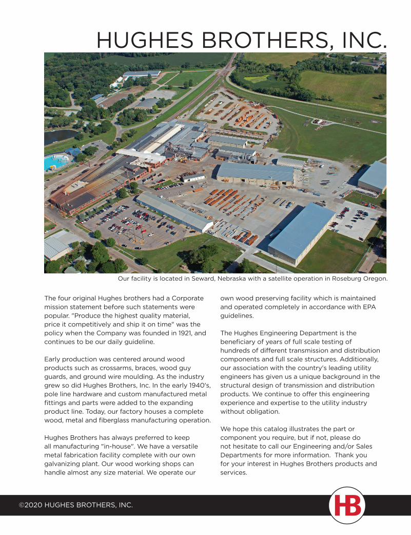
our facility is located in seward, Nebraska with a satellite operation in roseburg oregon.
HugHes BrotHers, INc.
the four original Hughes brothers had a corporate mission statement before such statements were popular. "Produce the highest quality material, price it competitively and ship it on time" was the policy when the company was founded in 1921, and continues to be our daily guideline.
early production was centered around wood products such as crossarms, braces, wood guy guards, and ground wire moulding. as the industry grew so did Hughes Brothers, Inc. In the early 1940's, pole line hardware and custom manufactured metal fittings and parts were added to the expanding product line. today, our factory houses a complete wood, metal and fiberglass manufacturing operation.
Hughes Brothers has always preferred to keep all manufacturing "in-house". We have a versatile metal fabrication facility complete with our own galvanizing plant. our wood working shops can handle almost any size material. We operate our
own wood preserving facility which is maintained and operated completely in accordance with ePa guidelines.
the Hughes engineering department is the beneficiary of years of full scale testing of hundreds of different transmission and distribution components and full scale structures. additionally, our association with the country's leading utility engineers has given us a unique background in the structural design of transmission and distribution products. We continue to offer this engineering experience and expertise to the utility industry without obligation.
We hope this catalog illustrates the part or component you require, but if not, please do not hesitate to call our engineering and/or sales departments for more information. thank you for your interest in Hughes Brothers products and services.
©2020 HugHes BrotHers, INc.
a
B
c
d
e
F
g
H
I
J
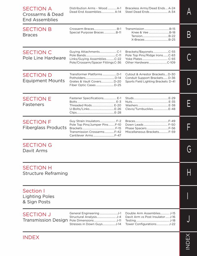
sectIoN a Crossarms & Dead end assemblies
sectIoN B Braces
sectIoN c Pole line Hardware
sectIoN d Equipment Mounts
sectIoN e Fasteners
sectIoN F Fiberglass Products
sectIoN g davit arms
sectIoN H structure reframing
section I lighting Poles & Sign Posts
sectIoN J transmission design
INdeX
IN
de
X
distribution arms - Wood ............a-1 Braceless arms/dead ends ... a-24dead end assemblies .................. a-14 steel dead ends ......................... a-34
crossarm Braces ............................... B-1 transmission ..................................B-15special Purpose Braces ................B-11 Knee & Vee ............................B-18 tension....................................B-22 X-Braces .................................B-25
guying attachments .......................c-1 Brackets/Bayonets .....................c-55Pole Bands .........................................c-11 Pole top Pins/ridge Irons .......c-83links/guying assemblies ...........c-22 Yoke Plates ................................... c-93Pole/crossarm/spacer Fittings c-36 other Hardware .........................c-109
transformer Platforms ...................D-1 Cutout & Arrestor Brackets....d-30Potholders........................................ d-14 conduit support Brackets ...... d-36Grates & Vault Covers .................d-20 sports Field lighting Brackets d-41Fiber optic cases ........................ d-25
Fastener Specifications.................. e-1 studs ................................................e-29Bolts ..................................................... e-3 Nuts ..................................................e-35threaded rods .............................. e-20 Washers ..........................................e-38u-Bolts/links ..................................e-26 clevis/turnbuckles .....................e-48clips ....................................................e-28
guy strain Insulators ...................... F-2 Braces ..............................................F-49Pole top Pins/Jumper Pins .........F-10 down leads ................................. F-50Brackets .............................................F-15 Phase spacers ..............................F-56transmission crossarms .............F-42 Miscellaneous Brackets.............F-59cantilever arms .............................F-47
general engineering ........................J-1 double arm assemblies ............ J-15structural analysis .......................... J-4 davit arm vs Post Insulator ..... J-16Pole dimensions .............................. J-11 testing .............................................. J-18stresses in down guys .................J-14 Tower Configurations ................ J-22
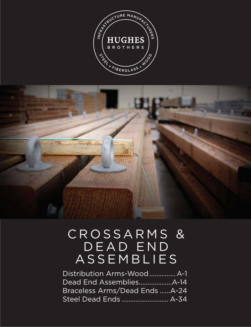
C R O S S A R M S & D E A D E N D
A S S E M B L I E SDistribution Arms-Wood ............... A-1Dead End Assemblies ...................A-14Braceless Arms/Dead Ends ......A-24Steel Dead Ends ........................... A-34
©2020 HugHes BrotHers, Inc. A-1
Crossarms & dead end assemblies a
Distribution Crossarms, 4" x 5"
and smallerCrossarms
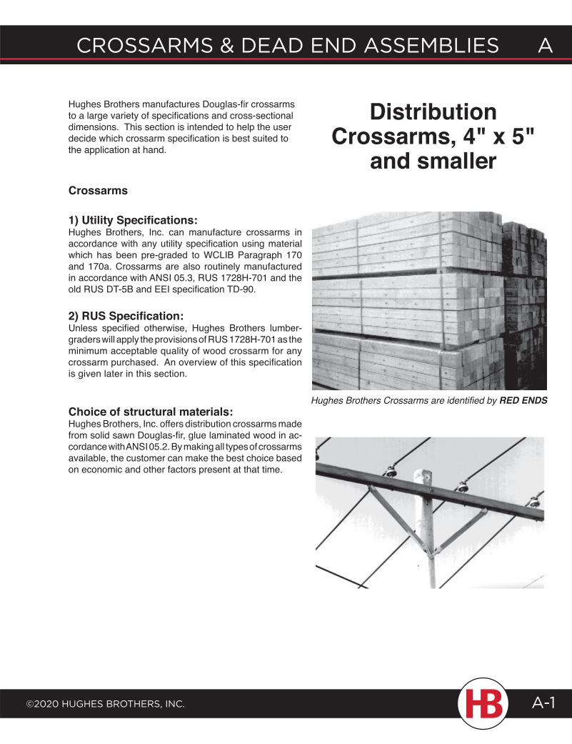
1) Utility Specifications:Hughes Brothers, Inc. can manufacture crossarms in accordance with any utility specification using material which has been pre-graded to WCLIB Paragraph 170 and 170a. Crossarms are also routinely manufactured in accordance with ANSI 05.3, RUS 1728H-701 and the old RUS DT-5B and EEI specification TD-90.
2) RUS Specification:Unless specified otherwise, Hughes Brothers lumber-graders will apply the provisions of RUS 1728H-701 as the minimum acceptable quality of wood crossarm for any crossarm purchased. An overview of this specification is given later in this section.
Choice of structural materials:Hughes Brothers, Inc. offers distribution crossarms made from solid sawn Douglas-fir, glue laminated wood in ac-cordance with ANSI 05.2. By making all types of crossarms available, the customer can make the best choice based on economic and other factors present at that time.
Hughes Brothers manufactures Douglas-fir crossarms to a large variety of specifications and cross-sectional dimensions. This section is intended to help the user decide which crossarm specification is best suited to the application at hand.
Hughes Brothers Crossarms are identified by RED ENDS
A CrossArms & deAd end Assemblies
©2020 HugHes brotHers, inC.A-2
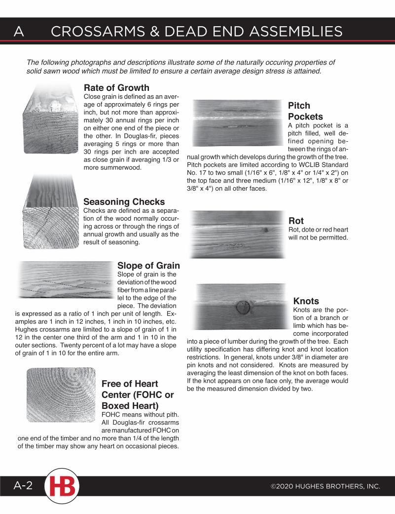
The following photographs and descriptions illustrate some of the naturally occuring properties of solid sawn wood which must be limited to ensure a certain average design stress is attained.
Slope of Grain
Seasoning ChecksChecks are defined as a separa-tion of the wood normally occur-ing across or through the rings of annual growth and usually as the result of seasoning.
Slope of grain is the deviation of the wood fiber from a line paral-lel to the edge of the piece. The deviation
is expressed as a ratio of 1 inch per unit of length. Ex-amples are 1 inch in 12 inches, 1 inch in 10 inches, etc. Hughes crossarms are limited to a slope of grain of 1 in 12 in the center one third of the arm and 1 in 10 in the outer sections. Twenty percent of a lot may have a slope of grain of 1 in 10 for the entire arm.
KnotsKnots are the por-tion of a branch or limb which has be-come incorporated
into a piece of lumber during the growth of the tree. Each utility specification has differing knot and knot location restrictions. In general, knots under 3/8" in diameter are pin knots and not considered. Knots are measured by averaging the least dimension of the knot on both faces. If the knot appears on one face only, the average would be the measured dimension divided by two.Free of Heart
Center (FOHC or Boxed Heart)FOHC means without pith. All Douglas-fir crossarms are manufactured FOHC on
one end of the timber and no more than 1/4 of the length of the timber may show any heart on occasional pieces.
RotRot, dote or red heart will not be permitted.
Rate of GrowthClose grain is defined as an aver-age of approximately 6 rings per inch, but not more than approxi-mately 30 annual rings per inch on either one end of the piece or the other. In Douglas-fir, pieces averaging 5 rings or more than 30 rings per inch are accepted as close grain if averaging 1/3 or more summerwood.
PitchPocketsA pitch pocket is a pitch filled, well de-fined opening be-tween the rings of an-
nual growth which develops during the growth of the tree. Pitch pockets are limited according to WCLIB Standard No. 17 to two small (1/16" x 6", 1/8" x 4" or 1/4" x 2") on the top face and three medium (1/16" x 12", 1/8" x 8" or 3/8" x 4") on all other faces.
©2020 HugHes BrotHers, Inc.
A crossArms & deAd end AssemBlIes
A-3
Crossarms & dead end assemblies a
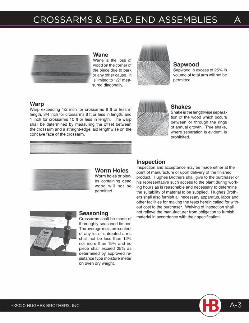
WaneWane is the loss of wood on the corner of the piece due to bark or any other cause. It is limited to 1/2" mea-sured diagonally.
WarpWarp exceeding 1/2 inch for crossarms 6 ft or less in length, 3/4 inch for crossarms 8 ft or less in length, and 1 inch for crossarms 10 ft or less in length. The warp shall be determined by measuring the offset between the crossarm and a straight-edge laid lengthwise on the concave face of the crossarm.
Worm HolesWorm holes or piec-es containing dead wood will not be permitted.
SapwoodSapwood in excess of 25% in volume of total arm will not be permitted.
ShakesShake is the lengthwise separa-tion of the wood which occurs between or through the rings of annual growth. True shake, where separation is evident, is prohibited.
InspectionInspection and acceptance may be made either at the point of manufacture or upon delivery of the finished product. Hughes Brothers shall give to the purchaser or his representative such access to the plant during work-ing hours as is reasonable and necessary to determine the suitability of material to be supplied. Hughes Broth-ers shall also furnish all necessary apparatus, labor and other facilities for making the tests herein called for with-out cost to the purchaser. Waiving of inspection shall not relieve the manufacturer from obligation to furnish material in accordance with their specification.
SeasoningCrossarms shall be made of thoroughly seasoned timber. The average moisture content of any lot of untreated arms shall not be less than 12% nor more than 19% and no piece shall exceed 25% as determined by approved re-sistance type moisture meter on oven dry weight.
A CrossArms & deAd end Assemblies
©2020 HugHes brotHers, inC.A-4
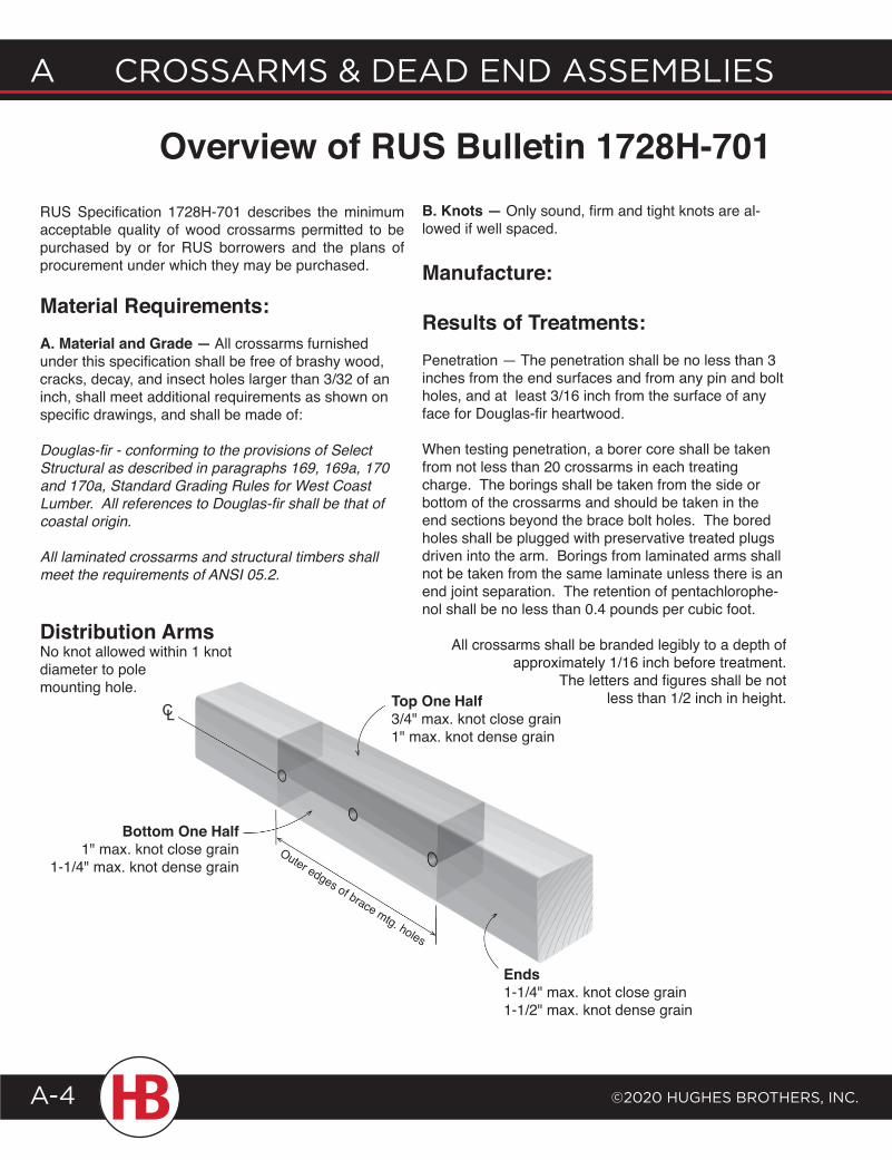
RUS Specification 1728H-701 describes the minimum acceptable quality of wood crossarms permitted to be purchased by or for RUS borrowers and the plans of procurement under which they may be purchased.
Material Requirements:A. Material and Grade — All crossarms furnished under this specification shall be free of brashy wood, cracks, decay, and insect holes larger than 3/32 of an inch, shall meet additional requirements as shown on specific drawings, and shall be made of:
Douglas-fir - conforming to the provisions of Select Structural as described in paragraphs 169, 169a, 170 and 170a, Standard Grading Rules for West Coast Lumber. All references to Douglas-fir shall be that of coastal origin.
All laminated crossarms and structural timbers shall meet the requirements of ANSI 05.2.
Overview of RUS Bulletin 1728H-701
CL
Outer edges of brace mtg. holes
Bottom One Half1" max. knot close grain
1-1/4" max. knot dense grain
Top One Half3/4" max. knot close grain1" max. knot dense grain
Ends1-1/4" max. knot close grain1-1/2" max. knot dense grain
Distribution ArmsNo knot allowed within 1 knot diameter to pole mounting hole.
B. Knots — Only sound, firm and tight knots are al-lowed if well spaced.
Manufacture:
Results of Treatments:Penetration — The penetration shall be no less than 3 inches from the end surfaces and from any pin and bolt holes, and at least 3/16 inch from the surface of any face for Douglas-fir heartwood.
When testing penetration, a borer core shall be taken from not less than 20 crossarms in each treating charge. The borings shall be taken from the side or bottom of the crossarms and should be taken in the end sections beyond the brace bolt holes. The bored holes shall be plugged with preservative treated plugs driven into the arm. Borings from laminated arms shall not be taken from the same laminate unless there is an end joint separation. The retention of pentachlorophe-nol shall be no less than 0.4 pounds per cubic foot.
All crossarms shall be branded legibly to a depth of approximately 1/16 inch before treatment.
The letters and figures shall be not less than 1/2 inch in height.
©2020 HugHes BrotHers, Inc.
A crossArms & deAd end AssemBlIes
A-5
Crossarms & dead end assemblies a
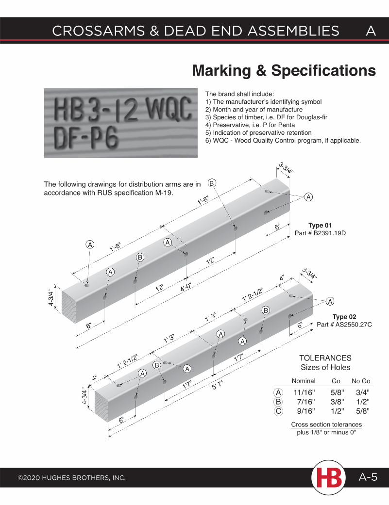
Overview of RUS Bulletin 1728H-701 Marking & SpecificationsThe brand shall include:1) The manufacturer’s identifying symbol2) Month and year of manufacture3) Species of timber, i.e. DF for Douglas-fir4) Preservative, i.e. P for Penta5) Indication of preservative retention6) WQC - Wood Quality Control program, if applicable.
The following drawings for distribution arms are in accordance with RUS specification M-19.
ABC
11/16"7/16"9/16"
5/8"3/8"1/2"
3/4"1/2"5/8"
Nominal Go No Go
Cross section tolerancesplus 1/8" or minus 0"
TOLERANCESSizes of Holes
Type 01Part # B2391.19D
Type 02Part # AS2550.27C
6"
1'7"
1'7"
6"
A CrossArms & deAd end Assemblies
©2020 HugHes brotHers, inC.A-6
ABC
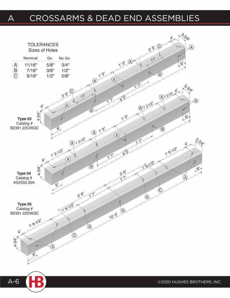
11/16"7/16"9/16"
5/8"3/8"1/2"
3/4"1/2"5/8"
TOLERANCESSizes of Holes
Nominal Go No Go
Type 03Catalog #
B2391.22CWQC
Type 04Catalog #
AS2550.30A
Type 05Catalog #
B2391.22DWQC 1' 6-1/2"
1' 6-1/2"
©2020 HugHes BrotHers, Inc.
A crossArms & deAd end AssemBlIes
A-7
Crossarms & dead end assemblies a
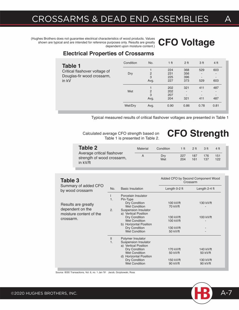
(Hughes Brothers does not guarantee electrical characteristics of wood products. Values shown are typical and are intended for reference purposes only. Results are greatly
dependent upon moisture content.) CFO Voltage
Table 1Critical flashover voltage of Douglas-fir wood crossarm, in kV
Electrical Properties of Crossarms Condition No. 1 ft 2 ft 3 ft 4 ft
1 224 368 529 603 Dry 2 231 356 - - 3 225 396 - - Avg. 227 373 529 603 1 202 321 411 487 Wet 2 202 - - - 3 207 - - - Avg. 204 321 411 487
Wet/Dry Avg. 0.90 0.86 0.78 0.81
Typical measured results of critical flashover voltages are presented in Table 1
Calculated average CFO strength based on Table 1 is presented in Table 2.
Material Condition 1 ft 2 ft 3 ft 4 ft
A Dry 227 187 176 151 Wet 204 161 137 122
Table 2Average critical flashover strength of wood crossarm, in kV/ft
CFO Strength
Table 3Summary of added CFO by wood crossarm
Added CFO by Second Component Wood Crossarm
Basic Insulation
Porcelain InsulatorPin-Type Dry Condition Wet ConditionSuspension Insulatora) Vertical Position Dry Condition Wet Conditionb) Horizontal Position Dry Condition Wet Condition
Polymer InsulatorSuspension Insulatora) Vertical Position Dry Condition Wet Conditiond) Horizontal Position Dry Condition Wet Condition
No.
I1.
2.
II1.
Length 0-2 ft
100 kV/ft70 kV/ft
130 kV/ft100 kV/ft
130 kV/ft50 kV/ft
170 kV/ft50 kV/ft
150 kV/ft90 kV/ft
Length 2-4 ft
130 kV/ft-
100 kV/ft-
--
140 kV/ft50 kV/ft
130 kV/ft90 kV/ft
Results are greatly dependent on the moisture content of the crossarm.
Source: IEEE Transactions, Vol. 6, no. 1 Jan '91 Jacob, Grzybowski, Ross
A CrossArms & deAd end Assemblies
©2020 HugHes brotHers, inC.A-8
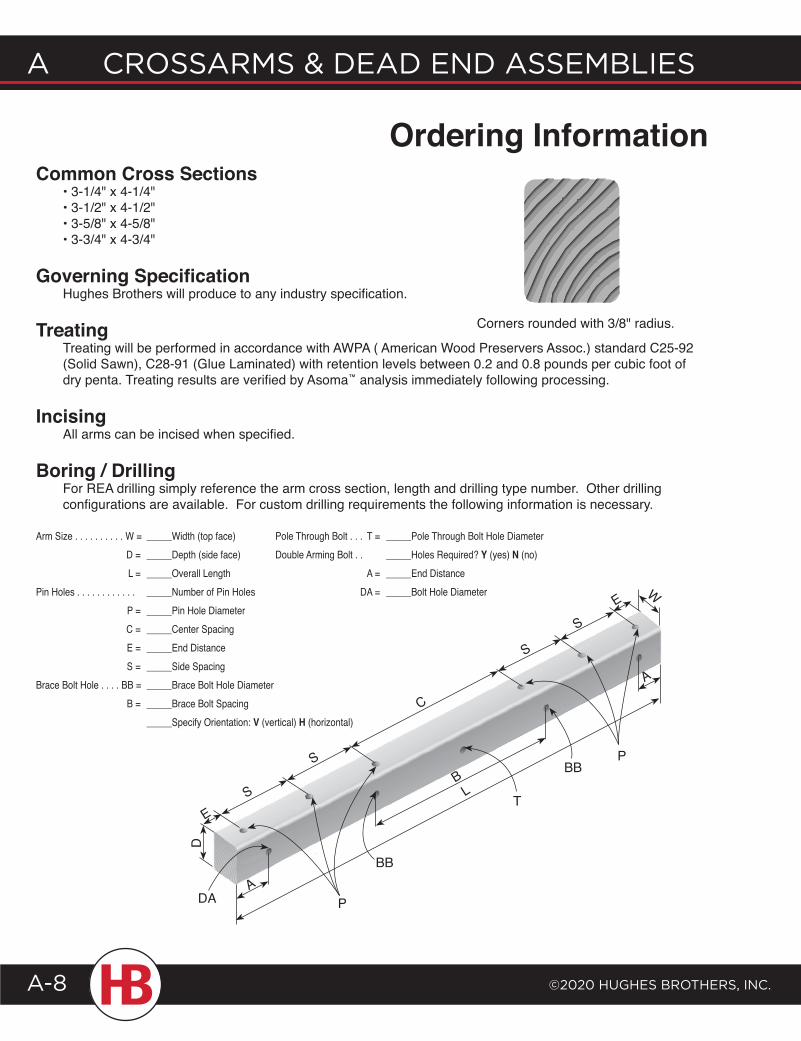
Common Cross Sections • 3-1/4" x 4-1/4" • 3-1/2" x 4-1/2" • 3-5/8" x 4-5/8" • 3-3/4" x 4-3/4"
Governing Specification Hughes Brothers will produce to any industry specification.
Treating Treating will be performed in accordance with AWPA ( American Wood Preservers Assoc.) standard C25-92 (Solid Sawn), C28-91 (Glue Laminated) with retention levels between 0.2 and 0.8 pounds per cubic foot of dry penta. Treating results are verified by Asoma™ analysis immediately following processing.
Incising All arms can be incised when specified.
Boring / Drilling For REA drilling simply reference the arm cross section, length and drilling type number. Other drilling configurations are available. For custom drilling requirements the following information is necessary.
Ordering Information
Arm Size . . . . . . . . . . W = _____Width (top face) D = _____Depth (side face) L = _____Overall LengthPin Holes . . . . . . . . . . . . _____Number of Pin Holes P = _____Pin Hole Diameter C = _____Center Spacing E = _____End Distance S = _____Side SpacingBrace Bolt Hole . . . . BB = _____Brace Bolt Hole Diameter B = _____Brace Bolt Spacing _____Specify Orientation: V (vertical) H (horizontal)
Pole Through Bolt . . . T = _____Pole Through Bolt Hole DiameterDouble Arming Bolt . . _____Holes Required? Y (yes) N (no) A = _____End Distance DA = _____Bolt Hole Diameter
Corners rounded with 3/8" radius.
D
ES
S
A
B
C
S
SE
L
A
W
DA P
BB
PBB
T
©2020 HugHes BrotHers, Inc.
A crossArms & deAd end AssemBlIes
A-9
Crossarms & dead end assemblies a
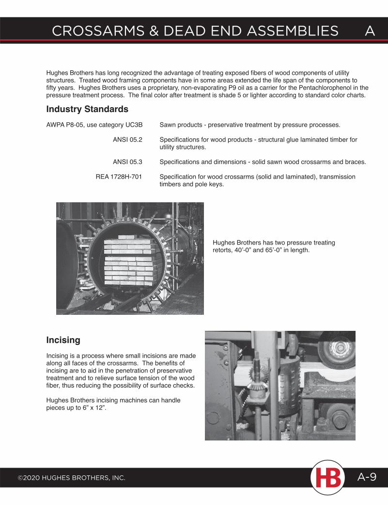
Hughes Brothers has long recognized the advantage of treating exposed fibers of wood components of utility structures. Treated wood framing components have in some areas extended the life span of the components to fifty years. Hughes Brothers uses a proprietary, non-evaporating P9 oil as a carrier for the Pentachlorophenol in the pressure treatment process. The final color after treatment is shade 5 or lighter according to standard color charts.
Industry Standards AWPA P8-05, use category UC3B Sawn products - preservative treatment by pressure processes.
ANSI 05.2 Specifications for wood products - structural glue laminated timber for utility structures.
ANSI 05.3 Specifications and dimensions - solid sawn wood crossarms and braces.
REA 1728H-701 Specification for wood crossarms (solid and laminated), transmission timbers and pole keys.
Hughes Brothers has two pressure treating retorts, 40’-0” and 65’-0” in length.
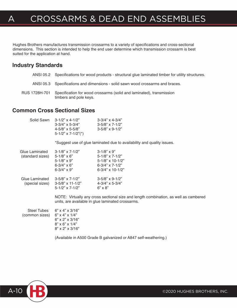
IncisingIncising is a process where small incisions are made along all faces of the crossarms. The benefits of incising are to aid in the penetration of preservative treatment and to relieve surface tension of the wood fiber, thus reducing the possibility of surface checks.
Hughes Brothers incising machines can handle pieces up to 6” x 12”.
A CrossArms & deAd end Assemblies
©2020 HugHes brotHers, inC.A-10
Hughes Brothers manufactures transmission crossarms to a variety of specifications and cross-sectional dimensions. This section is intended to help the end user determine which transmission crossarm is best suited for the application at hand.
Industry Standards ANSI 05.2 Specifications for wood products - structural glue laminated timber for utility structures.
ANSI 05.3 Specifications and dimensions - solid sawn wood crossarms and braces.
RUS 1728H-701 Specification for wood crossarms (solid and laminated), transmission timbers and pole keys.
Common Cross Sectional Sizes Solid Sawn 3-1/2” x 4-1/2” 3-3/4” x 4-3/4” 3-3/4” x 5-3/4” 3-5/8” x 7-1/2” 4-5/8” x 5-5/8” 3-5/8” x 9-1/2” 5-1/2” x 7-1/2”(*)
*Suggest use of glue laminated due to availability and quality issues.
Glue Laminated 3-1/8” x 7-1/2” 3-1/8” x 9” (standard sizes) 5-1/8” x 6” 5-1/8” x 7-1/2” 5-1/8” x 9” 5-1/8” x 10-1/2” 6-3/4” x 6” 6-3/4” x 7-1/2” 6-3/4” x 9” 6-3/4” x 10-1/2”
Glue Laminated 3-5/8” x 7-1/2” 3-5/8” x 9-1/2” (special sizes) 3-5/8” x 11-1/2” 4-3/4” x 5-3/4” 5-1/2” x 7-1/2” 6” x 8”
NOTE: Virtually any cross sectional size and length combination, as well as cambered units, are available in glue laminated crossarms.
Steel Tubes 6” x 4” x 3/16” (common sizes) 6” x 4” x 1/4” 6” x 2” x 3/16” 8” x 6” x 1/4” 8" x 2" x 3/16"
(Available in A500 Grade B galvanized or A847 self-weathering.)
©2020 HugHes BrotHers, Inc.
A crossArms & deAd end AssemBlIes
A-11
Crossarms & dead end assemblies a
3414 spacer shown, see pages C36-C393414 spacer shown, see pages C36-C39
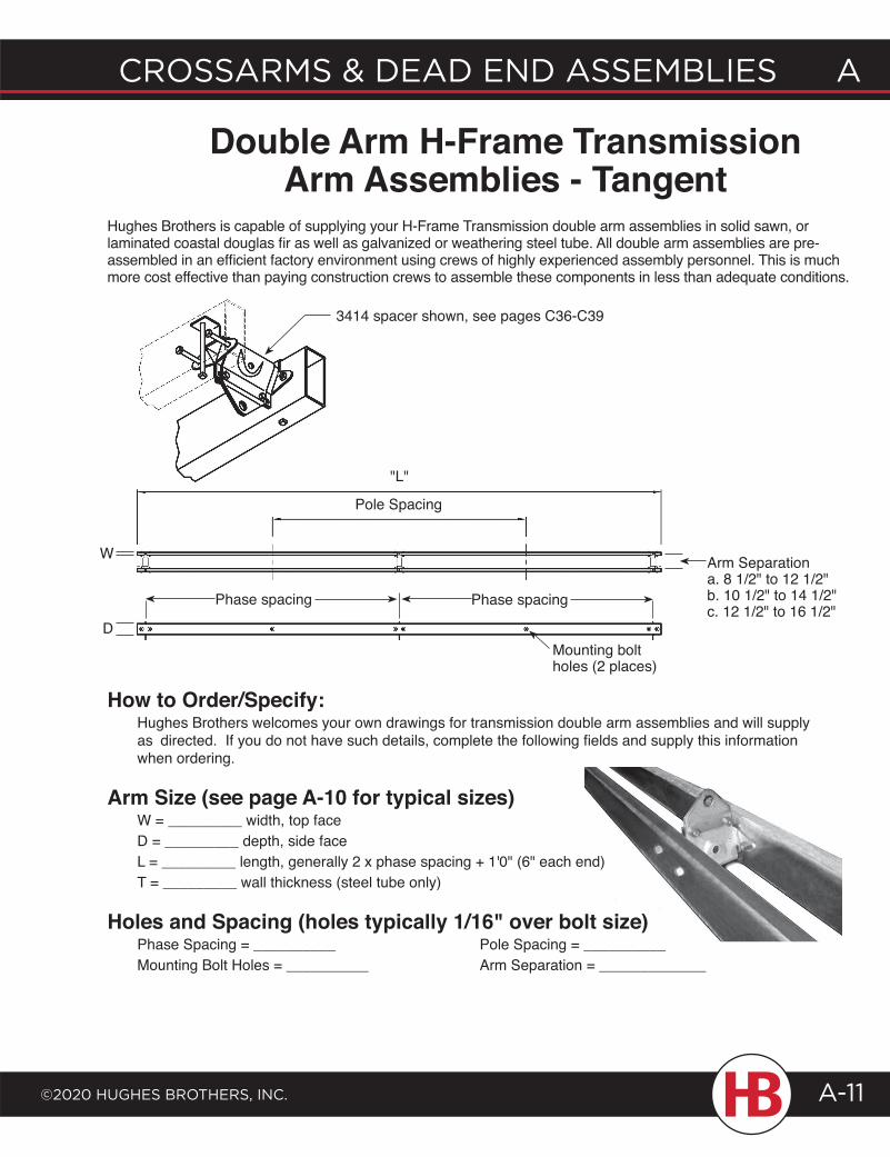
Hughes Brothers is capable of supplying your H-Frame Transmission double arm assemblies in solid sawn, or laminated coastal douglas fir as well as galvanized or weathering steel tube. All double arm assemblies are pre- assembled in an efficient factory environment using crews of highly experienced assembly personnel. This is much more cost effective than paying construction crews to assemble these components in less than adequate conditions.
How to Order/Specify: Hughes Brothers welcomes your own drawings for transmission double arm assemblies and will supply as directed. If you do not have such details, complete the following fields and supply this information when ordering.
Arm Size (see page A-10 for typical sizes) W = _________ width, top face D = _________ depth, side face L = _________ length, generally 2 x phase spacing + 1'0" (6" each end) T = _________ wall thickness (steel tube only)
Holes and Spacing (holes typically 1/16" over bolt size) Phase Spacing = __________ Pole Spacing = __________ Mounting Bolt Holes = __________ Arm Separation = _____________
Double Arm H-Frame Transmission Arm Assemblies - Tangent
Pole Spacing
"L"
W
DMounting bolt holes (2 places)
Phase spacing Phase spacing
Arm Separationa. 8 1/2" to 12 1/2"b. 10 1/2" to 14 1/2"c. 12 1/2" to 16 1/2"
3414 spacer shown, see pages C36-C39
A CrossArms & deAd end Assemblies
©2020 HugHes brotHers, inC.A-12
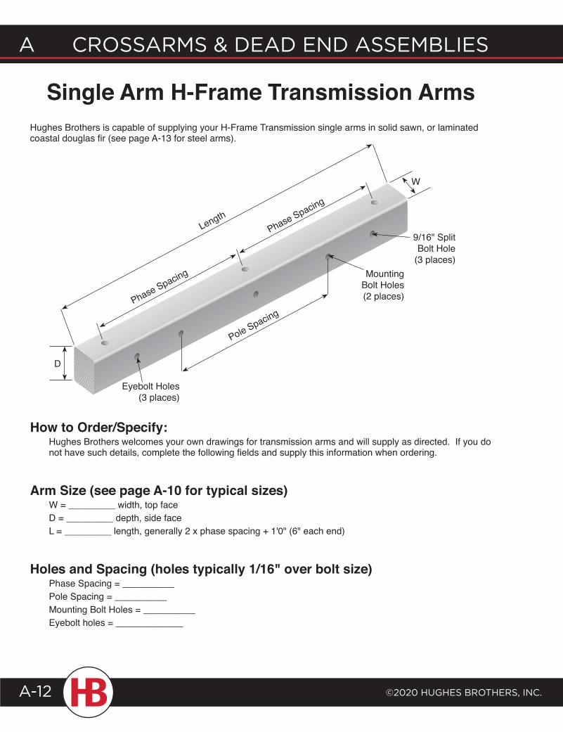
Hughes Brothers is capable of supplying your H-Frame Transmission single arms in solid sawn, or laminated coastal douglas fir (see page A-13 for steel arms).
How to Order/Specify: Hughes Brothers welcomes your own drawings for transmission arms and will supply as directed. If you do not have such details, complete the following fields and supply this information when ordering.
Arm Size (see page A-10 for typical sizes) W = _________ width, top face D = _________ depth, side face L = _________ length, generally 2 x phase spacing + 1'0" (6" each end)
Holes and Spacing (holes typically 1/16" over bolt size) Phase Spacing = __________ Pole Spacing = __________ Mounting Bolt Holes = __________ Eyebolt holes = _____________
Single Arm H-Frame Transmission Arms
9/16" Split Bolt Hole
(3 places)
D
Pole SpacingPhase Spacing
Phase Spacing
Length
W
Mounting Bolt Holes (2 places)
Eyebolt Holes (3 places)
©2020 HugHes BrotHers, Inc.
A crossArms & deAd end AssemBlIes
A-13
Crossarms & dead end assemblies a
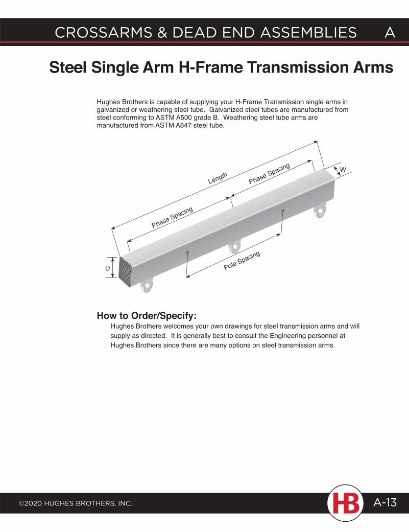
Hughes Brothers is capable of supplying your H-Frame Transmission single arms in galvanized or weathering steel tube. Galvanized steel tubes are manufactured from steel conforming to ASTM A500 grade B. Weathering steel tube arms are manufactured from ASTM A847 steel tube.
How to Order/Specify: Hughes Brothers welcomes your own drawings for steel transmission arms and will supply as directed. It is generally best to consult the Engineering personnel at Hughes Brothers since there are many options on steel transmission arms.
Steel Single Arm H-Frame Transmission Arms
Pole Spacing
Phase Spacing
Phase Spacing
LengthW
D
A CrossArms & deAd end Assemblies
©2020 HugHes brotHers, inC.A-14
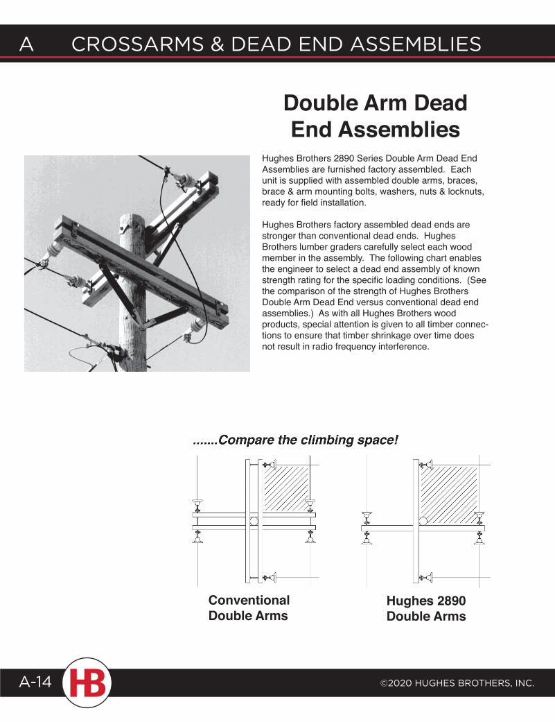
Conventional Double Arms
Hughes 2890 Double Arms
Double Arm Dead End Assemblies
Hughes Brothers 2890 Series Double Arm Dead End Assemblies are furnished factory assembled. Each unit is supplied with assembled double arms, braces, brace & arm mounting bolts, washers, nuts & locknuts, ready for field installation.
Hughes Brothers factory assembled dead ends are stronger than conventional dead ends. Hughes Brothers lumber graders carefully select each wood member in the assembly. The following chart enables the engineer to select a dead end assembly of known strength rating for the specific loading conditions. (See the comparison of the strength of Hughes Brothers Double Arm Dead End versus conventional dead end assemblies.) As with all Hughes Brothers wood products, special attention is given to all timber connec-tions to ensure that timber shrinkage over time does not result in radio frequency interference.
©2020 HugHes BrotHers, Inc.
A crossArms & deAd end AssemBlIes
A-15
Crossarms & dead end assemblies a
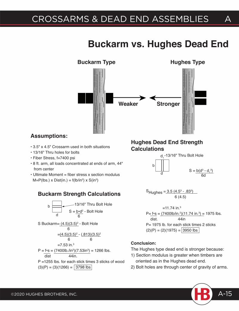
SHughes = 3.5 (4.53 - .833) 6 (4.5)
=11.74 in.3
P= f•s = (7400lb/in.2)(11.74 in.3) = 1975 lbs. dist. 44inP= 1975 lb. for each stick times 2 sticks(2)(P) = (2)(1975) = 3950 lbs
6 6 =7.53 in.3
P = f•s = (7400lb./in2)(7.53in3) = 1266 lbs. dist 44in.P =1255 lbs. for each stick times 3 sticks of wood(3)(P) = (3)(1266) = 3798 lbs
13/16" Thru Bolt Holeb
Buckarm Strength Calculations
Hughes TypeBuckarm Type
Buckarm vs. Hughes Dead End
Assumptions:
• 3.5" x 4.5" Crossarm used in both situations• 13/16" Thru holes for bolts• Fiber Stress, f=7400 psi• 8 ft. arm, all loads concentrated at ends of arm, 44" from center• Ultimate Moment = fiber stress x section modulus M=P(lbs.) x Dist(in.) = f(lb/in2) x S(in3)
S Buckarm= (4.5)(3.5)2 - Bolt Hole 6 =(4.5)(3.5)2 - (.813)(3.5)2
dS = b•d2 - Bolt Hole 6
S = b(d3 - d13)
6d
b
d
Hughes Dead End Strength Calculations
d1 -13/16" Thru Bolt Hole
StrongerWeaker
Conclusion:The Hughes type dead end is stronger because:1) Section modulus is greater when timbers are oriented as in the Hughes dead end.2) Bolt holes are through center of gravity of arms.
A CrossArms & deAd end Assemblies
©2020 HugHes brotHers, inC.A-16
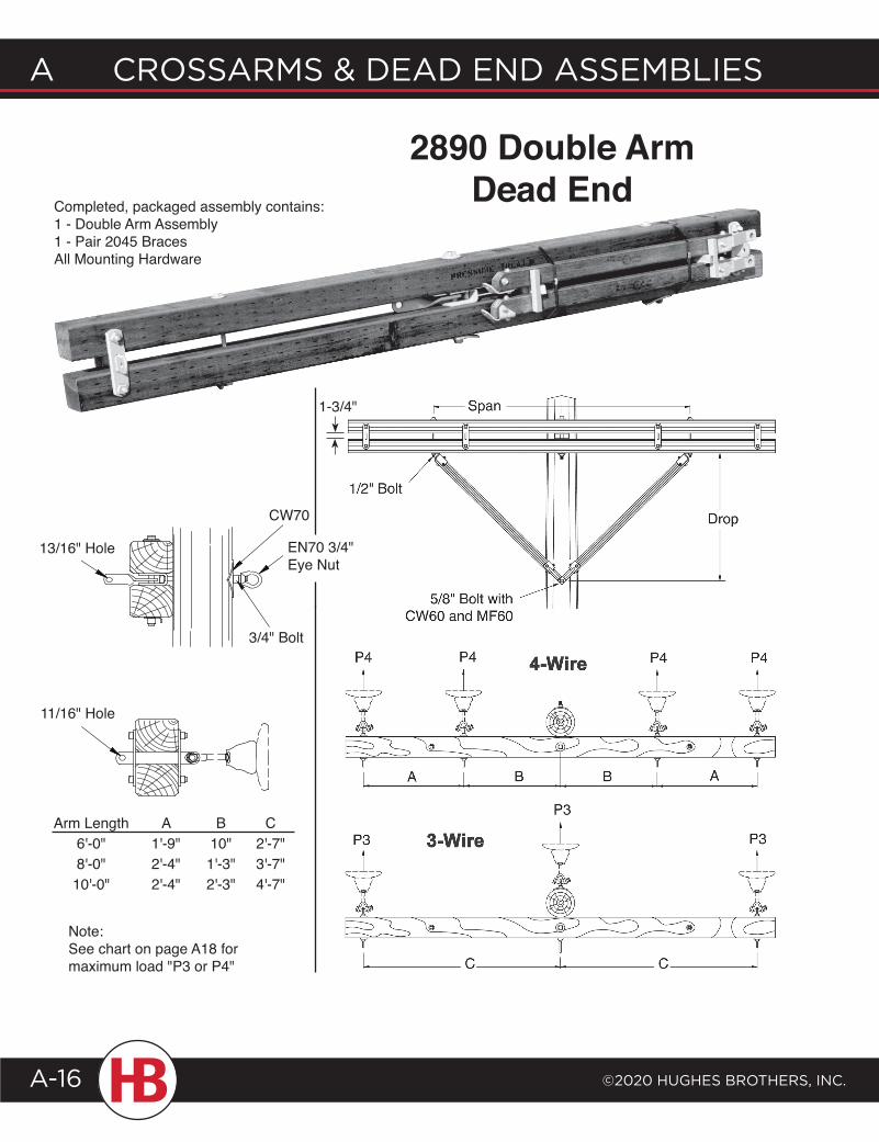
2890 Double Arm Dead End
Note:See chart on page A18 for maximum load "P3 or P4"
Arm Length6'-0"8'-0"10'-0"
A 1'-9"2'-4"2'-4"
B 10"1'-3"2'-3"
C2'-7"3'-7"4'-7"
Completed, packaged assembly contains:1 - Double Arm Assembly1 - Pair 2045 BracesAll Mounting Hardware
11/16" Hole
13/16" Hole EN70 3/4" Eye Nut
3/4" Bolt
CW70
1-3/4"
©2020 HugHes BrotHers, Inc.
A crossArms & deAd end AssemBlIes
A-17
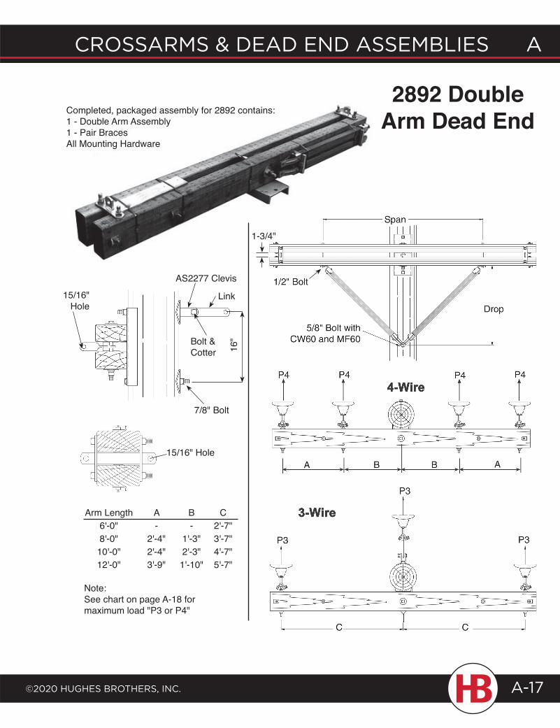
Crossarms & dead end assemblies a
Note:See chart on page A-18 for maximum load "P3 or P4"
Arm Length6'-0"8'-0"10'-0"12'-0"
A-
2'-4"2'-4"3'-9"
B-
1'-3"2'-3"1'-10"
C2'-7"3'-7"4'-7"5'-7"
2892 Double Arm Dead EndCompleted, packaged assembly for 2892 contains:
1 - Double Arm Assembly1 - Pair BracesAll Mounting Hardware
Bolt & Cotter 16
"
7/8" Bolt
15/16" Hole
AS2277 Clevis
Link
15/16" Hole
1-3/4"
A CrossArms & deAd end Assemblies
©2020 HugHes brotHers, inC.A-18
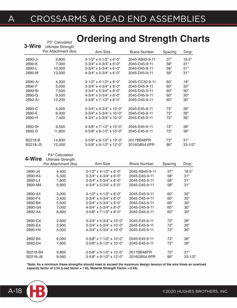
2890-J• 5,800 3-1/2" x 4-1/2" x 6'-0" 2045-AB45-9-11 37" 18.5"2890-K 7,000 3-3/4" x 4-3/4" x 6'-0" 2045-D45-9-11 58" 31"2890-L 10,000 3-3/4" x 5-3/4" x 6'-0" 2045-D45-9-11 58" 31"2890-M 13,000 4-3/4" x 5-3/4" x 6'-0" 2045-D45-9-11 58" 31"
2890-A• 4,300 3-1/2" x 4-1/2" x 8'-0" 2045-CC30-9-11 60" 18"2890-F 5,000 3-3/4" x 4-3/4" x 8'-0" 2045-D45-9-11 60" 30"2890-B• 7,500 3-3/4" x 5-3/4" x 8'-0" 2045-D45-9-11 60" 30"2890-G 9,500 4-3/4" x 5-3/4" x 8'-0" 2045-D45-9-11 60" 30"2892-A• 12,200 3-5/8" x 7-1/2" x 8'-0" 2045-D45-9-11 60" 30"
2890-C 4,000 3-3/4" x 4-3/4" x 10'-0" 2045-E45-9-11 72" 36"2890-E 6,000 3-3/4" x 5-3/4" x 10'-0" 2045-E45-9-11 72" 36"2890-H 7,400 4-3/4" x 5-3/4" x 10'-0" 2045-E45-9-11 72" 36"
2892-B• 9,500 3-5/8" x 7-1/2" x 10'-0" 2045-E45-9-11 72" 36"2892-D 11,800 3-5/8" x 8-1/2" x 10'-0" 2045-E45-9-11 72" 36"
B2218-B 14,600 3-5/8" x 9-1/2" x 10'-0" 2017BB48PR 72" 31"B2218-J3 12,000 3-5/8" x 9-1/2" x 12'-0" 2016GB54.6PR 86" 33-1/2"
Arm Size Brace Number Spacing Drop
P3* CalculatedUltimate Strength
Per Attachment (lbs)
Arm Size Brace Number Spacing Drop
2890-J4 4,400 3-1/2" x 4-1/2" x 6'-0" 2045-AB45-9-11 37" 18.5"2890-K4 5,300 3-3/4" x 4-3/4" x 6'-0" 2045-D45-9-11 58" 31"2890-L4 7,800 3-3/4" x 5-3/4" x 6'-0" 2045-D45-9-11 58" 31"2890-M4 9,900 4-3/4" x 5-3/4" x 6'-0" 2045-D45-9-11 58" 31"
2890-A4 3,000 3-1/2" x 4-1/2" x 8'-0" 2045-D45-9-11 60" 30"2890-F4 3,400 3-3/4" x 4-3/4" x 8'-0" 2045-D45-9-11 60" 30"2890-B4 5,500 3-3/4" x 5-3/4" x 8'-0" 2045-D45-9-11 60" 30"2890-G4 7,000 4-3/4" x 5-3/4" x 8'-0" 2045-D45-9-11 60" 30"2892-A4 8,600 3-5/8" x 7-1/2" x 8'-0" 2045-D45-9-11 60" 30"
2890-C4 2,600 3-3/4" x 4-3/4" x 10'-0" 2045-E45-9-11 72" 36"2890-E4 3,900 3-3/4" x 5-3/4" x 10'-0" 2045-E45-9-11 72" 36"2890-H4 5,000 4-3/4" x 5-3/4" x 10'-0" 2045-E45-9-11 72" 36"
2892-B4 6,000 3-5/8" x 7-1/2" x 10'-0" 2045-E45-9-11 72" 36"2892-D4 7,800 3-5/8" x 8-1/2" x 10'-0" 2045-E45-9-11 72" 36"
B2218-B4 9,800 3-5/8" x 9-1/2" x 10'-0" 2017BB48PR 72" 31"B2218-J8 9,060 3-5/8" x 9-1/2" x 12'-0" 2016GB54.6PR 86" 33-1/2"
P4* CalculatedUltimate Strength
Per Attachment (lbs)4-Wire
*Note: As a minimum these strengths should meet or exceed the maximum design tension of the wire times an overload capacity factor of 2.54 (Load factor = 1.65, Material Strength Factor = 0.65).
Ordering and Strength Charts3-Wire
©2020 HugHes BrotHers, Inc.
A crossArms & deAd end AssemBlIes
A-19
Crossarms & dead end assemblies a
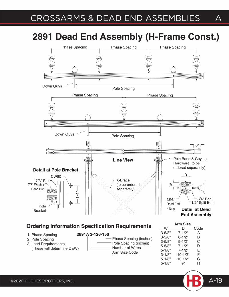
2891 Dead End Assembly (H-Frame Const.)
Arm Size W D Code 3-5/8" 7-1/2" A 3-5/8" 8-1/2" B 3-5/8" 9-1/2" C 5-5/8" 7-1/2" D 5-1/8" 7-1/2" E 3-1/8" 10-1/2" F 5-1/8" 10-1/2" G 5-1/8" 9" H
2891A 3-126-150Phase Spacing (inches)Pole Spacing (inches)Number of WiresArm Size Code
Ordering Information Specification Requirements1. Phase Spacing2. Pole Spacing3. Load Requirements (These will determine D&W)
A CrossArms & deAd end Assemblies
©2020 HugHes brotHers, inC.A-20
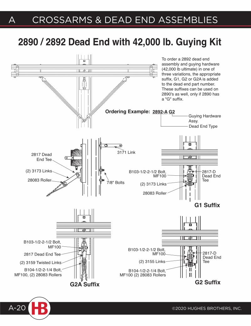
2892-A G2Guying Hardware Assy.Dead End Type
Ordering Example:
To order a 2892 dead end assembly and guying hardware (42,000 lb ultimate) in one of three variations, the appropriate suffix, G1, G2 or G2A is added to the dead end part number. These suffixes can be used on 2890's as well, only if 2890 has a "G" suffix.
G2A Suffix
2890 / 2892 Dead End with 42,000 lb. Guying Kit
2817 Dead End Tee
(2) 3173 Links
28083 Roller 7/8" Bolts
B103-1/2-2-1/2 Bolt, MF100
(2) 3173 Links
28083 Roller
G1 Suffix
G2 Suffix
B103-1/2-2-1/2 Bolt, MF100
(2) 3155 Links
B104-1/2-2-1/4 Bolt, MF100 (2) 28083 Rollers
3171 Link
B103-1/2-2-1/2 Bolt, MF100
B104-1/2-2-1/4 Bolt, MF100, (2) 28083 Rollers
(2) 3159 Twisted Links
2817 Dead End Tee
2817-D Dead End Tee
2817-D Dead End Tee
©2020 HugHes BrotHers, Inc.
A crossArms & deAd end AssemBlIes
A-21
Crossarms & dead end assemblies a
G1 Suffix
G2 Suffix
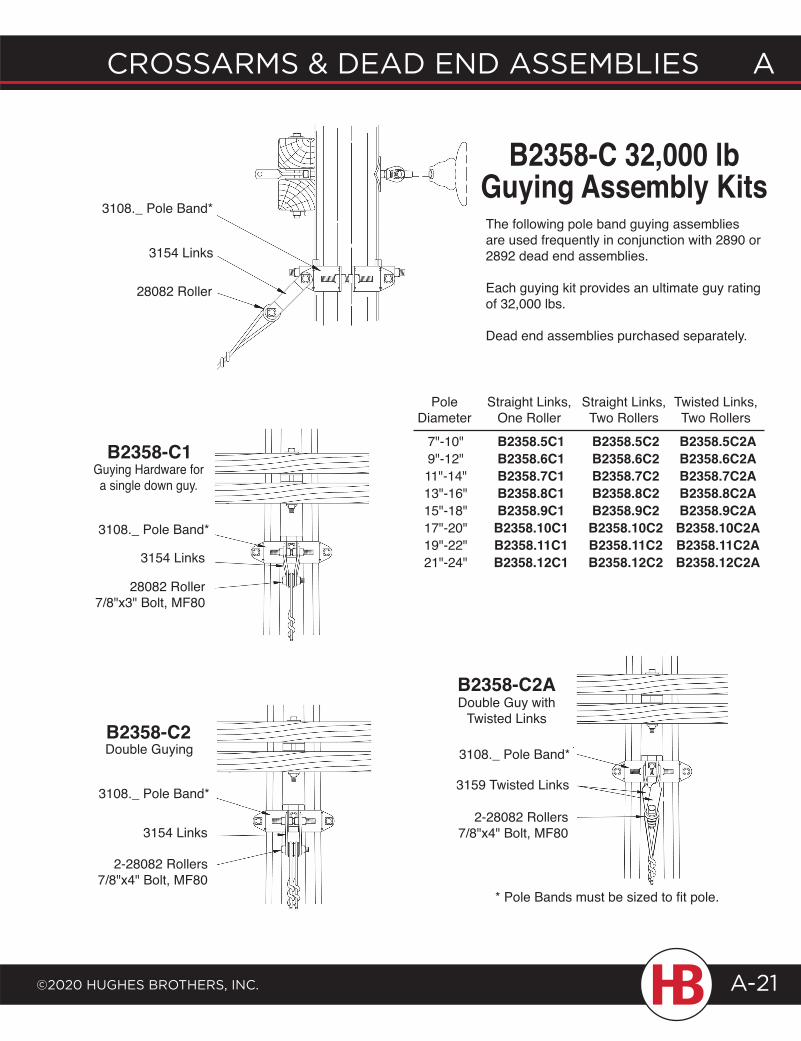
3108._ Pole Band*
3154 Links
2-28082 Rollers7/8"x4" Bolt, MF80
3108._ Pole Band*
3159 Twisted Links
2-28082 Rollers7/8"x4" Bolt, MF80
* Pole Bands must be sized to fit pole.
3108._ Pole Band*
3154 Links
28082 Roller
Pole Diameter
7"-10"9"-12"11"-14"13"-16"15"-18"17"-20"19"-22"21"-24"
Straight Links,One RollerB2358.5C1B2358.6C1B2358.7C1B2358.8C1B2358.9C1B2358.10C1B2358.11C1B2358.12C1
Straight Links,Two RollersB2358.5C2B2358.6C2B2358.7C2B2358.8C2B2358.9C2B2358.10C2B2358.11C2B2358.12C2
Twisted Links,Two RollersB2358.5C2AB2358.6C2AB2358.7C2AB2358.8C2AB2358.9C2AB2358.10C2AB2358.11C2AB2358.12C2A
3108._ Pole Band*
3154 Links
28082 Roller7/8"x3" Bolt, MF80
B2358-C 32,000 lb Guying Assembly KitsThe following pole band guying assemblies are used frequently in conjunction with 2890 or 2892 dead end assemblies.
Each guying kit provides an ultimate guy rating of 32,000 lbs.
Dead end assemblies purchased separately.
B2358-C1Guying Hardware for a single down guy.
B2358-C2Double Guying
B2358-C2ADouble Guy with
Twisted Links
A CrossArms & deAd end Assemblies
©2020 HugHes brotHers, inC.A-22
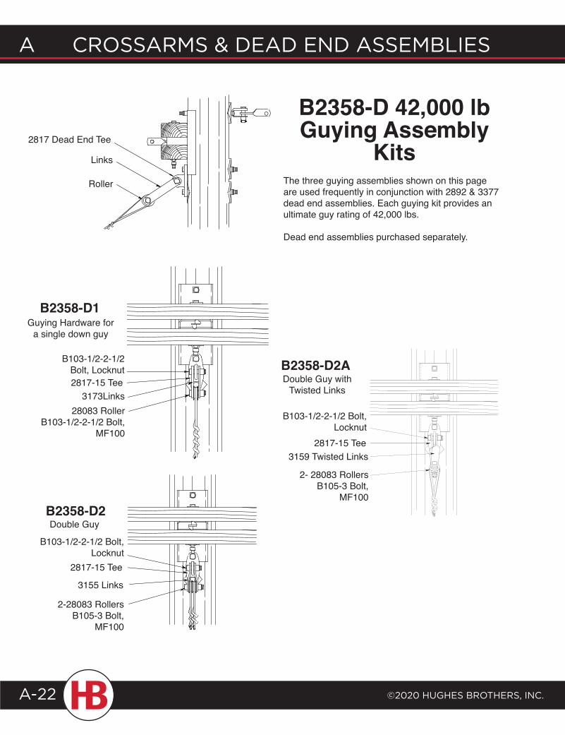
B2358-D2
B2358-D1Guying Hardware for
a single down guy
Double Guy
B2358-D 42,000 lb Guying Assembly
Kits
3173Links2817-15 Tee
B103-1/2-2-1/2 Bolt, Locknut
28083 RollerB103-1/2-2-1/2 Bolt,
MF100
2-28083 RollersB105-3 Bolt,
MF100
3155 Links
2817-15 Tee
B103-1/2-2-1/2 Bolt, Locknut
B103-1/2-2-1/2 Bolt, Locknut
2817-15 Tee3159 Twisted Links
2- 28083 RollersB105-3 Bolt,
MF100
B2358-D2ADouble Guy with
Twisted Links
The three guying assemblies shown on this page are used frequently in conjunction with 2892 & 3377 dead end assemblies. Each guying kit provides an ultimate guy rating of 42,000 lbs.
Dead end assemblies purchased separately.
2817 Dead End Tee
Links
Roller
©2020 HugHes BrotHers, Inc.
A crossArms & deAd end AssemBlIes
A-23
Crossarms & dead end assemblies a
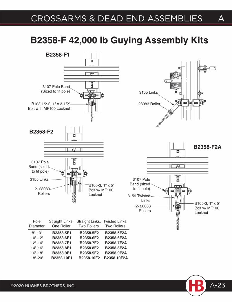
B2358-F 42,000 lb Guying Assembly Kits
B2358-F2
8"-10"10"-12"12"-14"14"-16"16"-18"18"-20"
B2358.5F1B2358.6F1B2358.7F1B2358.8F1B2358.9F1B2358.10F1
Straight Links,Two RollersB2358.5F2B2358.6F2B2358.7F2B2358.8F2B2358.9F2B2358.10F2
Twisted Links,Two RollersB2358.5F2AB2358.6F2AB2358.7F2AB2358.8F2AB2358.9F2AB2358.10F2A
Pole Diameter
Straight Links,One Roller
3107 Pole Band (sized
to fit pole)
3155 Links
2- 28083 Rollers
B105-3, 1" x 5" Bolt w/ MF100 Locknut
B2358-F2A
3159 Twisted Links
2- 28083 Rollers
3107 Pole Band (sized
to fit pole)
B105-3, 1" x 5" Bolt w/ MF100 Locknut
3107 Pole Band (Sized to fit pole)
B103 1/2-2, 1" x 3-1/2" Bolt with MF100 Locknut
B2358-F1
28083 Roller
3155 Links
A CrossArms & deAd end Assemblies
©2020 HugHes brotHers, inC.A-24
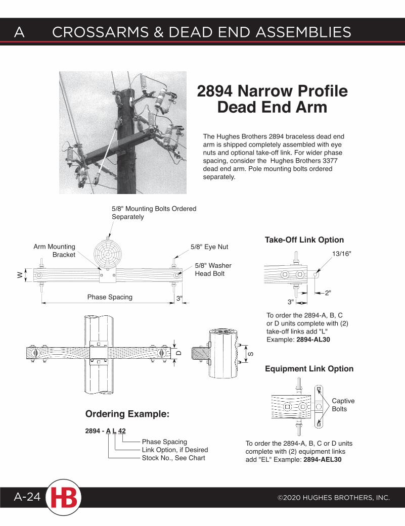
The Hughes Brothers 2894 braceless dead end arm is shipped completely assembled with eye nuts and optional take-off link. For wider phase spacing, consider the Hughes Brothers 3377 dead end arm. Pole mounting bolts ordered separately.
Ordering Example:2894 - A L 42
Phase SpacingLink Option, if DesiredStock No., See Chart
5/8" Mounting Bolts Ordered Separately
5/8" Washer Head Bolt
Arm Mounting Bracket
W
3"
5/8" Eye Nut
D S
Phase Spacing
2894 Narrow Profile Dead End Arm
Take-Off Link Option
3"
13/16"
2"
To order the 2894-A, B, C or D units complete with (2) take-off links add "L"Example: 2894-AL30
Equipment Link Option
Captive Bolts
To order the 2894-A, B, C or D units complete with (2) equipment links add "EL" Example: 2894-AEL30
©2020 HugHes BrotHers, Inc.
A crossArms & deAd end AssemBlIes
A-25
Crossarms & dead end assemblies a
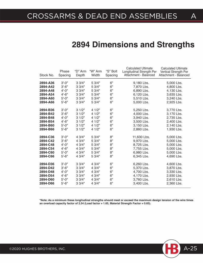
Phase “D” Arm “W” Arm “S” Bolt Stock No. Spacing Depth Width Spacing
2894-A36 3'-0" 3 3/4" 5 3/4" 6" 9,180 Lbs. 5,000 Lbs.2894-A42 3'-6" 3 3/4" 5 3/4" 6" 7,870 Lbs. 4,800 Lbs.2894-A48 4'-0" 3 3/4" 5 3/4" 6" 6,890 Lbs. 4,130 Lbs.2894-A54 4'-6" 3 3/4" 5 3/4" 6" 6,120 Lbs. 3,635 Lbs.2894-A60 5'-0" 3 3/4" 5 3/4" 6" 5,510 Lbs. 3,240 Lbs.2894-A66 5'-6" 3 3/4" 5 3/4" 6" 5,000 Lbs. 2,925 Lbs.
2894-B36 3'-0" 3 1/2" 4 1/2" 6" 5,250 Lbs. 3,770 Lbs.2894-B42 3'-6" 3 1/2" 4 1/2" 6" 4,000 Lbs. 3,170 Lbs.2894-B48 4'-0" 3 1/2" 4 1/2" 6" 3,940 Lbs. 2,735 Lbs.2894-B54 4'-6" 3 1/2" 4 1/2" 6" 3,500 Lbs. 2,400 Lbs.2894-B60 5'-0" 3 1/2" 4 1/2" 6" 3,150 Lbs. 2,140 Lbs.2894-B66 5'-6" 3 1/2" 4 1/2" 6" 2,860 Lbs. 1,930 Lbs.
2894-C36 3'-0" 4 3/4" 5 3/4" 8" 11,630 Lbs. 5,000 Lbs.2894-C42 3'-6" 4 3/4" 5 3/4" 8" 9,970 Lbs. 5,000 Lbs.2894-C48 4'-0" 4 3/4" 5 3/4" 8" 8,725 Lbs. 5,000 Lbs.2894-C54 4'-6" 4 3/4" 5 3/4" 8" 7,755 Lbs. 5,000 Lbs.2894-C60 5'-0" 4 3/4" 5 3/4" 8" 6,980 Lbs. 5,000 Lbs.2894-C66 5'-6" 4 3/4" 5 3/4" 8" 6,345 Lbs. 4,690 Lbs.
2894-D36 3'-0" 3 3/4" 4 3/4" 6" 6,260 Lbs. 4,600 Lbs.2894-D42 3'-6" 3 3/4" 4 3/4" 6" 5,370 Lbs. 3,870 Lbs.2894-D48 4'-0" 3 3/4" 4 3/4" 6" 4,700 Lbs. 3,330 Lbs.2894-D54 4'-6" 3 3/4" 4 3/4" 6" 4,170 Lbs. 2,930 Lbs.2894-D60 5'-0" 3 3/4" 4 3/4" 6" 3,760 Lbs. 2,610 Lbs.2894-D66 5'-6" 3 3/4" 4 3/4" 6" 3,400 Lbs. 2,360 Lbs.
Calculated Ultimate Longitudinal Strength Per
Attachment - Balanced
Calculated Ultimate Vertical Strength Per
Attachment - Balanced
2894 Dimensions and Strengths
*Note: As a minimum these longitudinal strengths should meet or exceed the maximum design tension of the wire times an overload capacity factor of 2.54 (Load factor = 1.65, Material Strength Factor = 0.65).
A CrossArms & deAd end Assemblies
©2020 HugHes brotHers, inC.A-26
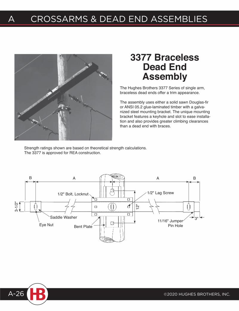
The Hughes Brothers 3377 Series of single arm, braceless dead ends offer a trim appearance.
The assembly uses either a solid sawn Douglas-fir or ANSI 05.2 glue-laminated timber with a galva-nized steel mounting bracket. The unique mounting bracket features a keyhole and slot to ease installa-tion and also provides greater climbing clearances than a dead end with braces.
Strength ratings shown are based on theoretical strength calculations. The 3377 is approved for REA construction.
3377 Braceless Dead End Assembly
A A B
12"
3"Saddle Washer
Eye Nut
B
Bent Plate11/16" Jumper
Pin Hole
3-1/
2"
1/2" Bolt, Locknut 1/2" Lag Screw
©2020 HugHes BrotHers, Inc.
A crossArms & deAd end AssemBlIes
A-27
Crossarms & dead end assemblies a
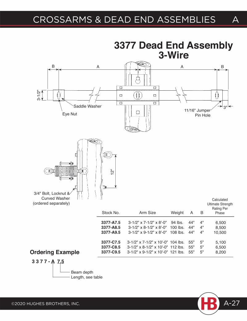
3377 Dead End Assembly3-Wire
3 3 7 7 - A 7.5
Ordering Example
Beam depthLength, see table
3/4" Bolt, Locknut & Curved Washer
(ordered separately)
12"
Calculated Ultimate Strength
Rating Per Phase
6,500 8,500 10,500
5,100 6,500 8,200
B
4"4"4"
5"5"5"
Arm Size
3-1/2" x 7-1/2" x 8'-0"3-1/2" x 8-1/2" x 8'-0"3-1/2" x 9-1/2" x 8'-0"
3-1/2" x 7-1/2" x 10'-0"3-1/2" x 8-1/2" x 10'-0"3-1/2" x 9-1/2" x 10'-0"
Weight
94 lbs.100 lbs.108 lbs.
104 lbs.112 lbs.121 lbs.
A
44"44"44"
55"55"55"
Stock No.
3377-A7.5 3377-A8.5 3377-A9.5
3377-C7.5 3377-C8.5 3377-C9.5
A A B
3"Saddle Washer
Eye Nut
B
11/16" Jumper Pin Hole
3-1/
2"
A CrossArms & deAd end Assemblies
©2020 HugHes brotHers, inC.A-28
3-1/
2"
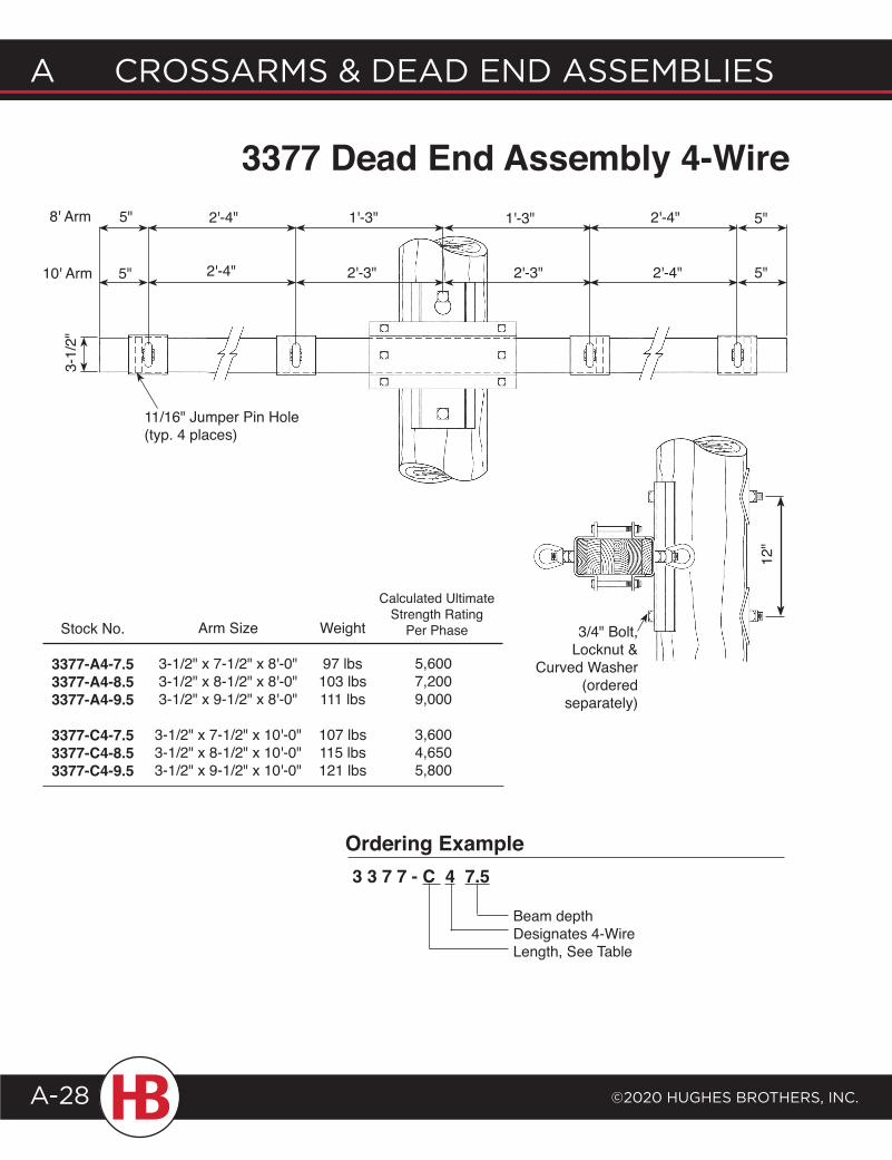
2'-4" 2'-3" 5"2'-4"2'-3"5"
11/16" Jumper Pin Hole (typ. 4 places)
3377 Dead End Assembly 4-Wire8' Arm
10' Arm
Ordering Example
Beam depthDesignates 4-WireLength, See Table
3 3 7 7 - C 4 7.5
Weight
97 lbs103 lbs111 lbs
107 lbs115 lbs121 lbs
Stock No.
3377-A4-7.5 3377-A4-8.5 3377-A4-9.5
3377-C4-7.5 3377-C4-8.5 3377-C4-9.5
Arm Size
3-1/2" x 7-1/2" x 8'-0"3-1/2" x 8-1/2" x 8'-0"3-1/2" x 9-1/2" x 8'-0"
3-1/2" x 7-1/2" x 10'-0"3-1/2" x 8-1/2" x 10'-0"3-1/2" x 9-1/2" x 10'-0"
Calculated Ultimate Strength Rating
Per Phase
5,6007,2009,000
3,6004,6505,800
3/4" Bolt, Locknut &
Curved Washer (ordered
separately)
2'-4" 1'-3" 5"2'-4"1'-3"5"
12"
©2020 HugHes BrotHers, Inc.
A crossArms & deAd end AssemBlIes
A-29
Crossarms & dead end assemblies a
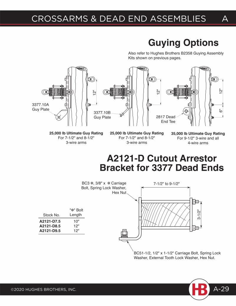
7-1/2" to 9-1/2"BC3 ✽, 3/8" x ✽ Carriage Bolt, Spring Lock Washer,
Hex Nut
BC51-1/2, 1/2" x 1-1/2" Carriage Bolt, Spring Lock Washer, External Tooth Lock Washer, Hex Nut.
A2121-D7.5 10"A2121-D8.5 12"A2121-D9.5 12"
Stock No."✽" Bolt Length
A2121-D Cutout Arrestor Bracket for 3377 Dead Ends
12"
3377.10B Guy Plate
12"
2817 Dead End Tee
12"
6"
3377.10A Guy Plate
Guying OptionsAlso refer to Hughes Brothers B2358 Guying Assembly Kits shown on previous pages.
25,000 lb Ultimate Guy RatingFor 7-1/2" and 8-1/2"
3-wire arms
25,000 lb Ultimate Guy RatingFor 7-1/2" and 8-1/2"
3-wire arms
35,000 lb Ultimate Guy RatingFor 9-1/2" 3-wire and all
4-wire arms
3-1/
2"
A CrossArms & deAd end Assemblies
©2020 HugHes brotHers, inC.A-30
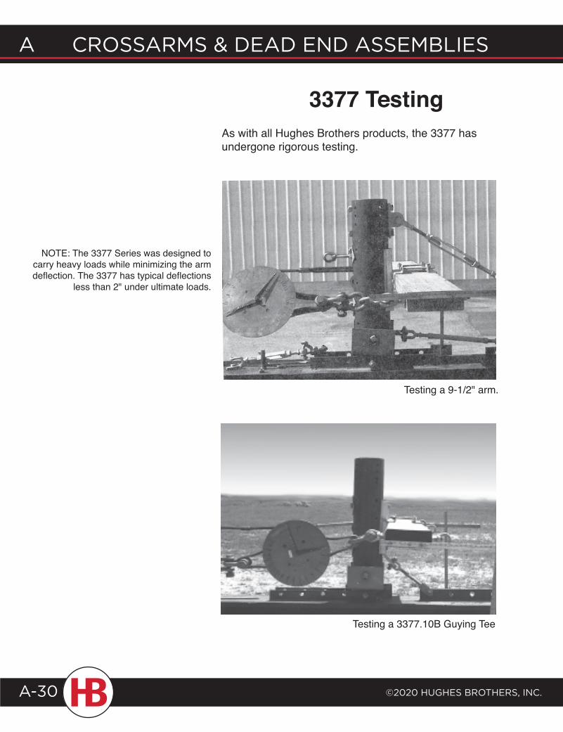
As with all Hughes Brothers products, the 3377 has undergone rigorous testing.
3377 Testing
Testing a 9-1/2" arm.
Testing a 3377.10B Guying Tee
NOTE: The 3377 Series was designed to carry heavy loads while minimizing the arm deflection. The 3377 has typical deflections
less than 2" under ultimate loads.
©2020 HugHes BrotHers, Inc.
A crossArms & deAd end AssemBlIes
A-31
Crossarms & dead end assemblies a
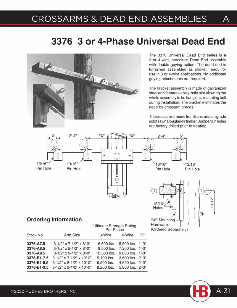
3376 3 or 4-Phase Universal Dead End
Stock No. Arm Size 3-Wire 4-Wire "X"
3376-A7.5 3-1/2" x 7-1/2" x 8'-0" 6,500 lbs. 5,600 lbs. 1'-3"3376-A8.5 3-1/2" x 8-1/2" x 8'-0" 8,500 lbs. 7,200 lbs. 1'-3"3376-A9.5 3-1/2" x 9-1/2" x 8'-0" 10,500 lbs. 9,000 lbs. 1'-3"3376-E1-7.5 3-1/2" x 7-1/2" x 10'-0" 5,100 lbs. 3,600 lbs. 2'-3"3376-E1-8.5 3-1/2" x 8-1/2" x 10'-0" 6,500 lbs. 4,650 lbs. 2'-3"3376-E1-9.5 3-1/2" x 9-1/2" x 10'-0" 8,200 lbs. 5,800 lbs. 2'-3"
Ultimate Strength Rating Per Phase
The 3376 Universal Dead End series is a 3 or 4-wire, braceless Dead End assembly with double guying option. The dead end is furnished assembled as shown, ready for use in 3 or 4-wire applications. No additional guying attachments are required.
The bracket assembly is made of galvanized steel and features a key-hole slot allowing the whole assembly to be hung on a mounting bolt during installation. The bracket eliminates the need for crossarm braces.
The crossarm is made from transmission grade solid sawn Douglas-fir timber. Jumper pin holes are factory drilled prior to treating.
Ordering Information
2"
5" 2'-4" "X" "X" 2'-4" 5"
13/16" Pin Hole
15/16" Holes 10
-12"
7/8" Mounting Hardware (Ordered Separately)
2"2" 2"
13/16" Pin Hole
13/16" Pin Hole
13/16" Pin Hole
A CrossArms & deAd end Assemblies
©2020 HugHes brotHers, inC.A-32
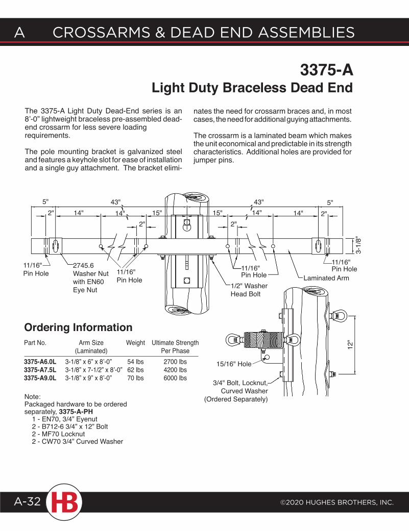
3375-A Light Duty Braceless Dead End
The 3375-A Light Duty Dead-End series is an 8’-0” lightweight braceless pre-assembled dead- end crossarm for less severe loading requirements.
The pole mounting bracket is galvanized steel and features a keyhole slot for ease of installation and a single guy attachment. The bracket elimi-
nates the need for crossarm braces and, in most cases, the need for additional guying attachments.
The crossarm is a laminated beam which makes the unit economical and predictable in its strength characteristics. Additional holes are provided for jumper pins.
Part No. Arm Size Weight Ultimate Strength (Laminated) Per Phase3375-A6.0L 3-1/8” x 6” x 8’-0” 54 lbs 2700 lbs3375-A7.5L 3-1/8” x 7-1/2” x 8’-0” 62 lbs 4200 lbs3375-A9.0L 3-1/8” x 9” x 8’-0” 70 lbs 6000 lbs
Ordering Information
Note:Packaged hardware to be ordered separately, 3375-A-PH 1 - EN70, 3/4” Eyenut 2 - B712-6 3/4” x 12” Bolt 2 - MF70 Locknut 2 - CW70 3/4” Curved Washer
5" 43"2" 14" 14" 15"
2" 2"15"
43"14" 14"
5"2"
2745.6 Washer Nutwith EN60Eye Nut 1/2" Washer
Head Bolt
11/16" Pin Hole Laminated Arm
3-1/
8"12
"
3/4" Bolt, Locknut, Curved Washer
(Ordered Separately)
11/16" Pin Hole 11/16"
Pin Hole
11/16" Pin Hole
15/16" Hole
©2020 HugHes BrotHers, Inc.
A crossArms & deAd end AssemBlIes
A-33
Crossarms & dead end assemblies a
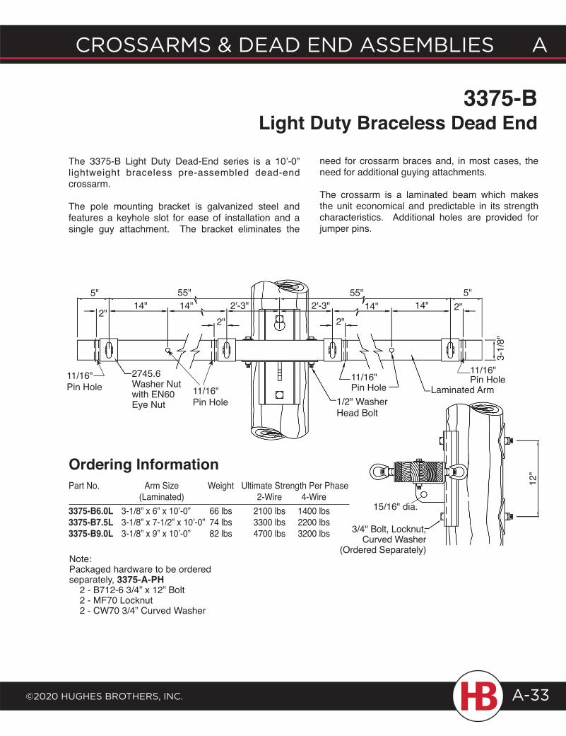
3375-B Light Duty Braceless Dead End
The 3375-B Light Duty Dead-End series is a 10’-0” lightweight braceless pre-assembled dead-end crossarm.
The pole mounting bracket is galvanized steel and features a keyhole slot for ease of installation and a single guy attachment. The bracket eliminates the
need for crossarm braces and, in most cases, the need for additional guying attachments.
The crossarm is a laminated beam which makes the unit economical and predictable in its strength characteristics. Additional holes are provided for jumper pins.
Part No. Arm Size Weight Ultimate Strength Per Phase (Laminated) 2-Wire 4-Wire3375-B6.0L 3-1/8” x 6” x 10’-0” 66 lbs 2100 lbs 1400 lbs3375-B7.5L 3-1/8” x 7-1/2” x 10’-0” 74 lbs 3300 lbs 2200 lbs3375-B9.0L 3-1/8” x 9” x 10’-0” 82 lbs 4700 lbs 3200 lbs
Ordering Information
Note:Packaged hardware to be ordered separately, 3375-A-PH 2 - B712-6 3/4” x 12” Bolt 2 - MF70 Locknut 2 - CW70 3/4” Curved Washer
5"
2"
55"14" 14" 2'-3"
2"2'-3"
55"
2745.6 Washer Nut with EN60Eye Nut
3-1/
8"
2"2"
5"14" 14"
1/2" Washer Head Bolt
11/16" Pin Hole Laminated Arm
12"
15/16" dia.
3/4" Bolt, Locknut, Curved Washer
(Ordered Separately)
11/16" Pin Hole11/16"
Pin Hole 11/16" Pin Hole
A CrossArms & deAd end Assemblies
©2020 HugHes brotHers, inC.A-34
2045 Braces
5/8" Bolt with MF60 & CW60
1" Bolt
2' -1
¼"
3'-0
"
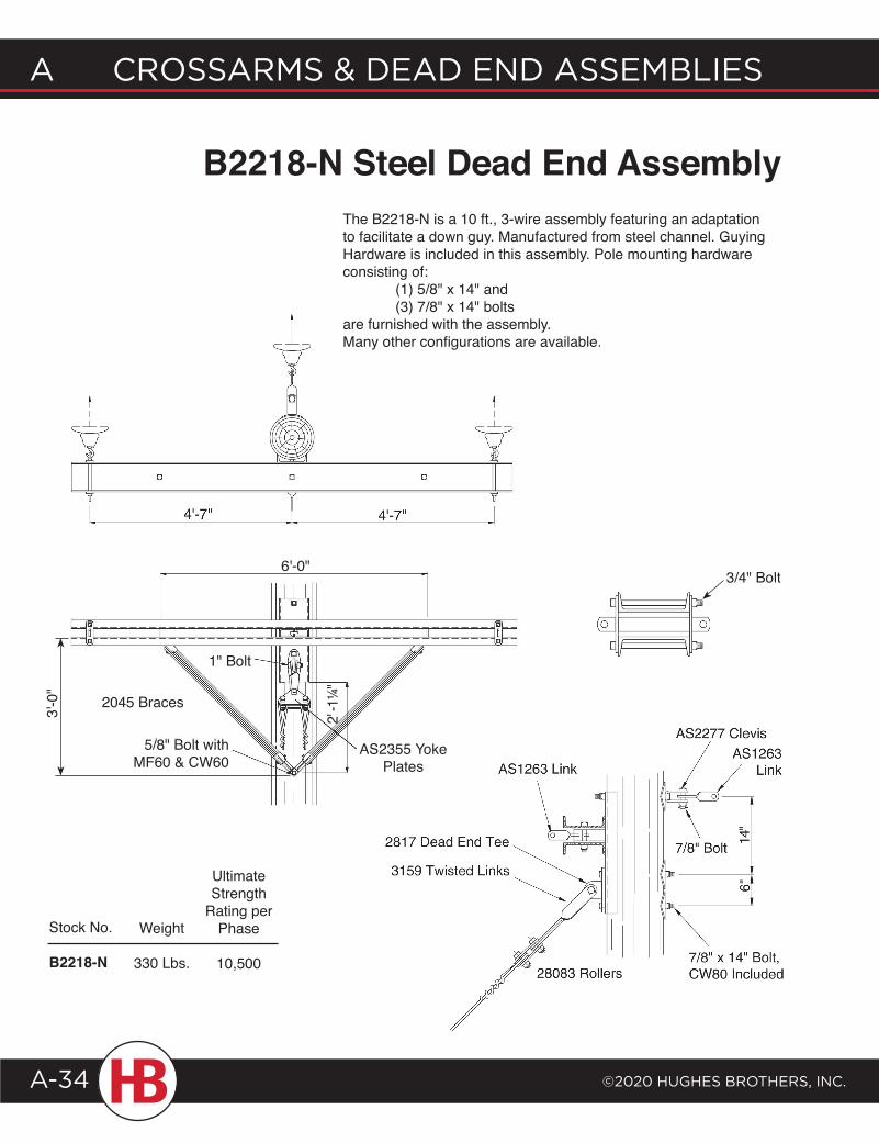
B2218-N Steel Dead End Assembly
Stock No.
B2218-N
The B2218-N is a 10 ft., 3-wire assembly featuring an adaptation to facilitate a down guy. Manufactured from steel channel. Guying Hardware is included in this assembly. Pole mounting hardware consisting of: (1) 5/8" x 14" and (3) 7/8" x 14" bolts are furnished with the assembly.Many other configurations are available.
Ultimate Strength
Rating per Phase
10,500
Weight
330 Lbs.
3/4" Bolt
AS2355 Yoke Plates
6'-0"
©2020 HugHes BrotHers, Inc.
A crossArms & deAd end AssemBlIes
A-35
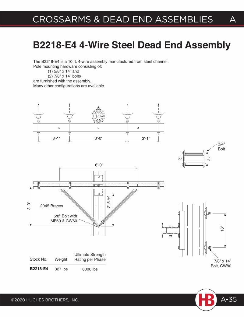
Crossarms & dead end assemblies a3'
-0"
Stock No.
B2218-E4
Ultimate Strength Rating per Phase
8000 lbs
Weight
327 lbs
The B2218-E4 is a 10 ft. 4-wire assembly manufactured from steel channel. Pole mounting hardware consisting of: (1) 5/8" x 14" and (2) 7/8" x 14" bolts are furnished with the assembly.Many other configurations are available.
B2218-E4 4-Wire Steel Dead End Assembly
3/4" Bolt
16"
7/8" x 14" Bolt, CW80
6'-0"
2045 Braces
2'
-53 /8
"
A CrossArms & deAd end Assemblies
©2020 HugHes brotHers, inC.A-36
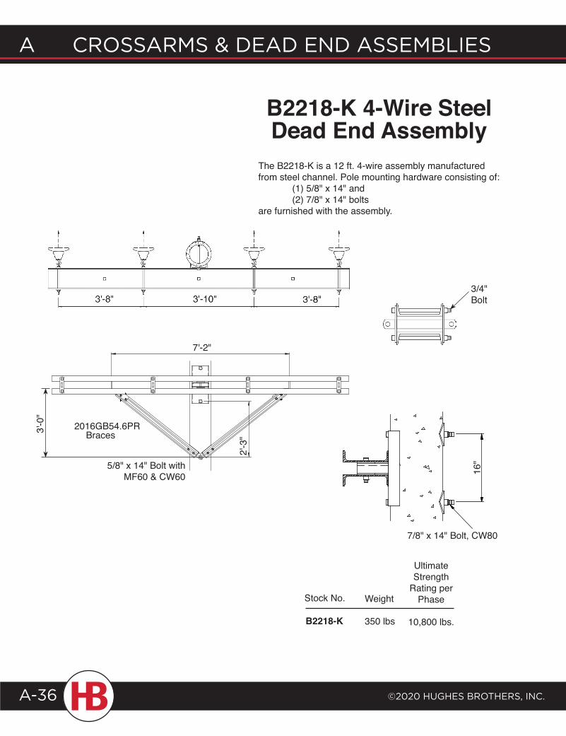
7'-2"
2'-3
"
5/8" x 14" Bolt with MF60 & CW60
Stock No. Weight
350 lbsB2218-K
Ultimate Strength
Rating per Phase
10,800 lbs.
B2218-K 4-Wire Steel Dead End Assembly
2016GB54.6PR
The B2218-K is a 12 ft. 4-wire assembly manufactured from steel channel. Pole mounting hardware consisting of: (1) 5/8" x 14" and (2) 7/8" x 14" bolts are furnished with the assembly.
7/8" x 14" Bolt, CW80
3/4" Bolt
16"
3'-0
"
Braces
©2020 HugHes BrotHers, Inc.
A crossArms & deAd end AssemBlIes
A-37
Crossarms & dead end assemblies a
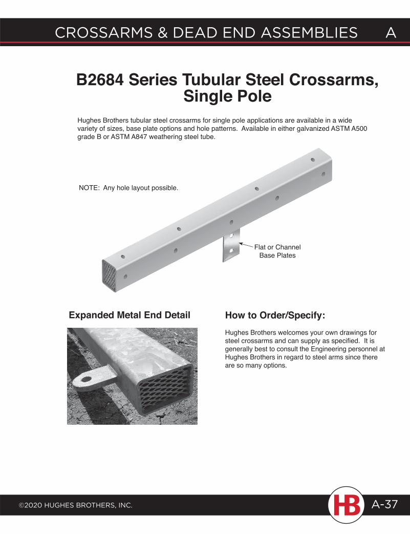
B2684 Series Tubular Steel Crossarms, Single Pole
Hughes Brothers tubular steel crossarms for single pole applications are available in a wide variety of sizes, base plate options and hole patterns. Available in either galvanized ASTM A500 grade B or ASTM A847 weathering steel tube.
How to Order/Specify:Hughes Brothers welcomes your own drawings for steel crossarms and can supply as specified. It is generally best to consult the Engineering personnel at Hughes Brothers in regard to steel arms since there are so many options.
Expanded Metal End Detail
Flat or Channel Base Plates
NOTE: Any hole layout possible.
A CrossArms & deAd end Assemblies
©2020 HugHes brotHers, inC.A-38
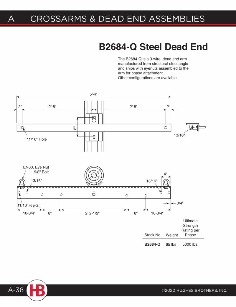
The B2684-Q is a 3-wire, dead end arm manufactured from structural steel angle and ships with eyenuts assembled to the arm for phase attachment.Other configurations are available.
2" 2"2'-8" 2'-8"
8"
5'-4"
13/16"
Stock No.
B2684-Q
Weight
65 lbs
Ultimate Strength
Rating per Phase
5000 lbs.
B2684-Q Steel Dead End
13/16"
EN60, Eye Nut 5/8" Bolt
11/16" (6 plcs,)
10-3/4" 2' 2-1/2" 8"8" 10-3/4"
4"
3/4"
13/16"
11/16" Hole
8"
©2020 HugHes BrotHers, Inc.
A crossArms & deAd end AssemBlIes
A-39
Crossarms & dead end assemblies a
Stock No.
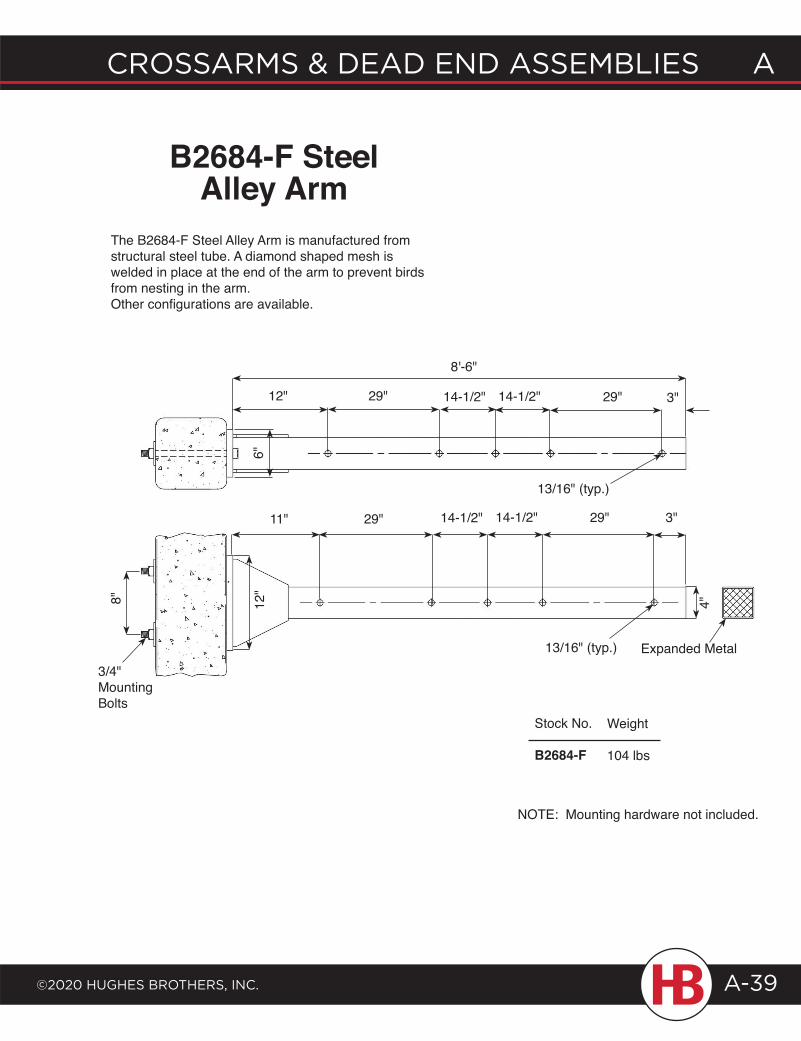
B2684-F
Weight
104 lbs
B2684-F Steel Alley Arm
The B2684-F Steel Alley Arm is manufactured from structural steel tube. A diamond shaped mesh is welded in place at the end of the arm to prevent birds from nesting in the arm. Other configurations are available.
29"14-1/2"29"12" 3"14-1/2"
8'-6"
11" 3"29" 14-1/2"
Expanded Metal
4"
13/16" (typ.)
6"12
"8"
3/4"MountingBolts
13/16" (typ.)
14-1/2" 29"
.
.
.
.
.
.
.
.
.
.
.
.
.
.
.
NOTE: Mounting hardware not included.
B R AC E SCrossarm Braces ....................... B-1Special Purpose Braces ........B-11Transmission .............................B-15 Knee & Vee ........................B-18 Tension ...............................B-22 X-Braces ............................B-25
braces b
©2020 HugHes brotHers, Inc. B-1
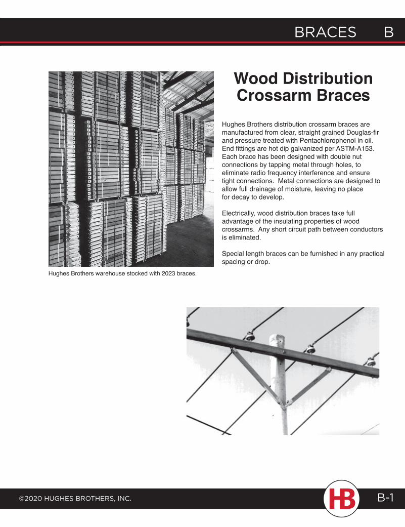
Hughes Brothers distribution crossarm braces are manufactured from clear, straight grained Douglas-fir and pressure treated with Pentachlorophenol in oil. End fittings are hot dip galvanized per ASTM-A153. Each brace has been designed with double nut connections by tapping metal through holes, to eliminate radio frequency interference and ensure tight connections. Metal connections are designed to allow full drainage of moisture, leaving no place for decay to develop.
Electrically, wood distribution braces take full advantage of the insulating properties of wood crossarms. Any short circuit path between conductors is eliminated.
Special length braces can be furnished in any practical spacing or drop.
Wood Distribution Crossarm Braces
Hughes Brothers warehouse stocked with 2023 braces.
B Braces
©2020 HugHes BrotHers, Inc.B-2
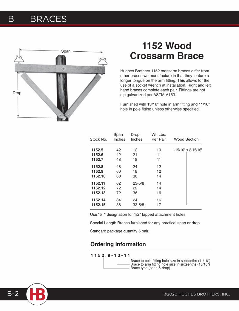
Hughes Brothers 1152 crossarm braces differ from other braces we manufacture in that they feature a longer tongue on the arm fitting. This allows for the use of a socket wrench at installation. Right and left hand braces complete each pair. Fittings are hot dip galvanized per ASTM-A153.
Furnished with 13/16" hole in arm fitting and 11/16" hole in pole fitting unless otherwise specified.
1152 WoodCrossarm Brace
Brace to pole fitting hole size in sixteenths (11/16")Brace to arm fitting hole size in sixteenths (13/16")Brace type (span & drop)
1 1 5 2 . 9 - 1 3 - 1 1
Ordering Information
Stock No.SpanInches
DropInches
Wt. Lbs.Per Pair Wood Section
1152.51152.61152.71152.81152.91152.101152.111152.121152.131152.141152.15
424248
486060
627272
8486
122118
241830
23-5/82236
2433-5/8
101111
121214
141416
1617
1-15/16" x 2-15/16"
Special Length Braces furnished for any practical span or drop.
Standard package quantity 5 pair.
Use "5T" designation for 1/2" tapped attachment holes.
Span
Drop
braces b
©2020 HugHes brotHers, Inc.
b braces
B-3
2002 InvertedWood Crossarm
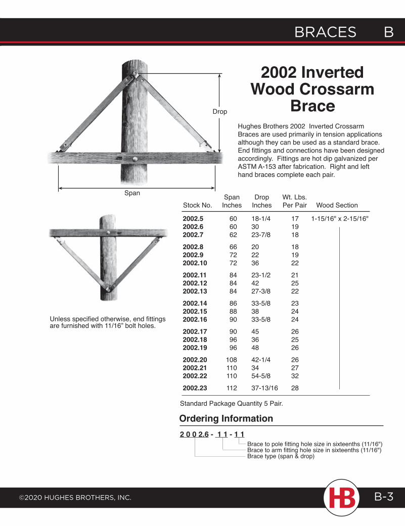
BraceHughes Brothers 2002 Inverted Crossarm Braces are used primarily in tension applications although they can be used as a standard brace. End fittings and connections have been designed accordingly. Fittings are hot dip galvanized per ASTM A-153 after fabrication. Right and left hand braces complete each pair.
Unless specified otherwise, end fittings are furnished with 11/16” bolt holes.
Brace to pole fitting hole size in sixteenths (11/16")Brace to arm fitting hole size in sixteenths (11/16")Brace type (span & drop)
2 0 0 2.6 - 1 1 - 1 1
Ordering Information
2002.52002.62002.72002.82002.92002.102002.112002.122002.132002.142002.152002.162002.172002.182002.192002.202002.212002.222002.23
Stock No.
606062
667272
848484
868890
909696
108110110
112
SpanInches
Drop Inches
18-1/43023-7/8
202236
23-1/24227-3/8
33-5/83833-5/8
453648
42-1/43454-5/8
37-13/16
Wt. Lbs.Per Pair
171918
181922
212522
232424
262526
262732
28
Wood Section
1-15/16" x 2-15/16"
Standard Package Quantity 5 Pair.
Drop
Span
B Braces
©2020 HugHes BrotHers, Inc.B-4
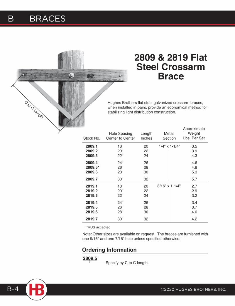
Hughes Brothers flat steel galvanized crossarm braces, when installed in pairs, provide an economical method for stabilizing light distribution construction.
2809 & 2819 FlatSteel Crossarm
Brace
ApproximateWeight
Lbs. Per SetMetal
SectionLength Inches
Hole SpacingCenter to CenterStock No.
2809.12809.22809.32809.42809.5*2809.62809.72819.12819.22819.32819.42819.52819.62819.7
18"20"22"
24"26"28"
30"
18"20"22"
24"26"28"
30"
202224
262830
32
202224
262830
32
1/4" x 1-1/4" 3.53.94.3
4.64.85.3
5.7
2.72.93.2
3.43.74.0
4.2
3/16" x 1-1/4"
*RUS accepted
Note: Other sizes are available on request. The braces are furnished with one 9/16" and one 7/16" hole unless specified otherwise.
Ordering Information2809.5
Specify by C to C length.
C to C Length
braces b
©2020 HugHes brotHers, Inc.
b braces
B-5
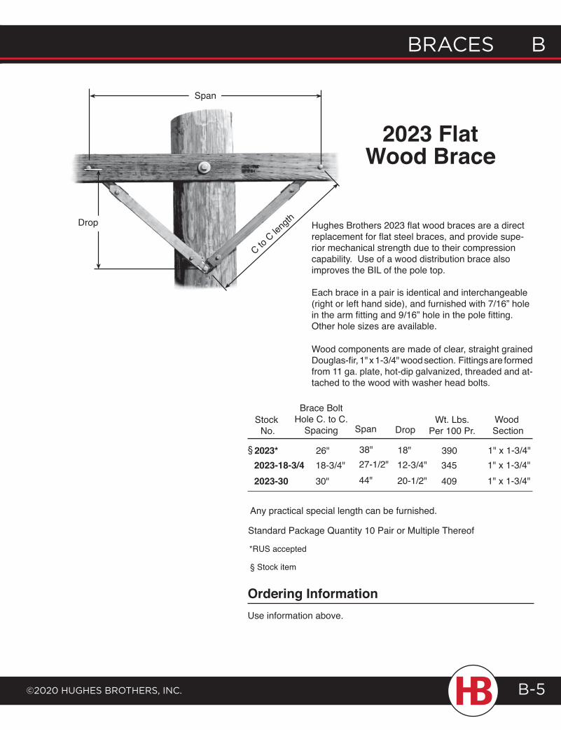
Stock No.
390
Wood Section
1" x 1-3/4"
Brace Bolt Hole C. to C.
SpacingWt. Lbs.
Per 100 Pr.DropSpan
26" 38" 18"345 1" x 1-3/4"18-3/4" 27-1/2" 12-3/4"409 1" x 1-3/4"44" 20-1/2"30"
2023*2023-18-3/42023-30
§
Any practical special length can be furnished.
Standard Package Quantity 10 Pair or Multiple Thereof
*RUS accepted
§ Stock item
Ordering InformationUse information above.
Wood components are made of clear, straight grained Douglas-fir, 1" x 1-3/4" wood section. Fittings are formed from 11 ga. plate, hot-dip galvanized, threaded and at-tached to the wood with washer head bolts.
2023 FlatWood Brace
Span
Drop
C to C len
gth Hughes Brothers 2023 flat wood braces are a direct replacement for flat steel braces, and provide supe-rior mechanical strength due to their compression capability. Use of a wood distribution brace also improves the BIL of the pole top.
Each brace in a pair is identical and interchangeable (right or left hand side), and furnished with 7/16” hole in the arm fitting and 9/16” hole in the pole fitting. Other hole sizes are available.
B Braces
©2020 HugHes BrotHers, Inc.B-6
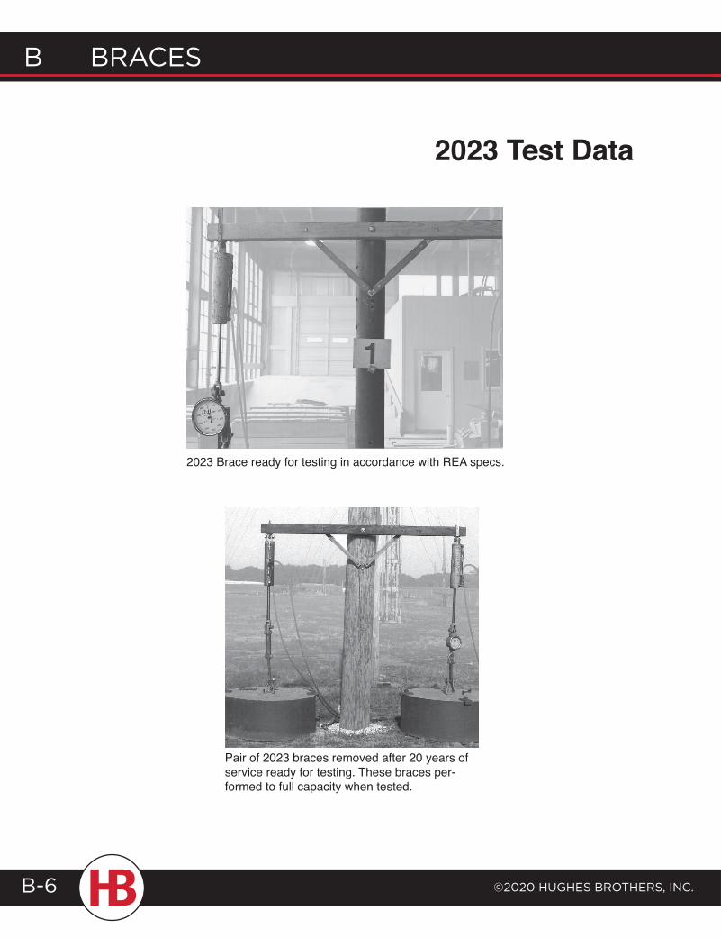
2023 Brace ready for testing in accordance with REA specs.
Pair of 2023 braces removed after 20 years of service ready for testing. These braces per-formed to full capacity when tested.
2023 Test Data
braces b
©2020 HugHes brotHers, Inc.
b braces
B-7
Drop
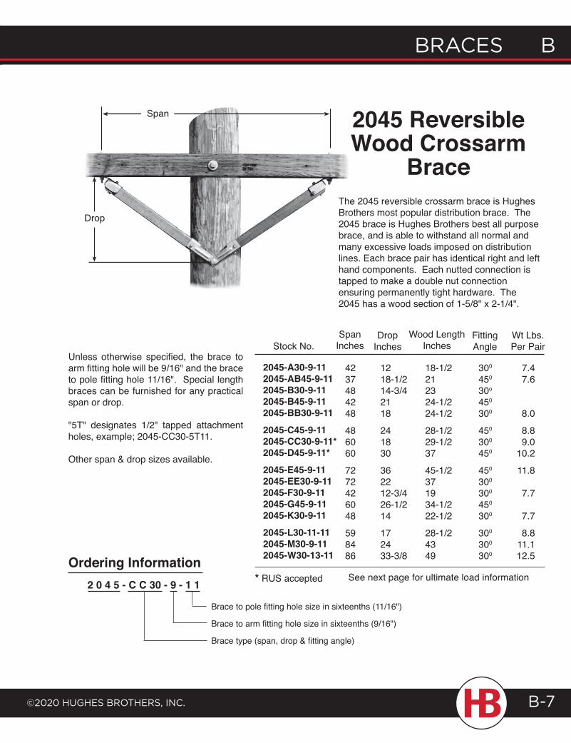
Span 2045 ReversibleWood Crossarm
BraceThe 2045 reversible crossarm brace is Hughes Brothers most popular distribution brace. The 2045 brace is Hughes Brothers best all purpose brace, and is able to withstand all normal and many excessive loads imposed on distribution lines. Each brace pair has identical right and left hand components. Each nutted connection is tapped to make a double nut connection ensuring permanently tight hardware. The 2045 has a wood section of 1-5/8" x 2-1/4".
Stock No.Span
Inches
4237484248
486060
7272426048
598486
1218-1/214-3/42118
241830
362212-3/426-1/214
172433-3/8
Drop Inches
18-1/2212324-1/224-1/2
28-1/229-1/237
45-1/2371934-1/222-1/2
28-1/24349
Wood LengthInches
300
450
30o
450
300
450
300
450
450
300
300
450
300
300
300
300
7.47.6
8.0
8.89.0
10.2
11.8
7.7
7.7
8.811.112.5
Wt Lbs.Per Pair
2045-A30-9-112045-AB45-9-112045-B30-9-112045-B45-9-112045-BB30-9-112045-C45-9-112045-CC30-9-11*2045-D45-9-11*2045-E45-9-112045-EE30-9-112045-F30-9-112045-G45-9-112045-K30-9-112045-L30-11-112045-M30-9-112045-W30-13-11
* RUS accepted2 0 4 5 - C C 30 - 9 - 1 1
Ordering Information
Unless otherwise specified, the brace to arm fitting hole will be 9/16" and the brace to pole fitting hole 11/16". Special length braces can be furnished for any practical span or drop.
"5T" designates 1/2" tapped attachment holes, example; 2045-CC30-5T11.
Other span & drop sizes available.
See next page for ultimate load information
FittingAngle
Brace to pole fitting hole size in sixteenths (11/16")
Brace to arm fitting hole size in sixteenths (9/16")
Brace type (span, drop & fitting angle)
B Braces
©2020 HugHes BrotHers, Inc.B-8
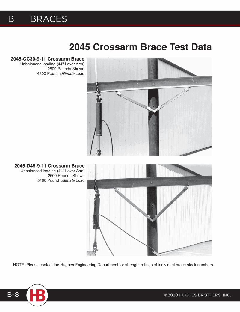
2045 Crossarm Brace Test Data
2045-D45-9-11 Crossarm BraceUnbalanced loading (44" Lever Arm)
2500 Pounds Shown5100 Pound Ultimate Load
2045-CC30-9-11 Crossarm BraceUnbalanced loading (44" Lever Arm)
2500 Pounds Shown4300 Pound Ultimate Load
NOTE: Please contact the Hughes Engineering Department for strength ratings of individual brace stock numbers.
braces b
©2020 HugHes brotHers, Inc.
b braces
B-9
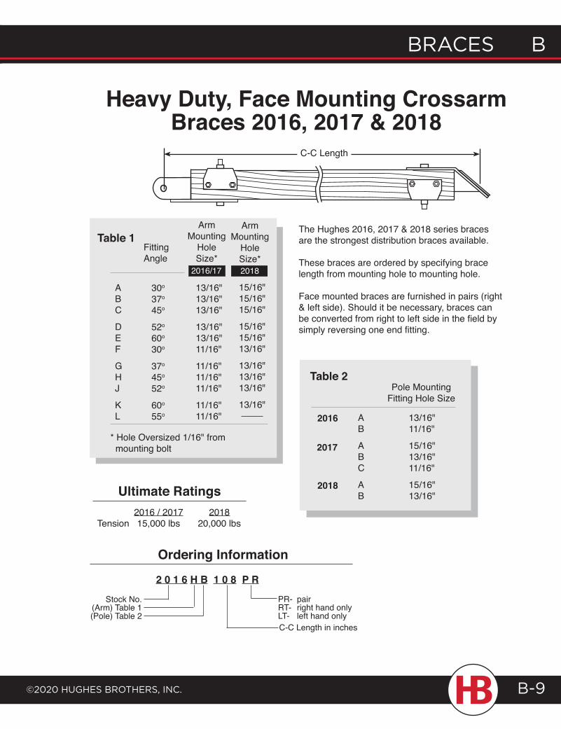
Heavy Duty, Face Mounting Crossarm Braces 2016, 2017 & 2018
30o
37o
45o
52o
60o
30o
37o
45o
52o
60o
55o
ABC
DEF
GHJ
KL
13/16"13/16"13/16"
13/16"13/16"11/16"
11/16"11/16"11/16"
11/16"11/16"
FittingAngle
ArmMounting
HoleSize*
* Hole Oversized 1/16" from mounting bolt
Table 1The Hughes 2016, 2017 & 2018 series braces are the strongest distribution braces available.
These braces are ordered by specifying brace length from mounting hole to mounting hole.
Face mounted braces are furnished in pairs (right & left side). Should it be necessary, braces can be converted from right to left side in the field by simply reversing one end fitting.
Table 2Pole Mounting
Fitting Hole Size
13/16"11/16"
15/16"13/16"11/16"
15/16"13/16"
AB
ABC
AB
2016
2017
2018Ultimate Ratings 2016 / 2017 2018 Tension 15,000 lbs 20,000 lbs
2 0 1 6 H B 1 0 8 P R
Stock No.(Arm) Table 1(Pole) Table 2
C-C Length in inches
Ordering Information
PR- pairRT- right hand onlyLT- left hand only
15/16"15/16"15/16"
15/16"15/16"13/16"
13/16"13/16"13/16"
13/16"
ArmMounting
HoleSize*
2016/17 2018
C-C Length
B Braces
©2020 HugHes BrotHers, Inc.B-10
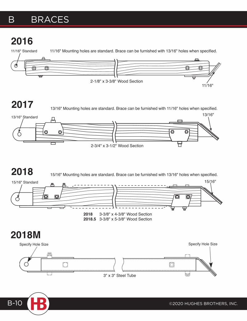
2017
11/16" Standard
2-1/8" x 3-3/8" Wood Section11/16"
15/16" Standard
2018 3-3/8" x 4-3/8" Wood Section2018.5 3-3/8" x 5-3/8" Wood Section
15/16" Mounting holes are standard. Brace can be furnished with 13/16" holes when specified.2018
13/16" Mounting holes are standard. Brace can be furnished with 11/16" holes when specified.
15/16"
201611/16" Mounting holes are standard. Brace can be furnished with 13/16" holes when specified.
2-3/4" x 3-1/2" Wood Section
13/16" Standard 13/16"
2018MSpecify Hole Size Specify Hole Size
3" x 3" Steel Tube
braces b
©2020 HugHes brotHers, Inc.
b braces
B-11
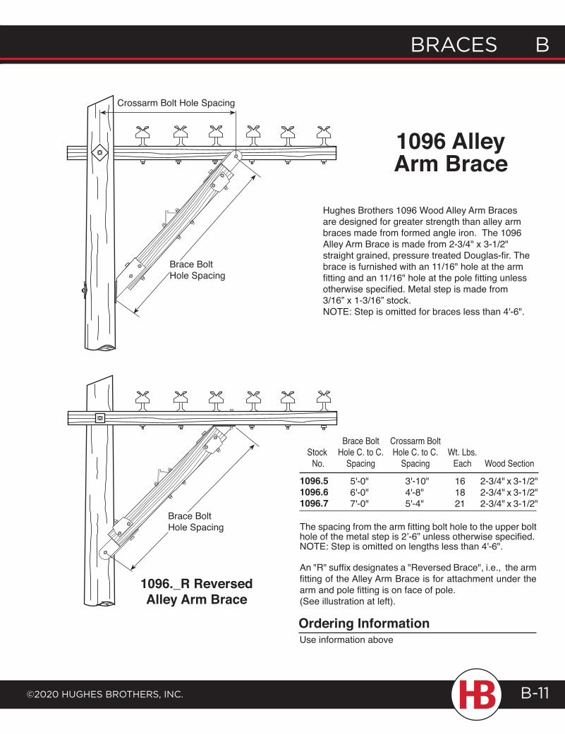
1096._R Reversed Alley Arm Brace
Wood SectionWt. Lbs.
Each
Crossarm BoltHole C. to C.
Spacing
Brace BoltHole C. to C.
SpacingStock No.
2-3/4" x 3-1/2"2-3/4" x 3-1/2"2-3/4" x 3-1/2"
161821
3'-10"4'-8"5'-4"
5'-0"6'-0"7'-0"
1096.51096.61096.7
The spacing from the arm fitting bolt hole to the upper bolt hole of the metal step is 2’-6” unless otherwise specified.NOTE: Step is omitted on lengths less than 4'-6".
An "R" suffix designates a "Reversed Brace", i.e., the arm fitting of the Alley Arm Brace is for attachment under the arm and pole fitting is on face of pole. (See illustration at left).
Ordering InformationUse information above
Brace Bolt Hole Spacing
Crossarm Bolt Hole Spacing
1096 AlleyArm Brace
Hughes Brothers 1096 Wood Alley Arm Braces are designed for greater strength than alley arm braces made from formed angle iron. The 1096 Alley Arm Brace is made from 2-3/4" x 3-1/2" straight grained, pressure treated Douglas-fir. The brace is furnished with an 11/16" hole at the arm fitting and an 11/16" hole at the pole fitting unless otherwise specified. Metal step is made from 3/16” x 1-3/16” stock.NOTE: Step is omitted for braces less than 4'-6".
Specify Hole Size
Brace Bolt Hole Spacing
B Braces
©2020 HugHes BrotHers, Inc.B-12
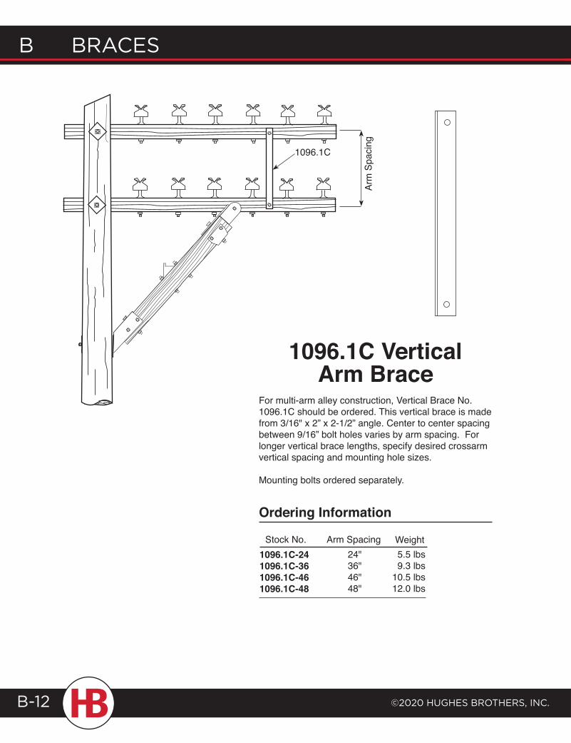
1096.1C
1096.1C VerticalArm Brace
For multi-arm alley construction, Vertical Brace No. 1096.1C should be ordered. This vertical brace is made from 3/16" x 2” x 2-1/2” angle. Center to center spacing between 9/16” bolt holes varies by arm spacing. For longer vertical brace lengths, specify desired crossarm vertical spacing and mounting hole sizes.
Mounting bolts ordered separately.
1096.1C-241096.1C-361096.1C-461096.1C-48
24"36"46"48"
Stock No. Arm Spacing Weight
Arm
Spa
cing
5.5 lbs9.3 lbs
10.5 lbs12.0 lbs
Ordering Information

braces b
©2020 HugHes brotHers, Inc.
b braces
B-13
AS2329 Welded SteelAlley Arm Brace
The Hughes Brothers AS2329 Brace is manufactured from plate which is notched, bent and welded.
B
AS2329AS2329-D
2'-6"
Stock No. "A" "B"
16.3 lbs
16.3 lbs
Weight
- Same as AS2329 but reversed so that flat end mounts against pole.
A
B 1097 Steel Alley Arm BraceThe 1097 Steel Alley Arm Brace is used where the arms are mounted on one side of the pole. The brace end is flattened for the pole or arm attachment. Manufactured from plate, which is folded and bent.
"A"
1097.1A60-91097.1A84-11
Stock No.
60"84"
30"30"
"B"Top Mtg.
Hole
NOTE:To order the brace reversed such that the brace mounts under the crossarm, add an "R" to the part number (i.e. 1097.1AR60-9).
Ordering Information
7'-0"
9/16"11/16"
(2) 9-16' Holes on 2-1/2" Centers
11/16"Hole
11/16" Hole
A
B Braces
©2020 HugHes BrotHers, Inc.B-14
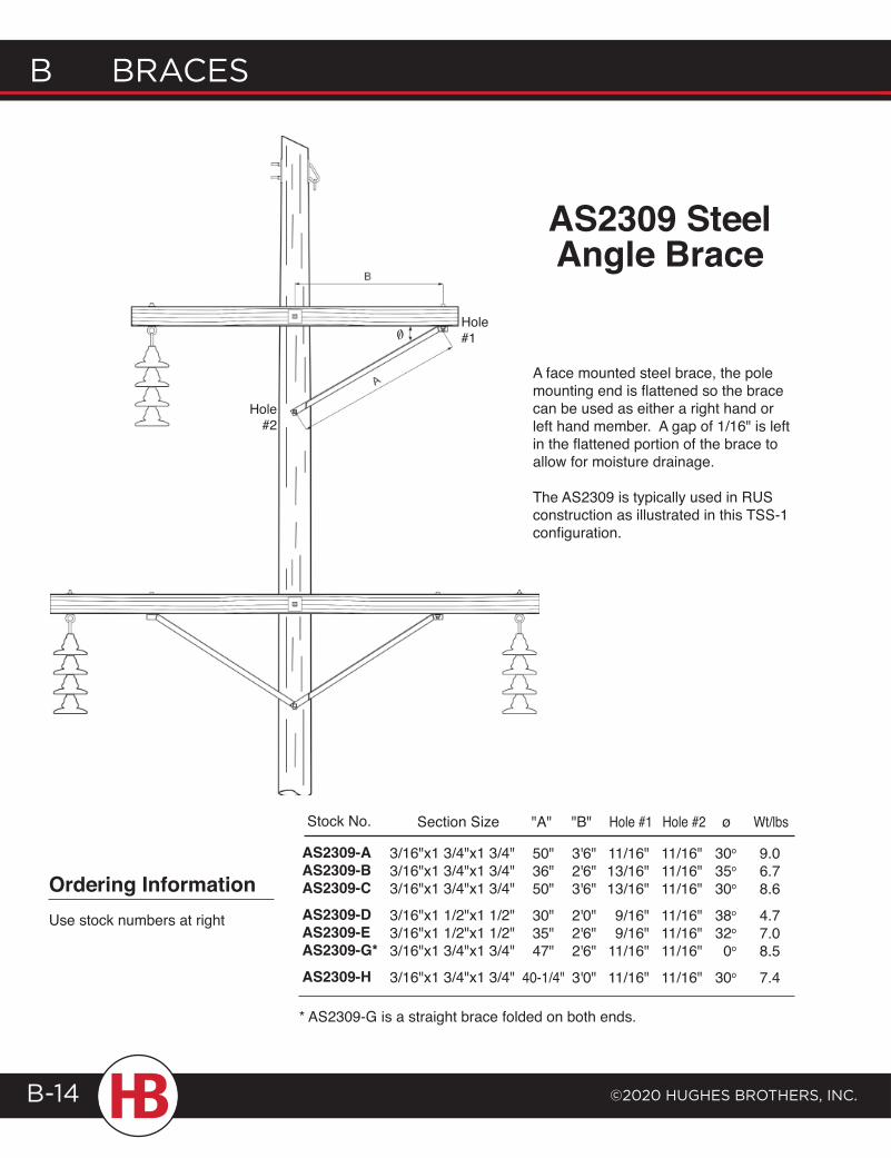
A face mounted steel brace, the pole mounting end is flattened so the brace can be used as either a right hand or left hand member. A gap of 1/16" is left in the flattened portion of the brace to allow for moisture drainage.
The AS2309 is typically used in RUS construction as illustrated in this TSS-1 configuration.
AS2309 SteelAngle Brace
* AS2309-G is a straight brace folded on both ends.
30o
35o
30o
38o
32o
0o
30o
ø
11/16"11/16"11/16"
11/16"11/16"11/16"
11/16"
Hole #2
11/16"13/16"13/16"
9/16"9/16"
11/16"
11/16"
Hole #1
3'6"2'6"3'6"
2'0"2'6"2'6"
3'0"
"B""A"
50"36"50"
30"35"47"
40-1/4"
AS2309-AAS2309-BAS2309-CAS2309-DAS2309-EAS2309-G*AS2309-H
Stock No.
9.06.78.6
4.77.08.5
7.4
Wt/lbs
3/16"x1 3/4"x1 3/4"3/16"x1 3/4"x1 3/4"3/16"x1 3/4"x1 3/4"
3/16"x1 1/2"x1 1/2"3/16"x1 1/2"x1 1/2"3/16"x1 3/4"x1 3/4"
3/16"x1 3/4"x1 3/4"
Section Size
Ordering InformationUse stock numbers at right
Hole#2
Hole#10/
braces b
©2020 HugHes brotHers, Inc.
b braces
B-15
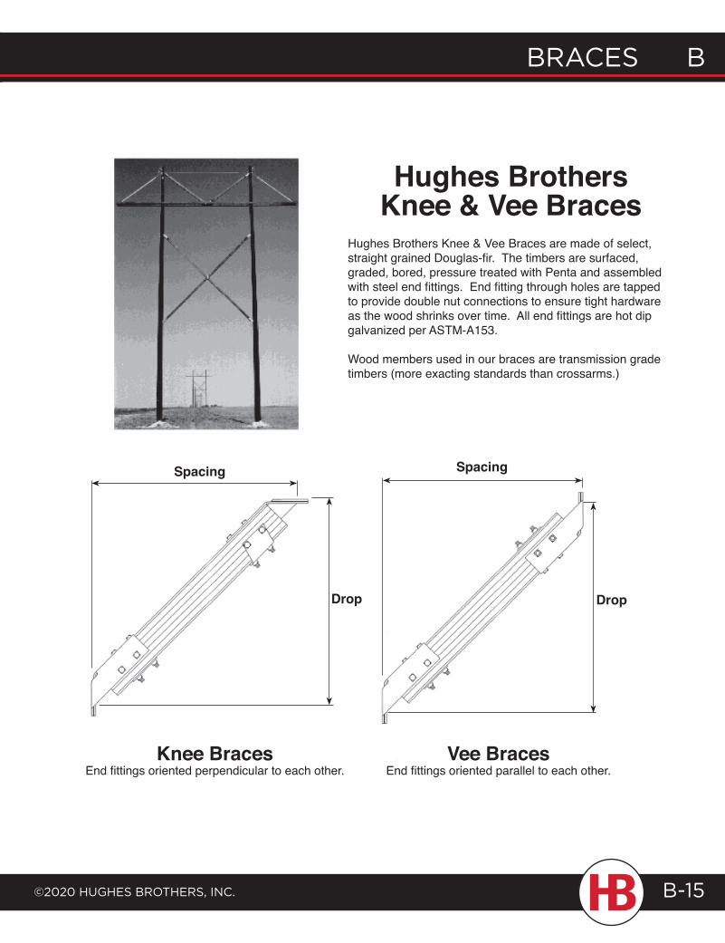
Hughes Brothers Knee & Vee Braces are made of select, straight grained Douglas-fir. The timbers are surfaced, graded, bored, pressure treated with Penta and assembled with steel end fittings. End fitting through holes are tapped to provide double nut connections to ensure tight hardware as the wood shrinks over time. All end fittings are hot dip galvanized per ASTM-A153.
Wood members used in our braces are transmission grade timbers (more exacting standards than crossarms.)
Knee Braces End fittings oriented perpendicular to each other.
Vee Braces End fittings oriented parallel to each other.
Spacing
Drop
Spacing
Drop
Hughes Brothers Knee & Vee Braces
B Braces
©2020 HugHes BrotHers, Inc.B-16
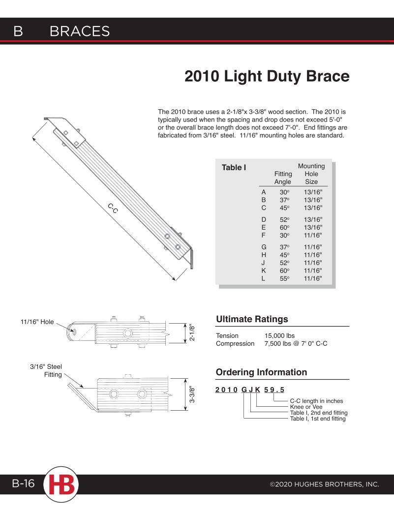
C-C
The 2010 brace uses a 2-1/8"x 3-3/8" wood section. The 2010 is typically used when the spacing and drop does not exceed 5'-0" or the overall brace length does not exceed 7'-0". End fittings are fabricated from 3/16" steel. 11/16" mounting holes are standard.
2010 Light Duty Brace
11/16" Hole
3/16" SteelFitting
Ultimate RatingsTension 15,000 lbsCompression 7,500 lbs @ 7' 0" C-C
2 0 1 0 G J K 5 9 . 5C-C length in inchesKnee or VeeTable I, 2nd end fittingTable I, 1st end fitting
Ordering Information
13/16"13/16"13/16"
13/16"13/16"11/16"
11/16"11/16"11/16"11/16"11/16"
MountingHoleSize
30o
37o
45o
52o
60o
30o
37o
45o
52o
60o
55o
FittingAngle
ABC
DEF
GHJKL
Table I
2-1/
8"3-
3/8"
braces b
©2020 HugHes brotHers, Inc.
b braces
B-17
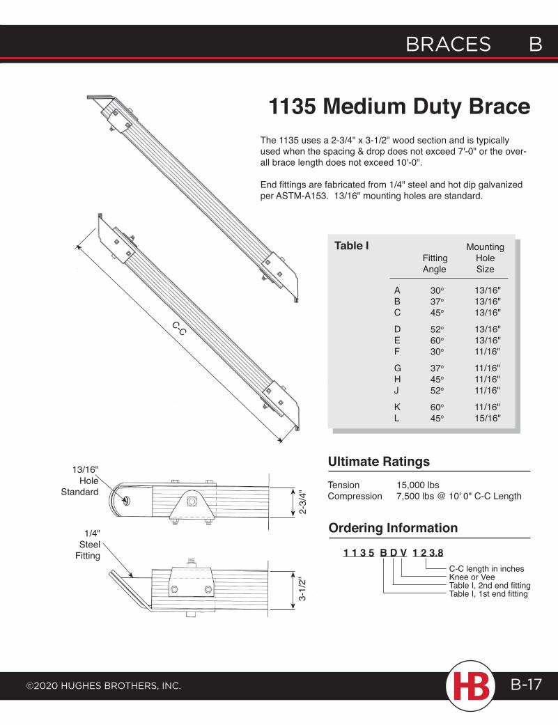
13/16" Hole
Standard
1/4" Steel
Fitting
2-3/
4"3-
1/2"
1135 Medium Duty BraceThe 1135 uses a 2-3/4" x 3-1/2" wood section and is typically used when the spacing & drop does not exceed 7'-0" or the over-all brace length does not exceed 10'-0".
End fittings are fabricated from 1/4" steel and hot dip galvanized per ASTM-A153. 13/16" mounting holes are standard.
Ultimate RatingsTension 15,000 lbsCompression 7,500 lbs @ 10' 0" C-C Length
Ordering Information
1 1 3 5 B D V 1 2 3.8C-C length in inchesKnee or VeeTable I, 2nd end fittingTable I, 1st end fitting
30o
37o
45o
52o
60o
30o
37o
45o
52o
60o
45o
ABC
DEF
GHJ
KL
13/16"13/16"13/16"
13/16"13/16"11/16"
11/16"11/16"11/16"
11/16"15/16"
FittingAngle
MountingHoleSize
Table I
C-C
B Braces
©2020 HugHes BrotHers, Inc.B-18
2025.5
2025
C-C
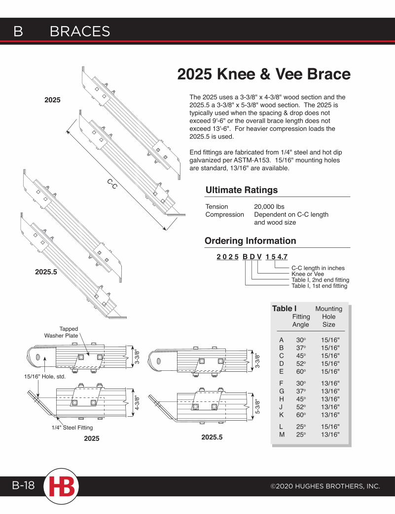
2025 Knee & Vee BraceThe 2025 uses a 3-3/8" x 4-3/8" wood section and the 2025.5 a 3-3/8" x 5-3/8" wood section. The 2025 is typically used when the spacing & drop does not exceed 9'-6" or the overall brace length does not exceed 13'-6". For heavier compression loads the 2025.5 is used.
End fittings are fabricated from 1/4" steel and hot dip galvanized per ASTM-A153. 15/16" mounting holes are standard, 13/16" are available.
MountingHoleSize
15/16"15/16"15/16"15/16"15/16"
13/16"13/16"13/16"13/16"13/16"
15/16"13/16"
FittingAngle
30o
37o
45o
52o
60o
30o
37o
45o
52o
60o
25o
25o
ABCDE
FGHJK
LM
Table I
Ultimate RatingsTension 20,000 lbsCompression Dependent on C-C length and wood size
2 0 2 5 B D V 1 5 4.7C-C length in inchesKnee or VeeTable I, 2nd end fittingTable I, 1st end fitting
Ordering Information
1/4" Steel Fitting2025.52025
Tapped Washer Plate
15/16" Hole, std.
3-3/
8"
4-3/
8"
5-3/
8"
3-3/
8"
braces b
©2020 HugHes brotHers, Inc.
b braces
B-19
C-C
MountingHoleSize
15/16"15/16"15/16"15/16"15/16"
13/16"13/16"13/16"13/16"13/16"
15/16"
13/16"
FittingAngle
30o
37o
45o
52o
60o
30o
37o
45o
52o
60o
25o
25o
ABCDE
FGHJK
L
M
Table I
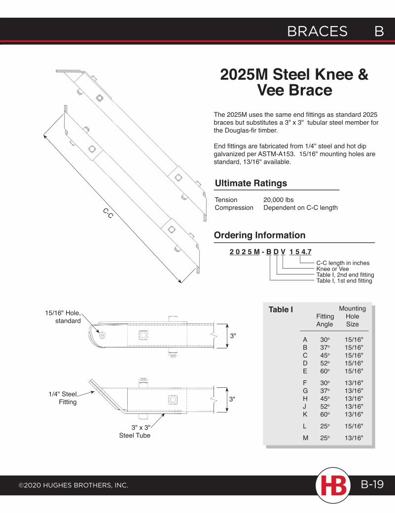
The 2025M uses the same end fittings as standard 2025 braces but substitutes a 3" x 3" tubular steel member for the Douglas-fir timber.
End fittings are fabricated from 1/4" steel and hot dip galvanized per ASTM-A153. 15/16" mounting holes are standard, 13/16" available.
2025M Steel Knee & Vee Brace
Ordering Information2 0 2 5 M - B D V 1 5 4.7
C-C length in inchesKnee or VeeTable I, 2nd end fittingTable I, 1st end fitting
Ultimate RatingsTension 20,000 lbsCompression Dependent on C-C length
15/16" Hole,standard
3"
3"
3" x 3" Steel Tube
1/4" Steel Fitting
B Braces
©2020 HugHes BrotHers, Inc.B-20
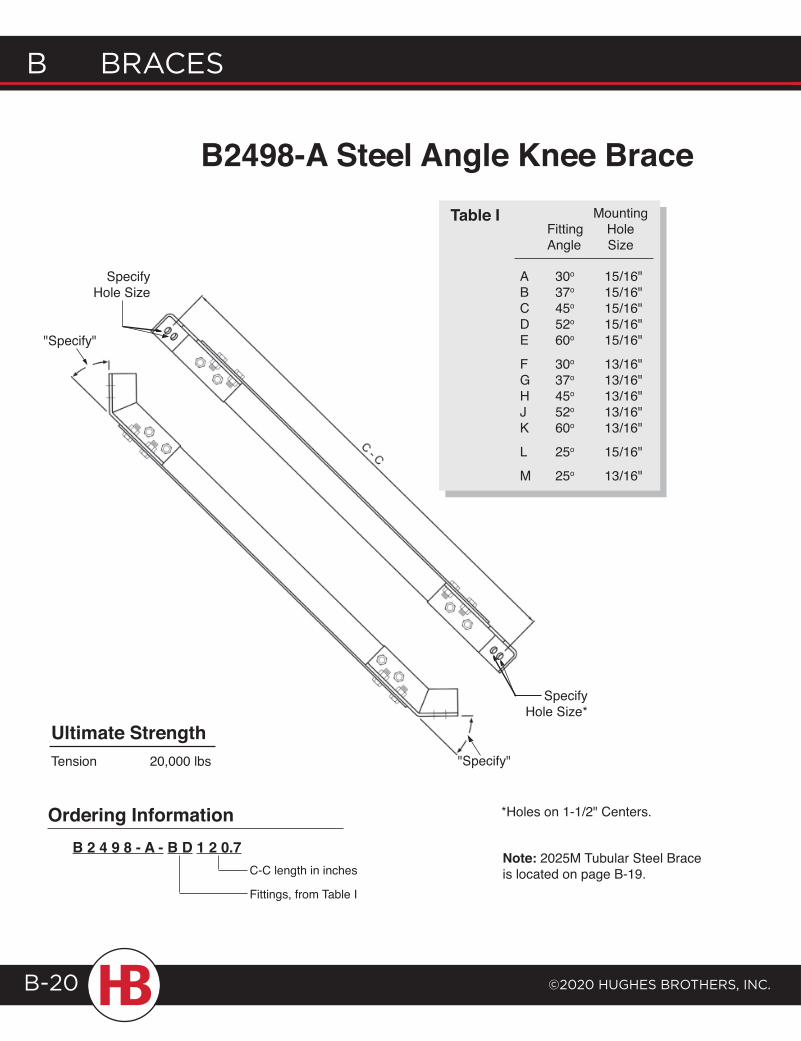
B2498-A Steel Angle Knee Brace
Specify Hole Size
Specify Hole Size*
"Specify"
"Specify"
MountingHoleSize
15/16"15/16"15/16"15/16"15/16"
13/16"13/16"13/16"13/16"13/16"
15/16"
13/16"
FittingAngle
30o
37o
45o
52o
60o
30o
37o
45o
52o
60o
25o
25o
ABCDE
FGHJK
L
M
Table I
Note: 2025M Tubular Steel Brace is located on page B-19.
Ultimate StrengthTension 20,000 lbs
B 2 4 9 8 - A - B D 1 2 0.7C-C length in inches
Fittings, from Table I
Ordering Information *Holes on 1-1/2" Centers.
braces b
©2020 HugHes brotHers, Inc.
b braces
B-21
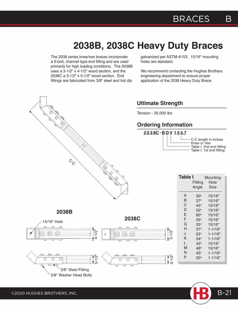
2038C
4-1/
2"3-
1/2"
3/8" Steel Fitting5/8" Washer Head Bolts
5-1/
2"3-
1/2"
2038B
2038B, 2038C Heavy Duty BracesThe 2038 series knee/vee braces incorporate a 6-bolt, channel type end fitting and are used primarily for high loading conditions. The 2038B uses a 3-1/2" x 4-1/2" wood section, and the 2038C a 3-1/2" x 5-1/2" wood section. End fittings are fabricated from 3/8" steel and hot dip
MountingHoleSize
15/16"15/16"15/16"15/16"15/16"15/16"15/16"1-1/16"1-1/16"1-1/16"15/16"15/16"1-1/16"1-1/16"
FittingAngle
30o
37o
45o
52o
60o
55o
25o
37o
52o
34o
42o
48o
45o
30o
ABCDEFGHJKLMNP
Table I
C-C length in inchesKnee or VeeTable I, 2nd end fittingTable I, 1st end fitting
2 0 3 8C - B D V 1 5 4.7Ordering Information
Tension - 35,000 lbs
Ultimate Strength
15/16" Hole
C-C
galvanized per ASTM-A153. 15/16" mounting holes are standard.
We recommend contacting the Hughes Brothers engineering department to ensure proper application of the 2038 Heavy Duty Brace.
B Braces
©2020 HugHes BrotHers, Inc.B-22
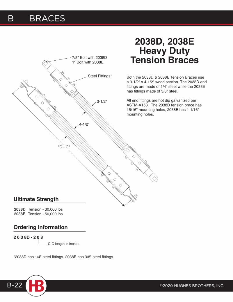
7/8" Bolt with 2038D1" Bolt with 2038E
Steel Fittings* Both the 2038D & 2038E Tension Braces use a 3-1/2" x 4-1/2" wood section. The 2038D end fittings are made of 1/4" steel while the 2038E has fittings made of 3/8" steel.
All end fittings are hot dip galvanized per ASTM-A153. The 2038D tension brace has 15/16" mounting holes, 2038E has 1-1/16" mounting holes.
2038D, 2038E Heavy Duty
Tension Braces
Ultimate Strength2038D Tension - 30,000 lbs2038E Tension - 50,000 lbs
Ordering Information
2 0 3 8D - 2 0 8C-C length in inches
*2038D has 1/4" steel fittings. 2038E has 3/8" steel fittings.
4-1/2"
3-1/2"
"C - C"
braces b
©2020 HugHes brotHers, Inc.
b braces
B-23
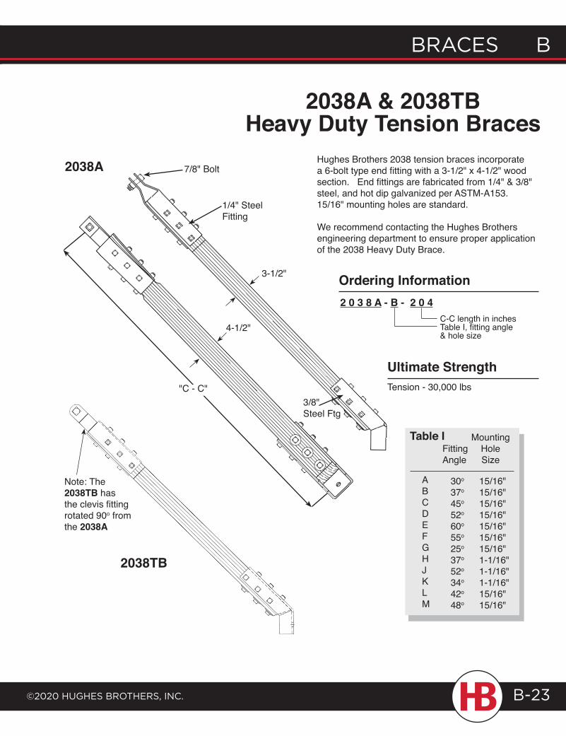
7/8" Bolt
1/4" SteelFitting
3-1/2"
4-1/2"
3/8" Steel Ftg
2038A & 2038TB Heavy Duty Tension Braces
Hughes Brothers 2038 tension braces incorporate a 6-bolt type end fitting with a 3-1/2" x 4-1/2" wood section. End fittings are fabricated from 1/4" & 3/8" steel, and hot dip galvanized per ASTM-A153. 15/16" mounting holes are standard.
We recommend contacting the Hughes Brothers engineering department to ensure proper application of the 2038 Heavy Duty Brace.
C-C length in inchesTable I, fitting angle & hole size
2 0 3 8 A - B - 2 0 4
Ordering Information
Ultimate StrengthTension - 30,000 lbs
2038A
Note: The 2038TB has the clevis fitting rotated 90o fromthe 2038A
"C - C"
2038TB
MountingHoleSize
15/16"15/16"15/16"15/16"15/16"15/16"15/16"1-1/16"1-1/16"1-1/16"15/16"15/16"
FittingAngle
30o
37o
45o
52o
60o
55o
25o
37o
52o
34o
42o
48o
ABCDEFGHJKLM
Table I
B Braces
©2020 HugHes BrotHers, Inc.B-24
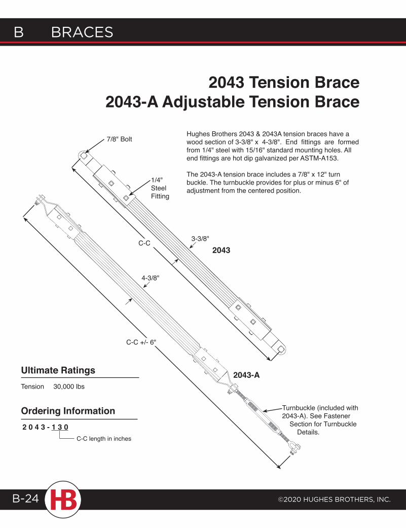
3-3/8"
1/4" Steel Fitting
7/8" Bolt
Turnbuckle (included with 2043-A). See Fastener Section for Turnbuckle Details.
2043-AUltimate RatingsTension 30,000 lbs
Ordering Information
C-C length in inches
2 0 4 3 - 1 3 0
2043 Tension Brace2043-A Adjustable Tension Brace
Hughes Brothers 2043 & 2043A tension braces have a wood section of 3-3/8" x 4-3/8". End fittings are formed from 1/4" steel with 15/16" standard mounting holes. All end fittings are hot dip galvanized per ASTM-A153.
The 2043-A tension brace includes a 7/8" x 12" turn buckle. The turnbuckle provides for plus or minus 6" of adjustment from the centered position.
4-3/8"
2043
C-C +/- 6"
C-C
braces b
©2020 HugHes brotHers, Inc.
b braces
B-25
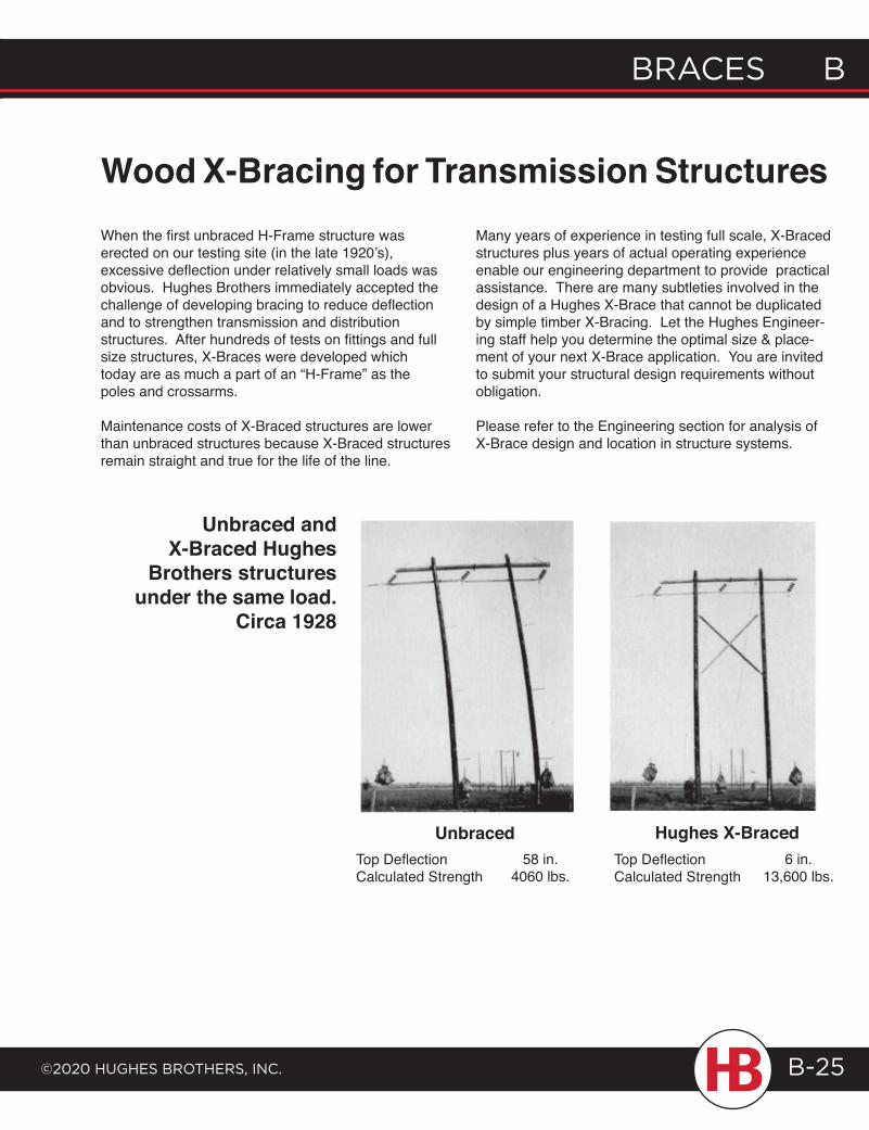
Wood X-Bracing for Transmission StructuresWhen the first unbraced H-Frame structure was erected on our testing site (in the late 1920’s), excessive deflection under relatively small loads was obvious. Hughes Brothers immediately accepted the challenge of developing bracing to reduce deflection and to strengthen transmission and distribution structures. After hundreds of tests on fittings and full size structures, X-Braces were developed which today are as much a part of an “H-Frame” as the poles and crossarms.
Maintenance costs of X-Braced structures are lower than unbraced structures because X-Braced structures remain straight and true for the life of the line.
Many years of experience in testing full scale, X-Braced structures plus years of actual operating experience enable our engineering department to provide practical assistance. There are many subtleties involved in the design of a Hughes X-Brace that cannot be duplicated by simple timber X-Bracing. Let the Hughes Engineer-ing staff help you determine the optimal size & place-ment of your next X-Brace application. You are invited to submit your structural design requirements without obligation.
Please refer to the Engineering section for analysis of X-Brace design and location in structure systems.
Unbraced Hughes X-BracedTop DeflectionCalculated Strength
58 in.4060 lbs.
Top DeflectionCalculated Strength
6 in.13,600 lbs.
Unbraced and X-Braced Hughes
Brothers structures under the same load.
Circa 1928
B Braces
©2020 HugHes BrotHers, Inc.B-26
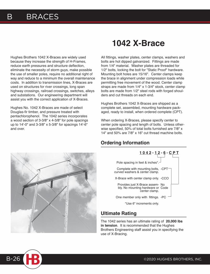
Hughes Brothers 1042 X-Braces are widely used because they increase the strength of H-Frames, reduce earth pressures and structure deflection, eliminate the necessity of storm guys, make possible the use of smaller poles, require no additional right of way and reduce to a minimum the overall maintenance costs. In addition to transmission lines, X-Braces are used on structures for river crossings, long span highway crossings, railroad crossings, switches, alleys and substations. Our engineering department will assist you with the correct application of X-Braces.
Hughes No. 1042 X-Braces are made of select Douglas-fir timber, and pressure treated with pentachlorophenol. The 1042 series incorporates a wood section of 3-3/8" x 4-3/8" for pole spacings up to 14'-0" and 3-3/8" x 5-3/8" for spacings 14'-6" and over.
Ordering Information
Pole spacing in feet & inches*.
Complete with mounting bolts, curved washers & center clamp.
X-Brace with center clamp only.
Provides just X-Brace assem-bly. No mounting hardware or
center clamp.
One member only with fittings.
*Use 6" increments only.
-CPT
-CCO
No Code
-PC
1 0 4 2 - 1 2 - 6 - C P T
The 1042 series has an ultimate rating of 20,000 lbs in tension. It is recommended that the Hughes Brothers Engineering staff assist you in specifying the use of X-Bracing.
Ultimate Rating
1042 X-BraceAll fittings, washer plates, center clamps, washers and bolts are hot dipped galvanized. Fittings are made from 1/4" material. Washer plates are threaded for 1/2" bolts, locking the bolt for "Static Proof" hardware. Mounting bolt holes are 15/16". Center clamps keep the brace in alignment under compression loads while permitting free movement of the wood. Center clamp straps are made from 1/4" x 1-3/4" stock, center clamp bolts are made from 1/2" steel rods with forged shoul-ders and cut threads on each end.
Hughes Brothers 1042 X-Braces are shipped as a complete set, assembled, mounting hardware pack-aged, ready to install, when ordered complete (CPT).
When ordering X-Braces, please specify center to center pole spacing and length of bolts. Unless other-wise specified, 50% of total bolts furnished are 7/8" x 14" and 50% are 7/8" x 16" cut thread machine bolts.
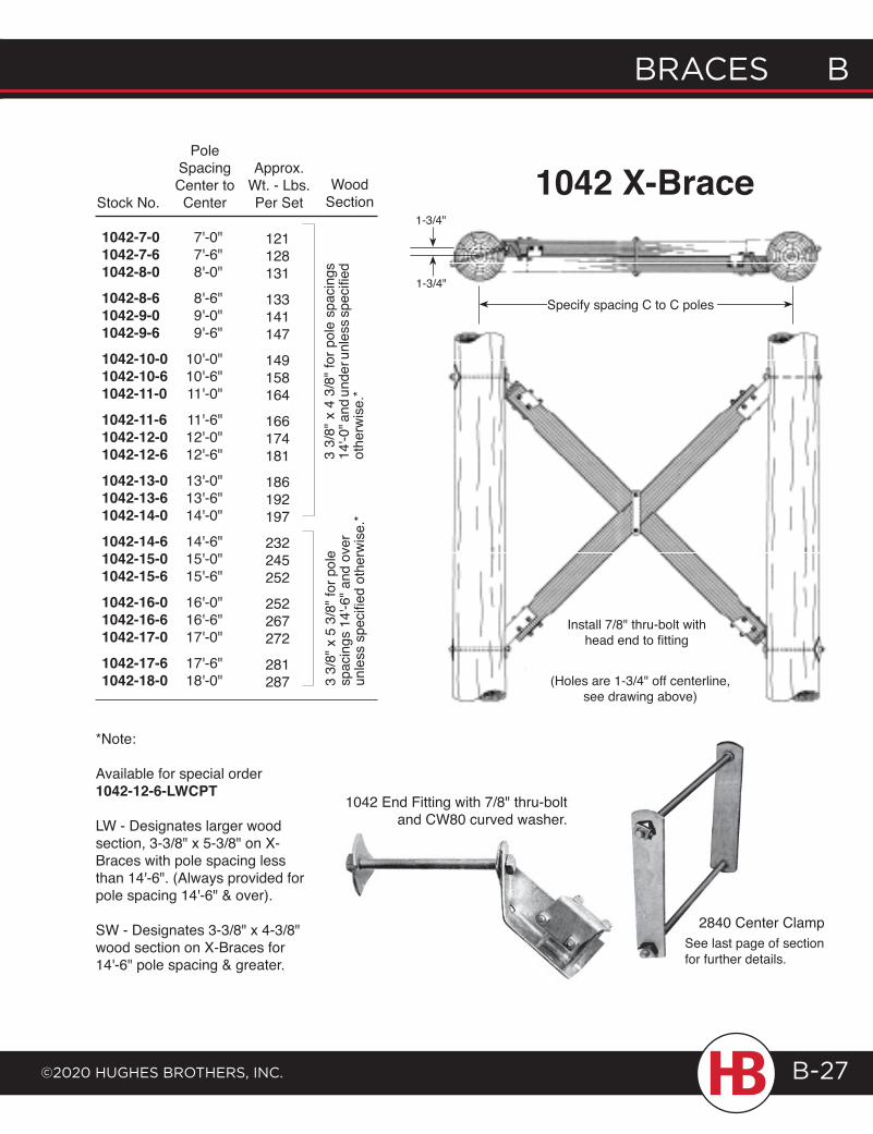
braces b
©2020 HugHes brotHers, Inc.
b braces
B-27
1042 X-Brace1042-7-01042-7-61042-8-01042-8-61042-9-01042-9-61042-10-01042-10-61042-11-01042-11-61042-12-01042-12-61042-13-01042-13-61042-14-01042-14-61042-15-01042-15-61042-16-01042-16-61042-17-01042-17-61042-18-0
Stock No.
7'-0"7'-6"8'-0"
8'-6"9'-0"9'-6"
10'-0"10'-6"11'-0"
11'-6"12'-0"12'-6"
13'-0"13'-6"14'-0"
14'-6"15'-0"15'-6"
16'-0"16'-6"17'-0"
17'-6"18'-0"
PoleSpacingCenter toCenter
121128131
133141147
149158164
166174181
186192197
232245252
252267272
281287
Approx.Wt. - Lbs.Per Set
3 3/
8" x
4 3
/8" f
or p
ole
spac
ings
14
'-0" a
nd un
der u
nles
s spe
cifie
d ot
herw
ise.
*
Wood Section
3 3/
8" x
5 3
/8" f
or p
ole
sp
acin
gs 1
4'-6
" and
ove
r un
less
spe
cifie
d ot
herw
ise.
*
*Note:
Available for special order 1042-12-6-LWCPT
LW - Designates larger wood section, 3-3/8" x 5-3/8" on X- Braces with pole spacing less than 14'-6". (Always provided for pole spacing 14'-6" & over).
SW - Designates 3-3/8" x 4-3/8" wood section on X-Braces for 14'-6" pole spacing & greater.
1042 End Fitting with 7/8" thru-bolt and CW80 curved washer.
2840 Center ClampSee last page of section for further details.
(Holes are 1-3/4" off centerline, see drawing above)
Install 7/8" thru-bolt with head end to fitting
1-3/4"
Specify spacing C to C poles1-3/4"
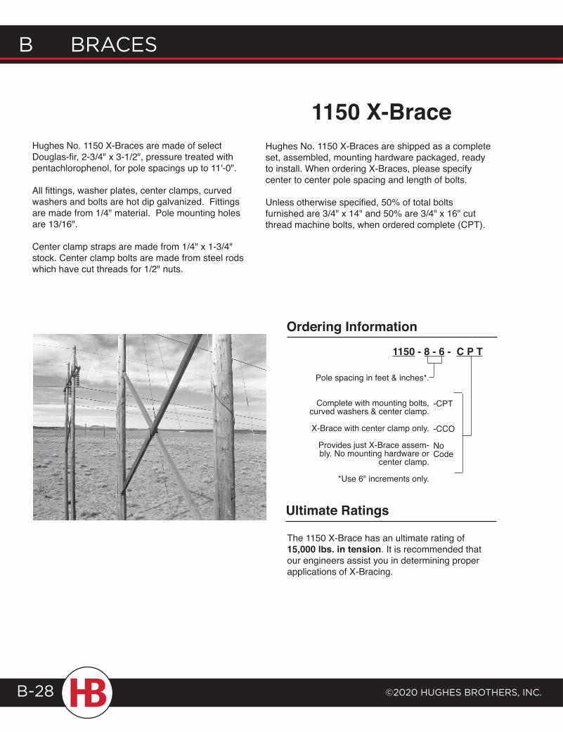
B Braces
©2020 HugHes BrotHers, Inc.B-28
1150 X-Brace
Pole spacing in feet & inches*.
Complete with mounting bolts, curved washers & center clamp.
X-Brace with center clamp only.
Provides just X-Brace assem-bly. No mounting hardware or
center clamp.
*Use 6" increments only.
-CPT
-CCO
No Code
The 1150 X-Brace has an ultimate rating of 15,000 lbs. in tension. It is recommended that our engineers assist you in determining proper applications of X-Bracing.
Ordering Information
Ultimate Ratings
Hughes No. 1150 X-Braces are made of select Douglas-fir, 2-3/4" x 3-1/2", pressure treated with pentachlorophenol, for pole spacings up to 11'-0".
All fittings, washer plates, center clamps, curved washers and bolts are hot dip galvanized. Fittings are made from 1/4" material. Pole mounting holes are 13/16".
Center clamp straps are made from 1/4" x 1-3/4" stock. Center clamp bolts are made from steel rods which have cut threads for 1/2" nuts.
Hughes No. 1150 X-Braces are shipped as a complete set, assembled, mounting hardware packaged, ready to install. When ordering X-Braces, please specify center to center pole spacing and length of bolts.
Unless otherwise specified, 50% of total bolts furnished are 3/4" x 14" and 50% are 3/4" x 16" cut thread machine bolts, when ordered complete (CPT).
1150 - 8 - 6 - C P T
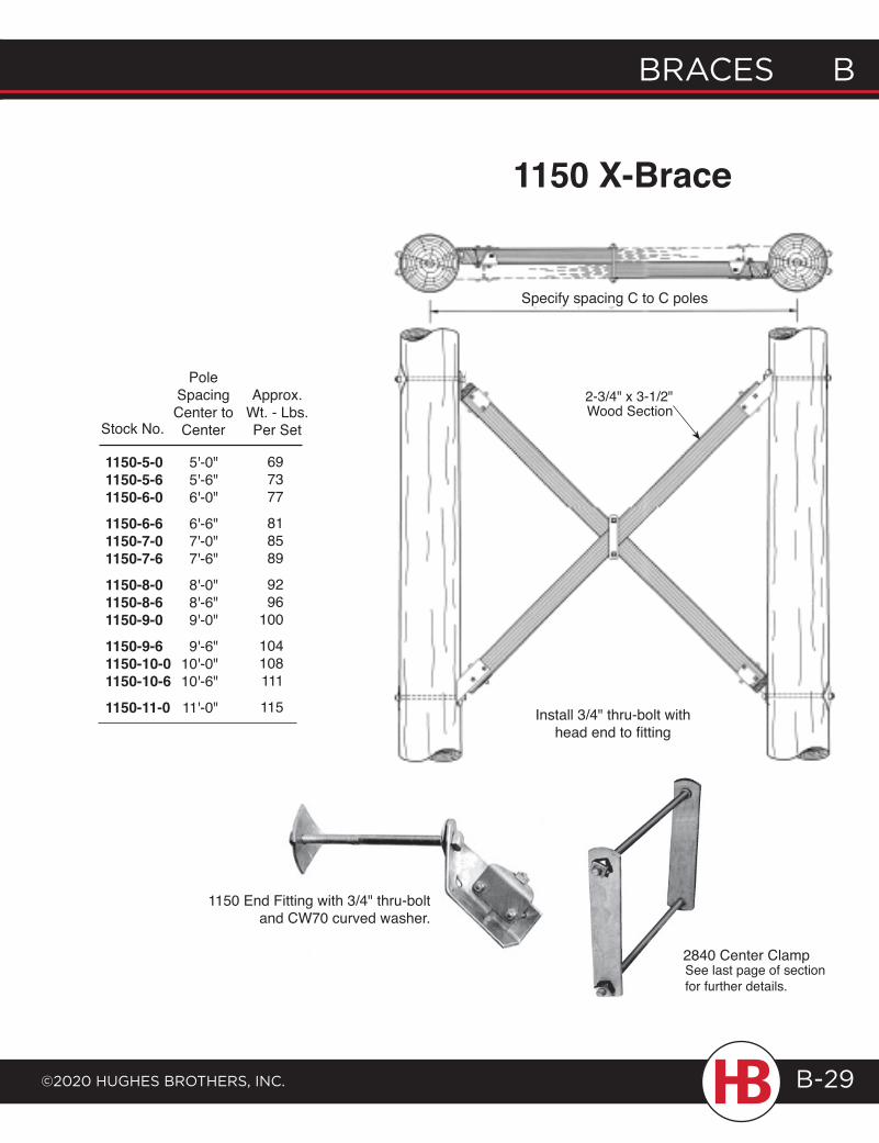
braces b
©2020 HugHes brotHers, Inc.
b braces
B-29
1150 X-Brace
2840 Center Clamp
1150 End Fitting with 3/4" thru-bolt and CW70 curved washer.
See last page of section for further details.
Stock No.
1150-5-01150-5-61150-6-01150-6-61150-7-01150-7-61150-8-01150-8-61150-9-01150-9-61150-10-01150-10-61150-11-0
5'-0"5'-6"6'-0"
6'-6"7'-0"7'-6"
8'-0"8'-6"9'-0"
9'-6"10'-0"10'-6"
11'-0"
PoleSpacingCenter toCenter
697377
818589
9296
100
104108111
115
Approx.Wt. - Lbs.Per Set
Specify spacing C to C poles
2-3/4" x 3-1/2" Wood Section
Install 3/4" thru-bolt withhead end to fitting
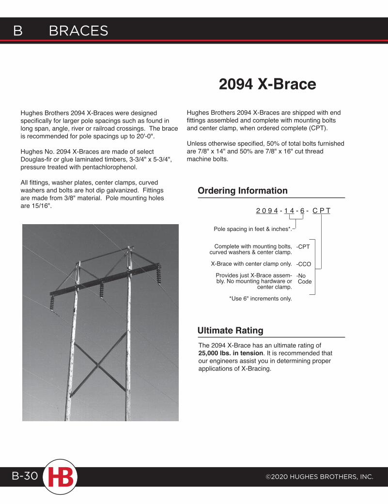
B Braces
©2020 HugHes BrotHers, Inc.B-30
2094 X-BraceHughes Brothers 2094 X-Braces were designed specifically for larger pole spacings such as found in long span, angle, river or railroad crossings. The brace is recommended for pole spacings up to 20'-0".
Hughes No. 2094 X-Braces are made of select Douglas-fir or glue laminated timbers, 3-3/4" x 5-3/4", pressure treated with pentachlorophenol.
All fittings, washer plates, center clamps, curved washers and bolts are hot dip galvanized. Fittings are made from 3/8" material. Pole mounting holes are 15/16".
Hughes Brothers 2094 X-Braces are shipped with end fittings assembled and complete with mounting bolts and center clamp, when ordered complete (CPT).
Unless otherwise specified, 50% of total bolts furnished are 7/8" x 14" and 50% are 7/8" x 16" cut thread machine bolts.
Pole spacing in feet & inches*.
Complete with mounting bolts, curved washers & center clamp.
X-Brace with center clamp only.
Provides just X-Brace assem-bly. No mounting hardware or
center clamp.
*Use 6" increments only.
2 0 9 4 - 1 4 - 6 - C P T
-CPT
-CCO
-No Code
The 2094 X-Brace has an ultimate rating of 25,000 lbs. in tension. It is recommended that our engineers assist you in determining proper applications of X-Bracing.
Ordering Information
Ultimate Rating
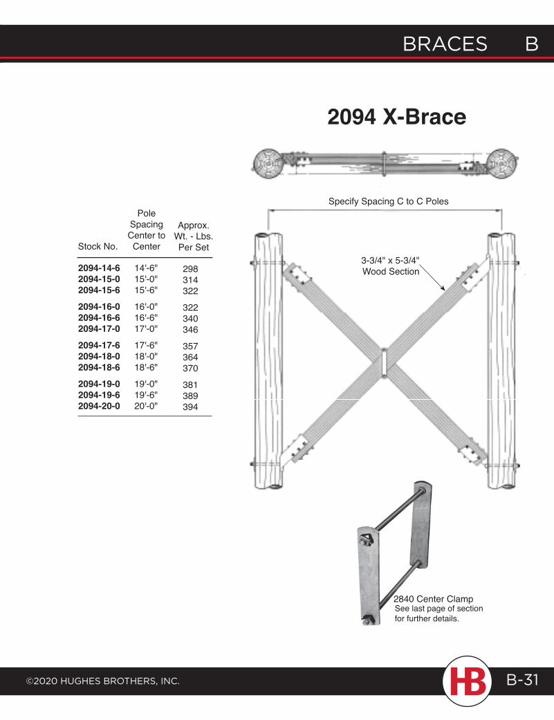
braces b
©2020 HugHes brotHers, Inc.
b braces
B-31
2094 X-Brace
Stock No.
PoleSpacingCenter toCenter
Approx.Wt. - Lbs.Per Set
2094-14-62094-15-02094-15-62094-16-02094-16-62094-17-02094-17-62094-18-02094-18-62094-19-02094-19-62094-20-0
14'-6"15'-0"15'-6"
16'-0"16'-6"17'-0"
17'-6"18'-0"18'-6"
19'-0"19'-6"20'-0"
298314322
322340346
357364370
381389394
2840 Center ClampSee last page of section for further details.
3-3/4" x 5-3/4"Wood Section
Specify Spacing C to C Poles
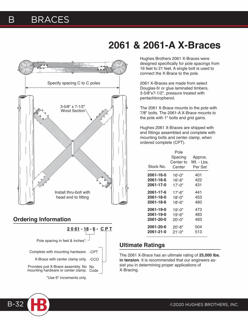
B Braces
©2020 HugHes BrotHers, Inc.B-32
2061 & 2061-A X-Braces
2 0 61 - 18 - 6 - C P T
-CPT
-CCO
No Code
Pole spacing in feet & inches*.
Complete with mounting hardware.
X-Brace with center clamp only.
Provides just X-Brace assembly. No mounting hardware or center clamp.
*Use 6" increments only.
Ordering Information
Stock No.
PoleSpacingCenter toCenter
Approx.Wt. - Lbs.Per Set
401422431
441453460
473483493
504513
16'-0"16'-6"17'-0"
17'-6"18'-0"18'-6"
19'-0"19'-6"20'-0"
20'-6"21'-0"
2061-16-02061-16-62061-17-02061-17-62061-18-02061-18-62061-19-02061-19-62061-20-02061-20-62061-21-0
The 2061 X-Brace has an ultimate rating of 25,000 lbs. in tension. It is recommended that our engineers as-sist you in determining proper applications of X-Bracing.
Ultimate Ratings
Hughes Brothers 2061 X-Braces were designed specifically for pole spacings from 16 feet to 21 feet. A single bolt is used to connect the X-Brace to the pole.
2061 X-Braces are made from select Douglas-fir or glue laminated timbers, 3-5/8"x7-1/2", pressure treated with pentachlorophenol.
The 2061 X-Brace mounts to the pole with 7/8" bolts. The 2061-A X-Brace mounts to the pole with 1" bolts and grid gains.
Hughes 2061 X-Braces are shipped with end fittings assembled and complete with mounting bolts and center clamp, when ordered complete (CPT).
Specify spacing C to C poles
3-5/8" x 7-1/2"Wood Section
Install thru-bolt withhead end to fitting
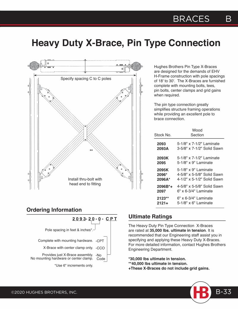
braces b
©2020 HugHes brotHers, Inc.
b braces
B-33
Heavy Duty X-Brace, Pin Type Connection
Hughes Brothers Pin Type X-Braces are designed for the demands of EHV H-Frame construction with pole spacings of 18' to 30'. The X-Braces are furnished complete with mounting bolts, tees, pin bolts, center clamps and grid gains when required.
The pin type connection greatly simplifies structure framing operations while providing an excellent pole to brace connection.
5-1/8" x 7-1/2" Laminate3-5/8" x 7-1/2" Solid Sawn
5-1/8" x 7-1/2" Laminate5-1/8" x 9" Laminate
5-1/8" x 9" Laminate4-5/8" x 5-5/8" Solid Sawn4-1/2" x 5-1/2" Solid Sawn
4-5/8" x 5-5/8" Solid Sawn6" x 6-3/4" Laminate
6" x 6-3/4" Laminate5-1/8" x 6" Laminate
20932093A
2093K20952095K2096*2096A*2096B*+20972123**2121+
Wood SectionStock No.
Pole spacing in feet & inches*.
Complete with mounting hardware.
X-Brace with center clamp only.
Provides just X-Brace assembly. No mounting hardware or center clamp.
*Use 6" increments only.
-CPT
-CCO
-No Code
2 0 9 3- 2 0 - 0 - C P TThe Heavy Duty Pin Type Connection X-Braces are rated at 35,000 lbs. ultimate in tension. It is recommended that our Engineering staff assist you in specifying and applying these Heavy Duty X-Braces. For more detailed information, contact Hughes Brothers Engineering Department.
*30,000 lbs ultimate in tension.**40,000 lbs ultimate in tension.+These X-Braces do not include grid gains.
Ordering InformationUltimate Ratings
Install thru-bolt withhead end to fitting
Specify spacing C to C poles
**
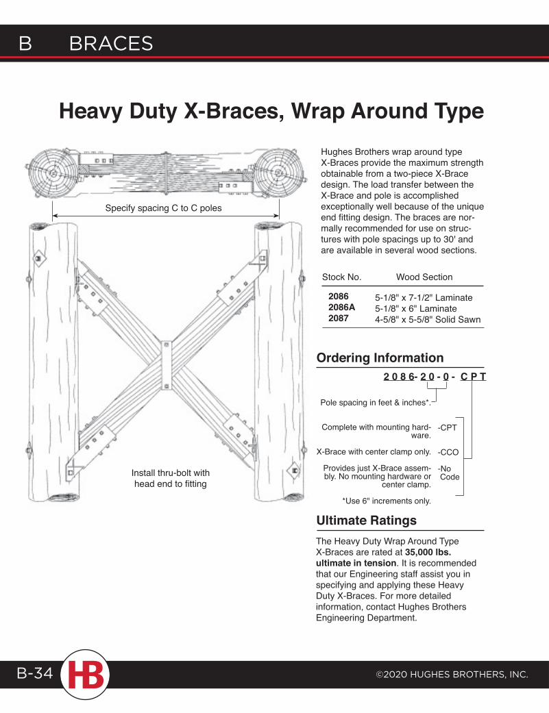
B Braces
©2020 HugHes BrotHers, Inc.B-34
Heavy Duty X-Braces, Wrap Around TypeHughes Brothers wrap around type X-Braces provide the maximum strength obtainable from a two-piece X-Brace design. The load transfer between the X-Brace and pole is accomplished exceptionally well because of the unique end fitting design. The braces are nor-mally recommended for use on struc-tures with pole spacings up to 30' and are available in several wood sections.
5-1/8" x 7-1/2" Laminate5-1/8" x 6" Laminate4-5/8" x 5-5/8" Solid Sawn
20862086A2087
Stock No. Wood Section
Pole spacing in feet & inches*.
Complete with mounting hard-ware.
X-Brace with center clamp only.
Provides just X-Brace assem-bly. No mounting hardware or
center clamp.
*Use 6" increments only.
-CPT
-CCO
-No Code
2 0 8 6- 2 0 - 0 - C P T
The Heavy Duty Wrap Around Type X-Braces are rated at 35,000 lbs. ultimate in tension. It is recommended that our Engineering staff assist you in specifying and applying these Heavy Duty X-Braces. For more detailed information, contact Hughes Brothers Engineering Department.
Ultimate Ratings
Ordering Information
Install thru-bolt withhead end to fitting
Specify spacing C to C poles
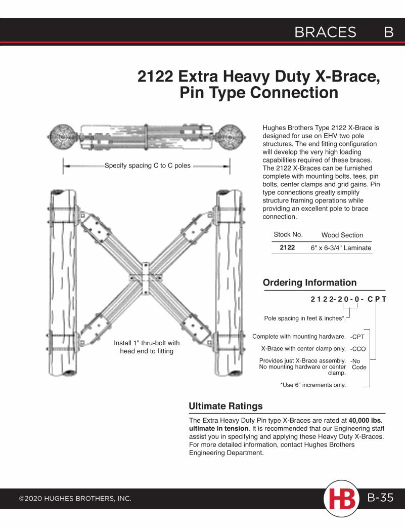
braces b
©2020 HugHes brotHers, Inc.
b braces
B-35
Hughes Brothers Type 2122 X-Brace is designed for use on EHV two pole structures. The end fitting configuration will develop the very high loading capabilities required of these braces. The 2122 X-Braces can be furnished complete with mounting bolts, tees, pin bolts, center clamps and grid gains. Pin type connections greatly simplify structure framing operations while providing an excellent pole to brace connection.
Pole spacing in feet & inches*.
Complete with mounting hardware.
X-Brace with center clamp only.
Provides just X-Brace assembly. No mounting hardware or center
clamp.
*Use 6" increments only.
-CPT
-CCO
-No Code
2 1 2 2- 2 0 - 0 - C P T
6" x 6-3/4" Laminate
Stock No.
2122
Wood Section
Ordering Information
The Extra Heavy Duty Pin type X-Braces are rated at 40,000 lbs. ultimate in tension. It is recommended that our Engineering staff assist you in specifying and applying these Heavy Duty X-Braces. For more detailed information, contact Hughes Brothers Engineering Department.
Ultimate Ratings
2122 Extra Heavy Duty X-Brace, Pin Type Connection
Specify spacing C to C poles
Install 1" thru-bolt withhead end to fitting
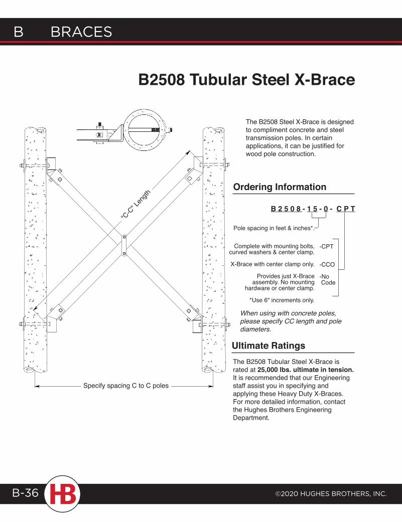
B Braces
©2020 HugHes BrotHers, Inc.B-36
The B2508 Steel X-Brace is designed to compliment concrete and steel transmission poles. In certain applications, it can be justified for wood pole construction.
B2508 Tubular Steel X-Brace
Pole spacing in feet & inches*.
Complete with mounting bolts, curved washers & center clamp.
X-Brace with center clamp only.
Provides just X-Brace assembly. No mounting
hardware or center clamp.
*Use 6" increments only.
-CPT
-CCO
-No Code
B 2 5 0 8 - 1 5 - 0 - C P T
Ordering Information
Ultimate RatingsThe B2508 Tubular Steel X-Brace is rated at 25,000 lbs. ultimate in tension. It is recommended that our Engineering staff assist you in specifying and applying these Heavy Duty X-Braces. For more detailed information, contact the Hughes Brothers Engineering Department.
Specify spacing C to C poles
"C-C
" Len
gth
When using with concrete poles, please specify CC length and pole diameters.
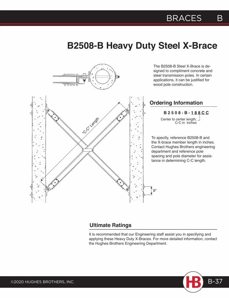
braces b
©2020 HugHes brotHers, Inc.
b braces
B-37
B2508-B Heavy Duty Steel X-Brace
The B2508-B Steel X-Brace is de-signed to compliment concrete and steel transmission poles. In certain applications, it can be justified for wood pole construction.
Ordering Information
B 2 5 0 8 - B - 1 8 8 C C
Ultimate RatingsIt is recommended that our Engineering staff assist you in specifying and applying these Heavy Duty X-Braces. For more detailed information, contact the Hughes Brothers Engineering Department.
9"
"C-C
" Len
gth Center to center length, C-C in inches
To specify, reference B2508-B and the X-brace member length in inches. Contact Hughes Brothers engineering department and reference pole spacing and pole diameter for assis-tance in determining C-C length.
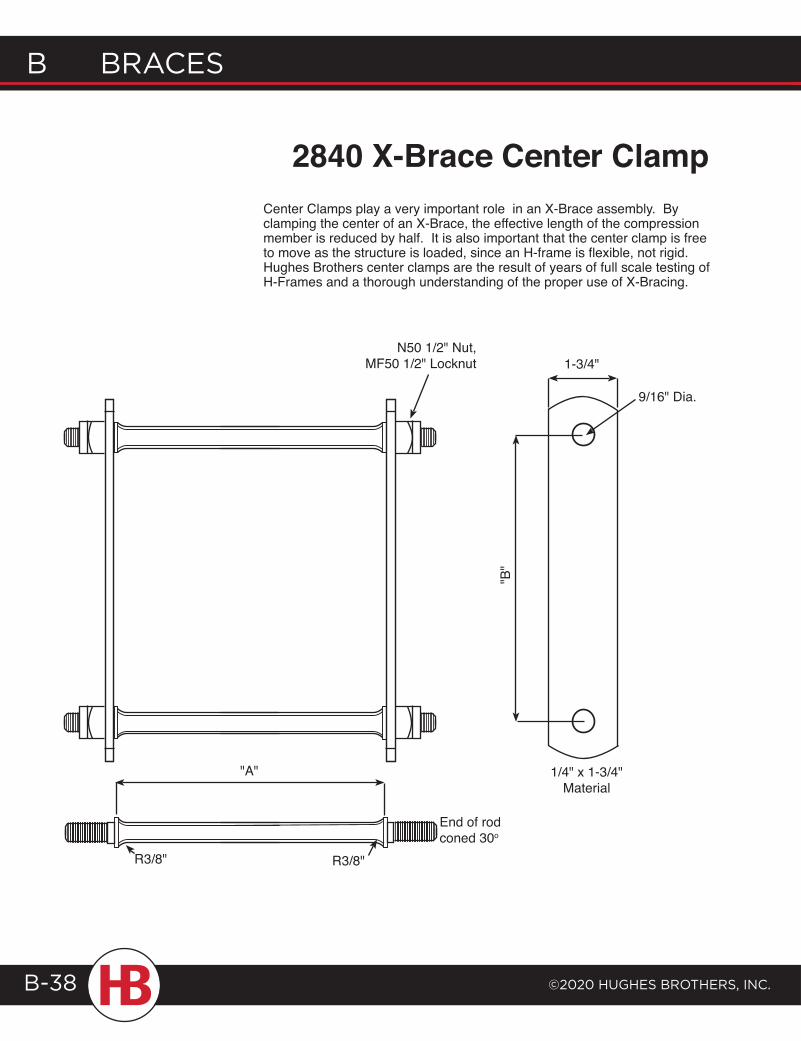
B Braces
©2020 HugHes BrotHers, Inc.B-38
2840 X-Brace Center ClampCenter Clamps play a very important role in an X-Brace assembly. By clamping the center of an X-Brace, the effective length of the compression member is reduced by half. It is also important that the center clamp is free to move as the structure is loaded, since an H-frame is flexible, not rigid. Hughes Brothers center clamps are the result of years of full scale testing of H-Frames and a thorough understanding of the proper use of X-Bracing.
1-3/4"
"B"
"A"
R3/8" R3/8"
End of rod coned 30o
1/4" x 1-3/4" Material
N50 1/2" Nut, MF50 1/2" Locknut
9/16" Dia.
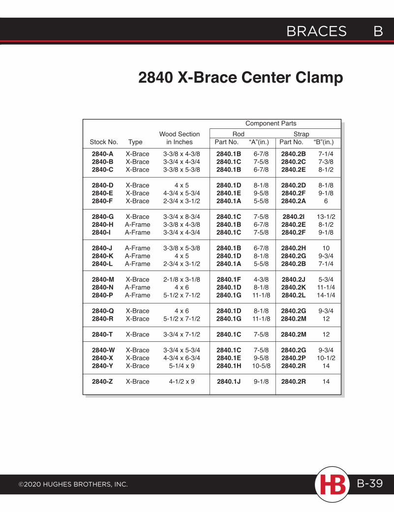
braces b
©2020 HugHes brotHers, Inc.
b braces
B-39
2840-A X-Brace 3-3/8 x 4-3/8 2840.1B 6-7/8 2840.2B 7-1/42840-B X-Brace 3-3/4 x 4-3/4 2840.1C 7-5/8 2840.2C 7-3/82840-C X-Brace 3-3/8 x 5-3/8 2840.1B 6-7/8 2840.2E 8-1/2
2840-D X-Brace 4 x 5 2840.1D 8-1/8 2840.2D 8-1/82840-E X-Brace 4-3/4 x 5-3/4 2840.1E 9-5/8 2840.2F 9-1/82840-F X-Brace 2-3/4 x 3-1/2 2840.1A 5-5/8 2840.2A 6
2840-G X-Brace 3-3/4 x 8-3/4 2840.1C 7-5/8 2840.2I 13-1/22840-H A-Frame 3-3/8 x 4-3/8 2840.1B 6-7/8 2840.2E 8-1/22840-I A-Frame 3-3/4 x 4-3/4 2840.1C 7-5/8 2840.2F 9-1/8
2840-J A-Frame 3-3/8 x 5-3/8 2840.1B 6-7/8 2840.2H 102840-K A-Frame 4 x 5 2840.1D 8-1/8 2840.2G 9-3/42840-L A-Frame 2-3/4 x 3-1/2 2840.1A 5-5/8 2840.2B 7-1/4
2840-M X-Brace 2-1/8 x 3-1/8 2840.1F 4-3/8 2840.2J 5-3/42840-N A-Frame 4 x 6 2840.1D 8-1/8 2840.2K 11-1/42840-P A-Frame 5-1/2 x 7-1/2 2840.1G 11-1/8 2840.2L 14-1/4
2840-Q X-Brace 4 x 6 2840.1D 8-1/8 2840.2G 9-3/42840-R X-Brace 5-1/2 x 7-1/2 2840.1G 11-1/8 2840.2M 12
2840-T X-Brace 3-3/4 x 7-1/2 2840.1C 7-5/8 2840.2M 12
2840-W X-Brace 3-3/4 x 5-3/4 2840.1C 7-5/8 2840.2G 9-3/42840-X X-Brace 4-3/4 x 6-3/4 2840.1E 9-5/8 2840.2P 10-1/22840-Y X-Brace 5-1/4 x 9 2840.1H 10-5/8 2840.2R 14
2840-Z X-Brace 4-1/2 x 9 2840.1J 9-1/8 2840.2R 14
Component Parts
2840 X-Brace Center Clamp
Wood Section Rod StrapStock No. Type in Inches Part No. “A”(in.) Part No. “B”(in.)
P O L E L I N E H A R DWA R E
Guying Attachments ................................C-1Pole Bands ................................................. C-11Links/Guying Assemblies ................... C-22Pole/Crossarm/Spacer Fittings .......C-36Brackets/Bayonets ...............................C-55Pole Top Pins/Ridge Irons .................C-83Yoke Plates ..............................................C-93Other Hardware ................................... C-109
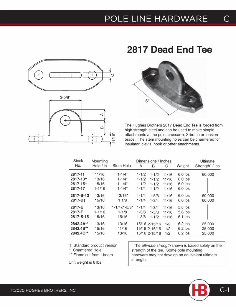
POLE LINE HARDWARE C
©2020 HugHEs BROtHERs, INC. C-1
2817 Dead End Tee
The Hughes Brothers 2817 Dead End Tee is forged from high strength steel and can be used to make simple attachments at the pole, crossarm, X-brace or tension brace. The stem mounting holes can be chamfered for insulator, clevis, hook or other attachments.
StockNo.
11/1613/1615/161-1/16
13/1615/16
13/161-1/1615/16
13/1615/1615/16
Mounting Hole / in.
1-1/4*1-1/4*1-1/4*1-1/4*
13/16*1 1/8
1-1/4x1-5/8*1-1/815/16
13/1611/1613/16
Stem Hole
2817-112817-13†2817-15†2817-172817-B-132817-D†
2817-E2817-F2817-S-152842.4A**2842.4B**2842.4C**
UltimateStrength1 / lbs
1-1/21-1/21-1/21-1/4
1-1/41-1/4
1-1/41-3/81-3/8
15/1615/1615/16
A
1-1/21-1/21-1/21-1/2
1-5/81-3/4
1-3/41-5/81-1/2
2-15/162-15/162-15/16
B
11/1611/1611/1611/16
11/1611/16
11/1611/1611/16
1/21/21/2
C Dimensions / Inches
6.0 lbs6.0 lbs6.0 lbs6.0 lbs
6.0 lbs6.0 lbs
5.8 lbs5.8 lbs6.1 lbs
6.2 lbs6.2 lbs6.2 lbs
Weight
1 The ultimate strength shown is based solely on the strength of the tee. Some pole mounting hardware may not develop an equivalent ultimate strength.
† Standard product version* Chamfered Hole** Flame cut from I-beam
Unit weight is 6 lbs
60,000
60,00060,000
25,00025,00025,000
11/1
6”
BA
3-5/8”
C+ +
+
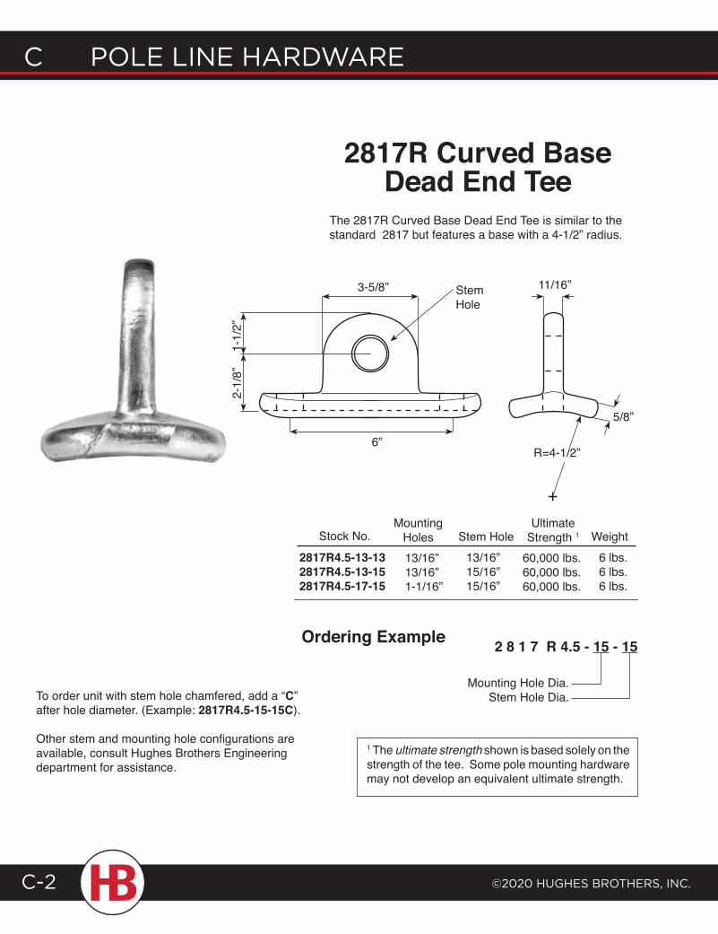
C POLE LINE HARDWARE
©2020 HugHEs BROtHERs, INC.C-2
2817R4.5-13-132817R4.5-13-152817R4.5-17-15
Stem Hole13/16”15/16”15/16”
Weight6 lbs.6 lbs.6 lbs.
MountingHoles
Ultimate Strength 1Stock No.
60,000 lbs.60,000 lbs.60,000 lbs.
13/16”13/16”1-1/16”
To order unit with stem hole chamfered, add a “C” after hole diameter. (Example: 2817R4.5-15-15C).
Other stem and mounting hole configurations are available, consult Hughes Brothers Engineering department for assistance.
Mounting Hole Dia.Stem Hole Dia.
2 8 1 7 R 4.5 - 15 - 15Ordering Example
2817R Curved Base Dead End Tee
The 2817R Curved Base Dead End Tee is similar to the standard 2817 but features a base with a 4-1/2” radius.
1 The ultimate strength shown is based solely on the strength of the tee. Some pole mounting hardware may not develop an equivalent ultimate strength.
Stem Hole
1-1/
2”
3-5/8” 11/16”
5/8”
6”
2-1/
8”
+
R=4-1/2”
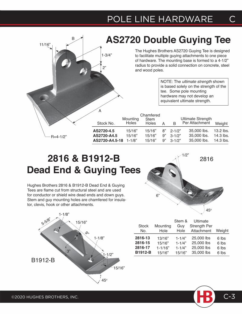
POLE LINE HARDWARE C
©2020 HugHEs BROtHERs, INC.
C POLE LINE HARDWARE
C-3
15/16”5-5/8”
9”
45o
1-1/2”
1-1/8”
3”
1-1/8”
B1912-B
2816
15/16”
Hughes Brothers 2816 & B1912-B Dead End & Guying Tees are flame cut from structural steel and are used for conductor or shield wire dead ends and down guys. Stem and guy mounting holes are chamfered for insula-tor, clevis, hook or other attachments.
AS2720 Double Guying Tee11/16”
A
R=4-1/2”
2816 & B1912-B Dead End & Guying Tees
6”
B
AS2720-4.5AS2720-A4.5AS2720-A4.5-18
Stock No.
15/16”15/16”1-1/8”
Mounting Holes
ChamferedStem Holes
15/16”15/16”15/16”
A B
8”9”9”
2-1/2”3-1/2”3-1/2”
Ultimate StrengthPer Attachment
35,000 lbs.35,000 lbs.35,000 lbs.
13.2 lbs.14.3 lbs.14.3 lbs.
Weight
2816-132816-152816-17B1912-B
StockNo.
13/16”15/16”1-1/16”15/16”
Mounting Hole
Stem &GuyHole
1-1/4”1-1/4”1-1/4”15/16”
UltimateStrength PerAttachment
25,000 lbs25,000 lbs25,000 lbs35,000 lbs
Weight
NOTE: The ultimate strength shown is based solely on the strength of the tee. Some pole mounting hardware may not develop an equivalent ultimate strength.
6 lbs6 lbs6 lbs6 lbs
1/2”
45o
1-3/4”
2”
The Hughes Brothers AS2720 Guying Tee is designed to facilitate multiple guying attachments to one piece of hardware. The mounting base is formed to a 4-1/2” radius to provide a solid connection on concrete, steel and wood poles.
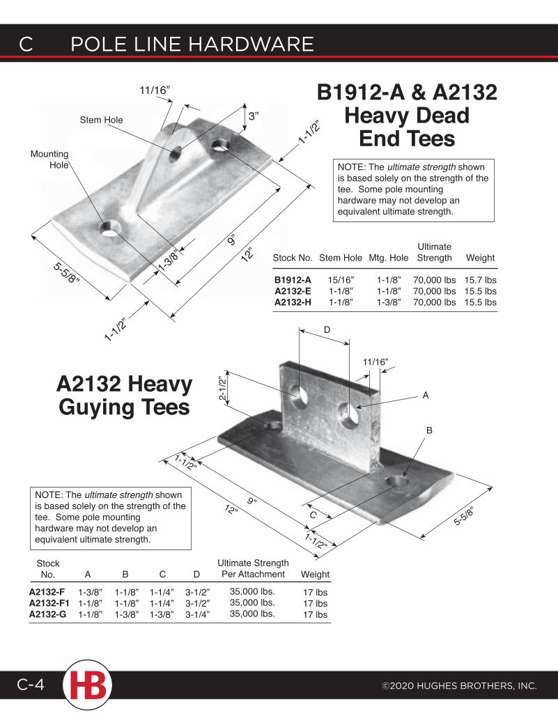
C POLE LINE HARDWARE
©2020 HugHEs BROtHERs, INC.C-4
D
B
A
1-1/2”
C9”
5-5/8”
2-1/
2”
12”
11/16”
1-1/2”
1-1/2”
A2132-FA2132-F1A2132-G
StockNo. A
1-3/8”1-1/8”1-1/8”
1-1/8”1-1/8”1-3/8”
B
1-1/4”1-1/4”1-3/8”
3-1/2”3-1/2”3-1/4”
DC
NOTE: The ultimate strength shown is based solely on the strength of the tee. Some pole mounting hardware may not develop an equivalent ultimate strength.
Ultimate Stock No. Stem Hole Mtg. Hole Strength Weight
B1912-A 15/16” 1-1/8” 70,000 lbs 15.7 lbs A2132-E 1-1/8” 1-1/8” 70,000 lbs 15.5 lbs A2132-H 1-1/8” 1-3/8” 70,000 lbs 15.5 lbs
NOTE: The ultimate strength shown is based solely on the strength of the tee. Some pole mounting hardware may not develop an equivalent ultimate strength.
A2132 HeavyGuying Tees
B1912-A & A2132 Heavy Dead
End Tees
Ultimate StrengthPer Attachment
35,000 lbs.35,000 lbs.35,000 lbs.
17 lbs17 lbs17 lbs
Weight
11/16”
Mounting Hole
Stem Hole 3”
5-5/8”
12”
9”
1-3/8”
1-1/2”
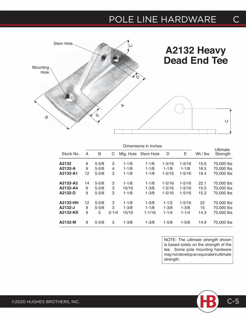
POLE LINE HARDWARE C
©2020 HugHEs BROtHERs, INC.
C POLE LINE HARDWARE
C-5
Mounting Hole
Stem Hole
B
C
A
D
E
A2132 HeavyDead End Tee
Stock No.
A2132A2132-AA2132-A1
A2132-A2A2132-A4A2132-D
A2132-HHA2132-JA2132-KK
A2132-M
A
9912
1499
1299
9
B
5-5/85-5/85-5/8
5-5/85-5/85-5/8
5-5/85-5/8
5
5-5/8
C
343
333
33
2-1/4
3
Mtg. Hole
1-1/81-1/81-1/8
1-1/815/161-1/8
1-1/81-3/815/16
1-3/8
Stem Hole
1-1/81-1/81-1/8
1-1/81-3/81-3/8
1-3/81-1/81-1/16
1-3/8
D
1-5/161-1/81-5/16
1-5/161-5/161-5/16
1-1/21-3/81-1/4
1-5/8
E
1-5/161-1/81-5/16
1-5/161-5/161-5/16
1-5/161-3/81-1/4
1-5/8
Wt./ lbs
15.616.519.4
22.115.515.3
2215
14.3
14.9
Strength
70,000 lbs70,000 lbs70,000 lbs
70,000 lbs70,000 lbs70,000 lbs
70,000 lbs70,000 lbs70,000 lbs
70,000 lbs
Dimensions in Inches
C
NOTE: The ultimate strength shown is based solely on the strength of the tee. Some pole mounting hardware may not develop an equivalent ultimate strength.
Ultimate
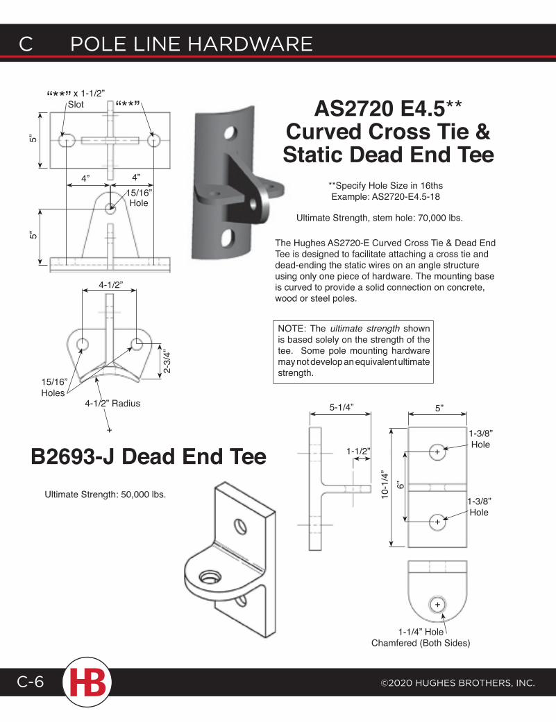
C POLE LINE HARDWARE
©2020 HugHEs BROtHERs, INC.C-6
AS2720 E4.5**Curved Cross Tie & Static Dead End Tee
B2693-J Dead End Tee
15/16”Hole
“**” x 1-1/2” Slot
5”
15/16”Holes
5”
4” 4”
“**”
The Hughes AS2720-E Curved Cross Tie & Dead End Tee is designed to facilitate attaching a cross tie and dead-ending the static wires on an angle structure using only one piece of hardware. The mounting base is curved to provide a solid connection on concrete, wood or steel poles.
**Specify Hole Size in 16thsExample: AS2720-E4.5-18
1-3/8” Hole
1-3/8” Hole
10-1
/4”
6”
1-1/4” HoleChamfered (Both Sides)
5-1/4”
1-1/2”
5”
Ultimate Strength: 50,000 lbs.
NOTE: The ultimate strength shown is based solely on the strength of the tee. Some pole mounting hardware may not develop an equivalent ultimate strength.
+
+
+
4-1/2” Radius
+
4-1/2”
2-3/
4”
Ultimate Strength, stem hole: 70,000 lbs.
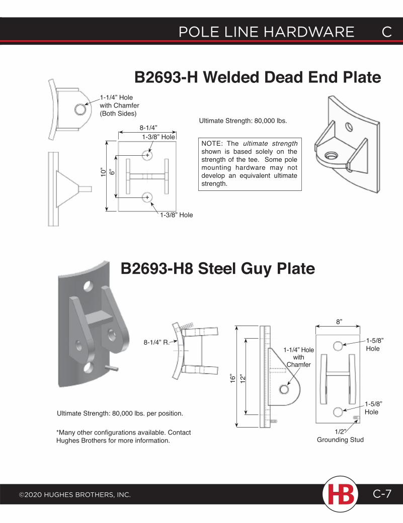
POLE LINE HARDWARE C
©2020 HugHEs BROtHERs, INC.
C POLE LINE HARDWARE
C-7
B2693-H Welded Dead End Plate
B2693-H8 Steel Guy Plate
1-1/4” Hole with Chamfer (Both Sides)
8-1/4”1-3/8” Hole
8-1/4” R.
10”
6”
1-3/8” Hole
1-5/8” Hole
1-5/8” Hole
8”
16”
12”
1-1/4” Hole with
Chamfer
1/2” Grounding Stud
*Many other configurations available. Contact Hughes Brothers for more information.
Ultimate Strength: 80,000 lbs.
Ultimate Strength: 80,000 lbs. per position.
NOTE: The ultimate strength shown is based solely on the strength of the tee. Some pole mounting hardware may not develop an equivalent ultimate strength.
+
+
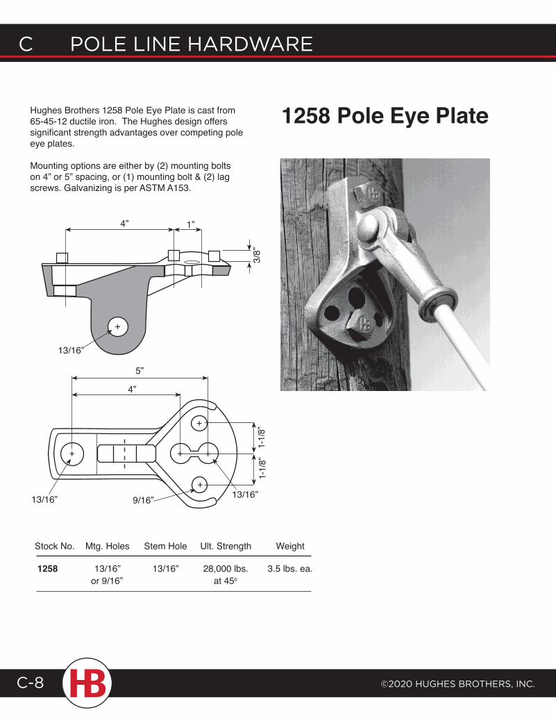
C POLE LINE HARDWARE
©2020 HugHEs BROtHERs, INC.C-8
+
+
+
+ +
1258 Pole Eye Plate
4” 1”
3/8”
1-1/
8”
13/16”
1-1/
8”
4”
5”
9/16”13/16”
13/16”
Stock No. Mtg. Holes Stem Hole Ult. Strength Weight
1258 13/16” 13/16” 28,000 lbs. 3.5 lbs. ea. or 9/16” at 45o
Hughes Brothers 1258 Pole Eye Plate is cast from 65-45-12 ductile iron. The Hughes design offers significant strength advantages over competing pole eye plates.
Mounting options are either by (2) mounting bolts on 4” or 5” spacing, or (1) mounting bolt & (2) lag screws. Galvanizing is per ASTM A153.
+
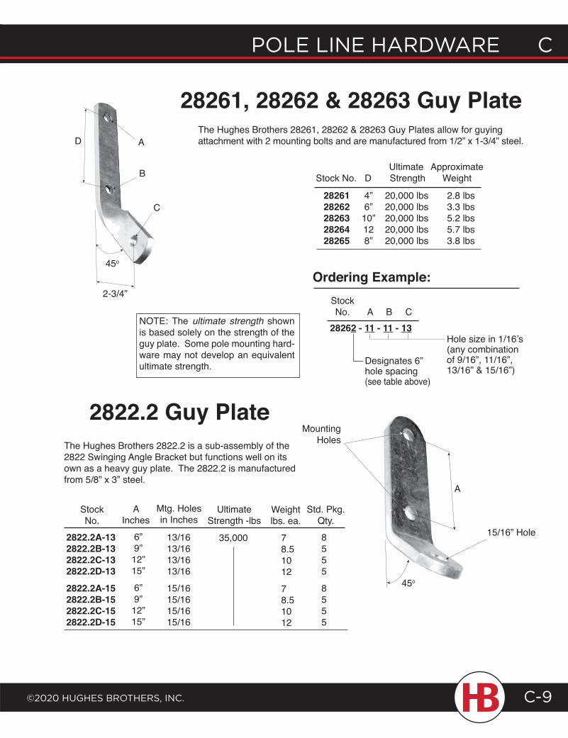
POLE LINE HARDWARE C
©2020 HugHEs BROtHERs, INC.
C POLE LINE HARDWARE
C-9
StockNo.
2822.2A-132822.2B-132822.2C-132822.2D-132822.2A-152822.2B-152822.2C-152822.2D-15
The Hughes Brothers 2822.2 is a sub-assembly of the 2822 Swinging Angle Bracket but functions well on its own as a heavy guy plate. The 2822.2 is manufactured from 5/8” x 3” steel.
2822.2 Guy Plate
The Hughes Brothers 28261, 28262 & 28263 Guy Plates allow for guying attachment with 2 mounting bolts and are manufactured from 1/2” x 1-3/4” steel.
28261, 28262 & 28263 Guy Plate
28262 - 11 - 11 - 13A B C
StockNo.
Hole size in 1/16’s(any combinationof 9/16”, 11/16”,13/16” & 15/16”)
Designates 6” hole spacing (see table above)
Ordering Example:45o
C
B
A
2-3/4”
28261 4” 20,000 lbs 2.8 lbs 28262 6” 20,000 lbs 3.3 lbs 28263 10” 20,000 lbs 5.2 lbs 28264 12 20,000 lbs 5.7 lbs 28265 8” 20,000 lbs 3.8 lbs
NOTE: The ultimate strength shown is based solely on the strength of the guy plate. Some pole mounting hard-ware may not develop an equivalent ultimate strength.
Mounting Holes
A
45o
15/16” Hole
Std. Pkg.Qty.8555
8555
Weightlbs. ea.
78.51012
78.51012
AInches
6”9”12”15”
6”9”12”15”
Mtg. Holesin Inches
13/1613/1613/1613/16
15/1615/1615/1615/16
UltimateStrength -lbs
Ultimate Approximate Stock No. D Strength Weight
35,000
D
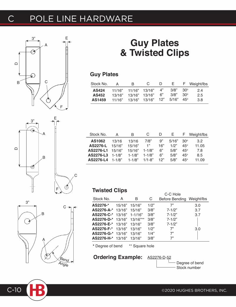
C POLE LINE HARDWARE
©2020 HugHEs BROtHERs, INC.C-10
3”
Guy Plates& Twisted Clips
A B C D E F Weight/lbs
Stock No. A B CC-C Hole
Before Bending
* Degree of bend ** Square hole
Twisted Clips
11/16”13/16”11/16”
11/16”13/16”13/16”
13/16”13/16”13/16”
4”6”12”
3/8”3/8”5/16”
30o
30o
45o
2.42.53.8
AS424AS452AS1459
Stock No.
Guy Plates
AS2276-*AS2276-A-*AS2276-C-*AS2276-D-*AS2276-E-*AS2276-F-*AS2276-G-*AS2276-H-*
15/16”15/16”1-1/16”13/16”**13/16”13/16”13/16”13/16”
1/2”3/8”3/8”3/8”3/8”1/2”1/4”3/8”
7”7-1/2”7-1/2”7-1/2”7-1/2”
7”7”7”
3.03.73.7
3.0
15/16”13/16”13/16”13/16”13/16”13/16”13/16”13/16”
Weight/lbs
Ordering Example: AS2276-D-52Degree of bendStock number
A
B C
D
F
E3”
B
3”C
A
Bend Angle
F
C
A
B
D
E
A B C D E F Weight/lbs13/1615/16”15/16”1-1/8”1-1/8”
13/1615/16”15/16”1-1/8”1-1/8”
7/8”1”
1-1/8”1-1/8”1/1-8”
9”16”6”6”12”
5/16”1/2”5/8”5/8”5/8”
30o
45o
45o
45o
45o
3.211.057.88.5
11.09
AS1062AS2276-L
AS2276-L1AS2276-L3AS2276-L4
Stock No.
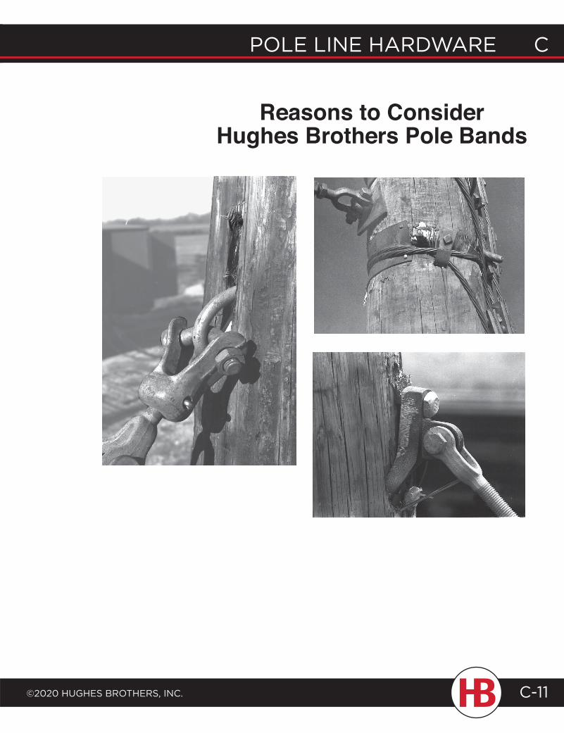
POLE LINE HARDWARE C
©2020 HugHEs BROtHERs, INC.
C POLE LINE HARDWARE
C-11
Reasons to Consider Hughes Brothers Pole Bands
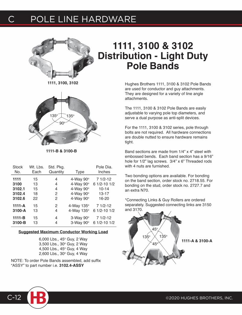
C POLE LINE HARDWARE
©2020 HugHEs BROtHERs, INC.C-12
Hughes Brothers 1111, 3100 & 3102 Pole Bands are used for conductor and guy attachments. They are designed for a variety of line angle attachments.
The 1111, 3100 & 3102 Pole Bands are easily adjustable to varying pole top diameters, and serve a dual purpose as anti-split devices.
For the 1111, 3100 & 3102 series, pole through bolts are not required. All hardware connections are double nutted to ensure hardware remains tight.
Band sections are made from 1/4” x 4” steel with embossed bends. Each band section has a 9/16” hole for 1/2” lag screws. 3/4” x 6” Threaded rods with 4 nuts are furnished.
Two bonding options are available. For bonding on the band section, order stock no. 2718.55. For bonding on the stud, order stock no. 2727.7 and an extra N70.
*Connecting Links & Guy Rollers are ordered separately. Suggested connecting links are 3150 and 3170.
NOTE: To order Pole Bands assembled, add suffix “ASSY” to part number i.e. 3102.4-ASSY
111131003102.13102.43102.61111-A3100-A1111-B3100-B
Wt. Lbs.Each
StockNo.
1513151822
1513
1513
Std. Pkg.Quantity
44422
24
44
Type
7 1/2-126 1/2-10 1/2
10-1413-1716-20
7 1/2-126 1/2-10 1/2
7 1/2-126 1/2-10 1/2
Pole Dia.Inches
4-Way 90o
4-Way 90o
4-Way 90o
4-Way 90o
4-Way 90o
4-Way 135o
4-Way 135o
3-Way 90o
3-Way 90o
1111-A & 3100-A
1111-B & 3100-B
135o 135o
135o 135o
45o
45o
90o
1111, 3100, 3102
Suggested Maximum Conductor Working Load6,000 Lbs., 45o Guy, 2 Way3,500 Lbs., 30o Guy, 2 Way4,500 Lbs., 45o Guy, 4 Way2,600 Lbs., 30o Guy, 4 Way
1111, 3100 & 3102Distribution - Light Duty
Pole Bands
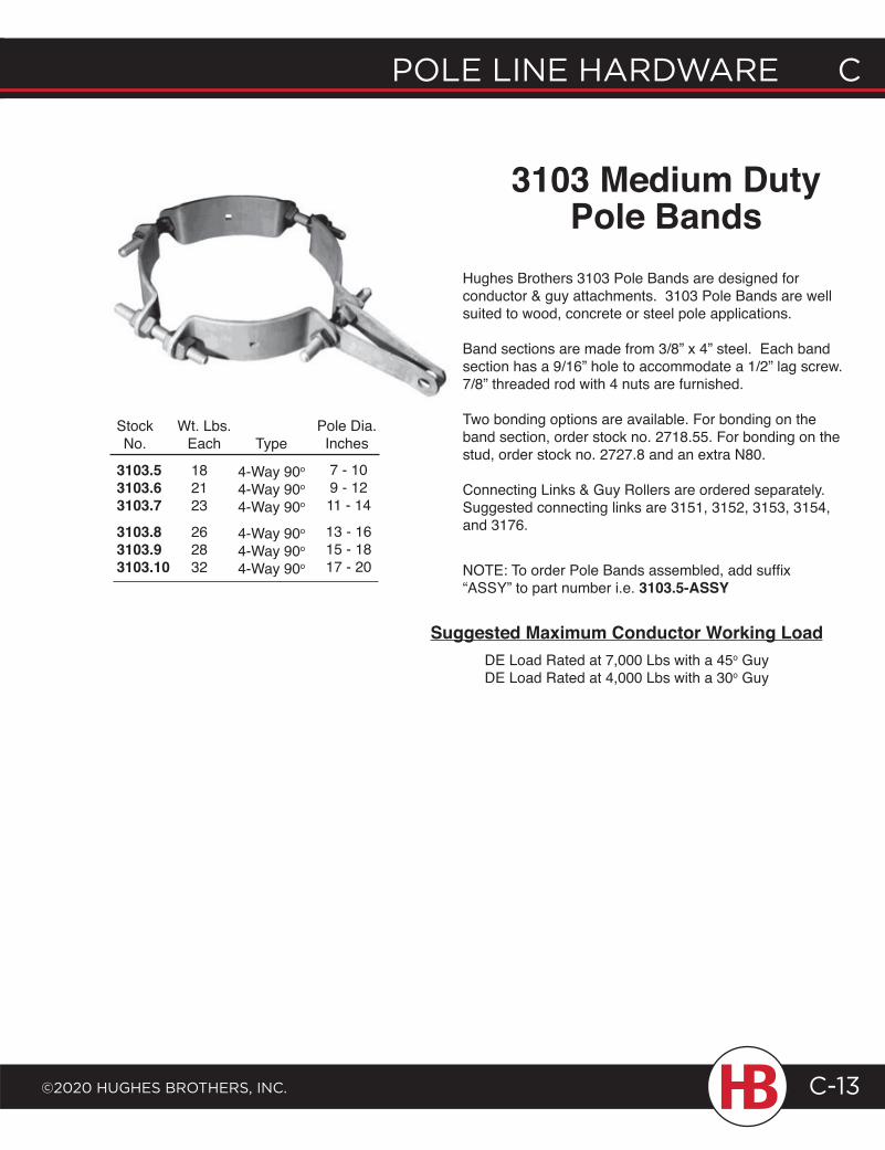
POLE LINE HARDWARE C
©2020 HugHEs BROtHERs, INC.
C POLE LINE HARDWARE
C-13
NOTE: To order Pole Bands assembled, add suffix “ASSY” to part number i.e. 3103.5-ASSY
Hughes Brothers 3103 Pole Bands are designed for conductor & guy attachments. 3103 Pole Bands are well suited to wood, concrete or steel pole applications.
Band sections are made from 3/8” x 4” steel. Each band section has a 9/16” hole to accommodate a 1/2” lag screw. 7/8” threaded rod with 4 nuts are furnished.
Two bonding options are available. For bonding on the band section, order stock no. 2718.55. For bonding on the stud, order stock no. 2727.8 and an extra N80.
Connecting Links & Guy Rollers are ordered separately. Suggested connecting links are 3151, 3152, 3153, 3154, and 3176.
3103 Medium DutyPole Bands
3103.53103.63103.73103.83103.93103.10
Wt. Lbs.Each
StockNo.
182123
262832
Type
4-Way 90o
4-Way 90o
4-Way 90o
4-Way 90o
4-Way 90o
4-Way 90o
7 - 109 - 1211 - 14
13 - 1615 - 1817 - 20
Pole Dia.Inches
Suggested Maximum Conductor Working LoadDE Load Rated at 7,000 Lbs with a 45o GuyDE Load Rated at 4,000 Lbs with a 30o Guy
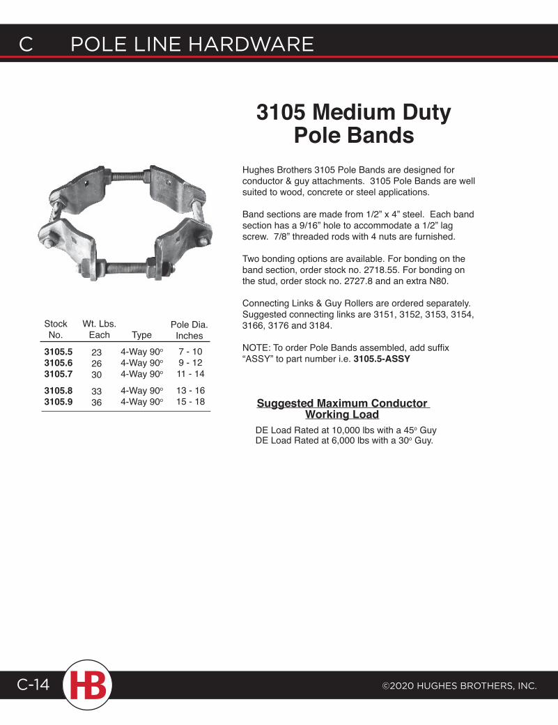
C POLE LINE HARDWARE
©2020 HugHEs BROtHERs, INC.C-14
Hughes Brothers 3105 Pole Bands are designed for conductor & guy attachments. 3105 Pole Bands are well suited to wood, concrete or steel applications.
Band sections are made from 1/2” x 4” steel. Each band section has a 9/16” hole to accommodate a 1/2” lag screw. 7/8” threaded rods with 4 nuts are furnished.
Two bonding options are available. For bonding on the band section, order stock no. 2718.55. For bonding on the stud, order stock no. 2727.8 and an extra N80.
Connecting Links & Guy Rollers are ordered separately. Suggested connecting links are 3151, 3152, 3153, 3154, 3166, 3176 and 3184.
NOTE: To order Pole Bands assembled, add suffix “ASSY” to part number i.e. 3105.5-ASSY
3105 Medium DutyPole Bands
3105.53105.63105.73105.83105.9
Wt. Lbs.Each
StockNo. Type
4-Way 90o
4-Way 90o
4-Way 90o
4-Way 90o
4-Way 90o
7 - 109 - 1211 - 14
13 - 1615 - 18
Pole Dia.Inches
232630
3336 Suggested Maximum Conductor
Working LoadDE Load Rated at 10,000 lbs with a 45o GuyDE Load Rated at 6,000 lbs with a 30o Guy.
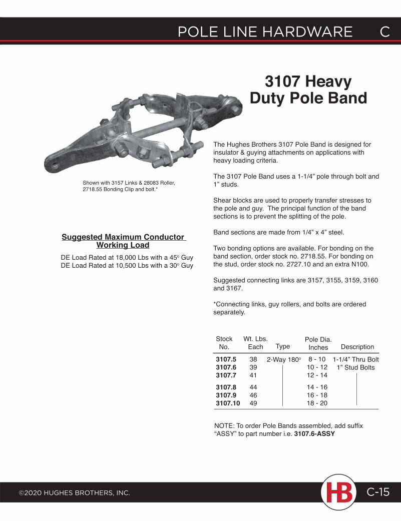
POLE LINE HARDWARE C
©2020 HugHEs BROtHERs, INC.
C POLE LINE HARDWARE
C-15
3107 Heavy Duty Pole Band
Shown with 3157 Links & 28083 Roller, 2718.55 Bonding Clip and bolt.*
The Hughes Brothers 3107 Pole Band is designed for insulator & guying attachments on applications with heavy loading criteria.
The 3107 Pole Band uses a 1-1/4” pole through bolt and 1” studs.
Shear blocks are used to properly transfer stresses to the pole and guy. The principal function of the band sections is to prevent the splitting of the pole.
Band sections are made from 1/4” x 4” steel.
Two bonding options are available. For bonding on the band section, order stock no. 2718.55. For bonding on the stud, order stock no. 2727.10 and an extra N100.
Suggested connecting links are 3157, 3155, 3159, 3160 and 3167.
*Connecting links, guy rollers, and bolts are ordered separately.
Wt. Lbs.Each
StockNo.
3107.53107.63107.73107.83107.93107.10
383941
444649
Pole Dia.Inches Description
8 - 1010 - 1212 - 14
14 - 1616 - 1818 - 20
1-1/4” Thru Bolt1” Stud Bolts
Type
2-Way 180o
NOTE: To order Pole Bands assembled, add suffix “ASSY” to part number i.e. 3107.6-ASSY
Suggested Maximum Conductor Working Load
DE Load Rated at 18,000 Lbs with a 45o Guy DE Load Rated at 10,500 Lbs with a 30o Guy
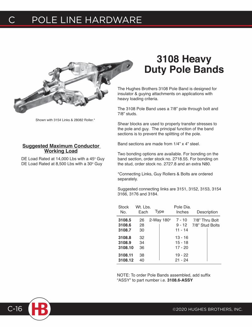
C POLE LINE HARDWARE
©2020 HugHEs BROtHERs, INC.C-16
Shown with 3154 Links & 28082 Roller.*
3108 Heavy Duty Pole Bands
The Hughes Brothers 3108 Pole Band is designed for insulator & guying attachments on applications with heavy loading criteria.
The 3108 Pole Band uses a 7/8” pole through bolt and 7/8” studs.
Shear blocks are used to properly transfer stresses to the pole and guy. The principal function of the band sections is to prevent the splitting of the pole.
Band sections are made from 1/4” x 4” steel.
Two bonding options are available. For bonding on the band section, order stock no. 2718.55. For bonding on the stud, order stock no. 2727.8 and an extra N80.
*Connecting Links, Guy Rollers & Bolts are ordered separately.
Suggested connecting links are 3151, 3152, 3153, 3154 3166, 3176 and 3184.
NOTE: To order Pole Bands assembled, add suffix “ASSY” to part number i.e. 3108.6-ASSY
3108.53108.63108.73108.83108.93108.103108.113108.12
Wt. Lbs.Each
StockNo.
262830
323436
3840
DescriptionType
2-Way 180o
Pole Dia.Inches
7 - 109 - 1211 - 14
13 - 1615 - 1817 - 20
19 - 2221 - 24
7/8” Thru Bolt7/8” Stud Bolts
Suggested Maximum Conductor Working Load
DE Load Rated at 14,000 Lbs with a 45o Guy DE Load Rated at 8,500 Lbs with a 30o Guy
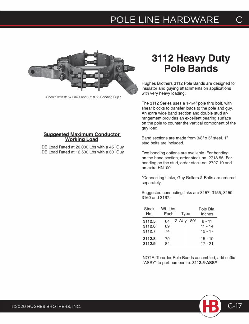
POLE LINE HARDWARE C
©2020 HugHEs BROtHERs, INC.
C POLE LINE HARDWARE
C-17
3112 Heavy Duty Pole Bands
Hughes Brothers 3112 Pole Bands are designed for insulator and guying attachments on applications with very heavy loading.
The 3112 Series uses a 1-1/4” pole thru bolt, with shear blocks to transfer loads to the pole and guy. An extra wide band section and double stud ar-rangement provides an excellent bearing surface on the pole to counter the vertical component of the guy load.
Band sections are made from 3/8” x 5” steel. 1” stud bolts are included.
Two bonding options are available. For bonding on the band section, order stock no. 2718.55. For bonding on the stud, order stock no. 2727.10 and an extra HN100.
*Connecting Links, Guy Rollers & Bolts are ordered separately.
Suggested connecting links are 3157, 3155, 3159, 3160 and 3167.
Wt. Lbs.Each
StockNo.
Pole Dia.Inches
646974
7984
3112.53112.63112.73112.83112.9
8 - 1111 - 1412 - 17
15 - 1917 - 21
Type2-Way 180o
NOTE: To order Pole Bands assembled, add suffix “ASSY” to part number i.e. 3112.5-ASSY
Shown with 3157 Links and 2718.55 Bonding Clip.*
Suggested Maximum Conductor Working Load
DE Load Rated at 20,000 Lbs with a 45o Guy DE Load Rated at 12,500 Lbs with a 30o Guy
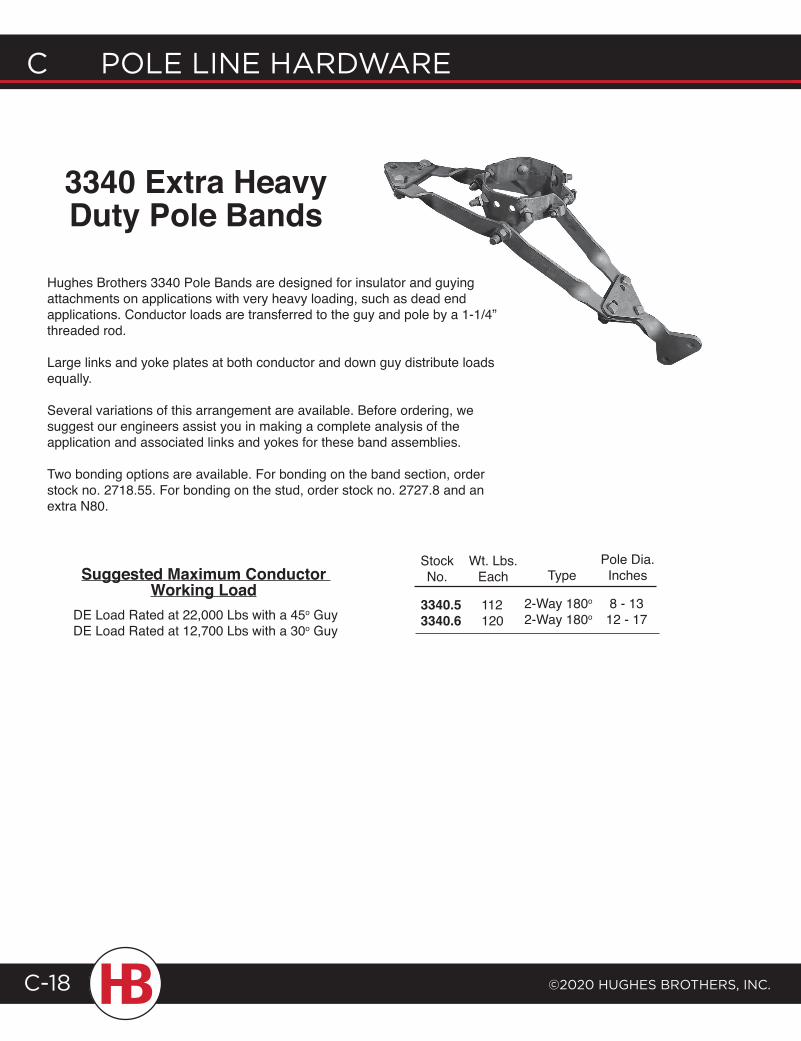
C POLE LINE HARDWARE
©2020 HugHEs BROtHERs, INC.C-18
3340 Extra Heavy Duty Pole Bands
Hughes Brothers 3340 Pole Bands are designed for insulator and guying attachments on applications with very heavy loading, such as dead end applications. Conductor loads are transferred to the guy and pole by a 1-1/4” threaded rod.
Large links and yoke plates at both conductor and down guy distribute loads equally.
Several variations of this arrangement are available. Before ordering, we suggest our engineers assist you in making a complete analysis of the application and associated links and yokes for these band assemblies.
Two bonding options are available. For bonding on the band section, order stock no. 2718.55. For bonding on the stud, order stock no. 2727.8 and an extra N80.
Suggested Maximum Conductor Working Load
DE Load Rated at 22,000 Lbs with a 45o Guy DE Load Rated at 12,700 Lbs with a 30o Guy
3340.53340.6
StockNo.
112120
Wt. Lbs.Each Type
2-Way 180o
2-Way 180o8 - 1312 - 17
Pole Dia.Inches
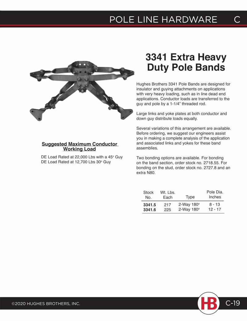
POLE LINE HARDWARE C
©2020 HugHEs BROtHERs, INC.
C POLE LINE HARDWARE
C-19
3341 Extra Heavy Duty Pole Bands
Hughes Brothers 3341 Pole Bands are designed for insulator and guying attachments on applications with very heavy loading, such as in line dead end applications. Conductor loads are transferred to the guy and pole by a 1-1/4” threaded rod.
Large links and yoke plates at both conductor and down guy distribute loads equally.
Several variations of this arrangement are available. Before ordering, we suggest our engineers assist you in making a complete analysis of the application and associated links and yokes for these band assemblies.
Two bonding options are available. For bonding on the band section, order stock no. 2718.55. For bonding on the stud, order stock no. 2727.8 and an extra N80.
Suggested Maximum Conductor Working Load
3341.53341.6
217225
8 - 1312 - 17
2-Way 180o
2-Way 180o
Wt. Lbs.Each
StockNo. Type
Pole Dia.Inches
DE Load Rated at 22,000 Lbs with a 45o Guy DE Load Rated at 12,700 Lbs 30o Guy
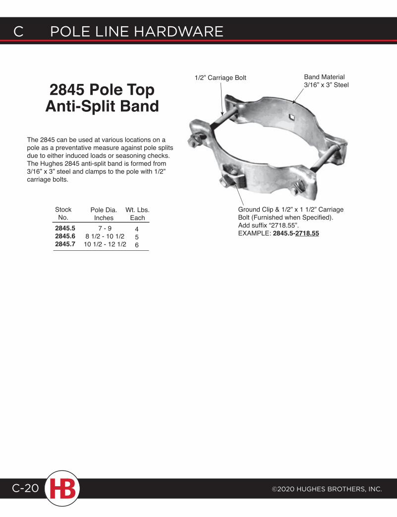
C POLE LINE HARDWARE
©2020 HugHEs BROtHERs, INC.C-20
2845 Pole Top Anti-Split Band
The 2845 can be used at various locations on a pole as a preventative measure against pole splits due to either induced loads or seasoning checks. The Hughes 2845 anti-split band is formed from 3/16” x 3” steel and clamps to the pole with 1/2” carriage bolts.
2845.52845.62845.7
StockNo.
Pole Dia.Inches
7 - 98 1/2 - 10 1/210 1/2 - 12 1/2
Wt. Lbs.Each
456
Band Material 3/16” x 3” Steel
1/2” Carriage Bolt
Ground Clip & 1/2” x 1 1/2” Carriage Bolt (Furnished when Specified). Add suffix “2718.55”. EXAMPLE: 2845.5-2718.55
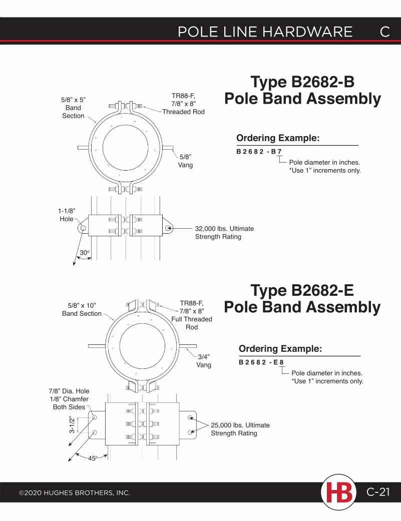
POLE LINE HARDWARE C
©2020 HugHEs BROtHERs, INC.
C POLE LINE HARDWARE
C-21
1-1/8”Hole
5/8” x 10”Band Section
TR88-F, 7/8” x 8”
Full Threaded Rod
3/4”Vang
7/8” Dia. Hole1/8” Chamfer Both Sides
3-1/
2”
5/8”Vang
5/8” x 5”Band
Section
TR88-F, 7/8” x 8”
Threaded Rod
Type B2682-BPole Band Assembly
Type B2682-EPole Band Assembly
32,000 lbs. Ultimate Strength Rating
25,000 lbs. Ultimate Strength Rating
30o
45o
Ordering Example:B 2 6 8 2 - B 7
Pole diameter in inches.*Use 1” increments only.
Ordering Example:B 2 6 8 2 - E 8
Pole diameter in inches.*Use 1” increments only.
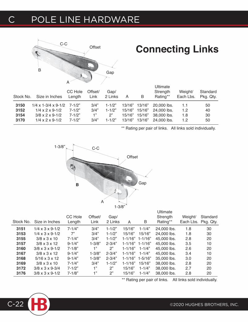
C POLE LINE HARDWARE
©2020 HugHEs BROtHERs, INC.C-22
C-COffset
Gap
A
B
Stock No.
3150315231543170
Size in Inches
1/4 x 1-3/4 x 9-1/21/4 x 2 x 9-1/23/8 x 2 x 9-1/21/4 x 2 x 9-1/2
7-1/2”7-1/2”7-1/2”7-1/2”
CC HoleLength
3/4”3/4”1”
3/4”
Offset/Link
Gap/2 Links
1-1/2”1-1/2”
2”1-1/2”
13/16”15/16”15/16”13/16”
A
13/16”15/16”15/16”13/16”
B
UltimateStrengthRating**
20,000 lbs.24,000 lbs.38,000 lbs.24,000 lbs.
Weight/Each Lbs.
StandardPkg. Qty.
1.11.21.81.2
50403050
** Rating per pair of links. All links sold individually.
Connecting Links
1-3/8” C-C
Offset
B
A1-3/8”
Gap
Stock No. Size in InchesCC HoleLength
Offset/Link
Gap/2 Links A
StandardPkg. Qty.B
UltimateStrengthRating**
Weight/Each Lbs.
3/4”3/4”3/4”
1-3/8”1”
1-3/8”1-3/8”3/4”1”1”
1-1/2”1-1/2”1-1/2”2-3/4”
2”2-3/4”2-3/4”1-1/2”
2”2”
15/16”15/16”1-1/16”1-1/16”1-1/16”1-1/16”1-1/16”1-1/16”15/16”15/16”
30302010201020202020
1/4 x 3 x 9-1/21/4 x 3 x 9-1/2
3/8 x 3 x 103/8 x 3 x 12
3/8 x 3 x 9-1/23/8 x 3 x 125/16 x 3 x 123/8 x 3 x 10
3/8 x 3 x 9-3/43/8 x 3 x 9-1/2
7-1/4”7”
7-1/4”9-1/4”7-1/8”9-1/4”9-1/4”7-1/4”7-1/2”7-1/8”
1-1/4”15/16”1-1/16”1-1/16”1-1/4”1-1/4”1-5/16”15/16”1-1/4”1-1/4”
24,000 lbs.24,000 lbs.45,000 lbs.45,000 lbs.45,000 lbs.45,000 lbs.35,000 lbs.38,000 lbs.38,000 lbs.38,000 lbs.
1.81.82.83.52.63.43.02.82.72.8
3151315331553157316031673168316931723176
** Rating per pair of links. All links sold individually.
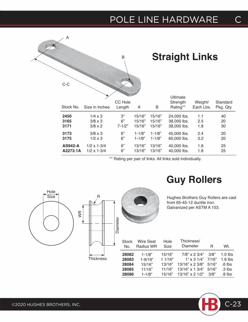
POLE LINE HARDWARE C
©2020 HugHEs BROtHERs, INC.
C POLE LINE HARDWARE
C-23
B
A
C-C
Straight Links
Stock No. Size in InchesCC HoleLength
1/4 x 33/8 x 3 3/8 x 2
3/8 x 31/2 x 3
1/2 x 1-3/41/2 x 1-3/4
15/16”15/16”15/16”
1-1/8”1-1/8”
13/16”13/16”
A B
UltimateStrengthRating**
24,000 lbs.38,000 lbs.38,000 lbs.
45,000 lbs.60,000 lbs.
40,000 lbs.40,000 lbs.
Weight/Each Lbs.
StandardPkg. Qty.
1.12.51.8
2.43.2
1.81.8
402030
2020
2525
15/16”15/16”15/16”
1-1/8”1-1/8”
13/16”13/16”
3”6”
7-1/2”
6”6”
6”6”
** Rating per pair of links. All links sold individually.
Thickness
Dia
met
er
RHoleSize
StockNo.
2808228083280842808528086
Wire SeatRadius WR
1.0 lbs1.6 lbs.6 lbs.3 lbs.8 lbs
Wt.Hole Size
15/16”1 1/16”13/16”11/16”15/16”
7/8” x 2 3/4”1” x 3 1/4”
13/16” x 2 3/8”13/16” x 1 3/4”13/16” x 2 1/2”
Thickness/Diameter
3/8”7/16”5/16”5/16”3/8”
R
1-1/8”1-9/16”15/16”11/16”1-1/8”
Hughes Brothers Guy Rollers are cast from 65-45-12 ductile iron. Galvanized per ASTM A 153.
Guy Rollers
WR
24503165317131733175AS942-AA2273.1A
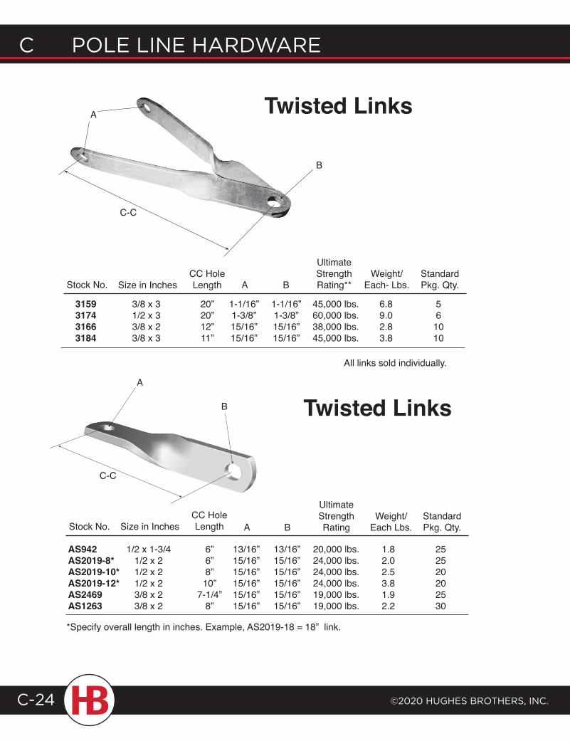
C POLE LINE HARDWARE
©2020 HugHEs BROtHERs, INC.C-24
3159317431663184
Stock No. Size in InchesCC HoleLength
3/8 x 3 1/2 x 33/8 x 2 3/8 x 3
A B
UltimateStrengthRating**
45,000 lbs.60,000 lbs.38,000 lbs.45,000 lbs.
StandardPkg. Qty.
6.89.02.83.8
561010
20”20”12”11”
1-1/16”1-3/8”15/16”15/16”
1-1/16”1-3/8”15/16”15/16”
Twisted Links
B
C-C
Stock No. Size in InchesCC HoleLength A B
Weight/Each Lbs.
StandardPkg. Qty.
1.82.02.53.81.92.2
252520202530
6”6”8”10”
7-1/4”8”
13/16”15/16”15/16”15/16”15/16”15/16”
13/16”15/16”15/16”15/16”15/16”15/16”
1/2 x 1-3/41/2 x 21/2 x 21/2 x 23/8 x 23/8 x 2
B
C-C
Twisted Links
AS942AS2019-8*AS2019-10*AS2019-12*AS2469AS1263
All links sold individually.
UltimateStrengthRating
Weight/Each- Lbs.
20,000 lbs.24,000 lbs.24,000 lbs.24,000 lbs.19,000 lbs.19,000 lbs.
A
A
*Specify overall length in inches. Example, AS2019-18 = 18” link.
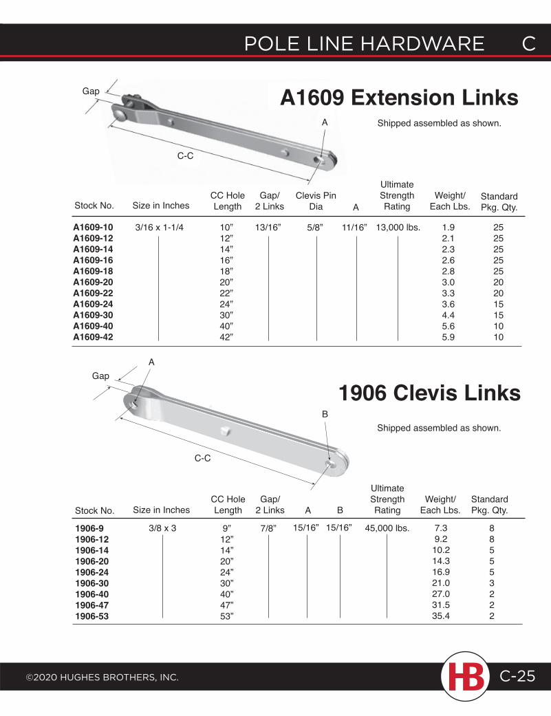
POLE LINE HARDWARE C
©2020 HugHEs BROtHERs, INC.
C POLE LINE HARDWARE
C-25
Stock No.CC HoleLengthSize in Inches
9”12”14”20”24”30”40”47”53”
7/8”
Gap/2 Links
15/16”
A B
15/16”
UltimateStrengthRating
Weight/Each Lbs.
StandardPkg. Qty.
A1609-10A1609-12A1609-14A1609-16A1609-18A1609-20A1609-22A1609-24A1609-30A1609-40A1609-42
Stock No.CC HoleLengthSize in Inches
10”12”14”16”18”20”22”24”30”40”42”
13/16”
Gap/2 Links A
5/8” 11/16”
Clevis PinDia
UltimateStrengthRating
Weight/Each Lbs.
StandardPkg. Qty.
1.92.12.32.62.83.03.33.64.45.65.9
2525252525202015151010
7.39.210.214.316.921.027.031.535.4
885553222
C-C
A
B
AGap
C-C
3/16 x 1-1/4
Shipped assembled as shown.
Shipped assembled as shown.
1906 Clevis Links
13,000 lbs.
45,000 lbs.1906-91906-121906-141906-201906-241906-301906-401906-471906-53
Gap A1609 Extension Links
3/8 x 3
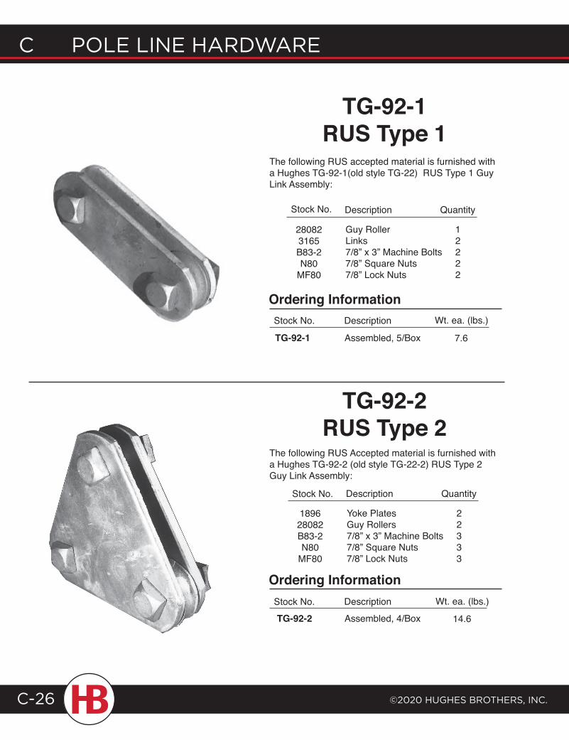
C POLE LINE HARDWARE
©2020 HugHEs BROtHERs, INC.C-26
Stock No.
189628082B83-2N80
MF80
Yoke PlatesGuy Rollers7/8” x 3” Machine Bolts7/8” Square Nuts7/8” Lock Nuts
Description
22333
Quantity
Stock No.
280823165B83-2N80
MF80
Guy RollerLinks7/8” x 3” Machine Bolts7/8” Square Nuts7/8” Lock Nuts
Description
12222
Quantity
Ordering InformationStock No.
TG-92-1 Assembled, 5/Box
Description
Ordering InformationStock No.TG-92-2 Assembled, 4/Box
Description
TG-92-1 RUS Type 1
The following RUS accepted material is furnished with a Hughes TG-92-1(old style TG-22) RUS Type 1 Guy Link Assembly:
TG-92-2 RUS Type 2
The following RUS Accepted material is furnished with a Hughes TG-92-2 (old style TG-22-2) RUS Type 2 Guy Link Assembly:
Wt. ea. (lbs.)
7.6
Wt. ea. (lbs.)
14.6
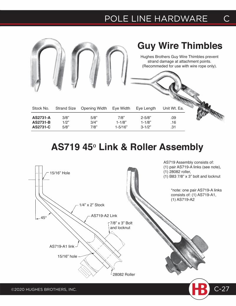
POLE LINE HARDWARE C
©2020 HugHEs BROtHERs, INC.
C POLE LINE HARDWARE
C-27
Guy Wire Thimbles
Stock No. Strand Size Opening Width Eye Width Eye Length Unit Wt. Ea.
AS2731-A 3/8” 5/8” 7/8” 2-5/8” .09AS2731-B 1/2” 3/4” 1-1/8” 1-1/8” .16AS2731-C 5/8” 7/8” 1-5/16” 3-1/2” .31
Hughes Brothers Guy Wire Thimbles prevent strand damage at attachment points.
(Recommeded for use with wire rope only).
AS719 450 Link & Roller Assembly
15/16” Hole
45°
1/4” x 2” Stock
AS719-A2 Link
7/8” x 3” Bolt and locknut
28082 Roller
AS719 Assembly consists of:(1) pair AS719-A links (see note), (1) 28082 roller,(1) B83 7/8” x 3” bolt and locknut
*note: one pair AS719-A links consists of: (1) AS719-A1, (1) AS719-A2
AS719-A1 link
15/16” hole
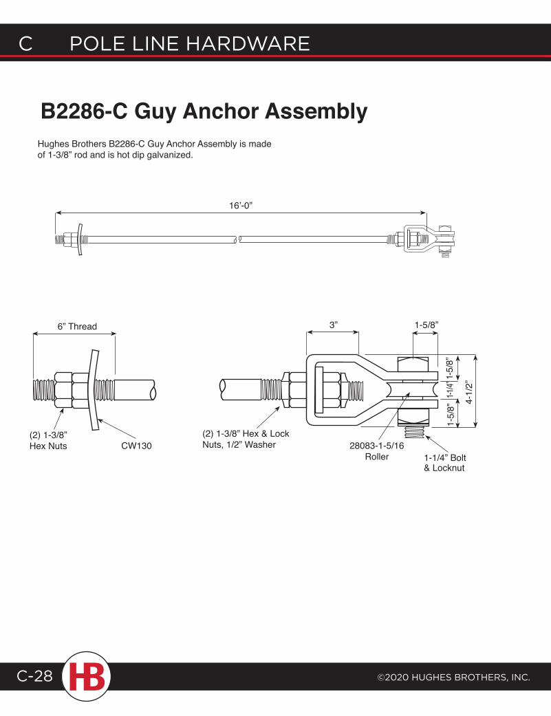
C POLE LINE HARDWARE
©2020 HugHEs BROtHERs, INC.C-28
B2286-C Guy Anchor AssemblyHughes Brothers B2286-C Guy Anchor Assembly is made of 1-3/8” rod and is hot dip galvanized.
16’-0”
6” Thread
(2) 1-3/8” Hex Nuts CW130
(2) 1-3/8” Hex & Lock Nuts, 1/2” Washer 28083-1-5/16
Roller 1-1/4” Bolt & Locknut
3” 1-5/8”
1-5/
8”1-
5/8”
1-1/4”
4-1/
2”
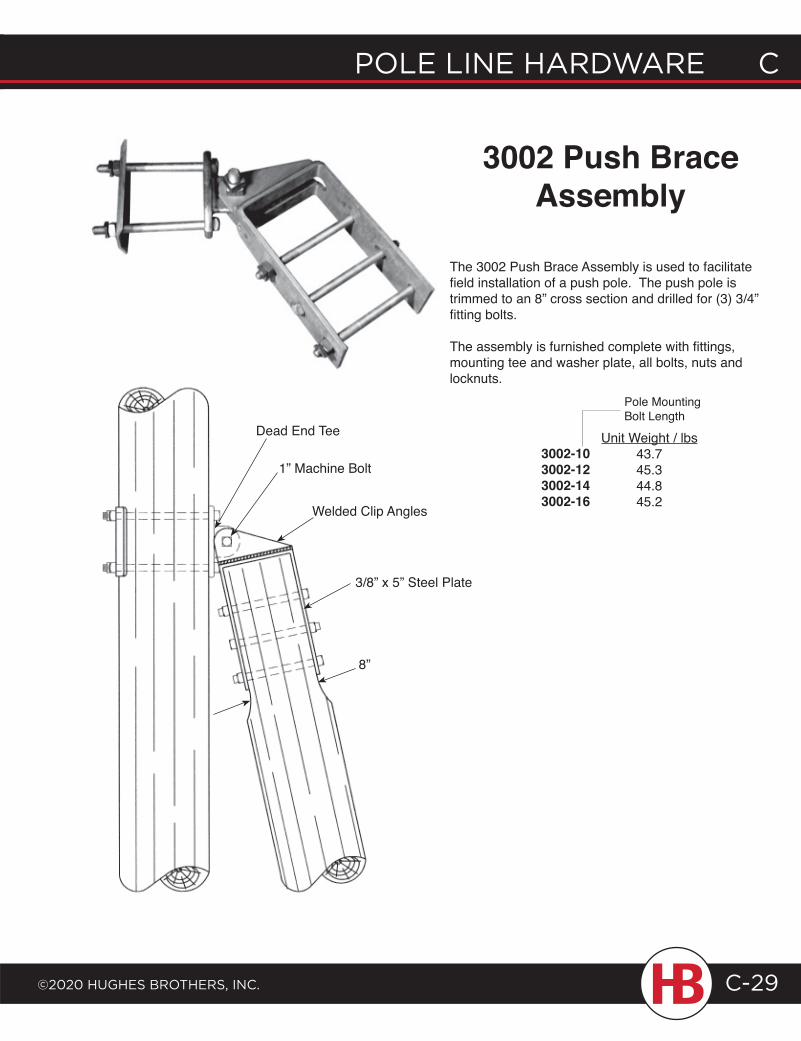
POLE LINE HARDWARE C
©2020 HugHEs BROtHERs, INC.
C POLE LINE HARDWARE
C-29
3002 Push BraceAssembly
The 3002 Push Brace Assembly is used to facilitate field installation of a push pole. The push pole is trimmed to an 8” cross section and drilled for (3) 3/4” fitting bolts.
The assembly is furnished complete with fittings, mounting tee and washer plate, all bolts, nuts and locknuts.
Pole Mounting Bolt Length
3002-10 3002-123002-143002-16
Unit Weight / lbs43.745.344.845.2
Dead End Tee
1” Machine Bolt
Welded Clip Angles
3/8” x 5” Steel Plate
8”
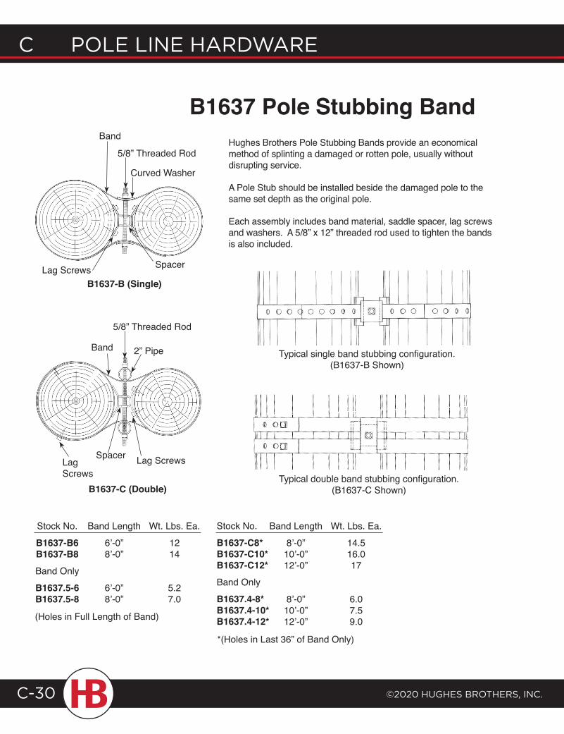
C POLE LINE HARDWARE
©2020 HugHEs BROtHERs, INC.C-30
Hughes Brothers Pole Stubbing Bands provide an economical method of splinting a damaged or rotten pole, usually without disrupting service.
A Pole Stub should be installed beside the damaged pole to the same set depth as the original pole.
Each assembly includes band material, saddle spacer, lag screws and washers. A 5/8” x 12” threaded rod used to tighten the bands is also included.
B1637 Pole Stubbing Band
Typical single band stubbing configuration.(B1637-B Shown)
Stock No.
B1637-B6B1637-B8Band Only
B1637.5-6B1637.5-8
Band Length
6’-0”8’-0”
6’-0”8’-0”
Wt. Lbs. Ea.
1214
5.27.0
Band Length
8’-0”10’-0”12’-0”
8’-0”10’-0”12’-0”
Wt. Lbs. Ea.
14.516.017
6.07.59.0
Lag Screws
Band
5/8” Threaded Rod
Curved Washer
Spacer
B1637-B (Single)
5/8” Threaded Rod
2” PipeBand
Spacer Lag Screws
Stock No.
B1637-C8*B1637-C10*B1637-C12*Band Only
B1637.4-8*B1637.4-10*B1637.4-12*
Lag Screws
B1637-C (Double)
(Holes in Full Length of Band)
*(Holes in Last 36” of Band Only)
Typical double band stubbing configuration.(B1637-C Shown)
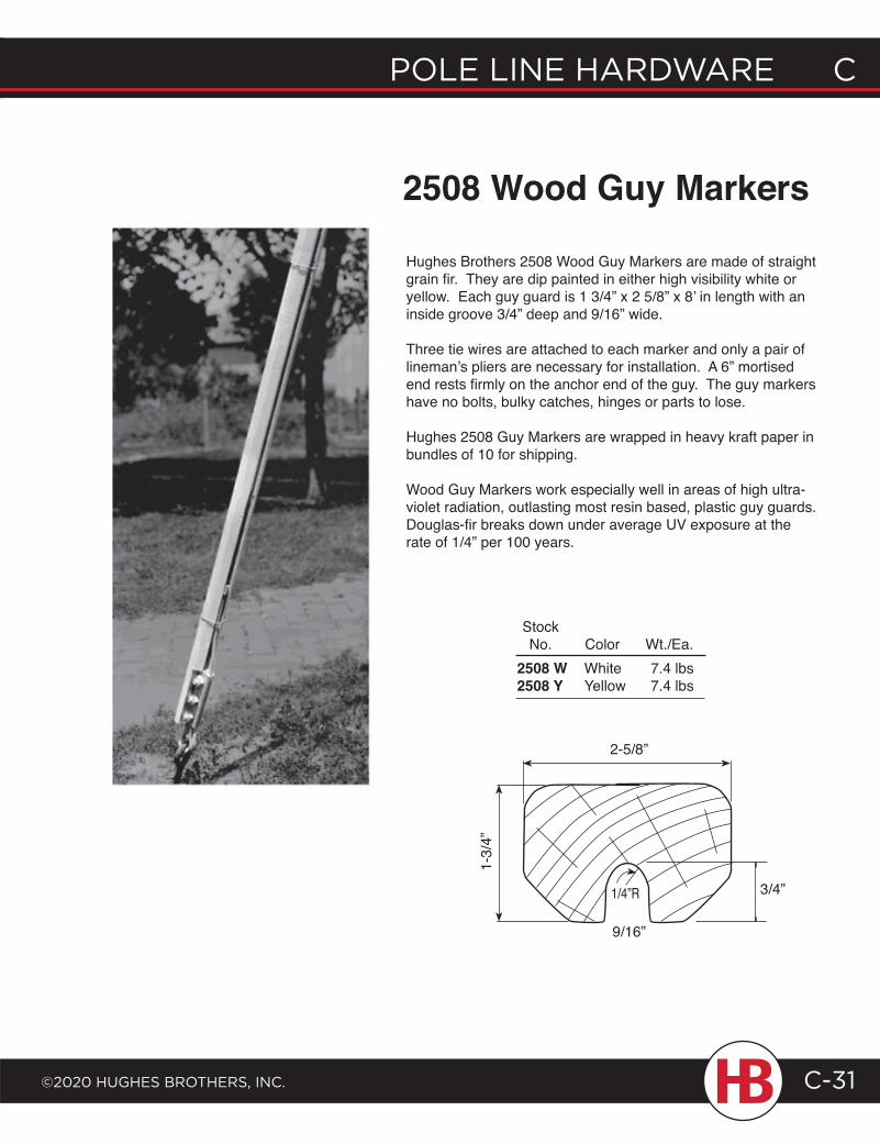
POLE LINE HARDWARE C
©2020 HugHEs BROtHERs, INC.
C POLE LINE HARDWARE
C-31
Hughes Brothers 2508 Wood Guy Markers are made of straight grain fir. They are dip painted in either high visibility white or yellow. Each guy guard is 1 3/4” x 2 5/8” x 8’ in length with an inside groove 3/4” deep and 9/16” wide.
Three tie wires are attached to each marker and only a pair of lineman’s pliers are necessary for installation. A 6” mortised end rests firmly on the anchor end of the guy. The guy markers have no bolts, bulky catches, hinges or parts to lose.
Hughes 2508 Guy Markers are wrapped in heavy kraft paper in bundles of 10 for shipping.
Wood Guy Markers work especially well in areas of high ultra-violet radiation, outlasting most resin based, plastic guy guards. Douglas-fir breaks down under average UV exposure at the rate of 1/4” per 100 years.
2508 Wood Guy Markers
1/4”R
9/16”
1-3/
4”
2-5/8”
StockNo.
2508 W2508 Y
ColorWhiteYellow
Wt./Ea.7.4 lbs7.4 lbs
3/4”
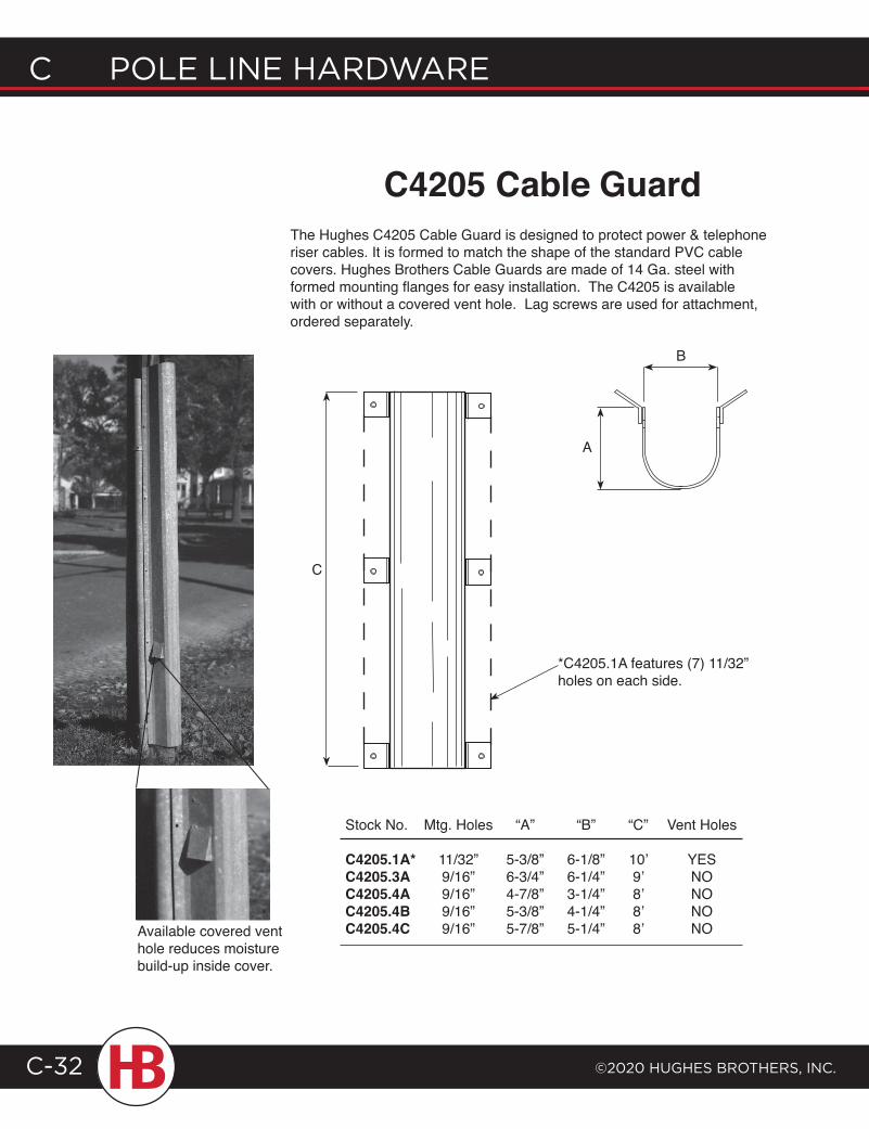
C POLE LINE HARDWARE
©2020 HugHEs BROtHERs, INC.C-32
C4205 Cable Guard
C
*C4205.1A features (7) 11/32” holes on each side.
B
A
Stock No.
C4205.1A*C4205.3AC4205.4AC4205.4BC4205.4C
Mtg. Holes
11/32”9/16”9/16”9/16”9/16”
“A”
5-3/8”6-3/4”4-7/8”5-3/8”5-7/8”
“B”
6-1/8”6-1/4”3-1/4”4-1/4”5-1/4”
“C”
10’9’8’8’8’
Vent Holes
YESNONONONO
The Hughes C4205 Cable Guard is designed to protect power & telephone riser cables. It is formed to match the shape of the standard PVC cable covers. Hughes Brothers Cable Guards are made of 14 Ga. steel with formed mounting flanges for easy installation. The C4205 is available with or without a covered vent hole. Lag screws are used for attachment, ordered separately.
Available covered vent hole reduces moisture build-up inside cover.
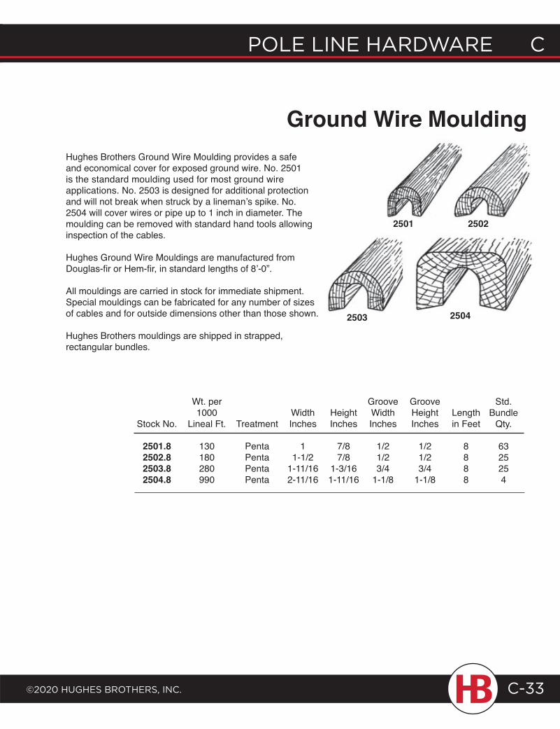
POLE LINE HARDWARE C
©2020 HugHEs BROtHERs, INC.
C POLE LINE HARDWARE
C-33
Ground Wire MouldingHughes Brothers Ground Wire Moulding provides a safe and economical cover for exposed ground wire. No. 2501 is the standard moulding used for most ground wire applications. No. 2503 is designed for additional protection and will not break when struck by a lineman’s spike. No. 2504 will cover wires or pipe up to 1 inch in diameter. The moulding can be removed with standard hand tools allowing inspection of the cables.
Hughes Ground Wire Mouldings are manufactured from Douglas-fir or Hem-fir, in standard lengths of 8’-0”.
All mouldings are carried in stock for immediate shipment. Special mouldings can be fabricated for any number of sizes of cables and for outside dimensions other than those shown.
Hughes Brothers mouldings are shipped in strapped, rectangular bundles.
Stock No.
2501.82502.82503.82504.8
Wt. per1000
Lineal Ft.
130180280990
Treatment
PentaPentaPentaPenta
WidthInches
11-1/2
1-11/162-11/16
HeightInches
7/87/8
1-3/161-11/16
GrooveWidthInches
1/21/23/4
1-1/8
Groove HeightInches
1/21/23/4
1-1/8
Lengthin Feet
8888
Std. Bundle
Qty.
6325254
2504
25022501
2503
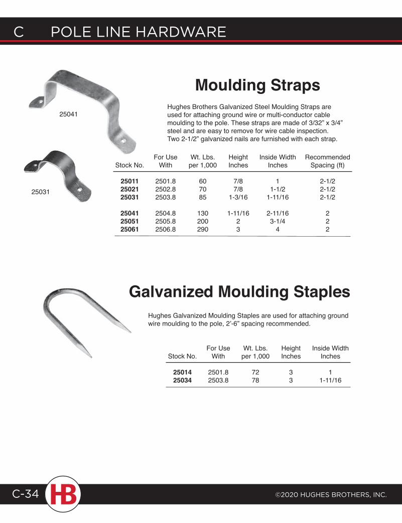
C POLE LINE HARDWARE
©2020 HugHEs BROtHERs, INC.C-34
Moulding StrapsHughes Brothers Galvanized Steel Moulding Straps are used for attaching ground wire or multi-conductor cable moulding to the pole. These straps are made of 3/32” x 3/4” steel and are easy to remove for wire cable inspection. Two 2-1/2” galvanized nails are furnished with each strap.
Stock No.
250112502125031
250412505125061
For Use With
2501.82502.82503.8
2504.82505.82506.8
Wt. Lbs. per 1,000
607085
130200290
Height Inches
7/87/8
1-3/16
1-11/1623
Inside Width Inches
11-1/2
1-11/16
2-11/163-1/4
4
Recommended Spacing (ft)
2-1/22-1/22-1/2
222
25031
25041
Hughes Galvanized Moulding Staples are used for attaching ground wire moulding to the pole, 2’-6” spacing recommended.
Galvanized Moulding Staples
Stock No.
2501425034
For Use With
2501.82503.8
Wt. Lbs. per 1,000
7278
Height Inches
33
Inside Width Inches
11-11/16
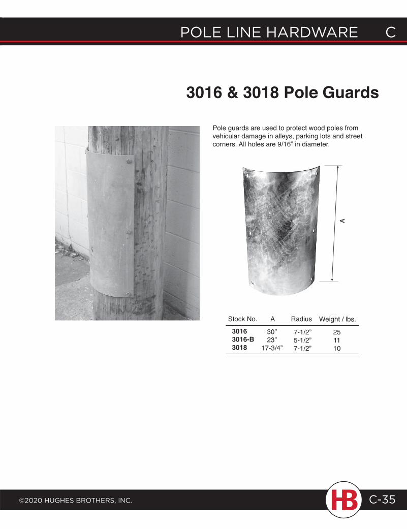
POLE LINE HARDWARE C
©2020 HugHEs BROtHERs, INC.
C POLE LINE HARDWARE
C-35
Stock No.
A
3016 & 3018 Pole Guards
Pole guards are used to protect wood poles from vehicular damage in alleys, parking lots and street corners. All holes are 9/16” in diameter.
A Radius Weight / lbs.
30”23”
17-3/4”
7-1/2”5-1/2”7-1/2”
251110
30163016-B3018
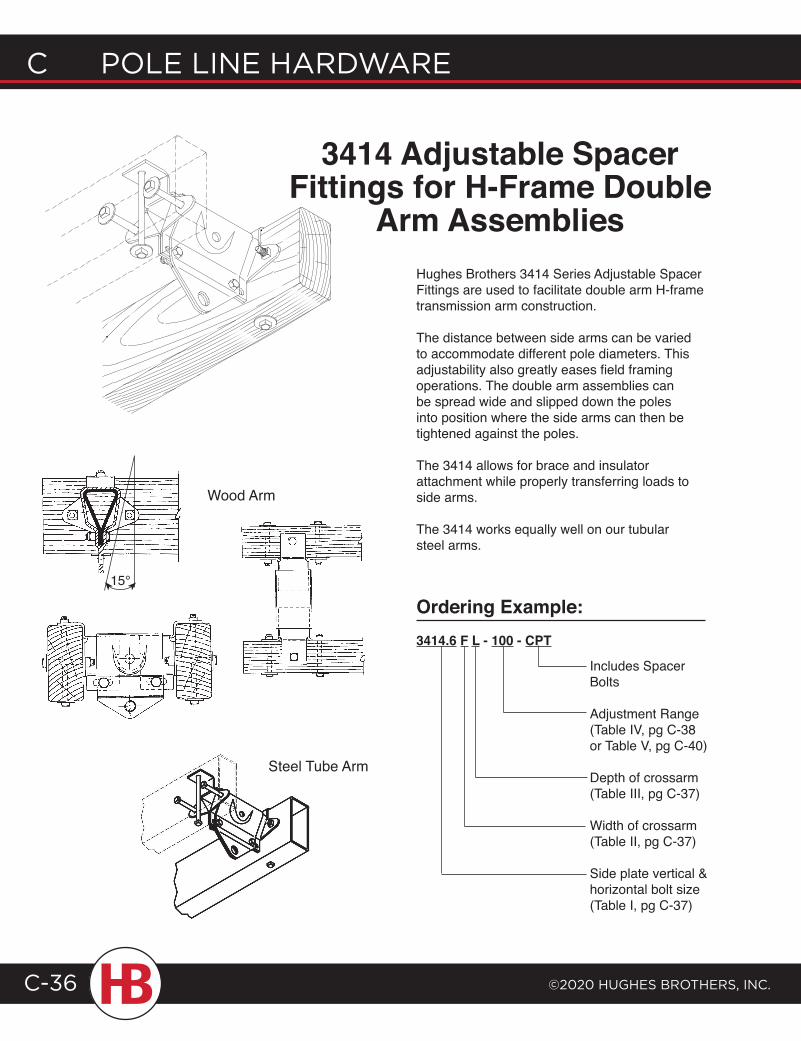
C POLE LINE HARDWARE
©2020 HugHEs BROtHERs, INC.C-36
3414 Adjustable Spacer Fittings for H-Frame Double
Arm AssembliesHughes Brothers 3414 Series Adjustable Spacer Fittings are used to facilitate double arm H-frame transmission arm construction.
The distance between side arms can be varied to accommodate different pole diameters. This adjustability also greatly eases field framing operations. The double arm assemblies can be spread wide and slipped down the poles into position where the side arms can then be tightened against the poles.
The 3414 allows for brace and insulator attachment while properly transferring loads to side arms.
The 3414 works equally well on our tubular steel arms.
Ordering Example:3414.6 F L - 100 - CPT
Includes Spacer Bolts
Adjustment Range(Table IV, pg C-38or Table V, pg C-40)
Depth of crossarm(Table III, pg C-37)
Width of crossarm(Table II, pg C-37)
Side plate vertical & horizontal bolt size (Table I, pg C-37)
Steel Tube Arm
Wood Arm
15°
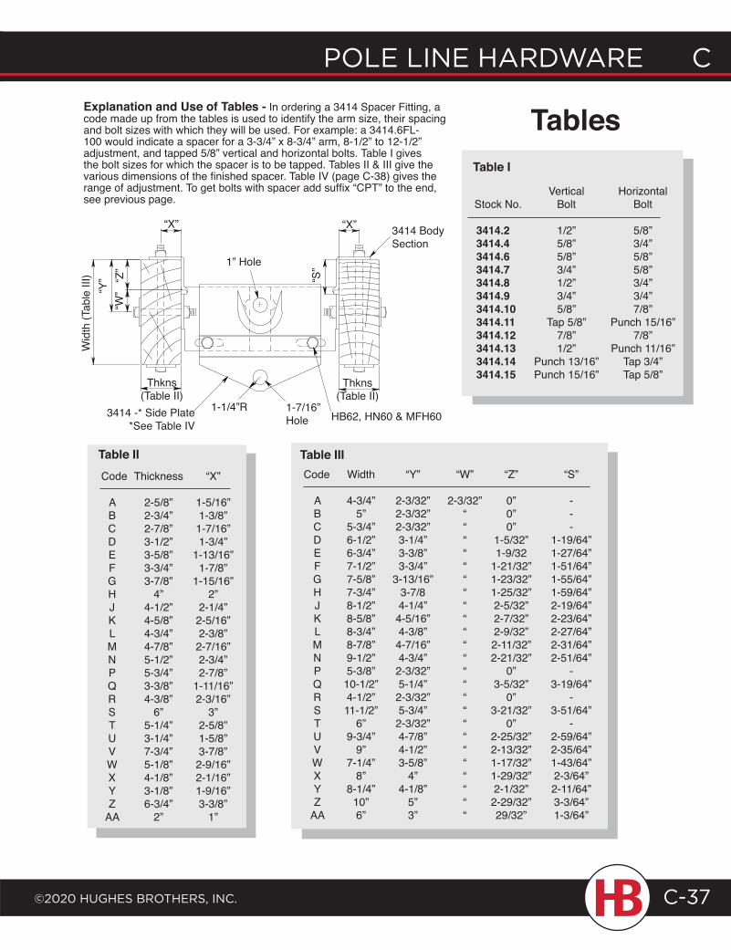
POLE LINE HARDWARE C
©2020 HugHEs BROtHERs, INC.
C POLE LINE HARDWARE
C-37
Code Width “Y” “W” “Z” “S”
A 4-3/4” 2-3/32” 2-3/32” 0” - B 5” 2-3/32” “ 0” - C 5-3/4” 2-3/32” “ 0” - D 6-1/2” 3-1/4” “ 1-5/32” 1-19/64” E 6-3/4” 3-3/8” “ 1-9/32 1-27/64” F 7-1/2” 3-3/4” “ 1-21/32” 1-51/64” G 7-5/8” 3-13/16” “ 1-23/32” 1-55/64” H 7-3/4” 3-7/8 “ 1-25/32” 1-59/64” J 8-1/2” 4-1/4” “ 2-5/32” 2-19/64” K 8-5/8” 4-5/16” “ 2-7/32” 2-23/64” L 8-3/4” 4-3/8” “ 2-9/32” 2-27/64” M 8-7/8” 4-7/16” “ 2-11/32” 2-31/64” N 9-1/2” 4-3/4” “ 2-21/32” 2-51/64” P 5-3/8” 2-3/32” “ 0” - Q 10-1/2” 5-1/4” “ 3-5/32” 3-19/64” R 4-1/2” 2-3/32” “ 0” - S 11-1/2” 5-3/4” “ 3-21/32” 3-51/64” T 6” 2-3/32” “ 0” - U 9-3/4” 4-7/8” “ 2-25/32” 2-59/64” V 9” 4-1/2” “ 2-13/32” 2-35/64” W 7-1/4” 3-5/8” “ 1-17/32” 1-43/64” X 8” 4” “ 1-29/32” 2-3/64” Y 8-1/4” 4-1/8” “ 2-1/32” 2-11/64” Z 10” 5” “ 2-29/32” 3-3/64” AA 6” 3” “ 29/32” 1-3/64”
Table III Code Thickness “X” A 2-5/8” 1-5/16” B 2-3/4” 1-3/8” C 2-7/8” 1-7/16” D 3-1/2” 1-3/4” E 3-5/8” 1-13/16” F 3-3/4” 1-7/8” G 3-7/8” 1-15/16” H 4” 2” J 4-1/2” 2-1/4” K 4-5/8” 2-5/16” L 4-3/4” 2-3/8” M 4-7/8” 2-7/16” N 5-1/2” 2-3/4” P 5-3/4” 2-7/8” Q 3-3/8” 1-11/16” R 4-3/8” 2-3/16” S 6” 3” T 5-1/4” 2-5/8” U 3-1/4” 1-5/8” V 7-3/4” 3-7/8” W 5-1/8” 2-9/16” X 4-1/8” 2-1/16” Y 3-1/8” 1-9/16” Z 6-3/4” 3-3/8” AA 2” 1”
Table II
Vertical Horizontal Stock No. Bolt Bolt
3414.2 1/2” 5/8” 3414.4 5/8” 3/4” 3414.6 5/8” 5/8” 3414.7 3/4” 5/8” 3414.8 1/2” 3/4” 3414.9 3/4” 3/4” 3414.10 5/8” 7/8” 3414.11 Tap 5/8” Punch 15/16” 3414.12 7/8” 7/8” 3414.13 1/2” Punch 11/16” 3414.14 Punch 13/16” Tap 3/4” 3414.15 Punch 15/16” Tap 5/8”
Table I
TablesExplanation and Use of Tables - In ordering a 3414 Spacer Fitting, a code made up from the tables is used to identify the arm size, their spacing and bolt sizes with which they will be used. For example: a 3414.6FL-100 would indicate a spacer for a 3-3/4” x 8-3/4” arm, 8-1/2” to 12-1/2” adjustment, and tapped 5/8” vertical and horizontal bolts. Table I gives the bolt sizes for which the spacer is to be tapped. Tables II & III give the various dimensions of the finished spacer. Table IV (page C-38) gives the range of adjustment. To get bolts with spacer add suffix “CPT” to the end, see previous page.
Thkns(Table II)
Thkns(Table II)
“X”“X”
“Y” “Z
”“W
”
“S”
3414 Body Section
Wid
th (T
able
III)
1” Hole
1-7/16” Hole
1-1/4”R3414 -* Side Plate*See Table IV
HB62, HN60 & MFH60
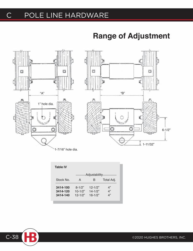
C POLE LINE HARDWARE
©2020 HugHEs BROtHERs, INC.C-38
“A” “B”
6-1/2”
1-11/32”
AdjustabilityStock No. A B Total Adj.
3414-100 8-1/2” 12-1/2” 4”3414-120 10-1/2” 14-1/2” 4”3414-140 12-1/2” 16-1/2” 4”
Table IV
Range of Adjustment
1” hole dia.
1-7/16” hole dia.
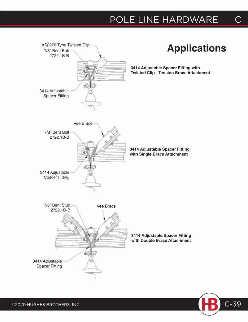
POLE LINE HARDWARE C
©2020 HugHEs BROtHERs, INC.
C POLE LINE HARDWARE
C-39
AS2276 Type Twisted Clip7/8” Bent Bolt
2722.1B-B
3414 Adjustable Spacer Fitting
Applications
3414 Adjustable Spacer Fitting with Double Brace Attachment
Vee Brace
3414 Adjustable Spacer Fitting with Single Brace Attachment
3414 Adjustable Spacer Fitting withTwisted Clip - Tension Brace Attachment
Vee Brace
7/8” Bent Bolt2722.1B-B
3414 Adjustable Spacer Fitting
3414 Adjustable Spacer Fitting
7/8” Bent Stud2722.1D-B
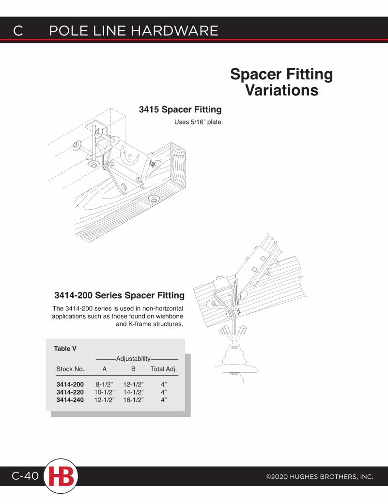
C POLE LINE HARDWARE
©2020 HugHEs BROtHERs, INC.C-40
3414-200 Series Spacer FittingThe 3414-200 series is used in non-horizontal applications such as those found on wishbone
and K-frame structures.
AdjustabilityStock No. A B Total Adj.
3414-200 8-1/2” 12-1/2” 4”3414-220 10-1/2” 14-1/2” 4”3414-240 12-1/2” 16-1/2” 4”
Table V
Spacer Fitting Variations
3415 Spacer FittingUses 5/16” plate.
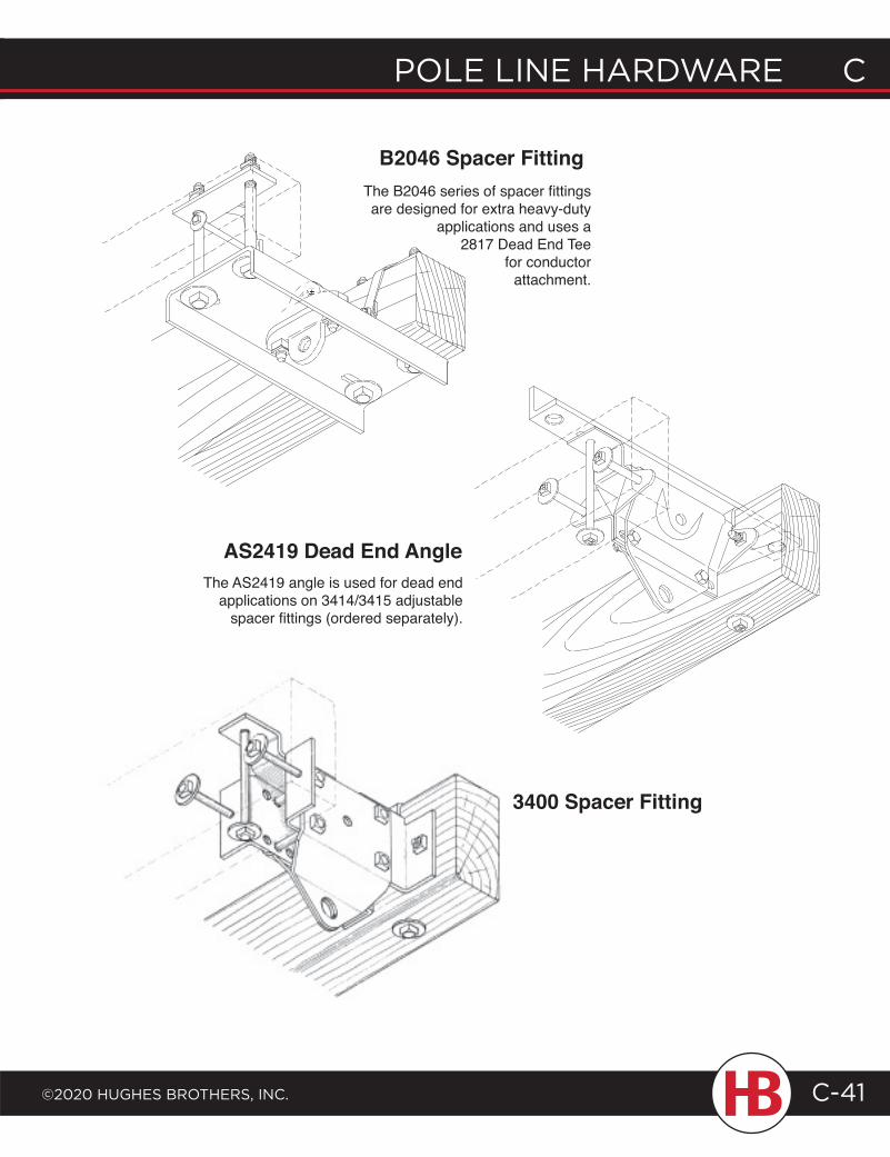
POLE LINE HARDWARE C
©2020 HugHEs BROtHERs, INC.
C POLE LINE HARDWARE
C-41
The B2046 series of spacer fittings are designed for extra heavy-duty
applications and uses a 2817 Dead End Tee
for conductor attachment.
B2046 Spacer Fitting
AS2419 Dead End AngleThe AS2419 angle is used for dead end
applications on 3414/3415 adjustable spacer fittings (ordered separately).
3400 Spacer Fitting
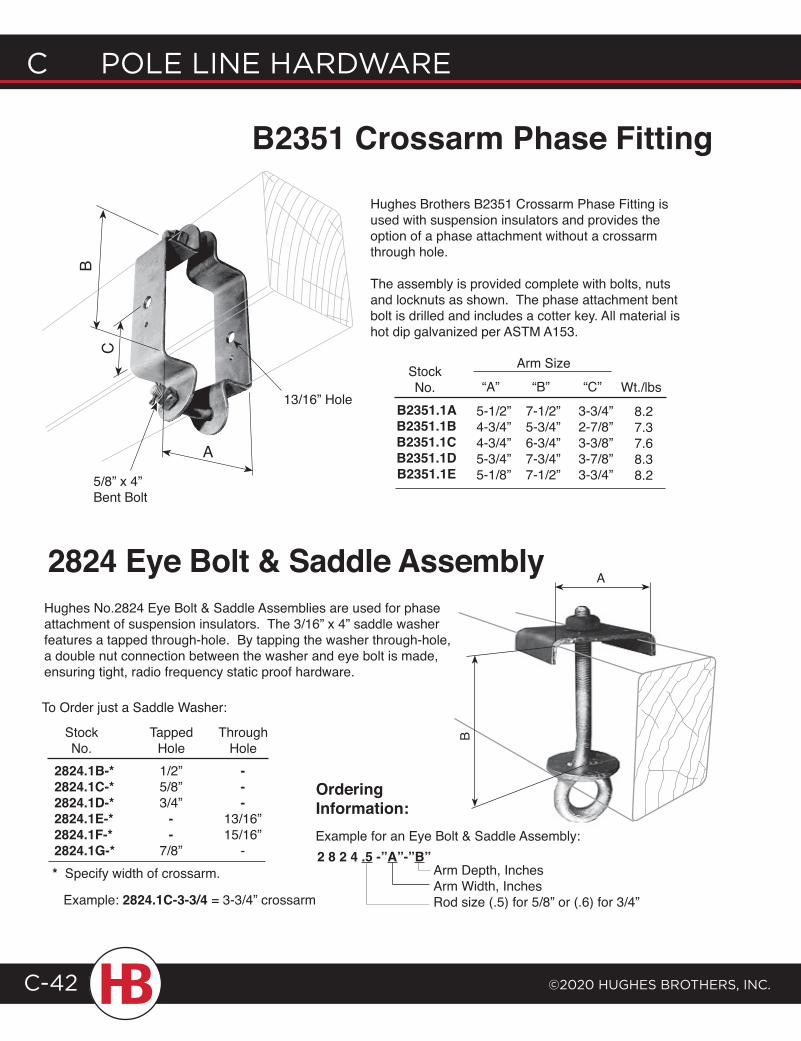
C POLE LINE HARDWARE
©2020 HugHEs BROtHERs, INC.C-42
B
A
5/8” x 4” Bent Bolt
A
C
Hughes No.2824 Eye Bolt & Saddle Assemblies are used for phase attachment of suspension insulators. The 3/16” x 4” saddle washer features a tapped through-hole. By tapping the washer through-hole, a double nut connection between the washer and eye bolt is made, ensuring tight, radio frequency static proof hardware.
To Order just a Saddle Washer:
Stock Tapped Through No. Hole Hole2824.1B-* 1/2” -2824.1C-* 5/8” -2824.1D-* 3/4” -2824.1E-* - 13/16”2824.1F-* - 15/16”2824.1G-* 7/8” -* Specify width of crossarm.
Example: 2824.1C-3-3/4 = 3-3/4” crossarm
Example for an Eye Bolt & Saddle Assembly:2 8 2 4 .5 -”A”-”B”
Arm Depth, InchesArm Width, InchesRod size (.5) for 5/8” or (.6) for 3/4”
Ordering Information:
B2351 Crossarm Phase Fitting
Hughes Brothers B2351 Crossarm Phase Fitting is used with suspension insulators and provides the option of a phase attachment without a crossarm through hole.
The assembly is provided complete with bolts, nuts and locknuts as shown. The phase attachment bent bolt is drilled and includes a cotter key. All material is hot dip galvanized per ASTM A153.
B
13/16” Hole
StockNo. “A” “C”“B”
Arm Size
B2351.1AB2351.1BB2351.1CB2351.1DB2351.1E
5-1/2”4-3/4”4-3/4”5-3/4”5-1/8”
7-1/2”5-3/4”6-3/4”7-3/4”7-1/2”
3-3/4”2-7/8”3-3/8”3-7/8”3-3/4”
Wt./lbs
8.27.37.68.38.2
2824 Eye Bolt & Saddle Assembly
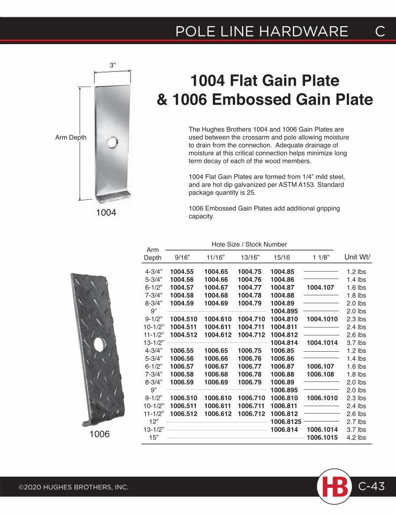
POLE LINE HARDWARE C
©2020 HugHEs BROtHERs, INC.
C POLE LINE HARDWARE
C-43
The Hughes Brothers 1004 and 1006 Gain Plates are used between the crossarm and pole allowing moisture to drain from the connection. Adequate drainage of moisture at this critical connection helps minimize long term decay of each of the wood members.
1004 Flat Gain Plates are formed from 1/4” mild steel, and are hot dip galvanized per ASTM A153. Standard package quantity is 25.
1006 Embossed Gain Plates add additional gripping capacity.
1004 Flat Gain Plate& 1006 Embossed Gain Plate
1004.551004.561004.571004.581004.59
1004.5101004.5111004.512
1006.551006.561006.571006.581006.59
1006.5101006.5111006.512
4-3/4”5-3/4”6-1/2”7-3/4”8-3/4”
9”9-1/2”10-1/2”11-1/2”13-1/2”4-3/4”5-3/4”6-1/2”7-3/4”8-3/4”
9”9-1/2”10-1/2”11-1/2”
12”13-1/2”
15”
1004.651004.661004.671004.681004.69
1004.6101004.6111004.612
1006.651006.661006.671006.681006.69
1006.610 1006.611 1006.612
1004.751004.761004.771004.781004.79
1004.7101004.7111004.712
1006.751006.761006.771006.781006.79
1006.7101006.7111006.712
1004.851004.861004.871004.881004.891004.8951004.8101004.8111004.8121004.8141006.851006.861006.871006.881006.891006.8951006.8101006.8111006.8121006.81251006.814
1004.107
1004.1010
1004.1014
1006.1071006.108
1006.1010
1006.10141006.1015
ArmDepth 9/16” 11/16” 13/16” 15/16 1 1/8”
Hole Size / Stock Number
Unit Wt/
1.2 lbs1.4 lbs1.6 lbs1.8 lbs2.0 lbs2.0 lbs2.3 lbs2.4 lbs2.6 lbs3.7 lbs1.2 lbs1.4 lbs1.6 lbs1.8 lbs2.0 lbs2.0 lbs2.3 lbs2.4 lbs2.6 lbs2.7 lbs3.7 lbs4.2 lbs
3”
Arm Depth
1004
1006
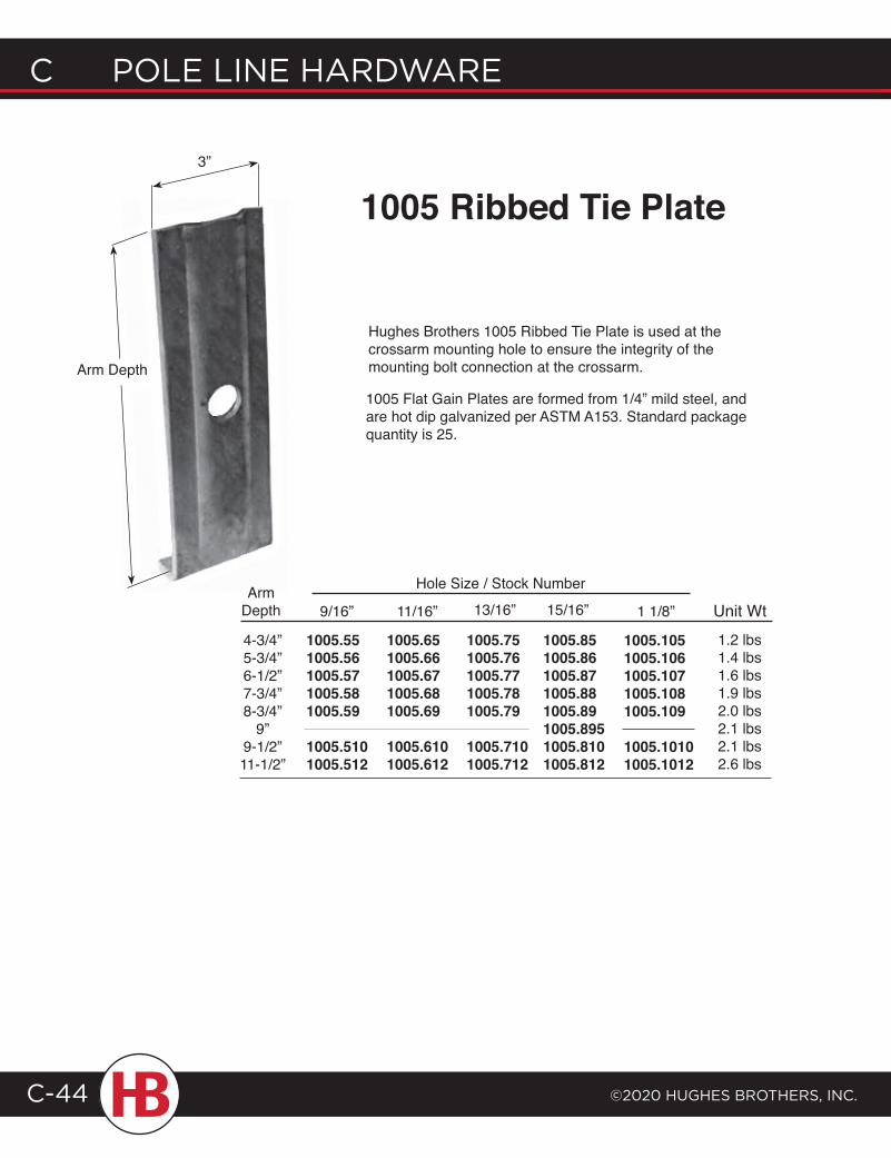
C POLE LINE HARDWARE
©2020 HugHEs BROtHERs, INC.C-44
1005 Ribbed Tie Plate
1005.1051005.1061005.1071005.1081005.109
1005.10101005.1012
ArmDepth 9/16” 11/16” 13/16” 15/16” 1 1/8”
Hole Size / Stock Number
1005.551005.561005.571005.581005.59
1005.5101005.512
1005.651005.661005.671005.681005.69
1005.6101005.612
1005.751005.761005.771005.781005.79
1005.7101005.712
1005.851005.861005.871005.881005.891005.8951005.8101005.812
Hughes Brothers 1005 Ribbed Tie Plate is used at the crossarm mounting hole to ensure the integrity of the mounting bolt connection at the crossarm.
Unit Wt1.2 lbs1.4 lbs1.6 lbs1.9 lbs2.0 lbs2.1 lbs2.1 lbs2.6 lbs
1005 Flat Gain Plates are formed from 1/4” mild steel, and are hot dip galvanized per ASTM A153. Standard package quantity is 25.
4-3/4”5-3/4”6-1/2”7-3/4”8-3/4”
9”9-1/2”11-1/2”
3”
Arm Depth
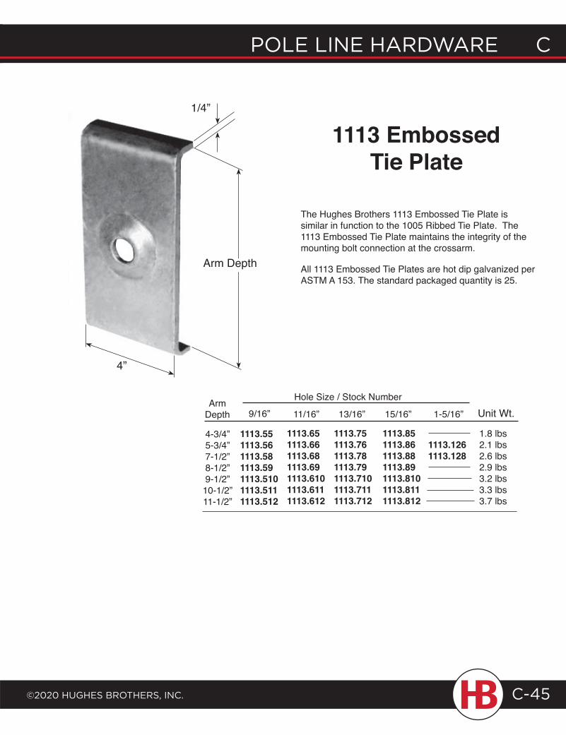
POLE LINE HARDWARE C
©2020 HugHEs BROtHERs, INC.
C POLE LINE HARDWARE
C-45
1113 Embossed Tie Plate
The Hughes Brothers 1113 Embossed Tie Plate is similar in function to the 1005 Ribbed Tie Plate. The 1113 Embossed Tie Plate maintains the integrity of the mounting bolt connection at the crossarm.
All 1113 Embossed Tie Plates are hot dip galvanized per ASTM A 153. The standard packaged quantity is 25.
1/4”
4”
4-3/4”5-3/4”7-1/2”8-1/2”9-1/2”10-1/2”11-1/2”
ArmDepth 9/16”
1113.551113.561113.581113.591113.5101113.5111113.512
11/16”
1113.651113.661113.681113.691113.6101113.6111113.612
13/16”
1113.751113.761113.781113.791113.7101113.7111113.712
15/16”
1113.851113.861113.881113.891113.8101113.8111113.812
1113.1261113.128
1-5/16”
Hole Size / Stock NumberUnit Wt.
1.8 lbs2.1 lbs2.6 lbs2.9 lbs3.2 lbs3.3 lbs3.7 lbs
Arm Depth
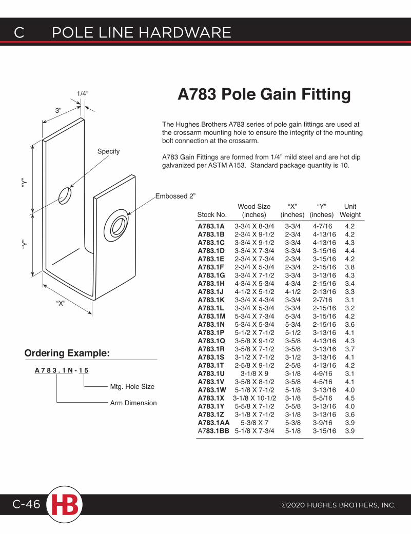
C POLE LINE HARDWARE
©2020 HugHEs BROtHERs, INC.C-46
A783 Pole Gain FittingThe Hughes Brothers A783 series of pole gain fittings are used at the crossarm mounting hole to ensure the integrity of the mounting bolt connection at the crossarm.
A783 Gain Fittings are formed from 1/4” mild steel and are hot dip galvanized per ASTM A153. Standard package quantity is 10.
A783.1A 3-3/4 X 8-3/4 3-3/4 4-7/16 4.2A783.1B 2-3/4 X 9-1/2 2-3/4 4-13/16 4.2A783.1C 3-3/4 X 9-1/2 3-3/4 4-13/16 4.3A783.1D 3-3/4 X 7-3/4 3-3/4 3-15/16 4.4A783.1E 2-3/4 X 7-3/4 2-3/4 3-15/16 4.2A783.1F 2-3/4 X 5-3/4 2-3/4 2-15/16 3.8A783.1G 3-3/4 X 7-1/2 3-3/4 3-13/16 4.3A783.1H 4-3/4 X 5-3/4 4-3/4 2-15/16 3.4A783.1J 4-1/2 X 5-1/2 4-1/2 2-13/16 3.3A783.1K 3-3/4 X 4-3/4 3-3/4 2-7/16 3.1A783.1L 3-3/4 X 5-3/4 3-3/4 2-15/16 3.2A783.1M 5-3/4 X 7-3/4 5-3/4 3-15/16 4.2A783.1N 5-3/4 X 5-3/4 5-3/4 2-15/16 3.6 A783.1P 5-1/2 X 7-1/2 5-1/2 3-13/16 4.1A783.1Q 3-5/8 X 9-1/2 3-5/8 4-13/16 4.3A783.1R 3-5/8 X 7-1/2 3-5/8 3-13/16 3.7A783.1S 3-1/2 X 7-1/2 3-1/2 3-13/16 4.1A783.1T 2-5/8 X 9-1/2 2-5/8 4-13/16 4.2A783.1U 3-1/8 X 9 3-1/8 4-9/16 3.1A783.1V 3-5/8 X 8-1/2 3-5/8 4-5/16 4.1A783.1W 5-1/8 X 7-1/2 5-1/8 3-13/16 4.0A783.1X 3-1/8 X 10-1/2 3-1/8 5-5/16 4.5A783.1Y 5-5/8 X 7-1/2 5-5/8 3-13/16 4.0A783.1Z 3-1/8 X 7-1/2 3-1/8 3-13/16 3.6A783.1AA 5-3/8 X 7 5-3/8 3-9/16 3.9 A783.1BB 5-1/8 X 7-3/4 5-1/8 3-15/16 3.9
Wood Size “X” “Y” UnitStock No. (inches) (inches) (inches) Weight
3”
1/4”
“Y”
“Y”
Specify
Embossed 2”
“X”
Ordering Example:A 7 8 3 . 1 N - 1 5
Mtg. Hole Size
Arm Dimension
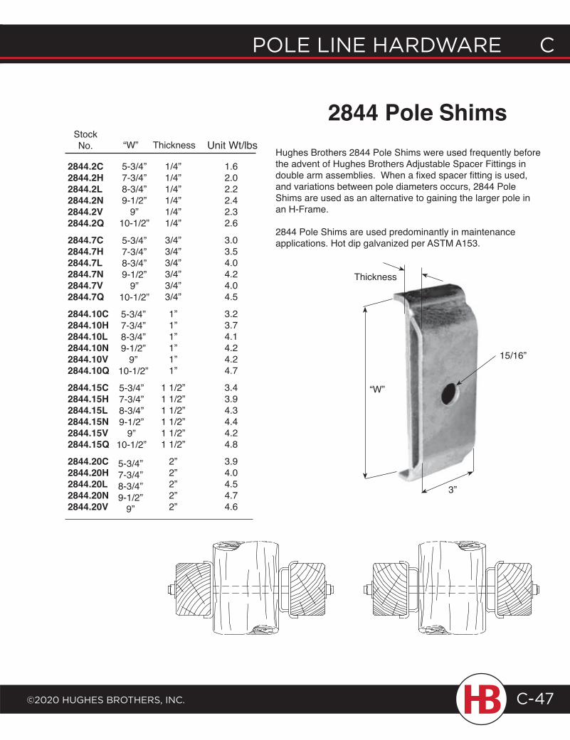
POLE LINE HARDWARE C
©2020 HugHEs BROtHERs, INC.
C POLE LINE HARDWARE
C-47
2844 Pole ShimsHughes Brothers 2844 Pole Shims were used frequently before the advent of Hughes Brothers Adjustable Spacer Fittings in double arm assemblies. When a fixed spacer fitting is used, and variations between pole diameters occurs, 2844 Pole Shims are used as an alternative to gaining the larger pole in an H-Frame.
2844 Pole Shims are used predominantly in maintenance applications. Hot dip galvanized per ASTM A153.
5-3/4”7-3/4”8-3/4”9-1/2”
9”10-1/2”
2844.2C2844.2H2844.2L2844.2N2844.2V2844.2Q2844.7C2844.7H2844.7L2844.7N2844.7V2844.7Q2844.10C2844.10H2844.10L2844.10N2844.10V2844.10Q2844.15C2844.15H2844.15L2844.15N2844.15V2844.15Q2844.20C2844.20H2844.20L2844.20N2844.20V
5-3/4”7-3/4”8-3/4”9-1/2”
9”10-1/2”
5-3/4”7-3/4”8-3/4”9-1/2”
9”10-1/2”
5-3/4”7-3/4”8-3/4”9-1/2”
9”10-1/2”
5-3/4”7-3/4”8-3/4”9-1/2”
9”
1/4”1/4”1/4”1/4”1/4”1/4”
3/4”3/4”3/4”3/4”3/4”3/4”
1”1”1”1”1”1”
1 1/2”1 1/2”1 1/2”1 1/2”1 1/2”1 1/2”
2”2”2”2”2”
StockNo. “W” Thickness
“W”
Thickness
3”
Unit Wt/lbs
1.62.02.22.42.32.6
3.03.54.04.24.04.5
3.23.74.14.24.24.7
3.43.94.34.44.24.8
3.94.04.54.74.6
15/16”
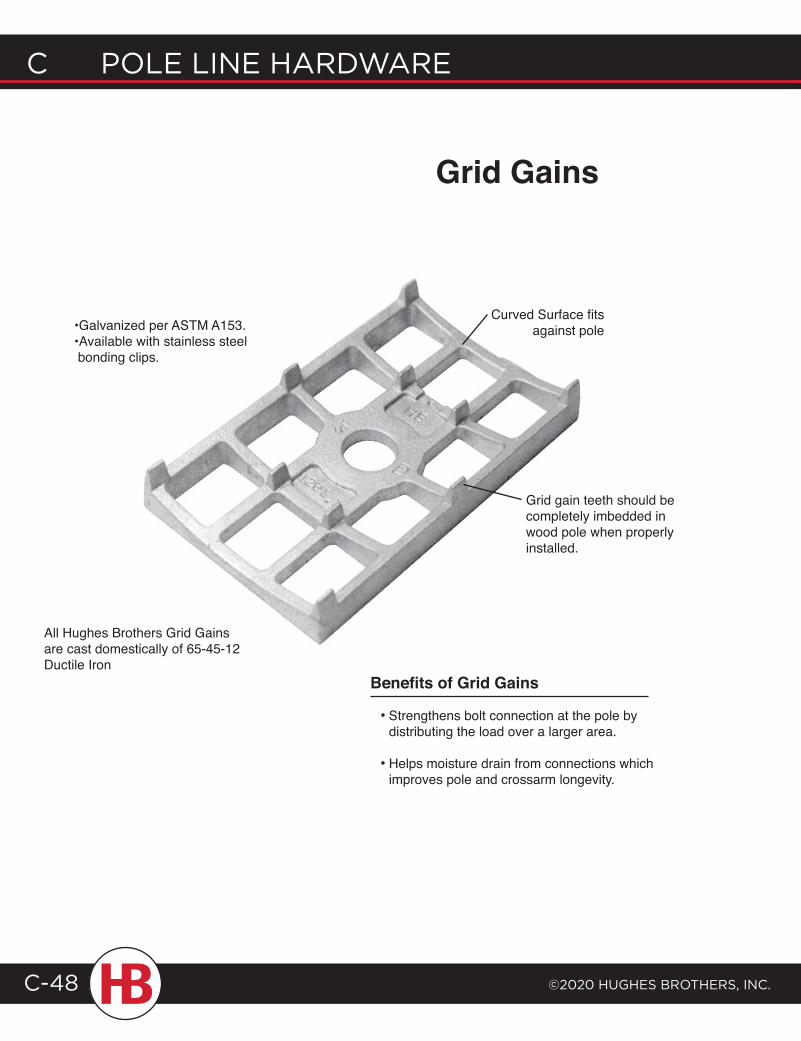
C POLE LINE HARDWARE
©2020 HugHEs BROtHERs, INC.C-48
Curved Surface fitsagainst pole•Galvanized per ASTM A153.
•Available with stainless steel bonding clips.
Strengthens bolt connection at the pole bydistributing the load over a larger area.
Helps moisture drain from connections which improves pole and crossarm longevity.
•
•
Benefits of Grid Gains
Grid Gains
All Hughes Brothers Grid Gains are cast domestically of 65-45-12 Ductile Iron
Grid gain teeth should be completely imbedded in wood pole when properly installed.
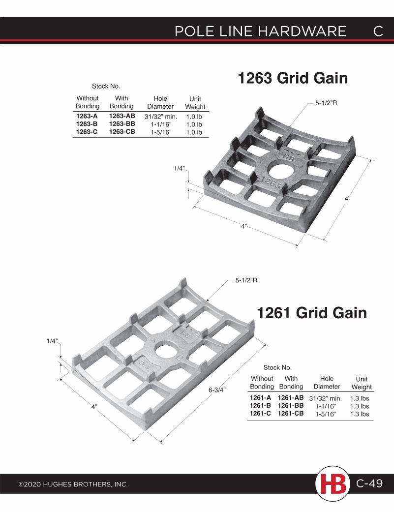
POLE LINE HARDWARE C
©2020 HugHEs BROtHERs, INC.
C POLE LINE HARDWARE
C-49
4”
1/4”
4”
5-1/2”R
1263 Grid Gain
5-1/2”R
6-3/4”
4”
1/4”
1261 Grid Gain
WithoutBonding
WithBonding
Stock No.
HoleDiameter
UnitWeight
1263-A1263-B1263-C
1263-AB1263-BB1263-CB
31/32” min.1-1/16”1-5/16”
1.0 lb1.0 lb1.0 lb
WithoutBonding
WithBonding
Stock No.Hole
DiameterUnit
Weight1261-A1261-B1261-C
1261-AB1261-BB1261-CB
31/32” min.1-1/16”1-5/16”
1.3 lbs1.3 lbs1.3 lbs
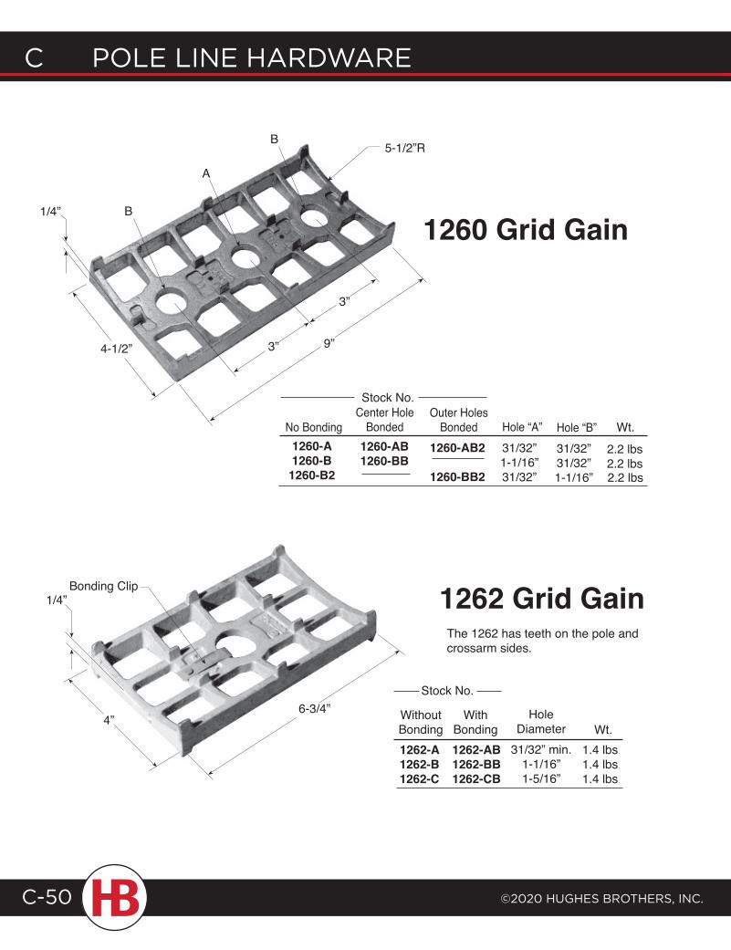
C POLE LINE HARDWARE
©2020 HugHEs BROtHERs, INC.C-50
1/4”
1260 Grid Gain
9”4-1/2”
5-1/2”R
B
A
B
3”
3”
No BondingCenter Hole
BondedOuter Holes
Bonded Hole “A” Hole “B” Wt.
Stock No.
1260-A1260-B1260-B2
1260-AB1260-BB
1260-AB2
1260-BB2
31/32”1-1/16”31/32”
31/32”31/32”1-1/16”
2.2 lbs2.2 lbs
6-3/4”4”
1262 Grid GainThe 1262 has teeth on the pole and crossarm sides.
Bonding Clip1/4”
WithoutBonding
WithBonding
HoleDiameter Wt.
Stock No.
1262-A1262-B1262-C
1262-AB1262-BB1262-CB
31/32” min.1-1/16”1-5/16”
1.4 lbs1.4 lbs1.4 lbs
2.2 lbs
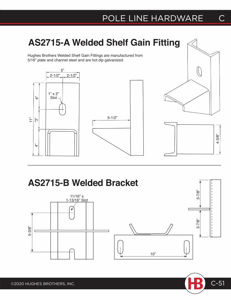
POLE LINE HARDWARE C
©2020 HugHEs BROtHERs, INC.
C POLE LINE HARDWARE
C-51
Hughes Brothers Welded Shelf Gain Fittings are manufactured from 5/16” plate and channel steel and are hot dip galvanized.
11”
4”“3
”4”
1” x 2” Slot
5”2-1/2” 2-1/2”
5-1/2”
4-3/
8”
AS2715-A Welded Shelf Gain Fitting
10”
3-7/
8”3-
7/8”
5-3/
8”
AS2715-B Welded Bracket11/16” x
1-13/16” Slot
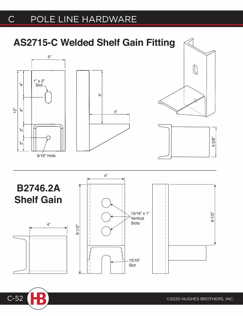
C POLE LINE HARDWARE
©2020 HugHEs BROtHERs, INC.C-52
AS2715-C Welded Shelf Gain Fitting
6”
8”
9/16” Hole
5”
1” x 2” Slot
2”2”
4”4”
12”
4-3/
8”
B2746.2A Shelf Gain
15/16” x 1” Vertical Slots
15/16” Slot
6-1/
2”
4”
9-1/
2”
4”
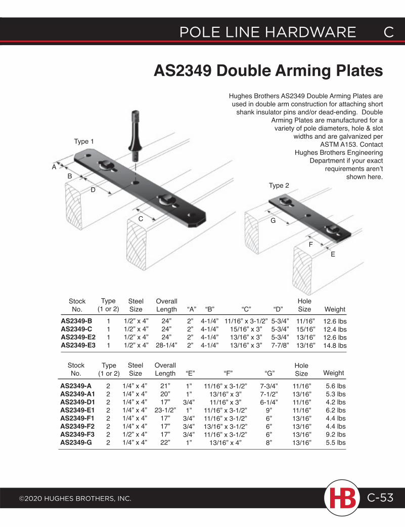
POLE LINE HARDWARE C
©2020 HugHEs BROtHERs, INC.
C POLE LINE HARDWARE
C-53
AB
D
C
Type 1
EF
G
Type 2
AS2349 Double Arming PlatesHughes Brothers AS2349 Double Arming Plates are used in double arm construction for attaching short
shank insulator pins and/or dead-ending. Double Arming Plates are manufactured for a variety of pole diameters, hole & slot
widths and are galvanized per ASTM A153. Contact
Hughes Brothers Engineering Department if your exact
requirements aren’t shown here.
StockNo.
SteelSize
OverallLength “A” “B” “C” “D”
Type (1 or 2) Weight
Hole Size
1/2” x 4”1/2” x 4”1/2” x 4”1/2” x 4”
24”24”24”
28-1/4”
2”2”2”2”
4-1/4”4-1/4”4-1/4”4-1/4”
11/16” x 3-1/2”15/16” x 3”13/16” x 3”13/16” x 3”
5-3/4”5-3/4”5-3/4”7-7/8”
12.6 lbs12.4 lbs12.6 lbs14.8 lbs
11/16”15/16”13/16”13/16”
1”1”
3/4”1”
3/4”3/4”3/4”1”
11/16” x 3-1/2”13/16” x 3”11/16” x 3”
11/16” x 3-1/2”11/16” x 3-1/2”13/16” x 3-1/2”11/16” x 3-1/2”
13/16” x 4”
7-3/4”7-1/2”6-1/4”
9”6”6”6”8”
1/4” x 4”1/4” x 4”1/4” x 4”1/4” x 4”1/4” x 4”1/4” x 4”1/2” x 4”1/4” x 4”
21”20”17”
23-1/2”17”17”17”22”
22222222
AS2349-AAS2349-A1AS2349-D1AS2349-E1AS2349-F1AS2349-F2AS2349-F3AS2349-G
5.6 lbs5.3 lbs4.2 lbs6.2 lbs4.4 lbs4.4 lbs9.2 lbs5.5 lbs
11/16”13/16”11/16”11/16”13/16”13/16”13/16”13/16”
SteelSize
OverallLength “E” “F” “G”
Type (1 or 2)
StockNo.
HoleSize Weight
1111
AS2349-BAS2349-CAS2349-E2AS2349-E3
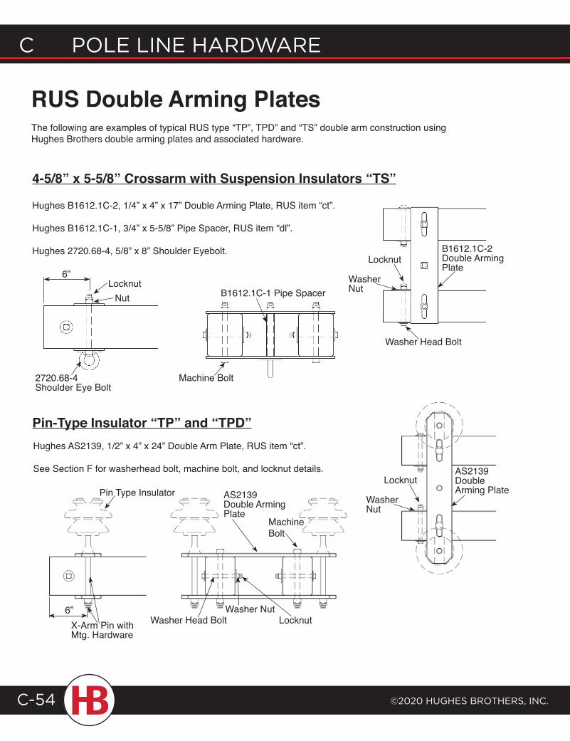
C POLE LINE HARDWARE
©2020 HugHEs BROtHERs, INC.C-54
RUS Double Arming PlatesThe following are examples of typical RUS type “TP”, TPD” and “TS” double arm construction using Hughes Brothers double arming plates and associated hardware.
4-5/8” x 5-5/8” Crossarm with Suspension Insulators “TS”
Pin-Type Insulator “TP” and “TPD”
Hughes B1612.1C-2, 1/4” x 4” x 17” Double Arming Plate, RUS item “ct”.
Hughes B1612.1C-1, 3/4” x 5-5/8” Pipe Spacer, RUS item “dl”.
Hughes 2720.68-4, 5/8” x 8” Shoulder Eyebolt.
Hughes AS2139, 1/2” x 4” x 24” Double Arm Plate, RUS item “ct”.
See Section F for washerhead bolt, machine bolt, and locknut details.
B1612.1C-2 Double Arming Plate
Washer Head Bolt
Locknut
Washer NutB1612.1C-1 Pipe Spacer
Machine Bolt2720.68-4 Shoulder Eye Bolt
6”Locknut
Nut
AS2139 Double Arming Plate
Locknut
Washer Nut
Pin Type Insulator AS2139 Double Arming Plate
Machine Bolt
Washer Head Bolt LocknutWasher Nut6”
X-Arm Pin with Mtg. Hardware
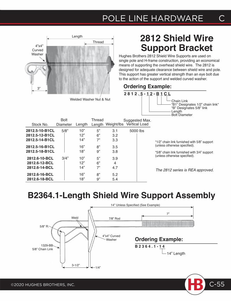
POLE LINE HARDWARE C
©2020 HugHEs BROtHERs, INC.
C POLE LINE HARDWARE
C-55
2812 Shield Wire Support Bracket
Hughes Brothers 2812 Shield Wire Supports are used on single pole and H-frame construction, providing an economical means of supporting the overhead shield wire. The 2812 is designed for adequate clearance between shield wire and pole. This support has greater vertical strength than an eye bolt due to the action of the support and welded curved washer.
2 8 1 2 . 5 - 1 2 - B 1 C LChain Link“B1” Designates 1/2” chain link*“B” Designates 5/8” linkLengthBolt Diameter
Length10”12”14”
16”18”
10”12”14”
16”18”
ThreadLength
5”6”7”
8”9”
5”6”7”
8”9”
5000 lbsWeight/lbs
3.13.23.3
3.53.8
3.94
4.7
5.25.4
*1/2” chain link furnished with 5/8” support (unless otherwise specified).
*5/8” chain link furnished with 3/4” support (unless otherwise specified).
2812.5-10-B1CL2812.5-12-B1CL2812.5-14-B1CL2812.5-16-B1CL2812.5-18-B1CL2812.6-10-BCL2812.6-12-BCL2812.6-14-BCL2812.6-16-BCL2812.6-18-BCL
Stock No.Bolt
Diameter5/8”
3/4”
The 2812 series is REA approved.
Suggested Max.Vertical Load
4”x4” Curved Washer
3”
Welded Washer Nut & Nut
ThreadLength
5/8” R.
1329-BB5/8” Chain Link
3-1/2”1/4”
Weld 7/8” Rod
14” Unless Specified (See Example)
7”
B2364.1-Length Shield Wire Support Assembly
4”x4” Curved Washer Ordering Example:
Ordering Example:
B 2 3 6 4 . 1 - 1 4
14” Length
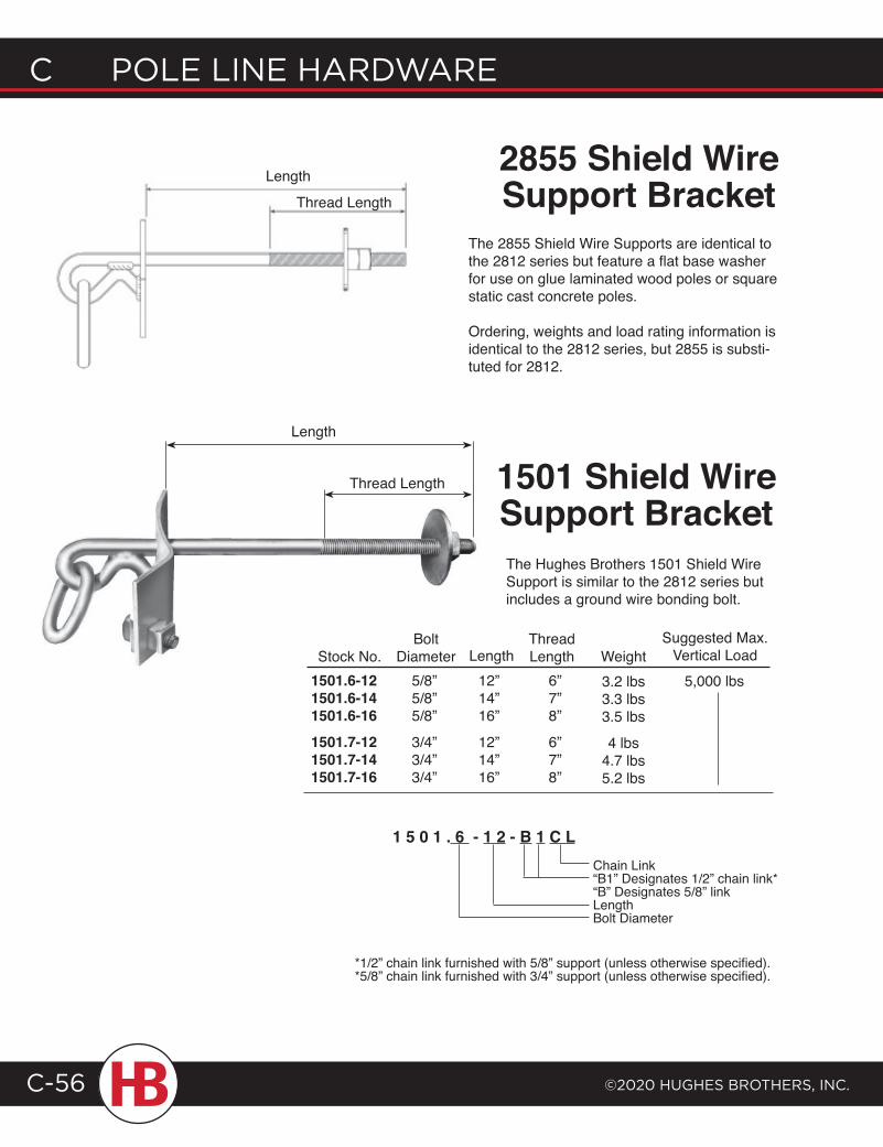
C POLE LINE HARDWARE
©2020 HugHEs BROtHERs, INC.C-56
Length
Thread Length
2855 Shield Wire Support Bracket
1501 Shield Wire Support BracketThe Hughes Brothers 1501 Shield Wire Support is similar to the 2812 series but includes a ground wire bonding bolt.
Stock No.Bolt
Diameter Weight3.2 lbs3.3 lbs3.5 lbs
4 lbs4.7 lbs5.2 lbs
1501.6-121501.6-141501.6-161501.7-121501.7-141501.7-16
5/8”5/8”5/8”
3/4”3/4”3/4”
12”14”16”
12”14”16”
Length6”7”8”
6”7”8”
ThreadLength
Chain Link“B1” Designates 1/2” chain link*“B” Designates 5/8” linkLengthBolt Diameter
1 5 0 1 . 6 - 1 2 - B 1 C L
*1/2” chain link furnished with 5/8” support (unless otherwise specified).*5/8” chain link furnished with 3/4” support (unless otherwise specified).
The 2855 Shield Wire Supports are identical to the 2812 series but feature a flat base washer for use on glue laminated wood poles or square static cast concrete poles.
Ordering, weights and load rating information is identical to the 2812 series, but 2855 is substi-tuted for 2812.
Suggested Max.Vertical Load
5,000 lbs
Length
Thread Length
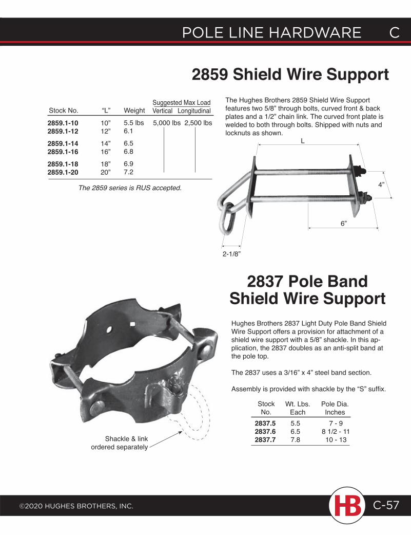
POLE LINE HARDWARE C
©2020 HugHEs BROtHERs, INC.
C POLE LINE HARDWARE
C-57
2859 Shield Wire SupportSuggested Max LoadVertical Longitudinal5,000 lbs 2,500 lbs
Stock No.
2859.1-102859.1-122859.1-142859.1-162859.1-182859.1-20
“L”
10”12”
14”16”
18”20”
Weight
5.5 lbs6.1
6.56.8
6.97.2
The Hughes Brothers 2859 Shield Wire Support features two 5/8” through bolts, curved front & back plates and a 1/2” chain link. The curved front plate is welded to both through bolts. Shipped with nuts and locknuts as shown.
The 2859 series is RUS accepted.
Hughes Brothers 2837 Light Duty Pole Band Shield Wire Support offers a provision for attachment of a shield wire support with a 5/8” shackle. In this ap-plication, the 2837 doubles as an anti-split band at the pole top.
The 2837 uses a 3/16” x 4” steel band section.
Assembly is provided with shackle by the “S” suffix.
2837 Pole Band Shield Wire Support
StockNo.
Pole Dia.Inches
2837.52837.62837.7
7 - 98 1/2 - 1110 - 13
Wt. Lbs.Each5.56.57.8
L
4”
6”
2-1/8”
Shackle & link ordered separately
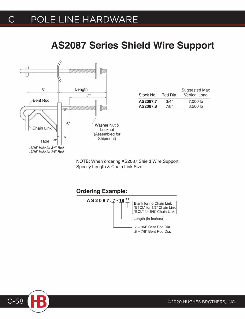
C POLE LINE HARDWARE
©2020 HugHEs BROtHERs, INC.C-58
“Length”
AS2087 Series Shield Wire Support
Blank for no Chain Link“B1CL” for 1/2” Chain Link“BCL” for 5/8” Chain Link
A S 2 0 8 7 . 7 - 18 **Ordering Example:
Bent Rod
Length7”
Chain LinkWasher Nut &
Locknut(Assembled for
Shipment)
NOTE: When ordering AS2087 Shield Wire Support, Specify Length & Chain Link Size
6”
.7 = 3/4” Bent Rod Dia.
.8 = 7/8” Bent Rod Dia.
Length (in Inches)
6”
Suggested Max Stock No. Rod Dia. Vertical Load AS2087.7 3/4” 7,000 lb AS2087.8 7/8” 8,500 lb
Hole13/16” Hole for 3/4” Rod15/16” Hole for 7/8” Rod
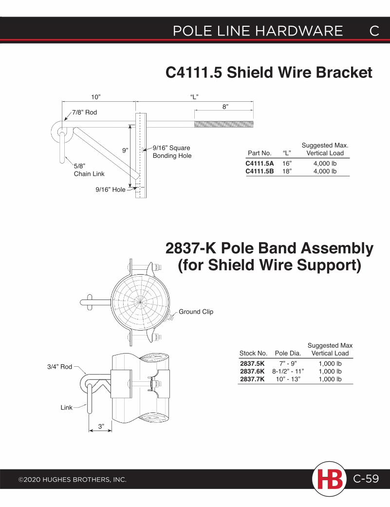
POLE LINE HARDWARE C
©2020 HugHEs BROtHERs, INC.
C POLE LINE HARDWARE
C-59
5/8” Chain Link
10” “L”8”
Suggested Max. Part No. “L” Vertical LoadC4111.5A 16” 4,000 lbC4111.5B 18” 4,000 lb
Ground Clip
3/4” Rod
Link
Suggested Max Stock No. Pole Dia. Vertical Load 2837.5K 7” - 9” 1,000 lb 2837.6K 8-1/2” - 11” 1,000 lb 2837.7K 10” - 13” 1,000 lb
C4111.5 Shield Wire Bracket
2837-K Pole Band Assembly (for Shield Wire Support)
3”
9/16” Hole
9/16” Square Bonding Hole
7/8” Rod
9”
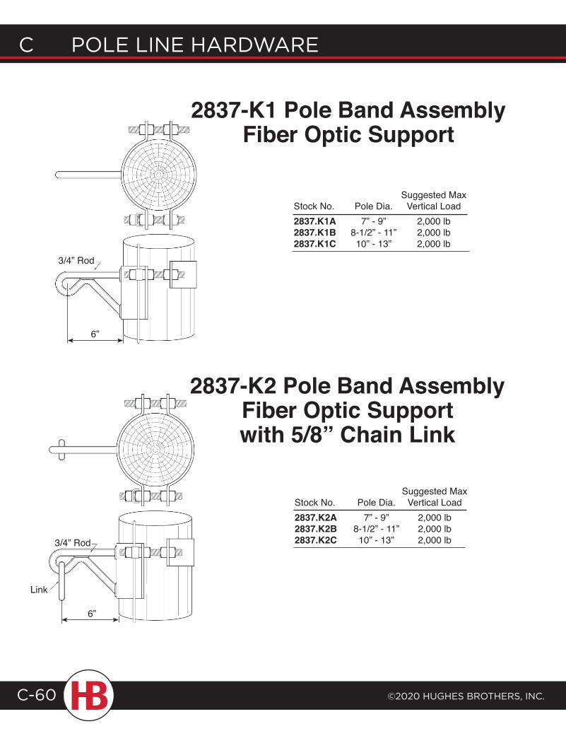
C POLE LINE HARDWARE
©2020 HugHEs BROtHERs, INC.C-60
2837-K1 Pole Band Assembly Fiber Optic Support
2837-K2 Pole Band Assembly Fiber Optic Supportwith 5/8” Chain Link
3/4” Rod
3/4” Rod
Link
Suggested MaxStock No. Pole Dia. Vertical Load2837.K1A 7” - 9” 2,000 lb2837.K1B 8-1/2” - 11” 2,000 lb2837.K1C 10” - 13” 2,000 lb
Suggested MaxStock No. Pole Dia. Vertical Load2837.K2A 7” - 9” 2,000 lb2837.K2B 8-1/2” - 11” 2,000 lb2837.K2C 10” - 13” 2,000 lb
6”
6”
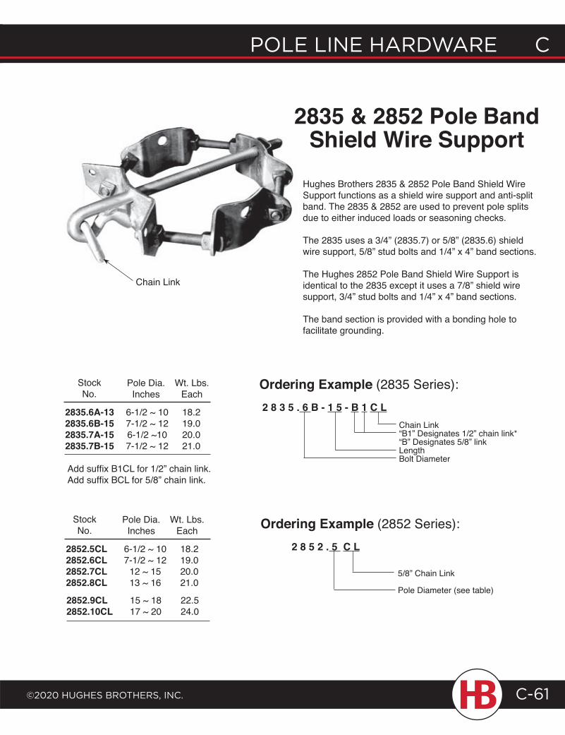
POLE LINE HARDWARE C
©2020 HugHEs BROtHERs, INC.
C POLE LINE HARDWARE
C-61
2835 & 2852 Pole Band Shield Wire Support
2852.5CL2852.6CL2852.7CL2852.8CL
2852.9CL2852.10CL
Pole Dia.Inches
Wt. Lbs.Each
StockNo.
18.219.020.021.0
6-1/2 ~ 107-1/2 ~ 12
12 ~ 1513 ~ 16
22.524.0
15 ~ 1817 ~ 20
2835.6A-132835.6B-152835.7A-152835.7B-15
Pole Dia.Inches
18.219.020.021.0
Wt. Lbs.Each
6-1/2 ~ 107-1/2 ~ 126-1/2 ~107-1/2 ~ 12
StockNo.
Add suffix B1CL for 1/2” chain link.Add suffix BCL for 5/8” chain link.
Hughes Brothers 2835 & 2852 Pole Band Shield Wire Support functions as a shield wire support and anti-split band. The 2835 & 2852 are used to prevent pole splits due to either induced loads or seasoning checks.
The 2835 uses a 3/4” (2835.7) or 5/8” (2835.6) shield wire support, 5/8” stud bolts and 1/4” x 4” band sections.
The Hughes 2852 Pole Band Shield Wire Support is identical to the 2835 except it uses a 7/8” shield wire support, 3/4” stud bolts and 1/4” x 4” band sections.
The band section is provided with a bonding hole to facilitate grounding.
Chain Link“B1” Designates 1/2” chain link*“B” Designates 5/8” linkLengthBolt Diameter
2 8 3 5 . 6 B - 1 5 - B 1 C L
Ordering Example (2835 Series):
2 8 5 2 . 5 C L
Ordering Example (2852 Series):
5/8” Chain Link
Pole Diameter (see table)
Chain Link
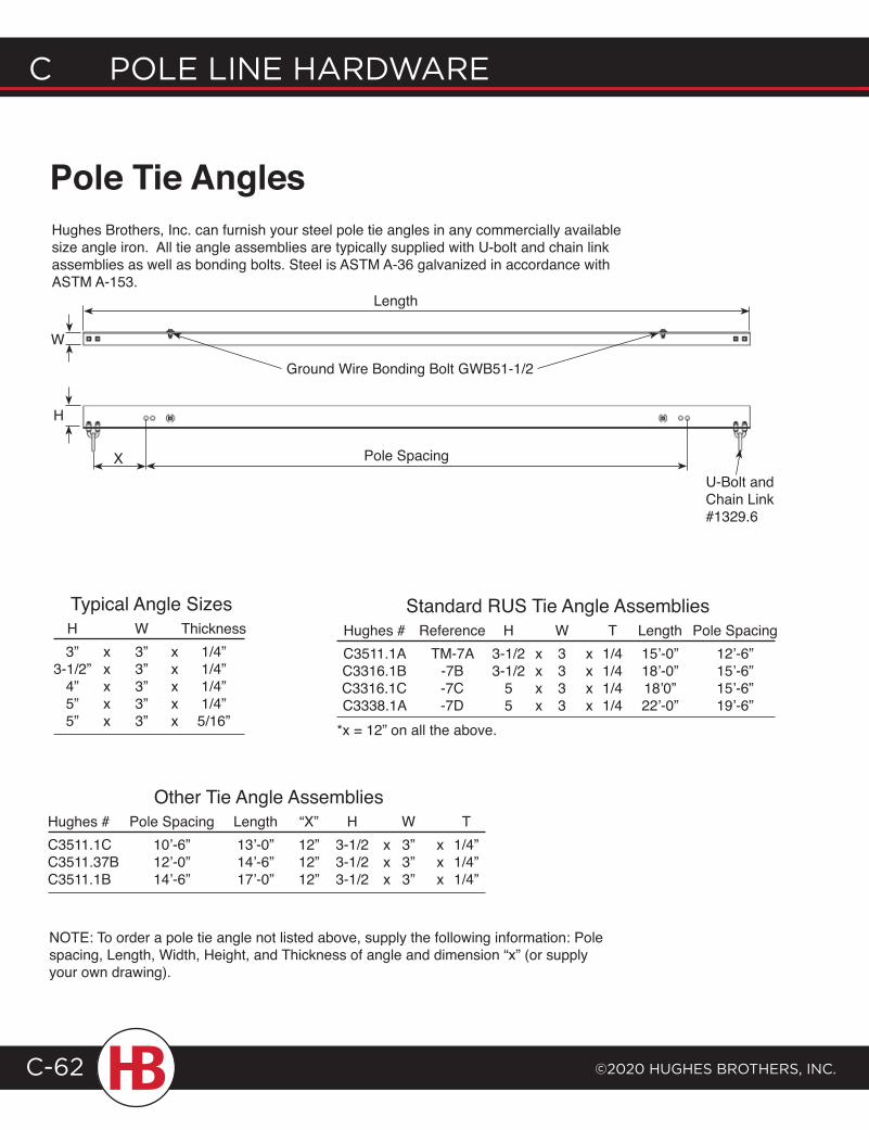
C POLE LINE HARDWARE
©2020 HugHEs BROtHERs, INC.C-62
Pole Tie AnglesHughes Brothers, Inc. can furnish your steel pole tie angles in any commercially available size angle iron. All tie angle assemblies are typically supplied with U-bolt and chain link assemblies as well as bonding bolts. Steel is ASTM A-36 galvanized in accordance with ASTM A-153.
H
Length
Pole Spacing
U-Bolt and Chain Link #1329.6
Typical Angle Sizes H W Thickness 3” x 3” x 1/4” 3-1/2” x 3” x 1/4” 4” x 3” x 1/4” 5” x 3” x 1/4” 5” x 3” x 5/16”
Standard RUS Tie Angle Assemblies Hughes # Reference H W T Length Pole Spacing C3511.1A TM-7A 3-1/2 x 3 x 1/4 15’-0” 12’-6” C3316.1B -7B 3-1/2 x 3 x 1/4 18’-0” 15’-6” C3316.1C -7C 5 x 3 x 1/4 18’0” 15’-6” C3338.1A -7D 5 x 3 x 1/4 22’-0” 19’-6”*x = 12” on all the above.
W
NOTE: To order a pole tie angle not listed above, supply the following information: Pole spacing, Length, Width, Height, and Thickness of angle and dimension “x” (or supply your own drawing).
Other Tie Angle AssembliesHughes # Pole Spacing Length “X” H W TC3511.1C 10’-6” 13’-0” 12” 3-1/2 x 3” x 1/4”C3511.37B 12’-0” 14’-6” 12” 3-1/2 x 3” x 1/4”C3511.1B 14’-6” 17’-0” 12” 3-1/2 x 3” x 1/4”
X
Ground Wire Bonding Bolt GWB51-1/2
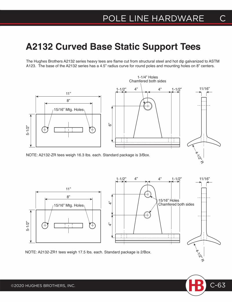
POLE LINE HARDWARE C
©2020 HugHEs BROtHERs, INC.
C POLE LINE HARDWARE
C-63
A2132 Curved Base Static Support TeesThe Hughes Brothers A2132 series heavy tees are flame cut from structural steel and hot dip galvanized to ASTM A123. The base of the A2132 series has a 4.5” radius curve for round poles and mounting holes on 8” centers.
15/16” Mtg. Holes
11/16”11”
8”
5-1/
2” 6”
1-1/4” Holes Chamfered both sides
4-1/2” R
15/16” Mtg. Holes
11”
8”
5-1/
2” 4”4”
NOTE: A2132-ZR tees weigh 16.3 lbs. each. Standard package is 3/Box.
NOTE: A2132-ZR1 tees weigh 17.5 lbs. each. Standard package is 2/Box.
1-1/2” 4” 1-1/2”4”
1-1/2” 4” 1-1/2”4” 11/16”
4-1/2” R
15/16” Holes Chamfered both sides
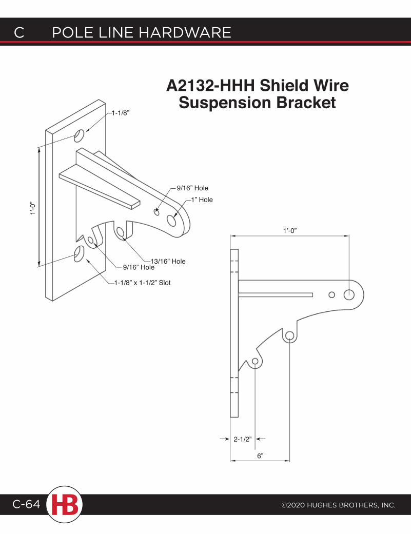
C POLE LINE HARDWARE
©2020 HugHEs BROtHERs, INC.C-64
A2132-HHH Shield Wire Suspension Bracket
1” Hole
13/16” Hole9/16” Hole
1-1/8” x 1-1/2” Slot
1-1/8”
1’-0
”
1’-0”
6”
2-1/2”
9/16” Hole
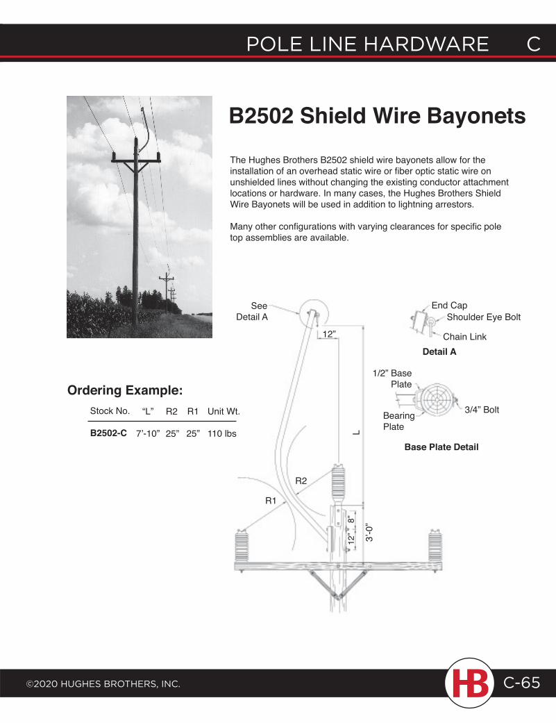
POLE LINE HARDWARE C
©2020 HugHEs BROtHERs, INC.
C POLE LINE HARDWARE
C-65
The Hughes Brothers B2502 shield wire bayonets allow for the installation of an overhead static wire or fiber optic static wire on unshielded lines without changing the existing conductor attachment locations or hardware. In many cases, the Hughes Brothers Shield Wire Bayonets will be used in addition to lightning arrestors.
Many other configurations with varying clearances for specific pole top assemblies are available.
R1
End CapShoulder Eye Bolt
Chain Link12”
3/4” Bolt
R2
Detail A
1/2” Base Plate
Bearing PlateL
12”
Base Plate Detail
B2502 Shield Wire Bayonets
Stock No.
B2502-C
“L”
7’-10”
R1
25”
R2
25”
Unit Wt.
110 lbs
See Detail A
8”
3’-0
”
Ordering Example:
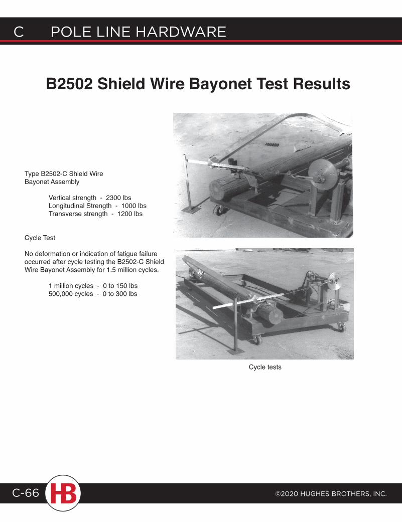
C POLE LINE HARDWARE
©2020 HugHEs BROtHERs, INC.C-66
Cycle tests
Type B2502-C Shield Wire Bayonet Assembly
Vertical strength - 2300 lbs Longitudinal Strength - 1000 lbs Transverse strength - 1200 lbs
Cycle Test
No deformation or indication of fatigue failure occurred after cycle testing the B2502-C Shield Wire Bayonet Assembly for 1.5 million cycles.
1 million cycles - 0 to 150 lbs 500,000 cycles - 0 to 300 lbs
B2502 Shield Wire Bayonet Test Results
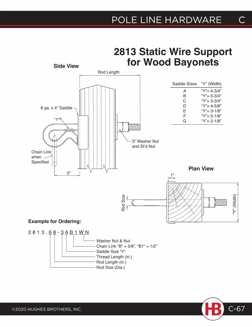
POLE LINE HARDWARE C
©2020 HugHEs BROtHERs, INC.
C POLE LINE HARDWARE
C-67
2813 Static Wire Support for Wood BayonetsSide View
Plan View
Example for Ordering:
2 8 1 3 . 6 8 - 3 A B 1 W NWasher Nut & NutChain Link “B” = 5/8”, “B1” = 1/2”Saddle Size “Y”Thread Length (in.)Rod Length (in.)Rod Size (Dia.)
Rod Length
8 ga. x 4” Saddle
Chain Linkwhen Specified
3”
3” Washer Nutand St’d Nut
Rod
Siz
e
1”
“Y” (
Wid
th)
Saddle Sizes “Y” (Width) A “Y”= 4-3/4” B “Y”= 5-3/4” C “Y”= 3-3/4” D “Y”= 4-5/8” E “Y”= 3-1/8” F “Y”= 5-1/8” G “Y”= 2-1/8”
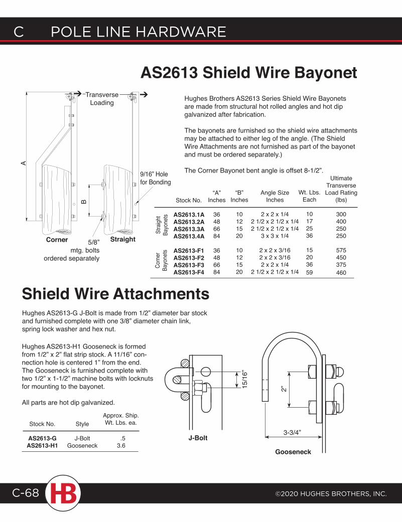
C POLE LINE HARDWARE
©2020 HugHEs BROtHERs, INC.C-68
AS2613 Shield Wire Bayonet
A
B
9/16” Hole for Bonding
Corner Straight5/8” mtg. bolts
ordered separately
Hughes Brothers AS2613 Series Shield Wire Bayonets are made from structural hot rolled angles and hot dip galvanized after fabrication.
The bayonets are furnished so the shield wire attachments may be attached to either leg of the angle. (The Shield Wire Attachments are not furnished as part of the bayonet and must be ordered separately.)
The Corner Bayonet bent angle is offset 8-1/2”.
J-Bolt
Gooseneck
3-3/4”
2”15/1
6”
Hughes AS2613-G J-Bolt is made from 1/2” diameter bar stock and furnished complete with one 3/8” diameter chain link, spring lock washer and hex nut.
Hughes AS2613-H1 Gooseneck is formed from 1/2” x 2” flat strip stock. A 11/16” con-nection hole is centered 1” from the end. The Gooseneck is furnished complete with two 1/2” x 1-1/2” machine bolts with locknuts for mounting to the bayonet.
All parts are hot dip galvanized.
Stock No.
AS2613-GAS2613-H1
Approx. Ship. Wt. Lbs. ea.Style
J-BoltGooseneck
Shield Wire Attachments
.53.6
➔➔ Transverse Loading
Stra
ight
Bayo
nets
Stock No.
AS2613.1AAS2613.2AAS2613.3AAS2613.4A
AS2613-F1AS2613-F2AS2613-F3AS2613-F4
“A”Inches
36486684
36486684
“B”Inches
10121520
10121520
Angle SizeInches
2 x 2 x 1/42 1/2 x 2 1/2 x 1/42 1/2 x 2 1/2 x 1/4
3 x 3 x 1/4
2 x 2 x 3/162 x 2 x 3/162 x 2 x 1/4
2 1/2 x 2 1/2 x 1/4
Corn
er
Bayo
nets
Wt. Lbs. Each
10172536
15203659
Ultimate Transverse Load Rating
(lbs)
300400250250
575450375460
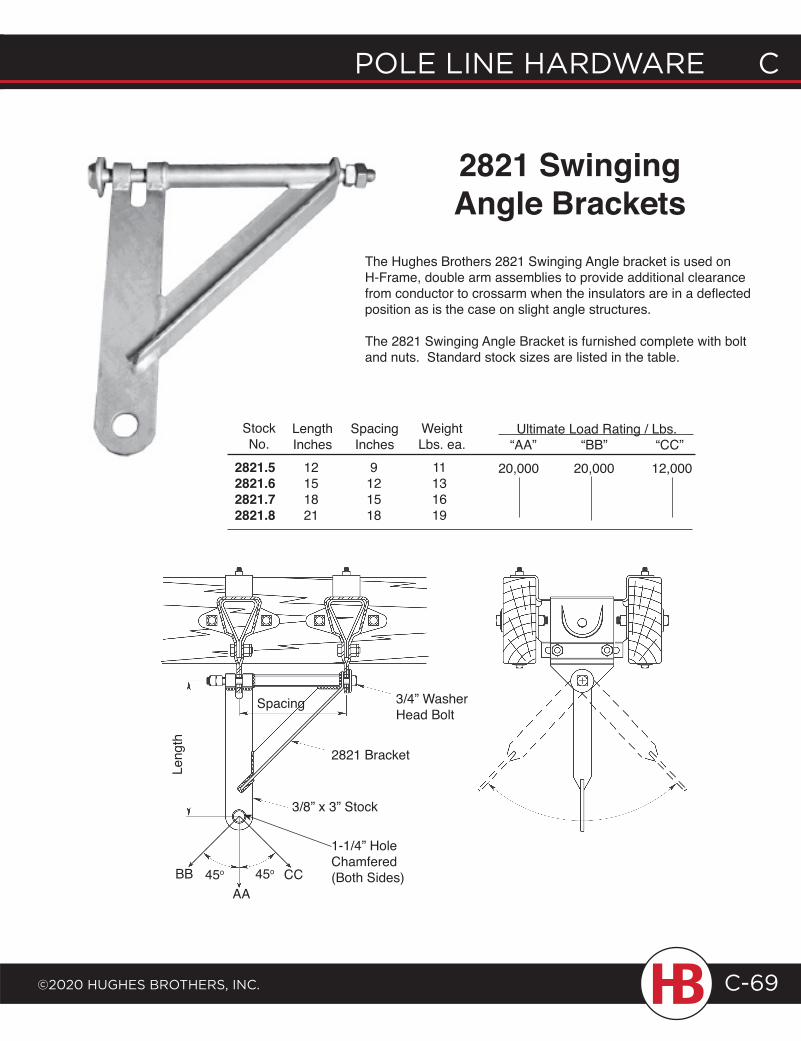
POLE LINE HARDWARE C
©2020 HugHEs BROtHERs, INC.
C POLE LINE HARDWARE
C-69
The Hughes Brothers 2821 Swinging Angle bracket is used on H-Frame, double arm assemblies to provide additional clearance from conductor to crossarm when the insulators are in a deflected position as is the case on slight angle structures.
The 2821 Swinging Angle Bracket is furnished complete with bolt and nuts. Standard stock sizes are listed in the table.
2821 SwingingAngle Brackets
StockNo.
2821.52821.62821.72821.8
LengthInches
12151821
SpacingInches
9121518
WeightLbs. ea.
11131619
Leng
th
Spacing
2821 Bracket
3/8” x 3” Stock
3/4” Washer Head Bolt
BB 45o
AA45o CC
20,000 20,000 12,000
Ultimate Load Rating / Lbs.“AA” “BB” “CC”
1-1/4” HoleChamfered(Both Sides)
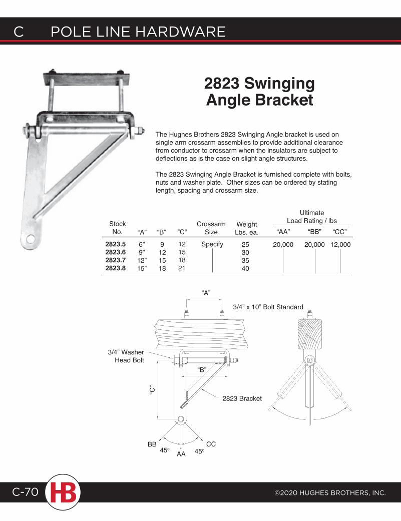
C POLE LINE HARDWARE
©2020 HugHEs BROtHERs, INC.C-70
StockNo.
2823.52823.62823.72823.8
CrossarmSize
Specify6”9”12”15”
“A”
9121518
“B”12151821
“C”WeightLbs. ea.
25303540
“AA” “BB”
20,000 20,000 12,000
“CC”
Ultimate Load Rating / lbs
The Hughes Brothers 2823 Swinging Angle bracket is used on single arm crossarm assemblies to provide additional clearance from conductor to crossarm when the insulators are subject to deflections as is the case on slight angle structures.
The 2823 Swinging Angle Bracket is furnished complete with bolts, nuts and washer plate. Other sizes can be ordered by stating length, spacing and crossarm size.
2823 SwingingAngle Bracket
CC45o 45o
“A”
“C”
3/4” Washer Head Bolt
“B”
2823 Bracket
AABB
3/4” x 10” Bolt Standard
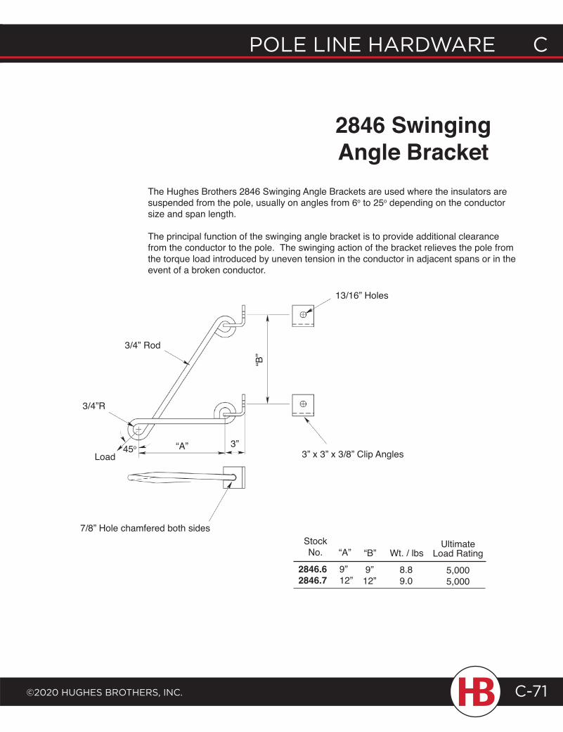
POLE LINE HARDWARE C
©2020 HugHEs BROtHERs, INC.
C POLE LINE HARDWARE
C-71
2846 SwingingAngle Bracket
The Hughes Brothers 2846 Swinging Angle Brackets are used where the insulators are suspended from the pole, usually on angles from 6o to 25o depending on the conductor size and span length.
The principal function of the swinging angle bracket is to provide additional clearance from the conductor to the pole. The swinging action of the bracket relieves the pole from the torque load introduced by uneven tension in the conductor in adjacent spans or in the event of a broken conductor.
StockNo.
3/4” Rod
“B”
13/16” Holes
3” x 3” x 3/8” Clip Angles
3/4”R
“A” 3”45o
Load
“A” “B” Wt. / lbsUltimate
Load Rating
5,0005,000
2846.62846.7
9”12”
9”12”
8.89.0
7/8” Hole chamfered both sides
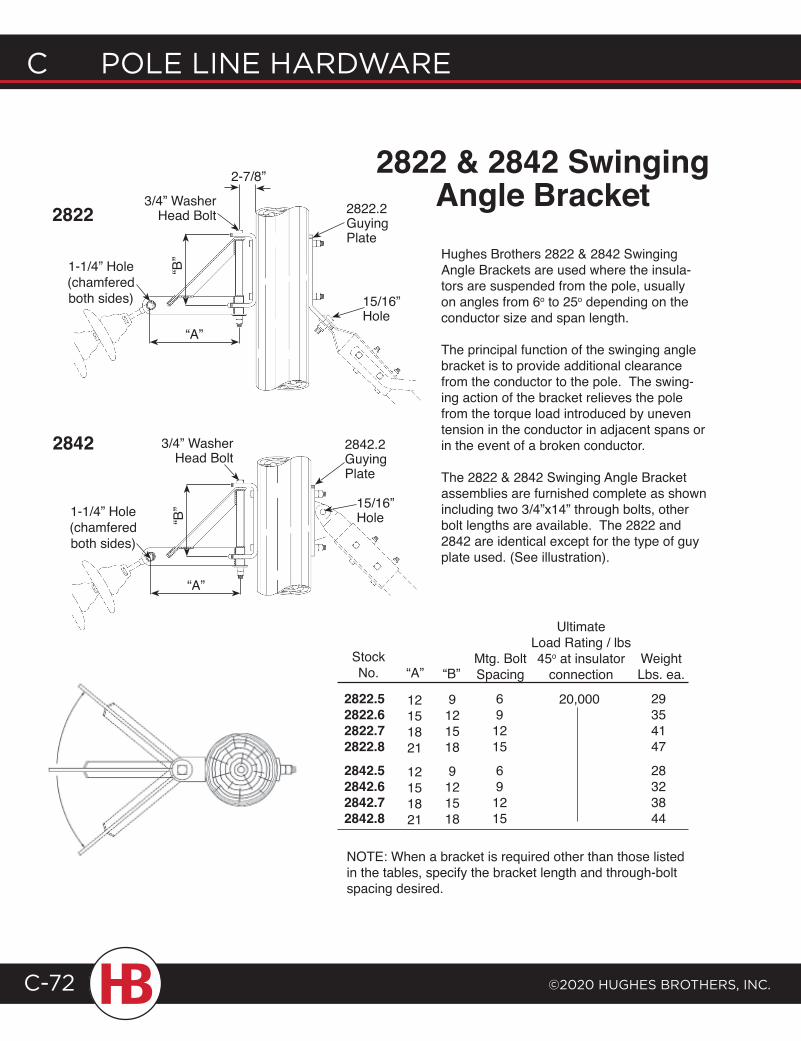
C POLE LINE HARDWARE
©2020 HugHEs BROtHERs, INC.C-72
2-7/8” 2822 & 2842 SwingingAngle BracketHughes Brothers 2822 & 2842 Swinging Angle Brackets are used where the insula-tors are suspended from the pole, usually on angles from 6o to 25o depending on the conductor size and span length.
The principal function of the swinging angle bracket is to provide additional clearance from the conductor to the pole. The swing-ing action of the bracket relieves the pole from the torque load introduced by uneven tension in the conductor in adjacent spans or in the event of a broken conductor.
The 2822 & 2842 Swinging Angle Bracket assemblies are furnished complete as shown including two 3/4”x14” through bolts, other bolt lengths are available. The 2822 and 2842 are identical except for the type of guy plate used. (See illustration).
NOTE: When a bracket is required other than those listed in the tables, specify the bracket length and through-bolt spacing desired.
StockNo.
2822.52822.62822.72822.82842.52842.62842.72842.8
12151821
12151821
“A” “B”
9121518
9121518
Mtg. BoltSpacing
691215
691215
WeightLbs. ea.
29354147
28323844
1-1/4” Hole (chamfered both sides)
2822 2822.2 Guying Plate
3/4” Washer Head Bolt
“A”
15/16” Hole
“B”
2842.2 Guying Plate
15/16” Hole1-1/4” Hole
(chamfered both sides)
3/4” Washer Head Bolt
2842
“B”
“A”
20,000
UltimateLoad Rating / lbs45o at insulator
connection
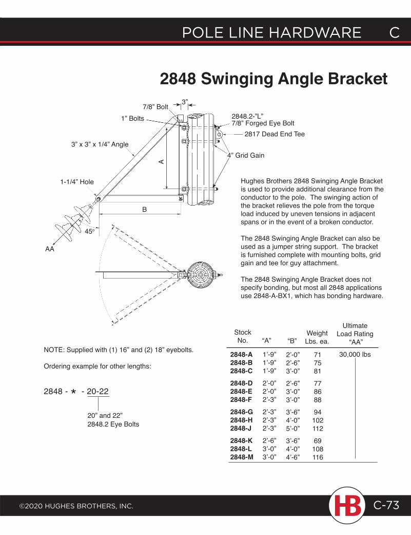
POLE LINE HARDWARE C
©2020 HugHEs BROtHERs, INC.
C POLE LINE HARDWARE
C-73
StockNo.
2848-A2848-B2848-C2848-D2848-E2848-F2848-G2848-H2848-J2848-K2848-L2848-M
1’-9”1’-9”1’-9”
2’-0”2’-0”2’-3”
2’-3”2’-3”2’-3”
2’-6”3’-0”3’-0”
“A” “B”WeightLbs. ea.
717581
778688
94102112
69108116
2’-0”2’-6”3’-0”
2’-6”3’-0”3’-0”
3’-6”4’-0”5’-0”
3’-6”4’-0”4’-6”
UltimateLoad Rating
“AA”
30,000 lbs
Hughes Brothers 2848 Swinging Angle Bracket is used to provide additional clearance from the conductor to the pole. The swinging action of the bracket relieves the pole from the torque load induced by uneven tensions in adjacent spans or in the event of a broken conductor.
The 2848 Swinging Angle Bracket can also be used as a jumper string support. The bracket is furnished complete with mounting bolts, grid gain and tee for guy attachment.
The 2848 Swinging Angle Bracket does not specify bonding, but most all 2848 applications use 2848-A-BX1, which has bonding hardware.
7/8” Bolt
B
AA
45o
1-1/4” Hole
3” x 3” x 1/4” Angle4” Grid Gain
1” Bolts
A
2817 Dead End Tee
2848.2-”L”7/8” Forged Eye Bolt
2848 Swinging Angle Bracket
NOTE: Supplied with (1) 16” and (2) 18” eyebolts.
Ordering example for other lengths:
3”
2848 - * - 20-22
20” and 22” 2848.2 Eye Bolts
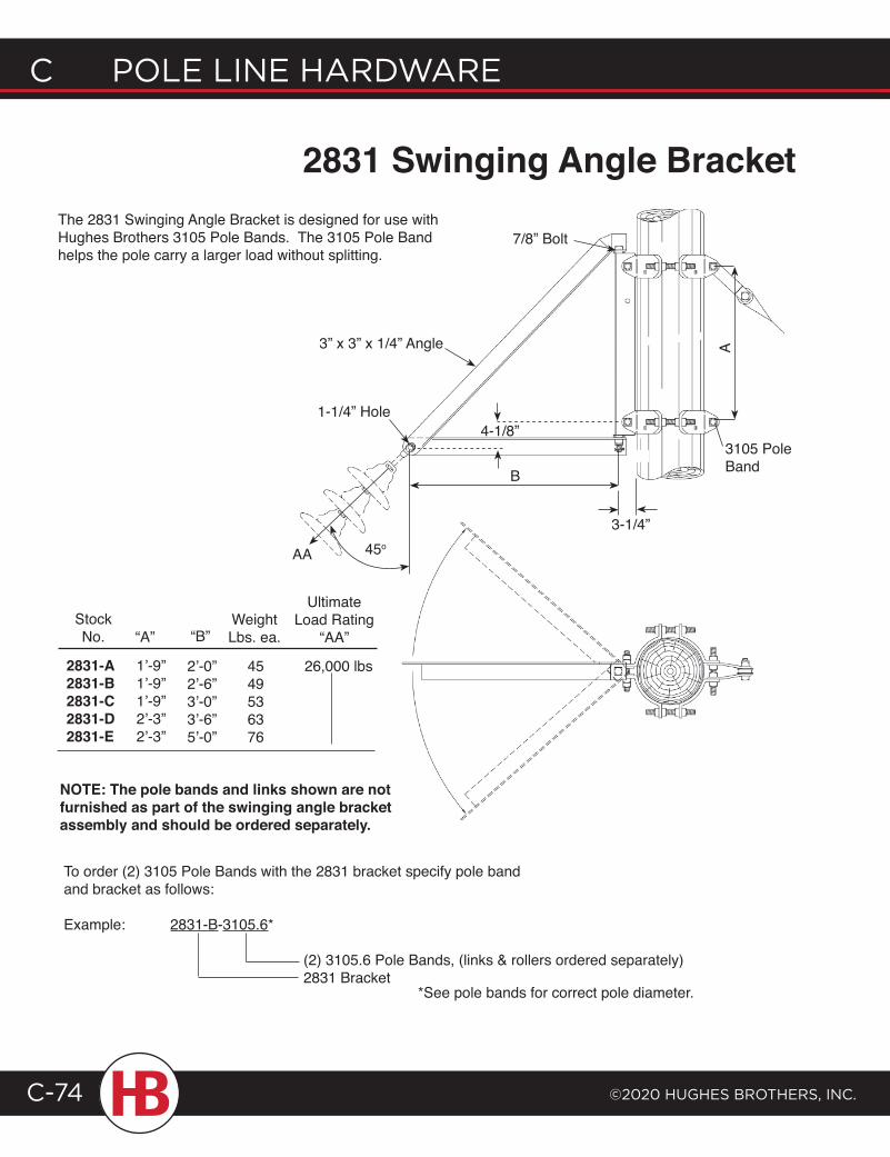
C POLE LINE HARDWARE
©2020 HugHEs BROtHERs, INC.C-74
2831 Swinging Angle Bracket
7/8” Bolt
45oAA
1-1/4” Hole
3” x 3” x 1/4” Angle
B
3105 Pole Band
A
NOTE: The pole bands and links shown are not furnished as part of the swinging angle bracket assembly and should be ordered separately.
StockNo.
2831-A2831-B2831-C2831-D2831-E
1’-9”1’-9”1’-9”2’-3”2’-3”
“A” “B”WeightLbs. ea.
4549536376
2’-0”2’-6”3’-0”3’-6”5’-0”
UltimateLoad Rating
“AA”
26,000 lbs
The 2831 Swinging Angle Bracket is designed for use with Hughes Brothers 3105 Pole Bands. The 3105 Pole Band helps the pole carry a larger load without splitting.
To order (2) 3105 Pole Bands with the 2831 bracket specify pole band and bracket as follows:
Example: 2831-B-3105.6*
(2) 3105.6 Pole Bands, (links & rollers ordered separately)2831 Bracket
*See pole bands for correct pole diameter.
4-1/8”
3-1/4”
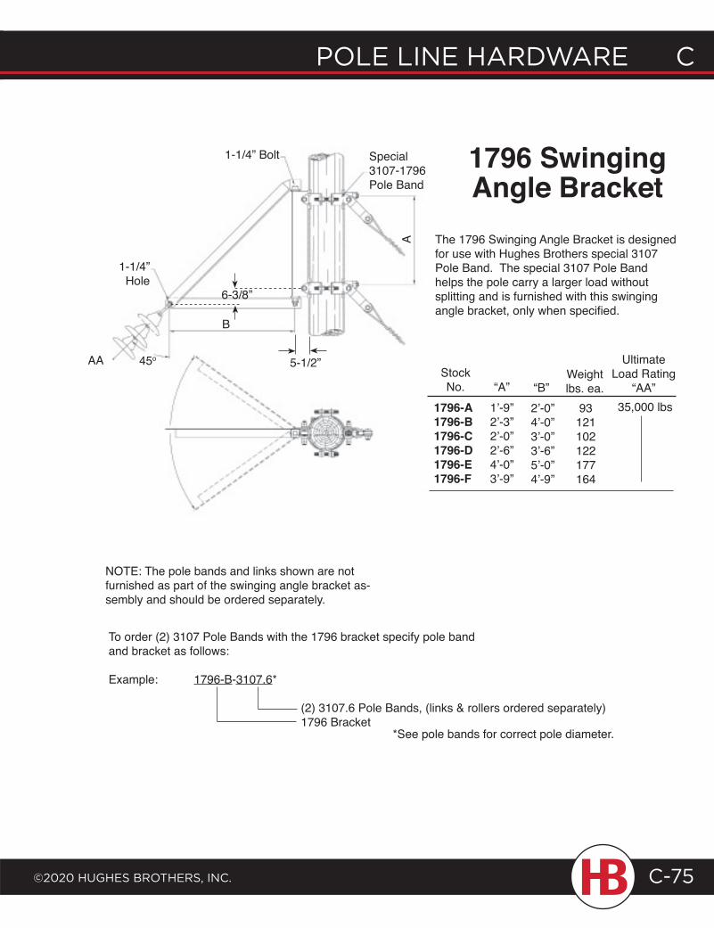
POLE LINE HARDWARE C
©2020 HugHEs BROtHERs, INC.
C POLE LINE HARDWARE
C-75
1796 SwingingAngle Bracket
1-1/4” Bolt
StockNo.
1796-A1796-B1796-C1796-D1796-E1796-F
1’-9”2’-3”2’-0”2’-6”4’-0”3’-9”
Weightlbs. ea.
93121102122177164
2’-0”4’-0”3’-0”3’-6”5’-0”4’-9”
Ultimate Load Rating
“AA”A
B
1-1/4” Hole
AA 45o
“A” “B”35,000 lbs
Special3107-1796 Pole Band
The 1796 Swinging Angle Bracket is designed for use with Hughes Brothers special 3107 Pole Band. The special 3107 Pole Band helps the pole carry a larger load without splitting and is furnished with this swinging angle bracket, only when specified.
NOTE: The pole bands and links shown are not furnished as part of the swinging angle bracket as-sembly and should be ordered separately.
To order (2) 3107 Pole Bands with the 1796 bracket specify pole band and bracket as follows:
Example: 1796-B-3107.6*
(2) 3107.6 Pole Bands, (links & rollers ordered separately)1796 Bracket
*See pole bands for correct pole diameter.
6-3/8”
5-1/2”
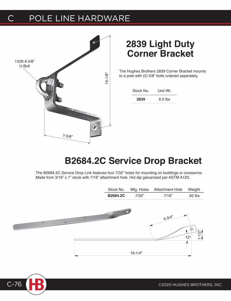
C POLE LINE HARDWARE
©2020 HugHEs BROtHERs, INC.C-76
Stock No. Mtg. Holes Attachment Hole Weight B2684.2C 7/32” 7/16” .92 lbs
Stock No.
2839
Unit Wt.
6.5 lbs
The Hughes Brothers 2839 Corner Bracket mounts to a pole with (2) 5/8” bolts ordered separately.
2839 Light DutyCorner Bracket
B2684.2C Service Drop BracketThe B2684.2C Service Drop Link features four 7/32” holes for mounting on buildings or crossarms. Made from 3/16” x 1” stock with 7/16” attachment hole. Hot dip galvanized per ASTM A123.
4-3/4”
12o
16-1/4”
1-1/
2”
1329-A 5/8” U-Bolt
7-5/8”
14-1
/8”
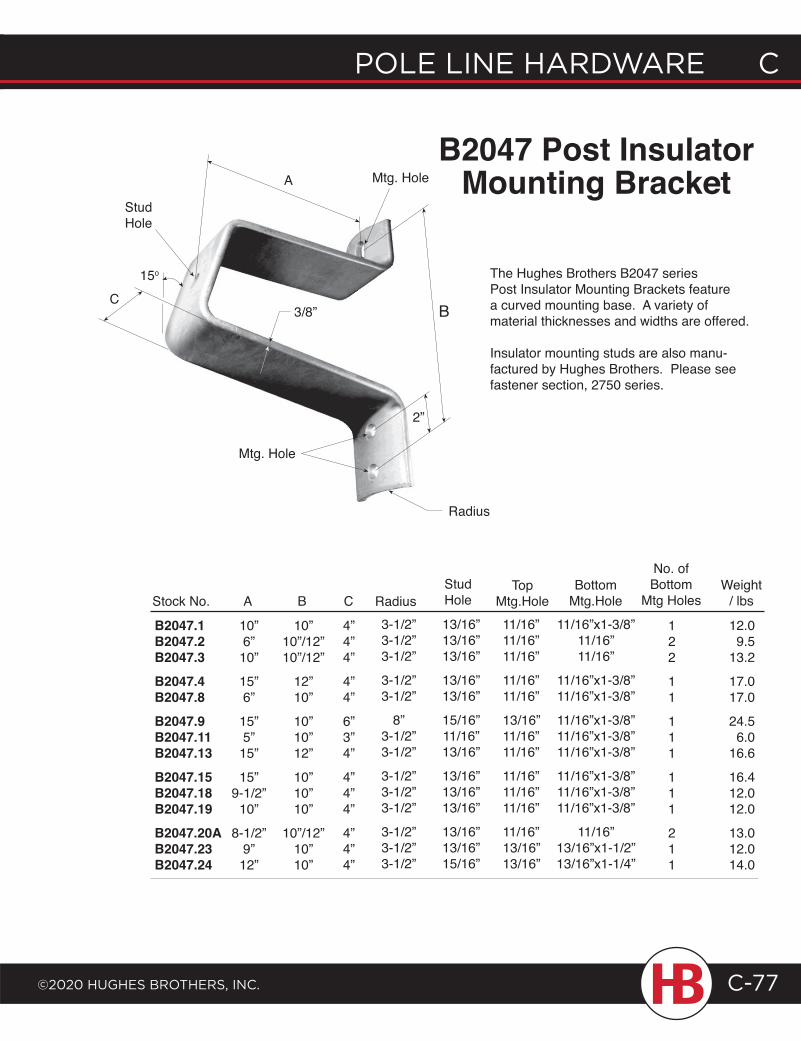
POLE LINE HARDWARE C
©2020 HugHEs BROtHERs, INC.
C POLE LINE HARDWARE
C-77
B2047 Post InsulatorMounting Bracket
The Hughes Brothers B2047 series Post Insulator Mounting Brackets feature a curved mounting base. A variety of material thicknesses and widths are offered.
Insulator mounting studs are also manu-factured by Hughes Brothers. Please see fastener section, 2750 series.
Stock No. A B
B2047.1B2047.2B2047.3B2047.4B2047.8B2047.9B2047.11B2047.13B2047.15B2047.18B2047.19B2047.20AB2047.23B2047.24
10”6”10”
15”6”
15”5”15”
15”9-1/2”
10”
8-1/2”9”12”
10”10”/12”10”/12”
12”10”
10”10”12”
10”10”10”
10”/12”10”10”
C
4”4”4”
4”4”
6”3”4”
4”4”4”
4”4”4”
Radius3-1/2”3-1/2”3-1/2”
3-1/2”3-1/2”
8”3-1/2”3-1/2”
3-1/2”3-1/2”3-1/2”
3-1/2”3-1/2”3-1/2”
StudHole
13/16”13/16”13/16”
13/16”13/16”
15/16”11/16”13/16”
13/16”13/16”13/16”
13/16”13/16”15/16”
11/16”11/16”11/16”
11/16”11/16”
13/16”11/16”11/16”
11/16”11/16”11/16”
11/16”13/16”13/16”
TopMtg.Hole
122
11
111
111
211
Weight / lbs
12.09.5
13.2
17.017.0
24.56.0
16.6
16.412.012.0
13.012.014.0
No. ofBottom
Mtg Holes
11/16”x1-3/8”11/16”11/16”
11/16”x1-3/8”11/16”x1-3/8”
11/16”x1-3/8”11/16”x1-3/8”11/16”x1-3/8”
11/16”x1-3/8”11/16”x1-3/8”11/16”x1-3/8”
11/16”13/16”x1-1/2”13/16”x1-1/4”
BottomMtg.Hole
15o
C3/8” B
2”
Mtg. HoleA
StudHole
Radius
Mtg. Hole
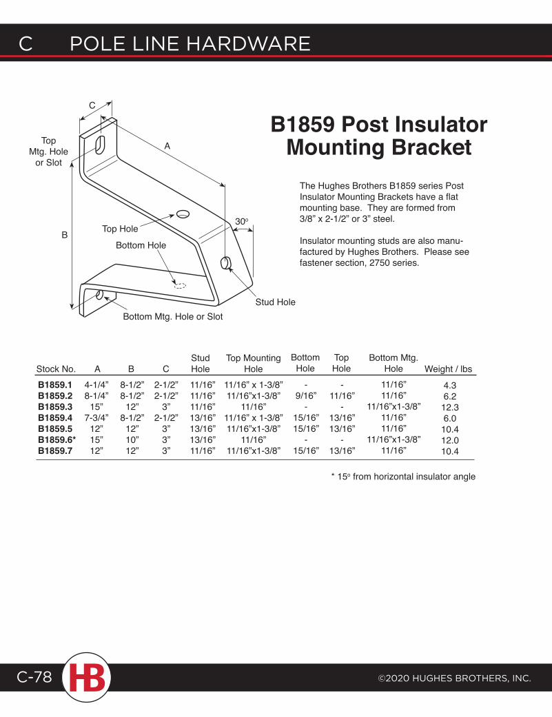
C POLE LINE HARDWARE
©2020 HugHEs BROtHERs, INC.C-78
B1859 Post Insulator Mounting Bracket
The Hughes Brothers B1859 series Post Insulator Mounting Brackets have a flat mounting base. They are formed from 3/8” x 2-1/2” or 3” steel.
Insulator mounting studs are also manu-factured by Hughes Brothers. Please see fastener section, 2750 series.
Stock No.B1859.1B1859.2B1859.3B1859.4B1859.5B1859.6*B1859.7
A4-1/4”8-1/4”
15”7-3/4”
12”15”12”
B8-1/2”8-1/2”
12”8-1/2”
12”10”12”
C2-1/2”2-1/2”
3”2-1/2”
3”3”3”
StudHole11/16”11/16”11/16”13/16”13/16”13/16”11/16”
Top MountingHole
11/16” x 1-3/8”11/16”x1-3/8”
11/16”11/16” x 1-3/8”11/16”x1-3/8”
11/16”11/16”x1-3/8”
BottomHole
-9/16”
-15/16”15/16”
-15/16”
TopHole
-11/16”
-13/16”13/16”
-13/16”
Bottom Mtg.Hole
11/16”11/16”
11/16”x1-3/8”11/16”11/16”
11/16”x1-3/8”11/16”
Weight / lbs4.36.212.36.010.412.010.4
* 15o from horizontal insulator angle
TopMtg. Hole
or Slot
30o
Bottom Hole
Top Hole
Stud Hole
B
A
C
Bottom Mtg. Hole or Slot
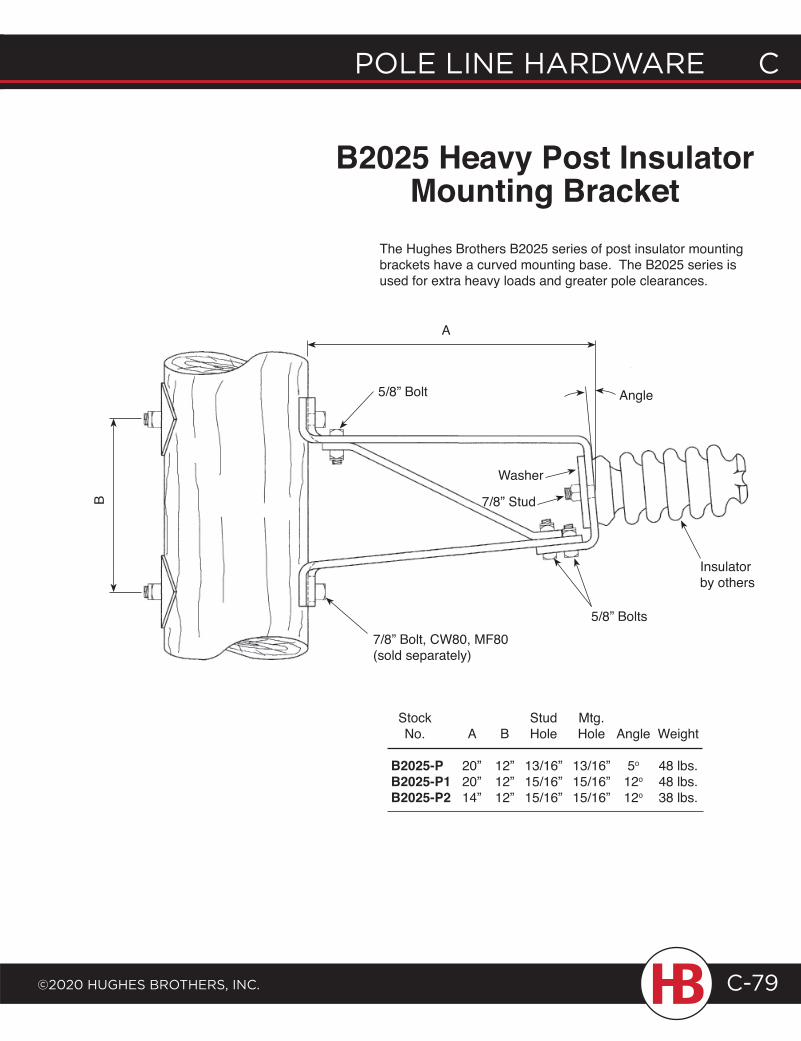
POLE LINE HARDWARE C
©2020 HugHEs BROtHERs, INC.
C POLE LINE HARDWARE
C-79
B2025 Heavy Post Insulator Mounting Bracket
The Hughes Brothers B2025 series of post insulator mounting brackets have a curved mounting base. The B2025 series is used for extra heavy loads and greater pole clearances.
B
Stock Stud Mtg. No. A B Hole Hole Angle Weight
B2025-P 20” 12” 13/16” 13/16” 5o 48 lbs.B2025-P1 20” 12” 15/16” 15/16” 12o 48 lbs.B2025-P2 14” 12” 15/16” 15/16” 12o 38 lbs.
7/8” Bolt, CW80, MF80 (sold separately)
5/8” Bolt
Washer
7/8” Stud
5/8” Bolts
A
Angle
Insulator by others
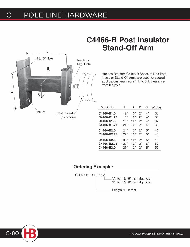
C POLE LINE HARDWARE
©2020 HugHEs BROtHERs, INC.C-80
L
AC
13/16” Hole
Hughes Brothers C4466-B Series of Line Post Insulator Stand-Off Arms are used for special applications requiring a 1 ft. to 3 ft. clearance from the pole.
12”15”18”21”
24”27”
30”33”36”
Stock No. L
C4466-B1.0C4466-B1.25C4466-B1.5C4466-B1.75C4466-B2.0C4466-B2.25C4466-B2.5C4466-B2.75C4466-B3.0
10”10”10”10”
12”12”
12”12”12”
A
2”2”2”2”
2”2”
2”2”2”
B
4”4”4”4”
5”5”
5”5”5”
C Wt./lbs.
33353739
4346
495255
Post Insulator (by others)
Insulator Mtg. Hole
13/16”
B
Ordering Example:C 4 4 6 6 - B 1 . 7 5 A
“A” for 13/16” ins. mtg. hole“B” for 15/16” ins. mtg. hole
Length “L” in feet
C4466-B Post Insulator Stand-Off Arm
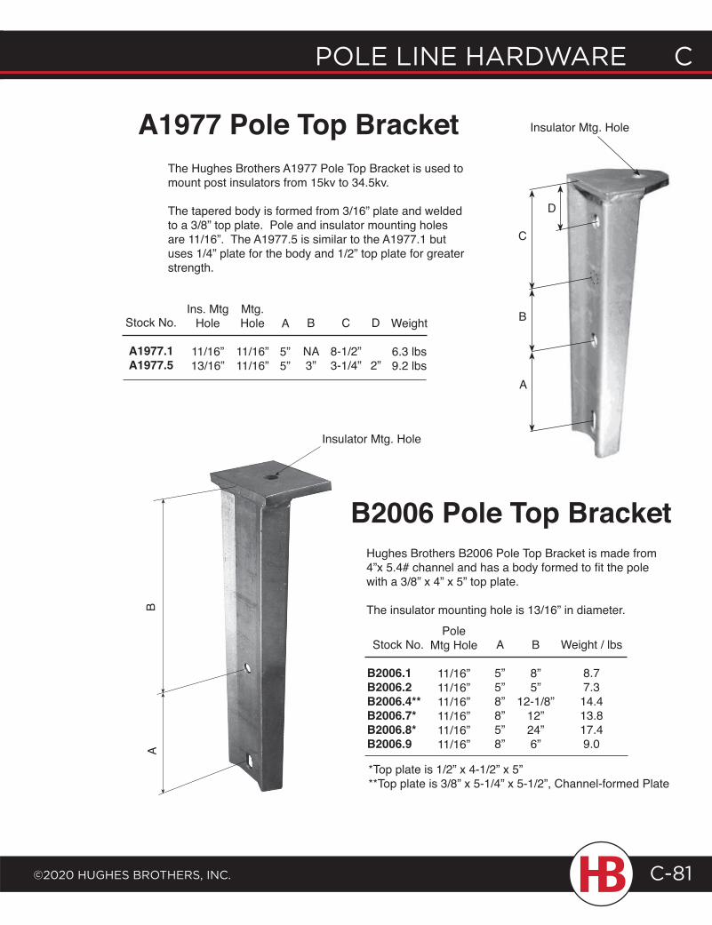
POLE LINE HARDWARE C
©2020 HugHEs BROtHERs, INC.
C POLE LINE HARDWARE
C-81
Hughes Brothers B2006 Pole Top Bracket is made from 4”x 5.4# channel and has a body formed to fit the pole with a 3/8” x 4” x 5” top plate.
The insulator mounting hole is 13/16” in diameter.
B
8”5”
12-1/8”12”24”6”
PoleMtg Hole
11/16”11/16”11/16”11/16”11/16”11/16”
A
5”5”8”8”5”8”
Weight / lbs
8.77.314.413.817.49.0
B2006 Pole Top Bracket
*Top plate is 1/2” x 4-1/2” x 5”**Top plate is 3/8” x 5-1/4” x 5-1/2”, Channel-formed Plate
The Hughes Brothers A1977 Pole Top Bracket is used to mount post insulators from 15kv to 34.5kv.
The tapered body is formed from 3/16” plate and welded to a 3/8” top plate. Pole and insulator mounting holes are 11/16”. The A1977.5 is similar to the A1977.1 but uses 1/4” plate for the body and 1/2” top plate for greater strength.
Stock No.
A1977.1A1977.5
Ins. Mtg Hole
11/16”13/16”
Mtg. Hole
11/16”11/16”
A
5”5”
B
NA3”
C
8-1/2”3-1/4”
Weight
6.3 lbs9.2 lbs
A1977 Pole Top BracketB
A
Insulator Mtg. Hole
Stock No.
B2006.1B2006.2B2006.4**B2006.7*B2006.8*B2006.9
D
2”A
B
C
D
Insulator Mtg. Hole
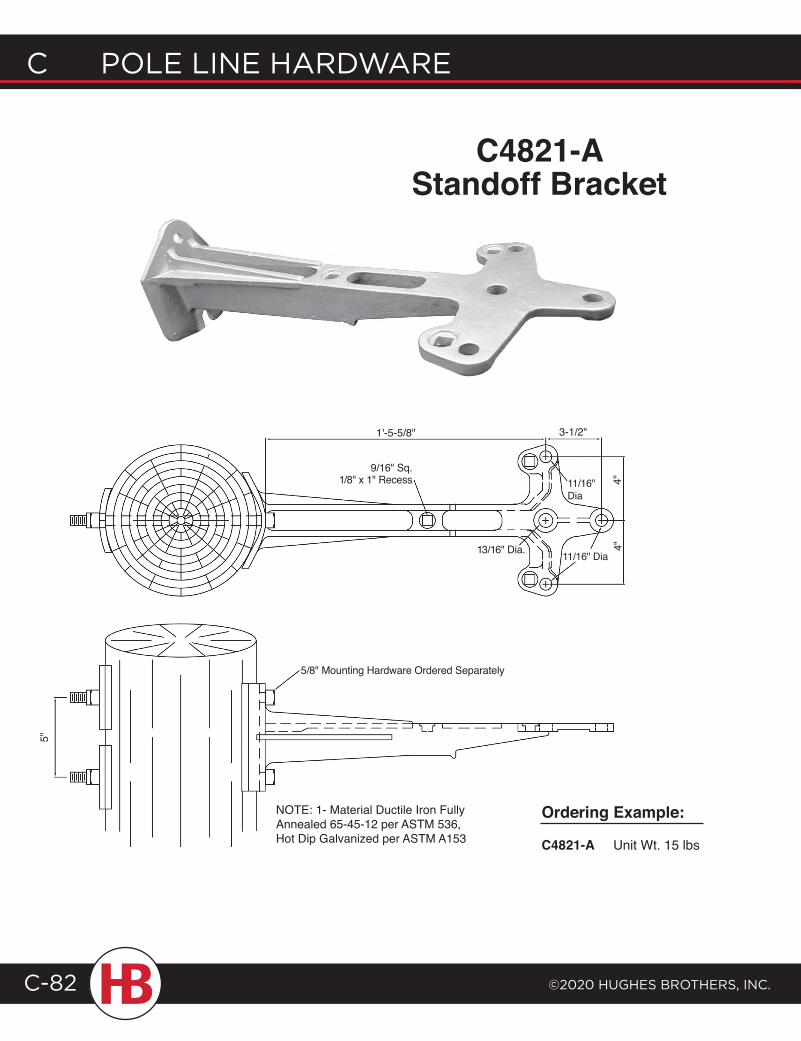
C POLE LINE HARDWARE
©2020 HugHEs BROtHERs, INC.C-82
C4821-A Standoff Bracket
Ordering Example:
C4821-A Unit Wt. 15 lbs
1'-5-5/8" 3-1/2"
11/16" Dia
4"4"
13/16" Dia.
9/16" Sq. 1/8" x 1" Recess
5/8" Mounting Hardware Ordered Separately
NOTE: 1- Material Ductile Iron Fully Annealed 65-45-12 per ASTM 536, Hot Dip Galvanized per ASTM A153
5"
11/16" Dia
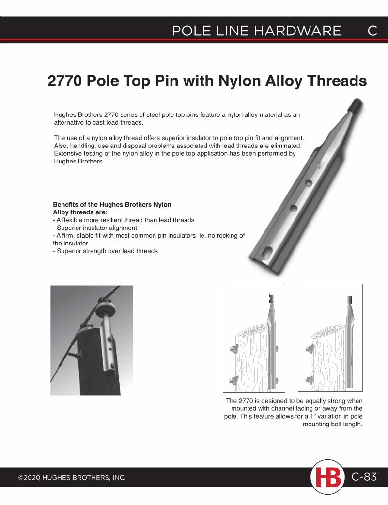
POLE LINE HARDWARE C
©2020 HugHEs BROtHERs, INC.
C POLE LINE HARDWARE
C-83
Benefits of the Hughes Brothers NylonAlloy threads are:- A flexible more resilient thread than lead threads- Superior insulator alignment- A firm, stable fit with most common pin insulators ie. no rocking of the insulator- Superior strength over lead threads
The 2770 is designed to be equally strong when mounted with channel facing or away from the
pole. This feature allows for a 1” variation in pole mounting bolt length.
2770 Pole Top Pin with Nylon Alloy Threads
Hughes Brothers 2770 series of steel pole top pins feature a nylon alloy material as an alternative to cast lead threads.
The use of a nylon alloy thread offers superior insulator to pole top pin fit and alignment. Also, handling, use and disposal problems associated with lead threads are eliminated. Extensive testing of the nylon alloy in the pole top application has been performed by Hughes Brothers.
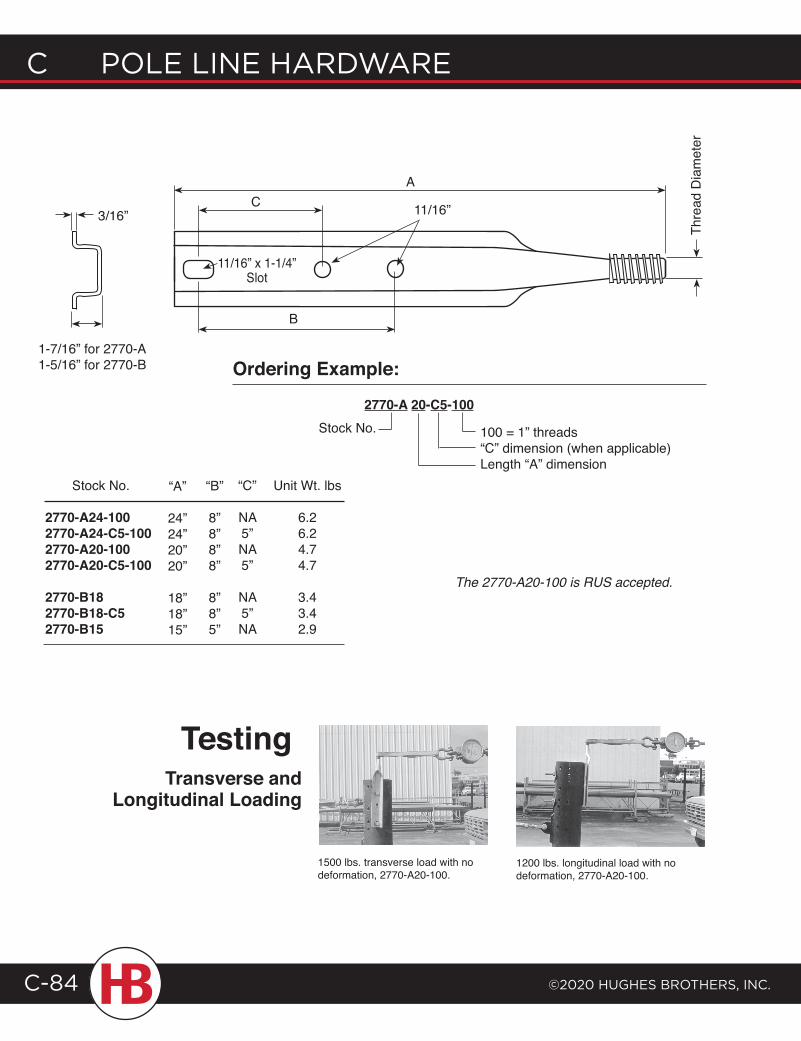
C POLE LINE HARDWARE
©2020 HugHEs BROtHERs, INC.C-84
1500 lbs. transverse load with no deformation, 2770-A20-100.
1200 lbs. longitudinal load with no deformation, 2770-A20-100.
Transverse and Longitudinal Loading
11/16”
A
11/16” x 1-1/4” Slot
Thre
ad D
iam
eter
2770-A 20-C5-100
100 = 1” threads“C” dimension (when applicable)Length “A” dimension
Ordering Example:
B
C
Testing
The 2770-A20-100 is RUS accepted.
3/16”
1-7/16” for 2770-A1-5/16” for 2770-B
Stock No.
Stock No.
2770-A24-1002770-A24-C5-1002770-A20-1002770-A20-C5-100
2770-B182770-B18-C52770-B15
“A”
24”24”20”20”
18”18”15”
“B”
8”8”8”8”
8”8”5”
Unit Wt. lbs
6.26.24.74.7
3.43.42.9
“C”
NA5”NA5”
NA5”NA
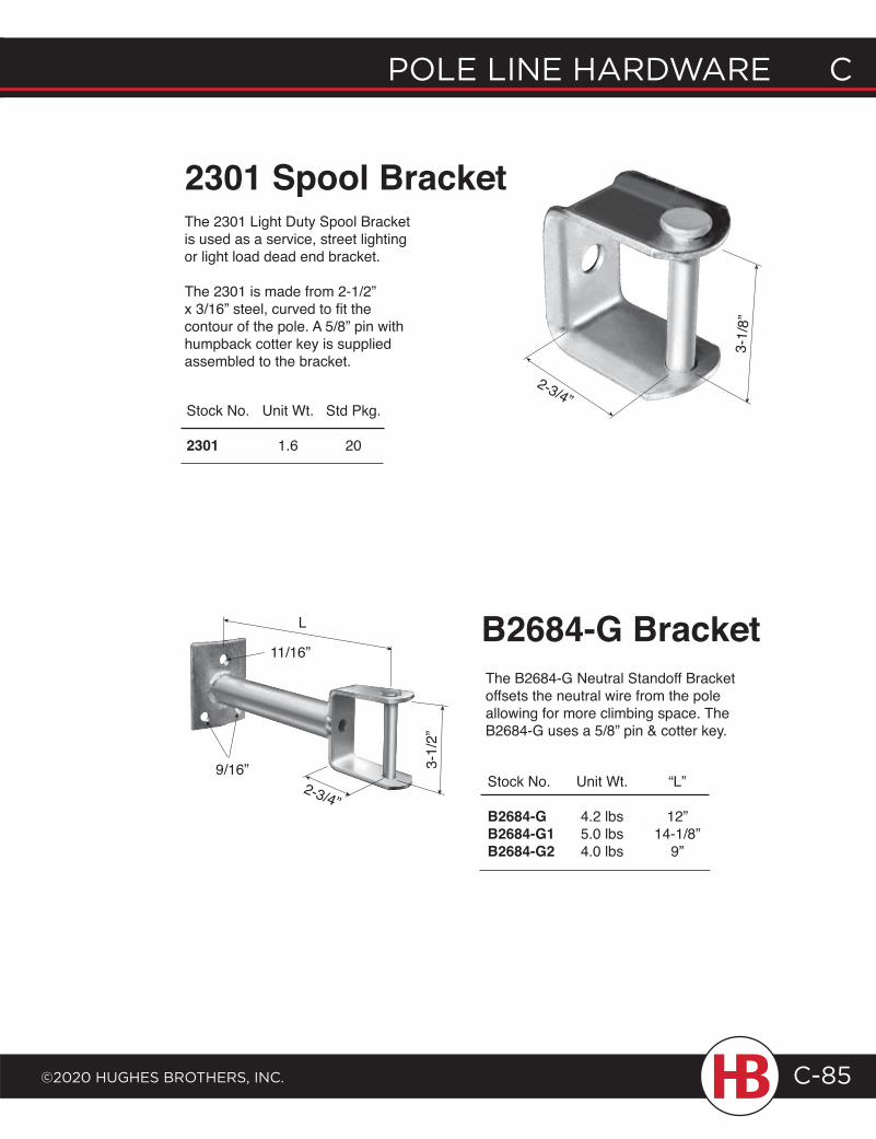
POLE LINE HARDWARE C
©2020 HugHEs BROtHERs, INC.
C POLE LINE HARDWARE
C-85
The 2301 Light Duty Spool Bracket is used as a service, street lighting or light load dead end bracket.
The 2301 is made from 2-1/2” x 3/16” steel, curved to fit the contour of the pole. A 5/8” pin with humpback cotter key is supplied assembled to the bracket.
2301 Spool Bracket
Stock No. Unit Wt. Std Pkg.
2301 1.6 20
The B2684-G Neutral Standoff Bracket offsets the neutral wire from the pole allowing for more climbing space. The B2684-G uses a 5/8” pin & cotter key.
B2684-G Bracket
Stock No. Unit Wt. “L”
B2684-G 4.2 lbs 12”B2684-G1 5.0 lbs 14-1/8”B2684-G2 4.0 lbs 9”
3-1/
8”
2-3/4”
3-1/
2”
2-3/4”
9/16”
11/16”
L
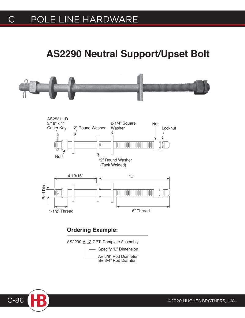
C POLE LINE HARDWARE
©2020 HugHEs BROtHERs, INC.C-86
AS2290 Neutral Support/Upset Bolt
2” Round Washer Welded
Ordering Example:
AS2290-A-12-CPT, Complete Assembly
Specify “L” Dimension
A= 5/8” Rod Diameter B= 3/4” Rod Diamter
AS2531.1D 3/16” x 1” Cotter Key
Nut
2” Round Washer2-1/4” Square Washer
NutLocknut
2” Round Washer (Tack Welded)
Rod
Dia
.
4-13/16”
1-1/2” Thread 6” Thread
“L”
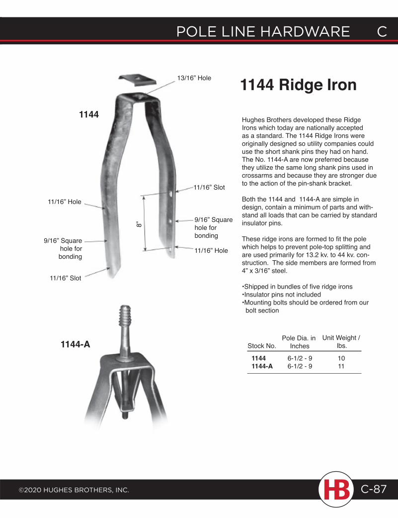
POLE LINE HARDWARE C
©2020 HugHEs BROtHERs, INC.
C POLE LINE HARDWARE
C-87
Hughes Brothers developed these Ridge Irons which today are nationally accepted as a standard. The 1144 Ridge Irons were originally designed so utility companies could use the short shank pins they had on hand. The No. 1144-A are now preferred because they utilize the same long shank pins used in crossarms and because they are stronger due to the action of the pin-shank bracket.
Both the 1144 and 1144-A are simple in design, contain a minimum of parts and with-stand all loads that can be carried by standard insulator pins.
These ridge irons are formed to fit the pole which helps to prevent pole-top splitting and are used primarily for 13.2 kv. to 44 kv. con-struction. The side members are formed from 4” x 3/16” steel.
•Shipped in bundles of five ridge irons•Insulator pins not included•Mounting bolts should be ordered from our bolt section
1144 Ridge Iron
Stock No.
6-1/2 - 96-1/2 - 9
Pole Dia. in Inches
Unit Weight / lbs.
1011
1144-A
11/16” Slot
9/16” Square hole forbonding
11/16” Hole
11/16” Slot
9/16” Square hole for bonding
11/16” Hole
13/16” Hole
8”
1144
11441144-A
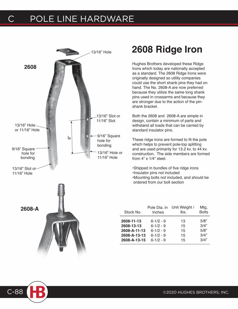
C POLE LINE HARDWARE
©2020 HugHEs BROtHERs, INC.C-88
2608-A
2608 Hughes Brothers developed these Ridge Irons which today are nationally accepted as a standard. The 2608 Ridge Irons were originally designed so utility companies could use the short shank pins they had on hand. The No. 2608-A are now preferred because they utilize the same long shank pins used in crossarms and because they are stronger due to the action of the pin-shank bracket.
Both the 2608 and 2608-A are simple in design, contain a minimum of parts and withstand all loads that can be carried by standard insulator pins.
These ridge irons are formed to fit the pole which helps to prevent pole-top splitting and are used primarily for 13.2 kv. to 44 kv. construction. The side members are formed from 4” x 1/4” steel.
•Shipped in bundles of five ridge irons•Insulator pins not included•Mounting bolts not included, and should be ordered from our bolt section
Stock No.
6-1/2 - 96-1/2 - 96-1/2 - 96-1/2 - 96-1/2 - 9
Pole Dia. in Inches
Unit Weight / lbs.
1315151515
2608 Ridge Iron
13/16” Holeor 11/16” Hole
13/16” Slot or 11/16” Hole
9/16” Square hole for bonding
13/16” Slot or 11/16” Slot
9/16” Square hole for bonding
13/16” Hole or 11/16” Hole
8”
13/16” Hole
2608-11-132608-13-132608-A-11-132608-A-13-132608-A-13-15
Mtg,Bolts
5/8”3/4”5/8”3/4”3/4”
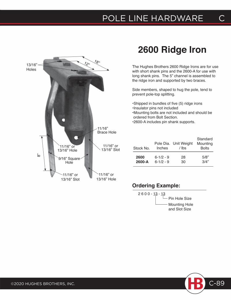
POLE LINE HARDWARE C
©2020 HugHEs BROtHERs, INC.
C POLE LINE HARDWARE
C-89
The Hughes Brothers 2600 Ridge Irons are for use with short shank pins and the 2600-A for use with long shank pins. The 5” channel is assembled to the ridge iron and supported by two braces.
Side members, shaped to hug the pole, tend to prevent pole-top splitting.
•Shipped in bundles of five (5) ridge irons•Insulator pins not included•Mounting bolts are not included and should be ordered from Bolt Section.•2600-A includes pin shank supports.
2600 Ridge Iron
Stock No.
6-1/2 - 96-1/2 - 9
Pole Dia.Inches
2830
Unit Weight / lbs
8” 26002600-A
12”13/16” Holes
18”
9/16” Square Hole
Ordering Example:2 6 0 0 - 13 - 13
Pin Hole SizeMounting Hole and Slot Size
11/16” or 13/16” Slot
11/16” Brace Hole
StandardMounting
Bolts
5/8”3/4”
11/16” or 13/16” Hole
11/16” or 13/16” Hole
11/16” or 13/16” Slot
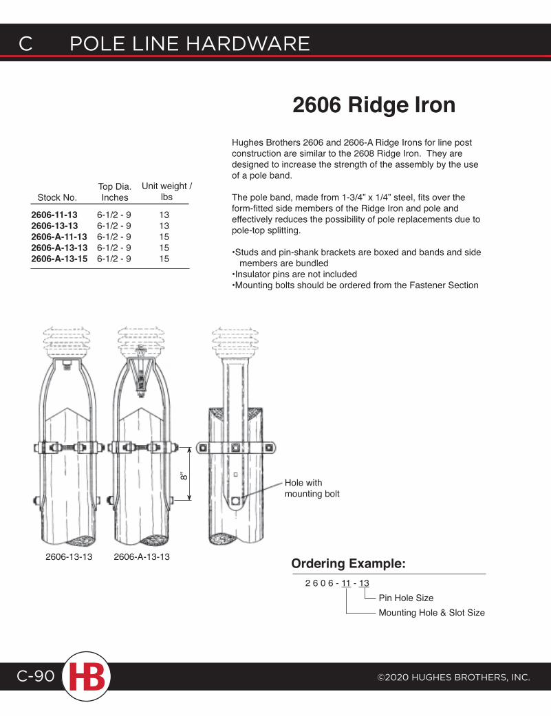
C POLE LINE HARDWARE
©2020 HugHEs BROtHERs, INC.C-90
2606 Ridge Iron
Stock No.
6-1/2 - 96-1/2 - 96-1/2 - 96-1/2 - 96-1/2 - 9
Top Dia.Inches
Unit weight /lbs
1313151515
Hole with mounting bolt
2606-A-13-132606-13-13
2606-11-132606-13-132606-A-11-132606-A-13-132606-A-13-15
8”
Ordering Example:2 6 0 6 - 11 - 13
Pin Hole SizeMounting Hole & Slot Size
Hughes Brothers 2606 and 2606-A Ridge Irons for line post construction are similar to the 2608 Ridge Iron. They are designed to increase the strength of the assembly by the use of a pole band.
The pole band, made from 1-3/4” x 1/4” steel, fits over the form-fitted side members of the Ridge Iron and pole and effectively reduces the possibility of pole replacements due to pole-top splitting.
•Studs and pin-shank brackets are boxed and bands and side members are bundled•Insulator pins are not included•Mounting bolts should be ordered from the Fastener Section
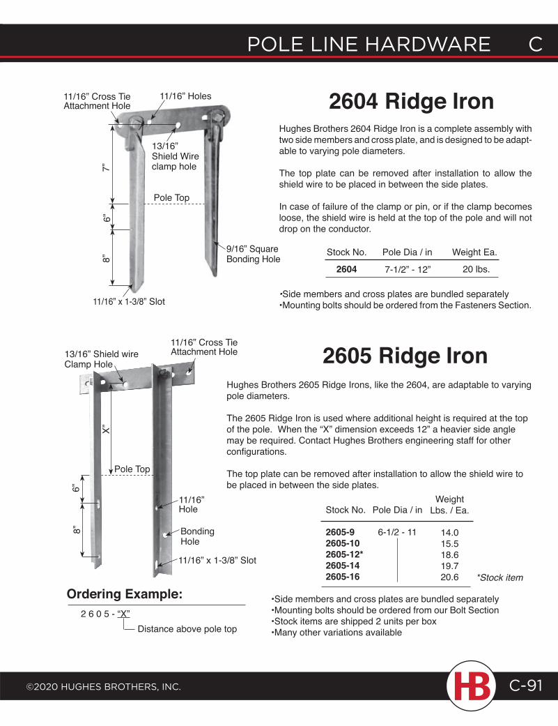
POLE LINE HARDWARE C
©2020 HugHEs BROtHERs, INC.
C POLE LINE HARDWARE
C-91
Hughes Brothers 2604 Ridge Iron is a complete assembly with two side members and cross plate, and is designed to be adapt-able to varying pole diameters.
The top plate can be removed after installation to allow the shield wire to be placed in between the side plates.
In case of failure of the clamp or pin, or if the clamp becomes loose, the shield wire is held at the top of the pole and will not drop on the conductor.
2604 Ridge Iron
Stock No. Pole Dia / in Weight Ea.
2604 20 lbs.7-1/2” - 12”
13/16” Shield Wire clamp hole
9/16” Square Bonding Hole
11/16” x 1-3/8” Slot
8”11/16” Cross Tie Attachment Hole
11/16” Holes
•Side members and cross plates are bundled separately •Mounting bolts should be ordered from the Fasteners Section.
2605 Ridge IronHughes Brothers 2605 Ridge Irons, like the 2604, are adaptable to varying pole diameters. The 2605 Ridge Iron is used where additional height is required at the top of the pole. When the “X” dimension exceeds 12” a heavier side angle may be required. Contact Hughes Brothers engineering staff for other configurations.
The top plate can be removed after installation to allow the shield wire to be placed in between the side plates.
Pole Dia / in
6-1/2 - 11
Weight Lbs. / Ea.
14.0 15.5 18.6 19.7 20.6
•Side members and cross plates are bundled separately •Mounting bolts should be ordered from our Bolt Section•Stock items are shipped 2 units per box•Many other variations available
Stock No.
2605-92605-102605-12*2605-142605-16 *Stock item
8” BondingHole
11/16” Hole
11/16” x 1-3/8” Slot
13/16” Shield wire Clamp Hole
Ordering Example:2 6 0 5 - “X”
Distance above pole top
Pole Top
6”7”
Pole Top
6”
X”
11/16” Cross Tie Attachment Hole
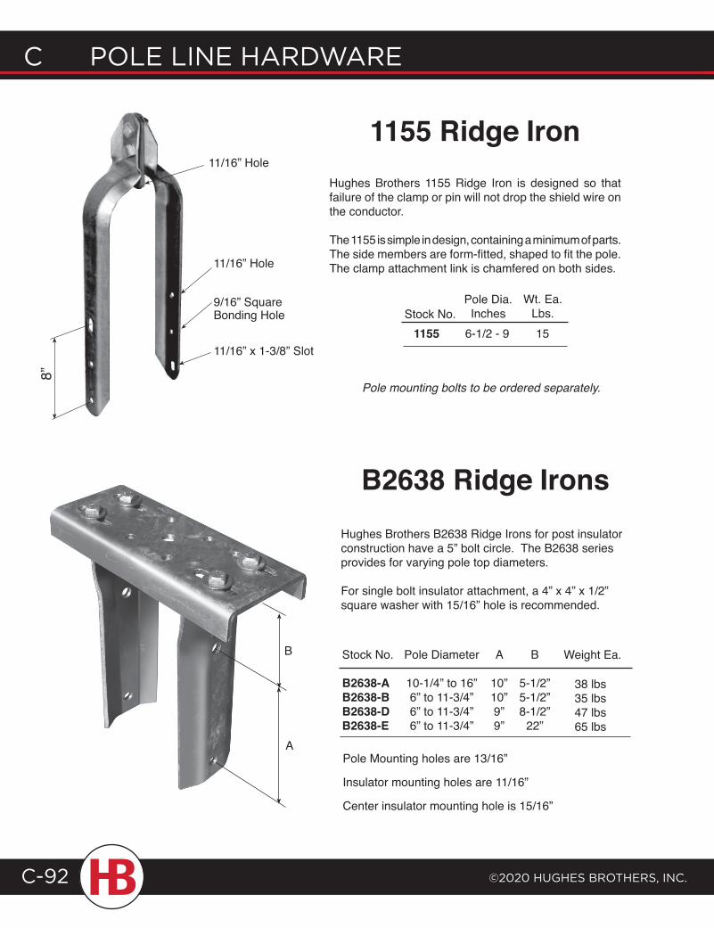
C POLE LINE HARDWARE
©2020 HugHEs BROtHERs, INC.C-92
8”
11/16” x 1-3/8” Slot
11/16” Hole
11/16” Hole
Hughes Brothers 1155 Ridge Iron is designed so that failure of the clamp or pin will not drop the shield wire on the conductor.
The 1155 is simple in design, containing a minimum of parts. The side members are form-fitted, shaped to fit the pole. The clamp attachment link is chamfered on both sides.
Stock No.6-1/2 - 9
Pole Dia.Inches
15
Wt. Ea.Lbs.
1155
Pole mounting bolts to be ordered separately.
1155 Ridge Iron
9/16” SquareBonding Hole
Hughes Brothers B2638 Ridge Irons for post insulator construction have a 5” bolt circle. The B2638 series provides for varying pole top diameters.
For single bolt insulator attachment, a 4” x 4” x 1/2” square washer with 15/16” hole is recommended.
B2638 Ridge Irons
Stock No.
B2638-AB2638-BB2638-DB2638-E
Pole Diameter
10-1/4” to 16”6” to 11-3/4”6” to 11-3/4”6” to 11-3/4”
A
10”10”9”9”
B
5-1/2”5-1/2”8-1/2”
22”
Weight Ea.
38 lbs35 lbs47 lbs65 lbs
Pole Mounting holes are 13/16”
Insulator mounting holes are 11/16”
Center insulator mounting hole is 15/16”
A
B
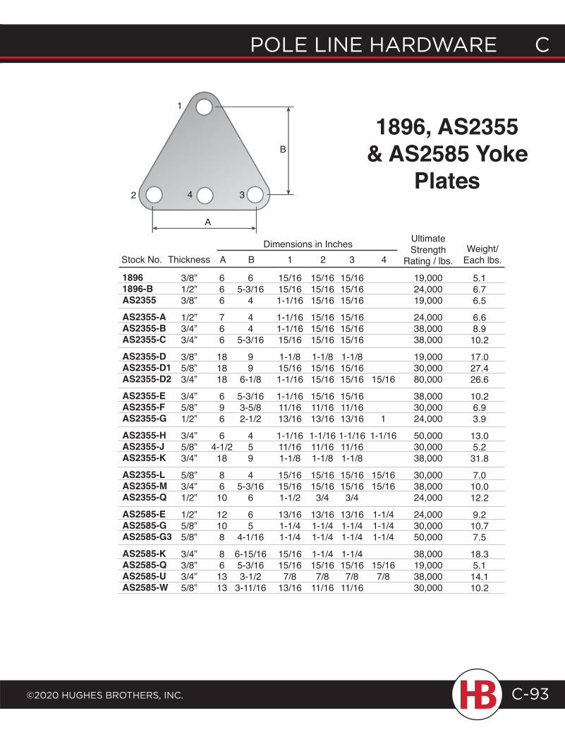
POLE LINE HARDWARE C
©2020 HugHEs BROtHERs, INC.
C POLE LINE HARDWARE
C-93
342
1
1896, AS2355& AS2585 Yoke
Plates
Stock No. Thickness
666
766
181818
696
64-1/2
18
8610
12108
861313
A
65-3/16
4
44
5-3/16
99
6-1/8
5-3/163-5/82-1/2
459
45-3/16
6
65
4-1/16
6-15/165-3/163-1/2
3-11/16
BDimensions in Inches
3/8”1/2”3/8”
1/2”3/4”3/4”
3/8”5/8”3/4”
3/4”5/8”1/2”
3/4” 5/8”3/4”
5/8”3/4”1/2”
1/2”5/8”5/8”
3/4”3/8”3/4”5/8”
18961896-BAS2355AS2355-AAS2355-BAS2355-CAS2355-DAS2355-D1AS2355-D2AS2355-EAS2355-FAS2355-GAS2355-HAS2355-JAS2355-KAS2355-LAS2355-MAS2355-QAS2585-EAS2585-GAS2585-G3AS2585-KAS2585-QAS2585-UAS2585-W
1
15/1615/161-1/16
1-1/161-1/1615/16
1-1/815/161-1/16
1-1/1611/1613/16
1-1/1611/161-1/8
15/1615/161-1/2
13/161-1/41-1/4
15/1615/167/8
13/16
15/1615/1615/16
15/1615/1615/16
1-1/815/1615/16
15/1611/1613/16
1-1/1611/161-1/8
15/1615/163/4
13/161-1/41-1/4
1-1/415/167/8
11/16
15/1615/1615/16
15/1615/1615/16
1-1/815/1615/16
15/1611/1613/16
1-1/1611/161-1/8
15/1615/163/4
13/161-1/41-1/4
1-1/415/167/8
11/16
2 3Weight/
Each lbs.
15/16
1
1-1/16
15/1615/16
1-1/41-1/41-1/4
15/167/8
4
5.16.76.5
6.68.910.2
17.027.426.6
10.26.93.9
13.05.231.8
7.010.012.2
9.210.77.5
18.35.114.110.2
UltimateStrength
Rating / lbs.
19,00024,00019,000
24,00038,00038,000
19,00030,00080,000
38,00030,00024,000
50,00030,00038,000
30,00038,00024,000
24,00030,00050,000
38,00019,00038,00030,000
A
B
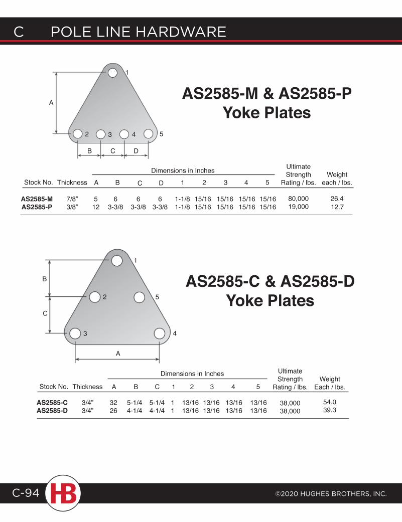
C POLE LINE HARDWARE
©2020 HugHEs BROtHERs, INC.C-94
53 42
1
Stock No. Thickness A
AS2585-MAS2585-P
7/8”3/8”
512
1
2
3 4
5
AS2585-C & AS2585-DYoke Plates
12.7
UltimateStrength
Rating / lbs.
80,00019,000
Weighteach / lbs.
26.4
5
15/1615/16
4
15/1615/16
3
15/1615/16
2
15/1615/16
1
1-1/81-1/8
D
63-3/8
C
63-3/8
B
63-3/8
Dimensions in Inches
AS2585-M & AS2585-P Yoke Plates
Stock No. Thickness
AS2585-CAS2585-D
3/4”3/4”
UltimateStrength
Rating / lbs.
38,00038,000
54.039.3
WeightEach / lbs.5
13/1613/16
4
13/1613/16
3
13/1613/16
2
13/1613/16
1
11
C
5-1/44-1/4
B
5-1/44-1/4
A
3226
Dimensions in Inches
C D
A
B
C
B
A
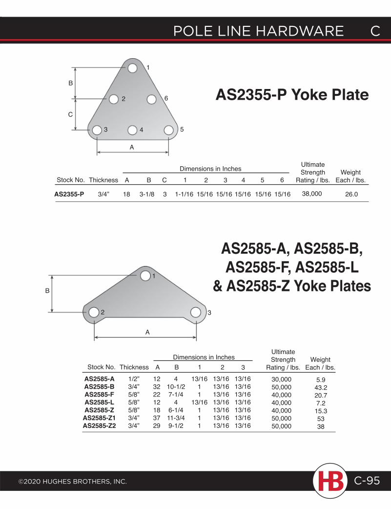
POLE LINE HARDWARE C
©2020 HugHEs BROtHERs, INC.
C POLE LINE HARDWARE
C-95
AS2355-P Yoke Plate
543
1
2 6
1
2 3
Stock No. Thickness A B 1 2 3Dimensions in Inches
AS2585-AAS2585-BAS2585-FAS2585-LAS2585-ZAS2585-Z1AS2585-Z2
1/2”3/4”5/8”5/8”5/8”3/4”3/4”
12322212183729
410-1/27-1/4
46-1/411-3/49-1/2
13/1611
13/16111
13/1613/1613/1613/1613/1613/1613/16
13/1613/1613/1613/1613/1613/1613/16
UltimateStrength
Rating / lbs.
AS2585-A, AS2585-B, AS2585-F, AS2585-L
& AS2585-Z Yoke Plates
30,00050,00040,00040,00040,00050,00050,000
Stock No. Thickness A
AS2355-P 3/4” 18
UltimateStrength
Rating / lbs.
26.038,000
WeightEach / lbs.6
15/16
5
15/16
4
15/16
3
15/16
21
1-1/16
C
3
B
3-1/8 15/16
Dimensions in Inches
5.943.220.77.215.35338
WeightEach / lbs.
A
B
C
B
A
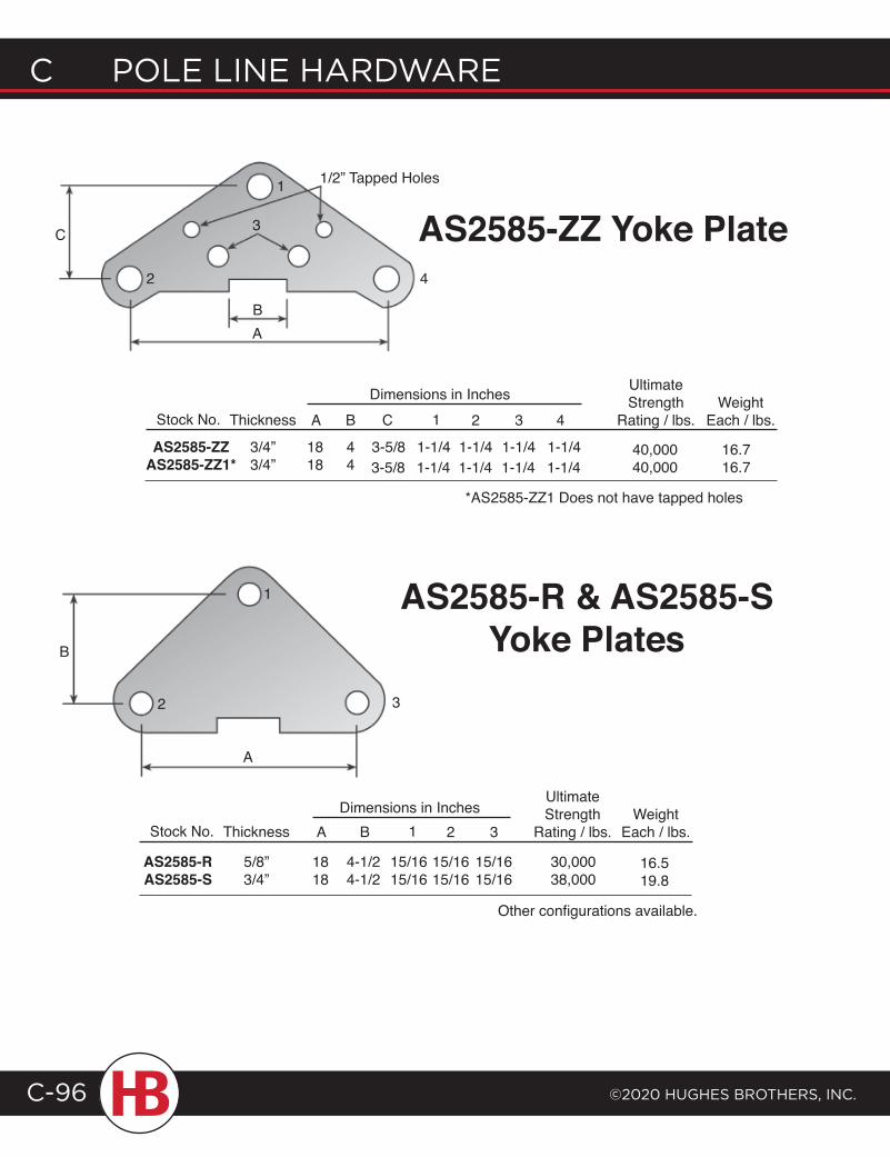
C POLE LINE HARDWARE
©2020 HugHEs BROtHERs, INC.C-96
1
2
3
4
AS2585-ZZ Yoke Plate1/2” Tapped Holes
Stock No. Thickness
AS2585-RAS2585-S
5/8”3/4”
UltimateStrength
Rating / lbs.
1
2 3
A
1818
4-1/24-1/2
B 21
15/1615/16
15/1615/16
15/1615/16
3
AS2585-R & AS2585-S Yoke Plates
Dimensions in Inches
30,00038,000
16.519.8
Stock No. Thickness A 21
AS2585-ZZAS2585-ZZ1*
3/4”3/4”
1818
1-1/4 1-1/41-1/41-1/4
3Dimensions in Inches
44
UltimateStrength
Rating / lbs.4
16.716.7
B
3-5/8
C
1-1/4 1-1/41-1/41-1/43-5/840,00040,000
*AS2585-ZZ1 Does not have tapped holes
WeightEach / lbs.
WeightEach / lbs.
B
C
A
B
A
Other configurations available.
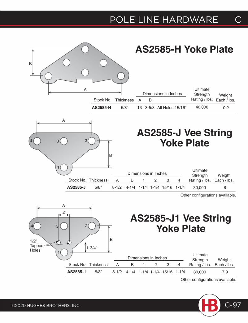
POLE LINE HARDWARE C
©2020 HugHEs BROtHERs, INC.
C POLE LINE HARDWARE
C-97
AS2585-H Yoke Plate
Stock No. Thickness
AS2585-H 5/8”
UltimateStrength
Rating / lbs.
40,000A
13 3-5/8
BDimensions in Inches
Stock No. ThicknessAS2585-J 5/8”
10.2All Holes 15/16”
AS2585-J Vee String Yoke Plate
WeightEach / lbs.
UltimateStrength
Rating / lbs.30,000
WeightEach / lbs.
81-1/443
15/162
1-1/41
1-1/4B
4-1/4A
8-1/2
Dimensions in Inches1
4 3 2
B
A
A
B
Other configurations available.
Stock No. ThicknessAS2585-J 5/8”
UltimateStrength
Rating / lbs.30,000
WeightEach / lbs.
7.91-1/443
15/162
1-1/41
1-1/4B
4-1/4A
8-1/2
Dimensions in Inches
Other configurations available.
1
4 3 2
A
B
AS2585-J1 Vee String Yoke Plate
1/2” Tapped Holes
2”
1-3/4”
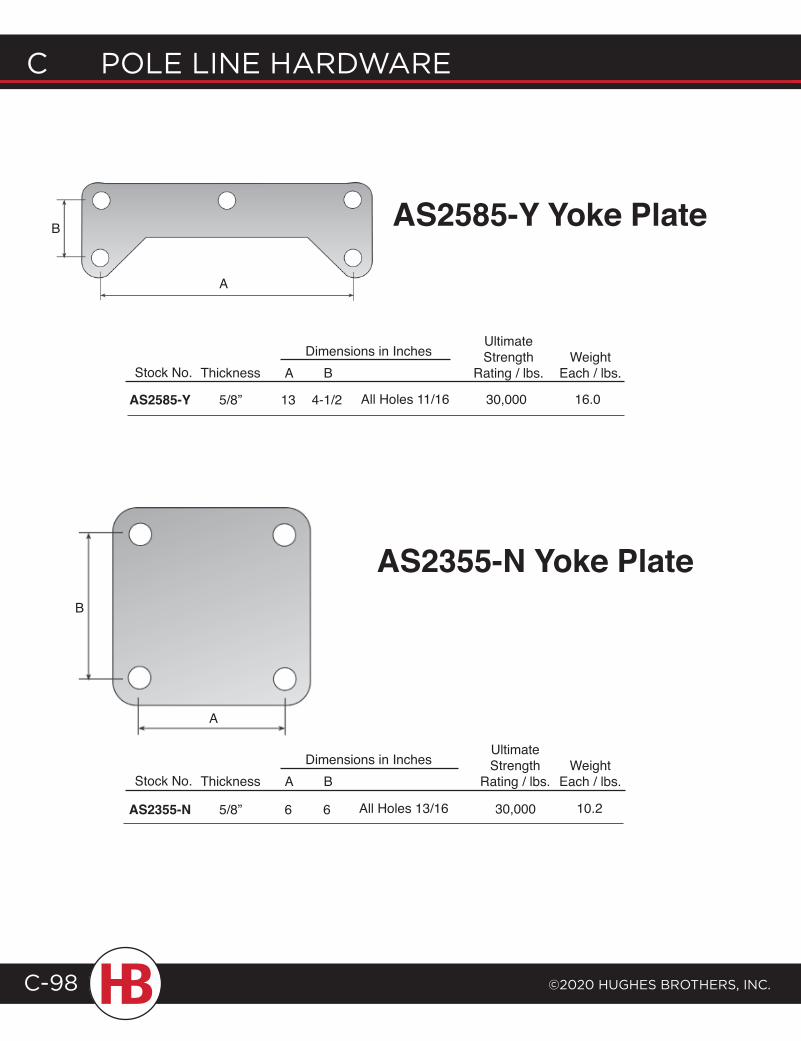
C POLE LINE HARDWARE
©2020 HugHEs BROtHERs, INC.C-98
AS2585-Y Yoke Plate
Stock No. Thickness
AS2585-Y 5/8”
A
13 4-1/2
BDimensions in Inches
Stock No. Thickness
AS2355-N 5/8”
UltimateStrength
Rating / lbs.A
6 6
BDimensions in Inches
AS2355-N Yoke Plate
All Holes 11/16
10.230,000All Holes 13/16
WeightEach / lbs.
WeightEach / lbs.
16.0
UltimateStrength
Rating / lbs.
30,000
B
A
B
A
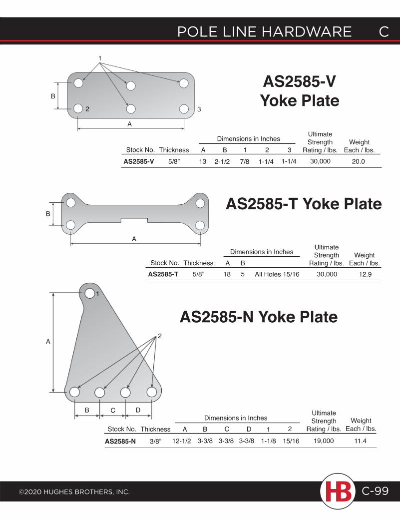
POLE LINE HARDWARE C
©2020 HugHEs BROtHERs, INC.
C POLE LINE HARDWARE
C-99
B
A
1
2 3
Stock No. Thickness A
UltimateStrength
Rating / lbs.Weight
Each / lbs.3B 1 2Dimensions in Inches
AS2585-V 5/8” 13 30,000 20.01-1/42-1/2 7/8 1-1/4
AS2585-T Yoke PlateB
A
Stock No. Thickness ADimensions in Inches Ultimate
StrengthRating / lbs.B
WeightEach / lbs.
AS2585-T 5/8” 18 5 All Holes 15/16 30,000 12.9
A
1
B C D
AS2585-N Yoke Plate
Stock No. Thickness
AS2585-N 3/8”
A
UltimateStrength
Rating / lbs.19,000 11.4
WeightEach / lbs.
15/16
2
1-1/81D
3-3/8C
3-3/83-3/8B
12-1/2
Dimensions in Inches
2
AS2585-V Yoke Plate
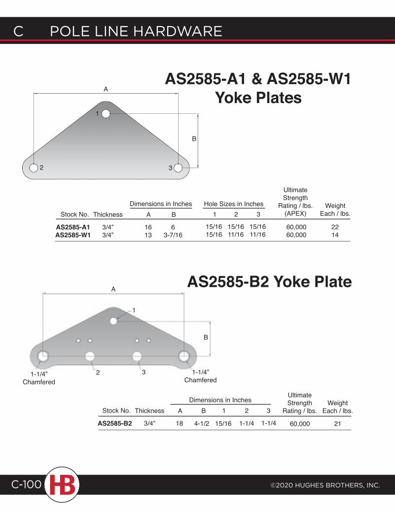
C POLE LINE HARDWARE
©2020 HugHEs BROtHERs, INC.C-100
AS2585-A1 & AS2585-W1 Yoke Plates
Stock No. Thickness
AS2585-A1AS2585-W1
3/4”3/4”
A
1613
63-7/16
BDimensions in Inches
UltimateStrength
Rating / lbs.(APEX)
60,00060,000
1 2 3Hole Sizes in Inches
15/1615/16
15/1611/16
15/1611/16
WeightEach / lbs.
2214
2
AS2585-B2 Yoke Plate
A
B
1
3
A
B
1
1-1/4”Chamfered
2 3 1-1/4”Chamfered
Stock No. Thickness
AS2585-B2 3/4”
UltimateStrength
Rating / lbs.
60,000
WeightEach / lbs.
1-1/4
321
15/16
B
4-1/2
A
18
Dimensions in Inches
1-1/4 21
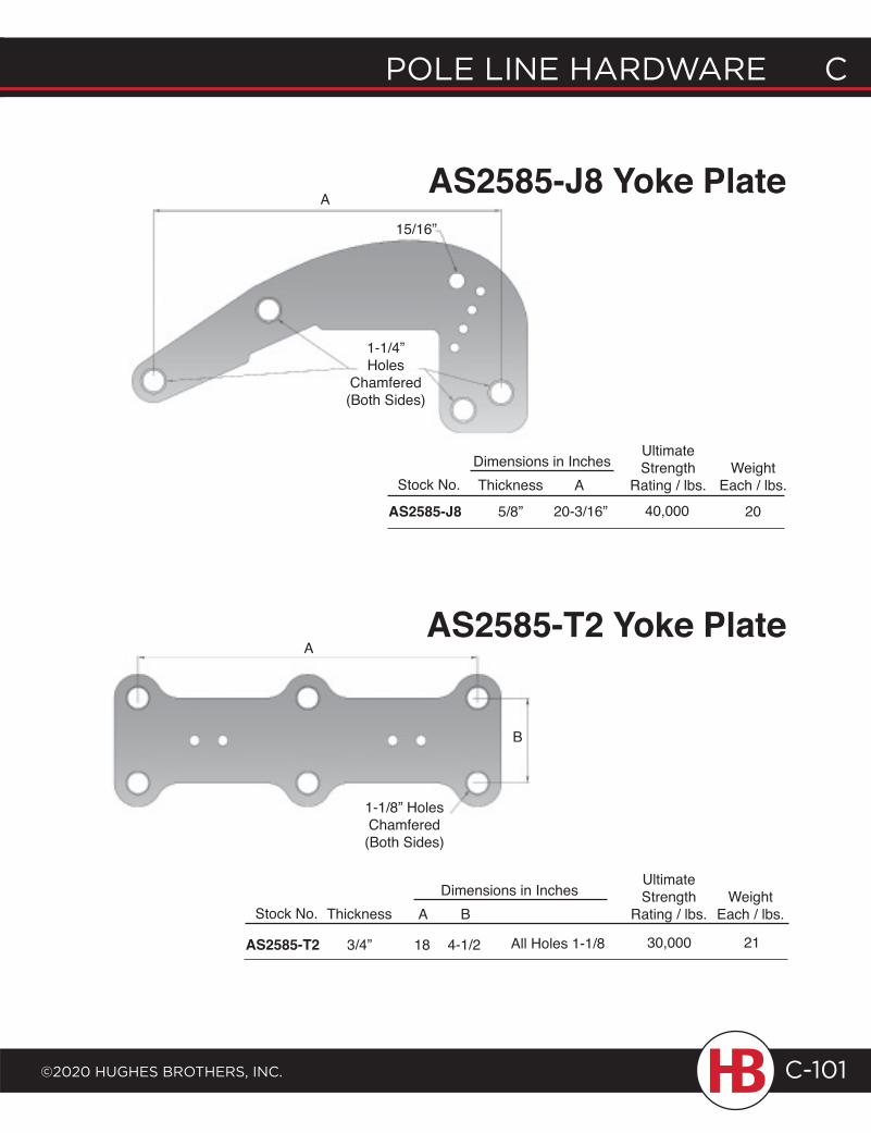
POLE LINE HARDWARE C
©2020 HugHEs BROtHERs, INC.
C POLE LINE HARDWARE
C-101
AS2585-J8 Yoke Plate
AS2585-T2 Yoke Plate
20-3/16”
Stock No. Thickness
AS2585-J8 5/8”
UltimateStrength
Rating / lbs.40,000
WeightEach / lbs.A
Dimensions in Inches
A
1-1/4”Holes
Chamfered (Both Sides)
15/16”
A
B
1-1/8” HolesChamfered(Both Sides)
Stock No. Thickness
AS2585-T2 3/4”
UltimateStrength
Rating / lbs.A
18 4-1/2
BDimensions in Inches
30,000All Holes 1-1/8
WeightEach / lbs.
20
21
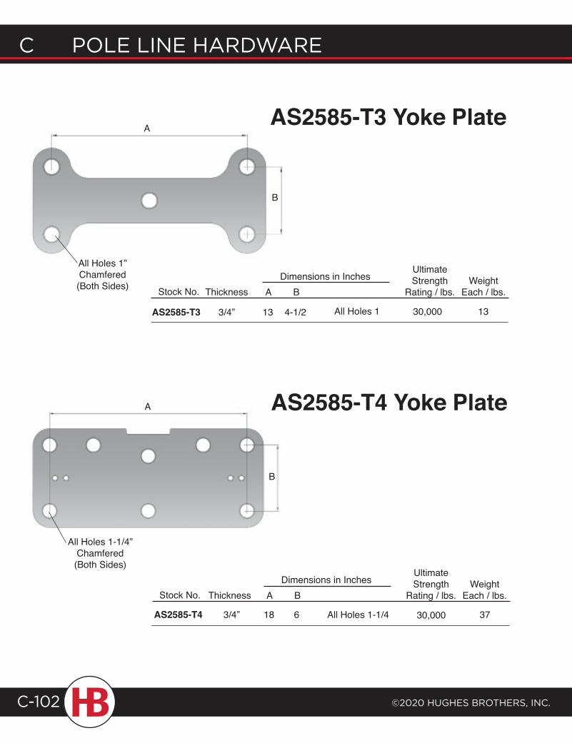
C POLE LINE HARDWARE
©2020 HugHEs BROtHERs, INC.C-102
AS2585-T3 Yoke Plate
AS2585-T4 Yoke Plate
A
B
A
B
Stock No. Thickness
AS2585-T3 3/4”
UltimateStrength
Rating / lbs.A
13 4-1/2
BDimensions in Inches
30,000All Holes 1
WeightEach / lbs.
Stock No. Thickness
AS2585-T4 3/4”
UltimateStrength
Rating / lbs.A
18 6
BDimensions in Inches
3730,000All Holes 1-1/4
WeightEach / lbs.
All Holes 1”Chamfered (Both Sides)
All Holes 1-1/4”Chamfered (Both Sides)
13
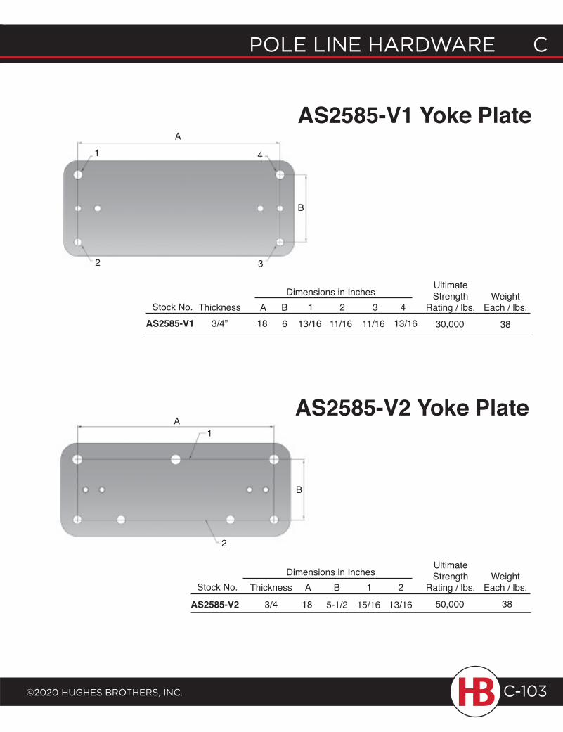
POLE LINE HARDWARE C
©2020 HugHEs BROtHERs, INC.
C POLE LINE HARDWARE
C-103
AS2585-V1 Yoke Plate
AS2585-V2 Yoke Plate
A
B
1
2 3
4
Stock No. ThicknessAS2585-V1 3/4”
UltimateStrength
Rating / lbs.30,000
WeightEach / lbs.
13/1643
11/162
11/161
13/16B6
A18
Dimensions in Inches
38
A
B
1
2
Stock No. Thickness
AS2585-V2 3/4
UltimateStrength
Rating / lbs.50,000
WeightEach / lbs.
382
13/16
1
15/16
B
5-1/2
A
18
Dimensions in Inches
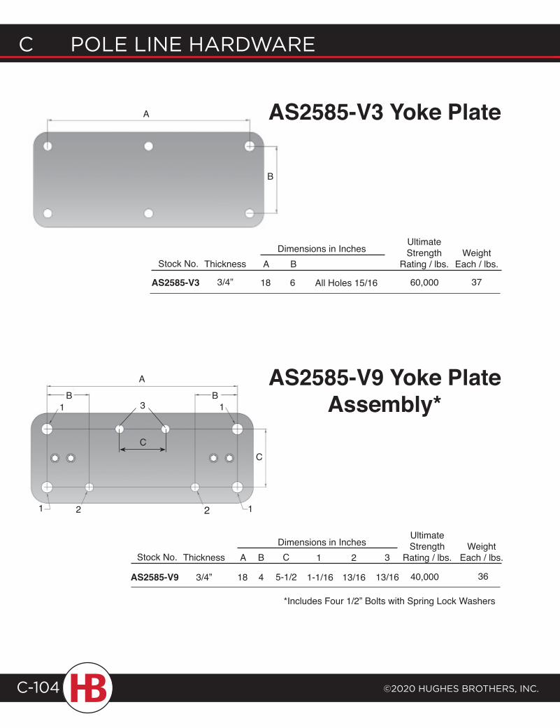
C POLE LINE HARDWARE
©2020 HugHEs BROtHERs, INC.C-104
AS2585-V3 Yoke PlateA
B
Stock No. Thickness
AS2585-V3 3/4”
UltimateStrength
Rating / lbs.A
18 6
BDimensions in Inches
60,000All Holes 15/16
WeightEach / lbs.
Stock No. Thickness
AS2585-V9 3/4”
UltimateStrength
Rating / lbs.A
18 4
BDimensions in Inches
3640,000
WeightEach / lbs.
AB B
C
5-1/2
C
1
1 1
1
2 2
1
1-1/16 13/16
2
13/16
3
AS2585-V9 Yoke PlateAssembly*
*Includes Four 1/2” Bolts with Spring Lock Washers
37
C
3
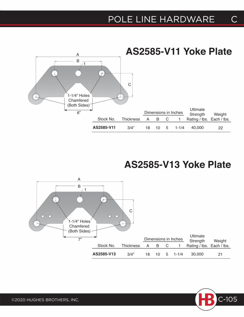
POLE LINE HARDWARE C
©2020 HugHEs BROtHERs, INC.
C POLE LINE HARDWARE
C-105
AS2585-V11 Yoke Plate
AS2585-V13 Yoke Plate
AB
C
1
1-1/4” Holes Chamfered (Both Sides)
AB
C
1
1-1/4” Holes Chamfered (Both Sides)
Stock No. Thickness
AS2585-V11 3/4”
UltimateStrength
Rating / lbs.A
18 10
BDimensions in Inches
2240,000
WeightEach / lbs.C
5 1-1/4
1
Stock No. Thickness
AS2585-V13 3/4”
UltimateStrength
Rating / lbs.A
18 10
BDimensions in Inches
30,000
WeightEach / lbs.C
5 1-1/4
1
21
6”
7”
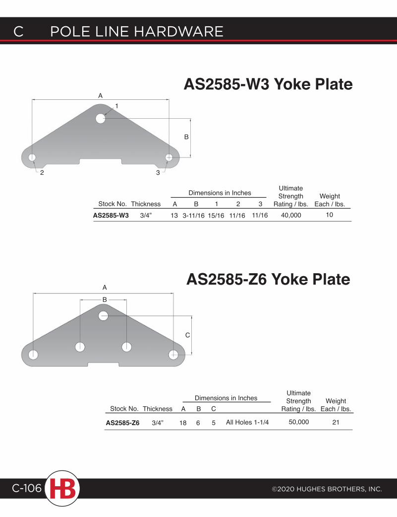
C POLE LINE HARDWARE
©2020 HugHEs BROtHERs, INC.C-106
AS2585-W3 Yoke Plate
AS2585-Z6 Yoke Plate
A
B
1
2 3
A
B
C
Stock No. Thickness A
UltimateStrength
Rating / lbs.Weight
Each / lbs.3B 1 2Dimensions in Inches
AS2585-W3 3/4” 13 40,000 1011/163-11/16 15/16 11/16
Stock No. Thickness
AS2585-Z6 3/4”
UltimateStrength
Rating / lbs.A
18 6
BDimensions in Inches
2150,000All Holes 1-1/4
WeightEach / lbs.
5
C
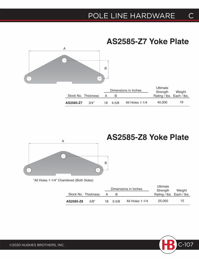
POLE LINE HARDWARE C
©2020 HugHEs BROtHERs, INC.
C POLE LINE HARDWARE
C-107
AS2585-Z7 Yoke Plate
AS2585-Z8 Yoke Plate
A
B
Stock No. Thickness
AS2585-Z7 3/4”
UltimateStrength
Rating / lbs.A
18 4-5/8
BDimensions in Inches
1940,000All Holes 1-1/4
WeightEach / lbs.
A
B
Stock No. Thickness
AS2585-Z8 5/8”
UltimateStrength
Rating / lbs.A
18 3-5/8
BDimensions in Inches
1525,000All Holes 1-1/4
WeightEach / lbs.
*All Holes 1-1/4” Chamfered (Both Sides)
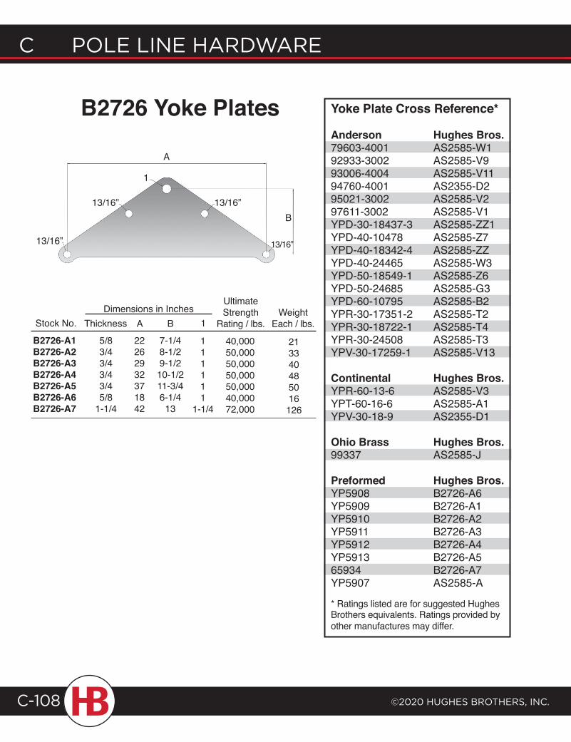
C POLE LINE HARDWARE
©2020 HugHEs BROtHERs, INC.C-108
B2726 Yoke Plates
A
B
1
13/16”
13/16”
13/16”
13/16”
Stock No. Thickness A BDimensions in Inches
B2726-A1B2726-A2B2726-A3B2726-A4B2726-A5B2726-A6B2726-A7
5/83/43/43/43/45/8
1-1/4
22262932371842
7-1/48-1/29-1/210-1/211-3/46-1/4
13
UltimateStrength
Rating / lbs.
40,00050,00050,00050,00050,00040,00072,000
213340485016126
WeightEach / lbs.
Yoke Plate Cross Reference*
Anderson Hughes Bros.79603-4001 AS2585-W192933-3002 AS2585-V993006-4004 AS2585-V1194760-4001 AS2355-D295021-3002 AS2585-V297611-3002 AS2585-V1YPD-30-18437-3 AS2585-ZZ1YPD-40-10478 AS2585-Z7YPD-40-18342-4 AS2585-ZZYPD-40-24465 AS2585-W3YPD-50-18549-1 AS2585-Z6YPD-50-24685 AS2585-G3YPD-60-10795 AS2585-B2YPR-30-17351-2 AS2585-T2YPR-30-18722-1 AS2585-T4YPR-30-24508 AS2585-T3YPV-30-17259-1 AS2585-V13
Continental Hughes Bros.YPR-60-13-6 AS2585-V3YPT-60-16-6 AS2585-A1YPV-30-18-9 AS2355-D1
Ohio Brass Hughes Bros.99337 AS2585-J
Preformed Hughes Bros.YP5908 B2726-A6YP5909 B2726-A1YP5910 B2726-A2YP5911 B2726-A3YP5912 B2726-A4YP5913 B2726-A565934 B2726-A7YP5907 AS2585-A
* Ratings listed are for suggested Hughes Brothers equivalents. Ratings provided by other manufactures may differ.
1
111111
1-1/4
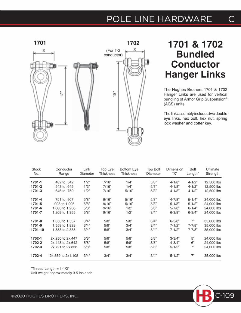
POLE LINE HARDWARE C
©2020 HugHEs BROtHERs, INC.
C POLE LINE HARDWARE
C-109
Stock Conductor Link Top Eye Bottom Eye Top Bolt Dimension Bolt Ultimate No. Range Diameter Thickness Thickness Diameter “X” Length* Strength
1701-1 .482 to .542 1/2” 7/16” 1/4” 5/8” 4-1/8” 4-1/2” 12,500 lbs1701-2 .543 to .645 1/2” 7/16” 1/4” 5/8” 4-1/8” 4-1/2” 12,500 lbs1701-3 .646 to .750 1/2” 7/16” 5/16” 5/8” 4-1/8” 4-1/2” 12,500 lbs
1701-4 .751 to .907 5/8” 9/16” 5/16” 5/8” 4-7/8” 5-1/4” 24,000 lbs1701-5 .908 to 1.005 5/8” 9/16” 5/16” 5/8” 5-1/8” 5-1/2” 24,000 lbs1701-6 1.006 to 1.208 5/8” 9/16” 1/2” 5/8” 5-7/8” 6-1/4” 24,000 lbs1701-7 1.209 to 1.355 5/8” 9/16” 1/2” 3/4” 6-3/8” 6-3/4” 24,000 lbs
1701-8 1.356 to 1.557 3/4” 5/8” 5/8” 3/4” 6-5/8” 7” 35,000 lbs1701-9 1.558 to 1.828 3/4” 5/8” 3/4” 3/4” 7-1/2” 7-7/8” 35,000 lbs1701-10 1.883 to 2.333 3/4” 5/8” 3/4” 3/4” 7-1/2” 7-7/8” 35,000 lbs
1702-1 2x.250 to 2x.447 5/8” 5/8” 5/8” 5/8” 3-3/4” 5” 24,000 lbs1702-2 2x.448 to 2x.642 5/8” 5/8” 5/8” 5/8” 4-3/4” 6” 24,000 lbs1702-3 2x.721 to 2x.858 5/8” 5/8” 5/8” 5/8” 5-1/2” 7” 24,000 lbs
1702-4 2x.859 to 2x1.108 3/4” 3/4” 3/4” 3/4” 5-1/2” 7” 35,000 lbs
*Thread Length = 1-1/2”Unit weight approximately 3.5 lbs each
The Hughes Brothers 1701 & 1702 Hanger Links are used for vertical bundling of Armor Grip Suspension® (AGS) units.
The link assembly includes two double eye links, hex bolt, hex nut, spring lock washer and cotter key.
12”
1701 & 1702 Bundled
Conductor Hanger Links
1701 1702(For T-2
conductor)
18”
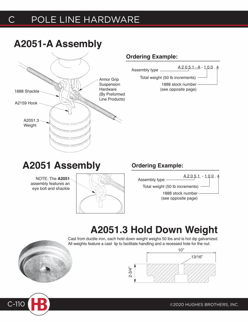
C POLE LINE HARDWARE
©2020 HugHEs BROtHERs, INC.C-110
1888 Shackle
A2051.3 Weight
A2159 Hook
Armor Grip Suspension Hardware (By Preformed Line Products)
NOTE: The A2051 assembly features an eye bolt and shackle
A2051 Assembly
2-3/
4”
A2051.3 Hold Down Weight
A2051-A Assembly
1888 stock number (see opposite page)
A 2 0 5 1 - A - 1 0 0 . 4
Total weight (50 lb increments)
Assembly type
Ordering Example:
10”13/16”
Cast from ductile iron, each hold down weight weighs 50 lbs and is hot dip galvanized. All weights feature a cast lip to facilitate handling and a recessed hole for the nut.
1888 stock number (see opposite page)
A 2 0 5 1 - 1 0 0 . 4
Total weight (50 lb increments)Assembly type
Ordering Example:
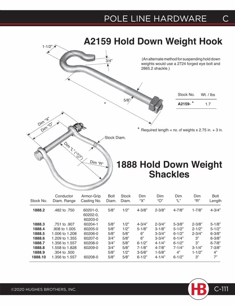
POLE LINE HARDWARE C
©2020 HugHEs BROtHERs, INC.
C POLE LINE HARDWARE
C-111
Conductor Armor-Grip Bolt Stock Dim Dim Dim Dim Bolt Stock No. Diam. Range Casting No. Diam. Diam. “X” “O” “L” “R” Length
1888.2 .482 to .750 60201-0, 5/8” 1/2” 4-3/8” 2-3/8” 4-7/8” 1-7/8” 4-3/4” 60202-0, 60203-0 1888.3 .751 to .907 60204-1 5/8” 1/2” 4-3/4” 2-3/4” 5-3/8” 2-3/8” 5-1/8” 1888.4 .908 to 1.005 60205-0 5/8” 1/2” 5-1/8” 3-1/8” 5-1/2” 2-1/2” 5-1/2” 1888.5 1.006 to 1.208 60206-0 5/8” 5/8” 6” 3-3/4” 6-1/2” 2-3/4” 6-3/8” 1888.6 1.209 to 1.355 60207-0 3/4” 5/8” 6” 3-3/4” 6-1/4” 3” 6-3/8” 1888.7 1.356 to 1.557 60208-0 3/4” 5/8” 6-1/2” 4-1/4” 6-1/2” 3” 6-7/8” 1888.8 1.558 to 1.828 60209-0 3/4” 5/8” 7-1/8” 4-7/8” 7-1/4” 3-1/4” 7-3/8” 1888.9 .304 to .500 5/8” 1/2” 3-5/8” 1-5/8” 4” 1-1/2” 4” 1888.10 1.356 to 1.557 60208-0 5/8” 5/8” 6-1/2” 4-1/4” 6-1/2” 3” 7”
3/4”
1-1/2”
(An alternate method for suspending hold down weights would use a 2724 forged eye bolt and 2865.2 shackle.)
A2159 Hold Down Weight Hook
1888 Hold Down Weight Shackles
5/8”
* Required length = no. of weights x 2.75 in. + 3 in.
Stock No.
A2159- *Wt. / lbs
1.7
Dim “R”
Stock Diam.
*
Dim “X”
Dim “O”
Dim “L” ( +3/16”)-O”
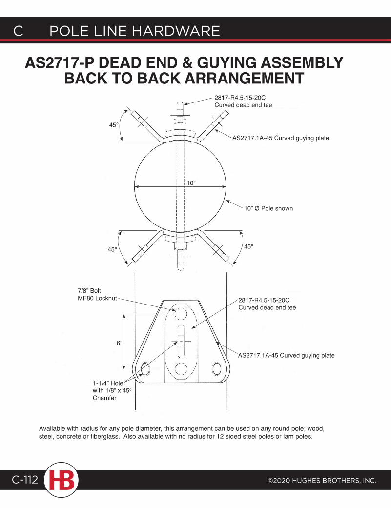
C POLE LINE HARDWARE
©2020 HugHEs BROtHERs, INC.C-112
AS2717-P DEAD END & GUYING ASSEMBLY BACK TO BACK ARRANGEMENT
45°
2817-R4.5-15-20CCurved dead end tee
AS2717.1A-45 Curved guying plate
10” O Pole shown/
10”
45° 45°
6”
7/8” Bolt MF80 Locknut
1-1/4” Hole with 1/8” x 450 Chamfer
2817-R4.5-15-20CCurved dead end tee
AS2717.1A-45 Curved guying plate
Available with radius for any pole diameter, this arrangement can be used on any round pole; wood, steel, concrete or fiberglass. Also available with no radius for 12 sided steel poles or lam poles.
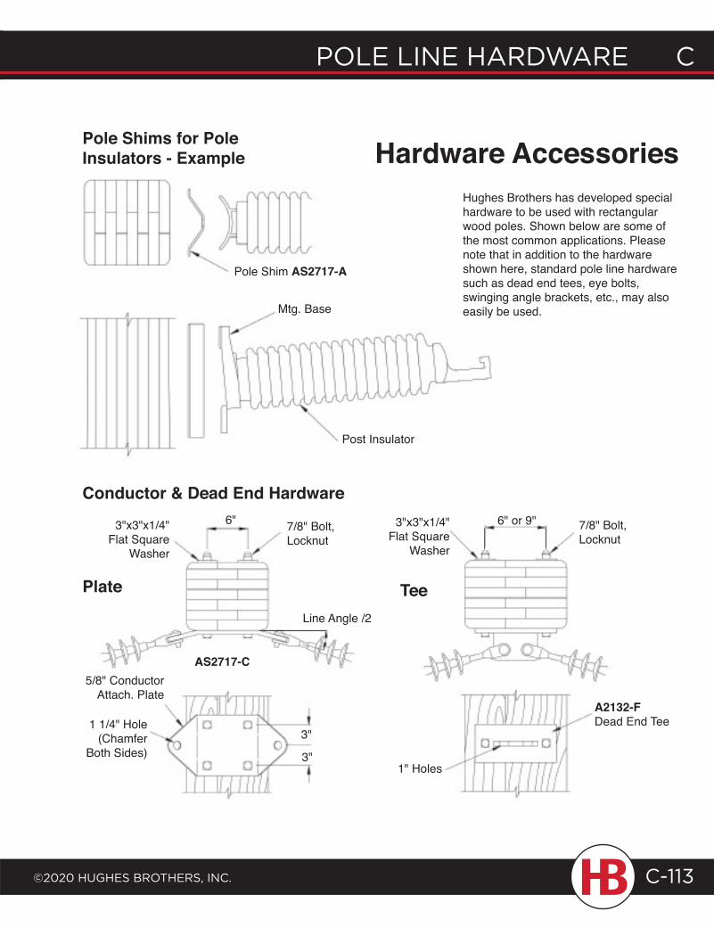
POLE LINE HARDWARE C
©2020 HugHEs BROtHERs, INC.
C POLE LINE HARDWARE
C-113
7/8" Bolt, Locknut
Conductor & Dead End Hardware
Pole Shims for Pole Insulators - Example
Pole Shim AS2717-A
Mtg. Base
Post Insulator
5/8" Conductor Attach. Plate
6"3"x3"x1/4" Flat Square
Washer
7/8" Bolt, Locknut
Line Angle /2
Plate
1 1/4" Hole (Chamfer
Both Sides)3"
3"
3"x3"x1/4" Flat Square
Washer
6" or 9"
Tee
1" Holes
A2132-FDead End Tee
Hughes Brothers has developed special hardware to be used with rectangular wood poles. Shown below are some of the most common applications. Please note that in addition to the hardware shown here, standard pole line hardware such as dead end tees, eye bolts, swinging angle brackets, etc., may also easily be used.
Hardware Accessories
AS2717-C
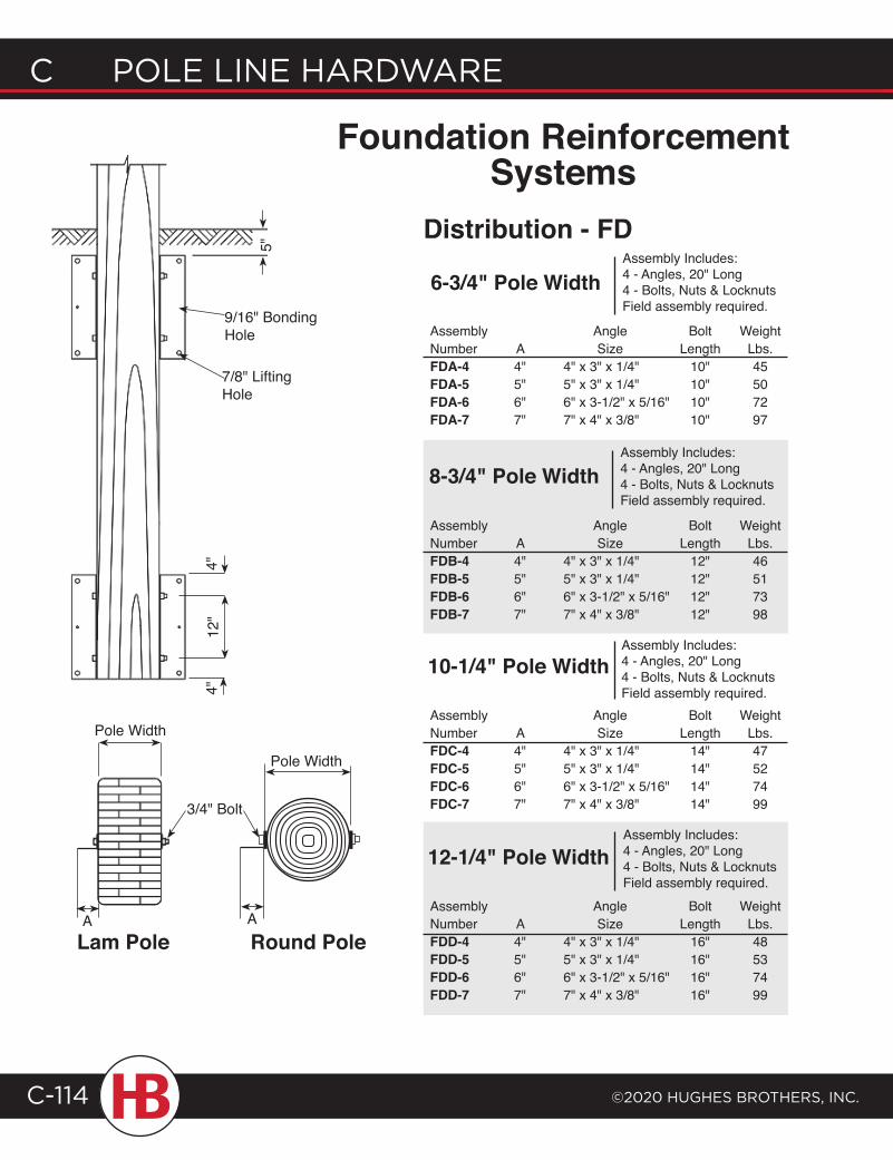
C POLE LINE HARDWARE
©2020 HugHEs BROtHERs, INC.C-114
Assembly Angle Bolt WeightNumber A Size Length Lbs.FDA-4 4" 4" x 3" x 1/4" 10" 45FDA-5 5" 5" x 3" x 1/4" 10" 50FDA-6 6" 6" x 3-1/2" x 5/16" 10" 72FDA-7 7" 7" x 4" x 3/8" 10" 97
Assembly Angle Bolt WeightNumber A Size Length Lbs.FDB-4 4" 4" x 3" x 1/4" 12" 46FDB-5 5" 5" x 3" x 1/4" 12" 51FDB-6 6" 6" x 3-1/2" x 5/16" 12" 73FDB-7 7" 7" x 4" x 3/8" 12" 98
Assembly Angle Bolt WeightNumber A Size Length Lbs.FDC-4 4" 4" x 3" x 1/4" 14" 47FDC-5 5" 5" x 3" x 1/4" 14" 52FDC-6 6" 6" x 3-1/2" x 5/16" 14" 74FDC-7 7" 7" x 4" x 3/8" 14" 99
Assembly Angle Bolt WeightNumber A Size Length Lbs.FDD-4 4" 4" x 3" x 1/4" 16" 48FDD-5 5" 5" x 3" x 1/4" 16" 53FDD-6 6" 6" x 3-1/2" x 5/16" 16" 74FDD-7 7" 7" x 4" x 3/8" 16" 99
5"
4"4"
Pole Width
12"
Distribution - FD
8-3/4" Pole Width
10-1/4" Pole Width
12-1/4" Pole Width
6-3/4" Pole Width
3/4" Bolt
9/16" Bonding Hole
7/8" Lifting Hole
Foundation Reinforcement Systems
Assembly Includes:4 - Angles, 20" Long4 - Bolts, Nuts & LocknutsField assembly required.
Assembly Includes:4 - Angles, 20" Long4 - Bolts, Nuts & LocknutsField assembly required.
Assembly Includes:4 - Angles, 20" Long4 - Bolts, Nuts & LocknutsField assembly required.
Assembly Includes:4 - Angles, 20" Long4 - Bolts, Nuts & LocknutsField assembly required.
Pole Width
Lam Pole Round PoleAA
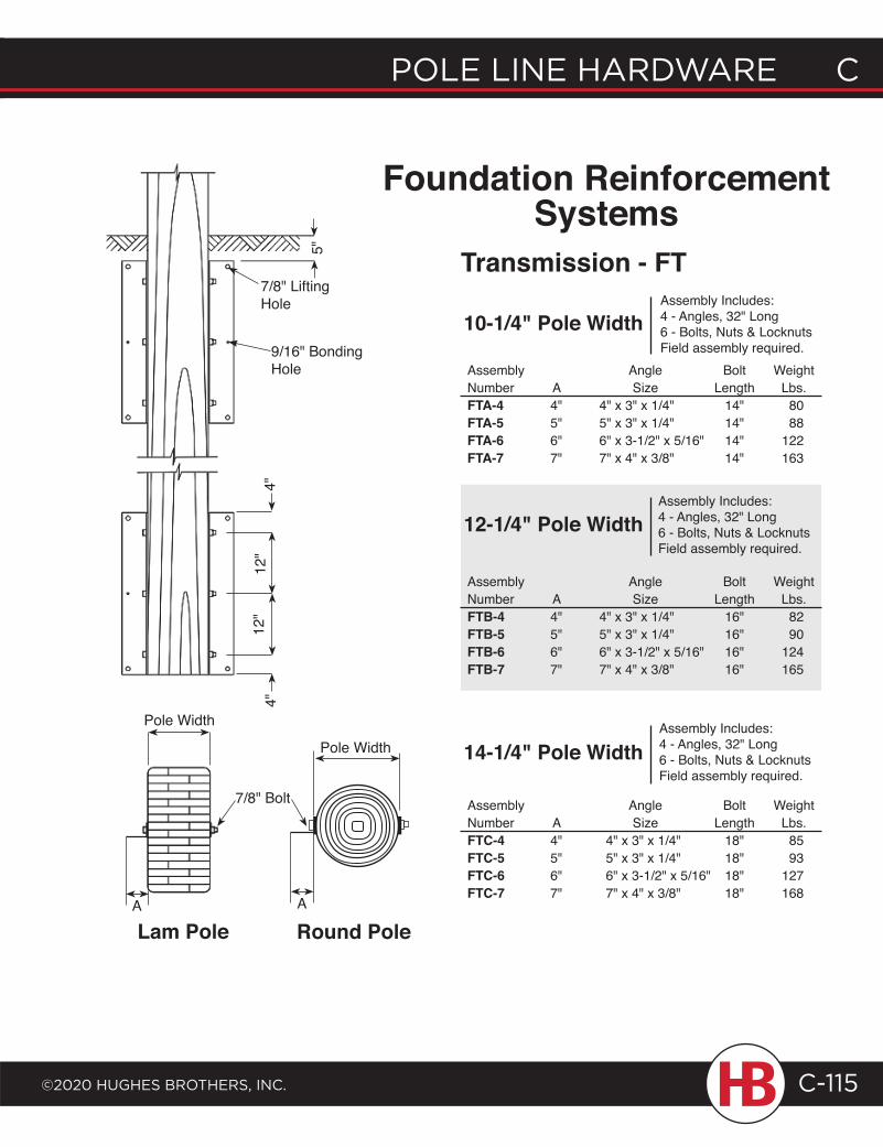
POLE LINE HARDWARE C
©2020 HugHEs BROtHERs, INC.
C POLE LINE HARDWARE
C-115
Assembly Angle Bolt WeightNumber A Size Length Lbs.FTA-4 4" 4" x 3" x 1/4" 14" 80FTA-5 5" 5" x 3" x 1/4" 14" 88FTA-6 6" 6" x 3-1/2" x 5/16" 14" 122FTA-7 7" 7" x 4" x 3/8" 14" 163
Assembly Includes:4 - Angles, 32" Long6 - Bolts, Nuts & LocknutsField assembly required.
Transmission - FT
10-1/4" Pole Width5"
Assembly Angle Bolt WeightNumber A Size Length Lbs.FTC-4 4" 4" x 3" x 1/4" 18" 85FTC-5 5" 5" x 3" x 1/4" 18" 93FTC-6 6" 6" x 3-1/2" x 5/16" 18" 127FTC-7 7" 7" x 4" x 3/8" 18" 168
14-1/4" Pole Width
Assembly Angle Bolt WeightNumber A Size Length Lbs.FTB-4 4" 4" x 3" x 1/4" 16" 82FTB-5 5" 5" x 3" x 1/4" 16" 90FTB-6 6" 6" x 3-1/2" x 5/16" 16" 124FTB-7 7" 7" x 4" x 3/8" 16" 165
12-1/4" Pole Width
Foundation Reinforcement Systems
4"12
"4"
7/8" Lifting Hole
9/16" Bonding Hole
Assembly Includes:4 - Angles, 32" Long6 - Bolts, Nuts & LocknutsField assembly required.
Assembly Includes:4 - Angles, 32" Long6 - Bolts, Nuts & LocknutsField assembly required.
Round PoleLam Pole
Pole Width
7/8" Bolt
A
12"
Pole Width
A
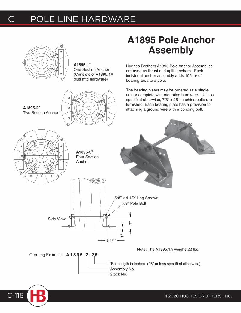
C POLE LINE HARDWARE
©2020 HugHEs BROtHERs, INC.C-116
A1895-3*Four Section Anchor
Side View
A1895-2*Two Section Anchor
Hughes Brothers A1895 Pole Anchor Assemblies are used as thrust and uplift anchors. Each individual anchor assembly adds 106 in2 of bearing area to a pole.
The bearing plates may be ordered as a single unit or complete with mounting hardware. Unless specified otherwise, 7/8” x 26” machine bolts are furnished. Each bearing plate has a provision for attaching a ground wire with a bonding bolt.
A1895 Pole AnchorAssembly
A 1 8 9 5 - 2 - 2 6
*Bolt length in inches. (26” unless specified otherwise)
Ordering Example
A1895-1*One Section Anchor(Consists of A1895.1A plus mtg hardware)
Note: The A1895.1A weighs 22 lbs.
Stock No.
5/8” x 4-1/2” Lag Screws7/8” Pole Bolt
7”
1”
6-1/4”
Assembly No.

E Q U I P M E N T M O U N T S
Transformer Platforms ...................D-1Potholders .......................................D-14Grates & Vault Covers .................D-20Fiber Optic Cases ........................D-25Cutout & Arrestor Brackets ......D-30Conduit Support Brackets ........D-36Sports Field Lighting Brackets D-41
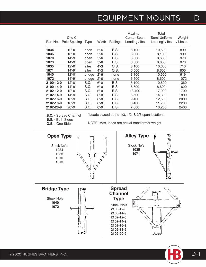
EQUIPMENT MOUNTS D
©2020 HUgHES BrOTHErS, INc. D-1
Part No.
103410361070107310351071104010722100-12-02100-14-92102-12-02102-14-92102-16-92102-18-92102-20-9
C to CPole Spacing
12'-0"16'-0"14'-9"14'-9"12'-0"14'-9"12'-0"14'-9"12'-0"14'-9"12'-0"14'-9"16'-9"18'-9"20'-9"
Type
openopenopenopenalleyalleybridgebridgeS.C.S.C.S.C.S.C.S.C.S.C.S.C.
Width
5'-6"5'-6"5'-6"5'-6"4'-3"4'-3"2'-6"2'-6"6'-0"6'-0"6'-0"6'-0"6'-0"6'-0"6'-0"
Railings
B.S.B.S.B.S.B.S.O.S.O.S.nonenoneB.S.B.S.B.S.B.S.B.S.B.S.B.S.
Maximum Center Span Loading / lbs
8,1006,0006,5006,5008,1006,5008,1006,5008,1006,50013,4006,5009,4008,4007,600
Total Semi-Uniform Loading* / lbs
10,6008,1008,6008,60010,6008,60010,6008,60010,6008,60017,00014,30012,50011,25010,200
Weight/ Lbs ea.
890990970970710800619
10721360162017001800200022002400
Alley Type
Stock No's10351071
Open Type
Stock No's1034103610701073
Spread Channel
TypeStock No's2100-12-02100-14-92102-12-02102-14-92102-16-92102-18-92102-20-9
Stock No's10401072
Bridge Type
*Loads placed at the 1/3, 1/2, & 2/3 span locations
NOTE: Max. loads are actual transformer weight.
S.C. - Spread ChannelB.S. - Both SidesO.S. - One Side
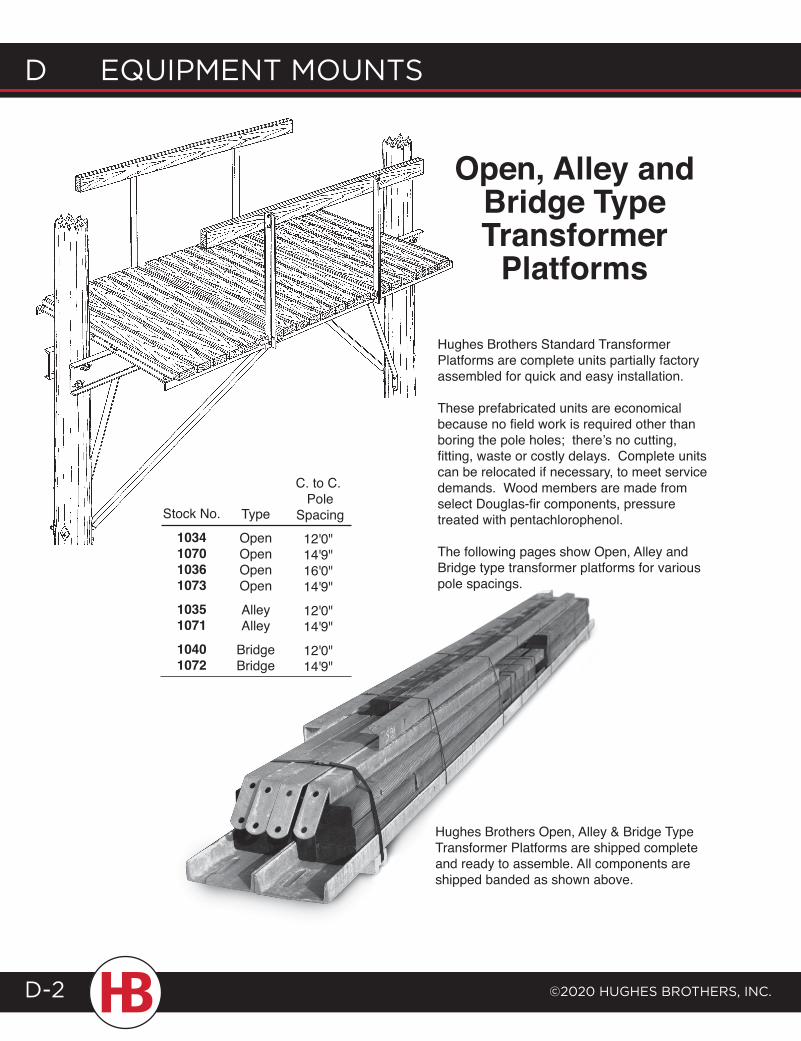
d EQUIPMENT MOUNTS
©2020 HUgHES BrOTHErS, INc.D-2
Hughes Brothers Open, Alley & Bridge Type Transformer Platforms are shipped complete and ready to assemble. All components are shipped banded as shown above.
Type
OpenOpenOpenOpen
AlleyAlley
BridgeBridge
C. to C. Pole
Spacing
12'0"14'9"16'0"14'9"
12'0"14'9"
12'0"14'9"
Stock No.
10341070103610731035107110401072
Open, Alley and Bridge Type Transformer
Platforms
Hughes Brothers Standard Transformer Platforms are complete units partially factory assembled for quick and easy installation.
These prefabricated units are economical because no field work is required other than boring the pole holes; there’s no cutting, fitting, waste or costly delays. Complete units can be relocated if necessary, to meet service demands. Wood members are made from select Douglas-fir components, pressure treated with pentachlorophenol.
The following pages show Open, Alley and Bridge type transformer platforms for various pole spacings.
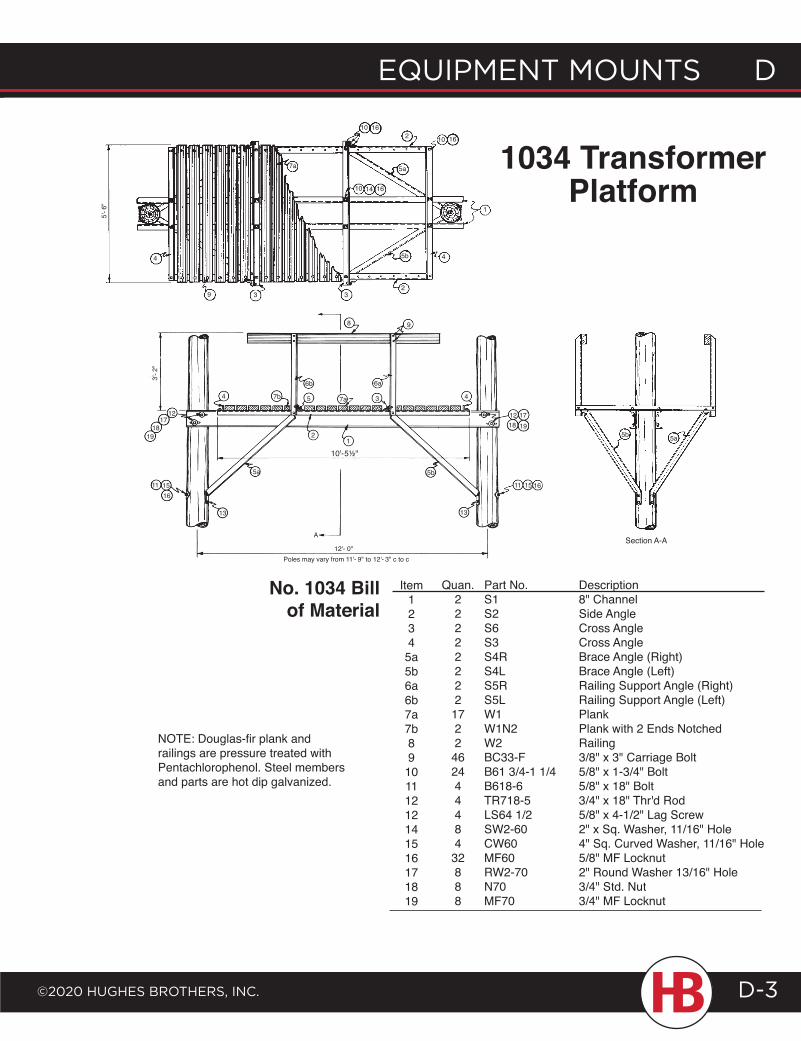
EQUIPMENT MOUNTS D
©2020 HUgHES BrOTHErS, INc.
D EQUIPMENT MOUNTS
D-3
Item1234
5a5b6a6b7a7b89
10111212141516171819
Quan.22222222
1722
462444484
32888
Part No.S1S2S6S3S4RS4LS5RS5LW1W1N2W2BC33-FB61 3/4-1 1/4B618-6TR718-5LS64 1/2SW2-60CW60MF60RW2-70N70MF70
Description8" ChannelSide AngleCross AngleCross AngleBrace Angle (Right)Brace Angle (Left)Railing Support Angle (Right)Railing Support Angle (Left)PlankPlank with 2 Ends NotchedRailing3/8" x 3" Carriage Bolt5/8" x 1-3/4" Bolt5/8" x 18" Bolt3/4" x 18" Thr'd Rod5/8" x 4-1/2" Lag Screw2" x Sq. Washer, 11/16" Hole4" Sq. Curved Washer, 11/16" Hole5/8" MF Locknut2" Round Washer 13/16" Hole3/4" Std. Nut3/4" MF Locknut
No. 1034 Bill of Material
NOTE: Douglas-fir plank and railings are pressure treated with Pentachlorophenol. Steel members and parts are hot dip galvanized.
10 16
10 16
7a 5a
10 14 16
2
1
5b
3 32
4
9
4
5'- 6
"
6b
8 9
54 7b 7a 3
6a
21
4
10'-5½"
1718 1912
11
5b
13
15 16
5a
1217
1819
13
11 1516
A
12'- 0"Poles may vary from 11'- 9" to 12'- 3" c to c
5a5b
Section A-A
1034 Transformer Platform
3'- 2
"
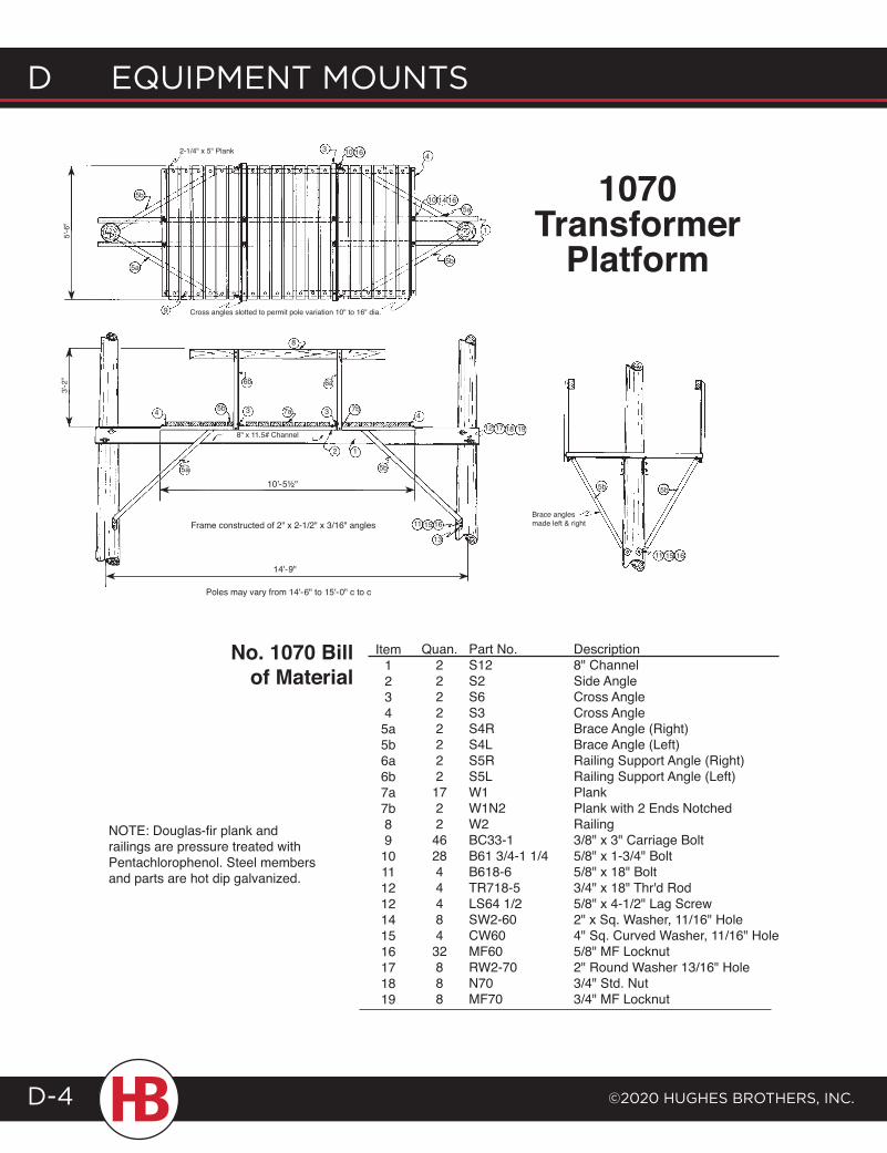
d EQUIPMENT MOUNTS
©2020 HUgHES BrOTHErS, INc.D-4
Item1234
5a5b6a6b7a7b89
10111212141516171819
Quan.22222222
1722
462844484
32888
Part No.S12S2S6S3S4RS4LS5RS5LW1W1N2W2BC33-1B61 3/4-1 1/4B618-6TR718-5LS64 1/2SW2-60CW60MF60RW2-70N70MF70
Description8" ChannelSide AngleCross AngleCross AngleBrace Angle (Right)Brace Angle (Left)Railing Support Angle (Right)Railing Support Angle (Left)PlankPlank with 2 Ends NotchedRailing3/8" x 3" Carriage Bolt5/8" x 1-3/4" Bolt5/8" x 18" Bolt3/4" x 18" Thr'd Rod5/8" x 4-1/2" Lag Screw2" x Sq. Washer, 11/16" Hole4" Sq. Curved Washer, 11/16" Hole5/8" MF Locknut2" Round Washer 13/16" Hole3/4" Std. Nut3/4" MF Locknut
No. 1070 Bill of Material
1070 Transformer
Platform
NOTE: Douglas-fir plank and railings are pressure treated with Pentachlorophenol. Steel members and parts are hot dip galvanized.
10
5b
3 16 4
10 14 165a
1
5b
5a
9
2-1/4" x 5" Plank
5'-6
"
Cross angles slotted to permit pole variation 10" to 16" dia.
5b
6a
7b
5b5a
8" x 11.5# Channel
7a 3 4
8
3
6b
12
10'-5½"
12 17 18 19
11 15 16
13
4
3'-2
"
Frame constructed of 2" x 2-1/2" x 3/16" angles
Poles may vary from 14'-6" to 15'-0" c to c
5b5b
Brace angles made left & right
11 15 16
14'-9"
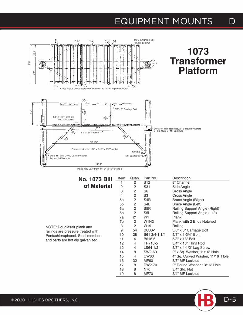
EQUIPMENT MOUNTS D
©2020 HUgHES BrOTHErS, INc.
D EQUIPMENT MOUNTS
D-5
Item1234
5a5b6a6b7a7b89
10111212141516171819
Quan.22222222
2122
542844484
32888
Part No.S12S31S6S3S4RS4LS5RS5LW1W1N2W19BC33-1B61 3/4-1 1/4B618-6TR718-5LS64 1/2SW2-60CW60MF60RW2-70N70MF70
Description8" ChannelSide AngleCross AngleCross AngleBrace Angle (Right)Brace Angle (Left)Railing Support Angle (Right)Railing Support Angle (Left)PlankPlank with 2 Ends NotchedRailing3/8" x 3" Carriage Bolt5/8" x 1-3/4" Bolt5/8" x 18" Bolt3/4" x 18" Thr'd Rod5/8" x 4-1/2" Lag Screw2" x Sq. Washer, 11/16" Hole4" Sq. Curved Washer, 11/16" Hole5/8" MF Locknut2" Round Washer 13/16" Hole3/4" Std. Nut3/4" MF Locknut
No. 1073 Bill of Material
NOTE: Douglas-fir plank and railings are pressure treated with Pentachlorophenol. Steel members and parts are hot dip galvanized.
7b
5'-6
"
2'-9
"2'
-9"
9
4 3
7a 3 7b
6
S-12
5/8" x 1-3/4" Bolt, Sq. Nut, MF Locknut
Cross angles slotted to permit variation of 10" to 16" in pole diameter
1073 Transformer
Platform
6a
6b
1
3/8" x 3" Carriage Bolt
8
2
5a5b
5/8" x 1-3/4" Bolt, Sq. Nut, MF Locknut
3'-2
"
5/8" x 18" Bolt, CW60 Curved Washer, Sq. Nut, MF Locknut
12'-5½"
Frame constructed of 2" x 2-1/2" x 3/16" angles
8" x 11.5# Channel
5/8" Bolt5/8" Lag Screw
3/4" x 18" Threaded Rod, 2 - 2" Round Washers2 - Sq. Nuts, 2 - MF Locknuts
14'-9"
Poles may vary from 14'-6" to 15'-0" c to c
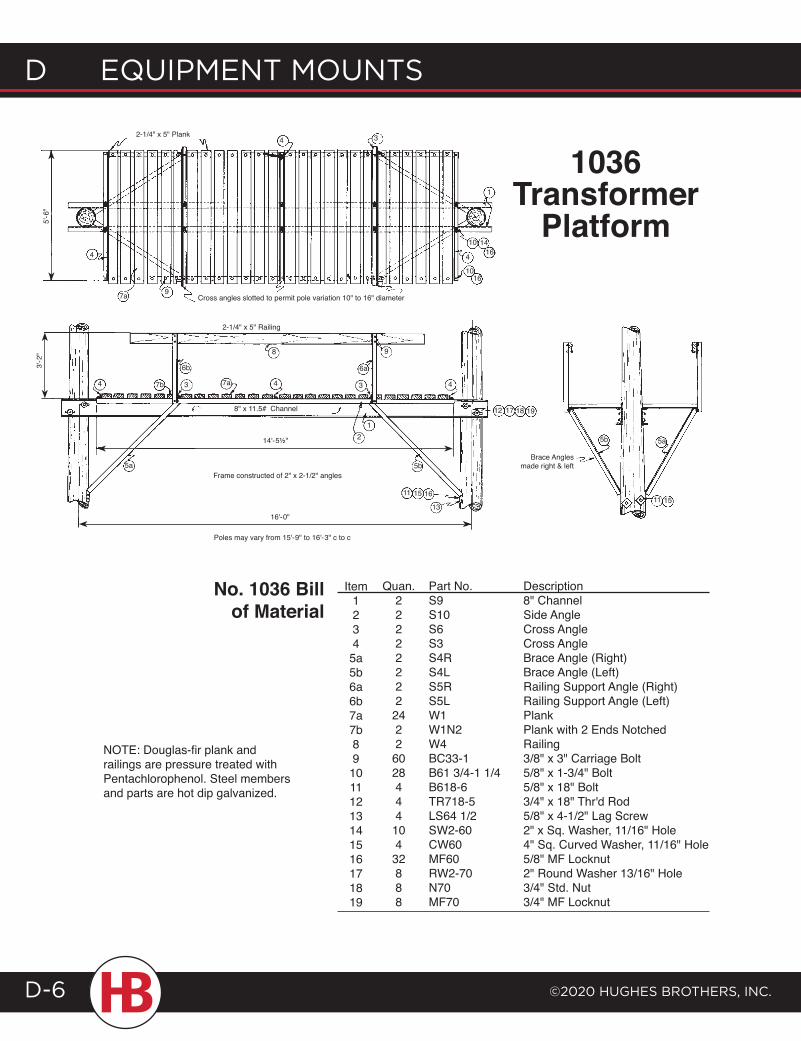
d EQUIPMENT MOUNTS
©2020 HUgHES BrOTHErS, INc.D-6
Item1234
5a5b6a6b7a7b89
10111213141516171819
Quan.22222222
2422
6028444
104
32888
Part No.S9S10S6S3S4RS4LS5RS5LW1W1N2W4BC33-1B61 3/4-1 1/4B618-6TR718-5LS64 1/2SW2-60CW60MF60RW2-70N70MF70
Description8" ChannelSide AngleCross AngleCross AngleBrace Angle (Right)Brace Angle (Left)Railing Support Angle (Right)Railing Support Angle (Left)PlankPlank with 2 Ends NotchedRailing3/8" x 3" Carriage Bolt5/8" x 1-3/4" Bolt5/8" x 18" Bolt3/4" x 18" Thr'd Rod5/8" x 4-1/2" Lag Screw2" x Sq. Washer, 11/16" Hole4" Sq. Curved Washer, 11/16" Hole5/8" MF Locknut2" Round Washer 13/16" Hole3/4" Std. Nut3/4" MF Locknut
No. 1036 Bill of Material
NOTE: Douglas-fir plank and railings are pressure treated with Pentachlorophenol. Steel members and parts are hot dip galvanized.
1036 Transformer
Platform
4 3
Cross angles slotted to permit pole variation 10" to 16" diameter
1
10 14164
1016
97a
5'-6
"
4
2-1/4" x 5" Plank
7a
6b
7b
5a
3'-2
"
8" x 11.5# Channel
34
1
9
11 15 16
13
14'-5½"
Frame constructed of 2" x 2-1/2" angles
Poles may vary from 15'-9" to 16'-3" c to c
4 3
2
8
12 17 18 19
4
5b
6a
2-1/4" x 5" Railing
5b
11 15
5a
Brace Angles made right & left
16'-0"
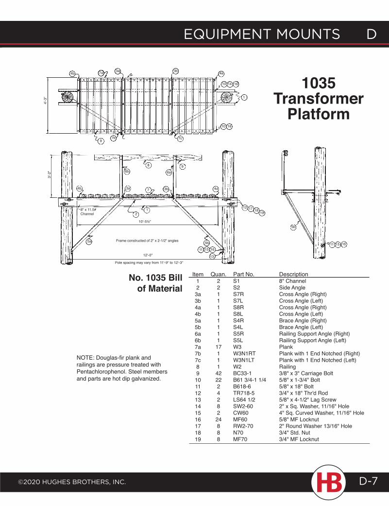
EQUIPMENT MOUNTS D
©2020 HUgHES BrOTHErS, INc.
D EQUIPMENT MOUNTS
D-7
Item12
3a3b4a4b5a5b6a6b7a7b7c89
10111213141516171819
Quan.2211111111
17111
422224282
24888
Part No.S1S2S7RS7LS8RS8LS4RS4LS5RS5LW3W3N1RTW3N1LTW2BC33-1B61 3/4-1 1/4B618-6TR718-5LS64 1/2SW2-60CW60MF60RW2-70N70MF70
Description8" ChannelSide AngleCross Angle (Right)Cross Angle (Left)Cross Angle (Right)Cross Angle (Left)Brace Angle (Right)Brace Angle (Left)Railing Support Angle (Right)Railing Support Angle (Left)PlankPlank with 1 End Notched (Right)Plank with 1 End Notched (Left)Railing3/8" x 3" Carriage Bolt5/8" x 1-3/4" Bolt5/8" x 18" Bolt3/4" x 18" Thr'd Rod5/8" x 4-1/2" Lag Screw2" x Sq. Washer, 11/16" Hole4" Sq. Curved Washer, 11/16" Hole5/8" MF Locknut2" Round Washer 13/16" Hole3/4" Std. Nut3/4" MF Locknut
NOTE: Douglas-fir plank and railings are pressure treated with Pentachlorophenol. Steel members and parts are hot dip galvanized.
No. 1035 Bill of Material
7a 3a
4'-3
"
4b
97b
3b
7c
10 16
4a
10 14 16
1
5b
11 15 16
3b4b
8" x 11.5# Channel
3'-2
" 6b
3a 7
8
6a9
4a
12 17 18 19
5b
11 15 16
13
5a
21
10'-5½"
Frame constructed of 2" x 2-1/2" angles
12'-0"
Pole spacing may vary from 11'-9" to 12'-3"
1035 Transformer
Platform
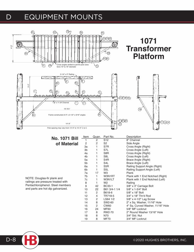
d EQUIPMENT MOUNTS
©2020 HUgHES BrOTHErS, INc.D-8
Item12
3a3b4a4b5a5b6a6b7a7b7c89
10111213141516171819
Quan.2211111111
17111
422224282
24888
Part No.S12S2S7RS7LS8RS8LS4RS4LS5RS5LW3W3N1RTW3N1LTW2BC33-1B61 3/4-1 1/4B618-6TR718-5LS64 1/2SW2-60CW60MF60RW2-70N70MF70
Description8" ChannelSide AngleCross Angle (Right)Cross Angle (Left)Cross Angle (Right)Cross Angle (Left)Brace Angle (Right)Brace Angle (Left)Railing Support Angle (Right)Railing Support Angle (Left)PlankPlank with 1 End Notched (Right)Plank with 1 End Notched (Left)Railing3/8" x 3" Carriage Bolt5/8" x 1-3/4" Bolt5/8" x 18" Bolt3/4" x 18" Thr'd Rod5/8" x 4-1/2" Lag Screw2" x Sq. Washer, 11/16" Hole4" Sq. Curved Washer, 11/16" Hole5/8" MF Locknut2" Round Washer 13/16" Hole3/4" Std. Nut3/4" MF Locknut
No. 1071 Bill of Material
5a
4b
4'-3
"
9 7b
16 3b
16
5b
1610
7cCross angles slotted to permit pole varia-tions 10" to 16" diameter
7a4a
1410
6b
3a 7a3b
6a
7c
9
8" x 11.5# Channel
2-1/4" x 5" Railing
8
4 7b
3'-2
"
5a
1 2
10'-5½"
Frame constructed of 2" x 2-1/2" x 3/16" angles
14'-9"
Pole spacing may vary from 14'-6" to 15'-0" C to C
5b
12 17 18 19
11 15 16
13
4
11 1615
5b
1071Transformer
Platform
NOTE: Douglas-fir plank and railings are pressure treated with Pentachlorophenol. Steel members and parts are hot dip galvanized.
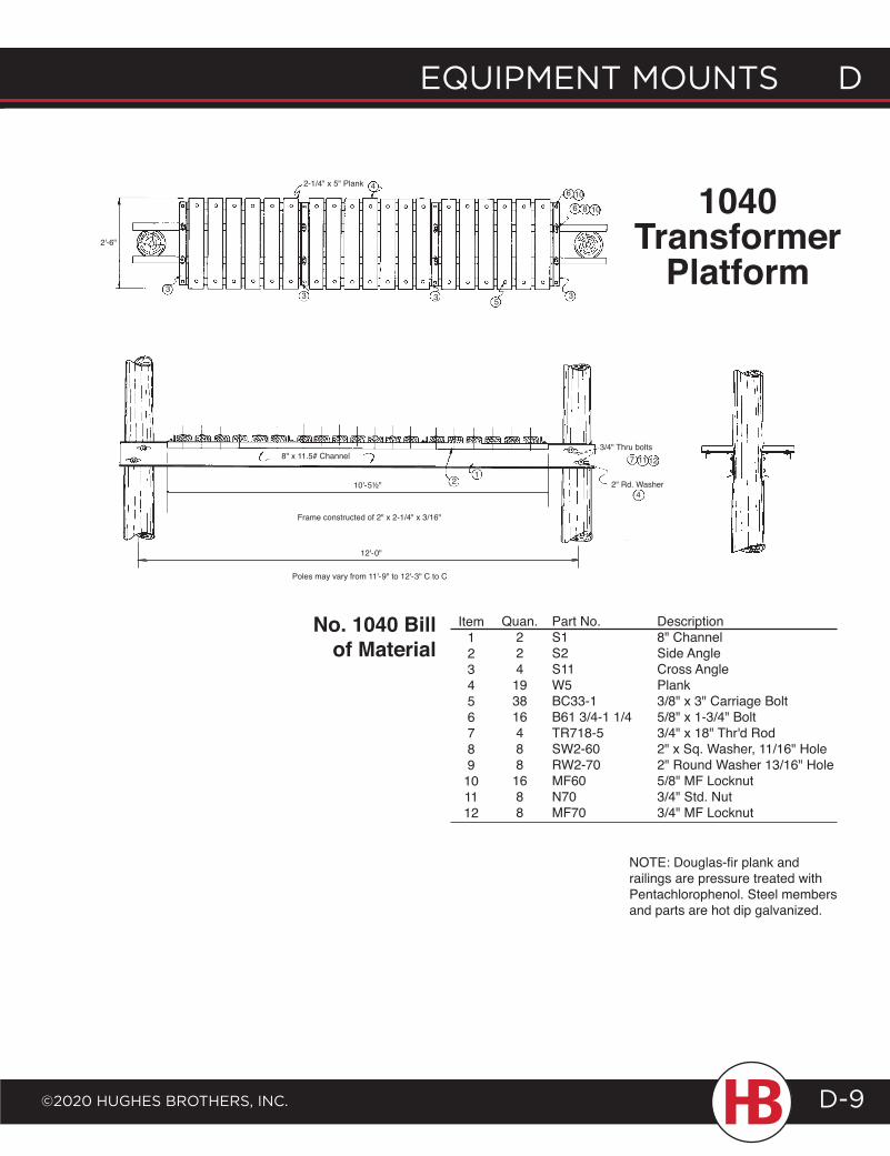
EQUIPMENT MOUNTS D
©2020 HUgHES BrOTHErS, INc.
D EQUIPMENT MOUNTS
D-9
Item123456789
101112
Quan.224
193816488
1688
Part No.S1S2S11W5BC33-1B61 3/4-1 1/4TR718-5SW2-60RW2-70MF60N70MF70
Description8" ChannelSide AngleCross AnglePlank3/8" x 3" Carriage Bolt5/8" x 1-3/4" Bolt3/4" x 18" Thr'd Rod2" x Sq. Washer, 11/16" Hole2" Round Washer 13/16" Hole5/8" MF Locknut3/4" Std. Nut3/4" MF Locknut
No. 1040 Bill of Material
NOTE: Douglas-fir plank and railings are pressure treated with Pentachlorophenol. Steel members and parts are hot dip galvanized.
3
2'-6"
3
2-1/4" x 5" Plank 4
3 5
6
6 8
3
10
10
21
8" x 11.5# Channel3/4" Thru bolts
4
11 12
2" Rd. Washer
7
Frame constructed of 2" x 2-1/4" x 3/16"
12'-0"
Poles may vary from 11'-9" to 12'-3" C to C
1040 Transformer
Platform
10'-5½"
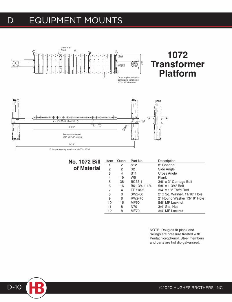
d EQUIPMENT MOUNTS
©2020 HUgHES BrOTHErS, INc.D-10
1072 Transformer
Platform
Item123456789
101112
Quan.224
193816488
1688
Part No.S12S2S11W5BC33-1B61 3/4-1 1/4TR718-5SW2-60RW2-70MF60N70MF70
Description8" ChannelSide AngleCross AnglePlank3/8" x 3" Carriage Bolt5/8" x 1-3/4" Bolt3/4" x 18" Thr'd Rod2" x Sq. Washer, 11/16" Hole2" Round Washer 13/16" Hole5/8" MF Locknut3/4" Std. Nut3/4" MF Locknut
No. 1072 Bill of Material
NOTE: Douglas-fir plank and railings are pressure treated with Pentachlorophenol. Steel members and parts are hot dip galvanized.
43
5
3 3
6
6 8
Cross angles slotted to permit pole variation of 10" to 16" diameter
10
10 2'-6
"
2-1/4" x 5" Plank
2 1
8" x 11.5# Channel
10'-5½" 7
9
1112
Frame constructed of 2" x 2-1/2" angles
Pole spacing may vary from 14'-6" to 15'-0"
14'-9"
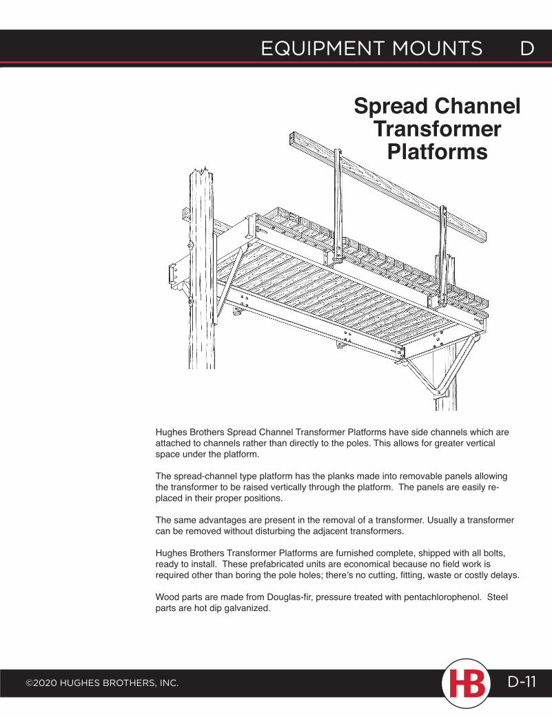
EQUIPMENT MOUNTS D
©2020 HUgHES BrOTHErS, INc.
D EQUIPMENT MOUNTS
D-11
Hughes Brothers Spread Channel Transformer Platforms have side channels which are attached to channels rather than directly to the poles. This allows for greater vertical space under the platform.
The spread-channel type platform has the planks made into removable panels allowing the transformer to be raised vertically through the platform. The panels are easily re-placed in their proper positions.
The same advantages are present in the removal of a transformer. Usually a transformer can be removed without disturbing the adjacent transformers.
Hughes Brothers Transformer Platforms are furnished complete, shipped with all bolts, ready to install. These prefabricated units are economical because no field work is required other than boring the pole holes; there’s no cutting, fitting, waste or costly delays.
Wood parts are made from Douglas-fir, pressure treated with pentachlorophenol. Steel parts are hot dip galvanized.
Spread Channel Transformer
Platforms
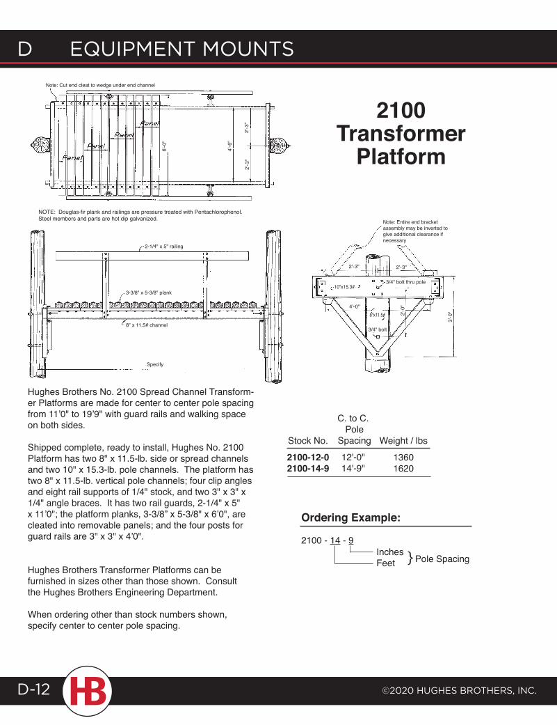
d EQUIPMENT MOUNTS
©2020 HUgHES BrOTHErS, INc.D-12
Hughes Brothers No. 2100 Spread Channel Transform-er Platforms are made for center to center pole spacing from 11’0" to 19’9" with guard rails and walking space on both sides.
Shipped complete, ready to install, Hughes No. 2100 Platform has two 8" x 11.5-lb. side or spread channels and two 10" x 15.3-lb. pole channels. The platform has two 8" x 11.5-lb. vertical pole channels; four clip angles and eight rail supports of 1/4" stock, and two 3" x 3" x 1/4" angle braces. It has two rail guards, 2-1/4" x 5" x 11’0"; the platform planks, 3-3/8” x 5-3/8" x 6’0", are cleated into removable panels; and the four posts for guard rails are 3" x 3" x 4’0".
NOTE: Douglas-fir plank and railings are pressure treated with Pentachlorophenol.Steel members and parts are hot dip galvanized.
Stock No.
2100-12-02100-14-9
C. to C. Pole
Spacing
12'-0"14'-9"
InchesFeet } Pole Spacing
Ordering Example:
2100 - 14 - 9
Note: Cut end cleat to wedge under end channel
6'-0
"
4'-6
"
2'-3
"2'
-3"
2-1/4" x 5" railing
3-3/8" x 5-3/8" plank
8" x 11.5# channel
Specify
3/4" bolt thru pole
2'-3"2'-3"
4'-0"
Note: Entire end bracket assembly may be inverted to give additional clearance if necessary
10"x15.3#
8"x11.5#
3/4" bolt
2'-0
"
3'-0
"
2100Transformer
Platform
Hughes Brothers Transformer Platforms can be furnished in sizes other than those shown. Consult the Hughes Brothers Engineering Department.
When ordering other than stock numbers shown, specify center to center pole spacing.
Weight / lbs
13601620
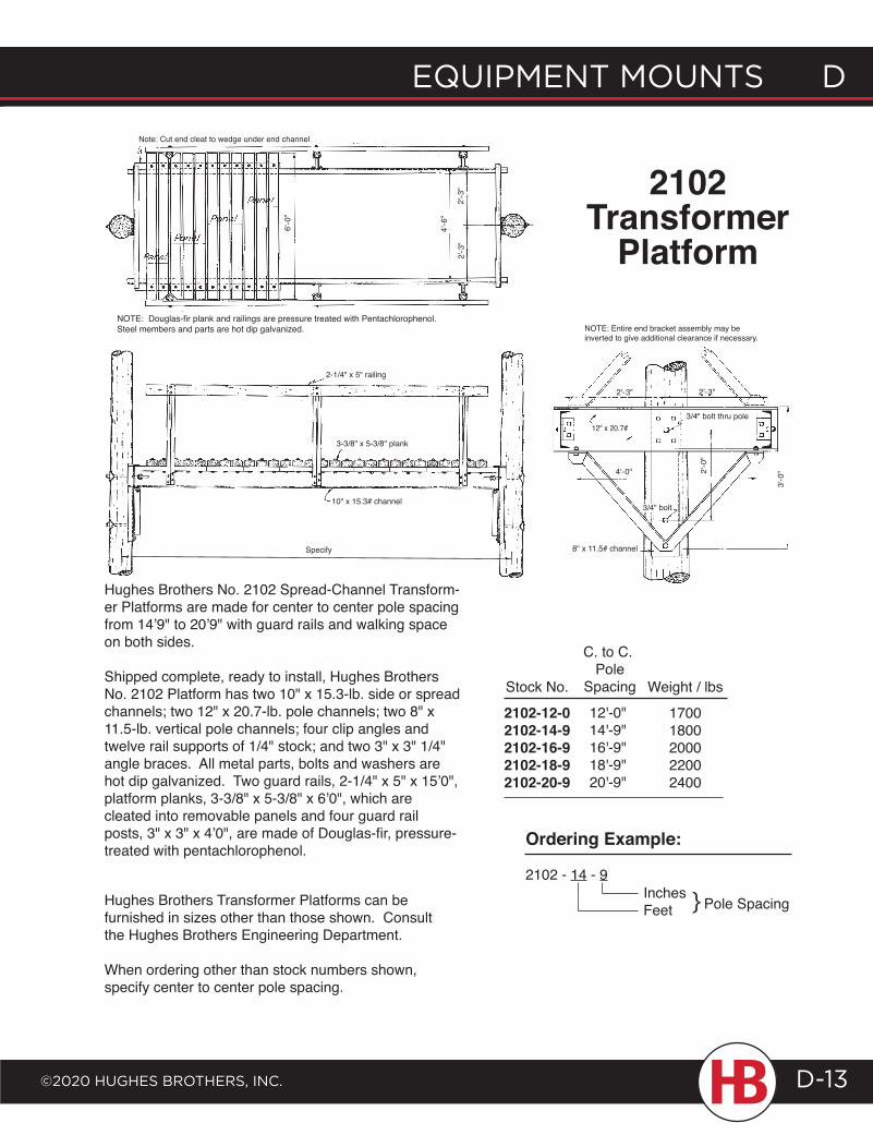
EQUIPMENT MOUNTS D
©2020 HUgHES BrOTHErS, INc.
D EQUIPMENT MOUNTS
D-13
Hughes Brothers No. 2102 Spread-Channel Transform-er Platforms are made for center to center pole spacing from 14’9" to 20’9" with guard rails and walking space on both sides.
Shipped complete, ready to install, Hughes Brothers No. 2102 Platform has two 10" x 15.3-lb. side or spread channels; two 12" x 20.7-lb. pole channels; two 8" x 11.5-lb. vertical pole channels; four clip angles and twelve rail supports of 1/4" stock; and two 3" x 3" 1/4" angle braces. All metal parts, bolts and washers are hot dip galvanized. Two guard rails, 2-1/4" x 5" x 15’0", platform planks, 3-3/8" x 5-3/8" x 6’0", which are cleated into removable panels and four guard rail posts, 3" x 3" x 4’0", are made of Douglas-fir, pressure-treated with pentachlorophenol.
Stock No.
2102-12-02102-14-92102-16-92102-18-92102-20-9
InchesFeet } Pole Spacing
Ordering Example:
2102 - 14 - 9
C. to C. Pole
Spacing
12'-0"14'-9"16'-9"18'-9"20'-9"
3-3/8" x 5-3/8" plank
10" x 15.3# channel
NOTE: Douglas-fir plank and railings are pressure treated with Pentachlorophenol.Steel members and parts are hot dip galvanized.
Note: Cut end cleat to wedge under end channel
6'-0
"
2'-3
"2'
-3"
4'-6
"
2-1/4" x 5" railing
NOTE: Entire end bracket assembly may be inverted to give additional clearance if necessary.
2'-0
"
4'-0"
12" x 20.7#
2'-3"2'-3"
3/4" bolt thru pole
3/4" bolt
3'-0
"
2102Transformer
Platform
8" x 11.5# channel
Weight / lbs
17001800200022002400
Hughes Brothers Transformer Platforms can be furnished in sizes other than those shown. Consult the Hughes Brothers Engineering Department.
When ordering other than stock numbers shown, specify center to center pole spacing.
Specify
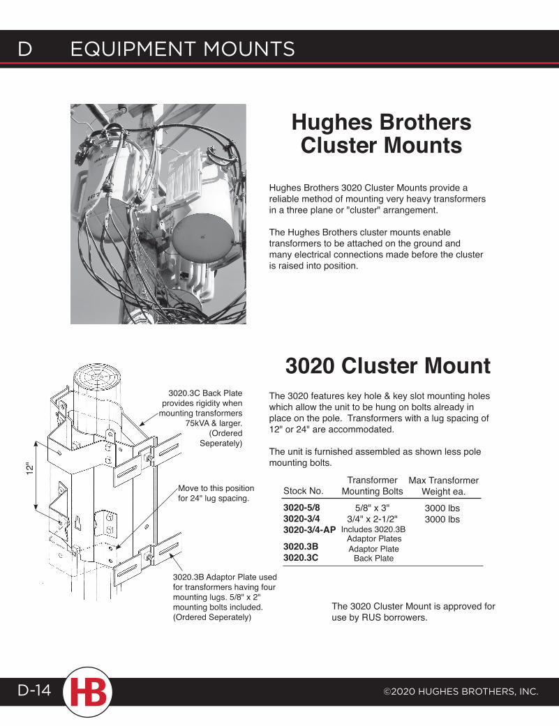
d EQUIPMENT MOUNTS
©2020 HUgHES BrOTHErS, INc.D-14
Hughes Brothers Cluster Mounts
Hughes Brothers 3020 Cluster Mounts provide a reliable method of mounting very heavy transformers in a three plane or "cluster" arrangement.
The Hughes Brothers cluster mounts enable transformers to be attached on the ground and many electrical connections made before the cluster is raised into position.
3020 Cluster MountThe 3020 features key hole & key slot mounting holes which allow the unit to be hung on bolts already in place on the pole. Transformers with a lug spacing of 12" or 24" are accommodated.
The unit is furnished assembled as shown less pole mounting bolts.
3020.3C Back Plate provides rigidity when
mounting transformers 75kVA & larger.
(OrderedSeperately)
3020.3B Adaptor Plate used for transformers having four mounting lugs. 5/8" x 2" mounting bolts included. (Ordered Seperately)
12"
TransformerMounting Bolts
5/8" x 3"3/4" x 2-1/2"
Max TransformerWeight ea.
3000 lbs3000 lbs
The 3020 Cluster Mount is approved for use by RUS borrowers.
Adaptor PlateBack Plate
Includes 3020.3B Adaptor Plates
Stock No.
3020-5/83020-3/43020-3/4-AP3020.3B3020.3C
Move to this position for 24" lug spacing.
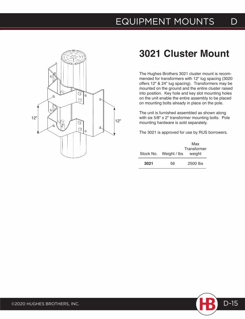
EQUIPMENT MOUNTS D
©2020 HUgHES BrOTHErS, INc.
D EQUIPMENT MOUNTS
D-15
3021 Cluster Mount
The Hughes Brothers 3021 cluster mount is recom-mended for transformers with 12" lug spacing (3020 offers 12" & 24" lug spacing). Transformers may be mounted on the ground and the entire cluster raised into position. Key hole and key slot mounting holes on the unit enable the entire assembly to be placed on mounting bolts already in place on the pole.
The unit is furnished assembled as shown along with six 5/8" x 2" transformer mounting bolts. Pole mounting hardware is sold separately.
The 3021 is approved for use by RUS borrowers.
12"
Stock No.
3021
Weight / lbs
56
Max Transformer
weight
2500 lbs
12"
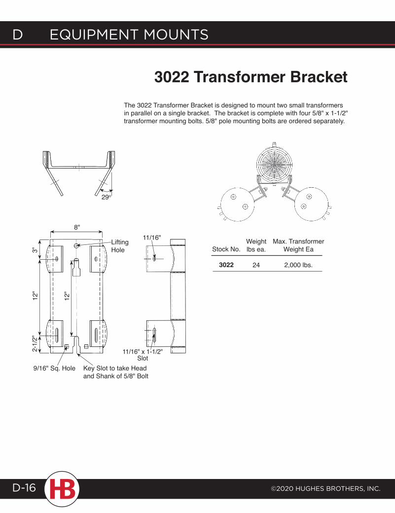
d EQUIPMENT MOUNTS
©2020 HUgHES BrOTHErS, INc.D-16
3022 Transformer BracketThe 3022 Transformer Bracket is designed to mount two small transformers in parallel on a single bracket. The bracket is complete with four 5/8" x 1-1/2" transformer mounting bolts. 5/8" pole mounting bolts are ordered separately.
Stock No.
3022
3"12
"
9/16" Sq. Hole
2-1/
2"
8"
Key Slot to take Head and Shank of 5/8" Bolt
11/16" x 1-1/2" Slot
12"
Max. TransformerWeight Ea
2,000 lbs.
Weightlbs ea.
24
Lifting Hole
11/16"
29o
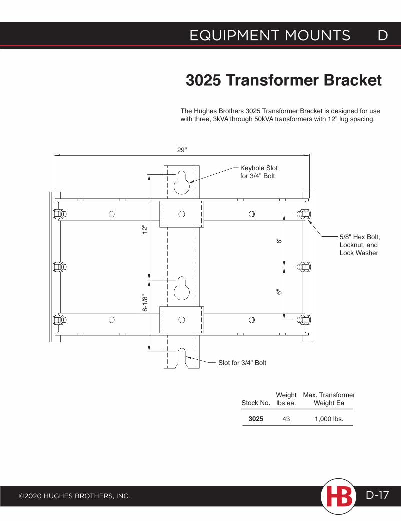
29"
Keyhole Slotfor 3/4" Bolt
Slot for 3/4" Bolt
5/8" Hex Bolt, Locknut, and Lock Washer
12"
8-1/
8"
6"6"
EQUIPMENT MOUNTS D
©2020 HUgHES BrOTHErS, INc.
D EQUIPMENT MOUNTS
D-17
3025 Transformer BracketThe Hughes Brothers 3025 Transformer Bracket is designed for use with three, 3kVA through 50kVA transformers with 12" lug spacing.
Stock No.
3025
Max. TransformerWeight Ea
1,000 lbs.
Weightlbs ea.
43
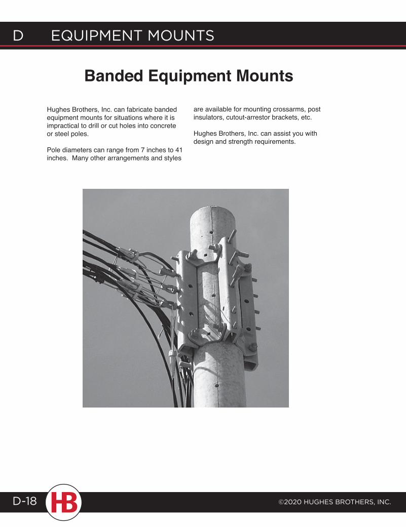
d EQUIPMENT MOUNTS
©2020 HUgHES BrOTHErS, INc.D-18
Banded Equipment Mounts
Hughes Brothers, Inc. can fabricate banded equipment mounts for situations where it is impractical to drill or cut holes into concrete or steel poles.
Pole diameters can range from 7 inches to 41 inches. Many other arrangements and styles
are available for mounting crossarms, post insulators, cutout-arrestor brackets, etc.
Hughes Brothers, Inc. can assist you with design and strength requirements.
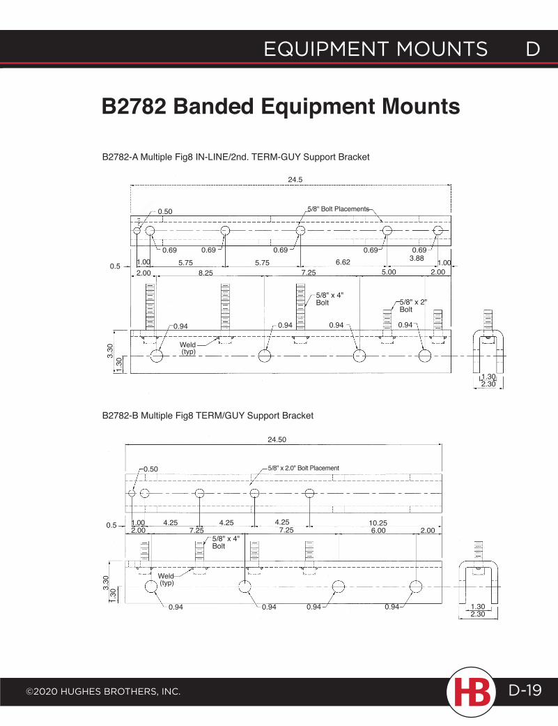
24.5
0.50
5.00 2.00
3.88
7.258.252.000.5 6.625.75 5.75
0.94 0.94 0.94 0.94
5/8" x 2" Bolt
5/8" x 4" Bolt
3.30
1.30
Weld (typ)
1.30 2.30
0.94 0.94 0.94 0.94
0.50
3.30
1.30
5/8" x 4" Bolt
Weld (typ)
0.5 4.25 4.25 10.256.00 2.00
1.30 2.30
5/8" Bolt Placements
EQUIPMENT MOUNTS D
©2020 HUgHES BrOTHErS, INc.
D EQUIPMENT MOUNTS
D-19
B2782 Banded Equipment Mounts
1.001.000.69 0.69 0.69 0.69 0.69
1.00 4.252.00 7.25 7.25
5/8" x 2.0" Bolt Placement
24.50
B2782-B Multiple Fig8 TERM/GUY Support Bracket
B2782-A Multiple Fig8 IN-LINE/2nd. TERM-GUY Support Bracket
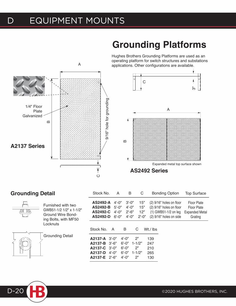
d EQUIPMENT MOUNTS
©2020 HUgHES BrOTHErS, INc.D-20
A
4'-0"5'-0"4'-0"6'-0"
B
3'-0"4'-0"2'-6"4'-0"
C
15"15"12"2'-0"
Bonding Option
(2) 9/16" holes on floor(2) 9/16" holes on floor(1) GWB51-1/2 on leg(2) 9/16" holes on side
Top Surface
Floor PlateFloor Plate
Expanded MetalGrating
Stock No.
A2137-AA2137-BA2137-CA2137-DA2137-E
A
3'-0"3'-6"3'-0"4'-0"2'-6"
B
4'-0"6'-0"6'-0"6'-0"4'-0"
C
2"1-1/2"
2"1-1/2"
2"
Wt./ lbs
139247210265130
Stock No.
AS2492-AAS2492-BAS2492-CAS2492-D
Furnished with two GWB51-1/2 1/2" x 1-1/2" Ground Wire Bond-ing Bolts, with MF50 Locknuts
Grounding Detail
Grounding Detail
Grounding Platforms
AS2492 Series
A
B
1/4" Floor Plate
Galvanized
9/16
" hol
e fo
r gro
undi
ng
A2137 Series
C
Hughes Brothers Grounding Platforms are used as an operating platform for switch structures and substations applications. Other configurations are available.
Expanded metal top surface shown
B
A
C
3"
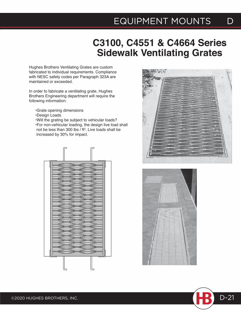
EQUIPMENT MOUNTS D
©2020 HUgHES BrOTHErS, INc.
D EQUIPMENT MOUNTS
D-21
C3100, C4551 & C4664 Series Sidewalk Ventilating Grates
Hughes Brothers Ventilating Grates are custom fabricated to individual requirements. Compliance with NESC safety codes per Paragraph 323A are maintained or exceeded.
In order to fabricate a ventilating grate, Hughes Brothers Engineering department will require the following information:
•Grate opening dimensions •Design Loads •Will the grating be subject to vehicular loads? •For non-vehicular loading, the design live load shall not be less than 300 lbs / ft2. Live loads shall be increased by 30% for impact.
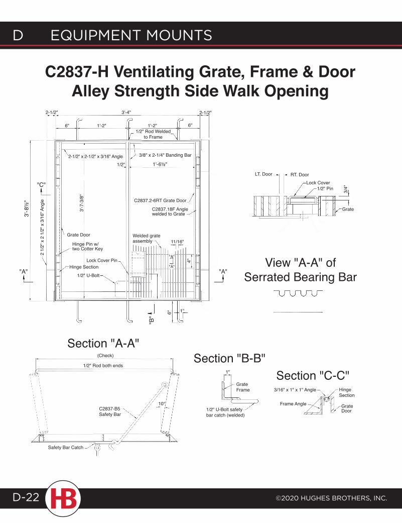
C2837-H Ventilating Grate, Frame & Door Alley Strength Side Walk Opening
Section "A-A"Section "B-B"
Section "C-C"
View "A-A" of Serrated Bearing Bar
2-1/2" 3'-4" 2-1/2"
6" 6"1'-2" 1'-2"1/2" Rod Welded
to Frame
2-1/2" x 2-1/2" x 3/16" Angle1/2"
3/8" x 2-1/4" Banding Bar
"C"
C2837.2-6RT Grate Door
C2837.18F Angle welded to Grate
3'-7
-3/8
"
Grate Door Welded grate assembly 11/16"
"A"
4"
"A"
"A"
Hinge Pin w/ two Cotter Key
Lock Cover PinHinge Section
1/2" U-Bolt"A"
2 1/
2" x
2 1
/2" x
3/1
6" A
ngle
"B" 6" 1"
Grate
LT. Door RT. DoorLock Cover
1/2" Pin 3/4"
(Check)
1/2" Rod both ends
Safety Bar Catch
10°C2837-B5 Safety Bar
1"
Grate Frame
1/2" U-Bolt safety bar catch (welded)
3/16" x 1" x 1" Angle
Frame Angle
Hinge Section
Grate Door
3'-8
½"
1'-6½"
d EQUIPMENT MOUNTS
©2020 HUgHES BrOTHErS, INc.D-22
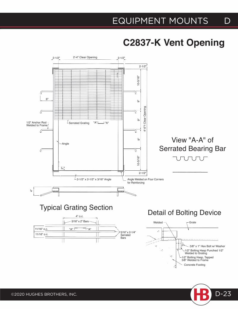
C2837-K Vent Opening
Typical Grating Section
View "A-A" of Serrated Bearing Bar
Detail of Bolting DeviceWelded Grate
1/2" Anchor Rod
3/8" x 1" Hex Bolt w/ Washer1/2" Bolting Hasp Punched 1/2" Welded to Grating
1/2" Bolting Hasp, Tapped 3/8" Welded to Frame
Concrete Footing
4" o.c.
3/16" x 2" Bars
"A" "A"11/16" o.c.
11/16" o.c. 3/16" x 2-1/4"Serrated Bars
4"
2-1/2" x 2-1/2" x 3/16" Angle Angle Welded on Four Corners for Reinforcing
2"
Angle
2-1/2"
10-5
/16"
9"9"
9"
"A" "A"
4'-0
"+ C
lear
Ope
ning
-
10-5
/16"
Serrated Grating1/2" Anchor Rod Welded to Frame
6"
2-1/2" 2'-4" Clear Opening 2-1/2"
2-1/2"
EQUIPMENT MOUNTS D
©2020 HUgHES BrOTHErS, INc.
D EQUIPMENT MOUNTS
D-23
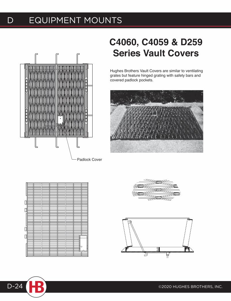
d EQUIPMENT MOUNTS
©2020 HUgHES BrOTHErS, INc.D-24
C4060, C4059 & D259 Series Vault Covers
Hughes Brothers Vault Covers are similar to ventilating grates but feature hinged grating with safety bars and covered padlock pockets.
Padlock Cover
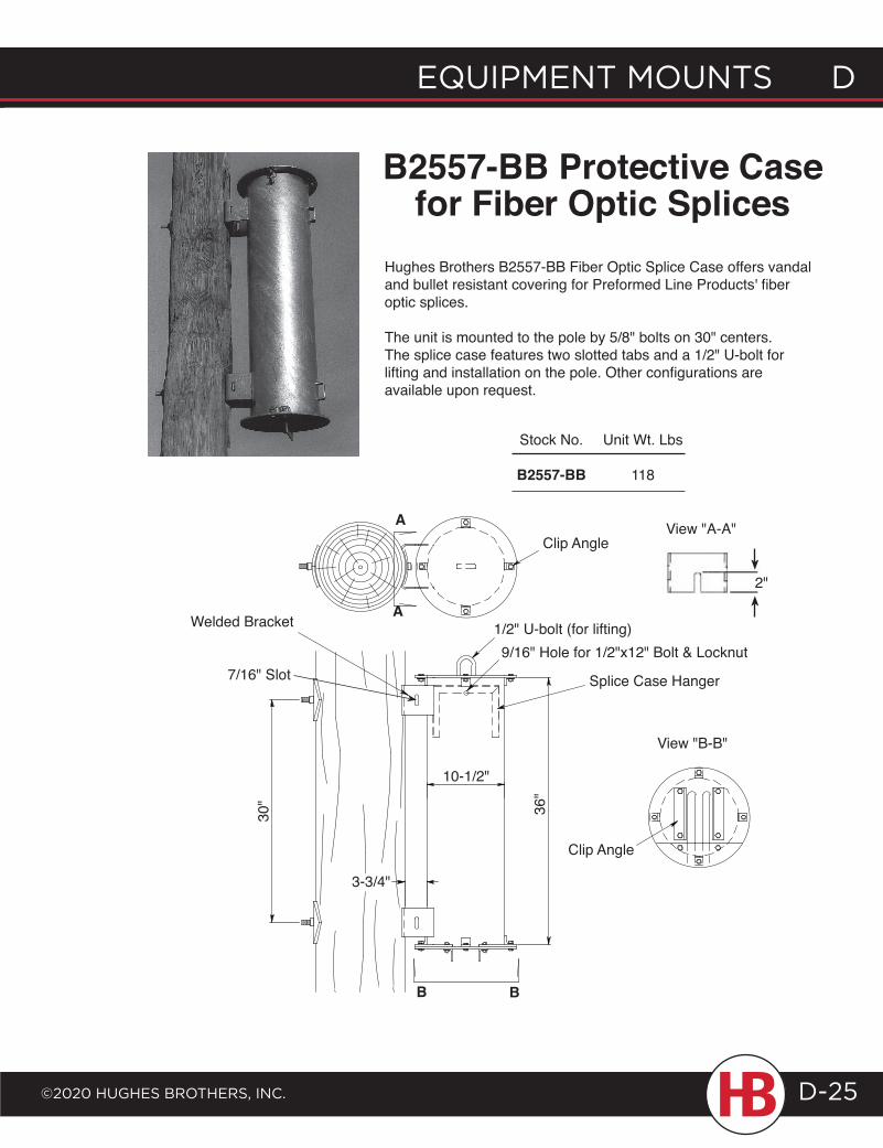
EQUIPMENT MOUNTS D
©2020 HUgHES BrOTHErS, INc.
D EQUIPMENT MOUNTS
D-25
B2557-BB Protective Case for Fiber Optic Splices
Hughes Brothers B2557-BB Fiber Optic Splice Case offers vandal and bullet resistant covering for Preformed Line Products' fiber optic splices.
The unit is mounted to the pole by 5/8" bolts on 30" centers. The splice case features two slotted tabs and a 1/2" U-bolt for lifting and installation on the pole. Other configurations are available upon request.
A
AClip Angle
Splice Case Hanger
1/2" U-bolt (for lifting)9/16" Hole for 1/2"x12" Bolt & Locknut
Welded Bracket
10-1/2"
30" 36"
3-3/4"
B B
Clip Angle
View "B-B"
View "A-A"
Stock No.
B2557-BB
Unit Wt. Lbs
118
2"
7/16" Slot
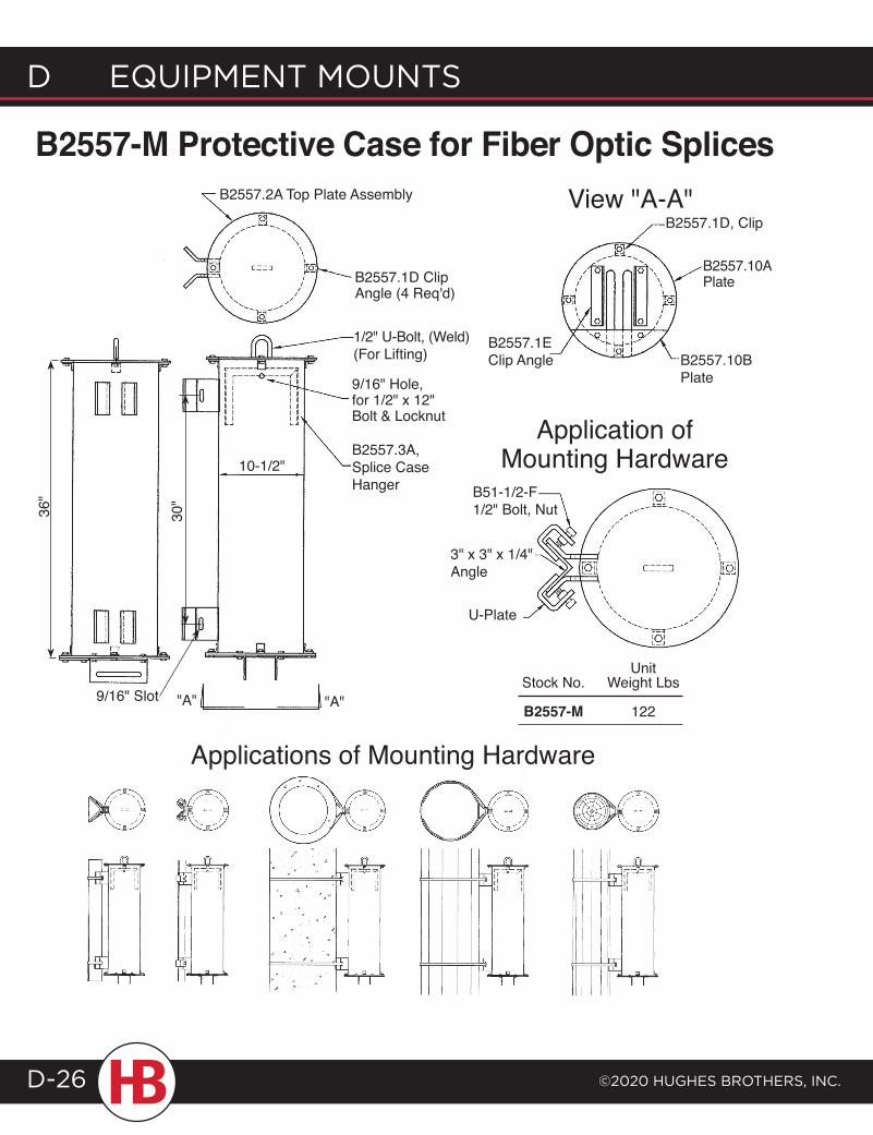
d EQUIPMENT MOUNTS
©2020 HUgHES BrOTHErS, INc.D-26
Application of Mounting Hardware
B2557-M Protective Case for Fiber Optic SplicesB2557.2A Top Plate Assembly
B2557.1D Clip Angle (4 Req'd)
1/2" U-Bolt, (Weld) (For Lifting)
9/16" Hole, for 1/2" x 12" Bolt & Locknut
B2557.3A, Splice Case Hanger
10-1/2"
"A"
B2557.1D, Clip
B2557.10A Plate
B2557.1E Clip Angle B2557.10B
Plate
B51-1/2-F 1/2" Bolt, Nut
3" x 3" x 1/4" Angle
U-Plate
Applications of Mounting Hardware
"A"
36"
30"
9/16" Slot
View "A-A"
Unit Stock No. Weight Lbs
B2557-M 122
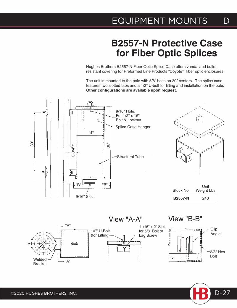
EQUIPMENT MOUNTS D
©2020 HUgHES BrOTHErS, INc.
D EQUIPMENT MOUNTS
D-27
B2557-N Protective Case for Fiber Optic Splices
Hughes Brothers B2557-N Fiber Optic Splice Case offers vandal and bullet resistant covering for Preformed Line Products “Coyote®” fiber optic enclosures.
The unit is mounted to the pole with 5/8” bolts on 30” centers. The splice case features two slotted tabs and a 1/2” U-bolt for lifting and installation on the pole. Other configurations are available upon request.
30"
3-3/
4"± 36
"
"B" "B"
14"
9/16" Hole, For 1/2" x 16" Bolt & LocknutSplice Case Hanger
Structural Tube
View "A-A" View "B-B"Clip Angle
3/8" Hex Bolt
11/16" x 2" Slot, for 5/8" Bolt or Lag Screw
1/2" U-Bolt (for Lifting)
"A"
"A"Welded Bracket
Unit Stock No. Weight Lbs
B2557-N 2409/16" Slot
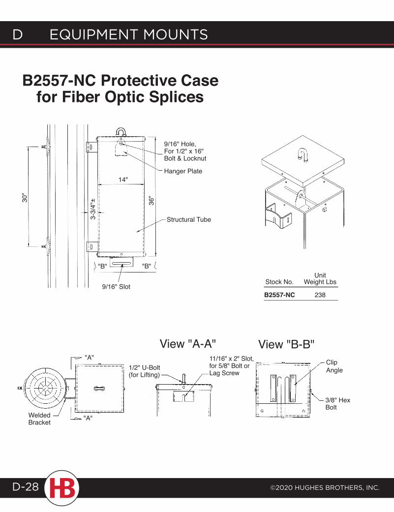
d EQUIPMENT MOUNTS
©2020 HUgHES BrOTHErS, INc.D-28
B2557-NC Protective Case for Fiber Optic Splices
View "A-A" View "B-B""A"
"A"Welded Bracket
11/16" x 2" Slot, for 5/8" Bolt or Lag Screw
1/2" U-Bolt (for Lifting)
Clip Angle
3/8" Hex Bolt
30"
3-3/
4"± 36
"
"B" "B"
14"
9/16" Hole, For 1/2" x 16" Bolt & Locknut
Hanger Plate
Structural Tube
Unit Stock No. Weight Lbs
B2557-NC 2389/16" Slot
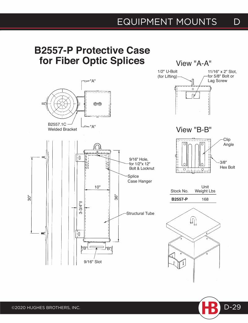
EQUIPMENT MOUNTS D
©2020 HUgHES BrOTHErS, INc.
D EQUIPMENT MOUNTS
D-29
B2557-P Protective Case for Fiber Optic Splices
"A"
"A"B2557.1C Welded Bracket
30"
3-3/
4"+ -
36"
"B" "B"
Structural Tube
Splice Case Hanger
9/16" Hole, for 1/2"x 12" Bolt & Locknut
Clip Angle
3/8" Hex Bolt
View "B-B"
1/2" U-Bolt (for Lifting)
11/16" x 2" Slot, for 5/8" Bolt or Lag Screw
View "A-A"
10" Unit Stock No. Weight Lbs
B2557-P 168
9/16" Slot
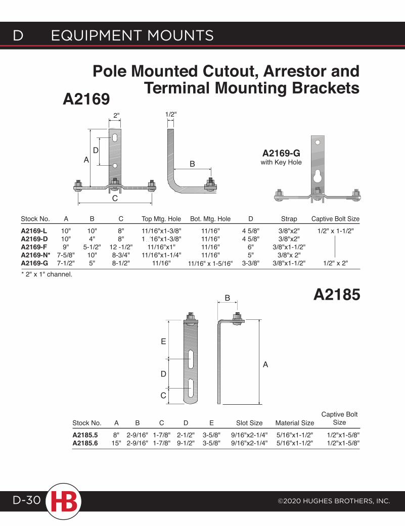
d EQUIPMENT MOUNTS
©2020 HUgHES BrOTHErS, INc.D-30
A2185
A
B
D
A2169-Gwith Key Hole
A2169Pole Mounted Cutout, Arrestor and
Terminal Mounting Brackets
E
11/16" x 1-5/16"
Stock No. A B C Top Mtg. Hole Bot. Mtg. Hole D Strap Captive Bolt Size
A2169-L 10" 10" 8" 11/16"x1-3/8" 11/16" 4 5/8" 3/8"x2" 1/2" x 1-1/2"A2169-D 10" 4" 8" 11/16"x1-3/8" 11/16" 4 5/8" 3/8"x2" A2169-F 9" 5-1/2" 12 -1/2" 11/16"x1" 11/16" 6" 3/8"x1-1/2"A2169-N* 7-5/8" 10" 8-3/4" 11/16"x1-1/4" 11/16" 5" 3/8"x 2"A2169-G 7-1/2" 5" 8-1/2" 11/16" 3-3/8" 3/8"x1-1/2" 1/2" x 2"* 2" x 1" channel.
Stock No. A B C D E Slot Size Material Size
A2185.5 8" 2-9/16" 1-7/8" 2-1/2" 3-5/8" 9/16"x2-1/4" 5/16"x1-1/2" 1/2"x1-5/8"A2185.6 15" 2-9/16" 1-7/8" 9-1/2" 3-5/8" 9/16"x2-1/4" 5/16"x1-1/2" 1/2"x1-5/8"
Captive BoltSize
B
2"
A
C
1/2"
D
C
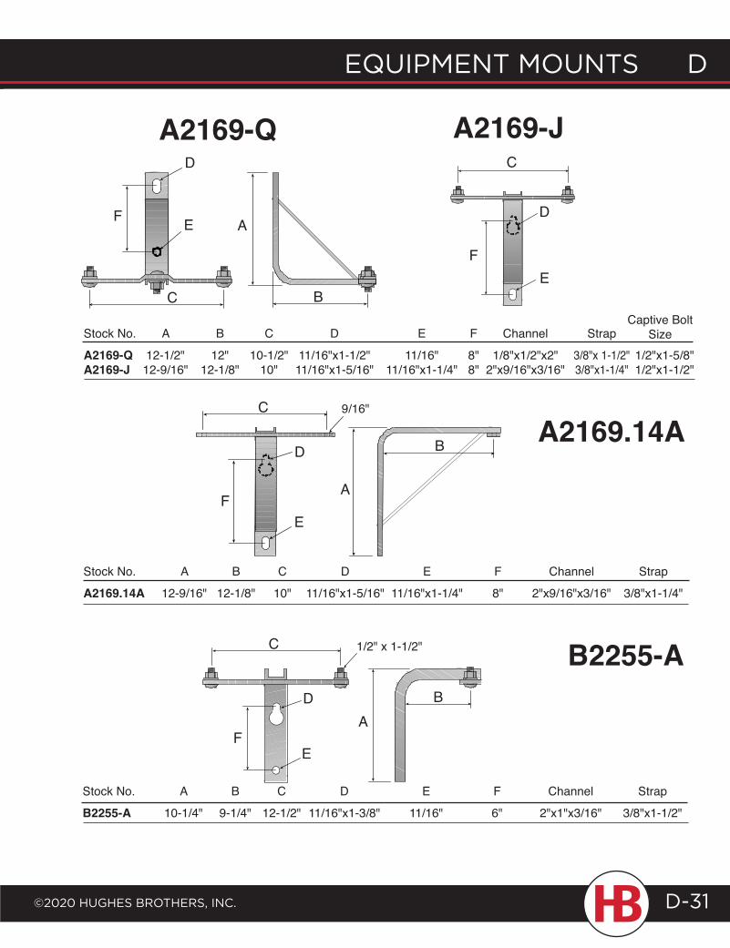
EQUIPMENT MOUNTS D
©2020 HUgHES BrOTHErS, INc.
D EQUIPMENT MOUNTS
D-31
A2169-Q A2169-J
Stock No. A B C D E F Channel Strap
A2169-Q 12-1/2" 12" 10-1/2" 11/16"x1-1/2" 11/16" 8" 1/8"x1/2"x2" 3/8"x 1-1/2" 1/2"x1-5/8"A2169-J 12-9/16" 12-1/8" 10" 11/16"x1-5/16" 11/16"x1-1/4" 8" 2"x9/16"x3/16" 3/8"x1-1/4" 1/2"x1-1/2"
Captive Bolt Size
F
D
E
C
A
B
F
D
E
C
A2169.14AB
A
C
D
E
Stock No. A B C D E F Channel Strap
A2169.14A 12-9/16" 12-1/8" 10" 11/16"x1-5/16" 11/16"x1-1/4" 8" 2"x9/16"x3/16" 3/8"x1-1/4"
F
9/16"
A
C
D
E
Stock No. A B C D E F Channel Strap
B2255-A 10-1/4" 9-1/4" 12-1/2" 11/16"x1-3/8" 11/16" 6" 2"x1"x3/16" 3/8"x1-1/2"
B2255-A1/2" x 1-1/2"
B
F
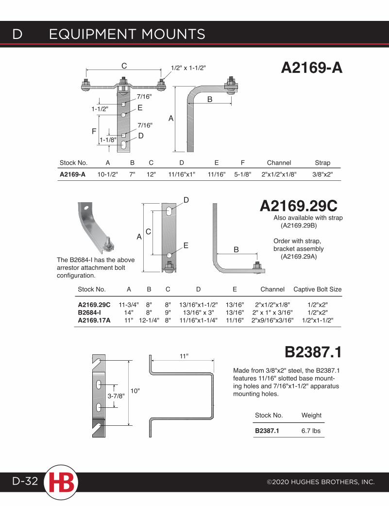
d EQUIPMENT MOUNTS
©2020 HUgHES BrOTHErS, INc.D-32
C
F
E
D
A
A2169-A
B
1/2" x 1-1/2"
1-1/8"
1-1/2"
7/16"
7/16"
Stock No. A B C D E F Channel Strap
A2169-A 10-1/2" 7" 12" 11/16"x1" 11/16" 5-1/8" 2"x1/2"x1/8" 3/8"x2"
A2169.29CCA
E
D
B
Stock No. A B C D E Channel Captive Bolt Size A2169.29C 11-3/4" 8" 8" 13/16"x1-1/2" 13/16" 2"x1/2"x1/8" 1/2"x2" B2684-I 14" 8" 9" 13/16" x 3" 13/16" 2" x 1" x 3/16" 1/2"x2" A2169.17A 11" 12-1/4" 8" 11/16"x1-1/4" 11/16" 2"x9/16"x3/16" 1/2"x1-1/2"
The B2684-I has the above arrestor attachment bolt configuration.
B2387.1Made from 3/8"x2" steel, the B2387.1 features 11/16" slotted base mount-ing holes and 7/16"x1-1/2" apparatus mounting holes.10"
11"
Stock No. Weight
B2387.1 6.7 lbs
3-7/8"
Also available with strap (A2169.29B)
Order with strap, bracket assembly (A2169.29A)
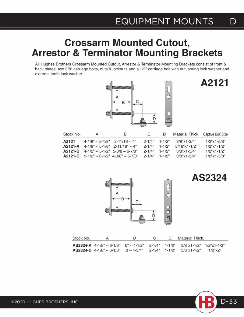
EQUIPMENT MOUNTS D
©2020 HUgHES BrOTHErS, INc.
D EQUIPMENT MOUNTS
D-33
Stock No. Weight
B2387.1 6.7 lbs
Crossarm Mounted Cutout, Arrestor & Terminator Mounting Brackets
All Hughes Brothers Crossarm Mounted Cutout, Arrestor & Terminator Mounting Brackets consist of front & back plates, two 3/8" carriage bolts, nuts & locknuts and a 1/2" carriage bolt with nut, spring lock washer and external tooth lock washer.
C
A2121
Stock No. A B C D Material Thick. Captive Bolt Size
A2121 4-1/8" ~ 5-1/8" 2-11/16 ~ 4" 2-1/4" 1-1/2" 3/8"x1-3/4" 1/2"x1-5/8"A2121-A 4-1/8" ~ 5-1/8" 2-11/16" ~ 4" 2-1/4" 1-1/2" 5/16"x1-1/2" 1/2"x1-1/2"A2121-B 4-1/2" ~ 5-1/2" 5-3/8 ~ 6-7/8" 2-1/4" 1-1/2" 3/8"x1-3/4" 1/2"x1-1/2"A2121-C 5-1/2" ~ 6-1/2" 4-3/8" ~ 6-7/8" 2-1/4" 1-1/2" 3/8"x1-3/4" 1/2"x1-5/8"
AS2324
Stock No. A B C D Material Thick.
AS2324-A 4-1/8" ~ 6-1/8" 0" ~ 4-1/2" 2-1/4" 1-1/2" 3/8"x1-1/2" 1/2"x1-1/2"AS2324-D 4-1/8" ~ 6-1/8" 0 ~ 4-3/4" 2-1/4" 1-1/2" 3/8"x1-1/2" 1/2"x2"
C
AB
D
AB
D
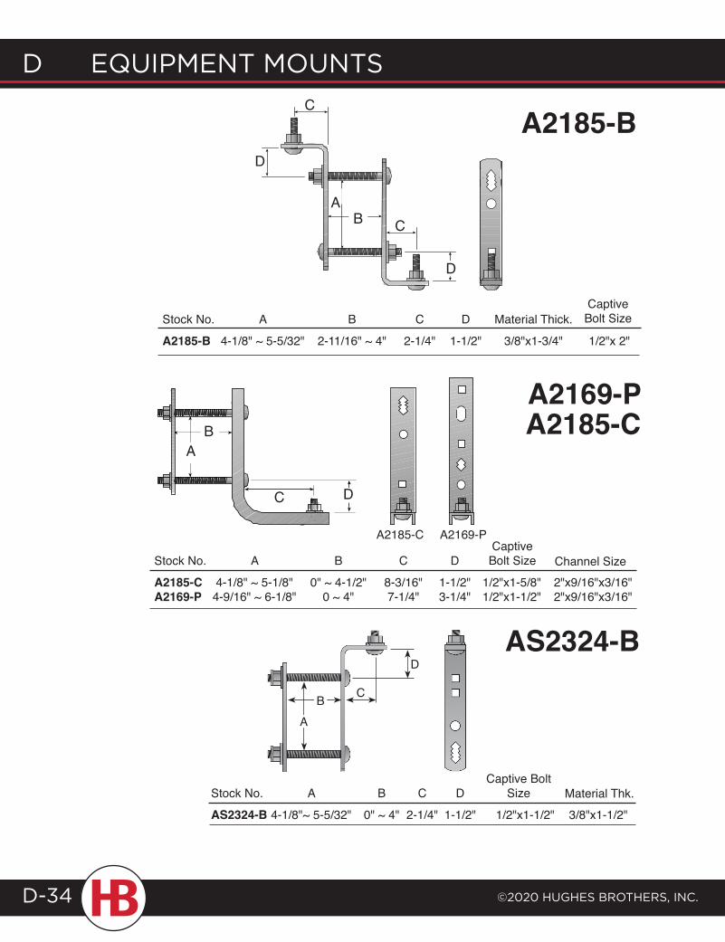
d EQUIPMENT MOUNTS
©2020 HUgHES BrOTHErS, INc.D-34
A2185-B
C
C
Captive Bolt SizeStock No. A B C D Material Thick.
A2185-B 4-1/8" ~ 5-5/32" 2-11/16" ~ 4" 2-1/4" 1-1/2" 3/8"x1-3/4" 1/2"x 2"
A
D
B
D
A2185-C A2169-P
C
A2169-P A2185-C
Stock No. A B C D
A2185-C 4-1/8" ~ 5-1/8" 0" ~ 4-1/2" 8-3/16" 1-1/2" 1/2"x1-5/8" 2"x9/16"x3/16" A2169-P 4-9/16" ~ 6-1/8" 0 ~ 4" 7-1/4" 3-1/4" 1/2"x1-1/2" 2"x9/16"x3/16"
CaptiveBolt Size Channel Size
BA
D
D
C
AS2324-B
Stock No. A B C D
AS2324-B 4-1/8"~ 5-5/32" 0" ~ 4" 2-1/4" 1-1/2" 1/2"x1-1/2" 3/8"x1-1/2"
Captive Bolt Size Material Thk.
BA
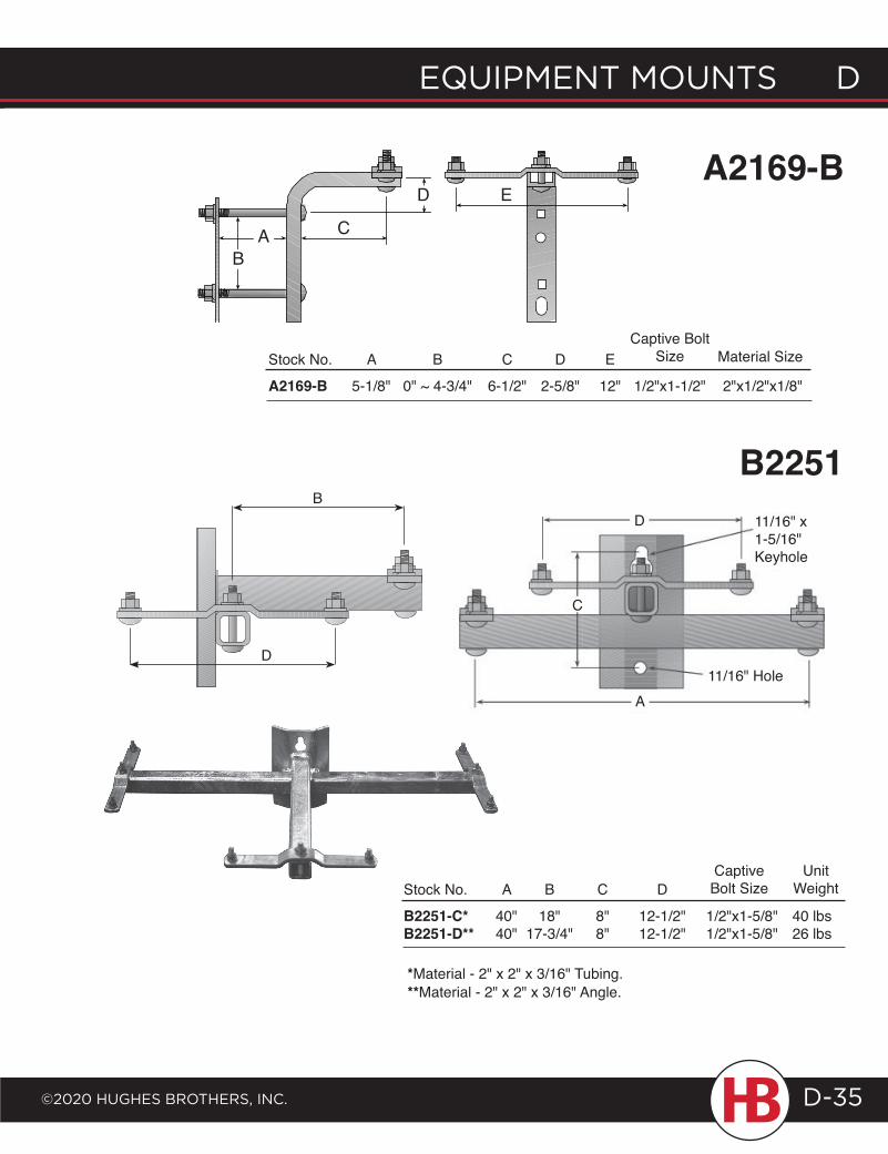
EQUIPMENT MOUNTS D
©2020 HUgHES BrOTHErS, INc.
D EQUIPMENT MOUNTS
D-35
A2169-BC
Stock No. A B C D E
A2169-B 5-1/8" 0" ~ 4-3/4" 6-1/2" 2-5/8" 12" 1/2"x1-1/2" 2"x1/2"x1/8"
Captive Bolt Size Material Size
E
BA
D
B2251B
D
*Material - 2" x 2" x 3/16" Tubing.**Material - 2" x 2" x 3/16" Angle.
Stock No. A B C D B2251-C* 40" 18" 8" 12-1/2" 1/2"x1-5/8" 40 lbsB2251-D** 40" 17-3/4" 8" 12-1/2" 1/2"x1-5/8" 26 lbs
CaptiveBolt Size
A
D 11/16" x 1-5/16" Keyhole
11/16" Hole
C
UnitWeight
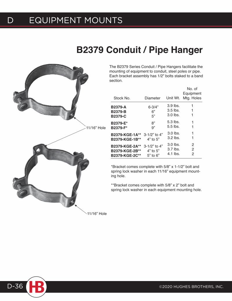
B2379 Conduit / Pipe HangerThe B2379 Series Conduit / Pipe Hangers facilitate the mounting of equipment to conduit, steel poles or pipe. Each bracket assembly has 1/2” bolts staked to a band section.
11/16” Hole
Stock No. Diameter
5”
8”9”
3-1/2” to 4”4” to 5”
3-1/2” to 4”4” to 5”5” to 6”
6-3/4” 6”
B2379-AB2379-BB2379-CB2379-E*B2379-F*B2379-KGE-1A**B2379-KGE-1B**B2379-KGE-2A**B2379-KGE-2B**B2379-KGE-2C**
Unit Wt.
3.9 lbs.3.5 lbs.3.0 lbs.
5.3 lbs.5.5 lbs.3.0 lbs.3.2 lbs.3.0 lbs.3.7 lbs.4.1 lbs.
No. of Equipment Mtg. Holes
111
1111
222
*Bracket comes complete with 5/8” x 1-1/2” bolt and spring lock washer in each 11/16” equipment mount-ing hole.
**Bracket comes complete with 5/8” x 2” bolt and spring lock washer in each equipment mounting hole.
11/16” Hole
d EQUIPMENT MOUNTS
©2020 HUgHES BrOTHErS, INc.D-36
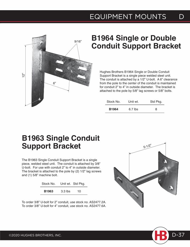
Hughes Brothers B1964 Single or Double Conduit Support Bracket is a single piece welded steel unit. The conduit is attached by a 1/2” U-bolt. A 6” clearance from the pole to the center of the conduit is maintained for conduit 2” to 4” in outside diameter. The bracket is attached to the pole by 5/8” lag screws or 5/8” bolts.
Stock No. Unit wt. Std Pkg.
B1964 6.7 lbs 8
B1964 Single or Double Conduit Support Bracket
B1963 Single Conduit Support Bracket
To order 3/8” U-bolt for 2” conduit, use stock no. AS2477.2A.To order 3/8” U-bolt for 4” conduit, use stock no. AS2477.6A.
The B1963 Single Conduit Support Bracket is a single piece, welded steel unit. The conduit is attached by 3/8” U-bolt. For use with conduit 2” to 4” in outside diameter. The bracket is attached to the pole by (2) 1/2” lag screws and (1) 5/8” machine bolt.
Stock No. Unit wt. Std Pkg.
B1963 3.3 lbs 10
12”
9/16”
CL
6”
5-1/2”
EQUIPMENT MOUNTS D
©2020 HUgHES BrOTHErS, INc.
D EQUIPMENT MOUNTS
D-37
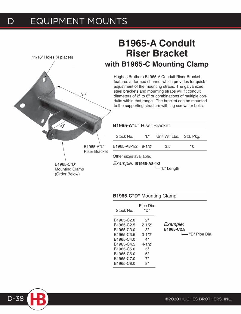
B1965-A Conduit Riser Bracket
with B1965-C Mounting ClampHughes Brothers B1965-A Conduit Riser Bracket features a formed channel which provides for quick adjustment of the mounting straps. The galvanized steel brackets and mounting straps will fit conduit diameters of 2" to 8" or combinations of multiple con-duits within that range. The bracket can be mounted to the supporting structure with lag screws or bolts.
B1965-A"L"Riser Bracket
B1965-C"D" Mounting Clamp(Order Below)
"L"
"D" B1965-A"L" Riser Bracket
Stock No. "L" Unit Wt. Lbs. Std. Pkg.
B1965-A8-1/2 8-1/2" 3.5 10
Other sizes available.
Example: B1965-A8-1/2 "L" Length
B1965-C"D" Mounting Clamp
Pipe Dia. Stock No. "D" B1965-C2.0 2" B1965-C2.5 2-1/2" B1965-C3.0 3" B1965-C3.5 3-1/2" B1965-C4.0 4" B1965-C4.5 4-1/2" B1965-C5.0 5" B1965-C6.0 6" B1965-C7.0 7" B1965-C8.0 8"
Example: B1965-C2.5 "D" Pipe Dia.
11/16" Holes (4 places)
d EQUIPMENT MOUNTS
©2020 HUgHES BrOTHErS, INc.D-38
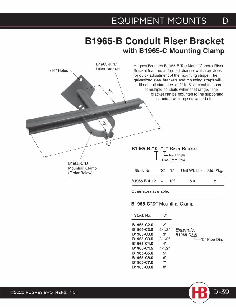
B1965-B Conduit Riser Bracket
Hughes Brothers B1965-B Tee Mount Conduit Riser Bracket features a formed channel which provides for quick adjustment of the mounting straps. The galvanized steel brackets and mounting straps will fit conduit diameters of 2" to 8" or combinations of multiple conduits within that range. The bracket can be mounted to the supporting structure with lag screws or bolts.
B1965-B "L" Riser Bracket
B1965-C"D" Mounting Clamp(Order Below)
"X"
"L"B1965-B-"X"-"L" Riser Bracket
Stock No. "X" "L" Unit Wt. Lbs. Std. Pkg.
B1965-B-4-12 4" 12" 5.0 5
Other sizes available.
B1965-C"D" Mounting Clamp
Stock No. "D" B1965-C2.0 2" B1965-C2.5 2-1/2" B1965-C3.0 3" B1965-C3.5 3-1/2" B1965-C4.0 4" B1965-C4.5 4-1/2" B1965-C5.0 5" B1965-C6.0 6" B1965-C7.0 7" B1965-C8.0 8"
"D"
Tee LengthDist. From Pole
Example: B1965-C2.5 "D" Pipe Dia.
with B1965-C Mounting Clamp
11/16" Holes
EQUIPMENT MOUNTS D
©2020 HUgHES BrOTHErS, INc.
D EQUIPMENT MOUNTS
D-39
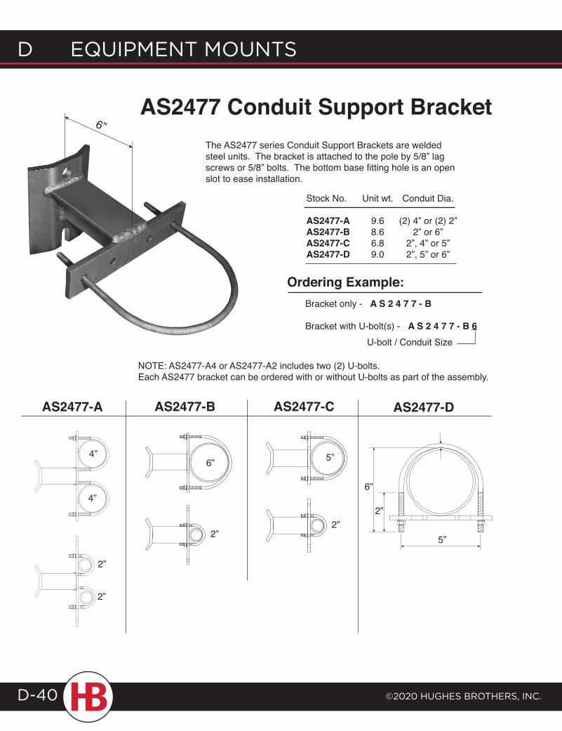
6”AS2477 Conduit Support Bracket
The AS2477 series Conduit Support Brackets are welded steel units. The bracket is attached to the pole by 5/8” lag screws or 5/8” bolts. The bottom base fitting hole is an open slot to ease installation.
Stock No. Unit wt. Conduit Dia.
AS2477-A 9.6 (2) 4” or (2) 2”AS2477-B 8.6 2” or 6”AS2477-C 6.8 2”, 4” or 5”AS2477-D 9.0 2”, 5” or 6”
AS2477-A AS2477-DAS2477-B AS2477-C
2”
4”
4”
2”
2”
6” 5”
2”
6”
5”
2”
NOTE: AS2477-A4 or AS2477-A2 includes two (2) U-bolts.Each AS2477 bracket can be ordered with or without U-bolts as part of the assembly.
Ordering Example:Bracket only - A S 2 4 7 7 - B
Bracket with U-bolt(s) - A S 2 4 7 7 - B 6 U-bolt / Conduit Size
d EQUIPMENT MOUNTS
©2020 HUgHES BrOTHErS, INc.D-40
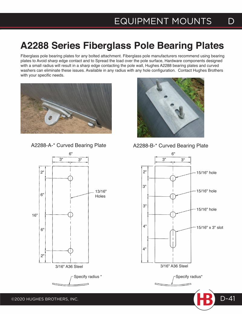
A2288 Series Fiberglass Pole Bearing Plates
3" 3"
2"
6"
2"
6"
13/16"Holes
3/16" A36 Steel
EQUIPMENT MOUNTS D
©2020 HUgHES BrOTHErS, INc.
D EQUIPMENT MOUNTS
D-41
Fiberglass pole bearing plates for any bolted attachment. Fiberglass pole manufacturers recommend using bearing plates to Avoid sharp edge contact and to Spread the load over the pole surface, Hardware components designed with a small radius will result in a sharp edge contacting the pole wall, Hughes A2288 bearing plates and curved washers can eliminate these issues. Available in any radius with any hole configuration. Contact Hughes Brothers with your specific needs.
A2288-A-* Curved Bearing Plate
2"
2"
6"
6"
16"
3" 3"6"
3/16" A36 Steel
Specify radius *
3" 3"6"
15/16" hole
15/16" hole
15/16" hole
15/16" x 3" slot
3/16" A36 Steel
Specify radius*
2"
3"
3"
4"
4"
A2288-B-* Curved Bearing Plate
FA S T E N E R S Fastener Specifications ..........E-1Bolts ..............................................E-3Threaded Rods .......................E-20U-Bolts/Links ..........................E-26Clips ............................................E-28Studs ..........................................E-29Nuts ............................................E-35Washers ....................................E-38Clevis/Turnbuckles ...............E-48

FASTENERS E
©2020 HugHES BRoTHERS, INc. E-1
Standard Specifications for FastenersStandards for Fasteners from American Society for Testing and Materials (ASTM)
ASTM Fastener Standards
ASTM A194 Standard Specification for Carbon and Alloy Steel Nuts for Bolts for High Pressure and High Temperature Service.This specification covers a variety of carbon and alloy steel nuts. These steel nuts are used with A 325 Bolts.Hughes Brothers uses Grade 2H.
ASTM A307 Standard Specification for Carbon Steel Bolts and Studs, 60,000 PSI Tensile Strength.This specification covers the chemical and mechanical requirements of two grades of carbon steel bolts and studs in sizes 1/4 inch through 4 inch.Grade A bolts are used for general applications.
ASTM A325 Standard Specification for High-Strength Bolts for Structural Steel Joints.This specification covers the chemical and mechani-cal requirements of various types of quenched and tempered steel bolts commonly known as “high strength structural bolts,” intended for use in structural joints.Type 1, Bolts made of medium carbon steel.Type 3, Bolts having atmospheric corrosion resistance.
ASTM A394 Standard Specification for Zinc Coated Steel Transmission Tower Bolts.This specification covers the chemical and mechanical requirements of hexagon and squarehead zinc coated steel bolts and atmospheric corrosion resistant bolts in nominal thread diameters of 1/2, 5/8, 3/4, 7/8 and 1 inch for use in the construction of transmission towers, substations, and similar steel structures.Type 0: Zinc coated bolts made of low or medium carbon steel.Type 3: Bolts having atmospheric corrosion resistance and weathering characteristics comparable to that of steel covered in Specifications A242, A588 and A709.
ASTM A563 Standard Specification for Carbon and Alloy Steel Nuts.This specification covers chemical and mechanical requirements for eight grades of carbon and alloy steel nuts for general structural and mechanical uses on bolts, studs, and other externally threaded parts.Grade A nuts are used for general applications.
ASTM A193 Standard Specification for Alloy Steel, Special Purpose Applications.This specification covers alloy steel and stainless steel bolting materials for other special purpose applications.
ASTM A449 Standard Specification for Bolts and Studs, Heat-treated for General Use.This specification covers quenched and tempered steel bolts and studs having a minimum tensile strength.
ASTM Steel Standards for Fasteners
ASTM A36 Standard Specification for Structural Steel Interchangeable with SAE C1018 Low Carbon, general purpose, special quality machinery steel.This specification covers carbon steel shapes, plates, and bars of structural quality for use in riveted, bolted, or welded construction of bridges and buildings, and for general structural purposes.
ASTM A242, A588, and A709 Standard Specifications for High Strength Low Alloy Structural Steels with enhanced atmospheric corrosion resistance.
ASTM A536 Ductile Iron Castings. This specification covers castings made of ductile iron, also
known as spheroidal or nodular iron is used for eyenuts and washer nuts, Grade 65-45-12.
ASTM A320 Alloy Steel Bolting Material for Low-Tem-perature Service. This specification covers alloy steel bolting materials for pressure vessels, valves, flanges, and fittings for low-temperature service. The term "bolting material" as used in this specification covers rolled, forged, or strain hardened bars, bolts, screws, studs, and stud bolts. The material may be further processed by centerless grinding or by cold drawing. Austenitic stainless steel may be solution annealed or annealed and strain-hardened. Several grades are available.
E FASTENERS
©2020 HugHES BRoTHERS, INc.E-2
ASTM Galvanizing Standards
ASTM A123 Standard Specification for Zinc (Hot Dip Galvanized) Coatings on Iron and Steel Products.This specification covers the requirements for zinc coating (galvanizing) by the hot dip process on iron and steel products made from rolled, pressed and forged shapes, castings, plates, bars and strips.This specification covers both unfabricated products and fabricated products, for example, assembled steel products, structural steel fabrications, large tubes already bent or welded before galvanizing, and wire work fabricated from uncoated steel wire.This specification also covers steel forgings and iron castings incorporated into pieces fabricated before galvanizing or which are too large to be centrifuged (or otherwise handled to remove excess galvanizing bath metal).
ASTM A153 Standard Specification for Zinc Coating (Hot Dip) on Iron and Steel Hardware.This specification covers zinc coatings applied by the hot dip process on iron and steel hardware.This document is intended to be applicable to hardware items that are centrifuged or otherwise handled to remove excess galvanizing bath metal (free zinc).
Standards from American National Standards Institute & American Society
of Mechanical Engineers
ANSI/ASME B1.1 Standard for Unified Inch Screw Threads (UN and UNR Thread Form).This specification specifies the thread form, series, class, allowance, tolerance, and designation for unified screw threads.
ANSI/ASME B18.2.1 Standard for Square and Hex Bolts and Screws.This Standard is intended to cover the complete general and dimensional data for the various types of inch series square and hex bolts and screws.
ANSI/ASME B18.5 Standard for Round Head Bolts (Carriage Bolts).This standard covers the complete general and dimen-sional data for the various types of inch series bolts generally classified as round head bolts.
ANSI/ASME B18.15 Standard for Forged Eyebolts.This standard is limited to dimensions and capacities for forged threaded eyebolts intended primarily for lifting applications.
ANSI/ASME 18.2.2 Standard for Square and Hex Nuts.This standard is intended to cover the complete general and dimensional data for the various types of inch series square and hex nuts.
Standards from the American National Standard Institute - Pole Line Hardware
ANSI C135.2 Standard for threaded zinc-coated ferrous strand-eye anchor rods and nuts for overhead line construction.
ANSI C135.3 Standard for zinc-coated ferrous lag screws for overhead line construction.
ANSI C135.62 Standard for zinc-coated forged anchor shackles.
ANSI C135.80 Standard for fasteners for overhead line construction.This standard covers zinc-coated carriage bolts, machine bolts, double arming bolts, double end bolts, and nuts commonly used in overhead line construction.
ANSI C135.90 Standard for pole line hardware for overhead line construction.
Standards from the International Fasteners Institute
IFI 136 Standard for Studs and Bent Bolts.This standard covers the general and dimensional requirements for various types of studs and bent bolts, including threaded rod, J-bolts, L-bolts, U-bolts, and eyebolts (closed).
IFI 128 Standard for Hex Coupling Nuts.This standard covers the general and dimensional requirements for hex coupling nuts.
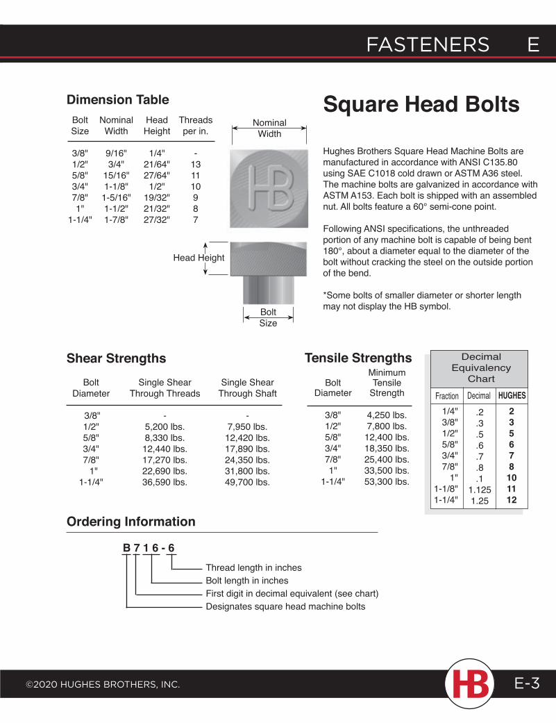
FASTENERS E
©2020 HugHES BRoTHERS, INc.
E FASTENERS
E-3
Hughes Brothers Square Head Machine Bolts are manufactured in accordance with ANSI C135.80 using SAE C1018 cold drawn or ASTM A36 steel. The machine bolts are galvanized in accordance with ASTM A153. Each bolt is shipped with an assembled nut. All bolts feature a 60° semi-cone point.
Following ANSI specifications, the unthreaded portion of any machine bolt is capable of being bent 180°, about a diameter equal to the diameter of the bolt without cracking the steel on the outside portion of the bend.
*Some bolts of smaller diameter or shorter length may not display the HB symbol.
Thread length in inches Bolt length in inchesFirst digit in decimal equivalent (see chart)Designates square head machine bolts
B 7 1 6 - 6
Ordering Information
Bolt Single Shear Single Shear Diameter Through Threads Through Shaft
3/8" - - 1/2" 5,200 lbs. 7,950 lbs. 5/8" 8,330 lbs. 12,420 lbs. 3/4" 12,440 lbs. 17,890 lbs. 7/8" 17,270 lbs. 24,350 lbs. 1" 22,690 lbs. 31,800 lbs. 1-1/4" 36,590 lbs. 49,700 lbs.
Shear Strengths
Bolt Nominal Head Threads Size Width Height per in.
3/8" 9/16" 1/4" - 1/2" 3/4" 21/64" 13 5/8" 15/16" 27/64" 11 3/4" 1-1/8" 1/2" 10 7/8" 1-5/16" 19/32" 9 1" 1-1/2" 21/32" 8 1-1/4" 1-7/8" 27/32" 7
BoltSize
NominalWidth
Dimension Table
Tensile Strengths Minimum Bolt Tensile Diameter Strength
3/8" 4,250 lbs. 1/2" 7,800 lbs. 5/8" 12,400 lbs. 3/4" 18,350 lbs. 7/8" 25,400 lbs. 1" 33,500 lbs. 1-1/4" 53,300 lbs.
DecimalFraction.2.3.5.6.7.8.1
1.1251.25
235678
101112
Decimal Equivalency
ChartHUGHES
1/4"3/8"1/2"5/8"3/4"7/8"
1"1-1/8"1-1/4"
Square Head Bolts
Head Height
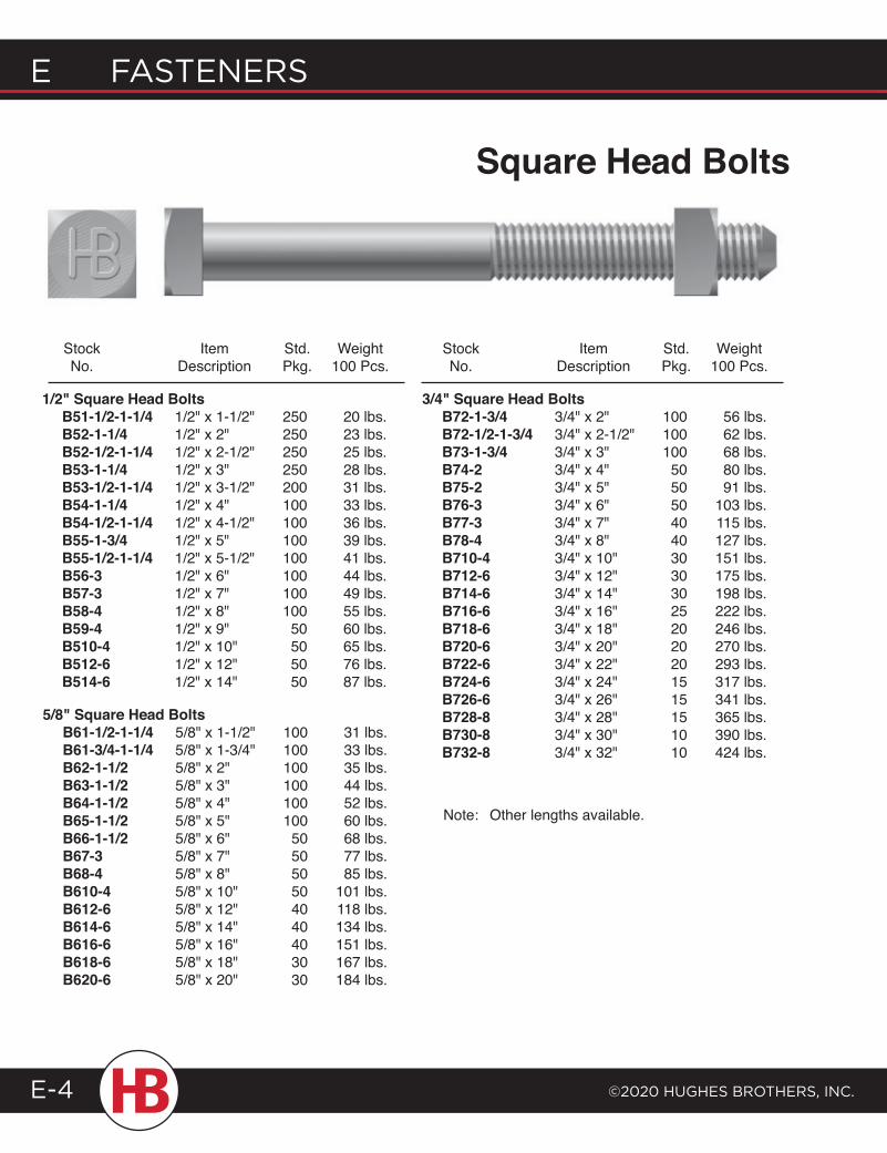
E FASTENERS
©2020 HugHES BRoTHERS, INc.E-4
1/2" Square Head Bolts B51-1/2-1-1/4 1/2" x 1-1/2" 250 20 lbs. B52-1-1/4 1/2" x 2" 250 23 lbs. B52-1/2-1-1/4 1/2" x 2-1/2" 250 25 lbs. B53-1-1/4 1/2" x 3" 250 28 lbs. B53-1/2-1-1/4 1/2" x 3-1/2" 200 31 lbs. B54-1-1/4 1/2" x 4" 100 33 lbs. B54-1/2-1-1/4 1/2" x 4-1/2" 100 36 lbs. B55-1-3/4 1/2" x 5" 100 39 lbs. B55-1/2-1-1/4 1/2" x 5-1/2" 100 41 lbs. B56-3 1/2" x 6" 100 44 lbs. B57-3 1/2" x 7" 100 49 lbs. B58-4 1/2" x 8" 100 55 lbs. B59-4 1/2" x 9" 50 60 lbs. B510-4 1/2" x 10" 50 65 lbs. B512-6 1/2" x 12" 50 76 lbs. B514-6 1/2" x 14" 50 87 lbs.
Stock Item Std. Weight No. Description Pkg. 100 Pcs.
5/8" Square Head Bolts B61-1/2-1-1/4 5/8" x 1-1/2" 100 31 lbs. B61-3/4-1-1/4 5/8" x 1-3/4" 100 33 lbs. B62-1-1/2 5/8" x 2" 100 35 lbs. B63-1-1/2 5/8" x 3" 100 44 lbs. B64-1-1/2 5/8" x 4" 100 52 lbs. B65-1-1/2 5/8" x 5" 100 60 lbs. B66-1-1/2 5/8" x 6" 50 68 lbs. B67-3 5/8" x 7" 50 77 lbs. B68-4 5/8" x 8" 50 85 lbs. B610-4 5/8" x 10" 50 101 lbs. B612-6 5/8" x 12" 40 118 lbs. B614-6 5/8" x 14" 40 134 lbs. B616-6 5/8" x 16" 40 151 lbs. B618-6 5/8" x 18" 30 167 lbs. B620-6 5/8" x 20" 30 184 lbs.
3/4" Square Head Bolts B72-1-3/4 3/4" x 2" 100 56 lbs. B72-1/2-1-3/4 3/4" x 2-1/2" 100 62 lbs. B73-1-3/4 3/4" x 3" 100 68 lbs. B74-2 3/4" x 4" 50 80 lbs. B75-2 3/4" x 5" 50 91 lbs. B76-3 3/4" x 6" 50 103 lbs. B77-3 3/4" x 7" 40 115 lbs. B78-4 3/4" x 8" 40 127 lbs. B710-4 3/4" x 10" 30 151 lbs. B712-6 3/4" x 12" 30 175 lbs. B714-6 3/4" x 14" 30 198 lbs. B716-6 3/4" x 16" 25 222 lbs. B718-6 3/4" x 18" 20 246 lbs. B720-6 3/4" x 20" 20 270 lbs. B722-6 3/4" x 22" 20 293 lbs. B724-6 3/4" x 24" 15 317 lbs. B726-6 3/4" x 26" 15 341 lbs. B728-8 3/4" x 28" 15 365 lbs. B730-8 3/4" x 30" 10 390 lbs. B732-8 3/4" x 32" 10 424 lbs.
Stock Item Std. Weight No. Description Pkg. 100 Pcs.
Note: Other lengths available.
Square Head Bolts
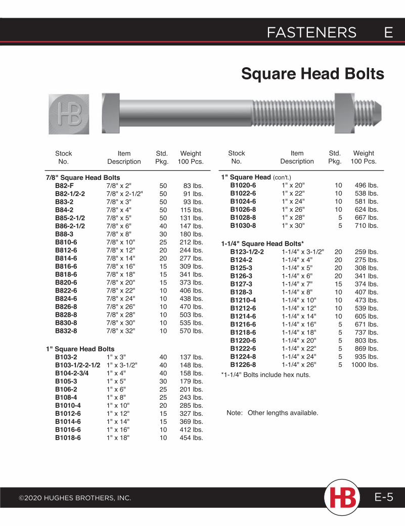
FASTENERS E
©2020 HugHES BRoTHERS, INc.
E FASTENERS
E-5
7/8" Square Head Bolts B82-F 7/8" x 2" 50 83 lbs. B82-1/2-2 7/8" x 2-1/2" 50 91 lbs. B83-2 7/8" x 3" 50 93 lbs. B84-2 7/8" x 4" 50 115 lbs. B85-2-1/2 7/8" x 5" 50 131 lbs. B86-2-1/2 7/8" x 6" 40 147 lbs. B88-3 7/8" x 8" 30 180 lbs. B810-6 7/8" x 10" 25 212 lbs. B812-6 7/8" x 12" 20 244 lbs. B814-6 7/8" x 14" 20 277 lbs. B816-6 7/8" x 16" 15 309 lbs. B818-6 7/8" x 18" 15 341 lbs. B820-6 7/8" x 20" 15 373 lbs. B822-6 7/8" x 22" 10 406 lbs. B824-6 7/8" x 24" 10 438 lbs. B826-8 7/8" x 26" 10 470 lbs. B828-8 7/8" x 28" 10 503 lbs. B830-8 7/8" x 30" 10 535 lbs. B832-8 7/8" x 32" 10 570 lbs.
1" Square Head Bolts B103-2 1" x 3" 40 137 lbs. B103-1/2-2-1/2 1" x 3-1/2" 40 148 lbs. B104-2-3/4 1" x 4" 40 158 lbs. B105-3 1" x 5" 30 179 lbs. B106-2 1" x 6" 25 201 lbs. B108-4 1" x 8" 25 243 lbs. B1010-4 1" x 10" 20 285 lbs. B1012-6 1" x 12" 15 327 lbs. B1014-6 1" x 14" 15 369 lbs. B1016-6 1" x 16" 10 412 lbs. B1018-6 1" x 18" 10 454 lbs.
1" Square Head (con't.) B1020-6 1" x 20" 10 496 lbs. B1022-6 1" x 22" 10 538 lbs. B1024-6 1" x 24" 10 581 lbs. B1026-8 1" x 26" 10 624 lbs. B1028-8 1" x 28" 5 667 lbs. B1030-8 1" x 30" 5 710 lbs.
1-1/4" Square Head Bolts* B123-1/2-2 1-1/4" x 3-1/2" 20 259 lbs. B124-2 1-1/4" x 4" 20 275 lbs. B125-3 1-1/4" x 5" 20 308 lbs. B126-3 1-1/4" x 6" 20 341 lbs. B127-3 1-1/4" x 7" 15 374 lbs. B128-3 1-1/4" x 8" 10 407 lbs. B1210-4 1-1/4" x 10" 10 473 lbs. B1212-6 1-1/4" x 12" 10 539 lbs. B1214-6 1-1/4" x 14" 10 605 lbs. B1216-6 1-1/4" x 16" 5 671 lbs. B1218-6 1-1/4" x 18" 5 737 lbs. B1220-6 1-1/4" x 20" 5 803 lbs. B1222-6 1-1/4" x 22" 5 869 lbs. B1224-8 1-1/4" x 24" 5 935 lbs. B1226-8 1-1/4" x 26" 5 1000 lbs. *1-1/4" Bolts include hex nuts.
Stock Item Std. Weight No. Description Pkg. 100 Pcs.
Stock Item Std. Weight No. Description Pkg. 100 Pcs.
Note: Other lengths available.
Square Head Bolts
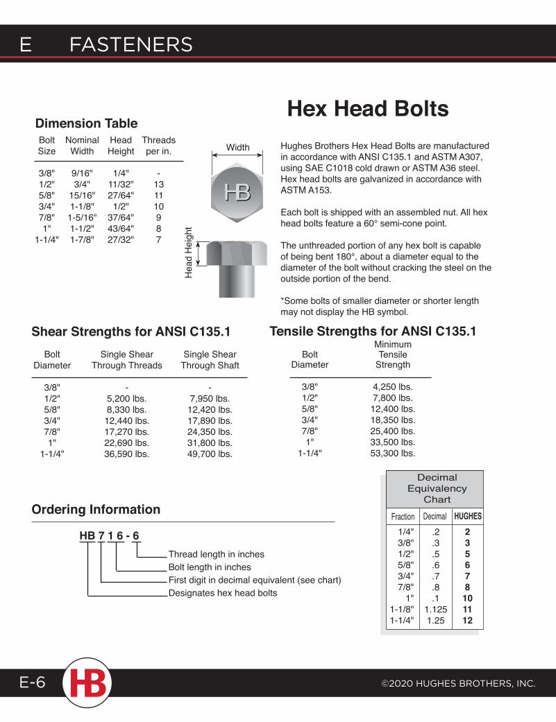
E FASTENERS
©2020 HugHES BRoTHERS, INc.E-6
Hughes Brothers Hex Head Bolts are manufactured in accordance with ANSI C135.1 and ASTM A307, using SAE C1018 cold drawn or ASTM A36 steel. Hex head bolts are galvanized in accordance with ASTM A153.
Each bolt is shipped with an assembled nut. All hex head bolts feature a 60° semi-cone point.
The unthreaded portion of any hex bolt is capable of being bent 180°, about a diameter equal to the diameter of the bolt without cracking the steel on the outside portion of the bend.
*Some bolts of smaller diameter or shorter length may not display the HB symbol.
Ordering Information
HB 7 1 6 - 6
Width
Hea
d H
eigh
t
Dimension Table Bolt Nominal Head Threads Size Width Height per in.
3/8" 9/16" 1/4" - 1/2" 3/4" 11/32" 13 5/8" 15/16" 27/64" 11 3/4" 1-1/8" 1/2" 10 7/8" 1-5/16" 37/64" 9 1" 1-1/2" 43/64" 8 1-1/4" 1-7/8" 27/32" 7
Thread length in inchesBolt length in inchesFirst digit in decimal equivalent (see chart) Designates hex head bolts
DecimalFraction.2.3.5.6.7.8.1
1.1251.25
235678101112
Decimal Equivalency
ChartHUGHES
1/4"3/8"1/2"5/8"3/4"7/8"
1"1-1/8"1-1/4"
Bolt Single Shear Single Shear Diameter Through Threads Through Shaft
3/8" - - 1/2" 5,200 lbs. 7,950 lbs. 5/8" 8,330 lbs. 12,420 lbs. 3/4" 12,440 lbs. 17,890 lbs. 7/8" 17,270 lbs. 24,350 lbs. 1" 22,690 lbs. 31,800 lbs. 1-1/4" 36,590 lbs. 49,700 lbs.
Minimum Bolt Tensile Diameter Strength
3/8" 4,250 lbs. 1/2" 7,800 lbs. 5/8" 12,400 lbs. 3/4" 18,350 lbs. 7/8" 25,400 lbs. 1" 33,500 lbs. 1-1/4" 53,300 lbs.
Tensile Strengths for ANSI C135.1
Hex Head Bolts
Shear Strengths for ANSI C135.1
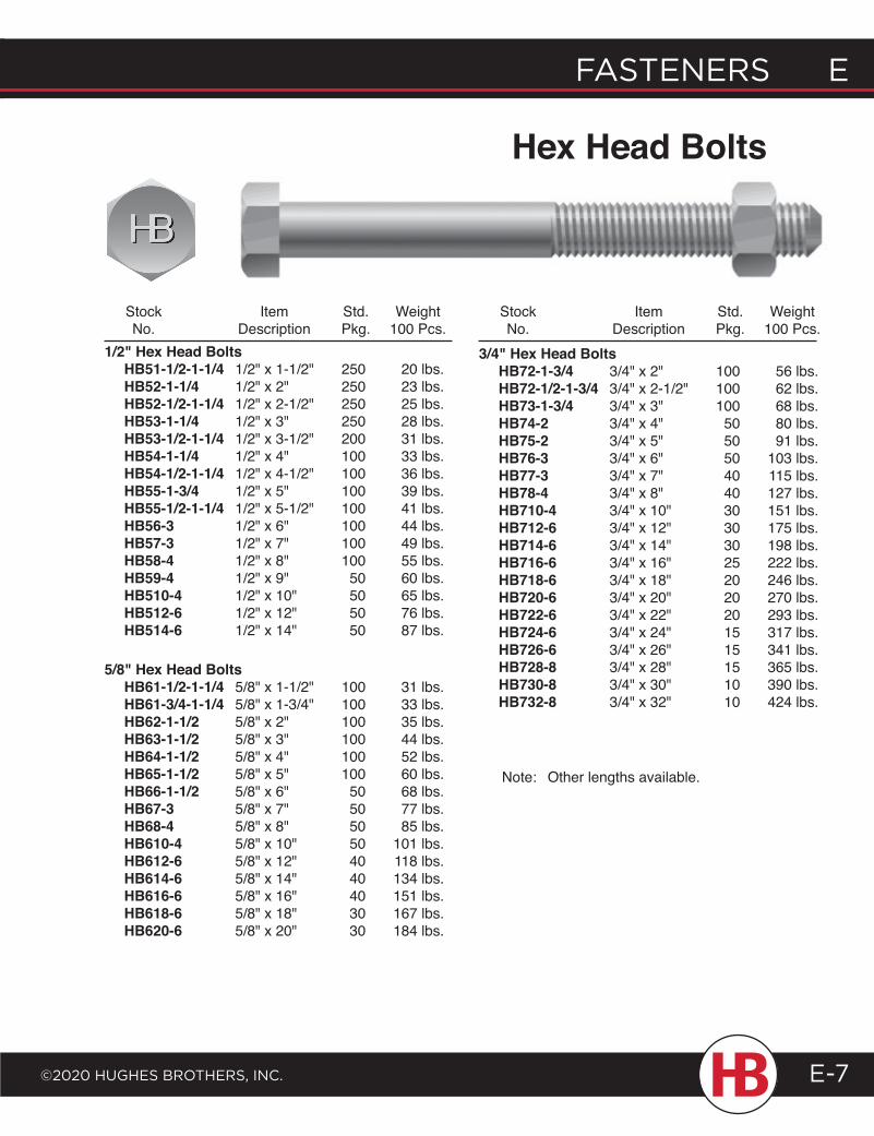
FASTENERS E
©2020 HugHES BRoTHERS, INc.
E FASTENERS
E-7
Stock Item Std. Weight No. Description Pkg. 100 Pcs.
Stock Item Std. Weight No. Description Pkg. 100 Pcs.
Hex Head Bolts
1/2" Hex Head Bolts HB51-1/2-1-1/4 1/2" x 1-1/2" 250 20 lbs. HB52-1-1/4 1/2" x 2" 250 23 lbs. HB52-1/2-1-1/4 1/2" x 2-1/2" 250 25 lbs. HB53-1-1/4 1/2" x 3" 250 28 lbs. HB53-1/2-1-1/4 1/2" x 3-1/2" 200 31 lbs. HB54-1-1/4 1/2" x 4" 100 33 lbs. HB54-1/2-1-1/4 1/2" x 4-1/2" 100 36 lbs. HB55-1-3/4 1/2" x 5" 100 39 lbs. HB55-1/2-1-1/4 1/2" x 5-1/2" 100 41 lbs. HB56-3 1/2" x 6" 100 44 lbs. HB57-3 1/2" x 7" 100 49 lbs. HB58-4 1/2" x 8" 100 55 lbs. HB59-4 1/2" x 9" 50 60 lbs. HB510-4 1/2" x 10" 50 65 lbs. HB512-6 1/2" x 12" 50 76 lbs. HB514-6 1/2" x 14" 50 87 lbs.
5/8" Hex Head Bolts HB61-1/2-1-1/4 5/8" x 1-1/2" 100 31 lbs. HB61-3/4-1-1/4 5/8" x 1-3/4" 100 33 lbs. HB62-1-1/2 5/8" x 2" 100 35 lbs. HB63-1-1/2 5/8" x 3" 100 44 lbs. HB64-1-1/2 5/8" x 4" 100 52 lbs. HB65-1-1/2 5/8" x 5" 100 60 lbs. HB66-1-1/2 5/8" x 6" 50 68 lbs. HB67-3 5/8" x 7" 50 77 lbs. HB68-4 5/8" x 8" 50 85 lbs. HB610-4 5/8" x 10" 50 101 lbs. HB612-6 5/8" x 12" 40 118 lbs. HB614-6 5/8" x 14" 40 134 lbs. HB616-6 5/8" x 16" 40 151 lbs. HB618-6 5/8" x 18" 30 167 lbs. HB620-6 5/8" x 20" 30 184 lbs.
3/4" Hex Head Bolts HB72-1-3/4 3/4" x 2" 100 56 lbs. HB72-1/2-1-3/4 3/4" x 2-1/2" 100 62 lbs. HB73-1-3/4 3/4" x 3" 100 68 lbs. HB74-2 3/4" x 4" 50 80 lbs. HB75-2 3/4" x 5" 50 91 lbs. HB76-3 3/4" x 6" 50 103 lbs. HB77-3 3/4" x 7" 40 115 lbs. HB78-4 3/4" x 8" 40 127 lbs. HB710-4 3/4" x 10" 30 151 lbs. HB712-6 3/4" x 12" 30 175 lbs. HB714-6 3/4" x 14" 30 198 lbs. HB716-6 3/4" x 16" 25 222 lbs. HB718-6 3/4" x 18" 20 246 lbs. HB720-6 3/4" x 20" 20 270 lbs. HB722-6 3/4" x 22" 20 293 lbs. HB724-6 3/4" x 24" 15 317 lbs. HB726-6 3/4" x 26" 15 341 lbs. HB728-8 3/4" x 28" 15 365 lbs. HB730-8 3/4" x 30" 10 390 lbs. HB732-8 3/4" x 32" 10 424 lbs.
Note: Other lengths available.
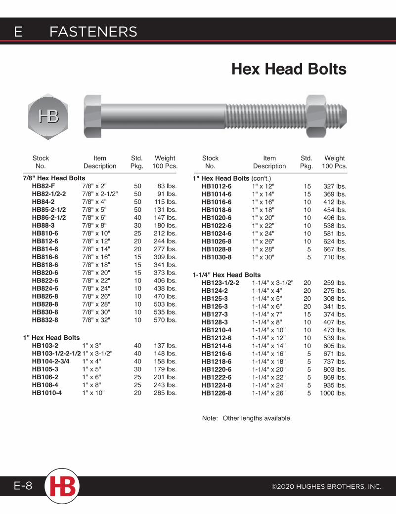
E FASTENERS
©2020 HugHES BRoTHERS, INc.E-8
Stock Item Std. Weight No. Description Pkg. 100 Pcs.
Stock Item Std. Weight No. Description Pkg. 100 Pcs.
7/8" Hex Head Bolts HB82-F 7/8" x 2" 50 83 lbs. HB82-1/2-2 7/8" x 2-1/2" 50 91 lbs. HB84-2 7/8" x 4" 50 115 lbs. HB85-2-1/2 7/8" x 5" 50 131 lbs. HB86-2-1/2 7/8" x 6" 40 147 lbs. HB88-3 7/8" x 8" 30 180 lbs. HB810-6 7/8" x 10" 25 212 lbs. HB812-6 7/8" x 12" 20 244 lbs. HB814-6 7/8" x 14" 20 277 lbs. HB816-6 7/8" x 16" 15 309 lbs. HB818-6 7/8" x 18" 15 341 lbs. HB820-6 7/8" x 20" 15 373 lbs. HB822-6 7/8" x 22" 10 406 lbs. HB824-6 7/8" x 24" 10 438 lbs. HB826-8 7/8" x 26" 10 470 lbs. HB828-8 7/8" x 28" 10 503 lbs. HB830-8 7/8" x 30" 10 535 lbs. HB832-8 7/8" x 32" 10 570 lbs.
1" Hex Head Bolts HB103-2 1" x 3" 40 137 lbs. HB103-1/2-2-1/2 1" x 3-1/2" 40 148 lbs. HB104-2-3/4 1" x 4" 40 158 lbs. HB105-3 1" x 5" 30 179 lbs. HB106-2 1" x 6" 25 201 lbs. HB108-4 1" x 8" 25 243 lbs. HB1010-4 1" x 10" 20 285 lbs.
1" Hex Head Bolts (con't.) HB1012-6 1" x 12" 15 327 lbs. HB1014-6 1" x 14" 15 369 lbs. HB1016-6 1" x 16" 10 412 lbs. HB1018-6 1" x 18" 10 454 lbs. HB1020-6 1" x 20" 10 496 lbs. HB1022-6 1" x 22" 10 538 lbs. HB1024-6 1" x 24" 10 581 lbs. HB1026-8 1" x 26" 10 624 lbs. HB1028-8 1" x 28" 5 667 lbs. HB1030-8 1" x 30" 5 710 lbs.
1-1/4" Hex Head Bolts HB123-1/2-2 1-1/4" x 3-1/2" 20 259 lbs. HB124-2 1-1/4" x 4" 20 275 lbs. HB125-3 1-1/4" x 5" 20 308 lbs. HB126-3 1-1/4" x 6" 20 341 lbs. HB127-3 1-1/4" x 7" 15 374 lbs. HB128-3 1-1/4" x 8" 10 407 lbs. HB1210-4 1-1/4" x 10" 10 473 lbs. HB1212-6 1-1/4" x 12" 10 539 lbs. HB1214-6 1-1/4" x 14" 10 605 lbs. HB1216-6 1-1/4" x 16" 5 671 lbs. HB1218-6 1-1/4" x 18" 5 737 lbs. HB1220-6 1-1/4" x 20" 5 803 lbs. HB1222-6 1-1/4" x 22" 5 869 lbs. HB1224-8 1-1/4" x 24" 5 935 lbs. HB1226-8 1-1/4" x 26" 5 1000 lbs.
Note: Other lengths available.
Hex Head Bolts
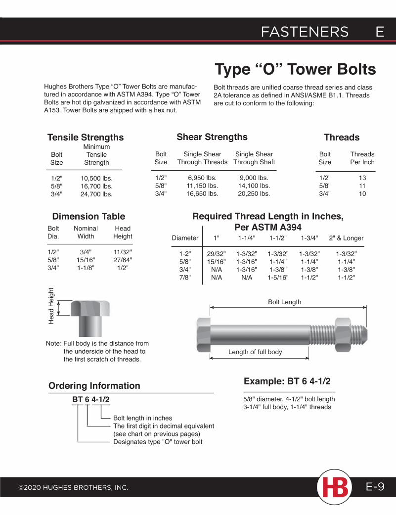
FASTENERS E
©2020 HugHES BRoTHERS, INc.
E FASTENERS
E-9
Minimum Bolt Tensile Size Strength
1/2" 10,500 lbs. 5/8" 16,700 lbs. 3/4" 24,700 lbs.
Bolt Single Shear Single Shear Size Through Threads Through Shaft 1/2" 6,950 lbs. 9,000 lbs. 5/8" 11,150 lbs. 14,100 lbs. 3/4" 16,650 lbs. 20,250 lbs.
Bolt Threads Size Per Inch
1/2" 13 5/8" 11 3/4" 10
Bolt Nominal Head Dia. Width Height
1/2" 3/4" 11/32" 5/8" 15/16" 27/64" 3/4" 1-1/8" 1/2"
1-1/2"
1-3/32"1-1/4"1-3/8"1-5/16"
1-1/4"
1-3/32"1-3/16"1-3/16"
N/A
1"
29/32"15/16"
N/AN/A
Diameter
1-2"5/8"3/4"7/8"
Tensile Strengths Shear Strengths Threads
Dimension Table Required Thread Length in Inches, Per ASTM A394
Hughes Brothers Type “O” Tower Bolts are manufac-tured in accordance with ASTM A394. Type “O” Tower Bolts are hot dip galvanized in accordance with ASTM A153. Tower Bolts are shipped with a hex nut.
Type “O” Tower BoltsBolt threads are unified coarse thread series and class 2A tolerance as defined in ANSI/ASME B1.1. Threads are cut to conform to the following:
Bolt Length
Length of full body
BT 6 4-1/2
Bolt length in inchesThe first digit in decimal equivalent (see chart on previous pages)Designates type "O" tower bolt
Ordering Information
Note: Full body is the distance from the underside of the head to the first scratch of threads.
Hea
d H
eigh
t
1-3/4"
1-3/32"1-1/4"1-3/8"1-1/2"
2" & Longer
1-3/32"1-1/4"1-3/8"1-1/2"
Example: BT 6 4-1/2
5/8" diameter, 4-1/2" bolt length3-1/4" full body, 1-1/4" threads
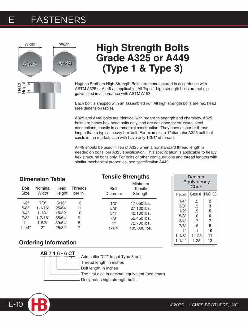
E FASTENERS
©2020 HugHES BRoTHERS, INc.E-10
DecimalFraction.2.3.5.6.7.8.1
1.1251.25
235678101112
Decimal Equivalency
ChartHUGHES
1/4"3/8"1/2"5/8"3/4"7/8"
1"1-1/8"1-1/4"
Minimum Bolt Tensile Diameter Strength
1/2" 17,050 lbs. 5/8" 27,100 lbs. 3/4" 40,100 lbs. 7/8" 55,450 lbs. 1" 72,700 lbs. 1-1/4" 105,000 lbs.
Ordering Information
AB 7 1 6 - 6 CT
Tensile Strengths
Width High Strength BoltsGrade A325 or A449
(Type 1 & Type 3)Hughes Brothers High Strength Bolts are manufactured in accordance with ASTM A325 or A449 as applicable. All Type 1 high strength bolts are hot dip galvanized in accordance with ASTM A153.
Each bolt is shipped with an assembled nut. All high strength bolts are hex head (see dimension table).
A325 and A449 bolts are identical with regard to strength and chemistry. A325 bolts are heavy hex head bolts only, and are designed for structural steel connections, mostly in commercial construction. They have a shorter thread length than a typical heavy hex bolt. For example, a 1" diameter A325 bolt that exists in the marketplace with have only 1-3/4" of thread.
A449 should be used in lieu of A325 when a nonstandard thread length is needed on bolts, per A325 specification. This specification is applicable to heavy hex structural bolts only. For bolts of other configurations and thread lengths with similar mechanical properties, see specification A449.
Add suffix "CT" to get Type 3 boltThread length in inchesBolt length in inchesThe first digit in decimal equivalent (see chart)Designates high strength bolts
Bolt Nominal Head Threads Size Width Height per in.
1/2" 7/8" 5/16" 13 5/8" 1-1/16" 25/64" 11 3/4" 1-1/4" 15/32" 10 7/8" 1-7/16" 35/64" 9 1" 1-5/8" 39/64" 8 1-1/4" 2" 25/32" 7
Dimension Table
Hea
d H
eigh
t
Width
A325A325 A449A449
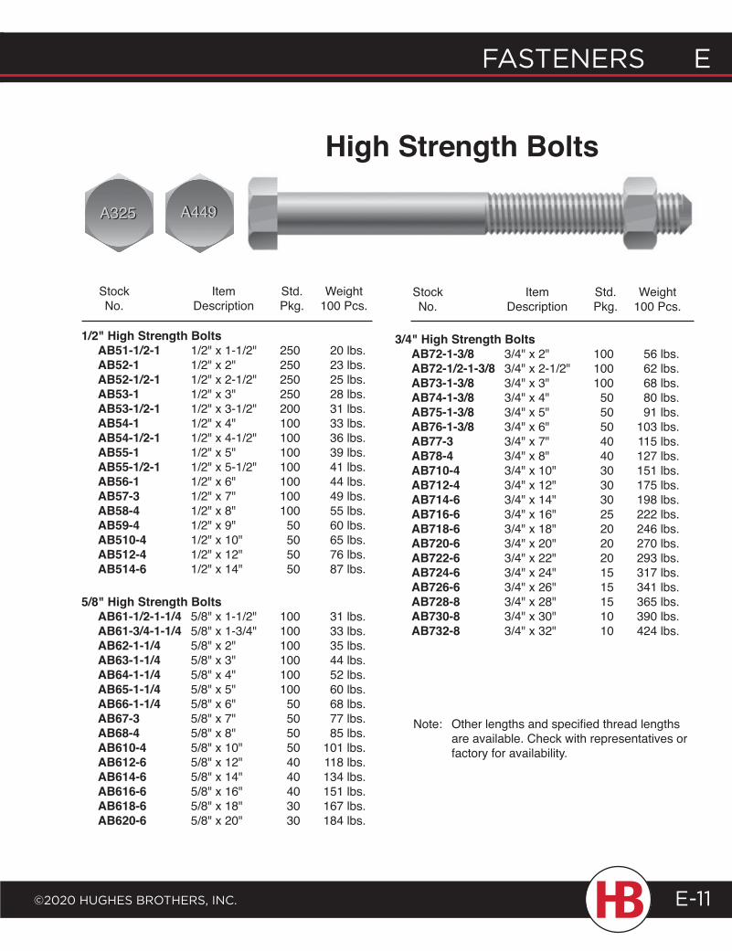
FASTENERS E
©2020 HugHES BRoTHERS, INc.
E FASTENERS
E-11
High Strength Bolts
Stock Item Std. Weight No. Description Pkg. 100 Pcs.
Stock Item Std. Weight No. Description Pkg. 100 Pcs.
1/2" High Strength Bolts AB51-1/2-1 1/2" x 1-1/2" 250 20 lbs. AB52-1 1/2" x 2" 250 23 lbs. AB52-1/2-1 1/2" x 2-1/2" 250 25 lbs. AB53-1 1/2" x 3" 250 28 lbs. AB53-1/2-1 1/2" x 3-1/2" 200 31 lbs. AB54-1 1/2" x 4" 100 33 lbs. AB54-1/2-1 1/2" x 4-1/2" 100 36 lbs. AB55-1 1/2" x 5" 100 39 lbs. AB55-1/2-1 1/2" x 5-1/2" 100 41 lbs. AB56-1 1/2" x 6" 100 44 lbs. AB57-3 1/2" x 7" 100 49 lbs. AB58-4 1/2" x 8" 100 55 lbs. AB59-4 1/2" x 9" 50 60 lbs. AB510-4 1/2" x 10" 50 65 lbs. AB512-4 1/2" x 12" 50 76 lbs. AB514-6 1/2" x 14" 50 87 lbs.
5/8" High Strength Bolts AB61-1/2-1-1/4 5/8" x 1-1/2" 100 31 lbs. AB61-3/4-1-1/4 5/8" x 1-3/4" 100 33 lbs. AB62-1-1/4 5/8" x 2" 100 35 lbs. AB63-1-1/4 5/8" x 3" 100 44 lbs. AB64-1-1/4 5/8" x 4" 100 52 lbs. AB65-1-1/4 5/8" x 5" 100 60 lbs. AB66-1-1/4 5/8" x 6" 50 68 lbs. AB67-3 5/8" x 7" 50 77 lbs. AB68-4 5/8" x 8" 50 85 lbs. AB610-4 5/8" x 10" 50 101 lbs. AB612-6 5/8" x 12" 40 118 lbs. AB614-6 5/8" x 14" 40 134 lbs. AB616-6 5/8" x 16" 40 151 lbs. AB618-6 5/8" x 18" 30 167 lbs. AB620-6 5/8" x 20" 30 184 lbs.
3/4" High Strength Bolts AB72-1-3/8 3/4" x 2" 100 56 lbs. AB72-1/2-1-3/8 3/4" x 2-1/2" 100 62 lbs. AB73-1-3/8 3/4" x 3" 100 68 lbs. AB74-1-3/8 3/4" x 4" 50 80 lbs. AB75-1-3/8 3/4" x 5" 50 91 lbs. AB76-1-3/8 3/4" x 6" 50 103 lbs. AB77-3 3/4" x 7" 40 115 lbs. AB78-4 3/4" x 8" 40 127 lbs. AB710-4 3/4" x 10" 30 151 lbs. AB712-4 3/4" x 12" 30 175 lbs. AB714-6 3/4" x 14" 30 198 lbs. AB716-6 3/4" x 16" 25 222 lbs. AB718-6 3/4" x 18" 20 246 lbs. AB720-6 3/4" x 20" 20 270 lbs. AB722-6 3/4" x 22" 20 293 lbs. AB724-6 3/4" x 24" 15 317 lbs. AB726-6 3/4" x 26" 15 341 lbs. AB728-8 3/4" x 28" 15 365 lbs. AB730-8 3/4" x 30" 10 390 lbs. AB732-8 3/4" x 32" 10 424 lbs.
Note: Other lengths and specified thread lengths are available. Check with representatives or factory for availability.
A449A449A325A325
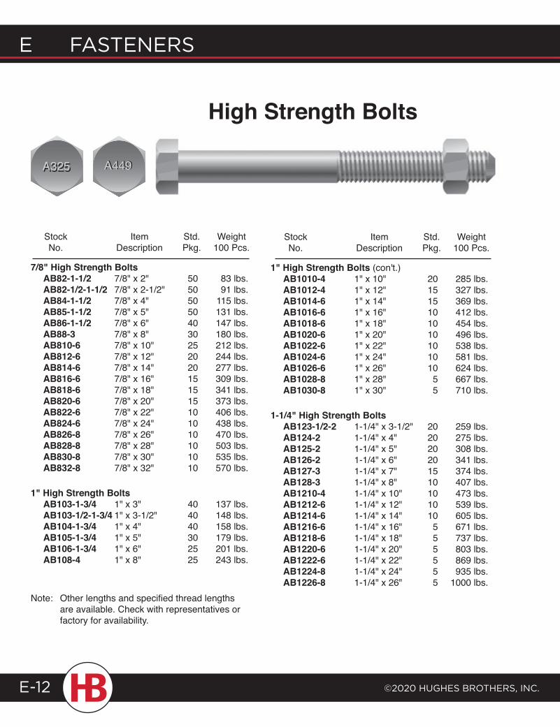
E FASTENERS
©2020 HugHES BRoTHERS, INc.E-12
Stock Item Std. Weight No. Description Pkg. 100 Pcs.
Stock Item Std. Weight No. Description Pkg. 100 Pcs.
7/8" High Strength Bolts AB82-1-1/2 7/8" x 2" 50 83 lbs. AB82-1/2-1-1/2 7/8" x 2-1/2" 50 91 lbs. AB84-1-1/2 7/8" x 4" 50 115 lbs. AB85-1-1/2 7/8" x 5" 50 131 lbs. AB86-1-1/2 7/8" x 6" 40 147 lbs. AB88-3 7/8" x 8" 30 180 lbs. AB810-6 7/8" x 10" 25 212 lbs. AB812-6 7/8" x 12" 20 244 lbs. AB814-6 7/8" x 14" 20 277 lbs. AB816-6 7/8" x 16" 15 309 lbs. AB818-6 7/8" x 18" 15 341 lbs. AB820-6 7/8" x 20" 15 373 lbs. AB822-6 7/8" x 22" 10 406 lbs. AB824-6 7/8" x 24" 10 438 lbs. AB826-8 7/8" x 26" 10 470 lbs. AB828-8 7/8" x 28" 10 503 lbs. AB830-8 7/8" x 30" 10 535 lbs. AB832-8 7/8" x 32" 10 570 lbs.
1" High Strength Bolts AB103-1-3/4 1" x 3" 40 137 lbs. AB103-1/2-1-3/4 1" x 3-1/2" 40 148 lbs. AB104-1-3/4 1" x 4" 40 158 lbs. AB105-1-3/4 1" x 5" 30 179 lbs. AB106-1-3/4 1" x 6" 25 201 lbs. AB108-4 1" x 8" 25 243 lbs.
1" High Strength Bolts (con't.) AB1010-4 1" x 10" 20 285 lbs. AB1012-4 1" x 12" 15 327 lbs. AB1014-6 1" x 14" 15 369 lbs. AB1016-6 1" x 16" 10 412 lbs. AB1018-6 1" x 18" 10 454 lbs. AB1020-6 1" x 20" 10 496 lbs. AB1022-6 1" x 22" 10 538 lbs. AB1024-6 1" x 24" 10 581 lbs. AB1026-6 1" x 26" 10 624 lbs. AB1028-8 1" x 28" 5 667 lbs. AB1030-8 1" x 30" 5 710 lbs.
1-1/4" High Strength Bolts AB123-1/2-2 1-1/4" x 3-1/2" 20 259 lbs. AB124-2 1-1/4" x 4" 20 275 lbs. AB125-2 1-1/4" x 5" 20 308 lbs. AB126-2 1-1/4" x 6" 20 341 lbs. AB127-3 1-1/4" x 7" 15 374 lbs. AB128-3 1-1/4" x 8" 10 407 lbs. AB1210-4 1-1/4" x 10" 10 473 lbs. AB1212-6 1-1/4" x 12" 10 539 lbs. AB1214-6 1-1/4" x 14" 10 605 lbs. AB1216-6 1-1/4" x 16" 5 671 lbs. AB1218-6 1-1/4" x 18" 5 737 lbs. AB1220-6 1-1/4" x 20" 5 803 lbs. AB1222-6 1-1/4" x 22" 5 869 lbs. AB1224-8 1-1/4" x 24" 5 935 lbs. AB1226-8 1-1/4" x 26" 5 1000 lbs.
High Strength Bolts
Note: Other lengths and specified thread lengths are available. Check with representatives or factory for availability.
A449A449A325A325
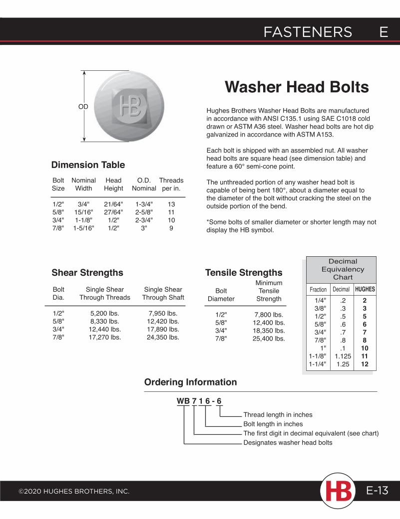
FASTENERS E
©2020 HugHES BRoTHERS, INc.
E FASTENERS
E-13
Hughes Brothers Washer Head Bolts are manufactured in accordance with ANSI C135.1 using SAE C1018 cold drawn or ASTM A36 steel. Washer head bolts are hot dip galvanized in accordance with ASTM A153.
Each bolt is shipped with an assembled nut. All washer head bolts are square head (see dimension table) and feature a 60° semi-cone point.
The unthreaded portion of any washer head bolt is capable of being bent 180°, about a diameter equal to the diameter of the bolt without cracking the steel on the outside portion of the bend.
*Some bolts of smaller diameter or shorter length may not display the HB symbol.
Washer Head Bolts
Dimension Table
Bolt Single Shear Single Shear Dia. Through Threads Through Shaft
1/2" 5,200 lbs. 7,950 lbs. 5/8" 8,330 lbs. 12,420 lbs. 3/4" 12,440 lbs. 17,890 lbs. 7/8" 17,270 lbs. 24,350 lbs.
Shear Strengths
Bolt Nominal Head O.D. Threads Size Width Height Nominal per in.
1/2" 3/4" 21/64" 1-3/4" 13 5/8" 15/16" 27/64" 2-5/8" 11 3/4" 1-1/8" 1/2" 2-3/4" 10 7/8" 1-5/16" 1/2" 3" 9
Minimum Bolt Tensile Diameter Strength
1/2" 7,800 lbs. 5/8" 12,400 lbs. 3/4" 18,350 lbs. 7/8" 25,400 lbs.
Tensile StrengthsDecimalFraction
.2
.3
.5
.6
.7
.8
.11.1251.25
235678
101112
Decimal Equivalency
ChartHUGHES
1/4"3/8"1/2"5/8"3/4"7/8"
1"1-1/8"1-1/4"
Thread length in inchesBolt length in inchesThe first digit in decimal equivalent (see chart)Designates washer head bolts
Ordering Information
WB 7 1 6 - 6
OD
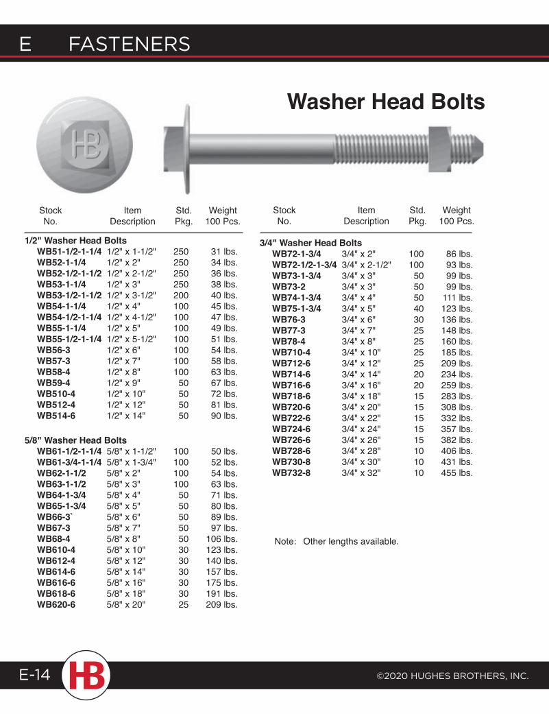
E FASTENERS
©2020 HugHES BRoTHERS, INc.E-14
Stock Item Std. Weight No. Description Pkg. 100 Pcs.
Stock Item Std. Weight No. Description Pkg. 100 Pcs.
1/2" Washer Head Bolts WB51-1/2-1-1/4 1/2" x 1-1/2" 250 31 lbs. WB52-1-1/4 1/2" x 2" 250 34 lbs. WB52-1/2-1-1/2 1/2" x 2-1/2" 250 36 lbs. WB53-1-1/4 1/2" x 3" 250 38 lbs. WB53-1/2-1-1/2 1/2" x 3-1/2" 200 40 lbs. WB54-1-1/4 1/2" x 4" 100 45 lbs. WB54-1/2-1-1/4 1/2" x 4-1/2" 100 47 lbs. WB55-1-1/4 1/2" x 5" 100 49 lbs. WB55-1/2-1-1/4 1/2" x 5-1/2" 100 51 lbs. WB56-3 1/2" x 6" 100 54 lbs. WB57-3 1/2" x 7" 100 58 lbs. WB58-4 1/2" x 8" 100 63 lbs. WB59-4 1/2" x 9" 50 67 lbs. WB510-4 1/2" x 10" 50 72 lbs. WB512-4 1/2" x 12" 50 81 lbs. WB514-6 1/2" x 14" 50 90 lbs.
5/8" Washer Head Bolts WB61-1/2-1-1/4 5/8" x 1-1/2" 100 50 lbs. WB61-3/4-1-1/4 5/8" x 1-3/4" 100 52 lbs. WB62-1-1/2 5/8" x 2" 100 54 lbs. WB63-1-1/2 5/8" x 3" 100 63 lbs. WB64-1-3/4 5/8" x 4" 50 71 lbs. WB65-1-3/4 5/8" x 5" 50 80 lbs. WB66-3` 5/8" x 6" 50 89 lbs. WB67-3 5/8" x 7" 50 97 lbs. WB68-4 5/8" x 8" 50 106 lbs. WB610-4 5/8" x 10" 30 123 lbs. WB612-4 5/8" x 12" 30 140 lbs. WB614-6 5/8" x 14" 30 157 lbs. WB616-6 5/8" x 16" 30 175 lbs. WB618-6 5/8" x 18" 30 191 lbs. WB620-6 5/8" x 20" 25 209 lbs.
3/4" Washer Head Bolts WB72-1-3/4 3/4" x 2" 100 86 lbs. WB72-1/2-1-3/4 3/4" x 2-1/2" 100 93 lbs. WB73-1-3/4 3/4" x 3" 50 99 lbs. WB73-2 3/4" x 3" 50 99 lbs. WB74-1-3/4 3/4" x 4" 50 111 lbs. WB75-1-3/4 3/4" x 5" 40 123 lbs. WB76-3 3/4" x 6" 30 136 lbs. WB77-3 3/4" x 7" 25 148 lbs. WB78-4 3/4" x 8" 25 160 lbs. WB710-4 3/4" x 10" 25 185 lbs. WB712-6 3/4" x 12" 25 209 lbs. WB714-6 3/4" x 14" 20 234 lbs. WB716-6 3/4" x 16" 20 259 lbs. WB718-6 3/4" x 18" 15 283 lbs. WB720-6 3/4" x 20" 15 308 lbs. WB722-6 3/4" x 22" 15 332 lbs. WB724-6 3/4" x 24" 15 357 lbs. WB726-6 3/4" x 26" 15 382 lbs. WB728-6 3/4" x 28" 10 406 lbs. WB730-8 3/4" x 30" 10 431 lbs. WB732-8 3/4" x 32" 10 455 lbs.
Note: Other lengths available.
Washer Head Bolts
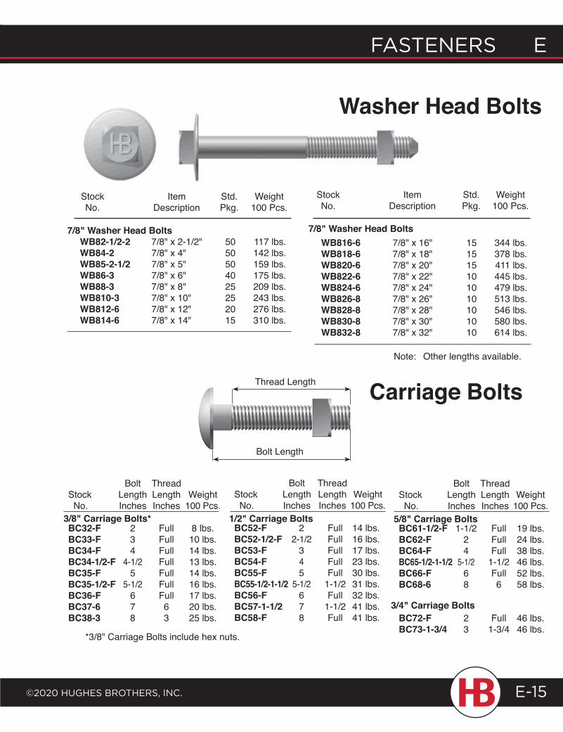
FASTENERS E
©2020 HugHES BRoTHERS, INc.
E FASTENERS
E-15
Stock Item Std. Weight No. Description Pkg. 100 Pcs.
Stock Item Std. Weight No. Description Pkg. 100 Pcs.
7/8" Washer Head Bolts WB82-1/2-2 7/8" x 2-1/2" 50 117 lbs. WB84-2 7/8" x 4" 50 142 lbs. WB85-2-1/2 7/8" x 5" 50 159 lbs. WB86-3 7/8" x 6" 40 175 lbs. WB88-3 7/8" x 8" 25 209 lbs. WB810-3 7/8" x 10" 25 243 lbs. WB812-6 7/8" x 12" 20 276 lbs. WB814-6 7/8" x 14" 15 310 lbs.
WB816-6 7/8" x 16" 15 344 lbs. WB818-6 7/8" x 18" 15 378 lbs. WB820-6 7/8" x 20" 15 411 lbs. WB822-6 7/8" x 22" 10 445 lbs. WB824-6 7/8" x 24" 10 479 lbs. WB826-8 7/8" x 26" 10 513 lbs. WB828-8 7/8" x 28" 10 546 lbs. WB830-8 7/8" x 30" 10 580 lbs. WB832-8 7/8" x 32" 10 614 lbs.
Note: Other lengths available.
7/8" Washer Head Bolts
Bolt Thread Stock Length Length Weight No. Inches Inches 100 Pcs.
BC32-F 2 Full 8 lbs.BC33-F 3 Full 10 lbs.BC34-F 4 Full 14 lbs.BC34-1/2-F 4-1/2 Full 13 lbs.BC35-F 5 Full 14 lbs.BC35-1/2-F 5-1/2 Full 16 lbs.BC36-F 6 Full 17 lbs.BC37-6 7 6 20 lbs.BC38-3 8 3 25 lbs.
3/8" Carriage Bolts*
Bolt Thread Stock Length Length Weight No. Inches Inches 100 Pcs.
BC52-F 2 Full 14 lbs.BC52-1/2-F 2-1/2 Full 16 lbs.BC53-F 3 Full 17 lbs.BC54-F 4 Full 23 lbs.BC55-F 5 Full 30 lbs.BC55-1/2-1-1/2 5-1/2 1-1/2 31 lbs.BC56-F 6 Full 32 lbs.BC57-1-1/2 7 1-1/2 41 lbs.BC58-F 8 Full 41 lbs.
1/2" Carriage Bolts
Bolt Thread Stock Length Length Weight No. Inches Inches 100 Pcs.
BC61-1/2-F 1-1/2 Full 19 lbs.BC62-F 2 Full 24 lbs.BC64-F 4 Full 38 lbs.BC65-1/2-1-1/2 5-1/2 1-1/2 46 lbs.BC66-F 6 Full 52 lbs.BC68-6 8 6 58 lbs.
BC72-F 2 Full 46 lbs.BC73-1-3/4 3 1-3/4 46 lbs.
5/8" Carriage Bolts
3/4" Carriage Bolts
Carriage Bolts
*3/8" Carriage Bolts include hex nuts.
Thread Length
Bolt Length
Washer Head Bolts
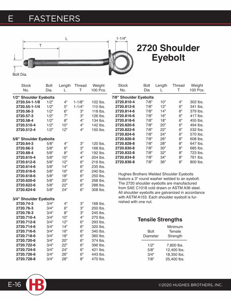
E FASTENERS
©2020 HugHES BRoTHERS, INc.E-16
2720 Shoulder Eyebolt
Hughes Brothers Welded Shoulder Eyebolts feature a 3" round washer welded to an eyebolt. The 2720 shoulder eyebolts are manufactured from SAE C1018 cold drawn or ASTM A36 steel. All shoulder eyebolts are galvanized in accordance with ASTM A153. Each shoulder eyebolt is fur-nished with one nut.
Minimum Bolt Tensile Diameter Strength
1/2" 7,800 lbs. 5/8" 12,400 lbs. 3/4" 18,350 lbs. 7/8" 25,400 lbs.
Tensile Strengths
TL
Bolt Dia.
1-1/4"
Stock Bolt Length Thread Weight No. Dia. L T 100 Pcs.
1/2" Shoulder Eyebolts 2720.54-1-1/8 1/2" 4" 1-1/8" 102 lbs. 2720.55-1-1/4 1/2" 5" 1-1/4" 110 lbs. 2720.56-3 1/2" 6" 3" 118 lbs. 2720.57-3 1/2" 7" 3" 126 lbs. 2720.58-4 1/2" 8" 4" 134 lbs. 2720.510-4 1/2" 10" 4" 142 lbs. 2720.512-4 1/2" 12" 4" 150 lbs.
5/8" Shoulder Eyebolts 2720.64-3 5/8" 4" 3" 120 lbs. 2720.66-3 5/8" 6" 3" 168 lbs. 2720.68-4 5/8" 8" 4" 192 lbs. 2720.610-4 5/8" 10" 4" 204 lbs. 2720.612-6 5/8" 12" 6" 216 lbs. 2720.614-6 5/8" 14" 6" 235 lbs. 2720.616-6 5/8" 16" 6" 240 lbs. 2720.618-6 5/8" 18" 6" 250 lbs. 2720.620-6 5/8" 20" 6" 268 lbs. 2720.622-6 5/8" 22" 6" 288 lbs. 2720.624-6 5/8" 24" 6" 308 lbs.
3/4" Shoulder Eyebolts 2720.74-3 3/4" 4" 3" 168 lbs. 2720.76-3 3/4" 6" 3" 200 lbs. 2720.78-3 3/4" 8" 3" 245 lbs. 2720.710-4 3/4" 10" 4" 270 lbs. 2720.712-6 3/4" 12" 6" 293 lbs. 2720.714-6 3/4" 14" 6" 320 lbs. 2720.716-6 3/4" 16" 6" 340 lbs. 2720.718-6 3/4" 18" 6" 360 lbs. 2720.720-6 3/4" 20" 6" 374 lbs. 2720.722-6 3/4" 22" 6" 396 lbs. 2720.724-6 3/4" 24" 6" 421 lbs. 2720.726-6 3/4" 26" 6" 443 lbs. 2720.728-8 3/4" 28" 8" 470 lbs.
Stock Bolt Length Thread Weight No. Dia L T 100 Pcs.
7/8" Shoulder Eyebolts 2720.810-4 7/8" 10" 4" 302 lbs. 2720.812-6 7/8" 12" 6" 341 lbs. 2720.814-6 7/8" 14" 6" 379 lbs. 2720.816-6 7/8" 16" 6" 417 lbs. 2720.818-6 7/8" 18" 6" 455 lbs. 2720.820-6 7/8" 20" 6" 494 lbs. 2720.822-6 7/8" 22" 6" 532 lbs. 2720.824-6 7/8" 24" 6" 570 lbs. 2720.826-8 7/8" 26" 8" 608 lbs. 2720.828-8 7/8" 28" 8" 647 lbs. 2720.830-8 7/8" 30" 8" 685 lbs. 2720.832-8 7/8" 32" 8" 723 lbs. 2720.834-8 7/8" 34" 8" 761 lbs. 2720.836-8 7/8" 36" 8" 800 lbs.
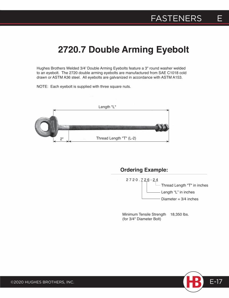
FASTENERS E
©2020 HugHES BRoTHERS, INc.
E FASTENERS
E-17
Minimum Tensile Strength 18,350 lbs.(for 3/4" Diameter Bolt)
2720.7 Double Arming Eyebolt
Hughes Brothers Welded 3/4' Double Arming Eyebolts feature a 3" round washer welded to an eyebolt. The 2720 double arming eyebolts are manufactured from SAE C1018 cold drawn or ASTM A36 steel. All eyebolts are galvanized in accordance with ASTM A153.
NOTE: Each eyebolt is supplied with three square nuts.
Ordering Example:2 7 2 0 . 7 2 6 - 2 4
Thread Length "T" in inches
Length “L” in inches
Diameter = 3/4 inches
Length "L"
Thread Length "T" (L-2)2"
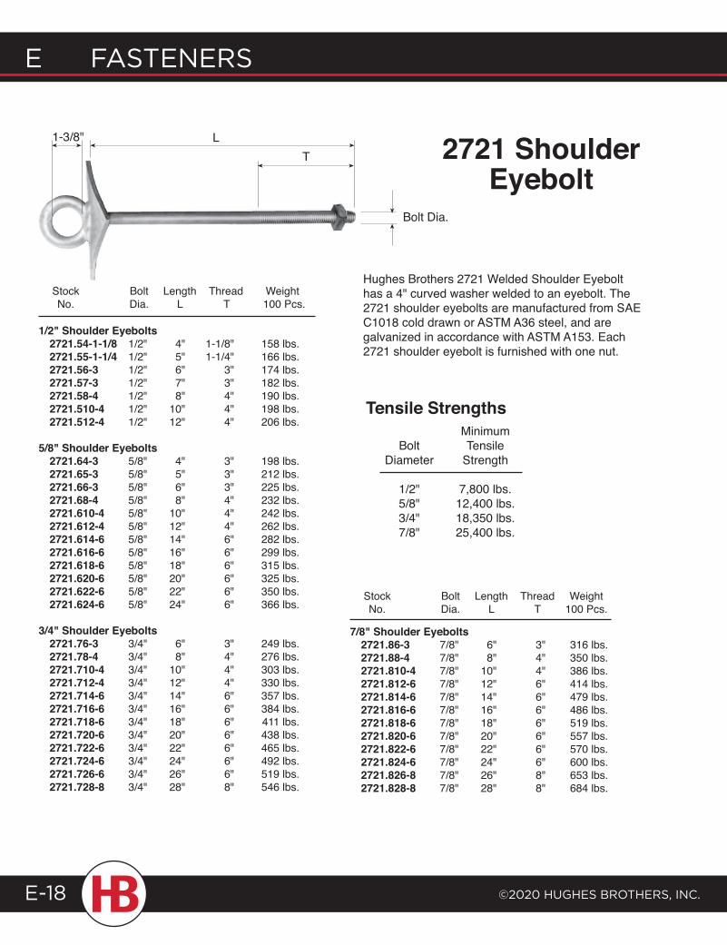
E FASTENERS
©2020 HugHES BRoTHERS, INc.E-18
2721 Shoulder Eyebolt
LT
Bolt Dia.
Hughes Brothers 2721 Welded Shoulder Eyebolt has a 4" curved washer welded to an eyebolt. The 2721 shoulder eyebolts are manufactured from SAE C1018 cold drawn or ASTM A36 steel, and are galvanized in accordance with ASTM A153. Each 2721 shoulder eyebolt is furnished with one nut.
Stock Bolt Length Thread Weight No. Dia. L T 100 Pcs.
1/2" Shoulder Eyebolts 2721.54-1-1/8 1/2" 4" 1-1/8" 158 lbs. 2721.55-1-1/4 1/2" 5" 1-1/4" 166 lbs. 2721.56-3 1/2" 6" 3" 174 lbs. 2721.57-3 1/2" 7" 3" 182 lbs. 2721.58-4 1/2" 8" 4" 190 lbs. 2721.510-4 1/2" 10" 4" 198 lbs. 2721.512-4 1/2" 12" 4" 206 lbs.
5/8" Shoulder Eyebolts 2721.64-3 5/8" 4" 3" 198 lbs. 2721.65-3 5/8" 5" 3" 212 lbs. 2721.66-3 5/8" 6" 3" 225 lbs. 2721.68-4 5/8" 8" 4" 232 lbs. 2721.610-4 5/8" 10" 4" 242 lbs. 2721.612-4 5/8" 12" 4" 262 lbs. 2721.614-6 5/8" 14" 6" 282 lbs. 2721.616-6 5/8" 16" 6" 299 lbs. 2721.618-6 5/8" 18" 6" 315 lbs. 2721.620-6 5/8" 20" 6" 325 lbs. 2721.622-6 5/8" 22" 6" 350 lbs. 2721.624-6 5/8" 24" 6" 366 lbs.
3/4" Shoulder Eyebolts 2721.76-3 3/4" 6" 3" 249 lbs. 2721.78-4 3/4" 8" 4" 276 lbs. 2721.710-4 3/4" 10" 4" 303 lbs. 2721.712-4 3/4" 12" 4" 330 lbs. 2721.714-6 3/4" 14" 6" 357 lbs. 2721.716-6 3/4" 16" 6" 384 lbs. 2721.718-6 3/4" 18" 6" 411 lbs. 2721.720-6 3/4" 20" 6" 438 lbs. 2721.722-6 3/4" 22" 6" 465 lbs. 2721.724-6 3/4" 24" 6" 492 lbs. 2721.726-6 3/4" 26" 6" 519 lbs. 2721.728-8 3/4" 28" 8" 546 lbs.
Stock Bolt Length Thread Weight No. Dia. L T 100 Pcs.
Minimum Bolt Tensile Diameter Strength
1/2" 7,800 lbs. 5/8" 12,400 lbs. 3/4" 18,350 lbs. 7/8" 25,400 lbs.
Tensile Strengths
1-3/8"
7/8" Shoulder Eyebolts 2721.86-3 7/8" 6" 3" 316 lbs. 2721.88-4 7/8" 8" 4" 350 lbs. 2721.810-4 7/8" 10" 4" 386 lbs. 2721.812-6 7/8" 12" 6" 414 lbs. 2721.814-6 7/8" 14" 6" 479 lbs. 2721.816-6 7/8" 16" 6" 486 lbs. 2721.818-6 7/8" 18" 6" 519 lbs. 2721.820-6 7/8" 20" 6" 557 lbs. 2721.822-6 7/8" 22" 6" 570 lbs. 2721.824-6 7/8" 24" 6" 600 lbs. 2721.826-8 7/8" 26" 8" 653 lbs. 2721.828-8 7/8" 28" 8" 684 lbs.
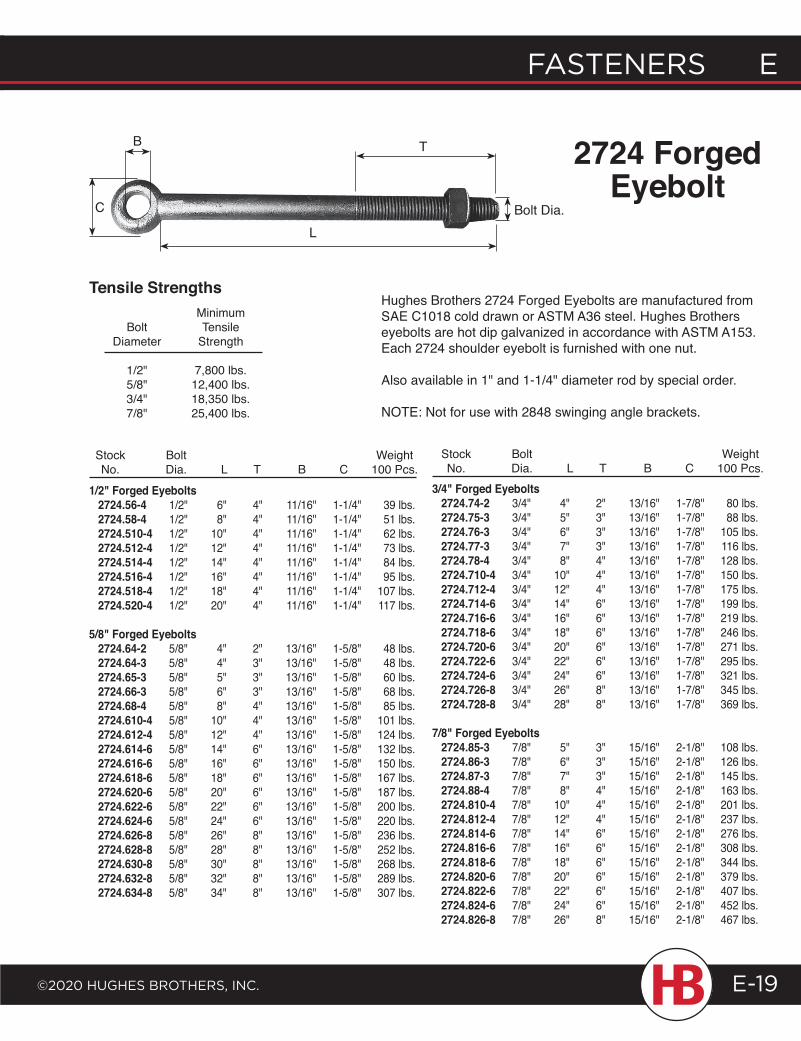
FASTENERS E
©2020 HugHES BRoTHERS, INc.
E FASTENERS
E-19
C
B T
Bolt Dia.
Tensile Strengths
1/2" Forged Eyebolts 2724.56-4 1/2" 6" 4" 11/16" 1-1/4" 39 lbs. 2724.58-4 1/2" 8" 4" 11/16" 1-1/4" 51 lbs. 2724.510-4 1/2" 10" 4" 11/16" 1-1/4" 62 lbs. 2724.512-4 1/2" 12" 4" 11/16" 1-1/4" 73 lbs. 2724.514-4 1/2" 14" 4" 11/16" 1-1/4" 84 lbs. 2724.516-4 1/2" 16" 4" 11/16" 1-1/4" 95 lbs. 2724.518-4 1/2" 18" 4" 11/16" 1-1/4" 107 lbs. 2724.520-4 1/2" 20" 4" 11/16" 1-1/4" 117 lbs.
5/8" Forged Eyebolts 2724.64-2 5/8" 4" 2" 13/16" 1-5/8" 48 lbs. 2724.64-3 5/8" 4" 3" 13/16" 1-5/8" 48 lbs. 2724.65-3 5/8" 5" 3" 13/16" 1-5/8" 60 lbs. 2724.66-3 5/8" 6" 3" 13/16" 1-5/8" 68 lbs. 2724.68-4 5/8" 8" 4" 13/16" 1-5/8" 85 lbs. 2724.610-4 5/8" 10" 4" 13/16" 1-5/8" 101 lbs. 2724.612-4 5/8" 12" 4" 13/16" 1-5/8" 124 lbs. 2724.614-6 5/8" 14" 6" 13/16" 1-5/8" 132 lbs. 2724.616-6 5/8" 16" 6" 13/16" 1-5/8" 150 lbs. 2724.618-6 5/8" 18" 6" 13/16" 1-5/8" 167 lbs. 2724.620-6 5/8" 20" 6" 13/16" 1-5/8" 187 lbs. 2724.622-6 5/8" 22" 6" 13/16" 1-5/8" 200 lbs. 2724.624-6 5/8" 24" 6" 13/16" 1-5/8" 220 lbs. 2724.626-8 5/8" 26" 8" 13/16" 1-5/8" 236 lbs. 2724.628-8 5/8" 28" 8" 13/16" 1-5/8" 252 lbs. 2724.630-8 5/8" 30" 8" 13/16" 1-5/8" 268 lbs. 2724.632-8 5/8" 32" 8" 13/16" 1-5/8" 289 lbs. 2724.634-8 5/8" 34" 8" 13/16" 1-5/8" 307 lbs.
3/4" Forged Eyebolts 2724.74-2 3/4" 4" 2" 13/16" 1-7/8" 80 lbs. 2724.75-3 3/4" 5" 3" 13/16" 1-7/8" 88 lbs. 2724.76-3 3/4" 6" 3" 13/16" 1-7/8" 105 lbs. 2724.77-3 3/4" 7" 3" 13/16" 1-7/8" 116 lbs. 2724.78-4 3/4" 8" 4" 13/16" 1-7/8" 128 lbs. 2724.710-4 3/4" 10" 4" 13/16" 1-7/8" 150 lbs. 2724.712-4 3/4" 12" 4" 13/16" 1-7/8" 175 lbs. 2724.714-6 3/4" 14" 6" 13/16" 1-7/8" 199 lbs. 2724.716-6 3/4" 16" 6" 13/16" 1-7/8" 219 lbs. 2724.718-6 3/4" 18" 6" 13/16" 1-7/8" 246 lbs. 2724.720-6 3/4" 20" 6" 13/16" 1-7/8" 271 lbs. 2724.722-6 3/4" 22" 6" 13/16" 1-7/8" 295 lbs. 2724.724-6 3/4" 24" 6" 13/16" 1-7/8" 321 lbs. 2724.726-8 3/4" 26" 8" 13/16" 1-7/8" 345 lbs. 2724.728-8 3/4" 28" 8" 13/16" 1-7/8" 369 lbs.
7/8" Forged Eyebolts 2724.85-3 7/8" 5" 3" 15/16" 2-1/8" 108 lbs. 2724.86-3 7/8" 6" 3" 15/16" 2-1/8" 126 lbs. 2724.87-3 7/8" 7" 3" 15/16" 2-1/8" 145 lbs. 2724.88-4 7/8" 8" 4" 15/16" 2-1/8" 163 lbs. 2724.810-4 7/8" 10" 4" 15/16" 2-1/8" 201 lbs. 2724.812-4 7/8" 12" 4" 15/16" 2-1/8" 237 lbs. 2724.814-6 7/8" 14" 6" 15/16" 2-1/8" 276 lbs. 2724.816-6 7/8" 16" 6" 15/16" 2-1/8" 308 lbs. 2724.818-6 7/8" 18" 6" 15/16" 2-1/8" 344 lbs. 2724.820-6 7/8" 20" 6" 15/16" 2-1/8" 379 lbs. 2724.822-6 7/8" 22" 6" 15/16" 2-1/8" 407 lbs. 2724.824-6 7/8" 24" 6" 15/16" 2-1/8" 452 lbs. 2724.826-8 7/8" 26" 8" 15/16" 2-1/8" 467 lbs.
Stock Bolt Weight No. Dia. L T B C 100 Pcs.
Stock Bolt Weight No. Dia. L T B C 100 Pcs.
Minimum Bolt Tensile Diameter Strength
1/2" 7,800 lbs. 5/8" 12,400 lbs. 3/4" 18,350 lbs. 7/8" 25,400 lbs.
Hughes Brothers 2724 Forged Eyebolts are manufactured from SAE C1018 cold drawn or ASTM A36 steel. Hughes Brothers eyebolts are hot dip galvanized in accordance with ASTM A153. Each 2724 shoulder eyebolt is furnished with one nut.
Also available in 1" and 1-1/4" diameter rod by special order.
NOTE: Not for use with 2848 swinging angle brackets.
2724 Forged Eyebolt
L
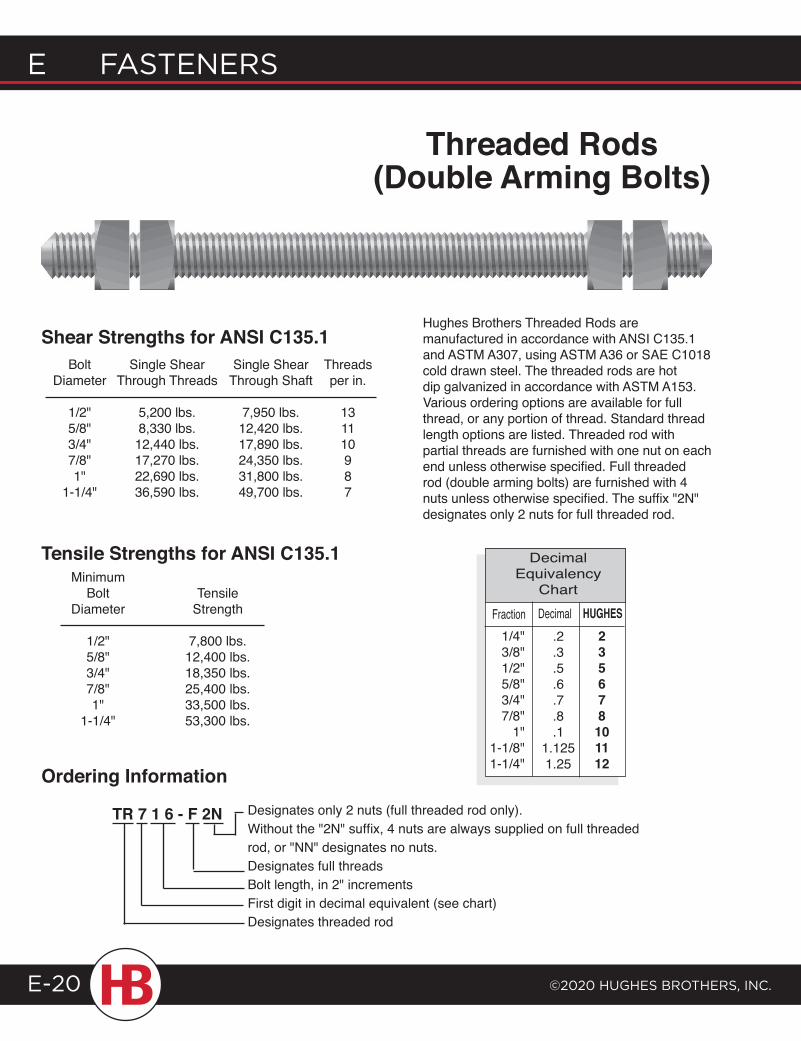
E FASTENERS
©2020 HugHES BRoTHERS, INc.E-20
Designates only 2 nuts (full threaded rod only). Without the "2N" suffix, 4 nuts are always supplied on full threaded rod, or "NN" designates no nuts.
Designates full threads Bolt length, in 2" increments First digit in decimal equivalent (see chart) Designates threaded rod
Threaded Rods (Double Arming Bolts)
Ordering Information
TR 7 1 6 - F 2N
Hughes Brothers Threaded Rods are manufactured in accordance with ANSI C135.1 and ASTM A307, using ASTM A36 or SAE C1018 cold drawn steel. The threaded rods are hot dip galvanized in accordance with ASTM A153. Various ordering options are available for full thread, or any portion of thread. Standard thread length options are listed. Threaded rod with partial threads are furnished with one nut on each end unless otherwise specified. Full threaded rod (double arming bolts) are furnished with 4 nuts unless otherwise specified. The suffix "2N" designates only 2 nuts for full threaded rod.
Bolt Single Shear Single Shear Threads Diameter Through Threads Through Shaft per in.
1/2" 5,200 lbs. 7,950 lbs. 13 5/8" 8,330 lbs. 12,420 lbs. 11 3/4" 12,440 lbs. 17,890 lbs. 10 7/8" 17,270 lbs. 24,350 lbs. 9 1" 22,690 lbs. 31,800 lbs. 8 1-1/4" 36,590 lbs. 49,700 lbs. 7
Minimum Bolt Tensile Diameter Strength
1/2" 7,800 lbs. 5/8" 12,400 lbs. 3/4" 18,350 lbs. 7/8" 25,400 lbs. 1" 33,500 lbs. 1-1/4" 53,300 lbs.
Tensile Strengths for ANSI C135.1
DecimalFraction.2.3.5.6.7.8.1
1.1251.25
235678101112
Decimal Equivalency
ChartHUGHES
1/4"3/8"1/2"5/8"3/4"7/8"
1"1-1/8"1-1/4"
Shear Strengths for ANSI C135.1
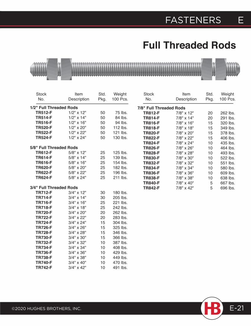
FASTENERS E
©2020 HugHES BRoTHERS, INc.
E FASTENERS
E-21
Full Threaded Rods
1/2" Full Threaded Rods TR512-F 1/2" x 12" 50 75 lbs. TR514-F 1/2" x 14" 50 84 lbs. TR516-F 1/2" x 16" 50 94 lbs. TR520-F 1/2" x 20" 50 112 lbs. TR522-F 1/2" x 22" 50 121 lbs. TR524-F 1/2" x 24" 50 130 lbs.
5/8" Full Threaded Rods TR612-F 5/8" x 12" 25 125 lbs. TR614-F 5/8" x 14" 25 139 lbs. TR616-F 5/8" x 16" 25 154 lbs. TR620-F 5/8" x 20" 25 182 lbs. TR622-F 5/8" x 22" 25 196 lbs. TR624-F 5/8" x 24" 25 211 lbs.
3/4" Full Threaded Rods TR712-F 3/4" x 12" 30 180 lbs. TR714-F 3/4" x 14" 30 205 lbs. TR716-F 3/4" x 16" 25 221 lbs. TR718-F 3/4" x 18" 25 242 lbs. TR720-F 3/4" x 20" 20 262 lbs. TR722-F 3/4" x 22" 20 283 lbs. TR724-F 3/4" x 24" 15 304 lbs. TR726-F 3/4" x 26" 15 325 lbs. TR728-F 3/4" x 28" 15 346 lbs. TR730-F 3/4" x 30" 15 366 lbs. TR732-F 3/4" x 32" 10 387 lbs. TR734-F 3/4" x 34" 10 408 lbs. TR736-F 3/4" x 36" 10 429 lbs. TR738-F 3/4" x 38" 10 449 lbs. TR740-F 3/4" x 40" 10 470 lbs. TR742-F 3/4" x 42" 10 491 lbs.
7/8" Full Threaded Rods TR812-F 7/8" x 12" 20 262 lbs. TR814-F 7/8" x 14" 20 291 lbs. TR816-F 7/8" x 16" 15 320 lbs. TR818-F 7/8" x 18" 15 349 lbs. TR820-F 7/8" x 20" 15 378 lbs. TR822-F 7/8" x 22" 15 406 lbs. TR824-F 7/8" x 24" 10 435 lbs. TR826-F 7/8" x 26" 10 464 lbs. TR828-F 7/8" x 28" 10 493 lbs. TR830-F 7/8" x 30" 10 522 lbs. TR832-F 7/8" x 32" 10 551 lbs. TR834-F 7/8" x 34" 10 580 lbs. TR836-F 7/8" x 36" 10 609 lbs. TR838-F 7/8" x 38" 10 638 lbs. TR840-F 7/8" x 40" 5 667 lbs. TR842-F 7/8" x 42" 5 696 lbs.
Stock Item Std. Weight No. Description Pkg. 100 Pcs.
Stock Item Std. Weight No. Description Pkg. 100 Pcs.
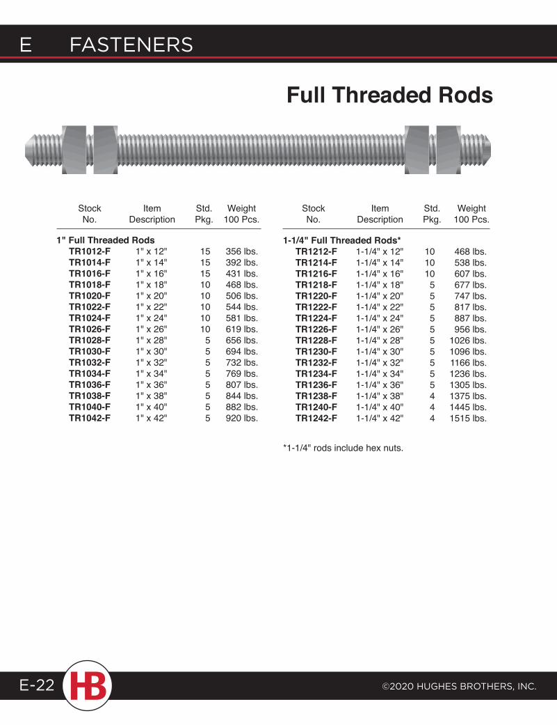
E FASTENERS
©2020 HugHES BRoTHERS, INc.E-22
1-1/4" Full Threaded Rods* TR1212-F 1-1/4" x 12" 10 468 lbs. TR1214-F 1-1/4" x 14" 10 538 lbs. TR1216-F 1-1/4" x 16" 10 607 lbs. TR1218-F 1-1/4" x 18" 5 677 lbs. TR1220-F 1-1/4" x 20" 5 747 lbs. TR1222-F 1-1/4" x 22" 5 817 lbs. TR1224-F 1-1/4" x 24" 5 887 lbs. TR1226-F 1-1/4" x 26" 5 956 lbs. TR1228-F 1-1/4" x 28" 5 1026 lbs. TR1230-F 1-1/4" x 30" 5 1096 lbs. TR1232-F 1-1/4" x 32" 5 1166 lbs. TR1234-F 1-1/4" x 34" 5 1236 lbs. TR1236-F 1-1/4" x 36" 5 1305 lbs. TR1238-F 1-1/4" x 38" 4 1375 lbs. TR1240-F 1-1/4" x 40" 4 1445 lbs. TR1242-F 1-1/4" x 42" 4 1515 lbs.
*1-1/4" rods include hex nuts.
Stock Item Std. Weight No. Description Pkg. 100 Pcs.
Stock Item Std. Weight No. Description Pkg. 100 Pcs.
1" Full Threaded Rods TR1012-F 1" x 12" 15 356 lbs. TR1014-F 1" x 14" 15 392 lbs. TR1016-F 1" x 16" 15 431 lbs. TR1018-F 1" x 18" 10 468 lbs. TR1020-F 1" x 20" 10 506 lbs. TR1022-F 1" x 22" 10 544 lbs. TR1024-F 1" x 24" 10 581 lbs. TR1026-F 1" x 26" 10 619 lbs. TR1028-F 1" x 28" 5 656 lbs. TR1030-F 1" x 30" 5 694 lbs. TR1032-F 1" x 32" 5 732 lbs. TR1034-F 1" x 34" 5 769 lbs. TR1036-F 1" x 36" 5 807 lbs. TR1038-F 1" x 38" 5 844 lbs. TR1040-F 1" x 40" 5 882 lbs. TR1042-F 1" x 42" 5 920 lbs.
Full Threaded Rods
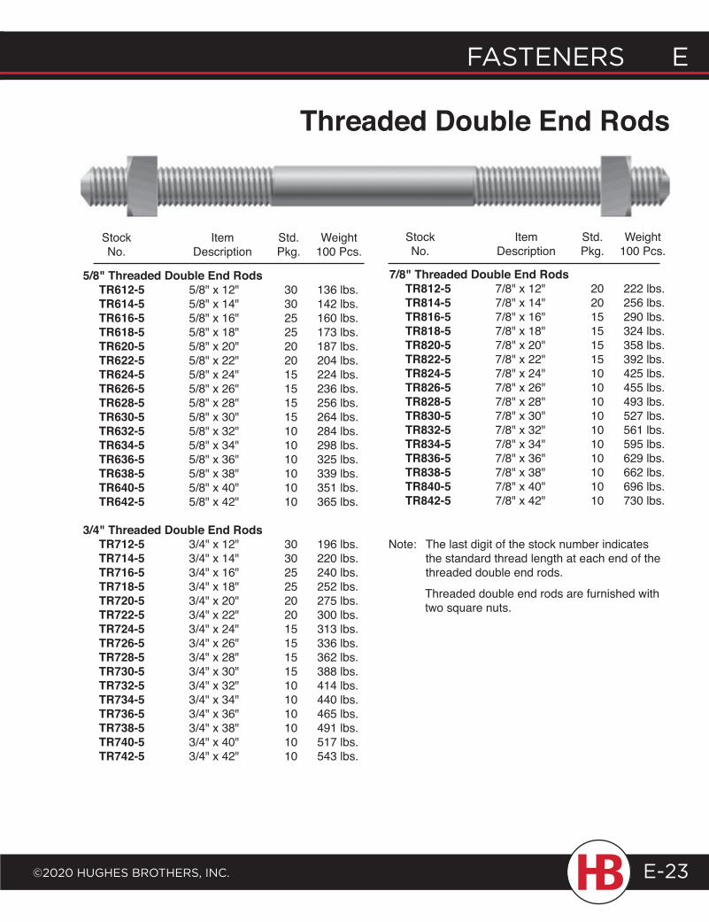
FASTENERS E
©2020 HugHES BRoTHERS, INc.
E FASTENERS
E-23
Threaded Double End Rods
Stock Item Std. Weight No. Description Pkg. 100 Pcs.
Stock Item Std. Weight No. Description Pkg. 100 Pcs.
5/8" Threaded Double End Rods TR612-5 5/8" x 12" 30 136 lbs. TR614-5 5/8" x 14" 30 142 lbs. TR616-5 5/8" x 16" 25 160 lbs. TR618-5 5/8" x 18" 25 173 lbs. TR620-5 5/8" x 20" 20 187 lbs. TR622-5 5/8" x 22" 20 204 lbs. TR624-5 5/8" x 24" 15 224 lbs. TR626-5 5/8" x 26" 15 236 lbs. TR628-5 5/8" x 28" 15 256 lbs. TR630-5 5/8" x 30" 15 264 lbs. TR632-5 5/8" x 32" 10 284 lbs. TR634-5 5/8" x 34" 10 298 lbs. TR636-5 5/8" x 36" 10 325 lbs. TR638-5 5/8" x 38" 10 339 lbs. TR640-5 5/8" x 40" 10 351 lbs. TR642-5 5/8" x 42" 10 365 lbs.
3/4" Threaded Double End Rods TR712-5 3/4" x 12" 30 196 lbs. TR714-5 3/4" x 14" 30 220 lbs. TR716-5 3/4" x 16" 25 240 lbs. TR718-5 3/4" x 18" 25 252 lbs. TR720-5 3/4" x 20" 20 275 lbs. TR722-5 3/4" x 22" 20 300 lbs. TR724-5 3/4" x 24" 15 313 lbs. TR726-5 3/4" x 26" 15 336 lbs. TR728-5 3/4" x 28" 15 362 lbs. TR730-5 3/4" x 30" 15 388 lbs. TR732-5 3/4" x 32" 10 414 lbs. TR734-5 3/4" x 34" 10 440 lbs. TR736-5 3/4" x 36" 10 465 lbs. TR738-5 3/4" x 38" 10 491 lbs. TR740-5 3/4" x 40" 10 517 lbs. TR742-5 3/4" x 42" 10 543 lbs.
7/8" Threaded Double End Rods TR812-5 7/8" x 12" 20 222 lbs. TR814-5 7/8" x 14" 20 256 lbs. TR816-5 7/8" x 16" 15 290 lbs. TR818-5 7/8" x 18" 15 324 lbs. TR820-5 7/8" x 20" 15 358 lbs. TR822-5 7/8" x 22" 15 392 lbs. TR824-5 7/8" x 24" 10 425 lbs. TR826-5 7/8" x 26" 10 455 lbs. TR828-5 7/8" x 28" 10 493 lbs. TR830-5 7/8" x 30" 10 527 lbs. TR832-5 7/8" x 32" 10 561 lbs. TR834-5 7/8" x 34" 10 595 lbs. TR836-5 7/8" x 36" 10 629 lbs. TR838-5 7/8" x 38" 10 662 lbs. TR840-5 7/8" x 40" 10 696 lbs. TR842-5 7/8" x 42" 10 730 lbs.
Note: The last digit of the stock number indicates the standard thread length at each end of the threaded double end rods.
Threaded double end rods are furnished with two square nuts.
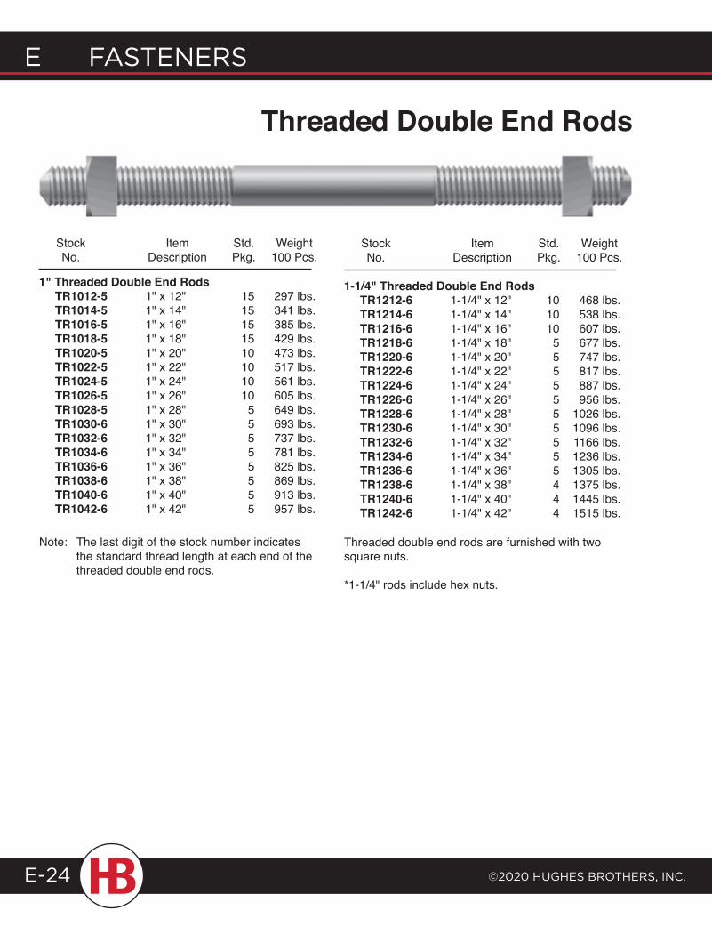
E FASTENERS
©2020 HugHES BRoTHERS, INc.E-24
Threaded Double End Rods
Stock Item Std. Weight No. Description Pkg. 100 Pcs.
1" Threaded Double End Rods TR1012-5 1" x 12" 15 297 lbs. TR1014-5 1" x 14" 15 341 lbs. TR1016-5 1" x 16" 15 385 lbs. TR1018-5 1" x 18" 15 429 lbs. TR1020-5 1" x 20" 10 473 lbs. TR1022-5 1" x 22" 10 517 lbs. TR1024-5 1" x 24" 10 561 lbs. TR1026-5 1" x 26" 10 605 lbs. TR1028-5 1" x 28" 5 649 lbs. TR1030-6 1" x 30" 5 693 lbs. TR1032-6 1" x 32" 5 737 lbs. TR1034-6 1" x 34" 5 781 lbs. TR1036-6 1" x 36" 5 825 lbs. TR1038-6 1" x 38" 5 869 lbs. TR1040-6 1" x 40" 5 913 lbs. TR1042-6 1" x 42" 5 957 lbs.
Stock Item Std. Weight No. Description Pkg. 100 Pcs.
1-1/4" Threaded Double End Rods TR1212-6 1-1/4" x 12" 10 468 lbs. TR1214-6 1-1/4" x 14" 10 538 lbs. TR1216-6 1-1/4" x 16" 10 607 lbs. TR1218-6 1-1/4" x 18" 5 677 lbs. TR1220-6 1-1/4" x 20" 5 747 lbs. TR1222-6 1-1/4" x 22" 5 817 lbs. TR1224-6 1-1/4" x 24" 5 887 lbs. TR1226-6 1-1/4" x 26" 5 956 lbs. TR1228-6 1-1/4" x 28" 5 1026 lbs. TR1230-6 1-1/4" x 30" 5 1096 lbs. TR1232-6 1-1/4" x 32" 5 1166 lbs. TR1234-6 1-1/4" x 34" 5 1236 lbs. TR1236-6 1-1/4" x 36" 5 1305 lbs. TR1238-6 1-1/4" x 38" 4 1375 lbs. TR1240-6 1-1/4" x 40" 4 1445 lbs. TR1242-6 1-1/4" x 42" 4 1515 lbs.
Note: The last digit of the stock number indicates the standard thread length at each end of the threaded double end rods.
Threaded double end rods are furnished with two square nuts.
*1-1/4" rods include hex nuts.
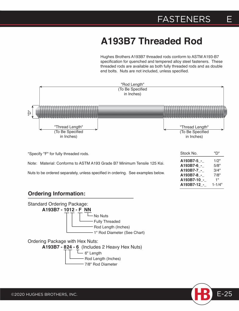
"Thread Length"(To Be Specified
in Inches)
"Thread Length"(To Be Specified
in Inches)
"Rod Length"(To Be Specified
in Inches)
FASTENERS E
©2020 HugHES BRoTHERS, INc.
E FASTENERS
E-25
A193B7-5_-_ 1/2"A193B7-6_-_ 5/8"A193B7-7_-_ 3/4"A193B7-8_-_ 7/8"A193B7-10_-_ 1"A193B7-12_-_ 1-1/4"
Stock No. "D"
A193B7 Threaded Rod"D
"
Ordering Information:
Standard Ordering Package: A193B7 - 1012 - F NN
No NutsFully ThreadedRod Length (Inches) 1" Rod Diameter (See Chart)
Ordering Package with Hex Nuts: A193B7 - 824 - 6 (Includes 2 Heavy Hex Nuts)
6" LengthRod Length (Inches)7/8" Rod Diameter
*Specify "F" for fully threaded rods.
Note: Material: Conforms to ASTM A193 Grade B7 Minimum Tensile 125 Ksi.
Nuts to be ordered separately, unless specified in ordering. See examples below.
Hughes Brothers A193B7 threaded rods conform to ASTM A193-B7 specification for quenched and tempered alloy steel fasteners. These threaded rods are available as both fully threaded rods and as double end bolts. Nuts are not included, unless specified.
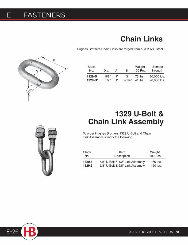
E FASTENERS
©2020 HugHES BRoTHERS, INc.E-26
A
B
Dia.
Hughes Brothers Chain Links are forged from ASTM A36 steel.
Chain Links
1329-B 5/8" 1" 3" 73 lbs. 30,000 lbs.1329-B1 1/2" 1" 2-1/4" 41 lbs. 20,000 lbs.
Stock Weight Ultimate No. Dia. A B 100 Pcs. Strength
1329.5 5/8" U-Bolt & 1/2" Link Assembly 160 lbs.1329.6 5/8" U-Bolt & 5/8" Link Assembly 190 lbs.
Stock Item Weight No. Description 100 Pcs.
To order Hughes Brothers 1329 U-Bolt and Chain Link Assembly, specify the following:
1329 U-Bolt & Chain Link Assembly
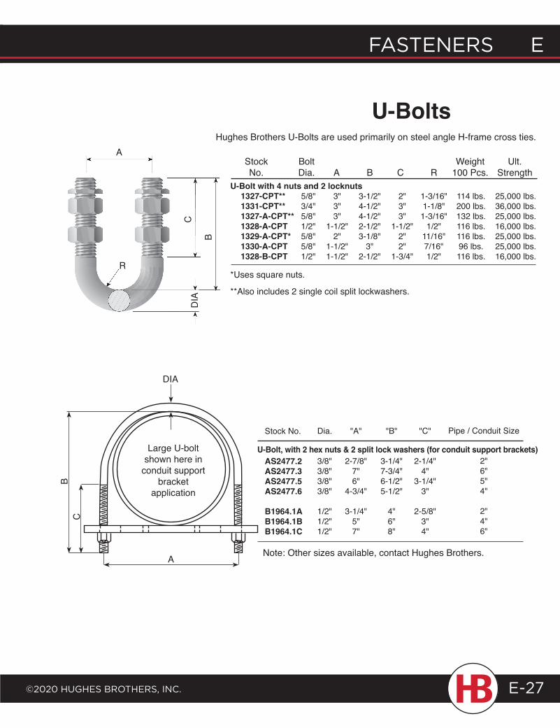
FASTENERS E
©2020 HugHES BRoTHERS, INc.
E FASTENERS
E-27
Hughes Brothers U-Bolts are used primarily on steel angle H-frame cross ties.
U-Bolts
U-Bolt with 4 nuts and 2 locknuts 1327-CPT** 5/8" 3" 3-1/2" 2" 1-3/16" 114 lbs. 25,000 lbs. 1331-CPT** 3/4" 3" 4-1/2" 3" 1-1/8" 200 lbs. 36,000 lbs. 1327-A-CPT** 5/8" 3" 4-1/2" 3" 1-3/16" 132 lbs. 25,000 lbs. 1328-A-CPT 1/2" 1-1/2" 2-1/2" 1-1/2" 1/2" 116 lbs. 16,000 lbs. 1329-A-CPT* 5/8" 2" 3-1/8" 2" 11/16" 116 lbs. 25,000 lbs. 1330-A-CPT 5/8" 1-1/2" 3" 2" 7/16" 96 lbs. 25,000 lbs. 1328-B-CPT 1/2" 1-1/2" 2-1/2" 1-3/4" 1/2" 116 lbs. 16,000 lbs. *Uses square nuts.
**Also includes 2 single coil split lockwashers.
Stock Bolt Weight Ult. No. Dia. A B C R 100 Pcs. Strength
A
C
BD
IA
R
Large U-bolt shown here in
conduit support bracket
application
Stock No.
AS2477.2AS2477.3AS2477.5AS2477.6
B1964.1AB1964.1BB1964.1C
Dia.
3/8"3/8"3/8"3/8"
1/2"1/2"1/2"
"A"
2-7/8"7"6"
4-3/4"
3-1/4"5"7"
"B"
3-1/4"7-3/4"6-1/2"5-1/2"
4"6"8"
"C"
2-1/4"4"
3-1/4"3"
2-5/8"3"4"
Pipe / Conduit Size
2"6"5"4"
2"4"6"
U-Bolt, with 2 hex nuts & 2 split lock washers (for conduit support brackets)
C
A
DIA
B
Note: Other sizes available, contact Hughes Brothers.
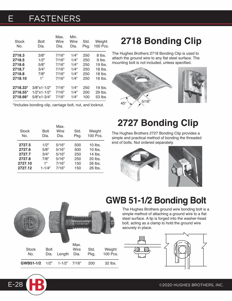
E FASTENERS
©2020 HugHES BRoTHERS, INc.E-28
*Includes bonding clip, carriage bolt, nut, and locknut.
Max. Min. Stock Bolt Wire Wire Std. Weight No. Dia. Dia. Dia. Pkg. 100 Pcs.
2718.3 3/8" 7/16" 1/4" 250 8 lbs.2718.5 1/2" 7/16" 1/4" 250 9 lbs.2718.6 5/8" 7/16" 1/4" 250 19 lbs.2718.7 3/4" 7/16" 1/4" 250 18 lbs.2718.8 7/8" 7/16" 1/4" 250 18 lbs.2718.10 1" 7/16" 1/4" 250 16 lbs.
2718.33* 3/8"x1-1/2" 7/16" 1/4" 250 19 lbs.2718.55* 1/2"x1-1/2" 7/16" 1/4" 200 29 lbs.2718.66* 5/8"x1-3/4" 7/16" 1/4" 100 53 lbs.
Max. Stock Bolt Wire Std. Weight No. Dia. Dia. Pkg. 100 Pcs.
2727.5 1/2" 5/16" 500 10 lbs. 2727.6 5/8" 5/16" 500 10 lbs. 2727.7 3/4" 5/16" 250 14 lbs. 2727.8 7/8" 5/16" 250 20 lbs. 2727.10 1" 7/16" 150 26 lbs. 2727.12 1-1/4" 7/16" 150 26 lbs.
2718 Bonding ClipThe Hughes Brothers 2718 Bonding Clip is used to attach the ground wire to any flat steel surface. The mounting bolt is not included, unless specified.
2727 Bonding Clip
The Hughes Brothers ground wire bonding bolt is a simple method of attaching a ground wire to a flat steel surface. A lip is forged into the washer-head bolt, acting as a clamp to hold the ground wire securely in place.
The Hughes Brothers 2727 Bonding Clip provides a simple and practical method of bonding the threaded end of bolts. Nut ordered separately.
5/16"45°
GWB 51-1/2 Bonding Bolt
Max. Stock Bolt Wire Std. Weight No. Dia. Length Dia. Pkg. 100 Pcs.
GWB51-1/2 1/2" 1-1/2" 7/16" 200 32 lbs.
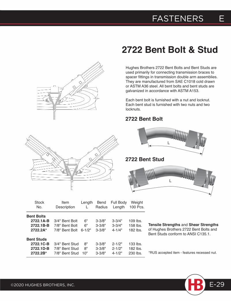
FASTENERS E
©2020 HugHES BRoTHERS, INc.
E FASTENERS
E-29
2722 Bent Bolt & StudHughes Brothers 2722 Bent Bolts and Bent Studs are used primarily for connecting transmission braces to spacer fittings in transmission double arm assemblies. They are manufactured from SAE C1018 cold drawn or ASTM A36 steel. All bent bolts and bent studs are galvanized in accordance with ASTM A153.
Each bent bolt is furnished with a nut and locknut. Each bent stud is furnished with two nuts and two locknuts.
2722 Bent Bolt
L
2722 Bent Stud
L
Stock Item Length Bend Full Body Weight No. Description L Radius Length 100 Pcs.
Bent Bolts 2722.1A-B 3/4" Bent Bolt 6" 3-3/8" 3-3/4" 109 lbs. 2722.1B-B 7/8" Bent Bolt 6" 3-3/8" 3-3/4" 158 lbs. 2722.2A* 7/8" Bent Bolt 6-1/2" 3-3/8" 4-1/4" 182 lbs. Bent Studs 2722.1C-B 3/4" Bent Stud 8" 3-3/8" 2-1/2" 133 lbs. 2722.1D-B 7/8" Bent Stud 8" 3-3/8" 2-1/2" 182 lbs. 2722.2B* 7/8" Bent Stud 10" 3-3/8" 4-1/2" 230 lbs.
Tensile Strengths and Shear Strengths of Hughes Brothers 2722 Bent Bolts and Bent Studs conform to ANSI C135.1.
*RUS accepted item - features recessed nut.
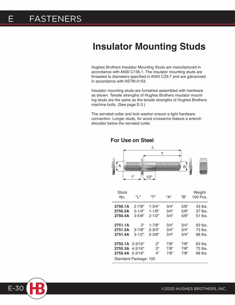
E FASTENERS
©2020 HugHES BRoTHERS, INc.E-30
Hughes Brothers Insulator Mounting Studs are manufactured in accordance with ANSI C135.1. The insulator mounting studs are threaded to diameters specified in ANSI CZ9.7 and are galvanized in accordance with ASTM A153.
Insulator mounting studs are furnished assembled with hardware as shown. Tensile strengths of Hughes Brothers insulator mount-ing studs are the same as the tensile strengths of Hughes Brothers machine bolts. (See page E-3.)
The serrated collar and lock washer ensure a tight hardware connection. Longer studs, for wood crossarms feature a wrench shoulder below the serrated collar.
Insulator Mounting Studs
Stock Weight No. "L" "T" "A" "B" 100 Pcs.
2750.1A 2-7/8" 1-3/4" 3/4" 5/8" 43 lbs. 2750.2A 2-1/4" 1-1/8" 3/4" 5/8" 37 lbs. 2750.4A 3-5/8" 2-1/2" 3/4" 5/8" 51 lbs.
2751.1A 3" 1-7/8" 3/4" 3/4" 63 lbs. 2751.3A 3-7/8" 2-3/4" 3/4" 3/4" 73 lbs. 2751.4A 3-1/2" 2-3/8" 3/4" 3/4" 68 lbs.
2755.1A 3-3/16" 2" 7/8" 7/8" 63 lbs. 2755.3A 4-3/16" 3" 7/8" 7/8" 73 lbs. 2755.4A 5-3/16" 4" 7/8" 7/8" 68 lbs. Standard Package: 100
T
B
L
1"
A
For Use on Steel
1/2"
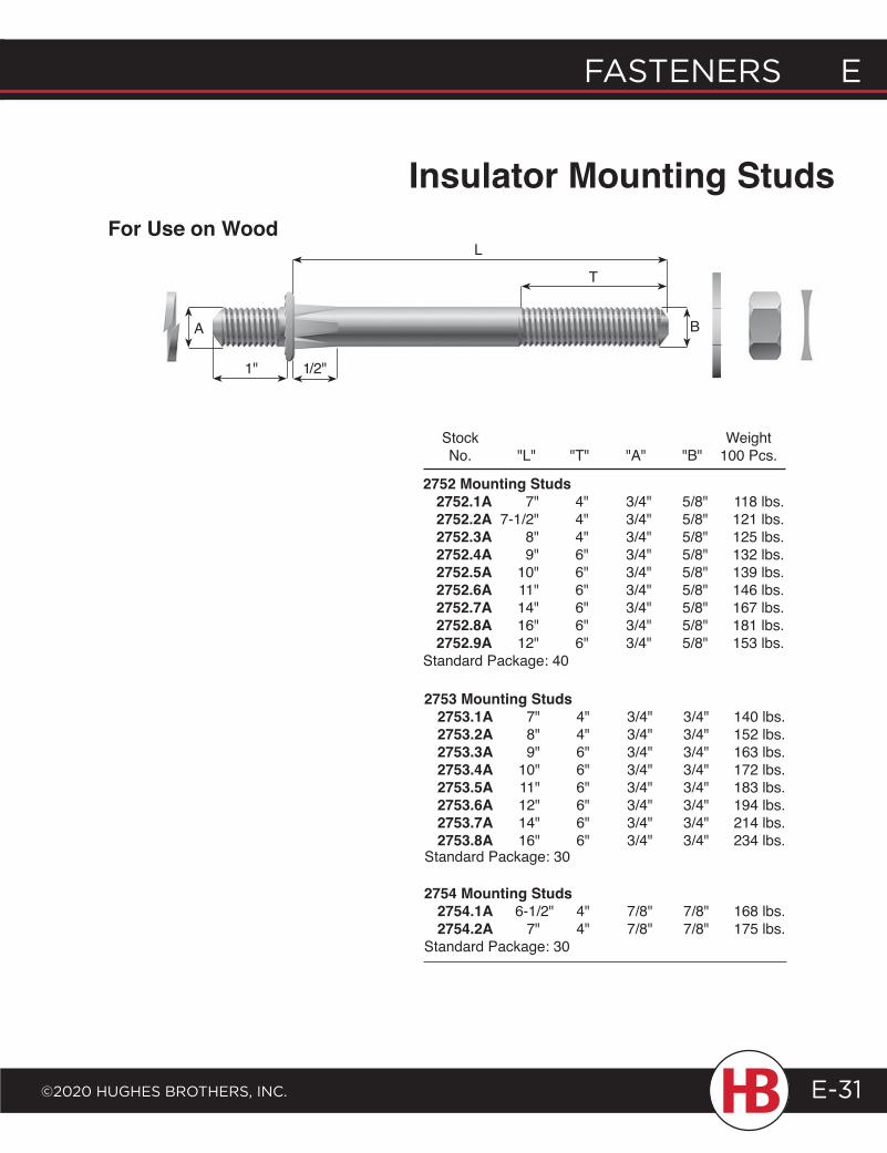
FASTENERS E
©2020 HugHES BRoTHERS, INc.
E FASTENERS
E-31
For Use on WoodL
T
BA
1/2"1"
Insulator Mounting Studs
Stock Weight No. "L" "T" "A" "B" 100 Pcs.
2752 Mounting Studs 2752.1A 7" 4" 3/4" 5/8" 118 lbs. 2752.2A 7-1/2" 4" 3/4" 5/8" 121 lbs. 2752.3A 8" 4" 3/4" 5/8" 125 lbs. 2752.4A 9" 6" 3/4" 5/8" 132 lbs. 2752.5A 10" 6" 3/4" 5/8" 139 lbs. 2752.6A 11" 6" 3/4" 5/8" 146 lbs. 2752.7A 14" 6" 3/4" 5/8" 167 lbs. 2752.8A 16" 6" 3/4" 5/8" 181 lbs. 2752.9A 12" 6" 3/4" 5/8" 153 lbs.Standard Package: 40
2753 Mounting Studs 2753.1A 7" 4" 3/4" 3/4" 140 lbs. 2753.2A 8" 4" 3/4" 3/4" 152 lbs. 2753.3A 9" 6" 3/4" 3/4" 163 lbs. 2753.4A 10" 6" 3/4" 3/4" 172 lbs. 2753.5A 11" 6" 3/4" 3/4" 183 lbs. 2753.6A 12" 6" 3/4" 3/4" 194 lbs. 2753.7A 14" 6" 3/4" 3/4" 214 lbs. 2753.8A 16" 6" 3/4" 3/4" 234 lbs.
2754 Mounting Studs 2754.1A 6-1/2" 4" 7/8" 7/8" 168 lbs. 2754.2A 7" 4" 7/8" 7/8" 175 lbs.Standard Package: 30
Standard Package: 30
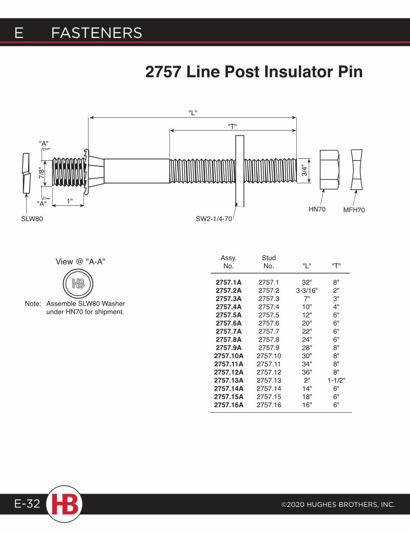
2757 Line Post Insulator Pin
E FASTENERS
©2020 HugHES BRoTHERS, INc.E-32
Assy. Stud No. No. "L" "T"
2757.1A 2757.1 32" 8" 2757.2A 2757.2 3-3/16" 2" 2757.3A 2757.3 7" 3" 2757.4A 2757.4 10" 4" 2757.5A 2757.5 12" 6" 2757.6A 2757.6 20" 6" 2757.7A 2757.7 22" 6" 2757.8A 2757.8 24" 6" 2757.9A 2757.9 28" 8" 2757.10A 2757.10 30" 8" 2757.11A 2757.11 34" 8" 2757.12A 2757.12 36" 8" 2757.13A 2757.13 2" 1-1/2" 2757.14A 2757.14 14" 6" 2757.15A 2757.15 18" 6" 2757.16A 2757.16 16" 6"
"L"
"T"
SW2-1/4-70
3/4"
SLW80
"A"
"A" 1"
View @ "A-A"
HN70 MFH70
Note: Assemble SLW80 Washer under HN70 for shipment.
7/8"
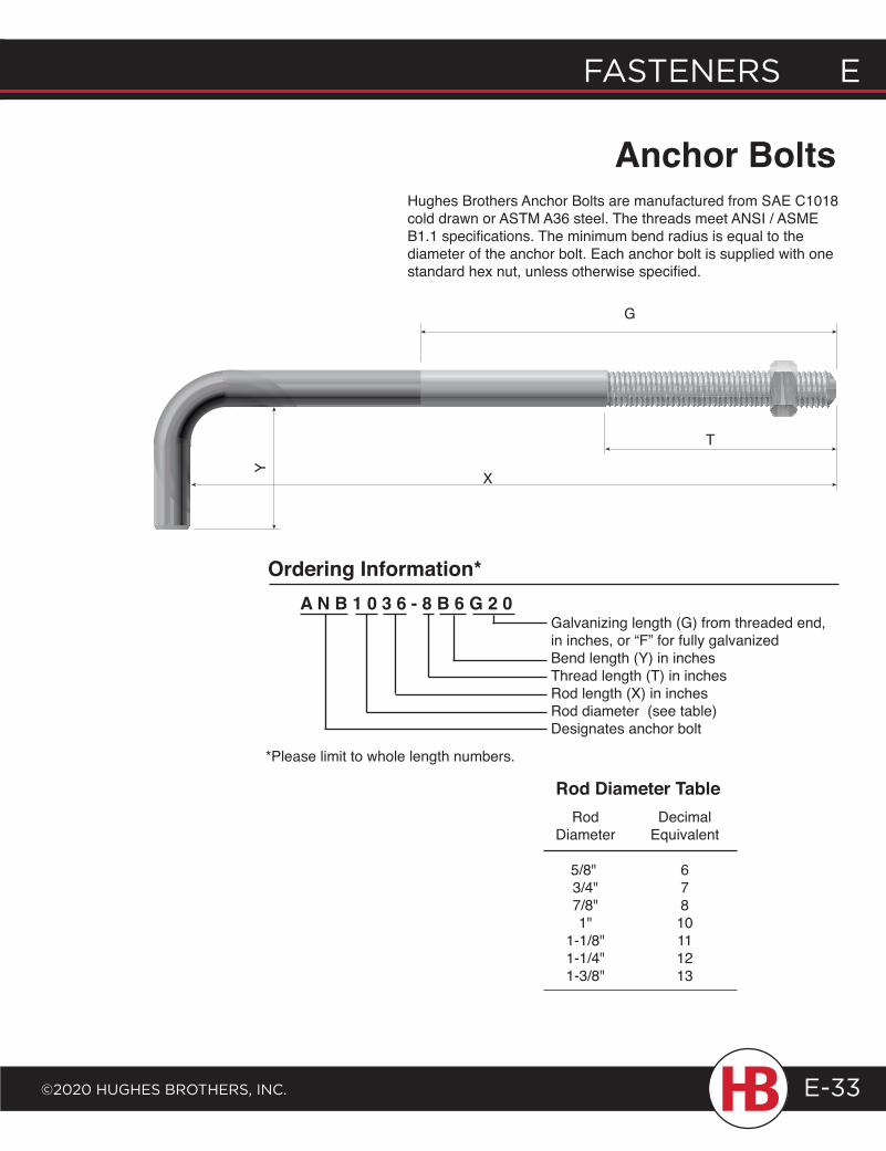
FASTENERS E
©2020 HugHES BRoTHERS, INc.
E FASTENERS
E-33
Y
Rod Decimal Diameter Equivalent 5/8" 6 3/4" 7 7/8" 8 1" 10 1-1/8" 11 1-1/4" 12 1-3/8" 13
Rod Diameter Table
Hughes Brothers Anchor Bolts are manufactured from SAE C1018 cold drawn or ASTM A36 steel. The threads meet ANSI / ASME B1.1 specifications. The minimum bend radius is equal to the diameter of the anchor bolt. Each anchor bolt is supplied with one standard hex nut, unless otherwise specified.
Anchor Bolts
T
X
G
A N B 1 0 3 6 - 8 B 6 G 2 0 Galvanizing length (G) from threaded end,
in inches, or “F” for fully galvanized Bend length (Y) in inches Thread length (T) in inches Rod length (X) in inches Rod diameter (see table) Designates anchor bolt
Ordering Information*
*Please limit to whole length numbers.
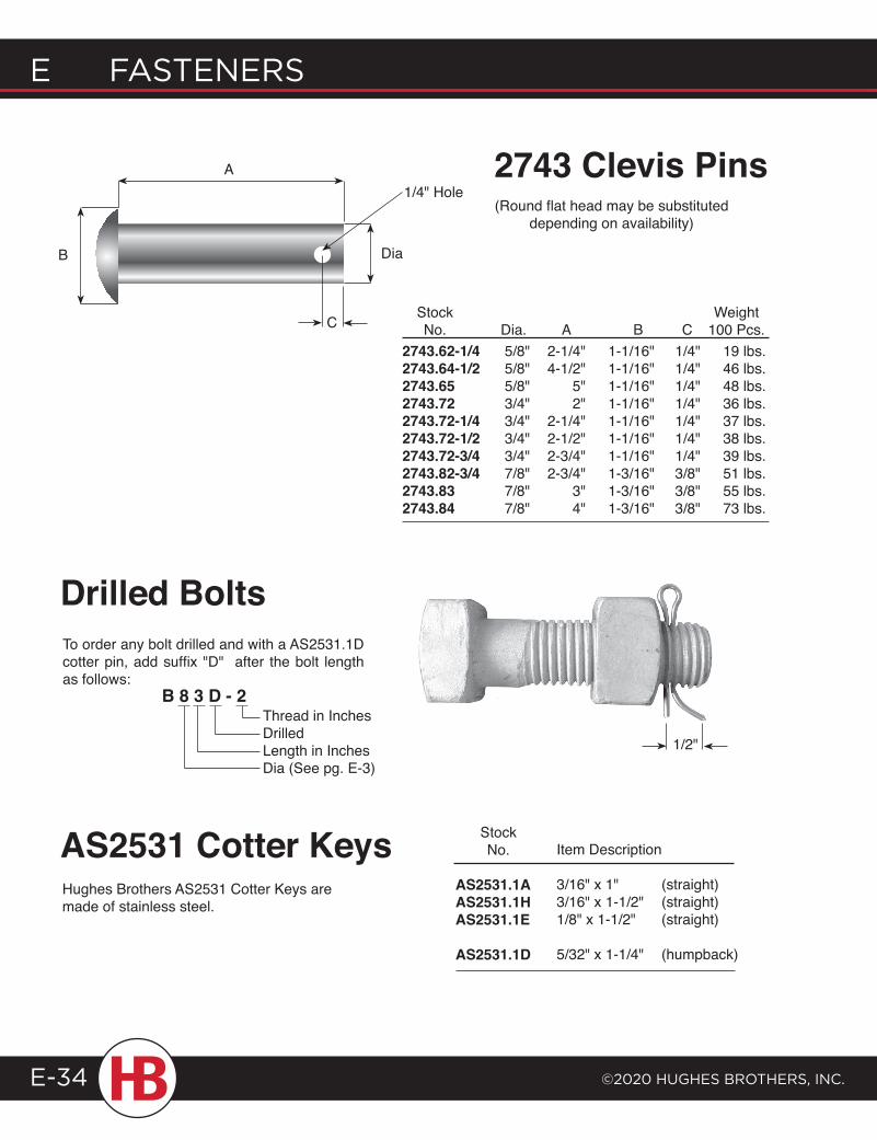
E FASTENERS
©2020 HugHES BRoTHERS, INc.E-34
C
A
B Dia
1/4" Hole
2743.62-1/4 5/8" 2-1/4" 1-1/16" 1/4" 19 lbs.2743.64-1/2 5/8" 4-1/2" 1-1/16" 1/4" 46 lbs.2743.65 5/8" 5" 1-1/16" 1/4" 48 lbs.2743.72 3/4" 2" 1-1/16" 1/4" 36 lbs.2743.72-1/4 3/4" 2-1/4" 1-1/16" 1/4" 37 lbs.2743.72-1/2 3/4" 2-1/2" 1-1/16" 1/4" 38 lbs.2743.72-3/4 3/4" 2-3/4" 1-1/16" 1/4" 39 lbs.2743.82-3/4 7/8" 2-3/4" 1-3/16" 3/8" 51 lbs.2743.83 7/8" 3" 1-3/16" 3/8" 55 lbs.2743.84 7/8" 4" 1-3/16" 3/8" 73 lbs.
Stock Weight No. Dia. A B C 100 Pcs.
2743 Clevis Pins
Hughes Brothers AS2531 Cotter Keys are made of stainless steel.
Item Description
3/16" x 1" (straight)3/16" x 1-1/2" (straight)1/8" x 1-1/2" (straight)
5/32" x 1-1/4" (humpback)
Stock No.
AS2531.1AAS2531.1HAS2531.1E
AS2531.1D
AS2531 Cotter Keys
To order any bolt drilled and with a AS2531.1D cotter pin, add suffix "D" after the bolt length as follows:
B 8 3 D - 2
Drilled Bolts
(Round flat head may be substituted depending on availability)
1/2"
Thread in InchesDrilledLength in InchesDia (See pg. E-3)
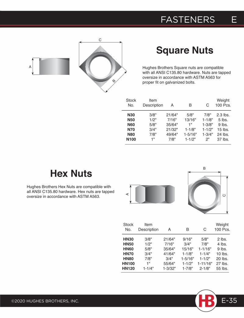
FASTENERS E
©2020 HugHES BRoTHERS, INc.
E FASTENERS
E-35
Hughes Brothers Square nuts are compatible with all ANSI C135.80 hardware. Nuts are tapped oversize in accordance with ASTM A563 for proper fit on galvanized bolts.
Square NutsA
C
Hughes Brothers Hex Nuts are compatible with all ANSI C135.80 hardware. Hex nuts are tapped oversize in accordance with ASTM A563.
Hex Nuts
A
B
C
Stock Item Weight No. Description A B C 100 Pcs.
N30 3/8" 21/64" 5/8" 7/8" 2.3 lbs. N50 1/2" 7/16" 13/16" 1-1/8" 5 lbs. N60 5/8" 35/64" 1" 1-3/8" 9 lbs. N70 3/4" 21/32" 1-1/8" 1-1/2" 15 lbs. N80 7/8" 49/64" 1-5/16" 1-3/4" 24 lbs. N100 1" 7/8" 1-1/2" 2" 37 lbs.
Stock Item Weight No. Description A B C 100 Pcs.
HN30 3/8" 21/64" 9/16" 5/8" 2 lbs. HN50 1/2" 7/16" 3/4" 7/8" 4 lbs. HN60 5/8" 35/64" 15/16" 1-1/16" 9 lbs. HN70 3/4" 41/64" 1-1/8" 1-1/4" 10 lbs. HN80 7/8" 3/4" 1-5/16" 1-1/2" 20 lbs. HN100 1" 55/64" 1-1/2" 1-11/16" 27 lbs. HN120 1-1/4" 1-3/32" 1-7/8" 2-1/8" 55 lbs.
B
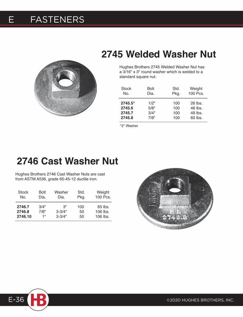
E FASTENERS
©2020 HugHES BRoTHERS, INc.E-36
Stock Bolt Std. Weight No. Dia. Pkg. 100 Pcs.
2745.5* 1/2" 100 26 lbs. 2745.6 5/8" 100 46 lbs. 2745.7 3/4" 100 49 lbs. 2745.8 7/8" 100 60 lbs.
Hughes Brothers 2745 Welded Washer Nut has a 3/16" x 3" round washer which is welded to a standard square nut.
2745 Welded Washer Nut
Stock Bolt Washer Std. Weight No. Dia. Dia. Pkg. 100 Pcs. 2746.7 3/4" 3" 100 65 lbs. 2746.8 7/8" 3-3/4" 50 106 lbs. 2746.10 1" 3-3/4" 50 106 lbs.
Hughes Brothers 2746 Cast Washer Nuts are cast from ASTM A536, grade 65-45-12 ductile iron.
2746 Cast Washer Nut
*2" Washer
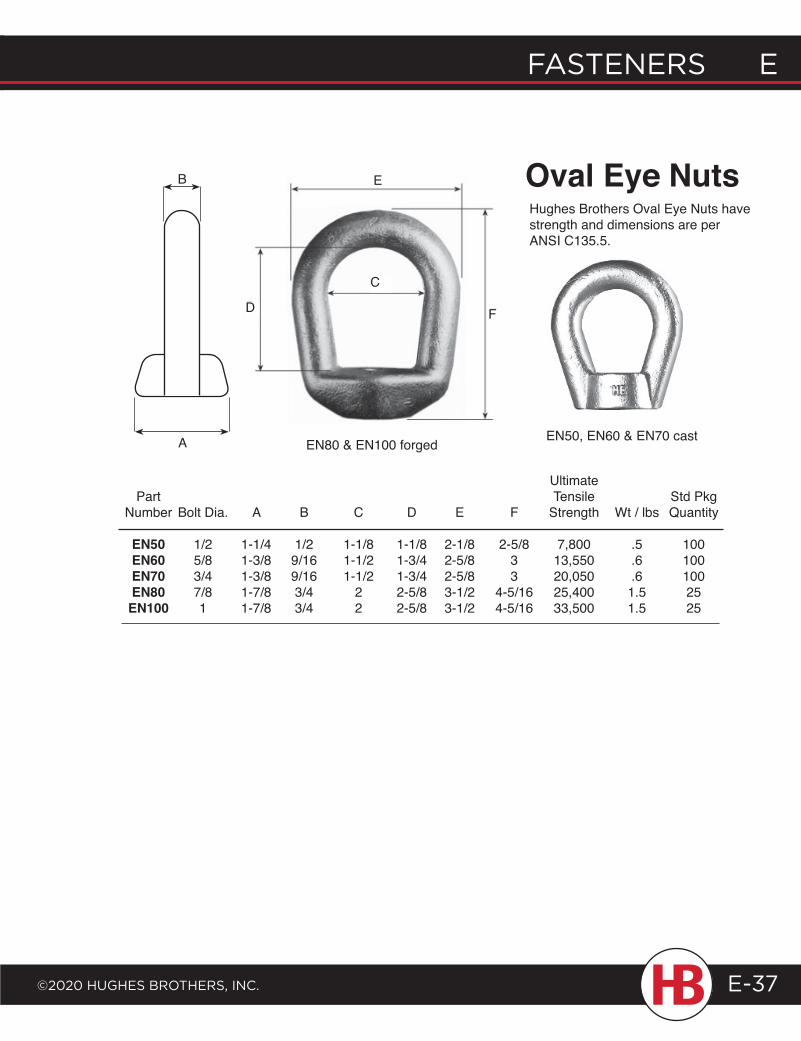
FASTENERS E
©2020 HugHES BRoTHERS, INc.
E FASTENERS
E-37
Ultimate Part Tensile Std Pkg Number Bolt Dia. A B C D E F Strength Wt / lbs Quantity
EN50 1/2 1-1/4 1/2 1-1/8 1-1/8 2-1/8 2-5/8 7,800 .5 100 EN60 5/8 1-3/8 9/16 1-1/2 1-3/4 2-5/8 3 13,550 .6 100 EN70 3/4 1-3/8 9/16 1-1/2 1-3/4 2-5/8 3 20,050 .6 100 EN80 7/8 1-7/8 3/4 2 2-5/8 3-1/2 4-5/16 25,400 1.5 25 EN100 1 1-7/8 3/4 2 2-5/8 3-1/2 4-5/16 33,500 1.5 25
EN50, EN60 & EN70 cast
Oval Eye NutsHughes Brothers Oval Eye Nuts have strength and dimensions are per ANSI C135.5.
B
A
D F
C
E
EN80 & EN100 forged
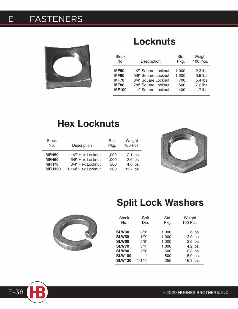
E FASTENERS
©2020 HugHES BRoTHERS, INc.E-38
Locknuts
Stock Bolt Std. Weight No. Dia. Pkg. 100 Pcs.
SLW30 3/8" 1,000 .6 lbs. SLW50 1/2" 1,000 2.0 lbs. SLW60 5/8" 1,000 2.5 lbs. SLW70 3/4" 1,000 4.2 lbs. SLW80 7/8" 500 6.3 lbs. SLW100 1" 500 8.9 lbs. SLW120 1-1/4" 250 16.3 lbs.
Stock Std. Weight No. Description Pkg. 100 Pcs.
MF50 1/2" Square Locknut 1,000 2.3 lbs. MF60 5/8" Square Locknut 1,000 3.9 lbs. MF70 3/4" Square Locknut 700 5.4 lbs. MF80 7/8" Square Locknut 500 7.2 lbs. MF100 1" Square Locknut 400 11.7 lbs.
Split Lock Washers
Hex Locknuts
Stock Std. Weight No. Description Pkg. 100 Pcs.
MFH50 1/2" Hex Locknut 1,000 2.1 lbs. MFH60 5/8" Hex Locknut 1,000 2.6 lbs. MFH70 3/4" Hex Locknut 500 4.6 lbs. MFH120 1-1/4" Hex Locknut 300 11.7 lbs.
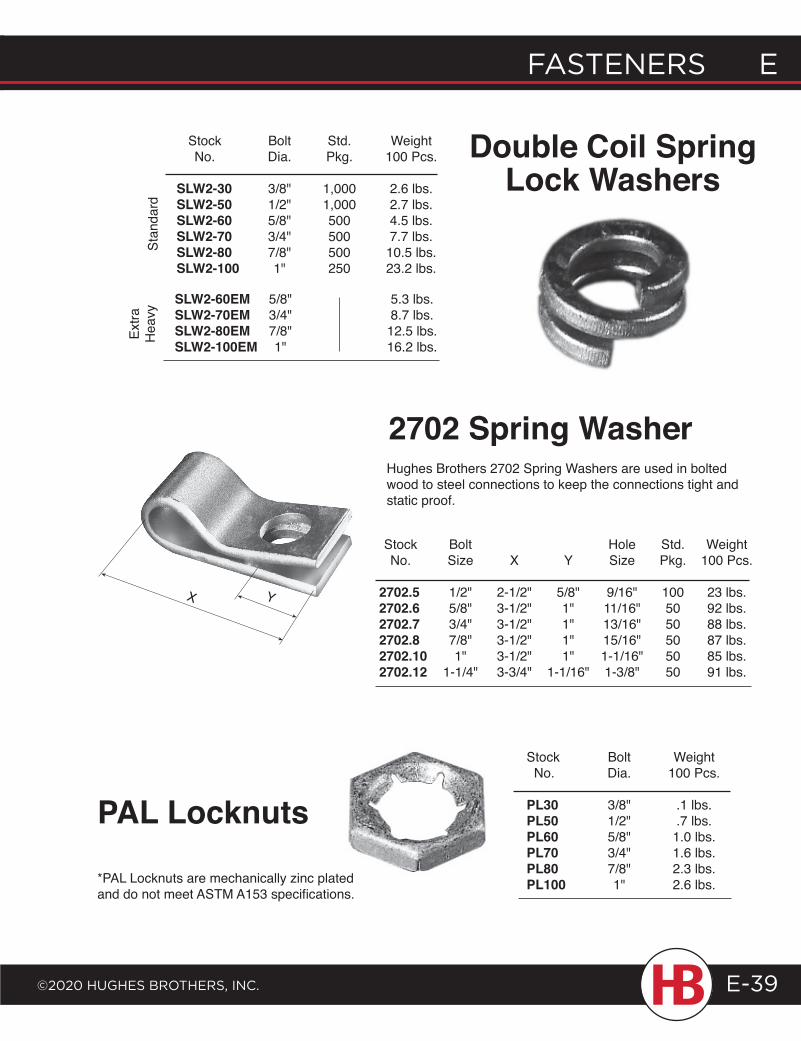
FASTENERS E
©2020 HugHES BRoTHERS, INc.
E FASTENERS
E-39
Double Coil Spring Lock Washers
Stock Bolt Std. Weight No. Dia. Pkg. 100 Pcs.
SLW2-30 3/8" 1,000 2.6 lbs. SLW2-50 1/2" 1,000 2.7 lbs. SLW2-60 5/8" 500 4.5 lbs. SLW2-70 3/4" 500 7.7 lbs. SLW2-80 7/8" 500 10.5 lbs. SLW2-100 1" 250 23.2 lbs.
SLW2-60EM 5/8" 5.3 lbs. SLW2-70EM 3/4" 8.7 lbs. SLW2-80EM 7/8" 12.5 lbs. SLW2-100EM 1" 16.2 lbs.
2702 Spring Washer
Stock Bolt Hole Std. Weight No. Size X Y Size Pkg. 100 Pcs.
2702.5 1/2" 2-1/2" 5/8" 9/16" 100 23 lbs. 2702.6 5/8" 3-1/2" 1" 11/16" 50 92 lbs. 2702.7 3/4" 3-1/2" 1" 13/16" 50 88 lbs. 2702.8 7/8" 3-1/2" 1" 15/16" 50 87 lbs. 2702.10 1" 3-1/2" 1" 1-1/16" 50 85 lbs. 2702.12 1-1/4" 3-3/4" 1-1/16" 1-3/8" 50 91 lbs.
Hughes Brothers 2702 Spring Washers are used in bolted wood to steel connections to keep the connections tight and static proof.
PAL Locknuts
Stock Bolt Weight No. Dia. 100 Pcs.
PL30 3/8" .1 lbs. PL50 1/2" .7 lbs. PL60 5/8" 1.0 lbs. PL70 3/4" 1.6 lbs. PL80 7/8" 2.3 lbs. PL100 1" 2.6 lbs.
Stan
dard
Extra
H
eavy
YX
*PAL Locknuts are mechanically zinc plated and do not meet ASTM A153 specifications.
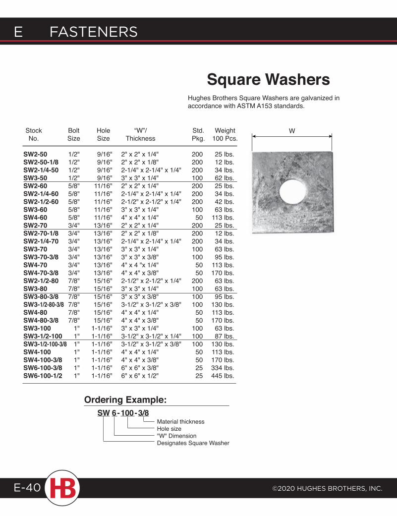
E FASTENERS
©2020 HugHES BRoTHERS, INc.E-40
Hughes Brothers Square Washers are galvanized in accordance with ASTM A153 standards.
W
Ordering Example:SW 6 - 100 - 3/8
Material thicknessHole size"W" DimensionDesignates Square Washer
Square Washers
Stock Bolt Hole “W”/ Std. Weight No. Size Size Thickness Pkg. 100 Pcs. SW2-50 1/2" 9/16" 2" x 2" x 1/4" 200 25 lbs. SW2-50-1/8 1/2" 9/16" 2" x 2" x 1/8" 200 12 lbs. SW2-1/4-50 1/2" 9/16" 2-1/4" x 2-1/4" x 1/4" 200 34 lbs. SW3-50 1/2" 9/16" 3" x 3" x 1/4" 100 62 lbs. SW2-60 5/8" 11/16" 2" x 2" x 1/4" 200 25 lbs. SW2-1/4-60 5/8" 11/16" 2-1/4" x 2-1/4" x 1/4" 200 34 lbs. SW2-1/2-60 5/8" 11/16" 2-1/2" x 2-1/2" x 1/4" 200 42 lbs. SW3-60 5/8" 11/16" 3" x 3" x 1/4" 100 63 lbs. SW4-60 5/8" 11/16" 4" x 4" x 1/4" 50 113 lbs. SW2-70 3/4" 13/16" 2" x 2" x 1/4" 200 25 lbs. SW2-70-1/8 3/4" 13/16" 2" x 2" x 1/8" 200 12 lbs. SW2-1/4-70 3/4" 13/16" 2-1/4" x 2-1/4" x 1/4" 200 34 lbs. SW3-70 3/4" 13/16" 3" x 3" x 1/4" 100 63 lbs. SW3-70-3/8 3/4" 13/16" 3" x 3" x 3/8" 100 95 lbs. SW4-70 3/4" 13/16" 4" x 4 "x 1/4" 50 113 lbs. SW4-70-3/8 3/4" 13/16" 4" x 4" x 3/8" 50 170 lbs. SW2-1/2-80 7/8" 15/16" 2-1/2" x 2-1/2" x 1/4" 200 63 lbs. SW3-80 7/8" 15/16" 3" x 3" x 1/4" 100 63 lbs. SW3-80-3/8 7/8" 15/16" 3" x 3" x 3/8" 100 95 lbs. SW3-1/2-80-3/8 7/8" 15/16" 3-1/2" x 3-1/2" x 3/8" 100 130 lbs. SW4-80 7/8" 15/16" 4" x 4" x 1/4" 50 113 lbs. SW4-80-3/8 7/8" 15/16" 4" x 4" x 3/8" 50 170 lbs. SW3-100 1" 1-1/16" 3" x 3" x 1/4" 100 63 lbs. SW3-1/2-100 1" 1-1/16" 3-1/2" x 3-1/2" x 1/4" 100 87 lbs. SW3-1/2-100-3/8 1" 1-1/16" 3-1/2" x 3-1/2" x 3/8" 100 130 lbs. SW4-100 1" 1-1/16" 4" x 4" x 1/4" 50 113 lbs. SW4-100-3/8 1" 1-1/16" 4" x 4" x 3/8" 50 170 lbs. SW6-100-3/8 1" 1-1/16" 6" x 6" x 3/8" 25 334 lbs. SW6-100-1/2 1" 1-1/16" 6" x 6" x 1/2" 25 445 lbs.
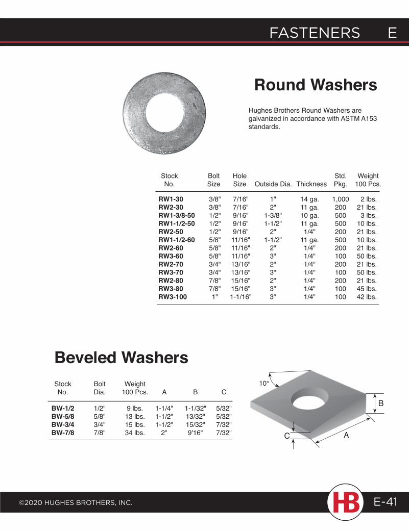
FASTENERS E
©2020 HugHES BRoTHERS, INc.
E FASTENERS
E-41
Stock Bolt Weight No. Dia. 100 Pcs. A B C
BW-1/2 1/2" 9 lbs. 1-1/4" 1-1/32" 5/32" BW-5/8 5/8" 13 lbs. 1-1/2" 13/32" 5/32" BW-3/4 3/4" 15 lbs. 1-1/2" 15/32" 7/32" BW-7/8 7/8" 34 lbs. 2" 9'16" 7/32"
Beveled Washers
Round WashersHughes Brothers Round Washers are galvanized in accordance with ASTM A153 standards.
Stock Bolt Hole Std. Weight No. Size Size Outside Dia. Thickness Pkg. 100 Pcs.
RW1-30 3/8" 7/16" 1" 14 ga. 1,000 2 lbs. RW2-30 3/8" 7/16" 2" 11 ga. 200 21 lbs. RW1-3/8-50 1/2" 9/16" 1-3/8" 10 ga. 500 3 lbs. RW1-1/2-50 1/2" 9/16" 1-1/2" 11 ga. 500 10 lbs. RW2-50 1/2" 9/16" 2" 1/4" 200 21 lbs. RW1-1/2-60 5/8" 11/16" 1-1/2" 11 ga. 500 10 lbs. RW2-60 5/8" 11/16" 2" 1/4" 200 21 lbs. RW3-60 5/8" 11/16" 3" 1/4" 100 50 lbs. RW2-70 3/4" 13/16" 2" 1/4" 200 21 lbs. RW3-70 3/4" 13/16" 3" 1/4" 100 50 lbs. RW2-80 7/8" 15/16" 2" 1/4" 200 21 lbs. RW3-80 7/8" 15/16" 3" 1/4" 100 45 lbs. RW3-100 1" 1-1/16" 3" 1/4" 100 42 lbs.
10°
C A
B
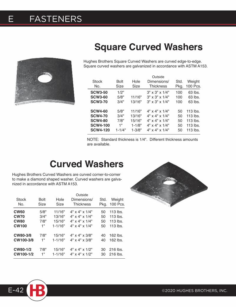
E FASTENERS
©2020 HugHES BRoTHERS, INc.E-42
Hughes Brothers Square Curved Washers are curved edge-to-edge. Square curved washers are galvanized in accordance with ASTM A153.
Square Curved Washers
CW60 5/8" 11/16" 4" x 4" x 1/4" 50 113 lbs. CW70 3/4" 13/16" 4" x 4" x 1/4" 50 113 lbs. CW80 7/8" 15/16" 4" x 4" x 1/4" 50 113 lbs. CW100 1" 1-1/16" 4" x 4" x 1/4" 50 113 lbs.
CW80-3/8 7/8" 15/16" 4" x 4" x 3/8" 40 162 lbs. CW100-3/8 1" 1-1/16" 4" x 4" x 3/8" 40 162 lbs.
CW80-1/2 7/8" 15/16" 4" x 4" x 1/2" 30 216 lbs. CW100-1/2 1" 1-1/16" 4" x 4" x 1/2" 30 216 lbs.
Hughes Brothers Curved Washers are curved corner-to-corner to make a diamond shaped washer. Curved washers are galva-nized in accordance with ASTM A153.
Curved Washers
Outside Stock Bolt Hole Dimensions/ Std. Weight No. Size Size Thickness Pkg. 100 Pcs. SCW3-50 1/2" 3" x 3" x 1/4" 100 63 lbs. SCW3-60 5/8" 11/16" 3" x 3" x 1/4" 100 63 lbs. SCW3-70 3/4" 13/16" 3" x 3" x 1/4" 100 63 lbs.
SCW4-60 5/8" 11/16" 4" x 4" x 1/4" 50 113 lbs. SCW4-70 3/4" 13/16" 4" x 4" x 1/4" 50 113 lbs. SCW4-80 7/8" 15/16" 4" x 4" x 1/4" 50 113 lbs. SCW4-100 1" 1-1/8" 4" x 4" x 1/4" 50 113 lbs. SCW4-120 1-1/4" 1-3/8" 4" x 4" x 1/4" 50 113 lbs.
NOTE: Standard thickness is 1/4". Different thickness amounts are available.
Outside Stock Bolt Hole Dimensions/ Std. Weight No. Size Size Thickness Pkg. 100 Pcs.
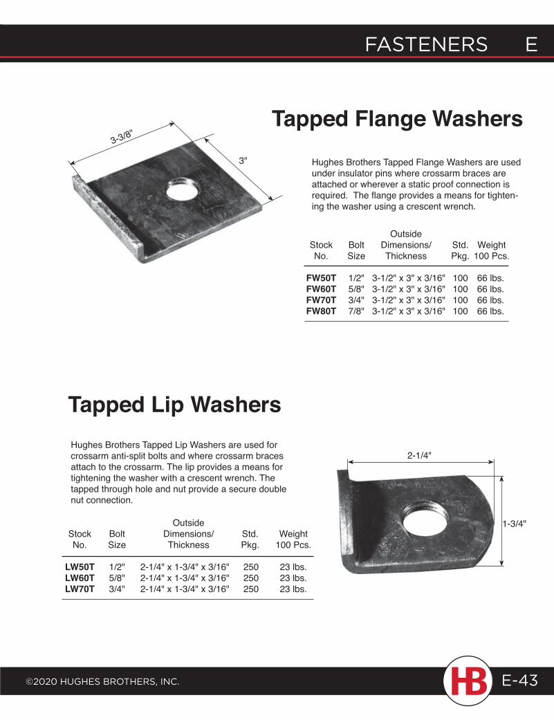
FASTENERS E
©2020 HugHES BRoTHERS, INc.
E FASTENERS
E-43
Hughes Brothers Tapped Flange Washers are used under insulator pins where crossarm braces are attached or wherever a static proof connection is required. The flange provides a means for tighten-ing the washer using a crescent wrench.
Tapped Flange Washers
Hughes Brothers Tapped Lip Washers are used for crossarm anti-split bolts and where crossarm braces attach to the crossarm. The lip provides a means for tightening the washer with a crescent wrench. The tapped through hole and nut provide a secure double nut connection.
Outside Stock Bolt Dimensions/ Std. Weight No. Size Thickness Pkg. 100 Pcs.
FW50T 1/2" 3-1/2" x 3" x 3/16" 100 66 lbs. FW60T 5/8" 3-1/2" x 3" x 3/16" 100 66 lbs. FW70T 3/4" 3-1/2" x 3" x 3/16" 100 66 lbs. FW80T 7/8" 3-1/2" x 3" x 3/16" 100 66 lbs.
Outside Stock Bolt Dimensions/ Std. Weight No. Size Thickness Pkg. 100 Pcs.
LW50T 1/2" 2-1/4" x 1-3/4" x 3/16" 250 23 lbs. LW60T 5/8" 2-1/4" x 1-3/4" x 3/16" 250 23 lbs. LW70T 3/4" 2-1/4" x 1-3/4" x 3/16" 250 23 lbs.
Tapped Lip Washers
3"
3-3/8"
2-1/4"
1-3/4"
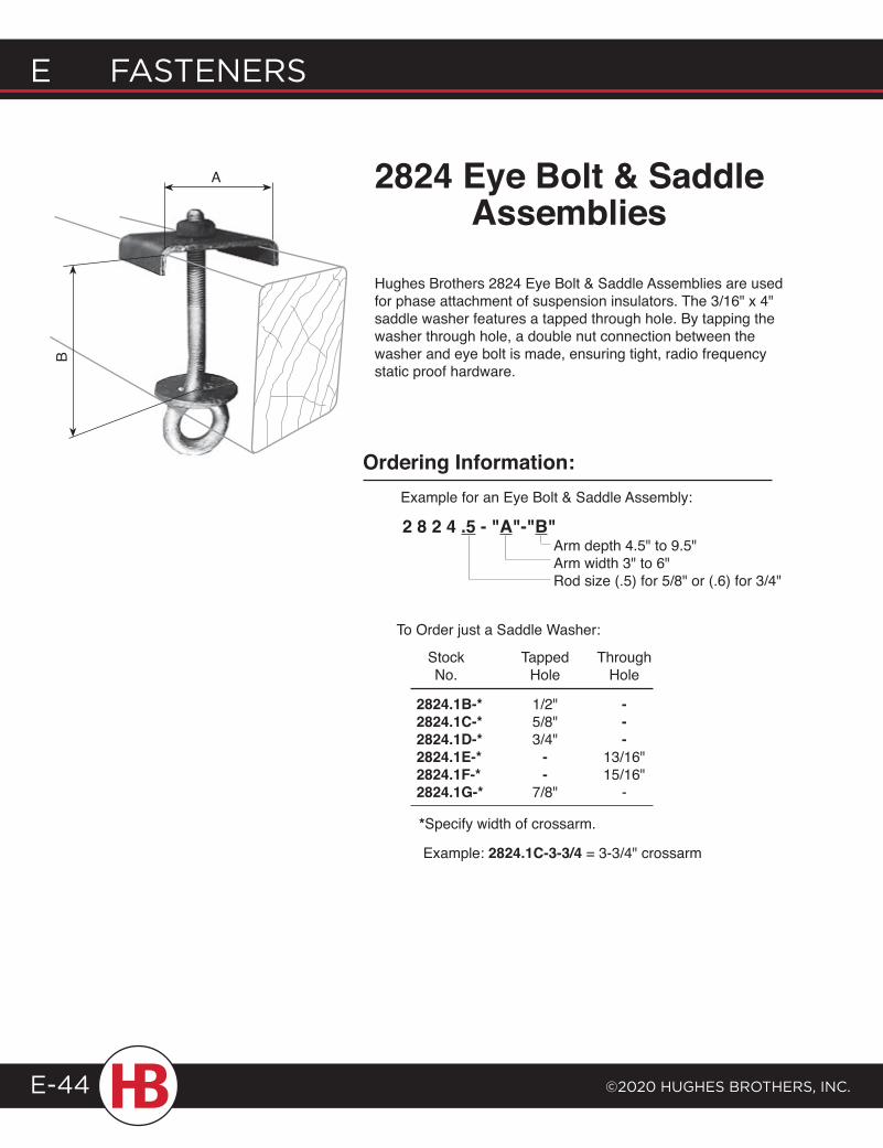
E FASTENERS
©2020 HugHES BRoTHERS, INc.E-44
Hughes Brothers 2824 Eye Bolt & Saddle Assemblies are used for phase attachment of suspension insulators. The 3/16" x 4" saddle washer features a tapped through hole. By tapping the washer through hole, a double nut connection between the washer and eye bolt is made, ensuring tight, radio frequency static proof hardware.
2824 Eye Bolt & Saddle Assemblies
B
A
Ordering Information:
2 8 2 4 .5 - "A"-"B"Arm depth 4.5" to 9.5"Arm width 3" to 6"Rod size (.5) for 5/8" or (.6) for 3/4"
Example for an Eye Bolt & Saddle Assembly:
To Order just a Saddle Washer:
Stock Tapped Through No. Hole Hole
2824.1B-* 1/2" -2824.1C-* 5/8" -2824.1D-* 3/4" -2824.1E-* - 13/16"2824.1F-* - 15/16"2824.1G-* 7/8" -
*Specify width of crossarm.
Example: 2824.1C-3-3/4 = 3-3/4" crossarm
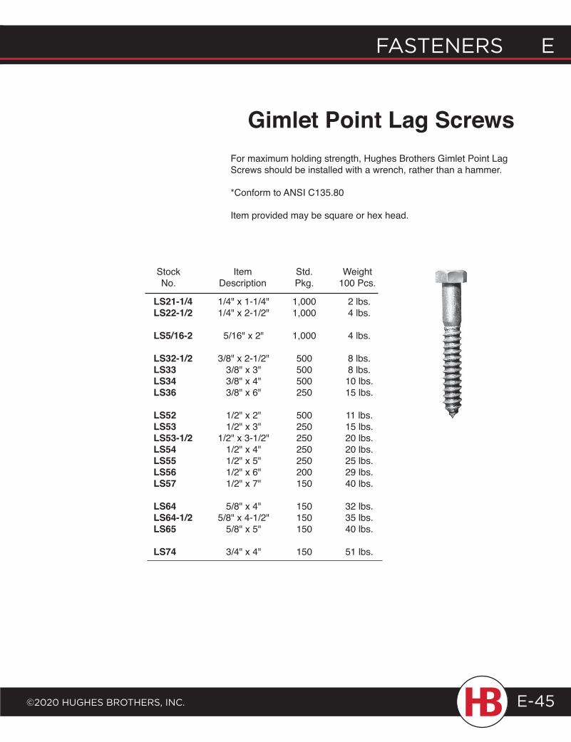
FASTENERS E
©2020 HugHES BRoTHERS, INc.
E FASTENERS
E-45
Gimlet Point Lag Screws
Stock Item Std. Weight No. Description Pkg. 100 Pcs.
LS21-1/4 1/4" x 1-1/4" 1,000 2 lbs. LS22-1/2 1/4" x 2-1/2" 1,000 4 lbs.
LS5/16-2 5/16" x 2" 1,000 4 lbs.
LS32-1/2 3/8" x 2-1/2" 500 8 lbs. LS33 3/8" x 3" 500 8 lbs. LS34 3/8" x 4" 500 10 lbs. LS36 3/8" x 6" 250 15 lbs.
LS52 1/2" x 2" 500 11 lbs. LS53 1/2" x 3" 250 15 lbs. LS53-1/2 1/2" x 3-1/2" 250 20 lbs. LS54 1/2" x 4" 250 20 lbs. LS55 1/2" x 5" 250 25 lbs. LS56 1/2" x 6" 200 29 lbs. LS57 1/2" x 7" 150 40 lbs.
LS64 5/8" x 4" 150 32 lbs. LS64-1/2 5/8" x 4-1/2" 150 35 lbs. LS65 5/8" x 5" 150 40 lbs.
LS74 3/4" x 4" 150 51 lbs.
For maximum holding strength, Hughes Brothers Gimlet Point Lag Screws should be installed with a wrench, rather than a hammer.
*Conform to ANSI C135.80
Item provided may be square or hex head.
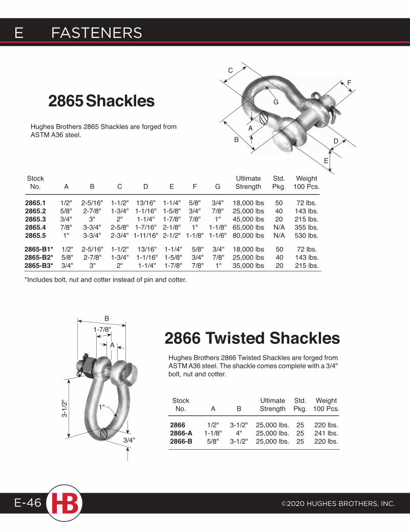
Stock Ultimate Std. Weight No. A B C D E F G Strength Pkg. 100 Pcs.
2865.1 1/2" 2-5/16" 1-1/2" 13/16" 1-1/4" 5/8" 3/4" 18,000 lbs 50 72 lbs. 2865.2 5/8" 2-7/8" 1-3/4" 1-1/16" 1-5/8" 3/4" 7/8" 25,000 lbs 40 143 lbs. 2865.3 3/4" 3" 2" 1-1/4" 1-7/8" 7/8" 1" 45,000 lbs 20 215 lbs. 2865.4 7/8" 3-3/4" 2-5/8" 1-7/16" 2-1/8" 1" 1-1/8" 65,000 lbs N/A 355 lbs. 2865.5 1" 3-3/4" 2-3/4" 1-11/16" 2-1/2" 1-1/8" 1-1/6" 80,000 lbs N/A 530 lbs.
E FASTENERS
©2020 HugHES BRoTHERS, INc.E-46
F
Stock Ultimate Std. Weight No. A B Strength Pkg. 100 Pcs.
2866 1/2" 3-1/2" 25,000 lbs. 25 220 lbs. 2866-A 1-1/8" 4" 25,000 lbs. 25 241 lbs. 2866-B 5/8" 3-1/2" 25,000 lbs. 25 220 lbs.
2866 Twisted Shackles
1"
B1-7/8"
3/4"
3-1/
2"
2865-B1* 1/2" 2-5/16" 1-1/2" 13/16" 1-1/4" 5/8" 3/4" 18,000 lbs 50 72 lbs. 2865-B2* 5/8" 2-7/8" 1-3/4" 1-1/16" 1-5/8" 3/4" 7/8" 25,000 lbs 40 143 lbs. 2865-B3* 3/4" 3" 2" 1-1/4" 1-7/8" 7/8" 1" 35,000 lbs 20 215 lbs.
Hughes Brothers 2866 Twisted Shackles are forged from ASTM A36 steel. The shackle comes complete with a 3/4" bolt, nut and cotter.
*Includes bolt, nut and cotter instead of pin and cotter.
Hughes Brothers 2865 Shackles are forged from ASTM A36 steel.
2865 Shackles
A
C
G
AB
E
D
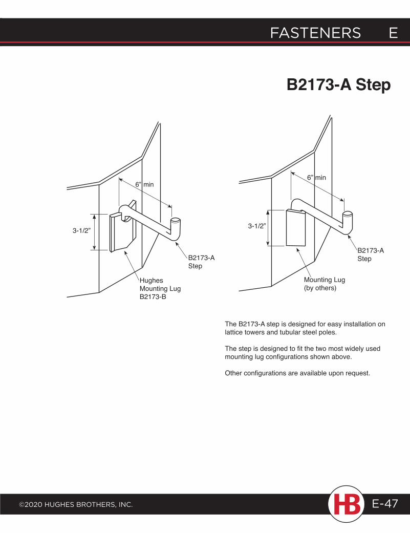
FASTENERS E
©2020 HugHES BRoTHERS, INc.
E FASTENERS
E-47
The B2173-A step is designed for easy installation on lattice towers and tubular steel poles.
The step is designed to fit the two most widely used mounting lug configurations shown above.
Other configurations are available upon request.
B2173-A Step
3-1/2”
HughesMounting LugB2173-B
B2173-A Step
3-1/2”
Mounting Lug(by others)
B2173-A Step
6” min6” min
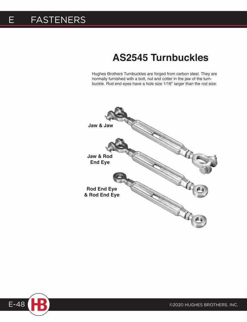
E FASTENERS
©2020 HugHES BRoTHERS, INc.E-48
Jaw & Jaw
Jaw & Rod End Eye
Rod End Eye& Rod End Eye
Hughes Brothers Turnbuckles are forged from carbon steel. They are normally furnished with a bolt, nut and cotter in the jaw of the turn-buckle. Rod end eyes have a hole size 1/16" larger than the rod size.
AS2545 Turnbuckles
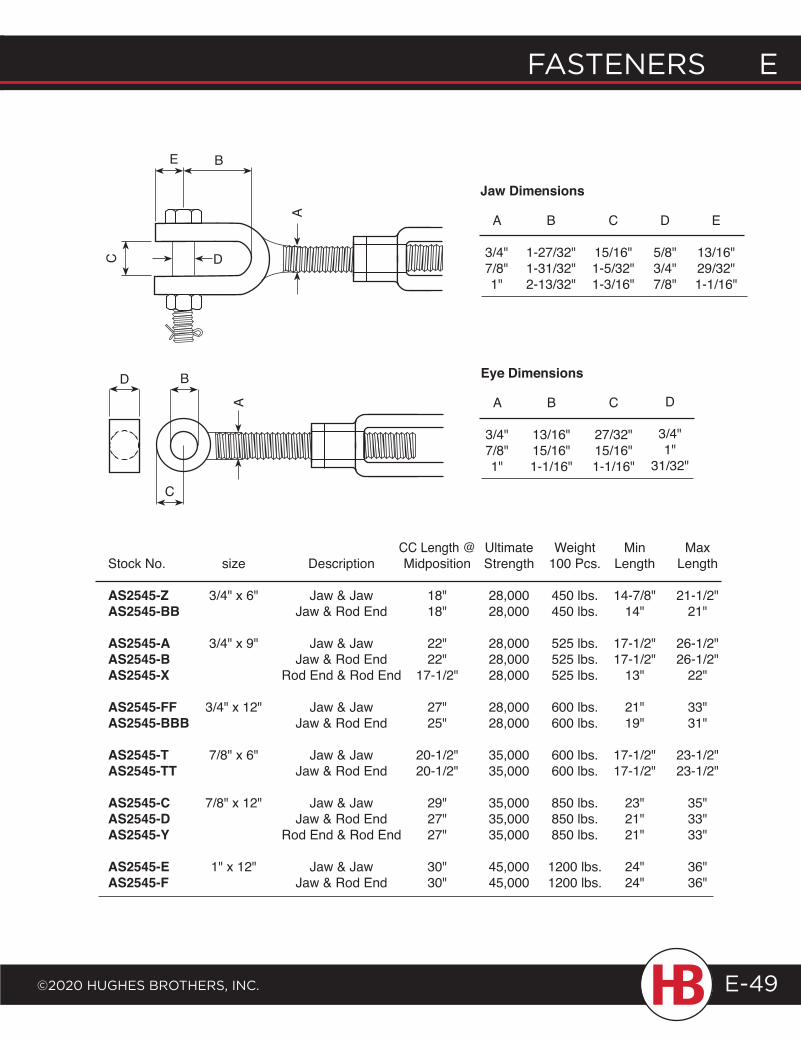
FASTENERS E
©2020 HugHES BRoTHERS, INc.
E FASTENERS
E-49
CC Length @ Ultimate Weight Min Max Stock No. size Description Midposition Strength 100 Pcs. Length Length
AS2545-Z 3/4" x 6" Jaw & Jaw 18" 28,000 450 lbs. 14-7/8" 21-1/2" AS2545-BB Jaw & Rod End 18" 28,000 450 lbs. 14" 21"
AS2545-A 3/4" x 9" Jaw & Jaw 22" 28,000 525 lbs. 17-1/2" 26-1/2" AS2545-B Jaw & Rod End 22" 28,000 525 lbs. 17-1/2" 26-1/2" AS2545-X Rod End & Rod End 17-1/2" 28,000 525 lbs. 13" 22"
AS2545-FF 3/4" x 12" Jaw & Jaw 27" 28,000 600 lbs. 21" 33" AS2545-BBB Jaw & Rod End 25" 28,000 600 lbs. 19" 31"
AS2545-T 7/8" x 6" Jaw & Jaw 20-1/2" 35,000 600 lbs. 17-1/2" 23-1/2" AS2545-TT Jaw & Rod End 20-1/2" 35,000 600 lbs. 17-1/2" 23-1/2"
AS2545-C 7/8" x 12" Jaw & Jaw 29" 35,000 850 lbs. 23" 35" AS2545-D Jaw & Rod End 27" 35,000 850 lbs. 21" 33" AS2545-Y Rod End & Rod End 27" 35,000 850 lbs. 21" 33"
AS2545-E 1" x 12" Jaw & Jaw 30" 45,000 1200 lbs. 24" 36" AS2545-F Jaw & Rod End 30" 45,000 1200 lbs. 24" 36"
A
3/4"7/8"1"
B
1-27/32"1-31/32"2-13/32"
C
15/16"1-5/32"1-3/16"
D
5/8"3/4"7/8"
Jaw Dimensions
E
13/16"29/32"1-1/16"
A
3/4"7/8"1"
B
13/16"15/16"1-1/16"
C
27/32"15/16"1-1/16"
Eye Dimensions
A
C D
BE
A
B
C
DD
3/4"1"
31/32"
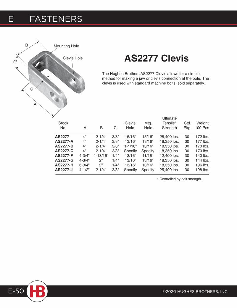
E FASTENERS
©2020 HugHES BRoTHERS, INc.E-50
AS2277 4" 2-1/4" 3/8" 15/16" 15/16" 25,400 lbs. 30 172 lbs. AS2277-A 4" 2-1/4" 3/8" 13/16" 13/16" 18,350 lbs. 30 177 lbs. AS2277-B 4" 2-1/4" 3/8" 1-1/16" 13/16" 18,350 lbs. 30 170 lbs. AS2277-C 4" 2-1/4" 3/8" Specify Specify 18,350 lbs. 30 170 lbs. AS2277-F 4-3/4" 1-13/16" 1/4" 13/16" 11/16" 12,400 lbs. 30 140 lbs. AS2277-G 4-3/4" 2" 1/4" 13/16" 13/16" 18,350 lbs. 30 144 lbs. AS2277-H 6-3/4" 2" 1/4" 13/16" 13/16" 18,350 lbs. 30 196 lbs. AS2277-J 4-1/2" 2-1/4" 3/8" Specify Specify 25,400 lbs. 30 198 lbs.
* Controlled by bolt strength.
The Hughes Brothers AS2277 Clevis allows for a simple method for making a jaw or clevis connection at the pole. The clevis is used with standard machine bolts, sold separately.
AS2277 Clevis
C
B
A
Mounting Hole
Clevis Hole2"
Ultimate Stock Clevis Mtg. Tensile* Std. Weight No. A B C Hole Hole Strength Pkg. 100 Pcs.
F I B E R G L A S S Guy Strain Insulators ..................... F-2Pole Top Pins/Jumper Pins ........F-10Brackets ............................................F-14Transmission Crossarms .............F-41Cantilever Arms ........................... F-46Braces .............................................. F-49Down Leads ................................... F-50Phase Spacers ...............................F-56Miscellaneous Brackets ..............F-59
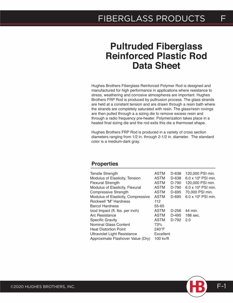
fiberglass products f
©2020 HugHes brotHers, inc. F-1
Hughes Brothers Fiberglass Reinforced Polymer Rod is designed and manufactured for high performance in applications where resistance to stress, weathering and corrosive atmospheres are important. Hughes Brothers FRP Rod is produced by pultrusion process. The glass strands are held at a constant tension and are drawn through a resin bath where the strands are completely saturated with resin. The glass/resin rovings are then pulled through a a sizing die to remove excess resin and through a radio frequency pre-heater. Polymerization takes place in a heated final sizing die and the rod exits this die a thermoset shape.
Hughes Brothers FRP Rod is produced in a variety of cross section diameters ranging from 1/2 in. through 2-1/2 in. diameter. The standard color is a medium-dark gray.
Tensile Strength ASTM D-638 120,000 PSI min.Modulus of Elasticity, Tension ASTM D-638 6.0 x 10⁶ PSI min.Flexural Strength ASTM D-790 120,000 PSI min.Modulus of Elasticity, Flexural ASTM D-790 6.0 x 10⁶ PSI min.Compressive Strength ASTM D-695 70,000 PSI min.Modulus of Elasticity, Compressive ASTM D-695 6.0 x 10⁶ PSI min.Rockwell “M” Hardness 112Barcol Hardness 55-65Izod Impact (ft. lbs. per inch) ASTM D-256 44 min.Arc Resistance ASTM D-495 186 sec.Specific Gravity ASTM D-792 2.0Nominal Glass Content 73%Heat Distortion Point 240°FUltraviolet Light Resistance ExcellentApproximate Flashover Value (Dry) 100 kv/ft
Properties
Pultruded Fiberglass Reinforced Plastic Rod
Data Sheet
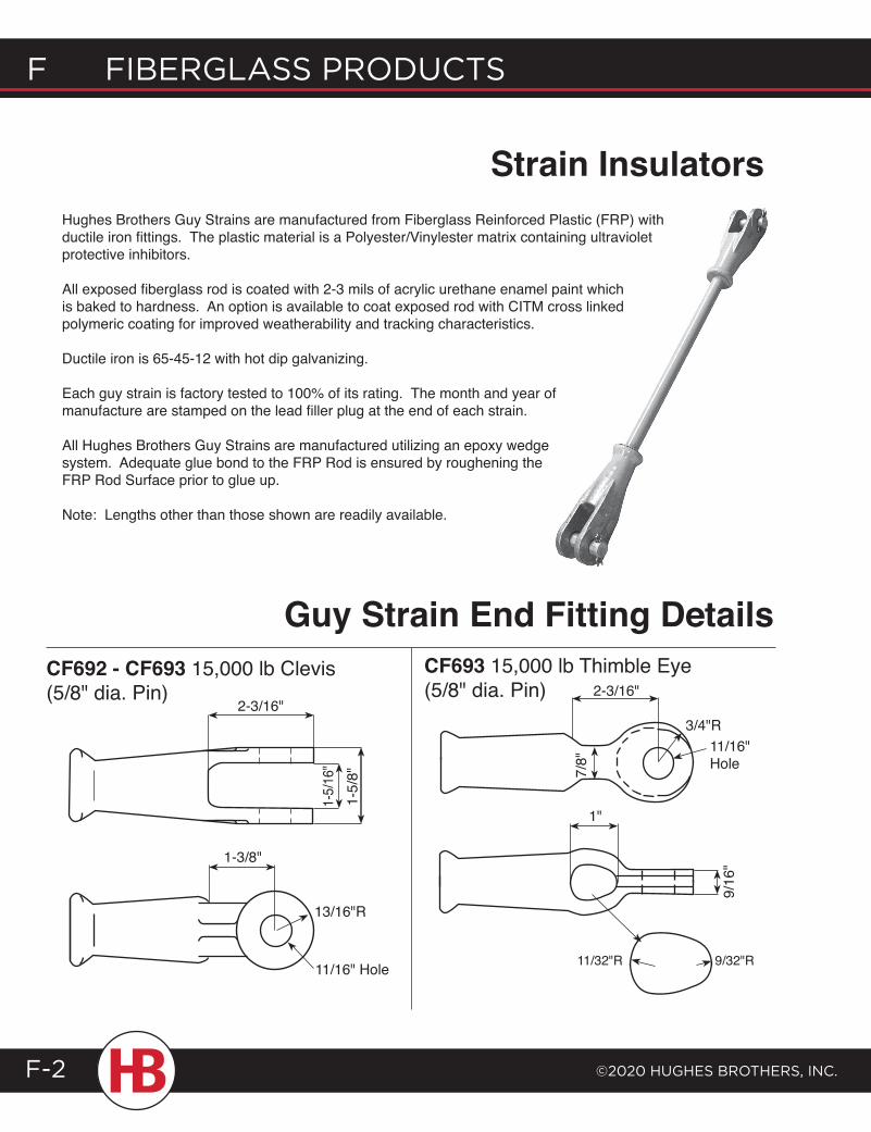
F Fiberglass products
©2020 HugHes brotHers, inc.F-2
Strain Insulators
Guy Strain End Fitting Details
3/4"R11/16" Hole7/
8"
1"
11/32"R 9/32"R
Hughes Brothers Guy Strains are manufactured from Fiberglass Reinforced Plastic (FRP) with ductile iron fittings. The plastic material is a Polyester/Vinylester matrix containing ultraviolet protective inhibitors.
All exposed fiberglass rod is coated with 2-3 mils of acrylic urethane enamel paint which is baked to hardness. An option is available to coat exposed rod with CITM cross linked polymeric coating for improved weatherability and tracking characteristics.
Ductile iron is 65-45-12 with hot dip galvanizing.
Each guy strain is factory tested to 100% of its rating. The month and year of manufacture are stamped on the lead filler plug at the end of each strain.
All Hughes Brothers Guy Strains are manufactured utilizing an epoxy wedge system. Adequate glue bond to the FRP Rod is ensured by roughening the FRP Rod Surface prior to glue up.
Note: Lengths other than those shown are readily available.
CF692 - CF693 15,000 lb Clevis (5/8" dia. Pin)
9/16
"
CF693 15,000 lb Thimble Eye (5/8" dia. Pin) 2-3/16"
1-3/8"
2-3/16"
1-5/
8"1-
5/16
"
13/16"R
11/16" Hole
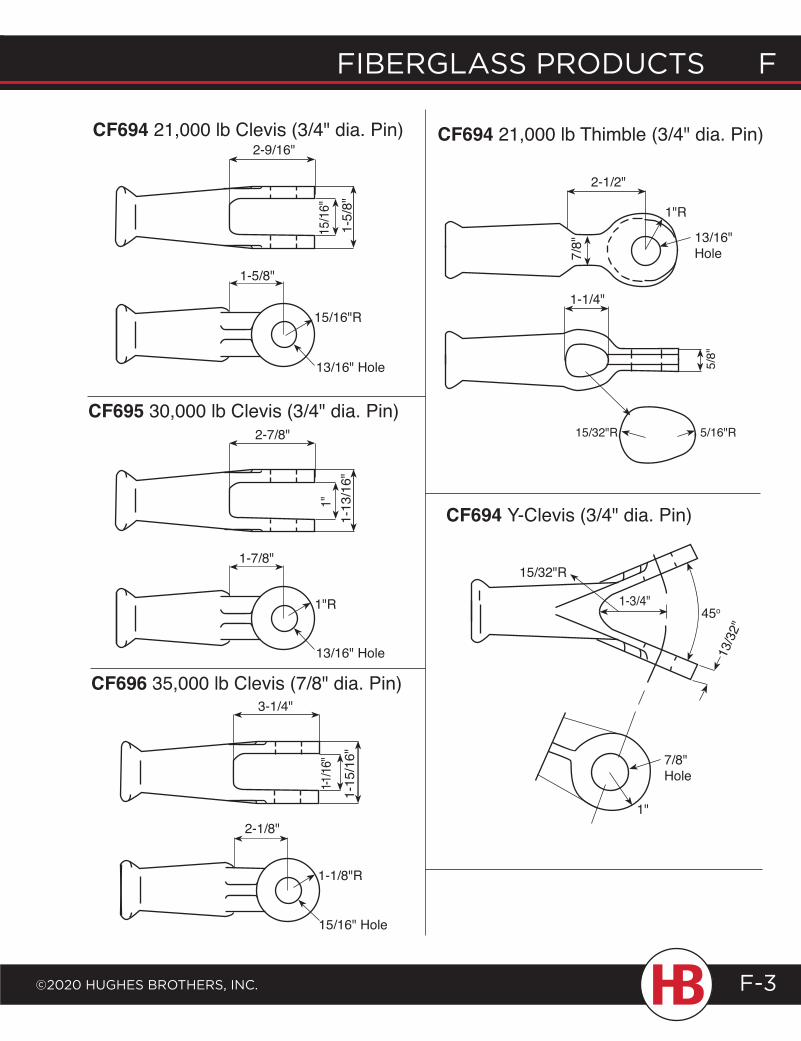
fiberglass products f
©2020 HugHes brotHers, inc.
f fiberglass products
F-3
CF694 21,000 lb Thimble (3/4" dia. Pin)CF694 21,000 lb Clevis (3/4" dia. Pin)
CF695 30,000 lb Clevis (3/4" dia. Pin)
CF696 35,000 lb Clevis (7/8" dia. Pin)
15/16" Hole
CF694 Y-Clevis (3/4" dia. Pin)
2-1/2"
1"R
13/16" Hole
1-1/4"
5/8"
15/32"R 5/16"R
15/32"R
1-3/4"45o
1"
13/3
2"
1"
1-1/8"R
2-7/8"
1-13
/16"
1-7/8"
1"R
13/16" Hole
3-1/4"
2-1/8"
1-1/16
"1-
15/1
6"
1-5/8"
2-9/16"
1-5/
8"15
/16"
15/16"R
13/16" Hole
7/8"
7/8" Hole
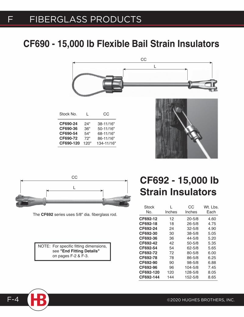
F Fiberglass products
©2020 HugHes brotHers, inc.F-4
CF690 - 15,000 lb Flexible Bail Strain Insulators
LCC
CC
LCF692 - 15,000 lb Strain Insulators Stock L CC Wt. Lbs. No. Inches Inches EachCF692-12 12 20-5/8 4.60CF692-18 18 26-5/8 4.75CF692-24 24 32-5/8 4.90CF692-30 30 38-5/8 5.05CF692-36 36 44-5/8 5.20CF692-42 42 50-5/8 5.35CF692-54 54 62-5/8 5.65CF692-72 72 80-5/8 6.00CF692-78 78 86-5/8 6.25CF692-90 90 98-5/8 6.88CF692-96 96 104-5/8 7.45CF692-120 120 128-5/8 8.05CF692-144 144 152-5/8 8.65
The CF692 series uses 5/8" dia. fiberglass rod.
Stock No.
CF690-24CF690-36CF690-54CF690-72CF690-120
L
24"36"54"72"120"
CC
38-11/16"50-11/16"68-11/16"86-11/16"134-11/16"
NOTE: For specific fitting dimensions, see "End Fitting Details" on pages F-2 & F-3.
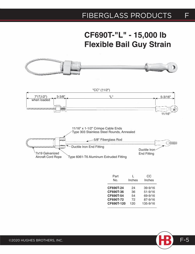
fiberglass products f
©2020 HugHes brotHers, inc.
f fiberglass products
F-5
CF690T-"L" - 15,000 lb Flexible Bail Guy Strain
"CC" (+1/2")-
7"(+1/2") when loaded
- 3-3/8" "L" 5-3/16"
11/16"
Part L CC No. Inches Inches
CF690T-24 24 39-9/16 CF690T-36 36 51-9/16CF690T-54 54 69-9/16CF690T-72 72 87-9/16CF690T-120 120 135-9/16
Ductile Iron End Fitting
5/8" Fiberglass Rod
11/16" x 1-1/2" Crimpe Cable EndsType 303 Stainless Steel Rounds, Annealed
Ductile Iron End Fitting
7x19 GalvanizedAircraft Cord Rope Type 6061-T6 Aluminum Extruded Fitting
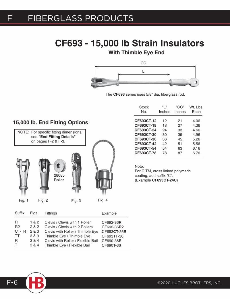
F Fiberglass products
©2020 HugHes brotHers, inc.F-6
CF693 - 15,000 lb Strain InsulatorsWith Thimble Eye End
L
CC
The CF693 series uses 5/8" dia. fiberglass rod.
Fig. 1 Fig. 2
Stock "L" "CC" Wt. Lbs. No. Inches Inches Each
CF693CT-12 12 21 4.06CF693CT-18 18 27 4.36CF693CT-24 24 33 4.66CF693CT-30 30 39 4.96CF693CT-36 36 45 5.26CF693CT-42 42 51 5.56CF693CT-54 54 63 6.16CF693CT-78 78 87 6.76
Note:For CITM, cross linked polymeric coating, add suffix "C". (Example CF693CT-24C)
15,000 lb. End Fitting Options
Figs.
1 & 22 & 22 & 33 & 32 & 43 & 4
Fittings
Clevis / Clevis with 1 RollerClevis / Clevis with 2 RollersClevis with Roller / Thimble EyeThimble Eye / Thimble EyeClevis with Roller / Flexible BailThimble Eye / Flexible Bail
Example
CF692-36RCF692-36R2CF693CT-36RCF693TT-36CF690-36RCF690T-36
Suffix
RR2CT-_RTTRT
28085Roller
Fig. 3 Fig. 4
NOTE: For specific fitting dimensions, see "End Fitting Details" on pages F-2 & F-3.
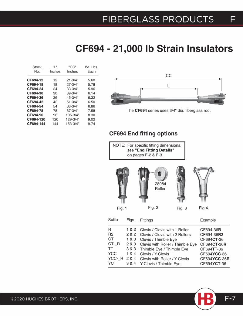
fiberglass products f
©2020 HugHes brotHers, inc.
f fiberglass products
F-7
CC
L
Stock "L" "CC" Wt. Lbs. No. Inches Inches Each
CF694-12 12 21-3/4" 5.60CF694-18 18 27-3/4" 5.78CF694-24 24 33-3/4" 5.96CF694-30 30 39-3/4" 6.14CF694-36 36 45-3/4" 6.32CF694-42 42 51-3/4" 6.50CF694-54 54 63-3/4" 6.86CF694-78 78 87-3/4" 7.58CF694-96 96 105-3/4" 8.30CF694-120 120 129-3/4" 9.02CF694-144 144 153-3/4" 9.74
The CF694 series uses 3/4" dia. fiberglass rod.
Fig 4.Fig. 1 Fig. 3Fig. 2
Example
CF694-36RCF694-36R2CF694CT-36CF694CT-36RCF694TT-36CF694YCC-36CF694YCC-36RCF694YCT-36
Fittings
Clevis / Clevis with 1 RollerClevis / Clevis with 2 RollersClevis / Thimble EyeClevis with Roller / Thimble EyeThimble Eye / Thimble EyeClevis / Y-ClevisClevis with Roller / Y-ClevisY-Clevis / Thimble Eye
Figs.
1 & 22 & 21 & 32 & 33 & 31 & 42 & 43 & 4
Suffix
RR2CTCT-_RTTYCCYCC-_RYCT
CF694 End fitting options
28084Roller
CF694 - 21,000 lb Strain Insulators
NOTE: For specific fitting dimensions, see "End Fitting Details" on pages F-2 & F-3.
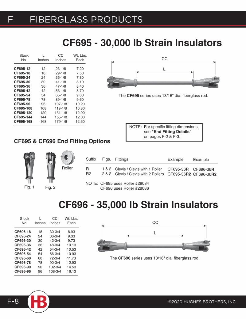
F Fiberglass products
©2020 HugHes brotHers, inc.F-8
CC
L
CC
L
CF695 - 30,000 lb Strain Insulators Stock L CC Wt. Lbs. No. Inches Inches Each
CF695-12 12 23-1/8 7.20CF695-18 18 29-1/8 7.50CF695-24 24 35-1/8 7.80CF695-30 30 41-1/8 8.10CF695-36 36 47-1/8 8.40CF695-42 42 53-1/8 8.70CF695-54 54 65-1/8 9.00CF695-78 78 89-1/8 9.60CF695-96 96 107-1/8 10.20CF695-108 108 119-1/8 10.80CF695-120 120 131-1/8 12.00CF695-144 144 155-1/8 12.00CF695-168 168 179-1/8 12.60
The CF695 series uses 13/16" dia. fiberglass rod.
CF696 - 35,000 lb Strain Insulators Stock L CC Wt. Lbs. No. Inches Inches Each
CF696-18 18 30-3/4 8.93CF696-24 24 36-3/4 9.33CF696-30 30 42-3/4 9.73CF696-36 36 48-3/4 10.13CF696-42 42 54-3/4 10.53CF696-54 54 66-3/4 10.93CF696-60 60 72-3/4 11.73CF696-78 78 90-3/4 12.93CF696-90 90 102-3/4 14.53CF696-96 96 108-3/4 16.13
Roller
Fig. 2Fig. 1
CF695 & CF696 End Fitting Options
Figs.
1 & 22 & 2
Suffix
RR2
Fittings
Clevis / Clevis with 1 RollerClevis / Clevis with 2 Rollers
Example
CF695-36RCF695-36R2
Example
CF696-36RCF696-36R2
The CF696 series uses 13/16" dia. fiberglass rod.
NOTE: For specific fitting dimensions, see "End Fitting Details" on pages F-2 & F-3.
NOTE: CF695 uses Roller #28084 CF696 uses Roller #28086
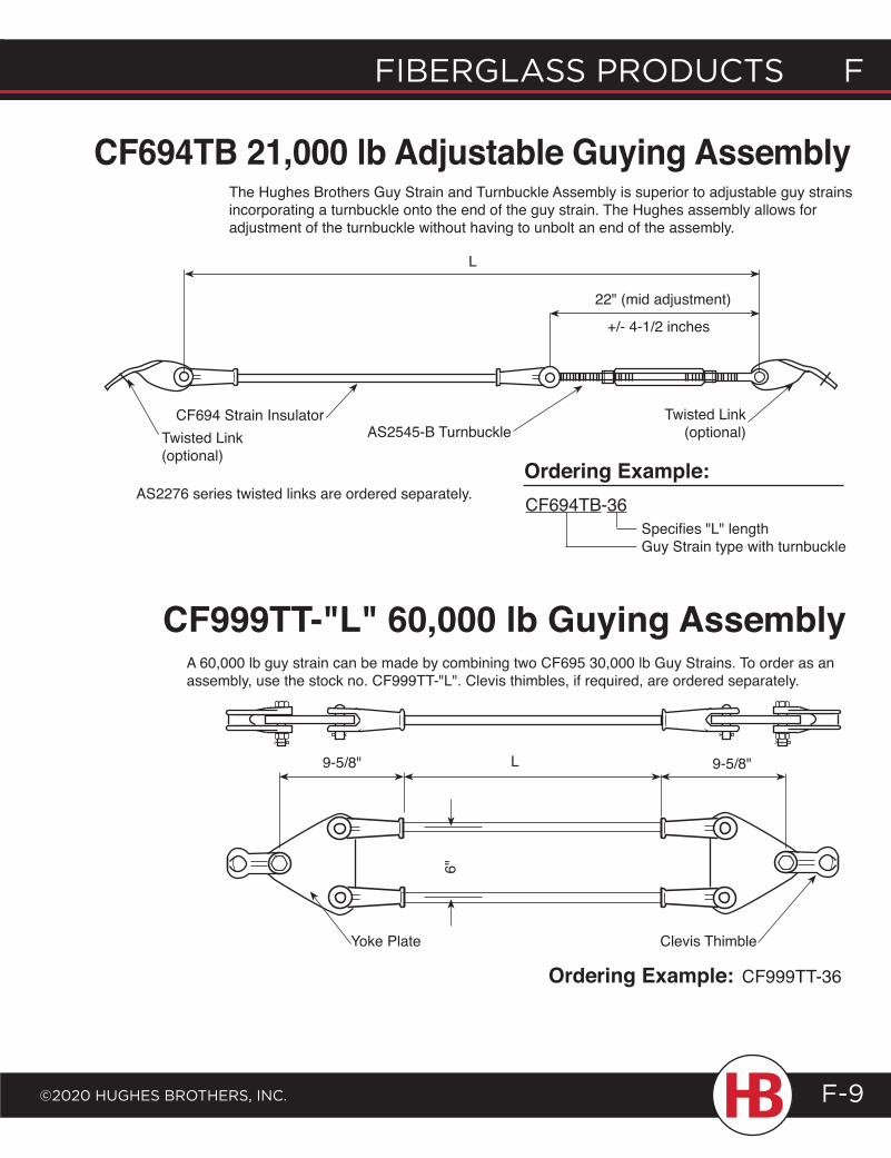
fiberglass products f
©2020 HugHes brotHers, inc.
f fiberglass products
F-9
L
CF694 Strain InsulatorTwisted Link(optional)
Twisted Link(optional)
22" (mid adjustment)
L 9-5/8"9-5/8"
6"
Yoke Plate Clevis Thimble
Ordering Example: CF999TT-36
A 60,000 lb guy strain can be made by combining two CF695 30,000 lb Guy Strains. To order as an assembly, use the stock no. CF999TT-"L". Clevis thimbles, if required, are ordered separately.
CF999TT-"L" 60,000 lb Guying Assembly
CF694TB 21,000 lb Adjustable Guying AssemblyThe Hughes Brothers Guy Strain and Turnbuckle Assembly is superior to adjustable guy strains incorporating a turnbuckle onto the end of the guy strain. The Hughes assembly allows for adjustment of the turnbuckle without having to unbolt an end of the assembly.
+/- 4-1/2 inches
AS2545-B Turnbuckle
Specifies "L" lengthGuy Strain type with turnbuckle
CF694TB-36
Ordering Example:AS2276 series twisted links are ordered separately.
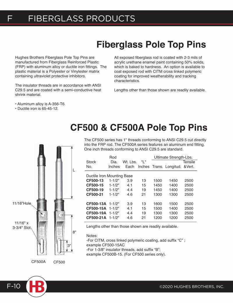
F Fiberglass products
©2020 HugHes brotHers, inc.F-10
Fiberglass Pole Top Pins
CF500 & CF500A Pole Top PinsThe CF500 series has 1" threads conforming to ANSI C29.5 cut directly into the FRP rod. The CF500A series features an aluminum end fitting. One inch threads conforming to ANSI C29.5 are standard.
Rod Ultimate Strength-Lbs. Stock Dia. Wt. Lbs. "L" Tensile No. Inches Each Inches Trans. Longitud. &Vert.
Ductile Iron Mounting Base CF500-13 1-1/2" 3.9 13 1500 1450 2500 CF500-15 1-1/2" 4.1 15 1450 1400 2500 CF500-19 1-1/2" 4.4 19 1450 1400 2500 CF500-21 1-1/2" 4.6 21 1300 1300 2500
CF500-13A 1-1/2" 3.9 13 1600 1500 2500 CF500-15A 1-1/2" 4.1 15 1500 1400 2500 CF500-19A 1-1/2" 4.4 19 1300 1300 2500 CF500-21A 1-1/2" 4.6 21 1200 1200 2500
Lengths other than those shown are readily available.
Notes:-For CITM, cross linked polymeric coating, add suffix “C” ; example CF500-15AC-For 1-3/8" insulator threads, add suffix “B”; example CF500B-15. (For CF500 series only).
Hughes Brothers Fiberglass Pole Top Pins are manufactured from Fiberglass Reinforced Plastic (FRP) with aluminum alloy or ductile iron fittings. The plastic material is a Polyester or Vinylester matrix containing ultraviolet protective inhibitors.
The insulator threads are in accordance with ANSI C29.5 and are coated with a semi-conductive heat shrink material. • Aluminum alloy is A-356-T6. • Ductile iron is 65-45-12.
All exposed fiberglass rod is coated with 2-3 mils of acrylic urethane enamel paint containing 50% solids, which is baked to hardness. An option is available to coat exposed rod with CITM cross linked polymeric coating for improved weatherability and tracking characteristics.
Lengths other than those shown are readily available.
L
8"
CF500A CF500
3"
11/16"Hole
11/16" x 3-3/4" Slot
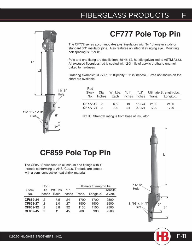
fiberglass products f
©2020 HugHes brotHers, inc.
f fiberglass products
F-11
The CF859 Series feature aluminum end fittings with 1" threads conforming to ANSI C29.5. Threads are coated with a semi-conductive heat shrink material.
The CF777 series accommodates post insulators with 3/4" diameter studs or standard 3/4" insulator pins. Also features an integral stringing eye. Mounting bolt spacing is 6" or 8".
Pole and end fitting are ductile iron, 65-45-12, hot dip galvanized to ASTM A153. All exposed fiberglass rod is coated with 2-3 mils of acrylic urethane enamel, baked to hardness.
Ordering example: CF777-"L1" (Specify "L1" in inches). Sizes not shown on the chart are available.
Rod Stock Dia. Wt. Lbs. "L1" "L2" Ultimate Strength-Lbs. No. Inches Each Inches Inches Trans. Longitud. CF777-19 2 6.5 19 15-3/4 2100 2100 CF777-24 2 7.8 24 20-3/4 1700 1700
CF777 Pole Top Pin
CF859 Pole Top Pin
Rod Ultimate Strength-Lbs. Stock Dia. Wt. Lbs. "L" Tensile No. Inches Each Inches Trans. Longitud. &Vert.
11/16"Hole
CF859-24 2 7.5 24 1700 1700 2500 CF859-27 2 8.0 27 1500 1500 2500 CF859-32 2 8.8 32 1150 1150 2500 CF859-45 2 11 45 900 900 2500
NOTE: Strength rating is from base of insulator.
2"
6"
L1
L2
6"8"
L
11/16" Hole
11/16" x 1-1/4" Slot
11/16" x 1-1/4"Slot
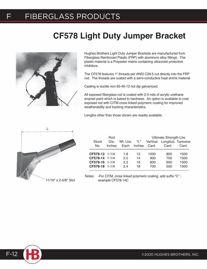
F Fiberglass products
©2020 HugHes brotHers, inc.F-12
CF578 Light Duty Jumper Bracket
Hughes Brothers Light Duty Jumper Brackets are manufactured from Fiberglass Reinforced Plastic (FRP) with aluminum alloy fittings. The plastic material is a Polyester matrix containing ultraviolet protective inhibitors.
The CF578 features 1" threads per ANSI C29.5 cut directly into the FRP rod. The threads are coated with a semi-conductive heat shrink material.
Casting is ductile iron 65-45-12 hot dip galvanized.
All exposed fiberglass rod is coated with 2-3 mils of acrylic urethane enamel paint which is baked to hardness. An option is available to coat exposed rod with CITM cross linked polymeric coating for improved weatherability and tracking characteristics.
Lengths other than those shown are readily available.
Rod Ultimate Strength-Lbs. Stock Dia. Wt. Lbs. "L" Vertical Longitud. Transverse No. Inches Each Inches Cant. Cant. Cant.
CF578-12 1-1/4 1.8 12 1000 800 1500 CF578-14 1-1/4 2.0 14 900 700 1500 CF578-16 1-1/4 2.2 16 800 600 1500 CF578-18 1-1/4 2.4 18 700 500 1500
Notes: -For CITM, cross linked polymeric coating, add suffix “C” ; example CF578-14C
L
11/16" x 2-5/8" Slot
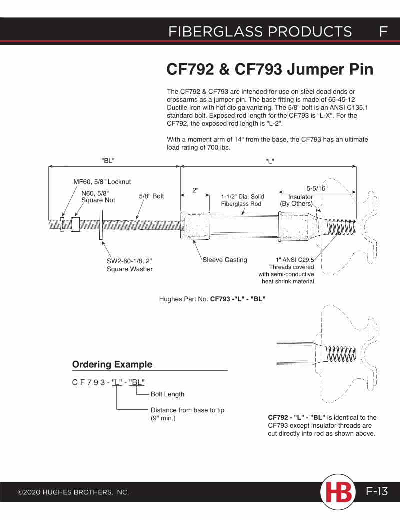
fiberglass products f
©2020 HugHes brotHers, inc.
f fiberglass products
F-13
CF792 - "L" - "BL" is identical to the CF793 except insulator threads are cut directly into rod as shown above.
Bolt Length
Distance from base to tip(9" min.)
The CF792 & CF793 are intended for use on steel dead ends or crossarms as a jumper pin. The base fitting is made of 65-45-12 Ductile Iron with hot dip galvanizing. The 5/8" bolt is an ANSI C135.1 standard bolt. Exposed rod length for the CF793 is "L-X". For the CF792, the exposed rod length is "L-2".
With a moment arm of 14" from the base, the CF793 has an ultimate load rating of 700 lbs.
CF792 & CF793 Jumper Pin
Ordering Example
C F 7 9 3 - "L" - "BL"
Hughes Part No. CF793 -"L" - "BL"
"L"
MF60, 5/8" Locknut
5/8" Bolt
SW2-60-1/8, 2" Square Washer
Sleeve Casting 1" ANSI C29.5Threads covered
with semi-conductive heat shrink material
1-1/2" Dia. SolidFiberglass Rod
Insulator(By Others)
5-5/16"2"
"BL"
N60, 5/8"Square Nut
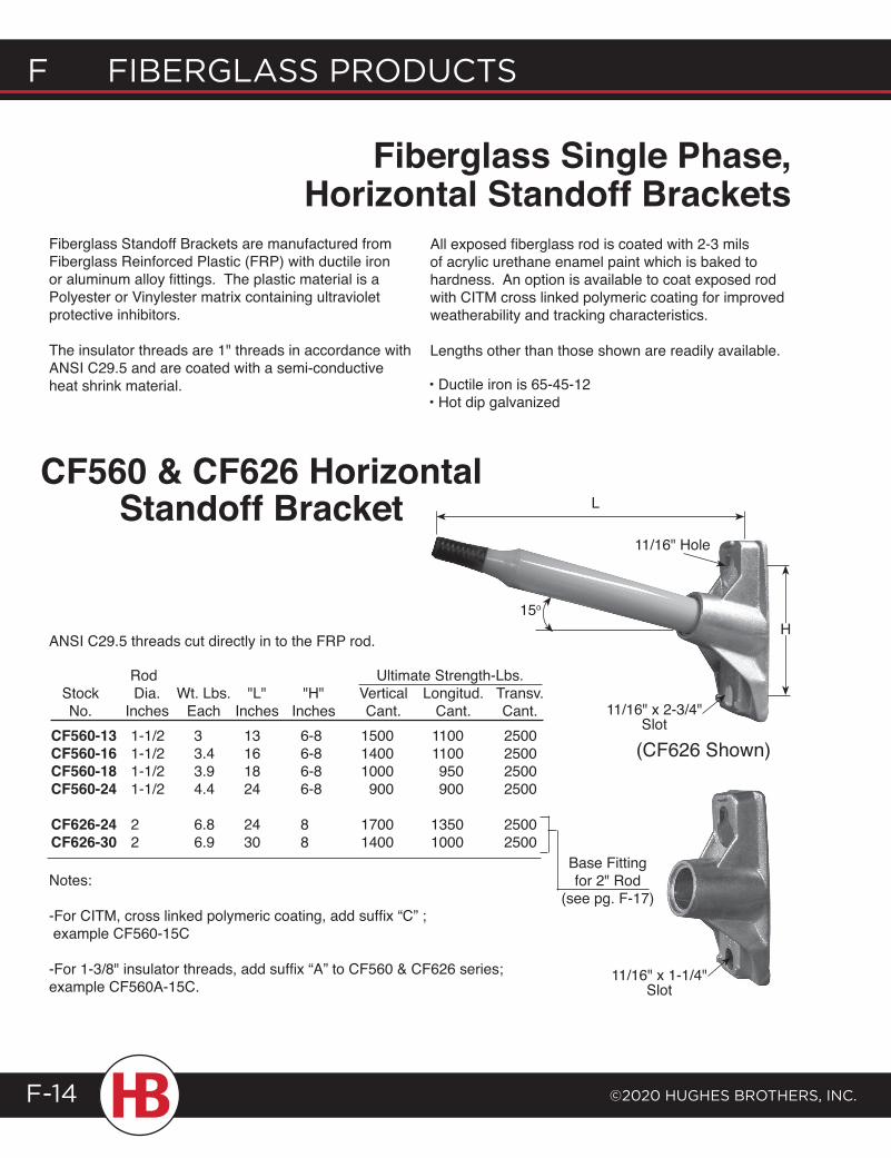
F Fiberglass products
©2020 HugHes brotHers, inc.F-14
Fiberglass Standoff Brackets are manufactured from Fiberglass Reinforced Plastic (FRP) with ductile iron or aluminum alloy fittings. The plastic material is a Polyester or Vinylester matrix containing ultraviolet protective inhibitors.
The insulator threads are 1" threads in accordance with ANSI C29.5 and are coated with a semi-conductive heat shrink material.
All exposed fiberglass rod is coated with 2-3 mils of acrylic urethane enamel paint which is baked to hardness. An option is available to coat exposed rod with CITM cross linked polymeric coating for improved weatherability and tracking characteristics.
Lengths other than those shown are readily available.
Fiberglass Single Phase, Horizontal Standoff Brackets
Rod Ultimate Strength-Lbs. Stock Dia. Wt. Lbs. "L" "H" Vertical Longitud. Transv. No. Inches Each Inches Inches Cant. Cant. Cant.
ANSI C29.5 threads cut directly in to the FRP rod.
Notes:
-For CITM, cross linked polymeric coating, add suffix “C” ; example CF560-15C
-For 1-3/8" insulator threads, add suffix “A” to CF560 & CF626 series; example CF560A-15C.
CF560 & CF626 Horizontal Standoff Bracket
• Ductile iron is 65-45-12• Hot dip galvanized
15o
L
11/16" Hole
11/16" x 2-3/4" Slot
CF560-13 1-1/2 3 13 6-8 1500 1100 2500 CF560-16 1-1/2 3.4 16 6-8 1400 1100 2500 CF560-18 1-1/2 3.9 18 6-8 1000 950 2500 CF560-24 1-1/2 4.4 24 6-8 900 900 2500
CF626-24 2 6.8 24 8 1700 1350 2500 CF626-30 2 6.9 30 8 1400 1000 2500
Base Fitting for 2" Rod
(see pg. F-17)
H
11/16" x 1-1/4" Slot
(CF626 Shown)
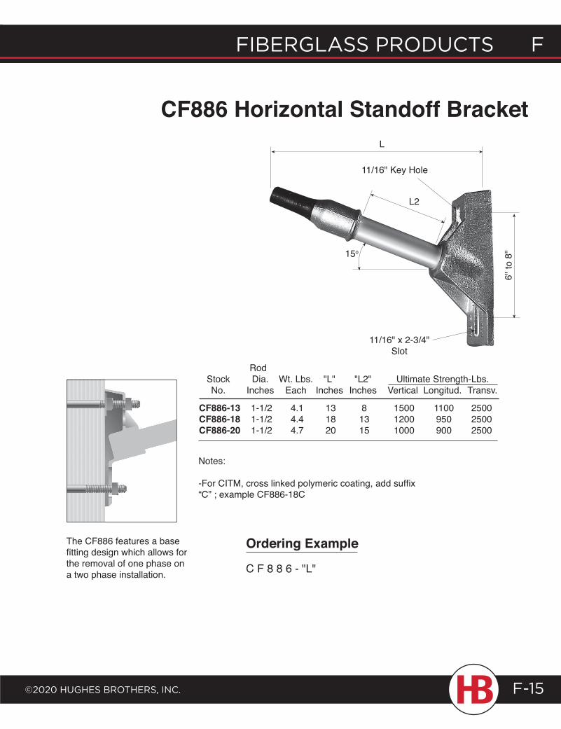
fiberglass products f
©2020 HugHes brotHers, inc.
f fiberglass products
F-15
CF886 Horizontal Standoff BracketL
L2
15o
11/16" Key Hole
Rod Stock Dia. Wt. Lbs. "L" "L2" Ultimate Strength-Lbs. No. Inches Each Inches Inches Vertical Longitud. Transv.
CF886-13 1-1/2 4.1 13 8 1500 1100 2500 CF886-18 1-1/2 4.4 18 13 1200 950 2500 CF886-20 1-1/2 4.7 20 15 1000 900 2500
Notes:
-For CITM, cross linked polymeric coating, add suffix “C” ; example CF886-18C
The CF886 features a base fitting design which allows for the removal of one phase on a two phase installation.
6" to
8"
11/16" x 2-3/4"Slot
Ordering Example
C F 8 8 6 - "L"
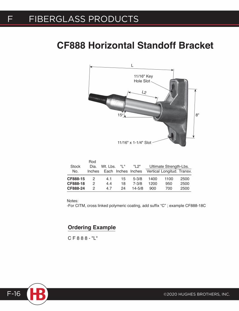
F Fiberglass products
©2020 HugHes brotHers, inc.F-16
CF888 Horizontal Standoff Bracket
L
11/16" Key Hole Slot
L2
15o 8"
11/16" x 1-1/4" Slot
Rod Stock Dia. Wt. Lbs. "L" "L2" Ultimate Strength-Lbs. No. Inches Each Inches Inches Vertical Longitud. Transv.
CF888-15 2 4.1 15 5-3/8 1400 1100 2500 CF888-18 2 4.4 18 7-3/8 1200 950 2500 CF888-24 2 4.7 24 14-5/8 900 700 2500
Notes:-For CITM, cross linked polymeric coating, add suffix “C” ; example CF888-18C
Ordering Example
C F 8 8 8 - "L"
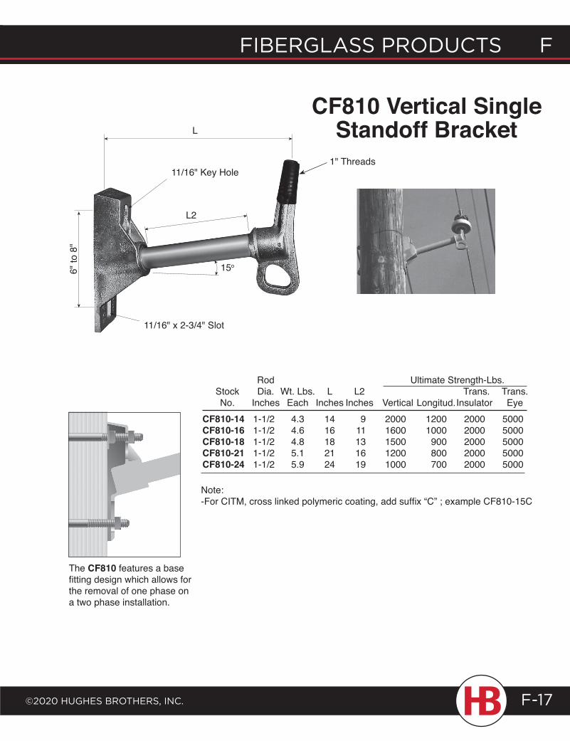
fiberglass products f
©2020 HugHes brotHers, inc.
f fiberglass products
F-17
Rod Ultimate Strength-Lbs. Stock Dia. Wt. Lbs. L L2 Trans. Trans. No. Inches Each Inches Inches Vertical Longitud. Insulator Eye
CF810 Vertical Single Standoff Bracket
CF810-14 1-1/2 4.3 14 9 2000 1200 2000 5000 CF810-16 1-1/2 4.6 16 11 1600 1000 2000 5000 CF810-18 1-1/2 4.8 18 13 1500 900 2000 5000 CF810-21 1-1/2 5.1 21 16 1200 800 2000 5000 CF810-24 1-1/2 5.9 24 19 1000 700 2000 5000
The CF810 features a base fitting design which allows for the removal of one phase on a two phase installation.
L
15o
11/16" Key Hole
L2
Note:-For CITM, cross linked polymeric coating, add suffix “C” ; example CF810-15C
6" to
8"
11/16" x 2-3/4" Slot
1" Threads
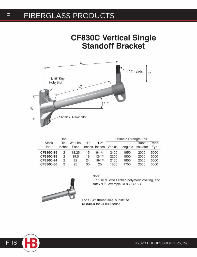
F Fiberglass products
©2020 HugHes brotHers, inc.F-18
CF830C Vertical Single Standoff Bracket
Rod Ultimate Strength-Lbs. Stock Dia. Wt. Lbs. "L" "L2" Trans. Trans. No. Inches Each Inches Inches Vertical Longitud. Insulator Eye CF830C-15 2 18.25 15 9-1/4 2400 1950 2000 5000 CF830C-18 2 19.5 18 12-1/4 2250 1900 2000 5000 CF830C-24 2 22 24 18-1/4 2100 1850 2000 5000 CF830C-30 2 23 30 25 1800 1750 2000 5000
Note:-For CITM, cross linked polymeric coating, add suffix “C” ; example CF830C-15C
For 1-3/8" thread size, substitute CF830-D for CF830 series.
11/16" Key Hole Slot
L
L2
15o
11/16" x 1-1/4" Slot
8"
1" Threads 4"
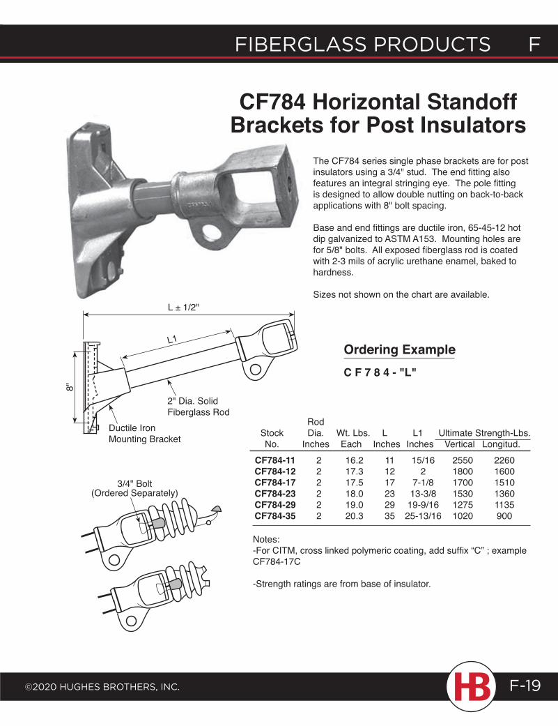
fiberglass products f
©2020 HugHes brotHers, inc.
f fiberglass products
F-19
CF784 Horizontal Standoff Brackets for Post Insulators
Rod Stock Dia. Wt. Lbs. L L1 Ultimate Strength-Lbs. No. Inches Each Inches Inches Vertical Longitud. CF784-11 2 16.2 11 15/16 2550 2260 CF784-12 2 17.3 12 2 1800 1600 CF784-17 2 17.5 17 7-1/8 1700 1510 CF784-23 2 18.0 23 13-3/8 1530 1360 CF784-29 2 19.0 29 19-9/16 1275 1135 CF784-35 2 20.3 35 25-13/16 1020 900
Notes:-For CITM, cross linked polymeric coating, add suffix “C” ; example CF784-17C
-Strength ratings are from base of insulator.
The CF784 series single phase brackets are for post insulators using a 3/4" stud. The end fitting also features an integral stringing eye. The pole fitting is designed to allow double nutting on back-to-back applications with 8" bolt spacing.
Base and end fittings are ductile iron, 65-45-12 hot dip galvanized to ASTM A153. Mounting holes are for 5/8" bolts. All exposed fiberglass rod is coated with 2-3 mils of acrylic urethane enamel, baked to hardness.
Sizes not shown on the chart are available.
Ordering ExampleC F 7 8 4 - "L"
3/4" Bolt (Ordered Separately)
2" Dia. Solid Fiberglass Rod
Ductile Iron Mounting Bracket
8"
L1
L ± 1/2"
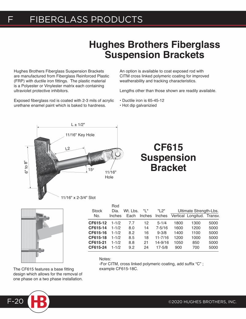
F Fiberglass products
©2020 HugHes brotHers, inc.F-20
Hughes Brothers Fiberglass Suspension Brackets are manufactured from Fiberglass Reinforced Plastic (FRP) with ductile iron fittings. The plastic material is a Polyester or Vinylester matrix each containing ultraviolet protective inhibitors.
Exposed fiberglass rod is coated with 2-3 mils of acrylic urethane enamel paint which is baked to hardness.
Rod Stock Dia. Wt. Lbs. "L" "L2" Ultimate Strength-Lbs. No. Inches Each Inches Inches Vertical Longitud. Transv. CF615-12 1-1/2 7.7 12 5-1/4 1800 1300 5000 CF615-14 1-1/2 8.0 14 7-5/16 1600 1200 5000 CF615-16 1-1/2 8.2 16 9-3/8 1400 1100 5000 CF615-18 1-1/2 8.5 18 11-7/16 1200 1000 5000 CF615-21 1-1/2 8.8 21 14-9/16 1050 850 5000 CF615-24 1-1/2 9.2 24 17-5/8 900 700 5000
CF615 Suspension
Bracket
The CF615 features a base fitting design which allows for the removal of one phase on a two phase installation.
Notes:-For CITM, cross linked polymeric coating, add suffix “C” ; example CF615-18C.
An option is available to coat exposed rod with CITM cross linked polymeric coating for improved weatherability and tracking characteristics.
Lengths other than those shown are readily available.
• Ductile iron is 65-45-12• Hot dip galvanizied
Hughes Brothers Fiberglass Suspension Brackets
11/16" Key Hole
L2
15o
6" to
8"
L ± 1/2"
11/16" x 2-3/4" Slot
11/16" Hole
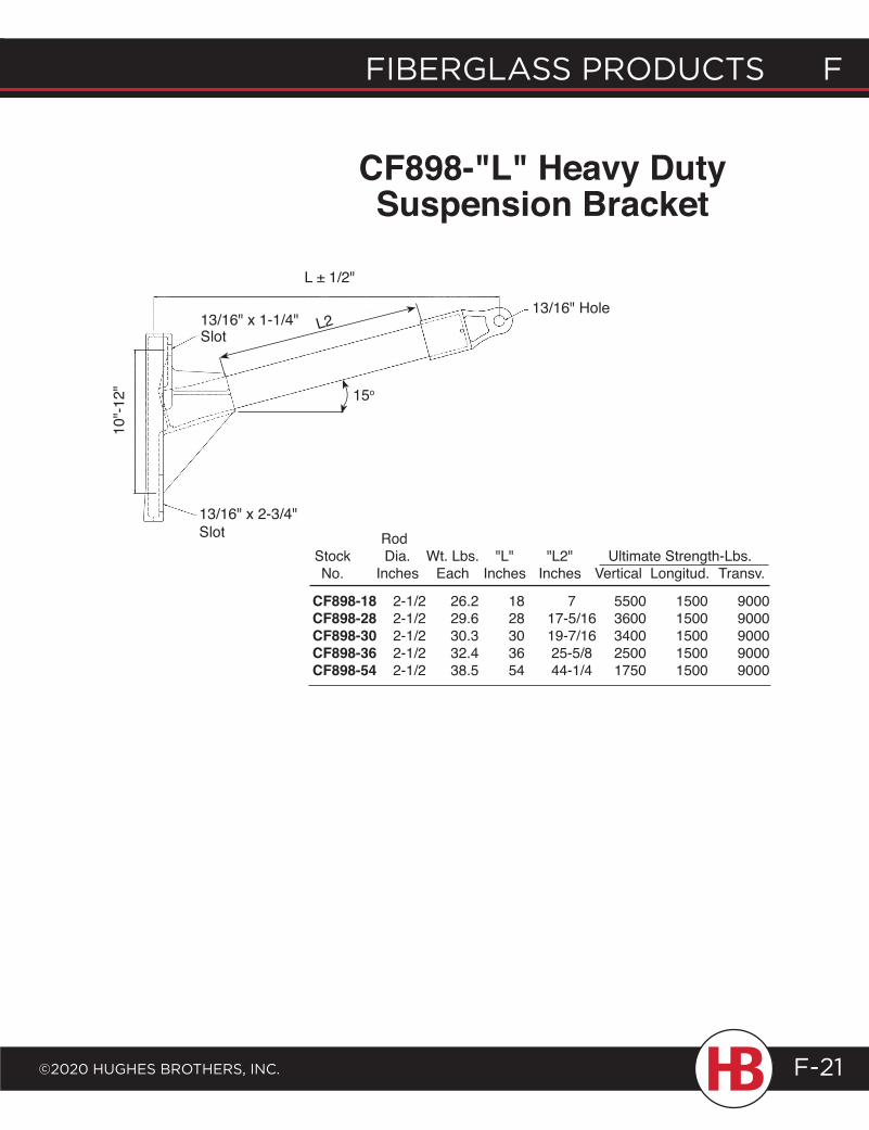
10"-1
2" 15o
L ± 1/2"
L213/16" x 1-1/4" Slot
13/16" x 2-3/4"Slot
13/16" Hole
fiberglass products f
©2020 HugHes brotHers, inc.
f fiberglass products
F-21
Rod Stock Dia. Wt. Lbs. "L" "L2" Ultimate Strength-Lbs. No. Inches Each Inches Inches Vertical Longitud. Transv.
CF898-18 2-1/2 26.2 18 7 5500 1500 9000 CF898-28 2-1/2 29.6 28 17-5/16 3600 1500 9000 CF898-30 2-1/2 30.3 30 19-7/16 3400 1500 9000 CF898-36 2-1/2 32.4 36 25-5/8 2500 1500 9000 CF898-54 2-1/2 38.5 54 44-1/4 1750 1500 9000
CF898-"L" Heavy Duty Suspension Bracket
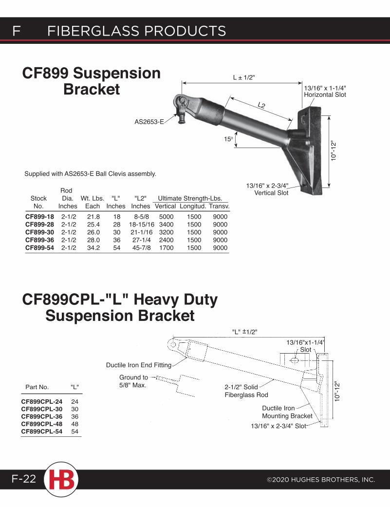
L ± 1/2"13/16" x 1-1/4" Horizontal Slot
15o
10"-1
2"
L2
AS2653-E
13/16" x 2-3/4" Vertical Slot
"L" +1/2"-
Ground to 5/8" Max.
Ductile Iron End Fitting
2-1/2" Solid Fiberglass Rod
Ductile Iron Mounting Bracket
13/16" x 2-3/4" Slot
13/16"x1-1/4" Slot
10"-1
2"
F Fiberglass products
©2020 HugHes brotHers, inc.F-22
Rod Stock Dia. Wt. Lbs. "L" "L2" Ultimate Strength-Lbs. No. Inches Each Inches Inches Vertical Longitud. Transv.
CF899 Suspension Bracket
CF899-18 2-1/2 21.8 18 8-5/8 5000 1500 9000 CF899-28 2-1/2 25.4 28 18-15/16 3400 1500 9000 CF899-30 2-1/2 26.0 30 21-1/16 3200 1500 9000 CF899-36 2-1/2 28.0 36 27-1/4 2400 1500 9000 CF899-54 2-1/2 34.2 54 45-7/8 1700 1500 9000
Supplied with AS2653-E Ball Clevis assembly.
CF899CPL-"L" Heavy Duty Suspension Bracket
Part No. "L" CF899CPL-24 24 CF899CPL-30 30 CF899CPL-36 36 CF899CPL-48 48 CF899CPL-54 54
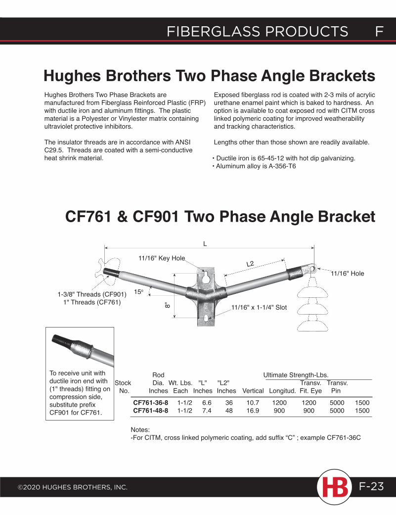
fiberglass products f
©2020 HugHes brotHers, inc.
f fiberglass products
F-23
Hughes Brothers Two Phase Angle BracketsHughes Brothers Two Phase Brackets are manufactured from Fiberglass Reinforced Plastic (FRP) with ductile iron and aluminum fittings. The plastic material is a Polyester or Vinylester matrix containing ultraviolet protective inhibitors.
The insulator threads are in accordance with ANSI C29.5. Threads are coated with a semi-conductive heat shrink material.
Exposed fiberglass rod is coated with 2-3 mils of acrylic urethane enamel paint which is baked to hardness. An option is available to coat exposed rod with CITM cross linked polymeric coating for improved weatherability and tracking characteristics.
Lengths other than those shown are readily available.
• Ductile iron is 65-45-12 with hot dip galvanizing.• Aluminum alloy is A-356-T6
CF761 & CF901 Two Phase Angle Bracket
Rod Ultimate Strength-Lbs. Stock Dia. Wt. Lbs. "L" "L2" Transv. Transv. No. Inches Each Inches Inches Vertical Longitud. Fit. Eye Pin
Notes:-For CITM, cross linked polymeric coating, add suffix “C” ; example CF761-36C
CF761-36-8 1-1/2 6.6 36 10.7 1200 1200 5000 1500 CF761-48-8 1-1/2 7.4 48 16.9 900 900 5000 1500
To receive unit with ductile iron end with (1" threads) fitting on compression side, substitute prefix CF901 for CF761.
8"
15o
11/16" Key HoleL2
L
11/16" x 1-1/4" Slot
11/16" Hole
1-3/8" Threads (CF901)1" Threads (CF761)
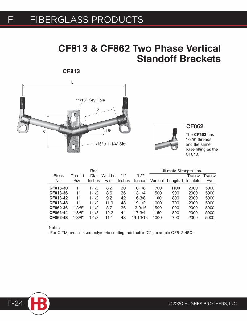
F Fiberglass products
©2020 HugHes brotHers, inc.F-24
L
8" 15o
11/16" x 1-1/4" Slot
L2
11/16" Key Hole
CF813 & CF862 Two Phase Vertical Standoff Brackets
Rod Ultimate Strength-Lbs. Stock Thread Dia. Wt. Lbs. "L" "L2" Transv. Transv. No. Size Inches Each Inches Inches Vertical Longitud. Insulator Eye
CF813-30 1" 1-1/2 8.2 30 10-1/8 1700 1100 2000 5000 CF813-36 1" 1-1/2 8.6 36 13-1/4 1500 900 2000 5000 CF813-42 1" 1-1/2 9.2 42 16-3/8 1100 800 2000 5000 CF813-48 1" 1-1/2 11.0 48 19-1/2 1000 700 2000 5000 CF862-36 1-3/8" 1-1/2 8.7 36 13-9/16 1500 900 2000 5000 CF862-44 1-3/8" 1-1/2 10.2 44 17-3/4 1150 800 2000 5000 CF862-48 1-3/8" 1-1/2 11.1 48 19-13/16 1000 700 2000 5000
Notes:-For CITM, cross linked polymeric coating, add suffix “C” ; example CF813-48C.
CF813
The CF862 has 1-3/8" threads and the same base fitting as the CF813.
CF862
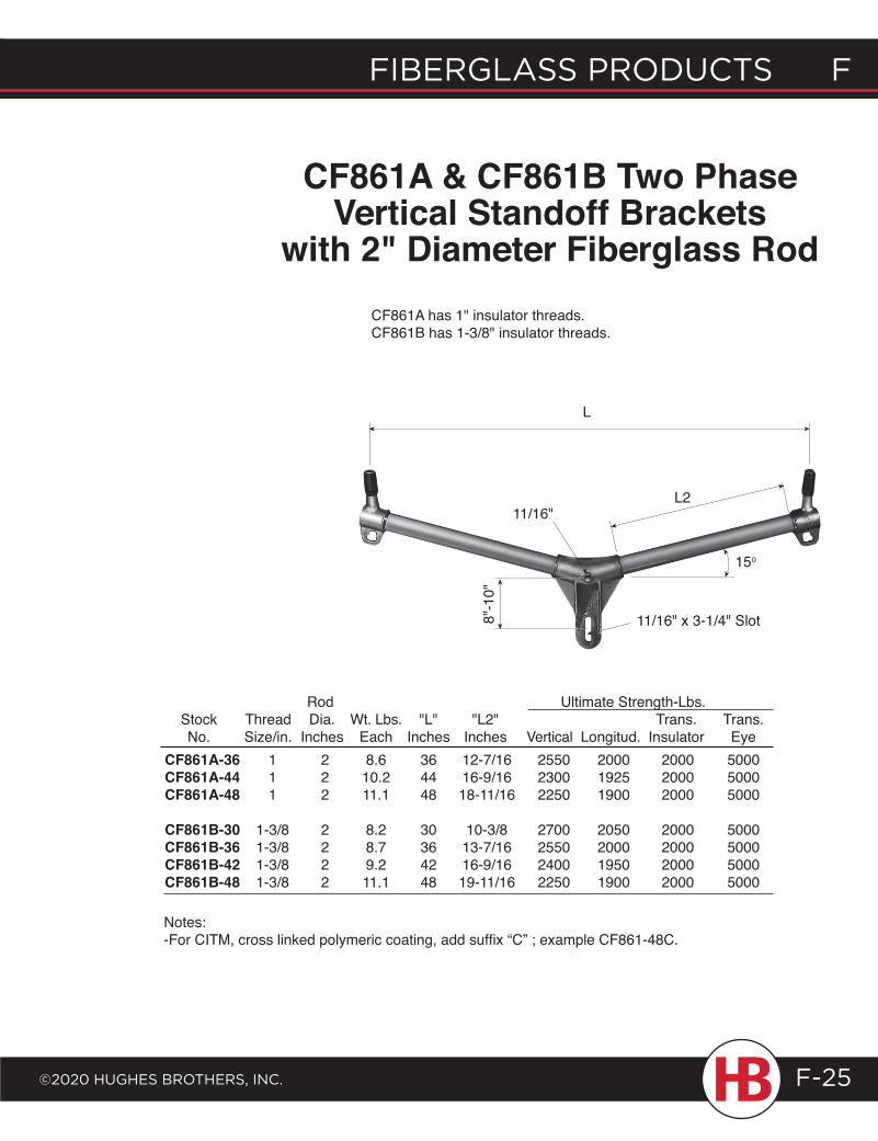
fiberglass products f
©2020 HugHes brotHers, inc.
f fiberglass products
F-25
L
CF861A & CF861B Two Phase Vertical Standoff Brackets
with 2" Diameter Fiberglass Rod
L2
11/16" x 3-1/4" Slot
15o
11/16"
CF861A has 1" insulator threads.CF861B has 1-3/8" insulator threads.
8"-1
0"
Rod Ultimate Strength-Lbs. Stock Thread Dia. Wt. Lbs. "L" "L2" Trans. Trans. No. Size/in. Inches Each Inches Inches Vertical Longitud. Insulator Eye CF861A-36 1 2 8.6 36 12-7/16 2550 2000 2000 5000 CF861A-44 1 2 10.2 44 16-9/16 2300 1925 2000 5000 CF861A-48 1 2 11.1 48 18-11/16 2250 1900 2000 5000 CF861B-30 1-3/8 2 8.2 30 10-3/8 2700 2050 2000 5000 CF861B-36 1-3/8 2 8.7 36 13-7/16 2550 2000 2000 5000 CF861B-42 1-3/8 2 9.2 42 16-9/16 2400 1950 2000 5000 CF861B-48 1-3/8 2 11.1 48 19-11/16 2250 1900 2000 5000
Notes:-For CITM, cross linked polymeric coating, add suffix “C” ; example CF861-48C.
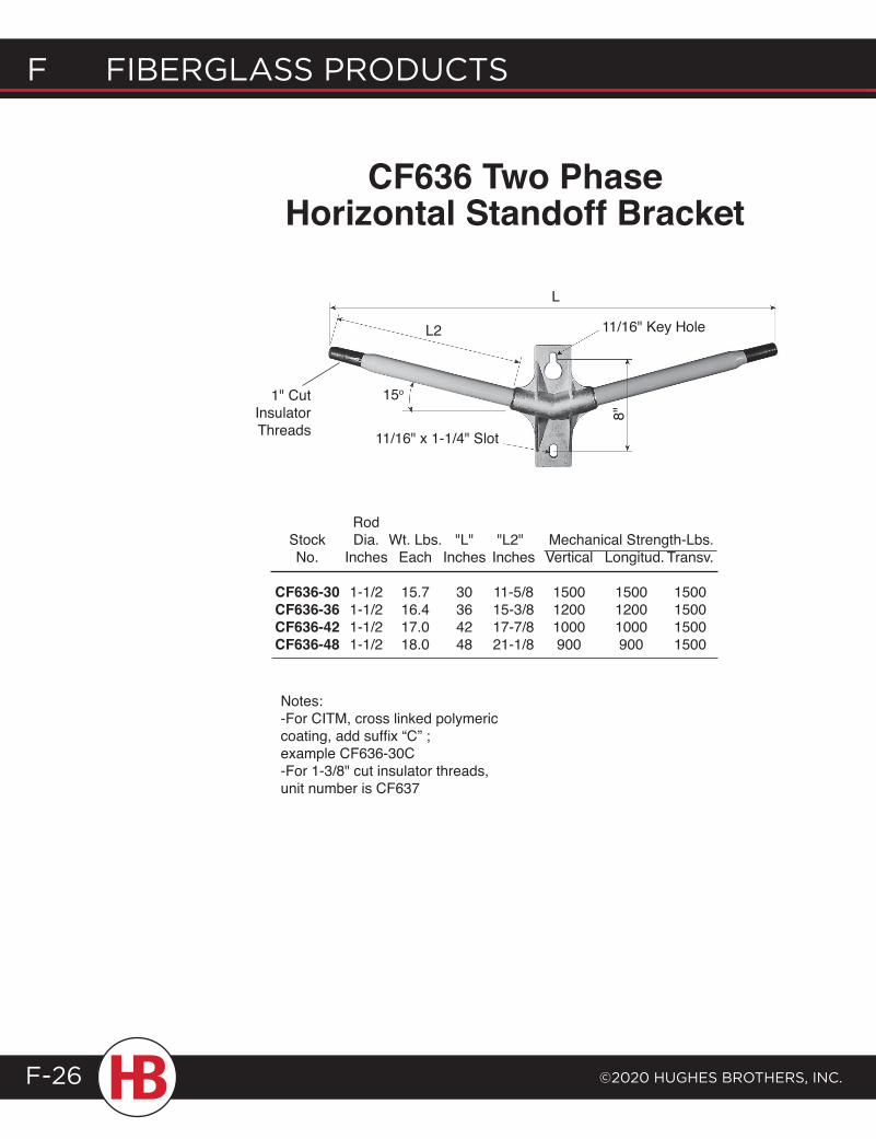
F Fiberglass products
©2020 HugHes brotHers, inc.F-26
CF636 Two Phase Horizontal Standoff Bracket
L
L2 11/16" Key Hole
15o
Notes:-For CITM, cross linked polymeric coating, add suffix “C” ; example CF636-30C -For 1-3/8" cut insulator threads, unit number is CF637
Rod Stock Dia. Wt. Lbs. "L" "L2" Mechanical Strength-Lbs. No. Inches Each Inches Inches Vertical Longitud. Transv.
CF636-30 1-1/2 15.7 30 11-5/8 1500 1500 1500 CF636-36 1-1/2 16.4 36 15-3/8 1200 1200 1500 CF636-42 1-1/2 17.0 42 17-7/8 1000 1000 1500 CF636-48 1-1/2 18.0 48 21-1/8 900 900 1500
11/16" x 1-1/4" Slot
8"
1" Cut Insulator Threads
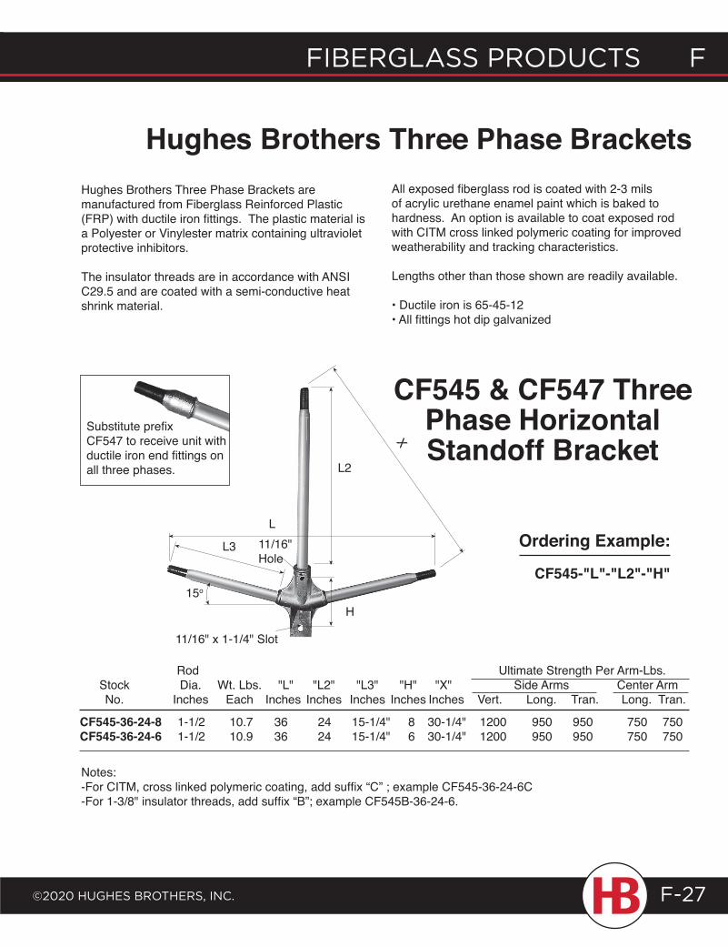
fiberglass products f
©2020 HugHes brotHers, inc.
f fiberglass products
F-27
Hughes Brothers Three Phase BracketsHughes Brothers Three Phase Brackets are manufactured from Fiberglass Reinforced Plastic (FRP) with ductile iron fittings. The plastic material is a Polyester or Vinylester matrix containing ultraviolet protective inhibitors.
The insulator threads are in accordance with ANSI C29.5 and are coated with a semi-conductive heat shrink material.
All exposed fiberglass rod is coated with 2-3 mils of acrylic urethane enamel paint which is baked to hardness. An option is available to coat exposed rod with CITM cross linked polymeric coating for improved weatherability and tracking characteristics.
Lengths other than those shown are readily available.
• Ductile iron is 65-45-12• All fittings hot dip galvanized
CF545 & CF547 Three Phase Horizontal Standoff Bracket
L2
L
H
L3 Ordering Example:
CF545-"L"-"L2"-"H"15o
Rod Ultimate Strength Per Arm-Lbs. Stock Dia. Wt. Lbs. "L" "L2" "L3" "H" "X" Side Arms Center Arm No. Inches Each Inches Inches Inches Inches Inches Vert. Long. Tran. Long. Tran.
CF545-36-24-8 1-1/2 10.7 36 24 15-1/4" 8 30-1/4" 1200 950 950 750 750 CF545-36-24-6 1-1/2 10.9 36 24 15-1/4" 6 30-1/4" 1200 950 950 750 750
Notes:-For CITM, cross linked polymeric coating, add suffix “C” ; example CF545-36-24-6C-For 1-3/8" insulator threads, add suffix “B”; example CF545B-36-24-6.
Substitute prefix CF547 to receive unit with ductile iron end fittings on all three phases.
11/16" Hole
11/16" x 1-1/4" Slot
X
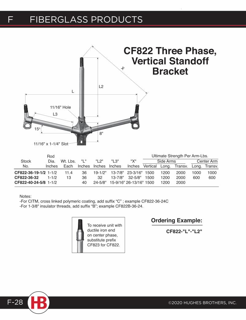
F Fiberglass products
©2020 HugHes brotHers, inc.F-28
CF822 Three Phase, Vertical Standoff
BracketL2
15o
8"
L
L3
Rod Stock Dia. Wt. Lbs. "L" "L2" "L3" "X" Side Arms Center Arm No. Inches Each Inches Inches Inches Inches Vertical Long. Transv. Long. Transv.CF822-36-19-1/2 1-1/2 11.4 36 19-1/2" 13-7/8" 23-3/16" 1500 1200 2000 1000 1000 CF822-36-32 1-1/2 13 36 32 13-7/8" 32-5/8" 1500 1200 2000 600 600CF822-40-24-5/8 1-1/2 40 24-5/8" 15-9/16" 26-13/16" 1500 1200 2000
Notes:-For CITM, cross linked polymeric coating, add suffix “C” ; example CF822-36-24C-For 1-3/8" insulator threads, add suffix “B”; example CF822B-36-24.
Ordering Example:
CF822-"L"-"L2"
11/16" Hole
11/16" x 1-1/4" Slot
To receive unit with ductile iron end on center phase, substitute prefix CF823 for CF822.
X
Ultimate Strength Per Arm-Lbs.
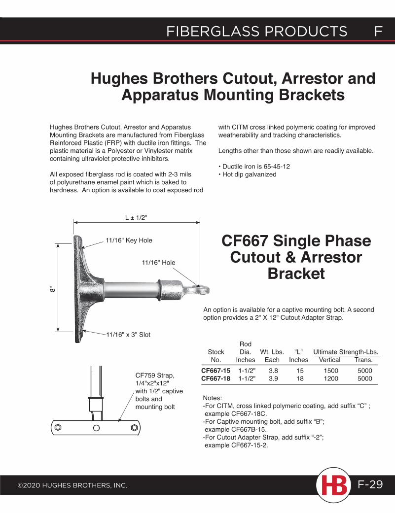
fiberglass products f
©2020 HugHes brotHers, inc.
f fiberglass products
F-29
Hughes Brothers Cutout, Arrestor and Apparatus Mounting Brackets are manufactured from Fiberglass Reinforced Plastic (FRP) with ductile iron fittings. The plastic material is a Polyester or Vinylester matrix containing ultraviolet protective inhibitors.
All exposed fiberglass rod is coated with 2-3 mils of polyurethane enamel paint which is baked to hardness. An option is available to coat exposed rod
Hughes Brothers Cutout, Arrestor and Apparatus Mounting Brackets
L ± 1/2"
11/16" Key Hole
with CITM cross linked polymeric coating for improved weatherability and tracking characteristics.
Lengths other than those shown are readily available.
• Ductile iron is 65-45-12• Hot dip galvanized
11/16" Hole
8"
CF667-15 1-1/2" 3.8 15 1500 5000CF667-18 1-1/2" 3.9 18 1200 5000
Rod Stock Dia. Wt. Lbs. "L" Ultimate Strength-Lbs. No. Inches Each Inches Vertical Trans.
Notes:-For CITM, cross linked polymeric coating, add suffix “C” ; example CF667-18C.-For Captive mounting bolt, add suffix “B”; example CF667B-15.-For Cutout Adapter Strap, add suffix “-2”; example CF667-15-2.
An option is available for a captive mounting bolt. A second option provides a 2" X 12" Cutout Adapter Strap.
CF759 Strap, 1/4"x2"x12"with 1/2" captive bolts and mounting bolt
CF667 Single Phase Cutout & Arrestor
Bracket
11/16" x 3" Slot
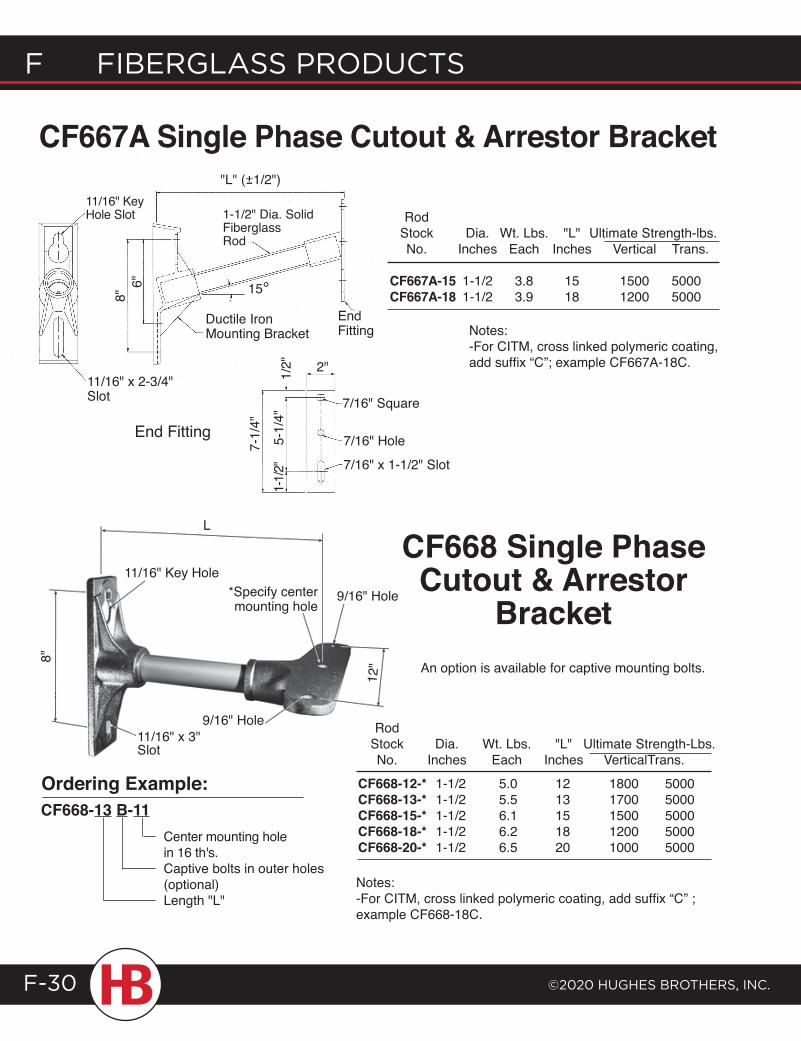
F Fiberglass products
©2020 HugHes brotHers, inc.F-30
CF668 Single Phase Cutout & Arrestor
Bracket
Center mounting hole in 16 th's.Captive bolts in outer holes (optional)Length "L"
Ordering Example:
Notes:-For CITM, cross linked polymeric coating, add suffix “C” ; example CF668-18C.
8"
11/16" x 3" Slot
9/16" Hole
*Specify center mounting hole
11/16" Key Hole
L
12"
9/16" Hole
Rod Stock Dia. Wt. Lbs. "L" Ultimate Strength-Lbs. No. Inches Each Inches Vertical Trans.CF668-12-* 1-1/2 5.0 12 1800 5000 CF668-13-* 1-1/2 5.5 13 1700 5000 CF668-15-* 1-1/2 6.1 15 1500 5000 CF668-18-* 1-1/2 6.2 18 1200 5000 CF668-20-* 1-1/2 6.5 20 1000 5000
CF668-13 B-11
An option is available for captive mounting bolts.
CF667A Single Phase Cutout & Arrestor Bracket
Rod Stock Dia. Wt. Lbs. "L" Ultimate Strength-lbs. No. Inches Each Inches Vertical Trans.
CF667A-15 1-1/2 3.8 15 1500 5000 CF667A-18 1-1/2 3.9 18 1200 5000
Notes:-For CITM, cross linked polymeric coating, add suffix “C”; example CF667A-18C.
"L" (+1/2")-
8"6"
Ductile Iron Mounting Bracket
15°
1-1/2" Dia. Solid Fiberglass Rod
End Fitting
2"
7-1/
4"
1-1/2
"5-
1/4"
1/2"
7/16" Square
7/16" x 1-1/2" Slot
7/16" HoleEnd Fitting
11/16" Key Hole Slot
11/16" x 2-3/4" Slot
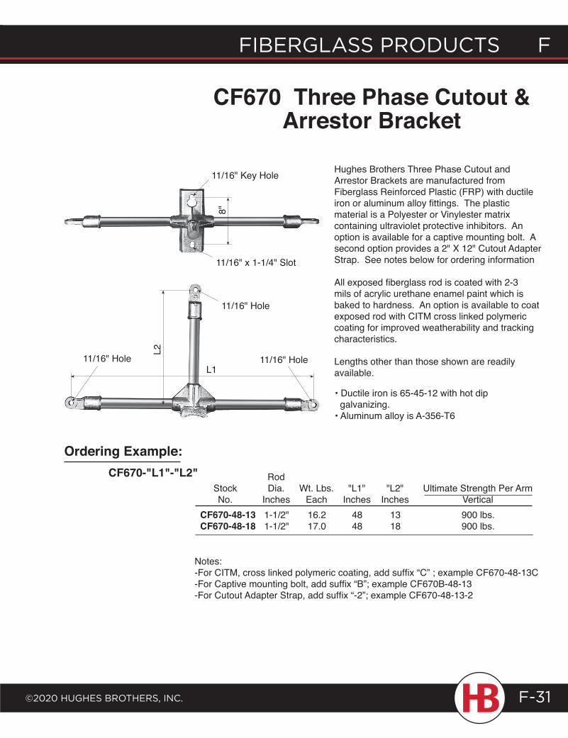
fiberglass products f
©2020 HugHes brotHers, inc.
f fiberglass products
F-31
Hughes Brothers Three Phase Cutout and Arrestor Brackets are manufactured from Fiberglass Reinforced Plastic (FRP) with ductile iron or aluminum alloy fittings. The plastic material is a Polyester or Vinylester matrix containing ultraviolet protective inhibitors. An option is available for a captive mounting bolt. A second option provides a 2" X 12" Cutout Adapter Strap. See notes below for ordering information
All exposed fiberglass rod is coated with 2-3 mils of acrylic urethane enamel paint which is baked to hardness. An option is available to coat exposed rod with CITM cross linked polymeric coating for improved weatherability and tracking characteristics.
Lengths other than those shown are readily available.L1
CF670-"L1"-"L2"
Ordering Example:
11/16" Key Hole
11/16" x 1-1/4" Slot
8"
11/16" Hole
11/16" Hole11/16" Hole
L2
CF670 Three Phase Cutout & Arrestor Bracket
Notes:-For CITM, cross linked polymeric coating, add suffix “C” ; example CF670-48-13C-For Captive mounting bolt, add suffix “B”; example CF670B-48-13-For Cutout Adapter Strap, add suffix “-2”; example CF670-48-13-2
Rod Stock Dia. Wt. Lbs. "L1" "L2" Ultimate Strength Per Arm No. Inches Each Inches Inches Vertical CF670-48-13 1-1/2" 16.2 48 13 900 lbs.CF670-48-18 1-1/2" 17.0 48 18 900 lbs.
• Ductile iron is 65-45-12 with hot dip galvanizing.• Aluminum alloy is A-356-T6
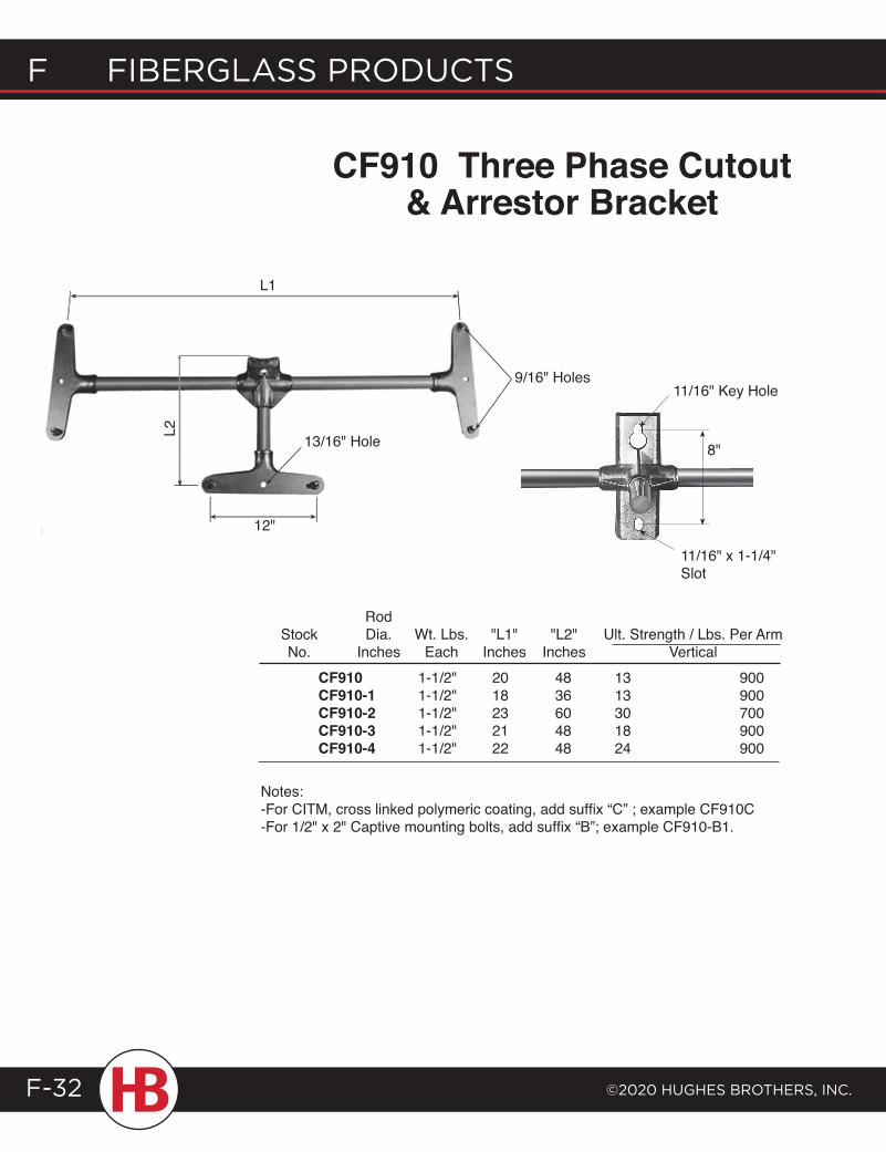
F Fiberglass products
©2020 HugHes brotHers, inc.F-32
CF910 Three Phase Cutout & Arrestor Bracket
12"
L1
13/16" Hole
9/16" Holes
8"
11/16" x 1-1/4" Slot
11/16" Key Hole
L2
Notes:-For CITM, cross linked polymeric coating, add suffix “C” ; example CF910C-For 1/2" x 2" Captive mounting bolts, add suffix “B”; example CF910-B1.
Rod Stock Dia. Wt. Lbs. "L1" "L2" Ult. Strength / Lbs. Per Arm No. Inches Each Inches Inches Vertical
CF910 1-1/2" 20 48 13 900CF910-1 1-1/2" 18 36 13 900CF910-2 1-1/2" 23 60 30 700CF910-3 1-1/2" 21 48 18 900CF910-4 1-1/2" 22 48 24 900
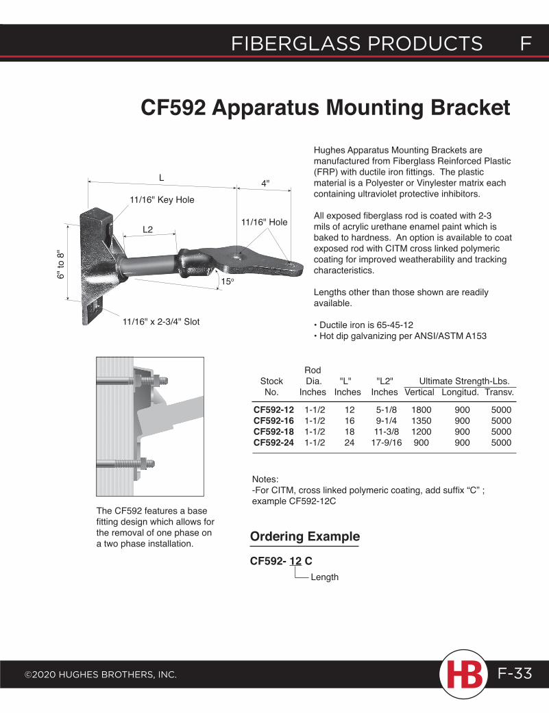
fiberglass products f
©2020 HugHes brotHers, inc.
f fiberglass products
F-33
CF910 1-1/2" 20 48 13 900CF910-1 1-1/2" 18 36 13 900CF910-2 1-1/2" 23 60 30 700CF910-3 1-1/2" 21 48 18 900CF910-4 1-1/2" 22 48 24 900
CF592 Apparatus Mounting BracketHughes Apparatus Mounting Brackets are manufactured from Fiberglass Reinforced Plastic (FRP) with ductile iron fittings. The plastic material is a Polyester or Vinylester matrix each containing ultraviolet protective inhibitors.
All exposed fiberglass rod is coated with 2-3 mils of acrylic urethane enamel paint which is baked to hardness. An option is available to coat exposed rod with CITM cross linked polymeric coating for improved weatherability and tracking characteristics.
Lengths other than those shown are readily available.
• Ductile iron is 65-45-12• Hot dip galvanizing per ANSI/ASTM A153
15o
L2
11/16" Key Hole
11/16" Hole
L 4"
11/16" x 2-3/4" Slot
The CF592 features a base fitting design which allows for the removal of one phase on a two phase installation.
Rod Stock Dia. "L" "L2" Ultimate Strength-Lbs. No. Inches Inches Inches Vertical Longitud. Transv.
CF592-12 1-1/2 12 5-1/8 1800 900 5000 CF592-16 1-1/2 16 9-1/4 1350 900 5000 CF592-18 1-1/2 18 11-3/8 1200 900 5000 CF592-24 1-1/2 24 17-9/16 900 900 5000
6" to
8"
Notes:-For CITM, cross linked polymeric coating, add suffix “C” ; example CF592-12C
Ordering Example
CF592- 12 CLength
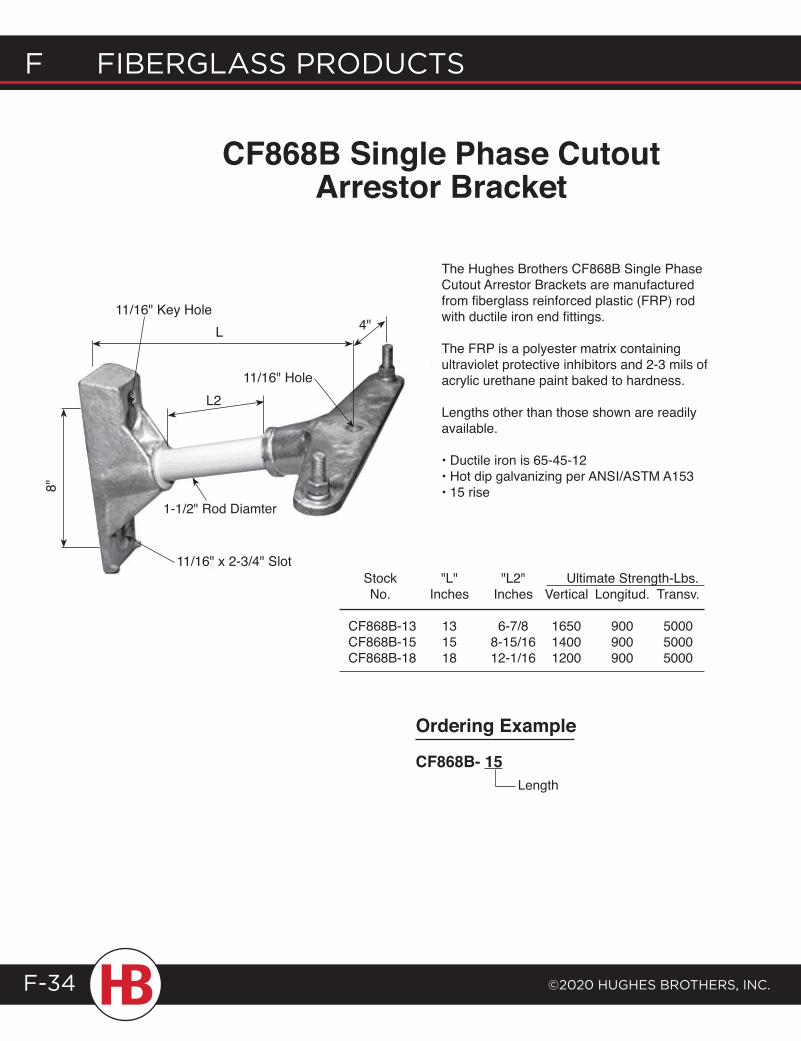
F Fiberglass products
©2020 HugHes brotHers, inc.F-34
CF868B Single Phase Cutout Arrestor Bracket
The Hughes Brothers CF868B Single Phase Cutout Arrestor Brackets are manufactured from fiberglass reinforced plastic (FRP) rod with ductile iron end fittings.
The FRP is a polyester matrix containing ultraviolet protective inhibitors and 2-3 mils of acrylic urethane paint baked to hardness.
Lengths other than those shown are readily available.
• Ductile iron is 65-45-12• Hot dip galvanizing per ANSI/ASTM A153• 15 rise 8"
L2
L 4"11/16" Key Hole
11/16" x 2-3/4" Slot
11/16" Hole
Ordering Example
CF868B- 15 Length
Stock "L" "L2" Ultimate Strength-Lbs. No. Inches Inches Vertical Longitud. Transv.
CF868B-13 13 6-7/8 1650 900 5000CF868B-15 15 8-15/16 1400 900 5000CF868B-18 18 12-1/16 1200 900 5000
1-1/2" Rod Diamter
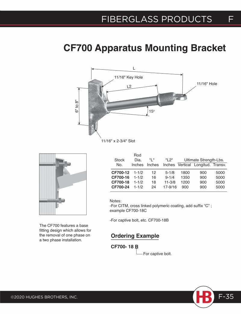
fiberglass products f
©2020 HugHes brotHers, inc.
f fiberglass products
F-35
CF700 Apparatus Mounting Bracket
The CF700 features a base fitting design which allows for the removal of one phase on a two phase installation.
Rod Stock Dia. "L" "L2" Ultimate Strength-Lbs. No. Inches Inches Inches Vertical Longitud. Transv.
CF700-12 1-1/2 12 5-1/8 1800 900 5000 CF700-16 1-1/2 16 9-1/4 1350 900 5000 CF700-18 1-1/2 18 11-3/8 1200 900 5000 CF700-24 1-1/2 24 17-9/16 900 900 5000
11/16" Key Hole6"
to 8
"
L
L2
15o
11/16" x 2-3/4" Slot
11/16" Hole
Notes:-For CITM, cross linked polymeric coating, add suffix “C” ; example CF700-18C
-For captive bolt, etc. CF700-18B
Ordering Example
CF700- 18 BFor captive bolt.
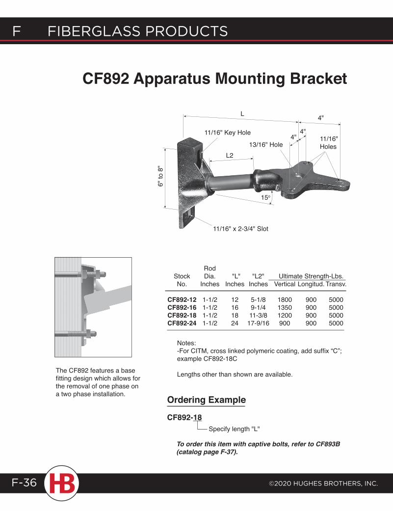
F Fiberglass products
©2020 HugHes brotHers, inc.F-36
CF892 Apparatus Mounting Bracket
Notes:-For CITM, cross linked polymeric coating, add suffix “C”; example CF892-18C
Lengths other than shown are available.The CF892 features a base fitting design which allows for the removal of one phase on a two phase installation.
L 4"
4"4"
13/16" Hole
11/16" Key Hole11/16"Holes
15o
L2
11/16" x 2-3/4" Slot
6" to
8"
Rod Stock Dia. "L" "L2" Ultimate Strength-Lbs. No. Inches Inches Inches Vertical Longitud. Transv.
CF892-12 1-1/2 12 5-1/8 1800 900 5000 CF892-16 1-1/2 16 9-1/4 1350 900 5000 CF892-18 1-1/2 18 11-3/8 1200 900 5000 CF892-24 1-1/2 24 17-9/16 900 900 5000
Ordering Example
CF892-18Specify length "L"
To order this item with captive bolts, refer to CF893B (catalog page F-37).
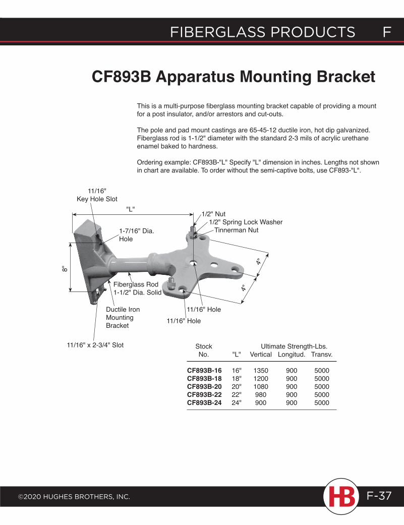
fiberglass products f
©2020 HugHes brotHers, inc.
f fiberglass products
F-37
CF893B Apparatus Mounting BracketThis is a multi-purpose fiberglass mounting bracket capable of providing a mount for a post insulator, and/or arrestors and cut-outs.
The pole and pad mount castings are 65-45-12 ductile iron, hot dip galvanized. Fiberglass rod is 1-1/2" diameter with the standard 2-3 mils of acrylic urethane enamel baked to hardness.
Ordering example: CF893B-"L" Specify "L" dimension in inches. Lengths not shown in chart are available. To order without the semi-captive bolts, use CF893-"L".
Stock Ultimate Strength-Lbs. No. "L" Vertical Longitud. Transv.
CF893B-16 16" 1350 900 5000 CF893B-18 18" 1200 900 5000CF893B-20 20" 1080 900 5000CF893B-22 22" 980 900 5000CF893B-24 24" 900 900 5000
8"
Ductile Iron Mounting Bracket
Fiberglass Rod 1-1/2" Dia. Solid
11/16" Hole11/16" Hole
4"
4"
"L" 1/2" Nut 1/2" Spring Lock Washer Tinnerman Nut
11/16" Key Hole Slot
11/16" x 2-3/4" Slot
1-7/16" Dia.Hole
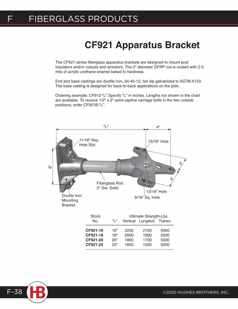
F Fiberglass products
©2020 HugHes brotHers, inc.F-38
The CF921 series fiberglass apparatus brackets are designed to mount post insulators and/or cutouts and arrestors. The 2" diameter GFRP rod is coated with 2-3 mils of acrylic urethane enamel baked to hardness.
End and base castings are ductile iron, 64-45-12, hot dip galvanized to ASTM A153. The base casting is designed for back-to-back applications on the pole.
Ordering example: CF912-"L" Specify "L" in inches. Lengths not shown in the chart are available. To receive 1/2" x 2" semi-captive carriage bolts in the two outside positions, order CF921B-"L".
CF921 Apparatus Bracket8"
Ductile Iron Mounting Bracket
Fiberglass Rod 2" Dia. Solid
13/16" Hole
4"
4"
"L"
9/16" Sq. Hole13/16" Hole
4"
11/16" Key Hole Slot
Stock Ultimate Strength-Lbs. No. "L" Vertical Longitud. Transv.
CF921-16 16" 2250 2100 5000 CF921-18 18" 2000 1900 5000CF921-20 20" 1800 1700 5000CF921-22 22" 1600 1500 5000
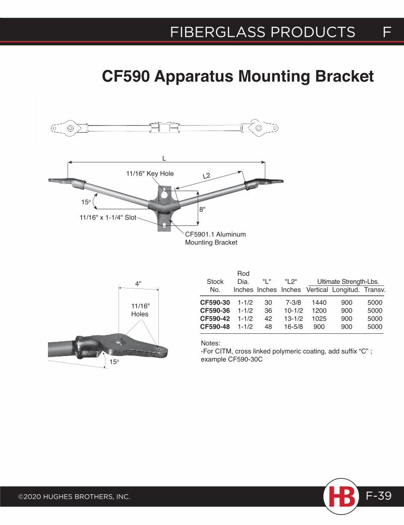
fiberglass products f
©2020 HugHes brotHers, inc.
f fiberglass products
F-39
CF590 Apparatus Mounting Bracket
4"
L
15o
11/16" x 1-1/4" Slot
11/16" Key Hole L2
8"
11/16" Holes
Rod Stock Dia. "L" "L2" Ultimate Strength-Lbs. No. Inches Inches Inches Vertical Longitud. Transv.
CF590-30 1-1/2 30 7-3/8 1440 900 5000 CF590-36 1-1/2 36 10-1/2 1200 900 5000 CF590-42 1-1/2 42 13-1/2 1025 900 5000 CF590-48 1-1/2 48 16-5/8 900 900 5000
Notes:-For CITM, cross linked polymeric coating, add suffix “C” ; example CF590-30C15o
CF5901.1 Aluminum Mounting Bracket
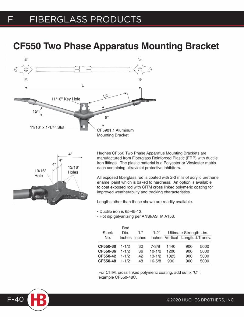
F Fiberglass products
©2020 HugHes brotHers, inc.F-40
Hughes CF550 Two Phase Apparatus Mounting Brackets are manufactured from Fiberglass Reinforced Plastic (FRP) with ductile iron fittings. The plastic material is a Polyester or Vinylester matrix each containing ultraviolet protective inhibitors.
All exposed fiberglass rod is coated with 2-3 mils of acrylic urethane enamel paint which is baked to hardness. An option is available to coat exposed rod with CITM cross linked polymeric coating for improved weatherability and tracking characteristics.
Lengths other than those shown are readily available.
• Ductile iron is 65-45-12.• Hot dip galvanizing per ANSI/ASTM A153.
4"
CF550 Two Phase Apparatus Mounting Bracket
Rod Stock Dia. "L" "L2" Ultimate Strength-Lbs. No. Inches Inches Inches Vertical Longitud. Transv.
13/16"Hole
CF550-30 1-1/2 30 7-3/8 1440 900 5000 CF550-36 1-1/2 36 10-1/2 1200 900 5000 CF550-42 1-1/2 42 13-1/2 1025 900 5000 CF550-48 1-1/2 48 16-5/8 900 900 5000
4"4"
For CITM, cross linked polymeric coating, add suffix “C” ; example CF550-48C.
13/16"Holes
L
15o
11/16" x 1-1/4" Slot
11/16" Key Hole L2
8"
CF5901.1 Aluminum Mounting Bracket
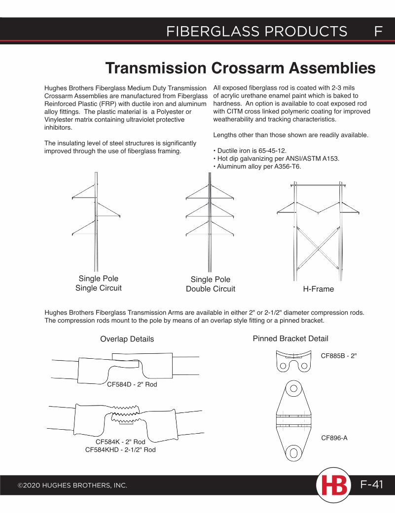
fiberglass products f
©2020 HugHes brotHers, inc.
f fiberglass products
F-41
Transmission Crossarm AssembliesHughes Brothers Fiberglass Medium Duty Transmission Crossarm Assemblies are manufactured from Fiberglass Reinforced Plastic (FRP) with ductile iron and aluminum alloy fittings. The plastic material is a Polyester or Vinylester matrix containing ultraviolet protective inhibitors.
The insulating level of steel structures is significantly improved through the use of fiberglass framing.
All exposed fiberglass rod is coated with 2-3 mils of acrylic urethane enamel paint which is baked to hardness. An option is available to coat exposed rod with CITM cross linked polymeric coating for improved weatherability and tracking characteristics.
Lengths other than those shown are readily available.
• Ductile iron is 65-45-12. • Hot dip galvanizing per ANSI/ASTM A153. • Aluminum alloy per A356-T6.
Hughes Brothers Fiberglass Transmission Arms are available in either 2" or 2-1/2" diameter compression rods. The compression rods mount to the pole by means of an overlap style fitting or a pinned bracket.
Single PoleSingle Circuit
Single PoleDouble Circuit H-Frame
Overlap Details Pinned Bracket Detail
CF584K - 2" RodCF584KHD - 2-1/2" Rod
CF885B - 2"
CF896-A
CF584D - 2" Rod
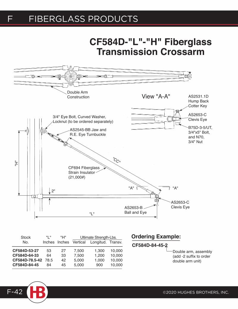
F Fiberglass products
©2020 HugHes brotHers, inc.F-42
CF584D-"L"-"H" Fiberglass Transmission Crossarm
Stock "L" "H" No. Inches Inches
CF584D-53-27 53 27 CF584D-64-33 64 33 CF584D-78.5-42 78.5 42CF584D-84-45 84 45
Double arm, assembly (add -2 suffix to order double arm unit)
CF584D-84-45-2Ordering Example:
"A" "A"
AS2653-C Clevis EyeAS2653-B
Ball and Eye
Double Arm Construction AS2531.1D
Hump Back Cotter Key
AS2653-C Clevis Eye
B75D-3-5/UT, 3/4"x5" Bolt, and N70, 3/4" Nut
"L"
"H"
2"
3/4" Eye Bolt, Curved Washer, Locknut (to be ordered separately)
"CC"
AS2545-BB Jaw and R.E. Eye Turnbuckle
CF694 Fiberglass Strain Insulator (21,000#)
View "A-A"
CF584D-53-27 53 27 7,500 1,300 10,000 CF584D-64-33 64 33 7,500 1,200 10,000 CF584D-78.5-42 78.5 42 5,000 1,000 10,000 CF584D-84-45 84 45 5,000 900 10,000
Stock "L" "H" Ultimate Strength-Lbs. No. Inches Inches Vertical Longitud. Transv.
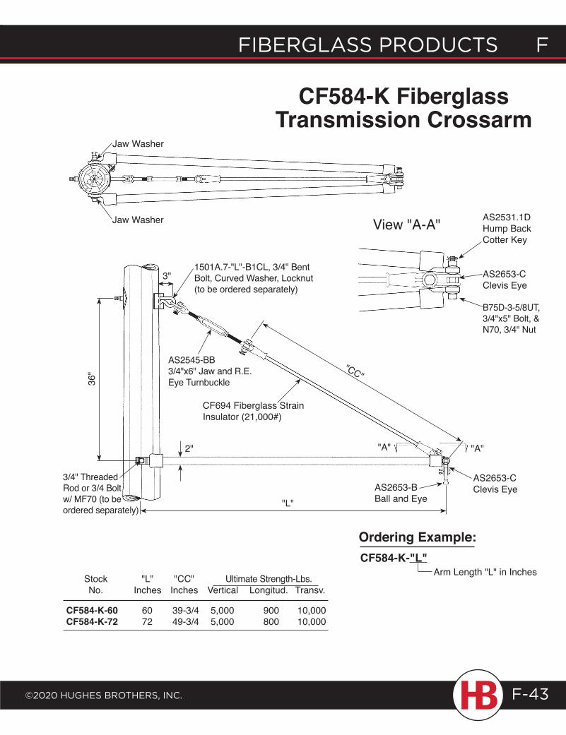
fiberglass products f
©2020 HugHes brotHers, inc.
f fiberglass products
F-43
Arm Length "L" in InchesCF584-K-"L"Ordering Example:
AS2531.1D Hump Back Cotter Key
AS2653-C Clevis Eye
B75D-3-5/8UT, 3/4"x5" Bolt, & N70, 3/4" Nut
Jaw Washer
Jaw Washer View "A-A"
36"
3/4" Threaded Rod or 3/4 Bolt w/ MF70 (to be ordered separately)
3"1501A.7-"L"-B1CL, 3/4" Bent Bolt, Curved Washer, Locknut (to be ordered separately)
"CC"
"A" "A"
AS2653-C Clevis EyeAS2653-B
Ball and Eye"L"
2"
AS2545-BB 3/4"x6" Jaw and R.E. Eye Turnbuckle
CF694 Fiberglass Strain Insulator (21,000#)
CF584-K Fiberglass Transmission Crossarm
CF584-K-60 60 39-3/4 5,000 900 10,000 CF584-K-72 72 49-3/4 5,000 800 10,000
Stock "L" "CC" Ultimate Strength-Lbs. No. Inches Inches Vertical Longitud. Transv.
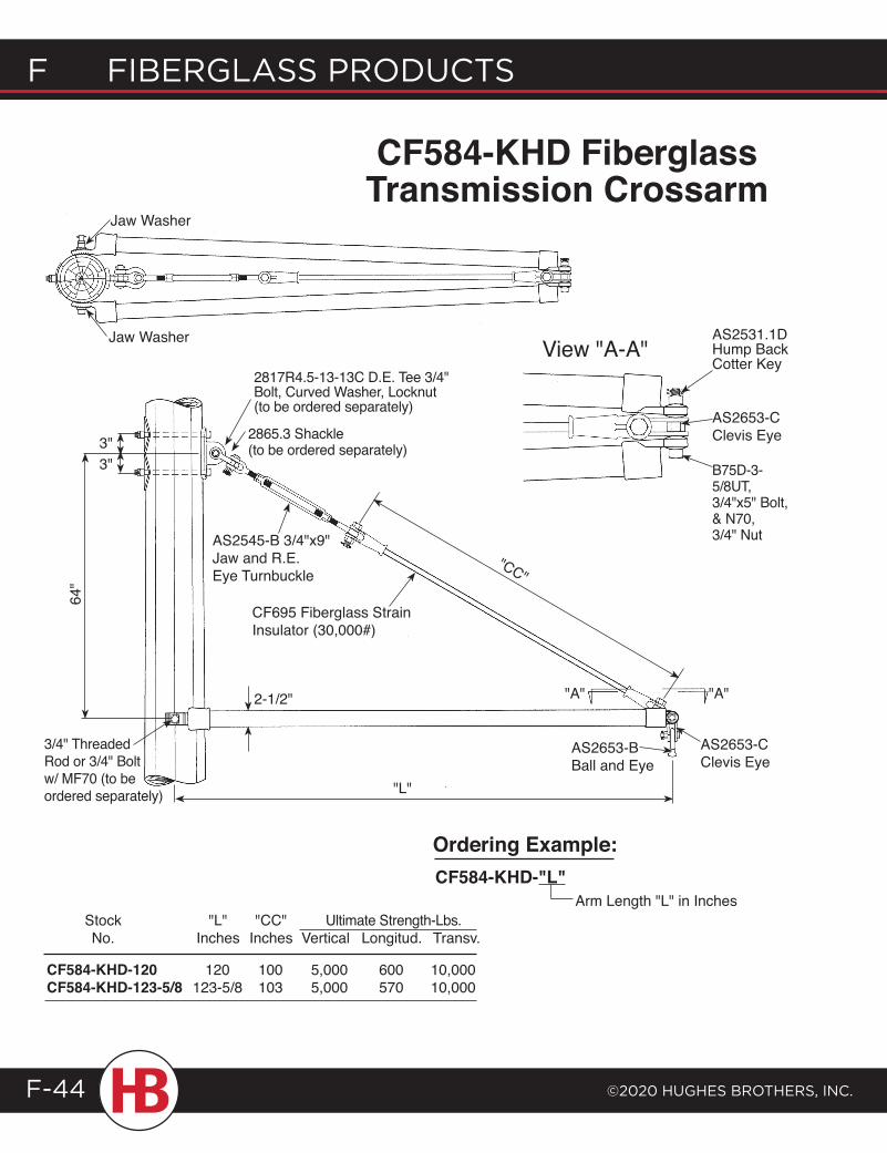
F Fiberglass products
©2020 HugHes brotHers, inc.F-44
Arm Length "L" in InchesCF584-KHD-"L"Ordering Example:
Jaw Washer
Jaw Washer AS2531.1D Hump Back Cotter Key
AS2653-C Clevis Eye
B75D-3-5/8UT, 3/4"x5" Bolt, & N70, 3/4" Nut
3/4" Threaded Rod or 3/4" Bolt w/ MF70 (to be ordered separately)
AS2653-C Clevis Eye
2-1/2"
3"3"
64"
"CC"
"L"
2817R4.5-13-13C D.E. Tee 3/4" Bolt, Curved Washer, Locknut (to be ordered separately)
2865.3 Shackle (to be ordered separately)
AS2545-B 3/4"x9" Jaw and R.E. Eye Turnbuckle
CF695 Fiberglass Strain Insulator (30,000#)
"A" "A"
AS2653-B Ball and Eye
View "A-A"
CF584-KHD-120 120 100 5,000 600 10,000 CF584-KHD-123-5/8 123-5/8 103 5,000 570 10,000
Stock "L" "CC" Ultimate Strength-Lbs. No. Inches Inches Vertical Longitud. Transv.
CF584-KHD Fiberglass Transmission Crossarm
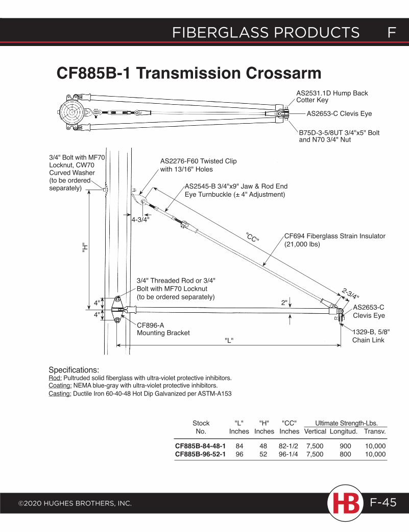
fiberglass products f
©2020 HugHes brotHers, inc.
f fiberglass products
F-45
CF885B-1 Transmission Crossarm
CF885B-84-48-1 84 48 82-1/2 7,500 900 10,000 CF885B-96-52-1 96 52 96-1/4 7,500 800 10,000
4"4"
3/4" Threaded Rod or 3/4" Bolt with MF70 Locknut (to be ordered separately)
CF896-A Mounting Bracket
"L"
AS2653-C Clevis Eye
1329-B, 5/8" Chain Link
2"
2-3/4"
"CC"
"H"
3/4" Bolt with MF70 Locknut, CW70 Curved Washer (to be ordered separately)
4-3/4"
AS2276-F60 Twisted Clip with 13/16" Holes
AS2545-B 3/4"x9" Jaw & Rod End Eye Turnbuckle (± 4" Adjustment)
CF694 Fiberglass Strain Insulator (21,000 lbs)
AS2531.1D Hump Back Cotter Key
B75D-3-5/8UT 3/4"x5" Bolt and N70 3/4" Nut
AS2653-C Clevis Eye
Specifications:Rod: Pultruded solid fiberglass with ultra-violet protective inhibitors.Coating: NEMA blue-gray with ultra-violet protective inhibitors.Casting: Ductile Iron 60-40-48 Hot Dip Galvanized per ASTM-A153
Stock "L" "H" "CC" Ultimate Strength-Lbs. No. Inches Inches Inches Vertical Longitud. Transv.
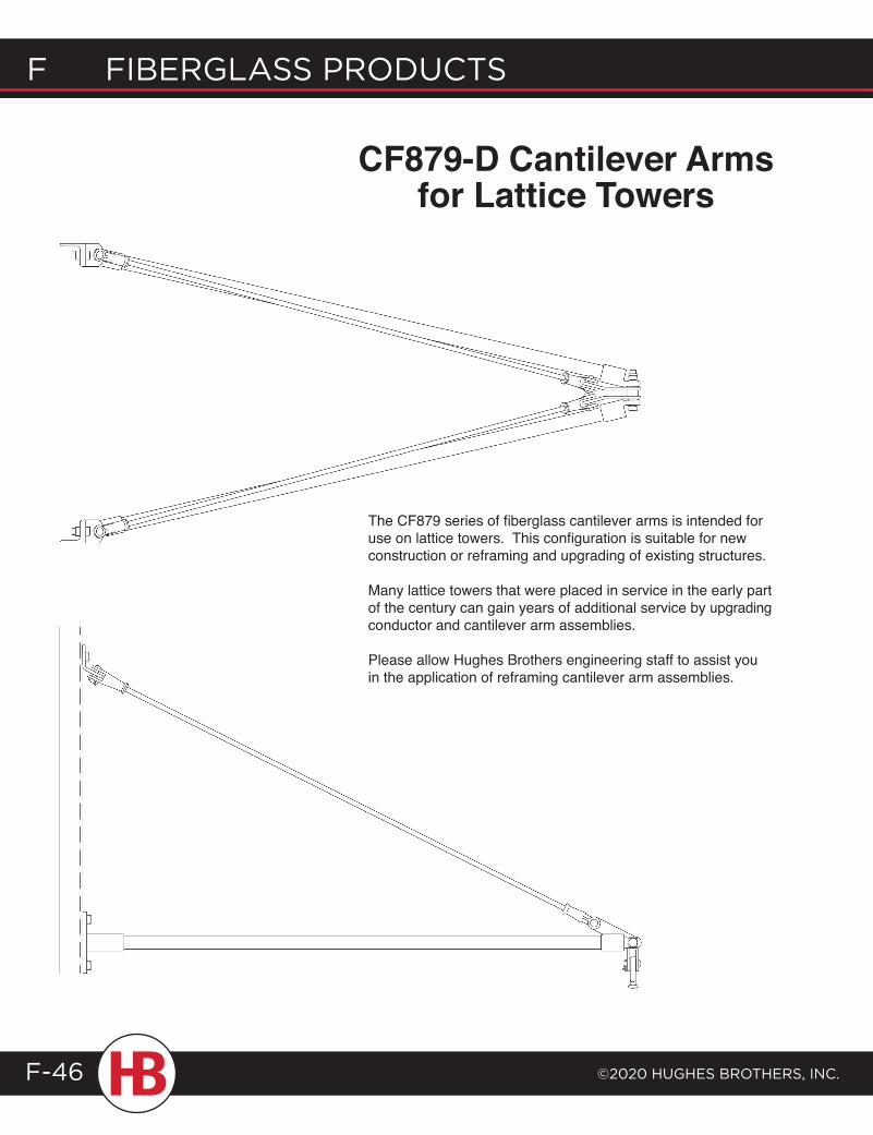
F Fiberglass products
©2020 HugHes brotHers, inc.F-46
CF879-D Cantilever Arms for Lattice Towers
The CF879 series of fiberglass cantilever arms is intended for use on lattice towers. This configuration is suitable for new construction or reframing and upgrading of existing structures.
Many lattice towers that were placed in service in the early part of the century can gain years of additional service by upgrading conductor and cantilever arm assemblies.
Please allow Hughes Brothers engineering staff to assist you in the application of reframing cantilever arm assemblies.
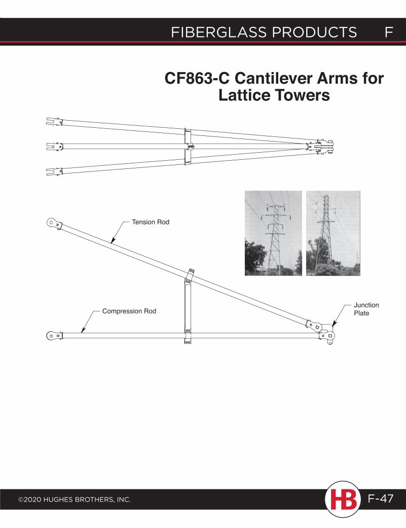
fiberglass products f
©2020 HugHes brotHers, inc.
f fiberglass products
F-47
Tension Rod
Compression RodJunction Plate
CF863-C Cantilever Arms for Lattice Towers
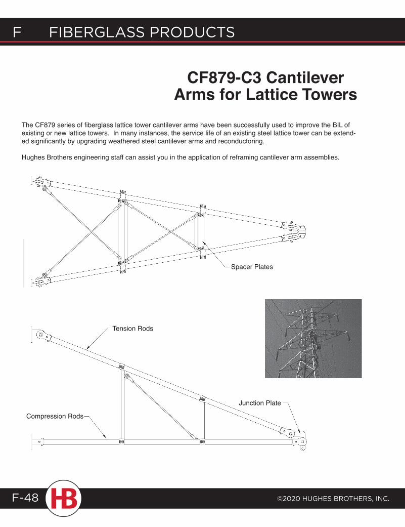
F Fiberglass products
©2020 HugHes brotHers, inc.F-48
Junction Plate
Compression Rods
The CF879 series of fiberglass lattice tower cantilever arms have been successfully used to improve the BIL of existing or new lattice towers. In many instances, the service life of an existing steel lattice tower can be extend-ed significantly by upgrading weathered steel cantilever arms and reconductoring.
Hughes Brothers engineering staff can assist you in the application of reframing cantilever arm assemblies.
CF879-C3 Cantilever Arms for Lattice Towers
Spacer Plates
Tension Rods
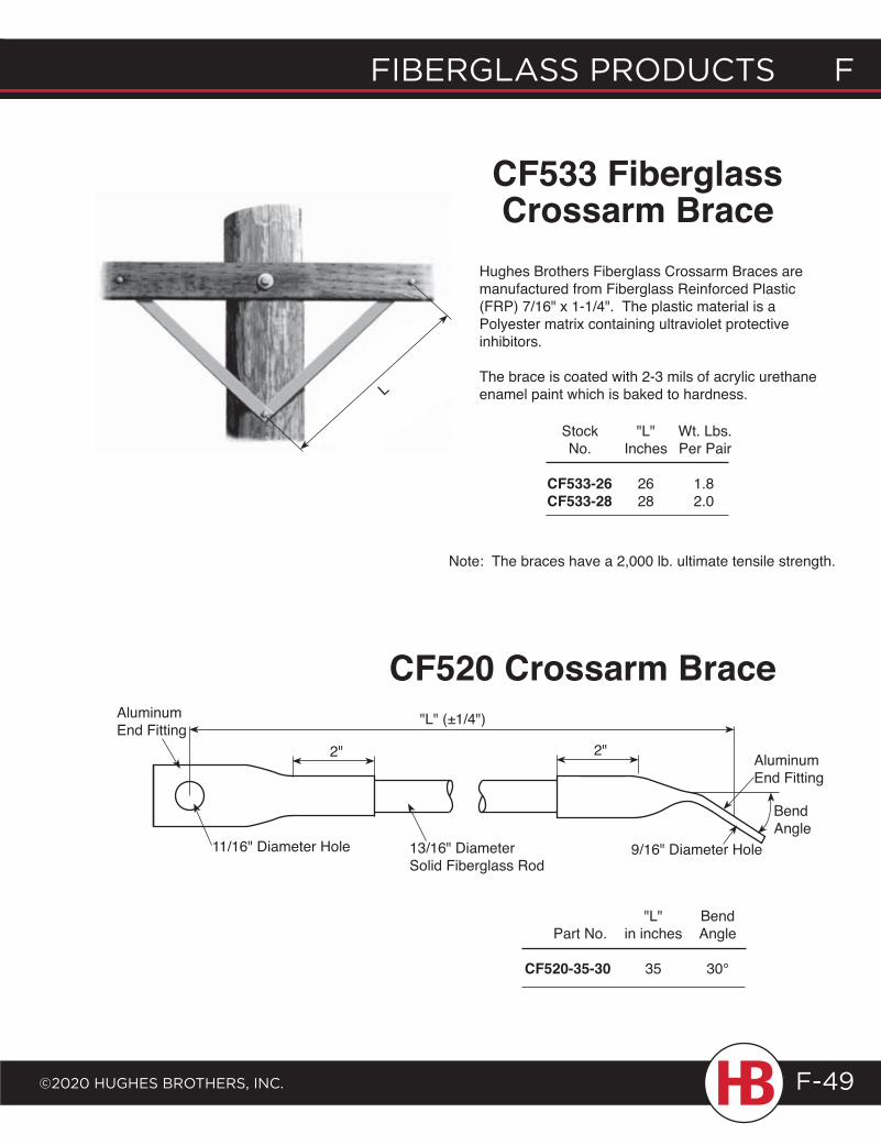
fiberglass products f
©2020 HugHes brotHers, inc.
f fiberglass products
F-49
Stock "L" Wt. Lbs. No. Inches Per Pair
CF533-26 26 1.8CF533-28 28 2.0
Note: The braces have a 2,000 lb. ultimate tensile strength.
L
Hughes Brothers Fiberglass Crossarm Braces are manufactured from Fiberglass Reinforced Plastic (FRP) 7/16" x 1-1/4". The plastic material is a Polyester matrix containing ultraviolet protective inhibitors.
The brace is coated with 2-3 mils of acrylic urethane enamel paint which is baked to hardness.
CF533 Fiberglass Crossarm Brace
Aluminum End Fitting
"L" (±1/4")
2" 2"
11/16" Diameter Hole 13/16" Diameter Solid Fiberglass Rod
Aluminum End Fitting
Bend Angle
9/16" Diameter Hole
"L" Bend Part No. in inches Angle CF520-35-30 35 30°
CF520 Crossarm Brace
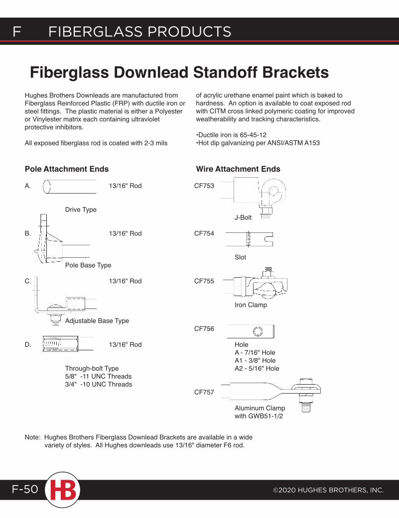
F Fiberglass products
©2020 HugHes brotHers, inc.F-50
A. 13/16" Rod
Drive Type
B. 13/16" Rod
Pole Base Type
C. 13/16" Rod
Adjustable Base Type
D. 13/16" Rod
Through-bolt Type 5/8" -11 UNC Threads 3/4" -10 UNC Threads
Hughes Brothers Downleads are manufactured from Fiberglass Reinforced Plastic (FRP) with ductile iron or steel fittings. The plastic material is either a Polyester or Vinylester matrix each containing ultraviolet protective inhibitors.
All exposed fiberglass rod is coated with 2-3 mils
of acrylic urethane enamel paint which is baked to hardness. An option is available to coat exposed rod with CITM cross linked polymeric coating for improved weatherability and tracking characteristics.
•Ductile iron is 65-45-12 •Hot dip galvanizing per ANSI/ASTM A153
Fiberglass Downlead Standoff Brackets
Note: Hughes Brothers Fiberglass Downlead Brackets are available in a wide variety of styles. All Hughes downleads use 13/16" diameter F6 rod.
Pole Attachment Ends Wire Attachment Ends
CF753
J-Bolt
CF754
Slot
CF755
Iron Clamp
CF756
Hole A - 7/16" Hole A1 - 3/8" Hole A2 - 5/16" Hole
CF757
Aluminum Clamp with GWB51-1/2
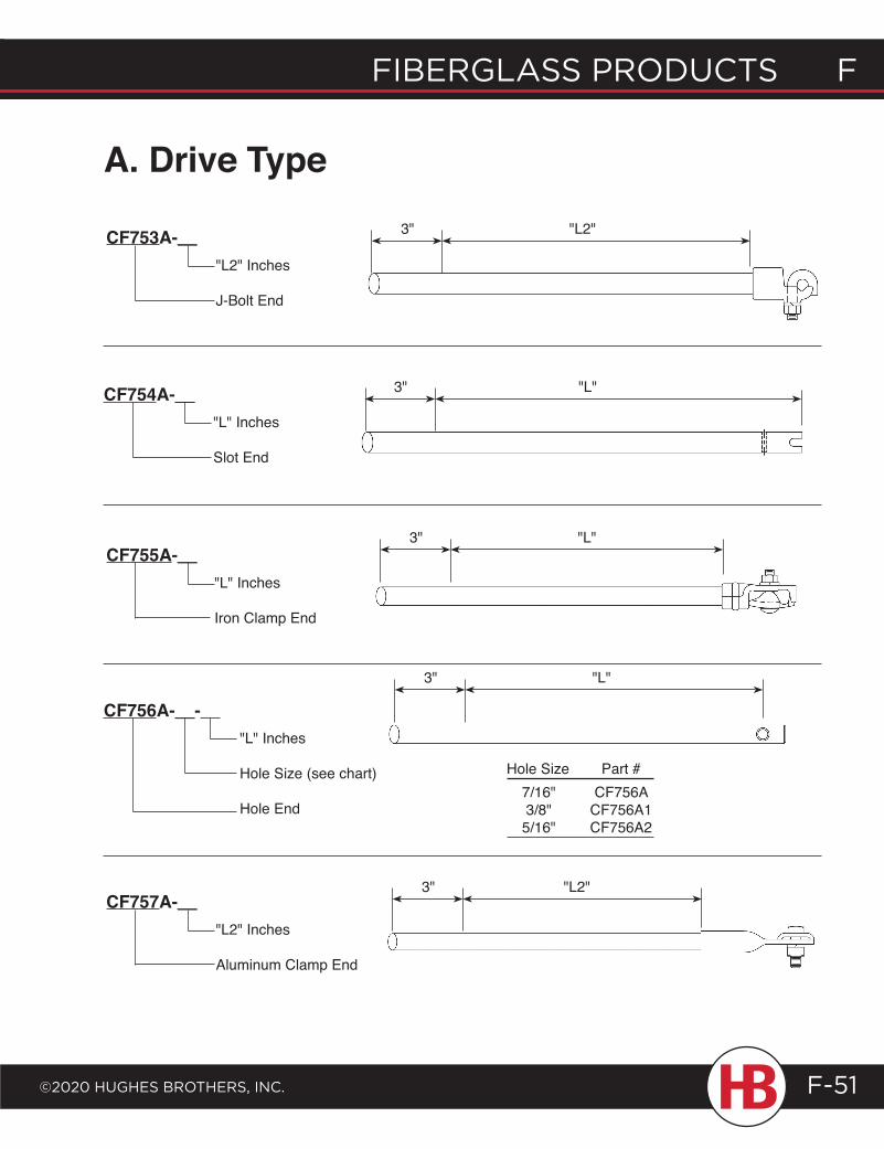
fiberglass products f
©2020 HugHes brotHers, inc.
f fiberglass products
F-51
A. Drive Type
CF753A-__"L2" Inches
J-Bolt End
CF754A-__"L" Inches
Slot End
CF755A-__"L" Inches
Iron Clamp End
CF756A-__- "L" Inches
Hole Size (see chart)
Hole End
CF757A-__"L2" Inches
Aluminum Clamp End
Hole Size Part # 7/16" CF756A 3/8" CF756A1 5/16" CF756A2
3" "L2"
3" "L"
3" "L"
3" "L"
3" "L2"
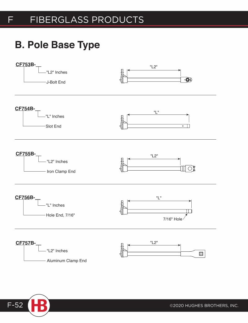
F Fiberglass products
©2020 HugHes brotHers, inc.F-52
B. Pole Base Type
CF753B-__"L2" Inches
J-Bolt End
CF754B-__"L" Inches
Slot End
CF755B-__"L2" Inches
Iron Clamp End
CF756B-__"L" Inches
Hole End, 7/16"
CF757B-__"L2" Inches
Aluminum Clamp End
"L2"
"L2"
"L2"
"L"
"L"
7/16" Hole
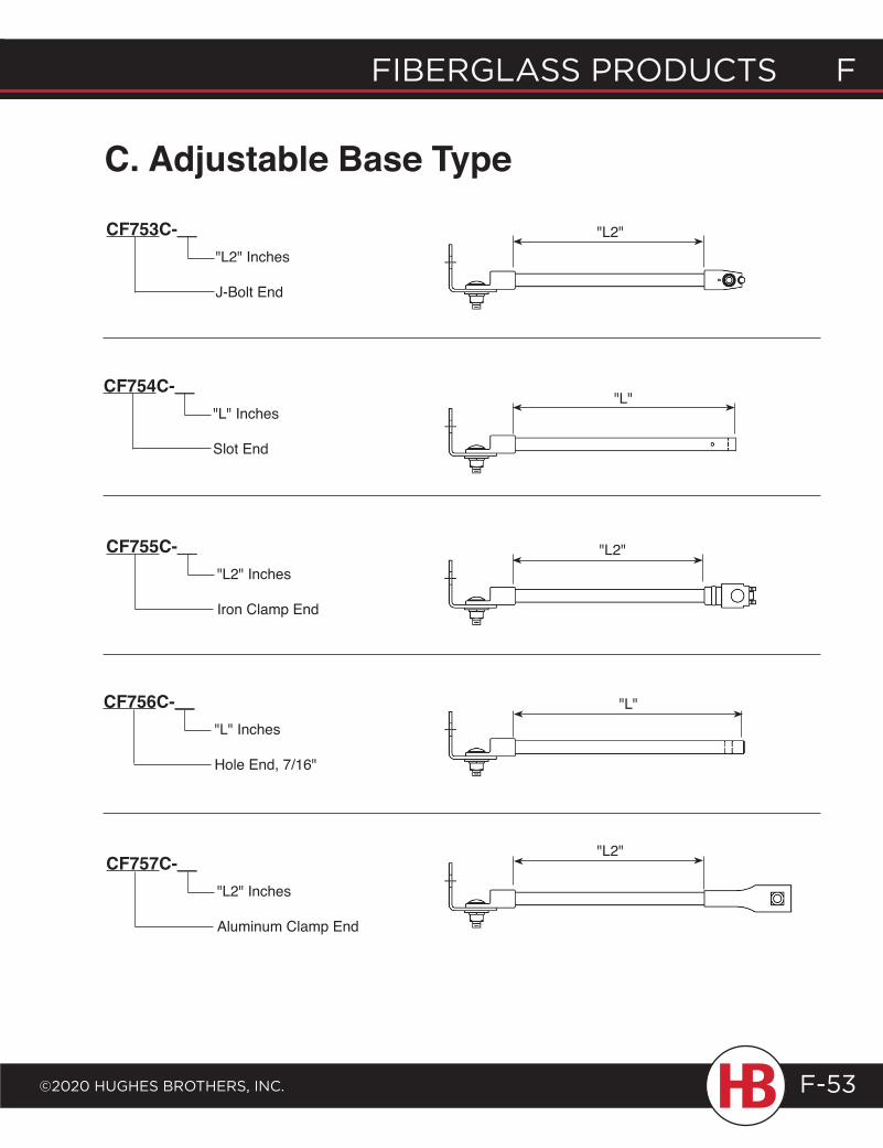
fiberglass products f
©2020 HugHes brotHers, inc.
f fiberglass products
F-53
C. Adjustable Base Type
CF753C-__"L2" Inches
J-Bolt End
CF754C-__"L" Inches
Slot End
CF755C-__"L2" Inches
Iron Clamp End
CF756C-__"L" Inches
Hole End, 7/16"
CF757C-__"L2" Inches
Aluminum Clamp End
"L2"
"L"
"L2"
"L"
"L2"
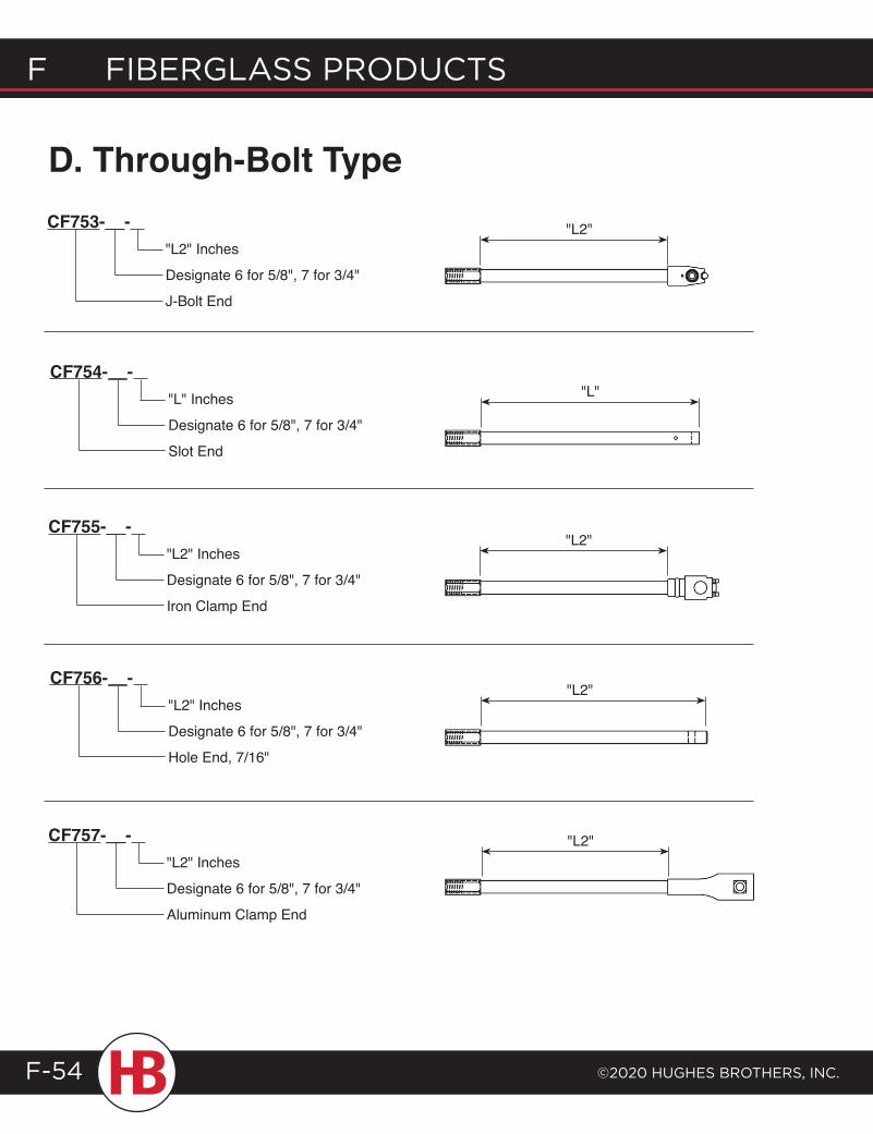
F Fiberglass products
©2020 HugHes brotHers, inc.F-54
D. Through-Bolt TypeCF753-__-
"L2" Inches
Designate 6 for 5/8", 7 for 3/4"
J-Bolt End
CF754-__- "L" Inches
Designate 6 for 5/8", 7 for 3/4"
Slot End
CF755-__- "L2" Inches
Designate 6 for 5/8", 7 for 3/4"
Iron Clamp End
CF756-__- "L2" Inches
Designate 6 for 5/8", 7 for 3/4"
Hole End, 7/16"
CF757-__- "L2" Inches
Designate 6 for 5/8", 7 for 3/4"
Aluminum Clamp End
"L2"
"L"
"L2"
"L2"
"L2"
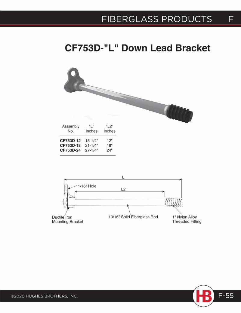
fiberglass products f
©2020 HugHes brotHers, inc.
f fiberglass products
F-55
CF753D-"L" Down Lead Bracket
L
L2
13/16" Solid Fiberglass Rod
11/16" Hole
Ductile Iron Mounting Bracket
1" Nylon Alloy Threaded Fitting
Assembly "L" "L2" No. Inches Inches
CF753D-12 15-1/4" 12"CF753D-18 21-1/4" 18"CF753D-24 27-1/4" 24"
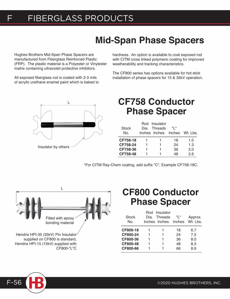
F Fiberglass products
©2020 HugHes brotHers, inc.F-56
Mid-Span Phase SpacersHughes Brothers Mid-Span Phase Spacers are manufactured from Fiberglass Reinforced Plastic (FRP). The plastic material is a Polyester or Vinylester matrix containing ultraviolet protective inhibitors.
All exposed fiberglass rod is coated with 2-3 mils of acrylic urethane enamel paint which is baked to
hardness. An option is available to coat exposed rod with CITM cross linked polymeric coating for improved weatherability and tracking characteristics.
The CF800 series has options available for hot stick installation of phase spacers for 15 & 35kV operation.
CF758 Conductor Phase Spacer
Rod Insulator Stock Dia. Threads "L" No. Inches Inches Inches Wt. Lbs.
CF758-18 1 1 18 1.0CF758-24 1 1 24 1.3CF758-36 1 1 36 2.0CF758-48 1 1 48 2.6
CF800 Conductor Phase Spacer
CF800-18 1 1 18 6.7CF800-24 1 1 24 7.5CF800-36 1 1 36 8.0CF800-48 1 1 48 8.3CF800-66 1 1 66 8.9
Rod Insulator Stock Dia. Threads "L" Approx. No. Inches Inches Inches Wt. Lbs.
L
L
Insulator by others
Filled with epoxy bonding material
Hendrix HPI-35 (35kV) Pin Insulator supplied on CF800 is standard,
Hendrix HPI-15 (15kV) supplied with CF800-"L"C
*For CITM Ray-Chem coating, add suffix "C", Example CF758-18C.

fiberglass products f
©2020 HugHes brotHers, inc.
f fiberglass products
F-57
L
Hendrix No. HPI 35-VT(M) 35kV pin insulator
1" Fiberglass rod(both ends threaded)
Filled with Epoxybonding material
Torque bolts are tightened until the ring breaks away.
Hughes Brothers CF800-"L"D & E enable the installation of a phase spacer using hot sticks. The Hendrix vise-top insulator features options for two conductor installation locations. Insulator jaws open to virtually any conductor size.*
CF800-18D(M)CF800-24D(M)CF800-36D(M)CF800-48D(M)CF800-66D(M)
Stock No.
CF800-"L"DMDesignates bare conductor application.Length
Ordering Example:
CF800-"L"EMDesignates bare conductor application.Length
Ordering Example:
CF800D 35kV Mid-Span Phase Spacer
CF800E 15kV Mid-Span Phase Spacer
1" Fiberglass rod(both ends threaded) Filled with Epoxy
bonding material Torque bolts are tightened until the ring breaks away.
L
CF800-18E(M)CF800-24E(M)CF800-36E(M)CF800-48E(M)CF800-66E(M)
Stock No.
Hendrix No. HPI 15-VT(M)15kV pin insulator
*Conductor Opening Max.=1.70" Min.=0.35"
*Conductor Opening Max.=1.70" Min.=0.312"
*For CITM Coating, add suffix "C", Example CF800-37DMC.
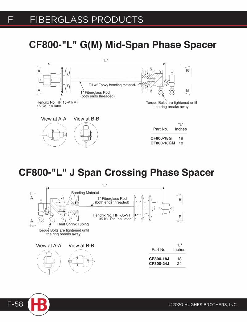
CF800-"L" G(M) Mid-Span Phase Spacer
View at A-A View at B-B
A
A
B
B
"L"
Hendrix No. HPI15-VT(M) 15 Kv. Insulator
1" Fiberglass Rod (both ends threaded)
Fill w/ Epoxy bonding material
A
A
B
B
Bonding Material1" Fiberglass Rod
(both ends threaded)
Heat Shrink Tubing
Hendrix No. HPI-35-VT35 Kv. Pin Insulator
View at A-A View at B-B
Torque Bolts are tightened until the ring breaks away
Torque Bolts are tightened until the ring breaks away
F Fiberglass products
©2020 HugHes brotHers, inc.F-58
"L" Part No. Inches CF800-18G 18 CF800-18GM 18
CF800-"L" J Span Crossing Phase Spacer"L"
"L" Part No. Inches CF800-18J 18 CF800-24J 24
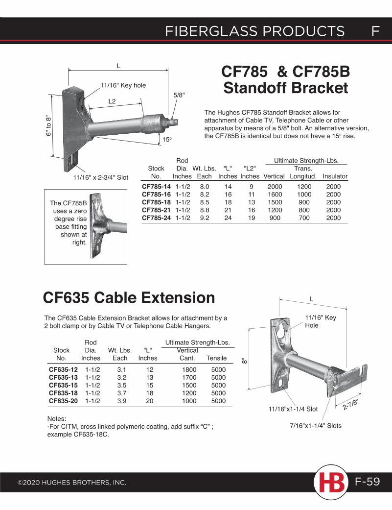
fiberglass products f
©2020 HugHes brotHers, inc.
f fiberglass products
F-59
L2
6" to
8"
11/16" Key hole
L
5/8"
15o
CF785 & CF785B Standoff Bracket
The Hughes CF785 Standoff Bracket allows for attachment of Cable TV, Telephone Cable or other apparatus by means of a 5/8" bolt. An alternative version, the CF785B is identical but does not have a 15o rise.
Rod Ultimate Strength-Lbs. Stock Dia. Wt. Lbs. "L" "L2" Trans. No. Inches Each Inches Inches Vertical Longitud. Insulator
CF785-14 1-1/2 8.0 14 9 2000 1200 2000 CF785-16 1-1/2 8.2 16 11 1600 1000 2000 CF785-18 1-1/2 8.5 18 13 1500 900 2000 CF785-21 1-1/2 8.8 21 16 1200 800 2000 CF785-24 1-1/2 9.2 24 19 900 700 2000
11/16" x 2-3/4" Slot
Rod Ultimate Strength-Lbs. Stock Dia. Wt. Lbs. "L" Vertical No. Inches Each Inches Cant. Tensile
Notes:-For CITM, cross linked polymeric coating, add suffix “C” ; example CF635-18C.
CF635-12 1-1/2 3.1 12 1800 5000 CF635-13 1-1/2 3.2 13 1700 5000 CF635-15 1-1/2 3.5 15 1500 5000 CF635-18 1-1/2 3.7 18 1200 5000 CF635-20 1-1/2 3.9 20 1000 5000
The CF635 Cable Extension Bracket allows for attachment by a 2 bolt clamp or by Cable TV or Telephone Cable Hangers.
CF635 Cable Extension
The CF785B uses a zero degree rise base fitting
shown at right.
11/16"x1-1/4 Slot
8"
11/16" Key Hole
L
2-7/8"
7/16"x1-1/4" Slots
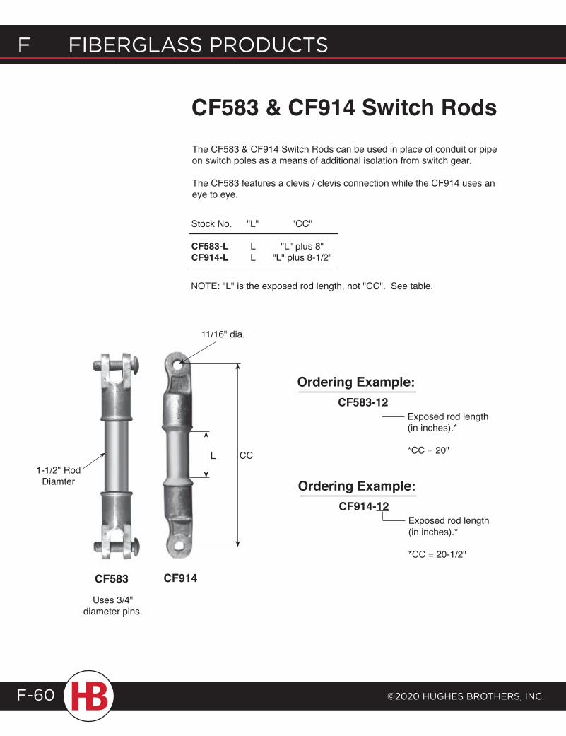
F Fiberglass products
©2020 HugHes brotHers, inc.F-60
CF583 & CF914 Switch RodsThe CF583 & CF914 Switch Rods can be used in place of conduit or pipe on switch poles as a means of additional isolation from switch gear.
The CF583 features a clevis / clevis connection while the CF914 uses an eye to eye.
Stock No.
CF583-LCF914-L
"L"
LL
"CC"
"L" plus 8""L" plus 8-1/2"
L CC
CF914
11/16" dia.
CF583
Uses 3/4" diameter pins.
1-1/2" Rod Diamter
CF583-12Exposed rod length (in inches).*
*CC = 20"
Ordering Example:
CF914-12Exposed rod length (in inches).*
*CC = 20-1/2"
Ordering Example:
NOTE: "L" is the exposed rod length, not "CC". See table.
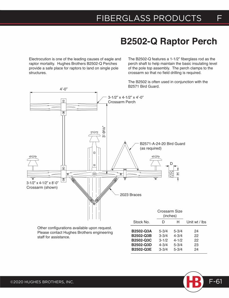
fiberglass products f
©2020 HugHes brotHers, inc.
f fiberglass products
F-61
.292
B2502-Q Raptor PerchElectrocution is one of the leading causes of eagle and raptor mortality. Hughes Brothers B2502-Q Perches provide a safe place for raptors to land on single pole structures.
Stock No.
B2502-Q3AB2502-Q3BB2502-Q3CB2502-Q3DB2502-Q3E
D
5-3/43-3/43-1/24-3/43-3/4
H
5-3/44-3/44-1/25-3/45-3/4
Crossarm Size(inches)
Unit wt / lbs
2422222324
Other configurations available upon request. Please contact Hughes Brothers engineering staff for assistance.
3-1/2” x 4-1/2” x 8’-0” Crossarm (shown)
3’-9
5 /8”
B2571-A-24-20 Bird Guard (as required)
2023 Braces
D
3-1/2” x 4-1/2” x 4’-0”Crossarm Perch
4’-0”
The B2502-Q features a 1-1/2” fiberglass rod as the perch shaft to help maintain the basic insulating level of the pole top assembly. The perch clamps to the crossarm so that no field drilling is required.
The B2502 is often used in conjunction with the B2571 Bird Guard.
H
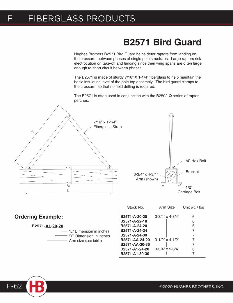
F Fiberglass products
©2020 HugHes brotHers, inc.F-62
B2571-A1-20-20“L” Dimension in inches“Y” Dimension in inchesArm size (see table)
Stock No.
B2571-A-20-20B2571-A-22-18B2571-A-24-20B2571-A-24-24B2571-A-24-30B2571-AA-24-20B2571-AA-30-36B2571-A1-24-20B2571-A1-30-30
Arm Size
3-3/4” x 4-3/4”
3-1/2” x 4-1/2”
3-3/4” x 5-3/4”
Unit wt. / lbs
666777767
Hughes Brothers B2571 Bird Guard helps deter raptors from landing on the crossarm between phases of single pole structures. Large raptors risk electrocution on take-off and landing since their wing spans are often large enough to short circuit between phases.
The B2571 is made of sturdy 7/16” X 1-1/4” fiberglass to help maintain the basic insulating level of the pole top assembly. The bird guard clamps to the crossarm so that no field drilling is required.
The B2571 is often used in conjunction with the B2502-Q series of raptor perches.
Ordering Example:
B2571 Bird Guard
7/16” x 1-1/4” Fiberglass Strap
Y
L
3-3/4” x 4-3/4” Arm (shown)
Bracket
1/4” Hex Bolt
1/2” Carriage Bolt

DAV I T A R M S
davit arms G
©2020 HuGHes BrotHers, inc. G-1
4000/4010See pagesG-2 to G-5
4020/4030See pagesG-6 to G-9
Typical cross section of Davit tubes
Each Hughes Brothers Steel Davit is assigned a serial number at the time of manufacture. This allows us to trace material, welding and other manufacturing procedures. After producing over 100,000 steel davit arms since the late 1970's we have yet to have a single failure. Davits can be custom designed for a particular application.
100% mechanical proof loading and magnetic particle verification of critical welds per ASTM E709, in conjunction with ANSI / AWS D1.1 are available as quality control options. Our standard production procedure utilizes mil-standard 105D sampling for proof load testing unless specified otherwise.
Hughes Brothers provides Steel Davits for use on wood, concrete or steel poles.
Hughes Brothers Steel Davit Arms
Ordering InformationThis catalog section will help you determine which base plate & phase attachment option are most suited to your individual application.
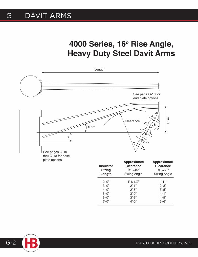
G davit arms
©2020 HuGHes BrotHers, inc.G-2
4000 Series, 16o Rise Angle, Heavy Duty Steel Davit Arms
7"
16o
Clearance
ø
See pages G-10 thru G-13 for base plate options
See page G-16 for end plate options
Ris
e
Length
Insulator Clearance Clearance String @θ=45° @θ=30° Length Swing Angle Swing Angle
2'-0" 1'-6 1/2" 1'-11" 3'-0" 2'-1" 2'-8" 4'-0" 2'-6" 3'-5" 5'-0" 3'-0" 4'-1" 6'-0" 3'-6" 4'-9" 7'-0" 4'-0" 5'-6"
Approximate Approximate
+-
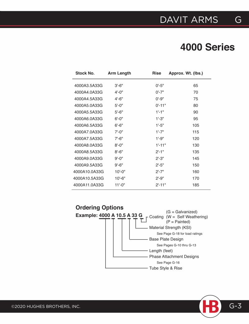
davit arms G
©2020 HuGHes BrotHers, inc.
G davit arms
G-3
4000 Series
Stock No. Arm Length Rise Approx. Wt. (lbs.)
4000A3.5A33G 3'-6" 0'-5" 65 4000A4.0A33G 4'-0" 0'-7" 70 4000A4.5A33G 4'-6" 0'-9" 75 4000A5.0A33G 5'-0" 0'-11" 80 4000A5.5A33G 5'-6" 1'-1" 90 4000A6.0A33G 6'-0" 1'-3" 95 4000A6.5A33G 6'-6" 1'-5" 105 4000A7.0A33G 7'-0" 1'-7" 115 4000A7.5A33G 7'-6" 1'-9" 120 4000A8.0A33G 8'-0" 1'-11" 130 4000A8.5A33G 8'-6" 2'-1" 135 4000A9.0A33G 9'-0" 2'-3" 145 4000A9.5A33G 9'-6" 2'-5" 150 4000A10.0A33G 10'-0" 2'-7" 160 4000A10.5A33G 10'-6" 2'-9" 170 4000A11.0A33G 11'-0" 2'-11" 185
(G = Galvanized)Coating (W = Self Weathering) (P = Painted)Material Strength (KSI) See Page G-18 for load ratingsBase Plate Design See Pages G-10 thru G-13 Length (feet)Phase Attachment Designs See Page G-16Tube Style & Rise
Ordering OptionsExample: 4000 A 10.5 A 33 G
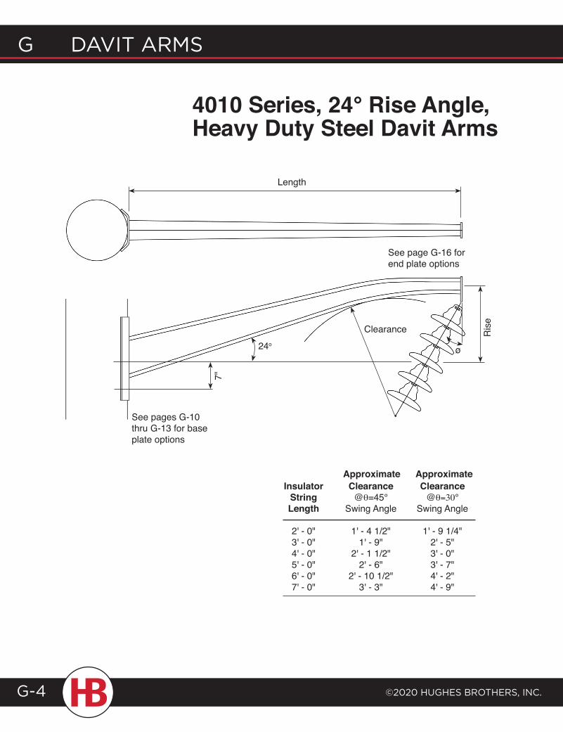
G davit arms
©2020 HuGHes BrotHers, inc.G-4
4010 Series, 24° Rise Angle, Heavy Duty Steel Davit Arms
Insulator Clearance Clearance String @θ=45° @θ=30° Length Swing Angle Swing Angle
2' - 0" 1' - 4 1/2" 1' - 9 1/4" 3' - 0" 1' - 9" 2' - 5" 4' - 0" 2' - 1 1/2" 3' - 0" 5' - 0" 2' - 6" 3' - 7" 6' - 0" 2' - 10 1/2" 4' - 2" 7' - 0" 3' - 3" 4' - 9"
Approximate Approximate
7"
24o
Clearance
ø
See pages G-10 thru G-13 for base plate options
See page G-16 for end plate options
Ris
e
Length
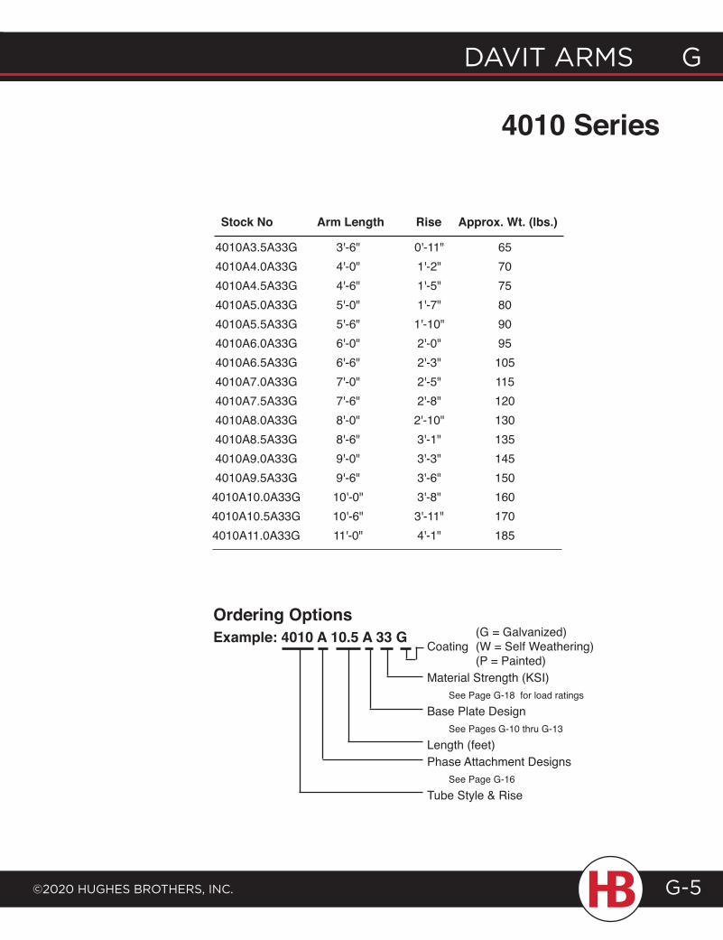
davit arms G
©2020 HuGHes BrotHers, inc.
G davit arms
G-5
4010 Series
(G = Galvanized)Coating (W = Self Weathering) (P = Painted)Material Strength (KSI) See Page G-18 for load ratingsBase Plate Design See Pages G-10 thru G-13Length (feet)Phase Attachment Designs See Page G-16Tube Style & Rise
Ordering OptionsExample: 4010 A 10.5 A 33 G
Stock No Arm Length Rise Approx. Wt. (lbs.)
4010A3.5A33G 3'-6" 0'-11" 65 4010A4.0A33G 4'-0" 1'-2" 70 4010A4.5A33G 4'-6" 1'-5" 75 4010A5.0A33G 5'-0" 1'-7" 80 4010A5.5A33G 5'-6" 1'-10" 90 4010A6.0A33G 6'-0" 2'-0" 95 4010A6.5A33G 6'-6" 2'-3" 105 4010A7.0A33G 7'-0" 2'-5" 115 4010A7.5A33G 7'-6" 2'-8" 120 4010A8.0A33G 8'-0" 2'-10" 130 4010A8.5A33G 8'-6" 3'-1" 135 4010A9.0A33G 9'-0" 3'-3" 145 4010A9.5A33G 9'-6" 3'-6" 150 4010A10.0A33G 10'-0" 3'-8" 160 4010A10.5A33G 10'-6" 3'-11" 170 4010A11.0A33G 11'-0" 4'-1" 185
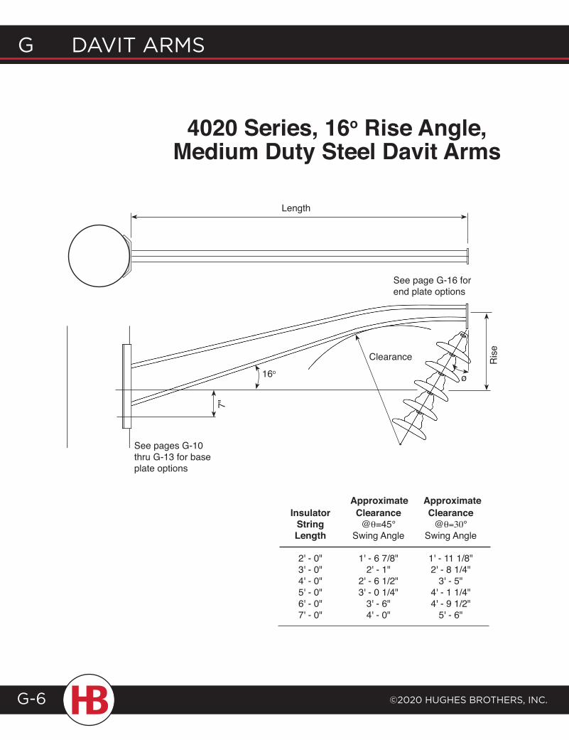
G davit arms
©2020 HuGHes BrotHers, inc.G-6
4020 Series, 16o Rise Angle, Medium Duty Steel Davit Arms
Insulator Clearance Clearance String @θ=45° @θ=30° Length Swing Angle Swing Angle
2' - 0" 1' - 6 7/8" 1' - 11 1/8" 3' - 0" 2' - 1" 2' - 8 1/4" 4' - 0" 2' - 6 1/2" 3' - 5" 5' - 0" 3' - 0 1/4" 4' - 1 1/4" 6' - 0" 3' - 6" 4' - 9 1/2" 7' - 0" 4' - 0" 5' - 6"
Approximate Approximate
7"
16o
Clearance
ø
See pages G-10 thru G-13 for base plate options
See page G-16 for end plate options
Ris
e
Length
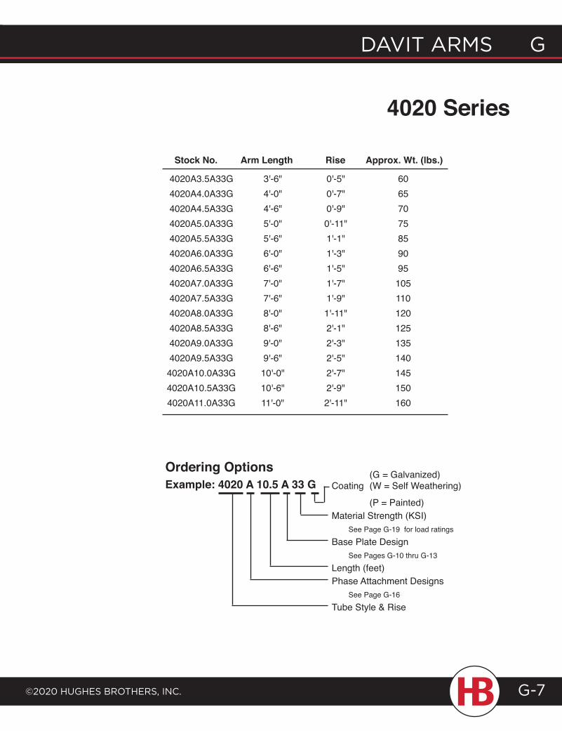
davit arms G
©2020 HuGHes BrotHers, inc.
G davit arms
G-7
4020 Series
4020A3.5A33G 3'-6" 0'-5" 60 4020A4.0A33G 4'-0" 0'-7" 65 4020A4.5A33G 4'-6" 0'-9" 70 4020A5.0A33G 5'-0" 0'-11" 75 4020A5.5A33G 5'-6" 1'-1" 85 4020A6.0A33G 6'-0" 1'-3" 90 4020A6.5A33G 6'-6" 1'-5" 95 4020A7.0A33G 7'-0" 1'-7" 105 4020A7.5A33G 7'-6" 1'-9" 110 4020A8.0A33G 8'-0" 1'-11" 120 4020A8.5A33G 8'-6" 2'-1" 125 4020A9.0A33G 9'-0" 2'-3" 135 4020A9.5A33G 9'-6" 2'-5" 140 4020A10.0A33G 10'-0" 2'-7" 145 4020A10.5A33G 10'-6" 2'-9" 150 4020A11.0A33G 11'-0" 2'-11" 160
Ordering OptionsExample: 4020 A 10.5 A 33 G
(G = Galvanized)Coating (W = Self Weathering)
(P = Painted)Material Strength (KSI) See Page G-19 for load ratingsBase Plate Design See Pages G-10 thru G-13Length (feet)Phase Attachment Designs See Page G-16 Tube Style & Rise
Stock No. Arm Length Rise Approx. Wt. (lbs.)
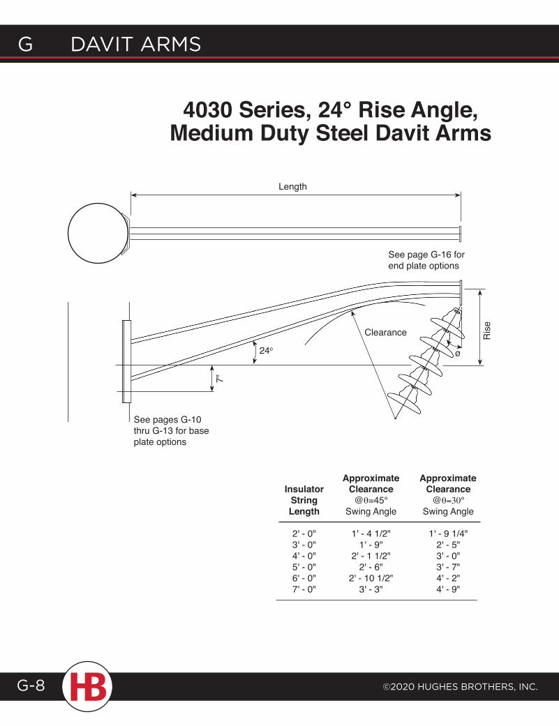
G davit arms
©2020 HuGHes BrotHers, inc.G-8
4030 Series, 24° Rise Angle, Medium Duty Steel Davit Arms
Insulator Clearance Clearance String @θ=45° @θ=30° Length Swing Angle Swing Angle
2' - 0" 1' - 4 1/2" 1' - 9 1/4" 3' - 0" 1' - 9" 2' - 5" 4' - 0" 2' - 1 1/2" 3' - 0" 5' - 0" 2' - 6" 3' - 7" 6' - 0" 2' - 10 1/2" 4' - 2" 7' - 0" 3' - 3" 4' - 9"
Approximate Approximate
7"
24o
Clearance
ø
See pages G-10 thru G-13 for base plate options
See page G-16 for end plate options
Ris
e
Length
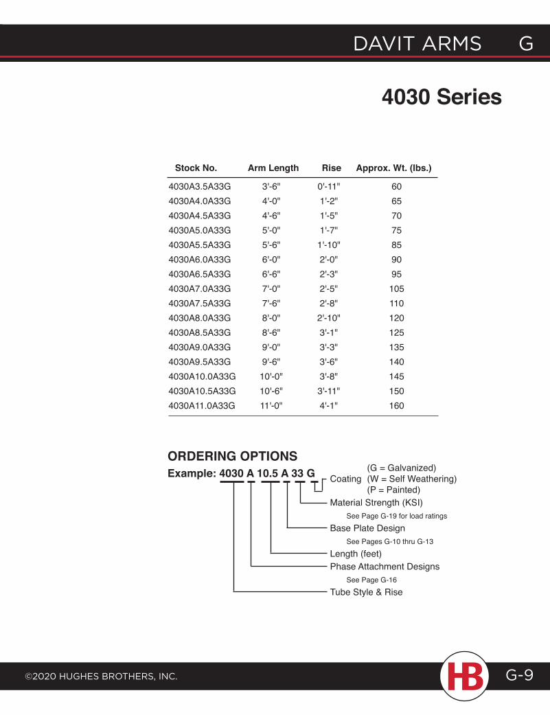
davit arms G
©2020 HuGHes BrotHers, inc.
G davit arms
G-9
4030 Series
4030A3.5A33G 3'-6" 0'-11" 60 4030A4.0A33G 4'-0" 1'-2" 65 4030A4.5A33G 4'-6" 1'-5" 70 4030A5.0A33G 5'-0" 1'-7" 75 4030A5.5A33G 5'-6" 1'-10" 85 4030A6.0A33G 6'-0" 2'-0" 90 4030A6.5A33G 6'-6" 2'-3" 95 4030A7.0A33G 7'-0" 2'-5" 105 4030A7.5A33G 7'-6" 2'-8" 110 4030A8.0A33G 8'-0" 2'-10" 120 4030A8.5A33G 8'-6" 3'-1" 125 4030A9.0A33G 9'-0" 3'-3" 135 4030A9.5A33G 9'-6" 3'-6" 140 4030A10.0A33G 10'-0" 3'-8" 145 4030A10.5A33G 10'-6" 3'-11" 150 4030A11.0A33G 11'-0" 4'-1" 160
ORDERING OptIONSExample: 4030 A 10.5 A 33 G (G = Galvanized)
Coating (W = Self Weathering) (P = Painted)Material Strength (KSI) See Page G-19 for load ratingsBase Plate Design See Pages G-10 thru G-13 Length (feet)Phase Attachment Designs See Page G-16Tube Style & Rise
Stock No. Arm Length Rise Approx. Wt. (lbs.)
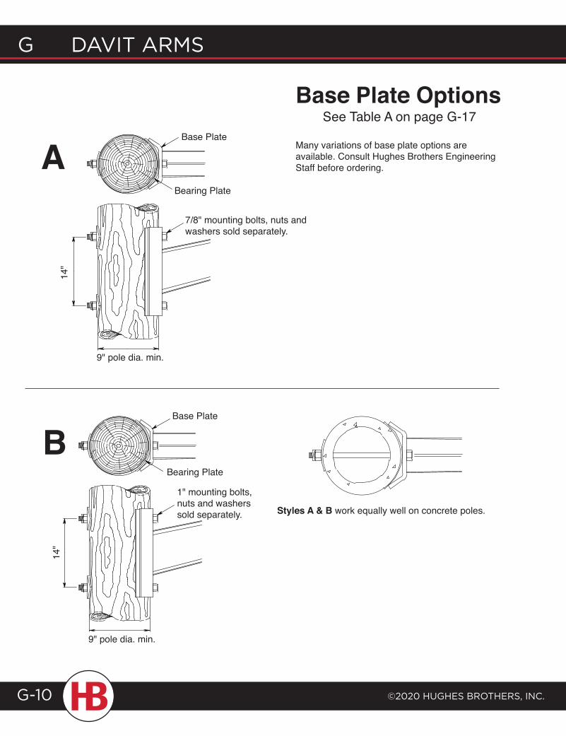
G davit arms
©2020 HuGHes BrotHers, inc.G-10
Base plate Options
14"
Base Plate
Bearing Plate
9" pole dia. min.
1" mounting bolts, nuts and washers sold separately.
BStyles A & B work equally well on concrete poles.
14"
Base Plate
9" pole dia. min.
Bearing Plate
7/8" mounting bolts, nuts and washers sold separately.
ASee Table A on page G-17
Many variations of base plate options are available. Consult Hughes Brothers Engineering Staff before ordering.
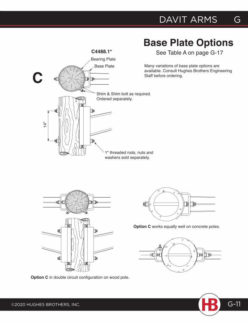
C4488.1*
davit arms G
©2020 HuGHes BrotHers, inc.
G davit arms
G-11
Base plate Options
Option C works equally well on concrete poles.
Option C in double circuit configuration on wood pole.
Bearing PlateBase Plate
Shim & Shim bolt as required. Ordered separately.
14"
1" threaded rods, nuts and washers sold separately.
CMany variations of base plate options are available. Consult Hughes Brothers Engineering Staff before ordering.
See Table A on page G-17
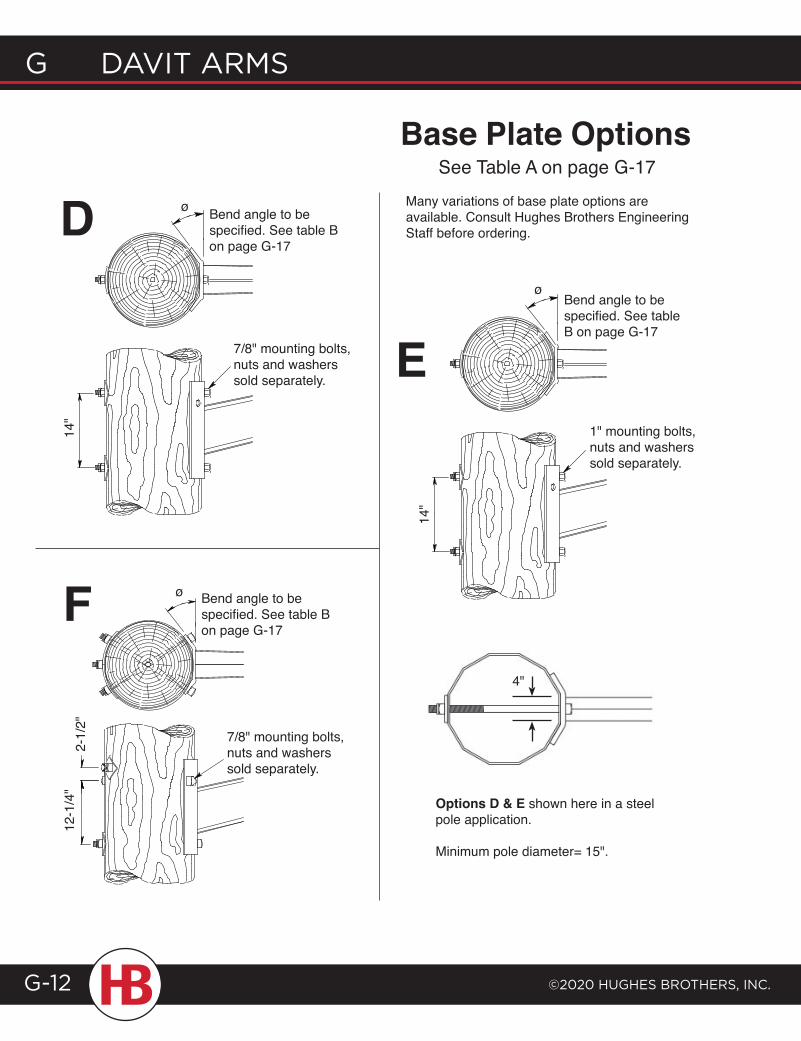
G davit arms
©2020 HuGHes BrotHers, inc.G-12
Bend angle to be specified. See table B on page G-17
14"
7/8" mounting bolts, nuts and washers sold separately.
ø
ø Bend angle to be specified. See table B on page G-17
2-1/
2"12
-1/4
"
7/8" mounting bolts, nuts and washers sold separately.
Bend angle to be specified. See table B on page G-17
1" mounting bolts, nuts and washers sold separately.
ø
E14
"
Many variations of base plate options are available. Consult Hughes Brothers Engineering Staff before ordering.
Base plate OptionsSee Table A on page G-17
Options D & E shown here in a steel pole application.
Minimum pole diameter= 15".
D
F4"
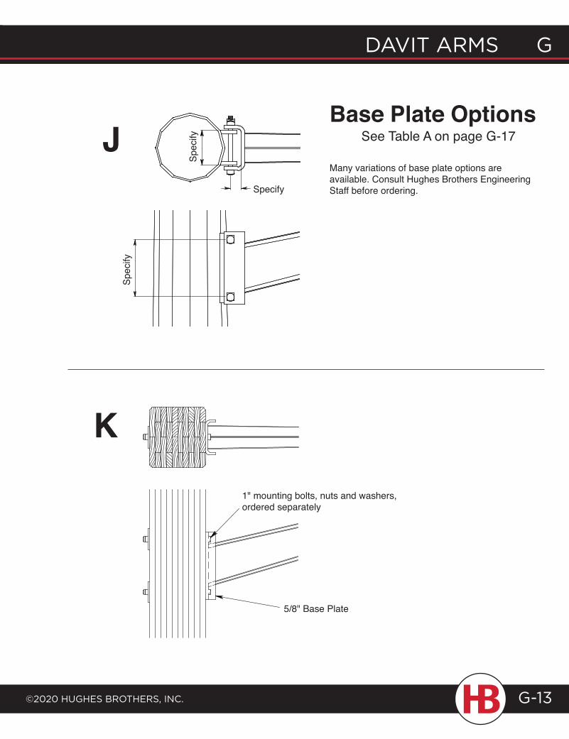
davit arms G
©2020 HuGHes BrotHers, inc.
G davit arms
G-13
Base plate OptionsJ
Spec
ifySpecify
Spec
ify
K
1" mounting bolts, nuts and washers, ordered separately
5/8" Base Plate
See Table A on page G-17
Many variations of base plate options are available. Consult Hughes Brothers Engineering Staff before ordering.
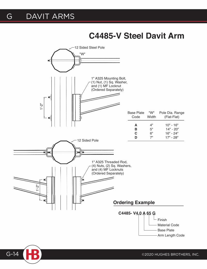
G davit arms
©2020 HuGHes BrotHers, inc.G-14
C4485-V Steel Davit Arm12 Sided Steel Pole
"W"
1" A325 Mounting Bolt, (1) Nut, (1) Sq. Washer, and (1) MF Locknut (Ordered Separately)
1'-2
"
12 Sided Pole
1" A325 Threaded Rod, (4) Nuts, (2) Sq. Washers, and (4) MF Locknuts (Ordered Separately)
1'-2
"
Ordering Example
C4485- V4.0 A 65 GFinishMaterial CodeBase PlateArm Length Code
Base Plate "W" Pole Dia. Range Code Width (Flat-Flat) A 4" 10" - 16" B 5" 14" - 20" C 6" 16" - 24" D 7" 17" - 28"
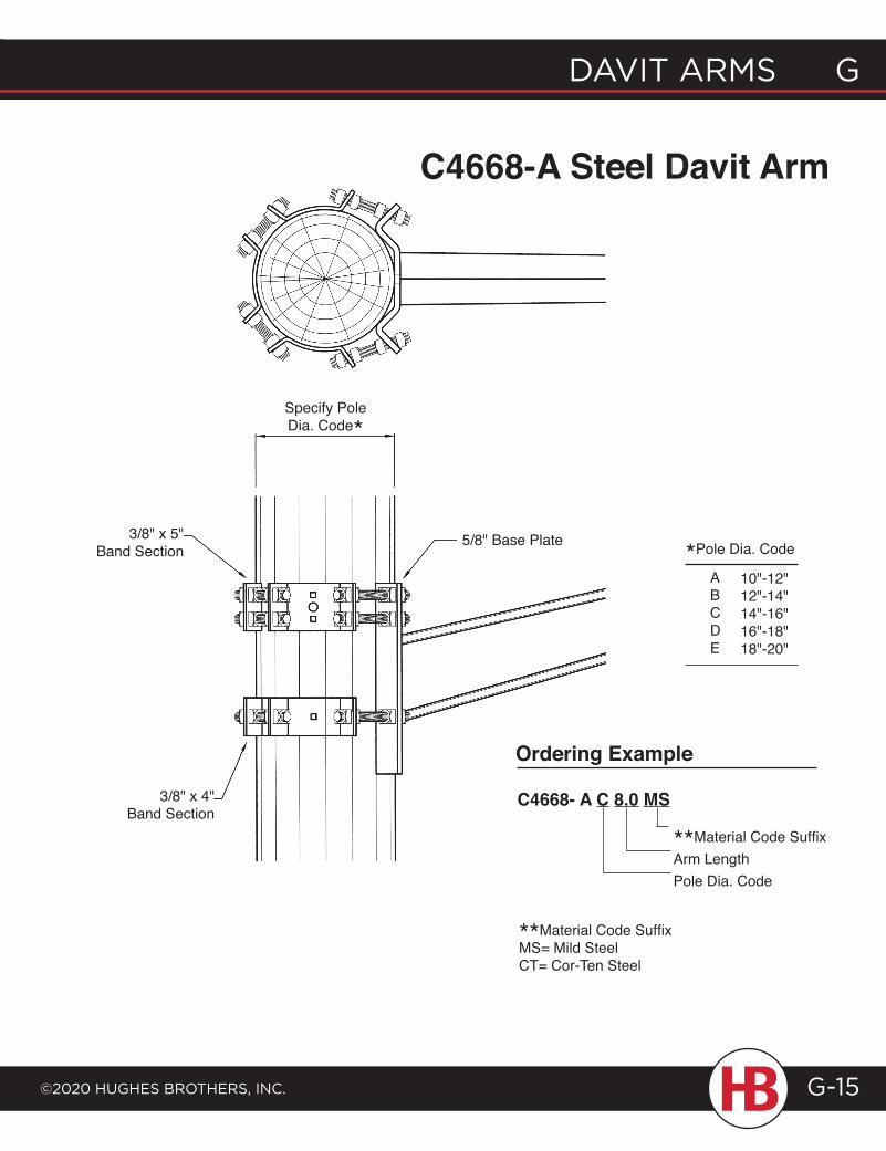
davit arms G
©2020 HuGHes BrotHers, inc.
G davit arms
G-15
Specify Pole Dia. Code*
3/8" x 5" Band Section
3/8" x 4" Band Section
5/8" Base Plate
FinishMaterial CodeBase PlateArm Length Code
C4668-A Steel Davit Arm
Ordering Example
C4668- A C 8.0 MS
**Material Code SuffixArm LengthPole Dia. Code
*Pole Dia. Code
ABCDE
10"-12"12"-14"14"-16"16"-18"18"-20"
**Material Code SuffixMS= Mild SteelCT= Cor-Ten Steel
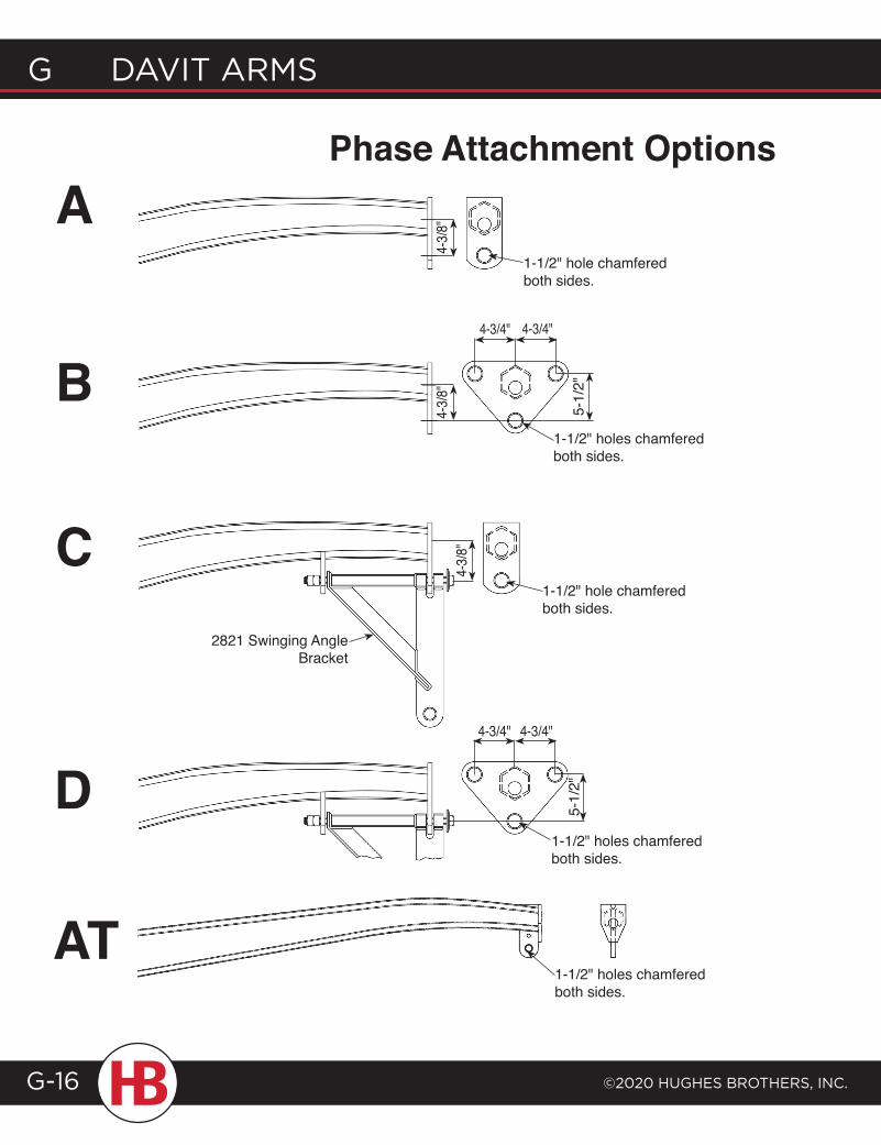
G davit arms
©2020 HuGHes BrotHers, inc.G-16
1-1/2" hole chamfered both sides.
4-3/4" 4-3/4"
4-3/8
"4-
3/8"
5-1/
2"
4-3/8
"
1-1/2" hole chamfered both sides.
1-1/2" holes chamfered both sides.
5-1/
2"
1-1/2" holes chamfered both sides.
2821 Swinging Angle Bracket
4-3/4" 4-3/4"
A
B
C
D
phase Attachment Options
At1-1/2" holes chamfered both sides.
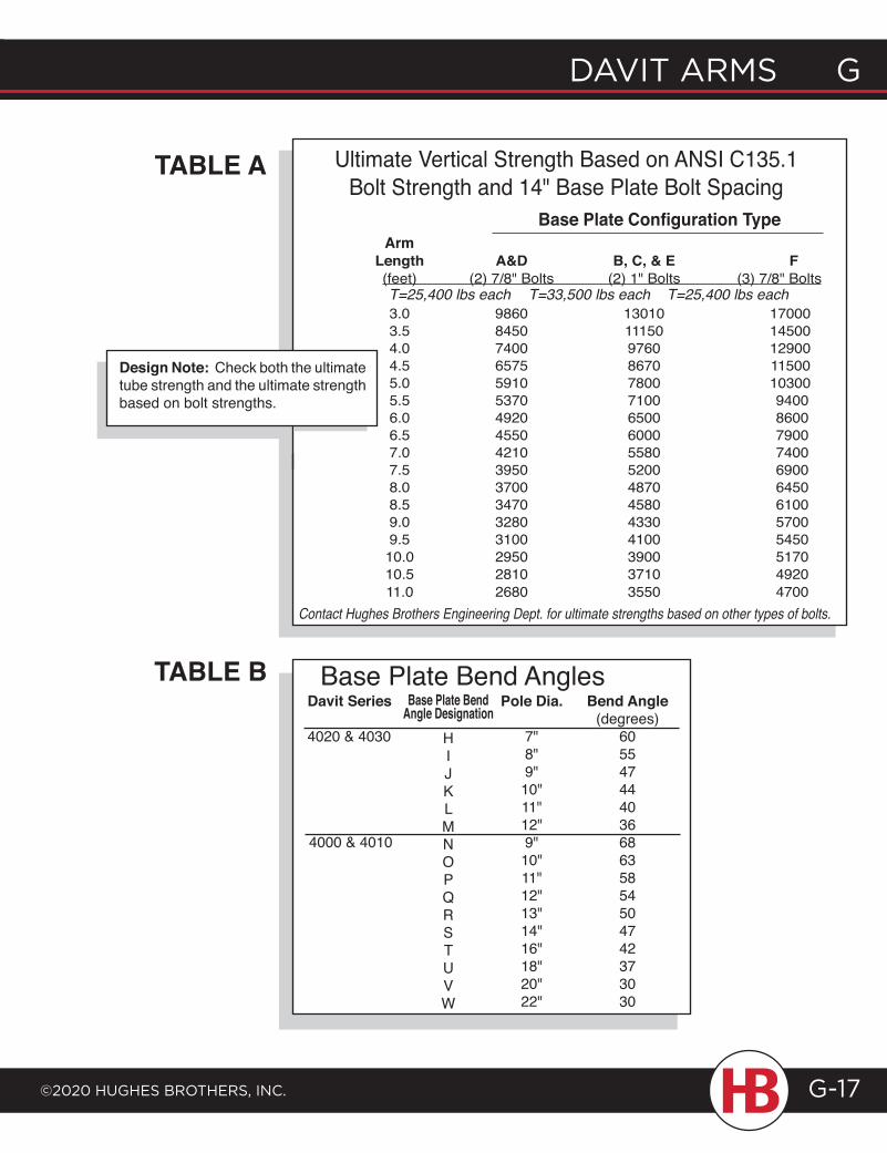
davit arms G
©2020 HuGHes BrotHers, inc.
G davit arms
G-17
Davit Series
4020 & 4030
4000 & 4010
Base Plate Bend AnglestABLE B
tABLE A
Bend Angle(degrees)
60554744403668635854504742373030
pole Dia.
7"8"9"10"11"12"9"10"11"12"13"14"16"18"20"22"
Base plate Bend
HIJKLMNOPQRSTUVW
Angle Designation
Design Note: Check both the ultimate tube strength and the ultimate strength based on bolt strengths.
Contact Hughes Brothers Engineering Dept. for ultimate strengths based on other types of bolts.
ArmBase Plate Configuration Type
Ultimate Vertical Strength Based on ANSI C135.1 Bolt Strength and 14" Base Plate Bolt Spacing
Length A&D B, C, & E F (feet) (2) 7/8" Bolts (2) 1" Bolts (3) 7/8" Bolts
3.0 9860 13010 17000 3.5 8450 11150 14500 4.0 7400 9760 12900 4.5 6575 8670 11500 5.0 5910 7800 10300 5.5 5370 7100 9400 6.0 4920 6500 8600 6.5 4550 6000 7900 7.0 4210 5580 7400 7.5 3950 5200 6900 8.0 3700 4870 6450 8.5 3470 4580 6100 9.0 3280 4330 5700 9.5 3100 4100 5450 10.0 2950 3900 5170 10.5 2810 3710 4920 11.0 2680 3550 4700
T=25,400 lbs each T=33,500 lbs each T=25,400 lbs each
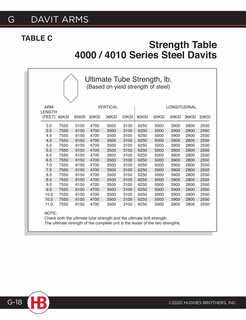
G davit arms
©2020 HuGHes BrotHers, inc.G-18
tABLE C
NOTE:Check both the ultimate tube strength and the ultimate bolt strength. The ultimate strength of the complete unit is the lesser of the two strengths.
3.0 7550 6150 4700 3500 3100 6250 5000 3900 2800 2550 3.5 7550 6150 4700 3500 3100 6250 5000 3900 2800 2550 4.0 7550 6150 4700 3500 3100 6250 5000 3900 2800 2550 4.5 7550 6150 4700 3500 3100 6250 5000 3900 2800 2550 5.0 7550 6150 4700 3500 3100 6250 5000 3900 2800 2550 5.5 7550 6150 4700 3500 3100 6250 5000 3900 2800 2550 6.0 7550 6150 4700 3500 3100 6250 5000 3900 2800 2550 6.5 7550 6150 4700 3500 3100 6250 5000 3900 2800 2550 7.0 7550 6150 4700 3500 3100 6250 5000 3900 2800 2550 7.5 7550 6150 4700 3500 3100 6250 5000 3900 2800 2550 8.0 7550 6150 4700 3500 3100 6250 5000 3900 2800 2550 8.5 7550 6150 4700 3500 3100 6250 5000 3900 2800 2550 9.0 7550 6150 4700 3500 3100 6250 5000 3900 2800 2550 9.5 7550 6150 4700 3500 3100 6250 5000 3900 2800 2550 10.0 7550 6150 4700 3500 3100 6250 5000 3900 2800 2550 10.5 7550 6150 4700 3500 3100 6250 5000 3900 2800 2550 11.0 7550 6150 4700 3500 3100 6250 5000 3900 2800 2550
Ultimate Tube Strength, lb.(Based on yield strength of steel)
Strength table4000 / 4010 Series Steel Davits
ArM VErTICAL LongITudInAL LENGTH (FEET) 80KSI 65KSI 50KSI 36KSI 33KSI 80KSI 65KSI 50KSI 36KSI 33KSI
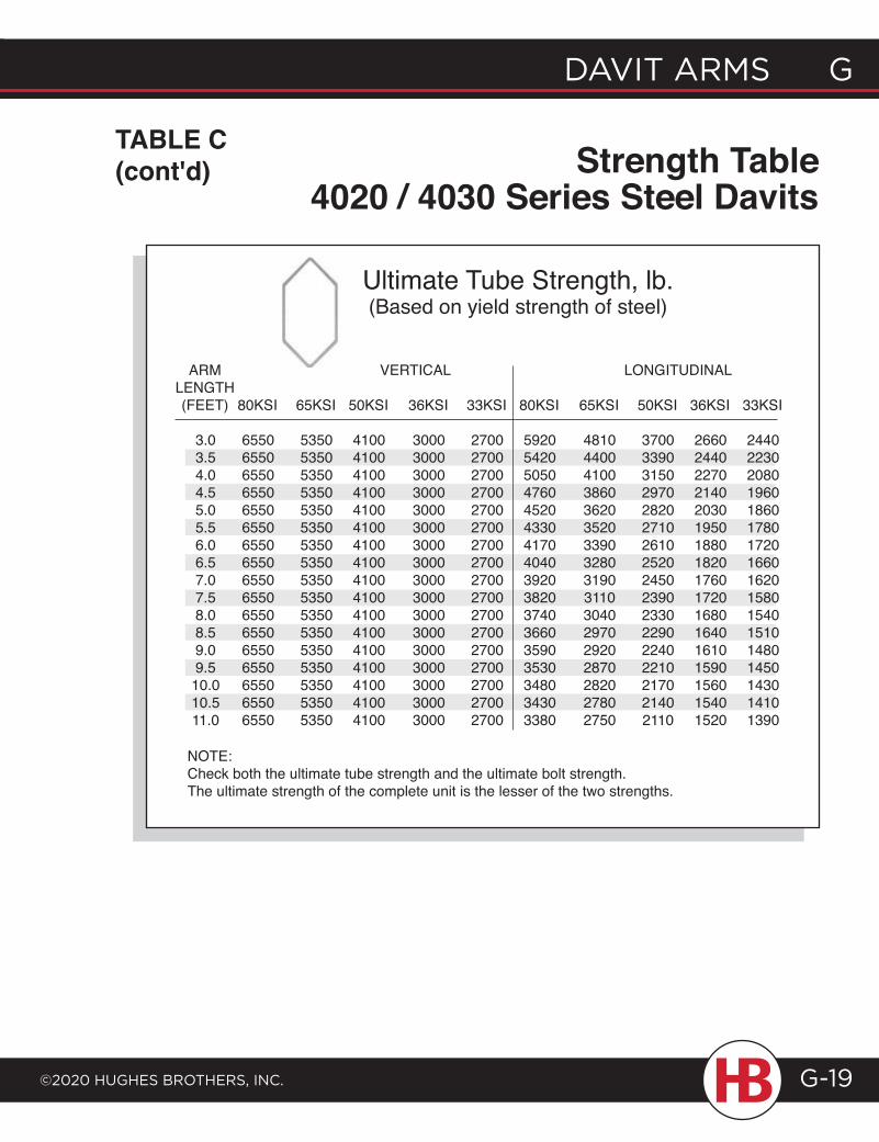
davit arms G
©2020 HuGHes BrotHers, inc.
G davit arms
G-19
Strength table4020 / 4030 Series Steel Davits
ArM VErTICAL LongITudInAL LENGTH (FEET) 80KSI 65KSI 50KSI 36KSI 33KSI 80KSI 65KSI 50KSI 36KSI 33KSI
Ultimate Tube Strength, lb.(Based on yield strength of steel)
tABLE C (cont'd)
3.0 6550 5350 4100 3000 2700 5920 4810 3700 2660 2440 3.5 6550 5350 4100 3000 2700 5420 4400 3390 2440 2230 4.0 6550 5350 4100 3000 2700 5050 4100 3150 2270 2080 4.5 6550 5350 4100 3000 2700 4760 3860 2970 2140 1960 5.0 6550 5350 4100 3000 2700 4520 3620 2820 2030 1860 5.5 6550 5350 4100 3000 2700 4330 3520 2710 1950 1780 6.0 6550 5350 4100 3000 2700 4170 3390 2610 1880 1720 6.5 6550 5350 4100 3000 2700 4040 3280 2520 1820 1660 7.0 6550 5350 4100 3000 2700 3920 3190 2450 1760 1620 7.5 6550 5350 4100 3000 2700 3820 3110 2390 1720 1580 8.0 6550 5350 4100 3000 2700 3740 3040 2330 1680 1540 8.5 6550 5350 4100 3000 2700 3660 2970 2290 1640 1510 9.0 6550 5350 4100 3000 2700 3590 2920 2240 1610 1480 9.5 6550 5350 4100 3000 2700 3530 2870 2210 1590 1450 10.0 6550 5350 4100 3000 2700 3480 2820 2170 1560 1430 10.5 6550 5350 4100 3000 2700 3430 2780 2140 1540 1410 11.0 6550 5350 4100 3000 2700 3380 2750 2110 1520 1390
NOTE:Check both the ultimate tube strength and the ultimate bolt strength. The ultimate strength of the complete unit is the lesser of the two strengths.
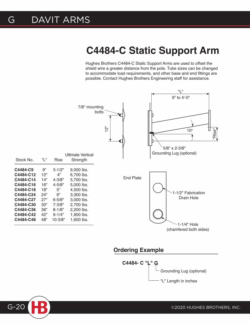
G davit arms
©2020 HuGHes BrotHers, inc.G-20
C4484-C Static Support ArmHughes Brothers C4484-C Static Support Arms are used to offset the shield wire a greater distance from the pole. Tube sizes can be changed to accommodate load requirements, and other base and end fittings are possible. Contact Hughes Brothers Engineering staff for assistance.
5/8" x 2-3/8" Grounding Lug (optional)
12"
"L"
10o
7/8" mounting bolts
1-1/4" Hole (chamfered both sides)
Ordering Example
C4484- C "L" GGrounding Lug (optional)
"L" Length in inches
End Plate
Ultimate Vertical Stock No. "L" Rise Strength C4484-C9 9" 3-1/2" 9,000 lbs. C4484-C12 12" 4" 6,700 lbs. C4484-C14 14" 4-3/8" 5,700 lbs. C4484-C16 16" 4-5/8" 5,000 lbs. C4484-C18 18" 5" 4,500 lbs. C4484-C24 24" 6" 3,300 lbs. C4484-C27 27" 6-5/8" 3,000 lbs. C4484-C30 30" 7-3/8" 2,700 lbs. C4484-C36 36" 8-1/8" 2,200 lbs. C4484-C42 42" 9-1/4" 1,900 lbs. C4484-C48 48" 10-3/8" 1,600 lbs.
9" to 4'-0"
"Ris
e"
1-1/2" Fabrication Drain Hole
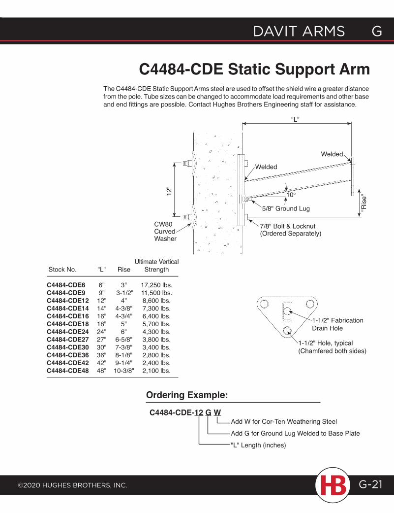
davit arms G
©2020 HuGHes BrotHers, inc.
G davit arms
G-21
C4484-CDE Static Support Arm The C4484-CDE Static Support Arms steel are used to offset the shield wire a greater distance
from the pole. Tube sizes can be changed to accommodate load requirements and other base and end fittings are possible. Contact Hughes Brothers Engineering staff for assistance.
C4484-CDE-12 G WAdd W for Cor-Ten Weathering Steel
Add G for Ground Lug Welded to Base Plate
"L" Length (inches)
Ordering Example:
1-1/2" Hole, typical (Chamfered both sides)
Ultimate Vertical Stock No. "L" Rise Strength C4484-CDE6 6" 3" 17,250 lbs. C4484-CDE9 9" 3-1/2" 11,500 lbs. C4484-CDE12 12" 4" 8,600 lbs. C4484-CDE14 14" 4-3/8" 7,300 lbs. C4484-CDE16 16" 4-3/4" 6,400 lbs. C4484-CDE18 18" 5" 5,700 lbs. C4484-CDE24 24" 6" 4,300 lbs. C4484-CDE27 27" 6-5/8" 3,800 lbs. C4484-CDE30 30" 7-3/8" 3,400 lbs. C4484-CDE36 36" 8-1/8" 2,800 lbs. C4484-CDE42 42" 9-1/4" 2,400 lbs. C4484-CDE48 48" 10-3/8" 2,100 lbs.
CW80 Curved Washer
12"
"L"
10o
5/8" Ground Lug
Welded
7/8" Bolt & Locknut (Ordered Separately)
"Ris
e"
Welded
1-1/2" Fabrication Drain Hole
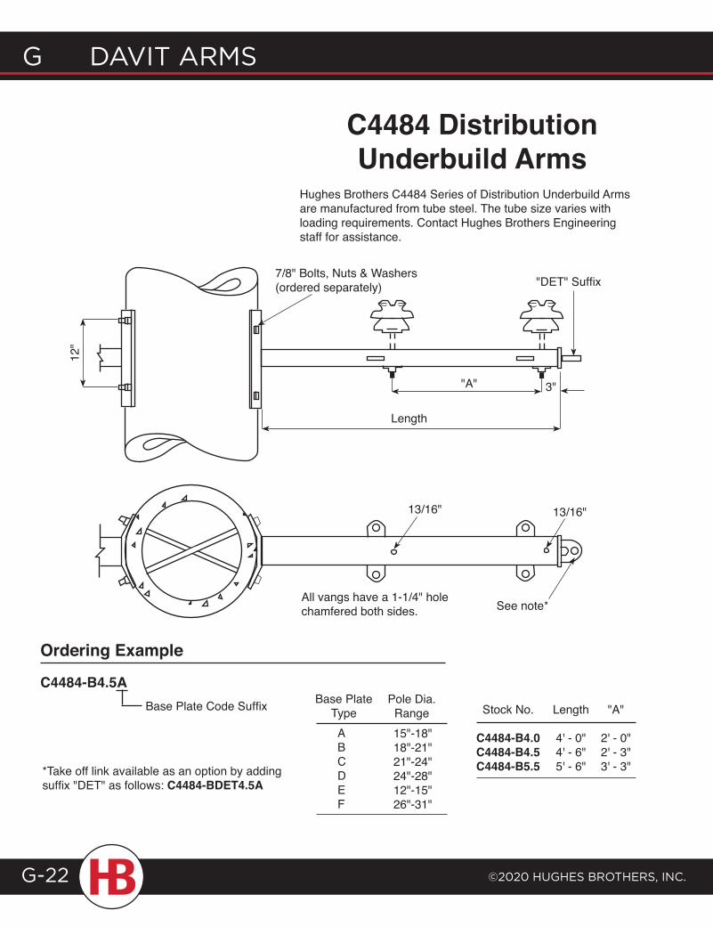
G davit arms
©2020 HuGHes BrotHers, inc.G-22
Ordering Example
C4484-B4.5ABase Plate Code Suffix Base Plate
TypeABCDEF
Pole Dia.Range15"-18"18"-21"21"-24"24"-28"12"-15"26"-31"
*Take off link available as an option by adding suffix "dET" as follows: C4484-BDEt4.5A
Stock No. Length "A" C4484-B4.0 4' - 0" 2' - 0"C4484-B4.5 4' - 6" 2' - 3"C4484-B5.5 5' - 6" 3' - 3"
12"
"dET" Suffix
"A"
Length
3"
13/16" 13/16"
See note*
7/8" Bolts, Nuts & Washers(ordered separately)
Hughes Brothers C4484 Series of Distribution Underbuild Arms are manufactured from tube steel. The tube size varies with loading requirements. Contact Hughes Brothers Engineering staff for assistance.
C4484 Distribution Underbuild Arms
All vangs have a 1-1/4" hole chamfered both sides.
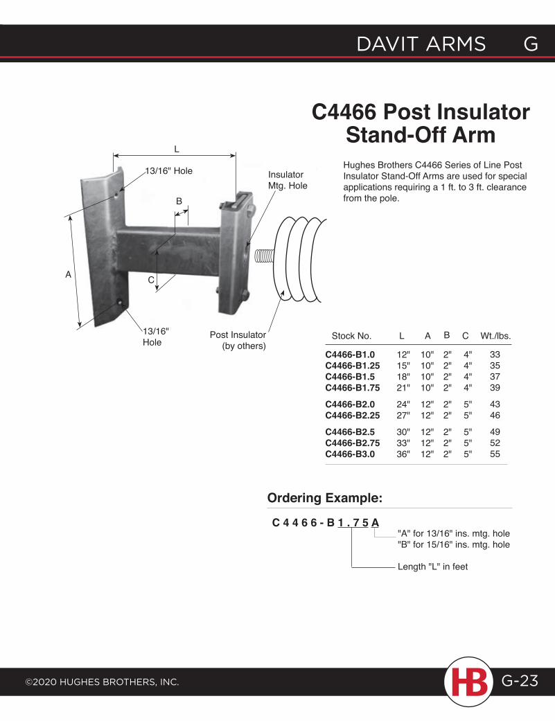
davit arms G
©2020 HuGHes BrotHers, inc.
G davit arms
G-23
12"15"18"21"
24"27"
30"33"36"
Stock No. L
C4466-B1.0C4466-B1.25C4466-B1.5C4466-B1.75C4466-B2.0C4466-B2.25C4466-B2.5C4466-B2.75C4466-B3.0
C4466 post Insulator Stand-Off ArmHughes Brothers C4466 Series of Line Post Insulator Stand-Off Arms are used for special applications requiring a 1 ft. to 3 ft. clearance from the pole.
L
A C
13/16" Hole
10"10"10"10"
12"12"
12"12"12"
A
2"2"2"2"
2"2"
2"2"2"
B
4"4"4"4"
5"5"
5"5"5"
C Wt./lbs.
33353739
4346
495255
Insulator Mtg. Hole
Post Insulator (by others)
B
Ordering Example:
C 4 4 6 6 - B 1 . 7 5 A"A" for 13/16" ins. mtg. hole"B" for 15/16" ins. mtg. hole
Length "L" in feet
13/16"Hole
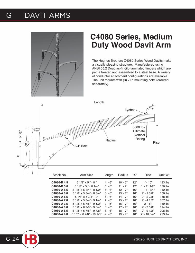
G davit arms
©2020 HuGHes BrotHers, inc.G-24
Stock No. Arm Size Length Radius "X" Rise Unit Wt.
C4080-B 4.5 5 1/8" x 5 " - 8 " 4' - 6" 10' - 7" 12" 1' - 10" 123 lbs C4080-B 5.0 5 1/8" x 5 " - 8 1/4" 5' - 0" 11' - 7" 12" 1' - 11 1/2" 130 lbs C4080-A 5.5 5 1/8" x 5 3/4" - 8 1/2" 5' - 6" 12' - 7" 16" 1' - 11 3/4" 142 lbs C4080-A 6.0 5 1/8" x 5 3/4" - 8 3/4" 6' - 0" 13' - 7" 16" 2' - 1 3/8" 150 lbs C4080-A 6.5 5 1/8" x 5 3/4" - 9" 6' - 6" 14' - 7" 16" 2' - 2 7/8" 158 lbs C4080-A 7.0 5 1/8" x 5 3/4" - 9 1/4" 7' - 0" 15' - 7" 16" 2' - 4 1/2" 167 lbs C4080-A 7.5 5 1/8" x 6 7/8" - 9 1/2" 7' - 6" 16' - 7" 16" 2' - 6" 180 lbs C4080-A 8.0 5 1/8" x 6 7/8" - 9 3/4" 8' - 0" 17' - 7" 16" 2' - 7 5/8" 194 lbs C4080-A 8.5 5 1/8" x 6 7/8" - 9 7/8" 8' - 6" 18' - 7" 16" 2' - 9 1/2" 208 lbs C4080-A 9.0 5 1/8" x 6 7/8" - 10 1/8" 9' - 0" 19' - 7" 16" 2' - 10 3/4" 223 lbs
Length
5000 lbs Ultimate Vertical RatingRadius
6"
1-1/
2"X
The Hughes Brothers C4080 Series Wood Davits make a visually pleasing structure. Manufactured using AnSI 05.2 douglas-fir glu-laminated timbers which are penta treated and assembled to a steel base. A variety of conductor attachment configurations are available. The unit mounts with (3) 7/8" mounting bolts (ordered separately).
C4080 Series, Medium Duty Wood Davit Arm
Rise
Eyebolt
3/4" Bolt
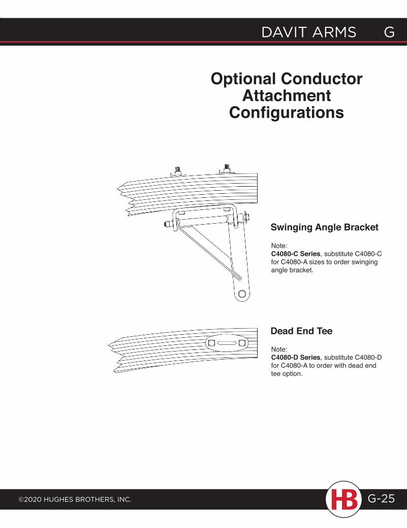
davit arms G
©2020 HuGHes BrotHers, inc.
G davit arms
G-25
Swinging Angle Bracket
Dead End tee
Optional Conductor Attachment
Configurations
Note:C4080-C Series, substitute C4080-C for C4080-A sizes to order swinging angle bracket.
Note:C4080-D Series, substitute C4080-D for C4080-A to order with dead end tee option.
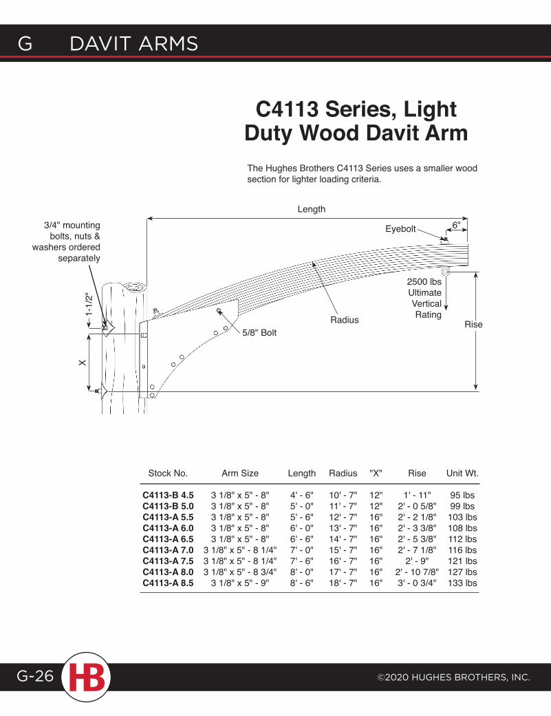
G davit arms
©2020 HuGHes BrotHers, inc.G-26
C4113 Series, Light Duty Wood Davit ArmThe Hughes Brothers C4113 Series uses a smaller wood section for lighter loading criteria.
Stock No. Arm Size Length Radius "X" Rise Unit Wt.
C4113-B 4.5 3 1/8" x 5" - 8" 4' - 6" 10' - 7" 12" 1' - 11" 95 lbs C4113-B 5.0 3 1/8" x 5" - 8" 5' - 0" 11' - 7" 12" 2' - 0 5/8" 99 lbs C4113-A 5.5 3 1/8" x 5" - 8" 5' - 6" 12' - 7" 16" 2' - 2 1/8" 103 lbs C4113-A 6.0 3 1/8" x 5" - 8" 6' - 0" 13' - 7" 16" 2' - 3 3/8" 108 lbs C4113-A 6.5 3 1/8" x 5" - 8" 6' - 6" 14' - 7" 16" 2' - 5 3/8" 112 lbs C4113-A 7.0 3 1/8" x 5" - 8 1/4" 7' - 0" 15' - 7" 16" 2' - 7 1/8" 116 lbs C4113-A 7.5 3 1/8" x 5" - 8 1/4" 7' - 6" 16' - 7" 16" 2' - 9" 121 lbs C4113-A 8.0 3 1/8" x 5" - 8 3/4" 8' - 0" 17' - 7" 16" 2' - 10 7/8" 127 lbs C4113-A 8.5 3 1/8" x 5" - 9" 8' - 6" 18' - 7" 16" 3' - 0 3/4" 133 lbs
Length
2500 lbs Ultimate Vertical Rating
Rise
6"
X
3/4" mounting bolts, nuts &
washers ordered separately
Radius1-1/
2"
Rise
Eyebolt
5/8" Bolt
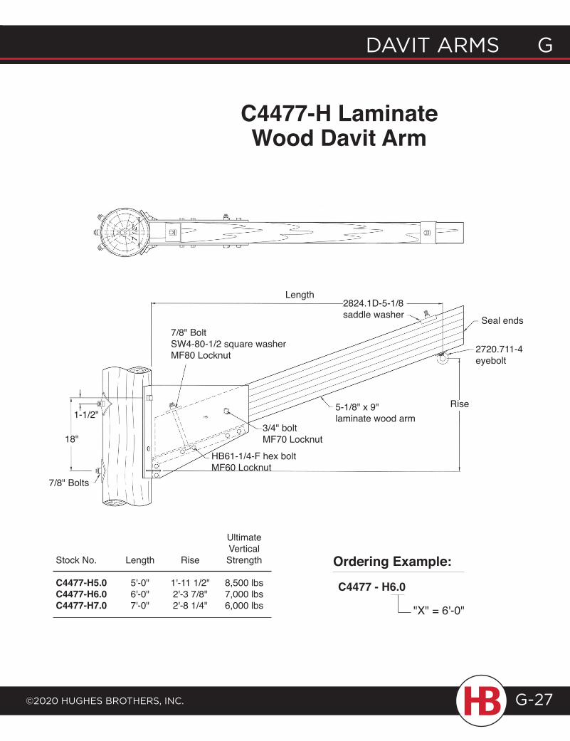
davit arms G
©2020 HuGHes BrotHers, inc.
G davit arms
G-27
C4477-H Laminate Wood Davit Arm
Ultimate Vertical Stock No. Length Rise Strength
C4477-H5.0 5'-0" 1'-11 1/2" 8,500 lbs C4477-H6.0 6'-0" 2'-3 7/8" 7,000 lbs C4477-H7.0 7'-0" 2'-8 1/4" 6,000 lbs
Ordering Example:
C4477 - H6.0
"X" = 6'-0"
Length
Rise1-1/2"
18"
7/8" Bolts
7/8" BoltSW4-80-1/2 square washerMF80 Locknut
2824.1D-5-1/8saddle washer
5-1/8" x 9"laminate wood arm
3/4" boltMF70 Locknut
HB61-1/4-F hex boltMF60 Locknut
Seal ends
2720.711-4eyebolt
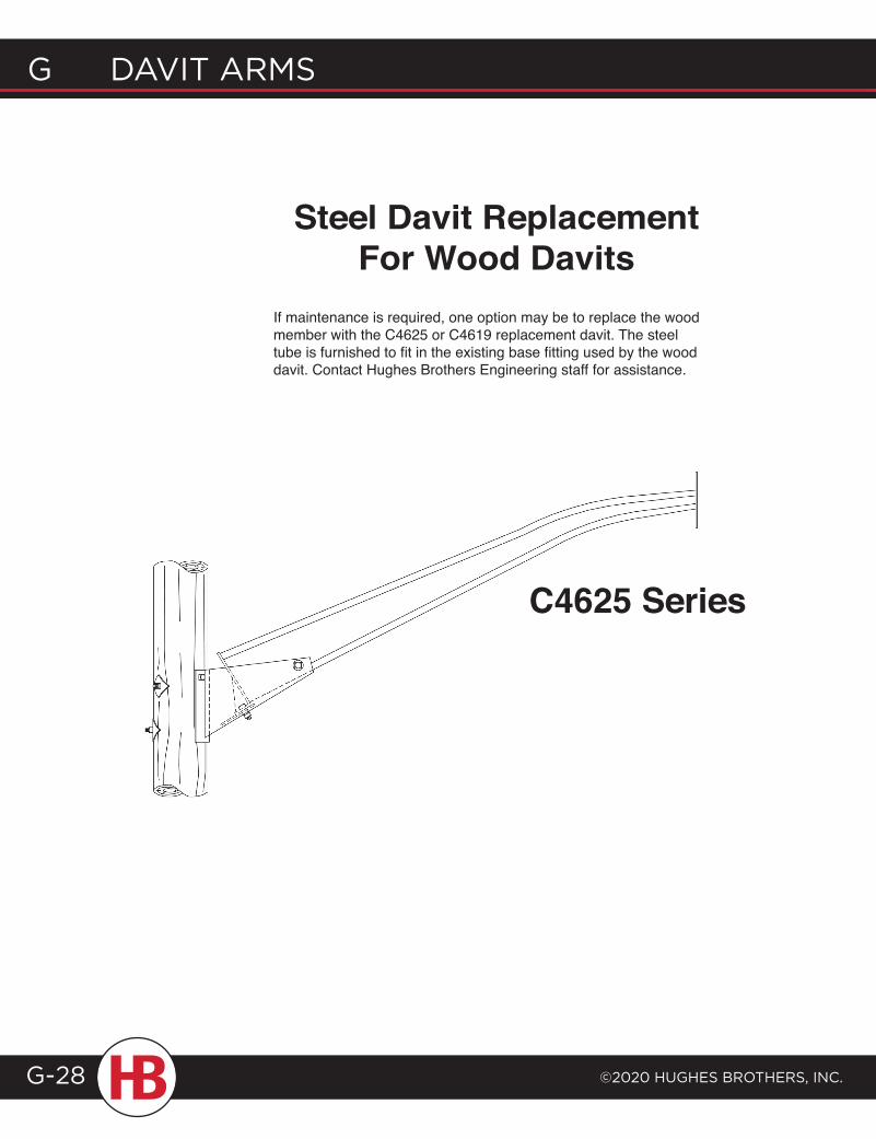
G davit arms
©2020 HuGHes BrotHers, inc.G-28
Steel Davit Replacement For Wood Davits
If maintenance is required, one option may be to replace the wood member with the C4625 or C4619 replacement davit. The steel tube is furnished to fit in the existing base fitting used by the wood davit. Contact Hughes Brothers Engineering staff for assistance.
C4625 Series
S T R U C T U R E R E PA I R ,S TO R M R E S P O N S E ,
& R E F R A M I N G
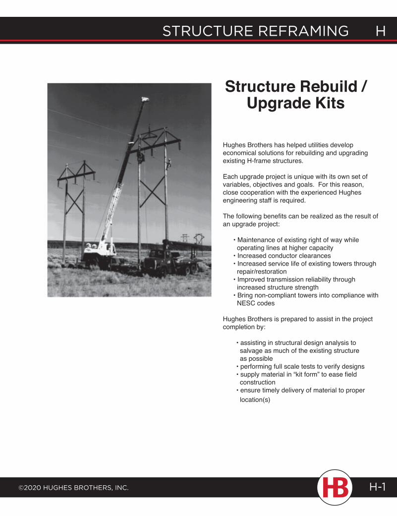
structure reframing H
©2020 HugHes BrotHers, inc. H-1
Hughes Brothers has helped utilities develop economical solutions for rebuilding and upgrading existing H-frame structures.
Each upgrade project is unique with its own set of variables, objectives and goals. For this reason, close cooperation with the experienced Hughes engineering staff is required.
The following benefits can be realized as the result of an upgrade project:
• Maintenance of existing right of way while operating lines at higher capacity• Increased conductor clearances• Increased service life of existing towers through repair/restoration• Improved transmission reliability through increased structure strength• Bring non-compliant towers into compliance with NESC codes
Hughes Brothers is prepared to assist in the project completion by:
• assisting in structural design analysis to salvage as much of the existing structure as possible• performing full scale tests to verify designs• supply material in “kit form” to ease field construction• ensure timely delivery of material to proper location(s)
Structure Rebuild / Upgrade Kits
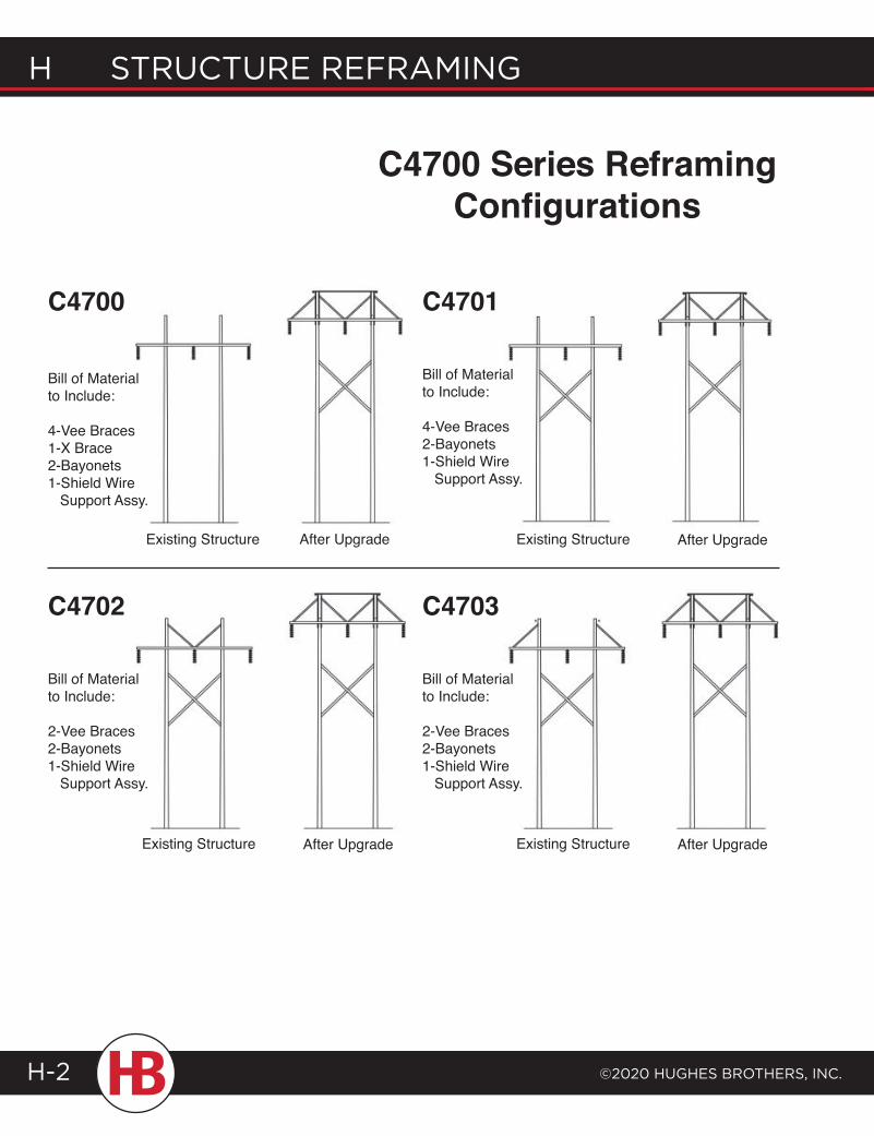
H structure reframing
©2020 HugHes BrotHers, inc.H-2
C4702
Existing Structure After Upgrade
C4703
Existing Structure After Upgrade
Bill of Material to Include:
2-Vee Braces2-Bayonets1-Shield Wire Support Assy.
Bill of Material to Include:
2-Vee Braces2-Bayonets1-Shield Wire Support Assy.
After Upgrade
C4701
Existing Structure After UpgradeExisting Structure
C4700
Bill of Material to Include:
4-Vee Braces2-Bayonets1-Shield Wire Support Assy.
Bill of Material to Include:
4-Vee Braces1-X Brace2-Bayonets1-Shield Wire Support Assy.
C4700 Series Reframing Configurations
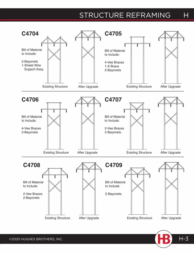
structure reframing H
©2020 HugHes BrotHers, inc.
H structure reframing
H-3
After UpgradeExisting Structure
C4706
Bill of Material to Include:
4-Vee Braces2-Bayonets
After UpgradeExisting Structure
C4707
Bill of Material to Include:
2-Vee Braces2-Bayonets
C4704
Existing Structure After Upgrade After UpgradeExisting Structure
C4705
Bill of Material to Include:
2-Bayonets1-Shield Wire Support Assy.
Bill of Material to Include:
4-Vee Braces1-X Brace2-Bayonets
After UpgradeExisting Structure
C4708
Bill of Material to Include:
2-Vee Braces2-Bayonets
After UpgradeExisting Structure
C4709
Bill of Material to Include:
2-Bayonets
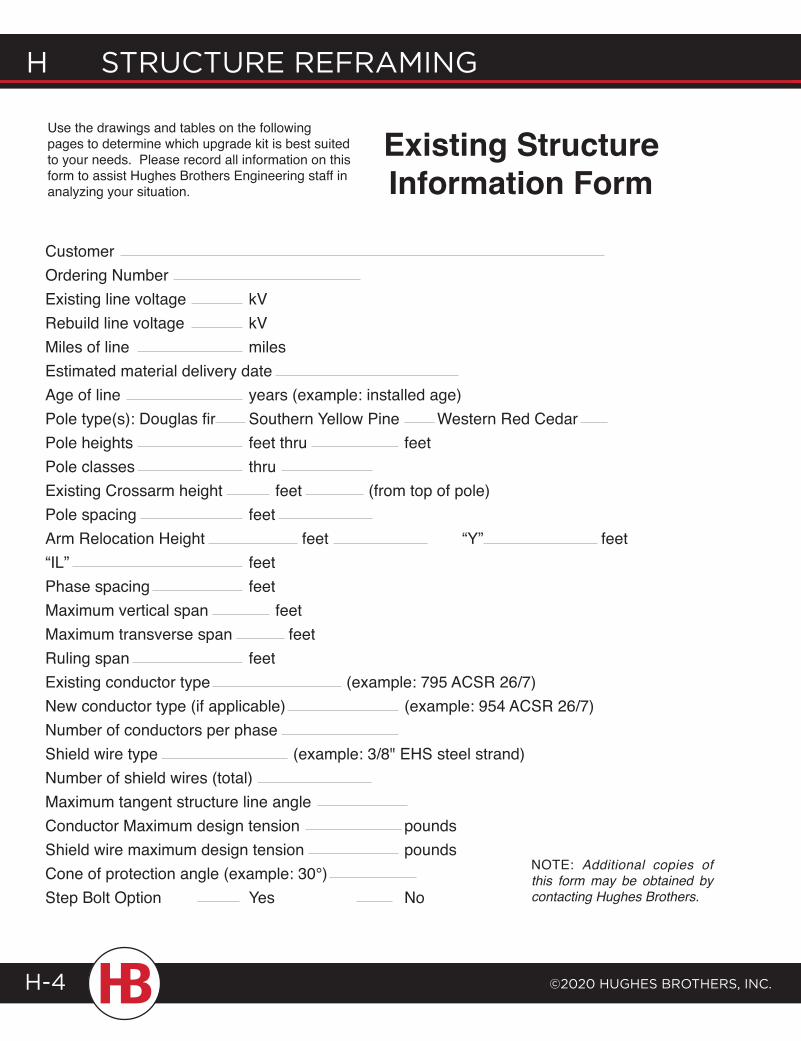
H structure reframing
©2020 HugHes BrotHers, inc.H-4
CustomerOrdering NumberExisting line voltage kVRebuild line voltage kVMiles of line milesEstimated material delivery dateAge of line years (example: installed age)Pole type(s): Douglas fir Southern Yellow Pine Western Red CedarPole heights feet thru feetPole classes thruExisting Crossarm height feet (from top of pole)Pole spacing feetArm Relocation Height feet “Y” feet“IL” feetPhase spacing feetMaximum vertical span feetMaximum transverse span feetRuling span feetExisting conductor type (example: 795 ACSR 26/7)New conductor type (if applicable) (example: 954 ACSR 26/7)Number of conductors per phaseShield wire type (example: 3/8" EHS steel strand)Number of shield wires (total)Maximum tangent structure line angleConductor Maximum design tension poundsShield wire maximum design tension poundsCone of protection angle (example: 30°)Step Bolt Option Yes No
Use the drawings and tables on the following pages to determine which upgrade kit is best suited to your needs. Please record all information on this form to assist Hughes Brothers Engineering staff in analyzing your situation.
Existing Structure Information Form
NOTE: Additional copies of this form may be obtained by contacting Hughes Brothers.
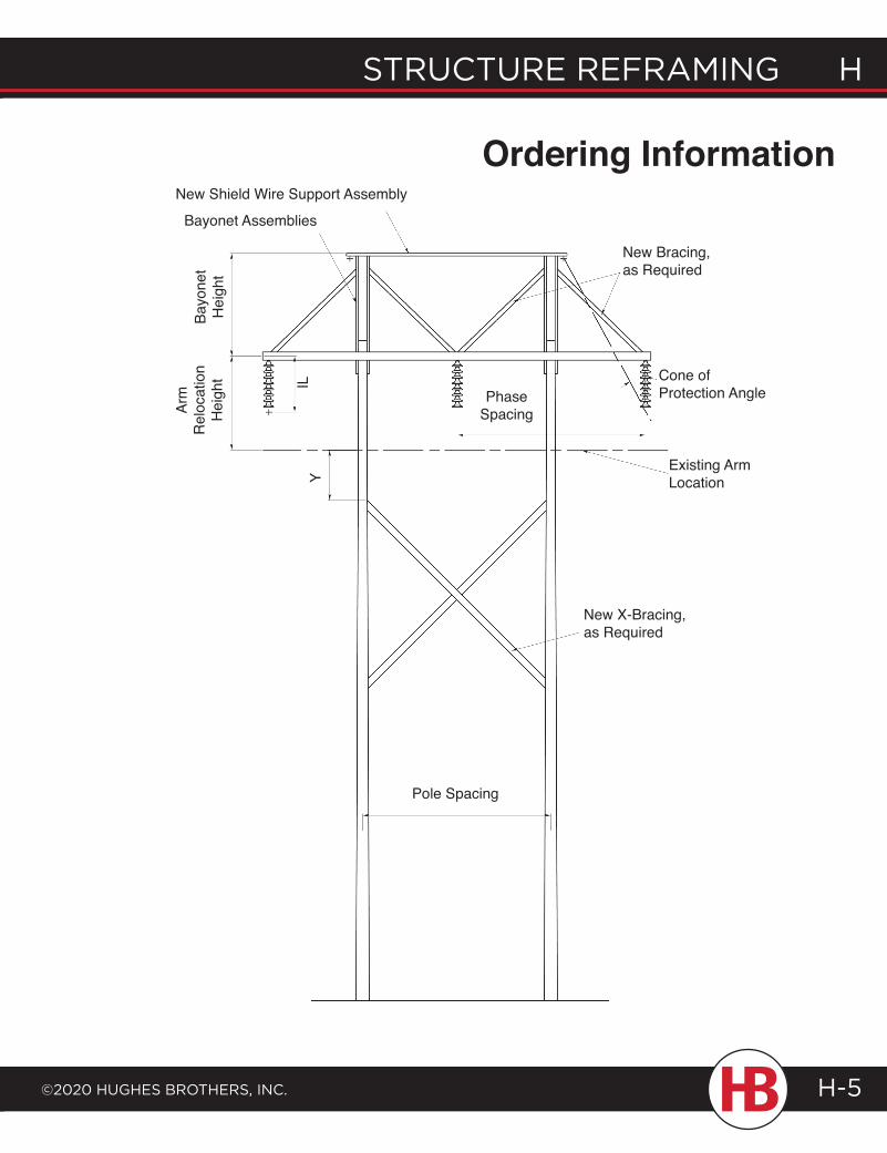
structure reframing H
©2020 HugHes BrotHers, inc.
H structure reframing
H-5
Ordering InformationBa
yone
t H
eigh
t
Arm
Rel
ocat
ion
Hei
ght IL
Y
Bayonet Assemblies
New Shield Wire Support Assembly
PhaseSpacing
New Bracing, as Required
Cone of Protection Angle
Existing ArmLocation
New X-Bracing, as Required
Pole Spacing
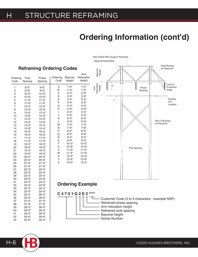
H structure reframing
©2020 HugHes BrotHers, inc.H-6
Ordering Example
C 4 7 0 1 G 2 E 2 ****Customer Code (3 to 4 characters - example NSP)Reframed phase spacingArm relocation heightReframed pole spacingBayonet heightSeries Number
Ordering Pole Phase Code Spacing Spacing
1 9'-0" 9'-0" 2 9'-6" 9'-6" 3 10'-0" 10'-0" 4 10'-6" 10'-6" 5 11'-0" 11'-0" 6 11'-6" 11'-6" 7 12'-0" 12'-0" 8 12'-6" 12'-6" 9 13'-0" 13'-0" 10 13-6" 13-’6" 11 14'-0" 14'-0" 12 14'-6" 14'-6" 13 15'-0" 15'-0" 14 15'-6" 15'-6" 15 16'-0" 16'-0" 16 16'-6" 16'-6" 17 17'-0" 17'-0" 18 17'-6" 17'-6" 19 18'-0" 18'-0" 20 18'-6" 18'-6" 21 19'-0" 19'-0" 22 19'-6" 19'-6" 23 20'-0" 20'-0" 24 20'-6" 20'-6" 25 21'-0" 21'-0" 26 21'-6" 21'-6" 27 22'-0" 22'-0" 28 22'-6" 22'-6" 29 23'-0" 23'-0" 30 23'-6" 23'-6" 31 24'-0" 24'-0" 32 24'-6" 24'-6" 33 25'-0" 25'-0" 34 25'-6" 25'-6" 35 26'-0" 26'-0" 36 26'-6" 26'-6" 37 27'-0" 27'-0" 38 27'-6" 27'-6" 39 28'-0" 28'-0" 40 28'-6" 28'-6" 41 29'-0" 29'-0" 42 29'-6" 29'-6" 43 30'-0" 30'-0"
ArmOrdering Bayonet Relocation Code Height Height
A 1'-0" 1'-0" B 1'-6" 1'-6" C 2'-0" 2'-0" D 2'-6" 2'-6" E 3'-0" 3'-0" F 3'-6" 3'-6" G 4'-0" 4'-0" H 4'-6" 4'-6" I 5'-0" 5'-0" J 5'-6" 5'-6" K 6'-0" 6'-0" L 6'-6" 6'-6" M 7'-0" 7'-0" N 7'-6" 7'-6" P 8'-0" 8'-0" Q 8'-6" 8'-6" R 9'-0" 9'-0" S 9'-6" 9'-6" T 10'-0" 10'-0" U 10'-6" 10'-6" V 11'-0" 11'-0" W 11'-6" 11'-6" X 12'-0" 12'-0" Y 12'-6" 12'-6" Z 13'-0" 13'-0"
Reframing Ordering Codes
Ordering Information (cont'd)
Bayo
net
Hei
ght
Arm
Rel
ocat
ion
Hei
ght IL
Y
Bayonet Assemblies
New Shield Wire Support Assembly
PhaseSpacing
New Bracing, as Required
Cone of Protection Angle
Existing ArmLocation
New X-Bracing, as Required
Pole Spacing
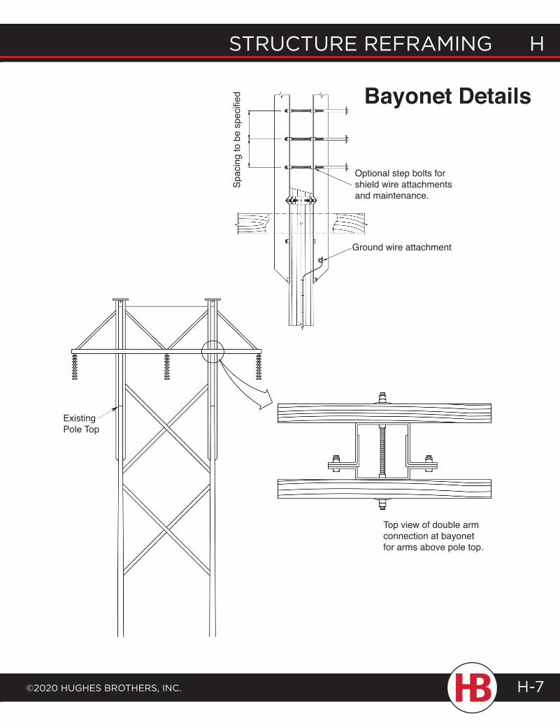
structure reframing H
©2020 HugHes BrotHers, inc.
H structure reframing
H-7
Bayonet Details
Spac
ing
to b
e sp
ecifi
ed
Optional step bolts for shield wire attachments and maintenance.
Ground wire attachment
Top view of double arm connection at bayonet for arms above pole top.
Existing Pole Top
Ordering Information (cont'd)
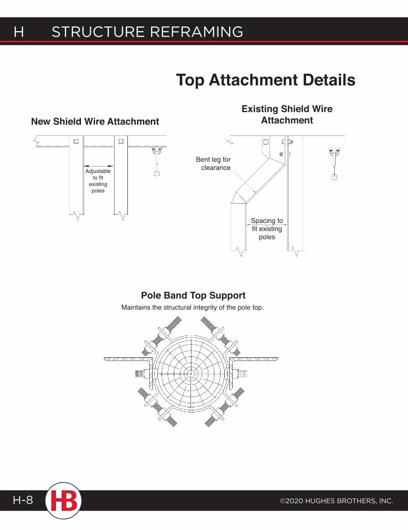
H structure reframing
©2020 HugHes BrotHers, inc.H-8
Maintains the structural integrity of the pole top.Pole Band Top Support
Existing Shield Wire AttachmentNew Shield Wire Attachment
Adjustable to fit
existing poles
Top Attachment Details
Bent leg for clearance
Spacing to fit existing
poles
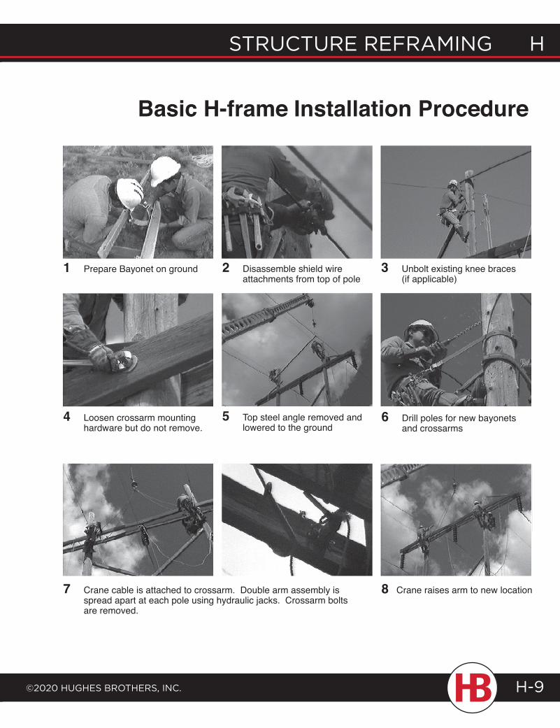
structure reframing H
©2020 HugHes BrotHers, inc.
H structure reframing
H-9
Basic H-frame Installation Procedure
1 Prepare Bayonet on ground 2 Disassemble shield wire attachments from top of pole
3 Unbolt existing knee braces (if applicable)
4 Loosen crossarm mounting hardware but do not remove.
5 Top steel angle removed and lowered to the ground
6 Drill poles for new bayonets and crossarms
7 Crane cable is attached to crossarm. Double arm assembly is spread apart at each pole using hydraulic jacks. Crossarm bolts are removed.
8 Crane raises arm to new location
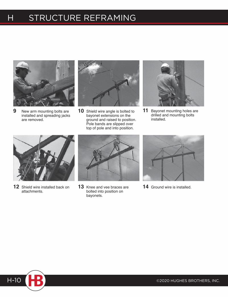
H structure reframing
©2020 HugHes BrotHers, inc.H-10
9 New arm mounting bolts are installed and spreading jacks are removed.
10 Shield wire angle is bolted to bayonet extensions on the ground and raised to position. Pole bands are slipped over top of pole and into position.
11 Bayonet mounting holes are drilled and mounting bolts installed.
12 Shield wire installed back on attachments.
13 Knee and vee braces are bolted into position on bayonets.
14 Ground wire is installed.
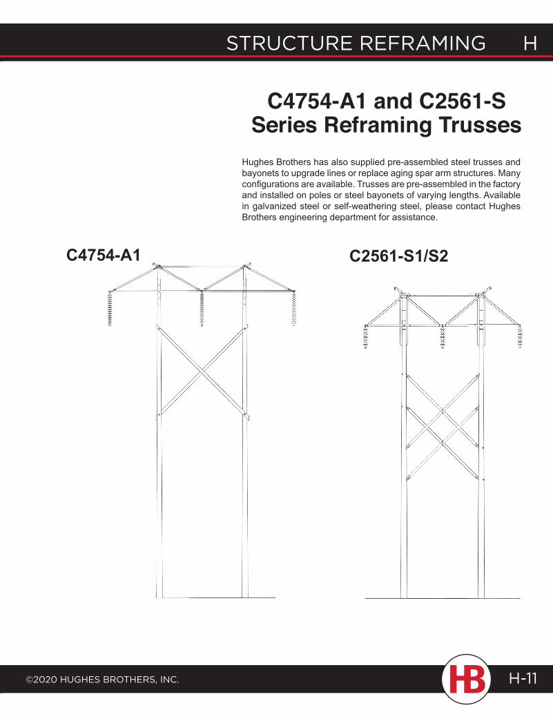
structure reframing H
©2020 HugHes BrotHers, inc.
H structure reframing
H-11
C4754-A1 and C2561-S Series Reframing Trusses
C4754-A1 C2561-S1/S2
Hughes Brothers has also supplied pre-assembled steel trusses and bayonets to upgrade lines or replace aging spar arm structures. Many configurations are available. Trusses are pre-assembled in the factory and installed on poles or steel bayonets of varying lengths. Available in galvanized steel or self-weathering steel, please contact Hughes Brothers engineering department for assistance.
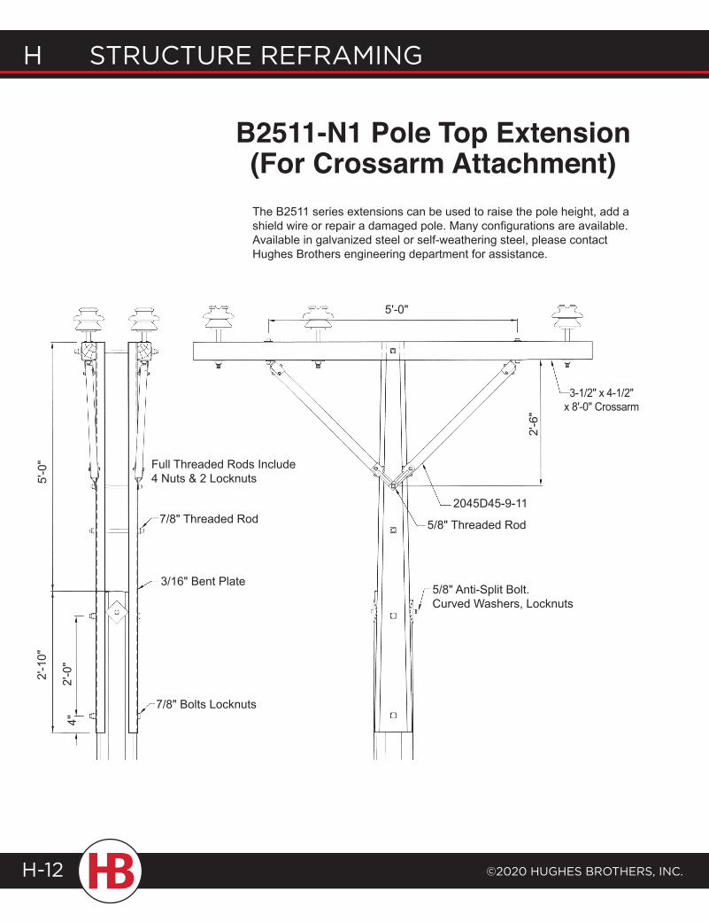
H structure reframing
©2020 HugHes BrotHers, inc.H-12
B2511-N1 Pole Top Extension (For Crossarm Attachment)
5'-0
" Full Threaded Rods Include 4 Nuts & 2 Locknuts
7/8" Threaded Rod
2'-1
0"
2'-0
"
7/8" Bolts Locknuts
3/16" Bent Plate
4"
5'-0"
2'-6
"
3-1/2" x 4-1/2" x 8'-0" Crossarm
2045D45-9-11
5/8" Threaded Rod
5/8" Anti-Split Bolt. Curved Washers, Locknuts
The B2511 series extensions can be used to raise the pole height, add a shield wire or repair a damaged pole. Many configurations are available. Available in galvanized steel or self-weathering steel, please contact Hughes Brothers engineering department for assistance.
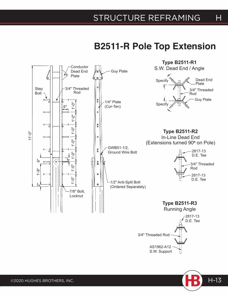
structure reframing H
©2020 HugHes BrotHers, inc.
H structure reframing
H-13
B2511-R Pole Top Extension
Conductor Dead End Plate
Guy Plate
6" 1'-0
"1'
-0"
1'-0
"1'
-0"
1'-0
"1'
-0"
4"
3/4" Threaded Rod
11'-0
"
6"
1'-0
"
2"1'
-8"
7/8" Bolt, Locknut
1/2" Anti-Split Bolt (Ordered Separately)
GWB51-1/2, Ground Wire Bolt
1/4" Plate (Cor-Ten)
Type B2511-R1 S.W. Dead End / Angle
Type B2511-R2 In-Line Dead End
(Extensions turned 90o on Pole)
Type B2511-R3 Running Angle
2817-13 D.E. Tee
3/4" Threaded Rod
AS1962-A12 S.W. Support
2817-13 D.E. Tee
3/4" Threaded Rod
2817-13 D.E. Tee
3/4" Threaded Rod
Specify
Specify
Dead End Plate
Guy Plate
StepBolt
B2511-N1 Pole Top Extension (For Crossarm Attachment)
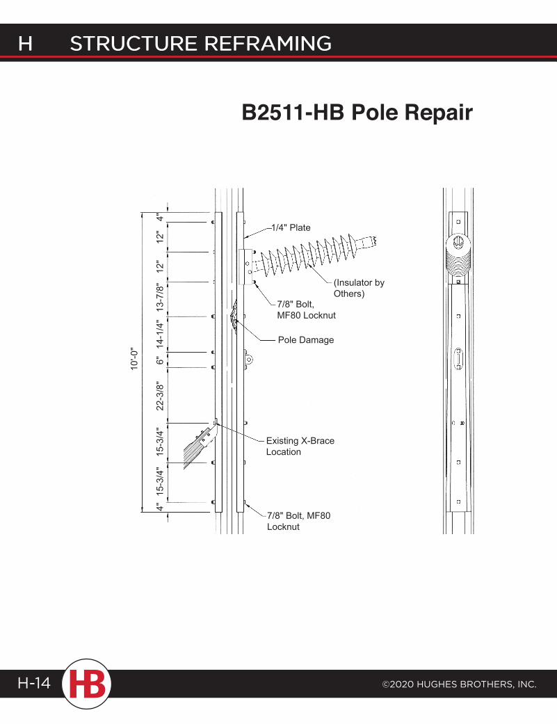
H structure reframing
©2020 HugHes BrotHers, inc.H-14
H STRUCTURE REFRAMING
B2511-HB Pole Repair
1/4" Plate
4"12
"12
"13
-7/8
"14
-1/4
"
(Insulator by Others)
7/8" Bolt, MF80 Locknut
Pole Damage
6"
10'-0
"
22-3
/8"
15-3
/4"
15-3
/4"
4"
Existing X-Brace Location
7/8" Bolt, MF80 Locknut
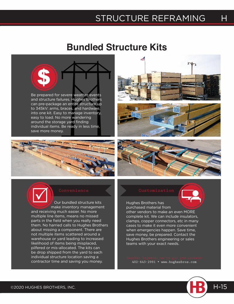
structure reframing H
©2020 HugHes BrotHers, inc.
H structure reframing
H-15
STRUCTURE REFRAMING H
©2020 HUGHES BROTHERS, INC.
H STRUCTURE REFRAMING
H-15
Our bundled structure kits make inventory management and receiving much easier. No more multiple line items, means no missed parts in the field when you really need them. No harried calls to Hughes Brothers about missing a component. There are not multiple items scattered around a warehouse or yard leading to increased likelihood of items being misplaced, pilfered or mis-allocated. The kits can be drop shipped from the yard to each individual structure location saving a contractor time and saving you money.
Convenience Customization
Hughes Brothers has purchased material from other vendors to make an even MORE complete kit. We can include insulators, clamps, copper connectors, etc in many cases to make it even more convenient when emergencies happen. Save time, save money, be prepared. Contact the Hughes Brothers engineering or sales teams with your exact needs.
Bundled Structure Kits
Weather happens; we’ve got you covered402-643-2991 • www.hughesbros.com
Be prepared for severe weather events and structure failures. Hughes Brothers can pre-package an entire structure up to 345kV: arms, braces, and hardware, into one kit. Easy to manage inventory, easy to load. No more wandering around the storage yard finding individual items. Be ready in less time, save more money.
L I G H T I N G P O L E S& S I G N P O S T S
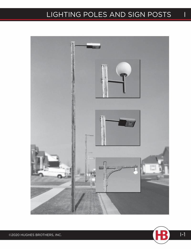
lighting poles and sign posts i
©2020 hughes Brothers, inc. I-1
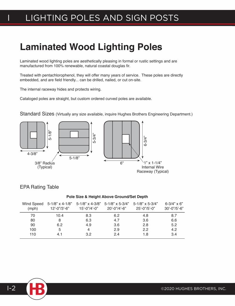
I lIghtIng poles and sIgn posts
©2020 hughes Brothers, Inc.I-2
Laminated Wood Lighting PolesLaminated wood lighting poles are aesthetically pleasing in formal or rustic settings and are manufactured from 100% renewable, natural coastal douglas fir.
Treated with pentachlorophenol, they will offer many years of service. These poles are directly embedded, and are field friendly... can be drilled, nailed, or cut on-site.
The internal raceway hides and protects wiring.
Cataloged poles are straight, but custom ordered curved poles are available.
Standard Sizes (Virtually any size available, inquire Hughes Brothers Engineering Department.)
EPA Rating Table
Pole Size & Height Above Ground/Set Depth Wind Speed 5-1/8” x 4-1/8” 5-1/8” x 4-3/8” 5-1/8” x 5-3/4” 5-1/8” x 5-3/4” 6-3/4” x 6” (mph) 12’-0”/3’-6” 15’-0”/4’-0” 20’-0”/4’-6” 25’-0”/5’-0” 30’-0”/5’-6” 70 10.4 8.3 6.2 4.8 8.7 80 8 6.3 4.7 3.6 6.6 90 6.2 4.9 3.6 2.8 5.2 100 5 4 2.9 2.2 4.2 110 4.1 3.2 2.4 1.8 3.4
4-3/8”
5-1/
8”
5-1/8”
5-3/
4”
6-3/
4”
6”3/8” Radius (Typical)
1” x 1-1/4” Internal Wire
Raceway (Typical)
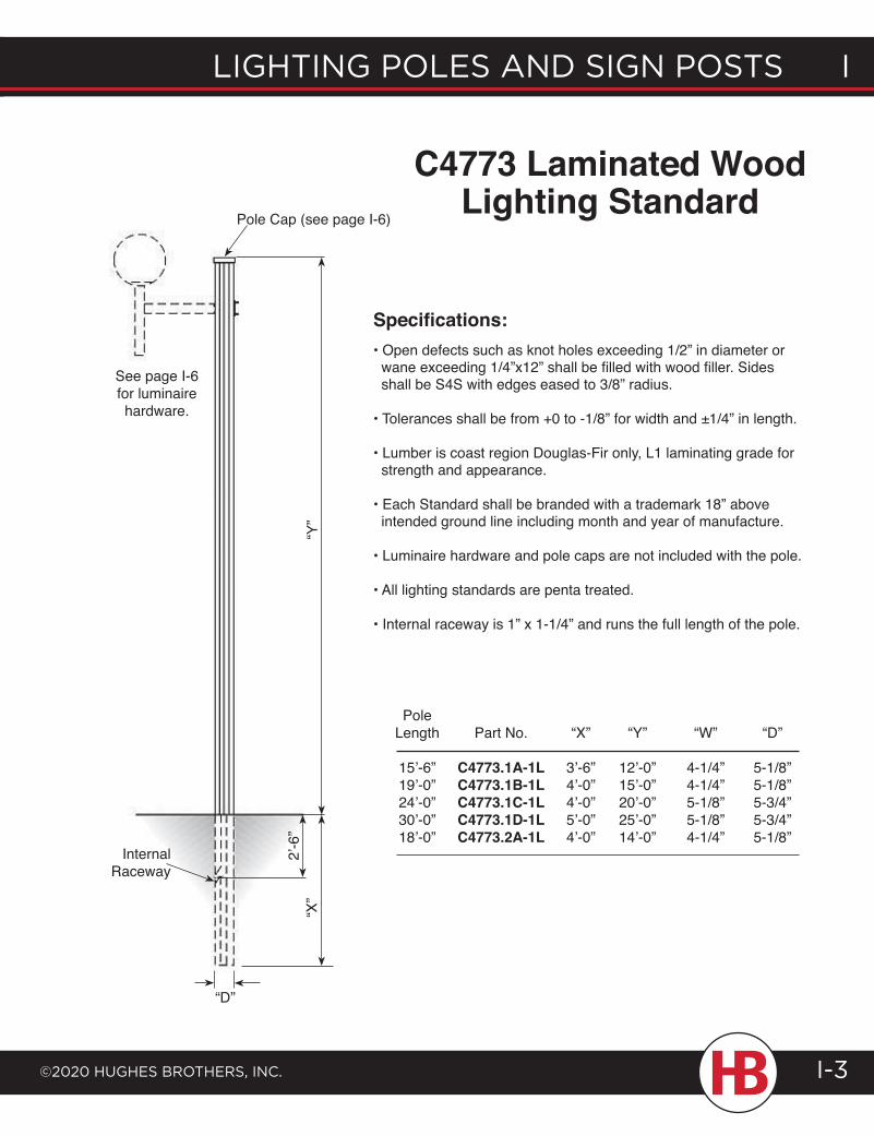
lighting poles and sign posts i
©2020 hughes Brothers, inc.
i lighting poles and sign posts
I-3
Pole Length Part No. “X” “Y” “W” “D”
15’-6” C4773.1A-1L 3’-6” 12’-0” 4-1/4” 5-1/8” 19’-0” C4773.1B-1L 4’-0” 15’-0” 4-1/4” 5-1/8” 24’-0” C4773.1C-1L 4’-0” 20’-0” 5-1/8” 5-3/4” 30’-0” C4773.1D-1L 5’-0” 25’-0” 5-1/8” 5-3/4” 18’-0” C4773.2A-1L 4’-0” 14’-0” 4-1/4” 5-1/8”
C4773 Laminated Wood Lighting Standard
Pole Cap (see page I-6)
“Y”
“X”
2’-6
”
Internal Raceway
“D”
See page I-6 for luminaire hardware.
Specifications:• Open defects such as knot holes exceeding 1/2” in diameter or wane exceeding 1/4”x12” shall be filled with wood filler. Sides shall be S4S with edges eased to 3/8” radius.
• Tolerances shall be from +0 to -1/8” for width and ±1/4” in length.
• Lumber is coast region Douglas-Fir only, L1 laminating grade for strength and appearance.
• Each Standard shall be branded with a trademark 18” above intended ground line including month and year of manufacture.
• Luminaire hardware and pole caps are not included with the pole.
• All lighting standards are penta treated.
• Internal raceway is 1” x 1-1/4” and runs the full length of the pole.
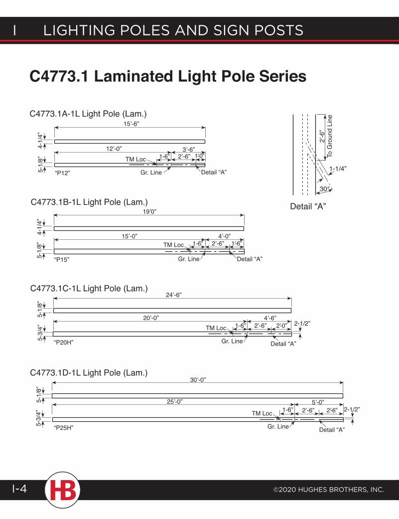
I lIghtIng poles and sIgn posts
©2020 hughes Brothers, Inc.I-4
4-1/
4”5-
1/8”
15’-6”
12’-0”TM Loc
“P12” Gr. Line Detail “A”
3’-6”1-6” 2’-6” 1’-0”
19’0”
4-1/
4”5-
1/8”
“P15”
15’-0”1-6”
4’-0”2’-6” 1’-6”TM Loc
Gr. Line Detail “A”
C4773.1 Laminated Light Pole Series
C4773.1A-1L Light Pole (Lam.)
C4773.1B-1L Light Pole (Lam.)
C4773.1C-1L Light Pole (Lam.)
C4773.1D-1L Light Pole (Lam.)
5-1/
8”5-
3/4”
5-1/
8”5-
3/4”
24’-6”
TM Loc20’-0”
Gr. Line Detail “A”
2-1/2”1-6” 2’-6” 2’-0”4’-6”
“P20H”
“P25H”
30’-0”
25’-0”
Detail “A”
2-1/2”2’-6” 2’-6”5’-0”
TM Loc
Gr. Line
1-6”
2’-6
” To
Gro
und
Line
Detail “A”
1-1/4”
30°
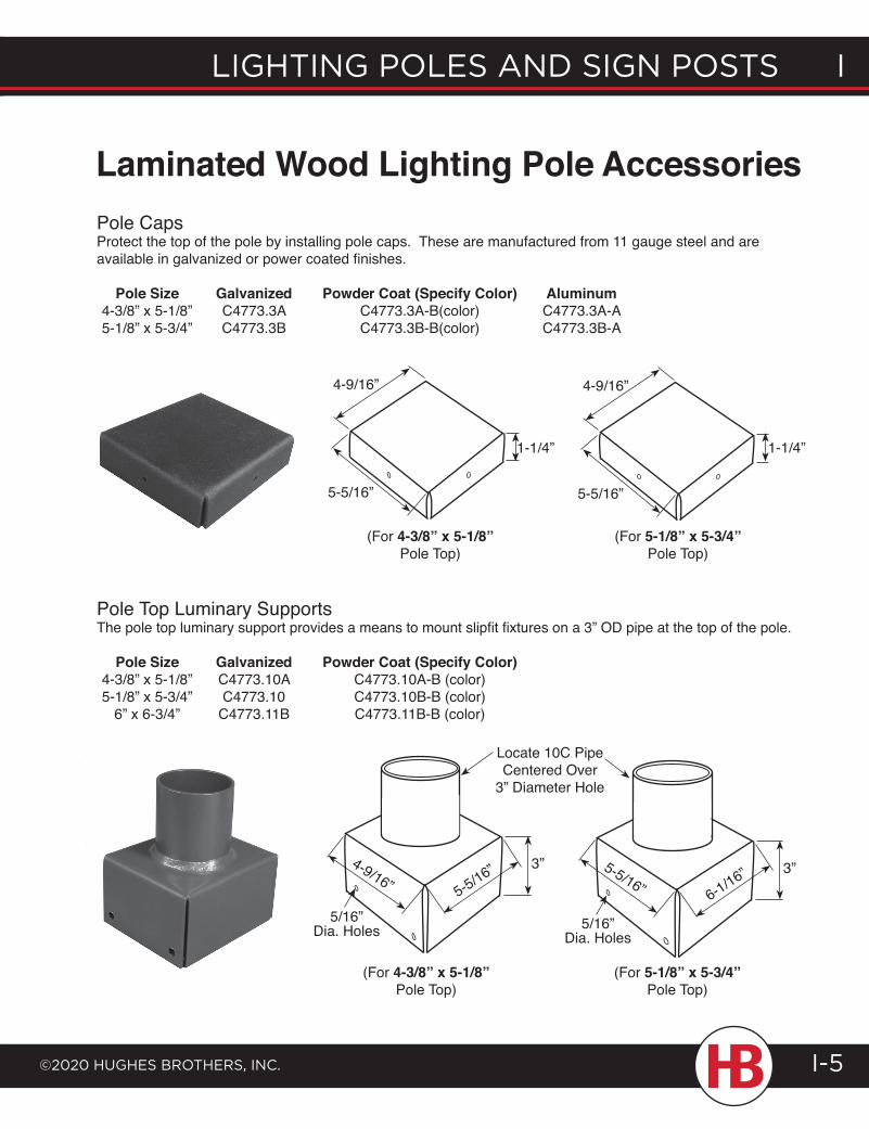
lighting poles and sign posts i
©2020 hughes Brothers, inc.
i lighting poles and sign posts
I-5
Laminated Wood Lighting Pole AccessoriesPole CapsProtect the top of the pole by installing pole caps. These are manufactured from 11 gauge steel and are available in galvanized or power coated finishes.
Pole Size Galvanized Powder Coat (Specify Color) Aluminum 4-3/8” x 5-1/8” C4773.3A C4773.3A-B(color) C4773.3A-A 5-1/8” x 5-3/4” C4773.3B C4773.3B-B(color) C4773.3B-A
Pole Top Luminary SupportsThe pole top luminary support provides a means to mount slipfit fixtures on a 3” OD pipe at the top of the pole.
Pole Size Galvanized Powder Coat (Specify Color) 4-3/8” x 5-1/8” C4773.10A C4773.10A-B (color) 5-1/8” x 5-3/4” C4773.10 C4773.10B-B (color) 6” x 6-3/4” C4773.11B C4773.11B-B (color)
1-1/4”
4-9/16”
5-5/16”
1-1/4”
4-9/16”
5-5/16”
(For 4-3/8” x 5-1/8” Pole Top)
(For 5-1/8” x 5-3/4” Pole Top)
Locate 10C Pipe Centered Over
3” Diameter Hole
5/16” Dia. Holes 5/16”
Dia. Holes
4-9/16” 5-5/16” 5-5/16” 6-1/16”
(For 4-3/8” x 5-1/8” Pole Top)
(For 5-1/8” x 5-3/4” Pole Top)
3” 3”
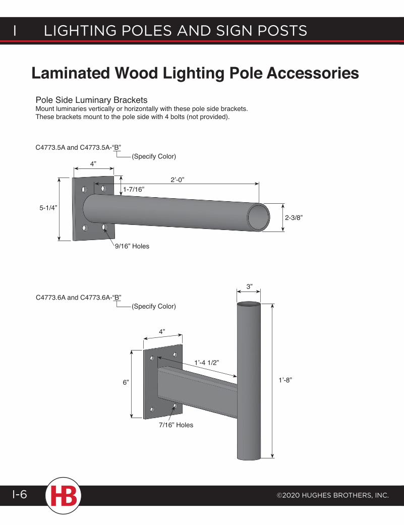
I lIghtIng poles and sIgn posts
©2020 hughes Brothers, Inc.I-6
Laminated Wood Lighting Pole AccessoriesPole Side Luminary BracketsMount luminaries vertically or horizontally with these pole side brackets. These brackets mount to the pole side with 4 bolts (not provided).
C4773.5A and C4773.5A-“B”
C4773.6A and C4773.6A-“B”
4”
5-1/4”
2’-0”
9/16” Holes
1-7/16”
6”
7/16” Holes
4”
1’-4 1/2”
1’-8”
3”
2-3/8”
(Specify Color)
(Specify Color)
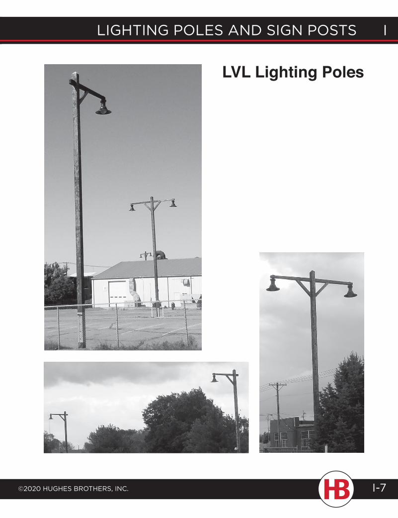
lighting poles and sign posts i
©2020 hughes Brothers, inc.
i lighting poles and sign posts
I-7
LVL Lighting Poles
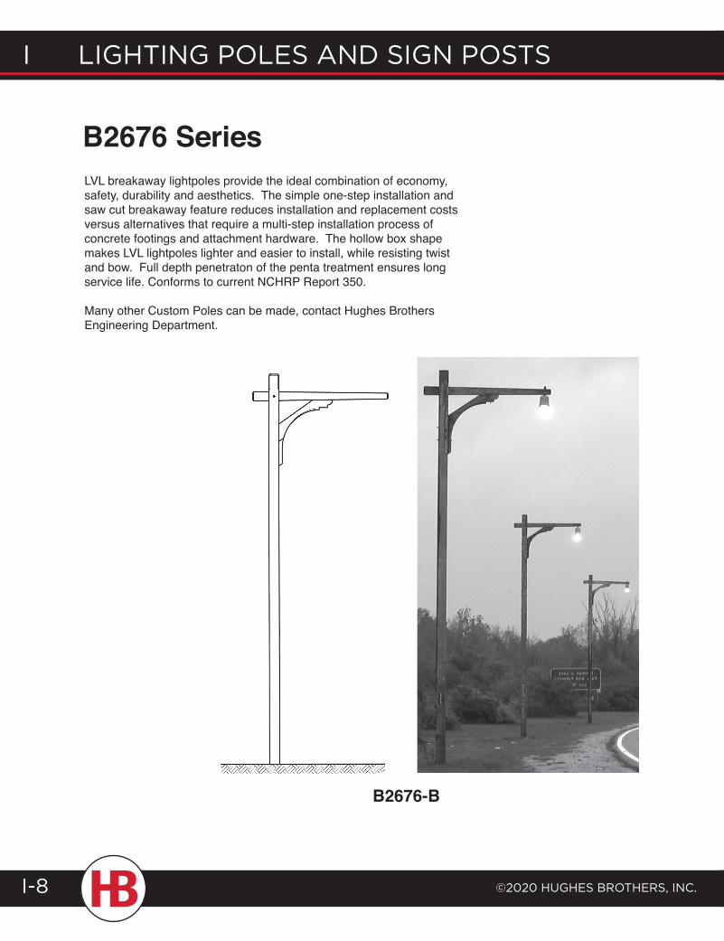
I lIghtIng poles and sIgn posts
©2020 hughes Brothers, Inc.I-8
B2676 Series
B2676-B
LVL breakaway lightpoles provide the ideal combination of economy, safety, durability and aesthetics. The simple one-step installation and saw cut breakaway feature reduces installation and replacement costs versus alternatives that require a multi-step installation process of concrete footings and attachment hardware. The hollow box shape makes LVL lightpoles lighter and easier to install, while resisting twist and bow. Full depth penetraton of the penta treatment ensures long service life. Conforms to current NCHRP Report 350.
Many other Custom Poles can be made, contact Hughes Brothers Engineering Department.
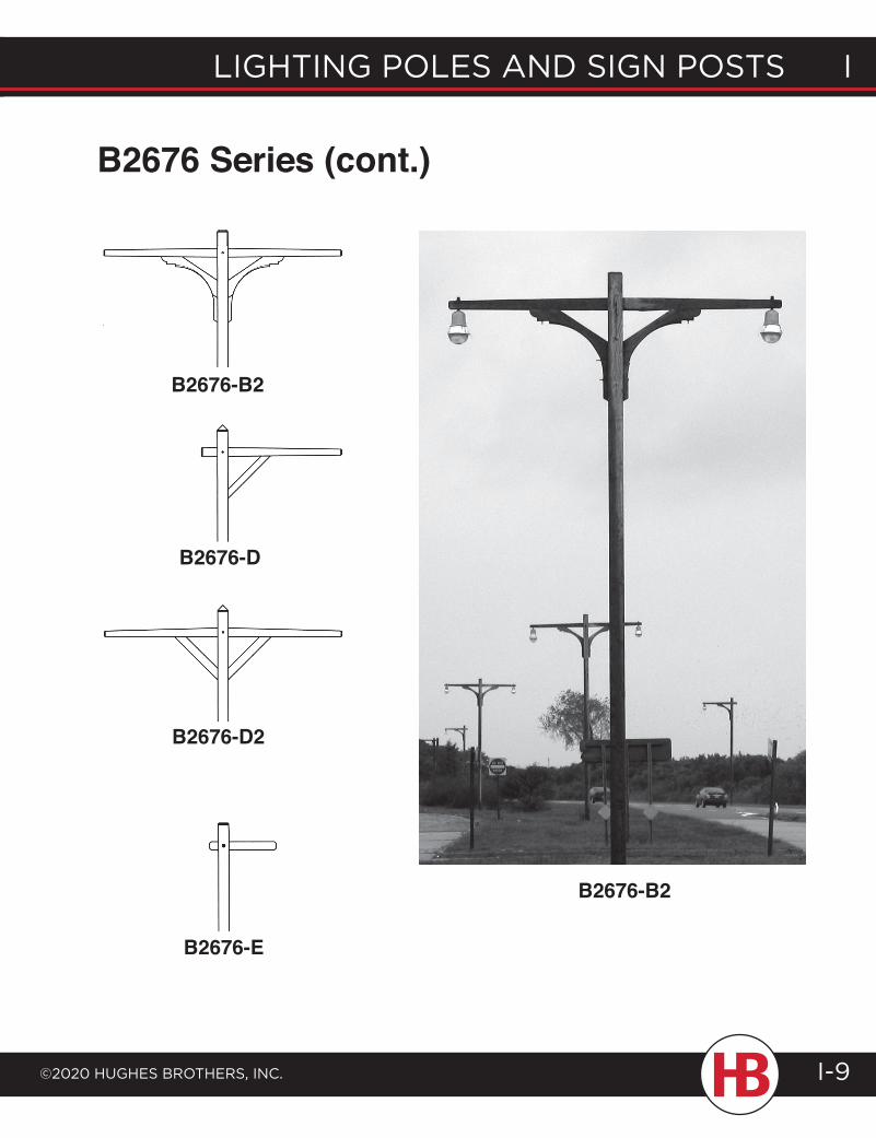
lighting poles and sign posts i
©2020 hughes Brothers, inc.
i lighting poles and sign posts
I-9
B2676-B2
B2676-D
B2676-D2
B2676-E
B2676 Series (cont.)
B2676-B2
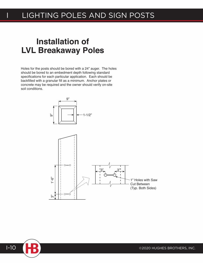
I lIghtIng poles and sIgn posts
©2020 hughes Brothers, Inc.I-10
Installation of LVL Breakaway Poles
Holes for the posts should be bored with a 24” auger. The holes should be bored to an embedment depth following standard specifications for each particular application. Each should be backfilled with a granular fill as a minimum. Anchor plates or concrete may be required and the owner should verify on-site soil conditions.
9”
1-1/2”9”3”
1’-6
”
3” 3”
1” Holes with Saw Cut Between (Typ. Both Sides)

LVL breakaway signposts and lightpoles provide the ideal combination of economy, safety, durability and aesthetics. The simple one-step installation and saw cut breakaway feature reduces installation and replacement costs versus alternatives that require a multiple-step installation process of concrete footings and attachment hardware. The hollow box shape makes LVL signposts and lightpoles lighter and easier to install, while resisting twist and bow. Both products are treated with wood preservatives to provide long life, and each conforms to current NCHRP Report 350.
lighting poles and sign posts i
©2020 hughes Brothers, inc.
i lighting poles and sign posts
I-11
Breakaway Sign Posts
• Warranted to be free from defects
• Simple one-step installation
• Supports large signs and high wind loads
• More attractive than steel or aluminum
• Preservative treated to AWPA Standard C33 for durability
• Hollow box design resists twist and bow
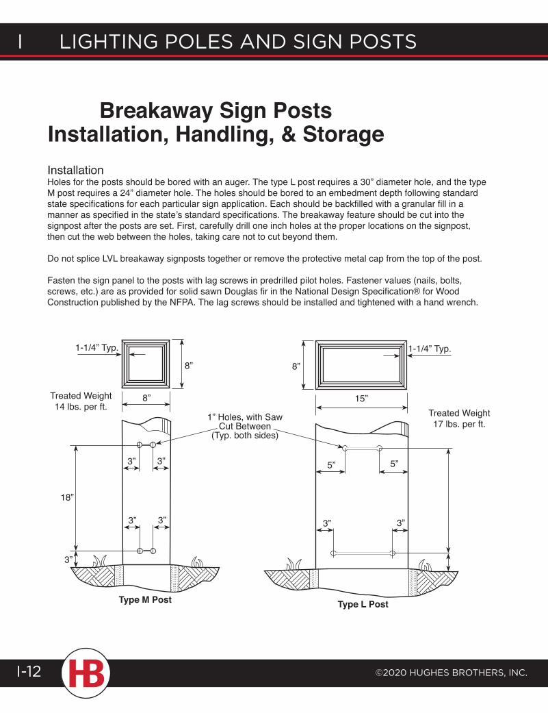
I lIghtIng poles and sIgn posts
©2020 hughes Brothers, Inc.I-12
InstallationHoles for the posts should be bored with an auger. The type L post requires a 30” diameter hole, and the type M post requires a 24” diameter hole. The holes should be bored to an embedment depth following standard state specifications for each particular sign application. Each should be backfilled with a granular fill in a manner as specified in the state’s standard specifications. The breakaway feature should be cut into the signpost after the posts are set. First, carefully drill one inch holes at the proper locations on the signpost, then cut the web between the holes, taking care not to cut beyond them.
Do not splice LVL breakaway signposts together or remove the protective metal cap from the top of the post.
Fasten the sign panel to the posts with lag screws in predrilled pilot holes. Fastener values (nails, bolts, screws, etc.) are as provided for solid sawn Douglas fir in the National Design Specification® for Wood Construction published by the NFPA. The lag screws should be installed and tightened with a hand wrench.
Breakaway Sign PostsInstallation, Handling, & Storage
8”
1-1/4” Typ.
8”
15”
1-1/4” Typ.
8”
Treated Weight 14 lbs. per ft. Treated Weight
17 lbs. per ft.1” Holes, with Saw
Cut Between (Typ. both sides)
Type M Post Type L Post
3” 3”
3” 3”
18”
3”
5” 5”
3” 3”
T R A N S M I S S I O N D E S I G N
General Engineering ........................ J-1Structural Analysis ...........................J-4Pole Dimensions ...............................J-11Stresses in Down Guys ..................J-14Double Arm Assemblies ...............J-15Davit Arm vs Post Insulator ........J-16Testing .................................................J-18Tower Configurations ...................J-22
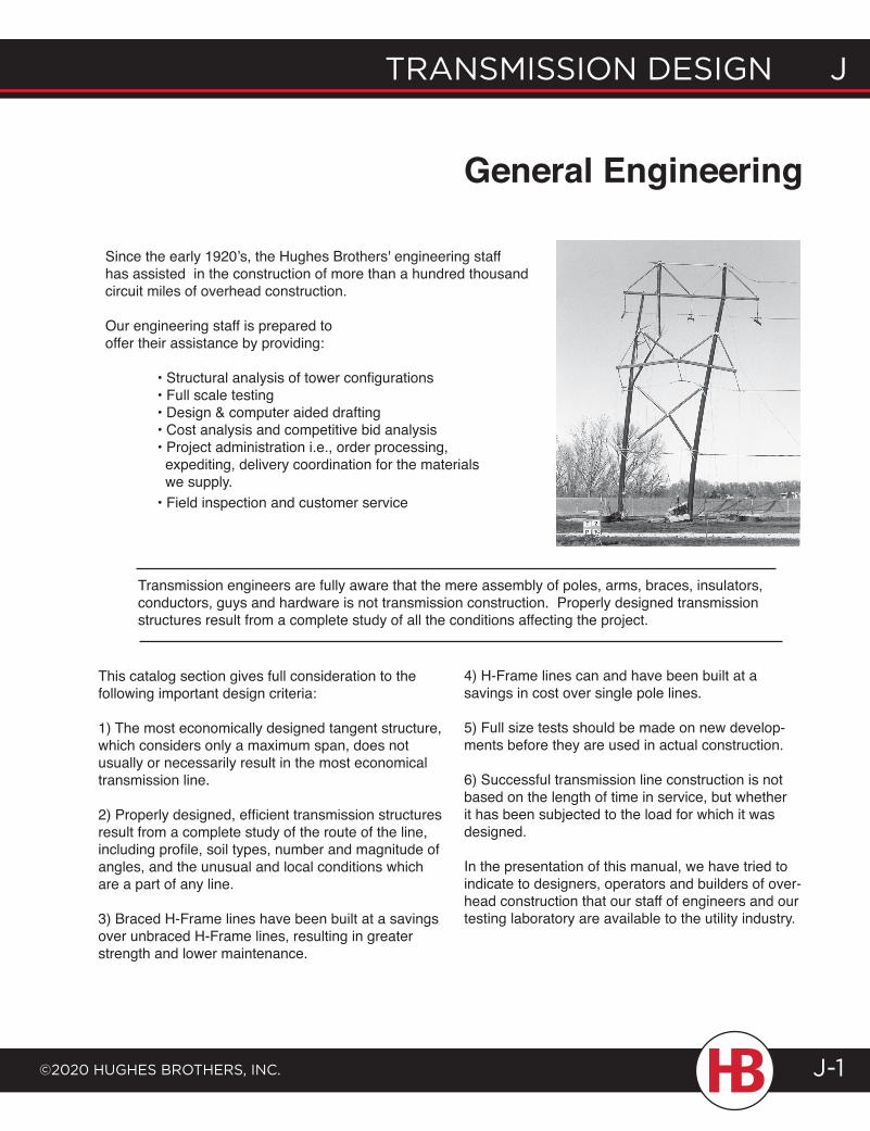
transmission design J
©2020 HugHes BrotHers, inc. J-1
Since the early 1920’s, the Hughes Brothers' engineering staff has assisted in the construction of more than a hundred thousand circuit miles of overhead construction.
Our engineering staff is prepared to offer their assistance by providing:
• Structural analysis of tower configurations • Full scale testing • Design & computer aided drafting • Cost analysis and competitive bid analysis • Project administration i.e., order processing, expediting, delivery coordination for the materials we supply. • Field inspection and customer service
This catalog section gives full consideration to the following important design criteria:
1) The most economically designed tangent structure, which considers only a maximum span, does not usually or necessarily result in the most economical transmission line.
2) Properly designed, efficient transmission structures result from a complete study of the route of the line, including profile, soil types, number and magnitude of angles, and the unusual and local conditions which are a part of any line.
3) Braced H-Frame lines have been built at a savings over unbraced H-Frame lines, resulting in greater strength and lower maintenance.
4) H-Frame lines can and have been built at a savings in cost over single pole lines.
5) Full size tests should be made on new develop-ments before they are used in actual construction.
6) Successful transmission line construction is not based on the length of time in service, but whether it has been subjected to the load for which it was designed.
In the presentation of this manual, we have tried to indicate to designers, operators and builders of over-head construction that our staff of engineers and our testing laboratory are available to the utility industry.
Transmission engineers are fully aware that the mere assembly of poles, arms, braces, insulators, conductors, guys and hardware is not transmission construction. Properly designed transmission structures result from a complete study of all the conditions affecting the project.
General Engineering
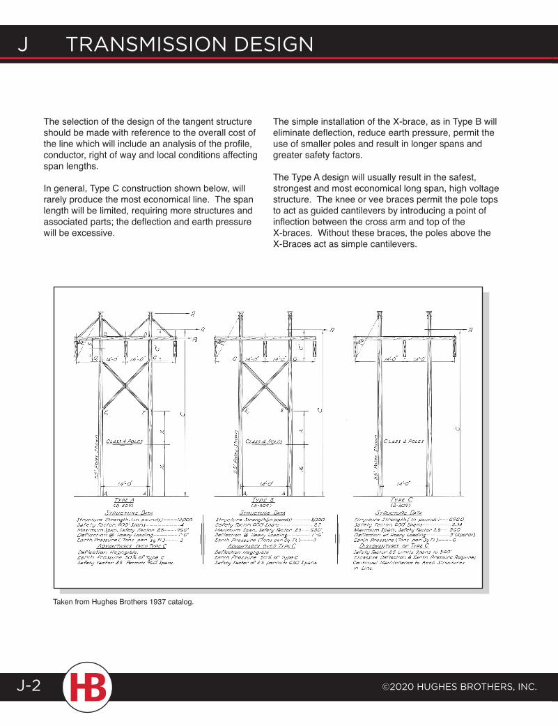
J transmission design
©2020 HugHes BrotHers, inc.J-2
The selection of the design of the tangent structure should be made with reference to the overall cost of the line which will include an analysis of the profile, conductor, right of way and local conditions affecting span lengths.
In general, Type C construction shown below, will rarely produce the most economical line. The span length will be limited, requiring more structures and associated parts; the deflection and earth pressure will be excessive.
The simple installation of the X-brace, as in Type B will eliminate deflection, reduce earth pressure, permit the use of smaller poles and result in longer spans and greater safety factors.
The Type A design will usually result in the safest, strongest and most economical long span, high voltage structure. The knee or vee braces permit the pole tops to act as guided cantilevers by introducing a point of inflection between the cross arm and top of the X-braces. Without these braces, the poles above the X-Braces act as simple cantilevers.
Taken from Hughes Brothers 1937 catalog.
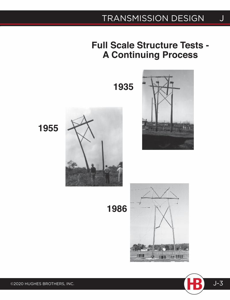
transmission design J
©2020 HugHes BrotHers, inc.
J transmission design
J-3
Full Scale Structure Tests - A Continuing Process
1955
1986
1935
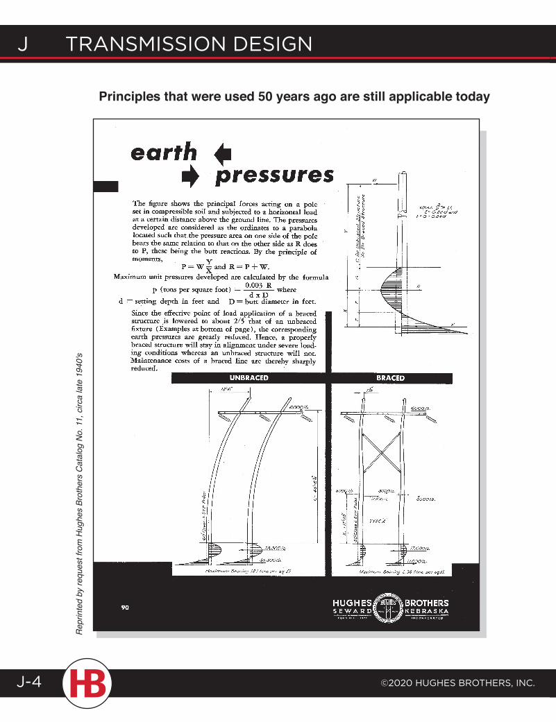
J transmission design
©2020 HugHes BrotHers, inc.J-4
Principles that were used 50 years ago are still applicable todayR
eprin
ted
by re
ques
t fro
m H
ughe
s Br
othe
rs C
atal
og N
o. 1
1, c
irca
late
194
0's
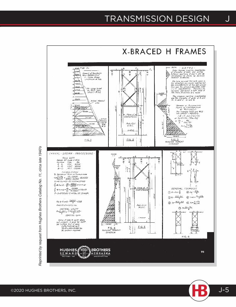
transmission design J
©2020 HugHes BrotHers, inc.
J transmission design
J-5
Rep
rinte
d by
requ
est f
rom
Hug
hes
Brot
hers
Cat
alog
No.
11,
circ
a la
te 1
940'
s
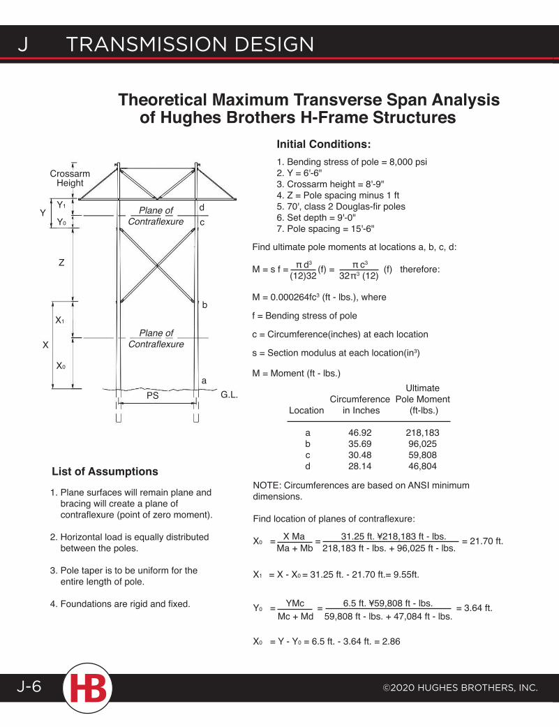
J transmission design
©2020 HugHes BrotHers, inc.J-6
Ultimate Circumference Pole Moment Location in Inches (ft-lbs.)
a 46.92 218,183 b 35.69 96,025 c 30.48 59,808 d 28.14 46,804
Theoretical Maximum Transverse Span Analysis of Hughes Brothers H-Frame Structures
List of Assumptions
1. Plane surfaces will remain plane and bracing will create a plane of contraflexure (point of zero moment).
2. Horizontal load is equally distributed between the poles.
3. Pole taper is to be uniform for the entire length of pole.
4. Foundations are rigid and fixed.
NOTE: Circumferences are based on ANSI minimum dimensions.
Find location of planes of contraflexure:
X0 = X Ma = 31.25 ft. ¥218,183 ft - lbs. = 21.70 ft.
X1 = X - X0 = 31.25 ft. - 21.70 ft.= 9.55ft.
Y0 = YMc = 6.5 ft. ¥59,808 ft - lbs. = 3.64 ft.
X0 = Y - Y0 = 6.5 ft. - 3.64 ft. = 2.86
1. Bending stress of pole = 8,000 psi 2. Y = 6'-6"3. Crossarm height = 8'-9"4. Z = Pole spacing minus 1 ft5. 70', class 2 Douglas-fir poles6. Set depth = 9'-0"7. Pole spacing = 15'-6"
Initial Conditions:
aG.L.PS
Y1
Y0
Z
X1
X0
X
Y Plane of Contraflexure
dc
b
Plane of Contraflexure
Crossarm Height
Find ultimate pole moments at locations a, b, c, d:
M = s f = π d3 (f) = π c3
(f) therefore:
M = 0.000264fc3 (ft - lbs.), where
f = Bending stress of pole
c = Circumference(inches) at each location
s = Section modulus at each location(in3)
M = Moment (ft - lbs.)
(12)32 32π 3 (12)
Ma + Mb 218,183 ft - lbs. + 96,025 ft - lbs.
Mc + Md 59,808 ft - lbs. + 47,084 ft - lbs.
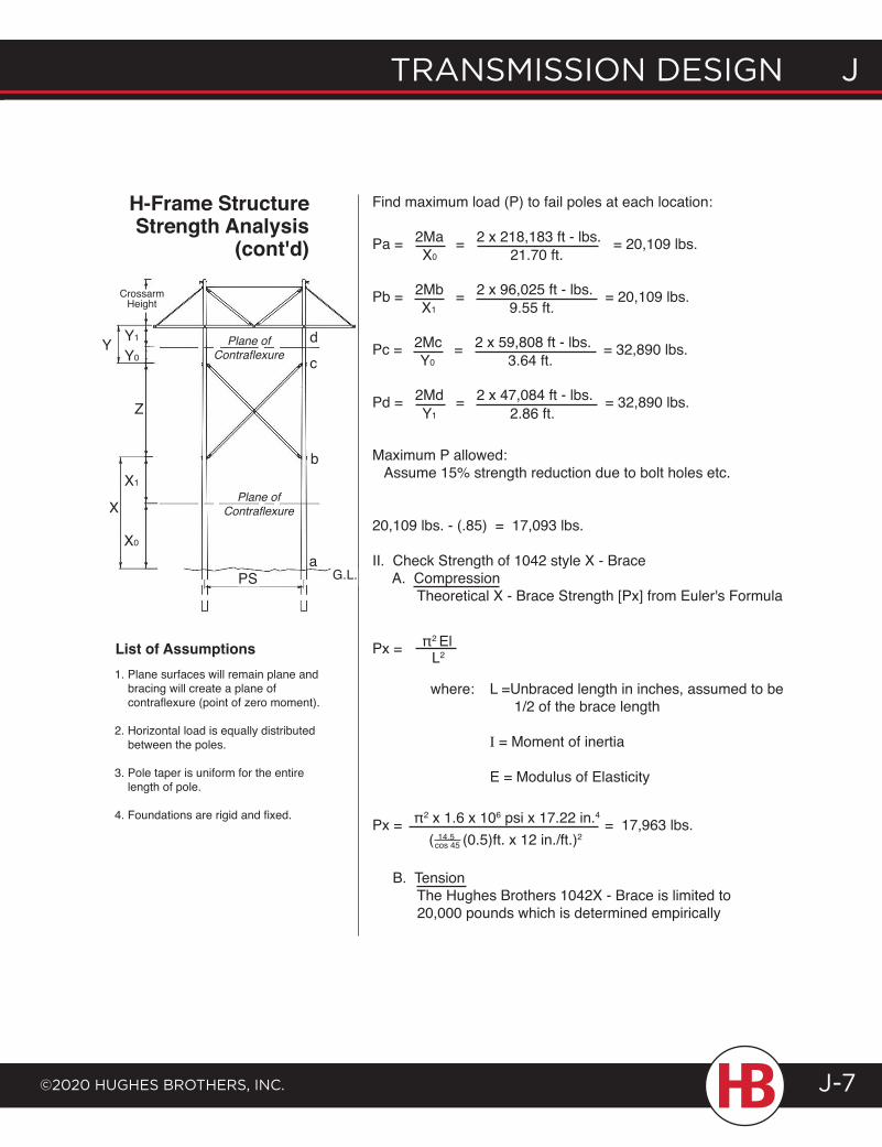
transmission design J
©2020 HugHes BrotHers, inc.
J transmission design
J-7
H-Frame Structure Strength Analysis
(cont'd)
List of Assumptions1. Plane surfaces will remain plane and bracing will create a plane of contraflexure (point of zero moment).
2. Horizontal load is equally distributed between the poles.
3. Pole taper is uniform for the entire length of pole.
4. Foundations are rigid and fixed.
Find maximum load (P) to fail poles at each location:
where: L =Unbraced length in inches, assumed to be 1/2 of the brace length
I = Moment of inertia
E = Modulus of Elasticity
b
Crossarm Height
Y1
Y0Y
Z
X1
X0
XPlane of
Contraflexure
Plane of Contraflexure
dc
aPS
Pa = 2Ma = 2 x 218,183 ft - lbs. = 20,109 lbs.
Pb = 2Mb = 2 x 96,025 ft - lbs. = 20,109 lbs.
Pc = 2Mc = 2 x 59,808 ft - lbs. = 32,890 lbs.
Pd = 2Md = 2 x 47,084 ft - lbs. = 32,890 lbs.
Maximum P allowed: Assume 15% strength reduction due to bolt holes etc.
20,109 lbs. - (.85) = 17,093 lbs.
II. Check Strength of 1042 style X - Brace A. Compression Theoretical X - Brace Strength [Px] from Euler's Formula
Px = π2 El
X0 21.70 ft.
X1 9.55 ft.
Y0 3.64 ft.
Y1 2.86 ft.
L2
Px = π2 x 1.6 x 106 psi x 17.22 in.4
= 17,963 lbs.
B. Tension The Hughes Brothers 1042X - Brace is limited to 20,000 pounds which is determined empirically
( 14.5 (0.5)ft. x 12 in./ft.)2cos 45
G.L.
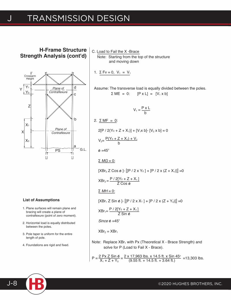
J transmission design
©2020 HugHes BrotHers, inc.J-8
C. Load to Fail the X -Brace Note: Starting from the top of the structure and moving down
1. Ʃ Fv = 0, V1 = V1
Assume: The transverse load is equally divided between the poles. Ʃ ME = 0: [P x L] = [V1 x b]
V1 = P x L
2. Ʃ MF = 0:
2[P / 2(Y0 + Z + X1)] + [V1x b]- [V2 x b] = 0
V2= P(Y0 + Z + X1) + V1
o =45o
Ʃ MG = 0:
[XBr2 Z Cos o ]- [[P / 2 x Y0 ] + [P / 2 x (Z + X1)]] =0
XBr2 = P / 2[Y0 + Z + X1 ]
Ʃ MH = 0:
[XBr1 Z Sin o ]- [[P / 2 x X1 ] + [P / 2 x (Z + Y0)]] =0
XBr1= P / 2[Y0 + Z + X1 ]
Since o =45o
XBr2 = XBr1
Note: Replace XBr1 with Px (Theoretical X - Brace Strength) and solve for P (Load to Fail X - Brace).
P = 2 Px Z Sin o = 2 x 17,963 lbs. x 14.5 ft. x Sin 45o =13,303 lbs.
b
b
/
Z Cos o
/
/
Z Sin o/
/
/
H-Frame Structure Strength Analysis (cont'd)
List of Assumptions
1. Plane surfaces will remain plane and bracing will create a plane of contraflexure (point of zero moment).
2. Horizontal load is equally distributed between the poles.
3. Pole taper is uniform for the entire length of pole.
4. Foundations are rigid and fixed.
b
Crossarm Height
Y1
Y0Y
Z
X1
X0
XPlane of
Contraflexure
Plane of Contraflexure
dc
aPS G.L.
/X1 + Z + Y0 (9.55 ft. + 14.5 ft. + 3.64 ft.)
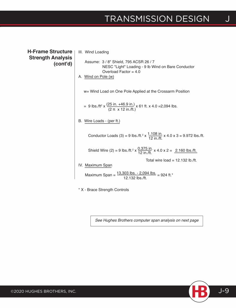
transmission design J
©2020 HugHes BrotHers, inc.
J transmission design
J-9
H-Frame Structure Strength Analysis
(cont'd)
See Hughes Brothers computer span analysis on next page
III. Wind Loading
Assume: 3 / 8" Shield, 795 ACSR 26 / 7 NESC "Light" Loading - 9 lb Wind on Bare Conductor Overload Factor = 4.0A. Wind on Pole (w)
w= Wind Load on One Pole Applied at the Crossarm Position
= 9 lbs./ft2 x (25 in. +46.9 in.) x 61 ft. x 4.0 =2,094 lbs.
B. Wire Loads - (per ft.)
Conductor Loads (3) = 9 lbs./ft.2 x 1.108 in. x 4.0 x 3 = 9.972 lbs./ft.
Shield Wire (2) = 9 lbs./ft.2 x 0.375 in. x 4.0 x 2 = 2.160 lbs./ft.
Total wire load = 12.132 lb./ft.IV. Maximum Span
Maximum Span = 13,303 lbs. - 2,094 lbs. = 924 ft.*
* X - Brace Strength Controls
(2 π x 12 in./ft.)
12 in./ft.
12 in./ft.
12.132 lbs./ft.
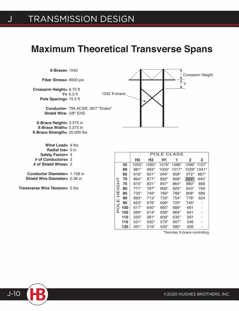
J transmission design
©2020 HugHes BrotHers, inc.J-10
X-Brace=
Fiber Stress=
Crossarm Height=Y=
Pole Spacing=
Conductor-Shield Wire-
X-Brace Height=X-Brace Width=
X-Brace Strength=
1042
8000 psi
8.75 ft6.5 ft15.5 ft
795 ACSR, 26/7 "Drake"3/8" EHS
3.375 in5.375 in20,000 lbs
Wind Load=Radial Ice=
Safety Factor=# of Conductors=
# of Shield Wires=
Conductor Diameter=Shield Wire Diameter=
Transverse Wire Tension=
9 lbs0 in432
1.108 in0.36 in
0 lbs
Crossarm Height
Y
1042 X-brace
H3 H2 H1 1 2 3 55 1055* 1065* 1076* 1086* 1096* 1107* 60 981* 993* 1005* 1017* 1029* 1041* 65 918* 931* 944* 958* 972* 987* 70 864* 877* 892* 908* 924* 940* 75 815* 831* 847* 864* 880* 866 80 771* 787* 806* 825* 843* 769 85 730* 749* 769* 788* 808* 689 90 693* 713* 733* 754* 778* 624 95 653* 676* 699* 720* 745* - 100 617* 640* 665* 689* 691 - 105 589* 614* 638* 664* 641 - 110 555* 581* 609* 635* 591 - 115 521* 550* 579* 607* 546 - 120 491* 519* 550* 580* 506 -
POLE CLASS
PO
LE
HE
IGH
T
*Denotes X-brace controlling.
Maximum Theoretical Transverse Spans
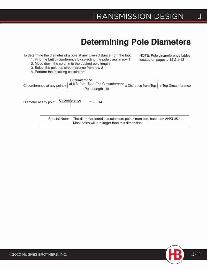
transmission design J
©2020 HugHes BrotHers, inc.
J transmission design
J-11
To determine the diameter of a pole at any given distance from the top: 1. Find the butt circumference by selecting the pole class in row 1 2. Move down the column to the desired pole length 3. Select the pole top circumference from row 2 4. Perform the following calculation:
NOTE: Pole circumference tables located on pages J-12 & J-13
Determining Pole Diameters
Special Note: The diameter found is a minimum pole dimension, based on ANSI 05.1. Most poles will run larger than this dimension.
Circumference at any point = Circumference
- Top Circumference x Distrance from Top + Top Circumference
Diameter at any point = Circumference π = 3.14
at 6 ft. from Butt(Pole Length - 6)( (
π
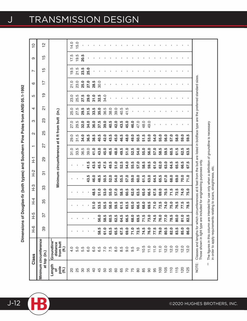
J transmission design
©2020 HugHes BrotHers, inc.J-12
Cla
ssM
inim
um c
ircum
fere
nce
at to
p (i
n.)
Leng
th
of
pole
(ft
.)
Gro
undl
ine*
*di
stan
ce
from
but
t (ft
.) H
-6
H
-5
H
-4
H
-3
H
-2
H
-1
1
2
3
4
5
6
7
9
1
0
39
37
35
33
31
29
27
25
2
3
21
19
17
1
5
15
12
Min
imum
circ
umfe
renc
e at
6 ft
from
but
t (in
.)
20
4.
0
25
5.0
30
5.
5
35
6.0
40
6.
0
45
6.5
50
7.
0
55
7.5
60
8.
0
65
8.5
70
9.
0
75
9.5
80
10
85
10
.5
90
11.0
95
11
.0
100
11.0
10
5 12
.0
110
12.0
11
5 12
.0
120
12.0
12
5 12
.0
-
- -
- -
- 31
.0
29.0
27
.0
25.0
23
.0
21.0
19
.5
17.5
14
.0
- -
- -
- -
33.5
31
.5
29.5
27
.5
25.5
23
.0
21.5
19
.5
15.0
-
- -
- -
- 36
.5
34.0
32
.0
29.5
27
.5
25.0
23
.5
20.5
-
-
- -
- 43
.5
41.5
39
.0
36.5
34
.0
31.5
29
.0
27.0
25
.0
- -
-
- 51
.0
48.5
46
.0
43.5
41
.0
38.5
36
.0
33.5
31
.0
28.5
-
- -
58
.5
56.0
53
.5
51.0
48
.5
45.5
43
.0
40.5
37
.5
35.0
32
.5
30.0
-
- -
61
.0
58.5
55
.5
53.0
50
.5
47.5
45
.0
42.0
39
.0
36.5
34
.0
- -
- -
63
.5
60.5
58
.0
55.0
52
.0
49.5
46
.5
43.5
40
.5
38.0
-
- -
- -
65
.5
62.5
59
.5
57.0
54
.0
51.0
48
.0
45.0
42
.0
39.0
-
- -
- -
67
.5
64.5
61
.5
58.5
55
.5
52.5
49
.5
46.5
43
.5
40.5
-
- -
- -
69
.0
66.5
63
.5
60.5
57
.0
54.0
51
.0
48.0
45
.0
41.5
-
- -
- -
71
.0
68.0
65
.0
62.0
59
.0
55.5
52
.5
49.0
46
.0
- -
- -
- -
72
.5
69.5
66
.5
63.5
60
.0
57.0
54
.0
50.5
47
.0
- -
- -
- -
74
.5
71.5
68
.0
65.0
61
.5
58.5
55
.0
51.5
48
.0
- -
- -
- -
76
.0
73.0
69
.5
66.5
63
.0
59.5
56
.0
53.0
49
.0
- -
- -
- -
77
.5
74.5
71
.0
67.5
64
.5
61.0
57
.0
54.0
-
- -
- -
- -
79
.0
76.0
72
.5
69.0
65
.5
62.0
58
.5
55.0
-
- -
- -
- -
80
.5
77.0
74
.0
70.5
67
.0
63.0
59
.5
56.0
-
- -
- -
- -
82
.0
78.5
75
.0
71.5
68
.0
64.5
60
.5
57.0
-
- -
- -
- -
83
.5
80.0
76
.5
72.5
69
.0
65.5
61
.5
58.0
-
- -
- -
- -
85
.0
81.0
77
.5
74.0
70
.0
66.5
62
.5
59.0
-
- -
- -
- -
86
.0
82.5
78
.5
75.0
71
.0
67.5
63
.5
59.5
-
- -
- -
- -
NO
TE:
Cla
sses
and
leng
ths
for w
hich
circ
umfe
renc
es a
t 6 fe
et fr
om th
e bu
tt ar
e lis
ted
in b
oldf
ace
type
are
the
pref
erre
d st
anda
rd s
izes
.
T
hose
sho
wn
in li
ght t
ype
are
incl
uded
for e
ngin
eerin
g pu
rpos
es o
nly.
**
The
figu
res
in th
is c
olum
n ar
e in
tend
ed fo
r use
onl
y w
hen
a de
finiti
on o
f gro
undl
ine
is n
eces
sary
i
n or
der t
o ap
ply
requ
irem
ents
rela
ting
to s
cars
, stra
ight
ness
, etc
.
Dim
ensi
ons
of D
ougl
as-fi
r (bo
th ty
pes)
and
Sou
ther
n Pi
ne P
oles
from
AN
SI 0
5.1-
1992
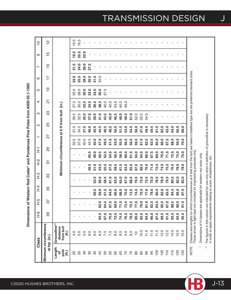
transmission design J
©2020 HugHes BrotHers, inc.
J transmission design
J-13
Cla
ssM
inim
um c
ircum
fere
nce
at to
p (i
n.)
Leng
th
of
pole
(ft
.)
Gro
undl
ine*
*di
stan
ce
from
but
t (ft
.) H
-6
H
-5
H
-4
H
-3
H
-2
H
-1
1
2
3
4
5
6
7
9
1
0
39
37
35
33
31
29
27
25
2
3
21
19
17
1
5
15
12
Min
imum
circ
umfe
renc
e at
6 ft
from
but
t (in
.)
20
4.
0
25
5.0
30
5.
5
35
6.0
40
6.
0
45
6.5
50
7.
0
55
7.5
60
8.
0
65
8.5
70
9.
0
75
9.5
80
10
85
10
.5
90
11.0
95
11
.0
100
11.0
10
5 12
.0
110
12.0
11
5 12
.0
120
12.0
12
5 12
.0
-
- -
- -
- 33
.5
31.5
29
.5
27.0
25
.0
23.0
21
.5
18.5
15
.0
- -
- -
- -
37.0
34
.5
32.5
30
.0
28.0
25
.5
24.0
20
.5
16.5
-
- -
- -
- 40
.0
37.5
35
.0
32.5
30
.0
28.0
26
.0
22.0
-
-
- -
- 48
.0
45.5
42
.5
40.0
37
.5
34.5
32
.0
30.0
27
.5
- -
-
- 56
.5
53.5
51
.0
48.0
45
.0
42.5
39
.5
36.5
34
.0
31.5
-
- -
64
.5
62.0
59
.0
56.0
53
.5
50.5
47
.5
44.5
41
.5
38.5
36
.0
33.0
-
- -
67
.0
64.5
61
.5
58.5
55
.5
52.5
49
.5
46.5
43
.5
40.0
37
.5
- -
- -
70
.0
67.0
64
.0
61.0
57
.5
54.5
51
.5
48.5
45
.0
42.0
-
- -
- -
72
.0
69.0
66
.0
63.0
59
.5
56.5
53
.5
50.0
46
.5
43.5
-
- -
- -
74
.5
71.5
68
.0
65.0
61
.5
58.5
55
.0
51.5
48
.0
45.0
-
- -
- -
76
.5
73.5
70
.0
67.0
63
.5
60.0
56
.5
53.0
49
.5
46.0
-
- -
- -
78
.5
75.5
72
.0
68.5
65
.0
61.5
58
.0
54.5
51
.0
- -
- -
- -
80
.5
77.0
74
.0
70.5
67
.0
63.0
59
.5
56.0
52
.0
- -
- -
- -
82
.5
79.0
75
.5
72.0
68
.5
64.5
61
.0
57.0
53
.5
- -
- -
- -
84
.5
81.0
77
.0
73.5
70
.0
66.0
62
.5
58.5
54
.5
- -
- -
- -
86
.0
82.5
79
.0
75.0
71
.5
67.5
63
.5
59.5
-
- -
- -
- -
87
.5
84.0
80
.5
76.5
72
.5
69.0
65
.0
61.0
-
- -
- -
- -
89
.5
85.5
82
.0
78.0
74
.0
70.0
66
.0
62.0
-
- -
- -
- -
91
.0
87.0
83
.5
79.5
75
.5
71.5
67
.5
63.0
-
- -
- -
- -
92
.5
88.5
84
.5
80.5
76
.5
72.5
68
.5
64.0
-
- -
- -
- -
84
.0
90.0
86
.0
82.0
78
.0
74.0
69
.5
65.0
-
- -
- -
- -
95
.5
91.5
87
.5
83.0
79
.0
75.0
70
.5
66.0
-
- -
- -
- -
NO
TE:
Cla
sses
and
leng
ths
for w
hich
circ
umfe
renc
es a
t 6 fe
et fr
om th
e bu
tt ar
e lis
ted
in b
oldf
ace
type
are
the
pref
erre
d st
anda
rd s
izes
.
T
hose
sho
wn
in li
ght t
ype
are
incl
uded
for e
ngin
eerin
g pu
rpos
es o
nly.
*
Dim
ensi
ons
of H
cla
sses
are
app
licab
le fo
r wes
tern
red
ceda
r onl
y.
**
The
figu
res
in th
is c
olum
n ar
e in
tend
ed fo
r use
onl
y w
hen
a de
finiti
on o
f gro
undl
ine
is n
eces
sary
i
n or
der t
o ap
ply
requ
irem
ents
rela
ting
to s
cars
, stra
ight
ness
, etc
.
Dim
ensi
ons
of W
este
rn R
ed C
edar
* and
Pon
dero
sa P
ine
Pole
s fr
om A
NSI
05.
1-19
92
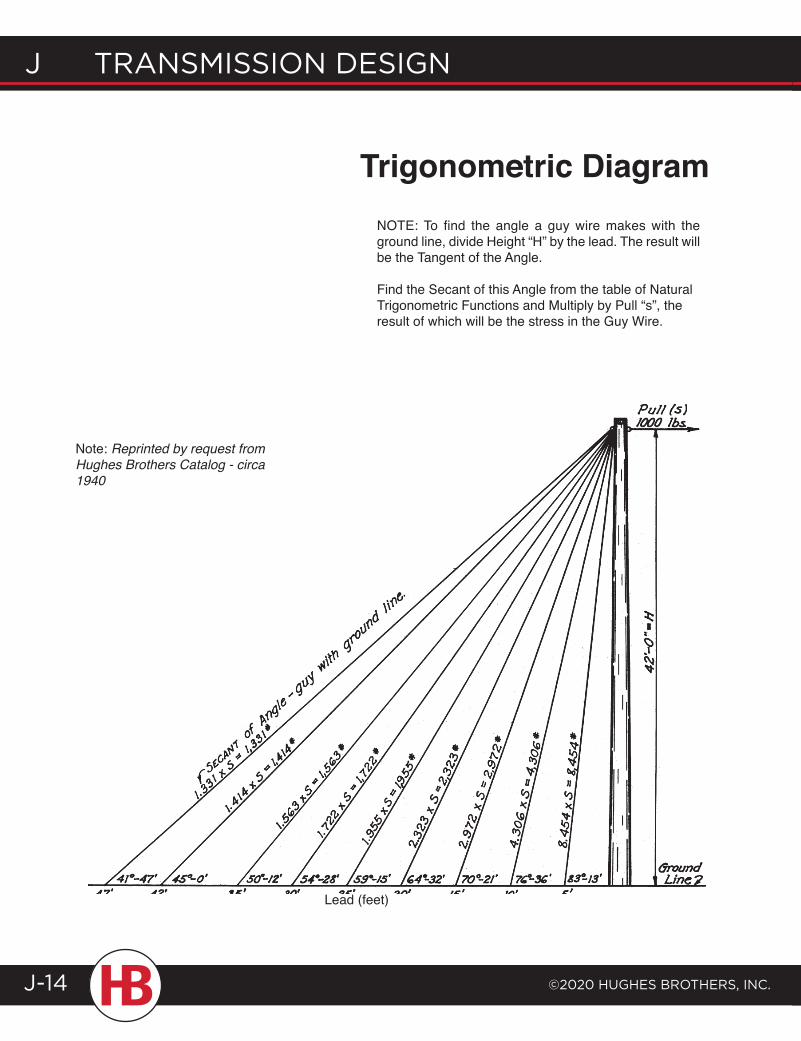
J transmission design
©2020 HugHes BrotHers, inc.J-14
Trigonometric Diagram
Note: Reprinted by request from Hughes Brothers Catalog - circa 1940
NOTE: To find the angle a guy wire makes with the ground line, divide Height “H” by the lead. The result will be the Tangent of the Angle.
Find the Secant of this Angle from the table of Natural Trigonometric Functions and Multiply by Pull “s”, the result of which will be the stress in the Guy Wire.
Lead (feet)
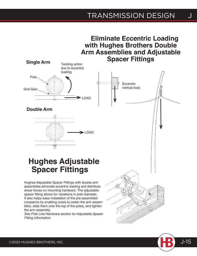
transmission design J
©2020 HugHes BrotHers, inc.
J transmission design
J-15
NOTE: To find the angle a guy wire makes with the ground line, divide Height “H” by the lead. The result will be the Tangent of the Angle.
Find the Secant of this Angle from the table of Natural Trigonometric Functions and Multiply by Pull “s”, the result of which will be the stress in the Guy Wire.
Eccentric vertical load.
Eliminate Eccentric Loading with Hughes Brothers Double
Arm Assemblies and Adjustable Spacer Fittings
Hughes Adjustable Spacer Fittings
Hughes Adjustable Spacer Fittings with double arm assemblies eliminate eccentric loading and distribute shear forces on mounting hardware. The adjustable spacer fitting allows for variations in pole diameter. It also helps ease installation of the pre-assembled crossarms by enabling crews to widen the arm assem-blies, slide them over the top of the poles, and tighten the arm assembly.See Pole Line Hardware section for Adjustable Spacer Fitting information.
Single Arm
Grid Gain
Pole
Twisting actiondue to eccentric loading
LOAD
Double Arm
LOAD
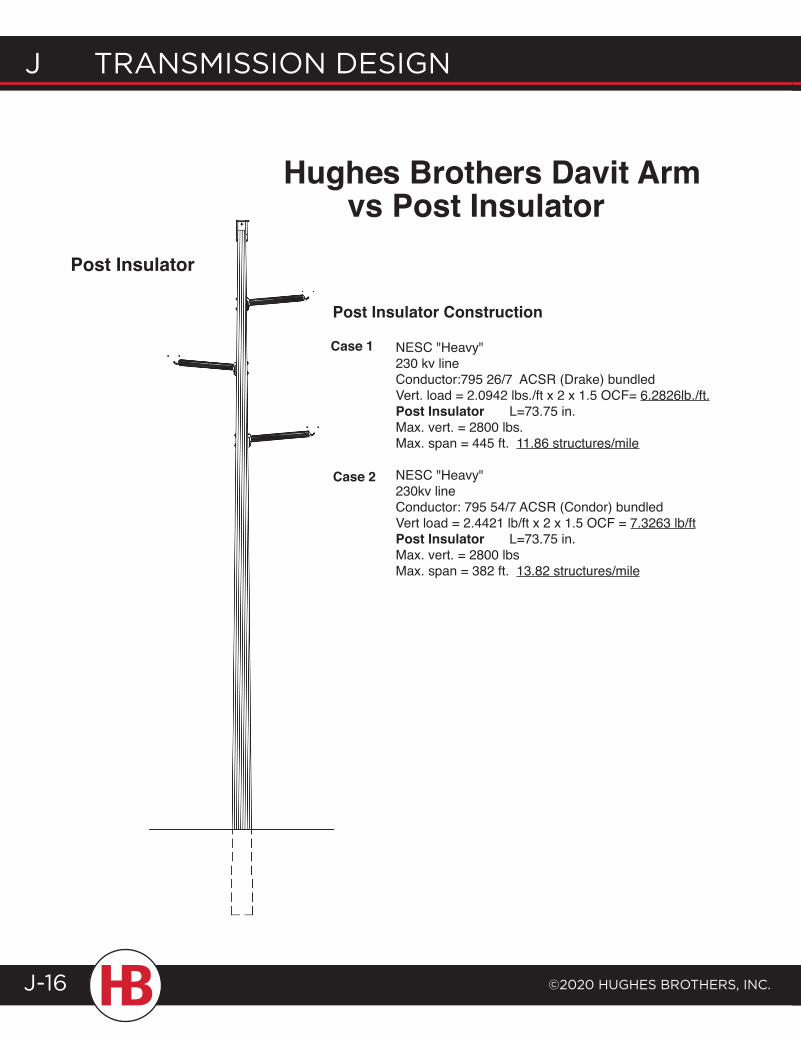
J transmission design
©2020 HugHes BrotHers, inc.J-16
Hughes Brothers Davit Arm vs Post Insulator
Post Insulator Construction
nESc "Heavy" 230 kv line Conductor:795 26/7 ACSR (Drake) bundled Vert. load = 2.0942 lbs./ft x 2 x 1.5 OCF= 6.2826lb./ft. Post Insulator L=73.75 in. Max. vert. = 2800 lbs. Max. span = 445 ft. 11.86 structures/mile nESc "Heavy" 230kv line Conductor: 795 54/7 ACSR (Condor) bundled Vert load = 2.4421 lb/ft x 2 x 1.5 OCF = 7.3263 lb/ft Post Insulator L=73.75 in. Max. vert. = 2800 lbs Max. span = 382 ft. 13.82 structures/mile
Case 1
Case 2
Post Insulator
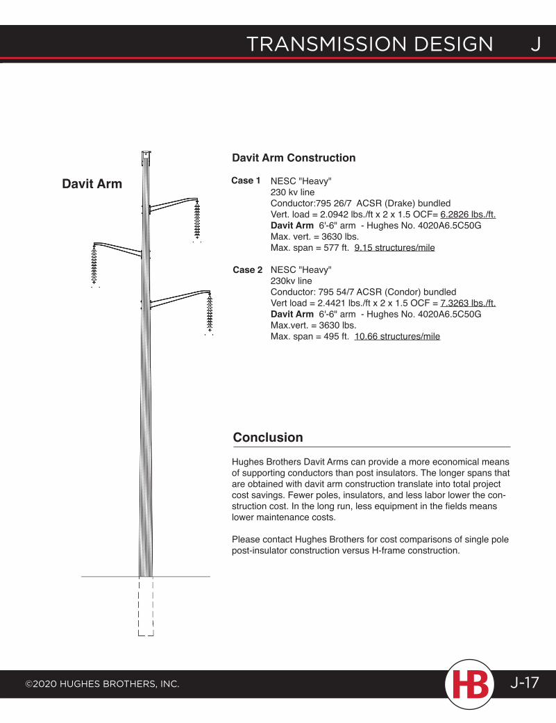
transmission design J
©2020 HugHes BrotHers, inc.
J transmission design
J-17
Davit Arm Construction
nESc "Heavy" 230 kv line Conductor:795 26/7 ACSR (Drake) bundled Vert. load = 2.0942 lbs./ft x 2 x 1.5 OCF= 6.2826 lbs./ft. Davit Arm 6'-6" arm - Hughes No. 4020A6.5C50G Max. vert. = 3630 lbs. Max. span = 577 ft. 9.15 structures/mile
nESc "Heavy" 230kv line Conductor: 795 54/7 ACSR (Condor) bundled Vert load = 2.4421 lbs./ft x 2 x 1.5 OCF = 7.3263 lbs./ft. Davit Arm 6'-6" arm - Hughes No. 4020A6.5C50G Max.vert. = 3630 lbs. Max. span = 495 ft. 10.66 structures/mile
Case 1
Case 2
Hughes Brothers Davit Arms can provide a more economical means of supporting conductors than post insulators. The longer spans that are obtained with davit arm construction translate into total project cost savings. Fewer poles, insulators, and less labor lower the con-struction cost. In the long run, less equipment in the fields means lower maintenance costs.
Please contact Hughes Brothers for cost comparisons of single pole post-insulator construction versus H-frame construction.
Conclusion
Davit Arm
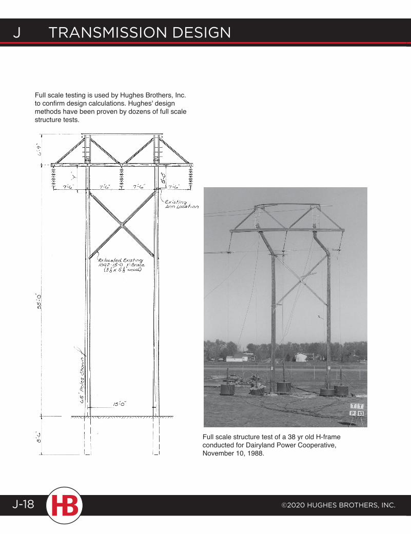
J transmission design
©2020 HugHes BrotHers, inc.J-18
Full scale structure test of a 38 yr old H-frame conducted for Dairyland Power Cooperative, November 10, 1988.
Full scale testing is used by Hughes Brothers, Inc. to confirm design calculations. Hughes' design methods have been proven by dozens of full scale structure tests.
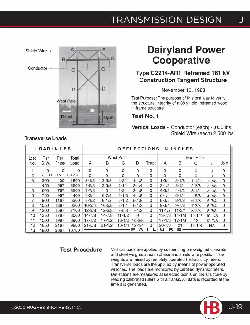
transmission design J
©2020 HugHes BrotHers, inc.
J transmission design
J-19
Shield Wire
ConductorType C2214-AR1 Reframed 161 kV
Construction Tangent StructureNovember 10, 1988
Dairyland Power Cooperative
12345678910111213
0
300450600750900
105012001350150016501800
0
400567767967
1167136715671767196721672367
0
1800260035004400530062007100800089009800
10700
LoadNo.
PerS.W.
Per Phase
Total Load
00
1-3/43-1/84-3/86-1/48-3/89-3/411-1/213-7/817-1/820-7/8
A B
00
2-1/83-1/44-1/26-1/48-1/89-7/811-3/414-1/817-1/8
21
c
00
1-1/42-3/83-1/44-5/86-1/87-3/88-7/810-1/2
1316-1/8
00
1-3/82-3/83-1/84-3/85-3/46-3/48-3/810-1/812-7/8
NA
D000000000000
UpliftEast Pole
D E F L E C T I O N S I N I N C H E S
00
2-1/23-5/84-7/86-3/48-1/210-3/412-3/814-7/817-1/221-5/8
00
2-3/83-5/8
56-7/88-1/210-5/812-3/814-7/817-1/221-1/2
00
1-3/42-1/43-3/45-1/86-1/28-1/49-5/811-1/213-1/216-1/4
A B c
00
1-1/22-1/43-1/84-1/85-1/86-1/27-1/2
910-3/812-1/4
DWest Pole
V E R T I C A L L O A D000000000000
Thrust
F A I L U R E
L O A D I N L B S.
Transverse Loads
Test Procedure
Test Purpose: The purpose of this test was to verify the structural integrity of a 38 yr. old, reframed wood H-frame structure.
UpliftThrust
West Pole
Test No. 1
Vertical Loads - Conductor (each) 4,000 lbs. Shield Wire (each) 2,500 lbs.
Vertical loads are applied by suspending pre-weighed concrete and steel weights at each phase and shield wire position. The weights are raised by remotely operated hydraulic cylinders. Transverse loads are the applied by means of power operated winches. The loads are monitored by certified dynamometers. Deflections are measured at selected points on the structure by reading calibrated rulers with a transit. All data is recorded at the time it is generated.
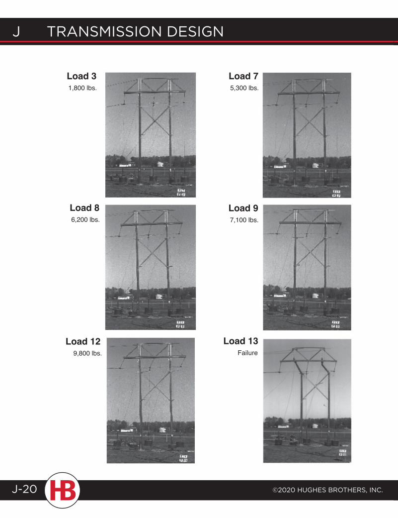
J transmission design
©2020 HugHes BrotHers, inc.J-20
Load 31,800 lbs.
Load 75,300 lbs.
Load 86,200 lbs.
Load 97,100 lbs.
Load 13Failure9,800 lbs.
Load 12
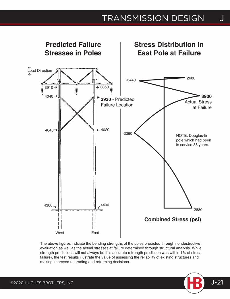
transmission design J
©2020 HugHes BrotHers, inc.
J transmission design
J-21
NOTE: Douglas-fir pole which had been in service 38 years.
Load Direction
3910➔
4040➔
4040➔
➔4300 ➔4400
4020➔
3860➔
➔
3930 - Predicted Failure Location
-3440 2680
-3360
2880
Stress Distribution in East Pole at Failure
Predicted Failure Stresses in Poles
3900Actual Stress
at Failure
West
Combined Stress (psi)➔
➔
The above figures indicate the bending strengths of the poles predicted through nondestructive evaluation as well as the actual stresses at failure determined through structural analysis. While strength predictions will not always be this accurate (strength prediction was within 1% of stress failure), the test results illustrate the value of assessing the reliability of existing structures and making improved upgrading and reframing decisions.
East
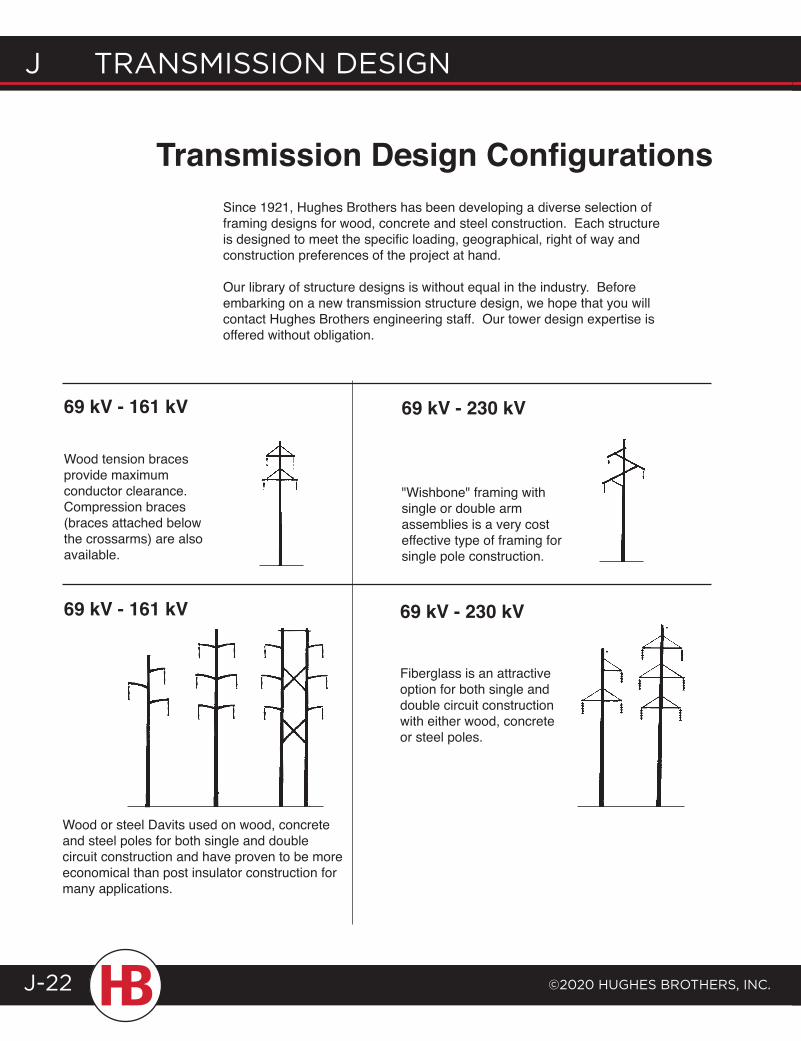
J transmission design
©2020 HugHes BrotHers, inc.J-22
Transmission Design ConfigurationsSince 1921, Hughes Brothers has been developing a diverse selection of framing designs for wood, concrete and steel construction. Each structure is designed to meet the specific loading, geographical, right of way and construction preferences of the project at hand.
Our library of structure designs is without equal in the industry. Before embarking on a new transmission structure design, we hope that you will contact Hughes Brothers engineering staff. Our tower design expertise is offered without obligation.
69 kV - 161 kV
Wood tension braces provide maximum conductor clearance. Compression braces (braces attached below the crossarms) are also available.
69 kV - 230 kV
"Wishbone" framing with single or double arm assemblies is a very cost effective type of framing for single pole construction.
69 kV - 161 kV 69 kV - 230 kV
Fiberglass is an attractive option for both single and double circuit construction with either wood, concrete or steel poles.
Wood or steel Davits used on wood, concrete and steel poles for both single and double circuit construction and have proven to be more economical than post insulator construction for many applications.
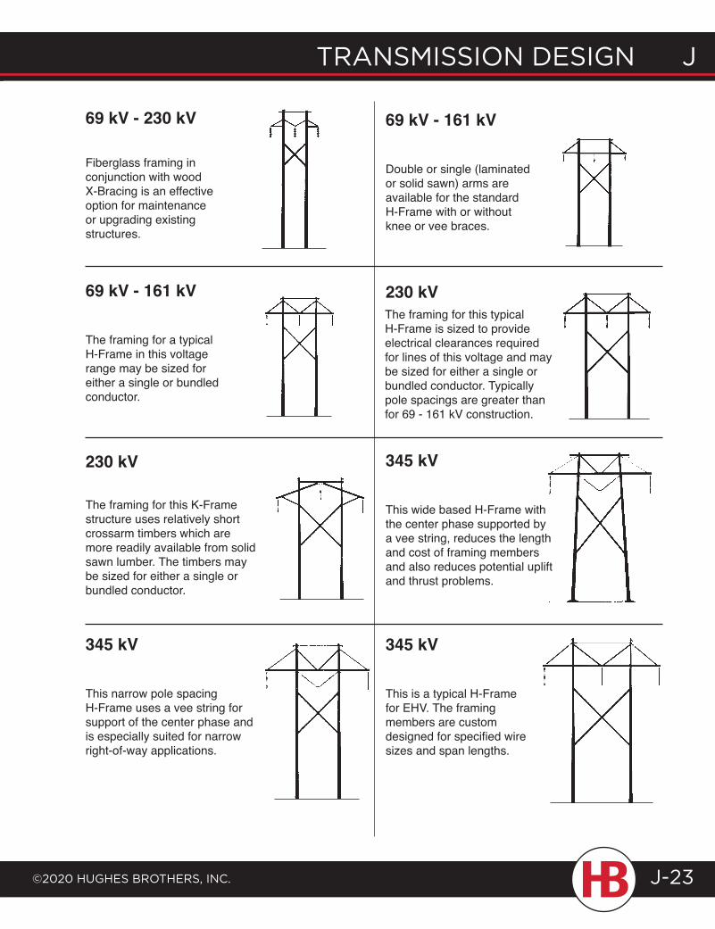
transmission design J
©2020 HugHes BrotHers, inc.
J transmission design
J-23
69 kV - 230 kV
Fiberglass framing in conjunction with wood X-Bracing is an effective option for maintenance or upgrading existing structures.
69 kV - 161 kV
Double or single (laminated or solid sawn) arms are available for the standard H-Frame with or without knee or vee braces.
69 kV - 161 kV
The framing for a typical H-Frame in this voltage range may be sized for either a single or bundled conductor.
230 kVThe framing for this typical H-Frame is sized to provide electrical clearances required for lines of this voltage and may be sized for either a single or bundled conductor. Typically pole spacings are greater than for 69 - 161 kV construction.
230 kV
The framing for this K-Frame structure uses relatively short crossarm timbers which are more readily available from solid sawn lumber. The timbers may be sized for either a single or bundled conductor.
345 kV
This wide based H-Frame with the center phase supported by a vee string, reduces the length and cost of framing members and also reduces potential uplift and thrust problems.
345 kV
This narrow pole spacing H-Frame uses a vee string for support of the center phase and is especially suited for narrow right-of-way applications.
345 kV
This is a typical H-Frame for EHV. The framing members are custom designed for specified wire sizes and span lengths.
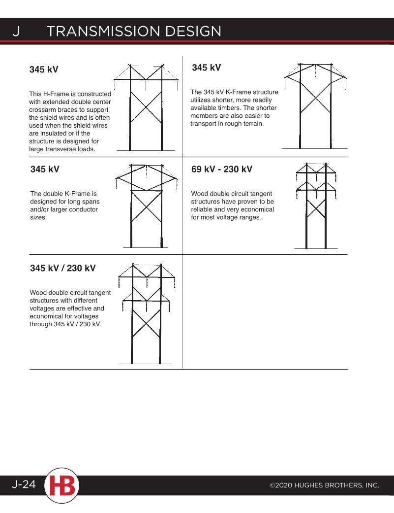
J transmission design
©2020 HugHes BrotHers, inc.J-24
345 kV
This H-Frame is constructed with extended double center crossarm braces to support the shield wires and is often used when the shield wires are insulated or if the structure is designed for large transverse loads.
345 kV
345 kV
The double K-Frame is designed for long spans and/or larger conductor sizes.
69 kV - 230 kV
Wood double circuit tangent structures have proven to be reliable and very economical for most voltage ranges.
345 kV / 230 kV
Wood double circuit tangent structures with different voltages are effective and economical for voltages through 345 kV / 230 kV.
The 345 kV K-Frame structure utilizes shorter, more readily available timbers. The shorter members are also easier to transport in rough terrain.
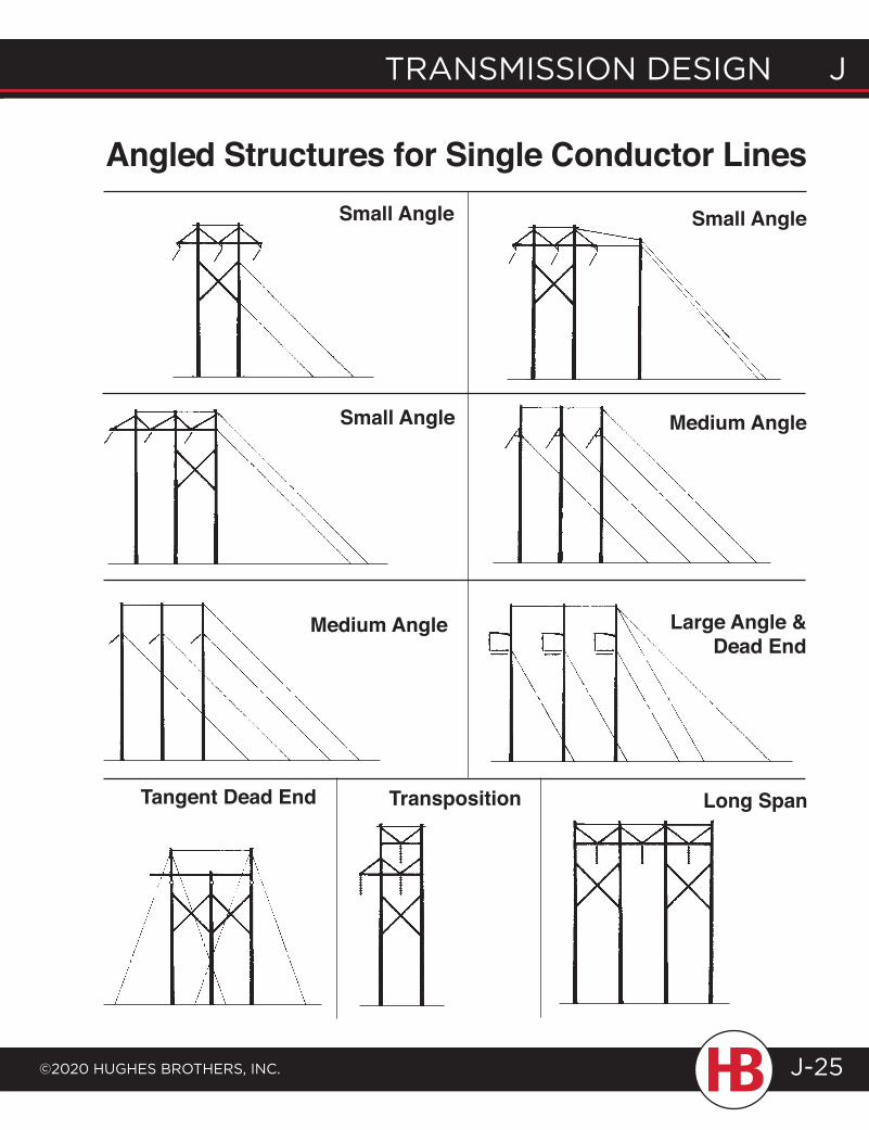
transmission design J
©2020 HugHes BrotHers, inc.
J transmission design
J-25
Angled Structures for Single Conductor LinesSmall Angle Small Angle
Medium AngleSmall Angle
Medium Angle Large Angle & Dead End
Long SpanTangent Dead End Transposition
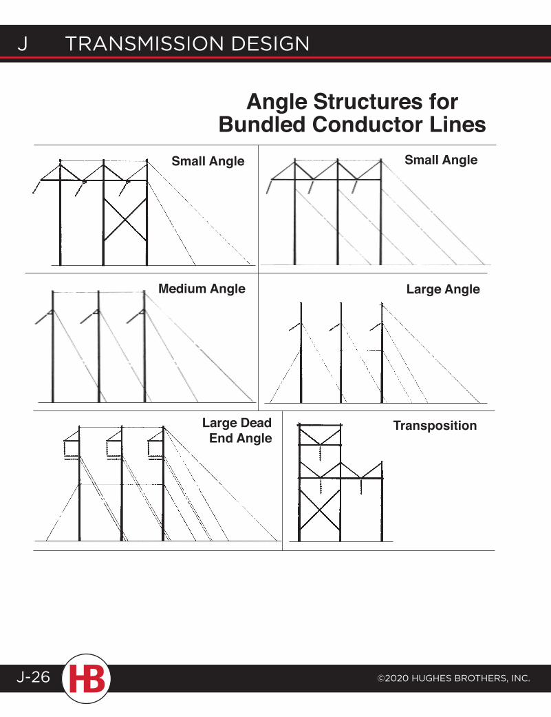
J transmission design
©2020 HugHes BrotHers, inc.J-26
Angle Structures for Bundled Conductor Lines
Small AngleSmall Angle
Medium Angle Large Angle
Large Dead End Angle
Transposition
index
©2020 HugHes BrotHers, inc. INDEX-1
AA325, High Strength Bolts ..................................AB* ..........................E10Adaptor, Post Inslulator to Lam Pole .............AS2717-A ............ C113Adjustable Guying Assembly ............................CF694TB ................F9Alley Arm, Steel .......................................................B2684-F.............. A39Anchor Bolts .............................................................ANB* .....................E33Angle Bracket, Two Phase, Fiberglass ...........CF761 .................... F23Angle Bracket, Two Phase, Fiberglass ...........CF901 .................... F23Apparatus Mounting Bracket, 1 Phase ...........CF592 ...................F33Apparatus Mounting Bracket, 1 Phase ...........CF700 ..................F35Apparatus Mounting Bracket, 2 Phase ..........CF590 ...................F39Apparatus Mounting Bracket, 2 Phase ..........CF550 .................. F40Apparatus Mounting Bracket, 3 Phase ..........CF670 .................... F31Apparatus Mounting Bracket, 3 Phase ..........CF910 .................... F32Apparatus Mounting Bracket, Cloverleaf .....CF892 ...................F36Apparatus Mounting Bracket, Cloverleaf .....CF893B ................ F37Apparatus Mounting Bracket, Cloverleaf .....CF921 ....................F38
BB2358-C 32,000 lb. guying kits........................B2358-C ................A21B2358-D 42,000 lb. guying kits .......................B2358-D ..............A22B2358-F 42,000 lb. guying kits ........................B2358-F ...............A23Banded Equipment Mount .................................B2782-A ................D19Banded Equipment Mount .................................B2782-B ................D19Base Plate Options, for Davit Arms .................................................. G10Bayonets, Shield Wire ...........................................B2502 ...................C65Bayonets, Shield Wire ...........................................AS2613 ..................C68Bayonets (Wood), Static Wire Support ........ 2813 ........................C67Bent Bolt & Bent Stud .......................................... 2722 .......................E29Beveled Washers .....................................................BW* ........................E41Bird Guard ..................................................................B2571 .....................F62Bolt, Anchor type....................................................ANB* .....................E33Bolt, Bent type ......................................................... 2722 .......................E29Bolt, Ground Wire Bonding ................................GWB51-1/2 ..........E28Bolt, Insulator Mounting Stud ........................... 2750 ......................E30Bolt, Insulator Mounting Stud ........................... 2751 ........................E30Bolt, Insulator Mounting Stud ........................... 2755 .......................E30Bolt, Insulator Mounting Stud ........................... 2752 ........................ E31Bolt, Insulator Mounting Stud ........................... 2753 ........................ E31Bolt, Insulator Mounting Stud ........................... 2754........................ E31Bolts, Carriage ..........................................................BC* .......................... E15Bolts, Double Arming Eyebolt .......................... 2720.7 .................... E17Bolts, Drilled ..............................................................B* ............................E34Bolts, Drilled with Cotter Key ..............................................................E34Bolts, Forged Eyebolt ........................................... 2724 ........................E19Bolts, Hex Head .......................................................HB* ............................E8Bolts, High Strength, Type A325 ......................AB* ..........................E10Bolts, Machine (Square Head) ..........................B* ...............................E3Bolts, Neutral Support/Upset ...........................AS2290 ................C86Bolts, Shoulder Eyebolt ........................................ 2720 .......................E16Bolts, Shoulder Eye, Curved Washer.............. 2721 .........................E18Bolts, Type ”O” Tower ...........................................BT* ............................E9Bolts, U type .............................................................. 1329........................E26Bolts, Washer Head................................................WB* ........................ E15Bonding Bolt .............................................................GWB51-1/2 ..........E28Bonding Clip, bolt end type ............................... 2727 .......................E28Bonding Clip, flat surface type ......................... 2718 ........................E28Brace, Alley Arm, Wood ....................................... 1096 .........................B11Brace, Crossarm, Fiberglass ...............................CF520 ...................F49Brace, Crossarm, Fiberglass ...............................CF533 ...................F49
Brace, Crossarm, Flat Steel ................................. 2809 ........................B4Brace, Crossarm, Flat Steel ................................. 2819 .........................B4Brace, Crossarm, Steel, Angle Knee ...............B2498-A ..............B20Brace, Crossarm, Steel, Heavy Duty ............... 2018M ....................B10Brace, Crossarm, Steel, Knee & Vee ................ 2025M....................B19Brace, Crossarm, Wood........................................ 1152 ............................B2Brace, Crossarm, Wood........................................ 2023 ........................ B5Brace, Crossarm, Wood, Heavy Duty ............. 2016 ............ B9 & B10Brace, Crossarm, Wood, Heavy Duty ............. 2017 ............ B9 & B10Brace, Crossarm, Wood, Heavy Duty ............. 2018 ............ B9 & B10Brace, Crossarm, Wood, Heavy Duty ............. 2038A ...................B23Brace, Crossarm, Wood, Heavy Duty ............. 2038B ....................B21Brace, Crossarm, Wood, Heavy Duty ............. 2038C ....................B21Brace, Crossarm, Wood, Heavy Duty ............. 2038D ...................B22Brace, Crossarm, Wood, Heavy Duty ............. 2038E ...................B22Brace, Crossarm, Wood, Heavy Duty ............. 2038TB ................B23Brace, Crossarm, Wood, Inverted .................... 2002 ........................ B3Brace, Crossarm, Wood, Knee & Vee ............. 2025 .......................B18Brace, Crossarm, Wood, Light Duty ............... 2010 ........................B16Brace, Crossarm, Wood, Medium Duty ......... 1135 ..........................B17Brace, Crossarm, Wood, Reversible ................ 2045 .........................B7Brace, Crossarm, Wood, Tension ..................... 2043 ......................B24Brace, Crossarm, Wood, Tension ..................... 2043-A .................B24Brace, Steel Alley Arm .......................................... 1097 ........................B13Brace, Steel Alley Arm (Welded) .....................AS2329 .................B13Brace, Steel Angle ..................................................AS2309 .................B14Brace, Vertical Arm ................................................ 1096.1C ..................B12Braceless Dead-end Assembly ......................... 3377 .......................A26Braceless Dead-end, 10 ft. 3-wire .................... 3377-C ..................A27Braceless Dead-end, 10 ft. 4-wire .................... 3377-C4 ...............A28Braceless Dead-end, 8 ft. 3-wire ...................... 3377-A ..................A27Braceless Dead-end, 8 ft. 4-wire ...................... 3377-A4 ...............A28Braceless Dead-end, Light Duty ...................... 3375-A ..................A32Braceless Dead-end, Light Duty ...................... 3375-B ..................A33Bracket, Conduit Riser ..........................................B1965-A ...............D38Bracket, Conduit Riser ..........................................B1965-B ...............D39Bracket, Conduit Support ...................................B1964 ....................D37Bracket, Conduit Support (Single) ..................B1963 ....................D37Bracket, Conduit Support ...................................AS2477 ................D40Bracket, Corner (Light Duty) ............................. 2839 ......................C76Bracket, Cutout/Arrestor, Fiberglass ..............CF667 ...................F29Bracket, Cutout/Arrestor, Fiberglass ..............CF667A ................F30Bracket, Cutout/Arrestor, Fiberglass ..............CF668 ...................F30Bracket, Cutout/Arrestor, Fiberglass ..............CF670 .................... F31Bracket, Cutout/Arrestor, Fiberglass ..............CF868B ................F34Bracket, Cutout/Arrestor, Fiberglass ..............CF910 .................... F32Bracket, Cutout/Arrestor Mounting ................A2169 .........D30-D35Bracket, Cutout/Arrestor Mounting ................A2185 ...................D30Bracket, Cutout/Arrestor Mounting ................B2255-A ................D31Bracket, Cutout/Arrestor Mounting ................B2387.1 ..................D32Bracket, Cutout/Arrestor Mounting ................A2121 .....................D33Bracket, Cutout/Arrestor Mounting ................AS2324 .....D33-D34Bracket, Cutout/Arrestor Mounting ................B2251 .....................D35Bracket, Jumper Pin, Fiberglass .......................CF578 .................... F12Bracket, Lighting (Sports Field) .......................C4141 ......................D41Bracket, Neutral Extension .................................B2684-G ..............C85Bracket, Pole Top ....................................................A1977 .....................C81Bracket, Pole Top ....................................................B2006 ...................C81Bracket, Post Insulator Mounting.....................B1859 ....................C78Bracket, Post Insulator Mounting.....................B2047 ...................C77Bracket, Post Insulator Mounting (Heavy) ...B2025 ...................C79Bracket, Light Duty Single Spool ..................... 2301 .......................C85Bracket, Service Drop ...........................................B2684.2C ............C76Bracket, Transformer Mounting ........................ 3022 .......................D16
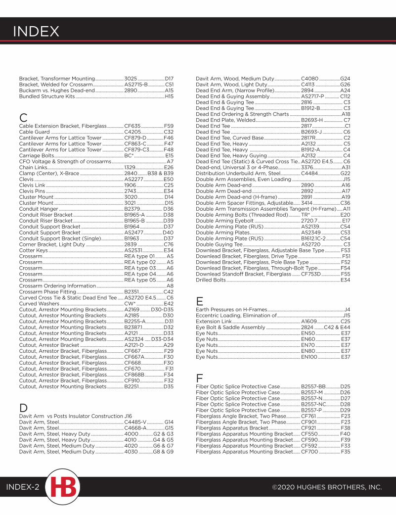
Index
©2020 HugHes BrotHers, Inc.INDEX-2
Bracket, Transformer Mounting ........................ 3025 .......................D17Bracket, Welded for Crossarm ..........................AS2715-B ..............C51 Buckarm vs. Hughes Dead-end ........................ 2890 .......................A15Bundled Structure Kits ............................................................................H15
CCable Extension Bracket, Fiberglass ..............CF635 ...................F59Cable Guard ..............................................................C4205 ...................C32Cantilever Arms for Lattice Tower ..................CF879-D ..............F46Cantilever Arms for Lattice Tower ..................CF863-C ..............F47Cantilever Arms for Lattice Tower ..................CF879-C3 ............F48Carriage Bolts ...........................................................BC* .......................... E15CFO Voltage & Strength of crossarms ..............................................A7Chain Links ................................................................. 1329........................E26Clamp (Center), X-Brace ..................................... 2840 ........B38 & B39Clevis ............................................................................AS2277 .................E50Clevis Link .................................................................. 1906 .......................C25Clevis Pins .................................................................. 2743 .......................E34Cluster Mount ........................................................... 3020 ...................... D14Cluster Mount ........................................................... 3021 ........................D15Conduit Hanger .......................................................B2379 ................... D36Conduit Riser Bracket ...........................................B1965-A ...............D38Conduit Riser Bracket ...........................................B1965-B ...............D39Conduit Support Bracket ....................................B1964 ....................D37Conduit Support Bracket ....................................AS2477 ................D40Conduit Support Bracket (Single) ...................B1963 ....................D37Corner Bracket, Light Duty ................................ 2839 ......................C76Cotter Keys ................................................................AS2531 ..................E34 Crossarm .....................................................................REA type 01 .........A5Crossarm .....................................................................REA type 02 ........A5Crossarm .....................................................................REA type 03 ........A6Crossarm .....................................................................REA type 04 ........A6Crossarm .....................................................................REA type 05 ........A6Crossarm Ordering Information ...........................................................A8Crossarm Phase Fitting ........................................B2351 .....................C42Curved Cross Tie & Static Dead End Tee .....AS2720 E4.5 ........ C6Curved Washers ......................................................CW* .......................E42Cutout, Arrestor Mounting Brackets ..............A2169 .........D30-D35Cutout, Arrestor Mounting Brackets ..............A2185 ...................D30Cutout, Arrestor Mounting Brackets ..............B2255-A ................D31Cutout, Arrestor Mounting Brackets ..............B2387.1 ..................D32Cutout, Arrestor Mounting Brackets ..............A2121 .....................D33Cutout, Arrestor Mounting Brackets ..............AS2324 .....D33-D34Cutout, Arrestor Bracket .....................................A2121-D ................A29Cutout, Arrestor Bracket, Fiberglass ..............CF667 ...................F29Cutout, Arrestor Bracket, Fiberglass ..............CF667A ................F30Cutout, Arrestor Bracket, Fiberglass ..............CF668 ...................F30Cutout, Arrestor Bracket, Fiberglass ..............CF670 .................... F31Cutout, Arrestor Bracket, Fiberglass ..............CF868B ................F34Cutout, Arrestor Bracket, Fiberglass ..............CF910 .................... F32Cutout, Arrestor Mounting Brackets ..............B2251 .....................D35
DDavit Arm vs Posts Insulator Construction J16Davit Arm, Steel .......................................................C4485-V .............. G14Davit Arm, Steel .......................................................C4668-A ...............G15Davit Arm, Steel, Heavy Duty ............................4000 ............G2 & G3Davit Arm, Steel, Heavy Duty ............................4010 .............G4 & G5Davit Arm, Steel, Medium Duty ........................4020 ............G6 & G7Davit Arm, Steel, Medium Duty ........................4030 ............G8 & G9
Davit Arm, Wood, Medium Duty ......................C4080 ..................G24Davit Arm, Wood, Light Duty ............................C4113 .....................G26Dead End Arm, (Narrow Profile) ...................... 2894 ......................A24Dead End & Guying Assembly ..........................AS2717-P ............ C112Dead End & Guying Tee ....................................... 2816 ......................... C3Dead End & Guying Tee .......................................B1912-B ................... C3Dead End Ordering & Strength Charts ............................................A18Dead End Plate, Welded ......................................B2693-H ................ C7Dead End Tee ........................................................... 2817 ............................C1Dead End Tee ...........................................................B2693-J ................. C6Dead End Tee, Curved Base ............................... 2817R ....................... C2Dead End Tee, Heavy ............................................A2132 ...................... C5Dead End Tee, Heavy ...........................................B1912-A ...................C4Dead End Tee, Heavy Guying ............................A2132 ......................C4Dead End Tee (Static) & Curved Cross Tie ..AS2720 E4.5 ........ C6Dead-end, Universal 3 or 4-Phase ................... 3376 ........................A31Distribution Underbuild Arm, Steel.................C4484...................G22Double Arm Assemblies, Even Loading ...........................................J15Double Arm Dead-end ......................................... 2890 .......................A16Double Arm Dead-end ......................................... 2892 .......................A17Double Arm Dead-end (H-frame) ................... 2891 ........................A19Double Arm Spacer Fittings, Adjustable ...... 3414 .......................C36Double Arm Transmission Assemblies Tangent (H-Frame) .....A11Double Arming Bolts (Threaded Rod) .......... TR* .........................E20Double Arming Eyebolt ....................................... 2720.7 .................... E17Double Arming Plate (RUS) ...............................AS2139..................C54Double Arming Plates ...........................................AS2349 ................C53Double Arming Plate (RUS) ...............................B1612.1C-2 ............C54Double Guying Tee .................................................AS2720 .................. C3Downlead Bracket, Fiberglass, Adjustable Base Type .............F53Downlead Bracket, Fiberglass, Drive Type ..................................... F51Downlead Bracket, Fiberglass, Pole Base Type .......................... F52Downlead Bracket, Fiberglass, Through-Bolt Type ...................F54Downlead Standoff Bracket, Fiberglass .......CF753D ................F55Drilled Bolts .................................................................................................E34
EEarth Pressures on H-Frames .................................................................J4Eccentric Loading, Elimination of ........................................................J15Extension Link ..........................................................A1609....................C25Eye Bolt & Saddle Assembly ............................. 2824 ........C42 & E44Eye Nuts ......................................................................EN50 ..................... E37Eye Nuts ......................................................................EN60 ..................... E37Eye Nuts ......................................................................EN70 ..................... E37Eye Nuts ......................................................................EN80 ..................... E37Eye Nuts ......................................................................EN100 ................... E37
FFiber Optic Splice Protective Case .................B2557-BB ............D25Fiber Optic Splice Protective Case .................B2557-M ..............D26Fiber Optic Splice Protective Case .................B2557-N ...............D27Fiber Optic Splice Protective Case .................B2557-NC ............D28Fiber Optic Splice Protective Case .................B2557-P ...............D29Fiberglass Angle Bracket, Two Phase ............CF761 .................... F23Fiberglass Angle Bracket, Two Phase ............CF901 .................... F23Fiberglass Apparatus Bracket ...........................CF921 ....................F38Fiberglass Apparatus Mounting Bracket ......CF550 .................. F40Fiberglass Apparatus Mounting Bracket ......CF590 ...................F39Fiberglass Apparatus Mounting Bracket ......CF592 ...................F33Fiberglass Apparatus Mounting Bracket ......CF700 ..................F35
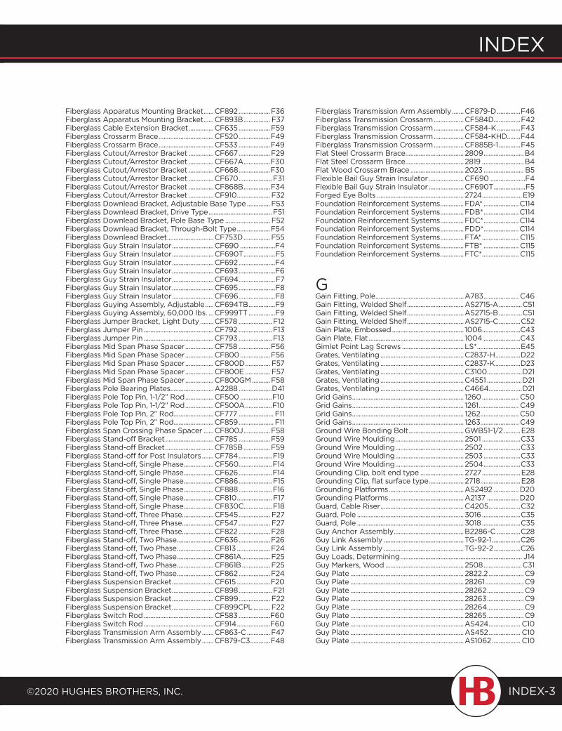
index
©2020 HugHes BrotHers, inc.
index
INDEX-3
Fiberglass Apparatus Mounting Bracket ......CF892 ...................F36Fiberglass Apparatus Mounting Bracket ......CF893B ................ F37Fiberglass Cable Extension Bracket ...............CF635 ...................F59Fiberglass Crossarm Brace .................................CF520 ...................F49Fiberglass Crossarm Brace .................................CF533 ...................F49Fiberglass Cutout/Arrestor Bracket ...............CF667 ...................F29Fiberglass Cutout/Arrestor Bracket ...............CF667A ................F30Fiberglass Cutout/Arrestor Bracket ...............CF668 ...................F30Fiberglass Cutout/Arrestor Bracket ...............CF670 .................... F31Fiberglass Cutout/Arrestor Bracket ...............CF868B ................F34Fiberglass Cutout/Arrestor Bracket ...............CF910 .................... F32Fiberglass Downlead Bracket, Adjustable Base Type ..............F53Fiberglass Downlead Bracket, Drive Type ...................................... F51Fiberglass Downlead Bracket, Pole Base Type ........................... F52Fiberglass Downlead Bracket, Through-Bolt Type ....................F54Fiberglass Downlead Bracket ............................CF753D ................F55Fiberglass Guy Strain Insulator .........................CF690 .....................F4Fiberglass Guy Strain Insulator .........................CF690T ...................F5Fiberglass Guy Strain Insulator .........................CF692 ......................F4Fiberglass Guy Strain Insulator .........................CF693 ......................F6Fiberglass Guy Strain Insulator .........................CF694 ......................F7Fiberglass Guy Strain Insulator .........................CF695 ......................F8Fiberglass Guy Strain Insulator .........................CF696 ......................F8Fiberglass Guying Assembly, Adjustable .....CF694TB ................F9Fiberglass Guying Assembly, 60,000 lbs. ...CF999TT ................F9Fiberglass Jumper Bracket, Light Duty ........CF578 .................... F12Fiberglass Jumper Pin ..........................................CF792 .................... F13Fiberglass Jumper Pin ..........................................CF793 .................... F13Fiberglass Mid Span Phase Spacer .................CF758 ...................F56Fiberglass Mid Span Phase Spacer .................CF800 ..................F56Fiberglass Mid Span Phase Spacer .................CF800D ............... F57Fiberglass Mid Span Phase Spacer .................CF800E ............... F57Fiberglass Mid Span Phase Spacer .................CF800GM ...........F58Fiberglass Pole Bearing Plates..........................A2288 ....................D41Fiberglass Pole Top Pin, 1-1/2” Rod .................CF500 ...................F10Fiberglass Pole Top Pin, 1-1/2” Rod .................CF500A ................F10Fiberglass Pole Top Pin, 2” Rod ........................CF777 ..................... F11Fiberglass Pole Top Pin, 2” Rod ........................CF859 ..................... F11Fiberglass Span Crossing Phase Spacer ......CF800J ................F58Fiberglass Stand-off Bracket .............................CF785 ...................F59Fiberglass Stand-off Bracket .............................CF785B ................F59Fiberglass Stand-off for Post Insulators .......CF784 ....................F19Fiberglass Stand-off, Single Phase ..................CF560 ....................F14Fiberglass Stand-off, Single Phase ..................CF626 ....................F14Fiberglass Stand-off, Single Phase ..................CF886 .................... F15Fiberglass Stand-off, Single Phase ..................CF888 ....................F16Fiberglass Stand-off, Single Phase ..................CF810 ..................... F17Fiberglass Stand-off, Single Phase ..................CF830C.................F18Fiberglass Stand-off, Three Phase...................CF545 ................... F27Fiberglass Stand-off, Three Phase...................CF547 ................... F27Fiberglass Stand-off, Three Phase...................CF822 ...................F28Fiberglass Stand-off, Two Phase ......................CF636 ...................F26Fiberglass Stand-off, Two Phase ......................CF813 ....................F24Fiberglass Stand-off, Two Phase ......................CF861A ................. F25Fiberglass Stand-off, Two Phase ......................CF861B ................. F25Fiberglass Stand-off, Two Phase ......................CF862 ...................F24Fiberglass Suspension Bracket .........................CF615 ....................F20Fiberglass Suspension Bracket .........................CF898 .................... F21Fiberglass Suspension Bracket .........................CF899 ................... F22Fiberglass Suspension Bracket .........................CF899CPL .......... F22Fiberglass Switch Rod ..........................................CF583 ...................F60Fiberglass Switch Rod ..........................................CF914 ....................F60Fiberglass Transmission Arm Assembly .......CF863-C ..............F47Fiberglass Transmission Arm Assembly .......CF879-C3 ............F48
Fiberglass Transmission Arm Assembly .......CF879-D ..............F46Fiberglass Transmission Crossarm ..................CF584D................F42Fiberglass Transmission Crossarm ..................CF584-K ..............F43Fiberglass Transmission Crossarm ..................CF584-KHD........F44Fiberglass Transmission Crossarm ..................CF885B-1 .............F45Flat Steel Crossarm Brace ................................... 2809 ........................B4Flat Steel Crossarm Brace ................................... 2819 .........................B4Flat Wood Crossarm Brace ................................ 2023 ........................ B5Flexible Bail Guy Strain Insulator .....................CF690 .....................F4Flexible Bail Guy Strain Insulator .....................CF690T ...................F5Forged Eye Bolts .................................................... 2724 ........................E19Foundation Reinforcement Systems ..............FDA* .....................C114Foundation Reinforcement Systems ..............FDB* .....................C114Foundation Reinforcement Systems ..............FDC* .....................C114Foundation Reinforcement Systems ..............FDD* .....................C114Foundation Reinforcement Systems ..............FTA* ...................... C115Foundation Reinforcement Systems ..............FTB* ..................... C115Foundation Reinforcement Systems ..............FTC* ...................... C115
GGain Fitting, Pole .....................................................A783 ..................... C46Gain Fitting, Welded Shelf ..................................AS2715-A ..............C51Gain Fitting, Welded Shelf ..................................AS2715-B ..............C51Gain Fitting, Welded Shelf ..................................AS2715-C .............C52Gain Plate, Embossed ........................................... 1006 .......................C43Gain Plate, Flat ......................................................... 1004 ......................C43Gimlet Point Lag Screws ..................................... LS* ..........................E45Grates, Ventilating ..................................................C2837-H ...............D22Grates, Ventilating ..................................................C2837-K ...............D23Grates, Ventilating ..................................................C3100 .....................D21Grates, Ventilating ..................................................C4551 .....................D21Grates, Ventilating ..................................................C4664 ....................D21Grid Gains ................................................................... 1260 ...................... C50Grid Gains ................................................................... 1261 ........................ C49Grid Gains ................................................................... 1262 ....................... C50Grid Gains ................................................................... 1263 ....................... C49Ground Wire Bonding Bolt .................................GWB51-1/2 ..........E28Ground Wire Moulding ......................................... 2501 .......................C33Ground Wire Moulding ......................................... 2502 ......................C33Ground Wire Moulding ......................................... 2503 ......................C33Ground Wire Moulding ......................................... 2504 ......................C33Grounding Clip, bolt end type .......................... 2727 .......................E28Grounding Clip, flat surface type ..................... 2718 ........................E28Grounding Platforms .............................................AS2492 ...............D20Grounding Platforms .............................................A2137 ...................D20Guard, Cable Riser ..................................................C4205 ...................C32Guard, Pole ................................................................ 3016 .......................C35Guard, Pole ................................................................ 3018 .......................C35Guy Anchor Assembly ..........................................B2286-C ..............C28Guy Link Assembly ................................................ TG-92-1 .................C26Guy Link Assembly ................................................ TG-92-2 ................C26Guy Loads, Determining ......................................................................... J14Guy Markers, Wood ............................................... 2508 .......................C31Guy Plate .................................................................... 2822.2 ..................... C9Guy Plate .................................................................... 28261 ....................... C9Guy Plate .................................................................... 28262 ...................... C9Guy Plate .................................................................... 28263 ...................... C9Guy Plate .................................................................... 28264...................... C9Guy Plate .................................................................... 28265 ...................... C9Guy Plate ....................................................................AS424 ................... C10Guy Plate ....................................................................AS452 ................... C10Guy Plate ....................................................................AS1062 ................. C10
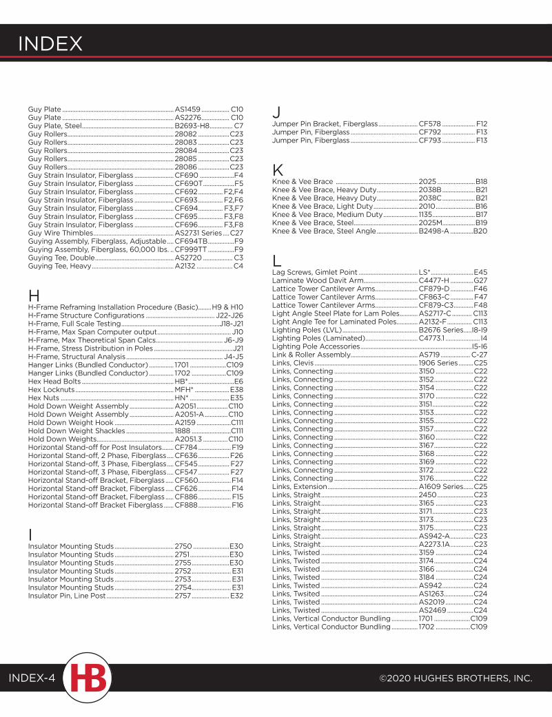
Index
©2020 HugHes BrotHers, Inc.INDEX-4
Guy Plate ....................................................................AS1459 ................. C10Guy Plate ....................................................................AS2276 ................. C10Guy Plate, Steel ........................................................B2693-H8 .............. C7Guy Rollers ................................................................. 28082 ...................C23Guy Rollers ................................................................. 28083 ...................C23Guy Rollers ................................................................. 28084 ...................C23Guy Rollers ................................................................. 28085 ...................C23Guy Rollers ................................................................. 28086 ...................C23Guy Strain Insulator, Fiberglass ........................CF690 .....................F4Guy Strain Insulator, Fiberglass ........................CF690T ...................F5Guy Strain Insulator, Fiberglass ........................CF692 ...............F2,F4Guy Strain Insulator, Fiberglass ........................CF693 ............... F2,F6Guy Strain Insulator, Fiberglass ........................CF694 ............... F3,F7Guy Strain Insulator, Fiberglass ........................CF695 ............... F3,F8Guy Strain Insulator, Fiberglass ........................CF696 ............... F3,F8Guy Wire Thimbles .................................................AS2731 Series ....C27Guying Assembly, Fiberglass, Adjustable ....CF694TB ................F9Guying Assembly, Fiberglass, 60,000 lbs. ..CF999TT ................F9Guying Tee, Double ................................................AS2720 .................. C3Guying Tee, Heavy ..................................................A2132 ......................C4
HH-Frame Reframing Installation Procedure (Basic)........H9 & H10H-Frame Structure Configurations .......................................... J22-J26H-Frame, Full Scale Testing ............................................................J18-J21H-Frame, Max Span Computer output ............................................. J10H-Frame, Max Theoretical Span Calcs......................................... J6-J9H-Frame, Stress Distribution in Poles ................................................J21H-Frame, Structural Analysis ........................................................... J4-J5Hanger Links (Bundled Conductor) ............... 1701 ......................C109Hanger Links (Bundled Conductor) ............... 1702 .....................C109Hex Head Bolts ........................................................HB* ............................E6Hex Locknuts ............................................................MFH* .....................E38Hex Nuts .....................................................................HN* ........................E35Hold Down Weight Assembly ...........................A2051 ...................C110Hold Down Weight Assembly ...........................A2051-A ..............C110Hold Down Weight Hook ....................................A2159 .....................C111Hold Down Weight Shackles ............................. 1888 ........................C111Hold Down Weights ...............................................A2051.3 ...............C110Horizontal Stand-off for Post Insulators .......CF784 ....................F19Horizontal Stand-off, 2 Phase, Fiberglass ....CF636 ...................F26Horizontal Stand-off, 3 Phase, Fiberglass ....CF545 ................... F27Horizontal Stand-off, 3 Phase, Fiberglass ....CF547 ................... F27Horizontal Stand-off Bracket, Fiberglass .....CF560 ....................F14Horizontal Stand-off Bracket, Fiberglass .....CF626 ....................F14Horizontal Stand-off Bracket, Fiberglass .....CF886 .................... F15Horizontal Stand-off Bracket Fiberglass ......CF888 ....................F16
IInsulator Mounting Studs .................................... 2750 ......................E30Insulator Mounting Studs .................................... 2751 ........................E30Insulator Mounting Studs .................................... 2755 .......................E30Insulator Mounting Studs .................................... 2752 ........................ E31Insulator Mounting Studs .................................... 2753 ........................ E31Insulator Mounting Studs .................................... 2754........................ E31Insulator Pin, Line Post ......................................... 2757 .......................E32
JJumper Pin Bracket, Fiberglass ........................CF578 .................... F12Jumper Pin, Fiberglass .........................................CF792 .................... F13Jumper Pin, Fiberglass .........................................CF793 .................... F13
KKnee & Vee Brace .................................................. 2025 .......................B18Knee & Vee Brace, Heavy Duty ......................... 2038B ....................B21Knee & Vee Brace, Heavy Duty ......................... 2038C ....................B21Knee & Vee Brace, Light Duty ........................... 2010 ........................B16Knee & Vee Brace, Medium Duty ..................... 1135 ..........................B17Knee & Vee Brace, Steel ....................................... 2025M....................B19Knee & Vee Brace, Steel Angle .........................B2498-A ..............B20
LLag Screws, Gimlet Point .................................... LS* ..........................E45Laminate Wood Davit Arm .................................C4477-H ..............G27Lattice Tower Cantilever Arms ..........................CF879-D ..............F46Lattice Tower Cantilever Arms ..........................CF863-C ..............F47Lattice Tower Cantilever Arms ..........................CF879-C3 ............F48Light Angle Steel Plate for Lam Poles ...........AS2717-C ............ C113Light Angle Tee for Laminated Poles.............A2132-F ............... C113Lighting Poles (LVL) ..............................................B2676 Series .....I8-I9Lighting Poles (Laminated) ................................C4773.1 ..................... I4Lighting Pole Accessories ....................................................................I5-I6Link & Roller Assembly.........................................AS719 .................. C-27Links, Clevis ............................................................... 1906 Series .........C25Links, Connecting ................................................... 3150 .......................C22Links, Connecting ................................................... 3152 ........................C22Links, Connecting ................................................... 3154 .......................C22Links, Connecting ................................................... 3170 .......................C22Links, Connecting ................................................... 3151 .........................C22Links, Connecting ................................................... 3153 ........................C22Links, Connecting ................................................... 3155 ........................C22Links, Connecting ................................................... 3157 ........................C22Links, Connecting ................................................... 3160 .......................C22Links, Connecting ................................................... 3167 ........................C22Links, Connecting ................................................... 3168 .......................C22Links, Connecting ................................................... 3169 .......................C22Links, Connecting ................................................... 3172 ........................C22Links, Connecting ................................................... 3176 ........................C22Links, Extension .......................................................A1609 Series ......C25Links, Straight ........................................................... 2450 ......................C23Links, Straight ........................................................... 3165 .......................C23Links, Straight ........................................................... 3171 .........................C23Links, Straight ........................................................... 3173 ........................C23Links, Straight ........................................................... 3175 ........................C23Links, Straight ...........................................................AS942-A ..............C23Links, Straight ...........................................................A2273.1A ..............C23Links, Twisted ........................................................... 3159 .......................C24Links, Twisted ........................................................... 3174 ........................C24Links, Twisted ........................................................... 3166 .......................C24Links, Twisted ........................................................... 3184 .......................C24Links, Twisted ...........................................................AS942 ...................C24Links, Twsited ...........................................................AS1263..................C24Links, Twisted ...........................................................AS2019 .................C24Links, Twisted ...........................................................AS2469 ................C24Links, Vertical Conductor Bundling ................ 1701 ......................C109Links, Vertical Conductor Bundling ................ 1702 .....................C109
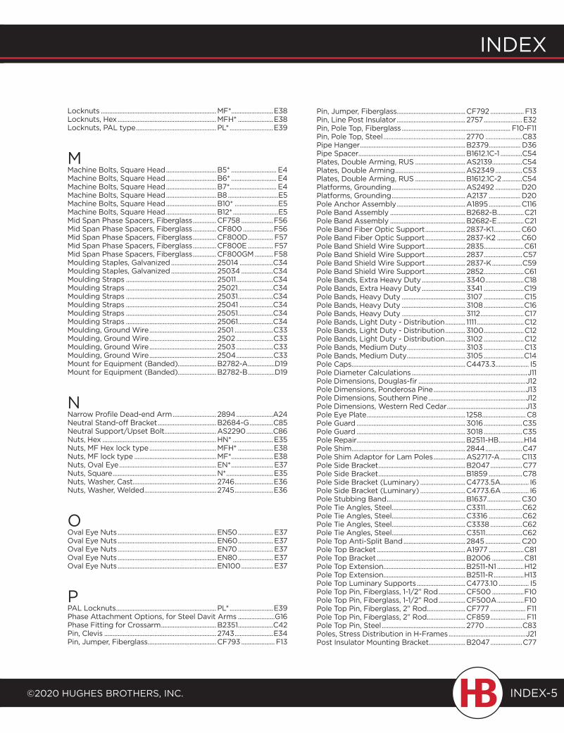
index
©2020 HugHes BrotHers, inc.
index
INDEX-5
Locknuts .....................................................................MF* .........................E38Locknuts, Hex ...........................................................MFH* .....................E38Locknuts, PAL type ................................................PL* ..........................E39
MMachine Bolts, Square Head ..............................B5* ........................... E4Machine Bolts, Square Head ..............................B6* ........................... E4Machine Bolts, Square Head ..............................B7*............................ E4Machine Bolts, Square Head ..............................B8 ..............................E5Machine Bolts, Square Head ..............................B10* ..........................E5Machine Bolts, Square Head ..............................B12* ...........................E5Mid Span Phase Spacers, Fiberglass ..............CF758 ...................F56Mid Span Phase Spacers, Fiberglass ..............CF800 ..................F56Mid Span Phase Spacers, Fiberglass ..............CF800D ............... F57Mid Span Phase Spacers, Fiberglass ..............CF800E ............... F57Mid Span Phase Spacers, Fiberglass ..............CF800GM ...........F58Moulding Staples, Galvanized ........................... 25014 ....................C34Moulding Staples, Galvanized ........................... 25034 ...................C34Moulding Straps ...................................................... 25011 ......................C34Moulding Straps ...................................................... 25021 .....................C34Moulding Straps ...................................................... 25031 .....................C34Moulding Straps ...................................................... 25041 ....................C34Moulding Straps ...................................................... 25051 .....................C34Moulding Straps ...................................................... 25061 .....................C34Moulding, Ground Wire ........................................ 2501 .......................C33Moulding, Ground Wire ........................................ 2502 ......................C33Moulding, Ground Wire ........................................ 2503 ......................C33Moulding, Ground Wire ........................................ 2504 ......................C33Mount for Equipment (Banded).......................B2782-A ................D19Mount for Equipment (Banded).......................B2782-B ................D19
NNarrow Profile Dead-end Arm .......................... 2894 ......................A24Neutral Stand-off Bracket ...................................B2684-G ..............C85Neutral Support/Upset Bolt ...............................AS2290 ................C86Nuts, Hex ....................................................................HN* ........................E35Nuts, MF Hex lock type ........................................MFH* .....................E38Nuts, MF lock type .................................................MF* .........................E38Nuts, Oval Eye ..........................................................EN* ......................... E37Nuts, Square ..............................................................N* ............................E35Nuts, Washer, Cast.................................................. 2746 .......................E36Nuts, Washer, Welded ........................................... 2745 .......................E36
OOval Eye Nuts ...........................................................EN50 ..................... E37Oval Eye Nuts ...........................................................EN60 ..................... E37Oval Eye Nuts ...........................................................EN70 ..................... E37Oval Eye Nuts ...........................................................EN80 ..................... E37Oval Eye Nuts ...........................................................EN100 ................... E37
PPAL Locknuts ............................................................PL* ..........................E39Phase Attachment Options, for Steel Davit Arms ......................G16Phase Fitting for Crossarm .................................B2351 .....................C42Pin, Clevis ................................................................... 2743 .......................E34Pin, Jumper, Fiberglass .........................................CF793 .................... F13
Pin, Jumper, Fiberglass .........................................CF792 .................... F13Pin, Line Post Insulator ......................................... 2757 .......................E32Pin, Pole Top, Fiberglass ................................................................. F10-F11Pin, Pole Top, Steel ................................................. 2770 ......................C83Pipe Hanger ...............................................................B2379 ................... D36Pipe Spacer................................................................B1612.1C-1 .............C54Plates, Double Arming, RUS ..............................AS2139..................C54Plates, Double Arming ..........................................AS2349 ................C53Plates, Double Arming, RUS ..............................B1612.1C-2 ............C54Platforms, Grounding ............................................AS2492 ...............D20Platforms, Grounding ............................................A2137 ...................D20Pole Anchor Assembly .........................................A1895 ................... C116Pole Band Assembly .............................................B2682-B................C21Pole Band Assembly .............................................B2682-E ................C21Pole Band Fiber Optic Support ........................ 2837-K1................C60Pole Band Fiber Optic Support ........................ 2837-K2 ..............C60Pole Band Shield Wire Support ........................ 2835........................C61Pole Band Shield Wire Support ........................ 2837 .......................C57Pole Band Shield Wire Support ........................ 2837-K ..................C59Pole Band Shield Wire Support ........................ 2852 ........................C61Pole Bands, Extra Heavy Duty .......................... 3340 .......................C18Pole Bands, Extra Heavy Duty .......................... 3341 ........................C19Pole Bands, Heavy Duty ...................................... 3107 ........................C15Pole Bands, Heavy Duty ...................................... 3108 ........................C16Pole Bands, Heavy Duty ...................................... 3112 ..........................C17Pole Bands, Light Duty - Distribution ............ 1111 ............................C12Pole Bands, Light Duty - Distribution ............ 3100 ........................C12Pole Bands, Light Duty - Distribution ............ 3102 ........................C12Pole Bands, Medium Duty ................................... 3103 ........................C13Pole Bands, Medium Duty ................................... 3105 ........................C14Pole Caps ....................................................................C4473.3 .................... I5Pole Diameter Calculations .....................................................................J11Pole Dimensions, Douglas-fir ................................................................J12Pole Dimensions, Ponderosa Pine .......................................................J13Pole Dimensions, Southern Pine ..........................................................J12Pole Dimensions, Western Red Cedar ...............................................J13Pole Eye Plate ........................................................... 1258 .......................... C8Pole Guard ................................................................. 3016 .......................C35Pole Guard ................................................................. 3018 .......................C35Pole Repair .................................................................B2511-HB ...............H14Pole Shim .................................................................... 2844 ......................C47Pole Shim Adaptor for Lam Poles ...................AS2717-A ............ C113Pole Side Bracket ....................................................B2047 ...................C77Pole Side Bracket ....................................................B1859 ....................C78Pole Side Bracket (Luminary) ...........................C4773.5A................. I6Pole Side Bracket (Luminary) ...........................C4773.6A ................ I6Pole Stubbing Band ...............................................B1637 .................... C30Pole Tie Angles, Steel ............................................C3311 ......................C62Pole Tie Angles, Steel ............................................C3316 ....................C62Pole Tie Angles, Steel ............................................C3338 ...................C62Pole Tie Angles, Steel ............................................C3511 ......................C62Pole Top Anti-Split Band ..................................... 2845 ..................... C20Pole Top Bracket .....................................................A1977 .....................C81Pole Top Bracket .....................................................B2006 ...................C81Pole Top Extension .................................................B2511-N1 ................H12Pole Top Extension .................................................B2511-R ..................H13Pole Top Luminary Supports .............................C4773.10 .................. I5Pole Top Pin, Fiberglass, 1-1/2” Rod ................CF500 ...................F10Pole Top Pin, Fiberglass, 1-1/2” Rod ................CF500A ................F10Pole Top Pin, Fiberglass, 2” Rod .......................CF777 ..................... F11Pole Top Pin, Fiberglass, 2” Rod .......................CF859 ..................... F11Pole Top Pin, Steel .................................................. 2770 ......................C83Poles, Stress Distribution in H-Frames ..............................................J21Post Insulator Mounting Bracket......................B2047 ...................C77
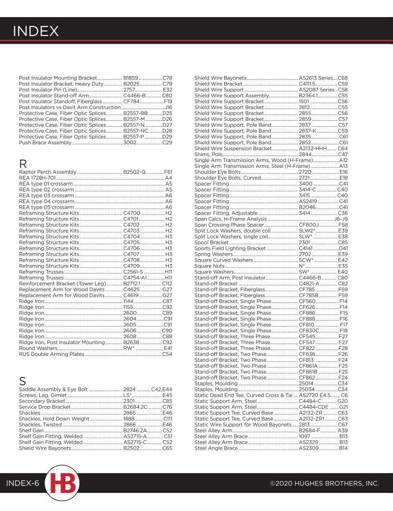
Index
©2020 HugHes BrotHers, Inc.INDEX-6
Post Insulator Mounting Bracket......................B1859 ....................C78Post Insulator Bracket, Heavy Duty ................B2025 ...................C79Post Insulator Pin (Line) ....................................... 2757 .......................E32Post Insulator Stand-off Arm.............................C4466-B ............. C80Post Insulator Standoff, Fiberglass .................CF784 ....................F19Post Insulators vs Davit Arm Construction .....................................J16Protective Case, Fiber Optic Splices ..............B2557-BB ............D25Protective Case, Fiber Optic Splices ..............B2557-M ..............D26Protective Case, Fiber Optic Splices ..............B2557-N ...............D27Protective Case, Fiber Optic Splices ..............B2557-NC ............D28Protective Case, Fiber Optic Splices ..............B2557-P ...............D29Push Brace Assembly ........................................... 3002 ......................C29
RRaptor Perch Assembly .......................................B2502-Q ...............F61REA 1728H-701 .............................................................................................A4REA type 01 crossarm ..............................................................................A5REA type 02 crossarm .............................................................................A5REA type 03 crossarm .............................................................................A6REA type 04 crossarm .............................................................................A6REA type 05 crossarm .............................................................................A6Reframing Structure Kits .....................................C4700..................... H2Reframing Structure Kits .....................................C4701 ...................... H2Reframing Structure Kits .....................................C4702 ..................... H2Reframing Structure Kits .....................................C4703 ..................... H2Reframing Structure Kits .....................................C4704 ..................... H3Reframing Structure Kits .....................................C4705 ..................... H3Reframing Structure Kits .....................................C4706 ..................... H3Reframing Structure Kits .....................................C4707 ..................... H3Reframing Structure Kits .....................................C4708 ..................... H3Reframing Structure Kits .....................................C4709 ..................... H3Reframing Trusses ..................................................C2561-S ..................H11Reframing Trusses ..................................................C4754-A1 ...............H11Reinforcement Bracket (Tower Leg) ..............B2712.1 ................. C112Replacement Arm for Wood Davits ...............C4625 ...................G27Replacement Arm for Wood Davits ...............C4619 ....................G27Ridge Iron ................................................................... 1144 ........................C87Ridge Iron ................................................................... 1155 .........................C92Ridge Iron ................................................................... 2600......................C89Ridge Iron ................................................................... 2604 .......................C91Ridge Iron ................................................................... 2605 .......................C91Ridge Iron ................................................................... 2606 .....................C90Ridge Iron ................................................................... 2608 ......................C88Ridge Iron, Post Insulator Mounting ...............B2638 ...................C92Round Washers ........................................................RW* ........................E41RUS Double Arming Plates ..................................................................C54
SSaddle Assembly & Eye Bolt ............................. 2824 ............C42,E44Screws, Lag, Gimlet ................................................ LS* ..........................E45Secondary Bracket ................................................. 2301 .......................C85Service Drop Bracket ............................................B2684.2C ............C76Shackles ...................................................................... 2865 ......................E46Shackles, Hold Down Weight ............................ 1888 ........................C111Shackles, Twisted .................................................... 2866 ......................E46Shelf Gain ...................................................................B2746.2A .............C52Shelf Gain Fitting, Welded ..................................AS2715-A ..............C51Shelf Gain Fitting, Welded ..................................AS2715-C .............C52Shield Wire Bayonets ............................................B2502 ...................C65
Shield Wire Bayonets ............................................AS2613 Series ....C68Shield Wire Bracket ...............................................C4111.5 ...................C59Shield Wire Support ..............................................AS2087 Series ..C58Shield Wire Support Assembly.........................B2364.1 .................C55Shield Wire Support Bracket ............................. 1501 ........................C56Shield Wire Support Bracket ............................. 2812 ........................C55Shield Wire Support Bracket ............................. 2855.......................C56Shield Wire Support Bracket ............................. 2859 ......................C57Shield Wire Support, Pole Band ....................... 2837 .......................C57Shield Wire Support, Pole Band ....................... 2837-K ..................C59Shield Wire Support, Pole Band ....................... 2835........................C61Shield Wire Support, Pole Band ....................... 2852 ........................C61Shield Wire Suspension Bracket ......................A2132-HHH ........ C64Shims, Pole ................................................................. 2844 ......................C47Single Arm Transmission Arms, Wood (H-Frame) ......................A12Single Arm Transmission Arms, Steel (H-Frame) ........................A13Shoulder Eye Bolts ................................................. 2720 .......................E16Shoulder Eye Bolts, Curved................................ 2721 .........................E18Spacer Fitting ........................................................... 3400 ......................C41Spacer Fitting ........................................................... 3414-C .................C40Spacer Fitting ........................................................... 3415 ......................C40Spacer Fitting ...........................................................AS2419 ..................C41Spacer Fitting ...........................................................B2046 ....................C41Spacer Fitting, Adjustable .................................. 3414 .......................C36Span Calcs, H-Frame Analysis ........................................................ J6-J9Span Crossing Phase Spacer .............................CF800J ................F58Split Lock Washers, double coil ....................... SLW2* ...................E39Split Lock Washers, single coil .......................... SLW* .....................E38Spool Bracket ........................................................... 2301 .......................C85Sports Field Lighting Bracket ...........................C4141 ......................D41Spring Washers ........................................................ 2702 ......................E39Square Curved Washers ...................................... SCW* ....................E42Square Nuts ...............................................................N* ............................E35Square Washers ....................................................... SW* ....................... E40Stand-off Arm, Post Insulator............................C4466-B ............. C80Stand-off Bracket ...................................................C4821-A ...............C82Stand-off Bracket, Fiberglass ............................CF785 ...................F59Stand-off Bracket, Fiberglass ............................CF785B ................F59Stand-off Bracket, Single Phase .......................CF560 ....................F14Stand-off Bracket, Single Phase .......................CF626 ....................F14Stand-off Bracket, Single Phase .......................CF886 .................... F15Stand-off Bracket, Single Phase .......................CF888 ....................F16Stand-off Bracket, Single Phase .......................CF810 ..................... F17Stand-off Bracket, Single Phase .......................CF830C.................F18Stand-off Bracket, Three Phase ........................CF545 ................... F27Stand-off Bracket, Three Phase ........................CF547 ................... F27Stand-off Bracket, Three Phase ........................CF822 ...................F28Stand-off Bracket, Two Phase ...........................CF636 ...................F26Stand-off Bracket, Two Phase ...........................CF813 ....................F24Stand-off Bracket, Two Phase ...........................CF861A ................. F25Stand-off Bracket, Two Phase ...........................CF861B ................. F25Stand-off Bracket, Two Phase ...........................CF862 ...................F24Staples, Moulding ................................................... 25014 ....................C34Staples, Moulding ................................................... 25034 ...................C34Static Dead End Tee, Curved Cross & Tie ....AS2720 E4.5 ........ C6Static Support Arm, Steel ...................................C4484-C .............G20Static Support Arm, Steel ...................................C4484-CDE ........G21Static Support Tee, Curved Base .....................A2132-ZR .............C63Static Support Tee, Curved Base .....................A2132-ZR1 ...........C63Static Wire Support for Wood Bayonets ..... 2813 ........................C67Steel Alley Arm ........................................................B2684-F.............. A39Steel Alley Arm Brace ........................................... 1097 ........................B13Steel Alley Arm Brace ...........................................AS2329 .................B13Steel Angle Brace ...................................................AS2309 .................B14
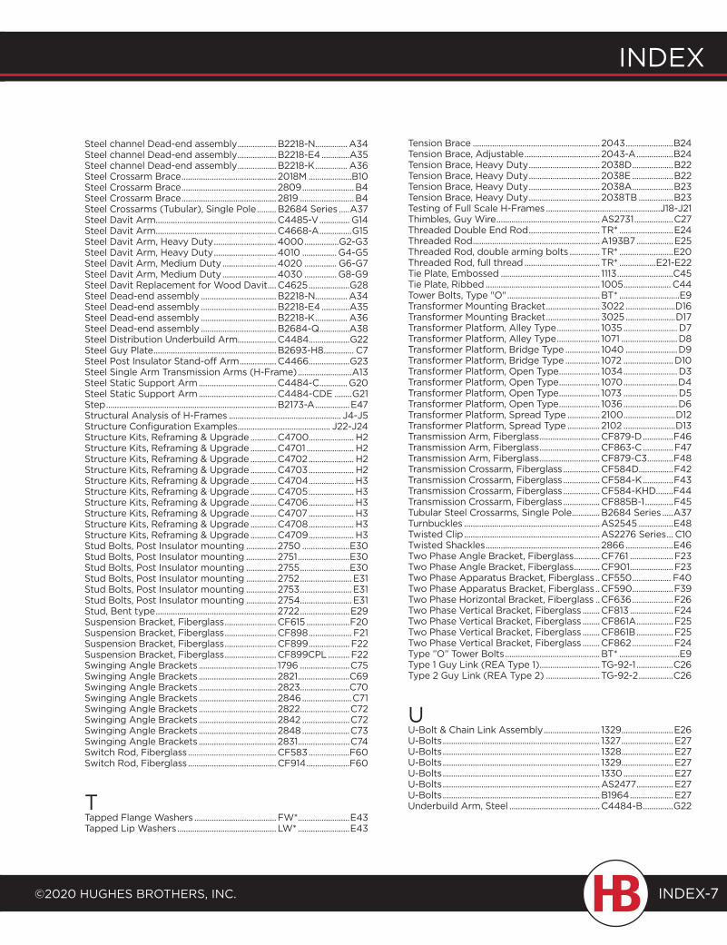
index
©2020 HugHes BrotHers, inc.
index
INDEX-7
Steel channel Dead-end assembly ..................B2218-N............... A34Steel channel Dead-end assembly ..................B2218-E4 .............A35Steel channel Dead-end assembly ..................B2218-K ............... A36Steel Crossarm Brace ............................................ 2018M ....................B10Steel Crossarm Brace ............................................ 2809 ........................B4Steel Crossarm Brace ............................................ 2819 .........................B4Steel Crossarms (Tubular), Single Pole .........B2684 Series .....A37Steel Davit Arm ........................................................C4485-V .............. G14Steel Davit Arm ........................................................C4668-A ...............G15Steel Davit Arm, Heavy Duty .............................4000 ................G2-G3Steel Davit Arm, Heavy Duty .............................4010 ................ G4-G5Steel Davit Arm, Medium Duty .........................4020 ............... G6-G7Steel Davit Arm, Medium Duty .........................4030 ............... G8-G9Steel Davit Replacement for Wood Davit ....C4625 ...................G28Steel Dead-end assembly ...................................B2218-N............... A34Steel Dead-end assembly ...................................B2218-E4 .............A35Steel Dead-end assembly ...................................B2218-K ............... A36Steel Dead-end assembly ...................................B2684-Q ..............A38Steel Distribution Underbuild Arm..................C4484...................G22Steel Guy Plate .........................................................B2693-H8 .............. C7Steel Post Insulator Stand-off Arm .................C4466 ...................G23Steel Single Arm Transmission Arms (H-Frame) .........................A13Steel Static Support Arm ....................................C4484-C .............G20Steel Static Support Arm ....................................C4484-CDE ........G21Step ...............................................................................B2173-A ................E47Structural Analysis of H-Frames .................................................... J4-J5Structure Configuration Examples ........................................... J22-J24Structure Kits, Reframing & Upgrade ............C4700..................... H2Structure Kits, Reframing & Upgrade ............C4701 ...................... H2Structure Kits, Reframing & Upgrade ............C4702 ..................... H2Structure Kits, Reframing & Upgrade ............C4703 ..................... H2Structure Kits, Reframing & Upgrade ............C4704 ..................... H3Structure Kits, Reframing & Upgrade ............C4705 ..................... H3Structure Kits, Reframing & Upgrade ............C4706 ..................... H3Structure Kits, Reframing & Upgrade ............C4707 ..................... H3Structure Kits, Reframing & Upgrade ............C4708 ..................... H3Structure Kits, Reframing & Upgrade ............C4709 ..................... H3Stud Bolts, Post Insulator mounting .............. 2750 ......................E30Stud Bolts, Post Insulator mounting .............. 2751 ........................E30Stud Bolts, Post Insulator mounting .............. 2755 .......................E30Stud Bolts, Post Insulator mounting .............. 2752 ........................ E31Stud Bolts, Post Insulator mounting .............. 2753 ........................ E31Stud Bolts, Post Insulator mounting .............. 2754........................ E31Stud, Bent type ........................................................ 2722 .......................E29Suspension Bracket, Fiberglass ........................CF615 ....................F20Suspension Bracket, Fiberglass ........................CF898 .................... F21Suspension Bracket, Fiberglass ........................CF899 ................... F22Suspension Bracket, Fiberglass ........................CF899CPL .......... F22Swinging Angle Brackets .................................... 1796 .......................C75Swinging Angle Brackets .................................... 2821 ........................C69Swinging Angle Brackets .................................... 2823.......................C70Swinging Angle Brackets .................................... 2846 .......................C71Swinging Angle Brackets .................................... 2822 .......................C72Swinging Angle Brackets .................................... 2842 ......................C72Swinging Angle Brackets .................................... 2848 ......................C73Swinging Angle Brackets .................................... 2831 ........................C74Switch Rod, Fiberglass .........................................CF583 ...................F60Switch Rod, Fiberglass .........................................CF914 ....................F60
TTapped Flange Washers ......................................FW* ........................E43Tapped Lip Washers .............................................. LW* ........................E43
Tension Brace ........................................................... 2043 ......................B24Tension Brace, Adjustable ................................... 2043-A .................B24Tension Brace, Heavy Duty ................................. 2038D ...................B22Tension Brace, Heavy Duty ................................. 2038E ...................B22Tension Brace, Heavy Duty ................................. 2038A ...................B23Tension Brace, Heavy Duty ................................. 2038TB ................B23Testing of Full Scale H-Frames .....................................................J18-J21Thimbles, Guy Wire ................................................AS2731 ..................C27Threaded Double End Rod ................................. TR* .........................E24Threaded Rod ...........................................................A193B7 .................E25Threaded Rod, double arming bolts .............. TR* .........................E20Threaded Rod, full thread ................................... TR* .................E21-E22Tie Plate, Embossed .............................................. 1113 ..........................C45Tie Plate, Ribbed ..................................................... 1005 ...................... C44Tower Bolts, Type "O" ...........................................BT* ............................E9Transformer Mounting Bracket ......................... 3022 .......................D16Transformer Mounting Bracket ......................... 3025 .......................D17Transformer Platform, Alley Type .................... 1035 ......................... D7Transformer Platform, Alley Type .................... 1071 ..........................D8Transformer Platform, Bridge Type ................ 1040 ........................D9Transformer Platform, Bridge Type ................ 1072 ....................... D10Transformer Platform, Open Type ................... 1034 .........................D3Transformer Platform, Open Type ................... 1070 .........................D4Transformer Platform, Open Type ................... 1073 .........................D5Transformer Platform, Open Type ................... 1036 .........................D6Transformer Platform, Spread Type ............... 2100 ........................D12Transformer Platform, Spread Type ............... 2102 ........................D13Transmission Arm, Fiberglass ............................CF879-D ..............F46Transmission Arm, Fiberglass ............................CF863-C ..............F47Transmission Arm, Fiberglass ............................CF879-C3 ............F48Transmission Crossarm, Fiberglass .................CF584D................F42Transmission Crossarm, Fiberglass .................CF584-K ..............F43Transmission Crossarm, Fiberglass .................CF584-KHD........F44Transmission Crossarm, Fiberglass .................CF885B-1 .............F45Tubular Steel Crossarms, Single Pole .............B2684 Series .....A37Turnbuckles ...............................................................AS2545 ................E48Twisted Clip ...............................................................AS2276 Series ... C10Twisted Shackles ..................................................... 2866 ......................E46Two Phase Angle Bracket, Fiberglass ............CF761 .................... F23Two Phase Angle Bracket, Fiberglass ............CF901 .................... F23Two Phase Apparatus Bracket, Fiberglass ..CF550 .................. F40Two Phase Apparatus Bracket, Fiberglass ..CF590 ...................F39Two Phase Horizontal Bracket, Fiberglass ..CF636 ...................F26Two Phase Vertical Bracket, Fiberglass ........CF813 ....................F24Two Phase Vertical Bracket, Fiberglass ........CF861A ................. F25Two Phase Vertical Bracket, Fiberglass ........CF861B ................. F25Two Phase Vertical Bracket, Fiberglass ........CF862 ...................F24Type ”O” Tower Bolts ............................................BT* ............................E9Type 1 Guy Link (REA Type 1) ............................ TG-92-1 .................C26Type 2 Guy Link (REA Type 2) ......................... TG-92-2 ................C26
UU-Bolt & Chain Link Assembly .......................... 1329........................E26U-Bolts ......................................................................... 1327 ........................ E27U-Bolts ......................................................................... 1328 ........................ E27U-Bolts ......................................................................... 1329........................ E27U-Bolts ......................................................................... 1330 ....................... E27U-Bolts .........................................................................AS2477 ................. E27U-Bolts .........................................................................B1964 .................... E27Underbuild Arm, Steel ..........................................C4484-B ..............G22
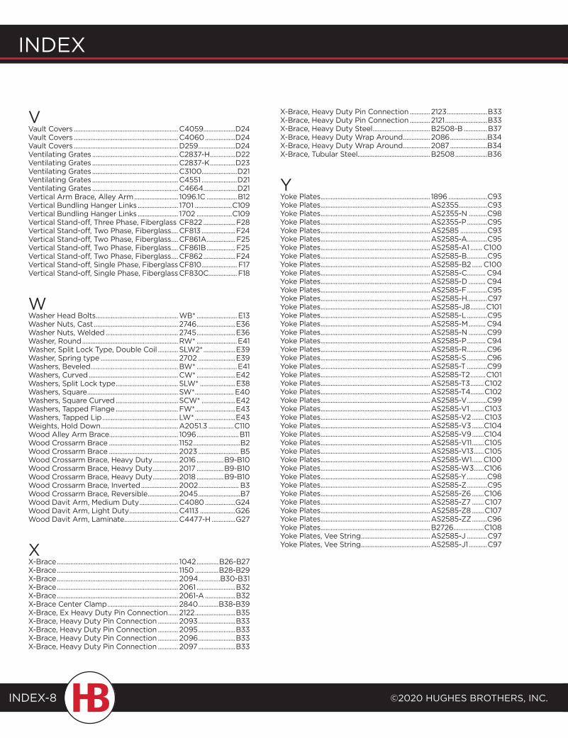
Index
©2020 HugHes BrotHers, Inc.INDEX-8
VVault Covers ..............................................................C4059...................D24Vault Covers ..............................................................C4060 ..................D24Vault Covers ..............................................................D259 ......................D24Ventilating Grates ...................................................C2837-H ...............D22Ventilating Grates ...................................................C2837-K ...............D23Ventilating Grates ...................................................C3100 .....................D21Ventilating Grates ...................................................C4551 .....................D21Ventilating Grates ...................................................C4664 ....................D21Vertical Arm Brace, Alley Arm .......................... 1096.1C ..................B12Vertical Bundling Hanger Links ........................ 1701 ......................C109Vertical Bundling Hanger Links ........................ 1702 .....................C109Vertical Stand-off, Three Phase, Fiberglass CF822 ...................F28Vertical Stand-off, Two Phase, Fiberglass ....CF813 ....................F24Vertical Stand-off, Two Phase, Fiberglass ....CF861A ................. F25Vertical Stand-off, Two Phase, Fiberglass ....CF861B ................. F25Vertical Stand-off, Two Phase, Fiberglass ....CF862 ...................F24Vertical Stand-off, Single Phase, Fiberglass CF810 ..................... F17Vertical Stand-off, Single Phase, Fiberglass CF830C.................F18
WWasher Head Bolts.................................................WB* ........................ E13Washer Nuts, Cast .................................................. 2746 .......................E36Washer Nuts, Welded ........................................... 2745 .......................E36Washer, Round .........................................................RW* ........................E41Washer, Split Lock Type, Double Coil ............ SLW2* ...................E39Washer, Spring type .............................................. 2702 ......................E39Washers, Beveled ....................................................BW* ........................E41Washers, Curved .....................................................CW* .......................E42Washers, Split Lock type ..................................... SLW* .....................E38Washers, Square ...................................................... SW* ....................... E40Washers, Square Curved ..................................... SCW* ....................E42Washers, Tapped Flange .....................................FW* ........................E43Washers, Tapped Lip ............................................. LW* ........................E43Weights, Hold Down ..............................................A2051.3 ...............C110Wood Alley Arm Brace......................................... 1096 .........................B11Wood Crossarm Brace ......................................... 1152 ............................B2Wood Crossarm Brace ......................................... 2023 ........................ B5Wood Crossarm Brace, Heavy Duty ............... 2016 ................B9-B10Wood Crossarm Brace, Heavy Duty ............... 2017 ................B9-B10Wood Crossarm Brace, Heavy Duty ............... 2018 ................B9-B10Wood Crossarm Brace, Inverted ...................... 2002 ........................ B3Wood Crossarm Brace, Reversible .................. 2045 .........................B7Wood Davit Arm, Medium Duty .......................C4080 ..................G24Wood Davit Arm, Light Duty .............................C4113 .....................G26Wood Davit Arm, Laminate ................................C4477-H ..............G27
XX-Brace ........................................................................ 1042 .............B26-B27X-Brace ........................................................................ 1150 ..............B28-B29X-Brace ........................................................................ 2094 .............B30-B31X-Brace ........................................................................ 2061 .......................B32X-Brace ........................................................................ 2061-A ..................B32X-Brace Center Clamp .......................................... 2840 ............B38-B39X-Brace, Ex Heavy Duty Pin Connection ...... 2122 ........................B35X-Brace, Heavy Duty Pin Connection ............ 2093 ......................B33X-Brace, Heavy Duty Pin Connection ............ 2095 ......................B33X-Brace, Heavy Duty Pin Connection ............ 2096 ......................B33X-Brace, Heavy Duty Pin Connection ............ 2097 ......................B33
X-Brace, Heavy Duty Pin Connection ............ 2123 ........................B33X-Brace, Heavy Duty Pin Connection ............ 2121 .........................B33X-Brace, Heavy Duty Steel ..................................B2508-B ..............B37X-Brace, Heavy Duty Wrap Around ................ 2086 ......................B34X-Brace, Heavy Duty Wrap Around ................ 2087 ......................B34X-Brace, Tubular Steel...........................................B2508 ...................B36
YYoke Plates ................................................................. 1896 .......................C93Yoke Plates .................................................................AS2355 .................C93Yoke Plates .................................................................AS2355-N ...........C98Yoke Plates .................................................................AS2355-P ............C95Yoke Plates .................................................................AS2585 ................C93Yoke Plates .................................................................AS2585-A ............C95Yoke Plates .................................................................AS2585-A1 ....... C100Yoke Plates .................................................................AS2585-B ............C95Yoke Plates .................................................................AS2585-B2 ...... C100Yoke Plates .................................................................AS2585-C ........... C94Yoke Plates .................................................................AS2585-D .......... C94Yoke Plates .................................................................AS2585-F ............C95Yoke Plates .................................................................AS2585-H............C97Yoke Plates .................................................................AS2585-J8 .........C101Yoke Plates .................................................................AS2585-L ............C95Yoke Plates .................................................................AS2585-M .......... C94Yoke Plates .................................................................AS2585-N ...........C99Yoke Plates .................................................................AS2585-P ........... C94Yoke Plates .................................................................AS2585-R ............C96Yoke Plates .................................................................AS2585-S ............C96Yoke Plates .................................................................AS2585-T ............C99Yoke Plates .................................................................AS2585-T2 .........C101Yoke Plates .................................................................AS2585-T3 ........C102Yoke Plates .................................................................AS2585-T4........C102Yoke Plates .................................................................AS2585-V ............C99Yoke Plates .................................................................AS2585-V1 ........C103Yoke Plates .................................................................AS2585-V2 .......C103Yoke Plates .................................................................AS2585-V3 .......C104Yoke Plates .................................................................AS2585-V9 .......C104Yoke Plates .................................................................AS2585-V11 .......C105Yoke Plates .................................................................AS2585-V13 ......C105Yoke Plates .................................................................AS2585-W1 ...... C100Yoke Plates .................................................................AS2585-W3 ......C106Yoke Plates .................................................................AS2585-Y ............C98Yoke Plates .................................................................AS2585-Z ............C95Yoke Plates .................................................................AS2585-Z6 .......C106Yoke Plates .................................................................AS2585-Z7 .......C107Yoke Plates .................................................................AS2585-Z8 .......C107Yoke Plates .................................................................AS2585-ZZ .........C96Yoke Plates .................................................................B2726 ..................C108Yoke Plates, Vee String .........................................AS2585-J ............C97Yoke Plates, Vee String .........................................AS2585-J1 ...........C97
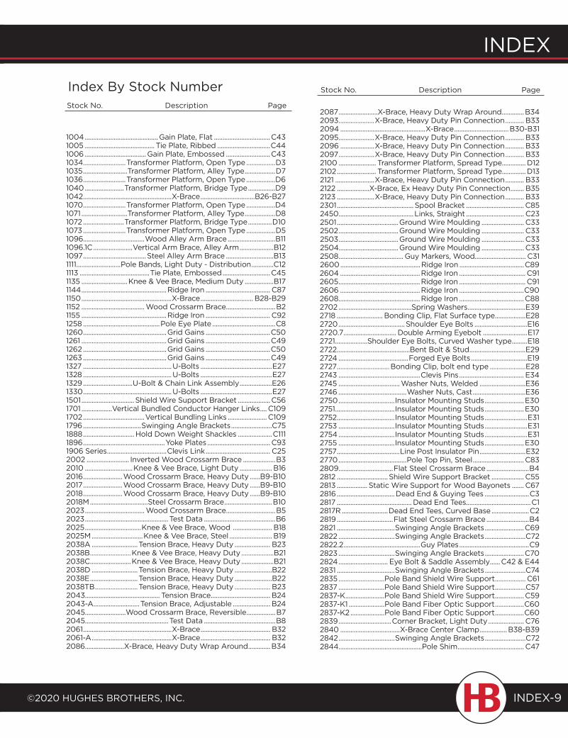
index
©2020 HugHes BrotHers, inc.
index
INDEX-9
1004 ...........................................Gain Plate, Flat .................................C431005 ......................................... Tie Plate, Ribbed ...............................C441006 .................................... Gain Plate, Embossed ..........................C431034 .........................Transformer Platform, Open Type .................D31035 ..........................Transformer Platform, Alley Type ..................D71036 .........................Transformer Platform, Open Type .................D61040 .......................Transformer Platform, Bridge Type ................D91042 ....................................................X-Brace ................................B26-B271070 .........................Transformer Platform, Open Type .................D41071 ...........................Transformer Platform, Alley Type ..................D81072 ........................Transformer Platform, Bridge Type ..............D101073 .........................Transformer Platform, Open Type .................D51096....................................Wood Alley Arm Brace ............................B111096.1C .......................Vertical Arm Brace, Alley Arm ....................B121097 .....................................Steel Alley Arm Brace ............................B131111 ..........................Pole Bands, Light Duty - Distribution .............C121113 .........................................Tie Plate, Embossed ............................C451135 ...........................Knee & Vee Brace, Medium Duty .................B171144 ..................................................Ridge Iron ...................................... C871150 .....................................................X-Brace ............................... B28-B291152 ..................................... Wood Crossarm Brace .............................B21155 ..................................................Ridge Iron ...................................... C921258 .............................................Pole Eye Plate .....................................C81260 .................................................Grid Gains ......................................C501261 ..................................................Grid Gains ......................................C491262 .................................................Grid Gains ......................................C501263 .................................................Grid Gains ......................................C491327 ....................................................U-Bolts ..........................................E271328 ....................................................U-Bolts ..........................................E271329 .............................U-Bolt & Chain Link Assembly ...................E261330 ....................................................U-Bolts ..........................................E271501 ............................... Shield Wire Support Bracket ...................C561701 ..................Vertical Bundled Conductor Hanger Links .... C1091702 ....................................Vertical Bundling Links ....................... C1091796 ..................................Swinging Angle Brackets ........................C751888 .............................. Hold Down Weight Shackles ....................C1111896 ................................................Yoke Plates .....................................C931906 Series ...................................Clevis Link ...................................... C252002 ......................... Inverted Wood Crossarm Brace ...................B32010 ............................Knee & Vee Brace, Light Duty ................... B162016 .......................Wood Crossarm Brace, Heavy Duty ......B9-B102017 .......................Wood Crossarm Brace, Heavy Duty ......B9-B102018 .......................Wood Crossarm Brace, Heavy Duty ......B9-B102018M ..................................Steel Crossarm Brace ............................B102023 ................................... Wood Crossarm Brace .............................B52023 .................................................Test Data ..........................................B62025 .................................Knee & Vee Brace, Wood ....................... B182025M ..............................Knee & Vee Brace, Steel ......................... B192038A ...........................Tension Brace, Heavy Duty ..................... B232038B ........................Knee & Vee Brace, Heavy Duty ...................B212038C ........................Knee & Vee Brace, Heavy Duty ...................B212038D ...........................Tension Brace, Heavy Duty ......................B222038E ............................Tension Brace, Heavy Duty ......................B222038TB .........................Tension Brace, Heavy Duty ..................... B232043............................................ Tension Brace ................................... B242043-A ...........................Tension Brace, Adjustable ...................... B242045........................Wood Crossarm Brace, Reversible .................B72045.................................................Test Data ..........................................B82061 ....................................................X-Brace ......................................... B322061-A ...............................................X-Brace ......................................... B322086.......................X-Brace, Heavy Duty Wrap Around .............B34
2087 .......................X-Brace, Heavy Duty Wrap Around .............B342093 .....................X-Brace, Heavy Duty Pin Connection ........... B332094 ..................................................X-Brace ................................B30-B312095 .....................X-Brace, Heavy Duty Pin Connection ........... B332096 ....................X-Brace, Heavy Duty Pin Connection ........... B332097 .....................X-Brace, Heavy Duty Pin Connection ........... B332100 ...................... Transformer Platform, Spread Type.............. D122102 ....................... Transformer Platform, Spread Type.............. D132121 .......................X-Brace, Heavy Duty Pin Connection ........... B332122 ...................X-Brace, Ex Heavy Duty Pin Connection ........ B352123 ......................X-Brace, Heavy Duty Pin Connection ........... B332301 ............................................. Spool Bracket .................................. C852450 ............................................Links, Straight .................................. C232501 ....................................Ground Wire Moulding ......................... C332502 ...................................Ground Wire Moulding ......................... C332503 ...................................Ground Wire Moulding ......................... C332504...................................Ground Wire Moulding ......................... C332508 ...................................... Guy Markers, Wood.............................. C312600 ...............................................Ridge Iron ......................................C892604 ...............................................Ridge Iron ....................................... C912605 ................................................Ridge Iron ....................................... C912606 ...............................................Ridge Iron ......................................C902608................................................Ridge Iron ......................................C882702 ...........................................Spring Washers ..................................E392718 ........................... Bonding Clip, Flat Surface type ..................E282720 .......................................Shoulder Eye Bolts ...............................E162720.7 ............................... Double Arming Eyebolt ..........................E172721 ...................Shoulder Eye Bolts, Curved Washer type .........E182722...........................................Bent Bolt & Stud .................................E292724 .........................................Forged Eye Bolts .................................E192727 ...............................Bonding Clip, bolt end type .....................E282743 ................................................Clevis Pins ...................................... E342745 .................................... Washer Nuts, Welded ...........................E362746 ........................................Washer Nuts, Cast ...............................E362750 .................................Insulator Mounting Studs .......................E302751 ...................................Insulator Mounting Studs .......................E302752 ..................................Insulator Mounting Studs .........................E312753 .................................Insulator Mounting Studs .........................E312754 .................................Insulator Mounting Studs .........................E312755 .................................Insulator Mounting Studs .......................E302757 .....................................Line Post Insulator Pin ...........................E322770 ........................................Pole Top Pin, Steel .............................. C832809................................Flat Steel Crossarm Brace .........................B42812 .............................. Shield Wire Support Bracket ................... C552813 .................. Static Wire Support for Wood Bayonets ....... C672816 ..................................Dead End & Guying Tees ..........................C32817 ............................................ Dead End Tees......................................C12817R ...........................Dead End Tees, Curved Base ......................C22819 .................................Flat Steel Crossarm Brace .........................B42821 ..................................Swinging Angle Brackets .......................C692822 .................................Swinging Angle Brackets ........................C722822.2 .............................................Guy Plates .........................................C92823 .................................Swinging Angle Brackets .......................C702824 ............................. Eye Bolt & Saddle Assembly ......C42 & E442831 ..................................Swinging Angle Brackets ........................C742835 ...........................Pole Band Shield Wire Support .................. C612837 ...........................Pole Band Shield Wire Support ..................C572837-K .......................Pole Band Shield Wire Support .................C592837-K1 .....................Pole Band Fiber Optic Support .................C602837-K2 ....................Pole Band Fiber Optic Support .................C602839 ...............................Corner Bracket, Light Duty ..................... C762840 ...................................X-Brace Center Clamp ................ B38-B392842 .................................Swinging Angle Brackets ........................C722844 .................................................Pole Shim ....................................... C47
Index By Stock NumberStock No. Description Page
Stock No. Description Page
Index
©2020 HugHes BrotHers, Inc.INDEX-10
2845 ................................. Pole Top Anti-Split Band .......................C202846 .................................Swinging Angle Brackets .........................C712848 .................................Swinging Angle Brackets ........................C732852 ...........................Pole Band Shield Wire Support .................. C612855 ............................. Shield Wire Support Bracket ...................C562859 ............................. Shield Wire Support Bracket ....................C572865 ..................................................Shackles ........................................ E462866 .........................................Twisted Shackles ............................... E462890 ........................ 2890 Ordering & Strength Tables ................A182890 ...........................Buckarm vs. Hughes Dead-end ..................A152890 ...................................Double Arm Dead-end ..........................A162890-* G1 ......................... 2890/2892 guying kits .........................A202890-* G2 ........................ 2890/2892 guying kits .........................A202890-* G2A ..................... 2890/2892 guying kits .........................A202891 ......................... Double Arm Dead-end (H-frame) ...............A192892 .........................2892 Ordering & Strength Tables ................A182892 ...................................Double Arm Dead-end .......................... A172894 ............................Narrow Profile Dead-end Arm ..................A242894 ............................2894 Dimensions & Strengths ..................A253002 ................................... Push Brace Assembly........................... C293016 ................................................ Pole Guard...................................... C353018 ................................................ Pole Guard...................................... C353020 ........................................... Cluster Mount ...................................D143021 ............................................. Cluster Mount ................................... D153022 ...........................Transformer Mounting Bracket ..................D163025 ...........................Transformer Mounting Bracket .................. D173100 .....................Pole Bands, Light Duty - Distribution .............C123102 ......................Pole Bands, Light Duty - Distribution .............C123103 .................................Pole Bands, Medium Duty ....................... C133105 .................................Pole Bands, Medium Duty .......................C143107 ...................................Pole Bands, Heavy Duty ......................... C153108 ...................................Pole Bands, Heavy Duty ......................... C163112 ....................................Pole Bands, Heavy Duty ..........................C173150 ......................................... Links, Connecting .............................. C223151 .......................................... Links, Connecting .............................. C223152 ......................................... Links, Connecting .............................. C223153 ......................................... Links, Connecting .............................. C223154 ......................................... Links, Connecting .............................. C223155 ......................................... Links, Connecting .............................. C223157 ......................................... Links, Connecting .............................. C223159 ............................................. Links, Twisted................................... C243160 ......................................... Links, Connecting .............................. C223165 .............................................Links, Straight .................................. C233166 ............................................. Links, Twisted................................... C243167 ......................................... Links, Connecting .............................. C223168 ......................................... Links, Connecting .............................. C223169 ......................................... Links, Connecting .............................. C223170 ......................................... Links, Connecting .............................. C223171 ..............................................Links, Straight .................................. C233172 ......................................... Links, Connecting .............................. C223173 .............................................Links, Straight .................................. C233174 ............................................. Links, Twisted................................... C243175 .............................................Links, Straight .................................. C233176 ......................................... Links, Connecting .............................. C223184 ............................................. Links, Twisted................................... C243340 ...........................Pole Bands, Extra Heavy Duty ................... C183341 .............................Pole Bands, Extra Heavy Duty ................... C193375-A...................... Light Duty Braceless Dead-end.................A323375-B ...................... Light Duty Braceless Dead-end.................A333376 ........................Universal Dead-end, 3 or 4-phase ...............A313377 ...........................Braceless Dead-end Assembly .................A263377 ..........................3377 Dead-End Guying Options ................A293377 ..............................................3377 Testing ....................................A303377-A ......................Braceless Dead-end, 8 ft. 3-wire ................ A27
3377-A4 ...................Braceless Dead-end, 8 ft. 4-wire ................A283377-C .....................Braceless Dead-end, 10 ft. 3-wire ............... A273377-C4 ..................Braceless Dead-end, 10 ft. 4-wire ...............A283400 ........................................... Spacer Fitting ................................... C413414 ..........................Double Arm Spacers, Adjustable ..... C36-C373414-C ........................................ Spacer Fitting ..................................C403415 ............................................. Spacer Fitting ..................................C404000 ............................Steel Davit Arm, Heavy Duty ..............G2-G34010 .............................Steel Davit Arm, Heavy Duty ..............G4-G54020 .......................... Steel Davit Arm, Medium Duty ............G6-G74030 .......................... Steel Davit Arm, Medium Duty ............G8-G925011 .........................................Moulding Straps ................................C3425014 .......................... Moulding Staples, Galvanized ..................C3425021 ........................................Moulding Straps ................................C3425031 ........................................Moulding Straps ................................C3425034 ......................... Moulding Staples, Galvanized ..................C3425041 ........................................Moulding Straps ................................C3425051 ........................................Moulding Straps ................................C3425061 ........................................Moulding Straps ................................C3428082 ............................................Guy Rollers ..................................... C2328083 ............................................Guy Rollers ..................................... C2328084 ............................................Guy Rollers ..................................... C2328085 ............................................Guy Rollers ..................................... C2328086 ............................................Guy Rollers ..................................... C2328261 ................................................Guy Plate ..........................................C928262...............................................Guy Plate ..........................................C928263 ..............................................Guy Plate ..........................................C928264 ..............................................Guy Plate ..........................................C928265 ..............................................Guy Plate ..........................................C9A1609 Series ..........................Extension Links ................................. C25A1895 .................................Pole Anchor Assembly .........................C116A1977 ....................................... Pole Top Bracket ................................ C81A2051..........................Hold Down Weight Assembly ..................C110A2051.3 ................................Hold Down Weights ............................C110A2051-A .....................Hold Down Weight Assembly ..................C110A2121 .....................Cutout, Arrestor Mounting Brackets ............D33A2121-D .......................3377 cutout/arrestor bracket ...................A29A2132 ...........................Dead End Tee, Heavy Guying ......................C4A2132 ...................................Dead End Tee, Heavy ..............................C5A2132-F...............Light Angle Tee for Laminated Poles ...........C113A2132-HHH .............Shield Wire Suspension Bracket ................C64A2132-ZR ............... Static Support Tee, Curved Base ...............C63A2132-ZR1 .............. Static Support Tee, Curved Base ...............C63A2137 ...................................Grounding Platforms ...........................D20A2159 ...............................Hold Down Weight Hook ........................C111A2169 ....................Cutout, Arrestor Mounting Brackets ..D30-D35A2185 ....................Cutout, Arrestor Mounting Brackets ............D30A2185-B ...............Cutout, Arrestor Mounting Brackets ............D34A2185-C ...............Cutout, Arrestor Mounting Brackets ............D34A2273.1A ...................................Links, Straight .................................. C23A2288 ........................ Fiberglass Pole Bearing Plates ...................D41A783 ........................................Gain Fitting, Pole ...............................C46AB* ..................................A325, High Strength Bolts ...............E10-E12ANB* ............................................ Anchor Bolts ....................................E33AS1062 ............................................Guy Plate ........................................C10AS1263 ....................................... Links, Twisted................................... C24AS1459 ............................................Guy Plate ........................................C10AS2019 Series .......................... Link, Twisted .................................... C24AS2087 Series ..................Shield Wire Support ............................ C58AS2139 ...........................Double Arming Plate, RUS ......................C54AS2276 ...........................................Guy Plate ........................................C10AS2276 ........................................ Twisted Clip .....................................C10AS2277 ...............................................Clevis ...........................................E50AS2290 ........................Neutral Support/Upset Bolt ....................C86
Stock No. Description Page Stock No. Description Page
index
©2020 HugHes BrotHers, inc.
index
INDEX-11
AS2309 .................................. Steel Angle Brace ............................... B14AS2324 ................Cutout, Arrestor Mounting Brackets ..D33-D34AS2329 ..............................Steel Alley Arm Brace ............................B13AS2349 ..............................Double Arming Plates .......................... C53AS2355 .........................................Yoke Plates .....................................C93AS2355-N ....................................Yoke Plates .....................................C98AS2355-P .....................................Yoke Plates .....................................C95AS2419 ..................Dead End Angle, 3414 Application .............. C41AS2469 ...................................... Links, Twisted................................... C24AS2477 ...........................Conduit Support Bracket ...................... D40AS2477 .............................................U-Bolts ..........................................E27AS2492 ...............................Grounding Platforms ...........................D20AS2531 ..........................................Cotter Keys ..................................... E34AS2545 ........................................ Turnbuckles........................... E48-E49AS2585 .........................................Yoke Plates .....................................C93AS2585-A ....................................Yoke Plates .....................................C95AS2585-A1 ...................................Yoke Plates ...................................C100AS2585-B ....................................Yoke Plates .....................................C95AS2585-B2 ..................................Yoke Plates ...................................C100AS2585-C ....................................Yoke Plates .....................................C94AS2585-D ....................................Yoke Plates .....................................C94AS2585-F .....................................Yoke Plates .....................................C95AS2585-H ....................................Yoke Plates ..................................... C97AS2585-J ..........................Vee String Yoke Plates .......................... C97AS2585-J1 .........................Vee String Yoke Plates .......................... C97AS2585-J8 ..................................Yoke Plates .....................................C101AS2585-L .....................................Yoke Plates .....................................C95AS2585-M ....................................Yoke Plates .....................................C94AS2585-N ....................................Yoke Plates .....................................C99AS2585-P .....................................Yoke Plates .....................................C94AS2585-R ....................................Yoke Plates .....................................C96AS2585-S .....................................Yoke Plates .....................................C96AS2585-T .....................................Yoke Plates .....................................C99AS2585-T2...................................Yoke Plates .....................................C101AS2585-T3 ..................................Yoke Plates ....................................C102AS2585-T4 ..................................Yoke Plates ....................................C102AS2585-V ....................................Yoke Plates .....................................C99AS2585-V1 ...................................Yoke Plates ................................... C103AS2585-V2 ..................................Yoke Plates ................................... C103AS2585-V3 ..................................Yoke Plates ...................................C104AS2585-V9 ........................Yoke Plate Assembly .........................C104AS2585-V11 .................................Yoke Plates ................................... C105AS2585-V13 ................................Yoke Plates ................................... C105AS2585-W1 .................................Yoke Plates ...................................C100AS2585-W3 ................................Yoke Plates ................................... C106AS2585-Y .....................................Yoke Plates .....................................C98AS2585-Z .....................................Yoke Plates .....................................C95AS2585-Z6 ..................................Yoke Plates ................................... C106AS2585-Z7 ..................................Yoke Plates ....................................C107AS2585-Z8 ..................................Yoke Plates ....................................C107AS2585-ZZ ..................................Yoke Plates .....................................C96AS2613 ................................Shield Wire Bayonets ...........................C68AS2715-A ......................Gain Fitting, Welded Shelf ....................... C51AS2715-B .......................Gain Fitting, Welded Shelf ....................... C51AS2715-C.......................Gain Fitting, Welded Shelf ...................... C52AS2717-A ...............Pole Shim Adaptor for Lam Poles ..............C113AS2717-P ...................Dead End & Guying Assembly ..................C112AS2717-C ...........Light Angle Steel Plate for Lam Poles ..........C113AS2720 .................................Double Guying Tee ................................C3AS2720 E4.5 ..Static Dead End Tee, Curved Cross Tie ............C6AS2731 Series .....................Guy Wire Thimbles ..............................C27AS424 .............................................Guy Plate ........................................C10AS719 .............................45° Link & Roller Assembly ....................C-27AS452 ..............................................Guy Plate ........................................C10
AS942 ......................................... Link, Twisted .................................... C24AS942-A ...................................Links, Straight .................................. C23B**D.................................Drilled Bolts, Nut & Cotter ...................... E34B5* .................................Machine Bolts, Square Head .......................E4B6* .................................Machine Bolts, Square Head .......................E4B7* .................................Machine Bolts, Square Head .......................E4B8* .................................Machine Bolts, Square Head ....................... E5B10* ...............................Machine Bolts, Square Head ....................... E5B12* ................................Machine Bolts, Square Head ....................... E5B1612.1C-1 ..................................... Pipe Spacer .....................................C54B1612.1C-2 ...........................Double Arming Plate ...........................C54B1637 ....................................Pole Stubbing Band ............................C30B1859 ....................... Post Insulator Mounting Bracket ................ C78B1912-A ...............................Dead End Tee, Heavy .............................C4B1912-B ............................Dead End & Guying Tee ...........................C3B1963 ....................... Conduit Support Bracket, Single ............... D37B1964 ......................Conduit Support Bracket, Double .............. D37B1964 .................................................U-Bolts ..........................................E27B1965-A .............................Conduit Riser Bracket ..........................D38B1965-B .............................Conduit Riser Bracket ..........................D39B2006 ..................................... Pole Top Bracket ................................ C81B2025 ....................Post Insulator Bracket, Heavy Duty ............. C79B2046 ...........................Spacer Fitting, Heavy Duty ...................... C41B2047 ...................... Post Insulator Mounting Bracket .................C77B2173-A................................................Step .............................................E47B2218 .............................Ordering & Strength Tables ......................A18B2218-E4 ...............Steel channel Dead-end assembly ..............A35B2218-K .................Steel channel Dead-end assembly ..............A36B2218-N .................Steel channel Dead-end assembly ..............A34B2251 ....................Cutout/Arrestor Mounting Brackets ............D35B2255-A ..............Cutout, Arrestor Mounting Brackets ............. D31B2286-C ............................Guy Anchor Assembly .......................... C28B2351 .................................Crossarm Phase Fitting .........................C42B2358-C .................. B2358-C 32,000 lb. guying kits .................. A21B2358-D ..................B2358-D 42,000 lb. guying kits ................A22B2358-F ....................B2358-F 42,000 lb. guying kits .................A23B2364.1 .....................Shield Wire Support Assembly ................. C55B2379 ..................................Conduit Pipe Hanger ...........................D36B2387.1 .................Cutout, Arrestor Mounting Brackets ............D32B2498-A .......................... Steel Angle Knee Brace.........................B20B2502 ..................................Shield Wire Bayonets ...........................C65B2502-Q ......................... Raptor Perch Assembly ..........................F61B2508 .................................X-Brace, Tubular Steel .......................... B36B2508-B ........................X-Brace, Heavy Duty Steel .......................B37B2511-HB ......................................Pole Repair ......................................H14B2511-N1 ................................Pole Top Extension .............................. H12B2511-R ..................................Pole Top Extension .............................. H13B2557-BB .............Fiber Optic Splice Protective Case .............D25B2557-M ...............Fiber Optic Splice Protective Case .............D26B2557-N ...............Fiber Optic Splice Protective Case ............. D27B2557-NC ............Fiber Optic Splice Protective Case .............D28B2557-P ................Fiber Optic Splice Protective Case .............D29B2571 ..............................................Bird Guard .......................................F62B2638 ...................Ridge Iron, Post Insulator Mounting ............ C92B2676 Series .............................. Light Poles ................................ I8 & I9B2682-B ............................. Pole Band Assembly ..............................C21B2682-E ............................. Pole Band Assembly ..............................C21B2684 Series ....Tubular Steel Crossarms, Single Pole ........... A37B2684.2C ...........................Service Drop Bracket ........................... C76B2684-F ...................................Steel Alley Arm .................................A39B2684-G ........................Neutral Stand-off Bracket ...................... C85B2684-I ................Cutout, Arrestor Mounting Brackets ............D32B2684-Q ....................... Steel Dead-end assembly ......................A38B2684.2C ...........................Service Drop Bracket ........................... C76
Stock No. Description Page Stock No. Description Page
Index
©2020 HugHes BrotHers, Inc.INDEX-12
B2693-H ..........................Dead End Plate, Welded ...........................C7B2693-H8 ................................Guy Plate, Steel ....................................C7B2693-J ..................................... Dead End Tee ......................................C6B2726 ............................................Yoke Plates ................................... C108B2746.2A ...................................... Shelf Gain....................................... C52B2782-A ....................... Banded Equipment Mount.......................D19B2782-B........................ Banded Equipment Mount.......................D19BC*...............................................Carriage Bolts ....................................E15BT* ........................................Type "O" Tower Bolts ..............................E9BW* ..........................................Beveled Washers .................................E41C2561-S ..................................Reframing Trusses ................................ H11C2837-H ...................... Sidewalk Ventilating Grates ..................... D22C2837-K....................... Sidewalk Ventilating Grates .....................D23C3100 ........................... Sidewalk Ventilating Grates ...................... D21C4551 ............................ Sidewalk Ventilating Grates ...................... D21C4664 .......................... Sidewalk Ventilating Grates ...................... D21C3311 ..........................................Pole Tie Angles ................................. C62C3316 .........................................Pole Tie Angles ................................. C62C3338 ........................................Pole Tie Angles ................................. C62C3511 ..........................................Pole Tie Angles ................................. C62C4059 ...........................................Vault Cover .....................................D24C4060 ...........................................Vault Cover .....................................D24C4080 ......................Wood Davit Arm, Medium Duty ................G24C4111.5 ................................... Shield Wire Bracket.............................C59C4113 ............................Wood Davit Arm, Light Duty ...................G26C4205 ..........................................Cable Guard .................................... C32C4466 ...................Post Insulator Stand-off Arm, Steel .............G23C4466-B ....................Post Insulator Stand-off Arm ...................C80C4477-H .......................Laminate Wood Davit Arm ..................... G27C4484 ...................Distribution Underbuild Arm, Steel ............. G22C4484-C ....................... Static Support Arm, Steel ......................G20C4484-CDE ................. Static Support Arm, Steel ....................... G21C4485-V .................................. Steel Davit Arm ..................................G14C4625 ..............Steel Davit Replacement for Wood Davit .......G28C4668-A ................................. Steel Davit Arm .................................. G15C4700 ................. Reframing & Upgrade Structure Kits ..............H2C4701 ................... Reframing & Upgrade Structure Kits ..............H2C4702 .................. Reframing & Upgrade Structure Kits ..............H2C4703 .................. Reframing & Upgrade Structure Kits ..............H2C4704 ................. Reframing & Upgrade Structure Kits ..............H3C4705 .................. Reframing & Upgrade Structure Kits ..............H3C4706 ................. Reframing & Upgrade Structure Kits ..............H3C4707 .................. Reframing & Upgrade Structure Kits ..............H3C4708 .................. Reframing & Upgrade Structure Kits ..............H3C4709 ................. Reframing & Upgrade Structure Kits ..............H3C4754-A1 ..............................Reframing Trusses ................................ H11C4773.1 .........................Laminated Light Pole Series .........................I4C4773.3...........................................Pole Caps ............................................I5C4773.5A ....................Pole Side Luminary Bracket .........................I6C4773.6A ....................Pole Side Luminary Bracket .........................I6C4773.10 ..................... Pole Top Luminary Supports ........................I5C4821-A ................................. Stand-off Bracket ............................... C82CF500 ................... Fiberglass Pole Top Pin, 1-1/2" Rod .............. F10CF500A ................ Fiberglass Pole Top Pin, 1-1/2" Rod .............. F10CF520 ...........................Fiberglass Crossarm Brace ..................... F49CF533 ............................Fiberglass Crossarm Brace ..................... F49CF545 .....................Fiberglass Stand-off, Three Phase ...............F27CF547 .....................Fiberglass Stand-off, Three Phase ...............F27CF550 ..............Fiberglass Apparatus Mounting Bracket ........F40CF560 ....................Fiberglass Stand-off, Single Phase ................F14CF578 ........................Jumper Pin Bracket, Fiberglass ...................F12CF583 .................................Fiberglass Switch Rod ..........................F60CF584D .................Fiberglass Transmission Crossarm ...............F42CF584-K ................Fiberglass Transmission Crossarm .............. F43
CF584-KHD .........Fiberglass Transmission Crossarm .............. F44CF590 ..............Fiberglass Apparatus Mounting Bracket .........F39CF592 ...............Fiberglass Apparatus Mounting Bracket .........F33CF615 .........................Fiberglass Suspension Bracket ................. F20CF626 .....................Fiberglass Stand-off, Single Phase ................F14CF635 ...................Fiberglass Cable Extension Bracket .............F59CF636 .......................Fiberglass Stand-off, Two Phase .................F26CF667 ................... Fiberglass Cutout/Arrestor Bracket..............F29CF667A ............... Fiberglass Cutout/Arrestor Bracket............. F30CF668 .................. Fiberglass Cutout/Arrestor Bracket............. F30CF670 .................. Fiberglass Cutout/Arrestor Bracket...............F31CF690 .......................Fiberglass Guy Strain Insulator ....................F4CF690T ....................Fiberglass Guy Strain Insulator .................... F5CF692 ........................Fiberglass Guy Strain Insulator ..............F2,F4CF693 ........................Fiberglass Guy Strain Insulator ..............F2,F6CF694 .......................Fiberglass Guy Strain Insulator ..............F3,F7CF694TB ...................Adjustable Guying Assembly ......................F9CF695 ........................Fiberglass Guy Strain Insulator ..............F3,F8CF696 .......................Fiberglass Guy Strain Insulator ..............F3,F8CF700 ..............Fiberglass Apparatus Mounting Bracket .........F35CF753 Series ....Fiberglass Downlead Standoff Bracket . F50-F54CF753D .............Fiberglass Downlead Standoff Bracket ..........F55CF754 Series ....Fiberglass Downlead Standoff Bracket . F50-F54CF755 Series ....Fiberglass Downlead Standoff Bracket . F50-F54CF756 Series ....Fiberglass Downlead Standoff Bracket . F50-F54CF757 Series ....Fiberglass Downlead Standoff Bracket . F50-F54CF758 ...................Fiberglass Mid Span Phase Spacers .............F56CF761 ...................Fiberglass Two Phase Angle Bracket ............F23CF777 ........................Fiberglass Pole Top Pin, 2" Rod ....................F11CF784 ............... Fiberglass Stand-off for Post Insulators ..........F19CF785 ..........................Fiberglass Stand-off Bracket ....................F59CF785B .......................Fiberglass Stand-off Bracket ....................F59CF792 ................................ Jumper Pin, Fiberglass ...........................F13CF793 ................................ Jumper Pin, Fiberglass ...........................F13CF800 ..................Fiberglass Mid Span Phase Spacers .............F56CF800D...............Fiberglass Mid Span Phase Spacers .............F57CF800E ...............Fiberglass Mid Span Phase Spacers .............F57CF800GM ...........Fiberglass Mid Span Phase Spacers .............F58CF800J............Fiberglass Span Crossing Phase Spacer .........F58CF810 .....................Fiberglass Stand-off, Single Phase ................F17CF813 ........................Fiberglass Stand-off, Two Phase .................F24CF822 .....................Fiberglass Stand-off, Three Phase ...............F28CF830C .................Fiberglass Stand-off, Single Phase ................F18CF859 ........................Fiberglass Pole Top Pin, 2" Rod ....................F11CF861A ....................Fiberglass Stand-off, Two Phase .................F25CF861B .....................Fiberglass Stand-off, Two Phase .................F25CF862 .......................Fiberglass Stand-off, Two Phase .................F24CF863-C ................Cantilever Arms for Lattice Tower ...............F47CF868B ....Fiberglass Single Phase Cutout/Arrestor Bracket .F34CF879-C3 .............Cantilever Arms for Lattice Tower .............. F48CF879-D ................Cantilever Arms for Lattice Tower .............. F46CF885B-1...............Fiberglass Transmission Crossarm .............. F45CF886.....................Fiberglass Stand-off, Single Phase ................F15CF888 .....................Fiberglass Stand-off, Single Phase ................F16CF892 ...............Fiberglass Apparatus Mounting Bracket .........F36CF893B ............Fiberglass Apparatus Mounting Bracket .........F37CF898........................Fiberglass Suspension Bracket ...................F21CF899 .......................Fiberglass Suspension Bracket ..................F22CF899CPL ...............Fiberglass Suspension Bracket ..................F22CF901 ..................Fiberglass Two Phase Angle Bracket ............F23CF910 ................... Fiberglass Cutout/Arrestor Bracket..............F32CF914..................................Fiberglass Switch Rod ..........................F60CF921 ..........................Fiberglass Apparatus Bracket ...................F38CF999TT ....... Guying Assembly, Fiberglass 60,000 lbs. ..........F9
Stock No. Description Page Stock No. Description Page
index
©2020 HugHes BrotHers, inc.
index
INDEX-13
CW* ...........................................Curved Washers ................................ E42D259 ..............................................Vault Cover .....................................D24EN100 .........................................Oval Eye Nuts ...................................E37EN50 ...........................................Oval Eye Nuts ...................................E37EN60...........................................Oval Eye Nuts ...................................E37EN70 ...........................................Oval Eye Nuts ...................................E37EN80 ...........................................Oval Eye Nuts ...................................E37FDA* ......................Foundation Reinforcement Systems ............C114FDB*......................Foundation Reinforcement Systems ............C114FDC* .....................Foundation Reinforcement Systems ............C114FDD* .....................Foundation Reinforcement Systems ............C114FTA* .......................Foundation Reinforcement Systems ............C115FTB* ......................Foundation Reinforcement Systems ............C115FTC* ......................Foundation Reinforcement Systems ............C115FW* ...................................Tapped Flange Washers ........................ E43GWB51-1/2 ...................Ground Wire Bonding Bolt ......................E28B* ..................................................Bolts, Machine ..............................E3-E5HB* ............................................ Bolts, Hex Head.............................E6-E8HN* ................................................... Hex Nuts .........................................E35LS* .................................... Gimlet Point Lag Screws........................ E45LW* ........................................Tapped Lip Washers ............................ E43MF* ................................................... Locknuts.........................................E38MFH* ............................................Hex Locknuts ....................................E38N* ...................................................Square Nuts .....................................E35PL* .................................................PAL Locknuts ....................................E39RW* ........................................... Round Washers ...................................E41SCW* ................................Square Curved Washers ........................ E42SLW* ...........................Split Lock Washers, single coil ...................E38SLW2*....................... Split Lock Washers, double coil .................E39SW* ...........................................Square Washers ................................E40TG-92-1 ........................Type 1 Guy Link (REA Type 1) ................... C26TG-92-2 .................... Type 2 Guy Link (REA Type 2) .................. C26TR* .......................Double Arming Bolts, Threaded Rods .......... E20TR* ............................................Double End Rods ......................E23-E24TR* ..........................................Full Threaded Rods .....................E21-E22WB* ........................................Washer Head Bolts ...............................E15
Stock No. Description Page


