Embed Size (px)
Citation preview
PRODUCT CATALOG
PRO
DU
CT C
ATA
LOG
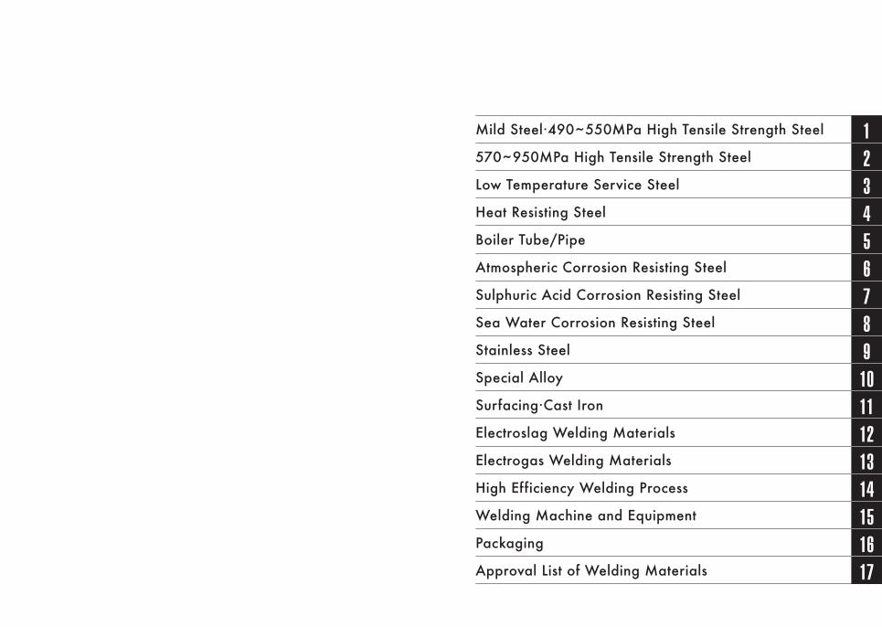
Mild Steel·490~550MPa High Tensile Strength Steel 1570~950MPa High Tensile Strength Steel 2Low Temperature Service Steel 3Heat Resisting Steel 4Boiler Tube/Pipe 5Atmospheric Corrosion Resisting Steel 6Sulphuric Acid Corrosion Resisting Steel 7Sea Water Corrosion Resisting Steel 8Stainless Steel 9Special Alloy 10Surfacing·Cast Iron 11Electroslag Welding Materials 12Electrogas Welding Materials 13High Efficiency Welding Process 14Welding Machine and Equipment 15Packaging 16Approval List of Welding Materials 17
PRODUCT CATALOG
■ Please note the following points in the use of this catalog. 1. Classification numbers either by JIS (Japanese Industrial Standards) or AWS
(American Welding Society) are given to the products except for some types which are classified into neither of them. There are three different ways in which the classification numbers are given depending on the extent that the products meet the classifications. (1) The classification number without an mark;
(i.e. JIS Z 3211 E4319) It means that the product meets the classification requirements and that JIS Mark is usable on the product based on the JIS mark system.
(2) The classification number with the mark “ ☆ ”;(i.e. ☆ JIS Z 3214 E49J03-NCCAU, ☆ AWS 5.1 E7016) It means that the product meets the classification requirements but that the JIS Mark system and AWS are not authentication to the classification.
(3) The classification number with the mark“ ★ ”; (i.e. ★ AWS A5.1 E7016) It means that the product meets most of the classification requirements. However, there is for example a partial deviation in chemical composition.
2. The symbols of welding consumables are determined as following from the initial letter of the welding process.(1) FCAW: Flux Cored Arc Welding (flux cored wires)(2) SMAW: Shielded Metal Arc Welding (covered arc welding electrodes)(3) SAW: Submerged Arc Welding (fluxes, wires, cut wires and backing materials)(4) GMAW: Gas Metal Arc Welding (solid wires)(5) GTAW: Gas Tungsten Arc Welding (rods and solid wires)(6) ESW: Electroslag Welding (solid wires and fluxes)(7) EGW: Electrogas Welding (flux core wires and backing materials)
3. The definition of the “Weld Metal” described in this catalog is a weld metal which has not been diluted by base metal except in the case of SAW.
4. Besides the products listed in this catalog, we will make every effort to manufacture welding consumables and/or machinery tailored to customers' requirements.
5. The status of our ship approvals may change from time to time. Your kind confirmation for up-to-date information will be appreciated.
6. The specifications of the products included in this catalog are subject to change without prior notice.
■ “WELDREAM” is a trademark of NIPPON STEEL WELDING & ENGINEERING CO., LTD.■ WEL-TEN is a trademark of NIPPON STEEL CORPORATION.■ S-TEN is a trademark of NIPPON STEEL CORPORATION.■ MARILOY is a trademark of NIPPON STEEL CORPORATION.■ NSSC is a trademark of NIPPON STEEL STAINLESS STEEL CORPORATION.■ INCONEL is a trademark of HUNTINGTON ALLOYS CORPORATION.■ INCO-WELD is a trademark of HUNTINGTON ALLOYS CORPORATION.■ INCOLOY is a trademark of HUNTINGTON ALLOYS CORPORATION.■ HCM2S is a trademark of NIPPON STEEL CORPORATION.■ SUPER304H is a trademark of NIPPON STEEL CORPORATION.■ NSSC 2120 is a trademark of NIPPON STEEL STAINLESS STEEL CORPORATION.■ NITTETSU is a registered trademark or trademark of NIPPON STEEL CORPORATION,
and our company is licensed.■ YAWATA is a registered trademark or trademark of NIPPON STEEL CORPORATION,
and our company is licensed.The 11th edition Sep. 2021
INDEX
NITTETSU is a registered trademark or trademark of NIPPON STEEL CORPORATION, and our company is licensed.
4 5
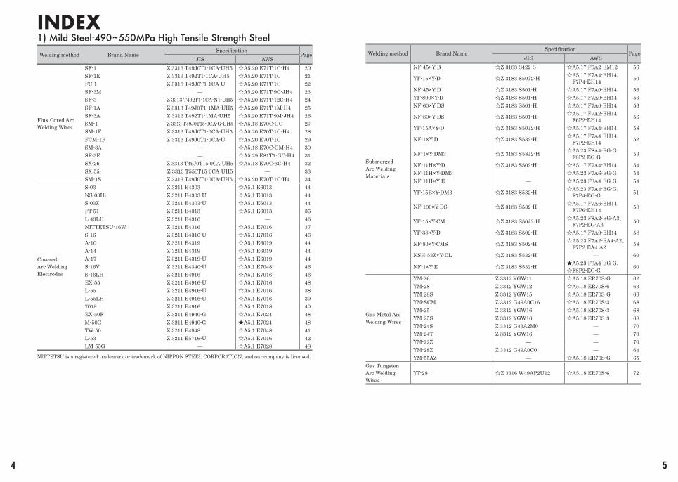
1) Mild Steel·490~550MPa High Tensile Strength Steel
Welding method Brand NameSpecification
PageJIS AWS
Flux Cored Arc Welding Wires
SF-1 Z 3313 T49J0T1-1CA-UH5 ☆A5.20 E71T-1C-H4 20SF-1E Z 3313 T492T1-1CA-UH5 ☆A5.20 E71T-1C 21FC-1 Z 3313 T49J0T1-1CA-U ☆A5.20 E71T-1C 22SF-3M — ☆A5.20 E71T-9C-JH4 23SF-3 Z 3313 T492T1-1CA-N1-UH5 ☆A5.20 E71T-12C-H4 24SF-1A Z 3313 T49J0T1-1MA-UH5 ☆A5.20 E71T-1M-H4 25SF-3A Z 3313 T492T1-1MA-UH5 ☆A5.20 E71T-9M-JH4 26SM-1 Z 3313 T49J0T15-0CA-G-UH5 ☆A5.18 E70C-GC 27SM-1F Z 3313 T49J0T1-0CA-UH5 ☆A5.20 E70T-1C-H4 28FCM-1F Z 3313 T49J0T1-0CA-U ☆A5.20 E70T-1C 29SM-3A — ☆A5.18 E70C-GM-H4 30SF-3E — ☆A5.29 E81T1-GC-H4 31SX-26 Z 3313 T49J0T15-0CA-UH5 ☆A5.18 E70C-3C-H4 32SX-55 Z 3313 T550T15-0CA-UH5 — 33SM-1S Z 3313 T49J0T1-0CA-UH5 ☆A5.20 E70T-1C-H4 34
Covered Arc Welding Electrodes
S-03 Z 3211 E4303 ☆A5.1 E6013 44NS-03Hi Z 3211 E4303-U ☆A5.1 E6013 44S-03Z Z 3211 E4303-U ☆A5.1 E6013 44FT-51 Z 3211 E4313 ☆A5.1 E6013 36L-43LH Z 3211 E4316 — 46NITTETSU-16W Z 3211 E4316 ☆A5.1 E7016 37S-16 Z 3211 E4316-U ☆A5.1 E7016 46A-10 Z 3211 E4319 ☆A5.1 E6019 44A-14 Z 3211 E4319 ☆A5.1 E6019 44A-17 Z 3211 E4319-U ☆A5.1 E6019 44S-16V Z 3211 E4340-U ☆A5.1 E7048 46S-16LH Z 3211 E4916 ☆A5.1 E7016 46EX-55 Z 3211 E4916-U ☆A5.1 E7016 48L-55 Z 3211 E4916-U ☆A5.1 E7016 38L-55LH Z 3211 E4916-U ☆A5.1 E7016 397018 Z 3211 E4916 ☆A5.1 E7018 40EX-50F Z 3211 E4940-G ☆A5.1 E7024 48M-50G Z 3211 E4940-G ★A5.1 E7024 48TW-50 Z 3211 E4948 ☆A5.1 E7048 41L-53 Z 3211 E5716-U ☆A5.1 E7016 42LM-55G — ☆A5.1 E7028 48
Welding method Brand NameSpecification
PageJIS AWS
Submerged Arc Welding Materials
NF-45×Y-B ☆Z 3183 S422-S ☆A5.17 F6A2-EM12 56
YF-15×Y-D ☆Z 3183 S50J2-H ☆A5.17 F7A4-EH14、F7P4-EH14 50
NF-45×Y-D ☆Z 3183 S501-H ☆A5.17 F7A0-EH14 56YF-800×Y-D ☆Z 3183 S501-H ☆A5.17 F7A0-EH14 56NF-60×Y-DS ☆Z 3183 S501-H ☆A5.17 F7A0-EH14 56
NF-80×Y-DS ☆Z 3183 S501-H ☆A5.17 F7A2-EH14、F6P2-EH14 56
YF-15A×Y-D ☆Z 3183 S50J2-H ☆A5.17 F7A4-EH14 58
NF-1×Y-D ☆Z 3183 S532-H ☆A5.17 F7A4-EH14、F7P2-EH14 52
NF-1×Y-DM3 ☆Z 3183 S58J2-H ☆A5.23 F8A4-EG-G、F8P2-EG-G 53
NF-11H×Y-D ☆Z 3183 S502-H ☆A5.17 F7A4-EH14 54NF-11H×Y-DM3 — ☆A5.23 F7A6-EG-G 54NF-11H×Y-E — ☆A5.23 F8A4-EG-G 54
YF-15B×Y-DM3 ☆Z 3183 S532-H ☆A5.23 F7A4-EG-G、F7P4-EG-G 51
NF-100×Y-DS ☆Z 3183 S532-H ☆A5.17 F7A6-EH14、F7P6-EH14 58
YF-15×Y-CM ☆Z 3183 S50J2-H ☆A5.23 F8A2-EG-A3、F7P2-EG-A3 50
YF-38×Y-D ☆Z 3183 S502-H ☆A5.17 F7A0-EH14 58
NF-80×Y-CMS ☆Z 3183 S502-H ☆A5.23 F7A2-EA4-A2、F7P2-EA4-A2 58
NSH-53Z×Y-DL ☆Z 3183 S532-H — 60
NF-1×Y-E ☆Z 3183 S532-H ★A5.23 F8A4-EG-G、☆F8P2-EG-G 60
Gas Metal Arc Welding Wires
YM-26 Z 3312 YGW11 ☆A5.18 ER70S-G 62YM-28 Z 3312 YGW12 ☆A5.18 ER70S-6 63YM-28S Z 3312 YGW15 ☆A5.18 ER70S-G 66YM-SCM Z 3312 G49A0C16 ☆A5.18 ER70S-3 68YM-25 Z 3312 YGW16 ☆A5.18 ER70S-3 68YM-25S Z 3312 YGW16 ☆A5.18 ER70S-3 68YM-24S Z 3312 G43A2M0 — 70YM-24T Z 3312 YGW16 — 70YM-22Z — — 70YM-28Z Z 3312 G49A0C0 — 64YM-55AZ — ☆A5.18 ER70S-G 65
Gas Tungsten Arc Welding Wires
YT-28 ☆Z 3316 W49AP2U12 ☆A5.18 ER70S-6 72
6 7
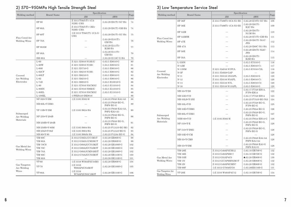
2) 570~950MPa High Tensile Strength Steel
Welding method Brand NameSpecification
PageJIS AWS
Flux Cored Arc Welding Wires
SF-60 Z 3313 T59J1T1-1CA-N2M1-UH5 ☆A5.29 E81T1-GC-H4 74
SF-60A Z 3313 T59J1T1-1MA-N2M1-UH5 ☆A5.29 E81T1-GM-H4 74
SF-60T ☆Z 3313 T59J1T1-1CA-G-UH5 ☆A5.29 E81T1-GC-H4 75
SF-70A — ☆A5.29 E101T1-GM-H4 76
SF-80AM — ☆A5.29 E111T1-K3M-H4 77
SF-80A ☆A5.29 E111T1-GM-H4 78
SM-80A — ☆A5.28 E110C-G-H4 79
Covered Arc Welding Electrodes
L-60 Z 3211 E5916-N1M1U ☆A5.5 E8016-G 80L-60W Z 3211 E5916-N1M1 ☆A5.5 E8016-G 81L-60S Z 3211 E5716-G ☆A5.5 E8016-G 86L-62CF Z 3211 E6216-N1M1 ☆A5.5 E9016-G 82L-60LT Z 3211 E6216-G ☆A5.5 E9016-G 83L-62 Z 3211 E6216-G ☆A5.5 E9016-G 86L-74S Z 3211 E6916-G ☆A5.5 E10016-G 86L-80 Z 3211 E7816-N5CM3U ☆A5.5 E11016-G 84L-80SN Z 3211 E7816-N9M3U ☆A5.5 E11016-G 85L-80EL Z 3211 E7816-N5CM3U ☆A5.5 E11016-G 86L-100EL ☆WES410-DK9016 — 86
Submerged Arc Welding Materials
NF-820×Y-DM ☆Z 3183 S582-H ☆A5.23 F8A0-EA3-A3 88
NB-60L×Y-DM3 — ☆A5.23 F8A8-EG-G、F8P8-EG-G 89
YF-15B×Y-DM ☆Z 3183 S624-H4 ☆A5.23 F9A6-EA3-A3、F8P2-EA3-A3 90
NF-250×Y-204B — ☆A5.23 F9A6-EG-G、F8P6-EG-G 96
NB-250H×Y-204B — ☆A5.23 F9A8-EG-G、F9P8-EG-G 91
NB-250H×Y-80M ☆Z 3183 S804-H4 ☆A5.23 F11A10-EG-M3 92NB-250J×Y-80J ☆Z 3183 S804-H4 ☆A5.23 F11A10-EG-G 93NB-80×Y-80 ☆Z 3183 S80J4-H4 ☆A5.23 F12A4-EG-G 94
Gas Metal Arc Welding Wires
YM-60C Z 3312 G59JA1UC3M1T ☆A5.28 ER80S-G 98YM-60A Z 3312 G59JA1UM3M1T ☆A5.28 ER80S-G 99YM-70CS Z 3312 G69A2UCN1M2T ☆A5.28 ER100S-G 102YM-70C Z 3312 G69A2UCN4M3T ☆A5.28 ER100S-G 102YM-70A Z 3312 G69A3UMN4M3T ☆A5.28 ER100S-G 102YM-80C Z 3312 G78A2UCN5M3T ☆A5.28 ER110S-G 100YM-80A — ☆A5.28 ER110S-G 101
Gas Tungsten Arc Welding Wires
YT-60 ☆Z 3316 W59AP2U34M3 ☆A5.28 ER80S-G 104
YT-70 ☆Z 3316 W69AP2UN4M3T ☆A5.28 ER100S-G 105
YT-80A ☆Z 3316 W78AP2UN5C1M3T ☆A5.28 ER110S-G 106
3) Low Temperature Service Steel
Welding method Brand NameSpecification
PageJIS AWS
Flux Cored Arc Welding Wires
SF-36F Z 3313 T496T1-0CA-N1-H5 ☆A5.29 E70T1-GC-H4 108
SF-36E Z 3313 T496T1-1CA-N3-H5 ☆A5.29 E81T1-K2C-H4 109
SF-3AM — ☆A5.29 E81T1-Ni1M-H4 110
SF-3AMSR — ☆A5.29 E71T1-GM-H4 111
SF-47E — ☆A5.29 E81T1-Ni1C-JH4 112
SM-47A — ☆A5.28 E80C-Ni1-H4 113
SF-50E — ☆A5.29 E91T1-Ni2C-JH4 114
SF-50A — ☆A5.29 E91T1-K2M-H4 115
Covered Arc Welding Electrodes
L-55SN — ☆A5.5 E7016-G 116N-12M — ☆A5.5 E8016-C1 117N-13NM Z 3211 E4916-N7PUL ☆A5.5 E7016-C2L 118N-5F Z 3311 E4928-GAP — 120N-11 Z 3311 E5516-3N3APL ☆A5.5 E8016-G 120N-12 Z 3311 E5516-N5APL ☆A5.5 E8016-C1 120N-13 Z 3311 E5516-N7L ☆A5.5 E8016-C2 120N-16 Z 3311 E5516-N13APL ☆A5.5 E8016-G 120
Submerged Arc Welding Materials
NB-55×Y-DS — ☆A5.17 F7A8-EH14、F7P8-EH14 122
NB-55E×Y-D — ☆A5.17 F7A8-EH14 123NB-55LS×Y-3NI — ☆A5.23 F7A10-EG-Ni3 124
NB-55L×Y-D — ☆A5.23 F7A8-EG-G、F7P8-EG-G 125
NB-55E×Y-DM3 — ☆A5.23 F8A4-EG-G 126
NB-60L×Y-DM3 — ☆A5.23 F8A8-EG-G、F8P8-EG-G 127
NSH-60×Y-D ☆Z 3183 S582-H ☆A5.23 F8A4-EH14-G 128
NF-310×Y-E — ☆A5.23 F8A8-EG-G、F8P4-EG-G 128
NF-310×Y-DM3 — ☆A5.23 F8A8-EG-G、F8P4-EG-G 128
NB-55E×Y-CM — — 128
NB-55×Y-CMS — ☆A5.23 F8A8-EA4-A4 F8P8-EA4-A4 128
NB-55×Y-DM — ☆A5.23 F9A8-EA3-G F9P8-EA3-G 128
Gas Metal Arc Welding Wires
YM-28E Z 3312 G49AP3UM12 ☆A5.18 ER70S-G 132YM-36E Z 3312 G49AP6M17 ☆A5.18 ER70S-G 132YM-55H Z 3312 G55AP4C0 ★A5.28 ER80S-G 130YM-1N Z 3312 G57AP6MN2M1T ☆A5.28 ER80S-G 132YM-3N Z 3312 G49AP6UMN7 ☆A5.28 ER80S-G 132YM-69F ☆Z 3312 G78A6UG0 ☆A5.28ER110S-G 131
Gas Tungsten Arc Welding Wires YT-28E ☆Z 3316 W49AP4U12 ☆A5.18 ER70S-G 134
8 9
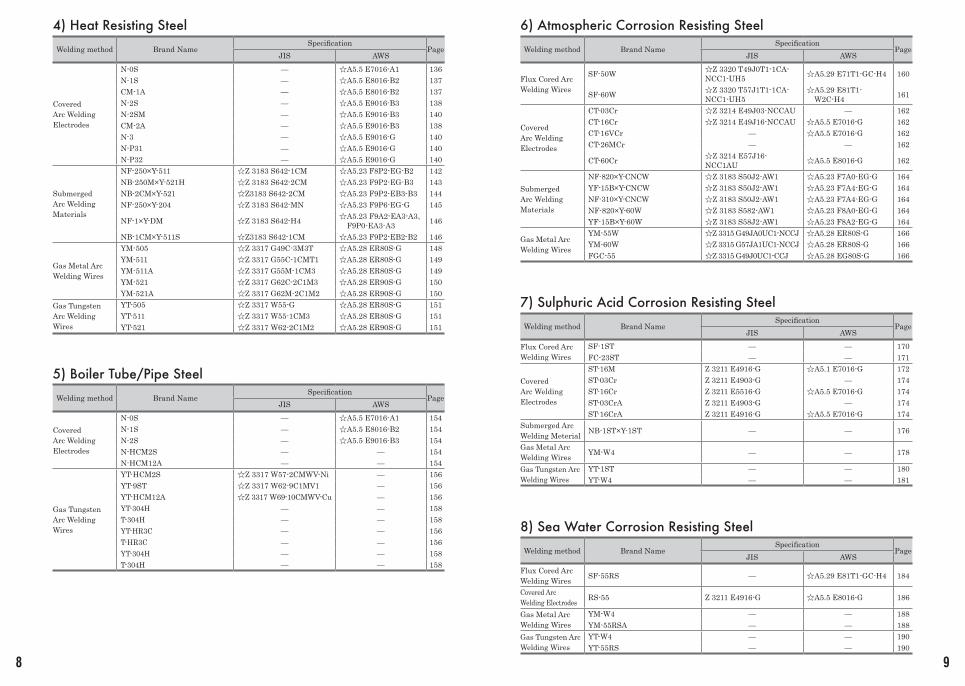
4) Heat Resisting Steel
Welding method Brand NameSpecification
PageJIS AWS
Covered Arc Welding Electrodes
N-0S — ☆A5.5 E7016-A1 136N-1S — ☆A5.5 E8016-B2 137CM-1A — ☆A5.5 E8016-B2 137N-2S — ☆A5.5 E9016-B3 138N-2SM — ☆A5.5 E9016-B3 140CM-2A — ☆A5.5 E9016-B3 138N-3 — ☆A5.5 E9016-G 140N-P31 — ☆A5.5 E9016-G 140N-P32 — ☆A5.5 E9016-G 140
Submerged Arc Welding Materials
NF-250×Y-511 ☆Z 3183 S642-1CM ☆A5.23 F8P2-EG-B2 142NB-250M×Y-521H ☆Z 3183 S642-2CM ☆A5.23 F9P2-EG-B3 143NB-2CM×Y-521 ☆Z3183 S642-2CM ☆A5.23 F9P2-EB3-B3 144NF-250×Y-204 ☆Z 3183 S642-MN ☆A5.23 F9P6-EG-G 145
NF-1×Y-DM ☆Z 3183 S642-H4 ☆A5.23 F9A2-EA3-A3、F9P0-EA3-A3 146
NB-1CM×Y-511S ☆Z3183 S642-1CM ☆A5.23 F9P2-EB2-B2 146
Gas Metal Arc Welding Wires
YM-505 ☆Z 3317 G49C-3M3T ☆A5.28 ER80S-G 148YM-511 ☆Z 3317 G55C-1CMT1 ☆A5.28 ER80S-G 149YM-511A ☆Z 3317 G55M-1CM3 ☆A5.28 ER80S-G 149YM-521 ☆Z 3317 G62C-2C1M3 ☆A5.28 ER90S-G 150YM-521A ☆Z 3317 G62M-2C1M2 ☆A5.28 ER90S-G 150
Gas Tungsten Arc Welding Wires
YT-505 ☆Z 3317 W55-G ☆A5.28 ER80S-G 151YT-511 ☆Z 3317 W55-1CM3 ☆A5.28 ER80S-G 151YT-521 ☆Z 3317 W62-2C1M2 ☆A5.28 ER90S-G 151
5) Boiler Tube/Pipe Steel
Welding method Brand NameSpecification
PageJIS AWS
Covered Arc Welding Electrodes
N-0S — ☆A5.5 E7016-A1 154N-1S — ☆A5.5 E8016-B2 154N-2S — ☆A5.5 E9016-B3 154N-HCM2S — — 154N-HCM12A — — 154
Gas Tungsten Arc Welding Wires
YT-HCM2S ☆Z 3317 W57-2CMWV-Ni — 156YT-9ST ☆Z 3317 W62-9C1MV1 — 156YT-HCM12A ☆Z 3317 W69-10CMWV-Cu — 156YT-304H — — 158T-304H — — 158YT-HR3C — — 156T-HR3C — — 156YT-304H — — 158T-304H — — 158
6) Atmospheric Corrosion Resisting Steel
Welding method Brand NameSpecification
PageJIS AWS
Flux Cored Arc Welding Wires
SF-50W ☆Z 3320 T49J0T1-1CA-NCC1-UH5 ☆A5.29 E71T1-GC-H4 160
SF-60W ☆Z 3320 T57J1T1-1CA-NCC1-UH5
☆A5.29 E81T1-W2C-H4 161
Covered Arc Welding Electrodes
CT-03Cr ☆Z 3214 E49J03-NCCAU — 162CT-16Cr ☆Z 3214 E49J16-NCCAU ☆A5.5 E7016-G 162CT-16VCr — ☆A5.5 E7016-G 162CT-26MCr — — 162
CT-60Cr ☆Z 3214 E57J16-NCC1AU ☆A5.5 E8016-G 162
Submerged Arc Welding Materials
NF-820×Y-CNCW ☆Z 3183 S50J2-AW1 ☆A5.23 F7A0-EG-G 164YF-15B×Y-CNCW ☆Z 3183 S50J2-AW1 ☆A5.23 F7A4-EG-G 164NF-310×Y-CNCW ☆Z 3183 S50J2-AW1 ☆A5.23 F7A4-EG-G 164NF-820×Y-60W ☆Z 3183 S582-AW1 ☆A5.23 F8A0-EG-G 164YF-15B×Y-60W ☆Z 3183 S58J2-AW1 ☆A5.23 F8A2-EG-G 164
Gas Metal Arc Welding Wires
YM-55W ☆Z 3315 G49JA0UC1-NCCJ ☆A5.28 ER80S-G 166YM-60W ☆Z 3315 G57JA1UC1-NCCJ ☆A5.28 ER80S-G 166FGC-55 ☆Z 3315 G49J0UC1-CCJ ☆A5.28 EG80S-G 166
7) Sulphuric Acid Corrosion Resisting Steel
Welding method Brand NameSpecification
PageJIS AWS
Flux Cored Arc Welding Wires
SF-1ST — — 170FC-23ST — — 171
Covered Arc Welding Electrodes
ST-16M Z 3211 E4916-G ☆A5.1 E7016-G 172ST-03Cr Z 3211 E4903-G — 174ST-16Cr Z 3211 E5516-G ☆A5.5 E7016-G 174ST-03CrA Z 3211 E4903-G — 174ST-16CrA Z 3211 E4916-G ☆A5.5 E7016-G 174
Submerged Arc Welding Meterial NB-1ST×Y-1ST — — 176
Gas Metal Arc Welding Wires YM-W4 — — 178
Gas Tungsten Arc Welding Wires
YT-1ST — — 180YT-W4 — — 181
8) Sea Water Corrosion Resisting Steel
Welding method Brand NameSpecification
PageJIS AWS
Flux Cored Arc Welding Wires SF-55RS — ☆A5.29 E81T1-GC-H4 184
Covered Arc Welding Electrodes RS-55 Z 3211 E4916-G ☆A5.5 E8016-G 186
Gas Metal Arc Welding Wires
YM-W4 — — 188YM-55RSA — — 188
Gas Tungsten Arc Welding Wires
YT-W4 — — 190YT-55RS — — 190
10 11
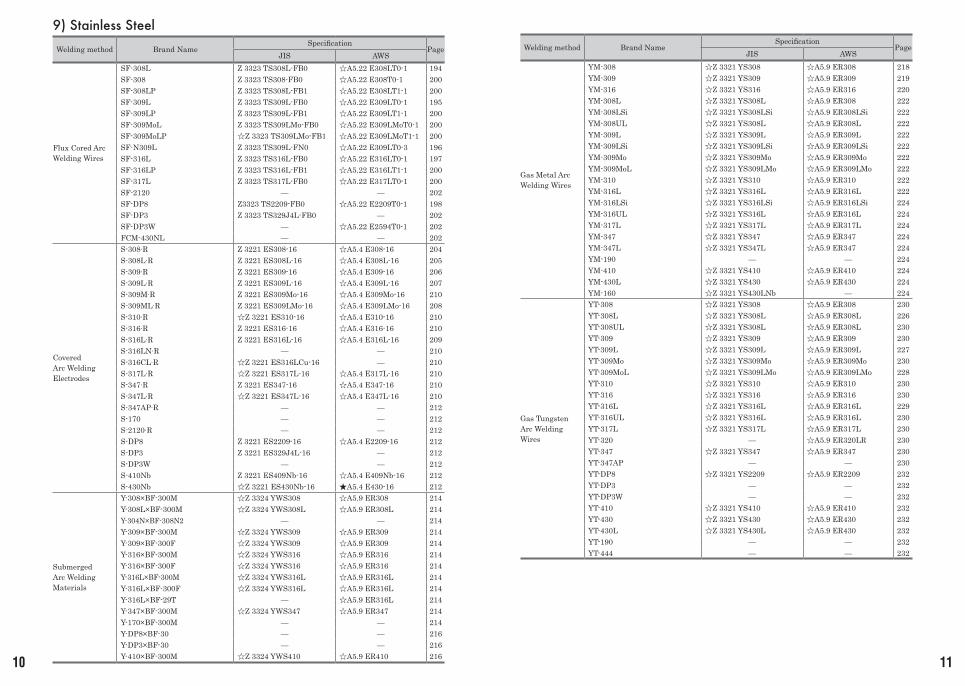
9) Stainless Steel
Welding method Brand NameSpecification
PageJIS AWS
Flux Cored Arc Welding Wires
SF-308L Z 3323 TS308L-FB0 ☆A5.22 E308LT0-1 194SF-308 Z 3323 TS308-FB0 ☆A5.22 E308T0-1 200SF-308LP Z 3323 TS308L-FB1 ☆A5.22 E308LT1-1 200SF-309L Z 3323 TS309L-FB0 ☆A5.22 E309LT0-1 195SF-309LP Z 3323 TS309L-FB1 ☆A5.22 E309LT1-1 200SF-309MoL Z 3323 TS309LMo-FB0 ☆A5.22 E309LMoT0-1 200SF-309MoLP ☆Z 3323 TS309LMo-FB1 ☆A5.22 E309LMoT1-1 200SF-N309L Z 3323 TS309L-FN0 ☆A5.22 E309LT0-3 196SF-316L Z 3323 TS316L-FB0 ☆A5.22 E316LT0-1 197SF-316LP Z 3323 TS316L-FB1 ☆A5.22 E316LT1-1 200SF-317L Z 3323 TS317L-FB0 ☆A5.22 E317LT0-1 200SF-2120 — — 202SF-DP8 Z3323 TS2209-FB0 ☆A5.22 E2209T0-1 198SF-DP3 Z 3323 TS329J4L-FB0 — 202SF-DP3W — ☆A5.22 E2594T0-1 202FCM-430NL — — 202
Covered Arc Welding Electrodes
S-308∙R Z 3221 ES308-16 ☆A5.4 E308-16 204S-308L∙R Z 3221 ES308L-16 ☆A5.4 E308L-16 205S-309∙R Z 3221 ES309-16 ☆A5.4 E309-16 206S-309L∙R Z 3221 ES309L-16 ☆A5.4 E309L-16 207S-309M∙R Z 3221 ES309Mo-16 ☆A5.4 E309Mo-16 210S-309ML∙R Z 3221 ES309LMo-16 ☆A5.4 E309LMo-16 208S-310∙R ☆Z 3221 ES310-16 ☆A5.4 E310-16 210S-316∙R Z 3221 ES316-16 ☆A5.4 E316-16 210S-316L∙R Z 3221 ES316L-16 ☆A5.4 E316L-16 209S-316LN∙R — — 210S-316CL∙R ☆Z 3221 ES316LCu-16 — 210S-317L∙R ☆Z 3221 ES317L-16 ☆A5.4 E317L-16 210S-347∙R Z 3221 ES347-16 ☆A5.4 E347-16 210S-347L∙R ☆Z 3221 ES347L-16 ☆A5.4 E347L-16 210S-347AP∙R — — 212S-170 — — 212S-2120∙R — — 212S-DP8 Z 3221 ES2209-16 ☆A5.4 E2209-16 212S-DP3 Z 3221 ES329J4L-16 — 212S-DP3W — — 212S-410Nb Z 3221 ES409Nb-16 ☆A5.4 E409Nb-16 212S-430Nb ☆Z 3221 ES430Nb-16 ★A5.4 E430-16 212
Submerged Arc Welding Materials
Y-308×BF-300M ☆Z 3324 YWS308 ☆A5.9 ER308 214Y-308L×BF-300M ☆Z 3324 YWS308L ☆A5.9 ER308L 214Y-304N×BF-308N2 — — 214Y-309×BF-300M ☆Z 3324 YWS309 ☆A5.9 ER309 214Y-309×BF-300F ☆Z 3324 YWS309 ☆A5.9 ER309 214Y-316×BF-300M ☆Z 3324 YWS316 ☆A5.9 ER316 214Y-316×BF-300F ☆Z 3324 YWS316 ☆A5.9 ER316 214Y-316L×BF-300M ☆Z 3324 YWS316L ☆A5.9 ER316L 214Y-316L×BF-300F ☆Z 3324 YWS316L ☆A5.9 ER316L 214Y-316L×BF-29T — ☆A5.9 ER316L 214Y-347×BF-300M ☆Z 3324 YWS347 ☆A5.9 ER347 214Y-170×BF-300M — — 214Y-DP8×BF-30 — — 216Y-DP3×BF-30 — — 216Y-410×BF-300M ☆Z 3324 YWS410 ☆A5.9 ER410 216
Welding method Brand NameSpecification
PageJIS AWS
Gas Metal Arc Welding Wires
YM-308 ☆Z 3321 YS308 ☆A5.9 ER308 218YM-309 ☆Z 3321 YS309 ☆A5.9 ER309 219YM-316 ☆Z 3321 YS316 ☆A5.9 ER316 220YM-308L ☆Z 3321 YS308L ☆A5.9 ER308 222YM-308LSi ☆Z 3321 YS308LSi ☆A5.9 ER308LSi 222YM-308UL ☆Z 3321 YS308L ☆A5.9 ER308L 222YM-309L ☆Z 3321 YS309L ☆A5.9 ER309L 222YM-309LSi ☆Z 3321 YS309LSi ☆A5.9 ER309LSi 222YM-309Mo ☆Z 3321 YS309Mo ☆A5.9 ER309Mo 222YM-309MoL ☆Z 3321 YS309LMo ☆A5.9 ER309LMo 222YM-310 ☆Z 3321 YS310 ☆A5.9 ER310 222YM-316L ☆Z 3321 YS316L ☆A5.9 ER316L 222YM-316LSi ☆Z 3321 YS316LSi ☆A5.9 ER316LSi 224YM-316UL ☆Z 3321 YS316L ☆A5.9 ER316L 224YM-317L ☆Z 3321 YS317L ☆A5.9 ER317L 224YM-347 ☆Z 3321 YS347 ☆A5.9 ER347 224YM-347L ☆Z 3321 YS347L ☆A5.9 ER347 224YM-190 — — 224YM-410 ☆Z 3321 YS410 ☆A5.9 ER410 224YM-430L ☆Z 3321 YS430 ☆A5.9 ER430 224YM-160 ☆Z 3321 YS430LNb — 224
Gas Tungsten Arc Welding Wires
YT-308 ☆Z 3321 YS308 ☆A5.9 ER308 230YT-308L ☆Z 3321 YS308L ☆A5.9 ER308L 226YT-308UL ☆Z 3321 YS308L ☆A5.9 ER308L 230YT-309 ☆Z 3321 YS309 ☆A5.9 ER309 230YT-309L ☆Z 3321 YS309L ☆A5.9 ER309L 227YT-309Mo ☆Z 3321 YS309Mo ☆A5.9 ER309Mo 230YT-309MoL ☆Z 3321 YS309LMo ☆A5.9 ER309LMo 228YT-310 ☆Z 3321 YS310 ☆A5.9 ER310 230YT-316 ☆Z 3321 YS316 ☆A5.9 ER316 230YT-316L ☆Z 3321 YS316L ☆A5.9 ER316L 229YT-316UL ☆Z 3321 YS316L ☆A5.9 ER316L 230YT-317L ☆Z 3321 YS317L ☆A5.9 ER317L 230YT-320 — ☆A5.9 ER320LR 230YT-347 ☆Z 3321 YS347 ☆A5.9 ER347 230YT-347AP — — 230YT-DP8 ☆Z 3321 YS2209 ☆A5.9 ER2209 232YT-DP3 — — 232YT-DP3W — — 232YT-410 ☆Z 3321 YS410 ☆A5.9 ER410 232YT-430 ☆Z 3321 YS430 ☆A5.9 ER430 232YT-430L ☆Z 3321 YS430L ☆A5.9 ER430 232YT-190 — — 232YT-444 — — 232
YAWATA is a registered trademark or trademark of NIPPON STEEL CORPORATION, and our company is licensed.NITTETSU is a registered trademark or trademark of NIPPON STEEL CORPORATION, and our company is licensed.
12 13
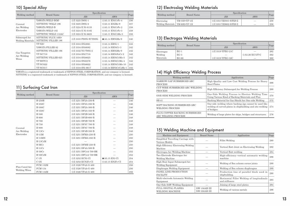
10) Special Alloy
Welding method Brand NameSpecification
PageJIS AWS
Covered Arc Welding Electrodes
YAWATA WELD B(M) ☆Z 3225 D9Ni-1 ☆A5.11 ENiCrFe-4 236NITTETSU WELD 196 ☆Z 3225 D9Ni-2 ☆A5.11 ENiMo-9 237YAWATA WELD B ☆Z 3224 E Ni 6133 ☆A5.11 ENiCrFe-2 238YAWATA WELD 182 ☆Z 3224 E Ni 6182 ☆A5.11 ENiCrFe-3 238NITTETSU WELD 112AC ☆Z 3224 E Ni 6625 ☆A5.11 ENiCrMo-3 238
Submerged Arc Welding Materials
NITTETSU FLUX 10H×NITTETSU FILLER 196 ☆Z 3333 FS9Ni-H YS9Ni ★A5.14 ERNiMo-9 240
Gas Tungsten Arc Welding Wires
YT-NIC ☆Z 3334 SNi2061 ☆A5.14 ERNi-1 242YAWATA FILLER 82 ☆Z 3334 SNi6082 ☆A5.14 ERNiCr-3 242NITTETSU FILLER 196 ☆Z 3332 YG-T9Ni-2 ☆A5.14 ERNiMo-9 242YT-NC718 ☆Z 3334 SNi7718 ☆A5.14 ERNiFeCr-2 242NITTETSU FILLER 625 ☆Z 3334 SNi6625 ☆A5.14 ERNiCrMo-3 242YT-HSTC2 ☆Z 3334 SNi6276 ☆A5.14 ERNiCrMo-4 242YT-NC622 ☆Z 3334 SNi6622 ☆A5.14 ERNiCrMo-10 242YT-NC617 ☆Z 3334 SNi 6617 ☆A5.14 ERNiCrCoMo-1 242
11) Surfacing·Cast Iron
Welding method Brand NameSpecification
PageJIS AWS
Covered Arc Welding Electrodes
H-250B ☆Z 3251 DF2A-250-R — 246H-250C ☆Z 3251 DF2A-250-B — 246H-300C ☆Z 3251 DF2A-300-B — 246H-350C ☆Z 3251 DF2A-350-B — 246H-500 ☆Z 3251 DF2B-500-B — 246H-600 ☆Z 3251 DF2B-600-B — 248H-700 ☆Z 3251 DF2B-700-B — 248H-750 ☆Z 3251 DF3C-700-B — 248H-800 ☆Z 3251 DF3C-700-B — 248H-13Cr ☆Z 3251 DF4B-350-B — 248H-13M ☆Z 3251 DFMA-250-B — 250H-13MN ☆Z 3251 DFMA-250-B — 250H-13CrM — — 250H-MCr ☆Z 3251 DFME-250-B — 250H-11Cr ☆Z 3251 DF4A-500-B — 250H-30Cr ☆Z 3251 DFCrA-700-BR — 252H-30CrM ☆Z 3251 DFCrA-700-BR — 252C-1N ☆Z 3252 ECNi-CI ★A5.15 ENi-CI 254C-5N ☆Z 3252 ECNiFe-CI ☆A5.15 ENiFe-CI 254
Flux Cored Arc Welding Wires
FCM-132M ☆Z 3326 YF4A-G-400 256FCM-134 ☆Z 3326 YF4A-G-400 256FCM-134M ☆Z 3326 YF4A-G-400 256
12) Electroslag Welding Materials
Welding method Brand NameSpecification
PageJIS AWS
Electroslag Welding Materials
YM-55S×YF-15I ☆Z 3353 YES501-S/FES-Z — 258YM-60E×YF-15I ☆Z 3353 YES602-S/FES-Z — 258
13) Electrogas Welding Materials
Welding method Brand NameSpecification
PageJIS AWS
Electrogas Welding Materials
EG-1 ☆Z 3319 YFEG-21C — 262EG-3 — ☆A5.26 EG72T-G 262EG-60 ☆Z 3319 YFEG-32C — 262
14) High Efficiency Welding ProcessWelding method Application Page
NARROW GAP SUBMERGED ARC PROCESS
High Quality and Low Cost Welding Process for Heavy Steel Plates 266
CUT WIRE SUBMERGED ARC WELDING PROCESS High Efficiency Submerged Arc Welding Process 268
ONE-SIDE WELDING PROCESS One-Side Welding Process to Shorten Welding Time Using Various Kind of Backing Materials and Flux 270
SB-41 Backing Material for Gas Shield Arc One-side Welding 272
SOFT BACKING SUBMERGED ARC WELDING PROCESS
One-side welding where backing jigs cannot be used like welding of curved plates in shipbuilding and site welding of bridges.
274
FLUX COPPER BACKING SUBMERGED ARC WELDING PROCESS Welding of large plates for ships, bridges and structures. 276
15) Welding Machine and EquipmentMachine and Equipment Brand Name Application Page
Simplified Travelling Carriage with Various Models — Fillet Welding 280
High Efficiency Electroslag Welding Machine — Vertical Butt Joint on Electroslag Welding 282
Electrogas Arc Welding Machine — Vertical Butt welding 284Two Electrode Electrogas Arc Welding Machine — High-efficiency vertical automatic welding
machine 286
High Heat Input Submerged Arc Welding Equipment — Welding of Box column corner joints 288
Diaphragm Welding Equipment — Welding of Box column diaphragms 289PANEL LINE PRODUCTION FACILITY — Production line of parallel block used in
shipbuilding. 290
Multi-electrode Automatic Welding Equipment — Horizontal Fillet Welding of longitudinals
and stiffeners 293
One-Side SAW Welding Equipment — Joining of large steel plates 294FULL DIGITAL PLASMA WELDING MACHINE
NW-150AH-IIINW-350AH-III Welding of various metals 296
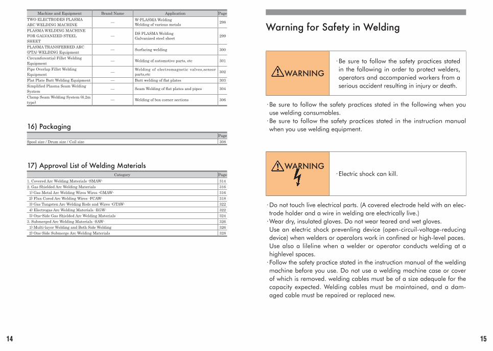
Warning for Safety in Welding
WARNING
·Be sure to follow the safety practices stated in the following in order to protect welders, operators and accompanied workers from a serious accident resulting in injury or death.
·Be sure to follow the safety practices stated in the following when you use welding consumables.
·Be sure to follow the safety practices stated in the instruction manual when you use welding equipment.
WARNING· Electric shock can kill.
·Do not touch live electrical parts. (A covered electrode held with an elec-trode holder and a wire in welding are electrically live.)
·Wear dry, insulated gloves. Do not wear teared and wet gloves. Use an electric shock prevenling device (open-circuil-voltage-reducing device) when welders or operalors work in confined or high-level paces. Use also a lileline when a welder or operator conducts welding at a highlevel spaces.
· Follow the safety practice stated in the instruction manual of the welding machine before you use. Do not use a welding machine case or cover of which is removed. welding cables must be of a size adequale for the capacity expected. Welding cables must be maintained, and a dam-aged cable must be repaired or replaced new.
14 15
Machine and Equipment Brand Name Application PageTWO ELECTRODES PLASMA ARC WELDING MACHINE — W-PLASMA Welding
Welding of various metals 298
PLASMA WELDING MACHINE FOR GALVANIZED STEEL SHEET
— DS PLASMA WeldingGalvanized steel sheet 299
PLASMA TRANSFERRED ARC (PTA) WELDING Equipment — Surfacing welding 300
Circumferential Fillet Welding Equipment — Welding of automotive parts, etc 301
Pipe Overlap Fillet Welding Equipment — Welding of electromagnetic valves,sensor
parts,etc 302
Flat Plate Butt Welding Equipment — Butt welding of flat plates 303Simplified Plasma Seam Welding System — Seam Welding of flat plates and pipes 304
Clamp Seam Welding System (6.2m type) — Welding of box corner sections 306
16) Packaging Page
Spool size / Drum size / Coil size 308
17) Approval List of Welding MaterialsCategory Page
1. Covered Arc Welding Materials -SMAW- 3142. Gas Shielded Arc Welding Materials 316 1) Gas Metal Arc Welding Wires Wires -GMAW- 316 2) Flux Cored Arc Welding Wires -FCAW- 318 3) Gas Tungsten Arc Welding Rods and Wires -GTAW- 322 4) Electrogas Arc Welding Materials -EGW- 322 5) One-Side Gas Shielded Arc Welding Materials 3243. Submerged Arc Welding Materials -SAW- 326 1) Multi-layer Welding and Both Side Welding 326 2) One-Side Submerge Arc Welding Materials 328
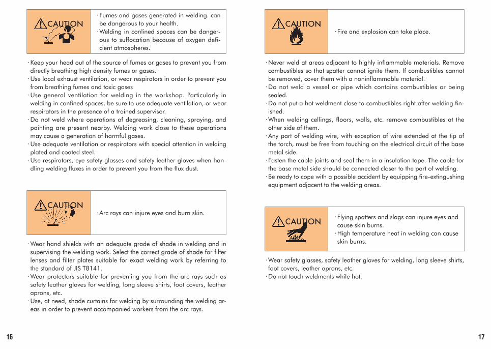
CAUTION· Fumes and gases generated in welding. can be dangerous to your health.
·Welding in conlined spaces can be danger-ous to suffocation because of oxygen defi-cient atmospheres.
·Keep your head out of the source of fumes or gases to prevent you from directly breathing high density fumes or gases.
·Use local exhaust ventilation, or wear respirators in order to prevent you from breathing fumes and toxic gases
·Use general ventilation for welding in the workshop. Particularly in welding in confined spaces, be sure to use adequate ventilation, or wear respirators in the presence of a trained supervisor.
·Do not weld where operations of degreasing, cleaning, spraying, and painting are present nearby. Welding work close to these operations may cause a generation of harmful gases.
·Use adequate ventilation or respirators with special attention in welding plated and coated steel.
·Use respirators, eye safety glasses and safety leather gloves when han-dling welding fluxes in order to prevent you from the flux dust.
CAUTION·Arc rays can injure eyes and burn skin.
·Wear hand shields with an adequate grade of shade in welding and in supervising the welding work. Select the correct grade of shade for filter lenses and filter plates suitable for exact welding work by referring to the standard of JIS T8141.
·Wear protectors suitable for preventing you from the arc rays such as safety leather gloves for welding, long sleeve shirts, foot covers, Ieather aprons, etc.
·Use, at need, shade curtains for welding by surrounding the welding ar-eas in order to prevent accompanied workers from the arc rays.
CAUTION· Fire and explosion can take place.
·Never weld at areas adjacent to highly inflammable materials. Remove combustibles so that spatter cannot ignite them. If combustibles cannot be removed, cover them with a noninflammable material.
·Do not weld a vessel or pipe which contains combustibles or being sealed.
·Do not put a hot weldment close to combustibles right after welding fin-ished.
·When welding cellings, floors, walls, etc. remove combustibles at the other side of them.
·Any part of welding wire, with exception of wire extended at the tip of the torch, must be free from touching on the electrical circuit of the base metal side.
· Fasten the cable joints and seal them in a insulation tape. The cable for the base metal side should be connected closer to the part of welding.
·Be ready to cope with a possible accident by equipping fire-extingushing equipment adjacent to the welding areas.
CAUTION· Flying spatters and slags can injure eyes and cause skin burns.
·High temperature heat in welding can cause skin burns.
·Wear safety glasses, safety leather gloves for welding, long sleeve shirts, foot covers, leather aprons, etc.
·Do not touch weldments while hot.
16 17
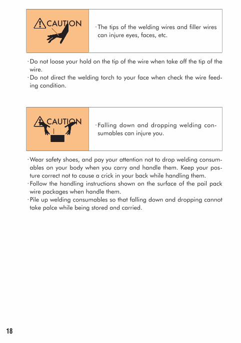
CAUTION · The tips of the welding wires and filler wires can injure eyes, faces, etc.
·Do not loose your hold on the tip of the wire when take off the tip of the wire.
·Do not direct the welding torch to your face when check the wire feed-ing condition.
CAUTION · Falling down and dropping welding con-sumables can injure you.
·Wear safety shoes, and pay your attention not to drop welding consum-ables on your body when you carry and handle them. Keep your pos-ture correct not to cause a crick in your back while handling them.
·Follow the handling instructions shown on the surface of the pail pack wire packages when handle them.
·Pile up welding consumables so that falling down and dropping cannot take palce while being stored and carried.
18
19
Mild Steel·490~550MPa High Tensile Strength SteelFlux Cored Arc Welding WiresCovered Arc Welding ElectrodesSubmerged Arc Welding MaterialsGas Metal Arc Welding WiresGas Tungsten Arc Welding Rods and Wires
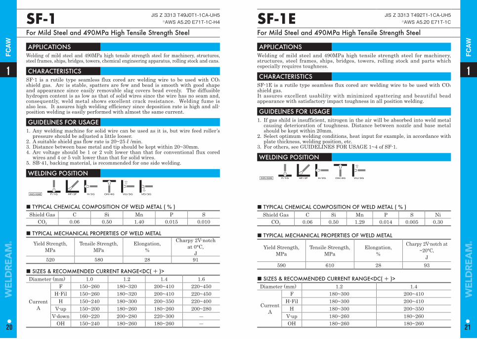
■ TYPICAL CHEMICAL COMPOSITION OF WELD METAL ( % ) Shield Gas C Si Mn P S
CO2 0.06 0.50 1.40 0.015 0.010
■ TYPICAL MECHANICAL PROPERTIES OF WELD METAL
Yield Strength,MPa
Tensile Strength, MPa
Elongation,%
Charpy 2V-notchat 0°C,
J520 580 28 91
■ SIZES & RECOMMENDED CURRENT RANGE<DC( + )> Diameter (mm) 1.0 1.2 1.4 1.6
CurrentA
F 150~260 180~320 200~410 220~450H-Fil 150~260 180~320 200~410 220~450
H 150~240 180~300 200~350 220~400V-up 150~200 180~260 180~260 200~280
V-down 160~220 200~280 220~300 ―OH 150~240 180~260 180~260 ―
SF-1 JIS Z 3313 T49J0T1-1CA-UH5☆AWS A5.20 E71T-1C-H4
For Mild Steel and 490MPa High Tensile Strength Steel
APPLICATIONS Welding of mild steel and 490MPa high tensile strength steel for machinery, structures, steel frames, ships, bridges, towers, chemical engineering apparatus, rolling stock and cans.
CHARACTERISTICS SF-1 is a rutile type seamless flux cored arc welding wire to be used with CO2
shield gas. Arc is stable, spatters are few and bead is smooth with good shape and appearance since easily removable slag covers bead evenly. The diffusible hydrogen content is as low as that of solid wires since the wire has no seam and, consequently, weld metal shows excellent crack resistance. Welding fume is also less. It assures high welding efficiency since deposition rate is high and all-position welding is easily performed with almost the same current.
GUIDELlNES FOR USAGE 1. Any welding machine for solid wire can be used as it is, but wire feed roller’s
pressure should be adjusted a little looser.2. A suitable shield gas flow rate is 20~25ℓ/min.3. Distance between base metal and tip should be kept within 20~30mm.4. Arc voltage should be 1 or 2 volt lower than that for conventional flux cored
wires and 4 or 5 volt lower than that for solid wires.5. SB-41, backing material, is recommended for one side welding.
WELDING POSITION
AWS/ASME F/1G HF/2F H/2G OH/4G VU/3G VD/3G
■ TYPICAL CHEMICAL COMPOSITION OF WELD METAL ( % ) Shield Gas C Si Mn P S Ni
CO2 0.06 0.50 1.29 0.014 0.005 0.30
SF-1E JIS Z 3313 T492T1-1CA-UH5☆AWS A5.20 E71T-1C
For Mild Steel and 490MPa High Tensile Strength Steel
APPLICATIONS Welding of mild steel and 490MPa high tensile strength steel for machinery, structures, steel frames, ships, bridges, towers, rolling stock and parts which especially requires toughness.
CHARACTERISTICS SF-1E is a rutile type seamless flux cored arc welding wire to be used with CO2
shield gas.It assures excellent usability with minimized spattering and beautiful bead appearance with satisfactory impact toughness in all position welding.
GUIDELlNES FOR USAGE 1. If gas shild is insufficient, nitrogen in the air will be absorbed into weld metal
causing deterioration of toughness. Distance between nozzle and base metal should be kept within 20mm.
2. Select optimum welding conditions, heat input for example, in accordance with plate thickness, welding position, etc.
3. For others, see GUIDELINES FOR USAGE 1~4 of SF-1.
WELDING POSITION
AWS/ASME F/1G HF/2F H/2G OH/4G VU/3G
■ TYPICAL MECHANICAL PROPERTIES OF WELD METAL
Yield Strength,MPa
Tensile Strength, MPa
Elongation,%
Charpy 2V-notch at −20°C,
J590 610 28 93
■ SIZES & RECOMMENDED CURRENT RANGE<DC( + )> Diameter (mm) 1.2 1.4
CurrentA
F 180~300 200~410H-Fil 180~300 200~410
H 180~300 200~350V-up 180~260 180~260OH 180~260 180~260
11
20 21
FC
AW
FC
AW
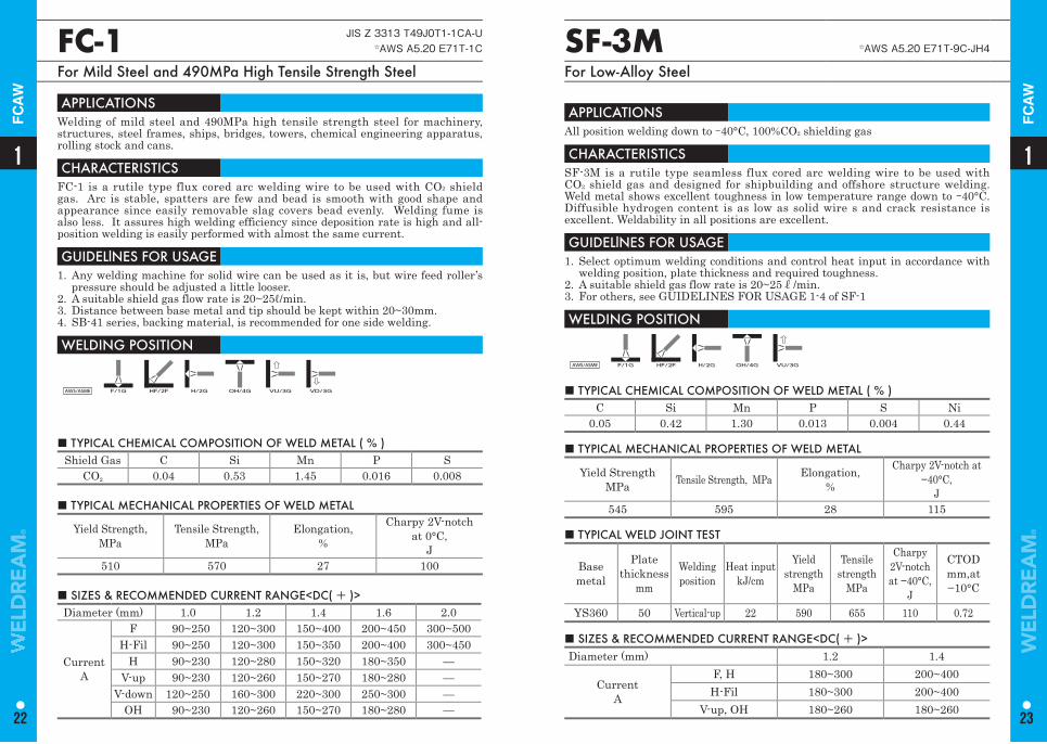
■ TYPICAL CHEMICAL COMPOSITION OF WELD METAL ( % ) Shield Gas C Si Mn P S
CO2 0.04 0.53 1.45 0.016 0.008
FC-1 JIS Z 3313 T49J0T1-1CA-U☆AWS A5.20 E71T-1C
For Mild Steel and 490MPa High Tensile Strength Steel
APPLICATIONS Welding of mild steel and 490MPa high tensile strength steel for machinery, structures, steel frames, ships, bridges, towers, chemical engineering apparatus, rolling stock and cans.
CHARACTERISTICS FC-1 is a rutile type flux cored arc welding wire to be used with CO2 shield gas. Arc is stable, spatters are few and bead is smooth with good shape and appearance since easily removable slag covers bead evenly. Welding fume is also less. It assures high welding efficiency since deposition rate is high and all-position welding is easily performed with almost the same current.
GUIDELlNES FOR USAGE 1. Any welding machine for solid wire can be used as it is, but wire feed roller’s
pressure should be adjusted a little looser.2. A suitable shield gas flow rate is 20~25ℓ/min.3. Distance between base metal and tip should be kept within 20~30mm.4. SB-41 series, backing material, is recommended for one side welding.
WELDING POSITION
AWS/ASME F/1G HF/2F H/2G OH/4G VU/3G VD/3G
■ TYPICAL MECHANICAL PROPERTIES OF WELD METAL
Yield Strength,MPa
Tensile Strength, MPa
Elongation,%
Charpy 2V-notchat 0°C,
J510 570 27 100
■ SIZES & RECOMMENDED CURRENT RANGE<DC( + )> Diameter (mm) 1.0 1.2 1.4 1.6 2.0
CurrentA
F 90~250 120~300 150~400 200~450 300~500H-Fil 90~250 120~300 150~350 200~400 300~450
H 90~230 120~280 150~320 180~350 —V-up 90~230 120~260 150~270 180~280 —
V-down 120~250 160~300 220~300 250~300 —OH 90~230 120~260 150~270 180~280 —
SF-3M ☆AWS A5.20 E71T-9C-JH4
For Low-Alloy Steel
APPLICATIONS All position welding down to -40°C, 100%CO2 shielding gas
CHARACTERISTICS SF-3M is a rutile type seamless flux cored arc welding wire to be used with CO2 shield gas and designed for shipbuilding and offshore structure welding. Weld metal shows excellent toughness in low temperature range down to -40°C. Diffusible hydrogen content is as low as solid wire s and crack resistance is excellent. Weldability in all positions are excellent.
GUIDELlNES FOR USAGE 1. Select optimum welding conditions and control heat input in accordance with
welding position, plate thickness and required toughness.2. A suitable shield gas flow rate is 20~25ℓ/min.3. For others, see GUIDELINES FOR USAGE 1-4 of SF-1
WELDING POSITION
AWS/ASME F/1G HF/2F H/2G OH/4G VU/3G
■ TYPICAL CHEMICAL COMPOSITION OF WELD METAL ( % ) C Si Mn P S Ni
0.05 0.42 1.30 0.013 0.004 0.44
■ TYPICAL MECHANICAL PROPERTIES OF WELD METAL
Yield StrengthMPa Tensile Strength, MPa Elongation,
%
Charpy 2V-notch at −40°C,
J545 595 28 115
■ SIZES & RECOMMENDED CURRENT RANGE<DC( + )> Diameter (mm) 1.2 1.4
CurrentA
F, H 180~300 200~400H-Fil 180~300 200~400
V-up, OH 180~260 180~260
■ TYPICAL WELD JOINT TEST
Base metal
Plate thickness
mm
Welding position
Heat inputkJ/cm
Yield strength
MPa
Tensile strength
MPa
Charpy 2V-notchat −40°C,
J
CTODmm,at−10°C
YS360 50 Vertical-up 22 590 655 110 0.72
11
22 23
FC
AW
FC
AW
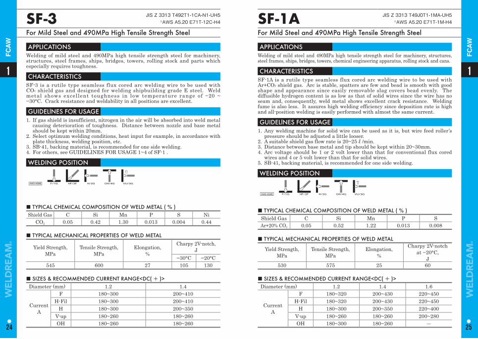
SF-1A JIS Z 3313 T49J0T1-1MA-UH5☆AWS A5.20 E71T-1M-H4
For Mild Steel and 490MPa High Tensile Strength Steel
APPLICATIONS Welding of mild steel and 490MPa high tensile strength steel for machinery, structures, steel frames, ships, bridges, towers, chemical engineering apparatus, rolling stock and cans.
CHARACTERISTICS SF-1A is a rutile type seamless flux cored arc welding wire to be used with Ar+CO2 shield gas. Arc is stable, spatters are few and bead is smooth with good shape and appearance since easily removable slag covers bead evenly. The diffusible hydrogen content is as low as that of solid wires since the wire has no seam and, consequently, weld metal shows excellent crack resistance. Welding fume is also less. It assures high welding efficiency since deposition rate is high and all-position welding is easily performed with almost the same current.
GUIDELlNES FOR USAGE 1. Any welding machine for solid wire can be used as it is, but wire feed roller’s
pressure should be adjusted a little looser.2. A suitable shield gas flow rate is 20~25ℓ/min.3. Distance between base metal and tip should be kept within 20~30mm.4. Arc voltage should be 1 or 2 volt lower than that for conventional flux cored
wires and 4 or 5 volt lower than that for solid wires.5. SB-41, backing material, is recommended for one side welding.
WELDING POSITION
AWS/ASME F/1G HF/2F H/2G OH/4G VU/3G
■ TYPICAL CHEMICAL COMPOSITION OF WELD METAL ( % ) Shield Gas C Si Mn P SAr+20% CO2 0.05 0.52 1.22 0.013 0.008
■ TYPICAL MECHANICAL PROPERTIES OF WELD METAL
Yield Strength,MPa
Tensile Strength, MPa
Elongation,%
Charpy 2V-notchat −20°C,
J530 575 25 60
■ SIZES & RECOMMENDED CURRENT RANGE<DC( + )> Diameter (mm) 1.2 1.4 1.6
CurrentA
F 180~320 200~430 220~450H-Fil 180~320 200~430 220~450
H 180~300 200~350 220~400V-up 180~260 180~260 200~280OH 180~300 180~260 ―
SF-3 JIS Z 3313 T492T1-1CA-N1-UH5☆AWS A5.20 E71T-12C-H4
For Mild Steel and 490MPa High Tensile Strength Steel
APPLICATIONS Welding of mild steel and 490MPa high tensile strength steel for machinery, structures, steel frames, ships, bridges, towers, rolling stock and parts which especially requires toughness.
CHARACTERISTICS SF-3 is a rutile type seamless flux cored arc welding wire to be used with CO2 shield gas and designed for welding shipbuilding grade E steel. Weld metal shows excellent toughness in low temperature range of −20 ~ −30°C. Crack resistance and weldability in all positions are excellent.
GUIDELlNES FOR USAGE 1. If gas shield is insufficient, nitrogen in the air will be absorbed into weld metal
causing deterioration of toughness. Distance between nozzle and base metal should be kept within 20mm.
2. Select optimum welding conditions, heat input for example, in accordance with plate thickness, welding position, etc.
3. SB-41, backing material, is recommended for one side welding.4. For others, see GUIDELINES FOR USAGE 1~4 of SF-1 .
WELDING POSITION
AWS/ASME F/1G HF/2F H/2G OH/4G VU/3G
■ TYPICAL CHEMICAL COMPOSITION OF WELD METAL ( % ) Shield Gas C Si Mn P S Ni
CO2 0.05 0.42 1.30 0.013 0.004 0.44
■ TYPICAL MECHANICAL PROPERTIES OF WELD METAL
Yield Strength,MPa
Tensile Strength, MPa
Elongation,%
Charpy 2V-notch,J
−30°C −20°C545 600 27 105 130
■ SIZES & RECOMMENDED CURRENT RANGE<DC( + )> Diameter (mm) 1.2 1.4
CurrentA
F 180~300 200~410H-Fil 180~300 200~410
H 180~300 200~350V-up 180~260 180~260OH 180~260 180~260
11
24 25
FC
AW
FC
AW
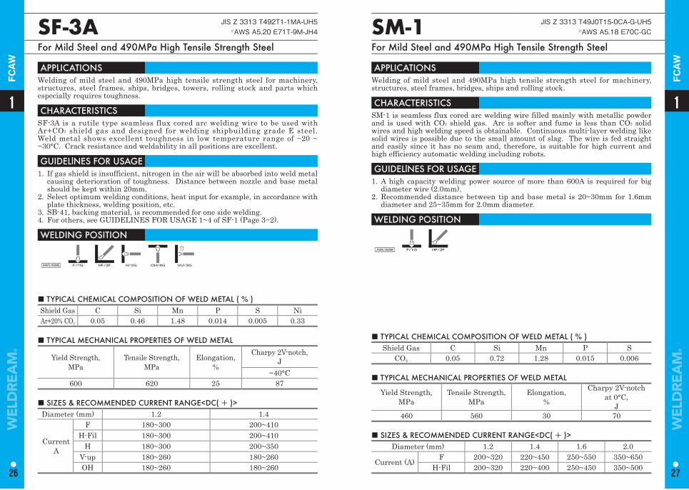
SF-3A JIS Z 3313 T492T1-1MA-UH5☆AWS A5.20 E71T-9M-JH4
For Mild Steel and 490MPa High Tensile Strength Steel
APPLICATIONS Welding of mild steel and 490MPa high tensile strength steel for machinery, structures, steel frames, ships, bridges, towers, rolling stock and parts which especially requires toughness.
CHARACTERISTICS SF-3A is a rutile type seamless flux cored arc welding wire to be used with Ar+CO2 shield gas and designed for welding shipbuilding grade E steel. Weld metal shows excellent toughness in low temperature range of −20 ~ −30°C. Crack resistance and weldability in all positions are excellent.
GUIDELlNES FOR USAGE 1. If gas shield is insufficient, nitrogen in the air will be absorbed into weld metal
causing deterioration of toughness. Distance between nozzle and base metal should be kept within 20mm.
2. Select optimum welding conditions, heat input for example, in accordance with plate thickness, welding position, etc.
3. SB-41, backing material, is recommended for one side welding.4. For others, see GUIDELINES FOR USAGE 1~4 of SF-1 (Page 3−2).
WELDING POSITION
AWS/ASME F/1G HF/2F H/2G OH/4G VU/3G
■ TYPICAL CHEMICAL COMPOSITION OF WELD METAL ( % ) Shield Gas C Si Mn P S NiAr+20% CO2 0.05 0.46 1.48 0.014 0.005 0.33
■ TYPICAL MECHANICAL PROPERTIES OF WELD METAL
Yield Strength,MPa
Tensile Strength, MPa
Elongation,%
Charpy 2V-notch,J
−40°C600 620 25 87
■ SIZES & RECOMMENDED CURRENT RANGE<DC( + )> Diameter (mm) 1.2 1.4
CurrentA
F 180~300 200~410H-Fil 180~300 200~410
H 180~300 200~350V-up 180~260 180~260OH 180~260 180~260
■ TYPICAL CHEMICAL COMPOSITION OF WELD METAL ( % ) Shield Gas C Si Mn P S
CO2 0.05 0.72 1.28 0.015 0.006
SM-1 JIS Z 3313 T49J0T15-0CA-G-UH5☆AWS A5.18 E70C-GC
For Mild Steel and 490MPa High Tensile Strength Steel
APPLICATIONS Welding of mild steel and 490MPa high tensile strength steel for machinery, structures, steel frames, bridges, ships and rolling stock.
CHARACTERISTICS SM-1 is seamless flux cored arc welding wire filled mainly with metallic powder and is used with CO2 shield gas. Arc is softer and fume is less than CO2 solid wires and high welding speed is obtainable. Continuous multi-layer welding like solid wires is possible due to the small amount of slag. The wire is fed straight and easily since it has no seam and, therefore, is suitable for high current and high efficiency automatic welding including robots.
GUIDELlNES FOR USAGE 1. A high capacity welding power source of more than 600A is required for big
diameter wire (2.0mm).2. Recommended distance between tip and base metal is 20~30mm for 1.6mm
diameter and 25~35mm for 2.0mm diameter.
WELDING POSITION
AWS/ASME F/1G HF/2F
■ TYPICAL MECHANICAL PROPERTIES OF WELD METAL
Yield Strength,MPa
Tensile Strength,MPa
Elongation,%
Charpy 2V-notchat 0°C,
J460 560 30 70
■ SIZES & RECOMMENDED CURRENT RANGE<DC( + )> Diameter (mm) 1.2 1.4 1.6 2.0
Current (A) F 200~320 220~450 250~550 350~650H-Fil 200~320 220~400 250~450 350~500
11
26 27
FC
AW
FC
AW
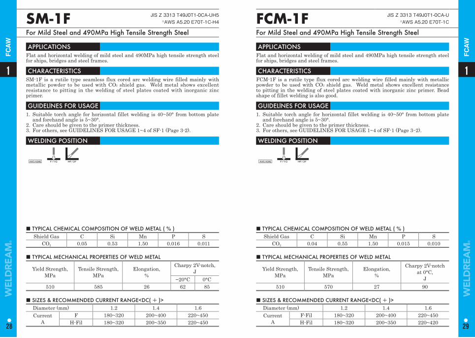
■ TYPICAL CHEMICAL COMPOSITION OF WELD METAL ( % ) Shield Gas C Si Mn P S
CO2 0.05 0.53 1.50 0.016 0.011
SM-1F JIS Z 3313 T49J0T1-0CA-UH5☆AWS A5.20 E70T-1C-H4
For Mild Steel and 490MPa High Tensile Strength Steel
APPLICATIONS Flat and horizontal welding of mild steel and 490MPa high tensile strength steel for ships, bridges and steel frames.
CHARACTERISTICS SM-1F is a rutile type seamless flux cored arc welding wire filled mainly with metallic powder to be used with CO2 shield gas. Weld metal shows excellent resistance to pitting in the welding of steel plates coated with inorganic zinc primer.
GUIDELlNES FOR USAGE 1. Suitable torch angle for horizontal fillet welding is 40~50° from bottom plate
and forehand angle is 5~30°.2. Care should be given to the primer thickness.3. For others, see GUIDELINES FOR USAGE 1~4 of SF-1 (Page 3-2).
WELDING POSITION
AWS/ASME F/1G HF/2F
■ TYPICAL MECHANICAL PROPERTIES OF WELD METAL
Yield Strength,MPa
Tensile Strength,MPa
Elongation,%
Charpy 2V-notch, J
−20°C 0°C510 585 26 62 85
■ SIZES & RECOMMENDED CURRENT RANGE<DC( + )> Diameter (mm) 1.2 1.4 1.6Current
AF 180~320 200~400 220~450
H-Fil 180~320 200~350 220~450
■ TYPICAL CHEMICAL COMPOSITION OF WELD METAL ( % ) Shield Gas C Si Mn P S
CO2 0.04 0.55 1.50 0.015 0.010
FCM-1F JIS Z 3313 T49J0T1-0CA-U☆AWS A5.20 E70T-1C
For Mild Steel and 490MPa High Tensile Strength Steel
APPLICATIONS Flat and horizontal welding of mild steel and 490MPa high tensile strength steel for ships, bridges and steel frames.
CHARACTERISTICS FCM-1F is a rutile type flux cored arc welding wire filled mainly with metallic powder to be used with CO2 shield gas. Weld metal shows excellent resistance to pitting in the welding of steel plates coated with inorganic zinc primer. Bead shape of fillet welding is also good.
GUIDELlNES FOR USAGE 1. Suitable torch angle for horizontal fillet welding is 40~50° from bottom plate
and forehand angle is 5~30°.2. Care should be given to the primer thickness.3. For others, see GUIDELINES FOR USAGE 1~4 of SF-1 (Page 3-2).
WELDING POSITION
AWS/ASME F/1G HF/2F
■ TYPICAL MECHANICAL PROPERTIES OF WELD METAL
Yield Strength,MPa
Tensile Strength,MPa
Elongation,%
Charpy 2V-notchat 0°C,
J510 570 27 90
■ SIZES & RECOMMENDED CURRENT RANGE<DC( + )> Diameter (mm) 1.2 1.4 1.6Current
AF-Fil 180~320 200~400 220~450H-Fil 180~320 200~350 220~420
11
28 29
FC
AW
FC
AW
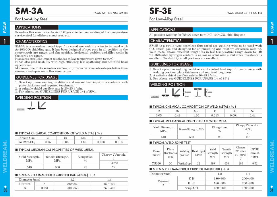
■ TYPICAL CHEMICAL COMPOSITION OF WELD METAL ( % ) Shield Gas C Si Mn P SAr+20%CO2 0.05 0.66 1.69 0.008 0.013
SM-3A ☆AWS A5.18 E70C-GM-H4
For Low-Alloy Steel
APPLICATIONS Seamless flux cored wire for Ar-CO2 gas shielded arc welding of low temperature service steel for offshore structures, etc.
CHARACTERISTICS SM-3A is a seamless metal type flux cored arc welding wire to be used with Ar-20%CO2 shielding gas. It has been designed of root pass in all position in the short-circuit arc range, and flat position, horizontal position and fillet welds in the spray arc range.It assures excellent impact toughness at low temperature down to-40°C.It has also good usability with high efficiency, less spattering and beautiful bead appearance.Moreover, due to its seamless surface, it provides various advantages better than conventional open-seam flux cored wires.
GUIDELlNES FOR USAGE 1. Select optimum welding conditions and control heat input in accordance with
plate thickness and required toughness.2. A suitable shield gas flow rate is 20~25ℓ/min.3. For others, see GUIDELINES FOR USAGE 1~4 of SF-1.
WELDING POSITION
AWS/ASME F/1G HF/2F
■ TYPICAL MECHANICAL PROPERTIES OF WELD METAL
Yield Strength,MPa
Tensile Strength, MPa
Elongation,%
Charpy 2V-notch,J
−40°C540 600 29 72
■ SIZES & RECOMMENDED CURRENT RANGE<DC( + )> Diameter (mm) 1.2 1.4Current
AF 200~350 250~400
H-Fil 200~350 250~400
SF-3E ☆AWS A5.29 E81T1-GC-H4
For Low-Alloy Steel
APPLICATIONS All position welding for YS420 down to -40°C, 100%CO2 shielding gas
CHARACTERISTICS SF-3E is a rutile type seamless flux cored arc welding wire to be used with CO2 shield gas and designed for shipbuilding and offshore structure welding. Weld metal shows excellent toughness in low temperature range down to -40 °C. Diffusible hydrogen content is as low as solid wire s and crack resistance is excellent. Weldability in all positions are excellent.
GUIDELlNES FOR USAGE 1. Select optimum welding conditions and control heat input in accordance with
welding position, plate thickness and required toughness.2. A suitable shield gas flow rate is 20~25ℓ/min.3. For others, see GUIDELINES FOR USAGE 1-4 of SF-1
WELDING POSITION
AWS/ASME F/1G HF/2F H/2G OH/4G VU/3G
■ TYPICAL CHEMICAL COMPOSITION OF WELD METAL ( % ) C Si Mn P S Ni
0.05 0.42 1.30 0.013 0.004 0.44
■ TYPICAL MECHANICAL PROPERTIES OF WELD METAL
Yield StrengthMPa Tensile Strength, MPa Elongation,
%
Charpy 2V-notch at −40°C,
J540 590 28 115
■ SIZES & RECOMMENDED CURRENT RANGE<DC( + )> Diameter (mm) 1.2 1.4
CurrentA
F, H 180~300 200~400H-Fil 180~300 200~400
V-up, OH 180~260 180~260
■ TYPICAL WELD JOINT TEST
Base metal
Plate thickness
mm
Welding position
Heat inputkJ/cm
Yield strength
MPa
Tensile strength
MPa
Charpy 2V-notchat −40°C,
J
CTODmm,at−10°C
YS360 50 Vertical-up 22 590 650 105 0.72
11
30 31
FC
AW
FC
AW
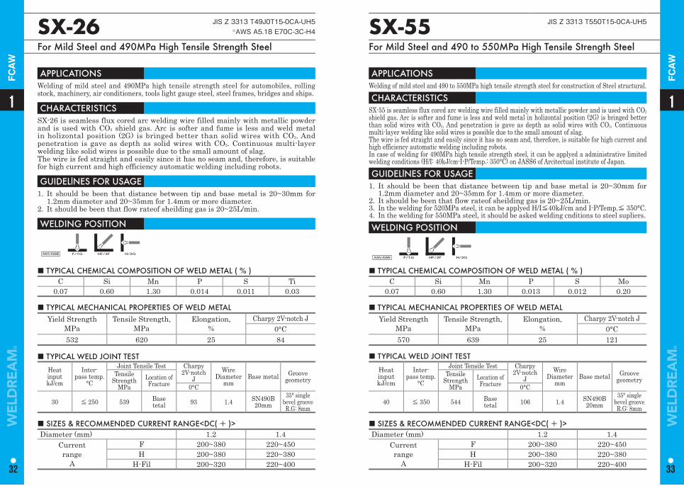
SX-26 JIS Z 3313 T49J0T15-0CA-UH5☆AWS A5.18 E70C-3C-H4
For Mild Steel and 490MPa High Tensile Strength Steel
SX-55 JIS Z 3313 T550T15-0CA-UH5
For Mild Steel and 490 to 550MPa High Tensile Strength Steel
APPLICATIONS Welding of mild steel and 490MPa high tensile strength steel for automobiles, rolling stock, machinery, air conditioners, tools light gauge steel, steel frames, bridges and ships.
CHARACTERISTICS SX-26 is seamless flux cored arc welding wire filled mainly with metallic powder and is used with CO2 shield gas. Arc is softer and fume is less and weld metal in holizontal position (2G) is bringed better than solid wires with CO2. And penetration is gave as depth as solid wires with CO2. Continuous multi-layer welding like solid wires is possible due to the small amount of slag.The wire is fed straight and easily since it has no seam and, therefore, is suitable for high current and high efficiency automatic welding including robots.
GUIDELlNES FOR USAGE 1. It should be been that distance between tip and base metal is 20~30mm for
1.2mm diameter and 20~35mm for 1.4mm or more diameter.2. It should be been that flow rateof sheilding gas is 20~25L/min.
WELDING POSITION
AWS/ASME F/1G HF/2F H/2G
APPLICATIONS Welding of mild steel and 490 to 550MPa high tensile strength steel for construction of Steel structural.CHARACTERISTICS
SX-55 is seamless flux cored arc welding wire filled mainly with metallic powder and is used with CO2
shield gas. Arc is softer and fume is less and weld metal in holizontal position (2G) is bringed better than solid wires with CO2. And penetration is gave as depth as solid wires with CO2. Continuous multi-layer welding like solid wires is possible due to the small amount of slag.The wire is fed straight and easily since it has no seam and, therefore, is suitable for high current and high efficiency automatic welding including robots.In case of welding for 490MPa high tensile strength steel, it can be applyed a administrative limited welding conditions (H/I: 40kJ/cm-I-P/Temp.: 350°C) on JASS6 of Arcitectual institute of Japan. GUIDELlNES FOR USAGE
1. It should be been that distance between tip and base metal is 20~30mm for 1.2mm diameter and 20~35mm for 1.4mm or more diameter.
2. It should be been that flow rateof sheilding gas is 20~25L/min.3. In the welding for 520MPa steel, it can be applyed H/I≦40kJ/cm and I-P/Temp.≦ 350°C.4. In the welding for 550MPa steel, it should be asked welding cnditions to steel supliers.WELDING POSITION
AWS/ASME F/1G HF/2F H/2G
■ TYPICAL CHEMICAL COMPOSITION OF WELD METAL ( % ) C Si Mn P S Ti
0.07 0.60 1.30 0.014 0.011 0.03
■ TYPICAL CHEMICAL COMPOSITION OF WELD METAL ( % ) C Si Mn P S Mo
0.07 0.60 1.30 0.013 0.012 0.20
■ TYPICAL MECHANICAL PROPERTIES OF WELD METAL Yield Strength
MPaTensile Strength,
MPa Elongation,
%Charpy 2V-notch J
0°C532 620 25 84
■ TYPICAL MECHANICAL PROPERTIES OF WELD METAL Yield Strength
MPaTensile Strength,
MPa Elongation,
%Charpy 2V-notch J
0°C570 639 25 121
■ SIZES & RECOMMENDED CURRENT RANGE<DC( + )> Diameter (mm) 1.2 1.4
Currentrange
A
F 200~380 220~450H 200~380 220~380
H-Fil 200~320 220~400
■ SIZES & RECOMMENDED CURRENT RANGE<DC( + )> Diameter (mm) 1.2 1.4
Currentrange
A
F 200~380 220~450H 200~380 220~380
H-Fil 200~320 220~400
■ TYPICAL WELD JOINT TEST
HeatinputkJ/cm
Inter-pass temp.
°C
Joint Tensile Test Charpy 2V-notch
JWire
Diametermm
Base metal Groove geometry
Tensile Strength
MPaLocation of Fracture 0°C
30 ≦ 250 539 Base tetal 93 1.4 SN490B
20mm35° single
bevel grooveR.G: 8mm
■ TYPICAL WELD JOINT TEST
HeatinputkJ/cm
Inter-pass temp.
°C
Joint Tensile Test Charpy 2V-notch
JWire
Diametermm
Base metal Groove geometry
Tensile Strength
MPaLocation of Fracture 0°C
40 ≦ 350 544 Base tetal 106 1.4 SN490B
20mm35° single
bevel grooveR.G: 8mm
11
32 33
FC
AW
FC
AW
Typical Chemical Compositionof Weld Metal(%)
Typical Mechanical Properties of Weld Metal Type
ofCurrentC Si Mn P S Yield Strength,
MPaTensile Strength,
MPaElongation,
%
Charpy 2V-notch at 0°C,
J
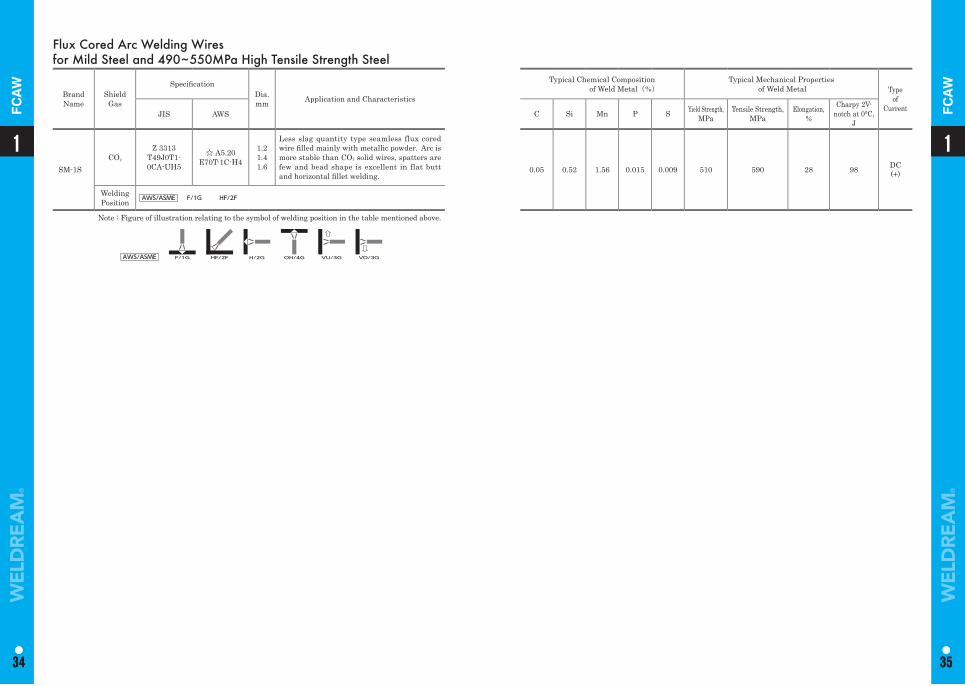
0.05 0.52 1.56 0.015 0.009 510 590 28 98 DC(+)
Flux Cored Arc Welding Wires for Mild Steel and 490~550MPa High Tensile Strength Steel
Brand Name
Shield Gas
Specifi cationDia. mm Application and Characteristics
JIS AWS
SM-1SCO2
Z 3313T49J0T1-0CA-UH5
☆ A5.20 E70T-1C-H4
1.21.41.6
Less slag quantity type seamless flux cored wire fi lled mainly with metallic powder. Arc is more stable than CO2 solid wires, spatters are few and bead shape is excellent in flat butt and horizontal fi llet welding.
Welding Position AWS/ASME F/1G HF/2F
Note : Figure of illustration relating to the symbol of welding position in the table mentioned above.
AWS/ASME F/1G HF/2F H/2G OH/4G VU/3G VD/3G
11
34 35
1
34
1
35
FC
AW
FC
AW
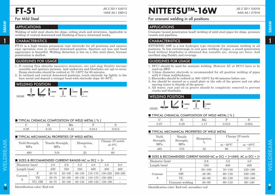
■ TYPICAL CHEMICAL COMPOSITION OF WELD METAL ( % ) C Si Mn P S
0.08 0.33 0.42 0.014 0.013
FT-51 JIS Z 3211 E4313☆AWS A5.1 E6013
For Mild Steel
APPLICATIONS Welding of mild steel sheets for ships, rolling stock and structures. Applicable to welding of vertical downward and finishing of heavy structural works.
CHARACTERISTICS FT-51 is a high titania potassium type electrode for all positions and assures easy operation even in vertical downward position. Spatters are less and bead appearance is beautiful. Welding distortion is low on a thin steel sheet, because penetration is shallow.
GUIDELlNES FOR USAGE 1. If coating flux absorbs excessive moisture, arc and slag fluidity become
unstable and spatters increase. And undercuts and blowholes are apt to occur. Damp electrodes should be redried at 70~120°C for 60 minutes.
2. In inclined and vertical downward positions, touch electrode tip lightly to the base metal and deposit a stringer bead with electrode slope 40~80°C.
WELDING POSITION
AWS/ASME F/1G HF/2F H/2G OH/4G VU/3G VD/3G
■ TYPICAL MECHANICAL PROPERTIES OF WELD METAL
Yield Strength,MPa
Tensile Strength, MPa
Elongation,%
Charpy 2V-notch at 0°C,
J460 510 25 60
■ SIZES & RECOMMENDED CURRENT RANGE<AC or DC( + )> Diameter (mm) 2.0 2.6 3.2 4.0 5.0 6.0Length (mm) 250 350 350 400 400 400
CurrentA
F 30~70 50~100 60~130 110~170 150~220 200~280VD 30~70 50~100 60~130 110~170 150~220 ―
VU, OH 30~70 50~100 60~130 100~150 130~190 ―Identifi cation color: End-red
■ TYPICAL CHEMICAL COMPOSITION OF WELD METAL ( % ) C Si Mn P S
0.07 0.58 1.17 0.012 0.004
NITTETSU™-16W JIS Z 3211 E4316AWS A5.1 E7016
For uranami welding in all positions
APPLICATIONS Uranami (sound penetration bead) welding of mild steel pipes for ships, pressure vessels and pipelines.
CHARACTERISTICS NITTETSU-16W is a low hydrogen type electrode for uranami welding in all positions. In low currentrange in root pass welding of pipes, a sound penetration bead without blowholes is obtained due tostable arc, strong arc force. And excellent slag fluidity and coverage.
GUIDELlNES FOR USAGE 1. DC(-) should be used for uranami welding. However AC or DC(+) have to be
used on AWS.2. 3.2mm diameter electrode is recommended for all position welding of pipes
with 6-15mm wallthickness.3. Electrodes should be redried at 300~350°C for 60 minutes before use.4. Arc should be started on a small plate or the side of the groove and cut after
moving crater to theside of the groove5. All water, rust and oil in groove should be completely removed to prevent
cracks and blowholes.
WELDING POSITION
AWS/ASME F/1G HF/2G H/2G OH/4G VD/3G
■ TYPICAL MECHANICAL PROPERTIES OF WELD METAL
Yield Strength,
MPa
Tensile Strength,
MPa
Elongation,%
Charpy 2V-notch J
at −20°C at −40°C465 570 32 96 77
■ SIZES & RECOMMENDED CURRENT RANGE<AC or DC( + )><AWS: AC or DC( + )>Diameter (mm) 2.6 3.2 4.0Length (mm) 350 400 400
CurrentA
F 50~100 70~130 120~180OH 40~80 60~130 100~160VU 40~80 60~130 100~160
Uranami welding 40~80 60~110 80~140Identifi cation color: End-red, secondary-red
11
36 37
SM
AW
SM
AW
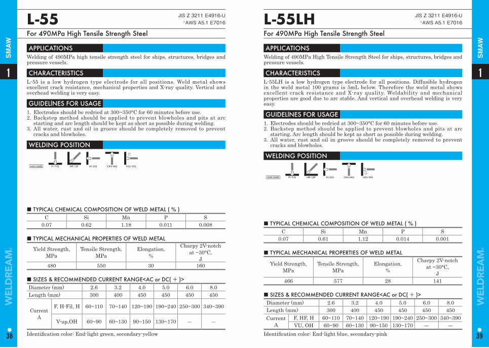
■ TYPICAL CHEMICAL COMPOSITION OF WELD METAL ( % ) C Si Mn P S
0.07 0.62 1.18 0.011 0.008
L-55 JIS Z 3211 E4916-U☆AWS A5.1 E7016
For 490MPa High Tensile Strength Steel
APPLICATIONS Welding of 490MPa high tensile strength steel for ships, structures, bridges and pressure vessels.
CHARACTERISTICS L-55 is a low hydrogen type electrode for all positions. Weld metal shows excellent crack resistance, mechanical properties and X-ray quality. Vertical and overhead welding is very easy.
GUIDELlNES FOR USAGE 1. Electrodes should be redried at 300~350°C for 60 minutes before use. 2. Backstep method should be applied to prevent blowholes and pits at arc
starting and arc length should be kept as short as possible during welding. 3. All water, rust and oil in groove should be completely removed to prevent
cracks and blowholes.
WELDING POSITION
AWS/ASME F/1G HF/2F H/2G OH/4G VU/3G
■ TYPICAL MECHANICAL PROPERTIES OF WELD METAL
Yield Strength,MPa
Tensile Strength, MPa
Elongation,%
Charpy 2V-notch at −30°C,
J480 550 30 160
■ SIZES & RECOMMENDED CURRENT RANGE<AC or DC( + )> Diameter (mm) 2.6 3.2 4.0 5.0 6.0 8.0 Length (mm) 300 400 450 450 450 450
CurrentA
F, H-Fil, H 60~110 70~140 120~190 190~240 250~300 340~390
V-up,OH 60~90 60~130 90~150 130~170 ― ―
Identifi cation color: End-light green, secondary-yellow
■ TYPICAL CHEMICAL COMPOSITION OF WELD METAL ( % ) C Si Mn P S
0.07 0.61 1.12 0.014 0.001
L-55LH JIS Z 3211 E4916-U☆AWS A5.1 E7016
For 490MPa High Tensile Strength Steel
APPLICATIONS Welding of 490MPa High Tensile Strength Steel for ships, structures, bridges and pressure vessels.
CHARACTERISTICS L-55LH is a low hydrogen type electrode for all positions. Diffusible hydrogen in the weld metal 100 grams is 5mL below. Therefore the weld metal shows excellent crack resistance and X-ray quality. Weldability and mechanical properties are good due to arc stable. And vertical and overhead welding is very easy.
GUIDELlNES FOR USAGE 1. Electrodes should be redried at 300~350°C for 60 minutes before use.2. Backstep method should be applied to prevent blowholes and pits at arc
starting. Arc length should be kept as short as possible during welding.3. All water, rust and oil in groove should be completely removed to prevent
cracks and blowholes.
WELDING POSITION
AWS/ASME F/1G HF/2F H/2G OH/4G VD/3G
■ TYPICAL MECHANICAL PROPERTIES OF WELD METAL
Yield Strength,MPa
Tensile Strength, MPa
Elongation,%
Charpy 2V-notch at −30°C,
J466 577 28 141
■ SIZES & RECOMMENDED CURRENT RANGE<AC or DC( + )>Diameter (mm) 2.6 3.2 4.0 5.0 6.0 8.0Length (mm) 300 400 450 450 450 450Current
AF, HF, H 60~110 70~140 120~190 190~240 250~300 340~390VU, OH 60~90 60~130 90~150 130~170 ― ―
Identifi cation color: End-light blue, secondary-pink
11
38 39
SM
AW
SM
AW
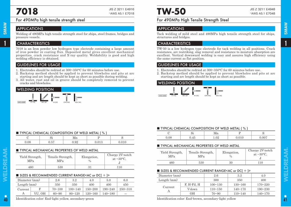
■ TYPICAL CHEMICAL COMPOSITION OF WELD METAL ( % ) C Si Mn P S
0.08 0.45 1.02 0.010 0.007■ TYPICAL CHEMICAL COMPOSITION OF WELD METAL ( % )
C Si Mn P S 0.08 0.57 0.92 0.013 0.010
TW-50 JIS Z 3211 E4948☆AWS A5.1 E7048
For 490MPa High Tensile Strength Steel
7018 JIS Z 3211 E4916☆AWS A5.1 E7018
For 490MPa high tensile strength steel
APPLICATIONS Tack welding of mild steel and 490MPa high tensile strength steel for ships, structures and bridges.
CHARACTERISTICS TW-50 is a low hydrogen type electrode for tack welding in all positions. Crack resistance, arc restriking, slag removal and resistance to moisture absorption are excellent. Vertical downward welding is easy and assures high efficiency using the same current as flat position.
GUIDELlNES FOR USAGE 1. Electrodes should be redried at 300~350°C for 60 minutes before use. 2. Backstep method should be applied to prevent blowholes and pits at arc
starting and arc length should be kept as short as possible.
WELDING POSITION
AWS/ASME F/1G HF/2F H/2G OH/4G VD/3G
APPLICATIONS Welding of 490MPa high tensile strength steel for ships, steel frames, bridges and pressure vessels.
CHARACTERISTICS 7018 is an Iron powder low hydrogen type electrode containing a large amount of iron powder in coating flux. Deposited metal gives excellent mechanical properties, crack resistance and X-ray quality. Weldability is good and high welding efficiency is obtained.
GUIDELlNES FOR USAGE 1. Electrodes should be redried at 300~350°C for 60 minutes before use.2. Backstep method should be applied to prevent blowholes and pits at arc
starting and arc length should be kept as short as possible during welding.3. All water, rust and oil in groove should be completely removed to prevent
cracks and blowholes.
WELDING POSITION
AWS/ASME F/1G HF/2F H/2G OH/4G VD/3G
■ TYPICAL MECHANICAL PROPERTIES OF WELD METAL
Yield Strength,MPa
Tensile Strength, MPa
Elongation,%
Charpy 2V-notch at −30°C,
J460 530 30 110
■ TYPICAL MECHANICAL PROPERTIES OF WELD METAL
Yield Strength,MPa
Tensile Strength, MPa
Elongation,%
Charpy 2V-notch at −30°C,
J460 530 31 110
■ SIZES & RECOMMENDED CURRENT RANGE<AC or DC( + )> Diameter (mm) 2.6 3.2 4.0 Length (mm) 300 350 400
CurrentA
F, H-Fil, H 100~130 130~160 170~220V-down 110~150 140~170 190~230
OH 70~90 110~140 140~170Identifi cation color: End-brown, secondary-light yellow
■ SIZES & RECOMMENDED CURRENT RANGE<AC or DC( + )> Diameter (mm) 2.6 3.2 4.0 5.0 6.0Length (mm) 350 350 400 400 450Current
AF 70~100 100~140 150~200 190~240 250~310
VU, OH 60~90 80~120 120~160 140~180 ―Identifi cation color: End-light yellow, secondary-green
11
40 41
SM
AW
SM
AW
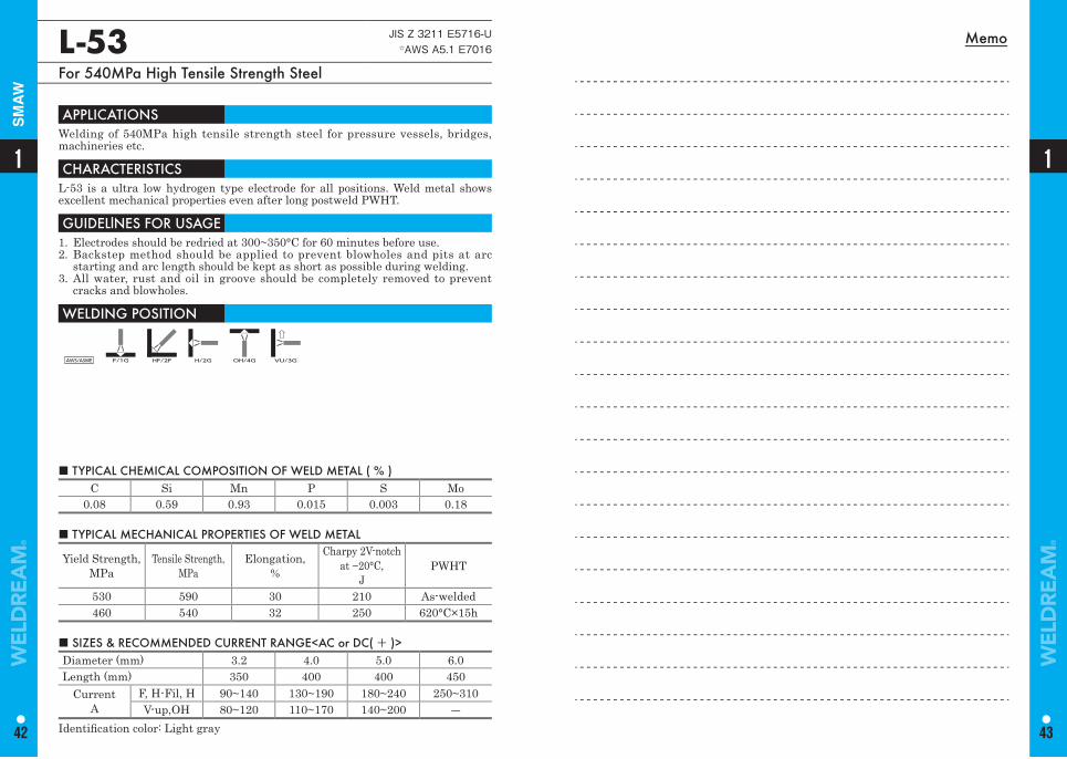
MemoL-53 JIS Z 3211 E5716-U☆AWS A5.1 E7016
For 540MPa High Tensile Strength Steel
APPLICATIONS Welding of 540MPa high tensile strength steel for pressure vessels, bridges, machineries etc.
CHARACTERISTICS L-53 is a ultra low hydrogen type electrode for all positions. Weld metal shows excellent mechanical properties even after long postweld PWHT.
GUIDELlNES FOR USAGE 1. Electrodes should be redried at 300~350°C for 60 minutes before use. 2. Backstep method should be applied to prevent blowholes and pits at arc
starting and arc length should be kept as short as possible during welding. 3. All water, rust and oil in groove should be completely removed to prevent
cracks and blowholes.
WELDING POSITION
AWS/ASME F/1G HF/2F H/2G OH/4G VU/3G
■ TYPICAL CHEMICAL COMPOSITION OF WELD METAL ( % ) C Si Mn P S Mo
0.08 0.59 0.93 0.015 0.003 0.18
■ TYPICAL MECHANICAL PROPERTIES OF WELD METAL
Yield Strength,MPa
Tensile Strength, MPa
Elongation,%
Charpy 2V-notch at −20°C,
JPWHT
530 590 30 210 As-welded460 540 32 250 620°C×15h
■ SIZES & RECOMMENDED CURRENT RANGE<AC or DC( + )> Diameter (mm) 3.2 4.0 5.0 6.0Length (mm) 350 400 400 450
CurrentA
F, H-Fil, H 90~140 130~190 180~240 250~310V-up,OH 80~120 110~170 140~200 ―
Identifi cation color: Light gray
1
42
1
43
SM
AW
Typical Chemical Composition of Weld Metal (%)
Typical Mechanical Properties of Weld Metal
C Si Mn P S Yield Strength, MPa
Tensile Strength, MPa
Elongation,%
Charpy 2V-notch at 0°C,
J
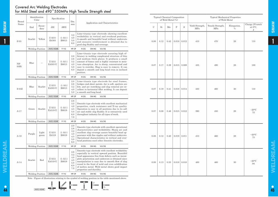
0.08 0.12 0.42 0.018 0.012 410 470 28 110
0.07 0.17 0.39 0.015 0.009 435 490 28 100
0.07 0.19 0.41 0.018 0.014 430 460 30 110
0.07 0.08 0.46 0.015 0.012 390 450 29 −20°C72
0.08 0.12 0.40 0.019 0.011 410 460 28 −20°C73
0.08 0.13 0.53 0.018 0.010 400 460 30 −20°C94
Covered Arc Welding Electrodes for Mild Steel and 490~550MPa High Tensile Strength steel
Brand Name
ldentifi cation Color Specifi cation
Dia. mm Application and Characteristics
End Secon-dary JIS AWS
S-03Scarlet Yellow Z 3211
E4303☆ A5.1E6013
3.2 4.0 5.0 6.0
Lime-titania type electrode showing excellent weldability in vertical and overhead positions. A smooth and beautiful bead without undercuts and excessive reinforcement is obtained due to good slag fl uidity and coverage.
Welding Position AWS/ASME F/1G HF/2F H/2G OH/4G VU/3G
NS-03Hi
Blue ― Z 3211E4303-U
☆ A5.1 E6013
2.0 2.6 3.2 4.0 5.0 6.0
Lime-titania type electrode assuring high ef-fi ciency in welding complicated structure of thin and medium thick plates. It produces a small amount of fumes and is highly resistant to mois-ture absorption. Arc is sharp, concentrated and easy to restrike. Slag is easy to remove. It can deposit a smooth and long bead even in inclined position.
Welding Position AWS/ASME F/1G HF/2F H/2G OH/4G VU/3G
S-03ZBlue Scarlet Z 3211
E4303-U☆ A5.lE6013
2.0 2.6 3.2 4.0 5.0
Lime-titania type electrode for steel frames, bridges and sheet metals. Arc is soft, spatters are few, and arc restriking and slag removal are ex-cellent in horizontal fi llet welding. It can deposit a smooth and long bead.
Welding Position AWS/ASME F/1G HF/2F H/2G OH/4G VU/3G
A-17Green Scarlet Z 3211
E4319-U☆ A5.1 E6019
2.63.24.04.55.06.07.0
Ilmenite type electrode with excellent mechanical properties, crack resistance and X-ray quality. Operation is easy in all positions due to its soft arc and stable slag fl uidity. It is extensively used throughout industry for all types of work.
Welding Position AWS/ASME F/1G HF/2F H/2G OH/4G VU/3G
A-10Purple Light
greenZ 3211E4319
☆ A5.1 E6019
2.02.63.24.04.55.06.0
Ilmenite type electrode with excellent operational characteristics and weldability. Sharp arc and excellent slag coverage assure beautiful bead ap-pearance with fi ne ripples and without undercuts. Operational characteristics in vertical and over-head positions excel other ilmenite electrodes.
Welding Position AWS/ASME F/1G HF/2F H/2G OH/4G VU/3G
A-14Scarlet Red Z 3211
E4319-U☆ A5.1 E6019
2.63.24.04.55.06.07.0
Ilmenite type electrode with excellent weldability especially in vertical upward position. Beautiful bead appearance free from defects such as incom-plete penetration and undercuts is obtained since manipulation is easy due to smooth fl ow of slag round to the front of weld and even solidifi cation of molten metal. Weld metal shows good impact properties and ductility.
Welding Position AWS/ASME F/1G HF/2F H/2G OH/4G VU/3G
Note : Figure of illustration relating to the symbol of welding position in the table mentioned above.
AWS/ASME F/1G HF/2F H/2G OH/4G VU/3G VD/3G
11
44 45
1
44
1
45
SM
AW
SM
AW
Typical Chemical Composition of Weld Metal (%)
Typical Mechanical Properties of Weld Metal
C Si Mn P S Yield Strength, MPa
Tensile Strength, MPa
Elongation,%
Charpy 2V-notch at 0°C,
J
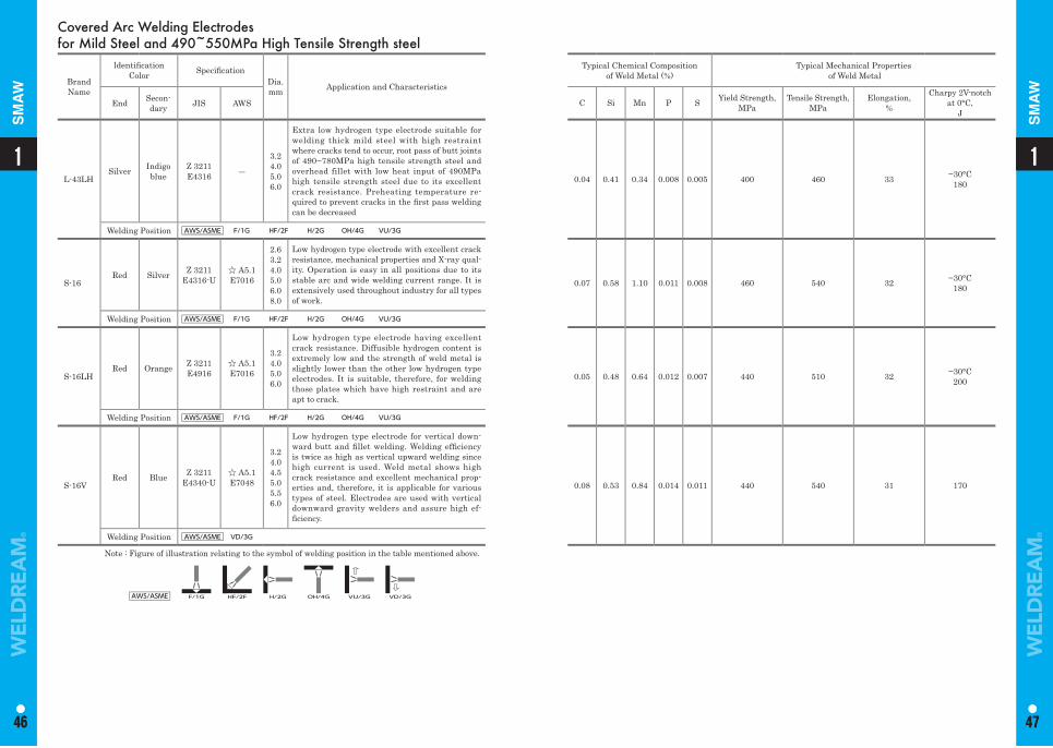
0.04 0.41 0.34 0.008 0.005 400 460 33 −30°C180
0.07 0.58 1.10 0.011 0.008 460 540 32 −30°C180
0.05 0.48 0.64 0.012 0.007 440 510 32 −30°C200
0.08 0.53 0.84 0.014 0.011 440 540 31 170
Covered Arc Welding Electrodes for Mild Steel and 490~550MPa High Tensile Strength steel
Brand Name
ldentifi cation Color Specifi cation
Dia. mm Application and Characteristics
End Secon-dary JIS AWS
L-43LHSilver Indigo
blueZ 3211E4316 ―
3.2 4.0 5.0 6.0
Extra low hydrogen type electrode suitable for welding thick mild steel with high restraint where cracks tend to occur, root pass of butt joints of 490~780MPa high tensile strength steel and overhead fillet with low heat input of 490MPa high tensile strength steel due to its excellent crack resistance. Preheating temperature re-quired to prevent cracks in the fi rst pass welding can be decreased
Welding Position AWS/ASME F/1G HF/2F H/2G OH/4G VU/3G
S-16Red Silver Z 3211
E4316-U☆ A5.1 E7016
2.63.24.05.06.08.0
Low hydrogen type electrode with excellent crack resistance, mechanical properties and X-ray qual-ity. Operation is easy in all positions due to its stable arc and wide welding current range. It is extensively used throughout industry for all types of work.
Welding Position AWS/ASME F/1G HF/2F H/2G OH/4G VU/3G
S-16LHRed Orange Z 3211
E4916☆ A5.1 E7016
3.24.05.06.0
Low hydrogen type electrode having excellent crack resistance. Diffusible hydrogen content is extremely low and the strength of weld metal is slightly lower than the other low hydrogen type electrodes. It is suitable, therefore, for welding those plates which have high restraint and are apt to crack.
Welding Position AWS/ASME F/1G HF/2F H/2G OH/4G VU/3G
S-16VRed Blue Z 3211
E4340-U☆ A5.1 E7048
3.2 4.0 4.55.05.56.0
Low hydrogen type electrode for vertical down-ward butt and fi llet welding. Welding effi ciency is twice as high as vertical upward welding since high current is used. Weld metal shows high crack resistance and excellent mechanical prop-erties and, therefore, it is applicable for various types of steel. Electrodes are used with vertical downward gravity welders and assure high ef-fi ciency.
Welding Position AWS/ASME VD/3G
Note : Figure of illustration relating to the symbol of welding position in the table mentioned above.
AWS/ASME F/1G HF/2F H/2G OH/4G VU/3G VD/3G
11
46 47
1
46
1
47
SM
AW
SM
AW
Typical Chemical Composition of Weld Metal (%)
Typical Mechanical Properties of Weld Metal
C Si Mn P S Yield Strength, MPa
Tensile Strength,MPa
Elongation,%
Charpy 2V-notch at 0°C,
J
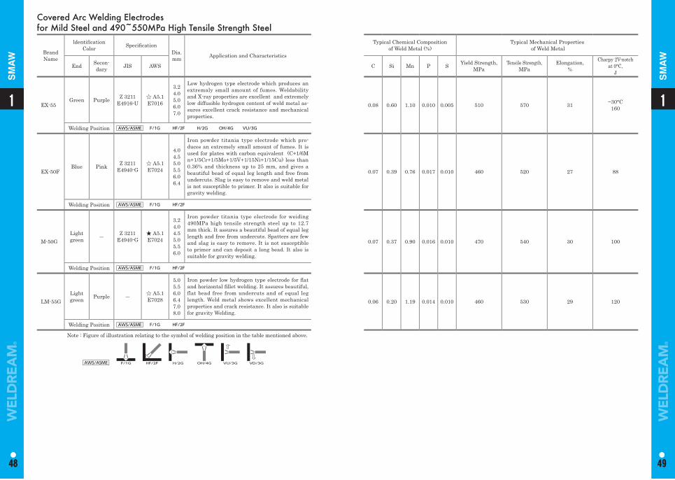
0.08 0.60 1.10 0.010 0.005 510 570 31 −30°C160
0.07 0.39 0.76 0.017 0.010 460 520 27 88
0.07 0.37 0.90 0.016 0.010 470 540 30 100
0.06 0.20 1.19 0.014 0.010 460 530 29 120
Covered Arc Welding Electrodes for Mild Steel and 490~550MPa High Tensile Strength Steel
Brand Name
ldentifi cation Color Specifi cation
Dia. mm Application and Characteristics
End Secon-dary JIS AWS
EX-55Green Purple Z 3211
E4916-U☆ A5.1 E7016
3.24.05.06.07.0
Low hydrogen type electrode which produces an extremaly small amount of fumes. Weldability and X-ray properties are excellent and extremely low diffusible hydrogen content of weld metal as-sures excellent crack resistance and mechanical properties.
Welding Position AWS/ASME F/1G HF/2F H/2G OH/4G VU/3G
EX-50FBlue Pink Z 3211
E4940-G☆ A5.1E7024
4.0 4.5 5.0 5.5 6.0 6.4
Iron powder titania type electrode which pro-duces an extremely small amount of fumes. It is used for plates with carbon equivalent (C+1/6Mn+1/5Cr+1/5Mo+1/5V+1/15Ni+1/15Cu) less than 0.36% and thickness up to 25 mm, and gives a beautiful bead of equal leg length and free from undercuts. Slag is easy to remove and weld metal is not susceptible to primer. It also is suitable for gravity welding.
Welding Position AWS/ASME F/1G HF/2F
M-50GLight green ― Z 3211
E4940-G★ A5.1 E7024
3.24.0 4.5 5.0 5.5 6.0
Iron powder titania type electrode for weiding 490MPa high tensile strength steel up to 12.7 mm thick. It assures a beautiful bead of equal leg length and free from undercuts. Spatters are few and slag is easy to remove. It is not susceptible to primer and can deposit a long bead. It also is suitable for gravity welding.
Welding Position AWS/ASME F/1G HF/2F
LM-55GLight green Purple ― ☆ A5.1
E7028
5.05.56.06.47.08.0
Iron powder low hydrogen type electrode for fl at and horizontal fi llet welding. It assures beautiful, flat bead free from undercuts and of equal leg length. Weld metal shows excellent mechanical properties and crack resistance. It also is suitable for gravity Welding.
Welding Position AWS/ASME F/1G HF/2F
Note : Figure of illustration relating to the symbol of welding position in the table mentioned above.
AWS/ASME F/1G HF/2F H/2G OH/4G VU/3G VD/3G
11
48 49
1
48
1
49
SM
AW
SM
AW
1
51
1
50
SA
W
SA
W
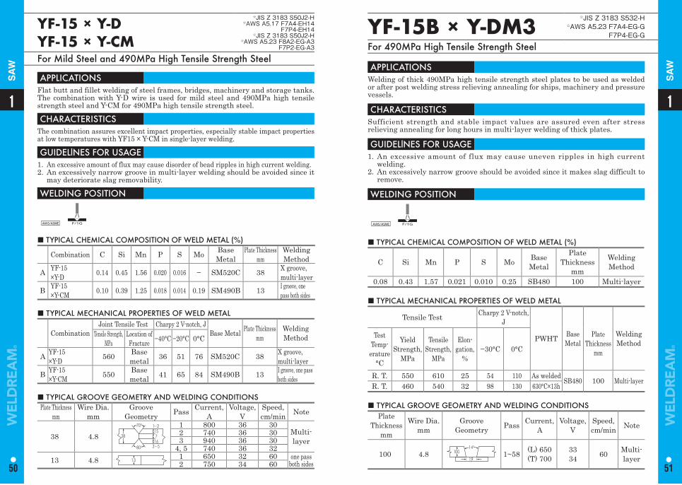
YF-15 × Y-DYF-15 × Y-CM
☆JIS Z 3183 S50J2-H☆AWS A5.17 F7A4-EH14
F7P4-EH14☆JIS Z 3183 S50J2-H
☆AWS A5.23 F8A2-EG-A3F7P2-EG-A3
For Mild Steel and 490MPa High Tensile Strength Steel
■ TYPICAL CHEMICAL COMPOSITION OF WELD METAL (%)
Combination C Si Mn P S Mo Base Metal
Plate Thicknessmm
Welding Method
A YF-15×Y-D 0.14 0.45 1.56 0.020 0.016 − SM520C 38 X groove,
multi-layer
B YF-15×Y-CM 0.10 0.39 1.25 0.018 0.014 0.19 SM490B 13 I groove, one
pass both sides
APPLICATIONS Flat butt and fillet welding of steel frames, bridges, machinery and storage tanks. The combination with Y-D wire is used for mild steel and 490MPa high tensile strength steel and Y-CM for 490MPa high tensile strength steel.
CHARACTERISTICS The combination assures excellent impact properties, especially stable impact properties at low temperatures with YF15 × Y-CM in single-layer welding.
GUIDELlNES FOR USAGE 1. An excessive amount of flux may cause disorder of bead ripples in high current welding.2. An excessively narrow groove in multi-layer welding should be avoided since it
may deteriorate slag removability.
WELDING POSITION
AWS/ASME F/1G
■ TYPICAL MECHANICAL PROPERTIES OF WELD METAL
CombinationJoint Tensile Test Charpy 2 V-notch, J
Base Metal Plate Thicknessmm
Welding MethodTensile Strength,
MPa Location of Fracture −40°C −20°C 0°C
A YF-15×Y-D 560 Base
metal 36 51 76 SM520C 38 X groove, multi-layer
B YF-15×Y-CM 550 Base
metal 41 65 84 SM490B 13 I groove, one pass both sides
■ TYPICAL GROOVE GEOMETRY AND WELDING CONDITIONS Plate Thickness
mmWire Dia.
mmGroove
Geometry Pass Current, A
Voltage, V
Speed, cm/min Note
38 4.8 38
70°
80°
1~215716
3~5
1 800 36 30Multi-layer
2 740 36 303 940 36 30
4, 5 740 36 3213 4.8 13
1 650 32 60 one pass both sides2 750 34 60
YF-15B × Y-DM3☆JIS Z 3183 S532-H
☆AWS A5.23 F7A4-EG-GF7P4-EG-G
For 490MPa High Tensile Strength Steel
■ TYPICAL CHEMICAL COMPOSITION OF WELD METAL (%)
C Si Mn P S Mo Base Metal
Plate Thickness
mm
Welding Method
0.08 0.43 1.57 0.021 0.010 0.25 SB480 100 Multi-layer
APPLICATIONS Welding of thick 490MPa high tensile strength steel plates to be used as welded or after post welding stress relieving annealing for ships, machinery and pressure vessels.
CHARACTERISTICS Sufficient strength and stable impact values are assured even after stress relieving annealing for long hours in multi-layer welding of thick plates.
GUIDELlNES FOR USAGE 1. An excessive amount of flux may cause uneven ripples in high current
welding.2. An excessively narrow groove should be avoided since it makes slag difficult to
remove.
WELDING POSITION
AWS/ASME F/1G
■ TYPICAL MECHANICAL PROPERTIES OF WELD METAL
Tensile Test Charpy 2 V-notch,J
PWHT Base Metal
Plate Thickness
mm
Welding Method
Test Temp-
erature °C
YieldStrength,
MPa
TensileStrength,
MPa
Elon-gation,
%−30°C 0°C
R. T. 550 610 25 54 110 As welded SB480 100 Multi-layerR. T. 460 540 32 98 130 630°C×13h
■ TYPICAL GROOVE GEOMETRY AND WELDING CONDITIONS Plate
Thickness mm
Wire Dia.mm
Groove Geometry Pass Current,
AVoltage,
VSpeed, cm/min Note
100 4.8 10014°
191~58 (L) 650
(T) 7003334 60 Multi-
layer
11
52 53
SA
W
SA
W
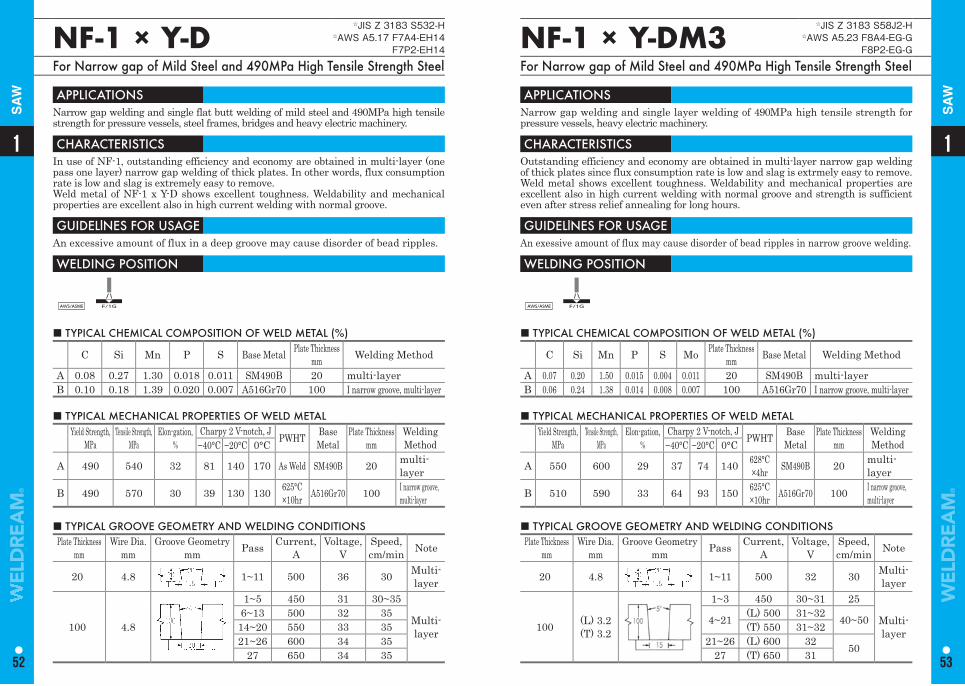
NF-1 × Y-D☆JIS Z 3183 S532-H
☆AWS A5.17 F7A4-EH14F7P2-EH14
For Narrow gap of Mild Steel and 490MPa High Tensile Strength Steel
NF-1 × Y-DM3☆JIS Z 3183 S58J2-H
☆AWS A5.23 F8A4-EG-GF8P2-EG-G
For Narrow gap of Mild Steel and 490MPa High Tensile Strength Steel
APPLICATIONS Narrow gap welding and single flat butt welding of mild steel and 490MPa high tensile strength for pressure vessels, steel frames, bridges and heavy electric machinery.
CHARACTERISTICS In use of NF-1, outstanding efficiency and economy are obtained in multi-layer (one pass one layer) narrow gap welding of thick plates. In other words, flux consumption rate is low and slag is extremely easy to remove.Weld metal of NF-1 x Y-D shows excellent toughness. Weldability and mechanical properties are excellent also in high current welding with normal groove.
GUIDELlNES FOR USAGE An excessive amount of flux in a deep groove may cause disorder of bead ripples.
WELDING POSITION
AWS/ASME F/1G
APPLICATIONS Narrow gap welding and single layer welding of 490MPa high tensile strength for pressure vessels, heavy electric machinery.
CHARACTERISTICS Outstanding efficiency and economy are obtained in multi-layer narrow gap welding of thick plates since flux consumption rate is low and slag is extrmely easy to remove. Weld metal shows excellent toughness. Weldability and mechanical properties are excellent also in high current welding with normal groove and strength is sufficient even after stress relief annealing for long hours.
GUIDELlNES FOR USAGE An exessive amount of flux may cause disorder of bead ripples in narrow groove welding.
WELDING POSITION
AWS/ASME F/1G
■ TYPICAL CHEMICAL COMPOSITION OF WELD METAL (%)
C Si Mn P S Base Metal Plate Thicknessmm Welding Method
A 0.08 0.27 1.30 0.018 0.011 SM490B 20 multi-layerB 0.10 0.18 1.39 0.020 0.007 A516Gr70 100 I narrow groove, multi-layer
■ TYPICAL CHEMICAL COMPOSITION OF WELD METAL (%)
C Si Mn P S Mo Plate Thicknessmm Base Metal Welding Method
A 0.07 0.20 1.50 0.015 0.004 0.011 20 SM490B multi-layerB 0.06 0.24 1.38 0.014 0.008 0.007 100 A516Gr70 I narrow groove, multi-layer
■ TYPICAL MECHANICAL PROPERTIES OF WELD METAL Yield Strength,
MPaTensile Strength,
MPaElon-gation,
%Charpy 2 V-notch, J PWHT Base
MetalPlate Thickness
mmWelding Method−40°C −20°C 0°C
A 490 540 32 81 140 170 As Weld SM490B 20 multi-layer
B 490 570 30 39 130 130 625°C×10hr A516Gr70 100 I narrow groove,
multi-layer
■ TYPICAL MECHANICAL PROPERTIES OF WELD METAL Yield Strength,
MPaTensile Strength,
MPaElon-gation,
%Charpy 2 V-notch, J PWHT Base
MetalPlate Thickness
mmWelding Method−40°C −20°C 0°C
A 550 600 29 37 74 140 628°C×4hr SM490B 20 multi-
layer
B 510 590 33 64 93 150 625°C×10hr A516Gr70 100 I narrow groove,
multi-layer
■ TYPICAL GROOVE GEOMETRY AND WELDING CONDITIONS Plate Thickness
mmWire Dia.
mmGroove Geometry
mm Pass Current, A
Voltage, V
Speed, cm/min Note
20 4.8 1~11 500 36 30 Multi-layer
100 4.8
1~5 450 31 30~35
Multi-layer
6~13 500 32 3514~20 550 33 3521~26 600 34 35
27 650 34 35
■ TYPICAL GROOVE GEOMETRY AND WELDING CONDITIONS Plate Thickness
mmWire Dia.
mmGroove Geometry
mm Pass Current, A
Voltage, V
Speed, cm/min Note
20 4.8 1~11 500 32 30 Multi-layer
100 (L) 3.2 (T) 3.2
1~3 450 30~31 25
Multi-layer
4~21 (L) 500 31~32 40~50(T) 550 31~3221~26 (L) 600 32 5027 (T) 650 31
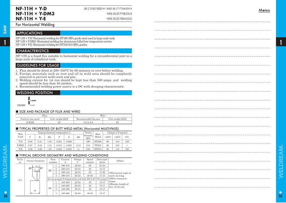
Memo
1
54
1
55
SA
WNF-11H × Y-DNF-11H × Y-DM3NF-11H × Y-E
☆JIS Z 3183 S502-H/☆AWS A5.17 F7A4-EH14☆AWS A5.23 F7A6-EG-G☆AWS A5.23 F8A4-EG-G
For Horizontal Welding
APPLICATIONS NF-11H × Y-D: Horizontal welding for HT490 MPa grade steel used in large scale tankNF-11H × Y-DM3: Horizontal welding for aluminium-killed low temperature service NF-11H × Y-E: Horizontal welding for HT550-610 MPa grades
CHARACTERISTICS NF-11H is a fused flux suitable to horizontal welding for a circumferential joint in a large scale of cylindrical tank.
GUIDELlNES FOR USAGE 1. Flux should be dried at 200~350°C for 60 minutes or over before welding.2. Foreign materials such as rust and oil in weld area should be completely
removed to prevent weld crack and pits.3. Welding current for 1st run should be kept less than 500 amps. and welding
speed should be less than 40 cm/min.4. Recommended welding power source is a DC with drooping characteristic.
WELDING POSITION
AWS/ASME H/2G
■ SIZE AND PACKAGE OF FLUX AND WIRE)Flux Wire
Particle size,mesh Unit weight,KGS Recommended dia,mm Unit weight,KGS2×X200 25 3.2 or 2.4 25
■ TYPICAL PROPERTIES OF BUTT WELD METAL (Horizontal MULTI-PASS) Wire Used
Typical chemical composition,% Tensile Strength,
MPa
Base Metal
Charpy 2 V-notch,J
C Si Mn P S Mo −46°C −20°C 0°C
Y-D 0.08 0.41 1.84 0.021 0.008 590 HT490 69 110 150Y-DM3 0.07 0.24 1.31 0.015 0.005 0.13 510 YP325 86 150 −
Y-E 0.09 0.29 1.63 0.023 0.005 tr. 640 HT610 60 110 150
■ TYPICAL GROOVE GEOMETRY AND WELDING CONDITIONS Wire Dia.
mm Groove Geometry Pass number
CurrentA
VoltageV
Speedcm/min
Heat inputkJ/cm Others
3.2
BP
1 390-410 22-24 25 21-24
1)Horizontal angle of torch: 22.5 deg. 2)Wire extension:25mm3)Burden height of fl ux: 35-40 mm
2 390-410 22-24 35 15-173 390-410 22-24 30 17-204 390-410 22-24 40-45 11-15
Arc-air gouging (9.5mmφ-carbon rod with 500 A-40 V-95 cm/min)
FP
1 440-460 22-24 40 15-172 440-460 22-24 40 15-173 440-460 22-24 40 15-17
4 440-460 22-24 40-45 13-17
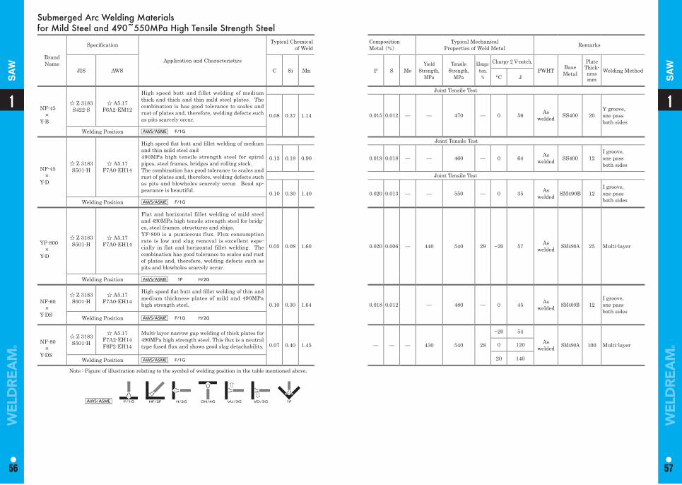
11
56 57
1
56
1
57
SA
W
SA
W
Submerged Arc Welding Materialsfor Mild Steel and 490~550MPa High Tensile Strength Steel
Brand Name
Specifi cation
Application and Characteristics
Typical Chemical of Weld
CompositionMetal (%)
Typical MechanicalProperties of Weld Metal Remarks
JIS AWS C Si Mn P S MoYield
Strength,MPa
Tensile Strength,
MPa
Elonga-tion,
%
Charpy 2 V-notch,PWHT Base
Metal
Plate Thick-nessmm
Welding Method°C J
NF-45×
Y-B
☆ Z 3183S422-S
☆ A5.17F6A2-EM12
High speed butt and fillet welding of medium thick and thick and thin mild steel plates. The combination is has good tolerance to scales and rust of plates and, therefore, welding defects such as pits scarcely occur.
Joint Tensile Test
0.08 0.37 1.14 0.015 0.012 — — 470 — 0 56 As welded SS400 20
Y groove, one passboth sides
Welding Position AWS/ASME F/1G
NF-45×
Y-D
☆ Z 3183S501-H
☆ A5.17F7A0-EH14
High speed fl at butt and fi llet welding of medium and thin mild steel and 490MPa high tensile strength steel for spiral pipes, steel frames, bridges and rolling stock.The combination has good tolerance to scales and rust of plates and, therefore, welding defects such as pits and blowholes scarcely occur. Bead ap-pearance is beautiful.
Joint Tensile Test
0.13 0.18 0.90 0.019 0.018 — — 460 — 0 64 As welded SS400 12
I groove, one pass both sides
Joint Tensile Test
0.10 0.30 1.40 0.020 0.013 — — 550 — 0 35 As welded SM490B 12
I groove, one pass both sidesWelding Position AWS/ASME F/1G
YF-800×
Y-D
☆ Z 3183S501-H
☆ A5.17F7A0-EH14
Flat and horizontal fillet welding of mild steel and 490MPa high tensile strength steel for bridg-es, steel frames, structures and ships.YF-800 is a pumiceous flux. Flux consumption rate is low and slag removal is excellent espe-cially in flat and horizontal fillet welding. The combination has good tolerance to scales and rust of plates and, therefore, welding defects such as pits and blowholes scarcely occur.
0.05 0.08 1.60 0.020 0.006 — 440 540 29 −20 57 As welded SM490A 25 Multi-layer
Welding Position AWS/ASME 1F H/2G
NF-60×
Y-DS
☆ Z 3183S501-H
☆ A5.17F7A0-EH14
High speed fl at butt and fi llet welding of thin and medium thickness plates of mild and 490MPa high strength steel. 0.10 0.30 1.64 0.018 0.012 — 480 — 0 45 As
welded SM400B 12I groove, one pass both sides
Welding Position AWS/ASME F/1G H/2G
NF-80×
Y-DS
☆ Z 3183S501-H
☆ A5.17F7A2-EH14F6P2-EH14
Multi-layer narrow gap welding of thick plates for 490MPa high strength steel. This fl ux is a neutral type fused fl ux and shows good slag detachability. 0.07 0.40 1.45 — — — 430 540 28
−20 54
As welded SM490A 100 Multi-layer0 120
20 140Welding Position AWS/ASME F/1G
Note : Figure of illustration relating to the symbol of welding position in the table mentioned above.
AWS/ASME F/1G HF/2F H/2G OH/4G VU/3G VD/3G 1F
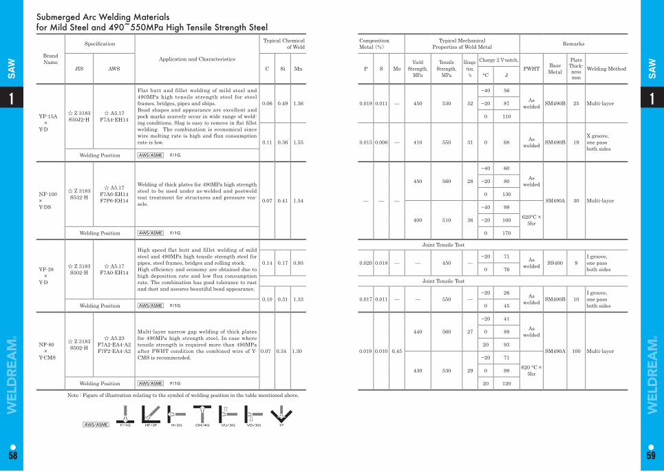
11
58 59
1
58
1
59
SA
W
SA
W
Submerged Arc Welding Materialsfor Mild Steel and 490~550MPa High Tensile Strength Steel
Brand Name
Specifi cation
Application and Characteristics
Typical Chemical of Weld
CompositionMetal (%)
Typical MechanicalProperties of Weld Metal Remarks
JIS AWS C Si Mn P S MoYield
Strength,MPa
Tensile Strength,
MPa
Elonga-tion,
%
Charpy 2 V-notch,PWHT Base
Metal
Plate Thick-nessmm
Welding Method°C J
YF-15A×
Y-D
☆ Z 3183S50J2-H
☆ A5.17F7A4-EH14
Flat butt and fillet welding of mild steel and 490MPa high tensile strength steel for steel frames, bridges, pipes and ships.Bead shapes and appearance are excellent and pock marks scarcely occur in wide range of weld-ing conditions. Slag is easy to remove in fl at fi llet welding. The combination is economical since wire melting rate is high and flux consumption rate is low.
0.06 0.49 1.56 0.019 0.011 — 450 530 32
−40 56
As welded SM490B 25 Multi-layer−20 87
0 110
0.11 0.36 1.55 0.015 0.006 — 410 550 31 0 68 As welded SM490B 19
X groove, one pass both sides
Welding Position AWS/ASME F/1G
NF-100×Y-DS
☆ Z 3183S532-H
☆ A5.17F7A6-EH14F7P6-EH14
Welding of thick plates for 490MPa high strength steel to be used under as-welded and postweld teat treatment for structures and pressure ves-sels. 0.07 0.41 1.54 — — —
450 560 28
−40 60
As welded
SM490A 30 Multi-layer
−20 80
0 130
400 510 36
−40 98
620°C ×5hr−20 160
Welding Position AWS/ASME F/1G 0 170
YF-38×
Y-D
☆ Z 3183S502-H
☆ A5.17F7A0-EH14
High speed flat butt and fillet welding of mild steel and 490MPa high tensile strength steel for pipes, steel frames, bridges and rolling stock.High effi ciency and economy are obtained due to high deposition rate and low flux consumption rate. The combination has good tolerance to rust and dust and assures beautiful bead appearance.
Joint Tensile Test
0.14 0.17 0.93 0.020 0.018 — — 450 —−20 71 As
welded SS400 9I groove, one pass both sides0 76
Joint Tensile Test
0.10 0.31 1.33 0.017 0.011 — — 550 —−20 26 As
welded SM490B 10I groove, one pass both sidesWelding Position AWS/ASME F/1G 0 45
NF-80×
Y-CMS
☆ Z 3183S502-H
☆ A5.23F7A2-EA4-A2F7P2-EA4-A2
Multi-layer narrow gap welding of thick plates for 490MPa high strength steel. In case where tensile strength is required more than 490MPa after PWHT condition the combined wire of Y-CMS is recommended.
0.07 0.34 1.30 0.019 0.010 0.45
440 560 27
−20 41
As welded
SM490A 100 Multi-layer
0 88
20 93
430 530 29
−20 71
620 °C ×5hr0 98
Welding Position AWS/ASME F/1G 20 120
Note : Figure of illustration relating to the symbol of welding position in the table mentioned above.
AWS/ASME F/1G HF/2F H/2G OH/4G VU/3G VD/3G 1F
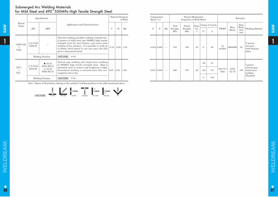
11
60 61
1
60
1
61
SA
W
SA
W
Submerged Arc Welding Materialsfor Mild Steel and 490~550MPa High Tensile Strength Steel
Brand Name
Specifi cation
Application and Characteristics
Typical Chemical of Weld
CompositionMetal (%)
Typical MechanicalProperties of Weld Metal Remarks
JIS AWS C Si Mn P S MoYield
Strength,MPa
Tensile Strength,
MPa
Elonga-tion,
%
Charpy 2 V-notch,PWHT Base
Metal
Plate Thick-nessmm
Welding Method°C J
NSH-53Z×
Y-DL
☆ Z 3183S502-H ―
Flat butt welding and fi llet welding of double bev-el grooves of mild steel and 490MPa high tensile strength steel for steel frames, and corner joint welding of box columns. It is possible to weld up to 60mm thick plates in one run since the flux gives a deep penetration.
0.12 0.28 1.50 0.016 0.005 — 370 530 30 0 50 As welded SM490B 50
Y groove, one pass with backing plate.
Welding Position AWS/ASME F/1G
NF-1×
Y-E
☆ Z 3183S532-H
★ A5.23F8A4-EG-G
☆ A5.23F8P2-EG-G
Narrow gap welding and single-layer welding of 490MPa high tensile strength steel. Slag is extremely easy to remove and toughness is high. Economical welding is assured since flux con-sumption rate is low.
0.07 0.32 1.89 0.011 0.004 — 480 570 28
−40 31
630 °C×10hr
A516Gr 70 100
I groove, narrow gap, multi-layer welding(Tandem)
−20 76
0 140Welding Position AWS/ASME F/1G
Note : Figure of illustration relating to the symbol of welding position in the table mentioned above.
AWS/ASME F/1G HF/2F H/2G OH/4G VU/3G VD/3G 1F
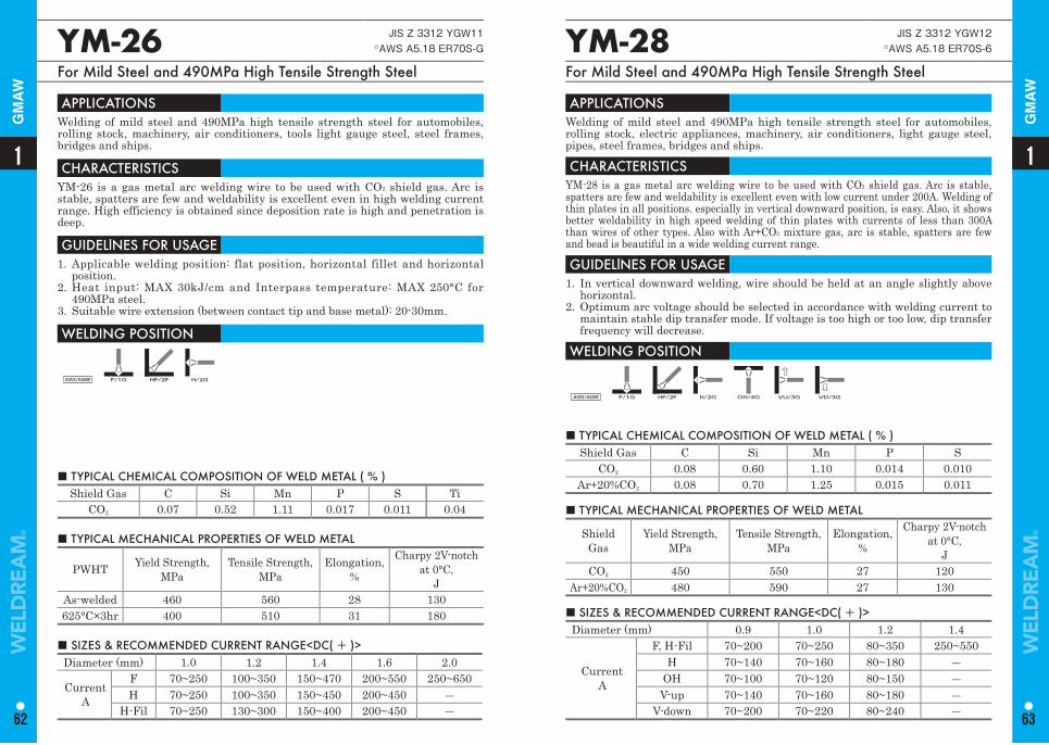
■ TYPICAL CHEMICAL COMPOSITION OF WELD METAL ( % ) Shield Gas C Si Mn P S
CO2 0.08 0.60 1.10 0.014 0.010Ar+20%CO2 0.08 0.70 1.25 0.015 0.011
YM-28 JIS Z 3312 YGW12 ☆AWS A5.18 ER70S-6
For Mild Steel and 490MPa High Tensile Strength Steel
APPLICATIONS Welding of mild steel and 490MPa high tensile strength steel for automobiles, rolling stock, electric appliances, machinery, air conditioners, light gauge steel, pipes, steel frames, bridges and ships.
CHARACTERISTICS YM-28 is a gas metal arc welding wire to be used with CO2 shield gas. Arc is stable, spatters are few and weldability is excellent even with low current under 200A. Welding of thin plates in all positions. especially in vertical downward position, is easy. Also, it shows better weldability in high speed welding of thin plates with currents of less than 300A than wires of other types. Also with Ar+CO2 mixture gas, arc is stable, spatters are few and bead is beautiful in a wide welding current range.
GUIDELlNES FOR USAGE 1. In vertical downward welding, wire should be held at an angle slightly above
horizontal. 2. Optimum arc voltage should be selected in accordance with welding current to
maintain stable dip transfer mode. If voltage is too high or too low, dip transfer frequency will decrease.
WELDING POSITION
AWS/ASME F/1G HF/2F H/2G OH/4G VU/3G VD/3G
■ SIZES & RECOMMENDED CURRENT RANGE<DC( + )> Diameter (mm) 0.9 1.0 1.2 1.4
CurrentA
F, H-Fil 70~200 70~250 80~350 250~550H 70~140 70~160 80~180 ―
OH 70~100 70~120 80~150 ―V-up 70~140 70~160 80~180 ―
V-down 70~200 70~220 80~240 ―
■ TYPICAL MECHANICAL PROPERTIES OF WELD METAL
Shield Gas
Yield Strength,MPa
Tensile Strength, MPa
Elongation,%
Charpy 2V-notch at 0°C,
J CO2 450 550 27 120
Ar+20%CO2 480 590 27 130
■ TYPICAL CHEMICAL COMPOSITION OF WELD METAL ( % ) Shield Gas C Si Mn P S Ti
CO2 0.07 0.52 1.11 0.017 0.011 0.04
YM-26 JIS Z 3312 YGW11 ☆AWS A5.18 ER70S-G
For Mild Steel and 490MPa High Tensile Strength Steel
APPLICATIONS Welding of mild steel and 490MPa high tensile strength steel for automobiles, rolling stock, machinery, air conditioners, tools light gauge steel, steel frames, bridges and ships.
CHARACTERISTICS YM-26 is a gas metal arc welding wire to be used with CO2 shield gas. Arc is stable, spatters are few and weldability is excellent even in high welding current range. High efficiency is obtained since deposition rate is high and penetration is deep.
GUIDELlNES FOR USAGE 1. Applicable welding position: flat position, horizontal fillet and horizontal
position.2. Heat input: MAX 30kJ/cm and Interpass temperature: MAX 250°C for
490MPa steel.3. Suitable wire extension (between contact tip and base metal): 20-30mm.
WELDING POSITION
AWS/ASME F/1G HF/2F H/2G
■ TYPICAL MECHANICAL PROPERTIES OF WELD METAL
PWHT Yield Strength,MPa
Tensile Strength, MPa
Elongation,%
Charpy 2V-notch at 0°C,
J As-welded 460 560 28 130625°C×3hr 400 510 31 180
■ SIZES & RECOMMENDED CURRENT RANGE<DC( + )> Diameter (mm) 1.0 1.2 1.4 1.6 2.0
CurrentA
F 70~250 100~350 150~470 200~550 250~650H 70~250 100~350 150~450 200~450 ―
H-Fil 70~250 130~300 150~400 200~450 ―
11
62 63
GM
AW
GM
AW
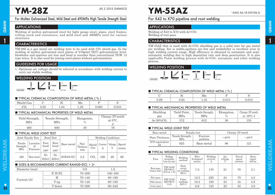
■ TYPICAL CHEMICAL COMPOSITION OF WELD METAL ( % ) Shield Gas C Si Mn P S
CO2 0.05 1.04 1.38 0.005 0.010
YM-28Z JIS Z 3312 G49A0C0
For Molten Galvanized Steel, Mild Steel and 490MPa High Tensile Strength Steel
APPLICATIONS Welding of molten galvanized steel for light gauge steel, pipes, steel frames, rolling stock and containers, and mild steel and 490MPa steel for various structures.
CHARACTERISTICS YM-28Z is a gas metal arc welding wire to be used with CO2 shield gas. In the welding of molten galvanized steel plates of 270g/m2 (Z27) galvanization level, blowholes and spatters are less and bead is sounder than conventional YGW 14 type wires. It is also used for joining steel plates without galvanization.
GUIDELlNES FOR USAGE 1. Optimum arc voltage should be selected in accordance with welding current to
carry out stable welding.
WELDING POSITION
AWS/ASME F/1G HF/2F H/2G VU/3G VD/3G
■ TYPICAL MECHANICAL PROPERTIES OF WELD METAL
Yield Strength,MPa
Tensile Strength,MPa
Elongation,%
Charpy 2V-notchat 0°C,
J 460 600 30 76
■ TYPICAL WELD JOINT TESTJoint Tensile Test Bend Test
Base metal
Welding Conditions
Tensile Strength,
MPa
Locationof
Fracture
Face bend180°
Root bend180°
Plate Thickness
mm
ShieldGas
Current A
Voltage V
Speed cm/min
460 Base metal No defect
No defect SGH400 Z27 3.2 CO2 160 20 60
■ SIZES & RECOMMENDED CURRENT RANGE<DC( + )> Diameter (mm) 0.9 1.2
Current (A)
F, H-Fil 70~200 100~350H 70~140 80~180
V-up 70~140 80~180V-down 70~200 80~240
■ TYPICAL CHEMICAL COMPOSITION OF WELD METAL ( % )C Si Mn P S
0.09 0.65 1.35 0.015 0.010
YM-55AZ ☆AWS A5.18 ER70S-G
For X42 to X70 pipeline and root welding
APPLICATIONS Welding of X42 to X70 with Ar+CO2
Welding of root pass
CHARACTERISTICS YM-55AZ that is used with Ar+CO2 shielding gas is a solid wire for gas metal arc welding. Arc is stable,spatters are few and weldability is excellent even in high welding current range. High efficiency is obtained in automatic and semi-automatic welding due to high deposition rate and deep penetration. It is also applicable Pulse welding process with Ar+CO2, automatic and robot welding process.
WELDING POSITION
AWS/ASME F/1G HF/2G H/2G OH/4G VU/3G VD/3G
■ TYPICAL MECHANICAL PROPERTIES OF WELD METAL Shielding
gasYield Point,
MPaTensile Strength,
MPaElongation,
%Charpy 2V-notch
at −20°C, J Ar-20%CO2 572 612 30 155
■ TYPICAL WELD JOINT TEST Base metal Tensile test Charpy 2V-notch
Plate Thickness Tensile Strength,MPa
Fractureposition −40°C −20°C
X70 equivalent22 625 Base metal 86 121
■ TYPICAL WELDING CONDITIONS
PassWeldingc
onsumables(wire dia.mm)
Weldingmethod
Wire feedspeed
m/min
Welding current
A
Arc voltage
V
Travel speed
cm/min
Heat inputkJ/cm
Root pass(inner side)
YM-55AZER70S-G
(0.9 or 1.0)
Short circuit
arc welding(DC+)
7.3 170 21 70 3.1
Hot passYM-55AZER70S-G
(1.0)
Pulsewelding(DC+)
12.5 220 24 70 4.5Filler layers 10.5 180 23 45 5.6Cover pass 6.6 125 22 45 3.8
11
64 65
GM
AW
GM
AW
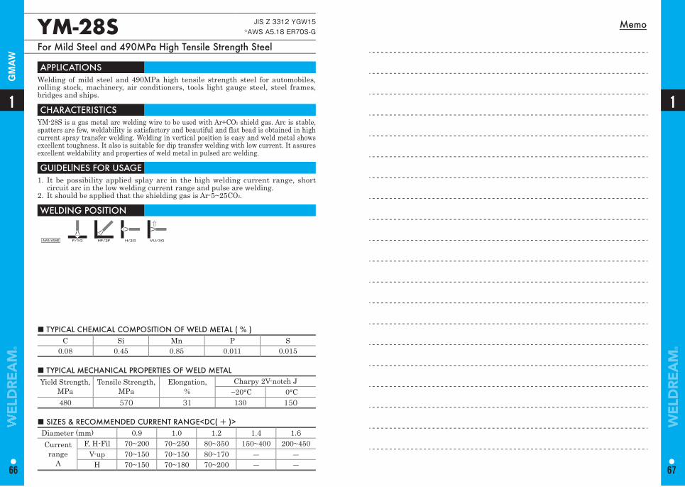
Memo
■ TYPICAL CHEMICAL COMPOSITION OF WELD METAL ( % ) C Si Mn P S
0.08 0.45 0.85 0.011 0.015
YM-28S JIS Z 3312 YGW15 ☆AWS A5.18 ER70S-G
For Mild Steel and 490MPa High Tensile Strength Steel
APPLICATIONS Welding of mild steel and 490MPa high tensile strength steel for automobiles, rolling stock, machinery, air conditioners, tools light gauge steel, steel frames, bridges and ships.
CHARACTERISTICS YM-28S is a gas metal arc welding wire to be used with Ar+CO2 shield gas. Arc is stable, spatters are few, weldability is satisfactory and beautiful and flat bead is obtained in high current spray transfer welding. Welding in vertical position is easy and weld metal shows excellent toughness. It also is suitable for dip transfer welding with low current. It assures excellent weldability and properties of weld metal in pulsed arc welding.
GUIDELlNES FOR USAGE 1. It be possibility applied splay arc in the high welding current range, short
circuit arc in the low welding current range and pulse are welding. 2. It should be applied that the shielding gas is Ar-5~25CO2.
WELDING POSITION
AWS/ASME F/1G HF/2F H/2G VU/3G
■ SIZES & RECOMMENDED CURRENT RANGE<DC( + )> Diameter (mm) 0.9 1.0 1.2 1.4 1.6Currentrange
A
F, H-Fil 70~200 70~250 80~350 150~400 200~450V-up 70~150 70~150 80~170 ― ―
H 70~150 70~180 70~200 ― ―
■ TYPICAL MECHANICAL PROPERTIES OF WELD METAL Yield Strength,
MPaTensile Strength,
MPa Elongation,
%Charpy 2V-notch J
−20°C 0°C480 570 31 130 150
1
66
1
67
GM
AW
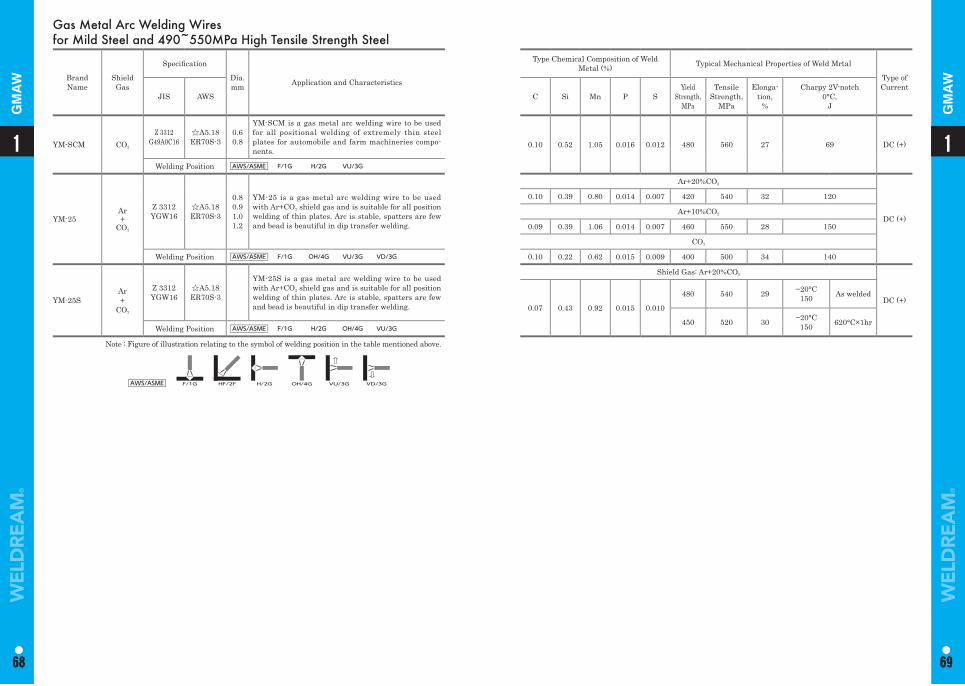
Gas Metal Arc Welding Wires for Mild Steel and 490~550MPa High Tensile Strength Steel
Brand Name
Shield Gas
Specifi cation
Dia. mm Application and Characteristics
Type Chemical Composition of Weld Metal (%) Typical Mechanical Properties of Weld Mrtal
Type of Current
JIS AWS C Si Mn P SYield
Strength,MPa
Tensile Strength,
MPa
Elonga-tion,
%
Charpy 2V-notch0°C,
J
YM-SCM CO2
Z 3312G49A0C16
☆A5.18ER70S-3
0.60.8
YM-SCM is a gas metal arc welding wire to be used for all positional welding of extremely thin steel plates for automobile and farm machineries compo-nents.
0.10 0.52 1.05 0.016 0.012 480 560 27 69 DC (+)
Welding Position AWS/ASME F/1G H/2G VU/3G
YM-25Ar+
CO2
Z 3312YGW16
☆A5.18ER70S-3
0.80.91.01.2
YM-25 is a gas metal arc welding wire to be used with Ar+CO2 shield gas and is suitable for all position welding of thin plates. Arc is stable, spatters are few and bead is beautiful in dip transfer welding.
Ar+20%CO2
DC (+)
0.10 0.39 0.80 0.014 0.007 420 540 32 120
Ar+10%CO2
0.09 0.39 1.06 0.014 0.007 460 550 28 150
CO2
Welding Position AWS/ASME F/1G OH/4G VU/3G VD/3G 0.10 0.22 0.62 0.015 0.009 400 500 34 140
YM-25SAr+
CO2
Z 3312YGW16
☆A5.18ER70S-3
YM-25S is a gas metal arc welding wire to be used with Ar+CO2 shield gas and is suitable for all position welding of thin plates. Arc is stable, spatters are few and bead is beautiful in dip transfer welding.
Shield Gas: Ar+20%CO2
DC (+)0.07 0.43 0.92 0.015 0.010
480 540 29 −20°C150 As welded
450 520 30 −20°C150 620°C×1hr
Welding Position AWS/ASME F/1G H/2G OH/4G VU/3G
Note : Figure of illustration relating to the symbol of welding position in the table mentioned above.
AWS/ASME F/1G HF/2F H/2G OH/4G VU/3G VD/3G
11
68 69
1
68
1
69
GM
AW
GM
AW
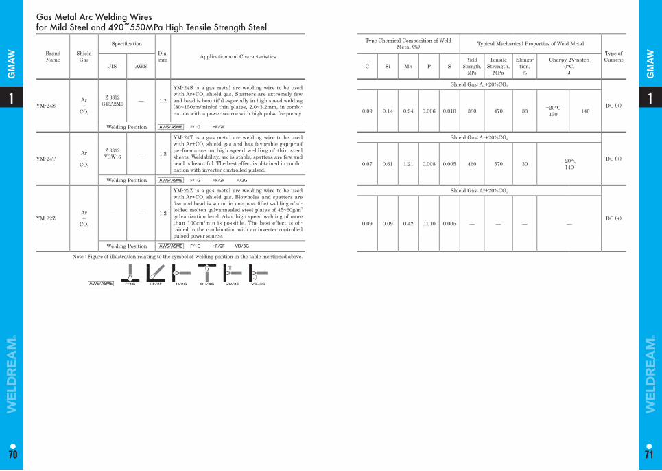
Gas Metal Arc Welding Wires for Mild Steel and 490~550MPa High Tensile Strength Steel
Brand Name
Shield Gas
Specifi cation
Dia. mm Application and Characteristics
Type Chemical Composition of Weld Metal (%) Typical Mechanical Properties of Weld Mrtal
Type of Current
JIS AWS C Si Mn P SYield
Strength,MPa
Tensile Strength,
MPa
Elonga-tion,
%
Charpy 2V-notch0°C,
J
YM-24SAr+
CO2
Z 3312G43A2M0 — 1.2
YM-24S is a gas metal arc welding wire to be used with Ar+CO2 shield gas. Spatters are extremely few and bead is beautiful especially in high speed welding (80~150cm/min)of thin plates, 2.0~3.2mm, in combi-nation with a power source with high pulse frequency.
Shield Gas: Ar+20%CO2
DC (+)0.09 0.14 0.94 0.006 0.010 380 470 33 −20°C
130 140
Welding Position AWS/ASME F/1G HF/2F
YM-24TAr+
CO2
Z 3312YGW16 — 1.2
YM-24T is a gas metal arc welding wire to be used with Ar+CO2 shield gas and has favorable gap-proof performance on high-speed welding of thin steel sheets. Weldability, arc is stable, spatters are few and bead is beautiful. The best effect is obtained in combi-nation with inverter controlled pulsed.
Shield Gas: Ar+20%CO2
DC (+)0.07 0.61 1.21 0.008 0.005 460 570 30 −20°C
140
Welding Position AWS/ASME F/1G HF/2F H/2G
YM-22ZAr+
CO2
— — 1.2
YM-22Z is a gas metal arc welding wire to be used with Ar+CO2 shield gas. Blowholes and spatters are few and bead is sound in one pass fi llet welding of al-loifi ed molten galvannealed steel plates of 45~60g/m2
galvanization level. Also, high speed welding of more than 100cm/min is possible. The best effect is ob-tained in the combination with an inverter controlled pulsed power source.
Shield Gas: Ar+20%CO2
DC (+)0.09 0.09 0.42 0.010 0.005 — — — —
Welding Position AWS/ASME F/1G HF/2F VD/3G
Note : Figure of illustration relating to the symbol of welding position in the table mentioned above.
AWS/ASME F/1G HF/2F H/2G OH/4G VU/3G VD/3G
11
70 71
1
70
1
71
GM
AW
GM
AW
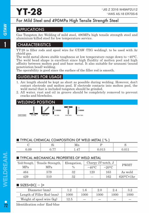
■ TYPICAL CHEMICAL COMPOSITION OF WELD METAL ( % ) C Si Mn P S
0.09 0.77 1.47 0.013 0.011
YT-28 ☆JIS Z 3316 W49AP2U12 ☆AWS A5.18 ER70S-6
For Mild Steel and 490MPa High Tensile Strength Steel
APPLICATIONS Gas Tungsten Arc Welding of mild steel, 490MPa high tensile strength steel and aluminium-killed steel for low temperature service.
CHARACTERISTICS YT-28 is filler rods and spool wire for GTAW (TIG welding). to be used with Ar shield gas. The weld metal shows stable toughness at low temperature range down to −40°C. The weld bead shape is excellent since high fluidity of molten pool and high affinity between molten pool and base metal. It also suitable for uranami (sound penetration bead) welding.The operability is good since the surface of the filler rod is smooth.
GUIDELlNES FOR USAGE 1. Arc length should be kept as short as possible during welding. However, don’t
contact electrode and molten pool. If electrode contacts into molten pool, the weld metal that is included tungsten should be grinded.
2. All water, rust and oil in groove should be completely removed to prevent cracks and blowholes.
WELDING POSITION
AWS/ASME F/1G HF/2F H/2G OH/4G VU/3G
■ TYPICAL MECHANICAL PROPERTIES OF WELD METAL Yield Strength,
MPaTensile Strength,
MPa Elongation,
%Charpy 2V-notch, J
PWHT−40°C −20°C
464 579 32 120 163 As weld429 510 32 ― 162 620°C×1hr
■ SIZES<DC( - )> Diameter (mm) 1.2 1.6 2.0 2.4 3.2
Length of Filler Rod (mm) 1000 1000 1000 1000 1000Weight of spool wire (kg) 12.5 ― ― ― ―
Identifi cation color: End-blue
1
72
GTA
W
570~950MPa High Tensile Strength SteelFlux Cored Arc Welding WiresCovered Arc Welding ElectrodesSubmerged Arc Welding MaterialsGas Metal Arc Welding WiresGas Tungsten Arc Welding Rods and Wires
73
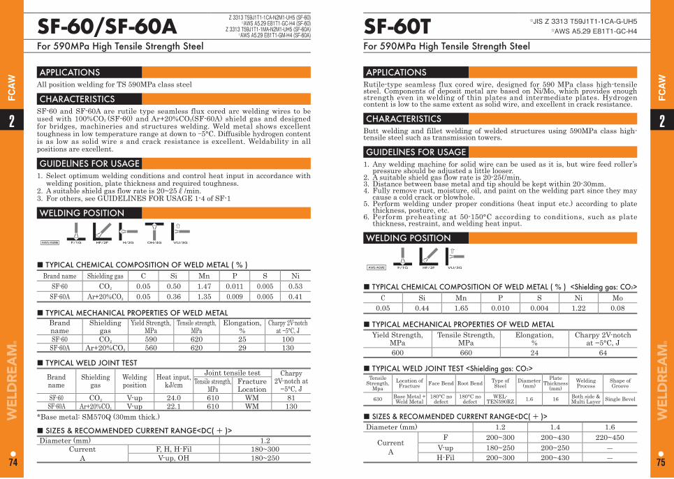
SF-60/SF-60A Z 3313 T59J1T1-1CA-N2M1-UH5 (SF-60)☆AWS A5.29 E81T1-GC-H4 (SF-60)
Z 3313 T59J1T1-1MA-N2M1-UH5 (SF-60A)☆AWS A5.29 E81T1-GM-H4 (SF-60A)
For 590MPa High Tensile Strength Steel
APPLICATIONS All position welding for TS 590MPa class steel
CHARACTERISTICS SF-60 and SF-60A are rutile type seamless flux cored arc welding wires to be used with 100%CO2 (SF-60) and Ar+20%CO2(SF-60A) shield gas and designed for bridges, machineries and structures welding. Weld metal shows excellent toughness in low temperature range at down to -5°C. Diffusible hydrogen content is as low as solid wire s and crack resistance is excellent. Weldability in all positions are excellent.
GUIDELlNES FOR USAGE 1. Select optimum welding conditions and control heat input in accordance with
welding position, plate thickness and required toughness.2. A suitable shield gas flow rate is 20~25ℓ/min.3. For others, see GUIDELINES FOR USAGE 1-4 of SF-1
WELDING POSITION
AWS/ASME F/1G HF/2F H/2G OH/4G VU/3G
■ TYPICAL CHEMICAL COMPOSITION OF WELD METAL ( % ) Brand name Shielding gas C Si Mn P S Ni
SF-60 CO2 0.05 0.50 1.47 0.011 0.005 0.53SF-60A Ar+20%CO2 0.05 0.36 1.35 0.009 0.005 0.41
■ TYPICAL MECHANICAL PROPERTIES OF WELD METAL Brandname
Shielding gas
Yield Strength, MPa
Tensile strength, MPa
Elongation,%
Charpy 2V-notch at −5°C, J
SF-60 CO2 590 620 25 100SF-60A Ar+20%CO2 560 620 29 130
■ SIZES & RECOMMENDED CURRENT RANGE<DC( + )> Diameter (mm) 1.2
CurrentA
F, H, H-Fil 180~300V-up, OH 180~250
■ TYPICAL WELD JOINT TEST
Brandname
Shieldinggas
Weldingposition
Heat input, kJ/cm
Joint tensile test Charpy 2V-notch at
−5°C, JTensile strength,
MPaFractureLocation
SF-60 CO2 V-up 24.0 610 WM 81SF-60A Ar+20%CO2 V-up 22.1 610 WM 130
*Base metal: SM570Q (30mm thick.)
SF-60T ☆JIS Z 3313 T59J1T1-1CA-G-UH5☆AWS A5.29 E81T1-GC-H4
For 590MPa High Tensile Strength Steel
APPLICATIONS Rutile-type seamless flux cored wire, designed for 590 MPa class high-tensile steel. Components of deposit metal are based on Ni/Mo, which provides enough strength even in welding of thin plates and intermediate plates. Hydrogen content is low to the same extent as solid wire, and excellent in crack resistance.
CHARACTERISTICS Butt welding and fillet welding of welded structures using 590MPa class high-tensile steel such as transmission towers.
GUIDELlNES FOR USAGE 1. Any welding machine for solid wire can be used as it is, but wire feed roller’s
pressure should be adjusted a little looser.2. A suitable shield gas flow rate is 20-25ℓ/min.3. Distance between base metal and tip should be kept within 20-30mm.4. Fully remove rust, moisture, oil, and paint on the welding part since they may
cause a cold crack or blowhole.5. Perform welding under proper conditions (heat input etc.) according to plate
thickness, posture, etc.6. Perform preheating at 50-150°C according to conditions, such as plate
thickness, restraint, and welding heat input.
WELDING POSITION
AWS/ASME F/1G HF/2F VU/3G
■ TYPICAL CHEMICAL COMPOSITION OF WELD METAL ( % ) <Shielding gas: CO2>C Si Mn P S Ni Mo
0.05 0.44 1.65 0.010 0.004 1.22 0.08
■ TYPICAL MECHANICAL PROPERTIES OF WELD METAL Yield Strength,
MPaTensile Strength,
MPaElongation,
%Charpy 2V-notch
at −5°C, J600 660 24 64
■ SIZES & RECOMMENDED CURRENT RANGE<DC( + )>Diameter (mm) 1.2 1.4 1.6
CurrentA
F 200~300 200~430 220~450V-up 180~250 200~250 ―H-Fil 200~300 200~430 ―
■ TYPICAL WELD JOINT TEST <Shielding gas: CO2>Tensile
Strength, Mpa
Location ofFracture Face Bend Root Bend Type of
SteelDiameter
(mm)Plate
Thickness (mm)
Welding Process
Shape of Groove
630 Base Metal +Weld Metal
180°C no defect
180°C no defect
WEL-TEN590RZ 1.6 16 Both side &
Multi Layer Single Bevel
22
74 75
FC
AW
FC
AW
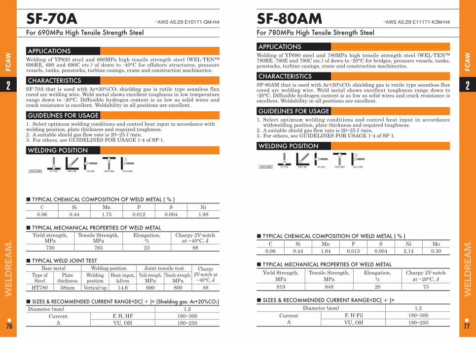
SF-70A ☆AWS A5.29 E101T1-GM-H4
For 690MPa High Tensile Strength Steel
APPLICATIONS Welding of YP620 steel and 690MPa high tensile strength steel (WEL-TEN™ 690RE, 690 and 690C etc.) of down to -40°C for offshore structures, pressure vessels, tanks, penstocks, turbine casings, crane and construction machineries.
CHARACTERISTICS SF-70A that is used with Ar+20%CO2 shielding gas is rutile type seamless flux cored arc welding wire. Weld metal shows excellent toughness in low temperature range down to -40°C. Diffusible hydrogen content is as low as solid wires and crack resistance is excellent. Weldability in all positions are excellent.
GUIDELlNES FOR USAGE 1. Select optimum welding conditions and control heat input in accordance withwelding position, plate thickness and required toughness.2. A suitable shield gas flow rate is 20~25ℓ/min.3. For others, see GUIDELINES FOR USAGE 1-4 of SF-1.
WELDING POSITION
AWS/ASME F/1G HF/2F H/2G OH/4G VU/3G
■ TYPICAL CHEMICAL COMPOSITION OF WELD METAL ( % ) C Si Mn P S Ni
0.06 0.44 1.75 0.012 0.004 1.88
■ TYPICAL MECHANICAL PROPERTIES OF WELD METAL Yield strength,
MPaTensile Strength,
MPaElongation,
%Charpy 2V-notch
at −40°C, J730 765 23 88
■ SIZES & RECOMMENDED CURRENT RANGE<DC( + )> (Shielding gas: Ar+20%CO2)Diameter (mm) 1.2
CurrentA
F, H, HF 180~300VU, OH 180~250
■ TYPICAL WELD JOINT TESTBase metal Welding position Joint tensile test Charpy
2V-notch at −40°C, J
Type ofSteel
Plate thickness
Welding position
Heat input, kJ/cm
Yield strength, MPa
Tensile strength, MPa
HT780 38mm Vertical-up 14.6 690 800 68
■ TYPICAL CHEMICAL COMPOSITION OF WELD METAL ( % ) C Si Mn P S Ni Mo
0.06 0.44 1.64 0.013 0.004 2.14 0.30
SF-80AM ☆AWS A5.29 E111T1-K3M-H4
For 780MPa High Tensile Strength Steel
APPLICATIONS Welding of YP690 steel and 780MPa high tensile strength steel (WEL-TEN™ 780RE, 780E and 780C etc.) of down to -20°C for bridges, pressure vessels, tanks, penstocks, turbine casings, crane and construction machineries.
CHARACTERISTICS SF-80AM that is used with Ar+20%CO2 shielding gas is rutile type seamless flux cored arc welding wire. Weld metal shows excellent toughness range down to -20°C. Diffusible hydrogen content is as low as solid wires and crack resistance is excellent. Weldability in all positions are excellent.
GUIDELlNES FOR USAGE 1. Select optimum welding conditions and control heat input in accordance
withwelding position, plate thickness and required toughness.2. A suitable shield gas flow rate is 20~25ℓ/min.3. For others, see GUIDELINES FOR USAGE 1-4 of SF-1.
WELDING POSITION
AWS/ASME F/1G HF/2F H/2G OH/4G VU/3G
■ TYPICAL MECHANICAL PROPERTIES OF WELD METAL Yield Strength,
MPaTensile Strength,
MPa Elongation,
%Charpy 2V-notch
at −20°C, J 819 848 20 73
■ SIZES & RECOMMENDED CURRENT RANGE<DC( + )> Diameter (mm) 1.2
Current A
F, H-Fil 180~300VU, OH 180~250
22
76 77
FC
AW
FC
AW
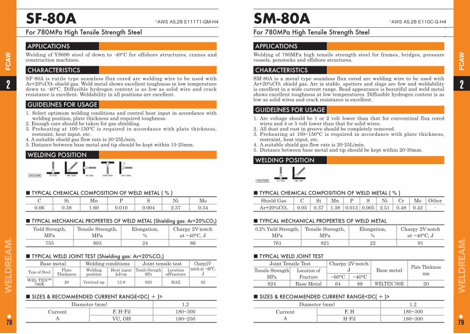
SF-80A ☆AWS A5.29 E111T1-GM-H4
For 780MPa High Tensile Strength Steel
APPLICATIONS Welding of YS690 steel of down to -40°C for offshore structures, cranes and construction machines.
CHARACTERISTICS SF-80A is rutile type seamless flux cored arc welding wire to be used with Ar+20%CO2 shield gas. Weld metal shows excellent toughness in low temperature down to -40°C. Diffusible hydrogen content is as low as solid wire and crack resistance is excellent. Weldability in all positions are excellent.
GUIDELlNES FOR USAGE 1. Select optimum welding conditions and control heat input in accordance with
welding position, plate thickness and required toughness.2. Enough care should be taken for gas shielding.3. Preheating at 100~150°C is required in accordance with plate thickness,
restraint, heat input, etc.4. A suitable shield gas flow rate is 20-25L/min.5. Distance between base metal and tip should be kept within 15-25mm.
WELDING POSITION
AWS/ASME F/1G HF/2G H/2G OH/4G VU/3G
■ TYPICAL CHEMICAL COMPOSITION OF WELD METAL ( % ) C Si Mn P S Ni Mo
0.06 0.38 1.60 0.010 0.004 2.37 0.34
■ TYPICAL MECHANICAL PROPERTIES OF WELD METAL (Shielding gas: Ar+20%CO2) Yield Strength,
MPaTensile Strength,
MPa Elongation,
%Charpy 2V-notch
at −40°C, J 755 803 24 86
■ TYPICAL WELD JOINT TEST (Shielding gas: Ar+20%CO2) Base metal Welding conditions Joint tensile test Charpy2V-
notch at −40°C, JType of Steel Plate
ThicknessWelding position
Heat input kJ/cm
Tensile Strength MPa
Location ofFracture
WEL-TEN™780E 20 Vertical-up 13.8 820 HAZ 82
■ SIZES & RECOMMENDED CURRENT RANGE<DC( + )>Diameter (mm) 1.2
Current A
F, H-Fil 180~300VU, OH 180~250
SM-80A ☆AWS A5.28 E110C-G-H4
For 780MPa High Tensile Strength Steel
APPLICATIONS Welding of 780MPa high tensile strength steel for frames, bridges, pressure vessels, penstocks and offshore structures.
CHARACTERISTICS SM-80A is a metal type seamless flux cored arc welding wire to be used with Ar+20%CO2 shield gas. Arc is stable, spatters and slags are few and weldability is excellent in a wide current range. Bead appearance is beautiful and weld metal shows excellent toughness at low temperatures. Diffusible hydrogen content is as low as solid wires and crack resistance is excellent.
GUIDELlNES FOR USAGE 1. Arc voltage should be 1 or 2 volt lower than that for conventinal flux cored
wires and 4 or 5 volt lower than that for solid wires. 2. All dust and rust in groove should be completely removed.3. Preheating at 100~150°C is required in accordance with plate thickness,
restraint, heat input, etc.4. A suitable shield gas flow rate is 20-25L/min.5. Distance between base metal and tip should be kept within 20-30mm.
WELDING POSITION
AWS/ASME F/1G HF/2F
■ TYPICAL CHEMICAL COMPOSITION OF WELD METAL ( % ) Shield Gas C Si Mn P S Ni Cr Mo OtherAr+20%CO2 0.05 0.37 1.38 0.013 0.005 2.51 0.48 0.42 -
■ TYPICAL MECHANICAL PROPERTIES OF WELD METAL 0.2% Yield Strength,
MPaTensile Strength,
MPa Elongation,
%Charpy 2V-notch
at −40°C, J 761 821 22 91
■ TYPICAL WELD JOINT TEST Joint Tensile Test Charpy 2V-notch
J Base metal Plate ThicknessmmTensile Strength
MPaLocation ofFracture −60°C −40°C
824 Base Metal 64 88 WELTEN 780E 20
■ SIZES & RECOMMENDED CURRENT RANGE<DC( + )> Diameter (mm) 1.2
Current A
F, H 180~300H-Fil 180~300
22
78 79
FC
AW
FC
AW
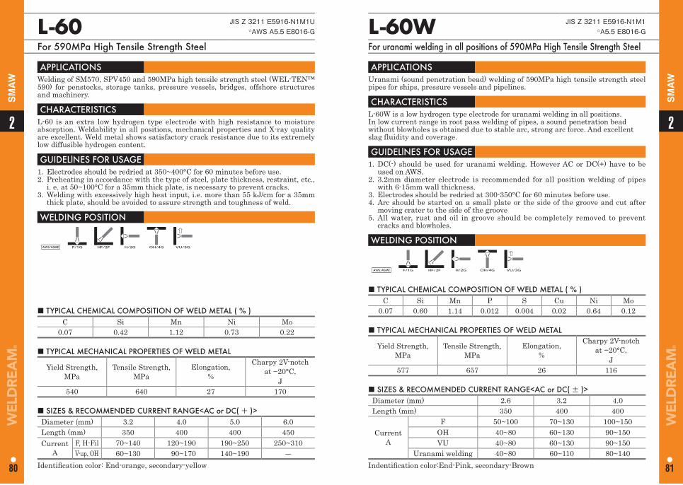
■ TYPICAL CHEMICAL COMPOSITION OF WELD METAL ( % ) C Si Mn P S Cu Ni Mo
0.07 0.60 1.14 0.012 0.004 0.02 0.64 0.12
L-60W JIS Z 3211 E5916-N1M1☆A5.5 E8016-G
For uranami welding in all positions of 590MPa High Tensile Strength Steel
APPLICATIONS Uranami (sound penetration bead) welding of 590MPa high tensile strength steel pipes for ships, pressure vessels and pipelines.
CHARACTERISTICS L-60W is a low hydrogen type electrode for uranami welding in all positions. In low current range in root pass welding of pipes, a sound penetration bead without blowholes is obtained due to stable arc, strong arc force. And excellent slag fluidity and coverage.
GUIDELlNES FOR USAGE 1. DC(-) should be used for uranami welding. However AC or DC(+) have to be
used on AWS.2. 3.2mm diameter electrode is recommended for all position welding of pipes
with 6-15mm wall thickness.3. Electrodes should be redried at 300-350°C for 60 minutes before use.4. Arc should be started on a small plate or the side of the groove and cut after
moving crater to the side of the groove5. All water, rust and oil in groove should be completely removed to prevent
cracks and blowholes.
WELDING POSITION
AWS/ASME F/1G HF/2F H/2G OH/4G VU/3G
■ TYPICAL MECHANICAL PROPERTIES OF WELD METAL
Yield Strength, MPa
Tensile Strength, MPa
Elongation,%
Charpy 2V-notch at −20°C,
J 577 657 26 116
■ SIZES & RECOMMENDED CURRENT RANGE<AC or DC( ± )> Diameter (mm) 2.6 3.2 4.0 Length (mm) 350 400 400
CurrentA
F 50~100 70~130 100~150OH 40~80 60~130 90~150VU 40~80 60~130 90~150
Uranami welding 40~80 60~110 80~140Indentifi cation color:End-Pink, secondary-Brown
■ TYPICAL CHEMICAL COMPOSITION OF WELD METAL ( % ) C Si Mn Ni Mo
0.07 0.42 1.12 0.73 0.22
L-60 JIS Z 3211 E5916-N1M1U☆AWS A5.5 E8016-G
For 590MPa High Tensile Strength Steel
APPLICATIONS Welding of SM570, SPV450 and 590MPa high tensile strength steel (WEL-TEN™ 590) for penstocks, storage tanks, pressure vessels, bridges, offshore structures and machinery.
CHARACTERISTICS L-60 is an extra low hydrogen type electrode with high resistance to moisture absorption. Weldability in all positions, mechanical properties and X-ray quality are excellent. Weld metal shows satisfactory crack resistance due to its extremely low diffusible hydrogen content.
GUIDELlNES FOR USAGE 1. Electrodes should be redried at 350~400°C for 60 minutes before use. 2. Preheating in accordance with the type of steel, plate thickness, restraint, etc.,
i. e. at 50~100°C for a 35mm thick plate, is necessary to prevent cracks. 3. Welding with excessively high heat input, i.e. more than 55 kJ/cm for a 35mm
thick plate, should be avoided to assure strength and toughness of weld.
WELDING POSITION
AWS/ASME F/1G HF/2F H/2G OH/4G VU/3G
■ TYPICAL MECHANICAL PROPERTIES OF WELD METAL
Yield Strength, MPa
Tensile Strength, MPa
Elongation,%
Charpy 2V-notch at −20°C,
J 540 640 27 170
■ SIZES & RECOMMENDED CURRENT RANGE<AC or DC( + )> Diameter (mm) 3.2 4.0 5.0 6.0 Length (mm) 350 400 400 450Current
AF, H-Fil 70~140 120~190 190~250 250~310V-up, OH 60~130 90~170 140~190 ―
Identifi cation color: End-orange, secondary-yellow
22
80 81
SM
AW
SM
AW
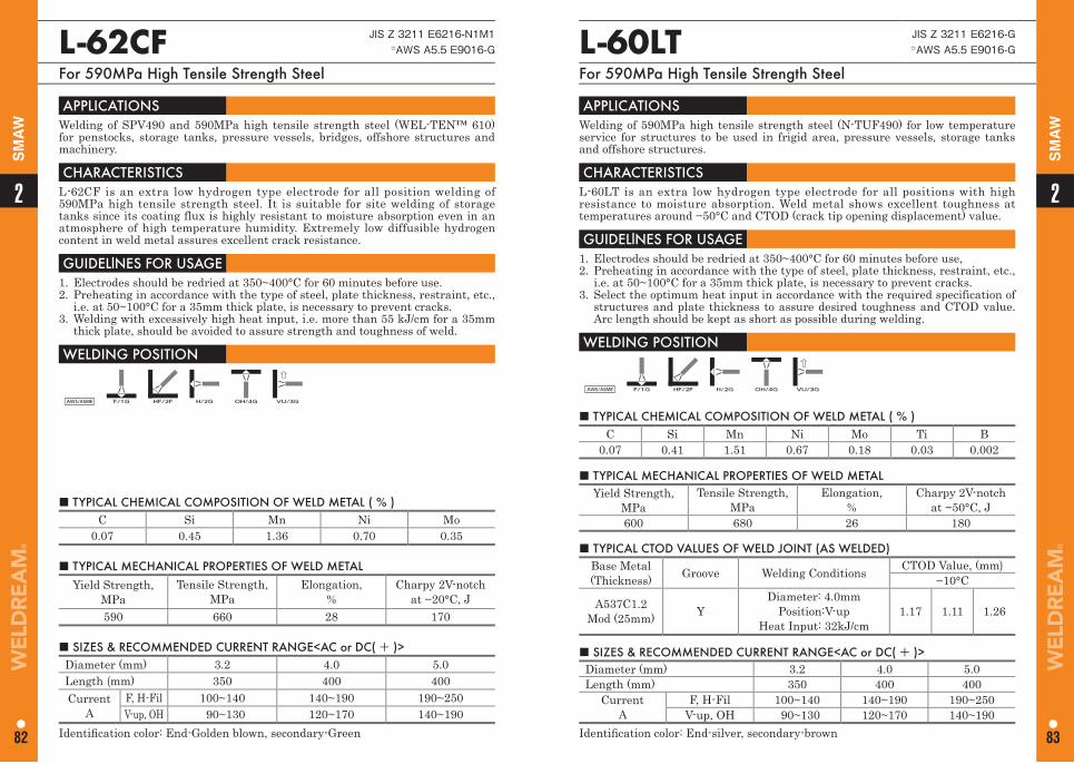
■ TYPICAL CHEMICAL COMPOSITION OF WELD METAL ( % ) C Si Mn Ni Mo Ti B
0.07 0.41 1.51 0.67 0.18 0.03 0.002
L-60LT JIS Z 3211 E6216-G☆AWS A5.5 E9016-G
For 590MPa High Tensile Strength Steel
APPLICATIONS Welding of 590MPa high tensile strength steel (N-TUF490) for low temperature service for structures to be used in frigid area, pressure vessels, storage tanks and offshore structures.
CHARACTERISTICS L-60LT is an extra low hydrogen type electrode for all positions with high resistance to moisture absorption. Weld metal shows excellent toughness at temperatures around −50°C and CTOD (crack tip opening displacement) value.
GUIDELlNES FOR USAGE 1. Electrodes should be redried at 350~400°C for 60 minutes before use, 2. Preheating in accordance with the type of steel, plate thickness, restraint, etc.,
i.e. at 50~100°C for a 35mm thick plate, is necessary to prevent cracks. 3. Select the optimum heat input in accordance with the required specification of
structures and plate thickness to assure desired toughness and CTOD value. Arc length should be kept as short as possible during welding.
WELDING POSITION
AWS/ASME F/1G HF/2F H/2G OH/4G VU/3G
■ TYPICAL MECHANICAL PROPERTIES OF WELD METAL Yield Strength,
MPa Tensile Strength,
MPa Elongation,
%Charpy 2V-notch
at −50°C, J 600 680 26 180
■ SIZES & RECOMMENDED CURRENT RANGE<AC or DC( + )> Diameter (mm) 3.2 4.0 5.0Length (mm) 350 400 400
CurrentA
F, H-Fil 100~140 140~190 190~250V-up, OH 90~130 120~170 140~190
Identifi cation color: End-silver, secondary-brown
■ TYPICAL CTOD VALUES OF WELD JOINT (AS WELDED) Base Metal (Thickness) Groove Welding Conditions CTOD Value, (mm)
−10°C
A537C1.2 Mod (25mm) Y
Diameter: 4.0mm Position:V-up
Heat Input: 32kJ/cm1.17 1.11 1.26
■ TYPICAL CHEMICAL COMPOSITION OF WELD METAL ( % ) C Si Mn Ni Mo
0.07 0.45 1.36 0.70 0.35
L-62CF JIS Z 3211 E6216-N1M1☆AWS A5.5 E9016-G
For 590MPa High Tensile Strength Steel
APPLICATIONS Welding of SPV490 and 590MPa high tensile strength steel (WEL-TEN™ 610) for penstocks, storage tanks, pressure vessels, bridges, offshore structures and machinery.
CHARACTERISTICS L-62CF is an extra low hydrogen type electrode for all position welding of 590MPa high tensile strength steel. It is suitable for site welding of storage tanks since its coating flux is highly resistant to moisture absorption even in an atmosphere of high temperature humidity. Extremely low diffusible hydrogen content in weld metal assures excellent crack resistance.
GUIDELlNES FOR USAGE 1. Electrodes should be redried at 350~400°C for 60 minutes before use. 2. Preheating in accordance with the type of steel, plate thickness, restraint, etc.,
i.e. at 50~100°C for a 35mm thick plate, is necessary to prevent cracks. 3. Welding with excessively high heat input, i.e. more than 55 kJ/cm for a 35mm
thick plate, should be avoided to assure strength and toughness of weld.
WELDING POSITION
AWS/ASME F/1G HF/2F H/2G OH/4G VU/3G
■ TYPICAL MECHANICAL PROPERTIES OF WELD METAL Yield Strength,
MPa Tensile Strength,
MPa Elongation,
%Charpy 2V-notch
at −20°C, J 590 660 28 170
■ SIZES & RECOMMENDED CURRENT RANGE<AC or DC( + )> Diameter (mm) 3.2 4.0 5.0Length (mm) 350 400 400Current
AF, H-Fil 100~140 140~190 190~250V-up, OH 90~130 120~170 140~190
Identifi cation color: End-Golden blown, secondary-Green
22
82 83
SM
AW
SM
AW
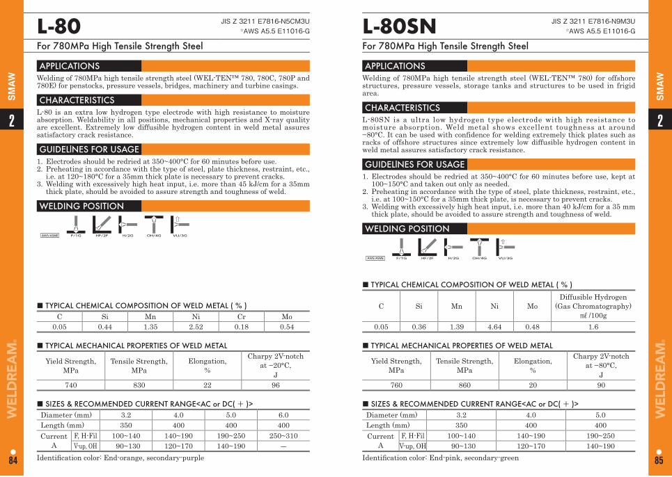
L-80SN JIS Z 3211 E7816-N9M3U☆AWS A5.5 E11016-G
For 780MPa High Tensile Strength Steel
APPLICATIONS Welding of 780MPa high tensile strength steel (WEL-TEN™ 780) for offshore structures, pressure vessels, storage tanks and structures to be used in frigid area.
CHARACTERISTICS L-80SN is a ultra low hydrogen type electrode with high resistance to moisture absorption. Weld metal shows excellent toughness at around −80°C. It can be used with confidence for welding extremely thick plates such as racks of offshore structures since extremely low diffusible hydrogen content in weld metal assures satisfactory crack resistance.
GUIDELlNES FOR USAGE 1. Electrodes should be redried at 350~400°C for 60 minutes before use, kept at
100~150°C and taken out only as needed. 2. Preheating in accordance with the type of steel, plate thickness, restraint, etc.,
i.e. at 100~150°C for a 35mm thick plate, is necessary to prevent cracks. 3. Welding with excessively high heat input, i.e. more than 40 kJ/cm for a 35 mm
thick plate, should be avoided to assure strength and toughness of weld.
WELDING POSITION
AWS/ASME F/1G HF/2F H/2G OH/4G VU/3G
■ TYPICAL CHEMICAL COMPOSITION OF WELD METAL ( % )
C Si Mn Ni MoDiffusible Hydrogen
(Gas Chromatography) ㎖ /100g
0.05 0.36 1.39 4.64 0.48 1.6
■ TYPICAL MECHANICAL PROPERTIES OF WELD METAL
Yield Strength, MPa
Tensile Strength, MPa
Elongation,%
Charpy 2V-notch at −80°C,
J 760 860 20 90
■ SIZES & RECOMMENDED CURRENT RANGE<AC or DC( + )> Diameter (mm) 3.2 4.0 5.0Length (mm) 350 400 400Current
AF, H-Fil 100~140 140~190 190~250
V-up, OH 90~130 120~170 140~190Identifi cation color: End-pink, secondary-green
■ TYPICAL CHEMICAL COMPOSITION OF WELD METAL ( % ) C Si Mn Ni Cr Mo
0.05 0.44 1.35 2.52 0.18 0.54
L-80 JIS Z 3211 E7816-N5CM3U☆AWS A5.5 E11016-G
For 780MPa High Tensile Strength Steel
APPLICATIONS Welding of 780MPa high tensile strength steel (WEL-TEN™ 780, 780C, 780P and 780E) for penstocks, pressure vessels, bridges, machinery and turbine casings.
CHARACTERISTICS L-80 is an extra low hydrogen type electrode with high resistance to moisture absorption. Weldability in all positions, mechanical properties and X-ray quality are excellent. Extremely low diffusible hydrogen content in weld metal assures satisfactory crack resistance.
GUIDELlNES FOR USAGE 1. Electrodes should be redried at 350~400°C for 60 minutes before use. 2. Preheating in accordance with the type of steel, plate thickness, restraint, etc.,
i.e. at 120~180°C for a 35mm thick plate is necessary to prevent cracks.3. Welding with excessively high heat input, i.e. more than 45 kJ/cm for a 35mm
thick plate, should be avoided to assure strength and toughness of weld.
WELDING POSITION
AWS/ASME F/1G HF/2F H/2G OH/4G VU/3G
■ TYPICAL MECHANICAL PROPERTIES OF WELD METAL
Yield Strength, MPa
Tensile Strength, MPa
Elongation,%
Charpy 2V-notch at −20°C,
J 740 830 22 96
■ SIZES & RECOMMENDED CURRENT RANGE<AC or DC( + )> Diameter (mm) 3.2 4.0 5.0 6.0 Length (mm) 350 400 400 400 Current
AF, H-Fil 100~140 140~190 190~250 250~310V-up, OH 90~130 120~170 140~190 ―
Identifi cation color: End-orange, secondary-purple
22
84 85
SM
AW
SM
AW
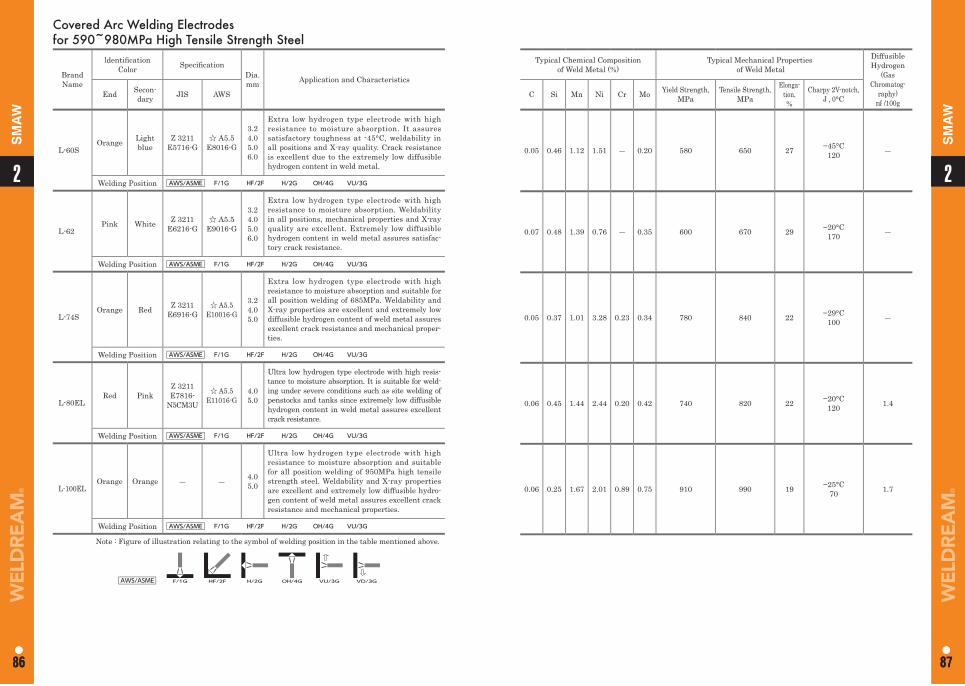
Typical Chemical Composition of Weld Metal (%)
Typical Mechanical Properties of Weld Metal
Diffusible Hydrogen
(Gas Chromatog-
raphy) ㎖ /100g
C Si Mn Ni Cr Mo Yield Strength, MPa
Tensile Strength, MPa
Elonga-tion,%
Charpy 2V-notch,J , 0°C
0.05 0.46 1.12 1.51 ― 0.20 580 650 27 −45°C 120 ―
0.07 0.48 1.39 0.76 ― 0.35 600 670 29 −20°C 170 ―
0.05 0.37 1.01 3.28 0.23 0.34 780 840 22 −29°C 100 ―
0.06 0.45 1.44 2.44 0.20 0.42 740 820 22 −20°C120 1.4
0.06 0.25 1.67 2.01 0.89 0.75 910 990 19 −25°C 70 1.7
Covered Arc Welding Electrodes for 590~980MPa High Tensile Strength Steel
Brand Name
ldentifi cation Color Specifi cation
Dia. mm Application and Characteristics
End Secon-dary JIS AWS
L-60SOrange Light
blueZ 3211
E5716-G☆ A5.5
E8016-G
3.24.05.06.0
Extra low hydrogen type electrode with high resistance to moisture absorption. It assures satisfactory toughness at -45°C, weldability in all positions and X-ray quality. Crack resistance is excellent due to the extremely low diffusible hydrogen content in weld metal.
Welding Position AWS/ASME F/1G HF/2F H/2G OH/4G VU/3G
L-62Pink White Z 3211
E6216-G☆ A5.5
E9016-G
3.24.05.06.0
Extra low hydrogen type electrode with high resistance to moisture absorption. Weldability in all positions, mechanical properties and X-ray quality are excellent. Extremely low diffusible hydrogen content in weld metal assures satisfac-tory crack resistance.
Welding Position AWS/ASME F/1G HF/2F H/2G OH/4G VU/3G
L-74SOrange Red Z 3211
E6916-G☆ A5.5
E10016-G
3.2 4.0 5.0
Extra low hydrogen type electrode with high resistance to moisture absorption and suitable for all position welding of 685MPa. Weldability and X-ray properties are excellent and extremely low diffusible hydrogen content of weld metal assures excellent crack resistance and mechanical proper-ties.
Welding Position AWS/ASME F/1G HF/2F H/2G OH/4G VU/3G
L-80ELRed Pink
Z 3211E7816-
N5CM3U
☆ A5.5E11016-G
4.0 5.0
Ultra low hydrogen type electrode with high resis-tance to moisture absorption. It is suitable for weld-ing under severe conditions such as site welding of penstocks and tanks since extremely low diffusible hydrogen content in weld metal assures excellent crack resistance.
Welding Position AWS/ASME F/1G HF/2F H/2G OH/4G VU/3G
L-100ELOrange Orange ― ― 4.0
5.0
Ultra low hydrogen type electrode with high resistance to moisture absorption and suitable for all position welding of 950MPa high tensile strength steel. Weldability and X-ray properties are excellent and extremely low diffusible hydro-gen content of weld metal assures excellent crack resistance and mechanical properties.
Welding Position AWS/ASME F/1G HF/2F H/2G OH/4G VU/3G
Note : Figure of illustration relating to the symbol of welding position in the table mentioned above.
AWS/ASME F/1G HF/2F H/2G OH/4G VU/3G VD/3G
11
86 87
2
86
2
87
SM
AW
SM
AW
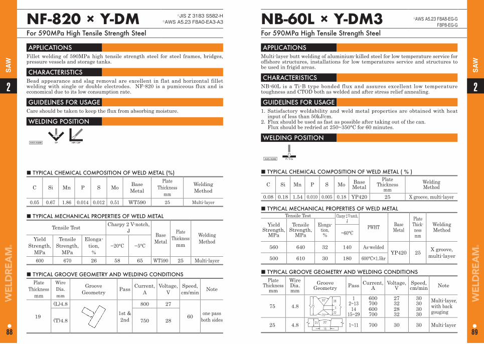
22
88 89
SA
W
SA
W
NF-820 × Y-DM ☆JIS Z 3183 S582-H☆AWS A5.23 F8A0-EA3-A3
For 590MPa High Tensile Strength Steel
■ TYPICAL CHEMICAL COMPOSITION OF WELD METAL (%)
C Si Mn P S Mo BaseMetal
PlateThickness
mm
Welding Method
0.05 0.67 1.86 0.014 0.012 0.51 WT590 25 Multi-layer
APPLICATIONS Fillet welding of 590MPa high tensile strength steel for steel frames, bridges, pressure vessels and storage tanks.
CHARACTERISTICS Bead appearance and slag removal are excellent in flat and horizontal fillet welding with single or double electrodes. NF-820 is a pumiceous flux and is economical due to its low consumption rate.
GUIDELlNES FOR USAGE Care should be taken to keep the flux from absorbing moisture.
WELDING POSITION
AWS/ASME 1F HF/2F
■ TYPICAL MECHANICAL PROPERTIES OF WELD METAL
Tensile Test Charpy 2 V-notch,J
Base Metal
PlateThickness
mm
Welding MethodYield
Strength, MPa
Tensile Strength,
MPa
Elonga-tion,
%−20°C −5°C
600 670 26 58 65 WT590 25 Multi-layer
■ TYPICAL GROOVE GEOMETRY AND WELDING CONDITIONS Plate
Thicknessmm
Wire Dia. mm
GrooveGeometry Pass Current,
AVoltage,
VSpeed, cm/min Note
19
(L)4.81st & 2nd
800 27
60 one pass both sides(T)4.8 750 28
NB-60L × Y-DM3 ☆AWS A5.23 F8A8-EG-GF8P8-EG-G
For 590MPa High Tensile Strength Steel
■ TYPICAL CHEMICAL COMPOSITION OF WELD METAL ( % )
C Si Mn P S Mo BaseMetal
Plate Thickness
mmWeldingMethod
0.08 0.18 1.54 0.010 0.005 0.18 YP420 25 X groove, multi-layer
APPLICATIONS Multi-layer butt welding of aluminium-killed steel for low temperature service for offshore structures, installations for low temperatures service and structures to be used in frigid areas.
CHARACTERISTICS NB-60L is a Ti-B type bonded flux and assures excellent low temperature toughness and CTOD both as welded and after stress relief annealing.
GUIDELlNES FOR USAGE 1. Satisfactory weldability and weld metal properties are obtained with heat
input of less than 50kJ/cm.2. Flux should be used as fast as possible after taking out of the can. Flux should be redried at 250~350°C for 60 minutes.
WELDING POSITION
AWS/ASME F/1G
■ TYPICAL MECHANICAL PROPERTIES OF WELD METALTensile Test Charpy 2 V-notch,
J PWHT Base
Metal
PlateThick-nessmm
Welding Method
YieldStrength,
MPa
Tensile Strength,
MPa
Elonga-tion,% −60°C
560 640 32 140 As-weldedYP420 25 X groove,
multi-layer500 610 30 180 600°C×1.5hr
■ TYPICAL GROOVE GEOMETRY AND WELDING CONDITIONS Plate
Thicknessmm
Wire Dia.mm
Groove Geometry Pass Current,
AVoltage,
VSpeed, cm/min Note
75 4.850°
70°
75
38
325
12~13
1415~29
600700600700
27322832
30303030
Multi-layer, with back gouging
25 4.8 25 20°
161~11 700 30 30 Multi-layer
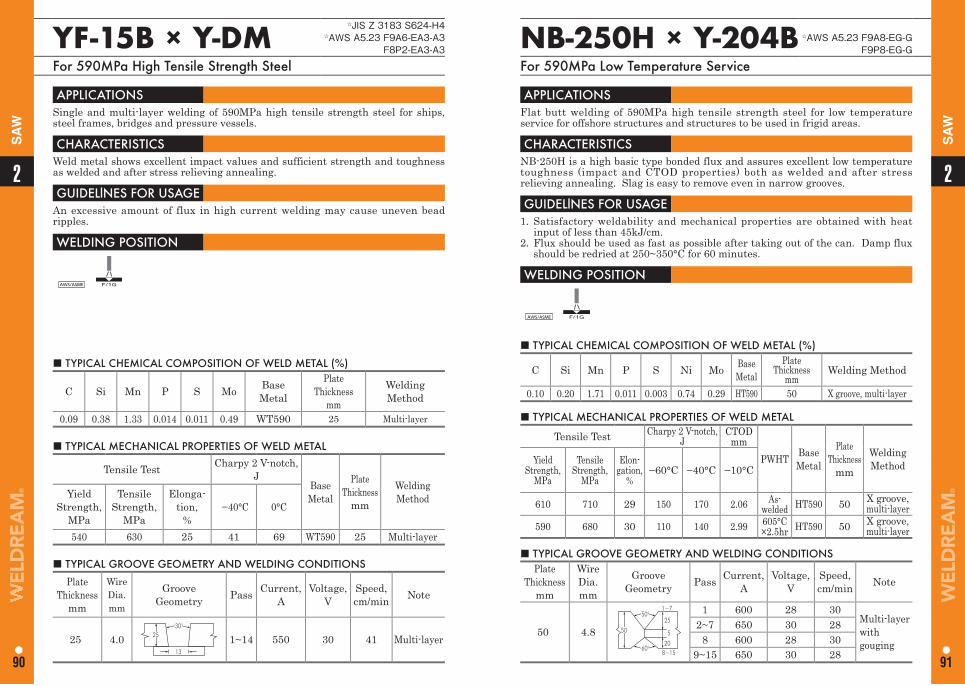
22
90 91
SA
W
SA
W
YF-15B × Y-DM☆JIS Z 3183 S624-H4
☆AWS A5.23 F9A6-EA3-A3F8P2-EA3-A3
For 590MPa High Tensile Strength Steel
■ TYPICAL CHEMICAL COMPOSITION OF WELD METAL (%)
C Si Mn P S Mo BaseMetal
PlateThickness
mm
Welding Method
0.09 0.38 1.33 0.014 0.011 0.49 WT590 25 Multi-layer
APPLICATIONS Single and multi-layer welding of 590MPa high tensile strength steel for ships, steel frames, bridges and pressure vessels.
CHARACTERISTICS Weld metal shows excellent impact values and sufficient strength and toughness as welded and after stress relieving annealing.
GUIDELlNES FOR USAGE An excessive amount of flux in high current welding may cause uneven bead ripples.
WELDING POSITION
AWS/ASME F/1G
■ TYPICAL MECHANICAL PROPERTIES OF WELD METAL
Tensile Test Charpy 2 V-notch,J
Base Metal
PlateThickness
mm
Welding MethodYield
Strength, MPa
Tensile Strength,
MPa
Elonga-tion,
% −40°C 0°C
540 630 25 41 69 WT590 25 Multi-layer
■ TYPICAL GROOVE GEOMETRY AND WELDING CONDITIONS
PlateThickness
mm
Wire Dia. mm
GrooveGeometry Pass Current,
AVoltage,
VSpeed, cm/min Note
25 4.0 2530°
13
1~14 550 30 41 Multi-layer
NB-250H × Y-204B ☆AWS A5.23 F9A8-EG-GF9P8-EG-G
For 590MPa Low Temperature Service
■ TYPICAL CHEMICAL COMPOSITION OF WELD METAL (%)
C Si Mn P S Ni Mo BaseMetal
Plate Thickness
mmWelding Method
0.10 0.20 1.71 0.011 0.003 0.74 0.29 HT590 50 X groove, multi-layer
APPLICATIONS Flat butt welding of 590MPa high tensile strength steel for low temperature service for offshore structures and structures to be used in frigid areas.
CHARACTERISTICS NB-250H is a high basic type bonded flux and assures excellent low temperature toughness (impact and CTOD properties) both as welded and after stress relieving annealing. Slag is easy to remove even in narrow grooves.
GUIDELlNES FOR USAGE 1. Satisfactory weldability and mechanical properties are obtained with heat
input of less than 45kJ/cm.2. Flux should be used as fast as possible after taking out of the can. Damp flux
should be redried at 250~350°C for 60 minutes.
WELDING POSITION
AWS/ASME F/1G
■ TYPICAL MECHANICAL PROPERTIES OF WELD METAL
Tensile Test Charpy 2 V-notch,J
CTODmm
PWHT Base Metal
Plate Thickness
mm
Welding MethodYield
Strength, MPa
Tensile Strength,
MPa
Elon-gation,
%−60°C −40°C −10°C
610 710 29 150 170 2.06 As-welded HT590 50 X groove,
multi-layer590 680 30 110 140 2.99 605°C
×2.5hr HT590 50 X groove, multi-layer
■ TYPICAL GROOVE GEOMETRY AND WELDING CONDITIONS Plate
Thicknessmm
Wire Dia.mm
Groove Geometry Pass Current,
AVoltage,
VSpeed, cm/min Note
50 4.8
50°
60°
50
25
20
5
1~7
8~15
1 600 28 30Multi-layerwithgouging
2~7 650 30 288 600 28 30
9~15 650 30 28
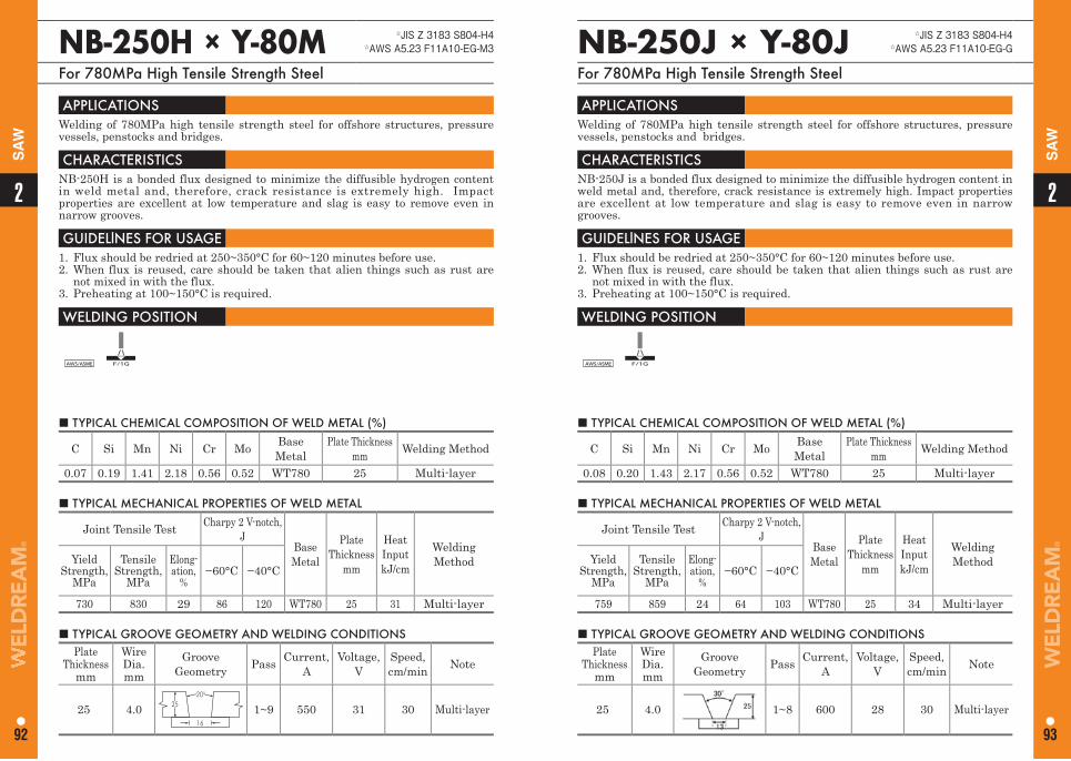
22
92 93
SA
W
SA
W
NB-250H × Y-80M ☆JIS Z 3183 S804-H4☆AWS A5.23 F11A10-EG-M3
For 780MPa High Tensile Strength Steel
NB-250J × Y-80J ☆JIS Z 3183 S804-H4☆AWS A5.23 F11A10-EG-G
For 780MPa High Tensile Strength Steel
■ TYPICAL CHEMICAL COMPOSITION OF WELD METAL (%)
C Si Mn Ni Cr Mo Base Metal
Plate Thickness mm Welding Method
0.07 0.19 1.41 2.18 0.56 0.52 WT780 25 Multi-layer
■ TYPICAL CHEMICAL COMPOSITION OF WELD METAL (%)
C Si Mn Ni Cr Mo Base Metal
Plate Thickness mm Welding Method
0.08 0.20 1.43 2.17 0.56 0.52 WT780 25 Multi-layer
APPLICATIONS Welding of 780MPa high tensile strength steel for offshore structures, pressure vessels, penstocks and bridges.
CHARACTERISTICS NB-250H is a bonded flux designed to minimize the diffusible hydrogen content in weld metal and, therefore, crack resistance is extremely high. Impact properties are excellent at low temperature and slag is easy to remove even in narrow grooves.
GUIDELlNES FOR USAGE 1. Flux should be redried at 250~350°C for 60~120 minutes before use.2. When flux is reused, care should be taken that alien things such as rust are
not mixed in with the flux.3. Preheating at 100~150°C is required.
WELDING POSITION
AWS/ASME F/1G
APPLICATIONS Welding of 780MPa high tensile strength steel for offshore structures, pressure vessels, penstocks and bridges.
CHARACTERISTICS NB-250J is a bonded flux designed to minimize the diffusible hydrogen content in weld metal and, therefore, crack resistance is extremely high. Impact properties are excellent at low temperature and slag is easy to remove even in narrow grooves.
GUIDELlNES FOR USAGE 1. Flux should be redried at 250~350°C for 60~120 minutes before use. 2. When flux is reused, care should be taken that alien things such as rust are
not mixed in with the flux.3. Preheating at 100~150°C is required.
WELDING POSITION
AWS/ASME F/1G
■ TYPICAL MECHANICAL PROPERTIES OF WELD METAL
Joint Tensile Test Charpy 2 V-notch,J
Base Metal
Plate Thickness
mm
Heat InputkJ/cm
Welding MethodYield
Strength, MPa
Tensile Strength,
MPa
Elong-ation,
%−60°C −40°C
730 830 29 86 120 WT780 25 31 Multi-layer
■ TYPICAL MECHANICAL PROPERTIES OF WELD METAL
Joint Tensile Test Charpy 2 V-notch,J
Base Metal
Plate Thickness
mm
Heat InputkJ/cm
Welding MethodYield
Strength, MPa
Tensile Strength,
MPa
Elong-ation,
%−60°C −40°C
759 859 24 64 103 WT780 25 34 Multi-layer
■ TYPICAL GROOVE GEOMETRY AND WELDING CONDITIONS Plate
Thicknessmm
Wire Dia.mm
Groove Geometry Pass Current,
AVoltage,
VSpeed, cm/min Note
25 4.0 2520°
16
1~9 550 31 30 Multi-layer
■ TYPICAL GROOVE GEOMETRY AND WELDING CONDITIONS Plate
Thicknessmm
Wire Dia.mm
Groove Geometry Pass Current,
AVoltage,
VSpeed, cm/min Note
25 4.0 1~8 600 28 30 Multi-layer
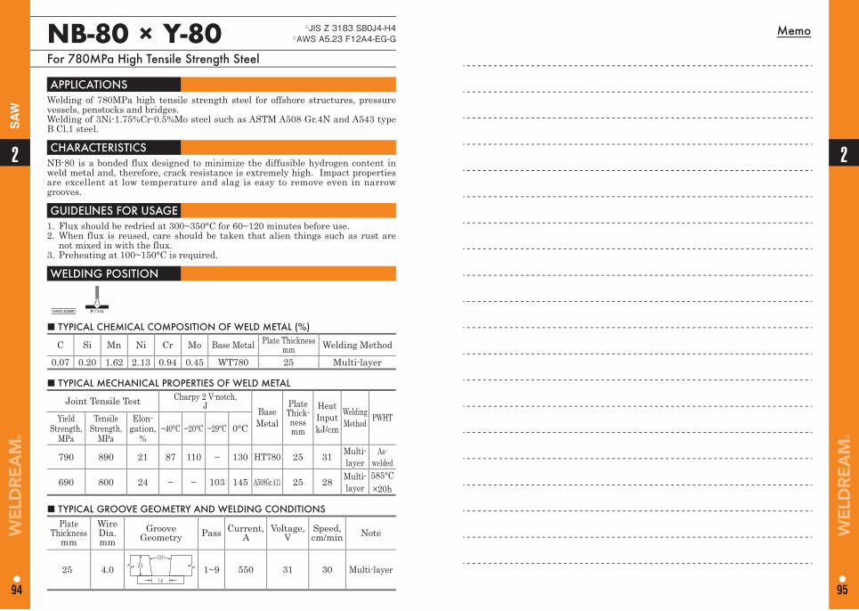
Memo
2
94
2
95
SA
W
NB-80 × Y-80 ☆JIS Z 3183 S80J4-H4☆AWS A5.23 F12A4-EG-G
For 780MPa High Tensile Strength Steel
■ TYPICAL CHEMICAL COMPOSITION OF WELD METAL (%)
C Si Mn Ni Cr Mo Base Metal Plate Thicknessmm Welding Method
0.07 0.20 1.62 2.13 0.94 0.45 WT780 25 Multi-layer
APPLICATIONS Welding of 780MPa high tensile strength steel for offshore structures, pressure vessels, penstocks and bridges.Welding of 3Ni-1.75%Cr-0.5%Mo steel such as ASTM A508 Gr.4N and A543 type B Cl.1 steel.
CHARACTERISTICS NB-80 is a bonded flux designed to minimize the diffusible hydrogen content in weld metal and, therefore, crack resistance is extremely high. Impact properties are excellent at low temperature and slag is easy to remove even in narrow grooves.
GUIDELlNES FOR USAGE 1. Flux should be redried at 300~350°C for 60~120 minutes before use.2. When flux is reused, care should be taken that alien things such as rust are
not mixed in with the flux.3. Preheating at 100~150°C is required.
WELDING POSITION
AWS/ASME F/1G
■ TYPICAL MECHANICAL PROPERTIES OF WELD METAL
Joint Tensile Test Charpy 2 V-notch,J Base
Metal
Plate Thick-nessmm
Heat InputkJ/cm
Welding Method PWHTYield
Strength,MPa
Tensile Strength,
MPa
Elon-gation,
%−40°C −20°C −29°C 0°C
790 890 21 87 110 − 130 HT780 25 31 Multi-layer
As-welded
690 800 24 − − 103 145 A508Gr.411 25 28 Multi-layer
585°C×20h
■ TYPICAL GROOVE GEOMETRY AND WELDING CONDITIONS Plate
Thicknessmm
Wire Dia.mm
Groove Geometry Pass Current,
AVoltage,
VSpeed, cm/min Note
25 4.0 2520°
16
1~9 550 31 30 Multi-layer
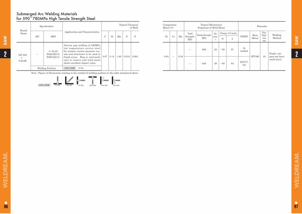
11
96 97
2
96
2
97
SA
W
SA
W
Submerged Arc Welding Materialsfor 590~780MPa High Tensile Strength Steel
Brand Name
Specifi cation
Application and Characteristics
Typical Chemicalof Weld
JIS AWS C Si Mn P S
NF-250×
Y-204B
―☆ A5.23
F9A6-EG-GF8P6-EG-G
Narrow gap welding of 590MPa low temperature service steel for nuclear reactor pressure ves-sels and structures to be used in frigid areas. Slag is extremely easy to remove and weld metal shows excellent impact value.
0.07 0.14 1.60 0.010 0.004
Welding Position AWS/ASME F/1G
Note : Figure of illustration relating to the symbol of welding position in the table mentioned above.
AWS/ASME F/1G HF/2F H/2G OH/4G VU/3G VD/3G
CompositionMetal (%)
Typical MechanicalProperties of Weld Metal Remarks
Ni Cr MoYield
Strength,MPa
Tensile Strength,MPa
Elon-gation,
%
Charpy 2 V-notch,PWHT Base
Metal
Plate Thick-nessmm
Welding Method°C J
0.94 ― 0.38
― 660 28 −50 91 As welded
SPV490 40Single, onepass one layer multi-layer
― 640 29 −50 64 625°C×1hr
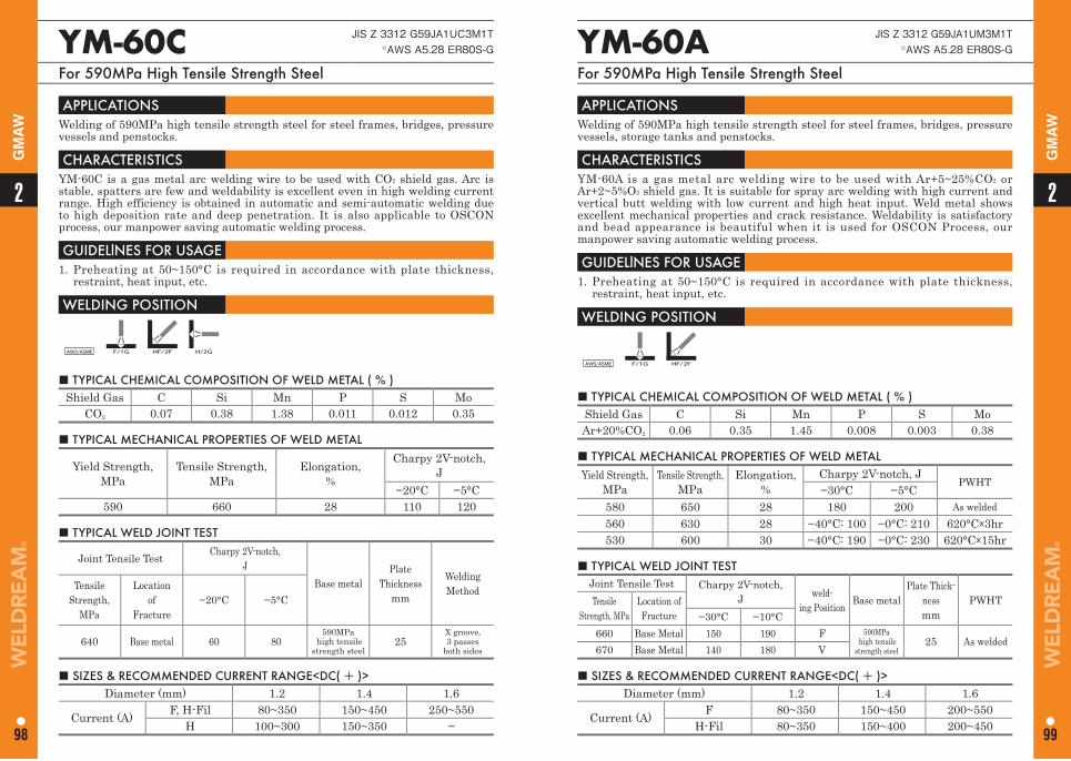
■ TYPICAL CHEMICAL COMPOSITION OF WELD METAL ( % ) Shield Gas C Si Mn P S Mo
CO2 0.07 0.38 1.38 0.011 0.012 0.35
YM-60C JIS Z 3312 G59JA1UC3M1T☆AWS A5.28 ER80S-G
For 590MPa High Tensile Strength Steel
APPLICATIONS Welding of 590MPa high tensile strength steel for steel frames, bridges, pressure vessels and penstocks.
CHARACTERISTICS YM-60C is a gas metal arc welding wire to be used with CO2 shield gas. Arc is stable, spatters are few and weldability is excellent even in high welding current range. High efficiency is obtained in automatic and semi-automatic welding due to high deposition rate and deep penetration. It is also applicable to OSCON process, our manpower saving automatic welding process.
GUIDELlNES FOR USAGE 1. Preheating at 50~150°C is required in accordance with plate thickness,
restraint, heat input, etc.
WELDING POSITION
AWS/ASME F/1G HF/2F H/2G
■ TYPICAL MECHANICAL PROPERTIES OF WELD METAL
Yield Strength,MPa
Tensile Strength,MPa
Elongation,%
Charpy 2V-notch,J
−20°C −5°C590 660 28 110 120
■ TYPICAL WELD JOINT TEST
Joint Tensile Test Charpy 2V-notch,J
Base metalPlate
Thicknessmm
Welding MethodTensile
Strength, MPa
Locationof
Fracture−20°C −5°C
640 Base metal 60 80590MPa
high tensilestrength steel
25X groove,3 passes
both sides
■ SIZES & RECOMMENDED CURRENT RANGE<DC( + )> Diameter (mm) 1.2 1.4 1.6
Current (A) F, H-Fil 80~350 150~450 250~550H 100~300 150~350 −
■ TYPICAL CHEMICAL COMPOSITION OF WELD METAL ( % ) Shield Gas C Si Mn P S MoAr+20%CO2 0.06 0.35 1.45 0.008 0.003 0.38
YM-60A JIS Z 3312 G59JA1UM3M1T☆AWS A5.28 ER80S-G
For 590MPa High Tensile Strength Steel
APPLICATIONS Welding of 590MPa high tensile strength steel for steel frames, bridges, pressure vessels, storage tanks and penstocks.
CHARACTERISTICS YM-60A is a gas metal arc welding wire to be used with Ar+5~25%CO2 or Ar+2~5%O2 shield gas. It is suitable for spray arc welding with high current and vertical butt welding with low current and high heat input. Weld metal shows excellent mechanical properties and crack resistance. Weldability is satisfactory and bead appearance is beautiful when it is used for OSCON Process, our manpower saving automatic welding process.
GUIDELlNES FOR USAGE 1. Preheating at 50~150°C is required in accordance with plate thickness,
restraint, heat input, etc.
WELDING POSITION
AWS/ASME F/1G HF/2F
■ TYPICAL MECHANICAL PROPERTIES OF WELD METAL Yield Strength,
MPaTensile Strength,
MPa Elongation,
%Charpy 2V-notch, J
PWHT−30°C −5°C
580 650 28 180 200 As welded560 630 28 −40°C: 100 −0°C: 210 620°C×3hr530 600 30 −40°C: 190 −0°C: 230 620°C×15hr
■ TYPICAL WELD JOINT TESTJoint Tensile Test Charpy 2V-notch,
J weld-ing Position Base metal
Plate Thick-nessmm
PWHTTensile Strength, MPa
Location ofFracture −30°C −10°C
660 Base Metal 150 190 F 590MPa high tensile
strength steel25 As welded
670 Base Metal 140 180 V
■ SIZES & RECOMMENDED CURRENT RANGE<DC( + )> Diameter (mm) 1.2 1.4 1.6
Current (A) F 80~350 150~450 200~550H-Fil 80~350 150~400 200~450
22
98 99
GM
AW
GM
AW
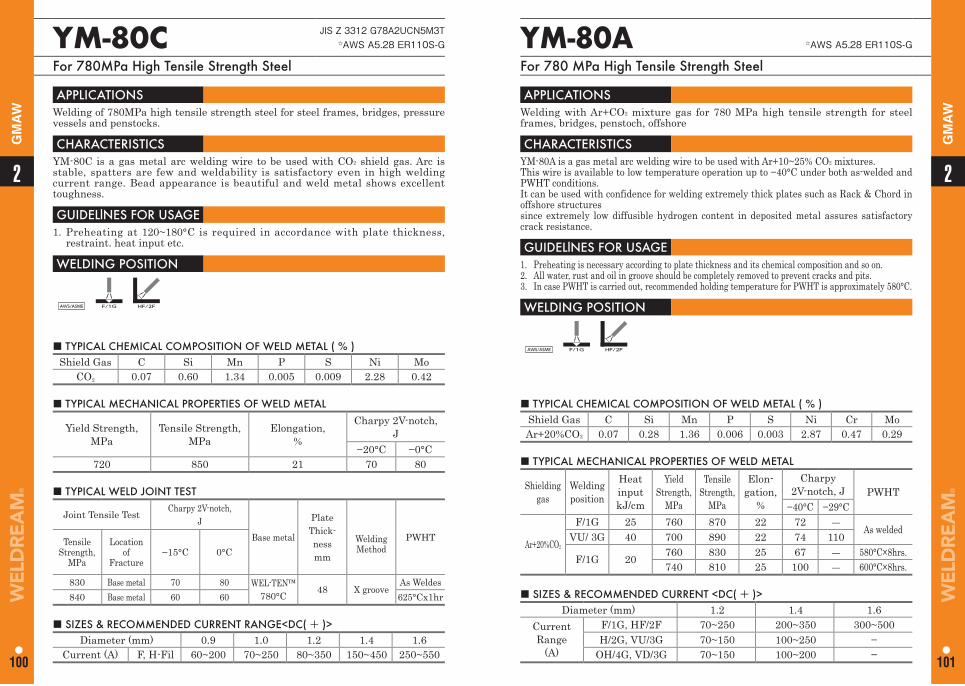
■ TYPICAL CHEMICAL COMPOSITION OF WELD METAL ( % ) Shield Gas C Si Mn P S Ni Mo
CO2 0.07 0.60 1.34 0.005 0.009 2.28 0.42
YM-80C JIS Z 3312 G78A2UCN5M3T☆AWS A5.28 ER110S-G
For 780MPa High Tensile Strength Steel
APPLICATIONS Welding of 780MPa high tensile strength steel for steel frames, bridges, pressure vessels and penstocks.
CHARACTERISTICS YM-80C is a gas metal arc welding wire to be used with CO2 shield gas. Arc is stable, spatters are few and weldability is satisfactory even in high welding current range. Bead appearance is beautiful and weld metal shows excellent toughness.
GUIDELlNES FOR USAGE 1. Preheating at 120~180°C is required in accordance with plate thickness,
restraint. heat input etc.
WELDING POSITION
AWS/ASME F/1G HF/2F
■ TYPICAL MECHANICAL PROPERTIES OF WELD METAL
Yield Strength,MPa
Tensile Strength,MPa
Elongation,%
Charpy 2V-notch,J
−20°C −0°C720 850 21 70 80
■ TYPICAL WELD JOINT TEST
Joint Tensile Test Charpy 2V-notch,J
Base metal
PlateThick-nessmm
PWHTTensile Strength,
MPa
Locationof
Fracture−15°C 0°C
Welding Method
830 Base metal 70 80 WEL-TEN™ 780°C 48 X groove
As Weldes840 Base metal 60 60 625°Cx1hr
■ SIZES & RECOMMENDED CURRENT RANGE<DC( + )> Diameter (mm) 0.9 1.0 1.2 1.4 1.6
Current (A) F, H-Fil 60~200 70~250 80~350 150~450 250~550
■ TYPICAL CHEMICAL COMPOSITION OF WELD METAL ( % ) Shield Gas C Si Mn P S Ni Cr MoAr+20%CO2 0.07 0.28 1.36 0.006 0.003 2.87 0.47 0.29
YM-80A ☆AWS A5.28 ER110S-G
For 780 MPa High Tensile Strength Steel
APPLICATIONS Welding with Ar+CO2 mixture gas for 780 MPa high tensile strength for steel frames, bridges, penstoch, offshore
CHARACTERISTICS YM-80A is a gas metal arc welding wire to be used with Ar+10~25% CO2 mixtures. This wire is available to low temperature operation up to −40°C under both as-welded and PWHT conditions. It can be used with confidence for welding extremely thick plates such as Rack & Chord in offshore structuressince extremely low diffusible hydrogen content in deposited metal assures satisfactory crack resistance.
GUIDELlNES FOR USAGE 1. Preheating is necessary according to plate thickness and its chemical composition and so on. 2. All water, rust and oil in groove should be completely removed to prevent cracks and pits.3. In case PWHT is carried out, recommended holding temperature for PWHT is approximately 580°C.
WELDING POSITION
AWS/ASME F/1G HF/2F
■ TYPICAL MECHANICAL PROPERTIES OF WELD METAL
Shielding gas
Welding position
Heat inputkJ/cm
Yield Strength,
MPa
Tensile Strength,
MPa
Elon-gation,
%
Charpy 2V-notch, J PWHT
−40°C −29°C
Ar+20%CO2
F/1G 25 760 870 22 72 ―As welded
VU/ 3G 40 700 890 22 74 110
F/1G 20 760 830 25 67 ― 580°C×8hrs.740 810 25 100 ― 600°C×8hrs.
■ SIZES & RECOMMENDED CURRENT <DC( + )> Diameter (mm) 1.2 1.4 1.6
Current Range
(A)
F/1G, HF/2F 70~250 200~350 300~500H/2G, VU/3G 70~150 100~250 −
OH/4G, VD/3G 70~150 100~200 −
22
100 101
GM
AW
GM
AW
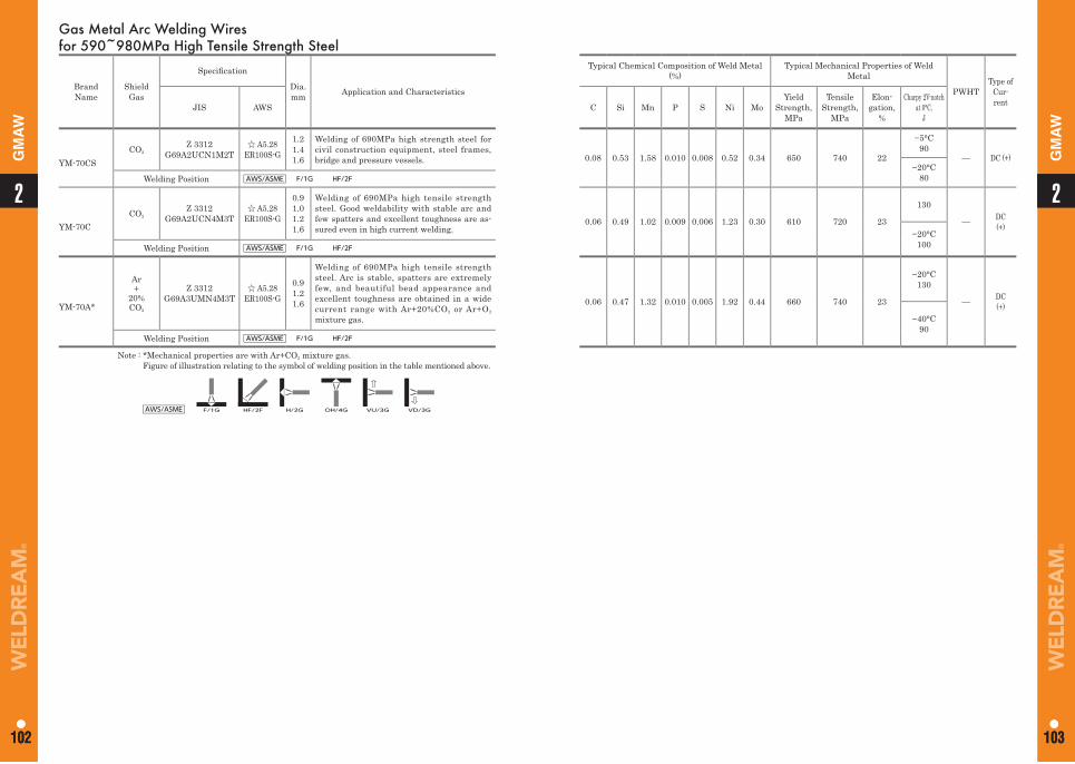
Gas Metal Arc Welding Wires for 590~980MPa High Tensile Strength Steel
Brand Name
Shield Gas
Specifi cation
Dia. mm Application and Characteristics
Typical Chemical Composition of Weld Metal(%)
Typical Mechanical Properties of Weld Metal
PWHTType of
Cur-rentJIS AWS C Si Mn P S Ni Mo
Yield Strength,
MPa
Tensile Strength,
MPa
Elon-gation,
%
Charpy 2V-notch at 0°C,
J
YM-70CSCO2
Z 3312G69A2UCN1M2T
☆ A5.28ER100S-G
1.21.41.6
Welding of 690MPa high strength steel for civil construction equipment, steel frames, bridge and pressure vessels. 0.08 0.53 1.58 0.010 0.008 0.52 0.34 650 740 22
−5°C 90
— DC (+)−20°C
80Welding Position AWS/ASME F/1G HF/2F
YM-70CCO2
Z 3312G69A2UCN4M3T
☆ A5.28ER100S-G
0.91.01.21.6
Welding of 690MPa high tensile strength steel. Good weldability with stable arc and few spatters and excellent toughness are as-sured even in high current welding.
0.06 0.49 1.02 0.009 0.006 1.23 0.30 610 720 23
130
— DC(+)
−20°C100Welding Position AWS/ASME F/1G HF/2F
YM-70A*
Ar+
20%CO2
Z 3312G69A3UMN4M3T
☆ A5.28ER100S-G
0.91.21.6
Welding of 690MPa high tensile strength steel. Arc is stable, spatters are extremely few, and beautiful bead appearance and excellent toughness are obtained in a wide current range with Ar+20%CO2 or Ar+O2
mixture gas.
0.06 0.47 1.32 0.010 0.005 1.92 0.44 660 740 23
−20°C130
— DC(+)
−40°C90
Welding Position AWS/ASME F/1G HF/2F
Note : *Mechanical properties are with Ar+CO2 mixture gas.Figure of illustration relating to the symbol of welding position in the table mentioned above.
AWS/ASME F/1G HF/2F H/2G OH/4G VU/3G VD/3G
11
102 103
2
102
2
103
GM
AW
GM
AW
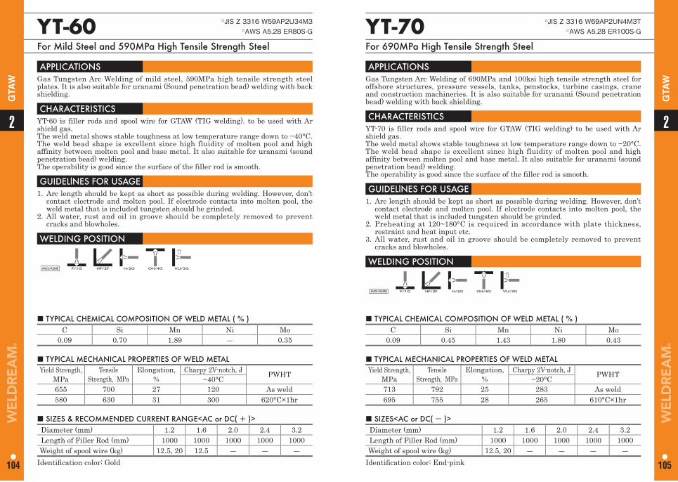
■ TYPICAL CHEMICAL COMPOSITION OF WELD METAL ( % ) C Si Mn Ni Mo
0.09 0.70 1.89 ― 0.35
■ TYPICAL CHEMICAL COMPOSITION OF WELD METAL ( % ) C Si Mn Ni Mo
0.09 0.45 1.43 1.80 0.43
YT-60 ☆JIS Z 3316 W59AP2U34M3☆AWS A5.28 ER80S-G
For Mild Steel and 590MPa High Tensile Strength Steel
YT-70 ☆JIS Z 3316 W69AP2UN4M3T☆AWS A5.28 ER100S-G
For 690MPa High Tensile Strength Steel
APPLICATIONS Gas Tungsten Arc Welding of mild steel, 590MPa high tensile strength steel plates. It is also suitable for uranami (Sound penetration bead) welding with back shielding.
CHARACTERISTICS YT-60 is filler rods and spool wire for GTAW (TIG welding). to be used with Ar shield gas. The weld metal shows stable toughness at low temperature range down to −40°C. The weld bead shape is excellent since high fluidity of molten pool and high affinity between molten pool and base metal. It also suitable for uranami (sound penetration bead) welding.The operability is good since the surface of the filler rod is smooth.
GUIDELlNES FOR USAGE 1. Arc length should be kept as short as possible during welding. However, don’t
contact electrode and molten pool. If electrode contacts into molten pool, the weld metal that is included tungsten should be grinded.
2. All water, rust and oil in groove should be completely removed to prevent cracks and blowholes.
WELDING POSITION
AWS/ASME F/1G HF/2F H/2G OH/4G VU/3G
APPLICATIONS Gas Tungsten Arc Welding of 690MPa and 100ksi high tensile strength steel for offshore structures, pressure vessels, tanks, penstocks, turbine casings, crane and construction machineries. It is also suitable for uranami (Sound penetration bead) welding with back shielding.
CHARACTERISTICS YT-70 is filler rods and spool wire for GTAW (TIG welding) to be used with Ar shield gas. The weld metal shows stable toughness at low temperature range down to −20°C. The weld bead shape is excellent since high fluidity of molten pool and high affinity between molten pool and base metal. It also suitable for uranami (sound penetration bead) welding.The operability is good since the surface of the filler rod is smooth.
GUIDELlNES FOR USAGE 1. Arc length should be kept as short as possible during welding. However, don’t
contact electrode and molten pool. If electrode contacts into molten pool, the weld metal that is included tungsten should be grinded.
2. Preheating at 120~180°C is required in accordance with plate thickness, restraint and heat input etc.
3. All water, rust and oil in groove should be completely removed to prevent cracks and blowholes.
WELDING POSITION
AWS/ASME F/1G HF/2F H/2G OH/4G VU/3G
■ TYPICAL MECHANICAL PROPERTIES OF WELD METAL Yield Strength,
MPaTensile
Strength, MPa Elongation,
%Charpy 2V-notch, J PWHT−40°C
655 700 27 120 As weld580 630 31 300 620°C×1hr
■ TYPICAL MECHANICAL PROPERTIES OF WELD METAL Yield Strength,
MPaTensile
Strength, MPa Elongation,
%Charpy 2V-notch, J PWHT−20°C
713 792 25 283 As weld695 755 28 265 610°C×1hr
■ SIZES & RECOMMENDED CURRENT RANGE<AC or DC( + )> Diameter (mm) 1.2 1.6 2.0 2.4 3.2Length of Filler Rod (mm) 1000 1000 1000 1000 1000Weight of spool wire (kg) 12.5, 20 12.5 ― ― ―
Identifi cation color: Gold
■ SIZES<AC or DC( - )> Diameter (mm) 1.2 1.6 2.0 2.4 3.2Length of Filler Rod (mm) 1000 1000 1000 1000 1000Weight of spool wire (kg) 12.5, 20 ― ― ― ―
Identifi cation color: End-pink
22
104 105
GTA
W
GTA
W
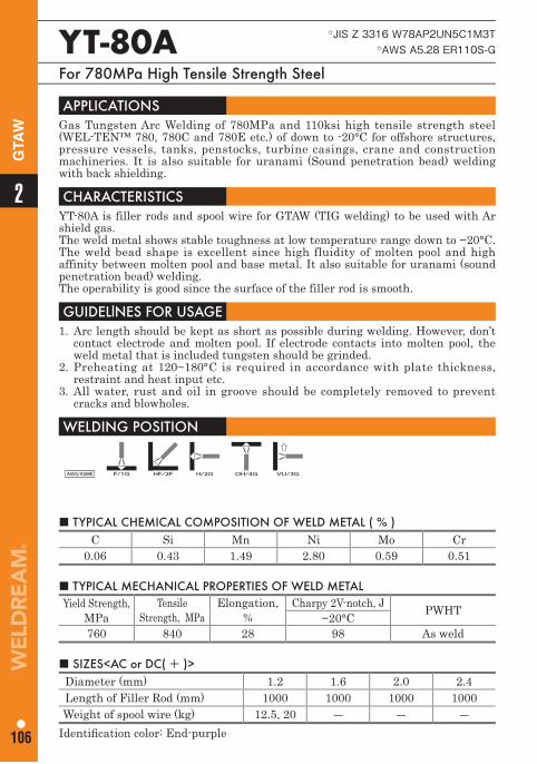
■ TYPICAL CHEMICAL COMPOSITION OF WELD METAL ( % ) C Si Mn Ni Mo Cr
0.06 0.43 1.49 2.80 0.59 0.51
YT-80A ☆JIS Z 3316 W78AP2UN5C1M3T☆AWS A5.28 ER110S-G
For 780MPa High Tensile Strength Steel
APPLICATIONS Gas Tungsten Arc Welding of 780MPa and 110ksi high tensile strength steel (WEL-TEN™ 780, 780C and 780E etc.) of down to -20°C for offshore structures, pressure vessels, tanks, penstocks, turbine casings, crane and construction machineries. It is also suitable for uranami (Sound penetration bead) welding with back shielding.
CHARACTERISTICS YT-80A is filler rods and spool wire for GTAW (TIG welding) to be used with Ar shield gas. The weld metal shows stable toughness at low temperature range down to −20°C. The weld bead shape is excellent since high fluidity of molten pool and high affinity between molten pool and base metal. It also suitable for uranami (sound penetration bead) welding.The operability is good since the surface of the filler rod is smooth.
GUIDELlNES FOR USAGE 1. Arc length should be kept as short as possible during welding. However, don’t
contact electrode and molten pool. If electrode contacts into molten pool, the weld metal that is included tungsten should be grinded.
2. Preheating at 120~180°C is required in accordance with plate thickness, restraint and heat input etc.
3. All water, rust and oil in groove should be completely removed to prevent cracks and blowholes.
WELDING POSITION
AWS/ASME F/1G HF/2F H/2G OH/4G VU/3G
■ TYPICAL MECHANICAL PROPERTIES OF WELD METAL Yield Strength,
MPaTensile
Strength, MPa Elongation,
%Charpy 2V-notch, J PWHT−20°C
760 840 28 98 As weld
■ SIZES<AC or DC( + )> Diameter (mm) 1.2 1.6 2.0 2.4Length of Filler Rod (mm) 1000 1000 1000 1000Weight of spool wire (kg) 12.5, 20 ― ― ―
Identifi cation color: End-purple
2
106
GTA
W
107
Low Temperature Service SteelFlux Cored Arc Welding WiresCovered Arc Welding ElectrodesSubmerged Arc Welding MaterialsGas Metal Arc Welding WiresGas Tungsten Arc Welding Rods and Wires
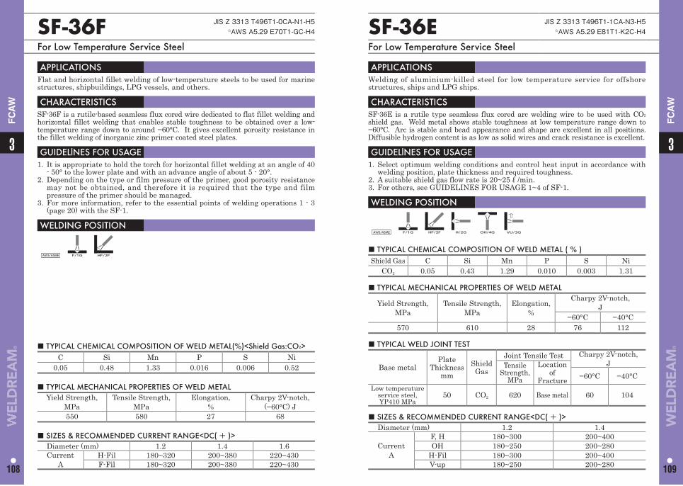
■ TYPICAL CHEMICAL COMPOSITION OF WELD METAL ( % ) Shield Gas C Si Mn P S Ni
CO2 0.05 0.43 1.29 0.010 0.003 1.31
■ TYPICAL CHEMICAL COMPOSITION OF WELD METAL(%)<Shield Gas:CO2> C Si Mn P S Ni
0.05 0.48 1.33 0.016 0.006 0.52
SF-36E JIS Z 3313 T496T1-1CA-N3-H5☆AWS A5.29 E81T1-K2C-H4
For Low Temperature Service Steel
SF-36F JIS Z 3313 T496T1-0CA-N1-H5☆AWS A5.29 E70T1-GC-H4
For Low Temperature Service Steel
APPLICATIONS Welding of aluminium-killed steel for low temperature service for offshore structures, ships and LPG ships.
CHARACTERISTICS SF-36E is a rutile type seamless flux cored arc welding wire to be used with CO2
shield gas. Weld metal shows stable toughness at low temperature range down to −60°C. Arc is stable and bead appearance and shape are excellent in all positions. Diffusible hydrogen content is as low as solid wires and crack resistance is excellent.
GUIDELlNES FOR USAGE 1. Select optimum welding conditions and control heat input in accordance with
welding position, plate thickness and required toughness.2. A suitable shield gas flow rate is 20~25ℓ/min.3. For others, see GUIDELINES FOR USAGE 1~4 of SF-1.
WELDING POSITION
AWS/ASME F/1G HF/2F H/2G OH/4G VU/3G
APPLICATIONS Flat and horizontal fillet welding of low-temperature steels to be used for marine structures, shipbuildings, LPG vessels, and others.
CHARACTERISTICS SF-36F is a rutile-based seamless flux cored wire dedicated to flat fillet welding and horizontal fillet welding that enables stable toughness to be obtained over a low-temperature range down to around −60°C. It gives excellent porosity resistance in the fillet welding of inorganic zinc primer coated steel plates.
GUIDELlNES FOR USAGE 1. It is appropriate to hold the torch for horizontal fillet welding at an angle of 40
- 50° to the lower plate and with an advance angle of about 5 - 20°.2. Depending on the type or film pressure of the primer, good porosity resistance
may not be obtained, and therefore it is required that the type and film pressure of the primer should be managed.
3. For more information, refer to the essential points of welding operations 1 - 3 (page 20) with the SF-1.
WELDING POSITION
AWS/ASME F/1G HF/2F
■ TYPICAL MECHANICAL PROPERTIES OF WELD METAL
Yield Strength,MPa
Tensile Strength,MPa
Elongation,%
Charpy 2V-notch,J
−60°C −40°C570 610 28 76 112
■ TYPICAL MECHANICAL PROPERTIES OF WELD METAL Yield Strength,
MPaTensile Strength,
MPa Elongation,
%Charpy 2V-notch,
(−60°C) J550 580 27 68 ■ SIZES & RECOMMENDED CURRENT RANGE<DC( + )>
Diameter (mm) 1.2 1.4
CurrentA
F, H 180~300 200~400OH 180~250 200~280
H-Fil 180~300 200~400V-up 180~250 200~280
■ SIZES & RECOMMENDED CURRENT RANGE<DC( + )> Diameter (mm) 1.2 1.4 1.6Current
AH-Fil 180~320 200~380 220~430F-Fil 180~320 200~380 220~430
■ TYPICAL WELD JOINT TEST
Base metalPlate
Thickness mm
Shield Gas
Joint Tensile Test Charpy 2V-notch,JTensile
Strength, MPa
Locationof
Fracture −60°C −40°CLow temperature
service steel, YP410 MPa
50 CO2 620 Base metal 60 104
33
108 109
FC
AW
FC
AW
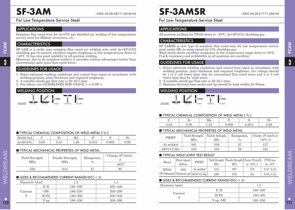
■ TYPICAL CHEMICAL COMPOSITION OF WELD METAL ( % ) Shield Gas C Si Mn P S NiAr+20%CO2 0.05 0.33 1.28 0.010 0.003 0.89
SF-3AM ☆AWS A5.29 E81T1-Ni1M-H4
For Low Temperature Service Steel
APPLICATIONS Seamless flux cored wire for Ar+CO2 gas shielded arc welding of low temperature service steel for offshore structures, etc.
CHARACTERISTICS SF-3AM is a rutile type seamless flux cored arc welding wire with Ar+20%CO2 shielding gas. It assures excellent impact toughness at low temperatures down to −40°C. It has also good usability in all position welding.Moreover, due to its seamless surface, it provides various advantages better than conventional open-seam flux cored wires.
GUIDELlNES FOR USAGE 1. Select optimum welding conditions and control heat input in accordance with
welding position, plate thickness and required toughness.2. A suitable shield gas flow rate is 20~25ℓ/min.3. For others, see GUIDELINES FOR USAGE 1~4 of SF-1.
WELDING POSITION
AWS/ASME F/1G HF/2F H/2G OH/4G VU/3G
■ TYPICAL MECHANICAL PROPERTIES OF WELD METAL
Yield Strength,MPa
Tensile Strength,MPa
Elongation,%
Charpy 2V-notch,J
−60°C550 610 27 95
■ SIZES & RECOMMENDED CURRENT RANGE<DC( + )> Diameter (mm) 1.2 1.4
CurrentA
F, H 180~300 200~400OH 180~250 200~280
H-Fil 180~300 200~400V-up 180~250 200~280
33
110 111
FC
AW
FC
AW
SF-3AMSR ☆AWS A5.29 E71T1-GM-H4
For Low Temperature Service Steel
APPLICATIONS All position welding for YS420 down to -40°C, Ar+20%CO2 shielding gas
CHARACTERISTICS SF-3AMSR is new type of seamless flux cored wire for low temperature service steel under SR, in using mixed Ar+CO2 shielding gas.Weld metal shows excellent toughness in low temperature range down to-40°C.Crack resistance and weldability in all positions are excellent.
GUIDELlNES FOR USAGE 1. Select optimum welding conditions and control heat input in accordance with
welding position, plate thickness and required toughness. Arc voltage should be 1 or 2 volt lower than that for conventinal flux cored wires and 4 or 5 volt lower than that for solid wires.
2. A suitable shield gas flow rate is 20~25ℓ/min.3. Distance between base metal and tip should be kept within 20-30mm.
WELDING POSITION
AWS/ASME F/1G HF/2F H/2G OH/4G VU/3G
■ TYPICAL CHEMICAL COMPOSITION OF WELD METAL ( % ) C Si Mn P S Ni
0.04 0.28 1.24 0.009 0.004 0.80
■ TYPICAL MECHANICAL PROPERTIES OF WELD METAL
PWHT Yield StrengthMPa
Tensile Strength, MPa
Elongation,%
Charpy 2V-notch at −40°C, J
As welded 505 559 27 137585°C×2.5hr 476 555 28 123
■ SIZES & RECOMMENDED CURRENT RANGE<DC( + )> Diameter (mm) 1.2
CurrentA
F, H 180~300H-Fil 180~300
V-up, OH 180~250
■ TYPICAL WELD JOINT TEST RESULT
Steel Heat inputkJ/cm PWHT Yield Strength
MPaTensile Strength
MPaCharpy 2V-notch
at −40°C, JCTOD mm,
at −10°CEH40
(T=50mm)505
(Vertical-up)As welded 515 587 110 0.37, 0.43
585°C×2.5hr 489 579 84 0.55, 0.54
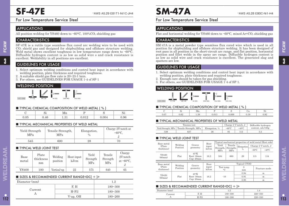
33
112 113
FC
AW
FC
AW
SF-47E ☆AWS A5.29 E81T1-Ni1C-JH4
For Low Temperature Service Steel
SM-47A ☆AWS A5.28 E80C-Ni1-H4
For Low Temperature Service Steel
APPLICATIONS All position welding for YS460 down to -60°C, 100%CO2 shielding gas
CHARACTERISTICS SF-47E is a rutile type seamless flux cored arc welding wire to be used with CO2 shield gas and designed for shipbuilding and offshore structure welding. Weld metal shows excellent toughness in low temperature range down to -60°C. Diffusible hydrogen content is as low as solid wire s and crack resistance is excellent. Weldability in all positions are excellent.
GUIDELlNES FOR USAGE 1. Select optimum welding conditions and control heat input in accordance with
welding position, plate thickness and required toughness.2. A suitable shield gas flow rate is 20~25ℓ/min.3. For others, see GUIDELINES FOR USAGE 1-4 of SF-1
WELDING POSITION
AWS/ASME F/1G HF/2F H/2G OH/4G VU/3G
APPLICATIONS Flat and horizontal welding for YS460 down to -60°C, mixed Ar+CO2 shielding gas
CHARACTERISTICS SM-47A is a metal powder type seamless flux cored wire which is used in all position for shipbuilding and offshore structure welding. It has been designed of root pass in all position in the short-circuit arc range, and flat position, horizontal position and fillet welds in the spray arc range. Diffusible hydrogen content is as low as solid wire and crack resistance is excellent. The generated slag and spatters are low.
GUIDELlNES FOR USAGE 1. Select optimum welding conditions and control heat input in accordance with
welding position, plate thickness and required toughness.2. Enough care should be taken for gas shielding.3. For others, see GUIDELINES FOR USAGE 1-4 of SF-1.
WELDING POSITION
AWS/ASME F/1G HF/2F H/2G OH/4G VU/3G VD/3G
■ TYPICAL CHEMICAL COMPOSITION OF WELD METAL ( % ) C Si Mn P S Ni
0.05 0.46 1.31 0.012 0.004 0.96
■ TYPICAL CHEMICAL COMPOSITION OF WELD METAL ( % ) C Si Mn P S Cu Ni
0.07 0.62 1.38 0.013 0.009 0.19 0.92
■ TYPICAL MECHANICAL PROPERTIES OF WELD METAL
Yield StrengthMPa
Tensile Strength, MPa
Elongation,%
Charpy 2V-notch at −60°C,
J545 600 28 70
■ TYPICAL MECHANICAL PROPERTIES OF WELD METAL Tension test Charpy 2 V-notch, J Diffusible hydrogen
content, mL/100gYield Strength, MPa Tensile Strength, MPa Elongation, % −60°C −40°C539 627 26 85 112 3.2
■ SIZES & RECOMMENDED CURRENT RANGE<DC( + )> Diameter (mm) 1.2
CurrentA
F, H 180~300H-Fil 180~300
V-up, OH 180~260
■ SIZES & RECOMMENDED CURRENT RANGE<DC( + )> Diameter (mm) 1.2 1.4
CurrentA
F, H 180~300 220~350H-Fil 180~300 220~350
■ TYPICAL WELD JOINT TEST
Base metal
Plate thickness
mm
Welding position
Heat inputkJ/cm
Yield Strength
MPa
Tensile Strength
MPa
Charpy 2V-notchat −60°C,
JYS400 100 Vertical-up 22 575 640 65
■ TYPICAL WELD JOINT TESTBase metal
(Plate thickness)
WeldingPosition
Groove geometry
Heat inputkJ/cm
Typical mechanical properties of weld metal (Root side)Yield
Strength, MPa
Tensile Strength,
MPaElongation
%Charpy 2 V-notch, J
−60°C −40°C
YS420(60mm) Flat
45°KRoot: 38mmCap: 20mm
16.2 584 660 29 115 134
Base metal(Plate
thickness)WeldingPosition
Groove geometry
Heat inputkJ/cm
Typical CTODTest temp.
°Cδ
mm Fracture mode
YS420(60mm) Flat
45°KRoot: 38mmCap: 20mm
16.2 -100.94 m0.91 m0.95 m
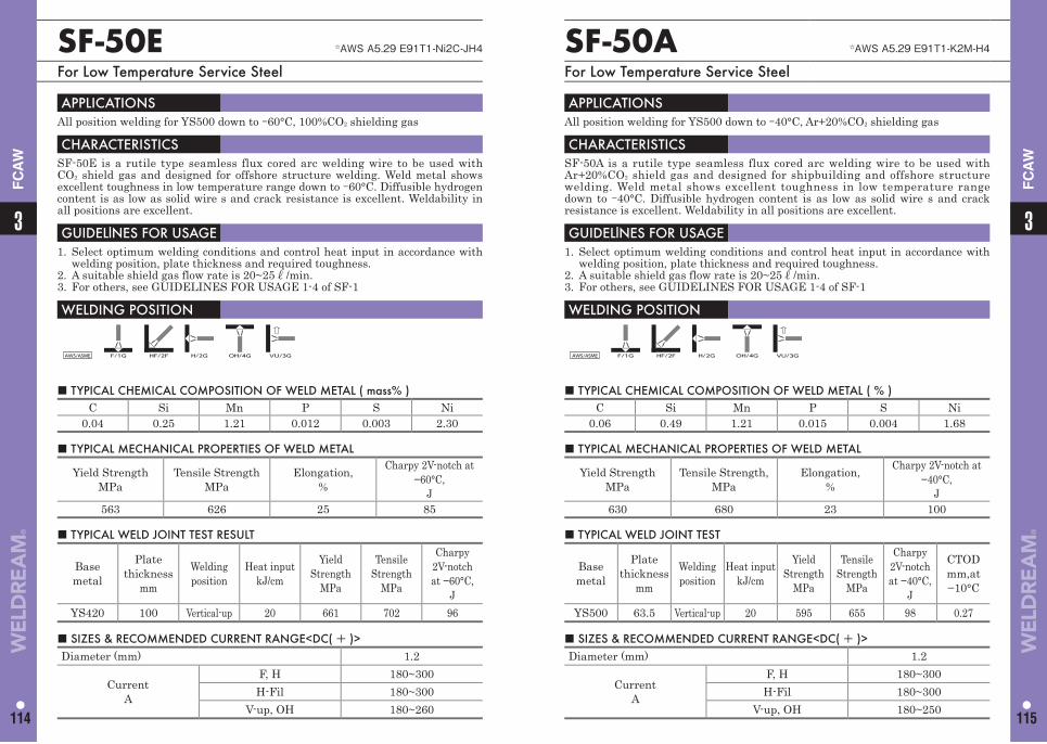
33
114 115
FC
AW
FC
AW
SF-50E ☆AWS A5.29 E91T1-Ni2C-JH4
For Low Temperature Service Steel
APPLICATIONS All position welding for YS500 down to -60°C, 100%CO2 shielding gas
CHARACTERISTICS SF-50E is a rutile type seamless flux cored arc welding wire to be used with CO2 shield gas and designed for offshore structure welding. Weld metal shows excellent toughness in low temperature range down to -60°C. Diffusible hydrogen content is as low as solid wire s and crack resistance is excellent. Weldability in all positions are excellent.
GUIDELlNES FOR USAGE 1. Select optimum welding conditions and control heat input in accordance with
welding position, plate thickness and required toughness.2. A suitable shield gas flow rate is 20~25ℓ/min.3. For others, see GUIDELINES FOR USAGE 1-4 of SF-1
WELDING POSITION
AWS/ASME F/1G HF/2F H/2G OH/4G VU/3G
■ TYPICAL CHEMICAL COMPOSITION OF WELD METAL ( mass% ) C Si Mn P S Ni
0.04 0.25 1.21 0.012 0.003 2.30
■ TYPICAL MECHANICAL PROPERTIES OF WELD METAL
Yield StrengthMPa
Tensile Strength MPa
Elongation,%
Charpy 2V-notch at −60°C,
J563 626 25 85
■ SIZES & RECOMMENDED CURRENT RANGE<DC( + )> Diameter (mm) 1.2
CurrentA
F, H 180~300H-Fil 180~300
V-up, OH 180~260
■ TYPICAL WELD JOINT TEST RESULT
Base metal
Plate thickness
mm
Welding position
Heat inputkJ/cm
Yield Strength
MPa
Tensile Strength
MPa
Charpy 2V-notchat −60°C,
JYS420 100 Vertical-up 20 661 702 96
SF-50A ☆AWS A5.29 E91T1-K2M-H4
For Low Temperature Service Steel
APPLICATIONS All position welding for YS500 down to -40°C, Ar+20%CO2 shielding gas
CHARACTERISTICS SF-50A is a rutile type seamless flux cored arc welding wire to be used with Ar+20%CO2 shield gas and designed for shipbuilding and offshore structure welding. Weld metal shows excellent toughness in low temperature range down to -40°C. Diffusible hydrogen content is as low as solid wire s and crack resistance is excellent. Weldability in all positions are excellent.
GUIDELlNES FOR USAGE 1. Select optimum welding conditions and control heat input in accordance with
welding position, plate thickness and required toughness.2. A suitable shield gas flow rate is 20~25ℓ/min.3. For others, see GUIDELINES FOR USAGE 1-4 of SF-1
WELDING POSITION
AWS/ASME F/1G HF/2F H/2G OH/4G VU/3G
■ TYPICAL CHEMICAL COMPOSITION OF WELD METAL ( % ) C Si Mn P S Ni
0.06 0.49 1.21 0.015 0.004 1.68
■ TYPICAL MECHANICAL PROPERTIES OF WELD METAL
Yield StrengthMPa
Tensile Strength, MPa
Elongation,%
Charpy 2V-notch at −40°C,
J630 680 23 100
■ SIZES & RECOMMENDED CURRENT RANGE<DC( + )> Diameter (mm) 1.2
CurrentA
F, H 180~300H-Fil 180~300
V-up, OH 180~250
■ TYPICAL WELD JOINT TEST
Base metal
Plate thickness
mm
Welding position
Heat inputkJ/cm
Yield Strength
MPa
Tensile Strength
MPa
Charpy 2V-notchat −40°C,
J
CTODmm,at−10°C
YS500 63.5 Vertical-up 20 595 655 98 0.27
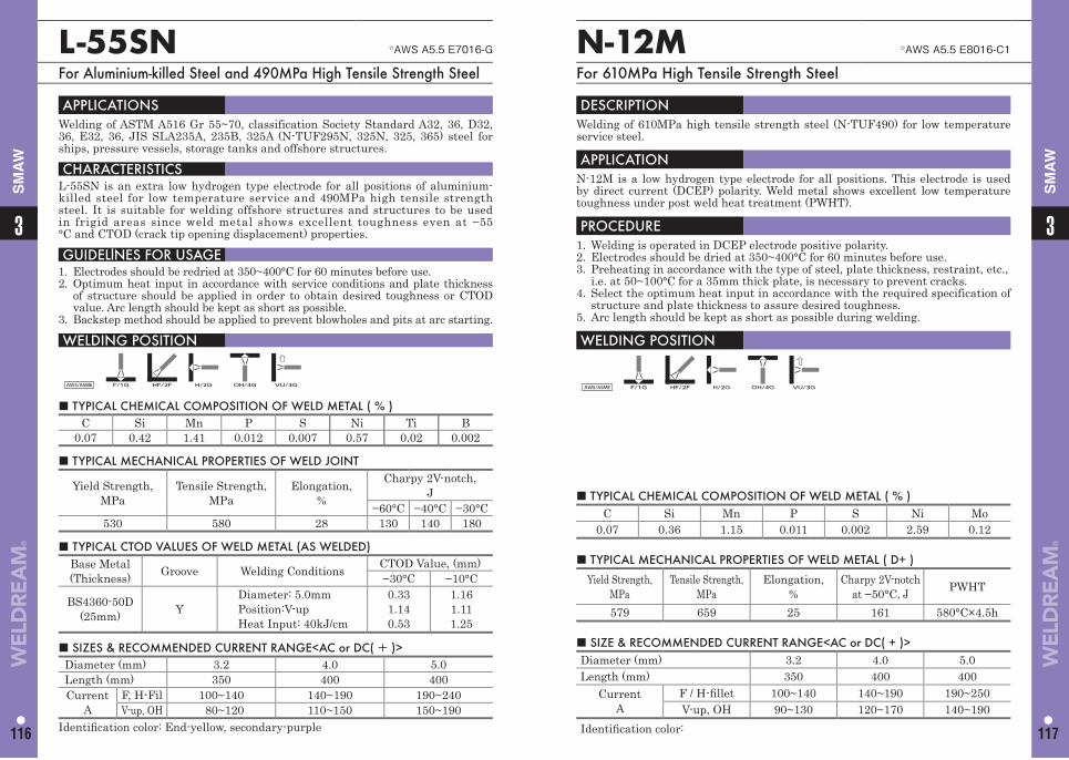
L-55SN ☆AWS A5.5 E7016-G
For Aluminium-killed Steel and 490MPa High Tensile Strength Steel
APPLICATIONS Welding of ASTM A516 Gr 55~70, classification Society Standard A32, 36, D32, 36, E32, 36, JIS SLA235A, 235B, 325A (N-TUF295N, 325N, 325, 365) steel for ships, pressure vessels, storage tanks and offshore structures.
CHARACTERISTICS L-55SN is an extra low hydrogen type electrode for all positions of aluminium-killed steel for low temperature service and 490MPa high tensile strength steel. It is suitable for welding offshore structures and structures to be used in frigid areas since weld metal shows excellent toughness even at −55°C and CTOD (crack tip opening displacement) properties.
GUIDELlNES FOR USAGE 1. Electrodes should be redried at 350~400°C for 60 minutes before use. 2. Optimum heat input in accordance with service conditions and plate thickness
of structure should be applied in order to obtain desired toughness or CTOD value. Arc length should be kept as short as possible.
3. Backstep method should be applied to prevent blowholes and pits at arc starting.
WELDING POSITION
AWS/ASME F/1G HF/2F H/2G OH/4G VU/3G
■ TYPICAL CHEMICAL COMPOSITION OF WELD METAL ( % ) C Si Mn P S Ni Ti B
0.07 0.42 1.41 0.012 0.007 0.57 0.02 0.002
■ TYPICAL MECHANICAL PROPERTIES OF WELD JOINT
Yield Strength,MPa
Tensile Strength, MPa
Elongation,%
Charpy 2V-notch, J
−60°C −40°C −30°C530 580 28 130 140 180
■ SIZES & RECOMMENDED CURRENT RANGE<AC or DC( + )> Diameter (mm) 3.2 4.0 5.0Length (mm) 350 400 400Current
AF, H-Fil 100~140 140~190 190~240V-up, OH 80~120 110~150 150~190
Identifi cation color: End-yellow, secondary-purple
■ TYPICAL CTOD VALUES OF WELD METAL (AS WELDED) Base Metal (Thickness) Groove Welding Conditions CTOD Value, (mm)
−30°C −10°C
BS4360-50D(25mm) Y
Diameter: 5.0mm Position:V-up Heat Input: 40kJ/cm
0.331.140.53
1.161.111.25
■ TYPICAL CHEMICAL COMPOSITION OF WELD METAL ( % ) C Si Mn P S Ni Mo
0.07 0.36 1.15 0.011 0.002 2.59 0.12
N-12M ☆AWS A5.5 E8016-C1
For 610MPa High Tensile Strength Steel
DESCRIPTION Welding of 610MPa high tensile strength steel (N-TUF490) for low temperature service steel.
APPLICATIONN-12M is a low hydrogen type electrode for all positions. This electrode is used by direct current (DCEP) polarity. Weld metal shows excellent low temperature toughness under post weld heat treatment (PWHT).
PROCEDURE1. Welding is operated in DCEP electrode positive polarity.2. Electrodes should be dried at 350~400°C for 60 minutes before use.3. Preheating in accordance with the type of steel, plate thickness, restraint, etc., i.e. at 50~100°C for a 35mm thick plate, is necessary to prevent cracks.4. Select the optimum heat input in accordance with the required specification of
structure and plate thickness to assure desired toughness.5. Arc length should be kept as short as possible during welding.
WELDING POSITION
AWS/ASME F/1G HF/2F H/2G OH/4G VU/3G
■ SIZE & RECOMMENDED CURRENT RANGE<AC or DC( + )> Diameter (mm) 3.2 4.0 5.0Length (mm) 350 400 400
CurrentA
F / H-fi llet 100~140 140~190 190~250V-up, OH 90~130 120~170 140~190
Identifi cation color:
■ TYPICAL MECHANICAL PROPERTIES OF WELD METAL ( D+ )
Yield Strength, MPa
Tensile Strength,MPa
Elongation,%
Charpy 2V-notch at −50°C, J PWHT
579 659 25 161 580°C×4.5h
33
116 117
SM
AW
SM
AW
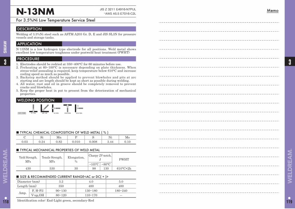
Memo
■ TYPICAL CHEMICAL COMPOSITION OF WELD METAL ( % ) C Si Mn P S Ni Mo
0.03 0.24 0.82 0.010 0.008 3.44 0.10
N-13NM JIS Z 3211 E4916-N7PUL☆AWS A5.5 E7016-C2L
For 3.5%Ni Low Temperature Service Steel
DESCRIPTION Welding of 3.5%Ni steel such as ASTM A203 Gr. D, E and JIS SL3N for pressure vessels and storage tanks.
APPLICATIONN-13NM is a low hydrogen type electrode for all positions. Weld metal shows excellent low temperature toughness under postweld heat treatment (PWHT)
PROCEDURE1. Electrodes should be redried at 350~400°C for 60 minutes before use. 2. Preheating at 60~100°C is necessary depending on plate thickness. When
stress-relief annealing is required, keep temperature below 610°C and increase cooling speed as much as possible.
3. Backstep method should be applied to prevent blowholes and pits at arc starting and arc length should be kept as short as possible during welding.
4. All water, rust and oil in groove should be completely removed to prevent cracks and blowholes.
5. Keep the proper heat in put to present from the deterioration of mechanical properties.
WELDING POSITION
AWS/ASME F/1G HF/2F H/2G OH/4G VU/3G
■ SIZE & RECOMMENDED CURRENT RANGE<AC or DC( + )> Diameter (mm) 3.2 4.0 5.0 Length (mm) 350 400 400
Amp. F, H-Fil 90−130 130−180 180−240 V-up,OH 80−120 110−170 ―
Identifi cation color: End-Light green, secondary-Red
■ TYPICAL MECHANICAL PROPERTIES OF WELD METAL
Yield Strength, MPa
Tensile Strength,MPa
Elongation,%
Charpy 2V-notch,J PWHT
−105°C −80°C 430 530 30 98 130 610°C×2h
3
118
3
119
SM
AW
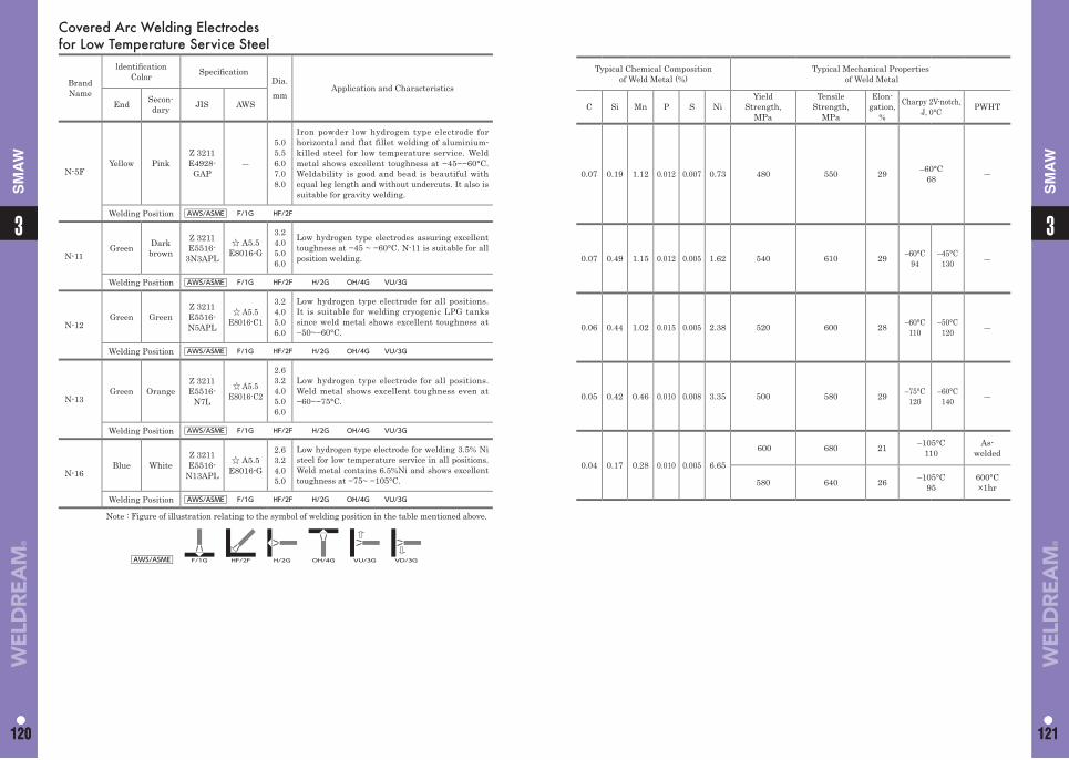
Typical Chemical Composition of Weld Metal (%)
Typical Mechanical Properties of Weld Metal
C Si Mn P S NiYield
Strength,MPa
Tensile Strength,
MPa
Elon-gation,
%
Charpy 2V-notch,J, 0°C PWHT
0.07 0.19 1.12 0.012 0.007 0.73 480 550 29 –60°C68 ―
0.07 0.49 1.15 0.012 0.005 1.62 540 610 29 –60°C94
–45°C 130 ―
0.06 0.44 1.02 0.015 0.005 2.38 520 600 28 –60°C110
–50°C120 ―
0.05 0.42 0.46 0.010 0.008 3.35 500 580 29 –75°C120
–60°C140 ―
0.04 0.17 0.28 0.010 0.005 6.65
600 680 21 –105°C110
As-welded
580 640 26 –105°C95
600°C×1hr
Covered Arc Welding Electrodes for Low Temperature Service Steel
Brand Name
ldentifi cation Color Specifi cation
Dia.mm
Application and Characteristics
End Secon-dary JIS AWS
N-5FYellow Pink
Z 3211E4928-
GAP―
5.05.56.07.08.0
Iron powder low hydrogen type electrode for horizontal and flat fillet welding of aluminium-killed steel for low temperature service. Weld metal shows excellent toughness at −45~−60°C. Weldability is good and bead is beautiful with equal leg length and without undercuts. It also is suitable for gravity welding.
Welding Position AWS/ASME F/1G HF/2F
N-11Green Dark
brown
Z 3211E5516-
3N3APL
☆ A5.5E8016-G
3.24.05.06.0
Low hydrogen type electrodes assuring excellent toughness at −45 ~ −60°C. N-11 is suitable for all position welding.
Welding Position AWS/ASME F/1G HF/2F H/2G OH/4G VU/3G
N-12Green Green
Z 3211E5516-N5APL
☆ A5.5E8016-C1
3.24.05.06.0
Low hydrogen type electrode for all positions. It is suitable for welding cryogenic LPG tanks since weld metal shows excellent toughness at −50~−60°C.
Welding Position AWS/ASME F/1G HF/2F H/2G OH/4G VU/3G
N-13Green Orange
Z 3211E5516-
N7L
☆ A5.5E8016-C2
2.63.24.05.06.0
Low hydrogen type electrode for all positions. Weld metal shows excellent toughness even at −60~−75°C.
Welding Position AWS/ASME F/1G HF/2F H/2G OH/4G VU/3G
N-16Blue White
Z 3211E5516-
N13APL
☆ A5.5E8016-G
2.63.2 4.0 5.0
Low hydrogen type electrode for welding 3.5% Ni steel for low temperature service in all positions. Weld metal contains 6.5%Ni and shows excellent toughness at −75~ −105°C.
Welding Position AWS/ASME F/1G HF/2F H/2G OH/4G VU/3G
Note : Figure of illustration relating to the symbol of welding position in the table mentioned above.
AWS/ASME F/1G HF/2F H/2G OH/4G VU/3G VD/3G
11
120 121
3
120
3
121
SM
AW
SM
AW
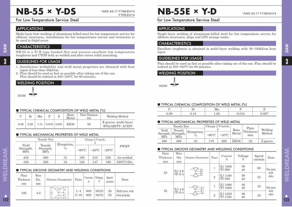
33
122 123
SA
W
SA
W
NB-55 × Y-DS ☆AWS A5.17 F7A8-EH14F7P8-EH14
For Low Temperature Service Steel
■ TYPICAL CHEMICAL COMPOSITION OF WELD METAL (%)
C Si Mn P S BaseMetal
Plate Thicknessmm Welding Method
0.08 0.20 1.74 0.016 0.001 KE36 50 X groove, multi-layer(POLARITY; ACEP)
APPLICATIONS Multi-layer butt welding of aluminium-killed steel for low temperature service for offshore structures, installations for low temperatures service and structures to be used in frigid areas.
CHARACTERISTICS NB-55 is a Ti-B type bonded flux and assures excellent low temperature toughness and CTOD both as welded and after stress relief annealing.
GUIDELlNES FOR USAGE 1. Satisfactory weldability and weld metal properties are obtained with heat
input of less than 50kJ/cm.2. Flux should be used as fast as possible after taking out of the can. Flux should be redried at 250~350°C for 60 minutes.
WELDING POSITION
AWS/ASME F/1G
■ TYPICAL MECHANICAL PROPERTIES OF WELD METALTensile Test Charpy 2 V-notch,
JPWHTYield
Strength,MPa
Tensile Strength,
MPa
Elongation,% −60°C −40°C −29°C
450 560 31 180 210 220 As-welded430 520 34 120 147 190 620°C×2hr
■ TYPICAL GROOVE GEOMETRY AND WELDING CONDITIONS
Plate Thickness
mm
Wire Dia.mm
Groove Geometry Pass Current, A
Voltage, V
Speed, cm/min Note
100 4.050°
80°
50
32
126
1~45~16
600600
30/3330/33
3030
Multi-layer, with back gouging
NB-55E × Y-D ☆AWS A5.17 F7A8-EH14
for Low Temperature Service Steel
APPLICATIONS Single-layer welding of aluminium-killed steel for low temperature service for offshore structures, ships and LPG storage tanks.
CHARACTERISTICS Excellent toughness is obtained in multi-layer welding with 30~100kJ/cm heat input.
GUIDELlNES FOR USAGE Flux should be used as fast as possible after taking out of the can. Flux should be redried at 250~350°C for 60 minutes.
WELDING POSITION
AWS/ASME F/1G
■ TYPICAL CHEMICAL COMPOSITION OF WELD METAL (%)C Si Mn P S
0.09 0.18 1.65 0.018 0.007
■ TYPICAL MECHANICAL PROPERTIES OF WELD METALTensile Test Charpy 2 V-notch,
J Base Metal
PlateThickness
mmWelding Method
Yield Strength,
MPa
Tensile Strength,
MPaElongation,
% −60°C −40°C
460 560 33 170 200 EH36 32 X groove
■ TYPICAL GROOVE GEOMETRY AND WELLDING CONDITIONSPlate
Thicknessmm
Wire Diamm
Groove Geometry Pass CurrentA
VoltageV
Speedcm/min Note
25 (L) 4.8(T) 6.4
60°
90°
979
1 (L) 1000(T) 900
3640 60 One pass
both sides2 (L) 1100
(T) 8503640 55
32 (L) 4.8(T) 6.4
60°
90°
121010
1 (L) 1080(T) 1000
3640 45 One pass
both sides2 (L) 1250
(T) 11003640 45
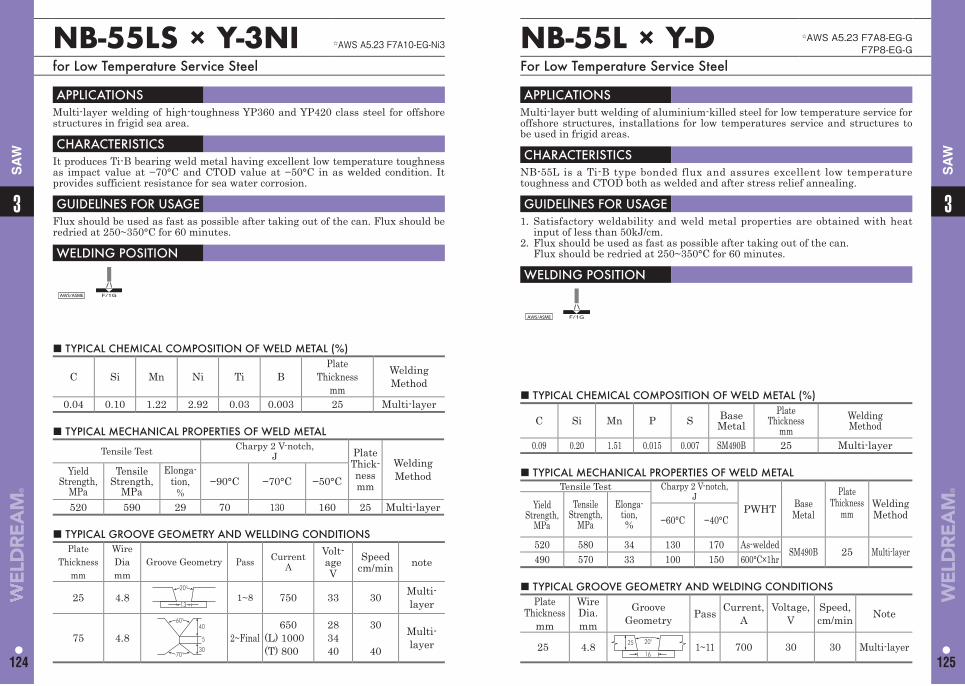
33
124 125
SA
W
SA
W
NB-55LS × Y-3NI ☆AWS A5.23 F7A10-EG-Ni3
for Low Temperature Service Steel
APPLICATIONS Multi-layer welding of high-toughness YP360 and YP420 class steel for offshore structures in frigid sea area.
CHARACTERISTICS It produces Ti-B bearing weld metal having excellent low temperature toughness as impact value at −70°C and CTOD value at −50°C in as welded condition. It provides sufficient resistance for sea water corrosion.
GUIDELlNES FOR USAGE Flux should be used as fast as possible after taking out of the can. Flux should be redried at 250~350°C for 60 minutes.
WELDING POSITION
AWS/ASME F/1G
■ TYPICAL CHEMICAL COMPOSITION OF WELD METAL (%)
C Si Mn Ni Ti BPlate
Thicknessmm
Welding Method
0.04 0.10 1.22 2.92 0.03 0.003 25 Multi-layer
■ TYPICAL MECHANICAL PROPERTIES OF WELD METAL
Tensile Test Charpy 2 V-notch,J Plate
Thick-nessmm
Welding MethodYield
Strength,MPa
Tensile Strength,
MPa
Elonga-tion,
%−90°C −70°C −50°C
520 590 29 70 130 160 25 Multi-layer
■ TYPICAL GROOVE GEOMETRY AND WELLDING CONDITIONSPlate
Thicknessmm
Wire Diamm
Groove Geometry Pass CurrentA
Volt-ageV
Speedcm/min note
25 4.813
20°
1~8 750 33 30 Multi-layer
75 4.8
60°
70°
40
30
5 2~Final650
(L) 1000(T) 800
283440
30
40
Multi-layer
NB-55L × Y-D ☆AWS A5.23 F7A8-EG-GF7P8-EG-G
For Low Temperature Service Steel
■ TYPICAL CHEMICAL COMPOSITION OF WELD METAL (%)
C Si Mn P S BaseMetal
Plate Thickness
mmWeldingMethod
0.09 0.20 1.51 0.015 0.007 SM490B 25 Multi-layer
APPLICATIONS Multi-layer butt welding of aluminium-killed steel for low temperature service for offshore structures, installations for low temperatures service and structures to be used in frigid areas.
CHARACTERISTICS NB-55L is a Ti-B type bonded flux and assures excellent low temperature toughness and CTOD both as welded and after stress relief annealing.
GUIDELlNES FOR USAGE 1. Satisfactory weldability and weld metal properties are obtained with heat
input of less than 50kJ/cm.2. Flux should be used as fast as possible after taking out of the can.
Flux should be redried at 250~350°C for 60 minutes.
WELDING POSITION
AWS/ASME F/1G
■ TYPICAL MECHANICAL PROPERTIES OF WELD METALTensile Test Charpy 2 V-notch,
JPWHT Base
Metal
PlateThickness
mmWelding Method
Yield Strength,
MPa
Tensile Strength,
MPa
Elonga-tion,% −60°C −40°C
520 580 34 130 170 As-welded SM490B 25 Multi-layer490 570 33 100 150 600°C×1hr
■ TYPICAL GROOVE GEOMETRY AND WELDING CONDITIONS Plate
Thicknessmm
Wire Dia.mm
Groove Geometry Pass Current,
AVoltage,
VSpeed, cm/min Note
25 4.8 25 20°
161~11 700 30 30 Multi-layer
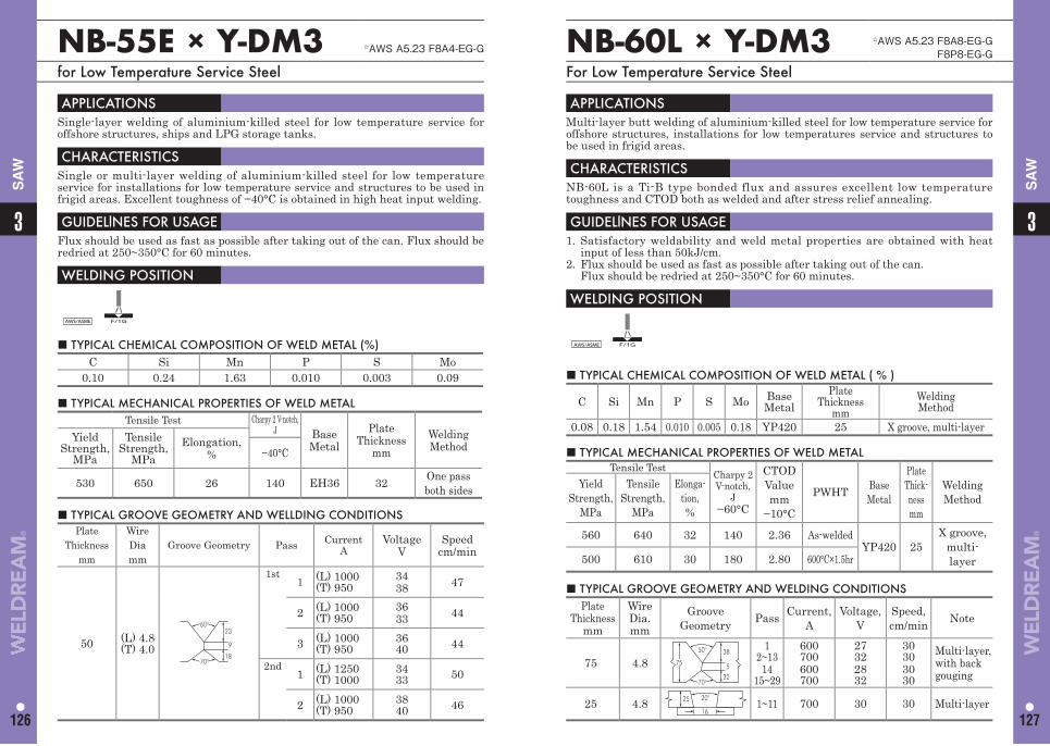
33
126 127
SA
W
SA
W
NB-55E × Y-DM3 ☆AWS A5.23 F8A4-EG-G
for Low Temperature Service Steel
APPLICATIONS Single-layer welding of aluminium-killed steel for low temperature service for offshore structures, ships and LPG storage tanks.
CHARACTERISTICS Single or multi-layer welding of aluminium-killed steel for low temperature service for installations for low temperature service and structures to be used in frigid areas. Excellent toughness of −40°C is obtained in high heat input welding.
GUIDELlNES FOR USAGE Flux should be used as fast as possible after taking out of the can. Flux should be redried at 250~350°C for 60 minutes.
WELDING POSITION
AWS/ASME F/1G
■ TYPICAL CHEMICAL COMPOSITION OF WELD METAL (%)C Si Mn P S Mo
0.10 0.24 1.63 0.010 0.003 0.09
■ TYPICAL MECHANICAL PROPERTIES OF WELD METALTensile Test Charpy 2 V-notch,
J Base Metal
PlateThickness
mmWelding Method
Yield Strength,
MPa
Tensile Strength,
MPaElongation,
% −40°C
530 650 26 140 EH36 32 One pass both sides
■ TYPICAL GROOVE GEOMETRY AND WELLDING CONDITIONSPlate
Thicknessmm
Wire Diamm
Groove Geometry Pass CurrentA
VoltageV
Speedcm/min
50 (L) 4.8(T) 4.0
60°
70°
23
18
9
1st1 (L) 1000
(T) 9503438 47
2 (L) 1000(T) 950
3633 44
3 (L) 1000(T) 950
3640 44
2nd1 (L) 1250
(T) 10003433 50
2 (L) 1000(T) 950
3840 46
NB-60L × Y-DM3 ☆AWS A5.23 F8A8-EG-GF8P8-EG-G
For Low Temperature Service Steel
■ TYPICAL CHEMICAL COMPOSITION OF WELD METAL ( % )
C Si Mn P S Mo BaseMetal
Plate Thickness
mmWeldingMethod
0.08 0.18 1.54 0.010 0.005 0.18 YP420 25 X groove, multi-layer
APPLICATIONS Multi-layer butt welding of aluminium-killed steel for low temperature service for offshore structures, installations for low temperatures service and structures to be used in frigid areas.
CHARACTERISTICS NB-60L is a Ti-B type bonded flux and assures excellent low temperature toughness and CTOD both as welded and after stress relief annealing.
GUIDELlNES FOR USAGE 1. Satisfactory weldability and weld metal properties are obtained with heat
input of less than 50kJ/cm.2. Flux should be used as fast as possible after taking out of the can. Flux should be redried at 250~350°C for 60 minutes.
WELDING POSITION
AWS/ASME F/1G
■ TYPICAL MECHANICAL PROPERTIES OF WELD METALTensile Test Charpy 2
V-notch,J
−60°C
CTOD Valuemm
−10°C
PWHT Base Metal
PlateThick-nessmm
Welding Method
Yield Strength,
MPa
Tensile Strength,
MPa
Elonga-tion,%
560 640 32 140 2.36 As-weldedYP420 25
X groove, multi-layer500 610 30 180 2.80 600°C×1.5hr
■ TYPICAL GROOVE GEOMETRY AND WELDING CONDITIONS Plate
Thicknessmm
Wire Dia.mm
Groove Geometry Pass Current,
AVoltage,
VSpeed, cm/min Note
75 4.850°
70°
75
38
325
12~13
1415~29
600700600700
27322832
30303030
Multi-layer, with back gouging
25 4.8 25 20°
161~11 700 30 30 Multi-layer

11
128 129
3
128
3
129
SA
W
SA
WSubmerged Arc Welding Materials for Low Temperature Service Steel
Brand Name
Specifi cation
Application and Characteristics
Typical Chemical of Weld
CompositionMetal (%)
Typical MechanicalProperties of Weld Metal Remarks
JIS AWS C Si Mn P S Mo NiYield
Strength,MPa
Tensile Strength,
MPa
Elonga-tion,
%
Charpy 2V-notch, PWHT Base
MetalPlate
Thicknessmm
Welding Method
°C J
NSH-60×
Y-D
☆Z 3183 S582-H
☆ A5.23 F8A4-EH14-G
Multi-layer butt welding and fi llet welding of up to 570 MPa tensile strength grade such as ASTM A537 Cl.2 plate or APIX65 pipe. NSH-60 is an agglomerated fl ux containing iron powder, and is able to make high deposition rate and deep penetration welding. Combined with a wire of Y-D, It is able to high heat input welding up to approx. 150kJ/cm.
0.08 0.41 1.84 0.016 0.008 — — 620 650 28
−40 65
As-welded YP420 25
Multi-layer
−29 76
−18 88Welding Position AWS/ASME F/1G
NF-310×
Y-E
☆ A5.23
F8A8-EG-GF8P4-EG-G
Single and multi-layer flat butt welding of aluminium-killed steel for low temperature ser-vice for LPG storage tanks, installations for low temperature service and structures to be used in frigid areas.Weld metal shows extremely high toughness and excellent ductility. Weldability is satisfactory and slag is easy to remove.
0.09 0.27 1.36 0.016 0.009 — —
520 590 31
−75 120
As-welded
N-TUF325N
20
−60 140
−45 160
−30 —
500 570 33
−75 —
630°C×1hr
−60 86
−45 130
Welding Position AWS/ASME F/1G −30 150
NF-310×
Y-DM3
☆ A5.23
F8A8-EG-GF8P4-EG-G
Single and multi-layer flat butt welding of aluminium-killed steel for low temperature ser-vice for LPG storage tanks, installations for low temperature service and structures to be used in frigid areas.Weld metal shows extremely high toughness and excellent ductility. Weldability is satisfactory and slag is easy to remove.
0.08 0.20 1.00 0.013 0.011 0.19 —
530 600 27
−60 100As-
welded−45 160
−30 170
520 600 30
−60 72630°C×
1hr−45 140
Welding Position AWS/ASME F/1G −30 170
NB-55E×
Y-CM
Single-layer welding of aluminium-killed steel for low temperature service for offshore structures, ships and LPG storage tanks. 0.08 0.24 1.48 0.010 0.003 0.18 — 490 650 27
−60 63
— EH36 27One pass both sides−40 120
Welding Position AWS/ASME F/1G
NB-55×
Y-CMS
☆ A5.23
F8A8-EA4-A4F8P8-EA4-A4
Multi-layer welding of aluminium-killed steel for low temperature service for offshore structures, ships and LPG storage tanks. 0.08 0.13 1.36 0.010 0.004 0.40 —
560 620 23−60 87 As-
weldedEH36 24 Multi-
layer−40 120
530 590 25−60 160 620°C×
2hrWelding Position AWS/ASME F/1G −40 200
NB-55×
Y-DM
☆ A5.23
F9A8-EA3-GF9P8-EA3-G
Single-layer welding of aluminium-killed steel for low temperature service for offshore structures, ships and LPG storage tanks. 0.09 0.12 1.62 0.009 0.002 0.35 —
570 660 26 −60 62 As- welded
SPV490Q 24Multi-layer (DC+)550 630 28 −60 48 620°C×
2hrWelding Position AWS/ASME F/1G
Note : Figure of illustration relating to the symbol of welding position in the table mentioned above.
AWS/ASME F/1G HF/2F H/2G OH/4G VU/3G VD/3G
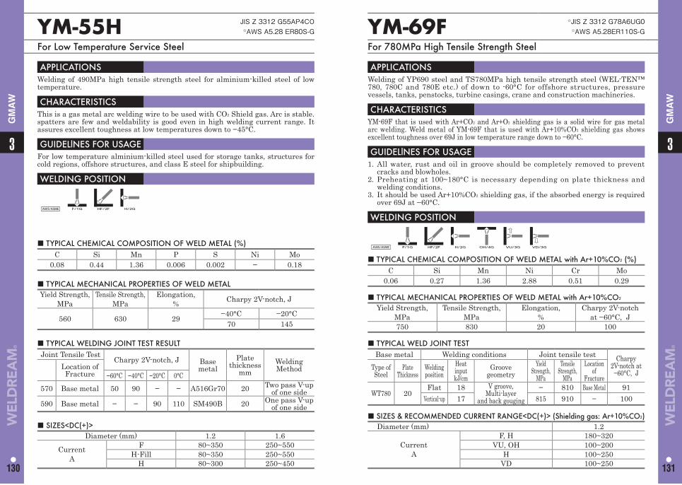
■ TYPICAL CHEMICAL COMPOSITION OF WELD METAL with Ar+10%CO2 (%)C Si Mn Ni Cr Mo
0.06 0.27 1.36 2.88 0.51 0.29
■ TYPICAL CHEMICAL COMPOSITION OF WELD METAL (%)C Si Mn P S Ni Mo
0.08 0.44 1.36 0.006 0.002 − 0.18
YM-69F ☆JIS Z 3312 G78A6UG0☆AWS A5.28ER110S-G
For 780MPa High Tensile Strength Steel
YM-55H JIS Z 3312 G55AP4CO☆AWS A5.28 ER80S-G
For Low Temperature Service Steel
APPLICATIONS Welding of YP690 steel and TS780MPa high tensile strength steel (WEL-TEN™ 780, 780C and 780E etc.) of down to -60°C for offshore structures, pressure vessels, tanks, penstocks, turbine casings, crane and construction machineries.
CHARACTERISTICS YM-69F that is used with Ar+CO2 and Ar+O2 shielding gas is a solid wire for gas metal arc welding. Weld metal of YM-69F that is used with Ar+10%CO2 shielding gas shows excellent toughness over 69J in low temperature range down to −60°C.
GUIDELlNES FOR USAGE 1. All water, rust and oil in groove should be completely removed to prevent
cracks and blowholes.2. Preheating at 100~180°C is necessary depending on plate thickness and
welding conditions.3. It should be used Ar+10%CO2 shielding gas, if the absorbed energy is required
over 69J at −60°C.
WELDING POSITION
AWS/ASME F/1G HF/2F H/2G OH/4G VU/3G VD/3G
APPLICATIONS Welding of 490MPa high tensile strength steel for alminium-killed steel of low temperature.
CHARACTERISTICS This is a gas metal arc welding wire to be used with CO2 Shield gas. Arc is stable.spatters are few and weldability is good even in high welding current range. It assures excellent toughness at low temperatures down to −45°C.
GUIDELlNES FOR USAGE For low temperature alminium-killed steel used for storage tanks, structures for cold regions, offshore structures, and class E steel for shipbuilding.
WELDING POSITION
AWS/ASME F/1G HF/2F H/2G
■ TYPICAL MECHANICAL PROPERTIES OF WELD METAL with Ar+10%CO2 Yield Strength,
MPaTensile Strength,
MPa Elongation,
%Charpy 2V-notch
at −60°C, J750 830 20 100
■ TYPICAL MECHANICAL PROPERTIES OF WELD METALYield Strength,
MPaTensile Strength,
MPaElongation,
% Charpy 2V-notch, J
560 630 29 −40°C −20°C70 145
■ SIZES & RECOMMENDED CURRENT RANGE<DC(+)> (Shielding gas: Ar+10%CO2) Diameter (mm) 1.2
CurrentA
F, H 180~320VU, OH 100~200
H 100~250VD 100~250
■ SIZES<DC(+)>Diameter (mm) 1.2 1.6
CurrentA
F 80~350 250~550H-Fill 80~350 250~550
H 80~300 250~450
■ TYPICAL WELD JOINT TESTBase metal Welding conditions Joint tensile test Charpy
2V-notch at−60°C, J
Type ofSteel
PlateThickness
Welding position
Heat inputkJ/cm
Groovegeometry
Yield Strength,
MPa
Tensile Strength,
MPa
Location of
Fracture
WT780 20Flat 18 V groove,
Multi-layerand back gouging
− 810 Base Metal 91Vertical-up 17 815 910 − 100
■ TYPICAL WELDING JOINT TEST RESULTJoint Tensile Test
Charpy 2V-notch, J Base metal
Plate thickness
mmWelding MethodLocation of
Fracture −60°C −40°C −20°C 0°C570 Base metal 50 90 − − A516Gr70 20 Two pass V-up
of one side590 Base metal − − 90 110 SM490B 20 One pass V-up
of one side
33
130 131
GM
AW
GM
AW
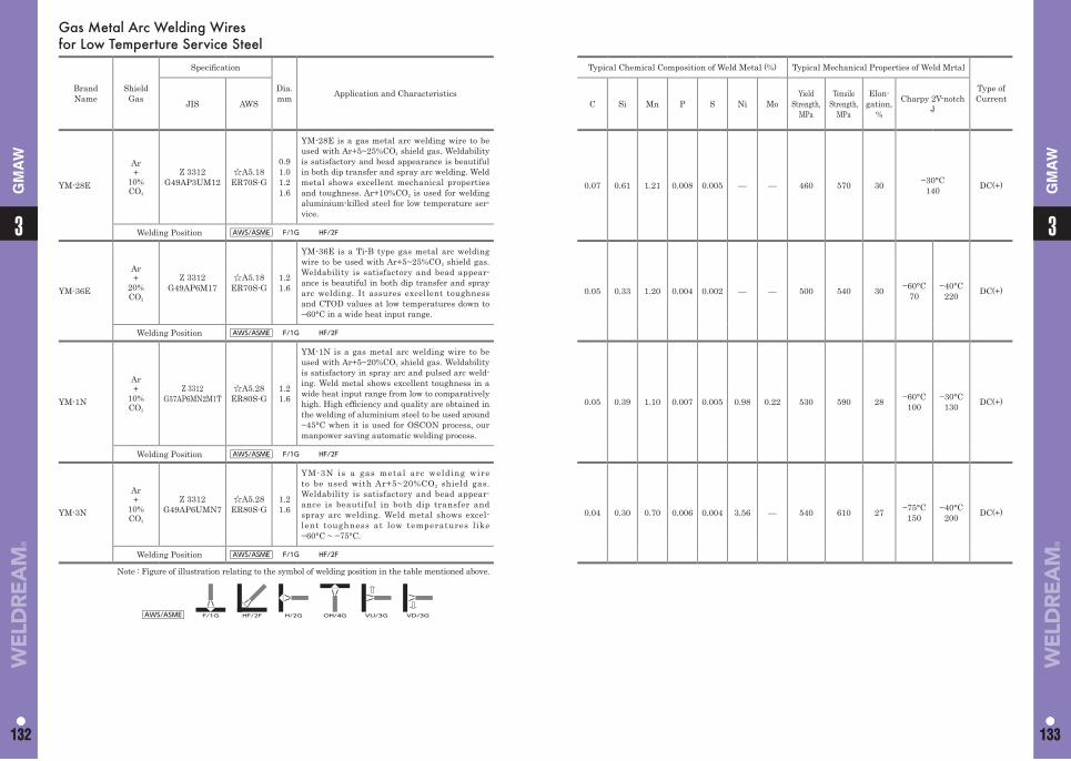
Gas Metal Arc Welding Wires for Low Temperture Service Steel
Brand Name
Shield Gas
Specifi cation
Dia.mm Application and Characteristics
Typical Chemical Composition of Weld Metal (%) Typical Mechanical Properties of Weld Mrtal
Type of CurrentJIS AWS C Si Mn P S Ni Mo
Yield Strength,
MPa
Tensile Strength,
MPa
Elon-gation,
%
Charpy 2V-notchJ
YM-28E
Ar+
10%CO2
Z 3312G49AP3UM12
☆A5.18ER70S-G
0.91.01.21.6
YM-28E is a gas metal arc welding wire to be used with Ar+5~25%CO2 shield gas. Weldability is satisfactory and bead appearance is beautiful in both dip transfer and spray arc welding. Weld metal shows excellent mechanical properties and toughness. Ar+10%CO2 is used for welding aluminium-killed steel for low temperature ser-vice.
0.07 0.61 1.21 0.008 0.005 — — 460 570 30 −30°C140 DC(+)
Welding Position AWS/ASME F/1G HF/2F
YM-36E
Ar+
20%CO2
Z 3312G49AP6M17
☆A5.18 ER70S-G
1.21.6
YM-36E is a Ti-B type gas metal arc welding wire to be used with Ar+5~25%CO2 shield gas. Weldability is satisfactory and bead appear-ance is beautiful in both dip transfer and spray arc welding. It assures excellent toughness and CTOD values at low temperatures down to −60°C in a wide heat input range.
0.05 0.33 1.20 0.004 0.002 — — 500 540 30 −60°C70
−40°C220 DC(+)
Welding Position AWS/ASME F/1G HF/2F
YM-1N
Ar+
10%CO2
Z 3312G57AP6MN2M1T
☆A5.28ER80S-G
1.21.6
YM-1N is a gas metal arc welding wire to be used with Ar+5~20%CO2 shield gas. Weldability is satisfactory in spray arc and pulsed arc weld-ing. Weld metal shows excellent toughness in a wide heat input range from low to comparatively high. High effi ciency and quality are obtained in the welding of aluminium steel to be used around −45°C when it is used for OSCON process, our manpower saving automatic welding process.
0.05 0.39 1.10 0.007 0.005 0.98 0.22 530 590 28 −60°C100
−30°C130 DC(+)
Welding Position AWS/ASME F/1G HF/2F
YM-3N
Ar+
10%CO2
Z 3312G49AP6UMN7
☆A5.28ER80S-G
1.21.6
YM-3N is a gas metal arc welding wire to be used with Ar+5~20%CO2 shield gas. Weldability is satisfactory and bead appear-ance is beautiful in both dip transfer and spray arc welding. Weld metal shows excel-lent toughness at low temperatures like −60°C ~ −75°C.
0.04 0.30 0.70 0.006 0.004 3.56 — 540 610 27 −75°C150
−40°C200 DC(+)
Welding Position AWS/ASME F/1G HF/2F
Note : Figure of illustration relating to the symbol of welding position in the table mentioned above.
AWS/ASME F/1G HF/2F H/2G OH/4G VU/3G VD/3G
11
132 133
3
132
3
133
GM
AW
GM
AW
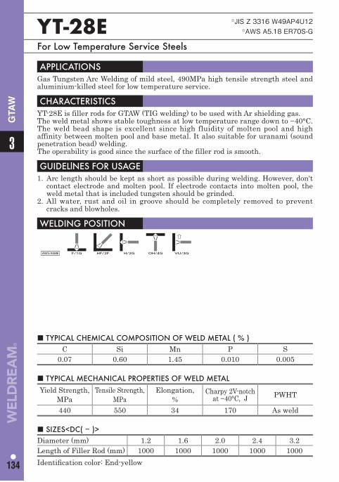
■ TYPICAL CHEMICAL COMPOSITION OF WELD METAL ( % ) C Si Mn P S
0.07 0.60 1.45 0.010 0.005
YT-28E ☆JIS Z 3316 W49AP4U12☆AWS A5.18 ER70S-G
For Low Temperature Service Steels
APPLICATIONS Gas Tungsten Arc Welding of mild steel, 490MPa high tensile strength steel and aluminium-killed steel for low temperature service.
CHARACTERISTICS YT-28E is filler rods for GTAW (TIG welding) to be used with Ar shielding gas. The weld metal shows stable toughness at low temperature range down to −40°C. The weld bead shape is excellent since high fluidity of molten pool and high affinity between molten pool and base metal. It also suitable for uranami (sound penetration bead) welding.The operability is good since the surface of the filler rod is smooth.
GUIDELlNES FOR USAGE 1. Arc length should be kept as short as possible during welding. However, don't
contact electrode and molten pool. If electrode contacts into molten pool, the weld metal that is included tungsten should be grinded.
2. All water, rust and oil in groove should be completely removed to prevent cracks and blowholes.
WELDING POSITION
AWS/ASME F/1G HF/2F H/2G OH/4G VU/3G
■ TYPICAL MECHANICAL PROPERTIES OF WELD METAL Yield Strength,
MPaTensile Strength,
MPaElongation,
%Charpy 2V-notch
at −40°C, J PWHT
440 550 34 170 As weld
■ SIZES<DC( − )> Diameter (mm) 1.2 1.6 2.0 2.4 3.2Length of Filler Rod (mm) 1000 1000 1000 1000 1000Identifi cation color: End-yellow
3
134
GTA
W
135
Heat Resisting SteelCovered Arc Welding ElectrodesSubmerged Arc Welding MaterialsGas Metal Arc Welding WiresGas Tungsten Arc Welding Rods and Wires
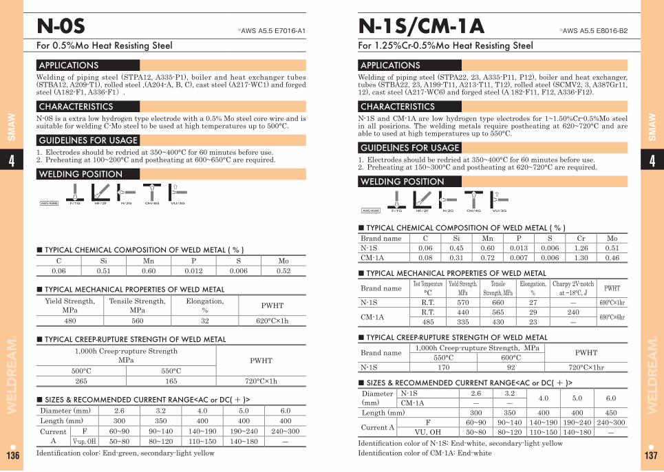
44
136 137
SM
AW
SM
AW
■ TYPICAL CHEMICAL COMPOSITION OF WELD METAL ( % ) C Si Mn P S Mo
0.06 0.51 0.60 0.012 0.006 0.52
N-0S ☆AWS A5.5 E7016-A1
For 0.5%Mo Heat Resisting Steel
APPLICATIONS Welding of piping steel (STPA12, A335-P1), boiler and heat exchanger tubes (STBA12, A209-T1), rolled steel ,(A204-A, B, C), cast steel (A217-WC1) and forged steel (A182-F1, A336-F1).
CHARACTERISTICS N-0S is a extra low hydrogen type electrode with a 0.5% Mo steel core wire and is suitable for welding C-Mo steel to be used at high temperatures up to 500°C.
GUIDELlNES FOR USAGE 1. Electrodes should be redried at 350~400°C for 60 minutes before use. 2. Preheating at 100~200°C and postheating at 600~650°C are required.
WELDING POSITION
AWS/ASME F/1G HF/2F H/2G OH/4G VU/3G
■ TYPICAL MECHANICAL PROPERTIES OF WELD METAL Yield Strength,
MPaTensile Strength,
MPa Elongation,
% PWHT
480 560 32 620°C×1h
■ SIZES & RECOMMENDED CURRENT RANGE<AC or DC( + )> Diameter (mm) 2.6 3.2 4.0 5.0 6.0Length (mm) 300 350 400 400 400Current
AF 60~90 90~140 140~190 190~240 240~300
V-up, OH 50~80 80~120 110~150 140~180 ―Identifi cation color: End-green, secondary-light yellow
■ TYPICAL CREEP-RUPTURE STRENGTH OF WELD METAL1,000h Creep-rupture Strength
MPa PWHT500°C 550°C
265 165 720°C×1h
N-1S/CM-1A ☆AWS A5.5 E8016-B2
For 1.25%Cr-0.5%Mo Heat Resisting Steel
APPLICATIONS Welding of piping steel (STPA22, 23, A335-P11, P12), boiler and heat exchanger, tubes (STBA22, 23, A199-T11, A213-T11, T12), rolled steel (SCMV2, 3, A387Gr11, 12), cast steel (A217-WC6) and forged steel (A 182-F11, F12, A336-F12).
CHARACTERISTICS N-1S and CM-1A are low hydrogen type electrodes for 1~1.50%Cr-0.5%Mo steel in all posirions. The welding metals require postheating at 620~720°C and are able to used at high temperatures up to 550°C.
GUIDELlNES FOR USAGE 1. Electrodes should be redried at 350~400°C for 60 minutes before use.2. Preheating at 150~300°C and postheating at 620~720°C are required.
WELDING POSITION
AWS/ASME F/1G HF/2F H/2G OH/4G VU/3G
■ TYPICAL CHEMICAL COMPOSITION OF WELD METAL ( % )Brand name C Si Mn P S Cr MoN-1S 0.06 0.45 0.60 0.013 0.006 1.26 0.51CM-1A 0.08 0.31 0.72 0.007 0.006 1.30 0.46
■ TYPICAL MECHANICAL PROPERTIES OF WELD METAL
Brand name Test Temperature °C
Yield Strength, MPa
Tensile Strength, MPa
Elongation, %
Charpy 2V-notch at −18°C, J PWHT
N-1S R.T. 570 660 27 ― 690°C×1hr
CM-1A R.T. 440 565 29 240 690°C×6hr485 335 430 23 ―
■ SIZES & RECOMMENDED CURRENT RANGE<AC or DC( + )> Diameter (mm)
N-1S 2.6 3.2 4.0 5.0 6.0CM-1A ― ―Length (mm) 300 350 400 400 450
Current A F 60~90 90~140 140~190 190~240 240~300VU, OH 50~80 80~120 110~150 140~180 ―
Identifi cation color of N-1S: End-white, secondary-light yellowIdentifi cation color of CM-1A: End-white
■ TYPICAL CREEP-RUPTURE STRENGTH OF WELD METAL
Brand name 1,000h Creep-rupture Strength, MPa PWHT550°C 600°CN-1S 170 92 720°C×1hr
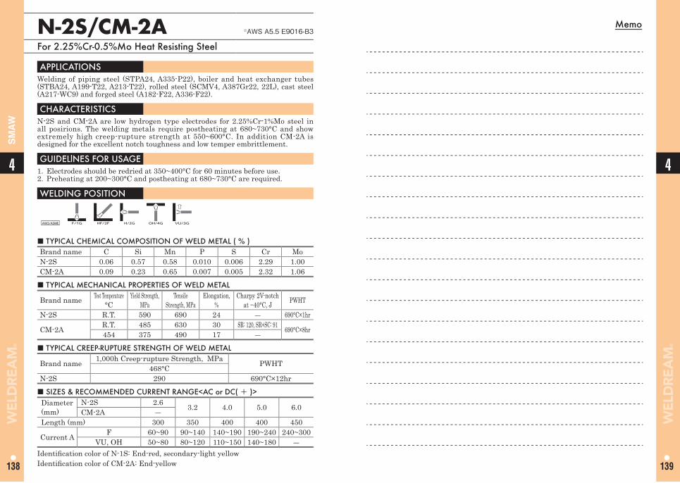
Memo
139
44
138
SM
AW
N-2S/CM-2A ☆AWS A5.5 E9016-B3
For 2.25%Cr-0.5%Mo Heat Resisting Steel
■ TYPICAL CHEMICAL COMPOSITION OF WELD METAL ( % )Brand name C Si Mn P S Cr MoN-2S 0.06 0.57 0.58 0.010 0.006 2.29 1.00 CM-2A 0.09 0.23 0.65 0.007 0.005 2.32 1.06
APPLICATIONS Welding of piping steel (STPA24, A335-P22), boiler and heat exchanger tubes (STBA24, A199-T22, A213-T22), rolled steel (SCMV4, A387Gr22, 22L), cast steel (A217-WC9) and forged steel (A182-F22, A336-F22).
CHARACTERISTICS N-2S and CM-2A are low hydrogen type electrodes for 2.25%Cr-1%Mo steel in all posirions. The welding metals require postheating at 680~730°C and show extremely high creep-rupture strength at 550~600°C. In addition CM-2A is designed for the excellent notch toughness and low temper embrittlement.
GUIDELlNES FOR USAGE 1. Electrodes should be redried at 350~400°C for 60 minutes before use.2. Preheating at 200~300°C and postheating at 680~730°C are required.
WELDING POSITION
AWS/ASME F/1G HF/2F H/2G OH/4G VU/3G
■ TYPICAL MECHANICAL PROPERTIES OF WELD METAL
Brand name Test Temperature °C
Yield Strength, MPa
Tensile Strength, MPa
Elongation, %
Charpy 2V-notch at −40°C, J PWHT
N-2S R.T. 590 690 24 ― 690°C×1hr
CM-2A R.T. 485 630 30 SR: 120, SR+SC: 91 690°C×8hr454 375 490 17 ―
■ SIZES & RECOMMENDED CURRENT RANGE<AC or DC( + )> Diameter (mm)
N-2S 2.6 3.2 4.0 5.0 6.0CM-2A ―Length (mm) 300 350 400 400 450
Current A F 60~90 90~140 140~190 190~240 240~300VU, OH 50~80 80~120 110~150 140~180 ―
Identifi cation color of N-1S: End-red, secondary-light yellowIdentifi cation color of CM-2A: End-yellow
■ TYPICAL CREEP-RUPTURE STRENGTH OF WELD METAL
Brand name 1,000h Creep-rupture Strength, MPa PWHT468°CN-2S 290 690°C×12hr
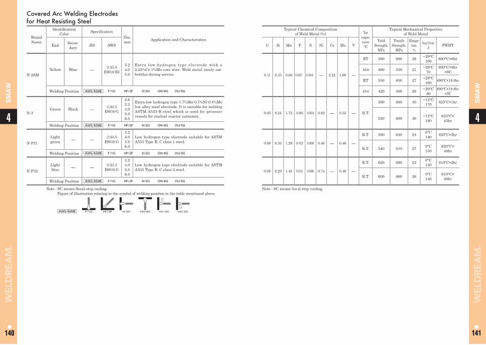
Covered Arc Welding Electrodes for Heat Resisting Steel
Brand Name
ldentifi cation Color Specifi cation
Dia.mm Application and Characteristics
Typical Chemical Compositionof Weld Metal (%) Test
temper-rature°C
Typical Mechanical Propertiesof Weld Metal
End Secon-dary JIS AWS C Si Mn P S Ni Cr Mo V
Yield Strength,
MPa
Tensile Strength,
MPa
Elonga-tion,%
Charpy 2V-notch,J PWHT
N-2SMYellow Blue ― ☆A5.5
E9016-B3
3.24.05.0
Extra low hydrogen type electrode with a 2.25%Cr-1%Mo core wire. Weld metal rarely em-brittles during service. 0.11 0.33 0.66 0.007 0.004 ― 2.24 1.00 ―
RT 590 680 26 −29°C160 690°C×6hr
454 460 530 21 −29°C70
690°C×6hr+SC
RT 550 650 27 −29°C160 690°C×19.8hr
Welding Position AWS/ASME F/1G HF/2F H/2G OH/4G VU/3G 454 420 500 20 −29°C80
690°C×19.8hr+SC
N-3Green Black ― ☆A5.5
E9016-G
2.63.24.05.06.0
Extra low hydrogen type 1.7%Mn-0.7%Ni-0.4%Mo low alloy steel electrode. It is suitable for welding ASTM A533-B steel which is used for pressure vessels for nuclear reactor container.
0.05 0.24 1.72 0.005 0.004 0.82 ― 0.35 ― R.T.
590 680 30 −12°C170 625°C×1hr
520 600 30 −12°C180
625°C×45hr
Welding Position AWS/ASME F/1G HF/2F H/2G OH/4G VU/3G
N-P31Light green ― ― ☆A5.5
E9016-G
3.24.05.06.0
Low hydrogen type electrode suitable for ASTM A533 Type B, C class 1 steel. 0.08 0.35 1.29 0.012 0.006 0.40 ― 0.46 ―
R.T. 580 640 24 0°C 140 620°C×2hr
R.T. 540 610 27 0°C 150
620°C×40hrWelding Position AWS/ASME F/1G HF/2F H/2G OH/4G VU/3G
N-P32Light blue ― ― ☆A5.5
E9016-G
3.24.05.06.0
Low hydrogen type electrode suitable for ASTM A533 Type B, C class 2 steel. 0.08 0.29 1.45 0.011 0.006 0.74 ― 0.46 ―
R.T. 620 690 23 0°C 130 610°C×2hr
R.T. 600 660 26 0°C 140
610°C×40hrWelding Position AWS/ASME F/1G HF/2F H/2G OH/4G VU/3G
Note : SC means Socal step cooling. Figure of illustration relating to the symbol of welding position in the table mentioned above.
Note : SC means Socal step cooling.
AWS/ASME F/1G HF/2F H/2G OH/4G VU/3G VD/3G
44
140 141140 141
SM
AW
SM
AW
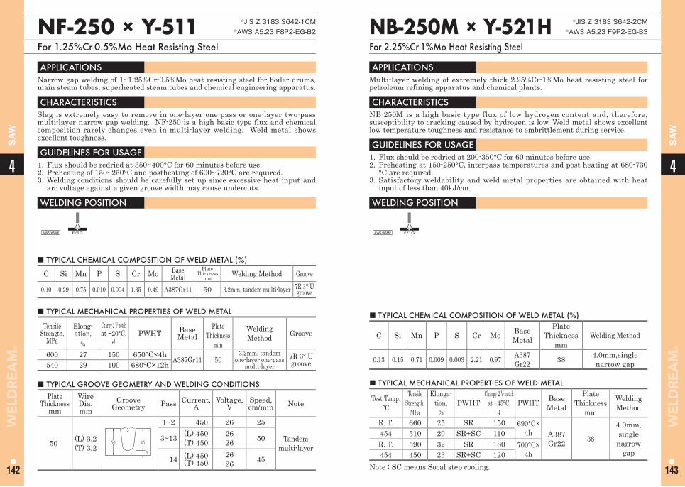
44
142 143
SA
W
SA
W
NF-250 × Y-511 ☆JIS Z 3183 S642-1CM☆AWS A5.23 F8P2-EG-B2
For 1.25%Cr-0.5%Mo Heat Resisting Steel
■ TYPICAL CHEMICAL COMPOSITION OF WELD METAL (%)
C Si Mn P S Cr Mo Base Metal
PlateThickness
mm Welding Method Groove
0.10 0.29 0.75 0.010 0.004 1.35 0.49 A387Gr11 50 3.2mm, tandem multi-layer 7R 3° U groove
APPLICATIONS Narrow gap welding of 1~1.25%Cr-0.5%Mo heat resisting steel for boiler drums, main steam tubes, superheated steam tubes and chemical engineering apparatus.
CHARACTERISTICS Slag is extremely easy to remove in one-layer one-pass or one-layer two-pass multi-layer narrow gap welding. NF-250 is a high basic type flux and chemical composition rarely changes even in multi-layer welding. Weld metal shows excellent toughness.
GUIDELlNES FOR USAGE 1. Flux should be redried at 350~400°C for 60 minutes before use.2. Preheating of 150~250°C and postheating of 600~720°C are required.3. Welding conditions should be carefully set up since excessive heat input and
arc voltage against a given groove width may cause undercuts.
WELDING POSITION
AWS/ASME F/1G
■ TYPICAL MECHANICAL PROPERTIES OF WELD METAL
Tensile Strength,
MPa
Elong-ation,
%
Charpy 2 V-notchat −20°C,
JPWHT Base
MetalPlate
Thicknessmm
WeldingMethod Groove
600 27 150 650°C×4h A387Gr11 503.2mm, tandem
one-layer one-pass multi-layer
7R 3° U groove540 29 100 680°C×12h
■ TYPICAL GROOVE GEOMETRY AND WELDING CONDITIONS Plate
Thicknessmm
Wire Dia.mm
Groove Geometry Pass Current,
AVoltage,
VSpeed, cm/min Note
50 (L) 3.2(T) 3.2
50 45
5
3°1~2 450 26 25
Tandem multi-layer
3~13 (L) 450(T) 450
2626 50
14 (L) 450(T) 450
2626 45
NB-250M × Y-521H ☆JIS Z 3183 S642-2CM☆AWS A5.23 F9P2-EG-B3
For 2.25%Cr-1%Mo Heat Resisting Steel
APPLICATIONS Multi-layer welding of extremely thick 2.25%Cr-1%Mo heat resisting steel for petroleum refining apparatus and chemical plants.
CHARACTERISTICS NB-250M is a high basic type flux of low hydrogen content and, therefore, susceptibility to cracking caused by hydrogen is low. Weld metal shows excellent low temperature toughness and resistance to embrittlement during service.
GUIDELlNES FOR USAGE 1. Flux should be redried at 200-350°C for 60 minutes before use. 2. Preheating at 150-250°C, interpass temperatures and post heating at 680-730
°C are required. 3. Satisfactory weldability and weld metal properties are obtained with heat
input of less than 40kJ/cm.
WELDING POSITION
AWS/ASME F/1G
■ TYPICAL CHEMICAL COMPOSITION OF WELD METAL (%)
C Si Mn P S Cr Mo Base Metal
Plate Thickness
mmWelding Method
0.13 0.15 0.71 0.009 0.003 2.21 0.97 A387 Gr22 38 4.0mm,single
narrow gap
■ TYPICAL MECHANICAL PROPERTIES OF WELD METAL
Test Temp. °C
Tensile Strength,
MPa
Elonga-tion,
%PWHT
Charpy 2 V-notchat −45°C,
JPWHT Base
Metal
Plate Thickness
mm
Welding Method
R. T. 660 25 SR 150 690°C×4h A387
Gr22 38
4.0mm, single
narrow gap
454 510 20 SR+SC 110R. T. 590 32 SR 180 700°C×
4h454 450 23 SR+SC 120Note : SC means Socal step cooling.
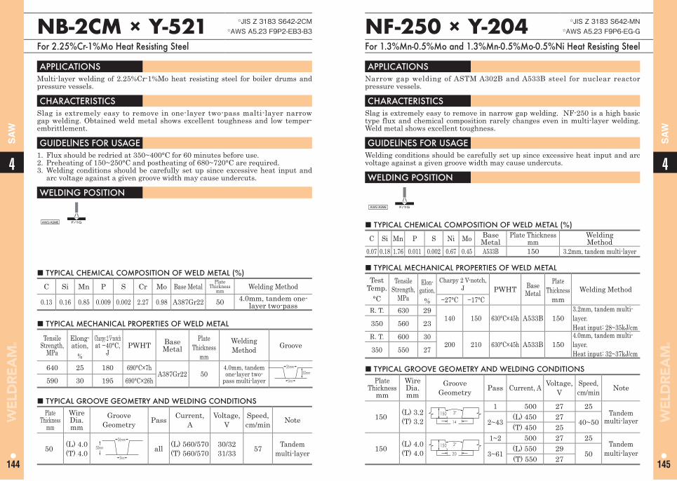
44
144 145
SA
W
SA
W
NF-250 × Y-204 ☆JIS Z 3183 S642-MN☆AWS A5.23 F9P6-EG-G
For 1.3%Mn-0.5%Mo and 1.3%Mn-0.5%Mo-0.5%Ni Heat Resisting Steel
■ TYPICAL CHEMICAL COMPOSITION OF WELD METAL (%)
C Si Mn P S Ni Mo BaseMetal
Plate Thicknessmm
WeldingMethod
0.07 0.18 1.76 0.011 0.002 0.67 0.45 A533B 150 3.2mm, tandem multi-layer
APPLICATIONS Narrow gap welding of ASTM A302B and A533B steel for nuclear reactor pressure vessels.
CHARACTERISTICS Slag is extremely easy to remove in narrow gap welding. NF-250 is a high basic type flux and chemical composition rarely changes even in multi-layer welding. Weld metal shows excellent toughness.
GUIDELlNES FOR USAGE Welding conditions should be carefully set up since excessive heat input and arc voltage against a given groove width may cause undercuts.
WELDING POSITION
AWS/ASME F/1G
■ TYPICAL MECHANICAL PROPERTIES OF WELD METAL
TestTemp.
°C
Tensile Strength,
MPa
Elon-gation,
%
Charpy 2 V-notch,J PWHT Base
MetalPlate
Thicknessmm
Welding Method−27°C −17°C
R. T. 630 29140 150 630°C×45h A533B 150
3.2mm, tandem multi-layer.Heat input: 28~35kJ/cm350 560 23
R. T. 600 30200 210 630°C×45h A533B 150
4.0mm, tandem multi-layer.Heat input: 32~37kJ/cm350 550 27
■ TYPICAL GROOVE GEOMETRY AND WELDING CONDITIONS Plate
Thicknessmm
Wire Dia.mm
Groove Geometry Pass Current, A Voltage,
VSpeed, cm/min Note
150 (L) 3.2(T) 3.2
150 3°
14
1 500 27 25Tandem
multi-layer2~43(L) 450 27
40~50(T) 450 25
150 (L) 4.0(T) 4.0
150 2°
20
1~2 500 27 25Tandem
multi-layer3~61(L) 550 29
50(T) 550 27
NB-2CM × Y-521 ☆JIS Z 3183 S642-2CM☆AWS A5.23 F9P2-EB3-B3
For 2.25%Cr-1%Mo Heat Resisting Steel
APPLICATIONS Multi-layer welding of 2.25%Cr-1%Mo heat resisting steel for boiler drums and pressure vessels.
CHARACTERISTICS Slag is extremely easy to remove in one-layer two-pass malti-layer narrow gap welding. Obtained weld metal shows excellent toughness and low temper-embrittlement.
GUIDELlNES FOR USAGE 1. Flux should be redried at 350~400°C for 60 minutes before use.2. Preheating of 150~250°C and postheating of 680~720°C are required.3. Welding conditions should be carefully set up since excessive heat input and
arc voltage against a given groove width may cause undercuts.
WELDING POSITION
AWS/ASME F/1G
■ TYPICAL CHEMICAL COMPOSITION OF WELD METAL (%)
C Si Mn P S Cr Mo Base MetalPlate
Thicknessmm Welding Method
0.13 0.16 0.85 0.009 0.002 2.27 0.98 A387Gr22 50 4.0mm, tandem one-layer two-pass
■ TYPICAL MECHANICAL PROPERTIES OF WELD METAL
Tensile Strength,
MPa
Elong-ation,
%
Charpy 2 V-notchat −40°C,
JPWHT Base
MetalPlate
Thicknessmm
WeldingMethod Groove
640 25 180 690°C×7hA387Gr22 50
4.0mm, tandem one-layer two-
pass multi-layer
26mm
24mm
50mm
590 30 195 690°C×26h
■ TYPICAL GROOVE GEOMETRY AND WELDING CONDITIONS Plate
Thicknessmm
Wire Dia.mm
Groove Geometry Pass Current,
AVoltage,
VSpeed, cm/min Note
50 (L) 4.0(T) 4.0
26mm
50mm
24mm
all (L) 560/570(T) 560/570
30/3231/33 57 Tandem
multi-layer
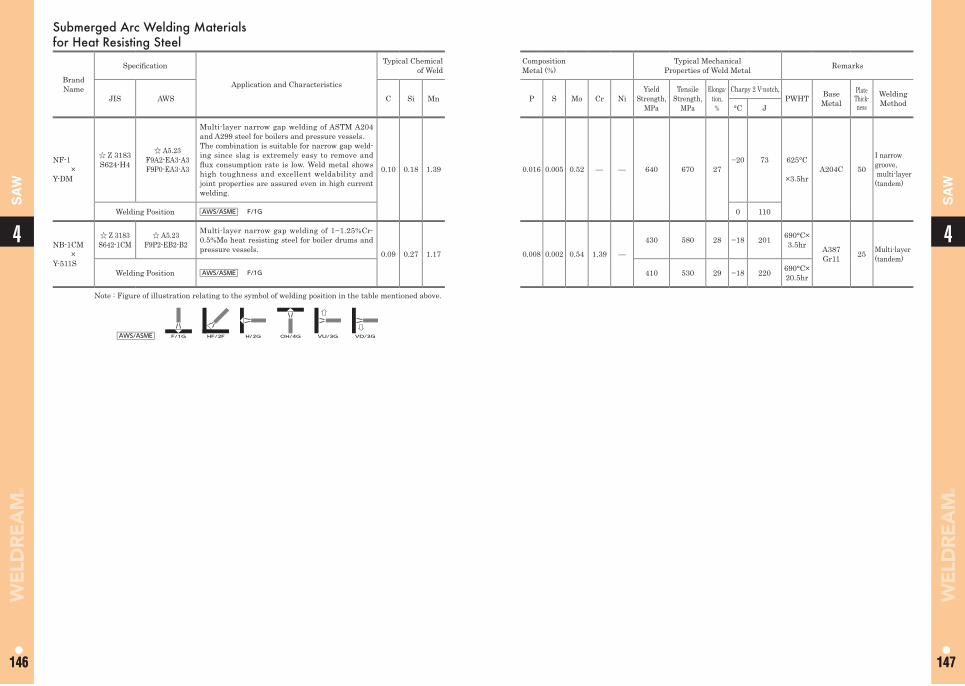
44
146 147146 147
SA
W
SA
WSubmerged Arc Welding Materials for Heat Resisting Steel
Brand Name
Specifi cation
Application and Characteristics
Typical Chemical of Weld
CompositionMetal (%)
Typical MechanicalProperties of Weld Metal Remarks
JIS AWS C Si Mn P S Mo Cr NiYield
Strength,MPa
Tensile Strength,
MPa
Elonga-tion,
%
Charpy 2 V-notch,PWHT Base
MetalPlate Thick-ness
Welding Method°C J
NF-1×
Y-DM
☆ Z 3183S624-H4
☆ A5.23F9A2-EA3-A3F9P0-EA3-A3
Multi-layer narrow gap welding of ASTM A204 and A299 steel for boilers and pressure vessels.The combination is suitable for narrow gap weld-ing since slag is extremely easy to remove and fl ux consumption rate is low. Weld metal shows high toughness and excellent weldability and joint properties are assured even in high current welding.
0.10 0.18 1.39 0.016 0.005 0.52 — — 640 670 27−20 73 625°C
×3.5hrA204C 50
I narrow groove, multi-layer (tandem)
Welding Position AWS/ASME F/1G 0 110
NB-1CM×
Y-511S
☆ Z 3183S642-1CM
☆ A5.23F9P2-EB2-B2
Multi-layer narrow gap welding of 1~1.25%Cr-0.5%Mo heat resisting steel for boiler drums and pressure vessels. 0.09 0.27 1.17 0.008 0.002 0.54 1.39 —
430 580 28 −18 201 690°C×3.5hr A387
Gr11 25 Multi-layer (tandem)
Welding Position AWS/ASME F/1G 410 530 29 −18 220 690°C×20.5hr
Note : Figure of illustration relating to the symbol of welding position in the table mentioned above.
AWS/ASME F/1G HF/2F H/2G OH/4G VU/3G VD/3G
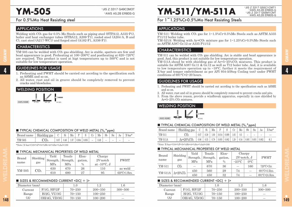
44
148 149
GM
AW
GM
AW
YM-511/YM-511A ☆JIS Z 3317 G55C1CMT1
☆AWS A5.28 ER80S-G☆JIS Z 3317 G55M1CMT
☆AWS A5.28 ER80S-G
For 1~1.25%Cr-0.5%Mo Heat Resisting Steels
YM-505 ☆JIS Z 3317 G49C3M3T☆AWS A5.28 ER80S-G
For 0.5%Mo Heat Resisting steel
■ TYPICAL CHEMICAL COMPOSITION OF WELD METAL (%,*ppm)Brand name Shielding gas C Si Mn P S Cr Mo Sb Sn As X-bar*YM-511 CO2 0.07 0.38 1.00 0.014 0.009 1.05 0.5 ― ― ― ―YM-511A Ar+20%CO2 0.06 0.35 0.78 0.005 0.002 1.28 0.54 0.001 0.001 0.002 6.1
*Note; X-bar=(10×%P+5×%Sb+4×%Sn+%As)×100
■ TYPICAL CHEMICAL COMPOSITION OF WELD METAL (%,*ppm)Brand name Shielding gas C Si Mn P S Cr Mo Sb Sn As X-bar*YM-505 CO2 0.07 0.46 1.07 0.004 0.005 ― 0.49 ― ― ― ―
*Note; X-bar=(10×%P+5×%Sb+4×%Sn+%As)×100
APPLICATIONS YM-511: Welding with CO2 gas for 1~1.5%Cr-0.5%Mo Steels such as ASTM A335 P11/12 boiler tube.YM-521A: Welding with Ar+CO2 mixture gas for 1~1.25%Cr-0.5%Mo Steels such as ASTM A387 Gr.12 or A335 P11/12
CHARACTERISTICS YM-511 can be welded with CO2 gas shielding. Arc is stable and bead appearance is good. And, this product is not suitable for low temperature operation.YM-511A shoud be with shielding gas of Ar+5~25%CO2 mixtures. This product is suitable for ASTM A387 Gr.11 & Gr.12 as well as T12 boiler tube. And, it is available to low temperature operation up to −18°C, further it meets the requirement of X-bar and temper embrittlment as per API 934-A(Step Cooling test) under PWHT conditions of 691°C×2~20 hours.
GUIDELlNES FOR USAGE 1. Preheating and PWHT should be carried out accrding to the specification such as ASME
and so on.2. All water, rust and oil in groove should be completely removed to prevent cracks and pits. 3. From the above reason, provide a windbreak apparatus, especially in case shielded by
Ar+5~25% CO2 mixtures.
WELDING POSITION
AWS/ASME F/1G HF/2F H/2G
APPLICATIONS Welding with CO2 gas for 0.5% Mo Steels such as piping steel (STPA12, A335-P1), boiler and heat exchanger tubes (STBA12, A209-T1), rooled steel (A204-A, B and C), cast steel (A217-WC1) and forged steel (A182-F1, A336-F1).
CHARACTERISTICS YM-505 can be welded with CO2 gas shielding. Arc is stable, spatters are few and bead appearance is good. Preheating at 100~200°C and postheating at 620~720°C are required. This product is used at higt temperatures up to 500°C and is not suitable for low temperature operation.
GUIDELlNES FOR USAGE 1. Preheating and PWHT should be carried out accrding to the specification such
as ASME and so on.2. All water, rust and oil in groove should be completely removed to prevent
cracks and blowholes.
WELDING POSITION
AWS/ASME F/1G HF/2F H/2G
■ TYPICAL MECHANICAL PROPERTIES OF WELD METAL
Brand name
Shielding gas
Yield Strength,
MPa
Tensile Strength,
MPa
Elon-gation,
%
Charpy 2V-notch, J PWHT
−23°C 0°CYM-511 CO2 ― 670 36 ― 160 720°C×1hr.
YM-511A Ar+20%CO2450 560 29 74 ― 691°C×3.5hrs.450 450 32 74 ― 691°C×24.5hrs.
■ TYPICAL MECHANICAL PROPERTIES OF WELD METAL
Brand name
Shielding gas
Yield Strength,
MPa
Tensile Strength,
MPa
Elon-gation,
%
Charpy 2V-notch
at ―10°C, JPWHT
YM-505 CO2630 670 26 110 as weld610 680 27 95 620°C×1.0hrs.
■ SIZES & RECOMMENDED CURRENT <DC( + )> Diameter (mm) 1.0 1.2 1.6
Current Range
(A)
F/1G, HF/2F 70~250 200~350 300~500H/2G, VU/3G 70~150 100~250 ―
OH/4G, VD/3G 70~150 100~200 ―
■ SIZES & RECOMMENDED CURRENT <DC( + )> Diameter (mm) 1.0 1.2 1.6
Current Range
(A)
F/1G, HF/2F 70~250 200~350 300~500H/2G, VU/3G 70~150 100~250 ―
OH/4G, VD/3G 70~150 100~200 ―
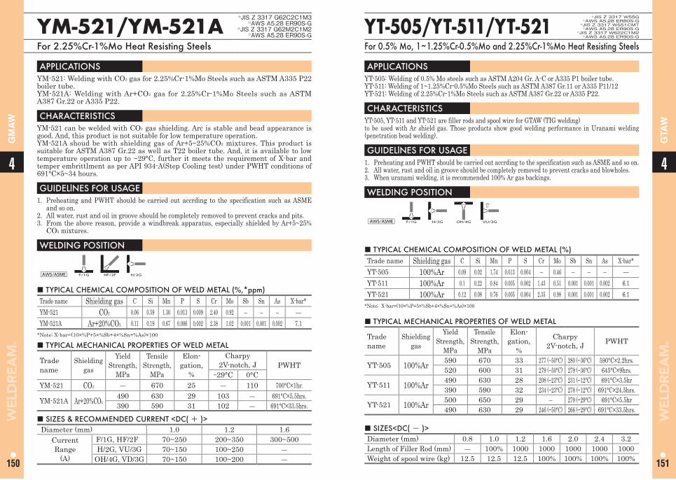
44
150 151
GTA
W
GM
AW
■ TYPICAL CHEMICAL COMPOSITION OF WELD METAL (%)Trade name Shielding gas C Si Mn P S Cr Mo Sb Sn As X-bar*YT-505 100%Ar 0.09 0.02 1.74 0.013 0.004 ― 0.46 ― ― ― ―YT-511 100%Ar 0.1 0.22 0.84 0.005 0.002 1.43 0.51 0.001 0.001 0.002 6.1YT-521 100%Ar 0.12 0.08 0.76 0.005 0.004 2.35 0.98 0.001 0.001 0.002 6.1
*Note; X-bar=(10×%P+5×%Sb+4×%Sn+%As)×100
■ TYPICAL CHEMICAL COMPOSITION OF WELD METAL (%,*ppm)Trade name Shielding gas C Si Mn P S Cr Mo Sb Sn As X-bar*YM-521 CO2 0.06 0.59 1.30 0.013 0.009 2.40 0.92 ― ― ― ―YM-521A Ar+20%CO2 0.11 0.19 0.67 0.006 0.002 2.38 1.02 0.001 0.001 0.002 7.1
*Note; X-bar=(10×%P+5×%Sb+4×%Sn+%As)×100
APPLICATIONS YT-505: Welding of 0.5% Mo steels such as ASTM A204 Gr. A-C or A335 P1 boiler tube. YT-511: Welding of 1~1.25%Cr-0.5%Mo Steels such as ASTM A387 Gr.11 or A335 P11/12YT-521: Welding of 2.25%Cr-1%Mo Steels such as ASTM A387 Gr.22 or A335 P22.
CHARACTERISTICS YT-505, YT-511 and YT-521 are filler rods and spool wire for GTAW (TIG welding)to be used with Ar shield gas. Those products show good welding performance in Uranami welding (penetration bead welding).
GUIDELlNES FOR USAGE 1. Preheating and PWHT should be carried out accrding to the specification such as ASME and so on.2. All water, rust and oil in groove should be completely removed to prevent cracks and blowholes.3. When uranami welding, it is recommended 100% Ar gas backings.
WELDING POSITION
AWS/ASME F/1G H/2G OH/4G VU/3G
APPLICATIONS YM-521: Welding with CO2 gas for 2.25%Cr-1%Mo Steels such as ASTM A335 P22 boiler tube.YM-521A: Welding with Ar+CO2 gas for 2.25%Cr-1%Mo Steels such as ASTM A387 Gr.22 or A335 P22.
CHARACTERISTICS YM-521 can be welded with CO2 gas shielding. Arc is stable and bead appearance is good. And, this product is not suitable for low temperature operation. YM-521A shoud be with shielding gas of Ar+5~25%CO2 mixtures. This product is suitable for ASTM A387 Gr.22 as well as T22 boiler tube. And, it is available to low temperature operation up to −29°C, further it meets the requirement of X-bar and temper embrittlment as per API 934-A(Step Cooling test) under PWHT conditions of 691°C×5~34 hours.
GUIDELlNES FOR USAGE 1. Preheating and PWHT should be carried out accrding to the specification such as ASME
and so on.2. All water, rust and oil in groove should be completely removed to prevent cracks and pits.3. From the above reason, provide a windbreak apparatus, especially shielded by Ar+5~25%
CO2 mixtures.
WELDING POSITION
AWS/ASME F/1G HF/2F H/2G
■ TYPICAL MECHANICAL PROPERTIES OF WELD METAL
Trade name
Shielding gas
Yield Strength,
MPa
Tensile Strength,
MPa
Elon-gation,
%
Charpy 2V-notch, J PWHT
YT-505 100%Ar 590 670 33 277 (−50°C) 280 (−36°C) 590°C×2.2hrs.520 600 31 279 (−50°C) 279 (−36°C) 645°C×9hrs.
YT-511 100%Ar 490 630 28 208 (−23°C) 231 (−12°C) 691°C×3.5hr390 590 32 234 (−23°C) 278 (−12°C) 691°C×24.5hrs.
YT-521 100%Ar 500 650 29 ― 279 (−29°C) 691°C×5.5hr490 630 29 246 (−50°C) 266 (−29°C) 691°C×33.5hrs.
■ TYPICAL MECHANICAL PROPERTIES OF WELD METAL
Trade name
Shielding gas
Yield Strength,
MPa
Tensile Strength,
MPa
Elon-gation,
%
Charpy 2V-notch, J PWHT
−29°C 0°CYM-521 CO2 ― 670 25 ― 110 700°C×1hr.
YM-521A Ar+20%CO2490 630 29 103 ― 691°C×5.5hrs.390 590 31 102 ― 691°C×33.5hrs.
■ SIZES<DC( - )> Diameter (mm) 0.8 1.0 1.2 1.6 2.0 2.4 3.2Length of Filler Rod (mm) ― 100% 1000 1000 1000 1000 1000Weight of spool wire (kg) 12.5 12.5 12.5 100% 100% 100% 100%
■ SIZES & RECOMMENDED CURRENT <DC( + )> Diameter (mm) 1.0 1.2 1.6
Current Range
(A)
F/1G, HF/2F 70~250 200~350 300~500H/2G, VU/3G 70~150 100~250 ―
OH/4G, VD/3G 70~150 100~200 ―
YT-505/YT-511/YT-521☆JIS Z 3317 W55G
☆AWS A5.28 ER80S-G☆JIS Z 3317 W551CMT
☆AWS A5.28 ER90S-G☆JIS Z 3317 W622C1M2
☆AWS A5.28 ER90S-G
For 0.5% Mo, 1~1.25%Cr-0.5%Mo and 2.25%Cr-1%Mo Heat Resisting Steels
YM-521/YM-521A ☆JIS Z 3317 G62C2C1M3
☆AWS A5.28 ER90S-G☆JIS Z 3317 G62M2C1M2
☆AWS A5.28 ER90S-G
For 2.25%Cr-1%Mo Heat Resisting Steels
Memo
152
4
153
Boiler Tube/PipeCovered Arc Welding ElectrodesGas Tungsten Arc Welding Rods and Wires
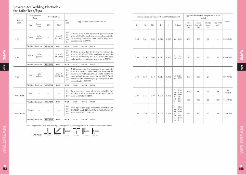
55
154 155154 155
SM
AW
SM
AW
Covered Arc Welding Electrodes for Boiler Tube/Pipe
Brand Name
ldentifi cation Color Specifi cation
Dia. mm Application and Characteristics
Typical Chemical Composition of Weld Metal (%) Typical Mechanical Properties of Weld Metal
PWHT
End Secon-dary JIS AWS C Si Mn P S Others
Yield Strength,
MPa
Tensile Strength,
MPa
Elonga-tion,
%
Charpy 2V-notch at 0°C,
J
N-0SGreen Light
yellow — ☆ A5.5 E7016-A1
2.63.24.05.06.0
N-0S is a extra low hydrogen type electrode with a 0.5% Mo steel core wire and is suitable for welding C-Mo steel to be used at high tem-peratures up to 500°C.
0.06 0.51 0.60 0.012 0.006 Mo:0.52 480 560 32 — 620°C×1h
Welding Position AWS/ASME F/1G HF/2F H/2G OH/4G VU/3G
N-1SWhite Light
yellow — ☆ A5.5 E8016-B2
2.63.24.05.06.0
N-1S is a extra low hydrogen type electrode with a 1.25%Cr-0.5% Mo steel core wire and is suitable for welding 1~1.50%Cr-0.5%Mo steel to be used at high temperatures up to 550°C.
0.06 0.45 0.60 0.013 0.006 Cr:1.26Mo:0.51 570 660 27 — 690°C×1h
Welding Position AWS/ASME F/1G HF/2F H/2G OH/4G VU/3G
N-2SRed Light
yellow — ☆ A5.5 E9016-B3
2.63.24.05.06.0
N-2S is an extra low hydrogen type electrode with a 2.25%Cr-1%Mo steel core wire and is suitable for welding 2.25%Cr-1%Mo steel to be used at high temperatures up to 600°C. Weld Metal shows extremely high creep-rupture strength at 550-600°C.
0.06 0.57 0.58 0.010 0.006 Cr:2.29Mo:1.00 590 690 24 — 690°C×1h
Welding Position AWS/ASME F/1G HF/2F H/2G OH/4G VU/3G
N-HCM2SRed — — —
2.63.24.0
Low hydrogen type electrode suitable for HCM2S™ (2.25%Cr-1.6%W-Mo-Nb-V) steel such as ASTM T23/P23. 0.06 0.41 0.80 0.004 0.002
Cr : 2.25Mo : 0.10Ni : 0.99W : 1.6Nb : 0.04V : 0.3
875 980 21 28 As welded
625 755 20 120 715°C×1hWelding Position AWS/ASME F/1G HF/2F H/2G OH/4G VU/3G
N-HCM12A
Cream — — —
2.63.24.05.0
Low hydrogen type electrode suitable for HCM12A steel (11%Cr-2%W-0.4%Mo-Cu-Nb-V) such as ASTM T122/P122. 0.08 0.25 0.84 0.004 0.001
Cr : 10.5Mo : 0.20Ni : 0.80W : 1.4Nb : 0.03V : 0.18Cu : 1.4
665 810 23 54 740°C×5h
Welding Position AWS/ASME F/1G HF/2F H/2G OH/4G VU/3G
Note : Figure of illustration relating to the symbol of welding position in the table mentioned above.
AWS/ASME F/1G HF/2F H/2G OH/4G VU/3G VD/3G
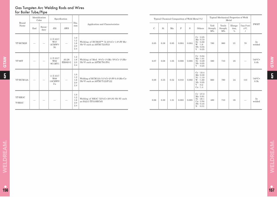
55
156 157156 157
GTA
W
GTA
WGas Tungsten Arc Welding Rods and Wires for Boiler Tube/Pipe
Brand Name
ldentifi cation Color Specifi cation
Dia. mm Application and Characteristics
Typical Chemical Composition of Weld Metal (%) Typical Mechanical Properties of Weld Metal
PWHT
End Secon-dary JIS AWS C Si Mn P S Others
Yield Strength,
MPa
Tensile Strength,
MPa
Elonga-tion,
%
Charpy 2V-notch at 0°C,
J
YT-HCM2S — —
☆ Z 3317W57
-2CMWV-Ni
—
1.01.21.62.02.4
Welding of HCM2S™ (2.25%Cr-1.6%W-Mo-Nb-V) such as ASTM T23/P23 0.05 0.38 0.85 0.004 0.004
Cr : 2.25Mo : 0.10Ni : 0.80W : 1.6Nb : 0.04V : 0.25
780 860 21 70 As welded
YT-9ST — —☆ Z 3317
W62-9C1MV1
A5.28ER90S-G
1.21.62.02.4
Welding of Mod. 9%Cr-1%Mo (9%Cr-1%Mo-Nb-V) such as ASTM T91/P91 0.07 0.08 1.05 0.008 0.005
Cr : 8.84Mo : 1.01Ni : 0.29Nb : 0.05V : 0.25
580 710 25 — 740°C×8.4h
YT-HCM12A — —
☆ Z 3317W69
-10CMWV-Cu
—
1.01.21.62.02.4
Welding of HCM12A (11%Cr-2%W-0.4%Mo-Cu-Nb-V) such as ASTM T122/P122 0.08 0.35 0.52 0.010 0.002
Cr : 10.4Mo : 0.30Ni : 1.10W : 1.60Nb : 0.05V : 0.2Cu : 1.4
660 790 24 110 740°C×0.5h
YT-HR3C
T-HR3C— — — —
1.0 1.2 1.6 2.0 2.4
Welding of HR3C (25%Cr-20%Ni-Nb-N) such as SA213 TP310HCbN 0.06 0.30 1.51 0.003 0.005
Cr : 27.0Mo : 0.91Ni : 20.1Cu : 2.94Nb : 0.45N : 0.31
480 710 35 — As welded
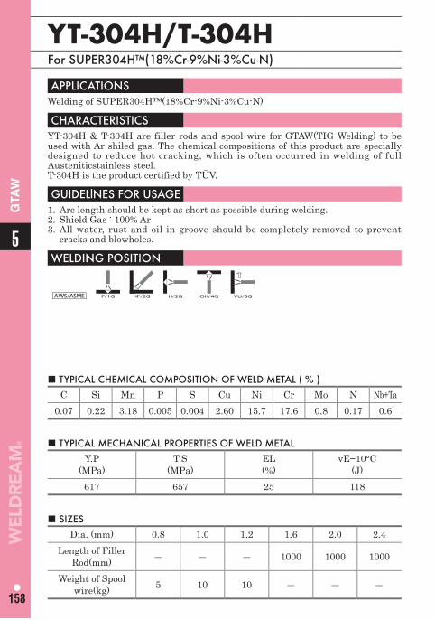
5
158
GTA
W
YT-304H/T-304H For SUPER304H™(18%Cr-9%Ni-3%Cu-N)
■ TYPICAL CHEMICAL COMPOSITION OF WELD METAL ( % )C Si Mn P S Cu Ni Cr Mo N Nb+Ta
0.07 0.22 3.18 0.005 0.004 2.60 15.7 17.6 0.8 0.17 0.6
APPLICATIONS Welding of SUPER304H™(18%Cr-9%Ni-3%Cu-N)
CHARACTERISTICS YT-304H & T-304H are filler rods and spool wire for GTAW(TIG Welding) to be used with Ar shiled gas. The chemical compositions of this product are specially designed to reduce hot cracking, which is often occurred in welding of full Austeniticstainless steel. T-304H is the product certified by TÜV.
GUIDELlNES FOR USAGE 1. Arc length should be kept as short as possible during welding.2. Shield Gas : 100% Ar 3. All water, rust and oil in groove should be completely removed to prevent
cracks and blowholes.
WELDING POSITION
AWS/ASME F/1G HF/2G H/2G OH/4G VU/3G
■ TYPICAL MECHANICAL PROPERTIES OF WELD METALY.P
(MPa)T.S
(MPa)EL(%)
vE−10°C(J)
617 657 25 118
■ SIZESDia. (mm) 0.8 1.0 1.2 1.6 2.0 2.4
Length of Filler Rod(mm) ― ― ― 1000 1000 1000
Weight of Spool wire(kg) 5 10 10 ― ― ―
159
Atmospheric Corrosion Resisting SteelFlux Cored Arc Welding WiresCovered Arc Welding ElectrodesSubmerged Arc Welding MaterialsGas Metal Arc Welding WiresGas Tungsten Arc Welding Rods and Wires
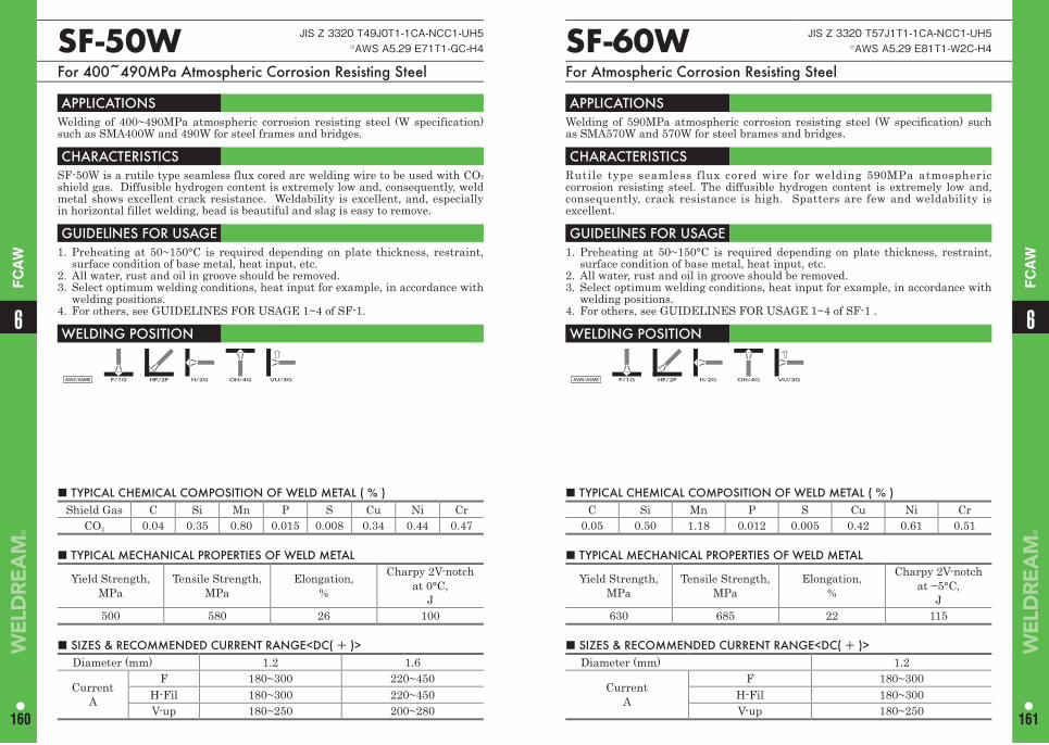
■ TYPICAL CHEMICAL COMPOSITION OF WELD METAL ( % ) Shield Gas C Si Mn P S Cu Ni Cr
CO2 0.04 0.35 0.80 0.015 0.008 0.34 0.44 0.47
SF-50W JIS Z 3320 T49J0T1-1CA-NCC1-UH5☆AWS A5.29 E71T1-GC-H4
For 400~490MPa Atmospheric Corrosion Resisting Steel
APPLICATIONS Welding of 400~490MPa atmospheric corrosion resisting steel (W specification) such as SMA400W and 490W for steel frames and bridges.
CHARACTERISTICS SF-50W is a rutile type seamless flux cored arc welding wire to be used with CO2
shield gas. Diffusible hydrogen content is extremely low and, consequently, weld metal shows excellent crack resistance. Weldability is excellent, and, especially in horizontal fillet welding, bead is beautiful and slag is easy to remove.
GUIDELlNES FOR USAGE 1. Preheating at 50~150°C is required depending on plate thickness, restraint,
surface condition of base metal, heat input, etc.2. All water, rust and oil in groove should be removed.3. Select optimum welding conditions, heat input for example, in accordance with
welding positions.4. For others, see GUIDELINES FOR USAGE 1~4 of SF-1.
WELDING POSITION
AWS/ASME F/1G HF/2F H/2G OH/4G VU/3G
■ TYPICAL MECHANICAL PROPERTIES OF WELD METAL
Yield Strength,MPa
Tensile Strength,MPa
Elongation,%
Charpy 2V-notchat 0°C,
J500 580 26 100
■ SIZES & RECOMMENDED CURRENT RANGE<DC( + )> Diameter (mm) 1.2 1.6
CurrentA
F 180~300 220~450H-Fil 180~300 220~450V-up 180~250 200~280
■ TYPICAL CHEMICAL COMPOSITION OF WELD METAL ( % ) C Si Mn P S Cu Ni Cr
0.05 0.50 1.18 0.012 0.005 0.42 0.61 0.51
SF-60W JIS Z 3320 T57J1T1-1CA-NCC1-UH5☆AWS A5.29 E81T1-W2C-H4
For Atmospheric Corrosion Resisting Steel
APPLICATIONS Welding of 590MPa atmospheric corrosion resisting steel (W specification) such as SMA570W and 570W for steel brames and bridges.
CHARACTERISTICS Rutile type seamless flux cored wire for welding 590MPa atmospheric corrosion resisting steel. The diffusible hydrogen content is extremely low and, consequently, crack resistance is high. Spatters are few and weldability is excellent.
GUIDELlNES FOR USAGE 1. Preheating at 50~150°C is required depending on plate thickness, restraint,
surface condition of base metal, heat input, etc.2. All water, rust and oil in groove should be removed.3. Select optimum welding conditions, heat input for example, in accordance with
welding positions.4. For others, see GUIDELINES FOR USAGE 1~4 of SF-1 .
WELDING POSITION
AWS/ASME F/1G HF/2F H/2G OH/4G VU/3G
■ TYPICAL MECHANICAL PROPERTIES OF WELD METAL
Yield Strength,MPa
Tensile Strength,MPa
Elongation,%
Charpy 2V-notchat −5°C,
J630 685 22 115
■ SIZES & RECOMMENDED CURRENT RANGE<DC( + )> Diameter (mm) 1.2
CurrentA
F 180~300H-Fil 180~300V-up 180~250
66
160 161
FC
AW
FC
AW
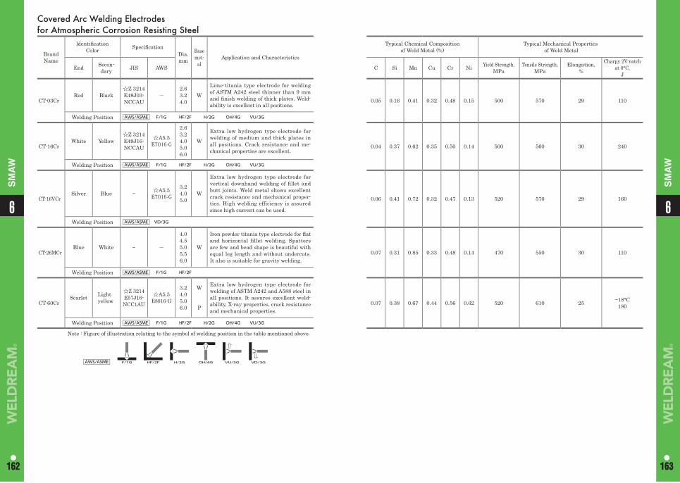
Covered Arc Welding Electrodes for Atmospheric Corrosion Resisting Steel
Brand Name
ldentifi cation Color Specifi cation
Dia.mm
Base met-
alApplication and Characteristics
End Secon-dary JIS AWS
CT-03CrRed Black
☆Z 3214E49J03-NCCAU
-2.6 3.2 4.0
W
Lime-titania type electrode for welding of ASTM A242 steel thinner than 9 mm and fi nish welding of thick plates. Weld-ability is excellent in all positions.
Welding Position AWS/ASME F/1G HF/2F H/2G OH/4G VU/3G
CT-16CrWhite Yellow
☆Z 3214E49J16-NCCAU
☆A5.5 E7016-G
2.6 3.2 4.0 5.0 6.0
W
Extra low hydrogen type electrode for welding of medium and thick plates in all positions. Crack resistance and me-chanical properties are excellent.
Welding Position AWS/ASME F/1G HF/2F H/2G OH/4G VU/3G
CT-16VCrSilver Blue − ☆A5.5
E7016-G
3.2 4.0 5.0
W
Extra low hydrogen type electrode for vertical downhand welding of fi llet and butt joints. Weld metal shows excellent crack resistance and mechanical proper-ties. High welding efficiency is assured since high current can be used.
Welding Position AWS/ASME VD/3G
CT-26MCrBlue White − -
4.0 4.5 5.0 5.5 6.0
W
Iron powder titania type electrode for fl at and horizontal fillet welding. Spatters are few and bead shape is beautiful with equal leg length and without undercuts. It also is suitable for gravity welding.
Welding Position AWS/ASME F/1G HF/2F
CT-60CrScarlet Light
yellow
☆Z 3214E57J16-NCC1AU
☆A5.5E8016-G
3.2 4.0 5.0 6.0
W
P
Extra low hydrogen type electrode for welding of ASTM A242 and A588 steel in all positions. It assures excellent weld-ability, X-ray properties, crack resistance and mechanical properties.
Welding Position AWS/ASME F/1G HF/2F H/2G OH/4G VU/3G
Note : Figure of illustration relating to the symbol of welding position in the table mentioned above.
AWS/ASME F/1G HF/2F H/2G OH/4G VU/3G VD/3G
Typical Chemical Composition of Weld Metal (%)
Typical Mechanical Properties of Weld Metal
C Si Mn Cu Cr Ni Yield Strength, MPa
Tensile Strength,MPa
Elongation,%
Charpy 2V-notchat 0°C,
J
0.05 0.16 0.41 0.32 0.48 0.15 500 570 29 110
0.04 0.37 0.62 0.35 0.50 0.14 500 560 30 240
0.06 0.41 0.72 0.32 0.47 0.13 520 570 29 160
0.07 0.31 0.85 0.33 0.48 0.14 470 550 30 110
0.07 0.38 0.67 0.44 0.56 0.62 520 610 25 −18°C 180
162 163162 163
66
SM
AW
SM
AW
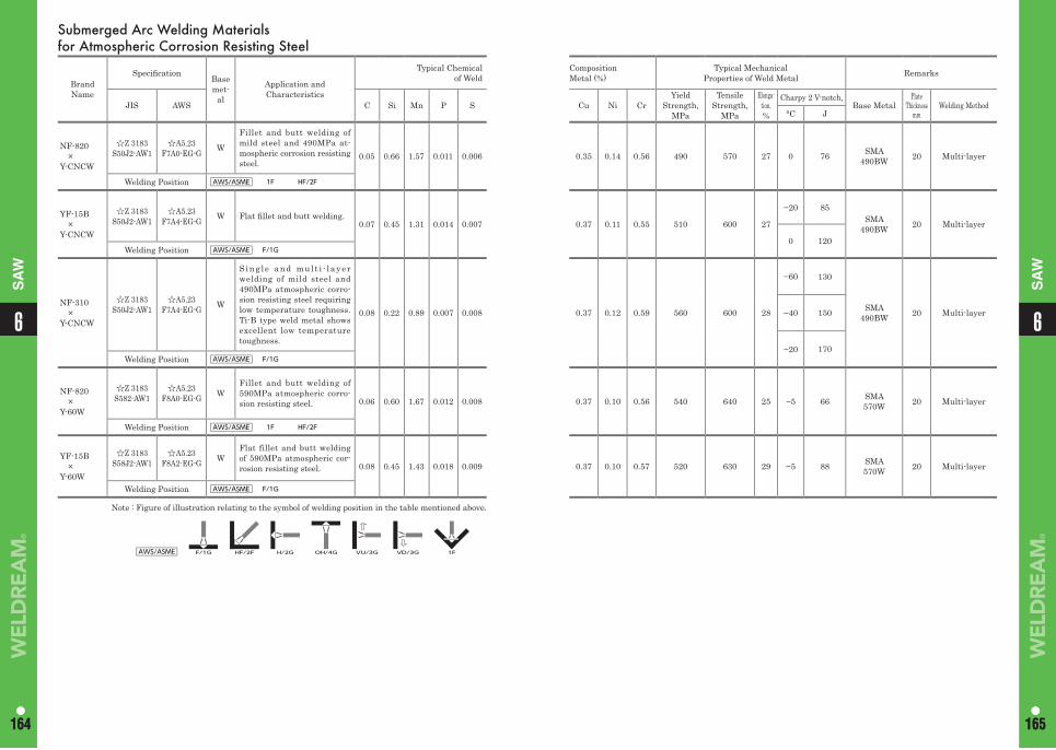
164 165164 165
66
SA
W
SA
WSubmerged Arc Welding Materialsfor Atmospheric Corrosion Resisting Steel
Brand Name
Specifi cation Base met-
al
Application andCharacteristics
Typical Chemicalof Weld
JIS AWS C Si Mn P S
NF-820×
Y-CNCW
☆Z 3183S50J2-AW1
☆A5.23F7A0-EG-G W
Fillet and butt welding of mild steel and 490MPa at-mospheric corrosion resisting steel.
0.05 0.66 1.57 0.011 0.006
Welding Position AWS/ASME 1F HF/2F
YF-15B×
Y-CNCW
☆Z 3183S50J2-AW1
☆A5.23F7A4-EG-G W Flat fi llet and butt welding.
0.07 0.45 1.31 0.014 0.007
Welding Position AWS/ASME F/1G
NF-310×
Y-CNCW
☆Z 3183S50J2-AW1
☆A5.23F7A4-EG-G W
Sing le and mul t i - l ayer welding of mild steel and 490MPa atmospheric corro-sion resisting steel requiring low temperature toughness. Ti-B type weld metal shows excellent low temperature toughness.
0.08 0.22 0.89 0.007 0.008
Welding Position AWS/ASME F/1G
NF-820×
Y-60W
☆Z 3183S582-AW1
☆A5.23F8A0-EG-G W
Fillet and butt welding of 590MPa atmospheric corro-sion resisting steel. 0.06 0.60 1.67 0.012 0.008
Welding Position AWS/ASME 1F HF/2F
YF-15B×
Y-60W
☆Z 3183S58J2-AW1
☆A5.23F8A2-EG-G W
Flat fillet and butt welding of 590MPa atmospheric cor-rosion resisting steel. 0.08 0.45 1.43 0.018 0.009
Welding Position AWS/ASME F/1G
Note : Figure of illustration relating to the symbol of welding position in the table mentioned above.
AWS/ASME F/1G HF/2F H/2G OH/4G VU/3G VD/3G 1F
CompositionMetal (%)
Typical MechanicalProperties of Weld Metal Remarks
Cu Ni CrYield
Strength,MPa
Tensile Strength,
MPa
Elonga-tion,%
Charpy 2 V-notch,Base Metal
Plate Thickness
mmWelding Method
°C J
0.35 0.14 0.56 490 570 27 0 76 SMA490BW 20 Multi-layer
0.37 0.11 0.55 510 600 27
−20 85SMA
490BW 20 Multi-layer
0 120
0.37 0.12 0.59 560 600 28
−60 130
SMA490BW 20 Multi-layer−40 150
−20 170
0.37 0.10 0.56 540 640 25 −5 66 SMA570W 20 Multi-layer
0.37 0.10 0.57 520 630 29 −5 88 SMA570W 20 Multi-layer
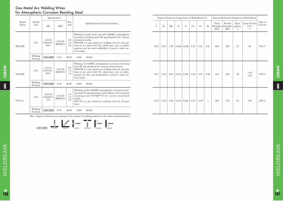
166 167166 167
66
GM
AW
GM
AW
Gas Metal Arc Welding Wires for Atmospheric Corrosion Resisting Steel
Brand Name
Shield Gas
Specifi cation
Dia.mm Application and Characteristics
Typical Chemical Composition of Weld Metal (%) Typical Mechanical Properties of Weld Metal
Type of CurrentJIS AWS C Si Mn P S Cu Cr Ni
Yield Strength,
MPa
Tensile Strength,
MPa
Elon-gation,
%
Charpy 2V-notchat 0°C,
J
YM-55WCO2
☆Z 3315G49JA0UC1-
NCCJ
☆A5.28ER80S-G
0.91.21.6
Welding of mild steel and 400~490MPa atmospheric corrosion resisting steel (W specifi cation) for various structural works.YM-55W is a gas metal arc welding wire for all posi-tions to be used with CO2 shield gas. Arc is stable, spatters are few and weldability is good in wide cur-rent range.
0.06 0.48 1.05 0.006 0.008 0.50 0.61 0.21 580 630 27 90 DC(+)
Welding Position AWS/ASME F/1G HF/2F H/2G VD/3G
YM-60WCO2
☆Z 3315G57JA1UC1-
NCCJ
☆A5.28ER80S-G
0.91.21.6
Welding of 570MPa atmospheric corrosion resisting steel (W specifi cation) for various constructions.YM-60W is a gas metal arc welding wire for all posi-tions to be used with CO2 shield gas. Arc is stable, spatter are few and weldability is good in wide cur-rent range.
0.07 0.38 0.83 0.016 0.005 0.58 0.50 0.46 540 640 26 −5°C110 DC(+)
Welding Position AWS/ASME F/1G HF/2F H/2G VD/3G
FGC-55CO2
☆Z 3315G49A0UC1-
CCJ
☆A5.28ER80S-G
1.01.21.6
Welding of 400~490MPa atmospheric corrosion resist-ing steel (P specifi cations) and sulfuric acid corrosion resisting steel (S-TEN™1) for various structural works.FGC-55 is a gas metal arc welding wire for all posi-tions.
0.08 0.36 0.98 0.016 0.005 0.35 0.48 — 460 570 25 180 DC(+)
Welding Position AWS/ASME F/1G HF/2F H/2G VD/3G
Note : Figure of illustration relating to the symbol of welding position in the table mentioned above.
AWS/ASME F/1G HF/2F H/2G OH/4G VU/3G VD/3G
Memo
168
6
169
Sulphuric Acid Corrosion Resisting Steel Flux Cored Arc Welding WiresCovered Arc Welding ElectrodesSubmerged Arc Welding MaterialsGas Metal Arc Welding WiresGas Tungsten Arc Welding Rods and Wires
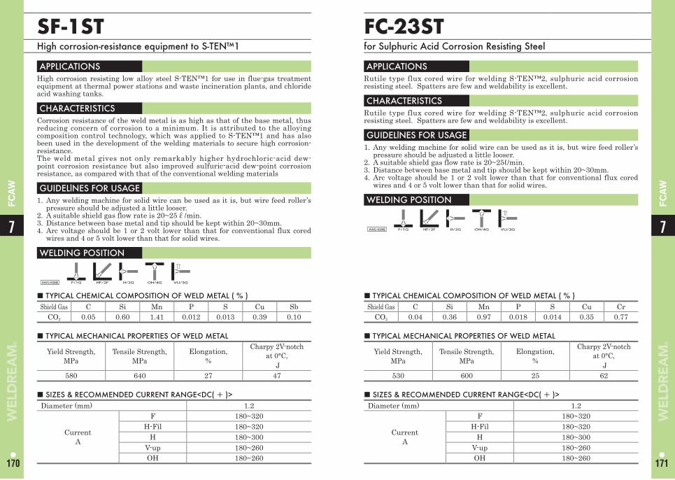
■ TYPICAL CHEMICAL COMPOSITION OF WELD METAL ( % ) Shield Gas C Si Mn P S Cu Sb
CO2 0.05 0.60 1.41 0.012 0.013 0.39 0.10
SF-1STHigh corrosion-resistance equipment to S-TEN™1
APPLICATIONS High corrosion resisting low alloy steel S-TEN™1 for use in flue-gas treatment equipment at thermal power stations and waste incineration plants, and chloride acid washing tanks.
CHARACTERISTICS Corrosion resistance of the weld metal is as high as that of the base metal, thus reducing concern of corrosion to a minimum. It is attributed to the alloying composition control technology, which was applied to S-TEN™1 and has also been used in the development of the welding materials to secure high corrosion-resistance.The weld metal gives not only remarkably higher hydrochloric-acid dew-point corrosion resistance but also improved sulfuric-acid dew-point corrosion resistance, as compared with that of the conventional welding materials
GUIDELlNES FOR USAGE 1. Any welding machine for solid wire can be used as it is, but wire feed roller’s
pressure should be adjusted a little looser.2. A suitable shield gas flow rate is 20~25ℓ/min.3. Distance between base metal and tip should be kept within 20~30mm.4. Arc voltage should be 1 or 2 volt lower than that for conventional flux cored
wires and 4 or 5 volt lower than that for solid wires.
WELDING POSITION
AWS/ASME F/1G HF/2F H/2G OH/4G VU/3G
■ TYPICAL MECHANICAL PROPERTIES OF WELD METAL
Yield Strength,MPa
Tensile Strength, MPa
Elongation,%
Charpy 2V-notchat 0°C,
J580 640 27 47
■ SIZES & RECOMMENDED CURRENT RANGE<DC( + )> Diameter (mm) 1.2
CurrentA
F 180~320H-Fil 180~320
H 180~300V-up 180~260OH 180~260
■ SIZES & RECOMMENDED CURRENT RANGE<DC( + )> Diameter (mm) 1.2
CurrentA
F 180~320H-Fil 180~320
H 180~300V-up 180~260OH 180~260
FC-23STfor Sulphuric Acid Corrosion Resisting Steel
APPLICATIONS Rutile type flux cored wire for welding S-TEN™2, sulphuric acid corrosion resisting steel. Spatters are few and weldability is excellent.
CHARACTERISTICS Rutile type flux cored wire for welding S-TEN™2, sulphuric acid corrosion resisting steel. Spatters are few and weldability is excellent.
GUIDELlNES FOR USAGE 1. Any welding machine for solid wire can be used as it is, but wire feed roller’s
pressure should be adjusted a little looser.2. A suitable shield gas flow rate is 20~25ℓ/min.3. Distance between base metal and tip should be kept within 20~30mm.4. Arc voltage should be 1 or 2 volt lower than that for conventional flux cored
wires and 4 or 5 volt lower than that for solid wires.
WELDING POSITION
AWS/ASME F/1G HF/2F H/2G OH/4G VU/3G
■ TYPICAL CHEMICAL COMPOSITION OF WELD METAL ( % ) Shield Gas C Si Mn P S Cu Cr
CO2 0.04 0.36 0.97 0.018 0.014 0.35 0.77
■ TYPICAL MECHANICAL PROPERTIES OF WELD METAL
Yield Strength,MPa
Tensile Strength, MPa
Elongation,%
Charpy 2V-notchat 0°C,
J530 600 25 62
77
170 171
FC
AW
FC
AW
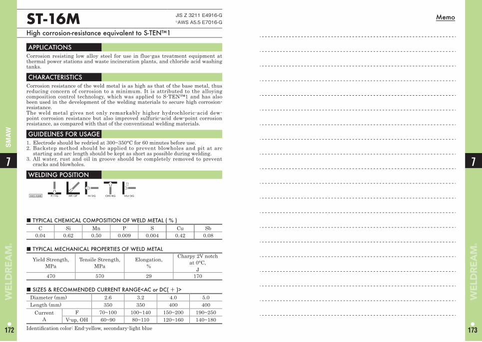
MemoST-16M JIS Z 3211 E4916-G☆AWS A5.5 E7016-G
High corrosion-resistance equivalent to S-TEN™1
APPLICATIONS Corrosion resisting low alloy steel for use in flue-gas treatment equipment at thermal power stations and waste incineration plants, and chloride acid washing tanks.
CHARACTERISTICS Corrosion resistance of the weld metal is as high as that of the base metal, thus reducing concern of corrosion to a minimum. It is attributed to the alloying composition control technology, which was applied to S-TEN™1 and has also been used in the development of the welding materials to secure high corrosion-resistance.The weld metal gives not only remarkably higher hydrochloric-acid dew-point corrosion resistance but also improved sulfuric-acid dew-point corrosion resistance, as compared with that of the conventional welding materials.
GUIDELlNES FOR USAGE 1. Electrode should be redried at 300~350°C for 60 minutes before use.2. Backstep method should be applied to prevent blowholes and pit at arc
starting and arc length should be kept as short as possible during welding.3. All water, rust and oil in groove should be completely removed to prevent
cracks and blowholes.
WELDING POSITION
AWS/ASME F/1G HF/2F H/2G OH/4G VU/3G
■ TYPICAL CHEMICAL COMPOSITION OF WELD METAL ( % ) C Si Mn P S Cu Sb
0.04 0.62 0.50 0.009 0.004 0.42 0.08
■ TYPICAL MECHANICAL PROPERTIES OF WELD METAL
Yield Strength,MPa
Tensile Strength, MPa
Elongation,%
Charpy 2V notch at 0°C,
J 470 570 29 170
■ SIZES & RECOMMENDED CURRENT RANGE<AC or DC( + )> Diameter (mm) 2.6 3.2 4.0 5.0Length (mm) 350 350 400 400
CurrentA
F 70~100 100~140 150~200 190~250V-up, OH 60~90 80~110 120~160 140~180
Identifi cation color: End-yellow, secondary-light blue
7
172
7
173
SM
AW
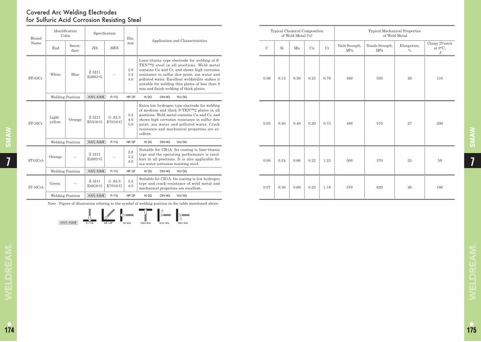
Covered Arc Welding Electrodes for Sulfuric Acid Corrosion Resisting Steel
Brand Name
ldentifi cation Color Specifi cation
Dia.mm Application and Characteristics
End Secon-dary JIS AWS
ST-03CrWhite Blue Z 3211
E4903-G ―2.6 3.2 4.0
Lime-titania type electrode for welding of S-TEN™2 steel in all positions. Weld metal contains Cu and Cr, and shows high corrosion resistance to sulfur dew point, sea water and polluted water. Excellent weldability makes it suitable for welding thin plates of less than 9 mm and fi nish welding of thick plates.
Welding Position AWS/ASME F/1G HF/2F H/2G OH/4G VU/3G
ST-16CrLight yellow Orange Z 3211
E5516-G☆ A5.5
E7016-G
3.2 4.0 5.0
Extra low hydrogen type electrode for welding of medium and thick S-TEN™2 plates in all positions. Weld metal contains Cu and Cr, and shows high corrosion resistance to sulfur dew point, sea water and polluted water. Crack resistance and mechanical properties are ex-cellent.
Welding Position AWS/ASME F/1G HF/2F H/2G OH/4G VU/3G
ST-03CrAOrange ― Z 3211
E4903-G ―2.63.24.0
Suitable for CR1A. Its coating is lime-titania type and the operating performance is excel-lent in all positions. It is also applicable for sea water corrosion resisting steel.
Welding Position AWS/ASME F/1G HF/2F H/2G OH/4G VU/3G
ST-16CrAGreen ― Z 3211
E4916-G☆ A5.5
E7016-G3.2 4.0
Suitable for CR1A. Its coating is low hydrogen type and crack-resistance of weld metal and mechanical properties are excellent.
Welding Position AWS/ASME F/1G HF/2F H/2G OH/4G VU/3G
Note : Figure of illustration relating to the symbol of welding position in the table mentioned above.
AWS/ASME F/1G HF/2F H/2G OH/4G VU/3G VD/3G
Typical Chemical Composition of Weld Metal (%)
Typical Mechanical Properties of Weld Metal
C Si Mn Cu Cr Yield Strength, MPa
Tensile Strength, MPa
Elongation,%
Charpy 2V-notchat 0°C,
J
0.06 0.15 0.56 0.23 0.79 460 530 26 110
0.05 0.50 0.48 0.20 0.73 480 570 27 200
0.08 0.24 0.66 0.22 1.23 500 570 25 59
0.07 0.38 0.69 0.23 1.18 570 620 26 180
77
174 175174 175
SM
AW
SM
AW
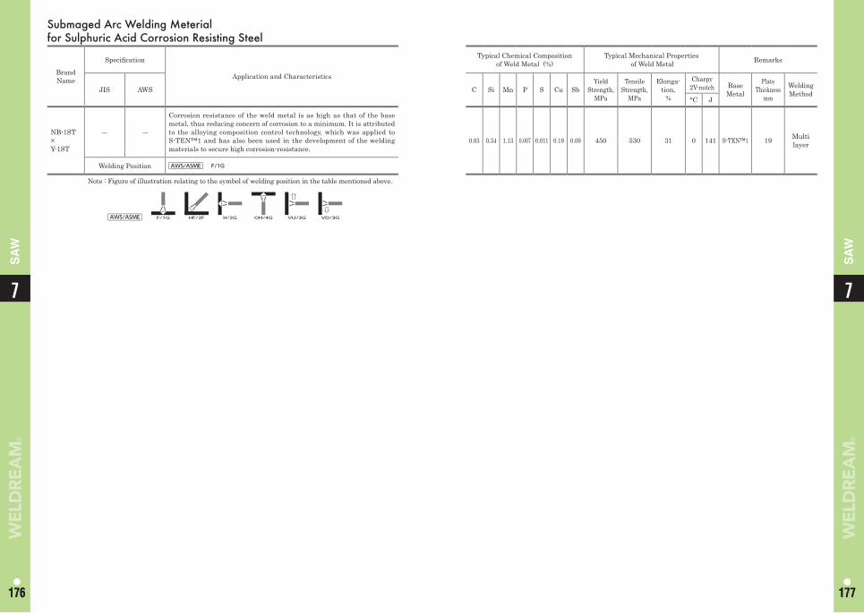
Submaged Arc Welding Meterial for Sulphuric Acid Corrosion Resisting Steel
Brand Name
Specifi cation
Application and Characteristics
JIS AWS
NB-1ST×Y-1ST
― ―
Corrosion resistance of the weld metal is as high as that of the base metal, thus reducing concern of corrosion to a minimum. It is attributed to the alloying composition control technology, which was applied to S-TEN™1 and has also been used in the development of the welding materials to secure high corrosion-resistance.
Welding Position AWS/ASME F/1G
Note : Figure of illustration relating to the symbol of welding position in the table mentioned above.
AWS/ASME F/1G HF/2F H/2G OH/4G VU/3G VD/3G
Typical Chemical Composition of Weld Metal (%)
Typical Mechanical Properties of Weld Metal Remarks
C Si Mn P S Cu SbYield
Strength, MPa
Tensile Strength,
MPa
Elonga-tion,
%
Charpy2V-notch Base
Metal
Plate Thickness
mm
Welding Method
°C J
0.03 0.34 1.13 0.007 0.011 0.19 0.09 450 530 31 0 141 S-TEN™1 19 Multi layer
77
176 177176 177
SA
W
SA
W
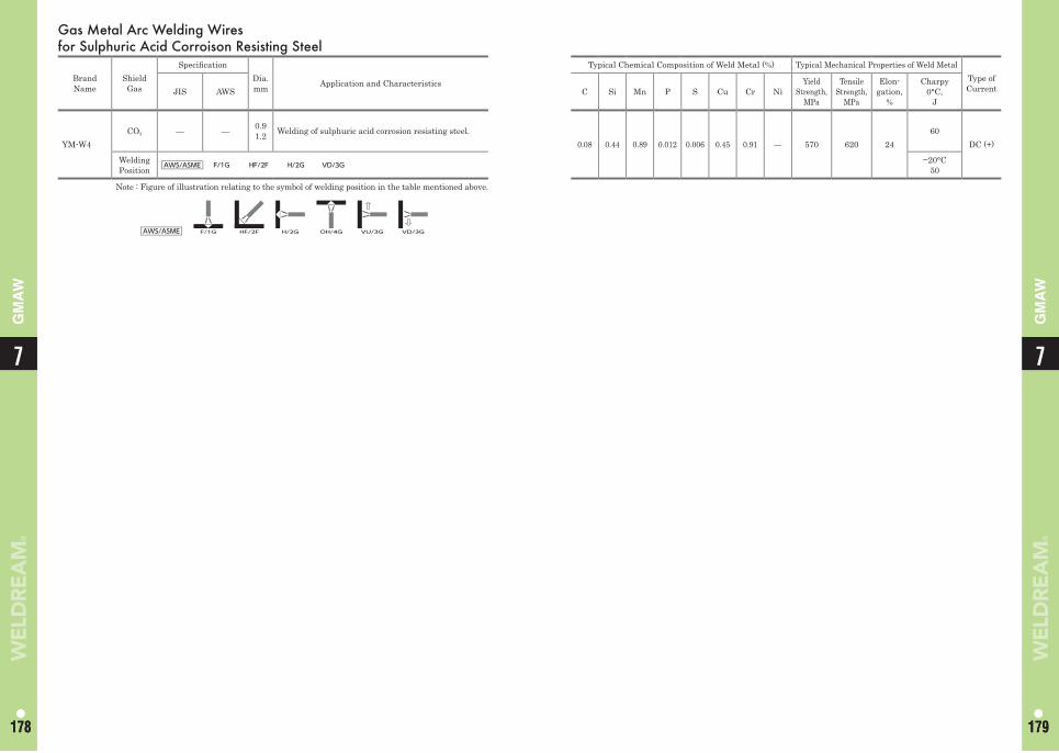
Gas Metal Arc Welding Wires for Sulphuric Acid Corroison Resisting Steel
Brand Name
Shield Gas
Specifi cationDia.mm Application and Characteristics
Typical Chemical Composition of Weld Metal (%) Typical Mechanical Properties of Weld MetalType of CurrentJIS AWS C Si Mn P S Cu Cr Ni
Yield Strength,
MPa
Tensile Strength,
MPa
Elon-gation,
%
Charpy0°C,
J
YM-W4CO2 — — 0.9
1.2 Welding of sulphuric acid corrosion resisting steel.0.08 0.44 0.89 0.012 0.006 0.45 0.91 — 570 620 24
60DC (+)
Welding Position AWS/ASME F/1G HF/2F H/2G VD/3G −20°C
50
Note : Figure of illustration relating to the symbol of welding position in the table mentioned above.
AWS/ASME F/1G HF/2F H/2G OH/4G VU/3G VD/3G
77
178 179178 179
GM
AW
GM
AW
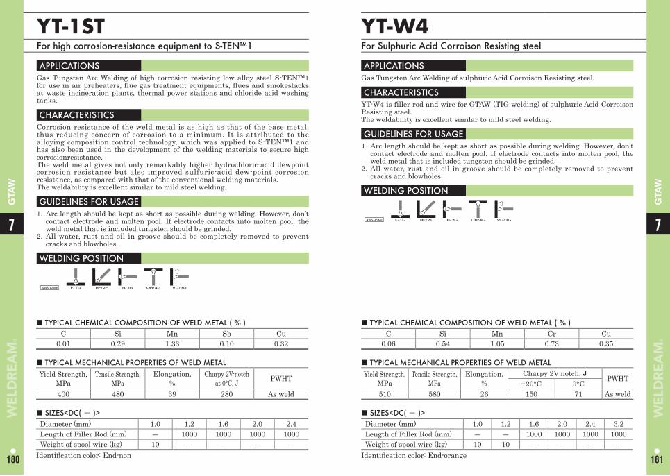
■ TYPICAL CHEMICAL COMPOSITION OF WELD METAL ( % )C Si Mn Sb Cu
0.01 0.29 1.33 0.10 0.32
■ TYPICAL CHEMICAL COMPOSITION OF WELD METAL ( % )C Si Mn Cr Cu
0.06 0.54 1.05 0.73 0.35
YT-1STFor high corrosion-resistance equipment to S-TEN™1
APPLICATIONS Gas Tungsten Arc Welding of high corrosion resisting low alloy steel S-TEN™1 for use in air preheaters, flue-gas treatment equipments, flues and smokestacks at waste incineration plants, thermal power stations and chloride acid washing tanks.
CHARACTERISTICS Corrosion resistance of the weld metal is as high as that of the base metal, thus reducing concern of corrosion to a minimum. It is attributed to the alloying composition control technology, which was applied to S-TEN™1 and has also been used in the development of the welding materials to secure high corrosionresistance. The weld metal gives not only remarkably higher hydrochloric-acid dewpoint corrosion resistance but also improved sulfuric-acid dew-point corrosion resistance, as compared with that of the conventional welding materials.The weldability is excellent similar to mild steel welding.
GUIDELlNES FOR USAGE 1. Arc length should be kept as short as possible during welding. However, don’t
contact electrode and molten pool. If electrode contacts into molten pool, the weld metal that is included tungsten should be grinded.
2. All water, rust and oil in groove should be completely removed to prevent cracks and blowholes.
WELDING POSITION
AWS/ASME F/1G HF/2F H/2G OH/4G VU/3G
■ TYPICAL MECHANICAL PROPERTIES OF WELD METALYield Strength,
MPaTensile Strength,
MPaElongation,
%Charpy 2V-notch
at 0°C, J PWHT
400 480 39 280 As weld
■ TYPICAL MECHANICAL PROPERTIES OF WELD METALYield Strength,
MPaTensile Strength,
MPaElongation,
%Charpy 2V-notch, J
PWHT−20°C 0°C
510 580 26 150 71 As weld
■ SIZES<DC( - )>Diameter (mm) 1.0 1.2 1.6 2.0 2.4Length of Filler Rod (mm) ― 1000 1000 1000 1000Weight of spool wire (kg) 10 ― ― ― ―
Identifi cation color: End-non
■ SIZES<DC( - )>Diameter (mm) 1.0 1.2 1.6 2.0 2.4 3.2Length of Filler Rod (mm) ― ― 1000 1000 1000 1000Weight of spool wire (kg) 10 10 ― ― ― ―
Identifi cation color: End-orange
YT-W4For Sulphuric Acid Corroison Resisting steel
APPLICATIONS Gas Tungsten Arc Welding of sulphuric Acid Corroison Resisting steel.
CHARACTERISTICS YT-W4 is filler rod and wire for GTAW (TIG welding) of sulphuric Acid Corroison Resisting steel.The weldability is excellent similar to mild steel welding.
GUIDELlNES FOR USAGE 1. Arc length should be kept as short as possible during welding. However, don’t
contact electrode and molten pool. If electrode contacts into molten pool, the weld metal that is included tungsten should be grinded.
2. All water, rust and oil in groove should be completely removed to prevent cracks and blowholes.
WELDING POSITION
AWS/ASME F/1G HF/2F H/2G OH/4G VU/3G
77
180 181
GTA
W
GTA
W
Memo
7
182
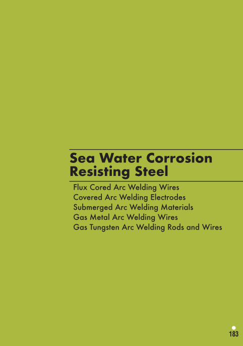
183
Sea Water Corrosion Resisting SteelFlux Cored Arc Welding WiresCovered Arc Welding ElectrodesSubmerged Arc Welding MaterialsGas Metal Arc Welding WiresGas Tungsten Arc Welding Rods and Wires
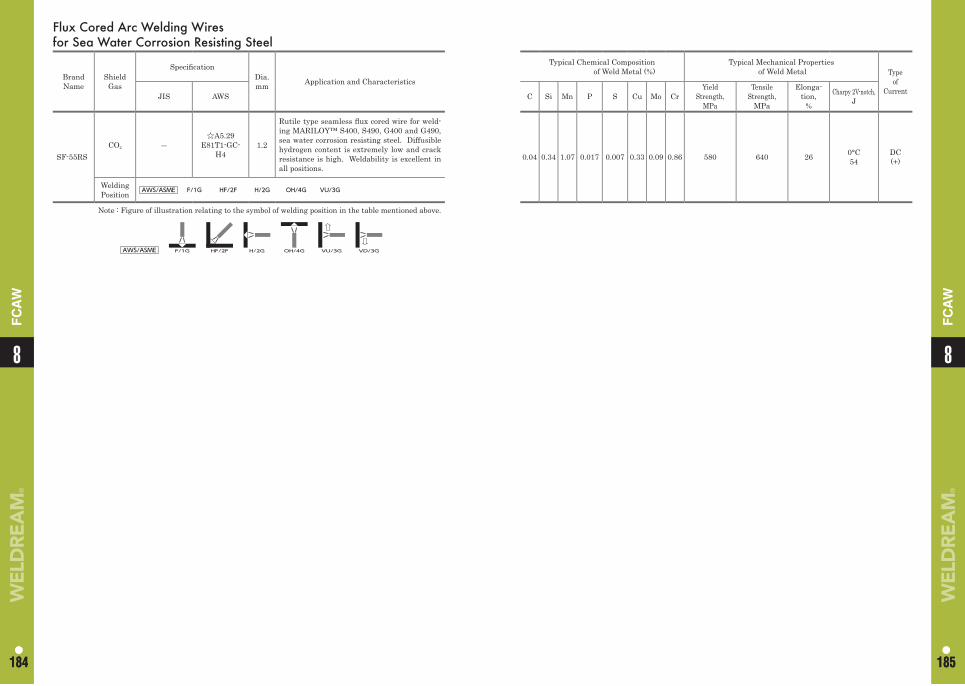
Flux Cored Arc Welding Wiresfor Sea Water Corrosion Resisting Steel
Brand Name
Shield Gas
Specifi cationDia. mm Application and Characteristics
JIS AWS
SF-55RSCO2 ―
☆A5.29 E81T1-GC-
H41.2
Rutile type seamless fl ux cored wire for weld-ing MARILOY™ S400, S490, G400 and G490, sea water corrosion resisting steel. Diffusible hydrogen content is extremely low and crack resistance is high. Weldability is excellent in all positions.
Welding Position AWS/ASME F/1G HF/2F H/2G OH/4G VU/3G
Note : Figure of illustration relating to the symbol of welding position in the table mentioned above.
AWS/ASME F/1G HF/2F H/2G OH/4G VU/3G VD/3G
Typical Chemical Compositionof Weld Metal (%)
Typical Mechanical Properties of Weld Metal Type
ofCurrentC Si Mn P S Cu Mo Cr
Yield Strength,
MPa
Tensile Strength,
MPa
Elonga-tion,
%
Charpy 2V-notch,J
0.04 0.34 1.07 0.017 0.007 0.33 0.09 0.86 580 640 26 0°C54
DC(+)
88
184 185184 185
FC
AW
FC
AW
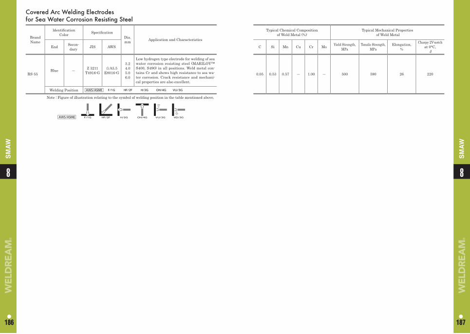
Typical Chemical Composition of Weld Metal (%)
Typical Mechanical Properties of Weld Metal
C Si Mn Cu Cr Mo Yield Strength, MPa
Tensile Strength, MPa
Elongation,%
Charpy 2V-notchat 0°C,
J
0.05 0.53 0.57 ― 1.00 ― 500 590 26 220
Covered Arc Welding Electrodes for Sea Water Corrosion Resisting Steel
Brand Name
ldentifi cation Color Specifi cation
Dia. mm Application and Characteristics
End Secon-dary JIS AWS
RS-55Blue ― Z 3211
T4916-G☆A5.5
E8016-G
3.2 4.0 5.0 6.0
Low hydrogen type electrode for welding of sea water corrosion resisting steel (MARILOY™ S400, S490) in all positions. Weld metal con-tains Cr and shows high resistance to sea wa-ter corrosion. Crack resistance and mechani-cal properties are also excellent.
Welding Position AWS/ASME F/1G HF/2F H/2G OH/4G VU/3G
Note : Figure of illustration relating to the symbol of welding position in the table mentioned above.
AWS/ASME F/1G HF/2F H/2G OH/4G VU/3G VD/3G
88
186 187186 187
SM
AW
SM
AW
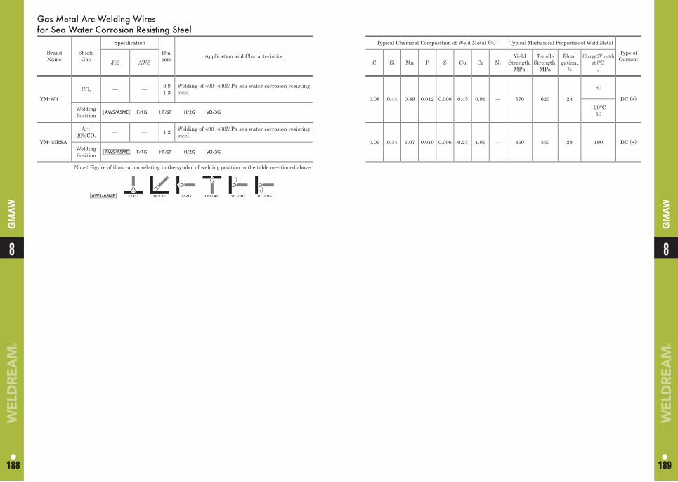
Gas Metal Arc Welding Wires for Sea Water Corrosion Resisting Steel
Brand Name
Shield Gas
Specifi cation
Dia. mm Application and Characteristics
Typical Chemical Composition of Weld Metal (%) Typical Mechanical Properties of Weld Metal
Type of CurrentJIS AWS C Si Mn P S Cu Cr Ni
Yield Strength,
MPa
Tensile Strength,
MPa
Elon-gation,
%
Charpy 2V- notchat 0°C,
J
YM-W4
CO2 — — 0.91.2
Welding of 400~490MPa sea water corrosion resisting steel
0.08 0.44 0.89 0.012 0.006 0.45 0.91 — 570 620 24
60
DC (+)–20°C
50Welding Position AWS/ASME F/1G HF/2F H/2G VD/3G
YM-55RSA
Ar+20%CO2
— — 1.2 Welding of 400~490MPa sea water corrosion resisting steel
0.06 0.34 1.07 0.010 0.006 0.23 1.09 — 460 550 28 190 DC (+)Welding Position AWS/ASME F/1G HF/2F H/2G VD/3G
Note : Figure of illustration relating to the symbol of welding position in the table mentioned above.
AWS/ASME F/1G HF/2F H/2G OH/4G VU/3G VD/3G
88
188 189188 189
GM
AW
GM
AW
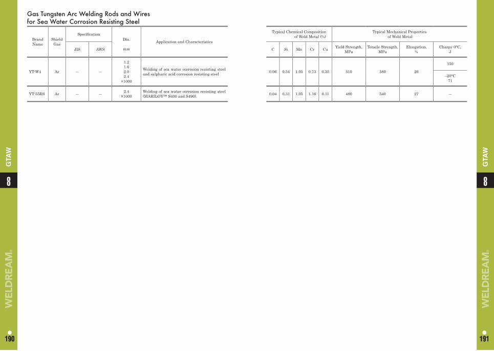
88
190 191190 191
GTA
W
GTA
WGas Tungsten Arc Welding Rods and Wires for Sea Water Corrosion Resisting Steel
Brand Name
Shield Gas
Specifi cationDia.
mm
Application and Characteristics
JIS AWS
YT-W4 Ar ― ―
1.21.62.02.4
×1000
Welding of sea water corrosion resisting steel and salpharic acid corrosion resisting steel
YT-55RS Ar ― ― 2.4×1000
Welding of sea water corrosion resisting steel (MARILOY™ S400 and S490).
Typical Chemical Compositionof Weld Metal (%)
Typical Mechanical Properties of Weld Metal
C Si Mn Cr Cu Yield Strength, MPa
Tensile Strength, MPa
Elongation,%
Charpy 0°C,J
0.06 0.54 1.05 0.73 0.35 510 580 26
150
–20°C71
0.04 0.31 1.05 1.16 0.11 480 540 27 ―
Memo
8
192
193
Stainless SteelFlux Cored Arc Welding WiresCovered Arc Welding ElectrodesSubmerged Arc Welding MaterialsGas Metal Arc Welding WiresGas Tungsten Arc Welding Rods and Wires
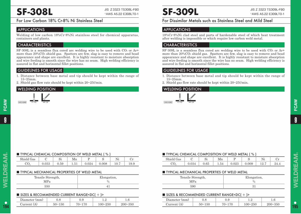
■ TYPICAL CHEMICAL COMPOSITION OF WELD METAL ( % ) Shield Gas C Si Mn P S Ni Cr
CO2 0.034 0.65 1.54 0.023 0.009 12.7 24.4
SF-309L JIS Z 3323 TS309L-FB0☆AWS A5.22 E309LT0-1
For Dissimilar Metals such as Stainless Steel and Mild Steel
APPLICATIONS 18%Cr-8%Ni clad steel and parts of hardenable steel of which heat treatment after welding is impossible or which require low carbon weld metal.
CHARACTERISTICS SF-309L is a seamless flux cored arc welding wire to be used with CO2 or Ar+ more than 20%CO2 shield gas. Spatters are few, slag is easy to remove and bead appearance and shape are excellent. It is highly resistant to moisture absorption and wire feeding is smooth since the wire has no seam. High welding efficiency is assured in flat and horizontal fillet positions.
GUIDELlNES FOR USAGE 1. Distance between base metal and tip should be kept within the range of
15~25mm.2. Shield gas flow rate should be kept within 20~25ℓ/min.
WELDING POSITION
AWS/ASME F/1G HF/2F
■ TYPICAL MECHANICAL PROPERTIES OF WELD METALTensile Strength,
MPa Elongation,
%590 31
■ SIZES & RECOMMENDED CURRENT RANGE<DC( + )> Diameter (mm) 0.8 0.9 1.2 1.6Current (A) 50~150 70~170 100~250 200~350
■ TYPICAL CHEMICAL COMPOSITION OF WELD METAL ( % ) Shield Gas C Si Mn P S Ni Cr
CO2 0.033 0.59 1.51 0.024 0.008 10.7 19.9
SF-308L JIS Z3323 TS308L-FB0☆AWS A5.22 E308LT0-1
For Low Carbon 18% Cr-8% Ni Stainless Steel
APPLICATIONS Welding of low carbon 18%Cr-8%Ni stainless steel for chemical apparatus, containers and plants.
CHARACTERISTICS SF-308L is a seamless flux cored arc welding wire to be used with CO2 or Ar+ more than 20%CO2 shield gas. Spatters are few, slag is easy to remove and bead appearance and shape are excellent. It is highly resistant to moisture absorption and wire feeding is smooth since the wire has no seam. High welding efficiency is assured in flat and horizontal fillet positions.
GUIDELlNES FOR USAGE 1. Distance between base metal and tip should be kept within the range of
15~25mm.2. Shield gas flow rate should be kept within 20~25ℓ/min.
WELDING POSITION
AWS/ASME F/1G HF/2F
■ TYPICAL MECHANICAL PROPERTIES OF WELD METALTensile Strength,
MPa Elongation,
%550 41
■ SIZES & RECOMMENDED CURRENT RANGE<DC( + )> Diameter (mm) 0.8 0.9 1.2 1.6Current (A) 50~150 70~170 100~250 200~350
99
194 195
FC
AW
FC
AW
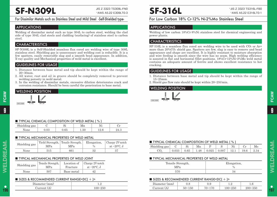
■ TYPICAL CHEMICAL COMPOSITION OF WELD METAL ( % ) Shielding gas C Si Mn P S Ni Cr Mo
CO2 0.033 0.65 1.48 0.025 0.007 12.1 19.6 2.34
SF-316L ☆JIS Z 3323 TS316L-FB0☆AWS A5.22 E316LT0-1
For Low Carbon 18% Cr-12% Ni-2%Mo Stainless Steel
APPLICATIONS Welding of low carbon 18%Cr-8%Ni stainless steel for chemical engineering and power plants.
CHARACTERISTICS SF-316L is a seamless flux cored arc welding wire to be used with CO2 or Ar+ more than 20%CO2 shield gas. Spatters are few, slag is easy to remove and bead appearance and shape are excellent. It is highly resistant to moisture absorption and wire feeding is smooth since the wire has no seam. High welding efficiency is assured in flat and horizontal fillet positions. 18%Cr-12%Ni-2%Mo weld metal contains an adequate amount of ferrite and shows excellent resistance to hot cracking.
GUIDELlNES FOR USAGE 1. Distance between base metal and tip should be kept within the range of
15~25mm.2. Shield gas flow rate should be kept within 20~25ℓ/min.
WELDING POSITION
AWS/ASME F/1G HF/2F
■ TYPICAL MECHANICAL PROPERTIES OF WELD METALTensile Strength,
MPa Elongation,
%570 34
■ SIZES & RECOMMENDED CURRENT RANGE<DC( + )> Diameter (mm) 0.8 0.9 1.2 1.6Current (A) 50~150 70~170 100~250 200~350
■ TYPICAL CHEMICAL COMPOSITION OF WELD METAL ( % ) Shielding gas C Si Mn Ni Cr
None 0.03 0.65 1.50 12.6 24.3
SF-N309L JIS Z 3323 TS309L-FN0☆AWS A5.22 E309LT0-3
For Dissimilar Metals such as Stainless Steel and Mild Steel -Self-Shielded type-
APPLICATIONS Welding of dissimilar metal such as type 304L to carbon steel, welding the clad side of type 304L clad steels and cladding (surfacing) of stainless steel to carbon steel.
CHARACTERISTICS SF-N309L is a Self-Shielded seamless flux cored arc welding wire of type 309L stainless steel. Shielding gas is unnecessary and welding cost is reducible. It is a few spatters, easily removable slag and a smooth bead appearance. In addition, X-ray quality and Mechanical properties of weld metal is excellent.
GUIDELlNES FOR USAGE 1. Distance between base metal and tip should be kept within the range of
20~30mm.2. All water, rust and oil in groove should be completely removed to prevent
welding porosity in weld metal.3. In the welding of dissimilar metals, excessive dilution deteriorates crack and
corrosion resistance. Should be been careful the penetration to base metal.
WELDING POSITION
AWS/ASME F/1G HF/2F
■ TYPICAL MECHANICAL PROPERTIES OF WELD METAL
Shielding gas Yield Strength, MPa
Tensile Strength, MPa
Elongation, %
Charpy 2V-notch at −20°C, J
None 515 661 32 37
■ TYPICAL MECHANICAL PROPERTIES OF WELD JOINT
Shielding gas Tensile Strength, MPa
Location of Fracture
Charpy 2V-notch at −20°C, J
None 507 Base metal 42
■ SIZES & RECOMMENDED CURRENT RANGE<DC( + )> Diameter (mm) 1.2
Current (A) 100~250
99
196 197
FC
AW
FC
AW

Memo
■ Typical chemical composition and mechanical properties (DC:wire(+))
Electrode Size(mm)
Base Metal Groove Shape Pass Current
(A)Volt.(V)
Speed(cm/min)
SF-DP8 1.2
JIS SM490A
The grooveare butteredwith SF-DP8
MultiPass 200 30 35
Shielding Gas Flow Rate
CO2 100% 20 l/min.
ChemicalComposition of Weld Metal(%)
C Si Mn P S Ni Cr Mo N Other0.03 0.44 1.14 0.019 0.006 8.80 23.5 3.05 0.13 −
PWHT
Tension Test Charpy Impact Test JHardness
Hv (10kgf)
TestTemp.
YieldStrength
MPa
TensileStrength
MPa
Elongation(5d)%
−20°C 0°C
As welded
RoomTemp. 641 808 24.1 32 − −
Corrosion test(Huey test)
ASTM A262 Practice C
Corrosion rate (g/m2h)1st 2nd 3rd 4th 5th Average− − − − − −
SF-DP8 Z3323 TS2209-FB0A5.22 E2209T0-1
Welding Materials for 22% Cr Duplex Stainless Steels
APPLICATIONS Welding of 22%Cr duplex stainless steel such as ASTM UNS S31803 and JIS SUS329J3L.
CHARACTERISTICS SF-DP8 is a flux cored wire designed for duplex stainless steel.It shows excellent welding performance such as good bead appearance, less spatter, easy slag removal and smoother wire feeding.The weld deposit has a good resistance for Stress Corrosion Cracking (SCC) at as-welded condition.
GUIDELlNES FOR USAGE 1. CO2 gas of JIS class 3 or for welding use should be used.2. Gas flow rate should be 20L/min, as a rule.3. Tip to work distance should be kept within 15 to 20mm.4. Wires should be used as soon as possible after taking out from package.5. The welding machine for solid wire is available.
SizeWire wound on spool : 1.2mm dia.
9
199
9
198
FC
AW
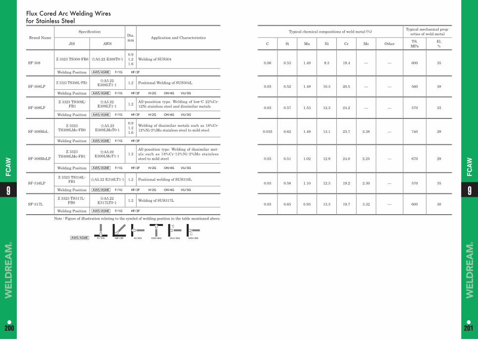
Flux Cored Arc Welding Wires for Stainless Steel
Brand NameSpecifi cation
Dia.mm Application and Characteristics
Typical chemical compositions of weld metal (%) Typical mechanical prop-erties of weld metal
JIS AWS C Si Mn Ni Cr Mo Other TS,MPa
El,%
SF-308Z 3323 TS308-FB0 ☆A5.22 E308T0-1
0.91.21.6
Welding of SUS3040.06 0.53 1.49 9.3 19.4 — — 600 35
Welding Position AWS/ASME F/1G HF/2F
SF-308LPZ 3323 TS308L-FB1 ☆A5.22
E308LT1-1 1.2 Positional Welding of SUS304L0.03 0.52 1.49 10.3 20.5 — — 560 38
Welding Position AWS/ASME F/1G HF/2F H/2G OH/4G VU/3G
SF-309LPZ 3323 TS309L-
FB1☆A5.22
E309LT1-1 1.2 All-possition type. Welding of low-C 22%Cr-12Ni stainless steel and dissimilar metals 0.03 0.57 1.53 12.3 24.2 — — 570 33
Welding Position AWS/ASME F/1G HF/2F H/2G OH/4G VU/3G
SF-309MoLZ 3323
TS309LMo-FB0☆A5.22
E309LMoT0-1
0.91.21.6
Welding of dissimilar metals such as 18%Cr-12%Ni-2%Mo stainless steel to mild steel 0.035 0.62 1.49 13.1 23.7 2.38 — 740 29
Welding Position AWS/ASME F/1G HF/2F
SF-309MoLP
Z 3323 TS309LMo-FB1
☆A5.22E309LMoT1-1 1.2
All-possition type. Welding of dissimilar met-als such as 18%Cr-12%Ni-2%Mo stainless steel to mild steel 0.03 0.51 1.02 12.9 24.0 2.25 — 670 29
Welding Position AWS/ASME F/1G HF/2F H/2G OH/4G VU/3G
SF-316LPZ 3323 TS316L-
FB1 ☆A5.22 E316LT1-1 1.2 Positional welding of SUS316L0.03 0.58 1.10 12.3 19.2 2.30 — 570 35
Welding Position AWS/ASME F/1G HF/2F H/2G OH/4G VU/3G
SF-317LZ 3323 TS317L-
FB0☆A5.22
E317LT0-1 1.2 Welding of SUS317L0.03 0.65 0.93 13.3 19.7 3.32 — 600 30
Welding Position AWS/ASME F/1G HF/2F
Note : Figure of illustration relating to the symbol of welding position in the table mentioned above.
AWS/ASME F/1G HF/2F H/2G OH/4G VU/3G VD/3G
99
200 201200 201
FC
AW
FC
AW
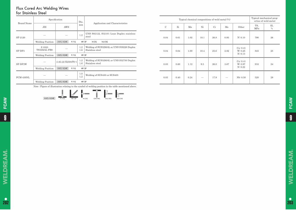
Flux Cored Arc Welding Wires for Stainless Steel
Brand NameSpecifi cation
Dia.mm Application and Characteristics
Typical chemical compositions of weld metal (%) Typical mechanical prop-erties of weld metal
JIS AWS C Si Mn Ni Cr Mo Other TS,MPa
El,%
SF-2120— — 1.2 UNS S82122, S32101 Lean Duplex stainless
steel 0.04 0.61 1.02 10.1 26.8 0.93 N: 0.10 790 26
Welding Position AWS/ASME F/1G HF/2F H/2G VU/3G
SF-DP3Z 3323
TS329J4L-FB0 — 1.21.6
Welding of SUS329J4L or UNS S39226 Duplex Stainless steel 0.04 0.64 1.00 10.4 25.6 2.82
Cu: 0.41W: 0.25N: 0.13
845 25
Welding Position AWS/ASME F/1G HF/2F
SF-DP3W— ☆A5.22 E2594T0-1 1.2
1.6Welding of SUS329J4L or UNS S32750 Duplex Stainless steel 0.03 0.60 1.12 9.5 26.0 3.67
Cu: 0.41W: 0.97N: 0.22
910 24
Welding Position AWS/ASME F/1G HF/2F
FCM-430NL— — 1.0
1.2 Welding of SUS430 or SUS4050.03 0.40 0.24 — 17.9 — Nb: 0.50 520 28
Welding Position AWS/ASME F/1G HF/2F
Note : Figure of illustration relating to the symbol of welding position in the table mentioned above.
AWS/ASME F/1G HF/2F H/2G OH/4G VU/3G VD/3G
99
202 203202 203
FC
AW
FC
AW
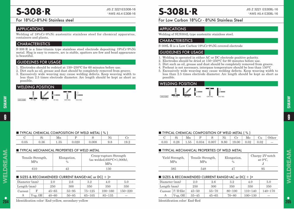
99
204 205
SM
AW
SM
AW
■ TYPICAL CHEMICAL COMPOSITION OF WELD METAL ( % ) C Si Mn P S Ni Cr
0.05 0.36 1.35 0.020 0.008 9.8 19.2
■ TYPICAL CHEMICAL COMPOSITION OF WELD METAL ( % ) C Si Mn P S Ni Cr Mo Cu Other
0.03 0.28 1.55 0.034 0.007 9.80 19.00 0.02 0.02 ―
S-308·R JIS Z 3221ES308-16☆AWS A5.4 E308-16
For 18%Cr-8%Ni Stainless steel
S-308L·R JIS Z 3221 ES308L-16☆AWS A5.4 E308L-16
For Low Carbon 18%Cr - 8%Ni Stainless Steel
APPLICATIONS Welding of 18%Cr-8%Ni austenitic stainless steel for chemical apparatus, containers and plants,
CHARACTERISTICS S-308·R is a lime-titania type stainless steel electrode depositing 19%Cr-9%Ni metal. Slag is easy to remove, arc is stable, spatters are few and bead appearance is beautiful.
GUIDELlNES FOR USAGE 1. Electrodes should be redried at 150~250°C for 60 minutes before use.2. Dirt such as oil, grease and dust should be completely removed from groove.3. Excessively wide weaving may cause welding defects. Keep weaving width to
less than 2.5 times electrode diameter. Arc length should be kept as short as possible.
WELDING POSITION
AWS/ASME F/1G HF/2F H/2G OH/4G VU/3G
APPLICATIONS Welding of SUS304L type austenitic stainless steel.
CHARACTERISTICS S-308L·R is a Low Carbon-19%Cr-9%Ni covered electrode
GUIDELlNES FOR USAGE 1. Welding is operated in either AC or DC electrode positive polarity.2. Electrodes should be dried at 150~250°C for 60 minutes before use.3. Dirt such as oil, grease and dust should be completely removed from groove.4. Preheat is not necessary, interpass temperature should be less than 150°C5. Excessively wide weaving may cause welding defects. Keep weaving width to
less than 2.5 times electrode diameter. Arc length should be kept as short as possible.
WELDING POSITION
AWS/ASME F/1G HF/2F H/2G OH/4G VU/3G
■ TYPICAL MECHANICAL PROPERTIES OF WELD METAL
Tensile Strength,MPa
Elongation,%
Creep-rupture Strength(as welded,650°C×1,000h),
MPa610 42 130
■ TYPICAL MECHANICAL PROPERTIES OF WELD METAL
Yield Strength,MPa
Tensile Strength,MPa
Elongation,%
Charpy 2V-notchat 0°C,
J385 548 47 95
■ SIZES & RECOMMENDED CURRENT RANGE<AC or DC( + )> Diameter (mm) 2.0 2.6 3.2 4.0 5.0Length (mm) 250 300 350 350 350Current
AF 45~65 55~95 75~125 100~160 150~220
V-up, OH 40~60 50~85 65~105 85~135 ―Identifi cation color: End-yellow, secondary-yellow
■ SIZES & RECOMMENDED CURRENT RANGE<AC or DC( + )> Diameter (mm) 2.0 2.6 3.2 4.0 5.0Length (mm) 250 300 350 350 350Current
AF / H-fi llet 45~50 55~70 80~100 110~140 140~170V-up, OH 35~45 45~65 70~80 100~130 ―
Identifi cation color: End-Red
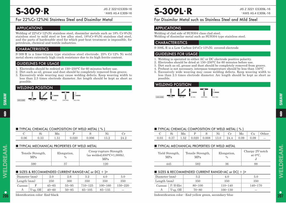
99
206 207
SM
AW
SM
AW
■ TYPICAL CHEMICAL COMPOSITION OF WELD METAL ( % ) C Si Mn P S Ni Cr
0.06 0.33 1.51 0.020 0.006 13.2 24.2
S-309·R JIS Z 3221ES309-16 ☆AWS A5.4 E309-16
For 22%Cr-12%Ni Staintess Steel and Dissimilar Metal
S-309L·R JIS Z 3221 ES309L-16 ☆AWS A5.4 E309L-16
For Dissimilar Metal such as Stainless Steel and Mild Steel
APPLICATIONS Welding of 22%Cr-12%Ni stainless steel, dissimilar metals such as 18% Cr-8%Ni stainless steel to mild steel or low alloy steel, 18%Cr-8%Ni stainless clad steel, and the parts of hardenable steel for which post-heat treatment is impossible, for petroleum, chemical and textile industries.
CHARACTERISTICS S-309·R is a lime-titania type stainless steel electrode. 25% Cr-12% Ni weld metal shows extremely high crack resistance due to its high ferrite content.
GUIDELlNES FOR USAGE 1. Electrodes should be redried at 150~250°C for 60 minutes before use. 2. Dirt such as oil, grease and dust should be completely removed from groove. 3. Excessively wide weaving may cause welding defects. Keep weaving width to
less than 2.5 times electrode diameter. Arc length should be kept as short as possible.
WELDING POSITION
AWS/ASME F/1G HF/2F H/2G OH/4G VU/3G
APPLICATIONS Welding of clad side of SUS304 class clad steel. Welding of dissimilar metal such as SUS304 type stainless steel.
CHARACTERISTICS S-309L·R is a Low Carbon-24%Cr-13%Ni covered electrode
GUIDELlNES FOR USAGE 1. Welding is operated in either AC or DC electrode positive polarity.2. Electrodes should be dried at 150~250°C for 60 minutes before use.3. Dirt such as oil, grease and dust should be completely removed from groove.4. Preheat is not necessary, interpass temperature should be less than 150°C5. Excessively wide weaving may cause welding defects. Keep weaving width to
less than 2.5 times electrode diameter. Arc length should be kept as short as possible.
WELDING POSITION
AWS/ASME F/1G HF/2F H/2G OH/4G VU/3G
■ TYPICAL MECHANICAL PROPERTIES OF WELD METAL
Tensile Strength,MPa
Elongation,%
Creep-rupture Strength(as welded,650°C×1,000h),
MPa590 37 120
■ SIZES & RECOMMENDED CURRENT RANGE<AC or DC( + )> Diameter (mm) 2.0 2.6 3.2 4.0 5.0Length (mm) 250 300 350 350 350Current
AF 45~65 55~95 710~125 100~160 150~220
V-up, OH 40~60 50~85 65~105 85~135 ―Identifi cation color: End-black
■ TYPICAL CHEMICAL COMPOSITION OF WELD METAL ( % ) C Si Mn P S Ni Cr Mo Cu Other
0.03 0.37 1.52 0.020 0.008 13.0 24.4 0.09 0.09 ―
■ TYPICAL MECHANICAL PROPERTIES OF WELD METAL
Yield Strength,MPa
Tensile Strength,MPa
Elongation,%
Charpy 2V-notchat 0°C,
J445 582 36 88
■ SIZES & RECOMMENDED CURRENT RANGE<AC or DC( + )> Diameter (mm) 3.2 4.0 5.0Length (mm) 350 350 350Current
AF / H-fi llet 80~100 110~140 140~170V-up, OH 70~80 100~130 ―
Indentifi cation color : End-yellow green, secondary-blue
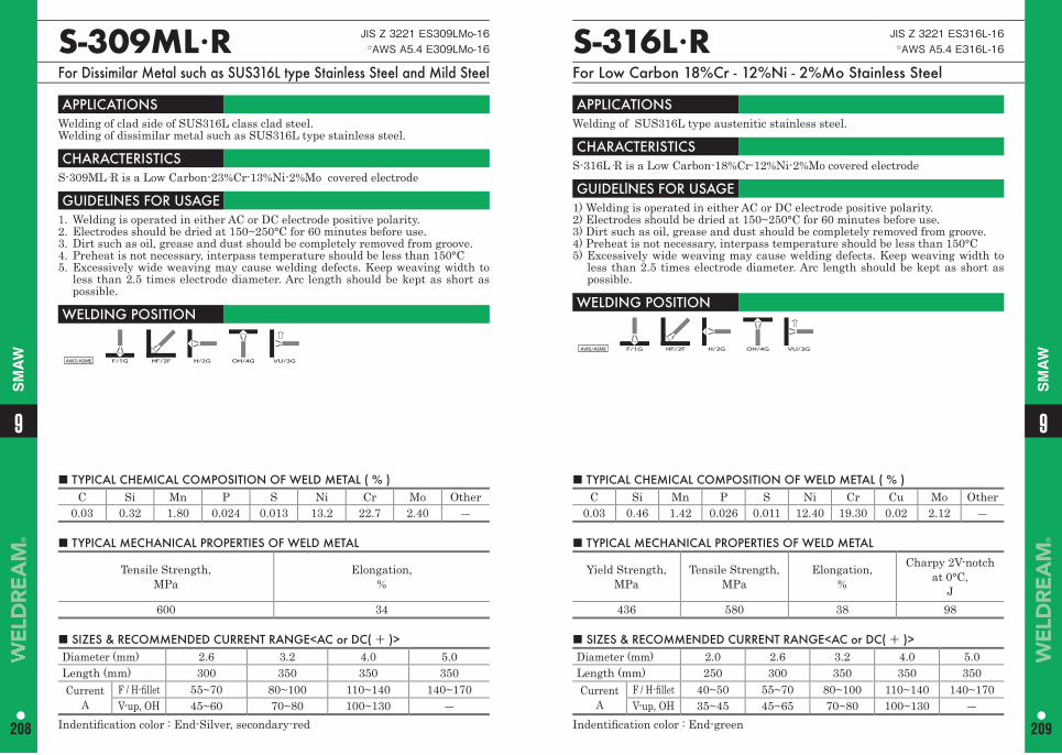
99
208 209
SM
AW
SM
AW
S-316L·R JIS Z 3221 ES316L-16 ☆AWS A5.4 E316L-16
For Low Carbon 18%Cr - 12%Ni - 2%Mo Stainless Steel
S-309ML·R JIS Z 3221 ES309LMo-16 ☆AWS A5.4 E309LMo-16
For Dissimilar Metal such as SUS316L type Stainless Steel and Mild Steel
APPLICATIONS Welding of SUS316L type austenitic stainless steel.
CHARACTERISTICS S-316L·R is a Low Carbon-18%Cr-12%Ni-2%Mo covered electrode
GUIDELlNES FOR USAGE 1) Welding is operated in either AC or DC electrode positive polarity.2) Electrodes should be dried at 150~250°C for 60 minutes before use.3) Dirt such as oil, grease and dust should be completely removed from groove.4) Preheat is not necessary, interpass temperature should be less than 150°C5) Excessively wide weaving may cause welding defects. Keep weaving width to
less than 2.5 times electrode diameter. Arc length should be kept as short as possible.
WELDING POSITION
AWS/ASME F/1G HF/2F H/2G OH/4G VU/3G
APPLICATIONS Welding of clad side of SUS316L class clad steel. Welding of dissimilar metal such as SUS316L type stainless steel.
CHARACTERISTICS S-309ML·R is a Low Carbon-23%Cr-13%Ni-2%Mo covered electrode
GUIDELlNES FOR USAGE 1. Welding is operated in either AC or DC electrode positive polarity.2. Electrodes should be dried at 150~250°C for 60 minutes before use.3. Dirt such as oil, grease and dust should be completely removed from groove.4. Preheat is not necessary, interpass temperature should be less than 150°C5. Excessively wide weaving may cause welding defects. Keep weaving width to
less than 2.5 times electrode diameter. Arc length should be kept as short as possible.
WELDING POSITION
AWS/ASME F/1G HF/2F H/2G OH/4G VU/3G
■ TYPICAL CHEMICAL COMPOSITION OF WELD METAL ( % ) C Si Mn P S Ni Cr Cu Mo Other
0.03 0.46 1.42 0.026 0.011 12.40 19.30 0.02 2.12 ―
■ TYPICAL CHEMICAL COMPOSITION OF WELD METAL ( % ) C Si Mn P S Ni Cr Mo Other
0.03 0.32 1.80 0.024 0.013 13.2 22.7 2.40 ―
■ TYPICAL MECHANICAL PROPERTIES OF WELD METAL
Yield Strength,MPa
Tensile Strength,MPa
Elongation,%
Charpy 2V-notchat 0°C,
J436 580 38 98
■ TYPICAL MECHANICAL PROPERTIES OF WELD METAL
Tensile Strength,MPa
Elongation,%
600 34
■ SIZES & RECOMMENDED CURRENT RANGE<AC or DC( + )> Diameter (mm) 2.0 2.6 3.2 4.0 5.0Length (mm) 250 300 350 350 350Current
AF / H-fi llet 40~50 55~70 80~100 110~140 140~170V-up, OH 35~45 45~65 70~80 100~130 ―
Indentifi cation color : End-green
■ SIZES & RECOMMENDED CURRENT RANGE<AC or DC( + )> Diameter (mm) 2.6 3.2 4.0 5.0 Length (mm) 300 350 350 350Current
AF / H-fi llet 55~70 80~100 110~140 140~170V-up, OH 45~60 70~80 100~130 ―
Indentifi cation color : End-Silver, secondary-red
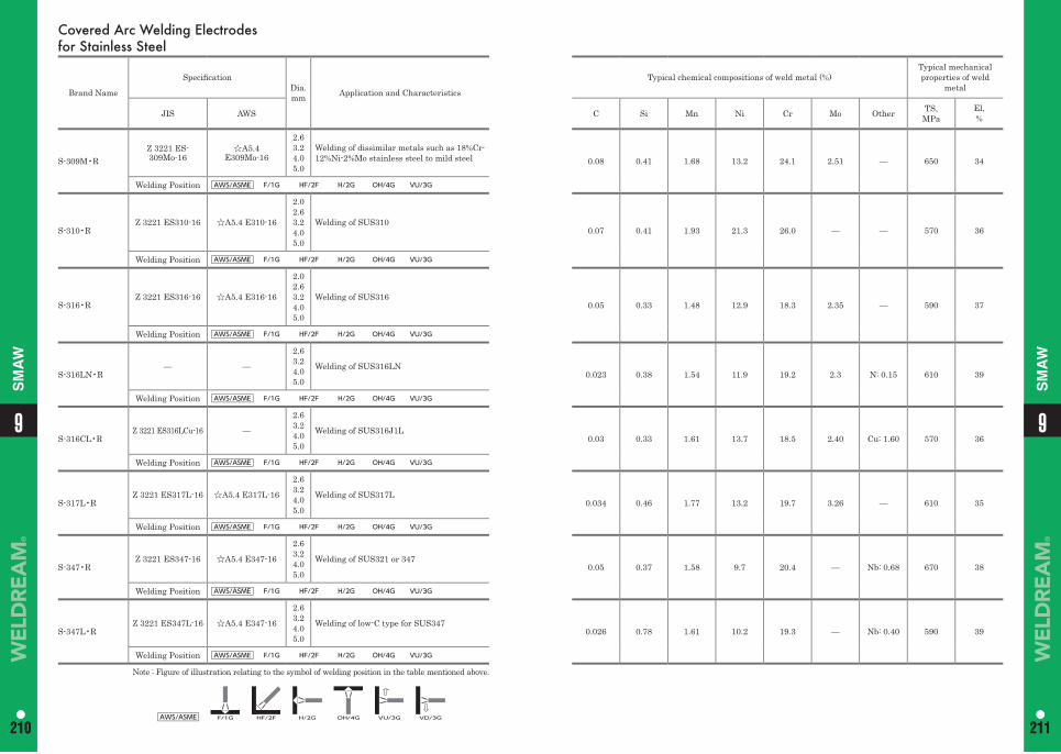
99
210 211210 211
SM
AW
SM
AW
Covered Arc Welding Electrodes for Stainless Steel
Brand Name
Specifi cationDia.mm Application and Characteristics
Typical chemical compositions of weld metal (%)Typical mechanical properties of weld
metal
JIS AWS C Si Mn Ni Cr Mo Other TS,MPa
El,%
S-309M•RZ 3221 ES-309Mo-16
☆A5.4 E309Mo-16
2.63.24.05.0
Welding of dissimilar metals such as 18%Cr-12%Ni-2%Mo stainless steel to mild steel 0.08 0.41 1.68 13.2 24.1 2.51 — 650 34
Welding Position AWS/ASME F/1G HF/2F H/2G OH/4G VU/3G
S-310•RZ 3221 ES310-16 ☆A5.4 E310-16
2.02.63.24.05.0
Welding of SUS3100.07 0.41 1.93 21.3 26.0 — — 570 36
Welding Position AWS/ASME F/1G HF/2F H/2G OH/4G VU/3G
S-316•RZ 3221 ES316-16 ☆A5.4 E316-16
2.02.63.24.05.0
Welding of SUS3160.05 0.33 1.48 12.9 18.3 2.35 — 590 37
Welding Position AWS/ASME F/1G HF/2F H/2G OH/4G VU/3G
S-316LN•R— —
2.63.24.05.0
Welding of SUS316LN0.023 0.38 1.54 11.9 19.2 2.3 N: 0.15 610 39
Welding Position AWS/ASME F/1G HF/2F H/2G OH/4G VU/3G
S-316CL•RZ 3221 ES316LCu-16 —
2.63.24.05.0
Welding of SUS316J1L0.03 0.33 1.61 13.7 18.5 2.40 Cu: 1.60 570 36
Welding Position AWS/ASME F/1G HF/2F H/2G OH/4G VU/3G
S-317L•RZ 3221 ES317L-16 ☆A5.4 E317L-16
2.63.24.05.0
Welding of SUS317L0.034 0.46 1.77 13.2 19.7 3.26 — 610 35
Welding Position AWS/ASME F/1G HF/2F H/2G OH/4G VU/3G
S-347•RZ 3221 ES347-16 ☆A5.4 E347-16
2.63.24.05.0
Welding of SUS321 or 3470.05 0.37 1.58 9.7 20.4 — Nb: 0.68 670 38
Welding Position AWS/ASME F/1G HF/2F H/2G OH/4G VU/3G
S-347L•RZ 3221 ES347L-16 ☆A5.4 E347-16
2.63.24.05.0
Welding of low-C type for SUS3470.026 0.78 1.61 10.2 19.3 — Nb: 0.40 590 39
Welding Position AWS/ASME F/1G HF/2F H/2G OH/4G VU/3G
Note : Figure of illustration relating to the symbol of welding position in the table mentioned above.
AWS/ASME F/1G HF/2F H/2G OH/4G VU/3G VD/3G
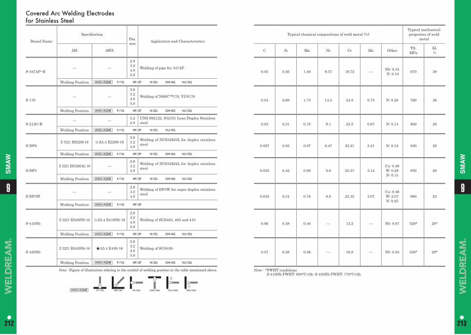
99
212 213212 213
SM
AW
SM
AW
Covered Arc Welding Electrodes for Stainless Steel
Brand Name
Specifi cationDia.mm Application and Characteristics
Typical chemical compositions of weld metal (%)Typical mechanical properties of weld
metal
JIS AWS C Si Mn Ni Cr Mo Other TS,MPa
El,%
S-347AP•R— —
2.63.24.05.0
Welding of pipe for 347AP0.05 0.56 1.40 9.57 19.72 — Nb: 0.34
N: 0.10 670 38
Welding Position AWS/ASME F/1G HF/2F H/2G OH/4G VU/3G
S-170— —
2.63.24.05.0
Welding of NSSC™170, YUS1700.04 0.69 1.73 14.5 24.8 0.75 N: 0.28 760 36
Welding Position AWS/ASME F/1G HF/2F H/2G OH/4G VU/3G
S-2120•R— — 3.2
4.0UNS S82122, S32101 Lean Duplex Stainless steel 0.03 0.31 0.78 9.1 25.5 0.67 N: 0.14 800 26
Welding Position AWS/ASME F/1G HF/2F H/2G VU/3G
S-DP8Z 3221 ES2209-16 ☆A5.4 E2209-16
2.63.24.0
Welding of SUS329J3L for duplex stainless steel 0.027 0.83 0.87 8.47 22.21 3.21 N: 0.12 830 28
Welding Position AWS/ASME F/1G HF/2F H/2G OH/4G VU/3G
S-DP3Z 3221 ES329J4L-16 —
2.63.24.0
Welding of SUS329J4L for duplex stainless steel 0.035 0.42 0.80 8.8 25.37 3.14
Cu: 0.49W: 0.28N: 0.15
850 20
Welding Position AWS/ASME F/1G HF/2F H/2G OH/4G VU/3G
S-DP3W— —
2.63.24.0
Welding of DP3W for super duplex stainless steel 0.035 0.34 0.78 8.8 25.35 3.07
Cu: 0.46W: 2.07N: 0.25
960 23
Welding Position AWS/ASME F/1G HF/2F
S-410NbZ 3221 ES409Nb-16 ☆A5.4 E419Nb-16
2.63.24.05.0
Welding of SUS403, 405 and 4100.06 0.38 0.40 — 13.2 — Nb: 0.87 520* 28*
Welding Position AWS/ASME F/1G HF/2F H/2G OH/4G VU/3G
S-430NbZ 3221 ES430Nb-16 ★A5.4 E430-16
2.63.24.05.0
Welding of SUS4300.07 0.38 0.56 — 16.8 — Nb: 0.85 530* 29*
Welding Position AWS/ASME F/1G HF/2F H/2G OH/4G VU/3G
Note : Figure of illustration relating to the symbol of welding position in the table mentioned above.
AWS/ASME F/1G HF/2F H/2G OH/4G VU/3G VD/3G
Note : *PWHT conditions S-410Nb PWHT: 850°C×2h; S-430Nb PWHT; 770°C×2h
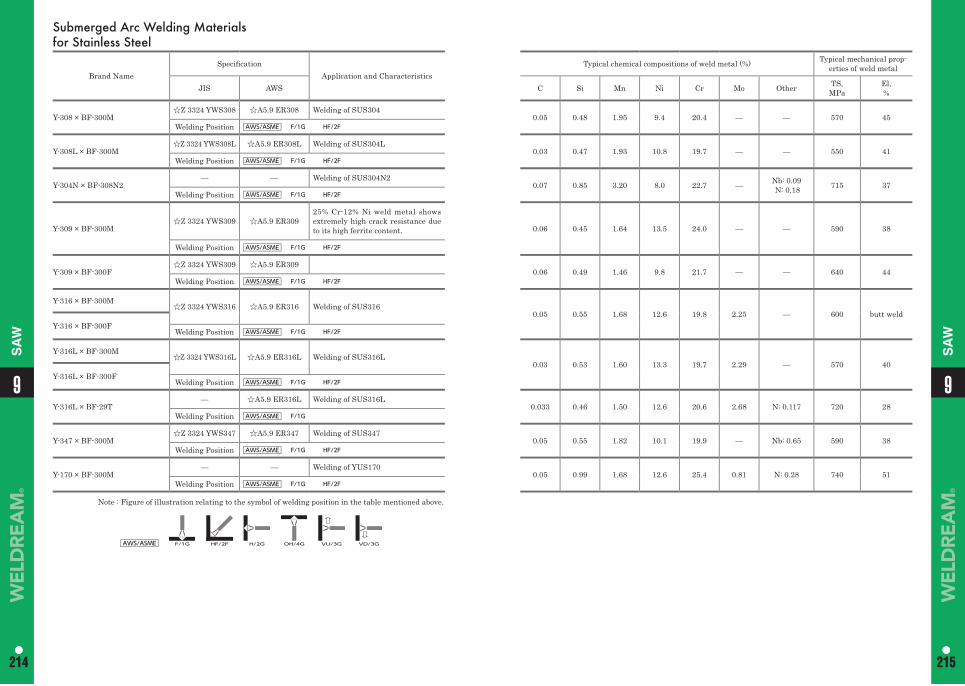
99
214 215214 215
SA
W
SA
WSubmerged Arc Welding Materials for Stainless Steel
Brand NameSpecifi cation
Application and CharacteristicsTypical chemical compositions of weld metal (%) Typical mechanical prop-
erties of weld metal
JIS AWS C Si Mn Ni Cr Mo Other TS,MPa
El,%
Y-308 × BF-300M☆Z 3324 YWS308 ☆A5.9 ER308 Welding of SUS304
0.05 0.48 1.95 9.4 20.4 — — 570 45Welding Position AWS/ASME F/1G HF/2F
Y-308L × BF-300M☆Z 3324 YWS308L ☆A5.9 ER308L Welding of SUS304L
0.03 0.47 1.93 10.8 19.7 — — 550 41Welding Position AWS/ASME F/1G HF/2F
Y-304N × BF-308N2— — Welding of SUS304N2
0.07 0.85 3.20 8.0 22.7 — Nb: 0.09 N: 0.18 715 37
Welding Position AWS/ASME F/1G HF/2F
Y-309 × BF-300M☆Z 3324 YWS309 ☆A5.9 ER309
25% Cr-12% Ni weld metal shows extremely high crack resistance due to its high ferrite content. 0.06 0.45 1.64 13.5 24.0 — — 590 38
Welding Position AWS/ASME F/1G HF/2F
Y-309 × BF-300F☆Z 3324 YWS309 ☆A5.9 ER309
0.06 0.49 1.46 9.8 21.7 — — 640 44Welding Position AWS/ASME F/1G HF/2F
Y-316 × BF-300M☆Z 3324 YWS316 ☆A5.9 ER316 Welding of SUS316
0.05 0.55 1.68 12.6 19.8 2.25 — 600 butt weldY-316 × BF-300F
Welding Position AWS/ASME F/1G HF/2F
Y-316L × BF-300M☆Z 3324 YWS316L ☆A5.9 ER316L Welding of SUS316L
0.03 0.53 1.60 13.3 19.7 2.29 — 570 40Y-316L × BF-300F
Welding Position AWS/ASME F/1G HF/2F
Y-316L × BF-29T— ☆A5.9 ER316L Welding of SUS316L
0.033 0.46 1.50 12.6 20.6 2.68 N: 0.117 720 28Welding Position AWS/ASME F/1G
Y-347 × BF-300M☆Z 3324 YWS347 ☆A5.9 ER347 Welding of SUS347
0.05 0.55 1.82 10.1 19.9 — Nb: 0.65 590 38Welding Position AWS/ASME F/1G HF/2F
Y-170 × BF-300M— — Welding of YUS170
0.05 0.99 1.68 12.6 25.4 0.81 N: 0.28 740 51Welding Position AWS/ASME F/1G HF/2F
Note : Figure of illustration relating to the symbol of welding position in the table mentioned above.
AWS/ASME F/1G HF/2F H/2G OH/4G VU/3G VD/3G
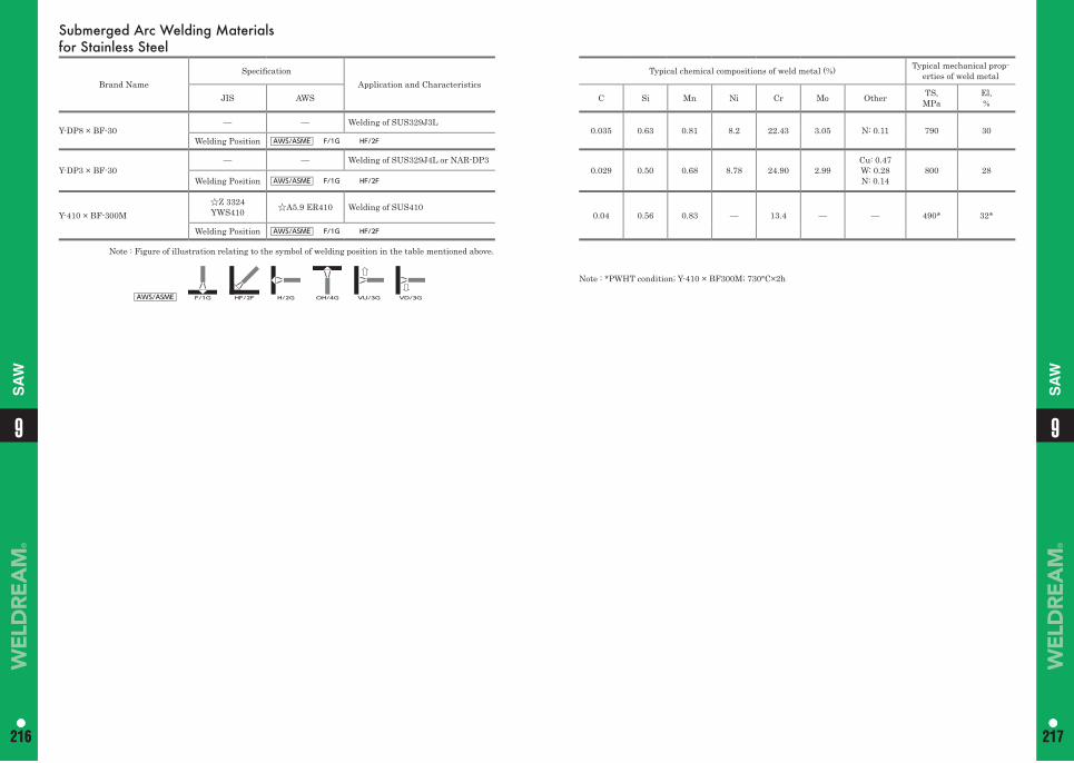
99
216 217216 217
SA
W
SA
W
Note : *PWHT condition; Y-410 × BF300M; 730°C×2h
Submerged Arc Welding Materials for Stainless Steel
Brand NameSpecifi cation
Application and CharacteristicsTypical chemical compositions of weld metal (%) Typical mechanical prop-
erties of weld metal
JIS AWS C Si Mn Ni Cr Mo Other TS,MPa
El,%
Y-DP8 × BF-30— — Welding of SUS329J3L
0.035 0.63 0.81 8.2 22.43 3.05 N: 0.11 790 30Welding Position AWS/ASME F/1G HF/2F
Y-DP3 × BF-30— — Welding of SUS329J4L or NAR-DP3
0.029 0.50 0.68 8.78 24.90 2.99Cu: 0.47W: 0.28N: 0.14
800 28Welding Position AWS/ASME F/1G HF/2F
Y-410 × BF-300M☆Z 3324 YWS410 ☆A5.9 ER410 Welding of SUS410
0.04 0.56 0.83 — 13.4 — — 490* 32*
Welding Position AWS/ASME F/1G HF/2F
Note : Figure of illustration relating to the symbol of welding position in the table mentioned above.
AWS/ASME F/1G HF/2F H/2G OH/4G VU/3G VD/3G
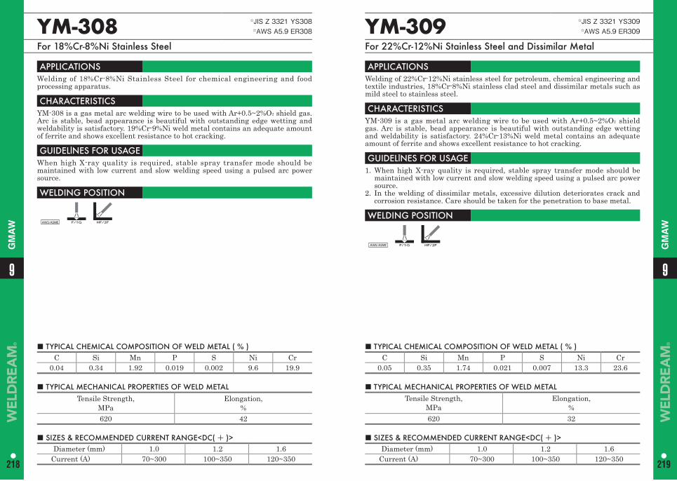
■ TYPICAL CHEMICAL COMPOSITION OF WELD METAL ( % ) C Si Mn P S Ni Cr
0.05 0.35 1.74 0.021 0.007 13.3 23.6
YM-309 ☆JIS Z 3321 YS309☆AWS A5.9 ER309
For 22%Cr-12%Ni Stainless Steel and Dissimilar Metal
APPLICATIONS Welding of 22%Cr-12%Ni stainless steel for petroleum, chemical engineering and textile industries, 18%Cr-8%Ni stainless clad steel and dissimilar metals such as mild steel to stainless steel.
CHARACTERISTICS YM-309 is a gas metal arc welding wire to be used with Ar+0.5~2%O2 shield gas. Arc is stable, bead appearance is beautiful with outstanding edge wetting and weldability is satisfactory. 24%Cr-13%Ni weld metal contains an adequate amount of ferrite and shows excellent resistance to hot cracking.
GUIDELlNES FOR USAGE 1. When high X-ray quality is required, stable spray transfer mode should be
maintained with low current and slow welding speed using a pulsed arc power source.
2. In the welding of dissimilar metals, excessive dilution deteriorates crack and corrosion resistance. Care should be taken for the penetration to base metal.
WELDING POSITION
AWS/ASME F/1G HF/2F
■ TYPICAL MECHANICAL PROPERTIES OF WELD METAL Tensile Strength,
MPa Elongation,
%620 32
■ SIZES & RECOMMENDED CURRENT RANGE<DC( + )> Diameter (mm) 1.0 1.2 1.6
Current (A) 70~300 100~350 120~350
■ TYPICAL CHEMICAL COMPOSITION OF WELD METAL ( % ) C Si Mn P S Ni Cr
0.04 0.34 1.92 0.019 0.002 9.6 19.9
YM-308 ☆JIS Z 3321 YS308☆AWS A5.9 ER308
For 18%Cr-8%Ni Stainless Steel
APPLICATIONS Welding of 18%Cr-8%Ni Stainless Steel for chemical engineering and food processing apparatus.
CHARACTERISTICS YM-308 is a gas metal arc welding wire to be used with Ar+0.5~2%O2 shield gas. Arc is stable, bead appearance is beautiful with outstanding edge wetting and weldability is satisfactory. 19%Cr-9%Ni weld metal contains an adequate amount of ferrite and shows excellent resistance to hot cracking.
GUIDELlNES FOR USAGE When high X-ray quality is required, stable spray transfer mode should be maintained with low current and slow welding speed using a pulsed arc power source.
WELDING POSITION
AWS/ASME F/1G HF/2F
■ TYPICAL MECHANICAL PROPERTIES OF WELD METAL Tensile Strength,
MPa Elongation,
%620 42
■ SIZES & RECOMMENDED CURRENT RANGE<DC( + )> Diameter (mm) 1.0 1.2 1.6
Current (A) 70~300 100~350 120~350
99
218 219
GM
AW
GM
AW
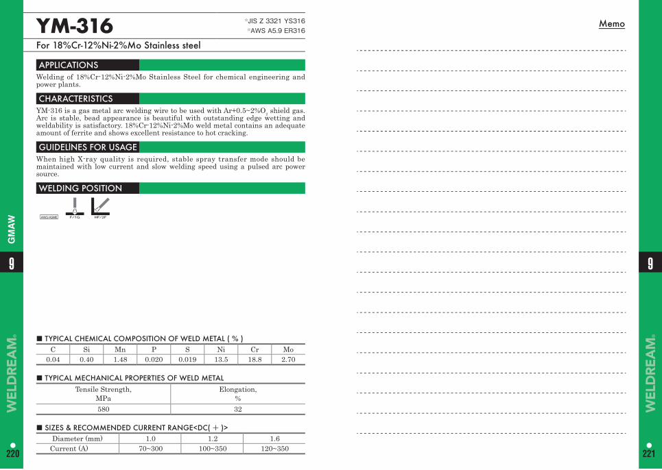
Memo
■ TYPICAL CHEMICAL COMPOSITION OF WELD METAL ( % ) C Si Mn P S Ni Cr Mo
0.04 0.40 1.48 0.020 0.019 13.5 18.8 2.70
YM-316 ☆JIS Z 3321 YS316☆AWS A5.9 ER316
For 18%Cr-12%Ni-2%Mo Stainless steel
APPLICATIONS Welding of 18%Cr-12%Ni-2%Mo Stainless Steel for chemical engineering and power plants.
CHARACTERISTICS YM-316 is a gas metal arc welding wire to be used with Ar+0.5~2%O2 shield gas. Arc is stable, bead appearance is beautiful with outstanding edge wetting and weldability is satisfactory. 18%Cr-12%Ni-2%Mo weld metal contains an adequate amount of ferrite and shows excellent resistance to hot cracking.
GUIDELlNES FOR USAGE When high X-ray quality is required, stable spray transfer mode should be maintained with low current and slow welding speed using a pulsed arc power source.
WELDING POSITION
AWS/ASME F/1G HF/2F
■ TYPICAL MECHANICAL PROPERTIES OF WELD METAL Tensile Strength,
MPa Elongation,
%580 32
■ SIZES & RECOMMENDED CURRENT RANGE<DC( + )> Diameter (mm) 1.0 1.2 1.6
Current (A) 70~300 100~350 120~350
9
220
9
221
GM
AW
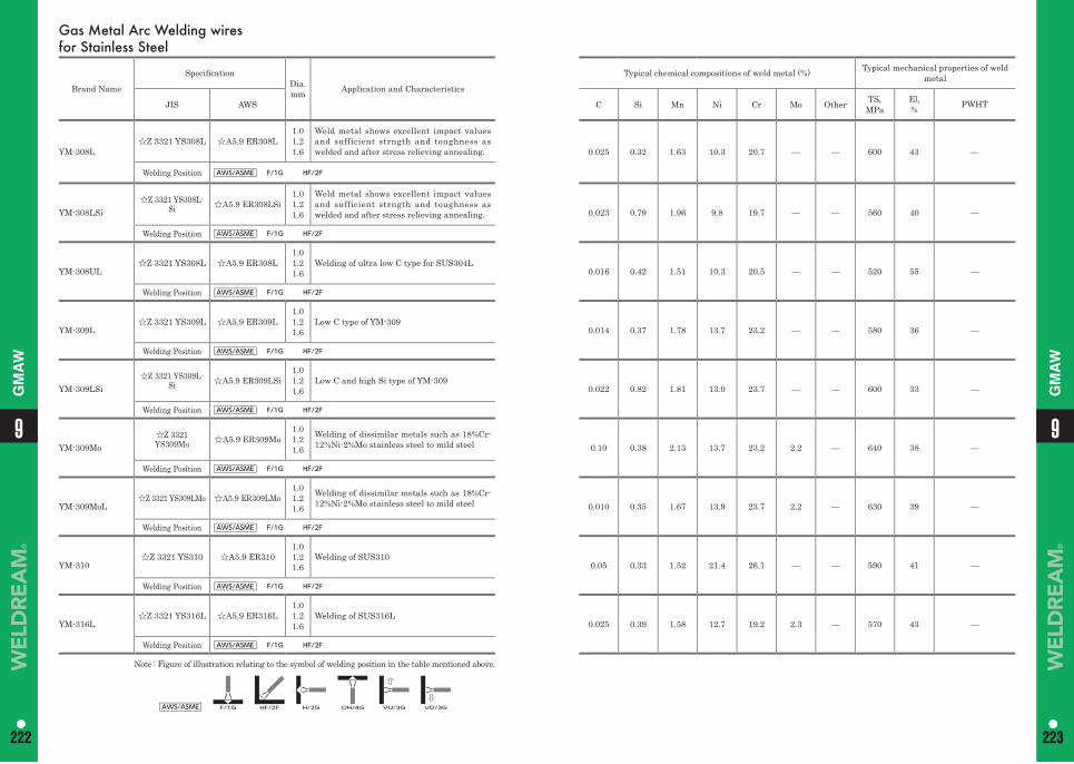
Gas Metal Arc Welding wires for Stainless Steel
Brand Name
Specifi cationDia.mm Application and Characteristics
Typical chemical compositions of weld metal (%) Typical mechanical properties of weld metal
JIS AWS C Si Mn Ni Cr Mo Other TS,MPa
El,% PWHT
YM-308L☆Z 3321 YS308L ☆A5.9 ER308L
1.01.21.6
Weld metal shows excellent impact values and sufficient strngth and toughness as welded and after stress relieving annealing. 0.025 0.32 1.63 10.3 20.7 — — 600 43 —
Welding Position AWS/ASME F/1G HF/2F
YM-308LSi☆Z 3321 YS308L-
Si ☆A5.9 ER308LSi1.01.21.6
Weld metal shows excellent impact values and sufficient strngth and toughness as welded and after stress relieving annealing. 0.023 0.79 1.96 9.8 19.7 — — 560 40 —
Welding Position AWS/ASME F/1G HF/2F
YM-308UL☆Z 3321 YS308L ☆A5.9 ER308L
1.01.21.6
Welding of ultra low C type for SUS304L0.016 0.42 1.51 10.3 20.5 — — 520 55 —
Welding Position AWS/ASME F/1G HF/2F
YM-309L☆Z 3321 YS309L ☆A5.9 ER309L
1.01.21.6
Low C type of YM-3090.014 0.37 1.78 13.7 23.2 — — 580 36 —
Welding Position AWS/ASME F/1G HF/2F
YM-309LSi☆Z 3321 YS309L-
Si ☆A5.9 ER309LSi1.01.21.6
Low C and high Si type of YM-3090.022 0.82 1.81 13.0 23.7 — — 600 33 —
Welding Position AWS/ASME F/1G HF/2F
YM-309Mo☆Z 3321 YS309Mo ☆A5.9 ER309Mo
1.01.21.6
Welding of dissimilar metals such as 18%Cr-12%Ni-2%Mo stainless steel to mild steel 0.10 0.38 2.13 13.7 23.2 2.2 — 640 38 —
Welding Position AWS/ASME F/1G HF/2F
YM-309MoL☆Z 3321 YS309LMo ☆A5.9 ER309LMo
1.01.21.6
Welding of dissimilar metals such as 18%Cr-12%Ni-2%Mo stainless steel to mild steel 0.010 0.35 1.67 13.9 23.7 2.2 — 630 39 —
Welding Position AWS/ASME F/1G HF/2F
YM-310☆Z 3321 YS310 ☆A5.9 ER310
1.01.21.6
Welding of SUS3100.05 0.33 1.52 21.4 26.1 — — 590 41 —
Welding Position AWS/ASME F/1G HF/2F
YM-316L☆Z 3321 YS316L ☆A5.9 ER316L
1.01.21.6
Welding of SUS316L0.025 0.39 1.58 12.7 19.2 2.3 — 570 43 —
Welding Position AWS/ASME F/1G HF/2F
Note : Figure of illustration relating to the symbol of welding position in the table mentioned above.
AWS/ASME F/1G HF/2F H/2G OH/4G VU/3G VD/3G
99
222 223222 223
GM
AW
GM
AW
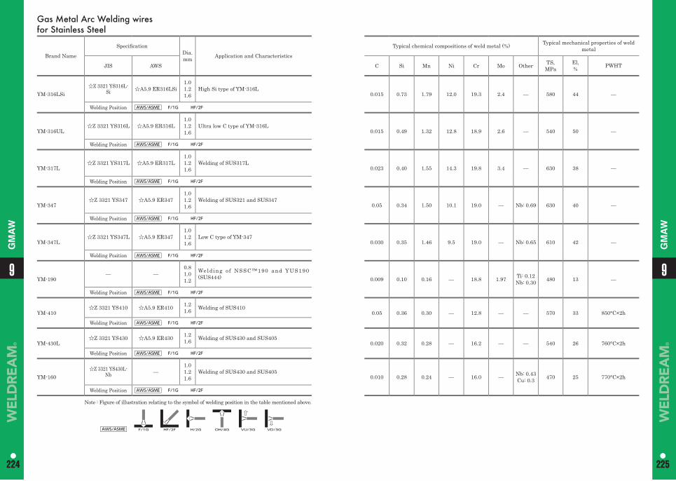
99
224 225224 225
GM
AW
GM
AW
Gas Metal Arc Welding wires for Stainless Steel
Brand Name
Specifi cationDia.mm Application and Characteristics
Typical chemical compositions of weld metal (%) Typical mechanical properties of weld metal
JIS AWS C Si Mn Ni Cr Mo Other TS,MPa
El,% PWHT
YM-316LSi☆Z 3321 YS316L-
Si ☆A5.9 ER316LSi1.01.21.6
High Si type of YM-316L0.015 0.73 1.79 12.0 19.3 2.4 — 580 44 —
Welding Position AWS/ASME F/1G HF/2F
YM-316UL☆Z 3321 YS316L ☆A5.9 ER316L
1.01.21.6
Ultra low C type of YM-316L0.015 0.49 1.32 12.8 18.9 2.6 — 540 50 —
Welding Position AWS/ASME F/1G HF/2F
YM-317L☆Z 3321 YS317L ☆A5.9 ER317L
1.01.21.6
Welding of SUS317L0.023 0.40 1.55 14.3 19.8 3.4 — 630 38 —
Welding Position AWS/ASME F/1G HF/2F
YM-347☆Z 3321 YS347 ☆A5.9 ER347
1.01.21.6
Welding of SUS321 and SUS3470.05 0.34 1.50 10.1 19.0 — Nb: 0.69 630 40 —
Welding Position AWS/ASME F/1G HF/2F
YM-347L☆Z 3321 YS347L ☆A5.9 ER347
1.01.21.6
Low C type of YM-3470.030 0.35 1.46 9.5 19.0 — Nb: 0.65 610 42 —
Welding Position AWS/ASME F/1G HF/2F
YM-190— —
0.81.01.2
Weld ing o f NSSC™190 and YUS190 (SUS444) 0.009 0.10 0.16 — 18.8 1.97 Ti: 0.12
Nb: 0.30 480 13 —
Welding Position AWS/ASME F/1G HF/2F
YM-410☆Z 3321 YS410 ☆A5.9 ER410 1.2
1.6 Welding of SUS4100.05 0.36 0.30 — 12.8 — — 570 33 850°C×2h
Welding Position AWS/ASME F/1G HF/2F
YM-430L☆Z 3321 YS430 ☆A5.9 ER430 1.2
1.6 Welding of SUS430 and SUS4050.020 0.32 0.28 — 16.2 — — 540 26 760°C×2h
Welding Position AWS/ASME F/1G HF/2F
YM-160☆Z 3321 YS430L-
Nb —1.01.21.6
Welding of SUS430 and SUS4050.010 0.28 0.24 — 16.0 — Nb: 0.43
Cu: 0.3 470 25 770°C×2h
Welding Position AWS/ASME F/1G HF/2F
Note : Figure of illustration relating to the symbol of welding position in the table mentioned above.
AWS/ASME F/1G HF/2F H/2G OH/4G VU/3G VD/3G
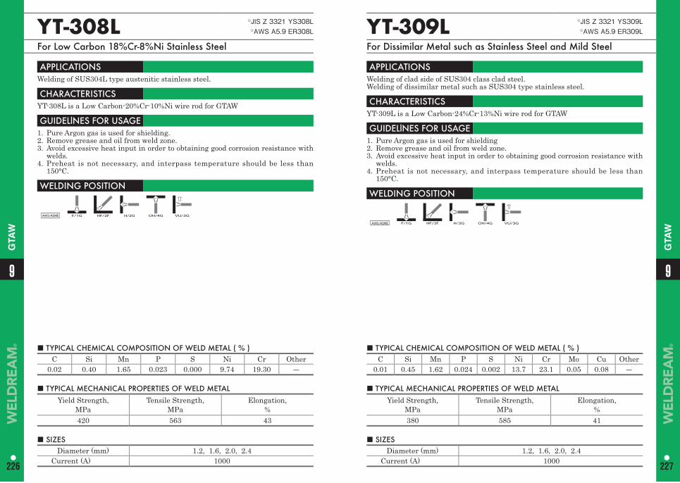
■ TYPICAL CHEMICAL COMPOSITION OF WELD METAL ( % ) C Si Mn P S Ni Cr Mo Cu Other
0.01 0.45 1.62 0.024 0.002 13.7 23.1 0.05 0.08 ―
YT-309L ☆JIS Z 3321 YS309L☆AWS A5.9 ER309L
For Dissimilar Metal such as Stainless Steel and Mild Steel
APPLICATIONS Welding of clad side of SUS304 class clad steel. Welding of dissimilar metal such as SUS304 type stainless steel.
CHARACTERISTICS YT-309L is a Low Carbon-24%Cr-13%Ni wire rod for GTAW
GUIDELlNES FOR USAGE 1. Pure Argon gas is used for shielding2. Remove grease and oil from weld zone.3. Avoid excessive heat input in order to obtaining good corrosion resistance with
welds.4. Preheat is not necessary, and interpass temperature should be less than
150°C.
WELDING POSITION
AWS/ASME F/1G HF/2F H/2G OH/4G VU/3G
■ TYPICAL CHEMICAL COMPOSITION OF WELD METAL ( % ) C Si Mn P S Ni Cr Other
0.02 0.40 1.65 0.023 0.000 9.74 19.30 ―
YT-308L ☆JIS Z 3321 YS308L☆AWS A5.9 ER308L
For Low Carbon 18%Cr-8%Ni Stainless Steel
APPLICATIONS Welding of SUS304L type austenitic stainless steel.
CHARACTERISTICS YT-308L is a Low Carbon-20%Cr-10%Ni wire rod for GTAW
GUIDELlNES FOR USAGE 1. Pure Argon gas is used for shielding.2. Remove grease and oil from weld zone.3. Avoid excessive heat input in order to obtaining good corrosion resistance with
welds.4. Preheat is not necessary, and interpass temperature should be less than
150°C.
WELDING POSITION
AWS/ASME F/1G HF/2F H/2G OH/4G VU/3G
■ TYPICAL MECHANICAL PROPERTIES OF WELD METAL Yield Strength,
MPaTensile Strength,
MPa Elongation,
%420 563 43
■ TYPICAL MECHANICAL PROPERTIES OF WELD METAL Yield Strength,
MPaTensile Strength,
MPa Elongation,
%380 585 41
■ SIZES Diameter (mm) 1.2, 1.6, 2.0, 2.4
Current (A) 1000
■ SIZES Diameter (mm) 1.2, 1.6, 2.0, 2.4
Current (A) 1000
99
226 227
GTA
W
GTA
W
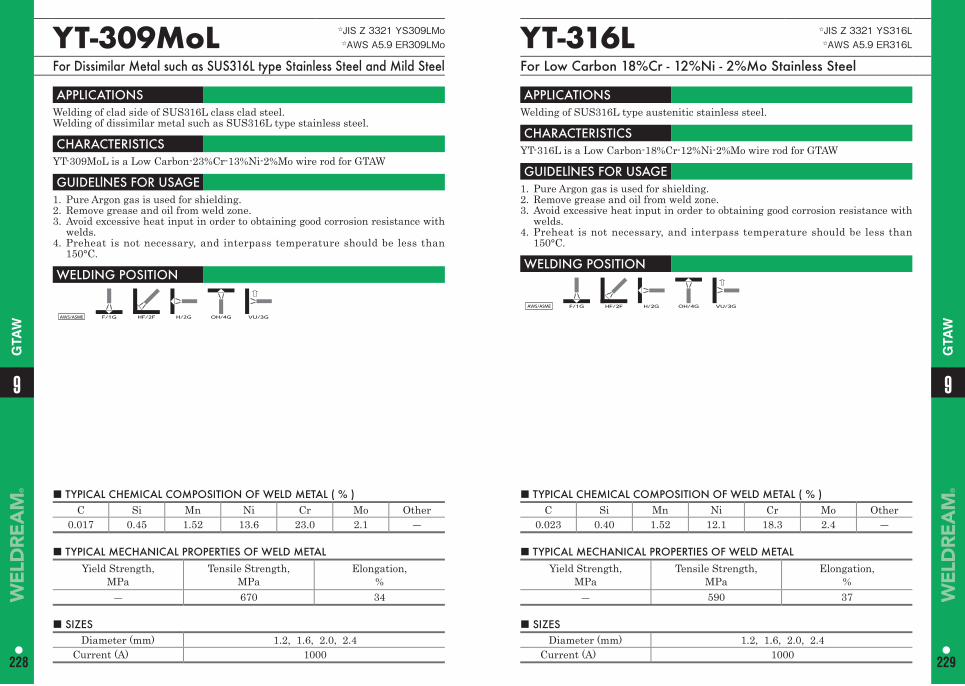
■ TYPICAL CHEMICAL COMPOSITION OF WELD METAL ( % ) C Si Mn Ni Cr Mo Other
0.023 0.40 1.52 12.1 18.3 2.4 ―
YT-316L ☆JIS Z 3321 YS316L☆AWS A5.9 ER316L
For Low Carbon 18%Cr - 12%Ni - 2%Mo Stainless Steel
APPLICATIONS Welding of SUS316L type austenitic stainless steel.
CHARACTERISTICS YT-316L is a Low Carbon-18%Cr-12%Ni-2%Mo wire rod for GTAW
GUIDELlNES FOR USAGE 1. Pure Argon gas is used for shielding.2. Remove grease and oil from weld zone.3. Avoid excessive heat input in order to obtaining good corrosion resistance with
welds.4. Preheat is not necessary, and interpass temperature should be less than
150°C.
WELDING POSITION
AWS/ASME F/1G HF/2F H/2G OH/4G VU/3G
■ TYPICAL CHEMICAL COMPOSITION OF WELD METAL ( % ) C Si Mn Ni Cr Mo Other
0.017 0.45 1.52 13.6 23.0 2.1 ―
YT-309MoL ☆JIS Z 3321 YS309LMo☆AWS A5.9 ER309LMo
For Dissimilar Metal such as SUS316L type Stainless Steel and Mild Steel
APPLICATIONS Welding of clad side of SUS316L class clad steel. Welding of dissimilar metal such as SUS316L type stainless steel.
CHARACTERISTICS YT-309MoL is a Low Carbon-23%Cr-13%Ni-2%Mo wire rod for GTAW
GUIDELlNES FOR USAGE 1. Pure Argon gas is used for shielding.2. Remove grease and oil from weld zone.3. Avoid excessive heat input in order to obtaining good corrosion resistance with
welds.4. Preheat is not necessary, and interpass temperature should be less than
150°C.
WELDING POSITION
AWS/ASME F/1G HF/2F H/2G OH/4G VU/3G
■ TYPICAL MECHANICAL PROPERTIES OF WELD METAL Yield Strength,
MPaTensile Strength,
MPa Elongation,
%― 670 34
■ TYPICAL MECHANICAL PROPERTIES OF WELD METAL Yield Strength,
MPaTensile Strength,
MPa Elongation,
%― 590 37
■ SIZES Diameter (mm) 1.2, 1.6, 2.0, 2.4
Current (A) 1000
■ SIZES Diameter (mm) 1.2, 1.6, 2.0, 2.4
Current (A) 1000
99
228 229
GTA
W
GTA
W
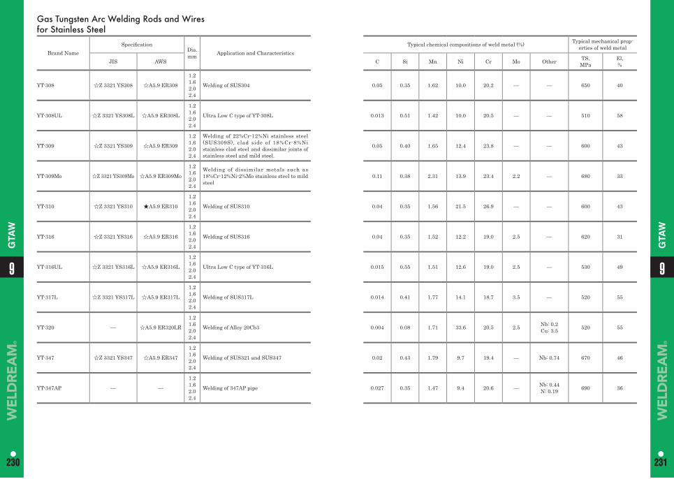
99
230 231230 231
GTA
W
GTA
W
Gas Tungsten Arc Welding Rods and Wires for Stainless Steel
Brand NameSpecifi cation
Dia.mm Application and Characteristics
Typical chemical compositions of weld metal (%) Typical mechanical prop-erties of weld metal
JIS AWS C Si Mn Ni Cr Mo Other TS,MPa
El,%
YT-308 ☆Z 3321 YS308 ☆A5.9 ER308
1.21.62.02.4
Welding of SUS304 0.05 0.35 1.62 10.0 20.2 — — 650 40
YT-308UL ☆Z 3321 YS308L ☆A5.9 ER308L
1.21.62.02.4
Ultra Low C type of YT-308L 0.013 0.51 1.42 10.0 20.5 — — 510 58
YT-309 ☆Z 3321 YS309 ☆A5.9 ER309
1.21.62.02.4
Welding of 22%Cr-12%Ni stainless steel (SUS309S), clad side of 18%Cr-8%Ni stainless clad steel and dissimilar joints of stainless steel and mild steel.
0.05 0.40 1.65 12.4 23.8 — — 600 43
YT-309Mo ☆Z 3321 YS309Mo ☆A5.9 ER309Mo
1.21.62.02.4
Welding of dissimilar metals such as 18%Cr-12%Ni-2%Mo stainless steel to mild steel
0.11 0.38 2.31 13.9 23.4 2.2 — 680 33
YT-310 ☆Z 3321 YS310 ★A5.9 ER310
1.21.62.02.4
Welding of SUS310 0.04 0.35 1.56 21.5 26.9 — — 600 43
YT-316 ☆Z 3321 YS316 ☆A5.9 ER316
1.21.62.02.4
Welding of SUS316 0.04 0.35 1.52 12.2 19.0 2.5 — 620 31
YT-316UL ☆Z 3321 YS316L ☆A5.9 ER316L
1.21.62.02.4
Ultra Low C type of YT-316L 0.015 0.55 1.51 12.6 19.0 2.5 — 530 49
YT-317L ☆Z 3321 YS317L ☆A5.9 ER317L
1.21.62.02.4
Welding of SUS317L 0.014 0.41 1.77 14.1 18.7 3.5 — 520 55
YT-320 — ☆A5.9 ER320LR
1.21.62.02.4
Welding of Alloy 20Cb3 0.004 0.08 1.71 33.6 20.5 2.5 Nb: 0.2Cu: 3.5 520 55
YT-347 ☆Z 3321 YS347 ☆A5.9 ER347
1.21.62.02.4
Welding of SUS321 and SUS347 0.02 0.43 1.79 9.7 19.4 — Nb: 0.74 670 46
YT-347AP — —
1.21.62.02.4
Welding of 347AP pipe 0.027 0.35 1.47 9.4 20.6 — Nb: 0.44N: 0.19 690 36
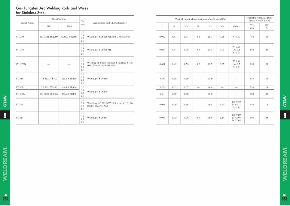
99
232 233232 233
GTA
W
GTA
W
Gas Tungsten Arc Welding Rods and Wires for Stainless Steel
Brand NameSpecifi cation
Dia.mm Application and Characteristics
Typical chemical compositions of weld metal (%) Typical mechanical prop-erties of weld metal
JIS AWS C Si Mn Ni Cr Mo Other TS,MPa
El,%
YT-DP8 ☆Z 3321 YS2209 ☆A5.9 ER2209
1.21.62.02.4
Welding of SUS329J3L and UNS S31803 0.007 0.41 1.61 8.4 22.1 3.26 N: 0.10 780 35
YT-DP3 — —
1.21.62.02.4
Welding of SUS329J4L 0.010 0.37 0.78 9.3 25.3 3.03W: 0.27Cu: 0.4N: 0.17
830 29
YT-DP3W — —
1.01.21.62.02.4
Welding of Super Duplex Stainless Steel (DP3W tube, NAR-DP3W) 0.017 0.42 0.53 9.2 25.7 3.07
W: 2.11Cu: 0.5N: 0.28
890 29
YT-410 ☆Z 3321 YS410 ☆A5.9 ER410
1.21.62.02.4
Welding of SUS410 0.06 0.38 0.30 — 12.9 — — 520 33
YT-430 ☆Z 3321 YS430 ☆A5.9 ER430 1.21.62.02.4
Welding of SUS430
0.05 0.33 0.37 — 16.8 — — 530 28
YT-430L ☆Z 3321 YS430L ☆A5.9 ER430 0.01 0.39 0.49 — 16.8 — — 520 30
YT-190 — —
1.21.62.02.4
Welding of NSSC™190 and YUS190 (190Cr-2Mo-Ti, Nb) 0.008 0.09 0.16 — 19.2 1.93
Nb: 0.30N: 0.011Ti: 0.13
480 12
YT-444 — —
1.21.62.02.4
Welding of SUS444 0.004 0.02 0.06 0.5 19.0 2.14Nb: 0.29N: 0.005O: 0.002
500 28
Memo
9
234
235
Special AlloyCovered Arc Welding ElectrodesSubmerged Arc Welding MaterialsGas Tungsten Arc Welding Rods and Wires
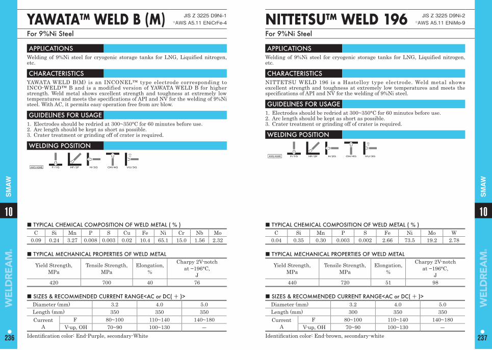
1010
236 237
SM
AW
SM
AW
■ TYPICAL CHEMICAL COMPOSITION OF WELD METAL ( % ) C Si Mn P S Cu Fe Ni Cr Nb Mo
0.09 0.24 3.27 0.008 0.003 0.02 10.4 65.1 15.0 1.56 2.32
YAWATA™ WELD B (M) JIS Z 3225 D9Ni-1☆AWS A5.11 ENiCrFe-4
For 9%Ni Steel
APPLICATIONS Welding of 9%Ni steel for cryogenic storage tanks for LNG, Liquified nitrogen, etc.
CHARACTERISTICS YAWATA WELD B(M) is an INCONEL™ type electrode corresponding to INCO-WELD™ B and is a modified version of YAWATA WELD B for higher strength. Weld metal shows excellent strength and toughness at extremely low temperatures and meets the specifications of API and NV for the welding of 9%Ni steel. With AC, it permits easy operation free from arc blow.
GUIDELlNES FOR USAGE 1. Electrodes should be redried at 300~350°C for 60 minutes before use. 2. Arc length should be kept as short as possible. 3. Crater treatment or grinding off of crater is required.
WELDING POSITION
AWS/ASME F/1G HF/2F H/2G OH/4G VU/3G
■ TYPICAL MECHANICAL PROPERTIES OF WELD METAL
Yield Strength,MPa
Tensile Strength,MPa
Elongation,%
Charpy 2V-notchat −196°C,
J420 700 40 76
■ SIZES & RECOMMENDED CURRENT RANGE<AC or DC( + )> Diameter (mm) 3.2 4.0 5.0Length (mm) 350 350 350Current
AF 80~100 110~140 140~180
V-up, OH 70~90 100~130 ―Identifi cation color: End-Purple, secondary-White
NITTETSU™ WELD 196 JIS Z 3225 D9Ni-2☆AWS A5.11 ENiMo-9
For 9%Ni Steel
APPLICATIONS Welding of 9%Ni steel for cryogenic storage tanks for LNG, Liquified nitrogen, etc.
CHARACTERISTICS NITTETSU WELD 196 is a Hastelloy type electrode. Weld metal shows excellent strength and toughness at extremely low temperatures and meets the specifications of API and NV for the welding of 9%Ni steel.
GUIDELlNES FOR USAGE 1. Electrodes should be redried at 300~350°C for 60 minutes before use. 2. Arc length should be kept as short as possible. 3. Crater treatment or grinding off of crater is required.
WELDING POSITION
AWS/ASME F/1G HF/2F H/2G OH/4G VU/3G
■ TYPICAL CHEMICAL COMPOSITION OF WELD METAL ( % ) C Si Mn P S Fe Ni Mo W
0.04 0.35 0.30 0.003 0.002 2.66 73.5 19.2 2.78
■ TYPICAL MECHANICAL PROPERTIES OF WELD METAL
Yield Strength,MPa
Tensile Strength,MPa
Elongation,%
Charpy 2V-notchat −196°C,
J440 720 51 98
■ SIZES & RECOMMENDED CURRENT RANGE<AC or DC( + )> Diameter (mm) 3.2 4.0 5.0Length (mm) 300 350 350Current
AF 80~100 110~140 140~180
V-up, OH 70~90 100~130 ―Identifi cation color: End-brown, secondary-white
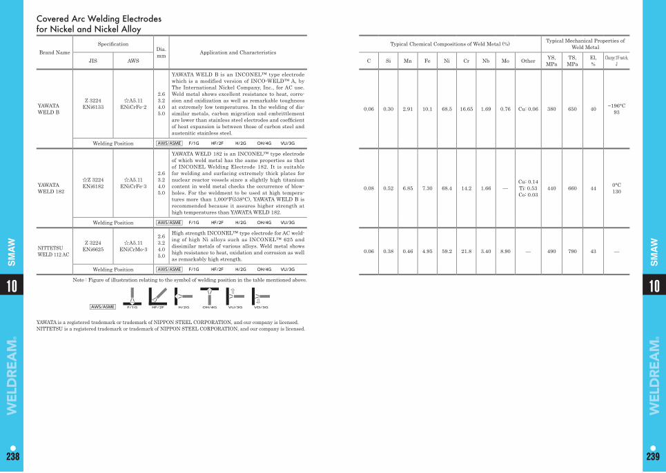
YAWATA is a registered trademark or trademark of NIPPON STEEL CORPORATION, and our company is licensed.NITTETSU is a registered trademark or trademark of NIPPON STEEL CORPORATION, and our company is licensed.
1010
238 239238 239
SM
AW
SM
AW
Covered Arc Welding Electrodes for Nickel and Nickel Alloy
Brand NameSpecifi cation
Dia.mm Application and Characteristics
Typical Chemical Compositions of Weld Metal (%) Typical Mechanical Properties of Weld Metal
JIS AWS C Si Mn Fe Ni Cr Nb Mo Other YS,MPa
TS,MPa
El,%
Charpy 2V-notch,J
YAWATA WELD B
Z 3224 ENi6133
☆A5.11 ENiCrFe-2
2.63.24.05.0
YAWATA WELD B is an INCONEL™ type electrode which is a modified version of INCO-WELD™ A, by The International Nickel Company, Inc., for AC use. Weld metal shows excellent resistance to heat, corro-sion and oxidization as well as remarkable toughness at extremely low temperatures. In the welding of dis-similar metals, carbon migration and embrittlement are lower than stainless steel electrodes and coeffi cient of heat expansion is between those of carbon steel and austenitic stainless steel.
0.06 0.30 2.91 10.1 68.5 16.65 1.69 0.76 Cu: 0.06 380 650 40 −196°C93
Welding Position AWS/ASME F/1G HF/2F H/2G OH/4G VU/3G
YAWATA WELD 182
☆Z 3224 ENi6182
☆A5.11 ENiCrFe-3
2.63.24.05.0
YAWATA WELD 182 is an INCONEL™ type electrode of which weld metal has the same properties as that of INCONEL Welding Electrode 182. It is suitable for welding and surfacing extremely thick plates for nuclear reactor vessels since a slightly high titanium content in weld metal checks the occurrence of blow-holes. For the weldment to be used at high tempera-tures more than 1,000°F(538°C), YAWATA WELD B is recommended because it assures higher strength at high temperatures than YAWATA WELD 182.
0.08 0.52 6.85 7.30 68.4 14.2 1.66 —Cu: 0.14Ti: 0.53Co: 0.03
440 660 44 0°C130
Welding Position AWS/ASME F/1G HF/2F H/2G OH/4G VU/3G
NITTETSU WELD 112 AC
Z 3224 ENi6625
☆A5.11 ENiCrMo-3
2.63.24.05.0
High strength INCONEL™ type electrode for AC weld-ing of high Ni alloys such as INCONEL™ 625 and dissimilar metals of various alloys. Weld metal shows high resistance to heat, oxidation and corrosion as well as remarkably high strength.
0.06 0.38 0.46 4.95 59.2 21.8 3.40 8.90 — 490 790 43 —
Welding Position AWS/ASME F/1G HF/2F H/2G OH/4G VU/3G
Note : Figure of illustration relating to the symbol of welding position in the table mentioned above.
AWS/ASME F/1G HF/2F H/2G OH/4G VU/3G VD/3G
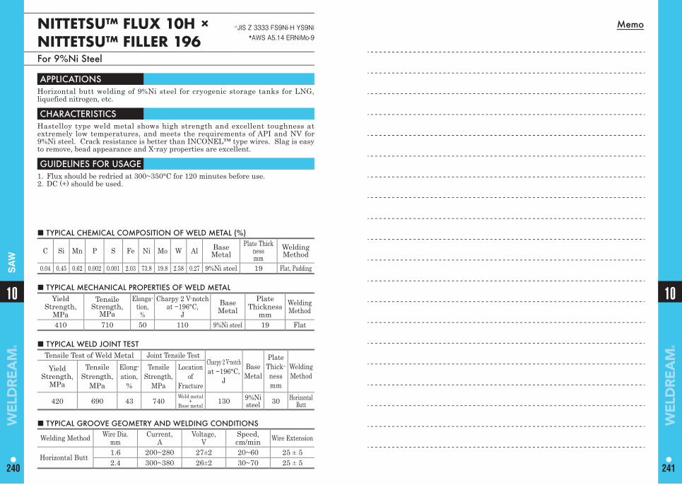
Memo
10
240
10
241
SA
W
NITTETSU™ FLUX 10H ×NITTETSU™ FILLER 196
☆JIS Z 3333 FS9Ni-H YS9Ni ★AWS A5.14 ERNiMo-9
For 9%Ni Steel
■ TYPICAL CHEMICAL COMPOSITION OF WELD METAL (%)
C Si Mn P S Fe Ni Mo W Al Base Metal
Plate Thicknessmm
Welding Method
0.04 0.45 0.62 0.002 0.001 2.03 73.8 19.8 2.58 0.27 9%Ni steel 19 Flat, Padding
APPLICATIONS Horizontal butt welding of 9%Ni steel for cryogenic storage tanks for LNG, liquefied nitrogen, etc.
CHARACTERISTICS Hastelloy type weld metal shows high strength and excellent toughness at extremely low temperatures, and meets the requirements of API and NV for 9%Ni steel. Crack resistance is better than INCONEL™ type wires. Slag is easy to remove, bead appearance and X-ray properties are excellent.
GUIDELlNES FOR USAGE 1. Flux should be redried at 300~350°C for 120 minutes before use.2. DC (+) should be used.
■ TYPICAL MECHANICAL PROPERTIES OF WELD METAL Yield
Strength, MPa
Tensile Strength,
MPa
Elonga-tion,
%
Charpy 2 V-notchat −196°C,
JBaseMetal
Plate Thickness
mmWelding Method
410 710 50 110 9%Ni steel 19 Flat
■ TYPICAL GROOVE GEOMETRY AND WELDING CONDITIONS
Welding Method Wire Dia.mm
Current, A
Voltage,V
Speed,cm/min Wire Extension
Horizontal Butt 1.6 200~280 27±2 20~60 25 ± 52.4 300~380 26±2 30~70 25 ± 5
■ TYPICAL WELD JOINT TEST Tensile Test of Weld Metal Joint Tensile Test
Charpy 2 V-notchat −196°C,
J
BaseMetal
Plate Thick-nessmm
Welding Method
Yield Strength,
MPa
Tensile Strength,
MPa
Elong-ation,
%
Tensile Strength,
MPa
Locationof
Fracture
420 690 43 740Weld metal
+Base metal
130 9%Ni steel 30 Horizontal
Butt
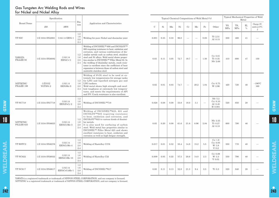
YAWATA is a registered trademark or trademark of NIPPON STEEL CORPORATION, and our company is licensed.NITTETSU is a registered trademark or trademark of NIPPON STEEL CORPORATION, and our company is licensed.
1010
242 243242 243
GTA
W
GTA
WGas Tungsten Arc Welding Rods and Wires for Nickel and Nickel Alloy
Brand Name
Specifi cationDia.mm Application and Characteristics
Typical Chemical Compositions of Weld Metal (%) Typical Mechanical Properties of Weld Metal
JIS AWS C Si Mn Ni Cr Mo Fe Other YS,MPa
TS,MPa
El,%
Charpy 2V-notch at 0°C,
J
YT-NIC ☆Z 3334 SNi2061 ☆A5.14 ERNi-1
1.21.62.02.4
Welding for pure Nickel and dissimilar joint 0.001 0.35 0.33 96.0 — — 0.05 Ti: 2.51Al: 0.15 230 460 41 —
YAWATA FILLER 82 ☆Z 3334 SNi6082 ☆A5.14
ERNiCr-3
1.21.62.02.4
Welding of INCONEL™ 600 and INCOLOY™ 800 requiring resistance to heat, oxidation and corrosion, and various combinations of dis-similar metals such as carbon steel, stainless steel and Ni alloys. Weld metal shows proper-ties similar to INCONEL™ Filler Metal 82. In the welding of dissimilar metals, crack resis-tance is excellent since the coeffi cient of heat expansion is between those of carbon steel and austenitic stainless steel.
0.03 0.11 3.05 72.7 19.7 — 1.50Co: 0.01Ti: 0.35Nb: 2.68
410 680 47 150
NITTETSU FILLER 196
☆Z3332 YGT9Ni-2
☆A5.14 ERNiMo-9
1.21.62.02.4
Welding of 9%Ni steel to be used at ex-tremely low temperatures for storage tanks for LNG and liquefied nitrogen gas and LNG tankers.Weld metal shows high strength and excel-lent toughness at extremely low tempera-tures, and meets the requirements of API and NV. Crack resistance is also excellent.
0.02 0.01 0.03 74.7 — 20.2 1.04 Cu: 0.75W: 2.96 420 720 46 −196°C
160
YT-NC718 ☆Z 3334 SNi7718 ☆A5.14 ERNiFeCr-2
1.21.62.02.4
Welding of INCONEL™718 0.028 0.08 0.08 53.8 18.0 3.1 —
Nb: 5.2Cu: 0.10Al: 0.45B: 0.001
520 850 28 —
NITTETSU FILLER 625 ☆Z 3334 SNi6625 ☆A5.14
ERNiCrMo-3
1.21.62.02.4
Welding of INCONEL™625, 601 and INCOLOY™825 requiring resistance to heat, oxidation and corrosion, and INCOLOY™825 to various kinds of dissimi-lar metals.It is also used for surfacing of carbon steel. Weld metal has properties similar to INCONEL™ Filler Metal 625 and shows excellent resistance to heat, oxidation and corrosion as well as high fatigue strength.
0.02 0.20 0.08 61.6 21.8 8.96 2.84Nb: 3.55Ti: 0.27Al: 0.18
600 790 46 —
YT-HSTC2 ☆Z 3334 SNi6276 ☆A5.14 ERNiCrMo-4
1.21.62.02.4
Welding of Hastelloy C276 0.017 0.01 0.52 55.4 14.8 15.2 5.5
Co: 1.9Cu: 0.05W: 3.8V: 0.2
550 770 40 —
YT-NC622 ☆Z 3334 SNi6022 ☆A5.14 ERNiCrMo-10
1.21.62.02.4
Welding of Hastelloy C22 0.009 0.05 0.22 57.5 20.6 14.0 2.3Co: 0.09W: 3.3V: 0.01
550 790 40 —
YT-NC617 ☆Z 3334 SNi6617 ☆A5.14 ERNiCrCoMo-1
1.21.62.02.4
Welding of INCONEL™617 0.08 0.11 0.13 52.8 21.3 9.4 0.5 Ti: 0.3 520 840 28 —
Memo
10
244
245
Surfacing·Cast IronCovered Arc Welding Electrodes
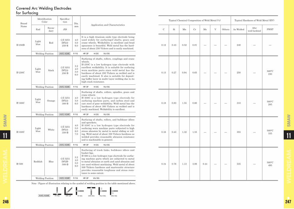
1111
246 247246 247
SM
AW
SM
AW
Covered Arc Welding Electrodes for Surfacing
Brand Name
ldentifi cation Color
Specifi ca-tion Dia.
mm Application and Characteristics
End Secon-dary JIS
H-250BLightblue Red
☆Z 3251 DF2A-250-R
4.0 5.0 6.0
It is a high titanium oxide type electrode being used widely for surfacingof shafts, gears and crane wheels. Weldability is excellent and bead apearance is beautiful. Weld metal has the hard-ness of about 250 Vickers and is easily machined.
Welding Position AWS/ASME F/1G HF/2F H/2G VU/3G
H-250CLightblue black
☆Z 3251 DF2A-250-B
3.24.05.06.0
Surfacing of shafts, rollers, couplings and crane wheels. H-250C is a low hydrogen type electrode with excellent weldability. It is suitable for surfacing worn machine parts since weld metal has the hardness of about 250 Vickers as welded and is easily machined. It also is suitable for deposit-ing buffer layer in multi-1ayer welding due to its high crack resistance.
Welding Position AWS/ASME F/1G HF/2F H/2G VU/3G
H-300CLightblue Orange
☆Z 3251 DF2A-300-B
4.05.06.0
Surfacing of shafts, rollers, spindles, gears and crane wheels H-300C is a low hydrogen type electrode for surfacing machine parts, and carbon steel and cast steel of poor weldability. Weld metal has the hardness of about 300 Vickers as welded and is easily machined. Weldability is excellent.
Welding Position AWS/ASME F/1G HF/2F H/2G VU/3G
H-350CLightblue White
☆Z 3251 DF2A-350-B
4.05.06.07.0
Surfacing of shafts, rollers, and bulldozer idlers and sprockets. H-350C is a low hydrogen type electrode for surfacing worn machine parts subjected to high stress abrasion by metal to metal sliding or roll-ing. Weld metal of about 350 Vickers hardness as welded provides reasonable abrasion resistance and is machinable in general.
Welding Position AWS/ASME F/1G HF/2F H/2G VU/3G
H-500Reddish Blue
☆Z 3251 DF2B-500-B
3.24.05.06.0
Surfacing of track links, bulldozer idlers and bucket lips.H-500 is a low hydrogen type electrode for surfac-ing machine parts which are subjected to metal to metal abrasion or earth and sand abrasion and are used without machining. Weld metal of about 500 Vickers hardness and martensitic structure provides reasonable toughness and stress resis-tance to some extent.
Welding Position AWS/ASME F/1G HF/2F VU/3G
Note : Figure of illustration relating to the symbol of welding position in the table mentioned above.
AWS/ASME F/1G HF/2F H/2G OH/4G VU/3G VD/3G
Typical Chemical Composition of Weld Metal (%) Typical Hardness of Weld Metal (HV)
C Si Mn Cr Mo V Others As Welded Afterwork-hardened PWHT
0.12 0.43 0.52 0.81 ― ― ― 240 ― ―
0.13 0.27 0.94 0.65 ― ― ― 250 ― 500°C230
0.18 0.83 1.55 0.60 ― ― ― 310 ― 500°C285
0.16 0.43 1.32 1.55 ― ― ― 355 ― 500°C335
0.34 0.76 1.13 3.06 0.44 ― ― 535 ― 500°C495
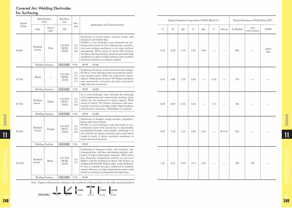
1111
248 249248 249
SM
AW
SM
AW
Typical Chemical Composition of Weld Metal (%) Typical Hardness of Weld Metal (HV)
C Si Mn Cr Mo V Others As Welded Afterwork-hardened PWHT
0.45 0.50 1.15 3.95 0.60 ― ― 625 ― 500°C605
0.64 0.90 1.23 2.58 ― 0.72 ― 710 ― ―
0.69 0.99 0.35 5.83 ― 1.71 ― 765 ― ―
0.82 1.28 1.10 8.26 0.52 ― B: 0.45 815 ― ―
1.21 0.34 0.30 13.3 0.50 ― ― 360 520 ―
Covered Arc Welding Electrodes for Surfacing
Brand Name
ldentifi cation Color
Specifi ca-tion Dia.
mm Application and Characteristics
End Secon-dary JIS
H-600Reddish brown Pink
☆Z 3251 DF2B-600-B
4.05.06.0
Surfacing of track rollers, crusher teeth, mill hammers and bucket lips. H-600 is a low hydrogen type electrode for sur-facing worn parts of civil engineering, construc-tion and mining machinery to be used without machining. Weld metal of about 600 Vickers hardness and martensitic structure provides high toughness in spite of high hardness and excellent abrasion resistance to midium impact.
Welding Position AWS/ASME F/1G HF/2F VU/3G
H-700Black ―
☆Z 3251 DF2B-700-B
4.05.06.07.0
Surfacing of mixers, screw conveyers and casings. H-700 is a low hydrogen type electrode for surfac-ing machine parts which are subjected to heavy impact. Weld metal of about 700 Vickers hardness and martensitic structure provides extremely high abrasion resistance.
Welding Position AWS/ASME F/1G HF/2F VU/3G
H-750Reddishbrown Yellow
☆Z 3251 DF3C-700-B
4.0 5.0 6.0
It is a low hydrogen type electrode for surfacing civil engineering and construction machine parts which are not subjected to heavy impact. Weld metal of about 750 Vickers hardness and mar-tensitic structure provides stably high hardness and abrasion resistance. Weldability is excellent.
Welding Position AWS/ASME F/1G HF/2F VU/3G
H-800Reddish brown Purple
☆Z 3251 DF3C-700-B
4.0 5.0 6.0
Surfacing of dredger pump mouths, impellers, liners and cutter knives. H-800 is a low hydrogen type electrode to give extremely hard weld metal due to dispersedly precipitated borides and carbides. Although it is not suitable for impact abrasion since weld metal tends to crack, it shows excellent resistance to earth and sand abrasion.
Welding Position AWS/ASME F/1G HF/2F
H-13CrReddishbrown Black
☆Z 3251 DF4B-350-B
4.0 5.0
Surfacing of hammer mills. roll crushers. hot trimming dies, roll dies and forging benches sub-jected to high temperature abrasion. Weld metal has chmeical composition similar to tool steel SKD11 and the hardness of about 350 Vickers as welded and 500-600 Vickers after work hardened. It also is suitable for parts subjected to medium impact abrasion at high temperatures since weld metal is resistant to comparatively high heat.
Welding Position AWS/ASME F/1G HF/2F
Note : Figure of illustration relating to the symbol of welding position in the table mentioned above.
AWS/ASME F/1G HF/2F H/2G OH/4G VU/3G VD/3G
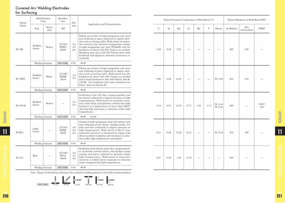
1111
250 251250 251
SM
AW
SM
AW
Covered Arc Welding Electrodes for Surfacing
Brand Name
ldentifi cation Color
Specifi ca-tion Dia.
mm Application and Characteristics
End Secon-dary JIS
H-13MReddishbrown Brown
☆Z 3251 DFMA-250-B
4.0 5.0 6.0
Filling up cavities of high manganese cast steel and surfacing of parts subjected to impact abra-sion such as boring mills. Weld metal of austen-itic structure has chemical composition similar to high manganese cast steel SCMnH2 and the hardness of about 250-300 Vickers as welded. Hardness goes up to 450-550 Vickers after work hardened and improves abrasion resistance re-markably.
Welding Position AWS/ASME F/1G HF/2F
H-13MNReddish brown White
☆Z 3251 DFMB-250-B
4.0 5.0
Filling up cavities of high manganese cast steel and surfacing of parts subjected to impact abra-sion such as boring mills. Weld metal has the hardness of about 200~250 Vickers as welded and is work hardened to 450~550 Vickers, like H-13CrM, but toughness and crack resistance are better since it contains Ni.
Welding Position AWS/ASME F/1G HF/2F
H-13CrM Reddish brown Brown ― 4.0
5.0
Surfacing of hot roll dies, tongue punches and hot shears subjected to impact abrasion at high temperataures. Weld metal of austenitic struc-ture with finely precipitated carbide has high hardness at temperatures of more than 600°C showing high resistance to abrasion under high temperatures.
Welding Position AWS/ASME F/1G HF/2F VU/3G
H-MCrLight brown ―
☆Z 3251 DFME-250-B
4.0 5.0 6.0
Joining of high manganese steel and carbon steel and surfacing of hot shears, forging molds, hot rolls and dies subjected to impact abrasion at high temperatures. Weld metal of Mn-Cr type austenitic structure is hardened by impact and shows excellent toughness and resistance to abra-sion under high temperatures and impact.
Welding Position AWS/ASME F/1G HF/2F
H-11Cr Blue ―
☆Z 3251 DF4A-500-B
3.2 4.0 5.0
Surfacing of hot shears, press dies, tongue punch-es, hydraulic turbine liners, and dredger pump casings and liners subjected to abrasion under high temperatures. Weld metal of austenitic structure a welded shows resistance to abrasion under comparatively high temperatures.
Welding Position AWS/ASME F/1G HF/2F
Note : Figure of illustration relating to the symbol of welding position in the table mentioned above.
AWS/ASME F/1G HF/2F H/2G OH/4G VU/3G VD/3G
Typical Chemical Composition of Weld Metal (%) Typical Hardness of Weld Metal (HV)
C Si Mn Cr Mo V Others As Welded Afterwork-hardened PWHT
0.49 0.16 13.9 ― ― ― ― 280 540 ―
0.90 0.26 12.61 ― ― ― Ni: 5.60 235 510 ―
0.19 0.51 12.16 13.71 1.56 1.13 Ni: 2.45 W: 3.45 295 ― 700°C
160
0.11 0.58 15.55 15.11 ― ― Ni: 2.45 215 490 ―
0.21 0.40 1.26 11.85 ― ― ― 540 ― ―
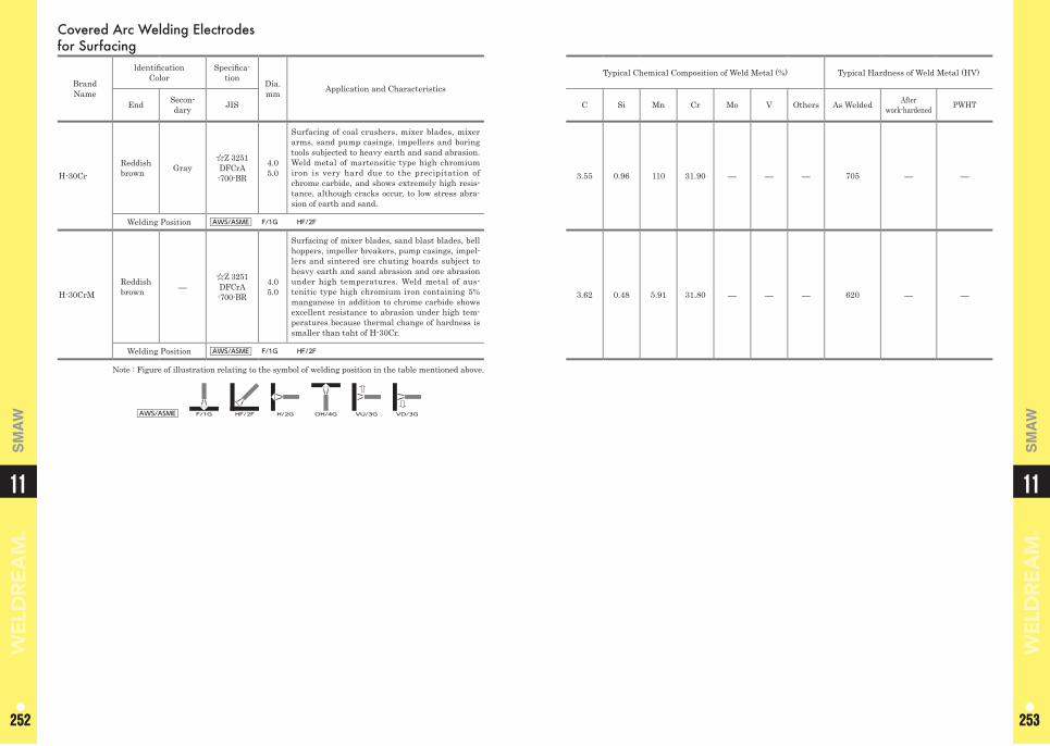
1111
252 253252 253
SM
AW
SM
AW
Covered Arc Welding Electrodes for Surfacing
Brand Name
ldentifi cation Color
Specifi ca-tion Dia.
mm Application and Characteristics
End Secon-dary JIS
H-30Cr Reddish brown Gray
☆Z 3251 DFCrA-700-BR
4.0 5.0
Surfacing of coal crushers, mixer blades, mixer arms, sand pump casings, impellers and boring tools subjected to heavy earth and sand abrasion. Weld metal of martensitic type high chromium iron is very hard due to the precipitation of chrome carbide, and shows extremely high resis-tance, although cracks occur, to low stress abra-sion of earth and sand.
Welding Position AWS/ASME F/1G HF/2F
H-30CrM Reddish brown ―
☆Z 3251 DFCrA-700-BR
4.0 5.0
Surfacing of mixer blades, sand blast blades, bell hoppers, impeller breakers, pump casings, impel-lers and sintered ore chuting boards subject to heavy earth and sand abrasion and ore abrasion under high temperatures. Weld metal of aus-tenitic type high chromium iron containing 5% manganese in addition to chrome carbide shows excellent resistance to abrasion under high tem-peratures because thermal change of hardness is smaller than taht of H-30Cr.
Welding Position AWS/ASME F/1G HF/2F
Note : Figure of illustration relating to the symbol of welding position in the table mentioned above.
AWS/ASME F/1G HF/2F H/2G OH/4G VU/3G VD/3G
Typical Chemical Composition of Weld Metal (%) Typical Hardness of Weld Metal (HV)
C Si Mn Cr Mo V Others As Welded Afterwork-hardened PWHT
3.55 0.96 110 31.90 ― ― ― 705 ― ―
3.62 0.48 5.91 31.80 ― ― ― 620 ― ―
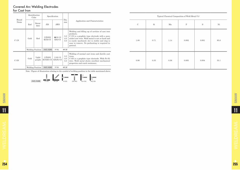
1111
254 255254 255
SM
AW
SM
AW
Covered Arc Welding Electrodes for Cast Iron
Brand Name
ldentifi cation Color Specifi cation
Dia. mm Application and Characteristics
Typical Chemical Composition of Weld Metal (%)
End Secon-dary JIS AWS C Si Mn P S Ni
C-1NGold Red ☆Z3252
ECNi-CI★A5.15ENi-CI
3.24.05.0
Welding and fi lling up of cavities of cast iron products. C-1N is a graphite type electrode with a pure nickel core wire. Weld metal is not so hard and is easily machined. Arc is stable and slag is easy to remove. No preheating is required in general.
1.00 0.71 1.14 0.002 0.001 95.8
Welding Position AWS/ASME F/1G HF/2F
C-5NGold Light
purple☆Z3252
ECNiFe-CI☆A5.15
ENiFe-CI
3.24.05.0
Welding of normal cast irons and ductile cast irons. C-5N is a graphite type electrode. With Fe-Ni wire. Weld metal shows excellent mechanical properties and crack resistance.
0.90 0.35 0.56 0.005 0.004 55.1
Welding Position AWS/ASME F/1G HF/2F
Note : Figure of illustration relating to the symbol of welding position in the table mentioned above.
AWS/ASME F/1G HF/2F H/2G OH/4G VU/3G VD/3G
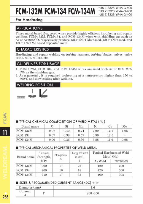
11
256
FC
AW
FCM-132M FCM-134 FCM-134M☆JIS Z 3326 YF4A-G-400 ☆JIS Z 3326 YF4A-G-400 ☆JIS Z 3326 YF4A-G-400
For Hardfacing
APPLICATIONS These metal-based flux cored wires provide highly efficient hardfacing and repair welding. FCM-132M, FCM-134, and FCM-134M wires with shielding gas such as Ar or Ar-20%CO2 respectively produce 13Cr-2Ni-1 Mo-based, 13Cr-4Ni-based, and 13Cr-4Ni-1Mo based deposited metal.
CHARACTERISTICS Hardfacing and repair welding on turbine runners, turbine blades, valves, valve seats, rolls, rollers, etc.
GUIDELlNES FOR USAGE 1. FCM-132M, FCM-134, and FCM-134M wires are used with Ar or 80%+20%
CO2 as the shielding gas.2. As a general , it is required preheating at a temperature higher than 150 to
300°C and slow cooling after welding.
WELDING POSITION
AWS/ASME F/1G HF/2G
■ TYPICAL CHEMICAL COMPOSITION OF WELD METAL ( % ) Brand name C Si Mn Ni Cr Mo
FCM-132M 0.07 0.40 0.74 2.09 12.7 1.06 FCM-134 0.07 0.38 0.57 3.96 12.5 −FCM-134M 0.06 0.36 0.56 3.88 11.6 0.98
■ TYPICAL MECHANICAL PROPERTIES OF WELD METAL
Brand nameTensile
Strength,MPa
Elongation,%
Charpy 2V-notchat 20°C,
J
Typical Hardness of Weld Metal (Hv)
As Weld PWHT 600°Cx2.5h FCM-132M 900 17 22 420 290FCM-134 900 16 18 420 300FCM-134M 910 17 33 400 305
■ SIZES & RECOMMENDED CURRENT RANGE<DC( + )> Diameter (mm) 1.6Current
A F 200~350
257
Electroslag Welding Materials
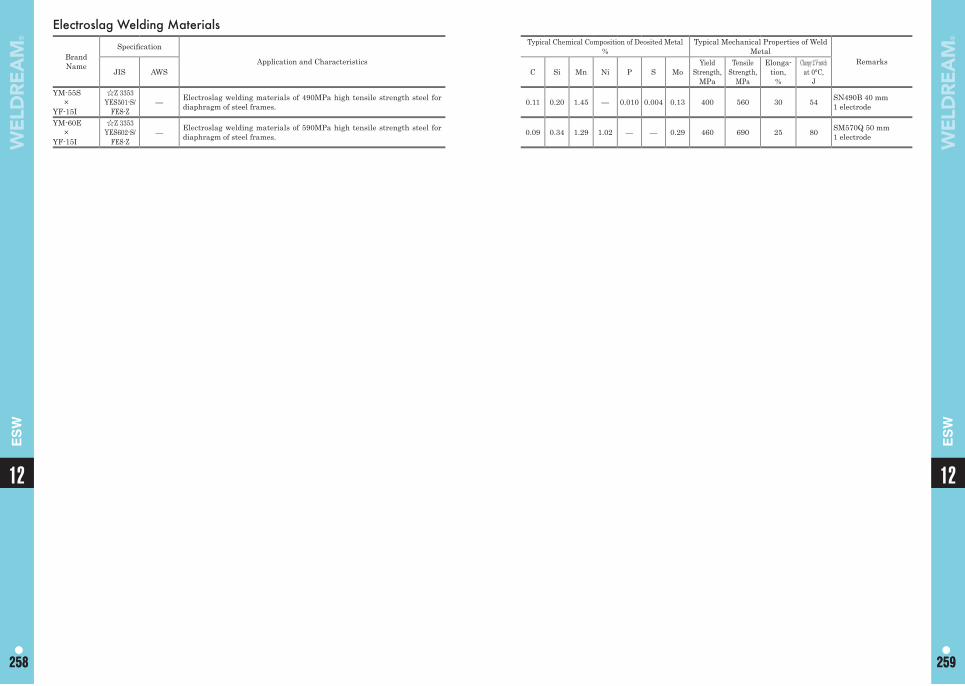
Electroslag Welding Materials
Brand Name
Specifi cation
Application and Characteristics
Typical Chemical Composition of Deosited Metal%
Typical Mechanical Properties of Weld Metal
RemarksJIS AWS C Si Mn Ni P S Mo
Yield Strength,
MPa
Tensile Strength,
MPa
Elonga-tion,
%
Charpy 2 V-notchat 0°C,
JYM-55S
×YF-15I
☆Z 3353 YES501-S/
FES-Z— Electroslag welding materials of 490MPa high tensile strength steel for
diaphragm of steel frames. 0.11 0.20 1.45 — 0.010 0.004 0.13 400 560 30 54 SN490B 40 mm1 electrode
YM-60E×
YF-15I
☆Z 3353 YES602-S/
FES-Z— Electroslag welding materials of 590MPa high tensile strength steel for
diaphragm of steel frames. 0.09 0.34 1.29 1.02 — — 0.29 460 690 25 80 SM570Q 50 mm1 electrode
1212
258 259258 259
ES
W
ES
W
Memo
12
260
261
Electrogas WeldingMaterialsFlux Cored Arc Welding Wires
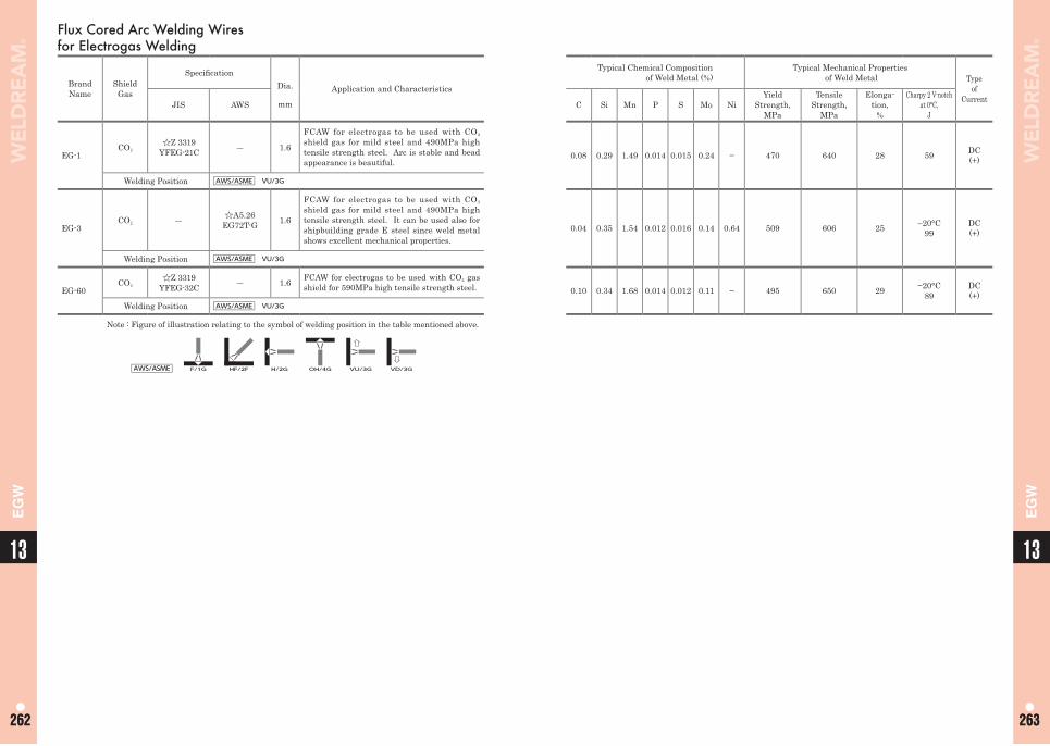
Typical Chemical Compositionof Weld Metal (%)
Typical Mechanical Properties of Weld Metal Type
ofCurrentC Si Mn P S Mo Ni
Yield Strength,
MPa
Tensile Strength,
MPa
Elonga-tion,
%
Charpy 2 V-notchat 0°C,
J
0.08 0.29 1.49 0.014 0.015 0.24 − 470 640 28 59 DC(+)
0.04 0.35 1.54 0.012 0.016 0.14 0.64 509 606 25 −20°C99
DC(+)
0.10 0.34 1.68 0.014 0.012 0.11 − 495 650 29 −20°C89
DC(+)
Flux Cored Arc Welding Wires for Electrogas Welding
Brand Name
Shield Gas
Specifi cationDia.
mm
Application and Characteristics
JIS AWS
EG-1CO2
☆Z 3319 YFEG-21C ― 1.6
FCAW for electrogas to be used with CO2
shield gas for mild steel and 490MPa high tensile strength steel. Arc is stable and bead appearance is beautiful.
Welding Position AWS/ASME VU/3G
EG-3CO2 ― ☆A5.26
EG72T-G 1.6
FCAW for electrogas to be used with CO2
shield gas for mild steel and 490MPa high tensile strength steel. It can be used also for shipbuilding grade E steel since weld metal shows excellent mechanical properties.
Welding Position AWS/ASME VU/3G
EG-60CO2
☆Z 3319 YFEG-32C ― 1.6 FCAW for electrogas to be used with CO2 gas
shield for 590MPa high tensile strength steel.
Welding Position AWS/ASME VU/3G
Note : Figure of illustration relating to the symbol of welding position in the table mentioned above.
AWS/ASME F/1G HF/2F H/2G OH/4G VU/3G VD/3G
1313
262 263262 263
EG
W
EG
W
Memo
13
264
265
High Efficiency Welding Process
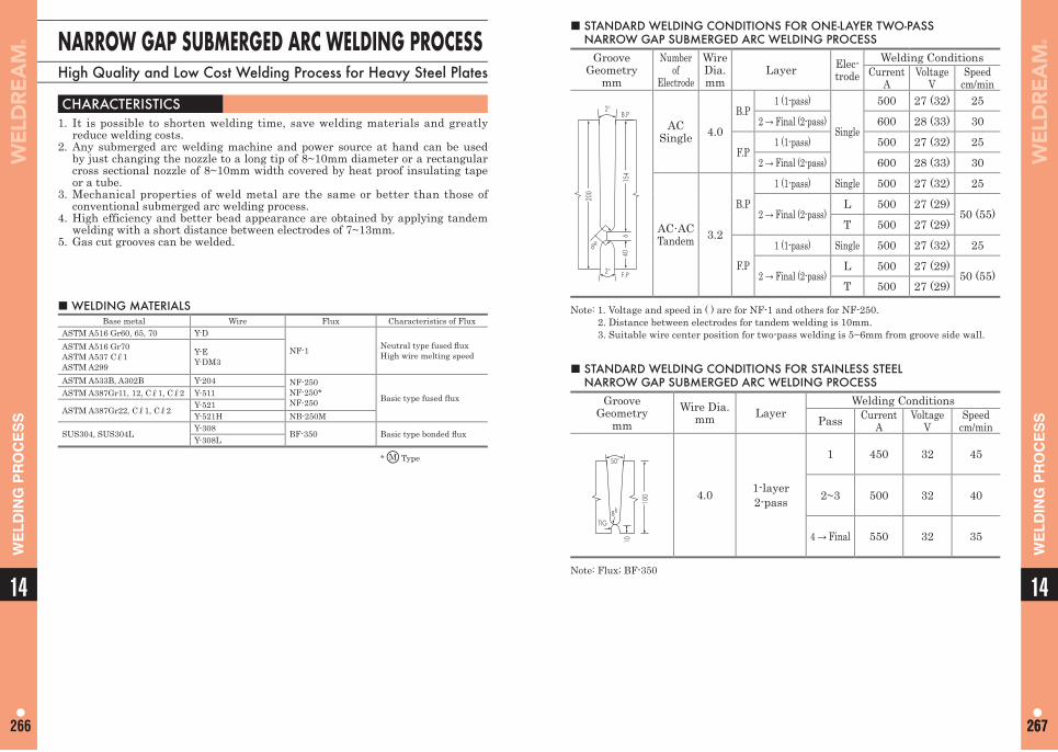
14
267267
WE
LD
ING
PR
OC
ES
S
14
266
WE
LD
ING
PR
OC
ES
S
NARROW GAP SUBMERGED ARC WELDING PROCESSHigh Quality and Low Cost Welding Process for Heavy Steel Plates
■ WELDING MATERIALSBase metal Wire Flux Characteristics of Flux
ASTM A516 Gr60, 65, 70 Y-D
NF-1 Neutral type fused fl uxHigh wire melting speed
ASTM A516 Gr70ASTM A537 Cℓ1ASTM A299
Y-EY-DM3
ASTM A533B, A302B Y-204 NF-250NF-250*NF-250 Basic type fused fl uxASTM A387Gr11, 12, Cℓ1, Cℓ2 Y-511
ASTM A387Gr22, Cℓ1, Cℓ2 Y-521Y-521H NB-250M
SUS304, SUS304L Y-308 BF-350 Basic type bonded fl uxY-308L
* M Type
CHARACTERISTICS 1. It is possible to shorten welding time, save welding materials and greatly
reduce welding costs.2. Any submerged arc welding machine and power source at hand can be used
by just changing the nozzle to a long tip of 8~10mm diameter or a rectangular cross sectional nozzle of 8~10mm width covered by heat proof insulating tape or a tube.
3. Mechanical properties of weld metal are the same or better than those of conventional submerged arc welding process.
4. High efficiency and better bead appearance are obtained by applying tandem welding with a short distance between electrodes of 7~13mm.
5. Gas cut grooves can be welded.
■ STANDARD WELDING CONDITIONS FOR ONE-LAYER TWO-PASS NARROW GAP SUBMERGED ARC WELDING PROCESS
GrooveGeometry
mm
Number of
Electrode
Wire Dia.mm
Layer Elec-trode
Welding ConditionsCurrent
AVoltage
VSpeed
cm/min
154
200
640
2°
2°
8R
F.P
B.P
AC Single 4.0
B.P1 (1-pass)
Single
500 27 (32) 25
2 → Final (2-pass) 600 28 (33) 30
F.P1 (1-pass) 500 27 (32) 25
2 → Final (2-pass) 600 28 (33) 30
AC·AC Tandem 3.2
B.P
1 (1-pass) Single 500 27 (32) 25
2 → Final (2-pass)L 500 27 (29)
50 (55)T 500 27 (29)
F.P1 (1-pass) Single 500 27 (32) 25
2 → Final (2-pass)L 500 27 (29)
50 (55)T 500 27 (29)
Note: 1. Voltage and speed in ( ) are for NF-1 and others for NF-250. 2. Distance between electrodes for tandem welding is 10mm. 3. Suitable wire center position for two-pass welding is 5~6mm from groove side wall.
■ STANDARD WELDING CONDITIONS FOR STAINLESS STEEL NARROW GAP SUBMERGED ARC WELDING PROCESS
GrooveGeometry
mmWire Dia.
mm LayerWelding Conditions
Pass CurrentA
VoltageV
Speedcm/min
100
50°
8R
10
TIG
4.0 1-layer2-pass
1 450 32 45
2~3 500 32 40
4 → Final 550 32 35
Note: Flux; BF-350
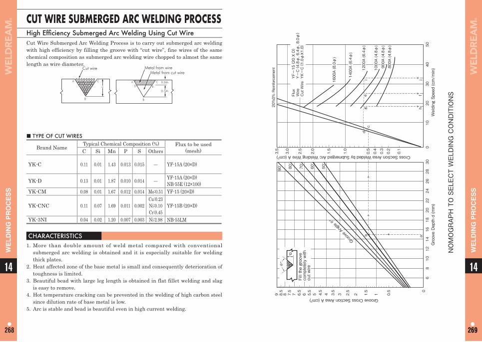
14
269269
WE
LD
ING
PR
OC
ES
S
14
268
WE
LD
ING
PR
OC
ES
S
CUT WIRE SUBMERGED ARC WELDING PROCESSHigh Effi ciency Submerged Arc Welding Using Cut WireCut Wire Submerged Arc Welding Process is to carry out submerged arc welding with high efficiency by filling the groove with “cut wire”, fine wires of the same chemical composition as submerged arc welding wire chopped to almost the same length as wire diameter.
A C
B
Cut wire
h
AD
C
E
B
Metal from wireMetal from cut wire
0.74h
0.26h
■ TYPE OF CUT WIRES
Brand NameTypical Chemical Composition (%) Flux to be used
(mesh)C Si Mn P S Others
YK-C 0.11 0.01 1.43 0.013 0.015 ― YF-15A (20×D)
YK-D 0.13 0.01 1.87 0.010 0.014 ― YF-15A (20×D)NB-55E (12×100)
YK-CM 0.08 0.01 1.67 0.012 0.014 Mo:0.51 YF-15 (20×D)
YK-CNC 0.11 0.07 1.69 0.011 0.002Cu:0.23Ni:0.10Cr:0.45
YF-15B (20×D)
YK-3NI 0.04 0.02 1.20 0.007 0.003 Ni:2.98 NB-55LM
CHARACTERISTICS 1. More than double amount of weld metal compared with conventional
submerged arc welding is obtained and it is especially suitable for welding thick plates.
2. Heat affected zone of the base metal is small and consequently deterioration of toughness is limited.
3. Beautiful bead with large leg length is obtained in flat fillet welding and slag is easy to remove.
4. Hot temperature cracking can be prevented in the welding of high carbon steel since dilution rate of base metal is low.
5. Arc is stable and bead is beautiful even in high current welding.
60
0.5
90°
80°
70°
60°
50°
11.5
22.5
33.5
44.555.566.577.588.59
Groove Cross Section Area A (cm2)
Cross Section Area Welded by Submerged Arc Welding Wire A (cm2)
Groove Depth d (mm)
Welding Speed (cm/min)
810
1214
1618
2022
2426
2830
010
2030
4050
Fill the groove
completely with
cut wire
Flux
YF-15 ( 20 X D)
Wire
Y-C ( 4.8φ, 6.4φ, 8.0φ)
Cut Wire YK-C ( 1.0φX1.0)
abdc
ge
hf
ji
d
θ°
Groove Angle θ°
0.1
0.2
0.3
0.4
0.5
1.0
2.0
2.5
3.0
3.5
20%0%Reinforcement
1.5
1600A (8.0φ)
1400A (6.4φ)
1200A (6.4φ)
1000A (4.8φ)
900A (4.8φ)
800A (4.8φ)
NOMOGRAPH TO SELECT WELDING CONDITIONS
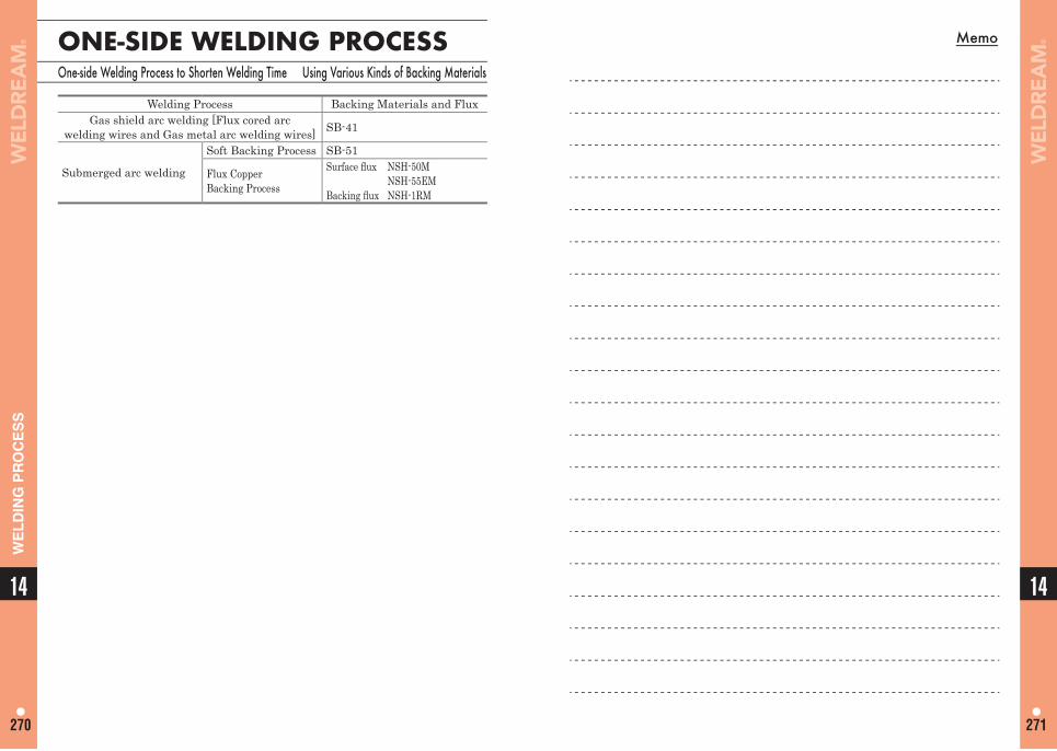
Memo
14
271
14
270
WE
LD
ING
PR
OC
ES
S
ONE-SIDE WELDING PROCESSOne-side Welding Process to Shorten Welding Time Using Various Kinds of Backing Materials
Welding Process Backing Materials and FluxGas shield arc welding [Flux cored arc
welding wires and Gas metal arc welding wires] SB-41
Submerged arc welding
Soft Backing Process SB-51
Flux CopperBacking Process
Surface fl ux NSH-50M NSH-55EMBacking fl ux NSH-1RM
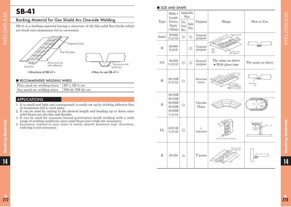
14
273273
14
272
Bac
kin
g M
ater
ials
Bac
kin
g M
ater
ials
■ SIZE AND SHAPE
Type
Width × Length (Groove Depth
× Width)
ApplicableWire
Purpose Shape How to UseFlux Cored Wire
Solid Wire
Standard 30×600(1.2×12) ○ ○ General
purposeDegassing hole
Aluminium foilwith adhesive
Joint
610600±5
126
25
3012
B 26×600(0.8×9) ○ General
purpose
GA 30×600(1.2×12) ○ ○ General
purposeThe same as above● With glass tape The same as above
H 30×150R(1.5×12) ○ Different plate
thickness
Aluminiumfoil
9.5 1.58
812.5
610600±5
100 30 Aluminiumfoil
R
30×100R30×150R30×200R30×250R30×300R(1.5×14)
○ Circular Plates
S B − 41
S B − 41 ( R )
100
300R
~
LL 30×87×18R(1.2×12) ○ L
longitudinals
Aluminum foil with adhesive
Magmetchamp
S B − 41
K 20×350 ○ T joints20
25
8
350
Aluminum foilwith adhesive
100
SB-41Backing Material for Gas Shield Arc One-side WeldingSB-41 is a backing material having a structure of tile-like solid flux blocks which are stuck onto aluminium foil in succession.
Solid flux
Peel off paper
Degassing hole
Aluminium foilSolid flux
<Structure of SB-41> <How to use SB-41>
Aluminium foilwith adhesive
■ RECOMMENDED WELDING WIRESFlux cored arc welding wires SF-1, SF-3, etc.Gas metal arc welding wires YM-26, YM-28, etc.
APPLICATIONS1. It is small and light and consequently is easily set up by sticking adhesive face
of aluminium foil to steel plate.2. It can be used by cutting to the desired length and bending up or down since
solid fluxes are tile-like and flexible.3. It can be used for uranami (sound penetration bead) welding with a wide
range of welding conditions since solid fluxes have high fire resistance.4. Inventory control is easy since it rarely absorb moisture and, therefore,
redrying is not necessary.
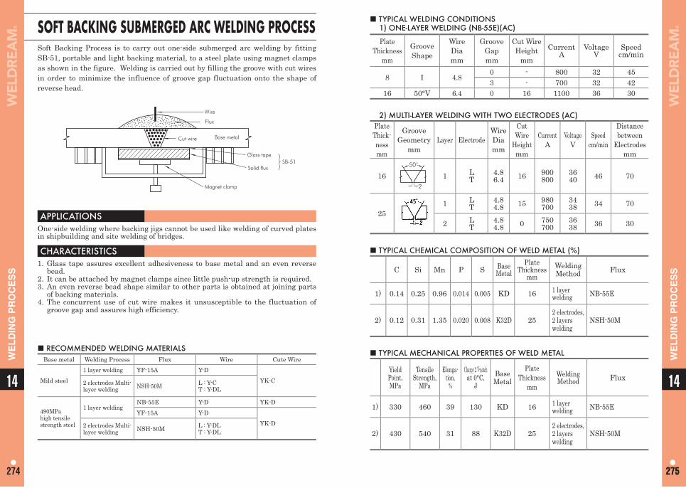
14
274
14
275275
WE
LD
ING
PR
OC
ES
S
WE
LD
ING
PR
OC
ES
S■ TYPICAL WELDING CONDITIONS
1) ONE-LAYER WELDING (NB-55E)(AC)
Plate Thickness
mm
Groove Shape
WireDiamm
Groove Gapmm
Cut Wire Height
mmCurrent
AVoltage
VSpeed
cm/min
8 I 4.80 - 800 32 453 - 700 32 42
16 50°V 6.4 0 16 1100 36 30
2) MULTI-LAYER WELDING WITH TWO ELECTRODES (AC)Plate Thick-ness mm
Groove Geometry
mmLayer Electrode
Wire Diamm
Cut Wire
Height mm
CurrentA
VoltageV
Speedcm/min
Distance between
Electrodes mm
1650°
2
1 LT
4.86.4 16 900
8003640 46 70
251 L
T4.84.8 15 980
7003438 34 70
2 LT
4.84.8 0 750
7003638 36 30
■ TYPICAL CHEMICAL COMPOSITION OF WELD METAL (%)
C Si Mn P S Base Metal
Plate Thickness
mmWelding Method Flux
1) 0.14 0.25 0.96 0.014 0.005 KD 16 1 layer welding NB-55E
2) 0.12 0.31 1.35 0.020 0.008 K32D 252 electrodes,2 layerswelding
NSH-50M
■ TYPICAL MECHANICAL PROPERTIES OF WELD METAL
YieldPoint, MPa
Tensile Strength,
MPa
Elonga-tion,
%
Charpy 2 V-notchat 0°C,
JBase Metal
Plate Thickness
mmWelding Method Flux
1) 330 460 39 130 KD 16 1 layer welding NB-55E
2) 430 540 31 88 K32D 252 electrodes, 2 layers welding
NSH-50M
SOFT BACKING SUBMERGED ARC WELDING PROCESSSoft Backing Process is to carry out one-side submerged arc welding by fitting SB-51, portable and light backing material, to a steel plate using magnet clamps as shown in the figure. Welding is carried out by filling the groove with cut wires in order to minimize the influence of groove gap fluctuation onto the shape of reverse head.
■ RECOMMENDED WELDING MATERIALSBase metal Welding Process Flux Wire Cute Wire
Mild steel1 layer welding YF-15A Y-D
YK-C2 electrodes Multi-layer welding NSH-50M L : Y-C
T : Y-DL
490MPa high tensile strength steel
1 layer weldingNB-55E Y-D YK-DYF-15A Y-D
YK-D2 electrodes Multi-layer welding NSH-50M L : Y-DL
T : Y-DL
APPLICATIONS One-side welding where backing jigs cannot be used like welding of curved plates in shipbuilding and site welding of bridges.
CHARACTERISTICS 1. Glass tape assures excellent adhesiveness to base metal and an even reverse
bead.2. It can be attached by magnet clamps since little push-up strength is required.3. An even reverse bead shape similar to other parts is obtained at joining parts
of backing materials.4. The concurrent use of cut wire makes it unsusceptible to the fluctuation of
groove gap and assures high efficiency.
Wire
Flux
Cut wire Base metal
Glass tape
Solid fluxSB-51
Magnet clamp
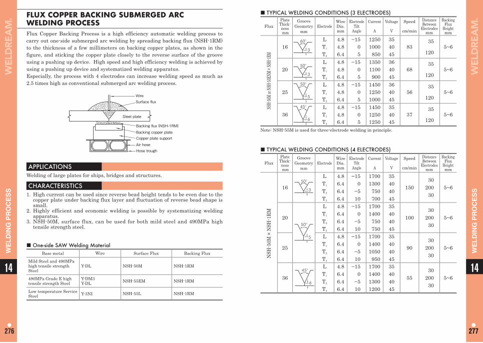
14
276
14
277277
WE
LD
ING
PR
OC
ES
S
WE
LD
ING
PR
OC
ES
S■ TYPICAL WELDING CONDITIONS (3 ELECTRODES)
FluxPlate Thick-ness mm
Groove Geometry
mmElectrode
Wire Dia. mm
Electrode Tilt
Angle
Current
A
Voltage
V
Speed
cm/min
Distance Between
Electrodes mm
Backing Flux
Height mm
NSH-5
0M or
NSH-5
5ENM
× NSH
-1RM
1660°
3
L 4.8 −15 1250 3583
355~6T1 4.8 0 1000 40
120T2 6.4 5 850 45
2050°
3
L 4.8 −15 1350 3668
355~6T1 4.8 0 1100 40
120T2 6.4 5 900 45
2550°
5
L 4.8 −15 1450 3656
355~6T1 4.8 0 1250 40
120T2 6.4 5 1000 45
3645°
6
L 4.8 −15 1450 3537
355~6T1 4.8 0 1250 40
120T2 6.4 5 1250 45Note: NSH-55M is used for three-electrode welding in principle.
■ TYPICAL WELDING CONDITIONS (4 ELECTRODES)
FluxPlate Thick-ness mm
Groove Geometry
mmElectrode
Wire Dia. mm
Electrode Tilt
Angle
Current
A
Voltage
V
Speed
cm/min
Distance Between
Electrodes mm
Backing Flux
Height mm
NSH
-50M
× N
SH-1
RM
1650°
3
LT1
T2
T3
4.86.46.46.4
−150
−510
17001300
750700
35404045
15030
20030
5~6
2050°
5
LT1
T2
T3
4.86.46.46.4
−150
−510
17001400
750750
35404045
10030
20030
5~6
25
LT1
T2
T3
4.86.46.46.4
−150
−510
170014001050
950
35404045
9030
20030
5~6
3645°
6
LT1
T2
T3
4.86.46.46.4
−150
−510
1700140013001200
35404045
5530
20030
5~6
FLUX COPPER BACKING SUBMERGED ARC WELDING PROCESSFlux Copper Backing Process is a high efficiency automatic welding process to carry out one-side submerged arc welding by spreading backing flux (NSH-1RM) to the thickness of a few millimeters on backing copper plates, as shown in the figure, and sticking the copper plate closely to the reverse surface of the groove using a pushing up device. High speed and high efficiency welding is achieved by using a pushing up device and systematized welding apparatus.Especially, the process with 4 electrodes can increase welding speed as much as 2.5 times high as conventional submerged arc welding process.
WireSurface flux
Steel plate
Backing flux (NSH-1RM)
Backing copper plateCopper plate support
Air hoseHose trough
■ One-side SAW Welding MaterialBase metal Wire Surface Flux Backing Flux
Mild Steel and 490MPa high tensile strength Steel
Y-DL NSH-50M NSH-1RM
490MPa Grade E high tensile strength Steel
Y-DM3Y-DL NSH-55EM NSH-1RM
Low temperature Service Steel Y-3NI NSH-55L NSH-1RM
APPLICATIONS Welding of large plates for ships, bridges and structures.
CHARACTERISTICS 1. High current can be used since reverse bead height tends to be even due to the
copper plate under backing flux layer and fluctuation of reverse bead shape is small.
2. Highly efficient and economic welding is possible by systematizing welding apparatus.
3. NSH-50M, surface flux, can be used for both mild steel and 490MPa high tensile strength steel.
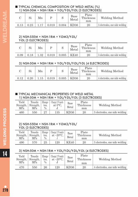
14
278278
WE
LD
ING
PR
OC
ES
S■ TYPICAL CHEMICAL COMPOSITION OF WELD METAL (%)
1) NSH-50M × NSH-1RM × Y-DL/Y-DL/Y-DL (3 ELECTRODES)
C Si Mn P S Base Metal
Plate Thickness
mmWelding Method
0.13 0.23 1.17 0.018 0.004 KD36 20 3 electrodes, one-side welding
2) NSH-55EM × NSH-1RM × Y-DM3/Y-DL/Y-DL (3 ELECTRODES)
C Si Mn P S Base Metal
Plate Thickness
mmWelding Method
0.09 0.18 1.32 0.018 0.005 KE40 20 3 electrodes, one-side welding
3) NSH-50M × NSH-1RM × Y-DL/Y-DL/Y-DL/Y-DL (4 ELECTRODES)
C Si Mn P S Base Metal
Plate Thickness
mmWelding Method
0.12 0.20 1.15 0.019 0.005 KD36 20 4 electrodes, one-side welding
■ TYPICAL MECHANICAL PROPERTIES OF WELD METAL1) NSH-50M × NSH-1RM × Y-DL/Y-DL/Y-DL (3 ELECTRODES)Yield
Strength, MPa
Tensile Strength,
MPa
Elonga-tion,%
Charpy 2 V-notch at 0°C,
JBase Metal
Plate Thickness
mmWelding Method
460 550 27 135 KD36 20 3 electrodes, one-side welding
2) NSH-55EM × NSH-1RM × Y-DM3/Y-DL/Y-DL (3 ELECTRODES)Yield
Strength, MPa
Tensile Strength,
MPa
Elonga-tion,%
Charpy 2 V-notch at –20°C,
JBase Metal
Plate Thickness
mmWelding Method
490 570 25 120 KE40 20 3 electrodes, one-side welding
3) NSH-50M × NSH-1RM × Y-DL/Y-DL/Y-DL/Y-DL (4 ELECTRODES)
YieldStrength,
MPa
Tensile Strength,
MPa
Elonga-tion, %
Charpy 2 V-notch at –20°C,
JBase Metal
Plate Thickness
mmWelding Method
470 550 26 120 KD36 20 4 electrodes, one-side welding
279
Welding Machine and Equipment Plasma Machine and Equipment
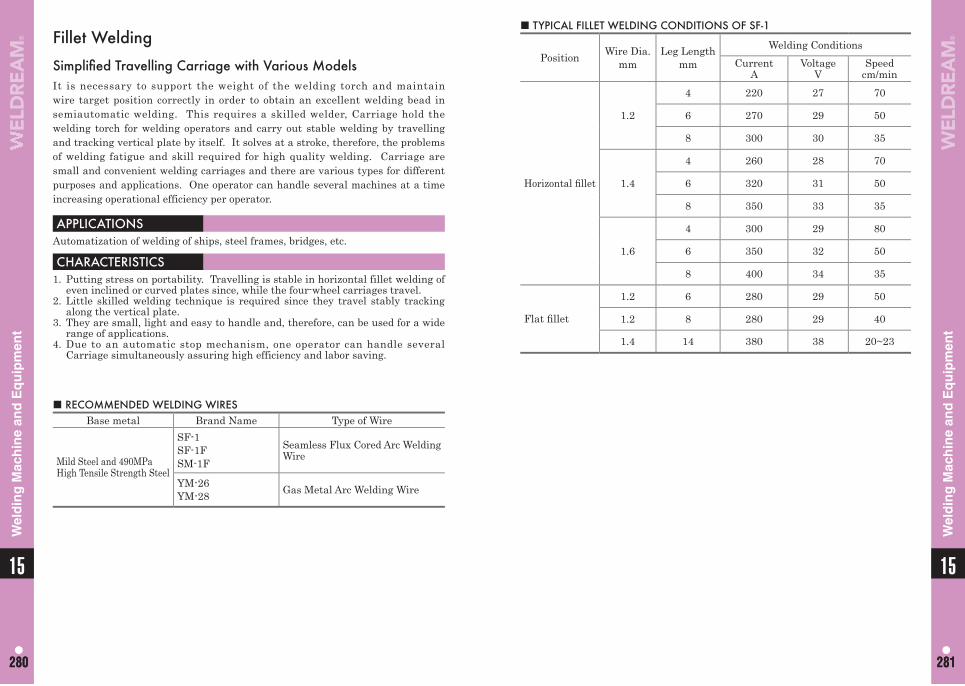
1515
280 281280 281
Wel
din
g M
ach
ine
and
Eq
uip
men
t
Wel
din
g M
ach
ine
and
Eq
uip
men
t
Fillet Welding
Simplifi ed Travelling Carriage with Various ModelsIt is necessary to support the weight of the welding torch and maintain wire target position correctly in order to obtain an excellent welding bead in semiautomatic welding. This requires a skilled welder, Carriage hold the welding torch for welding operators and carry out stable welding by travelling and tracking vertical plate by itself. It solves at a stroke, therefore, the problems of welding fatigue and skill required for high quality welding. Carriage are small and convenient welding carriages and there are various types for different purposes and applications. One operator can handle several machines at a time increasing operational efficiency per operator.
■ RECOMMENDED WELDING WIRESBase metal Brand Name Type of Wire
Mild Steel and 490MPa High Tensile Strength Steel
SF-1SF-1FSM-1F
Seamless Flux Cored Arc Welding Wire
YM-26YM-28 Gas Metal Arc Welding Wire
APPLICATIONSAutomatization of welding of ships, steel frames, bridges, etc.
CHARACTERISTICS1. Putting stress on portability. Travelling is stable in horizontal fillet welding of
even inclined or curved plates since, while the four-wheel carriages travel.2. Little skilled welding technique is required since they travel stably tracking
along the vertical plate.3. They are small, light and easy to handle and, therefore, can be used for a wide
range of applications.4. Due to an automatic stop mechanism, one operator can handle several
Carriage simultaneously assuring high efficiency and labor saving.
■ TYPICAL FILLET WELDING CONDITIONS OF SF-1
Position Wire Dia. mm
Leg Length mm
Welding ConditionsCurrent
AVoltage
VSpeed
cm/min
Horizontal fi llet
1.2
4 220 27 70
6 270 29 50
8 300 30 35
1.4
4 260 28 70
6 320 31 50
8 350 33 35
1.6
4 300 29 80
6 350 32 50
8 400 34 35
Flat fi llet
1.2 6 280 29 50
1.2 8 280 29 40
1.4 14 380 38 20~23
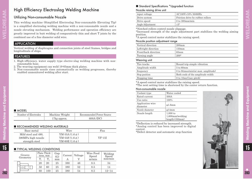
1515
282 283282 283
Wel
din
g M
ach
ine
and
Eq
uip
men
t
Wel
din
g M
ach
ine
and
Eq
uip
men
t
■ Standard Specifi cations *Upgraded functionNozzle raising drive unitinput voltage AC100V±10% 50/60HzDrive system Friction drive by rubber rollersDrive speed 0 to 300mm/minAngle Adjustment ±3°
*Notched rollers control nozzle slippage.*Increased strength of the angle adjustment part stabilizes the welding aiming position.*A speed control motor stabilizes the raising speed.Nozzle position adjustment rangeVertical direction 200mmLeft/right direction 150mmFront/back direction 65mmTurning angle 200°
Weaving unitTire tracks Round trip simple vibrationAmplitude width 5 to 60mmfrequency 0 to 8times/min(at max. amplitude)Stop position Both ends of the amplitude widthStopping time 0 to 10sec(1sec pitch)
*A speed control motor stabilizes the raising speed.*The next setting time is shortened by the center return function.Non-consumable nozzleCoolant type Water cooledRated current 500AUse ratio 100%Application wire diameter φ1.6mm
Nozzle diameter φ14mmNozzle length 1,000 to
1,600mm(welding length+350mm)
*Deflection is reduced by increased strength.*Analog control has been improved to digital control.*Defect detector and automatic stop function
High Efficiency Electroslag Welding Machine
Utilizing Non-consumable NozzleThis welding machine (Simplified Electroslag Non-consumable Elevating Tip) is a simplified electroslag welding machine with a non-consumable nozzle and a nozzle elevating mechanism. Welding performance and operation efficiency are greatly improved in butt welding of comparatively thin and short T joints by the combined use of a fine diameter solid wire.
APPLICATIONVertical welding of diaphragms and connection joints of steel frames, bridges and longitudinals of ships.
FEATURES1. High-efficiency, water supply type electro-slag welding machine with non-
consumable hose.2. The weaving equipment can weld 19-65mm thick plates.3. Non-consumable nozzle rises automatically as welding progresses, thereby
enabled unmonitored welding after start.
■ MODELNumber of Electrodes Machine Weight Recommended Power Source
1 17kg approx. 600A (DC)
■ RECOMMENDED WELDING MATERIALSBase metal Wire Flux
Mild steel and 490, 590MPa high tensile
strength steel
YM-55A (1.6φ)YM-55S (1.6φ)YM-60E (1.6φ)
YF-15I
■ TYPICAL WELDING CONDITIONS
Groove Geometry
Plate Thick-ness, mm
Gap (G) mm
CurrentA
VoltageV
Wire Feed Speedm/min
Welding Speed
mm/minT1 T2
T1T2
G
20 20 25 380 46 8.5 3450 60 25 380 52 8.5 1460 100 25 380 54 8.5 12~14
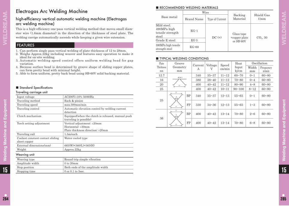
1515
284 285284 285
Wel
din
g M
ach
ine
and
Eq
uip
men
t
Wel
din
g M
ach
ine
and
Eq
uip
men
t
■ TYPICAL WELDING CONDITIONSPlate
Thicknessmm
Groove Geometry
mmCurrent
AVoltage
VSpeedcm/min
Heat Inputkj/cm
OscillationWidthmm
Frequencyn/min
12.75
17
340 35~37 11~12 60~70 0~1 60~8016 380 38~40 11~12 70~80 0~4 60~8020 400 40~42 11~12 80~90 4~8 60~8025 400 40~42 10~11 90~100 8~12 60~80
255
17
17
BP 340 35~37 12~13 55~65 0~1 60~80
FP 330 34~36 12~13 55~65 1~3 60~80
365
17
17
BP 400 40~42 13~14 70~80 2~6 60~80
FP 400 40~42 13~14 70~80 6~8 60~80
Electrogas Arc Welding Machinehigh-effi ciency vertical automatic welding machine (Electrogas arc welding machine)This is a high-efficiency one-pass vertical welding method that moves small diam-eter wire (1.6mm diameter) in the direction of the thickness of steel plate. The welding carrige automatically ascends while keeping a given wire extension.
FEATURES1. Can perform single pass vertical welding of plate thickness of 12 to 28mm.2. Weighs Approx.22kg including weaver and features easy operation to make it
ideal for on-site welding.3. Automatic welding speed control offers uniform welding bead for gap
variation.4. Because surface bead is determined by groove shape of sliding copper plates,
can form pretty bead with minimal height.5. Able to form uniform, pretty back bead using SB-60V solid backing material.
■ RECOMMENDED WELDING MATERIALS
Base metalWire
Backing Material
Shield Gasℓ/mmBrand Name Type of Current
Mild steel. 490MPa high tensile strength steel
EG-1
DC (+)Glass tape
+copper plateor SB-60V
CO2, 30Grade E steel EG-3590MPa high tensile strength steel EG-60
■ Standard Specifi cationsTraveling carriage unitInput voltage AC200V±10% 50/60HzTraveling method Rack & pinionTraveling speed max.500mm/minTraveling control Automatic elevation control by welding current
detectionClutch mechanism Equipped(when the clutch is released, manual push
traveling is possible)Torch setting adjustment Vertical adjustment: ±20mm
Horizontal: ±30mmPlate thickness direction: ±20mm
Traveling rail 1.5m/eachCoolant constant contact sliding sheet copper
Water cooled type
External dimensions(mm) 665(W)×360(L)×365(H)Weight Approx.22kg
Weaving unitWeaving type Round trip simple vibrationAmplitude width 0 to 20mmStop position Both ends of the amplitude widthStopping time 0 or 0.1 to 3sec.
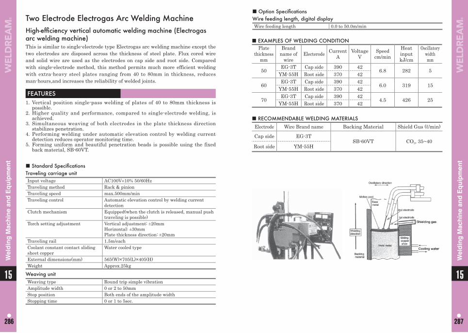
1515
286 287286 287
Wel
din
g M
ach
ine
and
Eq
uip
men
t
Wel
din
g M
ach
ine
and
Eq
uip
men
t
■ EXAMPLES OF WELDING CONDITIONPlate
thicknessmm
Brand name of
wireElecterode Current
AVoltage
VSpeed
cm/minHeat inputkJ/cm
Oscillatory widthmm
50EG-3T Cap side 390 42
6.8 282 5YM-55H Root side 370 42
60EG-3T Cap side 390 42
6.0 319 15YM-55H Root side 370 42
70EG-3T Cap side 390 42
4.5 426 25YM-55H Root side 370 42
■ RECOMMENDABLE WELDING MATERIALSElectrode Wire Brand name Backing Material Shield Gus (ℓ/min)
Cap side EG-3TSB-60VT CO2, 35~40
Root side YM-55H
Two Electrode Electrogas Arc Welding MachineHigh-effi ciency vertical automatic welding machine (Electrogas arc welding machine)This is similar to single-electrode type Electrogas arc welding machine except the two electrodes are disposed across the thickness of steel plate. Flux cored wire and solid wire are used as the electrodes on cap side and root side. Compared with single-electrode method, this method permits much more efficient welding with extra-heavy steel plates ranging from 40 to 80mm in thickness, reduces man-hours,and increases the reliability of welded joints.
FEATURES1. Vertical position single-pass welding of plates of 40 to 80mm thickness is
possible.2. Higher quality and performance, compared to single-electrode welding, is
achieved.3. Simultaneous weaving of both electrodes in the plate thickness direction
stabilizes penetration.4. Performing welding under automatic elevation control by welding current
detection reduces operator monitoring time.5. Forming uniform and beautiful penetration beads is possible using the fixed
back material, SB-60VT.
■ Standard Specifi cationsTraveling carriage unitInput voltage AC100V±10% 50/60HzTraveling method Rack & pinionTraveling speed max.500mm/minTraveling control Automatic elevation control by welding current
detectionClutch mechanism Equipped(when the clutch is released, manual push
traveling is possible)Torch setting adjustment Vertical adjustment: ±20mm
Horizontal: ±30mmPlate thickness direction: ±20mm
Traveling rail 1.5m/eachCoolant constant contact sliding sheet copper
Water cooled type
External dimensions(mm) 565(W)×705(L)×405(H)Weight Approx.25kg
Weaving unitWeaving type Round trip simple vibrationAmplitude width 0 or 2 to 50mmStop position Both ends of the amplitude widthStopping time 0 or 1 to 5sec.
■ Option Specifi cationsWire feeding length, digital displayWire feeding length 0.0 to 50.0m/min
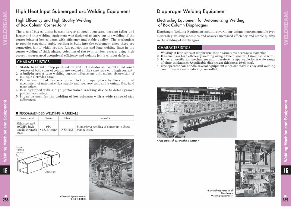
1515
288 289288 289
Wel
din
g M
ach
ine
and
Eq
uip
men
t
Wel
din
g M
ach
ine
and
Eq
uip
men
t
Diaphragm Welding Equipment
Electroslag Equipment for Automatizing Welding of Box Column DiaphragmsDiaphragm Welding Equipment mounts several our unique non-consumable type electroslag welding machines and assures increased efficiency and stable quality in the welding of diaphragms.
CHARACTERISTICS1. Welding of both sides of diaphragm at the same time decreases distortion.2. It is one-pass high efficiency welding using a fine diameter (1.6mm) solid wire.3. It has an oscillation mechanism and, therefore, is applicable for a wide range
of plate thicknesses (Applicable diaphragm thickness:19-60mm).4. One operator can handle several equipment since arc start is easy and welding
conditions are automatically controlled.
<External appearance of Diaphragm
Welding Equipment>
High Heat Input Submerged arc Welding Equipment
High Effi ciency and High Quality Weldingof Box Column Corner JointThe size of box columns became larger as steel structures became taller and larger and this welding equipment was designed to carry out the welding of the corner joints of box columns with efficiency and stable quality. The mechanism to provide especially stable welding is built into the equipment since there are connection joints which require full penetration and long welding lines in the corner welding of thick plates. Adoption of the twin-tandem process using high current assures good operational efficiency and welding joints without defects.
CHARACTERISTICS1. Stable bead with deep penetration and little distortion is obtained since
corners of both sides of column are welded at the same time with high current.2. A built-in preset type welding current adjustment unit makes observation of
multiple eletrodes easy.3. Proper amount of flux is supplied to the proper place by the combined
mechanism of automatic flux supply and recovery unit and a unique flux hold mechanism.
4. It is equipped with a high performance tracking device to detect groove position accurately.
5. It can be used for the welding of box columns with a wide range of size differences.
<External Appearance of BOX GIRDER>
■ RECOMMENDED WELDING MATERIALSBase metal Wire Flux Remarks
Mild steel and 490MPa high tensile strength steel
Y-DL(4.8, 6.4mm) NSH-53Z
Single-layer welding of plates up to about 50mm thick.
Cornerweldingplaces
Diaphragm
<Apparatus of our machine system>
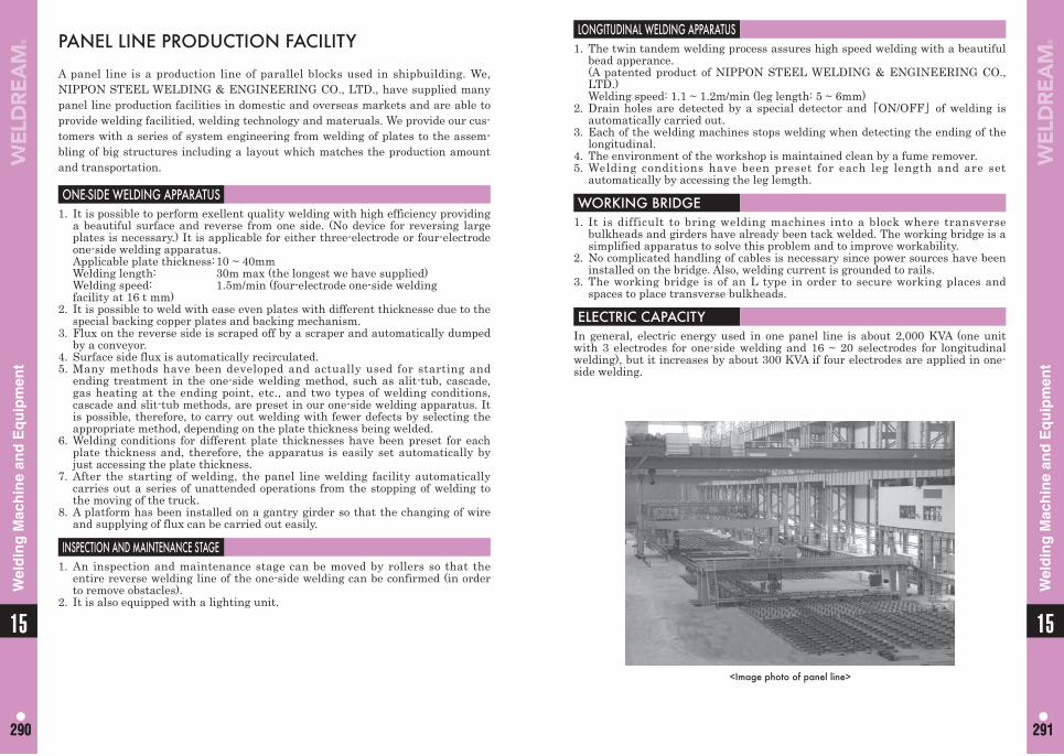
1515
290 291290 291
Wel
din
g M
ach
ine
and
Eq
uip
men
t
Wel
din
g M
ach
ine
and
Eq
uip
men
t
LONGITUDINAL WELDING APPARATUS1. The twin tandem welding process assures high speed welding with a beautiful
bead apperance. (A patented product of NIPPON STEEL WELDING & ENGINEERING CO.,
LTD.) Welding speed: 1.1 ~ 1.2m/min (leg length: 5 ~ 6mm)2. Drain holes are detected by a special detector and「ON/OFF」of welding is
automatically carried out.3. Each of the welding machines stops welding when detecting the ending of the
longitudinal.4. The environment of the workshop is maintained clean by a fume remover.5. Welding conditions have been preset for each leg length and are set
automatically by accessing the leg lemgth.
WORKING BRIDGE1. It is difficult to bring welding machines into a block where transverse
bulkheads and girders have already been tack welded. The working bridge is a simplified apparatus to solve this problem and to improve workability.
2. No complicated handling of cables is necessary since power sources have been installed on the bridge. Also, welding current is grounded to rails.
3. The working bridge is of an L type in order to secure working places and spaces to place transverse bulkheads.
ELECTRIC CAPACITYIn general, electric energy used in one panel line is about 2,000 KVA (one unit with 3 electrodes for one-side welding and 16 ~ 20 selectrodes for longitudinal welding), but it increases by about 300 KVA if four electrodes are applied in one-side welding.
PANEL LINE PRODUCTION FACILITY
A panel line is a production line of parallel blocks used in shipbuilding. We, NIPPON STEEL WELDING & ENGINEERING CO., LTD., have supplied many panel line production facilities in domestic and overseas markets and are able to provide welding facilitied, welding technology and materuals. We provide our cus-tomers with a series of system engineering from welding of plates to the assem-bling of big structures including a layout which matches the production amount and transportation.
ONE-SIDE WELDING APPARATUS1. It is possible to perform exellent quality welding with high efficiency providing
a beautiful surface and reverse from one side. (No device for reversing large plates is necessary.) It is applicable for either three-electrode or four-electrode one-side welding apparatus.
Applicable plate thickness: 10 ~ 40mm Welding length: 30m max (the longest we have supplied) Welding speed: 1.5m/min (four-electrode one-side welding facility at 16 t mm)2. It is possible to weld with ease even plates with different thicknesse due to the
special backing copper plates and backing mechanism.3. Flux on the reverse side is scraped off by a scraper and automatically dumped
by a conveyor.4. Surface side flux is automatically recirculated.5. Many methods have been developed and actually used for starting and
ending treatment in the one-side welding method, such as alit-tub, cascade, gas heating at the ending point, etc., and two types of welding conditions, cascade and slit-tub methods, are preset in our one-side welding apparatus. It is possible, therefore, to carry out welding with fewer defects by selecting the appropriate method, depending on the plate thickness being welded.
6. Welding conditions for different plate thicknesses have been preset for each plate thickness and, therefore, the apparatus is easily set automatically by just accessing the plate thickness.
7. After the starting of welding, the panel line welding facility automatically carries out a series of unattended operations from the stopping of welding to the moving of the truck.
8. A platform has been installed on a gantry girder so that the changing of wire and supplying of flux can be carried out easily.
INSPECTION AND MAINTENANCE STAGE1. An inspection and maintenance stage can be moved by rollers so that the
entire reverse welding line of the one-side welding can be confirmed (in order to remove obstacles).
2. It is also equipped with a lighting unit.
<Image photo of panel line>
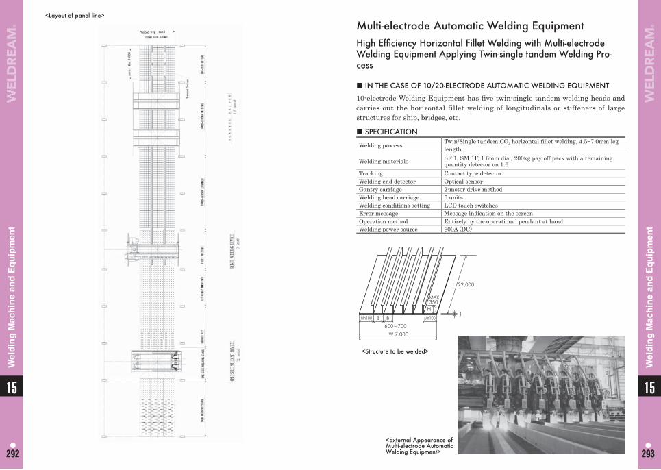
1515
292 293292 293
Wel
din
g M
ach
ine
and
Eq
uip
men
t
Wel
din
g M
ach
ine
and
Eq
uip
men
t
Multi-electrode Automatic Welding EquipmentHigh Effi ciency Horizontal Fillet Welding with Multi-electrode Welding Equipment Applying Twin-single tandem Welding Pro-cess
■ IN THE CASE OF 10/20-ELECTRODE AUTOMATIC WELDING EQUIPMENT
10-electrode Welding Equipment has five twin-single tandem welding heads and carries out the horizontal fillet welding of longitudinals or stiffeners of large structures for ship, bridges, etc.
■ SPECIFICATION
Welding process Twin/Single tandem CO2 horizontal fi llet welding, 4.5~7.0mm leg length
Welding materials SF-1, SM-1F, 1.6mm dia., 200kg pay-off pack with a remaining quantity detector on 1.6
Tracking Contact type detectorWelding end detector Optical sensorGantry carriage 2-motor drive methodWelding head carriage 5 unitsWelding conditions setting LCD touch switchesError message Message indication on the screenOperation method Entirely by the operational pendant at handWelding power source 600A (DC)
<External Appearance ofMulti-electrode Automatic Welding Equipment>
<Structure to be welded>
<Layout of panel line>
1Mn100Mn100
H
MAX350
600~700
W 7.000
B B
L 22,000
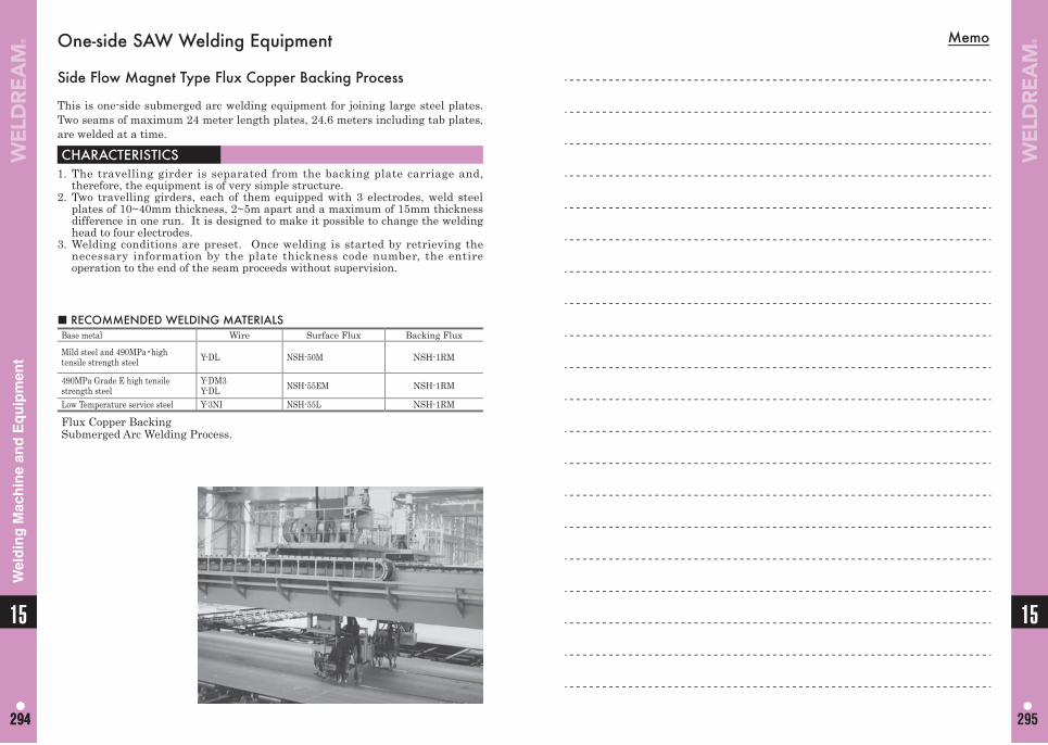
Memo
15
295
15
294294
Wel
din
g M
ach
ine
and
Eq
uip
men
t
■ RECOMMENDED WELDING MATERIALSBase metal Wire Surface Flux Backing Flux
Mild steel and 490MPa•high tensile strength steel Y-DL NSH-50M NSH-1RM
490MPa Grade E high tensile strength steel
Y-DM3Y-DL NSH-55EM NSH-1RM
Low Temperature service steel Y-3NI NSH-55L NSH-1RM
Flux Copper BackingSubmerged Arc Welding Process.
One-side SAW Welding Equipment
Side Flow Magnet Type Flux Copper Backing Process
This is one-side submerged arc welding equipment for joining large steel plates. Two seams of maximum 24 meter length plates, 24.6 meters including tab plates, are welded at a time.
CHARACTERISTICS1. The travelling girder is separated from the backing plate carriage and,
therefore, the equipment is of very simple structure.2. Two travelling girders, each of them equipped with 3 electrodes, weld steel
plates of 10~40mm thickness, 2~5m apart and a maximum of 15mm thickness difference in one run. It is designed to make it possible to change the welding head to four electrodes.
3. Welding conditions are preset. Once welding is started by retrieving the necessary information by the plate thickness code number, the entire operation to the end of the seam proceeds without supervision.
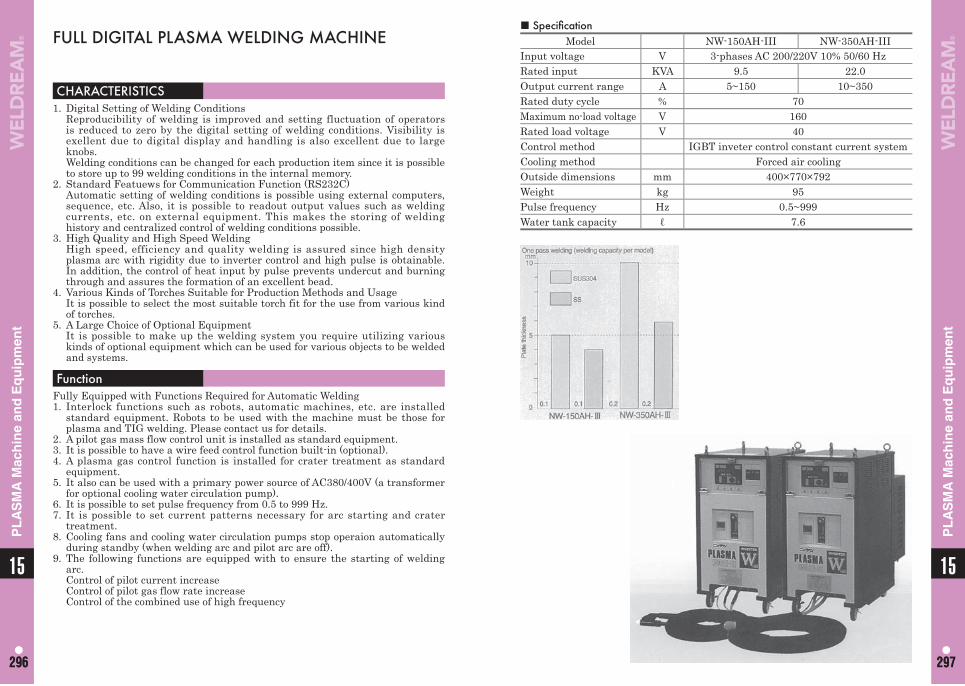
1515
296 297296 297
PL
AS
MA
Mac
hin
e an
d E
qu
ipm
ent
PL
AS
MA
Mac
hin
e an
d E
qu
ipm
ent
■ Specifi cation Model NW-150AH-III NW-350AH-III
Input voltage V 3-phases AC 200/220V 10% 50/60 HzRated input KVA 9.5 22.0Output current range A 5~150 10~350Rated duty cycle % 70Maximum no-load voltage V 160Rated load voltage V 40Control method IGBT inveter control constant current systemCooling method Forced air coolingOutside dimensions mm 400×770×792Weight kg 95Pulse frequency Hz 0.5~999Water tank capacity ℓ 7.6
CHARACTERISTICS 1. Digital Setting of Welding Conditions Reproducibility of welding is improved and setting fluctuation of operators
is reduced to zero by the digital setting of welding conditions. Visibility is exellent due to digital display and handling is also excellent due to large knobs.
Welding conditions can be changed for each production item since it is possible to store up to 99 welding conditions in the internal memory.
2. Standard Featuews for Communication Function (RS232C) Automatic setting of welding conditions is possible using external computers,
sequence, etc. Also, it is possible to readout output values such as welding currents, etc. on external equipment. This makes the storing of welding history and centralized control of welding conditions possible.
3. High Quality and High Speed Welding High speed, efficiency and quality welding is assured since high density
plasma arc with rigidity due to inverter control and high pulse is obtainable. In addition, the control of heat input by pulse prevents undercut and burning through and assures the formation of an excellent bead.
4. Various Kinds of Torches Suitable for Production Methods and Usage It is possible to select the most suitable torch fit for the use from various kind
of torches.5. A Large Choice of Optional Equipment It is possible to make up the welding system you require utilizing various
kinds of optional equipment which can be used for various objects to be welded and systems.
FunctionFully Equipped with Functions Required for Automatic Welding1. Interlock functions such as robots, automatic machines, etc. are installed
standard equipment. Robots to be used with the machine must be those for plasma and TIG welding. Please contact us for details.
2. A pilot gas mass flow control unit is installed as standard equipment.3. It is possible to have a wire feed control function built-in (optional).4. A plasma gas control function is installed for crater treatment as standard
equipment.5. It also can be used with a primary power source of AC380/400V (a transformer
for optional cooling water circulation pump).6. It is possible to set pulse frequency from 0.5 to 999 Hz.7. It is possible to set current patterns necessary for arc starting and crater
treatment.8. Cooling fans and cooling water circulation pumps stop operaion automatically
during standby (when welding arc and pilot arc are off).9. The following functions are equipped with to ensure the starting of welding
arc. Control of pilot current increase Control of pilot gas flow rate increase Control of the combined use of high frequency
FULL DIGITAL PLASMA WELDING MACHINE
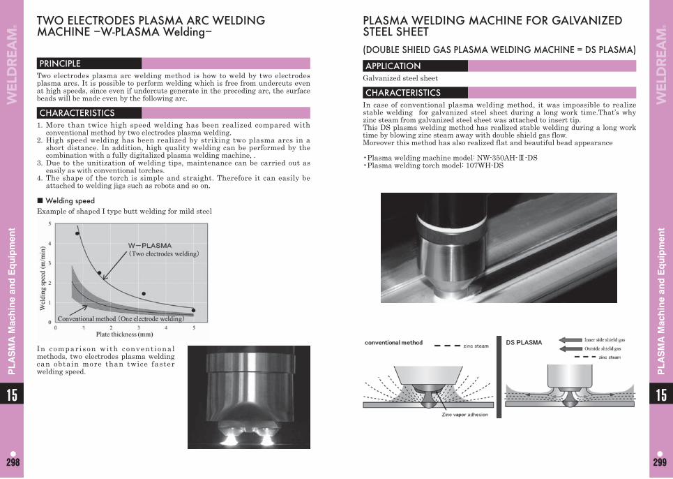
1515
298 299298 299
PL
AS
MA
Mac
hin
e an
d E
qu
ipm
ent
PL
AS
MA
Mac
hin
e an
d E
qu
ipm
ent
PLASMA WELDING MACHINE FOR GALVANIZED STEEL SHEET(DOUBLE SHIELD GAS PLASMA WELDING MACHINE = DS PLASMA)
APPLICATIONGalvanized steel sheet
CHARACTERISTICSIn case of conventional plasma welding method, it was impossible to realize stable welding for galvanized steel sheet during a long work time.That’s why zinc steam from galvanized steel sheet was attached to insert tip.This DS plasma welding method has realized stable welding during a long work time by blowing zinc steam away with double shield gas flow.Moreover this method has also realized flat and beautiful bead appearance
•Plasma welding machine model: NW-350AH-Ⅲ-DS•Plasma welding torch model: 107WH-DS
PRINCIPLE Two electrodes plasma arc welding method is how to weld by two electrodes plasma arcs. It is possible to perform welding which is free from undercuts even at high speeds, since even if undercuts generate in the preceding arc, the surface beads will be made even by the following arc.
CHARACTERISTICS1. More than twice high speed welding has been realized compared with
conventional method by two electrodes plasma welding. 2. High speed welding has been realized by striking two plasma arcs in a
short distance. In addition, high quality welding can be performed by the combination with a fully digitalized plasma welding machine, .
3. Due to the unitization of welding tips, maintenance can be carried out as easily as with conventional torches.
4. The shape of the torch is simple and straight. Therefore it can easily be attached to welding jigs such as robots and so on.
■ Welding speedExample of shaped I type butt welding for mild steel
In compar ison with convent ional methods, two electrodes plasma welding can obtain more than twice faster welding speed.
TWO ELECTRODES PLASMA ARC WELDING MACHINE −W-PLASMA Welding−
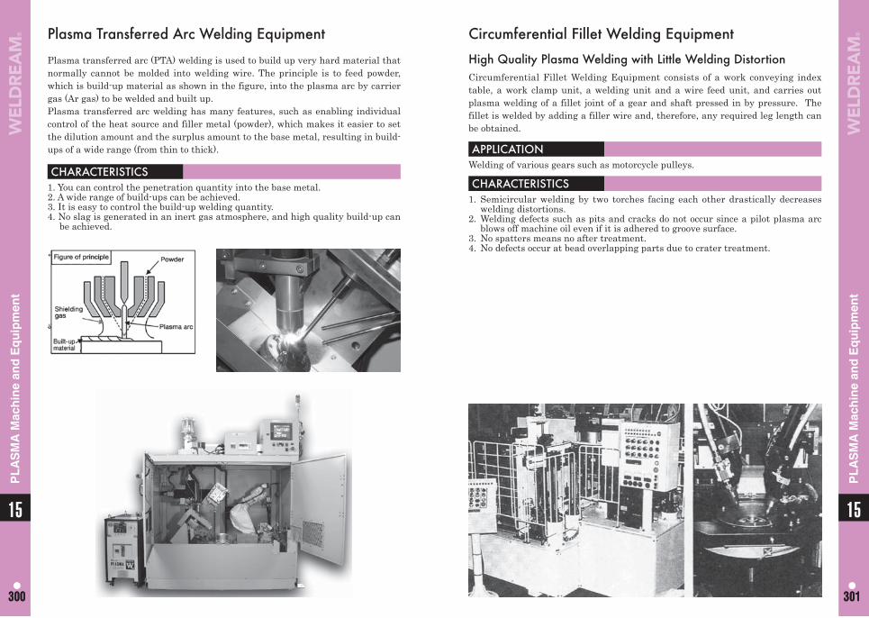
1515
300 301300 301
PL
AS
MA
Mac
hin
e an
d E
qu
ipm
ent
PL
AS
MA
Mac
hin
e an
d E
qu
ipm
ent
Circumferential Fillet Welding Equipment
High Quality Plasma Welding with Little Welding DistortionCircumferential Fillet Welding Equipment consists of a work conveying index table, a work clamp unit, a welding unit and a wire feed unit, and carries out plasma welding of a fillet joint of a gear and shaft pressed in by pressure. The fillet is welded by adding a filler wire and, therefore, any required leg length can be obtained.
APPLICATIONWelding of various gears such as motorcycle pulleys.
CHARACTERISTICS1. Semicircular welding by two torches facing each other drastically decreases
welding distortions.2. Welding defects such as pits and cracks do not occur since a pilot plasma arc
blows off machine oil even if it is adhered to groove surface.3. No spatters means no after treatment.4. No defects occur at bead overlapping parts due to crater treatment.
Plasma Transferred Arc Welding Equipment
Plasma transferred arc (PTA) welding is used to build up very hard material that normally cannot be molded into welding wire. The principle is to feed powder, which is build-up material as shown in the figure, into the plasma arc by carrier gas (Ar gas) to be welded and built up.Plasma transferred arc welding has many features, such as enabling individual control of the heat source and filler metal (powder), which makes it easier to set the dilution amount and the surplus amount to the base metal, resulting in build-ups of a wide range (from thin to thick).
CHARACTERISTICS1. You can control the penetration quantity into the base metal.2. A wide range of build-ups can be achieved.3. It is easy to control the build-up welding quantity.4. No slag is generated in an inert gas atmosphere, and high quality build-up can
be achieved.
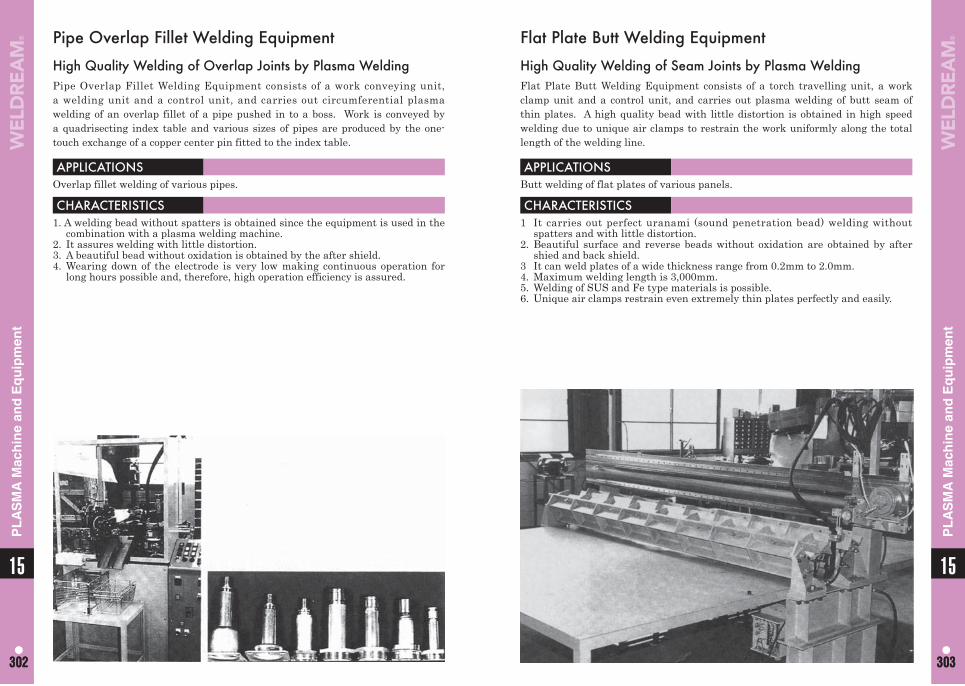
1515
302 303302 303
PL
AS
MA
Mac
hin
e an
d E
qu
ipm
ent
PL
AS
MA
Mac
hin
e an
d E
qu
ipm
ent
Flat Plate Butt Welding Equipment
High Quality Welding of Seam Joints by Plasma WeldingFlat Plate Butt Welding Equipment consists of a torch travelling unit, a work clamp unit and a control unit, and carries out plasma welding of butt seam of thin plates. A high quality bead with little distortion is obtained in high speed welding due to unique air clamps to restrain the work uniformly along the total length of the welding line.
APPLICATIONSButt welding of flat plates of various panels.
CHARACTERISTICS1 It carries out perfect uranami (sound penetration bead) welding without
spatters and with little distortion.2. Beautiful surface and reverse beads without oxidation are obtained by after
shied and back shield.3 It can weld plates of a wide thickness range from 0.2mm to 2.0mm.4. Maximum welding length is 3,000mm.5. Welding of SUS and Fe type materials is possible.6. Unique air clamps restrain even extremely thin plates perfectly and easily.
Pipe Overlap Fillet Welding Equipment
High Quality Welding of Overlap Joints by Plasma WeldingPipe Overlap Fillet Welding Equipment consists of a work conveying unit, a welding unit and a control unit, and carries out circumferential plasma welding of an overlap fillet of a pipe pushed in to a boss. Work is conveyed by a quadrisecting index table and various sizes of pipes are produced by the one-touch exchange of a copper center pin fitted to the index table.
APPLICATIONSOverlap fillet welding of various pipes.
CHARACTERISTICS1. A welding bead without spatters is obtained since the equipment is used in the
combination with a plasma welding machine.2. It assures welding with little distortion.3. A beautiful bead without oxidation is obtained by the after shield.4. Wearing down of the electrode is very low making continuous operation for
long hours possible and, therefore, high operation efficiency is assured.
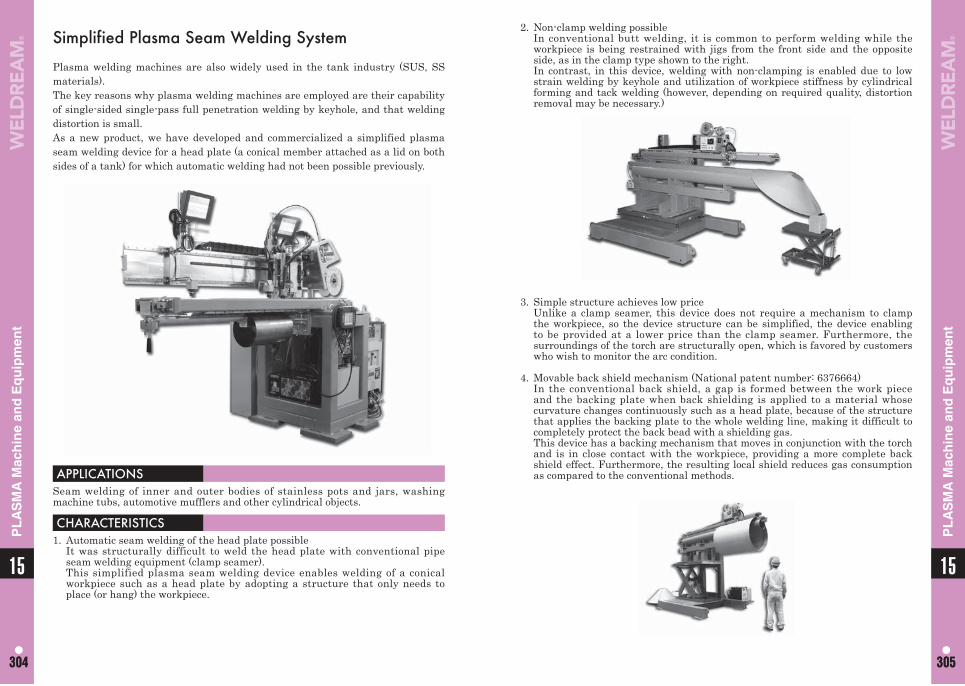
1515
304 305304 305
PL
AS
MA
Mac
hin
e an
d E
qu
ipm
ent
PL
AS
MA
Mac
hin
e an
d E
qu
ipm
ent
Simplified Plasma Seam Welding System
Plasma welding machines are also widely used in the tank industry (SUS, SS materials).The key reasons why plasma welding machines are employed are their capability of single-sided single-pass full penetration welding by keyhole, and that welding distortion is small.As a new product, we have developed and commercialized a simplified plasma seam welding device for a head plate (a conical member attached as a lid on both sides of a tank) for which automatic welding had not been possible previously.
APPLICATIONSSeam welding of inner and outer bodies of stainless pots and jars, washing machine tubs, automotive mufflers and other cylindrical objects.
CHARACTERISTICS1. Automatic seam welding of the head plate possible It was structurally difficult to weld the head plate with conventional pipe
seam welding equipment (clamp seamer). This simplified plasma seam welding device enables welding of a conical
workpiece such as a head plate by adopting a structure that only needs to place (or hang) the workpiece.
2. Non-clamp welding possible In conventional butt welding, it is common to perform welding while the
workpiece is being restrained with jigs from the front side and the opposite side, as in the clamp type shown to the right.
In contrast, in this device, welding with non-clamping is enabled due to low strain welding by keyhole and utilization of workpiece stiffness by cylindrical forming and tack welding (however, depending on required quality, distortion removal may be necessary.)
3. Simple structure achieves low price Unlike a clamp seamer, this device does not require a mechanism to clamp
the workpiece, so the device structure can be simplified, the device enabling to be provided at a lower price than the clamp seamer. Furthermore, the surroundings of the torch are structurally open, which is favored by customers who wish to monitor the arc condition.
4. Movable back shield mechanism (National patent number: 6376664) In the conventional back shield, a gap is formed between the work piece
and the backing plate when back shielding is applied to a material whose curvature changes continuously such as a head plate, because of the structure that applies the backing plate to the whole welding line, making it difficult to completely protect the back bead with a shielding gas.
This device has a backing mechanism that moves in conjunction with the torch and is in close contact with the workpiece, providing a more complete back shield effect. Furthermore, the resulting local shield reduces gas consumption as compared to the conventional methods.
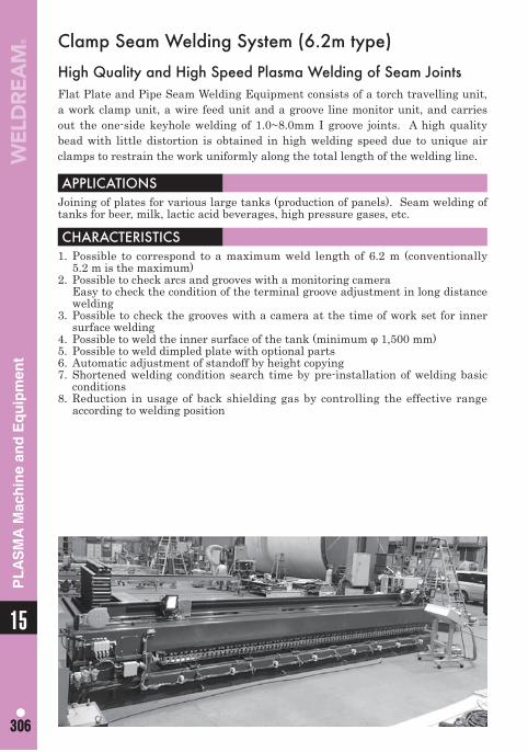
15
306306
PL
AS
MA
Mac
hin
e an
d E
qu
ipm
ent
Clamp Seam Welding System (6.2m type)
High Quality and High Speed Plasma Welding of Seam JointsFlat Plate and Pipe Seam Welding Equipment consists of a torch travelling unit, a work clamp unit, a wire feed unit and a groove line monitor unit, and carries out the one-side keyhole welding of 1.0~8.0mm I groove joints. A high quality bead with little distortion is obtained in high welding speed due to unique air clamps to restrain the work uniformly along the total length of the welding line.
APPLICATIONSJoining of plates for various large tanks (production of panels). Seam welding of tanks for beer, milk, lactic acid beverages, high pressure gases, etc.
CHARACTERISTICS1. Possible to correspond to a maximum weld length of 6.2 m (conventionally
5.2 m is the maximum)2. Possible to check arcs and grooves with a monitoring camera Easy to check the condition of the terminal groove adjustment in long distance
welding3. Possible to check the grooves with a camera at the time of work set for inner
surface welding4. Possible to weld the inner surface of the tank (minimum φ 1,500 mm)5. Possible to weld dimpled plate with optional parts6. Automatic adjustment of standoff by height copying7. Shortened welding condition search time by pre-installation of welding basic
conditions8. Reduction in usage of back shielding gas by controlling the effective range
according to welding position
307
Packaging-Spool -Drum -Coil
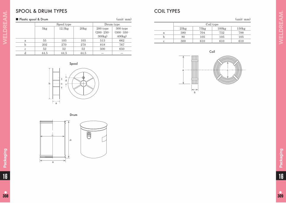
1616
308 309308 309
Pac
kag
ing
Pac
kag
ing
SPOOL & DRUM TYPES■ Plastic spool & Drum (unit: mm)
Spool type Drum type5kg 12.5kg 20kg 200 type
(200· 250· 300kg)
300 type(300· 350·
400kg)a 55 103 103 513 662b 202 270 270 818 767c 52 52 52 500 650d 44.5 44.5 44.5 ― ―
Spool
a
b cd
Drum
c
a
b
COIL TYPES(unit: mm)
Coil type25kg 75kg 100kg 150kg
a 380 704 732 788b 80 105 105 105c 300 610 610 610
Coil
c
b
a
Memo
16
310310
311
Approval List of Welding Materials
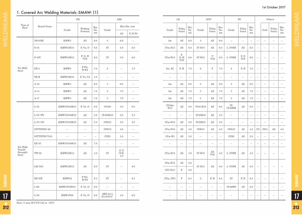
1st October 2017
1. Covered Arc Welding Materials -SMAW- (1)
Type ofSteel Brand Name
NK ABS LR DNV BV Others
Grade WeldingPosition
Max.Dia.mm
GradeMax.Dia. mm
Grade Welding Position
Max.Dia.mm
Grade Welding Position
Max.Dia.mm
Grade Welding Position
Max.Dia.mm
Grade WeldingPosition
Max.Dia.mmAll F, H-Fil
For Mild Steel
NS-03Hi KMW3 All 6.0 3 6.0 ― 3m All 6.0 3 All 6.0 ― ― ― ― ― ― ―
S-16 KMW53H15 F, Vu, O 6.0 3Y 5.0 6.0 3Ym H15 All 6.0 3Y H10 All 6.0 3, 3YHH All 6.0 ― ― ― ―
S-16V KMW53H15 F, O, H (Vd) 6.0 3Y 5.0 6.0 3Ym H15
F, O, H (Vd)
6.0 3Y H10 F (Vd) 6.0 3, 3YHH F, O
(Vd) 6.0 ― ― ― ―
EX-4 KMW2 F-Fil, H-Fil 7.0 2 ― 7.0 2m, 2G F, H 7.0 2 F 7.0 2 F, H 7.0 ― ― ― ―
TK-R KMW53H10 F, Vu, Vd 4.0 ― ― ― ― ― ― ― ― ― ― ― ― ― ― ― ―
A-10 KMW3 All 6.0 3 6.0 ― 3m All 6.0 3 All 6.0 3 All 6.0 ― ― ― ―
A-14 KMW3 All 7.0 3 7.0 ― 3m All 7.0 3 All 7.0 3 All 7.0 ― ― ― ―
A-17 KMW3 All 7.0 3 7.0 ― 3m All 7.0 3 All 7.0 3 All 7.0 ― ― ― ―
For High Tensile Strength Steel
L-55 KMW53Y40H15 F, Vu, O 6.0 3Y400 5.0 6.0 3Y40m H15 All 6.0 3Y40 H10 All 6.0 3Y,
3Y40HH All 6.0 ― ― ― ―
L-55•PX KMW53Y40H10 All 5.0 3Y400H10 5.0 5.0 ― ― ― 3Y40H10 All 5.0 ― ― ― ― ― ― ―
L-55•GP KMW53Y40H10 All 5.0 3YH10 5.0 5.0 3Ym H10 All 5.0 3Y40H10 All 5.0 ― ― ― ― ― ― ―
NITTETSU-56 ― ― ― 3YH10 4.0 ― 3Ym H10 All 4.0 3YH10 All 4.0 3YH10 All 4.0 CCS 3YH10 All 4.0
NITTETSU7018 ― ― ― 3YH5 5.0 ― 3Ym H5 All 5.0 ― ― ― 3YH5 All 5.0 ― ― ― ―
EX-55 KMW53Y40H15 All 7.0 ― ― ― ― ― ― ― ― ― ― ― ― ― ― ― ―
TW-50 KMW53H15 All 4.0 3YF, O (Vd): 4.0
― 3Ym H15 All 4.0 3Y H10 All (Vd) 4.0 3, 3YHH All 4.0 ― ― ― ―
LM-55G KMW53H15 All 8.0 3Y ― 8.0 3Ym H15 All 8.0
3Y H15 All 8.0 3, 3YHH All 8.0 ― ― ― ―3YG H15 F 8.0
EX-50F KMW52 F-Fil, H-Fil 6.4 2Y ― 6.4 2Ym, 2YG F 6.4 2 F, H 6.4 2Y F, H 6.4 ― ― ― ―
L-60 KMW3Y50H10 F, Vu, O 6.0 ― ― ― ― ― ― ― ― ― 3Y46HH All 6.0 ― ― ― ―
L-80 KMW4Y69 F, Vu, O 6.0 AWS A5.5 E11016-G1) 4.0 6.0 ― ― ― ― ― ― ― ― ― ― ― ― ―
Note; 1) min.AV.CVN 34J at −40°C
1717312 313312 313
SM
AW
SM
AW
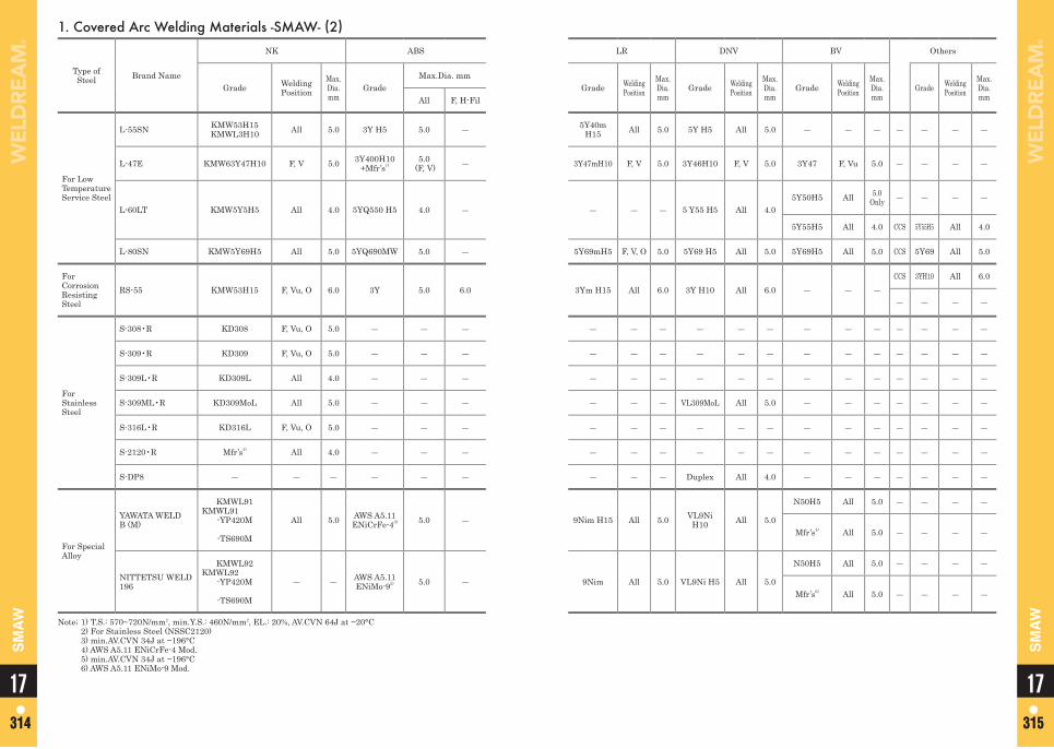
1. Covered Arc Welding Materials -SMAW- (2)
Type ofSteel Brand Name
NK ABS LR DNV BV Others
Grade WeldingPosition
Max.Dia.mm
GradeMax.Dia. mm
Grade Welding Position
Max.Dia.mm
Grade Welding Position
Max.Dia.mm
Grade Welding Position
Max.Dia.mm
Grade WeldingPosition
Max.Dia.mmAll F, H-Fil
For Low Temperature Service Steel
L-55SN KMW53H15 KMWL3H10 All 5.0 3Y H5 5.0 ― 5Y40m
H15 All 5.0 5Y H5 All 5.0 ― ― ― ― ― ― ―
L-47E KMW63Y47H10 F, V 5.0 3Y400H10 +Mfr’s1)
5.0 (F, V) ― 3Y47mH10 F, V 5.0 3Y46H10 F, V 5.0 3Y47 F, Vu 5.0 ― ― ― ―
L-60LT KMW5Y5H5 All 4.0 5YQ550 H5 4.0 ― ― ― ― 5 Y55 H5 All 4.05Y50H5 All 5.0
Only ― ― ― ―
5Y55H5 All 4.0 CCS 5Y55H5 All 4.0
L-80SN KMW5Y69H5 All 5.0 5YQ690MW 5.0 ― 5Y69mH5 F, V, O 5.0 5Y69 H5 All 5.0 5Y69H5 All 5.0 CCS 5Y69 All 5.0
For Corrosion Resisting Steel
RS-55 KMW53H15 F, Vu, O 6.0 3Y 5.0 6.0 3Ym H15 All 6.0 3Y H10 All 6.0 ― ― ―CCS 3YH10 All 6.0
― ― ― ―
For Stainless Steel
S-308•R KD308 F, Vu, O 5.0 ― ― ― ― ― ― ― ― ― ― ― ― ― ― ― ―
S-309•R KD309 F, Vu, O 5.0 ― ― ― ― ― ― ― ― ― ― ― ― ― ― ― ―
S-309L•R KD309L All 4.0 ― ― ― ― ― ― ― ― ― ― ― ― ― ― ― ―
S-309ML•R KD309MoL All 5.0 ― ― ― ― ― ― VL309MoL All 5.0 ― ― ― ― ― ― ―
S-316L•R KD316L F, Vu, O 5.0 ― ― ― ― ― ― ― ― ― ― ― ― ― ― ― ―
S-2120•R Mfr’s2) All 4.0 ― ― ― ― ― ― ― ― ― ― ― ― ― ― ― ―
S-DP8 ― ― ― ― ― ― ― ― ― Duplex All 4.0 ― ― ― ― ― ― ―
For Special Alloy
YAWATA WELD B (M)
KMWL91 KMWL91
-YP420M
-TS690M
All 5.0 AWS A5.11 ENiCrFe-43) 5.0 ― 9Nim H15 All 5.0 VL9Ni
H10 All 5.0
N50H5 All 5.0 ― ― ― ―
Mfr’s4) All 5.0 ― ― ― ―
NITTETSU WELD 196
KMWL92 KMWL92
-YP420M
-TS690M
― ― AWS A5.11 ENiMo-95) 5.0 ― 9Nim All 5.0 VL9Ni H5 All 5.0
N50H5 All 5.0 ― ― ― ―
Mfr’s6) All 5.0 ― ― ― ―
Note; 1) T.S.: 570~720N/mm2, min.Y.S.: 460N/mm2, EL.: 20%, AV.CVN 64J at −20°C 2) For Stainless Steel (NSSC2120) 3) min.AV.CVN 34J at −196°C 4) AWS A5.11 ENiCrFe-4 Mod. 5) min.AV.CVN 34J at −196°C 6) AWS A5.11 ENiMo-9 Mod.
1717314 315314 315
SM
AW
SM
AW
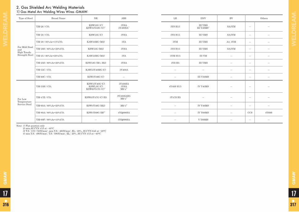
2. Gas Shielded Arc Welding Materials1) Gas Metal Arc Welding Wires Wires -GMAW-
Type of Steel Brand Name NK ABS LR DNV BV Others
For Mild Steel and High Tensile Strength Steel
YM-26 / CO2KSW53G (C)
KSW53Y40G (C)1)3YSA
3Y400SA1) 3YS H15 III YMSIII Y40MS1) SA3YM ― ―
YM-28 / CO2 KSW53G (C) 3YSA 3YS H15 III YMS SA3YM ― ―
YM-28 / 85%Ar+15%CO2 KAW53MG (M2) 3YA 3YM III YMS A3, 3YM ― ―
YM-28S / 80%Ar+20%CO2 KSW53G (M2) 3YSA 3YS H15 III YMS SA3YM ― ―
YM-25 / 80%Ar+20%CO2 KAW53MG (M2) 3YA 3YM H15 III YM ― ― ―
YM-25S / 80%Ar+20%CO2 KSW53G (M1, M2) 3YSA 3YS H5 III YMS ― ― ―
YM-55C / CO2 KAW53Y40MG (C) 3Y400A ― ― ― ― ―
YM-60C / CO2 KSW3Y46G (C) ― ― III Y50MS ― ― ―
For Low Temperature Service Steel
YM-55H / CO2
KSW53Y40G (C)KSWL3G (C)
KSW63Y47G (C)1)
3Y400SA3YSAMfr’s2)
4Y40S H15 IV Y40MS ― ― ―
YM-47E / CO2 KSW63Y47G (C) H5 3Y400SAH5Mfr’s3) 3Y47S H5 ― ― ― ―
YM-60A / 80%Ar+20%CO2 KSW4Y46G (M2) Mfr’s4) ― IV Y46MS ― ― ―
YM-80A / 80%Ar+20%CO2 KSW4Y69G (M)2) 4YQ690SA ― IV Y69MS ― CCS 4Y69S
YM-69F / 90%Ar+10%CO2 ― 5YQ690SA ― V Y69MS ― ― ―
Note; 1) Flat position only 2) min.AV.CVN 47J at −40°C 3) T.S.: 570~720N/mm2, min.Y.S.: 460N/mm2, EL.: 20%, AV.CVN 64J at −20°C 4) min.Y.S.: 490N/mm2, T.S.: 590N/mm2, EL.: 20%, AV.CVN 47J at −40°C
1717316 317316 317
GM
AW
GM
AW
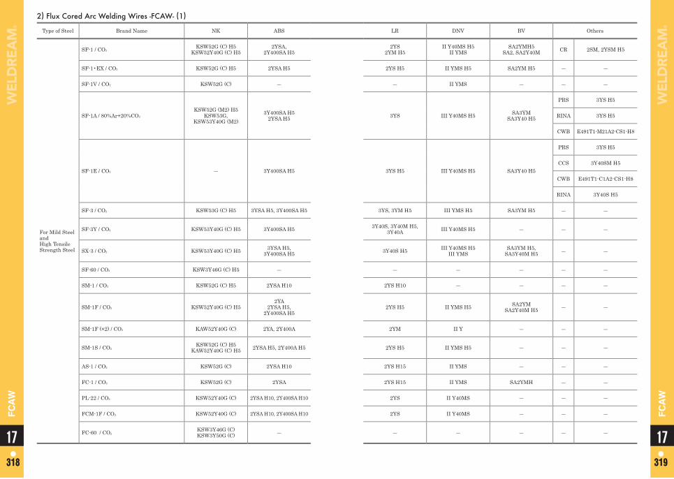
2) Flux Cored Arc Welding Wires -FCAW- (1)
Type of Steel Brand Name NK ABS LR DNV BV Others
For Mild Steel and High Tensile Strength Steel
SF-1 / CO2KSW52G (C) H5
KSW52Y40G (C) H52YSA,
2Y400SA H52YS
2YM H5II Y40MS H5
II YMSSA2YMH5
SA2, SA2Y40M CR 2SM, 2YSM H5
SF-1•EX / CO2 KSW52G (C) H5 2YSA H5 2YS H5 II YMS H5 SA2YM H5 ― ―
SF-1V / CO2 KSW52G (C) ― ― II YMS ― ― ―
SF-1A / 80%Ar+20%CO2
KSW52G (M2) H5KSW53G,
KSW53Y40G (M2)3Y400SA H5
2YSA H5 3YS III Y40MS H5 SA3YMSA3Y40 H5
PRS 3YS H5
RINA 3YS H5
CWB E491T1-M21A2-CS1-H8
SF-1E / CO2 ― 3Y400SA H5 3YS H5 III Y40MS H5 SA3Y40 H5
PRS 3YS H5
CCS 3Y40SM H5
CWB E491T1-C1A2-CS1-H8
RINA 3Y40S H5
SF-3 / CO2 KSW53G (C) H5 3YSA H5, 3Y400SA H5 3YS, 3YM H5 III YMS H5 SA3YM H5 ― ―
SF-3Y / CO2 KSW53Y40G (C) H5 3Y400SA H5 3Y40S, 3Y40M H5, 3Y40A III Y40MS H5 ― ― ―
SX-3 / CO2 KSW53Y40G (C) H5 3YSA H5, 3Y400SA H5 3Y40S H5 III Y40MS H5
III YMSSA3YM H5,
SA3Y40M H5 ― ―
SF-60 / CO2 KSW3Y46G (C) H5 ― ― ― ― ― ―
SM-1 / CO2 KSW52G (C) H5 2YSA H10 2YS H10 ― ― ― ―
SM-1F / CO2 KSW52Y40G (C) H52YA
2YSA H5, 2Y400SA H5
2YS H5 II YMS H5 SA2YM SA2Y40M H5 ― ―
SM-1F (×2) / CO2 KAW52Y40G (C) 2YA, 2Y400A 2YM II Y ― ― ―
SM-1S / CO2KSW52G (C) H5
KAW52Y40G (C) H5 2YSA H5, 2Y400A H5 2YS H5 II YMS H5 ― ― ―
AS-1 / CO2 KSW52G (C) 2YSA H10 2YS H15 II YMS ― ― ―
FC-1 / CO2 KSW52G (C) 2YSA 2YS H15 II YMS SA2YMH ― ―
PL-22 / CO2 KSW52Y40G (C) 2YSA H10, 2Y400SA H10 2YS II Y40MS ― ― ―
FCM-1F / CO2 KSW52Y40G (C) 2YSA H10, 2Y400SA H10 2YS II Y40MS ― ― ―
FC-60 / CO2KSW3Y46G (C)KSW3Y50G (C) ― ― ― ― ― ― 1717
318 319318 319
FC
AW
FC
AW
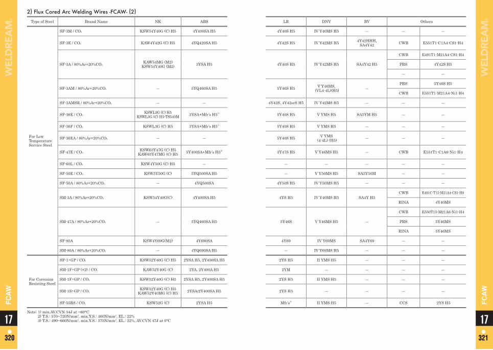
2) Flux Cored Arc Welding Wires -FCAW- (2)
Type of Steel Brand Name NK ABS LR DNV BV Others
For Low Temperature Service Steel
SF-3M / CO2 KSW54Y40G (C) H5 4Y400SA H5 4Y40S H5 IV Y40MS H5 ― ― ―
SF-3E / CO2 KAW4Y42G (C) H5 4YQ420SA H5 4Y42S H5 IV Y42MS H5 4Y42HHH, SA4Y42 CWB E551T1-C1A4-CS1-H4
SF-3A / 80%Ar+20%CO2KAW54MG (M2)
KSW54Y40G (M2) 3YSA H5 4Y40S H5 IV Y42MS H5 SA4Y42 H5
CWB E491T1-M21A4-CS1-H4
PRS 4Y42S H5
― ―
SF-3AM / 80%Ar+20%CO2 ― 5YQ460SA H5 5Y46S H5 V Y46MS, (VL4-4L)(H5) ―
PRS 5Y46S H5
CWB E551T1-M21A4-Ni1-H4
SF-3AMSR / 80%Ar+20%CO2 ― ― 4Y42S, 4Y42srS H5 IV Y42MS H5 ― ― ―
SF-36E / CO2KSWL3G (C) H5
KSWL3G (C) H5-TS540M 3YSA+Mfr’s H51) 5Y40S H5 V YMS H5 SA5YM H5 ― ―
SF-36F / CO2 KSWL3G (C) H5 3YSA+Mfr’s H51) 5Y40S H5 V YMS H5 ― ― ―
SF-36EA / 80%Ar+20%CO2 ― ― 5Y40S H5 V YMS (4-4L) (H5) ― ― ―
SF-47E / CO2KSW63Y47G (C) H5
KAW63Y47MG (C) H5 5Y400SA+Mfr’s H52) 3Y47S H5 V Y46MS H5 ― CWB E551T1-C1A6-Ni1-H4
SF-60L / CO2 KSW4Y50G (C) H5 ― ― ― ― ― ―
SF-50E / CO2 KSW5Y50G (C) 5YQ500SA H5 ― V Y50MS H5 SA5Y50M ― ―
SF-50A / 80%Ar+20%CO2 ― 4YQ500SA 4Y50S H5 IV Y50MS H5 ― ― ―
SM-3A / 80%Ar+20%CO2 KSW54Y40G(C) 4Y400SA H5 4YS H5 IV Y40MS H5 SA4Y H5CWB E491C-T15-M21A4-CS1-H8
RINA 4Y40MS
SM-47A / 80%Ar+20%CO2 ― 5YQ460SA H5 5Y46S V Y46MS H5 ―
CWB E550T15-M21A6-Ni1-H4
PRS 5Y46MS
RINA 5Y46MS
SF-80A KSW4Y69G(M2) 4Y690SA 4Y69 IV Y69MS SA4Y69 ― ―
SM-80A / 80%Ar+20%CO2 ― 4YQ690SA H5 ― IV Y69MS H5 ― ― ―
For Corrosion Resisting Steel
SF-1•GP / CO2 KSW52Y40G (C) H5 2YSA H5, 2Y400SA H5 2YS H5 II YMS H5 ― ― ―
SM-1F•GP (×2) / CO2 KAW52Y40G (C) 2YA, 2Y400A H5 2YM ― ― ― ―
SM-1F•GP / CO2 KSW52Y40G (C) H5 2YSA H5, 2Y400SA H5 2YS H5 II YMS H5 ― ― ―
SM-1S•GP / CO2KSW52Y40G (C) H5
KAW52Y40MG (C) H5 2YSA/2Y400SA H5 2YS H5 ― ― ― ―
SF-55RS / CO2 KSW52G (C) 2YSA H5 Mfr’s3) II YMS H5 ― CCS 2YS H5
Note; 1) min.AV.CVN 34J at −60°C 2) T.S.: 570~720N/mm2, min.Y.S.: 460N/mm2, EL.: 22% 3) T.S.: 490~660N/mm2, min.Y.S.: 375N/mm2, EL.: 22%, AV.CVN 47J at 0°C 1717
320 321320 321
FC
AW
FC
AW
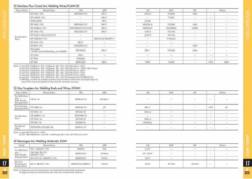
2) Stainless Flux Cored Arc Welding Wires-FCAW-(3)Type of Steel Brand Name NK ABS LR DNV BV Others
For Stainless Steel
SF-308L / CO2 KW308LG (C) Mfr’s1) 304L S VL308L 308L ― ―SF-308LK / CO2 ― Mfr’s2) ― VL5Ni ― ― ―FCM-308LK ― Mfr’s VL5Ni ― ― ― ―SF-309L / CO2 KW309LG (C) Mfr’s3) SS/CMn S VL309L 309L ― ―SF-309MoL / CO2 KW309MoLG (C)-315M Mfr’s4) SS/CMn S VL309MoL 309Mo ― ―SF-316L / CO2 KW316LG (C) Mfr’s5) 316L S VL316L ― ― ―SF-316LP / 80%Ar+20%CO2 ― ― 316L S VL316L ― ― ―SF-329J3LP / CO2 ― AWS A5.22 E2209T1-1 ― O-Duplex ― ― ―SF-2120 / CO2 Mfr’s6) ― ― ― ― ― ―SF-DP8 / CO2 KW2209G (C) ― ― ― 2205 ― ―SF-N309L (FCAW and Self Shielding, not GMAW) KW309LN Mfr’s2) Mfr’s7) VL309L 309L ― ―
FC-2120 Mfr’s ― ― ― ― ― ―FC-DP8 KW2209 ― ― ― ― ― ―FC-9NI KSWL92G Mfr’s 9NiS VL9Ni ― CCS 9NiS
Note; 1) min.Y.S.: 245N/mm2, T.S.: 510N/mm2, EL.: 35%, AV.CVN 34J at −20°C 2) min.Y.S.: 245N/mm2, T.S.: 510N/mm2, EL.: 35%, AV.CVN 31J at −196°C LE:0.38mm 3) min.Y.S.: 245N/mm2, T.S.: 510N/mm2, EL.: 30%, AV.CVN 34J at −20°C 4) min.Y.S.: 205N/mm2, T.S.: 510N/mm2, EL.: 20%, AV.CVN 27J at −20°C 5) min.Y.S.: 205N/mm2, T.S.: 510N/mm2, EL.: 35%, AV.CVN 27J at −20°C 6) min.Y.S.: 450N/mm2, T.S.: 690N/mm2, EL.: 15% for Stainless Steel (NSSC2120) 7) SS/CMn, suitable for welding stainless steel Grade(s) other than the duplex types to
any of the structural grades of ship steel for chemical use only.
3) Gas Tungsten Arc Welding Rods and Wires -GTAW-Type of Steel Brand Name NK ABS LR DNV BV Others
For Mild Steel and High Tensile Strength Steel
YT-28 / Ar KSWL3G (I) 4Y+Mfr’s1) ― ― ― ― ―
For Corrosion Resisting Steel YT-55RS / Ar KSW52G (I) 2Y Mfr’s2) ― ― CCS 2Y
For Stainless Steel
YT-308L / Ar KY308L (I) ― 304L m ― ― ― ―YT-309MoL / Ar KY309Mo (I) ― ― ― ― ― ―YT-316L / Ar KY316L (I) ― 316L m ― ― ― ―YT-DP8 / Ar KY2209 (I) ― S31803m ― ― ― ―
For Special Alloy NITTETSU FILLER 196 KAWL91 (I) ― ― ― ― ― ―
Note; 1) min.AV.CVN 47J at −60°C 2) T.S.: 490~660N/mm2, min.Y.S.: 375N/mm2, EL.: 22%, AV.CVN 47J at 0°C
4) Electrogas Arc Welding Materials -EGW-Grade Brand Name NK ABS LR DNV BV Others
For Mild Steel and High Tensile Strength Steel
EG-1 / SB-60V / CO2 KEW52 2YA 2, 2Y1) ― ― ― ―YM-55H / EG-3T / SB-60VT / CO2
KEW53Y40 3Y400A 3Y2), 3Y402) ― ― ― ―
EG-47T (×2) / SB-60VT / CO2 KEW63Y47 5Y470 3Y472) ― ― ― ―For Low Temperature Service Steel
EG-3 / SB-60V / CO2 KEW53Y40, KEW53 4Y400 4Y402) IV Y40 AV4Y40 ― ―
Note; 1) Approval may be restricted for use with steel treated with aluminium. 2) Approval may be restricted for use with steel treated with niobium.
1717322 323322 323
EG
W /
GTA
W
EG
W /
GTA
W
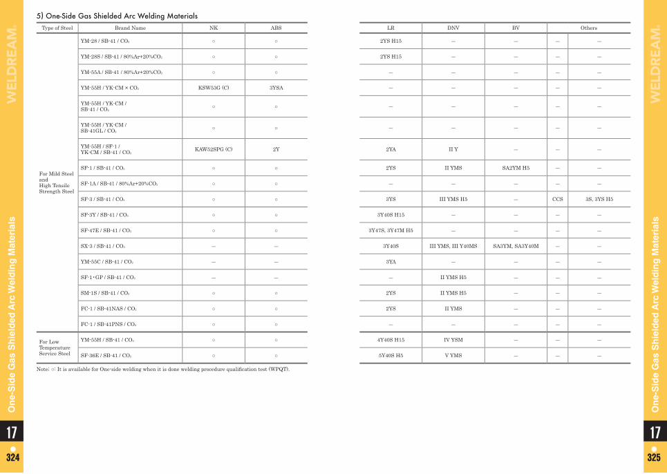
5) One-Side Gas Shielded Arc Welding MaterialsType of Steel Brand Name NK ABS LR DNV BV Others
For Mild Steel and High Tensile Strength Steel
YM-28 / SB-41 / CO2 ○ ○ 2YS H15 ― ― ― ―
YM-28S / SB-41 / 80%Ar+20%CO2 ○ ○ 2YS H15 ― ― ― ―
YM-55A / SB-41 / 80%Ar+20%CO2 ○ ○ ― ― ― ― ―
YM-55H / YK-CM × CO2 KSW53G (C) 3YSA ― ― ― ― ―
YM-55H / YK-CM / SB-41 / CO2
○ ○ ― ― ― ― ―
YM-55H / YK-CM / SB-41GL / CO2
○ ○ ― ― ― ― ―
YM-55H / SF-1 / YK-CM / SB-41 / CO2
KAW52SPG (C) 2Y 2YA II Y ― ― ―
SF-1 / SB-41 / CO2 ○ ○ 2YS II YMS SA2YM H5 ― ―
SF-1A / SB-41 / 80%Ar+20%CO2 ○ ○ ― ― ― ― ―
SF-3 / SB-41 / CO2 ○ ○ 3YS III YMS H5 ― CCS 3S, 3YS H5
SF-3Y / SB-41 / CO2 ○ ○ 3Y40S H15 ― ― ― ―
SF-47E / SB-41 / CO2 ○ ○ 3Y47S, 3Y47M H5 ― ― ― ―
SX-3 / SB-41 / CO2 ― ― 3Y40S III YMS, III Y40MS SA3YM, SA3Y40M ― ―
YM-55C / SB-41 / CO2 ― ― 3YA ― ― ― ―
SF-1•GP / SB-41 / CO2 ― ― ― II YMS H5 ― ― ―
SM-1S / SB-41 / CO2 ○ ○ 2YS II YMS H5 ― ― ―
FC-1 / SB-41NAS / CO2 ○ ○ 2YS II YMS ― ― ―
FC-1 / SB-41PNS / CO2 ○ ○ ― ― ― ― ―
For Low Temperature Service Steel
YM-55H / SB-41 / CO2 ○ ○ 4Y40S H15 IV YSM ― ― ―
SF-36E / SB-41 / CO2 ○ ○ 5Y40S H5 V YMS ― ― ―
Note; ○: It is available for One-side welding when it is done welding procedure qualifi cation test (WPQT).
1717324 325324 325
On
e-S
ide
Gas
Sh
ield
ed A
rc W
eld
ing
Mat
eria
ls
On
e-S
ide
Gas
Sh
ield
ed A
rc W
eld
ing
Mat
eria
ls
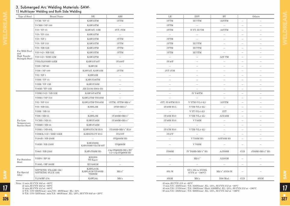
3. Submerged Arc Welding Materials -SAW-1) Multi-layer Welding and Both Side Welding
Type of Steel Brand Name NK ABS LR DNV BV Others
For Mild Steel and High Tensile Strength Steel
Y-CM / YF-15 KAW53TM 3YTM 3YTM III YTM A2YTM ― ―
Y-CMS / NF-100 KAW53TM ― 3YTM ― ― ― ―
Y-D / YF-15 KAW52T, 53M 2YT, 3YM 2YTM II YT, III YM A2YTM ― ―
Y-D / YF-15A KAW52TM ― ― ― ― ― ―
Y-D / NF-1 KAW53TM 3YTM 3YTM ― ― ― ―
Y-D / NF-310 KAW53TM 3YTM 3YTM III YTM ― ― ―
Y-D / NB-55E KAW53TM 3YTM 3YTM III YTM ― ― ―
Y-D (×2) / NB-55E KAW53TM 3YTM 3YTM III YTM ― ― ―
Y-D (×2) / NSH-52M KAW52TM ― ― ― A2Y TM ― ―
Y-DL(X2)/NSH-55ER KAW53Y40T 3Y400T 3Y40T ― ― ― ―
Y-DS / NF-60 KAW1M ― ― ― ― ― ―
Y-DS / NF-100 KAW52T, KAW53M 2YTM 2YT 3YM ― ― ― ―
Y-E / NF-1 KAW53M ― ― ― ― ― ―
Y-DM / YF-15 KAW3Y46TM ― ― ― ― ― ―
Y-DM / YF-15B KAW3Y50M ― ― ― ― ― ―
Y-80M / YF-15B JIS Z3183 S804-H4 ― ― ― ― ― ―
For Low Temperature Service Steel
Y-DM3 (×2) / NB-55E KAW54Y40TM ― ― IV Y40TM ― ― ―
Y-DM3 / NF-310 KAWL3TM-TS540M ― ― ― ― ― ―
Y-E / NF-310 KAWL3TM-TS540M 3YTM, 3YTM+Mfr’s1) 4YT, 5Y40TM H15 V YTM (VL4-4L) A5YTM ― ―
Y-D / NB-55L KAWL3M 3YM+Mfr’s2) 4Y40M H15 V YM (VL4-4L) ― ― ―
Y-DM / NB-55 ― ― ― V YT (VL4-4L) 5YT ― ―
Y-DS / NB-55 KAWL3M 3Y400M+Mfr’s3) 5Y40M H10 V YM (VL4-4L) A5Y40M ― ―
Y-CMS / NB-55 KAW5Y46M 5Y400M+Mfr’s4) 5Y46M H10 V Y46M ― ― ―
Y-DMS / NB-55 KAW4Y46M ― ― ― ― ― ―
Y-DM3 / NB-60L KAW63Y47M H10 3Y400M+Mfr’s5) H10 3Y47M H10 V YM (VL4-4L) ― ― ―
Y-DM3L (×2) / NSH-55ER KAW63Y47T H10 5Y470T 3Y47T ― ― ― ―
Y-204B / NB-250H ― 5YQ500M H5 ― V Y50M H5 A5Y50M H5 ― ―
Y-80M / NB-250H KAW4Y69M, KAW4Y69H-VE47M-60T 5YQ690M ― V Y69M ― ― ―
Y-80J / NB-250J KAW4Y69M H5 4.8φ:4YQ690M+Mfr’s H56)
3.2~4.0φ:5YQ690M H5 5Y69M IV Y69M+Mfr’s6) H5 A4Y69M CCS 4Y69M+Mfr’s6) H5
For Stainless Steel
Y-DP8 / BF-30 KD2209TS Equiv ― ― Mfr’s7) A2205M ― ―
Y-308L / BF-300M KU308LM ― ― ― ― ― ―
For Special Alloy
NITTETSU FILLER 196 / NITTETSU FLUX 10H
KAWL91M, KAWL91M-YP400M-
TS690MMfr’s8) 9Ni M NV1.5Ni to NV9Ni
(CVN at −196°C) Mfr’s9) AN50 M ― ―
Y-276/BF-276 KAWL92 Mfr’s 9NiM Mfr’s N90 Mod. CCS 9NiM
Note; 1) min.AV.CVN 30J at −60°C 2) min.AV.CVN 40J at −60°C 3) min.AV.CVN 41J at −60°C 4) T.S.: 570~690N/mm2, min.Y.S.: 460N/mm2, EL.: 22% 5) T.S.: 570-720N/mm2, min.Y.S.: 460N/mm2, EL.: 20%, AV.CVN 64J at−-20°C
6) min.AV.CVN 47J at −60°C 7) min.Y.S.: 450N/mm2, T.S.: 620N/mm2, EL.: 25%, AV.CVN 27J at −20°C 8) min.Y.S.: 375N/mm2, T.S.: 590N/mm2 (Butt: 630MPa), EL.: 25%, AV.CVN 27J at −196°C 9) min.Y.S.: 380N/mm2, T.S.: 600N/mm2, EL.: 25%, AV.CVN 34J at −196°C 1717
326 327326 327
SA
W
SA
W
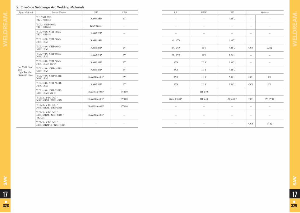
2) One-Side Submerge Arc Welding MaterialsType of Steel Brand Name NK ABS LR DNV BV Others
For Mild Steel and High TensileStrength Stee
Y-D / NB-55E / YK-D / SB-51 KAW52SP 2Y ― ― A2YU ― ―
Y-DL / NSH-50M / YK-D / SB-51 KAW52MP ― ― ― ― ― ―
Y-DL (×2) / NSH-50M / YK-D / SB-51 KAW52SP ― ― ― ― ― ―
Y-DL (×2) / NSH-50M / NSH-1RM KAW52SP ― 2A, 2YA ― A2YU ― ―
Y-DL (×3) / NSH-50M / NSH-1RM KAW52SP 2Y 2A, 2YA II Y A2YU CCS 2, 2Y
Y-DL (×4) / NSH-50M / NSH-1RM KAW52SP 2Y 2A, 2YA II Y A2YU ― ―
Y-DL (×4) / NSH-50M / NSH-1RM / YK-D KAW53SP 3Y 3YA III Y A3YU ― ―
Y-DL (×2) / NSH-55ER / NSH-1RM KAW53SP 3Y 3YA III Y A3YU ― ―
Y-DL (×3) / NSH-55ER / NSH-1RM KAW53Y40SP 3Y 3YA III Y A3YU CCS 3Y
Y-DL (×4) / NSH-55ER / NSH-1RM KAW53SP 3Y 3YA III Y A3YU CCS 3Y
Y-DL (×4) / NSH-55ER / NSH-1RM / YK-D KAW53Y40SP 3Y400 ― III Y40 ― ― ―
Y-DM3 / Y-DL (×2) / NSH-55EM / NSH-1RM KAW53Y40SP 3Y400 3YA, 3Y40A III Y40 A3Y40U CCS 3Y, 3Y40
Y-DM3 / Y-DL (×3) /NSH-55EM / NSH-1RM KAW53Y40SP 3Y400 ― ― ― ― ―
Y-DM3 / Y-DL (×2) / NSH-55EM / NSH-1RM / YK-CM
KAW53Y40SP ― ― ― ― ― ―
Y-DM3 / Y-DL (×2) / NSH-55EM•R / NSH-1RM ― ― ― ― ― CCS 3Y42
1717328 329328 329
SA
W
SA
W
Memo
17330
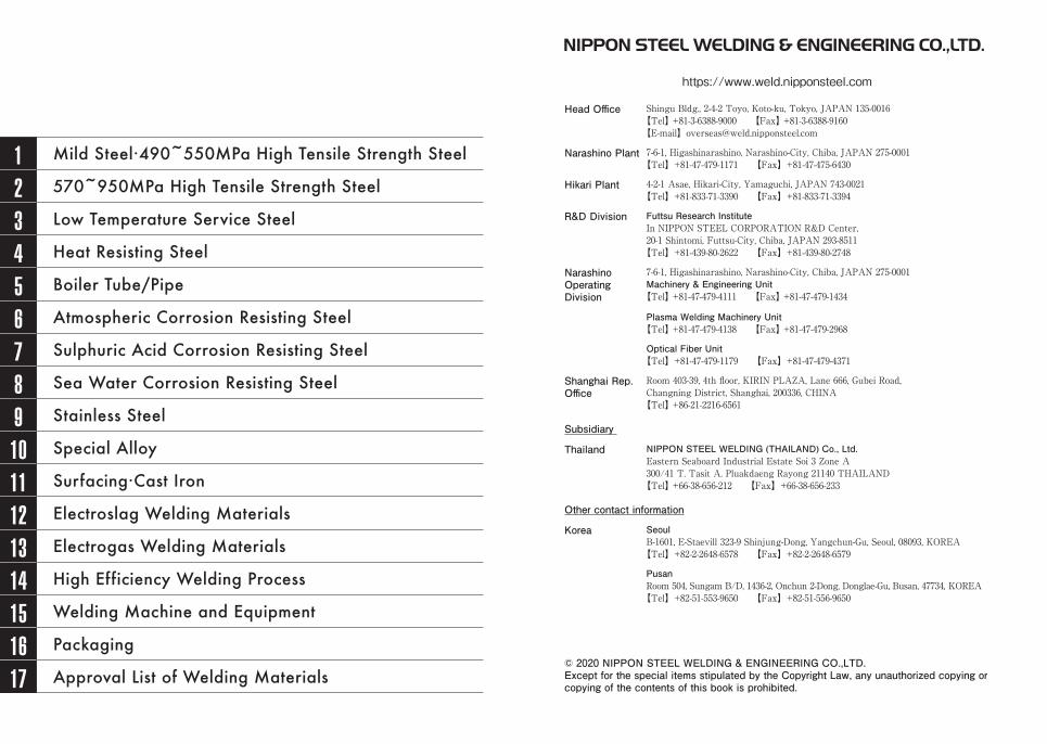
1 Mild Steel·490~550MPa High Tensile Strength Steel
2 570~950MPa High Tensile Strength Steel
3 Low Temperature Service Steel
4 Heat Resisting Steel
5 Boiler Tube/Pipe
6 Atmospheric Corrosion Resisting Steel
7 Sulphuric Acid Corrosion Resisting Steel
8 Sea Water Corrosion Resisting Steel
9 Stainless Steel
10 Special Alloy
11 Surfacing·Cast Iron
12 Electroslag Welding Materials
13 Electrogas Welding Materials
14 High Efficiency Welding Process
15 Welding Machine and Equipment
16 Packaging
17 Approval List of Welding Materials
https://www.weld.nipponsteel.com
Head Office Shingu Bldg., 2-4-2 Toyo, Koto-ku, Tokyo, JAPAN 135-0016【Tel】 +81-3-6388-9000 【Fax】 +81-3-6388-9160【E-mail】[email protected]
Narashino Plant 7-6-1, Higashinarashino, Narashino-City, Chiba, JAPAN 275-0001【Tel】+81-47-479-1171 【Fax】+81-47-475-6430
Hikari Plant 4-2-1 Asae, Hikari-City, Yamaguchi, JAPAN 743-0021【Tel】+81-833-71-3390 【Fax】+81-833-71-3394
R&D Division Futtsu Research InstituteIn NIPPON STEEL CORPORATION R&D Center, 20-1 Shintomi, Futtsu-City, Chiba, JAPAN 293-8511
【Tel】+81-439-80-2622 【Fax】+81-439-80-2748
Narashino Operating Division
7-6-1, Higashinarashino, Narashino-City, Chiba, JAPAN 275-0001Machinery & Engineering Unit
【Tel】 +81-47-479-4111 【Fax】 +81-47-479-1434
Plasma Welding Machinery Unit【Tel】 +81-47-479-4138 【Fax】 +81-47-479-2968
Optical Fiber Unit【Tel】+81-47-479-1179 【Fax】+81-47-479-4371
Shanghai Rep. Office
Room 403-39, 4th floor, KIRIN PLAZA, Lane 666, Gubei Road, Changning District, Shanghai, 200336, CHINA
【Tel】 +86-21-2216-6561
Subsidiary
Thailand NIPPON STEEL WELDING (THAILAND) Co., Ltd.Eastern Seaboard Industrial Estate Soi 3 Zone A300/41 T. Tasit A. Pluakdaeng Rayong 21140 THAILAND
【Tel】 +66-38-656-212 【Fax】+66-38-656-233
Other contact information
Korea SeoulB-1601, E-Staevill 323-9 Shinjung-Dong, Yangchun-Gu, Seoul, 08093, KOREA
【Tel】+82-2-2648-6578 【Fax】+82-2-2648-6579
PusanRoom 504, Sungam B/D, 1436-2, Onchun 2-Dong, Donglae-Gu, Busan, 47734, KOREA
【Tel】+82-51-553-9650 【Fax】+82-51-556-9650
© 2020 NIPPON STEEL WELDING & ENGINEERING CO.,LTD.Except for the special items stipulated by the Copyright Law, any unauthorized copying or copying of the contents of this book is prohibited.


