Embed Size (px)
Citation preview
1
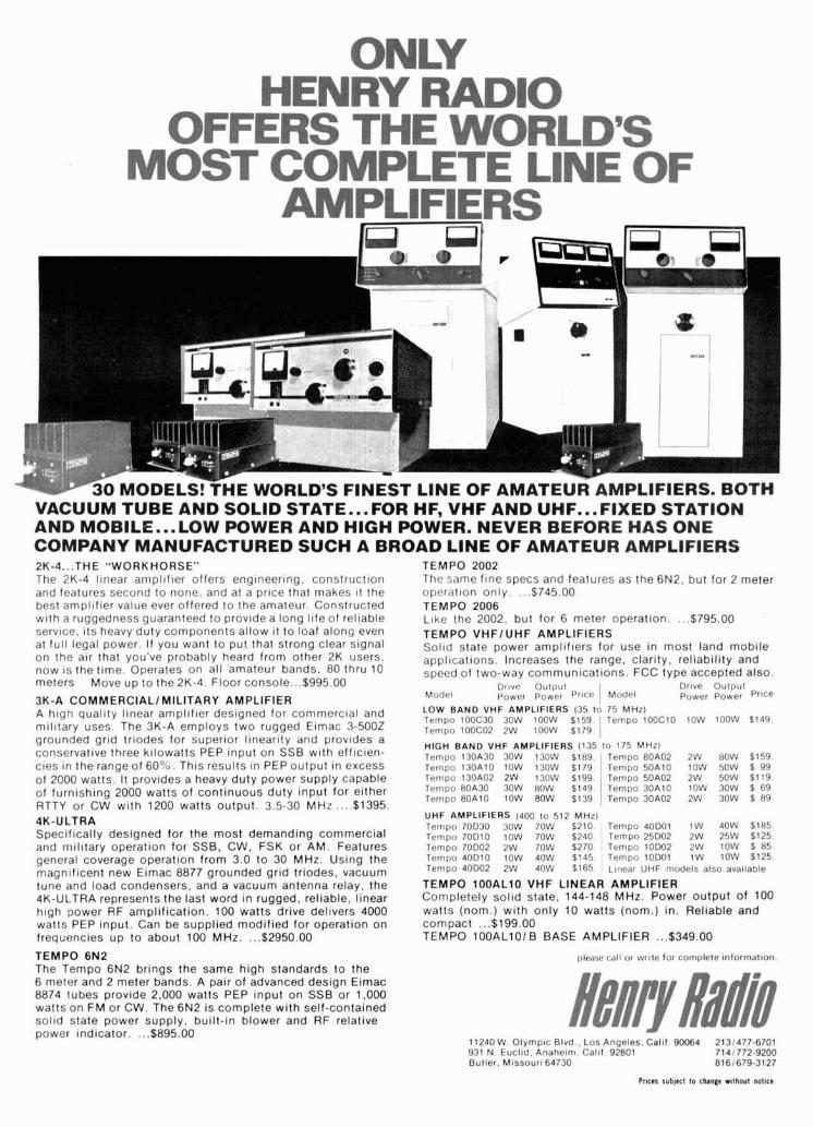
30 MODELS! THE WORLD'S FINEST LlNE OF AMATEUR AMPLIFIERS. BOTH VACUUM TUBE AND SOLID STATE...FOR HF, VHF AND UHF...FIXED STATION AND MOBILE...LOW POWER AND HIGH POWER. NEVER BEFORE HAS ONE COMPANY MANUFACTURED SUCH A BROAD LlNE OF AMATEUR AMPLIFIERS 2K-4. .THE "WORKHORSE" TEMPO 2002 The 2K-4 llnear arnplif~er offers englneerlng, construction T h r same flne specs and features as the 6N2, but for 2 meter and features second to none, and at a prlce that makes ~t the operation only $745 00 best ampllfler value ever offered to the amateur Constructed TEMPO 2006 wlth a ruggedness guaranteed to provlde a long llfe of rellable Like the 2002, but for 6 meter operation $795 00 servlce. ~ t s heavy duty components allow ~t to loaf along even TEMPO VHFIUHF AMPLIFIERS at full legal power If you want to put that strong clear slgnal Soltd state power ampllflers for use ~n most land mob~le on the alr that you've probably heard from other 2K users, appllcat~ons Increases the range, clar~ty, re l~ab~l l ty and now IS the tlme Operates on all amateur bands, 80 thru 10 speed of two-way commun~cat~ons FCC type accepted also. meters Move up to the 2K-4 Floor console $995 00 Drove Oulpul Drtve OUI~UI
3K-A COMMERClALlMlLlTARY AMPLIFIER Model power power Price I Model Power Power ProCe
A hlgh quallty l~near arnpllfler deslgned for commercial and ~ ~ ~ p ~ ~ ~ $ ~ F 3 ~ $ P ~ ~ d ~ R S $ ~ g t 0 ~ ~ ~ p ~ 2 ~ O O C 1 0 loow $149 mllltary uses The 3K-A employs two rugged Elmac 3-5002 Tempo 100C02 2 w ioow $179 1 grounded grld trlodes for superlor llnearlty and provldes a
BAND VHF (135 lo 175 MHz) conservat~ve three kilowatts PEP lnput on SSB w ~ t h efflclen- Tempo 130A30 30W 1 3 0 ~ $189 Tempo 80A02 2 w BOW $159
cles ~n the ranqe of 60% Thls results ~n PEP output ~n excess Temoo t3oAlo low 13ow $179 I T e m ~ o 50A10 low 50W $ 99 of 2000 watts.-lt provides a heavy duty power s"pply capable of furnishing 2000 watts of continuous duty input for either RTTY or CW with 1200 watts output. 3.5-30 MHz .... $1395. 4K-ULTRA Specifically designed for the most demanding commercial and military operation for SSB, CW, FSK or AM. Features general coverage operation from 3.0 to 30 MHz. Using the magnificent new Eimac 8877 grounded grid triodes, vacuum tune and load condensers, and a vacuum antenna relay, the 4K-ULTRA represents the last word in rugged, reliable, linear high power RF amplification. 100 watts drive delivers 4000 watts PEP input. Can be supplied modified for operation on frequencies up to about 100 MHz. ... $2950.00
TEMPO 6N2 The Tempo 6N2 brings the same high standards to the 6 meter and 2 meter bands. A pair of advanced design Eimac 8874 tubes provide 2,000 watts PEP input on SSB or 1,000 watts on FM or CW. The 6N2 is complete with self-contained solid state power supply, built-in blower and RF relative Dower indicator. . ..$895.00
UHF AMPLIFIERS (400 lo 512 MHz) Tempo 70D3O 30W 70W $210 Tempo 40DO1 1W 40W $185 Tempo 70D10 10W 70W $240 1 Tempo 25D02 2W 25W $125 Tempo 70D02 2W 70W $270 Tempo lOD02 2W 10W % 85 Tempo 40D10 10W 40W $'a5 Tempo lODOl 1W 10W $125 Tempo 4ODO2 2W 40W $165 L~near UHF models also avatlable
TEMPO lOOALlO VHF LINEAR AMPLIFIER Completely solld state, 144-148 MHz. Power output of 100 watts (nom.) with only 10 watts (nom.) ~ n . Reliable and compact ... $199.00 TEMPO lOOALlOl B BASE AMPLIFIER ... $349.00
~ e m b o 1 3 0 A 0 2 2W 130W $199 Tempo BOA30 30W 80W $149 Tempo BOA10 10W BOW $139
please call or write for complete informat~on.
~embo5OA02 2W 50W $119 Tempo 30A10 1OW 30W 8 69 Tempo 30AO2 2W 30W $ 89.
11240 W. Olympic Blvd . Los Angeles. Calif. 90064 2131477-6701 931 N Euclid. Anaheom. Call1 92801 71 4 1772-9200 Butler. Mossouro 64730 8161679-3127
Stay tuned for future programs.
.4
ONLY $595.00
NEW LOW PRICE
$119 5.00
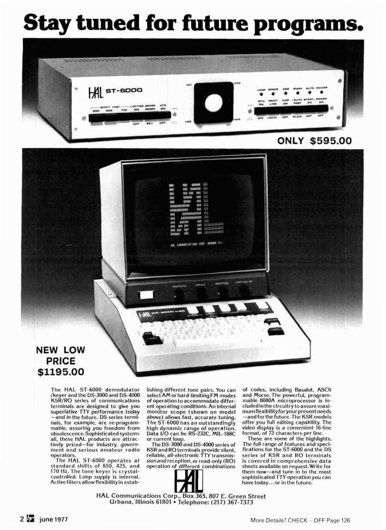
The H A L ST-6000 demodulator lishing different tone pairs. You can of codes, including Baudot, ASCII Ikeyer and the DS-3000 and DS-4000 select AM or hard-limiting FM modes and Morse. The powerful. program- KSR/RO series of communications of operation toaccommodate differ- mable 8080A microprocessor is in- terminals are designed to give you ent operating conditions. An internal cludedin thecircuitry toassure rnaxi- superlative TIT performance today monitor scope (shown on model rnumflexibilityforyourpresent needs -and in the future. DS series termi- above) allows fast, accurate tuning. -and forthe future.The KSR models nals, for example, are re-program- The ST-6000 has an outstandingly offer you full editing capability. The rnable, assuring you freedom from high dynamic range o f operation. video display is a convenient ld l ine obsolescence.Sophisticatedsystems Data 1/0 can be RS-232C, MIL-188C format, of 72 characters per line. all, these HAL products are attrac- or current loo . These are some of the highlights. tively priced-for industry. govern- he D S - 3 d a n d DS-~WO series of The full range of features and speci- ment and serious amateur radio KSRand RO terminals provide silent, fications for the ST-6000 and the DS operators. reliable. all-electronic TIT transmis- series o f KSR and RO terminals
The HAL ST-6000 operates a t sionand reception, or read-only (RO) is covered i n comprehensive data standard shifts o f 850, 425, and operation of different combinations sheets availableon request.Write for 170 Hz. The tone keyer is crystal- them now-and tune in to the most controlled. Loop supply is internal. sophisticated TTY operation you can Active filtersallow flexibilityin estab- have today ... or in the future.
HAL Communications Corp., Box 365,807 E. Green Street Urbana, Illinois 61801 Telephone: (217) 367-7373
2 0 june 1977 More Details? CHECK-OFF Page 126
ham
magazine
contents
10 432-MHz kilowatt power amplifier Anthony F. Souza, W3HMU
16 high-performance spectrum analyzer Wayne C. Ryder, W6URH
32 RTTY tape editor Thomas E. Gibson, W3EAG
34 top-coupled bandpass filters Leonard H. Anderson
42 gate-dip meter Charles G. Miller, W3WLX
46 toroid permeability meter Milton S. Ash, WGRJO
58 how many signals does your receiver see Ulrich L. Rohde, DJ2LR
60 7-MHz short vertical Harvey H. Hunter, W8TYX
67 1270-MHz ATV power amplifier Ronald J. Stefanskie, W9ZIH
76 microprocessors: the register pair instructions David G. Larsen, WB4HYJ Peter R. Rony Jonathan A. Titus
4 a second look 126 advertisers index 101 flea market 116 ham mart
80 ham notebook 84 new products 6 presstop
126 readers service
june 1977 Q 3
I n early March the FCC released new rules which could have a substantial effect on the whole future of amateur radio. The new rules, spelled out in Docket 20777, became effective on April 15th, and require that the spurious emis- sions from all high-frequency transmitters, transceivers, and amplifiers must be at least 40 dB below the mean power of the fundamental, without exceeding 50 milliwatts. The rules for vhf transmitters operating between 30 MHz and 235 MHz are even more stringent: for transmitters of 25 watts or more, spurious emissions must be down a minimum of 60 dB. Note that this is not just a proposal - it is the law, and it applies to all amateur equipment: new, used, or presently in use!
Furthermore, as the law is now written, there is no provision for the use of external filters to reduce spurious emis- sions to the required level; the rules imply that the required purity of emissions must be measured at the transmitter or amplifier output connector. Recent tests by the ARRL Technical Department with a Hewlett-Packard spectrum analyzer indicate that most of the commerciai high-frequency transmitters now on the market meet the new requirements.
In most cases, when the Commission adopts new rules, i t makes an effort to minimize hardships and harmful economic effects on the licensees - usually by providing enough lead time so equipment can be brought into line with the new requirements. That was not done in this case. Most amateurs, in fact, probably weren't even aware of the new restriction until several weeks after it went into effect, and few of those who did know about it had any way of measuring the spectral purity of their transmitters!
All amateur equipment sold after April 15th must comply with the new restrictions on purity of emissions; but what do you do if you are using equipment which was manufactured before April 15, 1977? The law doesn't tell you how to comply, only that you must. The best way is with a spectrum analyzer, but a new one costs as much as a small house, and good used ones cost as much as a complete transceiver. You might consider the homebuilt analyzer described in this issue (and we'll have others in the future) or perhaps the members of your club can be persuaded to pool their assets to buy one. There are also commercial test labs which can make the measurements for you, but no matter which approach you take, the price isn't going to be cheap.
The ARRL has petitioned the FCC to stay the effective date of the new rule for nine months, and they have also petitioned for a reconsideration of the action, but at this point it's impossible to tell what the outcome wvllnbe. In the meantime, all amateur transmitters must comply with the new restrictions.
The new rules on spectral purity are just one of a series of restrictions on amateur equipment which have been brought about by unscrupulous CB dealers and manufacturers who are peddling amateur transceivers and illegal broadband "amateur" linears to CBers. The FCC district offices are besieged with complaints about RFI from these devices; in some areas television interference from CB is extremely severe, and there's a strong feeling in Washington that the CB situation is now so far out of hand that drastic action is necessary.
One way the FCC feels they can control this is to place an outright ban on the manufacture of linear amplifiers which operate between 24 and 35 MHz, and to require type acceptance of all commercial amateur transmitters. Neither of these actions would probably have much effect on the illegal CB operators (any more than gun control removes guns from the hands of criminals), but it will surely increase the prices you'll have to pay for your amateur equipment in the future. I t will also mean that the manufacturers won't be able to offer you new circuits and technology as fast as they have in the past - each improvement they make in their equipment will require a whole new round of type acceptance. In-line production improvements will cease, and the natural evolution of modern amateur gear will grind to a halt.
In a statement that accompanied Docket 20117, the amplifier ban, FCC Chairman Richard Wiley expressed the hope that "the comments we receive will suggest other and better alternatives to the Commission's proposals." One alternative, proposed by the San Antonio Repeater Organization (SARO) would place legal responsibilities on the seller and buyer of amateur transmitting equipment. The R. L. Drake company has strongly endorsed the SARO pro- posal, but has worked out a modification which would remove the paperwork burden from the FCC and still provide the Commission with traceability and accountability for enforcement.
The Drake plan, which is based on presentation of a valid amateur license when purchasing transmitting equip- ment, is especially recommended. Under this plan your callsign would be recorded on the sales invoice along with the equipment serial number. If and when you sold the equipment you would keep a record of the amateur you sold it to. This plan would not add to the cost of amateur equipment because it's based largely on records which are already being kept as part of good business practice.
If the FCC located amateur equipment in the hands of an unlicensed operator, i t would be a simple matter to trace the equipment, by serial number, from the manufacturer to the point where it crossed over from amateur to CB. The violator would be subject to fines up to $500 per day during the time which the offense occurred.
This proposal requires your support - the whole future of amateur radio demands it. Let's place the burden of the CB problem where it belongs: on the shoulders of the unscrupulous dealers and illegal operators.
J im Fisk, WlHR editor-in-chief
4 Gbl june 1977
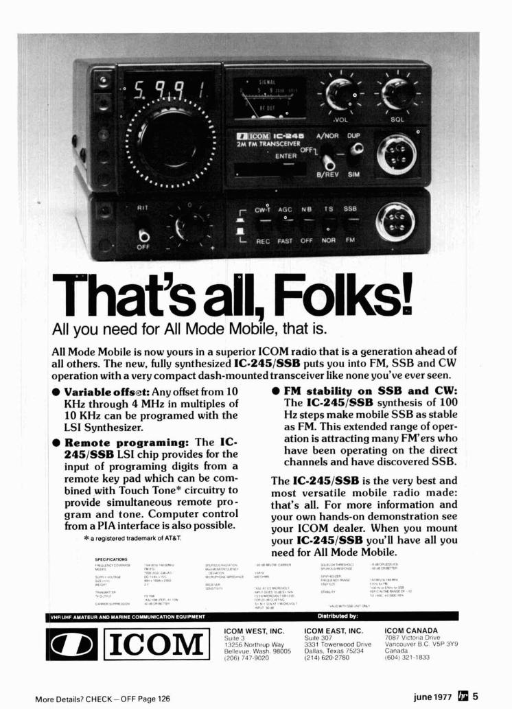
That's all, Folks! All you need for All Mode Mobile, that is. All Mode Mobile is now yours in a superior ICOM raciio that is a generation ahead of all others. The new, fully synthesized IC-245/SSB puts you into FM, SSB and CW operation with a very compact dash-mounted transceiver like none you've ever seen.
Variable offset: Any offset from 10 KHz through 4 MHz in multiples of 10 KHz can be programed with the LSI Synthesizer. Remote programing: The IC- 245/SSB LSI chip provides for the input of programing digits from a remote key pad which can be com- bined with Touch Tone* circuitry to provide simultaneous remote pro - gram and tone. Computer control from a PIA interface is also possible.
* a registered trademark of ATBT.
SPECIFICATIONS i u , , , , , ~ r c C , I " r r Y ' !um%.i I r *La* . ,
rvlt IPL"., , L A , A l V l " 8 +,.
"S".." t I 1 1 . l
"&'%A .,!W .a,..<.
.i,", . .rX?.Lc TX . , r , .,.- I,' I . > *
:,,.1 ,,."", m . -5 -W. ,*<I " , I '. iP..?.I UYT"I.8 7
M ...#I W < t . I " Y.,. . . 7 .
.".NWlT'," ', 0 I.,., 1,.1*1 ..li I R T f ' L. 1%
c.DII.,I).I.c**I..m# A* !I X I N 1 - , Y
FM stability on SSB and CW: The IC-245/8SB synthesis of 100 Hz steps make mobile SSB as stable as FM. This extended range of oper- ation is attracting many FM'ers who have been operating on the direct channels and have discovered SSB.
The IC-245/SSB is the very best and most versatile mobile radio made: that's all. For more information and your own hands-on demonstration see your ICOM dealer. When you mount your IC-245/SSB you'll have all you need for All Mode Mobile.
,,,,,"lrT,l,ir I r,l"," ,,.,,,tL,<? , C ! ., . / 4 ..,.,. / / . . I
', ,*<.:a ,c<~,<,,: , ' IP lnmlrrrs
. " ,.: mlrl* .."Vl*i,'TP
) Y t i l l .# . R 1 r W IadW(i ,o ll*VbIr . , , a . .I ..*: "" ,V
. I% 1.2,"<'"1a'#I ! ' r < * l v , * I . > I S Y I rn., ! i , d 5 1 1 1 1 R - . Y * S'.R.ll," ' T Y i I*'*fDY1?&"( l ' i
' , . L U I U , I I , ' I",,,.. ,,,,.> .,, ,,,,,,
. , .,A .,,m .:,. . . 9. L,,..! I Y , < . " i " l
,./" . L .,, 2.8 ,FW,7.< s-d ,,.',. m.
ICOM WEST. INC. ICOM EAST. INC. ICOM CANADA :AII~,> 3 S111lr 307 7087 V ~ c t c ~ r , ~ Dl i ie 13256 Norlhrup Way 3331 Towerwood Drtve Vdncouver B C V5P 3Y9 R ~ l l ~ v u e Wash 98005 Dallas Texas 75234 Calladd
More Details? CHECK-OFF Page 126 june1977 5
A PROPOSAL TO LIMIT TRANSMITTER SALES to Amateur licensees was filed with the FCC by the San Antonio Repeater Organization in response to an FCC request for workable alternative solutions to the problem of non-Amateur use of Amateur linear amplifiers in the CB bands (May HR). The SARO proposal, assigned RM-2839, drew a tremendous - possibly record-breakzg - number of Comments filed in its suDDort. rake And ARMA were both among those filing strong suppbrting Comments on
RM-Z839. Drake's offering even described a procedure for implementing a "Proof of License" program which would require little investment of time or money by the FCC.
FCC/AMATEUR DIALOGUE was severely curtailed as a result of a court decision handed down recently in Washington. In its ruling in the case of Home Box Office vs the FCC, the U.S. Court of Appeals of the District of Columbia stated:
"Once a Notice of Proposed Rule Making has been issued . . . any agency official or employee who is or may reasonably be expected to be involved in the decisional process of the rule-making proceeding, should refuse to discuss matters relative to the dis- posal of the Rule-Making proceeding with any interested private party or any attorney or agent for anv such ~artv prior to the aeencv's decision."
~fiis prohibition 1s'~ein ' interpreted to extend to 60 days after the final Report and Order on 4 an effective. to include the period in which a Petition for Reconsideration may be filed. An appeal of the decision by the FCC is considered likely but could in itself take years.
CONFUSION BETWEEN "TYPE ACCEPTANCE" and "Type Approval" seems to be contributing lots of heat but little light on much of the current discussion of Docket 21117, the FCC's proposal to require commercially-made Amateur transmitters to be Type Accepted. Type Acceptance requires only that the manufacturer submit certain performance data on h ~ s product and certify that what he markets will meet or exceed the performance he claims for it. Type Approval is a much different process, with the Commission itself per- forming elaborate tests following extensive testing by the maker.
As One High-Ranking FCC Spokesman said, "The FCC Type Acceptance procedure doesn't ask for any data that a manufacturer shouldn't have developed for himself, long before he was ready to put his product into production." This isn't to say that the FCC could not, or would not, require additional testing of suspect equipment in its own labs - that's what happened to CB, after FCC found that practically no CB sets met claimed specifications.
JACK ANDERSON SLAMMED AMATEUR RADIO, and the many dedicated FCC people who are also Amateurs, in his nationally-syndicated column that appeared in many papers Monday, April 4th. Thrust of the piece, which cited confusing comparisons from a confidential report prepared for U.S. Representative Elli~tt Levitas (D-Ga.) was that letting Com- mission Amateurs make CB policy was letting the wolf guard the flock" and implied ARRL membership might be a conflict of interest for FCC personnel.
The Column Turned Out to have provided one of the best PR opportunities Amateur Radio has had in recent years. Copies of many letters to the editor, a good number of them already published, have been received by HR - and Pete O'Dell, ARRL's Public Informa- tion Officer, says the League has a pile 3 pro-Amateur Radio clippings about four inches high with more coming in every day. In Michigan WB8VBP even managed to turn Anderson's blast into invitations to two radio talk shows, where she was able to push the positive side of the Amateur Service very strongly.
"HOW TO RESOLVE RADIO-TV INTERFERENCE PROBLEMS" is a new 35-page booklet by the FCC due out sometime in June. Coverage includes interference to telephones and a variety of electronic equipment, with useful tips for both homeowners and service technicians. Cost is about $1.50 from the Government Printing Office.
RUSSIAN COMMERCIAL AMATEUR GEAR was to have been produced for the first time under a DOSAAF (a somewhat MARS-like organization) five-year plan begun last year. Trans- mitters and receivers are already-supposed to be obt, with transceivers; keyers and other accessorlea to be introduced this year.
THE U.S. AMATEUR POPULATION passed 300,000 for the first time during March, with 300, 372 at the month's end. The total at the beginning of the month was 296,967, and 6,693 new licensees during March more than doubled the 3,288 who let their licenses expire during the month. A year ago we numbered only 265,528, so we increased almost 35,000 in one year!
ALIEN AMATEURS WHO become citizens are no longer eligible to hold reciprocal licenses, even if their non-U.S. licenses are still valid. The new citizen must take the U.S. Amateur examination and receive a U.S. license if he wishes to remain on the air, according to a recent FCC release.
6 june 1977
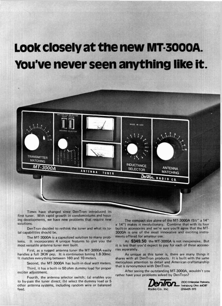
Look closely at the new MTm300o~. You've never seen anything like it.
Times have ch first tuner. With rapi ing developments, we have new problems that require new The compact size alone of the MT-3000A (5%" a 14" solutions. x 14") makes it revolutionary. Combine that with i t s four
DenTron decided to rethink the tuner and what i t s to- built-in accessories and we're sure you'll agree that the MT- tal capabilities should be. 3000A i s one of the most innovative and exciting instru-
The MT-3000A i s a capsulized solution to many prob- nwnts offered for amateur use. lems. It incorporates 4 unique features to give you the At $349.50 the MT-3000A is not inexpensive. But most versatile antenna tuner ever built. it i s less than you'd expect to pay for each of these accesso-
First, as a rugged antenna tuner the MT-3000A easily riesseparately- handles a full 3KW pep. It is continuous tuning 1.8-30mc. As unique as this tuner is, there are many things it It matches everything between 160 and 10 meters. shares with all DenTron products. It i s built with the same
second, the MT-3000A has built-in dual watt meters. meticulous attention to detail and American craftsmanship that i s synonymous with DenTron.
Third, it has a built-in 50ohm dummy load for proper exciter adjustment. After seeing the outstanding MT-3000A, wouldn't you
rather have your problems solved by DenTron? Fourth, the antenna selector switch; (a) enables you
to by-pass the tuner direct; (b) select the dummy load or 5 zk?!iiT/cy~ 2 m E- Par* other antenna systems, including random wire or balanced ~ v k ~ t u r g . oh0 MOBI feed. Radio Co.. Inc. (216)AZS-3l73
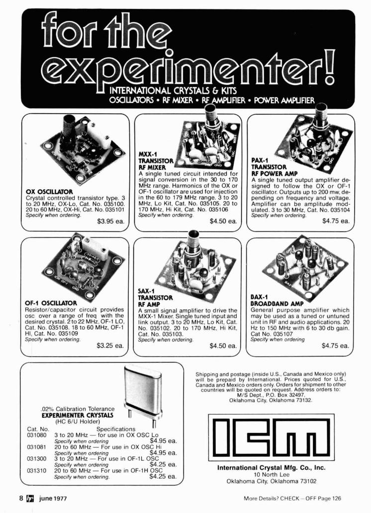
OX OSClLWOR Crystal controlled transistor type. 3 to 20 MHz, OX-Lo, Cat. No. 035100. 20 to 60 MHz, OX-Hi, Cat. No. 035101 Specify when ordering.
$3.95 ea.
MXX-1 TRANSISTOR RF MIXER A single tuned circuit intended for signal conversion in the 30 to 170 'MRz range. Harmonics of the OX or OF-1 oscillator are used for injection in the 60 to 179 MHz range. 3 to 20 MHz, Lo Kit, Cat. No. 035105. 20 to 170 MHz, Hi Kit, Cat. No. 035106 Specify when ordering.
$4.50 ea.
TRANSISTOR RF POWER AMP A stngle tuned output amplifier de- signed to follow the OX or OF-1 oscillator. Outputs up to 200 mw. de- pending on frequency and voltage. Amplifier can be amplitude mod- ulated. 3 to 30 MHz, Cat. No. 035104 Specify when ordering.
$4.75 ea.
A
SAX-1 TRANSISTOR RF AMP A small signal amplifier to drive the MXX-1 Mixer. Single tuned input and link output. 3 to 20 MHz. Lo Kit. Cat. No. 035102. 20 to 170 MHz, Hi Kit,
HI, Cat. No. 035109 Cat. No. 0351 03. Specify when ordering. Specify when ordering.
$4.50 ea.
Shipping and postage (inside U.S.. Canada and Mexico only) will be prepaid by International. Prices quoted for U.S..
I I Canada and Mexico orders only. Orders for shipment to other
i countr~es wtll be quoted on request. Address orders to:
MIS Dept.. P.O. Box 32497. Oklahoma City, Oklahoma 73132.
.02% Calibration Tolerance EXPERIMENTER CRYSTALS
(HC 6/U Holder) Cat. No. Specifications n 031080 3 to 20 MHz - for use in OX OSC Lo
Specify when ordering $4.95 ea. 031081 20 to 60 MHz - For use in OX OSC HI
Specify when ordering $4.95 ea. 031300 3 to 20 MHz - For use in OF-1L OSC
Specify when ordering $4.25 ea. 031310 20 to 60 MHz - For use in OF-1H OSC International Crystal Mfg. Co., Inc.
Specify when ordering. $4.25 ea. 10 North Lee Oklahoma City. Oklahoma 73102
DAX-1 DROADDAND AMP General purpose amplifier which may be used as a tuned or untuned unlt In RF and audto applications. 20 Hz to 150 MHz wlth 6 to 30 db galn. Cat No. 035 107 Specify when ordenng
$4.75 ea. L
8 a june1977 More Details? CHECKOFF Page 126

MATEUR ..e- -. ... BUT K
IF SPECTI
ENWOOC
RUM. . . F
ENOUGH
IN0 NOUl NOVICE JUST COI
T OPERA1
UlNG ANC
-OR WHO
) BUILDIN
1 WANTS
IG THE VE
A "KENW
.RY FINES
IOOD" Qt
iT EQUIPI
JALITY 4!
AENT POI
50 MHz R SSIBLE . . .
IIG LIKE 1
. A DEDIC,
'HE TR-8.
ATlON TO E POLICY . . . A DEI
YOU SPI
'FUR RAL
I T 0 . JHO GIVING Y
ELSE BL OU MORl
IT KENU
E SATISFP
1 0 0 0 . . . rCTlON F(
THE PAC
DOLLAR
' IN AMAl
EST OFF1
4ILABLE I
ERING . . . N JUNE.
RUN N l N IG 10 WATTS
' I 'THE TR-r <ENWOOD'S NEW
WITH 22 L ~ A I V I V ~ L CAPABILITY. AVb
LE/BASE STATION
CERTIFICATION.)
L YWOOD C( :ST WALNU
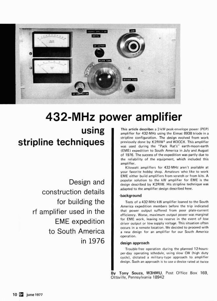
432-MHz power amplifier using
stripline techniques
Design and construction details
for building the rf amplifier used in the
EME expedition to South America
in 1976
This article describes a 2-kW peak-envelope power (PEP) amplifier for 432-MHz using the Eimac 8938 triode in a stripline configuration. The design evolved from work previously done by K2RIW1 and W3CCX. This amplifier was used during the "Pack Rat's" earth-moon-earth (EME) expedition to South America in July and August of 1976. The success of the expedition was partly due to the reliability of the equipment, which included this amplifier.
Kilowatt amplifiers for 432-MHz aren't available a t your favorite hobby shop. Amateurs who like to work EME either build amplifiers from scratch or from kits. A popular solution to the kW amplifier for EME is the design described by K2RIW. His stripline technique was adapted to the amplifier design described here.
Tests of a 432-MHz kW amplifier loaned to the South America expedition members before the trip indicated that power output suffered from poor plate-current efficiency. Worse, maximum output power was marginal for EME work, leaving no reserve in the event of low driver output or low supply voltage. This situation often occurs in a remote location. We decided to proceed with a new design for an amplifier for our South America operation.
design approach Trouble-free operation during the planned 12-hours-
per-day operating schedule, using slow CW (high duty cycle), dictated a military-type approach to amplifier design. Such an approach is to use a device rated at twice
By Tony Souza, W3HMU, Post Off ice Box 169, Ottsville, Pennsylvania 18942
10 june 1977
the expected requirements to ensure reliability. An amplifier used by W3CCX uses an Eimac 8938 triode in a grounded-grid, cathode-driven configuration. This tube is rated to 500 MHz with 1500 watts plate dissipation. The tube i s a coaxial-base version of the popular 8877 triode.
Advantages of the 8938 amplifier at W3CCX were trouble-free operation and easy drive requirements using only a straightforward power supply; a disadvantage of the W3CCX amplifier was that the cavity construction required metal-working facilities. Also, output-loading adjustment was difficult and time consuming. The only way to couple output from a cavity i s through an inductive link. Those who have experimented with link coupling in hf gear know the frustration involved. These frustrations are even worse in vhf cavity designs because of the limited number of adjustments possible.
Recently published vhf amplifier designs have used stripline techniques with excellent results. Striplines have been used from 50 through 1296 MHz. The ease of tuning and loading the K2RIW 432-MHz stripline amplifier convinced me that this was the way to go; what remained was to adapt the technique to the 8938 coaxial-based triode.
description
The plate circuit is a half-wave stripline with flapper capacitor tuning and loading controls. The grounded-grid triode is cathode driven using a half-wave stripline cathode circuit tuned by a movable capacitor disc. Matching to the driver transmission line is through a variable capacitor also of a movable-disc type. The amp- lifier enclosure consists of two aluminum sheet-metal chassis boxes similar to the K2RIW amplifier with flat- plate top, middle, and bottom plates. The amplifier i s easily built using simple tools and lends itself to simple disassembly for inspection and parts replacement. The only purchased parts were a blower, some brass shim stock, and a few nuts and bolts. The remainder of the parts were either adapted from the junk box or scrounged from friends.
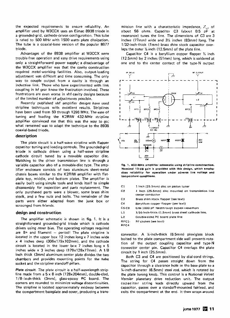
design and construction The amplifier schematic is shown in fig. 1. It i s a
straightforward grounded-grid triode which is cathode driven using Zener bias. The operating voltages required are B+ and filament - period! The plate stripline is located in the upper box 12 inches long x 7 inches wide x 4 inches deep (306x179x102mm), and the cathode circuit is located in the lower box 7 inches long x 5 inches wide x 3 inches deep (179~128~77mm). A 118 inch thick (3mm) aluminum center plate divides the two chambers and provides mounting points for the tube socket and the stripline standoff pillars.
mission line with a characteristic impedance, Z,, of about 56 ohms. Capacitor C3 (about 0.5 pF at resonance) tunes the line. The dimensions of C3 are 3 inches (77mm) wide and 3% inches (83mm) long. The 1132-inch-thick ( 1 mm) brass shim stock capacitor over- laps the outer % inch (12.5mm) of the plate line.
Capacitor C4 is a beryllium copper flapper '/2 inch (12.5mm) by 2 inches (51mm) long, which is soldered at one end to the center contact of the type-N output
fig. 1. 432-MHz amplifier schematic using stripline construction. Nominal 1 )-dB gain is provided with this design, which empha- sizes reliability for operation under adverse line voltage and tem~erature conditions.
RF DRIVE V F" RF OUTPUT
Y
1 Inch (25.5mm) disc on piston tuner
1 inch (25.5mm) disc mounted on transmission line center conductor
Brass shim stock flapper (see text)
Beryllium copper flapper (see text)
Erie 1000 p F feedthrough bypass capacitors
1/16-inch-thick (1.5mm) brass sheet cathode line.
Double-sided PC board plate line
Rf chokes (see text)
I I
connector. A '/n-inch-thick (6.5mm) plexiglass block bolted to the plate compartment side wall prevents rota- tion of the output coupling capacitor and type-N connector center pin. Capacitor C4 overlaps the plate circuit by 1 inch (25.5mm).
Both C3 and C4 are positioned by dial-cord strings. The string for C4 passes straight down from the ca~acitor throuqh a clearance hole in the base plate to a -
Plate circuit. The plate circuit i s a half-wavelength strip- %-inch-diameter (6.5mm) steel rod, which is rotated by line made from a 5 x 8 inch (128~204mm), double-clad, the plate tuning knob. This control is a National Velvet 118-inch-thick (3mm), glass-epoxy PC board. The Vernier planetary drive reduction unit. The output corners are rounded to minimize voltage discontinuities. capacitor string leads directly upward from the The stripline is located approximately midway between capacitor, passes over a standoff-mounted fairlead, and the compartment baseplate and cover, producing a trans- exits the compartment at the end. It then wraps around
r - - - - - - - - - - - - - - - - - - - - - - - I I I
1 I I
I c2 Qc4 I I I L 2
I I
I I I c a m 1
i I
I RFCZ
I I I
f-9 (-3 f- -j - - - -c5j C-- - .. -- - J
0 0 0 FILAMENT B+
rn 40 VAC
L -- *, -c%)
m
a !4-inch-diameter (6.5mm) steel rod, which i s also driven by a National Velvet Vernier knob. The capaci- tors are retracted by the pull of the strings and return due to spring action when the string tension is relaxed. Acti'on is smooth and positive. A string with a good dielectric must be used. Some fly fishing line was tried but melted in the strong rf field! Cathode circuit. The cathode circuit is a half-wavelength stripline counterpoised against one wall of the cathode compartment; it is tuned to resonance by a disc capaci- tor to ground at the open end of the line. Near this same end of the line, another disc capacitor couples drive power into the cathode.
The cathode line is made of 1116-inch-thick (1.5mm) biass sheet 4% inches (1 15mm) long by 1 'A inch (32mm) wide, which is soldered at one end to the tube socket cathode terminal. A teflon pillar, 314 inch (19mm) diameter by 1 !4 inch (32mm) long, supports the cathode line a t about its physical midpoint.
Cathode bias is connected through a feedthrough bypass capacitor and rf choke to the low r f point of the line, which is 1 inch (25.5mm) from the tube socket. The rf choke, RFC2, i s made of 5% turns of number 18 AWG (lmm) enameled copper wire. Diameter of the choke is 318 inch (9.5mm). Two large ferrite beads were slipped over RFC2 as added insurance against vhf parasitics.
The tuning capacitor, C1, is a 1-inch-diameter (25.5mm) brass disc mounted on the end of a surplus piston tuner. The tuner has finger-stock contacts to ensure good rf grounding of the capacitor rotating section. The stator is the end of the cathode line. Capacitor C1 is actuated by a panel-mounted knob through a long flexible shaft coupling.
The coupling capacitor, C2, is a 1-inch-diameter (25.5mm) disc of 118-inch-thick (3mm) double-clad PC board, which is soldered on both sides to the center conductor of a section of %-inch-diameter (12.5mm) foam-filled, semirigid coaxial transmission line. The
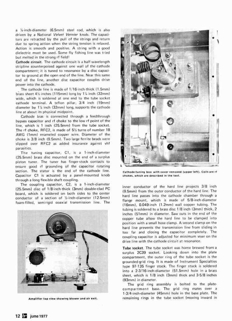
Ampllflcr top view showing blower and alr axit.
Cathode-tuning box with cover removed (upper left). Coils are rf chokes, which are described in the text.
inner conductor of the hard line projects 318 inch (9.5mm) from the outer conductor of the hard line. The hard line passes into the cathode chamber through a flange mount, which i s made of 518-inch-diameter (1 6mm). 0.049-inch (1.2mm) wall copper tubing. The tubing is soldered to a brass disc 1 18 inch (3mm) thick, 2 inches (51mm) in diameter. Saw cuts in the end of the copper tube allow the hard line to be clamped into position with a small hose clamp. A second clamp on the hard line prevents the transmission line from sliding in too far and closing the capacitor completely. The coupling capacitor is adjusted for minimum vswr on the drive line with the cathode circuit a t resonance.
Tube socket. The tube socket was home brewed from a surplus 2C39 socket. Looking down into the plate compartment, the outer ring of the tube socket i s the grounded-grid ring. I t is made of Instrument Specialties type 97-135 finger stock. The finger stock is soldered into a 2-3116-inch-diameter (51.5mm) hole in a brass sheet, which is 118 inch (3mm) thick and 3-518 inches (93mm) in diameter.
The grid ring assembly is bolted to the plate- compartment base. The grid ring mates over a 1 -314-inch-diameter (45mm) hole in the base plate. The remaining rings in the tube socket (moving inward in
12 june 1977
order) are the cathode ring, outer filament ring, and center cathode pin collet. The central rings are supported by the tube socket, which is mounted between two layers of 'A-inch-thick (6.5mm) plexiglass. These plexiglass layers insulate cathode and filament from ground.
The 2C39 tube socket adapted for this project has a coaxial set of brass tubes mutually insulated by a mylar sleeve. The outer tube is connected to the cathode ring and cathode line. The inner tube is connected to the outer filament ring. The center pin passes through a fused-glass bead up through the center of the socket. The center pin terminates in the filament-pin collet.
The cathode ring is a 2C39 plate ring (Instrument Specialties part no. 90-70). which is soldered inside a 1-318-inch (35mm) OD length of copper tubing. The tubing is shimmed to f i t with copper flashing material. The filament ring is made from a short length of 518-inch (16mm) OD copper tubing, 0.049 inch (1.2mm) wall, which was slotted with a hacksaw. The tube filament socket fits over the filament ring.
A 4%-turn close-spaced coil 718 inch (22mm) in diameter connects to the filament ring, and a 5-turn close-spaced coil, 'h inch (12.5mm) in diameter, connects filament voltage to the center pin. Both coils are made of number 10 AWG (2.6mm) enameled copper wire, and both coils are connected to 0.001-pF feed- through bypass capacitors mounted on the compartment side wall.
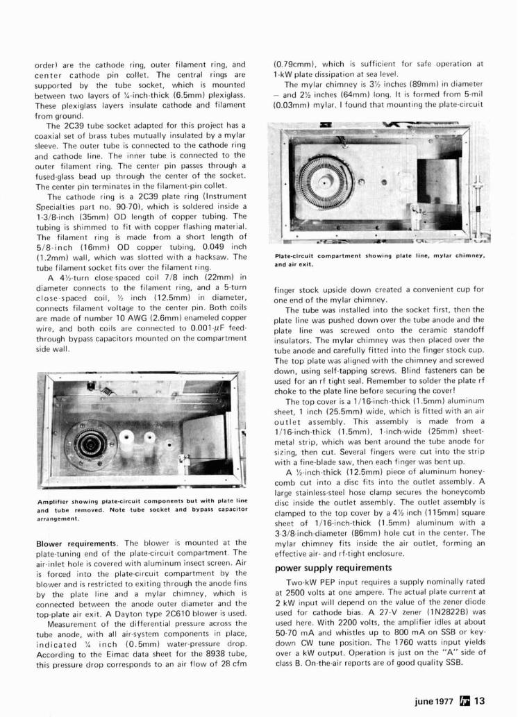
Amplifier showing plate-circuit components but with plate line and tube removed. Note tube socket and bypass capacitor arrangement.
Blower requirements. The blower is mounted at the plate-tuning end of the plate-circuit compartment. The air-inlet hole i s covered with aluminum insect screen. Air i s forced into the plate-circuit compartment by the blower and is restricted to exiting through the anode fins by the plate line and a mylar chimney, which is connected between the anode outer diameter and the top-plate air exit. A Dayton type 2C610 blower is used.
Measurement of the differential pressure across the tube anode, with all air-system components in place, ind icated 'A inch (0.5mm) water-pressure drop. According to the Eimac data sheet for the 8938 tube, this pressure drop corresponds to an air flow of 28 cfm
(0.79cmm), which i s sufficient for safe operation at 1 -kW plate dissipation at sea level.
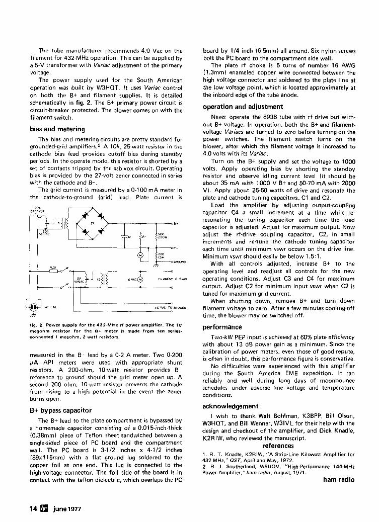
The mylar chimney is 3% inches (89mm) in diameter - and 2% inches (64mm) long. It is formed from 5-mil (0.03mm) mylar. I found that mounting the plate-circuit
Plate-clrcuit compartment showing plate line, mylar chimney. and air exit.
finger stock upside down created a convenient cup for one end of the mylar chimney.
The tube was installed into the socket first, then the plate line was pushed down over the tube anode and the plate line was screwed onto the ceramic standoff insulators. The mylar chimney was then placed over the tube anode and carefully fitted into the finger stock cup. The top plate was aligned with the chimney and screwed down, using self-tapping screws. Blind fasteners can be used for an rf tight seal. Remember to solder the plate r f choke to the plate line before securing the cover!
The top cover is a 1116-inch-thick (1.5mm) aluminum sheet, 1 inch (25.5mm) wide, which i s fitted with an air ou t le t assembly. This assembly is made from a 1116-inch-thick (1.5mm), l-inch-wide (25mm) sheet- metal strip, which was bent around the tube anode for sizing, then cut. Several fingers were cut into the strip with a fine-blade saw, then each finger was bent up.
A %-inch-thick (12.5mm) piece of aluminum honey- comb cut into a disc fits into the outlet assembly. A large stainless-steel hose clamp secures the honeycomb disc inside the outlet assembly. The outlet assembly i s clamped to the top cover by a 4% inch (1 15mm) square sheet of 1116-inch-thick (1.5mm) aluminum with a 3-318-inch-diameter (86mm) hole cut in the center. The mylar chimney fits inside the air outlet, forming an effective air- and rf-tight enclosure.
power supply requirements
Two-kW PEP input requires a supply nominally rated at 2500 volts at one ampere. The actual plate current at 2 kW input will depend on the value of the zener diode used for cathode bias. A 27-V zener (lN2822B) was used here. With 2200 volts, the amplifier idles at about 50-70 mA and whistles up to 800 mA on SSB or key- down CW tune position. The 1760 watts input yields over a kW output. Operation i s just on the "A" side of class B. On-the-air reports are of good quality SSB.
The tube manufacturer recommends 4.0 Vac on the filament for 432-MHz operation. This can be supplied by a 5-V transformer with Variac adjustment of the primary voltage.
The power supply used for the South American operation was built by WJHQT. It uses Variac control on both the B+ and filament supplies. I t i s detailed schematically in fig. 2. The B+ primary power circuit is circuit-breaker protected. The blower comes on with the filament switch.
bias and metering The bias and metering circuits are pretty standard for
grounded-grid amplifiers.* A IOk, 25-watt resistor in the cathode bias lead provides cutoff bias during standby periods. In the operate mode, this resistor is shorted by a set of contacts tripped by the ssb vox circuit. Operating bias i s provided by the 27-volt zener connected in series with the cathode and B- .
The grid current is measured by a 0-100 mA meter in the cathode-to-ground (grid) lead. Plate current is
2 0 1 BREAKER
VARIAC 2 0 0 W
fig. 2. Power supply for the 432-MHz r f power amplifier. The 10 megohm resistor for the B+ meter is made from ten series- connected 1 megohm, 2 watt resistors.
K LINE
measured in the B- lead by a 0-2 A meter. Two 0-200 @A API meters were used with appropriate shunt resistors. A 200-ohm, 10-watt resistor provides B- reference to ground should the grid meter open up. A second 200 ohm, 10-watt resistor prevents the cathode from rising to a high potential in the event the zener burns open.
I - . . - - 110 VAC TO BLOWER
B+ bypass capacitor The B+ lead to the plate compartment is bypassed by
a homemade capacitor consisting of a 0.015-inch-thick (0.38mm) piece of Teflon sheet sandwiched between a single-sided piece of PC board and the compartment wall. The PC board is 3-112 inches x 4-112 inches (89xl15mm) with a flat ground lug soldered to the copper foil at one end. This lug is convected to the high-voltage connector. The foil side of the board is in
0
contact with the teflon dielectric, which overlaps the PC
14 june1977
board by 114 inch (6.5mm) all around. Six nylon screws bolt the PC board to the compartment side wall.
The plate r f choke is 5 turns of number 16 AWG (1.3mm) enameled copper wire connected between the high voltage connector and soldered to the plate line at the low voltage point, which is located approximately at the inboard edge of the tube anode.
operation and adjustment Never operate the 8938 tube with r f drive but with-
out B+ voltage. In operation, both the B+ and filament- voltage Variacs are turned to zero before turning on the power switches. The filament switch turns on the blower, after which the filament voltage is increased to 4.0 volts with i t s Variac.
Turn on the B+ supply and set the voltage to 1000 volts. Apply operating bias by shorting the standby resistor and observe idling current level ( i t should be about 35 mA with 1000 V B+ and 50-70 mA with 2000 V). Apply about 25-50 watts of drive and resonate the plate and cathode tuning capacitors, C1 and C2.
Load the amplifier by adjusting output-coupling capacitor C4 a small increment at a time while re- resonating the tuning capacitor each time the load capacitor i s adjusted. Adjust for maximum output. Now adjust the rf-drive coupling capacitor, C2, in small increments and re-tune the cathode tuning capacitor each time until minimum vswr occurs on the drive line. Minimum vswr should easily be below 1.5:l.
With all controls adjusted, increase B+ to the operating level and readjust all controls for the new operating conditions. Adjust C3 and C4 for maximum output. Adjust C2 for minimum input vswr when C2 i s tuned for maximum grid current.
When shutting down, remove B+ and turn down filament voltage to zero. After a few minutes cooling-off time, the blower may be switched off.
performance Two-kW PEP input i s achieved at 60% plate efficiency
with about 13 dB power gain as a minimum. Since the calibration of power meters, even those of good repute, is often in doubt, this performance figure is conservative.
No difficulties were experienced with this amplifier during the South America EME expedition. It ran reliably and well during long days of moonbounce schedules under adverse line voltage and temperature conditions.
acknowledgement I wish to thank Walt Bohlman, K3BPP, Bill Olson,
WSHQT, and Bill Wenner, W31VL for their help with the design and checkout of the amplifier, and Dick Knadle, K2RIW, who reviewed the manuscript.
references 1. R. T. Knadle, KZRIW, "A Strip-Line Kilowatt Amplifier for 432 MHz," QST, April and May, 1972. 2. R. I. Southerland, WGUOV, "High-Performance 144-MHz Power Amplifier," ham radio, August, 1971.
ham radio
. ~ u $ ~ e d ~onstruction Versatility
FOR ADDITIONAL LITERATURE, CONTACT YOUR NEAREST AMATEUR DEALER
Wilson Electronics Corp. - 4288 SO. POLARIS . P. 0 . BOX 19000 . LAS VEGAS, NEVADA . 89119 . TELEX 684-522
More Details? CHECK-OFF Page 126 june1977 15
high-performance spectrum analyzer
These instruments have been limited mainly
to professional labs - now you can
build your own spectrum analyzer
from the information furnished here
A spectrum analyzer is a radio receiver with a swept local oscillator that allows continuous tuning over a specified frequency range. The received signals are dis- played on a conventional oscilloscope as pips. Fig. 1 shows the radio spectrum between 100 kHz and 100 MHz in the San Francisco area as displayed on the spectrum analyzer described in this article.
Because of their cost and complexity, good spectrum analyzers have been limited primarily to research and development activity. Some military instruments have shown up on the surplus market, but poor sensitivity and selectivity, images, spurious responses, and poor dynamic range have limited their usefulness.
Considerable time was spent in the design of the spectrum analyzer described here. Even more time was required to assure circuit reproducibility, minimize the variety of parts, and select the least-expensive components. No PC boards are used in the design nor are any planned. PC boards in the rf and i-f strips, unless very carefully made, would probably degrade the per- formance of the instrument. Complete design, construc- tion, and testing details are included for those wishing to build the spectrum analyzer.
applications The spectrum analyzer can be used to observe
harmonics, parasitic oscillations, and sidebands of CW, a-m, fm or ssb signals. Propagation conditions in terms
By Wayne C. Ryder, WGURH, 115 Hedge Road, Menlo Park, California 94025
16 june 1977
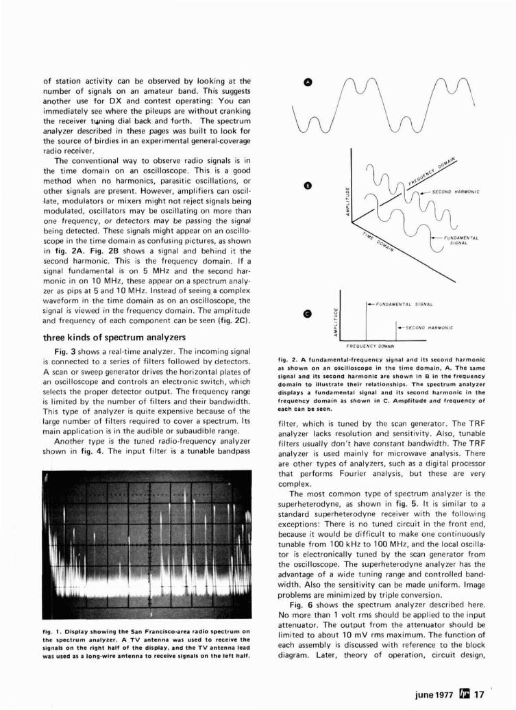
of station activity can be observed by looking at the number of signals on an amateur band. This suggests another use for DX and contest operating: You can immediately see where the pileups are without cranking the receiver tuning dial back and forth. The spectrum analyzer described in these pages was built to look for the source of birdies in an experimental general-coverage radio receiver.
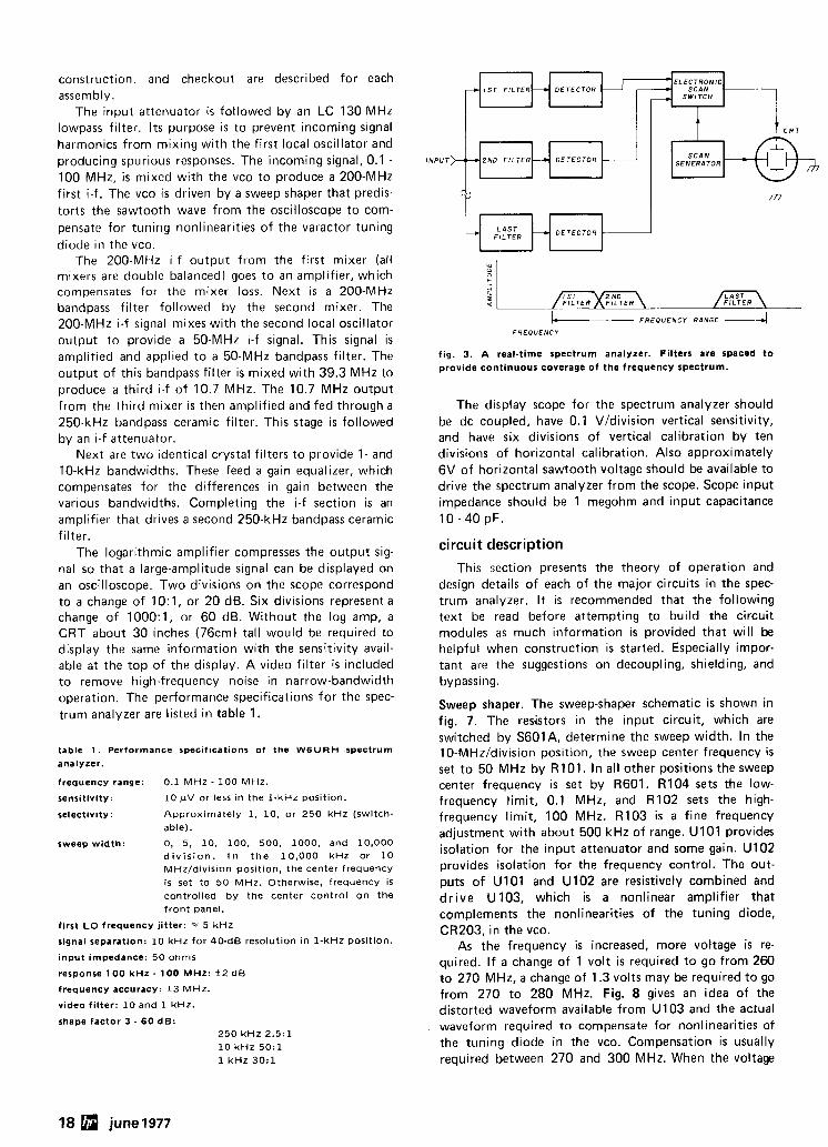
The conventional way to observe radio signals is in the time domain on an oscilloscope. This is a good method when no harmonics, parasitic oscillations, or other signals are present. However, amplifiers can oscil- ,late, modulators or mixers might not reject signals being modulated, oscillators may be oscillating on more than one frequency, or detectors may be passing the signal being detected. These signals might appear on an oscillo- scope in the time domain as confusing pictures, as shown in fig. 2A. Fig. 2B shows a signal and behind i t the second harmonic. This is the frequency domain. If a signal fundamental is on 5 MHz and the second har- monic in on 10 MHz, these appear on a spectrum analy- zer as pips at 5 and 10 MHz. Instead of seeing a complex waveform in the time domain as on an oscilloscope, the signal i s viewed in the frequency domain. The amplitude and frequency of each component can be seen (fig. 2C).
three kinds of spectrum analyzers Fig. 3 shows a real-time analyzer. The incoming signal
is connected to a series of filters followed by detectors. A scan or sweep generator drives the horizontal plates of an oscilloscope and controls an electronic switch, which selects the proper detector output. The frequency range is limited by the number of filters and their bandwidth. This type of analyzer is quite expensive because of the large number of filters required to cover a spectrum. I t s main application is in the audible or subaudible range.
Another type is the tuned radio-frequency analyzer shown in fig. 4. The input filter i s a tunable bandpass
c F U N D A M E N T A L S I G N A L
* S E C O N D H 4 R M O N I C
F R E Q U E N C Y DOMAIN
fig. 2. A fundamental-frequency slgnal and Its second harmonlc as shown on an oscilloscope In the time domain, A. The same slgnal and Its second harmonlc are shown In 6 In the frequency domain to illustrate their rclationshlps. The spectrum analyzer displays a fundamental signal and Its second harmonlc in the frequency domain as shown in C. Amplitude and frequency of each can be seen.
filter, which is tuned by the scan generator. The TRF analyzer lacks resolution and sensitivity. Also, tunable filters usually don't have constant bandwidth. The TRF analyzer i s used mainly for microwave analysis. There are other types of analyzers, such as a digital processor that performs Fourier analysis, but these are very complex.
The most common type of spectrum analyzer i s the superheterodyne, as shown in fig. 5. It i s similar to a standard superheterodyne receiver with the following exceptions: There i s no tuned circuit in the front end, because it would be difficult to make one continuously tunable from 100 kHz to 100 MHz, and the local oscilla- tor is electronically tuned by the scan generator from the oscilloscope. The superheterodyne analyzer has the advantage of a wide tuning range and controlled band- width. Also the sensitivity can be made uniform. Image problems are minimized by triple conversion.
Fig. 6 shows the spectrum analyzer described here. No more than 1 volt rms should be applied to the input attenuator. The output from the attenuator should be
fig. 1. Dlsplay showing the San Francisco-area radio spectrum on the spectrum analyzer. A T V antenna was used to receive the
limited to about 10 mV rms maximum. The function of
sianals on the rlaht half of the d lse la~ . and the TV antenna lead each assembly is discussed with reference to the block . .
was used as a long-wire antenna to receive signals on the left half. diagram. Later, theory of operation, circuit design,
construction, and checkout are described for each assembly.
The input attenuator is followed by an LC 130 MHz lowpass filter. Its purpose is to prevent incoming signal harmonics from mixing with the first local oscillator and producing spurious responses. The incoming signal, 0.1 - 100 MHz, is mixed with the vco to produce a 200-MHz first i-f. The vco is driven by a sweep shaper that predis- torts the sawtooth wave from the oscilloscope to com- pensate for tuning nonlinearities of the varactor tuning diode in the vco.
The 200-MHz i-f output from the first mixer (all mlxers are double balanced) goes to an amplifier, which compensates for the mixer loss. Next is a 200-MHz bandpass filter followed by the second mixer. The 200-MHz i-f signal mixes ,with the second local oscillator output to provide a 50-MHz i-f signal. This signal is ampliiied and applied to a 50-MHz bandpass filter. The output of this bandpass filter is mixed with 39.3 MHz to produce a third i-f of 10.7 MHz. The 10.7 MHz output from the third mixer is then amplified and fed through a 250-kHz bandpass ceramic filter. This stage is followed by an i-f attenuator.
Next are two identical crystal filters to provide 1- and 10-kHz bandwidths. These feed a gain equalizer, which compensates for the differences in gain between the various bandwidths. Completing the i-f section is an amplifier that drives a second 250-kHz bandpass ceramic filter.
The logarithmic amplifier compresses the output sig- nal so that a large-amplitude signal can be displayed on an oscilloscope. Two divisions on the scope correspond to a change of 10: 1, or 20 dB. Six divisions represent a change of 1000:1, or 60 dB. Without the log amp, a CRT about 30 inches (76cm) tall would be required to display the same information with the sensitivity avail- able at the top of the display. A video filter is included to remove high-frequency noise in narrow-bandwidth operation. The performance specifications for the spec- trum analyzer are listed in table 1.
table 1 . Performance specifications of the WBURH spectrum
analyzer.
frequency range: 0.1 M H z - 100 M H z .
sensitivity: 10 pV or less ~n the 1 - k H z pos~t ion.
selectivity: Approximate ly 1, 10, or 250 k H z (switch- able).
sweep width: 0, 5, 10, 100. 500, 1000, and 10,000 d i v i s i o n . I n t h e 10,000 k H z or 10 MHz/diviSion position, the center frequency is set to 50 M H z . Otherwise. frequency is controlled b y the center control o n the f ront panel.
first LO frequency j i t ter: = 5 k H z
signal separation: 10 k H z for 4 0 - 4 8 resolution in 1 - k H z position.
input impedance: 50 ohms
response 100 kHz - 100 MHz: f 2 d B
frequency accuracy: + 3 M H z .
video f i l ter: 10 and 1 k H z .
shape factor 3 - 60 dB: 250 k H z 2 . 5 : l 10 k H z 50:l 1 k H z 3 0 : l
E L E C T R O N I C S C A N
S W I T C H
I
I N P U T
Y-H-~ D E T E C T O R 1
b- F R E Q U E N C Y RANGE -4 F R E Q U E N C Y
fig. 3. A real-time spectrum analyzer. Filters are spaced t o provide continuous coverage of the frequency spectrum.
The display scope for the spectrum analyzer should be dc coupled, have 0.1 Vldivision vertical sensitivity, and have six divisions of vertical calibration by ten divisions of horizontal calibration. Also approximately 6V of horizontal sawtooth voltage should be available to drive the spectrum analyzer from the scope. Scope input impedance should be 1 megohm and input capacitance 1 0 - 4 0 pF.
circuit description
This section presents the theory of operation and design details of each of the major circuits in the spec- trum analyzer. I t is recommended that the following text be read before attempting to build the circuit modules as much information is provided that will be helpful when construction is started. Especially impor- tant are the suggestions on decoupling, shielding, and bypassing.
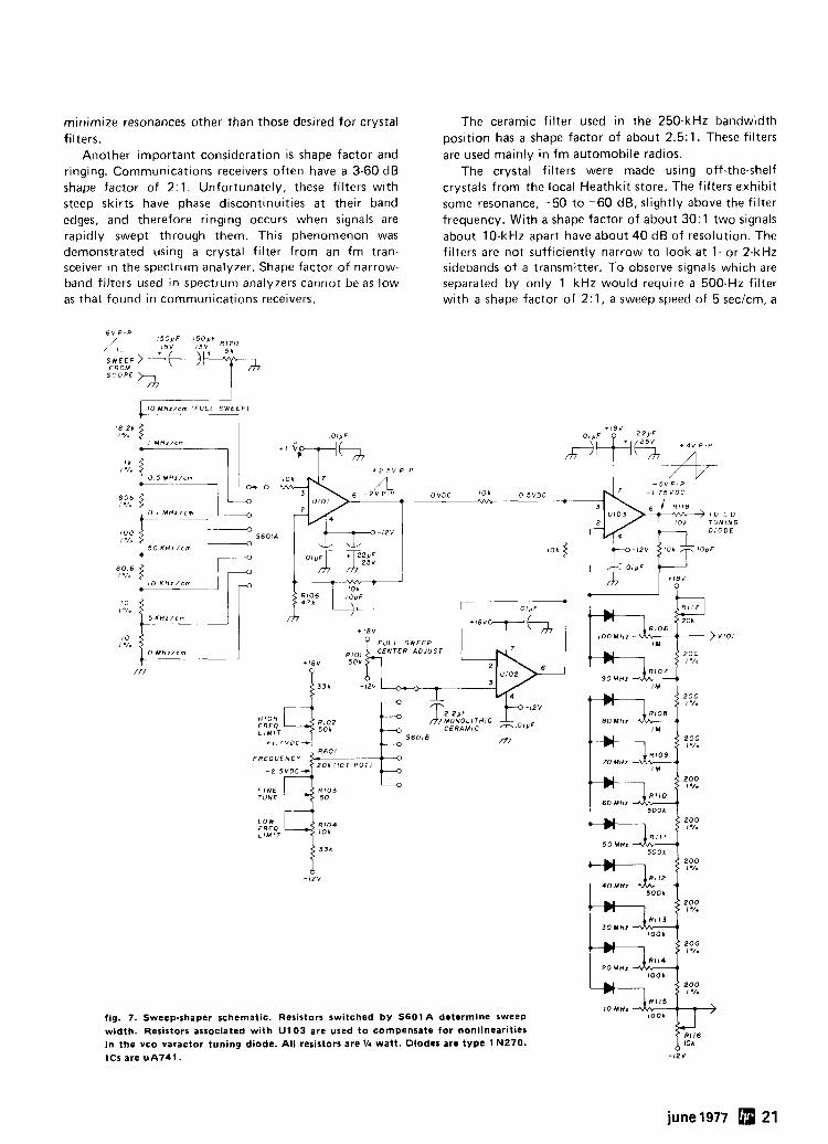
Sweep shaper. The sweep-shaper schematic is shown in fig. 7. The resistors in the input circuit, which are switched by S601A, determine the sweep width. In the 10-MHzfd~vision pos~tion, the sweep center frequency i s set to 50 MHz by R101. In all other positions the sweep center frequency is se t by R601. R104 sets the low- frequency limit, 0.1 MHz, and R102 sets the high- frequency limit, 100 MHz. R103 is a fine frequency adjustment with about 500 kHz of range. U101 prov~des isolation for the input attenuator and some gain. U102 provides isolation for the frequency control. The out- puts of U101 and U102 are resistively combined and dr ive U103, which is a nonlinear amplifier that complements the nonlinearities of the tuning diode, CR203, in the vco.
As the frequency is increased, more voltage is re- quired. If a change of 1 volt is required to go from 260 to 270 MHz, a change of 1.3 volts may be required to go from 270 to 280 MHz. Fig. 8 gives an idea of the distorted waveform available from U103 and the actual waveform required to compensate for nonlinearities of the tuning diode in the vco. Compensation is usually required between 270 and 300 MHz. When the voltage
18 june 1977
l N p u T ~ B%?AL& FILTER H LJETECTOR I-,
GENERATOR - fig. 4. Tuned radio frequency (TRF) spectrum analyzer. Tuning is accomplished b y adjusting the bandpass-filter frequency.
on pin 3 of U103 reaches the voltage on the right side of R115, gain will be increased by the setting of R115, and so on up the line, to R106. R115 sets the nonlinearity at 10 MHz and R106 at 100 MHz. The tuning diode used in the vco 1 built was linear up to about 280 MHz.
Care must be taken so that no low-frequency com- ponents, including power-supply hum, are added to the incoming sawtooth wave by the,sweep shaper. Added low-frequency components will result in first local- oscillator instability. This shows up as jitter in the dis- play when looking at narrow scan widths.
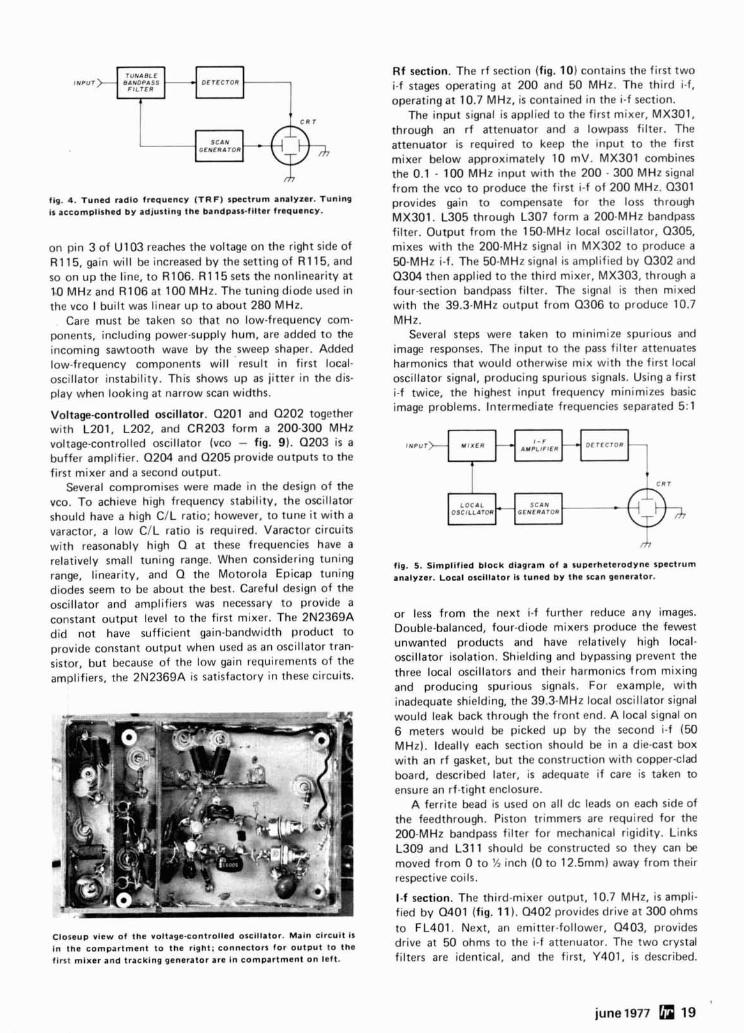
Voltage-controlled oscillator. Q201 and Q202 together with L201, L202, and CR203 form a 200-300 MHz voltage-controlled oscillator (vco - fig. 9). 0203 is a buffer amplifier. Q204 and Q205 provide outputs to the first mixer and a second output.
Several compromises were made in the design of the vco. To achieve high frequency stability, the oscillator should have a high C/L ratio; however, to tune i t with a varactor, a low C/L ratio i s required. Varactor circuits with reasonably high Q at these frequencies have a relatively small tuning range. When considering tuning range, linearity, and Q the Motorola Epicap tuning diodes seem to be about the best. Careful design of the oscillator and amplifiers was necessary to provide a constant output level to the first mixer. The 2N2369A did not have sufficient gain-bandwidth product to provide constant output when used as an oscillator tran- sistor, but because of the low gain requirements of the amplifiers, the 2N2369A is satisfactory in these circuits.
Closeup view of the voltage-controlled oscillator. Main circuit I S
in the compartment to the right; connectors for output to the first mixer and tracking generator are in compartment on left.
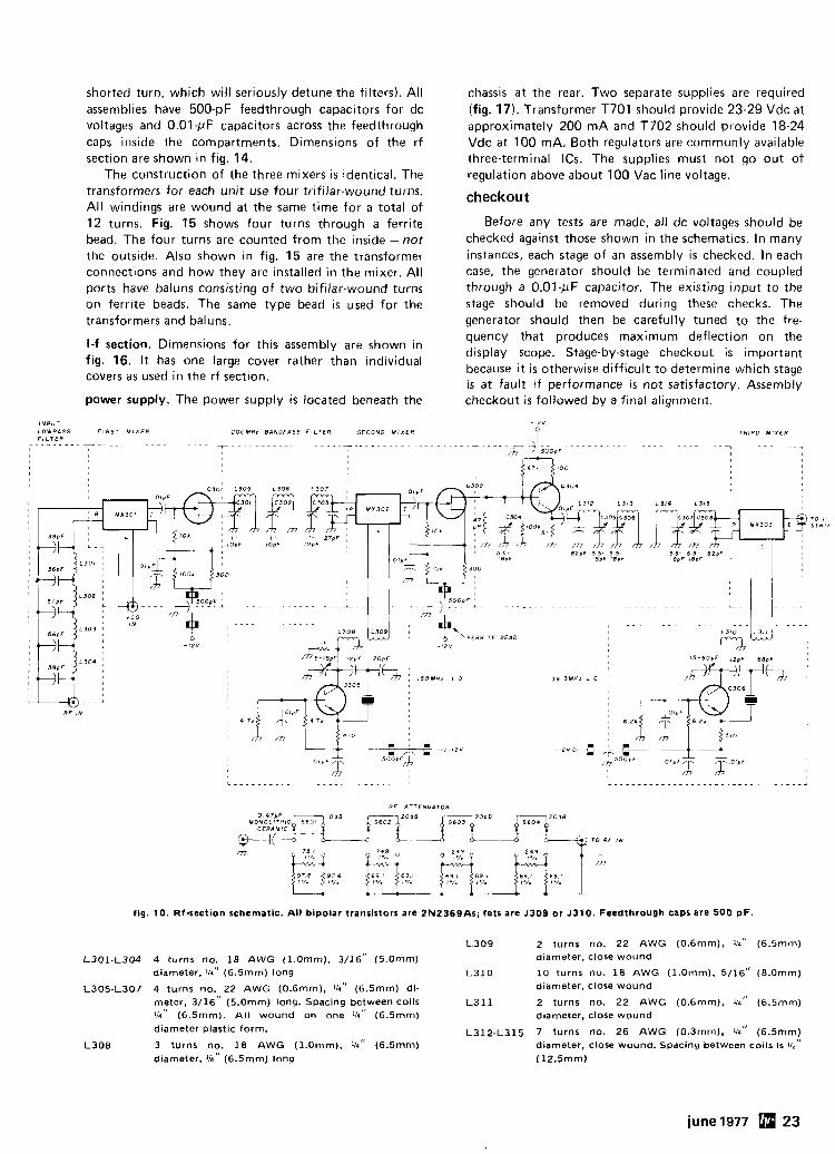
Rf section. The rf section (fig. 10) contains the first two i-f stages operating at 200 and 50 MHz. The third i-f, operating at 10.7 MHz, is contained in the i-f section.
The input signal i s applied to the first mixer, MX301, through an rf attenuator and a lowpass filter. The attenuator is required to keep the input to the first mixer below approximately 10 mV. MX301 combines the 0.1 - 100 MHz input with the 200 - 300 MHz signal from the vco to produce the first i-f of 200 MHz. Q301 provides gain to compensate for the loss through MX301. L305 through L307 form a 200-MHz bandpass filter. Output from the 150-MHz local oscillator, Q305, mixes with the 200-MHz signal in MX302 to produce a 50-MHz i-f. The 50-MHz signal is amplified by 0302 and Q304 then applied to the third mixer, MX303, through a four-section bandpass filter. The signal i s then mixed with the 39.3-MHz output from 0306 to produce 10.7 MHz.
Several steps were taken to minimize spurious and image responses. The input to the pass filter attenuates harmonics that would otherwise mix with the first local oscillator signal, producing spurious signals. Using a first i-f twice, the highest input frequency minimizes basic image problems. Intermediate frequencies separated 5:l
INPUT M I X E R AMPLIFIER
LOCAL
fig, 5. Simplified block diagram of a superheterodyne spectrum analyzer. Local oscillator is tuned by the scan generator.
or less from the next i-f further reduce any images. Double-balanced, four-diode mixers produce the fewest unwanted products and have relatively high local- oscillator isolation. Shielding and bypassing prevent the three local oscillators and their harmonics from mixing and producing spurious signals. For example, with inadequate shielding, the 39.3-MHz local oscillator signal would leak back through the front end. A local signal on 6 meters would be picked up by the second i-f (50 MHz). Ideally each section should be in a die-cast box with an rf gasket, but the construction with copper-clad board, described later, is adequate if care is taken to ensure an rf-tight enclosure.
A ferrite bead is used on all dc leads on each side of the feedthrough. Piston trimmers are required for the 200-MHz bandpass filter for mechanical rigidity. Links L309 and L311 should be constructed so they can be moved from 0 to 'h inch (0 to 12.5mm) away from their respective coils.
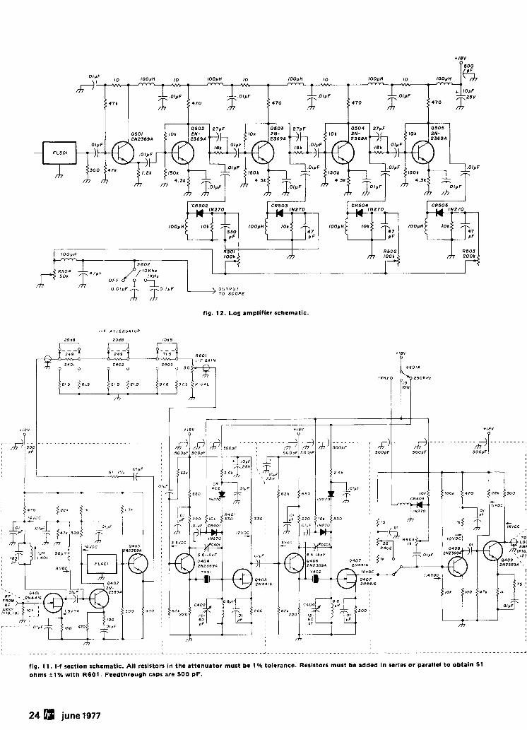
I-f section. The third-mixer output, 10.7 MHz, i s ampli- fied by 0401 (fig. 11). Q402 provides drive at 300 ohms to FL401. Next, an emitter-follower, 0403, provides drive at 50 ohms to the i-f attenuator. The two crystal filters are identical, and the first, Y401, i s described.
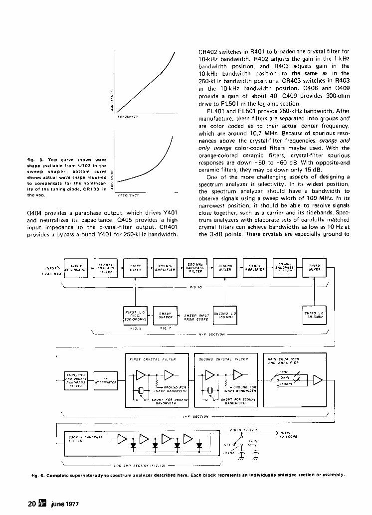
fig. 8. Top curve shows wave shape available from U103 in the sweep shaper ; bottom curve g shows actual wave shape required to compensate for the nonlinear- 2 i ty of the tuning diode, CR103, in the vco. FREOUENCY
Q404 provides a paraphase output, which drives Y401 and neutralizes its capacitance. 0405 provides a high input impedance to the crystal-filter output. CR401 provides a bypass around Y401 for 250-kHz bandwidth.
CR402 switches in R401 to broaden the crystal filter for 10-kHz bandwidth. R402 adjusts the gain in the 1-kHz bandwidth position, and R403 adjusts gain in the 10-kHz bandwidth position to the same as in the 250-kHz bandwidth positions. CR403 switches in R403 in the 10-kHz bandwidth position. 0408 and Q409 provide a gain of about 40. Q409 provides 300-ohm drive to FL501 in the log-amp section.
FL401 and FL501 provide 250-kHz bandwidth. After manufacture, these filters are separated into groups and are color coded as to their actual center frequency, which are around 10.7 MHz. Because of spurious reso- nances above the crystal-filter frequencies, orange and only orange color-coded filters maybe used. With the orange-colored ceramic filters, crystal-filter spurious responses are down -50 to -60 dB. With opposite-end ceramic filters, they may be down only 15 dB.
One of the more challenging aspects of designing a spectrum analyzer is selectivity. In its widest position, the spectrum analyzer should have a bandwidth to observe signals using a sweep width of 100 MHz. In its narrowest position, i t should be able to resolve signals close together, such as a carrier and its sidebands. Spec- trum analyzers with elaborate sets of carefully matched crystal filters can achieve bandwidths as low as 10 Hz at the 3-dB points. These crystals are especially ground to
F I R S T L O
ZOO-3OOMHz
- S E C O N D L O
I 5 0 M H z
4 *
5 0 M H z
B$y:E",S 5 0 M H z
A M P L I F I E R
F I G 9 F I G 7
\ R - F S E C T I O N /
I V A C M A X
F I G 1 0 --
- -
l1 I
\ I - F S E C T I O N --- /
T H I R D M I X E R
-
V I D E O F I L T E R
L
) O U T P U T 2 5 0 1 H z BANOPASS TO S C O P E F I L T E R
- M H z
- I N P U T INPUT>^^^^^^^^^^
GAIN E Q U A L I Z E R AND A M P L I F I E R
1 KHz
-""- 2 5 0 K H z IOKHz
LOG A M P S E C T I O N ( F I G 1 2 ) J
SECOND - M I X E R - -)
A M P L I F I E R
AND B A N O P A S S F I L T E R 2 5 0 K H 1
fig. 6. Complete superheterodyne spectrum analyzer described here. Each block represents an individually shielded section or assembly.
F I R S T C R Y S T A L F I L T E R
Q T ~ .OR l O K H z BANDWIDTH
S H O R T FOR 2 5 O K H z BANDWIDTH
ATTENUATOR 1 - F '-
F I R S T M I X E R
- I 3 O M H r L O W P A S S
F I L T E R
P O D M H z A M P L I F I E R
-4
-
S E C O N D C R Y S T A L F I L T E R
KJ FOR I O K H z BANDWIDTH
SHORT FOR 25OKHz B A N D W I D T H
minimize resonances other than those desired for crystal filters.
Another important consideration is shape factor and ringing. Communications receivers often have a 3-60 dB shape factor of 2:1. Unfortunately, these filters with steep skirts have phase discontinuities at their band edges, and therefore ringing occurs when signals are rapidly swept through them. This phenomenon was demonstrated using a crystal filter from an fm tran- sceiver in the spectrum analyzer. Shape factor of narrow- band filters used in spectrum analyzers cannot be as low as that found in communications receivers.
6 V P - P
F R O M S C O P E 'i'
The ceramic filter used in the 250-kHz bandwidth position has a shape factor of about 2.5: 1. These filters are used mainly in fm automobile radios.
The crystal filters were made using off-the-shelf crystals from the local Heathkit store. The filters exhibit some resonance, - 50 to -60 dB, slightly above the filter frequency. With a shape factor of about 30: 1 two signals about 10-kHz apart have about 40 dB of resolution. The filters are not sufficiently narrow to look at 1- or 2-kHz sidebands of a transmitter. To observe signals which are separated by only 1 kHz would require a 500-Hz filter with a shape factor of 2 : l . a sweep speed of 5 sec/cm, a
fig. 7. Sweep-shaper schematic. Resistors switched by S601A determine sweep width. Resistors associated with U103 are used to compensate for nonlinearities in the vco varactor tuning diode. All resistors are 114 watt. Diodes are type 1 N270. ICs are uA741.
june 1977 21
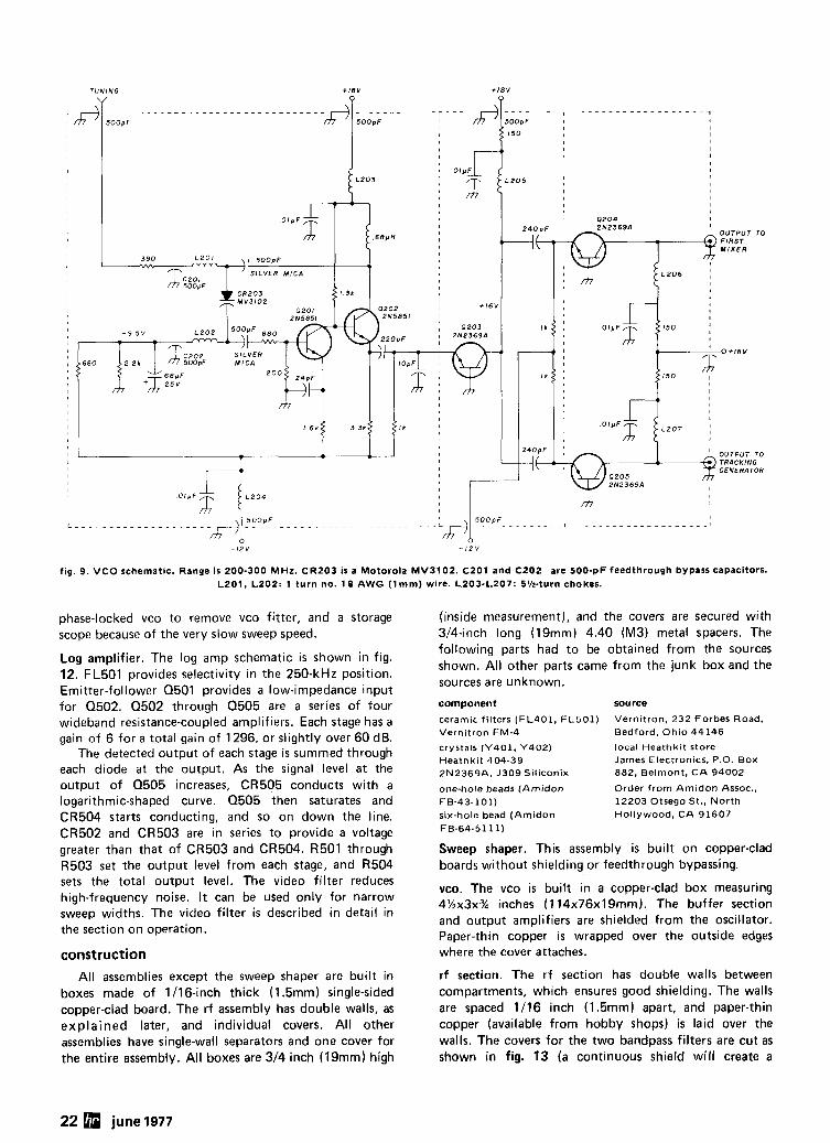
fig. 9. VCO schematic. Range is 200-300 MHz. CR203 is a Motorola MV3102. C Z O l and CZ02 are 500-pF feedthrough bypass capacitors. L201, L202: 1 turn no. 18 AWG ( l m m ) wire. L203-L207: SM-turn chokes.
phase-locked vco to remove vco fitter, and a storage (inside measurement), and the covers are secured with scope because of the very slow sweep speed. 314-inch long (19mm) 4.40 (M3) metal spacers. The
Log amplifier. The log amp schematic is shown in fig. 12. FL501 provides selectivity in the 250-kHz position. Emitter-follower 0501 provides a low-impedance input for 0502. 0502 through 0505 are a series of four wideband resistance-coupled amplifiers. Each stage has a gain of 6 for a total gain of 1296, or slightly over 60 dB.
The detected output of each stage is summed through each diode at the output. As the signal level at the output of 0505 increases, CR505 conducts with a logarithmic-shaped curve. 0505 then saturates and CR504 starts conducting, and so on down the line. CR502 and CR503 are in series to provide a voltage greater than that of CR503 and CR504. R501 through R503 se t the output level from each stage, and R504 sets the total output level. The video filter reduces high-frequency noise. It can be used only for narrow sweep widths. The video filter is described in detail in the section on operation.
construction All assemblies except the sweep shaper are built in
boxes made of 1116-inch thick (1.5mm) single-sided copper-clad board. The rf assembly has double walls, as explained later, and individual covers. All other assemblies have single-wall separators and one cover for the entire assembly. All boxes are 314 inch (19mm) high
following parts had to be obtained from the sources shown. All other parts came from the junk box and the sources are unknown.
component
ceramic filters (FL401 , FL501) Vernitron FM-4
crystals (Y401 . Y402) Heathkit 404-39 2N2369A, J309 Siliconix
one-hole beads (Amidon FB-43-101) six-hole bead (Amidon FB-64-5111)
source
Vernitron. 232 Forbes Road, Bedford, Ohio 44146
local Heathkit store James Electronics. P.O. Box 882. Belmont, C A 94002
Order from Amidon Assoc., 12203 Otsego St., North Hollywood, CA 91607
Sweep shaper. This assembly is built on copper-clad boards without shielding or feedthrough bypassing.
vco. The vco is built in a copper-clad box measuring 4'/2~3~3/4 inches (114x76x19mm). The buffer section and output amplifiers are shielded from the oscillator. Paper-thin copper is wrapped over the outside edges where the cover attaches.
rf section. The rf section has double walls between compartments, which ensures good shielding. The walls are spaced 1116 inch (1.5mm) apart, and paper-thin copper (available from hobby shops) is laid over the walls. The covers for the two bandpass filters are cut as shown in fig. 13 (a continuous shield wil l create a
22 june 1977
shorted turn, which will seriously detune the filters). All assemblies have 500-pF feedthrough capacitors for dc voltages and 0.01-pF capacitors across the feedthrough caps inside the compartments. Dimensions of the rf section are shown in fig. 14.
The construction of the three mixers is identical. The transformers for each unit use four trifilar-wound turns. All windings are wound at the same time for a total of 12 turns. Fig. 15 shows four turns through a ferrite bead. The four turns are counted from the inside -not the outside. Also shown in fig. 15 are the transformer connections and how they are installed in the mixer. All ports have baluns consisting of two bifilar-wound turns on ferrite beads. The same type bead is used for the transformers and. baluns.
I-f section. Dimensions for this assembly are shown in fig. 16. I t has one large cover rather than individual covers as used in the rf section.
power supply. The power supply is located beneath the
INPUT LOWPASS F I R S T M l X E R F l L T E R
2 0 0 M H z BANOPASS F ILTER SECOND M I X E R
chassis at the rear. Two separate supplies are required (fig. 17). Transformer T701 should provide 23-29 Vdc at approximately 200 mA and T702 should provide 18-24 Vdc a t 100 mA. Both regulators are commonly available three-terminal ICs. The supplies must not go out of regulation above about 100 Vac line voltage.
checkout
Before any tests are made, all dc voltages should be checked against those shown in the schematics. In many instances, each stage of an assembly is checked. In each case, the generator should be terminated and coupled through a 0.01-pF capacitor. The existing input to the stage should be removed during these checks. The generator should then be carefully tuned to the fre- quency that produces maximum deflection on the display scope. Stage-by-stage checkout is important because i t is otherwise difficult to determine which stage is at fault if performance is not satisfactory. Assembly checkout is followed by a final alignment.
THIRD MIXER
fig. 10. Rf-section schematic. All bipolar transistors are ZN2369As; fets are J309 or J310. Feedthrough caps are 500 pF.
L301-L304 4 turns no. 18 A W G (I .Omm). 3/16" (5.0mm) diameter. 114'1 (6.5mm) long
L305-L307 4 turns no. 22 AWG (O.6mm), 114 ' (6.5mm) di- meter, 3/16" (5.0mm) long. Spacing between coils 114'' (6.5mm). All wound on one 114'' (6.5mm)
diameter plastic form.
L308 3 turns no. 18 AWG (1.0mm). 114'' (6.5mm) diameter, '/a'' (6.5mm) long
L 3 0 9 2 turns no. 22 AWG (0.6mm), lh" (6.5mm) diameter. close wound
L310 10 turns no. 18 AWG (l.Omm), 5/16" (8.0mm) diameter, close wound
L 3 1 1 2 turns no. 22 AWG (0.6mm), 114" (6.5mm) diameter, close wound
~ 3 1 2 - L 3 1 5 7 turns no. 26 AWG (0.3mm), 1/4'' (6.5mm) diameter, close wound. Spacing between coils is 112"
(12.5mm)
june 1977 Q 23
I I
R 5 0 3 m
> O U T P U T T O SCOPE
fig. 12. Log amplifier schematic.
fig. 11. I-f section schematic. All resistors in the attenuator must be 1% tolerance. Resistors must be added in series or parallel to obtain 51 ohms ilk with R601. Feedthrough caps are 500 pF.
24 june 1977
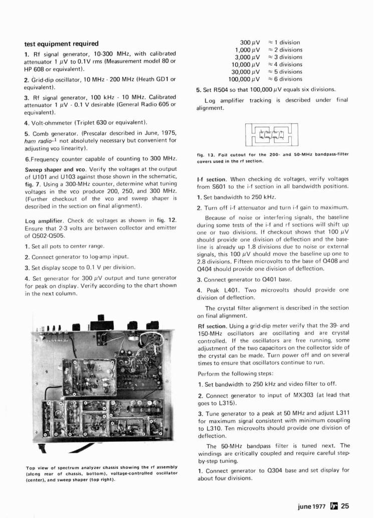
test equipment required
1. Rf signal generator, 10-300 MHz, with calibrated attenuator 1 pV to 0.1 V rms (Measurement model 80 or HP 608 or equivalent).
2. Grid-dip oscillator, 10 MHz - 200 MHz (Heath GD1 or equivalent).
3. Rf signal generator, 100 kHz - 10 MHz. Calibrated attenuator 1 pV - 0.1 V desirable (General Radio 605 or equivalent).
4. Volt-ohmmeter (Triplet 630 or equivalent).
5. Comb generator. (Prescalar described in June, 1975, ham radio.' not absolutely necessary but convenient for adjusting vco linearity).
6.Frequency counter capable of counting to 300 MHz.
Sweep shaper and vco. Verify the voltages at the output of U101 and U103 against those shown in the schematic, fig. 7. Using a 300-MHz counter, determine what tuning voltages in the vco produce 200, 250, and 300 MHz. (Further checkout of the vco and sweep shaper is described in the section on final alignment).
Log amplifier. Check dc voltages as shown in fig. 12. Ensure that 2-3 volts are between collector and emitter of Q502-0505.
1. Set all pots to center range.
2. Connect generator to log-amp input.
3. Set display scope to 0.1 V per division.
4. Set generator for 300 pV output and tune generator for peak on display. Verify according to the chart shown in the next column.
Top view of spectrum analyzer chassis showing the rf assembly (along rear of chassis. bottom), voltage-controlled oscillator (center), and sweep shaper (top right).
300 pV = 1 division 1,000 pV = 2 divisions 3,000 pV 3 divisions
10,000 pV % 4 divisions 30,000 pV = 5 divisions
100,000 pV = 6 divisions
5. Set R504 so that 100,000 p V equals six divisions.
Log amplifier tracking is described under final alignment.
fig. 13. Foil cutout for the 200- and 50-MHz bandpass-filter covers used in the rf section.
I-f section. When checking dc voltages, verify voltages from S601 to the i-f section in all bandwidth positions.
1. Set bandwidth to 250 kHz.
2. Turn off i-f attenuator and turn i-f gain to maximum.
Because of noise or interfering signals, the baseline during some tests of the i-f and rf sections will shift up one or two divisions. If checkout shows that 100 pV should provide one division of deflection and the base- line is already up 1.8 divisions due to noise or external signals, this 100 pV should move the baseline up one to 2.8 divisions. Fifteen microvolts to the base of 0408 and Q404 should provide one division of deflection.
3. Connect generator to 0401 base.
4. Peak L401. Two microvolts should provide one division of deflection.
The crystal filter alignment i s described in the section on final alignment.
Rf section. Using a grid-dip meter verify that the 39- and 150-MHz oscillators are oscillating and are crystal controlled. If the oscillators are free running, some adjustment of the two capacitors on the collector side of the crystal can be made. Turn power off and on several times to ensure that oscillators continue to run.
Perform the following steps:
1. Set bandwidth to 250 kHz and video filter to off.
2. Connect generator to input of MX303 (at lead that goes to L315).
3. Tune generator to a peak a t 50 MHz and adjust L311 for maximum signal consistent with minimum coupling to L310. Ten microvolts should provide one division of deflection.
The 50-MHz bandpass filter is tuned next. The windings are critically coupled and require careful step by-step tuning.
1. Connect generator to Q304 base and set display for about four divisions.
1 2 0 - M H z LOWPASS
F I L T E R
1 2 n o M H l A M P L I F I E R
d Z N D M I X E R - ( 2 5 5 m m ) 5 0 . M H , 5 0 - M H z 1 3 8 m m l
1 B A N D P A S S F I L T E R
1-5/8" 3 N D L O
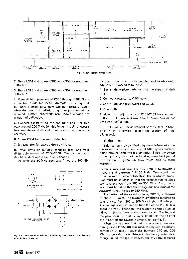
fig. 14. Rf-section dimensions.
2. Short L314 and adjust C306 and C308 for maximum deflection.
3. Short L313 and adjust C305 and C307 for maximum deflection.
4. Make slight adjustment of C305 through C308. Some interaction exists and several attempts will be required, but only a small adjustment will be necessary. Later, when the cover is installed, a slight readjustment will be required. Fifteen microvolts here should provide one division of deflection.
5. Connect generator to MX202 input and tune to a peak around 200 MHz. (At this frequency, signal genera- tors sometimes drift and some readjustment may be necessary 1. 6. Adjust C304 for maximum deflection.
7. Set generator for exactly three divisions.
8. Install cover on 50-MHz bandpass filter and make slight adjustments of C304-C308. Twenty microvolts should produce one division of deflection.
As with the 50-MHz bandpass filter, the 200-MHz
4 T U R N S THROUGH A RFA" . .
T R A N S F O R M E R C O N N E C T I O N
D O U B L E B A L A N C E D M I X E R S C H E M A T i C
fig. 15 . Construction details for winding transformers and baluns used in the r-f section.
bandpass filter is critically coupled and needs careful adjustment. Proceed as follows:
1. Set all three piston trimmers to the center of their range.
2. Connect generator to 0301 gate.
3. Short L306 and peak C301 and C303.
4. Peak C302.
5. Make slight adjustments of C301 -C303 for maximum deflection. Twenty microvolts here should provide one division of deflection.
6. Install covers. (Fine adjustment of the 200-MHz band- pass filter is covered under the section of final alignment).
final alignment This section provides final alignment information on
the sweep shaper and vco, crystal filter, gain equalizer, tuned circuits, and the log amplifier. Since the sweep shaper and vco may not be familiar, some background information is given on how these circuits work together.
Sweep shaper and vco. The first step is to provide a sweep signal between 0.1-100 MHz. Two conditions must be met to accomplish this: The sawtooth ampli- tude must be adjusted so that the varactor tuning diode can tune the vco from 200 to 300 MHz. Also, the dc level must be set so that the voltage one-half way up the sawtooth tunes the vco to 250 MHz.
The bottom of the varactor diode, CR203, is returned to about -9 volts. The sawtooth amplitude required to tune the vco from 200 to 300 MHz is about 8 volts p-p. The voltage level required to tune the vco to 250 MHz is about -2 volts. Therefore, the sawtooth should start at - 6 volts, the half-way point should be at - 2 volts, and the peak should end at +2 volts. R lO l sets the dc level and R 120 sets the sawtooth amplitude (see fig. 7).
When the vco was first built, a relatively nonlinear tuning diode (1N5140) was used. I t required frequency correction at most frequencies between 240 and 300 MHz to provide linear change in frequency with linear change in dc voltage. However, the MV3102 required
26 june 1977
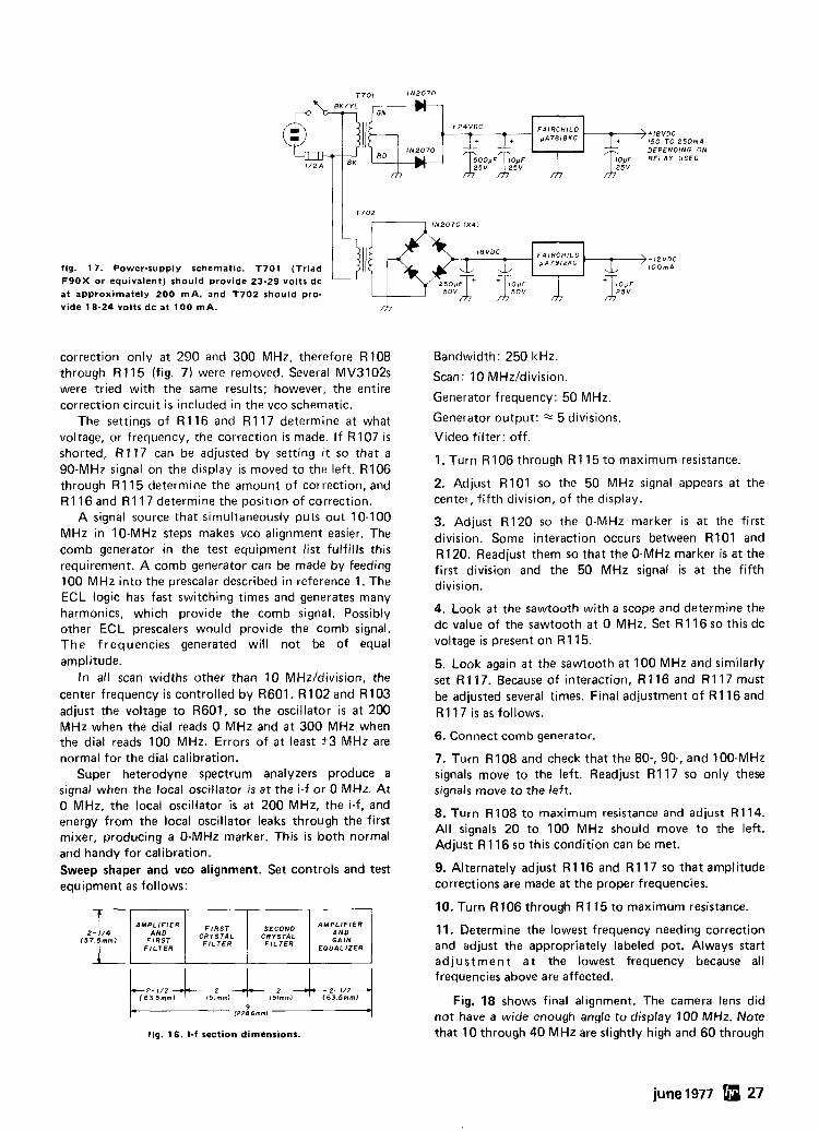
fig. 17. Power-supply schematic. T701 (Triad F 9 0 X or equivalent) should provide 23-29 volts dc at approximately 200 m A , and T 7 0 2 should pro- vide 18-24 volts dc at 1 0 0 mA.
correction only at 290 and 300 MHz, therefore R108 through R115 (fig. 7) were removed. Several MV3102s were tried with the same results; however, the entire correction circuit is included in the vco schematic.
The settings of R116 and R117 determine at what voltage, or frequency, the correction is made. If R107 is shorted, R117 can be adjusted by setting i t so that a 90-MHz signal on the display is moved to the left. R106 through R115 determine the amount of correction, and R116 and R117 determine the position of correction.
A signal source that simultaneously puts out 10-100 MHz in 10-MHz steps makes vco alignment easier. The comb generator in the test equipment list fulfills this requirement. A comb generator can be made by feeding 100 MHz into the prescalar described in reference 1. The ECL logic has fast switching times and generates many harmonics, which provide the comb signal. Possibly other ECL prescalers would provide the comb signal. The frequencies generated will not be of equal amplitude.
In all scan widths other than 10 MHzIdivision, the center frequency is controlled by R601. R102 and R103 adjust the voltage to R601, so the oscillator is at 200 MHz when the dial reads 0 MHz and at 300 MHz when the dial reads 100 MHz. Errors of at least ?3 MHz are normal for the dial calibration.
Super heterodyne spectrum analyzers produce a signal when the local oscillator is at the i-f or 0 MHz. At
Bandwidth: 250 kHz.
Scan: 10 MHzIdivision.
Generator frequency: 50 MHz.
Generator output: z 5 divisions.
Video filter: off.
1. Turn R 106 through R 1 15 to maximum resistance.
2. Adjust R101 so the 50 MHz signal appears at the center, f i f th division, of the display.
3. Adjust R120 so the 0-MHz marker is at the first division. Some interaction occurs between R101 and R120. Readjust them so that the 0-MHz marker is at the first division and the 50 MHz signal is at the f i fth division.
4. Look at the sawtooth with a scope and determine the dc value of the sawtooth at 0 MHz. Set R116 so this dc voltage is present on R 1 15.
5. Look again at the sawtooth at 100 MHz and similarly set R 1 17. Because of interaction, R 116 and R 1 17 must be adjusted several times. Final adjustment of R116 and R 11 7 is as follows.
6. Connect comb generator.
7. Turn R108 and check that the 80-, 90-, and 100-MHz signals move to the left. Readjust R117 so only these signals move to the left.
0 MHz. the local oscillator is at 200 MHz, the i-f, and 8. Turn R108 to maximum resistance and adjust R 1 14. energy from the local oscillator leaks through the first mixer, producing a 0-MHz marker. This i s both normal
All signals 20 to 100 MHz should move to the left. Adjust R 116 so this condition can be met.
and handv for calibration. Sweep shaper and vco alignment. Set controls and test 9. Alternately adjust R116 and R117 so that amplitude
equipment as follows: corrections are made at the proper frequencies.
I I I I I 10. Turn R106 through R115 to maximum resistance.
june 1977 27
I 2- 1/4
157.5mm,
adjustment a t the lowest frequency because all frequencies above are affected.
2- 112 / 6 3 5mml 151mml 151mml 163 5mml Fig. 18 shows final alignment. The camera lens did
f2286mml kt.-$ not have a wide enough angle to display 100 MHz. Note fig. 16. I-f section dimensions. that 10 through 40 MHz are slightly high and 60 through
AMPLIFIER
Ff::T FILTER
CRYSTAL CRYSTAL
AMPLIFIER AND GAIN
EOUALIZER
11. Determine the lowest frequency needing correction and adjust the appropriately labeled pot. Always start
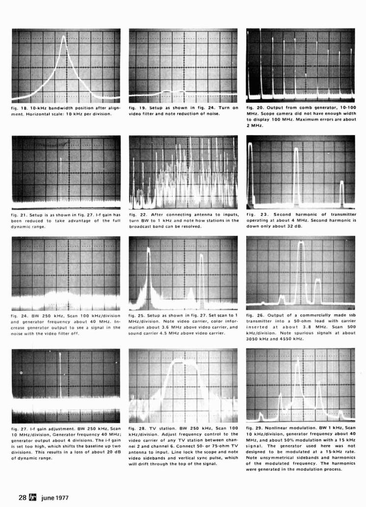
f ~ g . 18. 10 -kHz bandw id th pos i t ion a f ter al fgn- ment . Hor izonta l scale: 1 0 k H z per div is ion.
r a,->' . fig. 21. Setup is as shown i n fig. 27. 1-1 gafn has been reduced t o take advantage o f t he f u l l dynamic range.
*I I I I I I .-4a f fg 24. B W 250 kHz , Scan 1 0 0 k H z / d f v ~ s ~ o n
and generator frequency abou t 4 0 MHz . I n -
crease generator o u t p u t t o see a slgnal I n the
nolse w ~ t h t he vldeo f l l te r o f f .
fig. 27. 1.f gain ad jus tment . BW 250 kHz . Scan 1 0 MHzld iv is ion, Generator f requency 4 0 MHz :
generator o u t p u t about 4 divisions. T h e i-f gain is set t o o high, wh i ch shi f ts t he baseline u p t w o divislons. Th i s results i n a loss o f abou t 2 0 d B
o f dynamic range.
f ~ g . 19. Setup as shown In fig. 24. T u r n o n video f i l te r and n o t e reduc t i on o f noise.
fig. 22. A f t e r connect ing antenna t o inputs.
t u r n BW t o 1 k H z and n o t e h o w stat ions i n t he broadcast band can be resolved.
8 . . ..- fig. 25. Setup as shown i n fig. 27. Set scan t o I MHz/divfsion. N o t e video carrier, co lo r in for .
ma t i on abou t 3.6 M H z above video carrier, and sound carr ier 4.5 M H z above video carrier.
fig. 28. T V stat lon. BW 2 5 0 kHz, Scan 1 0 0
kHz/diVlSiOn. Ad jus t f requency con t ro l t o t he
video carrier o f any T V s ta t ion between chan-
ne l 2 and channel 6. Connect 50- o r 75 -ohm T V
antenna t o Input . L i ne l ock t he scope and n o t e
video sidebands and vert ical sync pulse. wh i ch w i l l d r i f t t h rough the t o p o f t he signal.
f ig. 20. O u t p u t f r o m c o m b generator. 10 -100 MHz . Scope camera d id n o t have enough w i d t h
t o display 1 0 0 MHz. M a x i m u m errors are abou t
2 MHz.
.%
.= - f i g . 2 3 . Second ha rmon ic o f t ransmi t ter operat ing at abou t 4 MHz. Second ha rmon ic is
d o w n o n l y abou t 3 2 dB.
m Y - ----- x f ~ g . 26. O u t p u t of a commerc ia l ly made ssb transmitter i n t o a 50 -ohm load w i t h carr ier
i n s e r t e d a t a b o u t 3 .8 MHz. Scan 500
kHz/divis ion. N o t e spurious signals a t abou t
3 0 5 0 k H z and 4 5 5 0 kHz.
--
fig. 29. Nonl inear modula t ion. BW 1 kHz. Scan
1 0 kHz/divis ion, generator f requency abou t 4 0
MHz, and abou t 50% modu la t i on w i t h a 1 5 k H z s i gna l . T h e generator used here was n o t deslgned t o be modu la ted a t a 15 -kHz rate. N o t e unsymmetr ica l sidebands a n d harmonics o f t he modu la ted frequency. T h e harmonics
were generated i n t he modu la t i on process.
28 june 1977
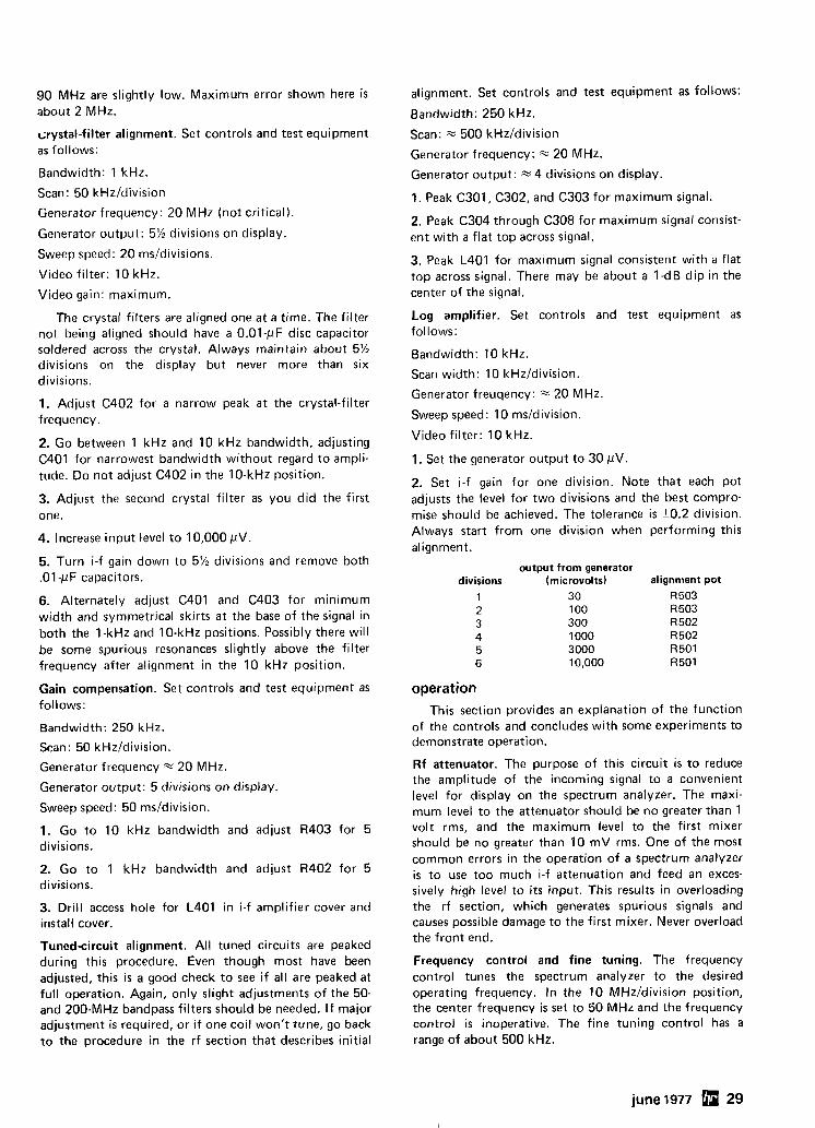
90 MHz are slightly low. Maximum error shown here is about 2 MHz.
irystal-filter alignment. Set controls and t e s t equipment as follows:
Bandwidth: 1 kHz.
Scan: 50 kHz1division
Generator frequency: 20 MHz (not critical).
Generator output: 5% divisions on display.
Sweep speed: 20 ms/divisions.
Video filter: 10 kHz.
Video gain: maximum.
The crystal filters are aligned one at a time. The filter not being aligned should have a 0.01-pF disc capacitor soldered across the crystal. Always maintain about 5% divisions on the display but never more than six divisions.
1. Adjust C402 for a narrow peak at the crystal-filter frequency.
2. Go between 1 kHz and 10 kHz bandwidth, adjusting C401 for narrowest bandwidth without regard to ampli- tude. Do not adjust C402 in the 10-kHz position.
3. Adjust the second crystal filter as you did the first one.
4. Increase input level to 10,000 pV
5. Turn i-f gain down to 5% divisions and remove both .O1 -pF capacitors.
6. Alternately adjust C401 and C403 for minimum width and symmetrical skirts at the base of the signal in both the I-kHz and 10-kHz positions. Possibly there will be some spurious resonances slightly above the filter frequency after alignment in the 10 kHz position.
Gain compensation. Set controls and test equipment as follows:
Bandwidth: 250 kHz.
Scan: 50 kHz1division.
Generator frequency % 20 MHz.
Generator output: 5 divisions on display.
Sweep speed: 50 msldivision.
1. Go to 10 kHz bandwidth and adjust R403 for 5 divisions.
2. Go to 1 kHz bandwidth and adjust R402 for 5 divisions.
3. Drill access hole for L401 in i-f amplifier cover and install cover.
Tuned-circuit alignment. All tuned circuits are peaked during this procedure. Even though most have been adjusted, this is a good check to see if all are peaked at full operation. Again, only slight adjustments of the 50- and 200-MHz bandpass filters should be needed. I f major adjustment i s required, or i f one coil won't tune, go back to the procedure in the rf section that describes initial
alignment. Set controls and test equipment as follows:
Bandwidth: 250 kHz.
Scan: = 500 kHz1division
Generator frequency: % 20 MHz.
Generator output: 4 divisions on display.
1. Peak C301, C302, and C303 for maximum signal.
2. Peak C304 through C308 for maximum signal consist- ent with a flat top across signal.
3. Peak L401 for maximum signal consistent with a flat top across signal. There may be about a I -dB dip in the center of the signal.
Log amplifier. Set controls and test equipment as follows:
Bandwidth: 10 kHz.
Scan width: 10 kHz1division.
Generator freuqency: 2 20 MHz.
Sweep speed: 10 msldivision.
Video filter: 10 kHz.
1. Set the generator output to 30 pV.
2, Set i-f gain for one division. Note that each pot adjusts the level for two divisions and the best compro- mise should be achieved. The tolerance is k0.2 division. Always start from one division when performing this alignment.
output from generator divisions (microvolts) alignment pot
1 30 R 503 2 100 R 503 3 300 R502 4 1000 R502 5 3000 R501 6 10,000 R501
operation This section provides an explanation of the function
of the controls and concludes with some experiments to demonstrate operation.
Rf attenuator. The purpose of this circuit is to reduce the amplitude of the incoming signal to a convenient level for display on the spectrum analyzer. The maxi- mum level to the attenuator should be no greater than 1 volt rms, and the maximum level to the first mixer should be no greater than 10 mV rms. One of the most common errors in the operation of a spectrum analyzer is to use too much i-f attenuation and feed an exces- sively high level to i t s input. This results in overloading the rf section, which generates spurious signals and causes possible damage to the first mixer. Never overload the front end.
Frequency control and fine tuning. The frequency control tunes the spectrum analyzer to the desired operating frequency. In the 10 MHzIdivision position, the center frequency is set to 50 MHz and the frequency control is inoperative. The fine tuning control has a range of about 500 kHz.
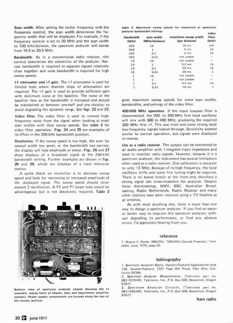
Scan width. After setting the center frequency with the frequency control, the scan width determines the fre- quency width that will be displayed. For example, if the frequency control is set to 20 MHz and the scan width to 100 kHzIdivision, the spectrum analyzer will sweep from 19.5 to 20.5 MHz.
Bandwidth. As in a conventional radio receiver, this control determines the selectivity of the analyzer. Nar- row bandwidth is required to separate signals relatively close together and wide bandwidth is required for high sweep speeds.
I-f attenuator and i-f gain. The i-f attenuator i s used for limited tests where discrete steps of attenuation are required. The i-f gain is used to provide sufficient gain with minimum noise at the baseline. The noise at the baseline rises as the bandwidth i s increased and should be maintained at between one-half and one division to avoid dtgrading the dynamic range. See figs. 22 and 23.
Video filter. The video filter is used to remove high- frequency noise from the signal when looking at small scan widths with slow sweep speeds. See table 2 for video filter operation. Figs. 24 and 25 are examples of i t s effect in the 250-kHz bandwidth position.
Resolution. If the sweep speed is too high, the scan (or sweep) width too great, or the bandwidth too narrow, the display will lose amplitude or smear. Figs. 26 and 27 show displays of a broadcast signal at the 250-kHz bandwidth setting. Further examples are shown in figs. 28 and 29, which are displays of a local television station.
A quick check on resolution is to decrease sweep speed and look for narrowing or increased amplitude of the displayed signal. The sweep speed should never exceed 2 ms/division. A P2 and P7 scope tube would be advantageous but is not absolutely required. Table 2
Bottom view of spectrum analyzer chassis showing the i-f assembly (along front of chassis, top) and logarithmic amplifier (center). Power supply components are located along the rear of the chassls, bottom.
table 2. Maximum sweep speeds for resolution at spectrum- analyzer bandwidth settings.
video bandwidth
(kHz) 250 250 250 250
10 10 10 10
1 1 1 1
scan width (MHzldivision)
10 1 0.1 0.01
10 1 0.1 0.01
10 1 0.1 0.01
maximum sweep width (per division)
10 rns 5 rns 2 rns
not usable not usable
0.2 sec 50 rns 20 rns
not usable not usable
0.2 sec 50 rns
filter (kHz) Off 10 10 - - 10 10
1 - - 10
1
gives maximum sweep speeds for some scan widths, bandwidths, and settings of the video filter.
400-500 MHz operation. If the input lowpass filter i s disconnected, the 200- to 300-MHz first local oscillator will mix with 500 to 400 MHz, producing the required 200 MHz first i-f. This was tried and some strong local low-frequency signals leaked through. Sensitivity seemed similar to normal operation, but signals were displayed in reverse.
Use as a radio receiver. The output can be connected to an audio amplifier with 1-megohm input impedance and used to monitor radio signals. However, because i t is a spectrum analyzer, the instrument has several limitations when used as a radio receiver. Dial calibration is accurate to only 23 MHz. Because of its high frequency, the local oscillator drifts and some fine tuning might be required. There is no tuned circuit at the front end, therefore a strong signal can cross-modulate the analyzer. Despite these shortcomings, WWV, BBC, Australian Broad- casting, Radio Netherlands, Radio Moscow and many other stations have been received using a TV feedline as an antenna.
As with most anything else, there is more than one way to design a spectrum analyzer. If you find an easier or better way to improve this spectrum analyzer, with- out degrading its performance, or find any obvious errors, I'd appreciate hearing from you.
reference 1. Wayne C. Ryder, WGURH, "500-MHz Decode Prescaler," ham radio, June, 1975, page 32.
bibliography 1. Spectrum Analyzer Basics, Hewlett-Packard Applications note 150, Hewlett-Packard, 1501 Page Mill Road, Palo Alto, Cali- fornia 94304. 2. Spectrum Analyzer Measurements, (Tektronix part no. 062-1070-001, Tektronix, Inc., P.O. Box 500, Beaverton, Oregon 97077. 3 . Spectrum Analyzer Ci rcui ts , (Tektronix part no. 062-1055-00). Tektronix, Inc., P.O. Box 500, Beaverton, Oregon 97077.
ham radio
There is no other amateur transceiver available in the United States today that can match the quality. The relia- bility. Or the performance of the Hy-Gain 3750.
It covers all amateur band 1.8-30MHz (1 60-1 0 meters) with uncanny accuracy. It has
I SPECIFICATIONS
FREOUENCY COVERAGE 1.8 MHz Band 1 8 - 2.0 MHz 3 5 MH7 Rand 3.5 - 4.0 MHz 7.0 MHz Band 7.0 - 7.5 MHz 14 MHz Band 14.0 - 14.5 MHz 21 MHz Band 21.0 - 21.5 MHz 28 MHz Band A 28.0 - 28.5 MHz 28 MHz Band B 28 5 - 29.0 MHz 28 MHz Band C 29.0 - 29 5 MHz 28 MHz Band D 29.5 - 30.0 MHz WWII RX only 10.0 MHz MIC, INPUT IMPEDANCE
5 0 U l AUDIO FREOUENCY CHARACTERISTICS
3CO - 2iOOH7 (-6dB) SENSlTlVlN
S:,B less than .25 p v for 10 dB S'N t N ratlo
CW less than .15uv for 10 dB S N + N iatio
MODES OF OPERATION S:,B (LSB or US01 CW
Matchlng speaker unit (Hy-Gain 3854)
advanced Phase-Lock-Loop circuitry. Dual gate MOS FET's at all critical RF amplifier and mixer stages. Electronic fre- quency counter with digital readout. Digital memory dis- play. And stability that's truly remarkable by any standards.
The Hy-Gain is simply the finest amateur transceiver you can buy. There is nothing else like it.
Read our specs. Then see your amateur radio dealer or write for complete details on the features and performance of the incomparable 3750.
------------- Hy-Gain E l e c t r o n i c s C o r p o r a t i o n 1 8601 N o r t h e a s t H i a h w a v S i x I
INPUT POWER 200 W PEP
ANT. IMPEDANCE 5 0 0 - 7%) Unbalanced
CARRIER SUPPRESSION More than 50dB
SIDE BAND SUPPRESSION More than 50dB
SPURIOUS AN0 HARMONIC SUPPRESSION
Grr,~ter thnn 40dB 3RO ORDER OlSTORTlON PRODUCTS SUPPRESSION
IF FREQUENCIES 151 I F SMHz 2nd IF 5OkHz
SELECTIVITY SSB 2 JkHz (-6dB) 4 OkHz (-66dB) CW 400Hz (-6dB) 1 8kHz (-66dBI
and complete external VFO (Hy
AUDIO OUTPUT into 811 load 2 5W ( 10°/. d~slor t~on) 3 OW (MAX)
POWER SOURCE AC 120v 50 60 Hz (can be re-w~red for 240'4)
POWER DRAIN JOOVA TX 7RVA RX 48VA RX (Power tube OFF)
SEMI-CONOUCTORS Trans~stor 98
~,ncludlnq 23 FETl IC 43 D~ode 120 Tube 3 D~oital Ind 1
wEIG=tn 44 lbs. 6 02s. (23kg)
DIMENSIONS
-Gain 3855) available at extra cost
-.. -
I L~ncoln, NE 68505- '
I Send me i n f o r m a t i o n on t h e i n c o m p a r a b l e I
H y - G a i n 3 7 5 0 a m a t e u r t r a n s c e i v e r . I
I I I I I NAME CALL I I I I ADDRESS I I I CITY
I STATE ZIP
I I I
This tape editor i s designed for use with a transmitter- distributor (or TD as i t i s more commonly known), a keyboard send-receive teletype (KSR) and a reper- forator. Any serious RTTY operator who owns this equipment has surely longed for an easy way to delete or insert material into a tape. This need could arise from errors in reception when punching tape off the air, or i t might be merely a desire to modify a tape to suit your particular needs. In any case the arrangement described here should f i t the bill.
The usual method of tape editing i s to insert the original tape into the TD and, while operating on local loop, make a new tape from the original tape on the reperforator. Editing is done by stopping the tape in the TD, entering corrections from the keyboard, moving the tape manually through the TD past the incorrect material, then restarting the TD to continue until reaching the next point for correction. The result of this exercise is monitored on the page printer. The problem with this procedure is getting the original tape moved to just the exact spot from which it should be restarted. This may sound simple enough, but if you've ever tried this method you know how easy i t is to end a character or so off from where you intended to restart, with another error to edit.
examples With the tape-edit circuit described here, the TD is
stepped one character for every character entered from the keyboard. Thus, if the tape reads "shop," and you wish to change it to "ship," you can stop the TD after "sh." put the EDlT switch to ON, and type "i." The TD will advance one character when the "i" is entered so that when the EDlT switch is thrown to OFF, the TD will start again and print the letter "p" thus completing the correction. Alternatively, the tape could have been stopped just before the word "shop," the EDIT switch placed to ON and the entire word "ship" typed in from the keyboard. The TD would have been stepped along one character for each character typed so that the net result would be the same.
Suppose the word "ship" had been garbled in the original tape, but from the message context you were able to determine that "ship" was the correct word. Suppose i t read "shxrnp." Stop the tape as before and turn the EDlT switch to ON. Enter "i" from the key- board then strike the LETTERS key, which will move the TD one more character past the extraneous "m." Turn the EDIT switch to OFF, which will restart the TD with the letter "p," and the correction will be complete. With these corrections, editing can be done on the air after a very little practice.
The circuit is shown in fig. 1. The objective is to advance the TD one character for each character entered from the keyboard without having the TD affect the print (or the new tape being punched by the reper- forator).
A miniature dpdt toggle switch was mounted on the front of the TD just below the main ON/OFF switch and slightly to the left. This required drilling a %-inch (6.5mm) hole in the TD casting - an easy job. One section of this switch, SIA, was placed in parallel with the TD signal line so that a MARK condition exists at all times when the EDIT switch is in the ON position. The other section, SIB, is connected in series with the TAPE-OUT and the TAUT-TAPE switch and is closed when the EDlT switch is OFF. A pair of leads parallel SIB and run to the contacts on a polar relay. When the EDlT switch is ON, SIB is open so the only way that current can get to the RUN MAGNET on the TD is through the polar-relay contacts.
The polar relay coil is connected in series with the keyboard. Thus loop current flows through the coil until a key is depressed. This action holds the relay in the MARK position.
When a key i s depressed, the START pulse moves the polar relay to the SPACE position, which closes the circuit to the TD run magnet, allowing the TD to start. As soon as the STOP pulse is transmitted for whatever character was typed in, the polar relay will return to the MARK position, which opens the run-magnet circuit, stopping the TD after i t has advanced one character. Thus the TD advances the tape one character for each character sent from the keyboard. Since the first section of the EDlT switch has shorted the TD signal line, the TD has no effect on the transmission.
tape changes Earlier in the article I discussed error corrections.
Sometimes it's desired to make changes in a tape. For example I have a Christmas-greeting tape, which was received from the State Council of Civil Defense. I wanted to use this tape with my name in the box where the original read "State Council of Civil Defense." Fig. 2 shows the print before and after editing.
cautionary measures Remember that nonprinting functions must be taken
into account when editing. For example, i f W3EAG is to be replaced by "Tommy," this is not just a one-for-one substitution as i t appears. The figure function preceding the 3, and the letters function following it, must be accounted for since these are two additional characters
y Tom Gibson, W3EAG, R. D. 1 Evansburg Road, sllegevil le, Pennsylvania 19426
32 june 1977
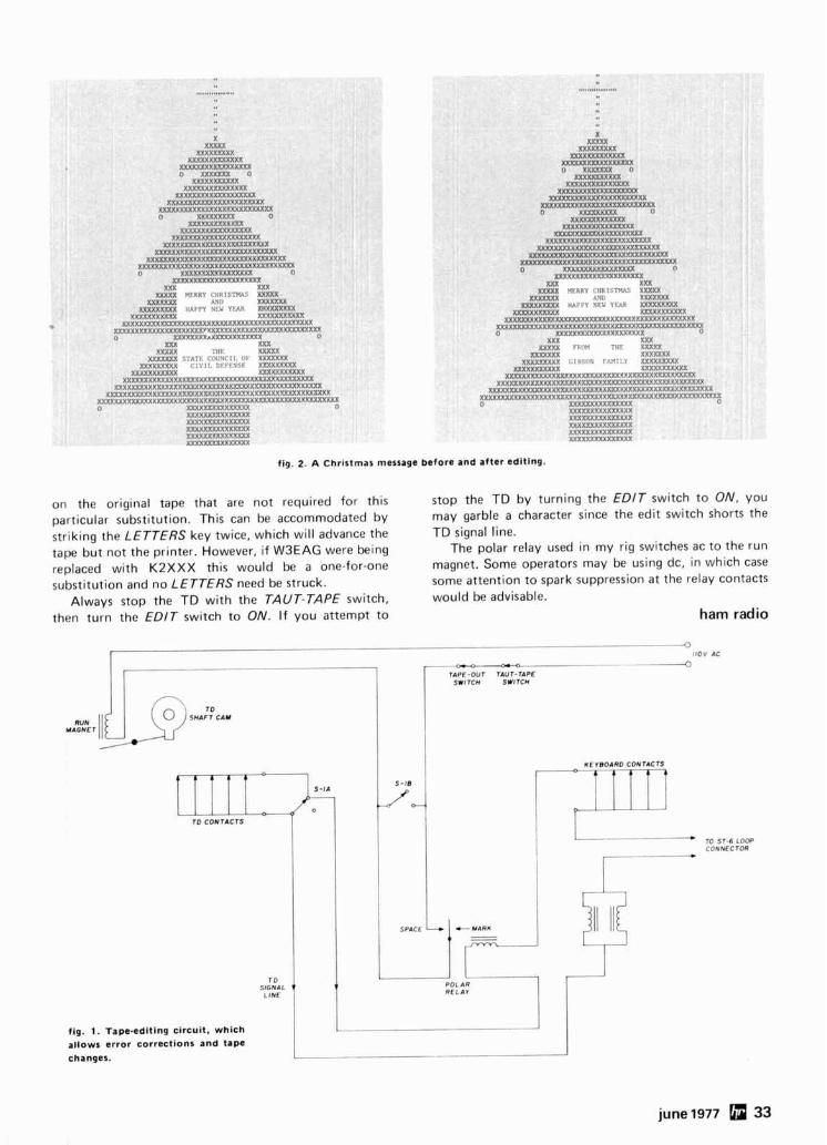
x x i 0
(XX (XXXX (TKRXXX
XXXXXYXX! m X X : ( Y X X S : O /E:~.<T:S 0
XXXT:<?i.XXXX X X Y Y X I . ' ~ : ~ : I ~ ? X X X X
U(XIX:<'Y'..'~ ' IXXXXXXX XXXXXXY"SSl ' ! . i :P"xxmXX
U(XXYxY:< '~ "< r " . ,, <"?:,iX.Y:UiY.XX 0 .("!:,',iy, 0
XX<'h*'" <l < X I XXXYX': ,,'i.?'<'X:<RXX
XXXIY~::<..?" < r ? \ :< lXXXXX XXXXXX):'<., x i ' ( . Y S ~ < X S X X X X X
XXXXXRVKA. V.'., .'??<I"X:<R.YXXXXXX XXyJXXyy:,:'<YV:y<YY .:(V'?.r?:<hhRXRXX)
mXyy,*:<::"\.:Y"y. . ~ . ~ ? ' ~ x : < , > , X . i ' < C T S S S ~ >
0 i .I?'~~iY'h, .PYY.\LX ~ y ~ < ' v ~ " y " " ' ; ~ " y Y X X
XXY XXX XXXXX L't H R Y I IIPll:llV%'. XXXXX
XXXXXhY ,,.i:~ XRXXXXX MUXXXXX IIAPPY . i t< Y W R XI 'TXRXIXX
XXXXYIXI:"Y X?" ' , <YXWX XXXy:,'?..(( " . \ ' < m X ~ X X X X m x m x x Y X Y <'X: i .KVYXM
)V(YRXY"Y:<iX.<:. i .Y.XXXXXX~XkXXXXXXXXkXX: .'LY.F .':Y.XW.XXX U X : < X Y Y : < Y X A * R ~ ' < X X S X Y ~ S Y 0
X I X S I X XXYI ' ! Tllt YYRXX
MXXXPX F T A T ~ Coi Ur11. OF :<:<RSX ~ m x : l ? \ A C I V I L l i l FFYSE Xl 'YY
X x X X x ~ X Y : ~ x XY'<%? XXXXTXS") ' \ ,,'XXXXXmXUOOOU(XXXXXX:~~.iiii
XXXW.?,:<'iA!::\:~ ' :, X :<YKXXXXXXXIXXXXXXXW ?Y:v,,,2vv VX\:xYYxj:..ilY.. '~':'.?YY?XX'LY>;XX"Yx%Y?YYEY ,. . .. r... ..YYXXYXX
vyXuryh,r,.u~., y : . : ~ y ~ i : y v ~ : i y v y y y x ~ : . p ~ i . Y Y ~ < Y Y : ~ V ~ ~ X X X X X I >;x':, ?X"> V,'<'\ > 'Z
!,,.??x,?:r<??S~ XX h:;:,.("> ,"',),*'\y x y h.,, ?" .,;y,:'.2;??'< ,..,,> ~ , ~ < . ~ > v " v " y . , ~
XX XXXX
XXXXXX M X X X X X
x x X x x Y x I Y : <
xx: X x x x :
X XXXXX
m x x x m
fig. 2. A Christmas message before and after editlng.
on the original tape that are not required for this particular substitution. This can be accommodated by striking the LETTERS key twice, which will advance the tape but not the printer. However, i f W3EAG were being replaced with K2XXX this would be a one-for-one substitution and no LETTERS need be struck.
Always stop the TD with the TAUT-TAPE switch, then turn the EDlT switch to ON. I f you attempt to
stop the TD by turning the EDlT switch to ON, you may garble a character since the edit switch shorts the TD signal line.
The polar relay used in my rig switches ac to the run magnet. Some operators may be using dc, in which case some attention to spark suppression at the relay contacts would be advisable.
ham radio
--
TbPE-OUT TAUT-TAPE SWITCH SWITCH
m sr-s LOOP CONNECTOR
june 1977 33
top-coupled chebyshev design
Practical design and construction data
for 3-, 4- and 5-section Chebyshev band pass filters
for amateur applications
The top-coupled bandpass filter is the easiest of its type to construct. I t appears to be several parallel resonant circuits connected in sequence with small coupling capacitors. All inductors are the same value. In actuality, this type of bandpass filter is one of many configura- tions based on a lowpass filter prototype. Presented here are the necessary component formulas to enable design and construction of 3-, 4-, and 5-section "I-dB ripple" Chebyshev bandpass filters along with passband and skirt selectivity response, input impedance, and insertion loss.
why Chebyshev?
The most common filter design is the Butterworth with its flat passband response. A Chebyshev filter has ripple in the passband, defined by dB difference of peak-to-valley; design bandwidth refers to the dB-down points on the edges rather. than the 3 dB points of the Butterworth. The Chebyshev response also has better skirt attenuation than the Butterworth.
The names refer to the mathematical operations used in determining component values. The math involved i s lengthy and may be found In many textbooks. Here, the only math will be that required for one type of Chebyshev ripple design.
Both Chebyshev and Butterworth designs for equal
bandpass filter load and source impedances suffer shape distortion and increased insertion loss as a function of finite Q. This will be seen on the response curves.
Schematics and individual value formulas are shown in fig. 1 . The formulas are derived from lossless-element designs and feature equal end resistances. Following are definitions common to all:
fL = owes st frequency o f pussband, M H z
fF, = Hig/rest frequency o f l~clssbarld, MHz
f,, = Gcom~t r i c cetlter frequency =
fi, = andw width = fH - fL
1' = Fractional bandwidth = f h / f c , 25330.3 C,, = Resonating capacitance = -
f,,T with L equal to L3 , L 4 , or L 5 , depending on filter
Note that all terms are scaled to megahertz, nicro- henries, picofarads, and kilohms. Practical designs require high end resistances. Matching to lower values is given later.
1 how degrading can you get? Circuit Q has little effect on skirt attenuation but
does distort the passband. Skirt response is shown in figs. 2 and 3 while passband response is shown in figs. 4, 5, and 6.
The parallel 1,-C combined Q will determine the pass- band shape and insertion loss. It can be shown that
Q = combined Qc and Q Qk " = QL + QC
A reference to Q will generally refer to the combination. Very high Q will still result in distortion, as shown on the passband curves. The curves are not ideal - they have been deliberately chosen to represent degraded performance in choosing coils and coupling capacitors as will be explained in the design example.
This unorthodox presentation is the "worst-case" design situation. Selection of component values closer to calculated values will improve shape, insertion-loss, and skirt attenuation. Curves of figs. 2 through 6 were taken from the design example where the inductor was higher in value than given by the formula, the coupling
By Leonard H. Anderson, 10048 Lanark Street, Sun Valley, California 91352
34 june 1977
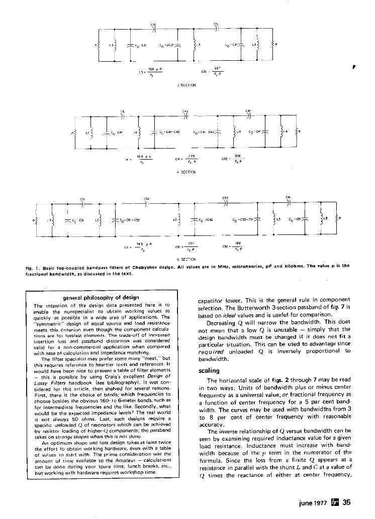
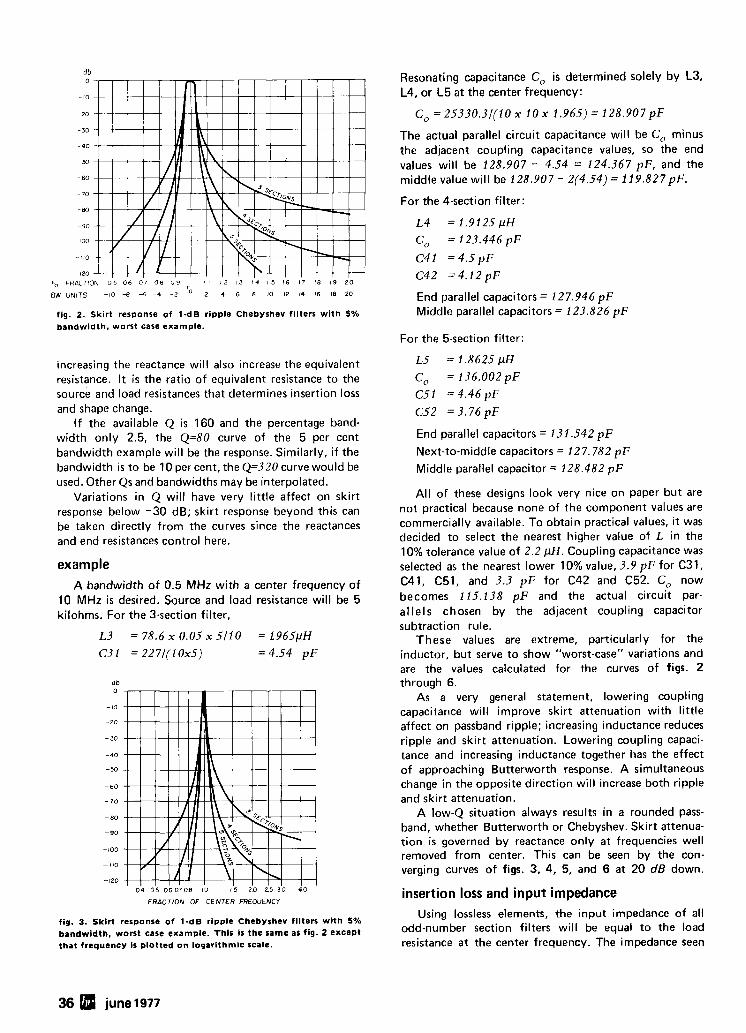
d b 0
- 10
- 20
-30
- 90
-5.3
- 60
- 70
-80
-90
100
110
-120
Fo FRACTION 0 5 0 6 0 7 0 8 0 9 1 1 12 13 14 15 16 17 18 19 2 0
BW UNITS -10 -8 -6 - 4 - 2 2 4 6 8 10 12 14 16 18 20
fig. 2. Skirt response of 1-dB ripple Chebyshev filters with 5% bandwidth, worst case example.
increasing the reactance will also increase the equivalent resistance. It is the ratio of equivalent resistance to the source and load resistances that determines insertion loss andshapechange.
I f the available Q is 160 and the percentage band- width only 2.5, the Q=80 curve of the 5 per cent bandwidth example will be the response. Similarly, i f the bandwidth is to be 10 per cent, the Q=320 curve would be used. Other Qs and bandwidths may be interpolated.
Variations in Q will have very little affect on skirt response below -30 dB; skirt response beyond this can be taken directly from the curves since the reactances and end resistances control here.
example A bandwidth of 0.5 MHz with a center frequency of
10 MHz is desired. Source and load resistance will be 5 kilohms. For the 3-section filter,
L3 = 78.6 x 0.05 x 5 /10 = t965pH C3 I = 227/(1Ox5) =4.54 pF
db 0
- 10
-20
- 30
-40
-50
-60
- 7 0
- 80
-90
-100
-110
- 120
0 4 0 5 0 6 0 7 0 8 10 15 2 0 25 30 4 0
FRACTION OF CENTER FREOUENCY
fig. 3. Skirt responro of 1-dB ripple Chebyshev filters with 5% bandwidth, worst care example. This is the same as fig. 2 except that frequency Is plotted on logarithmic scale.
Resonating capacitance C, is determined solely by L3, L4, or L5 at the center frequency:
The actual parallel circuit capacitance will be C, minus the adjacent coupling capacitance values, so the end values will be 128.907 - 4.54 = 124.367 pF, and the middle value will be 128.907 - Z(4.54) = 119.827pF.
For the 4-section filter:
End parallel capacitors = 127.946 pF Middle parallel capacitors = 123.826 pF
For the 5-section filter:
End parallel capacitors = 131 5 4 2 pF Next-to-middle capacitors = 127.782 pF Middle parallel capacitor = 128.482 pF
All of these designs look very nice on paper but are not practical because none of the component values are commercially available. To obtain practical values, i t was decided to select the nearest higher value of L in the 10% tolerance value of 2.2 pH. Coupling capacitance was selected as the nearest lower 10% value, 3.9 pF for C31, C41, C51, and 3.3 pF for C42 and C52. C, now becomes 115.138 pF and the actual circuit par- a1 lel s chosen by the adjacent coupling capacitor subtraction rule.
These values are extreme, particularly for the inductor, but serve to show "worst-case" variations and are the values calculated for the curves of figs. 2 through 6.
As a very general statement, lowering coupling capacitance will improve skirt attenuation with little affect on passband ripple; increasing inductance reduces ripple and skirt attenuation. Lowering coupling capaci- tance and increasing inductance together has the effect of approaching Butterworth response. A simultaneous change in the opposite direction will increase both ripple and skirt attenuation.
A low-Q situation always results in a rounded pass- band, whether Butterworth or Chebyshev. Skirt attenua- tion i s governed by reactance only at frequencies well removed from center. This can be seen by the con- verging curves of figs. 3, 4, 5, and 6 at 20 dB down.
insertion loss and input impedance Using lossless elements, the input impedance of all
odd-number section filters will be equal to the load resistance at the center frequency. The impedance seen
36 june 1977
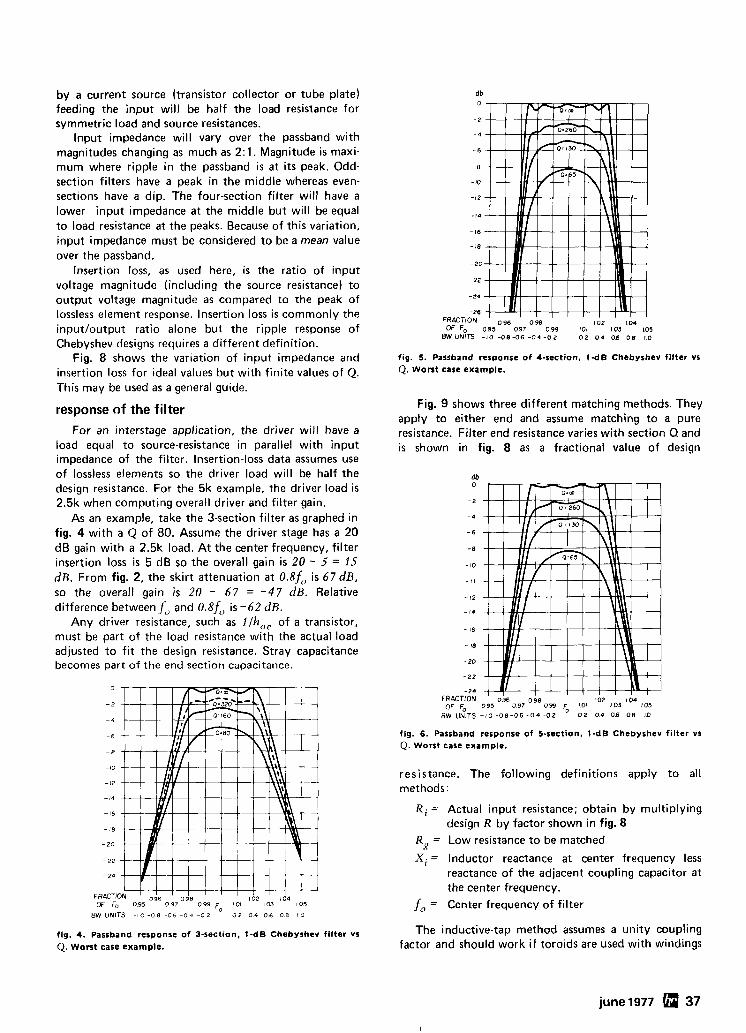
by a current source (transistor collector or tube plate) feeding the input will be half the load resistance for symmetric load and source resistances.
Input impedance will vary over the passband with magnitudes changing as much as 2: 1. Magnitude is maxi- mum where ripple in the passband is at its peak. Odd- section filters have a peak in the middle whereas even- sections have a dip. The four-section filter will have a lower input impedance at the middle but will be equal to load resistance at the peaks. Because of this variation, input impedance must be considered to be a mean value over the passband.
Insertion loss, as used here, i s the ratio of input voltage magnitude (including the source resistance) to output voltage magnitude as compared to the peak of lossless element response. Insertion loss is commonly the inputloutput ratio alone but the ripple response of Chebyshev designs requires a different definition.
Fig. 8 shows the variation of input impedance and insertion loss for ideal values but with finite values of Q. This may be used as a general guide.
response of the filter For an interstage application, the driver will have a
load equal to source-resistance in parallel with input impedance of the filter. Insertion-loss data assumes use of lossless elements so the driver load will be half the design resistance. For the 5k example, the driver load is 2.5k when computing overall driver and filter gain.
As an example, take the 3-section filter as graphed in fig. 4 with a Q of 80. Assume the driver stage has a 20 dB gain with a 2.5k load. At the center frequency, filter insertion loss is 5 dB so the overall gain is 20 - 5 = 15 dB. From fig. 2, the skirt attenuation at 0.8ffl is 6 7 d B . so the overall gain is 20 - 6 7 = - 4 7 dB. Relative difference between f,, and 0.8f,, is -62 dB.
Any driver resistance, such as llh,, of a transistor, must be part of the load resistance with the actual load adjusted to f i t the design resistance. Stray capacitance becomes part of the end section capacitance.
0 BW UNITS - 1 0 - 0 8 06 0 4 - 0 2 0 2 0 4 06 0 8 10
fig. 4. Passband response of 3-section, 1-dB Chebyshev filter vs 0. Worst case example.
fig. 5. Passband response of 4-section, 1-dB Chebyshev filter vs Q. Worst case example.
Fig. 9 shows three different matching methods. They apply to either end and assume matching to a pure resistance. Filter end resistance varies with section Q and is shown in fig. 8 as a fractional value of design
-24 FRACTION OF F.
fig. 6. Passband response of 5-section. 1-dB Chebyshev filter vs Q. Worst case example.
resistance. The following definitions apply to all methods:
Ri = Actual input resistance; obtain by multiplying design R by factor shown in fig. 8
Rx = Low resistance to be matched
X i = Inductor reactance at center frequency less reactance of the adjacent coupling capacitor at the center frequency.
f,, = Center frequency of filter
The inductive-tap method assumes a unity coupling factor and should work i f toroids are used with windings
june 1977 37
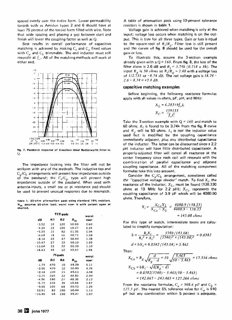
spaced evenly over the entire form. Lower permeability toroids such as Amidon types 2 and 6 should have at least 75 percent of the toroid form filled with wire. Note that wide spacing and placing a gap between start and finish will lower the coupling factor as well as Q.
Best results in overall performance of capacitive matching i s achieved by making C, and C, fixed values with Crl and CIl trimmable. The end inductor must still resonate at f,,. All of the matching methods will work at either end.
d b
BW UNITS - 1 0 0 8 -06 -04 -07 0 2 0 4 06 08 10 I r
fig. 7. Passband response of 3-section ideal Butterworth filter vs
U.
The impedance looking into the filter will not be uniform with any of the methods. The inductive-tap and C,/Cb arrangements will present low impedances outside of the passband; the C,ICrJ type will present high impedances outside of the passband. When used with antenna-inputs, a small tee or pi resistance pad should be used to prevent unusual responses due to mismatch.
table 1. 50-ohm attenuation pads using standard 10% resistors. Rin assumes 50-ohm load; worst vswr is with output open or shorted.
TEE-pads worst
d B R 1 R Z Rin vswr
-3.52 10 120 50.00 2.60 -4.24 12 100 50.27 2.24 -5.29 15 82 51.26 1.94 -6.68 18 56 48.71 1.58 -8.14 22 47 50.44 1.38
-10.47 27 33 50.10 1.20
-13.64 33 22 50.39 1.10 -18.43 39 12 49.57 1.04
PI-pads worst d B R3 R4 Rin vswr
-1.74 470 10 49.39 5.11 2.05 470 12 50.99 4.76 -2.58 330 15 49.63 3.48 3.75 220 22 48.82 2.50 -4.56 I80 27 48.36 2.13 -6.19 150 39 50.66 1.67 -9.66 100 68 50.33 1.25
-12.51 82 100 50.44 1.13 -15.85 68 150 49.27 1.07
A table of attenuation pads using 10-percent tolerance resistors is shown in table 1.
Voltage gain is achieved when matching is only at the input; voltage loss occurs when matching is on the out- put. This i s true for all three types. Gain or loss is equal to the square-root of RiIRR Filter loss is still present and the curves of fig. 8 should be used for the overall gain or loss.
To illustrate this, assume the 3-section example already given with a Q = 160. From fig. 8, the loss of the filter alone is 2.6 dB and R; = 3.74k (0.718 x 5 k ) . The input K , is 50 ohms so R,./R, = 7.48 k i t h a voltage loss of 112.735 or -8.74 d B . The net voltage gain i s 18.74 - 2.6 - 8.74 =+7.4 dB.
capacittve matching examples
Before beginning, the following reactance formulas apply with all values in ohms, pF, pH, and MHz:
X L = 6 . 2 8 3 1 % ~
Take the 3-section example with Q = 160 and match to 50 ohms. Ri is found to be 3.74k from the fig. 8 curve and R will be 50 ohms. Li is not the inductor value used 6ut is modified by the coupling capacitance immediately adjacent, plus any distributed capacitance of the inductor. The latter can be discounted since a 2.2 pH inductor will have little distributed capacitance. A properly-adjusted filter will cancel all reactance at the center frequency since each coil will resonate with the com b i nat ion of parallel capacitance and adjacent coupling capacitance. All of the matching component formulas take this into account.
Consider the C,/Cb arrangement, sometimes called the "capacitive voltage divider" match. To find Xi, the reactance of the inductor, X L , must be found (138.230 ohms at 10 MHz for 2.2 pH); Xcc represents the coupling capacitance of 3.9 pF which will be 4080.90 ohms. Therefore,
= 143.08 ohms
For this type of match, intermediate terms are calcu- lated to simplify computation:
Then :
JII Jr= I 7.516 ohms X ~ a = R g ~7- 50 - 5.465
x,, = bRi - j m = 0.0382(3740) - 5.465(50 - 5.465)
= 142.867 - 243.403 = 127.266 o !~ms
From the reactance formulas, C , = 908.6 pI: and Cb = 127.3 p F . The nearest 5% tolerance value for C, is 910 pF but any combination within 5 percent i s adequate.
38 june 1977
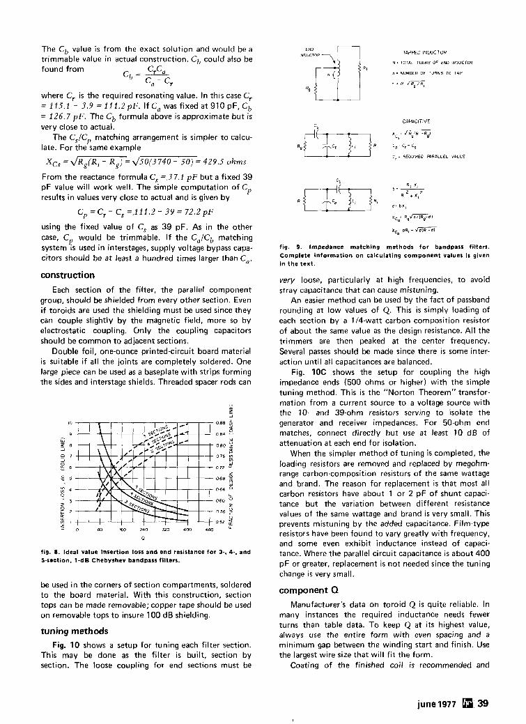
The Cb value i s from the exact solution and would be a trimmable value in actual construction. Cb could also be found from cr 'a
Cb = --- C d - cr
where C, is the required resonating value. In this case C, = 115.1 - 3.9 = 111 .2pF. If C, was fixed at 910 pF, Cb = 126.7 pF. The Cb formula above i s approximate but i s very close to actual:
The Cs/Cr, matching arrangement is simpler to calcu- late. For the same example
Xcs = ~ R ~ ( R ~ - Rg) = 4 5 0 ( 3 7 4 0 - 5 0 ) = 429.5 ohms
From the reactance formula C, =.37.1 pF but a fixed 39 pF value will work well. The simple computation of Cp results in values very close to actual and is given by
using the fixed value of C, as 39 pF. As in the other case, C would be trimmable. I f the C,/Cb matching r! system IS used in interstages, supply voltage bypass capa- citors should be at least a hundred times larger than Ca.
construction
Each section of the filter, the parallel cornponent group, should be shielded from every other section. Even if toroids are used the shielding must be used since they can couple slightly by the magnetic field, more so by electrostatic coupling. Only the coupling capacitors should be common to adjacent sections.
Double foil, one-ounce printed-circuit board material is suitable i f all the joints are completely soldered. One large piece can be used as a baseplate with strips forming the sides and interstage shields. Threaded spacer rods can
fig. 8. Ideal value insertion loss and end resistance for 3-, 4-, and 5-section, 1-dB Chebyshev bandpass filters.
be used in the corners of section compartments, soldered to the board material. With this construction, section tops can be made removable; copper tape should be used on removable tops to insure 100 dB shielding.
tuning methods
Fig. 10 shows a setup for tuning each filter section. This may be done as the filter i s built, section by section. The loose coupling for end sections must be
~NDEUNCDTOR - n TAPPED INDUCTOR
N - TOTAL TURNS OF END INDUCTOR
n = NUMBER OF TURNS TO TAP
" = N
Rq
CAPACITIVE
C. ; REOUIREO M R A L L E L VALUE
fig. 9. Impedance matching methods for bandpass filters. Complete information on calculating component values i s given in the text.
very loose, particularly at high frequencies, to avoid stray capacitance that can cause mistuning.
An easier method can be used by the fact of passband rounding at low values of Q. This is simply loading of each section by a 114-watt carbon composition resistor of about the same value as the design resistance. All the trimmers are then peaked at the center frequency. Several passes should be made since there is some inter- action until all capacitances are balanced.
Fig. 10C shows the setup for coupling the high impedance ends (500 ohms or higher) with the simple tuning method. This i s the "Norton Theorem" transfor- mation from a current source to a voltage source with the 10- and 39-ohm resistors serving to isolate the generator and receiver impedances. For 50-ohm end matches, connect directly but use at least 10 dB of attenuation at each end for isolation.
When the simpler method of tuning is completed, the loading resistors are removed and replaced by megohm- range carbon-composition resistors of the same wattage and brand. The reason for replacement is that most all carbon resistors have about 1 or 2 pF of shunt capaci- tance but the variation between different resistance values of the same wattage and brand is very small. This prevents mistuning by the added capacitance. Film-type resistors have been found to vary greatly with frequency, and some even exhibit inductance instead of capaci- tance. Where the parallel circuit capacitance is about 400 pF or greater, replacement is not needed since the tuning change is very small.
component Q Manufacturer's data on toroid Q is quite reliable. In
many instances the required inductance needs fewer turns than table data. To keep Q at its highest value, always use the entire form with even spacing and a minimum gap between the winding start and finish. Use the largest wire size that will f i t the form.
Coating of the finished coil i s recommended and
june 1977 39
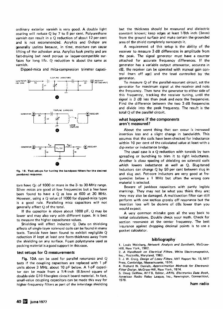
ordinary exterior varnish is very good. A double light coating will reduce Q by 7 to 8 per cent. Polyurethane varnish can result in a Q reduction of about 12 per cent and is not recommended. Acrylics and Q-dope are generally useless because, in time, moisture can cause lifting of the adhesion area. Acrylics look pretty and are fast-drying but need porous or laquer-compatible sur- faces for long life. Q reduction is about the same as varnish.
Dipped-mica and mica-compression trimmer capaci-
COUPLING CAPACIT(WIS
COUPLING CAPACITOR
A LOOSE CWPLING
0
GENERATOR RECEIVER
fig. 10. Test setups for tuning the bandpass filters for the desired passband response.
tors have Qs of 1000 or more in the 3- to 30-MHz range. Silver micas are good at low frequencies but a few have been found to have a Q as low as 600 at 30 MHz. However, using a Q value of 1000 for dipped-mica types is a good rule. Paralleling mica capacitors will not generally affect Q of the total.
If the capacitor i s above about 1000 pF, Q may be lower and may also vary with different tylpes. It i s best to measure the higher capacitance values.
Shielding will affect inductor Q. Data on shielding affects of single-layer solenoid coils can be found in many texts. Toroids have been found to exhibit negligible Q reduction if kept at least one form-thickness away from the shielding on any surface. Foam polystyrene used as packing material i s agood support in this case.
test setups for Q measurements Fig. 10A can be used for parallel resonance and Q
tests i f the coupling capacitors are replaced with 1 pF units above 3 MHz, about 10 pF below. A 1-pF capaci- tor can be made from a 114-inch (6.5mm) square of double-side G10 fiberglass circuit board material. In fact, small-value coupling capacitors can be made this way for higher-frequency filters as part of the interstage shielding
but the thickness should be measured and dielectric constant known; keep edges at least 118th inch (3mm) from the ground surface and make certain the grounded area of the shield completely surrounds it.
A requirement of this setup is the ability of the receiver to measure 3 dB differences in amplitude from the peak. The signal generator must have a counter attached for accurate frequency differences. I f the generator has a variable output attenuator, accurate in dB, the receiver can be operated with manual gain con- trol (turn off agc) and the level controlled by the generator.
To measure Q of the parallel-resonant circuit, set the generator for maximum signal at the receiver and note the frequency. Then tune the generator to either side of this frequency, tracking the receiver tuning, until the signal is 3 dB less than peak and note the frequencies. Find the difference between the two 3 dB frequencies and divide into the peak frequency. The result i s the total Q of the parallel circuit.
what happens if the components aren't measured?
About the worst thing that can occur i s increased insertion loss and a slight change in bandwidth. This assumes that the coils have been checked for inductance within 10 per cent of the calculated value at least with a dip-meter or inductance bridge.
The usual case is a Q reduction with toroids by turn spreading or bunching to trim it to right inductance. Another i s close spacing of shielding on solenoid coils which lowers inductance as well as Q. Slug-tuned inductors can change Q by 50 per cent between slug in and slug out. Pot-core inductors are very good at fre- quencies below a 1 MHz but often the wrong core material is selected.
Beware of junkbox capacitors with partly legible markings. They may not be what you think they are; they may also be damaged. A multisection filter can still perform with one section grossly off resonance but the insertion loss will be dozens of dBs lower than you would expect.
A very common mistake goes all the way back to initial calculations. Double check your math. Check for section resonance at the center frequency. The best insurance against dropping decimal points is to use a pocket calculator.
bibliography 1. Louis Weinberg, Network Analysis and Synthesis, McGraw- Hill, New York, 1962. 2. A Handbook on Electrical Filters, White Electromagnetics, Inc., Rockville, Maryland, 1963. 3. J. W. Craig, Design of Lossy Filters, MIT Report No. 19, M I T Press, Cambridge, Massachusetts, 1970. 4. Richard W. Daniels, Approximation Methods for Electronic Filter Design, McGraw-Hill, New York, 1974. 5. Doug DeMaw, W1 FB, Editor, ARRL Electronics Data Book, American Radio Relay League, Inc., Newington, Connecticut, 1976.
ham radio
40 june 1977
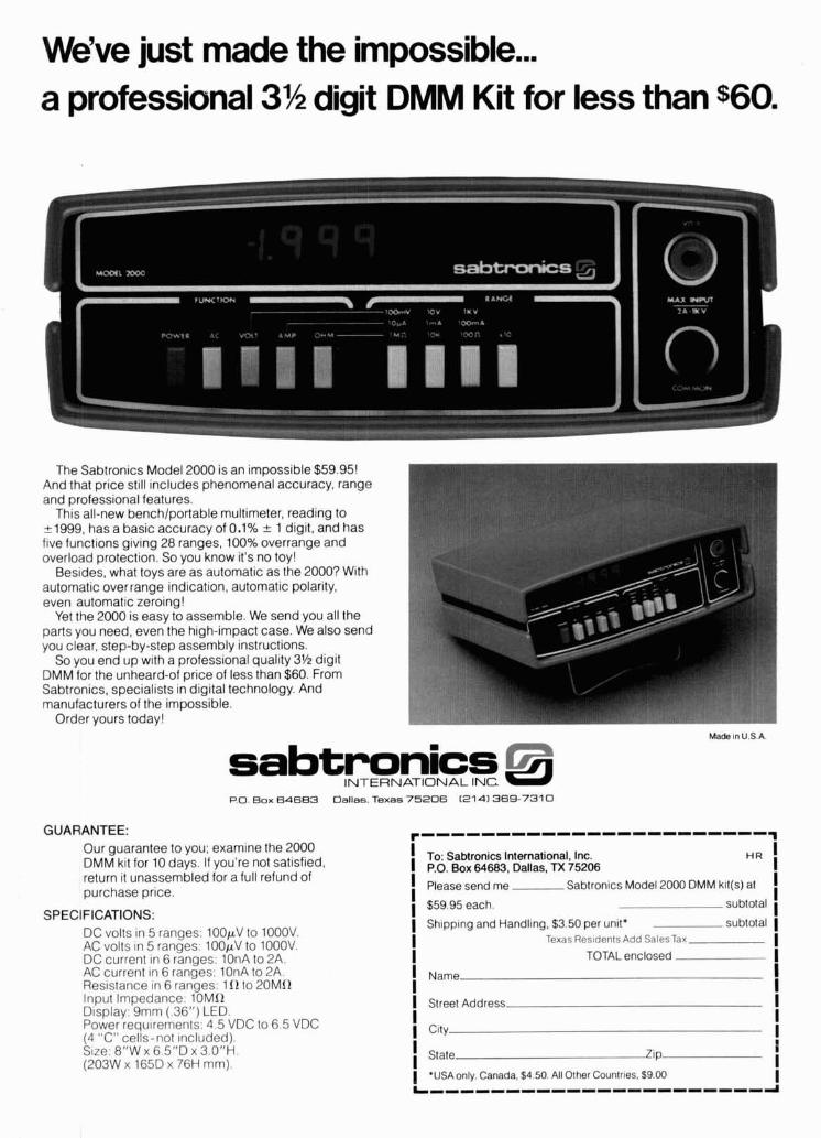
We've just made the impossible ... a professional 3% digit DMM Kit for less than $60.
The Sabtronics Model 2000 is an impossible $59.95! And that price still includes phenomenal accuracy, range and professional features.
This all-new benchlportable multimeter, reading to r1999, has a basic accuracy of 0.1% k 1 digit, and has five functions giving 28 ranges, 100% overrange and overload protection. So you know it's no toy!
Besides, what toys are as automatic as the 2000? With automatic overrange indication, automatic polarity, even automatic zeroing!
Yet the 2000 is easy to assemble. We send you all the parts you need, even the high-impact case. We also send you clear, step-by-step assembly instructions.
So you end up with a professional quality 3% digit DMM for the unheard-of rice of less than $60. From Sabtronics, specialists in digital technology. And manufacturers of the impossible.
Order yours today! Made In U.S A
sabtronics INTERNATIONAL I N C .
Box 64683 Dallas. Texas 75206 (2141 369-731 0
GUARANTEE: Our guarantee to you; examine the 2000 DMM kit for 10 days. If you're not satisfied, return it unassembled for a full refund of purchase price.
SPECIFICATIONS: DC volts in 5 ranges: 100pV to 1000V. AC volts in 5 ranges: 100p.V to 1000V. DC current in 6 ranges: 10nA to 2A. AC current in 6 ranges: 10nA to 2A. Resistance in 6 ranges: 110 to 20MR l n ~ u t Im~edance: 10MR ~lspla~: '9rnm (.36") LED. Power requirements: 4.5 VDC to 6.5 VDC 14 "C" cells-not included). slze: 8"W x 6.5"D x 3 . 0 " ~ (203W x 165D x 76H mm).
To: Sabtronics International, Inc. I I P.O. Box 64683, Dallas, TX 75206 I I Please send me Sabtronics Model 2000 DMM kit(s) at I
$5995 each. subtotal I
I Shipping and Handling, $3.50 per unit* I
subtotal ( I Texas Res~denls Add SalesTax
TOTAL enclosed I
I I I Name I I I i Street Address I I I City
I I
State I Zip
'USAonly. Canada. $4.50. All Other Countries. $9.00 I L I ~ I I I I ~ I I I ~ I ~ I ~ ~ I I ~ ~ ~ I ~
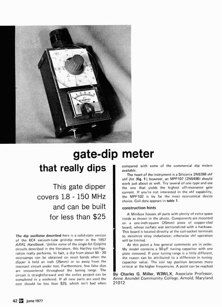
gate-dip meter that really dips
This gate dipper covers 1.8 - 150 MHz
and can be built for less than $25
The dip oscillator described here is a solid-state version of the 6C4 vacuum-tube grid-dip meter in the 1957 ARRL Handbook. Unlike some of the single-fet Colpitts circuits described in the literature, this Hartley configu- ration really performs. In fact, a dip from about 50 - 20 microamps can be obtained on most bands when the dipper i s held an inch (25mm) or so away from the resonant circuit under test. Furthermore, few false dips are encountered throughout the tuning range. The circuit i s straightforward and the entire project can be completed in a weekend. If all new parts are used the cost should be less than $25, which isn't bad when
compared with some of the commercial dip meters available.
The heart of the instrument i s a Siliconix 2N5398 vhf uhf jfet (fig. 1); however, an MPF107 (2N5486) should work just about as well. Try several of one type and use the one that yields the highest off-resonance gate current. I f you're not interested in the vhf capability, the MPF102 is by far the most economical device choice. Coil data appears in table 1.
1 construction hints A Minibox houses all parts with plenty of extra space
inside as shown in the photo. Components are mounted on a one-inch-square (25mm) piece of copper-clad board, whose surface was sectionalized with a hacksaw. This board is located directly a t the coil-socket terminals to minimize stray inductance; otherwise vhf operation will be limited.
At this point a few general comments are in order. My model contains a 50-pF tuning capacitor with one plate removed. If your tuning range i s a little different, the reason can be attributed to a difference in tuning- capacitor value. The coil tap position becomes more critical at the higher frequencies. A point can be reached -
By Charles G. Miller, WSWLX, Associate Professor, Anne Arundel Community College, Arnold, Maryland 21012
42 june 1977
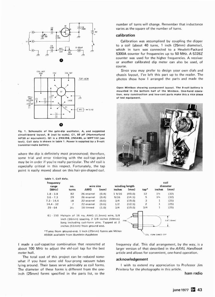
number of turns will change. Remember that inductance varies as the square of the number of turns.
calibration
COIL HOT END +9V COIL TAP
b b
fig. 1. Schematic of the gate-dip oscillator, A, and suggested circuit-board layout. B (not t o scale). C l , 50 pF (Hammarlund HF50 or equivalent). Q l is a 2N5398, 2N5486, or MPF102 (see text). Coll data is shown in table 1. Power is supplied by a 9-volt translstor-radio battery.
where the dip is definitely most pronounced; therefore, some trial and error tinkering with the coil-tap point may be in order if you're really particular. The vhf coil i s especially critical in this respect. Fortunately, the tap point is easily moved about on this hair-pin-shaped coil.
Calibration was accomplised by coupling the dipper to a coil (about 40 turns, 1 inch (25mm) diameter), which in turn was connected to a Hewlett-Packard 5300A counter for frequencies up to 50 MHz. A 53282 counter was used for the higher frequencies. A receiver or another calibrated dip meter can also be used, of course.
Since you may prefer to design your own dials and chassis layout, I've left this part up to the reader. The photos show how I arranged the parts and made the
Open Minibox showing component layout. The 9-volt battery Is mounted in the bottom half of the Minibox. One-hand opera- tion, easy construction and low-cost parts make this a nice piece of t o t equipment.
table 1. Coil data.
frequency coil range no. wire size winding length diameter (MHz) turns AWG (mm) inches (mm) tap* inches (mm)
1.8 - 3.8 82 26 enamel (0.4) 1 9/16 (40.0) 12 I l k (32) 3.6 - 7.3 29 26 enamel (0.4) 9/16 (14.5) 5 I l l 4 (32)
7.3 - 14.4 18 22 enamel (0.6) 3/4 (19.0) 3 1 (25) 14.4 - 32 7 22 enamel (0.6) 1/2 (12.5) 2 1 (25) 29 - 64 3112 18 tinned (1.0) 3/4 (19.0) 3/4 1 (25)
61 - 150 Hairpin of 16 no. AWG (1.3mm) wire. 5/8
inch (16mm) spacing, 2 3/8 inches (60mm) JB" i16mm) long including coil-form pins. Tapped at 2 inches (51mm) from ground end.
U
*Turns from ground-end. 1 inch (25mm) forms are Millen 45004 available from Buntein-Applebee '\ rn FORM W D OFF
I made a coil-capacitor combination that resonated at frequency dial. This dial arrangement, by the way, i s a about 100 MHz to adjust the vhf-coil tap for the best larger version of that described in the ARRL Handbook meter hull. article and allows for convenient, one-hand operation.
The total cost of this project can be reduced some- what if you have some old four-prong vacuum tubes lying around. Their bases serve admirably as coil forms. I wish to extend my appreciation to Professor Jim The diameter of these forms i s different from the one- Privitera for the photographs in this article. inch (25mm) forms specified in the parts list, so the ham radio
june 1977 43
=7 ' f I ' '/ I
Drake L-4B %kW nfimea~ a~~niffie~~~~
9 many DX pile-ups 'V?! *:.
I;
The L-4B features smooth, quiet, continuous duty operation on ssb, cw, SSTV and RTTY with full operator convenience such as front panel by-pass switch and precision high- power wattmeter1VSWR bridge.
The L-46 puts the smoke Write for our new free Drake brochure: in the antenna, "DX-ing; from the ground up!" not in the ham shack
the unsung hero of
540 Richard St., Miamisburg, Ohio 45342 R. L. DRAKE COMPANY p h o n e : ~ f i r 8 ~ ~ ~ ~ ~ 1 * ~ e 1 e r : ~ 8 8 ~ 1 ~
@
Western Sales and Service Center, 2020 Western Street, Las Vegas, Nevada 89102 7021382-9470
The First Report and Order, in docket 20777, requires that harmonic and spurious radiation from most hf amateur radio equipment must be attenuated by at least 40 dB. Can YOUR equipment meet this new regulation?
lPPPV
It can ... if it was made by R. L. Drake
R. L. Drake has been mak~ng equipment to meet these new regulations for the last 13 years. We didn't wait to be "forced" to produce qual~ty equipment by FCC regulations.
It can ... if you use a Drake Matching Network (tunable low- pass filter)
If you don't own Drake equipment, you can still use your present gear by adding a Drake MN-4 or MN-2000 Matching Network. Drake's Matching Networks, unlike most other networks, utilize the tunable low-pass filter type of matching (similar to a TVI filter) to provide 20 to 25 dB of harmonic attenuation in addition to producing a perfect impedance match. This, plus a direct reading SWR and forward rf power meter and built-in antenna selector provide the ultimate an- swer to the new FCC rules.
Drake M The Drake design philosophy has been meeting FCC radia- tion specifications before there were any! Think about it.
jlo .- - .- -
Drake TR4Cw w -
Drak
To receive a FREE Drake Full Line Catalog, please send name and date of this publication to
R, L. DRAKE COMPANY 540 Richard St., Miamisburg, Ohio 45342
8 Phone: (513) 866-2421 Telex: 288-017
Western Sales and Service Center, 2020 Western Street, Las Vegas, Nevada 89102 7021362-9470
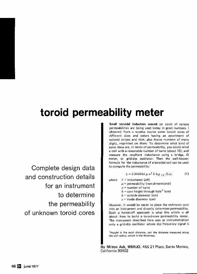
toroid permeability meter
Complete design data and construction details
for an instrument to determine
the permeability of unknown toroid cores
Small toroidal inductors wound on cores of various permeabilities are being used today in great numbers. I obtained from a surplus source some toroid cores of different sizes and colors having an assortment of colored stripes and dots, plus house numbers of many digits, imprinted on them. To determine what kind of cores these are, in terms of permeability, you could wind a coil with a reasonable number of turns (about lo) , and measure the resultant inductance using a bridge, Q meter, or grid-dip oscillator. Then the well-known formula for the inductance of a toroidal coil can be used to compute the permeability:
where L = inductance (pH) p = permeability (non-dimensional) n = number of turns h = core height through hole* (cm) b = outside diameter (cm) a = inside diameter (cm)
However, i t would be easier to place the unknown core into an instrument and directly determine permeability. Such a hands-off approach is what this article is all about: how to build a toroid-core permeability meter. The instrument described here uses as instrumentation only a grid-dip oscillator whose dip frequency signal i s
"Height is the axial distance, not the distance measured along the coil radius, which is the thickness.
-
By Milton Ash, WGRJO, 455 21 Place, Santa Monica, California 90402
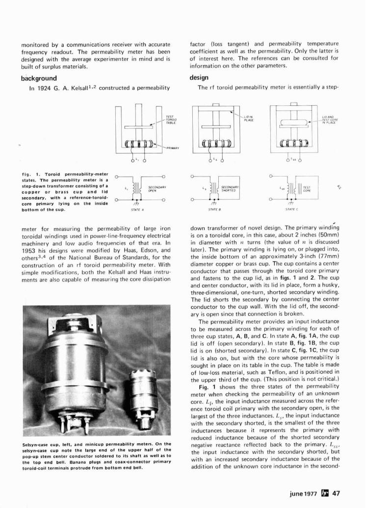
monitored by a communications receiver with accurate frequency readout. The permeability meter has been designed with the average experimenter in mind and is built of surplus materials.
background In 1924 G. A. ~elsal l l ** constructed a permeability
f ig. 1. Toroid permeability-meter states. The permeability meter is a step-down transformer consisting of a c o p p e r o r brass c u p a n d l id secondary, with a reference-toroid- core primary lying on the inside bottom of the cup. STATE A
meter for measuring the permeability of large iron toroidal windings used in power-line-frequency electrical machinery and low audio frequencies of that era. In 1953 his designs were modified by Haas, Edson, and others3v4 of the National Bureau of Standards, for the construction of an rf toroid permeability meter. With simple modifications, both the Kelsall and Haas instru- ments are also capable of measuring the core dissipation
Sslsyn-case cup. left, and minicup permeability meten. On the selsynsase cup note the large end of the upper half of the pop-up stem center conductor soldered to its shaft as well as to the top end bell. Banana plugs and coaxconnector primary toroid-coil terminals protrude from bottom end bell.
factor (loss tangent) and permeability temperature coefficient as well as the permeability. Only the latter i s of interest here. The references can be consulted for information on the other parameters.
design The rf toroid permeability meter i s essentially a step-
LID AND -TCS' CORE
111 PLACE
- d?
STATE €5
down transformer of novel design. The primary winding is on a toroidal core, in this case, about 2 inches (50mm) in diameter with n turns (the value of n i s discussed later). The primary winding is lying on, or plugged into, the inside bottom of an approximately 3-inch (77mm) diameter copper or brass cup. The cup contains a center conductor that passes through the toroid core primary and fastens to the cup lid, as in figs. 1 and 2. The cup and center conductor, with i t s lid in place, form a husky, three-dimensional, one-turn, shorted secondary winding. The lid shorts the secondary by connecting the center conductor to the cup wall. With the lid off, the second- ary is open since that connection is broken.
The permeability meter provides an input inductance to be measured across the primary winding for each of three cup states, A, B, and C. In state A, fig. I A , the cup lid i s off (open secondary). In state B, fig. IB, the cup lid is on (shorted secondary). In state C, fig. IC, the cup lid i s also on, but with the core whose permeability i s sought in place on its table in the cup. The table is made of low-loss material, such as Teflon, and is positioned in the upper third of the cup. (This position is not critical.)
Fig. 1 shows the three states of the permeability meter when checking the permeability of an unknown core. L,, the input inductance measured across the refer- ence toroid coil primary with the secondary open, is the largest of the three inductances. L,, the input inductance with the secondary shorted, i s the smallest of the three inductances because it represents the primary with reduced inductance because of the shorted secondary negative reactance reflected back to the primary. L,,, the input inductance with the secondary shorted, but with an increased secondary inductance because of the addition of the unknown core inductance in the second-
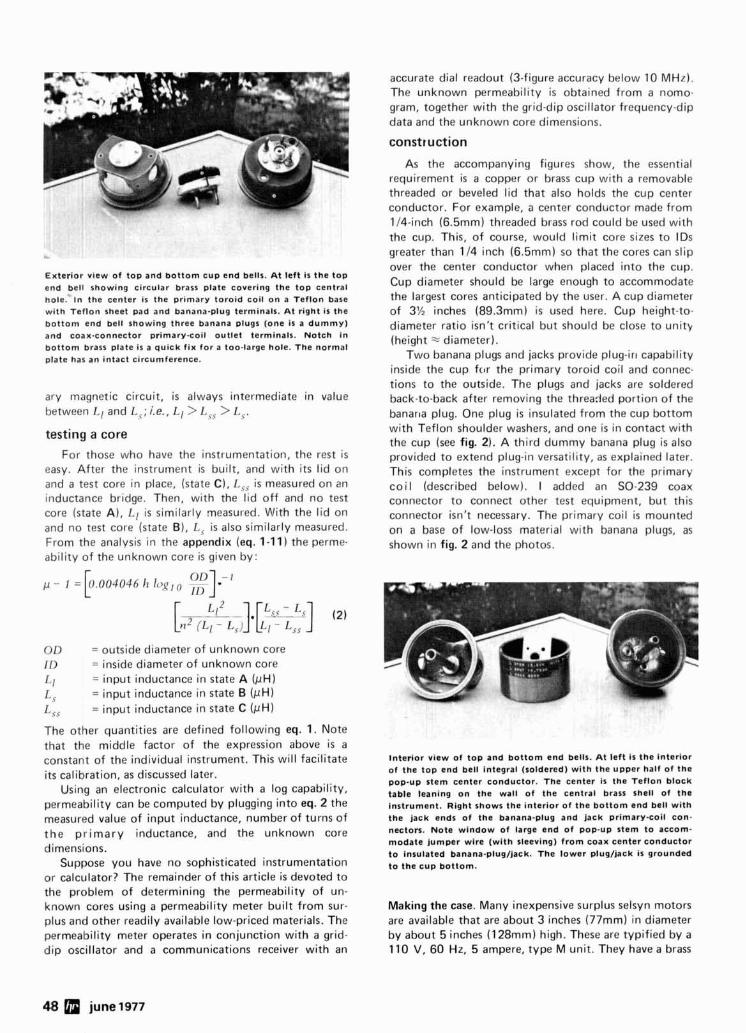
Exterior view of top and bottom cup end bells. A t left is the top end bell showing circular brass plate covering the top central hole. In the center is the primary toroid coil on a Teflon base with Teflon sheet pad and banana-plug terminals. At right is the bottom end bell showing three banana plugs (one is a dummy) and coax-connector primary-coil outlet terminals. Notch In bottom brass plate is a quick fix for a too-large hole. The normal plate has an intact circumference.
ary magnetic circuit, is always intermediate in value between L I and L,; i.e., LI > L,, > L,. testing a core
For those who have the instrumentation, the rest i s easy. After the instrument is built, and with its lid on and a test core in place, (state C), L,, is measured on an inductance bridge. Then, with the lid off and no test core (state A), LI is similarly measured. With the lid on and no test core (state B), L, is also similarly measured. From the analysis in the appendix (eq. 1-1 1) the perme- ability of the unknown core is given by:
On = outside diameter of unknown core ID = inside diameter of unknown core
L 1 = input inductance in state A (pH)
L s = input inductance in state B (pH)
L~~ = input inductance in state C (pH)
The other quantities are defined following eq. 1. Note that the middle factor of the expression above i s a constant of the individual instrument. This will facilitate its calibration, as discussed later.
Using an electronic calculator with a log capability, permeability can be computed by plugging into eq. 2 the measured value of input inductance, number of turns of the pr imary inductance, and the unknown core dimensions.
Suppose you have no sophisticated instrumentation or calculator? The remainder of this article is devoted to the problem of determining the permeability of un- known cores using a permeability meter built from sur- plus and other readily available low-priced materials. The permeability meter operates in conjunction with a grid- dip oscillator and a communications receiver with an
accurate dial readout (3-figure accuracy below 10 MHz). The unknown permeability i s obtained from a nomo- gram, together with the grid-dip oscillator frequency-dip data and the unknown core dimensions.
construction
As the accompanying figures show, the essential requirement is a copper or brass cup with a removable threaded or beveled lid that also holds the cup center conductor. For example, a center conductor made from 114-inch (6.5mm) threaded brass rod could be used with the cup. This, of course, would limit core sizes to IDS greater than 114 inch (6.5mi-n) so that the cores can slip over the center conductor when placed into the cup. Cup diameter should be large enough to accommodate the largest cores anticipated by the user. A cup diameter of 3% inches (89.3mm) i s used here. Cup height-to- diameter ratio isn't critical but should be close to unity (height * diameter).
Two banana plugs and jacks provide plug-in capability inside the cup fc~r the primary toroid coil and connec- tions to the outside. The plugs and jacks are soldered back-to-back after removing the threaded portion of the banana plug. One plug is insulated from the cup bottom with Teflon shoulder washers, and one is in contact with the cup (see fig. 2). A third dummy banana plug is also provided to extend plug-in versatility, as explained later. This completes the instrument except for the primary coi l (described below). I added an SO-239 coax connector to connect other test equipment, but this connector isn't necessary. The primary coil is mounted on a base of low-loss material with banana plugs, as shown in fig. 2 and the photos.
lnterior view of top and bottom end bells. At left is the Interior of the top end bell integral (soldered) with the upper half of the pop-up stem center conductor. The center is the Teflon block table leaning on the wall of the central brass shell of the Instrument. Right shows the interior of the bottom end bell with the jack ends of the banana-plug and jack primary-coil con. nectors. Note window of large end of pop-up stem to accom- modate jumper wire (with sleeving) from coax center conductor to insulated banana-piug/jack. The lower plugljack is grounded to the cup bottom.
Making the case. Many inexpensive surplus selsyn motors are available that are about 3 inches (77mm) in diameter by about 5 inches (128mm) high. These are typified by a 110 V, 60 Hz, 5 ampere, type M unit. They have a brass
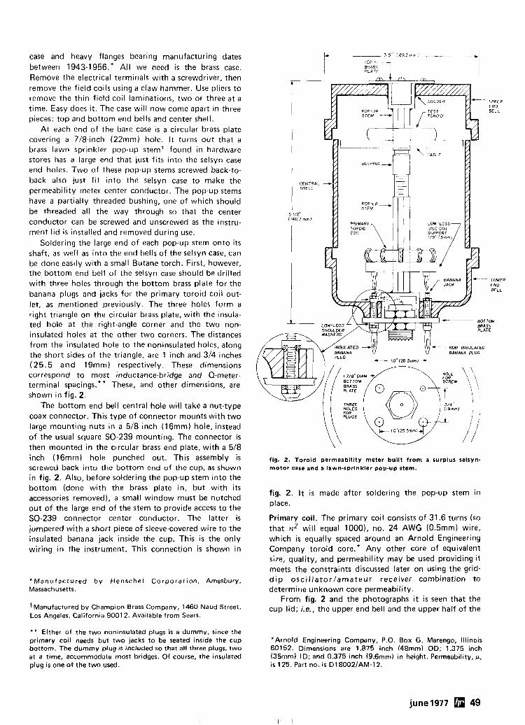
case and heavy flanges bearing manufacturing dates between 1943-1956." All we need is the brass case. Remove the electrical terminals with a screwdriver, then remove the field coils using a claw hammer. Use pliers to remove the thin field-coil laminations, two or three a t a time. Easy does it. The case will now come apart in three pieces: top and bottom end bells and center shell.
At each end of the bare case is a circular brass plate covering a 7/8-inch (22mm) hole. It turns out that a brass lawn sprinkler pop-up stemf found in hardware stores has a large end that just fits into the selsyn case end holes. Two of these pop-up stems screwed back-to- back also just f i t into the selsyn case to make the permeability meter center conductor. The pop-up stems have a partially threaded bushing, one of which should be threaded all the way through so that the center conductor can be screwed and unscrewed as the instru- ment lid is installed and removed during use.
Soldering the large end of each pop-up stem onto its shaft, as well as into the end bells of the selsyn case, can be done easily with a small Butane torch. First, however, the bottom end bell of the selsyn case should be drilled with three holes through the bottom brass plate for the banana plugs and jacks for the primary toroid coil out- let, as mentioned previously. The three holes form a right triangle on the circular brass plate, with the insula- ted hole at the right-angle corner and the two non- insulated holes at the other two corners. The distances from the insulated hole to the noninsulated holes, along the short sides of the triangle, are 1 inch and 314 inches (25.5 and 19mm) respectively. These dimensions correspond to most inductance-bridge and Q-meter- terminal spacings.** These, and other dimensions, are shown in fig. 2.
The bottom end bell central hole will take a nut-type coax connector. This type of connector mounts with two large mounting nuts in a 518 inch (16mm) hole, instead of the usual square SO-239 mounting. The connector is then mounted in the circular brass end plate, with a 518 inch (16mm) hole punched out. This assembly is screwed back into the bottom end of the cup, as shown in fig. 2. Also, before soldering the pop-up stem into the bottom (done with the brass plate in, but with its accessories removed), a small window must be notched out of the large end of the stem to provide access to the SO-239 connector center conductor. The latter is jumpered with a short piece of sleeve-covered wire to the insulated banana jack inside the cup. This is the only wiring in the instrument. This connection is shown in
'Manufactured by Henschel Corporation, Arnesbury, Massachusetts.
+~anufactured by Champ~on Brass Company, 1460 Naud Street, Los Angeles, California 9001 2. Available from Sears.
" * Either of the two noninsulated plugs is a dummy, since the primary coil needs but two jacks to be seated inside the cup bottom. The dummy plug i s included so that all three plugs, two at a time, accommodate most bridges. Of course, the insulated plug i s one of the two used.
fig. 2. Toroid permeability meter built from a surplus selsyn- motor case and a lawn-sprinkler pop-up stem.
fig. 2. It is made after soldering the pop-up stem in place.
Primary coil. The primary coil consists of 31.6 turns (so that n2 will equal 1000), no. 24 AWG (0.5mm) wire, which is equally spaced around an Arnold Engineering Company toroid core.* Any other core of equivalent size, quality, and permeability may be used providing it meets the constraints discussed later on using the grid- d i p osci l lator/amateur receiver combination to determine unknown core permeability.
From fig. 2 and the photographs i t is seen that the cup lid; i.e., the upper end bell and the upper half of the
*Arnold Engineering Company, P.O. Box G. Marengo, Illinois 60152. Dimensions are 1.875 inch (48mm) OD: 1.375 inch (35mm) ID; and 0.375 inch (9.6mm) in height. Permeability, u, i s 125. Part no. i s D18002lAM-12.
june 1977 49
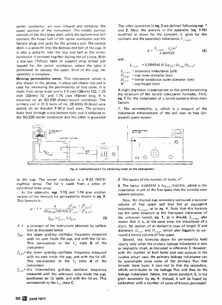
center conductor, are now integral and comprise the The other quantities in eq. 3 are defined following eqs. 1 upper portion of the instrument. The middle portion and 2. Now, the analysis in the appendix (eq. 1-15) consists of the thin brass shell, while the bottom end bell modified as above for the constant, k, gives for this contains the lower half of the center conductor and the constant and the secondary inductance, LI.,,,,, banana plugs and jacks for the primary coil. The central shell is a press-fit into the bottom end bell of the cup. I t is also a press-fit into the top end bell as the center . ~
conductor is screwed together during test of a core. With 3 low-loss (Teflon) table or support strip drilled and and
tapped for the center conductor, where the table is L,. ,,<, ,. = 0.004046 H lolJ?,o (Dcu,,~D,,,,) positioned to occupy the upper third of the cup, the assembly is complete. Minicup permeability meter. This instrument, which is also shown in the photos, is about salt shaker size and is used for measuring the permeability of tiny cores. I t is made from scrap brass and is 1.5 inch (38mm) OD, 1.25 inch (32mm) ID, and 1.75 inch (45mm) long. I t is mounted on an SO-239 chassis-mount connector. The primary coil is 31.5 turns of no. 28 AWIG (0.3mm) wire
LC,,,, = secondary inductance (pH) D,,,[, = cup inner diameter (cm) D,,.,, = center conductor outer diameter (cm) H = cup height (cm)
A slight digression is appropriate at this point concerning the structure of the toroid inductance formulas. First, eq. 1 for the inductance of a toroid contains three main factors:
spaced on an Amidon T-94-2 (red) core. The primary 1. The permeability, p, which i s a measure of the leads feed through a cup bottom hole; one is soldered to inductance enhancement of the coil over its free (air- the SO-239 center conductor and the other is grounded wound) space version.
fig. 3. Instrumentation for obtaining input to the nomograms.
PERMEABILITY MET;. L.+ COMMUNlCATlONS
RECEIVER
to the cup. The center conductor is a 6-32 (M3-5) 2. The square of the number of turns, n 2 .
SUPPORT F IXTURE
GDO
machine screw. The lid is made from a piece of cylindrical brass scrap.
In the appendix, eqs. 1-13 and 1-14 give another version of the formula for permeability shown in eq. 2. This formula is:
0
k = a constant of the instrument obtained by calibra- tion as discussed below
fwr= the upper grid-dip oscillator frequency measured with no core inside the cup, and with *he lid on. This corresponds to the L, state B of the instrument
fLO= the lower grid-dip oscillator frequency measured with no core inside the cup, and with the lid off. This corresponds to the Ll state A of the instrument
f,,,,=the intermediate grid-dip oscillator frequency measured with the unknown core inside the cup, positioned on i t s table, and with the lid on. This corresponds to the L,, state C
3. The factor 0.004046 h k~~~~ (ODIID), which is the inductance in pH of the free space that the toroidal core volume occupies.
Now, the shorted cup secondary surrounds a toroidal volume of free space and thus has an equivalent inductance, LC,,,, as in eq. 4. Note that this formula has the same structure as the free-space inductance of the unknown toroid, eq. 1, as i t should. L,,,, also means that it is, at the same time, the inductance of a short, fat section of air-dielectric coax of length H and diameters D,,,,, and Dcl ,pr which also happens to sur- round a toroid volume of free space.
Second, the formulas above for permeability hold ideally only when the primary leakage inductance is zero or negligibly small, as discussed in reference 3. However, with the number of bolt holes and cast cutouts in the surplus selsyn case, the primary leakage inductance can be appreciable since some of the primary flux that threads these holes is sure not to iink the secondary, which contributes to the leakage flux and thus to the leakage inductance. Hence, the above constant, k, i s not given accurately by eq. 4. Instead, k will be found by calibration with a number of cores of known permeabil-
50 june 1977
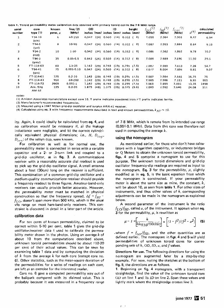
table 1. Toroid
serial number
permeability
core type (1) T94-10
(blk) T94-6
(yell T94-2
(red) T94-3
(grey) FT-114-63
T94-41
(srn) F T - 1 1 4 6 1 FT-114-43 FT-114-72 Arn. Eng
AM-$2
meter calibration data obtained with' primary t0r0id coil in the 7-8 MHz range.
known freq (2) OD ID tteisht k0f3) fHi3) j,,,,,(3) perm, fi (MHz) inches (mm) inches (mm) inches (mm) (MHz) (MHz) (MHz)
notes: (1) Amidon Associates nomenclature except core 10. T prefix indicates powdered iron; F T prefix indicates ferrite. (2) Manufacturer's recommended frequencies. (3) Meaured using a 1947 Millen grid-dip oscillator and surplus ARR-41 receiver. (4) Calculated using eq. 3 with frequency measurements described in text and known permeabilities. k A ~ = 10.
i ty. Again, k could ideally be calculated from eq. 4, and no calibration would be necessary if, a) the leakage inductance were negligible, and b) the correct cylindri- cally equivalent physical dimensions; i.e., H, D C u p , D,,,,; of the selsyn cup, were known.
For calibration as well as for normal use, the permeability meter is connected in series with a variable capacitor and a 2- or 3-turn link and coupled to a grid-dip oscillator, as in fig. 3. A communications receiver with a reasonably accurate dial readout i s used to pick up the grid-dip oscillator signal. A small antenna about a foot (30cm) long on the receiver i s sufficient. This combination of a common grid-dip oscillator and a medium-quality communications receiver should provide a frequency readout to three figures. Amateur-band-only receivers can usually provide better accuracy. However, the permeability meter must be matched in physical construction so that the frequency spread, Af = fHr - fLo, doesn't span more than 500 kHz, which is the usual vfo range on most ham-band-only receivers. This con- straint is discussed in detail in a later part of the article.
calibration data For ten cores of known permeability, claimed to be
correct within 5-10 per cent, table 1 gives the grid-dip oscillator/receiver data I used to calibrate the permea- bility meter shown in the photos. Using an average k of about 10 from the computations described above, unknown toroid permeabilities should be about t10-20 per cent of their actual values. This can be seen by examining table 1 data and by computing the deviation of k from the average k for each core (except core no. 6). Other statistics, such as the mean-square deviation of the permeabilities for a series of readings on each core, are left as an exercise for the interested reader.
Core no. 6 gave a computed permeability way out of the ballpark compared with its claimed value. This is probably because i t was measured in a frequency range
calculated k f 4 ) permeability
8.47 6.94
of 7-8 MHz, which is remote from i t s intended use range (0.001-0.1 MHz). Data from this core was therefore not used in computing the average k.
using the nomogram As mentioned earlier, for those who don't have calcu-
lators with a logarithm capability, or inductance bridges or Q Meters to obtain the unknown toroid permeability, figs. 4 and 5 comprise a nomogram to use for this purpose. The unknown toroid dimensions and grid-dip oscillator frequency-dip readings are required as input to the nomogram. Eq. 3 for the permeability, p , slightly modified as in eq. 5, is the basic equation from which the nomogram is constructed. If your permeability meter is about the same size as mine, the constant, k, will be about 10, as seen from table 1. For other sizes of instruments, and thus other values of k, corresponding adjustments can be made in the nomogram as explained below.
A second parameter of the instrument is the ratio fLO/fHI, called a, of the instrument. I t appears when eq. 3 for the permeability, p, is rewritten as
.where f = fcorlfHI, and the other quantities are as defined earlier. The nomogram in figs. 4 and 5 will yield permeabilities of unknown toroid cores for corres- ponding sets of h , OD, ID, a, and f values.
Directions for use. The following directions for using the nomogram are augmented later by a step-by-step example. For now, noting the sketches at the bottom of fig. 5, the directions are as follows. 1. Beginning on fig. 4 nomogram, with a transparent straightedge, find the value of the unknown toroid core OD on line 1 and i t s ID on line 2. Span these values and lightly mark where the straightedge crosses line 3.
june 1977 51
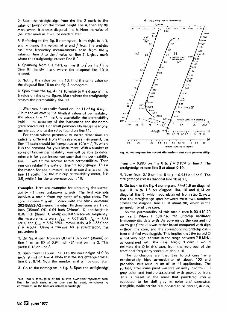
2. Span the straightedge from the line 3 mark to the value of height on the toroid height line 4, then lightly mark where i t crosses diagonal line 5. Note the value of the latter mark as it will be needed later.
3. Referring to the fig. 5 nomogram, from right to left, and knowing the values of a and f from the grid-dip oscillator frequency measurements, span from the a value on line 6 to the f value on line 7. Lightly mark where the straightedge crosses line 8."
4. Spanning from the mark on line 8 to f on the f line (line 91, lightly mark where the diagonal line 10 i s crossed.
5. Noting the value on line 10, find the same value on the diagonal line 10 on the fig. 4 nomogram.
6. Span from the fig. 4 line 10 value to the diagonal line 5 value on the same figure. Mark where the straightedge crosses the permeability line 11.
What you have really found on line 11 of fig. 4 i s p - 1 but for all except the smallest values of permeability, the above line 11 mark is essentially the permeability (within the accuracy of the instrument and the nomo- gram procedure). For small permeability values near one, merely add one to the value found on line 11.
For those whose permeability meter dimensions are radically different from this selsyn-case instrument, the line 11 scale should be interpreted as iO(p - i ) l k , where k i s the constant for your instrument. With a number of cores of known permeability, you will be able to deter- mine a k for your instrument such that the permeability line 11 will fit the known toroid permeabilities. Then you can relabel the scale on line 11 accordingly. This i s the reason for the numbers less than one that are on the line 11 scale. For the minicup permeability meter, k is 3.5, while k for the selsyn-case cup is 10.
Examples. Here are examples for obtaining the perme- ability of three unknown toroids. The first example involves a toroid from my batch of surplus cores. The core i s medium gray in color with the black numerals 262-55582-A2 around the edge. I t s dimensions are 1.375 inch (35mm) OD, 0.94 inch (24mm) ID, and height i s 0.35 inch (9mm). Grid-dip oscillator/receiver frequency- dip measurements were: fLO = 7.07 MHz, fHI = 7.98 MHz, and f,,, = 7.46 MHz. Immediately, a i s 0.885 and f i s 0.934. Using a triangle for a straightedge, the procedure is :
1. On fig. 4 span from an OD of 1.375 inch (35mm) on line 1 to an ID of 0.94 inch (24mm) on line 2. This yields 0.1 5 on line 3.
2. Span from 0.15 on line 3 to the core height of 0.35 inch (9mm) on line 4. Note that the straightedge crosses line 5 at 0.14. Note this number as it will be used later.
3. Go to the nomogram in fig. 5. Span the straightedge
'On fines 6 through 9 of fig. 5, two quantities represent each line. In each case, either one can be used, whichever is convenient, as the lines are scaled accordingly.
[4] TOR010 CORE HEIGHT ( h l tn INCHES
0 15 p I 6
1 ' 7 1 1 1 , 1 ( 1 I ! 1 ' I 1 1 I , . 1 Ill 0 6 0 1 0 2 0 3 0 4 0 6 0 8 1 0 I 5 2 0 3 0
TOROID CORE OD on INCHES
fig. 4. Nomogram for toroid dimensions and core permeability.
from a = 0.885 on line 6 to f = 0.934 on line 7 . The straightedge crosses line 8 at about 0.10.
4. Span from 0.10 on line 8 to f = 0.934 on line 9. The straightedge crosses diagonal line 10 at 1.5.
5. Go back to the fig. 4 nomogram. Find 1.5 on diagonal line 10. With 1.5 on diagonal line 10 and 0.14 on diagonal line 5, which you obtained from step 2, note that the straightedge span between these two numbers crosses the diagonal line 11 a t about 90, which is the permeability of this core.
So the permeability of this toroid core is 90 +lo-20 per cent. When I obtained the grid-dip oscillator frequency dip data with the core inside the cup and lid on to get f , the dip was rather broad compared with dips without the core, and the corresponding grid-dip oscil- lator dial feel was sluggish. This implies that the toroid Q - - is not very high, at least in the range between 7-8 MHz, as compared with the usual toroid rf core. I would estimate the Q in this case, from the reciprocal of the fractional frequency spread, a t about 10.
The conclusions are that this toroid core has a moderately high permeability of about 100 and probably was used in an af or i-f application. The surface, after some paint was scraped away, had the dull gray color and texture associated with powdered iron. This is meant in the sense that powdered iron is supposed to be dull gray in color and somewhat frangible, while ferrite i s supposed to be darker, shinier,
52 june 1977
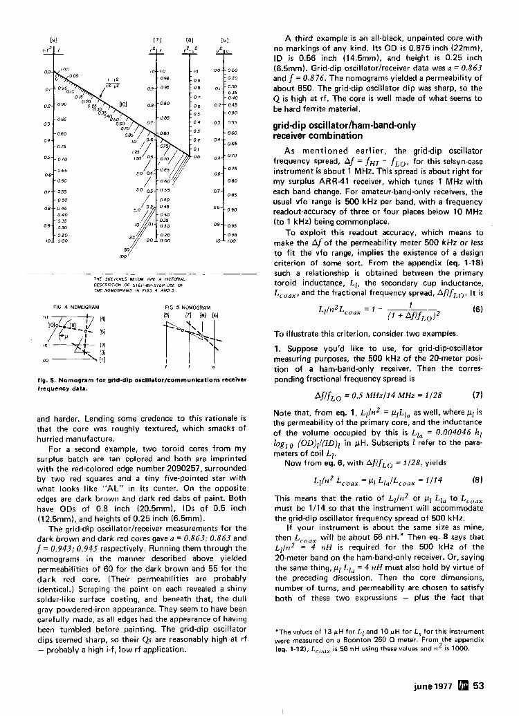
THE SKETCHES BELOW ARE A PICTORIAL DESCRIPTION OF STEP-BY-STEP USE O F THE NOMOGRAMS IN FIGS 4 A N 0 5 .
FIG 4 NOMOGRAM FIG 5 NOMOGRAM
fig. 5. Nomogram for grid-dip oscillator/communications receiver frequency data.
and harder. Lending some credence to this rationale is that the core was roughly textured, which smacks of hurried manufacture.
For a second example, two toroid cores from my surplus batch are tan colored and both are imprinted with the red-colored edge number 2090257, surrounded by two red squares and a tiny five-pointed star with what looks like "AL" in its center. On the opposite edges are dark brown and dark red dabs of paint. Both have ODs of 0.8 inch (20.5mm). IDS of 0.5 inch (12.5mm), and heights of 0.25 inch (6.5mm).
The grid-dip oscillator/receiver measurements for the dark brown and dark red cores gave a = 0.863; 0.863 and f = 0.943; 0.945 respectively. Running them through the nomograms in the manner described above yielded permeabilities of 60 for the dark brown and 55 for the dark red core. (Their permeabilities are probably identical.) Scraping the paint on each revealed a shiny solder-like surface coating, and beneath that, the dull gray powdered-iron appearance. They seem to have been carefully made, as all edges had the appearance of having been tumbled before painting. The grid-dip oscillator dips seemed sharp, so their Qs are reasonably high at rf - probably a high i-f, low rf application.
A third example is an all-black, unpainted core with no markings of any kind. I t s OD is 0.875 inch (22mm), ID is 0.56 inch (14,5mm), and height i s 0.25 inch (6.5mm). Grid-dip oscillator/receiver data was a = 0.863 and f = 0.876. The nomograms yielded a permeability of about 850. The grid-dip oscillator dip was sharp, so the Q i s high at rf. The core is well made of what seems to be hard ferrite material.
grid-dip oscillator/ham-band-only receiver combination
As mentioned earlier, the grid-dip oscillator frequency spread, Af = fHI - fLO, for this selsyn-case instrument i s about 1 MHz. This spread is about right for my surplus ARR-41 receiver, which tunes 1 MHz with each band change. For amateur-band-only receivers, the usual vfo range is 500 kHz per band, with a frequency readout-accuracy of three or four places below 10 MHz (to 1 kHz) being commonplace.
To exploit this readout accuracy, which means to make the Af of the permeability meter 500 kHz or less to fit the vfo range, implies the existence of a design criterion of some sort. From the appendix (eq. 1-18) such a relationship is obtained between the primary toroid inductance, Ll , the secondary cup inductance, LC,,,, and the fractional frequency spread, Af/fLo. I t is
To illustrate this criterion, consider two examples.
1. Suppose you'd like to use, for grid-dip-oscillator measuring purposes, the 500 kHz of the 20-meter posi- tion of a ham-band-only receiver. Then the corres- ponding fractional frequency spread is
Af/fLo = 0.5 MHz11 4 MHz = 1 128 (7)
Note that, from eq. 1, ~ ~ / n ~ = plLla as well, where p1 i s the permeability of the primary core, and the inductance of the volume occupied by this is LIa = 0.004046 hl loglo (OD)ll(ID)l in pH. Subscripts 1 refer to the para- meters of coil Ll .
Now from eq. 6, with Af/fLo = 1/28, yields
This means that the ratio of ~ ~ l n ~ or p1 Lla to LC,,, must be 1/14 so that the instrument will accommodate the grid-dip oscillator frequency spread of 500 kHz.
If your instrument is about the same size as mine, then LC,,, will be about 56 nH.* Then eq. 8 says that ~ ~ / n ~ = 4 nH is required for the 500 kHz of the 20-meter band on the ham-band-only receiver. Or, saying the same thing, p, Ll, = 4 nH must also hold by virtue of the preceding discussion. Then the core dimensions, number of turns, and permeability are chosen to satisfy both of these two expressions - plus the fact that
"The values of 13 pH for Ll and 10 pH for L, for this instrument were measured on a Boonton 260 Q meter. From the appendix (eq. 1-12), L,,,, i s 56 nH using these values and n2 i s 1000.
june 1977 53
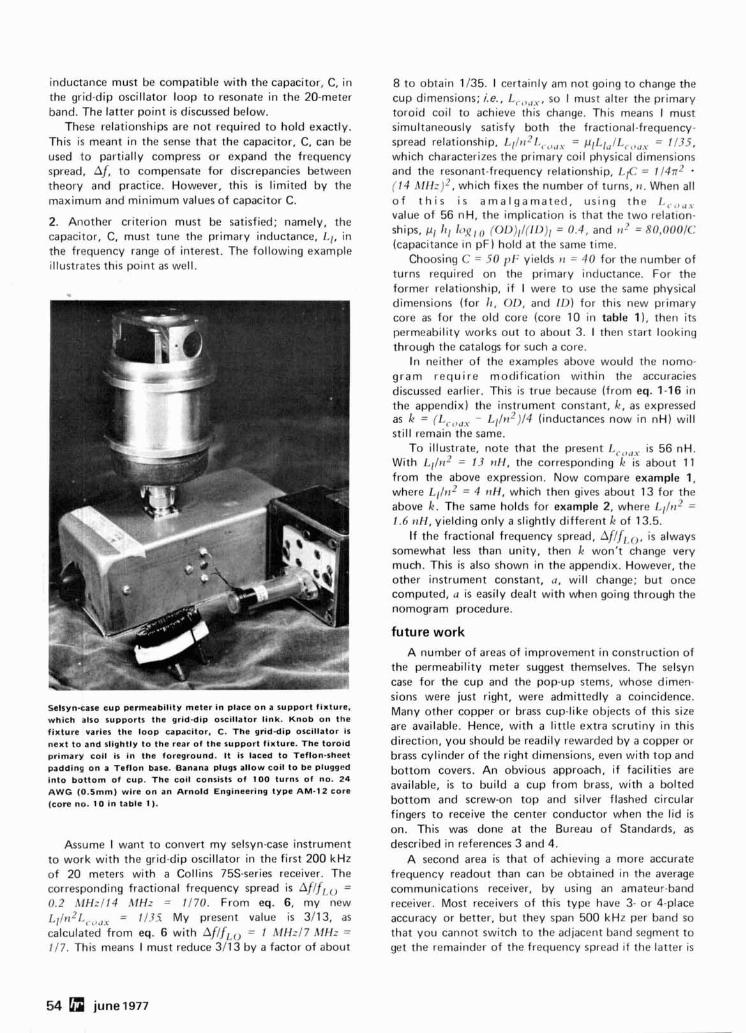
inductance must be compatible with the capacitor, C, in the grid-dip oscillator loop to resonate in the 20-meter band. The latter point i s discussed below.
These relationships are not required to hold exactly. This is meant in the sense that the capacitor, C, can be used to partially compress or expand the frequency spread, Af, to compensate for discrepancies between theory and practice. However, this is limited by the maximum and minimum values of capacitor C.
2. Another criterion must be satisfied; namely, the capacitor, C, must tune the primary inductance, LI, in the frequency range of interest. The following example illustrates this point as well.
Selsynsase aup permeability meter in place on a support fixture, which also supports the grid-dip oscillator link. Knob on the fixture varies the loop capacitor. C. The grid-dip oscillator is next to and slightly to the rear of the support fixture. The toroid primary coil is in the foreground. I t is laced to Teflon-sheet padding on a Teflon base. Banana plugs allow coil to be plugged into bottom of cup. The coil consists of 100 turns of no. 2 4 AWG (0.5mm) wire on an Arnold Engineering type AM-12 core (core no. 10 in table 1 ).
Assume 1 want to convert my selsyncase instrument to work with the grid-dip oscillator in the first 200 kHz of 20 meters with a Collins 75s-series receiver. The corresponding fractional frequency spread is Af/.frao = 0.2 AfHzI14 AlHz = 1/70. From eq. 6, my new L ~ / ~ I ~ I .,.,,,, = 1/3S My present value is 3/13, as calculated from eq. 6 with Af/fI,o = 1 MHz17 hfHz = 117. This means I must reduce 311 3 by a factor of about
8 to obtain 1/35. 1 certainly am not going to change the cup dimensions; i.e., L ,.,,, ] , , so I must alter the primary toroid coil to achieve this change. This means I must simultaneously satisfy both the fractional-frequency- spread relationship, l ~ l l r r ~ l d l . ~ , , , = pII,I,lL ,.,,, , = 1/35, which characterizes the primary coil physical dimensions and the resonant-frequency relationship, LIC = 1/4n2 - (14 h l f f z )* , which fixes the number of turns, t z . When all o f t h i s i s amalgamated, using the I . , . ' , , , , value of 56 nH, the implication is that the two relation- ships, pl 111 l q q , (OI~)Il(IL))I = 0.4 , and P I - ' = 80,000IC (capacitance in pF) hold at the same time.
Choosing C = 50 p t : yields t i = 40 for the number of turns required on the primary inductance. For the former relationship, if I were to use the same physical dimensions (for 1 1 , OD, and ID) for this new primary core as for the old core (core 10 in table I), then its permeability works out to about 3. 1 then start looking through the catalogs for such a core.
In neither of the examples above would the nomo- gram require modification within the accuracies discussed earlier. This is true because (from eq. 1-16 in the appendix) the instrument constant, k, as expressed as k = (L , , , , , - ~ ~ / t z ~ ) / 4 (inductances now in nH) will still remain the same.
To illustrate, note that the present I , ,c , , , i s 56 nH. With Lllrt2 = 13 wH, the corresponding k is about 11 from the above expression. Now compare example 1, where ~ ~ l t 1 ~ = 4 r7H, which then gives about 13 for the above k. The same holds for example 2, where LIIn2 = 1.6 nH, yielding only a slightly different k of 13.5.
If the fractional frequency spread, Af/fl ,o, i s always somewhat less than unity, then k won't change very much. This is also shown in the appendix. However, the other instrument constant, a, will change; but once computed, a is easily dealt with when going through the nomogram procedure.
future work A number of areas of improvement in construction of
the permeability meter suggest themselves. The selsyn case for the cup and the pop-up stems, whose dimen- sions were just right, were admittedly a coincidence. Many other copper or brass cup-like objects of this size are available. Hence, with a little extra scrutiny in this direction, you should be readily rewarded by a copper or brass cylinder of the right dimensions, even with top and bottom covers. An obvious approach, if facilities are available, i s to build a cup from brass, with a bolted bottom and screw-on top and silver flashed circular fingers to receive the center conductor when the lid i s on. This was done at the Bureau of Standards, as described in references 3 and 4.
A second area is that of achieving a more accurate frequency readout than can be obtained in the average communications receiver, by using an amateur-band receiver. Most receivers of this type have 3- or 4-place accuracy or better, but they span 500 kHz per band so that you cannot switch to the adjacent band segment to get the remainder of the frequency spread if the latter i s
54 june 1977
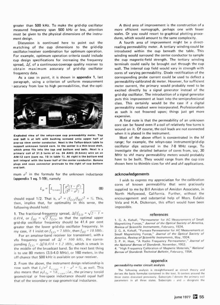
greater than 500 kHz. To make the grid-dip oscillator measured frequency span 500 kHz or less, attention must be given to the physical dimensions of the instru- ment design.
. Discussion is continued here to point out the matching of the cup dimensions to the grid-dip oscillator/receiver combination for optimum operation. For example, optimum operation criteria could include cup design specifications for increasing the frequency spread, Af, of a continuous-coverage quality receiver to obtain maximum accuracy of grid-dip oscillator frequency data.
As a case in point, it is shown in appendix 1, last paragraph, using a criterion of uniform measurement
-,accuracy from low to high permeabilities, that the opti-
Exploded view of the selsyn-case cup premeabillty meter. Top end bell Is at left with bushing screwed onto upper half of pop-up stem center conductor. Next is the Teflon-block table to support unknown toroid core. In the center is a thin brass shell. which press fits into the top and bottom end bells. Next is a primary coil of 31.5 turns of no. 24 AWG (0.5mm) wire on an AM-12 core (core no. 10 in table 1 ). At right Is the bottom end bell integral with the lower half of the center conductor. Banana plugs and coax connector protrude to the right of cup bottom end bell.
mum a2 in the formula for the unknown inductance (appendix 1 eq. 1-19), namely
should equal 112. That is, a2 = (fr,olfi,,)2 = 54. This, then, implies that, for optimality in this sense, the following should hold:
1. The fractional-frequency spread, AflfI,, = d m = 0.414, or filr = d z , so that the optimal upper grid-dip oscillator frequency should be 41.4 per cent greater than the lower grid-dip oscillator frequency. In my case, if I insist on .frZo = 7 M H z , then.fIlr = 10 A l H z .
For an amateur-band receiver (or transceiver), with a vfo frequency spread of Af = .500 k H z , the corres- ponding fr,(, = Afl0.414 = 1.2 ,\Iffz, which is smack in the middle of the broadcast band. So the next best thing is to use 80 meters (3.5-4.0 MHz), or 160 meters, in the off chance that 500 kHz is available on your receiver.
2. From the above, the instrument design relationship is now such that ~ ~ ~ l t ~ ~ L,,,,, = 1 - a* = %, as well. This also means that p I L I , = % L C , , , , ; i.e., the primary toroid geometrical or free-space inductance should equal half that of the secondary or cup geometrical inductance.
A third area of improvement i s the construction of a more efficient nomograph, perhaps one with fewer scales. Or you could resort to graphical plotting proce- dures, which would amount to the same complexity.
A fourth area of improvement might be a direct- reading permeability meter. A tertiary winding could be introduced within the cup beneath the table. This winding would surround the center conductor to sample the cup magnetic-field strength. The tertiary winding terminals could easily be brought out through the cup wall. The internal cup field would vary in strength with cores of varying permeability. Diode rectification of the corresponding probe current could be used to deflect a permeability-calibrated dc meter. However, for sufficient meter current, the primary would probably need to be excited directly by a signal generator instead of the grid-dip oscillator. The introduction of a signal generator puts this improvement at least into the semiprofessional class. This certainly would be the case if a digital permeability readout were incorporated. Professionalism as such i s not frowned upon; things just get more expensive.
A final note is that the permeability of an unknown core can be found even if a coil of relatively few turns is wound on it. Of course, the coil leads are not connected when it is placed in the instrument.
Most of the above effort is concentrated in the hf range; for example, the selsyn-case instrumentlgrid-dip oscillator dips occurred in the 7-8 MHz range. To investigate the detailed behavior of cores from, say, 30 MHz to vhf many permeability meters would probably have to be built. They would range from the cup size shown here to thimble sizes for vhf and uhf applications.
acknowledgements I wish to express my appreciation for the calibration
cores of known permeability that were graciously supplied to me by Bill Amidon of Amidon Associates, /n North Hollywood, California. Further, without the encouragement and substantial help of Mssrs. Eulalio Vela and H.A. Dickerson, this effort would have been impossible.
references 1. G. A. Kelsall, "Permeameter for AC Measurements o f Small Magnetizing Forces," Journal of the Optical Society of America, Review of Scientific Instruments, February, 1924. 2. G. A. Kelsall, "Furnace Permeameter for AC Measurements at Small Magnetizing Forces," Journal of the Optical Society of America, Review of Scientific Instruments. May, 1924. 3. P. H. Haas, "A Radio Frequency Permeameter," Journal of the National Bureau of Standards, November, 1953. 4. "High Frequency Calibration o f Magnetic Materials," National Bureau of Standards Technical Bulletin, February, 1954.
appendix permeability-meter circuit analysis
The following analysis is straightforward ac circuit theory and derives the basic formulas containetf in the text. I t centers around the three states discussed previously. Subscrlpts I denote the primary cot1 parameters in all three states. Subscrlpts v and , I designate the
june 1977 55
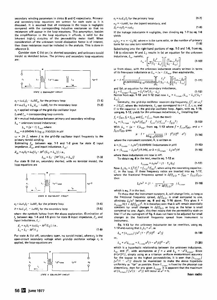
secondary winding parameters in states B and C respectively. Primary- el = iwLIII, for the primary loop (1-7) . . and secondary-loop equations are written for each state as it is discussed. It is assumed that all resistance in the loops i s negligible
e 2 = -iwM1l for the (open) secondary' and
com~ared with the corres~ondinq inductive reactances so that no Zl = e l / l l = rwLl resistances will appear in the loop-equations. This assumption, besides the simplification in the loop equations i t affords, is valid for the inherent high-Q circuitry of the permeability meter itself. When consideration of the unknown toroid dissipation factor is of interest, then these resistances must be included in the analysis. This is done in reference 3.
Consider state C (lid 0n:i.e. shorted secondary, and unknown toroid inside) as sketched below. The primary and secondary loop equations are:
STATE C EQUIVALENT CIRCUIT
el = iwLlI1 - iwMI,, for the primary loop (1-1)
0 = iw(L2 + L,)I,, - iwMIl for the secondary loop (1-2)
el = applied voltage of the grid-dip oscillator input
11 and I , , = corresponding loop currents
M = mutual inductance between primary and secondary windings
L, = unknown toroid inductance;
L, = ( p - 1 ) L,,. where
L,, = 0.004046 h loglO (ODllD) in pH
w = 2n f , where f is the grid-dip oscillator input frequency to the primary toroid winding. Estimating I,, between eqs. 1-1 and 1-2 gives for state C input impedance, Z,,, and input inductance, L,,:
Z,, = ellll = iw[Ll - M ~ / ( L ~ + L , ) ] ; i.e.,
L , ~ = L~ - [ M ~ / ( L ~ + L,,)] (1-3) For state B (lid on, secondary shorted, with no toroidal inside), the loop equations are
STATE B EOUIVALENT ClRCUll
el = iwLIIl - iwMI, for the primary loop
0 = iwLZI, - iwMI, for the secondary lo9p
where the symbols follow from the above explanation. Elimination of I, between eqs. 1 4 and 1-5 gives for state B input impedance, Z,, and input inductance, L,:
Z, = ellll = iw(Ll - M ~ I L ~ ) ; i.e.,
L, = L~ - M ~ I L ~ (1-6)
For state A (lid off, secondary open, no toroid inside), where e2 is the open-circuit secondary voltage when grid-dip oscillator voltage el is applied, the loop equations are
STATE A EOUIVALENT CIRCUIT
If the leakage inductance is negligible, then dividing eq. 1-7 by eq. 1-8 yields
el /e2 = n = -Ll /M, where n is the turns ratio, or the number of primary turns for our one turn secondary. (1-9)
Substituting into the right-hand portions of eqs. 1-3 and 1-6, from eq. 1-9 to eliminate M and L2 results in (a) an equation for the unknown inductance, L, , namely,
(1-10)
or from above, with the unknown inductance usually written in terms of its free-space inductance as L, = (u - 1)L,, , then equivalently,
and (b). an equation for the secondary inductance, L2 = LC,,,; LC,,, = L ~ ~ I ~ ~ ( L , - L,) (1-12) Notice from eqs. 1-10 and 1-12 that now L, = LC,,, (L,, - L,)I(Ll - Lssh
Generally, the grid-dip oscillator resonant dip frequency,fi2, or w i 2 = lILiC, where the inductance, Li can correspond to i = 1, 2, s, ss, and C is the capacitor in the grid-dip oscillator loop. Again, with eq. 1-10, using eq. 1-12, yields for the unknown inductance, L, (recalling that
f, = fHI, fi = fLO and f,, = fco, from the text):
L, = (LcOax - L I / ~ ~ ) ( ~ H I ~ - fcor2)l(fcor2 - f ~ o ' ) (1-13)
With L, - ( p - 1)L,, , from eq. 1-13 where f = fcor/ fHI, and a =
where the instrument constant, k, is written as
k = (Lcoax - ~ ~ / n ~ ) / 0 . 0 0 4 0 4 6 (inductances in pH) (1-15)
where these inductances are now in nH. To obtain eq. 6 in the text, rewrite eq. 1-12 as
LC,,, = ~ ~ / n ~ . (1 - L,ILl) (1-17)
Now L,/Ll = fi2/fs2 = f L O 2 / f H I 2 , when using the resonating capacitor, C , in the loop. If these frequency ratios are inserted into eq. 1-17, where the fractional frequency spread is AflfLO = ( fHr - fLo)fLo, then
which is eq. 7 in the text. To show that the instrument constant, k, will change little, as long as
the fractional frequency spread, Af/fLO, i s small compared to one, eliminate Ll/n2 between eq. 6 and eq. 1-16 above. This gives k = L,,,,/4(1 + ~ f / f ~ ~ ) ~ . It is therefore seen that k will remain essentially constant for small changes in Af/fLO as long as the latter i s small compared to one. Again, this then means that the permeability scale on line 11 of the nomogram of fig. 4 does not have to be adjusted for small changes in the fractional frequency spread from instrument to instrument.
Eq. 1-13 for the unknown inductance can be rewritten, using eq. 1-12 and noting that L,LI = a 2 , as
or.
which is a hyperbolic relationship between the unknown inductance, L,, and f2. with asymptotes at f = a and L, = - a 2 ~ , , , , . Since O(o<fCl, simply using as a criterion uniform measurement accuracy for the lowest to the highest permeabilities, i t is seen that [LC, , , ] [a2(1 - ,?)] should be maximized to make the above hyperbola uniformly as "fat" as possible. Since LC,,, is fixed by the physical cup dimensions, then for any given LC,,, i t is apparent that the maximum of [LC, , , 1 [aZ( l - a Z ) ] will occur at a2 = %.
ham radio
56 june 1977
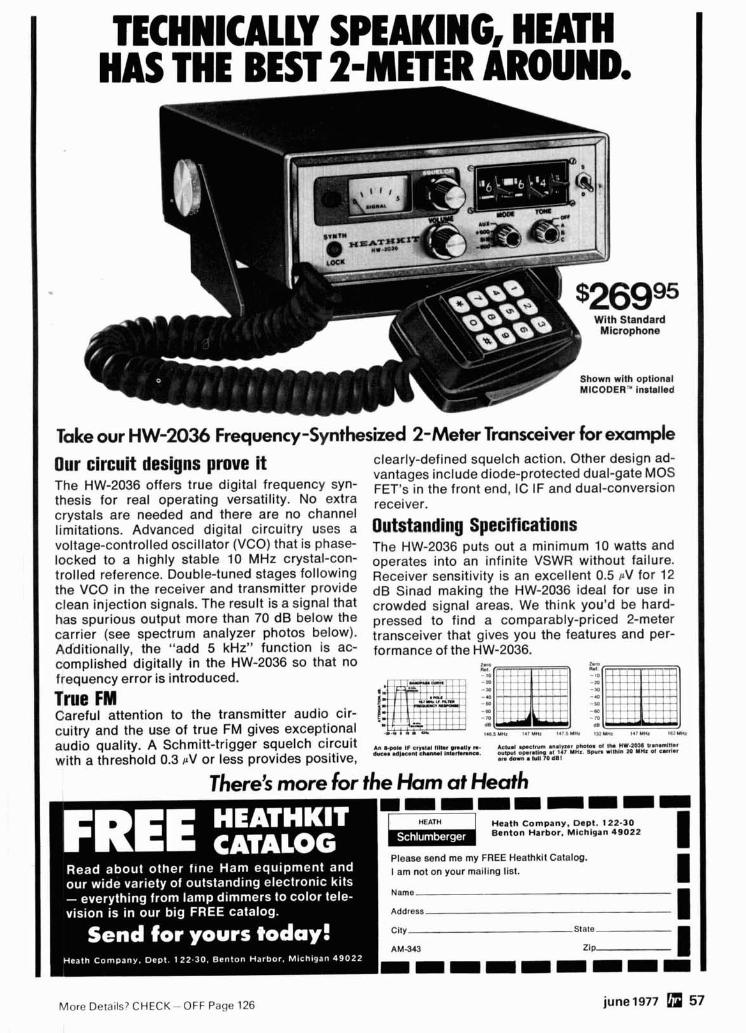
TECHNICALLY SPEAKING, HEATH HAS THE BEST 2-METER AROUND.
-ma=- With Standard
Shown with optional MICODER" installed -
Take our HW-2036 Frequency -Synthesized 2-Meter Transceiver for example
Our circuit designs prove it The HW-2036 offers true digital frequency syn- thesis for real operating versatility. No extra crystals are needed and there are no channel limitations. Advanced digital circuitry uses a voltage-controlled oscillator (VCO) that is phase- locked to a highly stable 10 MHz crystal-con- trolled reference. Double-tuned stages following the VCO in the receiver and transmitter provide clean injection signals. The result is a signal that has spurious output more than 70 dB below the carrier (see spectrum analyzer photos below). Additionally, the "add 5 kHz" function is ac- complished digitally in the HW-2036 so that no frequency error is introduced.
True FM Careful attention to the transmitter audio cir- cuitry and the use of true FM gives exceptional audio quality. A Schmitt-trigger squelch circuit with a threshold 0.3 aV or less provides positive,
clearly-defined squelch action. Other design ad- vantages include diode-protected dual-gate MOS FET's in the front end, IC IF and dual-conversion receiver.
Outstanding Specifications The HW-2036~uts out a minimum 10 watts and operates into an infinite VSWR without failure. Receiver sensitivity is an excellent 0.5 PV for 12 dB Sinad making the HW-2036 ideal for use in crowded signal areas. We think you'd be hard- pressed to find a comparably-priced 2-meter transceiver that gives you the features and per- formance of the HW-2036.
2.m 0.1 2.- n.1
- 10 - 10
-20 -M -a -50 -M - 70
6s
$465 MHz ' A ' M Y , 1 4 . 5 UHX 13ZYMr (4; YHr I C i Y W 1
3 , 2: z;:;: :;:lrLnPy&: ~%IY2%"::z"T: are d o m lull 70 dlll
There's more for the Ham at Heath
1 HEATH I Heath ComDanv. DaDt. 1 . Benton Harbor; Michigan 49022
Please send me my FREE Heathkit Catalog. I am not on your mailing list.
Name
Address
City State
I AM343 ZIP I
More Details? CHECK -OFF Page 126 june 1977 57
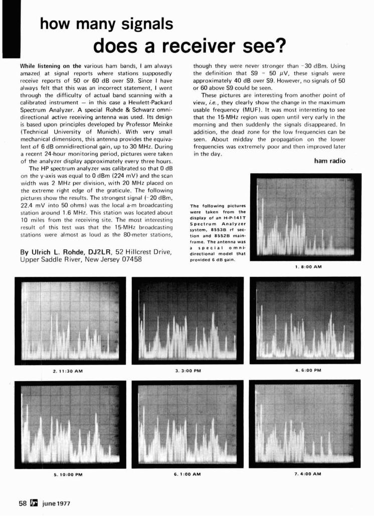
I how many signals does a receiver see?
While listening on the various ham bands, I am always amazed, at signal reports where stations supposedly receive reports of 50 or 60 dB over S9. Since I have always felt that this was an incorrect statement, I went through the difficulty of actual band scanning with a calibrated instrument - in this case a Hewlett-Packard Spectrum Analyzer. A special Rohde & Schwarz omni- directional active receiving antenna was used. Its design is based upon principles developed by Professor Meinke (Technical University of Munich). With very small mechanical dimensions, this antenna provides the equiva- lent .of 6 dB omnidirectional gain, up to 30 MHz. During a recent 24-hour monitoring period, pictures were taken of the analyzer display approximately every three hours.
The HP spectrum analyzer was calibrated so that 0 dB on the y-axis was equal to 0 dBm (224 mV) and the scan width was 2 MHz per division, with 20 MHz placed on the extreme right edge of the graticule. The following pictures show the results. The strongest signal (-20 dBm, 22.4 mV into 50 ohms) was the local a-m broadcasting station around 1.6 MHz. This station was located about 10 miles from the receiving site. The most interesting result of this test was that the 15-MHz broadcasting stations were almost as loud as the 80-meter stations,
By Ulrich L. Rohde, DJ2LR, 52 Hillcrest Drive, Upper Saddle River, New Jersey 07458
though they were never stronger than -30 dBm. Using the definition that S9 = 50 pV, these signals were approximately 40 dB over S9. However, no signals of 50 or 60 above S9 could be seen.
These pictures are interesting from another point of view, i.e., they clearly show the change in the maximum usable frequency (MUF). It was most interesting to see that the 15-MHz region was open until very early in the morning and then suddenly the signals disappeared. In addition, the dead zone for the low frequencies can be seen. About midday the propagation on the lower frequencies was extremely poor and then improved later in the day.
ham radio
The following pictures
display of an H-P-1417 S p e c t r u m A n a l y z e r
tion and 8 5 5 2 8 main- frame. The antenna war
directional model that provided 6 dB gain.
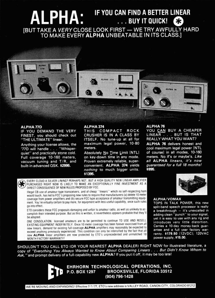
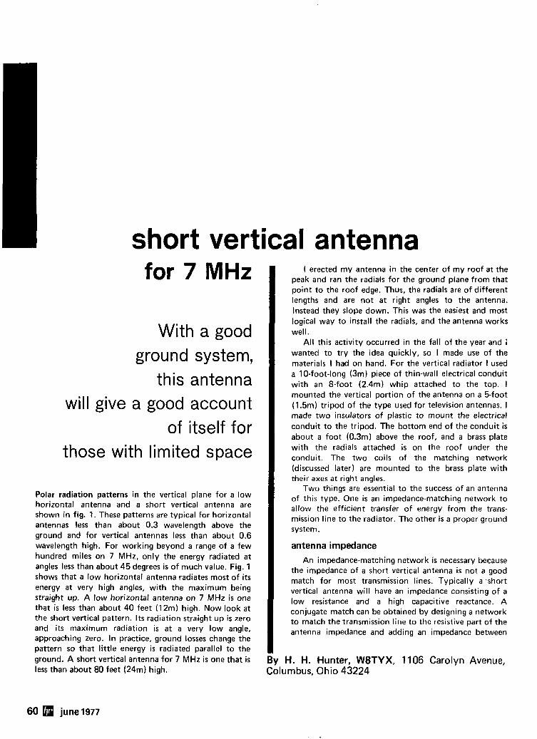
short vertical antenna for 7 MHz
With a good ground system,
this antenna will give a good account
of itself for those with limited space
Polar radiation patterns in the vertical plane for a low horizontal antenna and a short vertical antenna are shown in fig. 1. These patterns are typical for horizontal antennas less than about 0.3 wavelength above the ground and for vertical antennas less than about 0.6 wavelength high. For working beyond a range of a few hundred miles on 7 MHz, only the energy radiated at angles less than about 45 degrees is of much value. Fig. 1 shows that a low horizontal antenna radiates most of its energy a t very high angles, with the maximum being straight up. A low horizontal antenna on 7 MHz is one that i s less than about 40 feet (12m) high. Now look a t the short vertical pattern. I t s radiation straight up is zero and i t s maximum radiation is at a very low angle, approaching zero. In practice, ground losses change the pattern so that little energy is radiated parallel to the ground. A short vertical antenna for 7 MHz i s one that i s less than about 80 feet (24m) high.
I erected my antenna in the center of my roof at the peak and ran the radials for the ground plane from that point to the roof edge. Thus, the radials are of different lengths and are not at right angles to the antenna. Instead they slope down. This was the easiest and most logical way to install the radials, and the antenna works well.
All this activity occurred in the fall of the year and i wanted to try the idea quickly, so I made use of the materials I had on hand. For the vertical radiator I used a 10-foot-long (3m) piece of thin-wall electrical conduit with an 8-foot (2.4m) whip attached to the top. I mounted the vertical portion of the antenna on a 5-foot (1.5m) tripod of the type used for television antennas. I made two insulators of plastic to mount the electrical conduit to the tripod. The bottom end of the conduit i s about a foot (0.3m) above the roof, and a brass plate with the radials attached is on the roof under the conduit. The two coils of the matching network (discussed later) are mounted to the brass plate with their axes a t right angles.
Two things are essential to the success of an antenna of this type. One is an impedance-matching network to allow the efficient transfer of energy from the trans- mission line to the radiator. The other is a proper ground system.
antenna impedance An impedance-matching network is necessary because
the impedance of a short vertical antenna is not a good match for most transmission lines. Typically a .short vertical antenna will have an impedance consisting of a low resistance and a high capacitive reactance. A conjugate match can be obtained by designing a network to match the transmission line to the resistive part of the antenna impedance and adding an impedance between
1 H. H. Hunter, W8TYX, 1106 Carolyn Avenue, ~lumbus, Ohio 43224
60 june 1977
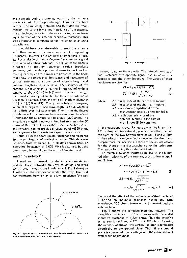
the network and the antenna equal to the antenna reactance but of the opposite sign. Thus for my short vertical, the matching network had to match the trans- mission line to the few ohms impedance of the antenna. I also included a series inductance having a reactance equal to that of the antenna capacitive reactance. This series inductance compensates for the effect of antenna capacitance.
It would have been desireable to erect the antenna and then measure its impedance at the operating frequency. However, I did not have an impedance bridge. La Port's Radio Antenna Engineering contains a good discussion of vertical antennas. A portion of the book is d i rected t o medium-frequency, vertical broadcast antennas, but the data presented seem to work well at the higher frequencies. Curves are presented in the book that show the impedance (resistance and reactance) of vertical antennas as a function of antenna height and antenna length-to-diameter ratio. The diameter of my antenna is not constant since the 8-foot (2.4m) whip is tapered to about 0.1 25 inch (3mm) diameter at the top. I assumed an average diameter for the entire antenna of 0.5 inch (12.5mm). Thus, the ratio of length to diameter is 18 x 12/0.5 or 432. The antenna height in degrees, where 360 degrees is one wavelength, is 46.3, which i s just a little over 1 18 wavelength. Then, from the figures in reference 1, the antenna base resistance will be about 5 ohms and the reactance will be about - 1320 ohms. The impedance-matching network thus had to match the 50 ohms of the RG-8/U coax cable I used to 5 ohms. Also, the network had to provide a reactance of t i320 ohms to compensate for the antenna capacitive reactance.
Table 1 lists the approximate resistance and reactance for several lengths of vertical antennas. This data was obtained from reference 1. In all data shown here, an operating frequency of 7.037 MHz is assumed, but the data should be useful over the entire 40-meter band.
matching network I used an L network for the impedance-matching
system. These networks are easy to design and work well. I used the equations in reference 2. Fig. 2 shows an L network. The network can work either way. That is, it can transform from a high to a low impedance (the way
fig. 2. L network.
I wanted to go) or the opposite. The network consists of two reactances with opposite signs. That is, one must be capacitive and the other inductive. The values of these reactances are given by:
Zl = + ~ ~ R Z ( R I - R2) (1
22 = f jR1 diK2 (2)
where Z1 = reactance of the series arm (ohms) 2 2 = reactance of the shunt arm (ohms) R 1 = resistance (impedance) of the
transmission line; 50 ohms for RG-8 R2 = radiation resistance of the
antenna; 5 ohms in the case of my 18-foot (5.5m) antenna.
In the equations above, R1 must always be larger than R2. In designing the network, you can use either the two top signs or the two bottom signs of eqs. 1 and 2. That is, the series arm can be an inductance and the shunt arm a capacitance, or vice versa. I chose to use an inductance for the shunt arm and a capacitance for the series arm. The reason for doing this is described later.
To match a 50-ohm transmission line to the 5-ohm radiation resistance of the antenna, substitution in eqs. 1 and 2 gives
21 = - ~ J R ~ ( R I - RZ)
fig. 1. Typical polar radiation patterns in the vertical plane for a low horizontal and short vertical antenna.
To cancel the effect of the antenna capacitive reactance I added an inductive reactance having the same magnitude, 320 ohms, between the L network and the antenna base.
Fig. 3 shows the complete matching network. The capacitive reactance of Z l is in series with the added inductive reactance of +j320 ohms. Thus the effective series arm is -j15 and +j320, or +j305 ohms. By using the network as shown, the vertical radiator is connected electrically to the ground plane. Thus, if the ground plane i s connected to an earth ground the entire antenna system can be grounded.
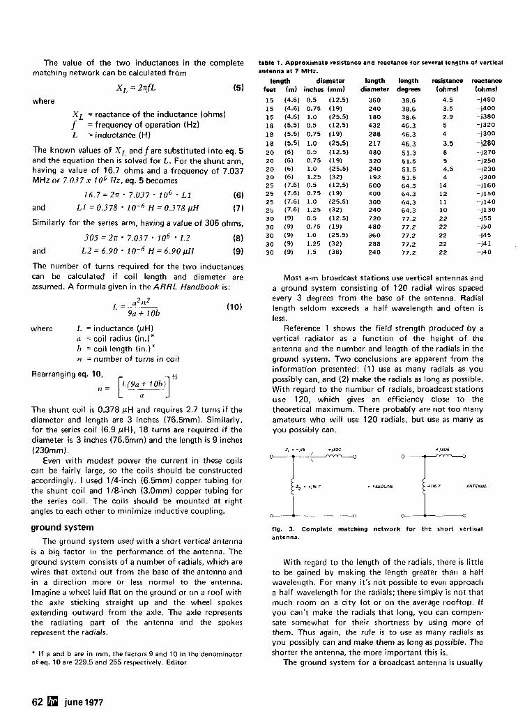
The value of the two inductances in the complete matching network can be calculated from
x, = 27rfL ( 5 )
where
X L = reactance of the inductance (ohms)
f = frequency of operation (Hz) L = inductance (H)
The known values of X L and f are substituted into eq. 5 and the equation then is solved for L. For the shunt arm, having a value of 16.7 ohms and a frequency of 7.037 MHz or 7.037 x 1 o6 Hz , eq. 5 becomes
16.7=2n 7.037 lo6 . L1 (6) and L1 = 0.378 H = 0.378 pN (7)
Similarly for the series arm, having a value of 305 ohms,
3 0 5 = 2 n . 7.037. lo6 . L2 (8) and L2 = 6.90 1 0-6 H = 6.90 pH (9)
table 1. Approximate resistance and reactance for several lengths of vertical antenna at 7 MHz.
length diameter length length resistance reactance feet (m) inches (mm) diameter degrees (ohms) (ohms)
15 (4.6) 0.5 (12.5) 360 38.6 4.5 -j450 15 (4.6) 0.75 (19) 240 38.6 3.5 -1400 15 (4.6) 1.0 (25.5) 180 38.6 2.9 -j380 18 (5.5) 0.5 (12.5) 432 46.3 5 -j320
18 (5.5) 0.75 (19) 288 46.3 4 -1300
18 (5.5) 1.0 (25.5) 217 46.3 3.5 -j280 20 (6) 0.5 (12.5) 480 51.3 8 -j270 20 (6) 0.75 (19) 320 51.5 5 -j250 20 (6) 1.0 (25.5) 240 51.5 4.5 -1230 20 (6) 1.25 (32) 192 51.5 4 -j200 25 (7.6) 0.5 (12.5) 600 64.3 14 -i160 25 (7.6) 0.75 (19) 400 64.3 12 -j150 25 (7.6) 1.0 (25.5) 300 64.3 11 -j140 25 (7.6) 1.25 (32) 240 64.3 10 -j130 30 (9) 0.5 (12.5) 720 77.2 22 -j55
30 ( 9 ) 0.75 ( 1 9 ) 480 77.2 22 -150 30 (9) 1.0 (25.5) 360 77.2 22 -145
30 (9) 1.25 (32) 288 77.2 22 -j4 1 30 (9) 1.5 (38) 240 77.2 2 2 -140
The number of turns required for the two inductances can be calculated if coil length and diameter are Most a-m broadcast stations use vertical antennas and assumed. A formula given in the ARRL Handbook is: a ground system consisting of 120 radial wires spaced
a2n2 every 3 degrees from the base of the antenna. Radial L =
9a+ lob (10) length seldom exceeds a half wavelength and often is
less. where L = inductance (pH)
u = coil radius (in.)" b = coil length (in.)" n = number of turns in coil
Rearranging eq. 10, [1>(9a + I 0b 4 ' n =
The shunt coil is 0.378 pH and requires 2.7 turns if the diameter and length are 3 inches (76.5mm). Similarly, for the series coil (6.9 pH), 18 turns are required if the diameter i s 3 inches (76.5mm) and the length is 9 inches (230mm).
Even with modest power the current in these coils can be fairly large, so the coils should be constructed accordingly. I used 114-inch (6.5mm) copper tubing for the shunt coil and 118-inch (3.0mm) copper tubing for the series coil. The coils should be mounted at right angles to each other to minimize inductive coupling.
ground system
The ground system used with a short vertical antenna is a big factor in the performance of the antenna. The ground system consists of a number of radials, which are wires that extend out from the base of the antenna and in a direction more or less normal to the antenna. Imagine a wheel laid flat on the ground or on a roof with the axle sticking straight up and the wheel spokes extending outward from the axle. The axle represents the radiating part of the antenna and the spokes represent the radials.
* I f a and b are in rnrn, the factors 9 and 10 in the denominator of eq. 10 are 229.5 and 255 respectively. Editor
Reference 1 shows the field strength produced by a vertical radiator as a function of the height of the antenna and the number and length of the radials in the ground system. Two conclusions are apparent from the information presented: (1) use as many radials as you possibly can, and (2) make the radials as long as possible. With regard to the number of radials, broadcast stations use 120, which gives an efficiency close to the theoretical maximum. There probably are not too many amateurs who will use 120 radials, but use as many as you possibly can.
fig. 3. Complete matching network for the short vertical antenna.
With regard to the length of the radials, there is little to be gained by making the length greater than a half wavelength. For many i t ' s not possible to even approach a half wavelength for the radials; there simply i s not that much room on a city lot or on the average rooftop. I f you can't make the radials that long, you can compen- sate somewhat for their shortness by using more of them. Thus again, the rule is to use as many radials as you possibly can and make them as long as possible. The shorter the antenna, the more important this is.
The ground system for a broadcast antenna i s usually
62 june 1977
buried a few inches to get it out of the way, and the wires are at right angles to the vertical radiator. With my roof-mounted vertical antenna, the radials are on the roof and slope away from the vertical radiator instead of being at right angles. However, this antenna performs well, so the sloping radials apparently do not effect performance adverse1 y.
In my system I mounted an 8 x 10 inch (2Ox25cm) brass plate under the lower end of the vertical radiator. 1 drilled a series of holes around the edge of this plate and tapped them for 6-32 (M3.5) machine screws. When I installed the radial wires I attached each one under the head of a screw mounted in one of the tapped holes. After I had attached all of the radials to the plate I
" soldered the wires and the screws to the base plate. My house is single story about 29 x 41 feet (9xl2m)
with a hip roof. I mounted the antenna in the center of the roof at the peak. I used 20 radials of no. 24 (0.5mm) bare copper wire and spaced them equally. My longest radial is about 25 feet (7.6m); the shortest i s about 15 feet (4.6m).
adjustment Adjustment of the matching-network series coil i s
necessary. As explained earlier, the purpose of this coil i s to compensate for the antenna capacitive reactance. The information about the capacitive reactance of the antenna is approximate rather than exact. Thus it's necessary to either measure the reactance of both the antenna and series coil and make them equal or adjust the inductance after it is in place and make it "tune out" the antenna capacitance. I did the latter.
With the antenna, ground system and feed line installed, I used a vswr meter at the transmitter and adjusted the series-coil inductance for the lowest swr at the low end of the 7-MHz band. I obtained a swr of 1.5:l. 1 adjusted the coil by spreading or compressing the length of the coil. This adjustment i s critical. It should be possible to perform this adjustment with a noise bridge or with a rf-current indicator connected at the junction of the series coil and the vertical-antenna base. For the noise bridge, adjust the series coil so the antenna is resonant at the desired frequency. For the rf-current meter, adjust the coil for maximum current.
results This short vertical antenna has given a good account
of itself. If your antenna farm is smaller than you'd like, or if you can't erect a 70 footer (20m) consider a vertical, even a short one. Consider also installing the antenna on top of the house. Installing the antenna on the roof reduces clutter in the back yard and allows the antenna to "see" the horizon much better than at ground level.
references 1. E. A. La Port, Radio Antenna Engineering, 1952 edition, McGraw-Hill Book Company, New York. 2. F. E. Terman, Electronic and Radio Engineering, 4th edition, McGraw-Hill Book Company, New York, page 11 5.
ham radio
THE COMPUTER ROOM SMALL COMPUTER SYSTEMS SOFTWARE . AMATEUR RADIO EOUIPMENT
1455-8 SO 1100 E Salt Lake C11y. Utah 84105 Phone 801-466-791 1
"WE TAKE THE
%&Y%X%'P\Y OUT OF THE MlCRn "
One Of The Nat~ons Largest Over 1600 Square Feet 0 1 SRIPS Full-Serv~ce Computer Stores And Serv~ce Fact l~ t~es
WHEN YOU WRITE FOR OUR CATALOG AND ENCLOSES1 TO HELP DEFRAY THE COST OF HANDLING AND MAILING. HERE'S WHAT YOU GET:
1. A CERTIFICATE GOOD FOR $2 ON YOUR NEXT . . . . . . . . . . . . . . . . . . . . . . . . . . . . . . . . . . . . . . . . . . . . . . . . PURCHASE
2. THE COMPUTER ROOM EASY TO UNDERSTAND . . . . . . . . . . . . . . . . . . . . . . . . . . . . . . . . . . . . . CATALOGCOVERING
IMSAI THE DIGITAL GROUP POLYMORPHIC SYSTEMS SOUTH WEST TECHNICAL PRODUCTS CORPORA T lON TECHNICAL DESIGN LABS E TC.
3. THE COMPUTER ROOM "EASY GUIDE" TO HELP YOU PICK THE RIGHT SYSTEM, PERIPHERALS. COMPONENTS. ANDSOFTWAREFOR . . . . . . . . . . . . . . . . . . . . . . . . . . . . . . . . . . . . . .
THE BEGINNER THE ADVANCED THE EXPERT THE SMALL BUSINESS
4. A CURRENT LISTING OF PRESENTLY AVAILABLE
SOFTWARE PUBLICA TIONS PERIPHERALS
5. INFORMATION ON REPAIR SERVICE, LOW COST CUSTOM PROGRAMMING AND OTHER SPECIAL SERVICES.
AT THE COMPUTER ROOM YOUR WRITTEN OUESTIONS ARE HAPPILY RECEIVED AND PROMPTLY ANSWERED . . . . . .
WE ALSO STOCK A COMPLETE LINE OF AMATEUR RADIO EOUIPMENT
. . . . . . . . . . . . . . . . . . BANKAMERICARO MASTERCHARGE
june 1977 63
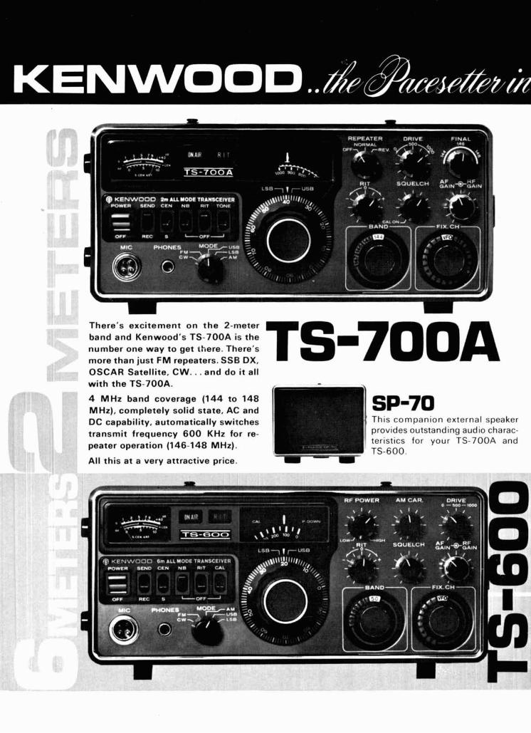
There's excitement on the 2-meter band and Kenwood's TS-700A is the number one way to get there. There's more than just FM repeaters. SSB DX, TS-7OOA OSCAR Satellite, CW.. . and do it all w i th the TS-7OOA.
4 MHz band coverage (144 to 148 MHz), completely solid state, AC and DC capability, automatically switches transmit frequency 600 KHz for re- peater operation (146-148 MHz).
All this at a very attractive price.
This companion external speaker provides outstanding audio charac- teristics for your TS-700A and TS-600.
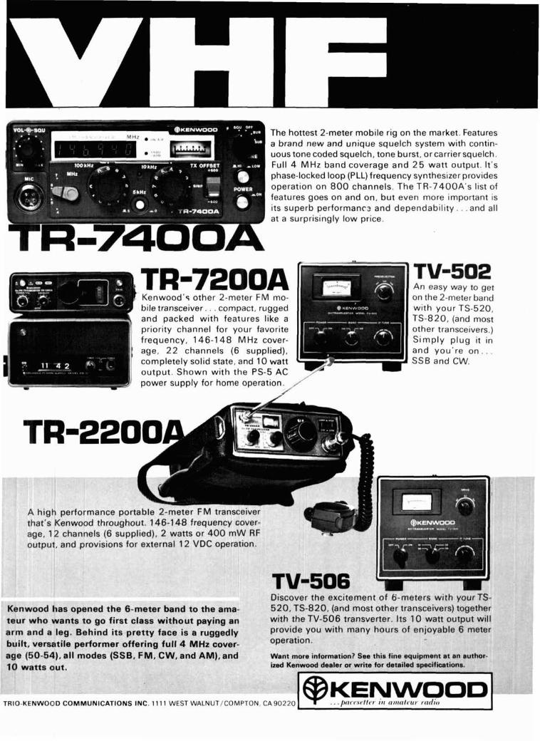
The hottest 2-meter mobile rig on the market. Features a brand new and unique squelch system with contin- uous tone coded squelch, tone burst, or carrier squelch. Full 4 MHz band coverage and 2 5 watt output. It's phase-locked loop (PLL) frequency synthesizer provides operation on 8 0 0 channels. The TR-7400A's list of features goes on and on, but even more important is its superb performancz and dependability. . .and all at a surprisingly low price.
Kenwood's other 2-meter FM mo- bile transceiver. . . compact, rugged and packed with features like a priority channel for your favorite frequency, 146-1 4 8 MHz cover- age, 2 2 channels (6 supplied), completely solid state, and 10 watt output. Shown with the PS-5 AC power supply for home operation.
high performance portable 2-meter FM transceivt at's ~ b n w o o d throughout. 146-1 4 8 frequency cove ie, 12 channels (6 supplied), 2 watts or 4 0 0 m W R ~tput, and provisions for external 12 VDC operation
."... -- arm an built, u --- ,C1
~d a leg. fersatile -. C A , -11
An easy way to get on the 2-meter band with your TS-520, TS-820, (and most other transceivers.) Simply p lug it in and you're o n . . . SSB and CW.
spened 1 d to the Kenwood has ( bter banr tnMr who wants to go flrst class without payir
Behind its pretty face is a rugg performer offering full 4 MHz CI
age tau-3-j, a ~ i modes (SSB, FM, CW, and AM)
lg an ledly over- --A
Discc 520, .* .:. L WlIrl
provi oper;
want ized K
~ v e r the excitemt ~ i t h you1 TS-820, (and mc rers) toge the TV-506 transverrar. 11s I v watt outpul de you c 3tion.
~ i t h mar
m ?nt of 6- ,st other ...- A-- I ,
~y hours
I meters \ transceh 6- 4 n .-.-
of enjoy able 6 rr
. . - ~ . more lntormatlonr see tnts tlne equtpment at an aui enwood dealer or write for detailed specifications.
a
r TS- :ther . ... :I1 . W111
reter
TRIO-KENWOOD COMMUNICATIONS INC. 11 11 WEST WALNUT/COMPTON, C A 9 0 2 2 0 KENWOOL, . . . l l ( l ( l,.\t 111~1 I I I ~ l l t l l l ~ ~ ~ t l ~ ~ I ~ ( ~ ~ / ; , I
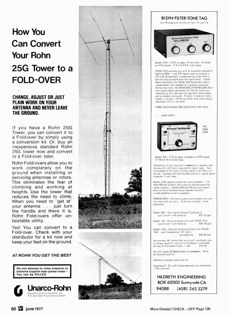
How You Can Convert Your Rohn
25G Tower to a FOLD-OVER
CHANGE, ADJUST OR JUST PLAIN WORK ON YOUR ANTENNA AND NEVER LEAVE THE GROUND.
If you have a Rohn 25G Tower, you can convert it to a Fold-over by simply using a conversion kit. Or, buy an inexpensive standard Rohn 25G tower now and convert to a Fold-over later.
Rohn Fold-overs allow you to work completely on the ground when installing or servicing antennas or rotors. This eliminates the fear of climbing and working at heights. Use the tower that reduces the need to climb. When you need to "get at" your antenna . . . just turn the handle and there it is. Rohn Fold-overs offer un- beatable utility.
Yes! You can convert to a Fold-over. Check with your distributor for a kit now and keep your feet on the ground.
B AT ROHN YOU GET THE BEST
antenna support near power lines-
Uir,? on I 1 ' " a r i n Irvlustre~. l'l i P 0 Box .'UOO Prorla, lll8nc~s 61601
BI-SYN-FILTER-TONE-TAG See HR mogazinc orticler on Nov '75 and '76
Model l I00 - 13 IC op amp, 4 tronsi%ton, 10 diodes on 4 PC boards. 3 X 6 3/B X 8 inches deep
TONE-TAG provides you with an excellent method for fighting QRM -- ony CW sign01 tuned to produce a
750 t 50 Hz beotnote is mcdvloted by a tone thot is derived ond processed from the sign01 itself. Signals above and below the TONE-TAG bondwidth remain unmodvloted, thur readability is greatly enhanced. At the ,.me time, the BINAURAL SYNTHESIZER chon- nelr signal, obova and below the 750 Hz cross-over frequency to the right and left ~ p o c i o l l ~ (sterelheod- sets or spcoken ore used). Finally, to make o triple- hwder, o 4 pole, 150 Hz pre-filler with continwurly odjurtablc skirts is included
THREE TECHNIQUES ARE SELECTING FOR YOU1
. . . AND NOW -
THE NEW ONE
Model 700 - 7 IC op ompl, 6 diodes on 2 PC boards 2 7 / 8 X 4 X 2 inches deep
Connection to y w r receiver's hedphone or speoker jock (monourol) is al l that is required for signal input. Tens to hundreds of mil l ivoltr of o d i o sign01 is o l l thot is re-
quired. Symmetrical limiting taker place on rignols above ~nom ino l I volt input.
Model I 1 00 svpplics outpvts for stereo speakers - 1/2 Wott PEP per channel and o jack ot reduced power for
stereo heodsctr. Models 400 and 700 provide outputs tho, con drive standard stereo headsets directly - or odd rmpl i f ien to drire speaken.
PHONE MEN - the stereo system and variable skirt con- trol work well on voice. To borrow a phrase: I t h a presence l
Model 400 - The original Binourol Synlherizer user 2 each 9 volt batteries 129.95 ppd
Model /00 - Binrurol Synthesizer with TONE-TAG user 2 each 9 volt batterier $44 .OO ppd
Model 1100 - Binourol Synthrizer-Filter with TONE- TAG uses 8 e c ~ a i c a l "D" cells -
Less batteries $46.00 ppd
An econay AC v t i o n that usel a woll tronrfonner plus o voltogc regulotx internal to the Model is moiloble for any of the models listed - odd 310.00
We sti l l supply PC Boards plain w msembled. Write for brochres and list
California residents add state tox
Guarantee? Our self esteem dcmondr your rotirfoction - The very bcrt
HILDRETH ENGINEERING BOX 60003 Sunnyvale CA 94088 (408) 245 3279
66 june 1977 More Details? CHECK-OFF Page 126
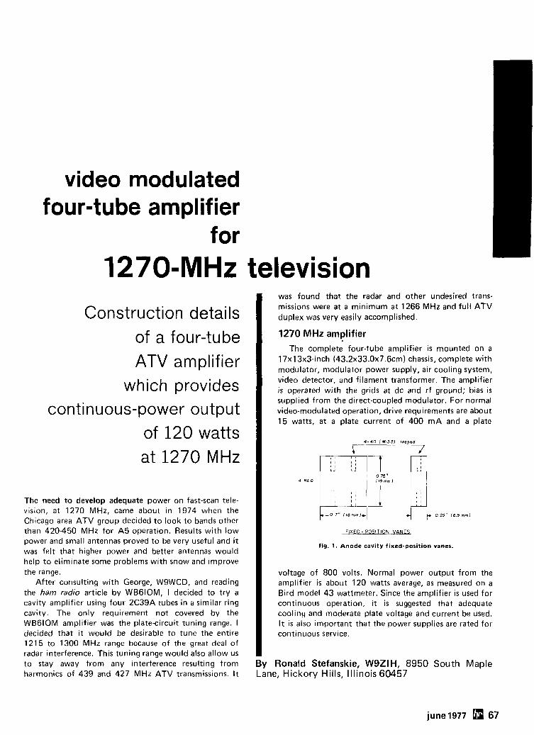
video modulated four-tube amplifier
for 1270-MHz television
Construction details of a four-tube ATV amplifier
which provides continuous-power output
of 120 watts at 1270 MHz
The need to develop adequate power on fast-scan tele- vision, at 1270 MHz, came about in 1974 when the Chicago area ATV group decided to look to bands other than 420-450 MHz for A5 operation. Results with low power and small antennas proved to be very useful and it was felt that higher power and better antennas would help to eliminate some problems with snow and improve the range.
After consulting with George, WSWCD, and reading the ham radio article by WBGIOM, I decided to try a cavity amplifier using four 2C39A tubes in a similar ring cavity. The only requirement not covered by the WBGIOM amplifier was the plate-circuit tuning range. I decided that it would be desirable to tune the entire 1215 to 1300 MHz range because of the great deal of radar interference. This tuning range would also allow us to stay away from any interference resulting from harmonics of 439 and 427 MHz ATV transmissions. It
was found that. the radar and other undesired trans- missions were at a minimum at 1266 MHz and full ATV duplex was very easily accomplished.
1270 MHz amplifier The complete four-tube amplifier is mounted on a
17x1 3x3-inch (43.2~33.0~7.6cm) chassis, complete with modulator, modulator power supply, air cooling system, video detector, and filament transformer. The amplifier is operated with the grids at dc and rf ground; bias is supplied from the direct-coupled modulator. For normal video-modulated operation, drive requirements are about 15 watts, at a plate current of 400 mA and a plate
FIXED - POSITION VANES
fig. 1. Anode cavity fixed-position vanes.
voltage of 800 volts. Normal power output from the amplifier is about 120 watts average, as measured on a Bird model 43 wattmeter. Since the amplifier is used for continuous operation, i t is suggested that adequate cooling and moderate plate voltage and current be used. I t is also important that the power supplies are rated for continuous service.
By Ronald Stefanskie, WSZIH, 8950 South Maple Lane, Hickory Hills, Illinois 60457
june 1977 67
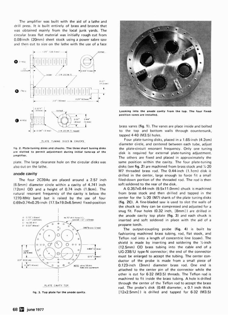
The amplifier was built with the aid of a lathe and drill press. I t i s built entirely of brass and bronze that was obtained mainly from the local junk yards. The circular brass flat material was initially rough cut from 0.08-inch (20mm) sheet stock using a power sabre saw and then cut to size on the lathe with the use of a face
I I / 0 17"
- , 14 Omml
PLATE TUNING DISCS 8 CHUCKS-
fig. 2. Plate-tuning disks and chucks. The three short tuning disks are slotted to permit adjustment during initial tune-up of the amplifier.
plate. The large clearance hole on the circular disks was also cut on the lathe.
anode cavity The four 2C39As are placed around a 2.57 inch
(6.5mm) diameter circle within a cavity of 4.741 inch (12cm) OD and a height of 0.74 inch (1.9cm). The natural resonant frequency of the cavity is below the 1270-MHz band but is raised by the use of four 0.69~0.74~0.25-inch (1 7.5x19.0x6.5mm) fixed-position
-c- --- =:/- NOTE- allno 32 drlln
- - -- hO*l Or. cw111.RUnb
I
PLATE CAVITY TOP
fig. 3. Top plate for the anode cavity.
Looking into the anode cavity from the top. The four fixed- position vanes are installed.
brass vanes (fig. 1 ). The vanes are place inside and bolted to the top and bottom walls through countersunk, tapped 4-40 (M3.5) holes.
Four plate-tuning disks, placed in a 1.65-inch (4.2cm) diameter circle, and centered between each tube, adjust the plate-circuit resonant frequency. Only one tuning disk is required for external plate-tuning adjustment. The others are fixed and placed in approximately the same position within the cavity. The four plate-tuning disks (see fig. 2) are machined from brass stock and %-20 M7 threaded brass rod. The 0.44-inch (1.lcm) disk is drilled in the center, large enough to force fit a small fileddown portion of the threaded rod. The rod i s then soft soldered to the rear of the disk.
A 0.357x0.44-inch (9.5~11 .0mm) chuck i s machined from brass stock and then drilled and tapped in the center for the %-20 (M7) shank of the plate tuning disks (fig. 2C). A fine-bladed saw is used to slot the walls of the chuck so they can be compressed and adjusted for a snug fit. Four holes (0.32 inch, [8mm] ) are drilled in the anode cavity top plate (fig. 3) and each chuck is inserted and soft soldered in place with the aid of a propane torch.
The output-coupling probe (fig. 4) is built by fashioning machined brass tubing, rod, flat stock, and Teflon rod into a length of concentric line (coax). The shield is made by inserting and soldering the %-inch (12.5mm) OD brass tubing into the cable end of a UG-23BlU type-N connector; the end of the connector must be enlarged to accept the tubing. The center con- ductor of the probe is made from a small piece of 0.123-inch (3mm) diameter brass rod. One end is attached to the center pin of the connector while the other is cut for 6-32 (M3.5) threads. The Teflon rod is machined to fit inside the brass tubing. A hole is drilled through the center of the Teflon rod to accept the brass rod. The probe's disk (0.48 diameter, x 0.1 inch thick [12x2.5mm] ) is drilled and tapped for 6-32 (M3.5)
68 june 1977
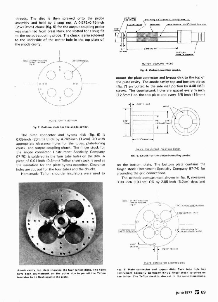
threads. The disc is then screwed onto the probe assembly and held by a stop nut. A 0.975x0.75-inch (25xl9mm) chuck (fig. 5 ) for the output-coupling probe was machined from brass stock and slotted for a snug fit to the output-coupling probe. The chuck is also soldered to the underside of the center hole in the top plate of the anode cavity.
1 P L A T E p C A V I T Y BOTTOM -.
fig. 7. Bottom plate for the anode cavity.
The plate connector and bypass disk (fig. 6) is 0.08-inch (20mm) thick by 4.742-inch (12cm) OD with appropriate clearance holes for the tubes, plate-tuning chuck, and output-coupling chuck. The finger stock for the anode connector (Instrument Specialty Company 97-70) i s soldered in the four tube holes on the disk. A piece of 0.01-inch (0.5mm) Teflon sheet stock is used as the insulation for the plate-bypass capacitor. Clearance holes are cut out for the four tubes and the chucks.
Homemade Teflon shoulder insulators were used to
Anode cavity top plate showing the four tuning disks. The holes have been countersunk on the other side to permit the Teflon insulator to lie flush against the plate.
WTPUT - COUPLING PROBE
fig. 4. output-coupling probe.
mount the plate connector and bypass disk to the top of the plate cavity. The anode cavity top and bottom plates (fig. 7) are bolted to the side wall portion by 4-40 (M3) screws. The countersunk holes are spaced every % inch (12.5mm) on the top plate and every 518 inch (16mm)
CHUCK FOR OUTPUT C_OUPLING PROBE
fig. 5. Chuck for the output-coupling probe.
on the bottom plate. The bottom plate contains the finger stock (Instrument Specialty Company 97-74) for grounding the grid connections.
The cathode compartment shown in fig. 8, measures 3.98 inch (1O.lcm) OD by 2.05 inch (5.2cm) deep and
- -
(111 c l w r ~ n c e holes
PLATE CONNECTOR B BYPASS DISC
fig. 6. Plate connector and bypass disk. Each tube hole has Instrument Specialty Company 97-70 finger stock soldered on the inside. The Teflon sheet is also cut to the same dimensions.
june 1977 69
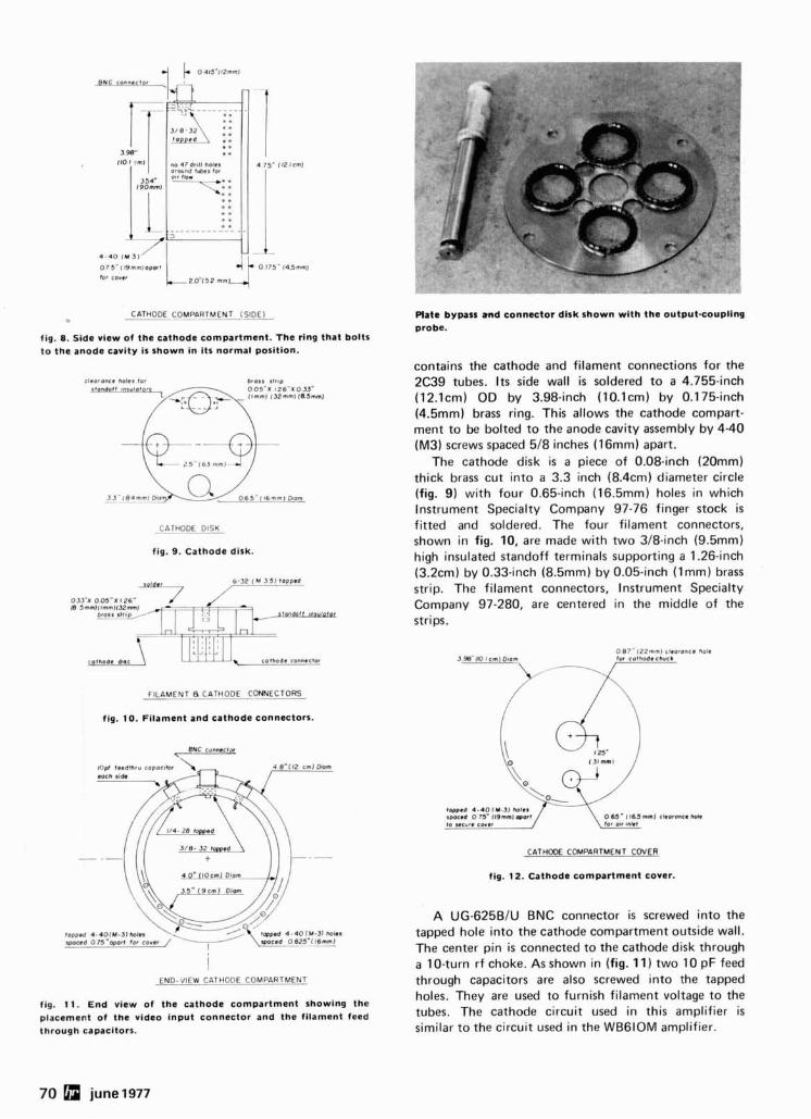
CATHODE COMPARTMENT-(SIDEL -- -
fig. 8. Side view of the cathode compartment. The ring that bolts to the anode cavity is shown in its normal position.
CATHODE DISK - --
fig. 9. Cathode disk.
FILAMENT 8 CATHODE CONNECTORS - - --
fig. 10. Filament and cathode connectors.
BNC ronnocra -
END-VIEW CATHO_DE COMPARTMENT
fig. 11. End view of the cathode compartment showing the placement of the video input connector and the filament feed through capacitors.
Plate bypass m d connmtor disk shown with the outputsoupling probe.
contains the cathode and filament connections for the 2C39 tubes. I t s side wall is soldered to a 4.755-inch (12.lcm) OD by 3.98-inch (10.lcm) by 0.175-inch (4.5mm) brass ring. This allows the cathode compart- ment to be bolted to the anode cavity assembly by 4-40 (M3) screws spaced 518 inches (16mm) apart.
The cathode disk is a piece of 0.08-inch (20mm) thick brass cut into a 3.3 inch (8.4cm) diameter circle (fig. 9) with four 0.65-inch (16.5mm) holes in which Instrument Specialty Company 97-76 finger stock is fitted and soldered. The four filament connectors, shown in fig. 10, are made with two 318-inch (9.5mm) high insulated standoff terminals supporting a 1.26-inch (3.2cm) by 0.33-inch (8.5mm) by 0.05-inch ( lmm) brass strip. The filament connectors, lnstrument Specialty Company 97-280, are centered in the middle of the strips.
CATHODE COMPARTMENT COVER
fig. 12. Cathode compartment cover.
A UG-625BlU BNC connector is screwed into the tapped hole into the cathode compartment outside wall. The center pin is connected to the cathode disk through a 10-turn rf choke. As shown in (fig. 11) two 10 pF feed through capacitors are also screwed into the tapped holes. They are used to furnish filament voltage to the tubes. The cathode circuit used in this amplifier is similar to the circuit used in the WB6IOM amplifier.
70 june 1977
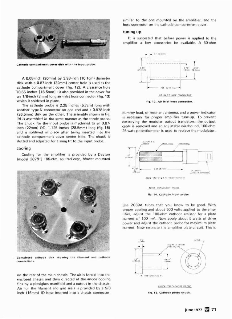
Cathode compartment cover disk with the input probe.
A 0.08-inch (20mm) by 3.98-inch (10.lcm) diameter disk with a 0.87-inch (22mm) center hole is used as the cathode compartment cover (fig. 12). A clearance hole
"(0.65 inches [16.5mm] ) is also provided in the cover for an 118-inch (3mm) long air-inlet hose connector (fig. 13) which is soldered in place.
The cathode probe is 2.25 inches (5.7cm) long with another type-N connector on one end and a 0.978-inch (26.5mm) disk on the other. The assembly shown in fig. 14 is assembled in the same manner as the anode probe. The chuck for the input probe is machined to an 0.87- inch (22mm) OD, 1.125 inches (28.5mm) long (fig. 15) and i s soldered in place after being inserted into the cathode compartment cover center hole. The chuck is slotted and adjusted for a snug fit to the input probe.
cooling Cooling for the amplifier is provided by a Dayton
(model 2C781) 100-cfm, squirrel-cage, blower mounted
Completed cathode dirk showing the filament and cathode connections.
on the rear of the main chassis. The air i s forced into the enclosed chassis and then directed at the anode cooling fins by a plexiglass manifold and a cutout in the chassis. Air for the filament and grid seals is provided by a 518 inch (16mm) ID hose inserted into a chassis connector,
similar to the one mounted on the amplifier, and the hose connector on the cathode compartment cover.
tuning up I t is suggested that before power is applied to the
amplifier a few accessories be available. A 50-ohm
AIR INLET HOSE CONNECTOR
fig. 13. Air inlet hose aonnector.
dummy load, or resonant antenna, and a power indicator is necessary for proper amplifier tune-up. To prevent destroying the modular output transistors, the output cable is removed and an adjustable wirebound, 100-ohm 25-watt potentiometer is used to replace the modulator.
0 1 1 0 o, - L zz5" i57mm1 - 4 125mmJ
U G 2J.31' r *m" 'e v C o " " e ~ t 0 ~ - --
_yplE ..1er to I,* 4 tor .el,ront ~nlormoflon
INPUT C O N N E C T O R P R O B E - - -- - . -
fig. 14. Cathode input probe.
Use 2C39A tubes that you know to be good. With proper cooling and about 500 volts applied to the amp- lifier, adjust the 100-ohm cathode resistor for a plate current of 100 mA. Now apply about 5 watts of drive power and adjust the cathode probe for maximum plate current. Now resonate the amplifier plate circuit. This is
CHUCK FOR CATHODE PROBE -- - - - --
fig. 15. Cathode probe chuck.
june 1977 71
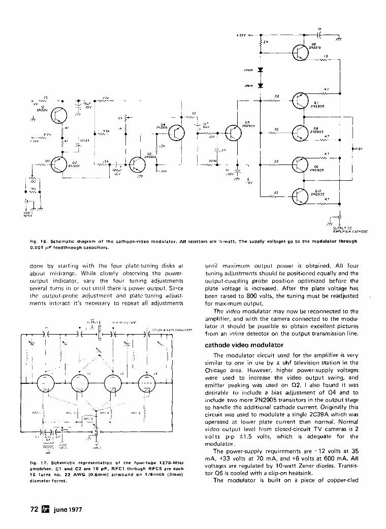
OUTPUT TO AMPLIFIER CATHODE
fig. 16. Schematic diagram of the cathode-video modulator. All resistors are '14-watt. The supply voltages go to the modulator through 0.001 pF feedthrough capacitors.
done by starting with the four plate-tuning disks at about midrange. While closely observing the power- output indicator, vary the four tuning adjustmerits several turns in or out until there is power output. Since the output-probe adjustment and plate-tuning adjust- ments interact it's necessary to repeat all adjustments
_= v ~ E C i? i
IVPJ MPUT
fag. 17. Schematic representataon of the four-tube 1270-MHz
a m p l ~ f ~ e r . C1 and C2 are 10 pF. R F C l through RFCS are each 10 turns no. 22 AWG (0.6mm) alrwound on 1/8-anch (3mm)
dtameter forms.
until maximum output power is obtained. All four tuning adjustments should be positioned equally and the output-coupling probe position optimized before the plate voltage is increased. After the plate voltage has been raised to 800 volts, the tuning must be readjusted for maximum output.
The video modulator may now be reconnected to the amplifier, and with the camera connected to the modu- lator it should be possible to obtain excellent pictures from an inline detector on the output transmission line.
cathode video modulator
The modulator circuit used for the amplifier i s very similar to one in use by a uhf television station in the Chicago area. However, higher power-supply voltages were used to increase the video output swing, and emitter peaking was used on Q2. I also found i t was desirable to include a bias adjustment of 0 4 and to include two more 2N2905 transistors in the output stage to handle the additional cathode current. Originally this circuit was used to modulate a single 2C39A which was operated at lower plate current than normal. Normal video output level from closed-circuit TV cameras is 2 volts p-p 51.5 volts, which is adequate for the modulator.
The power-supply requirements are - 12 volts at 35 mA, +33 volts at 70 mA, and +6 volts at 600 mA. All voltages are regulated by 10-watt Zener diodes. Transis- tor Q5 is cooled with a clip-on heatsink.
The modulator is built on a piece of copper-clad
72 june 1977
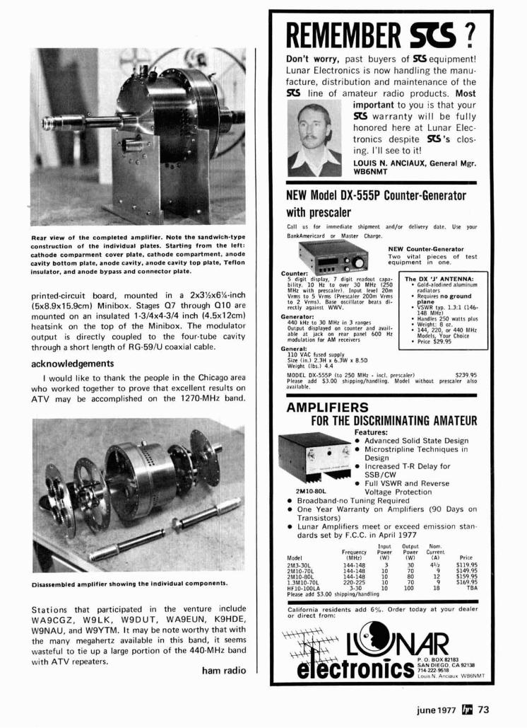
R e a r v i e w o f t h e c o m p l e t e d amp l i f i e r . N o t e t h e s a n d w i c h - t y p e c o n s t r u c t i o n o f t h e i n d l v i d u a l plates. S t a r t l n g f r o m t h e lef t : c a t h o d e c o r n p a n n e n t c o v e r p late, c a t h o d e c o m p a r t m e n t , a n o d e c a v i t y b o t t o m plate, a n o d e cav i t y , a n o d e c a v i t y t o p p late, T e f l o n insu la to r , a n d a n o d e b y p a s s a n d c o n n e c t o r p la te .
printed-circuit board, mounted in a 2x3Xx6X-inch (5x8.9x15.9cm) Minibox. Stages Q7 through QIO are mounted on an insulated 1-314x4-314 inch (4.5x12cm) heatsink on the top of the Minibox. The modulator output is directly coupled to the four-tube cavity through a short length of RG-59/U coaxial cable.
acknowledgements
I would like to thank the people in the Chicago area who worked together to prove that excellent results on ATV may be accomplished on the 1270-MHz band.
Disassembled a m p l i f i e r s h o w i n g t h e I n d i v i d u a l c o m p o n e n t s .
Stations that participated in the venture include WASCGZ, WSLK, WSDUT, WASEUN, KSHDE, WSNAU, and WSYTM. It may be note worthy that with the many megahertz available in this band, it seems wasteful to tie up a large portion of the 440-MHz band with ATV repeaters.
ham radio
REMEMBER RS ? Don't worry, past buyers of N equipment! Lunar Electronics is now handling the manu- facture, distribution and maintenance of the 513 line of amateur radio products. Most a important to you is that your
!$ Q warranty wi l l be fu l l y honored here at Lunar Elec- 4 tronics despite S ' s clos- ing. I ' l l see to it! LOUIS N. ANCIAUX, General Mgr. WB6NMT
NEW Model DX-555P Counter-Generator with prescaler Call us for immediate shipment and/or delivery date. Use your
BankAmericard or Master Charge.
NEW Counter-Generator Two v i t a l p ieces o f t e s t e q u i p m e n t i n one.
5 digit dirplay, 7 dig!( readout capa- The DX 'J' ANTENNA: bility. 10 Hz to over 30 MHz (250 . Gold-aladtn~dalumin~rm MHz with prescaler). input level 20m radiators Vrms to 5 Vrms (Prescaler 200m Vrms Requires n o g r o u n d to 2 Vrms). Base osc~llator beats di- p l a n e reclly against WWV. VSWR typ. 1.3:1 (146-
Generator : 14R MHz)
440 kHz to 30 MHz in 3 ranges Handles 250 watts plus
Output displayed on counter and avail- : yii7h$f; i:'440 M H ~ able at jack on rear panel 600 Hz modulation for AM receivers
Models Your Choice Puce 629.95
General: 110 VAC fused supply Size (in.) 2.3H x 6.3W x 8.50 Weight (Ibs.) 4.4
MODEL DX-555P (to 250 MHz - Incl. prrscaler) 5 239.95 Please add 53.00 shipping/handling. Model without prercaler also available.
AMPLIFIERS FOR THE DISCRIMINATING AMATEUR
Microstripline Techniques in
Full VSWR and Reverse 2 ~ 1 0 - ~ O L Voltage Protection Broadband-no Tuning Required One Year Warranty on Amplifiers (90 Days on Transistors) Lunar Amplifiers meet or exceed emission stan- dards set by F.C.C. in April 1977
Input Output Nom. Frequency Power Power Current
Model (MHz) (W) (W) (A) Price 2M3-30L 144-148 3 30 4 5119.95 2M10-70L 144-148 10 70 9 5149.95 2M10-80L 144-148 10 80 12 5159.95 1.3M10-70L 220-225 10 70 9 5169.95 HF10-100LA 3-30 10 100 18 TEA Please add 53.00 shipping/handling
Cal t forn ia res iden ts a d d 6%. Order today a t y o u r dea le r o r d i r e c t f r o m :
P 0 BOX82183 ct ro nits ;rzz$ cAw13 Low, Y Arr8aur WBGNMT
An exciting new era in amateur radio is about to begin.. . the era of AMSAT PHASE 111 OSCAR satellites.
Many of you are familiar with the bene- fits of the AMSAT OSCAR satellites, notably OSCAR 6 and 2 These satellites, with a com- bined total of over 8 years in orbit, have provided communications between amateurs throughout the world. They have also pro- vided a capability for an educational program in space sciences and many interesting experiments.
AMSAT, with members and contrib- uting groups worldwide, and headquarters in Washington, D. C., has been responsible for our current satellite program. Many people feel that perhaps the greatest value of the amateur satellite program is the dramatic demonstration of amateur resourcefulness and technical capability to radio spectrum policy makers around the world.
The value of this aspect of amateur radio as we prepare for the 1979 World Adminis- trative Radio Conference (WARC) is enormous.
The AMSAT PHASE 111 satellite pro- gram promises a continuing demonstration that amateur radio is at the forefront of modern technology. PHASE 111 satellites will routinely provide reliable communications over paths of up to 11,000 miles (12600 km) for 17 hours each day. You can think of them as a resource equivalent to a new band.
The cost of these PHASE I l l satellites is a projected $250,000. Commercial satel- lites of similar performance would cost nearly s10.000,000.
Your help is needed to put these PHASE 111 OSCAR satellites in orbit.
Your valued, tax-deductible contribu- - tion can be as small as one of the 5000+ solar cells needed. A handsome certificate will acknowledge the numbered cells you sponsor for $10 each. Larger components of the satellites may also be sponsored with con- tribution acknowledgements ranging to a plaque carrying your name aboard the satel- lites. Call or write us for the opportunities available.
Your membership in AMSAT is impor- - tant to the satellite program, and will give AMSATa stronger voice in regulatory matters concerned with satellites. At $10 per year or $100 for life, you will be making a most signifi- cant contribution to the satellite program and the future of amateur radio. You will also receive the quarterly AMSAT newsletter.
Clip the AMSAT PHASE 111 coupon below and send your support today, or call 202-488-8649 and charge your contribution to your BankAmericard (VISA) or Master Charge card.
. - - - - - - - - - - - - - AMSAT PHASE I l l H R
1 9 Radio Amateur Satell~te Corporation 1 Box 271 Washington. D C 20044 202-488-8649 I
YES. I want to support AMSAT PHASE 111 OSCAR I satell~tes Enclosed IS.
S ~ n s p o n s o r s h r p o f s o l a r c e l l s la 970 each) I $70 Annual membershfp U dl00 Lffe membershfp
[? Send rnformatlon on sponsorfng larqer satellfte corn- 1 ponents
I Name Call AMSAT Member7 I
I Street I ( Cfly State ZIP
The ubltshcr has donated l h ~ s space to AMSAT rn support 01 I
L AM&T and the PHASE 111 program - - - - - - - - - - - - - J
T20 Tr lp ler /Dr ivsr Modu le Kit, 1 5 0 m W 2 M Input. 200 m W 450 MHz o u t p u t $19.95
Premium mode l where space permi ts - 1 % in. x 3 in.
Al l c o m m o n i-f's
Connectors Low Power Dra in
Crystals Avai l f o r a n y Desired Freq Scheme
Mode ls f o r 2M. 6M. 10M. 220 MHz, air- craf t , com'l, etc. - Stable cascode rf stage 0.3-0.5 uv sensi t iv i ty 10-20 d B ga ln Compact 2 % x 41/:" p c b A n y i.f 10.50 M H z
MODEL U20-450 U H F CONVERTER $ 19.95 For 432 M H z ssb o r atv. 450 M H z fm.
ANTENNAS STOCKED IN DEPTH
18HT 6 8 0 meters. $279.95 The ally vertical antenna on the market offering multi-band performance without traps. The Hy-Gain 18HT utilizes a unique stub decoupling system to maximize effi- clency frequency stability and band isola- tion. i t also offers a 50 ohm input impe- dance for all bands.
The 18HT features automatic band
MULTI-BAND.TRAP DOUBLETS - Traps, wlre, and Insulators for qu~ck and
14AVQ/WB 10-40 meters. $67.00 easy installation! 28DQ 549.95 80 & 40 meters Same features as 18AVT, but without 58DQ 579.95 80, 40, 20, 15 & 10 meters
CALL OR WRITE NOW FOR FREE CATALOG OR TO PLACE YOUR ORDER! PHONE 716-663-9254,gAM-9PM EST DAILY. Use your credit card or C.O.D.
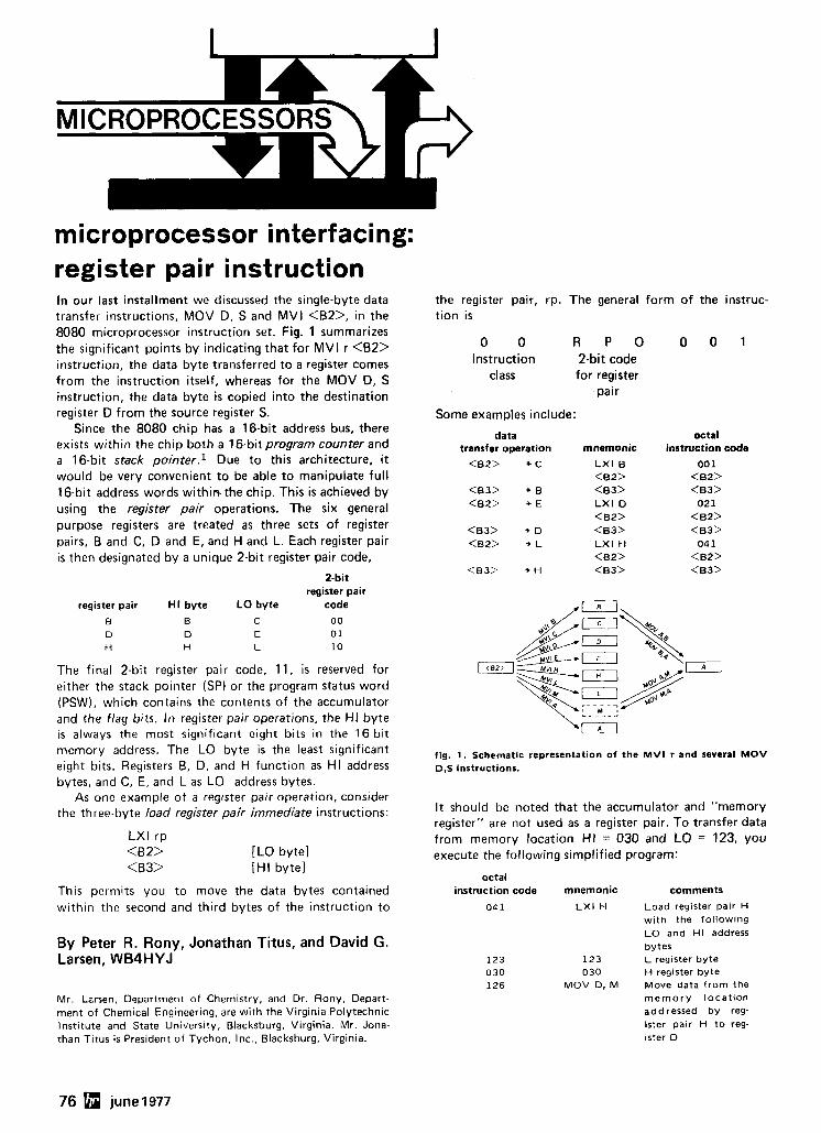
microprocessor interfacing: register pair instruction In our last installment we discussed the single-byte data transfer instructions. MOV D, S and MVI <B2>, in the 8080 microprocessor instruction set. Fig. 1 summarizes the significant points by indicating that for MVI r <62> instruction, the data byte transferred to a register comes from the instruction itself, whereas for the MOV D, S instruction, the data byte is copied into the destination register D from the source register S.
Since the 8080 chip has a 16-bit address bus, there exists within the chip both a 16-bit program counter and a 16-bit stack p0inter.l Due to this architecture, it would be very convenient to be able to manipulate ful l 16-bit address words within the chip. This is achieved by using the register pair operations. The six general purpose registers are treated as three sets of register pairs, B and C, D and E, and H and L. Each register pair is then designated by a unique 2-bit register pair code,
2-bit register pair
register pair H I byte LO byte code
The final 2-bit register pair code, 11, is reserved for either the stack pointer (SP) or the program status word (PSW), which contains the contents of the accumulator and the flag bits. In register pair operations, the HI byte is always the most significant eight bits in the 16-bit memory address. The LO byte is the least significant eight bits. Registers 6, D, and H function as HI address bytes, and C, E, and L as LO address bytes.
As one example of a register pair operation, consider the three-byte load register pair immediate instructions:
LXl rp <B 2> [LO byte1 <B3> [HI byte]
This permits you to move the data bytes contained within the second and third bytes of the instruction to
By Peter R. Rony, Jonathan Titus, and David G. Larsen, WB4HYJ
Mr. Larsen. Department of Chemistry, and Dr. Rony, Depart- ment of Chemical Engineering, are with the Virginia Polytechnic Institute and State University, Blacksburg, Virginia. Mr. Jona- than Titus is President of Tychon, Inc., Blacksburg, Virginia.
the register pair, rp. The general form of the instruc- tion is
0 0 R P O 0 0 1 Instruction 2-bit code
class for register pair
Some examples include:
data transfer operation
<B2> + C
mnemonic
L X I B <B2> <B3> L X I D <B2> <B3> L X I H <B2> <B3>
octal instruction code
00 1 <B2> <B3>
021 <B2> <B3> 04 1
<B2> <B3>
fig. 1 . Schematic representation of the M V I r and several M O V D.S instructions.
I t should be noted that the accumulator and "memory register" are not used as a register pair. To transfer data from memory location HI = 030 and LO = 123, you execute the following simplified program:
octal instruction code mnemonic comments
04 1 L X I H Load register pair H with the following L O and H I address bytes
123 123 L register byte 030 030 H register byte 126 M O V D, M Move data from the
m e m o r y location addressed by reg- ister pair H to reg- ister D
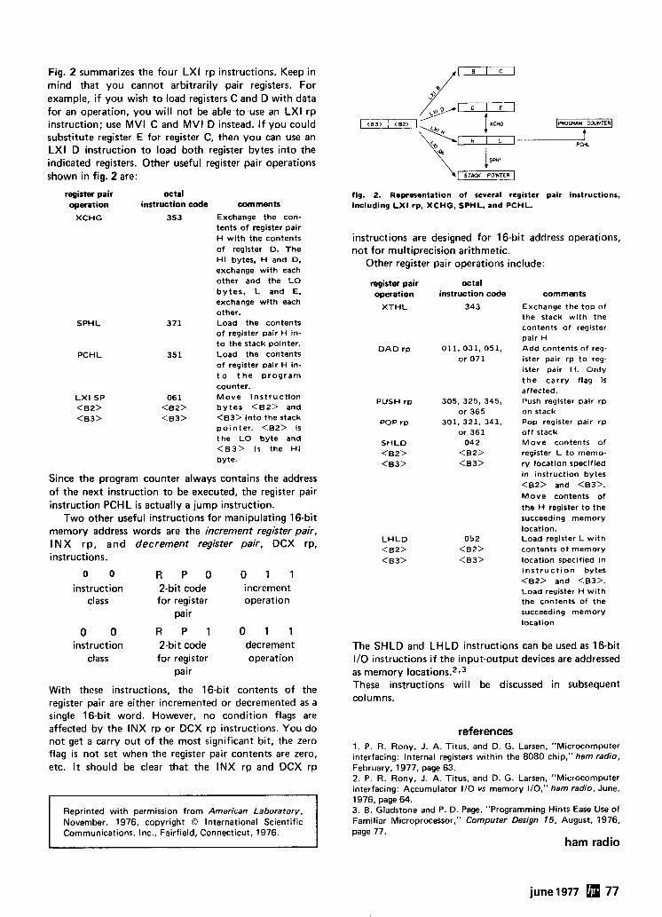
Fig. 2 summarizes the four LXI rp instructions. Keep in mind that you cannot arbitrarily pair registers. For example, i f you wish to load registers C and D with data for an operation, you will not be able to use an LXI rp instruction; use MVI C and MVI D instead. I f you could substitute register E for register C, then you can use an LXI D instruction to load both register bytes into the indicated registers. Other useful register pair operations shown in fig. 2 are:
register pair octal operation instruction code comments
XCHG
SPHL
PCHL
353 Exchange the con- tents o f register pair H w i t h the contents of register D. The H I bytes, H and D, exchange w i th each other and the L O b y t e s , L and E, exchange w i th each other.
371 Load the contents o f register pair H In- t o the stack pointer.
351 Load the contents o f register pair H in- t o t h e p r o g r a m counter.
06 1 M o v e i n s t r u c t i o n <B2> b y t e s <B2> and <B3> <B3> in to the stack
p o i n t e r . <B2> is the L O byte and < B 3 > is the H I byte.
Since the program counter always contains the address of the next instruction to be executed, the register pair instruction PCHL is actually a jump instruction.
Two other useful instructions for manipulating 16-bit memory address words are the increment register pair, INX rp, and decrement register pair, DCX rp, instructions.
0 0 R P O 0 1 1 instruction 2-bit code increment
class for register operation pair
instruction 2-bit code decrement class for register operation
pair
With these instructions, the 16-bit contents of the register pair are either incremented or decremented as a single 16-bit word. However, no condition flags are affected by the INX rp or DCX rp instructions. You do not get a carry out of the most significant bit, the zero flag i s not set when the register pair contents are zero, etc. It should be clear that the INX rp and DCX rp
Reprinted w i t h permission f rom American Laboratory, November, 1976, copyright O International Scientific Communications, Inc., Fairfield, Connecticut, 1976.
1 1 8 3 ) 1 1 8 2 ) PROGRAM CWNTER
PCHL
SPHL
STACK POINTER
fig. 2. Representation o f several register pair instructions. including L X I rp, XCHG, SPHL, and PCHL.
instructions are designed for 16-bit address operations, not for multiprecision arithmetic.
Other register pair operations include:
register pair operation
X T H L
D A D r p
PUSH r p
POP r p
S H L D <B2> <B3>
L H L D <B2> <B3>
octal instruction code
343
comments
Exchange the top o f the stack w i t h the contents o f register pair H A d d contents o f reg- ister pair r p t o reg- ister pair H. Only t h e c a r r y flag is affected. Push register pair r p on stack Pop register pair r p o f f stack M o v e contents of register L t o memo- r y location specified in instruction bytes <B2> and <B3>. M o v e contents of the H register t o the succeeding memory location. Load register L w i th contents o f memory location specified i n i n s t r u c t i o n bytes <B2> and <B3>. Load register H w i th the contents of the succeeding memory location
The SHLD and LHLD instructions can be used as 16-bit I10 instructions i f the input-output devices are addressed as memory location^.^.^ These instructions will be discussed in subsequent columns.
references 1. P. I?. Rony, J. A. Titus, and D. G. Larsen, "Microcomputer interfacing: Internal registers w i th in the 8080 chip," ham radio, February, 1977, page 63. 2. P. R. Rony, J. A. Titus, and D. G. Larsen, "Microcomputer interfacing: Accumulator I10 vs memory 110," ham radio, June, 1976, page 64. 3. 0 . Gladstone and P. D. Page, "Programming Hints Ease Use o f Familiar Microprocessor," Computer Design 15, August, 1976, page 77.
ham radio
june 1977 77
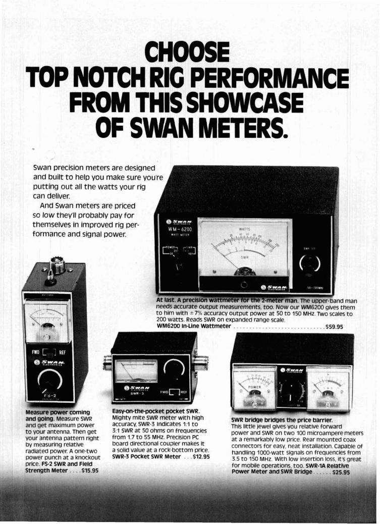
CHOOSE TOP NOTCH RIG PERFORMANCE
FROM THIS SHOWCASE OF SWAN METERS.
. Swan precision meters are designed A and built to help you make sure you're A putting out all the watts your rig can deliver.
And Swan meters are priced so low they'll probably pay for themselves in improved rig per- formance and signal power.
needs accurate output measurements, too. NOW our WM6200 gives them t o him with +- 7% accuracy output power at 50 t o 150 MHz. Two scales t o 200 watts. Reads SWR on expanded range scale.
Easy-on-thepocket pocket SWR. and g0tng. Measure SWR Mighty mite SWR meter with high and get maximum power accuracy, SWR-3 Indicates 1:l t o t o your antenna. Then get 3:l SwR at 50 ohms On frequencies your antenna pattern right from 1.7 t o 55 MHz. Precision PC by measuring relative board directional cou~ le r makes it radiated power. A one-two a solid value at a rock-bottom price. power punch at a knockout SWR-3 Pocket SWR Meter . . . $12.95 price. FS-2 SWR and Field Strength Meter . . . . $15.95
SWR bridge bridges the price barrier. This little jewel gives you relative forward power and SWR on two 100 microampere meten at a remarkably low price. Rear mounted coax connectors for easy, neat installation. Capable of handling 1000-watt signals on frequencies from 3.5 t o 150 MHz. With low insertion loss, it's great for mobile operations, too. SWR-1A Relatlve Power Meter and SWR Bridge. . . . . . $25.95
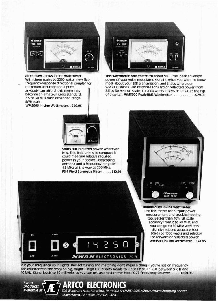
All-the-law-allows in-line wattmeter. This wattmeter tells the truth about SSB. True peak envelope With three scales to 2000 watts, new flat- power of your voice modulated signal is what you want to know frequency-response directional coupler for most about your SSB transmission, and that's where our maximum accuracy and a price WM3000 shines. Flat response forward or reflected power from anybody can afford, this meter has 3.5 to 30 MHz on scales to 2000 watts in RMS or PEAK a t the flip become an amateur radio standard. of a switch. WM3000 Peak/RMS Wattmeter . . . . . . . . . . . .S79.95 3.5 to 30 MHz with expanded range SWR scale. WMZOOO In-Line Wattmeter. . $59.95
Put your frequency up in lights. Perfect tuning and matching don't mean a thing if youre not on frequency. This counter tells the story on big, bright 5-digit LED display. Reads to t 100 Hz or * 1 KHz between 5 KHz and 40 MHz. Signal levels to 50 millivolts so you can use as a test meter, too. FC-76 Frequency Counter . . . . . $169.95
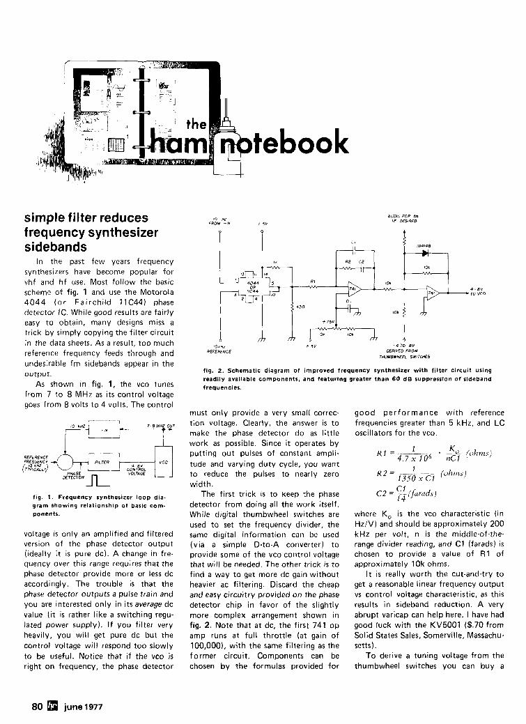
tebook
simple filter reduces frequency synthesizer sidebands
In the past few years frequency synthesizers have become popular for vhf and hf use. Most follow the basic scheme of fig. 1 and use the Motorola 4044 (o r Fairchild 11C44) phase detector IC. While good results are fairly easy to obtain, many designs miss a trick by simply copying the filter circuit in the data sheets. As a result, too much reference frequency feeds through and undesirable fm sidebands appear in the output.
As shown in fig. 1, the vco tunes from 7 to 8 MHz as its control voltage goes from 8 volts to 4 volts. The control
REFERENCE FREOUENCY
PHASE CONTROL
DETECTOR VOLT4GE
fig. 1. Frequency synthesizer loop dia- gram showing relationship of basic com- ponents.
voltage is only an amplified and filtered version of the phase detector output (ideally i t is pure dc). A change in fre- quency over this range requires that the phase detector provide more or less dc accordingly. The trouble is that the phase detector outputs a pulse train and you are interested only in its average dc value (it is rather like a switching regu- lated power supply). If you filter very heavily, you will get pure dc but the control voltage will respond too slowly to be useful. Notice that if the vco is right on frequency, the phase detector
I 0 HZ FROM - N + 5 V
v ?
AUDIO FOR Im I F DESIRED
4
4-8 . TO VCO
IO"H1 REFERENCE
- 4 TO-BY DERIVED FROM
THUMBWHEEL SWITCHES
fig. 2. Schematic diagram of improved frequency synthesizer with filter circuit using readily available components, and featuring greater than 60 dB suppression of sideband frequencies.
must only provide a very small correc- good performance with reference tion voltage. Clearly, the answer is to frequencies greater than 5 kHz, and LC make the phase detector do as little oscillators for the vco. work as possible. Since it operates by putting out pulses of constant ampli-
1 K R I = . --2 (ohms) 4.7 x 1 o"c1
tude and varying duty cycle, you want I
to reduce the pulses to nearly zero width.
The first trick is to keep the phase detector from doing all the work itself. While digital thumbwheel switches are used to set the frequency divider, the same digital information can be used (via a simple D-to-A converter) to provide some of the vco control voltage that will be needed. The other trick is to find a way to get more dc gain without heavier ac filtering. Discard the cheap and easy circuitry provided on the phase detector chip in favor of the slightly more complex arrangement shown in fig. 2. Note that at dc, the first 741 op amp runs at full throttle (at gain of 100,000), with the same filtering as the former circuit. Components can be chosen by the formulas provided for
where KO is the vco characteristic (in Hz/V) and should be approximately 200 kHz per volt, n is the middle-of-the- range divider reading, and C1 (farads) is chosen to provide a value of R1 of approximately 1Ok ohms.
I t is really worth the cut-and-try to get a reasonable linear frequency output vs control voltage characteristic, as this results in sideband reduction. A very abrupt varicap can help here. I have had good luck with the KV5001 ($.70 from Solid States Sales, Somerville, Massachu- setts).
To derive a tuning voltage from the thumbwheel switches you can buy a
80 june 1977
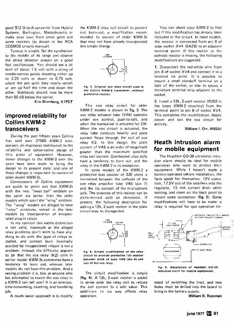
good $1 2 D-to-A converter from Hybrid Systems, Burlington, Massachusetts or make your own from cmos gates and some resistors (as shown in the RCA COSMOS circuits manual).
Tuneup is simple. Set the synthesizer to the middle of its range and observe the phase detector output on a good fast oscilloscope. You should see a dc level of about 1.5 volt with a string of needle-narrow pulses shooting either up to 2.25 volts or down to 0.75 volt, adjust the pot until they nearly vanish or are up half the time and down the other. Sidebands should now be more than 60 dB below the carrier.
Eric Blomberg, KIPCT
improved reliability for Collins KWM-2 transceivers
During the past fifteen years Collins has sold over 27000 KWM-2 tran- sceivers, an impressive testimonial to the reliability and conservative design of this piece of equipment. However, minor changes to the KWM-2 over the years have been made to bring the design to its present state; and one of these changes is important to owners of older-model KWM-2s.
Connoisseurs of Collins equipment are quick to point out that KWM-2s with the new "meat ball" emblem on the panel are better than the older models which sport the "wing" emblem. The "wing" models are alleged to have "relay" problems, solved in the later models by incorporation of encapsu- lated plug-in relays.
In my opinion this subtle distinction is not valid, inasmuch as the alleged relay problems don't seem to have any- thing to do with the type of relays in- stalled, and contact burn (nornially avoided by encapsulated relays) is not a problem. Instead, the difficulty appears to be that the vox relay (K2) coils in earlier model KWM-2s sometimes have a tendency to burn out, whereas later models do not have this problem. And a vexing problem it is, too, as anyone who has attempted to rewire the vox relay in a KWM-2 can tell you! It is an onerous, time-consuming, exacting, and humbling job.
A much easier approach is to modify
the KWM-2 relay coil circuit to prevent You can check your KWM-2 to find coil burn-out, a modificatiori r t 'corn- mended to owners of older KWM-2s that may not have already incorporated this simple change.
fig. 3. Original vox relay circuit used in the Collins K W M - 2 transceiver, without protective resistor.
The vox relay circuit for older KWM-2 models is shown in fig. 3. The vox relay actuator tube (V4B) operates under vox control, push-to-talk, and when the transceiver i s actuated for CW. When the vox circuit is actuated, the relay tube conducts heavily and plate current flows through the coil of vox relay K2. In this design, the plate current of V4B is an order of magnitude greater than the maximum specified relay coil current. Overheated relay coils have a tendency to burn out, and the relay in the KWM-2 is no exception.
In some models of the KWM-2 a protective bias resistor of 330 ohms is connected between the cathode of the vox relay amplifier tube V4B (pin 7) and the tip contact of the microphone jack. The presence of this resistor can be determined with an ohmmeter. If present, the following description for adding a 12k. 2-watt resistor in the plate circuit may be disregarded.
out if this modification has already been included in the circuit. In most models, the resistor is connected from pin 8 of tube socket XV4 (6AZ8) to an adjacent terminal point. I f this resistor or the cathode resistor is missing, the following modifications are suggested:
1. Disconnect the red-white wire from pin 8 of socket XV4 and connect i t to a terminal tie point. It is possible to mount a small standoff terminal on a bolt of the socket, or else to epoxy a miniature terminal strip adjacent to the socket.
2. Install a 12k, 2-watt resistor (R202 in the latest KWM-2 circuitry) from the terminal point to pin 8 of socket XV4. This completes the modification. Apply power and test the vox circuit for activity.
William I. Orr, WGSAI
Heath intrusion alarm for mobile equipment
The Heathkit GD-39 ultrasonic intru- sion alarm should be ideal for mobile operators who want to protect their equipment. While I haven't made a battery-operated vehicle installation, the facts speak for themselves: 12V opera- tion, 17.5V out of the rectifiers into the regulator, 13 mA current drain while waiting, and room on the back panel to mount some connectors (fig. 5) . Some modifications will have to be made: a relay is required for spst operation (in-
RECTIF IER f l N 4 0 0 2 1 TO EL IMINATE / REVERSE P O L A R I T Y DAMAGE
D R I L L T W O HOLES
I CONNECTOR + - R A C K PANEL
fig. 4. Simple modification of the relay circuit to provide protective 12k resistor between plate of tube V4B (Pin 8 ) and coil of the vox relay.
fig. 5. Adaptation of Heathkit GD-39 intrusion alarm for mobile equipment.
The circuit modification is simple (fig. 4). A 12k, 2-watt resistor is added in series with the relay coil to reduce stead of switching the line), and two the coil current to a safe value. This holes must be drilled into the board to addi t ion i n no way affects relay bring in the battery supply. operation. William 6. Rossman
june 1977 81
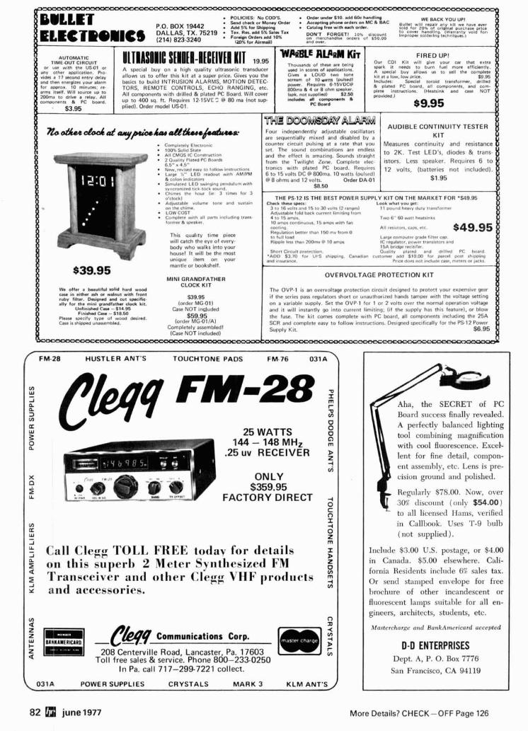
82 a june1977 More Details? CHECK-OFF Page 126
AUTOMATIC TIME-OUT CIRCUIT
n b o d C u a G a o C a t ~ ~ A a r & d C u e . . AUDIBLE CONTINUITY TESTER
. Completel~ Electronic 100% Sdtd Stole Al l CMOS IC Construction 2 Oual~tv Pletetl PC Boards
. LOWCOST Two 6" 60 watt hestrinks
Ail m i r lo r f , caps, ete.
Th is q u a l ~ t y t ime piece Large computer grade filter cap. w i l l catch the eye o f every- Ripple less than 2Wmv @ 10 amm IC regulator, power transator3 and b o d y w h o walks i n t o your house! I t w i l l be the mos t unique i t e m o n your mant le o r bookshelf.
MINI GRANDFATHER
We o f l n buut i fu l -1ld hmrd wood CLOCK KIT
The OVP-1 is an overvoltage p ro tec t ion c i rcui t designed t o protect your expensive gear clw in d t h n a h or w.lnut wath front ruby filter. D n n g d and cut r p r i f i c - i f the series pars regulators short o r unauthor jzed hands tamper w i t h the voltage setting
ally for the mino grandfath.r dock hot. (order MG-01) Unlinirhad C . u - $14.95
Fmnishsd Cn. - f 16.50 Case N O T ~ n d u d e d
PI.- ~pec i f v type of wood d n i n d .
f FM-28 HUSTLER ANT'S TOUCHTONE PADS FM-76 031A
U) W - -1 a o m 3 cM4 FI#U-28 V) z I- w
a 0 o 5 25 WATTS 0
G) B 144 - 148 MHz m
.25uv RECEIVER g 4 V)
x ONLY 4 $359.95 ? FACTORY DIRECT -I
0 C o
cn I -I
E W
0 - z -I rn
-" -1 Call Clegg TOLL FREE today for details x D
% on this superb 2 Meter Synthesized FM z a g 4 Transceiver and other Clegg V H F proclacts 7
V)
Y and accessories.
U) 0 a [=I : 1 -C&q * BlklllMtR!ClRO
Communicrtions Corp. I- z 208 Centerville Road, Lancaster, Pa. 17603 ?' V) a To l l free sales & service. Phone 800-233-0250
I n Pa. call 717-299-7221 collect.
L 0 3 1 A POWER SUPPLIES CRYSTALS MARK 3 K L M ANT'S
Aha, Board the srlccess SECRET finally revealed. of PC A perfectly balanced lighting tool combining magnification with cool fluorescence. Excel- lent for fine detail, compon- ent assembly, etc. Lens is pre- cision ground and polished.
Regcllarly $78.00. Now, over 307 tliscor~nt (only $54.00) - to all licensetl Hnms, verified in Callbook. Uses T-9 bulb (not supplied).
Inclrlcle $3.00 U.S. postage, or $4.00 in Canada. $5.00 elsewhere. Cali- fornia Residents include 6% sales tax. Or send stalnped envelope for free 1,rochure of other incandescent or fluorescent lamps suitahle for all en- gineers, architects, students, etc.
Mastercharge and BankAmrricard accepted
D-D ENTERPRISES Dept. A, P. 0. Box 7776 San Francisco, CA 94119
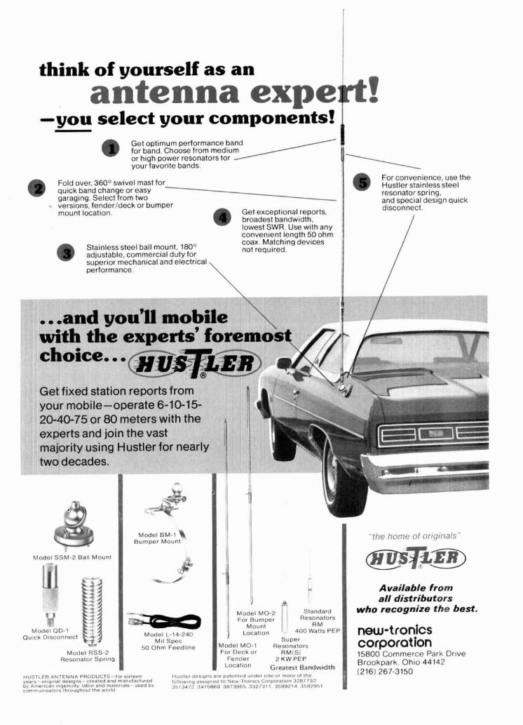
think of yourself as an antenna expert!
-you select your components! - I Get optimum performance band d) for band. Choose from medium or high power resonators tor your favorite bands.
Fold over, 360° swivel mast for 19 auick band chanae or easy b For convenience, use the Hustler stainless steel resonator spring, - --A ,.---.;el An-;-- ,.a*;-&
T garaging. ~electl from two - -
-. versions, fender/deck or bumper mount locat~on. Get exceptional reports, @ broadest bandwidth.
lowest SWR. Use wlth any
a1 IU apcLlal uc31y1 I qulbn
disconnect.
convenient length 50 ohm I / coax ~atchlngbevlces
Stainless steel ball mount, 180° (B adjustable. commercial duty for not required
superlor mechan~cal and electrical performance
-- -- . 7 - - _ _ \ - ._ . __-__. - -- . - - A
. . .and you'll mobil with the experts' fc
\ nos'
choice.. . @ @ ~ ~ % i @ \-
u e ~ I I X W station reports from h your mobile-operate 6-10-15- 20-40-75 or 80 meters with the experts and join the vast majority using Hustler for nearly two decades.
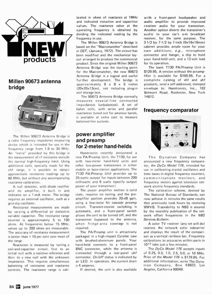
brated in ohms of reactance at 1MHz w i th a front-panel loudspeaker and and indicated inductive and capacitive values. The reactance value at the operating frequency is obtained by dividing the indicated reading by the
audio amplifier to provide improved receiver audio for your transceiver. Another option diverts the transceiver's audio to your car's a-m broadcast
frequency in use. The Millen 90673 Antenna Bridge is
based on the "Macromatcher" described in QST, (January, 1972). The circuit has
receiver, for the same purpose. The 3-1 12 by 7-1 /2 by 7-inch (9x1 9x1 8mm) cabinet provides ample room for your own addit ions; e.g . , microphone
been modified and the mechanical lay- connector and hanger, a clip to hold your hand-held unit, and a 12-volt lead products out arranged to produce the commercial
product. Since the original Millen 90672 for its operation. The basic T I30 PAIPreamp Unit is
$1 29.95. A version without the preamp- lifier is available for $109.95. For a
Antenna Bridge was the starting point for the Macromatcher, the new 90673 Antenna Bridge is a logical and useful further development. The bridge is complete catalog of vhf and uhf Millen 90673 antenna approximately 8 x 8 x 5 inches (2Ox20x13cm), not including plug-in coil storage box.
The 90673 Antenna Bridge normally
products, send a self-addressed, stamped envelope to: Hamtronics, Inc., 182 Belmont Road, Rochester, New York 14612.
bridge
measures coax ia l - l ine connected impedances (unbalanced). A set of balun coils, with series and parallel frequency comparator reactances tuned out for amateur bands, is available at extra cost to measure balanced-line systems.
power amplifier and preamp for 2-meter hand-helds
The Millen 90673 Antenna Bridge is a radio frequency impedance measuring device which is intended for use in the frequency range from 1.8 to 30 MHz. An "extra" provided by this bridge is the measurement of rf resistance outside the normal high-frequency limit. Using additional coils, specially made for the vhf range, it is possible to obtain approximate resistance readings up to 60 MHz, but without any accompanying reactance calibration.
A null detector, with diode rectifier and dc amplifier, is built in and indicates on a 1-mA meter. The bridge requires an external oscillator, such as a grid-dip oscillator.
Resistance measurements are made by varying a differential air dielectric variable capacitor. The resistance range covered is approximately 5 to 150 ohms. At frequencies below 15 MHz, values up to 200 ohms are measurable. The accuracy of resistance measurement is better than t 10 per cent over most of the range.
Reactance is measured by tuning a coil-and-capacitor circuit, first to an initial null with a resistive reference and then to a new null with the unknown impedance. This requires simultaneous balancing of resistance and reactance controls. The reactance range is cali-
Hamtronics recently announced a new PAIPreamp Unit, the T130, for use with two-meter hand-held units and other low-power transceivers in either mobile or base-station applications. The T130 PA/Preamp Unit provides up to 25-watts output for inputs between 200 milliwatts and 6 watts (specify output power of your transceiver).
The power amplifier section is solid state, requires no tuning, and the pre- amplifier portion provides 20-dB gain, using a low-noise fet cascode preamp circuit. Transmit-receive switching1 is automatic, and a front-panel switch allows the unit to be turned off, and the transceiver bypassed to the antenna, when fringe-area coverage is not required.
The PAIPreamp unit is attractively packaged in a high-impact Cycolac case with brushed-aluminum panels. Your hand-held connects to a front-panel BNC connector, while the antenna is connected through a rear-panel uhf connector. On/off status is indicated by an LED. In operation, the current drain is 4 amperes.
If desired, the unit i s also available
T h e D y n a t r o n Company has announced a new frequency compara- tor, the DyCo Model 176, intended for use in calibrating crystal oscillators and time bases in digital frequency counters, c o m m u n icat ions moni tors , and frequency meters against television net- work atomic frequency standards.
The calibration scheme, devised by The National Bureau of Standards, can now achieve in minutes the same results that previously took hours by receiving WWVB. Traceability to NBS is assured by the monthly publication of the net- work offset frequencies in the NBS Services Bulletin.
A color TV receiver (any set will do) receives the network color subcarrier and displays the result of the compari- son as a vertical rainbow bar. Frequency calibrations to accuracies within parts in 101° take just a few minutes.
The DyCo Model 776 accepts inputs of 0.25, 0.5, 1.0, 2.5, 5.0, or 10 MHz. Price of the Model 176 i s $179.95. For additional information, write The Dyna- t r on Company, Box 48822, Los Angeles, California 90048.
84 june 1977
i- n n~
IN STOCK WITH YOUR LOCAL DEALER IN CANADA SCOTCOMM RADIO LTR - 4643 kr- O I d - Qlomul*~, Lard 9- WORLDWIDI: 1.1- L... - ---- U _ _ r L ..- _-.- ---- I L .---- ... .. I A 1 n 1 m a
P.C " 3 X 468- ' IANCHEST"" 'I. He 03108
INTRODUCES THE
@) More Channels ... at the flip of a switch Unlock the unique mode switch and 12 channels become 144
@ More Sensitivity, Less Interference. .25 Sensitivity plus 75 db adjacent channel selectivity and 70 db image rejection
@ More Power Out 35 watts nominal with a minimum of 30 watts across the band
. . . for a lot less
Amateur Net
C ~ 7 ~ C Y l t L E C T I O N I e S . INC. 7707 Records Street @ 1976 rm. &.I -. w , d ~O.V.
Indianapolis, Indiana 46226
THE FM LEADER ' 2METER 220 MHz
6 METER 440 MHz
6 db INCREASE IN AVERAGE POWER MAINTAINS VOICE OUALITY :l
NO CABLES OR BENCH SPACE REQUIRED EXCELLENT FOR - .- PHONE PATCH "p NO ADDITIONAL ADJUST- MENTS - MIKE GAIN ADJUSrS CLIPPING LEVEL UNIQUE PLUG-IN UNIT- NO MODIFICATIONS REQUIRED
=.,, This i s RF Envelope Cllpplng- -- the feature being used in new transmitter designs for amateur 'I-- and military use.
I Models Now Available I Collins 32S, KWM-2 ...... $ 98.50 ea. Drake TR-3, TR-4. TR-6, TR-4C, T-4, T-4X, T-4x6, T-4XC $128.50 ea.
I Postpaid - Calif. dents add 6% Tax I
I Watch for other models Imterl I
IF WE WERE YOU
the indispensable BIRD 43 THRULINEB* WAITMETER
I'D BUY FROM US YOUR INQUIRY OR ORDER WILL GET OUR PROMPT A?TENTION
AUTHORIZED
;*ik'm DISTRIBUTOR WEBSTER COMMUNICATIONS
115 BELLARMINE ROCHESTER, MI 48063
313-375-0420 'T.M. of BIRD ELECTRONIC CORP.
86 june 1977 More Details? CHECK-OFF Page 126
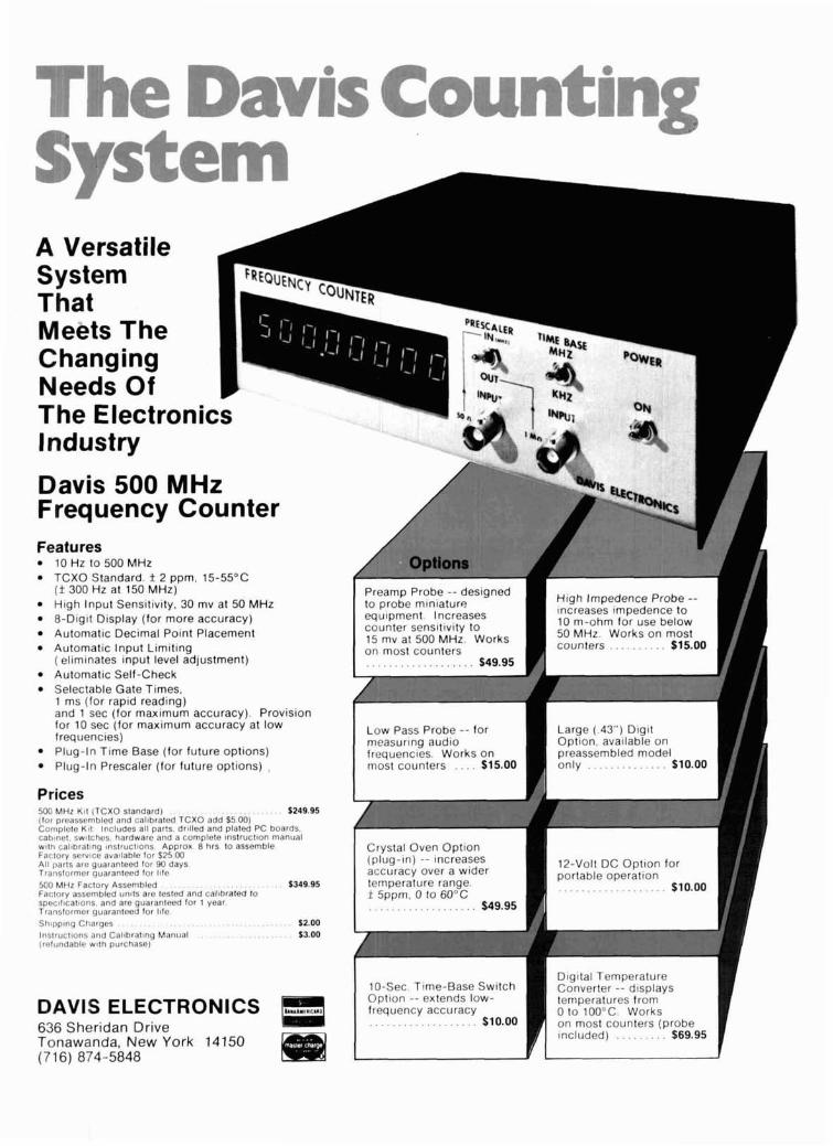
P - ' ' p v w' -4
i
A Versatile System That Meets The Changing Needs Of The Electronics Industry
Davis 500 MHz Frequency Counter Features
10 Hz to 500 MHz TCXO Standard. f 2 ppm. 15-55'C ( f 300 Hz at 150 MHz) High lnput Sensitivity. 30 mv at 50 MHz &Digit Display (for more accuracy) Automatic Decimal Point Placement 15 mv at 500 MHz. Works Automatic Input Limiting on most counters (eliminates input level adjustment) Automatic Self-check Selectable Gate Times. 1 ms (for rapid reading) and 1 sec (for maximum accuracy). Provision for 10 sec (for maximum accuracy at low Low Pass Probe -- for Large ( .43") D l g l t f requenc~es) measuring audio Opt~on, available on Plug-In Time Base (for future options) frequencies. Works on preassembled model
. . . . . . . . . . . . . . . . . . Plug-In Prescaler (for future options) , most counters $15.00 only $10.00
Prices 500 MHz Kit ITCXO standard) (for preassembled and cal~brated TCXO add'55 00) Complcte KII Includes all parts, dr~l led and plated PC boards. cabtnel, sw~tches. hardware and a complete lnstructlon manual wtth callbraling lnstruclbons Approx 8 hrs to assemble Factory servlcc ava~lable for 525 00 AII parts are guaranteed for 90 days 12-Volt DC Option for Translormer guaranteed tor ltfe portable operation 500 MHz Factory Assembled . . . . . . $349.95 . . . . . . . . . . . . . . . . . . . Factory assembled units are tested and callbratea to
$10.00 spcc~l~cat~oris. and are guaranteed for 1 year. Translormer guaranteed for I ~ l e
. . . . S h ~ p p ~ n g Charges . . 52.00 lnstructlons and Cal~bratlng Manual . . . . . . . $3.00 (refundable with purchase)
10-Sec. T~me-Base Switch
DAVIS ELECTRONICS a Opt~on - - extends low- frequency accuracy . . . . . . . . . . . . . . . . . . . 636 Sheridan Drive $10.00 counters (probe
Tonawanda, New York 14150 (716) 874-5848
made this good.
I i ( I I
[ Once in a while something really big comes along like Tri-Ex's all new W-80. So big we decided to call it the "Big W".
It's the big one of Tri-Ex's "W' Series towers.
Early on was the W-51. A superb per- former and very popular still. . I Last year came the W-67. Higher, bigger, 1 stronger.
Now the W-80, Tri-Ex's "Big W" tower. Excellent Performance
Provides good DX capability at low costs. And if you're watching the sunspot cycle-it's now on an upswing for better than
averar transmission and reception. ig W" is a free-standing, crank-up
tower that goes a full 80-feet up. You can 1 lower it with relative ease under windy condi-
tions using "Big W's" comfortably positive pulldown cable to protect your antenna load.
Inherently Strong As with all "W" Series towers, the W-80 is
made of hi h strength steel tubing legs with solid rod "&" bracing. Stable? You bet!
Hot dipped galvanized after fabrication. Long lasting. Five sections. included is a free rigid base mount. And the top plate is pre- drilled for a TB-2 thrust bearing.
Is Tri-Ex's "Bi W" your kind of tower? &r Better believe it! rite today or see your nearest dealer. Ask about the W-80. it's real.
... every tower in the world should be
LL BIG W"
TOWER CORPORATION 7l82 Rasmussen Avenue. Visalia. California 93277
f iest for resonan i
I resistance with an omega-t antenna noise I
The Omega-l Nolse Br~dge IS an tnexpenstve and llex~bletest~ngdev~ce IhaI can ellecl~vely rwasure anlenna resonanl frequency and tmpedance Thls unlpue plece of lesl equtpmenl does the work 01 more expenslve devtces by ustng an exlsttng recelver lor a br~dge deleclor There IS no longer a need lor power loss because of ~rnpedance rn~smatch Gel more detatls or order now' I
Model TE7-01 tor 1-100 MHz Range $29.95 Mode l TE7-02 l o r 1-300 MHz Range $39.95 I - mVmT#?Mm INC
320 TERRACE VILLAGE RICHARDSON. TEXAS 75080 TELEPHONE (214) 231-9303 1 Sold ar Amateur Radio Dealers
L or Drrecl from Electros~ace Svslems. Inc. 1
PRE-AMP -- - _---
- P
t fl&- - % HIGH GAIN LOW NOISE
35dB power gain, 2.5-3.0 dB N.F. at 150
MHz 2 stage, R.F. protected, dual-gate
MOSFETS. Manual gain control and pro.
vision for AGC. 4%" x 1%" x l?hN alum-
inum case with power switch and choice
of BNC or RCA phono connectors (be
sure to specify). Available factory tuned to the frequency of your choice from 5
MHz to 250 MHz with approximately 3%
bandwidth. Up to 10% B.W. available on
special order.
N. Y. State residents add sales tax.
Model 201 price: 5250 MHz $29.95
Vanguard Labs
196-23 JAMAICA AVE.
HOLLIS, N. Y. 11423
88 june 1977 More Details7 CHECK-OFF Page 126
THE HAM-KEY NOW 5 MODELS
Iambic circuit for squeeze keying. Self completing dots & dashes Dot memory.
NEW Battery operated with prov~sion for external power. MODEL HK-5 B u ~ l t - ~ n s~de-tone monitor. Speed. Volume, tone & weight controls. Gr~d-block or dlrect keying.
ELECTRONIC KEYER Use wlth external paddle such as HK-1. $69.95
Heavy base, no need to attach to desk. Velvet smooth act~on.
MODEL HK-4 $44.95
I Same as HK-1. less base for those Combination HK-1 & HK.3 on who wish to incorporate in their own Keyer. same base.
Available from your local dealer or order direct.
I HAM RADIO CENTER. INC. I 8340-42 OLIVE BLVD. P. 0. BOX 28271 ST.' LOUIS, MO. 63132 I
More Details? CHECK-OFF Page 126
presents JUNE - VHF MONTH
KLM
I 4 MEG. MULTI-MODE 2 METER TRANSCEIVER
NEW! IC-245 \ 141 MHz FM 10 W TRANSCEIVER
MULTI-2700 \ BRILLIANT NEW 2 METER I NEW! Drake
TS-700A THE TS-700A KENWOOD TRANSCEIVER. SOLID STATE 2 METERS
TRANSCEIVER ENCODER MIKE NOW IN STOCK.
.=@=E3= WE CARRY A FULL LINE OF ANTENNAS, ROTATORS AND TOWERS.
TUBES AVAILABLE
COMPLETE YAESU. KLM. KENWOOD. DRAKE. ICOM. TEMPO. SHURE. TURNER ASTATIC. HYGAIN. LARSEN. KDK. ETC. IN STOCK. TOP &&#!%Co&i&' TRADES GIVEN ON YOUR USED EQUIPMENT.
MAIL ALL ORDERS TO: BARRY ELECTRONICS CORPORATION 512 BROADWAY. NEW YORK CITY. NEW YORK 10012
THE NAME THAT'S KNOWN AROUND THE WORLD BARRY INTERNATIONAL TELEX 12-7670
NOW OPEN SUNDAYS 12 TO 5 212-925-7000 I ICOM IC 225 Frequency Encoder I
Here is an interesting general electronics hobby magazine. It's loaded with lots of inter- esting simple circuits and ideas, not only about radio, but in all phases of electronics including test gear, audio, re- mote control and security electronics.
We are sure that you will find a number of worthwhile pro- jects in this British magazine.
I 1 Year (12 issues) $1 1.00 I
Radio & Electronics Constructor Greenville, N H 03048
90 june 1977 More Details? CHECK-OFF Page 126
Here's
D I G I T A L CLOCK with
10 MINUTE TIMER
6 digits - 12/24 hour
the k i t evervone has been askina for! Never fail t o identif; your station aga iny~nd
it's easy t o use, just tap timer button to start, 9 minutes later the display wil l flash on and o f f t o alert you. Reset i t by simply touching the timer button or i t wil l reset itself automatically after two minutes! Other features are: jumbo .4" LED readouts, durable extended aluminum case available in 5 colors, plug transformer, Polaroid lens filter, time set buttons, finest quality PC boards and super instructions. You get all parts - no extras are needed, unlike some of the kludges our competitors offer! Colors available: gold, black, silver, bronze, blue (specify). Size: 4.25 x 1.5" x 1.5. Clock K i t with 10 min. timer, DC-10 ..................................... $25.95 Regular 12/24 hr clock k i t ............................................. .22.95 Alarm clock, 12 hr only, D C 8 .......................................... .24.95 Kits are also available fu l lv assembled and tested. iust add $10 t o k i t orice.
FM Wireless M i k e Kit
$2.95
Transmit up to 300' to any FM broadcast radio.
Sensitive mike input requires crystal ceramic or dynamic mike. Runs on 3 t o I I". I
T O N E DECODER K I T I A complete tone decoder on a single PC Board. Features: 400-5000 Hz adjustable frequency range, voltage regulation, 567 IC. Useful for touch-tone decoding, tone burst detection, FSK demod, signaling, and many other uses. Use 7 for 12 button touchtone decoding. Runs on 5 to 12 volts. Complete Kit, TD-1 .............. $4.95
Has every feature one could ever ask for. Kit 0 B 1 g .4" LED display includes everything except case, b u ~ l d i t into wall,
spikes and transients SUPER-SNOOP AMPLIFIER Same case as illustrated above
True 24 Hour Alarm Reverse polarity protected ... . . . . . . .......
~ s s e h b l e d and calibrated ... 35.95 ( Complete Kit, less case, DC-9 ........... $34.95 output, runs on 6 to 12 volts, uses any type I of mike. Requires 8-45 ohm speaker.
600 MHz .............. Complete Kit, BN-9 $4.95
The famolls R E ( lass C power amp now MUSIC LIGHTS K I T - -..- available mail order1 Four Watn in for 30 See music come alive! 3 different lights
$59.95 Watts out, 2 in for 15 out, 1 in for 8 out, f l~cker with music or voice. One light for Incredible value, complete with all Parts, lows, one for the mid-range and one for the
Assembled and tested. Extend the range of instructions and details on T-R relay. Fully highs. Each channel individually adjustable, your counter to 600 MHz. Works wi th all stable, output short proof, infinite VSWR and drives up to 300 watts, for counters. Available in k i t form for $44.95. protected! Case not included.
Sn.95 parties, band music, nite clubs and more.
Specify -1 0 or el00 with order. Complete K i t Complete Kit, ML-1 .............. $7.95
COMING SOON: VIDEO TERMINAL KIT SEND FOR DETAILS SIREN KIT $149.95
Produces upward and downward wail char- TT L LINEAR REGULATOR TRANSISTORS acteristic of oolice siren. 5 Watts audio
74S00 .35 555 .50 309K .99 NPN 2N3904 type lOlSl.00 748112 .75 556 .75 309H 4) .99 PNP 2N3906 type 10lL1.00 7447 .79 567 1.75 340K.12 7 1.25 NPN Power Tab 40W 3151.00 7473 .35 1458 .50 7805 .99 PNP Power Tab 40W 3/$1.00 7475 .50 LED DRIVER 7812 8 .99 FET MPF.102 type 3192.00 7490A .55 75491 .50 781 5 3 .99 UJT 2N2646 type 3/$2.00 74143 3.50 75492 .50 7818 .99 2N3055 NPN Power .75
. . . . . . ....... , DIODES: lKV.2.5A.. ...... 5/$1.00 1WV. lA . . 101$1.00 1N914A Iyp. . 50152.00 1
I FND 359 . . . . . .4" C.C. . . . . . .75 8080A $1 8.95 FND 510 . . . . . .5" CA. . . . . .1.25 DL 707 ...... ,33.. CA. . . . . . Factory Prnme - oncludes FREE rocket!
HP 7730 ..... .27" CA. .... .1.25 . . .. Red Polaroid F~l ter .4.25" X 1.125" .59 21L02-1 $'"' 450 ns Low Power
LED DlSPLAYS
CHEAP CLOCK KIT $9.95 PC Bmrd Dealers DC4 Fvatures D a s not $2.95 Wrtte lor our 0 6 d q ~ t .4" LED ~nclude board Transformer wholesale p r~ce
12 or 24 famat or franrtormer $1 4 9 Itst. HI M'D
...........
60 Hz XTAL TIME BASE Runs on 5-1 5 VDC Low current (2.5 mat
*Operate clocks In car. boat, p l a n 1 minutelmonth accuracy
... Kgt. TB-7 $5.50 A s m b l e d & Calibrated
741 OP-AMP SPECIAL I SOCKETS Factory prime m#n# dip with both 14 PIN 5 l t l . 00
Xerox and 741 part numben 16 PIN 5191.00 10 f o r $2.00 24 PIN 2191.00
OIN 71~71x1
output, runs on 3-9 volts, uses 8-45 ohm speaker. I
FERRITE BEADS SOCKET KIT wmth lnfo and specs Assortment of 12 15151.00 I most used IC 6 hole Balun Beads sockets. Good to */bt on hrw arotlnd the
Complete Kit, SM-3 .............. $2.95
CODE OSCILLATOR K I T Powerful 1 watt audio oscillator of approx. 1 kHz, good for many uses. Great for warning alarm, battery checker, voltage indi- cator and code oscillator. Complete Kit, CPO-1 ............. $2.50
POWER SUPPLY K I T Corn~lete triple requlated power supply I
variable h 5 volts at 200 m A and +5 volts at 1 Amp. 50 mV load regulation good filtering and small size. K i t less trans- formers. Requires 6-8 V at 1 Amp and 18 to 30 VCT.
............ Complete Kit, PS-3LT $6.95
DECADE COUNTER PARTS KIT
SEE YOU IN ATLANTA - HAMFESTIVAL JUNE 18& 19
june1977 91
.<\-*- LOGIC PROBE Compare these features ' > 100 kn input Z
;; s t .-. + " Probe t ip protected against
L \- overvoltage
2.. k Automatic pulse memory Counts < 15 ns pulses
Assembled and tested
ONLY $24.95 Use in almost any logic system SEND CHECK OR MONEY ORDER
LmSm(., BOX 7197. UNIV. STA.. PROVO, UTAH 84602
4
'QUALITY KENWOOD TRANSCEIVERS . . . from KLAUS RADIO
The T M 2 0 is the r ig that is the talk of the Ham Bands. Too many built-in features to list here. What a r ig and only $830.00 ppd. in U.S.A. Many accessories are also available to increase your oper- ating pleasure and station ver- satility.
Super 2-meter operating capability is yours with this ultimate design. Operates all modes: SSB (upper & lower), FM, AM and CW. 4 MHz coverage (144 to 148 MHz). The combination of this unit's many exciting features with the quality & reliability that is inherent in
TS-700A Kenwood equipment is yours for 2M TRANSCEIVER only 5599.00 ppd. in U.S.A.
- I . .--.*-.-*.-
Guess which transceiver has made the Kenwood name near and dear to Amateur operators, probably more than any other piece of equipment? That's right, the TS- 520. Reliability is the name of this r ig in capital letters. 80 thru 10 meters with many, many built. in features for only $629.00 ppd. in U.S.A.
This brand new mobile transceiver (TR-7400A) with the astonishing price tag is causing quite a com- motion. Two meters with 25W or 10W output (selectable), digital read-out, 144 through 148 MHz and 800 channels are some of the features. that make this such a
TR-7400A great buy at $399.00 ppd. i n U.S.A. 2M MOBILE TRANSCEIVER
Send SASE NOW for detailed info on these systems as well as on many other fine lines. Or, better still, visit our store Monday thru Friday from 8:00 a.m. thru 5:00 p.m. The Amateurs a t Klaus Radio are here to assist you in the selection of the optimum unit to fullfi l i your needs.
KLAUS RADUO inc. 8400 N. Pioneer Parkway, Peoria, IL 61 614 Jim Plack W9NWE - Phone 309-691 -4840 .
2m converter - at a price you can afford
MODEL C-144-A ONLY 538.95 READ T H E SPECIFICATIONS & SEE WHY IT'S T H E BL!T CONVERTER
VAI.IIE AVAII.AR1.E ANYWHERE!! Dual-gate MOSFET r.f. stage w ~ t h diode protected input. Dual-gate MOSFET mixer for minimum cross modulation. Every converter tested for noise figure (2.5 - 3.0 dB max.) with Hewlett Packard noise meaturing equip- ment. 6 tuned circuits. More than 20 dB gain. .I microvolt sen- sitivity guarantee when used with receivers having I microvolt or better sensitivity. Complete with one .005% plug-in crystal to cover 144-146 or 146-14R MHz (be sure to specify which, or get both for only $5.00 more). Standard output it for 2R-30 MH7. 16 gauge aluminum case with BNC recep- tacles and antenn;/power twitch. Measures 3 ' / ~ * ~ 2 % ~ x l ' A Operates 12 Vdc @ I5 ma.
IN STOCK NOW FOR IMMEDIATE C.O.D. SHIPMENT. Call Monday through Friday 9 AM to 4 PM (2 121 468-2720.
VANGUARD LABS 196 23 Jama~ca Ave , Hollis. New York 11423
Insulates and protects Color code your tools
PLASTI-DIP YOUR GRIP
-d'
DIP your own t o o l s In plast~c . J u s t d ~ p and le t dry ( n o h e a t r e q u ~ r e d ) . Eas~er on hands . More g r l p p l n g power . No m o r e cold, sl~ppery handles . l d e n t l f l e s your tools ( c h o ~ c e o f c o l o r s ) . Also coats wood, glass, p las t l c , e tc . . Permanent . Wears l~ke plast~c & ~t insulates . Smooth & t h ~ c k - feels l~ke hot d ~ p flexible v ~ n y l
CONTENTS 16 FL OZS
COLORS Red Blue Green Black Yellow Orange
$4.95 ea, N O FOR $9 90 - WE LL PAY SHIPPING
ADO 45C POST 6 HAND N Y S RES ADD 7% T U
DEALER INQUIRIES INVITED
*QUBE INTTNATIONAL DEPT HR P O BOX 151
NO T O N . NEW YORK 14120
92 june 1977 More Details? CHECK-OFF Page 126
Vired and ' 4 -I-...-.
$29.95 (
\F tested, cc K- I ~ I = I ~ I V I ~ ~
each mplete \n
nunicd P. 0
SREA, CAI
Lion8 81 . BOX 153 LIFORNIA . --- ---a
-iali& K-1 FIELD H WLACEABLE, PLUG-IN. FREQUENCY
More Details? CHECK -OFF Page 126 une 1977 93
94 june1977 More Details? CHECK-OFF Page 126
ADVA ASSEMBLED $17.95
ADD $1.25 FOR
POSTAGEfHANDLING
VARl AB 1 F POWER S U PPLY Continuously Variable f rom 2V t o over 15V Short-Circuit Proof Typical Regulation o f 0.1% Electronic Current Limit ing a t 300mA Very Low Output Ripple Fiberglass PC Board Mounts A l l Components Assemble i n about One Hour ' Makes a Great Bench o r Lab Power Supply
Includes A l l Components except Case and Meters
FREE IC o r FET's WlTH 55 & $10 0RDERS.t DATA SHEETS WlTH MANY ITEMS.
- -~ - -
OTHER ADVA KITS: LOGlC W0.1 K t 1 Ur n t h CYOS. TTL. DTL. RTL. WTL. MIMIL .n( mU Ym IC'% a,,. ,. p,,~mt.n -,-t d r , n lmv~ M -+e... I- n~ tlan cIINI~
" n ~ , unr OW, L ~ O ,..lbVq m. k,t -- ~d CO.M OULV $?I. S#XFO RCGULIIID WCR SUWLV X ~ T S ~ l o n ~ ~ ~ , , ,."I ~ h . - 4 n.,nl ,v.,lll ~ m * ~ , $,,. .M ,r-~ .*ma o 5% mr. m a. sol -2 .*nlnr CoCIb A..,(-8. la 5" e wrm* sv r -, ev r -4 1m C U D ~ A . 14" -A h m t v .~~~c&c.uIR (.sn
Thr ,,,, 4dylal,rommrrnn, munmbn(.,l( ,,b*" PC bard, Par-r ,nhdUwmnn Ld.s,Xp ,,, me nd h.701a.w
111111 - F ~ F E 0 1 1 ~ w ~ r n w~ll*d - n- ha mk d FRFF tm RFOUESI M I (*. I- rath -v a- 01 so. nan 149 DW OD ~ n n C. t r r t qrn P C T %nlh- ud.l of Slow m . . w R n ~ n ~ n L * I p c CC 3131111 (h l l r lln a m h O R O l l TODAV AII t l m s u M so pr* ul. d pm ubO 10 - -82- mlr. All ,am,.,. rrr",,#"."..,, ,Om l"rnMl,l" ,.ad WRITE FOR FRCC CATALOG #re ot*,lq or* ~ U I --a. u r d n s a l SRI I Y U ~ P ~ ~ n m ~ ~ - o r - ~ ~ s r - ~ w n h ~ . ~ w p . r ~ ~ r ~ l n r m ~ ~ ~ ~ ~ ~ ~ . c.4. nd ~ . x i c a 1 . x ~ a m.1 11 m hndlh hry on wb,. uh $10 ~ l i l lu
ral"-bll(dml.e mDadn. mw.*lduw
DIODES
~~~~~& I W Y I .
1#4111. I,,, t ~ 8 6
;:;::m , 1 1 I ~ I N 1 ~ 9 ~ ~ m r m wi
;!;E!. !;;/ 1N4001 12R1 IWUU w n l 1u&0(11 to,1,
- - - - .
MORE SPECIALS: RC419Y1N .lW Ic vw mv lo
a =a liaphEV Rwh'a( '15' la OP AMP"' #=. Rm8m on* unevma oc 'le-mv' 'lY1 b*- W"h ~aU-*x(Slhnm'm. pm nqL'lP 51.25
LM741 FREO CWPENSATED OP AMP. uAJ41. MC1741. .lc. mDlP 5 R l MC14- DUAL 741 C+ AMP mDlP 3/51 RC4558 DUAL 741 OP AMP 3/51 2NJlO4 NPN TRANSISTOR AMPL lF lERmlTCH lo5OmA I1100 6R1 7FNt R S - S I ~ ~ ~ Y VUII.*C 3 3.3 9.4 3.5 1 . 6 8 . 8 2 4OOmW 4/31 W
0 1. 10. 12. 15. 18. 18. 20. 27.24.27.- 3 N I'lW-I 1 Walt 3/51 W
MONEY-BACK GUARANTEE ALL TESTED AND GUARANTEED
ADVA ELECT RON l CS BOX 4181 0, WOODSIDE, CA 94062 Tel. (4 15) 85 1 -0455
Quality for an Economy Price Solid State Construction Linear Switch (FM/SSB) Broad Band
Model Input Output typical Frequency Price 702 10W-20W SOW-90W 10W inl7OW out 143-149MHr $149.00 7028 1W- SW SOW-IOW 1W inl7OWout 143-149MHr $179.00
Now get TPL COMMUNICATIONS quality and reliability at an economy price. The solid state construc- tion, featuring magnetically coupled transistors and a floating ground, glves you an electronically protected amplif~er that should last and last.
The Linear Bias Switch allows you to operate on either FM or SSB. The 702 and 7028 are exceptionally well suited for 2-meter SSB. Typical power output levels as high as lOOW PEP can be achieved with the proper drive.
The broad band frequency range means that your ampl~fier is immediately ready to use. No tuning is required for the entire 2-meter band and adjacent MARS channels on TPL's new Econdine .
See these great new additions to the TPL COM- MUNICATIONS product line at your favorite radio dealer.
Call or wrile for prices and infor- mallon on TPL's complete line of amaleur and commercial amplifiers.
UHF DX!
MBM48170cm Horizontal
Beamwidth : 26'
Power Rating : 1 Kw Peak
Weight : 2.7 Kg
Design Impedance : 50 ohms
PRICE $49.45
. . . . . . . . . . . . . . . . . . . . . . . . . . . . . . . . . . . . . . . " , M o vu ". . . . .--.. .--. -. I . . . . . . . . . . . . . . . . . . . . ......... . . . . . . . . . . . . . . . . . . . . . . . . . . . . . . . . :; ::::::, :, . L ::::::::: . : ' . . : : : : : ::::::: :o:..:: .::.: .. ::::::. ..................................................
. . . . . . . . . . . . . . . . . . . . . . . . . .
,
.I 45 .:.:, FREOUENCY ha .i
VHF Communications 915 N. Main Street
Jarnestown, N. Y. 14701
r
TRAlSlSlORS
EZ mz 211S11 ZE a n d: I W I I I I n Z M ? ~ 2 l l l s l 11 I 2 217111 I ~ I I W ~ I A . 4n l m n s ~ 4nn
;;izil- ,; 2*11061 3 1 I M ~ O , . MI 113553 %I 50
1~0m 10nl l*1%3 ml 7 ~ 6 1 ,* 4001 ,on, l l lW 4-8 ,Y"llt mll::::: g w :::::::la ::
TIlUSmORS
Z: i? E::: 7 W t M SRI Z: ? u m l 5Rl 4 4 2N4710 4111 4 $ 8 n u t o t m n I W W O I FJ 2anSt sn
ornurul s 4 I YYIIOI. YV11) MY,6m,. YVlrY
Y V I I I I , . ""!I?, ff UV1)OI I ~ " " 0 ,
TRAmISISTORI
E: % :Ed. cmin EZ Y m r l o o 4 ~ 8 I I 1102 YSl 5 3Rl U*SIUN- n r t u u r r t n an t
-- -- -- 5 *SUPER SPECIALS: J
IN914 10m)IlOmA D i d 2 0 D l MPF102 mOMHz RF Amp 3/L1 IN4001 l 0 0 V l l A R e f . 15131 / 40673 MOSFET RF Amp 51.75 IN4154 30V IN914 25/51 , LM324 Ouad 141 Op Amp .94 81t1 W V Y .ALx IgsRe 4'51 8 LM316P0,Volt RaymDIP .55 2N2222A NPN lmnso$ta 61S1 NC555 T m m mDIP 2/51 2 N m 7 PNP Tr.tsv,tur 6 lSl LM123 2-3JV Ray DIP 3 R l ZN311!,5 PO- ~ m r o r IOA ~ i q LM741 ~ o r n p ~ p Amp ~ O I P 4/51 2N3lKI4 NPN AmplSw ,.I00 6/51 LM1458 11~11 141 mO1P 3/51 2N3'1(6 PNP Anlp/Sr, 100 6'51 CA3086 5 Trmr Arm* DIP 55 CPG!*I Poww FFT %Arm, 55 RC41!lSON 15VI5OmAmDIP 1.75
~,","\~&,;h4"D9,~~~~~~m21 ~ ~ ~ ~ , " ~ ~ ~5.00 3/51 RC4 lD4TKDua lT r rk~~~gRng l l a lo r~02 to30V( rMOmATO-68 $250 RC4195TK Dual Trackmy H~qulntor .15V P 1WmA ITO66l S? 25 W J ~ w ~ ~ I ~ ~ ~ ~ ~ e ~ ~ ~ ~ l o r w n s w,th c s c u r t ~ & Data 53 75
1 ~ l a , 2 ,O z 40 lN1IU 7s I N l l O l W
2Ulqm ,WIVIP 5D(
;:;:; son 120 2*1'151 I I5 7M19r0 I 00
LllEAR IC"
::E::: ::::::I LwlWl 15 t l s : :: r w r o r n I 75 n 5% lU1!1* 150 LYl lO l ln m t + l w - IS, ~ ~ 5 6 1 8 1 0 lu,oscm n
;;;!: I:,KE; !; ,MU16 1R8 lSl2Wl llSl ?~a*nr)\ ~ ~ O ' S F ~ O I a n , 7 N l l S l %, ll5LWl l
;;EE; :; lM I191 N W LUI~IIU IR I l U l a t C W 4 5 1
t ~ r l o m 2 n 1 1153111 n l a 2NY12 190 I e Y % ? 181
I w y y ,I$Uu SO,a I / s , ~YYIU I n t , W , Y I moo m L Y I 2 LO
i ~ n t a n ~ r s t w o o n nu l Y l O l l l 11 L U I O J W .2I
IM1111" lU1111K 1.25 I# LMIIIN YO LYI,O", 13, IUI1OI I 2 115
u l r l ~ r l . 150 11rr1,\om. t I 5 Y L I I I I I I ' I 1 5 I Y I I 5 O C * 1 0 0 A L I 5 I X O N MI'IIIY 55 95
RLI'IIY 10 ,i"l""IUC I ?r 1011 111.. 1 I5
m 1 ~ 1 I Z D O I I H ~ Z O K ~ S 3 15 n m , w I 19
Everythlng you put Into ham radio TBQ
T M-
comes together at your antenna. That's why we put everything we've got into making Swan an- tennas the best you can buy. Heavy-duty, four- ~eavy-duty, three- ~ight-weight, two- Heavy-duty, two-
Swan beam antennas are pre- working-element an- working-element an- working-element an- working-element an- cision engineered t' give you a tenna for 10,lS and tenna for 10,15 and tenna for 10,lS and tenna for 40 full 2000-watt P.E.P. rating. 20 meters. $259.95 20 meters. .S199.95 20 meters. $129.95 meters. $199.95 They're designed for a VSWR of I.S:I orbetter at res0nance.Thev'll ~ s k about our 104w trap vertical for 10 thru 40 meters with optional 7s-meter add-on kit. give you optimum gain and they're built tough and rugged to stand IPrlceS FOB Oceanslde. CAI
up to some of the meanest environments.
Don't lose it right where it all comes together. Get one of these swan beam antennas and top off your rig with a winner. use your Swan credit card. Applications at your dealer or write t o us.
Dealers thrwghout the world of Order direct horn
SWAM@ E L E C T R O N I C S 1 SuMldlaw of Cublr Cormrar!on
305 A~mort Road. Oceansloe. CA 92050 (7141 757.7525
Glade Valley School Radio Session 18th Yeor - Ir11y 30 thru Atrgr~st 12, I977
Need someone to make you upgrade? Let us do it before the QRM does!
I It's more fun our way. Instruction in theory and four code practice
Handymen! Hobbyists! 1@1- DO-IT-YOURSELFERS! Let Kester Solder aid you in your home repairs or hobbies. For that household item that needs repairing - a radio, TV, model train, jewelry, appliances, minor electrical repairs, plumbing, etc. - Save money - repair it yourself. Soldering with Kester is a simple, inexpensive way to permanently join two metals.
When you Solder go "First Class" -use Kester Solder.
For valuable soldrqing information send self-addressed stamped envelope to Kester for a FREE Copy of "Soldering Simplified".
[B KESTER SOLDER \ Litton 4 2 0 1 WRIGHTWOOD A V E N U E / C H I C A G O , I L L I N O I S 6 0 6 3 9
THE SIGNAL INTENSIFIER .... I T REALLY WORKS ' 4- - NO TUNING. 10, IS, 20, 40 1 8 0 METER OPERATION
FOR AMATEUR OR HAM .... - BROAD M M D WTM ADEOUATE MARS OVERLAP 1Y.r L. h w d 1- b -4 I1 Y(.I ~ - . . .~ ~ .
I Yl" Ocnl ." A".,l.bI. AI... . VASTLY IWROVEO SIWALI)IOISE RAT10 (I... L15 mi. h r E - w n U.I.A.) Ir.r..d n I. 9 0w.r rlC IABA 5.
T I R E L A Y OPERATIOH FOR IMITAMTAMCOUI SWITCHIHG IS AVAILABLE. . =I0 STATE Y O I - F E T CIRCUITRT. . SIWLE INSTALLATIOH. KI YX)IFIUTIOI( TO AMY Y*KEI/UX)ELS OF AMATEUR EWIPYCMT (Aw.I- C-rtln L PI- I. P - r r ) . . DATTERY OR EXTERNAL POWER YX)ELS ARC AVAILABLE.
w 1 1 olncn,,~-.-.-. ik::"(k.",I I -- *.l I"' .-8 . ~- --
tl-.. # ..-. k l . l r l r - 4 hTr 1II M I L . I ~ Y I M A ~ C E ~ crd *... . - E w . D-n ".*DCI*G I l l 2.li.U.I . U r k L ,.I1 *.. *.I bhlrri.r(
i j FOR MORE INFORMATICW PLEASE CONTACT:
, ' i t SYMTEK INC. ---- - - -- - - -~~
4805 W. HEIPERIDES. T W A , FLA..3%IC U.I.A. ,on PLACING 0110tns om ICOVCSII~C Y L ~ S I M F O ~ U T I ~ P L L A S ~ CALL e ~ n ~ n . ~ ? m
60. TICMMICAL I I I F O ~ ~ A ~ I I PLEASC CALL man t 7 r . a ~
sessions per day. Have a "Vaca- tion wi th a Purpose". Two weeks in the Blue Ridge Mountains of North Carolina. Classes at al l levels and FCC exam available at close of Session.
................................... I C. L. PETERS. K4DNJ. Director I
I P. 0. Box 458, Glade Valley, N. C. 28627 j I P l e a s e s e n d me t h e Booklet and Ap- I I p l i c a t i o n Blank for the 1977 Glade I V a l l e y School Radio S e s s i o n . I I I I I
I Name c a l l I I I
Address I I
I I
I City/State/Zip I I
L---------------------------------2
DON & BOB'S SUPER STATION BUYS
VHF SPECIALS: Kenwood TS.700A List . . . $599 - Call for quote KLM In Stock on Antennas. Linears. Accessories. JANEL PREAMPS In Stock KLM KR400 Rotor $85.00 CDE Big Talk Rotor $79.00 CDE Ham-2 f 129.00 Hy Gain handi talkie $189.95 - Call for quote Midland 13-510 2m FM synthesized $3S9.00 - Call for quote CABLE 5/32". 6-strand, soft-drawn guy cable. For mast or light tower. 36 foot. RAYTHEON 811A $16.00/pr. BELDEN COAX CABLE: 8237 RG8 196 ft., 8214 RG8 foam 23c ft., 8448 rotor cable 1 4 t ft.. 8210 72 ohm kw twinlead $19/100 ft. 8235 300 ohm kw twinlead $12/100 ft.. PL259 49e; UG175 adapter 19C; PL258 double female $1.00. TELEX HEADSETS In Stock NYLON CORD 5000 ft. + per roll $15.00 BIRD PRODUCTS I N STOCK.
CALL US FOR QUOTES ON: ATLAS 350XL, KENWOOD TS520, TS700A, TR7400A, FTlOlE, TEMPO 2020 & ETO. ALL IN SEALED CARTONS.
CALL US FOR QUOTES & ITEMS NOT LISTED TERMS: All prices FOB Houston. Quotes Good 30 Days. All Items Guaranteed. Some items subject to prior sale. Send letterhead for Amateur dealers price list. Texas residents add 5% tax. Please add postage estimate, excess refunded.
MADISON ELECTRONICS SUPPLY, INC.
1508 McKlNNEY HOUSTON, TEXAS 77002 7131658-0268 Nites 7131497-5683
96 junel9n More Details? CHECK-OFF Page 126
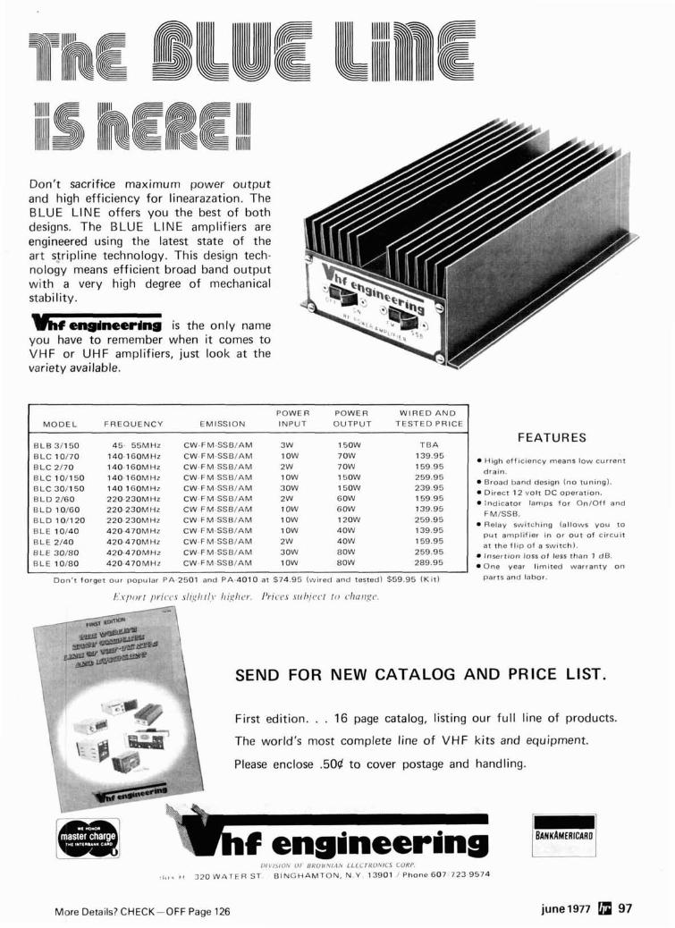
Don't sacrifice maximum power output and high efficiency for linearazation. The BLUE LlNE offers you the best of both designs. The BLUE LlNE amplifiers are engineered using the latest state of the art stripline technology. This design tech- nology means efficient broad band output with a very high degree of mechanical stability.
b enaineerlng is the only name you have to remember when it comes to VHF or UHF amplifiers, just look a t the variety available.
I B L C 10170 140-160MHz CW-FM-SSBIAM 1 OW 70W
B L C 2/70 140-160MHz CW-FM-SSB/AM 2W 70W
7
POWER POWER W I R E D A N D
M O D E L FREQUENCY EMISSION INPUT OUTPUT TESTED PRICE
B L B 311 5 0 45 - 55MHz CW-FM-SSB/AM 3W 150W T B A
B L C 101150 B L C 30/150 B L D 2 / 6 0 B L D 10160 B L D 10 /120 B L E 10140 B L E 2 / 4 0 B L E 30180 B L E 10180
FEATURES
CW-F M-SSBIAM CW-FM-SSB/AM CW. F M-SSBIAM CW FM-SSB/AM CW FM-SSBIAM CW FM-SSB/AM CW.FM-SSBIAM CW-FM-SSB/AM CW- F M-SSB/AM
eff ic iency means low current 159.95
W Broad band design (no tuning). D ~ r e c t 1 2 vo l t DC operation. . Indicator lamps f o r On/Of f and FMISSB. Relay switching (al lows you t o p u t ampli f ier i n o r o u t o f c i rcu i t at the f l i p o f a switch).
W Insert ion loss o f less than 1 dB. .One vear l imi ted warranty o n
I I
Don' t forget our popular PA-2501 and PA-4010 at $74.95 (wi red and tested) $59.95 ( K i t ) parts and labor.
M- \ SEND FOR NEW CATALOG A N D PRICE LIST.
First edition. . . 16 page catalog, listing our full line of products.
The world's most complete line of VHF kits and equipment.
Please enclose .50d to cover postage and handling.
l ~ l ~ / ~ ~ O ' ~ 111 I l A ' r , , ' , I I i 1 1 1 ~ l K o \ / ~ 5 C O R P
r t t l q H 320 WATER ST B l N G H A M l ON, N . Y 13901 ' Phone 607 723 9574
More Details? CHECK-OFF Page 126 june1977 97
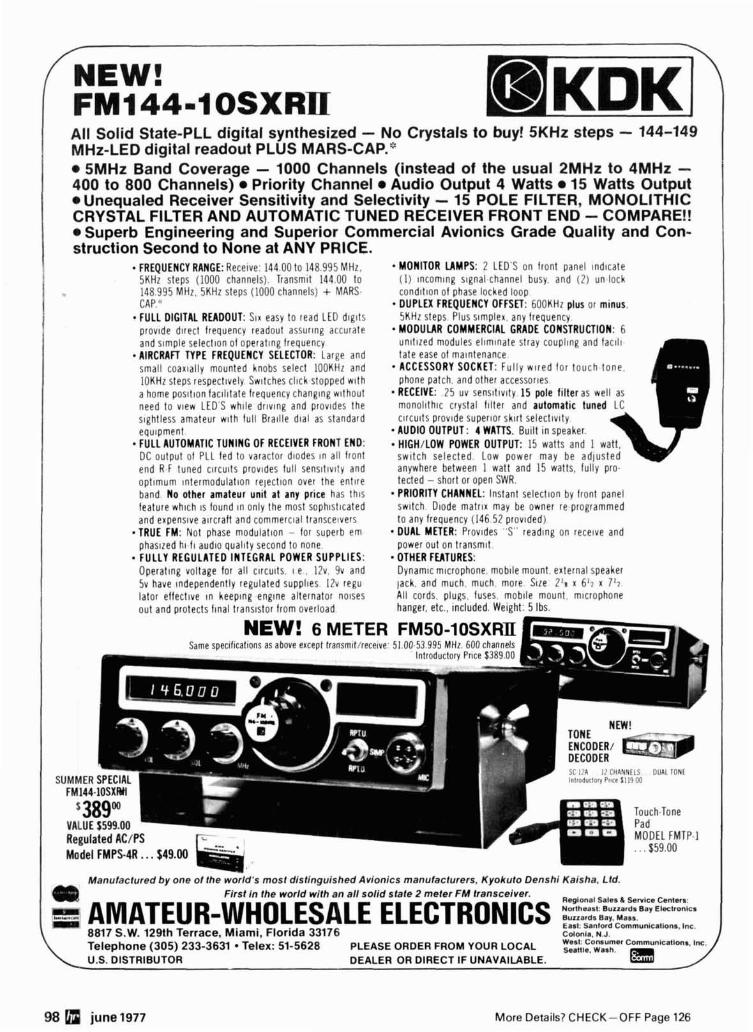
All Solid State-PLL digital synthesized - No Crystals to buy! 5KHz steps - 144-149 MHz-LED digital readout PLUS MARS-CAP."
5MHz Band Coverage - 1000 Channels (instead of the usual 2MHz to 4MHz - 400 to 800 Channels) Priority Channel Audio Output 4 Watts 15 Watts Output
Unequaled Receiver Sensitivity and Selectivity - 15 POLE FILTER, MONOLITHIC CRYSTAL FILTER AND AUTOMATIC TUNED RECEIVER FRONT END - COMPARE!!
Superb Engineering and Superior Commercial Avionics Grade Quality and Con- struction Second to None at ANY PRICE.
FREQUENCY RANGE: Recelve: 144.00 to 148.995 MHz. MONITOR LAMPS: 2 LED'S on front panel ~ n d ~ c a t e 5KHz steps (1000 channels). Transm~t 144.00 to (1) lncomlng slgnal channel busy. and (2) un.lock 148.995 MHz. 5KHz steps (1000 channels) + MARS. c o n d ~ t ~ o n of phase locked loop CAP." DUPLEX FREQUENCY OFFSET: 600KHz plus or minus. FULL DIGITAL READOUT: SIX easy to read LED d ~ g ~ t s 5KHZ steps Plus s~mplex. any frequency prov~de direct frequency readout assurlng accurate MODULAR COMMERCIAL GRADE CONSTRUCTION: 6 and slmple select~on of operating frequency u n ~ t ~ z e d modules e l ~ m ~ n a t e stray coupl~ng and f a c ~ l ~ AIRCRAFT TYPE FREQUENCY SELECTOR: Large and tale ease of ma~ntenance small coax~ally mounted knobs select 100KHz and ACCESSORY SOCKET: Ful ly w ~ r e d for touch.tone. lOKHz steps respect~vely Sw~tches click stopped wlth phone patch, and other accessories
a home pos~t lon facl l~tate frequency changlng without RECEIVE: 25 uv sens~t lv~ty . I5 pole filter as well need to vlew LED'S whlle drlvlng and prov~des the m o n o l ~ t h ~ c crystal f ~ l t e r and automatic tuned s~ghtless amateur w ~ t h full Braille d ~ a l as standard clrcults prov~de superlor sklrt selectlvlty equ~pment AUDIO OUTPUT: 4 WATTS. Built ~n speaker. FULL AUTOMATIC TUNING OF RECEIVER FRONT END: HIGH/LOW POWER OUTPUT: 15 watts and 1 watt, DC output of PLL fed to varactor diodes In all front s w ~ t c h selected. Low power may be ad jus ted end R.F tuned c l rcu~ts provldes full sensltlv~ty and anywhere between 1 watt and 15 watts, fully pro. opt lmum ~ntermodula t~on rejection over the en t~ re tected - short or open SWR. band. No other amateur unit a t any price has thls PRIORITY CHANNEL: Instant select~on by front panel feature whlch 1s found In only the most sophlstlcated swltch D~ode ma t r~x may be owner re.programmed and expens~ve a~rcraft and commerc~al transce~vers to any frequency (146 52 prov~ded)
*TRUE FM: Not phase modulat~on - for superb em DUAL METER: Prov~des "S" readlng on receive and phaslzed h1.11 aud~o quallty second to none. power out on t ransm~t . FULLY REGULATED INTEGRAL POWER SUPPLIES: OTHER FUTURES: Operating voltage for all clrcults. I e . 12v. 9v and Dynam~c mlcrophone, moblle mount. external speaker 5v have Independently regulated suppl~es IZv regu lack. and much. much, more. S~ze 2'8 x 6'7 x 7 ' 7 .
lator effectlve In keeplng englne alternator nolses All cords, p l u ~ s . fuses. moblle mount. mlcrophone out and protects f ~ n a l trans~stor from overload hanger, etc., included. Weight: 5 Ibs.
NEW! 6 METER FM50-10SXRII
51 i A I: CHANNfLS DlJAl l O N t Inlroriuclorr Place 11 19 00
Manufactured by one of the world's most distinguished Avionics manufacturers. Kyokuto Denshi Kaisha, Ltd. First in the world with an all solid state 2 meter FM transceiver.
R.glonal Sales Sanlce C.nt.r,:
E: AMATEUR-WHOLESALE ELECTRONICS : z z ~ ~ Y E Y ~ ~ ~ ~ ~ ~ East: Sanlofd Cornrnunlcations. lnc. 8817 S.W. 1 2 9 t h T e r r a c e , Miami, Florida 33176 Colonla. N.J.
T e l e p h o n e (305) 233-3631 Telex: 51-5628 P L E A S E O R D E R F R O M Y O U R L O C A L Seattle. Wash. U.S. D I S T R I B U T O R D E A L E R O R D I R E C T I F UNAVAILABLE.
98 june 1977
-
M o r e De ta i l s? CHECK-OFF P a g e 126
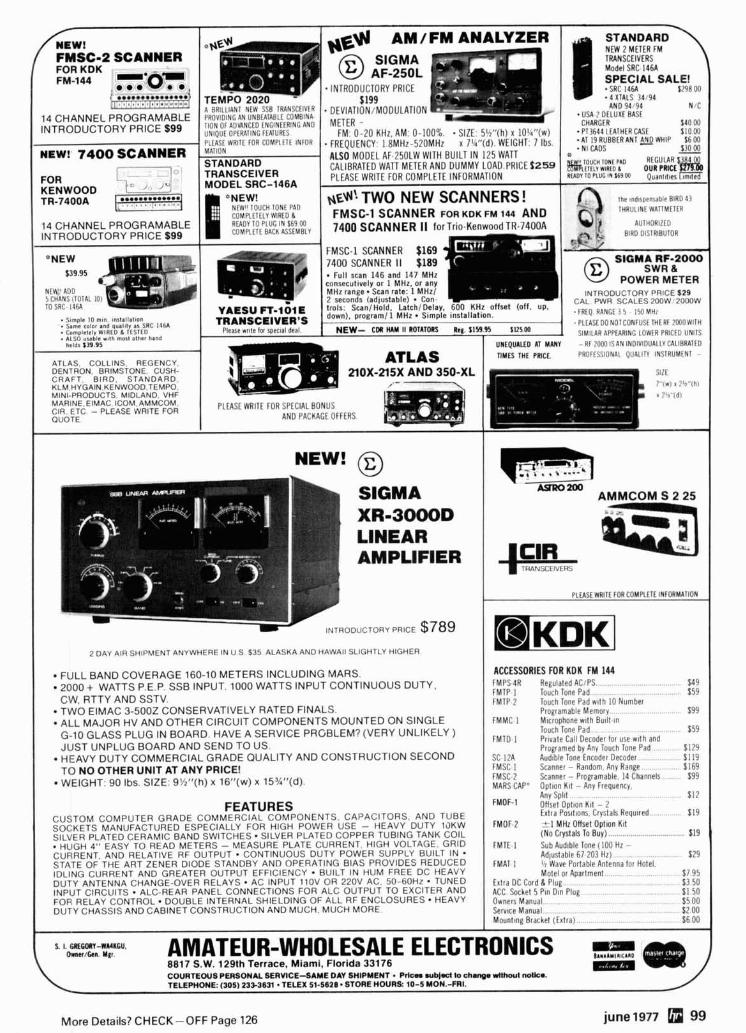
FMSC-2 SCANNER Model SRC 1461
SPECIAL SALE!
AND 94 94 N fC
IOMPLLTELY WlRLD 1 RLADV TO PLUG IN $69 00 COMPLETE BACK ASSEMBLY
FMSC-1 SCANNER $169 7400 SCANNER I1 $189
INTRODUCTOR
TO SRC- I46A
LOWER PRICED UNITS
I
NEW! @ w
SIGMA XR-3000D LINEAR AMPLIFIER
INTROD~CTORY PRICE $789
2 DAY AIR SHIPMENT ANYWHERE IN U S $35 ALASKA AND HAWAII SLIGHTLY HIGHER
FULL BAND COVERAGE 160-10 METERS INCLUDING MARS. 2000 + WATTS P.E.P. SSB INPUT. 1000 WATTS INPUT CONTlNUOUS DUTY. CW, RTTY AND SSTV. TWO ElMAC 3-5002 CONSERVATIVELY RATED FINALS. ALL MAJOR HV AND OTHER CIRCUIT COMPONENTS MOUNTED ON SINGLE G-10 GLASS PLUG IN BOARD. HAVE A SERVICE PRGBLEM? (VERY UNLIKELY ) JUST UNPLUG BOARD AND SEND TO US. HEAVY DUTY COMMERCIAL GRADE QUALITY AND CONSTRUCTION SECOND TO NO OTHER UNIT AT ANY PRICE! WEIGHT: 90 Ibs. SIZE. 9'h1'(h) x 16"(w) x 153/l"(d).
AMMCOM S 2 25
PLfASE WRITE FOR COMPLETE lNFORMATlON
ACCESSORIES FOR KDK FM 144 FMPS 4R FMTP I FMTP 2
FMMC l
FMTD l
SC-12A FMSC l FMSC.2 MARS CAP*
Regulated ACtPS $49 Touch Tone Pad $ 59 Touch Tone Pad wllh 10 Number Programable Memory $ 99 M~crophone w~th Bull1 In Touch Tone Pad $59 Private Call Decoder for use wlth and Programed by Any Touch Tone Pad $129 Audtble Tone Encoder Decoder $119 Scanner - Random Any Range $169 Scanner - Programable 14 Channels $99 Optlon Kit - Any Frequency
1 Mounllng Bracket (Extra) $6 00
FEATURES CUSTOM COMPUTER GRADE COMMERCIAL COMPONENTS CAPACITORS AND TUBE SOCKETS MANUFACTURED ESPECIALLY FOR HIGH POWER USE - HEAVY DUTY lOKW SILVER PLATED CERAMIC BAND SWITCHES SILVER PLATED COPPER TUBING TANK COIL
HUGH 4" EASY TO READ METERS - MEASURE PLATE CURRENT HlGH VOLTAGE GRID CURRENT. AND RELATIVE RF OUTPUT CONTINUOUS DUTY POWER SUPPLY BUILT IN STATE OF THE ART ZENER DIODE STANDBY AND OPFRATING BIAS PROVIDES REDUCED IDLING CURRENT AND GREATER OUTPUT EFFICIENCY BUILT IN HUM FREE DC HEAVY DUTY ANTENNA CHANGE-OVER RELAYS AC INPUT l lOV OR 220V AC 50-60Hz TUNED INPUT CIRCUITS ALC-REAR PANEL CONNECTIONS FOR ALC OUTPUT TO EXCITER AND FOR RELAY CONTROL. DOUBLE INTERNAL SHIELDING OF ALL RF ENCLOSURES HEAVY DUTY CHASSIS AND CABINET CONSTRUCTION AND MUCH MUCH MORE
s. I. 6 l tSm-WMnCU. hnn/ten. MEI. AMATEUR-WHOLESALE ELECTRONICS lm
8817 S.W. 129th Terrace, Miami. Florida 33176 COURTEOUS PERSONAL SERVICE-SAME DAY SHIPMENT . Pdca w b ) d to chmga NIUIOUI nolko.
- TELEPHONE: (305) 233-3631 .TELEX 51-5628. STORE HOURS: 10-5 M0N.-FRI.
$12
$19 FMDF 2 1 MHz Offset Option Ktt
(No Crystals To Buy) $19 FMTE 1 Sub Audible Tone (100 Hz -
Adjustable 67 203 Hz) FMAT ] 1, Wave PorlablP Antenna for Hotel
$29
Motel 7 95 Extra DC Cord& Plu 3 50 ACC Sockel 5 Pin Dl 1 50 Owners Manual $5 00 Service Manual $2 00
More Details? CHECK-OFF Page 126 june1977 99
100 june1977 More Details? CHECK-OFF Page 126
flea ~t market RATES Non-commercial ads 10e per
word; commercial ads 6 0 ~ per word both payable in advance. No cash discounts or agency commlsslons allowed.
HAMFESTS Sponsored by non-prof it organizations recelve one free Flea Market ad (subject to our editing). Repeat inser- tions of hamfest ads pay the non- commerclai rate.
COPY No special layout or ar- rangements avallable. Material should be typewritten or clearly printed (not ail capitals) and must include full name and address. We reserve the right to reject un- suitable copy. Ham Radlo cannot check each advertiser and thus cannot be held responslble for claims made. Llablllty for correctness of material limited to cor- rected ad In next avallable Issue
DEADLINE 15th of second preceding month.
SEND MATERIAL TO: Flea Market, Ham Radlo, Greenvllle, N.H. 03048.
HAM RADIO HORIZONS, a super new magazine for the Beolnner. the Novice and anyone Interested In Amateur ~a ; f l o . . .'what lt's all about. how to get started, The fun of ham radio. lt's all here and just $10.00 per year. HURRY! HURRY! Ham Radlo HORIZONS, Greenvllle, NH 03048.
RlTY - NS.1A PLL TU board $3.00, parts kit (no board) $15.00, wlredltested $24.95 all postpaid. SASE for Info. Nat Stlnnette Electronlcs, Tavares. FL 32778.
QRP TRANSMATCH wlth Preamp for HW7 Ten-Tec. Send stamp for details to Peter Meacham Associates, 19 Lorreta Road. Waltham Mass. 02154.
CANADIANS 1,000,000 surplus parts. Bargains galore. Free catalog. Etco-HR. Box 741, Montreal, H3c 2v2.
W.I.M.U. HAMFEAST (Wyoming, Idaho, Montana an2 Utah). The 45th annual WlMU hamfeast is scheduled to be held at Macs Inn, Idaho. Just south of west Yellowstone about 25 mlles. The dates to be August 5.8 and 7th. This Is one of the Rocky Mountaln Northwest's largest hamfeast and we would like to lnvlte you to at- tend, and at the same time enjoy a tour through Yellowstone National Park. Advance reglstratlon Is $8.00 before July 1st. Reglstratlon wi l l he $7.00 at the hamfeast. Please send all pre-registrations to WlMU hamfeast, P.O. Box 30756. Bllllngs, Montana 59107. c/o R o n a l d C o n i e y Gene ra l Cha i rman . W lMU Hamfeast.
RADIO MUSEUM now open. Free Admission. 15,000 pieces of equipment from 1850 telegraph Instruments to amateur and commerclai transmitters of the 1920's Amateur station W2AN. Wrlte for lnformatlon. Antique Wireless Assn., Main St., Holcomb. N. Y. 14489.
SlS1 COLLINS RECEIVER Q2-3BMHz. Excellent Condl- tlon $850. (315)882-8185 after8 P.M. WPGRU.
STOP LOOKINQ for a good deal on amateur radlo equlp- ment - you've found It here - at your amateur radlo headquarters In the heart of the Mldwest. We are factory authorized dealers for Kenwwd, Drake, Colllns, ICOM. Ten-Tec, Atlas. Regency, Tempo, Swan, Midland. Alpha, Standard. Dentron. Hy-Galn. Mosley, Cushcraft, and CDE, accessorles: Thousands of thrifty hams from coast to coast already know us and we lnvlte you to I0ln them by wrltlng or caillng us today for our low quote and trylno our personal and frlendly Hoosier service. HOOSIER ELECTRONICS, P.O. Box 2001, Terre Haute, Indiana 47802. (812)-236-1458.
PORTAPAK the accessory that makes your mobile real- ly portable. $87.50 and $88.00. Dealer Inquires In. vlted. P.O. Box 87. Somers, Wlsc. 53171.
QSL - BROWNIE W3CJI - 30358 Lehlgh, Allentown, Pa. 18103. Samples wlth cut catalog 506. - RlTY DEMODULATORS - New ST-5's wlth auto-start and AK-1 AFSK audio oscillator $185 or $25 and balance UPS COD. Davld Tanclg. 818 W. White St., Champaign, ILL. 81820.
NEW CVaractor, 3-transistor UHF N tuner. Tunes thru 440 MHz for A N or repeater appllcatlons. $7.95 ppd. Workshop. Box 393H, Bethpage, NY 11714.
WANTED Heath HW-18 SSB XCVR. State Prlce and con- dltlon. Dennis Vernacchla WBELGI, 8993 Covlna St., San Dlego, Ca. 92126. - CRYSTALS - S.A.S.E. my Ilst. KBLJQ, 355 Mower Rd., Plnckney. Mlch. 48189.
LOW POWER CLUB - Join QRP A.R.C. lnternetlonal Joseph Szemplas WEJKB, 2359 Woodford Street, Toledo, Ohio 43805.
RECONDITIONED TEST EQUIPMENT for sale. Catalog S.50. Welter, 2897 Nickel, San Pablo, Ca. 94806.
ELECTRONIC CW KEYERS. Completely automatlc lam- blc keyer, only $39.75. John Day, 12 Oakdale Ave.. Selden, NY 11784.
RTTY: E.51 AFSK generator - wldelnarrow shift - wlredltested - $34.95 - kits available. Stamp for Info. Com - Tech Electronlcs, P.O. Box 73, Rensselaer, N.Y. 12144.
CASH f o r y o u r ham gea r . B e a c o n Comm., 81 7-287-1 975.
WANTED: old keys. Navy.RR etc., also old mlcrophones. K4NBN. Del Poowell. 1948 Sweetbrlar. Jachsonvllle. Fla.
3.SIERRA 164 RF WATTMETERS, 1 rackmount. 2 have 10,50,100 and 500 watt 2001000 MHz elements. 1 has 1.5,10 and 50 watt 144-470 MHz element. $100 ea. 1-HIP scope camera model HOl-l96A. Needs new Polarold back. $35.00 1-SB200 linear. Used about 10 Hrs. Steal at $250. D. Marshall W5UJR18, 940 Portland Ave., New Car- Ilsle, OH 45344,513-8490123.
DISCOUNTS - KLM, Larsen, Brimstone, Stereo Systems, Police Monitors, etc. Catalog avallable. Bankamerlcard & Mastercharge. 201.962-4695 Narwld E lec t ron lcs , 81 Be l lo t Road, Rlngwood. N.J. 07458.
PRESCALER Board for650 MHz 1 lC90. Includes Instruc- tions and parts source. 3.00. Also CSJ counter boards 15.00 (see 76 ads). RTC Electronlcs, PO Box 2514. Lln. coln, NE 88502.
TRAVEL PAK QSL KIT - Send call and 2%. recelve your call sample kit In return. Samco. Box 203. Wynantsklll, N.Y. 12198.
REPEATER - Ideal for club or Indlvldual. All solid state. Single conversion recelver wlth five cavity helical resonator. Hot carrier diode mixer wlth excellent sen- sltlvlty and dynamic range. All IC transmltterand 30 watt P.A. Auto patch wlth Touchtone turn ON-OFF. Control circuit with beeper and reprogramable ID'r. Separate units wlth lndlvldual regulated power supplies and mounted In standard rack. Crystalled for 146.31191 and has been on the air for past year. Complete lnformatlon avallable from Lee Pennington, KBOVJ 1778 Anne. Lln- coin Park, Michigan 48148.
2.METER CRYSTALS. $3.50 each, for all popular rigs. In stock. Immediate delivery. Send cash or rnoney order, we pay postage. Rolln Distributors, P.O. Box 438, Dunellen. N.J. 08812. - TRANSMITTINO TUBES, HV and fllament xfmrs, rotary Inductors, transmitting capacitors. Send stamp for flyer. T.S. Marlnlch Electronlcs, 102 Bell St., Welrton, W. Va. 28082. - WOCVU for SALE. Colllns KWS.1 and 75A-4 recelver and transmitter In excellent condition. All modlflcatlons on eouloment made at Colllns Radlo. Prlce $875.00 F.O.B. ~l;a;les Boegel, 1500 Center Point Road, NE, Cedar Rapids, Iowa.
SAVE! BEARCAT SCANNERS. $259.95. New. E.R. Brooks Guns. 6812 Eastern Ave., Bell Gardens, CA 90201 (213) 773-5193.
SELL Drake 2C, 2CQ. 2NB. Callbrator, Mint condition, wlmanuals, $250. All new parts for WA4DSY HT220 Syn- thesizer, $75. Prlce lncludes shlpplng. Wanted 4BN. WAgWD815 John Telea, 10511 Tenneco, Houston, Tx. 77099. Phone 713-495-2340.
TRANSFORMERS American made, 115V Primaries: 6.3V 1 Amp, Shielded $1.80 ea. 12V'- 250 m i l s - for P. C. Board.
$1.66 ea.
1 2 vol t '/z amp.
12V 1.2 Amp
12V. 3 Amp $4.48
Dual Secondary: 36V. 14V CT-la. CT-400 MA $4.20 ea.
44V CT-la, 6.3V, lh a m p tap $3.47 ea. 48V CT-la. 6.3V, % a m p tap $3.46 ea.
NEW ITEM Thordarson DC t o DC converter power supply transformer - for 12 Volt DC service. (Instruc. & schematic lncl.) TR 9 1 - output 450V. 120W, 270MA DC.
$9.88 ea. TR-98 - output 1500V. 12MA DC. $8.15 ea.
$/ NEW - 5% Resistors - NEW
8 WATT - Full Leads - Imported 75 220 390 430 820 1 5 K 2K 10K 15k, 22k. 39k, 8 i ~ , 190~; 2 2 0 ~ , ' 2 7 0 ~ :
33/$1.66 One Value 100/$4.15
Assorted Values 100/$4.55
NEW P.C. POTS - j/4W b y Piher Vert. Mt. 2508 w/screw slot drive. Hori- zontal Mt. 1008 & 10K hex slot drive.
204 ea. - 6/$1.00
TUNING METERS - Blue t in ted plast ic body, 0 t o l e f t , g r a d u a t e d sca le , 200sA. 1%"W x 1%"H x 3h"D. Scale can be rear lighted. Sylvania #18148-1
$2.25 ea. or 4/$6.95
"S" UNIT METER - Pearce-Simpson 3701-004. Scale 0. 3, 5, 7, 9, +lo, +30.
P m A rating. l ' / znW x 1%"H x %OD. $2.95 each
3000 MFD @ 30 Volt Capacitors.
1" Dia. x 3" - 3000 MFD @ 20V Capacitors. Same size
as above. 804 ea. or 3/$2.00
ELECTROLYTIC CAPACITOR - PHILCO QUAD SECTION
4" x 1%'' dla. TWISTAB MTG.
100x150 MFD B ~ O V and a t 350V D.C. and 20x50 MFD @ 250V - A nice unlt for Xceiver. etc. $1.10 ea. or 3/$2.95
DUAL Electrolytic 1000 & 500 MFD. 15V. long leads. dla. x 2%" long.
38d ea., l0/$3.45
CRL Disc Capacitors. .l MFD. 10V %IB"
dia., long leads. 10 for $1.00; 10C/$8.40
UNPOTTED TOROIDS - center t a 8 8 MHY - 5 02. - 5/$2.95 5 pcs. - 9 02. - 5/$3.49
EMTECH BRIDGES Heat stnk w/center hole mtg. 1 0 Amp - Tested - 200V P.I.V. $1.75 ea. 400V P.I.V. $1.95 ea. 600V P.I.V. $2.15 ea.
25 AMP - TESTED
@ m v P.I.V. $2.25 ea. 400V P.I.V. $2.50 ea. 600V P.I.V. $2.85 ea.
CARBON TRIMMERS Miniature 1h wat t units. PC t y e. Values: 200, 700, 1000, l.!~, 250K, 700K. horz. mt.
NEW SIZES - VERTICAL MOUNT PC BOARD POTENTIOMETERS
American made (CRL) Cermet: 25K, lOOK 300K ohms. 5/$1.30 p d CTS b l u e wheel. Values: 750, PK: 1.5K, 50K, 750K ohms. 5/$1.25 P
I.C. - Fairchi ld RTL. s L 900 or s L 914 Ful l leads. @ pL923 Ful l Leads.
3/$1.35 3/$1.85
SEND STAMP FOR BARGIN LIST PENNSYLVANIA RESIDENTS - ADD 6%
ALL ITEMS PPD. USA Canadian orders f o r less t han $5.00 add $1.00 t o cover additional mai l ing costs. UPS requires your street address.
eleclronic specialties-BOX 353, IRWIN, PA 15642
More Details? CHECK-OFF Page 126 june 1977 101
flea market MOBILE IGNITION SHIELDING provides more range with no noise. Available most engines. Many other sup- pression accessories. Literature. Estes Englneerlng. 930 Marine Or.. Port Angeles. WA 93862.
--
GLOBE SCOUT Mod. 65A transmitter (has 180 meten) need copy of schematlc. George Lazarvs WASYEN, 639 Stephen Drlve, Palatine. lL 80067. - MOTOROLA HT220. HTlOb. and Pageboy servlce and modifications performed at reasonable rales. WA4FRV (804) 3204439. evenings. - TECH MANUALS for Govt. surplus gear - $6.50 each: SP.800 JX. URM-25D. OS-(IAIU, TS-17YUR. Thousands more available. Send 500 (coln) for 22-page Ilst. WJIHD, 7218 Roanne Drive. Washlngton, DC 20021. -- POWERFUL, ADJUSTABLE, REQUUTED, three output power supply and 900 easlly removable parts in com- plete CARTRlVlSlON televlsion recorder electronlc assembly w i t h documentat lon. Per fec t for MICROPROCESSOR. IC, transistor, televislon. CB radlo applications. $21.45. Free brochure. MADISON ELEC- TRONICS. INCORPORATED. 389. D77. Madison, Alabama 35758. SATISFACTION GUARANTEED.
MOBILE BONDING STRAPS under 506 each. Llterature. Estes Engineering. 930 Marlne Drlve, Port Angeles. Wash. 98362. - NEED INFORMATION on BC.639-A. Identlty of VT202 and W203 please. W5PAE. 3308 Bahama NE. Albuquer- que. New Mexico87111. - FERRITE BEADS: wlspeclflcatlon and application sheet - 10/$1.00. Assorled PC pots- Y51.00. Mlnlature mica trim- mers. 340 pf.. 5151.00. Postpaid. Includes latest catalog. Stamp for catalog alone. CPO Surplus. Box 189. Brsin- tree. MA 02184. - THE "CADILLAC" of OSL's! New! Samples: $1.00 (Refundable) - MAC'S SHACK; Box M1171.D; Garland. Texas 75040. - VERY In-ter-esthg! Nexl 4 Issues $1. "Ham Trader" Yellow Sheets. Sycamore. IL 89178.
WANTED - Dlagrams and or manuals for Collins R64WARR141 Rcvr. VE3FEZ. 421 Lodor Street. Ancaster, Ontarlo. - MODERN CODE PRACTICE. 0-22wpm on four 80 mln. cassettes. $10. Royal. P. 0. Box 2174. Sandusky. Ohlo 44870. - SALE 6 pole 250 Hz crystal fllter for Yaesu FTlOl 548. 5171. JOJO-tho, Kasugal.city. AIC~I. 486. Japan JAPUEO.
'
Kolchl. Kawai. - EXCLUSIVELY HAM TELETYPE 23rd year. RTTY Journal. articles, news. DX, VHF, classified ads. Sample 3%. $3.50 per year. Box 837. Royal Oak. Michigan 40888.
FERRIC CHLORIDE, Llquld 40% Board etchlng grade. Pints, quarts, gallons. Send SASE Bob's Eleclronlcs. Box 393H. Bay City. MI 48707.
FIGHT NI with the RSO Low Pass Fllter. For brochure write: Taylor Communlcatlons Manufacturlng Company. Box 126. Agincourt. Ontarlo. Canada. MIS 384.
RUBBER STAMP. namelcalllOTH $2.50 ppd. (CA resldents add lax). LWM Press. Box 22161. San Dlego. CA 92122.
POWER SUPPLIES - Speclal low prices on Hlgh Ouallty power supplies. For speclflcatlons wrlte: ASTRON Cor- poratlon. 1971 South Ritchey. Santa Ana. Callfornla 92705.
TELETYPEWRlfER PARTS, gears. mnuals, suppllea, tape, torolds. SASE Ilst. Typetronlcs, Box 8873. Ft. Lauderdale, FL. 33310. Buy pans. late machines. - WANTED CRYSTAL IMPEDANCE METERS TS-330, TS.883 or TSM-15 Glenn R. Kurzenknabe. K3SWZ, 403 Centervlew Av.. New Cumberland. Pa 17070.
MANUALS for most ham gear. 1939170. Llst $1.00. Send SASE (or 2%) for one speclflc model quote. Hobby In. dustry. WUJK, Box H884, Council Bluffs, Iowa 51501. - SWEEP OENERATOR. Telonlc Model SPX-5. 250 to 500 MHz. adlustable sweep wldth, marker generators. Up to 5 watts output. $295, plus freight collect. Vanguard Labs, 19823 Jamalca Ave.. Hollis. NY 11423.
-
STAINESS AND QALVANIZED STEEL antenna guy wire our specialty. Wllcox Electronlcs. Box 1331. S. L C.. Utah 84110.
TEST EQUIPMENT All equipment listed is operat~onal and un
conditionally quaranteed. Money back not salisfted - equipment beins rcturnrd must bc shipped prepa~d. Include chc*ck or money order w ~ t h order. Prices include UPS or motor f re~qh l charges.
. . . BOONTON 190A Q - m t r 30.200mHz $425 BOONTON 202E A M . F M s ig gen
. . . . . . . . . . . . . . . . . . . . . . . . . 54-216mHz 425 . . . . . . . D E I T D U - 4 30mHz v ideod isp lay 55 . . . . . GRlOOlA LF s ig gen 5kHz 50mHz 385
HPlOOER F r e q stand .05 pa r t s /m i l . . . . . Outputs 10,100Hz; 1,100,100kHz 155
HP1608(USM105) l 5mHz scopew i th . . . . . r e g horiz, dua l t race ve r t p lugs 375
H P l 6 6 B ( M i l ) D e l a y sweep for above . . 130 HP170A(USMl40) 30mHz scope w i t h
. . . . . r e q horiz, dua l t race ve r t p luqs 475 HP175A 50mHz scope w i t h r e g
. . . . . . . . . horiz, dua l t race ve r t plugs 565 HP185A Sampl ing scope to 1 gHz
. . . . . . . . . . . . . 1868 xs t r r ise t i m e p lug 585 . . . . . HP202B L F OSC .5H~.50kHZ 10V Out 75 . . . . HP205AG L a b aud iogen .02-20kHz 195
. . . . . . . HP212A Pulsegen .06 5kHzPRR 65 H P524D F r e q counter b a s ~ c range
. . . . 1OHz-lOmHz extends w/p lug- ins 195 HP540B Transosc t o 12.4gHz for
. . . . . . . . . use w/HP524-tyoe counters 145 . . . . . . . HP616 Sig gen 1.8-4gHz F M - C W 365
H P6R6 Sweep gen 8.2-12.4gHz sweep . . . . . . . . . . . . . . . range 4.4mHz-4.4gHz 495
. . . HP803A V H F An t bridge50.500mHz 135 SOLITRON 200A SCR tester - a l l
. . . . . . . . . . . funct ions w/scope output 135 . . . . . . . . . T e k l 8 l T i m e - m a r k scopecal ib. 55
. . . Tekl9O Sig gen(const amp l ) 5OrnHz 125 Tek536 l l m H z X.Y scope - uses
. . . . . . . . . . . t w o le t ter ser ies p lug Ins 295 Tek565 Dua l beam l0,mHz scope
. . . . . . . . . . . . . . less plug.ins (3 se r~es ) 625 . . . . . . . . . . TS505 Std V T V M (rf.5OOmHz) 65
For complete list 01 elti test equipment send stamped, sell addressed envelope
GRAY electronic.^ P.O.Box 941, Monroe, Mich. 48161
Specializ~ng tn used test equ~pment.
Ws OF THOUSANDS OF CRYSTALS
IN STOCK!
Immsdhfs dehwy on most -&sf
CRYSTAL BANKING SERVICE P.O. BOX 683
LYNNFIELD, MASSACHUSEnS 01 940
102 june 1977 More Details? CHECK-OFF Page 126
More Details? CHECK-OFF Page 126 june 1977 103
HERE ARE SOME ITEMS AND SPECIALS THAT WE THOUGHT YOU'D LIKE TO KNOW ABOUT. SOME ARE IN TOO SHORT SUPPLY TO LIST IN OUR CATALOG, SO IF YOU SEE SOMETHING YOU LIKE, DON'T DELAY.
COMING SOON THE ULTIMATE ACCESSORY FOR THE IC-22s
Have trouble remembering your programmed channel?
Need more than 22 channels?
Would you I ~ k e to add a scan feature to your 22S?
If the answer to the above IS YES, send an SASE marked
"SPEC SCAN" for pre-release Info. sheet.
-5' CABINETS- LIMITED SUPPLY
AVAILABLE.
IDEAL FOR
DRESSING UP
YOUR REPEATER.
LOCKABLE DOORS
DOUBLE RAILS
NEW MOT STYLE
MINT CONDX
$7 5.00 + shlpplng
-$I0 SPECIALS- Help us make room and save $$ at the same time.
T41GGV low band 30 watt rnob~le
TI lGGV low band 50 watt rnob~le
T43GGV 30 watt h~ band rnob~le
UHF "B" RCVR STRIPS 2 freq . PL, Ideal for rnonltors on l ~ n k s
OMNl NICADS
used but checked good
All above sold "as IS" and less accessories However, each I tem IS b a s ~ c a l l y complete M in~ rnum order 520 FOB Oak Park
-LET US FILL ALL YOUR- AMATEUR NEEDS
Drake
I C O ~
a Ten Tec
Atlas
Dentron
Wilson
Hy Gain
Swan
Send for your free copy of our 1977 Buyer's Guide. 44 pages loaded with Amateur goodies.
We want to meet you. We'll be at the following Hamfests - Hope to see you there. ABC HAMFEST . . . Santa Fe Park, IL June 12
ATLANTA HAMFESTIVAL . . . Atlanta, GA June 18-19
SPECTRONICS, INC. 1009 GARFIELD
OAK PARK, IL 60304 3 12 848-6777
TELEX 7293310
HOURS STORE HOURS:
Mon Thurs 9:30-6:00, Frl. 9:30-8:00 Sat. 9:30-3:00. Closed Sun. & Hol~dayr .
ah
w ~ t h JAN QUARTZ CRYSTALS
for CB Synthesized CB Standard
General Comrnun~catlons Industry Two-Meter Monitor Scanners
Marine VHF Amateur Bands
Dependable USA Mfg. for Frequency Control Frequency Stablllty H~gh Performance
Wnre or phone lor more dslarh Send Iff lor wr laresr caf*log
2400 Crystal Drive Ft. Myers. Florida 33901 - all Phones (813) 936-2397
, I 1
NOW . . . EEB GOES MAIL ORDER
D~rtrlbutor Q' for
C Bird 43
(and elements)
lIS), *', Pi Model 1471
B&K Dynascan
scopes & test
equlpment
Model 14718 10 MHz 5" dual t r~ce 5520 Model 1472C 15 MHz 5" dual trace $660 Model 1474 30 MHz 5" dual trace 9665 . Model 1801 40 MHz Counter $240 . . Model 18018 (1801 w/250 MHz prescaler)
$299 95 Model 1827 30 MHz portable counter $120
We're also a dlstr~butor for Tr~plel l - the world leader In VOMs We have a 5000 item Inentory of USED Hewlett-Packard, Tektron~x, Gencral Rad~o & o:her leading lnduslr~al equlpment.
FREE CATALOG Next tlme you're In Washington, D C stop In and see us
9-5 weekdays 10-4 Saturday I-- & COD WELCOME
Electronic Equipment Bank, Inc. 516 M ~ l l Street, N.E. V~enna. V l rg l n~a 22180
(703) 938-3350
flea market U.S. and FOREIQN CALLBOOK, Radlo Handbook, and other ARRL books. 195010 1975 editlon, Ham Radlo, QST. CO. 73, Popular Electronlcs magazines, second- hand, I want, cash-paid. Also your unused tubes, fet- moslet, translstors, IC, Xtal, fllten, parts. Send the prlcellst to: Vlttorlo Brunl 1-05030 COLLESTAnE Vernl) Italy. - HELP FOR YOUR NOVICE, general, advanced tlcket. Recorded audlrwlsual theory Instructlon. Free lnlorme tlon. Amateur Llcense Instructlon. P. 0 . Box 8015, Nor. folk, Va. 23508.
FREE CATALOO. Solar Cells, Nlcads, Klts. Calculators, Olgltal Watch Modules. Ultrasonlcs. Strobes. LEDS. Translstors, IC's. Unlqua Components. Chaneys. Box 27038, Denver. Colo. 80227.
ZOA, 13JVDC POWER SUPPLY: 11SVAC Input. 50% duty cycle; excellent electronlc ragulatlon; electronlc over- current and short clrcult protectlon; crowbar over voltage protectlon, perfect for 200W class transistorized transcelver; $99 postpald. WABNSY. Box 728. Huron, S.D. 57350. -
WIRE DIPOLE CUnlNQ CHART 6 notes on Installation. Chart covers 2 meters through 180 meters. Helpful In- lormatlon. $1.00 ppd. W.E. Schroedter. 6108 N. Sherman Blvd.. Milwaukee, Wlsc. 53209.
SELL: HQ170A wlth manual. WA7DKZ; 508 Clark. Laramle, WY 82070. - WANTED. PANADAPTER. Send Info. 6 prlce Bob Somers. W2QYH. 411 Hamllton Rd.. Glassboro, NJ 08028.609881-2826.
LWEI BE AFRAID 9: bF SNAKEBITE @iJp $ . ~ ~ ~ . s ~ ~ z ~ ~ i A6AlN
BOX 7141-Z, Kansas Clty, MO 641 13
structjon w~th bull. dog ~ ~ I D S . looks Ilhe real gun Stops agsr sor w~thout permanently InlurlnR htm Glves need protection an lonely, dark tor people local~ons wh I
nlght security for wlves and
needem, but not sold to mlnors F~res seven crrtr~dges w~thout reloading T pr~ce of each gun-unlt Includes one u ten rounds of tear gas shells. and all ship plng cost Prompl shlpment Insured selling tear gas eau~pment lor the Da years Thousands of satlsl~ed customers - 1 Gun-Unit . . . . . . . . . . . . . . . . . . . . . . . . . . . $17.00
......... j 2 Gun-Units @ $15 ea. .(total $30) 3 Gun -Un~ ts @ $14.50 ea. . (total 943.50) 5 4 Gun-Units @ $14 e a . ( total $ 5 6 )
.. 6 Gun-Units @ $13 ea. .(total $781 1 Extra tear gas shells . $3 for ten 0 Blanks for pract ice ...... .$2.50 per 100
. . . . . . . . . . . . . . . . . . . n nolsters $2.50 ea. ........ ear Gas Antidote. Bott le
C l l *
Coming Events THE MANKATO AREA RADIO CLUB wlll hold Its plcnlc. auctlon. and swapfest on July 31. between t0:00 A.M. and 4:00 P.M. at Sprlng Lake Park In North Mankato. MN. Talk-In on 3.93. 146.94, and 146.2Y85 MHz. Brlng your own dlnner. For further Info wrlte to Mankato ARC, Box 1981, North Mankato. MN 58001, or call Allen Wlndhorn - 4 scnn aq, 4l ra
sl)irc ZIP- I ;"i":Itsed is \Check for S Money Order for S--
or charce mv Master Charge BankAmer~card
I - -
Card ~ u m b e i - ............... Exp. Date
COME TO CANADA thls summer for Ontarlo Hamfest 77. July 810 1977, sponsored by Burllngton Amateur Radlo Club. Weekend camplng, fleamarket, auction, many displays. Wrlte Box 836 Burllngton Ont. L7R3Y7 for descrlptlve brochure.
-
2ND ANNUAL ERIE HAM JAM Sunday. September 25. 1977. Ralnbow Gardens - Waldameer Park. Door prlzes - Flea Market - Forums - Large Indoor lacllltles. Wrlte for more Info. Radlo Assoc. of Ede. P.O. Box 844. Erle. PA 18512. - MEMPHIS IS BEAUTIFUL IN OCTOBER1 The Memphls ARRL-sponsored Hamlest, blgger and better than the 4,500 who attended last year, wlll be held at State Technical Institute, Interstate 40 at Macon Road, on Saturday and Sunday October 1 and 2. Demonstratlons, dlsplays. MARS meetlngs, flea market, ladles flea market. too! Hospltallty room, Informal dlnners. XYL entertainment, many outstanding prlzes. Dealers and Dlstrlbutors welcome. Contact Harry Slmpson WISCF, PO Box 27015. Memphls. TN 38127 for further Infor- matlon. - DELTA QSO PARTY All amateurs are lnvlted to par- tlclpata In the elghth annual Delta QSO Pany whlch la sponsored by the Delta Dlvlslon of the Amerlcan Radlo Relay League. Contacts must take place from laOOZ Sept. 24 to 24002 Sept. 25.1977. No tlme or power restrlc- tlons. SASE lor detalls from W5RUB.
NEW YORK CITY. The 4th annual Hall of Sclence A.R.C. Flea Market and Hamventlon. 11 l t h Street and 48th Ave. Corona-Queens. Refreshments. Zoo Museum. Dealers booths, test bench. Famlly fun Sunday June 12(rain date June 19) 9 AM.3. Admlsslon $2.00 door prlzes. Talk In ,34194. Information (212) 6999400.
.-
BETTER THAN EVER-1077 EDITION Golden Spread Hamfest and Flea Market- Hollday Inn West Amarlllo. Texas Aug. 12. 13 6 14. SIX blg tech sesslons. Commer. clal exhlblts. Famlly recreatlon. Two Hospltallty Hours. Blg prereglstratlon prlze and super Grand Prlze, others. 53.00 advance, $4.00 at door. For Info. pre-reglstratlon packet. P.O. Box 10221. Amarlllo, Texas 79106. - NORTHEAST WISCONSIN SWAP FEST - Neenah. Wlsconsln. Sunday. July 24, 1977, 0000 - 1500. Talk-in on ,941.94 - Admlsslon $1.50 - Tables $2.00. Send ad- vance reservations to 3-F's, Box 1032, Neenah, Wlscon- sln 54956.
WORLD PREFIX MAP - Full color. 40" x 28". . . . shows prefrxes on each country DX zones.
time zones, c~ties. cross referenced tables $1.25
RADIO AMATEURS GREAT CIRCLE CHART OF THE WORLD - from the center of the Un~ted States' Full color. 30" x 25". l ~ s t ~ n g Great Clr. cle bear~ngs In degrees for sox malor U S cotles: Boston. Wash~ngton. D C . Mlam~. Seattle. Sari Franc~sco & Los Angeles. $1.25
RADIO AMATEURS MAP OF NORTH AMERICA! Full color. 30" x 75" - lncludes Central Amer. Ica and the Car~bbean to the equator, showtng call areas, zone boundaries, preflxes and tlme zones. FCC frequency chart, plus useful lnforma tlon on each of the 50 Un~ted States and other Counlrles $ i.25
WORLD ATLAS - Only atlas complled for rad~o amateurs Packed wlth world.w~de tnforrnatlon - ~ncludes 11 maps. on 4 colors wlth zone boundar~es and country preflxes on each map Also nncludes a polar projection map of the world plus a map of the Antarctica - a corn. plete set of maps of the world. 20 pages. Slze 8%' x 12" $2.50
I Complete reference library of maps - set of 4 as Ilsted above $3.75 1
See your favorite dealer or order diract.
Mai l orders please include $1.25 per order f o r shipping and handling. I
104 5 june 1977 More Details? CHECK-OFF Page 126
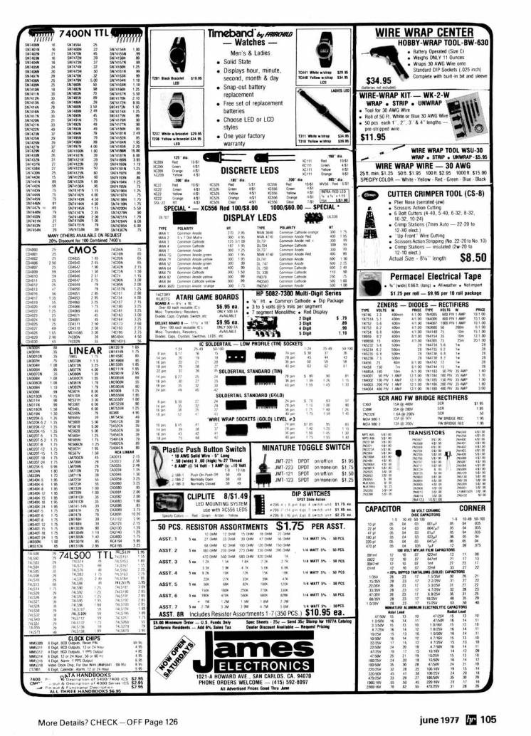
Armchair Copy
I
f3i st?/--
Barlow XCR 30
Shortwave Listening Our ONLY occupation IS
s u p p l y ~ n g everyth~ng you need to tune the med~umwave and shortwave bands-and ~den t~ f y what you hear Our NEW m~nl-catalog deta~ls Rarlow Wadley, Drake and Yaesu receivers, WORLD RADIO TV HANDBOOK, logs, recelvlng antennas & tuners, callbrators, FM or TV gu~des, A M pattern maps, QSL albums, ITU publ~cat~ons, R T T Y d~splays, CONFIDEN- TIAL FREQUENCY LIST, clocks and al l SWL books
GILFER ASSOCIATES, INC P.O. Box 239, Park Ridge, NJ 07656
ALOELCO SEMI.CONOUCTOR SUPERMARKET RF nFVlPFC --. --" 7N331L, 1 W 400 MU, 5 50 7NMIRO 4W 175 MU7 540 7N3866 I W 400 MU, 99 7NMYIl 15W 175 MHz 8 45 7N55RQ 3W 175 MU? 4 75 7Nfi087 25W 175 MHz 1095 IN5590 I O W 175 MHz 7 00 2N6083 30W 175 MHz 12 30 7N55')I 25W 175MHt 1095 2NllrlR4 40W 175 MU, 16 30 2SCbl7 3 95 2% 1 107 5 25 2% 1776 1 2 5 2N4421 135 2SC 1306 4 3 0 7N51W 2 05
NOW NEW IMPROVED DIGITAL ALARM CLOCK KIT Hour%. Mlntr!pr %toad% d8rpIaycd 18" RIG 0 5 F a ~ ~ c h t l O 7 %men,
Olsplav LEOS I 2 hour formal 24 hour alarm ~ 8 t h $noole lealure plus .lapled lome sndtratot and Iterr. lrslurc Elqh l W r of ~ICIO~IIII md I~(IIUCIIDI>I NEW on b o d p a v e # trawlormnr and ~mrcutrry lor opl,Ondl !,me hnr w o h rmmulrlnl wood gfam cahrwl
573 95 11/24 Hour Clock K8t Srx hvg 5 LEOS lrccrt lrrlurt ~ 8 t h *lmulalnl eond cahtnct 573 95 Sfmulaled hlwk leather mvarctl cluck slhanrl 54 95
ZENERS IN74Gto lN7594WMwn 25 IN472810 IN47M 1 w 28 ?N?R16 RCA RF S1095 CA 307BA Or1 Amp 51 50 MPSAl4 90 W80A 119 95 7N 1055 99 LMlO9K Volt Rep 1 10 MPF I02 FET s5 2N4HRR 50 2N3904 o* 2N3906 10 99 2 1 ~ 0 ) I Blor51750 MJ1055 2 20 MJF 340 l2N56551 f 1 10 40F,7l RCA F E T S I 55 74 1 or 100 Pqn DIP 25 555 T l m r 75 vHF Frrralr Bead, 1561 00 202 Volt 75 Amp Brtdqo 51 M IN'lt4 IN414R 15 l W
7Nfi103 89 7 Amp 10M Vol! Rrp 10 S I W 2N6103 16 Amp lo 220 90 LM709or LM741 Mlrl 030 45 LM741C or TO5 0P Am" 45 14 or 16 P!n IC Sr,cketl 30 MP5A 13 lSPS57OOl HO
IN34 INW IN64 101or 99 we haup 7400 rr80rr 1 0 an r l
2261H Babylon Tnpk.. Merr~ck, NY 11566 1516) 378.4555
flea market 1977 HAWKEYE HAM 6 COMPUTERFEST August 20and 21 sponsored by Des Mo~nes Amateur Radlo Assocla- Hon. WBBURB for details.
LEXINGTON. KY Bluegrass Amateur Radlo Club Central Kentucky Hamfest August 14.1977 at the Lexlngton Na. tlonal Guard Armory located adjacent to the Bluegrass Field on Airport Road. Lexlngton, Kentucky. Grand Prizes. Hourly Door Prizes, Manufacturer's Exhlblts, in- doorloutdoor Fleamarket, Guest Speakers and Forums. P.O. BOX 4411, Lexington. KY 40504 fordetails.
NEW ORLEANS HAMFESTICOMPUTERFEST at the Hilton Inn In Kenner. LA. September 24 6 25. Informallon on tlckets, room reservations and etc.. will be furnished upon request by contacting the New Orleans HarnfestlComputerfest; P. 0 . Box 10111. Jefferson. LA 70161. - THE NORTHERN BERKSHIRE Amateur Radlo Club Hamfest. July 9th and 1Mh Cummlngton Falr Grounds. Cummington Mass. Free overnight camplng. Tech talks, Demos, and dealers. Flea Market 51. Admlsslon $3 wlth XYL $5 advanced 52 and 54, for information wrlte Hildy Sheerin WAIZNE, 79 Greylock Ter.. Pittsfield, Ma. 01201.
MISSOURI: Second Annual Hamfest and Communlca- lions Show. Sunday. July 24, 1977 at the Slater Park wlth fly.in facilities Registration 51.00 in advance: $1.50 at the door Sunday noon meal for a nominal fee. Flea markets. XYL activities. For Information and advance tickets wrlte Dale Bellsmith. WBKNF. Box 74. Slater. Missourl65349. (616) 5242173.
MARAC - ICHN 9th Annual County Hunters Cbnventlon June 3Mh - July 3rd. 1977. Rochester Holiday Inn downtown. 220 South Broadway on Hlghway 63. Rochester. Minnesota.
NEW JERSEY as0 PARTY - August 20-22. The Englewood Amateur Radlo Assoclatlon lnvltes amateurs the world over to take part in this 16th Annual OSO party. Send SASE to the Englewood A.R.C.. 303 Tenafly Road. Englewood. NJ 07631 for full rules.
TOTAH AMATEUR RADIO CLUB field day. July 30 6 31. 1977 at our Corners National Monument (NM. AZ, UT h CO), Mode - SSB, CW. Bands 15, 20 h 40 meters. All contacts confirmed upon request. For further informa- tlon write R. Keith Mllier. Totah Amateur Radio Club. Box 1991. Farmington. NM 67401.
ROME HAM FAMILY DAY - June 5. 1977. Brlng the family to the Beeches, Rt. 26. Rome. NY for a full day of events. We have a giant outdoor flea market and over 5.000 sq. It. of indoor display area. There wlll be exhlblts. contests, new equipment displays, technical presenta- tions and a demonstration of French cooking for the XYL. For l n f o wr i te PO Box 721. Rome. NY 13440. - AKRON. OH Goodyear Amateur Radio Club Hamfest and Family Picnlc June 12. 1977 at Wingfoot Lake Park. 10 AM 6 PM. The park Is southeast of Akron on County Road 87 near Route 43. For detalls - Advance Dona- tions - Map - Program - etc. Contact Don Rogers. WABSXJ. 161 S. Hawkins Ave.. Akron. Ohio 44313. Phone: 216664.3865.
THE WOOD COUNTY ARC ANNUAL Ham-A.Rama Is Sunday. July 17. from 8:OOA.M. to 5:00 P.M.. at the Coun. ty Fairgrounds In Bowling Green, Ohlo (about 25 miles south of Toledo). Free parking and admlssion. Donation 51.50 advance. 52.00 at the door. Tables $2.00. Talk.in on 146.52. Refreshments available. Wrlte WCARC. 7929 Rudolph Road. Rudolph. Ohio 43462.
TRI-CLUB HAMFEST July 13. 1977 from 8:W AM to 500 PM at Allentown Police Academy Pistol Range i n Lehigh. Parkway South at Allentown, PA. Admisslon 51.00 to all, lncludlng sellers. Children free. Talk-in Is .34..94and .52. For further information contact Fred Her- mann. W3HYT at RD 1, Box 104. Emmaus. PA 18049.
HARRISBUR0 ARC HAMFEST - Monday July 4. lndlan Echo Park. 2 miles West of Henhey. Admlsslon 53.00. Sell no charge.
MCKEESPORT. PA Two Rivera Amateur Radlo Club Hamfest Sunday, July 17. 1977 at Green Valley Flre Department fairgrounds off U.S. Route 30 near East McKeesport. Big Flea Market.
-
PENN CENTRAL HAMFEST June 5.1977 at new locatlon in Allenwood. Penna.. rain or shine. Flea market, auction and contests. Registration $3.00 XYL and chlldren free. Talk.ln on 3940 MHz., 146.37.97. 146.13-73 and 52 simplex. For information conlact Clalr Yeagle WA3QXI. R.D.l l P.O. Box 224. Turbotvllle. Pa. 17772. Phone 71 7-437.2595.
HELP AGAl N
0 RF Power Meter - iden- t ~ c a l t o HP Model 430C - Read article Apri l '77 HR Mag.. Pg. 44 tor use. Cop~es o f article avail- able on wri t ten request. Our special purchase is your gain a t $34.95 ea. Note: This is Gen'l Mi. crowave.451. Bolometer/ thermistor mount avail- able with purchase. $15 t o $35 depend~ng on type.
AUDIO COMPRESSOR AN/GSA-33 - F ~ v e identical plug-in compressor amps w ~ t h power supply i n 19 inch rack. Al l sol id state. 600!! i n & out, great for auto patch and phone patch. Weighs less than 30 Ibs. Bui l t l ike a battleship. $34.95
Documentation available for above. ARR41/R-648 Collins Airborne version of R-390. Same outs tand~ng performance. Mechanical fi lters i n IF, Digi tal Tuning, 1 kHz readout. 28 VDC. Eas~ l y converted t o 115VAC. 190-500 kHz, 2.25 MHz.
$ 265.00 SRR-13A RCVR 2-32 MHz THIS CRllTER IS IMMACUUTE! Looks and smells new with some spares, conmc- tors to make test cables and complete documen- tation. $425.00 R-1151/GLQ RECEIVER - 540 kHz t o 54 MHz - Front end is tube, rest is solid state. Or ig~na l ly countermeasures rcvr. could be used for ISB. ln fo on request.
$185.00 L i t t le Goodie! Radar xponder loaded with microwave thr i l ls incl. Melabs mixer, SRC detector. Bendix circulator, TRAK LO - 2-3 GHz $19.95 AN/URM-23 SUMMATION BRIDGE (for applica- tlon see April '77 HR, Pg. 44) measures RF power be:ween 1 & 4 GHz wlth attenuators and bolometer. Unit complete with manual. 995.00 WE ARE BUYERS as well as wllers. What have you? We don't have a catalog, by the time we'd publish it the merchandise would be gone.
DISC-CAP, im . r w E M r n m. NORTHRIDGE. CA. 91326 213-360-3387
REACHING OUT WITH AMATEUR RADIO
Northwestern Division ARRL Convention
JULY 29-31,1977 At Seattle Center Seattle, WA
Special Event Callsign NW7ARL
presenting OCWA National
Convention Washington DX
Club Convention Prizes
Seminars FCC Exams Slow-Scam
TV Demo and much more
to see and do
Come and meet your ARRL National Officers
For tickets, write: SEA-Q-DX Convention Committee
Box 25537, Seattle, WA 981 25
More Details? CHECK-OFF Page 126
ANIERICA'S NEWEST AMATEUR DEALER! (and therefore the most eager to serve you)
nP9PR4F18a
A G L E L E C T R O N I C S I N A C T I O N ! Our staff of experienced Hams IS waltlng to ass~st you w ~ t h the select~on of the best pos- slble equipment to complement your station. Contact us today for fr~endly and competent ad- vice. You deserve the best treatment and we'll prov~de just that. Good Amateur equipment and service is the name of our game. Kim Q*
€t@/ I . . * \ ,FEVtJA~ ~ f i IJD ,otJAL e'"ctrooics -1 LARRY WAIWWH GORDON N5AU MIKE WA5UOB MIKE WB5ACM TOM K5fM BOB W5TPF
214-241-6414
AGL ELECTRONICS H - ~ , . A W I + .,n
3068 FOREST LANE, SUITE 309 DALLAS, TEXAS 75234 B
More Details? CHECK-OFF Page 126 june1977 107
1 and HF too. .. Summer Specials On
HAND HELDS
Standard Wilson Plus Antennas All Other Access
In Stock! Call or Write for Erlckson's Deal
Ameco ASP Atlas Belden Bird CDE CES. Collins Cushcraft Dentron Drake HAL Hy-Gain Icom KLM Kenwood Larsen . MFJ
I Midland Mosley NPC I Newtronics Nye
Regency Shure . Swan Standard TPL Tempo
, Ten-Tec. Wilson*Yaesu
I Hours: 9:30-9 Mm. & Thurs, \ 9:30-530 Tues, Wed. & Fri. I
9-3 Sat. am
E ERICKSON COMMUNICATIONS 5935 N. Milwaukee Ave. Chicago, IL 60646 (312) 631-5181
a
flea market 1 ALUMA I? J+:?I - -
MCKEESPORT, PENNSYLVANIA: The Two Rivers Amateur RadloClub wlll hold Its 13th annual Hamfest on Sunday, July 17. 1977. at the Green Valley Fire Dept. grounds off U.S. Route 30 near East McKeesport. Check- Ins on 52/52 end 22/82. For Information wrlte Andrew Salltros, W3OFM, 2901 Stewart Street, McKeesport. Pennsylvanla 15132
OKANAOAN INTERNATIONAL HAMFEST - GALLAGHER LAKE KOA - 8 mlles North of Oliver, BC. Prizes. Games. Contests - Famlly Fun - Gabfest - Brlng your Crafts Ladles Flea Market - POTLUCK DINNER on the SUNDAY AT NOON. For more lnfo. con- tac t : VE7ALV-Phl l Wl lk lnson. Naramata. B.C. Canada.
ATLANTA HAMFESTIVAL and 1977 Q00rgla ARRL con- ventlon wlll be held June 1S19th In Atlanta at the Downtown Merriott Hotel. (Rooms: $18 single, $24 dou- ble). A preregistration package wlll be malled on May 1st to all who have attended the HamFestlvsl within the pest three years; If you have not recelved a package by May loth, you may wrlte to Atlanta HamFestivel. 53 Old Stone Mlll Road. Msrletts. GA. 30067 or call area 4041971- HAMS anytlme day or night. Doors open at 9AM. Satur. day June 18th and Sunday June 13h. Contact the hotel dlrectly toll-free at 1-800-228-9290 for reservations - and hurry!! - THE SIXTH ANNUAL INDIANAPOLIS HAMFEST will be held on Sunday July 10. 1977 at the Marion County Fairground. Gate admlssion $2, whlch includes in bou t prlvlleges, hourly prize drawings, and meln prize draw- ing. ~ryzes wlll Include complete low band transceiver. 2. meter svntheslzer b the wss~bl l l tv of low 6 h l ~ h band beam antennas. Also large indoor f k s market. E l e ~ t r l ~ l t y avallable at most indoor flea market spaces. For further lnfo wrlte lndlanapolls Hamfest. P.O. Box 1002. In. dlanapolls. IN 46208.
INDIANA LAKE COUNTY AMATEUR RADIO CLUB'S hamfest June 19th at the Isaac Wslton League In Por- tage. Indiana. (lake 1.94 to Ind. 249 exit. then north on Ind. 249 Ih mlle) Tickets: $1.50 advance, $2.00 st gate. Wrlte Herbert S. Brler W9AD (W9EGO). 409 S. 14th St.. Chesterton. Ind. 46304.
SOUTH MILWAUKEE AMATEUR Radio Club Swapfest "77" wlll be held Saturday. July 9. 1977 at Shepard Park (Amerlcan Legion Post 0434). 9327 South Shepard Avenue. Oak Creek. Wisconsin. Actlvltles begln at 7:00 AM and run till 5:W PM. Parking. plcnlc area. hot and cold sandwiches and llquid refreshments avallable on grounds. Overnlte camplng available. Admission $1.00. And includes a "Happy Hour" wlth free beverages. Prlzes wlll be awarded. Talk-In on 146.94 MHz. FM. More details(lnc. map) from: South Mllwaukee Amateur Radlo Club Inc.. S. F Schrelter. WAKF. Sec.. 104 Brookdale Drlve. South Mllwaukee. WI 53172.
MADISON. WI SWAPFEST. Raln or Shine Sunday, June 19. Dane Co. Expo Center Youth Bulldlng. Doors open 8 AM. Bring the whole family for delicious food and enter- talnment.
SPOKANE RADIO AMATEUR COUNCIL (SARC) Hsm- lest. July 18th b 17th in the Pence Union Blvd. at Eastern Wash. State College, Cheney WA. About 15 mlles West of Spokane. Prereglstrstion Is $9.50. Includes banquet. semlnsrs, flea market. XYL actlvltles. Make pre- reglstratlon checks payable to SARC and send to Jlm Johnson. WA7BWO. DrawerWA". Cheney. WA 99004.
- HAM HOLLER-IN AWARD: Issue for contacting A.R.S. NC4NHC. Date18 June 77. Tlme: 9 A.M. to 9 P.M. E.S.T. Frequencies: 14280-7280-3980. NC4NHC wl l l be operating from The National Hollerin Contest grounds located at Splvey's Corner. N.C. The theme Is "Communication- The Old and The New." The award Is sponsored by The Cape Fear Amateur Radio Soclety, Methodist College. Box M818. Fayettevllle. N.C. 28301. The certiflcste wlll be Issued to stations who make con. tact wlth NC4NHC and send $1.00 (postage and handllng fee) to the Cepe Fear Amateur Radlo Soclety prior to 1 Seot. 1977.
Stolen Equipment ICOM 130 SN 40.59 lnscrlbed on back - Fred WA4OFR SW231 56 0589 - In Lanham. Md. March 13. Contact WA4OFR at 301-459-0798 wlth any Informatlon.
STOLEN from my car on February 2%. 1977. Clegg FM 278 s/n sometlme between 1:30 and 5:W PM. Car was parked at 571 Falrtleld Ave.. Brldgeport. CT. Contact Robert H. Horen. 571 Fairfield Ave.. Brldgeport, CT 08803 wlth any Informatlon.
/ I&;:JO W E RS Ham Model 7-140
HIGHEST QUALITY 1 MADE IN ALUMINUM
* TELESCOPING (CRANK UP)
+ GUYED * TILT OVER MODELS
HAM COMMUNICATIONS
MANY MODELS MFG.
Towers to 100 feet. Specials designed 8 made. See dealer or send fo r f r ee catalog.
COLLINS & MORE Collins 51S1 Receiver Collins 30S1 Linear A m p Collins 75538. H a m rcvr Collins 31284, Exc. cond. Collins KWM-2 transcvr. V.G. ~ o l l l n ; CP-1, c r y s t a l Pack Co l l ~ns 37S3 H a m Xmtr. Collins KWM-2A. round, m i n t Collins 32S1. xmtr, very good Heath SB303 H a m rcvr.. mint. Nems-Clark 1302A. 55-260 MHz
11295.00 $1995.00
$825.00 $235.00 $850.00 $225.00 $895.00
$1350.00 $425.00 $295.00
: rcvr. $395.00
We stock good used equipment from Collins, Drake Heath aAd other manufacturers. Hundreds of te;t items also available. Call for specific re- quirements, or write for free catalw.
DAMES COMMUNICATION SYSTEMS 201-998-4256
10 S C H U Y L E R AVENUE NORTH ARLINGTON, N. J. 07032 -
- PCB - PCB - PCB - PCB - PCB - PCB - m 0" P L . 6 ETCH-IT-YOURSELF m I j -F:y.T*-
\ -.;'-- I rn I Printed Circuit -J!
E NOW YOU CAN design and produce your G own p r ~ n t e d clrcul t boards. E p IT'S EASY. Photo positive method. N o , ; darkroom required. o 2 LESS THAN 2 HOURS t o produce a p.c. %
board d ~ r e c t f r om magazine article. I KIT INCLUDES mater ials t o make 4 p.c. I 5 boards dlrect f r om magazine article. 8
P Add f 1 fo r COD. S.A.S.E. f o r details. m
EXCEL CIRCUITS co. I 4412 Fernlee 313-5490440 Royal Oak. M I 48073 8
- PCB - PCB - PCB - PCB - PCB - PCB -
108 june1977 More Details? CHECK-OFF Page 126
I CRYSTAL FILTERS and DISCRIMINATORS 9.0 M H z FILTERS XF9.A 2.5 kHz SSB TX $31.95 XF9.B 2.4 kHz SSB RX/TX $45.95 XF9.C 3.75 kHz A M $48.95 Export XF9-D 5.0 kHz A M $48.95 XF9-E 12.0 kHz N B F M s48,95 Inquiries XF9-M 0.5 kHz CW (4 pole) 134.25 XF9.NB 0.5 kHz CW (8 pole) $63.95
Invited
9.0 M H z CRYSTALS (Hc25/u) XF900 9000.0 kHz Car r ie r $4.00
Shfpping XF901 8998.5 kHz USB $4.00 $1.25 XF902 9001.5 kHz L S B XF903 8999.0 kHz BFO s4.00 s 4.00 per filter F-05 Hc25/u Socket .50
ALSO AVAILABLE FROM KVG 10.7 M H z CRYSTAL FILTERS OSCILLATOR CRYSTALS 50 kHz T O 1 5 0 M H z I Wri te fo r Detai ls
432 MHz SSB TRANSVERTER, MMt432-28 Use your HF Transce~ver on the 432 MHz band wlth the addition of the MMt432 linear Transverter. The MMt432 operates on all modes; SSB, CW,
I AM FM. I t contalns BOTH the l~near transmit up-converter and the re- cel;e down-converter. An inlernal PIN diode T/R connects to your Trans- ceiver T/R line. The MMt432 is FTlOl and similar HF rig compatib!e. Add the 70/MBM48 MULTIBEAM and operate dirrct into OSCAR 7 mode 8. Write for application nole. Specifications: Output Power 10 W PEP Drive, 10 meters '/I W max Receiver N.F. 3.0dB typ Receiver gain 30 dB typ Bandwidth 2 MHz Pnme Power 12 V D.C. Pr ice $239.95 Shipping: $3.50 ALSO AVAILABLE: MMt432-28 M K 4 MMt432-50 MMt438-ATV QMt432-144 FMt440-146 MMt144-28
Send 266 (2 stamps) for full line catalogue of KVG crystal products and all your VHF & UHF equipment requirements. Pre-Selector Filters Amplifiers SSB Tramnrters Varactor Triplers Crystal Filters FM Tranmrters Decade Pre-Scalers Frequency Meten VHF Converters Antennas Oscillator Crystals UHF Converters
Panel Mount Handy Logging A
I Spinner Handle Available Case: 2x4"; shaf t '/oWx3"
LINEAR AMPLIFIERS and TRANSVERTERS bv POLAR ELECTRONIC DEVELOPMENTS
ccive-pre-amplifier (2.5 dB NF). T/R swiiching is automatic by an internal VOX circuit; no changes are needed to your existing transceiver.
..- .~ - ~~
cooling air blower, antenna relays and full mrtering. The RF section is also available as a complete sub-assembly, model EDL432, for use with an existing power supply etc.
Use your 10 meter transceiver wlth the EDT50-28 or EDT144-28 trans- verters lo operate on the 6M w 2M bands. These tranmrlen operate in all modes; they have the same style P.A. deslgn as the
EDL144 amplifier. Receiving is with a MMc5O or MMc144 style converter mounted in- side the cabinet. Spacifications:
, EOT50-28 50-52 MHz , EOT144-28 144-146 MHz Drive Power, 10M 0.5 W max I O~rtput Power 100 W PEP max i Rx Gain 30 dB typ N.F. 2.5 dB typ
1 S i x 10" x 6" x 7 - 1 An external power supply is required.
Wr i te for full detai ls a n d app l ica t ion notes. V is i t US a t A t lan ta J u n e 18. 19.
++A$$&& ANTENNAS 144-148 MHz
Model 8XY/2M 11 $39.95 e ' 3
Gain 9.5dB in each plane, 500 feed. Fw OSCAR communications add Circular polarization harness, PMH/ZC $9.70 Also available for 2 meters: 8 over 8 J-Slot, Model D8/2M 8 by 8 vertical pol. DB/ZM-vert. s39.95 IOSCARl $48.70
420450 MHz 48 element J-Beam MULTIBEAM Gain +15.7 d8d. Feed 50R coaxial. Model 70/MBM48 549.95
1296 - L Y 1296 M H z LOOP-YAGI
GAIN +20dBi FEED 509 COAXIAL
SY.45 1250-1340 MHz -- Shipping: Antennas FOB Concord. Mass. v ia UPS. Wri te d i rec t fo r Polar plots. Gain & VSWR curves.
7
TransCom TONE ENCODERS TWO MODELS Plug in type tone elements
TG-1 single frequency Low distortion slnewave elements TG-3 three frequency Excel. temp. & freq. stability
Output level control Immunity to RF All EIA freq. avail. 67.0-203.5 Hz 9-16V, reverse polarity protection incl.
Wired ' with frcqueKy TG-1 $24.95 TE3 $56.95 e'ement. TG-3 has 'lements Add $3 for each additional tone with frequency selection witch. element, Installs easily In most rad~os.
P. 0. BOX 120, ADDISON, IL 60101 11. residents add 5% sales tax.
More Details? CHECK-OFF Page 126 june 1977 109
r
IALF-SIZE FULL PERFORMANCE Multi- ..L A nnas -
>S IN USE
MOR.GAIN no PIPULE SPECI~ICATI~ MOC-' BANDS
(Meters) 40-2 40/20 40-1 40/20/15/11 80-1 80/40 + U 75-1 75/40 75.1 75/40 754 75/40/20 754 75/40/20 75.: 75/40/20/1! 75-10 HD (SP) 75/40/20/1! 80-10 HD 80/40/20/1! NOTE: 75 meter models are 3950 KHz. (SP) models a n 3800 KHz. 80 meter models at 3650 KHz.
M U U ~ I N HD Dipoles. . ~
the len h o f conven- If-wave $poles. d. Multi-frequency. I efficiency - no traps, oils, o r stubs.
Fully assembled and pre-tuned - no measuring, no cutting.
One half tional ha' Multi-bans Maximum loadlng c
N~III r r feet) 36 36 y 6? 5
Proven performance - more than 10.000 have been delivered. Permit use of the ful l capabili- 6:-- -s ',day's J.bar"
n
-, -- 5/10
factory l u ~ factory tune are factory
- - 69 1
!d 10 RSOMI bd lo resonat tuned to res
,1S, "I ,I
One fee( al l bands Lowest ance an today.
jl ine for a
cost/highe! tenna on
s t perforn the markc
WHY MORGAIN? NOVICE LICENSE OPERATION. The MOR-GAIN HD Dipole is the ideal antenna for the new or Novice operator. As the Novice progresKs to higher license classes he can easily re-tune the HD Dipole to the new f;equencies of his higher license frequency priv- ileges. The HD bipole Is thus a one4ime investment. HD Dipoles are available for all Novlce frequencies. LEAST COST. Dollar for dollar, the HD dipoles a n the highest performance least cost mulll-band anlennas on the market today. For Example: the 5-band 75-10 HD dipole costs less than 515.00 w r band - an unbeatable low cc
~ i g h e s t 1 vice as OP. Guarante,
! for the NI I ExtraClas
IAR. - . - .-a - .
,enormancc well as the
ed ONE YI
LIMITED REAL ESTATE. When na l nssrc rw an- tenna installation is limited, the HD dipole is the ideal solution. Operation on 80/75/40 meters Is now possible since the HD dipole is only half the length of a comentional half-wan dipole. For all-around operalion, the HD dipole will outperform any trap loaded horirc cal dipole. lntal or n r t ~
H today. WI I Contact your f four page broc
rite for ful l ]
.......--". )L South 4 t iworth. Kan (913) 682-3
i; street ~sas 66048 142
12 Button Touch Tone Encoder, 90 day guarantee $14.00 Plastlc Mounting Box for ITT. S/C. WECO. or A E pads, Black. Gray, o r Belge $4.75 Complete System with cable (battery not ~ncluded) .. $24.95 Complete System as above but w ~ t h speaker. amp l~ f~e r , and battery $39.95 Transmitter keying circuit (100 ma max) wlth delay drop out feature Installed In each system $7.50
I#""% 8ncl"dCd (i,,nranfc.d A, yo,,, dr.>lsrs or $3.95 po%tpmd. Conr- panmon ~nsulnlor. 7R 99
BUDWIG MFG. CO. PO 91H. Ramona. CA 92065
2 METER HAM BAND CRYSTALS
3.99 "stpald NO COO'S
LOS "ANGELES CRYSTAL P. 0. BOX 3355, LENNOX, CA. 90304
All Popular Units. Include brand, n~odcl # B calibration data if avail.
Other tubes and Klystrons also wantad. I 1 - ' I The Ted Dames Company
308 Hickory St. Arlington, N.J. 07032 I I TELEPHONE EOUIPMENT COMPANY
Post Office Box 596, Leerburg, Florida 32748 (201) 998-4246 Evenings (201) 998-6475 (904) 728-2730
m w m 1 1 1 1 1 1 1 m m Available directly
plug i t in like a key KEYBOARD I t r omthe fac to ry fo r and send perfectly TO only $225 plus post- timed Morse code as age & handling. Mas-
easily as typing a let- ter. Sidetone and
tercharge or Banka- - mericard accepted. 1 I buffer register make Call or write to order I
it simple to send at or request complete the speed you select. ATRON 1 CS options. specifications
BOX 77, ESCONDIDO, CA 92025 (714) 745-1971
110 june 1977 More Details? CHECK-OFF Page 126
More Details? CHECK-OFF Page 126 june1977 111
112 june1977 More Details? CHECK-OFF Page 126
The 1977 Atlanta HamFestival and
Georgia State ARRL Convention June iSal9,l977
Downtown Atlanta Marriott Hotel Courtland and Cain Streets Atlanta, GA. 30303
GIANT Covered Fleamarket Swapshop! 120 major exhibits! More than 50 technical forums! Special MICROPROCESSOR Section!
The BIGGEST door prizes in all of Ham Radio: First Prize is a complete 2MFM Mobile rig - including a 1977 AMC Gremlin!!!
I f you attended the Atlanta HamFestival within the past three years, you will receive a pre-registration package by May 10th; AFTER MAY 10, call 404/971-HAMS or write for preregistration materials to:
Atlanta HamFestival 53 Old Stone Mill Road
Marietta, GA 30067
NO MATERIALS WILL BE AVAILABLE BEFORE MAY IOTH!
SPECIAL HAMFESTIVAL RATES: $18 SINGLE, $24 DOUBLE.
CONTACT THE HOTEL DIRECTLY for reservations toll free at 1-800-228-9290 - and Hurry!!
THE BEST HAMFEST IN THE WORLD!
TRAGIC WASTE OF RF could be your fate a5 prcclous watts z ~ g zag round the world to shower just a l l t t l e - or I l l t l e Or none - on that hoped for OX s ta t~on BUT WE HAVE AN ALTERNATIVE - THE JOYSTICK VFA (Var~able freq ant ), wh~ch goves low angle, omnl- d~ rec t~ona l harmon~c free r a d ~ a t ~ o n on a l l bands 160 thru i o (+ MARS and rece~ve on a11 BC a, SW) Stalwarts WbTYP and G4DJY ach~eved notable results In contests - just t o mentton two of the many who have sent glow~ng reports of the VFA In use, often In Door QTH and/or under QRP
SYSTEM 'A' $75.00 250W P E P &/or Rece~v~ng Only
SYSTEM 'j' $99.00 5OOW P E P &/w Im- proved Q Factor Rece~w
Air Mall cost ~ncluded (each system 3 sectlons easlly assembled t o make ul l l t 7' 6" long Matching ATU Not only will you saw space but you will saw $$S a t present low exch rate and by buy~ng d~ rec t UK manuf ~ u s h your order - Mastercharge or c k k , or ask for brochure
PARTRIDGE (HR) ELECTRONICS LTD. B R O A D S T A I R S KENT ENGLAND
G 3 C E D TEL. T ~ A N E T k2525 G3VFA
111 1~HOI)lC I 5 II 115 \C\I\IIIII ID 11\11 I, \\IIH\HH\NTII,
COMPETITIVELY PRICED! I:::,: :':,h:l'::l:~'::;:, ~l:::~:;l:;:::::llt:~ANI,LINc.
p , , '0 ,< .& 4 2" ," A-
549 9s $39 95 EPC-300 EPL 144 R LA-I 44
300 M H z Prescslw 2 Meter FM Transmitter 30 Watt 2 Meter Powr Amplifier o rnqucncy rmpc 144-148 Mt17 o Built In 117 ta r 60 HZ power supply 0 2 Chdnncl~ 144 148 MH7
0 SII~ 3%" w x 2% h x 4 L o Power Output 2 wrrlts tvptcal I wall o Max~mum RF oulput power 10 walls mtn( I ? S V W
o BNC rnput output connecton o Maxtmum R1 npul powcr 5 watts o 50 ohm output ~mpcdsnce o Supply voltap 13 6 VDC o Input nmpedanc~ = 50 ohnis o Narrow hand FM + 5 KHZ
o Output TTL Fan out o i I o Small swe 1 718' w x 518' h x 1% L
o Senssltvity 14 mv C IS0 MHz o Rugged balanced emtlter outpul o V~rtually hurn-oul proof halancrd
150 mv (. 300 MHz transnstor rmttter output transstur
Small 'I8" I' 1U o FUII~ compatahlr w th the EPC 144-8 For F a s t e r Delivery 0 50 ohm Input & oulput ~mprdancc
Add S 1 .OO For Aumail Flproron o Sold m a fully trsled & aaumhkd clrcult hoard less c w connccton Send self Addrmrd Stamped ELECTRONIC PROTOTYPE CONSULTMS
Enwlap For Mare Inform*~non 1907 W Campbell I Phoenix Ar~rona 85015 and hrat rsnk
A.R.S. COMMUNICATION SERVICES - BRING YOU the BEST LARSEN HY-GAIN
Complete UHF/VHF Mob~le Llne Complete Antenna Line REGENCY TEC KAN
2 M. FM and Scanners Brimstone 144-Repeater KLM Control and Autopatch
Antennas, Ampllflers. Transce~vers Modules MICROWAVE MODULES The most advanced state of-the art 2 M trans-
144 to 1296 MHz Rece~v~ng celver, ~ncorporat~ng every In demand feature CUSHCRAFT
Converters and Transverters found on any other 2 M rad~o. Llmted Qty. Al l Popular Antennas
201-269-2987 Owner Mac, WB2PMF A.R.S. Communication Services, P. 0. Box 388, Bayville, N. 1. 08721
-
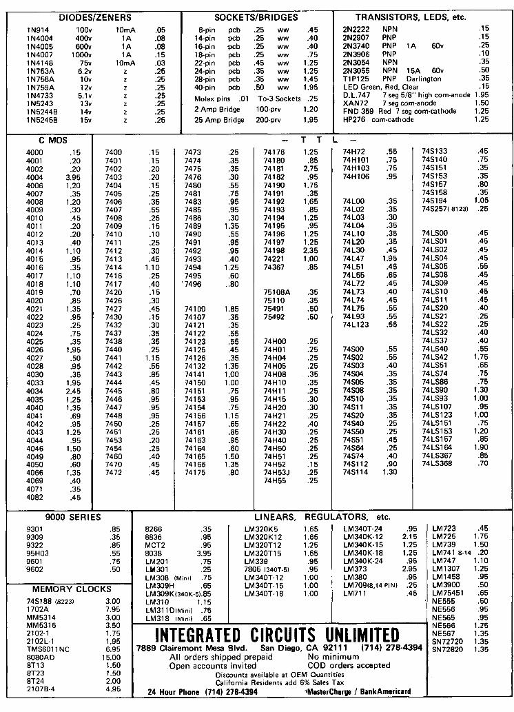
TRANSISTORS, LEDS, etc. 2N2222 NPN .15 2N2907 PNP .15 2N3740 PNP 1A 60v .25 2N3906 PNP .10 2N3054 NPN .35 2N3055 NPN 15A 60v .50 T I PI25 PNP Darlington .35 LED Green, Red, Clear .15 D.L.747 7 seg 518" high com-anode 1.95 XAN72 7 seg com-anode 1.50 FND 359 Red 7 seg com-cathode 1.25 HP276 corn-cathode 1.25
DIODESIZENERS IN914 1 OOv lOmA .05 1 N4004 400v 1 A .08 1 N4005 600v 1 A .08 IN4007 lOOOv 1 A .15 1 N4148 75v lOmA .03 1 N753A 6 . 2 ~ z .25 1 N758A 1 Ov z .25 1 N759A 12v z .25 1 N4733 5.lv z .25 1 N5243 13v z .25 1 N52448 14v z .25 1 N5245B 15v z .25
SOCKETSIBRIDGES 8-pin pcb .25 ww .45
14-pin pcb .25 ww .40 16-pin pcb .25 ww .40 18-pin pcb .25 ww .75 22-pin pcb .45 ww 1.25 24-pin pcb .35 ww 1.25 28-pin pcb .35 ww 1.45 40-pin pcb .50 ww 1.95
Molex pins .O1 To-3 Sockets .25 2 Amp Bridge 100-prv 1.20 25 Amp Bridge 200-prv 1.95
C MOS 4000 .I 5 4001 .20 4002 .20 4004 3.95 4006 1.20 4007 .35 4008 1.20 4009 .30 401 0 .45 401 1 .20 401 2 .20 401 3 .40 4014 1.1 0 401 5 .95 401 6 .35 401 7 1.10 401 8 1.10 401 9 .70 4020 .85 4021 1.35 4022 .95 4023 .25 4024 .75 4025 .35 4026 1.95 4027 .50 4028 .95 4030 .35 4033 1.95 4034 2.45 4035 1.25 4040 1.35 404 1 .69 4042 .95 4043 1.25 4044 .95 4046 1.50 4049 .80 4050 .60 4066 1.35 4069 .40 4071 .35 4082 .45
9000 SERIES
7400 .15 7401 .15 7402 .20 7403 .20 7404 .15 7405 .25 7406 .35 7407 .55 7408 .25 7409 . I5 741 0 .10 741 1 .25 741 2 .30 741 3 .45 7414 1.10 741 6 .25 741 7 -40 7420 .15 7426 .30 7427 .45 7430 .15 7432 .30 7437 .35 7438 .35 7440 .25 7441 1.15 7442 .55 7443 .85 7444 .45 7445 .80 7446 .95 7447 .95 7448 .95 7450 .25 7451 .25 7453 .20 7454 .25 7460 .40 7470 .45 7472 .45
930 1 .85 9309 .35 9322 .85 95H03 .55 9601 .75 9602 .50
MEMORY CLOCKS '
7481 88 (8223) 3.00 1702A 7.95 MM5314 3.00 MM5316 3.50 2102-1 1.75 2102L-1 1.95 TMS6011 NC 6.95 8080AD 15.00 8T13 1.50 8T23 1.50 8T24 2.00 21078-4 4.95
7473 .25 7474 .35 7475 .35 7476 .30 7480 .55 7481 .75 7483 .95 7485 .95 7486 .30 7489 1.35 7490 .55 7491 .95 7492 .95 7493 .40 7494 1.25 7495 .60 7496 .80
74100 1.85 74 107 .35 741 21 .35 74122 .55 741 23 .55 741 25 .45 74126 .35 74132 1.35 74141 1.00 74150 1.00 741 51 .75 741 53 .95 741 54 .75 74156 1.15 741 57 .65 741 61 .85 74 1 63 .95 74164 .60 74165 1.50 74166 1.35 741 75 .80
74S133 .45 748 140 .75 74S151 .35 74S153 .35 7481 57 .80 7481 58 .35 7481 94 1.05 74S257( 81 23) .25
74 LSOO .45 74 LSO 1 .45 74 LS02 .45 74 LS04 .45 74 LS05 .55 74 LS08 .45 74LS09 .45 74LS10 .45 74LSll .45 74 LS20 .40 74LS21 .25 74LS22 .25 74LS32 .40 74LS37 .40 74 LS40 .55 74LS42 1.75 74LS51 .65 74 LS74 .75 74 LS86 .75 74 LS90 1.30 74 LS93 1 .OO 74 LS107 .95 74LS123 1.00 74LS151 .75 74LS153 1.20 74 LS157 .85 74LS164 1.90 74 LS367 .85 74 LS368 .70
T T L - 74176 1.25 74 1 80 .85 741 81 2.75 74 1 82 .95 74190 1.75 74191 .35 74192 1.65 74 193 .85 74194 1.25 741 95 .95 74196 1.25 74197 1.25 74198 2.35 74221 1.00 74367 .85
75108A .35 751 10 .35 75491 .50 75492 .50
74H00 .25 74H01 .25 74H04 .25 74H05 .25 74H08 .35 74H10 .35 74H11 .25 74H15 .30 74H20 .30 74H21 .25 74H22 .40 74H30 .25 74H40 .25 74H50 .25 74H51 .25 74H52 .15 74H53J .25 74H55 .25
LINEARS,
74H72 .55 74H101 .75 74H103 .75 74H106 .95
74 LOO .35 74 LO2 .35 74 LO3 .30 74 LO4 .35 74L10 .35 74 L20 .35 74 L30 .45 74L47 1.95 74L51 .45 74 L55 .65 741172 .45 74 L73 .40 74 L74 .45 74 L75 .55 74L93 .55 74L123 .55
74SOO .55 74802 .55 74S03 .40 74504 .35 74S05 .35 74S08 -35 74510 .35 74Sll .35 74820 .35 74840 .25 74S50 .25 74851 .45 74S64 .25 74874 .40 7481 12 .90 748114 1.30
REGULATORS, etc. LM723 .45 LM725 1.75 LM739 1.50 LM741 8-14 .20 LM747 1.10 LM1307 1.25 LM1458 .95 LM3900 .50 LM75451 .65 NE555 .50 NE556 .95 NE565 .95 NE566 1.15 NE567 1.35 sN72720 ,,, ~ ~ 7 2 8 2 0 1.35
LM340T-24 .95 LM340K-12 2.15 LM340K-15 1.25 LM340K-18 1.25 LM340 K-24 .95 LM373 2.95 LM380 .95 LM709(8,14 PIN) .25 LM711 .45
8266 .35 8836 .95 MCT2 .95 8038 3.95 LM201 .75 LM 30 1 .25 LM308 ( M I ~ I ) .75 LM309H .65 LM309K(34OK-5).85 LM310 1.15 LM311 D(Mln11 .75 LM318 ( M I ~ I ) .65
'
INTEGRATED CIRCUITS UNLIMITED 7889 Clairemont Mesa Blvd. San Diego, CA 921 11 (714) 278-4394
All orders shipped prepaid No minimum Open accounts invited COD orders accepted
Discounts ava~lable at OEM Quant~ties California Res~dents add 6% Sales Tax
24 Hour Phone (714) 278-4394 Mastercharge 1 BankAmericard
LM320K5 1.65 LM320K12 1.65 LM320T12 1.25 LM320T 1 5 1.65 LM339 .95 7805 (34OT-5) .95 LM MOT- 1 2 1 .00 LM340T- 15 1 .00 LM MOT- 1 8 1 .OO
T S l MICROMINIATURE ENCODERDECODER Available in all EIA standard tones 67.OHz-2035Hz Microminiature in size, 125x2.0x.65 high Hi-pass tone rejection filter on board
I Powered by 6-16vdc, unregulated, at 3-9ma. I Decode sensitivity better than IOmvRMS, bandwidth, -1 1 Low distortion adiustable sinewave 01 l+nl I+
1 F;equen& accuracy k25Hz, freque stability %l Hz
I Encodes continuouslv and simultanec during decode. indebendent of mike hang-up
I Totally i~
tired and tesrea, complere w -1 elemen
59.95 7 1 field replaceame, plug-~n, Frequency eterminin
3.00 ea
BRE
6 METER F.M. SPECIALS G.E. MA/E13. 40-50 MHz, 6/12 volt, 30 watts. vibrator power supply, transmitter narrow band. receiver wide band. A complete unit. not oper- 14"9 6"2 " 9 j5"
ationally checked-out, less accessories, $ shipping weight 45 Ibs. .................. 280° MOTOROLA T51G series. 40-50 MHz. 6/12 volt. 50 watts, vibrator power supply, transmitter narrow band, receiver wide band. A complete unit, not
operationally checked- out, less accessories, shipping weight 60 Ibs.
$1 Boo
L, limited
NOW! r 4',
O U R NEW UNIVERSAL
PORTA-PAK M A K E S A L M O S T ANY F M O R A M R A D I O PORTABLE
Thrs lhnle guy l h ~ n b lhal the ncw U n m M l Pwta Pak a really the war lo go 101 a porlablP pow?! W ~ ~ C P 01 couoc he can I ezpress htmrcll In m d s so p u wall ]us1 have to lake my word lor 11 Davld IS anolh?! 01 ow more rcccnt and great new products He IS probably one ol our better clforts Dav~d 15 lust 13 wwks old and pre acup~ed w ~ t h the more rmportant t h lno Ilk catlng and sleep~np YI my rnterprctat~on 01 h ~ s thoughls may not be altogether coffect
Ihe Unrnrsal PortaPak IS dcsrgncd l o 111 anythlnl Imm a 5 wan CB to a 25 wan wmmerclal 2 way radro The Unrnrsal Porta Pak t o m s In two nrsrons onc IS a 4 5 AMP HR untt that w ~ l l rcchargc In 13 to 16 hours and the other IS a 9 AMP HA unll that recharges tn 28 lo 30 hours
The Un~verul Porla Pah comcs complcb wtth a hall arc weldcd alum~num caa a @I ccll b m r y and a plug rn charger The Porta Pak carc 1s l~nsshcd In a black wr!nklc and bahcd to Insure durablllty Our new UnlWl5dl Pula Pak can be attached rn r m r a l way dcpendlnp upon the hpe of vrvrce to wh~ch 11 WIII bc put For tntcrm~ltan( 01 temporary portable wrv~ce elastic bands arc prwlded for more permanent duty as a portable pop rmts or a sllde mount may be used
Our n r y popular custom models are strll ma~labk fw those of p u who h a c thc lollow~n; radm Rwncy BTH BTL HR2 HR6 M~crccom Aquaphonc MI25 or MI15 Ctnan Bus~nca lmalcur and M ~ l l n e ICOM 230 22 22s 301 M~dland 13 500 and 13 509 Hcathklt W202 and HW2036 and Standard SR C806 SR C826MA
Porta Pak startcd out as a n r y nrsatrlc acccs~lry lor the amatcur but now Ihc word IS out and as a r ~ u l l 85% of our sales are now to thc busrnnr fadlo arrlces Among enthus~ast~c uxrs ol Ihe Porta Pah arc the CAP
ambulance rcrrrces Irrc dcpartmnts Rcd Crms dlsastcr teams tow~ng rcrr~ces and prrvatc surn~lancc organ11atlons The Porta Pak and VHI Marrnc radm haw prorlded small cralt w~th rcllablc commun~cat~ons whe~e 11 was Im practical a short tlme ago
&sure to state the make and model ol p u t lranscernr when order~ng and a custom model wlll be pmvldcd 11 onc a madc lor 11 The repulp mabrlc mount holes are uled l o anach the custom models No modll~catmn of p u r r d m IS necessary
4 5 AMP HR Deluzc PortaPaL Unlwrwl or Custom Ctu $61 50 plus $1 15 Ihlpplng
9 AMP HR Supcr PortaPak Un l r rw l M Custom ba $88 00 plus $2 75 Ihlpplng
All Porta Pah unds rncludc Ct l Cell B l n e ~ y Charpr and Caa Rubber Ouchn Type Antcnnas $1 00 L t 0 Battery Condrhon lndlcators $5 00
PORTA-PAK, INC. P.O. BOX 67 SOMERS, WI. 53171
More Details? CHECK-OFF Page 126
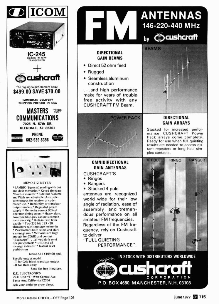
ICOM
16-245 146 MHz FM 10 W
TRANSCEIVER + , P j r 1 m CL The big signal (22 element array)
$499.00 SAVE $70.00 IMMEDIATE DELIVERY
SHIPPING PREPAID IN USA
MASTERS ';%Y COMMUNICATIONS
7025 N. 57th DR. GLENDALE, AZ 85301
PHONE 602-939-8356 4ii#R
L
I@ MEMO-512 KEYER
* IAMBIC (Squeeze) sendingwith dot and dash memories * Keyed timebase *Built-in monitor * Sidetone Volume and Pitch are adjustable. Aux. side- tone output for receiver or code- reader use. * Reed-relay or transistor output models * Regulated power supply * Memories correct 90% of operator timing errors * Heavy alum. two-tone blue-gray cabinets comple- ment your rig * Built-in twin lever paddle * Two 256 bit ( 23 - 28 characters each) message memories * Pushbottons both select and start a message run * Memories are large enough for CQ/ID and contest "Exchange". . .all you do is send one per contact! * LED end of message indicator * Instant reset pushbtltton
Memo-51 2 $109.00 ppd.
Specify output model -T for Grid block transistor output -R for Reed-relay
Send for free literature.
K.E. ELECTRONICS 2931 Unit "F" West Central Ave. Santa Ana, California 92704 Ask your dealer or order direct.
I construction I . . .and high performance make for years of trouble free activity w i th any CUSHCRAFT FM Beam.
OMNIDIRECTIONAL GAlN ANTENNAS
CUSHCRAFT'S Ringos Rangers Stacked 4-pole
antennas are recognized world wide for their low angle of radiation, ease of assembly, and tremen- dous performance on all amateur FM frequencies.
DIRECTIONAL GAlN ARRAYS
Stacked for increased perfor- mance, CUSHCRAFT Power Pack arrays come complete. Ready for use when full quieting results are needed t o access dis- tant repeaters or long haul sim- plex contacts.
Regardless of the FM fre- I quency, rely on Cushcraft 1 / "FULL QUIETING
PERFORMANCE".
More Details7 CHECK-OFF Page 126 june1977 115
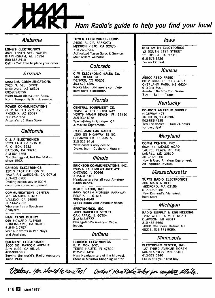
Ham Radio's guide to help you find your local f i ' lo wa
BOB SMITH ELECTRONICS 12 SOUTH 21ST STREET FT. DODGE, IA 50501 515-576-3886 For an EZ deal.
Kansas ASSOCIATED RADIO 8012 CONSER P.O.B. 4327 OVERLAND PARK, KS 66204 913-381-5901 Amateur Radio's Top Dealer. Buy - Sell - Trade.
Kentucky COHOON AMATEUR SUPPLY HIGHWAY 475 TRENTON, KY 42286 502-886-4535 Ten-Tec dealer - Call 24 hours for best deal
Maryland COMM CENTER, INC. 9624 FT. MEADE ROAD LAUREL PLAZA RT. 198 LAUREL, MD 20810 301-792-0600 New & Used Amateur Equipment. All Inquiries Invited.
Massachuse f ts TUFTS RADIO ELECTRONICS 386 MAIN STREET MEDFORD. MA 02155 617-395-8280 New England's friendliest ham store.
Michigan RADIO SUPPLY & ENGINEERING 1207 WEST 14 MILE ROAD CLAWSON, MI 48017 313-435-5660 10001 Chalrners, Detroit, MI 48213, 313-371-9050.
Minneso ta ELECTRONIC CENTER, INC. 127 THIRD AVENUE NORTH MINNEAPOLIS, MN 55401 612-371-5240 ECI is still your best buy.
Alabama
LONG'S ELECTRONICS 3521 TENTH AVE. NORTH BIRMINGHAM, AL 35234 800-633-34 10 Call us Toll Free to place your order
Arizona MASTERS COMMUNICATIONS 7025 N. 57th DRIVE GLENDALE, AZ 85301 602-939-8356 Rohn tower distributor, Atlas, ~com, Tempo, HyGain & service.
POWER COMMUNICATIONS 6012 NORTH 27th AVE. PHOENIX, AZ 85017 602-242-8990 Arizona's #1 Ham Store.
California
C & A ELECTRONICS 2529 EAST CARSON ST. P. 0. BOX 5232 CARSON, CA 90745 2 13-834-5868 Not the biggest, but the best - since 1962.
CARSON ELECTRONICS 12010 EAST CARSON ST. HAWAIIAN GARDENS, CA 90716 213-421-3786 Dealing exclusively in ICOM communications equipment.
COMMUNICATIONS CENTER 705 AMADOR STREET VALLEJO, CA 94590 707-642-7223 who else has a Spectrum Analyzer?
HAM RADIO OUTLET 999 HOWARD AVENUE BURLINGAME, CA 94010 415-342-5757 Visit our stores in Van Nuys and Anaheim.
QUEMENT ELECTRONICS 1000 SO. BASCOM AVENUE SAN JOSE, CA 95128 408-998-5900 Serving the world's Radio Amateurs since 1933.
TOWER ELECTRONICS CORP. 24001 ALICIA PARKWAY MISSION VIEJO, CA 92675 714-768-8900 Authorized Yaesu Sales & Service. Mail orders welcome.
Colorado C W ELECTRONIC SALES CO. 1401 BLAKE ST. DENVER, CO 80202 303-573-1386 Rocky Mountain area's complete ham radio distributor.
Florida CENTRAL EQUIPMENT CO. 18451 W. DIXIE HIGHWAY NORTH MIAMI BEACH, FL. 33160 305-932-1818 Specializing i n Amateur, CB & Marine Equipment.
RAY'S AMATEUR RADIO 1590 US HIGHWAY 19 SO. CLEARWATER, FL 33516 813-535-1416 West coast's only dealer: Drake, Icorn, Cushcraft, Hustler.
/llinois ERICKSON COMMUNICATIONS, INC. 5935 NORTH MILWAUKEE AVE. CHICAGO, IL 60646 312-631-5181 Headquarters for all your Amateur Radio needs.
KLAUS RADIO, INC. 8400 NORTH PIONEER PARKWAY PEORIA, IL 61614 309-691 -4840 Let us quote your Amateur needs.
SPECTRONICS, INC. 1009 GARFIELD STREET OAK PARK, IL 60304 312-848-6777 Chicagoland's Amateur Radio leader.
Indiana HOOSIER ELECTRONICS P. 0. BOX 2001 TERRE HAUTE, I N 47802 812-238-1456 Ham Headquarters of the Midwest. Store in Meadow Shopping Center.
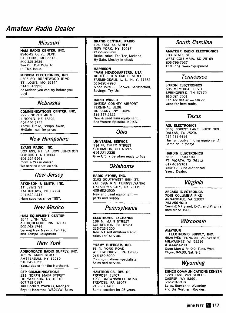
Amateur Radio Dealer
GRAND CENTRAL RADlO 124 EAST 44 STREET NEW YORK, NY 10017 212-682-3869 Drake, Atlas, Ten-Tec, Midland, Hy-Gain, Mosley in stock
South Carolina Missouri -- -
HAM RADlO CENTER, INC. 8340-42 OLIVE BLVD. ST. LOUIS, MO 63132 800-325-3636 See Our Full Page Ad In This Issue.
AMATEUR RADlO ELECTRONICS 100 STATE ST. WEST COLUMBIA, SC 29169 803-796-7957 Featuring Swan Equipment
HARRISON "HAM HEADQUARTERS, USA" ROUTE 110 & SMITH STREET FARMINGDALE, L. I., N. Y. 11735 516-293-7990 Since 1925 . . . Service, Satisfaction, Savings. Try Us!
MIDCOM ELECTRONICS, INC. 2506 SO. BRENTWOOD BLVD. ST. LOUIS, MO 63144 314-961-9990 At Midcon you can try before you buy!
Tennessee J-TRON ELECTRONICS 505 MEMORIAL BLVD. SPRINGFIELD, TN 37172 615-384-3501 Ten-Tec dealer - call or write for best trade.
RADlO WORLD ONEIDA COUNTY AIRPORT TERMINAL BLDG. ORISKANY, NY 13424 315-337-2622 New & used ham equipment. See Warren Spindler, K21XN.
Nebraska COMMUNICATIONS CENTER, INC. 2226 NORTH 48 ST. LINCOLN, NE 68504 402-466-3733 Yaesu, Drake, Tempo, Swan, HyGain - call for prices.
Texas - -- -
AGL ELECTRONICS 3068 FOREST LANE, SUITE 309 DALLAS, TX 75234 214-241-6414 Having trouble finding equ~pment? Come on in today!
Ohio New Hampshire
UNIVERSAL SERVICE 114 N. THIRD STREET COLUMBUS, OH 43215 614-221-2335 Give U.S. a try when ready to buy.
EVANS RADIO, INC. BOX 893, RT. 3A BOW JUNCTION CONCORD, NH 03301 603-224-9961 lcom & Yaesu dealer. We service what we sell.
HARDIN ELECTRONICS 5635 E. ROSEDALE FT. WORTH, TX 76112 817-461-9761 Your Full Line Authorized Yaesu Dealer.
Oklahoma
RADlO STORE, INC. 2102 SOUTHWEST 59th ST. (AT 59th & S. PENNSYLVANIA) OKLAHOMA CITY, OK 73119 405-682-2929 New and used equipment - parts and supply.
New Jersey Virginia ATKINSON & SMITH, INC.
17 LEWIS ST. EATONTOWN, NJ 07724 201 -542-2447 Ham supplies since "55".
ARCADE ELECTRONICS 7048 COLUMBIA PIKE ANNANDALE, VA 22003 703-256-4610 Serving Maryland, D.C., and Virginia area since 1962. New Mexico Pennsylvania
HAM EQUIPMENT CENTER 6344 LlNN N.E. ALBUQUERQUE, NM 87108 505-268-1744 Serving New Mexico. Ten Tec and Tempo Equipment
ELECTRONIC EXCHANGE 136 N. MAlN STREET SOUDERTON, PA 18964 215-723-1200 New & Used Amateur Radio sales and service.
Wisconsin
AMATEUR ELECTRONIC SUPPLY, INC.
4828 WEST FOND du LAC AVENUE MILWAUKEE, W1 53216 414-442-4200 Open Mon & Fri 9-9, Tues, Wed, Thurs, 9-5:30, Sat, 9-3.
New York "HAM" BUERGER, INC. 68 N. YORK ROAD WILLOW GROVE, PA 19090 215-659-5900 Communications specialists. Sales and service.
ADIRONDACK RADIO SUPPLY, INC. 185 W. MAlN STREET AMSTERDAM, NY 12010
, 518-842-8350 Yaesu dealer for the Northeast.
CFP COMMUNICATIONS 211 NORTH MAlN STREET HORSEHEADS, NY 12010 607-739-0187 Jim Beckett, WA2KTJ, Manager Bryant Hozempa, WB2LVW, Sales
Wyoming HAMTRONICS, DIV. OF TREVOSE ELECT. 4033 BROWNSVILLE ROAD TREVOSE, PA 19047 215-357-1400 Same location for 25 years.
DENCO COMMUNICATIONS CENTER 1728 EAST 2nd STREET CASPER, WY 82601 307-234-9197 Sales, Service to Wyoming and the Northern Rockies.
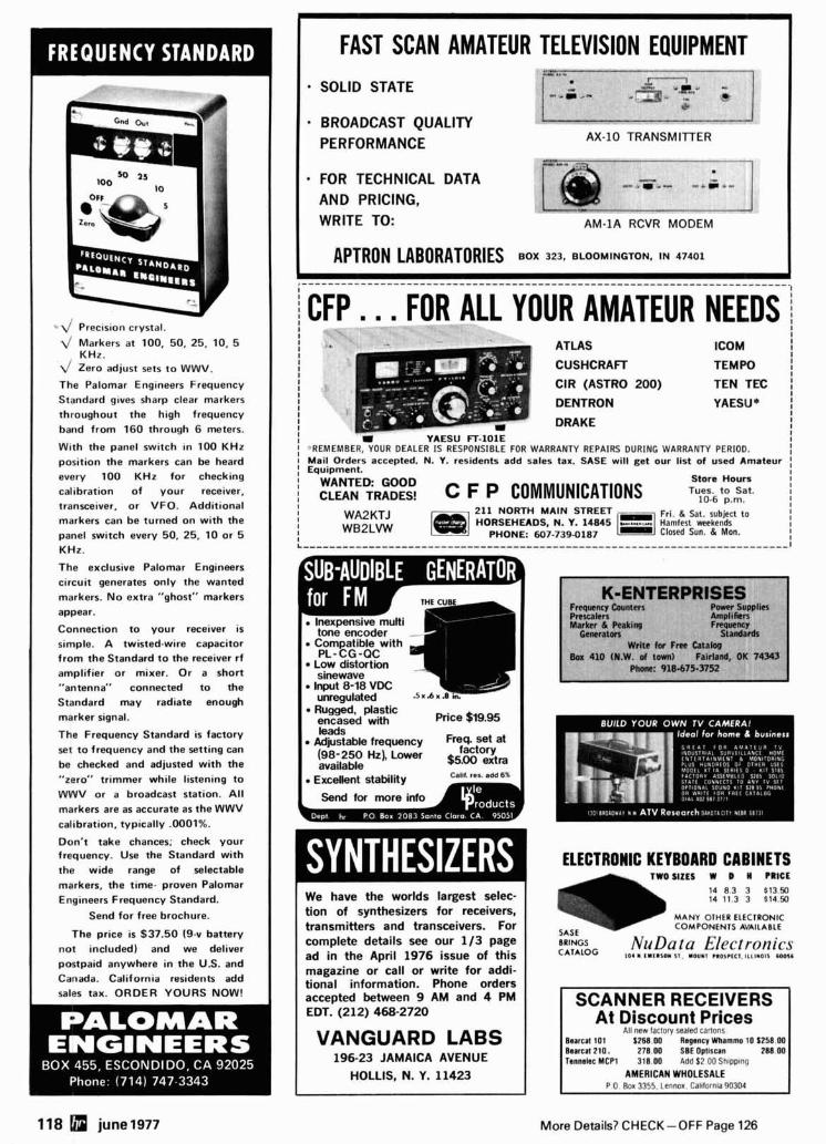
* L / Precision crystal.
4 Markers at 100, 50, 25, 10, 5 KHz.
L/ Zero adjust sets t o WWV.
The Palomar Engineers Frequency Standard gives sharp clear markers throughout the high frequency band f r o m 160 through 6 meters.
Wi th the panel switch in 100 K H z
posit ion the markers can be heard every 100 K H z fo r checking calibration o f your receiver. transceiver, o r VFO. Addi t ional markers can be turned o n w i t h the panel switch every 50, 25, 1 0 o r 5 KHz.
The exclusive Palomar Engineers circuit generates on ly the wanted markers. N o extra "ghost" markers appear.
Connection t o your receiver is simple. A twisted-wire capacitor f r o m the Standard t o the receiver r f ampli f ier o r mixer. O r a short "antenna" connected t o the Standard may radiate enough marker signal.
The Frequency Standard is factory
set t o frequency and the setting can be checked and adjusted w i t h the "zero" tr immer while listening t o WWV o r a broadcast station. A l l markers are as accurate as the WWV
calibration, typical ly .0001%.
Don't take chances; check your frequency. Use the Standard w i t h the wide range o f selectable markers, the t ime- proven Palomar Engineers Frequency Standard.
Send f o r free brochure.
The price is $37.50 (9-v battery n o t includedl and we deliver
postpaid anywhere in the U.S. and Canada. California residents add sales tax. ORDER YOURS NOW!
FAST SCAN AMATEUR TELEVISION EQUIPMENT SOLID STATE
BROADCAST QUALITY PERFORMANCE AX-10 TRANSMITTER
FOR TECHNICAL DATA AND PRICING,
r-@ .-
WRITE TO: AM-1A RCVR MODEM
APTRON LABORATORIES B o x 323, BLOOMINGTON, IN 47401
1 CFP . . - . - FOR ALL YOUR AMATEUR NEEDS 1 ! !
ATLAS ICOM I - I
I I I CUSHCRAFT TEMPO j I I CIR (ASTRO 200) TEN TEC I I
I I DENTRON YAESU* I I
I I I DRAKE !
I YAESU FT-IOIE I ^REMEMBER, YOUR DEALER I S RESPONSIBLE FOR WARRANTY REPAIRS DURING WARRANTY PERIOD. I
Mail Orders accepted. N. Y. residents add sales tax. SASE wil l get our l ist of used Amateur I Equipment. I
WANTED: GOOD Store Hours I
CLEAN TRADES! C F P COMMUNICATIONS Tues. 10.6 to D.~. Sat. I I I I I I WA2KTJ 211 NoRTH STREET Fri. & Sat. subject t o
I I BZLw HO;;M;IDS;-;~~~.~M k] ;y:~~~yp$~. I I I I I
1. Inexpensive muRi benraron
Box 410 (N.
aking
Wrltc for Fr .W. of tm)
Phone: 918
Fnquc Sta~
ee Catalog Fairland,
,675-3752
s Supplies kn
ENTERPRISE, unterr P m r
Arnplil Marker & Pe .. . -. .. . - ..
Rugged. plastic encased with
Adlustable frequency FmQ set at ( 9 8 - 2 5 0 Hz), Lower $ ~ ~ ~ ~ r a
Excellent stabilk
We have the worlds largest selec- tion of synthesizers for receivers. transmitters and transceivers. For complete details see our 113 page ad in the April 1976 issue of this magazine or call or write for addi- tional information. Phone orders accepted between 9 AM and 4 PM EDT. (212) 468-2720
VANGUARD LABS 196-23 JAMAICA AVENUE
HOLLIS, N. Y. 11423
ELECTRONIC KEYBOARD CABINETS 0 SIZES W 0 II PRICE
14 8.3 3 $13 50 14 11 3 3 $1450
M A N Y OTHER ELECTRONIC COMPONENTS AVAILABLE
BRINGS NuData Electronics CATALOG 11.1 t"t110.S1, *OU"I ."OS.fC,. lLll"0lS 'W,'
SCANNER RECEIVERS At Discount Prices
All nt.w factory sealrd carlnns
Bemd 101 S268 00 Regency Whammo 10 $258.00 Beanlt210. 278 00 SBE Optlscan 288.W Tennelec MCPl 318 00 Add $7 00 Shlpplng
AMERICAN WHOLESALE
118 june1977 More Details? CHECK-OFF Page 126
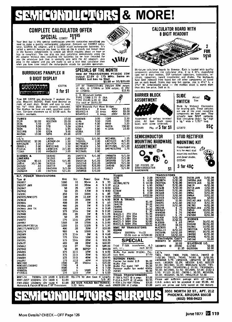
More Details? CHECK-OFF Page 126 june1977 119
I New device ope"$ up the world of Very Low Frequency radio. I Gives reception of the 1750 meter band at 160-190 KHz where transmitters of one watt
.. power can be operated wlthout FCC license. Also covers the navlgatlon rad- lobeacon band, standard fre- quency broadcasts, shlp-to- shore communications, and the European low frequency broad- cast band.
The converter moves all these signals to the 80 meter amateur band where they can be tuned in on an ordinary shortwave re- ceiver. The converter is simple to use and has no tuning adjustments. Tun- ing of VLF signals is done entirely bythe receiver which picks up 10 KHz signals at 3510 KHz, 100 KHz signals at 3600 KHz, 500 KHz signals at 4000 KHz. The VLF converter has crystal control for accurate frequency conversion, a low noise rf ampli- fier for high sensitivity, and a multipole filter to cut broadcast and 80 meter interference. All this performance is packed into a small 3" ~ 1 % " x 6" die cast aluminum case with UHF (SO-239) connectors.
The unique Palomar Engineers circuit eliminates the complex bandswitching and tuning adjust- ments usually found in VLF converters. Free descriptive bro- chure sent on request. Order direct. VLF Converter $55.00 postpaid in U.S. and Canada. California residents add sales tax.
Explore the lnterestlng world of VLF. Order your converter today1 Send check or money order to:
I YAESU I YAESU HF SSB FT-101E. 160.thru 10M
$729.
KENWOOD Transceiver
TS.820 160 thru 10M
$830.
CTC . U H F N H F TRANSISTORS FOR AMA TEUR
JlOl UNDERWOOD CAPACITORS
WANTED Sales Engineer with strong technical and commercial background in HF and VHF communications. Inter- national b id experience helpful. Growth opportunity with medium sized international marketing firm. Send confidential resume and salary requirements to
MAGNUS ELECTRONICS CORPORATION
571 5 Lincoln Avenue Chicago, Illinois 60659
TECHNICAL MANUALS Arneco Hayden-Rider Sams ARRL RCA Tab Cowan Radio Callbook T. I. Gilfer Radio Pub.
Poslage 356 per book. PPD 5 or mwe books. MADISON ELECTRONICS SUPPLY. INC.
1508 McKinney. Houston. TX 77002 7 13-658.0268
CHANNELS For The ICOM-22s 145.350 To 148.21 5 MHz in 1 5 KHz Steps Easy to use, low cost • Totally enclosed wiring Unit fully wired and tested a Top quality components and construction .- Easy installation a Post Paid in U.S.A. a
The ILL RESIDENTS ADD 5% SALES TAX
MS-1 MARCONI ENGINEERING Channel Proarammer 1250 Golf Road . Des Phines, Illinois 60016
I -
I
I $289. 1
The B~drcat 210 super synlheslred recelver 1 scans and searches 32-50 146-174 8
I 416-512 MHz w~thout expenslve crystals Order now on our 24 hour toll-free credtt
I I card order llne 800-521-4414 In Mlchlgan I I and outs~de the U S call 313-994-4441 Add I
$5 00 for sh~pplng In U S or $8 00 for alr
I UPS lo west coast Charge cards or money I orders only Fore~gn orders lnvlled For
I add~tlonal ~n fo rma l~on wrtte Cornmunl- I catlons Electronics P 0 Box 1002 Depl
I 21 Ann Arbor Mlchlgan 48106 1 COMMUNICATIONS ELECTRONICS I
I P.O. BOX 1002 DEPT. 22 --.I ANN ARBOR, MICHIGAN 48106 CTM - rn I
120 june1977 More Details? CHECK-OFF Page 126
March 1968 (first issue) June 1973 September 1975 FEATURING: 5-band SSB exciter, IC. FEATURING: Digi tal RTTY autostart, f m FEATURING: Inductively-tuned six-meter regulated power supply. Remotely-tuned repeater installation, micropower receiver, kilowatt, RTTY terminal unit, SSB speech 10.meter beam. Transistor curve tracer, broadband amplifiers, logic oscillators. splatter, 432 MHz power amplifier. Hand- Double-balanced mixers. held touch-tone, VHF mobile antenna.
May 1969 July 1973 FEATURING: SSTV test generator, carrler October 1975
FEATURING: Potpourri of integrated-cir operated relay, VHF receiver, two-meter FEATURING: Special receiver issue, Re- cu i t applications. FM repeater receiver frequency synthesizer, antenna matching. ceiver sensitivity and dynamic range, performance, RTTY converter. IC noise blanker, The ionospheric e-layer.
High dynamic range receiver input stages, D e c e m b g r 1973 High-frequency communications receiver.
August 1969 FEATURING: Two-meter power amplifier, Pre.amplifier fo r satell ite communications. AFSK generator, VHF cavity filter, Band. Crystal discriminator.
FEATURING: Homebrew Parabolic Ref!ec- pass filter design, ~ i ~ h . ~ ~ i ~ wire antenna. tor, Solid-state Q-5er. Frequency calibrator with mos IC's. New mult iband quad an- January 1974
November 1975 tenna, Troubleshooting with a scope. FEATURING: High.performance VHF FM
FEATURING: CW memory for RTTY ident- receiver, RTTY line-end indicator, Tunable September 1969 i f ication, Linear amplifier, IC logic fami- audio filter, SSTV preamplifier. Binaural FEATURING: FM techniques and practices, lies, FM transceiver. Heatsink design. CW reception, Master frequency oscil lator. IC power supplies. 1296-MHz varactor ~ ~ ~ i l 1974 tripler, Tucable bandpass fi lters, Amateur December 1975 microwave standards. FEATURING: Communications techniques FEATURING: s.line frequency synthesizer,
for Oscar 7, Active fi lter design. Telefax October 1969 conversion, FM receivers, Wideband amp. Introduction to microprocessors, 1296-
FEATURING: Hot Carrier Diodes, Low. lifier, Antenna radiation patterns. MHz bandpass fi lters, UHF frequency scaler, Cumulative index.
cost l inear IC's. Diversity antennas, solid. state 432-MHz exciter, Tropospheric-duct May
FEATURING: 5th annual antenna issue January 1976
communications. L~~ per,odics, parabolic antennas, An: FEATURING: 50.MHz frequency counter, November 1969 tennas for satellite communications, microprocessors, wideband llnear ampl l-
FEATURING: op . . . theory, selec. Ground systems. Antenna measurements. f iere 432.MHz Yagl, audio power ICs.
t ion & application. WWV receiver, Mult i - band antenna, Electronic key, Six-meter August 1974 June 1976 collinear. FEATURING: High.power solid-state linear FEATURING: Survey of FM detectors.
power amplifier. Wind loading on antenna audio speech processing techniques, SSB June 1970 VHF FM scanners, SSB trans. linearity meter, receiver troubleshooting FEATURING: Communication experiments ceivers, Variable-speed RTTY. and microprocessors. with l ight emi t t ing diodes. FM modula- t ion standards, Designing phase-shift net- February 1975 July 1976 works, Transistor frequency multipliers. FEATURING: 2 3 0 4 . ~ ~ ~ power amplifier, FEATURING: Frequency synthesizer de- RTTY frequency-shift meter. Bandpass fi lter design, Speech proces. sign. WWV receiver, transistor tester.
October 1970 s ing RTTY terminal unit, GHz frequency VHF/UHF antenna matching techniques, scalers. carr ier operated relay.
FEATURING: An SWR meter fo r accurate RF power measurements, Direct-conversion April 1975 September 1976 receiver. IC voltage regulators. 432 MHz FEATURING: Integrated.circuit electronic -FEATURING: Digital frequency readout, converter, Introduction to thyristors. keyer. 1296 MHz preamplifiers, ouch. morse keyboard. UHF dummy load, audio
December 1970 tone encoder, Capacitance meter, Wide. frequency-shift keyer, troubleshooting sol- band RF amplifier. rd-state.
FEATURING: SSB generator, RF interfer. ence, Antenna bridge, QRP transmitter, June 1975 October 1976 AFSK oscillator. FEATURING: A phasing.type single.side. FEATURING: liigh.frequency receiver de.
June 1971 band transmit ter, slim.line touch-tone, sign, mult iband HF converter, microwave UHF prescaler, Crystal oscillators, Noise- amplifier design, two-channel VHF.FM re-
FEATURING: A practical approach to 432- figure measurements, ceiver, four.band VHF converter. MHz SSB, FM carrier-operated relay. Audio agc systems. Practical IC's, Low- July 1975 noise 1296-MHz preamp.
November 1976 FEATURING: UHF double-balanced mixers. FEATURING: Low-frequency receiving con-
June 1972 Tone encoder. Cubical quad antenna, ATV verter. RTTY test-message generator,
FEATURING: Band solid-state commun- sync generators, 432 MHz converters, crystal-fi lter design, servicing power
Sweepstakes winners. supplies. ications receiver, FM repeater control, SSTV synch generator, microwave experi- August 1975 menting.
December 1976 FEATURING: 500 watt power amplifier FEATURING: High-frequency communica.
October 1972 for 160 meters. FM alignment techniques, tions receiver, loop antennas, broadband Programmable keyer memory. Solid-state mospower amplifier, ASCII-to-Morse code
FEATURING: 4 channel spectrum analy- 432 MHZ linear amplifier, Adjustable IC translator, CUMULATIVE INDEX, first zer, HF frequency syntheslzer., all-band voltage regulators. dlpole. 160 meter vertical. multl.function issue thru 1976.
IC's.
/ ham I
February 1973 n March 1968 (first issue) FEATURING: Communications receiver [I May 1569 n May 1974 scanner, Plessey SL600 integrated cir- I C August 1969 August 1974 cults, solid.state noise blanker. I GREENVILLE. N H 03048 fl September 1969 February 1975 1 M a r c h 1973
I n October 1969 April 1975 1 There's no place like a good collec- November 1969 June 1975 FEATURING: Solid-state 80-meter trans- ceiver, reciprocating detector receiver, ! tion HA^ R ~ ~ ~ o back issues to June 1970 n ~ u l y 1975 AFSK generator, electronic keyers, mobile I find answers you're looking for. Go [] October 1970 C] August 1975 touch-tone. I over the list above and find the December 1970 C] September 1975 1 HAM RADIO BINDERS I ones you need. r l June 1971 October 1975 I
Collectors i tems deserve the best protec- I n June 1972 [7 November 1975 1 t ion you can give them, and we know of 1 October 1972 December 1975 1 no better than our handsome Ham Radio I is------- Binders. Bound i n washable buckram and I the i tems I have checked. n February 1973 January 1976 1 supplied with year labels to identify each March 1973 June 1976 I
I volume. Each binder holds 12 issues. June 1973 July 1976
Large Size Only $5.95 each j Name- I
July 1973 U September 1976 1 3 for $15.95 1 C] December 1973 0 October 1976 I
I Call January 1974 November 1976 1 HAM RADIO BOUND VOLUMES I
I April 1974 December 1976 1 Here is a handsome addition t o your l i- Address- I brary. Twelve issues (a fu l l year) of Ham I Just $1.50 each ppd. I
Radio bound into a rugged, good looking 3 for $3.95 I
hard cover book. Certainly the most de- 1 I I
luxe way t o collect Ham Radio and per- I I
haps the only way t o acquire some out I
of pr int back issues. Years 1972. 1973. 1 City p - - - . - p - . - - B i n d e r s $5.95 each 3 for $15.95 i 1974. 1975 and 1976 available.
$19.95 each or Al l Five $85.00 1 I I
I State Zip - B o u n d Volumes $19.95 Specify year(+) I :-----------------------------------------------------------------------j
More.Details? CHECK-OFF Page 126 june 1977 121
A l l t he popular sizes and mixes. Fast Service. Same day shipment
! via f i rs t class mai l o r air. j \! N o m i n i m u m order.
I R O N POWDER TOROIDS: I
R F FERRITE TOROIDS:
6 87 600 2.05
500 190 .50 1.25
400 140 .37 1.25
F 2 3 190 60 .23 1.10
! Chart shows u H per 100 turns.
FERRITE BEADS:
-
1
I me@ I : $2.00 DOZEN
! (' RE , ' 4 % ~
TO ORDER: Specify both core size and m i x f o r toroids. Packing and shipping 50 cents per order U S A and Canada. Cal i fornians add 6% sales tax.
I Fast service. Free brochure and wind ing chart o n request.
MIXol "-125
170 M-Hz
YOUR BEST BUY IN KITS ANALOG-DIGI-LAB FREQUENCY Features 3 Regu la ted COUNTER power Supplies 3 Out- put wave forms.
dlgl- 7 Dlglt 0-300 MHz Freq. Counter $99.00
tal level switches no 7 Dlglt 0-500 MHz Freq. Counter $139.00
bounce puiser switches 8 Dlglt 0-30 MHz Counter wlth options $109.00
LEDs with drivers. Super strip 0-300 MHz Prescaler for 8 Dlglt Counter $19.95
Easlly constructed Deslgned by RETS 0-300 MHz Prescaler with Preamp $29.95 Electronic School 0-600 MHz Prescaler for 8 D l g ~ t Counter $39.95 Now only f139-00 Cabmet accessory package ava~lable for al l of
Clock Kit (complete less case) $12.95 the above $24.95 Clock Cabinet $6.50 Anyone of the above ki ts available praassem.
or $4.50 wi th purchase of clock klt. bled for an addi t~onal $50.00. Allow 3-4 weeks Function Generator K l t $10.95 on assembled un~ts.
Please add $1.00 Sh~pping/Handl lng on any order under $15.00 Send SASE for flyer. Featuring Electron~c components and kl ts available.
HAL-TRONlX P. 0. Box 1101 Southgate, Mich. 48195 (313) 285-1782
- ---.- -- All f~ltcrs contaln specially - treated hlqh-0 crystals
600 Hz 6-Pole First-IF Filter for Drake R-4C
t r n d to oh- cm.MI 11.. C l 6C4 6 $75 W RU." .wlfch kll $29 m
125 Hz 8-Pole Second-IF Filter for Drake R-4C Denver. Colo 80210 6harpll a.*l.bW 300 M I .I o d b l CUIS ORY 1w.I 10, DX and cml..l rm Un.ncd*d u&t rmmd.d Mnd oondlloon. Dor. rh.l no eudlo Ill1.r can do Y o n
(303) 722-2257
.u=tr.. man mudm ,st.,. put. uoraa.~, m roc I- untn. wa~o IIII.~ en.., Money back 11 not sat lsf~ed
NSTALLATION - ONLY ES AND 20 MINUTES TEXAS RESIDENTS
ADD 5% SALES TAX MOUNTING TO RADIO OR
DEALER AND CLUB INQUIRIES INVITED
I GROWING HAM DEALER I
!!'4v 10 150 MHz
FT-1OlE TRITON IV Featuring - Yaesu. Atlas. Dentron. Ten- Tec. Swan. Regency. Standard. Tempo. KLM. Hy-Gain. Mosley, and Larsen. We servlce everything we sell! Write or call for quote. YOU WON'T BE DISAPPOINTED.
We are just a few minutes off the NYS Thruway (1.901 . Exit 32.
I Space t~uvs more dnd [ ar', n~ore Hlqh- e5t prlces ever on U S M ~ l ~ l a r y sur- plus, espec~ally on Col l~ns equipment or parls We pay fre~ghl Call collect now lor our h ~ g h offer 201 440-8787
SPACE ELECTRONICS CO. d ~ v of Mil~lary Electronics Corp
35 Ruta Court. S Hackensack. N.J 07606
SIZE
SST T-1 RANDOM WIRE ANTENNA TUNER A l l ,,,,,,c, ,,,,erd!,<,,> # I t , 8 !,I mele,, b W , h
",O,, a<>" .,,n<,r,r.> ,,,%,~,k> +,,re JW wo,, ""l.", ",,.,el rr""bllllr ldrrl lo, Purlable or lame n*ml#cln 1oro.O ~ndurlor lor ,ma,, n r . 3 . 4 1 4 . 7 3 R Bull, In m n Tuns-up ,"d,C.#", SO 739 ronx COnnCClol
Cuslanl& 10, 1 VI . 10dov lllal Carnplrl - ear ln use on11 S78 95 P011rucO (Ad0 Saln. Tan ~n Calcl I 17131 376 5881
551 LLt.(.lWUNICS. P O BOX 1. LAWNDALE. CA 90260
PRICE 'lA
122 june 1977 More Details? CHECK-OFF Page 126
More Details? CHECK-OFF Page 126 june 1977 123
SPECIALS FROM electrovcs wTz Fairchi ld VHF Prescaler Chips llCOlFC High Speed Dual 5-4 Input no/nor 15.40 llC05DC 1 GHz Counter Divide by 4 74.35 llCO5DM 1 GHz Counter Divide by 4 110.50 llCO6DC UHF Prescaler 750 MHz D Type flip/flop 12.30 llC24DC Dual TTL VCM same as MC4024P 2.60 llC44DC Phase Freq. Detector same as MC4044P 2.60 llC58DC ECL VCM 4.53 11C7ODC 600 MHz flip/flop with reset 12.30 llC83DC 1 GHz 248/256 Prescaler 11C90DC 650 MHz Prescaler Divide by 10/11
29.20
llC9ODM same as above except Mil. version : 11C91DC 605 MHz Prescaler Divide by 5/6 11C91DM same as above except Mil. version
16.00
95H90DC 350 MHz Prescaler Divide by 10/11 24.00
95H90DM same as above except Mil. version 9.50
95H91DC 350 MHz Prescaler Divide by 5/6 16.50 9.50
95H91DM same as above except Mil. version Batter ies
16'50
Gel-Cell 12 volts at 1.5 Amp Hr. #GC-1215 Crystals JUST ARRIVEDl radios have jus:l;eE 1.000000 MHz 4.95 pulled out of service. Set up for approx. 150 MHz. 5.000000 MHz 4.95 Clean. All tubes included. No accessories. Prices 3579.545 KC 2.95 FOB Phoenix. 10 MHz $4.95 Motorola U43 GGT ~ ~ 9 . 9 5
GE TPL $99.95 GE MT-33 $39.95 GRClO Radio Set $169.95
Motorola MC14410CP CMOS t o n e Generator uses 1 MHz Crystal to produce standard dual frequency telephone dialing signal. Directly compatible with our 12 key Chomeric pads. Kit includes the following.
1 MC14410CP 1 1 MHz Crystal 1 Printed Circuit Board (From Ham Radio Sept. 1975) And all other parts for assembly. NOTE: Touch Tone Pad not included! $15.70 Fairchi ld 95H90DC Prescaler divide by 10 to 350 MHz. Will take any 35 MHz Counter to 350 MHz. Kit includes the following. 1 95H900C
1 2 ~ 5 1 7 9 2 UG-88/u BNYs 1 Printed Circu~t Board And all other parts for assembly.
$29.95 Fairchi ld l l C 9 O D C Prescaler divide by 10 to 650 MHz. Will take any 65 MHz Counter to 650 MHz or with a 82590 i t will divide by 1D/100 to 650 MHz. This will take a b.5 MHz counter to 650 MHz. Kit includes the following. 1 1lC9OOC 1 2N5179 2 UG-88/U 1 MC7805CP 1 Printed Circuit Board and all other parts for assembly. 1 Bridge 82590 add $5.70 to total.
$59.95 Fairchi ld 3817 Clock K i t from Ham Radio, Feb. 1976, Pg. 26 - All parts included except transformer and case. 12 hour $24.95 24 hour $29.95
I.C.'s
I MuRata 10.7 MHz Ceramic Filters 82238 $3.00 #SFW-10.7MA $3.95
10.7 Narrow Band Crystal Filters 2102 $1.99 Type 2194F $7.95 each - . - -. -.
Johanson a n d Johnson Ferr i te Beads T r i m m e r Capaci tors 12 for .99 or 1 to 14 pf. 51.95 120 for 9.99 1 to 20 pf. 51.95
FET's 2N3070 1.50 2N5460 .90 MFE3002 3.35 213436 2.25 2N5465 1.35 MPFlO2 .45 2N3458 1.30 2N5565 5.45 MPFl2l 1.50 2N3821 1.60 3N126 3.00 MPF4391 .80 2N3822 1.50 MFE2000 .90 U1282 2N4351 2.85 MFE2001 1.00 MMF5 : 2N4416 1.05 MFE2008 4.20 40673 1.39 2N4875 1.75 MFE2009 4.80 40674 1.49
- - --
TUBES 2E26 5.00 572B/T160L 25.00 7377 40.00 3828 4.00 811A 9.95 8156 3.95 4X150A 15.00 931A 11.95 8908 9.95 4X150G 18.00 5849 32.00 8950 5.50
29.95 4CX2508 24.00 6LQ6 4.50 4-46OA 4CX350A/8321 35.00 6146A 5.25 4-250A 4CX15000A 150.00 61468/8298A 6.25 4-125A $::: DX415 25.00 6360 7.95 . 4-654, 15.95
6907 35.00
RF TRANSISTORS 189-1-4 E. F. Johnson 1.2 to Vair. 4.2 pf Capaci tors .99 1139-504-4 1.5 to 5 pf, .99
2N1561 15.00 2N3927 11.50 2N5641 4.90 189-4-5 1.5 to 9.1 pf .99 189-355-5 1.7 to 11 pf 1.39 2N1562 15.00 2N3948 2.00 2N5643 20.70 189-5-8 1.7 to 11 pf .99 2N1692
189-352-5 1.3 to 5.4 ' pf 1.39 15.00 213950 26.25 2N5764 27.00 189-6-8 1.8 to 13 pf .99 = Differential
211693 15.00 2N3961 6.60 2N5841 11.00 _ ... ._ 2N2631
. - 4.20 2N4072 1.70 2N5842/MM1607 19.50
2N2857 1.80 2N4073 2.00 2N5849/MM1622 19.50 jUST ! 212876 12.35 2N4135 2.00 215862 50.00 Wilcox/Sperry C i rcu i t Boards: 2N2880 25.00 2N4427 1.24 2N5942 49.50 #118273/6118273 This board has many valuable parts including the following: 2N2927 7.00 2N4430 20.00 2N5922 10.00 1 each crystal 9.700000Mc 1 each 2N5486 2N2947 17.25 2N4440 8.60 216080 5.45 9.800000Mc 5 each 2N5208 2N2948 15.50 2N4957 6.30 2N6081 8.60 2N2949
9.900000Mc 4 each 2N4126 3.90 2N5070 13.80 2N6082 11.25
2N2950 92.734000Mc 4 each 2N3563
5.00 2N5090 6.90 2N6083 12.95 93.134hOOMc 2 each 2N4259 2N3287 4.30 2N5108 3.90 216084 14.95 93.535000M: 3 each #189 - 4 . 51 cap 1.5 to 9.1 pf 2N3300 1.05 2N5109 1.55 2N6166 36.80 93.935300Mc and about 100 more capacitors, resistors, coils 2N3302 1.05 2N5177/MRF5177 20.00 MRF8OO4 1.90 94.33550OMc etc.
- - - - - - - - -- -. .- -- Only $19.95
2N3307 10.50 2N5179 .68 HEP53014/76 4.95 ~ - - - --.. 213309 3.90 2N5184 HEPS3002 2N3375/MM3375 7.00 2N5216 47.50 HEPS3003 #118821/6118821 This board has many valuable par ts Including the
2N3553 1.80 2N5583 5.60 HEPS3005 : y l l o w i n g : 4 each 16 pin dlp sock~ts 2N3571 4.10 2N5589 4.60 HEPS3006 19.90 7490 1 7474 2N3818 6.00 2N5590 6.30 HEPS3007 24.95 74123 1 7400 2N3824 3.20 2N5591 10.35 HEPS3008 2.18 1 MC8300 1 DM8820 213866 1.09 2N5635 4.95 HEPS3010 7405 1 2N4401 2N3866 JAN 4.14 2N5636 11,95 RCA TA7994 : and about 35 more capacitors, resistors, crystals, col~nector
. . . . .- . Only $4.95
~ ~
2N3866 JAN TX 4.85 2N5637 20.70 RCA 40290 2N3925 6.00 2N5643 20.70 2'48 #118376/6118376 This board has m a n y valuable par ts inc lud ing the -. -.. ~. following: We also have t h e fol lowing Wi lcox lSoer ry c i rcu' t boards i n stock. 4 each MC1213 3 2N3553 #118788/6118788 #118374/6118374 #117867/6117867 1 MC1234 1 IN4004 #117198/6117198 #117535/6117535 MC724/824 and about 38 more capacitors, resistors, I : #118817/6118817 #117752/6117752 MC790/890 coils, connectors Only $8.95
2543 N. 32nd STREET PHOENIX, ARIZONA 85008
electroqcs PH. 602-957-0786 NO C.O.D. .
F-18X
TRANSFORMERS F*93X 6.3vct at 6 amps 3.56
6 . 5 ~ to 40v at 750 ma. 3.53 F-92A 6 . 5 ~ to 40v at 1 amp 4.59 N-51X Isolation 115vac at 35va. 2.80 Model D-2 6 . 5 ~ at 3.3 amps 4.95
6 . 5 ~ at 3.3 amps BE-12433.001 30v at 15 ma. .49 BGH-9 6.3vct at 10 amps. 6.95 F-107Z 12V @ 4A or 24 V @ 2A 7.80 P6377 12v @ 4a or 24v @ 2a 6.31 P6378 12v @ 8a or 24v @ 4a 10.31 P8196 80vct @ 1.2a 6.28
--
N e w Motorola Carbon Micro- phone Mode l P-7255A. This unit is a "nolsr cancelling" palm
i type microphone. These mikes come with or without cables. Price without $19.95 - with 529.95.
-
FANS Pamotor Fans, Model 4500C 117 VAC, 60 Hz, 19 w. $7,95
DIODES 1N270 Germanium Diodes $7.95/c HEP170, 2.5A, 1000 PIV $4.95/20 Semtech SFMS 20K, ZOKV, 10 ma, fast recovery $1.26 ea. ~ . -. .. . -.
H.P. 612A UHF Signal Generator, 450 MHz to 1230 MHz $900.00 H.P. 6248 Microwave test set, 6565 MHz to 7175 MHz $900.00 Beckman "Eput" meter and Hetero. dyne Plug-in/Freq. meter D.C. to 1 GHz. $900.00
Now an audio filter that really works. Connect t o your receiver phone jack, plug your phones into the filter and hear the difference a stable 8-pole active filter can make. Does not ring or sound "tinny". Multiple low Q filters add up t o sharp skirt selectivity without r~nging.
Switch position 1 gives "wide band" filtering (300 H z bandwidth, wide skirts). Removes hum and splatter, peaks the signal, but lets off-frequency signals come through.
S w i t c h pos i t ion 2 gives "narrow-band" filtering (80 H z bandwidth, steep skirts). Selects the signal you want, eliminates the rest. Greatly improves reception i n heavy QRM.
S w i t c h p o s i t i o n S S (Simulated-Stereo) puts the narrow band filter t o one earphone. the wide band filter t o the other. The signal is i n both 'phones - the QRM in only one. By the almost magical action o f the ears and the brain, the interference is rejected. Yet off-frequency calls can be heard. Great for contest operators. cw nets.
Send fo r free brochure.
Order direct. $39.95 postpaid i n U.S. and Canada. California residents add sales tax.
I
ONE FEEDLINE FOR TWO ANTENNAS? YES! you save cable, maintenance and money. sw~tch antennas where they are-vertical to hor~zon ta l -omn l to directional-control arrays-change bands etc., with INLINE wireless LfY)J # .
control, weatherproof coaxial relays. 500 watts PEP, ~n use worldwide. i /$ j ( 4 Type 103- 20 to 470 MHz- $39.95 I 4 Type 101 L- 1.7 to 60 MHz- 42.00 Type lOlH- 50 to 550 MHz- 40.00
li 4 1 Type 105- 1.5 to 180 MHz- 2500 W PEP-49.95 If not stocked by your dealer order direct.
Shipping prepa~d ~n USA BANKAMARICARD - MASTERCHARGE d! - INLINE INSTRUMENTS, INC " , , I _ I X
Box 473, Hwksett. N H 03106 (603) 622-0240
- D IGlTAL TONE ENCODERS
P V I CO'I' ?LIED n i r I r .rtr I, I
D l G l T R A t l YEYBflARD FOR H I - R f L AND 6 R t A T r l t L
CON1ICCT5 D I P E C T L Y TO YOllR BATTEPY AND M I K E W I T l i 110 STAVDBY POWFR D R A I N
NO NEED TO HUNT r n R TRANWIT POWER E T C
H T 220 ENCODER FRONTS f U L L Y P ' ! Q L E l r I i l t E ' L , Etl ' T I 11.1~ JUST n a n ~ O I I R M I ~ I , s ~ i n v i v . r..n 14, ~ * . r t s
NO EXTRA W I R I N G T O THE R A D I O C H f i 5 S I 5
H PRICES
bIT-77b 1 >
TONE ENCODER PADS 45ohWz 5u 584 5 0
711 t I I L A 5 r 1 . H T - 7 7 0 1111 OTHERS 5 7 4 50 PINT
5 r v u DISCRIPTIOII OF YOJR R A O I n W I T H ORDER
10'1E E'ICODLR PADS
MATCH OIIR ID r o R urn P n o o u c r B K PRODUCTS a s s t w L r D n u o i t s T ~ o 545 0 0
ANNOUNCLMFNTS I I T 539 50 P O sm 391
GROUP DISCOUNTS ARE A ~ A I L A B L E ~ n o n cnr cr wno C A L DES RDD 6 t a x
I -*
Ladk over .our
Respo-~ekam-i i ld, tlrners, e n g i n & ~ ~ o b b y i s t s , #6iitestersfi~'ers is the same: They enjoy it! --\
- q a v e y o u seen H O R I Z O ~ S btely?
I Greenvllle, NH 03048 Address -- -pp .. . -
Heres $1 00, let me see the latest Issue
- c1tv -
\ U Enclosed is $1000, send me a year of HORIZONS - if I'm not satlsfled I understand you'll State pp --- .-
\ refund any unused portion of
More Details? CHECK-OFF Page 126
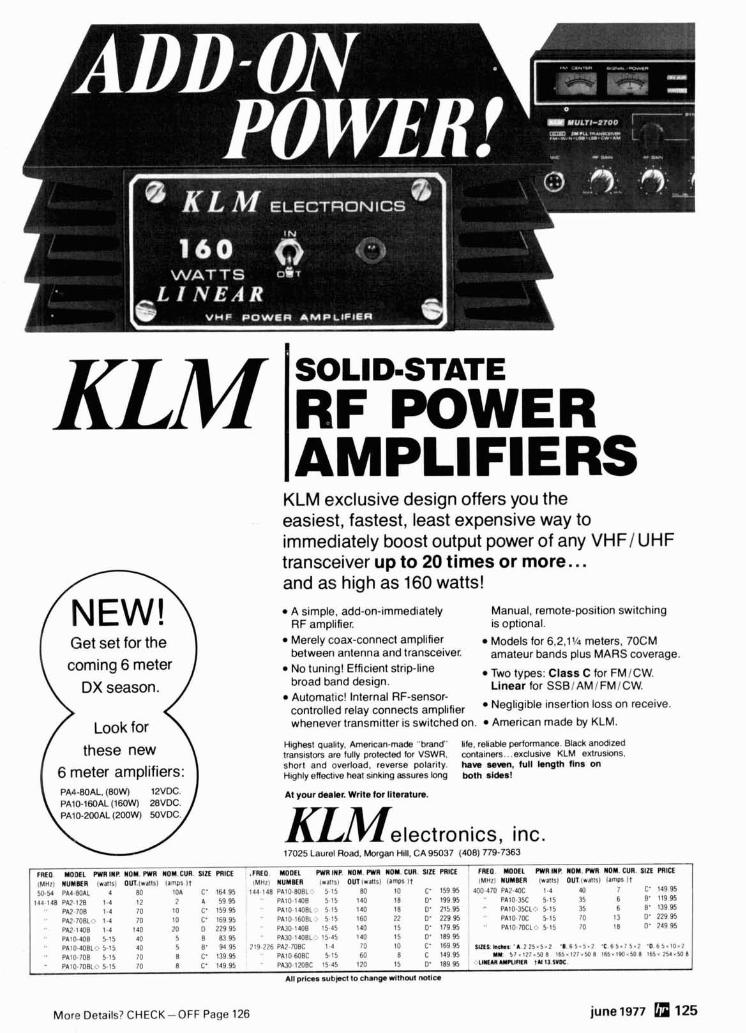
Get set for the coming 6 meter
KLM
DX season. ) Look for ( these new
SOLID=STATE
RF POWER
1 6 meter amplifiers: I
KLM exclusive design offers you the easiest, fastest, least expensive way to immediately boost output power of any VHFI UHF transceiver up to 20 times or more.. . and as high as 160 watts!
A simple, add-on-immediately Manual, remote-position switching RF amplifier. is optional. Merely coax-connect amplifier Models for 6,2,11/' meters, 70CM between antenna and transceiver. amateur bands plus MARS coverage. No tuning! Efficient strip-line Two types: Class C for FMICW. broad band design. Linear for SSBI AM1 FMICW. Automatic! Internal RF-sensor- controlled relay connects amplifier Negligible insertion loss on receive.
whenever transmitter is switched on. American made by KLM.
Highest quality. Arnerican-made "brand life, reliable perfmanca. Blaclc anodized transistors are fully protected for VSWR, containers.. .exclusive KLM extrusions. short and overload, reverse polarity. haw mm, full kngm fins On Highly effective heat sinking assures long both sidssl
At your dwbr. Write tor literature.
K L M e l e c t r o n i c s , inc. 17025 Laurel Road. Morgan Hill. CA 95037 (408) 779-7363
More Details? CHECK-OFF Page 126 june 1977 125
FIKO. MOOEL PWRINP. NOM. PWR NOM.CUR. S I E PRICE .FREO. MODEL PWRINP. MOM. PWR MOM. CUR. SIZE PRICE
(MHZ) NuYMR (watts1 OUT.(wa!rsl lamps It IMHZI NUMBER ~wa f f s l O~T(wa1ls l lamps lt FREO. MODEL PWRINP. MOM. RYR MOM. CUR. SIE PRICE (MHZI NUMBER (wals) OUTIW~I~S) (amps It
50-54 PA4 BOAL 4 80 10A C' 164 95 144-148 PA10 BOBL: 5-15 80 10 !? 15995 400-470 PAL 4OC 1-4 40 7 C' 149 95
144-148 PA7 128 1-4 12 2 L 59 95 " PA10 1408 5-15 140 18 0. 19995 " PA10 35C 5.15 35 6 8 ' 1 1 9 9 5
.. ~ ~ 2 . 7 0 8 1.4 70 10 C. 159 95 ' " PA10-1408L:. 5.15 140 18 0' 215 95 1 " PA10-35CL0 5-15 35 6 8' 139 95
,. p ~ 2 . 7 0 8 ~ 0 1.4 70 10 C' 169 95 '' PA10-1608L 1, 5-15 160 22 0' 229 95 '. PA10-70C 5-15 70 13 229 95 " PA2.1408 1-4 140 20 D 22995 '' PA30-1408 15-45 140 I 5 0' 17995 ! .' PA10-70CLC, 5-15 70 18 0' 249 95
' PA10-400 5-15 40 5 B 83 95 " PA30-l408L,:, 15-45 140 15 0' 189 95
" PA10-40BL.1. 5.15 40 5 8' 9495 219-226 PA2.708C 1-4 70 10 C' 16995
" PA10-708 5.15 70 8 C' 139 95 " PA10-60BC 5.15 60 8 C 14995
PA10-70BLi 5-15 70 8 C' 149 95 .. PA30-l208C 15.45 120 15 D. 189 95
UPS:h6 l r ' L .225 .5 .2 '1 .65-5.2 'C.65.75.2 '0.65.10.2 II 57rl21.508 165.121~508 165.190.50.4 165.254150
L M A R - M n ?Mu.-.
A l l prices subiect to change without n o t l c a
AqerTi~ers l/ check-off
... for literature, in a hurry - we'll rush your name to the companies whose names y o u "check-off" Place your check m a r k in t he space between name and number. Ex: H a m Radio 234
INDEX AGL - 558 ARS Sewices - 588 ATV Research Adva - 265 ~ l d e l c ~ 347 Aluma Tower 589 Ama. Wholesale
~ l c c t . - 003 Arnerlcan - 554 Amsat - 220 Aptron 380 Artco - 563 At lanta Hamfest ' Atlas - 198 Atronics - 382 BK Products - 463
Ramsey - 442 Regency -_ 102 Rohn _ _ 410 SST _ - 375 Sabtronics - 593 Semiconductors
Surolus 512 herw wood -: 435 Space 107 Spectronics - _ 191 Spectrum Int . _ 108 Swan _ . 11 1 Symtek - 203 TPL . 240 Tele. Equip. - 496 Trans Corn _ _ 552 Tri.ex - 116 VHF Comm. - 129 VHFEna . . 121
H a m R a d ~ o - 150 VanguaFd H a m Center - 491 V a r ~ a n -- 043 Hamtronlcs _ . 246 Webster Cornm. - 423 Heath - - 060 Webster Radlo _ - 255 Henry 062 We~nschenker 122 H ~ l d r e t h - 283 Wllson 123 Hy.Ga~n -_ 064 Yaesu 127 Icom _ 065
'Please contact t h i s advertiser directly.
Limit 15 inqrriries per rcqtrest.
June 1977 Please use before July 31, 1977
Tear of f and ma i l t o
H A M RADIO MAGAZINE - "check off" Greenville. N. H. 03048
NAME .................................................................................
CALL ..........................................
STREET ...................................................................................
CITY ......................................................................................................
STATE .............................................. .ZIP ......................... ..........
. / rl
. .- -.. - - --.-/ ---- - - --:: , 4 ::=--a- 1
. - - - - -- --- Liz= &ll ---- -
nothing There's I like it
RAOIO AMATEUR cellbook Respected worldwide as the only complete authority for radio amateur QSL and QTH information.
The U. S. Callbook has nearly 300,000 W & K listings. It lists calls, license classes, names and addresses plus the many valuable back-up charts and references you come to expect from the Callbook.
Specialize in DX? Then you're looking for the Foreign Callbook wi th almost 235,000 calls, names and addresses of ama- teurs outside of the USA.
U.S. Callbook $14.95
Foreign Callbook $13.95
Order from your favorite elec- tronics dealer or direct from the publisher. All direct orders add $1.25 for shipping. Illinois residents add 5% Sales Tax.
RAOlO AMATEUR
Lake Bluff, 111 60044
AGL Electronics . . 107 ARS Cornrnun~cation ~ e r v i c e s 112 ATV Research 118 Adva Electronrcs 94 Aldelco 106 Aluma Tower Co. 108 Amateur Wholesale Electron~cs 98. 99 Amer~can Wholesa 18
74 18 79 12
1 10 24 90
R H Bauman 109 Brevettata 104 Budwlg Mfg. Co. 110 Bullet 82 CFP Commun~ca t~ons 118 Clegg Cornrnun~cat~ons Corp. 82 Cleng Electron~cs 122 Commun~cat~ons Electron~cs 120 Commun~cat~ons Spec~a l~s t s 93. 114 The Computer Room 63 Crystal Banklng Service 102 Cushcraft 85. 115 D D Enterpr~ses 82 DX Eng~neerlng 86 Dames Commun~cat~ons Systems 108 Dames. Ted 110 Data Signal. Inc. 102 Davls Electron~cs 8 7 Dentron Radlo Co. 7 D~sc.Cap 106 Drake Co. R L 44. 45 Ehrhorn Technologtcal Operations 59 Electron~c D~s t r~bu to r s 110 Electron~c Equ~pment Bank 104 Electrospace 88 ELPROCON 112 Ertckson Cornmun~cat~ons 108 Excel C~rcu l ts 108 G~ l f e r Assoc~ates 106 Glade Valley Radlo Sesslons 96 Gray Electronacs 102 Gregory Electronics 114 Hal Commun~cat~ons Corp. 2 Hal-Tronlx 122 Ham Radlo 90. 121. 124 Ham Rad~o Center 89 Hamtron~cs Inc 7 5 Heath Company 57 Henry Rad~o Stores Cover I I Hlldreth Englneerlng 66 Hv G a ~ n Electron~cs Corp 31 lcom l n l ~ n e Instruments. Inc. Integrated C ~ r c u ~ t s Un l lm~ted lnternat~onal Crystal James Electronlcs Jan Crystals K-Enterpr~ses KE Electronlcs KLM Electronlcs. Inc. T r ~ o Kenwood Commun~catlons.
5 124 113
8 105 104 118 11 5 125
Inc. 9. 64. 65 Kester Solder Klaus Rad~o Log~c Systems. Inc Long's Electronlcs Los Angeles Crystal Lunar Electron~cs Lyle Products MFJ Enterpr~ses MHz Electron~cs Madlson Electronic Supply Magnus Electron~cs Marcon1 Eng~neerlng Masters Commun~cat lons Mor Galn N W ARRL Convention New-Tron~cs Corporation NuData Electronlcs Optoelectron~cs Palomar Engineers 118. Partr~dge (HR) Electronlcs Poly Paks Porta Pak Qube lnternatlonal Rad~o Amateur Callbook Rad~o World Ramsey Electronlcs Regency Electronlcs Rohn SST Electronlcs Sabtronlcs lnternatlonal, Inc Semtconductors Surplus Sherwood Englneenng Space Electronlcs Spectronlcs Spectrum lnternatlonal Swan Electronlcs Symtek. Inc TPL Commun~cat~ons Telephone Equ~pment Co Trans Corn Trl ex Tower Corp VHF Commun~cat~ons VHF Eng~neerlng. DIV of brown la^ Vanguard Labs Vanan. E ~ m a c Dtvlslon Webster Commun~cat lons Webster Rad~o We~nschenker Wtlson Electron~cs Yaesu Electronlcs Corp
88. 92. 118 Cover IV
Rf i 120 101
15 Cover I l l
More Details? CHECK-OFF Page 126
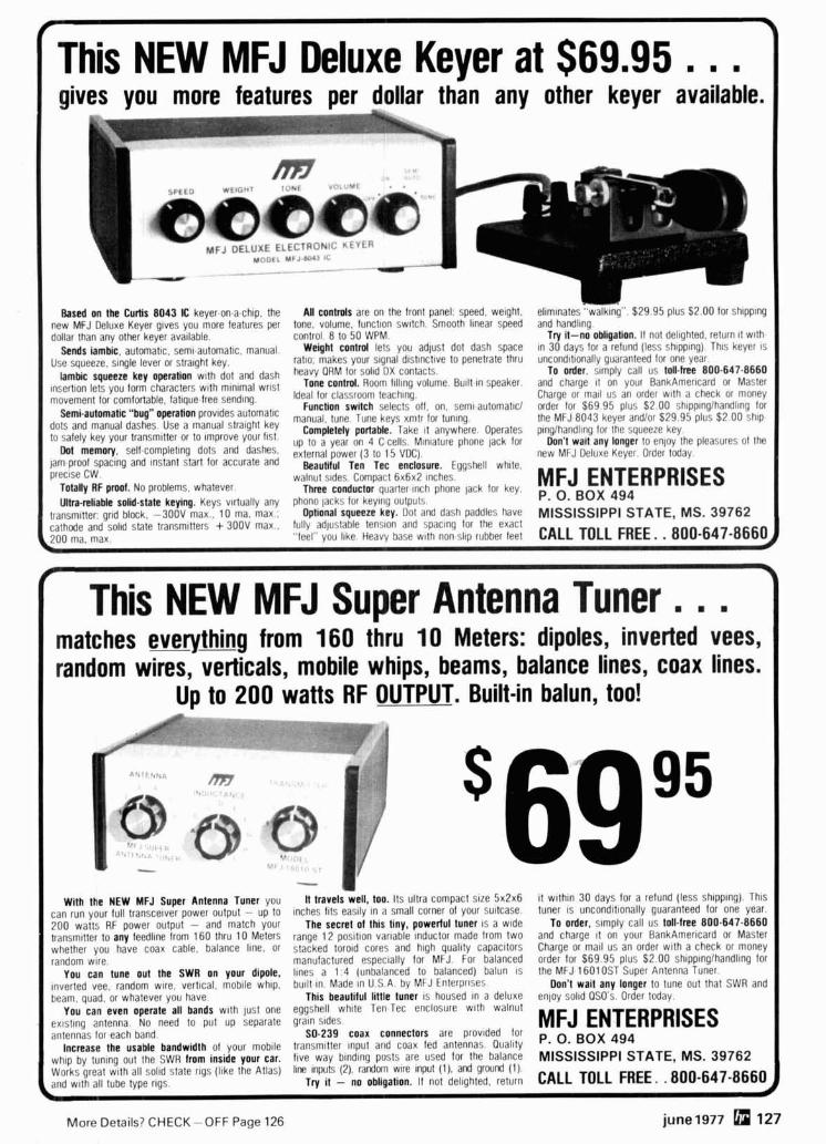
This NEW MFJ Deluxe Keyer at $69.95 . . . ' g iv
MF, .,i. UXE f . , .QOh ' ' *
,&<t:,*: .#, .> 3s.a * 'i
-- -- - - -
Based on the Curtis 8043 IC keyer.on.a.chip, the All controls are on the front panel: speed, weight. eliminates w,tklrl~j". $29.95 plus $2.00 for shlpplng new MFJ Deluxe Keyer glves you more features per tone. volume, lunct~on swltch. Smooth hea r speed and handllnq dollar than any other keyer ava~lable. control 8 to 50 WPM. Try it-no obligation. If not delighted, return 11 with.
sends iambic, automatic, seml-automatic, manual, Weight contml lets you adjust dot dash space In 30 days for a refund (less sh~pplng). T ~ I S keyer 1s Use squeeze, slngle lever or stra~ght key. ratlo. makes your s~gnal dlstlnctlve to penetrate thru uncond~t~onally guaranteed lor one year.
Iambic squeeze key operation w ~ t h dot and dash heavy ORM lor DX To order, stmply call us toll-free 8 0 0 - 6 4 7 4 6 6 0 insertion lets you characters with minimal wrist Tone contml. Room ftlllng volume. Bu~ l t -~n speaker, and chdrqe lt on your BankAmerlcard or Master
movement lor comfortable. latlque.tree sendlng. Ideal lor teaching. Charge or mall us an order w ~ t h a check or money Function switch selects off on seml automat~cl order lor $69.95 plus $2.00 sh~pp~nglhandllng lor Semi.automatic "bug" operation prov~des automatic tune T,lne keys xmtr ior t;nlng, the MFJ 8043 keyer andlor $29.95 plr~s $2 00 shlp
dots and Use a manual key Completely portable. Take ~t anywhere. Operates plnglhandllng lor the squeeze key. to key your transmitter Or Improve 'Ist. up lo CI year on 4 C cells. Mlnlature phone lack for Don't wait any longer to enjoy the pleasures ol the Dot memory, sell completing dots and dashes, external power (3 to 1 5 V D ~ ) , new MFJ [Ieluxe Keyer. Order today.
jam proof spacing and Instant start lor accurate and Beautiful Ten Tee enclosure. Eggshell white, preclse CW. walnut s~des. Compact 6 x 6 ~ 2 ~nches
Totally RF pmof. NO problems, whatever. Three conductor quarter Inch phone lack tor key. MFJ ENTERPRISES Ultra-reliable solid-state keying. Keys v~rtually any phono lacks lor keylllg oulpuls P. 0. BOX 494
transmltter gr~d block. -300V max.. 10 ma, max.; Optional squeeze key. Dot and dash Paddles have MISSISSIPPI STATE, MS. 39762 cathode and sol~d state transm~tters + 300V max.. fully adlustahle tenslon and spaclnq tor the exact
.'tee1 you itre. Heavy base W I ~ non S I I ~ rubber feet CALL TOLL FREE. . 800-547-8660,
This NEW MFJ Super Antenna Tuner. . . matches everything from 1 6 0 thru 10 Meters: dipoles, inverted vees, random wires, verticals, mobile whips, beams, balance lines, coax lines.
Up to 200 watts RF OUTPUT. Built-in balun, too!
With the NEW MFJ Super Antenna Tuner you It travels well, too. Its ultra compact slze 5 x 2 ~ 6 11 w~th ln 30 days for a refund (less shlpplng) Thls can run your full transcetver power output - up to Inches l ~ t s en ,lly In a small corner of your su~tcase tuner IS uncond~ttonally guaranteed for one year 200 watts RF power output - and match your The secret of this tiny, powerful tuner IS a wlde To order, slmply call us toll-free 800-647-8660 transmltter to any feedllne lrom 160 thru 10 Meters range 12 pos~t~on var~able lnductor made lrom two and charge 11 on your BankAmerlcard or Master whether you have coax cable, balance Ilne, or stacked torold cores and h~gh quallty capacitors Charge or mail us an order wlth a check or money random wrre manufactured espec~ally for MFJ For balanced order for $69 95 plus $2 00 sh~pplnglhandllng lor
You can tune out the SWR on your dipole, llnes a 1 4 (unbalanced to balanced) balun IS the MFJ 16010ST Super Antenna Tuner ~nverted vee, random wlre, v ~ r t ~ c a l moblie whlp, bullt ~n Made ~n U S A by MFJ Enterpr~ses Don't wait any longer to tune out that SWR and beam quad, or whatever you have This beautiful ltftle tuner IS housed ~n a deluxe enjoy solld OSO s Order today
You can even operate all bands w ~ t h just one eggshell wh~te Tell Tec enclosure w ~ t h walnut exlstllig antenna No need to put up separate graln stdes antennas for each bdnd
MFJ ENTERPRISES S0.239 coax connectors are provlded lor ,,. O. BOX q94 Increase the usable bandwidth of your moblle transm~tfer Input and coax led antennas Ouallty
wh~p by tun~ng out the SWR from inside your car. f ~ v e way blndlng posts are used for the balance MISSISSIPPI STATE, MS. 39762 Works great w ~ t h all sol~d state rlgs ( I~ke the Atlas) llne Inputs (2) randm wlre Input (I), and grwnd (1) and with all tube type rlgs ~ r y ~t - no obl~gation. II not del~ghted, return CALL TOLL FREE. .800-647-866
More Details? CHECK - OFF Page 126 june 1977 127
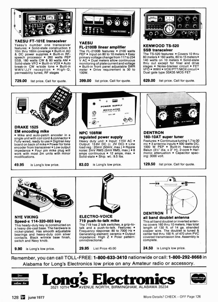
YAESU FT-101 E transceiver Yaesu's number one transceiver features: Solid-state construction 10m thru 160m coverage Built-in AC & DC power supplies Built-in RF- speech processor 260 watts PEP SSB, 180 watts CW & 0 watts AM Solid-state VFO Built-in VOX Auto break-in CW w/side tone Built-in WWV/JJY recept ion High-Q, permeability tuned, RF stages
729.00 Iist price. Call for quote. -
YAESU FL-21OOB llnear ampllfler The FL-2100B features: 2100 watts PEP Input on 80 to 10 meters Easy primaryvoltagechange from 11 7 to 234 V AC Dual meters allow continuous monitoring of plate current and voltage
Built-in front panel adjustable SWR meter Drive requirement is 30 to 1oow.
KENWOOD TS-520 SSB transceiver The TS-520 features: Covers 10 thru 80 meters 160 watts, 80 to 15 meters 140 watts on 10 meters Solid-state thru out except for final and drive sta es Noise-blanker circuit FET V F ~ WWV VOX/PTT/MOX circuit 1 Dual gate type 3SK35 MOS FET
399.00 list price. Call for quote. I 629.00 list price. Call for quote. I
DRAKE 1525 EM encodlng mlke
Mike and auto-patch encoder in a single unit with coil cord &connector* Fully wired, ready to use* Digitran key board on back of mike Power for tone encoder from transceiver Low output impedance Four pin mike plug will work with most 2m units with minor modifications.
NPC 108RM regulated power supply Heavy duty unit: Input: 115V AC Output: 13.6V DC (+ .2V DC) Line load reg.: 20mV (50mV, max.) Ripple noise: 2mV RMS (5mV RMS, max.) 8 amps continuous 12 amps, max. Solid-state Ship. wt.: 9.5 Ibs.
DENTRON 160-1 OAT super tuner Features: Continuoustuning 1.7 to30 mc 3 antenna inputs 500 watts DC, 1000 W PEP Built-in heavy-duty Balun (3%" dia. x 3" H& 2-core Har- monic attenuation apac~tor spac- ing: 3000 volt.
NYE VIKING Speed-x 1 14-320-003 key This heady-duty key is constructed on a heavy die-cast base. The hardware Is nickel-plated. Has smooth adjustable bearings and heavy-duty coin silver contacts. Black wrinkle base finish, switch and Navy knob.
49.95 is Long's low price. 83.03 is Long's low price.
9.m is Long's low price.
129.50 list price. Call for quote. I
ELECTRO-VOICE 719 push-to-talk mlke The 719 has 2 talk switches, a grip-to- talk and a push-to-talk. Features: Frequency response: 80 to 7000 Hz Generating element: ceramic Output impedance: High Z Polar pattern: omnidirectional.
29.95 List Price 45.00
all band doublet antenna This all band doublet or inverted anten- na covers 160 thru 10 meters. Has total length of 130 ft. of 14 ga. stranded copper wire. The doublet is tuned & center fed thru 100 ft. of 470 ohm PVC covered transmission line. Assembly is complete.
24.50 is Long's low price.
Remember, you can call TOLL-FREE: 1-800-633-3410 nationwide orcall: 1-800-292-8668 in Alabama for Long's Electronics low price on any Amateur radio or accessory. -
B A N K A M ~ R I C A R D mzm
AVENUE NORTH, BIRMINGHAM. ALABAMA 35234
128 june1977 More Details? CHECK-OFF Page 126
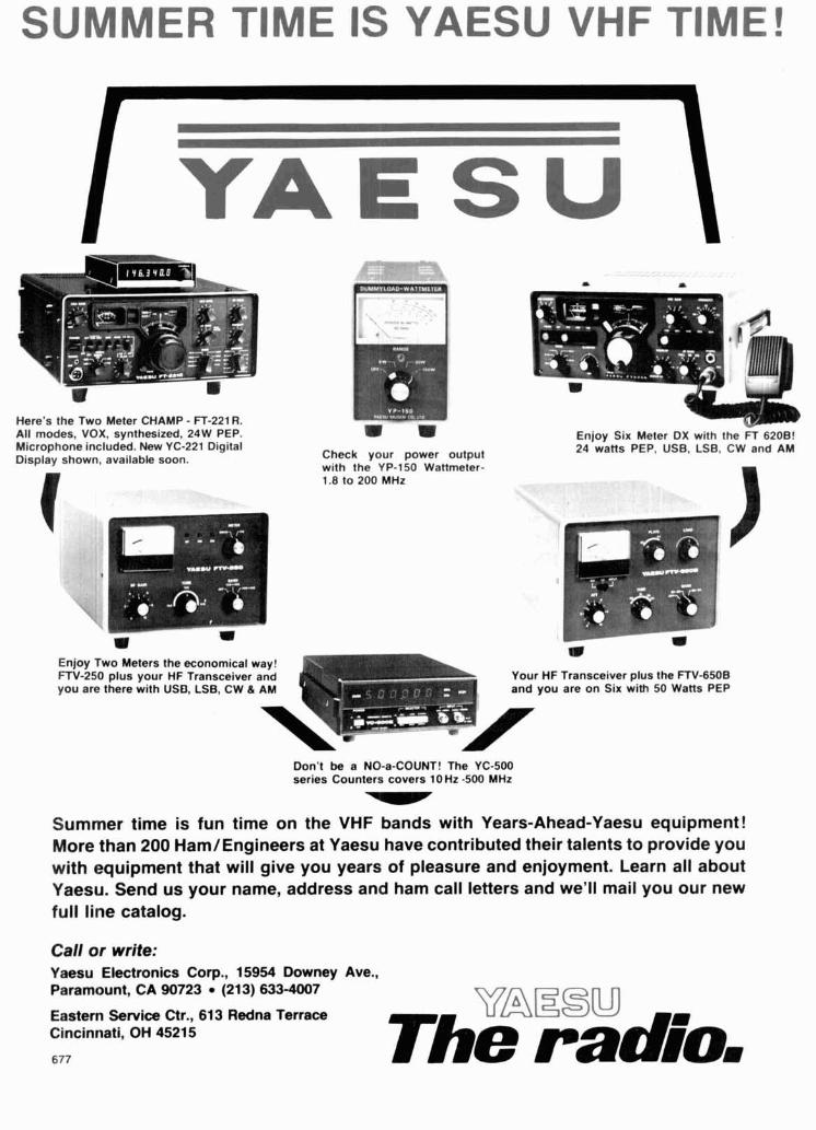
Here's the Two Meter CHAMP - FT-221 R. All modes, VOX, synthesized, 24W PEP. Enjoy Six Meter DX with the FT 6208! Microphone included. New YC-221 Digital
Check your power output 24 watts PEP, USE, LSB, CW and AM Display shown, available soon.
with the YP-150 Wattmeter-
[ 1.8 to 200 MHz
*Ei w w
w Enjoy Two Meters the economical way! FTV-250 plus your HF Transceiver and Your HF Transceiver plus the FTV-650B you are there with USD, LSB, CW & AM and you are on Six with 50 Watts PEP
Don't be a NO-a-COUNT! The YC-500 series Counters covers lOHz -500 MHz -
Summer time is fun time on the VHF bands with Years-Ahead-Yaesu equipment! More than 200 Ham/Engineers at Yaesu have contributed their talents to provide you with equipment that will give you years of pleasure and enjoyment. Learn all about Yaesu. Send us your name, address and ham call letters and we'll mail you our new full line catalog.
Call or write: Yaesu Electronics Corp., 15954 Downey Ave., Paramount, CA 90723 (21 3) 633-4007
Eastern Service Ctr., 613 Redna Terrace Cincinnati, OH 45215
VAEEU 677 The radr'o,
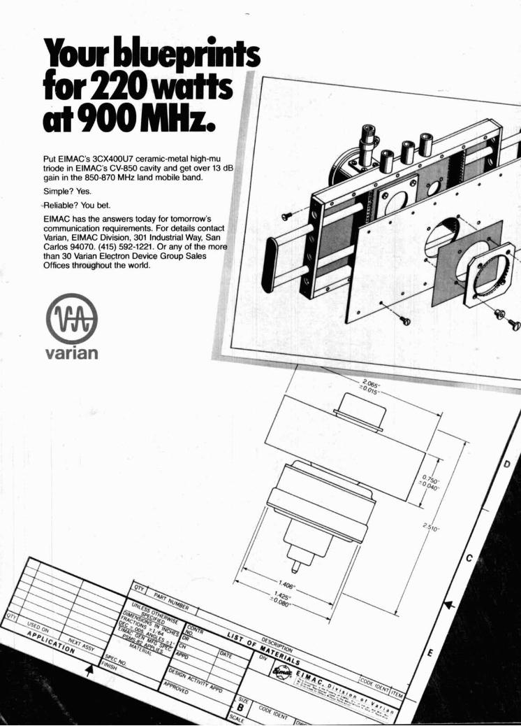
Put EIMAC's 3CX400U7 ceramic-metal high-mu triode in EIMAC's CV-850 cavity and get over 13 dB gain in the 850-870 MHz land mobile band.
Simple? Yes.
-.Reliable? You bet.
ElMAC has the answers todav for tomorrow's .communication requirements: For details contact Varian, ElMAC Division, 301 Industrial Way, San Carlos 94070. (415) 592-1221. Or any of the more than 30 Varian Electron Device Group Sales Offices throughout the world. 1
back€ in bet
I
!nd for your copy of the wid's largest catalog of lality kit-form electronic oduct!
Tal nearly
eath - :tronic
Heathkit Catalog. I am not on your r na~ l~ng Ilat
.- --- leader ce 194;
FILL IN ' CARD l -.. --
THIS 9ND
I I Get your very own copy of the latest I I ",F T A - I , q P / P-
=a 1
I I MAIL-ORDER KIT CATALOG
& ~ i t s for almost everything In
4, electronics; auto and marlne accessories.
L TV, stereo hl-fl, home products
L and much
are easy to
F bulld with cwstalclear.
assembly manuals.
/


