Embed Size (px)
Citation preview
3-1 Alternatives
3.0 ALTERNATIVES
As required by NEPA and Commission policy, we evaluated alternatives to the Project to determine whether any would be environmentally preferable and/or technically and economically feasible to the proposed actions while still meeting the Project’s primary objective of transporting and liquefying domestic natural gas into LNG for export and delivering affordable LNG to foreign markets. The alternatives we considered consisted of the following:
• the No-Action Alternative;
• system alternatives;
• alternative Terminal Expansion sites;
• alternative plot plans for the Terminal Expansion;
• alternative liquefaction technologies;
• supply dock alternatives;
• alternative CSA sites;
• alternative Pipeline Modification sites;
• alternative power source for the refrigeration compressors;
• alternative gas-fired turbine design for the refrigeration compressors; and
• alternative power sources for the Terminal Expansion.
These alternatives were evaluated using a specific set of criteria. The evaluation criteria applied to each alternative included a determination whether the alternative:
• meets the objectives of the proposed action;
• is technically and economically feasible and practical; and
• offers a significant environmental advantage over the proposed action.
Through environmental comparison and application of our professional judgment, each alternative is considered to a point where it becomes clear if the alternative could or could not meet the three evaluation criteria. Our environmental analysis and this evaluation consider quantitative data (e.g., acreage) and use common comparative factors, such as total length, amount of collocation, and land requirements.
In recognition of the competing interests and different nature of impacts resulting from an alternative that sometimes exist (i.e., impacts on the natural environment versus impacts on the human environment), we also consider other factors that are relevant to a particular alternative and discount or eliminate factors that are not relevant or may have less weight or significance.
The alternatives were reviewed against the evaluation criteria in the sequence presented above. The first consideration for including an alternative in our analysis is whether it could satisfy the stated purpose of the Project. An alternative that cannot achieve the purpose for the Project cannot be considered as an acceptable replacement for the Project.
Many alternatives are technically and economically feasible. Technically practical alternatives, with exceptions, would generally require the use of common construction methods. An alternative that
Alternatives 3-2
would require the use of a new, unique, or experimental construction method may not be technically practical because the required technology is not available or is unproven. Economically practical alternatives would result in an action that generally maintains the price competitive nature of the proposed action. Generally, we do not consider the cost of an alternative as a critical factor unless the added cost to design, permit, and construct the alternative would render the Project economically impractical.
Alternatives that would not meet the Project’s objective or were not feasible were not brought forward to the next level of review (i.e., the third evaluation criterion). Determining if an alternative provides a significant environmental advantage to the proposed action requires a comparison of the impacts on each resource as well as an analysis of impacts on resources that are not common to the alternatives being considered. The determination must then balance the overall impacts and all other relevant considerations. In comparing the impact between resources, we also considered the degree of impact anticipated on each resource. Ultimately, an alternative that results in equal or minor advantages in terms of environmental impact would not compel us to shift the impacts from the current set of landowners to a new set of landowners.
Gulf LNG participated in our pre-filing process during the preliminary design stage for the Project (see section 1.3). This process emphasized identification of potential stakeholder issues, as well as identification and evaluation of alternatives that could avoid or minimize impacts. Our analysis of alternatives is based on Project-specific information provided by the applicant, affected stakeholders, those comments received during Project scoping, publically available information, our consultations with federal and state agencies, and our own research regarding the siting, construction, and operation of the LNG facilities and their impacts on the environment (i.e., our alternatives analysis are comment and resource driven). Unless otherwise noted, we used the same desktop sources of information (e.g., aerial photographs, U.S. Geological Survey [USGS] topographic maps, National Wetland Inventory [NWI] maps, agency consultations, and other publicly available information) to standardize comparisons between the Project and each alternative. As a result, some of the information presented in this section relative to the Project may differ from information presented in section 4.0, which is based on Project-specific data derived from field surveys and engineered drawings.
NO-ACTION ALTERNATIVE
Under the No-Action Alternative, the objectives of the Project would not be met, Gulf LNG would not provide LNG for export, and the potential adverse and beneficial environmental impacts identified in section 4.0 of this EIS would not occur. However, development of and production from conventional and unconventional natural gas formations are occurring throughout many areas of the United States and are projected to continue for many years. With or without the No-Action Alternative, other LNG export projects will likely be developed elsewhere in the Gulf Coast region or in other areas of the United States, resulting in both adverse and beneficial environmental impacts. Selection of the No-Action Alternative could result in expansions of other existing terminals and pipeline systems to meet the objectives of the Project, which in turn would likely result in magnitudes and durations of potential adverse environmental impacts that would be similar to those of the Project. Development of any new LNG export terminals on previously undeveloped sites would likely result in greater environmental impacts, in both magnitude and duration, than those of the Project because they would require construction of LNG storage tanks, LNG berthing facilities, and associated facilities that already exist at Gulf LNG’s existing Terminal.
The No-Action Alternative could also require that potential end users make other arrangements to obtain natural gas service, make use of alternative fossil fuel energy sources (e.g., coal or fuel oil), or possibly make use of other traditional long-term fuel source alternatives (such as nuclear power) and/or renewable energy sources (e.g., solar power) to compensate for the reduced availability of natural gas that would otherwise be supplied by the Project. However, each of these are beyond the scope of this
3-3 Alternatives
analysis, as this would not meet the Project objective. Therefore, they are not evaluated further. We have dismissed the No-Action Alternative as a reasonable alternative to meet the Project objectives.
SYSTEM ALTERNATIVES
We reviewed system alternatives to evaluate the ability of existing, modified, or proposed facilities to meet the stated objectives of the Project. Our analysis of the systems alternatives is presented in section 3.2.1 for the Terminal Expansion and section 3.2.2 for the Pipeline Modifications. The purpose of identifying and evaluating system alternatives is to determine whether potential environmental impacts associated with the construction and operation of the Project could be avoided or reduced. By definition, implementation of a system alternative would make it unnecessary to construct all or part of the Project, although modifications or additions to the system alternative may be required to increase capacity or provide receipt and delivery capability consistent with that of the Project. Such modifications or additions may result in potential environmental impacts that would be less than, comparable to, or greater than those associated with construction and operation of the Project.
Terminal Expansion System Alternatives
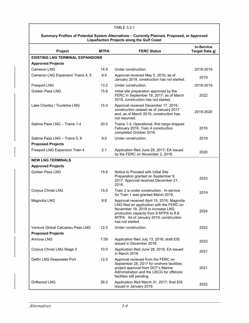
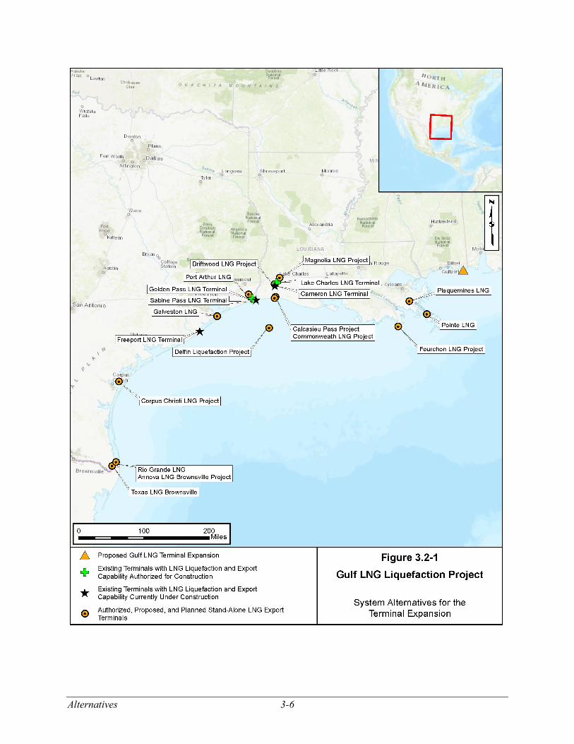
For a system alternative to be viable, it must meet the purpose of the Terminal Expansion, be technically and economically feasible, and offer a significant environmental advantage over the Terminal Expansion. The system alternatives considered in this analysis are identified in table 3.2-1 and depicted in figure 3.2-1. Although we considered each of the planned, proposed, or authorized LNG export projects1 as potential system alternatives, the market will ultimately decide which and how many of these facilities would be built.
As identified in table 3.2-1, there are five existing2 LNG terminal sites along the Gulf Coast in the southeastern United States with approved, proposed, and/or planned expansion(s) to export to FTA countries (eight expansion plans total). We also identified 15 stand-alone3 LNG liquefaction terminals approved, proposed (i.e., filed an application with the FERC), and/or planned (i.e., in the pre-filing process with the FERC). As of March 2019, liquefaction and export facilities are under construction at the Calcasieu Pass LNG, Cameron LNG, Corpus Christi LNG, Freeport LNG, and Sabine Pass LNG terminals. The Sabine Pass LNG and Corpus Christi LNG facilities are partly operational. Construction at each of the other approved, proposed, or planned terminals is pending completion of regulatory review and permitting.
Each of the 8 expansion projects and 15 stand-alone projects were evaluated as potential system alternatives for the Project. All of the projects are authorized to export to FTA countries, or have submitted applications to the DOE to receive authorization to do so, as of March 6, 2019, with the exception of Pointe LNG. The NGA, as amended, has deemed FTA exports to be in the public interest; therefore, we will not speculate or conclude that excess capacity is available to accommodate the purpose and need of the Terminal Expansion. Consequently, the proposed export capacity at any other existing or proposed LNG facility would require an expansion or new facility similar to the facilities proposed for the Terminal Expansion, resulting in environmental impacts similar to the Project. These systems alternatives, therefore, offer no significant environmental advantage over the proposed Project and are not considered to be preferable.
1 Proposed projects are projects for which the proponent has submitted a formal application with the FERC, or for deepwater
port projects, with the DOT’s Marine Administration (MARAD) and the USCG; planned projects are projects that are either in pre-filing or have been announced but have not been proposed.
2 The five existing LNG terminal sites were originally constructed as LNG import projects. 3 “Stand-alone” liquefaction projects are not associated with existing LNG import projects and are typically greenfield
projects; i.e., they are constructed in areas that are undeveloped at the time of construction.
Alternatives 3-4
TABLE 3.2-1
Summary Profiles of Potential System Alternatives – Currently Planned, Proposed, or Approved Liquefaction Projects along the Gulf Coast
Project MTPA FERC Status In-Service
Target Date a/ EXISTING LNG TERMINAL EXPANSIONS Approved Projects Cameron LNG 14.9 Under construction. 2018-2019 Cameron LNG Expansion Trains 4, 5 9.9 Approval received May 5, 2016; as of
January 2019, construction has not started. 2019
Freeport LNG 13.2 Under construction. 2018-2019 Golden Pass LNG 15.6 Initial site preparation approved by the
FERC in September 19, 2017; as of March 2019, construction has not started.
2022
Lake Charles / Trunkline LNG 15.0 Approval received December 17, 2015; construction ceased as of January 2017 and, as of March 2019, construction has not resumed.
2019-2020
Sabine Pass LNG – Trains 1-4 20.0 Trains 1-3: Operational, first cargo shipped February 2016; Train 4 construction completed October 2018.
2016
Sabine Pass LNG – Trains 5, 6 9.0 Under construction. 2019 Proposed Projects Freeport LNG Expansion Train 4 5.1 Application filed June 29, 2017; EA issued
by the FERC on November 2, 2018. 2020
NEW LNG TERMINALS Approved Projects Golden Pass LNG 15.6 Notice to Proceed with Initial Site
Preparation granted on September 9, 2017; Approval received December 21, 2016.
2023
Corpus Christi LNG 15.0 Train 2 is under construction. In-service for Train 1 was granted March 2019. 2019
Magnolia LNG 8.8 Approval received April 15, 2016; Magnolia LNG filed an application with the FERC on November 19, 2018 to increase LNG production capacity from 8 MTPA to 8.8 MTPA. As of January 2019, construction has not started.
2024
Venture Global Calcasieu Pass LNG 12.0 Under construction. 2022 Proposed Projects Annova LNG 7.09 Application filed July 13, 2016; draft EIS
issued in December 2018. 2023
Corpus Christi LNG Stage 3 10.0 Application filed June 28, 2018, EA issued in March 2019. 2021
Delfin LNG Deepwater Port 12.0 Approval received from the FERC on September 28, 2017 for onshore facilities; project approval from DOT’s Marine Administration and the USCG for offshore facilities still pending.
2021
Driftwood LNG 26.0 Application filed March 31, 2017; final EIS issued in January 2019. 2022
3-5 Alternatives
TABLE 3.2-1
Summary Profiles of Potential System Alternatives – Currently Planned, Proposed, or Approved Liquefaction Projects along the Gulf Coast
Project MTPA FERC Status In-Service
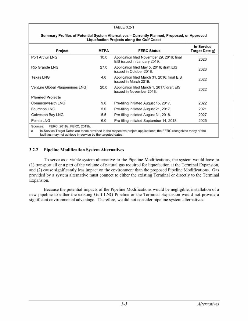
Target Date a/ Port Arthur LNG 10.0 Application filed November 29, 2016; final
EIS issued in January 2019. 2023
Rio Grande LNG 27.0 Application filed May 5, 2016; draft EIS issued in October 2018. 2023
Texas LNG 4.0 Application filed March 31, 2016; final EIS issued in March 2019. 2022
Venture Global Plaquemines LNG 20.0 Application filed March 1, 2017; draft EIS issued in November 2018. 2022
Planned Projects Commonwealth LNG 9.0 Pre-filing initiated August 15, 2017. 2022 Fourchon LNG 5.0 Pre-filing initiated August 21, 2017. 2021 Galveston Bay LNG 5.5 Pre-filing initiated August 31, 2018. 2027 Pointe LNG 6.0 Pre-filing initiated September 14, 2018. 2025 Sources: FERC, 2019a; FERC, 2019b. a In-Service Target Dates are those provided in the respective project applications; the FERC recognizes many of the
facilities may not achieve in-service by the targeted dates.
Pipeline Modification System Alternatives
To serve as a viable system alternative to the Pipeline Modifications, the system would have to (1) transport all or a part of the volume of natural gas required for liquefaction at the Terminal Expansion, and (2) cause significantly less impact on the environment than the proposed Pipeline Modifications. Gas provided by a system alternative must connect to either the existing Terminal or directly to the Terminal Expansion.
Because the potential impacts of the Pipeline Modifications would be negligible, installation of a new pipeline to either the existing Gulf LNG Pipeline or the Terminal Expansion would not provide a significant environmental advantage. Therefore, we did not consider pipeline system alternatives.
Alternatives 3-6
Figure 3.2-1 System Alternatives for the Terminal Expansion
3-7 Alternatives
TERMINAL EXPANSION ALTERNATIVES
Alternative Terminal Expansion Sites
Siting Criteria
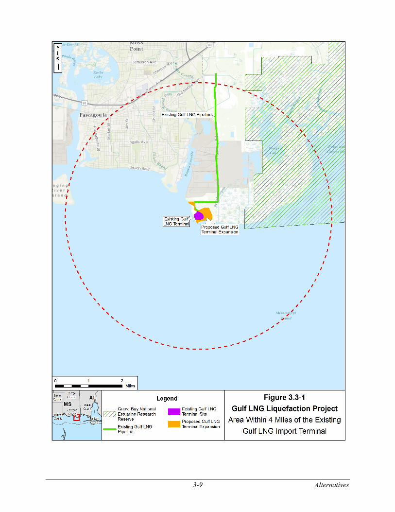
We evaluated the feasibility of constructing the Terminal Expansion at alternative sites. Proximity to the existing Terminal was a criterion in the evaluation to allow Gulf LNG to use the existing infrastructure, including the LNG storage tanks, the LNG carrier berths, and associated facilities. Use of the existing facilities would avoid the impacts of constructing all new facilities. The construction and operation of all new facilities would substantially increase the impacts of the Project as compared to the proposed use of the major LNG infrastructure and facilities at the existing Terminal. Proximity to the existing Terminal would also minimize the length of cryogenic pipelines needed to transport LNG to the existing LNG storage tanks at the Terminal creating additional impacts and siting concerns. Therefore, we evaluated alternative sites for the Terminal Expansion within upland areas in a 4-mile radius of the existing Terminal.
Selection of an alternative Terminal Expansion site near the existing Terminal would require sufficient land (about 231 acres) to construct (1) a natural gas supply pipeline to the site, (2) gas treating facilities, (3) liquefaction facilities, (4) associated support facilities (e.g., power and utilities), (5) a haul road from a supply dock; and (6) one or more cryogenic pipelines from the alternative site to the existing LNG storage tanks.
Alternative Site Assessment
Figure 3.3-1 depicts the area within a 4-mile radius of the existing Terminal. Mississippi Sound and the Gulf of Mexico are south of the Terminal. Lands to the east and northeast of the existing Terminal are within the Grand Bay National Estuarine Research Reserve (Grand Bay NERR), which includes extensive wetland areas, and is not available for development of the Project. The majority of the area north and west of the existing Terminal is heavily developed, including industrial and residential areas, and there is not sufficient land within those areas for a 231-acre project. Undeveloped areas north of the existing Terminal adjacent to about Milepost 4 of the existing Gulf LNG Pipeline were eliminated from consideration because they include about 90 acres of temporarily flooded, needle-leaved evergreen-forested palustrine wetlands and would not be large enough for the Terminal Expansion facilities. The FERC did not receive any comments from the public or federal and/or state agencies requesting an alternative site. In addition, development of the Terminal Expansion in this area would be farther from the existing Terminal and closer in proximity to populated areas and the Chevron Refinery (as compared to the proposed Project). A site farther removed from the existing Terminal would result in additional piping and equipment that could increase the overall likelihood of an incident occurring, and a closer proximity to populated areas may require reliance on additional or more drastic mitigation measures to prevent flammable vapors from extending offsite and impacting populated areas. Additional or larger equipment to handle the larger distances separating the two sites and closer proximity to populated areas could also increase air an noise impacts (if not mitigated) and more drastic mitigation measures (e.g., taller vapor barriers) could negatively affect visual impacts.
As a result of the above considerations, we could not identify a reasonable alternative to the proposed site of the Terminal Expansion that is within an upland area and would provide a significant environmental advantage.
Alternatives 3-8
Alternative Plot Plans for the Terminal Expansion
Criteria for Alternative Layouts of Terminal Expansion Facilities
Gulf LNG provided an assessment of alterative layouts for the Terminal Expansion, which initially focused on the following criteria:
• adequate security for liquefaction trains, tanks, loading facilities, and operational facilities;
• COE requirements for minimizing use of the existing BCDMMS;
• prevailing wind directions at the site, which would influence thermal efficiency;
• maintaining access for construction equipment;
• suitable land for expanding the storm surge protection system; and
• site access that would allow construction of the second liquefaction train while the first train is in operation.
During the pre-filing process, we also requested that Gulf LNG provide a comparison of wetland impacts among the layouts considered.
Potential Plot Plans
Based on the initial criteria, Gulf LNG developed a series of layouts for the site that were on the existing Terminal property and on property adjacent to the existing Terminal. As discussed in section 3.3.1.2, due to the land constraints around the existing Terminal for each layout, the majority of the additional property was within the BCDMMS, with the remaining portion consisting of a small amount of the COE wetland mitigation area south of the Project boundary.
Gulf LNG’s original layout, which was developed without stakeholder input, extended along the shoreline to the north and west. However, this layout would impact the marsh areas directly north of the existing Terminal as well as the wetland mitigation area in the northwest portion of the property. After further review and coordination with engineering and environmental consultants, Gulf LNG refined its preliminary layout to narrow the northwestern area to its current boundaries to reduce impacts on the marsh. Gulf LNG then identified and reviewed configurations for the liquefaction trains within the area adjacent to the existing Terminal. The objective of this review was to develop a configuration for the facilities that would minimize impacts on wetlands adjacent to the existing Terminal, use the smallest possible area of the BCDMMS, and optimize efficiency for operation of the liquefaction facilities.
3-9 Alternatives
Figure 3.3-1 Area Within 4 Miles of the Existing Gulf LNG Import Terminal
Alternatives 3-10
After consulting with the COE, Gulf LNG developed a revised configuration; however, the COE’s review of the new configuration determined that it impacted more of the BCDMMS than desired and the COE requested that the footprint within the BCDMMS be reduced to allow for future dredge material storage and dike construction. In response to that request, Gulf LNG altered the southeastern site boundary to remove about 2.8 acres of the BCDMMS from the Terminal Expansion site, which resulted in the proposed site boundaries.
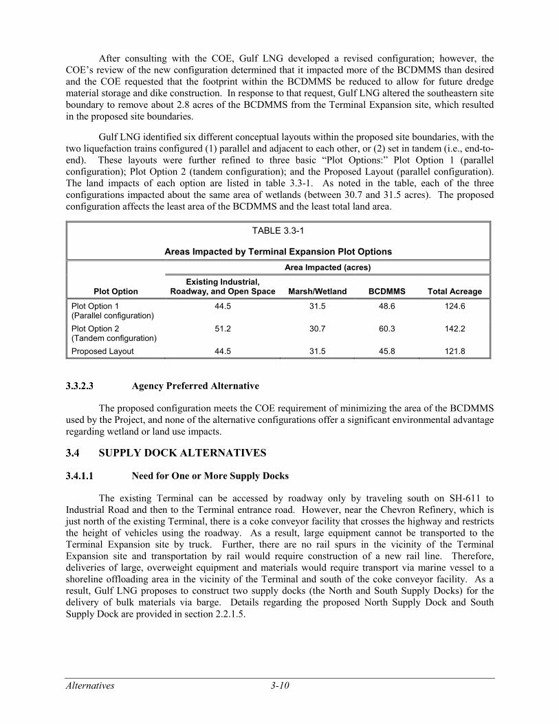
Gulf LNG identified six different conceptual layouts within the proposed site boundaries, with the two liquefaction trains configured (1) parallel and adjacent to each other, or (2) set in tandem (i.e., end-to-end). These layouts were further refined to three basic “Plot Options:” Plot Option 1 (parallel configuration); Plot Option 2 (tandem configuration); and the Proposed Layout (parallel configuration). The land impacts of each option are listed in table 3.3-1. As noted in the table, each of the three configurations impacted about the same area of wetlands (between 30.7 and 31.5 acres). The proposed configuration affects the least area of the BCDMMS and the least total land area.
TABLE 3.3-1
Areas Impacted by Terminal Expansion Plot Options
Plot Option
Area Impacted (acres) Existing Industrial,
Roadway, and Open Space Marsh/Wetland BCDMMS Total Acreage Plot Option 1 (Parallel configuration)
44.5 31.5 48.6 124.6
Plot Option 2 (Tandem configuration)
51.2 30.7 60.3 142.2
Proposed Layout 44.5 31.5 45.8 121.8
Agency Preferred Alternative
The proposed configuration meets the COE requirement of minimizing the area of the BCDMMS used by the Project, and none of the alternative configurations offer a significant environmental advantage regarding wetland or land use impacts.
SUPPLY DOCK ALTERNATIVES
Need for One or More Supply Docks
The existing Terminal can be accessed by roadway only by traveling south on SH-611 to Industrial Road and then to the Terminal entrance road. However, near the Chevron Refinery, which is just north of the existing Terminal, there is a coke conveyor facility that crosses the highway and restricts the height of vehicles using the roadway. As a result, large equipment cannot be transported to the Terminal Expansion site by truck. Further, there are no rail spurs in the vicinity of the Terminal Expansion site and transportation by rail would require construction of a new rail line. Therefore, deliveries of large, overweight equipment and materials would require transport via marine vessel to a shoreline offloading area in the vicinity of the Terminal and south of the coke conveyor facility. As a result, Gulf LNG proposes to construct two supply docks (the North and South Supply Docks) for the delivery of bulk materials via barge. Details regarding the proposed North Supply Dock and South Supply Dock are provided in section 2.2.1.5.
3-11 Alternatives
One Supply Dock Alternative
One alternative to the proposed two supply docks would be to construct and operate only one supply dock. The North Supply Dock would be sited where barge deliveries were made for construction of the existing Terminal.4 However, Gulf LNG determined that with the anticipated deliveries during construction – including more than 19,000 pilings, components of the flare tower, pipe, and other large equipment such as storage containers – would exceed those that were delivered during construction of the existing Terminal and that the use of only one supply dock would serve as a constraint to construction of the facility in a timely manner. As a result, Gulf LNG proposed to construct and use the South Supply Dock during construction of the first liquefaction train and the flare tower. The South Supply Dock would provide access to the southern portion of the construction area, increasing accessibility for offloading fill materials and aggregate. It would also be used for delivery of the flare tower, which would be installed near to and north of the dock. The South Supply Dock would be removed after construction is complete, and the impacted areas restored to pre-construction conditions to the extent practicable. The North Supply Dock would remain after construction and Gulf LNG would transfer ownership to the JCPA Port of Pascagoula who may use the dock for activities such as layberthing of barges, a base of operation for harbor tugs, and/or handling of project cargoes for local industries.5
Use of the Existing LNG Carrier Berthing Facility
An alternative to the construction and use of supply docks would be delivery of materials and equipment to the existing marine berthing facility of the existing Terminal. However, the existing marine berthing facility was designed for berthing and offloading LNG from LNG carriers. It was not designed and is not suitable for offloading heavy equipment and other materials needed for construction. Further, Gulf LNG anticipates that during part of the time that the second liquefaction train is being constructed, the first train would be in-service, and the berthing facility would be in use by LNG carriers and often not available for delivery of construction materials and equipment. As a result, use of the existing berthing facility for delivery of equipment and materials during construction is not a reasonable alternative.
Alternative Sites for the Supply Docks
Alternative sites for the supply docks would have to be reasonably close to the Terminal Expansion site for two primary reasons: (1) they must be sited south of the coke conveyor belt that crosses SH-611 and limits truck delivery of large equipment from north of the conveyor belt, and (2) to minimize construction of new haul roads, which would likely impact additional wetlands.
As indicated on figure 3.3-1, essentially all of the area adjacent to Mississippi Sound and the Bayou Casotte Navigation Channel in the vicinity of the Terminal Expansion site is either wetlands or is heavily developed. Nearby marine shorelines to the east are within the BCDMMS or the Grand Bay NERR, neither of which are available for installation of a supply dock. Nearby marine shorelines to the north and west are either wetlands or developed Chevron property. As a result, we did not identify any reasonable alternative sites for either supply dock.
Preferred Alternative
As a result of these considerations, we conclude that the construction of two supply docks at the proposed sites for use during construction is the preferred alternative. This preferred alternative also
4 A supply dock was not constructed for barge deliveries during construction of the existing Terminal; construction equipment
was offloaded from the barges using cranes. 5 Accession number 20180820-5167.
Alternatives 3-12
includes removal of the South Supply Dock after construction, restoration of the impacted area to pre-construction conditions, and use of the North Supply Dock during operation of the Project.
ALTERNATIVE CONSTRUCTION SUPPORT AREA SITES
Gulf LNG selected CSA sites that were previously used for similar activities and committed to specific measures to avoid impacts on sensitive resources on all but one of those sites, including avoidance of wetlands that are present in portions of some sites (see section 4.4.2). After construction is completed, Gulf LNG would return the sites to pre-construction conditions.
CSA-5 is a 34.5-acre site that is adjacent to and north of the existing Terminal. Gulf LNG would lease the property, which is a partially developed industrial site that includes about 7.6 acres of freshwater wetlands. The wetlands were surveyed and identified as being fragmented and disturbed due to the placement of fill that has altered the hydrology and vegetation; surrounding industrial activities, berms, ditches, and roads also contributed to the degradation of the wetlands. Gulf LNG proposes to clear and fill the site to maximize the useable area for construction support and to provide additional access points to the Project. After construction is complete, Gulf LNG would restore the site to meet owner specifications and terminate the lease. In February 2019, based on comments from the EPA, we asked Gulf LNG to evaluate an alternative location for CSA-5 within the BCDMMS. Gulf LNG indicated that it would not be feasible to relocate CSA-5 within the BCDMMS as this area is an active dredge disposal location that would be periodically inundated with dredge spoil and water. In addition, in section 4.4 we are recommending that Gulf LNG commit to restore the wetlands at CSA-5 to pre-construction conditions following construction in accordance with the FERC Procedures. Therefore, we conclude that impacts on the wetlands associated with CSA-5 would be temporary and not significant, with revegetation likely occurring within 1 to 3 years after the conclusion of construction (in accordance with our Procedures).
We do not consider the other direct impacts on the proposed CSA sites or the impacts due to use of the sites (such as transportation, air quality, and noise impacts) to be significant and, therefore did not assess alternative CSA sites.
ALTERNATIVE PIPELINE MODIFICATION SITES
The Pipeline Modifications would be made at existing metering facilities. As noted in section 1.0, there would also be modifications at the interconnection of the Gulf LNG Pipeline to the Transco/FGT Pipeline System that would be constructed by Transco and reviewed by the FERC under its blanket certificate process. In addition, Gulf LNG would connect the Gulf LNG Pipeline to the gas treatment facilities of the liquefaction trains within the Terminal Expansion site. With one minor exception, the Pipeline Modifications outside of the Terminal Expansion site would be constructed within existing fenced and graveled facilities that are within natural gas pipeline rights-of-way. At the interconnection of the Gulf LNG Pipeline to the Gulfstream Pipeline System, about 0.1 acre of temporary workspace would be required outside of the fenced area, but within the pipeline right-of-way. We did not identify any environmental concerns with the Pipeline Modifications that would require the identification and evaluation alternative sites, nor were any alternatives suggested during the public scoping period.
ALTERNATIVE POWER SOURCES
As proposed, each liquefaction train would have two gas-fired turbines to provide the power required to operate the refrigeration compressors. FERC staff assessed whether using purchased electrical power would be a suitable alternative. To provide the power necessary to operate the remainder of the Project, Gulf LNG would purchase electric power from the grid. As an alternative to that design, we also assessed the use of only on-site power generation.
3-13 Alternatives
Alternative Power Source for the Refrigeration Compressors
A total of 405 MW would be required to power the two liquefaction trains. Of that amount, approximately 387 MW would be provided by the four gas turbines, with the remaining 18 MW provided by four 4.5 MW electric-driven “helper” motors (one per gas turbine) which would obtain power from MPC’s regional electrical transmission grid. The alternative of using electric power to operate the compressors would require that Gulf LNG obtain 387 MW of electrical power from the regional transmission grid. The use of electric power from the grid would avoid on-site emissions from the Terminal Expansion site but would result in additional emissions from the generators supplying power to the grid. MPC stated that the additional electricity required would be obtained from multiple generation sources on the regional electrical transmission grid.
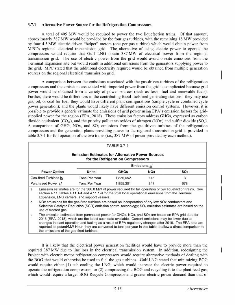
A comparison between the emissions associated with the gas-driven turbines of the refrigeration compressors and the emissions associated with imported power from the grid is complicated because grid power would be obtained from a variety of power sources (such as fossil fuel and renewable fuels). Further, there would be differences in the contributing fossil fuel‐fired generating stations: they may use gas, oil, or coal for fuel; they would have different plant configurations (simple cycle or combined cycle power generation); and the plants would likely have different emission control systems. However, it is possible to provide a generic estimate the emissions of grid power using EPA’s emission factors for grid-supplied power for the region (EPA, 2018). These emission factors address GHGs, expressed as carbon dioxide equivalent (CO2e), and the priority pollutants oxides of nitrogen (NOx) and sulfur dioxide (SO2). A comparison of GHG, NOx, and SO2 emissions from the gas-driven turbines of the refrigeration compressors and the generation plants providing power to the regional transmission grid is provided in table 3.7-1 for full operation of the two trains (i.e., 387 MW of power provided by each method).
TABLE 3.7-1
Emission Estimates for Alternative Power Sources for the Refrigeration Compressors
Power Option Emissions a/
Units GHGs NOx SO2 Gas-fired Turbines b/ Tons Per Year 1,836,652 145 3 Purchased Power c/ Tons Per Year 1,855,301 847 678 a Emission estimates are for the 386.8 MW of power required for full operation of two liquefaction trains. See
section 4.11, tables 4.11.1-4 and 4.11.1-9 for the total local operational emissions from the Terminal Expansion, LNG carriers, and support vessels.
b NOx emissions for the gas-fired turbines are based on incorporation of dry‐low NOx combustors and Selective Catalytic Reduction (SCR) emission control technology; SO2 emission estimates are based on the use of treated gas.
c The emission estimates from purchased power for GHGs, NOx, and SO2 are based on EPA grid data for 2016 (EPA, 2018), which are the latest such data available. Current emissions may be lower due to changes in plant operation and fueling as a result of EPA regulatory changes after 2016. The EPA data are reported as pound/MW Hour; they are converted to tons per year in this table to allow a direct comparison to the emissions of the gas-fired turbines.
It is likely that the electrical power generation facilities would have to provide more than the required 387 MW due to line loss in the electrical transmission system. In addition, redesigning the Project with electric motor refrigeration compressors would require alternative methods of dealing with the BOG that would otherwise be used to fuel the gas turbines. Gulf LNG stated that minimizing BOG would require either (1) sub‐cooling the LNG, which would increase the electric power required to operate the refrigeration compressors, or (2) compressing the BOG and recycling it to the plant feed gas, which would require a larger BOG Recycle Compressor and greater electric power demand than that of
Alternatives 3-14
the gas turbine design. In either case, the power required would be greater than the 387 MW generated by the gas turbines and could increase the purchased power requirements.
Emissions modeling was not conducted for the alternative. The electrical power generation estimates are generic in nature, and based on the available data, we cannot conclude that the alternative of using purchased power offers a significant environmental advantage over the proposed use of gas-fired turbines with emission control equipment.
On-Site Power Generation
In addition to the power required to operate the refrigeration compressors, Gulf LNG would require about 100 MW of power to operate the remainder of the Terminal Expansion. As proposed, this power would be provided by a non-jurisdictional project: MPC would construct and operate two new 115-kV electrical transmission lines and an on-site substation (see section 1.4.1). The on-site substation is included in the environmental analysis presented in this EIS.
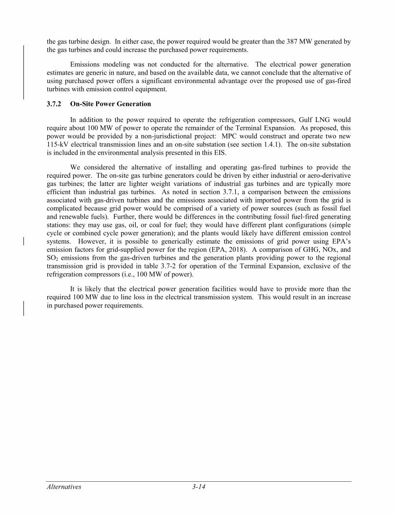
We considered the alternative of installing and operating gas-fired turbines to provide the required power. The on-site gas turbine generators could be driven by either industrial or aero-derivative gas turbines; the latter are lighter weight variations of industrial gas turbines and are typically more efficient than industrial gas turbines. As noted in section 3.7.1, a comparison between the emissions associated with gas-driven turbines and the emissions associated with imported power from the grid is complicated because grid power would be comprised of a variety of power sources (such as fossil fuel and renewable fuels). Further, there would be differences in the contributing fossil fuel‐fired generating stations: they may use gas, oil, or coal for fuel; they would have different plant configurations (simple cycle or combined cycle power generation); and the plants would likely have different emission control systems. However, it is possible to generically estimate the emissions of grid power using EPA’s emission factors for grid-supplied power for the region (EPA, 2018). A comparison of GHG, NOx, and SO2 emissions from the gas-driven turbines and the generation plants providing power to the regional transmission grid is provided in table 3.7-2 for operation of the Terminal Expansion, exclusive of the refrigeration compressors (i.e., 100 MW of power).
It is likely that the electrical power generation facilities would have to provide more than the required 100 MW due to line loss in the electrical transmission system. This would result in an increase in purchased power requirements.
3-15 Alternatives
TABLE 3.7-2
Emission Estimates for Alternative Power Sources for Operation of the Terminal Expansion
Emissions a/ Power Option Units GHGs NOx SO2
Gas-fired Turbine Generators b/ Industrial-Driver Tons Per Year 640,186 504 1 Aero-derivative Driver Tons Per Year 474,212 374 1 Purchased Power c/ Tons Per Year 479,654 219 175 a Emission estimates are for the 100 MW of power required for operation of the Terminal Expansion, not
including the refrigeration compressors of the liquefaction trains. b NOx emissions for the gas-fired turbines are based on incorporation of dry‐low NOx combustors without
SCR emission control technology; due to the size of the turbines, the emissions criteria for New Source Performance Standards can be met without SCR. SO2 emission estimates are based on the use of treated gas.
c The emission estimates from purchased power for GHGs, NOx, and SO2 are based on EPA grid data for 2016 (EPA, 2018), which are the latest such data available. Current emissions may be lower due to changes in plant operation and fueling as a result of EPA regulatory changes after 2016. The EPA data are reported as pound/MW Hour; they are converted to tons per year in this table to allow a direct comparison to the emissions of the gas-fired turbines.
The data in table 3.7-2 indicate that emissions of GHGs for purchased power are about 25 percent lower than those of industrial-driver gas-fired turbines. The GHG emissions for purchased power are about 1 percent higher than those of aero-derivative driver gas-fired turbines, or about 5,442 more tons per year (tpy) of CO2e, though this is likely in the margin of error for the emissions estimates. NOx emissions for purchased power are about 57 percent lower than those of industrial-driver gas-fired turbines, and about 41 percent lower than those of aero-derivative driver gas-fired turbines. Conversely, the SO2 emissions for purchased power are substantially greater than those from both of the gas-fired turbine alternatives, at about 174 more tons per year. Ultimately, attempting to include on-site power generators would be problematic from a space-availability standpoint at the Project site and would increase Project emissions of “criteria pollutants” included in the National Ambient Air Quality Standards, potentially causing the Project to surpass mandated limits (see sections 4.11.1.2 and 4.11.1.5). The electrical power generation estimates are generic in nature, but based on the available data, and considering space constraints at the site, we cannot conclude that the alternative of using on-site gas turbine generators for power to operate the remainder of the Terminal Expansion offers a significant environmental advantage over the proposal.
ALTERNATIVES CONCLUSION
We assessed a range of alternatives for the Gulf LNG Liquefaction Project that could achieve the Project objectives. The alternatives analyzed included the No-Action Alternative, system alternatives, alternative Terminal Expansion sites, alternative plot plans for the Terminal Expansion, supply dock alternatives, alternative CSA sites, alternative Pipeline Modification sites, an alternative power source for the refrigeration compressors, and an alternative power source for the Terminal Expansion. However, none of the alternatives evaluated would provide a significant environmental advantage. Therefore, we conclude that the proposed Project, as modified by our recommended mitigation measures (see section 5.2), is the preferred alternative to meet the Project objectives.
4-1 Geologic Conditions, Resources, and Hazards
4.0 ENVIRONMENTAL IMPACT ANALYSIS
In this section, we discuss the affected environment as it currently exists, general construction and
operational impacts, and proposed mitigation measures for each resource. The applicant, as part of its
proposal, agreed to implement certain measures to reduce impacts on environmental resources. We
evaluated the proposed mitigation measures to determine whether additional measures would be necessary
to reduce impacts. Where we identified the need for additional mitigation, the measures appear as bulleted,
boldfaced paragraphs in the text. We will recommend that these measures be included as specific conditions
to authorizations that the Commission may issue to the applicant.
The environmental consequence of constructing and operating the Project would vary in duration
and significance. Four levels of impact duration were considered: temporary, short-term, long-term, and
permanent. A temporary impact would generally occur during construction, with the resource returning to
pre-construction conditions almost immediately afterward. A short-term impact could continue for up to 3
years following construction. An impact was considered long-term if the resource would require more than
3 years to recover. A permanent impact could occur as a result of an activity that modifies a resource to
the extent that it would not return to pre-construction conditions during the life of the Project, such as the
construction and operational impact of a liquefaction train. We considered an impact to be significant if it
would result in a substantial beneficial or adverse change in the physical environment and the relationship
of people with the environment.
Conclusions in this EIS are based on our analysis of the environmental impact and the following
assumptions:
the applicant would comply with all applicable federal laws and regulations;
the proposed facilities would be constructed as described in section 2.0 and the
recommendations listed in section 5.2 of this document; and
the applicant would implement the mitigation measures included in its application and
supplemental filings to the FERC, and other applicable permits and approvals.
GEOLOGIC CONDITIONS, RESOURCES, AND HAZARDS
Geologic Setting
The Project lies within the Gulf Coastal Plain Physiographic Division of Mississippi and within the
EPA Gulf Barrier Islands and Coastal Marshes ecoregions, which are characterized by brackish marshes,
dunes, beaches, and barrier islands (Chapman et al., 2004). Surficial sediment deposits in the general area
of the Project consisting of gravel, sand, silt, and clay were deposited during the Holocene and Pleistocene
epochs of the Quaternary Period [the last 2.6 million years] (Champlin et al., 1994; Bicker, 1969; Bates and
Jackson, 1984). In Jackson County, Mississippi, these deposits are underlain by older marine and alluvial
sediments from the Quaternary and Tertiary Periods. Cretaceous Period (145 to 66 million years ago)
bedrock occurs at depths greater than 5,000 feet in the Project area. Elevations range from sea level at the
Gulf coast to 200 feet above msl in northern Jackson County, with existing site elevations in the area of the
Terminal Expansion averaging 4 feet above msl. Topography in the Project area is generally flat, with no
significant slopes (Strom and Oakley, 1996).
Geologic Conditions, Resources, and Hazards 4-2
Terminal Expansion
The land at the Terminal Expansion site was previously submerged under the waters of the
Mississippi Sound but was reclaimed by the placement of dredge material from Bayou Casotte in the 1950s
and 1960s (Fugro, 2007). The overlying dredge material was identified through soiling borings conducted
by Gulf LNG during construction of the existing Terminal and extends to a depth of approximately 35 to
50 feet below msl. The dredge materials consist of very soft to soft clays and very loose to loose sands and
silts. A large portion of the Project would be within the boundaries of the BCDMMS.
Bedrock was not encountered during the soil borings conducted by Gulf LNG but is estimated to
be about 5,000 feet deep (Oivanki, 1994). Due to the significant depth to bedrock, blasting is not anticipated
for the Project.
Pipeline Modifications
The geologic setting in the areas of the Pipeline Modifications is similar to that of the proposed
Terminal Expansion site.
Mineral Resources
In Jackson County, the major minerals being exploited include construction sand, gravel, and sulfur
(USGS, 2014a). Other economically viable mineral resources located in Mississippi include bauxite,
glauconite, salt, kaolinite, bentonite, heavy minerals, lime, petroleum, iron, and carbon dioxide (Booth and
Schmitz, 1983).
Terminal Expansion
Except for oil and gas, there are no currently known exploitable mineral resources in the general
vicinity of the Terminal Expansion. Coastal deposits of sand are known to contain heavy minerals such as
kyanite, staurolite, limonite, tourmaline, and zirconium but there is no current or planned extraction of these
potential resources (Booth and Schmitz, 1983; USGS, 2014a; USGS, 2014b). No known mining operations
exist within a 1-mile radius of the Terminal Expansion site.
Oil and gas exploration and production have occurred about 8 miles to the north of the existing
Terminal. Six former oil wells are in this area, the last of which was plugged and abandoned in 2011
(Mississippi Oil and Gas Board, 2010). The closest onshore oil and gas fields are about 50 miles west and
northwest, and the closest offshore well is about 13 miles from the proposed Project (Thompson, 2009;
GSA-SOGB, 2014). Therefore, we conclude that the Terminal Expansion would not affect mining or oil
and gas exploration activities.
Pipeline Modifications
No mineral resources or mineral extraction activities are known to be within close proximity of the
Pipeline Modifications. Therefore, we conclude that the Pipeline Modifications would not affect mining
or oil and gas activities.
Geologic Hazards and Mitigation Measures for the Terminal Expansion
As part of the permitting of the existing Terminal, Gulf LNG conducted a geotechnical
investigation in the winter of 2005 (Fugro, 2007). This initial investigation consisted of five soil borings
to depths of about 104 to 130 feet below msl. In October 2007, additional borings were conducted to a
depth of 30 feet and 16 cone penetration tests to depths of 99 to 130 feet below msl where refusal was
encountered at a very dense silty sand/sand layer.
4-3 Geologic Conditions, Resources, and Hazards
Gulf LNG’s geotechnical consulting firm, Geosyntec, conducted additional geotechnical
investigations in July and August of 2014 to supplement existing geotechnical data for areas that were not
surveyed during construction of the existing Terminal. These investigations confirmed the presence of a
stiff to very stiff clay layer between approximately 60 and 123 feet below msl, and a very dense sand layer
117 feet below msl, with a thickness greater than 29 feet. The Terminal Expansion site would be cleared,
graded, and filled to achieve a general site grade of 10 to 13 feet above NAVD. Because of the presence
of very soft, compressible soils, Gulf LNG would support all settlement sensitive structures on deep
foundations. Lightly loaded structures or equipment insensitive to settlement may be founded on shallow
piles or concrete pads if appropriate.
Natural hazards including seismicity, soil liquefaction, landslide susceptibility, flooding, storm
surge, tsunami, settlement, scour, and erosion for the Terminal Expansion are discussed in detail in section
4.12.1 of this EIS.
Geologic Hazards and Mitigation Measures for the Pipeline Modifications
Geologic hazards are defined by the American Geological Institute as “geologic conditions or
phenomena that present a risk or are a potential danger to life and property, either naturally occurring or
man-made” (Bates and Jackson, 1984). Potential geologic hazards in the vicinity of the Pipeline
Modifications include seismic ground shaking, faults, soil liquefaction, slope failures/landslides, tsunamis,
erosion, flooding, and ground subsidence. Neither volcanism nor karst topography occurs within the
vicinity of the Pipeline Modifications and these geologic hazards were excluded from further consideration.
Seismic Ground Shaking Hazards
The majority of significant earthquakes around the world are associated with tectonic subduction
zones, where one crustal plate is overriding another (e.g., the Japanese islands), where tectonic plates are
sliding past each other (such as in California), or where tectonic plates are converging (e.g., the Indian Sub-
Continent). Unlike these highly active tectonic regions, the Gulf coast of the United States is not a
tectonically active area. No significant active or major inactive faults were identified through a review of
structural feature maps of Mississippi (Thompson, 2009). However, a belt of mostly seaward-facing faults,
collectively known as the Gulf-margin normal faults occur along the Gulf of Mexico. These faults exist in
sediments and poorly lithified rocks and most of these materials are unable to support the extreme stress
required for the propagation of significant seismic events and ground motion (Crone and Wheeler, 2000).
The Pipeline Modifications are in an area of low seismicity. Earthquakes have occurred in
Mississippi, but occurrences have been infrequent and of low magnitude, with most having a magnitude of
3.5 to 4.0 (ML) on the Richter scale, too small to have caused serious damage to property or structures
(USGS, 2014c; USGS, 2014d). Several significant earthquakes occurred in the New Madrid Seismic Zone
near New Madrid, Missouri, about 450 miles northwest of the Pipeline Modifications sites, during the
winter of 1811 to 1812. The largest of these earthquakes was estimated to have a magnitude of 7.0 or higher
(USGS, 2014c; USGS, 2014ehttp://earthquake.usgs.gov/learn/topics/mag_vs_int.php) and resulted in
significant damage from ground motion in the New Madrid, Missouri area. These earthquakes also caused
some damage in northern Mississippi, more than 250 miles from the Terminal area (Bograd, 2014).
Gulf LNG conducted a review of historical aerial photography, topographic maps, subsurface
structural maps, and conducted site reconnaissance in order to document any features that may indicate a
potential for surface faulting. The results of Gulf LNG’s investigation indicated that there were no reported
active seismogenic faults within an approximate 350-mile radius of the Project. There are also many
mapped extensional growth faults identified in the northern Gulf of Mexico near Texas and Louisiana.
However, these typically normal faults have not been identified in or near Mississippi (Champlin et al.,
1994).
Geologic Conditions, Resources, and Hazards 4-4
Seismic risk can be quantified by motions experienced at the ground surface or by structures during
a given earthquake, expressed in terms of the acceleration due to gravity (g). The USGS estimates peak
ground accelerations in Southern Mississippi to be in the range of 4 to 6 percent of the acceleration of
gravity (0.04 to 0.06 g) and have a 2 percent probability of being exceeded in 50 years (USGS, 2014f).
Pipeline Modifications would take place at the existing Destin Meter Station, Gulfstream Meter
Station, and the Transco/FGT Interconnection. Due to the low probability of a significant seismic event in
the area and ground disturbing work being limited, we conclude that only a minimal overall hazard would
be associated with seismicity and surface faulting at the Pipeline Modifications sites.
Soil Liquefaction
Soil liquefaction occurs when a saturated soil loses its load-bearing capability through an increase
in pore water pressure that results from seismic ground shaking. Saturated sandy soils with low silt and
clay content are susceptible to soil liquefaction during seismic events. Soils must exhibit the three following
characteristics in order for soil liquefaction to occur: (1) a clay content of less than 15 percent by weight;
(2) a liquid limit less than 35 percent; and (3) a moisture content more than 0.9 times the liquid limit.
Soils within the Pipeline Modification sites are of the type considered to have a moderate to high
soil liquefaction potential. However, the risk of strong earthquake ground motions occurring at the site is
relatively low. Because the potential for seismic ground shaking in the vicinity of the Pipeline
Modifications is low, we conclude the probability of soil liquefaction is also low.
Landslide Incidence and Susceptibility
“Landslides” are defined as the movement of rock, debris, or soil down a slope (USGS, 2014g).
Given that the topography of the Pipeline Modifications sites is relatively flat, with very little grade change,
the Pipeline Modifications have a low risk of impact caused by landslides.
Ground Subsidence
Subsidence hazards involve either the sudden collapse of the ground to form a depression or the
slow subsidence or settlement of sediments near the ground’s surface. Ground subsidence in the vicinity
of the Project could result from natural geologic processes or from man-made processes, such as subsurface
mining and removal of fluid from underground reservoirs, such as aquifers or oil fields. The Northeast
Petit Bois Pass and Northwest Dauphin Island oil fields are off of the Alabama coast and are 12.5 and
13.5 miles respectively to the southeast.
Work associated with the Pipeline Modifications would be limited to existing facilities. Any
subsidence hazards would have been addressed during construction of the existing facilities and land at the
facility location was converted to industrial use. We conclude the potential for subsidence hazards to
pipeline facilities in areas of Pipeline Modifications would be low.
Flooding/Storm Surge/Tsunamis
A flood occurs when the water level in a stream or river channel overflows the natural or man-
made bank. Storm surge from tropical cyclones and tsunamis can also cause flooding. There are no records
of tsunamis in the vicinity of the Project (Dunbar and Weaver, 2008). Storm surge is a coastal phenomenon
associated with low-pressure weather systems, typically intense hurricanes and winter storms. The surge
of ocean water inland above the high tide mark is a result of low barometric pressure combined with high
winds pushing on the ocean surface, causing the water to “pile up” higher than ordinary sea level. The
storm surge effect is enhanced if it occurs at high tide (NWS, 2014).
4-5 Geologic Conditions, Resources, and Hazards
Flash floods typically result from intense rapid precipitation in upstream areas that leads to
extensive short-duration runoff into the stream channel. The 100-year flood represents a river channel
water level that, based on an analysis of the historic record, is likely to be equaled or exceeded every 100
years-meaning that there is a 1 percent chance that the water level will be equaled or exceeded in any
individual year during a century. The 100-year flood is generally used for planning purposes for buildings
within a floodplain to assess the likelihood of inundation over time.
The Pipeline Modification sites are proposed about 3 to 4 miles inland and the work would be
limited to modifications to existing facilities with limited ground disturbance. Construction of the Pipeline
Modifications would not have any increased risk from flooding, storm surge, or tsunamis.
Shoreline Erosion and Localized Scour
The Destin Meter Station, Gulfstream Meter Station, and Transco/FGT Interconnection would not
be located directly on the coast or along a major waterbody; therefore, the facilities would not be subjected
to direct effects from shoreline erosion.
Paleontology
While fossils along the Gulf coast of Mississippi are generally rare, the dredge material that makes
up the majority of the Project area is known to contain fossil fragments (such as shark teeth and whale
bones). Holocene marine fossil fragments are sometimes found within sedimentary units deposited in these
epochs, but these fragments have little scientific value. The Project facilities would not impact any older
underlying geologic formations or the fossils, if any, within them. If any paleontological resources are
discovered during construction, they would be treated in accordance with Gulf LNG’s Unanticipated
Discoveries and Emergency Procedures Plan (see appendix F). We have reviewed Gulf LNG’s
Unanticipated Discoveries and Emergency Procedures Plan and find it acceptable.
Soils 4-6
SOILS
Potential impacts on soil resources during construction and operation of the Terminal Expansion
and Pipeline Modifications may be associated with soil limitations, prime farmland, hydric soils, soil
compaction, soil erosion, revegetation, and contamination.
Soil Types and Limitations
Soil types and the general attributes and limitations that occur within the Project area were
identified through the U.S. Department of Agriculture (USDA) Natural Resources Conservation Service
(NRCS), Soil Survey Geographic (SSURGO) (NRCS, 2014a) and Web Soil Survey Application (NRCS,
2014b; NRCS, 2015a; NRCS, 2015b). This section describes the soil series, limitations, and attributes that
would be impacted by the proposed Project. Table 4.2.1-1 presents a summary of soils limitations that
would be affected by the proposed Project by component and a detail of soils.
Terminal Expansion
Soils within the Terminal Expansion site consist of the Axis series that is a mucky sandy clay loam
soil, a very small proportion of Udorthents (<1 percent), and water. As discussed, land at the Terminal
Expansion site had previously been submerged under the waters of the Mississippi Sound but was reclaimed
through the placement of material from Bayou Casotte dredging activities in the 1950s and 1960s (Fugro,
2007). The overlying dredge material is about 35 feet to 50 feet deep and was identified through soiling
borings conducted by Gulf LNG during construction of the existing Terminal. Additionally, about 46 acres
of the proposed Terminal Expansion site is located within the BCDMMS and this area, although mapped
as Axis mucky sandy clay loam by the NRCS, consists of dredge spoils, which may not have the same
characteristics as the Axis series. Soils within the BCDMMS are also recent dredge spoils and consist of
very soft-to-soft clay surface soils which are underlain by soft and loose sands, silts, sandy clays, and clayey
sands. These soils in turn are underlain by a thick layer of soft gray clay, which contains pockets and lenses
of fine sands. Dredge materials within the BCDMMS range from thicknesses of 15 to 25 feet (COE, 2000).
Gulf LNG would remove about 1,524,600 cy of dredged material from the BCDMMS. Gulf LNG estimates
about 7 feet of material would be removed from the BCDMMS. Gulf LNG estimates that 20 percent
(304,920 cy) of BCDMMS material and about 770,080 cy of fill (preferably from the COE Tombigbee
Project) would be used to raise the grade of the Terminal Expansion site to an elevation of 12 to 13 NAVD.
The remaining 1,219,680 cy of BCDMMS material would be disposed of at an approved upland site. About
323,000 cy of fill from the COE Tombigbee Project would be used as fill material for the off-site wetland
mitigation site (see section 4.4.3).
Construction of the Terminal Expansion would temporarily impact 0.2 acre of the Axis series.
Permanent impacts due to construction of the Terminal Expansion, access roads, and the North and South
Heavy Haul Roads would include 112.9 acres of the Axis series, of which about 46.0 acres mapped as Axis
series are in fact dredge spoils within the BCDMMS. Expansion of the Terminal, access roads, and North
and South Heavy Haul Roads would also permanently impact 0.5 acre of Udorthents and 6.3 acres of
Water/Axis series. According to Gulf LNG, the 6.3 acres currently mapped by the NRCS as water was
determined during field surveys to be the Axis series that is frequently flooded.
The Terminal Expansion would also include construction of a permanent North Supply Dock and
a temporary South Supply Dock. Construction of the North Supply Dock would permanently affect 0.9
acre of the Axis series and 8.2 acres of water, while construction of the South Supply Dock would
temporarily affect 4.9 acres of water and 1.5 acres of the Axis series. The water surrounding the supply
docks consists of marine sediments, which do not have the same limitations as soils.
4-7
So
ils
4-7
E
nviro
nm
enta
l Impa
ct An
alysis
4
-7
Soils
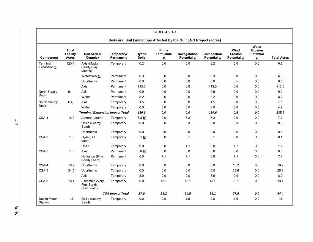
TABLE 4.2.1-1
Soils and Soil Limitations Affected by the Gulf LNG Project (acres)
Component
Total Facility Acres
Soil Series/ Complex
Temporary/ Permanent
Hydric Soils
Prime Farmlands
a/ Revegetation Potential b/
Compaction Potential c/
Wind Erosion
Potential d/
Water Erosion Potential
e/ Total Acres
Terminal Expansion f/
120.4 Axis (Mucky Sandy Clay Loams)
Temporary 0.2 0.0 0.0 0.2 0.0 0.0 0.2
Water/Axis g/ Permanent 6.3 0.0 0.0 6.3 0.0 0.0 6.3
Udorthents Permanent 0.0 0.0 0.0 0.0 0.5 0.0 0.5
Axis Permanent 113.5 0.0 0.0 113.5 0.0 0.0 113.5
North Supply Dock
9.1 Axis Permanent 0.9 0.0 0.0 0.9 0.0 0.0 0.9
Water Permanent 8.2 0.0 0.0 8.2 0.0 0.0 8.2
South Supply Dock
6.4 Axis Temporary 1.5 0.0 0.0 1.5 0.0 0.0 1.5
Water Temporary 0.0 0.0 0.0 0.0 0.0 0.0 4.9
Terminal Expansion Impact Total 130.6 0.0 0.0 130.6 0.5 0.0 135.9
CSA-1 16.0 Atmore (Loam) Temporary 7.2 h/ 0.0 7.2 7.2 0.0 0.0 7.2
Ocilla (Loamy Sand)
Temporary 0.0 0.0 0.3 0.0 0.3 0.0 0.3
Udorthents Temporary 0.0 0.0 0.0 0.0 8.5 0.0 8.5
CSA-2 1.8 Hyde (Silt Loam)
Temporary 0.1 h/ 0.0 0.1 0.1 0.0 0.0 0.1
Ocilla Temporary 0.0 0.0 1.7 0.0 1.7 0.0 1.7
CSA-3 7.8 Axis Permanent 0.8 h/ 0.0 0.0 0.8 0.0 0.0 0.8
Harleston (Fine Sandy Loam)
Permanent 0.0 7.1 7.1 0.0 7.1 0.0 7.1
CSA-4 16.2 Udorthents Temporary 0.0 0.0 0.0 0.0 16.2 0.0 16.2
CSA-5 34.5 Udorthents Temporary 0.0 0.0 0.0 0.0 25.6 0.0 25.6
Axis Temporary 8.9 0.0 0.0 8.9 0.0 0.0 8.9
CSA-6 18.1 Escambia (Very Fine Sandy Clay Loam)
Temporary 0.0 18.1 18.1 18.1 18.1 0.0 18.1
CSA Impact Total 17.0 25.2 34.5 35.1 77.5 0.0 94.4
Destin Meter Station
1.5 Ocilla (Loamy Sand)
Temporary 0.0 0.0 1.5 0.0 1.5 0.0 1.5
So
ils 4-8
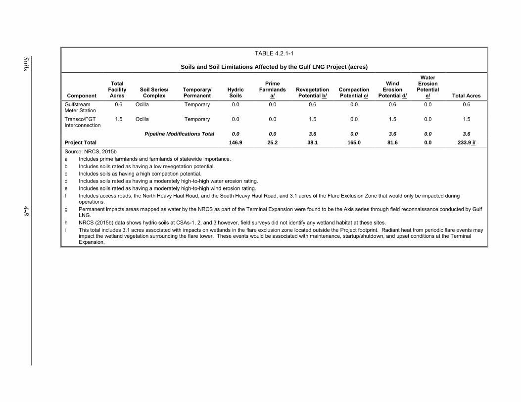
TABLE 4.2.1-1
Soils and Soil Limitations Affected by the Gulf LNG Project (acres)
Component
Total Facility Acres
Soil Series/ Complex
Temporary/ Permanent
Hydric Soils
Prime Farmlands
a/ Revegetation Potential b/
Compaction Potential c/
Wind Erosion
Potential d/
Water Erosion Potential
e/ Total Acres
Gulfstream Meter Station
0.6 Ocilla Temporary 0.0 0.0 0.6 0.0 0.6 0.0 0.6
Transco/FGT Interconnection
1.5 Ocilla Temporary 0.0 0.0 1.5 0.0 1.5 0.0 1.5
Pipeline Modifications Total 0.0 0.0 3.6 0.0 3.6 0.0 3.6
Project Total 146.9 25.2 38.1 165.0 81.6 0.0 233.9 i/
Source: NRCS, 2015b
a Includes prime farmlands and farmlands of statewide importance.
b Includes soils rated as having a low revegetation potential.
c Includes soils as having a high compaction potential.
d Includes soils rated as having a moderately high-to-high water erosion rating.
e Includes soils rated as having a moderately high-to-high wind erosion rating.
f Includes access roads, the North Heavy Haul Road, and the South Heavy Haul Road, and 3.1 acres of the Flare Exclusion Zone that would only be impacted during operations.
g Permanent impacts areas mapped as water by the NRCS as part of the Terminal Expansion were found to be the Axis series through field reconnaissance conducted by Gulf LNG.
h NRCS (2015b) data shows hydric soils at CSAs-1, 2, and 3 however, field surveys did not identify any wetland habitat at these sites.
i This total includes 3.1 acres associated with impacts on wetlands in the flare exclusion zone located outside the Project footprint. Radiant heat from periodic flare events may impact the wetland vegetation surrounding the flare tower. These events would be associated with maintenance, startup/shutdown, and upset conditions at the Terminal Expansion.
4-9 Soils
Installation of the supply docks would require dredging of about 100,000 cy of sediment for each
dock to a depth of 12 feet below msl. Gulf LNG initially planned to dispose of dredge materials from
construction of the supply docks at one of two state-approved BU sites: Greenwood Island and Round
Island. However, the Round Island is privately owned and not expected to be available. According to Gulf
LNG, the Greenwood Island site is expected to reach capacity prior to construction, but will be expanded
250-acres by February 2020. Gulf LNG would prefer to use a BU site for disposal and would work with
federal and state agencies to identify a suitable BU site for dredge material disposal. Gulf LNG would
utilize an offshore dredged material disposal site if a suitable BU site is not available.
Additionally, Gulf LNG would utilize six CSAs during construction. All of the CSAs have been
previously used for industrial activities. However, part of the undeveloped eastern half of CSA-5 would
require clearing of upland forested land and the filling of wetland areas to maximize useable space.
Pipeline Modifications
The Pipeline Modifications would temporarily impact a total of 3.6 acres of Ocilla loamy sand. To
minimize impacts on soils, Gulf LNG would construct and restore the Pipeline Modifications in accordance
with the Gulf LNG Plan, (see appendix D) which includes provisions for erosion control, restoration, and
revegetation, as identified in the FERC’s Plan.
Prime Farmland Soils
Prime farmland soils have the best combination of physical and chemical characteristics for
producing food, feed, forage, fiber, and oilseed crops (NRCS, 2014c). It is a special classification that
receives special protections under the Federal Surface Mining Control and Reclamation Act of 1977. In
general, prime farmland soils have adequate and dependable precipitation, a favorable temperature and
growing season, have acceptable acidity or alkalinity, and have few or no surface stones. They are
permeable to water and air. Prime farmland soils are not excessively erodible or saturated with water for
long periods of time.
Terminal Expansion
There are no prime farmland soils at the Terminal Expansion site. Therefore, there would be no
impacts on prime farmland soils in this area.
Only the Harleston fine sandy loam and Escambia very fine sandy loam soil type located at CSA-
3 and CSA-6, respectively are considered to be prime farmland soil. CSA-3 contains 7.1 acres of prime
farmland soils and CSA-6 contains 18.1 acres of prime farmland soils. CSA-3 is currently used by Gulf
LNG for warehousing and equipment storage while CSA-6 is currently being used as a parking lot with a
layer of crushed gravel covering the area. Neither CSA contains any active agricultural operations and both
are already being used for industrial use; therefore, no new impacts on prime farmland soils would be
expected.
Pipeline Modifications
None of the soils in the areas of the Destin Meter Station, the Gulfstream Meter Station, and the
Transco/FGT Interconnection, have been identified to be prime farmland soils. Therefore, no impacts on
prime farmlands would occur due to the Pipeline Modifications.
Soils 4-10
Hydric Soils
Hydric soils are formed under conditions of saturation, flooding, or ponding long enough during
the growing season to develop anaerobic conditions in the upper soil horizon (NRCS, 2014d). These soils
are typically associated with wetlands. Soils that are artificially drained or protected from flooding (e.g.,
by levees) are still considered hydric if the soil in its undisturbed state would meet the definition of a hydric
soil.
Terminal Expansion
The Axis soil series present at the Terminal Expansion site, access roads, and North and South
Heavy Haul Roads is categorized as hydric due to its high water content. Construction of the Terminal
Expansion, access roads, and North and South Heavy Haul Roads would permanently impacted 119.7 acres
and temporarily impact 0.2 acre of the Axis series (see table 4.2.1-1). We believe that this would be a
significant environmental impact without mitigation; however, these impacts would be reduced to less than
significant levels from implementation of the wetland mitigation and conservation measures identified in
section 4.4.
Construction of the North Supply Dock would permanently affect 0.9 acre of hydric soils while
construction of the South Supply Dock would temporarily affect 1.5 acres of hydric soil.
The Atmore, Hyde, and Axis soil series impacted by the CSAs are considered to be hydric soils.
Use of the CSAs would temporarily impact 7.2 acres of the Atmore series at CSA-1, 0.1 acre of the Hyde
series at CSA-2, and 8.9 and 0.8 acres of the Axis series at CSA-5 and CSA-3, respectively. NRCS (2015b)
data shows hydric soils at CSAs-1, 2, and 3 however, field surveys did not identify any wetland habitat at
these sites. Permanent impacts totaling 9.7 acres of the Axis series would occur at CSA-3 and CSA-5.
However, both these CSAs are currently used as commercial/industrial sites. In addition, implementation
of the measures contained in the Gulf LNG Procedures (see appendix E) which incorporates the FERC’s
Procedures, would adequately minimize potential impacts on hydric soils during construction.
Pipeline Modifications
Modifications to the Destin Meter Station, the Gulfstream Meter Station, and the Transco/FGT
Interconnection would not affect any hydric soils. Therefore, no impacts on hydric soils would occur due
to the Pipeline Modifications.
Compaction Potential
Soil compaction modifies the structure and reduces the porosity and moisture-holding capacity of
the soil. The degree of soil compaction during construction depends on moisture content and soil texture.
Fine-textured soils with poor internal drainage and high shrink-swell potential are the most susceptible to
compaction. Construction equipment traveling over wet soils could disrupt soil structure, reduce pore
space, increase runoff potential, and cause rutting. Moist or saturated soils are more likely to compact or
rut.
Terminal Expansion
All of the soils at the Terminal Expansion site, access roads, and North and South Heavy Haul
Roads are susceptible to compaction and rutting. During construction, loss of soil productivity is likely to
occur from compaction and damage to soil structure from heavy equipment. However, these areas would
be developed; replaced by structures, paving, and gravel; and not used to support vegetation. Therefore,
compaction is not a concern.
4-11 Soils
About 7.2 acres at CSA-1 (7.2 acres), 0.1 acre at CSA-2, the 0.8 at CSA-3, and 18.1 acres at CSA-
6 have a compaction potential rating of high (see table 4.2.1-1). The CSAs would be restored as per owner’s
specifications except for CSA-3, which would remain in use by Gulf LNG during operation of the proposed
Project. Additionally wetland impacts at CSA-5 would be permanent. However, we have determined that
Gulf LNG has not adequately justified permanently filling the wetlands at CSA-5. Therefore, in section
4.4 we are recommending that Gulf LNG commit to restore the wetlands at CSA-5 to pre-construction
conditions following construction in accordance with the FERC Procedures. If an area requires
decompaction, Gulf LNG would use the most practical method, such as deep tilling, to decompact the soils.
Pipeline Modifications
The Destin Meter Station, the Gulfstream Meter Station, and the Transco/FGT Interconnection do
not have a high soil compaction potential or soil rutting potential rating. Therefore, we conclude no
compaction potential would occur due to the Pipeline Modifications.
Erosion
Erosion is a continuing natural process that can be accelerated by human disturbance. Factors that
influence erosion potential include soil characteristics, climate, topography, vegetative cover, soil texture,
surface roughness, percent slope, and length of slope. Water erosion typically occurs on loose, exposed
soils with a low permeability on moderate to steep slopes. Wind erosion generally occurs in an arid climate
with soils containing little vegetative growth and high wind conditions.
Clearing, grading, and equipment movement could accelerate the erosion process and, without
adequate protection, result in discharge of sediment into waterbodies and wetlands. Soil loss due to erosion
could also reduce soil fertility and impair revegetation rates.
Terminal Expansion
The erosion potential of soils at the Terminal Expansion site, access roads, and North and South
Heavy Haul Roads would be minimal because of the cohesive nature of the soils and the flat topography of
the site. None of the soils at the facility, access roads, and North and South Heavy Haul Roads are listed
as being highly erodible by water. Only 0.5 acre of soils in the Terminal Expansion site, access roads, and
North and South Heavy Haul Roads are identified as being highly erodible by wind (see table 4.2.1-1). Due
to the low potential for erosion associated with these soils and implementation of the Gulf LNG Plan during
construction, restoration, and operation, we conclude that the potential for erosion at expanded Terminal,
access roads, and North and South Heavy Haul Roads is low.
The erosion potential of soils at the CSAs is relatively minimal due to the level nature of the site,
limited amount of proposed ground disturbance, and the erosion ratings of the soils in these areas. CSA-2,
CSA-3, and CSA-6 are currently surfaced with gravel, and therefore would not be susceptible to soil
erosion. In addition, all CSAs are currently or previously have been commercial/industrial sites. CSA-1
contains 8.8 acres, CSA-4 consists 16.2 acres, CSA-5 contains 25.6 acres, and CSA-6 contains 18.1 acres
of soils which are classified moderate to highly wind erodible (see table 4.2.1-1).
To limit the effects of erosion, Gulf LNG would implement the erosion control measures in the
Gulf LNG Plan. Gulf LNG would implement and maintain erosion and sedimentation control measures,
such as silt fencing and hay bales, during construction and through restoration. The CSAs would be restored
as per landowner’s specifications, except for CSA-3, which would remain in use by Gulf LNG during
operation of the Project. Implementation of these measures during construction and restoration would
minimize overall soil erosion.
Soils 4-12
Pipeline Modifications
The erosion potential of soils at the Pipeline Modification areas would be relatively minimal due
to the level nature of the sites, limited amount of proposed ground disturbance, and the erosion rating of the
soils in these areas. Gulf LNG would further minimize the erosion potential of these soils by adhering to
the erosion protection measures in the Gulf LNG Plan during construction and restoration of the Pipeline
Modifications. Additionally these areas are already in industrial use and disturbances would be limited to
graveled areas and a 0.1 acre of temporary workspace within the existing pipeline right-of-way at the
Gulfstream Meter Station. We conclude Gulf LNG’s implementation of its Gulf LNG Plan during
construction, restoration, and operation would minimize erosion.
Revegetation Potential
Successful restoration and revegetation of areas that would be temporarily disturbed during
construction is important to maintain ecosystem productivity and to protect the underlying soils from
potential damage, such as erosion.
Gulf LNG would cover much of the Terminal Expansion site with pavement, gravel, major
structures, and other Project facilities; however, Gulf LNG would revegetate limited areas within the
Terminal Expansion site. Gulf LNG would follow the requirements in its Gulf LNG Plan for revegetation
of disturbed areas following construction. This would include seeding disturbed areas with native
vegetation as recommended by soil conservation authorities.
The CSAs would temporarily impact 34.5 acres of soils that have been identified as having a low
revegetation potential. No or very limited clearing, grading, or surface improvement would be expected at
the CSA locations. CSA-2, CSA-3, and CSA-6 are currently surfaced with gravel and CSA-1, CSA-4, and
CSA-5 are currently or have recently been used for industrial purposes. The CSAs would be restored to
landowner specifications at the completion of construction except for CSA-3, which would continue to be
used by Gulf LNG throughout operation of the Project. In addition, wetlands located at CSA-5 would be
filled and not restored to preexisting conditions (see section 4.4.3 for discussion of wetland mitigation).
However, in section 4.4 we are recommending that Gulf LNG commit to restore the wetlands at CSA-5 to
pre-construction conditions following construction in accordance with the FERC Procedures.
We conclude that if upland vegetation is restored in those areas not graveled, paved, or covered
with permanent facilities, in accordance with the Gulf LNG Plan, the areas disturbed by construction would
be successfully revegetated to pre-construction conditions and the impacts on soils would be minor and
short-term.
Pipeline Modifications
Construction of the metering modifications would require excavation adjacent to the existing
facilities within the existing fenced and graveled areas, with the exception of 0.1 acre of temporary
workspace outside the fence line of the existing Gulfstream Meter Station but within the existing pipeline
right-of-way. At the Destin Meter Station and Transco/FGT Interconnection, only limited clearing and
grading activities would be necessary, and site cleanup would involve replacing gravel on previously
graveled areas and restoring surface contours. Vegetation within the 0.1 acre at the Gulfstream Meter
Station would be restored in accordance with the Gulf LNG Plan. Therefore, revegetation would not be
required at the Destin Meter Station, the Gulfstream Meter Station, and the Transco/FGT Interconnection.
4-13 Soils
Soil Contamination
Contamination from spills or leaks of fuels, lubricants, and coolant from construction equipment
could adversely affect soils.
Terminal Expansion
According to Gulf LNG, contaminated soil was not encountered during construction of the existing
Terminal and Gulf LNG does not anticipate any previously contaminated soils at the Terminal Expansion
site.
Gulf LNG conducted sediment sampling of the North Supply Dock (eight sediment samples) and
the South Supply Dock (eight sediment samples) on March 16, 2015 and March 17, 2015. Sediment
sampling was also conducted at the BCDMMS (10 sediment samples and 1 elutriate sample) on March 18,
2015 and March 19, 2015. Petroleum aromatic hydrocarbons, polychlorinated biphenyls, pesticides, semi-
volatile organic compounds, dioxins, and cyanide were not identified within the samples obtained from the
BCDMMS, the North Supply Dock, or the South Supply Dock. No heavy metal concentrations were found
to exceed EPA screening levels and the levels of aluminum and iron were found to be comparable to
estuarine sediments found in the region. NOAA’s Sediment Quality Guidelines - Ecological Effects Range
Low (ERL) screening criteria for arsenic (8.2 milligrams per kilogram [mg/kg]) was exceeded at 8 of the
10 BCDMMS sample locations (concentrations above the ERL ranged from 10.2 to 14.3 mg/kg) and ERL
screening criteria for cadmium (1.2 mg/kg) was exceeded at 9 of the 10 BCDMMS sample locations
(concentration ranged from 1.25 to 1.65 mg/kg). It was later determined that the results for arsenic and
cadmium could be artificially elevated due to matrix and/or instrument interference. Results of the
analytical and toxicity testing conducted by Gulf LNG confirmed that sediment from nine of the BCDMMS
sample locations and all of the North and South Supply Dock sample locations could be used for beneficial
use. Station 10 sediment bioassay tests with the amphipod L. plumulosus had survival rates of 84 percent
while the remaining nine stations showed survival rates of 96 to 100 percent. According to Gulf LNG,
about 10.4 acres of sediments around station 10 may have elevated contaminant levels of arsenic and
cadmium. Because these sediments would meet the permissible concentration requirements for ocean
disposal, Gulf LNG proposes to blend these sediments with the other sediments removed from the
BCDMMS. Gulf LNG would consult with the MDEQ and the COE prior to construction to determine if
the blended sediments would be appropriate for use at the Terminal Expansion site. Any sediment not used
would be transported to an approved site for upland disposal. See section 4.4.3 for additional information
regarding wetland mitigation.
Gulf LNG has amended its Spill Prevention, Control, and Countermeasure Plan (SPCC Plan) to
incorporate the Terminal Expansion (see appendix G).1 This plan identifies cleanup procedures to be
implemented in the event of soil contamination from spills or leaks from Project construction equipment of
fuel, lubricants, coolants, or solvents.
No known spills, releases, or leaks have occurred at the CSAs and construction activities at the
proposed CSAs would involve little to no soil disturbance. If previously unknown contaminated soil or
hazardous materials are discovered during construction of the Project, Gulf LNG would follow the
procedures outlined in its Plan for Unanticipated Discovery of Hazardous Materials (see appendix H) to
minimize potential impacts.
1 Gulf LNG provided a revised SPCC on January 7, 2019. Appendix G has been revised accordingly.
Soils 4-14
Pipeline Modifications
Contaminated soil was not encountered during the construction of the existing facilities and
modifications to the meter stations and interconnection would involve limited soil disturbance.
Additionally modifications to these facilities would be completed in areas already used for industrial
purposes. If unanticipated contaminated soil is discovered within the site, Gulf LNG would follow its Plan
for Unanticipated Discovery of Hazardous Materials to minimize potential impacts. Additionally, Gulf
LNG would implement its SPCC Plan in the event of a spill during construction. Therefore, we conclude
that impacts on soils from contamination due to Project construction, if any, would not be significant.
Conclusions
Given the minimization and mitigation measures described above we conclude that impacts on soils
due to construction and operation of the Terminal Expansion would be permanent but minor and impacts
on soils due to construction and operation of the Pipeline Modifications would be minor.
4-15 Water Resources
WATER RESOURCES
Groundwater
Existing Groundwater Resources
The Project is above the Coastal Lowlands Aquifer System, which underlies portions of southeast
Texas, southern and central Louisiana, southern Mississippi, southern Alabama, and the western part of the
Florida panhandle. Comprised of discontinuous wedge-shaped sediment beds, the Coastal Lowlands
Aquifer System overlies the Vicksburg-Jackson confining unit, which separates the Coastal Lowlands
Aquifer System from the underlying Mississippi embayment aquifer system. The Coastal Lowlands
Aquifer System consists of five permeability zones: permeable Zones A through E. These permeability
zones consist of unconsolidated beds of sands and clay, ranging in age from Oligocene to Holocene.
Sediment beds of the Coastal Lowlands Aquifer System dip and thicken as the system extends toward the
Gulf of Mexico.
In the Coastal Lowland Aquifer system, total dissolved solids (TDS) concentrations are directly
related to groundwater flow paths (USGS, 1998). The aquifer is recharged in up-dip areas where TDS
concentrations are low. Groundwater becomes increasingly saline as it moves south toward the coast. This
increase in salinity is a result of dissolution of aquifer minerals and mixing with seawater. Near the coast,
groundwater movement is sluggish and not sufficient to flush saltwater from the aquifer. In coastal areas,
water may have TDS concentrations of more than 1,000 milligrams per liter, reaching the lower limits of
TDS concentrations of brackish waters. At these levels, groundwater typically requires treatment prior to
industrial and residential use. The Coastal Lowlands Aquifer System is a major source of water for public
consumption as well as for domestic, commercial, industrial, and agricultural uses. Most groundwater
withdrawals are concentrated in New Orleans, Baton Rouge, and southwestern Louisiana.
In the immediate vicinity of the Project, superficial alluvial deposits comprise the uppermost,
unconfined aquifer. These deposits locally comprise permeable Zone A and the uppermost portion of
permeable Zone B of the Coastal Lowlands Aquifer System. The Citronelle Formation underlies these
deposits, forming much of the permeable Zone B, and the uppermost portion of permeable Zone C. The
water in the Citronelle Formation, like the Coastal Lowlands Aquifer System as a whole, is saline due to
saltwater intrusion. At a depth of about 200 to 300 feet below ground surface, the Graham Ferry Formation
underlies the Citronelle Formation. This formation is comprised of Pliocene and Miocene sediments.
Groundwater from the Graham Ferry Formation is the source of roughly 60 percent of the groundwater
used in Jackson County, Mississippi (USGS, 1965).
According to the MDEQ, no sites with known contaminated groundwater are within 1 mile of the
existing Terminal; the nearest active site with known groundwater contamination is a USCG facility, about
3.5 miles west of the existing Terminal.
Protected Groundwater and Springs
Sole Source Aquifers
The EPA defines a sole or principal source aquifer as one that supplies at least 50 percent of the
drinking water consumed in the area overlying the aquifer and for which no alternative drinking water
sources exist that could physically, legally, and economically supply all those who depend on the aquifer
for drinking water (EPA, 2012a). The Project does not cross any EPA-designated sole source aquifers.
Therefore, no impacts are anticipated. Additionally, no aquifers within the state of Mississippi have been
designated with a special significance.
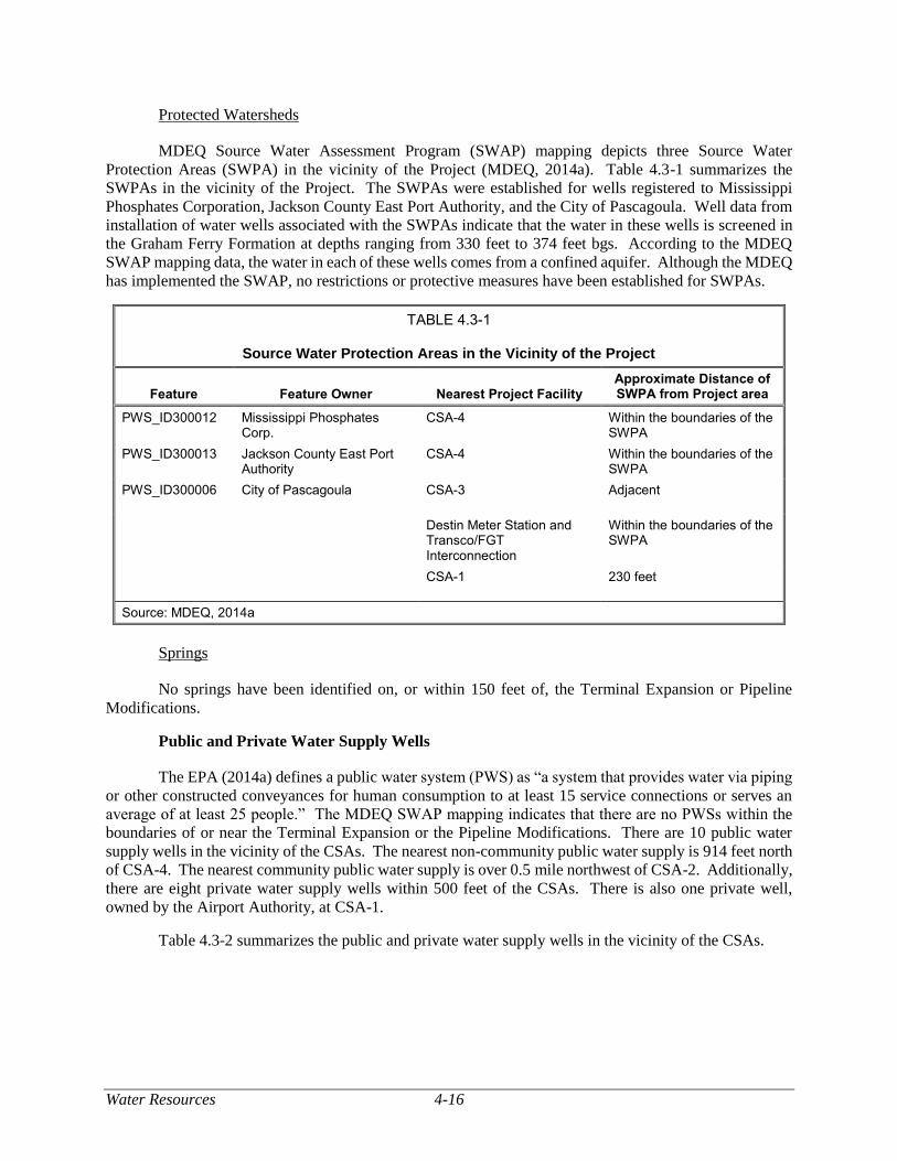
Water Resources 4-16
Protected Watersheds
MDEQ Source Water Assessment Program (SWAP) mapping depicts three Source Water
Protection Areas (SWPA) in the vicinity of the Project (MDEQ, 2014a). Table 4.3-1 summarizes the
SWPAs in the vicinity of the Project. The SWPAs were established for wells registered to Mississippi
Phosphates Corporation, Jackson County East Port Authority, and the City of Pascagoula. Well data from
installation of water wells associated with the SWPAs indicate that the water in these wells is screened in
the Graham Ferry Formation at depths ranging from 330 feet to 374 feet bgs. According to the MDEQ
SWAP mapping data, the water in each of these wells comes from a confined aquifer. Although the MDEQ
has implemented the SWAP, no restrictions or protective measures have been established for SWPAs.
TABLE 4.3-1
Source Water Protection Areas in the Vicinity of the Project
Feature Feature Owner Nearest Project Facility Approximate Distance of SWPA from Project area
PWS_ID300012 Mississippi Phosphates Corp.
CSA-4 Within the boundaries of the SWPA
PWS_ID300013 Jackson County East Port Authority
CSA-4 Within the boundaries of the SWPA
PWS_ID300006 City of Pascagoula CSA-3 Adjacent
Destin Meter Station and Transco/FGT Interconnection
Within the boundaries of the SWPA
CSA-1 230 feet
Source: MDEQ, 2014a
Springs
No springs have been identified on, or within 150 feet of, the Terminal Expansion or Pipeline
Modifications.
Public and Private Water Supply Wells
The EPA (2014a) defines a public water system (PWS) as “a system that provides water via piping
or other constructed conveyances for human consumption to at least 15 service connections or serves an
average of at least 25 people.” The MDEQ SWAP mapping indicates that there are no PWSs within the
boundaries of or near the Terminal Expansion or the Pipeline Modifications. There are 10 public water
supply wells in the vicinity of the CSAs. The nearest non-community public water supply is 914 feet north
of CSA-4. The nearest community public water supply is over 0.5 mile northwest of CSA-2. Additionally,
there are eight private water supply wells within 500 feet of the CSAs. There is also one private well,
owned by the Airport Authority, at CSA-1.
Table 4.3-2 summarizes the public and private water supply wells in the vicinity of the CSAs.
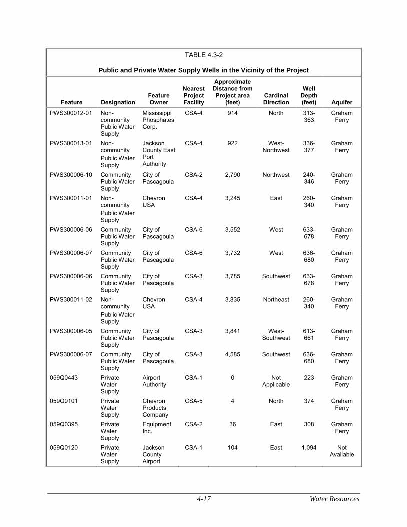
4-17 Water Resources
TABLE 4.3-2
Public and Private Water Supply Wells in the Vicinity of the Project
Feature Designation Feature Owner
Nearest Project Facility
Approximate Distance from Project area
(feet)
Cardinal Direction
Well Depth (feet) Aquifer
PWS300012-01 Non-community Public Water Supply
Mississippi Phosphates Corp.
CSA-4 914 North 313-363
Graham Ferry
PWS300013-01 Non-community
Public Water Supply
Jackson County East Port Authority
CSA-4 922 West-Northwest
336-377
Graham Ferry
PWS300006-10 Community Public Water Supply
City of Pascagoula
CSA-2 2,790 Northwest 240-346
Graham Ferry
PWS300011-01 Non-community
Public Water Supply
Chevron USA
CSA-4 3,245 East 260-340
Graham Ferry
PWS300006-06 Community Public Water Supply
City of Pascagoula
CSA-6 3,552 West 633-678
Graham Ferry
PWS300006-07 Community Public Water Supply
City of Pascagoula
CSA-6 3,732 West 636-680
Graham Ferry
PWS300006-06 Community Public Water Supply
City of Pascagoula
CSA-3 3,785 Southwest 633-678
Graham Ferry
PWS300011-02 Non-community
Public Water Supply
Chevron USA
CSA-4 3,835 Northeast 260-340
Graham Ferry
PWS300006-05 Community Public Water Supply
City of Pascagoula
CSA-3 3,841 West-Southwest
613-661
Graham Ferry
PWS300006-07 Community Public Water Supply
City of Pascagoula
CSA-3 4,585 Southwest 636-680
Graham Ferry
059Q0443 Private Water Supply
Airport Authority
CSA-1 0 Not Applicable
223 Graham Ferry
059Q0101 Private Water Supply
Chevron Products Company
CSA-5 4 North 374 Graham Ferry
059Q0395 Private Water Supply
Equipment Inc.
CSA-2 36 East 308 Graham Ferry
059Q0120 Private Water Supply
Jackson County Airport
CSA-1 104 East 1,094 Not Available
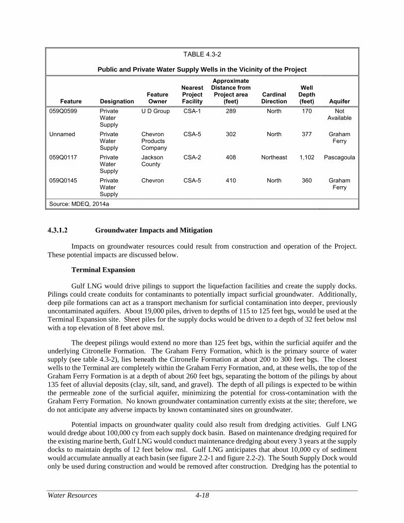
Water Resources 4-18
TABLE 4.3-2
Public and Private Water Supply Wells in the Vicinity of the Project
Feature Designation Feature Owner
Nearest Project Facility
Approximate Distance from Project area
(feet)
Cardinal Direction
Well Depth (feet) Aquifer
059Q0599 Private Water Supply
U D Group CSA-1 289 North 170 Not Available
Unnamed Private Water Supply
Chevron Products Company
CSA-5 302 North 377 Graham Ferry
059Q0117 Private Water Supply
Jackson County
CSA-2 408 Northeast 1,102 Pascagoula
059Q0145 Private Water Supply
Chevron CSA-5 410 North 360 Graham Ferry
Source: MDEQ, 2014a
Groundwater Impacts and Mitigation
Impacts on groundwater resources could result from construction and operation of the Project.
These potential impacts are discussed below.
Terminal Expansion
Gulf LNG would drive pilings to support the liquefaction facilities and create the supply docks.
Pilings could create conduits for contaminants to potentially impact surficial groundwater. Additionally,
deep pile formations can act as a transport mechanism for surficial contamination into deeper, previously
uncontaminated aquifers. About 19,000 piles, driven to depths of 115 to 125 feet bgs, would be used at the
Terminal Expansion site. Sheet piles for the supply docks would be driven to a depth of 32 feet below msl
with a top elevation of 8 feet above msl.
The deepest pilings would extend no more than 125 feet bgs, within the surficial aquifer and the
underlying Citronelle Formation. The Graham Ferry Formation, which is the primary source of water
supply (see table 4.3-2), lies beneath the Citronelle Formation at about 200 to 300 feet bgs. The closest
wells to the Terminal are completely within the Graham Ferry Formation, and, at these wells, the top of the
Graham Ferry Formation is at a depth of about 260 feet bgs, separating the bottom of the pilings by about
135 feet of alluvial deposits (clay, silt, sand, and gravel). The depth of all pilings is expected to be within
the permeable zone of the surficial aquifer, minimizing the potential for cross-contamination with the
Graham Ferry Formation. No known groundwater contamination currently exists at the site; therefore, we
do not anticipate any adverse impacts by known contaminated sites on groundwater.
Potential impacts on groundwater quality could also result from dredging activities. Gulf LNG
would dredge about 100,000 cy from each supply dock basin. Based on maintenance dredging required for
the existing marine berth, Gulf LNG would conduct maintenance dredging about every 3 years at the supply
docks to maintain depths of 12 feet below msl. Gulf LNG anticipates that about 10,000 cy of sediment
would accumulate annually at each basin (see figure 2.2-1 and figure 2.2-2). The South Supply Dock would
only be used during construction and would be removed after construction. Dredging has the potential to
4-19 Water Resources
affect the groundwater quality of surficial alluvial aquifer systems and the underlying Citronelle Formation
by facilitating a direct pathway for saltwater intrusion into fresh groundwater supplies. However, dredging
would be to a depth of 12 feet below msl, which is not of sufficient depth to reach the Citronelle Formation
and provide a pathway for saltwater intrusion into the aquifer. In addition, groundwater resources in the
area of the supply docks are seaward of the Coastal Lowlands Aquifer in areas where aquifers would contain
high salinity levels; therefore, dredging would not affect fresh groundwater resources. The water in the
Citronelle Formation, like the Coastal Lowlands Aquifer System as a whole, is already saline due to
saltwater intrusion.
Impacts on groundwater resources could occur due to an accidental spill, leak, or other release of a
hazardous substance during construction or operation of the expanded Terminal. Should a release occur,
Gulf LNG would adhere to the measures outlined in its SPCC Plan to minimize potential impacts on
groundwater resources.
The Terminal Expansion would result in the conversion of about 77 acres of previously vegetation
land to industrial land in the Project area, thereby reducing groundwater infiltration in the area of the
Terminal site. Groundwater in the Project area is classified as brackish to saline and is not suitable as a
source of potable water, the quality of the groundwater, and its use would not be adversely affected as a
result of loss of surficial infiltration from the permanent conversion of this area to an industrial land use.
Gulf LNG would comply with its Gulf LNG Plan, Gulf LNG Procedures, and SPCC Plan which include
measures to prevent and minimize impacts on water quality. Therefore we conclude that there would not
be impacts on groundwater. In addition, impacts associated with the increase of impervious surface would
be addressed in the NPDES permit which Gulf LNG must obtain.
Groundwater would not be used for hydrostatic testing; therefore, no impacts on groundwater as a
result of hydrostatic testing are expected. Additional information regarding hydrostatic testing can be found
in section 4.3.2.2.
Dewatering activities associated with construction of the Terminal Expansion has the potential to
alter groundwater quality. Discharge of water removed from excavations would be directed to vegetated
land surfaces (where available) to control erosion and runoff. If adequate vegetation is not present during
construction, discharge water would be filtered through filter bags or straw bale lined dewatering structures.
If the dewatering location is not proximal to the existing Terminal during construction, it is anticipated that
Gulf LNG would discharge water from dewatering activities over the seawall and into Mississippi Sound
through the existing permitted Outfall 002 location. Because water removed from excavations would be
reintroduced to the aquifer in the immediate proximity of excavations, potential dewatering impacts would
be localized and temporary, resulting in temporary and not significant impacts on groundwater.
The CSAs would be developed for staging, laydown areas, contractor yards, and parking. Only
minor modifications would be made to the sites. The CSAs would not be paved and would be established
consistent with the requirements of the Gulf LNG Project-specific Plans and Procedures. CSA-3 is
currently used by Gulf LNG for staging and laydown, and after construction, the current use would
continue. The remaining CSAs would be returned to pre-construction conditions after construction is
completed and would not be used further for the Project. As previously discussed, the nearest non-
community public water supply is 914 feet north of CSA-4. The nearest community public water supply is
over 0.5 mile northwest of CSA-2. The nearest private well is 141 feet from CSA-1. CSA-4 is within the
boundaries of two SWPAs. Because the disturbances to the sites would be minor and temporary, and Gulf
LNG would implement its SPCC Plan, we conclude impacts on groundwater resources would not occur as
a result of Project-related activities at the CSAs.
Water wells within 150 feet of CSAs may be susceptible to damage from construction activities
and could be susceptible to impacts from inadvertent spills. Four private water supply wells would be
Water Resources 4-20
located within 150 feet of a CSA. The location of the private water supply well at CSA-1 would be clearly
marked and refueling and the storage of hazardous materials would be restricted within a 200-foot buffer
of its location. Gulf LNG would also conduct pre- and post-construction monitoring of water quality and
yield for the private well with the Airport Authority’s permission. To ensure that potential impacts on
groundwater resources are minimized, Gulf LNG would identify and mark any undocumented water wells
and confirm the location of documented wells within 150 feet of prior to construction. As a result, we
conclude that impacts on groundwater wells due to development or use of the CSAs would not be
significant. In addition, to confirm that there are no impacts on these wells, Gulf LNG has committed to
conducting baseline and post-construction water sampling, chemical analysis, and yield testing on public
and private water wells within 150 feet of the Project in order to detect construction impacts on groundwater
quality and/or yield. If construction resulted in temporary impacts on a private water well, Gulf LNG would
provide an alternative water source or compensate the owner. If permanent damage to the well were to
occur, Gulf LNG would either compensate the owner or drill a new well.
To avoid or minimize potential groundwater impacts during both construction and operation, Gulf
LNG would implement the measures presented in its Gulf LNG Plan and Gulf LNG Procedures (see section
2.6 for a description of the Project-specific Plan and Procedures).
Using the measures discussed above, we believe that impacts on groundwater resources during
construction and operation of the Terminal Expansion would be minimized and would not be significant.
Pipeline Modifications
Gulf LNG would modify two existing pipeline facilities, the Destin Meter Station and the
Gulfstream Meter Station, to enable bi-directional flow capability. Gulf LNG would construct the
modifications within the existing fenced and graveled areas, or on land associated with the existing pipeline
right-of-way. To avoid or minimize potential groundwater impacts during construction of the
modifications, Gulf LNG would implement the measures presented in its Gulf LNG Plan and Gulf LNG
Procedures. In addition, Gulf LNG would implement its SPCC Plan to protect groundwater resources in
the event of an inadvertent spill or leak of hazardous material.
Transco would also make modifications to the existing and jointly owned Transco/FGT
Interconnection to permit bi-directional flow. These modifications would be constructed by Transco and
would be reviewed by the FERC under its blanket certificate process.
Gulf LNG would hydrostatically test the Destin and Gulfstream Meter Stations prior to placing
them into service. Groundwater would not be used for hydrostatic testing; therefore, no impacts on
groundwater as a result of hydrostatic testing are expected. Additional information regarding hydrostatic
testing can be found in section 4.3.2.2.
Therefore, we conclude that no impacts on groundwater would occur as a result of construction or
operation of the Pipeline Modifications.
Surface Water
Existing Surface Water Resources
Terminal Expansion
The Terminal Expansion site is adjacent to the southern end of Bayou Casotte at the edge of
Mississippi Sound (see figure 4.3-1). Mississippi Sound is an estuarine body of water extending about
90 miles from Lake Borgne, Louisiana on the west, to Mobile Bay, Alabama on the east, with a distance
4-21 Water Resources
from 6 to 12 miles from the shoreline. Mississippi Sound is relatively shallow, with an average mean low
water depth of 10 feet and is bordered on the north by small bays, marshes, bayous, rivers, and coastal
beaches (Gulfbase.org, 2014). In the vicinity of the Project, the Barrier Islands, a series of narrow islands
and sandbars, separate the sound from the Gulf of Mexico.
Bayou Casotte is an estuary fed by two freshwater tributaries, the East Prong and the West Prong,
which drain the Bayou Casotte watershed. Within Bayou Casotte, the federally maintained Bayou Casotte
Navigation Channel extends northward from its origin near the southern shore of Jackson County,
Mississippi (see figure 4.3-2). This channel provides shipping access to the existing Terminal as well as
the Bayou Casotte Inner Harbor. At its southern end, the navigation channel merges with the Upper
Pascagoula Navigation Channel to form the Lower Pascagoula Navigation Channel (COE, 2014).
The Project facilities are in the Mississippi Coastal watershed, also known as the Coastal Streams
Basin. The Mississippi Coastal watershed is in the South Atlantic Gulf Region, Pascagoula Sub-region,
and Pascagoula Mississippi Accounting Unit (USGS, 2014h). Agriculture and silviculture (forestry) are
the major land uses throughout the upper watershed, while the lower watershed, where the Project would
be constructed, is heavily industrialized with extensive urban and recreational developments (MDEQ,
2000).
The Mississippi Coastal watershed, which begins in Lamar County (80 miles from the Terminal
Expansion site) and extends toward the Gulf coast, is a relatively flat area (MDEQ, 2000). The northern
portion of the watershed is comprised of extensive pine forests and low rolling hills. As it extends
southward, it gradually changes to low-lying flatlands and salt marshes (MDEQ, 2000). In the northern
portion of the watershed, streams are shallow and clear, with moderate flow; they become wider and deeper
with a more sluggish flow as they move toward the coast due to tidal influence and flatter landscape
(MDEQ, 2000). Major waterbodies in the Mississippi Coastal watershed include Bayou Casotte, Wolf
River, Rotten Bayou, De Lisle Bayou, Bayou La Croix, Jourdan River, Bernard Bayou, Biloxi River, and
Tuxachanie Creek (MDEQ, 2008).
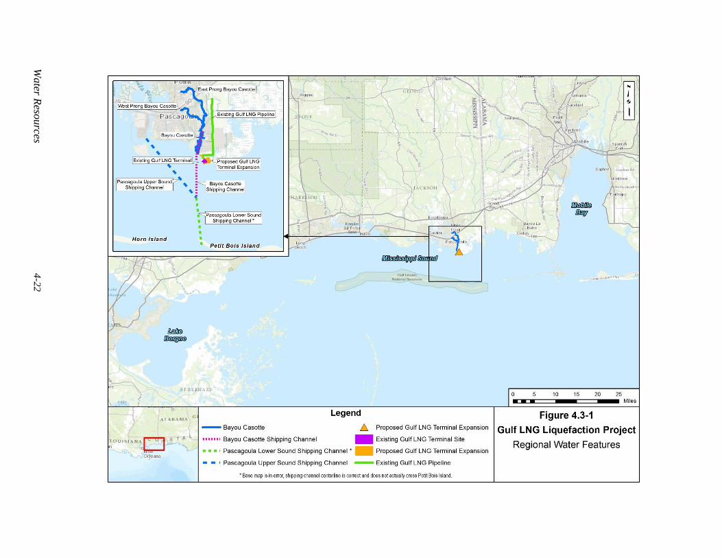
Water R
esources
4-2
2
Figure 4.3-1 Regional Water Features
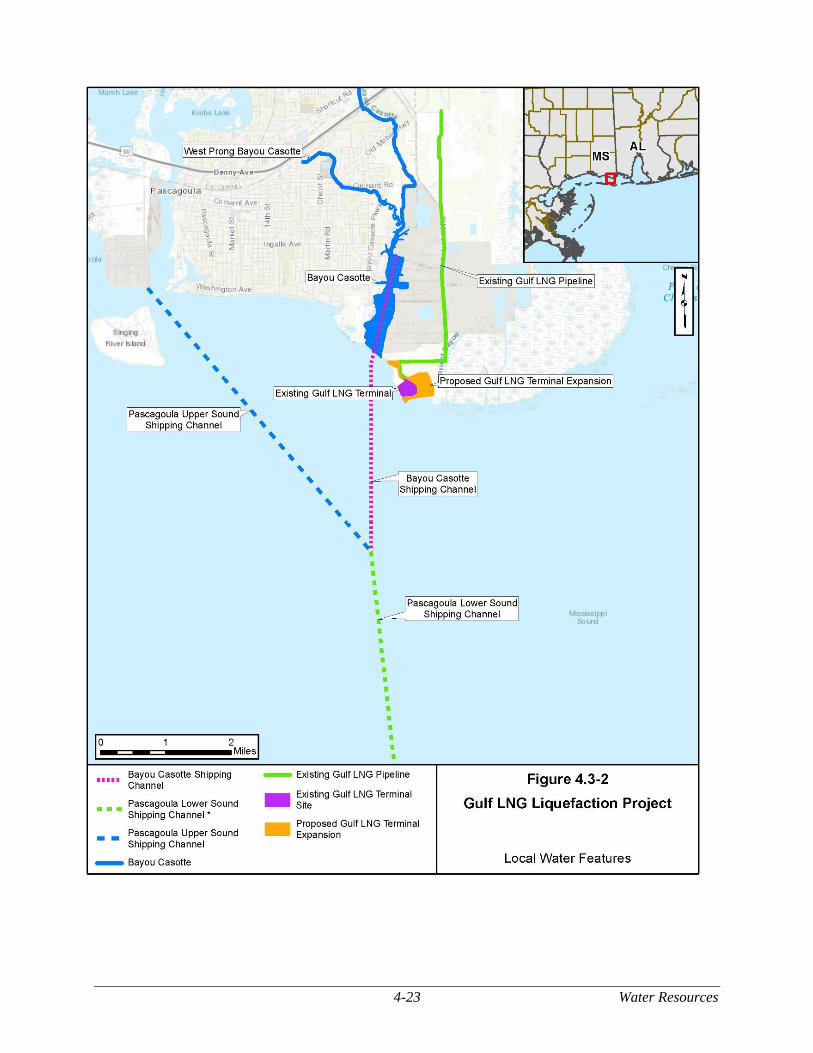
4-23 Water Resources
Figure 4.3-2 Local Water Features
Water Resources 4-24
Sensitive Surface Waters
Sensitive waterbodies include those that are designated as national or state wild and scenic rivers,
are state-designated high-quality or outstanding natural resource waters, provide habitat for threatened and
endangered species or critical habitat, are in sensitive and protected watershed areas or in SWPAs, or have
impaired segments or contaminated sediments.
Designated water quality criteria and special use classifications for waterbodies are listed in the
State of Mississippi Water Quality Criteria for Intrastate, Interstate, and Coastal Waters (MDEQ, 2007).
According to MDEQ criteria, Mississippi Sound is estuarine and a designated recreational waterway. It is
not listed as an impaired waterbody according to Section 303(d) of the CWA (MDEQ, 2012). Many inlets
near the Terminal Expansion site, including Bayou Casotte, are designated for fish and wildlife use.
Designated Wild and Scenic Waterbodies
No Nationwide Rivers or Wild and Scenic Rivers would be affected by the Project (National Wild
and Scenic Rivers System, 2017).
Critical Habitat
According to the Endangered Species Act of 1973, waterbodies containing threatened or
endangered species or critical habitat are protected. Mississippi Sound has been designated as critical
habitat for the federally threatened and state endangered Gulf sturgeon (Acipenser oxyrinchus desotoi); this
designation extends to adjacent open bays, including Pascagoula Bay, Point aux Chenes Bay, Grand Bay,
and Sandy Bay (NMFS, 2014). Threatened and endangered species are discussed in section 4.7.
Contaminated Sediments
Chemical contaminants can accumulate in the sediments of waterbodies. Contaminated sediments
have the potential to cause acute and chronic effects on aquatic life. Waterbodies known to have
contaminated sediments are listed on their respective state’s 303(d) List of Impaired Waters. Mississippi
Sound is not listed on Mississippi’s 303(d) list (MDEQ, 2012). Results of sediment sampling conducted
by Gulf LNG at the supply docks and the BCDMMS are discussed in section 4.2.7.1.
Potable Water Intakes
Water for the Terminal Expansion would be obtained through the existing Port of Pascagoula’s
Industrial Water Supply which provides water to the existing Terminal. The intake for this system is about
14 miles north-northwest of the existing Terminal on the Pascagoula River The port treats water to contain
less than 1 part per million of total particulate matter and buffers the water using caustic injection to achieve
a pH of 7.0. Gulf LNG would use a reverse osmosis system to further treat the water.
Public Watersheds
Public watersheds supply drinking water to the public. No public watershed areas are in the vicinity
of the proposed Project. The closest waterbody to the Project that is designated for public water supply use
is the Pascagoula River, about 14 miles north of the City of Pascagoula (MDEQ, 2007).
4-25 Water Resources
Pipeline Modifications
The Destin Meter Station, the Gulfstream Meter Station, and the Transco/FGT Interconnection are
within the Mississippi Coastal watershed. Gulf LNG would construct the modifications within the existing
fenced and graveled areas, or on land associated with the existing pipeline right-of-way. No waterbodies
would be impacted by construction or operation of the Pipeline Modifications.
Surface Water Impacts and Mitigation
Direct impacts on surface water resources are defined as those Project-related impacts that occur
on waterbodies in the construction workspace that are temporarily or permanently disturbed and for which
the acreage of impacts can be calculated. Direct impacts could include turbidity and sedimentation
associated with construction activities (such as pile driving and installation of the supply docks) and
alterations to the depth of the waterbody (e.g., filling or dredging). Indirect impacts on surface water
resources occur outside of the construction workspace and could include potential changes in flow regime
or water quality. Noise impacts on aquatic resources are discussed in section 4.6.
Terminal Expansion
As previously stated, Mississippi Sound is the only waterbody that would be affected by the
Terminal Expansion.
Dredging
The primary impact on the Mississippi Sound from construction of the Terminal Expansion would
be dredging about 200,000 cy of sediment for the North and South Supply Docks. During operation of the
Terminal Expansion, the North Supply Dock would undergo maintenance dredging in accordance with
applicable MDMR and COE permits. As owner of the North Supply Dock, the JCPA would be responsible
for obtaining permits and clearances for dredging operations and for issuing notifications to agencies and
Port of Pascagoula users regarding dredging activities. Gulf LNG would remove the South Supply Dock
following construction.
Gulf LNG initially planned to dispose of dredge materials from construction of the supply docks at
one of two state-approved BU sites: Greenwood Island and Round Island. However, the Round Island is
privately owned and not expected to be available. According to Gulf LNG, the Greenwood Island site is
expected reach capacity prior to construction, but it would be expanded by 250-acres by February 2020.
Gulf LNG would prefer to use a BU site for disposal and would work with federal and state agencies to
identify a suitable BU site for dredge material disposal. Gulf LNG would utilize an offshore dredged
material disposal site if a suitable BU site is not available.
As further discussed in section 4.4, additional dredging would be associated with the construction
of the proposed wetland mitigation site. Gulf LNG would require dredging to allow barges to access the
marsh creation area. To protect the wetland mitigation site from erosion of the fill material and wave
activity, Gulf LNG would install about 19,000 cy of riprap along the seaward limits of the site. During
construction, a temporary channel would be dredged from the South Supply Dock along the outer perimeter
of the proposed wetland mitigation site. Barges would use the temporary channel to install the perimeter
riprap. The sediment removed for creation of the channel would be temporarily placed within the proposed
wetland mitigation site. All of the dredge material would be replaced in the temporary channel or contained
within the marsh creation area, so no off-site disposal would be necessary.
Because the sediments within the area are anticipated to consist primarily of fine particles, dredging
would result in temporary and local suspension of sediments and minor increased turbidity levels that would
Water Resources 4-26
be limited to the period of dredging and a short time after dredging ceases. Increases in suspended
sediments and turbidity from dredging may have adverse effects on marine animals and plants by reducing
light penetration into the water column and by physical disturbance (see section 4.6.2.1 for a discussion of
impacts of turbidity on marine species). The total area to be dredged (18.4 acres) is relatively small,
particularly in comparison to the maintenance dredging of the nearby Bayou Casotte Navigation Channel
(>129 acres [COE, 2014]). The dredging would be completed in a short period of time (about 7 to 21 days
for each dock). Maintenance dredging would be substantially shorter in duration than the initial dredging.
According to Gulf LNG’s Dredging and Disposal Plan turbidity curtains would be installed and maintained
around the area being excavated to limit the transport of turbid water beyond the vicinity of the dredging
operations. Although dredging would result in increased turbidity, the increase would be relatively small
and localized. Commercial shipping operations, bottom fishing, or severe storms often generate as much
increased suspended sediments as dredging activities; therefore, it is often challenging to distinguish the
environmental effects of dredging from normal navigation activities or natural processes such as storms,
floods, and large tides (Pennekamp et al., 1996). According to Gulf LNG, it would monitor turbidity, if
required by Section 401 of the CWA, suspending operations if unusual conditions occur and/or during
severe weather.
Dredging could release contaminants contained in sediments into the water column, such as heavy
metals, oil, PCBs, and pesticides, making them available to be taken up by animals and plants (McNair,
1994). Waterbodies known to have contaminated sediments are listed on their respective state’s CWA
303(d) List of Impaired Waters. Mississippi Sound is not on the 303(d) list for Mississippi. As discussed
in section 4.2.7, Gulf LNG conducted sediment sampling of the North Supply Dock, the South Supply
Dock, and the BCDMMS in March 2015. Results of the analytical and toxicity testing conducted by Gulf
LNG confirmed that sediment from nine of the BCDMMS sample locations and all of the North and South
Supply Dock sample locations can be used for beneficial use. One sampling location within the BCDMMS,
station 10, had slightly elevated contaminant levels of arsenic and cadmium. Gulf LNG proposes to blend
these sediments with the other sediments removed from the BCDMMS. See section 4.2 for additional
information regarding blended sediments.
Gulf LNG would minimize impacts from dredging by adhering to the mitigation measures provided
its revised Dredging and Disposal Plan.2 Gulf LNG is working with the COE to finalize its Dredging and
Disposal Plan. As stated previously, no contamination has been identified in the sediments in the Project
area. As a result, we conclude that the impacts of construction of the supply docks on water quality would
be minor and temporary and turbidity would return to pre-dredging levels soon after construction is
completed.
Marine Traffic and Ballast Water Management
As part of the original EIS for the existing Terminal, potential impacts related to Terminal
operations, including the use of LNG carriers (including traffic, transit, and ballast discharges, and LNG
spills) were assessed (FERC, 2006). Gulf LNG is not proposing to change the frequency of LNG carriers
analyzed in the EIS for the existing Terminal; however, Gulf LNG is proposing to increase the size of the
LNG carriers that could call upon the existing Terminal. Impacts associated with LNG carriers generally
are not expected to change. Unless there is the potential for an impact to increase, it is not addressed in this
EIS. We note that ballast water management would be modified and that ballast water management
requirements have changed since those reviews were conducted. During construction, barges and other
vessels delivering materials to the Terminal Expansion may use ballast pumps to maintain the barge level
during loading and unloading. Future LNG export would require that LNG carriers discharge ballast water
while loading LNG instead of taking in ballast during LNG offloading. The discharge of ballast water into
2 See Attachment No. 3 of accession number 20180829-5060.
4-27 Water Resources
Mississippi Sound could affect water quality by changing the salinity, pH, temperature, and dissolved
oxygen level. Discharge volumes would range between about 9.7 million gallons and 23.0 million gallons,
depending on the size of the vessel. The ballast water discharges would typically occur over a non-
continuous period of about 30 hours at a rate of about 29 cubic feet per second (cfs). The composition of
ballast water would vary as compared to the water in Mississippi Sound depending on its origin and the
conditions in Mississippi Sound at the time of discharge. However, it is expected that open ocean ballast
water would have a salinity between 33 and 37 parts per thousand, which is similar to the salinity in
Mississippi Sound. The pH of ballast water would be indicative of seawater, and would therefore be similar
to the pH in Mississippi Sound, which receives tidal flow from the Gulf of Mexico. Ballast water is stored
in the ship’s hull below the waterline; as a result, discharged water temperatures are not expected to deviate
markedly from ambient water temperatures. Dissolved oxygen is dependent on many factors, including
water temperature, water depth, phytoplankton, wind, and current. Water that is collected within the ballast
tanks of a ship would lack many of these important influences and could suppress dissolved oxygen levels.
Ballast water is expected to be anoxic (i.e., lacking all oxygen), but could contain dissolved oxygen levels;
if so, levels would be lower than the surface water of Mississippi Sound. The discharged ballast water
would be expected to mix with the surrounding water column relatively quickly given the proximity of the
marine berth to the mouth of the Pascagoula River, which has an average outflow of about 14,746 cfs, and
its exposure to outflow from Bayou Casotte and wind and tidal driven currents of the Mississippi Sound
(COE, 2014). Furthermore, estuarine species common to coastal Mississippi are generally tolerant of
fluctuating environmental conditions (Elliott and Quintino, 2007). Overall impacts on salinity, pH,
temperature, and dissolved oxygen levels from ballast water discharges would be negligible. Because
vessels would be required to comply with U.S. laws and regulations governing ballast water discharges, we
conclude that impacts on surface water quality resulting from ballast water discharge would be minor.
Based on current requirements, LNG captains would comply with revised ballast water
requirements, found in 33 CFR 151 (Vessels Carrying Oil, Noxious Liquid Substances, Garbage, Municipal
or Commercial Waste and Ballast Water), 46 CFR 162.060 (Ballast Water Management Systems), and the
USCG’s Navigation and Vessel Inspection Circular 07-04. Effective December 19, 2013, the EPA
promulgated an NPDES Vessel General Permit that sets numeric limits for ballast water discharges from
certain large commercial vessels and includes maximum discharge limitations for biocides and residues.
Additional information about impacts of Project-related ballast water on aquatic resources is provided in
section 4.6.2.
Barges and support vessels would deliver large equipment and construction materials to the supply
docks, which would increase ship traffic in Mississippi Sound and the navigation channel. Barge and
support vessel traffic may result in some suspension of bottom sediments and temporarily increase turbidity.
The increase in turbidity could result in localized, minor, and temporary decreases in dissolved oxygen
(URS, 1997).
Similarly, propeller action from boats used during Project construction could temporarily suspend
and re-suspend material that has entered the waterbody as a result of shoreline erosion. While commercial
vessels would mobilize greater amounts of sediment than recreational vessels, the depth of sediment
mobilized per passage would be negligible (less than 2 millimeter depth per passage) (AMOG, 2010). This
could lead to localized increases in turbidity in the Mississippi Sound; however, these minor impacts would
be limited to the duration of in-water construction activities. The turbidity caused by vessels would be
intermittent and the times for settlement are relatively short (AMOG, 2010).
Some barges and support vessels would take in cooling water for vessel boilers while in transit and
would discharge the cooling water after use. The cooling water would be circulated in a closed system,
withdrawing water from and returning to the surrounding seawater at the berthing dock; chemicals would
not be added to the cooling water. Discharge of the cooling water would potentially result in highly
localized and temporary increases in water temperature in Mississippi Sound and the navigation channel.
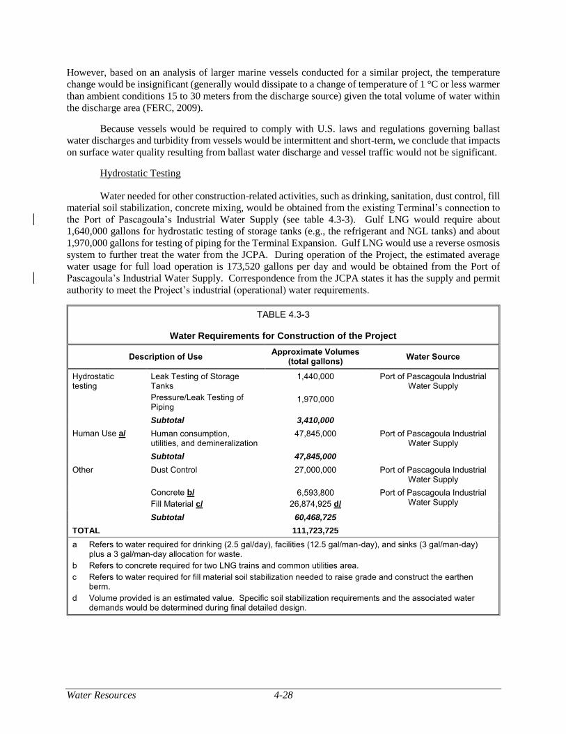
Water Resources 4-28
However, based on an analysis of larger marine vessels conducted for a similar project, the temperature
change would be insignificant (generally would dissipate to a change of temperature of 1 °C or less warmer
than ambient conditions 15 to 30 meters from the discharge source) given the total volume of water within
the discharge area (FERC, 2009).
Because vessels would be required to comply with U.S. laws and regulations governing ballast
water discharges and turbidity from vessels would be intermittent and short-term, we conclude that impacts
on surface water quality resulting from ballast water discharge and vessel traffic would not be significant.
Hydrostatic Testing
Water needed for other construction-related activities, such as drinking, sanitation, dust control, fill
material soil stabilization, concrete mixing, would be obtained from the existing Terminal’s connection to
the Port of Pascagoula’s Industrial Water Supply (see table 4.3-3). Gulf LNG would require about
1,640,000 gallons for hydrostatic testing of storage tanks (e.g., the refrigerant and NGL tanks) and about
1,970,000 gallons for testing of piping for the Terminal Expansion. Gulf LNG would use a reverse osmosis
system to further treat the water from the JCPA. During operation of the Project, the estimated average
water usage for full load operation is 173,520 gallons per day and would be obtained from the Port of
Pascagoula’s Industrial Water Supply. Correspondence from the JCPA states it has the supply and permit
authority to meet the Project’s industrial (operational) water requirements.
TABLE 4.3-3
Water Requirements for Construction of the Project
Description of Use Approximate Volumes
(total gallons) Water Source
Hydrostatic testing
Leak Testing of Storage Tanks
Pressure/Leak Testing of Piping
1,440,000
1,970,000
Port of Pascagoula Industrial Water Supply
Subtotal 3,410,000
Human Use a/ Human consumption, utilities, and demineralization
47,845,000 Port of Pascagoula Industrial Water Supply
Subtotal 47,845,000
Other Dust Control 27,000,000 Port of Pascagoula Industrial Water Supply
Concrete b/
Fill Material c/
6,593,800
26,874,925 d/
Port of Pascagoula Industrial Water Supply
Subtotal 60,468,725
TOTAL 111,723,725
a Refers to water required for drinking (2.5 gal/day), facilities (12.5 gal/man-day), and sinks (3 gal/man-day) plus a 3 gal/man-day allocation for waste.
b Refers to concrete required for two LNG trains and common utilities area.
c Refers to water required for fill material soil stabilization needed to raise grade and construct the earthen berm.
d Volume provided is an estimated value. Specific soil stabilization requirements and the associated water demands would be determined during final detailed design.
4-29 Water Resources
Hydrostatic test water would be discharged into the Mississippi Sound in accordance with its Gulf
LNG Procedures and MDEQ NPDES discharge permit MSG13.3 Gulf LNG does not anticipate any
treatment of hydrostatic test water prior to discharge. We conclude that hydrostatic testing of the Terminal
Expansion would not result in a significant impact on surface water.
Dewatering Activities
Dewatering activities may be required during construction of the Project. As previously discussed,
Gulf LNG would use vegetation, as available, to function as a filter medium, discharging directly to the
vegetated land surface to control erosion. If adequate vegetation is absent in the vicinity of waterbodies or
wetlands during construction, water would be filtered through filter bags or straw bale structures prior to
release. Minor changes to the water table may occur from dewatering activities; however, impacts would
be temporary and localized.
Erosion and Stormwater Runoff
Asphalt- and concrete-covered surfaces are considered to be impervious surfaces through which
water cannot drain. Vegetation-covered areas and gravel-covered surfaces are considered to be pervious
(porous) surfaces through which water can pass. The less pervious surface there is in an area, the farther
stormwater has to travel in order to either soak into the ground or to flow directly into a waterbody.
Construction of the Terminal Expansion would permanently reduce the amount of pervious surface, thereby
increasing the potential frequency and volume of stormwater runoff into the Mississippi Sound. Stormwater
runoff from Terminal Expansion would be integrated into the existing Terminal’s stormwater runoff
system. This discharge would be in accordance with the requirements of Gulf LNG’s SPCC Plan, Gulf
LNG Plan, and Gulf LNG Procedures to minimize impacts. In addition, Gulf LNG would obtain a
Mississippi Storm Water Construction General Permit for the Project. Gulf LNG would also adhere to the
measures in its Stormwater Pollution Prevention Plan (SWPPP); the current version is provided in appendix
I and would be updated as part of its Implementation Plan. The SWPPP describes the best management
practices (BMPs) to be followed to minimize wash-off of sediment throughout construction.
During operation, stormwater runoff from the Terminal Expansion area would be integrated into
the existing Terminal’s stormwater runoff outfall (Outfall 002). Two new stormwater outfalls (Outfall 003
and 004) are planned for the Terminal Expansion; these outfalls would drain in proximity to the existing
stormwater outfall (Outfall 002) in the LNG carrier berthing area. The existing facility’s stormwater
collection system would remain intact. Runoff from the existing Terminal is currently routed to an existing
sump located at the western edge of the LNG storage tank area. From the sump, the stormwater is pumped
over the storm surge protection system and discharged into Mississippi Sound. The sump is fitted with a
low temperature sensor to stop the pump in the event of an LNG release, thereby preventing the discharge
of LNG. With implementation of these measures and Gulf LNG’s design of the Project, we conclude that
erosion and runoff from construction and operation would be minimized and would not be significant.
Inadvertent Spills
In areas where surface contamination could occur due to potential leaks or spills from construction
equipment, Gulf LNG would grade the area so that stormwater runoff would only drain to oily-water sumps.
The oily-water sumps would then flow to oil-water separators where oil would be removed from the
stormwater runoff. The stormwater would then flow to one of two main transfer sumps prior to being
pumped outside of the facility.
3 Gulf LNG would work with the MDEQ to develop effective treatment methods for outfalls, which may include the use of
filter covers (accession number 20190107-5151).
Water Resources 4-30
Stormwater collected in the main stormwater sumps would be released after visual inspection for
the presence of floating and suspended materials, oil and grease, discoloration, turbidity, odor, or foam. If
visual inspection indicates that stormwater in the sumps is not suitable for discharge, Gulf LNG would
collect the stormwater and dispose it in accordance with regulatory requirements. If there is no visual
sheen, no floating solids, or foam other than trace amounts, and if the pH is between 6.0 and 9.0, the
stormwater would be discharge into Mississippi Sound through the outfall structures. A pH meter in the
west sump automatically tests the stormwater’s pH and does not allow the discharge pump to engage if the
pH is less than 6.0 or more than 9.0. In addition, the sump is fitted with a low temperature sensor to stop
the pump in the event of an LNG release.
To minimize the potential for a release of hazardous materials and to avoid or minimize the impacts
of a release if one were to occur, Gulf LNG would adhere to the measures outlined in its Gulf LNG Plan,
Gulf LNG Procedures, and its SPCC Plan during construction and operation of the Terminal Expansion.
With implementation of the measures discussed above, impacts on surface water resources from spills at
the Terminal Expansion would be minimized to the extent practicable and would not be significant.
Construction Support Areas
Gulf LNG would not disturb or cross any waterbodies at the proposed CSAs. Portions of the CSAs
are currently graveled and have been or are in use as industrial sites. Gulf LNG would permanently clear
wetland vegetation, including Chinese tallow tree, Chinese privet, cogon grass, and false willow, from
CSA-5. The increase of impervious surface at CSA-5 may increase stormwater runoff. However, we have
determined that Gulf LNG has not adequately justified permanently filling the wetlands at CSA-5.
Therefore, in section 4.4 we are recommending that Gulf LNG commit to restore the wetlands at CSA-5 to
pre-construction conditions following construction in accordance with the FERC Procedures. In addition,
to avoid or minimize impacts on water quality at the CSAs, Gulf LNG would comply with the requirements
of Gulf LNG Plan and Gulf LNG Procedures. As a result, construction and use of the CSAs would not
result in a significant impact on surface waters.
Pipeline Modifications
Hydrostatic Testing
Hydrostatic test water would be required to test new piping at the Destin Meter Station and the
Gulfstream Meter Station. Hydrostatic test water would be delivered via truck from the Port of Pascagoula
industrial water supply to the Destin and Gulfstream Meter Stations. Gulf LNG estimates that the Destin
Meter Station would require 57,450 gallons of hydrostatic test water and the Gulfstream Meter Station
would require 44,060 gallons. According to Gulf LNG, no biocides would be added to the test water, which
would be withdrawn and discharged in July 2020. Gulf LNG would discharge hydrostatic test water onto
vegetated lands (where available) to control erosion and runoff. If adequate vegetation is absent during
construction, water would be filtered through filter bags or straw bale lined dewatering structures.
Any hydrostatic testing needed for the Transco/FGT Interconnection would be completed by
Transco and would be reviewed by the FERC under its blanket certificate process.
We conclude that hydrostatic testing of the Pipeline Modifications would be temporary and would
not result in a significant impact on surface water.
Inadvertent Spills
To avoid or minimize the potential impacts of inadvertent spills from refueling of vehicles and
storage of fuel, oil, or other hazardous materials near surface waters, Gulf LNG would implement the
4-31 Water Resources
measures provided in its SPCC Plan. These measures include restricting refueling and storage of
potentially hazardous materials to upland areas at least 100 feet from waterbodies, where practicable, and
provisions to handle stormwater that may carry spilled materials. If a spill were to occur, immediate
downstream users of the water could experience degradation in water quality, and acute and chronic toxic
effects on aquatic organisms could occur. However, Gulf LNG would not store large volumes of fuel, oil,
or other hazardous materials at the Pipeline Modification sites; and we conclude that it is not likely that
significant long-term impacts would result if a spill were to reach a waterbody.
Impact Summary
As a result of proposed activities and implementation of the measures discussed above, we conclude
that impacts on surface waters due to construction and operation of the Project would be minimized to the
extent practicable and that significant impacts on surface waters would not occur.
Wetlands 4-32
WETLANDS
Wetlands are areas that are inundated or saturated by surface or groundwater at a frequency and
duration sufficient to support, and under normal circumstances do support, a prevalence of vegetation
typically adapted for life in saturated soil conditions (EPA, 2012b). Wetlands can be a source of substantial
biodiversity and serve a variety of functions that include providing wildlife habitat, recreational
opportunities, flood control, and naturally improving water quality.
Section 404 of the CWA establishes standards to evaluate and reduce total and net impacts on
wetlands under the regulatory jurisdiction of the COE. These standards require avoidance of wetlands
where possible and minimization of disturbance where impacts are unavoidable, to the degree practicable.
Gulf LNG must also demonstrate that it has taken appropriate and practicable steps to minimize wetland
impacts in compliance with the COE’s Section 404(b)(1) guidelines that restrict discharges of dredged or
fill material where less environmentally damaging alternatives exist. The COE Mobile District has
authority under Section 404 of the CWA to review and issue permits for project-related activities that would
result in the discharge of dredged or fill material into waters of the United States, including wetlands.
Section 401 of the CWA requires that proposed dredge and fill activities under Section 404 be
reviewed and certified by the EPA or its designated state agency (in this instance, the MDEQ) to ensure
that the Project would meet state water quality standards for discharges into waters of the United States.
All Project facilities would be entirely within the Mississippi Coastal Zone. The MDMR permits
wetland activities in the Mississippi Coastal Zone and provides guidance on mitigation requirements for
unavoidable losses of coastal wetland function and value due to permitted activities.
The Project proposes activities in wetlands and the erection of structures for water dependent
industries in Jackson County, both of which require permits. Gulf LNG filed their Joint application for
permits administered through the MDMR, the MDEQ (Office of Pollution Control), and the COE on July
10, 2015. A revised application was filed on March 29, 2019. The Joint Permit Application is first filed
with the MDMR and is then forwarded by the MDMR to the COE Mobile District and to the MDEQ. The
permits would cover the Section 404 and Section 10 permits, Section 401 Water Quality Certificate, and
the CZMA consistency determination. Gulf LNG would be required to comply with the CWA and CZMA
conditions of the permits issued by the COE, the MDEQ, and the MDMR, including the provisions of
required compensatory wetland mitigation. In correspondence dated October 16, 2015, the Mississippi
Secretary of State requested that Gulf LNG’s Section 401 permit, if granted, include the MDMR’s standard
condition requiring the permittee to obtain a Tidelands Lease from the Mississippi Secretary of State.
Finalization of the lease would be required prior to commencing construction of the Project (see also table
1.5-1).
Existing Environment
Gulf LNG reviewed available NWI maps and soil surveys and conducted wetland field surveys
within the Project footprint in June of 2014 through March of 2015. Wetland field surveys were conducted
at the Terminal Expansion site, Pipeline Modification sites, and the CSAs. Wetland boundaries were
delineated in accordance with the COE’s Wetland Delineation Manual requirements (Environmental
Laboratory, 1987) and the COE’s Regional Supplement to the Corps of Engineers Wetland Delineation
Manual: Atlantic and Gulf Coastal Plain Region (COE, 2010).
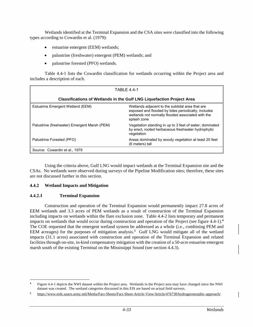
4-33 Wetlands
Wetlands identified at the Terminal Expansion and the CSA sites were classified into the following
types according to Cowardin et al. (1979):
estuarine emergent (EEM) wetlands;
palustrine (freshwater) emergent (PEM) wetlands; and
palustrine forested (PFO) wetlands.
Table 4.4-1 lists the Cowardin classification for wetlands occurring within the Project area and
includes a description of each.
TABLE 4.4-1
Classifications of Wetlands in the Gulf LNG Liquefaction Project Area
Estuarine Emergent Wetland (EEM) Wetlands adjacent to the subtidal area that are exposed and flooded by tides periodically; includes wetlands not normally flooded associated with the splash zone
Palustrine (freshwater) Emergent Marsh (PEM) Vegetation standing in up to 3 feet of water; dominated by erect, rooted herbaceous freshwater hydrophytic vegetation
Palustrine Forested (PFO) Areas dominated by woody vegetation at least 20 feet (6 meters) tall
Source: Cowardin et al., 1979
Using the criteria above, Gulf LNG would impact wetlands at the Terminal Expansion site and the
CSAs. No wetlands were observed during surveys of the Pipeline Modification sites; therefore, these sites
are not discussed further in this section.
Wetland Impacts and Mitigation
Terminal Expansion
Construction and operation of the Terminal Expansion would permanently impact 27.8 acres of
EEM wetlands and 3.3 acres of PEM wetlands as a result of construction of the Terminal Expansion
including impacts on wetlands within the flare exclusion zone. Table 4.4-2 lists temporary and permanent
impacts on wetlands that would occur during construction and operation of the Project (see figure 4.4-1).4
The COE requested that the emergent wetland system be addressed as a whole (i.e., combining PEM and
EEM acreages) for the purposes of mitigation analysis.5 Gulf LNG would mitigate all of the wetland
impacts (31.1 acres) associated with construction and operation of the Terminal Expansion and related
facilities through on-site, in-kind compensatory mitigation with the creation of a 50-acre estuarine emergent
marsh south of the existing Terminal on the Mississippi Sound (see section 4.4.3).
4 Figure 4.4-1 depicts the NWI dataset within the Project area. Wetlands in the Project area may have changed since the NWI
dataset was created. The wetland categories discussed in this EIS are based on actual field surveys.
5 https://www.erdc.usace.army.mil/Media/Fact-Sheets/Fact-Sheet-Article-View/Article/476738/hydrogeomorphic-approach/.
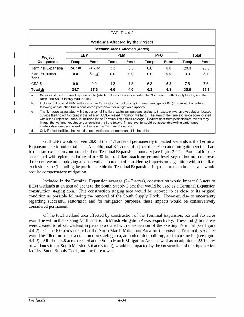
Wetlands 4-34
TABLE 4.4-2
Wetlands Affected by the Project
Project Component
Wetland Areas Affected (Acres)
Total EEM PEM PFO
Temp Perm Temp Perm Temp Perm Temp Perm
Terminal Expansion 24.7 a/ 24.7 b/ 3.3 3.3 0.0 0.0 28.0 28.0
Flare Exclusion Zone
0.0 3.1 c/ 0.0 0.0 0.0 0.0 0.0 3.1
CSA-5 0.0 0.0 1.3 1.3 6.3 6.3 7.6 7.6
Total d/ 24.7 27.8 4.6 4.6 6.3 6.3 35.6 38.7
a Consists of the Terminal Expansion site (which includes all access roads), the North and South Supply Docks, and the North and South Heavy Haul Roads.
b Includes 0.8 acre of EEM wetlands at the Terminal construction staging area (see figure 2.0-1) that would be restored following construction but is considered permanent for mitigation purposes.
c The 3.1 acres associated with this portion of the flare exclusion zone are related to impacts on wetland vegetation located outside the Project footprint in the adjacent COE-created mitigation wetland. The area of the flare exclusion zone located within the Project boundary is included in the Terminal Expansion acreage. Radiant heat from periodic flare events may impact the wetland vegetation surrounding the flare tower. These events would be associated with maintenance, startup/shutdown, and upset conditions at the Terminal Expansion.
d Only Project facilities that would impact wetlands are represented in the table.
Gulf LNG would convert 28.0 of the 31.1 acres of permanently impacted wetlands at the Terminal
Expansion site to industrial use. An additional 3.1 acres of adjacent COE-created mitigation wetland are
in the flare exclusion zone outside of the Terminal Expansion boundary (see figure 2.0-1). Potential impacts
associated with episodic flaring of a 430-foot-tall flare stack on ground-level vegetation are unknown;
therefore, we are employing a conservative approach of considering impacts on vegetation within the flare
exclusion zone (including the portion outside the Terminal Expansion site) as permanent impacts and would
require compensatory mitigation.
Included in the Terminal Expansion acreage (24.7 acres), construction would impact 0.8 acre of
EEM wetlands at an area adjacent to the South Supply Dock that would be used as a Terminal Expansion
construction staging area. This construction staging area would be restored to as close to its original
condition as possible following the removal of the South Supply Dock. However, due to uncertainty
regarding successful restoration and for mitigation purposes, these impacts would be conservatively
considered permanent.
Of the total wetland area affected by construction of the Terminal Expansion, 5.5 and 3.5 acres
would be within the existing North and South Marsh Mitigation Areas respectively. These mitigation areas
were created to offset wetland impacts associated with construction of the existing Terminal (see figure
4.4-2). Of the 6.0 acres created at the North Marsh Mitigation Area for the existing Terminal, 5.5 acres
would be filled for use as a construction staging area, administration building, and a parking lot (see figure
4.4-2). All of the 3.5 acres created at the South Marsh Mitigation Area, as well as an additional 22.1 acres
of wetlands in the South Marsh (25.6 acres total), would be impacted by the construction of the liquefaction
facility, South Supply Dock, and the flare tower.
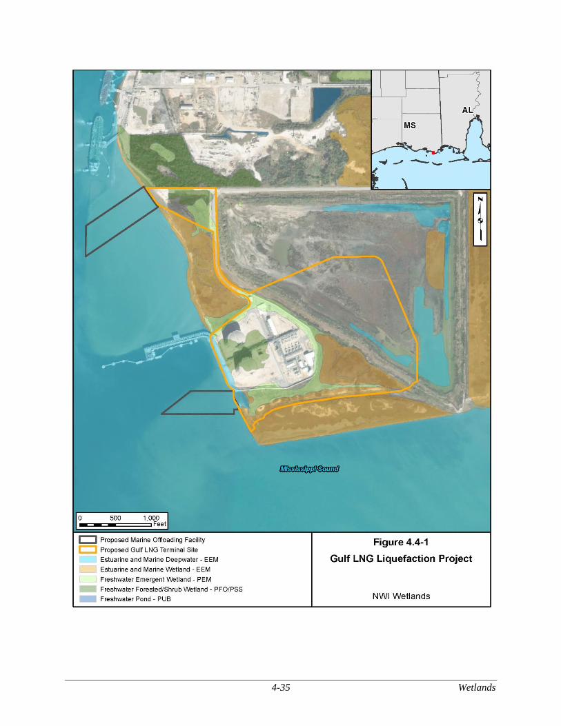
4-35 Wetlands
Figure 4.4-1 NWI Wetlands
Wetlands 4-36
Affected wetland vegetation would include smooth cordgrass, saltmeadow cordgrass, alkali
bulrush, saltwort, saltgrass, southern cattail, black needlerush, marsh elder, eastern false-willow, and
common cane. A large number of non-native plant species were observed in the marsh habitats and adjacent
upland areas, including cogongrass and Chinese tallow, which are listed on Mississippi’s Noxious Weed
List (MDAC, 2014). The prevalence of invasive plants and the industrial nature of the area in the vicinity
of the Project are indicative of disturbed uplands and wetlands. Exotic and invasive vegetation species are
discussed further in section 4.5.
Permanent wetland impacts would be mitigated through the COE compensatory wetland mitigation
process. Compensatory wetland mitigation for the Terminal Expansion is discussed in section 4.4.3.
Construction Support Areas
Gulf LNG identified a 0.4-acre tidal marsh at CSA-3 and 7.6 acres of fragmented freshwater
wetlands within CSA-5. The EEM wetland identified at CSA-3 would not be impacted by the Project; only
upland areas would be used at that site. The wetland would be protected through the use of appropriate
BMPs as described in Gulf LNG Procedures (see section 4.4.2.3).
CSA-5 is approximately 35.0 acres in total and was partially developed (western half) for use as an
equipment storage yard during construction of the existing Terminal. Gulf LNG would require more land
at the site than was previously developed and would impact the 7.6 acres of wetlands (6.3 acres of PFO and
1.3 acres of PEM) present on the site. The wetlands at CSA-5 are disturbed due to their proximity to fill
materials and as evidenced by a prevalence of invasive vegetation species and those indicative of disturbed
site conditions, such as Chinese tallow tree, Chinese privet, cogongrass, and false-willow. However,
Sections VI.C.2 and VI.C.5 of the Commission’s Procedures state Gulf LNG must restore pre-construction
wetland contours, maintain original wetland hydrology, and develop a Project-specific wetland restoration
plan which includes measures for re-establishing wetlands. Therefore, we recommended in the draft EIS
that Gulf LNG commit to restore the wetlands at CSA-5 following construction. In response to that
recommendation, Gulf LNG requested approval from the Commission to leave CSA-5 as a fenced/graveled
area and purchase adequate mitigation credits to compensate for wetland impacts. However, this response
does not meet the intent of the Procedures, which is to minimize the extent and duration of project-related
disturbance on wetlands and waterbodies, where possible. In February 2019, based on comments from the
EPA, we asked Gulf LNG to evaluate an alternative location for CSA-5 within the BCDMMS. Gulf LNG
indicated that it would not be feasible to relocate CSA-5 within the BCDMMS as this area is an active
dredge disposal location that would be periodically inundated with dredge spoil and water. Based on Gulf
LNG’s proposed permanent filling of CSA-5 for construction only and our experience with natural gas
facility construction, we have determined that Gulf LNG has not adequately justified permanently filling
the wetlands at CSA-5. Therefore, we recommend that:
Prior to construction, Gulf LNG should file with the Secretary a commitment to restore
the wetlands at CSA-5 to pre-construction conditions following construction in
accordance with Sections VI.C.2 and VI.C.5 of the Commission’s Wetland and Waterbody Construction and Mitigation Procedures.
No wetlands were observed during surveys of CSA-1, CSA-2, CSA-4, or CSA-6.
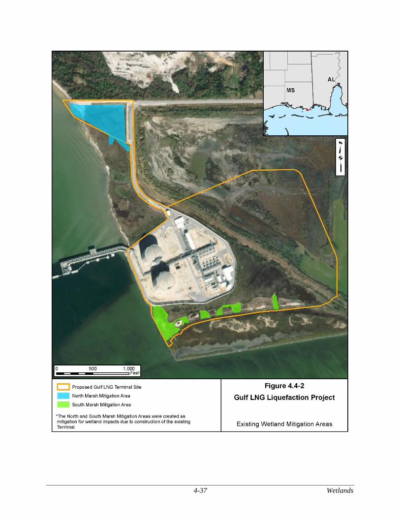
4-37 Wetlands
Figure 4.4-2 Existing Wetland Mitigation Areas
Wetlands 4-38
Project-wide Impacts
The Project would permanently affect 38.7 acres of wetlands (see table 4.4-2). Of these impacts,
27.8 acres would occur in EEM wetlands, 6.3 acres would occur in PFO wetlands, and 4.6 acres would
occur in PEM wetlands. The majority of wetland impacts, 31.1 acres, would be due to the Terminal
Expansion and flare exclusion zone and would involve permanent conversion to industrial-use land in order
to provide a safe and stable working surface during facility operations, allow addition of necessary
infrastructure, or would be impacted during operation of the flare.
The remaining 7.6 acres of wetlands, 6.3 acres of which would be PFO wetlands, would be filled
and graded for use as parking, storage, and other related construction activities at CSA-5. Gulf LNG would
mitigate the wetland impacts through the purchase of freshwater wetland mitigation credits. However, we
have determined that Gulf LNG has not adequately justified permanently filling the wetlands at CSA-5.
Therefore, in section 4.4.2.2 we are recommending that Gulf LNG commit to restore the wetlands at CSA-
5 to pre-construction conditions following construction in accordance with the FERC Procedures.
Gulf LNG would use only the upland portions of CSA-3 for Project activities. Of the 6.0 acres of
wetland created at the existing North Marsh Mitigation Area for construction of the existing Terminal,
about 0.5 acre would be outside the footprint of the Project and the remaining 5.5 acres would be
permanently impacted. Gulf LNG would protect the wetland area in CSA-3 and the 0.5 acre at the existing
North Marsh Mitigation Area through the use of exclusion fencing and implementation of the Gulf LNG
Procedures. Those measures would include clearly marking the wetlands and their buffers with signs
and/or highly visible flagging and preventing any sediment from entering wetlands until construction-
related ground disturbance is complete. Gulf LNG would also adhere to its SPCC Plan to avoid spills or
leaks of fuel, lubricants, coolants, or solvents in adjacent wetlands, and in the case that a spill did occur,
minimize the impacts to the greatest extent practicable. As a result, there would not be impacts on the
wetlands at CSA-3 and the 0.5 acre at the existing North Marsh Mitigation Area.
Compensatory Mitigation
The COE requires that project proponents offset all unavoidable wetland impacts by the creation,
restoration, enhancement, or preservation of at least equal amounts of wetlands, depending on the quality
of the wetlands affected and the type of wetlands created, restored, enhanced, or preserved (COE, 2017).
Direct, long-term effects on wetlands that would occur as part of Project construction and operation would
be subject to compensatory mitigation. There are three mechanisms for providing compensatory wetland
mitigation: permittee-responsible compensatory mitigation, mitigation banks, and in-lieu fee mitigation.
Gulf LNG consulted with the COE, the MDMR, the MDEQ, the FWS, and the NMFS, as well as
non-profit organizations such as The Nature Conservancy and the Conservation Fund, to develop acceptable
wetland mitigation for this Project. Gulf LNG initially considered many mitigation alternatives, such as
mitigation banks, in-lieu fees, and wetland expansion into Public Trust Tidelands. After the initial
assessments of potential mitigation alternatives, Gulf LNG focused its evaluations on screening potential
sites for new mitigation. In conjunction with agency and non-profit consultations, Gulf LNG considered
the following sites for the compensatory mitigation:
Gulf LNG Mitigation Site – creation of an on-site, in-kind salt marsh of about 50 acres of
estuarine emergent marsh that would expand an existing COE-created wetland mitigation site
south of the existing Terminal on Mississippi Sound (see figure 4.4-3). The seaward limits of
the proposed site would need to be armored with riprap to prevent erosion of the fill material
and protect the created marsh from wave activity. Fill material would be added to an
appropriate marsh elevation to support native EEM wetland vegetation (estimated to be 0.8
4-39 Wetlands
foot NAVD), and tidal channels would be created to establish a hydrologic connection with
Mississippi Sound. This site would provide all required compensatory mitigation;
Former International Paper Site – creation of an off-site, in-kind salt marsh by filling an
existing 80-acre pond and planting native marsh vegetation on the south shore of the
Escatawpa River. The pond has contaminated sediments which are currently contained by a
sediment cap.6 Groundwater has likewise been impacted by hydrocarbon contamination.
This site would provide all required compensatory mitigation but was not preferred by Gulf
LNG or the agencies because of the contamination issues;
Dutch Bayou/Moss Point Site – restoration of an off-site, in-kind EEM wetland in the
Escatawpa watershed through the placement of fill material in 32 acres of open water in order
to restore it to its previous EEM wetland status. Riprap would be placed at the site to protect
the fill against river erosion. This site would provide all required compensatory mitigation,
but was not preferred by Gulf LNG due to construction challenges and a high potential for
erosion during storm events;
Tennessee Gas Pipeline Canal – restoration of an off-site, in-kind salt marsh in Hancock
County, Mississippi (two counties from Jackson County, about 50 miles west of the Terminal
Expansion site). Access to the site is limited, complicating constructability and the ability to
attain and transport additional fill material beyond that which is available from cutting down
the sidecast berms from the construction of the original canal. This site would provide all
required compensatory mitigation, but due its distance from the Terminal Expansion site and
the potential risks of the existing buried pipeline, it was not preferred by Gulf LNG; and
Conservation Fund (CF) Sites – creation and restoration of an off-site, in-kind salt marsh by
filling and planting channelized marsh in the Mississippi Coastal watershed. These non-
contiguous properties were restrictive in their restoration capabilities and were not further
considered by Gulf LNG for mitigation purposes.
Other agencies and non-profits were consulted, and additional potential mitigation sites were
considered, as further described in the Gulf LNG Liquefaction Project Mitigation Plan Jackson County,
Mississippi.7 The preferred mitigation option was selected based on quality of the site, potential for
ecological uplift, constructability, location relative to the Terminal, and ultimately, agency preference for
on-site, in-kind mitigation. For these reasons, the Gulf LNG Wetland Mitigation Site was selected as Gulf
LNG’s preferred option. As presented in table 4.4-2, 31.1 acres of wetlands would be impacted by
construction of the Terminal Expansion. As discussed in Gulf LNG Liquefaction Project Mitigation Plan
Jackson County, Mississippi, Gulf LNG would be required to mitigate for 34.4 acres of wetlands. This
accounts for the re-mitigation of 3.3 acres of wetlands which were created as mitigation for the existing
Terminal and would be impacted again by the Project.
6 Sediment capping involves covering contaminated sediment, which remains in place, with clean material. Caps are
generally constructed of clean sediment, sand, or gravel. A more complex cap can include geotextiles, liners, and other
permeable or impermeable materials in multiple layers (EPA, 2017a).
7 See accession number 20190401-5626.
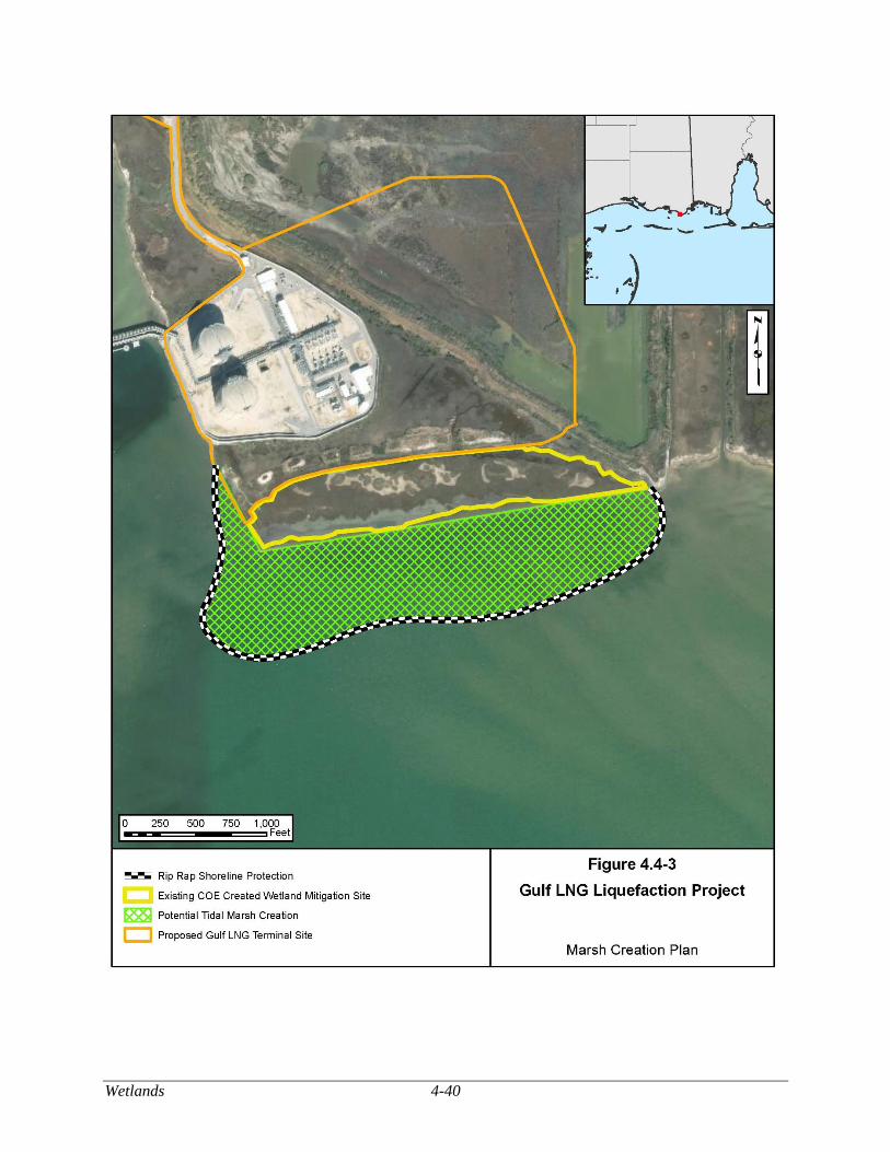
Wetlands 4-40
Figure 4.4-3 Marsh Creation Plan

4-41 Wetlands
Gulf LNG’s permittee-responsible compensatory mitigation would create and restore a 50-acre
tidal marsh wetland habitat. The compensatory mitigation acreage was calculated using a hydrogeomorphic
(HGM) model that took into account both the amount of land involved, as well as what ecological functions
the affected wetlands provided. The created wetland habitat would expand the existing COE-created
wetland mitigation site into the Mississippi Sound just south of the existing Terminal (see figure 4.4-2).
An about 50-acre area would be enclosed, armored with riprap, filled with sediments from the COE
Tombigbee Project, and planted with native EEM wetland vegetation, primarily smooth cordgrass and black
needlerush. Gulf LNG would plant native species, from nearby EEM wetlands and/or nursery-bought, to
achieve a minimum of 4,050 plants per acre. Plants taken from nearby wetlands would be collected at a
rate of less than or equal to 1 square foot per 1 square yard of wetland. About 323,000 cy of fill material
would be transported by barge from the COE Tombigbee Project into the mitigation area to appropriate
marsh elevations suitable for planting and revegetation.
To protect the site from erosion of the fill material and wave activity, about 19,000 cy of riprap
would be placed along the seaward limits of the site, set to an estimated height of 2.5 feet above msl to
allow for overtopping of the waves. During construction, a temporary barge access channel would be
dredged from the South Supply Dock along the outer perimeter of the proposed wetland mitigation site
(dredging of about 200,000 cy of material). Barges would use the temporary channel to install the perimeter
riprap. The sediment removed for the channel would be temporarily placed within the proposed wetland
mitigation site and then replaced in the temporary channel after the riprap is installed. All of the dredge
material would be replaced in the temporary channel or contained within the marsh creation area, so off-
site disposal would not be necessary. Tidal channels would be created to provide a hydrologic connection
and fishery access between the site and the Mississippi Sound.
Appropriate BMPs as documented in Gulf LNG Procedures, such as sediment and erosion control
and swamp mats, would be used to minimize the temporary impacts and avoid permanent impacts on the
existing COE-created wetland mitigation site. Mitigation activities at the wetland mitigation site would
provide the necessary acreage of anticipated compensatory mitigation required. The created marsh would
be monitored by Gulf LNG in accordance with the COE’s HGM method for fringing tidal marsh in the
northeastern Gulf coast for up to 5 years following Project completion. Monitoring marsh vegetation would
consider HGM measures of functional value including: wave energy attenuation, nekton utilization
potential, habitat provision for tidal marsh dependent wildlife species, and maintenance of plant community
composition and structure. Gulf LNG’s regular monitoring of the wetland mitigation site could identify
needed corrective actions, including the control of invasive exotic and/or noxious vegetation, which would
be physically removed and/or sprayed with habitat-appropriate herbicide by a certified licensed
professional. Data collected from the created marsh would be compared to that of a reference marsh and
submitted in an annual report to the COE Mobile District.
Gulf LNG would complete mitigation for all jurisdictional wetland impacts from construction and
operation of the Terminal Expansion as required by the permits issued by the COE and the MDMR. In
accordance with recommendation 10 (see section 5.2), Gulf LNG would be required to obtain approval in
support of their Joint Application for the Section 10, Section 404, and Section 401 permits. Since filing the
wetland mitigation plan, Gulf LNG has continued coordinating with federal and state agencies, (including
the COE, the MDMR, the FERC, the EPA, the Mississippi Secretary of State, the FWS, the NOAA, the
NMFS, and the MDEQ) to develop a final compensatory wetland mitigation plan for the Project. Gulf
LNG participated in meetings with agencies in September and October of 2015, and again on August 23,
2016, to provide a summary of the proposed mitigation plan, to discuss methods used to assess the quality
of existing wetlands at the proposed mitigation site, and to identify and address agency questions and
concerns. Gulf LNG would finalize the design details and construction plan during final design. Agency
coordination and final design is currently ongoing.
Wetlands 4-42
Conclusion
Permanent impacts on 31.1 acres of tidal wetlands associated with construction and operation of
the Terminal Expansion and related facilities would be mitigated under the compensatory mitigation
stipulations of the Section 404 and Section 10 permits issued by the COE and the Section 401 permit issued
by the MDEQ and MDMR. Impacts on 7.6 acres of freshwater wetlands (1.3 acres of PEM and 6.3 acres
of PFO) within CSA-5 would be mitigated through the purchase of freshwater wetland mitigation credits,
as stipulated in the Section 404 and Section 10 permits. However, we have determined that Gulf LNG has
not adequately justified permanently filling the wetlands at CSA-5. Therefore, in section 4.4.2.2 we are
recommending that Gulf LNG commit to restore the wetlands at CSA-5 to pre-construction conditions
following construction in accordance with the FERC Procedures. Further, Gulf LNG would implement the
mitigation measures included in its Gulf LNG Procedures. Based on implementation of the mitigation
measures and our recommendation, discussed above, we conclude impacts on wetlands due to construction
and operation of the Project would not be significant.
4-43 Vegetation
VEGETATION
Vegetation Resources
The Project would affect 230.8 acres of land during construction; 94.1 acres of this total affected
area is vegetated. Non-vegetated land cover types, such as open water and industrial lands, are discussed
in more detail in sections 4.3 and 4.8, respectively. Field surveys of the Project area, conducted in 2014
and 2015, identified five vegetation cover types: EEM wetlands, PEM wetlands, PFO wetlands, forested
uplands, and open uplands. Wetlands are described in section 4.4. The majority of the vegetated land that
would be affected by the Project include EEM wetlands (24.7 acres), followed by forested uplands (8.5
acres), PFO wetlands (6.3 acres), PEM wetlands (4.6 acres), and open uplands (3.5 acres). Vegetated land
also includes 46.4 acres of the BCDMMS, which was not surveyed because of safety concerns associated
with the unstable terrain (i.e., deep, unconsolidated sediment with varying water levels). The BCDMMS
is actively used as a dredge material disposal site. Regular disturbance at the site precludes the existence
of well-established vegetation.
The forested uplands canopy is dominated by live oak, water oak, and Chinese tallow, with an
understory of eastern false-willow, wax myrtle, and Hercules’ club (BVA, 2014; BVA, 2015). Within the
proposed Project area, open upland habitat is adjacent to the South Marsh Mitigation Area on mounded
dredge spoil. Dominant vegetation includes cogongrass and beach vitex. Of the above-mentioned
dominant vegetative species, cogongrass, Chinese tallow, and Chinese privet are identified as exotic,
invasive, and/or noxious plant species, further described in section 4.5.3.
Other than wetlands (discussed in section 4.4), no vegetative communities regulated by federal or
state agencies were identified in the Project area. Potential habitat for special-status plant species is
discussed in section 4.7.
Terminal Expansion
The Terminal Expansion would be constructed on about 77.9 acres of vegetated land, which
includes 3.5 acres of open upland habitat, 3.3 acres of PEM wetlands, 24.7 acres of EEM wetland, and 46.4
acres of the BCDMMS.8 There are no vegetative communities within the existing Terminal site; all of the
land was previously cleared of vegetation and is classified as industrial-use (see figure 2.0-1). Sparse
vegetation at the BCDMMS is low quality and frequently disturbed. The annual placement of 4 to 5 feet
of dredged material at the BCDMMS followed by dewatering activities to reduce volume has resulted in
the degradation of vegetation and wildlife habitat at the site. Dredge disposal activities at the BCDMMS
are expected to continue at this rate for more than 50 years (COE, 2014). Therefore, any vegetation that is
able to grow in the area between disposal events would be destroyed during the next event. Open water
habitat at the supply dock areas do not contain submerged aquatic vegetation (SAV); the nearest SAV beds
to the Project are about 3 miles east of the proposed Terminal Expansion site (Grand Bay NERR, 2015).
As evidenced by the presence of invasive/exotic vegetation (cogongrass) along with the visible
ground disturbance (spoil mounds), vegetated land within the proposed Terminal Expansion site is
generally disturbed. Additional invasive and/or exotic species at the site include Chinese tallow,
camphortree, and torpedo grass. The disturbed character of this site is largely due to industrial activity that
has occurred within the last 50 years in the surrounding areas and use of the BCDMMS as a dredge material
placement area.
Gulf LNG would use sediments from the BCDMMS (304,920 cy) and the COE Tombigbee Project
(770,080 cy) to raise the grade of the Terminal Expansion site. Of the 31.5 acres of wetlands and open
8 Numbers are rounded to the nearest tenth of a decimal point. As a result, the totals may not reflect the sum of the addends.
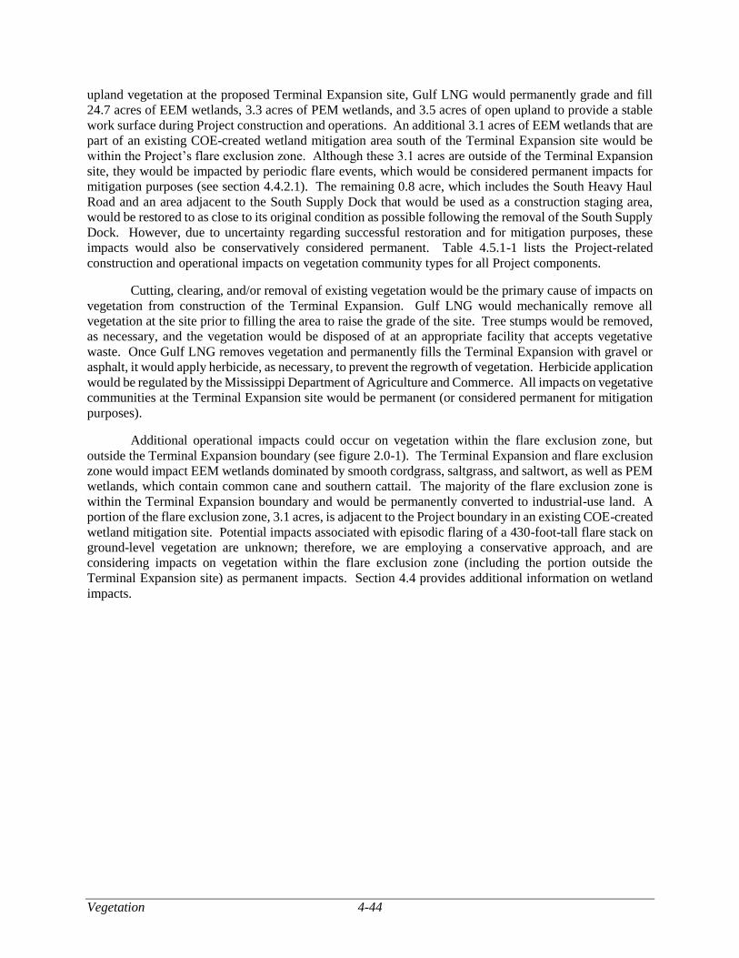
Vegetation 4-44
upland vegetation at the proposed Terminal Expansion site, Gulf LNG would permanently grade and fill
24.7 acres of EEM wetlands, 3.3 acres of PEM wetlands, and 3.5 acres of open upland to provide a stable
work surface during Project construction and operations. An additional 3.1 acres of EEM wetlands that are
part of an existing COE-created wetland mitigation area south of the Terminal Expansion site would be
within the Project’s flare exclusion zone. Although these 3.1 acres are outside of the Terminal Expansion
site, they would be impacted by periodic flare events, which would be considered permanent impacts for
mitigation purposes (see section 4.4.2.1). The remaining 0.8 acre, which includes the South Heavy Haul
Road and an area adjacent to the South Supply Dock that would be used as a construction staging area,
would be restored to as close to its original condition as possible following the removal of the South Supply
Dock. However, due to uncertainty regarding successful restoration and for mitigation purposes, these
impacts would also be conservatively considered permanent. Table 4.5.1-1 lists the Project-related
construction and operational impacts on vegetation community types for all Project components.
Cutting, clearing, and/or removal of existing vegetation would be the primary cause of impacts on
vegetation from construction of the Terminal Expansion. Gulf LNG would mechanically remove all
vegetation at the site prior to filling the area to raise the grade of the site. Tree stumps would be removed,
as necessary, and the vegetation would be disposed of at an appropriate facility that accepts vegetative
waste. Once Gulf LNG removes vegetation and permanently fills the Terminal Expansion with gravel or
asphalt, it would apply herbicide, as necessary, to prevent the regrowth of vegetation. Herbicide application
would be regulated by the Mississippi Department of Agriculture and Commerce. All impacts on vegetative
communities at the Terminal Expansion site would be permanent (or considered permanent for mitigation
purposes).
Additional operational impacts could occur on vegetation within the flare exclusion zone, but
outside the Terminal Expansion boundary (see figure 2.0-1). The Terminal Expansion and flare exclusion
zone would impact EEM wetlands dominated by smooth cordgrass, saltgrass, and saltwort, as well as PEM
wetlands, which contain common cane and southern cattail. The majority of the flare exclusion zone is
within the Terminal Expansion boundary and would be permanently converted to industrial-use land. A
portion of the flare exclusion zone, 3.1 acres, is adjacent to the Project boundary in an existing COE-created
wetland mitigation site. Potential impacts associated with episodic flaring of a 430-foot-tall flare stack on
ground-level vegetation are unknown; therefore, we are employing a conservative approach, and are
considering impacts on vegetation within the flare exclusion zone (including the portion outside the
Terminal Expansion site) as permanent impacts. Section 4.4 provides additional information on wetland
impacts.
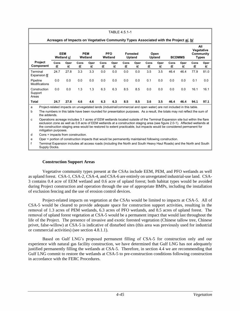
4-45 Vegetation
TABLE 4.5.1-1
Acreages of Impacts on Vegetative Community Types Associated with the Project a/, b/
Project Component
EEM Wetland c/
PEM Wetland
PFO Wetland
Forested Upland
Open Upland BCDMMS
All Vegetative Community
Types
Cons d/
Oper e/
Cons d/
Oper e/
Cons d/
Oper e/
Cons d/
Oper e/
Cons d/
Oper e/
Cons d/
Oper e/
Cons d/
Oper e/
Terminal Expansion f/
24.7 27.8 3.3 3.3 0.0 0.0 0.0 0.0 3.5 3.5 46.4 46.4 77.9 81.0
Pipeline Modifications
0.0 0.0 0.0 0.0 0.0 0.0 0.0 0.0 0.1 0.0 0.0 0.0 0.1 0.0
Construction Support Areas
0.0 0.0 1.3 1.3 6.3 6.3 8.5 8.5 0.0 0.0 0.0 0.0 16.1 16.1
Total 24.7 27.8 4.6 4.6 6.3 6.3 8.5 8.5 3.6 3.5 46.4 46.4 94.1 97.1
a Project-related impacts on unvegetated lands (industrial/commercial and open water) are not included in this table.
b The numbers in this table have been rounded for presentation purposes. As a result, the totals may not reflect the sum of the addends.
c Operations acreage includes 3.1 acres of EEM wetlands located outside of the Terminal Expansion site but within the flare exclusion zone as well as 0.8 acre of EEM wetlands at a construction staging area (see figure 2.0-1). Affected wetlands at the construction staging area would be restored to extent practicable, but impacts would be considered permanent for mitigation purposes.
d Cons = impacts from construction.
e Oper = portion of construction impacts that would be permanently maintained following construction.
f Terminal Expansion includes all access roads (including the North and South Heavy Haul Roads) and the North and South Supply Docks.
Construction Support Areas
Vegetative community types present at the CSAs include EEM, PEM, and PFO wetlands as well
as upland forest. CSA-1, CSA-2, CSA-4, and CSA-6 are entirely on unvegetated industrial-use land. CSA-
3 contains 0.4 acre of EEM wetland and 0.6 acre of upland forest; both habitat types would be avoided
during Project construction and operation through the use of appropriate BMPs, including the installation
of exclusion fencing and the use of erosion control devices.
Project-related impacts on vegetation at the CSAs would be limited to impacts at CSA-5. All of
CSA-5 would be cleared to provide adequate space for construction support activities, resulting in the
removal of 1.3 acres of PEM wetlands, 6.3 acres of PFO wetlands, and 8.5 acres of upland forest. The
removal of upland forest vegetation at CSA-5 would be a permanent impact that would last throughout the
life of the Project. The presence of invasive and exotic forested vegetation (Chinese tallow tree, Chinese
privet, false-willow) at CSA-5 is indicative of disturbed sites (this area was previously used for industrial
or commercial activities) (see section 4.8.1.1).
Based on Gulf LNG’s proposed permanent filling of CSA-5 for construction only and our
experience with natural gas facility construction, we have determined that Gulf LNG has not adequately
justified permanently filling the wetlands at CSA-5. Therefore, in section 4.4 we are recommending that
Gulf LNG commit to restore the wetlands at CSA-5 to pre-construction conditions following construction
in accordance with the FERC Procedures.
Vegetation 4-46
Pipeline Modifications
Gulf LNG would modify two existing pipeline facilities to enable bi-directional (north/south) flow
capability. Gulf LNG would construct the majority of modifications within the existing fenced and graveled
areas. Construction of the Gulfstream Meter Station would require extra workspace within adjacent existing
right-of-way that would impact 0.1 acre of open upland. Vegetation within the existing right-of-way
consists primarily of bahiagrass, Bermuda grass, and other volunteer vegetation. Gulf LNG would restore
the area once construction is completed in accordance with the Gulf LNG Plan. Therefore, no permanent
impacts on vegetative communities would occur as a result of the Pipeline Modifications.
Transco would also make modifications to the existing and jointly owned Transco/FGT
Interconnection to permit bi-directional flow. These modifications would be constructed by Transco and
would be reviewed by the FERC under its blanket certificate process.
Mitigation Measures
Gulf LNG would implement erosion control and other mitigation methods to minimize indirect
effects on vegetative communities during construction of the Project. Gulf LNG prepared a Project-specific
Gulf LNG Plan and Gulf LNG Procedures (appendices D and E) which incorporate measures in FERC’s
Plan and Procedures. Revegetation of temporarily disturbed areas would depend on the feasibility and
effectiveness of restoration and natural factors such as local climate and soil types. Some of the restoration
and best management practices identified for implementation by Gulf LNG include the following:
use of at least one environmental inspector at all times during construction and restoration;
acquisition of written recommendations from the local soil conservation authorities or land
management agencies regarding revegetation specifications;
installation of temporary and permanent erosion control measures, such as slope breakers,
sediment barriers, and mulch;
commencement of cleanup and restoration, including restoring contours, within 20 days of
the completion of construction (weather permitting);
grading temporarily affected Project areas to their original contours;
testing and mitigation for soil compaction;
preparing seedbeds in disturbed areas at a depth of 3 to 4 inches;
application of herbicides regulated by the Mississippi Department of Agriculture and
Commerce;
prohibiting the use of herbicides within 100 feet of a wetland or waterbody; and
inspecting all disturbed areas, as necessary (and at least after the first and second growing
seasons) to determine revegetation success.
Gulf LNG has proposed compensatory wetland mitigation to offset permanent wetland impacts at
the Terminal Expansion. The proposed mitigation wetland would be located offshore and adjacent to the
southern portion of the Terminal Expansion site (see section 4.4.3). The 50-acre mitigation wetland would
convert approximately 46 acres of open water habitat to EEM wetlands (see section 4.6).
Gulf LNG proposes to purchase credits from a wetland mitigation bank to mitigate for impacts on
PFO and PEM wetlands at CSA-5 (see section 4.4.3).
4-47 Vegetation
In general, although the majority of the Project-related impacts on vegetation would be permanent,
the disturbed nature of the Project area and the proposed mitigation measures, including Gulf LNG’s
Compensatory Wetland Mitigation Plan to create a 50-acre tidal marsh, leads us to conclude that impacts
from construction and operation of the Terminal Expansion on vegetation communities would be minimized
to the extent practicable and would therefore not be significant.
Exotic or Invasive Plant Communities and Noxious Weeds
Exotic plant communities, invasive species, and noxious weeds can out-compete and displace
native plant species, thereby negatively altering the appearance, composition, and habitat value of affected
areas. Exotic plant species are plants that were introduced (either intentionally or unintentionally) and
subsequently became established in an area other than that from which their species originated. Invasive
plant species are a subset of exotic species whose introduction can cause harm to the environment, human
health, or economic interests (UG, 2009). A noxious weed is any plant designated by a federal, state, or
county government as injurious to public health, agriculture, recreation, wildlife, or property (Sheley et al.,
1999). Invasive plants can be noxious weeds, but they also include plants that are not native to this country
or the area where they are growing (DOI, 2010). There were 20 exotic, invasive, and/or noxious plant
species identified within the Project area during field surveys in 2014; these are listed in table 4.5.3-1.
Regulation of invasive species is conducted at the federal level by the USDA’s Natural Resource
Conservation Service and at the state level, by the Mississippi Bureau of Plant Industry. Both of the
aforementioned agencies publish unique Noxious Weeds Lists. Of the 20 exotic plant species identified
within the Project area, two are on Mississippi’s Noxious Weed List (cogongrass and Chinese tallow).
Cogongrass is also listed on the Federal Noxious Weed List due to its aggressive weedy habit in other
countries (Byrd and Bryson, 1999; MDAC, 2014; USDA, 2014).
Within the Project area, cogongrass was observed growing on mounded dredge spoil south of the
existing Terminal. Cogongrass is native to tropical and subtropical areas of the eastern hemisphere and is
common throughout the coastal regions of the southeastern United States, including Mississippi (Brown,
1944; Hubbard, 1944; Byrd and Bryson, 1999). It produces numerous, tall stems that form thick stands.
Its dense stems and rooting systems allow it to choke out other nearby vegetation (Bryson and Carter, 1993;
Byrd and Bryson, 1999).
Chinese tallow was observed along the northern edges of the existing North Marsh Mitigation Site
(see figure 4.4-2). Chinese tallow grows quickly, is drought resistant due to its deep tap root, and produces
large quantities of seeds that are spread by water, birds, and mammals. This species can re-sprout quickly
from crown and root buds when top growth is mechanically removed. Native species are crowded out once
Chinese tallow is established (UF, 2014).
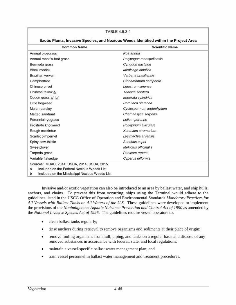
Vegetation 4-48
TABLE 4.5.3-1
Exotic Plants, Invasive Species, and Noxious Weeds Identified within the Project Area
Common Name Scientific Name
Annual bluegrass Poa annua
Annual rabbit’s-foot grass Polypogon monspeliensis
Bermuda grass Cynodon dactylon
Black medick Medicago lupulina
Brazilian vervain Verbena brasiliensis
Camphortree Cinnamomum camphora
Chinese privet Ligustrum sinense
Chinese tallow a/ Triadica sebifera
Cogon grass a/, b/ Imperata cylindrica
Little hogweed Portulaca oleracea
Marsh parsley Cyclospermum leptophyllum
Matted sandmat Chamaesyce serpens
Perennial ryegrass Lolium perenne
Prostrate knotweed Polygonum aviculare
Rough cocklebur Xanthium strumarium
Scarlet pimpernel Lysimachia arvensis
Spiny sow-thistle Sonchus asper
Sweetclover Melilotus officinalis
Torpedo grass Panicum repens
Variable flatsedge Cyperus difformis
Sources: MDAC, 2014; USDA, 2014; USDA, 2015
a Included on the Federal Noxious Weeds List
b Included on the Mississippi Noxious Weeds List
Invasive and/or exotic vegetation can also be introduced to an area by ballast water, and ship hulls,
anchors, and chains. To prevent this from occurring, ships using the Terminal would adhere to the
guidelines listed in the USCG Office of Operation and Environmental Standards Mandatory Practices for
All Vessels with Ballast Tanks on All Waters of the U.S. These guidelines were developed to implement
the provisions of the Nonindigenous Aquatic Nuisance Prevention and Control Act of 1990 as amended by
the National Invasive Species Act of 1996. The guidelines require vessel operators to:
clean ballast tanks regularly;
rinse anchors during retrieval to remove organisms and sediments at their place of origin;
remove fouling organisms from hull, piping, and tanks on a regular basis and dispose of any
removed substances in accordance with federal, state, and local regulations;
maintain a vessel-specific ballast water management plan; and
train vessel personnel in ballast water management and treatment procedures.
4-49 Vegetation
The guidelines also include reporting and record-keeping requirements regarding their
implementation. Copies of the reports must be send to the USCG and maintained on the vessel for at least
2 years (COE, 2015a).
There is also the potential for a Project-related spread of invasive and/or exotic species during the
creation of the tidal marsh as part of the proposed compensatory wetland mitigation. Sediment fill to create
the wetland would be excavated from the COE Tombigbee Project. Sediments could contain nuisance
vegetation; however, Gulf LNG would monitor the site for the establishment of nuisance vegetation during
and after development of the site in a manner consistent with the guidelines and recommendations from the
COE, the MDMR, and other applicable regulatory agencies. If needed, Gulf LNG would develop a plan to
remove the nuisance species using mechanical or chemical methods. The use of herbicides would be subject
to the approval from the Mississippi Department of Agriculture and Commerce.
Gulf LNG would also work with the COE to monitor the overall success of marsh establishment.
The marsh’s success would be monitored and assessed according to Gulf LNG’s Procedures and Gulf
LNG’s Project Mitigation Plan Jackson County, Mississippi, which require annual site inspections for five
years and a report at the end of those five years documenting the success of revegetation. Should any of
the wetlands not be revegetated, Gulf LNG would consult a professional wetland ecologist and implement
a remediation plan. In addition, mitigation success and monitoring requirements would be requirements of
and stipulated in any COE-approved mitigation plan. If problems with vegetation were observed at the site
during monitoring, Gulf LNG would develop a solution and take corrective actions as soon as practicable.
Corrective actions could include removal of nuisance vegetation by physical removal or other approved
removal methods, replanting dead or dying vegetation, sand replenishment, and improved signage to deter
people from disturbing the site.
Based on adherence with the vessel guidelines regarding ballast water and noxious weeds,
implementation of Gulf LNG’s Procedures and Gulf LNG’s Project Mitigation Plan Jackson County,
Mississippi at the proposed wetland mitigation site, we conclude that the potential spread of noxious or
invasive weed would be effectively minimized or mitigated.
Vegetation Communities of Special Concern
A population of Carolina grasswort was observed within the Project area at the existing North
Mitigation Area. Carolina grasswort is listed as a species of concern in Mississippi, but is not regulated at
the federal or state level. The area in which this population is located would be permanently filled for
Project operations; therefore, unless it is protected from Project activities, or moved to a different location,
this population would be eliminated during the vegetation removal phase of Project construction. On
August 27, 2018, the Mississippi Museum of Natural Science (MMNS) recommended the Carolina
grasswort populations be transplanted to a location containing similar habitat prior to construction activities.
Therefore, in section 4.7 we are recommending Gulf LNG work with MMNS to develop protocol to
transplant the Carolina grasswort populations to a location containing similar habitat prior to construction
activities. Potential impacts on plants of special concern and their habitats are further discussed in section
4.7.2.
Wildlife and Aquatic Resources 4-50
WILDLIFE AND AQUATIC RESOURCES
General Wildlife Resources
The wildlife habitat types in the Project area are characteristic of the vegetative communities and
land use types present and include open uplands, upland forest, EEM wetlands, PEM wetlands, PFO
wetlands, the BCDMMS, open water, and industrial/commercial land. We identified wildlife habitat types
based on interpretation of aerial photography and Gulf LNG’s field reconnaissance that was conducted in
2014 and 2015.
Terminal Expansion
Existing Wildlife Habitat
Wildlife habitats at the Terminal Expansion site, which includes the North and South Supply Docks
and associated heavy haul roads, consist of EEM wetlands, PEM wetlands, the BCDMMS, open upland,
and open water. Aquatic wildlife resources are discussed in section 4.6.2. Federal and state protected
species are discussed in section 4.7.
Wetland habitats at the Terminal Expansion site can provide habitat for waterfowl, wading birds,
raptors, mammals, reptiles, and amphibians. Typical wildlife associated with these wetland types include
muskrat, American mink, raccoon, opossum, several species of heron, great egret, clapper rail, purple
gallinule, belted kingfisher, northern harrier, Mississippi diamondback terrapin, American alligator, Gulf
salt marsh snake, cottonmouth, American green tree frog, American bullfrog, and southern leopard frog
(BVA, 1985; Gulf of Mexico Research Laboratory, 1973). Invasive species, such as nutria, also occur in
these wetland types (USDA, 2017). Some of the affected wetlands at the Terminal Expansion site are
portions of two existing mitigation areas that were created as part of the mitigation for wetland impacts due
to construction of the existing Terminal. The North and South Marsh Mitigation Areas are components of
tidal marsh systems (see figure 4.4-2). During the biological surveys conducted by Gulf LNG, several
species of exotic and/or invasive vegetative species were observed in marsh habitat within the boundaries
of the Terminal Expansion site. Section 4.4 provides a more detailed discussion of affected wetlands, and
section 4.5.3 addresses exotic and/or invasive plant species.
Gulf LNG would use about 46 acres of the 135-acre BCDMMS for the Terminal Expansion. Gulf
LNG did not perform wildlife and habitat surveys at the BCDMMS due to safety concerns. However, the
BCDMMS does not contain any established wildlife habitat due to its use as a dredged material placement
site. Therefore, while marginal wildlife habitat may establish itself between disposal events, it would be
destroyed during the next sediment deposition event. Typical animal species that could occur on the
BCDMMS include rock pigeons, mourning doves, house sparrows, brown rats, mice, raccoons, and
opossums.
Open upland consists primarily of mixed species of grasses, forbs, and shrubs. Wildlife associated
with these areas includes mammals such as the white-tailed deer, cotton rat, cottontail rabbit, raccoon,
opossum, and harvest mouse. Bird species include the northern mockingbird, northern cardinal, brown
thrasher, blue jay, song sparrow, Carolina wren, and northern bobwhite. Reptiles and amphibians include
several species of tree frogs, the southern toad, southern black racer, gray ratsnake, eastern diamondback
rattlesnake, and eastern box turtle.
Open water habitat at the Terminal Expansion site includes nearshore areas as well as deeper,
offshore waters that would be crossed by vessels calling on the Terminal. Several species of shorebirds,
wading birds, and waterfowl have been observed in and along open water habitat at the Terminal Expansion
4-51 Wildlife and Aquatic Resources
site, including the American oystercatcher, killdeer, tri-colored heron, snowy egret, greater scaup, and blue-
winged teal (BVA, 1985; FERC, 2006).
Much of the habitat at the Terminal Expansion site has been previously disturbed. About 10.6 acres
of the Terminal Expansion site would be sited on previously developed industrial/commercial land within
the existing Terminal’s footprint. The majority of the Terminal Expansion site that is outside the existing
Terminal footprint would be within the BCDMMS and was previously disturbed by placement of dredged
material. Nearshore and offshore open water habitat associated with the Terminal Expansion is subject to
regular disturbance due to anthropogenic activities (e.g., construction activities, shipping, fishing) and
severe weather (e.g., hurricanes).
Some species of terrestrial wildlife at the Terminal Expansion site have commercial, recreational,
and/or aesthetic value. Hunting, trapping, and bird watching all involve wildlife species found at the site.
However, these activities are not typically conducted at the Project site due to low-quality habitat and
restricted or prohibited access. Therefore, the Project is not expected to impact these wildlife values.
Wildlife Resources Impacts and Mitigation
Construction and operation of the Terminal Expansion would result in permanent alteration of the
wildlife habitat types listed above. Construction of the Terminal Expansion facilities would affect 132.2
acres and operation would affect 129.7 acres. Of the affected acreage, about 81 acres are potential terrestrial
wildlife habitat, including 31.1 acres wetlands (including 3.1 acres within the flare exclusion zone), 46.4
acres of the BCDMMS, and 3.5 acres of open upland.9 Land uses at the Terminal Expansion site are
discussed in section 4.8. Gulf LNG would convert 77.9 acres of terrestrial wildlife habitat affected during
construction of the Terminal Expansion to industrial land (see table 4.5.1-1).
During construction of the Terminal Expansion, Gulf LNG would clear vegetation and grade and
fill the site, including the heavy haul roads, to the design specifications. This would reduce cover, nesting,
and foraging habitat for some species and may result in mortality of less mobile forms of wildlife, such as
small rodents and reptiles. Other more mobile wildlife, such as birds and larger mammals, would be
expected to leave the area as construction activities approach. These animals may relocate into similar
habitats nearby; however, if there is a lack of adequate habitat to support the additional animals adjacent to
or near the site, they may be forced into suboptimal habitat and/or increased densities, which could lower
reproductive success and survival.
Of the 81 acres that would be affected by the Project, 3.1 acres of EEM wetlands would be located
outside of the Project boundary but within the flare exclusion zone (see figures 2.0-1 and 4.4-1). Potential
impacts on all wetlands within the flare exclusion zone would occur only when flaring occurs, but the
impact would be considered permanent for mitigation purposes. As stated in the August 2018 Gulf LNG
Liquefaction Project Mitigation Plan Jackson County, Mississippi, Gulf LNG proposes on-site, in-kind
mitigation of about 50-acres of open water located to the south of the existing Terminal adjacent to Bayou
Casotte. The area would be filled using sediment from the COE Tombigbee Project to create tidal marsh
wetland, which would mitigate the loss of wetland wildlife habitat. A more detailed discussion of
compensatory mitigation for wetland impacts is provided in section 4.4.3.
The 430-foot-high flare tower at the southeast corner of the Terminal Expansion site could pose a
hazard to birds (see figure 2.0-1). The primary hazard is the potential for avian collision with the structure,
especially at night when the tower would be lighted. To the extent practicable, Gulf LNG would use
measures from the 2013 U.S. Fish and Wildlife Revised Voluntary Guidelines for Communication Tower
Design, Siting, Construction, Operation, Retrofitting, and Decommissioning (FWS Communication Tower
9 Numbers are rounded to the nearest tenth of a decimal point. As a result, the totals may not reflect the sum of the addends.
Wildlife and Aquatic Resources 4-52
Guidelines; FWS, 2013) to develop a design that would reduce the likelihood for avian collisions while
minimizing potential impacts associated with light pollution. Gulf LNG’s design would include the
installation of lights that only meet the minimum requirements for obstruction avoidance and pilot warning,
and omitting the use of guy wires. There is also the potential for some bird species to use the flare tower
as perching and/or nesting sites, which could result in mortality during a flare event. However, the design
of typical flare towers is not conducive to nest building, because they lack closely spaced support bracings
(such as those present on transmission line towers). In contrast, flare towers have a more open surface with
more widely spaced bracings, which makes them less attractive as nesting sites. Further, for some species
that are known to nest on tall structures (e.g., bald eagle and brown pelican), the flare towers are
significantly taller than their preferred nesting sites, and it is therefore unlikely they would attempt to build
nests there. Should it be identified that birds are attempting to nest on the flare tower, Gulf LNG would
work with the MDWFP and the FWS to develop appropriate mitigation.
As part of the Terminal Expansion, Gulf LNG would construct and use two supply docks (see
figures 2.2-1 and 2.2-2). The North Supply Dock would be a permanent structure used during construction
by Gulf LNG and transferred to the Jackson County Port Authority after construction (see section 1.4.3).
The South Supply Dock would be a temporary, shallow-draft barge loading area, which would be removed
after construction. Both supply docks would require initial dredging to a depth of 12 feet below msl and
may require maintenance dredging as often as every 3 years. Open water adjacent to the supply docks
would remain as open water, although public use of the water would be prohibited. In addition, there is a
large amount of similar open water habitat to the west, south, and east of the Terminal Expansion site to
which mobile open water wildlife could relocate. Section 4.6.2 addresses potential impacts on open water
aquatic species.
The majority of the habitats at the Terminal Expansion site have been previously disturbed and
provide limited productive wildlife habitat. Areas adjacent to the Terminal Expansion site are also largely
disturbed with limited wildlife habitat. Some wildlife species may move away from the area during
construction due to the increased noise and activity levels. However, due to current industrial activities
within and around the Terminal Expansion area, most wildlife species in the area are acclimated to these
activities. Therefore, impacts due to operational noise and light, and human activity would not be
significant.
Gulf LNG would conduct all construction activities in accordance with the Gulf LNG Plan and Gulf
LNG Procedures to minimize impacts to the extent practicable. In addition, high-quality tidal marsh areas
would be created as compensatory mitigation for wetland impacts associated with construction and
operation of the Terminal Expansion. The mitigation area would provide habitat for wildlife to offset the
habitat lost due to Project construction and operation. Further, Gulf LNG would incorporate the FWS-
recommended mitigation methods for the flare tower to minimize the potential collision impacts on birds.
Therefore, with adherence to the proposed mitigation measures and given the abundance of suitable habitat
in adjacent areas, we conclude that construction and operation of the Terminal Expansion would be
adequately minimized on wildlife and these impacts would not be significant.
Construction Support Areas
Existing Wildlife Habitat
Gulf LNG would establish six CSAs. Five of the CSAs would be used for parking, staging,
contractor yards, and laydown areas. One CSA, CSA-3 (currently used by Gulf LNG), would be used for
warehousing and equipment storage only; Project-related activities that involve heavy traffic would not be
conducted on this property. All proposed CSAs are in industrial areas that were previously developed and
used for similar activities, either entirely or partially. CSA-3 and CSA-5 contain upland forest and
wetlands. There are 0.4 acre of EEM wetlands and 0.6 acre of upland forest habitat at CSA-3; however,
4-53 Wildlife and Aquatic Resources
these areas would be avoided during Project construction and operation. CSA-5 contains 1.3 acres of PEM
wetlands, 6.3 acres of PFO wetlands, and 8.5 acres of upland forest. CSA-1, CSA-2, CSA-4, and CSA-6
are entirely on developed, industrial/commercial land. Therefore, impacts on wildlife, if any, would be
minimal.
The PEM and PFO wetlands at proposed CSA-5 are at least partially dominated by invasive and
exotic vegetation (BVA, 2014; BVA, 2015). Wildlife species that may occur in these wetlands are the same
as those described in section 4.6.1.1 for wetland habitats at the Terminal Expansion. PFO wetlands at CSA-
5 could also provide habitat for several tree-nesting bird species (e.g., the common yellowthroat, eastern
towhee, and swamp sparrow) and other non-avian animals that use trees to meet various life requirements
(e.g., the gray squirrel and bobcat). Wetlands at CSA-5 are disturbed and fragmented as a result of
irregularly placed fill.
The upland forest at proposed CSA-5 is dominated by slash pine, loblolly pine, and water oak.
Invasive species, such as Chinese tallow, Chinese privet, and cogongrass, were observed during field
surveys. Reptiles and amphibians that may use these areas include several species of tree frogs and
salamanders, the southern toad, black racer, gray ratsnake, eastern diamondback rattlesnake, ground skink,
and eastern box turtle. Mammals include white-tailed deer, bobcat, raccoon, opossum, and gray fox. A
variety of birds may also use these habitats, including the northern mockingbird, northern cardinal, brown
thrasher, and blue jay.
Impacts and Mitigation
The CSA-3 site (which is currently in use by Gulf LNG) would be used ‘as-is’ (i.e., in its existing
condition), and no trees would be cleared. Gulf LNG would use BMPs to avoid and protect the wetlands
and would incorporate the mitigation methods presented in the Gulf LNG Procedures. This would include
installation of exclusion fencing and identification of exclusion boundaries using signage to keep
construction personnel away from the wetlands. As a result, we conclude wetlands at CSA-3 would not be
affected. Because the site is already in use by Gulf LNG as an industrial-use area and no additional upland
forested vegetation would be removed for the Project, it is unlikely that impacts on upland forest wildlife
would occur. Any wildlife present at the site prior to Project activities would have acclimatized to an
industrial setting and would not be significantly impacted by similar activity occurring at the site.
Gulf LNG would remove all vegetation within CSA-5 to permanently convert the site to upland,
industrial/commercial land. This would reduce cover, nesting, and foraging habitat for some species and
may result in mortality of less mobile forms of wildlife, such as small rodents and reptiles. Other more
mobile wildlife, such as birds and larger mammals, would be expected to leave the area during construction.
These animals may relocate into similar habitats nearby; however, if there is a lack of adequate habitat to
support the additional animals adjacent to or near CSA-5, they may be forced into suboptimal habitat and/or
increased densities, which could lower reproductive success and survival. Although Gulf LNG proposes
to maintain the site as a graveled lot, this area is already disturbed (as evidenced by the invasive vegetation
species present at the site), the conversion of 7.6 acres of vegetation to industrial land would represent less
than 0.001 percent of the vegetation within the County,10 and there is suitable habitat adjacent to the site.
Therefore, we conclude that impacts on local wildlife populations during construction of the CSAs would
not be significant. Additionally, we have determined that Gulf LNG has not adequately justified
permanently filling the wetlands at CSA-5. Therefore, in section 4.4.2.2 we are recommending that Gulf
LNG commit to restore the wetlands at CSA-5 to pre-construction conditions following construction in
accordance with the FERC Procedures, which would further minimize impacts on wildlife.
10 Jackson County contains about 330,000 acres of forest according to
https://www.mfc.ms.gov/sites/default/files/MS_Assessment_Resource_Strategy_2010.pdf.
Wildlife and Aquatic Resources 4-54
Pipeline Modifications
The proposed sites of the Pipeline Modifications are entirely industrial/commercial land. All
construction activities would be confined to previously disturbed areas, and the modifications would not
result in additional permanent impacts on natural habitat. Construction of the Gulfstream Meter Station
would require extra workspace within adjacent existing right-of-way that would impact 0.1 acre of open
upland. Gulf LNG would restore the area once construction is completed in accordance with the Gulf LNG
Plan. Therefore, impacts on wildlife habitat would not occur as a result of construction or operation of the
Pipeline Modifications.
Unique and Sensitive Wildlife Species
Unique or sensitive wildlife species, such as colonial nesting waterbirds and migratory birds, may
be present in the vicinity of the Project. Federally and state-listed threatened and endangered species and
other species of concern are discussed in section 4.7.
Migratory Birds and Birds of Conservation Concern
Migratory birds are protected under the MBTA and Executive Order 13186. Bald and golden eagles
are also protected under the BGEPA. Bald eagles are further discussed in section 4.7. Executive Order
13186 was enacted, in part, to ensure that environmental analyses of federal actions evaluate the impacts
of actions and agency plans on migratory birds. It also states that emphasis should be placed on species of
concern, priority habitats, and key risk factors, and it prohibits the take of any migratory bird without
authorization from the FWS. The destruction or disturbance of a migratory bird nest that results in the loss
of eggs or young is also a violation of the MBTA. Many migratory bird species, including colonial nesting
waterbirds, waterfowl, and neotropical songbirds, could be present in the vicinity of the Project.
On March 30, 2011, the FWS and the Commission entered into an MBTA Memorandum of
Understanding that focuses on avoiding or minimizing adverse impacts on migratory birds and
strengthening migratory bird conservation through enhanced collaboration between the two agencies. This
voluntary MBTA Memorandum of Understanding does not waive legal requirements under the MBTA,
BGEPA, ESA, NGA, or any other statutes, and does not authorize the take of migratory birds.
Migratory birds follow broad routes called “flyways” between summer breeding grounds in Canada
and the United States and winter feeding grounds in Central and South America, and the Caribbean. In
addition, several species migrate from breeding areas in the north to winter along the Gulf Coast and remain
throughout the non-breeding season. Migratory flyways are usually along major rivers, coastlines, and
mountain ranges. The Project is proposed in the Mississippi Flyway, which generally follows the
Mississippi River (National Wildlife Federation, 2014).
In North America, the Mississippi Flyway terminates at the Gulf of Mexico coastline. Almost half
of North America’s bird species spend at least part of their lives along the Mississippi Flyway, making it
one of the continent’s most important waterfowl areas (Audubon, 2015). The Gulf Coast provides wintering
and migration habitat for significant numbers of continental duck and goose populations that use the
Mississippi Flyway. The coastal marshes of Louisiana, Alabama, and Mississippi regularly hold half of the
wintering duck population of the Mississippi Flyway (Manlove et al., 2002).
Because much of the vegetation in the vicinity of the Project has been previously disturbed, the
area provides marginal habitat for migratory birds. The primary migratory birds using the wetland and
open water habitats include many species of waterfowl and water birds such as greater scaup, lesser scaup,
gadwall, blue-winged teal, green-winged teal, mallard, American widgeon, northern pintail, American coot,
wood duck, mottled duck, hooded merganser, red-breasted merganser, and several species of egrets and
4-55 Wildlife and Aquatic Resources
herons (Turcotte and Watts, 1999). Migratory bird species that use upland open and forest habitats in the
vicinity of the Project include the swallow-tailed kite, wood thrush, black-throated green warbler, and rusty
blackbird (FWS, 2008). However, the use of these habitats in the vicinity of the Project by migratory birds
is likely limited due to the proximity to and activity associated with the existing Terminal and the
BCDMMS.
Direct impacts on migratory birds would primarily occur during construction and would result from
clearing, cutting, and removal of existing vegetation at the Terminal Expansion and CSA sites. If Gulf
LNG plans to initiate site preparation at the Terminal Expansion site during the migratory bird nesting
season, potential impacts could include the removal of nesting habitat and the loss of nests, loss of birds,
reduction in productivity, or loss of secondary nesting opportunities. Gulf LNG is working with the FWS
to develop a plan to avoid nesting birds, which could include the use of pre-construction nesting surveys,
nest removal prior to construction, or a combination of the two. In August 2018, Gulf LNG submitted an
updated draft of its Migratory Bird Impact Assessment and Conservation Plan (Migratory Bird Plan) to the
FWS (see appendix J) for additional FWS review and comments. The Migratory Bird Plan identifies
migratory birds likely to be found in the Project area, discusses potential impacts on these species, and
provides impact mitigation strategies such as pre-construction surveys, following FWS measures for
construction of the flare tower, and creation of a wetland mitigation site. However, because Gulf LNG is
continuing consultations with the FWS, we recommend that:
Prior to construction, Gulf LNG should file with the Secretary its final Migratory Bird
Impact Assessment and Conservation Plan developed in consultation with the FWS.
In response to a 1998 amendment to the Fish and Wildlife Conservation Act, the FWS established
a list of Birds of Conservation Concern (BCC) that, without conservation action, were expected to become
candidate species for listing under the ESA (FWS, 2008). The BCC list includes species of concern at
national, the FWS region, and Bird Conservation Region (BCR) geographic scales. The Terminal
Expansion is located within BCR 27, also known as the Southeastern Coastal Plain habitat (FWS, 2008).
In 2008, the FWS Migratory Bird Management Program provided a complete list of breeding and non-
breeding birds present in this region. There are 54 BCC species included on the FWS’ BCR 27 list, of
which 19 are non-breeding in the BCR (FWS, 2008).
The loss of nesting habitat in forested areas at CSA-5 would be avoided if vegetation clearing at
this site was not scheduled to begin until after the nesting of migratory bird and BCC. Should this schedule
be delayed to begin clearing of the site during the nesting season, Gulf LNG would conduct pre-construction
nesting surveys to identify active nests. If active nests are discovered, Gulf LNG would postpone clearing
activities until after the nesting season is complete. We conclude the Project would not significantly impact
nesting migratory birds and BCC. Implementation of the Migratory Bird Impact Assessment and
Conservation Plan and Gulf LNG’s proposed nest avoidance at CSA-5 would further minimize potential
impacts.
Construction and operation of the 430-foot-high flare tower could cause mortality to migratory bird
and BCC due to collisions with the flare tower. Gulf LNG would use measures from the FWS
Communication Tower Guidelines (FWS, 2013) to reduce the likelihood for avian collisions. As a result
of incorporating these measures, we conclude that potential impacts on migratory birds and BCC due to
avian collisions and would be minimized and not significant.
Flaring may be required to dispose of excess gases during Project construction, maintenance,
startup/shutdown, and upset activities. During a warm startup, flaring may be required for up to 16 hours.
A scheduled shutdown would require a lower level of flaring for several days. It is expected that there
would be one shutdown and one startup each year. We conclude that the temporary and occasional flaring
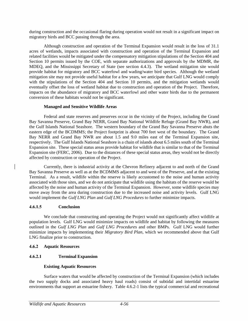
Wildlife and Aquatic Resources 4-56
during construction and the occasional flaring during operation would not result in a significant impact on
migratory birds and BCC passing through the area.
Although construction and operation of the Terminal Expansion would result in the loss of 31.1
acres of wetlands, impacts associated with construction and operation of the Terminal Expansion and
related facilities would be mitigated under the compensatory mitigation stipulations of the Section 404 and
Section 10 permits issued by the COE, with separate authorizations and approvals by the MDMR, the
MDEQ, and the Mississippi Secretary of State (see section 4.4.3). The wetland mitigation site would
provide habitat for migratory and BCC waterfowl and wading/water bird species. Although the wetland
mitigation site may not provide useful habitat for a few years, we anticipate that Gulf LNG would comply
with the stipulations of the Section 404 and Section 10 permits, and the mitigation wetlands would
eventually offset the loss of wetland habitat due to construction and operation of the Project. Therefore,
impacts on the abundance of migratory and BCC waterfowl and other water birds due to the permanent
conversion of these habitats would not be significant.
Managed and Sensitive Wildlife Areas
Federal and state reserves and preserves occur in the vicinity of the Project, including the Grand
Bay Savanna Preserve, Grand Bay NERR, Grand Bay National Wildlife Refuge (Grand Bay NWR), and
the Gulf Islands National Seashore. The western boundary of the Grand Bay Savanna Preserve abuts the
eastern edge of the BCDMMS; the Project footprint is about 700 feet west of the boundary. The Grand
Bay NERR and Grand Bay NWR are about 1.5 and 9.0 miles east of the Terminal Expansion site,
respectively. The Gulf Islands National Seashore is a chain of islands about 6.5 miles south of the Terminal
Expansion site. These special status areas provide habitat for wildlife that is similar to that of the Terminal
Expansion site (FERC, 2006). Due to the distances of these special status areas, they would not be directly
affected by construction or operation of the Project.
Currently, there is industrial activity at the Chevron Refinery adjacent to and north of the Grand
Bay Savanna Preserve as well as at the BCDMMS adjacent to and west of the Preserve, and at the existing
Terminal. As a result, wildlife within the reserve is likely accustomed to the noise and human activity
associated with those sites, and we do not anticipate that wildlife using the habitats of the reserve would be
affected by the noise and human activity of the Terminal Expansion. However, some wildlife species may
move away from the area during construction due to the increased noise and activity levels. Gulf LNG
would implement the Gulf LNG Plan and Gulf LNG Procedures to further minimize impacts.
Conclusion
We conclude that constructing and operating the Project would not significantly affect wildlife at
population levels. Gulf LNG would minimize impacts on wildlife and habitat by following the measures
outlined in the Gulf LNG Plan and Gulf LNG Procedures and other BMPs. Gulf LNG would further
minimize impacts by implementing their Migratory Bird Plan, which we recommended above that Gulf
LNG finalize prior to construction.
Aquatic Resources
Terminal Expansion
Existing Aquatic Resources
Surface waters that would be affected by construction of the Terminal Expansion (which includes
the two supply docks and associated heavy haul roads) consist of subtidal and intertidal estuarine
environments that support an estuarine fishery. Table 4.6.2-1 lists the typical commercial and recreational
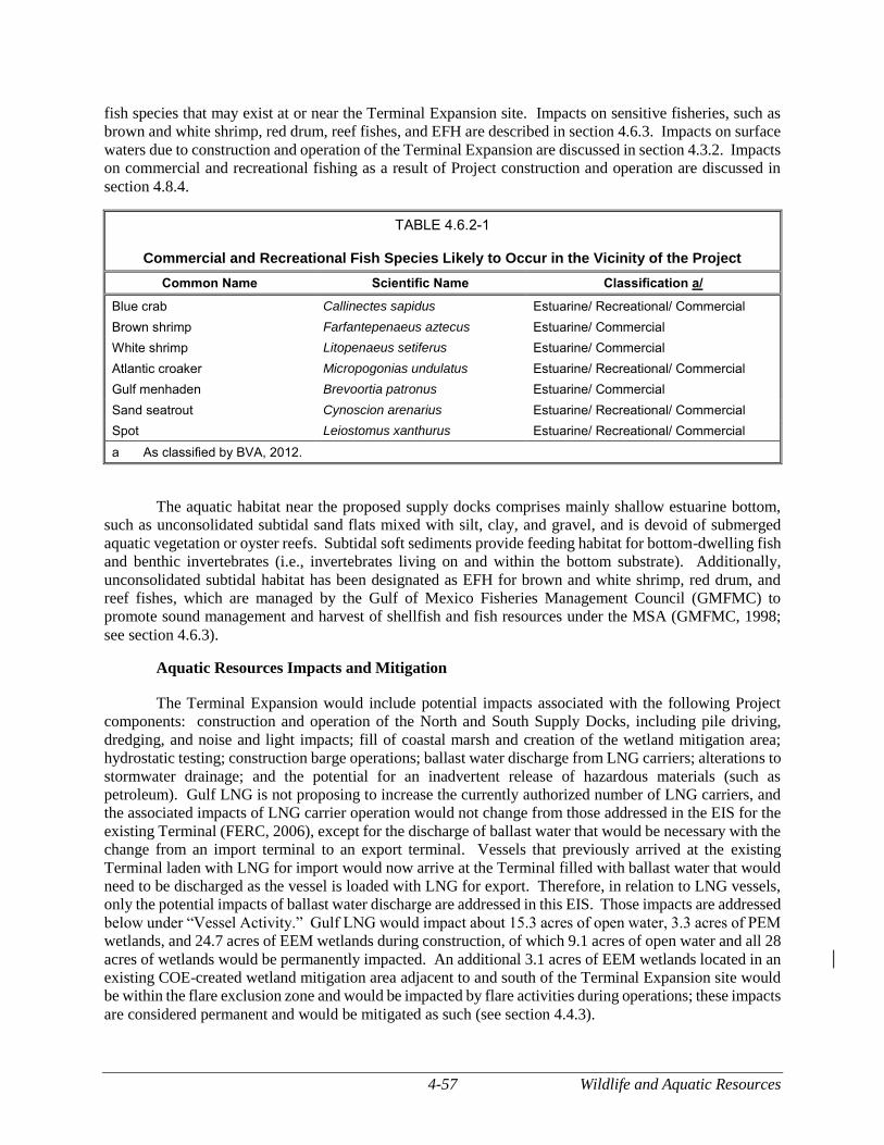
4-57 Wildlife and Aquatic Resources
fish species that may exist at or near the Terminal Expansion site. Impacts on sensitive fisheries, such as
brown and white shrimp, red drum, reef fishes, and EFH are described in section 4.6.3. Impacts on surface
waters due to construction and operation of the Terminal Expansion are discussed in section 4.3.2. Impacts
on commercial and recreational fishing as a result of Project construction and operation are discussed in
section 4.8.4.
TABLE 4.6.2-1
Commercial and Recreational Fish Species Likely to Occur in the Vicinity of the Project
Common Name Scientific Name Classification a/
Blue crab Callinectes sapidus Estuarine/ Recreational/ Commercial
Brown shrimp Farfantepenaeus aztecus Estuarine/ Commercial
White shrimp Litopenaeus setiferus Estuarine/ Commercial
Atlantic croaker Micropogonias undulatus Estuarine/ Recreational/ Commercial
Gulf menhaden Brevoortia patronus Estuarine/ Commercial
Sand seatrout Cynoscion arenarius Estuarine/ Recreational/ Commercial
Spot Leiostomus xanthurus Estuarine/ Recreational/ Commercial
a As classified by BVA, 2012.
The aquatic habitat near the proposed supply docks comprises mainly shallow estuarine bottom,
such as unconsolidated subtidal sand flats mixed with silt, clay, and gravel, and is devoid of submerged
aquatic vegetation or oyster reefs. Subtidal soft sediments provide feeding habitat for bottom-dwelling fish
and benthic invertebrates (i.e., invertebrates living on and within the bottom substrate). Additionally,
unconsolidated subtidal habitat has been designated as EFH for brown and white shrimp, red drum, and
reef fishes, which are managed by the Gulf of Mexico Fisheries Management Council (GMFMC) to
promote sound management and harvest of shellfish and fish resources under the MSA (GMFMC, 1998;
see section 4.6.3).
Aquatic Resources Impacts and Mitigation
The Terminal Expansion would include potential impacts associated with the following Project
components: construction and operation of the North and South Supply Docks, including pile driving,
dredging, and noise and light impacts; fill of coastal marsh and creation of the wetland mitigation area;
hydrostatic testing; construction barge operations; ballast water discharge from LNG carriers; alterations to
stormwater drainage; and the potential for an inadvertent release of hazardous materials (such as
petroleum). Gulf LNG is not proposing to increase the currently authorized number of LNG carriers, and
the associated impacts of LNG carrier operation would not change from those addressed in the EIS for the
existing Terminal (FERC, 2006), except for the discharge of ballast water that would be necessary with the
change from an import terminal to an export terminal. Vessels that previously arrived at the existing
Terminal laden with LNG for import would now arrive at the Terminal filled with ballast water that would
need to be discharged as the vessel is loaded with LNG for export. Therefore, in relation to LNG vessels,
only the potential impacts of ballast water discharge are addressed in this EIS. Those impacts are addressed
below under “Vessel Activity.” Gulf LNG would impact about 15.3 acres of open water, 3.3 acres of PEM
wetlands, and 24.7 acres of EEM wetlands during construction, of which 9.1 acres of open water and all 28
acres of wetlands would be permanently impacted. An additional 3.1 acres of EEM wetlands located in an
existing COE-created wetland mitigation area adjacent to and south of the Terminal Expansion site would
be within the flare exclusion zone and would be impacted by flare activities during operations; these impacts
are considered permanent and would be mitigated as such (see section 4.4.3).
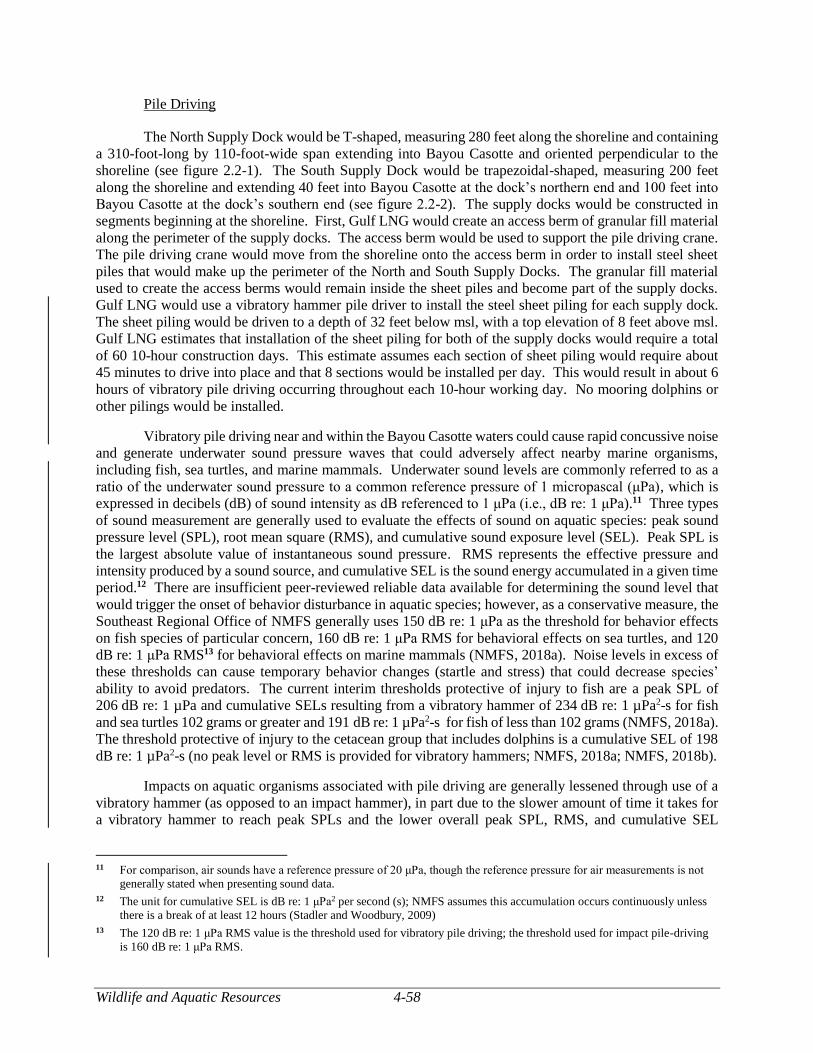
Wildlife and Aquatic Resources 4-58
Pile Driving
The North Supply Dock would be T-shaped, measuring 280 feet along the shoreline and containing
a 310-foot-long by 110-foot-wide span extending into Bayou Casotte and oriented perpendicular to the
shoreline (see figure 2.2-1). The South Supply Dock would be trapezoidal-shaped, measuring 200 feet
along the shoreline and extending 40 feet into Bayou Casotte at the dock’s northern end and 100 feet into
Bayou Casotte at the dock’s southern end (see figure 2.2-2). The supply docks would be constructed in
segments beginning at the shoreline. First, Gulf LNG would create an access berm of granular fill material
along the perimeter of the supply docks. The access berm would be used to support the pile driving crane.
The pile driving crane would move from the shoreline onto the access berm in order to install steel sheet
piles that would make up the perimeter of the North and South Supply Docks. The granular fill material
used to create the access berms would remain inside the sheet piles and become part of the supply docks.
Gulf LNG would use a vibratory hammer pile driver to install the steel sheet piling for each supply dock.
The sheet piling would be driven to a depth of 32 feet below msl, with a top elevation of 8 feet above msl.
Gulf LNG estimates that installation of the sheet piling for both of the supply docks would require a total
of 60 10-hour construction days. This estimate assumes each section of sheet piling would require about
45 minutes to drive into place and that 8 sections would be installed per day. This would result in about 6
hours of vibratory pile driving occurring throughout each 10-hour working day. No mooring dolphins or
other pilings would be installed.
Vibratory pile driving near and within the Bayou Casotte waters could cause rapid concussive noise
and generate underwater sound pressure waves that could adversely affect nearby marine organisms,
including fish, sea turtles, and marine mammals. Underwater sound levels are commonly referred to as a
ratio of the underwater sound pressure to a common reference pressure of 1 micropascal (μPa), which is
expressed in decibels (dB) of sound intensity as dB referenced to 1 μPa (i.e., dB re: 1 μPa).11 Three types
of sound measurement are generally used to evaluate the effects of sound on aquatic species: peak sound
pressure level (SPL), root mean square (RMS), and cumulative sound exposure level (SEL). Peak SPL is
the largest absolute value of instantaneous sound pressure. RMS represents the effective pressure and
intensity produced by a sound source, and cumulative SEL is the sound energy accumulated in a given time
period.12 There are insufficient peer-reviewed reliable data available for determining the sound level that
would trigger the onset of behavior disturbance in aquatic species; however, as a conservative measure, the
Southeast Regional Office of NMFS generally uses 150 dB re: 1 μPa as the threshold for behavior effects
on fish species of particular concern, 160 dB re: 1 μPa RMS for behavioral effects on sea turtles, and 120
dB re: 1 μPa RMS13 for behavioral effects on marine mammals (NMFS, 2018a). Noise levels in excess of
these thresholds can cause temporary behavior changes (startle and stress) that could decrease species’
ability to avoid predators. The current interim thresholds protective of injury to fish are a peak SPL of
206 dB re: 1 µPa and cumulative SELs resulting from a vibratory hammer of 234 dB re: 1 µPa2-s for fish
and sea turtles 102 grams or greater and 191 dB re: 1 µPa2-s for fish of less than 102 grams (NMFS, 2018a).
The threshold protective of injury to the cetacean group that includes dolphins is a cumulative SEL of 198
dB re: 1 µPa2-s (no peak level or RMS is provided for vibratory hammers; NMFS, 2018a; NMFS, 2018b).
Impacts on aquatic organisms associated with pile driving are generally lessened through use of a
vibratory hammer (as opposed to an impact hammer), in part due to the slower amount of time it takes for
a vibratory hammer to reach peak SPLs and the lower overall peak SPL, RMS, and cumulative SEL
11 For comparison, air sounds have a reference pressure of 20 μPa, though the reference pressure for air measurements is not
generally stated when presenting sound data.
12 The unit for cumulative SEL is dB re: 1 μPa2 per second (s); NMFS assumes this accumulation occurs continuously unless
there is a break of at least 12 hours (Stadler and Woodbury, 2009)
13 The 120 dB re: 1 μPa RMS value is the threshold used for vibratory pile driving; the threshold used for impact pile-driving
is 160 dB re: 1 μPa RMS.
4-59 Wildlife and Aquatic Resources
associated with vibratory hammers (WSDOT, 2017; NMFS, 2018a). Recent studies used by NMFS to
create effects analyses of pile driving noise on fishes suggest a vibratory hammer would typically be
expected to produce a peak SPL of no more than 182 dB re: 1 μPa at 10 meters, an RMS of 165 dB re: 1
μPa at 10 meters, and a cumulative SEL of 165 dB re: 1 μPa2-s at 10 meters (Buehler et al., 2015).
Calculations using the NMFS worksheet for analyzing the effects of pile driving on aquatic species indicate
noise from the vibratory hammers would diminish to less than 150 dB re: 1 μPa within 330 feet of the
location of the pile driver. Calculations further indicate that cumulative SEL would diminish to less than
234 dB re: 1 µPa2-s within 1 foot and less than 191 dB re: 1 µPa2-s within 330 feet of the location of the
pile driver (NMFS, 2018a). According to Gulf LNG, proofing of the sheet pile using an impact hammer
would not be necessary. In summary, vibratory pile driving noise would be unlikely to cause injury or
behavioral changes to aquatic organisms beyond 330 feet from the location of the pile driver. Additionally,
in February of 2019, Gulf LNG filed a Sheet Pile Driving Mitigation Plan14 that described the NMFS-
recommended BMPs Gulf LNG would implement to reduce pile driving-related noise impacts on aquatic
organisms, including the following:
conduct visual assessments for sea turtles and marine mammals prior to each time pile
driving begins;
o all construction personnel would be responsible for observing water-related activities
to detect the presence of protected species;
o if a sea turtle or marine mammal was seen within 330 feet of the active construction,
operation, or vessel movement, Gulf LNG would implement all appropriate
precautions to ensure its protection, including ceasing operation of any moving or
mechanical construction equipment closer than 50 feet from a sea turtle or marine
mammal and remaining on operational stand-down until the protected species has
departed the Project area of its own volition.
employ a soft-start technique, wherein pile driving begins with low-energy hammering to
produce noise levels above 150 dB re: 1 µPa but below the injury thresholds to drive mobile
aquatic organisms away from the area;
conduct in-water acoustic noise monitoring to confirm that the noise impact zone where pile
driving noise would result in injury to aquatic resources would not extend beyond 330 feet
from the pile driving location; and
report any injury to a sea turtle or sturgeon immediately to the NMFS’ Protected Resources
Division (727-824-5312) and the local authorized sea turtle stranding/rescue organization.
Gulf LNG also noted in its Sheet Pile Driving Mitigation Plan that if results from the in-water
acoustic monitoring indicate a larger noise impact zone than expected, Gulf LNG would implement steps
to reduce noise impacts, such as reducing the vibratory hammer energy levels. These practices would
reduce the likelihood that fish or protected species would be exposed to injury-causing sound levels (Savery
and Associates, 2010). Upon completion of the sound-causing activities, individuals would no longer avoid
the area and would likely return. Therefore, we conclude that impacts from vibratory pile driving would
be temporary, localized, and minor.
Dredging
The current depth of the portions of Bayou Casotte proposed for the supply dock basins is too
shallow to safely accommodate barge deliveries. During construction, Gulf LNG would dredge both supply
14 See attachment 17 of accession number 20190219-5042.
Wildlife and Aquatic Resources 4-60
dock basins to a depth of 12 feet below msl (which would total about 200,000 cy of sediment) to allow for
safe maneuvering and docking of barges and would conduct maintenance dredging as needed to maintain
the dredged depth of the supply dock basins for the duration of Project construction. Based on sediment
accumulation at the existing marine berth, Gulf LNG anticipates maintenance dredging of the supply dock
basins would be necessary about every 3 years. Gulf LNG anticipates that about 10,000 cy of sediment
would accumulate annually at each basin. A hydraulic or clamshell dredge would be used to remove the
sediments, dredging would be of limited duration (7 to 21 days per basin), and Gulf LNG would consult
with NMFS to determine the most appropriate times of year for dredging at the supply docks to minimize
impacts on aquatic organisms. The North Supply Dock would remain in use during operation. The Port of
Pascagoula would take ownership of the North Supply Dock after construction and would be responsible
for maintenance dredging of the dock’s basin during operation. After construction is completed, Gulf LNG
would completely remove the South Supply Dock, including all bulkhead backfill materials. The shoreline
would be restored and the associated basin would be allowed to revert to natural bathymetric conditions.
As with pile driving, dredging equipment would cause underwater noise. Depending on the type
of dredge chosen by Gulf LNG for dredging of the supply docks and the access channel for wetland
mitigation, sound frequency and intensity associated with these activities could cause a change in aquatic
species behavior in proximity to the dredged areas or could cause species to avoid the area. Peak noise
levels underwater during hydraulic dredging would be expected to be between 172 and 185 dB re: 1 µPa at
1 meter and would attenuate rapidly with distance (CEDA, 2011). Underwater noise levels associated with
a clamshell dredge would be much lower. The COE notes noise associated with clamshell dredging
operations is likely significantly less than 120 re: 1 µPa (COE, 2015b). The dredged channel would
comprise the footprint of the perimeter berm. Barges would use the dredged channel to access the wetland
mitigation site to deliver rock for the containment berm proposed for its perimeter. Gulf LNG would store
the dredged sediment from the channel in the proposed mitigation site and then replace it in the dredged
channel as the perimeter berm was constructed (i.e., the channel would be filled and rock would be placed
over the just-filled portion of the channel).
Dredging of the supply dock basins and the wetland mitigation site channel would likely increase
turbidity and suspension of solids within the water column. Increases in turbidity can affect the physiology
and behavior of marine organisms. Potential physiological effects include mechanical abrasion of surface
membranes, delayed larval and embryonic development, reduced bivalve pumping rates, and interference
with respiratory functions. Possible behavioral effects from increased turbidity include interference with
feeding for sight-foraging fish and area-avoidance (Berry et al., 2003; COE, 2014; Wenger et al., 2017).
Conversely, the reduced visibility of predatory fish could lower vulnerability to predation for prey species.
Turbidity also interferes with light penetration and thus reduces photosynthetic activity by phytoplankton.
Such reductions in primary production would be localized around the immediate vicinity of the area being
actively dredged and would be limited to immediately following completion of the dredging activities
(COE, 2014). The COE (2014) reports that the effects of temporarily increased levels of suspended
sediments due to dredging are comparable to the common passage of a storm front with high winds and
heavy wave action. Increased turbidity is typically confined to the time during dredging and about 2 to 3
hours after dredging ceases, after which suspended solids settle to background levels and the water column
habitat would be expected to revert to normal conditions (COE, 2014).
Another potential impact resulting from the suspension of solids in the water column due to
dredging may be the mobilization of contaminated sediments. Contaminants generally adhere to fine-
grained particles, which, when re-suspended, can be ingested by organisms and have potentially toxic
effects (EPA, 1999a; Schoellhamer, 2007). Gulf LNG sampled sediments in the proposed dredging areas
at both supply docks. Analytical testing revealed that the sediments had either no or very low levels of
chemical contaminants (see section 4.2.7). Therefore, adverse impacts on aquatic organisms due to the
resuspension of contaminated sediments are not anticipated.
4-61 Wildlife and Aquatic Resources
Excessive nutrient loading from sediment resuspension could have an adverse impact on Bayou
Casotte, because it could cause pronounced increases in the productivity of planktonic algal populations
(Dzialowski et al., 2008; Corbett, 2010). However, because any high-density patches of planktonic
organisms would be readily dispersed by currents (COE, 2014), the effects of additional nutrient loading
would be temporary and restricted to the immediate dredging area.
Generally, the MDEQ accepts that there are no feasible technologies or management practices to
effectively moderate turbidity levels at the dredge source; therefore, the MDEQ allows for a 750-foot
mixing zone surrounding the dredging operation where increased turbidity levels would be expected to
occur (MDEQ, 2007). Beyond the mixing zone, turbidity levels may not exceed background turbidity levels
by more than 50 Nephelometric Turbidity Units (ntu). Background turbidity levels in the vicinity of the
Project are about 15 to 20 ntu (COE, 2014). The COE (2014) reported that dredging conducted during the
construction of the berthing slip for the existing Terminal15 and other historical dredging operations in
Mississippi Sound did not have turbidity exceedances beyond the mixing zone. Additionally, Gulf LNG
filed a draft Dredging and Disposal Plan with the Commission on August 29, 201816 in which Gulf LNG
states it would install and maintain turbidity curtains around the area being excavated to limit the transport
of turbid water beyond the vicinity of the dredging operations. Gulf LNG is currently engaging in
consultations with the COE and the MDEQ as part of the CWA Section 404 and 401 application processes.
As part of this process, Gulf LNG would discuss with the COE and the MDEQ the practicality and
effectiveness of methods for reducing turbidity in the vicinity of dredging operations. Additionally, the
Dredging and Disposal Plan notes that Gulf LNG would monitor dredging-induced turbidity in accordance
with any MDEQ Section 401 certification requirements and report any turbidity levels that exceeded the
limits provided in the permit.
Dredging activities would remove the estuarine bottom sediments used as habitat by some aquatic
species. Benthic organisms, such as mollusks and crustaceans, may experience direct mortality during
dredging, while other more mobile species, such as blue crab, may experience temporary displacement.
Although the dredging-related impacts would be greatest on the benthic community within the dredging
area, impacts on saltwater fish species, such as red drum and spotted seatrout, would also occur, but would
be localized and temporary. Due to the relatively small area of direct impact resulting from the dredging
of the supply dock basins and the access channel between the South Supply Dock and the compensatory
wetland mitigation site (16.4 acres) and the short duration of dredging (less than 6 months), these species
and other similar species would be temporarily displaced and could return upon completion of dredging.
We believe that recolonization in the Project area would commence in a matter of days or weeks, and these
areas would become functional benthic communities similar to pre-dredge conditions or to adjacent
reference locations in about 12 to 18 months (FERC, 2006). Likewise, the Minerals Management Service
(MMS, 2004) reported that although the benthic community would be directly affected by dredging, these
communities generally re-populate within 1 year; therefore, we conclude that the impacts on the benthic
community due to the initial and maintenance dredging of the supply dock basins would be temporary and
minor. We discuss the impacts from the dredging of the compensatory wetland mitigation site in the Fill
of Coastal Marsh section below.
Light
Construction and operation of the supply docks would generate additional light at the Terminal
Expansion. Construction lighting would be temporarily installed at specific locations where ongoing
construction is occurring, and would be removed upon completion. Gulf LNG would direct any nighttime
15 Gulf LNG dredged about 2.96 million cy for the berthing slip and maneuvering basin for the existing Terminal. About
400,000 cy would be dredged for both supply docks and the barge access channel for the wetland mitigation site.
16 See attachment No. 3 of accession number 20180829-5060.
Wildlife and Aquatic Resources 4-62
lighting on the activity being conducted to ensure the safety of workers, which would minimize impacts on
aquatic species. Generally, construction and operational lighting of the supply docks and adjacent areas
would be situated as close as possible to the location needing illumination and directed downward to
minimize light impacts on adjacent areas.
Aquatic species in the area are likely acclimated to the current ambient light, due to the industrial
nature of Bayou Casotte, including light from the existing marine berths in the Project area. Therefore,
impacts on aquatic species due to nighttime lighting during construction and operation would not be
significant when taking into account the proximity of the existing Terminal to the supply docks, the existing
industrial nature of the area, and the lighting that would be used.
Wetland Impacts
As noted in section 4.4.2.1, construction and operation of the Terminal Expansion would
permanently impact 31.1 acres of wetlands, or coastal marsh, located adjacent to the North and South
Supply Docks and south and east of the existing Terminal. Aquatic habitat within the affected wetland
areas consists mainly of shallow estuarine bottom, such as unconsolidated sand and mud flats, and tidal
wetland vegetation. Subtidal and intertidal substrates provide important foraging habitat for fish and
benthic (bottom-dwelling) organisms that live on and within the sediments (epifauna and infauna), while
wetland vegetation serves as a nursery and source of protection from predation for many aquatic species.
Large benthic species known to inhabit these marshes include the ribbed mussel, American oyster,
hooked mussel, gray-common rangia clam, little surf clam, river snail, marsh periwinkle, salt marsh snail,
mysid shrimp, mud crab, Harris mud crab, heavy marsh crab, stone crab, and lesser blue crab. Smaller
species include nematodes, harpacticoid copepods, kinorhynchs, ostracods, small polychaetes, and some
insect larvae. Fish species commonly found in tidal marshes include the striped mullet, menhaden,
sheepshead minnow, bay anchovy, bayou killifish, inland silverside, chain pipefish, spotted seatrout, black
drum, red drum, and code goby (BVA, 1985).
As noted above and discussed in section 4.4.3, Gulf LNG proposes in-kind compensatory
mitigation for impacts on the wetlands on the Terminal Expansion site. We anticipate that the compensatory
wetland mitigation site, when fully developed, would provide sufficient habitat to offset the impacts on the
habitats of the affected coastal marsh. In addition, there is a substantial amount of coastal marsh in the
vicinity of the affected area, particularly within the nearby Grand Bay Savanna Preserve. As a result, we
conclude that during the development of the compensatory wetland mitigation site, there would be a
localized short-to long-term impact on the aquatic species that use the affected coastal marsh habitat;
however, we expect that it would not be a significant impact, as once the compensatory mitigation site
would be successfully established, the impact on aquatic species would be offset by the habitat created at
the mitigation site. Construction of the compensatory mitigation site would consist of covering the 50-acre
footprint of shallow estuarine bottom with about 323,000 cy of fill and 19,000 cy of stone. This would
contribute to the cumulative loss of shallow water habitat in the Mississippi Sound and mortality of
immobile benthic species within the site footprint would be likely. However, we conclude that the
successful completion of the compensatory wetland mitigation site would adequately offset these impacts
and that impacts would not be significant.
Hydrostatic Testing
Gulf LNG would hydrostatically test non-cryogenic piping and storage tanks to ensure the integrity
of the installed facilities prior to initiating operations. Gulf LNG would use water from the Port of
Pascagoula’s Industrial Water Supply with no additional treatment such as biocides.
4-63 Wildlife and Aquatic Resources
Upon completion of hydrostatic testing, Gulf LNG would discharge the hydrostatic test water into
Bayou Casotte through the existing Terminal’s current outfall at the existing berthing area. Discharging
hydrostatic test water could cause localized turbidity and differences in pH and salinity at the end of the
outfall pipe. However, to minimize such potential impacts, Gulf LNG would monitor the hydrostatic test
water prior to discharge and, if necessary, treat it to meet the requirements of Gulf LNG’s NPDES permit
(MSG13). We therefore conclude that impacts on aquatic resources from the discharge of hydrostatic test
water would be temporary and negligible. Hydrostatic testing is discussed in more detail in section 4.3.2.2.
Vessel Activity
Gulf LNG would use barges and marine support vessels during construction, and occasionally
during operation, to transport equipment and material to the Terminal Expansion. During operation, LNG
carriers would berth at the existing marine berth, take on LNG while discharging ballast water, and transport
the LNG to customers. The total number of LNG carriers calling on the Terminal would not exceed the
number currently authorized for the existing Terminal. The impacts of LNG carrier transit were assessed
in the EIS for the existing Terminal (FERC, 2006) and are not addressed in this EIS. Although Gulf LNG
has requested authorization to increase the size of LNG carriers permitted to call upon the Terminal, the
existing berthing facility was designed and constructed to accommodate LNG carriers of the increased size
requested by Gulf LNG and the impacts addressed in the EIS for the existing Terminal and in this EIS
would not be substantially affected by vessel size. The potential impacts of ballast water discharge are
addressed below.
Use of the supply docks for delivery of equipment and materials would increase vessel traffic in
the vicinity of the Project (see section 4.9.6 for a discussion of the potential marine traffic impacts). The
barges and support and supply vessels during construction of the Terminal Expansion are slow moving and
do not create substantial wakes and are not expected to substantially increase shoreline erosion, benthic
sediment disturbance, or propeller scouring in the immediate area. However, some benthic sediment
disturbance or propeller scouring could occur as a result of propeller wash from tugboats maneuvering
barges as they approach or depart from the supply docks. We expect these effects would be intermittent
and temporary.
Underwater noise generated by large vessels calling on the supply docks is estimated to be between
180 and 190 dB re: 1 µPa at 1 meter and would attenuate rapidly with distance (CEDA, 2011). Noise would
be greatest during vessel transport to and from the supply docks. However, noise would attenuate rapidly
as the vessels pass, and aquatic species would be subjected to the noise for only a short period of time.
Vessels moored at the docks would produce noise during engine start-up and idling. Idling noise would be
lower as the propeller would not be in use. Noise levels of vessels calling on the supply docks would be
similar to the noise currently generated by vessels transiting Bayou Casotte. Based on these considerations,
we conclude that adverse impacts of increased noise on aquatic species due to barge and support vessel
traffic would be intermittent and consistent with current vessel traffic noise occurring in proximity to the
Terminal Expansion and would not be significant. Therefore, we conclude that impacts on aquatic species
due to increased barge and support vessel traffic during construction and operation would be short-term and
minor.
Although non-native species are not uncommon in the Mississippi Sound, barges and support
vessels using the supply docks during construction and operation could inadvertently introduce new
invasive species to the area. However, those vessels would not discharge ballast water and would primarily
be local vessels and the potential for invasive species introduction via hull attachment on these vessels
would be negligible. Therefore, we do not anticipate impacts associated with the introduction of invasive
species during construction of the Terminal Expansion.
Wildlife and Aquatic Resources 4-64
During operation of the Terminal Expansion, LNG carriers would need to discharge ballast water
at the existing marine berth while taking on LNG. Discharge volumes would range between about 9.7
million gallons and 23.0 million gallons, depending on the size of the vessel. As noted in section 4.3.2.2,
the impact of the discharge on water quality would be localized and temporary. Likewise, the effects of the
localized changes in water quality on fish and invertebrate species would also be minimal (FERC, 2015).
The ballast water discharges would typically occur over a non-continuous period of about 30 hours at a rate
of about 29 cfs. The discharged ballast water would be expected to mix with the surrounding water column
relatively quickly given the proximity of the marine berth to the mouth of the Pascagoula River, which has
an average outflow of about 14,746 cfs, and its exposure to outflow from Bayou Casotte and wind and tidal
driven currents of the Mississippi Sound (COE, 2014). Furthermore, as estuarine species, fishes and
invertebrates common to coastal Mississippi are generally tolerant of fluctuating environmental conditions
(Elliott and Quintino, 2007). Therefore, we conclude that impacts on local fish and invertebrate populations
would be minimal and temporary, but would occur for the life of the Project.
Ballast water is regarded as a major source for introducing invasive species to coastal areas (Bailey,
2015). Consequently, LNG captains must comply with the ballast water management and discharge
requirements of both the USCG (33 CFR 151.2030; see also section 4.5.3) and the EPA (EPA, 2013a). All
LNG carriers would use a USCG-approved Ballast Water Management System, which may include either
ballast water exchange in the open ocean or ultra-violet light or chemical treatments (biocides) to destroy
aquatic organisms in the ballast water. These regulations offer several options for ballast water
management and are intended to limit the concentrations of organisms in ballast water discharges. In
addition, the EPA regulates effluent discharge and requires actions such as training, management plans and
practices, treatment measures, and monitoring, testing, and reporting requirements. All LNG carriers
calling on the Terminal Expansion would be required to obtain a Vessel General Permit from the EPA,
which, in part, regulates ballast water discharges under the authority of the NPDES permitting program
(EPA, 2013a). Therefore, we conclude that the introduction of exotic species due to the discharge of ballast
water from the LNG carriers would be minimized.
Further, if biocides were included as part of a ballast water management technique, the
concentration of residual biocides in the ballast water discharge would be required by the Vessel General
Permit to meet or exceed regulatory limits for environmental compliance; therefore, we conclude that
impacts on aquatic resources from residual biocides in ballast water discharges, if used, would be minor.
Scouring of the benthic surface is another potential impact of ballast water discharge. Ballast water
would be discharged by pumps regulated to maintain proper equilibrium with the volume of LNG being
loaded onto the LNG carrier and would not be rapidly discharged. In addition, ballast water would be
discharged horizontally, either through fittings located near the bottom of each side of the hull of the LNG
carrier or through valves located above the waterline. In either instance, based on conservative calculations
following Ervine and Flavey (1987), the force of the discharged water would be expected to dissipate prior
to reaching the benthic surface at 42 feet below msl (the depth of the existing marine berth).
LNG carriers would also withdraw water at the marine berth periodically to cool their boilers.
Depending on the engine type, LNG carriers would take in between 15 and 42 million gallons of water for
engine cooling while at the berth. The withdrawn water would be subsequently discharged back into Bayou
Casotte. The potential impacts of a localized increase in water temperature due to the discharging of cooling
water and entrainment of aquatic resources (e.g., the larvae of blue crab, white, brown, and pink shrimp,
and assorted fish species) were assessed in the EIS for the existing Terminal (FERC, 2006) and are therefore
not addressed in this EIS.
4-65 Wildlife and Aquatic Resources
Stormwater Management
During construction, Gulf LNG would manage stormwater in accordance with its SWPPP and
updated SPCC Plan (see section 4.3.2.2). During operation, the conversion of land to impervious surface
areas at the Terminal Expansion site would result in an increased volume of stormwater runoff. Stormwater
runoff from Terminal Expansion would be integrated into the existing Terminal’s stormwater runoff system
plus the two new stormwater outfalls (Outfall 003 and 004) which are planned for the Terminal Expansion.
The new outfalls would drain in close proximity to the existing stormwater outfall (Outfall 002) in the LNG
carrier berthing area. Stormwater runoff from areas with a likelihood of oil contamination (e.g., rotating
equipment, lubrication consoles, or transformers) would be curbed or diked and the runoff treated through
an oil-water separator prior to discharge. As required by Gulf LNG’s existing NPDES permit, stormwater
would be observed and tested prior to discharge. If there is no visible oil sheen, floating solids, or foam
other than trace amounts, and if the pH is between 6.0 and 9.0, the stormwater would be discharged into
Bayou Casotte through the stormwater outfall structure. A pH meter at the outfall structure automatically
tests the stormwater’s pH and does not allow the discharge pump to engage if the pH is less than 6.0 or
more than 9.0. In addition, the sump is fitted with a low temperature sensor to stop the pump in the event
of an LNG release.
During operation, stormwater would be discharged through the existing stormwater outfall and two
new outfalls that would be installed in the vicinity of the existing outfall. The stormwater would be
discharged into Bayou Casotte. The discharges would be similar to but greater in volume than the
discharges from the existing Terminal. The discharges could create temporary and localized changes in
salinity and/or temperature in the area of the outfalls; however, operations would not produce contaminants
such as nutrients or other oxygen demanding elements that would contribute to decreased dissolved oxygen.
All stormwater discharge would be conducted in compliance with Gulf LNG’s NPDES permit. Impacts
from increased stormwater runoff are expected to occur only during storm events and result in a negligible
impact on aquatic resources.
Inadvertent Releases
As described in section 4.3.2.2, Gulf LNG would update the Terminal’s existing SPCC Plan to
include the Terminal Expansion operations, including the supply docks. Gulf LNG would implement the
revised SPCC Plan and the Gulf LNG Plan and Gulf LNG Procedures to minimize the potential for
petroleum or hazardous materials spills from land equipment or vessels berthed at the supply docks during
construction and operation and to avoid or minimize impacts if a spill were to occur. Based on the
implementation of these procedures by Gulf LNG, we conclude that it is not likely that there would be a
significant impact on aquatic species due to an inadvertent release from the Terminal Expansion.
Construction Support Areas
One of the six construction support areas, CSA-3, would be adjacent to tidal wetlands connected to
Bayou Casotte. However, Gulf LNG would follow appropriate BMPs, such as installing exclusion fencing,
to avoid any impacts on the wetlands and any aquatic resources that may be using them during Project
activities. Impacts on the wetlands could result from an inadvertent spill at the site but, as noted in section
4.4.2.3, Gulf LNG would implement its revised SPCC Plan and its Gulf LNG Plan and Gulf LNG
Procedures to minimize the potential for petroleum or hazardous materials spills from equipment at the site
and to avoid or minimize impacts if a spill were to occur. Based on the implementation of these procedures
by Gulf LNG, we conclude that it is not likely that there would be a significant impact on aquatic species
related to the use of the CSAs.
Wildlife and Aquatic Resources 4-66
Pipeline Modifications
Existing Aquatic Resources
Gulf LNG would not impact waterbodies by constructing and operating the Pipeline Modifications.
Essential Fish Habitat
The MSA, as amended in 1996, was established, along with other goals, to promote the protection
of EFH for projects requiring federal permits, licenses, or other authorities and that affect or have the
potential to affect such habitat. EFH is defined in the MSA as those waters and substrate necessary to fish
for spawning, breeding, feeding, or growth to maturity. All estuaries and estuarine habitats in the northern
Gulf of Mexico are considered EFH (GMFMC, 1998).
Federal agencies that authorize, fund, or undertake activities that may adversely impact EFH must
consult with NMFS. Although absolute criteria have not been established for conducting EFH
consultations, NMFS recommends consolidated EFH consultations with interagency coordination
procedures required by other statutes, such as NEPA and the ESA, to reduce duplication and improve
efficiency. Generally, the EFH consultation process includes the following steps:
Notification – The action agency should clearly state the process being used for EFH
consultations (e.g., incorporating EFH consultation into the EIS);
EFH Assessment – The action agency should prepare an EFH Assessment that includes both
identification of affected EFH and an assessment of impacts. Specifically, the EFH should
include a description of the proposed action; an analysis of the effects (including cumulative
effects) of the proposed action on EFH, the managed fish species, and major prey species; the
federal agency’s views regarding the effects of the action on EFH; and proposed mitigation, if
applicable;
EFH Conservation Recommendations – After reviewing the EFH Assessment, NMFS would
provide recommendations to the action agency regarding measures that can be taken by that
agency to conserve EFH; and
Agency Response – The action agency must respond to NMFS within 30 days of receiving
recommendations from NMFS. The response must include a description of measures
proposed by the agency for avoiding, mitigating, or offsetting the impact of the activity on
EFH.
Only impacts associated with the proposed construction and operation of the Terminal Expansion
are discussed in this section. The FERC staff previously prepared an EIS and BA to assess construction
and operation impacts from the existing Terminal on EFH and EFH species (FERC, 2006). As a part of
those environmental documents, the FERC staff consulted with NMFS regarding dredging the berthing
area, accidental releases of LNG, and the number of LNG carriers and transit routes. We determined and
NMFS agreed that based on the implementation of conservation measures and the compensatory mitigation
plan developed by Gulf LNG, no substantial adverse impacts on EFH or EFH species would occur due to
construction and operation of the existing Terminal. With the exception of impacts caused by ballast water
discharge from the LNG carriers, the impacts of LNG carriers and their transit on EFH and EFH species
were addressed in that assessment. Therefore, they are not addressed in this EIS. Impacts on EFH and
EFH species due to ballast water discharge are discussed in section 4.6.3.
The FERC proposes to incorporate EFH consultations for the Terminal Expansion with the
interagency coordination procedures required under NEPA. As part of the consultation process, we
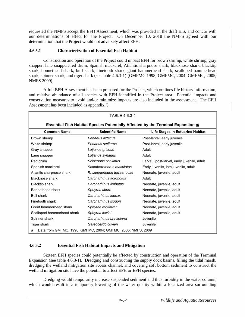
4-67 Wildlife and Aquatic Resources
requested the NMFS accept the EFH Assessment, which was provided in the draft EIS, and concur with
our determinations of effect for the Project. On December 10, 2018 the NMFS agreed with our
determination that the Project would not adversely affect EFH.
Characterization of Essential Fish Habitat
Construction and operation of the Project could impact EFH for brown shrimp, white shrimp, gray
snapper, lane snapper, red drum, Spanish mackerel, Atlantic sharpnose shark, blacknose shark, blacktip
shark, bonnethead shark, bull shark, finetooth shark, giant hammerhead shark, scalloped hammerhead
shark, spinner shark, and tiger shark (see table 4.6.3-1) (GMFMC 1998; GMFMC, 2004; GMFMC, 2005;
NMFS 2009).
A full EFH Assessment has been prepared for the Project, which outlines life history information,
and relative abundance of all species with EFH identified in the Project area. Potential impacts and
conservation measures to avoid and/or minimize impacts are also included in the assessment. The EFH
Assessment has been included as appendix C.
TABLE 4.6.3-1
Essential Fish Habitat Species Potentially Affected by the Terminal Expansion a/
Common Name Scientific Name Life Stages in Estuarine Habitat
Brown shrimp Penaeus aztecus Post-larval, early juvenile
White shrimp Penaeus setiferus Post-larval, early juvenile
Gray snapper Lutjanus griseus Adult
Lane snapper Lutjanus synagris Adult
Red drum Sciaenops ocellatus Larval , post-larval, early juvenile, adult
Spanish mackerel Scomberomorus maculatus Early juvenile, late juvenile, adult
Atlantic sharpnose shark Rhizoprionodon terraenovae Neonate, juvenile, adult
Blacknose shark Carcharhinus acronotus Adult
Blacktip shark Carcharhinus limbatus Neonate, juvenile, adult
Bonnethead shark Sphyrna tiburo Neonate, juvenile, adult
Bull shark Carcharhinus leucas Neonate, juvenile, adult
Finetooth shark Carcharhinus isodon Neonate, juvenile, adult
Great hammerhead shark Sphyrna mokarran Neonate, juvenile, adult
Scalloped hammerhead shark Sphyrna lewini Neonate, juvenile, adult
Spinner shark Carcharhinus brevipinna Juvenile
Tiger shark Galeocerdo cuvieri Juvenile
a Data from GMFMC, 1998; GMFMC, 2004; GMFMC, 2005; NMFS, 2009
Essential Fish Habitat Impacts and Mitigation
Sixteen EFH species could potentially be affected by construction and operation of the Terminal
Expansion (see table 4.6.3-1). Dredging and constructing the supply dock basins, filling the tidal marsh,
dredging the wetland mitigation site access channel, and covering soft bottom sediment to construct the
wetland mitigation site have the potential to affect EFH or EFH species.
Dredging would temporarily increase suspended sediment and thus turbidity in the water column,
which would result in a temporary lowering of the water quality within a localized area surrounding
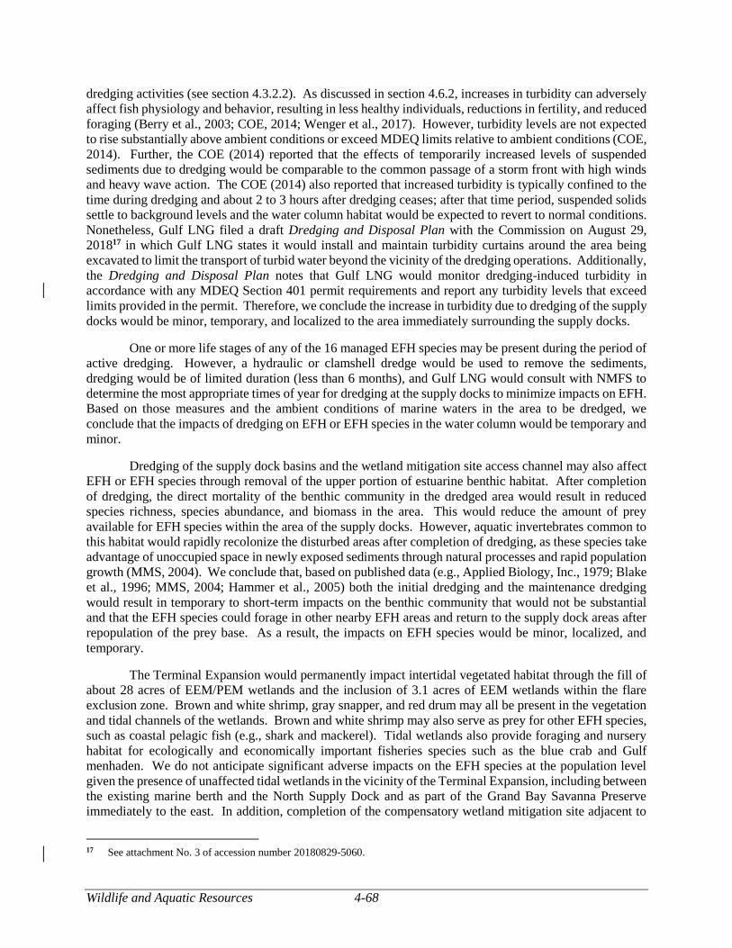
Wildlife and Aquatic Resources 4-68
dredging activities (see section 4.3.2.2). As discussed in section 4.6.2, increases in turbidity can adversely
affect fish physiology and behavior, resulting in less healthy individuals, reductions in fertility, and reduced
foraging (Berry et al., 2003; COE, 2014; Wenger et al., 2017). However, turbidity levels are not expected
to rise substantially above ambient conditions or exceed MDEQ limits relative to ambient conditions (COE,
2014). Further, the COE (2014) reported that the effects of temporarily increased levels of suspended
sediments due to dredging would be comparable to the common passage of a storm front with high winds
and heavy wave action. The COE (2014) also reported that increased turbidity is typically confined to the
time during dredging and about 2 to 3 hours after dredging ceases; after that time period, suspended solids
settle to background levels and the water column habitat would be expected to revert to normal conditions.
Nonetheless, Gulf LNG filed a draft Dredging and Disposal Plan with the Commission on August 29,
201817 in which Gulf LNG states it would install and maintain turbidity curtains around the area being
excavated to limit the transport of turbid water beyond the vicinity of the dredging operations. Additionally,
the Dredging and Disposal Plan notes that Gulf LNG would monitor dredging-induced turbidity in
accordance with any MDEQ Section 401 permit requirements and report any turbidity levels that exceed
limits provided in the permit. Therefore, we conclude the increase in turbidity due to dredging of the supply
docks would be minor, temporary, and localized to the area immediately surrounding the supply docks.
One or more life stages of any of the 16 managed EFH species may be present during the period of
active dredging. However, a hydraulic or clamshell dredge would be used to remove the sediments,
dredging would be of limited duration (less than 6 months), and Gulf LNG would consult with NMFS to
determine the most appropriate times of year for dredging at the supply docks to minimize impacts on EFH.
Based on those measures and the ambient conditions of marine waters in the area to be dredged, we
conclude that the impacts of dredging on EFH or EFH species in the water column would be temporary and
minor.
Dredging of the supply dock basins and the wetland mitigation site access channel may also affect
EFH or EFH species through removal of the upper portion of estuarine benthic habitat. After completion
of dredging, the direct mortality of the benthic community in the dredged area would result in reduced
species richness, species abundance, and biomass in the area. This would reduce the amount of prey
available for EFH species within the area of the supply docks. However, aquatic invertebrates common to
this habitat would rapidly recolonize the disturbed areas after completion of dredging, as these species take
advantage of unoccupied space in newly exposed sediments through natural processes and rapid population
growth (MMS, 2004). We conclude that, based on published data (e.g., Applied Biology, Inc., 1979; Blake
et al., 1996; MMS, 2004; Hammer et al., 2005) both the initial dredging and the maintenance dredging
would result in temporary to short-term impacts on the benthic community that would not be substantial
and that the EFH species could forage in other nearby EFH areas and return to the supply dock areas after
repopulation of the prey base. As a result, the impacts on EFH species would be minor, localized, and
temporary.
The Terminal Expansion would permanently impact intertidal vegetated habitat through the fill of
about 28 acres of EEM/PEM wetlands and the inclusion of 3.1 acres of EEM wetlands within the flare
exclusion zone. Brown and white shrimp, gray snapper, and red drum may all be present in the vegetation
and tidal channels of the wetlands. Brown and white shrimp may also serve as prey for other EFH species,
such as coastal pelagic fish (e.g., shark and mackerel). Tidal wetlands also provide foraging and nursery
habitat for ecologically and economically important fisheries species such as the blue crab and Gulf
menhaden. We do not anticipate significant adverse impacts on the EFH species at the population level
given the presence of unaffected tidal wetlands in the vicinity of the Terminal Expansion, including between
the existing marine berth and the North Supply Dock and as part of the Grand Bay Savanna Preserve
immediately to the east. In addition, completion of the compensatory wetland mitigation site adjacent to
17 See attachment No. 3 of accession number 20180829-5060.
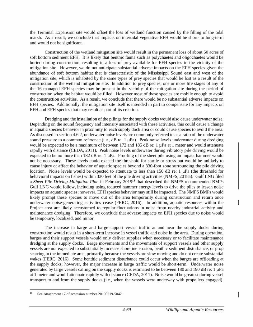
4-69 Wildlife and Aquatic Resources
the Terminal Expansion site would offset the loss of wetland function caused by the filling of the tidal
marsh. As a result, we conclude that impacts on intertidal vegetative EFH would be short- to long-term
and would not be significant.
Construction of the wetland mitigation site would result in the permanent loss of about 50 acres of
soft bottom sediment EFH. It is likely that benthic fauna such as polychaetes and oligochaetes would be
buried during construction, resulting in a loss of prey available for EFH species in the vicinity of the
mitigation site. However, we do not anticipate substantial adverse impacts on the EFH species given the
abundance of soft bottom habitat that is characteristic of the Mississippi Sound east and west of the
mitigation site, which is inhabited by the same types of prey species that would be lost as a result of the
construction of the wetland mitigation site. In addition to prey species, one or more life stages of any of
the 16 managed EFH species may be present in the vicinity of the mitigation site during the period of
construction when the habitat would be filled. However most of these species are mobile enough to avoid
the construction activities. As a result, we conclude that there would be no substantial adverse impacts on
EFH species. Additionally, the mitigation site itself is intended in part to compensate for any impacts on
EFH and EFH species that may result as part of its creation.
Dredging and the installation of the pilings for the supply docks would also cause underwater noise.
Depending on the sound frequency and intensity associated with these activities, this could cause a change
in aquatic species behavior in proximity to each supply dock area or could cause species to avoid the area.
As discussed in section 4.6.2, underwater noise levels are commonly referred to as a ratio of the underwater
sound pressure to a common reference (i.e., dB re: 1 μPa). Peak noise levels underwater during dredging
would be expected to be a maximum of between 172 and 185 dB re: 1 µPa at 1 meter and would attenuate
rapidly with distance (CEDA, 2011). Peak noise levels underwater during vibratory pile driving would be
expected to be no more than 182 dB re: 1 μPa. Proofing of the sheet pile using an impact hammer would
not be necessary. These levels could exceed the threshold for startle or stress but would be unlikely to
cause injury or affect the behavior of aquatic species beyond a 330-foot zone surrounding the pile driving
location. Noise levels would be expected to attenuate to less than 150 dB re: 1 μPa (the threshold for
behavioral impacts on fishes) within 330 feet of the pile driving activities (NMFS, 2018a). Gulf LNG filed
a Sheet Pile Driving Mitigation Plan in February 201918 that described the NMFS-recommended BMPs
Gulf LNG would follow, including using reduced hammer energy levels to drive the piles to lessen noise
impacts on aquatic species; however, EFH species behavior may still be impacted. The NMFS BMPs would
likely prompt these species to move out of the area temporarily during construction and return once
underwater noise-generating activities cease (FERC, 2016). In addition, aquatic resources within the
Project area are likely accustomed to regular fluctuations in noise from nearby industrial activity and
maintenance dredging. Therefore, we conclude that adverse impacts on EFH species due to noise would
be temporary, localized, and minor.
The increase in barge and barge-support vessel traffic at and near the supply docks during
construction would result in a short-term increase in vessel traffic and noise in the area. During operation,
barges and their support vessels would only deliver supplies when necessary or to facilitate maintenance
dredging at the supply docks. Barge movements and the movements of support vessels and other supply
vessels are not expected to substantially increase shoreline erosion, benthic sediment disturbance, or prop
scarring in the immediate area, primarily because the vessels are slow moving and do not create substantial
wakes (FERC, 2016). Some benthic sediment disturbance could occur when the barges are offloading at
the supply docks; however, the major increase in barge traffic would be short-term. Underwater noise
generated by large vessels calling on the supply docks is estimated to be between 180 and 190 dB re: 1 µPa
at 1 meter and would attenuate rapidly with distance (CEDA, 2011). Noise would be greatest during vessel
transport to and from the supply docks (i.e., when the vessels were underway with propellers engaged).
18 See Attachment 17 of accession number 20190219-5042. .
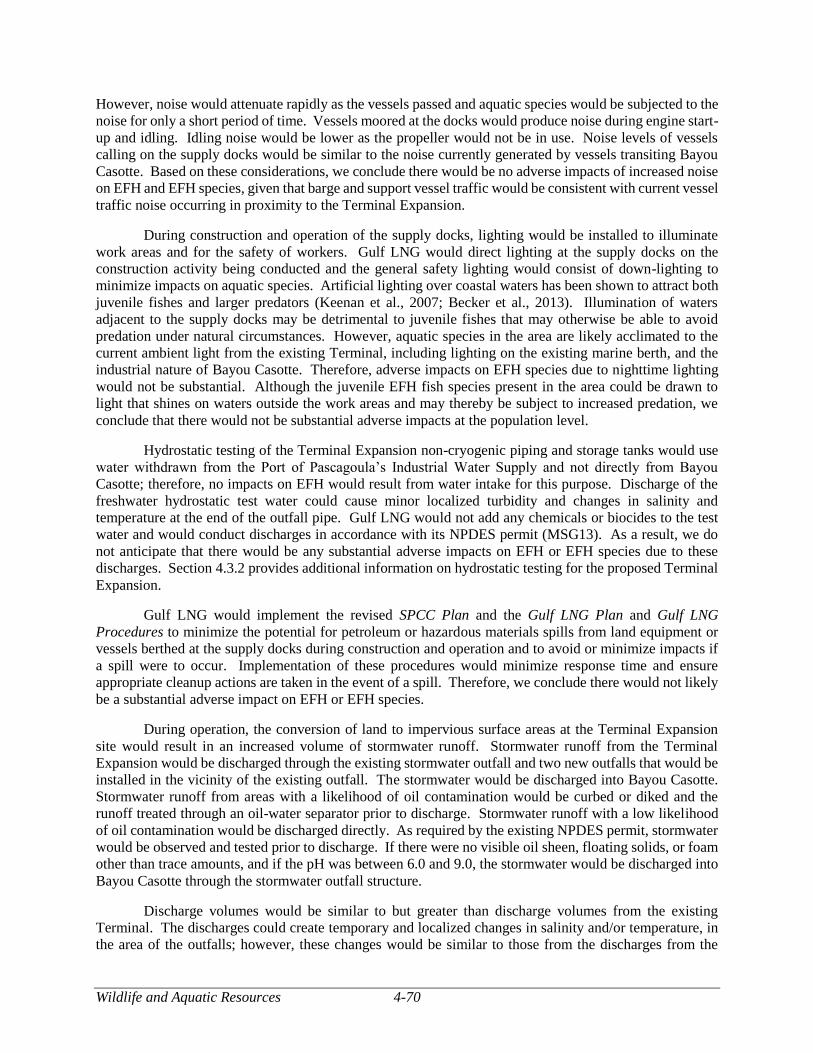
Wildlife and Aquatic Resources 4-70
However, noise would attenuate rapidly as the vessels passed and aquatic species would be subjected to the
noise for only a short period of time. Vessels moored at the docks would produce noise during engine start-
up and idling. Idling noise would be lower as the propeller would not be in use. Noise levels of vessels
calling on the supply docks would be similar to the noise currently generated by vessels transiting Bayou
Casotte. Based on these considerations, we conclude there would be no adverse impacts of increased noise
on EFH and EFH species, given that barge and support vessel traffic would be consistent with current vessel
traffic noise occurring in proximity to the Terminal Expansion.
During construction and operation of the supply docks, lighting would be installed to illuminate
work areas and for the safety of workers. Gulf LNG would direct lighting at the supply docks on the
construction activity being conducted and the general safety lighting would consist of down-lighting to
minimize impacts on aquatic species. Artificial lighting over coastal waters has been shown to attract both
juvenile fishes and larger predators (Keenan et al., 2007; Becker et al., 2013). Illumination of waters
adjacent to the supply docks may be detrimental to juvenile fishes that may otherwise be able to avoid
predation under natural circumstances. However, aquatic species in the area are likely acclimated to the
current ambient light from the existing Terminal, including lighting on the existing marine berth, and the
industrial nature of Bayou Casotte. Therefore, adverse impacts on EFH species due to nighttime lighting
would not be substantial. Although the juvenile EFH fish species present in the area could be drawn to
light that shines on waters outside the work areas and may thereby be subject to increased predation, we
conclude that there would not be substantial adverse impacts at the population level.
Hydrostatic testing of the Terminal Expansion non-cryogenic piping and storage tanks would use
water withdrawn from the Port of Pascagoula’s Industrial Water Supply and not directly from Bayou
Casotte; therefore, no impacts on EFH would result from water intake for this purpose. Discharge of the
freshwater hydrostatic test water could cause minor localized turbidity and changes in salinity and
temperature at the end of the outfall pipe. Gulf LNG would not add any chemicals or biocides to the test
water and would conduct discharges in accordance with its NPDES permit (MSG13). As a result, we do
not anticipate that there would be any substantial adverse impacts on EFH or EFH species due to these
discharges. Section 4.3.2 provides additional information on hydrostatic testing for the proposed Terminal
Expansion.
Gulf LNG would implement the revised SPCC Plan and the Gulf LNG Plan and Gulf LNG
Procedures to minimize the potential for petroleum or hazardous materials spills from land equipment or
vessels berthed at the supply docks during construction and operation and to avoid or minimize impacts if
a spill were to occur. Implementation of these procedures would minimize response time and ensure
appropriate cleanup actions are taken in the event of a spill. Therefore, we conclude there would not likely
be a substantial adverse impact on EFH or EFH species.
During operation, the conversion of land to impervious surface areas at the Terminal Expansion
site would result in an increased volume of stormwater runoff. Stormwater runoff from the Terminal
Expansion would be discharged through the existing stormwater outfall and two new outfalls that would be
installed in the vicinity of the existing outfall. The stormwater would be discharged into Bayou Casotte.
Stormwater runoff from areas with a likelihood of oil contamination would be curbed or diked and the
runoff treated through an oil-water separator prior to discharge. Stormwater runoff with a low likelihood
of oil contamination would be discharged directly. As required by the existing NPDES permit, stormwater
would be observed and tested prior to discharge. If there were no visible oil sheen, floating solids, or foam
other than trace amounts, and if the pH was between 6.0 and 9.0, the stormwater would be discharged into
Bayou Casotte through the stormwater outfall structure.
Discharge volumes would be similar to but greater than discharge volumes from the existing
Terminal. The discharges could create temporary and localized changes in salinity and/or temperature, in
the area of the outfalls; however, these changes would be similar to those from the discharges from the
4-71 Wildlife and Aquatic Resources
existing Terminal, and it is likely that the EFH species and prey in the vicinity of the Project are acclimated
to such conditions. Operations would not produce contaminants such as nutrients or other oxygen
demanding elements that would contribute to decreased dissolved oxygen. As a result, we conclude that
there would be no substantial adverse impact on EFH or EFH species as a result of the discharge of
stormwater runoff.
During operation of the Terminal Expansion, LNG carriers would discharge ballast water at the
existing marine berth while taking on LNG. Impacts on water quality, such as changes in salinity,
temperature, or dissolved oxygen, resulting from the discharged ballast water would be localized and
temporary. Likewise, the effects of the localized changes in water quality on EFH species and prey would
also be minimal (FERC, 2015). The discharged ballast water would be expected to mix with the
surrounding water column relatively quickly given the proximity of the marine berth to the mouth of the
Pascagoula River and its exposure to outflow from Bayou Casotte and wind and tidal driven currents of the
Mississippi Sound (COE, 2014). Furthermore, as estuarine species, fishes, and invertebrates common to
coastal Mississippi are generally tolerant of fluctuating environmental conditions (Elliott and Quintino,
2007). Therefore, we conclude that there would be no substantial adverse impacts on EFH or EFH species
as a result of the ballast water discharge.
Ballast water is regarded as a major source for introducing invasive species to coastal areas (Bailey,
2015). Consequently, LNG captains must comply with the ballast water management and discharge
requirements of both the USCG (33 CFR 151.2030) and EPA (EPA, 2013a). These regulations offer several
options for ballast water management and are intended to limit the concentrations of organisms in ballast
water discharges. EPA regulates effluent discharge and requires actions such as training, management
plans and practices, treatment measures, and monitoring, testing, and reporting requirements. All LNG
carriers calling on the Terminal Expansion would be required to obtain a Vessel General Permit from EPA,
which, in part, regulates ballast water discharges under the authority of the NPDES permitting program.
Therefore, we conclude that there would be no significant adverse impacts on EFH or EFH species due to
the introduction of exotic species resulting from the discharge of ballast water. Further, if biocides were
included as part of a ballast water management technique, the concentration of residual biocides in the
ballast water discharge would be required by the Vessel General Permit to meet or exceed regulatory limits
for environmental compliance; therefore we conclude there would be no substantial adverse impacts on
EFH or EFH species due to residual biocides in ballast water discharges.
Scouring of the benthic surface is another potential impact of ballast water discharge. Ballast water
would be discharged by pumps regulated to maintain proper equilibrium with the volume of LNG being
loaded onto the LNG carrier and would not be rapidly discharged. In addition, ballast water would be
discharged horizontally, either through fittings located near the bottom of each side of the hull of the LNG
carrier or through valves located above the waterline. In either instance, based on conservative calculations
following Ervine and Flavey (1987), the force of the discharged water would be expected to dissipate prior
to reaching the benthic surface at 42 feet below msl. Therefore, we conclude there would be no substantial
adverse impacts on EFH.
Essential Fish Habitat Conclusions
Construction of the Terminal Expansion and the wetland mitigation site would involve permanent
conversion of about 9.4 acres and short-term conversion of about 6.2 acres of shallow estuarine benthic
habitat to deeper subtidal habitat and permanent conversion of about 50 acres of shallow estuarine habitat
to intertidal vegetation habitat. This would result in direct mortality to benthic organisms. Construction
and operation of the Terminal Expansion would also result in the permanent loss of 27.8 acres of EEM
wetlands and 3.2 acres of PEM. However, the relatively small areas of estuarine water column and benthic
habitat EFH impacted by construction and operation of the supply docks and construction of the mitigation
site would be minor in consideration of the amount of similar habitat available in the vicinity of the Project,
Wildlife and Aquatic Resources 4-72
and Gulf LNG would offset the function of the impacted intertidal vegetative habitat by establishing the
wetland mitigation site adjacent to the Terminal Expansion.
The depth to which the shallow estuarine benthic habitat would be dredged (12 feet below msl)
would be generally shallow enough to prevent the onset of hypoxic conditions and subsequent permanent
changes to benthic species diversity and total biomass (COE, 2014). At 12 feet below msl, the supply dock
basins would be expected to recolonize with soft bottom benthic organisms soon after completion of
dredging, thus providing a similar prey base for EFH species as the adjacent and nearby non-dredged areas
(MMS, 2004). This temporary impact, as well as elevated water column turbidity levels, would re-occur
with maintenance dredging, which would likely occur every 3 years. These events represent a minor
increase in the already episodic nature of impacted benthic habitat and elevated turbidity due to relatively
frequent maintenance dredging throughout Bayou Casotte and at the existing marine berth (the COE [2014]
noted that maintenance dredging occurs within Bayou Casotte every 12 months).
Potential impacts on brown and white shrimp would be primarily limited to the post-larval and
juvenile stages, as both stages occur in estuaries similar to the habitat present at the supply docks and
wetland mitigation site. Adult stages of the species may also be present, but as most shrimp species
approach adulthood, they migrate to deeper offshore waters. White shrimp may be present in inshore
estuaries year-round, while brown shrimp are generally only present in estuaries between March and
November. Direct mortality could occur during active dredging or during the creation of the wetland
mitigation site; however, individuals are mobile and many could avoid the dredging and construction areas.
Until conditions are conducive for repopulation after completion of dredging, individuals could use areas
with suitable EFH in the vicinity of the Terminal Expansion. Impacts from each of the construction
activities discussed above are expected to be localized and temporary to short-term, as would impacts on
the prey species of brown and white shrimp and their EFH. We do not anticipate any substantial adverse
impacts on white or brown shrimp.
Various life stages of the gray snapper, lane snapper, red drum, Spanish mackerel and Atlantic
sharpnose, blacknose, blacktip, bull, bonnethead, finetooth, hammerhead, spinner, and tiger sharks could
be present in the vicinity of the Terminal Expansion during construction and operation. Direct mortality
could occur during active dredging or creation of the wetland mitigation site, but individuals would likely
avoid the area during construction. Prey of these species in the water column or in the benthos may be
impacted by construction activities; however, as discussed above, the impacts would be temporary to short-
term, as prey species would be expected to return to the water column after construction, and benthic prey
would be expected to rapidly recolonize the dredged areas. In the interim, given the mobility of each of
these managed species, individuals would be able to readily use other suitable EFH in the vicinity of the
Terminal Expansion. In addition, potential impacts from each of the construction activities discussed above
and potential impacts due to use of the North Supply Dock during operation would be temporary to short-
term or, in the case of the wetland mitigation site, would result in new EFH. Therefore, we do not anticipate
any substantial adverse impacts on gray snapper, lane snapper, red drum, Spanish mackerel, or Atlantic
sharpnose, blacknose, blacktip, bull, bonnethead, finetooth, hammerhead, spinner, or tiger sharks.
Based on this information, we conclude that effects on EFH and EFH species in and near the
construction area of the Terminal Expansion would be localized and temporary to short-term, particularly
with respect to the regular industrial use of Bayou Casotte and Mississippi Sound in the vicinity of the
Terminal Expansion. Further, creation of new tidal marsh on Mississippi Sound as mitigation for the tidal
wetlands that would be lost due to the Terminal Expansion would provide additional habitat for EFH
species. Therefore, the Terminal Expansion would not have a substantial adverse impact on EFH or EFH
species in the area.
4-73 Special Status Species
THREATENED, ENDANGERED, AND OTHER SPECIAL STATUS SPECIES
Special status species are those species for which federal or state agencies afford an additional level
of protection by law, regulation, or policy. Included in this category are federally listed and federally
proposed species that are protected under the ESA, as amended, or are considered as candidates for such
listing by the FWS or the NMFS, and those species that are state-listed as threatened, endangered, or other
special status.
Federal agencies, in consultation with the FWS, are required by Section 7(a)(2) of the ESA to
ensure that any action authorized, funded, or carried out by the agency would not jeopardize the continued
existence of a federally listed threatened or endangered, or a species proposed for listing. As the lead
federal agency, the FERC is responsible for the Section 7 consultation process with the FWS. The lead
agency is required to consult with the FWS and/or the NMFS to determine whether any federally listed
endangered or threatened species or any of their designated critical habitats are in the vicinity of the Project,
and to determine the proposed action’s potential effects on those species or critical habitats. ‘Critical
habitat’ is a term used in the ESA to refer to specific geographic areas that are essential for the conservation
of a threatened or endangered species and that may require special management and protection (FWS,
2014).
For actions involving major construction activities with the potential to affect listed species or
critical habitats, the federal agency must prepare a BA for those species that may be affected. As the lead
agency, the FERC must submit its BA to the FWS and/or the NMFS and, if it is determined that the action
may adversely affect a federally listed species, the FERC must submit a request for formal consultation to
comply with Section 7 of the ESA. In response, the FWS and the NMFS would issue a Biological Opinion
as to whether or not the federal action would likely adversely affect or jeopardize the continued existence
of a listed species, or result in the destruction or adverse modification of designated critical habitat. To
comply with Section 7 of the ESA, we prepared a BA for this Project (see appendix B). Gulf LNG does
not propose to change the currently authorized number of LNG carriers for Project operations, and we
addressed the effect of LNG carrier transit on threatened and endangered species in our EIS for the existing
Terminal (FERC, 2006).
To assist in compliance with Section 7 of the ESA, Gulf LNG, acting as the FERC’s non-federal
representative, initiated informal consultation with the FWS (Mississippi Ecological Services Field Office)
and the NMFS (Habitat Conservation Division, Panama City, Florida19) on April 18, 2014, regarding
federally listed and other special status species. Gulf LNG also consulted with the MDWFP regarding
state-listed or other special status species or habitat with the potential to be affected by construction and
operation of the Project.
These consultations, along with information collected by Gulf LNG during literature reviews and
field surveys of the Project area, were used to create a list of 42 federal or state-protected, listed, candidate,
or special status species with the potential to occur within the vicinity of the Project, including parts of the
Gulf of Mexico that would be traversed by Project shipping traffic (see table 4.7-1). Pedestrian wildlife
and protected habitat surveys were conducted concurrently with wetland delineations between June 2014
and August 2014; open water habitat was not surveyed. No federal or state-listed threatened, endangered,
candidate, or special status species were observed during field surveys. However, two piping plovers were
observed incidentally during a separate site visit in December 2014. Gulf LNG submitted the results of its
field surveys to the FWS and the NMFS.
19 NMFS consultations were initiated with the Panama City, Florida office in 2014. However, due to staffing changes the
Southeast Regional Office located in St. Petersburg, Florida is reviewing the Project.
Special Status Species 4-74
We have reviewed the information submitted by Gulf LNG, performed our own research, and
consulted directly with the FWS and the NMFS. Of the 42 initially identified species, 16 would not be
affected by the Project and thus are not addressed further in this EIS. The remaining 26 species with the
potential to occur in the Project area are listed in table 4.7-1 and discussed below.
Federally Listed Threatened and Endangered Species
A total of 19 federally protected species, and 3 species that are under federal review, have the
potential to occur in the vicinity of the Project (see table 4.7-1). Of these 22 species, 9 are under the
jurisdiction of the FWS, 6 are under the jurisdiction of the NMFS, and 7 (Gulf sturgeon, smalltooth sawfish,
and 5 sea turtles species) live in habitats that fall within an area where both services manage the species.
A full BA has been prepared for the Project, which outlines life history information, and relative
abundance of species with the potential to occur in the Project area. Potential impacts and conservation
measures to avoid and/or minimize impacts are also included in the BA. The BA has been included as
appendix B of this EIS.
Based on the limited amount of available habitat in the area, the temporary or short-term nature of
the construction impacts for the Project, and the mitigation measures proposed, we believe that the Project
is not likely to adversely affect the 19 federally listed species and would not contribute to a trend toward
federal listing for the 3 species under federal review.
On November 21, 2018 we requested the FWS and the NMFS accept the BA, which was provided
in the draft EIS, and concur with our determinations of effect for the Project. On February 22, 2019 the
FWS agreed with our determinations of effect for those species under their jurisdiction. A response from
the NMFS has not been received. As we have not completed Section 7 ESA consultation with the NMFS,
we recommend that:
Gulf LNG should not begin construction activities until:
FERC staff receives comments from the NMFS regarding the proposed action;
FERC staff completes ESA Section 7 consultation with the NMFS; and
Gulf LNG has received written notification from the Director of OEP that
construction or use of mitigation may begin.
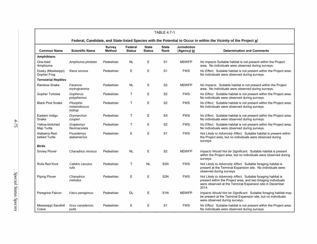
4
-75
Specia
l Sta
tus S
pecies
TABLE 4.7-1
Federal, Candidate, and State-listed Species with the Potential to Occur in within the Vicinity of the Project a/
Common Name Scientific Name Survey Method
Federal Status
State Status
State Rank
Jurisdiction (Agency) b/ Determination and Comments
Amphibians
One-toed Amphiuma
Amphiuma pholeter Pedestrian NL E S1 MDWFP No Impacts Suitable habitat is not present within the Project area. No individuals were observed during surveys.
Dusky (Mississippi) Gopher Frog
Rana sevosa Pedestrian E E S1 FWS No Effect. Suitable habitat is not present within the Project area. No individuals were observed during surveys.
Terrestrial Reptiles
Rainbow Snake Farancia erytrogramma
Pedestrian NL E S2 MDWFP No Impacts. Suitable habitat is not present within the Project area. No individuals were observed during surveys.
Gopher Tortoise Gopherus polyphemus
Pedestrian T E S2 FWS No Effect. Suitable habitat is not present within the Project area. No individuals were observed during surveys.
Black Pine Snake Pituophis melanoleucus lodingi
Pedestrian T E S2 FWS No Effect. Suitable habitat is not present within the Project area. No individuals were observed during surveys.
Eastern Indigo Snake
Drymarchon couperi
Pedestrian T E SX FWS No Effect. Suitable habitat is not present within the Project area. No individuals were observed during surveys.
Yellow-blotched Map Turtle
Graptemys flavimaculata
Pedestrian T E S2 FWS No Effect. Suitable habitat is not present within the Project area. No individuals were observed during surveys.
Alabama Red-bellied Turtle
Psuedemys alabamensis
Pedestrian E E S1 FWS Not Likely to Adversely Affect. Suitable habitat is present within the Project area, but no individuals were observed during surveys.
Birds
Snowy Plover Charadrius nivosus Pedestrian NL E S2 MDWFP Impacts Would Not be Significant. Suitable habitat is present within the Project area, but no individuals were observed during surveys.
Rufa Red Knot Calidris canutus rufa
Pedestrian T NL S2N FWS Not Likely to Adversely Affect. Suitable foraging habitat is present at the Terminal Expansion site. No individuals were observed during surveys.
Piping Plover Charadrius melodus
Pedestrian E E S2N FWS Not Likely to Adversely Affect. Suitable foraging habitat is present within the Project area, and two foraging individuals were observed at the Terminal Expansion site in December 2014.
Peregrine Falcon Falco peregrinus Pedestrian DL E S1N MDWFP Impacts Would Not be Significant. Suitable foraging habitat may be present at the Terminal Expansion site, but no individuals were observed during surveys.
Mississippi Sandhill Crane
Grus canadensis pulla
Pedestrian E E S1 FWS No Effect. Suitable habitat is not present within the Project area. No individuals were observed during surveys.
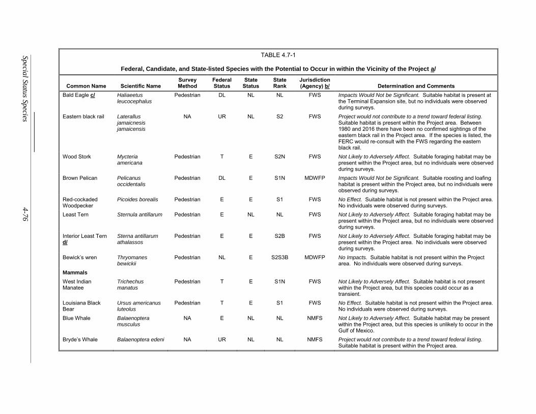
Sp
ecial S
tatu
s Species
4-7
6
TABLE 4.7-1
Federal, Candidate, and State-listed Species with the Potential to Occur in within the Vicinity of the Project a/
Common Name Scientific Name Survey Method
Federal Status
State Status
State Rank
Jurisdiction (Agency) b/ Determination and Comments
Bald Eagle c/ Haliaeetus leucocephalus
Pedestrian DL NL NL FWS Impacts Would Not be Significant. Suitable habitat is present at the Terminal Expansion site, but no individuals were observed during surveys.
Eastern black rail Laterallus jamaicnesis jamaicensis
NA UR NL S2 FWS Project would not contribute to a trend toward federal listing. Suitable habitat is present within the Project area. Between 1980 and 2016 there have been no confirmed sightings of the eastern black rail in the Project area. If the species is listed, the FERC would re-consult with the FWS regarding the eastern black rail.
Wood Stork Mycteria americana
Pedestrian T E S2N FWS Not Likely to Adversely Affect. Suitable foraging habitat may be present within the Project area, but no individuals were observed during surveys.
Brown Pelican Pelicanus occidentalis
Pedestrian DL E S1N MDWFP Impacts Would Not be Significant. Suitable roosting and loafing habitat is present within the Project area, but no individuals were observed during surveys.
Red-cockaded Woodpecker
Picoides borealis Pedestrian E E S1 FWS No Effect. Suitable habitat is not present within the Project area. No individuals were observed during surveys.
Least Tern Sternula antillarum Pedestrian E NL NL FWS Not Likely to Adversely Affect. Suitable foraging habitat may be present within the Project area, but no individuals were observed during surveys.
Interior Least Tern d/
Sterna antillarum athalassos
Pedestrian E E S2B FWS Not Likely to Adversely Affect. Suitable foraging habitat may be present within the Project area. No individuals were observed during surveys.
Bewick’s wren Thryomanes bewickii
Pedestrian NL E S2S3B MDWFP No Impacts. Suitable habitat is not present within the Project area. No individuals were observed during surveys.
Mammals
West Indian Manatee
Trichechus manatus
Pedestrian T E S1N FWS Not Likely to Adversely Affect. Suitable habitat is not present within the Project area, but this species could occur as a transient.
Louisiana Black Bear
Ursus americanus luteolus
Pedestrian T E S1 FWS No Effect. Suitable habitat is not present within the Project area. No individuals were observed during surveys.
Blue Whale Balaenoptera musculus
NA E NL NL NMFS Not Likely to Adversely Affect. Suitable habitat may be present within the Project area, but this species is unlikely to occur in the Gulf of Mexico.
Bryde’s Whale Balaenoptera edeni NA UR NL NL NMFS Project would not contribute to a trend toward federal listing. Suitable habitat is present within the Project area.
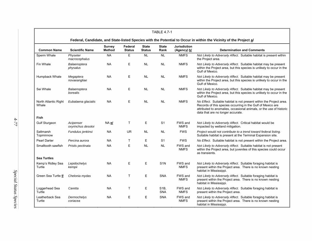
4
-77
Specia
l Sta
tus S
pecies
TABLE 4.7-1
Federal, Candidate, and State-listed Species with the Potential to Occur in within the Vicinity of the Project a/
Common Name Scientific Name Survey Method
Federal Status
State Status
State Rank
Jurisdiction (Agency) b/ Determination and Comments
Sperm Whale Physeter macrocephalus
NA E NL NL NMFS Not Likely to Adversely Affect. Suitable habitat is present within the Project area.
Fin Whale Balaenoptera physalus
NA E NL NL NMFS Not Likely to Adversely Affect. Suitable habitat may be present within the Project area, but this species is unlikely to occur in the Gulf of Mexico.
Humpback Whale Megaptera novaeangliae
NA E NL NL NMFS Not Likely to Adversely Affect. Suitable habitat may be present within the Project area, but this species is unlikely to occur in the Gulf of Mexico.
Sei Whale Balaenoptera borealis
NA E NL NL NMFS Not Likely to Adversely Affect. Suitable habitat may be present within the Project area, but this species is unlikely to occur in the Gulf of Mexico.
North Atlantic Right Whale
Eubalaena glacialis NA E NL NL NMFS No Effect. Suitable habitat is not present within the Project area. Records of this species occurring in the Gulf of Mexico are attributed to anomalies, occasional animals, or the use of historic data that are no longer accurate.
Fish
Gulf Sturgeon Acipenser oxyrinchus desotoi
NA e/ T E S1 FWS and NMFS
Not Likely to Adversely Affect. Critical habitat would be impacted by wetland mitigation.
Saltmarsh Topminnow
Fundulus jenkinsi NA UR NL NL FWS Project would not contribute to a trend toward federal listing. Suitable habitat is present at the Terminal Expansion site.
Pearl Darter Percina aurora NA T E S1 FWS No Effect. Suitable habitat is not present within the Project area.
Smalltooth sawfish Pristis pectinata NA E NL NL FWS and NMFS
Not Likely to Adversely Affect. Suitable habitat is not present within the Project area, but juveniles of this species could occur as transients.
Sea Turtles
Kemp’s Ridley Sea Turtle
Lepidochelys kempii
NA E E S1N FWS and NMFS
Not Likely to Adversely Affect. Suitable foraging habitat is present within the Project area. There is no known nesting habitat in Mississippi.
Green Sea Turtle f/ Chelonia mydas NA T E SNA FWS and NMFS
Not Likely to Adversely Affect. Suitable foraging habitat is present within the Project area. There is no known nesting habitat in Mississippi.
Loggerhead Sea Turtle
Caretta NA T E S1B, SNA
FWS and NMFS
Not Likely to Adversely Affect. Suitable foraging habitat is present within the Project area.
Leatherback Sea Turtle
Dermochelys coriacea
NA E E SNA FWS and NMFS
Not Likely to Adversely Affect. Suitable foraging habitat is present within the Project area. There is no known nesting habitat in Mississippi.
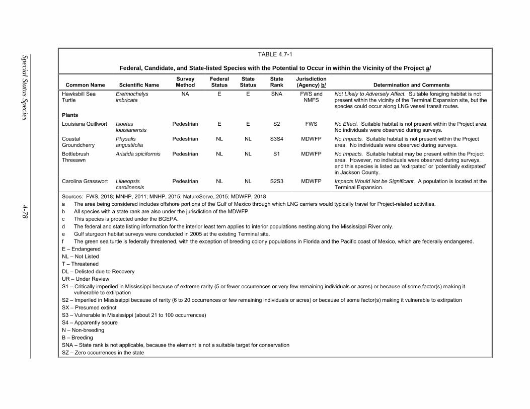
Sp
ecial S
tatu
s Species
4-7
8
TABLE 4.7-1
Federal, Candidate, and State-listed Species with the Potential to Occur in within the Vicinity of the Project a/
Common Name Scientific Name Survey Method
Federal Status
State Status
State Rank
Jurisdiction (Agency) b/ Determination and Comments
Hawksbill Sea Turtle
Eretmochelys imbricata
NA E E SNA FWS and NMFS
Not Likely to Adversely Affect. Suitable foraging habitat is not present within the vicinity of the Terminal Expansion site, but the species could occur along LNG vessel transit routes.
Plants
Louisiana Quillwort Isoetes louisianensis
Pedestrian E E S2 FWS No Effect. Suitable habitat is not present within the Project area. No individuals were observed during surveys.
Coastal Groundcherry
Physalis angustifolia
Pedestrian NL NL S3S4 MDWFP No Impacts. Suitable habitat is not present within the Project area. No individuals were observed during surveys.
Bottlebrush Threeawn
Aristida spiciformis Pedestrian NL NL S1 MDWFP No Impacts. Suitable habitat may be present within the Project area. However, no individuals were observed during surveys, and this species is listed as ‘extirpated’ or ‘potentially extirpated’ in Jackson County.
Carolina Grasswort Lilaeopsis carolinensis
Pedestrian NL NL S2S3 MDWFP Impacts Would Not be Significant. A population is located at the Terminal Expansion.
Sources: FWS, 2018; MNHP, 2011; MNHP, 2015; NatureServe, 2015; MDWFP, 2018
a The area being considered includes offshore portions of the Gulf of Mexico through which LNG carriers would typically travel for Project-related activities.
b All species with a state rank are also under the jurisdiction of the MDWFP.
c This species is protected under the BGEPA.
d The federal and state listing information for the interior least tern applies to interior populations nesting along the Mississippi River only.
e Gulf sturgeon habitat surveys were conducted in 2005 at the existing Terminal site.
f The green sea turtle is federally threatened, with the exception of breeding colony populations in Florida and the Pacific coast of Mexico, which are federally endangered.
E – Endangered
NL – Not Listed
T – Threatened
DL – Delisted due to Recovery
UR – Under Review
S1 – Critically imperiled in Mississippi because of extreme rarity (5 or fewer occurrences or very few remaining individuals or acres) or because of some factor(s) making it vulnerable to extirpation
S2 – Imperiled in Mississippi because of rarity (6 to 20 occurrences or few remaining individuals or acres) or because of some factor(s) making it vulnerable to extirpation
SX – Presumed extinct
S3 – Vulnerable in Mississippi (about 21 to 100 occurrences)
S4 – Apparently secure
N – Non-breeding
B – Breeding
SNA – State rank is not applicable, because the element is not a suitable target for conservation
SZ – Zero occurrences in the state
4-79 Special Status Species
State-listed and Special Status Species
In addition to the federally listed species above, three birds (snowy plover, peregrine falcon, and
brown pelican), one plant species of state concern (Carolina grasswort), and one special status species (bald
eagle) occur within 2 miles of the Project facility sites and could be affected by the Project (MDWFP, 2014;
see table 4.7-1). The life histories and potential impacts on these species are discussed below. The MDWFP
identified eight species of state concern during correspondence in 2014 that have since been removed from
the agency’s Listed Species of Mississippi publication (MNHP, 2015). Because these species are not
federally or state-protected and are no longer ranked as Mississippi species of concern, they are not included
in this discussion. Based on review of available literature, the results of field surveys, and coordination
with agency personnel, it is not likely that any of the other state-listed or special status species for Jackson
County would frequently inhabit the Project sites.
Snowy Plover
The snowy plover is a small shorebird that prefers barren to sparsely vegetated sand beaches, dry
salt flats in lagoons, dredge spoils deposited on beach or dune habitat, levees and flats at salt-evaporation
ponds, river bars, reservoirs, and ponds. It is present across several continents, but in North America, it
occurs only along the Gulf of Mexico and Pacific coastlines and scattered inland sites from Saskatchewan
to California and Texas. Breeding populations have likely decreased on the Gulf of Mexico coast since late
1800s due to habitat alteration and increased recreational use of beaches. They are year-round residents
along the Mississippi shoreline (Ridgely et al., 2003; NatureServe, 2015). This species has a Mississippi
state ranking of S2, which indicates that the species is imperiled in Mississippi, making it vulnerable to
extirpation (see table 4.7-1).
Suitable foraging and nesting habitat exists at the Terminal Expansion site, but no individuals were
observed during field surveys. This species is highly mobile and would likely avoid the area during
construction, unless it is nesting. Gulf LNG has committed to working with the FWS and MDWFP to
develop a plan to avoid nesting birds, which would include the use of pre-construction nesting surveys, nest
removal prior to construction, or a combination of the two. Due to the mobility of this species, Gulf LNG’s
commitment to avoid nesting birds, and the lack of sightings in the Project area, we believe the Project
would not significantly impact the snowy plover.
Peregrine Falcon
The peregrine falcon is the largest falcon in North America. It is a migratory species that feeds on
medium-sized birds and typically nests on ledges or the faces rocky cliffs (Cornell, 2015; NatureServe,
2015). It is designated as “critically imperiled” in Mississippi (MNHP, 2015).
The peregrine falcon formerly bred from Alaska and Greenland south to Georgia and Baja
California, southern South America, Eurasia, Africa, and Australia. It was at one time absent from much
of the eastern United States and Europe, although populations in eastern North American have rebounded.
There are no records of the peregrine falcon breeding in Mississippi. The species migrates along the Gulf
Coast of Mississippi and may occasionally winter on some of the offshore barrier islands (MDWFP, 2001).
Cornell (2015) reported that peregrine falcons could forage on shorebirds and waterfowl along
shorelines such as those in the vicinity of the Project. While foraging may be interrupted temporarily as a
result of some construction activities, this is a mobile species, and adjacent habitat provides adequate
alternative foraging habitat. Peregrine falcons perch and nest on tall structures, and it is possible that the
flare tower would be attractive as a perching site. However, the species occurs in the vicinity of the Project
in winter and does not breed in the area (Cornell, 2015); therefore, it is unlikely the flare tower would be
Special Status Species 4-80
used as a nesting site. Based on these factors, we conclude that the Project would not significantly impact
the peregrine falcon.
Brown Pelican
The brown pelican was federally listed as endangered in 1970, because the widespread use of
dichlorodiphenyltrichloroethane (DDT) had thinned eggshells of the brown pelican to the point that
survivorship of eggs was severely decreased. The species was delisted from the FWS Threatened and
Endangered Species list in 2009 due to species recovery; however, it remains state-listed as endangered in
Mississippi (MNHP, 2015). Pelicans usually occur in small flocks in bays, estuaries, and along the coast.
Although suitable brown pelican habitat and foraging areas were observed in the vicinity of the
Project, no rookeries or high-quality nesting habitat are present. Potential foraging areas for the brown
pelican exist near the Project area, but Defenders of Wildlife (2010) reported that there were no known
nesting records of brown pelicans in Mississippi, and the MDWFP (2001) reported that pelicans do not nest
in Mississippi but are seen fairly regularly along the Gulf Coast and near the barrier islands. During
biological resources surveys, no pelicans were observed using the habitats of the Terminal Expansion site;
however, brown pelicans were observed foraging close to the existing South Marsh Mitigation Area (see
figure 4.4-2). That area would not be available as habitat during construction of the proposed wetland
mitigation site and during the early phases of establishment of vegetation on the mitigation site. However,
there is considerable foraging habitat in the vicinity and it is likely that pelicans would use that habitat
during construction of the Terminal Expansion and the wetland mitigation site. As a result of these
considerations, we conclude that the Project would not significantly impact the brown pelican.
Bald Eagle
The bald eagle was federally listed as endangered in 1967 primarily because the use of DDT caused
thinning of eggshells and a decrease in egg survivorship. A recovery plan was put in place and the use of
DDT was curtailed, which allowed the bald eagle population to increase significantly. It was subsequently
delisted in 2007 but is still federally protected by the BGEPA, which prohibits the “taking” of bald eagles,
including their parts, nests, or eggs. “Taking” includes disturbance, which means to bother or agitate a bald
eagle to the point of injury, decrease in productivity, or nest abandonment (FWS, 2010). Bald eagles are
not threatened, endangered, or special status species by the state of Mississippi (MNHP, 2015).
The species winters and breeds throughout the United States along waterbodies from Alaska and
northern and western Canada, south to Florida, the Gulf Coast, and Arizona. Pairs nest along the Gulf
Coast near the Mississippi River in the west-central part of the state. During the 1999 nesting season, at
least 25 pairs of bald eagles were monitored in Mississippi (MDWFP, 2001). In Jackson County, bald
eagles are known to nest on Horn Island, Cat Island, and East Ship Island, which are all offshore barrier
islands between about 9 to 34 miles from the Project sites (COE, 2014).
The Mississippi Sound provides suitable foraging habitat, and it is possible that bald eagles may
occasionally forage in the vicinity of the Terminal Expansion. However, no nesting sites were observed
during surveys, and no suitable nesting habitat can be found in the Project area. It is not likely that bald
eagles would forage during construction or when there is human activity on or near the water during
operation. They would most likely move to nearby areas where there is ample foraging habitat. Bald eagle
nests are typically 50 to 125 feet above the ground and away from heavily developed areas (Cornell, 2015).
There is no documentation of bald eagles nesting at greater heights, other than on cliffs, and is therefore
not likely that they would nest on the flare tower (at about 433 feet above msl). Therefore, we conclude
the Project would not significantly impact the bald eagle.
4-81 Special Status Species
Carolina Grasswort
Carolina grasswort is a perennial forb with a native range along the Gulf of Mexico coast and along
the Atlantic coast from Florida, north to Virginia. This species almost always occurs in wetlands (USDA,
2015). MDWFP (2014) designated it as “vulnerable to imperiled” in Mississippi. During biological
surveys, Gulf LNG observed a small area of Carolina grasswort along the northern edge of the existing
North Marsh Mitigation Area (see figure 4.4-2). Gulf LNG would use this site for parking and
administrative buildings and it would therefore be permanently impacted unless the population of grasswort
on the site is relocated. On August 27, 2018 the MMNS recommended that the Carolina grasswort
populations be transplanted to a similar habitat prior to construction activities.20 We believe this is a
reasonable measure that Gulf LNG could implement to minimize and mitigate for impacts on this
population. Therefore, we recommend that:
Prior to construction, Gulf LNG should transplant the Carolina grasswort population
along the northern edge of the existing North Marsh Mitigation Area to a similar
habitat using protocols determined in consultation with the MMNS.
We conclude with implementation of our recommendation, the Project would not significantly
impact the Carolina grasswort.
State-Listed and Special Status Species Conclusion
A small population of Carolina grasswort may be impacted by construction and operation of the
Terminal Expansion. However, we recommend Gulf LNG transplant the Carolina grasswort population to
a similar habitat using protocols determined in consultation with the MMNS.
Based on review of available literature, the results of field surveys, and coordination with agency
personnel, it is not likely that any of the other, state-listed or special status species for Jackson County
would frequently inhabit the Project sites.
20 Accession number 20180829-5060
Land Use and Visual Resources 4-82
LAND USE, RECREATION, AND VISUAL RESOURCES
Land Use
Land use in the vicinity of the Project is generally classified within the following categories:
forested, open land, open water, wetlands, industrial/commercial lands, and the BCDMMS. The definitions
of these land use types are as follows:
forested – includes upland forests;
open land – existing utility rights-of-way and upland scrub-shrub;
open water – water crossings greater than 100 feet;
wetlands – emergent, scrub-shrub, and forested wetlands;
industrial/commercial – all developed areas, such as roads, railroads, and industrial areas; and
BCDMMS – land used by the COE Mobile District for placement of dredged materials.
Construction of the Project would require disturbance of about 230.8 acres of land. After
construction, the permanent footprint would encompass about 172.1 acres. The remaining 58.7 acres would
return to pre-construction conditions and uses. Table 4.8.1-1 summarizes the acreages of each land use
type that Gulf LNG would affect during construction and operation of the Project.
Terminal Expansion
The Terminal Expansion site is adjacent to the Bayou Casotte Navigation Channel on the
Mississippi Sound at the south end of SH-611 near Pascagoula, Mississippi. Gulf LNG would construct
the Terminal Expansion within and adjacent to its existing Terminal, which abuts the western end of the
Terminal Expansion site. Land uses surrounding and within the expansion site are primarily industrial,
non-forested wetlands, open land, open water, and the BCDMMS. Construction of the facilities (excluding
access roads and heavy haul roads) would require about 112.7 acres, including 2.7 acres of open land, 24.8
acres of wetlands, 40.3 acres of the BCDMMS, 29.5 acres of industrial land (of which 22.7 acres are within
the existing Terminal boundaries), and 15.3 acres of open water. During operation, the Terminal Expansion
would permanently affect 109.6 acres.
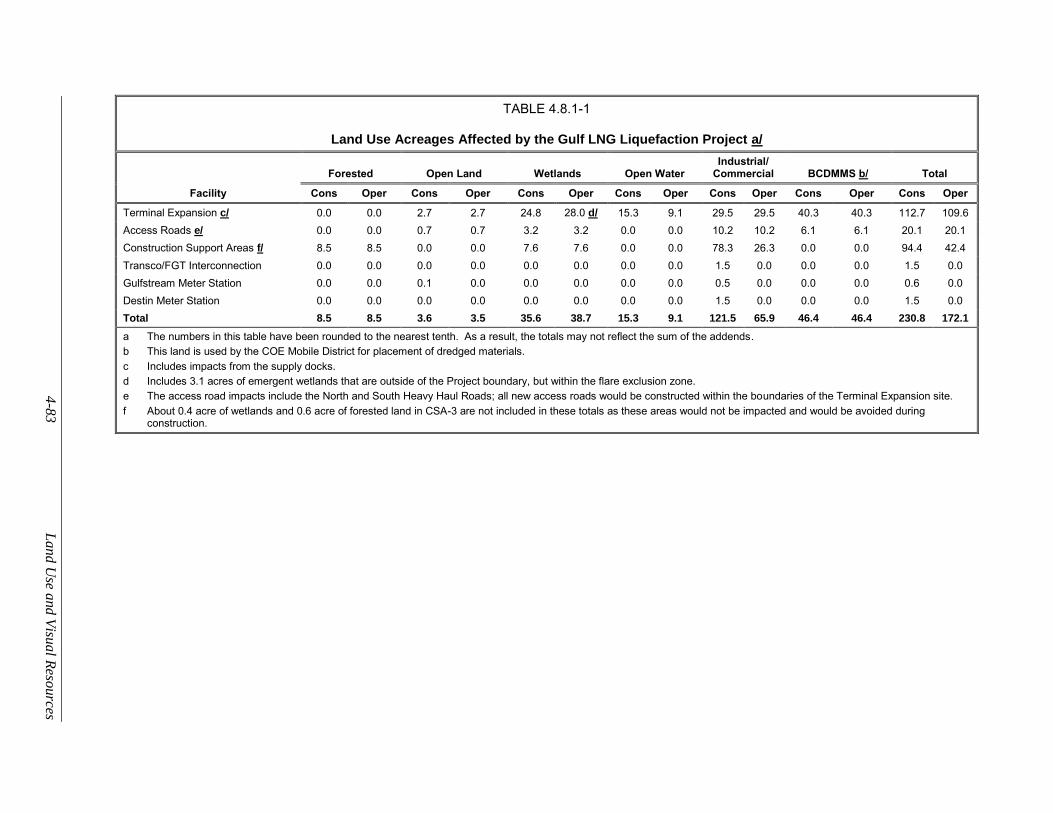
4
-83
Lan
d U
se and
Visu
al R
esources
TABLE 4.8.1-1
Land Use Acreages Affected by the Gulf LNG Liquefaction Project a/
Facility
Forested Open Land Wetlands Open Water Industrial/
Commercial BCDMMS b/ Total
Cons Oper Cons Oper Cons Oper Cons Oper Cons Oper Cons Oper Cons Oper
Terminal Expansion c/ 0.0 0.0 2.7 2.7 24.8 28.0 d/ 15.3 9.1 29.5 29.5 40.3 40.3 112.7 109.6
Access Roads e/ 0.0 0.0 0.7 0.7 3.2 3.2 0.0 0.0 10.2 10.2 6.1 6.1 20.1 20.1
Construction Support Areas f/ 8.5 8.5 0.0 0.0 7.6 7.6 0.0 0.0 78.3 26.3 0.0 0.0 94.4 42.4
Transco/FGT Interconnection 0.0 0.0 0.0 0.0 0.0 0.0 0.0 0.0 1.5 0.0 0.0 0.0 1.5 0.0
Gulfstream Meter Station 0.0 0.0 0.1 0.0 0.0 0.0 0.0 0.0 0.5 0.0 0.0 0.0 0.6 0.0
Destin Meter Station 0.0 0.0 0.0 0.0 0.0 0.0 0.0 0.0 1.5 0.0 0.0 0.0 1.5 0.0
Total 8.5 8.5 3.6 3.5 35.6 38.7 15.3 9.1 121.5 65.9 46.4 46.4 230.8 172.1
a The numbers in this table have been rounded to the nearest tenth. As a result, the totals may not reflect the sum of the addends.
b This land is used by the COE Mobile District for placement of dredged materials.
c Includes impacts from the supply docks.
d Includes 3.1 acres of emergent wetlands that are outside of the Project boundary, but within the flare exclusion zone.
e The access road impacts include the North and South Heavy Haul Roads; all new access roads would be constructed within the boundaries of the Terminal Expansion site.
f About 0.4 acre of wetlands and 0.6 acre of forested land in CSA-3 are not included in these totals as these areas would not be impacted and would be avoided during construction.
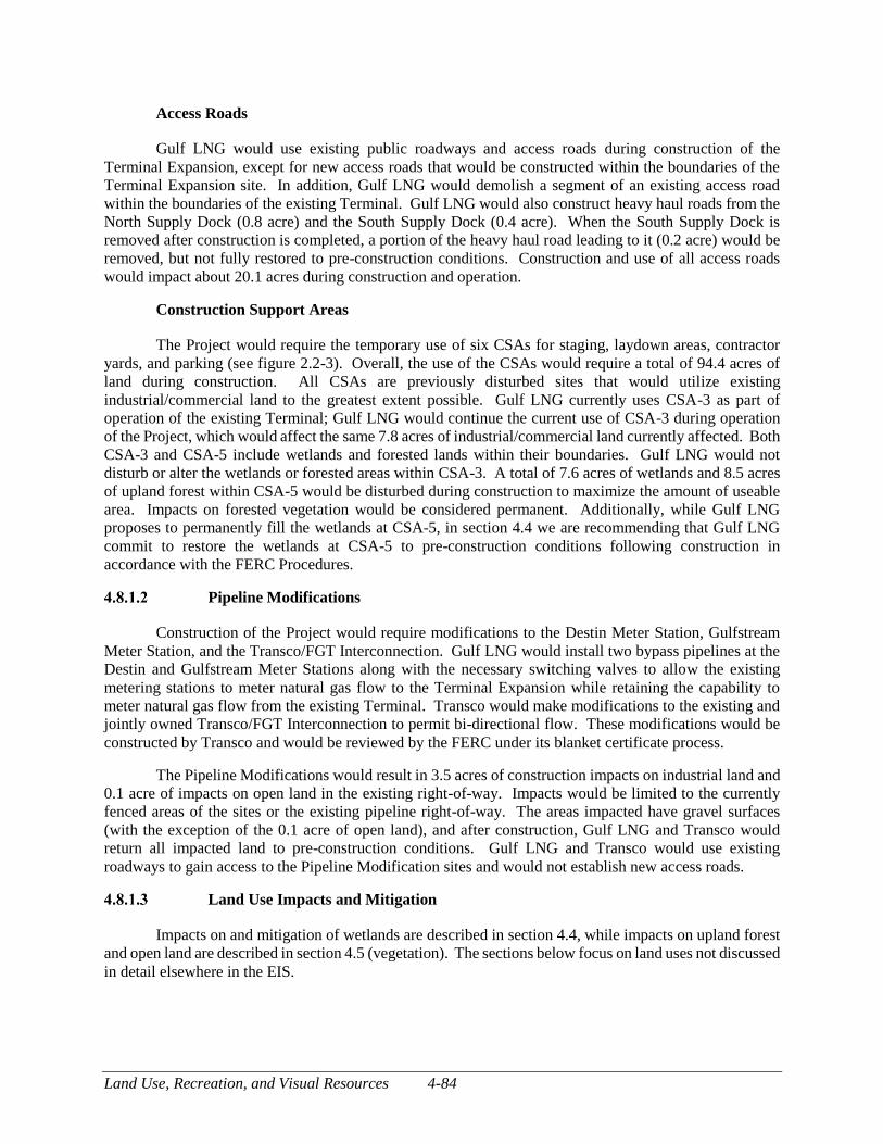
Land Use, Recreation, and Visual Resources 4-84
Access Roads
Gulf LNG would use existing public roadways and access roads during construction of the
Terminal Expansion, except for new access roads that would be constructed within the boundaries of the
Terminal Expansion site. In addition, Gulf LNG would demolish a segment of an existing access road
within the boundaries of the existing Terminal. Gulf LNG would also construct heavy haul roads from the
North Supply Dock (0.8 acre) and the South Supply Dock (0.4 acre). When the South Supply Dock is
removed after construction is completed, a portion of the heavy haul road leading to it (0.2 acre) would be
removed, but not fully restored to pre-construction conditions. Construction and use of all access roads
would impact about 20.1 acres during construction and operation.
Construction Support Areas
The Project would require the temporary use of six CSAs for staging, laydown areas, contractor
yards, and parking (see figure 2.2-3). Overall, the use of the CSAs would require a total of 94.4 acres of
land during construction. All CSAs are previously disturbed sites that would utilize existing
industrial/commercial land to the greatest extent possible. Gulf LNG currently uses CSA-3 as part of
operation of the existing Terminal; Gulf LNG would continue the current use of CSA-3 during operation
of the Project, which would affect the same 7.8 acres of industrial/commercial land currently affected. Both
CSA-3 and CSA-5 include wetlands and forested lands within their boundaries. Gulf LNG would not
disturb or alter the wetlands or forested areas within CSA-3. A total of 7.6 acres of wetlands and 8.5 acres
of upland forest within CSA-5 would be disturbed during construction to maximize the amount of useable
area. Impacts on forested vegetation would be considered permanent. Additionally, while Gulf LNG
proposes to permanently fill the wetlands at CSA-5, in section 4.4 we are recommending that Gulf LNG
commit to restore the wetlands at CSA-5 to pre-construction conditions following construction in
accordance with the FERC Procedures.
Pipeline Modifications
Construction of the Project would require modifications to the Destin Meter Station, Gulfstream
Meter Station, and the Transco/FGT Interconnection. Gulf LNG would install two bypass pipelines at the
Destin and Gulfstream Meter Stations along with the necessary switching valves to allow the existing
metering stations to meter natural gas flow to the Terminal Expansion while retaining the capability to
meter natural gas flow from the existing Terminal. Transco would make modifications to the existing and
jointly owned Transco/FGT Interconnection to permit bi-directional flow. These modifications would be
constructed by Transco and would be reviewed by the FERC under its blanket certificate process.
The Pipeline Modifications would result in 3.5 acres of construction impacts on industrial land and
0.1 acre of impacts on open land in the existing right-of-way. Impacts would be limited to the currently
fenced areas of the sites or the existing pipeline right-of-way. The areas impacted have gravel surfaces
(with the exception of the 0.1 acre of open land), and after construction, Gulf LNG and Transco would
return all impacted land to pre-construction conditions. Gulf LNG and Transco would use existing
roadways to gain access to the Pipeline Modification sites and would not establish new access roads.
Land Use Impacts and Mitigation
Impacts on and mitigation of wetlands are described in section 4.4, while impacts on upland forest
and open land are described in section 4.5 (vegetation). The sections below focus on land uses not discussed
in detail elsewhere in the EIS.
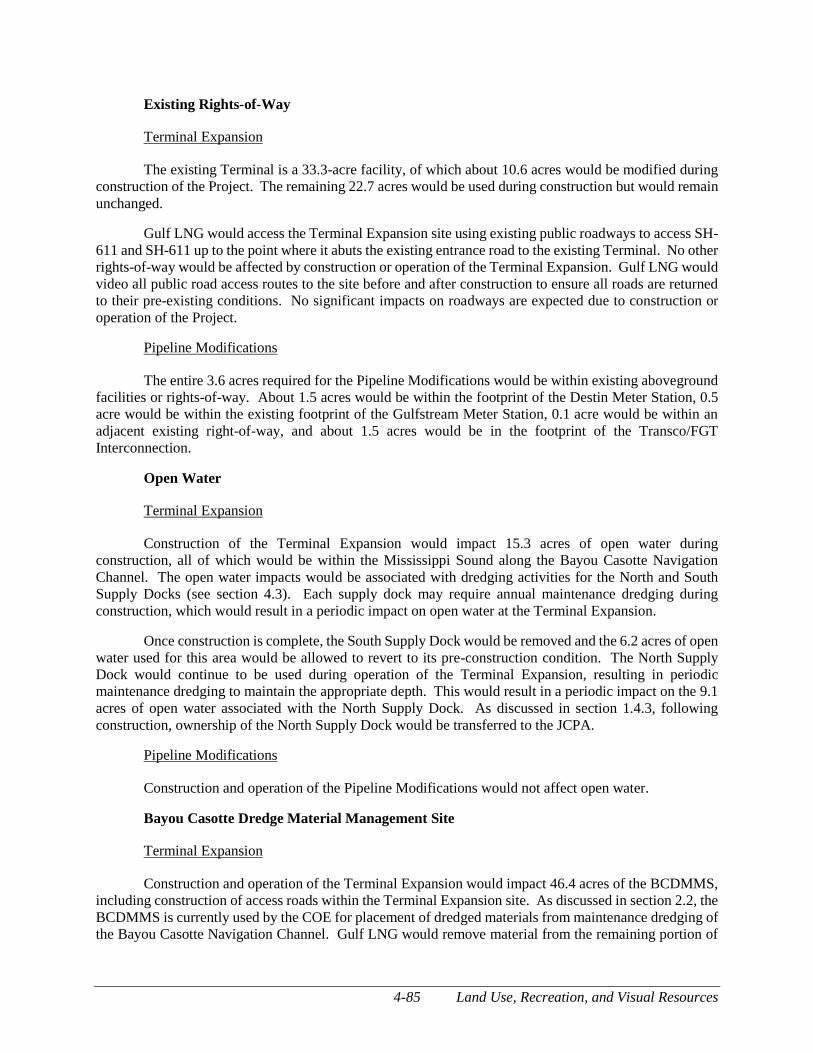
4-85 Land Use, Recreation, and Visual Resources
Existing Rights-of-Way
Terminal Expansion
The existing Terminal is a 33.3-acre facility, of which about 10.6 acres would be modified during
construction of the Project. The remaining 22.7 acres would be used during construction but would remain
unchanged.
Gulf LNG would access the Terminal Expansion site using existing public roadways to access SH-
611 and SH-611 up to the point where it abuts the existing entrance road to the existing Terminal. No other
rights-of-way would be affected by construction or operation of the Terminal Expansion. Gulf LNG would
video all public road access routes to the site before and after construction to ensure all roads are returned
to their pre-existing conditions. No significant impacts on roadways are expected due to construction or
operation of the Project.
Pipeline Modifications
The entire 3.6 acres required for the Pipeline Modifications would be within existing aboveground
facilities or rights-of-way. About 1.5 acres would be within the footprint of the Destin Meter Station, 0.5
acre would be within the existing footprint of the Gulfstream Meter Station, 0.1 acre would be within an
adjacent existing right-of-way, and about 1.5 acres would be in the footprint of the Transco/FGT
Interconnection.
Open Water
Terminal Expansion
Construction of the Terminal Expansion would impact 15.3 acres of open water during
construction, all of which would be within the Mississippi Sound along the Bayou Casotte Navigation
Channel. The open water impacts would be associated with dredging activities for the North and South
Supply Docks (see section 4.3). Each supply dock may require annual maintenance dredging during
construction, which would result in a periodic impact on open water at the Terminal Expansion.
Once construction is complete, the South Supply Dock would be removed and the 6.2 acres of open
water used for this area would be allowed to revert to its pre-construction condition. The North Supply
Dock would continue to be used during operation of the Terminal Expansion, resulting in periodic
maintenance dredging to maintain the appropriate depth. This would result in a periodic impact on the 9.1
acres of open water associated with the North Supply Dock. As discussed in section 1.4.3, following
construction, ownership of the North Supply Dock would be transferred to the JCPA.
Pipeline Modifications
Construction and operation of the Pipeline Modifications would not affect open water.
Bayou Casotte Dredge Material Management Site
Terminal Expansion
Construction and operation of the Terminal Expansion would impact 46.4 acres of the BCDMMS,
including construction of access roads within the Terminal Expansion site. As discussed in section 2.2, the
BCDMMS is currently used by the COE for placement of dredged materials from maintenance dredging of
the Bayou Casotte Navigation Channel. Gulf LNG would remove material from the remaining portion of
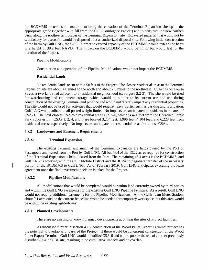
Land Use, Recreation, and Visual Resources 4-86
the BCDMMS to use as fill material to bring the elevation of the Terminal Expansion site up to the
appropriate grade (together with fill from the COE Tombigbee Project) and to construct the new earthen
berm along the northeastern border of the Terminal Expansion site. Excavated material that would not be
satisfactory for use as fill would be disposed of at an authorized disposal site. Following initial construction
of the berm by Gulf LNG, the COE, in order to expand capacity of the BCDMMS, would extend the berm
to a height of 39.2 feet NAVD. The impact on the BCDMMS would be minor but would last for the
duration of the Project.
Pipeline Modifications
Construction and operation of the Pipeline Modifications would not impact the BCDMMS.
Residential Lands
No residential lands occur within 50 feet of the Project. The closest residential areas to the Terminal
Expansion site are about 4.0 miles to the north and about 2.0 miles to the northwest. CSA-3 is on Louisa
Street, a two-lane road adjacent to a residential neighborhood (see figure 2.2-3). The site would be used
for warehousing and equipment storage, which would be similar to its current use and use during
construction of the existing Terminal and pipeline and would not directly impact any residential properties.
The site would not be used for activities that would require heavy traffic, such as parking and fabrication.
Gulf LNG would adhere to all posted weight limits. No impacts are anticipated to residents in the area of
CSA-3. The next closest CSA to a residential area is CSA-6, which is 421 feet from the Cherokee Forest
Park Subdivision. CSAs 1, 2, 4, and 5 are located 3,204 feet; 1,996 feet; 4,104 feet; and 6,228 feet from
residential areas respectively. No impacts are anticipated on residential areas from those CSAs.
Landowner and Easement Requirements
Terminal Expansion
The existing Terminal and much of the Terminal Expansion are lands owned by the Port of
Pascagoula and leased from the Port by Gulf LNG. All but 46.4 of the 132.2 acres required for construction
of the Terminal Expansion is being leased from the Port. The remaining 46.4 acres is the BCDMMS, and
Gulf LNG is working with the COE Mobile District and the JCPA to negotiate transfer of the necessary
portion of the BCDMMS to Gulf LNG. As of February 2019, Gulf LNG anticipates executing the lease
agreement once the final investment decision is taken for the Project.
Pipeline Modifications
All modifications that would be completed would be within land currently owned by third parties
and within the Gulf LNG easements for the existing Gulf LNG Pipeline facilities. As a result, Gulf LNG
would not require additional easements for the Pipeline Modifications. At the Gulfstream Meter Station,
about 0.1 acre outside the current fence line would be needed for temporary workspace, but this area would
be within the existing right-of-way.
Planned Developments
There are no existing or known planned developments at or near the sites of Project facilities.
As discussed further in section 4.13, construction of the Wood Pellet Export Terminal project has
the potential to overlap with parts of the Project. If there would be concurrent construction of the Wood
Pellet Export Terminal, Gulf LNG would not utilize CSA-6 and would pursue the use of another previously
disturbed (in-kind) use site, resulting in no cumulative impacts and no overlap.
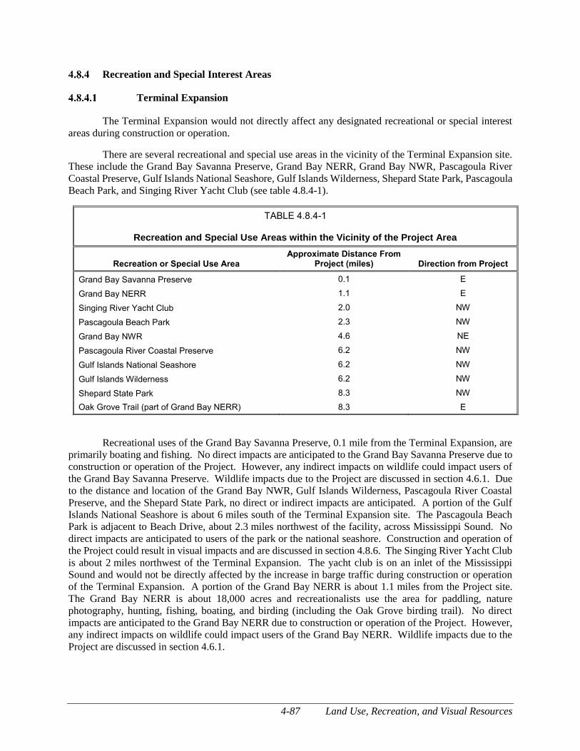
4-87 Land Use, Recreation, and Visual Resources
Recreation and Special Interest Areas
Terminal Expansion
The Terminal Expansion would not directly affect any designated recreational or special interest
areas during construction or operation.
There are several recreational and special use areas in the vicinity of the Terminal Expansion site.
These include the Grand Bay Savanna Preserve, Grand Bay NERR, Grand Bay NWR, Pascagoula River
Coastal Preserve, Gulf Islands National Seashore, Gulf Islands Wilderness, Shepard State Park, Pascagoula
Beach Park, and Singing River Yacht Club (see table 4.8.4-1).
TABLE 4.8.4-1
Recreation and Special Use Areas within the Vicinity of the Project Area
Recreation or Special Use Area Approximate Distance From
Project (miles) Direction from Project
Grand Bay Savanna Preserve 0.1 E
Grand Bay NERR 1.1 E
Singing River Yacht Club 2.0 NW
Pascagoula Beach Park 2.3 NW
Grand Bay NWR 4.6 NE
Pascagoula River Coastal Preserve 6.2 NW
Gulf Islands National Seashore 6.2 NW
Gulf Islands Wilderness 6.2 NW
Shepard State Park 8.3 NW
Oak Grove Trail (part of Grand Bay NERR) 8.3 E
Recreational uses of the Grand Bay Savanna Preserve, 0.1 mile from the Terminal Expansion, are
primarily boating and fishing. No direct impacts are anticipated to the Grand Bay Savanna Preserve due to
construction or operation of the Project. However, any indirect impacts on wildlife could impact users of
the Grand Bay Savanna Preserve. Wildlife impacts due to the Project are discussed in section 4.6.1. Due
to the distance and location of the Grand Bay NWR, Gulf Islands Wilderness, Pascagoula River Coastal
Preserve, and the Shepard State Park, no direct or indirect impacts are anticipated. A portion of the Gulf
Islands National Seashore is about 6 miles south of the Terminal Expansion site. The Pascagoula Beach
Park is adjacent to Beach Drive, about 2.3 miles northwest of the facility, across Mississippi Sound. No
direct impacts are anticipated to users of the park or the national seashore. Construction and operation of
the Project could result in visual impacts and are discussed in section 4.8.6. The Singing River Yacht Club
is about 2 miles northwest of the Terminal Expansion. The yacht club is on an inlet of the Mississippi
Sound and would not be directly affected by the increase in barge traffic during construction or operation
of the Terminal Expansion. A portion of the Grand Bay NERR is about 1.1 miles from the Project site.
The Grand Bay NERR is about 18,000 acres and recreationalists use the area for paddling, nature
photography, hunting, fishing, boating, and birding (including the Oak Grove birding trail). No direct
impacts are anticipated to the Grand Bay NERR due to construction or operation of the Project. However,
any indirect impacts on wildlife could impact users of the Grand Bay NERR. Wildlife impacts due to the
Project are discussed in section 4.6.1.
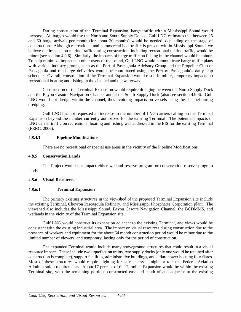
Land Use, Recreation, and Visual Resources 4-88
During construction of the Terminal Expansion, barge traffic within Mississippi Sound would
increase. All barges would use the North and South Supply Docks. Gulf LNG estimates that between 25
and 60 barge arrivals per month (for about 30 months) would be needed, depending on the stage of
construction. Although recreational and commercial boat traffic is present within Mississippi Sound, we
believe the impacts on marine traffic during construction, including recreational marine traffic, would be
minor (see section 4.9.6). Similarly, the impacts of barge traffic on fishing in the channel would be minor.
To help minimize impacts on other users of the sound, Gulf LNG would communicate barge traffic plans
with various industry groups, such as the Port of Pascagoula Advisory Group and the Propeller Club of
Pascagoula and the barge deliveries would be coordinated using the Port of Pascagoula’s daily ship
schedule. Overall, construction of the Terminal Expansion would result in minor, temporary impacts on
recreational boating and fishing in the channel and the waterway.
Construction of the Terminal Expansion would require dredging between the North Supply Dock
and the Bayou Casotte Navigation Channel and at the South Supply Dock (also see section 4.9.6). Gulf
LNG would not dredge within the channel, thus avoiding impacts on vessels using the channel during
dredging.
Gulf LNG has not requested an increase in the number of LNG carriers calling on the Terminal
Expansion beyond the number currently authorized for the existing Terminal. The potential impacts of
LNG carrier traffic on recreational boating and fishing was addressed in the EIS for the existing Terminal
(FERC, 2006).
Pipeline Modifications
There are no recreational or special use areas in the vicinity of the Pipeline Modifications.
Conservation Lands
The Project would not impact either wetland reserve program or conservation reserve program
lands.
Visual Resources
Terminal Expansion
The primary existing structures in the viewshed of the proposed Terminal Expansion site include
the existing Terminal, Chevron Pascagoula Refinery, and Mississippi Phosphates Corporation plant. The
viewshed also includes the Mississippi Sound, Bayou Casotte Navigation Channel, the BCDMMS, and
wetlands in the vicinity of the Terminal Expansion site.
Gulf LNG would construct its expansion adjacent to the existing Terminal, and views would be
consistent with the existing industrial area. The impact on visual resources during construction due to the
presence of workers and equipment for the about 64 month construction period would be minor due to the
limited number of viewers, and temporary, lasting only for the period of construction.
The expanded Terminal would include many aboveground structures that could result in a visual
resource impact. These include two liquefaction trains, two supply docks (only one would be retained after
construction is complete), support facilities, administrative buildings, and a flare tower housing four flares.
Most of these structures would require lighting for safe access at night or to meet Federal Aviation
Administration requirements. About 17 percent of the Terminal Expansion would be within the existing
Terminal site, with the remaining portions constructed east and south of and adjacent to the existing
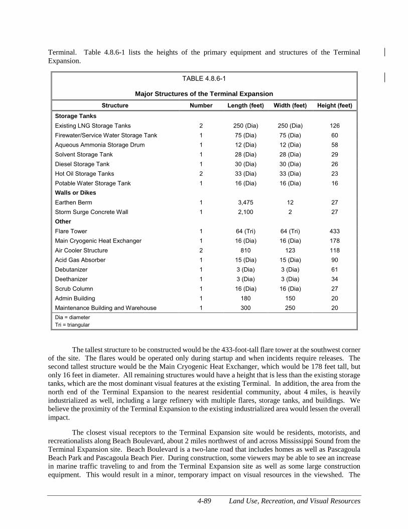
4-89 Land Use, Recreation, and Visual Resources
Terminal. Table 4.8.6-1 lists the heights of the primary equipment and structures of the Terminal
Expansion.
TABLE 4.8.6-1
Major Structures of the Terminal Expansion
Structure Number Length (feet) Width (feet) Height (feet)
Storage Tanks
Existing LNG Storage Tanks 2 250 (Dia) 250 (Dia) 126
Firewater/Service Water Storage Tank 1 75 (Dia) 75 (Dia) 60
Aqueous Ammonia Storage Drum 1 12 (Dia) 12 (Dia) 58
Solvent Storage Tank 1 28 (Dia) 28 (Dia) 29
Diesel Storage Tank 1 30 (Dia) 30 (Dia) 26
Hot Oil Storage Tanks 2 33 (Dia) 33 (Dia) 23
Potable Water Storage Tank 1 16 (Dia) 16 (Dia) 16
Walls or Dikes
Earthen Berm 1 3,475 12 27
Storm Surge Concrete Wall 1 2,100 2 27
Other
Flare Tower 1 64 (Tri) 64 (Tri) 433
Main Cryogenic Heat Exchanger 1 16 (Dia) 16 (Dia) 178
Air Cooler Structure 2 810 123 118
Acid Gas Absorber 1 15 (Dia) 15 (Dia) 90
Debutanizer 1 3 (Dia) 3 (Dia) 61
Deethanizer 1 3 (Dia) 3 (Dia) 34
Scrub Column 1 16 (Dia) 16 (Dia) 27
Admin Building 1 180 150 20
Maintenance Building and Warehouse 1 300 250 20
Dia = diameter
Tri = triangular
The tallest structure to be constructed would be the 433-foot-tall flare tower at the southwest corner
of the site. The flares would be operated only during startup and when incidents require releases. The
second tallest structure would be the Main Cryogenic Heat Exchanger, which would be 178 feet tall, but
only 16 feet in diameter. All remaining structures would have a height that is less than the existing storage
tanks, which are the most dominant visual features at the existing Terminal. In addition, the area from the
north end of the Terminal Expansion to the nearest residential community, about 4 miles, is heavily
industrialized as well, including a large refinery with multiple flares, storage tanks, and buildings. We
believe the proximity of the Terminal Expansion to the existing industrialized area would lessen the overall
impact.
The closest visual receptors to the Terminal Expansion site would be residents, motorists, and
recreationalists along Beach Boulevard, about 2 miles northwest of and across Mississippi Sound from the
Terminal Expansion site. Beach Boulevard is a two-lane road that includes homes as well as Pascagoula
Beach Park and Pascagoula Beach Pier. During construction, some viewers may be able to see an increase
in marine traffic traveling to and from the Terminal Expansion site as well as some large construction
equipment. This would result in a minor, temporary impact on visual resources in the viewshed. The
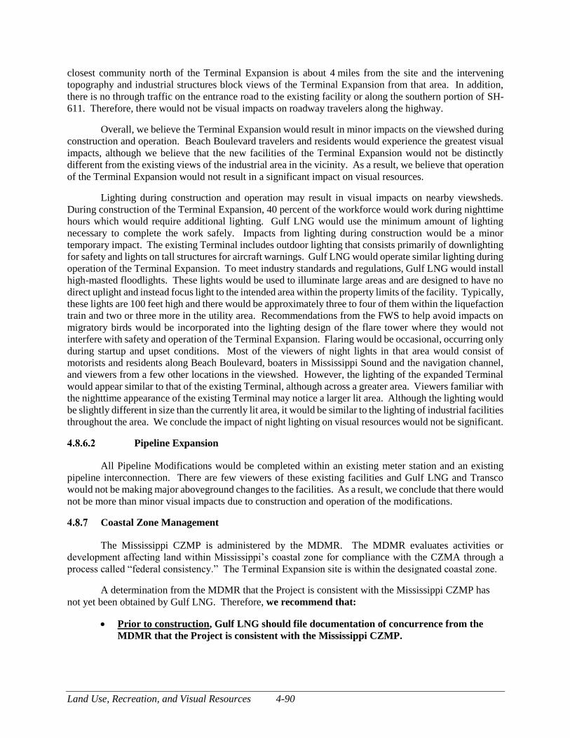
Land Use, Recreation, and Visual Resources 4-90
closest community north of the Terminal Expansion is about 4 miles from the site and the intervening
topography and industrial structures block views of the Terminal Expansion from that area. In addition,
there is no through traffic on the entrance road to the existing facility or along the southern portion of SH-
611. Therefore, there would not be visual impacts on roadway travelers along the highway.
Overall, we believe the Terminal Expansion would result in minor impacts on the viewshed during
construction and operation. Beach Boulevard travelers and residents would experience the greatest visual
impacts, although we believe that the new facilities of the Terminal Expansion would not be distinctly
different from the existing views of the industrial area in the vicinity. As a result, we believe that operation
of the Terminal Expansion would not result in a significant impact on visual resources.
Lighting during construction and operation may result in visual impacts on nearby viewsheds.
During construction of the Terminal Expansion, 40 percent of the workforce would work during nighttime
hours which would require additional lighting. Gulf LNG would use the minimum amount of lighting
necessary to complete the work safely. Impacts from lighting during construction would be a minor
temporary impact. The existing Terminal includes outdoor lighting that consists primarily of downlighting
for safety and lights on tall structures for aircraft warnings. Gulf LNG would operate similar lighting during
operation of the Terminal Expansion. To meet industry standards and regulations, Gulf LNG would install
high-masted floodlights. These lights would be used to illuminate large areas and are designed to have no
direct uplight and instead focus light to the intended area within the property limits of the facility. Typically,
these lights are 100 feet high and there would be approximately three to four of them within the liquefaction
train and two or three more in the utility area. Recommendations from the FWS to help avoid impacts on
migratory birds would be incorporated into the lighting design of the flare tower where they would not
interfere with safety and operation of the Terminal Expansion. Flaring would be occasional, occurring only
during startup and upset conditions. Most of the viewers of night lights in that area would consist of
motorists and residents along Beach Boulevard, boaters in Mississippi Sound and the navigation channel,
and viewers from a few other locations in the viewshed. However, the lighting of the expanded Terminal
would appear similar to that of the existing Terminal, although across a greater area. Viewers familiar with
the nighttime appearance of the existing Terminal may notice a larger lit area. Although the lighting would
be slightly different in size than the currently lit area, it would be similar to the lighting of industrial facilities
throughout the area. We conclude the impact of night lighting on visual resources would not be significant.
Pipeline Expansion
All Pipeline Modifications would be completed within an existing meter station and an existing
pipeline interconnection. There are few viewers of these existing facilities and Gulf LNG and Transco
would not be making major aboveground changes to the facilities. As a result, we conclude that there would
not be more than minor visual impacts due to construction and operation of the modifications.
Coastal Zone Management
The Mississippi CZMP is administered by the MDMR. The MDMR evaluates activities or
development affecting land within Mississippi’s coastal zone for compliance with the CZMA through a
process called “federal consistency.” The Terminal Expansion site is within the designated coastal zone.
A determination from the MDMR that the Project is consistent with the Mississippi CZMP has
not yet been obtained by Gulf LNG. Therefore, we recommend that:
Prior to construction, Gulf LNG should file documentation of concurrence from the
MDMR that the Project is consistent with the Mississippi CZMP.
4-91 Land Use, Recreation, and Visual Resources
The FERC would not approve construction until all federal authorizations, including a consistency
determination with the CZMA, have been granted.
Conclusions for Land Use, Special Interest Areas, and Visual Resources
A total of 230.8 acres would be impacted during construction of the Terminal Expansion and 172.1
acres would be impacted during operation. The largest portion of these impacts would be on industrial
land, land used for depositing dredged material, and wetlands. With implementation of agency-approved
compensatory mitigation, the land use impacts of the Terminal Expansion would be minor.
Grand Bay Savanna Preserve, the nearest recreation or special interest area, is about 0.1 mile from
the Terminal Expansion. Primary recreational uses of the Grand Bay Savanna Preserve are boating and
fishing. No direct impacts to the Grand Bay Savanna Preserve are anticipated due to construction or
operation of the Project. However, indirect impacts on wildlife (as discussed in section 4.6.1) could impact
users of the Grand Bay Savanna Preserve.
Views of the Terminal Expansion would generally be similar to those of the adjacent existing
Terminal and the surrounding industrial areas. The tallest structure to be constructed would be the 433-
foot-tall flare tower at the southwest corner of the site. The flares would be operated only during startup
and when incidents require releases. Overall, we conclude the Terminal Expansion would result in only
minor impacts on the viewshed during construction and operation.
Construction and operation of the Pipeline Modifications would result in 3.5 acres of construction
impacts on industrial land and 0.1 acre of impacts on open land. All of which would be within the currently
fenced areas of the meter stations and interconnection sites or the associated pipeline right-of-way. There
are few viewers of these existing facilities and Gulf LNG and Transco would not be making major
aboveground changes to the facilities. As a result, we believe that there would not be more than minor
visual impacts due to construction and operation of the modifications.
Socioeconomics 4-92
SOCIOECONOMICS
Socioeconomic conditions in the area may be affected by construction and operation of the Project.
Both the Terminal Expansion and Pipeline Modifications would be in Jackson County, Mississippi.
Construction and operation may affect population levels, employment levels, tax revenues, ongoing local
expenditures by the operator, housing availability, demand for public services, or transportation in the area.
For the socioeconomic analysis, Jackson County is considered the “Project area.”
Population
The population of Jackson County was estimated at 142,152 people in 2017 by the U.S. Census
Bureau (U.S. Census Bureau, 2017a). The population density was 196.7 people per square mile. The
average population density for the state of Mississippi was 63.6 people per square mile. Table 4.9.1-1 lists
selected population and demographics information in the Project area.
Gulf LNG estimates that the average workforce for construction of the Project would be 1,950
workers. The estimated number of construction workers for each year of construction are listed in table
4.9.1-2. During construction, Gulf LNG anticipates that the peak workforce would be 4,300 workers. The
workforce would include about 10 workers for construction of the Pipeline Modifications and the remaining
workforce would be used for construction of the Terminal Expansion. About 40 percent of the workforce
is expected to be hired from within the population of the City of Pascagoula and the surrounding areas. The
other 60 percent of the workers would be hired from outside the area and would temporarily relocate during
construction. While it is unlikely that most of the non-local workforce would relocate with their families,
as a conservative estimate Gulf LNG assumed that 1,950, or roughly 75 percent of the peak non-local
workforce, would bring their families and 630 non-local workers would relocate without families.
Assuming an average household size in the United States of 2.64 people (U.S. Census Bureau, 2017a), the
1,950 non-local workers would bring 3,198 family members. The total of the 630 non-local workers that
would relocate without bringing families, the 1,950 non-local workers that bring families, and the 3,198
family members that would relocate, the total population increase would be 5,778 people at the peak of
construction. This would result in a 4.1 percent increase in the Jackson County population. The increase
would represent a temporary impact on the local population.
Operation of the Terminal Expansion would require 113 new permanent jobs, with many of the
workers expected to be local hires. However, even if all 113 positions were to be filled by workers from
outside the Project area and they all brought their families, the population increase would be less than 300
people, which is less than 1 percent of the population of Jackson County.
There would be no new permanent positions required for operation of the Pipeline Modifications.
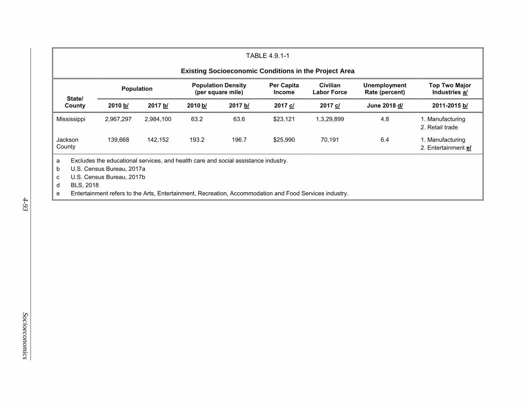
4
-93
So
cioeco
no
mics
TABLE 4.9.1-1
Existing Socioeconomic Conditions in the Project Area
State/ County
Population Population Density (per square mile)
Per Capita Income
Civilian Labor Force
Unemployment Rate (percent)
Top Two Major Industries a/
2010 b/ 2017 b/ 2010 b/ 2017 b/ 2017 c/ 2017 c/ June 2018 d/ 2011-2015 b/
Mississippi 2,967,297 2,984,100 63.2 63.6 $23,121 1,3,29,899 4.8 1. Manufacturing
2. Retail trade
Jackson County
139,668 142,152 193.2 196.7 $25,990 70,191 6.4 1. Manufacturing
2. Entertainment e/
a Excludes the educational services, and health care and social assistance industry.
b U.S. Census Bureau, 2017a
c U.S. Census Bureau, 2017b
d BLS, 2018
e Entertainment refers to the Arts, Entertainment, Recreation, Accommodation and Food Services industry.
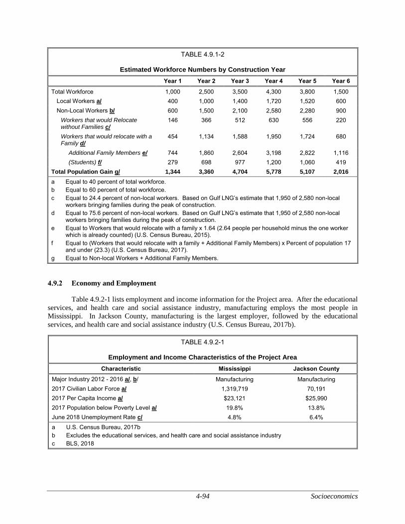
4-94 Socioeconomics
TABLE 4.9.1-2
Estimated Workforce Numbers by Construction Year
Year 1 Year 2 Year 3 Year 4 Year 5 Year 6
Total Workforce 1,000 2,500 3,500 4,300 3,800 1,500
Local Workers a/ 400 1,000 1,400 1,720 1,520 600
Non-Local Workers b/ 600 1,500 2,100 2,580 2,280 900
Workers that would Relocate without Families c/
146 366 512 630 556 220
Workers that would relocate with a Family d/
454 1,134 1,588 1,950 1,724 680
Additional Family Members e/ 744 1,860 2,604 3,198 2,822 1,116
(Students) f/ 279 698 977 1,200 1,060 419
Total Population Gain g/ 1,344 3,360 4,704 5,778 5,107 2,016
a Equal to 40 percent of total workforce.
b Equal to 60 percent of total workforce.
c Equal to 24.4 percent of non-local workers. Based on Gulf LNG’s estimate that 1,950 of 2,580 non-local workers bringing families during the peak of construction.
d Equal to 75.6 percent of non-local workers. Based on Gulf LNG’s estimate that 1,950 of 2,580 non-local workers bringing families during the peak of construction.
e Equal to Workers that would relocate with a family x 1.64 (2.64 people per household minus the one worker which is already counted) (U.S. Census Bureau, 2015).
f Equal to (Workers that would relocate with a family + Additional Family Members) x Percent of population 17 and under (23.3) (U.S. Census Bureau, 2017).
g Equal to Non-local Workers + Additional Family Members.
Economy and Employment
Table 4.9.2-1 lists employment and income information for the Project area. After the educational
services, and health care and social assistance industry, manufacturing employs the most people in
Mississippi. In Jackson County, manufacturing is the largest employer, followed by the educational
services, and health care and social assistance industry (U.S. Census Bureau, 2017b).
TABLE 4.9.2-1
Employment and Income Characteristics of the Project Area
Characteristic Mississippi Jackson County
Major Industry 2012 - 2016 a/, b/ Manufacturing Manufacturing
2017 Civilian Labor Force a/ 1,319,719 70,191
2017 Per Capita Income a/ $23,121 $25,990
2017 Population below Poverty Level a/ 19.8% 13.8%
June 2018 Unemployment Rate c/ 4.8% 6.4%
a U.S. Census Bureau, 2017b
b Excludes the educational services, and health care and social assistance industry
c BLS, 2018

4-95 Socioeconomics
The civilian labor force is defined as the total of employed persons and those searching for work.
In Jackson County, the civilian labor force in 2017 was 70,191 people and the per capita income was
$25,990. The per capita income is higher than the overall average for Mississippi which is $23,121 (U.S.
Census Bureau, 2017b). The unemployment rate for June 2018 was 6.4 percent for Jackson County and
4.8 percent for Mississippi (BLS, 2018). The average poverty rate for Jackson County in 2017 was 13.8
percent, and the overall state poverty rate for the same period was 19.8 percent (U.S. Census Bureau,
2017b).
Construction jobs for the Project would add temporary employment opportunities in the area. Gulf
LNG has estimated that they would hire 1,720 workers from the local area during the peak of construction.
This would result in a minor, temporary decrease in the unemployment rate for the Project area. Gulf LNG
estimated that the total construction expenditures for the Project would be about $7 billion. Based on an
assessment conducted by Gulf LNG’s economics contractor, Navigant Economics, about $1.5 billion would
be spent within a 75-mile radius of the Project, and employee earnings in Jackson County would increase
by $450.8 million (Navigant Economics, 2012). In addition to direct construction employment, other
employment (indirect) may increase in the Project area due to the newly created demand for goods and
services in the area. As construction workers spend money on food, housing, and other goods, local
businesses would benefit. Overall, this would result in a beneficial, but temporary, increase in the local
economy.
Operation of the Terminal Expansion would require up to 113 permanent new positions, with many
of these positions expected to be filled by local hires. Expenditures by the permanent workers would result
in a negligible permanent economic benefit to the Project area.
Local Taxes and Government Revenue
Gulf LNG estimates it would spend $7 billion on the Project during construction (Navigant
Economics, 2012). This includes construction worker wages, materials and equipment, and services.
Payroll taxes and sales taxes on purchases (such as materials and equipment) would generate increased
federal, state, and local tax revenues. In addition to direct Project-related expenditures, additional economic
benefits would accrue due to expenditures by construction workers, and in some cases their families, and
by some businesses that may make additional investments to meet additional demand. Total federal tax
revenues are expected to be $1.7 billion and total state and local tax revenues would be about $910.1 million
over the total construction period (Navigant Economics, 2012). In Jackson County, the total federal tax
revenues generated would be $132.0 million, and the state and local taxes generated would be $60.6 million
(Navigant Economics, 2012). Included within those estimates would be roughly $90 million per year in
income taxes and a total of $40 million in state sales and use taxes during construction. In addition, the
Jackson County property taxes from the Terminal are expected to total $104.1 million over the total
construction period (Navigant Economics, 2012). The increased tax benefits for the federal, state, and local
governments would be a temporary, beneficial impact.
Gulf LNG estimated that during operation of the Project, federal tax revenues would be $516.0
million per year and the state and local tax revenues would be $318.9 million per year. This includes the
taxes on Gulf LNG’s operating expenditures and the purchase of LNG by Gulf LNG’s customers. Navigant
Economics (2012) estimated that the state and local tax for Jackson County would be $13.2 million and the
Jackson County property tax would be as much as $65 million per year. Gulf LNG estimates that workers
would pay at least $500,000 per year in income taxes. This would result in a permanent beneficial impact
on federal, state, and local tax revenues.
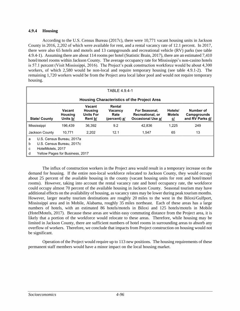
Socioeconomics 4-96
Housing
According to the U.S. Census Bureau (2017c), there were 10,771 vacant housing units in Jackson
County in 2016, 2,202 of which were available for rent, and a rental vacancy rate of 12.1 percent. In 2017,
there were also 65 hotels and motels and 13 campgrounds and recreational vehicle (RV) parks (see table
4.9.4-1). Assuming there are about 114 rooms per hotel (Statistic Brain, 2017), there are an estimated 7,410
hotel/motel rooms within Jackson County. The average occupancy rate for Mississippi’s non-casino hotels
is 57.1 percent (Visit Mississippi, 2016). The Project’s peak construction workforce would be about 4,300
workers, of which 2,580 would be non-local and require temporary housing (see table 4.9.1-2). The
remaining 1,720 workers would be from the Project area local labor pool and would not require temporary
housing.
TABLE 4.9.4-1
Housing Characteristics of the Project Area
State/ County
Vacant Housing Units b/
Vacant Housing Units For Rent b/
Rental Vacancy
Rate (percent) a/
For Seasonal, Recreational, or
Occasional Use a/
Hotels/ Motels
c/
Number of Campgrounds
and RV Parks d/
Mississippi 196,439 36,392 9.2 42,836 1,225 249
Jackson County 10,771 2,202 12.1 1,547 65 13
a U.S. Census Bureau, 2017a
b U.S. Census Bureau, 2017c
c HotelMotels, 2017
d Yellow Pages for Business, 2017
The influx of construction workers in the Project area would result in a temporary increase on the
demand for housing. If the entire non-local workforce relocated to Jackson County, they would occupy
about 25 percent of the available housing in the county (vacant housing units for rent and hotel/motel
rooms). However, taking into account the rental vacancy rate and hotel occupancy rate, the workforce
could occupy almost 70 percent of the available housing in Jackson County. Seasonal tourism may have
additional effects on the availability of housing, as vacancy rates may be lower during peak tourism months.
However, larger nearby tourism destinations are roughly 20 miles to the west in the Biloxi/Gulfport,
Mississippi area and in Mobile, Alabama, roughly 35 miles northeast. Each of these areas has a large
numbers of hotels, with an estimated 86 hotels/motels in Biloxi and 125 hotels/motels in Mobile
(HotelMotels, 2017). Because these areas are within easy commuting distance from the Project area, it is
likely that a portion of the workforce would relocate to these areas. Therefore, while housing may be
limited in Jackson County, there are sufficient numbers of hotel rooms in surrounding areas to absorb any
overflow of workers. Therefore, we conclude that impacts from Project construction on housing would not
be significant.
Operation of the Project would require up to 113 new positions. The housing requirements of these
permanent staff members would have a minor impact on the local housing market.
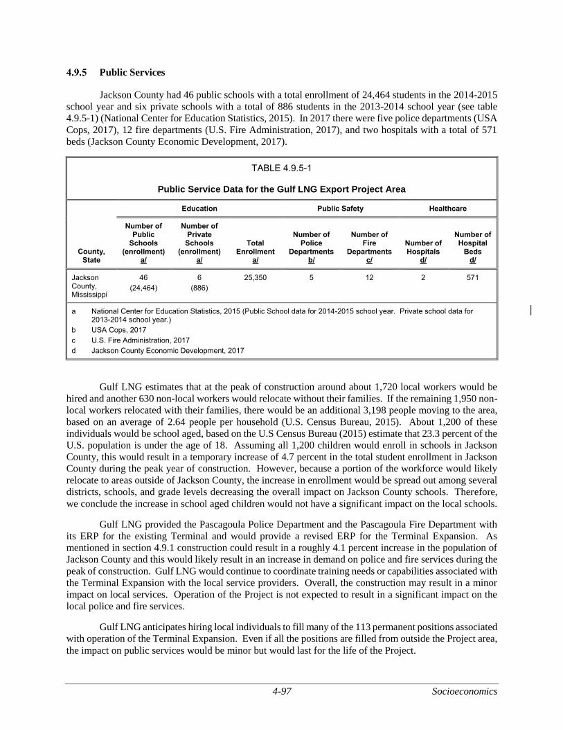
4-97 Socioeconomics
Public Services
Jackson County had 46 public schools with a total enrollment of 24,464 students in the 2014-2015
school year and six private schools with a total of 886 students in the 2013-2014 school year (see table
4.9.5-1) (National Center for Education Statistics, 2015). In 2017 there were five police departments (USA
Cops, 2017), 12 fire departments (U.S. Fire Administration, 2017), and two hospitals with a total of 571
beds (Jackson County Economic Development, 2017).
TABLE 4.9.5-1
Public Service Data for the Gulf LNG Export Project Area
County, State
Education Public Safety Healthcare
Number of Public
Schools (enrollment)
a/
Number of Private
Schools (enrollment)
a/
Total Enrollment
a/
Number of Police
Departments b/
Number of Fire
Departments c/
Number of Hospitals
d/
Number of Hospital
Beds d/
Jackson County, Mississippi
46
(24,464)
6
(886)
25,350 5 12 2 571
a National Center for Education Statistics, 2015 (Public School data for 2014-2015 school year. Private school data for 2013-2014 school year.)
b USA Cops, 2017
c U.S. Fire Administration, 2017
d Jackson County Economic Development, 2017
Gulf LNG estimates that at the peak of construction around about 1,720 local workers would be
hired and another 630 non-local workers would relocate without their families. If the remaining 1,950 non-
local workers relocated with their families, there would be an additional 3,198 people moving to the area,
based on an average of 2.64 people per household (U.S. Census Bureau, 2015). About 1,200 of these
individuals would be school aged, based on the U.S Census Bureau (2015) estimate that 23.3 percent of the
U.S. population is under the age of 18. Assuming all 1,200 children would enroll in schools in Jackson
County, this would result in a temporary increase of 4.7 percent in the total student enrollment in Jackson
County during the peak year of construction. However, because a portion of the workforce would likely
relocate to areas outside of Jackson County, the increase in enrollment would be spread out among several
districts, schools, and grade levels decreasing the overall impact on Jackson County schools. Therefore,
we conclude the increase in school aged children would not have a significant impact on the local schools.
Gulf LNG provided the Pascagoula Police Department and the Pascagoula Fire Department with
its ERP for the existing Terminal and would provide a revised ERP for the Terminal Expansion. As
mentioned in section 4.9.1 construction could result in a roughly 4.1 percent increase in the population of
Jackson County and this would likely result in an increase in demand on police and fire services during the
peak of construction. Gulf LNG would continue to coordinate training needs or capabilities associated with
the Terminal Expansion with the local service providers. Overall, the construction may result in a minor
impact on local services. Operation of the Project is not expected to result in a significant impact on the
local police and fire services.
Gulf LNG anticipates hiring local individuals to fill many of the 113 permanent positions associated
with operation of the Terminal Expansion. Even if all the positions are filled from outside the Project area,
the impact on public services would be minor but would last for the life of the Project.

Socioeconomics 4-98
Transportation
Highway access to the construction areas would be via SH-611. The entrance to the existing
Terminal is at the southern end of SH-611. An access road leads from that point to the main gate of the
existing Terminal. A project to widen SH-611 to five lanes from Old Mobile Avenue south to the Chevron
refinery was completed in 2016. According to Gulf LNG’s updated Traffic Impact Analysis, 2013 daily
traffic volumes were estimated to be 11,000 trips on the north end of SH-611 and 5,000 trips on the south
end.22 Traffic levels would increase from construction worker vehicle trips and deliveries to the site.
At the peak of the construction labor force, Gulf LNG estimates roughly 6,880 vehicle trips (3,440
vehicles in and out) for workers commuting to and from work. During the first year of construction of the
Terminal Expansion, dirt hauling for the Project is expected to be at its peak with an estimated 170 truck
trips per day for hauling dirt away from the Project site expected. Material deliveries during this same
period would peak at about 30 truck trips per day. As a result, during this period there would be an average
of 200 truck trips per day to and from the site. The addition of truck and commuter trips from the Project
are estimated to result in an increase of thru traffic along SR-611 of 43 percent to 120 percent, depending
on time of day and direction of traffic.
To help distribute impacts of vehicle trips by workers, Gulf LNG would have two daytime shift
start times and 40 percent of the workforce would work on the night shift. Estimated construction traffic
shift volumes are shown in table 4.9.6-1. During the morning, each shift would result in about 1,032
workers arriving on-site, and 115 workers leaving the site. To minimize vehicle trips to the Terminal
Expansion site, Gulf LNG has identified six CSAs for staging, laydown areas, contractor yards, and parking.
The primary parking area for construction workers would be at CSA-6, which is proposed along the Bayou
Casotte Parkway. Gulf LNG would require most construction workers to park at CSA-6 and take Gulf
LNG shuttle busses to the construction area. Up to four of the other CSAs may also be used for construction
worker parking with the exception of CSA-3. Because CSA-3 is proposed along a residential road, it would
only be used as a material staging area in order to minimize traffic impacts in the residential neighborhood.
Gulf LNG would use a total of 430 bus trips per day to transport workers between the CSAs and the
construction site at the peak of the construction workforce. Gulf LNG would provide traffic control
personnel to coordinate the traffic flows in and out of the CSAs and construction site, as needed, to minimize
congestion and ensure public safety.
In the draft EIS, we recommended that Gulf LNG file an updated Traffic Impact Analysis based on
more recent traffic conditions in the construction area. The updated Traffic Impact Analysis was filed on
January 7, 2019. It estimated the impact of the Project on several major intersections near the Terminal
Expansion site and the CSAs. Traffic levels at the intersections were measured in 2018 and then projected
traffic levels were modeled for 2023, when construction is estimated to be at its peak.
Table 4.9.6-2 shows the level of service (LOS) change for the morning rush hour and table 4.9.6-3
shows the LOS change for the evening rush hour. The LOS categorizes the estimated traffic flow along
roads and highways from best (LOS A) to worst (LOS F). LOS A indicates roads that are free flowing,
LOS B are roads that are reasonably free flowing, LOS C is stable flow but drivers are restricted in choosing
their own speed, LOS D is approaching unstable flow, LOS E is an unstable flow with short stoppages, and
LOS F indicates traffic that requires frequent stopping and slowing (USDOT, 2018). The biggest change
is at the Bayou Casotte Parkway and Orchard Road Intersection, where workers would be turning to access
CSA-6 along the Bayou Casotte Parkway.
22 According to Gulf LNG’s updated Traffic Impact Analysis, the MDOT has not published traffic counts on SH-611 since
2013.
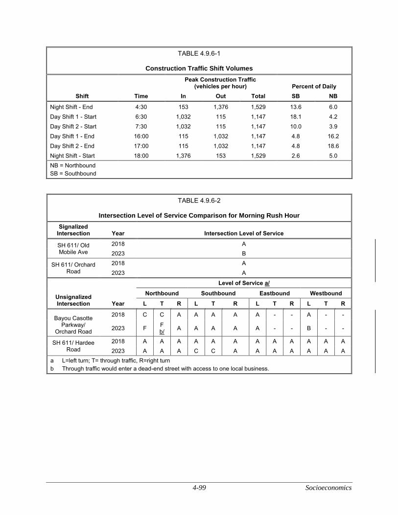
4-99 Socioeconomics
TABLE 4.9.6-1
Construction Traffic Shift Volumes
Shift Time
Peak Construction Traffic (vehicles per hour) Percent of Daily
In Out Total SB NB
Night Shift - End 4:30 153 1,376 1,529 13.6 6.0
Day Shift 1 - Start 6:30 1,032 115 1,147 18.1 4.2
Day Shift 2 - Start 7:30 1,032 115 1,147 10.0 3.9
Day Shift 1 - End 16:00 115 1,032 1,147 4.8 16.2
Day Shift 2 - End 17:00 115 1,032 1,147 4.8 18.6
Night Shift - Start 18:00 1,376 153 1,529 2.6 5.0
NB = Northbound
SB = Southbound
TABLE 4.9.6-2
Intersection Level of Service Comparison for Morning Rush Hour
Signalized Intersection Year Intersection Level of Service
SH 611/ Old Mobile Ave
2018 A
2023 B
SH 611/ Orchard Road
2018 A
2023 A
Unsignalized Intersection Year
Level of Service a/
Northbound Southbound Eastbound Westbound
L T R L T R L T R L T R
Bayou Casotte Parkway/
Orchard Road
2018 C C A A A A A - - A - -
2023 F F b/
A A A A A - - B - -
SH 611/ Hardee Road
2018 A A A A A A A A A A A A
2023 A A A C C A A A A A A A
a L=left turn; T= through traffic, R=right turn
b Through traffic would enter a dead-end street with access to one local business.
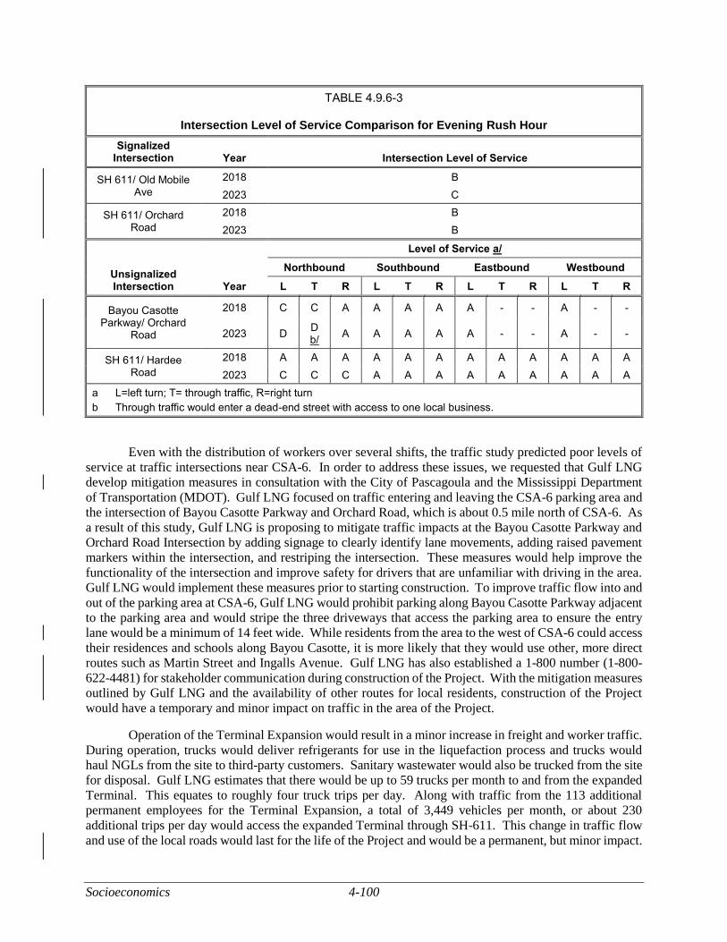
Socioeconomics 4-100
TABLE 4.9.6-3
Intersection Level of Service Comparison for Evening Rush Hour
Signalized Intersection Year Intersection Level of Service
SH 611/ Old Mobile Ave
2018 B
2023 C
SH 611/ Orchard Road
2018 B
2023 B
Unsignalized Intersection Year
Level of Service a/
Northbound Southbound Eastbound Westbound
L T R L T R L T R L T R
Bayou Casotte Parkway/ Orchard
Road
2018 C C A A A A A - - A - -
2023 D D b/
A A A A A - - A - -
SH 611/ Hardee Road
2018 A A A A A A A A A A A A
2023 C C C A A A A A A A A A
a L=left turn; T= through traffic, R=right turn
b Through traffic would enter a dead-end street with access to one local business.
Even with the distribution of workers over several shifts, the traffic study predicted poor levels of
service at traffic intersections near CSA-6. In order to address these issues, we requested that Gulf LNG
develop mitigation measures in consultation with the City of Pascagoula and the Mississippi Department
of Transportation (MDOT). Gulf LNG focused on traffic entering and leaving the CSA-6 parking area and
the intersection of Bayou Casotte Parkway and Orchard Road, which is about 0.5 mile north of CSA-6. As
a result of this study, Gulf LNG is proposing to mitigate traffic impacts at the Bayou Casotte Parkway and
Orchard Road Intersection by adding signage to clearly identify lane movements, adding raised pavement
markers within the intersection, and restriping the intersection. These measures would help improve the
functionality of the intersection and improve safety for drivers that are unfamiliar with driving in the area.
Gulf LNG would implement these measures prior to starting construction. To improve traffic flow into and
out of the parking area at CSA-6, Gulf LNG would prohibit parking along Bayou Casotte Parkway adjacent
to the parking area and would stripe the three driveways that access the parking area to ensure the entry
lane would be a minimum of 14 feet wide. While residents from the area to the west of CSA-6 could access
their residences and schools along Bayou Casotte, it is more likely that they would use other, more direct
routes such as Martin Street and Ingalls Avenue. Gulf LNG has also established a 1-800 number (1-800-
622-4481) for stakeholder communication during construction of the Project. With the mitigation measures
outlined by Gulf LNG and the availability of other routes for local residents, construction of the Project
would have a temporary and minor impact on traffic in the area of the Project.
Operation of the Terminal Expansion would result in a minor increase in freight and worker traffic.
During operation, trucks would deliver refrigerants for use in the liquefaction process and trucks would
haul NGLs from the site to third-party customers. Sanitary wastewater would also be trucked from the site
for disposal. Gulf LNG estimates that there would be up to 59 trucks per month to and from the expanded
Terminal. This equates to roughly four truck trips per day. Along with traffic from the 113 additional
permanent employees for the Terminal Expansion, a total of 3,449 vehicles per month, or about 230
additional trips per day would access the expanded Terminal through SH-611. This change in traffic flow
and use of the local roads would last for the life of the Project and would be a permanent, but minor impact.
4-101 Socioeconomics
Marine Traffic Impacts
Gulf LNG would construct two supply docks (North Supply Dock and South Supply Dock; see
figure 2.2-1 and figure 2.2-2) to support the transfer of construction materials delivered by barge. Marine
traffic would access the supply docks from the Bayou Casotte Navigation Channel. The supply docks
would be outside of the existing navigation channel, which would minimize impacts on boat traffic within
the navigation channel. According to the COE’s draft environmental impact statement for the proposed
Bayou Casotte Harbor Channel Improvement Project (COE, 2014), there are an estimated 2,900 vessel calls
per year to the Port of Pascagoula, or roughly 242 per month. During construction of the supply docks, a
total of 133 barge trips would be required to transport dredge material over a 2-month period. The 67
additional vessel calls would be a 27.7 percent increase in vessel traffic over the 2 months. Once the supply
docks are completed, Gulf LNG estimates that during construction of the Terminal Expansion, a peak of
16 barges per month would access the supply docks with material deliveries. This represents a 6.6 percent
increase to the number of vessel calls to the Port of Pascagoula, resulting in a temporary, but not significant
impact on marine traffic in the area.
Gulf LNG would remove the South Supply Dock after completion of construction. It is anticipated
that the North Supply Dock would remain in operation after construction, but ownership would be
transferred to the JCPA. This would result in a minor impact on marine vessel traffic in the area. During
operation of the Terminal Expansion, LNG carriers would use the existing marine berth at the existing
Terminal. Gulf LNG has not requested a change in the currently authorized number of LNG carriers calling
on the facility or the routes authorized for the carriers. Gulf LNG did request that the maximum size of
LNG carriers authorized to use the facility be increased from 170,000 m3 to 208,000 m3. The USCG
determined that the navigation portion of the original WSA did not account for larger LNG carriers.
Therefore, the USCG prepared an updated draft LOR and LOR-A which was provided to the FERC in
January 2016. The USCG prepared the final LOR and LOR-A dated May 4, 2016 which was provided to
the FERC on August 9, 2017. The USCG concluded that the Bayou Casotte Channel was suitable for LNG
marine traffic. Therefore, given that no increase in the number of LNG carriers are anticipated during
operation and the USCG conclusions in the LOR and LOR-A, operation of the Project would result in no
significant impacts.
Environmental Justice
Environmental justice considers disproportionately high and adverse impacts on minority or low-
income populations in the surrounding community resulting from the programs, policies, or activities of
federal agencies. Items considered in the evaluation of environmental justice include human health or
environmental hazards, the natural physical environment, and associated social, economic, and cultural
factors.
The EPA’s environmental justice policies (which are directed, in part, by Executive Order 12898,
Federal Actions to Address Environmental Justice in Minority Populations and Low Income Populations)
focus on enhancing opportunities for residents to participate in decision making. Specifically, meaningful
engagement was conducted with local communities, interested individuals, and organizations. As discussed
in section 1.3, there have been many opportunities for the public to comment on and provide input about
the Project. Gulf LNG met with many different stakeholders during initial development of the Project.
Gulf LNG held an open house in the Project area for the affected communities and local authorities.
In addition, Gulf LNG used the FERC’s pre-filing process (see section 1.3). One of the major goals
of this process is to increase public awareness and encourage public input regarding every aspect of the
Project before an application is filed. As part of this process, the FERC staff participated in Gulf LNG’s
open house to receive input from the public about the Project. Gulf LNG also held a meeting with the
community group Cherokee Concerned Citizens during the application process. Interested parties have
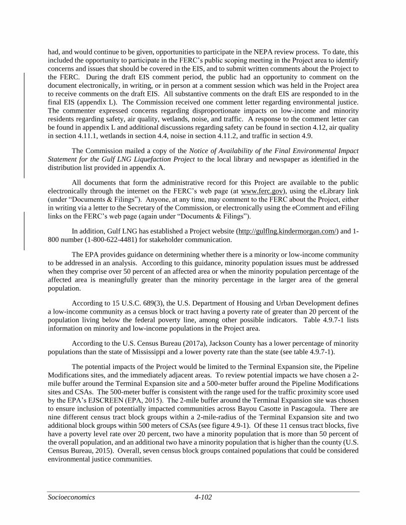
Socioeconomics 4-102
had, and would continue to be given, opportunities to participate in the NEPA review process. To date, this
included the opportunity to participate in the FERC’s public scoping meeting in the Project area to identify
concerns and issues that should be covered in the EIS, and to submit written comments about the Project to
the FERC. During the draft EIS comment period, the public had an opportunity to comment on the
document electronically, in writing, or in person at a comment session which was held in the Project area
to receive comments on the draft EIS. All substantive comments on the draft EIS are responded to in the
final EIS (appendix L). The Commission received one comment letter regarding environmental justice.
The commenter expressed concerns regarding disproportionate impacts on low-income and minority
residents regarding safety, air quality, wetlands, noise, and traffic. A response to the comment letter can
be found in appendix L and additional discussions regarding safety can be found in section 4.12, air quality
in section 4.11.1, wetlands in section 4.4, noise in section 4.11.2, and traffic in section 4.9.
The Commission mailed a copy of the Notice of Availability of the Final Environmental Impact
Statement for the Gulf LNG Liquefaction Project to the local library and newspaper as identified in the
distribution list provided in appendix A.
All documents that form the administrative record for this Project are available to the public
electronically through the internet on the FERC’s web page (at www.ferc.gov), using the eLibrary link
(under “Documents & Filings”). Anyone, at any time, may comment to the FERC about the Project, either
in writing via a letter to the Secretary of the Commission, or electronically using the eComment and eFiling
links on the FERC’s web page (again under “Documents & Filings”).
In addition, Gulf LNG has established a Project website (http://gulflng.kindermorgan.com/) and 1-
800 number (1-800-622-4481) for stakeholder communication.
The EPA provides guidance on determining whether there is a minority or low-income community
to be addressed in an analysis. According to this guidance, minority population issues must be addressed
when they comprise over 50 percent of an affected area or when the minority population percentage of the
affected area is meaningfully greater than the minority percentage in the larger area of the general
population.
According to 15 U.S.C. 689(3), the U.S. Department of Housing and Urban Development defines
a low-income community as a census block or tract having a poverty rate of greater than 20 percent of the
population living below the federal poverty line, among other possible indicators. Table 4.9.7-1 lists
information on minority and low-income populations in the Project area.
According to the U.S. Census Bureau (2017a), Jackson County has a lower percentage of minority
populations than the state of Mississippi and a lower poverty rate than the state (see table 4.9.7-1).
The potential impacts of the Project would be limited to the Terminal Expansion site, the Pipeline
Modifications sites, and the immediately adjacent areas. To review potential impacts we have chosen a 2-
mile buffer around the Terminal Expansion site and a 500-meter buffer around the Pipeline Modifications
sites and CSAs. The 500-meter buffer is consistent with the range used for the traffic proximity score used
by the EPA’s EJSCREEN (EPA, 2015). The 2-mile buffer around the Terminal Expansion site was chosen
to ensure inclusion of potentially impacted communities across Bayou Casotte in Pascagoula. There are
nine different census tract block groups within a 2-mile-radius of the Terminal Expansion site and two
additional block groups within 500 meters of CSAs (see figure 4.9-1). Of these 11 census tract blocks, five
have a poverty level rate over 20 percent, two have a minority population that is more than 50 percent of
the overall population, and an additional two have a minority population that is higher than the county (U.S.
Census Bureau, 2015). Overall, seven census block groups contained populations that could be considered
environmental justice communities.
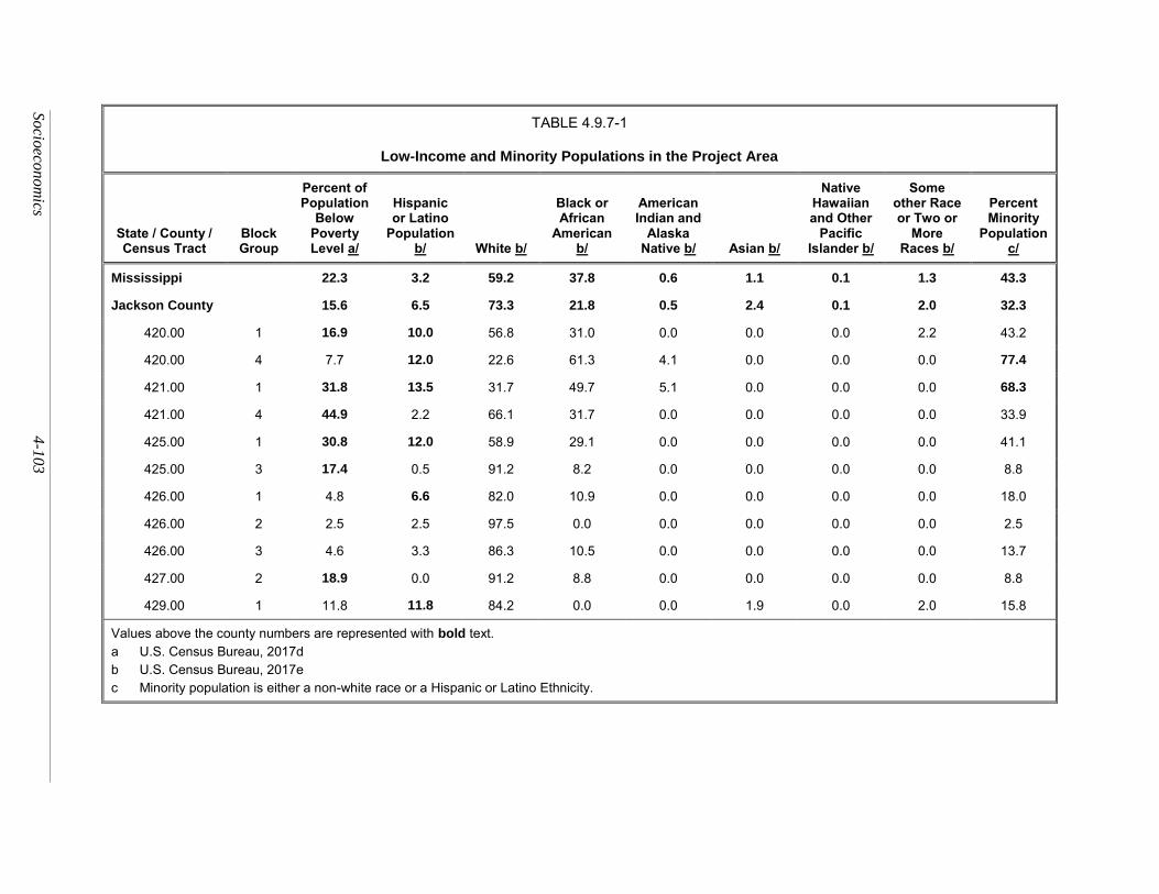
So
cioeco
nom
ics 4-1
03
TABLE 4.9.7-1
Low-Income and Minority Populations in the Project Area
State / County / Census Tract
Block Group
Percent of Population
Below Poverty Level a/
Hispanic or Latino
Population b/ White b/
Black or African
American b/
American Indian and
Alaska Native b/ Asian b/
Native Hawaiian and Other
Pacific Islander b/
Some other Race or Two or
More Races b/
Percent Minority
Population c/
Mississippi 22.3 3.2 59.2 37.8 0.6 1.1 0.1 1.3 43.3
Jackson County 15.6 6.5 73.3 21.8 0.5 2.4 0.1 2.0 32.3
420.00 1 16.9 10.0 56.8 31.0 0.0 0.0 0.0 2.2 43.2
420.00 4 7.7 12.0 22.6 61.3 4.1 0.0 0.0 0.0 77.4
421.00 1 31.8 13.5 31.7 49.7 5.1 0.0 0.0 0.0 68.3
421.00 4 44.9 2.2 66.1 31.7 0.0 0.0 0.0 0.0 33.9
425.00 1 30.8 12.0 58.9 29.1 0.0 0.0 0.0 0.0 41.1
425.00 3 17.4 0.5 91.2 8.2 0.0 0.0 0.0 0.0 8.8
426.00 1 4.8 6.6 82.0 10.9 0.0 0.0 0.0 0.0 18.0
426.00 2 2.5 2.5 97.5 0.0 0.0 0.0 0.0 0.0 2.5
426.00 3 4.6 3.3 86.3 10.5 0.0 0.0 0.0 0.0 13.7
427.00 2 18.9 0.0 91.2 8.8 0.0 0.0 0.0 0.0 8.8
429.00 1 11.8 11.8 84.2 0.0 0.0 1.9 0.0 2.0 15.8
Values above the county numbers are represented with bold text.
a U.S. Census Bureau, 2017d
b U.S. Census Bureau, 2017e
c Minority population is either a non-white race or a Hispanic or Latino Ethnicity.
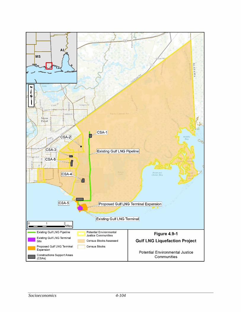
Socioeconomics 4-104
Figure 4.9-1 Potential Environmental Justice Communities
4-105 Socioeconomics
These communities have the potential to be impacted by excessive noise, dust, emissions from
construction equipment, or traffic during construction and they would potentially be impacted by noise,
emissions from the Terminal, or impaired viewsheds during operation. As described in section 4.11,
impacts from noise, dust, and emissions would be minor for the overall Project. In addition, there are no
residences within 4 miles of the proposed Terminal Expansion. Impacts on viewsheds are discussed in
detail in section 4.8.6. The view of the Terminal Expansion site would be similar to the existing site, and
we conclude that there would not be more than minor visual impacts due to construction and operation of
the modifications. Traffic impacts are discussed in detail in section 4.9.6. CSA-6 is located within a
potential EJ community. Traffic along the roads within the vicinity of CSA-6 could experience an increase
in traffic. However, Gulf LNG is proposing to mitigate traffic impacts at the Bayou Casotte Parkway and
Orchard Road Intersection by adding signage to clearly identify lane movements, adding raised pavement
markers within the intersection, and restriping the intersection. These measures would help improve the
functionality of the intersection and improve safety for drivers that are unfamiliar with driving in the area.
Additionally, the residents in the area of that intersection would likely use various other available routes to
access their neighborhoods and homes. Those populated areas are anticipated to experience minor traffic
impacts due to construction of the Project.
Although there are environmental justice communities within the study area, given the minor
impacts from the Project overall and the distance from the Terminal Expansion (the main Project
construction) to nearby residences, we conclude the Project would not have a disproportionately high and
adverse health or environmental effects on minority or low-income populations.
Cultural Resources 4-106
CULTURAL RESOURCES
Section 106 of the NHPA, as amended, requires the FERC to take into account the effect of its
undertakings on properties listed, or eligible for listing, in the NRHP and to afford the ACHP an opportunity
to comment on the undertaking. Gulf LNG, as a non-federal party, is assisting the FERC in meeting our
obligations under Section 106 and the implementing regulations in 36 CFR 800 by preparing the necessary
information, analyses, and recommendations, as authorized by 36 CFR 800.2(a)(3).
Construction and operation of the Project could affect historic properties (that is, cultural resources
listed in or eligible for listing in the NRHP). Historic properties include pre-contact or historic
archaeological sites, districts, buildings, structures, and objects, as well as locations with traditional value
to Native Americans or other groups. Such historic properties generally must possess integrity of location,
design, setting, materials, workmanship, feeling, and association, and must meet one or more of the criteria
specified in 36 CFR 60.4.
Terminal Expansion
The Area of Potential Effects (APE) is defined as the area within which direct Project effects could
result from ground disturbing activities and indirect Project effects could result from visual, auditory, or
atmospheric changes. Direct effects are typically long-term and adverse while indirect effects may be
temporary or short-term.
Gulf LNG completed a records review and a Phase I cultural resources survey of the Terminal
Expansion, including the administration building and the six CSAs: the Knight Yards 1 and 2 (CSA-1 and
CSA-2), Louise Street (CSA-3), Port Property (CSA-4), Chevron Property (CSA-5), and Bosarge Property
(CSA-6). The investigations included archaeological and architectural resources. The record review did
not identify any known archaeological or architectural resources within the areas surveyed.
The cultural resources surveys for the Terminal Expansion site, the administrative building, and
five of the six CSAs employed pedestrian surface inspection, systematic subsurface shovel testing, and
photo documentation. CSA-5 had been previously surveyed in 2005, the findings of which were adopted
for this Project and it was not resurveyed. Shovel testing was conducted for the remaining CSAs in all
areas unless impeded by existing modern buildings, underground utilities, pavement, or standing water. No
cultural materials or evidence of intact cultural soils were identified during the investigation.
Gulf LNG provided the SHPO with final footprints of the proposed supply docks in a letter dated
October 21, 2014. In a letter dated November 12, 2014, the SHPO determined that no cultural resources
surveys would be required for the proposed supply docks.
No cultural resources were identified within the Terminal Expansion site, administrative buildings,
or five of the CSAs, and no additional fieldwork was recommended (Cropley et al., 2014). Gulf LNG
submitted the draft Phase I cultural resources survey report on the investigations to the Mississippi SHPO
on October 31, 2014 and the final Phase I cultural resources survey report on November 28, 2014. In a
letter dated November 20, 2014 and an email dated March 20, 2015, the SHPO concurred that no properties
listed in or eligible for listing in the NRHP would be affected by the Project. We also concur.
CSA-6 and an ATWS adjacent to the Gulfstream Meter Station were surveyed subsequent to the
submission of the final Phase I cultural resources survey report. The results of the CSA-6 survey were
provided in a draft addendum to Phase I cultural resources survey report on April 30, 2015 (Hale and
Eberwine, 2015). No properties listed in or eligible for listing in the NRHP were identified during the
survey and as such, no historic properties would be affected by the Project. SHPO concurred with this
4-107 Cultural Resources
finding in a letter dated June 1, 2015. We also concur. The results of the ATWS survey are discussed
below.
In a letter dated June 4, 2015, Gulf LNG requested a SHPO determination on the necessity of a
cultural resources survey for the wetland mitigation site. In a letter dated July 6, 2016, SHPO determined
that no cultural resources were likely to be affected by the undertaking in the wetland mitigation site and
they had no objections with the proposed undertaking. We also concur.
Pipeline Modifications
Gulf LNG completed a records review and a Phase I cultural resources survey of the Pipeline
Modifications areas at the existing Destin Meter Station, the existing Gulfstream Meter Station, and the
existing Transco/FGT Interconnection. The investigations included archaeological and architectural
resources. The records review did not identify any known archaeological or architectural resources within
the areas investigated.
Gulf LNG completed cultural resources surveys, which examined a total of 3.6 acres for the three
sites. The surveys consisted of pedestrian surface inspection and photo documentation. No shovel testing
was conducted in these areas due to underground utilities and the presence of gravel. All areas where
subsurface disturbance would occur were previously disturbed by construction activities of the existing
facilities (not associated with the Project).
No cultural resources were identified within the Pipeline Modifications survey area and no
additional fieldwork was recommended. Gulf LNG submitted the results of the investigation to the SHPO
on October 31, 2014 as a draft Phase I cultural resources survey report (Cropley et al., 2014). In a letter
dated November 20, 2014, the SHPO concurred with this recommendation. We also concur.
An ATWS adjacent to the Gulfstream Meter Station was surveyed subsequent to the submission of
the final cultural resources survey report. The results of the ATWS survey was provided in a draft
addendum to Phase I cultural resources survey report on April 30, 2015, which also documented the survey
of CSA-6 (Hale and Eberwine, 2015). No properties listed in or eligible for listing in the NRHP were
identified during the survey and as such, no historic properties would be affected by the Project. SHPO
concurred with this finding in a letter dated June 1, 2015. We also concur.
Consultation
The FERC staff consulted with the SHPO and federally recognized Indian tribes (tribes) regarding
Project effects to cultural resources.
On July 31, 2014, the FERC sent copies of the NOI for the Project to a wide range of stakeholders,
including the ACHP, the Bureau of Indian Affairs, the SHPO, and tribes that may have an interest in the
Project and the area in the vicinity of the Project. The NOI contained a paragraph about Section 106 of the
NHPA, stated that the notice is used to initiate consultations with the SHPO, and solicited the views
government agencies, interested tribes, and the public on the Project’s potential effects on historic
properties.
On October 10, 2014, the FERC staff sent letters to the following eight tribes, inviting their
participation in the review of the Project: the Alabama-Coushatta Tribe of Texas, the Caddo Nation, the
Chitimacha Tribe of Louisiana, the Coushatta Tribe of Louisiana, the Jena Band of Choctaw Indians, the
Mississippi Band of Choctaw Indians, the Choctaw Nation of Oklahoma, and the Tunica-Biloxi Indians of
Louisiana. The FERC letter also requested their assistance in identifying properties of traditional, religious,
or cultural importance. No responses have been received to date.
Cultural Resources 4-108
In addition to the FERC’s notification process, Gulf LNG contacted the SHPO and tribes that might
attach cultural or religious significance to cultural resources in the vicinity of the Project. On May 21,
2014, Gulf LNG sent letters to two tribes requesting cultural resources consultation: the Eastern Band of
Cherokee and the Mississippi Band of Choctaw Indians. On October 21, 2014, additional letters were sent
to these tribes to identify changes to the Project footprint. No responses have been received to date.
Unanticipated Discoveries and Emergency Procedures Plan
Gulf LNG prepared an Unanticipated Discoveries and Emergency Procedures Plan that would be
implemented in the event that cultural resources, burials, and/or human remains are encountered during
construction. The plan was submitted to the SHPO as an appendix to the draft and final Phase I cultural
resources reports for the Project (Cropley et al., 2014). The SHPO confirmed via email (dated December
23, 2014) that the plan was sufficient. On December 6, 2018 the SHPO recommended revisions to the
Unanticipated Discoveries and Emergency Procedures Plan to expand the list of federally recognized
Native American tribes and include notification to the tribes of any unanticipated cultural resources. Gulf
LNG provided a revised Unanticipated Discoveries and Emergency Procedures Plan on February 11, 2019
(see appendix F). We have reviewed the revised plan and find it acceptable.
Compliance with the National Historic Preservation Act
Cultural resource investigations and surveys have been completed for the Terminal Expansion,
including the administration building and the six CSAs, and Pipeline Modifications, including an ATWS
adjacent to the Gulfstream Meter Station. A cultural resources survey is not necessary for the wetland
mitigation site. Therefore, based on the information provided by Gulf LNG and consultations with the
SHPO and Native American Tribes, we have determined that no historic properties would be affected by
the Project as proposed.
4-109 Air Quality and Noise
AIR QUALITY AND NOISE
Air Quality
Air quality would be affected by construction and operation of the proposed facilities. This section
summarizes federal and state air quality regulations that are applicable to the proposed facilities. The
section also characterizes the existing air quality and describes potential impacts the facilities may have on
air quality regionally and locally. The term air quality refers to relative concentrations of pollutants in the
ambient air. The subsections below describe well-established concepts that are applied to characterize air
quality and to determine the significance of increases in air pollution. This includes metrics for specific air
pollutants known as criteria pollutants referred to as National Ambient Air Quality Standards (NAAQS);
regional designations to manage air quality known as Air Quality Control Regions (AQCRs); and efforts
to monitor ambient air concentrations.
Combustion of natural gas would produce criteria air pollutants such as ozone (O3), carbon
monoxide (CO), nitrogen dioxide (NO2), SO2, and inhalable particulate matter (PM [PM2.5 and PM10]).
PM2.5 includes particles with an aerodynamic diameter less than or equal to 2.5 micrometers, and PM10
includes particles with an aerodynamic diameter less than or equal to 10 micrometers. Combustion of fossil
fuels also produces volatile organic compounds (VOC), a large group of organic chemicals that have a high
vapor pressure at room temperature; and NOx. VOCs react with NOx, typically on warm summer days, to
form O3. Other byproducts of combustion are GHGs and hazardous air pollutants (HAPs). HAPs are
chemicals known to cause cancer and other serious health impacts.
GHGs produced by fossil fuel combustion are carbon dioxide (CO2), methane (CH4), and nitrous
oxide (N2O). The status of GHG as a pollutant is not related to toxicity. GHGs are non-toxic and non-
hazardous at normal ambient concentrations. Increased levels of all GHGs since the industrial age are the
primary cause of warming of the global climate system since the 1950s. Emissions of the GHGs are
typically expressed in terms of CO2e.
Other pollutants, not produced by combustion, are fugitive dust and fugitive emissions. Fugitive
dust is a mix of PM2.5, PM10, and larger particles thrown up by vehicles, earth movement, or wind erosion.
Fugitive emissions, in the context of this EIS, would be fugitive emissions of CH4 (which is a specific VOC
and GHG) from operational pipelines, tanks, and aboveground facilities.
Temporary air emissions would be generated during Project construction, and long-term air
emissions would be generated during operation. Construction and operational air emissions as well as
proposed mitigation measures are discussed in sections 4.11.1.4 and 4.11.1.5.
Regional Climate
Mississippi has a humid subtropical climate. Although the potential exists for drought and flood,
rainfall is typically spread out consistently over the year. The winters are temperate, and the summers long
and hot. Winds are generally southerly, and provide high humidity during the summer season.
Thunderstorms occur on an average of 60 days per year (Mississippi State Climatologist, 2014).
Based on 1981 to 2010 climate data from the National Climatic Data Center (NCDC), temperatures
at the Pascagoula 3 NE meteorological station usually range from a monthly minimum average of 49.4 °F
in January to a maximum average of 80.8 °F in August. Mean annual precipitation is 65.0 inches, while
monthly average precipitation ranges from a minimum of 4.2 inches in October to a maximum of 7.3 inches
in August. The average annual snowfall is 0.0 inches (NCDC, 2010).
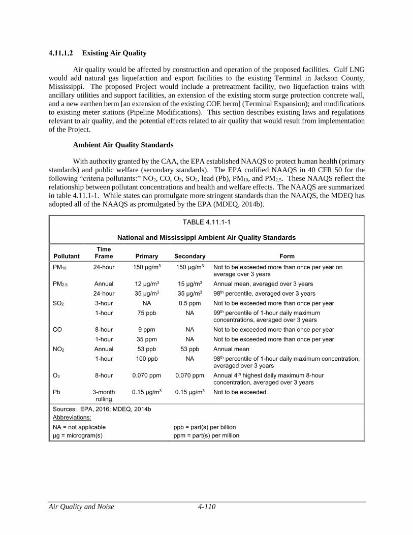
Air Quality and Noise 4-110
Existing Air Quality
Air quality would be affected by construction and operation of the proposed facilities. Gulf LNG
would add natural gas liquefaction and export facilities to the existing Terminal in Jackson County,
Mississippi. The proposed Project would include a pretreatment facility, two liquefaction trains with
ancillary utilities and support facilities, an extension of the existing storm surge protection concrete wall,
and a new earthen berm [an extension of the existing COE berm] (Terminal Expansion); and modifications
to existing meter stations (Pipeline Modifications). This section describes existing laws and regulations
relevant to air quality, and the potential effects related to air quality that would result from implementation
of the Project.
Ambient Air Quality Standards
With authority granted by the CAA, the EPA established NAAQS to protect human health (primary
standards) and public welfare (secondary standards). The EPA codified NAAQS in 40 CFR 50 for the
following “criteria pollutants:” NO2, CO, O3, SO2, lead (Pb), PM10, and PM2.5. These NAAQS reflect the
relationship between pollutant concentrations and health and welfare effects. The NAAQS are summarized
in table 4.11.1-1. While states can promulgate more stringent standards than the NAAQS, the MDEQ has
adopted all of the NAAQS as promulgated by the EPA (MDEQ, 2014b).
TABLE 4.11.1-1
National and Mississippi Ambient Air Quality Standards
Pollutant Time
Frame Primary Secondary Form
PM10 24-hour 150 μg/m3 150 μg/m3 Not to be exceeded more than once per year on average over 3 years
PM2.5 Annual 12 μg/m3 15 μg/m3 Annual mean, averaged over 3 years
24-hour 35 μg/m3 35 μg/m3 98th percentile, averaged over 3 years
SO2 3-hour NA 0.5 ppm Not to be exceeded more than once per year
1-hour 75 ppb NA 99th percentile of 1-hour daily maximum concentrations, averaged over 3 years
CO 8-hour 9 ppm NA Not to be exceeded more than once per year
1-hour 35 ppm NA Not to be exceeded more than once per year
NO2 Annual 53 ppb 53 ppb Annual mean
1-hour 100 ppb NA 98th percentile of 1-hour daily maximum concentration, averaged over 3 years
O3 8-hour 0.070 ppm 0.070 ppm Annual 4th highest daily maximum 8-hour concentration, averaged over 3 years
Pb 3-month rolling
0.15 μg/m3 0.15 μg/m3 Not to be exceeded
Sources: EPA, 2016; MDEQ, 2014b
Abbreviations:
NA = not applicable
μg = microgram(s)
ppb = part(s) per billion
ppm = part(s) per million
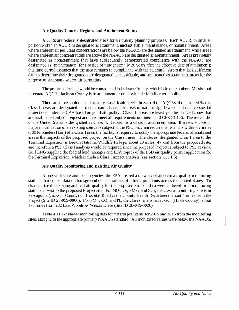
4-111 Air Quality and Noise
Air Quality Control Regions and Attainment Status
AQCRs are federally designated areas for air quality planning purposes. Each AQCR, or smaller
portion within an AQCR, is designated as attainment, unclassifiable, maintenance, or nonattainment. Areas
where ambient air pollutant concentrations are below the NAAQS are designated as attainment, while areas
where ambient air concentrations are above the NAAQS are designated as nonattainment. Areas previously
designated as nonattainment that have subsequently demonstrated compliance with the NAAQS are
designated as “maintenance” for a period of time (normally 20 years after the effective date of attainment);
this time period assumes that the area remains in compliance with the standard. Areas that lack sufficient
data to determine their designation are designated unclassifiable, and are treated as attainment areas for the
purpose of stationary source air permitting.
The proposed Project would be constructed in Jackson County, which is in the Southern Mississippi
Interstate AQCR. Jackson County is in attainment or unclassifiable for all criteria pollutants.
There are three attainment air quality classifications within each of the AQCRs of the United States.
Class I areas are designated as pristine natural areas or areas of natural significance and receive special
protections under the CAA based on good air quality. Class III areas are heavily-industrialized zones that
are established only on request and must meet all requirements outlined in 40 CFR 51.166. The remainder
of the United States is designated as Class II. Jackson is a Class II attainment area. If a new source or
major modification of an existing source is subject to the PSD program requirements and is within 62 miles
(100 kilometers [km]) of a Class I area, the facility is required to notify the appropriate federal officials and
assess the impacts of the proposed project on the Class I area. The closest designated Class I area to the
Terminal Expansion is Breton National Wildlife Refuge, about 29 miles (47 km) from the proposed site,
and therefore a PSD Class I analysis would be required since the proposed Project is subject to PSD review.
Gulf LNG supplied the federal land manager and EPA copies of the PSD air quality permit application for
the Terminal Expansion, which include a Class I impact analysis (see section 4.11.1.5).
Air Quality Monitoring and Existing Air Quality
Along with state and local agencies, the EPA created a network of ambient air quality monitoring
stations that collect data on background concentrations of criteria pollutants across the United States. To
characterize the existing ambient air quality for the proposed Project, data were gathered from monitoring
stations closest to the proposed Project site. For NO2, O3, PM2.5, and SO2, the closest monitoring site is in
Pascagoula (Jackson County) on Hospital Road at the County Health Department, about 4 miles from the
Project (Site ID 28-059-0006). For PM10, CO, and Pb, the closest site is in Jackson (Hinds County), about
170 miles from 232 East Woodrow Wilson Drive (Site ID 28-049-0020).
Table 4.11.1-2 shows monitoring data for criteria pollutants for 2015 and 2016 from the monitoring
sites, along with the appropriate primary NAAQS standard. All monitored values were below the NAAQS.
Air Quality and Noise 4-112
TABLE 4.11.1-2
Baseline Ambient Air Quality and Ambient Air Quality Standards
Pollutant Averaging
Period Description of Monitored
Value 2015 2016 Primary NAAQS
PM10 24-hour 2nd high 48 μg/m3 49 μg/m3 150 μg/m3
PM2.5 Annual Arithmetic mean 9.0 μg/m3 7.8 μg/m3 12 μg/m3
24-hour 98th percentile 19 μg/m3 14 μg/m3 35 μg/m3
SO2 1-hour 99th percentile 24 ppb 6 ppb 75 ppb
CO 8-hour 2nd high 1.5 ppm 1.2 ppm 9 ppm
1-hour 2nd high 1.8 ppm 1.8 ppm 35 ppm
NO2 Annual Arithmetic mean 4 ppb 4 ppb 53 ppb
1-hour 98th percentile 30 ppb 28 ppb 100 ppb
O3 8-hour 4th high 0.065 ppm 0.062 ppm 0.070 ppm
Pb 3-month rolling 1st high 0.01 μg/m3 0 μg/m3 0.15 μg/m3
Source: EPA, 2017b
Emissions from the Existing Terminal
Table 4.11.1-3 lists potential-to-emit (PTE) from the existing Terminal as previously permitted
under State of Mississippi Air Pollution Control Permit No. 1280-00132. The table also includes fugitive
emissions of VOCs (due to component leaks and diesel storage tanks).
TABLE 4.11.1-3
Potential-to-Emit for the Existing Terminal
Emission Unit (Quantity)
Annual Pollutant Emissions (tpy)
NOX CO SO2 PM10/ PM2.5 VOCs H2SO4 HAPs GHGs
Stationary Source Emissions
LNG Vaporizers (10) 163.3 131.0 2.4 7.6 42.0 0.2 12.0 489,930
Vent Stack Heater 5.1 4.3 0.03 0.4 0.3 0.00 0.8 6,201
Generator Turbines 14.2 17.2 0.4 0.9 0.1 0.04 1.9 16,662
Essential Diesel Generator 11.7 2.5 0.8 0.8 1.0 0.06 0.02 269
Backup Fire Water Pump 51 9.5 2.0 0.6 0.7 0.8 0.05 0.01 252
Backup Fire Water Pump 53 10.3 2.2 0.7 0.7 0.8 0.05 0.01 240
Backup Air Compressor 4.7 1.0 0.3 0.3 0.4 0.02 0.01 99
Stationary Source Subtotal
219 161 5.3 11 45 0.4 15 513,650
Fugitive Source Emissions
Component Leaks 0.0 0.0 0.0 0.0 12.0 0.0 0.0 0.0
TOTAL 219 161 5.3 11 57 0.4 15 513,650
Sources: EPA, 1995; MDEQ, 2006
Abbreviations:
H2SO4 = sulfuric acid mist
4-113 Air Quality and Noise
Regulatory Requirements for Air Quality
Terminal Expansion
Federal Air Quality Requirements
New Source Review/Prevention of Significant Deterioration. Federal pre-construction review
of certain large proposed projects varies for attainment and nonattainment areas. Federal pre-construction
review for sources in nonattainment areas is referred to as Nonattainment New Source Review (NNSR),
while federal pre-construction review for sources in attainment areas is formally referred to as PSD. The
review process aids in preventing new sources and modifications to existing systems from causing existing
air quality to deteriorate beyond acceptable levels.
A source is classified as PSD major if it has the PTE more than 100 tpy of a pollutant regulated
under the CAA and it is listed in one of the 28 named source categories in Section 169 of the CAA, or if it
has the PTE more than 250 tpy and is not listed in one of the 28 named source categories in Section 169 of
the CAA. The existing Terminal is considered a minor source with respect to PSD because it does not fall
under a listed source category, and has the PTE less than 250 tpy of a pollutant regulated under the CAA.
A modification to the Terminal would be subject to PSD if the modification itself resulted in an emission
increase above any PSD major threshold. PSD major thresholds23 are listed below.
For regulated pollutants other than GHGs, the modification is subject to PSD review if it
causes an increase of more than 100 tpy (if classified in one of the 28 named source
categories listed in Section 169 of the CAA) of the regulated air pollutant, or 250 tpy of the
regulated air pollutant for any other type of source.
For a modification subject to PSD review for one regulated pollutant, the source is also
subject to PSD review for all other pollutants causing a significant increase in emissions level
as defined in 40 CFR 52.21 (i.e., SO2/VOC/NOx increase of 40 tpy, CO increase of 100 tpy,
PM increase of 25 tpy, PM10 increase of 15 tpy, PM2.5 increase of 10 tpy, hydrogen sulfide
[H2S] increase of 10 tpy, sulfuric acid mist [H2SO4] increase of 7 tpy, or GHG increase of
75,000 tpy in terms of CO2e).
Table 4.11.1-4 summarizes the PTE due to the addition of new equipment that would be used for
the Terminal Expansion. Emissions from the Terminal Expansion itself are above the PSD major source
thresholds for NOx and CO. For a source subject to PSD review for one regulated pollutant, the source is
also subject to PSD review for all other pollutants causing a significant increase in emissions level.
Emissions of SO2, PM10/PM2.5, VOCs, sulfuric acid mist, and GHGs are above significant increase
thresholds, therefore, the Terminal Expansion would be subject to PSD review for NOx, CO, SO2,
PM10/PM2.5, VOCs, sulfuric acid mist, and GHGs.
Gulf LNG submitted a PSD air quality permit application for the Terminal Expansion in May 2015,
with revisions in June 2015 and December 2016. In July 2018, Gulf LNG provided written responses to
the MDEQ’s questions regarding Gulf LNG’s PSD application. Permit issuance is pending with the
MDEQ.
23 This summary reflects July 24, 2014 EPA Guidance indicating that the EPA will no longer treat GHGs as an air pollutant for
purposes of determining whether a source is a major source required to obtain a PSD or Title V permit (EPA, 2014b). The
MDEQ incorporates federal PSD rules into Mississippi regulations.
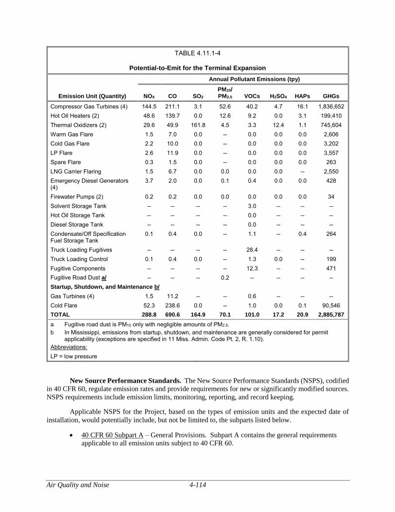
Air Quality and Noise 4-114
TABLE 4.11.1-4
Potential-to-Emit for the Terminal Expansion
Emission Unit (Quantity)
Annual Pollutant Emissions (tpy)
NOX CO SO2 PM10/ PM2.5 VOCs H2SO4 HAPs GHGs
Compressor Gas Turbines (4) 144.5 211.1 3.1 52.6 40.2 4.7 16.1 1,836,652
Hot Oil Heaters (2) 48.6 139.7 0.0 12.6 9.2 0.0 3.1 199,410
Thermal Oxidizers (2) 29.6 49.9 161.8 4.5 3.3 12.4 1.1 745,604
Warm Gas Flare 1.5 7.0 0.0 -- 0.0 0.0 0.0 2,606
Cold Gas Flare 2.2 10.0 0.0 -- 0.0 0.0 0.0 3,202
LP Flare 2.6 11.9 0.0 -- 0.0 0.0 0.0 3,557
Spare Flare 0.3 1.5 0.0 -- 0.0 0.0 0.0 263
LNG Carrier Flaring 1.5 6.7 0.0 0.0 0.0 0.0 -- 2,550
Emergency Diesel Generators (4)
3.7 2.0 0.0 0.1 0.4 0.0 0.0 428
Firewater Pumps (2) 0.2 0.2 0.0 0.0 0.0 0.0 0.0 34
Solvent Storage Tank -- -- -- -- 3.0 -- -- --
Hot Oil Storage Tank -- -- -- -- 0.0 -- -- --
Diesel Storage Tank -- -- -- -- 0.0 -- -- --
Condensate/Off Specification Fuel Storage Tank
0.1 0.4 0.0 -- 1.1 -- 0.4 264
Truck Loading Fugitives -- -- -- -- 28.4 -- -- --
Truck Loading Control 0.1 0.4 0.0 -- 1.3 0.0 -- 199
Fugitive Components -- -- -- -- 12.3 -- -- 471
Fugitive Road Dust a/ -- -- -- 0.2 -- -- -- --
Startup, Shutdown, and Maintenance b/
Gas Turbines (4) 1.5 11.2 -- -- 0.6 -- -- --
Cold Flare 52.3 238.6 0.0 -- 1.0 0.0 0.1 90,546
TOTAL 288.8 690.6 164.9 70.1 101.0 17.2 20.9 2,885,787
a Fugitive road dust is PM10 only with negligible amounts of PM2.5.
b In Mississippi, emissions from startup, shutdown, and maintenance are generally considered for permit applicability (exceptions are specified in 11 Miss. Admin. Code Pt. 2, R. 1.10).
Abbreviations:
LP = low pressure
New Source Performance Standards. The New Source Performance Standards (NSPS), codified
in 40 CFR 60, regulate emission rates and provide requirements for new or significantly modified sources.
NSPS requirements include emission limits, monitoring, reporting, and record keeping.
Applicable NSPS for the Project, based on the types of emission units and the expected date of
installation, would potentially include, but not be limited to, the subparts listed below.
40 CFR 60 Subpart A – General Provisions. Subpart A contains the general requirements
applicable to all emission units subject to 40 CFR 60.
4-115 Air Quality and Noise
40 CFR 60 Subpart Db – Standards of Performance for Industrial-Commercial-Institutional
Steam Generating Units. Subpart Db applies to each steam generating unit for which
construction, modification, or reconstruction is commenced after June 19, 1984 and has a
maximum design heat input capacity of greater than 29 MW (100 MMBtu/hr [million British
thermal units per hour]). Gulf LNG would operate the hot oil heaters at the Terminal
Expansion in compliance with Subpart Db.
40 CFR Subpart Kb – Standards of Performance for Volatile Organic Liquid Storage Vessels
(including Petroleum Liquid Storage Vessels). This subpart applies to each storage vessel
with a capacity greater than or equal to 75 m3 that is used to store volatile organic liquids for
which construction, reconstruction, or modification is commenced after July 23, 1984. This
subpart does not apply to storage vessels with a capacity greater than or equal to 151 m3
storing a liquid with a maximum true vapor pressure less than 3.5 kilopascals (kPa) or with a
capacity greater than or equal to 75 m3 but less than 151 m3 storing a liquid with a maximum
true vapor pressure less than 15.0 kPa. This subpart sets standards for VOC emissions
reduction. This subpart applies to the condensate/off specification fuel storage tank at the
Terminal Expansion. Gulf LNG would comply with all applicable Subpart Kb standards and
requirements for monitoring, recordkeeping, and reporting.
40 CFR Subpart IIII – Standards of Performance for Stationary Compression Ignition (CI)
Internal Combustion Engines (ICE). Subpart IIII applies to owners and operators of
stationary CI ICE as described in the subpart. This subpart sets emission standards for NOx
plus non-methane hydrocarbons, CO, and PM. This subpart applies to the four emergency
generators and two emergency firewater pumps at the Terminal Expansion. Gulf LNG would
comply with all applicable Subpart IIII standards and requirements for monitoring,
recordkeeping, and reporting.
40 CFR Subpart KKKK – Standards of Performance for Stationary Combustion Turbines.
This subpart applies to stationary combustion turbines that commenced construction,
modification, or reconstruction after February 18, 2005 and have a heat input at peak load
equal to or greater than 10.7 gigajoules per hour (10 MMBtu/hr). The proposed compressor
gas turbines would be subject to NSPS Subpart KKKK as their fuel heat input ratings would
exceed 10 MMBtu/hr, and their manufacturing date would be after February 18, 2005.
Subpart KKKK regulates emissions of NOx and SO2. The turbines would be subject to a NOx
emission limit of 25 parts per million (ppm) at 15 percent oxygen. Gulf LNG would comply
with the fuel sulfur requirements by using fuel with sulfur content at or below 0.060 pound of
SO2 per MMBtu. Gulf LNG would comply with all applicable Subpart KKKK standards and
requirements for monitoring, recordkeeping, and reporting.
National Emissions Standards for Hazardous Air Pollutants. The National Emissions
Standards for Hazardous Air Pollutants (NESHAPs), codified in 40 CFR 61 and 63, regulate the emissions
of HAPs from new and existing sources. Part 61, promulgated before the 1990 CAA Amendments,
regulates eight hazardous substances: asbestos, benzene, beryllium, coke oven emissions, inorganic
arsenic, mercury, radionuclides, and vinyl chloride.
The 1990 CAA Amendments established a list of 189 HAPs, resulting in the promulgation of Part
63, also known as the Maximum Achievable Control Technology (MACT) standards. Part 63 regulates
HAPs from major sources of HAPs and specific source categories emitting HAPs. Some NESHAPs may
apply to non-major sources (area sources) of HAPs. Major source thresholds for NESHAPs are 10 tpy of
any single HAP or 25 tpy of total HAPs. Gulf LNG is a major source of HAPs because formaldehyde
emissions exceed 10 tpy.
Air Quality and Noise 4-116
Applicable NESHAPs for the Project, based on the types of emission units and the expected date
of installation, would potentially include, but not be limited to, the subparts listed below.
40 CFR 63 Subpart A – General Provisions. Subpart A contains the general requirements
applicable to all emission units subject to 40 CFR 63.
40 CFR 63 Subpart HHH – National Emission Standards for Hazardous Air Pollutants from
Natural Gas Transmission and Storage Facilities. Although this subpart applies to the
facility, there are no glycol dehydration units and thus no applicable requirements.
40 CFR 63 Subpart YYYY – National Emission Standards for Hazardous Air Pollutants for
Stationary Combustion Turbines. In 2004, the EPA stayed the effectiveness of the emission
and operating limitations for lean-premixed gas-fired and diffusion flame gas-fired turbines.
These turbines must only comply with the initial notification requirements at this time.
40 CFR 63 Subpart ZZZZ – National Emission Standards for Hazardous Air Pollutants
Reciprocating Internal Combustion Engines (RICE). Subpart ZZZZ applies to any existing,
new, or reconstructed stationary RICE located at a major or area source of HAP emissions.
For stationary RICE located at an area source of HAP emissions, a stationary RICE is
“existing” if construction or reconstruction of the stationary RICE commenced before June
12, 2006. A stationary RICE located at an area source of HAP emissions is “new” if
construction of the stationary RICE commenced on or after June 12, 2006. For area sources,
this subpart sets operating limitations and emission limitations for CO and formaldehyde, as
well as management practices and work practice standards. This subpart applies to the four
diesel emergency engines and two diesel firewater pumps at the Terminal Expansion. Gulf
LNG would comply with all applicable Subpart ZZZZ standards and requirements for
monitoring, recordkeeping, and reporting.
40 CFR 63 Subpart DDDDD – National Emission Standards for Hazardous Air Pollutants for
Major Sources: Industrial, Commercial, and Institutional Boilers and Process Heaters. This
subpart applies to major source of HAPs. This subpart applies to the hot oil heaters at the
Terminal Expansion. Gulf LNG would comply with all applicable Subpart DDDDD
standards and requirements for monitoring, recordkeeping, and reporting.
Title V Operating Permit. The required elements of Title V operating permit programs are
outlined in 40 CFR 70 and 40 CFR 71. Title V operating permits may be referred to as “Part 70” or
“Part 71” permits, or as Title V permits. A Title V permit should list all air pollution requirements that
apply to the source, including emissions limits and monitoring, record keeping, and reporting requirements.
Regulations also require that the permittee annually report the compliance status of its source with respect
to permit conditions to the corresponding regulatory agency.
A Title V major source, as defined in 40 CFR 70.2, is a source or group of stationary sources
(including new and existing sources) within a contiguous area and under common control, emitting or with
the PTE criteria pollutants or HAPs above the criteria pollutant threshold values. The Title V major source
threshold is 100 tpy for any of the criteria pollutants, 10 tpy for any single HAP, and 25 tpy for any
combination of HAPs. The existing Terminal is a major source with respect to Title V, and Gulf LNG
currently operates it under Title V Permit No. 1280-00132. The proposed Terminal Expansion would
require Gulf LNG to submit an application to revise the Title V permit. Gulf LNG submitted a consolidated
application for a permit to construct and operate the Terminal Expansion in May 2015, with revisions in
June 2015 and December 2016.
General Conformity. The General Conformity Rule was designed to require federal agencies to
ensure that federally-funded or federally-approved projects conform to the applicable State Implementation
4-117 Air Quality and Noise
Plan (SIP). Section 176(c) of the CAA prohibits federal actions in nonattainment or PSD maintenance
areas that do not conform to the SIP for the attainment and maintenance of NAAQS. General Conformity
regulations apply to project-wide direct and indirect emissions of pollutants (and all precursors) for which
the project areas are designated as nonattainment or maintenance that are not subject to NSR and that are
greater than the significance thresholds established in the General Conformity regulations or 10 percent of
the total emissions budget for the entire nonattainment or maintenance area. Federal agencies are able to
make a positive conformity determination for a proposed project if any of several criteria in the General
Conformity Rule are met. These criteria include:
emissions from the project that are specifically identified and accounted for in the SIP
attainment or maintenance demonstration; or
emissions from the action that are fully offset within the same area through a revision to the
SIP, or a similarly enforceable measure that creates emissions reductions so there is no net
increase in emissions of that pollutant.
The existing Terminal and the proposed Terminal Expansion would be entirely within an attainment
area and would be subject to PSD permitting, therefore is not subject to General Conformity.
GHG Reporting Rule. In September 2009, the EPA issued the final Mandatory Reporting of
Greenhouse Gases Rule, requiring reporting of GHG emissions from suppliers of fossil fuels and facilities
that emit greater than or equal to 25,000 metric tpy of GHG (reported as CO2e). In November 2010, the
EPA signed a rule finalizing GHG reporting requirements for the petroleum and natural gas industry in 40
CFR Part 98, Subpart W. The industry separates LNG storage facilities from LNG import and export
equipment because the former are considered part of the source category regulated by Subpart W. The rule
does not apply to construction emissions.
The new LNG facilities associated with the Terminal Expansion would potentially be subject to the
GHG Mandatory Reporting Rule. The rule establishes reporting requirements based on actual emissions;
however, it does not require emission controls. Gulf LNG would monitor emissions in accordance with the
reporting rule. If actual emissions exceed the 25,000 metric tpy CO2e reporting threshold, Gulf LNG would
be required to report its GHG emissions to the EPA. Gulf LNG has not reported GHG emissions for the
existing Terminal as actual emissions were below thresholds. Gulf LNG would estimate the actual GHG
emissions from the Project and report GHGs as necessary for the existing source and the proposed Project,
combined.
Applicable State Air Quality Requirements
The Terminal Expansion would be subject to state standards, codified in MDEQ Title 11 (MDEQ,
2015a; MDEQ, 2015b; MDEQ, 2015c). The regulations listed below would apply to the existing facility
as well as the new facilities associated with the Terminal Expansion, including governing turbines, flares,
generators, fire water pumps, and fugitive emissions.
11 Miss. Admin. Code Pt. 2, R. 1.3. Specific Criteria for Source of Particulate Matter.
11 Miss. Admin Code Pt. 2, R. 1.4. Specific Criteria for Source of Sulfur Compounds.
11 Miss. Admin Code Pt. 2, R. 1.6 and 1.8. New Sources and Provisions for Hazardous Air
Pollutants.
11 Miss. Admin Code Pt. 2, R. 1.9. Stack Height Considerations.
11 Miss. Admin Code Pt. 2. R. 1.10. Provisions for Upsets, Startups, and Shutdowns.
11 Miss. Admin. Code Pt. 2, R. 2.1.D. Permitting Requirements.
Air Quality and Noise 4-118
11 Miss. Admin Code Pt. 2, R. 2.2. General Standards Applicable to All Permits.
11 Miss. Admin Code Pt. 2, R. 2.3. Application for Permit to Construct and State Permit to
Operate New Stationary Source.
11 Miss. Admin Code Pt. 2, R. 2.5. Application Review.
11 Miss. Admin Code Pt. 2, R. 10. Emission Reduction Schedule.
11 Miss. Admin Code Pt. 2, Ch. 5. Administrative Procedures.
11 Miss. Admin Code Pt. 2, Ch. 6. Rules of Practice for Formal Evidentiary Hearings.
Gulf LNG would comply with all applicable state requirements.
Pipeline Modifications
Federal Air Quality Requirements
New Source Review/Prevention of Significant Deterioration. The Pipeline Modifications would
not cause any emissions during operations; therefore, it would not trigger any additional federal or state
NSR/PSD permitting requirements.
New Source Performance Standards/National Emissions Standards for Hazardous Air
Pollutants. The Pipeline Modifications would not include addition of any new equipment or cause any
new emissions during operation; therefore, it would not trigger NSPS/NESHAPs requirements.
Title V Operating Permit. The Pipeline Modifications would not cause any emissions during
operations; therefore, it would not trigger Title V permitting requirements.
General Conformity. The Pipeline Modifications would cause emissions during construction, but
it is in an attainment area; therefore, it would not trigger General Conformity requirements.
GHG Reporting Rule. The Pipeline Modifications would not cause any emissions during
operations; therefore, it would not trigger GHG reporting requirements.
Chemical Accident Prevention Provisions. The Pipeline Modifications would be regulated by
the DOT under 49 CFR 192 (Federal Safety Standards for Transportation of Natural and Other Gas by
Pipeline), and therefore, exempt from Chemical Accident Prevention Provisions by definition.
Applicable State Air Quality Requirements
The Pipeline Modifications would not cause any emissions during operations; therefore, it would
not trigger state air quality permitting requirements.
Construction Air Emissions Impacts and Mitigation
Terminal Expansion
Emissions during Terminal Expansion construction would generally be associated with onshore
construction activities conducted using on-road and off-road mobile equipment; and offshore construction
activities conducted using marine vessels such as tugboats or barges, and dredging.
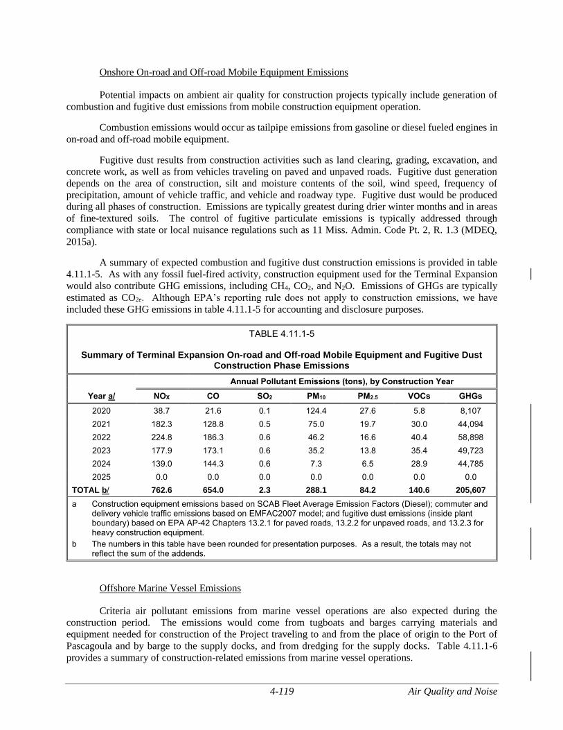
4-119 Air Quality and Noise
Onshore On-road and Off-road Mobile Equipment Emissions
Potential impacts on ambient air quality for construction projects typically include generation of
combustion and fugitive dust emissions from mobile construction equipment operation.
Combustion emissions would occur as tailpipe emissions from gasoline or diesel fueled engines in
on-road and off-road mobile equipment.
Fugitive dust results from construction activities such as land clearing, grading, excavation, and
concrete work, as well as from vehicles traveling on paved and unpaved roads. Fugitive dust generation
depends on the area of construction, silt and moisture contents of the soil, wind speed, frequency of
precipitation, amount of vehicle traffic, and vehicle and roadway type. Fugitive dust would be produced
during all phases of construction. Emissions are typically greatest during drier winter months and in areas
of fine-textured soils. The control of fugitive particulate emissions is typically addressed through
compliance with state or local nuisance regulations such as 11 Miss. Admin. Code Pt. 2, R. 1.3 (MDEQ,
2015a).
A summary of expected combustion and fugitive dust construction emissions is provided in table
4.11.1-5. As with any fossil fuel-fired activity, construction equipment used for the Terminal Expansion
would also contribute GHG emissions, including CH4, CO2, and N2O. Emissions of GHGs are typically
estimated as CO2e. Although EPA’s reporting rule does not apply to construction emissions, we have
included these GHG emissions in table 4.11.1-5 for accounting and disclosure purposes.
TABLE 4.11.1-5
Summary of Terminal Expansion On-road and Off-road Mobile Equipment and Fugitive Dust Construction Phase Emissions
Year a/
Annual Pollutant Emissions (tons), by Construction Year
NOX CO SO2 PM10 PM2.5 VOCs GHGs
2020 38.7 21.6 0.1 124.4 27.6 5.8 8,107
2021 182.3 128.8 0.5 75.0 19.7 30.0 44,094
2022 224.8 186.3 0.6 46.2 16.6 40.4 58,898
2023 177.9 173.1 0.6 35.2 13.8 35.4 49,723
2024 139.0 144.3 0.6 7.3 6.5 28.9 44,785
2025 0.0 0.0 0.0 0.0 0.0 0.0 0.0
TOTAL b/ 762.6 654.0 2.3 288.1 84.2 140.6 205,607
a Construction equipment emissions based on SCAB Fleet Average Emission Factors (Diesel); commuter and delivery vehicle traffic emissions based on EMFAC2007 model; and fugitive dust emissions (inside plant boundary) based on EPA AP-42 Chapters 13.2.1 for paved roads, 13.2.2 for unpaved roads, and 13.2.3 for heavy construction equipment.
b The numbers in this table have been rounded for presentation purposes. As a result, the totals may not reflect the sum of the addends.
Offshore Marine Vessel Emissions
Criteria air pollutant emissions from marine vessel operations are also expected during the
construction period. The emissions would come from tugboats and barges carrying materials and
equipment needed for construction of the Project traveling to and from the place of origin to the Port of
Pascagoula and by barge to the supply docks, and from dredging for the supply docks. Table 4.11.1-6
provides a summary of construction-related emissions from marine vessel operations.
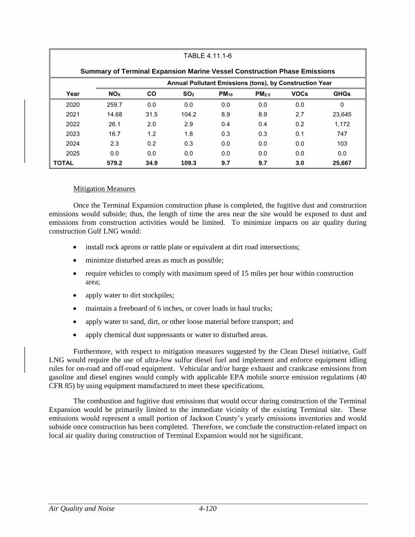
Air Quality and Noise 4-120
TABLE 4.11.1-6
Summary of Terminal Expansion Marine Vessel Construction Phase Emissions
Year
Annual Pollutant Emissions (tons), by Construction Year
NOX CO SO2 PM10 PM2.5 VOCs GHGs
2020 259.7 0.0 0.0 0.0 0.0 0.0 0
2021 14.68 31.5 104.2 8.9 8.9 2.7 23,645
2022 26.1 2.0 2.9 0.4 0.4 0.2 1,172
2023 16.7 1.2 1.8 0.3 0.3 0.1 747
2024 2.3 0.2 0.3 0.0 0.0 0.0 103
2025 0.0 0.0 0.0 0.0 0.0 0.0 0.0
TOTAL 579.2 34.9 109.3 9.7 9.7 3.0 25,667
Mitigation Measures
Once the Terminal Expansion construction phase is completed, the fugitive dust and construction
emissions would subside; thus, the length of time the area near the site would be exposed to dust and
emissions from construction activities would be limited. To minimize impacts on air quality during
construction Gulf LNG would:
install rock aprons or rattle plate or equivalent at dirt road intersections;
minimize disturbed areas as much as possible;
require vehicles to comply with maximum speed of 15 miles per hour within construction
area;
apply water to dirt stockpiles;
maintain a freeboard of 6 inches, or cover loads in haul trucks;
apply water to sand, dirt, or other loose material before transport; and
apply chemical dust suppressants or water to disturbed areas.
Furthermore, with respect to mitigation measures suggested by the Clean Diesel initiative, Gulf
LNG would require the use of ultra-low sulfur diesel fuel and implement and enforce equipment idling
rules for on-road and off-road equipment. Vehicular and/or barge exhaust and crankcase emissions from
gasoline and diesel engines would comply with applicable EPA mobile source emission regulations (40
CFR 85) by using equipment manufactured to meet these specifications.
The combustion and fugitive dust emissions that would occur during construction of the Terminal
Expansion would be primarily limited to the immediate vicinity of the existing Terminal site. These
emissions would represent a small portion of Jackson County’s yearly emissions inventories and would
subside once construction has been completed. Therefore, we conclude the construction-related impact on
local air quality during construction of Terminal Expansion would not be significant.
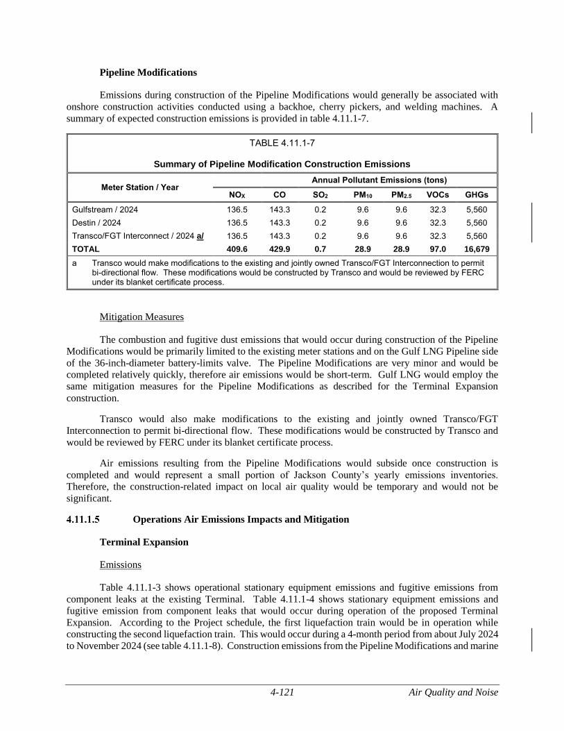
4-121 Air Quality and Noise
Pipeline Modifications
Emissions during construction of the Pipeline Modifications would generally be associated with
onshore construction activities conducted using a backhoe, cherry pickers, and welding machines. A
summary of expected construction emissions is provided in table 4.11.1-7.
TABLE 4.11.1-7
Summary of Pipeline Modification Construction Emissions
Meter Station / Year Annual Pollutant Emissions (tons)
NOX CO SO2 PM10 PM2.5 VOCs GHGs
Gulfstream / 2024 136.5 143.3 0.2 9.6 9.6 32.3 5,560
Destin / 2024 136.5 143.3 0.2 9.6 9.6 32.3 5,560
Transco/FGT Interconnect / 2024 a/ 136.5 143.3 0.2 9.6 9.6 32.3 5,560
TOTAL 409.6 429.9 0.7 28.9 28.9 97.0 16,679
a Transco would make modifications to the existing and jointly owned Transco/FGT Interconnection to permit bi-directional flow. These modifications would be constructed by Transco and would be reviewed by FERC under its blanket certificate process.
Mitigation Measures
The combustion and fugitive dust emissions that would occur during construction of the Pipeline
Modifications would be primarily limited to the existing meter stations and on the Gulf LNG Pipeline side
of the 36-inch-diameter battery-limits valve. The Pipeline Modifications are very minor and would be
completed relatively quickly, therefore air emissions would be short-term. Gulf LNG would employ the
same mitigation measures for the Pipeline Modifications as described for the Terminal Expansion
construction.
Transco would also make modifications to the existing and jointly owned Transco/FGT
Interconnection to permit bi-directional flow. These modifications would be constructed by Transco and
would be reviewed by FERC under its blanket certificate process.
Air emissions resulting from the Pipeline Modifications would subside once construction is
completed and would represent a small portion of Jackson County’s yearly emissions inventories.
Therefore, the construction-related impact on local air quality would be temporary and would not be
significant.
Operations Air Emissions Impacts and Mitigation
Terminal Expansion
Emissions
Table 4.11.1-3 shows operational stationary equipment emissions and fugitive emissions from
component leaks at the existing Terminal. Table 4.11.1-4 shows stationary equipment emissions and
fugitive emission from component leaks that would occur during operation of the proposed Terminal
Expansion. According to the Project schedule, the first liquefaction train would be in operation while
constructing the second liquefaction train. This would occur during a 4-month period from about July 2024
to November 2024 (see table 4.11.1-8). Construction emissions from the Pipeline Modifications and marine
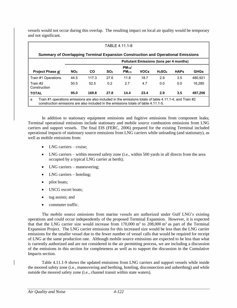
Air Quality and Noise 4-122
vessels would not occur during this overlap. The resulting impact on local air quality would be temporary
and not significant.
TABLE 4.11.1-8
Summary of Overlapping Terminal Expansion Construction and Operational Emissions
Project Phase a/
Pollutant Emissions (tons per 4 months)
NOX CO SO2 PM10/ PM2.5 VOCs H2SO4 HAPs GHGs
Train #1 Operations 44.5 117.3 27.6 11.8 18.7 2.9 3.5 480,921
Train #2 Construction
50.5 52.5 0.2 2.7 4.7 0.0 0.0 16,285
TOTAL 95.0 169.8 27.8 14.4 23.4 2.9 3.5 497,206
a Train #1 operations emissions are also included in the emissions totals of table 4.11.1-4, and Train #2 construction emissions are also included in the emissions totals of table 4.11.1-5.
In addition to stationary equipment emissions and fugitive emissions from component leaks;
Terminal operational emissions include stationary and mobile source combustion emissions from LNG
carriers and support vessels. The final EIS (FERC, 2006) prepared for the existing Terminal included
operational impacts of stationary source emissions from LNG carriers while unloading (and stationary), as
well as mobile emissions from:
LNG carriers – cruise;
LNG carriers – within moored safety zone (i.e., within 500 yards in all directs from the area
occupied by a typical LNG carrier at berth);
LNG carriers – maneuvering;
LNG carriers – hoteling;
pilot boats;
USCG escort boats;
tug assists; and
commuter traffic.
The mobile source emissions from marine vessels are authorized under Gulf LNG’s existing
operations and could occur independently of the proposed Terminal Expansion. However, it is expected
that that the LNG carrier size would increase from 170,000 m3 to 208,000 m3 as part of the Terminal
Expansion Project. The LNG carrier emissions for this increased size would be less than the LNG carrier
emissions for the smaller vessel due to the fewer number of vessel calls that would be required for receipt
of LNG at the same production rate. Although mobile source emissions are expected to be less than what
is currently authorized and are not considered in the air permitting process, we are including a discussion
of the emissions in this section for completeness as well as to support the discussion in the Cumulative
Impacts section.
Table 4.11.1-9 shows the updated emissions from LNG carriers and support vessels while inside
the moored safety zone (i.e., maneuvering and berthing, hoteling, disconnection and unberthing) and while
outside the moored safety zone (i.e., channel transit within state waters).
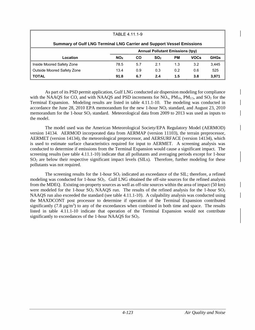
4-123 Air Quality and Noise
TABLE 4.11.1-9
Summary of Gulf LNG Terminal LNG Carrier and Support Vessel Emissions
Location
Annual Pollutant Emissions (tpy)
NOX CO SO2 PM VOCs GHGs
Inside Moored Safety Zone 78.5 5.7 2.1 1.3 3.2 3,445
Outside Moored Safety Zone 13.4 0.9 0.3 0.2 0.6 525
TOTAL 91.8 6.7 2.4 1.5 3.8 3,971
As part of its PSD permit application, Gulf LNG conducted air dispersion modeling for compliance
with the NAAQS for CO, and with NAAQS and PSD increments for NOx, PM10, PM2.5, and SO2 for the
Terminal Expansion. Modeling results are listed in table 4.11.1-10. The modeling was conducted in
accordance the June 28, 2010 EPA memorandum for the new 1-hour NO2 standard, and August 23, 2010
memorandum for the 1-hour SO2 standard. Meteorological data from 2009 to 2013 was used as inputs to
the model.
The model used was the American Meteorological Society/EPA Regulatory Model (AERMOD)
version 14134. AERMOD incorporated data from AERMAP (version 11103), the terrain preprocessor,
AERMET (version 14134), the meteorological preprocessor, and AERSURFACE (version 14134), which
is used to estimate surface characteristics required for input to AERMET. A screening analysis was
conducted to determine if emissions from the Terminal Expansion would cause a significant impact. The
screening results (see table 4.11.1-10) indicate that all pollutants and averaging periods except for 1-hour
SO2 are below their respective significant impact levels (SILs). Therefore, further modeling for these
pollutants was not required.
The screening results for the 1-hour SO2 indicated an exceedance of the SIL; therefore, a refined
modeling was conducted for 1-hour SO2. Gulf LNG obtained the off-site sources for the refined analysis
from the MDEQ. Existing on-property sources as well as off-site sources within the area of impact (50 km)
were modeled for the 1-hour SO2 NAAQS run. The results of the refined analysis for the 1-hour SO2
NAAQS run also exceeded the standard (see table 4.11.1-10). A culpability analysis was conducted using
the MAXDCONT post processor to determine if operation of the Terminal Expansion contributed
significantly (7.8 µg/m3) to any of the exceedances when combined in both time and space. The results
listed in table 4.11.1-10 indicate that operation of the Terminal Expansion would not contribute
significantly to exceedances of the 1-hour NAAQS for SO2.
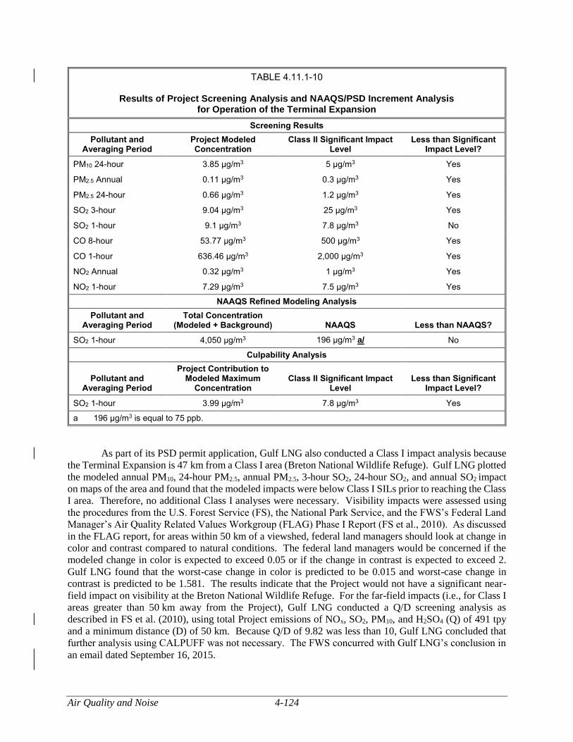
Air Quality and Noise 4-124
TABLE 4.11.1-10
Results of Project Screening Analysis and NAAQS/PSD Increment Analysis for Operation of the Terminal Expansion
Screening Results
Pollutant and Averaging Period
Project Modeled Concentration
Class II Significant Impact Level
Less than Significant Impact Level?
PM10 24-hour 3.85 μg/m3 5 μg/m3 Yes
PM2.5 Annual 0.11 μg/m3 0.3 μg/m3 Yes
PM2.5 24-hour 0.66 μg/m3 1.2 μg/m3 Yes
SO2 3-hour 9.04 μg/m3 25 μg/m3 Yes
SO2 1-hour 9.1 μg/m3 7.8 μg/m3 No
CO 8-hour 53.77 μg/m3 500 μg/m3 Yes
CO 1-hour 636.46 μg/m3 2,000 μg/m3 Yes
NO2 Annual 0.32 μg/m3 1 μg/m3 Yes
NO2 1-hour 7.29 μg/m3 7.5 μg/m3 Yes
NAAQS Refined Modeling Analysis
Pollutant and Averaging Period
Total Concentration (Modeled + Background) NAAQS Less than NAAQS?
SO2 1-hour 4,050 μg/m3 196 μg/m3 a/ No
Culpability Analysis
Pollutant and Averaging Period
Project Contribution to Modeled Maximum
Concentration Class II Significant Impact
Level Less than Significant
Impact Level?
SO2 1-hour 3.99 μg/m3 7.8 μg/m3 Yes
a 196 μg/m3 is equal to 75 ppb.
As part of its PSD permit application, Gulf LNG also conducted a Class I impact analysis because
the Terminal Expansion is 47 km from a Class I area (Breton National Wildlife Refuge). Gulf LNG plotted
the modeled annual PM10, 24-hour PM2.5, annual PM2.5, 3-hour SO2, 24-hour SO2, and annual SO2 impact
on maps of the area and found that the modeled impacts were below Class I SILs prior to reaching the Class
I area. Therefore, no additional Class I analyses were necessary. Visibility impacts were assessed using
the procedures from the U.S. Forest Service (FS), the National Park Service, and the FWS’s Federal Land
Manager’s Air Quality Related Values Workgroup (FLAG) Phase I Report (FS et al., 2010). As discussed
in the FLAG report, for areas within 50 km of a viewshed, federal land managers should look at change in
color and contrast compared to natural conditions. The federal land managers would be concerned if the
modeled change in color is expected to exceed 0.05 or if the change in contrast is expected to exceed 2.
Gulf LNG found that the worst-case change in color is predicted to be 0.015 and worst-case change in
contrast is predicted to be 1.581. The results indicate that the Project would not have a significant near-
field impact on visibility at the Breton National Wildlife Refuge. For the far-field impacts (i.e., for Class I
areas greater than 50 km away from the Project), Gulf LNG conducted a Q/D screening analysis as
described in FS et al. (2010), using total Project emissions of NOx, SO2, PM10, and H2SO4 (Q) of 491 tpy
and a minimum distance (D) of 50 km. Because Q/D of 9.82 was less than 10, Gulf LNG concluded that
further analysis using CALPUFF was not necessary. The FWS concurred with Gulf LNG’s conclusion in
an email dated September 16, 2015.
4-125 Air Quality and Noise
Gulf LNG reviewed the Terminal Expansion’s impact on the ozone NAAQS by calculating the
maximum percentage increase in NOx and VOC emissions (combined) and applying that increase to the 3-
year average ozone monitored values for 2013 through 2015, as measured at the Pascagoula monitor. The
highest-fourth high monitored values were 0.064, 0.075, and 0.065 ppm between 2013 and 2015
respectively for an average of 0.068 ppm. Gulf LNG calculated the percentage increase in NOx and VOC
emissions in Jackson County, George County, Harrison County, Mississippi; and Mobile County Alabama
(combined) to be 0.64 percent. A 0.64 percent increase to the 3-year average ozone monitored value is
0.0684 ppm, below the NAAQS of 0.070 ppm. Therefore, we conclude impacts on ozone from the
Terminal Expansion would not be significant.
We received a comment on the monitoring station locations used in modeling analysis. The
background monitoring data for NO2, PM2.5, and SO2 used in the model to determine Project impacts on the
NAAQS and increments was from a monitor in Pascagoula, about 4 miles from the Project. This site is
very close to the Project. Therefore, we conclude it would provide representative background data. Note
that, as Gulf LNG must obtain a PSD permit for this Project, the MDEQ will assess the representativeness
of the monitoring data under the PSD rules as part of the air quality permitting process. In addition, the
background data was only used to assess the 1-hour SO2 impacts, as all other pollutants and averaging
periods Project impacts were below the SIL.
Mitigation Measures
Gulf LNG would minimize potential impacts on air quality due to the operation of the Terminal
Expansion by adhering to applicable federal and state regulations (e.g., NSPS and NESHAPs) and installing
Best Available Control Technology (BACT) to minimize emissions. As presented in Gulf LNG’s PSD
permit application, the BACT analysis includes identification of all applicable control technologies based
on control effectiveness. The strictest controls are evaluated first and if those are technically or
economically infeasible, or if environmental effects are significant, then the next most stringent control
technology is reviewed. The process continues until the BACT level being considered cannot be eliminated
based on technical or economic considerations, energy or environmental impacts. BACT is required for
NOx, CO, SO2, PM10/PM2.5, VOC, sulfuric acid mist, and GHG emissions for the proposed equipment. Gulf
LNG proposes BACT as follows; however, the ultimate implementation of BACT will be made by the
MDEQ as part of the PSD permit.
BACT for Refrigeration Turbines. For NOx, Selective Catalytic Reduction and Dry Low NOx
burners are determined to be BACT for the turbines, in addition to the use of good combustion practices.
For CO and VOCs, oxidation catalyst is determined to be BACT, in addition to the use of good combustion
practices. For PM (encompassing both PM10 and PM2.5), good combustion practices and the use of natural
gas are determined as BACT. For SO2, use of low sulfur natural gas is determined as BACT. For GHG,
use of natural gas fuel, and good combustion practices are determined as BACT. For sulfuric acid mist,
treating streams to reduce sulfur content before combustion using a H2S removal unit is determined to be
BACT.
BACT for Hot Oil Heaters. For NOx, good combustion practices and ultra-low NOx burners are
determined as BACT. For CO and VOCs, good combustion practices are determined as BACT. For PM,
good combustion practices and the use of natural gas are determined as BACT. For SO2, the use of low
sulfur natural gas is determined as BACT. For GHGs, use of natural gas fuel and good combustion practices
are determined as BACT. For sulfuric acid mist, use of a H2S removal unit is determined to be BACT.
BACT for Thermal Oxidizers. Two thermal oxidizers would be installed to control VOCs and
H2S within the acid gas vent streams generated by the amine units. Good combustion practices are
determined as BACT for NOx and VOC emissions from the thermal oxidizers. For CO, VOCs, and PM,
good combustion practices and the use of natural gas are determined as BACT. For SO2 and sulfur acid
Air Quality and Noise 4-126
mist, the use of a H2S removal unit is determined as BACT. For GHGs, good combustion practices are
determined as BACT.
BACT for Flares. Good combustion practices and flaring minimization would minimize NOx,
CO, VOC, and GHG emissions and are determined as BACT. For PM, good combustion practices and
natural gas fuel is determined as BACT. For SO2, the use of low sulfur natural gas to limit maximum SO2
emissions is determined as BACT. Because all gases going to the flare would already be treated by an H2S
removal unit, no additional BACT is required for sulfur acid mist.
BACT for ICE. For NOx, CO, VOCs, PM, and GHGs, limited use, turbocharger and aftercooler,
and good operating practices are determined as BACT. For SO2, the use of ultra-low sulfur diesel, limited
use, and good combustion practices are determined as BACT. For sulfur acid mist, use of ultra-low sulfur
diesel is determined as BACT.
BACT from Storage Tanks. For the solvent tank and hot oil tank, VOC BACT is submerged fill
and a nitrogen blanket. For the diesel tank, VOC BACT is submerged fill and appropriate breather vent
settings. For the condensate tank, VOC BACT is submerged fill and vent to flare.
BACT for Truck Loading. VOC BACT is determined to be use of a flare (or equivalent device)
capable of achieving 98 percent destruction and removal efficiency to control vapors collected during truck
loading operations.
BACT for Fugitive Components. For VOCs and GHGs, BACT is determined to include the
development of a site-specific Leak Detection and Repair (LDAR) type program consisting of semiannual
Audio Visual and Olfactory (AVO) inspections.
Gulf LNG also proposes combustion turbine startup/shutdown work practices. The refrigeration
turbine startup would begin when fuel is introduced into the combustion turbine and would end when the
Selective Catalytic Reduction and Dry Low NOx burners systems are operating at normal destruction
efficiency. Turbine startup would not exceed 30 minutes. The refrigeration turbine shutdown would begin
when the initiation of a shutdown sequence results in the combustion turbine dropping below 75 percent
power and would be complete when fuel is terminated to the turbine. Turbine shutdown would not exceed
30 minutes.
Furthermore, Gulf LNG is a member of EPA’s voluntary Natural Gas STAR Program, and as a
result is committed to evaluating CH4 emission reduction opportunities; implementing CH4 reduction
projects where feasible; and annually reporting CH4 emission reduction actions to the EPA.
As a result of the mitigation measures described above, we conclude that air quality impacts during
operation of the Terminal Expansion would be minor.
Pipeline Modifications
Emissions
Operation of the existing pipeline and meter stations cause fugitive emissions of VOCs and GHGs
from valves, flanges, and other equipment. The Pipeline Modifications would not increase these emissions.
Mitigation Measures
Gulf LNG would continue to comply with all applicable state and local air permitting requirements
during construction and operation of the Pipeline Modifications.
4-127 Air Quality and Noise
Because there would be no increase in emissions, we conclude that air quality impacts due to
operation of the proposed Pipeline Modifications would be negligible.
Noise
The existing noise environment would be affected by construction and operation of the proposed
facilities. Temporary noise would be generated during Project construction, and long-term noise would be
generated during operation. Construction and operational noise impacts as well as proposed mitigation
measures are discussed in sections 4.11.2.4 and 4.11.2.5.
Noise Levels and Terminology
Sound is mechanical energy transmitted by pressure waves in media such as air or water (FTA,
2006). When sound becomes excessive, annoying, or unwanted, it is referred to as noise. Noise levels are
quantified using units of dB. Noise may be continuous (constant noise with a steady decibel level), steady
(constant noise with a fluctuating decibel level), impulsive (having a high peak of short duration), stationary
(occurring from a fixed source), intermittent (at intervals of high and low sound levels), or transient
(occurring at different rates).
Noise levels are quantified using dB, which is a unit of sound pressure. The A-Weighted Sound
Level, expressed as dBA, can be used to quantify sound and its effect on people (EPA, 1978). On the dBA
scale, normal conversation falls at about 60 to 65 dBA, and sleep disturbance occurs at about 40 to 45 dBA.
Ambient sound levels, or background sound levels, result from sound emanating from natural and
artificial sources. The magnitude and frequency of background noise may vary considerably over the
course of a day and throughout the year, caused in part by weather conditions, seasonal vegetative cover,
and human activity. Two measures used by federal agencies to relate the time-varying quality of
environmental sound levels to known effects on people are the 24-hour equivalent sound level (Leq(24)) and
the day-night sound level (Ldn). The Leq(24) is the level of steady sound with the same total energy as the
time-varying sound, averaged over a 24-hour period. The Ldn is the Leq(24) with 10 decibels on the dBA
scale added to the nighttime sound levels between the hours of 10 p.m. and 7 a.m., to account for people’s
greater sensitivity to sound during nighttime hours.
Table 4.11.2-1 contains examples of common activities and their associated noise levels in dBA
(CALTRANS, 2009).
The potential for noise impacts can be assessed by considering the sound level increase over
existing levels at receptors, referred to as noise sensitive areas (NSAs) such as residences, schools, or
hospitals. In general, an increase of 3 dBA is barely detectable by the human ear and an increase of 6 dBA
is considered clearly noticeable. Increases of 10 dBA are perceived as a doubling of noise (i.e., twice as
loud).
Air Quality and Noise 4-128
TABLE 4.11.2-1
Common Activities and Associated Noise Levels
Activity Noise Level (dBA)
Loud live band music 110
Truck 50 feet away 80
Gas lawnmower 100 feet away 70
Normal conversation indoors 60
Moderate rainfall on vegetation 50
Refrigerator 40
Source: CALTRANS, 2009
Noise Regulations
The State of Mississippi and Jackson County do not have regulations that would limit noise from
construction or operation of the Project.
In 1974, the EPA published its Information on Levels of Environmental Noise Requisite to Protect
Public Health and Welfare with an Adequate Margin of Safety. This document provides information for
state and local governments to use in developing their own ambient noise standards. The EPA has indicated
that an Ldn of 55 dBA protects the public from indoor and outdoor activity interference (EPA, 1974). Absent
an applicable state or local noise level limit, we have used this criterion to evaluate the potential noise
impacts from construction and operation of the Project. The potential for noise impacts are assessed by
comparing the Project’s noise levels with the 55 dBA noise level criterion.
Existing Sound Levels and Noise Sensitive Areas
Terminal Expansion
Gulf LNG evaluated potential noise impacts during construction and operation of the Terminal
Expansion by conducting a background noise level survey and then conducting noise impact evaluations at
the nearest NSAs. The baseline noise survey was conducted on June 30, 2014 (Hoover and Keith, 2014).
Ambient noise levels were recorded at two nearby residential NSAs identified by the surveyors. At NSA
#1, the sources of sound during the sound measurements included insects/birds, water, and occasionally
industrial activity from across Bayou Casotte. At NSA #2, the sources of sound included insects/birds,
outdoor residential air conditioning units, and occasionally water. The sound measurements typically
exclude “extraneous sound” or intermittent sound such as a vehicle passing the sound measurement
location. During the daytime surveys the temperature ranged from 84 to 91 oF, relative humidity ranged
from 70 to 75 percent, the sky was mostly clear and the wind was primarily from the west. During the
nighttime survey the temperature ranged from 83 to 85 oF, relative humidity was 80 percent, the sky was
mostly clear, and the wind was primarily from the south. The existing Terminal was operating in idle mode
at the time of the baseline noise survey.
Table 4.11.2-2 shows the noise survey results and estimated existing ambient Ldn at each NSA (see
also figure 4.11.2-1). The table includes corresponding distances and directions of the NSA from the
proposed liquefaction facility, where most noise generating sources would be during operations.
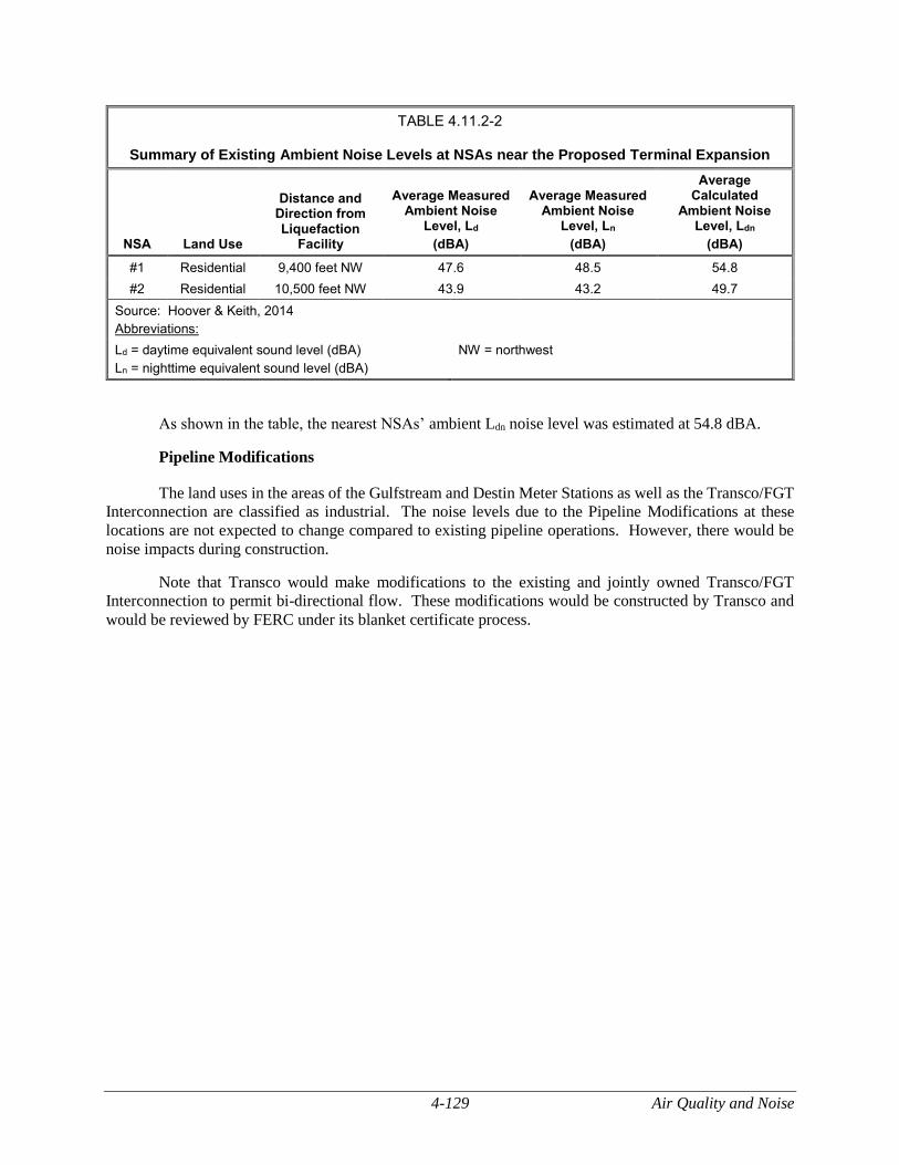
4-129 Air Quality and Noise
TABLE 4.11.2-2
Summary of Existing Ambient Noise Levels at NSAs near the Proposed Terminal Expansion
NSA Land Use
Distance and Direction from Liquefaction
Facility
Average Measured Ambient Noise
Level, Ld
(dBA)
Average Measured Ambient Noise
Level, Ln
(dBA)
Average Calculated
Ambient Noise Level, Ldn
(dBA)
#1 Residential 9,400 feet NW 47.6 48.5 54.8
#2 Residential 10,500 feet NW 43.9 43.2 49.7
Source: Hoover & Keith, 2014
Abbreviations:
Ld = daytime equivalent sound level (dBA)
Ln = nighttime equivalent sound level (dBA)
NW = northwest
As shown in the table, the nearest NSAs’ ambient Ldn noise level was estimated at 54.8 dBA.
Pipeline Modifications
The land uses in the areas of the Gulfstream and Destin Meter Stations as well as the Transco/FGT
Interconnection are classified as industrial. The noise levels due to the Pipeline Modifications at these
locations are not expected to change compared to existing pipeline operations. However, there would be
noise impacts during construction.
Note that Transco would make modifications to the existing and jointly owned Transco/FGT
Interconnection to permit bi-directional flow. These modifications would be constructed by Transco and
would be reviewed by FERC under its blanket certificate process.
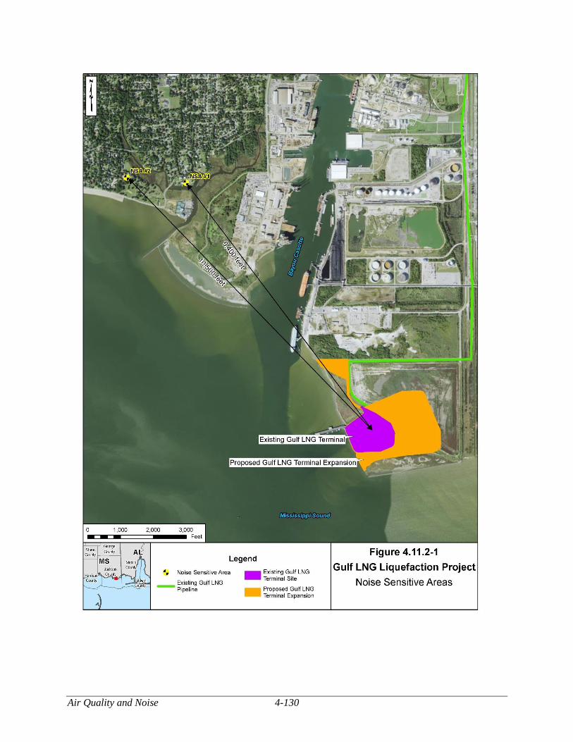
Air Quality and Noise 4-130
Figure 4.11.2-1 Noise Sensitive Areas
4-131 Air Quality and Noise
Construction Noise Impacts and Mitigation
Construction noise levels are rarely steady; instead, they fluctuate depending on the number and
type of equipment in use at any given time. There would be times when no large equipment is operating
and noise would be at or near existing ambient levels. In addition, construction-related sound levels
experienced by a noise sensitive receptor in the vicinity of construction activity would be a function of
distance, other noise sources, and the presence and extent of vegetation and intervening topography between
the noise source and the sensitive receptor.
Terminal Expansion
Construction of the Terminal Expansion would take place for about 66 months from
commencement through the completion of Phase II. Construction work would entail site clearing, grading,
and excavation; construction of temporary facilities such as equipment and laydown areas and two supply
docks; removal of one supply dock, extension of the existing storm surge protection wall; installation of
permanent foundations for heavy equipment and structures; installation of underground utilities; and
building erection. To help distribute impacts of vehicle trips by workers, Gulf LNG would have two
daytime shift start times and one nighttime shift start time.
The most prevalent and typical sound generating equipment during site construction of the
Terminal Expansion would be the ICE of construction equipment including track-excavators, backhoes,
bulldozers, dump trucks and concrete trucks, which produce noise levels up to 90 dBA at 50 feet. The
sound levels experienced at the NSAs would depend on the type of equipment used, the mode of operation
of the equipment, the length of time the equipment is in use, the amount of equipment used simultaneously,
and the distance between the sound generation source and the receptor. However, based on the distance to
the NSA, construction noise from this typical construction equipment is not anticipated to exceed the noise
criterion. If perceived noise levels cause a nuisance at the nearby NSAs are inconvenienced, Gulf LNG
would ensure the noise standard is met by construction of sound barriers, installation of residential grade
exhaust mufflers on equipment, or reducing utilization rates as necessary.
Dredging operations would also produce noise during construction and would be conducted using
a hydraulic or clamshell (bucket) method (up to 93 dBA Lmax [maximum sound level] at 50 feet) (FHWA,
2006). Gulf LNG would perform dredging activities 24 hours per day for up to 6 months total during
construction of the supply docks and for material barge access to the wetland mitigation area. The worst-
case peak noise level at NSA#1 and NSA#2 is expected to be 55 to 60 dBA; this is a peak noise level and
not a day/night average (Ldn). The resultant day/night average would depend on utilization rates, which can
be controlled to keep the Ldn to less than 55 dBA at the nearest NSA. Based on a typical 20 percent
utilization, dredging is expected to contribute sound levels of about 46.8 dBA Ldn which is less than our
noise criterion, and would not be expected to result in significant impacts on the NSA.
Another dominant noise source during construction of the Terminal Expansion would be that of
pile driving (96 and 101 dBA Lmax at 50 feet for one vibratory pile driver and one impact pile driver,
respectively) (FHWA, 2006), which could produce peak noise levels that would be perceptible above the
prevalent sound levels. Gulf LNG would conduct pile driving activities 24 hours per day during both
onshore during construction of the Terminal Expansion (worst-case noise assumption of concurrent
operation up to six impact pile drivers for an estimated 12 months per train) and offshore during
construction of the supply docks (worst-case noise assumption of concurrent operation of one vibratory pile
driver at the North Supply Dock for 40 to 60 days and one vibratory pile driver at the South Supply Dock
for 20 to 30 days). The operation of six impact pile drivers during onshore construction would cause the
maximum noise impact on the nearest NSA.
Air Quality and Noise 4-132
Pile driving operations are currently proposed to occur 24 hours a day for an estimated 2 years.
Based on the large number of residents who live in the Project area, the impulsive (short, intense) noise
impacts associated with pile-driving activities, the predicted and perceptible noise impacts on NSAs, the
duration of pile-driving activities, as well as the lack of noise mitigation measures proposed by Gulf LNG,
we recommend that:
Following the start of pile-driving activities, Gulf LNG should monitor daytime pile-driving
and file weekly data reports with the Secretary that identify the noise impact on the nearest
NSAs. If any measured daytime noise impacts (Lmax) at the nearest NSAs are greater than 10
dBA over the Leq ambient levels, Gulf LNG should:
a. cease pile-driving activities and implement noise mitigation measures; and
b. file with the Secretary evidence of noise mitigation installation and request written
notification from the Director of OEP that pile driving may resume.
Given the proximity of residences to construction and the predicted noise levels associated with
pile-driving, we conclude that pile-driving activities, without further noise mitigation, should be conducted
within reasonable working hours. Therefore, we recommend that:
Gulf LNG should conduct all pile-driving activities only between the hours of 7 a.m. and 7
p.m. throughout the duration of construction.
Pile driving operations would also produce the most dominant vibration impact during construction.
Based on the distance to the nearest NSA, operation of six impact pile drivers could contribute vibration
levels up to 62.4 vibration velocity decibels (VdB). Because the threshold of perception for humans is
around 65 VdB (FTA, 2006), pile driving would not be expected to result in significant impacts on the
NSAs.
Pipeline Modifications
Sound level increases during Pipeline Modifications would occur only during the day. Based on
the type of equipment proposed for construction (one backhoe, two cherry pickers, and two portable
welding machines), Gulf LNG modeled noise levels to be 28 dBA Leq at the nearest NSA, located 2,508
feet from a construction site. This would correspond to an Ldn of 35 dBA, which is below the FERC criterion
of 55 dBA Ldn, and would not be expected to result in significant impacts on the NSA.
Operation Noise Impacts and Mitigation
Terminal Expansion
Operation of the expanded Terminal would generate sound levels that would occur throughout the
life of the Project. Noise would generally be produced on a continuous basis at the liquefaction facility by
a number of sources, which would include various types of compressors and cooling fans.
Preliminary operational noise levels for anticipated equipment were assessed based on the two
liquefaction trains and associated equipment operating at full load concurrently. The preliminary maximum
estimated Ldn of the Terminal Expansion would be 47.0 dBA Ldn at NSA #1, below our noise criterion of
55 dBA Ldn (see table 4.11.2-3). The maximum increase in noise level would be 1.5 dBA Ldn at NSA #2,
below the “barely detectable” level of 3 dBA above current noise level. The liquefaction facility design
should also result in no discernable vibration at the nearest NSAs. Generally, if there are off-site vibrations
being induced from the Terminal, it would be indicative of malfunctioning equipment and would lead to
equipment shutdown to enable repairs to establish normal operation.
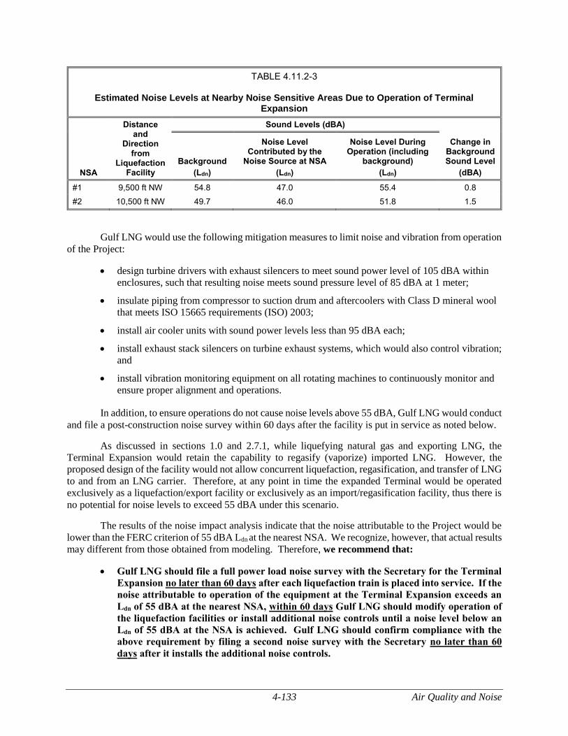
4-133 Air Quality and Noise
TABLE 4.11.2-3
Estimated Noise Levels at Nearby Noise Sensitive Areas Due to Operation of Terminal Expansion
NSA
Distance and
Direction from
Liquefaction Facility
Sound Levels (dBA)
Change in Background Sound Level
(dBA)
Background
(Ldn)
Noise Level Contributed by the
Noise Source at NSA
(Ldn)
Noise Level During Operation (including
background)
(Ldn)
#1 9,500 ft NW 54.8 47.0 55.4 0.8
#2 10,500 ft NW 49.7 46.0 51.8 1.5
Gulf LNG would use the following mitigation measures to limit noise and vibration from operation
of the Project:
design turbine drivers with exhaust silencers to meet sound power level of 105 dBA within
enclosures, such that resulting noise meets sound pressure level of 85 dBA at 1 meter;
insulate piping from compressor to suction drum and aftercoolers with Class D mineral wool
that meets ISO 15665 requirements (ISO) 2003;
install air cooler units with sound power levels less than 95 dBA each;
install exhaust stack silencers on turbine exhaust systems, which would also control vibration;
and
install vibration monitoring equipment on all rotating machines to continuously monitor and
ensure proper alignment and operations.
In addition, to ensure operations do not cause noise levels above 55 dBA, Gulf LNG would conduct
and file a post-construction noise survey within 60 days after the facility is put in service as noted below.
As discussed in sections 1.0 and 2.7.1, while liquefying natural gas and exporting LNG, the
Terminal Expansion would retain the capability to regasify (vaporize) imported LNG. However, the
proposed design of the facility would not allow concurrent liquefaction, regasification, and transfer of LNG
to and from an LNG carrier. Therefore, at any point in time the expanded Terminal would be operated
exclusively as a liquefaction/export facility or exclusively as an import/regasification facility, thus there is
no potential for noise levels to exceed 55 dBA under this scenario.
The results of the noise impact analysis indicate that the noise attributable to the Project would be
lower than the FERC criterion of 55 dBA Ldn at the nearest NSA. We recognize, however, that actual results
may different from those obtained from modeling. Therefore, we recommend that:
Gulf LNG should file a full power load noise survey with the Secretary for the Terminal
Expansion no later than 60 days after each liquefaction train is placed into service. If the
noise attributable to operation of the equipment at the Terminal Expansion exceeds an
Ldn of 55 dBA at the nearest NSA, within 60 days Gulf LNG should modify operation of
the liquefaction facilities or install additional noise controls until a noise level below an
Ldn of 55 dBA at the NSA is achieved. Gulf LNG should confirm compliance with the
above requirement by filing a second noise survey with the Secretary no later than 60
days after it installs the additional noise controls.
Air Quality and Noise 4-134
In addition, we recommend that:
Gulf LNG should file a noise survey with the Secretary no later than 60 days after placing
the entire Terminal Expansion into service. If a full load condition noise survey is not
possible, Gulf LNG should provide an interim survey at the maximum possible
horsepower load within 60 days of placing the Terminal Expansion into service and
provide the full load survey within 6 months. If the noise attributable to operation of the
equipment at the Terminal Expansion exceeds an Ldn of 55 dBA at the nearest NSA under
interim or full horsepower load conditions, Gulf LNG should file a report on what
changes are needed and should install the additional noise controls to meet the level within
1 year of the in-service date. Gulf LNG should confirm compliance with the above
requirement by filing an additional noise survey with the Secretary no later than 60 days
after it installs the additional noise controls.
Based on the results of the noise analysis and mitigation, we conclude that operational noise from
the Terminal Expansion would have no significant impact on the noise environment in the vicinity of the
Terminal Expansion.
Flare Operations
Gulf LNG would install three in-service flares (warm, cold, and low pressure) for venting excess
natural gas, if necessary, during maintenance, startup/shutdown, and upset activities. The facility would
include one additional flare to act as backup. The four flares would be constructed on a common 430-foot-
tall support structure [with an overall height of 433 feet above msl] (see figure 2.0-1). Noise impacts would
occur from flare operation on an intermittent basis during startup, shutdown, or commissioning of the
liquefaction facility, and infrequently in the event of a malfunction de-pressuring event.
The worst-case planned flare event would be for a total plant startup, which would happen for the
initial startup of the two liquefaction trains. Once the facility is in operation, a total plant re-start from a
warm condition would only occur if there is an extended outage of the entire train for maintenance or repairs
or a significant commercial interruption of the facility operation. Each total plant startup would last several
days. The total time in warm and cold starts is not anticipated to exceed 120 hours per year. A conservative
estimate of flare noise would be 55 dBA Ldn plus or minus 3 dBA Ldn for a worst-case of 58 dBA Ldn at the
nearest NSA based on utilization of an elevated sonic flare tip designed for smokeless operation and for a
conservative liquefaction plant startup flare rate. However, it is expected that noise attributable to the
planned flare events would achieve 55 dBA Ldn or less once detailed design is completed, the flare
design/vendor is selected, and final emergency flare rates are known.
The worst-case unplanned flare event would be a total liquefaction plant Emergency Shut-Down
(ESD). An event of this type would last less than one hour. Although the detailed flare design is not yet
completed, the worst-case peak noise is expected to be 70 to 75 dBA at NSA #1 and NSA #2; this is a peak
noise rate and not a day/night average (Ldn) since any such event would be for a short duration. The
correlating Ldn is estimated to be 56 to 61 dBA at the nearest NSAs assuming the event lasts for an entire
hour. Because of the infrequent occurrence and expected operation of flares during unplanned flare events,
we conclude that the resulting noise would not result in a significant impact on the NSAs.
Pipeline Modifications
The Pipeline Modifications would not include any additional noise generating equipment so would
not be anticipated to increase existing operational noise levels. Therefore, we conclude that operational
noise from the Pipeline Modifications would have no significant impact on the noise environment in the
vicinity of the Project.
4-135 Reliability and Safety
RELIABILITY AND SAFETY
LNG Facility Reliability, Safety, and Security Regulatory Oversight
LNG facilities handle flammable and sometimes toxic materials that can pose a risk to the public
if not properly managed. These risks are managed by the companies owning the facilities, through selecting
the site location and plant layout as well as through suitable design, engineering, construction, and operation
of the LNG facilities. Multiple federal agencies share regulatory authority over the LNG facilities and the
operator’s approach to risk management. The safety, security, and reliability of the Gulf LNG Liquefaction
Project would be regulated by the DOT, the USCG, and the FERC.
In February 2004, the DOT, USCG, and FERC entered into an Interagency Agreement to ensure
greater coordination among these three agencies in addressing the full range of safety and security issues at
LNG terminals and LNG marine vessel operations, and maximizing the exchange of information related to
the safety and security aspects of LNG facilities and related marine operations. Under the Interagency
Agreement, FERC is the lead federal agency responsible for the preparation of the analysis required under
NEPA for impacts associated with terminal construction and operation. The DOT and USCG participate
as cooperating agencies but remain responsible for enforcing their regulations covering LNG facility siting,
design, construction, operation, maintenance, and security. All three agencies have some oversight and
responsibility for the inspection and compliance during the LNG Terminal’s operation.
The DOT establishes and has the authority to enforce the federal safety standards for the location,
design, installation, construction, inspection, testing, operation, and maintenance of on-shore LNG facilities
under the Federal Pipeline Safety Laws (49 USC 60101 et seq.). The DOT’s LNG safety regulations are
codified in 49 CFR 193, which prescribes safety standards for LNG facilities used in the transportation of
gas by pipeline that are subject to federal pipeline safety laws (49 USC 60101 et seq.), and 49 CFR 192.
On August 31, 2018, DOT and FERC signed a MOU regarding methods to improve coordination
throughout the LNG permit application process for FERC jurisdictional LNG facilities. In the MOU, the
DOT agreed to issue a Letter of Determination (LOD) stating whether a proposed LNG facility would be
capable of complying with location criteria and design standards contained in Subpart B of Part 193. The
Commission committed to rely upon the DOT determination in conducting its review of whether the
facilities would be consistent with the public interest. The issuance of the LOD does not abrogate the
DOT’s continuing authority and responsibility over a proposed project’s compliance with Part 193 during
construction and future operation of the facility. The DOT’s conclusion on the siting and hazard analysis
required by Part 193 is based on preliminary design information which may be revised as the engineering
design progresses to final design. DOT regulations also contain requirements for the design, construction,
equipment, operation, maintenance, qualifications and training of personnel, fire protection, and security
for LNG facilities, as defined by 49 CFR 193, which would be completed during later stages of the Gulf
LNG Liquefaction Project. If the Project is approved, constructed, and operated, the LNG facilities as
defined in 49 CFR 193, would be subject to the DOT’s inspection and enforcement programs to ensure
compliance with the requirements of 49 CFR 193.
The USCG has authority over the safety of an LNG terminal’s marine transfer area and LNG marine
traffic, as well as security plans for the waterfront facilities handling LNG and LNG marine vessels. The
USCG regulations for LNG facilities are codified in 33 CFR 105 and 33 CFR 127. As a cooperating agency,
the USCG assists the FERC staff in evaluating whether an applicant’s proposed waterway would be suitable
for LNG marine vessel traffic and whether the waterfront facilities handling LNG would be operated in
accordance with 33 CFR 105 and 33 CFR 127. If the facilities are constructed and become operational, the
facilities would be subject to the USCG inspection program to ensure compliance with the requirements of
33 CFR 105 and 33 CFR 127.
Reliability and Safety 4-136
FERC authorizes the siting and construction of LNG terminals under the NGA and delegated
authority from the DOE. FERC requires standard information to be submitted to perform safety and
reliability engineering reviews. FERC’s filing regulations are codified in 18 CFR 380.12 (m) and (o), and
requires each applicant to identify how its proposed design would comply with the DOT’s siting
requirements of 49 CFR 193, Subpart B. The level of detail necessary for this submittal requires the
applicant to perform substantial front-end engineering review of the complete project. The design
information is required to be site-specific and developed to the extent that further detailed design would not
result in significant changes to the siting considerations, basis of design, operating conditions, major
equipment selections, equipment design conditions, or safety system designs. As part of the review required
for a FERC Order, we use this information from the applicant to assess whether the proposed facilities
would have a public safety impact and to recommend additional mitigation measures to the Commission
for incorporation as conditions in the Order. If the facilities are approved and the recommended mitigation
measures are incorporated into the Order as conditions, FERC staff would review material filed to satisfy
the conditions of the Order and conduct periodic inspections throughout construction and operation.
In addition, the Energy Policy Act of 2005 requires FERC to coordinate and consult with the DOD
on the siting, construction, expansion, and operation of LNG terminals that would affect the military. On
November 21, 2007, the FERC and the DOD entered into a MOU formalizing this process.24 In accordance
with the MOU, the FERC sent a letter to the DOD on June 29, 2015 requesting their comments on whether
the planned Project could potentially have an impact on the test, training, or operational activities of any
active military installation. On March 10, 2016 the FERC received a response letter from the DOD Siting
Clearinghouse stating that the Gulf LNG Liquefaction Project would have a minimal impact on military
training and operations conducted in the Jackson County, Mississippi area.
DOT Siting Requirements and 49 CFR 193 Subpart B Determination
Siting LNG facilities, as defined in 49 CFR 193, with regard to ensuring that the proposed site
selection and location would not pose an unacceptable level or risk to public safety is required by DOT’s
regulations in 49 CFR 193, Subpart B. The Commission’s regulations under 18 CFR 380.12(o)(14) require
Gulf LNG to identify how the proposed design complies with the siting requirements in DOT’s regulations
under 49 CFR 193, Subpart B. The scope of DOT’s siting authority under 49 CFR 193 applies to LNG
facilities used in the transportation of gas by pipeline subject to the federal pipeline safety laws and 49 CFR
192.25
The regulations in 49 CFR 193 Subpart B, require the establishment of an exclusion zone
surrounding an LNG facility in which an operator or government agency must exercise legal control over
the activities where specified levels of thermal radiation and flammable vapors may occur in the event of a
release for as long as the facility is in operation. Approved mathematical models must be used to calculate
the dimensions of these exclusion zones. The siting requirements specified in NFPA 59A (2001), an
industry consensus standard for LNG facilities, are incorporated into 49 CFR 193 Subpart B, by reference,
with regulatory preemption in the event of conflict. The following sections of 49 CFR 193 Subpart B
specifically address siting requirements:
Section 193.2051, Scope, states that each LNG facility designed, replaced, relocated or
significantly altered after March 31, 2000, must be provided with siting requirements in
accordance with Subpart B and NFPA 59A (2001). In the event of a conflict with NFPA 59A
(2001), the regulatory requirements in Part 193 prevail.
24 The MOU is available at: http://www.ferc.gov/legal/mou/mou-dod.pdf.
25 49 CFR 193.2001(b)(3), Scope of part, excludes any matter other than siting provisions pertaining to marine cargo transfer
systems between the LNG marine vessel and the last manifold or valve immediately before a storage tank.
4-137 Reliability and Safety
Section 193.2057, Thermal radiation protection, requires that each LNG container and LNG
transfer system have thermal exclusion zones in accordance with Section 2.2.3.2 of NFPA
59A (2001).
Section 193.2059, Flammable vapor-gas dispersion protection, requires that each LNG
container and LNG transfer system have a dispersion exclusion zone in accordance with
Sections 2.2.3.3 and 2.2.3.4 of NFPA 59A (2001).
Section 193.2067, Wind forces, requires that shop fabricated containers of LNG or other
hazardous fluids less than 70,000 gallons must be designed to withstand wind forces based on
the applicable wind load data in ASCE 7 (2005). All other LNG facilities must be designed
for a sustained wind velocity of not less than 150 mph unless the DOT Administrator finds a
lower wind speed is justified or the most critical combination of wind velocity and duration
for a 10,000-year mean return interval.
As stated in Section 193.2051, LNG facilities must meet the siting requirements of NFPA 59A
(2001), Chapter 2, and include but may not be limited to:
NFPA 59A (2001) Section 2.1.1(c) requires consideration of protection against forces of
nature.
NFPA 59A (2001) Section 2.1.1(d) requires that other factors applicable to the specific site
that have a bearing on the safety of plant personnel and surrounding public be considered,
including an evaluation of potential incidents and safety measures incorporated in the design
or operation of the facility.
NFPA 59A (2001) Section 2.2.3.2 requires provisions to minimize the damaging effects of
fire from reaching beyond a property line, and requires provisions to prevent a radiant heat
flux level of 1,600 British thermal units per square foot per hour (Btu/ft2-hr) from reaching
beyond a property line that can be built upon. The distance to this flux level is to be
calculated with LNGFIRE3 or with models that have been validated by experimental test data
appropriate for the hazard to be evaluated and that have been approved by DOT.
NFPA 59A (2001) Section 2.2.3.4 requires provisions to minimize the possibility of any
flammable mixture of vapors from a design spill from reaching a property line that can be
built upon and that would result in a distinct hazard. Determination of the distance that the
flammable vapors extend is to be determined with DEGADIS or approved alternative models
that take into account physical factors influencing LNG vapor dispersion.26
Taken together, 49 CFR 193 Subpart B and NFPA 59A (2001) require that flammable LNG vapors
either from a design spill do not extend beyond areas in which the operator or a government agency legally
controls all activities. Furthermore, consideration of other hazards which may affect the public or plant
personnel must be evaluated as prescribed in NFPA 59A (2001), Section 2.1.1(d).
Title 49 CFR 193 Subpart B and NFPA 59A (2001) also specify radiant heat flux levels which must
be considered as long as the facility is in operation.
The requirements for design spills from process and transfer areas require the 1,600 Btu/ft2-hr flux
level to not extend beyond the plant property line onto a property that can be built upon.
26 DOT has approved two additional models for the determination of vapor dispersion exclusion zones in accordance with 49
CFR 193.2059: FLACS 9.1 Release 2 (Oct. 7, 2011) and PHAST-UDM Version 6.6 and 6.7 (Oct. 7, 2011).
Reliability and Safety 4-138
In addition, Section 2.1.1 of NFPA 59A (2001) requires that factors applicable to the specific site
with a bearing on the safety of plant personnel and the surrounding public must be considered, including
an evaluation of potential incidents and safety measures incorporated into the design or operation of the
facility. DOT has indicated that potential incidents, such as vapor cloud explosions and toxic releases
should also be considered to comply with Part 193 Subpart B.27
The DOT issued an LOD on March 15, 2019 to FERC regarding the Project’s compliance with the
49 CFR 193 Subpart B regulatory requirements in accordance with the August 31, 2018 MOU.28 The LOD
provides PHMSA’s analysis and conclusions regarding 49 CFR 193 Subpart B regulatory compliance.
Pursuant to the MOU, the LOD is a consideration in the Commission’s decision to authorize, with or
without modification or conditions, or deny an application. The LOD will serve as one of the considerations
for the Commission to deliberate in its decision to authorize or deny an application.
USCG Safety Regulatory Requirements and Letter of Recommendation
LNG Marine Vessel Historical Record
Since 1959, marine vessels have transported LNG without a major release of cargo or a major
accident involving an LNG marine vessel. There are more than 370 LNG marine vessels in operation
routinely transporting LNG between more than 100 import/export terminals currently in operation
worldwide. Since U.S. LNG terminals first began operating under FERC jurisdiction in the 1970s, there
have been thousands of individual LNG marine vessel arrivals at terminals in the United States. For more
than 40 years, LNG shipping operations have been safely conducted in U.S. ports and waterways.
A review of the history of LNG maritime transportation indicates that there has not been a serious
accident at sea or in a port which resulted in a spill due to rupturing of the cargo tanks. However, insurance
records, industry sources, and public websites identify a number of incidents involving LNG marine vessels,
including minor collisions with other marine vessels of all sizes, groundings, minor LNG releases during
cargo unloading operations, and mechanical/equipment failures typical of large marine vessels. Some of
the more significant occurrences, representing the range of incidents experienced by the worldwide LNG
marine vessel fleet, are described below:
El Paso Paul Kayser grounded on a rock in June 1979 in the Straits of Gibraltar during a
loaded voyage from Algeria to the United States. Extensive bottom damage to the ballast
tanks resulted; however, no cargo was released because no damage was done to the cargo
tanks. The entire cargo of LNG was subsequently transferred to another LNG marine vessel
and delivered to its U.S. destination.
Tellier was blown by severe winds from its docking berth at Skikda, Algeria in
February 1989 causing damage to the loading arms and the LNG marine vessel and shore
piping. The cargo loading had been secured just before the wind struck, but the loading arms
had not been drained. Consequently, the LNG remaining in the loading arms spilled onto the
deck, causing fracture of some plating.
27 The DOT PHMSA’s “LNG Plant Requirements: Frequently Asked Questions” item H1. Available at:
https://www.phmsa.dot.gov/pipeline/liquified-natural-gas/lng-plant-requirements-frequently-asked-questions, accessed Aug
2018.
28 March 15, 2019 letter “Re: Gulf LNG Liquefaction Project FERC Docket CP15-521-000”. Accession Number 20190315-
3072.
4-139 Reliability and Safety
Mostefa Ben Boulaid had an electrical fire in the engine control room during unloading at
Everett, Massachusetts. The LNG marine vessel crew extinguished the fire and the LNG
marine vessel completed unloading.
Khannur had a cargo tank overfill into the LNG marine vessel’s vapor handling system on
September 10, 2001, during unloading at Everett, Massachusetts. Approximately 100 gallons
of LNG were vented and sprayed onto the protective decking over the cargo tank dome,
resulting in several cracks. After inspection by the USCG, the Khannur was allowed to
discharge its LNG cargo.
Mostefa Ben Boulaid had LNG spill onto its deck during loading operations in Algeria in
2002. The spill, which is believed to have been caused by overflow rather than a mechanical
failure, caused significant brittle fracturing of the steelwork. The LNG marine vessel was
required to discharge its cargo, after which it proceeded to dock for repair.
Norman Lady was struck by the USS Oklahoma City nuclear submarine while the
submarine was rising to periscope depth near the Strait of Gibraltar in November 2002. The
87,000 m3 LNG marine vessel, which had just unloaded its cargo at Barcelona, Spain,
sustained only minor damage to the outer layer of its double hull but no damage to its cargo
tanks.
Tenaga Lima grounded on rocks while proceeding to open sea east of Mopko, South Korea
due to strong current in November 2004. The shell plating was torn open and fractured over
an approximate area of 20 by 80 feet, and internal breaches allowed water to enter the
insulation space between the primary and secondary membranes. The LNG marine vessel
was refloated, repaired, and returned to service.
Golar Freeze moved away from its docking berth during unloading on March 14, 2006, in
Savannah, Georgia. The powered emergency release couplings on the unloading arms
activated as designed, and transfer operations were shut down.
Catalunya Spirit lost propulsion and became adrift 35 miles east of Chatham, Massachusetts
on February 11, 2008. Four tugs towed the LNG marine vessel to a safe anchorage for
repairs. The Catalunya Spirit was repaired and taken to port to discharge its cargo.
Al Gharrafa collided with a container ship, Hanjin Italy, in the Malacca Strait off Singapore
on December 19, 2013. The bow of the Al Gharrafa and the middle of the starboard side of
the Hanjin were damaged. Both ships were safely anchored after the incident. No loss of
LNG was reported.
Al Oraiq collided with a freight carrier, Flinterstar, near Zeebrugge, Belgium on October 6,
2015. The freight carrier sank, but the Al Oraiq was reported to have sustained only minor
damage to its bow and no damage to the LNG cargo tanks. According to reports, the Al
Oraiq took on a little water but was towed to the Zeebrugge LNG terminal where its cargo
was unloaded using normal procedures. No loss of LNG was reported.
Al Khattiya suffered damage after a collision with an oil carrier off the Port of Fujairah on
February 23, 2017. Al Khattiya had discharged its cargo and was anchored at the time of the
incident. A small amount of LNG was retained within the LNG marine vessel to keep the
cargo tanks cool. The collision damaged the hull and two ballast tanks on the Al Khattiya,
but did not cause any injury or water pollution. No loss of LNG was reported.
Aseem collided with a very large crude carrier (VLCC) Shinyo Ocean off the Port of Fujairah
on March 26, 2019. The VLCC suffered severe portside hull height breach and Aseem had
damage to its bow. Both marine vessels were unloaded at the time of the collision and
Reliability and Safety 4-140
subsequently no LNG or oil was released. Aseem was moved to port for anchorage and
Shinyo Ocean was relocated to another point of anchorage.
LNG Marine Vessel Safety Regulatory Oversight
The USCG exercises regulatory authority over LNG marine vessels under 46 CFR 154, which
contains the United States safety standards for LNG marine vessels transporting LNG in bulk. The LNG
marine vessels visiting the proposed facility would also be constructed and operated in accordance with the
International Maritime Organization (IMO) Code for the Construction and Equipment of Ships Carrying
Liquefied Gases in Bulk and the International Convention for the Safety of Life at Sea. All LNG marine
vessels entering U.S. waters are required to possess a valid IMO Certificate of Fitness and either a USCG
Certificate of Inspection for U.S. flag vessels or a USCG Certificate of Compliance for foreign flag vessels.
These documents certify that the LNG marine vessel is designed and operating in accordance with both
international standards and the U.S. regulations for bulk LNG marine vessels under Title 46 CFR 154.
The LNG marine vessels that would deliver or receive LNG to or from the proposed liquefaction
facilities would also need to comply with various U.S. and international security requirements. The IMO
adopted the International Ship and Port Facility Security Code in 2002. This code requires both marine
vessels and ports to conduct vulnerability assessments and to develop security plans. The purpose of the
code is to prevent and suppress terrorism against marine vessels; improve security aboard marine vessels
and ashore; and reduce the risk to passengers, crew, and port personnel on board marine vessels and in port
areas. All LNG marine vessels, as well as other cargo marine vessels (e.g. 500 gross tons and larger), and
ports servicing those regulated marine vessels, must adhere to the IMO standards. Some of the IMO
requirements for marine vessels are as follows:
marine vessels must develop security plans and have a Vessel Security Officer;
marine vessels must have a marine vessel security alert system to transmit ship-to-shore
security alerts identifying the marine vessel, its location, and an indication of whether the
security of the marine vessel is under threat or has been compromised;
marine vessels must have a comprehensive security plan for international port facilities,
focusing on areas having direct contact with marine vessels; and
marine vessels may have equipment onboard to help maintain or enhance the physical
security of the marine vessel.
In 2002, the Maritime Transportation Security Act (MTSA) was enacted by the U.S. Congress and
aligned domestic regulations with the maritime security standards of the International Ship and Port
Facility Security Code and the Code for the Construction and Equipment of Ships Carrying Liquefied Gases
in Bulk and the International Convention for the Safety of Life at Sea. The USCG’s regulations in 33 CFR
104 require marine vessels to conduct a vessel security assessment and develop a vessel security plan that
addresses each vulnerability identified in the vessel security assessments. All LNG marine vessels servicing
the facility would have to comply with the MTSA requirements and associated regulations while in U.S.
waters.
The USCG also exercises regulatory authority over LNG facilities that affect the safety and security
of port areas and navigable waterways under Executive Order 10173; the Magnuson Act (50 USC Section
191); the Ports and Waterways Safety Act of 1972, as amended (33 USC Section 1221, et seq.); and the
MTSA of 2002 (46 USC Section 701). The USCG is responsible for matters related to navigation safety,
LNG marine vessel engineering and safety standards, and all matters pertaining to the safety of facilities or
equipment located in or adjacent to navigable waters up to the last valve immediately before the receiving
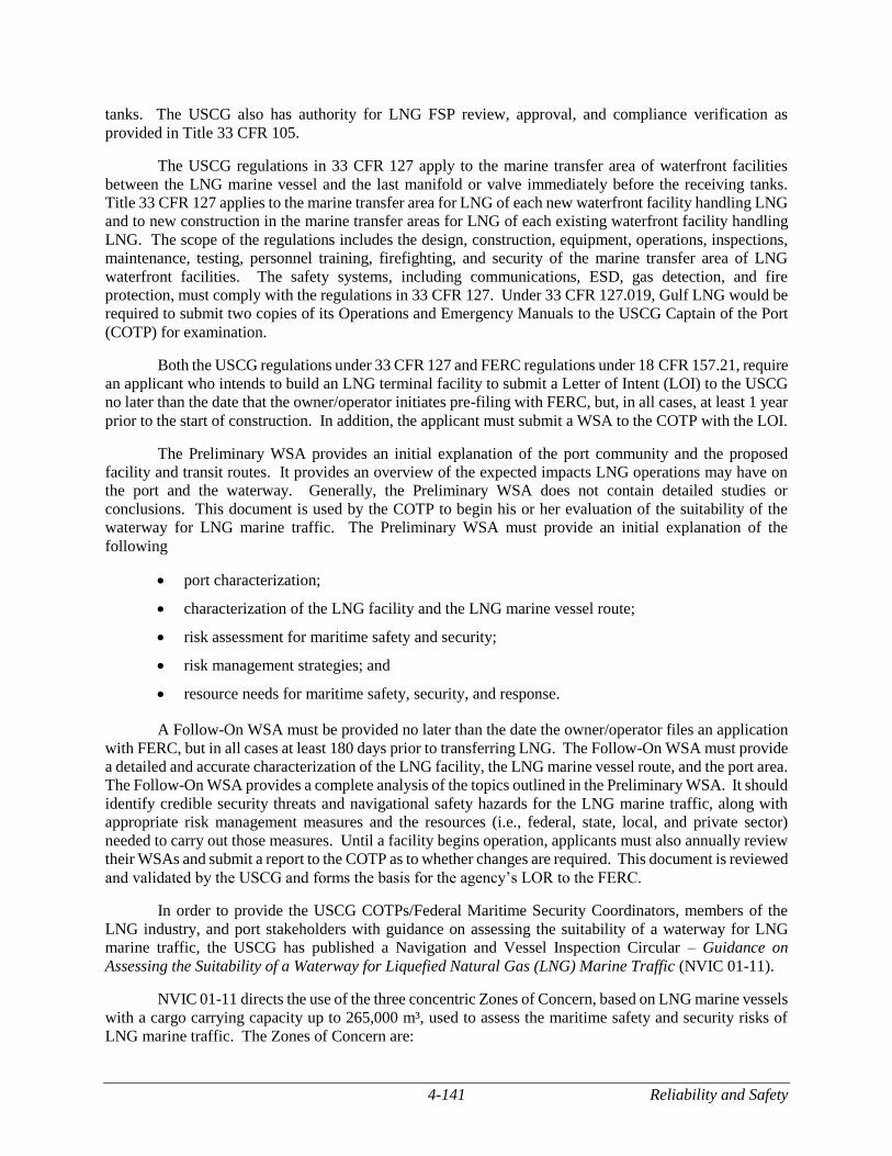
4-141 Reliability and Safety
tanks. The USCG also has authority for LNG FSP review, approval, and compliance verification as
provided in Title 33 CFR 105.
The USCG regulations in 33 CFR 127 apply to the marine transfer area of waterfront facilities
between the LNG marine vessel and the last manifold or valve immediately before the receiving tanks.
Title 33 CFR 127 applies to the marine transfer area for LNG of each new waterfront facility handling LNG
and to new construction in the marine transfer areas for LNG of each existing waterfront facility handling
LNG. The scope of the regulations includes the design, construction, equipment, operations, inspections,
maintenance, testing, personnel training, firefighting, and security of the marine transfer area of LNG
waterfront facilities. The safety systems, including communications, ESD, gas detection, and fire
protection, must comply with the regulations in 33 CFR 127. Under 33 CFR 127.019, Gulf LNG would be
required to submit two copies of its Operations and Emergency Manuals to the USCG Captain of the Port
(COTP) for examination.
Both the USCG regulations under 33 CFR 127 and FERC regulations under 18 CFR 157.21, require
an applicant who intends to build an LNG terminal facility to submit a Letter of Intent (LOI) to the USCG
no later than the date that the owner/operator initiates pre-filing with FERC, but, in all cases, at least 1 year
prior to the start of construction. In addition, the applicant must submit a WSA to the COTP with the LOI.
The Preliminary WSA provides an initial explanation of the port community and the proposed
facility and transit routes. It provides an overview of the expected impacts LNG operations may have on
the port and the waterway. Generally, the Preliminary WSA does not contain detailed studies or
conclusions. This document is used by the COTP to begin his or her evaluation of the suitability of the
waterway for LNG marine traffic. The Preliminary WSA must provide an initial explanation of the
following
port characterization;
characterization of the LNG facility and the LNG marine vessel route;
risk assessment for maritime safety and security;
risk management strategies; and
resource needs for maritime safety, security, and response.
A Follow-On WSA must be provided no later than the date the owner/operator files an application
with FERC, but in all cases at least 180 days prior to transferring LNG. The Follow-On WSA must provide
a detailed and accurate characterization of the LNG facility, the LNG marine vessel route, and the port area.
The Follow-On WSA provides a complete analysis of the topics outlined in the Preliminary WSA. It should
identify credible security threats and navigational safety hazards for the LNG marine traffic, along with
appropriate risk management measures and the resources (i.e., federal, state, local, and private sector)
needed to carry out those measures. Until a facility begins operation, applicants must also annually review
their WSAs and submit a report to the COTP as to whether changes are required. This document is reviewed
and validated by the USCG and forms the basis for the agency’s LOR to the FERC.
In order to provide the USCG COTPs/Federal Maritime Security Coordinators, members of the
LNG industry, and port stakeholders with guidance on assessing the suitability of a waterway for LNG
marine traffic, the USCG has published a Navigation and Vessel Inspection Circular – Guidance on
Assessing the Suitability of a Waterway for Liquefied Natural Gas (LNG) Marine Traffic (NVIC 01-11).
NVIC 01-11 directs the use of the three concentric Zones of Concern, based on LNG marine vessels
with a cargo carrying capacity up to 265,000 m³, used to assess the maritime safety and security risks of
LNG marine traffic. The Zones of Concern are:
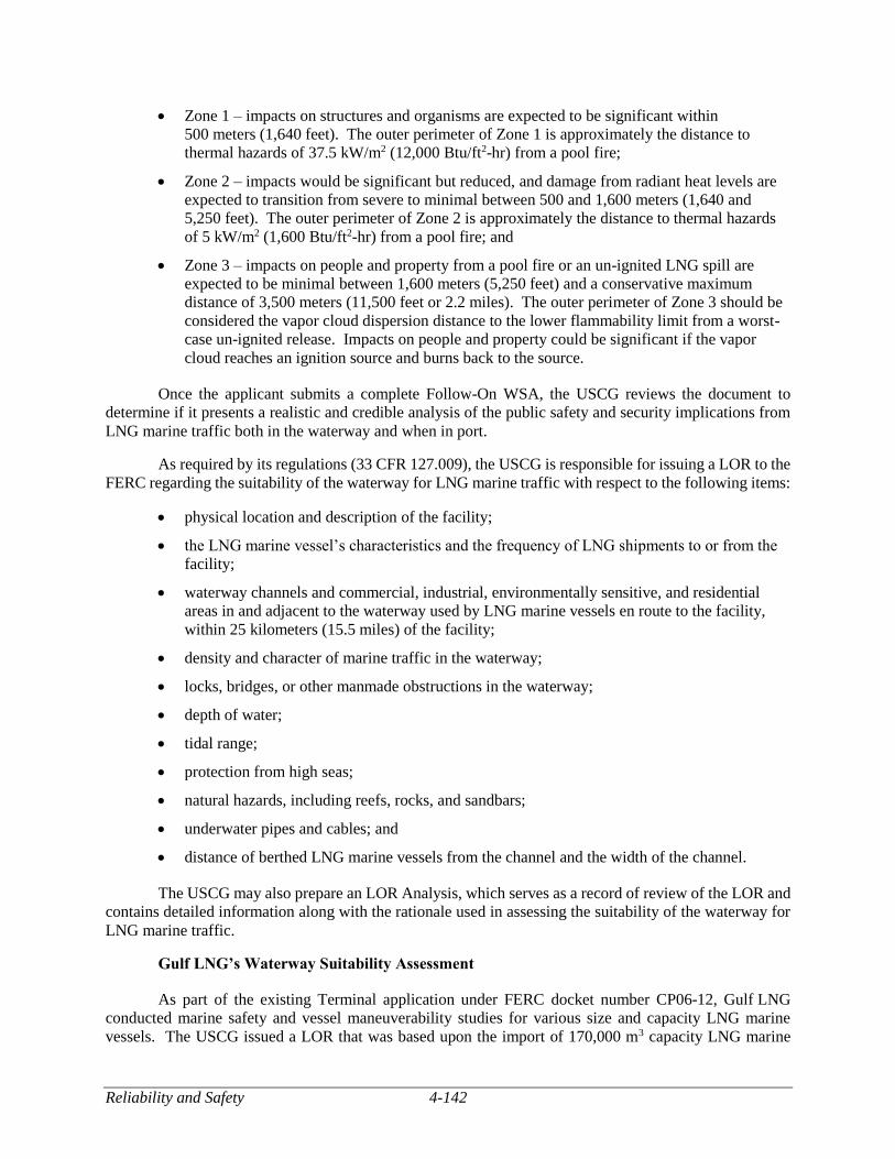
Reliability and Safety 4-142
Zone 1 – impacts on structures and organisms are expected to be significant within
500 meters (1,640 feet). The outer perimeter of Zone 1 is approximately the distance to
thermal hazards of 37.5 kW/m2 (12,000 Btu/ft2-hr) from a pool fire;
Zone 2 – impacts would be significant but reduced, and damage from radiant heat levels are
expected to transition from severe to minimal between 500 and 1,600 meters (1,640 and
5,250 feet). The outer perimeter of Zone 2 is approximately the distance to thermal hazards
of 5 kW/m2 (1,600 Btu/ft2-hr) from a pool fire; and
Zone 3 – impacts on people and property from a pool fire or an un-ignited LNG spill are
expected to be minimal between 1,600 meters (5,250 feet) and a conservative maximum
distance of 3,500 meters (11,500 feet or 2.2 miles). The outer perimeter of Zone 3 should be
considered the vapor cloud dispersion distance to the lower flammability limit from a worst-
case un-ignited release. Impacts on people and property could be significant if the vapor
cloud reaches an ignition source and burns back to the source.
Once the applicant submits a complete Follow-On WSA, the USCG reviews the document to
determine if it presents a realistic and credible analysis of the public safety and security implications from
LNG marine traffic both in the waterway and when in port.
As required by its regulations (33 CFR 127.009), the USCG is responsible for issuing a LOR to the
FERC regarding the suitability of the waterway for LNG marine traffic with respect to the following items:
physical location and description of the facility;
the LNG marine vessel’s characteristics and the frequency of LNG shipments to or from the
facility;
waterway channels and commercial, industrial, environmentally sensitive, and residential
areas in and adjacent to the waterway used by LNG marine vessels en route to the facility,
within 25 kilometers (15.5 miles) of the facility;
density and character of marine traffic in the waterway;
locks, bridges, or other manmade obstructions in the waterway;
depth of water;
tidal range;
protection from high seas;
natural hazards, including reefs, rocks, and sandbars;
underwater pipes and cables; and
distance of berthed LNG marine vessels from the channel and the width of the channel.
The USCG may also prepare an LOR Analysis, which serves as a record of review of the LOR and
contains detailed information along with the rationale used in assessing the suitability of the waterway for
LNG marine traffic.
Gulf LNG’s Waterway Suitability Assessment
As part of the existing Terminal application under FERC docket number CP06-12, Gulf LNG
conducted marine safety and vessel maneuverability studies for various size and capacity LNG marine
vessels. The USCG issued a LOR that was based upon the import of 170,000 m3 capacity LNG marine
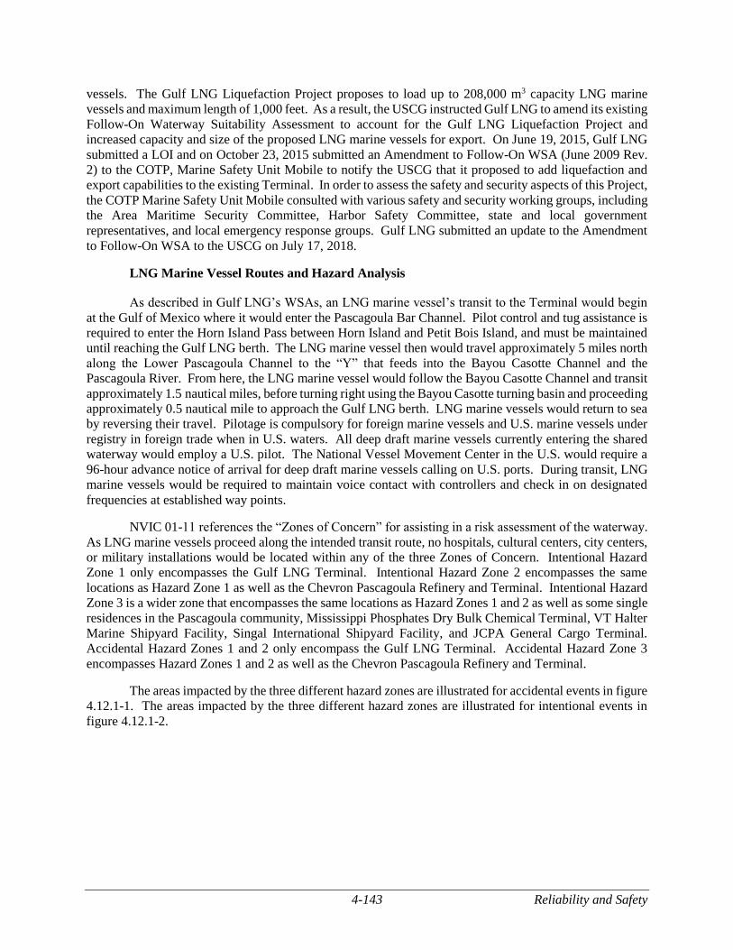
4-143 Reliability and Safety
vessels. The Gulf LNG Liquefaction Project proposes to load up to 208,000 m3 capacity LNG marine
vessels and maximum length of 1,000 feet. As a result, the USCG instructed Gulf LNG to amend its existing
Follow-On Waterway Suitability Assessment to account for the Gulf LNG Liquefaction Project and
increased capacity and size of the proposed LNG marine vessels for export. On June 19, 2015, Gulf LNG
submitted a LOI and on October 23, 2015 submitted an Amendment to Follow-On WSA (June 2009 Rev.
2) to the COTP, Marine Safety Unit Mobile to notify the USCG that it proposed to add liquefaction and
export capabilities to the existing Terminal. In order to assess the safety and security aspects of this Project,
the COTP Marine Safety Unit Mobile consulted with various safety and security working groups, including
the Area Maritime Security Committee, Harbor Safety Committee, state and local government
representatives, and local emergency response groups. Gulf LNG submitted an update to the Amendment
to Follow-On WSA to the USCG on July 17, 2018.
LNG Marine Vessel Routes and Hazard Analysis
As described in Gulf LNG’s WSAs, an LNG marine vessel’s transit to the Terminal would begin
at the Gulf of Mexico where it would enter the Pascagoula Bar Channel. Pilot control and tug assistance is
required to enter the Horn Island Pass between Horn Island and Petit Bois Island, and must be maintained
until reaching the Gulf LNG berth. The LNG marine vessel then would travel approximately 5 miles north
along the Lower Pascagoula Channel to the “Y” that feeds into the Bayou Casotte Channel and the
Pascagoula River. From here, the LNG marine vessel would follow the Bayou Casotte Channel and transit
approximately 1.5 nautical miles, before turning right using the Bayou Casotte turning basin and proceeding
approximately 0.5 nautical mile to approach the Gulf LNG berth. LNG marine vessels would return to sea
by reversing their travel. Pilotage is compulsory for foreign marine vessels and U.S. marine vessels under
registry in foreign trade when in U.S. waters. All deep draft marine vessels currently entering the shared
waterway would employ a U.S. pilot. The National Vessel Movement Center in the U.S. would require a
96-hour advance notice of arrival for deep draft marine vessels calling on U.S. ports. During transit, LNG
marine vessels would be required to maintain voice contact with controllers and check in on designated
frequencies at established way points.
NVIC 01-11 references the “Zones of Concern” for assisting in a risk assessment of the waterway.
As LNG marine vessels proceed along the intended transit route, no hospitals, cultural centers, city centers,
or military installations would be located within any of the three Zones of Concern. Intentional Hazard
Zone 1 only encompasses the Gulf LNG Terminal. Intentional Hazard Zone 2 encompasses the same
locations as Hazard Zone 1 as well as the Chevron Pascagoula Refinery and Terminal. Intentional Hazard
Zone 3 is a wider zone that encompasses the same locations as Hazard Zones 1 and 2 as well as some single
residences in the Pascagoula community, Mississippi Phosphates Dry Bulk Chemical Terminal, VT Halter
Marine Shipyard Facility, Singal International Shipyard Facility, and JCPA General Cargo Terminal.
Accidental Hazard Zones 1 and 2 only encompass the Gulf LNG Terminal. Accidental Hazard Zone 3
encompasses Hazard Zones 1 and 2 as well as the Chevron Pascagoula Refinery and Terminal.
The areas impacted by the three different hazard zones are illustrated for accidental events in figure
4.12.1-1. The areas impacted by the three different hazard zones are illustrated for intentional events in
figure 4.12.1-2.
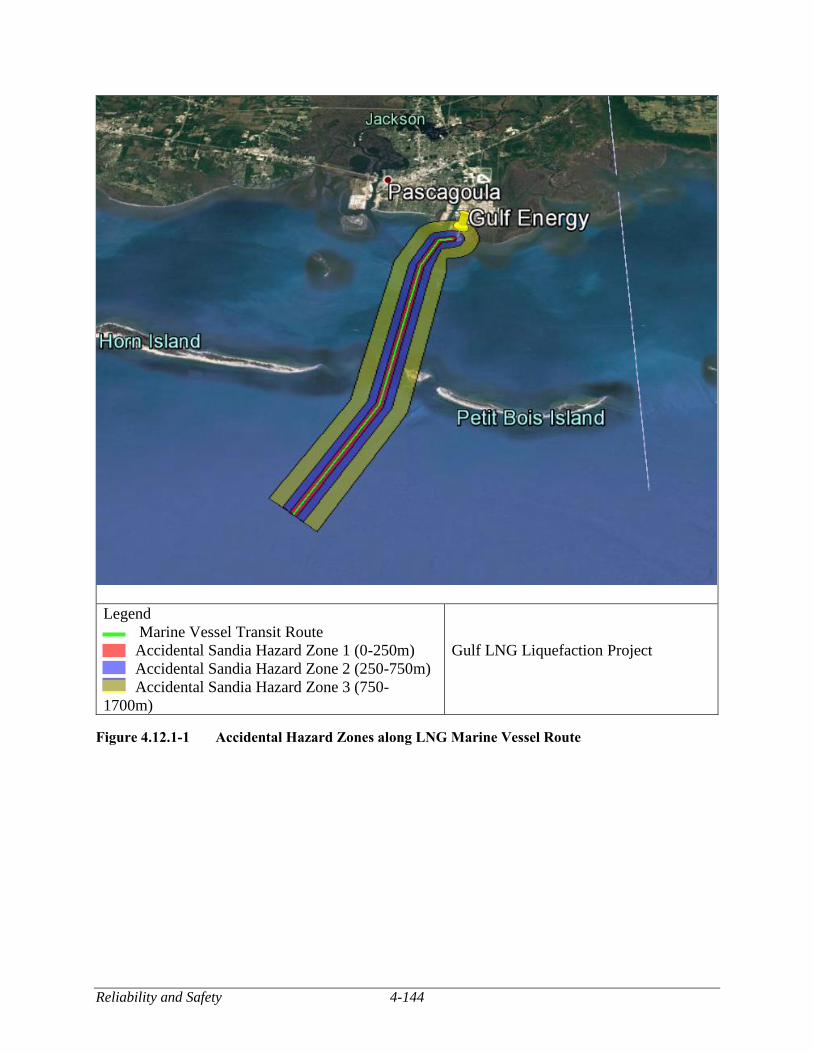
Reliability and Safety 4-144
Legend
Marine Vessel Transit Route
Accidental Sandia Hazard Zone 1 (0-250m)
Accidental Sandia Hazard Zone 2 (250-750m)
Accidental Sandia Hazard Zone 3 (750-
1700m)
Gulf LNG Liquefaction Project
Figure 4.12.1-1 Accidental Hazard Zones along LNG Marine Vessel Route
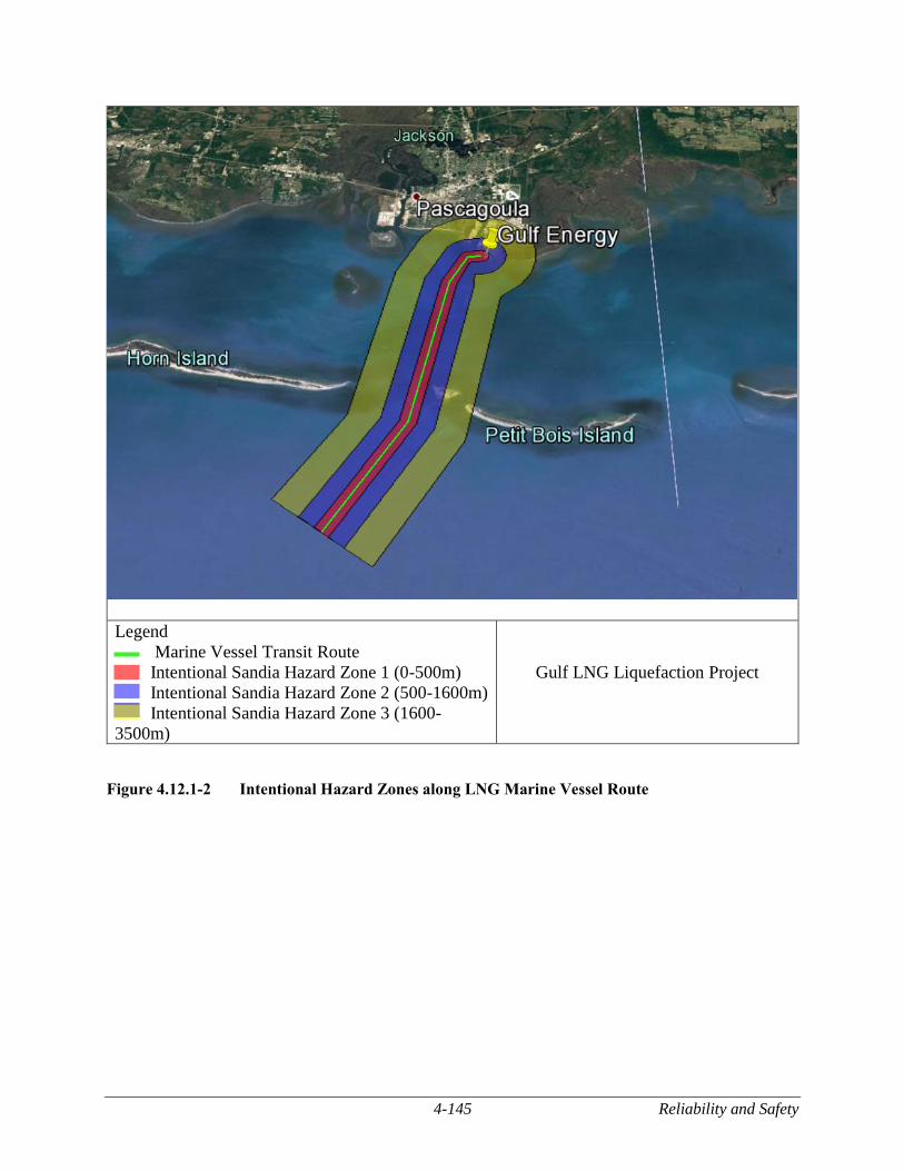
4-145 Reliability and Safety
Legend
Marine Vessel Transit Route
Intentional Sandia Hazard Zone 1 (0-500m)
Intentional Sandia Hazard Zone 2 (500-1600m)
Intentional Sandia Hazard Zone 3 (1600-
3500m)
Gulf LNG Liquefaction Project
Figure 4.12.1-2 Intentional Hazard Zones along LNG Marine Vessel Route
Reliability and Safety 4-146
Coast Guard Letter of Recommendation and Analysis
In a letter dated May 4, 2016, the USCG issued an LOR and LOR Analysis to FERC stating that
the Bayou Casotte turning basin, Bayou Casotte Channel, Lower Pascagoula Channel, Horn Island Pass
Channel, and Pascagoula Bar Channel would be considered suitable for accommodating the type and
frequency of LNG marine traffic associated with this Project. The LOR was based on full implementation
of the strategies and risk management measures identified by the USCG to Gulf LNG in its WSA, Follow-
On WSA, and Amendment to the Follow-On WSA.
Although Gulf LNG has suggested mitigation measures for responsibly managing the maritime
safety and security risks associated with LNG marine vessel traffic, the necessary marine vessel traffic
and/or facility control measures may change depending on changes in conditions along the waterway. The
USCG regulations in 33 CFR 127 require that applicants annually review WSAs until a facility begins
operation. The annual review and report to the USCG would identify any changes in conditions, such as
changes to the port environment, the LNG facility, or the LNG marine vessel route, that would affect the
suitability of the waterway. Gulf LNG submitted its annual WSA update on July 17, 2018 and the USCG
determined that the annual review met the requirements of 33 CFR 127.
The USCG’s LOR is a recommendation, regarding the current status of the waterway, to the FERC,
the lead agency responsible for siting the on-shore LNG facility. Neither the USCG nor the FERC has
authority to require waterway resources of anyone other than the applicant under any statutory authority or
under the ERP or the Cost-Sharing Plan. As stated in the LOR, the USCG would assess each transit on a
case by case basis to identify what, if any, safety and security measures would be necessary to safeguard
the public health and welfare, critical infrastructure and key resources, the port, the marine environment,
and the LNG marine vessel.
Under the Ports and Waterways Safety Act, the Magnuson Act, the MTSA, and the Security and
Accountability For Every (SAFE) Port Act, the COTP has the authority to prohibit LNG transfer or LNG
marine vessel movements within his or her area of responsibility if he or she determines that such action is
necessary to protect the waterway, port, or marine environment. If this Project is approved and if
appropriate resources are not in place prior to LNG marine vessel movement along the waterway, then the
COTP would consider at that time what, if any, marine vessel traffic and/or facility control measures would
be appropriate to adequately address navigational safety and maritime security considerations.
LNG Facility Security Regulatory Requirements
The security requirements for the proposed Gulf LNG Liquefaction Project are governed by 33
CFR 105, 33 CFR 127, and 49 CFR 193, Subpart J – Security. Title 33 CFR 105, as authorized by the
MTSA, requires all terminal owners and operators to submit a Facility Security Assessment (FSA) and a
FSP to the USCG for review and approval before commencement of operations of the proposed Project
facilities. The existing facility has a FSP, as required by 33 CFR 105, which has been approved by the
USCG. However, Gulf LNG would be expanding beyond the footprint of the existing Terminal and would
need to update the FSP to account for the Terminal Expansion. Gulf LNG would be required to control and
restrict access, patrol and monitor the plant, detect unauthorized access, and respond to security threats or
breaches under 33 CFR 105. In addition, some of the already existing responsibilities of the applicant that
may need to be updated include, but are not limited to:
designating a Facility Security Officer with a general knowledge of current security threats
and patterns, security assessment methodology, marine vessel and facility operations,
conditions, security measures, emergency preparedness, response, and contingency plans,
who would be responsible for implementing the FSA and FSP and performing an annual
audit for the life of the Project;
4-147 Reliability and Safety
conducting a FSA to identify site vulnerabilities, possible security threats and consequences
of an attack, and facility protective measures; developing a FSP based on the FSA, with
procedures for: responding to transportation security incidents; notification and coordination
with federal, state, and local authorities; prevention of unauthorized access; measures to
prevent or deter entrance with dangerous substances or devices; training; and evacuation;
defining the security organizational structure with facility personnel with knowledge or
training in current security threats and patterns; recognition and detection of dangerous
substances and devices, recognition of characteristics and behavioral patterns of persons who
are likely to threaten security; techniques to circumvent security measures; emergency
procedures and contingency plans; operation, testing, calibration, and maintenance of security
equipment; and inspection, control, monitoring, and screening techniques;
implementing scalable security measures to provide increasing levels of security at increasing
maritime security levels for facility access control, restricted areas, cargo handling, LNG
marine vessel stores and bunkers, and monitoring; ensuring that the Transportation Worker
Identification Credential (TWIC) program is properly implemented;
ensuring coordination of shore leave for LNG marine vessel personnel or crew change out as
well as access through the facility for visitors to the LNG marine vessel;
conducting drills and exercises to test the proficiency of security and facility personnel on a
quarterly and annual basis; and
reporting all breaches of security and transportation security incidents to the National
Response Center.
Title 33 CFR 127 has requirements for access controls, lighting, security systems, security
personnel, protective enclosures, communications, and emergency power that would also need to be applied
to the Gulf LNG Liquefaction Project. In addition, a waterfront facility handling LNG regulated under 33
CFR 105 and 33 CFR 127 would be subject to the TWIC Reader Requirements Rule issued by the USCG
on August 23, 2016. This rule requires owners and operators of certain marine vessels and facilities
regulated by the USCG to conduct electronic inspections of TWICs (e.g., readers with biometric fingerprint
authentication) as an access control measure. The final rule would also include recordkeeping requirements
and security plan amendments that would incorporate these TWIC requirements. The implementation of
the rule was first proposed to be in effect August 23, 2018. In a subsequent notice issued on June 22, 2018,
USCG indicated delaying the effective date for certain facilities by 3 years, until August 23, 2021. On
August 2, 2018, the President of the United States signed into law the TWIC Accountability Act of 2018
(H.R. 5729). This prohibits the USCG from implementing the rule requiring electronic inspections of
TWICs until after the Department of Homeland Security (DHS) has submitted a report to the
Congress. Although the implementation of this rule has been postponed, the company may need to consider
the rule when developing access control and security plan provisions for the facility.
Title 49 CFR 193 Subpart J also specifies security requirements for the on-shore component of
LNG facilities, as defined in 49 CFR 193, including requirements for conducting security inspections and
patrols, liaison with local law enforcement officials, design and construction of protective enclosures,
lighting, monitoring, alternative power sources, and warning signs. The existing Terminal, as defined in
49 CFR 193, is subject to these requirements already and Gulf LNG would augment their security program
to take into account the Gulf LNG Liquefaction Project facilities subject to 49 CFR 193.
If the Gulf LNG Liquefaction Project is constructed and operated, compliance with the security
requirements of 33 CFR 105, 33 CFR 127, and 49 CFR 193 Subpart J would be subject to the respective
USCG and DOT inspection and enforcement programs.
Reliability and Safety 4-148
Gulf LNG provided preliminary information on these security features and indicated additional
details would be completed in the final design. We recommend in section 4.12.1.5 that Gulf LNG provide
final design details on these security features, for review and approval, including: lighting coverage
drawings in final design that illustrate photometric analyses demonstrating the lux levels at the interior of
the terminal are in accordance with the electrical systems specification and referenced API 540, and in
accordance with federal regulations for lighting, including along the perimeter fence line and along
paths/roads of access and egress; camera coverage drawings in final design illustrate coverage areas of each
camera such that the entire perimeter of the plant is covered with redundancy and the interior of the plant
is covered including within pretreatment areas, within liquefaction areas, within truck transfer areas, within
marine transfer areas, and buildings; fencing drawings in final design demonstrate a fence would deter or
mitigate entry along the perimeter of the entire facility and is set back from exterior structures and
vegetation, and from interior hazardous piping and equipment by at least 10 feet; vehicle barrier and
controlled access point drawings in final design demonstrate crash rated barriers are provided to prevent
uncontrolled access, inadvertent entry, and impacts to components containing hazardous fluids from
vehicles. Furthermore, in accordance with the February 2004 Interagency Agreement among FERC, DOT,
and USCG, FERC staff would collaborate with USCG and DOT on the Project’s security features.
FERC Engineering and Technical Review of the Preliminary Engineering Designs
LNG Facility Historical Record
The operating history of the U.S. LNG industry has been free of safety-related incidents resulting
in adverse effects on the public or the environment with the exception of the October 20, 1944, failure at
an LNG plant in Cleveland, Ohio. The 1944 incident in Cleveland led to a fire that killed 128 people and
injured 200 to 400 more people.29 The failure of the LNG storage tank was due to the use of materials not
suited for cryogenic temperatures. LNG migrated through streets and into underground sewers due to
inadequate spill impoundments at the site. Current regulatory requirements ensure that proper materials
suited for cryogenic temperatures are used in the design and that spill impoundments are designed and
constructed properly to contain a spill at the site. To ensure that this potential hazard would be addressed
for proposed LNG facilities, we evaluate the preliminary and final specifications for suitable materials of
construction and for the design of spill containment systems that would properly contain a spill at the site.
Another operational accident occurred in 1979 at the Cove Point LNG plant in Lusby, Maryland.
A pump electrical seal located on a submerged electrical motor LNG pump leaked causing flammable gas
vapors to enter an electrical conduit and settle in a confined space. When a worker switched off a circuit
breaker, the flammable gas ignited, causing severe damage to the building and a worker fatality. With the
participation of the FERC, lessons learned from the 1979 Cove Point accident led to changes in the national
fire codes to better ensure that the situation would not occur again. To ensure that this potential hazard
would be addressed for proposed facilities that have electrical seal interfaces, we evaluated the preliminary
designs and recommend in section 4.12.1.5 that Gulf LNG provide, for review and approval, the final design
details of the electrical seal design at the interface between flammable fluids and the electrical conduit or
wiring system, details of the electrical seal leak detection system, and the details of a downstream physical
break (i.e., air gap) in the electrical conduit to prevent the migration of flammable vapors.
On January 19, 2004, a blast occurred at Sonatrach’s Skikda, Algeria, LNG liquefaction plant that
killed 27 and injured 56 workers. No members of the public were injured. The findings of the accident
investigation suggested that a cold hydrocarbon leak occurred at Liquefaction Train 40 and was introduced
into a high-pressure steam boiler by the combustion air fan. An explosion developed inside the boiler
29 For a description of the incident and the findings of the investigation, see “U.S. Bureau of Mines, Report on the
Investigation of the Fire at the Liquefaction, Storage, and Regasification Plant of the East Ohio Gas Co., Cleveland, Ohio,
October 20, 1944,” dated February 1946.
4-149 Reliability and Safety
firebox, which subsequently triggered a larger explosion of the hydrocarbon vapors in the immediate
vicinity. The resulting fire damaged the adjacent liquefaction process and liquid petroleum gas separation
equipment of Train 40, and spread to Trains 20 and 30. Although Trains 10, 20, and 30 had been
modernized in 1998 and 1999, Train 40 had been operating with its original equipment since start-up in
1981. To ensure that this potential hazard would be addressed for proposed facilities, we evaluated the
preliminary design for mitigation of flammable vapor dispersion and ignition in buildings and combustion
equipment to ensure they would be adequately covered by hazard detection equipment that could isolate
and deactivate any combustion equipment whose continued operation could add to or sustain an emergency.
We also recommend in section 4.12.1.5 that Gulf LNG provide, for review and approval, the final design
details of hazard detection equipment, including location and elevation of all detection equipment,
instrument tag numbers, type and location, alarm indication locations, and shutdown functions of the hazard
detection equipment.
On March 31, 2014, a detonation occurred within a gas heater at Northwest Pipeline Corporation’s
LNG peak-shaving plant in Plymouth, Washington.30 This internal detonation subsequently caused the
failure of pressurized equipment, resulting in high velocity projectiles. The plant was immediately shut
down, and emergency procedures were activated, which included notifying local authorities and evacuating
all plant personnel. No members of the public were injured, but one worker was sent to the hospital for
injuries. As a result of the incident, the liquefaction trains and a compressor station located on-site were
rendered inoperable. Projectiles from the incident also damaged the control building that was located near
pre-treatment facilities and penetrated the outer shell of one of the LNG storage tanks. All damaged
facilities were ultimately taken out of service for repair. The accident investigation showed that an
inadequate purge after maintenance activities resulted in a fuel-air mixture remaining in the system. The
fuel-air mixture auto-ignited during start-up after it passed through the gas heater at full operating pressure
and temperature. To ensure that this potential hazard would be addressed for proposed facilities, we
recommend in section 4.12.1.5 that Gulf LNG provide a plan for purging, for review and approval, which
addresses the requirements of the American Gas Association Purging Principles and Practice and to
provide justification if not using an inert or non-flammable gas for purging. In evaluating such plans, we
would assess whether the purging could be done safely based on review of other plans and lessons learned
from this and other past incidents. If a plan proposes the use of flammable mediums for cleaning, dry-out
or other activities, we would evaluate the plans against other recommended and generally accepted good
engineering practices, such as NFPA 56, Standard for Fire and Explosion Prevention during Cleaning and
Purging of Flammable Gas Piping Systems.
We also recommend in section 4.12.1.5 that Gulf LNG provide, for review and approval, operating
and maintenance plans, including safety procedures, prior to commissioning. In evaluating such plans, we
would assess whether the plans cover all standard operations, including purging activities associated with
start-up and shutdown. Also, in order to prevent other sources of projectiles from affecting occupied
buildings and storage tanks, we recommend in section 4.12.1.5 that Gulf LNG incorporate mitigation into
their final design with supportive information, for review and approval, that demonstrates it would mitigate
the risk of a pressure vessel burst or boiling liquid expanding vapor explosion (BLEVE) from occurring.
FERC Preliminary Engineering Review
FERC requires an applicant to provide safety, reliability, and engineering design information as
part of its application, including hazard identification studies and front-end-engineering-design (FEED)
information for its proposed Project. FERC staff evaluates this information with a focus on potential
hazards from within and nearby the site, including external events, which may have the potential to cause
30 For a description of the incident and the findings of the investigation, see Root Cause Failure Analysis, Plymouth LNG Plant
Incident Investigation under CP14-515.
Reliability and Safety 4-150
damage or failure to the Project facilities, and the engineering design and safety and reliability concepts of
the various protection layers to mitigate the risks of potential hazards.
The primary concerns are those events that could lead to a hazardous release of sufficient magnitude
to create an off-site hazard or interruption of service. In general, FERC staff considers an acceptable design
to include various layers of protection or safeguards to reduce the risk of a potentially hazardous scenario
from developing into an event that could impact the off-site public. These layers of protection are generally
independent of one another so that any one layer would perform its function regardless of the initiating
event or failure of any other protection layer. Such design features and safeguards typically include:
a facility design that prevents hazardous events, including the use of inherently safer designs;
suitable materials of construction; adequate design margins from operating limits for process
piping, process vessels, and storage tanks; adequate design for wind, flood, seismic, and other
outside hazards;
control systems, including monitoring systems and process alarms, remotely-operated control
and isolation valves, and operating procedures to ensure that the facility stays within the
established operating and design limits;
safety-instrumented prevention systems, such as safety control valves and emergency
shutdown systems, to prevent a release if operating and design limits are exceeded;
physical protection systems, such as appropriate electrical area classification, proper
equipment and building spacing, pressure relief valves, spill containment, and cryogenic,
overpressure, and fire structural protection, to prevent escalation to a more severe event;
site security measures for controlling access to the plant, including security inspections and
patrols, response procedures to any breach of security, and liaison with local law enforcement
officials; and
on-site and off-site emergency response, including hazard detection and control equipment,
firewater systems, and coordination with local first responders, to mitigate the consequences
of a release and prevent it from escalating to an event that could impact the public.
The inclusion of such protection systems or safeguards in a plant design can minimize the potential
for an initiating event to develop into an incident that could impact the safety of the off-site public. The
reviews of the engineering design for these layers of protection are initiated in the application process and
carried through to the next phase of the proposed Project in final design if authorization is granted by the
Commission.
The reliability of these layers of protection is informed by occurrence and likelihood of root causes
and the potential severity of consequences based on past incidents and validated hazard modeling. As a
result of the continuing engineering review, FERC staff recommend mitigation measures and continuous
oversight to the Commission for consideration to include as conditions in the Order. If a facility is
authorized and recommendations are adopted as conditions to the Order, FERC staff would continue its
engineering review through final design, construction, commissioning, and operation.
Process Design Review
In order to liquefy natural gas, most liquefaction technologies require that the feed gas stream be
pre-treated to remove components that could freeze out and clog the liquefaction equipment or would
otherwise be incompatible with the liquefaction process or equipment, including mercury, H2S, CO2, water,
and heavy hydrocarbons. For example, mercury is typically limited to concentrations less than 0.01
4-151 Reliability and Safety
microgram per normal cubic meter because it can cause embrittlement and corrosion resulting in
catastrophic failure of equipment.
The inlet gas would be conditioned by a filter/coalescer to remove solids and entrained water
droplets prior to entering feed gas pre-treatment processes. Once the inlet gas is conditioned, the feed gas
would enter the mercury removal system consisting of mercury adsorber(s) to reduce the mercury
concentration in the feed gas. Once the mercury is removed, the feed gas would contact an amine-based
solvent solution in an acid gas absorber column to remove acid gas components (i.e., CO2 and H2S). Once
the acid gas components accumulate in the amine solution, the amine solution is routed to a solvent
regenerator column that utilizes a reboiler to create hot amine vapor. Contact with the hot amine vapor
would release the acid gas from the amine solution. The regenerated amine solution would be recycled
back to the acid gas absorber column and the removed acid gas would be sent to a thermal oxidizer, where
CO2, H2S, and trace amounts of hydrocarbons would be incinerated. The feed gas exiting the acid gas
absorber column then enters a dryer inlet separator where bulk water would be recovered and recycled back
to the acid gas absorber column. After the dryer inlet separator, any remaining water in the feed gas would
be removed using regenerative molecular sieve beds. During the molecular sieve regeneration process,
heated regeneration gas would release water from the molecular sieve beds. Water would then be separated
from the regeneration gas and would be routed back to the acid gas removal equipment.
The dried treated feed gas is then sent through a propane pre-cooler to condense heavier
hydrocarbons prior to entering a scrub column that would separate the feed gas and the heavy hydrocarbons.
The heavy hydrocarbons would be stabilized after flowing through the deethanizer and debutanizer columns
and would be stored in the condensate storage tank and would be removed from the site by truck. The dry
treated feed gas exiting the scrub column would enter the main cryogenic heat exchanger and would be
cooled by thermal exchange with a mixed refrigerant (MR) stream. The Project expects to utilize a
liquefaction process designed and optimized by Air Products and Chemicals Inc. (APCI). After cooling
the natural gas into its liquid form, LNG would be routed to a LNG flash vessel before being pumped to
and stored in two existing full-containment LNG storage tanks.
In order to achieve the cryogenic temperatures needed to liquefy the natural gas stream in the above
process, the gas would be cooled by a MR stream comprised of a mixture of nitrogen, methane, ethane, and
propane. Methane would be provided from the dry treated feed gas stream exiting the scrub column and
both propane and ethane would be unloaded from trucks and stored on-site for initial filling and use, as
needed, for makeup. Nitrogen makeup would be provided from a nitrogen generation package that includes
a nitrogen storage vessel and vaporizer. The truck loading/unloading facility would be provided to unload
makeup refrigerants and to load condensate product for delivery into the marketplace.
As part of our engineering review, we evaluated the process flow diagrams (PFDs) and heat and
material balances (HMBs) to determine the liquefaction capacities relative to the requested capacity in the
application. While the application requests export with peak liquefaction rates of up to 11.5 million metric
tonnes per annum (mtpa), the PFDs and HMBs do not cover this liquefaction range and suggest a maximum
liquefaction rate of 10.85 mtpa. This is important as the PFDs and HMBs provide the flow rates, pressures,
and temperatures that form the basis of design for other engineering documents, including piping and
instrumentation diagrams (P&IDs), piping specifications, hazard analyses, and other pertinent engineering
information. As a result, Gulf LNG indicated, in a response to our January 11, 2018 data request, that Gulf
LNG is requesting authorization produce 10.85 mtpa of LNG at its proposed facility. We recommend in
section 4.12.1.5 that Gulf LNG provide updated PFDs and HMBs and any other engineering documentation.
During export operations, LNG stored within the existing LNG storage tanks would be sent out
through multiple new in-tank pumps (the pump discharge piping would penetrate through the roof and is
an inherently safer design when compared to penetrating the side of an LNG storage tank) and would be
routed through modified discharge lines (the discharge lines would have an increased diameter to
Reliability and Safety 4-152
accommodate higher flow). The LNG would then flow through an existing marine transfer line and multiple
liquid marine transfer arms connected to LNG marine vessel. In order to keep the marine transfer line cold
between LNG export cargoes, an existing LNG recirculation line would keep the marine transfer line cold
and avoid cool down prior to every LNG carrier loading operation. The LNG transferred to the LNG marine
vessel would displace vapors from the marine vessel, which would be sent back through a vapor marine
transfer arm, a new vapor return line, and into the BOG header. Once loaded, the LNG marine vessel would
be disconnected and leave for export.
Low-pressure BOG generated from stored LNG (LNG is continuously boiling) as well as vapors
returned during LNG carrier filling operations would be compressed and would be split between the fuel
gas system and the feed gas stream prior to the liquefaction process. The closed BOG system would prevent
the release of BOG to the atmosphere and would be in accordance with NFPA 59A. This would be an
inherently safer design when compared to allowing the BOG to vent to the atmosphere.
In addition, the Project would include many utilities and associated auxiliary equipment. The major
auxiliary systems required for the operation of the liquefaction facility include fuel gas, hot oil, flares,
instrument and utility air, water, demineralized water, nitrogen, and backup power. Hot oil would provide
heat to the acid gas removal unit inlet gas heater, amine regeneration reboiler, molecular sieve regeneration
gas heater, fuel gas heater, deethanizer reboiler, deethanizer overhead heater, and debutanizer reboiler.
There would be three flare systems: warm (wet), cold (dry), and low-pressure flares plus a common spare
flare. Each system would be routed to a separate flare stack and would be designed to handle and control
the vent gases from the process areas. Electric power would be generated off-site by the MPC system.
Diesel would be stored in a single above ground tank and would supply diesel to day tanks for each essential
diesel generator. In addition, diesel day tanks would be provided for the diesel firewater pumps. The
nitrogen generation system would supply gaseous nitrogen for various uses in the plant including pre-
commissioning, start-up, and refrigerant makeup. In addition, aqueous ammonia would be used in the
selective catalytic removal process to reduce the NOx emissions from gas turbine exhausts.
The failure of process equipment could pose potential harm if not properly safeguarded through the
use of appropriate controls and operation. Gulf LNG would install process control valves and
instrumentation to safely operate and monitor the facilities. Alarms would have visual and audible
notification in the control room to warn operators that process conditions may be approaching design limits.
Operators would have the capability to take action from the control room to mitigate an upset. Gulf LNG
would develop facility operation procedures after completion of the final design; this timing is fully
consistent with accepted industry practice. Gulf LNG indicated it would design their control systems and
human machine interfaces to the International Society for Automation (ISA) Standards 60.1, 60.3, 60.4,
and 60.6, and other standards and recommended practices, but did not make any references to some more
commonly recognized and generally accepted good engineering practices, such as ISA 5.3, Graphic
Symbols for Distributed Control/Shared Display Instrumentation, Logic, and Computer Systems, and ISA
5.5, Graphic Symbols for Process Displays. FERC staff recommends that Gulf LNG provide final
specifications for these systems. We would verify these include specifications for human machine interface
and other provisions to reduce the likelihood of human error that are similar to those in the ISA standards.
We also recommend in section 4.12.1.5 that Gulf LNG develop and implement an alarm management
program, for review and approval to ensure the effectiveness of the alarms. FERC staff would evaluate the
alarm management program against recommended and generally accepted good engineering practices, such
as ISA Standard 18.2.
Operators would have the capability to take action from the control room to mitigate an upset. Gulf
LNG would develop facility operation procedures after completion of the final design; this timing is fully
consistent with accepted industry practice. We recommend in section 4.12.1.5 that Gulf LNG provide more
information, for review and approval, on the operating and maintenance procedures, including safety
procedures, hot work procedures and permits, abnormal operating conditions procedures, and personnel
4-153 Reliability and Safety
training prior to commissioning. We would evaluate these procedures to ensure that an operator can operate
and maintain all systems safely, based on benchmarking against other operating and maintenance plans and
comparing against recommended and generally accepted good engineering practices, such as American
Institute of Chemical Engineers (AIChE) Center for Chemical Process Safety (CCPS), Guidelines for
Writing Effective Operating and Maintenance Procedures, AIChE CCPS, Guidelines for Management of
Change for Process Safety, AIChE CCPS, Guidelines for Effective Pre-Startup Safety Reviews, AGA,
Purging Principles and Practices, and NFPA 51B, Standard for Fire Prevention During Welding, Cutting,
and Other Hot Work. In addition, we recommend in section 4.12.1.5 that Gulf LNG tag and label
instrumentation and valves, piping, and equipment and provide car-seals/locks to address human factor
considerations and improve facility safety and prevent incidents.
In the event of a process deviation, ESD valves and instrumentation would be installed to monitor,
alarm, shutdown, and isolate equipment and piping during process upsets or emergency conditions. As
clarified in comments on the draft EIS, the Project would have a plant-wide ESD system to initiate closure
of valves and shutdown of the process during emergency situations as well as the ability to shutdown
specific areas to address local emergency conditions. The ESD system for existing equipment would
remain in place. Safety-instrumented systems would comply with ISA Standard 84.00.01 and other
recommended and generally accepted good engineering practices. We also recommend in section 4.12.1.5
that Gulf LNG file information, for review and approval, on the final design, installation, and
commissioning of instrumentation and ESD equipment to ensure appropriate cause-and-effect alarm or
shutdown logic and enhanced representation of the ESD system in the plant control room and throughout
the plant.
In developing the FEED, Gulf LNG conducted a simplified process hazard review (PHR) to identify
potential hazards (both safety and environmental) associated with the design of the process and the facility.
The PHR applied a checklist approach to identify hazards through review of the PFDs and other documents
such as the HMBs, process descriptions, and plot plans. However, Gulf LNG did not consider the process
details from the P&IDs in the PHR. Therefore, we made a recommendation in section 4.12.1.5 that at the
onset of detailed engineering to identify major process design issues prior to detailed design, Gulf LNG
provide, for review and approval, a preliminary hazard and operability review of the completed design.
Commonly, a more detailed hazard and operability review (HAZOP) analysis would be performed
during the final design to identify the major process hazards that may occur during the operation of the
facilities. The HAZOP study would be intended to address hazards of the process, engineering and
administrative controls and would provide a qualitative evaluation of a range of possible safety, health, and
environmental consequences that may result from the process hazard, and identify whether there are
adequate safeguards (e.g., engineering and administrative controls) to prevent or mitigate the risk from such
events. Where insufficient engineering or administrative controls were identified, recommendations to
prevent or minimize these hazards would be generated from the results of the HAZOP review. We
recommend in section 4.12.1.5 that Gulf LNG file the HAZOP study on the completed final design for
review and approval. We would evaluate the HAZOP to ensure all systems and process deviations are
addressed appropriately based on likelihood, severity, and risk values with commensurate layers of
protection in accordance with recommended and generally accepted good engineering practices, such as
American Institute of Chemical Engineers, Guidelines for Hazard Evaluation Procedures. We also
recommend in section 4.12.1.5 that Gulf LNG file the resolutions of the recommendations generated by the
HAZOP review for evaluation and approval by FERC staff. Once the design has been subjected to a
HAZOP review, the design development team would track, manage, and keep records of changes in the
facility design, construction, operations, documentation, and personnel. Gulf LNG would evaluate these
changes to ensure that the safety, health, and environmental risks arising from these changes are addressed
and controlled based on its management of change procedures. If our recommendations are adopted into
the Commission Order, resolutions of the recommendations generated by the HAZOP review would be
Reliability and Safety 4-154
monitored by FERC staff. We also recommend in section 4.12.1.5 that Gulf LNG file all changes to their
FEED for review and approval by FERC staff. However, major modifications could require an amendment
or new proceeding.
If the Project is authorized, constructed, and operated, Gulf LNG would install equipment in
accordance with its design. We recommend in section 4.12.1.5 that Project facilities be subject to
construction inspections and that Gulf LNG provide, for review and approval, commissioning plans,
procedures and commissioning demonstration tests that would verify the performance of equipment. In
addition, we recommend in section 4.12.1.5 that Gulf LNG provide semi-annual reports that include
abnormal operating conditions and planned facility modifications. Furthermore, we recommend in section
4.12.1.5 that the Project facilities be subject to regular inspections throughout the life of the facilities to
verify that equipment is being properly maintained and to verify basis of design conditions, such as feed
gas and send out conditions, do not exceed the original basis of design.
Mechanical Design Review
Gulf LNG provided codes and standards for the design, fabrication, construction, and installation
of piping and equipment and additional specifications for the facility. The design specifies materials of
construction and ratings suited to the pressure and temperature conditions of the process design. Piping
would be designed, fabricated, assembled, erected, inspected, examined, and tested in accordance with the
American Society of Mechanical Engineers (ASME) Standards B31.3, B36.10/M, and B36.19/M. Valves
and fittings would be designed to standards and recommended practices such as API Standards 6FA, 594,
598, 600, 602, 607, 608, and 609; ASME Standards B16.5, B16.9, B16.10, B16.11, B16.20, B16.21,
B16.25, B16.34, B16.47, and B16.48; and ISA Standards 75.08.01, 75.08.02, 75.0805, 75.08.06, 75.19.01.
Portions of the facility regulated under 33 CFR 127 for the marine transfer system, including piping, should
also be tested in accordance with 33 CFR 127.407.
Pressure vessels must be designed, fabricated, inspected, examined, and tested in accordance with
ASME Boiler and Pressure Vessel Code (BPVC) Section VIII per 49 CFR 193 Subparts C, D, and E and
NFPA 59A (2001). In addition, the operator should verify the set pressure of the pressure relief valves
meet the requirements in 33 CFR 127.407.
Low-pressure storage tanks such as the amine and condensate storage tanks, would be designed,
inspected, and maintained in accordance with the API Standards 620, 625, and 650. Heat exchangers would
be designed to ASME BPVC Section VIII standards; API Standards 530, 660, 661, and 662; and the
Tubular Exchanger Manufacturers Association standards. Rotating equipment would be designed to
standards and recommended practices, such as API Standards 610, 613, 614, 616, 617, 619, 670, 671, 672,
675, 682, and 686; and ASME Standards B73.1 and B73.2. Fired heaters would be specified and designed
to standards and recommended practices, such as API Standards 556 and 560.
Pressure and vacuum safety relief valves and flares would be installed to protect the storage
containers, pressure vessels, process equipment, and piping in the event of an unexpected vapor release or
uncontrolled pressure excursion. The safety relief valves would be designed to handle process upsets and
thermal expansion, per NFPA 59A (2001), ASME Standard B31.3, and ASME BPVC Section VIII; and
would be designed in accordance with API Standards 520, 521, 526, 527, 537, and 2000; and other
recommended and generally accepted good engineering practices. In addition, we recommend in section
4.12.1.5 that Gulf LNG provide final design information on pressure and vacuum relief devices and flares,
for review and approval, to ensure that the final sizing, design, and installation of these components are
adequate and in accordance with the standards reference and other recommended and generally accepted
good engineering practices.
4-155 Reliability and Safety
Although many of the codes and standards were described or listed as ones the project would meet,
Gulf LNG did not make reference to all codes and standards required by regulations (e.g., NFPA 51B) or
that are recommended and generally accepted good engineering practices (e.g., API 618, API 653,
NFPA 25, etc.). Therefore, we recommend in section 4.12.6 that Gulf LNG provide the final specifications
for all equipment and a cross referenced list of all referenced codes and standards for review and approval.
If the Project is authorized, constructed, and operated, Gulf LNG would install equipment in
accordance with its design and FERC staff would verify equipment nameplates to ensure equipment is being
installed based on the approved design. In addition, we would conduct construction inspections including
reviewing quality assurance and quality control plans to ensure construction work is being performed
according to proposed Project specifications, procedures, codes, and standards. We recommend in section
4.12.1.5 that Gulf LNG provide semi-annual reports that include equipment malfunctions and abnormal
maintenance activities. In addition, we recommend in section 4.12.1.5 that the Project facilities be subject
to inspections throughout the life of the facility to verify that the plant equipment is being properly
maintained.
Hazard Mitigation Design Review
If operational control of the facilities were lost and operational controls and ESD systems failed to
maintain the Gulf LNG Liquefaction Project within the design limits of the piping, containers, and safety
relief valves, a release could potentially occur. FERC regulations under 18 CFR 380.12(o)(1) through (4)
require applicants to provide information on spill containment, spacing and plant layout, hazard detection,
hazard control, and firewater systems. In addition, 18 CFR 380.12(o)(7) require applicants to provide
engineering studies on the design approach and 18 CFR 380.12(o)(14) requires applicants to demonstrate
how they comply with 49 CFR 193 and NFPA 59A. As required by 49 CFR Part 193 Subpart I and by
incorporation Section 9.1.2 of NFPA 59A (2001), fire protection must be provided for all DOT-regulated
LNG plant facilities based on an evaluation of sound fire protection engineering principles, analysis of local
conditions, hazards within the facility, and exposure to or from other property. NFPA 59A (2001) also
requires a fire protection evaluation to determine the type, quantity, and location of hazard detection and
hazard control, passive fire protection, ESD and depressurizing systems, and emergency response
equipment, training, and qualifications. If authorized, constructed, and operated, LNG facilities as defined
in 49 CFR 193, must comply with the requirements of 49 CFR 193 Subpart I and would be subject to DOT’s
inspection and enforcement programs. However, NFPA 59A (2001) also indicates the wide range in size,
design, and location of LNG facilities precludes the inclusion of detailed fire protection provisions that
apply to all facilities comprehensively and includes subjective performance-based language on where ESD
systems and hazard control are required and does not provide any additional guidance on placement or
selection of hazard detection equipment and provides minimal requirements on firewater. Also, the Project
marine facilities would be subject to 33 CFR 127, which incorporates sections of NFPA 59A (1994), which
have similar performance-based guidance. Therefore, we evaluated the proposed spill containment and
spacing, hazard detection, ESD and depressurization systems, hazard control, firewater coverage, structural
protection, and on-site and off-site emergency response to determine whether they would provide adequate
protection of the LNG facilities as described more fully below.
Gulf LNG performed a preliminary fire protection evaluation to ensure that adequate mitigation
would be in place, including spill containment and spacing, hazard detection, ESD and depressurization
systems, hazard control, firewater coverage, and structural protection. Although the preliminary fire
protection evaluation did not address on-site and off-site emergency response (e.g., plans, equipment,
training, or qualifications), Gulf LNG indicated they would update their existing ERP for the potential
hazards introduced by the Project that did not exist previously. We recommend in section 4.12.1.5 that
Gulf LNG provide a final fire protection evaluation, for review and approval, that evaluates the type,
quantity, and location of hazard detection and hazard control, passive fire protection, emergency shutdown
Reliability and Safety 4-156
and depressurizing systems, and emergency response equipment, training and qualifications in accordance
with NFPA 59A (2001), and to provide more information on the final design, installation, and
commissioning of spill containment, hazard detection, hazard control, firewater systems, structural fire
protection, and on-site and off-site emergency response procedures for review and approval.
Spill Containment
In the event of a release, sloped areas at the base of storage and process facilities would direct a
spill away from equipment and into the impoundment system. This arrangement would minimize the
dispersion of flammable vapors into confined, occupied, or public areas and minimize the potential for heat
from a fire to impact adjacent equipment, occupied buildings, or public areas if ignition were to occur.
Gulf LNG proposes to install an LNG Process Area impoundment located in each of the two
liquefaction units that would collect a spill from the LNG liquefaction areas. Gulf LNG also proposes to
install a Refrigerant Process Area impoundment for each of the two liquefaction units to collect spills from
all other process equipment in the train. Gulf LNG proposes to install an LNG Transfer Area impoundment
located in the BOG Compressor Area that would collect a potential spill from the LNG pumps and rundown
lines, the BOG compressor suction drum, and the end flash drums. In this area, the elevated spill trough
for the LNG rundown lines from the trains is proposed to transition to two downcomers to direct a spill into
the impounding area. One rundown line would also run through each downcomer. We will evaluate the
downcomer sizing calculations during final design. We acknowledge that Gulf LNG must comply with 49
CFR 193, regarding spill downcomers that are not associated with a container. LNG pumped from the end
flash drums to the existing storage tanks would be routed over a concrete trough which would drain to the
existing impoundment basin near the LNG tanks. Any spill from the new LNG withdrawal lines from the
existing LNG storage tanks would also be directed to this existing impoundment near the tanks. Tank top
spill collection is proposed to be expanded to serve the larger pump platform area. Gulf LNG proposes to
install a Diesel/Hot Oil Unloading impoundment located in the Utility Area that would collect potential
diesel and hot oil spills from that truck unloading area as well as from a propane transfer line. Gulf LNG
also proposes additional propane transfer impounding area in the Utility Area. A Diesel Storage Tank
impoundment and Hot Oil Tank impoundment would be provided to contain a full failure of each of those
tanks. In the Project storage area, Gulf LNG proposes a Refrigerant/Condensate Truck Unloading
impoundment that would contain spills in that area. Gulf LNG also proposes a Refrigerant/Condensate
transfer sump in the storage area to collect transfer piping spills. A Condensate/Off-spec Storage Tank
impoundment would be provided to contain a full failure of that tank. Gulf LNG would also provide a
Propane Storage Sphere Impoundment, which it proposes would be designed to contain the liquid remaining
after flashing from a full failure of that tank. In addition, Gulf proposes a curbed area under the three
Ethane Storage Tanks, which is indicated to be based on NFPA 55 Section 6.13. However, NFPA 55
Chapter 6 is for building related controls and NFPA 55 Section 6.13 specifically excludes compressed gases
as needing any spill containment. We recommend that spill containment be provided for all hazardous
fluids if the spill containment reduces the consequences based on the maximum amount of liquid that can
rainout after a release. Gulf LNG would also provide a Solvent Storage Tank impoundment and an Aqueous
Ammonia Storage Drum impoundment to contain a full failure of each of those vessels. FERC staff was
not able to verify the provision of containment for all significant amounts of hazardous liquids, such as for
the liquid nitrogen storage area, heated hot oil areas, the aqueous ammonia truck transfer, and other
hazardous fluid facilities. We recommend in section 4.12.1.5 that Gulf LNG provide additional information
on the final design of the impoundment systems for review and approval.
Under NFPA 59A (2001) Section 2.2.2.2, the capacity of impounding areas for vaporization,
process, or LNG transfer areas must equal the greatest volume that can be discharged from any single
accidental leakage source during a 10-minute period or during a shorter time period based upon
demonstrable surveillance and shutdown provisions acceptable to the DOT. If authorized, constructed, and
4-157 Reliability and Safety
operated, LNG facilities as defined in 49 CFR 193, must comply with the requirements of 49 CFR 193
Subpart C and would be subject to DOT’s inspection and enforcement programs. The impoundment system
design for the marine facilities would be subject to the USCG’s 33 CFR 127, which does not specify a spill
or duration for impoundment sizing. However, FERC staff evaluates whether all hazardous liquids are
provided with spill containment based on the largest flow capacity from a single pipe for 10 minutes
accounting for de-inventory or the liquid capacity of the largest vessel (or total of impounded vessels)
served, whichever is greater and whether providing spill containment reduces consequences from a release.
Some details would need to be clarified and adjustments would need to be made during the final design
phase, including but not limited to, evaluation of the impounding area or prevention mechanisms needed
for the sizing spill for the new in-tank LNG pumps, clarification of maximum liquid levels for vessels and
tanks, calculation of usable impoundment volumes considering only the depth under any trough intersection
and considering the volume used by any foundations and equipment, sizing of all hazardous liquid trenches
and troughs, routing of unloading/transfer piping in storage areas and also detailed justification, including
verification or validation, for liquid spill calculations for the size, fluid type, and potential orientations for
the refrigerant sizing spills. FERC staff would verify adequate sizing of the final containment design during
our final design review, based on our recommendation in section 4.12.1.5 that Gulf LNG provide additional
information on the final design of the impoundment systems for review and approval.
FERC staff also generally evaluate the means to remove water and snow from impounding areas to
ensure impoundment volumes would not be reduced through accumulation of rainwater or snow. In
addition, FERC staff generally evaluate whether there are provisions to ensure that hazardous fluids are not
accidentally discharged through the systems intended to remove rainwater or snow. In addition, if
authorized, constructed, and operated, LNG facilities, as defined in 49 CFR 193, must comply with the
requirements of 49 CFR 193 and would be subject to DOT’s inspection and enforcement programs. Gulf
LNG indicated that the stormwater removal pumps in the LNG spill containment basins would be
automatically and manually operated, and interlocked using low temperature detectors to prevent pumps
from operating if LNG is present. Gulf LNG would need to verify that the sump pumps meet the automatic
shutdown controls and water removal requirements specified in 49 CFR 193 Subpart C. Other hazardous
liquid impounding areas were indicated to have a manual outlet valve and drain piping as required.
Therefore, we recommend in section 4.12.1.5 that Gulf LNG provides correspondence from DOT
demonstrating the sump pump design meets DOT regulations regarding automatic shutdown controls and
water removal systems.
If the Project is authorized, constructed, and operated, Gulf LNG would install spill impoundments
in accordance with its design and FERC staff would verify during construction inspections that the spill
containment system including dimensions, and slopes of curbing and trenches, and volumetric capacity
matches final design information. In addition, we recommend in section 4.12.1.5 that Project facilities be
subject to regular inspections throughout the life of the facility to verify that impoundments are being
properly maintained.
Spacing and Plant Layout
The spacing of vessels and equipment between each other, from ignition sources, and to the
property line would need to meet the requirements of 49 CFR 193 Subparts C, D, and E, which incorporate
NFPA 59A (2001). NFPA 59A (2001) includes spacing and plant layout requirements and further
references NFPA Standards 30, NFPA 58, and NFPA 59 for additional spacing and plant layout
requirements. If the LNG facilities, as defined in 49 CFR 193, are authorized, constructed, and operated,
Gulf LNG must comply with the requirements of 49 CFR 193 and would be subject to DOT’s inspection
and enforcement programs.
In addition, we evaluated the spacing to determine if there could be cascading damage and to inform
what fire protection measures may be necessary to reduce the risk of cascading damage. If it was not
Reliability and Safety 4-158
practical for spacing to mitigate the potential for cascading damage, FERC staff evaluated whether other
mitigation measures were in place and evaluated those systems in further detail as discussed in subsequent
sections in section 4.12.1.5. FERC staff evaluated the spacing of buildings in line with AIChE CCPS,
Guidelines for Evaluating Process Plant Buildings for External Explosions and Fires, and API 752 and
753, which provide guidance on identifying and evaluating explosion and fire impacts to buildings and
occupants resulting from events external to the buildings. In addition, FERC staff evaluated other hazards
associated with releases and whether any damage would likely occur at buildings or would result in
cascading damage.
To minimize the risk of cryogenic spills causing structural supports and equipment from cooling
below their minimum design metal temperature, Gulf LNG would have spill containment systems
surrounding cryogenic equipment and would generally locate cryogenic equipment away from process
areas that do not handle cryogenic materials. Gulf LNG did not indicate whether cryogenic protection of
supports or equipment would be provided. Therefore, FERC staff recommends Gulf LNG file drawings
and specifications for structural passive protection systems to protect equipment and supports that could be
exposed to cryogenic releases.
To minimize risk for flammable or toxic vapor ingress into buildings and flammable vapors
reaching areas that could result in cascading damage from explosions, Gulf LNG would generally locate
buildings away from process areas and would locate fired equipment and ignition sources away from
process areas. We recommend in section 4.12.1.5 that Gulf LNG conduct a technical review of facility, for
review and approval, to identify all combustion/ventilation air intake equipment and the distances to any
possible flammable gas or toxic release; and verify that these areas would be adequately covered by hazard
detection devices that would isolate or shut down any combustion or heating ventilation and air conditioning
equipment whose continued operation could add to or sustain an emergency. We recommend in section
4.12.1.5 that Project facilities be subject to periodic inspections during construction to verify
flammable/toxic gas detection equipment is installed in heating, ventilation, and air condition intakes of
buildings at appropriate locations. In addition, we recommend in section 4.12.1.5 that Project facilities be
subject to regular inspections throughout the life of the facilities to continue to verify that flammable/toxic
gas detection equipment installed in building air intakes function as designed and are being maintained and
calibrated. To minimize the risk of pool fires from causing cascading damage, Gulf LNG would have spill
containment systems surrounding flammable and combustible equipment. However, a pool fire in any of
multiple proposed impoundments would result in high radiant heats at both adjacent elevated piperacks and
troughs. In addition, we note that radiant heats greater than 4,000 BTU/ft2-hr level from an impoundment
fire could impact process equipment, refrigerant storage vessels, process vessels, truck transfer areas, and
pipe racks. We also noted that thermal radiation levels from a LNG Rundown Line Impoundment Basin
fire could potentially impact the adjacent buildings (i.e. maintenance building and warehouse).
To mitigate against a impoundment fires and jet fires within the plant, Gulf LNG proposes thermal
radiation mitigation measures to prevent cascading events in the design, including emergency block valves
with fire protective blankets and fire resistant cables, ESD and emergency depressurization systems, fire
and gas detectors, fire proofing of structural steel columns supporting critical equipment, high expansion
foam systems, firewater monitors and hydrants, as well as consideration of deluge systems . However,
details of these systems would be developed in final design. We recommend in section 4.12.1.5 that Gulf
LNG provide the final design of these thermal mitigation measures, for review and approval, demonstrating
cascading events would be mitigated.
To address impacts from fires or explosions, we evaluated external fire and explosion risks for all
plant buildings and safety critical equipment. Results of hazard analyses indicate a number of fires and
explosions could impact buildings, but do not include occupied buildings. However, there were some
potential impacts from explosions to safety critical equipment, such as essential power generators and
firewater tanks. Therefore, we recommend in section 4.12.1.5 that Gulf LNG conduct a facility siting study,
4-159 Reliability and Safety
for review and approval, to assess explosion risks to safety critical equipment or provide refined modeling
that takes into account plant features that reduce the explosion risk and demonstrate explosions would not
impact safety critical equipment.
If the Project is authorized, Gulf LNG would finalize the plot plan, and we recommend in section
4.12.1.5 that Gulf LNG provide any changes for review and approval to ensure capacities and setbacks are
maintained. If the facilities are constructed, Gulf LNG would install equipment in accordance with the
spacing indicated on the plot plans, and we recommend in section 4.12.1.5 that Project facilities be subject
to periodic inspections during construction to verify equipment is installed in appropriate locations and the
spacing is met in the field. In addition, we recommend in section 4.12.1.5 that Project facilities be subject
to regular inspections throughout the life of the facilities to continue to verify that equipment setbacks from
other equipment and ignition sources are being maintained during operations.
Ignition Controls
Gulf LNG’s plant areas would be designated with an appropriate hazardous electrical classification
and process seals commensurate with the risk of the hazardous fluids being handled in accordance with
NFPA 59A (2001), 70, 497, and API RP 500. If authorized, constructed, and operated, LNG facilities, as
defined in 49 CFR 193, must comply with the requirements of 49 CFR Part 193 and would be subject to
DOT’s inspection and enforcement programs, which require compliance, by incorporation by reference,
with NFPA 59A (2001) and NFPA 70 (1999). The marine facilities must comply with similar electrical
area classification requirements of NFPA 59A (1994) and NFPA 70 (1993), which are incorporated by
reference into the USCG regulations in 33 CFR 127. Depending on the risk level, these areas would either
be unclassified or classified as Class 1 Division 1, or Class 1 Division 2. Electrical equipment located in
these classified areas would be designed such that in the event a flammable vapor is present, the equipment
would have a minimal risk of igniting the vapor. We evaluated the Gulf LNG electrical area classification
drawings to determine whether the Project would generally meet these electrical area classification
requirements and good engineering practices in NFPA 59A (2001), 70, 497, and API RP 500, and found
that some revisions would be needed to properly implement these classification areas. We recommend in
section 4.12.1.5 that Gulf LNG file the final electrical area classification drawings. If the Project is
authorized, Gulf LNG would finalize the electrical area classification drawings and would describe changes
made from the FEED design. If facilities are constructed, Gulf LNG would install appropriately classed
electrical equipment, and we recommend that the Project facilities be subject to periodic inspections during
construction for FERC staff to spot check electrical equipment and verify equipment is installed per
classification and are properly bonded or grounded in accordance with NFPA 70.
In addition, submerged electric motor pumps and instrumentation that have a direct interface with
a flammable fluid must be equipped with electrical process seals and leak detection in accordance with
NFPA 59A and NFPA 70 at each interface between a flammable fluid system and an electrical conduit or
wiring system. We generally recommend that companies provide final design drawings showing process
seals installed at the interface between a flammable fluid system and an electrical conduit or wiring system
that meet the requirements of NFPA 59A (2001) and NFPA 70. In its application, Gulf LNG describes an
electrical process seal design that may not “continuously vent to atmosphere” as required by NFPA 59A
Section 7.6.3.4. The design may also not detect a range of leak sizes through either side of the seal. We
acknowledge that Gulf LNG must meet the design requirements of NFPA 59A (2001), as incorporated by
49 CFR 193.2101 and that Gulf LNG should provide a means to detect a range of leak sizes in either side
of the seal. In addition, we recommend in section 4.12.1.5 that Gulf LNG provide details of an air gap or
vent equipped with a leak detection device that should continuously monitor for the presence of a flammable
fluid, alarm the hazardous condition, and shut down the appropriate systems.
In addition, we would recommend Project facilities be subject to regular inspections throughout the
life of the facility to ensure electrical equipment is maintained (e.g., bolts on explosion proof equipment
Reliability and Safety 4-160
properly installed and maintained, panels provided with purge, etc.), electrical process seals for submerged
pumps conform to NFPA 59A (2001) and NFPA 70, and electrical equipment are appropriately
de-energized and locked out and tagged out when being serviced.
Hazard Detection, Emergency Shutdown, and Depressurization Systems
Gulf LNG would also install hazard detection systems to detect cryogenic spills, flammable and
toxic vapors, and fires. The hazard detection systems would alarm and notify personnel in the area and
control room to initiate an ESD, depressurization, or initiate appropriate procedures, and would meet NFPA
Standard 72, ISA Standard 12.13, and other recommended and generally accepted good engineering
practices. In addition, Gulf LNG would have hazard detection that alarms in the control room for the
operators to initiate an ESD. However, Gulf LNG did not include a specification for hazard detection in
the application. We recommend in section 4.12.1.5 that Gulf LNG provide specifications, for review and
approval, for the final design of fire safety specifications, including, but not limited to, hazard detection,
hazard control, and firewater systems.
We also evaluated the adequacy of the general hazard detection equipment type, location, and
layout to ensure adequate coverage to detect cryogenic spills, flammable and toxic vapors, and fires near
potential release sources (i.e. pumps, compressors, sumps, trenches, flanges, and instrument and valve
connections). However, we note that Gulf LNG did not include H2S detection within the areas of the
liquefaction train that contains acid gas, low oxygen detection within the utilities liquid nitrogen area,
smoke detection in all occupied buildings, and gas detection in all buildings with an HVAC system (e.g. at
the utilities substation), therefore we recommend that the final hazard detection locations be submitted for
review and approval with these features. We also reviewed the fire and gas cause-and-effect matrices that
show which conditions would initiate an alarm, shutdown, depressurization, or other action based on the
FEED. We recommend in section 4.12.1.5 that Gulf LNG provide additional information, for review and
approval, on the final design of all hazard detection systems (e.g., manufacturer and model, elevations, etc.)
and hazard detection layout drawings in accordance with ISA 84.00.07 or equivalent methodologies. If the
Project is authorized, constructed, and operated, Gulf LNG would install hazard detectors according to its
specifications, and we recommend in section 4.12.1.5 that Project facilities be subject to periodic
inspections during construction to verify hazard detectors and ESD pushbuttons are appropriately installed
per approved design and functional based on cause-and-effect matrices prior to introduction of hazardous
fluids. In addition, we recommend in section 4.12.1.5 that Project facilities be subject to regular inspections
throughout the life of the facility to verify hazard detector coverage and functionality is being maintained
and are not being bypassed without appropriate precautions.
Hazard Control
If ignition of flammable vapors occurred, hazard control devices would be installed to extinguish
or control incipient fires and releases, and would meet NFPA 59A (2001); NFPA 10, 12, 15, 17, and 2001;
API 2218, and 2510A; as well as other recommended and generally accepted good engineering practices.
We evaluated the adequacy of the number and availability of hand-held, wheeled, and fixed fire
extinguishing devices throughout the site based on the FEED. We also evaluated whether the spacing of
the fire extinguishers meet NFPA 10 and agent type and capacities meet NFPA 59A (2009 and later
editions). The hazard control plans appeared to meet NFPA 10 travel distances to nearly all components
containing flammable or combustible fluids (Class B) for hand-held fire extinguishers (30-50 feet) and
wheeled extinguishers (100 feet) and NFPA 10 travel distance to nearly all other components that could
pose an ordinary combustible hazard (Class A) or associated electrical (Class C) hazard for hand-held
extinguishers (75 feet). Buildings also appear to be provided with hand-held extinguishers that appear to
satisfy NFPA 10 requirements, including placement at each entry/exit. The agent type (potassium
bicarbonate) and agent storage capacities for hand-held (minimum 20 pounds [lb]) and wheeled (minimum
4-161 Reliability and Safety
125 lb) also appear to meet NFPA 59A requirements. In addition, travel distances, installation heights,
visibility, flow rate capacities, and other requirements should be confirmed in final design and in the field
where design details, such as manufacturer, obstructions, and elevations, would be better known.
Therefore, we recommend in section 4.12.1.5 that Gulf LNG files the final design of these systems, for
review and approval, where details are yet to be determined (e.g., manufacturer and model, elevations,
flowrate, capacities, etc.) and where the final design could change as a result of these details or other
changes in the final design of the Liquefaction Project. In addition, we evaluated whether clean agent or
equivalent systems would be installed in all instrumentation buildings systems in accordance with NFPA
2001 and CO2 or equivalent systems in gas turbine enclosures in accordance with NFPA 12. Gulf LNG did
not have clean agent systems in all instrumentation buildings. Therefore, we recommend Gulf LNG provide
clean agent or equivalent systems in all instrumentation buildings. If the Project is authorized, constructed,
and operated, Gulf LNG would install hazard control equipment, and we recommend in section 4.12.1.5
that Project facilities be subject to periodic inspections during construction to verify hazard control
equipment is installed and functional prior to introduction of hazardous fluids. In addition, we recommend
in section 4.12.1.5 that Project facilities be subject to regular inspections throughout the life of the facility
to verify hazard control coverage and ensure equipment is being properly maintained and inspected.
Passive Cryogenic and Fire Protection
If cryogenic releases or fires could not be mitigated from impacting facility components to
insignificant levels, passive protection (e.g. fireproofing structural steel, cryogenic protection, etc.) should
be provided to prevent failure of structural supports of equipment and pipe racks. The structural fire
protection would comply with NFPA 59A (2001) and other recommended and generally accepted good
engineering practices. NFPA 59A (2001) section 6.4.1 requires pipe supports, including any insulation
systems used to support pipe whose stability is essential to plant safety, to be resistant to or protected against
fire exposure, escaping cold liquid, or both, if they are subject to such exposure. However, NFPA 59A
(2001) does not provide the criteria for determining if they are subject to such exposure or the level of
protection needed to protect the pipe supports against such exposures. In addition, NFPA 59A does not
address pressure vessels or other equipment.
We recommend passive cryogenic and fire protection is applied to pressure vessels and structural
supports to facilities that could be exposed to cryogenic liquids or to radiant heats of 4,000 Btu/ft2-hr or
greater from fires with durations that could result in failures31 and that they are specified in accordance with
recommended and generally accepted good engineering practices, such as: ISO 20088, API 2001, API
2010A, API 2218, ASCE/SFPE 29, ASTM E 84, ASTME E 2226, IEEE 1202, ISO 22899, NACE 0198,
NFPA 58, NFPA 255, NFPA 290, OTI 95 634, UL 1709, and/or UL 2080, with a cryogenic temperature
and duration of fire protection rating commensurate to the exposure. In addition, we recommend in section
4.12.1.5 that Gulf LNG provide additional information on the final design of these systems, for review and
approval, where details are yet to be determined (e.g., calculation of structural fire protection materials,
thicknesses, etc.) and where the final design could change as a result of these details or other changes in the
final design of the Gulf LNG Liquefaction Project. It was unclear as to whether Gulf LNG would
incorporate cryogenic protection or use materials of construction that would protect equipment and
structural supports that could potentially be exposed to cryogenic releases or fires. Therefore, we
recommend in section 4.12.1.5 that Gulf LNG file drawings and specifications, for review and approval,
for the structural passive protection systems to protect equipment and supports from cryogenic releases and
fires.
31 Pool fires from impoundments are generally mitigated through use of emergency shutdowns, depressurization systems,
structural fire protection, and firewater, while jet fires are primarily mitigated through the use of emergency shutdowns,
depressurization systems, and firewater with or without structural fire protection.
Reliability and Safety 4-162
We also note that Gulf LNG would install fire walls or fixed water spray systems where
separation distances and fire wall requirements could not be met in transformer areas. However, Gulf
LNG did not provide any additional information to where they would install the fire walls. Therefore,
we recommend Gulf LNG provide details on fire walls for transformers in accordance with NFPA 850
or equivalent that would prevent cascading damage.
If the Project is authorized, constructed, and operated, Gulf LNG would install structural cryogenic
and fire protection according to its design, and we recommend in section 4.12.1.5 that Project facilities be
subject to periodic inspections during construction to verify structural cryogenic and fire protection is
properly installed in the field as designed prior to introduction of hazardous fluids. In addition, we
recommend in section 4.12.1.5 that Project facilities be subject to regular inspections throughout the life of
the facility to continue to verify that passive protection is being properly maintained.
Firewater Systems
Gulf LNG would also provide firewater systems, including remotely-operated firewater monitors,
sprinkler systems, fixed water spray systems, and firewater hydrants and hoses for use during an emergency
to cool the surface of storage vessels, piping, and equipment exposed to heat from a fire. These firewater
systems would be designed, tested, and maintained to meet NFPA 59A (2001), 13, 15, 20, 22, 24, and 25
requirements. Gulf LNG would also install a high expansion foam system to reduce vaporization rates from
LNG pools and would meet NFPA 59A and NFPA 11. However, the firewater tank data sheet denotes the
firewater tank would be designed to API 650 with only applicable appurtenances specified in accordance
with NFPA 22. Therefore, we recommend Gulf LNG design the firewater tank in accordance with NFPA
22 or justify how API 650 provides an equivalent or better level of safety. We evaluated the adequacy of
the general firewater or foam system coverage and verified the appropriateness of the associated firewater
demands of those systems and worst-case fire scenarios to size the firewater and foam pumps. Gulf LNG
provided firewater coverage drawings for the firewater monitors, fire hydrants, and deluge and high
expansion foam systems. The coverage generally appears satisfactory, but where coverage circles intersect
pipe racks, large vessels or process equipment, the firewater coverage could be blocked and the coverage
circles should be modified to account for obstructions during the final design.
We also assessed whether the reliability of the firewater pumps and firewater source or on-site
storage volume are appropriate. If the Project is authorized, constructed, and operated, Gulf LNG would
install the firewater and foam systems based on the final specifications and drawings, and we recommend
in section 4.12.1.5 that Project facilities be subject to periodic inspections during construction and that
companies provide results of commissioning tests to verify the firewater and foam systems are installed and
functional as designed prior to introduction of hazardous fluids. We also recommend in section 4.12.1.5
that Gulf LNG should specify that the firewater flow test meter is equipped with a transmitter and that a
pressure transmitter is installed upstream of the flow transmitter, which should both be connected to the
DCS and recorded to keep a history of flow test data. In addition, we recommend in section 4.12.1.5 that
Project facilities be subject to regular inspections throughout the life of the facility to ensure firewater and
foam systems are being properly maintained and tested.
Geotechnical and Structural Design
Once the preliminary process, mechanical, and hazard mitigation features are determined, the
preliminary design of the supportive foundations and structures can be determined based on the estimated
loads and size of equipment and underlying geological and soil conditions. Gulf LNG provided
geotechnical and structural design information for its facilities to demonstrate the site preparation and
foundation designs would be appropriate for the underlying geological and soil characteristics and to ensure
the structural design of the Project facilities would be in accordance with federal regulations, standards, and
4-163 Reliability and Safety
recommended and generally accepted good engineering practices. The application focuses on the resilience
of the Project facilities against natural hazards, including extreme geological, meteorological, and
hydrological events, such as earthquakes, tsunamis, seiche, hurricanes, tornadoes, floods, rain, ice, snow,
regional subsidence, sea level rise, landslides, wildfires, volcanic activity, and geomagnetism.
Geotechnical Evaluation
FERC regulations under 18 CFR 380.12 (h) (3) require geotechnical investigations to be provided.
In addition, FERC regulations under 18 CFR §380.12 (o) (14) require an applicant demonstrate compliance
with regulations under 49 CFR 193 and NFPA 59A. If approved, constructed, and operated, all LNG
facilities, as defined in 49 CFR 193, must comply with the requirements of 49 CFR Part 193 and would be
subject to DOT’s inspection and enforcement programs. DOT regulations incorporate by reference NFPA
59A (2001). NFPA 59A (2001) Section 2.1.4 requires soil and general investigations of the site to
determine the design basis for the facility. However, no additional requirements are set forth in 49 CFR
193 or NFPA 59A on minimum requirements for evaluating existing soil site conditions or evaluating the
adequacy of the foundations, therefore we evaluated the existing site conditions, geotechnical report, and
proposed foundations to ensure they are adequate for the LNG facilities as described below.
The existing Terminal can be divided into four distinct areas: the existing LNG tanks and process
area; existing marine berth; existing wetlands area; and the BCDMMS. The Terminal Expansion would
cover an area of approximately 80 acres; this area primarily covers the existing wetlands area to the south
and east of the existing LNG tanks and process area and the BCDMMS to the east of the existing Terminal.
The mudline elevations in the area of the marine berth range from about -2 feet to -6 feet, the existing
wetlands area to the northwest south and southeast of the site consists of wetlands with ground surface
elevations ranging from approximately +1 feet to +4 feet, and the ground surface elevation at the pond
boundary is approximately +1 feet. An uplands area, stretching over about 3.5 acres, is situated to the south
of the existing wetlands area south of the existing Terminal. The elevation of the uplands area is
approximately +5 feet. The uplands area forms the southern boundary of the existing Terminal. The
existing COE-created wetland mitigation site lies to the south of the uplands area and ranges from about 0
feet to -3 feet. During the site investigation, the existing site grades average +4 feet msl. As such,
approximately 8 to 9 feet of fill would be placed to achieve the final site grades of +13 feet msl for the
process area and +12 feet msl for the balance of the site. The site would be cleared, grubbed, and prepared
using standard earthmoving and compaction equipment. Site preparation would result in a final grade
elevation being raised to +13 feet for the process unit and +12 feet for the remainder (above mean sea level
[amsl]) NAVD 88 with varying amounts of fill that would be added across the site. The facility would be
surrounded by a storm surge protective berm with the elevation +27 to +39.2 feet NAVD 88 around the
perimeter of Terminal.
Gulf LNG contracted MMI/Geosyntec to conduct geotechnical investigations to evaluate the
existing soil site conditions and proposed foundation design for the Project. The subsurface conditions in
this area were characterized using a comprehensive geotechnical investigation program that included soil
borings, cone penetration tests with pore pressure measurements (CPTu) and seismic cone penetration test
with pore pressure measurements (SCPTu), Standard Penetration Tests (SPTs) with split spoon sampling
in granular soil layers, Shelby-tube sampling of cohesive soils, and geotechnical laboratory testing.
MMI/Geosyntec conducted eight soil borings to depths ranging from 127 feet to 150 feet below existing,
grade, five cone penetration tests (CPTs) to depths ranging from 110 feet to 125 feet (or to refusal) below
existing grade, two seismic cone penetration tests (SCPTs) to depths ranging from 110 feet to 125 feet
below existing grade. The elevation of groundwater within the existing wetlands area was observed to be
0 feet. The groundwater within the BCDMMS was estimated to be at a depth of 1 feet bgs and therefore
ranges from approximated elevation of +3 feet to +4.5 feet. The groundwater elevation measured from the
borings closest to where the Project facilities would be located were estimated to range from +1.2 feet to
Reliability and Safety 4-164
+1.4 feet. MMI/Geosyntec performed 12 different tests on 100 recovered soil samples, including soil
identification and classification tests, plasticity and density tests (water/moisture content, Atterberg limits,
sieve tests), strength and compressibility tests (shear tests, triaxial tests), corrosion potential tests (pH,
chloride ion concentration, sulfate ion concentration), and organic content tests on recovered soil samples
in general accordance with pertinent ASTM standards. We evaluated the geotechnical investigation to
ensure the adequacy in the number, coverage, and types of the geotechnical borings, CPTs, SCPTs, and
other tests and found the number borings, CPT/SPT’s, and soil laboratory tests to be limited and insufficient
to adequately cover the proposed facility. Gulf LNG confirmed that additional geotechnical investigations
would be performed for the remaining area of the flare stack, refrigerant storage area, utility area, Trains 1
and 2, main substation, plant open storage area, new access road, maintenance building, and control/admin
building areas in accordance with Gulf LNG geotechnical investigation plan during design phase between
April 2019 and April 2020 to support the design of the expansion project. Gulf LNG has indicated that
throughout the site, the very soft to soft clay unit (and soil units below) have similar geotechnical properties,
but with somewhat varying thickness and top of unit elevations. Possible differences in subsurface
conditions that may be identified based on information from the additional geotechnical investigations
would likely be limited to variations in soil unit elevation and thickness. Such differences, if identified,
would likely result in minor refinements to the ground improvement and foundation support approaches.
We recommend in section 4.12.1.5 that prior to initial site preparation, Gulf LNG file supplemental
geotechnical investigations for the remaining area of the flare stack, refrigerant storage area, utility area,
Trains 1 and 2, main substation, plant open storage area, new access road, maintenance building, and
control/admin building areas, including geotechnical investigation location plan with spacing of no more
than 300 feet and field sampling methods and laboratory tests that are at least as comprehensive as the
existing geotechnical investigations. In addition, the geotechnical investigations and report must
demonstrate soil modifications and foundation designs would be similar to areas already investigated. If
the geotechnical investigations are not as comprehensive or indicate soil modifications and foundation
designs different from the existing geotechnical investigation results then a variance or amendment to the
project must be filed for review and approval depending on the degree and number of differences. FERC
staff would continue its review of the results of the geotechnical investigation to ensure foundation designs
are appropriate prior to construction of final design and throughout the life of the facilities.
Based on the test boring results, MMI/Geosyntec developed two generalized subsurface profiles to
represent the soil condition in the existing wetlands area and the BCDMMS. In the existing wetlands area,
the site is sand to clayey sand from +4 feet to -8 feet; very soft to soft clay, interbedded with thin sand
layers from -8 feet to -18 feet, and soft to medium (firm) clay from -18 feet to -38 feet; very loose to loose
sand with interbedded gravely (shelly) clay layers from -38 feet to -68 feet, and stiff to very stiff clay from
-68 feet to -123 feet (wooden fragments and pieces encountered between about -103 feet, -105 feet and -
115feet at some spots); very dense sand below -123 feet. In the BCDMMS, the site is very soft to soft clay
(Dredged Material) from +6 feet to -1 feet, and very loose to medium dense sand from -1 feet to -11 feet;
soft to medium (firm) clay from -11 feet to -30 feet, and very loose to loose sand from -30 feet to -50 feet
(wooden fragments encountered at -35 feet and -47 feet at some spots); gravelly clay interbedded with sand
layers from -50 feet to -60 feet, and from -60 feet to -117 feet is majority stiff to very stiff clay with thin
sand layer at -110 feet and 1 feet thick wooden fragment layer, suspected peat, encountered at about -115
feet at some spots; very dense sand below -117 feet. Gulf LNG indicated that the stratigraphy at the site
(comprising the existing wetlands area and BCDMMS) is very consistent below an elevation of about 0
feet (+/-) where the very soft to soft clay layer is encountered. Design analyses were therefore conducted
wherein a single subsurface profile was used for the entire expansion area with differences only related to
surface grades and water level assumptions.
Soil pH and chloride ion concentration, and sulfate ion concentration tests were performed to assess
the corrosion potential of the on-site near-surface soils on buried steel and concrete. The potential for
corrosion due to chloride ion concentration is predominantly high and the potential for corrosion due to pH
4-165 Reliability and Safety
is mild in the samples tested based on EPA testing guidelines. Possible measures to address corrosion
include assuming sacrificial thickness based on predicted steel losses due to corrosion (i.e., use a heavier
steel section) or using a protective coating. The potential for deterioration of concrete is generally mild to
moderate based on sulfate ion concentrations with some samples indicating a potential for severe concrete
degradation. Measures which could be used to protect buried concrete elements and concrete piles include
using a high density concrete which is less permeable to sulfate ions. As a result, the geotechnical report
recommends that a corrosion and concrete degradation specialist be consulted to provide appropriate
protective measures. We agree with this recommendation. In addition, electrical resistivity tests are
commonly done to aid in the determination of corrosion potential and potential solutions. Therefore, we
also recommend in section 4.12.1.5 that additional samples and tests be done, including electrical resistivity
tests prior to initial site preparation.
Based on the subsurface conditions and shallow footing analyses, shallow foundations should not
be used to support settlement-sensitive structures and would only be suitable for select very lightly loaded
or settlement insensitive structures. Therefore, all settlement-sensitive and heavily loaded structures should
be supported on deep foundations. Gulf LNG is proposing to use Open-end Hollow Steel Pipe Piles and
precast and prestressed Concrete Square Piles. For facilities including, but not limited to: loading facilities
and trestles, LNG booster pumps, gas turbines, pre-treatment and liquefaction equipment, compressors, and
blowers. Piles are proposed to be embedded between 80 to 138 feet below grade, depending on the
equipment being supported, pile spacing, pile type, and pile diameter. Gulf LNG indicated that they would
only use spread footings or mat foundations to support the settlement insensitive structures and lightly
loaded structures. Gulf LNG stated the miscellaneous small diameter pipe and cable tray supports, light
posts, and signage would typically be supported on spread footings or incorporated in paved areas on
thickened slabs. Shallow spread footings and mat foundations would be placed at an embedment depth of
at least 4 feet below final grade. Gulf LNG confirmed that the use of shallow foundations would be
submitted for FERC review during final design. We recommend in section 4.12.1.5 that prior to initial site
preparation, Gulf LNG file a comprehensive list of equipment and structures that would be supported by
deep foundations and a complete list of insensitive structures that would be supported by shallow
foundations for FERC review.
Subsidence is the sudden sinking or gradual downward settling of land with little or no horizontal
motion, caused by movements on surface faults or by subsurface mining or pumping of oil, natural gas, or
ground water. The results of Gulf LNG’s geotechnical investigation at the Project site indicate that
subsurface conditions are generally suitable for the proposed facilities, if adequate site preparation,
foundation design, and construction methods are implemented. Because subsidence is a recognized concern
in the area of the Project, Gulf LNG proposes to install all key liquefaction facilities on piles, including but
not limited to: loading facilities and trestles, LNG booster pumps, gas turbines, pre-treatment and
liquefaction equipment, and all compressors and blowers. Gulf LNG would monitor foundations and other
critical facilities to ensure they are maintained within acceptable limits. Site preparation activities would
be monitored to ensure adherence to the geotechnical design. Surface subsidence would be controlled by
potential use of lime-fly ash stabilization of the fill materials during placement and compaction with
monitoring settlement and systematic reworking, as needed. The lime-fly ash stabilized soil subgrade
should be thoroughly mixed and then recompacted to 95 percent of standard Proctor maximum dry density
(ASTM D698). Foundations would be constructed with pile supports to protect equipment and
interconnecting piping from differential movement. Earthen containment embankments would be earth-
supported and constricted with wide bases (using 2 horizontal to 1 vertical or 2.75 horizontal to 1 vertical
slopes, depending on height) to ensure stability. Earth-supported elements, such as the storm surge wall
and plant roads, would require periodic maintenance to mitigate the long-term effects of settlements and
differential movements. Because site-specific geotechnical mitigation has been incorporated into the
Project (e.g., pile-supported foundations) in accordance with NFPA 59A (2001) and where applicable,
NFPA 59A (2006), subsidence would not be a significant hazard to the proposed facilities. Gulf LNG
Reliability and Safety 4-166
indicated that the need for monitoring of settlement in key areas of equipment within the facility would be
addressed during the final design between April 2019 and April 2020, also confirmed that Gulf LNG would
implement a post construction settlement monitoring program to monitor changes in site elevations,
equipment foundations and dike elevations. In order to address the potential impact, we recommend in
section 4.12.1.5 that Gulf LNG file the information of the upper limit for total settlement for large flexible
foundations and the maximum total edge settlement at the proposed project area. FERC staff will continue
its review of the results of the geotechnical investigation to ensure foundation designs are appropriate and
make recommendations to the Commission for consideration to include in the Order and follow through
during initial site preparation, construction of final design, commissioning, and throughout the life of the
facilities.
The preliminary results of Gulf LNG’s limited geotechnical investigation at the Project site indicate
that the subsurface conditions are generally suitable for the proposed facility if proposed site preparation,
foundation design, and construction methods are implemented in addition to the satisfaction of proposed
recommendations. Additional geotechnical investigation is needed to confirm that the subsurface
conditions are suitable for the soil modification and foundation designs for the remaining area of the flare
stack, refrigerant storage area, utility area, Trains 1 and 2, main substation, plant open storage area, new
access road, maintenance building, and control/admin building areas and whether similar site preparation,
foundation design, and construction methods should be implemented in addition to the satisfaction of
proposed recommendations.
Structural and Natural Hazard Evaluation
FERC regulations under 18 CFR 380.12 (m) requires applicants to address the potential hazard to
the public from failure of facility components resulting from accidents or natural catastrophes, evaluate
how these events would affect reliability, and describe the design features and procedures that would be
used to reduce potential hazards. In addition, 18 CFR 380.12 (o) (14) require an applicant to demonstrate
how they would comply with 49 CFR 193 and NFPA 59A. In addition, if approved, constructed, and
operated, all LNG facilities, as defined in 49 CFR 193, must comply with the requirements of 49 CFR 193
and would be subject to DOT’s inspection and enforcement programs. DOT regulations under 49 CFR 193
have some specific requirements on designs to withstand certain loads from natural hazards and also
incorporates by reference NFPA 59A (2001 and 2006) and ASCE 7-05 and ASCE 7-93 via NFPA 59A
(2001). NFPA 59A (2001) Section 2.1.1(c) also requires that Gulf LNG consider the plant site location in
the design of the Project, with respect to the proposed facilities being protected, within the limits of
practicality, against natural hazards, such as from the effects of flooding, storm surge, and seismic activities.
This was covered in DOT Pipeline and Hazardous Materials Safety Administration’s (PHMSA) LOD on
49 CFR 193 Subpart B. However, the LOD does not cover whether the facility is designed appropriately
against these hazards, which is part of 49 CFR 193 Subpart C with the exception of wind forces, which are
covered in 49 CFR 193 Subpart B and were also covered in the LOD. If authorized, constructed, and
operated, LNG facilities as defined by 49 CFR 193, would be subject to DOT’s inspection and enforcement
programs.
In addition, the facilities would be constructed to the requirements in the 2009 International
Building Code and ASCE 7-05. These standards require various structural loads to be applied to the design
of the facilities, including live (i.e., dynamic) loads, dead (i.e., static) loads, and environmental loads. FERC
staff also evaluated the engineering design to withstand impacts from natural hazards, such as earthquakes,
tsunamis, seiche, hurricanes, tornadoes, floods, rain, ice, snow, regional subsidence, sea level rise,
landslides, wildfires, volcanic activity, and geomagnetism. We recommend in section 4.12.1.5 that Gulf
LNG file final design information (e.g., drawings, specifications, and calculations) and associated quality
assurance and quality control procedures with the documents reviewed, approved, and stamped and sealed
4-167 Reliability and Safety
by a professional engineer-of-record registered in the state of Mississippi. If the Project is authorized,
constructed, and operated, the company would install equipment in accordance with its final design.
Earthquakes, Tsunamis, and Seiche
Earthquakes and tsunamis have the potential to cause damage from shaking ground motion and
fault ruptures. Earthquakes and tsunamis often result from sudden slips along fractures in the earth’s crust
(i.e., faults) and the resultant ground motions caused by those movements, but can also be a result of
volcanic activity or other causes of vibration in the earth’s crust. The damage that could occur as a result
of ground motions is affected by the type/direction and severity of the fault activity and the distance and
type of soils the seismic waves must travel from the hypocenter (or point below the epicenter where seismic
activity occurs). To assess the potential impact from earthquakes and tsunamis, Gulf LNG evaluated
historic earthquakes along fault locations and their resultant ground motions.
The USGS maintains a database containing information on surface and subsurface faults and folds
in the United States that are believed to be sources of earthquakes of greater than 6.0 magnitude occurring
during the past 1.6 million years (Quaternary Period).32 The Project is located in the East Gulf Coast Plain
Physiographic Region of the Gulf Coast Basin geologic tectonic province. The closet seismogenic faults
to the area are situated with the New Madrid and Charleston seismic zones located approximately 450 miles
to the northwest and 475 miles to the northeast, respectively (USGS, 2008). Within the Northern Gulf of
Mexico, hundreds of non-seismogenic, extensional “growth faults” have been mapped (Wheeler, 1998).
However, previous studies performed in the region suggest that the growth faults, which are common in the
Louisiana and Texas coastal regions, are not present near coastal Mississippi (Champlin et al., 1994). To
evaluate the potential for fault rupture hazard at the Project site a previous study (Fugro, 2005) reviewed a
series of historic aerial photographs and topographic maps, reviewed subsurface structural maps, and
performed a site reconnaissance to document any suspect features on the ground. None of the lines of
evidence to support the presence of or potential for, active surface faulting was observed during the course
of the study. Additionally, the Fugro (2005) study concluded that the risk of active surface faulting similar
to that observed on growth faults in the coastal plains of Louisiana and Texas, is considered very low for
the Project site and that no further study of faulting or surface rupture was recommended. Movement within
the fault system has been classified as a general creep as opposed to the breaking of rocks, which is often
associated with earthquake events (Stevenson and McCulloh, 2001). Salt domes are prevalent throughout
the Gulf Coast Basin and are characterized by having a system of faults arranged in a circular pattern around
them (Gagliano, 1999). However, the Project is not located near an identified salt dome, and is unlikely to
be impacted by associated faults. While the presence of faults can require special consideration, the
presence or lack of faults identified near the site does not define whether earthquake ground motions can
impact the site because ground motions can be felt large distances away from an earthquake hypocenter
depending on number of factors. To address the potential ground motions at the site, DOT regulations in
49 CFR 193.2101, under Subpart C require that field-fabricated LNG tanks must comply with Section 7.2.2
of NFPA 59A (2006) for seismic design. NFPA 59A (2006) requires LNG storage tanks to be designed to
continue safely operating with earthquake ground motions at the ground surface at the site that have a 10
percent probability of being exceeded in 50 years (475 year mean return interval), termed the operating
basis earthquake (OBE). In addition, DOT regulations in 49 CFR 193.2101, under Subpart C require that
LNG tanks be designed to have the ability to safely shutdown when subjected to earthquake ground motions
which have a 2 percent probability of being exceeded in 50 years (2,475 year mean return interval) at the
ground surface at the site (termed the safe shutdown earthquake [SSE]). DOT regulations in 49 CFR
193.2101, under Subpart C also incorporate by reference of NFPA 59A (2001) Chapter 6, which require
piping systems conveying flammable liquids and flammable gases with service temperatures below -20
32 USGS, Earthquake Hazards Program, Quaternary Fault and Fold Database of the United States,
https://earthquake.usgs.gov/hazards/qfaults/, accessed Aug 2018.
Reliability and Safety 4-168
degrees Fahrenheit, be designed as required for seismic ground motions. If authorized, constructed, and
operated, LNG facilities, as defined in 49 CFR 193, would be subject to the DOT’s inspection and
enforcement programs.
In addition, FERC staff recognizes Gulf LNG would also need to address hazardous fluid piping
with service temperatures at -20 degrees Fahrenheit and higher, and equipment other than piping, and LNG
storage (shop built and field fabricated) containers. We also recognize the current FERC regulations under
Title 18 CFR 380.12 (h) (5) continue to incorporate National Bureau of Standards and Information Report
(NBSIR) 84-2833. NBSIR 84-2833 provides guidance on classifying stationary storage containers and
related safety equipment as Category I and classifying the remainder of the LNG Project structures, systems,
and components as either Category II or Category III, but does not provide specific guidance for the seismic
design requirements for them. Absent any other regulatory requirements, this guidance recommends that
other LNG Project structures classified as Seismic Category II or Category III be seismically designed to
satisfy the Design Earthquake and seismic requirements of the ASCE 7-05 in order to demonstrate there is
not a significant impact on the safety of the public. ASCE 7-05 is recommended as it is a complete
American National Standards Institute consensus design standard, its seismic requirements are based
directly on the National Earthquake Hazards Reduction Program (NEHRP) Recommended Provisions, and
it is referenced directly by the International Building Code (IBC). Having a link directly to the IBC and
ASCE 7 is important to accommodate seals by the engineer-of-record because the IBC is directly linked to
state professional licensing laws while the NEHRP Recommended Provisions are not.
The geotechnical investigations of the existing site performed by MMI/Geosyntec indicate the site
is classified as Site Class E33 based on a site average shear wave velocity (Vs) that from the four SCPTs is
526 feet per second. While the two previous investigations performed tests in the area of the LNG tanks,
the other two tests were performed in the area of the proposed Terminal Expansion. Sites with soil
conditions of this type would experience significant amplifications of surface earthquake ground motions.
However, due to the absence of a major fault in proximity to the site and lower ground motions, the seismic
risk to the site is considered low.
MMI/Geosyntec performed a site-specific seismic hazard study for the site. The study concluded
that the site would have an OBE peak ground acceleration (PGA) of 0.030g, a SSE PGA of 0.090g in
accordance with the IBC (2006) and ASCE 7-05. The OBE has a 10% probability of being exceed in 50
years (475 year mean return interval) while the SSE has a 2% chance of being exceeded in 50 years (2,475
year mean return interval). The study also concluded that the site would have a horizontal Operating Basis
Earthquake (OBE) peak ground acceleration (PGA) of 0.07 g at 0.2 s-period and a horizontal Safe Shutdown
Earthquake (SSE) PGA of 0.22 g at 0.2 s-period. The report also provided site specific vertical OBE and
SSE ground motion response spectra for site, and indicated the vertical design acceleration response spectra
OBE and SSE shall be equal to two-thirds of the respective horizontal OBE and SSE response spectra as
per NFPA 59A. These ground motions are relatively low compared to other locations in the United States.
Based on the design ground motions for the site and the importance of the facilities, the facility seismic
design is assigned Seismic Design Category B in accordance with ASCE 7-05. Based on the ATC and
USGS tools, FERC staff found the OBE and SSE peak spectral accelerations at 0.2 s-period for the site
based on Site Class E to equal 0.094 g and 0.259 g, respectively. The OBE and SSE that Gulf LNG provided
are about 80 percent of the values from the ATC/USGS websites which would be acceptable for site specific
values.
33 There are six different site classes in ASCE 7-05, A through F, that are representative of different soil conditions that impact
the ground motions and potential hazard ranging from Hard Rock (Site Class A), Rock (Site Class B), Very dense soil and
soft rock (Site Class C), Stiff Soil (Site Class D), Soft Clay Soil (Site Class E), to soils vulnerable to potential failure or
collapse, such as liquefiable soils, quick and highly sensitive clays, and collapsible weakly cemented soils (Site Class F).
4-169 Reliability and Safety
ASCE 7-05 also requires determination of the Seismic Design Category based on the Occupancy
Category (or Risk Category in ASCE 7-10 and 7-16) and severity of the earthquake design motion. The
Occupancy Category (or Risk Category) is based on the importance of the facility and the risk it poses to
the public.34 FERC staff has identified the Project as a Seismic Design Category B based on the ground
motions for the site and an Occupancy Category (or Risk Category) of I or II or III, this seismic design
categorization would appear to be consistent with IBC 2006 and ASCE 7-05 (and ASCE 7-10).
Seismic events can also result in soil liquefaction in which saturated, non-cohesive soils
temporarily lose their strength/cohesion and liquefy (i.e., behave like viscous liquid) as a result of increased
pore pressure and reduced effective stress when subjected to dynamic forces such as intense and prolonged
ground shaking. Areas susceptible to liquefaction may include saturated soils that are generally sandy or
silty. Typically, these soils are located along rivers, streams, lakes, and shorelines or in areas with shallow
groundwater. The site-specific seismic study conducted for the Project documented soft to very dense
sandy layers between -8 feet to -18 feet and -30 feet to -117 feet below grade. The site-specific geotechnical
investigations indicate the presence of layers of silty sands and sandy silts that are dense to very dense.
These sand layers could be liquefiable under sufficiently strong ground motions; however, the potential for
a large enough seismic event near enough to cause soil liquefaction in the Project area is low. Also LNG
facilities at the site would be constructed on either a site improved with deep soil mixing and preloading
with prefabricated vertical drains or in deep foundations, which would mitigate any potential impacts of
soil liquefaction.
Seismic events in waterbodies can also cause tsunamis or seiches by sudden displacement of the
sea floors in the ocean or standing water. Tsunamis and seiche may also be generated from volcanic
eruptions or landslides. Tsunami wave action can cause extensive damage to coastal regions and facilities.
The Terminal site’s low lying position would make it potentially vulnerable were a tsunami to occur. There
is little evidence that the Northern Gulf of Mexico is prone to tsunami events, but the occurrence of a
tsunami is possible. Two did occur in the Gulf of Mexico in the early 20th century and had wave heights
of 3 feet or less (USGS, 2009), which is not significantly higher than the average breaking wave height of
1.5 feet (Owen, 2008). No earthquake generating faults have been identified that are likely to produce
tsunamis, despite recorded seismic activity in the area.
The potential for tsunamis associated with submarine landslides is more likely a source in the Gulf
of Mexico and remains a focus of government research (USGS, 2009). Based on MMI/Geosyntec’s review
of the available geologic literature and a reassessment of conclusions from previous studies performed for
the existing Terminal, MMI/Geosyntec indicated that the risk for potential faulting and surface rupture as
well as tsunamis and seiche is considered to be negligible. From historical data, it is estimated that tsunamis
generated from landslides would be significantly less than the hurricane design storm surge elevations
discussed below, so any tsunami hazard has been considered in design.
34 ASCE 7-05 defines Occupancy Categories I, II, III, and IV. Occupancy Category I represents facilities with a low hazard to
human life in even of failure, such as agricultural facilities; Occupancy Category III represents facilities with a substantial
hazard to human life in the event of failure or with a substantial economic impact or disruption of day to day civilian life in
the event of failure, such as buildings where more than 300 people aggregate, daycare facilities with facilities greater than
150, schools with capacities greater than 250 for elementary and secondary and greater than 500 for colleges, health care
facilities with 50 or more patients, jails and detention facilities, power generating stations, water treatment facilities,
telecommunication centers, hazardous facilities that could impact public; Occupancy Category IV represents essential
facilities, such as hospitals, fire, rescue, and police stations, emergency shelters, power generating stations and utilities
needed in an emergency, aviation control towers, water storage and pump structures for fire suppression, national defense
facilities, and hazardous facilities that could substantially impact public; and Occupancy Category II represents all other
facilities. ASCE 7-10 changed the term to Risk Categories I, II, III, and IV with some modification.
Reliability and Safety 4-170
Hurricanes, Tornadoes, and Other Meteorological Events
Hurricanes, tornadoes, and other meteorological events have the potential to cause damage or
failure of facilities due to high winds and floods, including failures from flying or floating debris. To assess
the potential impact from hurricanes, tornadoes, and other meteorological events, Gulf LNG evaluated such
events historically. The severity of these events are often determined on the probability that they occur and
are sometimes referred to as the average number years that the event is expected to re-occur, or in terms of
its mean return/recurrence interval.
Because of its location, the Project site would likely be subject to hurricane force winds during the
life of the Project. Gulf LNG stated that the Project would be designed to ASCE 7-05 using Allowable
Stress Design and Strength Design. Gulf LNG indicates the design wind speed using ASCE 7-05 for all
LNG facilities with a sustained wind speed of 150 mph converts to 183 mph (3-second gust) with load
factor of 1.6 and importance factor of 1.15. A 183 mph 3-second gust would convert to a sustained wind
speed of 150 mph, using the Durst Curve in ASCE 7-05 or using a 1.23 gust factor recommended for
offshore winds at a coast line in World Meteorological Organization, Guidelines for Converting between
Various Wind Averaging Periods in Tropical Cyclone Conditions. These wind speeds are equivalent to an
approximately 6,000-9,275 year mean return interval or a 0.54 to 0.83 percent probability of exceedance in
a 50-year period for the site, based on weather ASCE 7-05 and ASCE 7-10 wind speed return period
conversions. The 183 mph 3-second gust equates to a strong Category 4 Hurricane using the Saffir-Simpson
scale (130-156 mph sustained winds, 166-195 mph 3-second gusts). Gulf LNG also indicates the balance
of the facility would be designed with 150 mph (3-second gust) wind speed in accordance with ASCE 7-05
wind load requirements with importance factor 1.0 at the facility location. Gulf LNG must meet 49 CFR
193.2067, under Subpart B for wind load requirements. In accordance with the MOU, the DOT evaluated
in its LOD whether an applicant’s proposed Project meets the DOT siting requirements under Subpart B.
If the Project is authorized, constructed, and operated, LNG facilities, as defined in 49 CFR 193, would be
subject to the DOT’s inspection and enforcement programs. Final determination of whether the facilities
are in compliance with the requirements of 49 CFR 193 would be made by the DOT staff.
However, as noted in the limitation of ASCE 7-05, tornadoes were not considered in developing
basic wind speed distributions. This leaves a potential gap in potential impacts from tornadoes. Therefore,
we evaluated the potential for tornadoes. Appendix C of ASCE 7-05 makes reference to American Nuclear
Society 2.3 (1983 edition), Standard for Estimating Tornado and Extreme Wind Characteristics at Nuclear
Power Sites. This document has since been revised in 2011 and reaffirmed in 2016 and is consistent with
NUREG/CR-4461, Tornado Climatology of the Contiguous U.S. Rev. 2 (NUREG2007). These documents
provide maps of a 100,000 mean year return period for tornadoes using 2° latitude and longitude boxes in
the region to estimate a tornado striking within 4,000-feet of an area. Figures 5-8 and 8-1 from Nuclear
Regulation 4661 (NUREG/CR-4461) indicate a 100,000 year maximum tornado wind speeds would be
approximately 140 mph 3-second gusts for the Project site. Later editions of ASCE 7 (ASCE 7-10 and
ASCE 7-16) make reference to International Code Council 500, Standard for Design and Construction of
Storm Shelters, for 10,000 year tornadoes. However, the International Code Council 500 maps were
conservatively developed based on tornadoes striking regions and indicate a 200 mph 3-second gust for a
10,000 year event, which is higher than the 140 mph 3-second gust in American Nuclear Society 2.3 and
NUREG/CR-4461. As a result, we conclude that the use of a 150 mph sustained wind speed, 183 mph 3-
second gust, is adequate from a risk standpoint for the other LNG facilities. DOT provided a LOD on the
Project’s compliance with 49 CFR 193 Subpart B in regard to wind speed. This determination was provided
to the Commission for consideration in its decision to authorize or deny the Project.
ASCE 7 also recognizes the facility would be in a wind borne debris region. Wind borne debris
has the potential to perforate equipment if not properly designed to withstand such impacts. The potential
impact from a projectile could result in a release, but there are no LNG storage tanks proposed and process
4-171 Reliability and Safety
piping and equipment would have emergency shutdown equipment that would allow for shutdown and
isolation within 10 minutes, and the 10 minute release would be fully contained in the spill containment.
Similarly, other hazardous fluid containers would have emergency shutdown equipment that would allow
for shutdown and isolation within 10 minutes, and the full contents of a container would be fully contained
in the spill containment.
In addition, we evaluated historical tropical storm, hurricane, and tornado tracks in the vicinity of
the Project facilities using data from the DHS Homeland Infrastructure Foundation Level Data and NOAA
Historical Hurricane Tracker.35,36 Between 1900 and 2017, 19 hurricanes and 19 tropical storms have made
landfall within 65 nautical miles of the Project, the most recent hurricane being Hurricane Nate (Category
1 at landfall) in 2017. Of the 19 hurricanes and 19 tropical storms, 8 would be considered major Hurricanes
(Category 3 or higher), including Unnamed Hurricane (Category 3 peak, Category 2 at landfall) in 1906,
Unnamed Hurricane (Category 3 at peak and landfall) in 1916, Unnamed Hurricane (Category 4 at peak,
Category 3 at landfall) in 1926, Hurricane Camille (Category 5 at peak and landfall) in 1969, Hurricane
Frederic (Category 4 at peak and landfall) in 1979, Hurricane Elena (Category 3 at peak and landfall) in
1985, and Hurricane Ivan (Category 4 at peak Category 3 at landfall) in 2004, and Hurricane Katrina
(Category 5 at peak, Category 3 at landfall) in 2005.
Potential flood levels may also be informed from the Federal Emergency Management Agency
(FEMA) Flood Insurance Rate Maps, which identifies Special Flood Hazard Areas (base flood) that have a
1 percent probability of exceedance in 1 year to flood (or a 100 year mean return interval) and moderate
flood hazard areas that have a 0.2 percent probability of exceedance in 1 year to flood (or a 500 year mean
return interval). According to the FEMA National Flood Hazard Layer, portions of the Project would be
located in the 100-year and 500-year floodplain. According to FEMA flood hazard maps (28059CV001B,
2017), the 100-year flood elevation at the Project site is +13.6 feet NAVD 88, and the 500-year flood
elevation is +17.9 feet NAVD 88. We also recognize that a 500 year flood event has been recommended
as the basis of design for critical infrastructure in publications, including ASCE 24, Flood Resistant Design
and Construction. Therefore, we conclude it is good practice to design critical energy infrastructure to
withstand 500 year event from a safety and reliability standpoint for the standing water elevation (SWEL)
and wave crests. Gulf LNG has indicated that the facility is designed to handle a 100-year storm surge
without any wave overtopping, and is designed to accommodate the wave overtopping that would occur
from a 500-year storm surge.
Gulf LNG is proposed to extend the existing concrete storm surge protection system to enclose the
entire Terminal, including the proposed Terminal Expansion. The existing concrete storm surge protection
wall surrounding the existing Terminal that has an elevation of +27 feet NAVD 88. The eastern portion of
the existing concrete storm surge protection system would be removed in order to permit access between
the existing and the new facilities. Temporary measures may be required to protect the existing Terminal
during this process. The new concrete wall and new earthen berm are proposed to be designed with a crest
elevation of +27 feet NAVD 88 to match the height of the existing concrete wall. The earthen berm may
be extended to a crest elevation at +39.2 feet NAVD 88 to accommodate some areas with additional dredged
fill by the COE. A sheet pile wall would be driven at the center of the earthen berm to a depth of
approximately 60 feet below ground surface (bgs) and would extend upward to just under the earthen berm
control road. Gulf LNG has provided two construction options for the new storm surge protection system
that would extend around the entire Terminal Expansion: (1) for the southern exposure of the Terminal
Expansion the concrete storm surge protection system would be extended and the earthen berm would be
constructed along the northern and eastern exposures with the BCDMMS (as discussed in section 2.2.1.7);
or (2) the concrete storm surge protection system can be extended all along the southern, eastern and
35 DHS, Homeland Infrastructure Foundation Level Data, https://hifld-geoplatform.opendata.arcgis.com/, August 2018.
36 NOAA, Historical Hurricane Tracker, https://coast.noaa.gov/hurricanes/, August 2018.
Reliability and Safety 4-172
northern exposures of the Terminal Expansion and tied into the existing COE berm. The final plan shall
be submitted for FERC staff review. The settlement analyses results conducted by MMI/Geosyntec
indicated that the computed settlements from about 1.5 to 3.5 feet with some areas potentially prone to
differential settlements resulting from fill thickness variability. Therefore, we recommend in section
4.12.1.5 that Gulf LNG file a berm maintenance plan that ensures the crest elevation be maintained for the
life of the project.
Gulf LNG also assessed flooding using the Sea, Lake, and Overland Surge from Hurricanes
(SLOSH) Model, which is used primarily for modeling coastal flood risk from hurricane events data from
the FEMA Flood Insurance Study for the City of Pascagoula, dated September 15, 1983. The SLOSH
Model predicted a 100-year recurring storm surge elevation at the site of 9.7 feet and a corresponding wave
crest elevation at the site of 13.8 feet. For an area 4,000 feet north of the Terminal Expansion at Chevron’s
Pascagoula Refinery, the SLOSH Model predicated maximum surge floods of 7.2 feet for a Category 1
storm, 11.9 feet for Category 2, 15.6 feet for Category 3, 18.8 feet for Category 4, and 22.2 feet Category
5. After comparing the actual storm surge data along the Mississippi coast (including 18 feet at Pascagoula)
caused by Hurricane Katrina in August 2005 with the FEMA and SLOSH Model predictions, Gulf LNG
determined that the SLOSH Model for a Category 4 hurricane, would provide the most appropriate results
to use as a design basis for the Project. Further evaluation of potential waves on top of the storm surge was
conducted by performing computer modeling to predict the wave height at the Project site based on an
offshore Category 4 storm wave height propagating shoreward with Category 4 wind speeds. Based on the
research and analysis conducted, the Category 4 storm surge elevation at the site was determined to be 19.5
feet amsl. Based on the wave modeling analysis, the Category 4 storm significant wave height at the site
was determined to be 11.4 feet, with a corresponding wave crest elevation of 27.3 feet amsl.
We generally evaluate the design against a 500-year SWEL with a 500-year wave crest and
projected sea level rise and subsidence. Using maximum envelope of water (MEOW) storm surge
inundation maps generated from the SLOSH Model developed by NOAA National Hurricane Center, a
500-year event would equate to a Category 3 to 4 Hurricane.37 This is lower than indicated in the 500-year
FEMA maps. In addition, while NOAA seems to provide higher resolution of topographic features, it limits
its SLOSH maps to storm surge levels at high tide above 9 feet. As a result, we evaluated the storm surge
against other sources using SLOSH maps that indicate a similar upper range of 9 to 12 feet MEOW for
Category 2 Hurricanes, and also indicated 12 to 15 feet MEOW for Category 3 Hurricanes, 13 to 17 feet
MEOW for Category 4 Hurricanes, and 19 to 23 feet MEOW for Category 5 Hurricanes.38 This data
suggests that Gulf LNG design may withstand Category 5 Hurricane storm surge SWEL equivalent to more
than a 10,000 year mean return intervals.
Based on monthly mean sea level data from NOAA tidal gauge at Gulf LNG between 1978 and
2017, the mean sea level trend is an increase of 4.56 millimeters per year with a 95 percent confidence
interval of +/- 0.86 mm per year, which is equivalent to a change of 0.213 inch per year (NOAA, 2018).
Fugro (2005) indicated that there was a possible land surface subsidence component in the Pascagoula
gauge. Fugro (2005) recommended that the design of the Site consider that the possibility of relative sea
level rise, as observed in the Pascagoula tide gauge, might continue or even be exceeded during the
anticipated life of the facility. Fugro (2005) reviewed historical water level data between 1942 and 1994
from the USGS in 32 wells within an approximate 2-mile radius of the Project. The ground water level
data, when combined with the review of relative sea level rise, concluded that some subsidence may have
occurred within the immediate site area as a result of groundwater withdrawal up until the 1970s. Fugro
(2005) also indicated that the risk of subsidence as a result of groundwater withdrawal is considered low,
37 U.S. Department of Commerce. NOAA. National Hurricane Center. National Storm Surge Hazard Maps. Available at:
https://www.nhc.noaa.gov/nationalsurge/#pop. Accessed August 2018.
38 Masters, J. Weather Underground. Storm Surge Inundation Maps for the U.S. Coast. Available at:
https://www.wunderground.com/hurricane/surge_images.asp. Accessed August 2018.
4-173 Reliability and Safety
but recommended that potential future wells at the Project be designed as to not drawdown groundwater
levels in the underlying Holocene age deposits. As such, Fugro does not consider long-term sea level rise
as a significant geological hazard for construction or operation of the Gulf LNG Liquefaction Project.
However, we believe the use of intermediate values from NOAA for sea level rise and subsidence is more
appropriate for design and higher projections are more appropriate for planning in accordance with NOAA
(2017),39 which recommends defining a central estimate or mid-range scenario as baseline for shorter-term
planning, such as setting initial adaptation plans for the next 2 decades and defining upper bound scenarios
as a guide for long-term adaptation strategies and a general planning envelope. NOAA (2017) indicates an
intermediate projected sea level rise and subsidence of 0.98 foot between 2020 and 2050.40 Given the
uncertainty in the 500-year SWEL data, 500-year wave data, SLOSH maps, sea level rise and subsidence
projections, and settlement projections and uncertainties, we believe that the maintaining of wall crest
elevations at +27 feet NAVD 88 post settlement levee would provide adequate protection of the Project site
and should be periodically monitored and maintained. We also recommend in section 4.12.1.5 that Gulf
LNG provide the monitoring and maintenance plan that has been reviewed, approved, stamped, and sealed
by the professional engineer-of-record registered in the state of Mississippi.
Long-term shoreline erosion along Mississippi mainland shores is fairly low due to extensive
armoring and periodic beach nourishment around the Mississippi Sound region. While the mainland shore
erosion rate is relatively low, barrier island shores are eroding rapidly. The average yearly shoreline erosion
rate for the state of Mississippi is approximately -2.1 meters per year, but is predominately experienced by
the barrier islands. Shoreline erosion could occur at the Project site and along the opposite shoreline as a
result of waves, currents, and vessel wakes. The Project has proposed the installation of a protective storm
surge berm with riprap armoring to help mitigate the impacts of shoreline erosion. Even though shoreline
erosion is a concern at the site, the proposed mitigation measures would minimize erosion and scour
impacts.
Landslides and Other Natural Hazards
Due to the low relief across the Project site, there is little likelihood that landslides or slope
movement at the Project site would be a realistic hazard. Landslides involve the downslope movement of
earth materials under force of gravity due to natural or human causes. The Project area has low relief which
reduces the possibility of landslides.
Volcanic activity is primarily a concern along plate boundaries on the West Coast and Alaska and
also Hawaii. Based on our review of maps from USGS41 and DHS42 of the nearly 1,500 volcanoes with
eruptions since the Holocene period (in the past 10,000 years) there are no known active or historic volcanic
activity within proximity of the site with the closest being over 880 miles away across the Gulf of Mexico
in Los Atlixcos, Mexico.
Geomagnetic disturbances (GMDs) may occur due to solar flares or other natural events with
varying frequencies that can cause geomagnetically induced currents, which can disrupt the operation of
39 Global And Regional Sea Level Rise Scenarios for the United States, U.S. Department Of Commerce, National Ocean and
Atmospheric Administration, National Ocean Service Center for Operational Oceanographic Products and Services, January
2017.
40 U.S. Army Corps of Engineers, Sea-Level Change Curve Calculator (Version 2017.55),
http://corpsmapu.usace.army.mil/rccinfo/slc/slcc_calc.html, accessed November 2018.
41 United States Geological Survey, U.S. Volcanoes and Current Activity Alerts, https://volcanoes.usgs.gov/index.html,
accessed Aug 2018.
42 Department of Homeland Security, Homeland Infrastructure, Foundation-Level data (HIFLD), Natural Hazards,
https://hifld-geoplatform.opendata.arcgis.com, accessed Aug 2018
Reliability and Safety 4-174
transformers and other electrical equipment. USGS provides a map of GMD intensities with an estimated
100 year mean return interval.43 The map indicates the Gulf LNG site could experience GMD intensities
of 90-150 nano-Tesla (nT) with a 100 year mean return interval. However, Gulf LNG would be designed
such that if a loss of power were to occur the valves would move into a fail-safe position.
External Impact Review
To assess the potential impact from external events, we conducted a series of reviews to evaluate
transportation routes, land use, and activities within the facility and surrounding the Liquefaction Project
site and the safeguards in place to mitigate the risk from events, where warranted. We coordinated the
results of the reviews with other federal agencies to assess potential impacts from vehicles and rail; aircraft
impacts to and from nearby airports and heliports; pipeline impacts from nearby pipelines; impacts to and
from adjacent facilities that handle hazardous materials under EPA’s Risk Management Program (RMP)
regulations and power plants, including nuclear facilities under Nuclear Regulatory Commission
regulations. Specific mitigation of impacts from use of external roadways, rail, airports, helipads, airstrips,
or pipelines are also considered as part of the engineering review done in conjunction with the NEPA
review.
FERC staff uses a risk based approach to assess the potential impact of the external events and the
adequacy of the mitigation measures. The risk based approach uses data based on the frequency of events
that could lead to an impact and the potential severity of consequences posed to the Project site and the
resulting consequences to the public beyond the initiating events. The frequency data is based on past
incidents and the consequences are based on past incidents and/or hazard modeling of potential failures.
Road
FERC staff generally reviews whether any truck operations would be associated with the Project
and whether any existing roads would be located near the site. We use this information to evaluate whether
the Project and any associated truck operations could increase the risk along the roadways and subsequently
to the public and whether any pre-existing unassociated vehicular traffic could adversely increase the risk
to the Project site and subsequently increase the risk to the public. In addition, if authorized, constructed,
and operated, LNG facilities as defined in 49 CFR 193, must comply with the requirements of 49 CFR 193
and would be subject to DOT’s inspection and enforcement programs. DOT regulations under 49 CFR
193.2155(a)(5)(ii), under Subpart C require that structural members of an impoundment system must be
designed and constructed to prevent impairment of the system’s performance reliability and structural
integrity as a result of a collision by or explosion of a tank truck that could reasonably be expected to cause
the most severe loading if the liquefaction facility adjoins the right-of-way of any highway. Similarly,
NFPA 59A (2001), Section 8.5.4, incorporated by reference in 49 CFR 193, requires transfer piping, pumps,
and compressors to be located or protected by barriers so that they are safe from damage by rail or vehicle
movements. However, the DOT regulations and NFPA 59A (2001) requirements do not indicate what
collision(s) or explosion(s) could reasonably be expected to cause the most severe loading. We evaluated
frequency and consequence data from these events to evaluate these potential impacts.
FERC staff evaluated the risk of the truck operations based on the consequences from a release,
incident data from DOT Federal Highway Administration (FHWA),44 DOT National Highway Traffic
43 United States Geological Survey, Magnetic Anomaly Maps and Data for North America,
https://mrdata.usgs.gov/magnetic/map-us.html#home, accessed Aug 2018.
44 U.S. DOT FHWA, Office of Highway Policy Information, Highway Statistics 2016,
https://www.fhwa.dot.gov/policyinformation/statistics/2016/, accessed March 2019.
4-175 Reliability and Safety
Safety Administration (NHTSA) ,45 and DOT PHMSA,46 EPA, NOAA,47 and other reports,48,49,50 and
frequency of trucks and proposed mitigation to prevent or reduce the impacts of a vehicular incident.
Incident data from DOT FHWA, DOT NHTSA, and DOT PHMSA indicates hazardous material incidents
are very infrequent (4E-3 incidents per lane-mile per year) and nearly 75 to 80 percent of hazardous material
vehicular incidents occur during unloading and loading operations while the other 20 to 25 percent occur
while in transit or in transit storage. In addition, approximately 99 percent of releases are 1,000 gallons
(gal) or less and catastrophic events that would spill 10,000 gal or more make up less than 0.1 percent of
releases and less than 1 percent result in injuries and less than 0.1 percent result in fatalities.
The EPA and NOAA report that 80 percent of fires that lead to container ruptures results in
projectiles and that 80 percent of projectiles from liquefied petroleum gas (LPG) incidents, which constitute
the largest product involved in BLEVEs, travel less than 660 feet. The EPA also reports that on average
less than four projectiles for cylindrical containers and 8.3 for spherical vessels. FERC staff evaluated other
reports that affirmed the EPA estimates based on data for approximately 150 experimental and accidental
PVBs and BLEVEs with approximately 683 total projectiles (4.6 average fragments per incident) that
showed approximately 80 percent of fragments traveled 490 to 820 feet and within 6.25 times the estimated
or observed fireball radius. The data also showed projectiles have traveled up to 3,900 feet for large LPG
vessels and 1,200 feet for LPG rail cars. In all the documented cases, the projectiles traveled less than 15
times the fireball diameter, but one of the reports indicated up to 30 times the fireball diameter is possible
albeit very rare.
Unmitigated consequences under average ambient conditions from releases of 1,000 gallons
through a 1-inch hole would result in much more modest distances ranging from 25 to 200 feet for
flammable vapor dispersion, and 75 to 175 feet for jet fires. Unmitigated consequences under worst-case
weather conditions from catastrophic failures of trucks proposed at the site generally can range from 200
to 2,000 feet for flammable vapor dispersion, 275 to 350 feet for radiant heat of 5kW/m2 from jet fires, 800
to 1,050 feet to a 1 psi overpressure from a BLEVE, 850 to 1,500 feet for a heat dose equivalent to a radiant
heat of 5kW/m2 over 40 seconds from 250 to 325 feet radii fireballs burning for 5 to 15 seconds from a
BLEVE, and projectiles from BLEVEs possibly extending farther. Based on distribution function of the
projectile distances, FERC staff estimate approximately 90 percent of all projectiles for a 10,000 gallon
tanker truck would be within 0.5 mile and there is approximately a 1 percent probability they would extend
beyond 1 mile and less than 0.1 percent probability they would extend 30 times the fireball diameter. These
values are also close to the distances provided by DOT FHWA51 for designating hazardous material
trucking routes (0.5 mile for flammable gases for potential impact distance) and DOT PHMSA for
emergency response (0.5 to 1 mile for initial evacuation and 1 mile for potential BLEVEs for flammable
gases).
45 U.S. DOT NHTSA, Traffic Safety Facts Annual Report Tables, https://cdan.nhtsa.gov/tsftables/tsfar.htm, accessed March
2019. 46 U.S. DOT PHMSA, Office of Hazardous Material Safety, Incident Reports Database Search,
https://hazmatonline.phmsa.dot.gov/IncidentReportsSearch/Welcome.aspx, accessed March 2019. 48 Birk, A.M., BLEVE Response and Prevention Technical Documentation, 1995. 48 Birk, A.M., BLEVE Response and Prevention Technical Documentation, 1995. 49 American Institute of Chemical Engineers, Center for Chemical Process Safety, Guidelines for Vapor Cloud Explosion,
Pressure Vessel Burst, BLEVE, and Flash Fire Hazards, Second Edition, 2010. 50 Lees, F.P, Lees Loss Prevention in the Process Industries, Hazard Identification, Assessment, and Control, Volume 2,
Second Edition, 1996. 51 U.S. Department of Transportation, Federal Highway Administration, Office of Highway Safety, Guidelines for Applying
Criteria to Designate Routes for Transporting Hazardous Materials, September 1994.
Reliability and Safety 4-176
During operation of the Project, trucks or tanker trucks would transport commodities (e.g., liquid
nitrogen, condensate product, etc.) to or from the facility. The distances from external roads are
approximately 3,000 feet to piping and equipment. There are no major highways or roads within close
proximity to piping or equipment containing hazardous materials to raise concerns of direct impacts from
a vehicle impacting the site. The closest road to the facility is State Road 611, a road which only services
Gulf LNG and the industrial services to the north of Gulf LNG, with speed limits up to 50 miles per hour.
The facility is set back from the road with approximately 3,000 feet between process piping and State Road
611. Gulf LNG also proposes to build an earthen berm bordering the Terminal Expansion. In addition, the
earthen berm and separation distances would provide protection from flammable vapor dispersion and
radiant heats. In addition, the separation distance of 3,000 feet between the facility and roadway and the
earthen berm surrounding the facility would provide protection from flammable vapor dispersion, BLEVEs,
and radiant heats. This layout would provide adequate protection from most potential accidental and
intentional vehicle impacts. Therefore, hazardous material incidents would not present a significant risk or
increase in risk of impacting the existing LNG facilities. Depending on the hazardous material truck routes,
which are decided by the state, and frequency and consequences of potential incidents, there would also be
insignificant risk or increase in risk to the public above existing levels.
While we believe the earthen berm and separation distances would provide adequate protection
from most potential accidental and intentional vehicle impacts, we recommend in section 4.12.1.5 that Gulf
file specifications and drawings of vehicle barriers at the access points, for review and approval, to further
mitigate accidental and intentional vehicle impacts. We recommend in section 4.12.1.5 that Gulf LNG
provide final design information, for review and approval, on internal road and vehicle protections, (e.g.
guard rails, barriers, and bollards) to protect transfer piping, pumps, compressors, etc. and to ensure that
they are located away from roadway or protected from damage by vehicle movements.
With the implementation of our recommendations, we conclude the proposed Project would not
pose a significant risk or significant increase in risk to the public due to vehicle impacts as a result of the
potential consequences, incident data, and frequency of trucks.
Rail
FERC staff generally reviews whether any rail operations would be associated with the Project and
whether any existing rail lines would be located near the site. We use this information to evaluate whether
the Project and any associated rail operations could increase the risk along the rail line and subsequently to
the public and whether any pre-existing unassociated rail operations could adversely increase the risk to the
Gulf LNG site and subsequently increase the risk to the public. In addition, if authorized, constructed, and
operated, LNG facilities, as defined in 49 CFR 193, must comply with the requirements of 49 CFR 193 and
would be subject to DOT’s inspection and enforcement programs. DOT regulations under 49 CFR
193.2155(a)(5)(ii), under Subpart C states if the LNG facility adjoins the right-of-way of any railroad, the
structural members of an impoundment system must be designed and constructed to prevent impairment of
the system’s performance reliability and structural integrity as a result of a collision by or explosion of a
train or tank car that could reasonably be expected to cause the most severe loading. Section 8.5.4 of NFPA
59A (2001), incorporated by reference in 49 CFR 193, requires transfer piping, pumps, and compressors to
be located or protected by barriers so that they are safe from damage by rail or vehicle movements.
However, the DOT regulations and NFPA 59A (2001) requirements do not indicate what collision(s) or
explosion(s) could reasonably be expected to cause the most severe loading. Therefore, we evaluated
consequence and frequency data from these events to evaluate these potential impacts. There would be no
rail transportation associated with the Gulf LNG Liquefaction Project.
FERC staff evaluated the risk of the rail operations based on incident data from DOT Federal
Railroad Administration (FRA), DOT PHMSA, EPA, NOAA, and other reports, the consequences from a
4-177 Reliability and Safety
release, frequency of rail operations nearby the Gulf LNG Liquefaction Project, proximity of nearby rail to
the plant, and proposed mitigation that would prevent or reduce the impacts of a rail incident.
Incident data from DOT FRA and DOT PHMSA indicates hazardous material incidents are very
infrequent (6E-3 incidents per rail-mile per year). In addition, approximately 95 percent of releases are
1,000 gal or less, and catastrophic events that would spill 30,000 gal or more make up less than 1 percent
of releases. In addition, less than 1 percent of hazardous material incidents result in injuries and less than
0.1 percent result in fatalities.
As previously discussed, the EPA and NOAA report that 80 percent of fires that lead to container
ruptures results in projectiles and that 80 percent of projectiles from LPG incidents, which constitute the
largest product involved in BLEVEs, travel less than 660 feet. The EPA and NOAA also report that
container ruptures average less than four projectiles for cylindrical containers and 8.3 for spherical vessels.
FERC staff evaluated other reports that affirmed the EPA and NOAA estimates based on data for
approximately 150 experimental and accidental PVBs and BLEVEs with approximately 683 total
projectiles (4.6 average fragments per incident) that showed approximately 80 percent of fragments traveled
490 to 820 feet and within 6.25 times the estimated or observed fireball radius. The data also showed
projectiles have traveled up to 3,900 feet for large LPG vessels and 1,200 feet for LPG rail cars. In all the
documented cases, the projectiles traveled less than 15 times the fireball diameter, but one of the reports
indicated up to 30 times the fireball diameter is possible albeit very rare.
Unmitigated consequences under average ambient conditions from releases of 1,000 gallons
through a 1-inch hole would result in much more modest distances ranging from 25 to 200 feet for
flammable vapor dispersion, and 75 to 175 feet for jet fires. Unmitigated consequences under worst-case
weather conditions from catastrophic failures of rail cars containing various flammable products generally
can range from 300 to 3,000 feet for flammable vapor dispersion, 450 to 575 feet for radiant heat of 5kW/m2
from jet fires, 1,225 to 1,500 feet to a 1 psi overpressure from a BLEVE, 1,250 to 2,100 feet for a heat dose
equivalent to a radiant heat of 5kW/m2 over 40 seconds from 350 to 450 feet radii fireballs burning for 7 to
20 seconds from a BLEVE, and projectiles from BLEVEs possibly extending farther. Based on distribution
function of the projectile distances, FERC staff estimate approximately 80 percent of all projectiles for a
30,000 gallon rail car would be within 0.5 mile and there is approximately a 5 percent probability they
would extend beyond 1 mile and less than 0.1 percent probability they would extend 30 times the fireball
diameter. These values are also close to the distances provided by DOT PHMSA for emergency response
(0.5 to 1 mile for initial evacuation and 1 mile for potential BLEVEs for flammable gases).
There would be no rail associated with the Project. The closest rail line services the Chevron
Pascagoula Refinery and Terminal and is located approximately 3,000 feet away from the Project. The
Gulf LNG facilities would be set back far enough from the rail to not pose a potential concern from a rail
car derailing and impacting the site, and there were no rail lines within close proximity to piping or
equipment containing hazardous materials at the site that would raise concerns of direct impacts from a
railcar derailing and impacting the site. Most of the Gulf LNG facilities would be set back farther than the
hazard distances from smaller 1,000 gal or less releases constituting approximately 95 percent of all
hazardous material incidents and farther than the worst case jet fires from the 30,000 gal or more releases
constituting 1 percent of the hazardous material incidents described above. However, portions of the Gulf
LNG facilities would be within range of the potential worst case unmitigated flammable vapor dispersion,
fireball, and BLEVE impacts from the 30,000 gal or more releases constituting 1 percent of the hazardous
material incidents.
Due to the low risk of any rail incident occurring that could directly impact the site, the low risk of
hazardous material rail incidents impacting the site that would cause cascading damage that could impact
the public, and the proposed and recommended mitigation, we conclude the proposed Project would not
Reliability and Safety 4-178
pose a significant risk or significant increase in risk to the public from external impacts occurring on the
rail.
Air
FERC staff generally reviews whether any aircraft operations would be associated with the Project
and whether any existing aircraft operations would be located near the site. We use this information to
evaluate whether the Project and any associated aircraft operations could increase the risk to the public and
whether any pre-existing unassociated aircraft operations could adversely increase the risk to the Project
site and subsequently increase the risk to the public. In addition, if authorized, constructed, and operated,
LNG facilities as defined in 49 CFR 193, must comply with the requirements of 49 CFR 193 and would be
subject to DOT’s inspection and enforcement programs. DOT regulations under 49 CFR 193.2155(b),
under Subpart C require that the height of LNG structures in the vicinity of an airport must comply with
DOT FAA requirements. In addition, we evaluated the risk of an aircraft impact from nearby airports.
There would be no aircraft associated with the Gulf LNG Liquefaction Project (e.g. helipads) that would
warrant a review that would increase the risk to the public from aircraft operations.
The closest airport to the Gulf LNG Liquefaction Project site is the Trent Lott International Airport
located approximately 9.8 miles away. We also identified three other airports within a 20 mile radius from
the Project: Ocean Springs Airport located 15.6 miles away, St. Elmo Airport located 18.4 miles away, and
Roy E Ray Airport located 19.7 miles away. The nearest helipad is associated with the Pascagoula Refinery,
approximately 3,500 feet away.
The DOT FAA regulations in 14 CFR 77 require Gulf LNG to provide notice to the FAA of its
proposed construction. This notification should identify all equipment that are more than 200 feet above
ground level or lesser heights if the facilities are within 20,000 feet of an airport (at 100:1 ratio or 50:1 ratio
depending on length of runway) or within 5,000 feet of a helipad (at 100:1 ratio). In addition, mobile
objects, including the LNG marine vessel that would be above the height of the highest mobile object that
would normally traverse it would require notification to DOT FAA. The FAA Aeronautical Study would
identify which structures and mobile objects (e.g. LNG marine vessels) exceed obstruction standards and
would indicate if the identified structures would be a hazard to air navigation. Based on this study, FAA
would issue a determination for each structure and mobile object that exceeds the obstruction standards.
The proposed Terminal Expansion would include equipment taller than 200 feet and it is unclear
as to whether the larger proposed LNG marine vessels would be higher than other mobile objects in the
waterway. Preliminary heights of permanent structures and temporary construction equipment were
provided in the application. Given the distance to the nearest airport exceeding 20,000 feet, Gulf LNG
would need to file notice to the FAA for any structures exceeding 200 feet to initiate an Aeronautical Study
for determining whether they would constitute obstructions to air navigation. Gulf LNG would also need
to file notice if the LNG marine vessel is higher than other objects that traverse the waterway in accordance
with 14 CFR 77. In addition, given the proximity to the Chevron helipad, Gulf LNG would also need to
file notice with DOT FAA. Gulf LNG has received a final determination of no hazard from the FAA dated
June 26, 2018, which will expire December 26, 2019, but it only included the flare tower and not any other
permanent or temporary structures. In addition, on December 26, 2018 Gulf LNG filed a request for an
FAA study of the temporary crane that will be used for the flare tower construction. Therefore, we
recommend in section 4.12.1.5 that Gulf LNG indicate whether any LNG marine vessels would exceed
height requirements in 14 CFR 77 and file notice to FAA for any LNG marine vessels that would require
an Aeronautical Study. Furthermore, we recommend in section 4.12.1.5 that Gulf LNG provide a final
determination from the FAA that the proposed facilities would not pose a hazard to air navigation, if
applicable.
4-179 Reliability and Safety
In addition, we analyzed existing aircraft operation frequency data based on the airports identified
above and their proximity to the LNG storage tanks and process areas, type and frequency of aircraft
operations, take-off and landing directions, and non-airport flight paths using the DOE Standard,
DOE-STD-3014-2006, Accident Analysis for Aircraft Crash into Hazardous Facilities. Based upon that
review, we conclude the proposed Gulf LNG Liquefaction Project would not pose a significant risk as a
result of the proximity of the Project to the airports, and we recommend in section 4.12.1.5 that Gulf LNG
receive a determination of no hazard (with or without conditions) from FAA prior to initial site preparation
to demonstrate there would not be an impact to the safety of aircraft.
With the implementation of our recommendations, we conclude the proposed Project would not
pose a significant risk or significant increase in risk to the public due to nearby aircraft operations as a result
of the potential consequences, incident data, and distance and position of the closest aircraft operations
relative to the populated areas north of the Project.
Pipelines
FERC staff generally reviews whether any pipeline operations would be associated with the Project
and whether any existing pipelines would be located near the site. We use this information to evaluate
whether the Project and any associated pipeline operations could increase the risk to the pipeline facilities
and subsequently to the public and whether any pre-existing unassociated pipeline operations could
adversely increase the risk to the Project site and subsequently increase the risk to the public. In addition,
pipelines associated with this Project must meet DOT regulations under 49 CFR 192 and are discussed in
section 4.12.2. All pipeline and LNG facilities, as defined in 49 CFR 192 and 49 CFR 193, once
constructed, must comply with the requirements of 49 CFR 192 and 49 CFR 193 and would be subject to
DOT’s inspection and enforcement programs. We evaluated the risk of a pipeline incident impacting the
Gulf LNG Liquefaction Project and the potential of cascading damage increasing the risk to the public
based on the consequences from a release, incident data from the DOT PHMSA, and proposed mitigation
to prevent or reduce the impacts of a pipeline incident from Gulf LNG.
We identified one crude oil pipeline and three natural gas pipelines located between 0.25 and 0.5
mile from the proposed Project. We evaluated the potential risk from an incident from the pipelines and
their potential impacts. Based on the pipeline routes, markings, and damage prevention measures and based
on an evaluation of the potential likelihood of pipeline incidents and potential consequences from a pipeline
incident, we conclude the proposed Project would not pose a significant increase in risk to the public as a
result of the potential consequences from the pipelines in the vicinity of the Gulf LNG Liquefaction Project,
the frequency of pipeline incidents, and the proposed mitigation to prevent and reduce the impacts of a
pipeline incident from Gulf LNG.
Hazardous Material Facilities and Power Plants
We reviewed whether any EPA RMP regulated facilities handling hazardous materials and power
plants were located near the site to evaluate whether the facilities could adversely increase the risk to the
Project site and whether the Project site could increase the risk to the EPA RMP facilities and power plants
and subsequently increase the risk to the public.
There were no adjacent facilities handling hazardous materials or power plants identified adjacent
to the site. We also evaluated whether any EPA RMP regulated facilities would be located near the
proposed Project and if these facilities could adversely increase the risk to the Project site and whether the
Project site could increase the risk to the EPA RMP facilities and power plants and subsequently increase
the risk to the public. The closest facility handling hazardous materials is the Chevron Pascagoula Refinery
and Terminal located approximately 0.8 mile north of the new liquefaction trains. In addition, the
Mississippi Phosphates Corporation is located approximately 1.7 miles, the VT Halter Marine Pascagoula
Reliability and Safety 4-180
Operations located approximately 1.75 miles, the Gulf Coast Cold Storage located approximately 2 miles,
the First Chemical Corporation located approximately 2.1 miles, the Pascagoula Water Treatment Plant
Bayou Casotte located approximately 3 miles, the Pascagoula Water Treatment Plant Community Avenue
located approximately 4.1 miles, the BP Pascagoula Gas Processing Plant located approximately 4.1 miles,
and the Pascagoula/Moss Point Waste Water Treatment Plant located approximately 4.7 miles from the
Gulf LNG site. The closest power plant identified is a coal power plant approximately 15 miles north of
the facility and the closest nuclear power plant is over 100 miles away.
Given the distances and locations of the facilities relative to the populated areas of the Pascagoula
community, we conclude the proposed Project would not pose a significant increase in risk to the public or
that the hazardous material facilities and power plants would pose a significant risk to the Project and
subsequently to the public.
On-site and Off-site Emergency Response Plans
As part of its application, Gulf LNG indicated that the Project would expand the current ERP
developed for the existing Terminal operations to include additional facility infrastructure and operations
introduced by the Gulf LNG Liquefaction Project, such as the increase in staffing levels, changes to roads
within the existing Terminal, and the addition of products that have not been previously handled at the
existing Terminal. The emergency procedures would continue to provide for the protection of personnel
and the public as well as the prevention of property damage that may occur as a result of incidents at the
Project facilities. The facilities would also provide appropriate personnel protective equipment to enable
operations personnel and first responder access to the area.
In addition, we recommend in section 4.12.1.5 that Gulf LNG provide, for review and approval, an
updated emergency response plan prior to construction of final design. We also recommend in section
4.12.1.5 that Gulf LNG file three-dimensional drawings, prior to construction of final design, for review
and approval that demonstrate there is a sufficient number of access and egress locations. In addition, we
recommend in section 4.12.1.5 that Project facilities be subject to regular inspections throughout the life of
the facility and would continue to require companies to file updates to the ERP.
Recommendations from FERC Preliminary Engineering and Technical Review
Based on our preliminary engineering and technical review of the reliability and safety of the Gulf
LNG Liquefaction Project, we recommend the following mitigation measures as conditions to any order
authorizing the Project. These recommendations would be implemented prior to initial site preparation,
prior to construction of final design, prior to commissioning, prior to introduction of hazardous fluids, prior
to commencement of service, and throughout the life of the facility to enhance the reliability and safety of
the facility and to mitigate the risk of impact on the public.
Prior to initial site preparation, Gulf LNG should file with the Secretary, for review and
written approval by the Director of OEP, supplemental geotechnical investigation for the
remaining area of the flare stack, refrigerant storage area, utility area, Trains 1 and 2, main
substation, plant open storage area, new access road, maintenance building, and
control/admin building areas. The supplemental shall also include a report with a
geotechnical investigation location plan with spacing of no more than 300 feet and field
sampling methods and laboratory tests that are at least as comprehensive as the existing
geotechnical investigations for the existing Terminal. In addition, the geotechnical
investigations and report must demonstrate soil modifications and foundation designs will be
similar to areas already investigated.
4-181 Reliability and Safety
Prior to initial site preparation, Gulf LNG should file with the Secretary the information of
the upper limit for total settlement for large flexible foundations and the maximum total edge
settlement at the proposed Project area.
Prior to initial site preparation, Gulf LNG should file with the Secretary a comprehensive list
of equipment and structures that would be supported by deep foundations and a complete
list of insensitive structures that would be supported by shallow foundations.
Prior to initial site preparation, Gulf LNG should file with the Secretary documentation
demonstrating LNG marine vessels will be no higher than existing ship traffic or
documentation demonstrating it has received a determination of no hazard (with or without
conditions) by DOT FAA for LNG marine vessels that may exceed the height requirements
in 14 CFR 77.9.
Prior to initial site preparation, Gulf LNG should file with the Secretary documentation
demonstrating it has received a determination of no hazard (with or without conditions) by
DOT FAA for all temporary construction equipment that exceed the height requirements in
14 CFR 77.9.
Prior to construction of final design, Gulf LNG should file with the Secretary consultation
from DOT PHMSA staff as to whether the current provisions for detection and shutdown
will meet the requirements of 49 CFR 193 to prevent the discharge of LNG through the water
removal systems in the impoundments.
Prior to construction of final design, Gulf LNG should file with the Secretary the following
information, stamped and sealed by the professional engineer-of-record, registered in
Mississippi:
a. site preparation drawings and specifications;
b. LNG Terminal structures and foundation design drawings and calculations
(including prefabricated and field constructed structures);
c. seismic specifications for procured Seismic Category I equipment prior to issuing of
requests for quotations; and
d. quality control procedures to be used for civil/structural design and construction.
In addition, Gulf LNG should file, in its Implementation Plan, the schedule for producing this
information.
Prior to commencement of service, Gulf LNG should file with the Secretary a monitoring and
maintenance plan, stamped and sealed by the professional engineer-of-record registered in
Mississippi, for the perimeter berm which ensures the crest elevation relative to mean sea
level will be maintained for the life of the facility considering berm settlement, subsidence,
and sea level rise.
Information pertaining to the following specific recommendations should be filed with the
Secretary for review and written approval by the Director of OEP, or the Director’s designee, within the
timeframe indicated by each recommendation. Specific engineering, vulnerability, or detailed design
information meeting the criteria specified in Order No. 833 (Docket No. RM16-15-000), including security
information, should be submitted as critical energy infrastructure information pursuant to 18 CFR 388.113.
See Critical Electric Infrastructure Security and Amending Critical Energy Infrastructure Information,
Order No. 833, 81 Fed. Reg. 93,732 (December 21, 2016), FERC Stats. & Regs. 31,389 (2016).
Reliability and Safety 4-182
Information pertaining to items such as off-site emergency response, procedures for public notification and
evacuation, and construction and operating reporting requirements would be subject to public disclosure.
All information should be filed a minimum of 30 days before approval to proceed is requested.
Prior to initial site preparation, Gulf LNG should file an overall Project schedule, which
includes the proposed stages of the commissioning plan.
Prior to initial site preparation, Gulf LNG should file quality assurance and quality control
procedures for construction activities.
Prior to initial site preparation, Gulf LNG should file procedures for controlling access
during construction.
Prior to initial site preparation, Gulf LNG should file an updated ERP to include the Project
facilities.
Prior to initial site preparation, Gulf LNG should file an updated Cost-Sharing Plan
identifying the mechanisms for funding all Project-specific security/emergency management
costs that would be imposed on state and local agencies. This comprehensive plan should
include funding mechanisms for the capital costs associated with any necessary
security/emergency management equipment and personnel base.
Prior to construction of final design, Gulf LNG should file change logs that list and explain
any changes made from the FEED provided in Gulf LNG’s application and filings. A list of
all changes with an explanation for the design alteration should be provided and all changes
should be clearly indicated on all diagrams and drawings.
Prior to construction of final design, Gulf LNG should file information/revisions pertaining
to Gulf LNG’ response numbers 15, 16, 17, 19, 43 from its March 1, 2016 filing, response
numbers 20, 23, 41 from its April 5, 2016 filing, response 61 from is May 10, 2016 filing,
response numbers 18, 24, 26, 35, 36, 37, 42, 48, 52, 56, 66, 67, 70, 71, 72, 74, 80, 91 from its
October 7, 2016 filing which indicated features to be included or considered in the final
design.
Prior to construction of final design, Gulf LNG should file a plot plan of the final design
showing all major equipment, structures, buildings, and impoundment systems.
Prior to construction of final design, Gulf LNG should file three-dimensional plant drawings
to confirm plant layout for maintenance, access, egress, and congestion.
Prior to construction of final design, Gulf LNG should file an up-to-date equipment list,
process and mechanical data sheets, and specifications. The specifications should include:
a. building specifications (e.g., control buildings, electrical buildings, compressor
buildings, storage buildings, pressurized buildings, ventilated buildings, blast
resistant buildings);
b. mechanical specifications (e.g., piping, valve, insulation, rotating equipment, heat
exchanger, storage tank and vessel, other specialized equipment);
c. electrical and instrumentation specifications (e.g., power system specifications,
control system specifications, safety instrument system [SIS] specifications, cable
specifications, other electrical and instrumentation specifications); and
d. security and fire safety specifications (e.g., security, passive protection, hazard
detection, hazard control, firewater).
4-183 Reliability and Safety
Prior to construction of final design, Gulf LNG should file a list of all codes and standards
and the final specification document number where they are referenced.
Prior to construction of final design, Gulf LNG should file up-to-date PFDs and P&IDs,
including vendor P&IDs. The PFDs should include HMBs. The P&IDs should include the
following information:
a. equipment tag number, name, size, duty, capacity, and design conditions;
b. equipment insulation type and thickness;
c. storage tank pipe penetration size and nozzle schedule;
d. valve high pressure side and internal and external vent locations;
e. piping with line number, piping class specification, size, and insulation type and
thickness;
f. piping specification breaks and insulation limits;
g. all control and manual valves numbered;
h. relief valves with size and set points; and
i. drawing revision number and date.
Prior to construction of final design, Gulf LNG should file a car seal philosophy document
and a list of all car-sealed and locked valves consistent with the P&IDs.
Prior to construction of final design, the engineering, procurement, and construction
contractor should verify that the recommendations from the FEED Hazard Identification are
complete and consistent with the requirements of the final design as determined by the
engineering, procurement, and construction contractor.
Prior to construction of final design, Gulf LNG should file a HAZOP review prior to issuing
the P&IDs for construction. A copy of the review, a list of the recommendations, and actions
taken on the recommendations should be filed.
Prior to construction of final design, Gulf LNG should provide P&IDs, specifications, and
procedures that clearly show and specify the tie-in details required to safely connect the
Terminal Expansion to the existing facility.
Prior to construction of final design, Gulf LNG should file process design information for the
thermal oxidizer system to include drawings, process simulation results, and calculations to
ensure the thermal oxidizer is sized to remove up to 2 percent CO2 from the feed gas streams.
Prior to construction of final design, Gulf LNG should include a low temperature alarm and
shutdown system on the piping connecting the overhead and bottoms of the deethanizer to
isolate and protect the piping from potential cryogenic conditions.
Prior to construction of final design, Gulf LNG should file equipment datasheets and vendor
drawings for the MR/PR compressor gas turbine emission control system.
Prior to construction of final design, Gulf LNG should file the safe operating limits (upper
and lower), alarm and shutdown set points for all instrumentation (i.e., temperature,
pressures, flows, and compositions).
Prior to construction of final design, Gulf LNG should file cause-and-effect matrices for the
process instrumentation, fire and gas detection system, and ESD system for review and
Reliability and Safety 4-184
approval. The cause-and-effect matrices should include alarms and shutdown functions,
details of the voting and shutdown logic, and set points.
Prior to construction of final design, Gulf LNG should file an evaluation of ESD valve closure
times. The evaluation should account for the time to detect an upset or hazardous condition,
notify plant personnel, and close the ESD valve.
Prior to construction of final design, Gulf LNG should file an evaluation of dynamic pressure
surge effects from valve opening and closure times and pump operations.
Prior to construction of final design, Gulf LNG should demonstrate that, for hazardous fluids,
piping and piping nipples 2 inches or less in diameter are designed to withstand external
loads, including vibrational loads in the vicinity of rotating equipment and operator live loads
in areas accessible by operators.
Prior to construction of final design, Gulf LNG should specify that all drains from high
pressure hazardous fluid systems are to be equipped with double isolation and bleed valves.
Prior to construction of final design, Gulf LNG should file electrical area classification
drawings. The drawings should demonstrate compliance with NFPA 59A, NFPA 70, NFPA
497, API 500, or equivalent, including but not limited to, illustrating or denoting Class 1
Division 1 and Division 2, as applicable, at the refrigerant truck transfer connection, diesel
truck transfer connection, vents and reliefs. In addition, LNG and other fluids that would
behave as dense gases should be designated as heavier than air, LNG and other fluids that
have a vapor pressure exceeding 40 psia at 100°F should be designated as highly volatile
liquids, and heat transfer fluids that would be processed above their flash point (e.g., near the
hot oil heater) should be designated as hazardous classification areas.
Prior to construction of final design, Gulf LNG should file drawings and details of how
process seals or isolations installed at the interface between a flammable fluid system and an
electrical conduit or wiring system meet the requirements of NFPA 59A (2001).
Prior to construction of final design, Gulf LNG should file details of an air gap or vent
installed downstream of process seals or isolations installed at the interface between a
flammable fluid system and an electrical conduit or wiring system. Each air gap should vent
to a safe location and be equipped with a leak detection device that should continuously
monitor for the presence of a flammable fluid, alarm the hazardous condition, and shut down
the appropriate systems.
Prior to construction of final design, Gulf LNG should include layout and design
specifications of the pig trap, inlet separation and liquid disposal, inlet/send out meter station,
and pressure control.
Prior to construction of final design, Gulf LNG should specify that piping and equipment that
may be cooled with liquid nitrogen is to be designed for liquid nitrogen temperatures, with
regard to allowable movement and stresses.
Prior to construction of final design, Gulf LNG should provide a stress and structural analysis
of the existing LNG storage tank piping and supports/platform to ensure they are adequately
designed for the higher rated in-tank pump discharge flow rates and modifications.
Prior to construction of final design, Gulf LNG should file procedures for replacing,
inspecting and testing the proposed in-tank pump column flanges and discharge piping.
Prior to construction of final design, Gulf LNG should file detailed drawing(s) and sizing
calculations to verify the existing steel collection pan under the in-tank pump platform would
4-185 Reliability and Safety
be adequately sized to contain the maximum LNG flowrate from the higher rated in-tank
pumps.
Prior to construction of final design, Gulf LNG should file a process narrative with
accompanying detailed drawings for direct loading of LNG to a marine vessel from the
rundown pumps.
Prior to construction of final design, Gulf LNG should file a process narrative with
accompanying detailed drawings for the BOG system, including valving and piping to allow
the BOG compressors to be pre-cooled during a standby condition.
Prior to construction of final design, Gulf LNG should file results of BOG compressor
dynamic simulation to ensure the anti-surge valve speed and capacity is designed to prevent
surge or reverse flow through the compressor during start-up and shutdown conditions.
Prior to construction of final design, Gulf LNG should file the sizing basis and capacity for
the final design of the flares and/or vent stacks as well as the pressure and vacuum relief
valves for major process equipment, vessels, and storage tanks.
Prior to construction of final design, Gulf LNG should provide sizing calculations for
pressure relief valve (16-PRV-1274) based on a full flow valve failure to provide adequate
protection for the propane transfer drum in the event of back pressure in the purge gas line.
Prior to construction of final design, Gulf LNG should include a relief valve study to evaluate
the existing LNG storage tank vacuum relief valves to ensure they provide adequate
protection based on the higher capacity in-tank pumps operating at full capacity.
Prior to construction of final design, Gulf LNG should specify fixed toxic gas detection to
detect H2S releases from loss of containment from the acid gas piping system and potential
release points (i.e., vents, relief valves, vent stacks, and thermal oxidizer stack).
Prior to construction of final design, Gulf LNG should file three-dimensional model and
hazard modeling results of acid gas vents and thermal oxidizer to demonstrate they are
located safely away from work areas.
Prior to construction of final design, Gulf LNG should provide the procedures for
pressure/leak tests which address the requirements of ASME BPVC Section VIII and ASME
B31.3.
Prior to construction of final design, Gulf LNG should file a plan for clean-out, dry-out,
purging, and tightness testing. This plan should address the requirements of the American
Gas Association’s Purging Principles and Practice, and should provide justification if not
using an inert or non-flammable gas for clean-out, dry-out, purging, and tightness testing.
Prior to construction of final design, Gulf LNG should file design and specifications for the
hot oil distribution and discharge piping that safeguard them from temperature above their
maximum design temperature.
Prior to construction of final design, Gulf LNG should evaluate the high pressure alarm set
point of (18-PAH 1001A) for the hot oil system and verify that it annunciates when the output
from the pressure controller (18-PIC 1001A) signals valve (18-PV 1001A) to open.
Prior to construction of final design, Gulf LNG should specify that all ESD valves are to be
equipped with open and closed position switches connected to the Distributed Control System
(DCS)/SIS.
Reliability and Safety 4-186
Prior to construction of final design, Gulf LNG should file a drawing showing the location of
the ESD buttons. ESD buttons should be easily accessible, conspicuously labeled, and located
in an area which would be accessible during an emergency.
Prior to construction of final design, Gulf LNG should file fencing drawings. The fencing
drawings should provide details of fencing that demonstrates it would restrict and deter
access around the entire facility and has a clearance from exterior features (e.g., power lines,
trees, etc.) and from interior features (e.g., piping, equipment, buildings, etc.) that does not
allow for the fence to be overcome.
Prior to construction of final design, Gulf LNG should file drawings and specifications for
protecting transfer piping, firewater equipment (e.g. hydrants, monitors, manifolds, etc.)
pumps, and compressors, etc. to ensure that they are located away from roadway or protected
from inadvertent damage from vehicles.
Prior to construction of final design, Gulf LNG should file drawings and specifications for
crash rated vehicle barriers at each facility entrance for access control.
Prior to construction of final design, Gulf LNG should file security camera and intrusion
detection drawings. The security camera drawings should show the location, areas covered,
and features of the camera (fixed, tilt/pan/zoom, motion detection alerts, low light, mounting
height, etc.) to verify camera coverage of the entire perimeter with redundancies and cameras
interior to the facility that would enable rapid monitoring of the LNG plant, including
coverage within pretreatment areas, within liquefaction areas, within truck transfer areas,
within marine transfer areas, and buildings. The drawings should show or note the location
of the intrusion detection to verify it covers the entire perimeter of the LNG plant.
Prior to construction of final design, Gulf LNG should file lighting drawings. The lighting
drawings should show the location, elevation, type of light fixture, and lux levels of the
lighting system and should be in accordance with the electrical system specification and
referenced API 540 and provide illumination along the perimeter of the facility and along
paths/roads of access and egress to facilitate security monitoring and emergency response
operations.
Prior to construction of final design, Gulf LNG should file an updated fire protection
evaluation of the proposed facilities. A copy of the evaluation, a list of recommendations and
supporting justifications, and actions taken on the recommendations should be filed. The
evaluation should justify the type, quantity, and location of hazard detection and hazard
control, passive fire protection, emergency shutdown and depressurizing systems, firewater,
and emergency response equipment, training, and qualifications in accordance with NFPA
59A (2001). The justification for the flammable and combustible gas detection and flame and
heat detection should be in accordance with ISA 84.00.07 or equivalent methodologies that
would demonstrate 90 percent or more of releases (unignited and ignited) that could result in
an off-site or cascading impact that could extend off-site would be detected by two or more
detectors and result in isolation and de-inventory within 10 minutes. The justification for
firewater should provide calculations for all firewater demands based on design densities,
surface area, and throw distance and specifications for the corresponding hydrant and
monitors needed to reach and cool equipment.
Prior to construction of final design, Gulf LNG should file spill containment system drawings
with dimensions and slopes of curbing, trenches, impoundments, and capacity calculations
considering any foundations and equipment within impoundments. The spill containment
drawings should show containment for all hazardous fluids, including all liquids handled
4-187 Reliability and Safety
above their flashpoint, from the largest flow from a single line for 10 minutes, including de-
inventory, or from the largest vessel, or otherwise demonstrate that providing spill
containment would not significantly reduce the flammable vapor dispersion or radiant heat
consequences of a spill.
Prior to construction of final design, Gulf LNG should file a building siting assessment to
ensure plant buildings that are occupied or critical to the safety of the LNG plant are
adequately protected from potential hazards involving fires and vapor cloud explosions.
Prior to construction of final design, Gulf LNG should specify the material of construction
for the curbed areas, trenches, and impoundments as insulated concrete or otherwise
demonstrate insulated concrete would not significantly reduce the flammable vapor
dispersion or radiant heat consequences of a spill.
Prior to construction of final design, Gulf LNG should file the details of the wastewater
removal systems for all hazardous liquid impoundments.
Prior to construction of final design, Gulf LNG should file detailed calculations to confirm
that the final fire water volumes would be accounted for when evaluating the capacity of the
impoundment system during a spill and fire scenario.
Prior to construction of final design, Gulf LNG should file complete drawings and a list of the
hazard detection equipment. The drawings should clearly show the location and elevation of
all detection equipment and demonstrate potential releases resulting in an off-site impact
could be detected by at least two detectors to allow for shutdown in less than 10 minutes. The
list should include the instrument tag number, type and location, alarm indication locations,
and shutdown functions of the hazard detection equipment.
Prior to construction of final design, Gulf LNG should file an analysis of the localized hazards
to operators from a potential liquid nitrogen release and should also provide low oxygen
detectors or other mitigation that may be prudent.
Prior to construction of final design, Gulf LNG should file an analysis of the localized hazards
from a potential hydrogen sulfide release and should also provide toxic detectors for
hydrogen sulfide releases from the acid gas piping system and potential release points (i.e.,
vents, relief valves, vent stacks, and thermal oxidizer stack).
Prior to construction of final design, Gulf LNG should file an analysis of the off gassing of
hydrogen in battery rooms and ventilation calculations that limit concentrations below the
lower flammability limits (e.g., 25 percent LFL) and should also provide hydrogen detectors
that alarm (e.g., 20 to 25 percent LFL) and initiate mitigative actions (e.g., 40 to 50 percent
LFL).
Prior to construction of final design, Gulf LNG should file the details of a plant-wide ESD
button, including details of the sequencing and reliability of the shutdown.
Prior to construction of final design, Gulf LNG should evaluate the terminal alarm system
and external notification system design to ensure the location of the terminal alarms and
other fire and evacuation alarm notification devices (e.g., audible/visual beacons and strobes)
will provide adequate warning at the terminal and external off-site areas in the event of an
emergency.
Reliability and Safety 4-188
Prior to construction of final design, Gulf LNG should file a technical review of facility design
that:
a. identifies all combustion/ventilation air intake equipment and the distances to any
possible flammable gas or toxic release; and
b. demonstrates that these areas are adequately covered by hazard detection devices and
indicates how these devices would isolate or shut down any combustion or heating
ventilation and air conditioning equipment whose continued operation could add to
or sustain an emergency.
Prior to construction of final design, Gulf LNG should file an evaluation of the voting logic
and voting degradation for hazard detectors.
Prior to construction of final design, Gulf LNG should file a list of alarm and shutdown set
points for all hazard detectors that account for the calibration gas of the hazard detectors
when determining the lower flammable limit set points for methane, propane, butane, ethane,
and condensate.
Prior to construction of final design, Gulf LNG should file a list of alarm and shutdown set
points for all hazard detectors that account for the calibration gas of hazard detectors when
determining the set points for toxic components such as aqueous ammonia, natural gas liquids
and H2S.
Prior to construction of final design, Gulf LNG should file a drawing that includes smoke
detection in occupied buildings.
Prior to construction of final design, Gulf LNG should file a drawing that includes hazard
detection equipment suitable to detect high temperatures and smoldering combustion
products in electrical buildings and control room buildings.
Prior to construction of final design, Gulf LNG should file facility plan drawings and a list of
the fixed and wheeled dry-chemical, hand-held fire extinguishers, and other hazard control
equipment. Plan drawings should clearly show the location by tag number and elevation of
all fixed dry-chemical system in accordance with NFPA 17, and wheeled and hand-held
extinguishers demonstrate travel distances are along normal paths of access and egress and
in compliance with NFPA 10. The list should include the equipment tag number,
manufacturer and model, elevations, agent type, agent capacity, discharge rate, automatic
and manual remote signals initiating discharge of the units and equipment covered.
Prior to construction of final design, Gulf LNG should file a drawing that includes clean agent
systems in the instrumentation buildings.
Prior to construction of final design, Gulf LNG should file drawings and specifications for
the structural passive protection systems to protect equipment and supports from cryogenic
releases.
Prior to construction of final design, Gulf LNG should file calculations or test results for the
structural passive protection systems to protect equipment and supports from cryogenic
releases.
Prior to construction of final design, Gulf LNG should file drawings and specifications for
the structural passive protection systems to protect equipment and supports from pool and
jet fires.
4-189 Reliability and Safety
Prior to construction of final design, Gulf LNG should file a detailed quantitative analysis to
demonstrate that adequate thermal mitigation would be provided for each significant
component within the 4,000 BTU/ft2-hr zone from an impoundment, or provide an analysis
that evaluates the consequences of pressure vessel bursts and boiling liquid expanding vapor
explosions. Trucks at the truck transfer station should be included in the analysis. A
combination of passive and active protection should be provided and demonstrate the
effectiveness and reliability. Effectiveness of passive mitigation should be supported by
calculations for the thickness limiting temperature rise and effectiveness of active mitigation
should be justified with calculations demonstrating flow rates and durations of any cooling
water to mitigate the heat absorbed by the vessel.
Prior to construction of final design, Gulf LNG should file an evaluation and associated
specifications and drawings of how it will prevent cascading damage of transformers (e.g.,
fire walls or spacing) in accordance with NFPA 850 or equivalent.
Prior to construction of final design, Gulf LNG should file facility plan drawings showing the
proposed location of the firewater and any foam systems. Plan drawings should clearly show
the location of firewater and foam piping, post indicator valves, and the location and area
covered by, each monitor, hydrant, hose, water curtain, deluge system, foam system, water-
mist system, and sprinkler. The drawings should demonstrate that each process area, fire
zone, or other sections of piping with several users can be isolated with post indicator valves
and that hydrants and monitors provide enough firewater flow to reach and cool exposed
surfaces subjected to a fire based on the throw distance, design density, and surface areas
that are needed to be cooled taking into account obstructions. Drawings should also include
P&IDs of the firewater and foam systems.
Prior to construction of final design, Gulf LNG should file documentation demonstrating the
firewater storage volume for its facilities has minimum reserved capacity for its most
demanding firewater scenario plus 1,000 gpm for no less than 2 hours, including the fire water
required for foam generation. The firewater storage should also demonstrate compliance
with NFPA 22, or demonstrate how API 650 provides an equivalent, or better level of safety.
Prior to construction of final design, Gulf LNG should file firewater hydraulic calculations
to demonstrate that the firewater system is capable of delivering 100 percent of the design
rate for at least 2 hours.
Prior to construction of final design, Gulf LNG should specify that the firewater flow test
meter is equipped with a transmitter and that a pressure transmitter is installed upstream of
the flow transmitter. The flow transmitter and pressure transmitter should be connected to
the DCS and recorded.
Prior to commissioning, Gulf LNG should file a detailed schedule for commissioning through
equipment start-up. The schedule should include milestones for all procedures and tests to
be completed: prior to introduction of hazardous fluids and during commissioning and start-
up. Gulf LNG should file documentation certifying that each of these milestones has been
completed before authorization to commence the next phase of commissioning and start-up
will be issued.
Prior to commissioning, Gulf LNG should file detailed plans and procedures for: testing the
integrity of on-site mechanical installation; functional tests; introduction of hazardous fluids;
operational tests; and placing the equipment into service.
Reliability and Safety 4-190
Prior to commissioning, Gulf LNG should file a plan for clean-out, dry-out, purging, and
tightness testing. This plan should address the requirements of the American Gas
Association’s Purging Principles and Practice, and should provide justification if not using
an inert or non-flammable gas for clean-out, dry-out, purging, and tightness testing.
Prior to commissioning, Gulf LNG should file the procedures for pressure/leak tests which
address the requirements of ASME BPVC Section VIII and ASME B31.3. In addition, Gulf
LNG should file a line list of pneumatic and hydrostatic test pressures.
Prior to commissioning, Gulf LNG should file updated operation and maintenance
procedures and manuals, as well as safety procedures, hot work procedures and permits,
abnormal operating conditions reporting procedures, simultaneous operations procedures,
and management of change procedures and forms.
Prior to commissioning, Gulf LNG should tag all equipment, instrumentation, and valves in
the field, including drain valves, vent valves, main valves, and car-sealed or locked valves.
Prior to commissioning, Gulf LNG should file a plan to maintain a detailed training log to
demonstrate that operating, maintenance, and emergency response staff has completed the
required training.
Prior to introduction of hazardous fluids, Gulf LNG should complete and document all
pertinent tests (Factory Acceptance Tests, Site Acceptance Tests, Site Integration Tests)
associated with the DCS and SIS that demonstrates full functionality and operability of the
system.
Prior to introduction of hazardous fluids, Gulf LNG should file an updated alarm
management program to ensure effectiveness of operator response to alarms.
Prior to introduction of hazardous fluids, Gulf LNG should complete and document a
firewater pump acceptance test and firewater monitor and hydrant coverage test. The actual
coverage area from each monitor and hydrant should be shown on facility plot plan(s).
Prior to introduction of hazardous fluids, Gulf LNG should complete and document a pre-
start-up safety review to ensure that installed equipment meets the design and operating
intent of the facility. The pre-start-up safety review should include any changes since the last
hazard review, operating procedures, and operator training. A copy of the review with a list
of recommendations, and actions taken on each recommendation, should be filed.
Gulf LNG should file a request for written authorization from the Director of OEP prior to
unloading or loading the first LNG commissioning cargo. After production of the first LNG,
Gulf LNG should file weekly reports on the commissioning of the proposed systems that detail
the progress toward demonstrating the facilities can safely and reliably operate at or near the
design production rate. The reports should include a summary of activities, problems
encountered, and remedial actions taken. The weekly reports should also include the latest
commissioning schedule, including projected and actual LNG production by each
liquefaction train, LNG storage inventories in each storage tank, and the number of
anticipated and actual LNG commissioning cargoes, along with the associated volumes loaded
or unloaded. Further, the weekly reports should include a status and list of all planned and
completed safety and reliability tests, work authorizations, and punch list items. Problems
of significant magnitude should be reported to the FERC within 24 hours.
Prior to commencement of service, Gulf LNG should file a request for written authorization
from the Director of OEP. Such authorization would only be granted following a
determination by the USCG, under its authorities under the Ports and Waterways Safety Act,
4-191 Reliability and Safety
the Magnuson Act, the MTSA of 2002, and the Security and Accountability For Every Port Act, that appropriate measures to ensure the safety and security of the facility and the
waterway have been put into place by Gulf LNG or other appropriate parties.
Prior to commencement of service, Gulf LNG should notify the FERC staff of any proposed
revisions to the security plan and physical security of the plant.
Prior to commencement of service, Gulf LNG should label piping with fluid service and
direction of flow in the field, in addition to the pipe labeling requirements of NFPA 59A
(2001).
Prior to commencement of service, Gulf LNG should file plans for any preventative and
predictive maintenance program that performs periodic or continuous equipment condition
monitoring.
Prior to commencement of service, Gulf LNG should file updated procedures for off-site
contractors’ responsibilities, restrictions, and limitations and for supervision of these
contractors by Gulf LNG staff.
In addition, the following recommendations should apply throughout the life of the facility:
The facilities should be subject to regular FERC staff technical reviews and site inspections
on at least an annual basis or more frequently as circumstances indicate. Prior to each FERC
staff technical review and site inspection, Gulf LNG should respond to a specific data request
including information relating to possible design and operating conditions that may have
been imposed by other agencies or organizations. Up-to-date detailed P&IDs reflecting
facility modifications and provision of other pertinent information not included in the semi-
annual reports described below, including facility events that have taken place since the
previously submitted semi-annual report, should be submitted.
Semi-annual operational reports should be filed with the Secretary to identify changes in
design and operating conditions; abnormal operating experiences; activities (e.g., marine
vessel arrivals, quantity and composition of imported and exported LNG, liquefied and
vaporized quantities, boil off/flash gas); and plant modifications, including future plans and
progress thereof. Abnormalities should include, but not be limited to,
unloading/loading/shipping problems, potential hazardous conditions from off-site vessels,
storage tank stratification or rollover, geysering, storage tank pressure excursions, cold spots
on the storage tanks, storage tank vibrations and/or vibrations in associated cryogenic piping,
storage tank settlement, significant equipment or instrumentation malfunctions or failures,
non-scheduled maintenance or repair (and reasons therefore), relative movement of storage
tank inner vessels, hazardous fluids releases, fires involving hazardous fluids and/or from
other sources, negative pressure (vacuum) within a storage tank, and higher than predicted
boil off rates. Adverse weather conditions and the effect on the facility also should be
reported. Reports should be submitted within 45 days after each period ending June 30 and
December 31. In addition to the above items, a section entitled “Significant Plant
Modifications Proposed for the Next 12 Months (dates)” should be included in the semi-
annual operational reports. Such information would provide the FERC staff with early
notice of anticipated future construction/maintenance at the facilities.
In the event the temperature of any region of the LNG storage container, including any
secondary containment and imbedded pipe supports, becomes less than the minimum
specified operating temperature for the material, the Commission should be notified within
24 hours and procedures for corrective action should be specified.
Reliability and Safety 4-192
Significant non-scheduled events, including safety-related incidents (e.g., LNG, heavier
hydrocarbons, refrigerant, or natural gas releases; fires; explosions; mechanical failures;
unusual over pressurization; and major injuries) and security-related incidents (e.g.,
attempts to enter site, suspicious activities) should be reported to the FERC staff. In the event
that an abnormality is of significant magnitude to threaten public or employee safety, cause
significant property damage, or interrupt service, notification should be made immediately,
without unduly interfering with any necessary or appropriate emergency repair, alarm, or
other emergency procedure. In all instances, notification should be made to the FERC staff
within 24 hours. This notification practice should be incorporated into the emergency
response plan. Examples of reportable hazardous fluids-related incidents include:
a. fire;
b. explosion;
c. estimated property damage of $50,000 or more;
d. death or personal injury necessitating in-patient hospitalization;
e. release of hazardous fluids for 5 minutes or more;
f. unintended movement or abnormal loading by environmental causes, such as an
earthquake, landslide, or flood, that impairs the serviceability, structural integrity,
or reliability of facilities that contains, controls, or processes hazardous fluids;
g. any crack or other material defect that impairs the structural integrity or reliability
of facilities that contain, control, or process hazardous fluids;
h. any malfunction or operating error that causes the pressure of a pipeline or LNG
facility that contains or processes hazardous fluids to rise above its maximum
allowable operating pressure (or working pressure for facilities) plus the build-up
allowed for operation of pressure-limiting or control devices;
i. a leak in a facility that contains or processes hazardous fluids that constitutes an
emergency;
j. inner tank leakage, ineffective insulation, or frost heave that impairs the structural
integrity of an LNG storage tank;
k. any safety-related condition that could lead to an imminent hazard and cause (either
directly or indirectly by remedial action of the operator), for purposes other than
abandonment, a 20 percent reduction in operating pressure or shutdown of operation
of a pipeline or a facility that contains or processes hazardous fluids;
l. safety-related incidents from hazardous fluids transportation occurring at or en route
to and from the facilities; or
m. an event that is significant in the judgment of the operator and/or management even
though it did not meet the above criteria or the guidelines set forth in an incident
management plan.
In the event of an incident, the Director of OEP has delegated authority to take whatever
steps are necessary to ensure operational reliability and to protect human life, health,
property, or the environment, including authority to direct the facilities to cease operations.
Following the initial company notification, the FERC staff would determine the need for a
separate follow-up report or follow-up in the upcoming semi-annual operational report. All
company follow-up reports should include investigation results and recommendations to
minimize a reoccurrence of the incident.
4-193 Reliability and Safety
Conclusions on LNG Facility and LNG Marine Vessel Reliability and Safety
As part of the NEPA review, Commission staff assesses the potential impact to the human
environment in terms of safety and whether the proposed facilities would operate safely, reliably, and
securely.
As a cooperating agency, the DOT assists the FERC staff by determining whether Gulf LNG’s
proposed design would meet the DOT’s 49 CFR 193 Subpart B siting requirements. On March 15, 2019,
the DOT issued an LOD to FERC regarding the proposed Project’s compliance with the 49 CFR 193,
Subpart B regulatory requirements.52 The LOD provided PHMSA’s analysis and conclusions regarding 49
CFR 193, Subpart B regulatory requirements for the Commission to consider in its decision to authorize,
with or without modification or conditions, or deny an application. If the facility is authorized, constructed,
and operated, the facility would be subject to the DOT’s inspection and enforcement program and final
determination of whether a facility is in compliance with the requirements of 49 CFR 193 would be made
by the DOT staff.
As a cooperating agency, the USCG also assisted the Commission by reviewing the proposed LNG
Terminal and the associated LNG marine vessel traffic. The USCG reviewed a WSA submitted by Gulf
LNG that focused on the navigation safety and maritime security aspects of LNG marine vessel transits
along the affected waterway. On May 4, 2016, the USCG issued a LOR staff indicating the Bayou Casotte
turning basin, Bayou Casotte Channel, Lower Pascagoula Channel, Horn Island Pass Channel, and
Pascagoula Bar Channel would be considered suitable for accommodating the type and frequency of LNG
marine traffic associated with the Liquefaction Project, based on the WSA and in accordance with the
guidance in the USCG’s NVIC 01-11. If the Liquefaction Project is authorized, constructed, and operated,
the facilities would be subject to the USCG’s inspection and enforcement program to ensure compliance
with the requirements of 33 CFR 105 and 33 CFR 127.
FERC staff conducted a preliminary engineering and technical review of the Gulf LNG design,
including potential external impacts based on the site location. Based on this review, we recommend a
number of mitigation measures to be implemented prior to initial site preparation, prior to construction of
final design, prior to commissioning, prior to introduction of hazardous fluids, prior to commencement of
service, and throughout the life of the facility to enhance the reliability and safety of the facility and to
mitigate the risk of impact on the public. Based on our external impact analysis and preliminary evaluation
of the engineering design, and with the incorporation of these mitigation measures and oversight, we
conclude that the Gulf LNG Terminal design would include acceptable layers of protection or safeguards
that would reduce the risk of a potentially hazardous scenario from developing into an event that could
impact the off-site public.
Pipeline Modifications
Pipeline Safety Standards
The transportation of natural gas by pipeline involves some risk to the public in the event of an
accident and subsequent release of gas. The greatest hazard is a fire or explosion following a major pipeline
rupture.
Methane, the primary component of natural gas, is colorless, odorless, and tasteless. It is not toxic,
but is classified as a simple asphyxiate, possessing a slight inhalation hazard. If breathed in high
concentration, oxygen deficiency can result in serious injury or death.
52 FERC eLibrary accession number 20190315-3072.
Reliability and Safety 4-194
Methane has an ignition temperature of 1,000 °F and is flammable at concentrations between 5 and
15 percent in air. Unconfined mixtures of methane in air are not explosive. However, a flammable
concentration within an enclosed space in the presence of an ignition source can explode. It is buoyant at
atmospheric temperatures and disperses rapidly in air.
The DOT is mandated to provide pipeline safety under 49 USC 601. The DOT PHMSA Office of
Pipeline Safety administers the national regulatory program to ensure the safe transportation of natural gas
and other hazardous materials by pipeline. It develops safety regulations and other approaches to risk
management that ensure safety in the design, construction, testing, operation, maintenance, and emergency
response of pipeline facilities. Many of the regulations are written as performance standards, which set the
level of safety to be attained and allow the pipeline operator to use various technologies to achieve safety.
The DOT PHMSA ensures that people and the environment are protected from the risk of pipeline incidents.
This work is shared with state agency partners and others at the federal, state, and local level. Section
60105 of Title 49 of the Pipeline Safety Laws provides for a state agency to assume all aspects of the safety
program for intrastate facilities by adopting and enforcing the federal standards, while Section 60106
permits a state agency that does not qualify under Section 60105 to perform certain inspection and
monitoring functions. The state of Mississippi has a Section 60105(a3) certification.
The DOT pipeline standards are published in 49 CFR 190 to 199. Part 192 address natural gas
pipeline safety issues. Under an MOU on Natural Gas Transportation Facilities (Memorandum) dated
January 15, 1993 between the DOT and the FERC, the DOT has the exclusive authority to promulgate
federal safety standards used in the transportation of natural gas. Section 157.14(a)(9)(vi) of the FERC’s
regulations require an applicant certify that the applicant will design, install, inspect, test, construct, operate,
replace, and maintain the facility for which a certificate is requested in accordance with federal safety
standards and plans for maintenance and inspection, or to certify that the applicant has been granted a
waiver of the requirements of the safety standards by the DOT in accordance with Section 60118(c) of the
Pipeline Safety Laws. Gulf LNG has stated that it would design, construct, operate, and maintain its
pipeline and aboveground facilities associated with the Pipeline Modifications in accordance with the
DOT’s Minimum Federal Safety Standards in 49 CFR 192.
The FERC accepts this certification and does not impose additional safety standards other than the
DOT standards. If the Commission becomes aware of an existing or potential safety problem, there is a
provision in the Memorandum to promptly alert the DOT. The Memorandum also provides for referring
complaints and inquiries made by state and local governments and the general public involving safety
matters related to pipelines under the Commission’s jurisdiction. The FERC also participates as a member
of the DOT’s Technical Pipeline Safety Standards Committee, which determines whether proposed safety
regulations are reasonable, feasible, and practicable.
Pipeline Modifications
Gulf LNG would modify the Destin and Gulfstream Meter Stations and the existing Gulf LNG
Pipeline at the existing LNG Import Terminal in accordance with 49 CFR 192. The proposed Pipeline
Modifications would include bypass lines, switching valves, and new filter/separators. No special
provisions for reverse flow would be required, and there would be no changes to the existing
instrumentation and control equipment. No measures would be required to comply with the PHMSA
Advisory Bulletin ADB-2014-04 regarding flow reversals.
Transco would also make modifications to the existing and jointly owned Transco/FGT
Interconnection to permit bi-directional flow. These modifications would be constructed by Transco and
would be reviewed by the FERC under its blanket certificate process.
4-195 Reliability and Safety
The only modification to the Gulf LNG Pipeline would be at the southern end of the existing
pipeline where Gulf LNG would construct a new connection to the liquefaction pre-treatment facilities
within the Terminal Expansion site. Internal pipe inspection would not be affected and would continue as
currently scheduled.
As required by 49 CFR 192, Gulf LNG has a written operation plan for the existing pipeline. That
plan would be modified to accommodate the Pipeline Modifications and the reversal of pipeline flow. There
would be no change to the current pipeline monitoring program; the pipeline would continue to be
monitored in accordance with DOT requirements or better. Gulf LNG also has an emergency plan as
required by 49 CFR 192.615. That plan, which includes procedures to minimize the hazards in a natural
gas pipeline emergency, would be modified, if appropriate, to incorporate the Pipeline Modifications.
Summary
As described above, the Pipeline Modifications would be constructed and operated at existing
pipeline facilities in accordance with DOT requirements. Therefore, we believe that operation of the
Pipeline Modifications would be safe and would represent a negligible increase in risk to the public.
Cumulative Impacts 4-196
CUMULATIVE IMPACTS
Cumulative impacts may result when the environmental effects associated with a proposed project
are added to impacts associated with past, present, and reasonably foreseeable future projects. Although
the individual impact of each separate project might not be significant, the additive or synergistic effects of
multiple projects could be significant.
This cumulative impacts analysis uses an approach consistent with the methodology set forth in
relevant guidance (CEQ, 1997; CEQ, 2005; EPA, 1999b), and focuses on potential impacts from the
proposed Project on resource areas or issues where their incremental contribution would be potentially
significant when added to the potential impacts of other actions. To avoid unnecessary discussions of
insignificant impacts and projects and to adequately address and accomplish the purposes of this analysis,
an action must first meet the following three criteria to be included in the cumulative analysis:
impact a resource potentially affected by the proposed Project;
impact that resource within all, or part of, the geographic scope of the Project. The
geographical area considered varies depending on the resource being discussed, which is the
general area in which the Project could contribute to cumulative impacts on that particular
resource; and
impact that resource within all, or part of, the time span for the potential impact from the
proposed Project.
Table 4.13-1 lists present and reasonably foreseeable future actions that may, when added to the
effects of past actions and the effects of construction and operation of the Project, result in a cumulative
effect on environmental resources (see also figure 4.13-1). These actions were identified based on
information provided by Gulf LNG; internet research; stakeholder comments; and communications with
federal, state, and local agencies.
The criteria listed below define the Project’s geographic scope, which is used in this cumulative
impacts analysis to describe the general area for which the Project could contribute to cumulative impacts.
Specifically, for the various resources our conservative approach considered that the:
geographic scope of potential impact on geologic resources and hazards was the area affected
by and immediately adjacent to proposed construction areas for the Project;
geographic scope of potential impact on soils was the area affected by and immediately
adjacent to the construction areas for the Project;
geographic scope of potential impact established on groundwater, surface water, vegetation,
aquatic, threatened and endangered species, and wildlife resources includes the hydrologic
unit code (HUC)-12 watersheds Bayou Casotte-Point Aux Chenes Bay (031700090301) and
Point Aux Chenes Bay-Mississippi Sound (031700090303) underlying the Project;
geographic scope of potential impact on land use and recreational resources was a 1-mile-
radius around the Project;
geographic scope of potential impact on visual resources was considered to be a 12-mile
radius around the Project;53
53 According to Gulf LNG 12 miles is the line of sight across a flat ocean to a point half way up the existing Terminal tanks.
4-197 Cumulative Impacts
geographic scope of potential impact on socioeconomics was Jackson County, Mississippi,
where Gulf LNG would construct the Project, and where most workers would reside during
construction and operation of the Project;
geographic scope for potential impacts on environmental justice was census tracts 420, 421,
426, and 427, that encompass the Project and the tract immediately across Bayou Casotte;
geographic scope for potential impacts on marine transportation was the Bayou Casotte
Navigation Channel and the Mississippi Sound within the vicinity of the Terminal Expansion;
geographic scope for potential impacts on land transportation include Jackson County,
Mississippi;
geographic scope of potential impact for cultural resources was the overlapping impacts
within the APE of the proposed Project;
geographic scope for air quality during operation of the Project was defined by the
Terminal’s PSD Radius of Impact (the maximum distance from the Project at which the
impact exceeds the SIL). Other projects, within 50 km (about 31.1 miles), which could
contribute to cumulative impacts on air quality were also identified. The methodology and
cumulative impacts analysis is described in section 4.11;
geographic scope for noise was a 2-mile radius around the Project;
geographic scope of potential impact on safety was the Mississippi Sound and the Bayou
Casotte Navigation Channel for the Terminal Expansion and the area adjacent to and in the
vicinity of Pipeline Modifications. The cumulative area for emergency services includes the
area in the general vicinity of the Project and other projects listed in table 4.13-1.
For the purposes of this analysis, the temporal extent of cumulative actions would start in the recent
past and extend out for the expected physical operational service life of the Project (50 years). “Reasonably
foreseeable actions” are proposed actions or developments that have applied for a permit from federal, state,
or local authorities or that are publicly known.
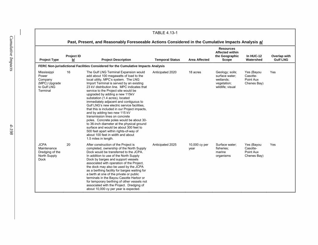
Cum
ula
tive Impacts
4-1
98
TABLE 4.13-1
Past, Present, and Reasonably Foreseeable Actions Considered in the Cumulative Impacts Analysis a/
Project Type Project ID
b/ Project Description Temporal Status Area Affected
Resources Affected within the Geographic
Scope In HUC-12 Watershed
Overlap with Gulf LNG
FERC Non-jurisdictional Facilities Considered for the Cumulative Impacts Analysis
Mississippi Power Company (MPC) Upgrade to Gulf LNG Terminal
16 The Gulf LNG Terminal Expansion would add about 100 megawatts of load to the local utility, MPC’s system. The LNG Import Terminal is served by an existing 23 kV distribution line. MPC indicates that service to the Project site would be upgraded by adding a new 115kV substation (1.4 acres), located immediately adjacent and contiguous to Gulf LNG’s new electric service facilities, that this is included in our Project impacts, and by adding two new 115 kV transmission lines on concrete poles. Concrete poles would be about 30- to 36-inch diameter at the physical ground surface and would be about 300 feet to 500 feet apart within rights-of-way of about 100 feet in width and about 1.5 miles in length.
Anticipated 2020 18 acres Geology; soils; surface water; wetlands; vegetation; wildlife; visual
Yes (Bayou Casotte- Point Aux Chenes Bay)
Yes
JCPA Maintenance Dredging of the North Supply Dock
20 After construction of the Project is completed, ownership of the North Supply Dock would be transferred to the JCPA. In addition to use of the North Supply Dock by barges and support vessels associated with operation of the Project, the dock may also be used by the JCPA as a berthing facility for barges waiting for a berth at one of the private or public terminals in the Bayou Casotte Harbor or for temporary berthing of other vessels not associated with the Project. Dredging of about 10,000 cy per year is expected.
Anticipated 2025 10,000 cy per year
Surface water; fisheries; marine organisms
Yes (Bayou Casotte- Point Aux Chenes Bay)
Yes
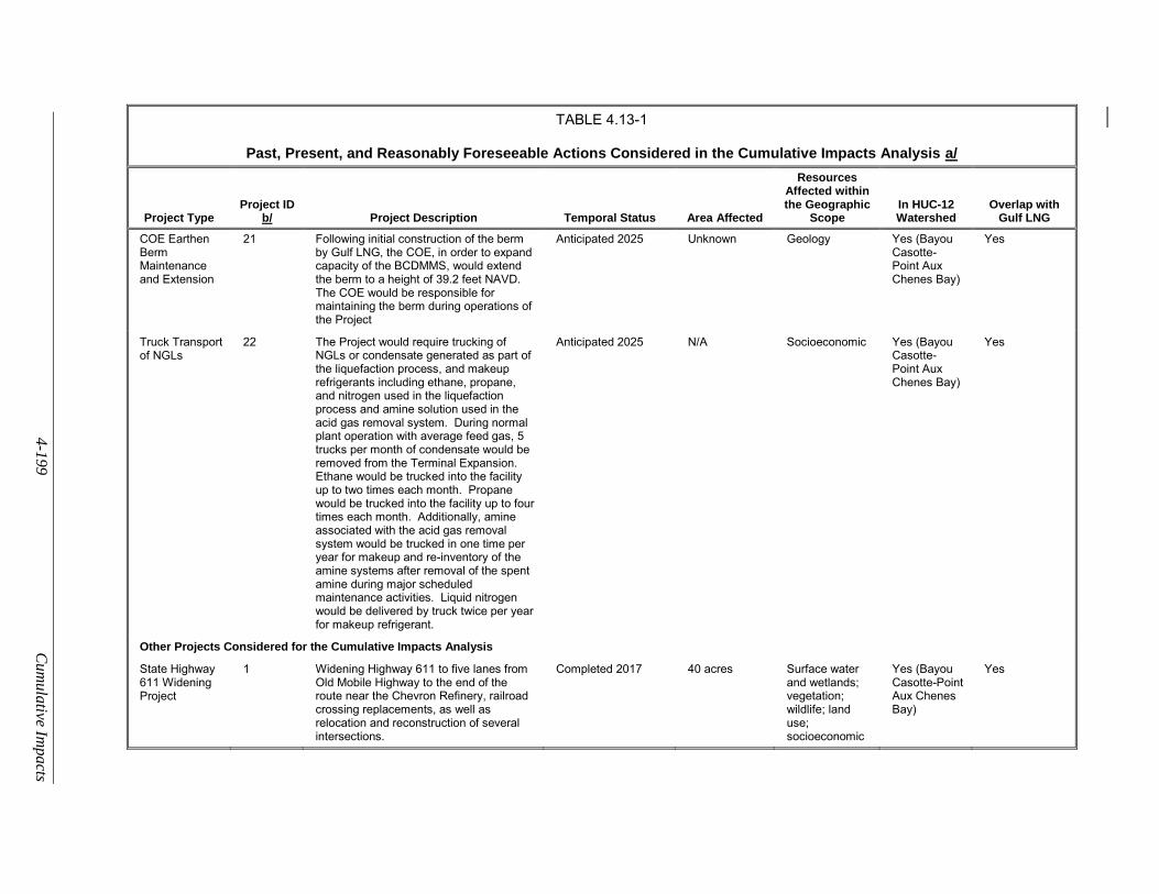
4-1
99
Cum
ula
tive Impa
cts
TABLE 4.13-1
Past, Present, and Reasonably Foreseeable Actions Considered in the Cumulative Impacts Analysis a/
Project Type Project ID
b/ Project Description Temporal Status Area Affected
Resources Affected within the Geographic
Scope In HUC-12 Watershed
Overlap with Gulf LNG
COE Earthen Berm Maintenance and Extension
21 Following initial construction of the berm by Gulf LNG, the COE, in order to expand capacity of the BCDMMS, would extend the berm to a height of 39.2 feet NAVD. The COE would be responsible for maintaining the berm during operations of the Project
Anticipated 2025 Unknown Geology Yes (Bayou Casotte- Point Aux Chenes Bay)
Yes
Truck Transport of NGLs
22 The Project would require trucking of NGLs or condensate generated as part of the liquefaction process, and makeup refrigerants including ethane, propane, and nitrogen used in the liquefaction process and amine solution used in the acid gas removal system. During normal plant operation with average feed gas, 5 trucks per month of condensate would be removed from the Terminal Expansion. Ethane would be trucked into the facility up to two times each month. Propane would be trucked into the facility up to four times each month. Additionally, amine associated with the acid gas removal system would be trucked in one time per year for makeup and re-inventory of the amine systems after removal of the spent amine during major scheduled maintenance activities. Liquid nitrogen would be delivered by truck twice per year for makeup refrigerant.
Anticipated 2025 N/A Socioeconomic Yes (Bayou Casotte- Point Aux Chenes Bay)
Yes
Other Projects Considered for the Cumulative Impacts Analysis
State Highway 611 Widening Project
1 Widening Highway 611 to five lanes from Old Mobile Highway to the end of the route near the Chevron Refinery, railroad crossing replacements, as well as relocation and reconstruction of several intersections.
Completed 2017 40 acres Surface water and wetlands; vegetation; wildlife; land use; socioeconomic
Yes (Bayou Casotte-Point Aux Chenes Bay)
Yes
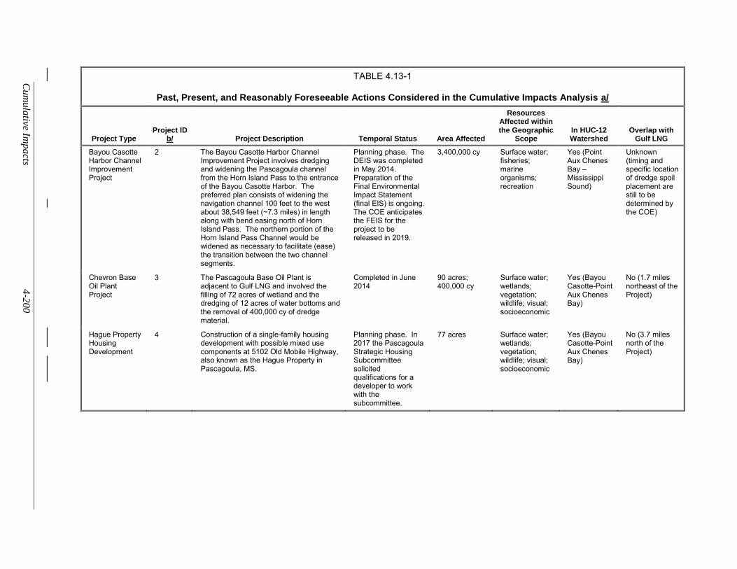
Cum
ula
tive Impacts
4-2
00
TABLE 4.13-1
Past, Present, and Reasonably Foreseeable Actions Considered in the Cumulative Impacts Analysis a/
Project Type Project ID
b/ Project Description Temporal Status Area Affected
Resources Affected within the Geographic
Scope In HUC-12 Watershed
Overlap with Gulf LNG
Bayou Casotte Harbor Channel Improvement Project
2 The Bayou Casotte Harbor Channel Improvement Project involves dredging and widening the Pascagoula channel from the Horn Island Pass to the entrance of the Bayou Casotte Harbor. The preferred plan consists of widening the navigation channel 100 feet to the west about 38,549 feet (~7.3 miles) in length along with bend easing north of Horn Island Pass. The northern portion of the Horn Island Pass Channel would be widened as necessary to facilitate (ease) the transition between the two channel segments.
Planning phase. The DEIS was completed in May 2014. Preparation of the Final Environmental Impact Statement (final EIS) is ongoing. The COE anticipates the FEIS for the project to be released in 2019.
3,400,000 cy Surface water; fisheries; marine organisms; recreation
Yes (Point Aux Chenes Bay – Mississippi Sound)
Unknown (timing and specific location of dredge spoil placement are still to be determined by the COE)
Chevron Base Oil Plant Project
3 The Pascagoula Base Oil Plant is adjacent to Gulf LNG and involved the filling of 72 acres of wetland and the dredging of 12 acres of water bottoms and the removal of 400,000 cy of dredge material.
Completed in June 2014
90 acres; 400,000 cy
Surface water; wetlands; vegetation; wildlife; visual; socioeconomic
Yes (Bayou Casotte-Point Aux Chenes Bay)
No (1.7 miles northeast of the Project)
Hague Property Housing Development
4 Construction of a single-family housing development with possible mixed use components at 5102 Old Mobile Highway, also known as the Hague Property in Pascagoula, MS.
Planning phase. In 2017 the Pascagoula Strategic Housing Subcommittee solicited qualifications for a developer to work with the subcommittee.
77 acres Surface water; wetlands; vegetation; wildlife; visual; socioeconomic
Yes (Bayou Casotte-Point Aux Chenes Bay)
No (3.7 miles north of the Project)
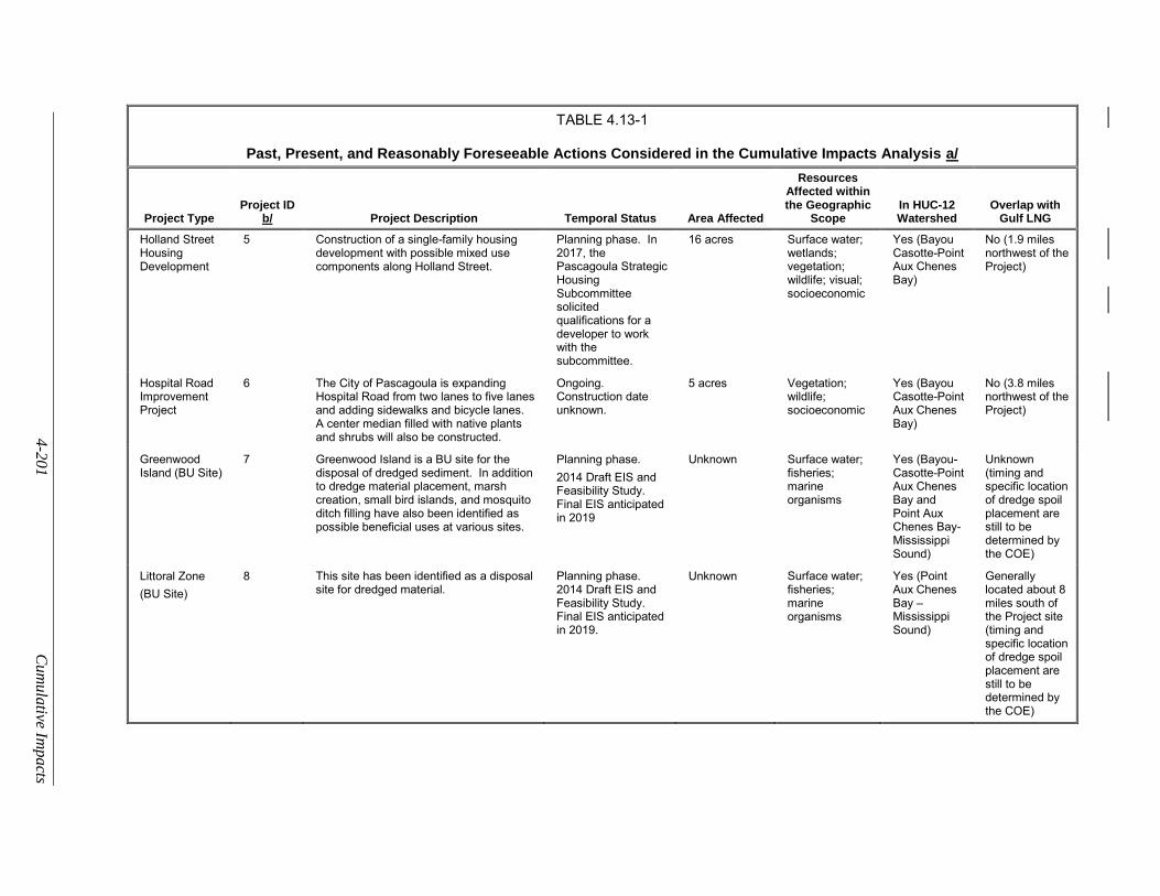
4-2
01
Cum
ula
tive Impa
cts
TABLE 4.13-1
Past, Present, and Reasonably Foreseeable Actions Considered in the Cumulative Impacts Analysis a/
Project Type Project ID
b/ Project Description Temporal Status Area Affected
Resources Affected within the Geographic
Scope In HUC-12 Watershed
Overlap with Gulf LNG
Holland Street Housing Development
5 Construction of a single-family housing development with possible mixed use components along Holland Street.
Planning phase. In 2017, the Pascagoula Strategic Housing Subcommittee solicited qualifications for a developer to work with the subcommittee.
16 acres Surface water; wetlands; vegetation; wildlife; visual; socioeconomic
Yes (Bayou Casotte-Point Aux Chenes Bay)
No (1.9 miles northwest of the Project)
Hospital Road Improvement Project
6 The City of Pascagoula is expanding Hospital Road from two lanes to five lanes and adding sidewalks and bicycle lanes. A center median filled with native plants and shrubs will also be constructed.
Ongoing. Construction date unknown.
5 acres Vegetation; wildlife; socioeconomic
Yes (Bayou Casotte-Point Aux Chenes Bay)
No (3.8 miles northwest of the Project)
Greenwood Island (BU Site)
7 Greenwood Island is a BU site for the disposal of dredged sediment. In addition to dredge material placement, marsh creation, small bird islands, and mosquito ditch filling have also been identified as possible beneficial uses at various sites.
Planning phase.
2014 Draft EIS and Feasibility Study. Final EIS anticipated in 2019
Unknown Surface water; fisheries; marine organisms
Yes (Bayou-Casotte-Point Aux Chenes Bay and Point Aux Chenes Bay-Mississippi Sound)
Unknown (timing and specific location of dredge spoil placement are still to be determined by the COE)
Littoral Zone
(BU Site)
8 This site has been identified as a disposal site for dredged material.
Planning phase. 2014 Draft EIS and Feasibility Study. Final EIS anticipated in 2019.
Unknown Surface water; fisheries; marine organisms
Yes (Point Aux Chenes Bay – Mississippi Sound)
Generally located about 8 miles south of the Project site (timing and specific location of dredge spoil placement are still to be determined by the COE)
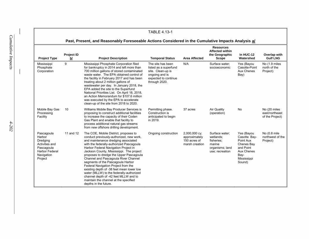
Cum
ula
tive Impacts
4-2
02
TABLE 4.13-1
Past, Present, and Reasonably Foreseeable Actions Considered in the Cumulative Impacts Analysis a/
Project Type Project ID
b/ Project Description Temporal Status Area Affected
Resources Affected within the Geographic
Scope In HUC-12 Watershed
Overlap with Gulf LNG
Mississippi Phosphate Corporation
9 Mississippi Phosphate Corporation filed for bankruptcy in 2014 and left more than 700 million gallons of stored contaminated waste water. The EPA obtained control of the facility in February 2017 and has been treating about 2 million gallons of wastewater per day. In January 2018, the EPA added the site to the Superfund National Priorities List. On April 18, 2018, an Action Memorandum for $107.6 million was executed by the EPA to accelerate clean-up of the site from 2018 to 2020.
The site has been listed as a superfund site. Clean-up is ongoing and is expected to continue through 2020.
N/A Surface water; socioeconomic
Yes (Bayou Casotte-Point Aux Chenes Bay)
No (1.9 miles north of the Project)
Mobile Bay Gas Processing Facility
10 Williams Mobile Bay Producer Services is proposing to construct additional facilities to increase the capacity of their Coden Gas Plant and enable that facility to process additional natural gas streams from new offshore drilling development.
Permitting phase. Construction is anticipated to begin in 2019.
37 acres Air Quality (operation)
No No (20 miles east/northeast of the Project)
Pascagoula Harbor Dredging Activities and Pascagoula Harbor Federal Navigation Project
11 and 12 The COE, Mobile District, proposes to conduct previously-authorized, new work, and maintenance dredging associated with the federally-authorized Pascagoula Harbor Federal Navigation Project in Jackson County, Mississippi. The project proposes to dredge the Upper Pascagoula Channel and Pascagoula River Channel segments of the Pascagoula Harbor Federal Navigation Project from the existing depth of -38 feet mean lower low water (MLLW) to the federally-authorized channel depth of -42 feet MLLW and to maintain the channel at the specified depths in the future.
Ongoing construction 2,000,000 cy; approximately 150 acres of marsh creation
Surface water; wetlands; fisheries; marine organisms; land use; recreation
Yes (Bayou Casotte Bay-Point Aux Chenes Bay and Point Aux Chenes Bay-Mississippi Sound)
No (0.8 mile northwest of the Project)
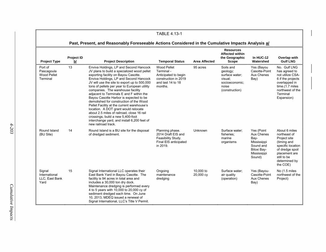
4-2
03
Cum
ula
tive Impa
cts
TABLE 4.13-1
Past, Present, and Reasonably Foreseeable Actions Considered in the Cumulative Impacts Analysis a/
Project Type Project ID
b/ Project Description Temporal Status Area Affected
Resources Affected within the Geographic
Scope In HUC-12 Watershed
Overlap with Gulf LNG
Port of Pascagoula Wood Pellet Terminal
13 Enviva Holdings, LP and Second Hancock JV plans to build a specialized wood pellet exporting facility on Bayou Casotte. Enviva Holdings, LP and Second Hancock JV will use the site to export up to 500,000 tons of pellets per year to European utility companies. The warehouse facility adjacent to Terminals E and F within the Bayou Casotte Harbor is expected to be demolished for construction of the Wood Pellet Facility at the current warehouse’s location. A DOT grant would relocate about 2.5 miles of railroad, close 16 rail crossings, build a new 5,400-foot interchange yard, and install 6,200 feet of new railroad track.
Wood Pellet Terminal - Anticipated to begin construction in 2019 and last 14 to 18 months.
95 acres Soils and geology; surface water; visual; socioeconomic; noise (construction)
Yes (Bayou Casotte-Point Aux Chenes Bay)
No. Gulf LNG has agreed to not utilize CSA-6 if the projects overlapped in time.(1.7 miles northwest of the Terminal Expansion)
Round Island (BU Site)
14 Round Island is a BU site for the disposal of dredged sediment.
Planning phase. 2014 Draft EIS and Feasibility Study. Final EIS anticipated in 2019.
Unknown Surface water; fisheries; marine organisms
Yes (Point Aux Chenes Bay-Mississippi Sound and Biloxi Bay-Mississippi Sound)
About 6 miles northeast of Project site (timing and specific location of dredge spoil placement are still to be determined by the COE)
Signal International LLC, East Bank Yard
15 Signal International LLC operates their East Bank Yard in Bayou Casotte. The facility is 94 acres in total area and includes a 30,000 ton dry dock. Maintenance dredging is performed every 4 to 5 years with 10,000 to 20,000 cy of sediment dredged each time. On June 10, 2013, MDEQ issued a renewal of Signal International, LLC’s Title V Permit.
Ongoing maintenance dredging
10,000 to 20,000 cy
Surface water; air quality (operation)
Yes (Bayou-Casotte-Point Aux Chenes Bay)
No (1.5 miles northwest of the Project)
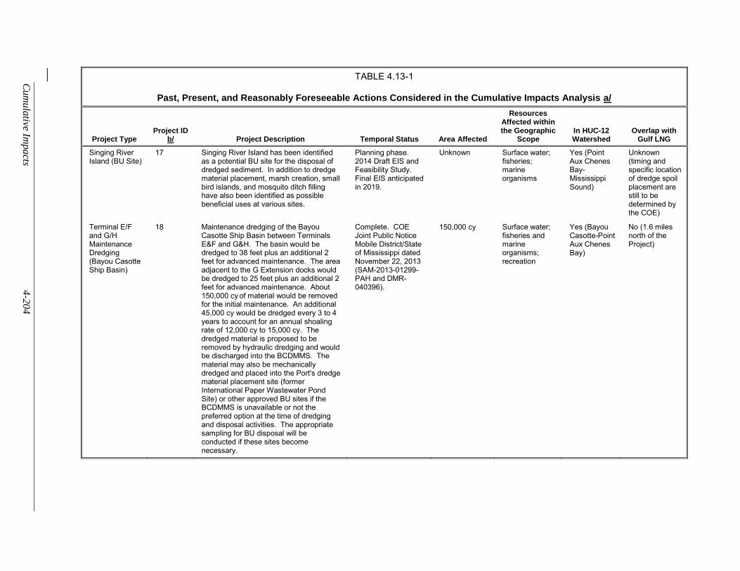
Cum
ula
tive Impacts
4-2
04
TABLE 4.13-1
Past, Present, and Reasonably Foreseeable Actions Considered in the Cumulative Impacts Analysis a/
Project Type Project ID
b/ Project Description Temporal Status Area Affected
Resources Affected within the Geographic
Scope In HUC-12 Watershed
Overlap with Gulf LNG
Singing River Island (BU Site)
17 Singing River Island has been identified as a potential BU site for the disposal of dredged sediment. In addition to dredge material placement, marsh creation, small bird islands, and mosquito ditch filling have also been identified as possible beneficial uses at various sites.
Planning phase. 2014 Draft EIS and Feasibility Study. Final EIS anticipated in 2019.
Unknown Surface water; fisheries; marine organisms
Yes (Point Aux Chenes Bay-Mississippi Sound)
Unknown (timing and specific location of dredge spoil placement are still to be determined by the COE)
Terminal E/F and G/H Maintenance Dredging (Bayou Casotte Ship Basin)
18 Maintenance dredging of the Bayou Casotte Ship Basin between Terminals E&F and G&H. The basin would be dredged to 38 feet plus an additional 2 feet for advanced maintenance. The area adjacent to the G Extension docks would be dredged to 25 feet plus an additional 2 feet for advanced maintenance. About 150,000 cy of material would be removed for the initial maintenance. An additional 45,000 cy would be dredged every 3 to 4 years to account for an annual shoaling rate of 12,000 cy to 15,000 cy. The dredged material is proposed to be removed by hydraulic dredging and would be discharged into the BCDMMS. The material may also be mechanically dredged and placed into the Port's dredge material placement site (former International Paper Wastewater Pond Site) or other approved BU sites if the BCDMMS is unavailable or not the preferred option at the time of dredging and disposal activities. The appropriate sampling for BU disposal will be conducted if these sites become necessary.
Complete. COE Joint Public Notice Mobile District/State of Mississippi dated November 22, 2013 (SAM-2013-01299-PAH and DMR-040396).
150,000 cy Surface water; fisheries and marine organisms; recreation
Yes (Bayou Casotte-Point Aux Chenes Bay)
No (1.6 miles north of the Project)
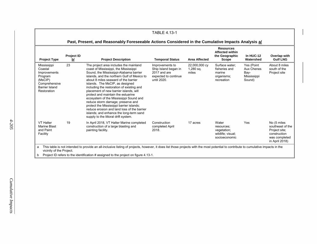
4-2
05
Cum
ula
tive Impa
cts
TABLE 4.13-1
Past, Present, and Reasonably Foreseeable Actions Considered in the Cumulative Impacts Analysis a/
Project Type Project ID
b/ Project Description Temporal Status Area Affected
Resources Affected within the Geographic
Scope In HUC-12 Watershed
Overlap with Gulf LNG
Mississippi Coastal Improvements Program (MsCIP) Comprehensive Barrier Island Restoration
23 The project area includes the mainland coast of Mississippi, the Mississippi Sound, the Mississippi-Alabama barrier islands, and the northern Gulf of Mexico to about 8 miles seaward of the barrier islands. The MsCIP, as designed including the restoration of existing and placement of new barrier islands, will protect and maintain the estuarine ecosystem of the Mississippi Sound and reduce storm damage; preserve and protect the Mississippi barrier islands; reduce erosion and land loss of the barrier islands; and enhance the long-term sand supply to the littoral drift system.
Improvements to Ship Island began in 2017 and are expected to continue until 2020.
22,000,000 cy 1,280 sq. miles
Surface water; fisheries and marine organisms; recreation
Yes (Point Aux Chenes Bay-Mississippi Sound)
About 8 miles south of the Project site
VT Halter Marine Blast and Paint Facility
19 In April 2018, VT Halter Marine completed construction of a large blasting and painting facility.
Construction completed April 2018.
17 acres Water resources; vegetation; wildlife; visual; socioeconomic
Yes No (5 miles southeast of the Project site; construction was completed in April 2018)
a This table is not intended to provide an all-inclusive listing of projects, however, it does list those projects with the most potential to contribute to cumulative impacts in the vicinity of the Project.
b Project ID refers to the identification # assigned to the project on figure 4.13-1.
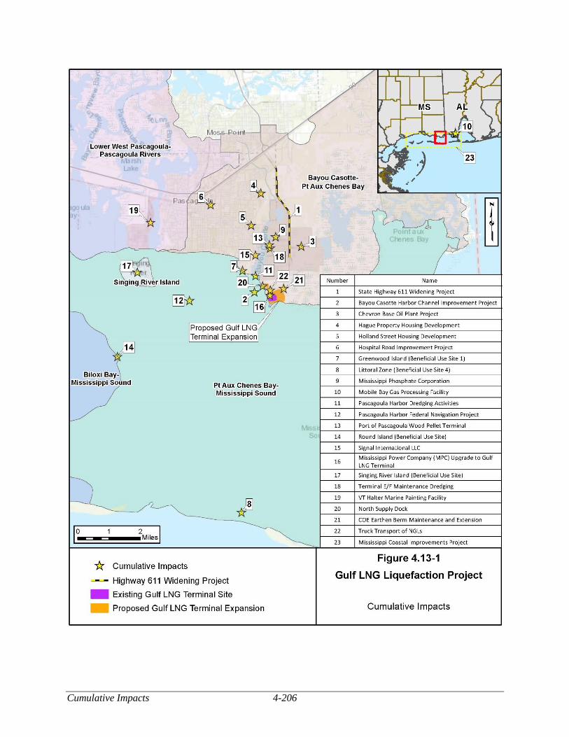
Cumulative Impacts 4-206
Figure 4.13-1 Cumulative Impacts
4-207 Cumulative Impacts
Projects and Activities Considered
There are many existing, under construction, planned, and reasonably foreseeable projects in the
vicinity of Gulf LNG’s Project. Table 4.13-1 lists the substantial projects and activities that were considered
in this cumulative impact analysis (see also figure 4.13-1).
CEQ regulations require agencies to consider environmental effects of proposed actions, including
direct and indirect effects, if these effects are reasonably foreseeable.
Several liquefaction and export projects that are proposed, planned, or under construction in the
vicinity of the proposed Project were identified and discussed in section 3.0. None of these projects would
be within the geographic scope of the proposed Project. Therefore, these facilities would not have the
potential to contribute to cumulative impacts when combined with the proposed Project.
State Highway 611 Widening Project
The project was completed in 2017 and extended from Old Mobile Highway to near the Chevron
Refinery. Highway 611 is now a five-lane highway. The project required railroad crossing replacements
and the reconstruction and relocation of several intersections (Sun Herald, 2017) and affected about 40
acres. The location of this project is depicted as project #1 on figure 4.13-1.
Bayou Casotte Harbor Channel Improvement Project
The Bayou Casotte Harbor Channel Improvement Project (BCHCIP) would involve the dredging
and widening the Pascagoula channel from the Horn Island Pass to the entrance of the Bayou Casotte
Harbor. The location of this project is depicted as project #2 on figure 4.13-1.
The draft EIS was completed in May 2014 and established that the proposed plans for the BCHCIP
were viable and technically feasible. There is a “locally preferred plan” which consists of widening the
navigation channel 100 feet to the west for about 38,549 feet (7.3 miles) north of Horn Island Pass. This
northern portion of the Horn Island Pass Channel would be widened as necessary to simplify the transition
between the two channel segments. Potential impacts associated with improving Port of Pascagoula’s
Lower Pascagoula and Bayou Casotte Channels would be addressed by the BCHCIP. These improvements
are associated with the federal navigation channel project and its associated future operation and
maintenance in Jackson County, Mississippi. About 3.4 million cy of dredged material would be removed
from the navigation channel. About 125,000 cy of dredged material would be placed within the littoral
zone placement site and/or Disposal Area #10, located east and south of Horn Island while about 3.3 million
cy of dredged material would be placed within the Pascagoula Ocean Dredged Material Disposal Sites
(ODMDS) south of Horn Island.
The COE is conducting a Feasibility Study. Should the study conclude favorably, future operation
and maintenance would be undertaken by the COE as part of its routine maintenance efforts. Preparation
of the final EIS is ongoing and is anticipated to be released in 2019.
Chevron Base Oil Plant Project
In June 2014 Chevron, Inc. completed its Pascagoula Base Oil Plant at the Chevron Pascagoula
Refinery adjacent to Gulf LNG. The project affected about 90 acres and resulted in 400,000 cy of dredge
material. The new plant can produce about 25,000 barrels per day of premium base oil. Construction
included adding 2 new berths to the Chevron wharf, 16 new product tanks, and new railcar capabilities,
which resulted in the filling of 72.29 acres of wetlands. Mitigation credits were to be obtained from the
Cumulative Impacts 4-208
Rhodes Lake Mitigation Area (Chevron, 2017). The location of this project is depicted as project #3 on
figure 4.13-1.
Hague Property Housing Development
The project is located 3.7 miles north of Gulf LNG. The Pascagoula Strategic Housing
Subcommittee began soliciting bids in 2017 seeking a developer to work with them to construct a 77-acre
single-family housing development with possible mixed use components at 5102 Old Mobile Highway (the
Hague Property), in Pascagoula, Mississippi (City of Pascagoula, 2017a). The project is depicted as project
#4 on figure 4.13-1.
Holland Street Housing Development
The project is located 1.9 miles northwest of Gulf LNG. The Pascagoula Strategic Housing
Subcommittee began soliciting bids in 2017 seeking a developer to work with them to construct a 16-acre
single-family housing development with possible mixed use components along Holland Street. (City of
Pascagoula, 2017b). The project is depicted as project #5 on figure 4.13-1.
Hospital Road Improvement Project
The City of Pascagoula began expansion of Hospital Road from two lanes to five lanes in July
2017. Sidewalks and bicycle lanes are being included as well as a center median filled with native plants
and shrubs. The project will improve safety and increase economic growth in the area. The project is
estimated to cost about $3.3 million and is being funded mostly with federal highway dollars. According
to the city, construction is anticipated to last about 2 years (City of Pascagoula, 2017c). The location of
this project is depicted as project #6 on figure 4.13-1.
Beneficial Use Sites
Dredged material has typically been disposed of by placement in sites along the margins of the
channels or in un-confined, open water disposal sites such as offshore of Horn Island. These types of
disposal areas are becoming limited in space and availability, therefore there is a need for new locations for
the BU of dredged sediment. Areas that are currently being considered as new or expanded BU sites include
Greenwood Island, Singing River Island, and Round Island.
An example of these new BU sites is the littoral zone disposal site, which is located just west of
Horn Island Pass and south of Horn Island between the -14 and -22-foot depth mean lower low water
(MLLW) contours. This site is designated to accept BU material dredged from the channel near Horn
Island Pass. Dredged material is pumped to an area west of the federal channel where it is reintroduced
into the east-to-west sediment transportation system. This BU disposal site was positioned specifically to
maximize sand migration to supplement the barrier island system. Suitable, sandy material dredged during
new work or channel maintenance efforts are placed within the littoral disposal site. There are also three
additional types of BU that are possible along the Mississippi Gulf Coast. These include marsh creation,
the filling of mosquito ditches, and small bird islands. In marsh creation, dredged material is used to raise
the intertidal elevation of the substrate. Small bird island creation occurs when dredged material is placed
in contained areas to form new habitat for migratory and resident bird populations (COE, 2014). Examples
of these projects are depicted as projects # 7, 8, 14, and 17 on figure 4.13-1.
Mississippi Phosphate Corporation
Mississippi Phosphate Corporation facilities are located about 1.9 miles north of the Project, at the
northern tip of the Bayou Casotte Channel. Production facilities consist of two sulfuric acid facilities, a
4-209 Cumulative Impacts
phosphoric acid facility, and a diammonium phosphate (DAP) granulation facility. Mississippi Phosphate
Corporation filed for bankruptcy in 2014 and left more than 700 million gallons of stored contaminated
waste water at this location. The EPA obtained control of the facility in February 2017 and has been treating
about 2 million gallons of wastewater per day. In January 2018, the EPA added the site to the Superfund
National Priorities List. On April 18, 2018, an Action Memorandum for $107.6 million was executed by
the EPA to accelerate clean-up of the site from 2018 to 2020. This project is depicted as project #9 on
figure 4.13-1.
Mobile Gas Processing Facility
Williams Mobile Bay Producer Services proposes the construction of additional facilities located
20 miles east/northeast of Gulf LNG. The expansion would affect about 37 acres of land and will result in
increased capacity of their Coden Gas Plant. It will enable that facility to process additional natural gas
streams from new offshore drilling development. The project is anticipated to begin in 2019 (EPA, 2017c)
and is depicted as project #10 on figure 4.13-1.
Pascagoula Harbor Dredging Activities and Pascagoula Harbor Federal Navigation
Project
The Pascagoula Harbor Federal Navigation Project is located about 0.8 mile northwest of the
Project in Jackson County, Mississippi. The COE plans to conduct previously-authorized work, new work,
and maintenance dredging associated with this federally-authorized project. Two BU placement areas are
being proposed for this project. The project proposes to dredge the Upper Pascagoula Channel and
Pascagoula River Channel segments of the Pascagoula Harbor Federal Navigation Project from the existing
depth of -38 feet MLLW to the federally-authorized channel depth of -42 feet MLLW and to maintain the
channel at the specified depths in the future. This would include an additional -2 feet of advance
maintenance dredging and -2 feet of allowable over depth for a total of maximum depth of -46 feet MLLW.
An additional 3 feet of sediment below the 2-foot paid allowable dredging cut may be disturbed in the
dredging process with minor amounts of the material being removed. Dredged material would be placed
within BU areas. These areas are the Singing River Island Semi-Confined Site, Round Island, and the
previously approved/utilized ODMDS adjacent to the channel. Areas of the channel affected by shoaling
are targeted for dredging and not all portions of the channel are dredged in each cycle (COE, 2016a).
Maintenance dredging cycles occur irregularly every 18 to 36 months. These projects would result in over
200,000 cy in Pascagoula Harbor and about 150 acres of marsh creation. These projects are depicted as
projects # 11 and 12 on figure 4.13-1.
Port of Pascagoula Wood Pellet Terminal
Enviva Holdings, LP and Second Hancock JV proposes the construction of a specialized wood
pellet exporting facility on Bayou Casotte, about 1.7 miles northwest of Gulf LNG. The proposed facility
will result in the export up to 500,000 tons of pellets per year to European utility companies. The project
would affect about 95 acres which is currently occupied by a warehouse facility, located adjacent to
Terminals E and F within the Bayou Casotte Harbor. The existing warehouse facility is expected to be
demolished for construction of the Wood Pellet Facility. An additional $14 million from the DOT’s
Transportation Investment Generating Economic Recovery (TIGER) discretionary grant Program will also
be used for intermodal improvements (Port of Pascagoula, 2017). The TIGER grant would be used to:
relocate about 2.5 miles of track through the City of Moss Point;
close 16 rail crossings through Moss Point and Pascagoula;
construct a new 5,400 foot interchange yard and
Cumulative Impacts 4-210
construct about 6,200 feet of additional track within Bayou Casotte Harbor.
The project, first announced in 2015, has been delayed. As of January 2019, construction of the
Wood Pellet Facility is expected to begin in 2019 and last about 14 to 18 months (AP News, 2019). The
project is depicted as project #13 on figure 4.13-1.
Signal International LLC
The Signal International LLC East Bank Yard is located 1.5 miles northwest of Gulf LNG and is
94 acres in total area. The facility specializes in marine drilling rig fabrication and upgrades, conversion,
and repair and includes a 30,000 ton dry dock. Maintenance dredging of 10,000 to 20,000 cy of sediment
each time is conducted every 4 to 5 years. In 2010, the company increased the dredging depth of a 3.5-acre
area to 60 feet to accommodate deep draft vessels such as semi-submersible rigs. The dredged material
was utilized for BU at the former International Paper Mill site in Moss Point. On June 10, 2013, the MDEQ
issued a renewal of Signal International, LLC’s Title V Permit. In addition, the facility’s air quality permit
allows emissions of 249 tpy VOCs. This project is depicted as project #15 on figure 4.13-1.
Mississippi Power Company Upgrade to Gulf LNG Terminal
The proposed Gulf LNG Terminal Expansion would add about 100 MW of load to the MPC system.
The existing Terminal is currently served by an existing 23 kV distribution line. According to MPC,
upgraded service to the Project site would be accomplished through the addition of a new 1.4-acre, 115kV
substation. This would be located immediately adjacent to and contiguous with Gulf LNG’s new electric
service facilities. This substation is included in our Project impacts as two new 115 kV transmission lines
on concrete poles. The concrete poles would be about 30- to 36-inch diameter and would be located about
300 to 500 feet apart. Construction of this project is expected to begin in 2020 and would affect about 18
acres of land. The project is depicted as project #16 on figure 4.13-1.
Terminal Maintenance Dredging (E, F, G, and H)
The maintenance dredging of the Bayou Casotte Ship Basin is proposed, about 1.6 miles north of
the Project, between Terminals E&F and G&H. The basin would be dredged to 38 feet plus an additional
2 feet for advanced maintenance. The area adjacent to the G Extension docks would be dredged to 25 feet
plus an additional 2 feet for advanced maintenance. Initial maintenance would remove about 150,000 cy
of material, and an additional 45,000 cy would be dredged every 3 to 4 years to account for an annual
shoaling rate of 12,000 cy to 15,000 cy. The dredged material would be removed by hydraulic dredging
and would be discharged into the BCDMMS. If the BCDMMS is unavailable or not the preferred option
at the time of dredging and disposal activities, the material may also be mechanically dredged and placed
into the Port’s dredge material placement site (former International Paper Wastewater Pond Site) or other
approved BU sites. The appropriate sampling for BU disposal will be conducted if these sites become
necessary (COE, 2013). This project is depicted as project #18 on figure 4.13-1.
Mississippi Coastal Improvements Program - Comprehensive Barrier Island
Restoration
The Mississippi Coastal Improvements Program (MsCIP) was created to support the long-term
recovery of Hancock, Harrison, and Jackson Counties from devastation caused by Hurricane Katrina and
other hurricanes in the Gulf of Mexico in 2005 and from past navigational dredging and disposal activities.
These activities (man-made and natural) have altered sediment availability and transport along the islands.
The Program’s project area includes the mainland coast of Mississippi, the Mississippi Sound, the
Mississippi-Alabama barrier islands, and the northern Gulf of Mexico to about 8 miles seaward of the
4-211 Cumulative Impacts
barrier islands. Improvements included in the Program intend to protect and maintain the estuarine
ecosystem of the Mississippi Sound and reduce storm damage through the restoration of existing barrier
islands and placement of new barrier islands. The plan includes 1,280 square miles of aquatic restoration
in the Mississippi Sound, 22 million cy increased sediment budget, and 30,000 acres of coastal habitat
restoration (COE, 2016b). Preservation and protection of the Mississippi barrier islands result in reduced
land loss and erosion of the barrier islands and enhance the long-term sand supply to the littoral drift system.
The final supplemental EIS was issued in January 2016 and the first project (the Ship Island Restoration)
began in 2017 and is anticipated to continue through 2020. This project is shown as project #23 on figure
4.13-1.
VT Halter Marine Blast and Paint Facility
In April 2018, VT Halter Marine announced the completion of a new blast and paint facility located
in Pascagoula, Mississippi. The 17-acre facility will allow surface preparation and final painting of ship
sections within an indoor and environmentally controlled structure. The facility can accommodate ship
sections as large as 105 feet wide, 80 feet long, 40 feet high with weights of up to 500 tons. The location
of this project is depicted as project #19 on figure 4.13-1.
Jackson County Port Authority Maintenance Dredging of the North Supply Dock
After construction of the Project is completed, ownership of the North Supply Dock would be
transferred to the JCPA. A letter from the JCPA-Port of Pascagoula confirming that they would accept
dock ownership was provided to Gulf LNG on May 28, 2015. In addition to use of the North Supply Dock
by barges and support vessels associated with operation of the Project, the dock may also be used by the
JCPA as a berthing facility for barges waiting for a berth at one of the private or public terminals in the
Bayou Casotte Harbor or for temporary berthing of other vessels not associated with the Project. Based on
the observed annual increase in sediment material at the existing marine berth, depth comparisons, and
other variables, about 10,000 cy of material would be deposited within the North Supply Dock berthing
area per year.54 However, dredging would not be required annually. As owner of the North Supply Dock,
the JCPA would be responsible for obtaining permits and clearances for dredging operations and for issuing
notifications to agencies and Port of Pascagoula users regarding dredging activities. The location of this
project is depicted as project #20 on figure 4.13-1.
COE Earthen Berm Maintenance and Extension
Gulf LNG would extend the existing storm protection system surrounding the existing Terminal to
encompass the Terminal Expansion facilities. The new storm surge protection system would consist of (1)
a new concrete wall with a top elevation of 27 feet NAVD and (2) a new earthen berm (an extension of the
existing COE berm) with a top elevation of 27 feet NAVD. Following initial construction of the berm by
Gulf LNG, the COE, in order to expand capacity of the BCDMMS, would extend the berm to a height of
39.2 feet NAVD. The COE would be responsible for maintaining the berm during operations of the Project,
and would be responsible for all permits and approvals associated with maintenance and extension of the
height of the earthen berm. The location of this project is depicted as project #21 on figure 4.13-1.
54 Dredging volumes were estimated from shoaling rates observed at the existing LNG carrier berth. The existing LNG carrier
berth is about 1,500,000 ft2. About 30,000 cy every 6 years (50,000 cy per year) are removed from the existing LNG carrier
berth. The North Supply Dock berthing area would be about 300,000 ft2 therefore the annual deposition of material should
be 300,000 ft2/1,500,000 ft2 x 50,000 cy = 10,000 cy per year.
Cumulative Impacts 4-212
Truck Transport of Natural Gas Liquids
The Project would require trucking of NGLs or condensate generated as part of the liquefaction
process, and makeup refrigerants including ethane, propane, and nitrogen used in the liquefaction process
and amine solution used in the acid gas removal system. Ethane and propane would be delivered by truck
and unloaded into storage facilities. In the worst case of very rich feed gas (expected less than 10 days per
year), the amount of condensate removed from the plant would be 16.5 trucks per day. For the rich case,
an average of 3.2 trucks per day would be removed from the plant. During normal operation with average
feed gas, approximately five trucks per month of condensate would be removed from the plant. Ethane
would be trucked into the facility up to two times each month. Propane would be trucked into the facility
up to four times each month. Additionally, amine associated with the acid gas removal system would be
trucked in one time per year for makeup and re-inventory of the amine systems after removal of the spent
amine during major scheduled maintenance activities. Liquid nitrogen would be delivered by truck twice
per year for makeup refrigerant.
After leaving the Terminal Expansion site, NGL trucking is regulated by DOT’s Federal Motor
Carrier Safety Administration. Gulf LNG anticipates negotiating agreements for the purchase of NGLs by
processing facilities near the Terminal Expansion. After leaving the Terminal Expansion site, the trucks
would use Industrial Road and SH-611 to transport the NGLs to nearby processing plants, or if Gulf LNG
has more distant customers for the NGLs, they would transit Industrial Road, SH-611, and SH-63 to reach
HWY-90 and I-10, the area’s main highways. According to Gulf LNG, the Hazardous Waste Branch of
the MDEQ does not have a requirement for a hazardous materials route analysis. Based on an average
composition of feed gas, we conclude that the estimated truck traffic of 11 trucks per month would not have
any significant impacts on roadway traffic.
Potential Cumulative Impacts by Resource
The following sections address the potential cumulative impacts from Gulf LNG’s Project and the
other projects identified within the geographic scope defined for specific environmental resources. The
other projects considered in each section are those for which impacts on the resource(s) discussed would
be within the same geographic scope as those that would result from the proposed projects and would occur
within the same timeframe.
The Pipeline Modifications would include minor modifications to existing industrial facilities.
Therefore, no cumulative impacts on geologic, soils, water, wetland, vegetation, wildlife, aquatic,
threatened and endangered species, land use, visual, recreation, socioeconomic, cultural, air quality, and
noise resources are anticipated for the Pipeline Modifications.
Geologic Resources
The geographic scope for geologic resources was considered to be the area adjacent to proposed
construction areas for the Terminal Expansion.
Except for oil and gas, there are no currently known exploitable mineral resources in the general
vicinity of the Terminal Expansion. The closest oil and gas exploration and production have occurred about
8 miles to the north of the existing Terminal. However, all of these wells are plugged and abandoned.
Therefore, cumulative impacts on mineral resources due to the construction and operation of the proposed
Terminal Expansion is not anticipated.
At the proposed Terminal Expansion site, Gulf LNG would modify the existing topographic
contours to accommodate its equipment and facilities and maintain adequate drainage from the site. This
would result in contours similar to those of the adjacent existing Terminal and would not differ substantially
4-213 Cumulative Impacts
from the existing topography. The small change in topography at the proposed Terminal site would not
result in significant cumulative impacts on geologic conditions.
Construction of the Wood Pellet Export Terminal project has the potential to overlap with parts of
the Project, while the MPC Upgrade to Gulf LNG Project would overlap with the Project construction
footprint, modifications to the existing topographic contours are not expected. If there would be concurrent
construction of the Wood Pellet Export Terminal, Gulf LNG would not utilize CSA-6 and would pursue
the use of another previously disturbed (in-kind) use site, resulting in no cumulative impacts and no overlap.
Maintenance and extension of the earthen berm by the COE would overlap with the Project
construction footprint but would not be concurrent with construction of the Terminal Expansion. Impacts
would be limited to the routinely disturbed BCDMMS which is used by the COE for placement of dredged
materials from maintenance dredging of the Bayou Casotte Navigation Channel.
No other projects were identified that involve excavation or significant grading in an area that
overlaps or directly abuts the proposed active construction footprint of the Project during the same
timeframe. Therefore, we have determined that the Terminal Expansion, along with other projects, would
not contribute to cumulative impacts on geologic resources.
Soils
The geographic scope for soils was considered to be the area adjacent to construction areas for the
Terminal Expansion. The existing Terminal and surrounding areas consist mainly of land used for
placement of dredge material that has occurred since the 1950s. Past impacts on soils resources in the
vicinity of the proposed Project have resulted from dredge placement, construction, and maintenance of
existing roads, natural gas and oil facilities and pipelines, and utility lines. Clearing and grading associated
with construction of the Terminal Expansion could result in soil loss due to erosion. However, Gulf LNG
would implement measures required by the FERC’s Plan and Procedures and contained in the Gulf LNG
Plan and the Gulf LNG Procedures to minimize erosion. In addition, the Terminal Expansion would be
adjacent to and integrated with the existing Terminal and with existing third-party natural gas infrastructure,
thereby minimizing impacts on previously undisturbed areas to the extent practicable.
Construction of the Wood Pellet Export Terminal would overlap the active construction footprint
of the Project’s CSA-6, which is an existing previously disturbed fenced graveled yard. According to a
January 2019 article, the Wood Pellet Export Terminal is scheduled for construction later in 2019 and the
facility would be constructed on the CSA-6 site (AP News, 2019). Based on this information, Gulf LNG’s
use of CSA-6 may coincide with construction of the Wood Pellet Facility in the same location. If this
occurs, Gulf LNG has agreed to not utilize CSA-6 and would pursue the use of another previously disturbed
(in-kind) use site, resulting in no overlap and no cumulative impacts.
Construction of the MPC Upgrade would involve the installation of a new substation and
transmission line immediately adjacent and within Project footprint (about 1.4 acres of overlap with the
Project footprint). It is assumed that this project would require a construction stormwater permit and
impacts would be mitigated through the implementation of best management practices. Construction would
also involve the restoration of disturbed areas following construction thereby minimizing impacts on soils.
Therefore, impacts from the MPC Upgrade are expected to be minor.
No other projects were identified that involve excavation or significant grading in an area that
overlaps or directly abuts the active construction footprint of the Project during the same timeframe. As a
result, we do not anticipate a significant cumulative impact on soils or sediments from construction and
operation of the Project combined with other projects.
Cumulative Impacts 4-214
Water Resources
The geographic scope established for water resources was considered to be the HUC-12 watersheds
shared by the Terminal Expansion site. Any projects listed in table 4.13-1 involving ground disturbance
within these HUC-12 watersheds could result in cumulative impacts on water resources.
Gulf LNG would not directly withdraw groundwater during construction or operation of the
Project. Gulf LNG would obtain water for construction and operation of the Terminal Expansion from the
existing Terminal’s connection to the Port of Pascagoula’s Industrial Water Supply. Construction needs
would include water required for hydrostatic testing of the facility piping to verify the integrity of the
facilities prior to placing them into service. According to the Port of Pascagoula, the JCPA has the supply
and permit authority to meet the Project’s industrial water requirements. Thus, adequate water is available
for the planned uses at the Terminal Expansion, and we conclude that the cumulative impact on water
supplies during construction and operation would not be significant.
As described in section 4.3, groundwater impacts resulting from construction or operation of the
Project are not anticipated and, should they occur, would be localized and would not affect other
groundwater users. Therefore, the Project would not contribute to signification cumulative impacts on
groundwater with other projects in the geographic scope.
Projects that involve dredging, modification of surface water resources, or operational vessel
traffic, could result in impacts on surface water resources and have the greatest potential to contribute to
cumulative impacts with the Project.
Construction of the two supply docks would include dredging about 200,000 cy of material for the
initial construction, 40,000 cy annually during construction, and 20,000 cy annually during operation.
Maintenance dredging for the North Supply Dock would also be required (see section 2.2.1.5). An
additional 200,000 cy would be dredged for the temporary barge access channel for the wetland mitigation
site. Impacts associated with dredging would be minor and temporary due to the methods used to minimize
sediment suspension in the water column, the high ambient levels of turbidity in the channel, and the
relatively rapid deposit of the suspended sediments.
Dredging projects and projects listed in table 4.13-1 that potentially require dredging include the
JCPA Maintenance Dredging of the North Supply Dock, BCHCIP, Signal International LLC East Bank
Yard, Pascagoula Harbor Navigation Channel Dredging, and the maintenance dredging of the Bayou
Casotte Ship Basin Terminals E&F and G&H.
The amount of material that would be dredged for these projects would range from about 20,000
cy for the Signal International LLC East Bank every 3 to 4 years to 3.4 million cy for the BCHCIP. The
BCHCIP would be the largest dredging project within the geographic scope. The improvement project
would require dredging of about 3.4 million cy of material from Horn Island Pass to the entrance of the
Bayou Casotte Harbor. The considered projects would dredge an estimate 5.58 million cy from Bayou
Casotte. Dredging is a routine and ongoing practice along the Bayou Casotte Navigation Channel. Given
the relative size of the dredging activities proposed, the amount of increased sediment removal resulting
from Project-related dredging would be minor relative to what is common in the Bayou Casotte Navigation
Channel. Consequently, any potential cumulative effects to the Bayou Casotte Navigation Channel
sediments are anticipated to be minor. Most of the planned dredging activities are currently in the planning
stages, therefore dredging activities would not likely occur at the same time, and would be widely dispersed
in the Project area.
However, prior to commencing dredging activities, Gulf LNG and the proponents of the other
projects would be required to obtain authorization under Section 10/404 of the CWA from the COE and
4-215 Cumulative Impacts
corresponding Section 401 Water Quality Certification from the state. These authorizations would be
contingent on the companies’ use of best management practices to minimize effects on water quality and
to ensure that state water quality standards are not violated. Additionally, the permits would require that
the dredge material be tested before being disposed of in an approved offshore or onshore location. These
measures would ensure that there are no long-term cumulative impacts on water quality as a result of
foreseeable dredging and pile-driving activities in Bayou Casotte. Because water quality would return to
pre-dredging conditions shortly after dredging is completed, we conclude the resulting cumulative impact
would not be significant.
Gulf LNG does not plan to increase LNG carrier traffic during operation beyond that previously
evaluated and approved for the existing Terminal (FERC, 2006); therefore, the Project would not contribute
to cumulative impacts related to vessel traffic beyond those previously assessed. The only increase in
marine traffic associated with the Project would be temporary barge and support vessel traffic during
construction; however, these vessels are generally slow moving and do not create substantial wakes and are
therefore not expected to substantially increase shoreline erosion, benthic sediment disturbance, or propeller
scouring in the immediate area. Therefore, we conclude that vessel traffic would not contribute to a
significant cumulative impact on shorelines.
Few, if any, of the barges used for construction of the Project would have ballast systems.
Nonetheless, ballast water management (discharge and uptake) may increase in the Bayou Casotte
Navigation Channel with the increase in vessel traffic. However, the captains of LNG carriers and other
vessels transiting the Bayou Casotte Navigation Channel would be required to comply with ballast water
management the procedures presented in 33 CFR 151 (Vessels Carrying Oil, Noxious Liquid Substances,
Garbage, Municipal or Commercial Waste and Ballast Water) and 46 CFR 162.060 (Ballast Water
Management Systems) as last revised in 2012, and the USCG’s Navigation and Vessel Inspection Circular
07-04, Change 1, dated October 29, 2004. These regulations set forth a limited number of acceptable ballast
water management methods. As a result, we conclude that the contribution of ballast water discharge from
the Project would not result in a significant cumulative impact on water quality.
Spills also could represent a potential for surface water contamination, but a Project-specific SPCC
Plan designed to prevent and handle any spills with a reasonable chance to occur on the Project would be
kept on-site during construction. In addition, a separate site-specific SPCC Plan, specifically designed to
prevent and handle spills with a reasonable chance to occur during operations, would be kept at the Terminal
Expansion during operation. Also, the Terminal Expansion would be designed to contain any spills. Spills
from the Project are not considered to represent a significant risk to groundwater or surface water. The
projects identified in table 4.13-1 would also be required by federal, state, or local agencies to obtain permits
for and provide plans to protect and minimize impacts on groundwater and surface water quality.
On February 11, 2017, the EPA Region 4 Emergency Response and Removal Program took over
temporary control and funding of wastewater treatment operations at the Mississippi Phosphate
Corporation’s former DAP fertilizer plant located 1.9 miles north of the Project. Wastewater treatment is
occurring at a rate of approximately 2,000,000 gallons per day. Presently, the EPA is maintaining
environmental stability at the facility and is evaluating potential long-term treatment and closure options
for the site in the event that the facility is not returned to beneficial use. The site is currently operating
under an emergency bypass of partially treated water as per the Site Contingency Plan. The EPA continues
to treat acidic wastewater at a rate of about 1 to 3 million gallons per day at a cost of about $1 million per
month (EPA, 2017d). Under EPA and MDEQ guidance and administration, it is not anticipated that this
project will contribute to additional groundwater or surface water impacts.
Cumulative Impacts 4-216
We are not aware of any other substantial construction projects within the geographic scope that
would contribute to surface water runoff. As a result, we conclude there would not be a significant
cumulative impact on surface water due to construction and operation of the Terminal Expansion.
Wetlands
The geographic scope for wetlands was considered to be the area within the HUC-12 watersheds
of the proposed Project construction areas. The Bayou Casotte-Point Aux Chenes Bay watershed
encompasses the non-marine portions of the Project including the facility expansion and associated
temporary workspace areas while the Point Aux Chenes Bay-Mississippi Sound watershed encompasses
marine portions of the Project, including the supply docks and potential dredge material disposal locations.
Projects within the wetlands geographic scope include the Pascagoula Harbor Federal Navigation
Project, Chevron Base Oil Plant, the Highway 611 Project, Hospital Road Improvements, Hague Property
Housing Development, Holland Street Housing Development, and the MPC Upgrade. The Chevron Base
Oil Plant was estimated to have impacted about 72.3 acres of wetlands, while the non-jurisdictional
transmission lines and new substation would impact less than 0.1 acre of wetlands. Chevron has initiated
compensatory mitigation, while all other projects would have to obtain a permit from the COE, the MDMR,
and the MDEQ (Office of Pollution Control) covering Sections 404, 10, and 401 of the CWA and the
Coastal Zone Management Act, which would require restoration of wetlands or compensatory mitigation if
there is a loss of wetlands. The Pascagoula Harbor Federal Navigation Project will create about 150 acres
of marsh habitat.
Construction of the Terminal Expansion would result in the loss of wetlands on the proposed
Terminal site. However, compensatory mitigation for wetland loss would be required by the COE and the
MDMR that would result in no net loss of wetland function and could improve regional coastal marsh
resources. As discussed in section 4.4, Gulf LNG has proposed in-kind compensatory mitigation for
impacts on about 31 acres of wetlands on the Terminal Expansion site in the form of a 50-acre tidal marsh
wetland at a site directly offshore of the southern border of the Terminal Expansion site. The success of
the created tidal marsh could result in a net gain of about 19 acres of tidal marsh wetland.
Chevron, Gulf LNG, and the other projects would permanently impact more than 200 acres of
wetlands; however, these projects would require mitigation for wetland loss or conversion; therefore, no
net loss of wetland function or value would occur. The Chevron and Gulf LNG projects would result in a
net gain of wetland habitat. While impacts on wetlands within the geographic scope would total more than
200 acres; when added to compensatory mitigation requirements for all projects, we conclude the
cumulative impact on wetlands would not be significant.
Vegetation
The HUC-12 watersheds was also used as the geographic scope for vegetation. During the
biological surveys conducted by Gulf LNG, several species of exotic and/or invasive vegetative species
were observed in marsh habitat within the boundaries of the Terminal Expansion site. Section 4.4 provides
a more detailed discussion of affected wetlands, and section 4.5.3 addresses exotic and/or invasive plant
species. The existing Terminal is adjacent to the proposed Terminal Expansion site. Construction of the
Terminal Expansion would remove 34.3 acres of vegetation from the Terminal Expansion site east of the
existing Terminal. Gulf LNG would mitigate for the loss of wetland habitat through creation of marsh
habitat at a location near the Project. Due to the minor amount of habitat that would be removed from the
site, the planned mitigation efforts, as well as the presence of several protected areas nearby, we do not
anticipate a significant impact on vegetation due to the Terminal Expansion.
4-217 Cumulative Impacts
The non-jurisdictional MPC Upgrade would affect vegetation within its 100-foot wide right-of-
way in Jackson County (estimated to be about 18 acres). Vegetation clearing for construction along the
100-foot-wide right-of-way would result in a minor and short-term impact. Pole placement could result in
a minor, permanent impact. Additionally, the MPC substation would be constructed within the Terminal
Expansion site thereby minimizing impacts.
It is anticipated that the MPC Upgrade Project would implement best management practices during
construction to minimize impacts on habitat and wildlife. Due to these best management practices and Gulf
LNG’s proposed wetland mitigation, we conclude there would not be a significant cumulative impact on
vegetation.
Other projects within the vegetation geographic scope include the Chevron Base Oil Plant, the
Highway 611 Project, Hospital Road Improvements, Hague Property Housing Development, the Holland
Street Housing Development, and the VT Halter Blast and Paint Facility. Based on publicly available
information we estimate that these projects combined would disturb about 245 acres of vegetation within
the HUC-12 watersheds underlying the Project. This accounts for about 0.3 percent of the total watershed
area (25,644 acres in Bayou Casotte-Point Aux Chenes Bay watershed and 58,581 acres in Point Aux
Chenes Bay-Mississippi Sound watershed).
While sufficient information is unavailable to accurately quantify the extent that all projects
considered for cumulative impacts on vegetation would impact rare plant communities, it can be reasonably
assumed that at least some of the projects would impact these resources. Impacts would be permanent
within the operational workspaces of aboveground facilities.
All projects potentially contributing to cumulative impacts on vegetation would be required to
adhere to applicable federal, state, and local regulations regarding water quality, erosion control,
construction within floodplains, and restoration of disturbed vegetation. However, several of the projects
considered for cumulative impacts on vegetation consist of large industrial developments that would result
in the permanent loss of vegetation.
Due to the relatively large proportion of the HUC-12 watersheds that would be affected by the
projects considered in the HUC-12 watersheds, we have determined that the Terminal Expansion would not
contribute to cumulative impacts on vegetation with other projects in the geographic scope.
Wildlife
Wildlife habitats at the Terminal Expansion site consist of EEM wetlands, PEM wetlands, the
BCDMMS, open upland, and open water. Some wildlife habitat (primarily EEM wetlands) would be lost
permanently on the Terminal Expansion site, but surveys show that there is no evidence this habitat is being
used by the wildlife that prefer it.
As stated in section 4.13.2.6, other projects within the wildlife geographic scope include the MPC
Upgrade Project, Chevron Base Oil Plant, the Highway 611 Project, Hospital Road Improvements, Hague
Property Housing Development, the Holland Street Housing Development, and the VT Halter Blast and
Paint Facility. Based on publicly available information we estimate that these projects combined would
disturb about 263 acres of terrestrial habitat.
Habitat (vegetation) loss and conversion associated with the projects identified above account for
much of the direct impact on wildlife species. Increased development and loss of habitat within the HUC-
12 watersheds would cause wildlife to either adapt to new conditions (in the case of some generalist species)
or relocate to undisturbed suitable habitat. Displacement of wildlife could result in additional stress and
increased competition in available habitats.
Cumulative Impacts 4-218
Cumulative impacts on wildlife as a result of increased noise, lighting, road traffic, and human
activity, would be greatest during the concurrent construction of the Terminal Expansion and other projects
considered; however, due to operation noise and permanent facility lighting associated with the Terminal
Expansion and several of the other projects that have permanent aboveground facilities, permanent
cumulative impacts would also occur. However, most of the projects considered are located within already
developed areas and characterized by industrial activities which are anticipated to have less of an impact
on wildlife than projects in areas where there is less development.
Cumulative impacts on wildlife resulting from noise would be greatest during the concurrent
construction of the projects considered, but would also occur during operation. Quantitative cumulative
noise impacts are further discussed in section 4.13.2.13. While noise contributions from the proposed
Project would not directly impact wildlife beyond the geographic scope for cumulative noise impacts, an
overall increase in noise associated with projects located throughout the HUC-12 watersheds could limit
the available habitat not affected by noise to which disturbed wildlife can relocate. Wildlife that cannot
relocate away from noise emitting sources could be adversely affected by increasing stress levels and
masking auditory cues necessary to avoid predation, hunt prey, and find mates.
Construction lighting requirements likely vary among the projects considered; however, it can
reasonably be assumed that several of the larger industrial projects, housing development projects, and
transportation projects could require nighttime construction lighting. The MPC Upgrade, Chevron Base
Oil Plant Project, and VT Halter Blast and Paint Facility are not anticipated to require operational facility
lighting. However, the housing development projects and the transportation projects would require
operation lighting. Increased lighting can cause more mobile wildlife to become disoriented, such as
migrating birds, and can increase predation on prey species by making them more visible to predators.
Artificial lighting can also adversely affect wildlife behavior by causing individuals to avoid the area or
alter sleep/activity patterns. The Terminal Expansion would minimize impacts on wildlife as a result of
lighting by only using lights that meet the minimum requirements for obstruction avoidance and pilot
warning, and omitting the use of guy wires (see section 4.6.1.1). It is anticipated that other facilities would
utilize similar methods to minimize the impacts of lighting on wildlife.
Elevated structures such as storage tanks, flares, and transmission lines would also contribute to
cumulative impacts on migratory birds. Gulf LNG would use measures from the 2013 U.S. Fish and
Wildlife Revised Voluntary Guidelines for Communication Tower Design, Siting, Construction, Operation,
Retrofitting, and Decommissioning (FWS Communication Tower Guidelines; FWS, 2013) to develop a
flare tower design that would reduce the likelihood for avian collisions while minimizing potential impacts
associated with light pollution. It is anticipated that other projects with elevated structures would
implement similar measures to minimize impacts on migratory birds; however, bird strikes with elevated
structures could still occur.
Overall, cumulative impacts on wildlife would be greatest during the concurrent construction of
the projects considered, and would continue, to a lesser extent during operation. Cumulative impacts on
wildlife could occur as a result of habitat disturbance and loss and increased noise and light. Most projects
considered are anticipated to implement BMPs to ensure restoration of temporarily impacted wildlife
habitat and minimize noise and lighting, therefore we have determined that the Project would not contribute
significantly to cumulative impacts on wildlife, including protected species, relative to the other past,
present, or foreseeable projects in the area.
Aquatic Resources
As with water, vegetation, and wetland resources, we considered the geographic scope for aquatic
resources to be the HUC-12 watersheds. Other projects within the aquatic resources geographic scope
include the JCPA Maintenance Dredging of the North Supply Dock, BCHCIP, the Signal International LLC
4-219 Cumulative Impacts
East Bank, Greenwood Island BU site, Littoral Zone BU site, Pascagoula Harbor Navigation Channel
Dredging, the Round Island BU site, the Singing River Island BU site, the Bayou Casotte Ship Basin
Terminals E&F and G&H, and the MsCIP (see table 4.13-1).
The primary cumulative impact would be related to the dredging and coastal improvement projects.
Altogether, the Project dredged volumes would be less than one percent of the amount projected to be
dredged for the BCHCIP and the proposed MsCIP Comprehensive Barrier Island Restoration Project which
includes dredging but also placement of new barrier islands.
Dredging resulting from the Project would impact bottom-dwelling marine organisms and the
bottom habitat, including EFH, within the dredged area; however, the subtidal habitat affected by the
dredging would remain estuarine open water habitat and continue to serve as habitat for EFH species.
Dredging would be required for the construction and maintenance of the North and South Supply Docks.
Construction of the two supply docks would include dredging about 200,000 cy of material for the initial
construction, 40,000 cy annually during construction, and 20,000 cy annually during operation.
Maintenance dredging for the North Supply Dock would also be required (see section 2.2.1.5). An
additional 200,000 cy would be dredged for the temporary barge access channel for the wetland mitigation
site.
Dredging projects and projects listed in table 4.13-1 that potentially require dredging include the
JCPA Maintenance Dredging of the North Supply Dock, BCHCIP, Signal International LLC, East Bank
Yard, Pascagoula Harbor Navigation Channel Dredging, and the maintenance dredging of the Bayou
Casotte Ship Basin Terminals E&F and G&H. These projects would dredge an estimate 5.58 million cy
from Bayou Casotte. Dredging is a routine and ongoing practice in the Project area and aquatic species are
likely acclimated to periodically turbid conditions.
The impact of increases in turbidity due to dredging for the supply docks, JCPA Maintenance
Dredging of the North Supply Dock, BCHCIP, the MsCIP, maintenance dredging of the Bayou Casotte
Ship Basin, and Signal International LLC sites would be temporary and localized to the dredged area and
areas directly adjacent and a relatively short distance downstream. As a result, marine species would
experience localized effects.
If dredging for the Project takes place at the same time as any of the other proposed dredging
projects the geographic extent of the temporary impacts would increase beyond the area affected by
dredging for the supply docks. The impact area would be smaller if the dredging projects were not
concurrent, but the total duration of impacts within the geographic scope would increase.
Prior to commencing dredging activities, Gulf LNG and the proponents of the other projects would
be required to obtain authorization under Section 10/404 of the CWA from the COE and corresponding
Section 401 Water Quality Certification from the state. These authorizations would be contingent on the
companies’ use of best management practices to minimize effects on water quality and to ensure that state
water quality standards are not violated. Additionally, the permits would require that the dredge material
be tested before being disposed of in an approved offshore or onshore location. These measures would help
to minimize any potential cumulative impacts on water quality as a result of foreseeable dredging activities
in Bayou Casotte. Because water quality would return to pre-dredging conditions after dredging is
completed, we conclude the resulting cumulative impact on EFH would not be substantial.
The impacts on EFH species of increases in turbidity due to dredging for the Terminal Expansion
and the above projects would be temporary and localized to the dredged area and areas directly adjacent
and a relatively short distance downstream. As a result, EFH species would experience localized effects.
If dredging for the Project takes place at the same time as the Bayou Casotte Improvement Project,
maintenance dredging of the Bayou Casotte Ship Basin, or the dredging activities at Signal International,
Cumulative Impacts 4-220
LLC, the geographic extent of the temporary impacts would increase beyond the area affected by dredging
for the supply docks. The impact area would be smaller if the dredging projects were not concurrent, but
the total duration of impacts within the cumulative impact area would increase. In either case, we conclude
that impacts in the cumulative impact area would not be substantial because these impacts would be
temporary and localized and turbidity would return to pre-dredging levels after dredging is completed. As
a result, we conclude the Project would have a minor cumulative impact on aquatic species.
The Greenwood Island BU site, the Littoral Zone BU site, the Round Island BU site, and the
Singing River Island BU site are all dredge disposal sites within the Project area. Use of these sites could
impact aquatic resources. However, prior to using these sites for dredge disposal, Gulf LNG and the
proponents of the other projects would be required to obtain authorization under from the COE.
Light emissions from the proposed facilities and flare may result in the temporary disruption of the
movements and habits of some fish. These impacts are anticipated to be localized and insignificant as the
flare lighting is expected to be intermittent with long intervals between flarings and is expected to be
temporary.
While the Project has the potential to impact fisheries and other marine organisms, particularly
benthos as a result of dredging activities, the incremental addition of the Project activities to the cumulative
impacts relative to other projects within the HUC-12 watersheds would be negligible.
Threatened and Endangered Species
As with water, vegetation, wetland, and aquatic resources, we considered the geographic scope for
threatened and endangered species to be the HUC-12 watersheds. The geographic scope of potential impact
for the protected marine mammals and marine sea turtles are those areas away from the Project along the
construction vessel transit corridors.
There are 19 species listed as federally threatened or endangered and 3 species that are under federal
review that could occur within the Project area. In addition to the federally listed species, three animal, one
plant, and one special status species of state concern occur within 2 miles of the Project facility sites and
could be affected by the Project.
Based on the limited amount of available habitat in the area for federal, state-listed, or other special
status species, the temporary or short-term nature of the construction impacts for the Project, and the
mitigation measures proposed, we believe that the Project is not likely to adversely impact the listed species
and would not contribute to a trend toward federal listing for species that are under federal review. If
Project-related impacts do occur, we conclude that they would not be significant.
Of the state-listed species identified within the Project area, we determined that only one would
potentially be impacted by the Terminal Expansion Project. A small area of Carolina grasswort was
observed along the northern edge of the North Marsh Mitigation Site within the Project area. This site is
proposed to be impacted by construction and operation as it would be permanently converted to parking
and administrative buildings. We are recommending Gulf LNG transplant the Carolina grasswort
population to a similar habitat using protocols determined in consultation with the MMNS. We conclude
with implementation of our recommendation, there would not be a significant impact on Carolina grasswort.
Each of the projects listed in table 4.13-1 would be required to comply with Section 7 of the ESA
(described in detail in section 4.7). As a result of the Section 7 consultation process, the FWS and the
NMFS would review each project’s potential impacts on federally listed species and either provide
concurrence that the project would not adversely affect listed species or issue a Biological Opinion as to
4-221 Cumulative Impacts
whether the project would likely jeopardize the continued existence of listed species. Therefore, we
conclude that cumulative impacts on threatened and endangered species would be less than significant.
Land Use, Visual Resources, and Recreation
Land Use
The geographic scope for assessing potential cumulative impact on land use was 1 mile around the
proposed Project facilities.
The proposed Terminal Expansion along with the existing Terminal, the MPC Upgrade, the
Highway 611 expansion, and the Pascagoula Harbor Dredging Project could contribute to the conversion
of a variety of land uses to industrial and transportation use within the geographic scope, resulting in
cumulative impacts on land use.
The existing Terminal site is dedicated to industrial use. Construction of the Terminal Expansion
would impact 230.8 acres of existing industrial, wetland, upland open land, and open water land uses and
convert them to industrial use and therefore consistent with the intended use of the land.
The MPC Upgrade and the Highway 611 expansion would disturb 58 acres of various land use
types within 1 mile of the Terminal Expansion. The Pascagoula Harbor Dredging Project would result in
dredging over 200,000 cy in Pascagoula Harbor and the creation of 150 acres of marsh. Combined the
Terminal Expansion and considered projects would impact about 288.8 acres of various land use types.
However, compensatory mitigation for wetland loss at the Terminal Expansion, and likely other considered
projects, would be required by the COE and the MDMR that would result in no net loss of wetland function
and could improve regional coastal marsh resources. Therefore, we conclude that successful completion
of the compensatory mitigation plan would have a minor contribution to overall cumulative impacts to land
use.
Visual Resources
The geographic scope used for visual resources was 12 miles of the proposed Project facilities.
Because of the height of the structures at the Terminal Expansion, the viewshed of the Terminal would
extend for several miles in all directions. Other projects within the visual resources geographic scope
include the MPC Upgrade, Chevron Base Oil Plant Project, the Hague Property Housing Development, the
Holland Street Housing Development, the Port of Pascagoula Wood Pellet Terminal, and the VT Halter
Blast and Paint Facility (see table 4.13-1).
The line of sight across a flat ocean to the top of the proposed flare (about 433 feet) is 24 miles.
The line of sight across a flat ocean to the top of the proposed facilities and structures, (which are located
below the 170-foot height of the existing storage tanks), is 12 miles. The line of sight to the Project’s NSAs
and other residential neighborhoods are screened by existing structures, trees, and other vegetation. The
only direct line of the sight for the Bayou Casotte Industrial Park, including the Terminal, is from the crest
of the Pascagoula Bridge on Highway 90, about 5 miles away.
Gulf LNG noted that there were no past, present, or reasonably foreseeable projects beyond
12 miles into the Mississippi Sound other than portions of the dredging and coastal improvement projects
identified in table 4.13-1. The non-jurisdictional MPC Upgrade would be within Jackson County in the
vicinity of the Terminal Expansion (see figure 1.4-1). The transmission line and associated right-of-way
would be along existing access roads and Highway 611 from the Terminal Expansion site and the Chevron
Base Oil Plant Project is directly adjacent to the Project. The Hague Property Housing Development, the
Holland Street Housing Development, the Port of Pascagoula Wood Pellet Terminal, and the VT Halter
Cumulative Impacts 4-222
Blast and Paint Facility are aboveground facilities located within 5 miles of the Terminal Expansion. These
projects may have a view of the Terminal Expansion. However, the visual quality would be consistent with
the existing industrial character of the area in the vicinity of the existing Terminal and consistent with
electrical transmission lines that parallel many roadways and the adjacent Chevron Pascagoula Refinery
towers, which stand about 100 to 250 feet high.
The Project would use the minimum lighting necessary to allow personnel to safely work and
inspect the equipment at the Terminal. The lighting at the Project would be consistent with lighting at other
industrial facilities within the industrial park and would not significantly increase light pollution in the area.
The existing environment surrounding the Terminal Expansion is already affected by industrial lighting and
while the proposed Project, along with the considered projects, would add to the industrial lighting, this
incremental addition of lighting impacts by the Project to cumulative lighting impacts in the area would be
insignificant.
The addition of new industrial development at the proposed Terminal site would be consistent with
existing land uses in the area, thereby changing the viewshed by only a small increment. In addition,
cumulative impacts from lighting and nighttime flaring on the environment would not be significant. The
Terminal Expansion would be consistent with the visual character of the existing Terminal, the ongoing
industrial facilities and activities along the Bayou Casotte Channel, and the many small oil and gas facilities
near the Terminal Expansion site. We conclude there would not be a significant cumulative visual impact.
Recreation
The geographic scope for recreational facilities for the Terminal Expansion was considered to be
1 mile around the proposed Project facilities. For the proposed Terminal Expansion, the geographic scope
for recreational-use vessels was considered to be the Bayou Casotte Harbor and Ship Channel and the
Mississippi Sound. Other projects within the recreational geographic scope include the BCHCIP, the
Pascagoula Harbor Dredging Project, the Bayou Casotte Ship Basin, and the MsCIP (see table 4.13-1).
The Terminal Expansion would not directly affect any designated recreational or special interest
areas during construction or operation. There are several recreational and special use areas in the vicinity
of the Terminal Expansion site. These include the Grand Bay Savanna Preserve, the Grand Bay NERR,
Grand Bay NWR, Pascagoula River Coastal Preserve, Gulf Islands National Seashore, Gulf Islands
Wilderness, Shepard State Park, Pascagoula Beach Park, and Singing River Yacht Club.
During construction of the Terminal Expansion, barge traffic within Mississippi Sound would
increase. All barges would use the North and South Supply Docks. Gulf LNG estimates that between 25
and 60 barge arrivals per month would be needed, depending on the stage of construction. Although
recreational and commercial boat traffic is present within Mississippi Sound. To help minimize impacts
on other users of the sound, Gulf LNG would communicate barge traffic plans with various industry groups
such as the Port of Pascagoula Advisory Group and the Propeller Club of Pascagoula and the barge
deliveries would be coordinated using the Port of Pascagoula’s daily ship schedule. Overall, construction
of the Terminal Expansion would result in minor, temporary impacts on recreational boating and fishing in
the channel and the waterway. Dredging from the BCHCIP, the Pascagoula Harbor Dredging Project, the
Bayou Casotte Ship Basin, and the MsCIP would result in barge traffic within Bayou Casotte and
Mississippi Sound. Publicly available information does not provide estimated boat traffic for these projects.
However, as stated earlier, dredging is a routine and ongoing practice in the Project area. Therefore, we
conclude that during construction the Gulf LNG Project would have a minor contribution to overall
cumulative impacts on boat traffic.
Barge traffic during operation of the Project would be minimal and would not contribute to impacts
on the waterway. Gulf LNG has not proposed to change its authorized LNG carrier traffic. Therefore, we
4-223 Cumulative Impacts
conclude operation of the Project would not contribute to cumulative impacts on recreational vessel traffic
in the Mississippi or nearby waterways.
The construction period for the Project could be concurrent with those of several of the dredging
projects within the vicinity of the Terminal Expansion. The impact area would be smaller if the dredging
projects were not concurrent, but the total duration of impacts within the cumulative impact area would
increase. In either case, we conclude that impacts in the cumulative impact area would not be substantial
because these impacts would be temporary and localized and turbidity would return to pre-dredging levels
after dredging is completed
We do not anticipate that concurrent construction of these projects would result in a significant
increase in non-local workers to the area. It is likely that many of those workers, and possibly their families,
would use the recreational facilities and other recreational opportunities available in Jackson County. In
addition, future population increases in the area resulting from housing projects, such as the Hague Property
Housing Development and the Holland Street Housing Development, should not be significant; nor
concurrent with the non-local work force increase. We do not expect the overall impact to be significant
due to the large geographic area in which the workers would be housed and the number of recreational
opportunities within that area.
Socioeconomics
Housing and Jobs
We considered the geographic scope for socioeconomics to include Jackson County, where Gulf
LNG would construct its facilities and workers would reside during construction and operation of its
Project. As proposed, the Project would have no significant impacts during construction or operation on
population, employment, regional, or local services, or minority or low-income communities. The Project
would have insignificant social impacts overall; however, it would contribute positively to social conditions
in the surrounding areas. The primary impacts of the Project pertinent to cumulative impacts would be on
housing and local road traffic.
Construction of the Project would generate a substantial number of jobs for a period of about 66
months starting in 2020. Construction of some of the other projects listed in table 4.13-1 could also occur
during portions of that time period. The cumulative effect would be a minor reduction in unemployment
in the area.
The influx of non-local workers would impact transient housing in Jackson County. As described
in section 4.9.4, there is an adequate amount of vacant transient housing in Jackson County to house workers
on the Project. The only other project with the potential to compete with the Project for housing availability
or combine with the Project to affect local traffic would be the construction of the Port of Pascagoula Wood
Pellet Export Terminal. Construction at the Port of Pascagoula Wood Pellet Export Terminal is expected
to begin in 2019 and last about 14 to 18 months. The Hospital Road Improvement project, Mississippi
Phosphate Corporation, and VT Halter Marine Blast and Paint Facility do not represent a significant
demand on housing, infrastructure, or community services. In addition, housing projects such as the Hague
Property Housing Development and the Holland Street Housing Development would contribute to
additional available long-term and transient housing in the area.
Given that the other projects in the area would likely not require large workforces similar to the
proposed Project; we anticipate that there is adequate housing in the Project area to accommodate all of the
proposed projects and do not anticipate a significant cumulative impact on the availability of housing in the
county. Further, these impacts would largely be temporary and we conclude that there would not be any
cumulative impacts on housing from operation of the projects.
Cumulative Impacts 4-224
Construction of the Project would generate a substantial number of jobs for a period of about 5
years. Construction of some of the other projects listed in table 4.13-1 could also occur during portions of
that time period. The cumulative effect would be a minor reduction in unemployment in the area.
Public Services
The combined construction workforces of projects would not increase the need for public services.
While construction of the Terminal Expansion would increase the number of workers within Jackson
County, the other projects listed in table 4.13-1 are not expected to require large workforces. Therefore,
we conclude the cumulative impact of the Project on public services would not be significant.
A large workforce for the Terminal Expansion as well as the workforces for the projects in the
geographic scope would have a beneficial impact on revenues for the state and for Jackson County due to
expenditures for services and materials for the projects, increased expenditures by local workers, and
expenditures by the non-local workforce and any family members accompanying the non-local workers.
Jackson County would also receive an increase in property taxes from some of the projects.
During operation, Gulf LNG would employ an additional 113 workers. The impact on housing,
public services, or local facilities and other users of those facilities would be minor and the cumulative
impact on these resources would not be significant. The total number of permanent employees for the new
projects listed in table 4.13-1 would likely be substantially lower than the number of construction workers
required for the Project. As with the construction workers, the permanent employees would be housed
throughout Jackson County. Therefore, we conclude the combined permanent workforce of the projects in
table 4.13-1 that are under construction, planned, or reasonably foreseeable is not expected to have a
significant impact on housing or public services in the area.
Marine Transportation
The geographic scope for marine transportation associated with the proposed Terminal Expansion
was considered to be the Bayou Casotte Navigation Channel and the Mississippi Sound within the vicinity
of the Terminal Expansion.
As previously described, construction of the projects within the Bayou Casotte would increase
barge and support vessel traffic in the channel. Concurrent construction of those projects and the Terminal
Expansion would likely result in a cumulative impact on vessel traffic in the waterway, primarily by
increasing vessel travel times due to congestion. However, the major vessel traffic increase from the Project
would be during the first 7 months and is not expected to result in a significant cumulative impact on vessel
traffic in the waterway. No change is proposed in the number of LNG vessels that would call on the
Terminal. Therefore, no cumulative impacts on marine traffic would occur during operation.
Land Transportation
We considered the geographic scope for land transportation to include Jackson County, which
would house the Project facilities and the construction workers for the proposed Project. During
construction, the addition of truck and commuter trips from the Project are estimated to result in an increase
of through traffic along SR-611 of 43 percent to 120 percent, depending on time of day and direction of
traffic.
Construction of the Project would result in temporary impacts on road traffic.
During construction of the Project and the projects within the vicinity of Bayou Casotte, roadways
within Pascagoula as well as Moss Point and Gautier may experience a moderate increase in daily vehicle
trips as most workers are expected to be housed in Pascagoula and the surrounding towns of Moss Point
4-225 Cumulative Impacts
and Gautier. During commuting times, impacts would be greatest along Highway 611, which is the only
road that allows access to the Terminal Expansion site, as well as the proposed Wood Pellet Export facility
and the existing Chevron Refinery. As the construction workers of the Project and the other projects listed
above would commute during the same times as workers at the existing facilities along SH-611, there may
be a cumulative impact on traffic along the road. The recent widening of Highway 611 that created
additional lanes as well as turning lines, would aid in reducing the overall cumulative impacts on road
traffic.
Additionally, Gulf LNG has proposed several CSAs that would serve as parking areas for
construction crews, limiting the traffic impacts on Highway 611. The majority of the workers would park
at CSA-6 along Bayou Casotte Parkway at the Borsage Boats Facility and be transported to the construction
site by bus. Based on the updated analysis of traffic impacts during construction, there could be moderate
to significant delays along the roads in the area of CSA-6. The expansion of Hospital Road would alleviate
additional congestion in the vicinity of the Project.
Truck transportation of NGLs would result in 11 truck trips per month. As discussed in section
4.9.6, according to Gulf LNG’s updated Traffic Impact Analysis, 2013 daily traffic volumes were estimate
to be 11,000 trips on the north end of SH-611 and 5,000 trips on the south end. The addition of 11 trucks
were month would not be significant.
The Port of Pascagoula Wood Pellet Export Terminal project would be constructed at Terminals E
and F on the east side of Bayou Casotte, where access would be required from Industrial Road for
construction of this project. Where the construction schedule for this project overlaps with the Project
construction schedule, the increase in traffic on Industrial Road would possibly increase access problems
for both projects. The minimal addition of traffic to Industrial Road from the Wood Pellet Export Terminal
project would not likely be significant. Construction of the Wood Pellet Export Terminal would overlap
the active construction footprint of the Project’s CSA-6, which is an existing previously disturbed fenced
graveled yard. According to a January 2019 article, the Wood Pellet Export Terminal is scheduled for
construction later in 2019 and the facility would be constructed on the CSA-6 site (AP News, 2019). Based
on this information, Gulf LNG’s use of CSA-6 may coincide with construction of the Wood Pellet Facility
in the same location. If this occurs, Gulf LNG has agreed to not utilize CSA-6 and would pursue the use
of another previously disturbed (in-kind) use site, resulting in no overlap and no cumulative impacts.
Therefore, the cumulative effect of this increase in combination with the Wood Pellet Export Terminal
project in the immediate Project area would be insignificant and would be temporary to short-term.
As previously stated, the Highway 611 Widening Project listed in table 4.13-1 has been completed
and resulted in the widening of the roadway to five lanes for a section south of Old Mobile Avenue to
Chevron, and then transitioning to a 4-lane undivided roadway south to Hardee Road at the end of state
maintenance and the south end of the Chevron Refinery.
Although other projects listed in the table, including the Chevron Base Oil Plant Project, could
increase road traffic in the Project area throughout the Project construction period, any potential increase
would be offset by the reduction of 175 Mississippi Phosphates employees associated without their
operations shut down and the reduction of 1,000 VT Halter Marine employees associated with their
reduction in operations.
Gulf LNG is proposing to mitigate traffic impacts at the Bayou Casotte Parkway and Orchard Road
Intersection by adding signage to clearly identify lane movements, adding raised pavement markers within
the intersection, and restriping the intersection. These measures would help improve the functionality of
the intersection and improve safety for drivers that are unfamiliar with driving in the area. To improve
traffic flow into and out of the parking area at CSA-6, Gulf LNG would prohibit parking along Bayou
Casotte Parkway adjacent to the parking area and would stripe the three driveways that access the parking
Cumulative Impacts 4-226
area to ensure the entry lane would be a minimum of 14 feet wide. Even with the distribution of workers
over several shifts the traffic study predicted poor levels of service at traffic intersections near CSA-6. In
order to address these issues, we requested that Gulf LNG develop mitigation measures in consultation with
the City of Pascagoula and the MDOT. Gulf LNG is proposing to mitigate traffic impacts at the Bayou
Casotte Parkway and Orchard Road Intersection by adding signage to clearly identify lane movements,
adding raised pavement markers within the intersection, and restriping the intersection. These measures
would help improve the functionality of the intersection and improve safety for drivers that are unfamiliar
with driving in the area. Gulf LNG would implement these measures prior to starting construction.
We conclude that with implementation of Gulf LNG’s proposed mitigation measures and our
recommendation land transportation is not expected to result in a significant cumulative impact.
Environmental Justice
The geographic scope established for assessing cumulative impacts for environmental justice
includes census tracts 420, 421, 426, and 427, that encompass the Project and the tract immediately across
Bayou Casotte.
The distance of the Project from populated areas and the location of the existing Terminal
effectively preclude disproportionate impacts by the Project on minority or low-income populations. As
discussed below in section 4.13.2.13, no significant cumulative impacts are anticipated to surrounding
communities, including EJ communities, based on the increase in both air and noise impacts from the
Project.
As discussed in section 4.13.2.9, the line of sight to the Project’s NSAs and other residential
neighborhoods are screened by existing structures, trees, and other vegetation. The only direct line of the
sight for the Bayou Casotte Industrial Park, including the Terminal, is from the crest of the Pascagoula
Bridge on Highway 90, about 5 miles away. Therefore, none of the EJ communities would be within the
viewshed for the Project nor would they experience any significant changes to their current viewshed.
There are potential traffic impacts associated with the Project traffic associated with CSA-6, which
is located within a census block with a minority population of 68.3 percent and a poverty level of 31.8
percent. However, none of the other projects would contribute to the traffic along Highway 611 except the
Wood Pellet Export Terminal. According to a January 2019 article, the Wood Pellet Export Terminal is
scheduled for construction later in 2019 and the facility would be constructed on the CSA-6 site (AP News,
2019). Based on this information, Gulf LNG’s use of CSA-6 may coincide with construction of the Wood
Pellet Facility in the same location. If this occurs, Gulf LNG has agreed to not utilize CSA-6 and would
pursue the use of another previously disturbed (in-kind) use site, resulting in no overlap and no cumulative
impacts to the community or its residents.
Overall, no cumulative impacts on environmental justice would be associated with the Project
relative to past, present, and reasonably foreseeable future projects in the area.
Cultural Resources
The geographic scope for cultural resources was considered to be the area adjacent to and
overlapping the APE of the Project. No cultural resources were identified as a result of surveys completed
for the Project. Therefore, the Project and other projects in the area would not add to cumulative impacts
on cultural resources.
4-227 Cumulative Impacts
Air Quality and Noise
Air Quality
Air quality would be affected by construction and operation of the proposed facilities. Temporary
air emissions would be generated during project construction, and long-term air emissions would be
generated during operation.
Construction of the Terminal Expansion would temporarily impact air quality due to emissions
from the combustion engines used to power construction equipment and from fugitive dust resulting from
equipment movement on dirt roads and earth-disturbing activities. The future projects in the vicinity of the
Terminal Expansion that would be constructed in a similar timeframe as the proposed Terminal Expansion
are the non-jurisdictional MPC electrical line and the various small projects within Bayou Casotte, such as
the residential developments and road improvement projects. The construction-related impacts of those
projects would be temporary and the project proponents for those projects would minimize fugitive dust to
the extent practicable. Because construction of the MPC Upgrade would be linear and move quickly, air
emissions associated with this project would be intermittent. The construction of the projects along Bayou
Casotte would be minor and are not expected to contribute to a significant cumulative impact on air quality.
Although the region in the vicinity of the Project is currently in attainment with air quality
standards, increases in industrial point sources could affect local and regional air quality. Under MDEQ
regulations, the Terminal Expansion would be considered a PSD major emissions source and would
contribute to cumulative impacts on air quality within the geographic scope.
As part of its PSD permit application, screening air quality dispersion modeling for the Terminal
Expansion was conducted for comparison with SILs for PM10, PM2.5, SO2, CO, and NO2. Ambient impacts
were below SILs for all pollutants except SO2; therefore, further refined modeling for PM10, PM2.5, CO, and
NO2 was not required. The cumulative modeling analysis for SO2 and culpability analysis (described in
section 4.11.1) was performed to quantitatively demonstrate that the Terminal Expansion operational
impacts, in addition to existing on-property sources and existing major sources of SO2 within 50 km of the
Terminal Expansion, would not have a significant impact on air quality. While the Terminal Expansion
would contribute to a cumulative impact on air quality, as shown in the modeling analysis, this impact
would not exceed the NAAQS, which were established to protect public health (including sensitive
populations) and public welfare. Projects that would potentially be constructed in the future, and are
considered to be major sources of air emissions, would be required to conduct a similar analysis. Should
operation of a new project result in a significant impact on air quality, the MDEQ would enforce operational
limitations or require emissions controls that ensure the facility’s compliance with the SIP and attainment
with the NAAQS.
Gulf LNG would minimize potential impacts on air quality due to the operation of the Terminal
Expansion by adhering to applicable federal and state regulations and installing BACT to minimize
emissions. As presented in Gulf LNG’s PSD permit application, the BACT analyses include identification
of all applicable control technologies based on control effectiveness. The strictest controls are evaluated
first and if those are technically or economically infeasible, or if environmental effects are significant, then
the next most stringent control technology is reviewed. The process continues until the BACT level being
considered cannot be eliminated based on technical or economic considerations, energy or environmental
impacts. Gulf LNG would be required to comply with permit conditions during operation of the facility
and incorporate the required controls to limit the emission of certain criteria pollutants, HAPs, and/or
GHGs.
Based on the current modeling analyses and the required emission controls, we conclude that there
would be no significant cumulative impact on air quality as a result of the Terminal Expansion.
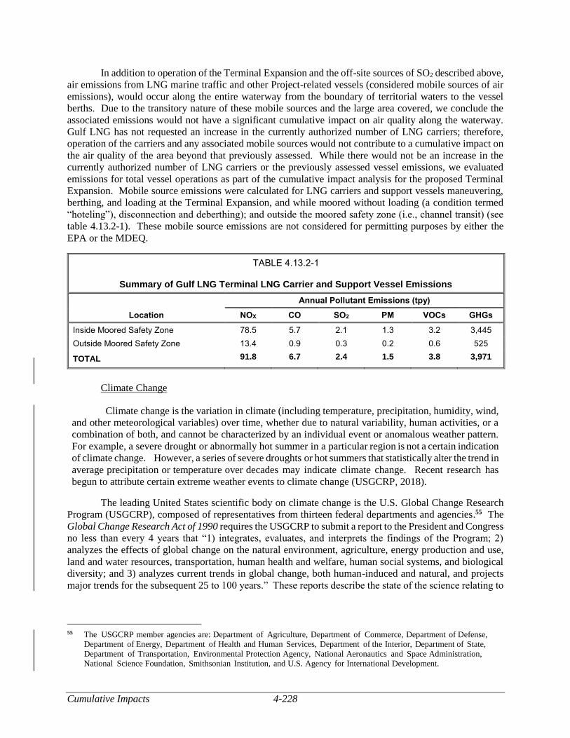
Cumulative Impacts 4-228
In addition to operation of the Terminal Expansion and the off-site sources of SO2 described above,
air emissions from LNG marine traffic and other Project-related vessels (considered mobile sources of air
emissions), would occur along the entire waterway from the boundary of territorial waters to the vessel
berths. Due to the transitory nature of these mobile sources and the large area covered, we conclude the
associated emissions would not have a significant cumulative impact on air quality along the waterway.
Gulf LNG has not requested an increase in the currently authorized number of LNG carriers; therefore,
operation of the carriers and any associated mobile sources would not contribute to a cumulative impact on
the air quality of the area beyond that previously assessed. While there would not be an increase in the
currently authorized number of LNG carriers or the previously assessed vessel emissions, we evaluated
emissions for total vessel operations as part of the cumulative impact analysis for the proposed Terminal
Expansion. Mobile source emissions were calculated for LNG carriers and support vessels maneuvering,
berthing, and loading at the Terminal Expansion, and while moored without loading (a condition termed
“hoteling”), disconnection and deberthing); and outside the moored safety zone (i.e., channel transit) (see
table 4.13.2-1). These mobile source emissions are not considered for permitting purposes by either the
EPA or the MDEQ.
TABLE 4.13.2-1
Summary of Gulf LNG Terminal LNG Carrier and Support Vessel Emissions
Location
Annual Pollutant Emissions (tpy)
NOX CO SO2 PM VOCs GHGs
Inside Moored Safety Zone 78.5 5.7 2.1 1.3 3.2 3,445
Outside Moored Safety Zone 13.4 0.9 0.3 0.2 0.6 525
TOTAL 91.8 6.7 2.4 1.5 3.8 3,971
Climate Change
Climate change is the variation in climate (including temperature, precipitation, humidity, wind,
and other meteorological variables) over time, whether due to natural variability, human activities, or a
combination of both, and cannot be characterized by an individual event or anomalous weather pattern.
For example, a severe drought or abnormally hot summer in a particular region is not a certain indication
of climate change. However, a series of severe droughts or hot summers that statistically alter the trend in
average precipitation or temperature over decades may indicate climate change. Recent research has
begun to attribute certain extreme weather events to climate change (USGCRP, 2018).
The leading United States scientific body on climate change is the U.S. Global Change Research
Program (USGCRP), composed of representatives from thirteen federal departments and agencies.55 The
Global Change Research Act of 1990 requires the USGCRP to submit a report to the President and Congress
no less than every 4 years that “1) integrates, evaluates, and interprets the findings of the Program; 2)
analyzes the effects of global change on the natural environment, agriculture, energy production and use,
land and water resources, transportation, human health and welfare, human social systems, and biological
diversity; and 3) analyzes current trends in global change, both human-induced and natural, and projects
major trends for the subsequent 25 to 100 years.” These reports describe the state of the science relating to
55 The USGCRP member agencies are: Department of Agriculture, Department of Commerce, Department of Defense,
Department of Energy, Department of Health and Human Services, Department of the Interior, Department of State,
Department of Transportation, Environmental Protection Agency, National Aeronautics and Space Administration,
National Science Foundation, Smithsonian Institution, and U.S. Agency for International Development.
4-229 Cumulative Impacts
climate change and the effects of climate change on different regions of the United States and on various
societal and environmental sectors, such as water resources, agriculture, energy use, and human health.
In 2017 and 2018, the USGCRP issued its Climate Science Special Report: Fourth National
Climate Assessment, Volumes I and II (Fourth Assessment Report) (USGCRP, 2017; and USGCRP, 2018,
respectively). The Fourth Assessment Report states that climate change has resulted in a wide range of
impacts across every region of the country. Those impacts extend beyond atmospheric climate change
alone and include changes to water resources, transportation, agriculture, ecosystems, and human health.
The U.S. and the world are warming; global sea level is rising and acidifying; and certain weather events
are becoming more frequent and more severe. These changes are driven by accumulation of GHG in the
atmosphere through combustion of fossil fuels (coal, petroleum, and natural gas), combined with
agriculture, clearing of forests, and other natural sources. These impacts have accelerated throughout the
end of 20th and into the 21st century (USGCRP, 2018).
Climate change is a global phenomenon; however, for this analysis, we will focus on the existing
and potential cumulative climate change impacts in the Project area. The USGCRP’s Fourth Assessment
Report notes the following observations of environmental impacts are attributed to climate change in the
Gulf Coast and Southeast regions:
The region has experienced an increase in annual average temperature of 0.46 F since the
early 20th century, with the greatest warming during the winter months.
The region has experienced more frequent and longer heat waves and a greater number of
days with nighttime temperatures above 75 F.
Over the past 50 years, there has been an overall increase in extreme rainfall events in the
region, except in some areas near the Appalachian Mountains and Florida where there has
been a downward trend.
The number of strong (Category 4 and 5) hurricanes has increased since the early 1980s.
Average global sea level rise over the past century averaged approximately 8 to 9 inches; in
some low lying areas of the Southeast region, the combination of vertical land motion and
changing currents has resulted in as much as 1 to 3 feet of local relative sea level rise. This
recent rise in local relative sea level has caused normal high tides to reach critical levels that
result in flooding in many coastal areas in the region.
The USGCRP’s Fourth Assessment Report notes the following projections of climate change
impacts in the project region with a high or very high level of confidence56 (USGCRP, 2018):
The frequency and severity of extreme precipitation events are projected to increase, with up
to double the number of heavy rainfall events by the end of the century.
The Southeast region’s coastal plain and inland low-lying areas are projected to experience
daily high tide flooding by the end of the century due to sea level rise and extreme rainfall
events.
56 The report authors assessed current scientific understanding of climate change based on available scientific literature. Each
“Key Finding” listed in the report is accompanied by a confidence statement indicating the consistency of evidence or the
consistency of model projections. A high level of confidence results from “moderate evidence (several sources, some
consistency, methods vary and/or documentation limited, etc.), medium consensus.” A very high level of confidence results
from “strong evidence (established theory, multiple sources, consistent results, well documented and accepted methods,
etc.), high consensus” (https://science2017.globalchange.gov/chapter/front-matter-guide/).
Cumulative Impacts 4-230
Rising temperatures and increases in the duration and intensity of droughts are expected to
increase wildfire occurrence.
Tropical storms are projected to be fewer in number globally, but stronger in force,
exacerbating the loss of barrier islands and coastal habitats.
It should be noted that while the impacts described above taken individually may be manageable
for certain communities, the impacts of compound extreme events (such as simultaneous heat and drought,
wildfires associated with hot and dry conditions, or flooding associated with high precipitation on top of
saturated soils) can be greater than the sum of the parts (USGCRP, 2018).
The GHG emissions associated with construction and operation of the Project are identified in
section 4.11. The construction and operation of the Project would increase the atmospheric concentration
of GHGs, in combination with past, current, and future emissions from all other sources globally and
contribute incrementally to future climate change impacts.
However, we note that Gulf LNG would incorporate GHG BACT as part of the air permits issued
by the MDEQ. Potential controls for these emissions include reducing GHG emissions, through
implementation of the following BACT: (1) use of natural gas to fire on-site equipment such as refrigeration
turbines and hot oil heaters; (2) design and operational energy efficiency measures; (3) good
combustion/operating practices; and (4) implementation of the 28VHP Leak Detection and Repair Program.
The ultimate implementation of BACT will be made by the MDEQ as part of the PSD permit.
Currently, there is no universally accepted methodology to attribute discrete, quantifiable, physical
effects on the environment to the Project’s incremental contribution to GHGs. We have looked at
atmospheric modeling used by the EPA, National Aeronautics and Space Administration, the
Intergovernmental Panel on Climate Change, and others and we found that these models are not reasonable
for project-level analysis for a number of reasons. For example, these global models are not suited to
determine the incremental impact of individual projects, due to both scale and overwhelming complexity.
We also reviewed simpler models and mathematical techniques to determine global physical effects caused
by GHG emissions, such as increases in global atmospheric CO2 concentrations, atmospheric forcing, or
ocean CO2 absorption. We could not identify a reliable, less complex model for this task and we are not
aware of a tool to meaningfully attribute specific increases in global CO2 concentrations, heat forcing, or
similar global impacts to project-specific GHG emissions. Similarly, it is not currently possible to
determine localized or regional impacts from GHG emissions from the Project. Absent such a method for
relating GHG emissions to specific resource impacts, we are not able to assess potential GHG-related
impacts attributable to this Project. Additionally, we have not been able to find any GHG emission
reduction goals established either at the federal level57 or by the State of Mississippi. Without either the
ability to determine discrete resource impacts or an established target to compare GHG emissions against,
we are unable to determine the significance of the Project’s contribution to climate change.
Noise
Noise levels typically attenuate quickly as the distance from the noise source increases. Therefore,
the geographic scope of potential impact considered for noise is within about 2 miles of the Terminal
Expansion. There are two NSAs in the vicinity of the Terminal Expansion site. The closest NSAs are
residences along Southshore Avenue about 1.8 miles northwest of the Project. The second NSAs are
residences about 2.0 miles northwest of the facility along Beach Boulevard. Based on the distance to the
NSA, sound levels from construction equipment would be significantly lower than 55 dBA and would not
57 The national emissions reduction targets expressed in the EPA’s Clean Power Plan and the Paris climate accord are pending
repeal and withdrawal, respectively.
4-231 Cumulative Impacts
be expected to result in adverse impacts on the NSA. Dredging and pile driving could contribute sound
levels of 46.8 dBA Ldn and 49.7 dBA Ldn at the nearest NSA respectively, which is also less than the noise
criteria and not be expected to result in significant impacts on the NSA. Furthermore, construction of the
MPC Upgrade is not expected to result in significant impacts on the NSA closest to the Terminal. Noise
impacts during construction of these projects and the Project would be localized, intermittent, and would
attenuate as the distance from the noise source increases. However, if perceived noise levels cause a
nuisance at the nearby NSAs and residents are inconvenienced, Gulf LNG would ensure the Commission’s
noise criterion of 55 dBA is met by construction of sound barriers, installation of residential grade exhaust
mufflers on equipment, or reducing utilization rates as necessary. As a result, we conclude construction of
the Terminal Expansion along with the non-jurisdictional project would not result in a significant noise
impact on the nearest NSA.
The estimated operational noise level of the Terminal Expansion at the nearest NSA (about
1.8 miles to the northwest) is 47.0 dBA Ldn and is 0.8 dBA greater than the estimated ambient noise levels
when considering operational and ambient noise. The threshold of perception of change in sound levels for
human hearing is about 3 dBA; therefore, the increase would be unnoticeable or barely noticeable at the
nearest NSA. To ensure operations do not cause noise levels above 55 dBA, Gulf LNG would conduct and
file a post-construction noise survey within 60 days after the facility is put in service. Noise impacts would
also occur from flare operation on an intermittent basis during startup, shutdown, or commissioning of the
liquefaction facility, and infrequently in the event of a malfunction de-pressuring event. It is expected that
noise attributable to the flare events would achieve 55 dBA Ldn or less once detailed design is completed,
the flare design/vendor is selected, and final emergency flare rates are known.
The combined operation of the identified projects, should they all be authorized, could result in the
raising of the average ambient noise level at the nearest NSAs but not by a significant measure. Cumulative
operational noise would be audible at the Terminal site, but should not be significantly greater than current
measured ambient noise due to noise attenuation. In addition, the liquefaction facility design should also
result in no discernable vibration at the nearest NSAs. Generally, if there are off-site vibrations being
induced from the Terminal, it would be indicative of malfunctioning equipment and would lead to
equipment shutdown to enable repairs to establish normal operation.
Therefore, operational noise from the Terminal Expansion would result in minor impacts on the
NSA.
Safety
For the proposed Terminal Expansion, we considered the geographic scope for marine vessel traffic
to include the Mississippi Sound and the Bayou Casotte Navigation Channel. The geographic scope for the
Terminal Expansion itself is the area adjacent to and in the vicinity of the Terminal site. The geographic
scope for emergency services includes the area in the general vicinity of the proposed Terminal Expansion
(which includes the non-jurisdictional projects and the existing industrial facilities along Highway 611).
Gulf LNG would mitigate impacts on public safety through the implementation of applicable
federal, state, and local rules and regulations for the proposed Project as described in section 4.12. Those
rules and regulations would ensure that the applicable design and engineering standards are implemented
to protect the public and avoid or minimize the potential for accidents and failures.
Because Gulf LNG has not requested an increase in the number of LNG carriers calling on the
Terminal, the Terminal Expansion would not add to the current risk assessment of public safety within the
Mississippi Sound or Bayou Casotte Navigation Channel or of an intentional attack on an LNG carrier at
berth or in transit in the sound.
Cumulative Impacts 4-232
As noted in section 4.12.2, the risk associated with the Pipeline Modifications would be small. In
addition, the proposed Pipeline Modifications would be within an existing interconnection or meter station.
As a result, we conclude that the cumulative impact on risk for the Pipeline Modifications would not be
significant.
Emergency response time is a key aspect of public health and safety. Key emergency services are
provided by the Gulf LNG Terminal, the Chevron Refinery, the Mississippi Phosphate Corporation, and
Jackson County and those services would expand to include the associated proposed liquefaction projects.
In accordance with our regulations, Gulf LNG would prepare a comprehensive plan that identifies the cost-
sharing mechanisms for funding these emergency response costs. Therefore, we believe that the cumulative
impact of each project’s comprehensive plans would not result in a significant impact on public safety.
5-1 Conclusions and Recommendations
5.0 CONCLUSIONS AND RECOMMENDATIONS
SUMMARY OF THE ENVIRONMENTAL ANALYSIS
The conclusions and recommendations presented in this section are those of the FERC environmental and engineering staff. Our conclusions and recommendations are based on input from the COE, the EPA, the USCG, the DOE/FE, the DOT/PHMSA, the FWS, NMFS, and the Mississippi Secretary of State as cooperating agencies in the preparation of this EIS. The federal cooperating agencies may adopt this EIS per 40 CFR 1501.3 if, after an independent review of the document, they conclude that their requirements and/or regulatory responsibilities have been satisfied. However, these agencies would present their own conclusions and recommendations in their respective and applicable records of decision or determinations. Otherwise, they may elect to conduct their own supplemental environmental analyses.
We conclude that construction and operation of the Gulf LNG Liquefaction Project would result in limited adverse environmental impacts. Most adverse environmental impacts would be temporary or short-term during construction and operation, but long-term and permanent environmental impacts would occur on wetlands, vegetation, land use, and EFH. This determination is based on a review of the information provided by Gulf LNG and further developed from data requests; field investigations; scoping; literature research; alternatives analysis; and contacts with federal, state, and local agencies as well as individual members of the public. As part of our analysis, we developed specific mitigation measures that we determined would appropriately and reasonably reduce the environmental impacts resulting from construction and operation of the Project. We are, therefore, recommending that these mitigation measures be attached as conditions to any authorization issued by the Commission. If the Project is constructed and operated in accordance with the mitigating measures discussed in this EIS, and our recommendations, adverse environmental impacts would be reduced to less than significant levels. A summary of the Project impacts and our conclusions regarding impacts are provided below by resource area.
Geologic Resources
Given the scope of the Project, we examined impacts on geologic resources within a 1-mile radius for the Terminal Expansion and in close proximity for the Pipeline Modifications. No known mining operations exist within a 1-mile radius of the Terminal Expansion site. The nearest oil and gas exploration and production to the Terminal have occurred about 8 miles to the north. Therefore, we conclude that the Terminal Expansion would not affect mining or oil and gas exploration activities. No mineral resources or mineral extraction activities are known to be within close proximity of the Pipeline Modifications. Therefore, we conclude that the Pipeline Modifications would not affect mining or oil and gas activities.
Soils
Construction of the Project facilities would temporarily and permanently disturb soils, resulting in increased potential for erosion, compaction, and reduced vegetation following construction. Erosion potential in the Project area is reduced by the generally level topography of the area and the highly cohesive nature of most of the soils. The potential for soil erosion would be further minimized through the use of erosion controls and revegetation measures as described in the Gulf LNG Plan. The majority of soils in the Project area are considered hydric and have a high potential for compaction. If soil de-compaction is required, Gulf LNG would use a method such as deep tilling to loosen the soil after construction is completed. The CSAs contain 34.5 acres of soils that have a low revegetation potential.
Conclusions and Recommendations 5-2
CSA-2, CSA-3, and CSA-6 are currently surfaced with gravel and CSA-1, CSA-4, and CSA-5 are currently or have recently been used for industrial purposes. The CSAs would be restored to their previous condition at the completion of construction except for CSA-3, which would continue to be used by Gulf LNG throughout operation of the Project.
Based on Gulf LNG’s proposed permanent filling of the wetlands at CSA-5 and our experience with natural gas facility construction, we have determined that Gulf LNG has not adequately justified permanently filling the wetlands at CSA-5. Therefore, we are recommending that Gulf LNG commit to restore the wetlands at CSA-5 to pre-construction conditions following construction in accordance with the FERC Procedures.
There are no prime farmland soils on the sites of the Terminal Expansion or Pipeline Modifications, but these soils are present at CSA-3 and CSA-6. CSA-3 is currently used by Gulf LNG for warehousing and equipment storage while CSA-6 is currently being used as a parking lot with a layer of crushed gravel covering the area. Neither CSA contains any active agricultural operations and both are already being used for industrial use; therefore, no new impacts on prime farmland soils is expected.
Gulf LNG did not encounter contaminated soil during construction of the existing Terminal or the associated pipeline facilities. Gulf LNG conducted soil sampling of previously dredged materials that would be removed as part of Project construction to determine their eligibility for beneficial use. According to Gulf LNG, about 10.4 acres of sediments around station 10 may have elevated contaminant levels of arsenic and cadmium. Because these sediments would meet the permissible concentration requirements for ocean disposal, Gulf LNG proposes to blend these sediments with other sediments removed from the BCDMMS. Gulf LNG would consult with the MDEQ and the COE prior to construction to determine if the blended sediments would be appropriate for use at the Terminal Expansion site. Any sediment not used would be transported to an approved site for upland disposal. In addition, if any previously unidentified contaminated soil were discovered during construction, Gulf LNG would implement its Plan for Unanticipated Discovery of Hazardous Materials (see appendix H).
Gulf LNG has amended its SPCC Plan to include the Terminal Expansion. This plan identifies cleanup procedures to be implemented in the event of soil contamination from spills or leaks of fuel, lubricants, coolants, or solvents.
Creation of the North and South Supply Docks would require dredging of approximately 100,000 cy of sediment for each dock to a depth of 12 feet below msl. Gulf LNG would work with federal and state agencies to identify a suitable BU site for dredge material disposal. Gulf LNG would utilize an offshore dredged material disposal site if a suitable BU site is not available in accordance with its dredge disposal permit that would be issued by the COE.
During construction, Gulf LNG would dredge a temporary barge access channel from the South Supply Dock along the outer perimeter of the proposed wetland mitigation site (dredging of about 200,000 cy of material). Barges would use the temporary channel to install the perimeter riprap. The sediment removed for the channel would be temporarily placed within the proposed wetland mitigation site and then replaced in the temporary channel after the riprap is installed. All of the dredge material would be replaced in the temporary channel or contained within the marsh creation area, so off-site disposal would not be necessary.
With implementation of the Gulf LNG Plan, Gulf LNG Procedures, SPCC Plan, and Gulf LNG abiding by any permit conditions associated with its CWA permit, we conclude that impacts on soils would mostly be temporary and would not be significant.
5-3 Conclusions and Recommendations
Water Resources
The Project is underlain by the upper portion of the Coastal Lowlands Aquifer System (known as the Chicot Aquifer); however, we do not anticipate any long-term or significant impacts on the aquifer due to construction or operation of the Project. Standard construction procedures could affect groundwater resources by altering overland water flow and infiltration rates. Because the recharge areas are much larger than the footprint of the Project, changes in groundwater recharge as a result of Project construction are not expected to be significant. There are no active public water supply wells, wellhead protection areas, or springs within 150 feet of Terminal Expansion. There are eight private water supply wells within 500 feet of the CSAs and one private well at CSA-1. The location of the private water supply well at CSA-1 would be clearly marked and refueling and the storage of hazardous materials would be restricted within a 200-foot buffer of its location. Gulf LNG would also conduct pre- and post-construction monitoring of water quality and yield for the private well with the owner’s permission.
Gulf LNG would withdraw water for hydrostatic testing the Terminal Expansion, the Destin Meter Station, and the Gulfstream Meter Station from the Port of Pascagoula’s Industrial Water Supply. Gulf LNG estimates that the Project would require a total of 111,723,725 gallons of water during construction (including 3,410,000 gallons for hydrostatic testing). Correspondence from the JCPA states it has the supply and permit authority to meet the Project’s industrial water requirements. Hydrostatic test water from the Terminal Expansion would be discharged into the Mississippi Sound in accordance with MDEQ NPDES discharge permit MSG13. Groundwater would not be used for hydrostatic testing; therefore, no impacts on groundwater as a result of hydrostatic testing are expected.
Gulf LNG would dredge about 200,000 cy for construction of the North and South Supply Docks; during operation of the Project, the North Supply Dock would undergo maintenance dredging. Dredging would be conducted in accordance with the MDMR and the COE permits. The South Supply Dock would be removed following construction. Following construction, ownership of the North Supply Dock would be transferred to the JCPA. Dredging impacts would be minimized through adherence to the mitigation measures provided in Gulf LNG’s Dredging and Disposal Plan which include the use of turbidity curtains around the area being excavated to limit the transport of turbid water beyond the vicinity of the dredging operations. Additionally, Gulf LNG is currently engaging in consultations with the COE and the MDEQ as part of the RHA Section 10 and CWA Section 404 and 401 application processes. As part of this process, Gulf LNG would discuss with the COE and the MDEQ the practicality and effectiveness of methods for reducing turbidity in the vicinity of dredging operations.
We conclude that the potential impacts on groundwater and surface water quality during construction and operation of the Terminal Expansion would be minimized through implementation of the measures contained in the Gulf LNG Plan and Gulf LNG Procedures, which incorporate measures required by the FERC’s Plan and Procedures. In addition, Gulf LNG would implement its SPCC Plan to minimize any potential impacts from a spill of hazardous fluids. Therefore, we conclude no significant impacts on water resources would occur due to construction and operation of the Project. In addition, Gulf LNG must comply with the COE Section 404 and Section 10 permits.
Wetlands
Construction and operation of the Terminal Expansion would permanently affect a total of 38.7 acres of wetlands (all of which are jurisdictional). Impacts would be offset by Gulf LNG’s compensatory mitigation measures, which are detailed in its compensatory wetland mitigation plan. Gulf LNG’s currently proposed wetland mitigation would include creation of a 50-acre EEM wetland south of the existing Terminal on Mississippi Sound and purchase of freshwater wetland mitigation credits. The mitigation plan is under agency review; Gulf LNG would finalize the design details and construction plan
Conclusions and Recommendations 5-4
and file the finalized plan during final design. To further minimize impacts on wetlands, Gulf LNG would comply with all conditions of the Section 404 and Section 10 permits.
Based on Gulf LNG’s proposed permanent filling of the wetlands at CSA-5 and our experience with natural gas facility construction, we have determined that Gulf LNG has not adequately justified permanently filling the wetlands at CSA-5. Therefore, we are recommending that Gulf LNG commit to restore the wetlands at CSA-5 to pre-construction conditions following construction in accordance with the FERC Procedures.
No wetlands would be impacted by construction of the Pipeline Modifications.
Based on implementation of the mitigation measures outlined by Gulf LNG, collocation of the Project with the existing Terminal, and implementation of agency-approved compensatory mitigation, we conclude that impacts on wetlands during construction and operation of the Project would not be significant.
Vegetation
The Terminal Expansion site is generally disturbed due to industrial activities that have occurred over the last 50 years, including the construction and operation of the existing Terminal and its use as a dredge material disposal site. As a result, much of the property is comprised of vegetation indicative of disturbed sites. Operation of the Terminal Expansion would permanently impact about 81 acres of vegetation. We conclude that the loss of vegetation from the Terminal Expansion would be minor but permanent. Gulf LNG would implement compensatory mitigation for wetland vegetation impacts as mentioned above.
The proposed CSA sites are sited either partially or entirely on previously developed, industrial/commercial land. Two of the sites (i.e., CSA-3 and CSA-5) contain areas of both upland forest and wetland vegetation. Gulf LNG would avoid impacts on vegetation at CSA-3 during construction and operation of the Project. However, Gulf LNG would remove all vegetation at CSA-5 to permanently convert it to upland, industrial/commercial land. Gulf LNG would purchase credits from a wetland mitigation bank to offset impacts on wetlands at CSA-5.
As discussed above, based on Gulf LNG’s proposed permanent filling of the wetlands at CSA-5 and our experience with natural gas facility construction, we have determined that Gulf LNG has not adequately justified permanently filling the wetlands at CSA-5. Therefore, we are recommending that Gulf LNG commit to restore the wetlands at CSA-5 to pre-construction conditions following construction in accordance with the FERC Procedures.
Construction of the Pipeline Modifications would take place mainly on industrial/commercial land. Construction of the Gulfstream Meter Station would require 0.1 acre of open upland (existing pipeline right-of-way); however, this land would revert back to pre-construction conditions once construction is completed. Therefore, impacts on vegetation would be negligible.
Twenty exotic, invasive, and/or noxious plant species were identified in the Project area (see table 4.5.3-1). Of these plants, two are noxious species of concern: Chinese tallow and cogongrass. Gulf LNG would control growth of these species through best-management vegetation practices. If these methods prove to be inadequate, Gulf LNG has committed to work with local vegetation experts to develop improved measures.
We anticipate that impacts on vegetation generally would be permanent but not significant due to the industrialized nature of the area and Gulf LNG’s compensatory wetland mitigation measures. Further, we anticipate that impacts on upland forested vegetation would result in permanent impacts.
5-5 Conclusions and Recommendations
Wildlife and Aquatic Resources
Construction and operation of the Terminal Expansion would result in the removal of all habitats at the site and conversion of the site to industrial land. This would have a permanent effect on wildlife and wildlife habitats of the site; however, much of the Terminal Expansion site was previously disturbed, as described above, resulting in degraded wildlife habitat and a reduction in habitat diversity and the number of species on the site. Gulf LNG would mitigate wetland habitat impacts at the Terminal Expansion site through the creation of tidal marsh, which would provide additional habitat.
As stated above, all CSA sites are either fully or partially on previously developed, industrial/commercial land with little to no wildlife habitat. Impacts on vegetation at CSA-3 would be avoided during construction and operation, therefore, impacts on wildlife habitat at that site would be temporary and minor. Removal of vegetation at CSA-5 and conversion of the site to upland industrial/commercial land would result in the permanent loss of wildlife habitat at this site. However, due to the measures Gulf LNG would employ to avoid impacts on nesting birds (see below), impacts would not be significant. In addition, Gulf LNG would mitigate for impacts on wetland vegetation and associated wildlife habitat at CSA-5 by purchasing credits at a wetland mitigation bank. However, based on Gulf LNG’s proposed permanent filling of the wetlands at CSA-5 and our experience with natural gas facility construction, we have determined that Gulf LNG has not adequately justified permanently filling the wetlands at CSA-5. Therefore, we are recommending that Gulf LNG commit to restore the wetlands at CSA-5 to pre-construction conditions following construction in accordance with the FERC Procedures.
The Pipeline Modifications would be located almost entirely on industrial/commercial land. Therefore, construction and operation at these sites would not result in impacts on wildlife habitat.
Gulf LNG filed its Migratory Bird Plan with the FWS, which identifies migratory birds likely to be found in the Project area, discusses potential impacts on these species, and provides impact mitigation strategies (see appendix J). Gulf LNG is continuing to consult with the FWS on the development of this plan. Therefore, we are recommending that Gulf LNG file its finalized Migratory Bird Plan with the FERC prior to construction (see section 4.6.1.4). Gulf LNG would avoid impacts on nesting birds at CSA-5 by either restricting vegetation clearing to times outside of the nesting season or conducting pre-construction surveys for active nests prior to clearing. If an active nest is identified during surveys, Gulf LNG would postpone vegetation clearing until the nesting season is complete. Based on Gulf LNG’s commitment to continue consultations with the FWS and implement mitigation measures to avoid impacts on migratory birds, we conclude adverse impacts on migratory birds would not be significant.
Impacts on aquatic resources during construction and operation of the Terminal Expansion would range from temporary and minor to permanent. Construction, including dredging, of the North and South Supply Docks and operation, including periodic dredging, at the North Supply Dock would result in minor and temporary impacts on shallow estuarine habitat. Construction of the Terminal Expansion, including the North Supply Dock, and the compensatory wetland mitigation site would result in permanent impacts on coastal marsh and shallow estuarine habitat, respectively. NMFS and the GMFMC have identified the Mississippi Sound near Bayou Casotte as EFH for multiple recreational and commercial marine species. The EFH that would be effected by the Terminal Expansion includes shallow estuarine habitat (i.e., estuarine water column and estuarine benthic habitat [soft bottom sediment]), and intertidal vegetation (i.e., coastal marsh). To minimize impacts from dredging and construction on EFH and EFH species, Gulf LNG would install and maintain turbidity curtains around the area being excavated to limit the transport of turbid water beyond the vicinity of the dredging operations, and adhere to measures contained in its Gulf LNG Plan and Gulf LNG Procedures, the SPPC Plan, and existing and future federal and state permit requirements.
Conclusions and Recommendations 5-6
Pile driving near and within the Bayou Casotte waters could cause rapid concussive noise and generate underwater sound pressure waves that could adversely affect nearby marine organisms, including fish, sea turtles, and marine mammals. However, Gulf LNG would use a vibratory hammer during pile driving and follow NMFS-recommended BMPs to reduce pile driving-related noise impacts on aquatic organisms. Vibratory pile driving noise could startle or stress aquatic organisms in the immediate vicinity but it would be unlikely to cause injury. Aquatic resources within the Project area are likely accustomed to regular fluctuations in noise from nearby industrial activity and maintenance dredging. Therefore, we conclude that adverse impacts on EFH species due to noise would be temporary, localized, and minor. Based on a review of the EFH species’ habitats and life histories and implementation of Gulf LNG’s conservation measures, we conclude that no substantial adverse impacts on EFH or EFH species would occur during construction or operation of the Terminal Expansion, as impacts would primarily be localized, temporary, and minor. Where impacts on coastal marsh and shallow estuarine EFH would be permanent, Gulf LNG would provide adequate compensation, as required by the COE for wetland impacts, through the successful completion of the wetland compensatory mitigation site. On December 10, 2018 the NMFS agreed with our determination that the Project would not adversely affect EFH.1
Gulf LNG would not impact waterbodies by constructing and operating the Pipeline Modifications.
Based on Gulf LNG’s proposal, including implementation of its Plan and Procedures, we conclude impacts on wildlife and aquatic resources would be adequately minimized and not significant.
Threatened, Endangered, and Other Special Status Species
Based on consultations with the FWS, NMFS, and Gulf LNG’s species-specific surveys, 19 federally listed species, and 3 species under review for federal listing potentially occur in the general Project area. We anticipate that construction and operation of the proposed Project is not likely to adversely affect the Alabama red-bellied turtle, rufa red knot, piping plover, wood stork, least tern, interior least tern, West Indian manatee, blue whale, sperm whale, fin whale, humpback whale, sei whale, gulf sturgeon, smalltooth sawfish, Kemp’s ridley sea turtle, green sea turtle, loggerhead sea turtle, leatherback sea turtle, and hawksbill sea turtle. We expect that Project-related construction and operation would not contribute to a trend toward federal listing for the Bryde’s whale, saltmarsh topminnow, or eastern black rail. As part of the ESA Section 7 consultation process, we have prepared a BA, which is summarized in section 4.7.1 and provided in appendix B.
Based on the analysis of information and potential affects regarding federally listed species and their critical habitats, we have determined that adherence with the FWS’ and NMFS’ avoidance and minimization recommendations, Gulf LNG’s proposed construction procedures and mitigation measures described in its application, and compliance with federal and state permit conditions, the Project is not likely to adversely affect federally listed species. With the draft EIS, we requested that the FWS and NMFS concur with our determination of effects on these protected species and complete Section 7 consultation. On February 22, 2019 the FWS agreed with our determination of effects for those species under their jurisdiction. Because consultation with the NMFS is ongoing, we are recommending that the FERC staff completes any necessary ESA consultation with the NMFS prior to construction.
Based on consultations with the MDWFP and Gulf LNG’s species-specific surveys, three birds, one plant species of state concern, and one special status species occur within 2 miles of the Project facility sites and could be affected by the Project. We anticipate that impacts from the Project would not 1 See accession number 20181211-5001.
5-7 Conclusions and Recommendations
be significant for the snowy plover, peregrine falcon, brown pelican, and bald eagle. A small population of Carolina grasswort is at the proposed Terminal Expansion. Therefore, we are recommending that Gulf LNG transplant the Carolina grasswort population to a similar habitat using protocols determined in consultation with the MMNS. With implementation of our recommendation, we expect that Project-related impacts on the population of Carolina grasswort would not be significant.
In summary, we conclude that implementation of Gulf LNG’s mitigation measures, our recommendations, and implementation of the measures contained in the Gulf LNG Plan and Gulf LNG Procedures, during construction and operation of the Project would adequately minimize impacts on federally and state-listed species along with other species of concern.
Land Use, Recreation, and Visual Resources
Construction of the Terminal Expansion would be within and adjacent to the existing Terminal and would result in 230.8 acres of construction impacts and 172.1 acres of operation impacts of open land, industrial/commercial land, wetlands, and open water. All of the affected area within the operational footprint would be permanently converted to industrial land. The Terminal Expansion site is within the designated coastal zone, which is managed by the MDMR. A determination from the MDMR that the Project is consistent with the Mississippi CZMP has not yet been obtained by Gulf LNG. Therefore, we are recommending that Gulf LNG be required to file documentation of concurrence from the MDMR that the Project is consistent with the Mississippi CZMP prior to construction.
Gulf LNG has not requested any changes in the number or route of LNG carriers currently authorized to call on the Terminal. Although barge traffic in the Bayou Casotte Navigation Channel would increase during construction, we anticipate that the overall impact on recreational boating and fishing would be minor.
Views of the Terminal Expansion would generally be similar to those of the adjacent existing Terminal and the surrounding industrial areas. The tallest structure to be constructed would be the 430-foot-tall flare tower at the southwest corner of the site. The flares would be operated only during start-up and when incidents require releases. Overall, we believe the Terminal Expansion would result in minor impacts on the viewshed during construction and operation.
Construction and operation of the Pipeline Modifications would result in 3.5 acres of construction impacts on industrial land and 0.1 acre of impacts on open land. All of which would be within the currently fenced areas of the meter stations and interconnection sites or the associated pipeline right-of-way. There are few viewers of these existing facilities and Gulf LNG and Transco would not make major above-ground changes to the facilities. As a result, we conclude that there would not be more than minor visual impacts due to construction and operation of the modifications.
Socioeconomics
Construction of the Project would increase the population within Jackson County for the 66-month construction period. Although the peak construction workforce for the Project would be about 4,300 workers, it is estimated that 40 percent of the workers would come from the local area. The large tourism destination areas of Biloxi/Gulfport, Mississippi, and Mobile, Alabama are within a 40-mile commuting distance. In addition to the local housing supply, these areas are estimated to be able to accommodate the excess demand and we conclude the impact on housing would not be significant. We anticipate that the impact of the Project workforce on public services would also be minor.
Conclusions and Recommendations 5-8
Construction and operation of the Project would increase local and state tax revenues from sales taxes, payroll taxes, and property taxes, and would likely increase local employment. However, these impacts would not be significant.
The Terminal Expansion and the Pipeline Modifications would all occur in an industrial area. The Project would not significantly impact urban or residential areas, and no disproportionately high and adverse human health or environmental effects on minority, low-income communities, or Native American tribes have been identified.
Gulf LNG would minimize traffic into and out of the Terminal Expansion site by including off-site parking into its Project design. In response to our recommendation in the draft EIS, Gulf LNG provided an updated Traffic Impact Analysis. Gulf LNG’s updated analysis predicted poor levels of service at traffic intersections near CSA-6 and high volumes of traffic near residential areas. To mitigate traffic impacts at the Bayou Casotte Parkway and Orchard Road intersection, Gulf LNG is proposing to add signage to clearly identify lane movements, add raised pavement markers within the intersection, and restripe the intersection. These measures would help improve the functionality of the intersection and improve safety for drivers that are unfamiliar with driving in the area. Gulf LNG would implement these measures prior to starting construction. To further improve traffic flow into and out of the parking area at CSA-6, Gulf LNG would prohibit parking along Bayou Casotte Parkway adjacent to the parking area and they would stripe the three driveways that access the parking area to ensure the entry lane would be a minimum of 14 feet wide. While residents from the area to the west of CSA-6 could access their residences and schools along Bayou Casotte Parkway, it is more likely that they would use other, more direct routes such as Martin Street and Ingalls Avenue. With the mitigation measures outlined by Gulf LNG and the availability of other routes for local residents, construction of the Project would have a temporary and minor impact on traffic in the area of the Project.
Barges would deliver equipment and materials to the two supply docks off the Bayou Casotte Navigation Channel. The impact of barge traffic on the waterway would be moderate during the 2-month period when the supply docks would be constructed and would decline to a minor impact for the rest of the construction period.
Gulf LNG has not requested to increase the number of LNG carriers calling on the Terminal above the number currently authorized; however, they did request an increase in the size of LNG carriers that could access the marine berths. The larger sized carriers would be consistent with the traffic analyzed under the existing Terminal.
Cultural Resources
Gulf LNG completed cultural resource surveys for the Project, and no cultural resources were identified within the Project footprint. The MDAH (SHPO) reviewed the Phase I survey reports and concurred that the Project would not affect historic properties, and we agree. The review process under Section 106 of the NHPA is complete for the Project.
Air Quality and Noise
Construction of the Project would result in temporary impacts on air quality due to emissions from fossil-fueled construction equipment and fugitive dust. Gulf LNG would incorporate dust control measures during construction to minimize fugitive dust, and we conclude the impact of construction on air quality would be minor.
Long-term impacts on air quality would be caused during operation of the Terminal Expansion. However, Gulf LNG would minimize potential impacts on air quality associated with operation of the
5-9 Conclusions and Recommendations
Terminal Expansion by adhering to applicable federal and state regulations, including installation of BACT to minimize emissions as required by the PSD air quality permit that is pending issuance by the MDEQ. It is expected that compliance with the applicable state and federal air quality standards and regulations would be addressed accordingly in the issued permit.
Construction activities and the associated noise would vary depending on the phase of construction in progress at any one time. The most prevalent sound generating equipment during site construction of the Terminal Expansion would be internal combustion engines of construction equipment. The sound levels experienced at the nearby noise sensitive areas (NSAs) would depend on the type of equipment used, the mode of operation of the equipment, the length of time the equipment is in use, the amount of equipment used simultaneously, and the distance between the sound generation source and the receptor. However, based on the distance to the NSA, construction noise from this typical construction equipment is not anticipated to exceed the Commission’s noise criterion. If perceived noise levels cause a nuisance at the nearby NSAs, Gulf LNG proposes to ensure the noise criterion of 55 dBA is met by construction of sound barriers or installation of residential grade exhaust mufflers on equipment as necessary. We conclude that Gulf LNG’s commitments would lessen impacts on residents to the extent practicable.
Dredging of the supply docks and for material barge access to the wetland mitigation area, would produce peak sound levels that would be perceptible above the prevalent sound levels during construction. However, the resulting noise is less than the Commission’s noise criterion, and would not be expected to result in significant impacts on the NSA. Based on the large number of residents who live in the Project area, the impulsive (short, intense) noise impacts associated with pile-driving activities, the predicted and perceptible noise impacts on NSAs, the duration of pile-driving activities, as well as the lack of noise mitigation measures proposed by Gulf LNG, we are recommending that Gulf LNG implement additional measures to minimize the noise impacts of pile-driving on NSAs. With the implementation of the mitigation measures proposed, in addition to our recommendation, effects resulting from construction of the Terminal Expansion would be temporary and would not result in significant impacts on nearby communities. Operation of the Terminal Expansion would generate sound levels that would occur throughout the life of the Project. Based on preliminary operational noise levels for anticipated equipment, the increase in noise levels would be below the “barely detectable” noise level increase of 3 dBA and would result in minor impacts on the nearest NSA. In addition, the noise level would be below the FERC limit of an Ldn of 55 dBA. We are recommending, however, that Gulf LNG file a full load noise survey no later than 60 days after each liquefaction train is put in service for the first and second liquefaction trains. If noise levels attributable to operation of the Terminal Expansion exceed the FERC limit of an Ldn of 55 dBA, Gulf LNG would be required to install additional mitigation to reduce the Terminal’s noise contribution to ensure that the noise level that is no higher than the FERC requirement. We are also recommending that Gulf LNG file a full load noise survey no later than 60 days after placing all the Terminal Expansion facilities in service.
Noise impacts would also occur from flare operation on an intermittent basis during start-up, shutdown, or commissioning of the liquefaction facility, and infrequently in the event of a malfunction de-pressuring event. We anticipate that noise attributable to planned flare events would achieve 55 dBA Ldn or less once detailed design is completed, the flare design/vendor is selected, and final emergency flare rates are known. Unplanned flare events would produce more noise, with an estimated Ldn of 56 to 61 dBA at the nearest NSAs; however, because of the infrequent occurrence and expected operation of flares during these events, we conclude that the resulting noise would not result in a significant impact on the NSAs.
Conclusions and Recommendations 5-10
Safety
An evaluation and review of the safety of the proposed Terminal Expansion by the FERC staff, including a review of the cryogenic design of the facilities proposed for liquefaction, related facilities, and safety systems, concluded that the Terminal Expansion would not pose a significant risk or significant increase in risk to public safety with the incorporation of our recommendations.
On March 15, 2019, the DOT issued a LOD, which provides PHMSA’s analysis and conclusions regarding 49 CFR 193, Subpart B regulatory requirements for the Commission’s consideration in its decision to authorize, with or without modification or conditions, or deny an application.2
The USCG reviewed Gulf LNG’s request to increase the size of the authorized LNG carriers from a maximum of 170,000 m3 to 208,000 m3. The USCG determined that the navigation portion of the original WSA did not account for larger LNG carriers. Therefore, the USCG prepared an updated draft LOR and Letter of Recommendation-Analysis (LOR-A) which was provided to the FERC in January 2016. The USCG prepared the final LOR and LOR-A dated May 16, 2016 which was provided to the FERC on August 9, 2017.
Gulf LNG would design, construct, operate, and maintain its Pipeline Modifications to meet or exceed the DOT Minimum Federal Safety Standards in 49 CFR 192 and other applicable federal and state regulations.
By designing and operating the proposed Project in accordance with the applicable standards, the Project would represent only a slight increase in risk to the nearby public.
Cumulative Impacts
We considered the contributions of the proposed Project in specific cumulative impact areas for the resources affected by the Project. As a part of that assessment, we identified existing projects, projects under construction, projects that are proposed or planned, and reasonably foreseeable projects, including the existing Terminal, non-jurisdictional facilities, currently operating and future oil and gas projects, land transportation projects, commercial developments, and dredging projects. Our assessment considered the impacts of the proposed Project combined with the impacts of the other projects on resources within all or part of the same area and time. We conclude that the Project’s contribution to cumulative impacts on the affected resources would not be significant.
Alternatives
As alternatives to the proposed action, we evaluated the No-Action Alternative, system alternatives, alternative Terminal Expansion sites, alternative plot plans for the Terminal Expansion, supply dock alternatives, alternative CSA sites, alternative Pipeline Modification sites, an alternative power source for the refrigeration compressors, and an alternative power source for the Terminal Expansion. Alternatives were evaluated and compared to the Project to determine if these alternatives were environmentally preferable to the Project. While the No-Action Alternative would avoid the environmental impacts identified in this EIS, adoption of this alternative would preclude meeting the Project objectives. If the Project is not approved and built, the need could potentially be met by other LNG export projects developed elsewhere in the Gulf Coast region or in other areas of the United States.
2 March 15, 2019 letter “Re: Gulf LNG Liquefaction Project FERC Docket CP15-521-000 49 CFR 193, Subpart
B, Siting – Letter of Determination”. FERC eLibrary accession number 20190315-3072.
5-11 Conclusions and Recommendations
Implementation of other LNG export projects likely would result in impacts similar to or greater than those of the proposed Project.
We evaluated 20 system alternatives for the Terminal Expansion, including 5 operating LNG import terminals in the Gulf of Mexico area, and 15 proposed or planned liquefaction and export projects along the Gulf Coast. All of the systems were eliminated from further consideration, primarily due to the need for substantial construction beyond that currently proposed or planned to meet the need of the Project, and the resultant potential environmental impacts that were considered comparable to or greater than those of the Project. As a result, none of the projects assessed as a potential system alternative offered a significant environmental advantage over the Project.
We considered potential alternative Terminal Expansion sites in proximity to the existing Terminal in an attempt to avoid or minimize wetland impacts while using the infrastructure of the existing Terminal, such as the LNG storage tanks and the marine berth. However, the area in the vicinity of the existing Terminal has extensive wetlands, including the Grand Bay Savanna Preserve, or is heavily developed. As a result, we conclude that development of the expanded Terminal on alternative sites or with alternate configurations would not be environmentally preferable.
In our alternatives analysis, we also considered the use of only one supply dock and alternative sites for the two proposed supply docks. We agreed with Gulf LNG that two supply docks were needed to facilitate construction, and that use of the existing marine berthing facility for delivery of construction equipment and materials was not a reasonable alternative. Essentially all of the area adjacent to Mississippi Sound and the Bayou Casotte Navigation Channel in the vicinity of the Terminal Expansion site is either wetlands or is heavily developed and we did not identify any reasonable alternative sites for either supply dock. As a result of these considerations, we conclude that the construction of two supply docks at the proposed sites for use during construction is the preferred alternative.
Except for CSA-5, Gulf LNG selected CSAs that were previously used for similar activities. We do not consider the direct impacts on the proposed CSA sites or the impacts due to use of the sites (such as transportation, air quality, and noise impacts) to be significant and therefore did not assess alternative CSA sites. Based on comments from the EPA and to avoid impacts on wetlands, we asked Gulf LNG to evaluate an alternative location for CSA-5 within the BCDMMS. Gulf LNG indicated that it would not be feasible to relocate CSA-5 within the BCDMMS as this area is an active dredge disposal location that would be periodically inundated with dredge spoil and water. Therefore, we are recommending that Gulf LNG commit to restore the wetlands at CSA-5 to pre-construction conditions following construction in accordance with the FERC Procedures.
All of the Pipeline Modifications outside of the Terminal Expansion site would be constructed within existing fenced and graveled facilities that are within natural gas pipeline rights-of-way. We did not identify any environmental concerns with those sites that require the need to identify and evaluate alternative sites.
Each liquefaction train would have two gas-fired turbines to provide the power required to operate the refrigeration compressors. In addition, Gulf LNG proposes to use purchased power to operate the remainder of the Terminal Expansion facilities. We assessed alternative power generation options. Based on the available data and using EPA’s emission factors for grid-supplied power for the region, we could not conclude that any alternative would offer a significant environmental advantage over the proposed power sources.
Conclusions and Recommendations 5-12
FERC STAFF’S RECOMMENDED MITIGATION
If the Commission authorizes the Gulf LNG Liquefaction Project, we are recommending that the following measures be included as specific conditions in the Commission’s Order. We believe that these measures would further mitigate the environmental impacts associated with construction and operation of the Project. These measures may apply to Gulf LLC, GLE, GLP or to all applicants collectively, referred to as “Gulf LNG.”
1. Gulf LNG shall follow the construction procedures and mitigation measures described in its application, supplemental filings (including responses to staff data requests), and as identified in the EIS, unless modified by the Order. Gulf LNG must:
a. request any modification to these procedures, measures, or conditions in a filing with the Secretary;
b. justify each modification relative to site-specific conditions;
c. explain how that modification provides an equal or greater level of environmental protection than the original measure; and
d. receive approval in writing from the Director of OEP before using that modification.
2. The Director of OEP has delegated authority to address any requests for approvals or authorizations necessary to carry out the conditions of the Order, and take whatever steps are necessary to ensure the protection of life, health, property, and the environment during construction and operation of the Project. This authority shall include:
a. the modification of conditions of the Order,
b. stop-work authority and authority to cease operation; and
c. the imposition of any additional measures deemed necessary to assure continued compliance with the intent of the conditions of the Order as well as the avoidance or mitigation of unforeseen adverse environmental impacts resulting from Project construction and operation.
3. Prior to any construction, Gulf LNG shall file affirmative statements with the Secretary, certified by a senior company official, that all company personnel, EIs, and contractor personnel will be informed of the EIs’ authority and have been or will be trained on the implementation of the environmental mitigation measures appropriate to their jobs before becoming involved with construction and restoration activities.
4. The authorized facility locations shall be as shown in the EIS, as supplemented by filed alignment sheets. As soon as they are available, and before the start of construction, Gulf LNG shall file with the Secretary any revised detailed survey alignment maps/sheets at a scale not smaller than 1:6,000 with station positions for all facilities approved by the Order. All requests for modifications of environmental conditions of the Order or site-specific clearances must be written and must reference locations designated on these alignment maps/sheets.
5. Gulf LNG shall file with the Secretary detailed alignment maps/sheets and aerial photographs at a scale not smaller than 1:6,000 identifying all facility relocations, and staging areas, construction support areas, new access roads, and other areas that would be used or disturbed and have not been previously identified in filings with the Secretary. Approval for each of these areas must be explicitly requested in writing. For each area, the request must include a description of the
5-13 Conclusions and Recommendations
existing land use/cover type, documentation of landowner approval, whether any cultural resources or federally listed threatened or endangered species would be affected, and whether any other environmentally sensitive areas are within or abutting the area. All areas shall be clearly identified on the maps/sheets/aerial photographs. All areas must be approved in writing by the Director of OEP before construction in or near that area.
This requirement does not apply to extra workspace allowed by the Commission’s Upland Erosion Control, Revegetation, & Maintenance Plan and/or minor field realignments per landowner needs and requirements that do not affect other landowners or sensitive environmental areas such as wetlands.
Examples of alterations requiring approval include all facility location changes resulting from:
a. implementation of cultural resources mitigation measures;
b. implementation of endangered, threatened, or special concern species mitigation measures;
c. recommendations by state regulatory authorities; and
d. agreements with individual landowners that affect other landowners or could affect sensitive environmental areas.
6. At least 60 days before construction begins, Gulf LNG shall file its Implementation Plan with the Secretary, for review and written approval by the Director of OEP. Gulf LNG must file revisions to its plans as schedules change. The plans shall identify:
a. how Gulf LNG will implement the construction procedures and mitigation measures described in its application and supplements (including responses to staff data requests), identified in the EIS, and required by the Order;
b. how Gulf LNG will incorporate these requirements into the contract bid documents, construction contracts (especially penalty clauses and specifications), and construction drawings so that the mitigation required at each site is clear to on-site construction and inspection personnel;
c. the number of EIs assigned per spread and/or facility, and how Gulf LNG will ensure that sufficient personnel are available to implement the environmental mitigation;
d. company personnel, including EIs and contractors, who will receive copies of the appropriate materials;
e. the location and dates of the environmental compliance training and instructions Gulf LNG will give to all personnel involved with construction and restoration (initial and refresher training as the Project progresses and personnel change), with the opportunity for OEP staff to participate in the training session(s);
f. the company personnel (if known) and specific portion of Gulf LNG’s organization having responsibility for compliance;
g. the procedures (including use of contract penalties) Gulf LNG will follow if noncompliance occurs; and
h. for each discrete facility, a Gantt or PERT chart (or similar Project scheduling diagram), and dates for:
1) the completion of all required surveys and reports;
Conclusions and Recommendations 5-14
2) the environmental compliance training of on-site personnel;
3) the start of construction; and
4) the start and completion of restoration.
7. Gulf LNG shall employ at least one EI for the Terminal Expansion. The EI shall be:
a. responsible for monitoring and ensuring compliance with all mitigation measures required by the Order and other grants, permits, certificates, or authorizing documents;
b. responsible for evaluating the construction contractor’s implementation of the environmental mitigation measures required in the contract (see condition 6 above) and any other authorizing document;
c. empowered to order correction of acts that violate the environmental conditions of the Order, and any other authorizing document;
d. a full-time position separate from all other activity inspectors;
e. responsible for documenting compliance with the environmental conditions of the Order, as well as any environmental conditions/permit requirements imposed by other federal, state, or local agencies; and
f. responsible for maintaining status reports.
8. Beginning with the filing of its Implementation Plan, Gulf LNG shall file updated status reports with the Secretary on a monthly basis for the Terminal Expansion until all construction and restoration activities are complete. Problems of a significant magnitude shall be reported to the FERC within 24 hours. On request, these status reports will also be provided to other federal and state agencies with permitting responsibilities. Status reports shall include the following:
a. an update on Gulf LNG’s efforts to obtain the necessary federal authorizations;
b. Project schedule including the current construction status at the Terminal Expansion site and at the Pipeline Modification sites, work planned for the following reporting period, and any schedule changes for work in other environmentally sensitive areas;
c. a listing of all problems encountered, contractor nonconformance/deficiency logs, and each instance of noncompliance observed by the EI during the reporting period (both for the conditions imposed by the Commission and any environmental conditions/permit requirements imposed by other federal, state, or local agencies);
d. a description of the corrective actions implemented in response to all instances of noncompliance, nonconformance, or deficiency;
e. the effectiveness of all corrective and remedial actions implemented;
f. a description of any landowner/resident complaints which may relate to compliance with the requirements of the Order, and the measures taken to satisfy their concerns; and
g. copies of any correspondence received by Gulf LNG from other federal, state, or local permitting agencies concerning instances of noncompliance, and Gulf LNG’s response.
9. Gulf LNG must receive written authorization from the Director of OEP before commencing construction of any Project facilities. To obtain such authorization, Gulf LNG must file with the Secretary documentation that it has received all applicable authorizations required under federal law (or evidence of waiver thereof).
5-15 Conclusions and Recommendations
10. Gulf LNG must receive written authorization from the Director of OEP prior to introducing hazardous fluids into the Terminal Expansion facilities. Instrumentation and controls, hazard detection, hazard control, and security components/systems necessary for the safe introduction of such fluids shall be installed and functional.
11. Gulf LNG must receive written authorization from the Director of OEP before placing the Terminal Expansion into service. Such authorization will only be granted following a determination that the facilities have been constructed in accordance with FERC approval, can be expected to operate safely as designed, and the rehabilitation and restoration of the areas affected by the Terminal Expansion are proceeding satisfactorily.
12. Within 30 days of placing the authorized facilities in service, Gulf LNG shall file an affirmative statement with the Secretary, certified by a senior company official:
a. that the facilities have been constructed in compliance with all applicable conditions, and that continuing activities will be consistent with all applicable conditions; or
b. identifying which of the conditions of the Order Gulf LNG has complied with or will comply with. This statement shall also identify any areas affected by the Project where compliance measures were not properly implemented, if not previously identified in filed status reports, and the reason for noncompliance.
13. Prior to construction, Gulf LNG shall file with the Secretary a commitment to restore the wetlands at CSA-5 to pre-construction conditions following construction in accordance with Sections VI.C.2 and VI.C.5 of the Commission’s Wetland and Waterbody Construction and Mitigation Procedures. (section 4.4.2.2)
14. Prior to construction, Gulf LNG shall file with the Secretary its final Migratory Bird Impact Assessment and Conservation Plan developed in consultation with the FWS. (section 4.6.1.4)
15. Gulf LNG shall not begin construction activities until:
a. FERC staff receives comments from the NMFS regarding the proposed action;
b. FERC staff completes ESA Section 7 consultation with the NMFS; and
c. Gulf LNG has received written notification from the Director of OEP that construction or use of mitigation may begin. (section 4.7.1)
16. Prior to construction, Gulf LNG shall transplant the Carolina grasswort population along the northern edge of the existing North Marsh Mitigation Area to a similar habitat using protocols determined in consultation with the MMNS. (section 4.7.2.5)
17. Prior to construction, Gulf LNG shall file documentation of concurrence from the MDMR that the Project is consistent with the Mississippi CZMP. (section 4.8.7)
18. Following the start of pile-driving activities, Gulf LNG shall monitor daytime pile-driving and file weekly data reports with the Secretary that identify the noise impact on the nearest NSAs. If any measured daytime noise impacts (Lmax) at the nearest NSAs are greater than 10 dBA over the Leq ambient levels, Gulf LNG shall:
a. cease pile-driving activities and implement noise mitigation measures; and
Conclusions and Recommendations 5-16
b. file with the Secretary evidence of noise mitigation installation and request written notification from the Director of OEP that pile driving may resume. (section 4.11.2.4)
19. Gulf LNG shall conduct all pile-driving activities only between the hours of 7 a.m. and 7 p.m. throughout the duration of construction. (section 4.11.2.4)
20. Gulf LNG shall file a full power load noise survey with the Secretary for the Terminal Expansion no later than 60 days after each liquefaction train is placed into service. If the noise attributable to operation of the equipment at the Terminal Expansion exceeds an Ldn of 55 dBA at the nearest NSA, within 60 days Gulf LNG shall modify operation of the liquefaction facilities or install additional noise controls until a noise level below an Ldn of 55 dBA at the NSA is achieved. Gulf LNG shall confirm compliance with the above requirement by filing a second noise survey with the Secretary no later than 60 days after it installs the additional noise controls. (section 4.11.2.5)
21. Gulf LNG shall file a noise survey with the Secretary no later than 60 days after placing the entire Terminal Expansion into service. If a full load condition noise survey is not possible, Gulf LNG shall provide an interim survey at the maximum possible horsepower load within 60 days of placing the Terminal Expansion into service and provide the full load survey within 6 months. If the noise attributable to operation of the equipment at the Terminal Expansion exceeds an Ldn of 55 dBA at the nearest NSA under interim or full horsepower load conditions, Gulf LNG shall file a report on what changes are needed and shall install the additional noise controls to meet the level within 1 year of the in-service date. Gulf LNG shall confirm compliance with the above requirement by filing an additional noise survey with the Secretary no later than 60 days after it installs the additional noise controls. (section 4.11.2.5)
22. Prior to initial site preparation, Gulf LNG shall file with the Secretary, for review and written approval by the Director of OEP, supplemental geotechnical investigation for the remaining area of the flare stack, refrigerant storage area, utility area, Trains 1 and 2, main substation, plant open storage area, new access road, maintenance building, and control/admin building areas. The supplemental shall also include a report with a geotechnical investigation location plan with spacing of no more than 300 feet and field sampling methods and laboratory tests that are at least as comprehensive as the existing geotechnical investigations for the existing Terminal. In addition, the geotechnical investigations and report must demonstrate soil modifications and foundation designs will be similar to areas already investigated. (section 4.12.1.5)
23. Prior to initial site preparation, Gulf LNG shall file with the Secretary the information of the upper limit for total settlement for large flexible foundations and the maximum total edge settlement at the proposed Project area. (section 4.12.1.5)
24. Prior to initial site preparation, Gulf LNG shall file with Secretary a comprehensive list of equipment and structures that would be supported by deep foundations and a complete list of insensitive structures that would be supported by shallow foundations. (section 4.12.1.5)
25. Prior to initial site preparation, Gulf LNG shall file with the Secretary documentation demonstrating LNG marine vessels will be no higher than existing ship traffic or documentation demonstrating it has received a determination of no hazard (with or without conditions) by DOT FAA for LNG marine vessels that may exceed the height requirements in 14 CFR 77.9. (section 4.12.1.5)
5-17 Conclusions and Recommendations
26. Prior to initial site preparation, Gulf LNG shall file with the Secretary documentation demonstrating it has received a determination of no hazard (with or without conditions) by DOT FAA for all temporary construction equipment that exceed the height requirements in 14 CFR 77.9. (section 4.12.1.5)
27. Prior to construction of final design, Gulf LNG shall file with the Secretary consultation from DOT PHMSA staff as to whether the current provisions for detection and shutdown will meet the requirements of 49 CFR 193 to prevent the discharge of LNG through the water removal systems in the impoundments. (section 4.12.1.5)
28. Prior to construction of final design, Gulf LNG shall file with the Secretary the following information, stamped and sealed by the professional engineer-of-record, registered in Mississippi:
a. site preparation drawings and specifications;
b. LNG Terminal structures and foundation design drawings and calculations (including prefabricated and field constructed structures);
c. seismic specifications for procured Seismic Category I equipment prior to issuing of requests for quotations; and
d. quality control procedures to be used for civil/structural design and construction.
In addition, Gulf LNG shall file, in its Implementation Plan, the schedule for producing this information. (section 4.12.1.5)
29. Prior to commencement of service, Gulf LNG shall file with the Secretary a monitoring and maintenance plan, stamped and sealed by the professional engineer-of-record registered in Mississippi, for the perimeter berm which ensures the crest elevation relative to mean sea level will be maintained for the life of the facility considering berm settlement, subsidence, and sea level rise. (section 4.12.1.5)
Conditions 30 through 127 shall apply to the liquefaction facilities at the Gulf LNG Terminal. Information pertaining to the following specific recommendations shall be filed with the Secretary for review and written approval by the Director of OEP, or the Director’s designee, within the timeframe indicated by each recommendation. Specific engineering, vulnerability, or detailed design information meeting the criteria specified in Order No. 833 (Docket No. RM16-15-000), including security information, shall be submitted as critical energy infrastructure information pursuant to 18 CFR 388.113. See Critical Electric Infrastructure Security and Amending Critical Energy Infrastructure Information, Order No. 833, 81 Fed. Reg. 93,732 (December 21, 2016), FERC Stats. & Regs. 31,389 (2016). Information pertaining to items such as off-site emergency response, procedures for public notification and evacuation, and construction and operating reporting requirements would be subject to public disclosure. All information shall be filed a minimum of 30 days before approval to proceed is requested.
30. Prior to initial site preparation, Gulf LNG shall file an overall Project schedule, which includes the proposed stages of the commissioning plan. (section 4.12.1.5)
31. Prior to initial site preparation, Gulf LNG shall file quality assurance and quality control procedures for construction activities. (section 4.12.1.5)
32. Prior to initial site preparation, Gulf LNG shall file procedures for controlling access during construction. (section 4.12.1.5)
Conclusions and Recommendations 5-18
33. Prior to initial site preparation, Gulf LNG shall file an updated ERP to include the Project facilities. (section 4.12.1.5)
34. Prior to initial site preparation, Gulf LNG shall file an updated Cost-Sharing Plan identifying the mechanisms for funding all Project-specific security/emergency management costs that would be imposed on state and local agencies. This comprehensive plan shall include funding mechanisms for the capital costs associated with any necessary security/emergency management equipment and personnel base. (section 4.12.1.5)
35. Prior to construction of final design, Gulf LNG shall file change logs that list and explain any changes made from the FEED provided in Gulf LNG’s application and filings. A list of all changes with an explanation for the design alteration shall be provided and all changes shall be clearly indicated on all diagrams and drawings. (section 4.12.1.5)
36. Prior to construction of final design, Gulf LNG shall file information/revisions pertaining to Gulf LNG’ response numbers 15, 16, 17, 19, 43 from its March 1, 2016 filing, response numbers 20, 23, 41 from its April 5, 2016 filing, response 61 from is May 10, 2016 filing, response numbers 18, 24, 26, 35, 36, 37, 42, 48, 52, 56, 66, 67, 70, 71, 72, 74, 80, 91 from its October 7, 2016 filing which indicated features to be included or considered in the final design. (section 4.12.1.5)
37. Prior to construction of final design, Gulf LNG shall file a plot plan of the final design showing all major equipment, structures, buildings, and impoundment systems. (section 4.12.1.5)
38. Prior to construction of final design, Gulf LNG shall file three-dimensional plant drawings to confirm plant layout for maintenance, access, egress, and congestion. (section 4.12.1.5)
39. Prior to construction of final design, Gulf LNG shall file an up-to-date equipment list, process and mechanical data sheets, and specifications. The specifications shall include:
a. building specifications (e.g., control buildings, electrical buildings, compressor buildings, storage buildings, pressurized buildings, ventilated buildings, blast resistant buildings);
b. mechanical specifications (e.g., piping, valve, insulation, rotating equipment, heat exchanger, storage tank and vessel, other specialized equipment);
c. electrical and instrumentation specifications (e.g., power system specifications, control system specifications, safety instrument system [SIS] specifications, cable specifications, other electrical and instrumentation specifications); and
d. security and fire safety specifications (e.g., security, passive protection, hazard detection, hazard control, firewater). (section 4.12.1.5)
40. Prior to construction of final design, Gulf LNG shall file a list of all codes and standards and the final specification document number where they are referenced. (section 4.12.1.5)
41. Prior to construction of final design, Gulf LNG shall file up-to-date PFDs and P&IDs, including vendor P&IDs. The PFDs shall include HMBs. The P&IDs shall include the following information:
a. equipment tag number, name, size, duty, capacity, and design conditions;
b. equipment insulation type and thickness;
5-19 Conclusions and Recommendations
c. storage tank pipe penetration size and nozzle schedule;
d. valve high pressure side and internal and external vent locations;
e. piping with line number, piping class specification, size, and insulation type and thickness;
f. piping specification breaks and insulation limits;
g. all control and manual valves numbered;
h. relief valves with size and set points; and
i. drawing revision number and date. (section 4.12.1.5)
42. Prior to construction of final design, Gulf LNG shall file a car seal philosophy document and a list of all car-sealed and locked valves consistent with the P&IDs. (section 4.12.1.5)
43. Prior to construction of final design, the engineering, procurement, and construction contractor shall verify that the recommendations from the FEED Hazard Identification are complete and consistent with the requirements of the final design as determined by the engineering, procurement, and construction contractor. (section 4.12.1.5)
44. Prior to construction of final design, Gulf LNG shall file a HAZOP review prior to issuing the P&IDs for construction. A copy of the review, a list of the recommendations, and actions taken on the recommendations shall be filed. (section 4.12.1.5)
45. Prior to construction of final design, Gulf LNG shall provide P&IDs, specifications, and procedures that clearly show and specify the tie-in details required to safely connect the Terminal Expansion to the existing facility. (section 4.12.1.5)
46. Prior to construction of final design, Gulf LNG shall file process design information for the thermal oxidizer system to include drawings, process simulation results, and calculations to ensure the thermal oxidizer is sized to remove up to 2 percent CO2 from the feed gas streams. (section 4.12.1.5)
47. Prior to construction of final design, Gulf LNG shall include a low temperature alarm and shutdown system on the piping connecting the overhead and bottoms of the deethanizer to isolate and protect the piping from potential cryogenic conditions. (section 4.12.1.5)
48. Prior to construction of final design, Gulf LNG shall file equipment datasheets and vendor drawings for the MR/PR compressor gas turbine emission control system. (section 4.12.1.5)
49. Prior to construction of final design, Gulf LNG shall file the safe operating limits (upper and lower), alarm and shutdown set points for all instrumentation (i.e., temperature, pressures, flows, and compositions). (section 4.12.1.5)
50. Prior to construction of final design, Gulf LNG shall file cause-and-effect matrices for the process instrumentation, fire and gas detection system, and ESD system for review and approval. The cause-and-effect matrices shall include alarms and shutdown functions, details of the voting and shutdown logic, and set points. (section 4.12.1.5)
Conclusions and Recommendations 5-20
51. Prior to construction of final design, Gulf LNG shall file an evaluation of ESD valve closure times. The evaluation shall account for the time to detect an upset or hazardous condition, notify plant personnel, and close the ESD valve. (section 4.12.1.5)
52. Prior to construction of final design, Gulf LNG shall file an evaluation of dynamic pressure surge effects from valve opening and closure times and pump operations. (section 4.12.1.5)
53. Prior to construction of final design, Gulf LNG shall demonstrate that, for hazardous fluids, piping and piping nipples 2 inches or less in diameter are designed to withstand external loads, including vibrational loads in the vicinity of rotating equipment and operator live loads in areas accessible by operators. (section 4.12.1.5)
54. Prior to construction of final design, Gulf LNG shall specify that all drains from high pressure hazardous fluid systems are to be equipped with double isolation and bleed valves. (section 4.12.1.5)
55. Prior to construction of final design, Gulf LNG shall file electrical area classification drawings. The drawings shall demonstrate compliance with NFPA 59A, NFPA 70, NFPA 497, API 500, or equivalent, including but not limited to, illustrating or denoting Class 1 Division 1 and Division 2, as applicable, at the refrigerant truck transfer connection, diesel truck transfer connection, vents and reliefs. In addition, LNG and other fluids that would behave as dense gases shall be designated as heavier than air, LNG and other fluids that have a vapor pressure exceeding 40 psia at 100°F shall be designated as highly volatile liquids, and heat transfer fluids that would be processed above their flash point (e.g., near the hot oil heater) shall be designated as hazardous classification areas. (section 4.12.1.5)
56. Prior to construction of final design, Gulf LNG shall file drawings and details of how process seals or isolations installed at the interface between a flammable fluid system and an electrical conduit or wiring system meet the requirements of NFPA 59A (2001). (section 4.12.1.5)
57. Prior to construction of final design, Gulf LNG shall file details of an air gap or vent installed downstream of process seals or isolations installed at the interface between a flammable fluid system and an electrical conduit or wiring system. Each air gap shall vent to a safe location and be equipped with a leak detection device that shall continuously monitor for the presence of a flammable fluid, alarm the hazardous condition, and shut down the appropriate systems. (section 4.12.1.5)
58. Prior to construction of final design, Gulf LNG shall include layout and design specifications of the pig trap, inlet separation and liquid disposal, inlet/send-out meter station, and pressure control. (section 4.12.1.5)
59. Prior to construction of final design, Gulf LNG shall specify that piping and equipment that may be cooled with liquid nitrogen is to be designed for liquid nitrogen temperatures, with regard to allowable movement and stresses. (section 4.12.1.5)
60. Prior to construction of final design, Gulf LNG shall provide a stress and structural analysis of the existing LNG storage tank piping and supports/platform to ensure they are adequately designed for the higher rated in-tank pump discharge flow rates and modifications. (section 4.12.1.5)
5-21 Conclusions and Recommendations
61. Prior to construction of final design, Gulf LNG shall file procedures for replacing, inspecting and testing the proposed in-tank pump column flanges and discharge piping. (section 4.12.1.5)
62. Prior to construction of final design, Gulf LNG shall file detailed drawing(s) and sizing calculations to verify the existing steel collection pan under the in-tank pump platform would be adequately sized to contain the maximum LNG flowrate from the higher rated in-tank pumps. (section 4.12.1.5)
63. Prior to construction of final design, Gulf LNG shall file a process narrative with accompanying detailed drawings for direct loading of LNG to a marine vessel from the rundown pumps. (section 4.12.1.5)
64. Prior to construction of final design, Gulf LNG shall file a process narrative with accompanying detailed drawings for the BOG system, including valving and piping to allow the BOG compressors to be pre-cooled during a standby condition. (section 4.12.1.5)
65. Prior to construction of final design, Gulf LNG shall file results of BOG compressor dynamic simulation to ensure the anti-surge valve speed and capacity is designed to prevent surge or reverse flow through the compressor during start-up and shutdown conditions. (section 4.12.1.5)
66. Prior to construction of final design, Gulf LNG shall file the sizing basis and capacity for the final design of the flares and/or vent stacks as well as the pressure and vacuum relief valves for major process equipment, vessels, and storage tanks. (section 4.12.1.5)
67. Prior to construction of final design, Gulf LNG shall provide sizing calculations for pressure relief valve (16-PRV-1274) based on a full flow valve failure to provide adequate protection for the propane transfer drum in the event of back pressure in the purge gas line. (section 4.12.1.5)
68. Prior to construction of final design, Gulf LNG shall include a relief valve study to evaluate the existing LNG storage tank vacuum relief valves to ensure they provide adequate protection based on the higher capacity in-tank pumps operating at full capacity. (section 4.12.1.5)
69. Prior to construction of final design, Gulf LNG shall specify fixed toxic gas detection to detect H2S releases from loss of containment from the acid gas piping system and potential release points (i.e., vents, relief valves, vent stacks, and thermal oxidizer stack). (section 4.12.1.5)
70. Prior to construction of final design, Gulf LNG shall file three-dimensional model and hazard modeling results of acid gas vents and thermal oxidizer to demonstrate they are located safely away from work areas. (section 4.12.1.5)
71. Prior to construction of final design, Gulf LNG shall provide the procedures for pressure/leak tests which address the requirements of ASME BPVC Section VIII and ASME B31.3. (section 4.12.1.5)
72. Prior to construction of final design, Gulf LNG shall file a plan for clean-out, dry-out, purging, and tightness testing. This plan shall address the requirements of the American Gas Association’s Purging Principles and Practice, and shall provide justification if not using an inert or non-flammable gas for clean-out, dry-out, purging, and tightness testing. (section 4.12.1.5)
Conclusions and Recommendations 5-22
73. Prior to construction of final design, Gulf LNG shall file design and specifications for the hot oil distribution and discharge piping that safeguard them from temperature above their maximum design temperature. (section 4.12.1.5)
74. Prior to construction of final design, Gulf LNG shall evaluate the high pressure alarm set point of (18-PAH 1001A) for the hot oil system and verify that it annunciates when the output from the pressure controller (18-PIC 1001A) signals valve (18-PV 1001A) to open. (section 4.12.1.5)
75. Prior to construction of final design, Gulf LNG shall specify that all ESD valves are to be equipped with open and closed position switches connected to the Distributed Control System (DCS)/ SIS. (section 4.12.1.5)
76. Prior to construction of final design, Gulf LNG shall file a drawing showing the location of the ESD buttons. ESD buttons shall be easily accessible, conspicuously labeled, and located in an area which would be accessible during an emergency. (section 4.12.1.5)
77. Prior to construction of final design, Gulf LNG shall file fencing drawings. The fencing drawings shall provide details of fencing that demonstrates it would restrict and deter access around the entire facility and has a clearance from exterior features (e.g., power lines, trees, etc.) and from interior features (e.g., piping, equipment, buildings, etc.) that does not allow for the fence to be overcome. (section 4.12.1.5)
78. Prior to construction of final design, Gulf LNG shall file drawings and specifications for protecting transfer piping, firewater equipment (e.g. hydrants, monitors, manifolds, etc.) pumps, and compressors, etc. to ensure that they are located away from roadway or protected from inadvertent damage from vehicles. (section 4.12.1.5)
79. Prior to construction of final design, Gulf LNG shall file drawings and specifications for crash rated vehicle barriers at each facility entrance for access control. (section 4.12.1.5)
80. Prior to construction of final design, Gulf LNG shall file security camera and intrusion detection drawings. The security camera drawings shall show the location, areas covered, and features of the camera (fixed, tilt/pan/zoom, motion detection alerts, low light, mounting height, etc.) to verify camera coverage of the entire perimeter with redundancies and cameras interior to the facility that would enable rapid monitoring of the LNG plant, including coverage within pretreatment areas, within liquefaction areas, within truck transfer areas, within marine transfer areas, and buildings. The drawings shall show or note the location of the intrusion detection to verify it covers the entire perimeter of the LNG plant. (section 4.12.1.5)
81. Prior to construction of final design, Gulf LNG shall file lighting drawings. The lighting drawings shall show the location, elevation, type of light fixture, and lux levels of the lighting system and shall be in accordance with the electrical system specification and referenced API 540 and provide illumination along the perimeter of the facility and along paths/roads of access and egress to facilitate security monitoring and emergency response operations. (section 4.12.1.5)
82. Prior to construction of final design, Gulf LNG shall file an updated fire protection evaluation of the proposed facilities. A copy of the evaluation, a list of recommendations and supporting justifications, and actions taken on the recommendations shall be filed. The evaluation shall justify the type, quantity, and location of hazard detection and hazard control, passive fire protection, emergency shutdown and depressurizing systems, firewater, and emergency response equipment, training, and qualifications in accordance with NFPA 59A (2001). The justification
5-23 Conclusions and Recommendations
for the flammable and combustible gas detection and flame and heat detection shall be in accordance with ISA 84.00.07 or equivalent methodologies that would demonstrate 90 percent or more of releases (unignited and ignited) that could result in an off-site or cascading impact that could extend off-site would be detected by two or more detectors and result in isolation and de-inventory within 10 minutes. The justification for firewater shall provide calculations for all firewater demands based on design densities, surface area, and throw distance and specifications for the corresponding hydrant and monitors needed to reach and cool equipment. (section 4.12.1.5)
83. Prior to construction of final design, Gulf LNG shall file spill containment system drawings with dimensions and slopes of curbing, trenches, impoundments, and capacity calculations considering any foundations and equipment within impoundments. The spill containment drawings shall show containment for all hazardous fluids, including all liquids handled above their flashpoint, from the largest flow from a single line for 10 minutes, including de-inventory, or from the largest vessel, or otherwise demonstrate that providing spill containment would not significantly reduce the flammable vapor dispersion or radiant heat consequences of a spill. (section 4.12.1.5)
84. Prior to construction of final design, Gulf LNG shall file a building siting assessment to ensure plant buildings that are occupied or critical to the safety of the LNG plant are adequately protected from potential hazards involving fires and vapor cloud explosions. (section 4.12.1.5)
85. Prior to construction of final design, Gulf LNG shall specify the material of construction for the curbed areas, trenches, and impoundments as insulated concrete or otherwise demonstrate insulated concrete would not significantly reduce the flammable vapor dispersion or radiant heat consequences of a spill. (section 4.12.1.5)
86. Prior to construction of final design, Gulf LNG shall file the details of the wastewater removal systems for all hazardous liquid impoundments. (section 4.12.1.5)
87. Prior to construction of final design, Gulf LNG shall file detailed calculations to confirm that the final fire water volumes would be accounted for when evaluating the capacity of the impoundment system during a spill and fire scenario. (section 4.12.1.5)
88. Prior to construction of final design, Gulf LNG shall file complete drawings and a list of the hazard detection equipment. The drawings shall clearly show the location and elevation of all detection equipment and demonstrate potential releases resulting in an off-site impact could be detected by at least two detectors to allow for shutdown in less than 10 minutes. The list shall include the instrument tag number, type and location, alarm indication locations, and shutdown functions of the hazard detection equipment. (section 4.12.1.5)
89. Prior to construction of final design, Gulf LNG shall file an analysis of the localized hazards to operators from a potential liquid nitrogen release and shall also provide low oxygen detectors or other mitigation that may be prudent. (section 4.12.1.5)
90. Prior to construction of final design, Gulf LNG shall file an analysis of the localized hazards from a potential hydrogen sulfide release and shall also provide toxic detectors for hydrogen sulfide releases from the acid gas piping system and potential release points (i.e., vents, relief valves, vent stacks, and thermal oxidizer stack). (section 4.12.1.5)
Conclusions and Recommendations 5-24
91. Prior to construction of final design, Gulf LNG shall file an analysis of the off gassing of hydrogen in battery rooms and ventilation calculations that limit concentrations below the lower flammability limits (e.g., 25 percent LFL) and shall also provide hydrogen detectors that alarm (e.g., 20 to 25 percent LFL) and initiate mitigative actions (e.g., 40 to 50 percent LFL). (section 4.12.1.5)
92. Prior to construction of final design, Gulf LNG shall file the details of a plant-wide ESD button, including details of the sequencing and reliability of the shutdown. (section 4.12.1.5)
93. Prior to construction of final design, Gulf LNG shall evaluate the terminal alarm system and external notification system design to ensure the location of the terminal alarms and other fire and evacuation alarm notification devices (e.g., audible/visual beacons and strobes) will provide adequate warning at the terminal and external off-site areas in the event of an emergency. (section 4.12.1.5)
94. Prior to construction of final design, Gulf LNG shall file a technical review of facility design that:
a. identifies all combustion/ventilation air intake equipment and the distances to any possible flammable gas or toxic release; and
b. demonstrates that these areas are adequately covered by hazard detection devices and indicates how these devices would isolate or shut down any combustion or heating ventilation and air conditioning equipment whose continued operation could add to or sustain an emergency. (section 4.12.1.5)
95. Prior to construction of final design, Gulf LNG shall file an evaluation of the voting logic and voting degradation for hazard detectors. (section 4.12.1.5)
96. Prior to construction of final design, Gulf LNG shall file a list of alarm and shutdown set points for all hazard detectors that account for the calibration gas of the hazard detectors when determining the lower flammable limit set points for methane, propane, butane, ethane, and condensate. (section 4.12.1.5)
97. Prior to construction of final design, Gulf LNG shall file a list of alarm and shutdown set points for all hazard detectors that account for the calibration gas of hazard detectors when determining the set points for toxic components such as aqueous ammonia, natural gas liquids and H2S. (section 4.12.1.5)
98. Prior to construction of final design, Gulf LNG shall file a drawing that includes smoke detection in occupied buildings. (section 4.12.1.5)
99. Prior to construction of final design, Gulf LNG shall file a drawing that includes hazard detection equipment suitable to detect high temperatures and smoldering combustion products in electrical buildings and control room buildings. (section 4.12.1.5)
100. Prior to construction of final design, Gulf LNG shall file facility plan drawings and a list of the fixed and wheeled dry-chemical, hand-held fire extinguishers, and other hazard control equipment. Plan drawings shall clearly show the location by tag number and elevation of all fixed dry-chemical system in accordance with NFPA 17, and wheeled and hand-held extinguishers demonstrate travel distances are along normal paths of access and egress and in compliance with NFPA 10. The list shall include the equipment tag number, manufacturer and
5-25 Conclusions and Recommendations
model, elevations, agent type, agent capacity, discharge rate, automatic and manual remote signals initiating discharge of the units and equipment covered. (section 4.12.1.5)
101. Prior to construction of final design, Gulf LNG shall file a drawing that includes clean agent systems in the instrumentation buildings. (section 4.12.1.5)
102. Prior to construction of final design, Gulf LNG shall file drawings and specifications for the structural passive protection systems to protect equipment and supports from cryogenic releases. (section 4.12.1.5)
103. Prior to construction of final design, Gulf LNG shall file calculations or test results for the structural passive protection systems to protect equipment and supports from cryogenic releases. (section 4.12.1.5)
104. Prior to construction of final design, Gulf LNG shall file drawings and specifications for the structural passive protection systems to protect equipment and supports from pool and jet fires. (section 4.12.1.5)
105. Prior to construction of final design, Gulf LNG shall file a detailed quantitative analysis to demonstrate that adequate thermal mitigation would be provided for each significant component within the 4,000 BTU/ft2-hr zone from an impoundment, or provide an analysis that evaluates the consequences of pressure vessel bursts and boiling liquid expanding vapor explosions. Trucks at the truck transfer station shall be included in the analysis. A combination of passive and active protection shall be provided and demonstrate the effectiveness and reliability. Effectiveness of passive mitigation shall be supported by calculations for the thickness limiting temperature rise and effectiveness of active mitigation shall be justified with calculations demonstrating flow rates and durations of any cooling water to mitigate the heat absorbed by the vessel. (section 4.12.1.5)
106. Prior to construction of final design, Gulf LNG shall file an evaluation and associated specifications and drawings of how it will prevent cascading damage of transformers (e.g., fire walls or spacing) in accordance with NFPA 850 or equivalent. (section 4.12.1.5)
107. Prior to construction of final design, Gulf LNG shall file facility plan drawings showing the proposed location of the firewater and any foam systems. Plan drawings shall clearly show the location of firewater and foam piping, post indicator valves, and the location and area covered by, each monitor, hydrant, hose, water curtain, deluge system, foam system, water-mist system, and sprinkler. The drawings shall demonstrate that each process area, fire zone, or other sections of piping with several users can be isolated with post indicator valves and that hydrants and monitors provide enough firewater flow to reach and cool exposed surfaces subjected to a fire based on the throw distance, design density, and surface areas that are needed to be cooled taking into account obstructions. Drawings shall also include P&IDs of the firewater and foam systems. (section 4.12.1.5)
108. Prior to construction of final design, Gulf LNG shall file documentation demonstrating the firewater storage volume for its facilities has minimum reserved capacity for its most demanding firewater scenario plus 1,000 gpm for no less than 2 hours, including the fire water required for foam generation. The firewater storage shall also demonstrate compliance with NFPA 22, or demonstrate how API 650 provides an equivalent, or better level of safety. (section 4.12.1.5)
Conclusions and Recommendations 5-26
109. Prior to construction of final design, Gulf LNG shall file firewater hydraulic calculations to demonstrate that the firewater system is capable of delivering 100 percent of the design rate for at least 2 hours. (section 4.12.1.5)
110. Prior to construction of final design, Gulf LNG shall specify that the firewater flow test meter is equipped with a transmitter and that a pressure transmitter is installed upstream of the flow transmitter. The flow transmitter and pressure transmitter shall be connected to the DCS and recorded. (section 4.12.1.5)
111. Prior to commissioning, Gulf LNG shall file a detailed schedule for commissioning through equipment start-up. The schedule shall include milestones for all procedures and tests to be completed: prior to introduction of hazardous fluids and during commissioning and start-up. Gulf LNG shall file documentation certifying that each of these milestones has been completed before authorization to commence the next phase of commissioning and start-up will be issued. (section 4.12.1.5)
112. Prior to commissioning, Gulf LNG shall file detailed plans and procedures for: testing the integrity of on-site mechanical installation; functional tests; introduction of hazardous fluids; operational tests; and placing the equipment into service. (section 4.12.1.5)
113. Prior to commissioning, Gulf LNG shall file a plan for clean-out, dry-out, purging, and tightness testing. This plan shall address the requirements of the American Gas Association’s Purging Principles and Practice, and shall provide justification if not using an inert or non-flammable gas for clean-out, dry-out, purging, and tightness testing. (section 4.12.1.5)
114. Prior to commissioning, Gulf LNG shall file the procedures for pressure/leak tests which address the requirements of ASME BPVC Section VIII and ASME B31.3. In addition, Gulf LNG shall file a line list of pneumatic and hydrostatic test pressures. (section 4.12.1.5)
115. Prior to commissioning, Gulf LNG shall file updated operation and maintenance procedures and manuals, as well as safety procedures, hot work procedures and permits, abnormal operating conditions reporting procedures, simultaneous operations procedures, and management of change procedures and forms. (section 4.12.1.5)
116. Prior to commissioning, Gulf LNG shall tag all equipment, instrumentation, and valves in the field, including drain valves, vent valves, main valves, and car-sealed or locked valves. (section 4.12.1.5)
117. Prior to commissioning, Gulf LNG shall file a plan to maintain a detailed training log to demonstrate that operating, maintenance, and emergency response staff has completed the required training. (section 4.12.1.5)
118. Prior to introduction of hazardous fluids, Gulf LNG shall complete and document all pertinent tests (Factory Acceptance Tests, Site Acceptance Tests, Site Integration Tests) associated with the DCS and SIS that demonstrates full functionality and operability of the system. (section 4.12.1.5)
119. Prior to introduction of hazardous fluids, Gulf LNG shall file an updated alarm management program to ensure effectiveness of operator response to alarms. (section 4.12.1.5)
5-27 Conclusions and Recommendations
120. Prior to introduction of hazardous fluids, Gulf LNG shall complete and document a firewater pump acceptance test and firewater monitor and hydrant coverage test. The actual coverage area from each monitor and hydrant shall be shown on facility plot plan(s). (section 4.12.1.5)
121. Prior to introduction of hazardous fluids, Gulf LNG shall complete and document a pre-start-up safety review to ensure that installed equipment meets the design and operating intent of the facility. The pre-start-up safety review shall include any changes since the last hazard review, operating procedures, and operator training. A copy of the review with a list of recommendations, and actions taken on each recommendation, shall be filed. (section 4.12.1.5)
122. Gulf LNG shall file a request for written authorization from the Director of OEP prior to unloading or loading the first LNG commissioning cargo. After production of the first LNG, Gulf LNG shall file weekly reports on the commissioning of the proposed systems that detail the progress toward demonstrating the facilities can safely and reliably operate at or near the design production rate. The reports shall include a summary of activities, problems encountered, and remedial actions taken. The weekly reports shall also include the latest commissioning schedule, including projected and actual LNG production by each liquefaction train, LNG storage inventories in each storage tank, and the number of anticipated and actual LNG commissioning cargoes, along with the associated volumes loaded or unloaded. Further, the weekly reports shall include a status and list of all planned and completed safety and reliability tests, work authorizations, and punch list items. Problems of significant magnitude shall be reported to the FERC within 24 hours. (section 4.12.1.5)
123. Prior to commencement of service, Gulf LNG shall file a request for written authorization from the Director of OEP. Such authorization would only be granted following a determination by the USCG, under its authorities under the Ports and Waterways Safety Act, the Magnuson Act, the MTSA of 2002, and the Security and Accountability For Every Port Act, that appropriate measures to ensure the safety and security of the facility and the waterway have been put into place by Gulf LNG or other appropriate parties. (section 4.12.1.5)
124. Prior to commencement of service, Gulf LNG shall notify the FERC staff of any proposed revisions to the security plan and physical security of the plant. (section 4.12.1.5)
125. Prior to commencement of service, Gulf LNG shall label piping with fluid service and direction of flow in the field, in addition to the pipe labeling requirements of NFPA 59A (2001). (section 4.12.1.5)
126. Prior to commencement of service, Gulf LNG shall file plans for any preventative and predictive maintenance program that performs periodic or continuous equipment condition monitoring. (section 4.12.1.5)
127. Prior to commencement of service, Gulf LNG shall file updated procedures for off-site contractors’ responsibilities, restrictions, and limitations and for supervision of these contractors by Gulf LNG staff. (section 4.12.1.5)
In addition, conditions 128 through 131 shall apply throughout the life of the facility.
128. The facilities shall be subject to regular FERC staff technical reviews and site inspections on at least an annual basis or more frequently as circumstances indicate. Prior to each FERC staff technical review and site inspection, Gulf LNG shall respond to a specific data request including information relating to possible design and operating conditions that may have been imposed by
Conclusions and Recommendations 5-28
other agencies or organizations. Up-to-date detailed P&IDs reflecting facility modifications and provision of other pertinent information not included in the semi-annual reports described below, including facility events that have taken place since the previously submitted semi-annual report, shall be submitted. (section 4.12.1.5)
129. Semi-annual operational reports shall be filed with the Secretary to identify changes in design and operating conditions; abnormal operating experiences; activities (e.g., marine vessel arrivals, quantity and composition of imported and exported LNG, liquefied and vaporized quantities, boil off/flash gas); and plant modifications, including future plans and progress thereof. Abnormalities shall include, but not be limited to, unloading/loading/shipping problems, potential hazardous conditions from off-site vessels, storage tank stratification or rollover, geysering, storage tank pressure excursions, cold spots on the storage tanks, storage tank vibrations and/or vibrations in associated cryogenic piping, storage tank settlement, significant equipment or instrumentation malfunctions or failures, non-scheduled maintenance or repair (and reasons therefore), relative movement of storage tank inner vessels, hazardous fluids releases, fires involving hazardous fluids and/or from other sources, negative pressure (vacuum) within a storage tank, and higher than predicted boil off rates. Adverse weather conditions and the effect on the facility also shall be reported. Reports shall be submitted within 45 days after each period ending June 30 and December 31. In addition to the above items, a section entitled “Significant Plant Modifications Proposed for the Next 12 Months (dates)” shall be included in the semi-annual operational reports. Such information would provide the FERC staff with early notice of anticipated future construction/maintenance at the facilities. (section 4.12.1.5)
130. In the event the temperature of any region of the LNG storage container, including any secondary containment, and imbedded pipe supports, becomes less than the minimum specified operating temperature for the material, the Commission shall be notified within 24 hours and procedures for corrective action shall be specified. (section 4.12.1.5)
131. Significant non-scheduled events, including safety-related incidents (e.g., LNG, heavier hydrocarbons, refrigerant, or natural gas releases; fires; explosions; mechanical failures; unusual over pressurization; and major injuries) and security-related incidents (e.g., attempts to enter site, suspicious activities) shall be reported to the FERC staff. In the event that an abnormality is of significant magnitude to threaten public or employee safety, cause significant property damage, or interrupt service, notification shall be made immediately, without unduly interfering with any necessary or appropriate emergency repair, alarm, or other emergency procedure. In all instances, notification shall be made to the FERC staff within 24 hours. This notification practice shall be incorporated into the emergency response plan. Examples of reportable hazardous fluids-related incidents include:
a. fire;
b. explosion;
c. estimated property damage of $50,000 or more;
d. death or personal injury necessitating in-patient hospitalization;
e. release of hazardous fluids for 5 minutes or more;
f. unintended movement or abnormal loading by environmental causes, such as an earthquake, landslide, or flood, that impairs the serviceability, structural integrity, or reliability of facilities that contains, controls, or processes hazardous fluids;
5-29 Conclusions and Recommendations
g. any crack or other material defect that impairs the structural integrity or reliability of facilities that contain, control, or process hazardous fluids;
h. any malfunction or operating error that causes the pressure of a pipeline or LNG facility that contains or processes hazardous fluids to rise above its maximum allowable operating pressure (or working pressure for facilities) plus the build-up allowed for operation of pressure-limiting or control devices;
i. a leak in a facility that contains or processes hazardous fluids that constitutes an emergency;
j. inner tank leakage, ineffective insulation, or frost heave that impairs the structural integrity of an LNG storage tank;
k. any safety-related condition that could lead to an imminent hazard and cause (either directly or indirectly by remedial action of the operator), for purposes other than abandonment, a 20 percent reduction in operating pressure or shutdown of operation of a pipeline or a facility that contains or processes hazardous fluids;
l. safety-related incidents from hazardous fluids transportation occurring at or en route to and from the facilities; or
m. an event that is significant in the judgment of the operator and/or management even though it did not meet the above criteria or the guidelines set forth in an incident management plan.
In the event of an incident, the Director of OEP has delegated authority to take whatever steps are necessary to ensure operational reliability and to protect human life, health, property, or the environment, including authority to direct the facilities to cease operations. Following the initial company notification, the FERC staff would determine the need for a separate follow-up report or follow-up in the upcoming semi-annual operational report. All company follow-up reports shall include investigation results and recommendations to minimize a reoccurrence of the incident. (section 4.12.1.5)


