Embed Size (px)
Citation preview
Granular flow and pattern formationon a vibratory conveyor
Christof A. Kruelle1, Andreas Gotzendorfer1, RafaÃl Grochowski2, IngoRehberg1, Mustapha Rouijaa1, and Peter Walzel2
1 Experimentalphysik V, Universitat Bayreuth, D–95440 Bayreuth, Germany2 Mechanische Verfahrenstechnik, Universitat Dortmund, D–44227 Dortmund,
Germany
Abstract. Vibratory conveyors are well established in routine industrial productionfor controlled transport of bulk solids. Because of the complicated interactions betweenthe vibrating trough and the particles both glide and throw movements frequently ap-pear within one oscillation cycle. Apart from the amplitude and frequency, the formof the trajectory of the conveyor’s motion also exerts an influence. The goal of ourproject is a systematic investigation of the dependence of the transport behavior onthe three principle oscillation forms: linear, circular and elliptic. For circular oscilla-tions of the shaking trough a non-monotonous dependence of the transport velocityon the normalized acceleration is observed. Two maxima are separated by a regime,where the granular flow is much slower and, in a certain driving range, even reversesits direction. In addition, standing waves oscillating at half the forcing frequency areobserved within a certain range of the driving acceleration. The dominant wavelengthof the pattern is measured for various forcing frequencies at constant amplitude. Thesewaves are not stationary, but drift with a velocity equal to the transport velocity of thegranular material, determined by means of a tracer particle. Finally, the fluidization ofa monolayer of glass beads is studied. At peak forcing accelerations between 1.1 g and1.5 g a solid-like and a gas-like domain coexist. It is found that the number density inthe solid phase is several times that in the gas, while its granular temperature is ordersof magnitude lower.
1 Introduction
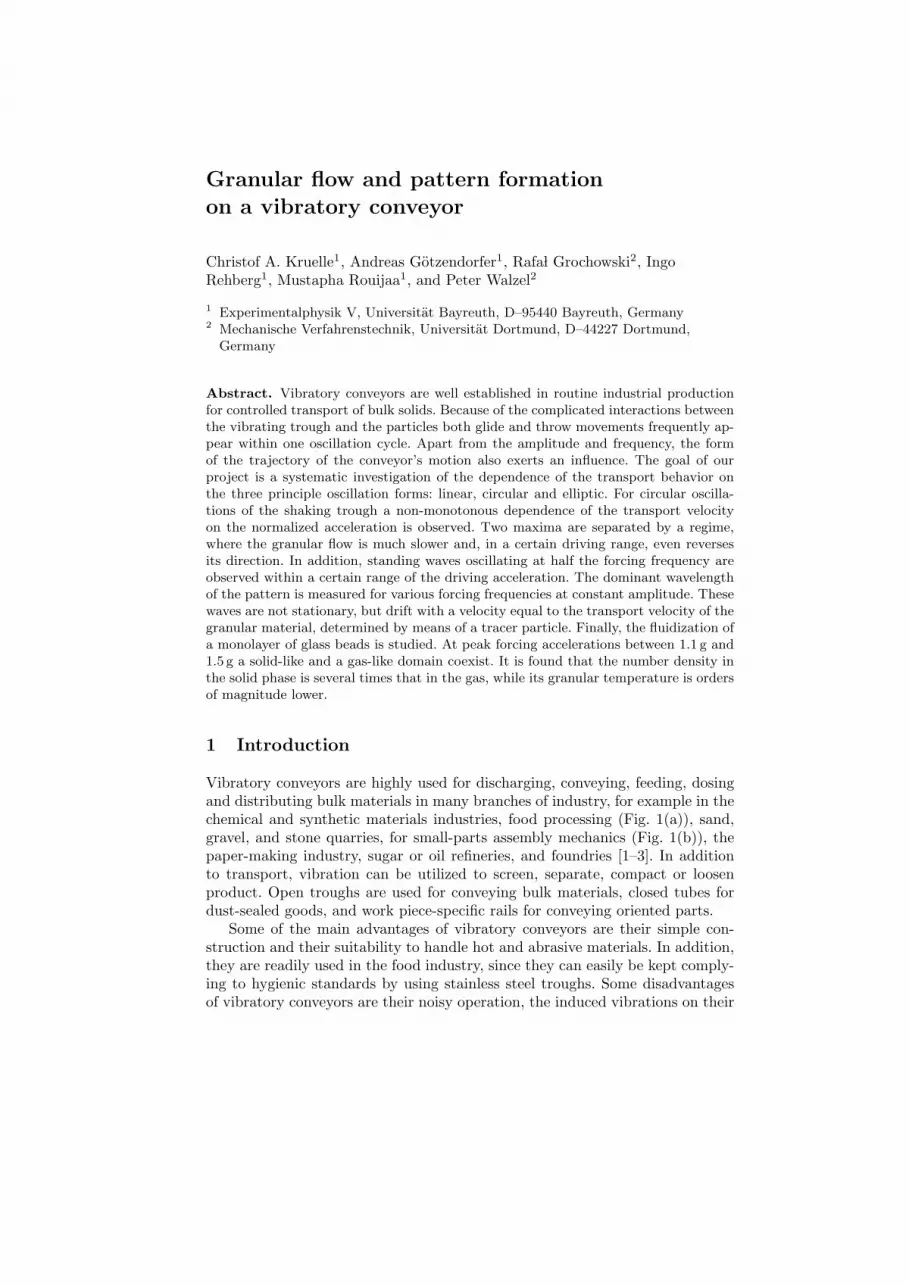
Vibratory conveyors are highly used for discharging, conveying, feeding, dosingand distributing bulk materials in many branches of industry, for example in thechemical and synthetic materials industries, food processing (Fig. 1(a)), sand,gravel, and stone quarries, for small-parts assembly mechanics (Fig. 1(b)), thepaper-making industry, sugar or oil refineries, and foundries [1–3]. In additionto transport, vibration can be utilized to screen, separate, compact or loosenproduct. Open troughs are used for conveying bulk materials, closed tubes fordust-sealed goods, and work piece-specific rails for conveying oriented parts.
Some of the main advantages of vibratory conveyors are their simple con-struction and their suitability to handle hot and abrasive materials. In addition,they are readily used in the food industry, since they can easily be kept comply-ing to hygienic standards by using stainless steel troughs. Some disadvantagesof vibratory conveyors are their noisy operation, the induced vibrations on their
2 Christof A. Kruelle et al.
(a) (b)
Fig. 1. (a) Linearvibratory conveyorsin the food industry,(b) Vibratory bowlfeeder in an auto-mated assembly chainat SUSPA company,Sulzbach-Rosenberg
surroundings and their limited transport distance. Furthermore, the granularmaterial may be damaged when it is subjected to extreme accelerations normalto the trough.
Important properties to be considered regarding the granular material (orbulk solid for engineers) are: particle size distribution and shape, friction be-tween particles and trough and inter-particle friction, modulus of elasticity ofthe particles and/or the bulk, cohesion, layer thickness, and the permeability ofair.
Considering the many parameters involved, the performance of a vibratoryconveyor is difficult to predict theoretically. Obvious design parameters are: vi-bration mode (linear with or without vibration angle α, circular, elliptic), ampli-tude A and frequency f of the oscillations, combined as dimensionless throw num-ber Γ = A sin(α)(2πf)2/g, inclination or declination of the conveyor, smoothnessof the trough surface, modulus of elasticity of the trough’s inner surface, whichcan be coated with rubber, plastic, etc., and possible electrostatic charges.
2 Conveying principles
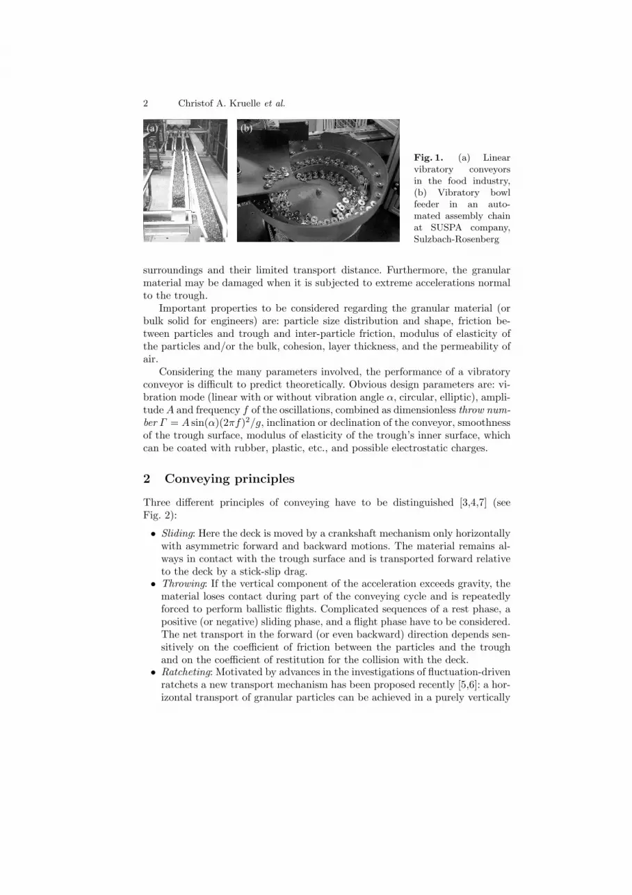
Three different principles of conveying have to be distinguished [3,4,7] (seeFig. 2):
• Sliding: Here the deck is moved by a crankshaft mechanism only horizontallywith asymmetric forward and backward motions. The material remains al-ways in contact with the trough surface and is transported forward relativeto the deck by a stick-slip drag.
• Throwing: If the vertical component of the acceleration exceeds gravity, thematerial loses contact during part of the conveying cycle and is repeatedlyforced to perform ballistic flights. Complicated sequences of a rest phase, apositive (or negative) sliding phase, and a flight phase have to be considered.The net transport in the forward (or even backward) direction depends sen-sitively on the coefficient of friction between the particles and the troughand on the coefficient of restitution for the collision with the deck.
• Ratcheting: Motivated by advances in the investigations of fluctuation-drivenratchets a new transport mechanism has been proposed recently [5,6]: a hor-izontal transport of granular particles can be achieved in a purely vertically
Granular flow and pattern formation on a vibratory conveyor 3
(a)
(b)
(c)
Fig. 2. Three different conveying principles: (a) ‘Sliding’ by asymmetric horizontalback-and-forth movements, (b) ‘Throwing’ by linear vibration with throw number Γ >1, both images taken from [4]. (c) ‘Ratcheting’ by vertical vibration on a sawtooth-shaped profile of the base. From [5,6]
vibrated system, if the symmetry is broken, instead of the direction of thevibration mode, by an asymmetric periodic sawtooth-shaped profile of thebase.
3 Granular transport
Since the transport phenomena on vibratory conveyors involve the nonlinearinteraction of many-particle systems with complex behavior, the investigation oftheir dynamical properties has become a challenging subject to physicists, too.In the past, most studies dealing with vibrated granular media were based onpurely vertical or purely horizontal vibration. Only recently a few experimentalexplorations of the dynamics of granular beds subject to simultaneous horizontaland vertical vibration have been reported [3,8–14]. The observed phenomenainclude the spontaneous formation of a static heap, convective flow, reversalof transport, and self-organized spatiotemporal patterns like granular surfacewaves.
The most important questions currently under investigation are:
• How does the granular transport velocity depend on (i) external parametersof the drive like amplitude and frequency of the oscillation, the vibrationmode, or the inclination of the trough, and (ii) internal bulk parameters likecoefficient of restitution, friction coefficients, and the filling height?
• Is it possible to optimize the transport effectivity by suitable modificationsof the surface of the trough implying ratchet like profiles?
• What kind of self-organized structures can be expected? Are there clearlycharacterized instabilities? Which physical mechanism underlie these struc-tures? How is the granular transport effected?
• Are there segregation effects in bidisperse or polydisperse systems? Whatare the analogies to vertical vibration?
• Can these results eventually lead to optimized industrial devices like con-veyor systems, metering devices, sieves, mixers, dryers, or coolers?
4 Christof A. Kruelle et al.
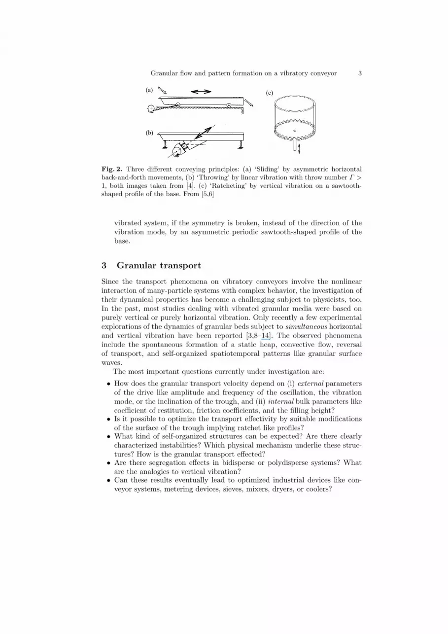
Fig. 3. Annular vibratory con-veyor with a toroidal trough ofradius R = 22.5 cm and widthw = 5 cm, suspended on ad-justable columns via elastic bands:(1) Torus-shaped vibration chan-nel, (2) Adjustable support, (3)Elastic band, (4) Vibration mod-ule with unbalanced masses, (5)Electric motor with integrated fre-quency inverter
4 Experimental setup
For this purpose, a prototype annular conveyor system has been constructed(Fig. 3) for systematic studies of the transport properties for different oscillationmodes, i.e. linear, elliptical, and circular (see Fig. 4) for a long running time,without disturbing boundary conditions [10–12,14]. In principle, this conveyorcan be excited in all six degrees of freedom individually, or by a combinationof two of them. For the first experiments, a vibration mode has been chosenconsisting of a torsional vibration φ(t) = A/R cos(2πft) around the symmetryaxis of the apparatus, superposed with a vertical oscillation y(t) = A cos(2πft+ϕ) where ϕ is the fixed phase shift between the two oscillations. If, for example,this phase shift ϕ is chosen to be π/2, then each point on the trough traces acircular path in a vertical plane tangent to the trough at that point. In short,the support agitates the granules via a vertical circular vibration.
For being able to adjust different vibration modes special driving units havebeen developed, equipped with four rotating unbalanced masses, as combinationsof two unbalanced-mass linear vibrators oriented perpendicularly to each other[10–12].
Characteristic of the unbalanced-mass agitated system is the frequency de-pendence of the vibration amplitude:
A(f) = Atf2
√(f2
0 − f2)2 + (2ζf0f)2. (1)

Granular flow and pattern formation on a vibratory conveyor 5
5 cm
(a)
(b)Fig. 4. (a) Driving module withfour unbalanced masses, (b) Sideviews of a driving unit with four ro-tating unbalanced masses, for threeprincipal modes of oscillation: lin-ear (ϕ = 0), elliptical (ϕ = π
4), and
circular (ϕ = π2)
The resonance frequency f0 = 12π
√keffMtot
can be limited to a small value (throughappropriate choice of spring constant keff), so that in the over critical range,f > 3f0, an almost constant terminal amplitude At = ru
mu,totMtot
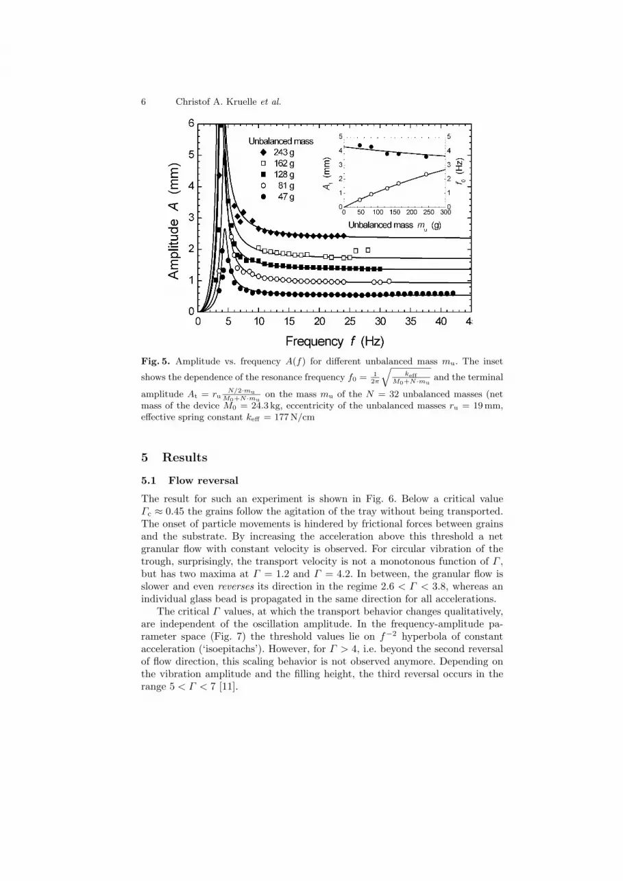
arises which canbe adjusted for fixed eccentricity ru by the out of balance mass mu. The frequencyresponse (see Fig. 5) was measured experimentally before every measurementby determination of the position of an affixed LED on the vibrating devicerecorded with a CCD camera. The vibration amplitude is found by aligning acircular path with radius A(f) to the image data. For excitation frequency f >15Hz, the vibration amplitude is nearly constant and therefore the dimensionlessacceleration, i.e. the machine number K = A(f) · 4π2f2/g is approximatelyproportional to f2. From the measured data, the damping constant ζ can bedetermined to be 0.08± 0.01
An important parameter of the bulk solid that should be chosen carefullyfor obtaining reproducible results is the layer height. For too thin layers theparticles will dilate mutually and start to perform irregular motions across thetrough bottom. In practice, as a rule of thumb, the layer of material should atleast be 10 particles high. Under these conditions, the bulk solid moves moreor less like a solid block, and the transport velocity is not very sensitive to theexact height.
During the transport experiments, the average flow velocity is determinedby tracking a colored tracer particle that is carried along with the bulk. Thisis done automatically with a PC based image processing system, which detectsthe passage of the tracer through a line perpendicular to the trough and storeseach passage time on hard disk.
6 Christof A. Kruelle et al.
Fig. 5. Amplitude vs. frequency A(f) for different unbalanced mass mu. The inset
shows the dependence of the resonance frequency f0 = 12π
√keff
M0+N·muand the terminal
amplitude At = ruN/2·mu
M0+N·muon the mass mu of the N = 32 unbalanced masses (net
mass of the device M0 = 24.3 kg, eccentricity of the unbalanced masses ru = 19mm,effective spring constant keff = 177 N/cm
5 Results
5.1 Flow reversal
The result for such an experiment is shown in Fig. 6. Below a critical valueΓc ≈ 0.45 the grains follow the agitation of the tray without being transported.The onset of particle movements is hindered by frictional forces between grainsand the substrate. By increasing the acceleration above this threshold a netgranular flow with constant velocity is observed. For circular vibration of thetrough, surprisingly, the transport velocity is not a monotonous function of Γ ,but has two maxima at Γ = 1.2 and Γ = 4.2. In between, the granular flow isslower and even reverses its direction in the regime 2.6 < Γ < 3.8, whereas anindividual glass bead is propagated in the same direction for all accelerations.
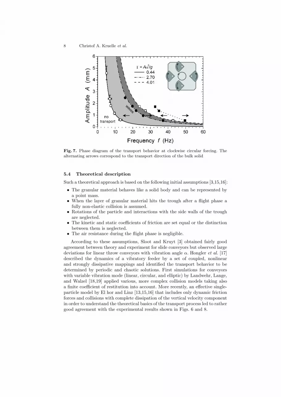
The critical Γ values, at which the transport behavior changes qualitatively,are independent of the oscillation amplitude. In the frequency-amplitude pa-rameter space (Fig. 7) the threshold values lie on f−2 hyperbola of constantacceleration (‘isoepitachs’). However, for Γ > 4, i.e. beyond the second reversalof flow direction, this scaling behavior is not observed anymore. Depending onthe vibration amplitude and the filling height, the third reversal occurs in therange 5 < Γ < 7 [11].

Granular flow and pattern formation on a vibratory conveyor 7
Transport
Fig. 6. Normalized transport velocity v∗ = vtr/Aω of a granular flow (≈ 300 000 glassbeads with 1mm diameter, see inset) on the vibratory conveyor with circular vibration,compared with the mean velocity of one single glass bead
5.2 Linear vibration mode
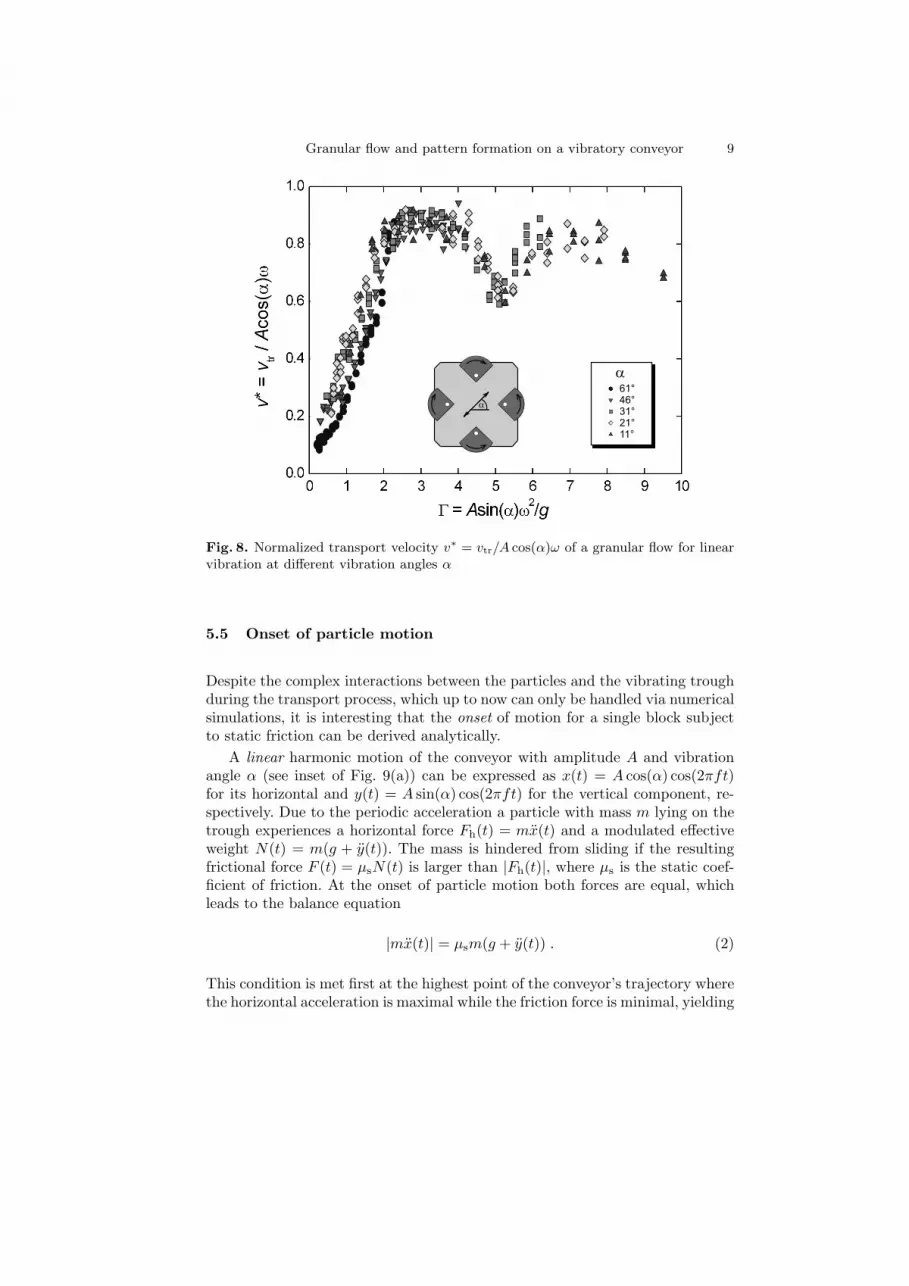
Complementary studies [9] applying linear vibrations have shown, that the flowreversal is a special property of the circular vibration. For linear vibrations, alsoa non-monotonous dependence of the transport velocity is seen (Fig. 8), with adip at Γ ≈ 5, but no reversal of the flow. Note that the maximum transportvelocity in this case arrives at about 90% of the oscillation velocity Aω, while inthe circular case only about 50% can be attained.
5.3 Sand bag test
Worth mentioning is the so-called ‘sand bag test’ [7] routinely performed by themanufacturers of vibratory conveyors. Since an individual grain, such as a singleglass bead, dropped onto the substrate will rebound with a high coefficient ofrestitution and therefore gives an unrealistic transport characteristic, a betterapproach for modelling the bulk transport is achieved by use of a small fabric bag,filled with the same kind of beads. The strikingly different collective behaviorarises from the large number of rapid inelastic collisions of neighboring grains.However, it takes some experience to find a suitable single object for producingreliable data for comparison with an effective one-particle model.
8 Christof A. Kruelle et al.
Fig. 7. Phase diagram of the transport behavior at clockwise circular forcing. Thealternating arrows correspond to the transport direction of the bulk solid
5.4 Theoretical description
Such a theoretical approach is based on the following initial assumptions [3,15,16]:
• The granular material behaves like a solid body and can be represented bya point mass.
• When the layer of granular material hits the trough after a flight phase afully non-elastic collision is assumed.
• Rotations of the particle and interactions with the side walls of the troughare neglected.
• The kinetic and static coefficients of friction are set equal or the distinctionbetween them is neglected.
• The air resistance during the flight phase is negligible.
According to these assumptions, Sloot and Kruyt [3] obtained fairly goodagreement between theory and experiment for slide conveyors but observed largedeviations for linear throw conveyors with vibration angle α. Hongler et al. [17]described the dynamics of a vibratory feeder by a set of coupled, nonlinearand strongly dissipative mappings and identified the transport behavior to bedetermined by periodic and chaotic solutions. First simulations for conveyorswith variable vibration mode (linear, circular, and elliptic) by Landwehr, Lange,and Walzel [18,19] applied various, more complex collision models taking alsoa finite coefficient of restitution into account. More recently, an effective single-particle model by El hor and Linz [13,15,16] that includes only dynamic frictionforces and collisions with complete dissipation of the vertical velocity componentin order to understand the theoretical basics of the transport process led to rathergood agreement with the experimental results shown in Figs. 6 and 8.
Granular flow and pattern formation on a vibratory conveyor 9
61°
46°
31°
21°
11°
a
a
Fig. 8. Normalized transport velocity v∗ = vtr/A cos(α)ω of a granular flow for linearvibration at different vibration angles α
5.5 Onset of particle motion
Despite the complex interactions between the particles and the vibrating troughduring the transport process, which up to now can only be handled via numericalsimulations, it is interesting that the onset of motion for a single block subjectto static friction can be derived analytically.
A linear harmonic motion of the conveyor with amplitude A and vibrationangle α (see inset of Fig. 9(a)) can be expressed as x(t) = A cos(α) cos(2πft)for its horizontal and y(t) = A sin(α) cos(2πft) for the vertical component, re-spectively. Due to the periodic acceleration a particle with mass m lying on thetrough experiences a horizontal force Fh(t) = mx(t) and a modulated effectiveweight N(t) = m(g + y(t)). The mass is hindered from sliding if the resultingfrictional force F (t) = µsN(t) is larger than |Fh(t)|, where µs is the static coef-ficient of friction. At the onset of particle motion both forces are equal, whichleads to the balance equation
|mx(t)| = µsm(g + y(t)) . (2)
This condition is met first at the highest point of the conveyor’s trajectory wherethe horizontal acceleration is maximal while the friction force is minimal, yielding
10 Christof A. Kruelle et al.
a
(a) (b)
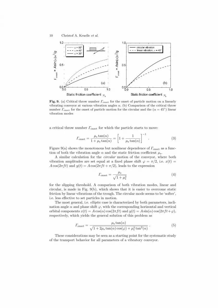
Fig. 9. (a) Critical throw number Γonset for the onset of particle motion on a linearlyvibrating conveyor at various vibration angles α. (b) Comparison of the critical thrownumber Γonset for the onset of particle motion for the circular and the (α = 45◦) linearvibration modes
a critical throw number Γonset for which the particle starts to move:
Γonset =µs tan(α)
1 + µs tan(α)=
[1 +
1µs tan(α)
]−1
. (3)
Figure 9(a) shows the monotonous but nonlinear dependence of Γonset as a func-tion of both the vibration angle α and the static friction coefficient µs.
A similar calculation for the circular motion of the conveyor, where bothvibration amplitudes are set equal at a fixed phase shift ϕ = π/2, i.e. x(t) =A cos(2πft) and y(t) = A cos(2πft + π/2), leads to the expression
Γonset =µs√
1 + µ2s
(4)
for the slipping threshold. A comparison of both vibration modes, linear andcircular, is made in Fig. 9(b), which shows that it is easier to overcome staticfriction by linear vibrations of the trough. The circular mode seems to be ‘softer’,i.e. less effective to set particles in motion.
The most general, i.e. elliptic case is characterized by both parameters, incli-nation angle α and phase shift ϕ, with the corresponding horizontal and verticalorbital components x(t) = A cos(α) cos(2πft) and y(t) = A sin(α) cos(2πft+ϕ),respectively, which yields the general solution of this problem as
Γonset =µs tan(α)√
1 + 2µs tan(α) cos(ϕ) + µ2s tan2(α)
. (5)
These considerations may be seen as a starting point for the systematic studyof the transport behavior for all parameters of a vibratory conveyor.
Granular flow and pattern formation on a vibratory conveyor 11
5 cm
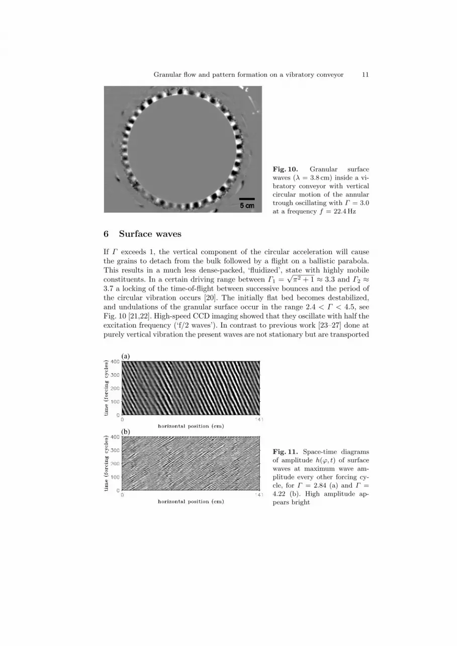
Fig. 10. Granular surfacewaves (λ = 3.8 cm) inside a vi-bratory conveyor with verticalcircular motion of the annulartrough oscillating with Γ = 3.0at a frequency f = 22.4 Hz
6 Surface waves
If Γ exceeds 1, the vertical component of the circular acceleration will causethe grains to detach from the bulk followed by a flight on a ballistic parabola.This results in a much less dense-packed, ‘fluidized’, state with highly mobileconstituents. In a certain driving range between Γ1 =
√π2 + 1 ≈ 3.3 and Γ2 ≈
3.7 a locking of the time-of-flight between successive bounces and the period ofthe circular vibration occurs [20]. The initially flat bed becomes destabilized,and undulations of the granular surface occur in the range 2.4 < Γ < 4.5, seeFig. 10 [21,22]. High-speed CCD imaging showed that they oscillate with half theexcitation frequency (‘f/2 waves’). In contrast to previous work [23–27] done atpurely vertical vibration the present waves are not stationary but are transported
Fig. 11. Space-time diagramsof amplitude h(ϕ, t) of surfacewaves at maximum wave am-plitude every other forcing cy-cle, for Γ = 2.84 (a) and Γ =4.22 (b). High amplitude ap-pears bright
12 Christof A. Kruelle et al.
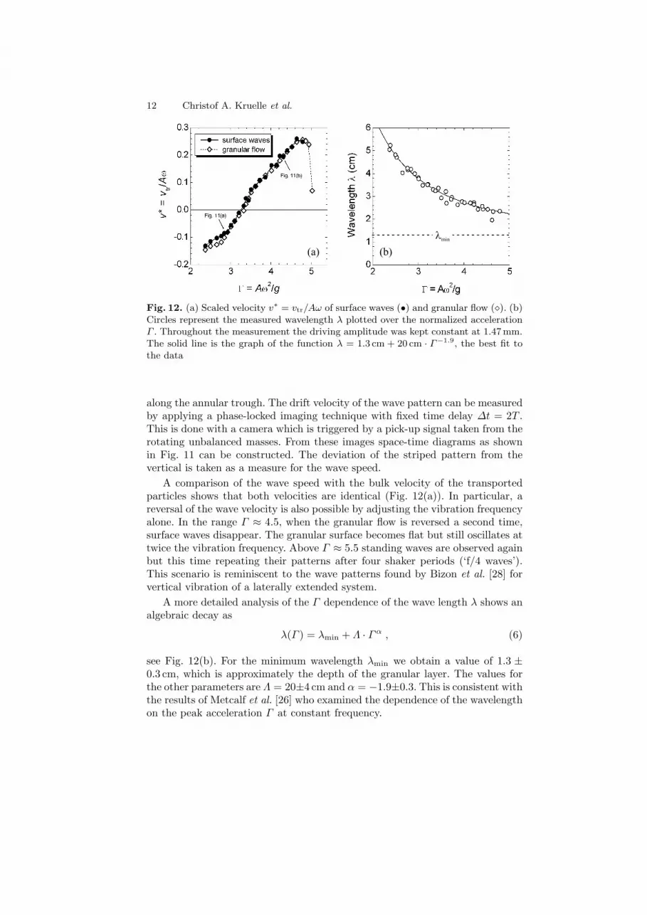
(a) (b)
lmin
Fig. 12. (a) Scaled velocity v∗ = vtr/Aω of surface waves (•) and granular flow (¦). (b)Circles represent the measured wavelength λ plotted over the normalized accelerationΓ . Throughout the measurement the driving amplitude was kept constant at 1.47mm.The solid line is the graph of the function λ = 1.3 cm + 20 cm · Γ−1.9, the best fit tothe data
along the annular trough. The drift velocity of the wave pattern can be measuredby applying a phase-locked imaging technique with fixed time delay ∆t = 2T .This is done with a camera which is triggered by a pick-up signal taken from therotating unbalanced masses. From these images space-time diagrams as shownin Fig. 11 can be constructed. The deviation of the striped pattern from thevertical is taken as a measure for the wave speed.
A comparison of the wave speed with the bulk velocity of the transportedparticles shows that both velocities are identical (Fig. 12(a)). In particular, areversal of the wave velocity is also possible by adjusting the vibration frequencyalone. In the range Γ ≈ 4.5, when the granular flow is reversed a second time,surface waves disappear. The granular surface becomes flat but still oscillates attwice the vibration frequency. Above Γ ≈ 5.5 standing waves are observed againbut this time repeating their patterns after four shaker periods (‘f/4 waves’).This scenario is reminiscent to the wave patterns found by Bizon et al. [28] forvertical vibration of a laterally extended system.
A more detailed analysis of the Γ dependence of the wave length λ shows analgebraic decay as
λ(Γ ) = λmin + Λ · Γα , (6)
see Fig. 12(b). For the minimum wavelength λmin we obtain a value of 1.3 ±0.3 cm, which is approximately the depth of the granular layer. The values forthe other parameters are Λ = 20±4 cm and α = −1.9±0.3. This is consistent withthe results of Metcalf et al. [26] who examined the dependence of the wavelengthon the peak acceleration Γ at constant frequency.

Granular flow and pattern formation on a vibratory conveyor 13
Fig. 13. Experimental setupwith transparent trough andconical mirror placed in thecenter of the ring. The reflectedimage of the surface profileis captured with a high-speedCCD camera on top of the mir-ror
For comparison with theoretical models it is necessary to determine the dy-namic surface profile h(ϕ, t) during the transport process with high spatial andtemporal resolution. This task has been solved by Pak and Behringer [24] only fora small section of an annular trough. Our container consists of a 2 cm wide annu-lar channel with open top, 7 cm high Plexiglas walls, and a radius of R = 22.5 cmgiving a circumference of L0 = 141 cm (see Fig. 13). The granular system is ob-served from the top via a conical mirror placed in the center of the ring, similarto Ref. [29]. Thus a side view of the whole channel is captured with a singlehigh-speed digital camera (resolution: 1280× 1024 pixels at rates up to 500 im-ages per second). Figure 14(a) shows an anamorphotic image reflected from theconical mirror. The wavy granular surface is seen as a jagged ring around thetip of the cone. For reconstructing the true shape of the profile h(ϕ, t) digitalimage processing is performed which delivers 360◦ panoramic side views of thegranular profile in the channel as presented in Figs. 14(b) and 15. The spatialresolution is sufficient for detecting single particles of 2 mm size. The channel islit from outside through diffusive parchment paper wrapped around the outerwall, hence particles appear dark in front of a bright background.
(a) (b)
Fig. 14. (a) Anamorphotic image reflected from the conical mirror. (b) Section of thereconstructed granular surface
14 Christof A. Kruelle et al.
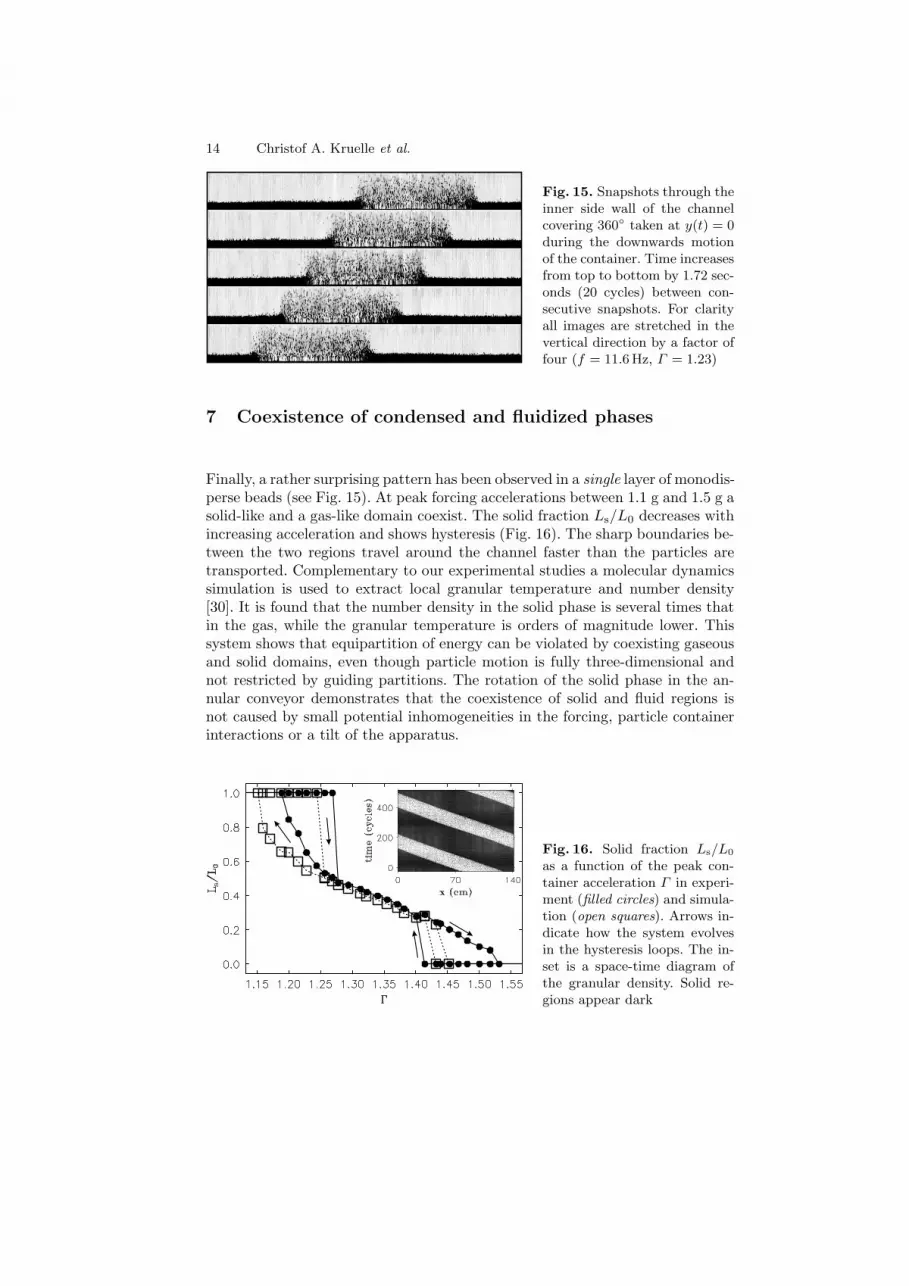
Fig. 15. Snapshots through theinner side wall of the channelcovering 360◦ taken at y(t) = 0during the downwards motionof the container. Time increasesfrom top to bottom by 1.72 sec-onds (20 cycles) between con-secutive snapshots. For clarityall images are stretched in thevertical direction by a factor offour (f = 11.6Hz, Γ = 1.23)
7 Coexistence of condensed and fluidized phases
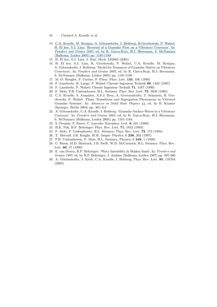
Finally, a rather surprising pattern has been observed in a single layer of monodis-perse beads (see Fig. 15). At peak forcing accelerations between 1.1 g and 1.5 g asolid-like and a gas-like domain coexist. The solid fraction Ls/L0 decreases withincreasing acceleration and shows hysteresis (Fig. 16). The sharp boundaries be-tween the two regions travel around the channel faster than the particles aretransported. Complementary to our experimental studies a molecular dynamicssimulation is used to extract local granular temperature and number density[30]. It is found that the number density in the solid phase is several times thatin the gas, while the granular temperature is orders of magnitude lower. Thissystem shows that equipartition of energy can be violated by coexisting gaseousand solid domains, even though particle motion is fully three-dimensional andnot restricted by guiding partitions. The rotation of the solid phase in the an-nular conveyor demonstrates that the coexistence of solid and fluid regions isnot caused by small potential inhomogeneities in the forcing, particle containerinteractions or a tilt of the apparatus.
Fig. 16. Solid fraction Ls/L0
as a function of the peak con-tainer acceleration Γ in experi-ment (filled circles) and simula-tion (open squares). Arrows in-dicate how the system evolvesin the hysteresis loops. The in-set is a space-time diagram ofthe granular density. Solid re-gions appear dark

Granular flow and pattern formation on a vibratory conveyor 15
8 Concluding remarks
The vibratory conveyor system presented here opens up the possibility to inves-tigate the transport properties of granular materials in a systematic way. Ourresults show that under certain conditions not even the direction of the granularflow can be predicted a priori. The delicate interactions of the particles with thesupport as well as among themselves have to be taken into account.
For industrial applications, the observed reversal effect is relevant as the di-rection of a granular flow is selected through the frequency of the excitationalone. One can employ such two-way conveyors for example in larger cascad-ing transport systems as control elements to convey the material to differentprocesses as needed.
These experiments indicate that the major concepts describing the complexbehavior of a vibrated granular system, namely phase transitions, pattern for-mation, and transport are closely related and yield a rewarding field for futureresearch.
Acknowledgements
We would like to thank H. El hor, F. Landwehr, S.J. Linz, J. Kreft, T. Schnautz,and S. Strugholtz, for valuable discussions. Support by Deutsche Forschungsge-meinschaft (DFG-Sonderprogramm ‘Verhalten granularer Medien’) is gratefullyacknowledged.
References
1. G. Pajer, H. Kuhnt, F. Kuhnt: Fordertechnik – Stetigforderer, 5th edn. (VEB VerlagTechnik, Berlin 1988)
2. F.J.C. Rademacher, L. Ter Borg: Eng. Res. 60, 261 (1994)3. E.M. Sloot, N.P. Kruyt: Powder Technol. 87, 203 (1996)4. A.W. Gerstel, J.G.R. Scheublin: Bulk Solids Handling 14, 573 (1994)5. I. Derenyi, P. Tegzes, T. Vicsek: Chaos 8, 657 (1998)6. Z. Farkas, P. Tegzes, A. Vukics, T. Vicsek: Phys. Rev. E 60, 7022 (1999)7. F.J.C. Rademacher: Bulk Solids Handling 15, 41 (1995)8. S.G.K. Tennakoon, R.P. Behringer: Phys. Rev. Lett. 81, 794 (1998)9. R. Grochowski, S. Strugholtz, P. Walzel, C.A. Krulle: Chemie Ingenieur Technik
75, 1103 (2003)10. M. Rouijaa, C. Krulle, I. Rehberg, R. Grochowski, P. Walzel: Chemie Ingenieur
Technik 76, 62 (2004)11. M. Rouijaa, C. Krulle, I. Rehberg, R. Grochowski, P. Walzel: Chem. Eng. Tech.
28, 41 (2005)12. R. Grochowski, P. Walzel, M. Rouijaa, C. A. Kruelle, I. Rehberg: Appl. Phys. Lett.
84, 1019 (2004)13. R. Grochowski, S. Strugholtz, H. El hor, S.J. Linz, P. Walzel: ‘Transport Proper-
ties of Granular Matter on Vibratory Conveyors’. In: Proceedings of InternationalCongress for Particle Technology (PARTEC 2004) at Nuremberg, March 16–18,2004
16 Christof A. Kruelle et al.
14. C.A. Kruelle, M. Rouijaa, A. Gotzendorfer, I. Rehberg, R.Grochowski, P. Walzel,H. El hor, S.J. Linz: ‘Reversal of a Granular Flow on a Vibratory Conveyor’. In:Powders and Grains 2005, ed. by R. Garca-Rojo, H.J. Herrmann, S. McNamara(Balkema, Leiden 2005) pp. 1185-1189
15. H. El hor, S.J. Linz: J. Stat. Mech. L02005 (2005)16. H. El hor, S.J. Linz, R. Grochowski, P. Walzel, C.A. Kruelle, M. Rouijaa,
A. Gotzendorfer, I. Rehberg: ‘Model for Transport of Granular Matter on VibratoryConveyors’. In: Powders and Grains 2005, ed. by R. Garca-Rojo, H.J. Herrmann,S. McNamara (Balkema, Leiden 2005) pp. 1191-1195
17. M.-O. Hongler, P. Cartier, P. Flury: Phys. Lett. 135, 106 (1989)18. F. Landwehr, R. Lange, P. Walzel: Chemie Ingenieur Technik 69, 1422 (1997)19. F. Landwehr, P. Walzel: Chemie Ingenieur Technik 71, 1167 (1999)20. F. Melo, P.B. Umbanhower, H.L. Swinney: Phys. Rev. Lett. 75, 3838 (1995)21. C.A. Kruelle, S. Aumaıtre, A.P.J. Breu, A. Goetzendorfer, T. Schnautz, R. Gro-
chowski, P. Walzel: ‘Phase Transitions and Segregation Phenomena in VibratedGranular Systems’. In: Advances in Solid State Physics 44, ed. by B. Kramer(Springer, Berlin 2004) pp. 401-414
22. A. Gotzendorfer, C.A. Kruelle, I. Rehberg: ‘Granular Surface Waves in a VibratoryConveyor’. In: Powders and Grains 2005, ed. by R. Garca-Rojo, H.J. Herrmann,S. McNamara (Balkema, Leiden 2005) pp. 1181-1184
23. S. Douady, S. Fauve, C. Laroche: Europhys. Lett. 8, 621 (1989)24. H.K. Pak, R.P. Behringer: Phys. Rev. Lett. 71, 1832 (1993)25. F. Melo, P. Umbanhower, H.L. Swinney: Phys. Rev. Lett. 72, 172 (1994)26. T. Metcalf, J.B. Knight, H.M. Jaeger: Physica A 236, 202 (1997)27. P.B. Umbanhowar, F. Melo, H.L. Swinney: Physica A 249, 1 (1998)28. C. Bizon, M.D. Shattuck, J.B. Swift, W.D. McCormick, H.L. Swinney: Phys. Rev.
Lett. 80, 57 (1998)29. E. van Doorn, R.P. Behringer: ‘Wavy Instability in Shaken Sand’. In: Powders and
Grains 1997, ed. by R.P. Behringer, J. Jenkins (Balkema, Leiden 1997) pp. 397-40030. A. Gotzendorfer, J. Kreft, C.A. Kruelle, I. Rehberg: Phys. Rev. Lett. 95, 135704
(2005)


