Embed Size (px)
Citation preview
University of Nebraska - Lincoln University of Nebraska - Lincoln
DigitalCommons@University of Nebraska - Lincoln DigitalCommons@University of Nebraska - Lincoln
Nebraska 4-H Clubs: Historical Materials and Publications 4-H Youth Development
1956
Good Wiring for Advanced 4-H Electrification Club Members and Good Wiring for Advanced 4-H Electrification Club Members and
Leaders : Extension Circular 7-61-2 Leaders : Extension Circular 7-61-2
M. L. Mumgaard
Don K. Wiles
Follow this and additional works at: https://digitalcommons.unl.edu/a4hhistory
Part of the Service Learning Commons
Mumgaard, M. L. and Wiles, Don K., "Good Wiring for Advanced 4-H Electrification Club Members and Leaders : Extension Circular 7-61-2" (1956). Nebraska 4-H Clubs: Historical Materials and Publications. 187. https://digitalcommons.unl.edu/a4hhistory/187
This Article is brought to you for free and open access by the 4-H Youth Development at DigitalCommons@University of Nebraska - Lincoln. It has been accepted for inclusion in Nebraska 4-H Clubs: Historical Materials and Publications by an authorized administrator of DigitalCommons@University of Nebraska - Lincoln.
195B E. C. 7 -61 -2
winn
<n
EXTENSION SERVICEUNIVERSITY OF NEBRASKA COLLEGE OF AGRICULTURE
AND U. S. DEPARTMENT OF AGRICULTURECOOPERATING
W. V. LAMBERT, DIRECTOR
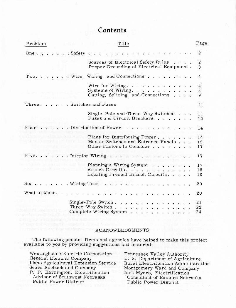
Contents
Problem Title Page
O n e . . . . . . . Safety . . . . 2
Sources of Electrical Safety Rules . . . . 2Proper Grounding of Electrical Equipment . 3
Two Wire, Wiring, and Connections • . . . 4
Wire for Wiring 4Systems of Wiring. . . 8Cutting, Splicing, and Connections . . . . 9
Three Switches and Fuses 11
Single-Pole and Three-Way Switches . . . 11Fuses and Circuit Breakers 12
Four Distribution of Power • 14
Plans for Distributing Power 14Master Switches and Entrance Panels . . . 15Other Factors to Consider 17
Five Interior Wiring 17
Planning a Wiring System . . . . . . . . 17Branch Circuits 18Locating Present Branch Circuits . . . . . 18
Six Wiring Tour 20
What to Make 20
Single-Pole Switch 21Three-Way Switch 22Complete Wiring System 24
A CKNOWLEDGMENTS
The following people, firms and agencies have helped to make this projectavailable to you by providing suggestions and material:
Westinghouse Electric Corporation Tennessee Valley AuthorityGeneral Electric Company U. S. Department of AgricultureIdaho Agricultural Extension Service Rural Electrification AdministrationSears Roebuck and Company Montgomery Ward and CompanyP. P. Harrington, Electrification Jack Myers, Electrification
Advisor of Southwest Nebraska Consultant of Eastern NebraskaPublic Power District Public Power District

Good Wiringby M. L,, Mumgaard and Don K. Wiles
This project is prepared for 4-H members who have taken first-year electrifi-cation. During the year you will be expected to do the following:
(1) Learn the principles of wiring.
(2) Make, or have someone else make at least one improvement in the presentwiring about your home and farm.
(3) Practice wiring. You will do this by making one of the following three panels.(Plans for the panels are given in the last section of this manual.)
a. Single-pole switch wiring,b'. Three-way switch wiring,c. Complete system wiring.
The purpose of this manual is to help you with your project by providing basicinformation about good wiring. It will not answer all of your questions. For furtherinformation, talk with your electrical dealer, power supplier and county agent. Theywill have material, bulletins and information to supplement what has been discussedin this manual.
This project will help you learn principles of good, safe wiring. You and yourfriends are not expected to become skilled electricians. By learning the principlesof good wiring you will be able to judge your abilities and the abilities of others inwiring. Do not attempt to wire a building without the aid of an experienced electrician.
Problem OneSAFETY
SOURCES OF ELECTRICAL SAFETY RULES
Do you remember ail that was discussed in the First-Year Electrification Projectabout safety? If not, you should review Problem One in your First-Year Electrifica-tion Manual. You should also become acquainted with the safety measures as givenin the National Electrical Code and the State and Local Codes. These codes can beobtained from your local electrician, your local power supplier and your electricalappliance dealer.
The National Electrical Code is a collection of rules to safeguard people, build-ings, and contents of buildings from electrical hazards. The rules cover such itemsas how to wire and install electrical equipment and how to wire buildings.
The provisions of the Code are for a minimum requirement. For best servicefrom your electrical machinery and equipment, you may often need to use largersizes of wire and more branch circuits than specified by the Code.
State and Local Code. Most states and local areas have their own electricalcodes which supplement the National Code. These state and local codes generallyhave more rigid requirements.
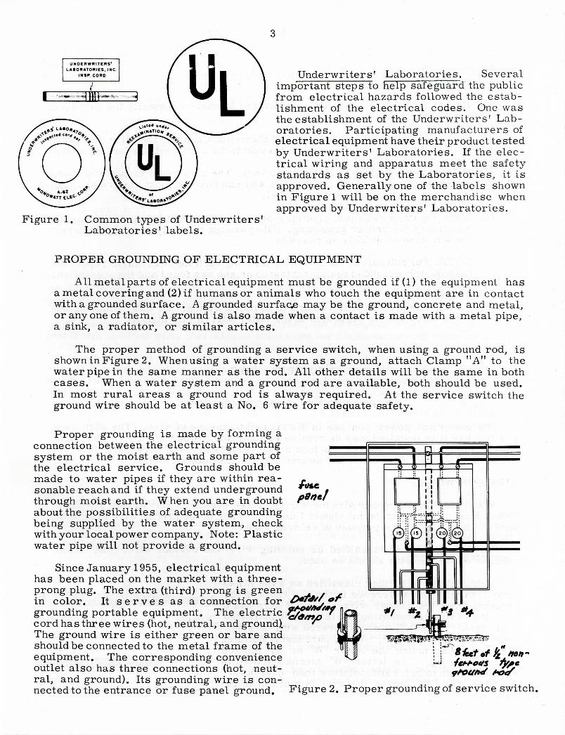
Figure 1. Common types of Underwriters'Laboratories' labels.
Underwriters' Laboratories. Severalimportant steps to help safeguard the publicfrom electrical hazards followed the estab-lishment of the electrical codes. One wasthe establishment of the Underwriters' Lab-oratories. Participating manufacturers ofelectrical equipment have their product testedby Underwriters' Laboratories. If the elec-trical wiring and apparatus meet the safetystandards as set by the Laboratories, it isapproved. Generally one of the labels shownin Figure 1 will be on the merchandise whenapproved by Underwriters' Laboratories.
PROPER GROUNDING OF ELECTRICAL EQUIPMENT
All metalparts of electrical equipment must be grounded if (1) the equipment hasa metal cove ring and (2) if humans or animals who touch the equipment are in contactwith a grounded surface. A grounded surface may be the ground, concrete and metal,or any one of them. A ground is also made when a contact is made with a metal pipe,a sink, a radiator, or similar articles.
The proper method of grounding a service switch, when using a ground rod, isshown in Figure 2. Whenusing a water system as a ground, attach Clamp "A" to thewater pipe in the same manner as the rod. All other details will be the same in bothcases. When a water system and a ground rod are available, both should be used.In most rural areas a ground rod is always required. At the service switch theground wire should be at least a No. 6 wire for adequate safety.
Proper grounding is made by forming aconnection between the electrical groundingsystem or the moist earth and some part ofthe electrical service. Grounds should bemade to water pipes if they are within rea-sonable reach and if they extend undergroundthrough moist earth. When you are in doubtabout the possibilities of adequate groundingbeing supplied by the water system, checkwith your local power company. Note: Plasticwater pipe will not provide a ground.
Since January 1955, electrical equipmenthas been placed on the market with a three-prong plug. The extra (third) prong is greenin color. It s e r v e s as a connection forgrounding portable equipment. The electriccord has three wires (hot, neutral, and ground).The ground wire is either green or bare andshould be connected to the metal frame of theequipment. The corresponding convenienceoutlet also has three connections (hot, neut-ral, and ground). Its grounding wire is con-nected to the entrance or fuse panel ground.
40ft-
Figure 2. Proper grounding of service switch.
THINGS TO DO
(1) Review the First- Year 4-H Electrification Manual--especially the part aboutsafety.
(2) Become acquainted with the National Electrical Code and the State and LocalCodes. Samples of each should be broughttothe club meetings for inspection.
(3) Have an Underwriters' Laboratories hunt. The club might divide into teamsand compete against each other to see who can find the most electrical equip-ment bearing an Underwriters' label.
(4) Inspect service switches, electric motors, power outlet boxes and electricalmachinery for proper grounding. If they are not properly grounded, correctthe situation as quickly as possible.
NOTE: For roll call at the following meeting each member might report theinadequately grounded equipment that he or she has found and the correctionsmade.
(5) During this project year you are to practice wiring. Do this by making oneof the three panels suggested in the latter part of this manual.
Problem Two
WIRE, WIRING, AND CONNECTIONS
The electrical power you use is distributed by means of wire. The wire usedand the way it is installed may determine whether you are satisfied with electricalpower. For that reason, we will now look at the various kinds of wires, the differentsystems of wiring, and review the proper way to make connections.
WIRE FOR WIRING
When selecting the proper wire for wiring, three questions may arise. They are:"What kind of wiring material should I use?", "What is the proper wire size to beused?" and "What is the purpose of colored wire?"
Wiring material is classified as building wire and outdoor wire. The namesindicate where the wire should be used.
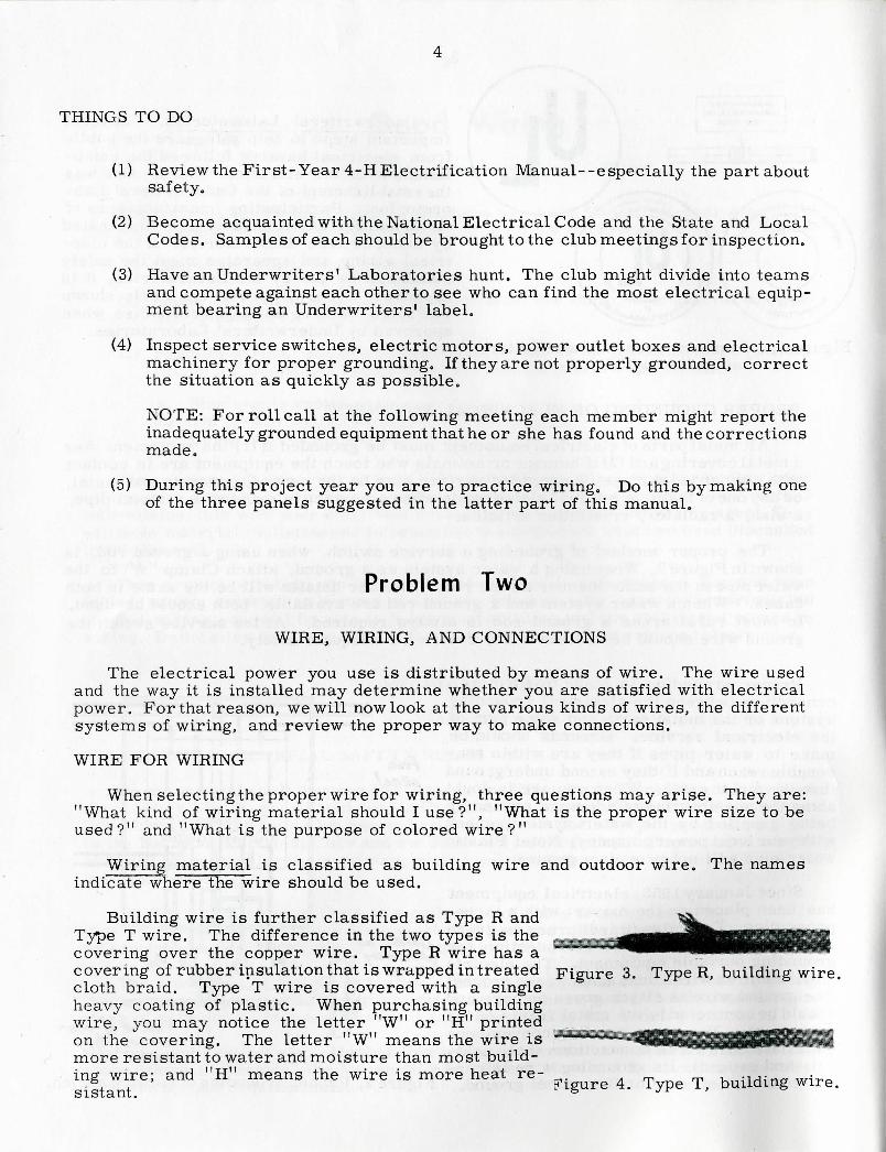
Building wire is further classified as Type R andType T wire. The difference in the two types is thecovering over the copper wire. Type R wire has acovering of rubber insulation that is wrapped in treated Figure 3. Type R, building wire.cloth braid. Type T wire is covered with a singleheavy coating of plastic. When purchasing buildingwire, you may notice the letter "W" or "H" printedon the covering. The letter "W" means the wire ismore resistant to water and moisture than most build-ing wire; and "H" means the wire is more heat re- ^ 4> Type ^ building wire_SlSTclTYl0

Outdoor wire is often referred to as weatherproof wire and underground wire.Weatherproof wire is covered with two or three layers of a very tough cotton fabricimpregnated with fire and moisture resistant material. Some weatherproof wirecoverings may consist of a single layer of neoprene or similar material. Weather-proof wire should not be considered as Insulated,
Underground wire is covered by a layer of special water resistant insulation.It can be laid in the ground without further protection from moisture. This wire isidentified by the letters USE or UF. The letters are printed on the wire.
Proper wire size is important for carrying your electrical load. Electric cur-rent flows along"a wire in about the same manner as water flows through a pipe.You need a large pipe if you want a lot of water. It is the same with electricity --it takes large wires to carry a lot of current. If the wire is too small for the load,the wire gets hot. This is because the wire resists the flow of current and thesmaller the wire the greater the resistance. The same is true with the wire'slength--the longer the wire, the more the resistance.
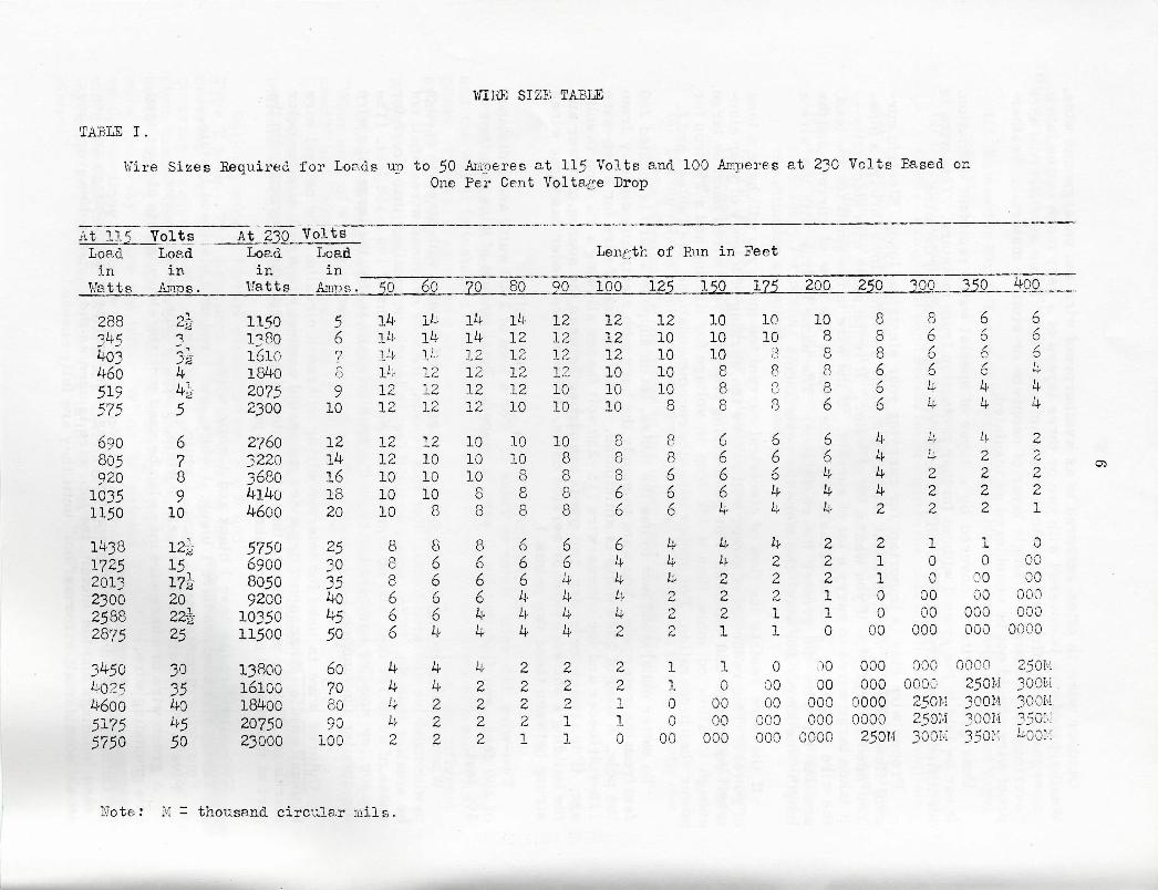
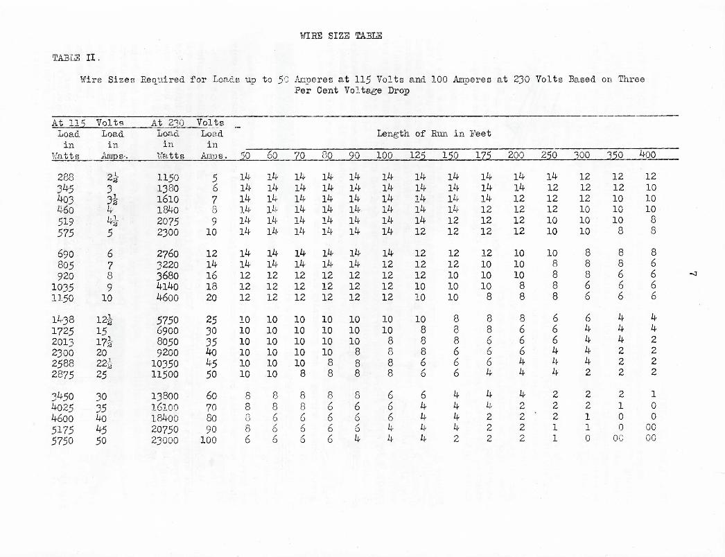
If the wire resists the flow of electrical current too much you will have a lossof power. This reduction of power will reduce the working efficiency of your elec-trical equipment and motors. For good wiring practice, your wires must be largeenough to allow no more than a 1% drop in voltage for lighting and a 3% drop forpower when in operation. For proper wire size recommendations, see Tables 1 and 2.
To better understand how to use the tables, let us suppose a barn is located 200feet from the meter pole. You want to supply the barn with electricity directly fromthe pole. A load of 2300 watts is anticipated. Find the size of wire for a two-wire115-volt feeder and for athree-wire 115-230 volt feeder allowing a 1% drop in volt-age. (For a two-wire feeder, two wires are strung between the source of power andthe building's entrance panel or service cable. Athree-wire feeder has three wiresstrung between these two points.)
Two-wire 115 volt: Refer to Table 1. For a load of 2300 watts and a distanceof 200 feet, you find that No. 1 wire is needed. Total amount of wire required is400 feet.
When planning outdoor wiring it is important to select wire with strength enoughto withstand ice and wind loads. For this reason, outdoor overhead wires shall notbe smaller than No. 10 for spans up to 50 feet in length; no smaller 1than No. 8 forspans of 50 to 100 feet; and no smaller than No. 6 for spans of 100 to 150 feet. (Thereason for smaller numbered wire on the greater spans is that the larger the wirethe smaller the number.)
Colored wire is used for interior wiring on branch circuits. The neutral wireis usually white. When connecting wires you should connect wires with similar colormarkings. The one exception to these two rules is given with the information in thepart of this manual on how to make a single-pole switch.
Two-wire circuits have 1 black and 1 white wire.Three-wire circuits have 1 black, 1 white, and 1 red or 2 black and 1 white.Four-wire circuits have 1 black, 1 white, 1 red, and 1 blue.Five-wire circuits have 1 black, 1 white, 1 red, 1 blue, and 1 yellow.A green wire or a bare wire may also be used with the above, and is always used
as a grounding wire.
Outdoor wires do not carry a color coding. On lines between buildings and be-tween buildings and the meter, the top wire is used as the neutral. However, youshould consider all wires as "hot" until they are fully checked.
WIRE SIZE TABLE
TABLE I.
Wire Sizes Required for Loads up to 50 Amperes at 115 Volts and 100 Amperes at 230 Volts Based, onOne Per Cent Voltage Drop
At 115Loadin
Watts
288345403460519575
69080592010351150
143817252.013230025882875
34504025460051755750
VoltsLoadin
Amp s .
oX
7
3*44i5
678910
12-0-15
2022g-25
30354o4550
At 230Loadin
V'atts
11501-̂ 801610184020752300
2760322036804l4o4600
57506900805092001035011500
1380016100184002075023000
VoltsLoadin
Amps •
5678910
1214161820
25?035404550
60708090100
Length of Run in
50
141414141212
1212101010
888666
44442
60
141414121212
121010108
866o64
4n,222
70
141412121212
10101088
866644
42222
80
141212121210
1010888
666444
22221
50
121212121010
108888
664444
22211
100
121212101010
88866
644442
22110
_JL25__
12101010108
88666
44422O
110000
15Q_
101010888
66664
442221
100000000
Feet
175
101088oO
8
66644
422211
00000000000
200
1088886
66444
222110
00000000000000
250
888666
44442
2110000
00000000000000250M
300
866644
1 ,
4222
1000000000
0000000250M25014300M
. 15P
6/o6o44
42222
100000000000
0000250H300M300M350M
400
660
444
2222
. 1
000000000000000
250M30 OH .300M350M4QOM
Mote: M - thousand circular mils.
WISE SIZE TABLE
TABLE II.
Wire Sizes Required for Loads up to 50 Amperes at 115 Volts and 100 Amperes at 2jQ Volts Based on ThreePer Cent Voltage Drop
At 115Loadin
Watts
288345403460519575
69080592010351150
143817252013230025882875
34504025460051755750
VoltsLoadin
Amps-.
2 A.
. \2
5̂
678910
12J151712022̂ >25
3035404550
At 230Loadin
Watts
115013801610184020752300
2760322036804l4o4600
57506900805092001035011500
13800 -161001840020750 ,.23000 .
VoltsLoadin
Amp s .
5670910
1214161820
253035404550
60708090100
Length of
50
141414141414
1414121212
101010101010
88886
60
141414141414
1414121212
101010101010
88666-
70
141414141414
1414121212
10101010108
88666
80
141414141414
1414121212
1010101088
86666
__9_p__
141414141414
1414121212
101010888
86664
100
141414141414
1412121212
10108888
66644
125
141414141412
1212121010
1088866
64444
Run in
150
141414141212
1212101010
8886
, 66 :
44442
Feet
175
141414121212
121010108
886664
44222
200
141412121212
1010108
: 8
866644
42222
250
141212121010
108888
;: 66
• 6•: 4
44
22
' 211
300
121212101010
88866
644442
22110
350
12121010108
88666
444222
210 .000
400
1210101088
86666
442222
: 1 • .0 • . -0
00 :00
SYSTEMS OF WIRING
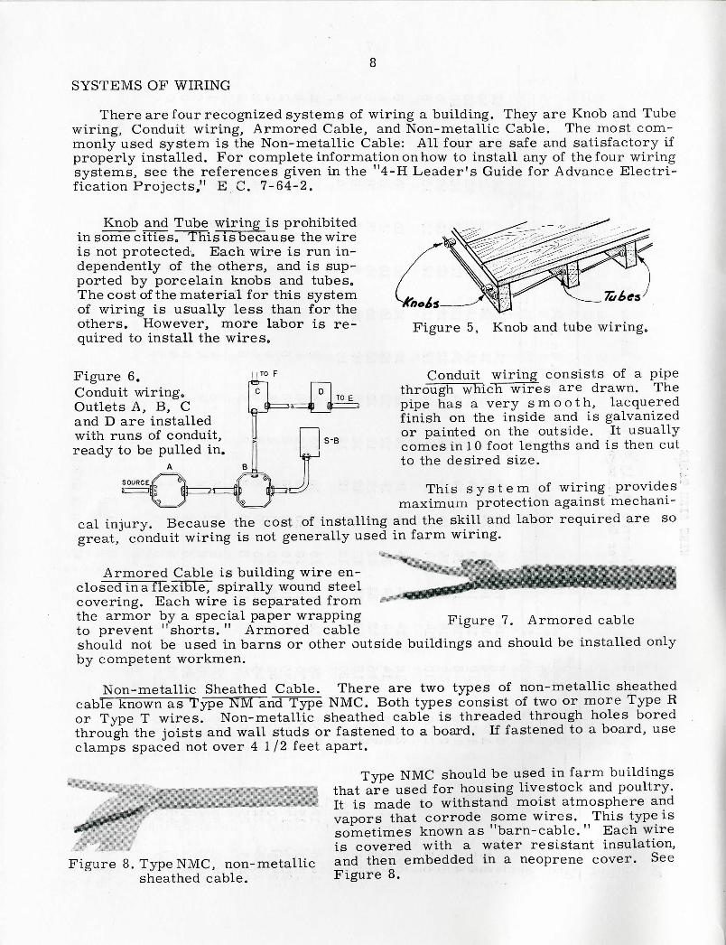
There are four recognized systems of wiring a building. They are Knob and Tubewiring, Conduit wiring, Armored Cable, and Non-metallic Cable. The most com-monly used system is the Non-metallic Cable: All four are safe and satisfactory ifproperly installed. For complete information on how to install any of the four wiringsystems, see the references given in the "4-H Leader's Guide for Advance Electri-fication Projects," E C . 7-64-2.
Knob and Tube wiring is prohibitedin some cities. Thisisbecause the wireis not protected,, Each wire is run in-dependently of the others, and is sup-ported by porcelain knobs and tubes.The cost of the material for this systemof wiring is usually less than for theothers. However, more labor is re-quired to install the wires.
Figure 5, Knob and tube wiring.
Figure 6.Conduit wiring.Outlets A, B, Cand D are installedwith runs of conduit,ready to be pulled in.
I TO F
TO £
SOURCE
Conduit wiring consists of a pipethrough which wires are drawn. Thepipe has a very s m o o t h , lacqueredfinish on the inside and is galvanizedor painted on the outside. It usuallycomes in 10 foot lengths and is then cutto the desired size.
This s y s t e m of wiring providesmaximum protection against mechani-
cal injury. Because the cost of installing and the skill and labor required are sogreat, conduit wiring is not generally used in farm wiring.
Armored Cable is building wire en-closed in a flexible, spirally wound steelcovering. Each wire is separated fromthe armor by a special paper wrappingto prevent "shorts. " Armored cable
Figure 7. Armored cable
should not be used in barns or other outside buildings and should be installed onlyby competent workmen.
Non-metallic Sheathed Cable. There are two types of non-metallic sheathedcable known as Type NM and Type NMC. Both types consist of two or more Type Ror Type T wires. Non-metallic sheathed cable is threaded through holes boredthrough the joists and wall studs or fastened to a board. If fastened to a board, useclamps spaced not over 4 1 / 2 feet apart.
Type NMC should be used in farm buildings1 < : H that are used for housing livestock and poultry.
It is made to withstand moist atmosphere andvapors that corrode some wires. This type issometimes known as "barn-cable. " Each wire
*-«;««.-=*-- is covered with a water resistant insulation,Figure 8. Type NMC, non-metallic and then embedded in a neoprene cover. See
sheathed cable. Figure 8.
9
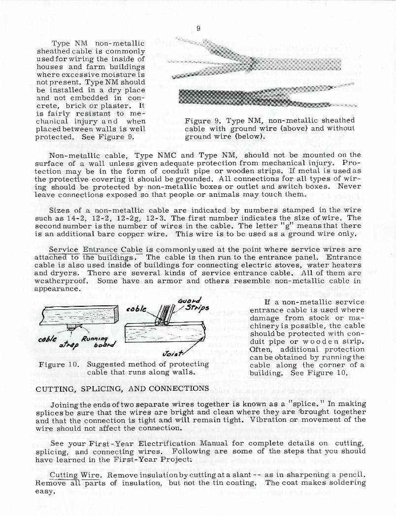
Type NM non-metallicsheathed cable is commonlyused for wiring the inside ofhouses and farm buildingswhere excessive moisture isnot present. Type NM shouldbe installed in a dry placeand not embedded in con-crete, brick or plaster. Itis fairly resistant to me-
n^t>t!nJUry a n d - ̂ FigUre 9' T^e NM> non-metallic sheathedDrotect^H cfn ^alls 1SQWeU cable with ground wire (above) and withoutprotected. See Figure 9. ground wire (below).
surf^rS^V^J6' TyPe NJfC and Type ™' Should not be mounted on thesurface of a wall unless given adequate protection from mechanical injury Pro-tection may be in the form of conduit pipe or wooden strips. If metal is used as™ T TH T cov^ng it should be grounded. All connections for all types of wir-
ing should be protected by non-metallic boxes or outlet and switch boxes Neverleave connections exposed so that people or animals may touch them ~
a t t a h r T H - r T - — - S?u commonly used at the point where service wires areattached to the buildings. The cable is then run to the entrance panel Entrancecable is also used inside of buildings for connecting electric stoves water Sers
weatheyreprroof Som^ ̂ ^ ̂ °f service fntrance cable! 'AS of them areTppearaSce VG M arm°r &nd °therS resemble non-metallic cable
a l numbers stamPed ^ the wireas 14 z, 14-2 12-2g, 12-3. The first number indicates the size of wire The
fs annadndTionallb ""̂ °f ̂ ^ ^ the ****• The letter "«" means tS thereis an additional bare copper wire. This wire is to be used as a ground wire only.
in
If a non-metallic serviceentrance cable is used wheredamage from stock or ma-chinery is possible, the cableshould be protected with con-duit pipe or w o o d e n strip.Often, additional protection
Figure 10. Suggested method of protecting H^ 2'a'"e?hby running'he
^S^tf^T6.of aCUTTING, SPLICING, AND CONNECTIONS
Joining the ends of two separate wires together is known as a "splice." In makingsplices be sure that the wires are bright and clean where they are 'brought togetherand that the connection is tight and will remain tight. Vibration or movement of thewire should not affect the connection. uvemtn i 01 int.
See your First-Year Electrification Manual for complete details on cuttingsplicing, and connecting wires. Following are some of the ~J - " ' - - -have learned in the First-Year Project:
R p n T T i ; Rem°veinsulationby cutting at a slant- as in sharpening a pencilRemove all parts of insulation, but not the tin coating. The coat makes soldering
10
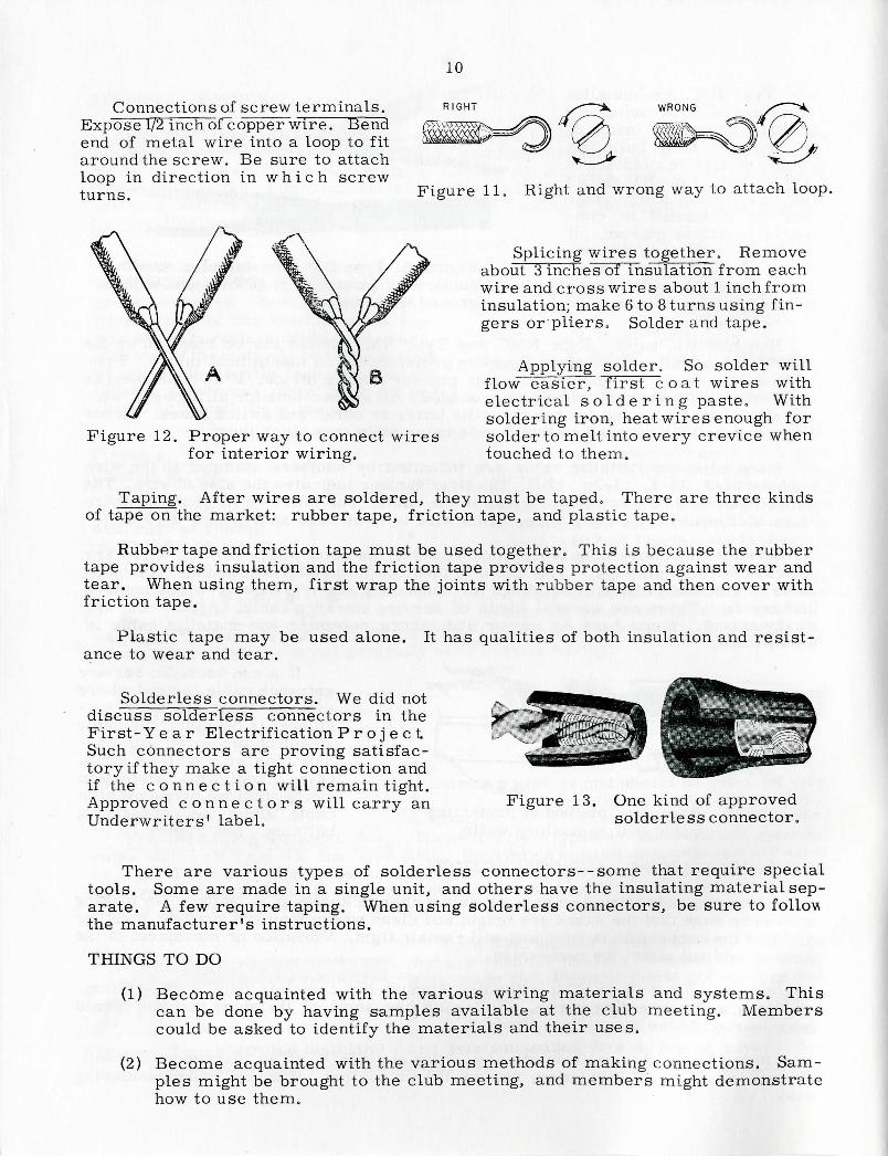
Connections of screw terminals.Expose 1/2 inch ofcopper wire. Bendend of metal wire into a loop to fitaround the screw. Be sure to attachloop in direction in w h i c h screwturns.
R I G H T WRONG
Figure 11. Right and wrong way to attach loop.
Figure 12. Proper way to connect wiresfor interior wiring.
Splicing wires together. Removeabout 3 inches of insulation from eachwire and cross wires about 1 inch frominsulation; make 6 to 8 turns using fin-gers or'pliers. Solder and tape.
Applying solder. So solder willflow easier, first c o a t wires withelectrical s o l d e r i n g paste. Withsoldering iron, heat wires enough forsolder to melt into every crevice whentouched to them.
Taping. After wires are soldered, they must be taped. There are three kindsof tape on the market: rubber tape, friction tape, and plastic tape,
Rubber tape and friction tape must be used together. This is because the rubbertape provides insulation and the friction tape provides protection against wear andtear. When using them, first wrap the joints with rubber tape and then cover withfriction tape.
Plastic tape may beance to wear and tear.
used alone. It has qualities of both insulation and resist-
Solderless connectors. We did notdiscuss solderle¥s connectors in theFirst-Y e a r Electrification P r o j e c tSuch connectors are proving satisfac-tory if they make a tight connection andif the c o n n e c t i o n will remain tight.Approved c o n n e c t o r s will carry anUnderwriters' label.
Figure 13. One kind of approvedsolderless connector.
There are various types of solderless connectors--some that require specialtools. Some are made in a single unit, and others have the insulating material sep-arate. A few require taping. When using solderless connectors, be sure to followthe manufacturer's instructions.
THINGS TO DO
(1) Become acquainted with the various wiring materials and systems. Thiscan be done by having samples available at the club meeting. Memberscould be asked to identify the materials and their uses.
(2) Become acquainted with the various methods of making connections. Sam-ples might be brought to the club meeting, and members might demonstratehow to use them.

11
Problem ThreeSWITCHES AND FUSES
By now you should have selected and started work on your wiring paneL Someof you may have completed one, and while making the panel you may have wonderedhow switches add fuses work. Problem Three is devoted to the working principlesof switches and fuses.
SINGLE-POLE AND THREE-WAY SWITCHES
Figure 14.Simplified sketchof how a single -pole switch works.
Single-pole switches are used toturn a light on or off from only onelocation. By turning the switch on,you have made a complete circuit forthe electrical current to flow through.By turning the switch off, you havebroken the circuit. Thus, the flowof electrical current is broken.
Three-way switches are used to turn lights on and off at either of two locations.The term "three-way" refers to the number of wire connections made, not the num-ber of switches. Three-way switches have become more and more popular because-of the steps they save.
Figure 15 shows how athree-way switch works. Inpart a, the current fromswitchleg A passes throughthe first switch, through theupper traveler wire, throughthe second switch and thenthrough the light. In part b,the right switch is discon-nected from the upper trav-erler wire and connected tothe lower traveler wire.This breaks the original cir-cuit, causing the light to gooff. If the left switch is con-nected to the lower travelerwire the current will passthrough the lower travelerwire to the second switch andon to the light. In this mannerlight can be turned on or offwith either of two switches.
Figure 15. Working sketch of a three-way switch.
To further understand the principle of a three-way switch, it is suggested thata club member make the demonstration panel as shown in Figure 16. He shouldbring the unit to a club meeting and demonstrate how it works.
To make the demonstration panel you will need:
x 6" board (approximately)2 - 1 0 penny nails6 - 6 penny nailsSome bell wire
A flashlight batteryA bulbSome solderA couple of rubber bands.

12
~ fte/itiy A/tit/s Figure 16.('2 * f?**f*\ Diagram of a three-wayz ,„ GM&+) sw.t^ch demonstrationpanei.
Figure 16. Diagram of a three-way switch demonstration panel.
FUSES AND CIRCUIT BREAKERS
Fuses protect electrical wir-ing fronTda mage due to overloadsand short c i r c u i t s . Fires ordamage to the wiring, appliances,and buildings may result throughfailure to use the proper fuse. Afuse c o n t a i n s a strip of metalthrough which the current mustpass. When a fuse "blows, " it
Figure 17. Commonfuse plug.
Figure 18. Cartridgefuses.
means that the flow of electric current is more than the metal strip can carry.Heat from the extra current melts the strip and breaks the circuit. There are twogeneral types of common fuses, as shown in Figure 17 and Figure 18. They areknown as the fuse plugs and cartridge fuses.
Fusetrons and fustats are protectivedevices similar in appearance to thecommon fuse plug. They serve the samepurpose as a common fuse. Fusetronsand fustats are made so that a small blockof solder melts when heated by an over-load. After the solder has melted, aspring attached to the fuse strip pullsthe circuit open and stops the flow ofelectricity. On a short circuit a stripof metal melts and breaks the circuit in
By examining a fustat or fusetron you can
Figure
the
Working parts of a fusetron.(The working parts of a fustatare the same)
same manner as in a common fuse.determine if the circuit has a short or an overload. lee Figure 19.

13
The interiors or "works" of a fusetron andfustat are identical. A fustat differs from afusetron in its base. With each different sizeof fustat, a different adapter is used as shownin Figure 20. The adapter is screwed into anormal plug fuse socket. It is constructed sothat when it is once in the socket, it cannot beremoved. A fusetron does not need an adapter. Figure 20. Fustat and fustat adapter.
Circuit breakers serve the same purpose as a fuse. They also have an alloymetal strip through which the current must pass. This metal strip does not meltas in the case of a fuse. Rather, the excessive heat created by an overload or shortcircuit causes the metal to expand. This action stops the flow of electrical currentby tripping the switch. When the cause of the trouble is corrected, the breaker maybe reset and the electrical current again started.
When You Change A Fuse:
(1) Locate and disconnect lampor appliance responsible.
(2) Locate blown fu se w h i l estanding on dry surface.
(3) Unscrew, being careful notto touch anything but fuserim. Replace with new fuseof correct' ampere rating.
Note: Use 15-ampere fusefor ordinary household orlighting circuits (No. 14 wire).A 20-ampere fuse canbe usedwith No. 12 wire.
THINGS TO DO
Figure 21. Steps to follow when changing a fuse.
(1) Have some member of the club make the three-way demonstration panel inin Figure 16. He can then demonstrate to the other members how a three-way switch works.
(2) Bring various types of fuses, fustats and fusetrons. Have the membersidentify them.
(3) Some of the members might bring some burnt-out fustats and fusetrons.The club could then try to determine if they were burnt out by an overload ora short circuit.
(4) Each member should report the progress made on the two wiring activities.
14
Problem FourDISTRIBUTION OF POWER
Now that you have reviewed some of the safety precautions and discussed properwiring, let's look at the process of getting the electricity from the distribution lineto the house and other points about the farm.
All farmsteads and homes should have a three-wire 115-230 volt electricalservice. This provides 115 volts for lights and small appliances, and 230 volts forall motors of 1/2 h.p. or larger and for large equipment such as water heaters,welders and ranges.
Each building should have an entrance panel. This panel provides the masterswitch for the entire building, the connections for the various individual branchcircuits in the building, the fuses for each of these branch circuits, and the groundwire connection for the building.
PLANS FOR DISTRIBUTING POWER
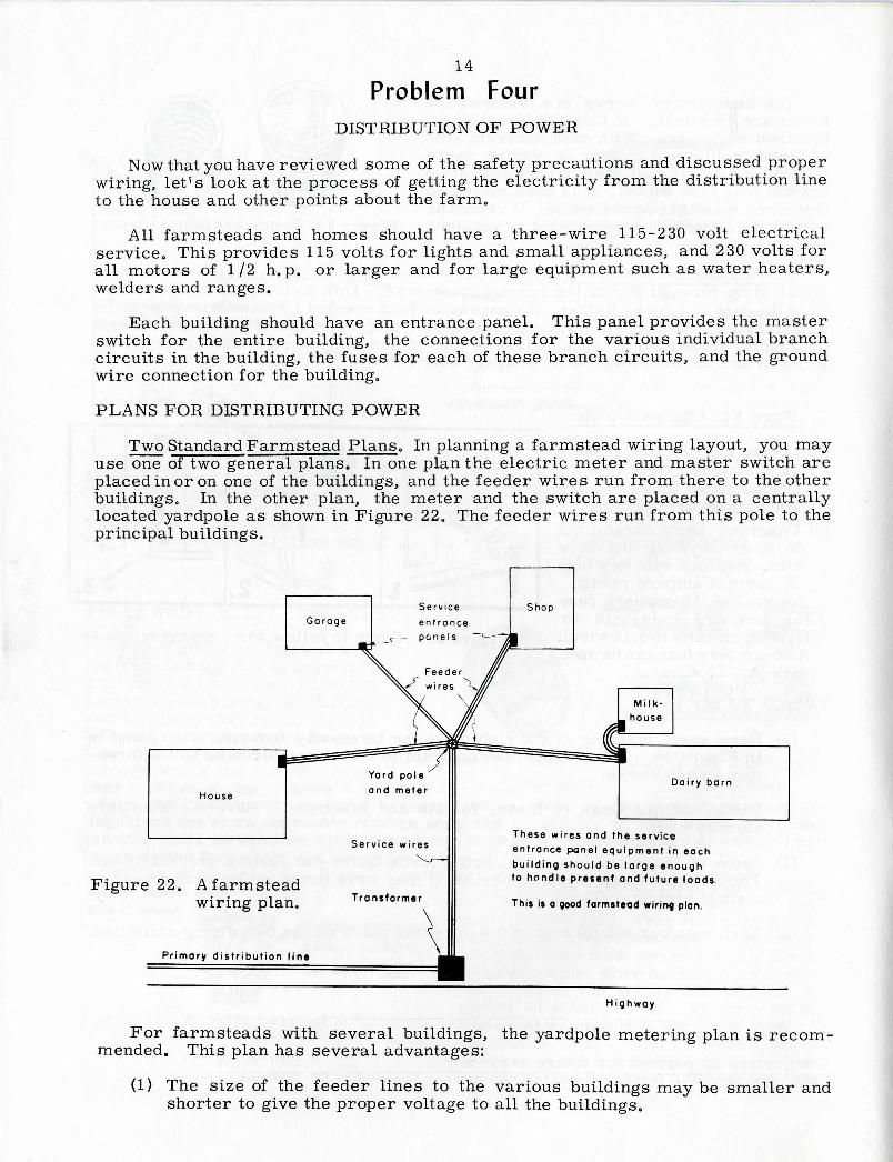
Two Standard Farmstead Plans. In planning a farmstead wiring layout, you mayuse one of two general plans. In one plan the electric meter and master switch areplaced in or on one of the buildings, and the feeder wires run from there to the otherbuildings. In the other plan, the meter and the switch are placed on a centrallylocated yardpole as shown in Figure 22. The feeder wires run from this pole to theprincipal buildings.
Garage
•*
Serv i ce
ent rance
Shop
( i — P a n e l s ^~^~M
House
Figure 22. A farmsteadwiring plan.
Serv ice w i r e s
Transformer
Da i ry barn
These wires and the serviceentrance panel equipment in eachbuilding should be large enoughto handle present and future loads.
This is a good farmstead wiring plan.
Primary d i s t r i b u t i o n line
H i g h w a y
For farmsteads with several buildings, the yardpole metering plan is recom-mended. This plan has several advantages;
(1) The size of the feeder lines to the various buildings may be smaller andshorter to give the proper voltage to all the buildings.

15
(2) The yardpole arrangement makes it easier to change the wiring system.
(3) It allows continued use of electricity if fire destroys one of the buildings.
(4) It provides an excellent place to locate a yard light.
Locating the Loadcenter. One method of finding the loadpoint center is to makea small map of the farmstead. Draw the map to scale, showing the relative locationand size of all buildings. This map should then be mounted on a piece of lightweightcardboard.
Next, determine the number of kilowattsof electricity needed in each building. Thiscan be done by totaling the watts each elec-trical appliance can use at any one time inthe building, and dividing by 1, 000. Forexample, suppose the total electrical load ina brooder house consists of two 1,000-wattbrooders and one 75-watt light. The totalwould be 2, 075. Dividing the total by 1, 000,we find that approximately two kilowatts willbe used.
Now place on each building on the mapone washer or penny for each kilowatt ofelectricity needed. With the washers orpennies in place, carefully balance your mapon the point of a spindle. A spindle can bequickly made by driving a nail through thecenter of a 1" board about 4" by 4. " Whenyou find the balance point, press down on thecardboard until the point sticks up throughyour map. The point where the spindle sticksup through the map will be the electrical loadcenter of the farm,this point will be the best location for the yard pole and meter.
Figure 23. Steps to followin locating the loadcenter.
Somewhere near
MASTER SWITCHES AND ENTRANCE PANELS
Master Switches. From a practical standpoint, although local regulations maynot require it, you should consider some type of fused switching equipment at theyardpole. This aids in "killing" the wiring system when repairs or additions areneeded, and is a safety device in case of fire in one of the buildings,
To determine the proper size of the master switch and fuses at the yardpole,make a table of the total demanded load of each feeder circuit as follows:
House 21, 400 wattsShop 9, 065 wattsMilkhouse and dairy barn 15, 000 wattsGarage 1, 000 watts
Total Maximum Demand 46, 465 watts
Then, allow 20 percent for future expansion 9, 293 wattsThis gives you the total anticipated maximum demand . 55, 758 'watts
16
/£ 4
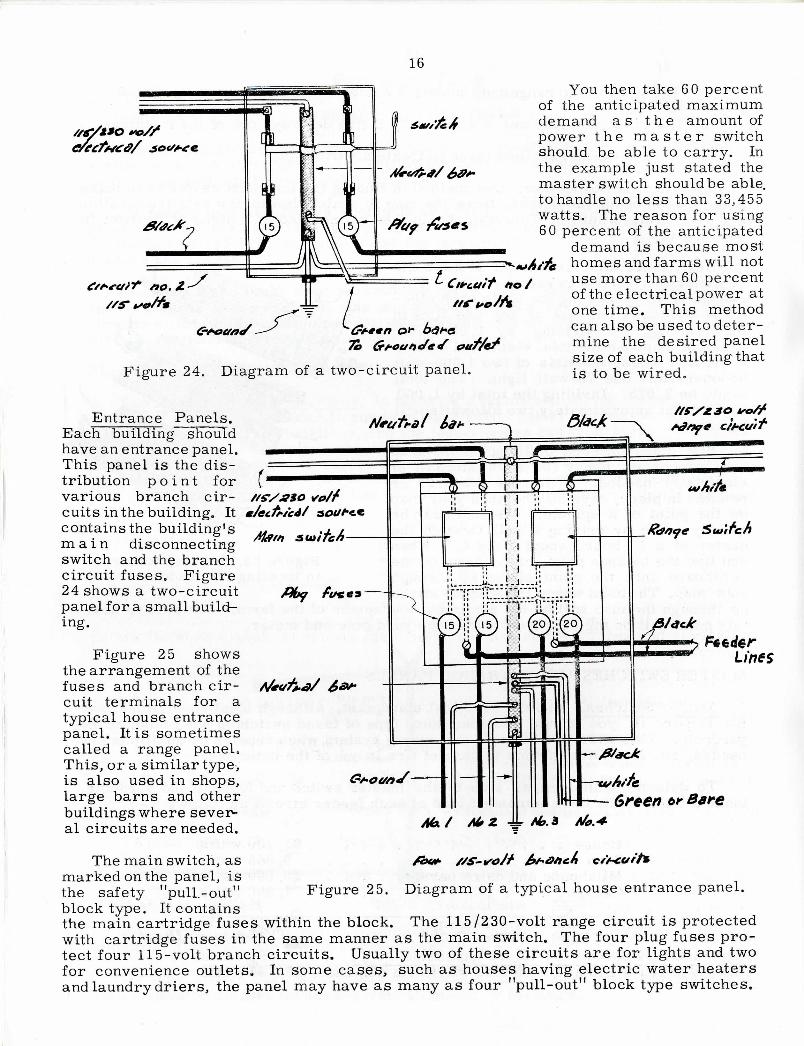
Figure 24. Diagram of a two-circuit panel.
You then take 60 percentof the anticipated maximumdemand as t h e amount ofpower the m a s t e r switchshould be able to carry. Inthe example just stated themaster switch should be able,to handle no less than 33,455watts. The reason for using60 percent of the anticipated
demand is because mosthomes and farms will notuse more than 60 percentof the electrical power atone time. This methodcan also be used to deter-mine the desired panelsize of each building thatis to be wired.
Entrance Panels.Each building shouldhave an entrance panel.This panel is the dis-tribution p o i n t forvarious branch cir-cuits in the building. Itcontains the building'sm a i n disconnectingswitch and the branchcircuit fuses. Figure24 shows a two-circuitpanel for a small build-ing.
Figure 25 showsthe arrangement of thefuses and branch cir-cuit terminals for atypical house entrancepanel. It is sometimescalled a range panel.This, or a similar type,is also used in shops,large barns and otherbuildings where sever-al circuits are needed.
feederLines
Green t»f Bare
Figure 25. Diagram of a typical house entrance panel.
The main switch, asmarked on the panel, isthe safety "pull.-out"block type. It containsthe main cartridge fuses within the block. The 115/230-volt range circuit is protectedwith cartridge fuses in the same manner as the main switch. The four plug fuses pro-tect four 115-volt branch circuits. Usually two of these circuits are for lights and twofor convenience outlets* In some cases, such as houses having electric water heatersand laundry driers, the panel may have as many as four "pull-out" block type switches.
17OTHER FACTORS TO CONSIDER
Selecting Feeder Wires. After you have chosen the location of the meter yard-pole, it is easy to measure the distance from the pole to the entrance panels of eachbuilding. As soon as you know the expected powerload and the distance the poweris to be carried you can determine the correct wire size by referring to Tables 1and 2 in Problem Two.
The Transformer and Service Wires. Most electric power companies supplythe transformer, the service wires, and the electric meter free of charge to thecustomer. They will determine the size to fit your needs.
THINGS TO DO
(1) Find the loadcenter of some group of buildings. This might be done as agroup activity--with the members meeting at a farmstead, making a mapof the buildings, and locating the loadcenter as discussed in this problem.Determine the needed wire size and panel size for each building.
(2) If you have not done so, begin work on your wiring projects.
Problem FiveINTERIOR WIRING
Adequate wiring depends upon two main factors: (1) the ability of the system totake the power from the meter to the building and (2) the ability of the branch cir-cuits within the building to carry the power to all appliances. This problem isdevoted to the second of these requirements.
PLANNING A WIRING SYSTEM
Proper wiring of a building begins with knowing the building and what electricalappliances might be used within each room. First, make a floor plan of the buildingto be wired. Show the location of each room and all possible places that electricityis likely to be used. Your sketch should be large enough to clearly show all wiringrequirements.
Next, make a list of all electrical equipment that is likely to be used in eachroom. The list will be used as a guide for planning the wiring; so try to include alluses at the present and all those expected in the future.
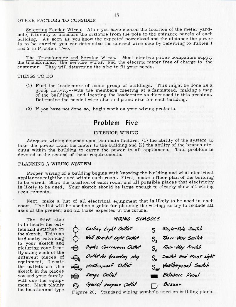
The third step WIRINGis to locate the out- .lets and switches on -O- Cft/tno £/o4t Ot/tfef C Sinyle~Polethe sketch. This can Ybe done by referring |~Q- "•//&**c&f t/ftf Ovtft* 5 7%*e*-Wayto your sketch and 3
picturing your fam- |=0 0*f*6* &**c*/tr*c« Ot/rtrf g &ut--lMyyily using each of the *different pieces of l-f^ ^V /̂/̂ x ^<//»/*y /»(y C 3u//fc4 ahc/ f>t'Jof
, T , i v^2 ' «<pequipment. Locate r J.r ± i 4L r 1 ithe outlets on the |"Q^ H/!e»mc*pt-oor OvTlcT c Wlcdt/lChpt-ooT StuiTcnsketch in the places ^*^ $IV
you and your family [=0 ffafyc Ot/r/ef gg Ehft-dntc Panelwill use the equip- /ment. Mark plainly @ •SpccfQ/ potpose 0i/fftr r~\, Bazz.et-the location and type „. on „, , , . . , n , , .,-.. ,Figure 26. Standard wiring symbols used on building plans
18
of each outlet with the symbols as shown in Figure 26. After plans are made youshould check with Table 3 to make sure you meet the minimum recommendationsfor outlets and switches.
BRANCH CIRCUITS
A branch circuit is the part of a wiring system that extends beyond the last fuseor circuit breaker in the panelbox. It is important to have plenty of branch circuitsin your house and farm buildings. The number of branch circuits you need dependsupon the size of building, the size of wire used and the number of power and lightoutlets to be installed.
Lighting and convenience outlets may be on the same circuit in all rooms exceptthe kitchen, dining room and utility room. In these rooms the lighting outlets andconvenience outlets should be on separate branch circuits. The planned electricalload carried on a branch circuit should never exceed 80 percent of the circuit'scapacity. This will limit the number of outlets per circuit.
For example: A lighting circuit of 15 amperes or approximately 1725 watts canbe planned to carry up to 12 amperes or approximately 1380 watts at one time. Ifyou plan to use light using 150 watts, you would be limited to nine outlets. Lightingand convenience branch circuits are always limited-to 20 amperes.
Individual equipment circuits are required for such appliances as ranges, waterheaters, clothes dryers, bathroom heaters, and motors of one-half horsepower orlarger.
Extension Cords. Because of unanticipated demands, there is often a need forexpanding existing electric circuits. It may not be possible to expand these circuitsby concealed wiring, so some method of exposed wiring must be used. Sometimesextension cords are strung along or tacked to the wall. This practice is dangerousand should be avoided because lamp cords are not sufficiently covered for'this us"eTCompare the insulation on lamp cord with that on non-metallic sheathed cable.
Several kinds of non-metallic surface extension cord are available. The importantthing to remember is that the extensions must not overload the present circuit.
LOCATING PRESENT BRANCH CIRCUITS
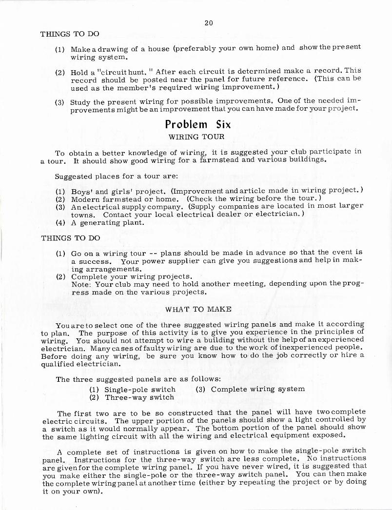
You may wonder how to determine the present wiring system in a building. Oneof the best methods is to hold a "circuit hunt. " Members in a family and club willenjoy participating. You will need pencil and paper, a flashlight and a test lamp.A portable electric lamp or electric clock may be used in place of the test lamp.
First, tighten all the branch fuses, or close the branch circuit breakers in theentrance panel. Then turn on all lights in the house. (Safety precautions to follow,when working with a panel, are given in the latter part of Problem Three. Readthem carefully before starting a "circuit hunt. ")
Second, loosen just one branch fuse or open one circuit breaker. Then have yourhelper(s) go through the building recording the lights that are out. To be sure nooutlets are skipped, test the ones not being used for lighting by plugging in the testlamp, portable lamp or clock. Make a list of all rooms and outlets where the elec-tric current is off. These are all on one circuit, protected by the fuse or breakeryou have just loosened or opened. When all outlets have been checked, tighten thefuse or close the circuit breaker.
Third, continue the "hunt" by loosening one fuse or opening one breaker at atime, until every area in the building is checked.
19
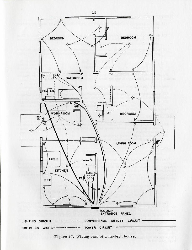
100 AMPENTRANCE PANEL
LIGHTING CIRCUIT —
SWITCHING WIRES —
— CONVENIENCE OUTLET CIRCUIT
POWER CIRCUIT
Figure 27. Wiring plan of a modern house.
20THINGS TO DO
(1) Make a drawing of a house (preferably your own home) and show the presentwiring system.
(2) Hold a "circuit hunt, " After each circuit is determined make a record. Thisrecord should be posted near the panel for future reference. (This can beused as the member's required wiring improvement.)
(3) Study the present wiring for possible improvements. One of the needed im-provements might be an improvement that you can have made for your project.
Problem SixWIRING TOUR
To obtain a better knowledge of wiring, it is suggested your club participate ina tour. It should show good wiring for a farmstead and various buildings.
Suggested places for a tour are:
(1) Boys' and girls' project. (Improvement and article made in wiring project.)(2) Modern farmstead or home. (Check the wiring before the tour. )(3) Anelectrical supply company. (Supply companies are located in most larger
towns. Contact your local electrical dealer or electrician.)(4) A generating plant.
THINGS TO DO
(1) Go on a wiring tour -- plans should be made in advance so that the event isa success. Your power supplier can give you suggestions and help in mak-ing arrangements.
(2) Complete your wiring projects.Note: Your club may need to hold another meeting, depending upon the prog-ress made on the various projects.
WHAT TO MAKE
You are to select one of the three suggested wiring panels and make it accordingto plan. The purpose of this activity is to give you experience in the principles ofwiring. You should not attempt to wire a building without the help of an experiencedelectrician. Many cases of faulty wiring are due to the work of inexperienced people.Before doing any wiring, be sure you know how to do the job correctly or hire aqualified electrician.
The three suggested panels are as follows:(1) Single-pole switch (3) Complete wiring system(2) Three-way switch
The first two are to be so constructed that the panel will have two completeelectric circuits. The upper portion of the panels should show a light controlled bya switch as it would normally appear. The bottom portion of the panel should showthe same lighting circuit with all the wiring and electrical equipment exposed.
A complete set of instructions is given on how to make the single-pole switchpanel. Instructions for the three-way switch are less complete. No instructionsare given for the complete wiring panel. If you have never wired, it is suggested thatyou make either the single-pole or the three-way switch panel. You can then makethe complete wiring panel at another time (either by repeating the project or by doingit on your own).
21
WIRING PANEL: SINGLE-POLE SWITCH
SINGLE-POLE SWITCH WIRING PANEL
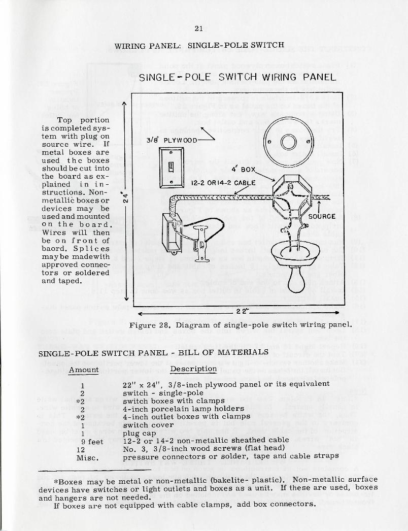
Top portionis completed sys-tem with plug onsource wire. Ifmetal boxes areused the boxesshould be cut intothe board as ex-plained in i n -structions. Non-metallic boxes ordevices may beused and mountedon the bo a r d .Wires will thenbe on f r o n t ofbaord. Spl icesmaybe made withapproved connec-tors or solderedand taped.
A
CO
3/8' PLYWOOD
4 BOX
12-2 OR 14-2 CABLE
22"
Figure 28, Diagram of single-pole switch wiring panel.
SINGLE-POLE SWITCH PANEL - BILL OF MATERIALS
Amount Description
1 22" x 24", 3/8-inch plywood panel or its equivalent2 switch - single-pole
*2 switch boxes with clamps2 4-inch porcelain lamp holders
*2 4-inch outlet boxes with clamps1 switch cover1 plug cap9 feet 12-2 or 14-2 non-metallic sheathed cable
12 No. 3, 3/8-inch wood screws (flat head)Misc. pressure connectors or solder, tape and cable straps
*Boxes maybe metal or non-metallic (bakelite- plastic). Non-metallic surfacedevices have switches or light outlets and boxes as a unit. If these are used, boxesand hangers are not needed.
If boxes are not equipped with cable clamps, add box connectors.
22
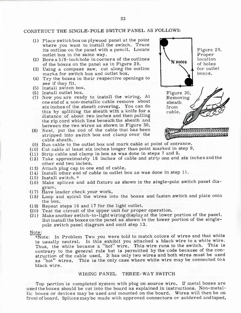
Figure 29.Properlocationof holesfor outletboxes.
Figure 30.Removingsheathfromcable.
CONSTRUCT THE SINGLE-POLE SWITCH PANEL AS FOLLOWS:
(1) Place switch box on plywood panel at the pointwhere you want to install the switch. Traceits outline on the panel with a pencil. Locateoutlet box in the same way.
(2) Bore a 5/8-inchhole incomers of the outlinesof the boxes on the panel as in Figure 29.
(3) Using a compass saw, cut along the outlinemarks for switch box and outlet box.
(4) Try the boxes in their respective openings tosee if they fit.
(5) Install switch box.(6) Install outlet box.(7) Now you are ready to install the wiring. At
one end of a non-metallic cable remove aboutsix inches of the sheath covering. You can dothis by splitting the sheath with a knife for adistance of about two inches and then pullingthe rip cord which lies beneath the sheath andbetween the two wires as shown in Figure 30.
(8) Next, put the end of the cable that has beenstripped into switch box and clamp over thecable sheath.
(9) Run cable to the outlet box and mark cable at point of entrance.(10) Cut cable at least six inches longer than point marked in step 9.(11) Strip cable and clamp in box as was done in steps 7 and 8.(12) Take approximately 18 inches of cable and strip one end six inches and the
other end two inches.(13) Attach plug cap to one end of cable.(14) Install other end of cable in outlet box as was done in step 11.(15) Install switch. *(16) Make splices and add fixture as shown in the single-pole switch panel dia-
gram.(17) Have leader check your work.(18) Loop and spiral the wires into the boxes and fasten switch and plate onto
the box.(19) Repeat steps 16 and 17 for the light outlet.(20) Test the circuit of the upper unit for proper operation.(21) Make another switch-to-light wiring display at the lower portion of the panel.
But install the boxes on the panel as shown in the lower portion of the single-pole switch panel diagram and omit step 13.
Note:*Note: In Problem Two you were told to match colors of wires and that whiteis usually neutral. In this exhibit you attached a black wire to a white wire.Thus, the white became a "hot" wire. This wire runs to the switch. This iscontrary to the general rule but is permitted by the code because of the con-struction of the cable used. It has only two wires and both wires must be used
This is the only case where white wire may be connected to aas "hot" wires.black wire.
WIRING PANEL THREE-WAY SWITCH
Top portion is completed system with plug on source wire. If metal boxes areused the boxes should be cut into the board as explained in instructions. Non-metal-lic boxes or devices may be used and mounted on the board. Wires will then be onfront of board. Splices may be made with approved connectors or soldered and taped.
23
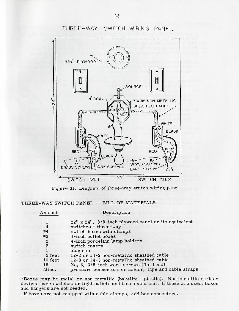
THREE-WAY SWITCH WIRING PANEL
OJ
,̂ ?=;
3/8" PLYWOOD
-3 WIRE NON-METALLICSHEATHED CABLE
LACK
22"SWITCH NO. I ' SWITCH NO-2
Figure 31. Diagram of three-way switch wiring panel.
THREE-WAY SWITCH PANEL -- BILL OF MATERIALS
Amount Description
1 22" K 24", 3/8-inch plywood panel or its equivalent4 switches - three-way
*4 switch boxes with clamps*2 4-inch outlet boxes
2 4-inch porcelain lamp holders2 switch covers1 plug cap3 feet 12-2 or 14-2 non-metallic sheathed cable
10 feet 12-3 or 14-3 non-metallic sheathed cable16 No. 3, 3/8-inch wood screws (flat head)Misc. pressure connectors or solder, tape and cable straps
*Boxes may be metal or non-metallic (bakelite - plastic). Non-metallic surfacedevices have switches or light outlets and boxes as a unit. If these are used, boxesand hangers are not needed.
If boxes are not equipped with cable clamps, add box connectors.
24
CONSTRUCT PANEL AS FOLLOWS:
(1) Place the switch and outlet boxes on the plywood panel as shown j.n diagramfor a three-way switch wiring panel.
(2) With a pencil, trace the box outline on the panel.(3) Follow steps given in the previous set of instructions to install boxes.(4) Follow the wiring diagram of three-way switch and proceed as follows:
a. Remove six inches of the outer sheath of covering from both ends of thetwo-foot pieces of 3-wire No. 12 non-metallic cable. Be careful not todamage the insulation of the individual wires.
b. Insert the 3-wire non-metallic cables between the switch boxes and theoutlet box as shown in the diagram.
c. Tighten the cable clamps. Be sure you have at least six inches of freewires extending out of each box.
d. Attach switches to wires as in diagram. Place red and white wires oncopper-colored terminals, and the black wires on the black terminals.Use eye loops.
e. At the outlet box, splice the two red wires together and splice the twowhite wires together.
f. Insert a two-foot piece of 2-wire No. 12 cable into the outlet box througha 1 / 2-inch knockout as shown indiagram. This cable is the power source.
g. Attach the white wire from the power source to the silver-colored terminalof the light fixture and splice the black wire from the power source to theblack wire from switch No. 2.
h. Attach the black wire from switch No. 1 to copper-colored terminal oflighting fixture.
i. Put plug cap on the power source lead.
j. Solder and tape all splices, or use approved solderless connectors. Havethe leader check your work.
k. Test the circuit of the upper unit for proper operation and complete in-stallation.
1. Repeat on lower portion of board but mount boxes on surface and do notmount devices.
WIRING PANEL - COMPLETE SYSTEM
This panel includes most of the wiring problems encountered in wiring a smallfarm building. The finished panel should have all devices mounted and covered withcorrect plates.
You should not attempt to construct a complete wiring system panel without havingfirst made one of the preceding panels. A diagram of the complete wiring of thispanel is given on the next page. If you have questions about wiring, refer to the in-structions given with the preceding two panels, information given in this manual,and guides and suggestions as given in good electrician handbooks. Names of sug-gested handbooks and information about where to obtain them are given in your clubleader's guide entitled "Leader's Guide for Advanced 4-H Electrification Projects."
25
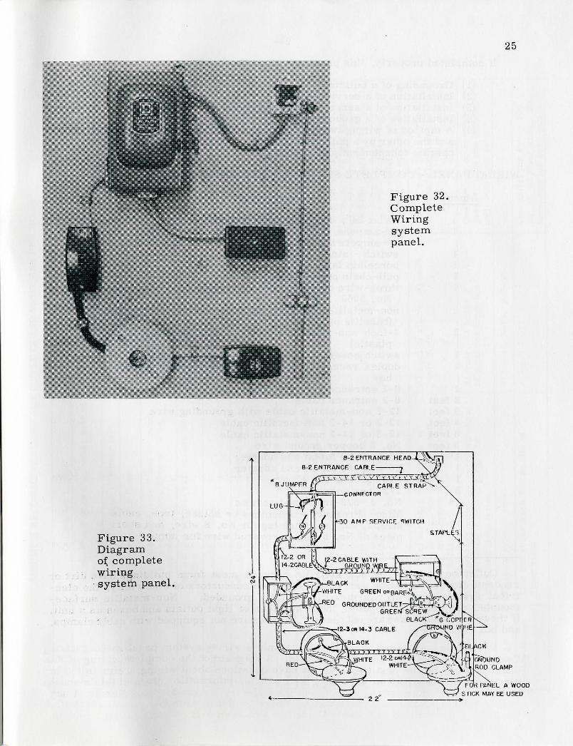
Figure 32.CompleteWiringsystempanel.
Figure 33.Diagramof completewiringsystem panel.
8-2 ENTRANCE HEAD -^
8-2. ENTRANCE CABLE ;
IZZte3T\ v \-"\ fCABLE S
— CONNECTOR
<-30 AMP SERVICE SWITCH
SLACK WHITE
WHITE GREEN OBBARE>'V \
RED GROUNDED OUTLET-JS&T'J'iGREEN SCREVV
•12-3OR 14-3 CABLE
BLACK
GROUNDROD CLAMP
FOV) PANEL A WOODSTICK MAYBE USED

26
If completed properly, this panel will show the following:
(1) Grounding of a building.(2) Installation of a service entrance cable.(3) Installation of a service entrance panel.(4) Installation of a grounded convenience outlet.(5) A method of wiring two lights--one is controlled by a single-pole switch
and the other by a pull-chain switch. These lights and switches shouldoperate independently of each other.
WIRING PANEL - COMPLETE SYSTEM -- BILL OF MATERIALS
Amount Description
1 22" x 24", 3/8-inch plywood panel or its equivalent1 30-ampere, 2-fuse, solid neutral service switch - or
30-ampere service with 15 and 20-ampere breakers1 switch - single-pole1 porcelain lamp holder1 pull-chain porcelain lamp holder1 three-wire duplex outlet, grounding type catalogue
No. 52622 non-metallic surface s w i t c h boxes w i t h clamps
(bakelite or plastic)2 4-inch non-metallic boxes with clamps (bakelite or
plastic)1 switch,cover to fit non-metallic surface box1 duplex receptacle cover to fit non-metallic surface
box1 8-2 entrance head for cable2 feet 8-2 entrance cable3 feet 12-2 non-metallic cable with grounding wire4 feet 12-2 or 14-2 non-metallic cable3 feet 12-3 or 14-3 non-metallic cable3 feet No. 6 copper ground wire1 15-ampere fustat and adapter1 20-ampere fustat and adapter1 5/8" ground rod clamp3 1/2" box connectors14 No. 3, 3/8-inch wood screws
Misc: Pressure connectors or solder, tape, cablestraps, staples, wire lug for No. 8 wire, and shortpiece of No. 8 rubber covered wire for jumper
Outlet boxes must be non-metallic because most farm buildings have dirt orconcrete floors. Because such floors are good conductors of electricity, the elec-trical system must be non-metallic or fully grounded. Non-metallic surface-mounted devices may be used; these switches or light outlets and boxes as a unit.If these are used, boxes are not needed. If boxes are not equipped with cable clamps,add box connectors.
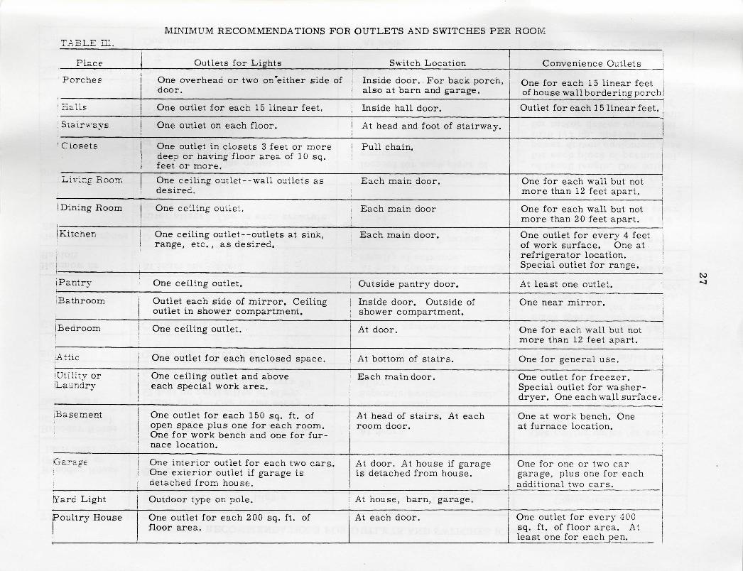
MINIMUM RECOMMENDATIONS FOR OUTLETS AND SWITCHES PER ROOMTABLE HI.
Place
Porches
^ Kails
i Stairways
! Closets
Living Room
I Dining Room
Kitchen
Pantry
i Bathroom
(Bedroom
[Attic
jUtility oriLaundry
iBasement
Garage
Yard Light
Poultry House
iOutlets for Lights
One overhead or two on'either side ofdoor.
One outlet for each 15 linear feet.
One outlet on each floor.
One outlet in closets 3 feet or moredeep or having floor area of 10 sq.
! feet or more.
One ceiling outlet—wall outlets asdesired.
One ceiling outlet.
One ceiling outlet --outlets at sink,i range, etc. , as desired.
One ceiling outlet.
Outlet each side of mirror. Ceilingoutlet in shower compartment.
One ceiling outlet.
One outlet for each enclosed space.
One ceiling outlet and aboveeach special work area.
One outlet for each 150 sq. ft. ofopen space plus one for each room.One for work bench and one for fur-nace location.
One interior outlet for each two cars-One exterior outlet if garage isdetached from house.
Outdoor type on pole.
One outlet for each 200 sq. ft. offloor area.
Switch Location
Inside door. For back porch,also at barn and garage.
Inside hall door.
At head and foot of stairway.
Pull chain.
i Each main door.
Each main door
Each main door.
Outside pantry door.
Inside door. Outside ofshower compartment.
At door.
At bottom of stairs.
Each main door.
At head of stairs. At eachroom door.
At door. At house if garageis detached from house.
At house, barn, garage.
At each door.
Convenience Outlets
One for each 15 linear feetof house wall bordering porch
Outlet for each 1 5 linear feet.
One for each wall but notmore than 12 feet apart. 1
One for each wall but notmore than 20 feet apart.
One outlet for every 4 feetof work surface. One atrefrigerator location.Special outlet for range.
At least one outlet.
One near mirror.
One for each wall but notmore than 12 feet apart.
One for general use.
One outlet for freezer.Special outlet for washer-dryer. One each wall surface.
One at work bench. Oneat furnace location.
One for one or two cargarage, plus one for eachadditional two cars.
One outlet for every 400sq. ft. of floor area. Atleast one for each pen.
ISi
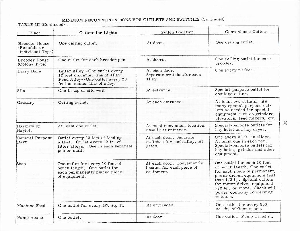
MINIMUM RECOMMENDATIONS FOR OUTLETS AND SWITCHES (Continued)TABLE HI (Continued)
: Place
Brooder House(Portable orIndividual Type
Brooder House(Colony Type)
Dairy Barn
Silo
Granary
f
Haymow orHayloft
jGeneral PurposeBarn
Shop
Machine Shed
Pump House
Outlets for Lights
One ceiling outlet.
One outlet for each brooder pen.
Litter Alley- -One outlet every12 feet on. center line of alley.Feed Alley- -One outlet every 20feet on center line of alley.
One in top of silo well
Ceiling outlet.
At least one outlet.
Outlet every 20 feet of feedingalleys. Outlet every 12 ft. -oflitter alleys. One in each separatepen or stall.
One outlet for every 10 feet ofbench length. One outlet foreach permanently placed pieceof equipment.
One outlet for every 400 sq. ft.
One outlet.
Switch Location
At door.
At doors.
At each door.Separate switches for eachalley.
AT; entrance.
At each entrance.
At most convenient location,usually at entrance.
At each door. Separateswitches for each alley. Atgates.
At each door. Convenientlylocated for each piece ofequipment.
'
At entrances.
At door.
Convenience Outlets
One ceiling outlet.
One ceiling outlet for eachbrooder.
One every 20 feet.
Special-purpose outlet forensilage cutter.
At least two outlets. Asmany special-purpose out-lets as needed for specialequipment such as grinders,elevators, feed mixers, etc.
Special-purpose outlets forhay hoist and hay dryer.
One every 20 ft. in alleys.At least one in each pen.Special-purpose outlets forhay hoist, grinder and otherequipment.
One outlet for each 10 feetof bench length. One outletfor each piece of permanent,power driven equipment lessthan 1/2 hp. Special outletsfor motor driven equipment1/2 hp. or more. Check withpower company concerningwelders.
One outlet for every 800sq. ft. of floor space.
One outlet. Pump wired in.


