Embed Size (px)
Citation preview

CONTENTS
CHAPTER Page
1. The Gunner's Mate (Missiles) Rating. . . . . . . . . . . . . . . . . . . . . . . . 1
2. Hitting A Moving Target From A Moving Ship. . . . . . . . . . . . . . . . 11
3. Principles Of Missile Flight And Jet Propulsion. . . . . . . . . . . . . . . . 32
4. Missile Guidance And Control. . . . . . . . . . . . . . . . . . . . . . . . . . . . . 64
5. Guided Missile Launching Systems. . . . . . . . . . . . . . . . . . . . . . . . . 101
6. A Typical Gun And Missile Weapons System. . . . . . . . . . . . . . . . . 152
7. Applications Of Servomechanisms. . . . . . . . . . . . . . . . . . . . . . . . . . 170
8. Hydraulics And Pneumatics In Missile Systems. . . . . . . . . . . . . . . . 197
9. Electrical Devices Used In Launching Systems. . . . . . . . . . . . . . . . . 224
10. Explosives, Pyrotechnics And Magazines. . . . . . . . . . . . . . . . . . . . 248
11. Small Arms, Landing Party Equipment And Demolition. . . . . . . . 297
12. General Maintenance. . . . . . . . . . . . . . . . . . . . . . . . . . . . . . . . . . . . 387
13. Common Test Equipment And Logical Troubleshooting. . . . . . . . 423
14. Launcher Checks, Missile Replenishment And Servicing. . . . . . . 455
15. Information: Input And Output. . . . . . . . . . . . . . . . . . . . . . . . . . . . 487
INDEX . . . . . . . . . . . . . . . . . . . . . . . . . . . . . . . . . . . . . . . . . . . . . . . . . . . . . . . 502
iii
CHAPTER 11
SMALL ARMS, LANDING PARTY
EQUIPMENT AND DEMOLITION
Although ground force operations are secondary duties for naval personnel, each ship of cruiser size and larger maintains a state of readiness for such action. Fleet ships maintain an organized landing party, for limited ground force operations, military police duties, parades and ceremonies. The Navy might be asked to land an armed force in a foreign country when there is a political disturbance and local authorities are unable to give adequate protection to life and property; or a landing party might be called upon to perform riot duty when there is widespread disorder which the civil authorities cannot control. Landing parties frequently give assistance in civil disasters, such as fires, floods, and hurricanes. Because someday you may be assigned to a landing party, now is the time to learn how to handle small arms. After studying this chapter you should know what safety precautions to observe while handling small arms, and how to field strip, clean, and reassemble them. You will also study how to use landing party equipment, and how to assemble, issue, and maintain the equipment. The information contained in this chapter on demolition is meant only to familiarize GMMs with the equipment, material, and safety precautions connected with demolition work. It is in no way intended to train GMMs to become demolition experts. Demolition work is a skill that is acquired only through intensive training and should not be attempted by untrained personnel. This chapter also contains information on the procedures for using hand grenades including the types of hand grenades now in use, the various methods of throwing grenades, and safety precautions when using hand grenades.
SMALL ARMS Small arms have been defined as guns with a bore of 0.60 or smaller. They include hand guns and shoulder weapons which are fired from the hand, such as the pistol and revolver; or from the shoulder, like the rifle, carbine, submachine gun or shotgun. NOTE: Shotguns have bores somewhat larger than 0.60-inch, but they are considered small arms never the less. Machine guns of small caliber, such as caliber .30 and caliber .50, technically may be classed as small arms on the basis of their bore diameter, though they usually are fired from a bipod or tripod, instead of from the shoulder. Often they are called light machine guns. Few of these machine guns are in use on ships, and they will be given only very brief treatment in this chapter. The line-throwing gun is fired from the shoulder, but it is not a weapon. It is used to fire a projectile to carry a line when the distance is too great for the line to be thrown by hand. Most small arms used by the Navy are basically standard Army weapons using Army ammunition. Therefore Army nomenclature and terminology are used with small arms. For example, instead of mark and mod numbers, the Army uses the letters M and A. Thus, "Carbine M1A2" would mean, in Navy language, "Carbine Mk 1 Mod 2." However, in discussing small arms we stick to the Army language; both the Army and the Navy call the weapon "Carbine, Cal. .30, M1A2." Reference publications such as technical and training publications are issued by the Army in two principal series - Field Manuals (FMs) and Technical Manuals (TMs). Field manuals are intended for the man in the field; they cover basic operations, elementary maintenance, marksmanship, and tactics. Technical manuals, however, are more like OPs: they contain technical data
297
GUNNER'S MATE M 3 & 2
on maintenance and repair. An index of Army FMs and TMs is found in O.D. 39397 and Army Pamphlet 310-4 Title, Military Publications. Much of the confusion surrounding small arms terminology lies in cartridge or round designations. For example, what is the difference between a .30-30 and a .30-06 round of ammunition? Actually, a .30-30 means that the cartridge has a caliber of .30 inch and contains 30 grains of propellant powder. The .30-06 cartridge, for which the M1 rifle is chambered, also has a caliber of .30 inch but the numbers -06 in this case mean the round was standardized in 1906. The diameter of a shotgun's bore is referred to as the "gage", which is not a measurement of inches or millimeters. Instead, it means the number of lead balls of that particular diameter required to make a pound. For example, if you measured the diameter of the bore of a 12-gage shotgun, you would find it to be 0.729 inch. If you were to make a number of lead balls of this diameter and weigh them, you would find that 12 of them would make a pound. So, the larger the bore of a shotgun, the smaller the gage number. A 16-gage shotgun has a smaller bore than a 12-gage. AUTOMATIC AND SEMIAUTOMATIC FIRING SYSTEMS Small arms weapons use fixed case ammunition. The ammunition may be loaded and the case ejected by operating the gun mechanism by hand, or the gun may perform these functions automatically. Revolvers and some shotguns require manual ejection of empty cases. All other modern small arms weapons are loaded and their empty cases ejected by mechanical devices powered by the energy of the burning propelling charge. This mechanical action may be either automatic or semiautomatic. A semiautomatic weapon unlocks, extracts, ejects, cocks, and reloads automatically. However. the trigger must be pulled each time to fire a round. The .45 cal. pistol is termed "automatic" but- actually it is semiautomatic, as are the .30 cal. M1 rifle and M1 carbine. A fully automatic weapon continues firing as long as the trigger is kept pulled. Submachine guns and the BARs are automatic. Weapons which are capable of both automatic and semiautomatic fire are the 7.62-mm M14 rifle, .30 cal. M2 carbine, and the .45 cal. submachine gun M1.
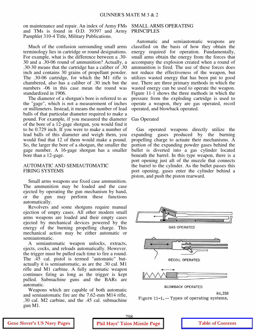
SMALL ARMS OPERATING PRINCIPLES Automatic and semiautomatic weapons are classified on the basis of how they obtain the energy required for operation. Fundamentally, small arms obtain the energy from the forces that accompany the explosion created when a round of ammunition is fired. The use of these forces does not reduce the effectiveness of the weapon, but utilizes wasted energy that has been put to good use. There are three primary methods in which the wasted energy can be used to operate the weapon. Figure 11-1 shows the three methods in which the pressure from the exploding cartridge is used to operate a weapon, they are gas operated, recoil operated, and blowback operated. Gas Operated Gas operated weapons directly utilize the expanding gases produced by the burning propelling charge to actuate their mechanisms. A portion of the expanding powder gases behind the bullet is diverted into a gas cylinder located beneath the barrel. In this type weapon, there is a port opening just aft of the muzzle that connects the barrel to the cylinder. As the bullet passes this port opening, gases enter the cylinder behind a piston, and push the piston rearward.
298
CHAPTER 11 - SMALL ARMS, LANDING PARTY EQUIPMENT AND DEMOLITION
The piston is connected by a rod to the operating mechanism of the weapon, such as the bolt. The piston carries the bolt aft with it, unlocking, extracting and ejecting the cartridge, and cocking the weapon. Examples of gas operated weapons are the .30 cal. Ml rifle, Ml carbine, and the BAR. Recoil Operated As a round is fired, high pressure is developed behind the bullet. This pressure serves a two- fold purpose, to force the bullet down the barrel and to force the breechblock (bolt) to the rear. If the barrel and bolt were secured together (as in the old time cannon), the entire force of recoil would be felt by the shooter's arm and shoulder. By designing the barrel and bolt so they slide in a frame or receiver, the rearward force of the pressure on the shooter is lessened, and the energy can be used to compress springs and move levers, etc., necessary to complete the cycle of operation. In recoil operated weapons, the bolt and barrel move rearward together for a short distance. The barrel then stops and the bolt (now unlocked) continues to the rear against spring pressure until the empty case is ejected. The force of recoil is also used to cock the weapon and compress the spring which returns the bolt to its firing position, chambering a new round in the process. The .45 Cal. pistol and Browning machineguns are examples of recoil operated weapons. Blowback Operated There are similarities between the recoil and blowback operated weapons. There are, however, several major differences. In recoil operation, the bolt and barrel move to the rear as one unit until the bullet leaves the barrel and most of the recoil is spent. The combined thrust of the recoiling barrel, bolt, and other parts is used to operate the weapon. In blowback operation, the bolt moves to the rear against spring pressure just as the bullet leaves the muzzle. The barrel does not move in recoil. The bolt is held closed by spring pressure and the mass of the breechbolt. The force of the exploding cartridge starts the bolt moving rearward. However, the weight of the bolt prevents the chamber from opening entirely until the round has left the muzzle. The recoil spring stops the bolt and returns it to closed position, chambering a new round in the process.
The weight of the breechbolt is an important factor in the design and operation of a blowback operated weapon. When used with low powered ammunition, it is a suitable arrangement. The .45 cal. submachinegun is an example of a blowback operated weapon. A military rifle, however, using the standard .30 cal. cartridge and blowback action, would require a 27-pound breechblock.
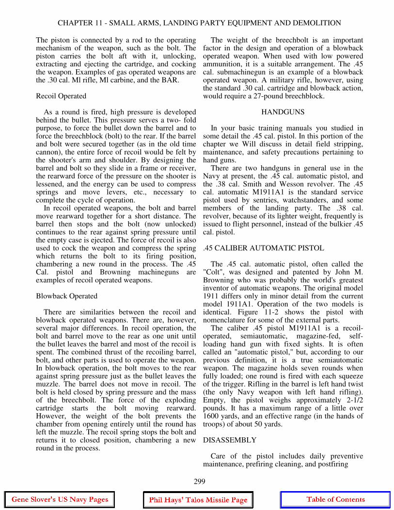
HANDGUNS In your basic training manuals you studied in some detail the .45 cal. pistol. In this portion of the chapter we Will discuss in detail field stripping, maintenance, and safety precautions pertaining to hand guns. There are two handguns in general use in the Navy at present, the .45 cal. automatic pistol, and the .38 cal. Smith and Wesson revolver. The .45 cal. automatic M1911A1 is the standard service pistol used by sentries, watchstanders, and some members of the landing party. The .38 cal. revolver, because of its lighter weight, frequently is issued to flight personnel, instead of the bulkier .45 cal. pistol. .45 CALIBER AUTOMATIC PISTOL The .45 cal. automatic pistol, often called the "Colt", was designed and patented by John M. Browning who was probably the world's greatest inventor of automatic weapons. The original model 1911 differs only in minor detail from the current model 1911A1. Operation of the two models is identical. Figure 11-2 shows the pistol with nomenclature for some of the external parts. The caliber .45 pistol M1911A1 is a recoil- operated, semiautomatic, magazine-fed, self- loading hand gun with fixed sights. It is often called an "automatic pistol," but, according to our previous definition, it is a true semiautomatic weapon. The magazine holds seven rounds when fully loaded; one round is fired with each squeeze of the trigger. Rifling in the barrel is left hand twist (the only Navy weapon with left hand rifling). Empty, the pistol weighs approximately 2-1/2 pounds. It has a maximum range of a little over 1600 yards, and an effective range (in the hands of troops) of about 50 yards. DISASSEMBLY Care of the pistol includes daily preventive maintenance, prefiring cleaning, and postfiring
299
GUNNER'S MATE M 3 & 2
300

CHAPTER 11 - SMALL ARMS, LANDING PARTY EQUIPMENT AND DEMOLITION
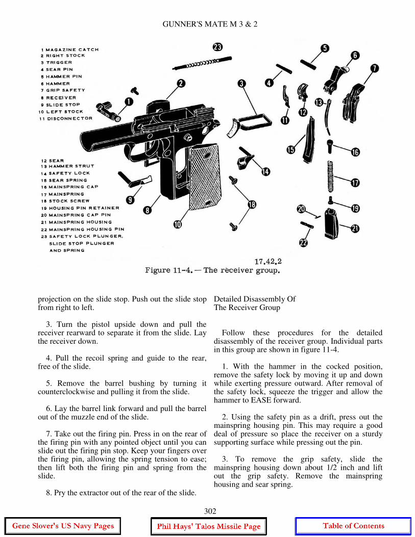
cleaning. For daily maintenance the pistol need not be disassembled but, for the prefiring and post- firing cleaning the pistol should be disassembled. There are two phases of disassembly for the pistol, general disassembly (field stripping) and detailed disassembly. General disassembly (fig. 11-3) is the disassembly necessary for normal care and cleaning and after the weapon has been fired. This is the extent of disassembly that is generally explained to personnel such as watchstanders. The detailed disassembly of the receiver group (fig. 11-4) is the job of the Gunner's Mate during periodic cleaning and repair. To do a good job of cleaning and repair, it is essential that you know the names of the parts of the weapon. The nomenclature of parts of the pistol should be learned while practicing disassembly and assembly. As each part is removed and replaced, the nomenclature is repeated until known. While studying the disassembly and assembly of the pistol, refer to illustrations showing the parts by name and description.
Become thoroughly familiar with them and their functions. Knowing the names of the parts also will help you understand the operation of the weapon. General Disassembly Prior to performing any work on the pistol, remove the magazine and pull the slide to the rear and inspect to see that the weapon is clear. Then perform the following steps: 1. Cock the hammer and put the safety lock in the up, or SAFE, position. Depress the recoil spring plug and turn the barrel bushing about a quarter turn clockwise. Allow the recoil spring to expand slowly, under control, to prevent injury or loss of parts. Turn the recoil spring plug counterclockwise and remove it from the recoil spring. Move the safety lock back down to its FIRE position. 2. Push the slide to the rear until the half- moon recess (on the slide) is directly above the
301
GUNNER'S MATE M 3 & 2
projection on the slide stop. Push out the slide stop from right to left. 3. Turn the pistol upside down and pull the receiver rearward to separate it from the slide. Lay the receiver down. 4. Pull the recoil spring and guide to the rear, free of the slide. 5. Remove the barrel bushing by turning it counterclockwise and pulling it from the slide. 6. Lay the barrel link forward and pull the barrel out of the muzzle end of the slide. 7. Take out the firing pin. Press in on the rear of the firing pin with any pointed object until you can slide out the firing pin stop. Keep your fingers over the firing pin, allowing the spring tension to ease; then lift both the firing pin and spring from the slide. 8. Pry the extractor out of the rear of the slide.
Detailed Disassembly Of The Receiver Group Follow these procedures for the detailed disassembly of the receiver group. Individual parts in this group are shown in figure 11-4. 1. With the hammer in the cocked position, remove the safety lock by moving it up and down while exerting pressure outward. After removal of the safety lock, squeeze the trigger and allow the hammer to EASE forward. 2. Using the safety pin as a drift, press out the mainspring housing pin. This may require a good deal of pressure so place the receiver on a sturdy supporting surface while pressing out the pin. 3. To remove the grip safety, slide the mainspring housing down about 1/2 inch and lift out the grip safety. Remove the mainspring housing and sear spring.
302
CHAPTER 11 - SMALL ARMS, LANDING PARTY EQUIPMENT AND DEMOLITION
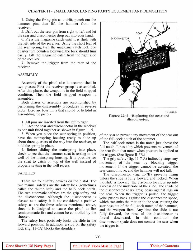
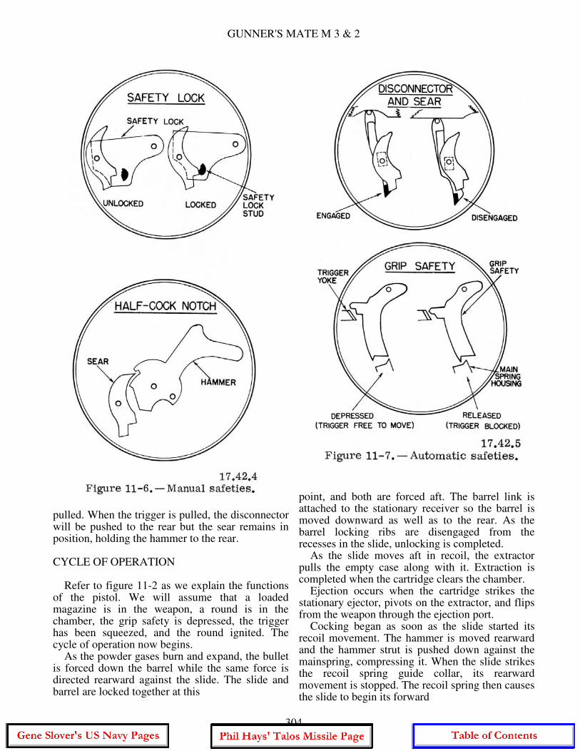
4. Using the firing pin as a drift, punch out the hammer pin; then lift the hammer from the receiver. 5. Drift out the sear pin from right to left and let the sear and disconnector drop out into your hand. 6. Press the magazine catch until it is flush with the left side of the receiver. Using the short leaf of the sear spring, turn the magazine catch lock one quarter turn counterclockwise, the lock should turn easily. Lift the magazine catch from the right side of the receiver. 7. Remove the trigger from the rear of the receiver. ASSEMBLY Assembly of the pistol also is accomplished in two phases: First the receiver group is assembled. After this phase, the weapon is in the field stripped condition. Then the field stripped weapon is assembled. Both phases of assembly are accomplished by performing the disassembly procedures in reverse order. Here are four hints that should be helpful in assembling the pistol- 1. All pins are inserted from the left to right. 2. Place the sear and disconnector in the receiver as one unit fitted together as shown in figure 11-5. 3. When you place the sear spring in position, have the mainspring housing ready to slide up about three quarters of the way into the receiver, to hold the spring in place. 4. Before sliding the mainspring into place, check to see that the hammer strut is resting in the well of the mainspring housing. It is possible for the strut to catch on top of the well instead of properly seating in the well recess. SAFETIES There are four safety devices on the pistol. The two manual safeties are the safety lock (sometimes called the thumb safe) and the half- cock notch. The two automatic safeties are the grip safety and the disconnector. Although the disconnector is classed as a safety, it is not considered a positive safety, as are the three safeties mentioned above, since it is designed to cause the pistol to fire semiautomatic fire and cannot be controlled by the shooter. The safety lock positively locks the slide in the forward position. In addition, a stud on the safety lock (fig. 11-6A) blocks the shoulders
of the sear to prevent any movement of the sear out of the full-cock notch of the hammer. The half-cock notch is the notch just above the full-notch. It has a lip which prevents movement of the sear from that notch when pressure is applied to the trigger. (See figure II-6B.) The grip safety (fig. 11-7 A) indirectly stops any movement of the sear by blocking trigger movement. If the trigger cannot be actuated, the sear cannot move, and the hammer will not fall. The disconnector (fig. II-7B) prevents firing unless the slide is fully forward and locked. When the slide is forward, the disconnector rides up into a recess on the underside of the slide. The spade of the disconnector (dark area) bears against lugs on the sear. When the trigger is pulled, the trigger yoke pushes back against the disconnector spade, which transmits the motion to the sear, rotating the sear nose out of the full-cock notch of the hammer, and the weapon fires. Any time the slide is not fully forward, the nose of the disconnector is forced downward. In this condition the disconnector spade does not contact the sear when the trigger is
303
GUNNER'S MATE M 3 & 2
pulled. When the trigger is pulled, the disconnector will be pushed to the rear but the sear remains in position, holding the hammer to the rear. CYCLE OF OPERATION Refer to figure 11-2 as we explain the functions of the pistol. We will assume that a loaded magazine is in the weapon, a round is in the chamber, the grip safety is depressed, the trigger has been squeezed, and the round ignited. The cycle of operation now begins. As the powder gases burn and expand, the bullet is forced down the barrel while the same force is directed rearward against the slide. The slide and barrel are locked together at this
point, and both are forced aft. The barrel link is attached to the stationary receiver so the barrel is moved downward as well as to the rear. As the barrel locking ribs are disengaged from the recesses in the slide, unlocking is completed. As the slide moves aft in recoil, the extractor pulls the empty case along with it. Extraction is completed when the cartridge clears the chamber. Ejection occurs when the cartridge strikes the stationary ejector, pivots on the extractor, and flips from the weapon through the ejection port. Cocking began as soon as the slide started its recoil movement. The hammer is moved rearward and the hammer strut is pushed down against the mainspring, compressing it. When the slide strikes the recoil spring guide collar, its rearward movement is stopped. The recoil spring then causes the slide to begin its forward
304
CHAPTER 11 - SMALL ARMS, LANDING PARTY EQUIPMENT AND DEMOLITION
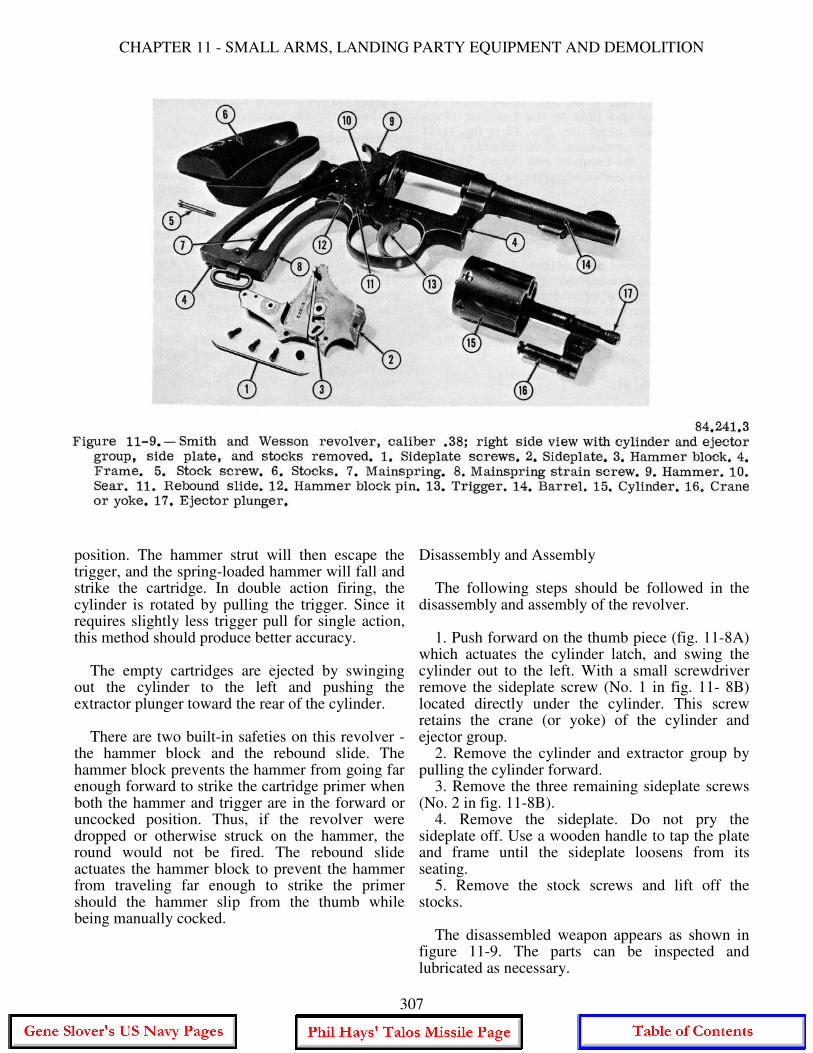
movement. The hammer follows the slide for a short distance. Then the sear, which bears against the hammer through the action of the sear spring, enters the full-cock notch of the hammer and holds it in a cocked position. Feeding starts as soon as the slide, moving to the rear, clears the top of the magazine. The magazine follower, under pressure from the magazine spring, forces the top round against the lips of the magazine. This places the top cartridge in position to be picked up by the face of the slide during its forward movement. Chambering occurs when the forward moving slide pushes a new round into the chamber. As the bullet is pushed up the ramp into the chamber, the base of the cartridge slides up the face of the slide. As this happens, the groove on the base of the cartridge is engaged by the hooked extractor. After chambering, the slide continues forward a small distance, pushing the barrel ahead of it. As the barrel moves, it pivots up and forward on the barrel link. The locking ribs on the barrel enter the locking recesses in the slide, thereby locking the two together. Firing will start the cycle all over again. When the grip safety is depressed and the trigger is squeezed, the trigger yoke presses against the disconnector, which pushes aft on the sear. The sear rotates on its pin, disengaging from the notch on the hammer. The mainspring pushes up on the hammer strut, rotating the hammer forward. The hammer strikes the firing pin, which in turn strikes the cartridge primer. .38 CALIBER SMITH AND WESSON REVOLVER The .38 cal. revolvers are found primarily in armories at shore activities. In this portion of the chapter we will discuss the .38 cal. Smith and Wesson Special (fig. 11-8). This weapon primarily is used by personnel assigned to guard duty or police work, but it is frequently issued to flight personnel. A revolver utilizing the caliber .38 special cartridge is considered a more practical close-quarters defense weapon than the bulky caliber .45 pistol. The .38 has about the same maximum and effective ranges as the .45 cal. automatic, 1600 and 50 yards, respectively. The caliber .38 S&W revolver is a single- shot breech-loading hand weapon. The cylinder of the weapon has six chambers and revolves around a central axis. Six shots can be fired
without reloading. When the cylinder is closed the weapon is ready to fire. Fired cases are extracted manually. This weapon is designed to fire the cartridge, ball, caliber .38 special. The action of cocking the hammer causes the cylinder to rotate counterclockwise and align the next chamber with the barrel. Squeezing the trigger all the way back cocks the hammer, or the hammer can be cocked with the thumb. Note that all these operations are manual. The revolver is not an automatic or semiautomatic weapon in the technical sense. One other caliber .38 revolver that is also used in the Navy (but less commonly) is the Colt. This weapon is in structure almost identical with the S&W. One structural difference is that the Colt has a shorter barrel than the S&W. The main functional difference is that the Colt's cylinder rotates clockwise when being fired; the S&W cylinder rotates counterclockwise. Both use the same ammunition. Figure 11-9 shows the parts of the revolver and the disassembly to the extent required for normal care. Operation In this discussion, operation of the revolver is limited to loading, firing, and unloading. To load the revolver, push the thumb piece (thumb latch) (fig. 11-8) forward with the right thumb. apply a little pressure to the right side of the cylinder and swing it out. (The thumb piece will not release the cylinder if the hammer is cocked.) Rotate the cylinder loading each chamber as it comes on top, keeping the weapon pointed in a safe direction. NOTE: The cylinder should not be flipped out sharply because this can cause the crane (fig. 11-9) to be bent, throwing the cylinder out of timing. To close the revolver, swing the cylinder in place and at the same time turn the cylinder to the left until the ratchet in the frame engages one of the rectangular cuts in the cylinder. This ensures positive alignment of one of the chambers with the barrel. The weapon is now loaded and ready to be fired. The revolver can be fired by single or double action. For single action firing, the hammer is pulled back with the thumb to the full-cock position for each round, this action also rotates the cylinder. The hammer is held in the cocked position by the sear until released by the trigger. In double action firing, pulling the trigger causes the hammer to be raised to nearly its full-cock
305

GUNNER'S MATE M 3 & 2
306
CHAPTER 11 - SMALL ARMS, LANDING PARTY EQUIPMENT AND DEMOLITION
position. The hammer strut will then escape the trigger, and the spring-loaded hammer will fall and strike the cartridge. In double action firing, the cylinder is rotated by pulling the trigger. Since it requires slightly less trigger pull for single action, this method should produce better accuracy. The empty cartridges are ejected by swinging out the cylinder to the left and pushing the extractor plunger toward the rear of the cylinder. There are two built-in safeties on this revolver - the hammer block and the rebound slide. The hammer block prevents the hammer from going far enough forward to strike the cartridge primer when both the hammer and trigger are in the forward or uncocked position. Thus, if the revolver were dropped or otherwise struck on the hammer, the round would not be fired. The rebound slide actuates the hammer block to prevent the hammer from traveling far enough to strike the primer should the hammer slip from the thumb while being manually cocked.
Disassembly and Assembly The following steps should be followed in the disassembly and assembly of the revolver. 1. Push forward on the thumb piece (fig. 11-8A) which actuates the cylinder latch, and swing the cylinder out to the left. With a small screwdriver remove the sideplate screw (No. 1 in fig. 11- 8B) located directly under the cylinder. This screw retains the crane (or yoke) of the cylinder and ejector group. 2. Remove the cylinder and extractor group by pulling the cylinder forward. 3. Remove the three remaining sideplate screws (No. 2 in fig. 11-8B). 4. Remove the sideplate. Do not pry the sideplate off. Use a wooden handle to tap the plate and frame until the sideplate loosens from its seating. 5. Remove the stock screws and lift off the stocks. The disassembled weapon appears as shown in figure 11-9. The parts can be inspected and lubricated as necessary.
307
GUNNER'S MATE M 3 & 2
To assemble the weapon, first remove the hammer block (No. 3 of fig. 11-9) from the sideplate. Place the hole in the hammer block over the hammer block pin (No. 12 in fig. 11-9) so that the "L" projection of the hammer block will fit between the hammer and frame. The remaining parts are installed following the reverse order of disassembly.
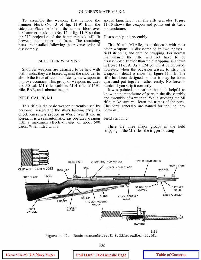
SHOULDER WEAPONS Shoulder weapons are designed to be held with both hands; they are braced against the shoulder to absorb the force of recoil and steady the weapon to improve accuracy. This group of weapons includes the .30 cal. M1 rifle, carbine, M14 rifle, M16E1 rifle, BAR, and submachinegun. RIFLE, CAL. 30, M1 This rifle is the basic weapon currently used by personnel assigned to the ship's landing party. Its effectiveness was proved in World War II and in Korea. It is a semiautomatic, gas-operated weapon with a maximum effective range of about 500 yards. When fitted with a
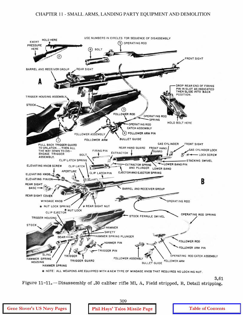
special launcher, it can fire rifle grenades. Figure 11-10 shows the weapon and points out its basic nomenclature. Disassembly and Assembly The .30 cal. Ml rifle, as is the case with most other weapons, is disassembled in two phases - field stripping and detailed stripping. For normal maintenance the rifle will not have to be disassembled further than field stripping as shown in figure 11-11A. As a GM you must be prepared, however, when the occasion arises, to strip the weapon in detail as shown in figure 11-11B. The rifle has been designed so that it may be taken apart and put together rather easily. No force is needed if you strip it correctly. It was pointed out earlier that it is helpful to know the nomenclature of parts in the disassembly and assembly of a weapon. While studying the Ml rifle, make sure you learn the names of the parts. The parts generally are named for the job they perform. Field Stripping There are three major groups in the field stripping of the Ml rifle - the trigger housing
308
CHAPTER 11 - SMALL ARMS, LANDING PARTY EQUIPMENT AND DEMOLITION
309
GUNNER'S MATE M 3 & 2
group, the barrel and receiver group, and the stock group. To disassemble the rifle into these three groups, grasp it with the left hand so that the base of the trigger housing is included in your grip. Place the rifle butt against the left thigh, with the trigger group toward you. With your right hand pull the trigger guard downward and outward. Swing the guard out as far as it will go, then lift out the trigger group. Next, grasp the rifle at the rear of the receiver with your left hand, muzzle to the left. With your right hand palm, give a downward blow to the small of the stock, grasping it as you do. This separates the stock group from the barrel and receiver group. Detailed Stripping Place the barrel and receiver group so that the sights are down, muzzle pointing to the left. With the thumb and forefinger of your left hand, grasp the follower rod and disengage it from the follower arm. Remove the follower rod and operating rod spring by withdrawing them to the right. Push out the follower arm pin from its seat and remove it. Grasp the bullet guide, follower arm, and operating catch rod catch assembly, and lift
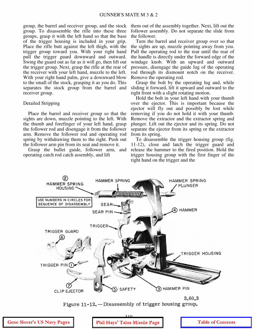
them out of the assembly together. Next, lift out the follower assembly. Do not separate the slide from the follower. Turn the barrel and receiver group over so that the sights are up, muzzle pointing away from you. Pull the operating rod to the rear until the rear of the handle is directly under the forward edge of the windage knob. With an upward and outward pressure, disengage the guide lug of the operating rod through its dismount notch on the receiver. Remove the operating rod. Grasp the bolt by the operating lug and, while sliding it forward, lift it upward and outward to the right front with a slight rotating motion. Hold the bolt in your left hand with your thumb over the ejector. This is important because the ejector will fly out and possibly be lost while removing if you do not hold it with your thumb. Remove the extractor and the extractor spring and plunger. Lift out the ejector and its spring. Do not separate the ejector from its spring or the extractor from its spring. To disassemble the trigger housing group (fig. 11-12), close and latch the trigger guard and release the hammer to the fired position. Hold the trigger housing group with the first finger of the right hand on the trigger and the
310

CHAPTER 11 - SMALL ARMS, LANDING PARTY EQUIPMENT AND DEMOLITION
thumb against the sear. Place the trigger housing against a firm surface, press on the sear with the right thumb, then push the trigger pin out from left to right. Slowly release the pressure with your thumb and finger allowing the hammer spring to expand. Lift out the trigger assembly and separate the hammer spring plunger, hammer spring, and the hammer spring housing. Do not remove the sear pin or sear. Push out the hammer pin from left to right and remove the hammer. Unlatch the trigger guard and lay the trigger housing on its right side. Push out the stud of the safety. Remove the safety by lifting it from its slot in the base of the trigger housing. Holding the rear of the trigger housing in your left hand and the trigger guard with your right hand, swing the trigger guard to the open position. Slide the trigger guard to the rear until the wings of the trigger guard are aligned with the safety stud hole. Rotate the trigger guard to the right and upward with your right hand until the hammer stop inside of the right wing clears the base of the trigger housing. Remove the trigger guard. Assembly The rifle and its component groups are assembled in the reverse order of their disassembly. First, assemble the trigger housing group, then the barrel and receiver group. The rifle is now in the field stripped condition of three main groups as shown in figure 11-11A. The stock group and the barrel and receiver group are fitted together, then the trigger housing group is inserted. The assembly is completed by closing and latching the trigger guard. To test the assembly of the rifle, pull the operating rod to its rearmost position. The bolt should stay open. Close the bolt and snap the safety to its locked position, and squeeze the trigger. The hammer should not fall. Push the safety forward and squeeze the trigger. The hammer should fall. Operation By studying the disassembly and assembly of the rifle, you now know the parts. It is important that you understand how the parts function. There are eight steps in a cycle of operation of the Ml rifle. You will better understand the operation of the Ml if we first look at the functioning of several individual parts. First, the trigger group will be discussed, then the actions that take place
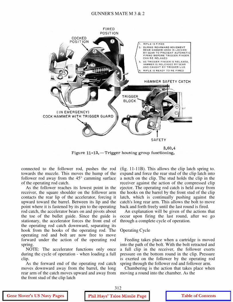
upon loading a clip are shown. A complete cycle of operation will be explained, then we will see what happens when the last round of a clip is fired. Trigger Housing Group Refer to figure 11-13 as we explain how this group functions. Take the trigger housing out of the rifle (close and latch the trigger guard and cock the hammer). You can see that the hammer is held in a cocked position by the trigger lugs engaging the hammer hooks. Hold the hammer with your left thumb and slowly squeeze the trigger. You will see the trigger lugs move forward, releasing the hammer hooks. The hammer will rotate forward under pressure of the hammer spring. Now, release the pressure on the trigger and again cock the hammer, you will see the trigger lugs engaging the hammer hooks to hold it cocked. However, there must be a way of preventing the hammer from going forward even if you keep pressure on the trigger after each shot. This is done by the sear, which catches on the rear hammer hooks. Now squeeze the trigger and hold it to the rear. Cock the hammer slowly and see how the sear catches on the rear hammer hooks and holds the hammer back. Slowly release the trigger and you will notice that the sear will release the hammer hooks. Now the hammer hooks catch on the trigger lugs and hold the hammer in the cocked position. This combination holds the hammer to the rear each time a round is fired. Action on Loading a Full Clip Before a clip can be loaded into the rifle, the operating rod and the bolt must be all the way to the rear. The follower is all the way up in the receiver, due to the pressure being exerted by the operating rod spring through the follower and follower arm, against the follower. The hump of the follower rod has contacted the 45° camming surface of the operating rod catch, pushing it toward the barrel and causing its undercut hook to engage with the hooks on the operating rod. This keeps the bolt and operating rod to the rear against pressure of the compressed operating rod spring. You can find the parts mentioned in figures 11-11, 11-14, and 11-15. As a full clip is placed on the follower and pressed down, the follower arm moves down rotating around its pin. The follower arm being
311
GUNNER'S MATE M 3 & 2
connected to the follower rod, pushes the rod towards the muzzle. This moves the hump of the follower rod away from the 45° camming surface of the operating rod catch. As the follower reaches its lowest point in the receiver, the square shoulder on the follower arm contacts the rear lip of the accelerator, forcing it upward toward the barrel. Between its lip and the point where it is fastened by its pin to the operating rod catch, the accelerator bears on and pivots about the toe of the bullet guide. Since the guide is stationary, the accelerator forces the front end of the operating rod catch downward, separating its hook from the hooks of the operating rod. The operating rod and bolt are now free to move forward under the action of the operating rod spring. NOTE: The accelerator functions only once during the cycle of operation - when loading a full clip. As the forward end of the operating rod catch moves downward away from the barrel, the long rear arm of the catch moves upward and away from the front stud of the clip latch
(fig. 11-11B). This allows the clip latch spring to. expand and force the rear stud of the clip latch into a notch on the clip. The stud holds the clip in the receiver against the action of the compressed clip ejector. The operating rod catch is held away from the hooks on the barrel by the front stud of the clip latch, which is continually pushing against the catch's long rear arm. This allows the bolt to move back and forth freely until the last round is fired. An explanation will be given of the actions that occur upon firing the last round, after we go through a complete cycle of operation. Operating Cycle Feeding takes place when a cartridge is moved into the path of the bolt. With the bolt retracted and a full clip in the receiver, the follower exerts pressure on the bottom round in the clip. Pressure is exerted on the follower by the operating rod spring through the follower rod and follower arm. Chambering is the action that takes place when moving a round into the chamber. As the
312

CHAPTER 11 - SMALL ARMS, LANDING PARTY EQUIPMENT AND DEMOLITION
313
GUNNER'S MATE M 3 & 2
bolt moves forward, it rotates and engages the top cartridge in the clip, ramming it into the chamber. When the bolt reaches its forward position, the rim of the cartridge is gripped by the extractor, and the base of the cartridge forces the ejector into the bolt, thus compressing the ejector spring. Locking of the bolt is accomplished when the bolt is all the way forward. The rear camming surface in the hump of the operating rod forces the operating lug of the bolt downward, causing the bolt to rotate clockwise. The bolt is locked by the locking lugs on both sides of the bolt, engaging in the locking recesses in the receiver. Slightly before the bolt reaches its foremost position, the tang of the firing pin contacts the bridge of the receiver, stopping the forward movement of the firing pin. When the bolt is turned and fully locked, the tang of the firing pin is lined up with the slot in the bridge of the receiver and may be driven home by the hammer. This is a safety feature to prevent a round from being fired before the bolt is fully locked. As the round is fired and the bullet nears the muzzle, a portion of the gases produced by the burning powder expand through a gas port into the gas cylinder, striking the piston head and driving the operating rod to the rear. The camming surfaces of the operating rod force the operating lug on the bolt upward, disengaging the bolt from the receiver. As the bolt rotates counterclockwise, the firing pin tang contacts the bridge of the receiver, camming the firing pin to the rear into the face of the bolt. You recall that the extractor gripped the rim of the cartridge as the bolt moved forward, it remains in this grip while it is in the chamber. As the bolt moves to the rear, the empty case is withdrawn from the chamber by the extractor. When the empty case clears the chamber, the ejector (which has been continually pushing against the base of the case) ejects the empty case from the receiver by the action of the expanding ejector spring. Cocking occurs as the bolt continues to the rear, riding over the hammer, forcing it rearward and down. The hammer is caught by the sear, if the trigger is still being pulled, or by the trigger hooks if the trigger has been released.
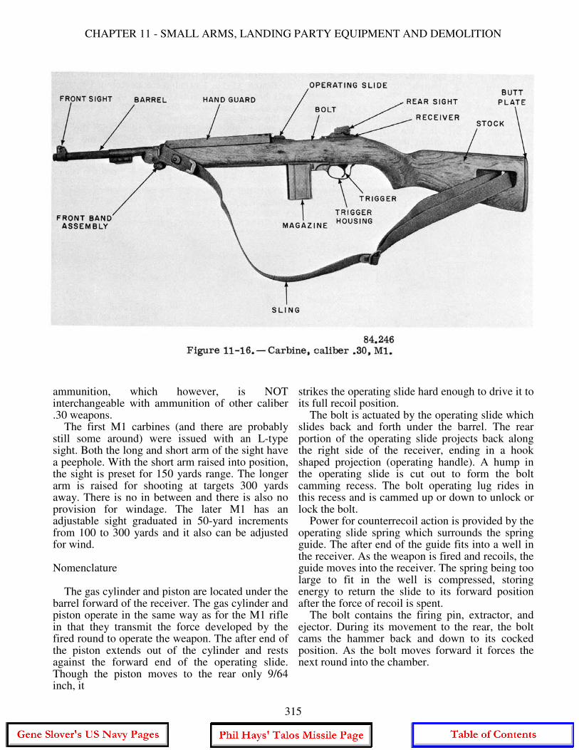
Action Following Last Round As the last round is fed into the path of the bolt, the hump of the follower rod moves closer to the 45° camming surface between, the front arms of the operating rod catch. While the last round is in the chamber, the follower is against the bottom of the bolt. When the last round is fired, the bolt comes to the rear and the follower is moved all the way up in the receiver. At the same time the hump of the follower rod contacts the 45° camming surface of the operating rod catch and pushes the catch up toward the barrel. As the catch is cammed toward the barrel, its hook is engaged by the hooks of the operating rod. This action holds the operating rod to the rear and the bolt open. When the front of the operating rod catch is cammed toward the barrel, the catch pivots on the follower arm pin and the long rear arm moves downward against the front stud of the clip latch. The clip latch rotates, withdrawing the rear stud from the notch in the clip. The empty clip is then ejected by the expanding clip ejector. CARBINE. CALIBER .30 M1 The carbine cal. .30 M1 was developed during World War II and was used extensively by the Army and Marine Corps, and various units of the Navy. The carbine does not have the stopping power of a .45 cal. weapon but its 300 yard range makes it a much more useful weapon than the pistol in the hands of a man who has received normal marksmanship training. Other models of the carbine include the M1A1, M2, and M3. The M1A1 is identical to the M1 except for a separate grip and a metal skeleton folding stock extension hinged to the grip and rear end of the stock. The M2 is the M1 with parts modifications and changes. These changes allow the M2 to be fired in automatic or semiautomatic fire by adjusting a selector. The M3 is identical to the M2 except that the top of the receiver is designed to accommodate special sighting equipment (sniperscope). In this chapter we will discuss the carbine Ml because this is the model you are most likely to see on board ship. The Ml carbine (fig. 11-16) is a gas-operated, self-loading, air-cooled shoulder weapon delivering semiautomatic fire, and is fed by a 15-round box type magazine. The carbine uses caliber .30
314
CHAPTER 11 - SMALL ARMS, LANDING PARTY EQUIPMENT AND DEMOLITION
ammunition, which however, is NOT interchangeable with ammunition of other caliber .30 weapons. The first M1 carbines (and there are probably still some around) were issued with an L-type sight. Both the long and short arm of the sight have a peephole. With the short arm raised into position, the sight is preset for 150 yards range. The longer arm is raised for shooting at targets 300 yards away. There is no in between and there is also no provision for windage. The later M1 has an adjustable sight graduated in 50-yard increments from 100 to 300 yards and it also can be adjusted for wind. Nomenclature The gas cylinder and piston are located under the barrel forward of the receiver. The gas cylinder and piston operate in the same way as for the M1 rifle in that they transmit the force developed by the fired round to operate the weapon. The after end of the piston extends out of the cylinder and rests against the forward end of the operating slide. Though the piston moves to the rear only 9/64 inch, it
strikes the operating slide hard enough to drive it to its full recoil position. The bolt is actuated by the operating slide which slides back and forth under the barrel. The rear portion of the operating slide projects back along the right side of the receiver, ending in a hook shaped projection (operating handle). A hump in the operating slide is cut out to form the bolt camming recess. The bolt operating lug rides in this recess and is cammed up or down to unlock or lock the bolt. Power for counterrecoil action is provided by the operating slide spring which surrounds the spring guide. The after end of the guide fits into a well in the receiver. As the weapon is fired and recoils, the guide moves into the receiver. The spring being too large to fit in the well is compressed, storing energy to return the slide to its forward position after the force of recoil is spent. The bolt contains the firing pin, extractor, and ejector. During its movement to the rear, the bolt cams the hammer back and down to its cocked position. As the bolt moves forward it forces the next round into the chamber.
315
GUNNER'S MATE M 3 & 2
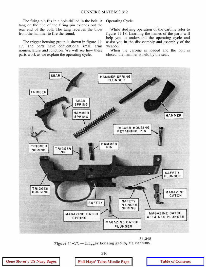
The firing pin fits in a hole drilled in the bolt. A tang on the end of the firing pin extends out the rear end of the bolt. The tang receives the blow from the hammer to fire the round. The trigger housing group is shown in figure 11-17. The parts have conventional small arms nomenclature and function. We will see how these parts work as we explain the operating cycle.
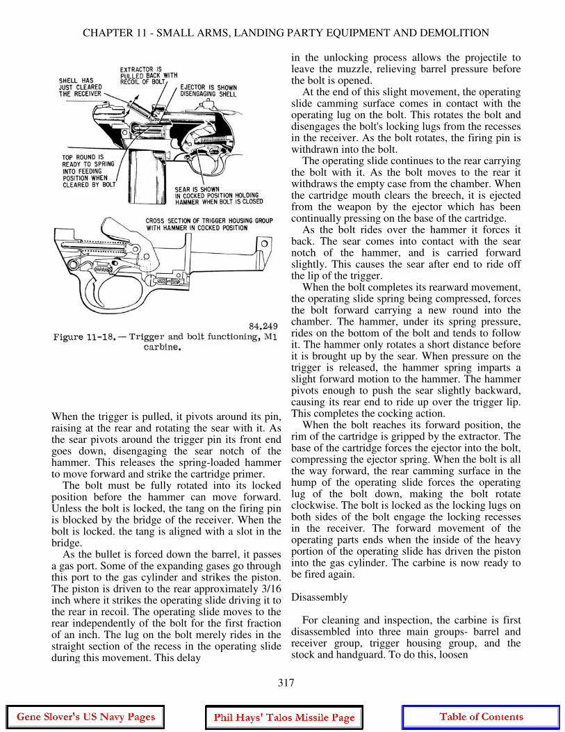
Operating Cycle While studying operation of the carbine refer to figure 11-18. Learning the names of the parts will help you to understand the operating cycle and assist you in the disassembly and assembly of the weapon. When the carbine is loaded and the bolt is closed, the hammer is held by the sear.
316
CHAPTER 11 - SMALL ARMS, LANDING PARTY EQUIPMENT AND DEMOLITION
When the trigger is pulled, it pivots around its pin, raising at the rear and rotating the sear with it. As the sear pivots around the trigger pin its front end goes down, disengaging the sear notch of the hammer. This releases the spring-loaded hammer to move forward and strike the cartridge primer. The bolt must be fully rotated into its locked position before the hammer can move forward. Unless the bolt is locked, the tang on the firing pin is blocked by the bridge of the receiver. When the bolt is locked. the tang is aligned with a slot in the bridge. As the bullet is forced down the barrel, it passes a gas port. Some of the expanding gases go through this port to the gas cylinder and strikes the piston. The piston is driven to the rear approximately 3/16 inch where it strikes the operating slide driving it to the rear in recoil. The operating slide moves to the rear independently of the bolt for the first fraction of an inch. The lug on the bolt merely rides in the straight section of the recess in the operating slide during this movement. This delay
in the unlocking process allows the projectile to leave the muzzle, relieving barrel pressure before the bolt is opened. At the end of this slight movement, the operating slide camming surface comes in contact with the operating lug on the bolt. This rotates the bolt and disengages the bolt's locking lugs from the recesses in the receiver. As the bolt rotates, the firing pin is withdrawn into the bolt. The operating slide continues to the rear carrying the bolt with it. As the bolt moves to the rear it withdraws the empty case from the chamber. When the cartridge mouth clears the breech, it is ejected from the weapon by the ejector which has been continually pressing on the base of the cartridge. As the bolt rides over the hammer it forces it back. The sear comes into contact with the sear notch of the hammer, and is carried forward slightly. This causes the sear after end to ride off the lip of the trigger. When the bolt completes its rearward movement, the operating slide spring being compressed, forces the bolt forward carrying a new round into the chamber. The hammer, under its spring pressure, rides on the bottom of the bolt and tends to follow it. The hammer only rotates a short distance before it is brought up by the sear. When pressure on the trigger is released, the hammer spring imparts a slight forward motion to the hammer. The hammer pivots enough to push the sear slightly backward, causing its rear end to ride up over the trigger lip. This completes the cocking action. When the bolt reaches its forward position, the rim of the cartridge is gripped by the extractor. The base of the cartridge forces the ejector into the bolt, compressing the ejector spring. When the bolt is all the way forward, the rear camming surface in the hump of the operating slide forces the operating lug of the bolt down, making the bolt rotate clockwise. The bolt is locked as the locking lugs on both sides of the bolt engage the locking recesses in the receiver. The forward movement of the operating parts ends when the inside of the heavy portion of the operating slide has driven the piston into the gas cylinder. The carbine is now ready to be fired again. Disassembly For cleaning and inspection, the carbine is first disassembled into three main groups- barrel and receiver group, trigger housing group, and the stock and handguard. To do this, loosen
317
GUNNER'S MATE M 3 & 2
the front band screw and slide the band (fig. 11-16) off the stock. Remove the handguard. The barrel and receiver group and the trigger housing group can be lifted out of the stock as one unit. Next, remove the slide spring and guide by disengaging the guide from its seat on the slide and withdrawing it to the left. out of its well in the receiver. The trigger housing group is then separated from the barrel and receiver group. To do this, cock the hammer by pulling the operating slide to the rear and pushing it forward again. Take out the trigger housing pin and remove the trigger housing group by sliding it toward the muzzle. Next, take out the operating slide and bolt. This is the extent of the disassembly for normal cleaning and inspection. For more detailed instructions refer to the Army Field Manuals for the .30 carbines. FM 23-7; TM-9- 1276 and TM-9-1005-210 (Series). Assembly The carbine is assembled in reverse order of its disassembly, following the additional procedures below. Hold the bolt by its operating lug so that the tail of the firing pin is opposite its notch in the receiver. Then lower the bolt into position. Now hold the forward end of the slide in the right hand, palm up. Slide the bolt forward until its forward end is about 1-1/2 inch from the chamber; hold it in this position with the left thumb. Engage the operating lug of the bolt in the operating cam groove of the slide. Raise the forward end of the slide so that the dismounting lug on its left side is opposite the notch in the left groove on the under side of the barrel. Then, by slightly twisting the slide to the right, engage the operating lugs of the slide in the operating grooves of the barrel. Move the slide and bolt to the rear until the operating slide lug is seated in its groove in the receiver; then close the bolt. Place the barrel and receiver on their left side, muzzle to the left. Replace the trigger group assembly by engaging its grooves with the corresponding grooves in the receiver, and then replace the retaining pin. Insert the small end of the guide rod in the loosely coiled end of the operating slide spring. Insert the loosely coiled end of the spring into its well in the receiver. By pressing on the
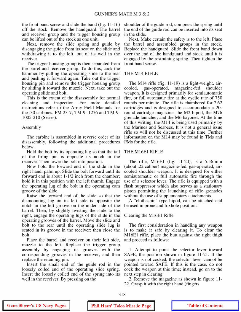
shoulder of the guide rod, compress the spring until the end of the guide rod can be inserted into its seat in the slide. Next, Make certain the safety is to the left. Place the barrel and assembled groups in the stock. Replace the handguard. Slide the front band down over the end of the handguard and stock until it is engaged by the restraining spring. Then tighten the front band screw. THE M14 RIFLE The M14 rifle (fig. 11-19) is a light-weight, air-cooled, gas-operated, magazine-fed shoulder weapon. It is designed primarily for semiautomatic fire, or full automatic fire at the cyclic rate of 750 rounds per minute. The rifle is chambered for 7.62 cartridges and is designed to accommodate a 20-round cartridge magazine, the M2 bipod, the M76 grenade launcher, and the M6 bayonet. At the time of this writing, the M14 is being used primarily by the Marines and Seabees. It is not a general issue rifle so will not be discussed at this time. Further information on the M14 may be found in TMs and FMs for the rifle. THE M16E1 RIFLE The rifle, M16E1 (fig. 11-20), is a 5.56-mm (about .22 caliber) magazine-fed, gas-operated, air-cooled shoulder weapon. It is designed for either semiautomatic or full automatic fire through the use of a selector lever. The rifle is equipped with a flash suppressor which also serves as a stationary piston permitting the launching of rifle grenades without the use of supplementary attachments. A "clothespin" type bipod, can be attached and be used in prone and foxhole positions. Clearing the M16E1 Rifle The first consideration in handling any weapon is to make it safe by clearing it. To clear the M16E1 rifle, place the butt against the right thigh and proceed as follows: 1. Attempt to point the selector lever toward SAFE, the position shown in figure 11-21. If the weapon is not cocked, the selector lever cannot be pointed toward SAFE. If this is the case, do not cock the weapon at this time; instead, go on to the next step in clearing. 2. Remove the magazine as shown in figure 11-22. Grasp it with the right hand (fingers
318

CHAPTER 11 - SMALL ARMS, LANDING PARTY EQUIPMENT AND DEMOLITION
319
GUNNER'S MATE M 3 & 2
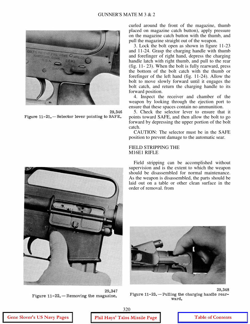
curled around the front of the magazine, thumb placed on magazine catch button), apply pressure on the magazine catch button with the thumb, and pull the magazine straight out of the weapon. 3. Lock the bolt open as shown in figure 11-23 and 11-24. Grasp the charging handle with thumb and forefinger of right hand, depress the charging handle latch with right thumb, and pull to the rear (fig. 11- 23). When the bolt is fully rearward, press the bottom of the bolt catch with the thumb or forefinger of the left hand (fig. 11-24). Allow the bolt to move slowly forward until it engages the bolt catch, and return the charging handle to its forward position. 4. Inspect the receiver and chamber of the weapon by looking through the ejection port to ensure that these spaces contain no ammunition. 5. Check the selector lever to ensure that it points toward SAFE, and then allow the bolt to go forward by depressing the upper portion of the bolt catch. CAUTION: The selector must be in the SAFE position to prevent damage to the automatic sear. FIELD STRIPPING THE M16E1 RIFLE Field stripping can be accomplished without supervision and is the extent to which the weapon should be disassembled for normal maintenance. As the weapon is disassembled, the parts should be laid out on a table or other clean surface in the order of removal. from
320

CHAPTER 11 - SMALL ARMS, LANDING PARTY EQUIPMENT AND DEMOLITION
left to right. This makes assembly easier because the parts are assembled in the reverse order of assembly. Nomenclature should be learned as the weapon is disassembled and assembled to enable you to better understand the operation of the weapon. The steps in field stripping are as follows: 1. Remove the sling and place the rifle on a table or flat surface, muzzle to the left. 2. Keeping the muzzle to the left, turn the weapon on its right side. Use the nose of a cartridge to press the takedown pin (fig. 11-25) until the upper receiver swings free of the lower receiver (fig. 11-26). CAUTION: The takedown pin does not come out of the receiver.
321
GUNNER'S MATE M 3 & 2
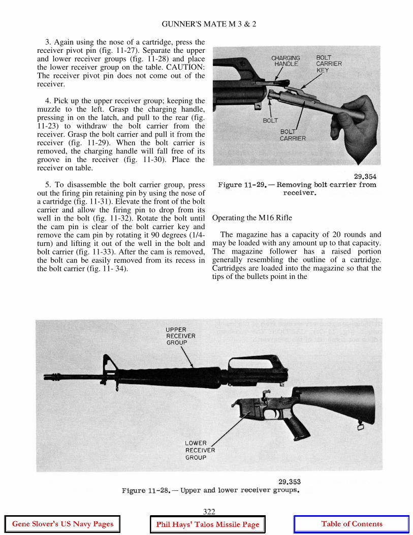
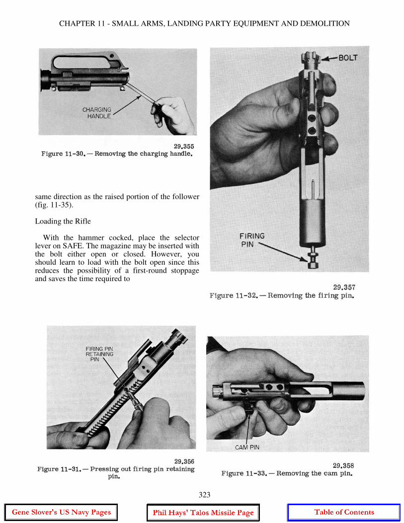
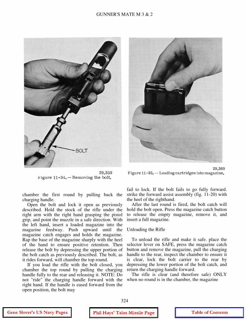
3. Again using the nose of a cartridge, press the receiver pivot pin (fig. 11-27). Separate the upper and lower receiver groups (fig. 11-28) and place the lower receiver group on the table. CAUTION: The receiver pivot pin does not come out of the receiver. 4. Pick up the upper receiver group; keeping the muzzle to the left. Grasp the charging handle, pressing in on the latch, and pull to the rear (fig. 11-23) to withdraw the bolt carrier from the receiver. Grasp the bolt carrier and pull it from the receiver (fig. 11-29). When the bolt carrier is removed, the charging handle will fall free of its groove in the receiver (fig. 11-30). Place the receiver on table. 5. To disassemble the bolt carrier group, press out the firing pin retaining pin by using the nose of a cartridge (fig. 11-31). Elevate the front of the bolt carrier and allow the firing pin to drop from its well in the bolt (fig. 11-32). Rotate the bolt until the cam pin is clear of the bolt carrier key and remove the cam pin by rotating it 90 degrees (1/4-turn) and lifting it out of the well in the bolt and bolt carrier (fig. 11-33). After the cam is removed, the bolt can be easily removed from its recess in the bolt carrier (fig. 11- 34).
Operating the M16 Rifle The magazine has a capacity of 20 rounds and may be loaded with any amount up to that capacity. The magazine follower has a raised portion generally resembling the outline of a cartridge. Cartridges are loaded into the magazine so that the tips of the bullets point in the
322
CHAPTER 11 - SMALL ARMS, LANDING PARTY EQUIPMENT AND DEMOLITION
same direction as the raised portion of the follower (fig. 11-35). Loading the Rifle With the hammer cocked, place the selector lever on SAFE. The magazine may be inserted with the bolt either open or closed. However, you should learn to load with the bolt open since this reduces the possibility of a first-round stoppage and saves the time required to
323
GUNNER'S MATE M 3 & 2
chamber the first round by pulling back the charging handle. Open the bolt and lock it open as previously described. Hold the stock of the rifle under the right arm with the right hand grasping the pistol grip, and point the muzzle in a safe direction. With the left hand, insert a loaded magazine into the magazine feedway. Push upward until the magazine catch engages and holds the magazine. Rap the base of the magazine sharply with the heel of the hand to ensure positive retention. Then release the bolt by depressing the upper portion of the bolt catch as previously described. The bolt, as it rides forward, will chamber the top round. If you load the rifle with the bolt closed, you chamber the top round by pulling the charging handle fully to the rear and releasing it. NOTE: Do not "ride" the charging handle forward with the right hand. If the handle is eased forward from the open position, the bolt may
fail to lock. If the bolt fails to go fully forward. strike the forward assist assembly (fig. 11-20) with the heel of the righthand. After the last round is fired, the bolt catch will hold the bolt open. Press the magazine catch button to release the empty magazine, remove it, and insert a full magazine. Unloading the Rifle To unload the rifle and make it safe. place the selector lever on SAFE, press the magazine catch button and remove the magazine, pull the charging handle to the rear, inspect the chamber to ensure it is clear, lock the bolt carrier to the rear by depressing the lower portion of the bolt catch, and return the charging handle forward. The rifle is clear (and therefore safe) ONLY when no round is in the chamber, the magazine
324
CHAPTER 11 - SMALL ARMS, LANDING PARTY EQUIPMENT AND DEMOLITION
is out, the bolt carrier is to the rear, and the selector lever is on the SAFE setting.
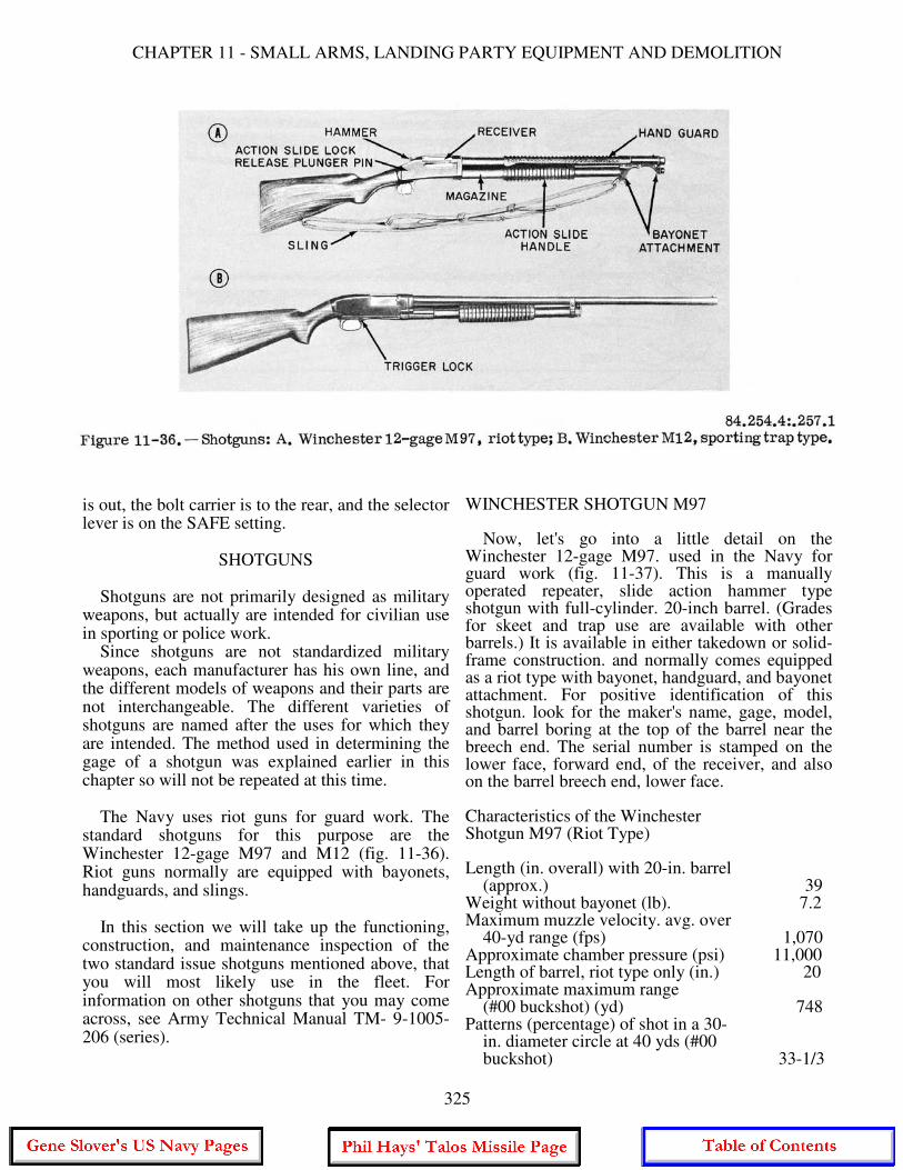
SHOTGUNS Shotguns are not primarily designed as military weapons, but actually are intended for civilian use in sporting or police work. Since shotguns are not standardized military weapons, each manufacturer has his own line, and the different models of weapons and their parts are not interchangeable. The different varieties of shotguns are named after the uses for which they are intended. The method used in determining the gage of a shotgun was explained earlier in this chapter so will not be repeated at this time. The Navy uses riot guns for guard work. The standard shotguns for this purpose are the Winchester 12-gage M97 and M12 (fig. 11-36). Riot guns normally are equipped with bayonets, handguards, and slings. In this section we will take up the functioning, construction, and maintenance inspection of the two standard issue shotguns mentioned above, that you will most likely use in the fleet. For information on other shotguns that you may come across, see Army Technical Manual TM- 9-1005-206 (series).
WINCHESTER SHOTGUN M97 Now, let's go into a little detail on the Winchester 12-gage M97. used in the Navy for guard work (fig. 11-37). This is a manually operated repeater, slide action hammer type shotgun with full-cylinder. 20-inch barrel. (Grades for skeet and trap use are available with other barrels.) It is available in either takedown or solid-frame construction. and normally comes equipped as a riot type with bayonet, handguard, and bayonet attachment. For positive identification of this shotgun. look for the maker's name, gage, model, and barrel boring at the top of the barrel near the breech end. The serial number is stamped on the lower face, forward end, of the receiver, and also on the barrel breech end, lower face. Characteristics of the Winchester Shotgun M97 (Riot Type) Length (in. overall) with 20-in. barrel (approx.) 39 Weight without bayonet (lb). 7.2 Maximum muzzle velocity. avg. over 40-yd range (fps) 1,070 Approximate chamber pressure (psi) 11,000 Length of barrel, riot type only (in.) 20 Approximate maximum range (#00 buckshot) (yd) 748 Patterns (percentage) of shot in a 30- in. diameter circle at 40 yds (#00 buckshot) 33-1/3
325
GUNNER'S MATE M 3 & 2
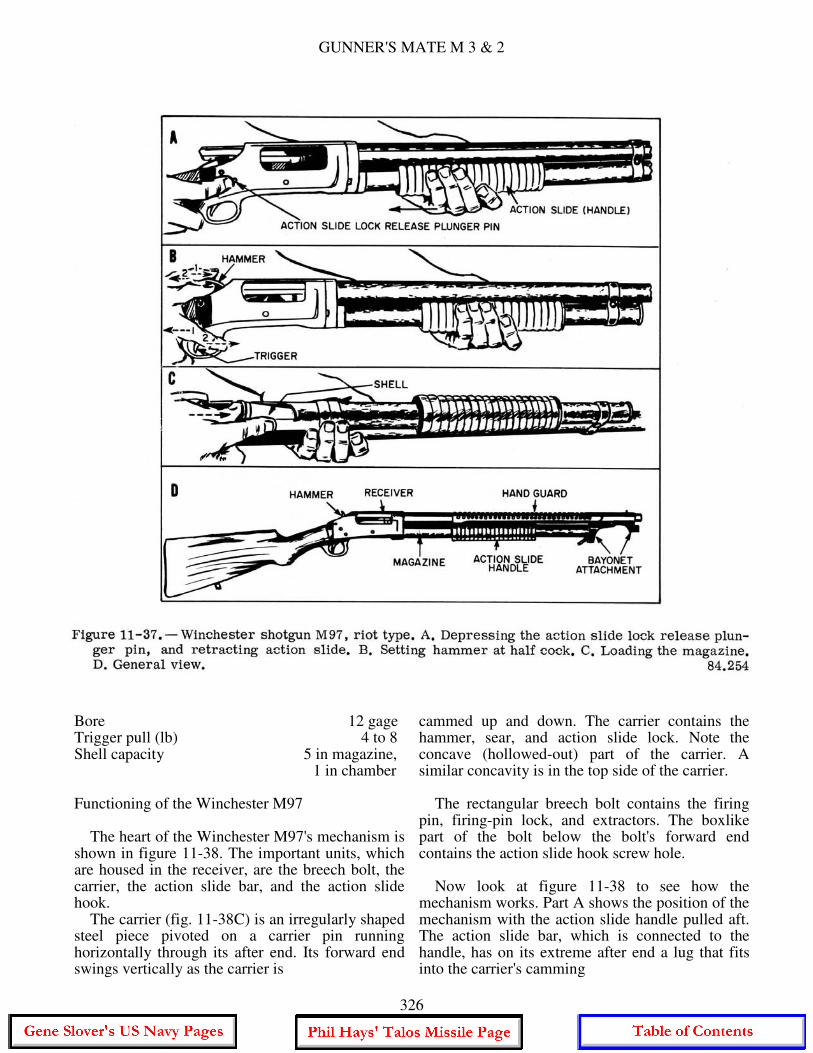
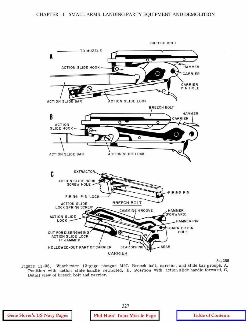
Bore 12 gage Trigger pull (lb) 4 to 8 Shell capacity 5 in magazine, 1 in chamber Functioning of the Winchester M97 The heart of the Winchester M97's mechanism is shown in figure 11-38. The important units, which are housed in the receiver, are the breech bolt, the carrier, the action slide bar, and the action slide hook. The carrier (fig. 11-38C) is an irregularly shaped steel piece pivoted on a carrier pin running horizontally through its after end. Its forward end swings vertically as the carrier is
cammed up and down. The carrier contains the hammer, sear, and action slide lock. Note the concave (hollowed-out) part of the carrier. A similar concavity is in the top side of the carrier. The rectangular breech bolt contains the firing pin, firing-pin lock, and extractors. The boxlike part of the bolt below the bolt's forward end contains the action slide hook screw hole. Now look at figure 11-38 to see how the mechanism works. Part A shows the position of the mechanism with the action slide handle pulled aft. The action slide bar, which is connected to the handle, has on its extreme after end a lug that fits into the carrier's camming
326
CHAPTER 11 - SMALL ARMS, LANDING PARTY EQUIPMENT AND DEMOLITION
327

GUNNER'S MATE M 3 & 2
groove, camming the carrier downward. Movement of the action slide handle also actuates a linkage (not shown) to draw a shell from the magazine and deposit it on the upper concave surface of the carrier. In this position, the action slide bar's after end engages the action slide hook, which is pinned to the breech bolt, thus pulling the bolt to rearward position, opening the breech, and camming the hammer back to cocked position. Figure 11-38B shows the mechanism with the action slide handle pushed forward. As the action slide bar cams the carrier upward, it pulls the action slide hook and bolt forward, so that they strip the shell from the upper surface of the carrier and drive it into the chamber. The hammer is left in the cocked position, engaged by the sear. The action slide lock on the carrier slips upward and locks the action slide bar so that the bar and action slide handle cannot be moved back. The shotgun is now ready to fire. When the hammer falls in firing, the action slide lock is automatically disengaged so that the slide handle can be pumped for ejecting, reloading, and recocking. There is no trigger safety on this shotgun. To set the gun at SAFE, you move the hammer to HALF COCK, which also locks the trigger and the action slide handle. Half cock is the hammer position midway between full-cock and hammer-released positions. Loading and Firing The Winchester M97 To load the gun chamber from the magazine, first disengage the action slide lock so that the action slide handle can be operated. If the gun has just been fired, do this by moving the action slide handle slightly forward to unlock it. (When the gun is fired as a repeater, and the gunner holds the handle, gun recoil automatically acts to unlock it.) If the hammer is at full cock, press the action slide lock release plunger pin (fig. 11-37A) and push the handle forward to unlock. If the hammer is at half cock, pull back to full cock, and proceed as above to unlock. With the action slide handle unlocked, move it smartly back, then forward. The shotgun now can be fired. When the hammer falls in firing, the action slide lock disengages automatically. But if the chamber is to be opened or the gun unloaded without firing, the hammer must be set at SAFE and the slide-lock release plunger (which disengages the slide lock) depressed. Then the
action slide handle can be pulled back to eject the shell in the chamber (fig. 11-37 A). The procedure for setting the hammer at half cock (fig. 11-37B) is as follows: 1. Set the hammer at full-cock, either by pulling it back with your thumb or by operating the action slide handle. 2. Hold the hammer firmly with the thumb, press the trigger, and ease the hammer down slightly beyond half-cock position. Release pressure on the trigger as soon as the hammer is released from full cock. 3. Pull the hammer back until it clicks into position at half-cock. The only safe way to carry the shotgun with chamber loaded is at half-cock. NEVER let the hammer down when there is a live shell in the chamber, except in the act of firing. To set the hammer at full-cock again, simply pull it back with the thumb. The shotgun is then ready to fire. To empty the chamber without firing, after the hammer has been set at half cock, pull the hammer back to full-cock, press the action slide lock release plunger pin, and retract the action slide handle. To load the magazine (fig. 11-37C), press the shell, nose first, into the after end of the magazine against the magazine follower, until the spring loaded retainers or SHELL STOPS snap out behind it to hold it. Load another in the same way, and continue loading until all five are in. To transfer a shell from magazine to chamber, work the slide handle back and forth once. To unload the magazine, press in the two shell-stop plungers on the magazine, and let the shells slide out. Retract the action slide handle to eject a chambered shell. Inspect receiver and chamber to be sure the gun is completely empty. Loading and unloading the magazine should be done only with the hammer at half-cock. To load the chamber only, with magazine empty. retract the action slide handle; place the shell directly in the chamber through the ejection opening in the receiver; close and lock the bolt by pushing the slide handle forward again; and set the hammer at half-cock. SAFETY PRECAUTIONS WHEN LOADING. UNLOADING. AND FIRING. - In addition to the general safety precautions applicable to small arms, note the following specific precautions for this weapon.
328
CHAPTER 11 - SMALL ARMS, LANDING PARTY EQUIPMENT AND DEMOLITION
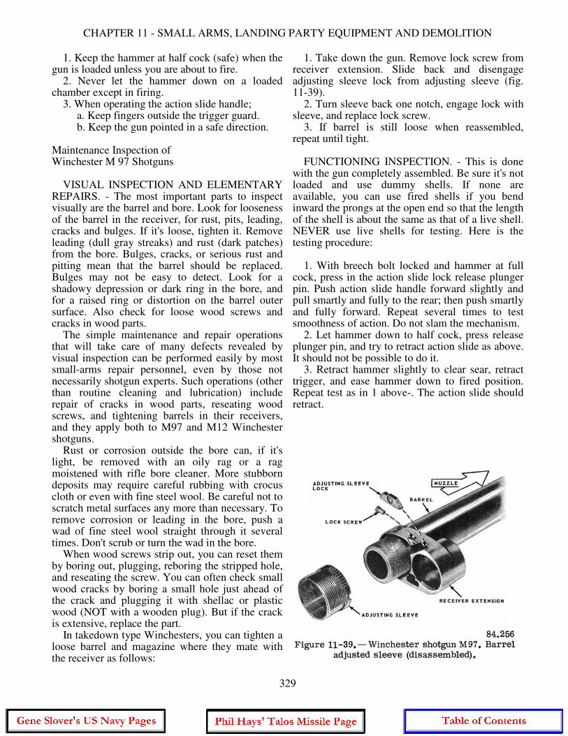
1. Keep the hammer at half cock (safe) when the gun is loaded unless you are about to fire. 2. Never let the hammer down on a loaded chamber except in firing. 3. When operating the action slide handle; a. Keep fingers outside the trigger guard. b. Keep the gun pointed in a safe direction. Maintenance Inspection of Winchester M 97 Shotguns VISUAL INSPECTION AND ELEMENTARY REPAIRS. - The most important parts to inspect visually are the barrel and bore. Look for looseness of the barrel in the receiver, for rust, pits, leading, cracks and bulges. If it's loose, tighten it. Remove leading (dull gray streaks) and rust (dark patches) from the bore. Bulges, cracks, or serious rust and pitting mean that the barrel should be replaced. Bulges may not be easy to detect. Look for a shadowy depression or dark ring in the bore, and for a raised ring or distortion on the barrel outer surface. Also check for loose wood screws and cracks in wood parts. The simple maintenance and repair operations that will take care of many defects revealed by visual inspection can be performed easily by most small-arms repair personnel, even by those not necessarily shotgun experts. Such operations (other than routine cleaning and lubrication) include repair of cracks in wood parts, reseating wood screws, and tightening barrels in their receivers, and they apply both to M97 and M12 Winchester shotguns. Rust or corrosion outside the bore can, if it's light, be removed with an oily rag or a rag moistened with rifle bore cleaner. More stubborn deposits may require careful rubbing with crocus cloth or even with fine steel wool. Be careful not to scratch metal surfaces any more than necessary. To remove corrosion or leading in the bore, push a wad of fine steel wool straight through it several times. Don't scrub or turn the wad in the bore. When wood screws strip out, you can reset them by boring out, plugging, reboring the stripped hole, and reseating the screw. You can often check small wood cracks by boring a small hole just ahead of the crack and plugging it with shellac or plastic wood (NOT with a wooden plug). But if the crack is extensive, replace the part. In takedown type Winchesters, you can tighten a loose barrel and magazine where they mate with the receiver as follows:
1. Take down the gun. Remove lock screw from receiver extension. Slide back and disengage adjusting sleeve lock from adjusting sleeve (fig. 11-39). 2. Turn sleeve back one notch, engage lock with sleeve, and replace lock screw. 3. If barrel is still loose when reassembled, repeat until tight. FUNCTIONING INSPECTION. - This is done with the gun completely assembled. Be sure it's not loaded and use dummy shells. If none are available, you can use fired shells if you bend inward the prongs at the open end so that the length of the shell is about the same as that of a live shell. NEVER use live shells for testing. Here is the testing procedure: 1. With breech bolt locked and hammer at full cock, press in the action slide lock release plunger pin. Push action slide handle forward slightly and pull smartly and fully to the rear; then push smartly and fully forward. Repeat several times to test smoothness of action. Do not slam the mechanism. 2. Let hammer down to half cock, press release plunger pin, and try to retract action slide as above. It should not be possible to do it. 3. Retract hammer slightly to clear sear, retract trigger, and ease hammer down to fired position. Repeat test as in 1 above-. The action slide should retract.
329
GUNNER'S MATE M 3 & 2
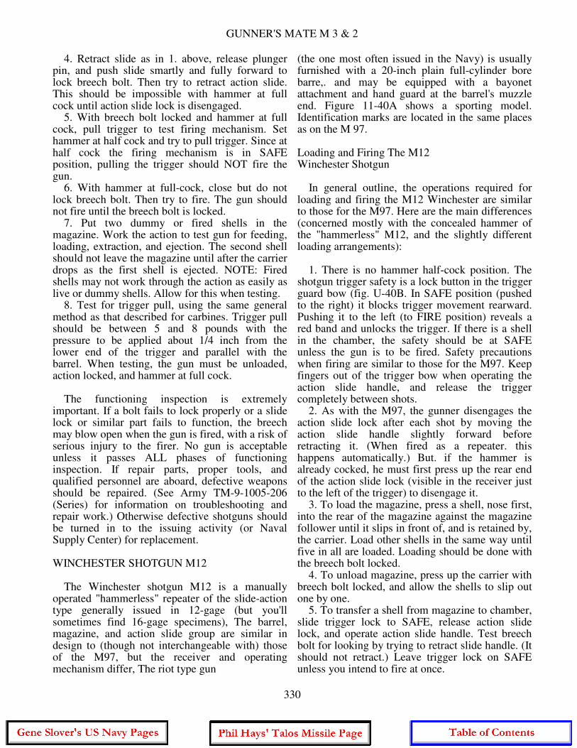
4. Retract slide as in 1. above, release plunger pin, and push slide smartly and fully forward to lock breech bolt. Then try to retract action slide. This should be impossible with hammer at full cock until action slide lock is disengaged. 5. With breech bolt locked and hammer at full cock, pull trigger to test firing mechanism. Set hammer at half cock and try to pull trigger. Since at half cock the firing mechanism is in SAFE position, pulling the trigger should NOT fire the gun. 6. With hammer at full-cock, close but do not lock breech bolt. Then try to fire. The gun should not fire until the breech bolt is locked. 7. Put two dummy or fired shells in the magazine. Work the action to test gun for feeding, loading, extraction, and ejection. The second shell should not leave the magazine until after the carrier drops as the first shell is ejected. NOTE: Fired shells may not work through the action as easily as live or dummy shells. Allow for this when testing. 8. Test for trigger pull, using the same general method as that described for carbines. Trigger pull should be between 5 and 8 pounds with the pressure to be applied about 1/4 inch from the lower end of the trigger and parallel with the barrel. When testing, the gun must be unloaded, action locked, and hammer at full cock. The functioning inspection is extremely important. If a bolt fails to lock properly or a slide lock or similar part fails to function, the breech may blow open when the gun is fired, with a risk of serious injury to the firer. No gun is acceptable unless it passes ALL phases of functioning inspection. If repair parts, proper tools, and qualified personnel are aboard, defective weapons should be repaired. (See Army TM-9-1005-206 (Series) for information on troubleshooting and repair work.) Otherwise defective shotguns should be turned in to the issuing activity (or Naval Supply Center) for replacement. WINCHESTER SHOTGUN M12 The Winchester shotgun M12 is a manually operated "hammerless" repeater of the slide-action type generally issued in 12-gage (but you'll sometimes find 16-gage specimens), The barrel, magazine, and action slide group are similar in design to (though not interchangeable with) those of the M97, but the receiver and operating mechanism differ, The riot type gun
(the one most often issued in the Navy) is usually furnished with a 20-inch plain full-cylinder bore barre,. and may be equipped with a bayonet attachment and hand guard at the barrel's muzzle end. Figure 11-40A shows a sporting model. Identification marks are located in the same places as on the M 97. Loading and Firing The M12 Winchester Shotgun In general outline, the operations required for loading and firing the M12 Winchester are similar to those for the M97. Here are the main differences (concerned mostly with the concealed hammer of the "hammerless" M12, and the slightly different loading arrangements): 1. There is no hammer half-cock position. The shotgun trigger safety is a lock button in the trigger guard bow (fig. U-40B. In SAFE position (pushed to the right) it blocks trigger movement rearward. Pushing it to the left (to FIRE position) reveals a red band and unlocks the trigger. If there is a shell in the chamber, the safety should be at SAFE unless the gun is to be fired. Safety precautions when firing are similar to those for the M97. Keep fingers out of the trigger bow when operating the action slide handle, and release the trigger completely between shots. 2. As with the M97, the gunner disengages the action slide lock after each shot by moving the action slide handle slightly forward before retracting it. (When fired as a repeater. this happens automatically.) But. if the hammer is already cocked, he must first press up the rear end of the action slide lock (visible in the receiver just to the left of the trigger) to disengage it. 3. To load the magazine, press a shell, nose first, into the rear of the magazine against the magazine follower until it slips in front of, and is retained by, the carrier. Load other shells in the same way until five in all are loaded. Loading should be done with the breech bolt locked. 4. To unload magazine, press up the carrier with breech bolt locked, and allow the shells to slip out one by one. 5. To transfer a shell from magazine to chamber, slide trigger lock to SAFE, release action slide lock, and operate action slide handle. Test breech bolt for looking by trying to retract slide handle. (It should not retract.) Leave trigger lock on SAFE unless you intend to fire at once.
330
CHAPTER 11 - SMALL ARMS, LANDING PARTY EQUIPMENT AND DEMOLITION
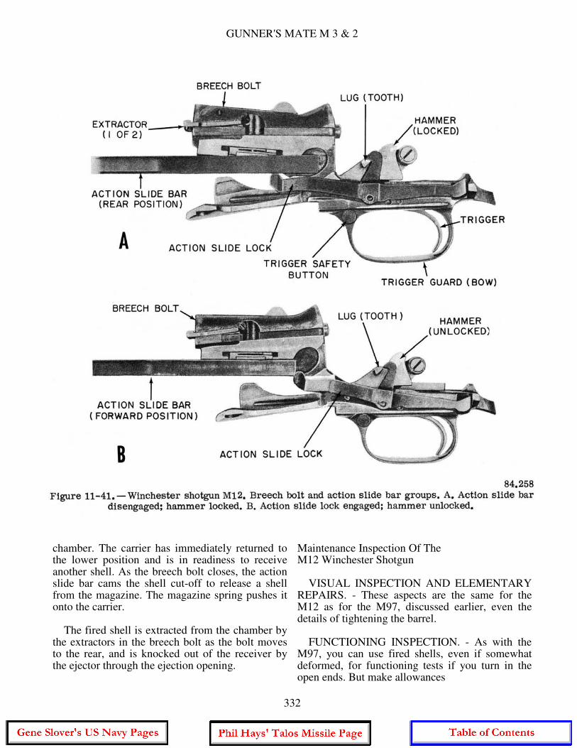
6. To unload the gun, slide trigger lock to SAFE, and unload magazine. Disengage slide handle to extract and eject shell in chamber. Inspect magazine and chamber to be sure gun is empty. 7. Loading the chamber without loading the magazine is done exactly as with the M97, except that you set the M12 trigger safety button at SAFE. Functioning of the Winchester M12 As with the M97, the mechanism of the M12 is operated when you work the action slide handle back, then forward. A cam lug on the action slide bar after end engages a camming aperture in the left side of the breech bolt. As the slide moves aft, the breech bolt rear end is cammed down from in front of the locking shoulder in the top of the receiver and the bolt moves to the rear. As the slide moves forward, the breech
bolt also moves forward and its rear end is cammed up in front of the locking shoulder. As the breech bolt moves aft it cams back the hammer which is caught and held by a hook (fig. 11-41A) on the action slide lock. As the breech bolt reaches forward position, the action slide lock, which has been held down by the action slide bar, is released and springs up behind the action slide bar to block its rearward movement (fig. 11-41B). At the same time, the lock releases the hammer, which is then held by the sear. The M12 Winchester, much like the M97, uses a carrier (not illustrated) to transfer shells from the magazine to the chamber, but the timing of its operation is a little different from the M97. As the breech bolt starts forward it cams the carrier up and down rapidly. The shell resting on the carrier is lifted in line with the bore and the breech bolt pushes it into the
331
GUNNER'S MATE M 3 & 2
chamber. The carrier has immediately returned to the lower position and is in readiness to receive another shell. As the breech bolt closes, the action slide bar cams the shell cut-off to release a shell from the magazine. The magazine spring pushes it onto the carrier. The fired shell is extracted from the chamber by the extractors in the breech bolt as the bolt moves to the rear, and is knocked out of the receiver by the ejector through the ejection opening.
Maintenance Inspection Of The M12 Winchester Shotgun VISUAL INSPECTION AND ELEMENTARY REPAIRS. - These aspects are the same for the M12 as for the M97, discussed earlier, even the details of tightening the barrel. FUNCTIONING INSPECTION. - As with the M97, you can use fired shells, even if somewhat deformed, for functioning tests if you turn in the open ends. But make allowances
332
CHAPTER 11 - SMALL ARMS, LANDING PARTY EQUIPMENT AND DEMOLITION
for these deformations when judging smoothness of action. Be sure the gun has no live ammunition in it when performing these tests. Here are the testing operations: 1. With breech bolt locked and hammer cocked, press upward on the action slide lock rear end. Push action slide handle forward slightly, pull smartly and fully to the rear, then push smartly and fully forward. Do this several times to test smoothness of action. But don't slam the mechanism. 2. Retract action slide as in 1. above, release pressure on rear of action slide lock, and push slide smartly forward to lock breech bolt, then attempt to retract the action slide. The action slide should not retract. 3. Pull the trigger to make the hammer fall. Try to retract the action slide. It should retract. 4. Retract it fully, then push forward until the breech bolt is fully forward, but not raised to the locked position. Pull the trigger to release the hammer. The hammer should not descend until the breech bolt is fully locked. 5. Place two more dummy or fired shells in the magazine and work the action to test for feeding, loading, extraction, and ejection. The second shell should not leave the magazine until the breech bolt is locking behind the first shell in the chamber. 6. With breech bolt locked and hammer cocked, push the trigger safety lock all the way to the right. Pull the trigger. The trigger should not retract nor should the hammer descend. 7. Push trigger lock all the way left so that red band shows, and pull the trigger. The trigger should retract and release the hammer.
CALIBER .45 LINE-THROWING GUN The line-throwing gun (fig. 11-42) is the only gun firing a projectile of small arms caliber that is not intended as a weapon. The gun is also unique among those we have taken up in this chapter in that it is not of Army origin. It is used only by the Navy, and the reference publication for it is OP 546. The gun is designed to pass a small line from Slip to ship or from a ship to a pier. A projectile, with one end of the line attached, is fired from the gun by the impulse of a blank cartridge. This small line serves as a messenger for the larger running lines of refueling rigs, high lines, breeches-buoys, etc.
The gun is single shot with a smooth bore (.45 cal.), and a short barrel of tip-down action hinged to the frame. It is ruggedly constructed, and the breech has been heavily reinforced to withstand the relatively high chamber pressures. The shot line is made of nylon with a minimum (when new) breaking strength of 125 pounds. It is wound on a wooden spindle in such a way that, when the spindle is removed for firing, it will payout without fouling. The ammunition is a blank 45-70 cartridge loaded through the breech of the gun and the projectile through the muzzle. The projectile (fig. 11-42) is made up of three major units: a buoyancy chamber, an illuminating unit, and the rod. The buoyancy chamber is a plastic bottle-shaped cylinder fitted onto the front of the rod. It serves to keep the projectile afloat. The illumination unit is essentially a small flashlight which is enclosed in the buoyancy chamber. It is especially useful during night operations for obvious reasons. The rod is the part of the projectile that goes in the gun's muzzle. The nylon shot line is attached to a slide on the rod. If the rod gets scratched, burred, or slightly bent, use fine emery cloth to get it back into shape. Do NOT fire any projectile that fails to enter the bore freely. FIRING THE GUN Before firing the caliber .45 line-throwing gun, certain precautions are necessary: 1. Before loading, select an outboard firing position clear of rigging, ship's structure, or any obstacles on which the line may become fouled. 2. All loading and firing operations are to be performed at the rail, with the gun pointed outboard in a safe direction. 3. Open the breech and inspect the bore to see that it is thoroughly clean and dry, and slip the projectile into the muzzle to see that it moves freely. The bore and the projectile must move freely its entire length of travel in the bore. Excessive friction produces dangerously high chamber pressure and reduces range. It takes two men to safely fire the line-throwing gun unless the special canister is used. One man holds the coiled line and the other fires the gun. Assuming that the projectile has been properly prepared, follow this procedure:
333
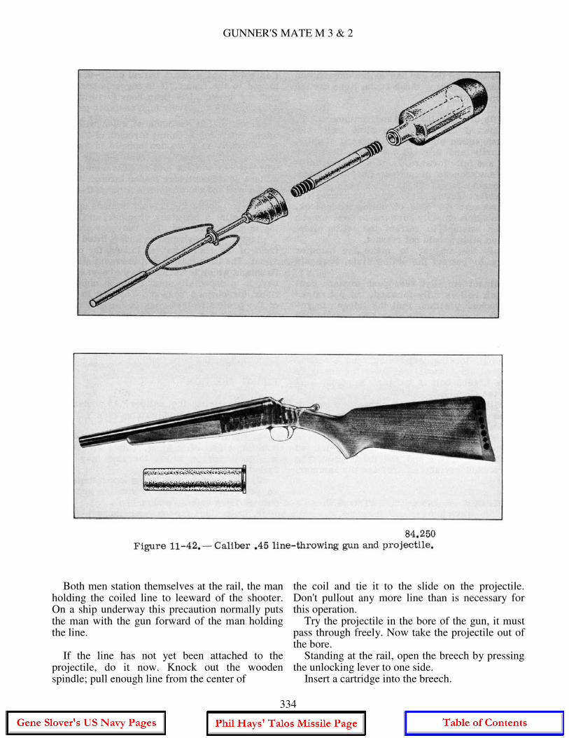
GUNNER'S MATE M 3 & 2
Both men station themselves at the rail, the man holding the coiled line to leeward of the shooter. On a ship underway this precaution normally puts the man with the gun forward of the man holding the line. If the line has not yet been attached to the projectile, do it now. Knock out the wooden spindle; pull enough line from the center of
the coil and tie it to the slide on the projectile. Don't pullout any more line than is necessary for this operation. Try the projectile in the bore of the gun, it must pass through freely. Now take the projectile out of the bore. Standing at the rail, open the breech by pressing the unlocking lever to one side. Insert a cartridge into the breech.
334
CHAPTER 11 - SMALL ARMS, LANDING PARTY EQUIPMENT AND DEMOLITION
Close the breech. Insert the projectile rod into the bore as far as it will go. Brace the gun firmly against the shoulder. Cock the gun by pulling back on the hammer until it reaches the full cock position. Aim the gun. At short ranges the gun is fairly accurate. At long ranges, however, you will have to elevate your aim and use "Kentucky windage" to lead the target. The path of the projectile and line are seriously affected by wind. Also, the projectile is relatively slow moving, so target speed is a factor in aiming the gun. About the only firm guideline we can give you is that your shot should be placed well clear of personnel on the receiving ship. Fire the gun. When the man holding the coiled line sees that the projectile has definitely crossed the other ship, he squeezes the coil, halting any further paying out of the shot line. Take a bight in the line and secure what is left in the coil with it. Bend your shot line to whatever running lines are going to be sent over to the receiving ship. Your interest in the proceedings now is largely one of trying to get your shot line and projectile sent back with the rig. Note 1: In the event of misfire, keep the gun braced against your shoulder and pointed in a safe direction. Recock and attempt to fire again. If repeated attempts to fire fail, wait one minute before opening the breech and removing the cartridge. Take a quick look at the primer to see if it has been struck by the firing pin; if so, deep six it. The firing pin of the line-throwing gun is a short, free-floating type. It is a good idea before you shoot to elevate the gun and jiggle it to bring the firing pin out toward the hammer as far as it will go. Note 2: When shooting the gun do NOT lay your thumb on top of the stock immediately behind the breech unlocking lever. Instead. lay it alongside the frame. The recoil of a line- throwing gun is such that, if you hold it incorrectly, the unlocking lever can pinch or even penetrate your hand. And there is the possibility that if your hand is placed so as to interfere with the unlocking lever's rearward movement, the lever may be cammed to one side, unlocking the breech. In this case, recoil may be accompanied by a rapid unintentional disassembly of the gun.
Maintenance Authorized disassembly of the line-throwing gun is limited to the following steps: 1. Remove the foregrip by pulling it down firmly to release the spring snap which secures the grip to the barrel. 2. Remove the barrel by opening the breech and pushing back on the barrel, disengaging it from the frame. The gun is reassembled by following these steps in reverse order. When the gun is stored in the armory, it is kept lubricated with a light oil, as are all small arms. When it is to be fired, however, the bore must be completely cleaned and dried by running patches through it. Also, between consecutive firings a dry patch should be run through the bore to remove all powder residue from the previous shot. The line-throwing gun is known for its kick, and anything causing the projectile to bind in the bore adds dangerously to the gun's recoil. BROWNING MACHINEGUN, CALIBER .30, M1919A4 Browning machineguns (abbreviated BMG) are standard Army weapons used by the Navy afloat, ashore, and in aircraft. The two calibers - .30 and .50 - have basically similar mechanisms. The caliber .30 BMG is issued to combat vessels and many auxiliaries as a landing-force weapon. Its general characteristics are listed below. In this section we'll take up its functioning, operation, and general (nonroutine) inspection and maintenance. For further details, see Army FM 23-55 and TM-9-1005-212 (Series). General Description The caliber .30 BMG is a recoil-operated, belt-fed, water- or air-cooled automatic weapon, various models of which are designed for use in aircraft or on ground mounts. The type we shall take up is the M1919A4, illustrated in figure 11-43 on the M2 ground mount. This is an air-cooled weapon designed for use with fabric belts. It has a heavy barrel surrounded with a perforated steel jacket to improve cooling. It uses a leaf-type sight. The .30 cal. BMG weighs approximately 31 pounds (less tripod) and has an extreme usable range of 2,000 yards. The rate of fire for the weapon is 400-500 rounds per minute.
335
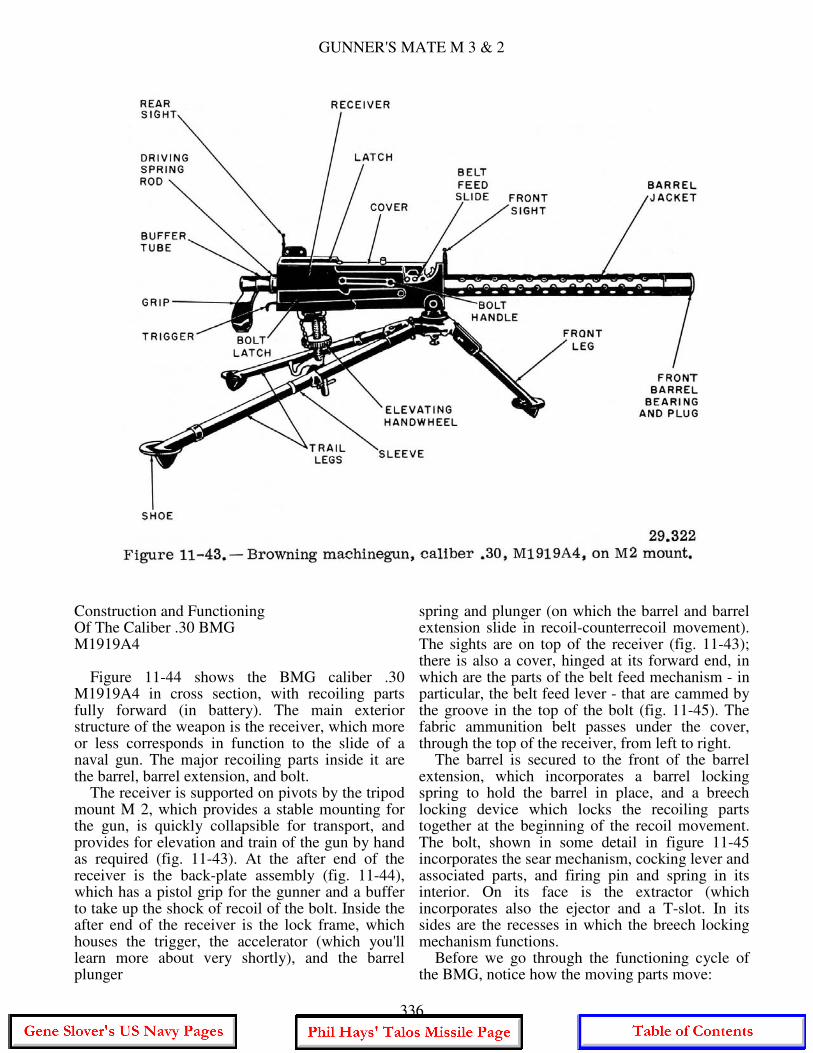
GUNNER'S MATE M 3 & 2
Construction and Functioning Of The Caliber .30 BMG M1919A4 Figure 11-44 shows the BMG caliber .30 M1919A4 in cross section, with recoiling parts fully forward (in battery). The main exterior structure of the weapon is the receiver, which more or less corresponds in function to the slide of a naval gun. The major recoiling parts inside it are the barrel, barrel extension, and bolt. The receiver is supported on pivots by the tripod mount M 2, which provides a stable mounting for the gun, is quickly collapsible for transport, and provides for elevation and train of the gun by hand as required (fig. 11-43). At the after end of the receiver is the back-plate assembly (fig. 11-44), which has a pistol grip for the gunner and a buffer to take up the shock of recoil of the bolt. Inside the after end of the receiver is the lock frame, which houses the trigger, the accelerator (which you'll learn more about very shortly), and the barrel plunger
spring and plunger (on which the barrel and barrel extension slide in recoil-counterrecoil movement). The sights are on top of the receiver (fig. 11-43); there is also a cover, hinged at its forward end, in which are the parts of the belt feed mechanism - in particular, the belt feed lever - that are cammed by the groove in the top of the bolt (fig. 11-45). The fabric ammunition belt passes under the cover, through the top of the receiver, from left to right. The barrel is secured to the front of the barrel extension, which incorporates a barrel locking spring to hold the barrel in place, and a breech locking device which locks the recoiling parts together at the beginning of the recoil movement. The bolt, shown in some detail in figure 11-45 incorporates the sear mechanism, cocking lever and associated parts, and firing pin and spring in its interior. On its face is the extractor (which incorporates also the ejector and a T-slot. In its sides are the recesses in which the breech locking mechanism functions. Before we go through the functioning cycle of the BMG, notice how the moving parts move:
336
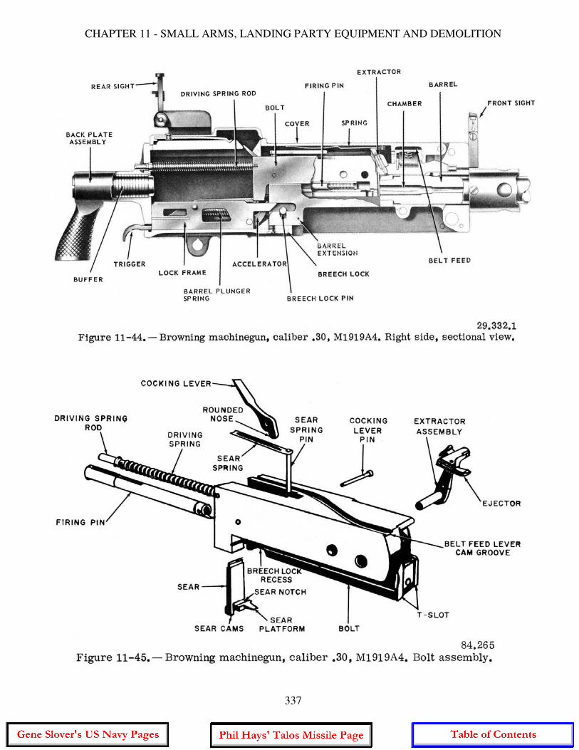
CHAPTER 11 - SMALL ARMS, LANDING PARTY EQUIPMENT AND DEMOLITION
337
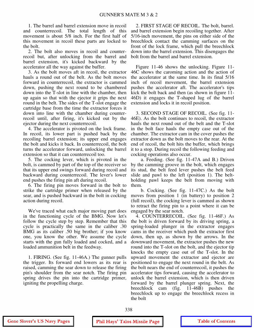
GUNNER'S MATE M 3 & 2
1. The barrel and barrel extension move in recoil and counterrecoil. The total length of this movement is about 5/8 inch. For the first half of this movement in recoil these parts are locked to the bolt. 2. The bolt also moves in recoil and counter- recoil but, after unlocking from the barrel and barrel extension, it's kicked backward by the accelerator all the way against the buffer. 3. As the bolt moves aft in recoil, the extractor hauls a round out of the belt. As the bolt moves forward in counterrecoil, the extractor is cammed down, pushing the next round to be chambered down into the T-slot in line with the chamber, then up again so that with the ejector it grips the next round in the belt. The sides of the T-slot engage the cartridge base from the time the extractor forces it down into line with the chamber during counter- recoil until, after firing, it's kicked out by the ejector during the next counterrecoil. 4. The accelerator is pivoted on the lock frame. In recoil, its lower part is pushed back by the recoiling barrel extension; its upper end engages the bolt and kicks it back. In counterrecoil, the bolt turns the accelerator forward, unlocking the barrel extension so that it can counterrecoil too. 5. The cocking lever, which is pivoted in the bolt, is cammed by part of the top of the receiver so that its upper end swings forward during recoil and backward during counterrecoil. The lever's lower end pushes the firing pin aft during recoil. 6. The firing pin moves forward in the bolt to strike the cartridge primer when released by the sear, and is pushed backward in the bolt in cocking action during recoil. We've traced what each major moving part does in the functioning cycle of the BMG. Now let's follow the cycle step by step. Remember that this cycle is practically the same in the caliber .30 BMG as its caliber .50 big brother; if you know one, you know the other. We assume the cycle starts with the gun fully loaded and cocked, and a loaded ammunition belt in the feedway. 1. FIRING. (See fig. 11-46A.) The gunner pulls the trigger. Its forward end lowers as its rear is raised, camming the sear down to release the firing pin's shoulder from the sear notch. The firing pin spring drives the pin into the cartridge primer, igniting the propelling charge.
2. FIRST STAGE OF RECOIL. The bolt, barrel. and barrel extension begin recoiling together. After 5/16-inch movement, the pins on either side of the breechlock contact the camming surfaces on the front of the lock frame, which pull the breechlock down into the barrel extension. This disengages the bolt from the barrel and barrel extension. Figure 11-46 shows the unlocking. Figure 11-46C shows the caroming action and the action of the accelerator at the same time. In its final 5/16 inch of recoil movement, the barrel extension pushes the accelerator aft. The accelerator's tips kick the bolt back and then (as shown in figure 11-46D) it engages the T-shaped lug of the barrel extension and locks it in recoil position. 3. SECOND STAGE OF RECOIL. (See fig. 11-46E). As the bolt continues to recoil, the extractor hauls the next round out of the belt and the T-slot in the bolt face hauls the empty case out of the chamber. The extractor cam in the cover pushes the extractor down as the bolt moves to the rear. At the end of recoil, the bolt hits the buffer, which brings it to a stop. During recoil the following feeding and cocking operations also occur. a. Feeding. (See fig. 11-47A and B.) Driven by the camming groove in the bolt, which engages its stud, the belt feed lever pushes the belt feed slide and pawl to the left (position 1). The belt-holding pawl keeps the belt from moving with them. b. Cocking. (See fig. 11-47C.) As the bolt moves from position 1 (in battery) to position 2 (full recoil), the cocking lever is cammed as shown to retract the firing pin to a point where it can be engaged by the sear notch. 4. COUNTERRECOIL. (See fig. 11-46F.) As the bolt is driven forward by its driving spring, a spring-loaded plunger in the extractor engages cams in the receiver which push the extractor first down, then up, as shown by the arrows. In the downward movement, the extractor pushes the new round into the T-slot on the bolt, and the ejector tip knocks the empty case out of the T-slot. In the upward movement the extractor and ejector are positioned to engage the next round in the belt. As the bolt nears the end of counterrecoil, it pushes the accelerator tips forward, causing the accelerator to unlock the barrel extension, which is then driven forward by the barrel plunger spring. Next, the breechlock cam (fig. 11-46B) pushes the breechlock up to engage the breechlock recess in the bolt
338
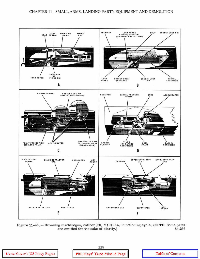
CHAPTER 11 - SMALL ARMS, LANDING PARTY EQUIPMENT AND DEMOLITION
339
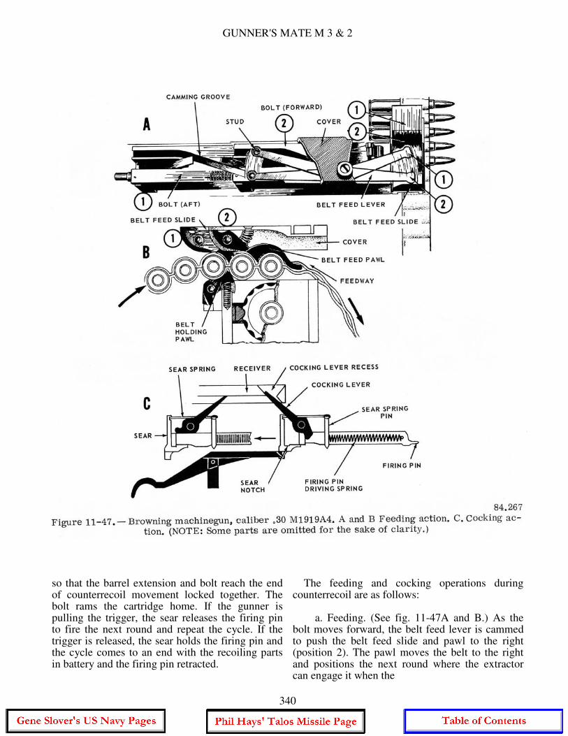
GUNNER'S MATE M 3 & 2
so that the barrel extension and bolt reach the end of counterrecoil movement locked together. The bolt rams the cartridge home. If the gunner is pulling the trigger, the sear releases the firing pin to fire the next round and repeat the cycle. If the trigger is released, the sear holds the firing pin and the cycle comes to an end with the recoiling parts in battery and the firing pin retracted.
The feeding and cocking operations during counterrecoil are as follows: a. Feeding. (See fig. 11-47A and B.) As the bolt moves forward, the belt feed lever is cammed to push the belt feed slide and pawl to the right (position 2). The pawl moves the belt to the right and positions the next round where the extractor can engage it when the
340
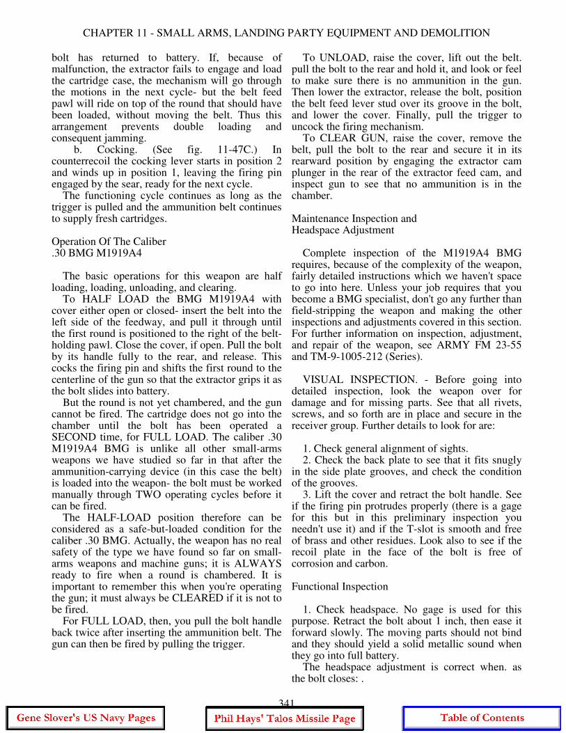
CHAPTER 11 - SMALL ARMS, LANDING PARTY EQUIPMENT AND DEMOLITION
bolt has returned to battery. If, because of malfunction, the extractor fails to engage and load the cartridge case, the mechanism will go through the motions in the next cycle- but the belt feed pawl will ride on top of the round that should have been loaded, without moving the belt. Thus this arrangement prevents double loading and consequent jamming. b. Cocking. (See fig. 11-47C.) In counterrecoil the cocking lever starts in position 2 and winds up in position 1, leaving the firing pin engaged by the sear, ready for the next cycle. The functioning cycle continues as long as the trigger is pulled and the ammunition belt continues to supply fresh cartridges. Operation Of The Caliber .30 BMG M1919A4 The basic operations for this weapon are half loading, loading, unloading, and clearing. To HALF LOAD the BMG M1919A4 with cover either open or closed- insert the belt into the left side of the feedway, and pull it through until the first round is positioned to the right of the belt-holding pawl. Close the cover, if open. Pull the bolt by its handle fully to the rear, and release. This cocks the firing pin and shifts the first round to the centerline of the gun so that the extractor grips it as the bolt slides into battery. But the round is not yet chambered, and the gun cannot be fired. The cartridge does not go into the chamber until the bolt has been operated a SECOND time, for FULL LOAD. The caliber .30 M1919A4 BMG is unlike all other small-arms weapons we have studied so far in that after the ammunition-carrying device (in this case the belt) is loaded into the weapon- the bolt must be worked manually through TWO operating cycles before it can be fired. The HALF-LOAD position therefore can be considered as a safe-but-loaded condition for the caliber .30 BMG. Actually, the weapon has no real safety of the type we have found so far on small-arms weapons and machine guns; it is ALWAYS ready to fire when a round is chambered. It is important to remember this when you're operating the gun; it must always be CLEARED if it is not to be fired. For FULL LOAD, then, you pull the bolt handle back twice after inserting the ammunition belt. The gun can then be fired by pulling the trigger.
To UNLOAD, raise the cover, lift out the belt. pull the bolt to the rear and hold it, and look or feel to make sure there is no ammunition in the gun. Then lower the extractor, release the bolt, position the belt feed lever stud over its groove in the bolt, and lower the cover. Finally, pull the trigger to uncock the firing mechanism. To CLEAR GUN, raise the cover, remove the belt, pull the bolt to the rear and secure it in its rearward position by engaging the extractor cam plunger in the rear of the extractor feed cam, and inspect gun to see that no ammunition is in the chamber. Maintenance Inspection and Headspace Adjustment Complete inspection of the M1919A4 BMG requires, because of the complexity of the weapon, fairly detailed instructions which we haven't space to go into here. Unless your job requires that you become a BMG specialist, don't go any further than field-stripping the weapon and making the other inspections and adjustments covered in this section. For further information on inspection, adjustment, and repair of the weapon, see ARMY FM 23-55 and TM-9-1005-212 (Series). VISUAL INSPECTION. - Before going into detailed inspection, look the weapon over for damage and for missing parts. See that all rivets, screws, and so forth are in place and secure in the receiver group. Further details to look for are: 1. Check general alignment of sights. 2. Check the back plate to see that it fits snugly in the side plate grooves, and check the condition of the grooves. 3. Lift the cover and retract the bolt handle. See if the firing pin protrudes properly (there is a gage for this but in this preliminary inspection you needn't use it) and if the T-slot is smooth and free of brass and other residues. Look also to see if the recoil plate in the face of the bolt is free of corrosion and carbon. Functional Inspection 1. Check headspace. No gage is used for this purpose. Retract the bolt about 1 inch, then ease it forward slowly. The moving parts should not bind and they should yield a solid metallic sound when they go into full battery. The headspace adjustment is correct when. as the bolt closes: .
341
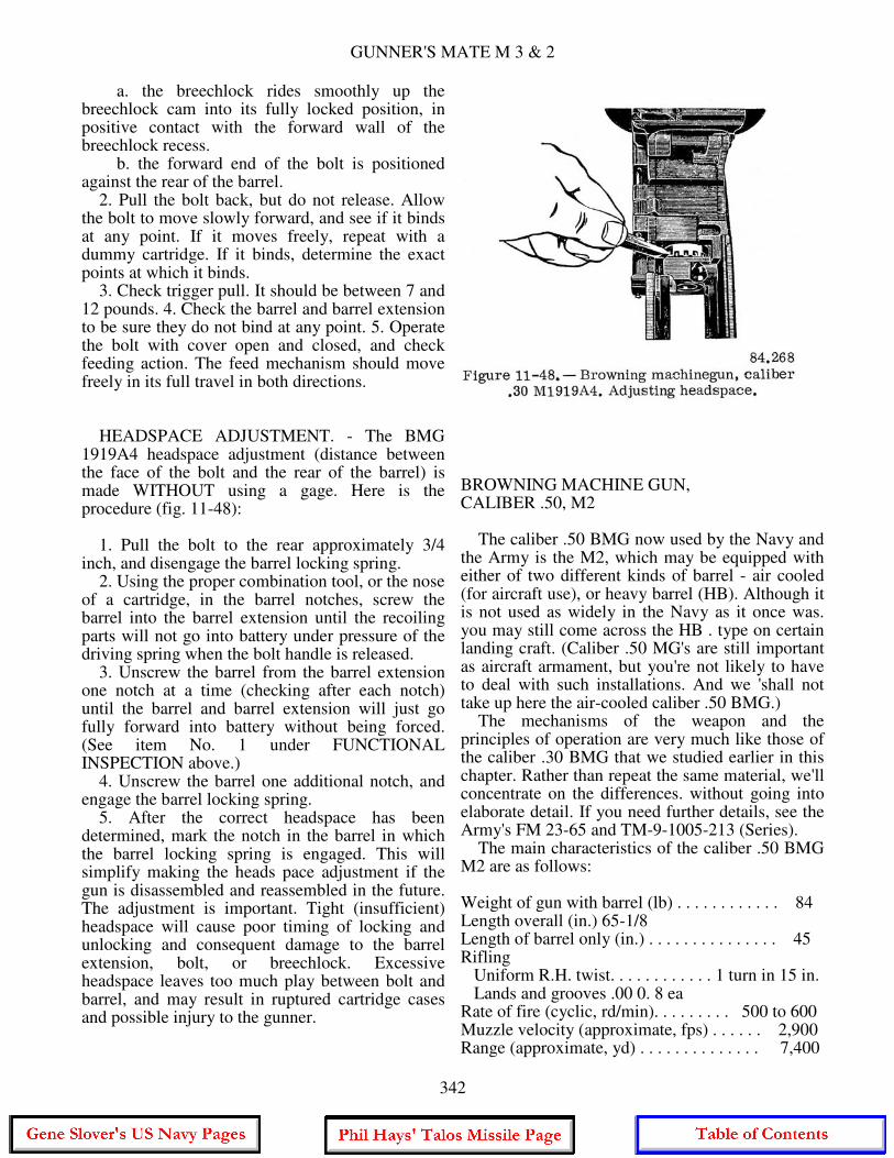
GUNNER'S MATE M 3 & 2
a. the breechlock rides smoothly up the breechlock cam into its fully locked position, in positive contact with the forward wall of the breechlock recess. b. the forward end of the bolt is positioned against the rear of the barrel. 2. Pull the bolt back, but do not release. Allow the bolt to move slowly forward, and see if it binds at any point. If it moves freely, repeat with a dummy cartridge. If it binds, determine the exact points at which it binds. 3. Check trigger pull. It should be between 7 and 12 pounds. 4. Check the barrel and barrel extension to be sure they do not bind at any point. 5. Operate the bolt with cover open and closed, and check feeding action. The feed mechanism should move freely in its full travel in both directions. HEADSPACE ADJUSTMENT. - The BMG 1919A4 headspace adjustment (distance between the face of the bolt and the rear of the barrel) is made WITHOUT using a gage. Here is the procedure (fig. 11-48): 1. Pull the bolt to the rear approximately 3/4 inch, and disengage the barrel locking spring. 2. Using the proper combination tool, or the nose of a cartridge, in the barrel notches, screw the barrel into the barrel extension until the recoiling parts will not go into battery under pressure of the driving spring when the bolt handle is released. 3. Unscrew the barrel from the barrel extension one notch at a time (checking after each notch) until the barrel and barrel extension will just go fully forward into battery without being forced. (See item No. 1 under FUNCTIONAL INSPECTION above.) 4. Unscrew the barrel one additional notch, and engage the barrel locking spring. 5. After the correct headspace has been determined, mark the notch in the barrel in which the barrel locking spring is engaged. This will simplify making the heads pace adjustment if the gun is disassembled and reassembled in the future. The adjustment is important. Tight (insufficient) headspace will cause poor timing of locking and unlocking and consequent damage to the barrel extension, bolt, or breechlock. Excessive headspace leaves too much play between bolt and barrel, and may result in ruptured cartridge cases and possible injury to the gunner.
BROWNING MACHINE GUN, CALIBER .50, M2 The caliber .50 BMG now used by the Navy and the Army is the M2, which may be equipped with either of two different kinds of barrel - air cooled (for aircraft use), or heavy barrel (HB). Although it is not used as widely in the Navy as it once was. you may still come across the HB . type on certain landing craft. (Caliber .50 MG's are still important as aircraft armament, but you're not likely to have to deal with such installations. And we 'shall not take up here the air-cooled caliber .50 BMG.) The mechanisms of the weapon and the principles of operation are very much like those of the caliber .30 BMG that we studied earlier in this chapter. Rather than repeat the same material, we'll concentrate on the differences. without going into elaborate detail. If you need further details, see the Army's FM 23-65 and TM-9-1005-213 (Series). The main characteristics of the caliber .50 BMG M2 are as follows: Weight of gun with barrel (lb) . . . . . . . . . . . . 84 Length overall (in.) 65-1/8 Length of barrel only (in.) . . . . . . . . . . . . . . . 45 Rifling Uniform R.H. twist. . . . . . . . . . . . 1 turn in 15 in. Lands and grooves .00 0. 8 ea Rate of fire (cyclic, rd/min). . . . . . . . . 500 to 600 Muzzle velocity (approximate, fps) . . . . . . 2,900 Range (approximate, yd) . . . . . . . . . . . . . . 7,400
342
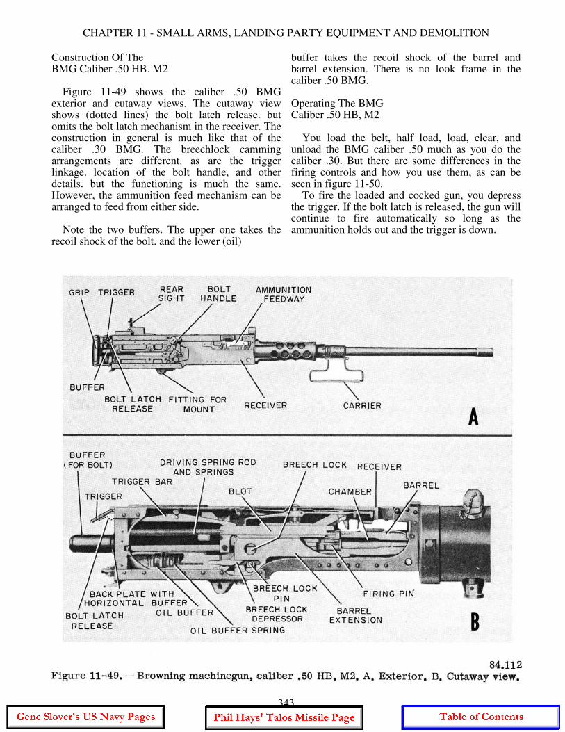
CHAPTER 11 - SMALL ARMS, LANDING PARTY EQUIPMENT AND DEMOLITION
Construction Of The BMG Caliber .50 HB. M2 Figure 11-49 shows the caliber .50 BMG exterior and cutaway views. The cutaway view shows (dotted lines) the bolt latch release. but omits the bolt latch mechanism in the receiver. The construction in general is much like that of the caliber .30 BMG. The breechlock camming arrangements are different. as are the trigger linkage. location of the bolt handle, and other details. but the functioning is much the same. However, the ammunition feed mechanism can be arranged to feed from either side. Note the two buffers. The upper one takes the recoil shock of the bolt. and the lower (oil)
buffer takes the recoil shock of the barrel and barrel extension. There is no look frame in the caliber .50 BMG. Operating The BMG Caliber .50 HB, M2 You load the belt, half load, load, clear, and unload the BMG caliber .50 much as you do the caliber .30. But there are some differences in the firing controls and how you use them, as can be seen in figure 11-50. To fire the loaded and cocked gun, you depress the trigger. If the bolt latch is released, the gun will continue to fire automatically so long as the ammunition holds out and the trigger is down.
343
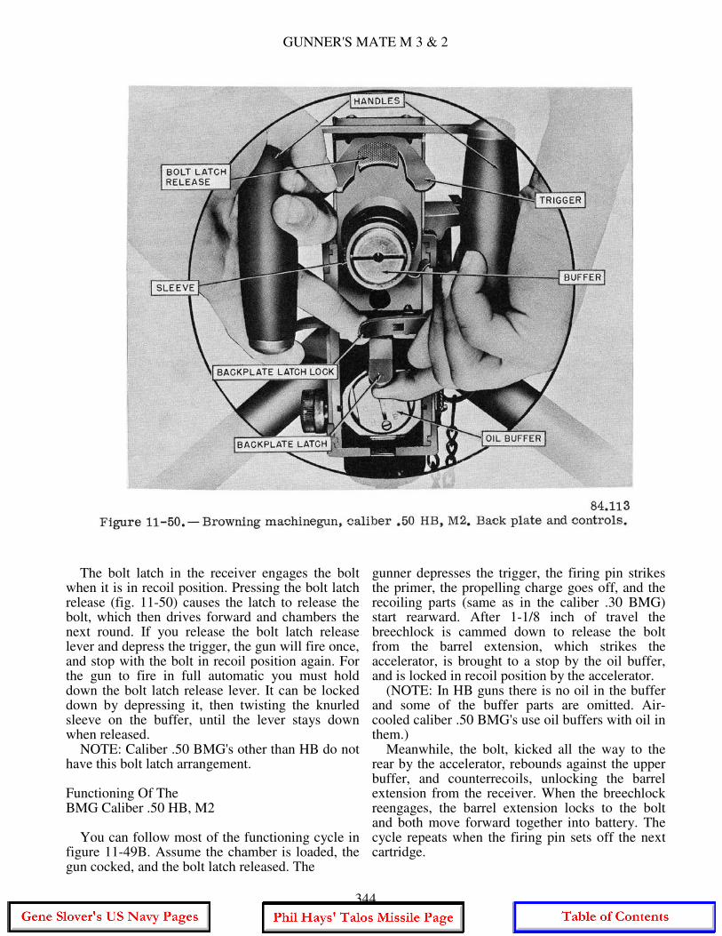
GUNNER'S MATE M 3 & 2
The bolt latch in the receiver engages the bolt when it is in recoil position. Pressing the bolt latch release (fig. 11-50) causes the latch to release the bolt, which then drives forward and chambers the next round. If you release the bolt latch release lever and depress the trigger, the gun will fire once, and stop with the bolt in recoil position again. For the gun to fire in full automatic you must hold down the bolt latch release lever. It can be locked down by depressing it, then twisting the knurled sleeve on the buffer, until the lever stays down when released. NOTE: Caliber .50 BMG's other than HB do not have this bolt latch arrangement. Functioning Of The BMG Caliber .50 HB, M2 You can follow most of the functioning cycle in figure 11-49B. Assume the chamber is loaded, the gun cocked, and the bolt latch released. The
gunner depresses the trigger, the firing pin strikes the primer, the propelling charge goes off, and the recoiling parts (same as in the caliber .30 BMG) start rearward. After 1-1/8 inch of travel the breechlock is cammed down to release the bolt from the barrel extension, which strikes the accelerator, is brought to a stop by the oil buffer, and is locked in recoil position by the accelerator. (NOTE: In HB guns there is no oil in the buffer and some of the buffer parts are omitted. Air-cooled caliber .50 BMG's use oil buffers with oil in them.) Meanwhile, the bolt, kicked all the way to the rear by the accelerator, rebounds against the upper buffer, and counterrecoils, unlocking the barrel extension from the receiver. When the breechlock reengages, the barrel extension locks to the bolt and both move forward together into battery. The cycle repeats when the firing pin sets off the next cartridge.
344
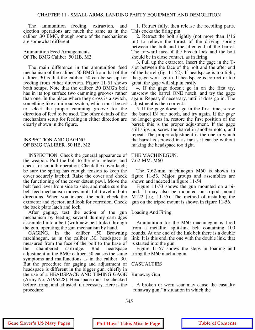
CHAPTER 11 - SMALL ARMS, LANDING PARTY EQUIPMENT AND DEMOLITION
The ammunition feeding, extraction, and ejection operations are much the same as in the caliber .30 BMG, though some of the mechanisms are somewhat different. Ammunition Feed Arrangements Of The BMG Caliber .50 HB, M2 The main difference in the ammunition feed mechanism of the caliber .50 BMG from that of the caliber .30 is that the caliber .50 can be set up for feeding from either direction. Figure 11-51 shows both setups. Note that the caliber .50 BMG's bolt has in its top surface two camming grooves rather than one. In the place where they cross is a switch, something like a railroad switch, which must be set to select the proper camming groove for the direction of feed to be used. The other details of the mechanism setup for feeding in either direction are clearly shown in the figure. INSPECTION AND GAGING OF BMG CALIBER .50 HB, M2 INSPECTION. Check the general appearance of the weapon. Pull the bolt to the rear. release. and check for smooth operation. Check the cover latch; be sure the spring has enough tension to keep the cover securely latched. Raise the cover and check the functioning of the cover detent pawl. Move the belt feed lever from side to side, and make sure the belt feed mechanism moves in its full travel in both directions. When you inspect the bolt, check the extractor and ejector, and look for corrosion. Check the back plate latch and lock. After gaging, test the action of the gun mechanism by feeding several dummy cartridges assembled into a belt (with new belt links) through the gun, operating the gun mechanism by hand. GAGING. In the caliber .50 Browning machinegun, as in the caliber .30, headspace is measured from the face of the bolt to the base of the chambered cartridge. Bad headspace adjustment in the BMG caliber .50 causes the same symptoms and malfunctions as in the caliber .30. But the procedure for gaging and adjustment of headspace is different in the bigger gun. chiefly in the use of a HEADSPACE AND TIMING GAGE (Army No. A196228). Headspace must be checked before firing, and adjusted, if necessary. Here is the procedure:
1. Retract fully, then release the recoiling parts. This cocks the firing pin. 2. Retract the bolt slightly (not more than 1/16 in.) to relieve the thrust of the driving spring between the bolt and the after end of the barrel. The forward face of the breech lock and the bolt should be in close contact, as in firing. 3. Pull up the extractor. Insert the gage in the T-slot between the face of the bolt and the after end of the barrel (fig. 11-52). If headspace is too tight, the gage won't go in. If headspace is correct or too great, the gage will slip in easily. 4. If the gage doesn't go in on the first try, unscrew the barrel ONE notch, and try the gage again. Repeat, if necessary, until it does go in. The adjustment is then correct. 5. If the gage doesn't go in the first time, screw the barrel IN one notch, and try again. If the gage no longer goes in, restore the first position of the barrel; this is the proper adjustment. If the gage still slips in, screw the barrel in another notch, and repeat. The proper adjustment is the one in which the barrel is screwed in as far as it can be without making the headspace too tight. THE MACHINEGUN, 7.62-MM. M60 The 7.62-mm machinegun M60 is shown in figure 11-53. Major groups and assemblies are shown and indexed in figure 11-54. Figure 11-53 shows the gun mounted on a bi- pod. It may also be mounted on tripod mount M122 (fig. 11-55). The method of installing the gun on the tripod mount is shown in figure 11-56. Loading And Firing Ammunition for the M60 machinegun is fired from a metallic, split-link belt containing 100 rounds. At one end of the link belt there is a double link. It is this end, the one with the double link, that is started into the gun. Figure 11-57 shows the steps in loading and firing the M60 machinegun. CASUALTIES Runaway Gun A broken or worn sear may cause the casualty "runaway gun," a situation in which the
345
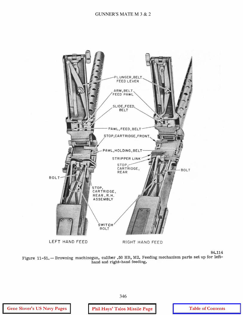
GUNNER'S MATE M 3 & 2
346
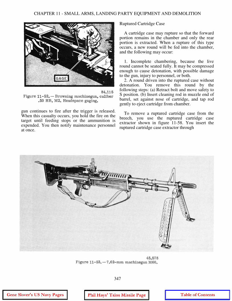
CHAPTER 11 - SMALL ARMS, LANDING PARTY EQUIPMENT AND DEMOLITION
gun continues to fire after the trigger is released. When this casualty occurs, you hold the fire on the target until feeding stops or the ammunition is expended. You then notify maintenance personnel at once.
Ruptured Cartridge Case A cartridge case may rupture so that the forward portion remains in the chamber and only the rear portion is extracted. When a rupture of this type occurs, a new round will be fed into the chamber, and the following may occur: 1. Incomplete chambering, because the live round cannot be seated fully. It may be compressed enough to cause detonation, with possible damage to the gun, injury to personnel, or both. 2. A round driven into the ruptured case without detonation. You remove this round by the following steps: (a) Retract bolt and move safety to S position. (b) Insert cleaning rod in muzzle end of barrel, set against nose of cartridge, and tap rod gently to eject cartridge from chamber. To remove a ruptured cartridge case from the breech, you use the ruptured cartridge case extractor shown in figure 11-58. You insert the ruptured cartridge case extractor through
347
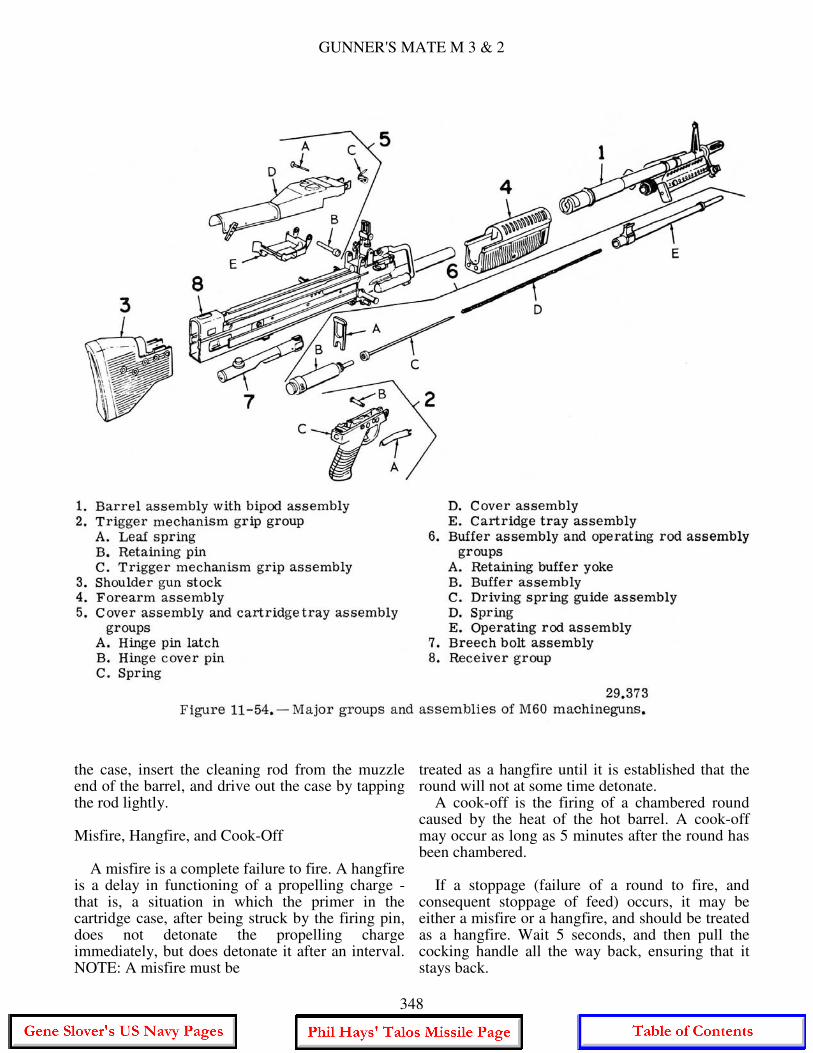
GUNNER'S MATE M 3 & 2
the case, insert the cleaning rod from the muzzle end of the barrel, and drive out the case by tapping the rod lightly. Misfire, Hangfire, and Cook-Off A misfire is a complete failure to fire. A hangfire is a delay in functioning of a propelling charge - that is, a situation in which the primer in the cartridge case, after being struck by the firing pin, does not detonate the propelling charge immediately, but does detonate it after an interval. NOTE: A misfire must be
treated as a hangfire until it is established that the round will not at some time detonate. A cook-off is the firing of a chambered round caused by the heat of the hot barrel. A cook-off may occur as long as 5 minutes after the round has been chambered. If a stoppage (failure of a round to fire, and consequent stoppage of feed) occurs, it may be either a misfire or a hangfire, and should be treated as a hangfire. Wait 5 seconds, and then pull the cocking handle all the way back, ensuring that it stays back.
348
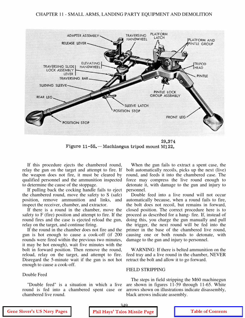
CHAPTER 11 - SMALL ARMS, LANDING PARTY EQUIPMENT AND DEMOLITION
If this procedure ejects the chambered round, relay the gun on the target and attempt to fire. If the weapon does not fire, it must be cleared by qualified personnel and the ammunition inspected to determine the cause of the stoppage. If pulling back the cocking handle fails to eject the chambered round, move the safety to S (safe) position, remove ammunition and links, and inspect the receiver, chamber, and extractor. If there is a round in the chamber, move the safety to F (fire) position and attempt to fire. If the round fires and the case is ejected reload the gun, relay on the target, and continue firing. If the round in the chamber does not fire and the gun is hot enough to cause a cook-off (if 200 rounds were fired within the previous two minutes, it may be hot enough), wait five minutes with the bolt in forward position. Then remove the round, reload, relay on the target, and attempt to fire. Disregard the 5-minute wait if the gun is not hot enough to cause a cook-off. Double Feed "Double feed" is a situation in which a live round is fed into a chambered spent case or chambered live round.
When the gun fails to extract a spent case, the bolt automatically recoils, picks up the next (live) round, and feeds it into the chambered case. The force may compress the live round enough to detonate it, with damage to the gun and injury to personnel. Double feed into a live round will not occur automatically because, when a round fails to fire, the bolt does not recoil, but remains in forward, closed position. The correct procedure here is to proceed as described for a hang- fire. If, instead of doing this, you charge the gun manually and pull the trigger, the next round will be fed into the primer in the base of the chambered live round, causing one or both rounds to detonate, with damage to the gun and injury to personnel. WARNING: If there is belted ammunition on the feed tray and a live round in the chamber, NEVER retract the bolt and allow it to go forward. FIELD STRIPPING The steps in field stripping the M60 machinegun are shown in figures 11-59 through 11-65. White arrows shown on illustrations indicate disassembly, black arrows indicate assembly.
349
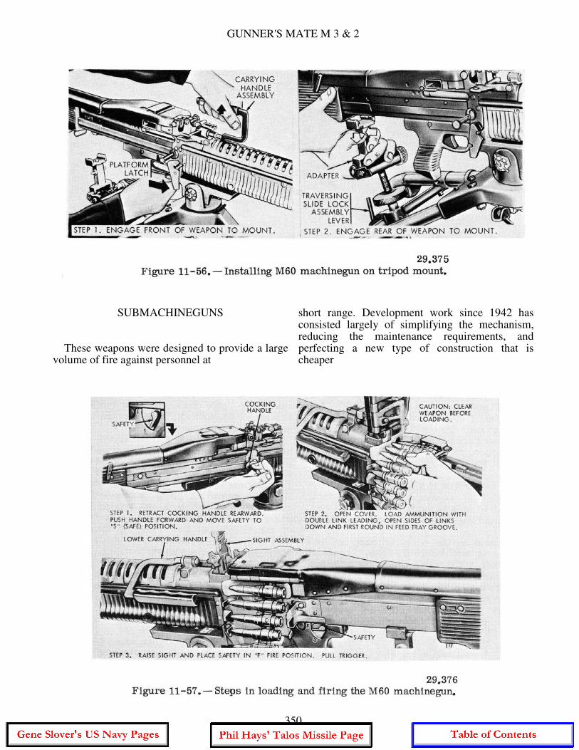
GUNNER'S MATE M 3 & 2
SUBMACHINEGUNS
These weapons were designed to provide a large volume of fire against personnel at
short range. Development work since 1942 has consisted largely of simplifying the mechanism, reducing the maintenance requirements, and perfecting a new type of construction that is cheaper
350
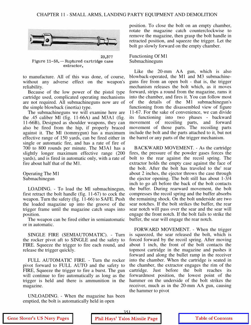
CHAPTER 11 - SMALL ARMS, LANDING PARTY EQUIPMENT AND DEMOLITION
to manufacture. All of this was done, of course, without any adverse effect on the weapon's reliability. Because of the low power of the pistol type cartridge used, complicated operating mechanisms are not required. All submachineguns now are of the simple blowback (inertia) type. The submachineguns we will examine here are the .45 caliber Ml (fig. 11-66A) and M3A1 (fig. 11-66B), Designed as shoulder weapons, they can also be fired from the hip, if properly braced against it. The Ml (tommygun) has a maximum effective range of 150 yards, can be fired either in single or automatic fire, and has a rate of fire of 700 to 800 rounds per minute. The M3A1 has a slightly longer maximum effective range (200 yards), and is fired in automatic only, with a rate of fire about half that of the M1. Operating The M1 Submachinegun LOADING. - To load the Ml submachinegun, first retract the bolt handle (fig. 11-67) to cock the weapon. Turn the safety (fig. 11-66) to SAFE. Push the loaded magazine up into the groove of the trigger frame until the magazine catch snaps into position. The weapon can be fired either in semiautomatic or in automatic. SINGLE FIRE (SEMIAUTOMATIC). - Turn the rocker pivot aft to SINGLE and the safety to FIRE. Squeeze the trigger to fire each round, and release the trigger quickly. FULL AUTOMATIC FIRE. - Turn the rocker pivot forward to FULL AUTO and the safety to FIRE, Squeeze the trigger to fire a burst. The gun will continue to fire automatically as long as the trigger is held and there is ammunition in the magazine. UNLOADING. - When the magazine has been emptied, the bolt is automatically held in open
position. To close the bolt on an empty chamber, rotate the magazine catch counterclockwise to remove the magazine, then grasp the bolt handle in retracted position, and squeeze the trigger. Let the bolt go slowly forward on the empty chamber. Functioning Of M1 Submachineguns Like the 20-mm AA gun, which is also blowback-operated, the M1 and M3 submachine-guns fire from an open bolt - that is, the trigger mechanism releases the bolt which, as it moves forward, strips a round from the magazine, rams it into the chamber, and fires it. You can follow most of the details of the M1 submachinegun's functioning from the disassembled view of figure 11-67. For the sake of convenience, we can divide its functioning into two phases - backward movement of recoiling parts, and forward movement of those parts. The recoiling parts include the bolt and the parts attached to it, but not the barrel or any parts of the trigger mechanism. BACKWARD MOVEMENT. - As the cartridge fires, the pressure of the powder gases forces the bolt to the rear against the recoil spring. The extractor holds the empty case against the face of the bolt. After the bolt has traveled to the' rear about 2 inches, the ejector throws the case through the ejector opening. The bolt still has about 1-3/4 inch to go aft before the back of the bolt contacts the buffer. During rearward movement, the bolt compresses the recoil spring and the buffer absorbs the remaining shock. On the bolt underside are two sear notches. If the bolt strikes the buffer, the rear sear notch will pass over the sear and the sear will engage the front notch. If the bolt fails to strike the buffer, the sear will engage the rear notch. FORWARD MOVEMENT. - When the trigger is squeezed, the sear released the bolt, which is forced forward by the recoil spring. After moving about 1 inch, the front of the bolt contacts the topmost cartridge in the magazine and pushes it forward and along the bullet ramp in the receiver into the chamber. When the cartridge is seated in the chamber, the extractor engages the rim of the cartridge. Just before the bolt reaches its forwardmost position, the lowest point of the hammer on the underside of the bolt strikes the receiver, much as in the 20-mm AA gun, causing the hammer to pivot
351
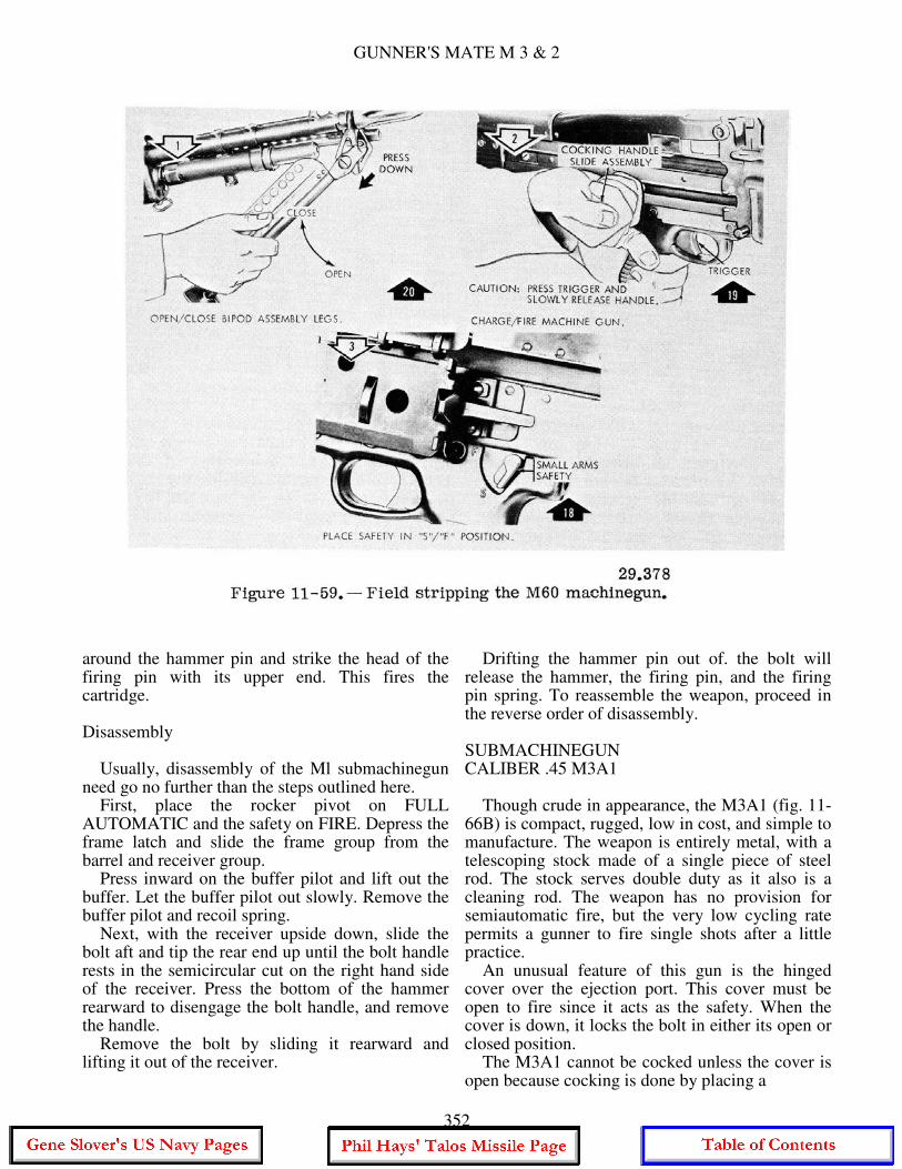
GUNNER'S MATE M 3 & 2
around the hammer pin and strike the head of the firing pin with its upper end. This fires the cartridge. Disassembly Usually, disassembly of the Ml submachinegun need go no further than the steps outlined here. First, place the rocker pivot on FULL AUTOMATIC and the safety on FIRE. Depress the frame latch and slide the frame group from the barrel and receiver group. Press inward on the buffer pilot and lift out the buffer. Let the buffer pilot out slowly. Remove the buffer pilot and recoil spring. Next, with the receiver upside down, slide the bolt aft and tip the rear end up until the bolt handle rests in the semicircular cut on the right hand side of the receiver. Press the bottom of the hammer rearward to disengage the bolt handle, and remove the handle. Remove the bolt by sliding it rearward and lifting it out of the receiver.
Drifting the hammer pin out of. the bolt will release the hammer, the firing pin, and the firing pin spring. To reassemble the weapon, proceed in the reverse order of disassembly. SUBMACHINEGUN CALIBER .45 M3A1 Though crude in appearance, the M3A1 (fig. 11-66B) is compact, rugged, low in cost, and simple to manufacture. The weapon is entirely metal, with a telescoping stock made of a single piece of steel rod. The stock serves double duty as it also is a cleaning rod. The weapon has no provision for semiautomatic fire, but the very low cycling rate permits a gunner to fire single shots after a little practice. An unusual feature of this gun is the hinged cover over the ejection port. This cover must be open to fire since it acts as the safety. When the cover is down, it locks the bolt in either its open or closed position. The M3A1 cannot be cocked unless the cover is open because cocking is done by placing a
352
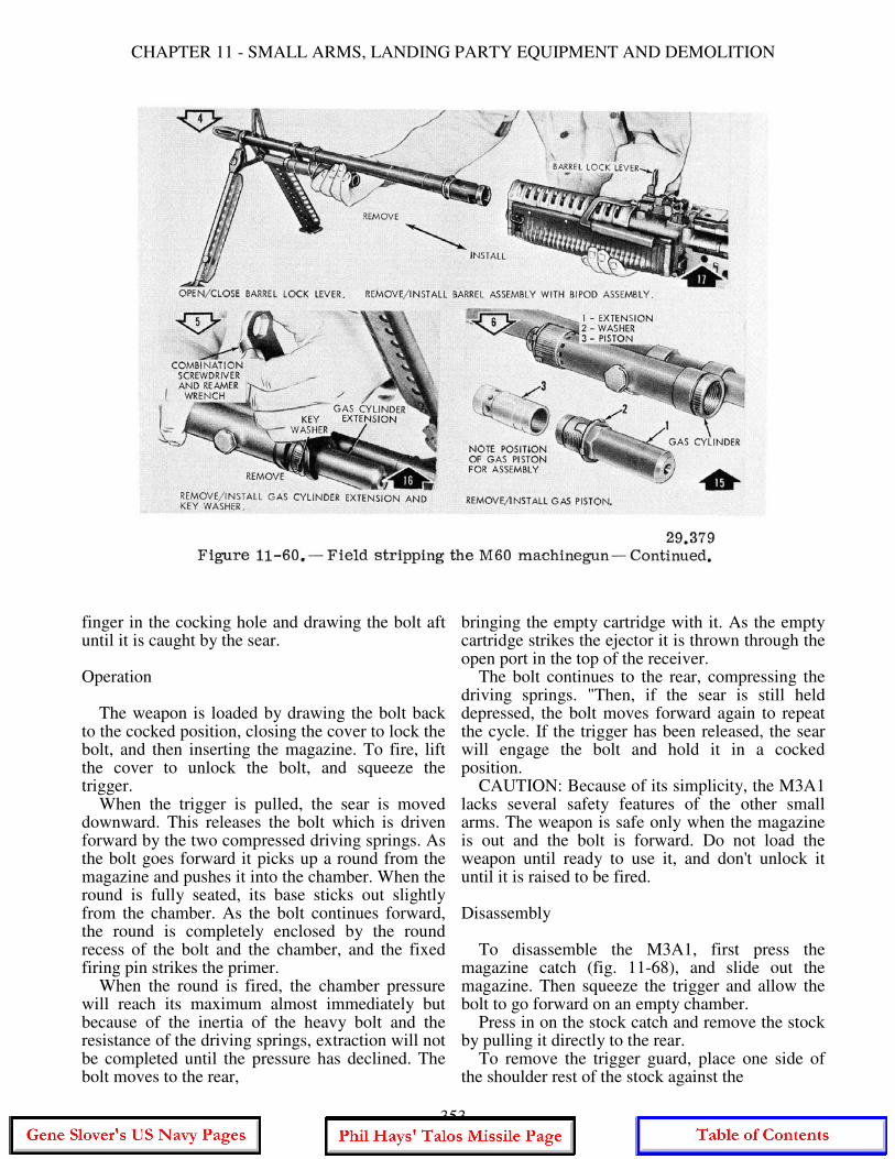
CHAPTER 11 - SMALL ARMS, LANDING PARTY EQUIPMENT AND DEMOLITION
finger in the cocking hole and drawing the bolt aft until it is caught by the sear. Operation The weapon is loaded by drawing the bolt back to the cocked position, closing the cover to lock the bolt, and then inserting the magazine. To fire, lift the cover to unlock the bolt, and squeeze the trigger. When the trigger is pulled, the sear is moved downward. This releases the bolt which is driven forward by the two compressed driving springs. As the bolt goes forward it picks up a round from the magazine and pushes it into the chamber. When the round is fully seated, its base sticks out slightly from the chamber. As the bolt continues forward, the round is completely enclosed by the round recess of the bolt and the chamber, and the fixed firing pin strikes the primer. When the round is fired, the chamber pressure will reach its maximum almost immediately but because of the inertia of the heavy bolt and the resistance of the driving springs, extraction will not be completed until the pressure has declined. The bolt moves to the rear,
bringing the empty cartridge with it. As the empty cartridge strikes the ejector it is thrown through the open port in the top of the receiver. The bolt continues to the rear, compressing the driving springs. "Then, if the sear is still held depressed, the bolt moves forward again to repeat the cycle. If the trigger has been released, the sear will engage the bolt and hold it in a cocked position. CAUTION: Because of its simplicity, the M3A1 lacks several safety features of the other small arms. The weapon is safe only when the magazine is out and the bolt is forward. Do not load the weapon until ready to use it, and don't unlock it until it is raised to be fired. Disassembly To disassemble the M3A1, first press the magazine catch (fig. 11-68), and slide out the magazine. Then squeeze the trigger and allow the bolt to go forward on an empty chamber. Press in on the stock catch and remove the stock by pulling it directly to the rear. To remove the trigger guard, place one side of the shoulder rest of the stock against the
353
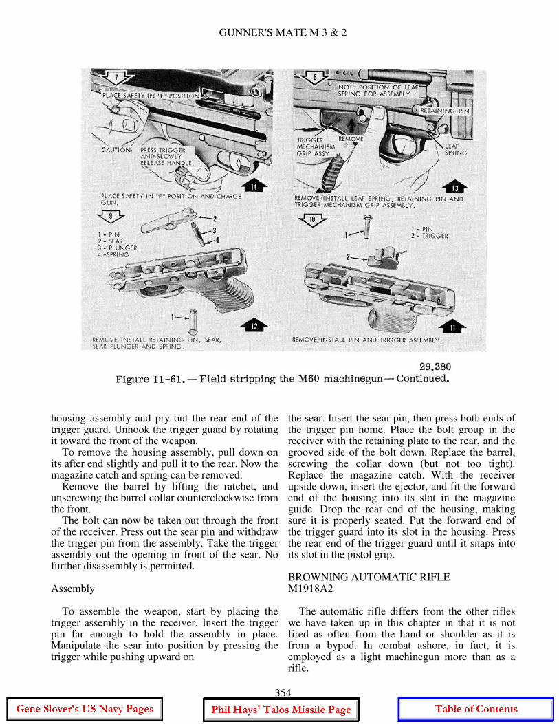
GUNNER'S MATE M 3 & 2
housing assembly and pry out the rear end of the trigger guard. Unhook the trigger guard by rotating it toward the front of the weapon. To remove the housing assembly, pull down on its after end slightly and pull it to the rear. Now the magazine catch and spring can be removed. Remove the barrel by lifting the ratchet, and unscrewing the barrel collar counterclockwise from the front. The bolt can now be taken out through the front of the receiver. Press out the sear pin and withdraw the trigger pin from the assembly. Take the trigger assembly out the opening in front of the sear. No further disassembly is permitted. Assembly To assemble the weapon, start by placing the trigger assembly in the receiver. Insert the trigger pin far enough to hold the assembly in place. Manipulate the sear into position by pressing the trigger while pushing upward on
the sear. Insert the sear pin, then press both ends of the trigger pin home. Place the bolt group in the receiver with the retaining plate to the rear, and the grooved side of the bolt down. Replace the barrel, screwing the collar down (but not too tight). Replace the magazine catch. With the receiver upside down, insert the ejector, and fit the forward end of the housing into its slot in the magazine guide. Drop the rear end of the housing, making sure it is properly seated. Put the forward end of the trigger guard into its slot in the housing. Press the rear end of the trigger guard until it snaps into its slot in the pistol grip. BROWNING AUTOMATIC RIFLE M1918A2 The automatic rifle differs from the other rifles we have taken up in this chapter in that it is not fired as often from the hand or shoulder as it is from a bypod. In combat ashore, in fact, it is employed as a light machinegun more than as a rifle.
354
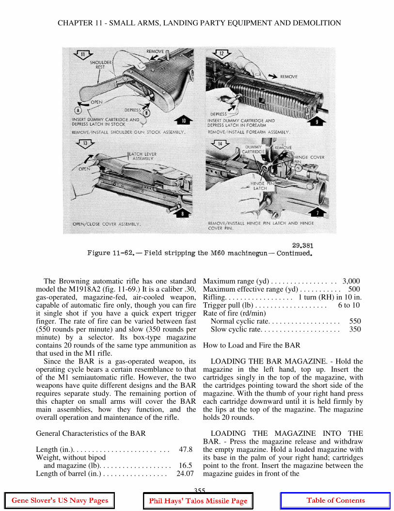
CHAPTER 11 - SMALL ARMS, LANDING PARTY EQUIPMENT AND DEMOLITION
The Browning automatic rifle has one standard model the M1918A2 (fig. 11-69.) It is a caliber .30, gas-operated, magazine-fed, air-cooled weapon, capable of automatic fire only, though you can fire it single shot if you have a quick expert trigger finger. The rate of fire can be varied between fast (550 rounds per minute) and slow (350 rounds per minute) by a selector. Its box-type magazine contains 20 rounds of the same type ammunition as that used in the M1 rifle. Since the BAR is a gas-operated weapon, its operating cycle bears a certain resemblance to that of the M1 semiautomatic rifle. However, the two weapons have quite different designs and the BAR requires separate study. The remaining portion of this chapter on small arms will cover the BAR main assemblies, how they function, and the overall operation and maintenance of the rifle. General Characteristics of the BAR Length (in.). . . . . . . . . . . . . . . . . . . . . . . . . 47.8 Weight, without bipod and magazine (lb). . . . . . . . . . . . . . . . . . . 16.5 Length of barrel (in.) . . . . . . . . . . . . . . . . . 24.07
Maximum range (yd) . . . . . . . . . . . . . . . . . 3,000 Maximum effective range (yd) . . . . . . . . . . . 500 Rifling. . . . . . . . . . . . . . . . . . 1 turn (RH) in 10 in. Trigger pull (lb) . . . . . . . . . . . . . . . . . . . 6 to 10 Rate of fire (rd/min) Normal cyclic rate. . . . . . . . . . . . . . . . . . . 550 Slow cyclic rate. . . . . . . . . . . . . . . . . . . . . 350 How to Load and Fire the BAR LOADING THE BAR MAGAZINE. - Hold the magazine in the left hand, top up. Insert the cartridges singly in the top of the magazine, with the cartridges pointing toward the short side of the magazine. With the thumb of your right hand press each cartridge downward until it is held firmly by the lips at the top of the magazine. The magazine holds 20 rounds. LOADING THE MAGAZINE INTO THE BAR. - Press the magazine release and withdraw the empty magazine. Hold a loaded magazine with its base in the palm of your right hand; cartridges point to the front. Insert the magazine between the magazine guides in front of the
355
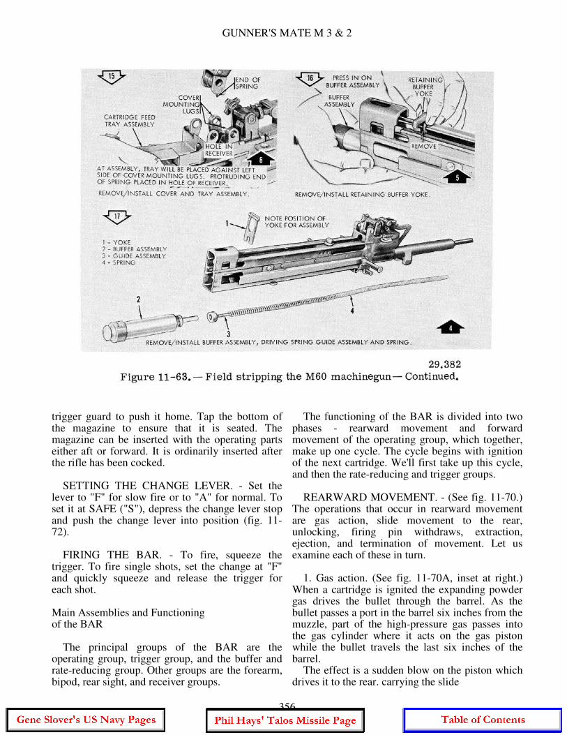
GUNNER'S MATE M 3 & 2
trigger guard to push it home. Tap the bottom of the magazine to ensure that it is seated. The magazine can be inserted with the operating parts either aft or forward. It is ordinarily inserted after the rifle has been cocked. SETTING THE CHANGE LEVER. - Set the lever to "F" for slow fire or to "A" for normal. To set it at SAFE ("S"), depress the change lever stop and push the change lever into position (fig. 11-72). FIRING THE BAR. - To fire, squeeze the trigger. To fire single shots, set the change at "F" and quickly squeeze and release the trigger for each shot. Main Assemblies and Functioning of the BAR The principal groups of the BAR are the operating group, trigger group, and the buffer and rate-reducing group. Other groups are the forearm, bipod, rear sight, and receiver groups.
The functioning of the BAR is divided into two phases - rearward movement and forward movement of the operating group, which together, make up one cycle. The cycle begins with ignition of the next cartridge. We'll first take up this cycle, and then the rate-reducing and trigger groups. REARWARD MOVEMENT. - (See fig. 11-70.) The operations that occur in rearward movement are gas action, slide movement to the rear, unlocking, firing pin withdraws, extraction, ejection, and termination of movement. Let us examine each of these in turn. 1. Gas action. (See fig. 11-70A, inset at right.) When a cartridge is ignited the expanding powder gas drives the bullet through the barrel. As the bullet passes a port in the barrel six inches from the muzzle, part of the high-pressure gas passes into the gas cylinder where it acts on the gas piston while the bullet travels the last six inches of the barrel. The effect is a sudden blow on the piston which drives it to the rear. carrying the slide
356
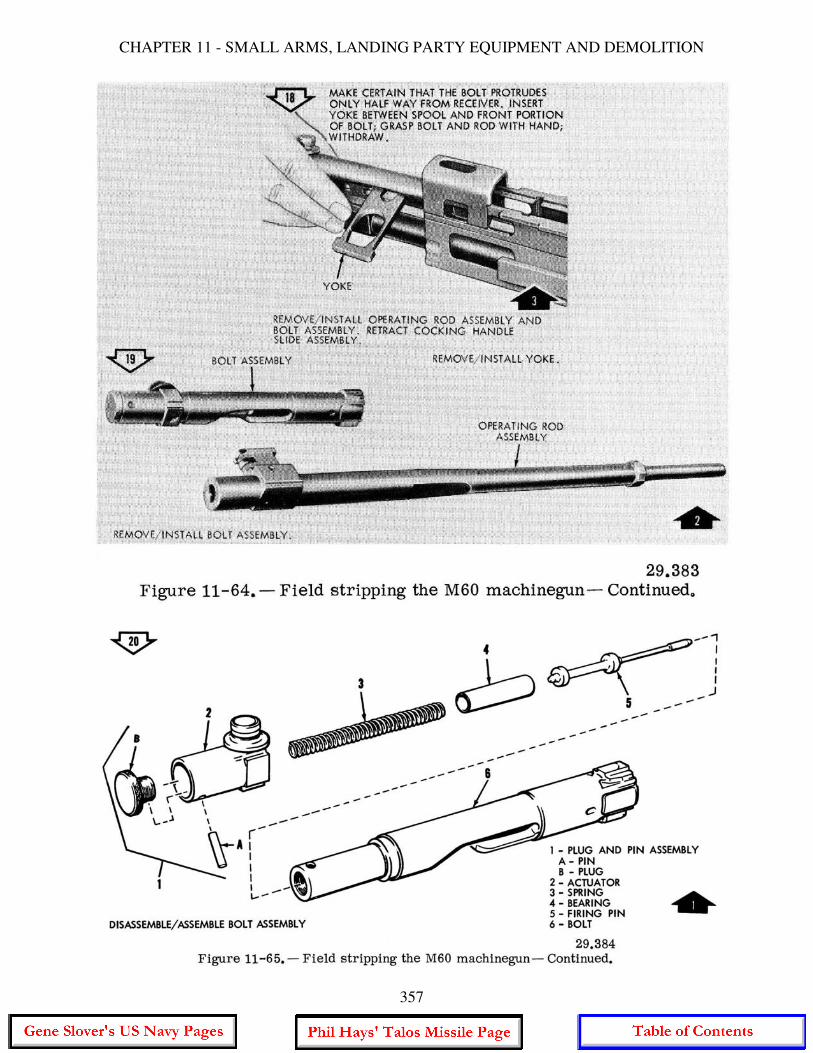
CHAPTER 11 - SMALL ARMS, LANDING PARTY EQUIPMENT AND DEMOLITION
357
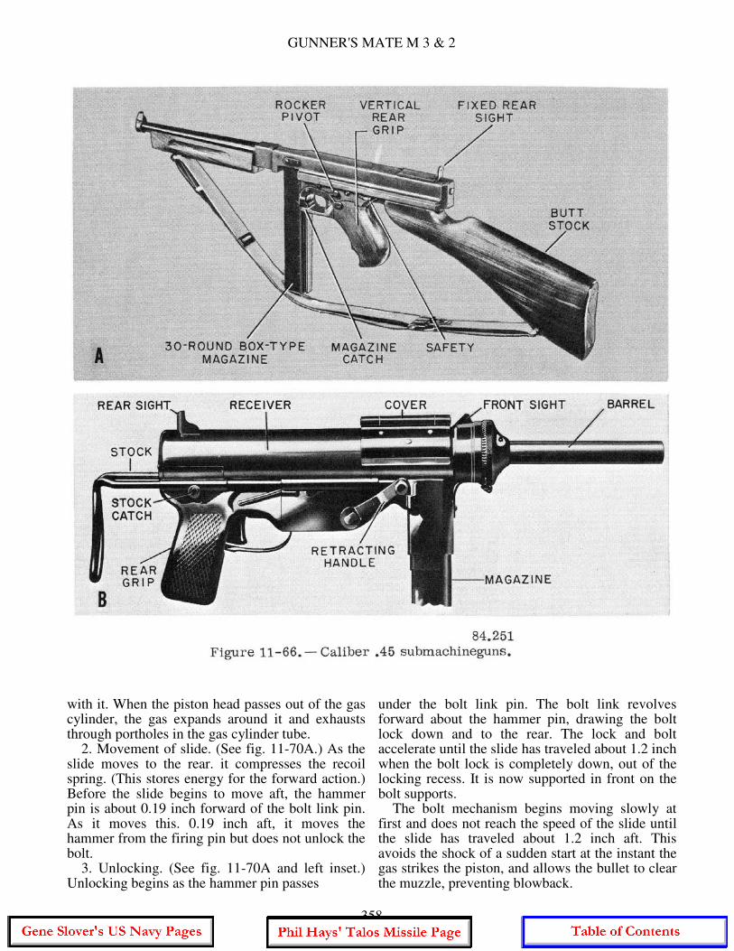
GUNNER'S MATE M 3 & 2
with it. When the piston head passes out of the gas cylinder, the gas expands around it and exhausts through portholes in the gas cylinder tube. 2. Movement of slide. (See fig. 11-70A.) As the slide moves to the rear. it compresses the recoil spring. (This stores energy for the forward action.) Before the slide begins to move aft, the hammer pin is about 0.19 inch forward of the bolt link pin. As it moves this. 0.19 inch aft, it moves the hammer from the firing pin but does not unlock the bolt. 3. Unlocking. (See fig. 11-70A and left inset.) Unlocking begins as the hammer pin passes
under the bolt link pin. The bolt link revolves forward about the hammer pin, drawing the bolt lock down and to the rear. The lock and bolt accelerate until the slide has traveled about 1.2 inch when the bolt lock is completely down, out of the locking recess. It is now supported in front on the bolt supports. The bolt mechanism begins moving slowly at first and does not reach the speed of the slide until the slide has traveled about 1.2 inch aft. This avoids the shock of a sudden start at the instant the gas strikes the piston, and allows the bullet to clear the muzzle, preventing blowback.
358
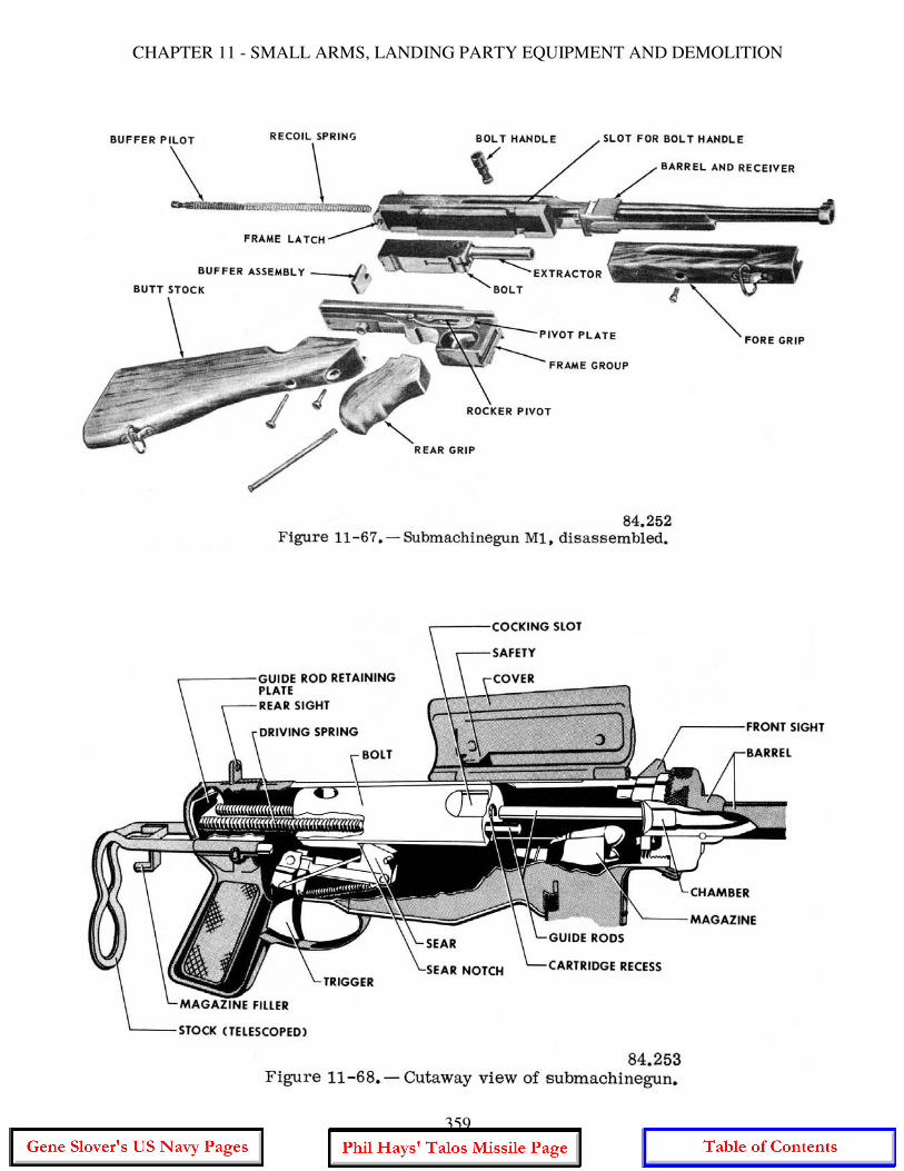
CHAPTER 11 - SMALL ARMS, LANDING PARTY EQUIPMENT AND DEMOLITION
359
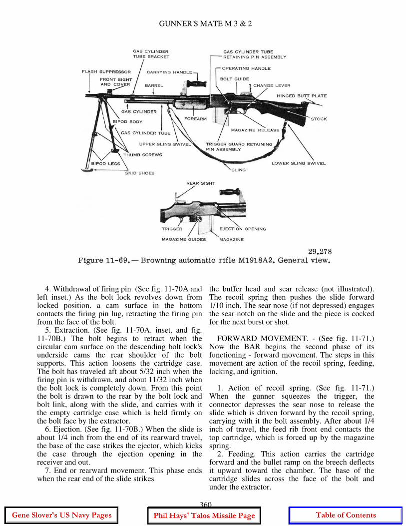
GUNNER'S MATE M 3 & 2
4. Withdrawal of firing pin. (See fig. 11-70A and left inset.) As the bolt lock revolves down from locked position. a cam surface in the bottom contacts the firing pin lug, retracting the firing pin from the face of the bolt. 5. Extraction. (See fig. 11-70A. inset. and fig. 11-70B.) The bolt begins to retract when the circular cam surface on the descending bolt lock's underside cams the rear shoulder of the bolt supports. This action loosens the cartridge case. The bolt has traveled aft about 5/32 inch when the firing pin is withdrawn, and about 11/32 inch when the bolt lock is completely down. From this point the bolt is drawn to the rear by the bolt lock and bolt link, along with the slide, and carries with it the empty cartridge case which is held firmly on the bolt face by the extractor. 6. Ejection. (See fig. 11-70B.) When the slide is about 1/4 inch from the end of its rearward travel, the base of the case strikes the ejector, which kicks the case through the ejection opening in the receiver and out. 7. End or rearward movement. This phase ends when the rear end of the slide strikes
the buffer head and sear release (not illustrated). The recoil spring then pushes the slide forward 1/10 inch. The sear nose (if not depressed) engages the sear notch on the slide and the piece is cocked for the next burst or shot. FORWARD MOVEMENT. - (See fig. 11-71.) Now the BAR begins the second phase of its functioning - forward movement. The steps in this movement are action of the recoil spring, feeding, locking, and ignition. 1. Action of recoil spring. (See fig. 11-71.) When the gunner squeezes the trigger, the connector depresses the sear nose to release the slide which is driven forward by the recoil spring, carrying with it the bolt assembly. After about 1/4 inch of travel, the feed rib front end contacts the top cartridge, which is forced up by the magazine spring. 2. Feeding. This action carries the cartridge forward and the bullet ramp on the breech deflects it upward toward the chamber. The base of the cartridge slides across the face of the bolt and under the extractor.
360
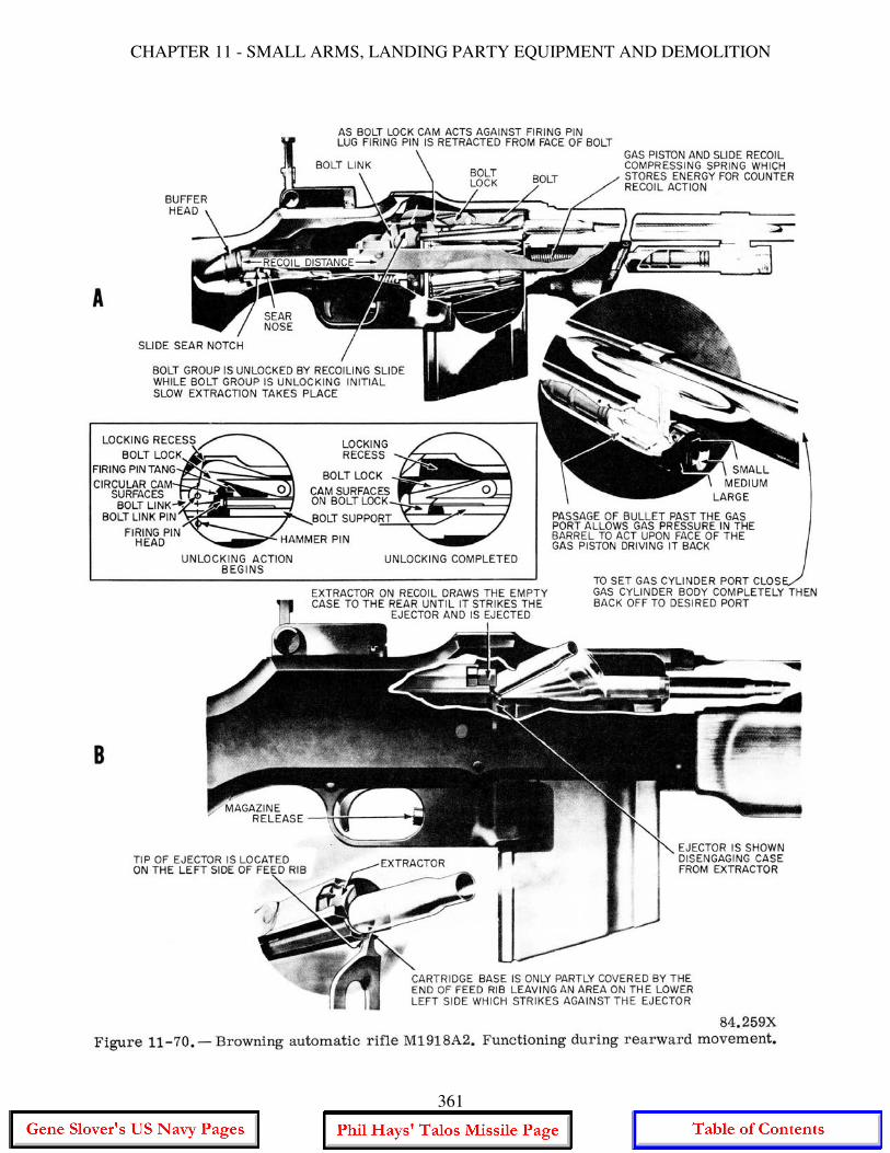
CHAPTER 11 - SMALL ARMS, LANDING PARTY EQUIPMENT AND DEMOLITION
361
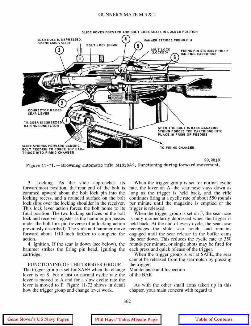
GUNNER'S MATE M 3 & 2
3. Locking. As the slide approaches its forwardmost position, the rear end of the bolt is cammed upward about the bolt lock pin into the locking recess, and a rounded surface on the bolt lock slips over the locking shoulder in the receiver. This lock lever action forces the bolt home to its final position. The two locking surfaces on the bolt lock and receiver register as the hammer pin passes under the bolt link pin (reverse of unlocking action previously described). The slide and hammer move forward about 1/10 inch farther to complete the action. 4. Ignition. If the sear is down (see below), the hammer strikes the firing pin head, igniting the cartridge. FUNCTIONING OF THE TRIGGER GROUP. - The trigger group is set for SAFE when the change lever is on S. For a fast or normal cyclic rate the lever is moved to A and for a slow cyclic rate the lever is moved to F. Figure 11-72 shows in detail how the trigger group and change lever work.
When the trigger group is set for normal cyclic rate, the lever on A. the sear nose stays down as long as the trigger is held back, and the rifle continues firing at a cyclic rate of about 550 rounds per minute until the magazine is emptied or the trigger is released. When the trigger group is set on F, the sear nose is only momentarily depressed when the trigger is held back. At the end of every cycle, the sear nose reengages the slide sear notch, and remains engaged until the sear release in the buffer cams the sear down. This reduces the cyclic rate to 350 rounds per minute, or single shots may be fired for each press and quick release of the trigger. When the trigger group is set at SAFE, the sear cannot be released from the sear notch by pressing the trigger. Maintenance and Inspection of the BAR As with the other small arms taken up in this chapter. your main concern with regard to
362
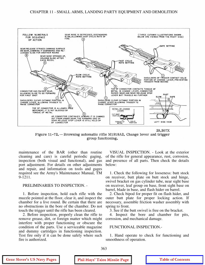
CHAPTER 11 - SMALL ARMS, LANDING PARTY EQUIPMENT AND DEMOLITION
maintenance of the BAR (other than routine cleaning and care) is careful periodic gaging, inspection (both visual and functional), and gas port adjustment. For details on other adjustments and repair, and information on tools and gages required see the Army's Maintenance Manual, TM 9-1211. PRELIMINARIES TO INSPECTION. - 1. Before inspection, hold each rifle with the muzzle pointed at the floor, clear it, and inspect the chamber for a live round. Be certain that there are no obstructions in the bore of the chamber. Do not touch the trigger until the rifle has been cleared. 2. Before inspection, properly clean the rifle to remove grease, dirt, or foreign matter which might interfere with proper functioning or obscure the condition of the parts. Use a serviceable magazine and dummy cartridges in functioning inspection. Test fire only if it can be done safely where such fire is authorized.
VISUAL INSPECTION. - Look at the exterior of the rifle for general appearance, rust, corrosion, and presence of all parts. Then check the details below: 1. Check the following for looseness: butt stock on receiver, butt plate on butt stock and hinge, swivel bracket on gas cylinder tube, near sight base on receiver, leaf group on base, front sight base on barrel, blade in base, and flash hider on barrel. 2. Check bipod for proper fit on flash hider, and outer butt plate for proper locking action. If necessary, assemble friction washer assembly with spring to front. 3. See if the butt swivel is free on the bracket. 4. Inspect the bore and chamber for pits, corrosion, and mechanical damage. FUNCTIONAL INSPECTION.- 1. Hand operate to check for functioning and smoothness of operation.
363
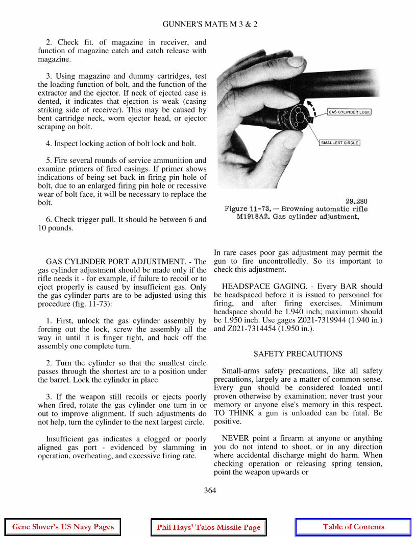
GUNNER'S MATE M 3 & 2
2. Check fit. of magazine in receiver, and function of magazine catch and catch release with magazine. 3. Using magazine and dummy cartridges, test the loading function of bolt, and the function of the extractor and the ejector. If neck of ejected case is dented, it indicates that ejection is weak (casing striking side of receiver). This may be caused by bent cartridge neck, worn ejector head, or ejector scraping on bolt. 4. Inspect locking action of bolt lock and bolt. 5. Fire several rounds of service ammunition and examine primers of fired casings. If primer shows indications of being set back in firing pin hole of bolt, due to an enlarged firing pin hole or recessive wear of bolt face, it will be necessary to replace the bolt. 6. Check trigger pull. It should be between 6 and 10 pounds. GAS CYLINDER PORT ADJUSTMENT. - The gas cylinder adjustment should be made only if the rifle needs it - for example, if failure to recoil or to eject properly is caused by insufficient gas. Only the gas cylinder parts are to be adjusted using this procedure (fig. 11-73): 1. First, unlock the gas cylinder assembly by forcing out the lock, screw the assembly all the way in until it is finger tight, and back off the assembly one complete turn. 2. Turn the cylinder so that the smallest circle passes through the shortest arc to a position under the barrel. Lock the cylinder in place. 3. If the weapon still recoils or ejects poorly when fired, rotate the gas cylinder one turn in or out to improve alignment. If such adjustments do not help, turn the cylinder to the next largest circle. Insufficient gas indicates a clogged or poorly aligned gas port - evidenced by slamming in operation, overheating, and excessive firing rate.
In rare cases poor gas adjustment may permit the gun to fire uncontrolledly. So its important to check this adjustment. HEADSPACE GAGING. - Every BAR should be headspaced before it is issued to personnel for firing, and after firing exercises. Minimum headspace should be 1.940 inch; maximum should be 1.950 inch. Use gages Z021-7319944 (1.940 in.) and Z021-7314454 (1.950 in.).
SAFETY PRECAUTIONS Small-arms safety precautions, like all safety precautions, largely are a matter of common sense. Every gun should be considered loaded until proven otherwise by examination; never trust your memory or anyone else's memory in this respect. TO THINK a gun is unloaded can be fatal. Be positive. NEVER point a firearm at anyone or anything you do not intend to shoot, or in any direction where accidental discharge might do harm. When checking operation or releasing spring tension, point the weapon upwards or
364
CHAPTER 11 - SMALL ARMS, LANDING PARTY EQUIPMENT AND DEMOLITION
in some safe direction before pressing the trigger. Never place the finger inside the trigger guard unless ready to fire. Do not work on a weapon you do not thoroughly understand. Ask a senior ordnanceman or other qualified personnel to instruct you if possible; otherwise refer to the proper technical publication. Never use force in disassembling and assembling small arms. They are all so constructed that undue force is unnecessary if parts are properly assembled or removed. Safety features should be frequently tested for proper functioning. For obvious reasons, an inoperative safety device is more dangerous than no safety device at all. In weapons with detachable magazines, always remove the magazine as the first step in unloading or clearing a stoppage. It should be noted that, in ALL magazine-fed weapons, the shape, position, and condition of the magazine lips are extremely critical and, if dented, will interfere with proper feeding of the cartridge into the chamber. The majority of stoppages in magazine-fed weapons is due to faulty magazines and consequently care must be taken when handling them not to cause damage. Before loading ammunition into the weapon, check for dirt, oil, grease, malformation, loose bullets, or other defects. Check the bore prior to firing to be sure it is free of foreign matter or obstructions. If, during firing, there is any indication of misfire or weak charge, make sure a bullet is not lodged in the bore. An obstructed bore will cause a serious accident when the next round is fired. To minimize danger from hangfire, wait 10 seconds after a misfire, then clear the weapon quickly. If the weapon cannot be cleared quickly and the barrel is hot, DANGER OF COOKOFF EXISTS. Leave the round in the chamber, point the weapon in a safe direction, and allow it to cool before removing the misfired round. SPECIAL PRECAUTIONS FOR PISTOLS AND REVOLVERS Automatic pistols in the hands of inexperienced or careless persons are largely responsible for the saying "It's always the unloaded gun that kills." It is a fact that many accidental deaths and injuries are due to a mistaken belief that removing the magazine of a pistol (or other magazine-fed weapon) is all that is necessary to unload it. Nothing could be further from the
truth. To completely unload a pistol or other magazine-fed weapon and render it safe to handle. it is necessary to not only remove or empty the magazine, but also to MAKE ABSOLUTELY CERTAIN THE CHAMBER IS EMPTY. The only way this can be done when handling the caliber .45 pistol is to pull back the slide and inspect the chamber either visually or by feel if it is dark. This should be done AFTER the magazine is removed, and with the muzzle pointed upward. Of course, if the chamber is loaded, the round will be extracted and ejected when the slide is operated. "I didn't know it was loaded" is never an excuse for the accidental discharge of a weapon - especially for the ordnanceman. When handling revolvers, a simple visual inspection is sufficient to determine if any chambers in the cylinder are loaded. Keep hammer fully down when pistol or revolver is not loaded. When the pistol is cocked, keep the safety lock in the ON position until ready to fire. Let's review briefly some of the safety precautions that apply to the handling of ALL small arms: 1. Never point a weapon at anyone unless you intend to kill him. 2. Unless the weapon is to be used immediately, never carry it with a round in the chamber. 3. Unless you are about to fire it, the safety of every small-arms weapon must always be ON. 4. Consider a gun loaded until you yourself have opened the chamber and verified that it is empty. It isn't enough to wail, afterward. "I didn't know it was loaded." The "empty" weapon is the dangerous one. 5. Before firing any weapon, be sure that there are no obstructions in the bore. 6. Before firing any weapon. be sure the ammunition you are using is the right ammunition. For example, the caliber .30 carbine cannot use standard rifle ammunition. Nor should you try to use Very signals with shotguns, even though they look much like shotgun shells. 7. Before firing, be sure there is no grease or oil on the ammunition or in the bore or chamber. Although lead bullets may be lightly waxed or greased, there must NEVER be any lubricant on the cartridge case. (This does not apply to aviation ammunition.) Lubricant on the case or chamber is particularly bad because, upon firing, the case slips backward, causing a dangerously heavy thrust against the bolt.
365
GUNNER'S MATE M 3 & 2
8. Keep ammunition dry and cool. Keep it out of the direct rays of the sun. Keep ammunition clean, but do NOT polish it or use abrasives on it. Do not attempt to use dented cartridges, cartridges with loose bullets, or cartridges eaten away by corrosion. Be particularly careful with tracer ammunition which can ignite spontaneously if damp. 9. Misfires and hangfires can occur with small-arms ammunition as well as with other types. On some weapons like the automatic pistol, the line-throwing gun, the Springfield rifle, the hammer-type shotgun, and a few others, you can recock and attempt to fire again without opening the breech. If, after a couple of tries, this proves unsuccessful or, if the weapon cannot be recocked without opening the bolt, wait at least 10 seconds, then open the bolt and eject the defective round. Defective small-arms ammunition should be disposed of in accordance with current regulations. It is prohibited to force out a bullet by firing another bullet. A misfire with blank cartridges may leave unburned powder deposited in the bore; always check the bore after any misfire and clean if necessary. 10. Guard against BLOWBACK. In this connection, blowback refers to leakage of high- pressure gases to the rear around the closed bolt. It can be caused either by excessive wear of the bolt or chamber, by obstructions that foul the bore, or by both. Blowback can be avoided by gaging and checking your weapons regularly and replacing worn parts as indicated, and by checking (see No. 5 above) to be sure that there are no obstructions in the bore.
THE LANDING PARTY As a Gunner's Mate, you must know how to issue, assemble, and demonstrate the use of landing party (infantry) equipment. To help you learn this, the Navy has issued a publication called the Landing Party Manual, OPNAV P34-03. It covers nearly all aspects of the naval landing party. It is interesting reading, and is recommended for all Gunner's Mates. In scope, this chapter falls somewhere between the simple requirements of the Third Class GM and the complete coverage of the Landing Party Manual. Here we will discuss the following:
The EQUIPMENT - what it is, how to make it up, and how to wear it. LANDING PARTY ASSIGNMENTS - what you might expect to be doing if you are assigned to a landing party. LIVING ASHORE - some factors to be considered when your living spaces and galley are miles away. Let's start the chapter by finding out what a landing party is.
THE SHIP'S LANDING PARTY To most sailors, the term landing party might bring to mind one of two things. First, a peaceful, if dull, march down main street in a parade or, second, mortal hand-to-hand combat with enemy troops ashore. While both situations are true functions of the landing party, they represent the extremes. The landing party may also be called away to help after a national disaster, to quell riots and other serious disorders, and to perform police functions such as the imposition of martial law. ORGANIZATION OF THE LANDING PARTY The size of a landing party varies, depending on the type of ship that lands it. A destroyer is required to maintain a 13-man rifle squad. A cruiser will furnish a rifle company of about 200 men. The common denominator of all landing parties, regardless of size, is the rifle squad, and our discussion here is based on this squad. Figure 11-74A shows an organization chart of a rifle squad. It is made up of the squad leader and three fire teams. Each of the fire teams consists of 3 riflemen and the individual fire team leader; thus there is a total number of 13 men in the squad. As a Gunner's Mate you will be the logical man to lead either a fire team or the entire squad. Figure 11-74B shows the result of combining the landing parties of three destroyers. This is the rifle platoon. Notice that, with the exception of the six people at the platoon headquarters, the major unit of the platoon is the rifle squad. You will find that the larger size landing parties employ some machine guns as well as rifles. A machine gun can deliver a heavy concentration of fire, but its crew is capable of
366
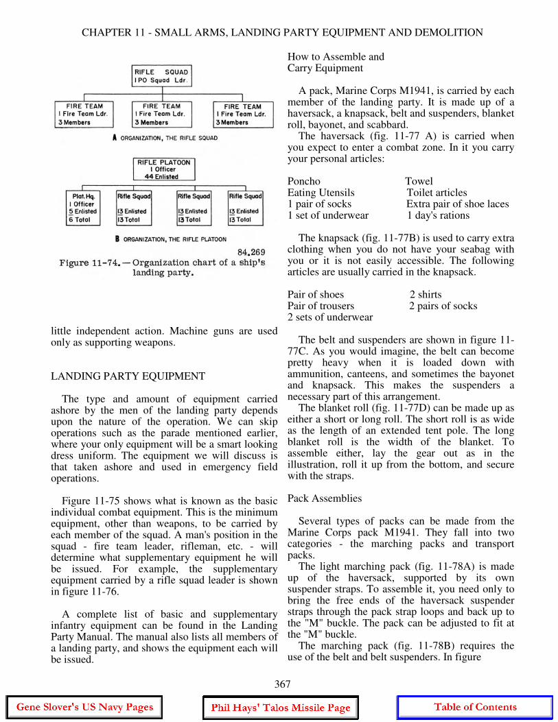
CHAPTER 11 - SMALL ARMS, LANDING PARTY EQUIPMENT AND DEMOLITION
little independent action. Machine guns are used only as supporting weapons. LANDING PARTY EQUIPMENT The type and amount of equipment carried ashore by the men of the landing party depends upon the nature of the operation. We can skip operations such as the parade mentioned earlier, where your only equipment will be a smart looking dress uniform. The equipment we will discuss is that taken ashore and used in emergency field operations. Figure 11-75 shows what is known as the basic individual combat equipment. This is the minimum equipment, other than weapons, to be carried by each member of the squad. A man's position in the squad - fire team leader, rifleman, etc. - will determine what supplementary equipment he will be issued. For example, the supplementary equipment carried by a rifle squad leader is shown in figure 11-76. A complete list of basic and supplementary infantry equipment can be found in the Landing Party Manual. The manual also lists all members of a landing party, and shows the equipment each will be issued.
How to Assemble and Carry Equipment A pack, Marine Corps M1941, is carried by each member of the landing party. It is made up of a haversack, a knapsack, belt and suspenders, blanket roll, bayonet, and scabbard. The haversack (fig. 11-77 A) is carried when you expect to enter a combat zone. In it you carry your personal articles: Poncho Towel Eating Utensils Toilet articles 1 pair of socks Extra pair of shoe laces 1 set of underwear 1 day's rations The knapsack (fig. 11-77B) is used to carry extra clothing when you do not have your seabag with you or it is not easily accessible. The following articles are usually carried in the knapsack. Pair of shoes 2 shirts Pair of trousers 2 pairs of socks 2 sets of underwear The belt and suspenders are shown in figure 11-77C. As you would imagine, the belt can become pretty heavy when it is loaded down with ammunition, canteens, and sometimes the bayonet and knapsack. This makes the suspenders a necessary part of this arrangement. The blanket roll (fig. 11-77D) can be made up as either a short or long roll. The short roll is as wide as the length of an extended tent pole. The long blanket roll is the width of the blanket. To assemble either, lay the gear out as in the illustration, roll it up from the bottom, and secure with the straps. Pack Assemblies Several types of packs can be made from the Marine Corps pack M1941. They fall into two categories - the marching packs and transport packs. The light marching pack (fig. 11-78A) is made up of the haversack, supported by its own suspender straps. To assemble it, you need only to bring the free ends of the haversack suspender straps through the pack strap loops and back up to the "M" buckle. The pack can be adjusted to fit at the "M" buckle. The marching pack (fig. 11-78B) requires the use of the belt and belt suspenders. In figure
367

GUNNER'S MATE M 3 & 2
368
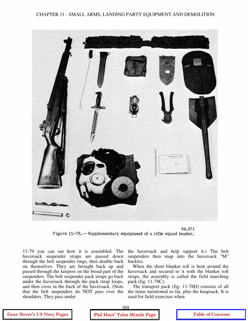
CHAPTER 11 - SMALL ARMS, LANDING PARTY EQUIPMENT AND DEMOLITION
11-79 you can see how it is assembled. The haversack suspender straps are passed down through the belt suspender rings, then double back on themselves. They are brought back up and passed through the keepers on the broad part of the suspenders. The belt suspender pack straps go back under the haversack through the pack strap loops, and then cross in the back of the haversack. (Note that the belt suspenders do NOT pass over the shoulders. They pass under
the haversack and help support it.) The belt suspenders then snap into the haversack "M" buckles. When the short blanket roll is bent around the haversack and secured to it with the blanket roll straps, the assembly is called the field marching pack (fig. 11-78C). The transport pack (fig. 11-78D) consists of all the items mentioned so far, plus the knapsack. It is used for field exercises when
369
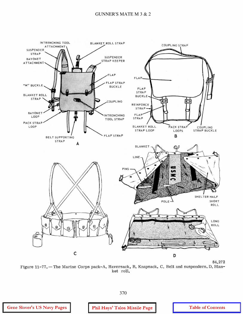
GUNNER'S MATE M 3 & 2
370
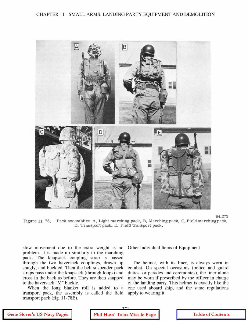
CHAPTER 11 - SMALL ARMS, LANDING PARTY EQUIPMENT AND DEMOLITION
slow movement due to the extra weight is no problem. It is made up similarly to the marching pack. The knapsack coupling strap is passed through the two haversack couplings, drawn up snugly, and buckled. Then the belt suspender pack straps pass under the knapsack (through loops) and cross in the back as before. They are then snapped to the haversack "M" buckle. When the long blanket roll is added to a transport pack, the assembly is called the field transport pack (fig. 11-78E).
Other Individual Items of Equipment The helmet, with its liner, is always worn in combat. On special occasions (police and guard duties, or parades and ceremonies), the liner alone may be worn if prescribed by the officer in charge of the landing party. This helmet is exactly like the one used aboard ship, and the same regulations apply to wearing it.
371
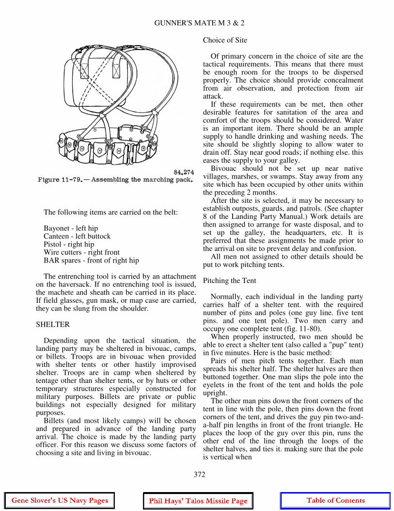
GUNNER'S MATE M 3 & 2
The following items are carried on the belt: Bayonet - left hip Canteen - left buttock Pistol - right hip Wire cutters - right front BAR spares - front of right hip The entrenching tool is carried by an attachment on the haversack. If no entrenching tool is issued, the machete and sheath can be carried in its place. If field glasses, gun mask, or map case are carried, they can be slung from the shoulder. SHELTER Depending upon the tactical situation, the landing party may be sheltered in bivouac, camps, or billets. Troops are in bivouac when provided with shelter tents or other hastily improvised shelter. Troops are in camp when sheltered by tentage other than shelter tents, or by huts or other temporary structures especially constructed for military purposes. Billets are private or public buildings not especially designed for military purposes. Billets (and most likely camps) will be chosen and prepared in advance of the landing party arrival. The choice is made by the landing party officer. For this reason we discuss some factors of choosing a site and living in bivouac.
Choice of Site Of primary concern in the choice of site are the tactical requirements. This means that there must be enough room for the troops to be dispersed properly. The choice should provide concealment from air observation, and protection from air attack. If these requirements can be met, then other desirable features for sanitation of the area and comfort of the troops should be considered. Water is an important item. There should be an ample supply to handle drinking and washing needs. The site should be slightly sloping to allow water to drain off. Stay near good roads; if nothing else. this eases the supply to your galley. Bivouac should not be set up near native villages, marshes, or swamps. Stay away from any site which has been occupied by other units within the preceding 2 months. After the site is selected, it may be necessary to establish outposts, guards, and patrols. (See chapter 8 of the Landing Party Manual.) Work details are then assigned to arrange for waste disposal, and to set up the galley, the headquarters, etc. It is preferred that these assignments be made prior to the arrival on site to prevent delay and confusion. All men not assigned to other details should be put to work pitching tents. Pitching the Tent Normally, each individual in the landing party carries half of a shelter tent. with the required number of pins and poles (one guy line. five tent pins. and one tent pole). Two men carry and occupy one complete tent (fig. 11-80). When properly instructed, two men should be able to erect a shelter tent (also called a "pup" tent) in five minutes. Here is the basic method: Pairs of men pitch tents together. Each man spreads his shelter half. The shelter halves are then buttoned together. One man slips the pole into the eyelets in the front of the tent and holds the pole upright. The other man pins down the front corners of the tent in line with the pole, then pins down the front corners of the tent, and drives the guy pin two-and-a-half pin lengths in front of the front triangle. He places the loop of the guy over this pin, runs the other end of the line through the loops of the shelter halves, and ties it. making sure that the pole is vertical when
372
CHAPTER 11 - SMALL ARMS, LANDING PARTY EQUIPMENT AND DEMOLITION
the line is taut. He then adjusts the rear tent pole through the eyelets in the rear of the tent. The first man pins down the rear corners of the tent, drives in the rear guy pin so that it is two-and-a-half tent pin lengths from the rear pin of the triangle, then adjusts the guy line. Then they pin down the sides. The tent should be trenched immediately after it is erected. This should be done even if the bivouac is for one night. Remember that this is only a basic method. The Landing Party Manual describes a drill method that is performed "by the numbers," but is similar to the one above. To strike pup tents, first unbutton enough buttons so that each man can grasp a tent pole and pull it to the left or right. When the tent is flat on the ground, pull the pins, finish unbuttoning the halves, and roll the packs. Hygiene and Sanitation Field sanitation is a term applied to the sanitary practices and principles which must be observed to maintain the health of the group when permanent type facilities are not available. In general they are the same common sense rules which apply to shipboard living.
In the field. however. they take on added importance. Improvisation is a necessity and, if it conforms to the correct principles, it should be encouraged. Basically, sanitation is concerned with food and water, and with waste disposal. Food should be obtained through your supply system. Emphasis must be placed on the proper preparation and handling of foods and the sanitizing of mess gear. A model field dishwashing unit can be set up by using a line of four GI cans. The first can in line is for garbage and waste; the second is a pre-wash can and has the soap in it; the third contains the hot water for quick and adequate washing of the mess gear; and the final can contains actively boiling water for rinsing. All water in the field should be regarded as unsafe for drinking until a medical officer or his representative has approved it. If it ever becomes necessary to use water from an unapproved source, it must be chemically treated or boiled. Boiling in this case means boiling for 20 minutes, not just heating it up. Water can be chemically treated by using the Lyster bag and kit, or by water purification tablets. Both are issued with instructions for their use. Chemically treated water may not taste so good but it is safe.
373

GUNNER'S MATE M 3 & 2
Waste disposal is important. Proper disposal is necessary to eliminate places where rodents and insects can live and breed. Human waste especially must be disposed of correctly since a careless unit may so contaminate a site that it will be unfit for further use for months. Kitchen waste and human waste are deposited in trenches which are dug according to the instructions in chapter 7 of the Landing Party Manual. Personal hygiene deals with the efforts you must put forth to keep in good physical, mental, and moral health, and to protect yourself from disease. Obeying the following rules of field sanitation is a matter of hygiene. 1. In the case of a suspected illness or disease, see the corpsman. It has been said, "A person who treats himself has a fool for a patient." By postponing proper treatment, you may not only harm yourself but be a source of danger to your shipmates. 2. Eat your meals slowly. Don't eat to excess, and never have a big meal before a long march or other strenuous exercise. 3. Drink plenty of water, but not all at one time. Drink only from your own cup or canteen. 4. The entire body should be bathed at least three times a week. Feet should be washed daily and dusted with powder. Care of feet is a primary factor in marching ability. 5. While it is comparatively easy to destroy vermin with DDT, every effort must be made to keep them from getting a start amongst your group. Body lice (which actually live in the clothing rather than on the body) can transmit serious diseases. The best way to prevent lice is to keep a clean body, and to change frequently to clean clothes. The information in this section of the chapter is, of course, just as important aboard ship as shore, and you have been drilled in these matters many times. Aboard ship, compliance with sanitation and personal hygiene rules is well supervised, with immediate penalties for the wrongdoer. Ashore, however, it becomes a matter of self-discipline. There is no compartment cleaner, scullery men, master-at-arms, etc. Ashore, the duties of these individuals are wrapped up in one man - you.
STOWING, ISSUING, AND MAINTAINING LANDING PARTY EQUIPMENT Most ships have a landing force locker or at least a space designated especially for the stowage of landing party equipment. You will be responsible for the security of this equipment. Much of the equipment, and all weapons, are highly pilfer able items. The rule is to keep the space locked, and impose strict accountability for the key. All small arms are considered equipage, and a signature of subcustody is required before they are issued from their normal place of stowage. Signatures of custody may also be required (at the weapons officer's discretion) before issuing other items of landing party equipment such as knives, canteens, and ponchos. It is important to get the signature of the man receiving the equipment, any type of signed custody record can be used. The important thing is to keep the equipment locked up and, when it is issued, get a signature. While some pieces of landing party equipment (such as tents and ponchos) are water resistant, they should not be folded and stowed while wet. This will cause mildew to attack the fabric. When tents are erected, they should be slackened. A tent will shrink when drying out after a rain. On occasion, tents whose lines have not been slackened have split down the middle upon drying. When the contents of a canteen have been used, empty it entirely. Even a small amount of water left in it will cause slight corrosion, and a disagreeable odor and taste. Leather shoes and boots can be treated with saddle soap. The application should be thorough in order to clean and soften the footwear, and to replace some of the oil in the leather. Mess gear should be clean and dry before you pack it away. After the final rinse in boiling water, dry these items by shaking them in the air. Do not use a cloth to dry them. Upon being issued a weapon, the receiving individual becomes responsible for its proper care and use. This requires training, which is the job of the Gunner's Mate. Instructions for the operation, maintenance, and repair of infantry weapons were covered earlier in this chapter. When operating with a landing party, there is a good possibility that the hand grenade will be used. The following section briefly discusses types of hand grenades and steps required for their safe and proper use.
374
CHAPTER 11 - SMALL ARMS, LANDING PARTY EQUIPMENT AND DEMOLITION
HAND GRENADES
A hand grenade is a small bomb with the user's arm providing the motive power to get it to the target. Hand grenades may be filled with explosives, explosives and chemicals, or (for practice purposes) may be empty or contain inert filler. Hand grenades come in many sizes, shapes, and types and are designed to fulfill a wide variety of purposes. They can be used for providing material and personnel casualties; for screening, signaling, and illuminating; for demolition and harassing; and for incendiary action. TYPES AND CHARACTERISTICS The general types of hand grenades issued by ordnance are: (1) training, (2) practice, (3) fragmentation, (4) offensive, and (5) chemical. Each type is designed to do a special job. For a summary of the characteristics and capabilities of each hand grenade refer to Army Field Manual FM 23-30. Certain characteristics, common to all hand grenades, are: 1. The range of a hand grenade is relatively short. The range depends on the ability of the individual and the weight and shape of the grenade. A well trained sailor should be able to throw the fragmentation hand grenade an average of about 44 yards. He may average only about 27 yards with the heavier white phosphorous smoke grenade. 2. The effective casualty radius of a hand grenade is relatively small when compared to that of other weapons. Effective casualty radius is defined as the radius of a circular area around the point of detonation within which at least 50 percent of the exposed personnel will become casualties. The effective casualty radius varies with the type of hand grenade used, so the casualties can and do occur at distances greater than this radius. 3. Delay type fuzes are used in all standard hand grenades. Detonation of the grenade is not on impact, but after the delay element in the fuze has burned. The fuze assembly (fig. 11- 81) consists of a fuze body, safety lever, safety pin, striker spring, a primer, a delay element, and detonator or igniter. For further information about the operation of the fuze assembly, refer to FM 23-30. All casualty-producing grenades (fragmentation, offensive, and while phosphorous) have a 4- to 5-second delay. Because
of this short delay, personnel must stay alert when arming and throwing hand grenades. PROCEDURES FOR THROWING For greater accuracy and range, the grenade should be thrown like a baseball, using the throwing motion most natural to the individual. It is important to grip the grenade properly. Figure 11-82 shows the proper position of the grenade prior to pulling the safety pin. First cradle the grenade in the fingers of the throwing hand. Hold the safety lever down firmly under the thumb, between the tip and first finger joint. In this way, the grenade fits snugly into the curved palm of your hand, giving you a firm, comfortable grip, but don't relax your thumb pressure on the safety lever until you throw the grenade. The first steps in grenade throwing are to develop good throwing habits, and several throwing positions. Four throwing positions are recommended: (1) standing, (2) kneeling, (3) prone, and (4) crouch.
375
GUNNER'S MATE M 3 & 2
The procedures for throwing from the standing position are as follows: 1. Stand half-facing the target, with your weight balanced equally on both feet. Hold grenade chest high, using the correct grip (view 1 fig. 11-83). 2. Pull pin with a twisting, pulling motion. Cock your throwing arm to the rear (view 2). 3. Throw the grenade with a free and natural motion. As it leaves your hand, follow through by stepping forward with your rear foot (view 3). Observe the point for probable strike, then duck your head to avoid fragments or other effects. 4. Recover, then resume the original standing position. Field Manual 23-30 explains the proper steps to be taken when using any of the other positions.
SAFETY The following safety precautions must be observed when handling or using hand grenades: 1. Do not take any grenade apart unless ordered to do so by competent authority.
2. Do not tamper with grenades and do not recover or tamper with live grenades that fail to explode (duds). These duds are recovered and destroyed only by qualified personnel. 3. Do not pull the safety pin until you are ready to throw the grenade. If the safety pin will not pullout easily with a pulling-twisting motion, straighten its ends. In the majority of cases, this will not be necessary. Maintain a firm grip on the safety lever when removing the safety pin. 4. After you pull the safety pin, throw the grenade. Do not attempt to replace the pin in order to return it to a safe condition. 5. When throwing a fragmentation grenade without protective cover, drop immediately to a prone position, face down, with your helmet toward the grenade. Keep your arms and legs flat against the ground. Other men in the area who are exposed must be warned to drop to a similar position. Steel helmets must be worn at all times when using grenades.
376

CHAPTER 11 - SMALL ARMS, LANDING PARTY EQUIPMENT AND DEMOLITION
6. Although little danger is involved in using practice hand grenades, they require some degree of care in handling and throwing. You can throw the practice grenade a safe distance but, for the purpose of training and to preclude injury from an improperly loaded grenade, take cover. Wear the steel helmet, and keep all other personnel at a safe distance. Practice grenades that fail to function (duds) are not recovered for at least 10 minutes, and then only by trained personnel. 7. Grenades are issued in the "with fuze and without fuze" condition. They are not necessarily shipped in separate containers. The detonator of a fuze is very sensitive to heat, shock or friction. Army Field Manual FM 23-30 explains the safety precautions and steps taken when fuzing hand grenades.
DEMOLITION If you are assigned to the Seabees, your job as a GM will have a lot to do with handling of explosives and demolition materials. Demolition equipment also is issued to ships for use in eliminating hazards to navigation, and the Gunner's Mates aboard are responsible for handling it. A subject like this is not, of course, to be covered in a single section of one chapter. The use of explosives and associated blasting equipment for construction projects or large- scale demolition involves highly developed skills. These skills are developed through intensive training and a great deal of experience. It was pointed out at the beginning of this chapter that the information on demolition contained in this chapter is to familiarize the GM with the explosives and equipment used in demolition work. It is NOT intended as a self-teaching text to train GMs to become experts in demolition. The discussion in this section will give you some idea of the tools used, and the names and uses of some of the more important explosives and other materials involved in this work. We will not try to cover the specific practical application of demolition explosives. For a much more detailed discussion, which includes other demolition equipment and techniques, you should read OP 2212, Vol. 1, Demolition Materials.
DEMOLITION CHARGES The demolition explosive usually issued to ships is most often TNT, in cast or pressed form, but it may be Tetrytol. The explosives come in half-pound and 1-pound blocks (fig. 11-84). TNT is also the main component of the 55-pound demolition charge. The half-pound and 1-pound blocks are issued in cardboard boxes, and can be used either by themselves or as boosters to set off larger charges. Both sizes are made with cap wells (or activator wells) into which you can insert blasting caps (which we will presently explain). The Mk 2 demolition charges (fig. 11-85) now issued to ships have rectangular rust- resisting steel cases a little over 9 inches square and a little over 14 inches high. Mods 2 and 3 (earlier mods are obsolete) are similar except that the Mod 2 has handling lugs. The 1-pound TNT block that is used as a booster to detonate the charge fits into a cavity in the main cast charge; the blasting cap that sets off the 1-pound block is screwed into the block's activator well. Figure 11-85 shows the charge as set up for blasting. The blasting cap is not inserted until just before the charge is set off. BLASTING CAPS Blasting caps are used for initiating high explosives. They are designed to be inserted in cap wells of demolition charges, and are also the detonating element in certain land mine firing devices. Special military blasting caps are designed to detonate the less sensitive explosives like TNT, military dynamite, and tetrytol. Blasting caps are extremely sensitive and may explode unless handled carefully. They must be protected from shock and extreme heat and not tampered with. Blasting caps must never be stored with other explosives. Two types, electric and nonelectric, are used in military operations. Nonelectric Blasting Cap The Cap, Blasting Special, Nonelectric (fig. 11-86) is capable of detonating all standard types of demolition material that has been properly primed with the blasting cap for nonelectric firing. The nonelectric blasting cap is contained in a clear-lacquered copper or aluminum tube. Three small explosive charges; the ignition
377
GUNNER'S MATE M 3 & 2
charge, priming charge, and base charge are assembled in layers in the partially filled tube. A portion of the tube remains empty so the blasting cap can be fitted over and crimped to a time blasting fuse or the snout of a coupling base. A flame from either a time blasting fuse, detonating cord, or special firing device will ignite the ignition (flash) charge. This ignites the priming charge which, in turn, detonates the base charge. This blasting cap, along with time blasting fuse, is used for firing demolition charges nonelectrically. This method, while not the preferred one (electrical firing is safer), is used under many conditions because of the light weight of the material and speed of placement and use.
NOTE: Fuse. A fuse is a slow-burning powder-filled cord that carries flame to an explosive or combustible mass after burning for a predetermined time. Fuze (Not to be confused with Fuse). The term fuze is a general one applying to any device that causes detonation, expulsion, or ignition upon the fulfillment of certain conditions. such as completion of a time delay, certain disturbances, impact, or inertia. The term is usually used in connection with bombs, pyrotechnics, or rocket heads. In demolition work, the term fuze is sometimes used interchangeably with the term firing device.
For all the details on the use of nonelectric blasting caps and their methods of ignition.
378

CHAPTER 11 - SMALL ARMS, LANDING PARTY EQUIPMENT AND DEMOLITION
it is recommended that you read FM 5-25. Explosives and Demolitions and OP 2212; Vol. 1. Demolition Materials. Figure 11-87 illustrates the method used in setting up a cap and fuse for nonelectric firing of a demolition charge. The burning rate of time fuse will vary by the way it is handled and the conditions under which it is burned. So testing of the burning rate is essential before setting up a charge for demolition with a nonelectric blasting cap. The burning rate of fuses issued by the NavOrdSysCom varies between 30 and 45 seconds per foot. Refer to figure 11-87 while we briefly go through the procedure of setting up a charge. STEP 1. Cut off and discard a 6 to 12 inch portion of the exposed end of the blasting time fuse. A test must be made of the burning rate by burning a 6-foot sample length of time fuse. The 6-foot sample length should be tested from the same coil that will be utilized for the shot. The sample length should be initiated by an M60 Time Blasting Fuze Igniter if available. STEP 2. Cut off the desired length of time fuse and push it through the hole in the unthreaded end of the priming adapter. STEP 3. Remove one nonelectric blasting cap from its box. Check inside the cap to ensure it is clear of obstructions. Check the end of
379
GUNNER'S MATE M 3 & 2
the time fuse to ensure a square cut. Insert the time fuse into the cap (DO NOT TWIST OR TAP). Crimp the cap onto the time fuse 1/8 inch from the open end of cap. Use only the crimping tool to crimp caps. (DO NOT CRIMP NEAR FACE). STEP 4. Insert the cap into the activator well of the demolition charge. Screw the adapter into the charge to hold the blasting cap in place. If screw adapters are not available, some means should be taken to prevent the cap from coming loose from the charge, such as wrapping a string tightly around the block a few times and tieing it securely over the well as shown in fig. 11-88. STEP 5. The blasting time fuse may be lighted two ways. The first, which should always be used if available, is the M60 Time Blasting Fuze Igniter. Since it is the safest and surest method. If the M60 fuze igniter is used, it should be installed on the time fuse, prior to the installation of the blasting cap. The second way is by a wooden match. Slit the time fuse longitudinally and insert a match in the slit so that the
head of the match protrudes slightly from the side of the time fuse. Hold the match and match box as shown in illustration No. 5 of figure 11-87 and draw the abrasive side of the match box against the match head. Do not attempt to light the match unless you are prepared to do it successfully the first time. After you have struck the match, depart vicinity and take cover - even though the attempt appears to be unsuccessful. Walk calmly but smartly to a safe area - NEVER RUN. If a long distance is necessary to reach the safe area, then additional length should be allowed on the blasting time fuse. STEP 6. If a misfire is encountered, wait 30 minutes plus time for the blasting time fuse to burn. Electric Blasting Caps Figure 11-89 shows Cap. Blasting. Special. Electric Type. Nos. 1-10 Delay. The cap comes in 10 delay types, with each delay type differing in length as well as delay time. The delay
380
CHAPTER 11 - SMALL ARMS, LANDING PARTY EQUIPMENT AND DEMOLITION
time and consequently the length of a particular cap is dependent on the amount of delay charge contained in the delay element. It can be seen in the figure that the construction of an electric blasting cap is simplicity
in itself. An electric current heats a wire bridge, setting off the heat-sensitive priming charge which. in turn. sets off the PETN base charge. This detonates the TNT block into which the cap has been inserted; if the block is the booster to a larger main charge, the train of explosions comes to an end with the detonation of the main charge. Another type of electric blasting cap is shown in figure 11-90. This is the Cap, Blasting, Electric. M6 and is used as the previously mentioned caps, to initiate high explosives. The cap consists of an aluminum alloy cup containing a base charge of RDX, intermediate charge of lead azide and an ignition charge of lead styphnate and barium chromate. The lead wires are 12 feet long and extend through a rubber plug assembly or a cast sulphur and rubber assembly into the ignition charge where they are connected to a wire bridge. The electrical characteristics of the M6 are so closely controlled that caps of this model, of different manufacturers, may be mixed in a firing circuit without causing misfires. A short-circuiting tab or shunt, as in other electric blasting caps, fastens the leads together to prevent accidental electric firing of the cap. These must NOT be removed until just before the cap is wired into the firing circuit.
381
GUNNER'S MATE M 3 & 2
The electric blasting cap fits into the activator well of the demolition charge. But it doesn't fit tightly and can easily slip out. To hold the cap in the charge you use a primer adapter, a small plastic cylinder that screws into the threaded end of the TNT block and holds the cap in place. Figure 11-91A shows the adapter assembled in the block, with part of the adapter cut away to show how it holds the cap in place. Figure 11-91B illustrates the two steps in assembling the adapter and cap before they go into the charge. These steps are described in the next section of this chapter. The other equipment used for electrical firing of demolition charges include a blasting machine for supplying current to the blasting cap (fig. 11-92), wire or cable of required length (the cable may be on a special reel like the one shown in figure 11-93 for connecting the machine to the charge, insulating tape for protecting the splices which connect the cable to the caps, and a blasting galvanometer for testing the circuit before you fire the charge.
BASIC PROCEDURES FOR SETTING UP AN ELECTRICAL CIRCUIT AND BLASTING As a second class Gunner's Mate, you must be able to demonstrate your ability to work with the demolition equipment on your own ship. In general, this will most likely mean that you will have to show that you can work with the equipment we have discussed so far in this section. Of course, nothing you read here or elsewhere will make you a genuine expert with demolitions. You need real training and experience with the gear for that. But, so that you can see how all the equipment we have described is used together, let's take up, step by step, the procedure for preparing and setting off a demolition setup, using demolition charges Mk 2 Mods 2 or 3 and electric blasting caps. 1. Determine where the charges are to be placed. This, of course, depends on what is being demolished and the purpose of demolition. If you're sinking a floating hulk that's a menace to navigation, place the charges so that the hulk will go down promptly in water deep enough so
382
CHAPTER 11 - SMALL ARMS, LANDING PARTY EQUIPMENT AND DEMOLITION
that it will be out of the way. Make sure that all WT (water tight) doors are open. If you're scuttling your own ship (this sad possibility is fortunately not frequent, but it might be necessary in the event of imminent capture by the
enemy), you must, in addition, make it as difficult as possible for anybody ever to use the ship again. Or you may be wiring up small charges to be used in destroying secret or confidential equipment against the possibility of capture. You'll be guided by orders from competent authority, but you must know something about demolition techniques. 2. Usually you will set off several charges at once. To do this, you place the charges and make up a circuit which includes the blasting machine and all the charges in series. First you wire in all the caps, then connect them to the cable, and then test the circuit. Here are these steps in more detail: a. Make sure your caps are all of the same manufacturer. Except for the M6 which was described earlier, caps of different make should
383
GUNNER'S MATE M 3 & 2
NEVER be used together in one circuit. Be sure not to use more caps than your blasting machine is designed to handle; it's better to use fewer. When you take caps out of their box, don't try to pry them loose with a sharp instrument; use your fingers, and slide them out carefully. Examine the caps before wiring them up; reject any that show signs of moisture or corrosion. b. Grasp the wire above the cap and straighten the coils from the wire leads, being careful not to put tension between cap and wire leads. Place caps behind a suitable barrier or in a heavy gauge bucket. Test each cap individually as far away from the bucket or barrier as the leads will allow with the galvanometer. After test of cap, shunt the cap by twisting the two wire legs together. Do this until you have tested the number of blasting caps you will use. c. You make electrical tests for demolition setups with only one instrument- the blasting galvanometer. (See fig. 11-93A.) You must NEVER use any other instrument. The blasting galvanometer is in a box, usually protected by a leather case, with a dial face on which you can see the galvanometer needle. It contains its own small batter as a source of current. At the base of the box are two terminals - flat metal discs. You test by touching the wires you are testing to the terminals. If current flows (and the currents indicated by the galvanometer are very tiny ones that will not set off a blasting cap), the needle deflects. d. First you test both cable conductors BEFORE they are connected to anything. (Make sure their ends are not twisted together.) You should get NO steady indication on the galvanometer. (But it's O.K. for the needle to flick, then return to zero.) If you DO get a steady galvanometer needle deflection, there is a current leak or short circuit in the cable (caused by defective insulation or conductors touching each other). If the trouble cannot be rectified, use other cable that will test O.K. e. Next, you wire the cable to the caps (but do NOT connect the blasting machine). Test the complete circuit by touching the cable terminals at the "reel end" (where the blasting machine will be connected) to the galvanometer. (See fig. 11-93B). This time you should get a definite steady needle deflection. If you don't, go over your circuit and repair it where it's broken. Test each splice and cap individually, if necessary. Or you may use the procedure described in the next section of this chapter for locating breaks in the circuit.
f. After testing the circuit, the next step is to set each blasting cap in its charge. Open the top of the charge shipping box. (The charge need not be removed from the shipping box to be used. however.) Break the paper seal protecting the activator well in the booster but don't use the blasting cap as a tool. Make sure there is no dirt in the well. Then slip the leg wires of the cap through the priming adapter's wire slot with the threaded end of the adapter pointing toward the cap (fig. 11-91). If the leg wires don't slide readily through the slot, don't try to force them by pulling on the cap. Grasp the wires about 6 inches from the blasting cap and slide the adapter slot along the wires away from the cap. Tilt the adapter as you do this. to make the entry of the wires easier. Now insert the cap gently all the way into the activator well; hold the adapter away from cap until it's all the way in. Then work the adapter down the wires until it reaches the well, and screw it in gently but firmly as far as it will go. Last, tie the wires so that the cable doesn't strain them at the cap. The Mk2 Mods 2 and 3 charges have cable anchors under the bolts in the booster covers that can be used to secure the cable. If you haven't tested the circuit, do it now. If time permits, it may be a good idea to do it again even if you tested it before assembling the caps into their charges. 3. The last step is to connect the blasting machine. Make sure everything else is in readiness, and that all personnel have cleared the danger area. Connect the cable to the blasting machine. Most blasting machines have removable handles; don't put the handle on until after the machine is connected, and just before you blast. To operate the machine, twist the handle smartly through its full range. 4. If the blast does not occur, remove the handle of the machine (and put it into your pocket to make sure nobody operates the machine inadvertently) and DISCONNECT the machine. Then, after 30 minutes and only then. is it safe to investigate the trouble further. PROCEDURE FOR LOCATING BREAKS IN THE FIRING CIRCUIT Here is a way (illustrated in fig. 11-94) in which a break in the firing circuit may be located if the circuit test from the reel end indicates an open circuit, or if you have a misfire.
384
CHAPTER 11 - SMALL ARMS, LANDING PARTY EQUIPMENT AND DEMOLITION
1. First disconnect the blasting machine. Make sure the two wires at the reel end of the firing cable are separated and not touching any conductor. 2. Connect the two spliced wires at the far end of the firing cable (C and D in fig. 11-94) with the blasting galvanometer. (Don't break the splices; just touch them to the galvanometer's terminals.) If the instrument now shows a complete circuit, these connections (C and D) or the cable are faulty. 3. If the galvanometer still shows an open circuit, connect splice D to one terminal (L) of galvanometer, using a wire (N) long enough to reach all connections in the circuit. Move around the circuit with the galvanometer, touching the other terminal (O) to all splices in succession. At the first point where the instrument shows an open circuit, you know that there is a break between that point and the previous one. If the break is accessible, splice the broken wire. If you can't handle it as a misfire; use additional priming, or set up another charge close by. After this repair, continue the test to locate additional breaks. When all are repaired, test the circuit again from the reel end.
SAFETY Here is a brief summary of precautions to ensure both reliability and safety, which you should bear in mind when blasting with electric caps:
1. Use only Army Engineer Special blasting caps of the types described previously for military demolitions. Other caps are weaker and may cause misfires. 2. Use only one brand of cap in anyone circuit. 3. Before using a blasting cap, inspect it for moisture. If you see any sign of dampness, use another cap. Never use a sharp instrument to pry a cap out of its box, and never take a cap out of its box unless you intend to use it. 4. All the firing in an electric blasting circuit must be the responsibility of one person only, and that man must know his job. He should keep the blasting machine, or its operating handle, on his person while the circuit is being wired to avoid accidental firing. 5. Before firing or testing, be sure the safety shunts are removed from all caps, but don't remove the shunts until you are actually wiring the caps into the circuit. If shunts are missing, keep the cap wires twisted together. 6. Never fail to use the blasting galvanometer to test your complete circuit before the blasting machine is connected. Don't depend on visual inspection only. Use no other device to test the circuit. Dry-cell powered ohmmeters, for instance, may set off the blasting caps. 7. Never yank the leg wires of an electric cap, or subject them to any steady pull. This is important to remember when you're installing the priming-adapter. Secure the leg wires and firing cable with strong twine or other fastenings so that pulls on the cable will not be transmitted through the splice or to the cap. 8. Don't connect the cable to the blasting machine until you're ready to fire and the danger area is clear. Unless you are actually testing the circuit or you are actually making ready to blast, it's a good idea to keep the free ends of the cable twisted together. 9. Avoid setting up an electric blasting circuit when there is a thunderstorm brewing. In general, protect electric blasting caps, whether in circuit or not, from any stray electric currents. 10. When you use the blasting machine, twist the handle sharply to be sure you get enough output to fire. If the machine has a thong, wrap it about your wrist to prevent the machine from slipping when you twist. Immediately after the blast, disconnect the machine and twist the cable
385

GUNNER'S MATE M 3 & 2
conductors together. If your circuit misfires, try once more. If it misfires again, disconnect the blasting machine, put the handle in your
pocket. and twist the cable conductors together before you try to investigate the cause of misfire.
386

CHAPTER 12
GENERAL MAINTENANCE
INTRODUCTION
The purpose of this chapter is to give you maintenance information, and explain techniques and procedures applicable to guided missile launching equipment in general. Maintenance information for your equipment can be found in its OP, usually Volume 2 of a series. The effectiveness and reliability of your equipment depend largely upon the care and attention you give it. A malfunctioning launcher power drive puts an entire missile weapon system out of operation. One open lead in a launcher-to-round connector destroys the effectiveness of a missile weapon system. Heavily grounded synchro transmission circuits introduce erroneous information into the receiving units of any weapon system. Improperly lubricated loading equipment may freeze up. If you can't load missiles, you can't launch them. And if you can't get them into the air, you might as well stay tied up to the dock. But there is no point in belaboring the obvious. You can probably think of many instances of improper maintenance that would put a weapon system out of commission or reduce its effectiveness. We include the above points only to illustrate how important your maintenance activities, as a GMM, are to the fighting effectiveness of your ship. Too many of us feel that the small maintenance tasks we are called on to do, like setting up loose screws on terminal boards, are unimportant. Admittedly, this is a long and boring process. But it must be done. Otherwise the vibration of the ship will loosen the screws a little more each day until finally they fall out. What happens then? Electrical leads are detached, and you may spend hours tracing the trouble. And in the meantime your ship may be defenseless.
DEFINITION OF MAINTENANCE The work you do on equipment falls into two broad categories: (1) actions you take to
reduce or eliminate failures and to prolong the useful life of your equipment, and (2) actions you take when a part or component has failed and the equipment is out of service. Therefore, we can think of the whole business of general maintenance as consisting of PREVENTIVE maintenance and CORRECTIVE maintenance. Figure 12-1 shows these two aspects of maintenance and the phases of each type. In maintenance work of any type you must use knowledge and skills of two fundamental kinds. First, you must have SPECIFIC information which applies only to the particular equipment you are working on. Second, you must have and use certain GENERAL skills and knowledge which apply to many kinds of equipment. The specific information required consists of special maintenance procedures and processes. These are detailed step-by-step directions which have been approved by NAVORD SYSCOM, type commanders, or other authorized sources. You can find specific maintenance information in the equipment OP or in type commander checkoff lists, and the Maintenance Requirement Cards (MRC) for the equipment. General maintenance skills and procedures are based on knowledge which is not contained in equipment OPs but must be learned on the job and from Rate Training Manuals such as this one. And it is this kind of information that forms the basic content of this chapter. PREVENTIVE MAINTENANCE DEFINED What is preventive maintenance? Let's use a familiar experience to illustrate the meaning of the term. You have probably owned a car or have taken part in keeping one in good shape. Undoubtedly you found out that there is more to having a car than simply driving it. You have to put air in the tires. Oil and water must be checked periodically. The car has to be washed and waxed to prevent the paint from peeling off.
387
GUNNER'S MATE M 3 & 2
Periodically, the brakes must be adjusted, the spark plugs cleaned, and the motor tuned up. If you faithfully follow the manufacturer's suggested maintenance program, the chances are your car will not be laid up in the garage for long repair periods. The procedures for maintaining launching system equipment are not exactly those you follow in taking care of a car, but the purpose is identical, and that is to stop trouble before it starts. Preventive maintenance, then, consists of the care, upkeep, and minor repairs and adjustments performed by the GMM to ensure the best operation of his equipment and to reduce the chance of sudden equipment failure. It involves four major types of activity, as shown in figure 12-1: 1. Periodic inspection. 2. Periodic lubrication. 3. Periodic cleaning. 4. Periodic performance checks.
In certain of the following sections of this chapter we will discuss each of these aspects of preventive maintenance. But before we do, let's consider the second maintenance category - corrective maintenance. CORRECTIVE MAINTENANCE DEFINED When preventive maintenance or the poor performance of equipment reveals that a casualty or malfunction exists in a system or equipment, some form of corrective maintenance is required. Corrective maintenance includes those activities needed to restore equipment to its designed capabilities or efficiency. This includes the repair of battle damage or damage caused by wear or accident. Corrective maintenance generally is performed in five phases: (1) inspection, (2) troubleshooting, (3) repair of replacement of parts, (4) alignment and adjustment, and (5) performance checks. Occasionally there is an overlap of some of the
388

CHAPTER 12 - GENERAL MAINTENANCE
activities of preventive and corrective maintenance; therefore; it is difficult to find a sharp dividing line to separate the two. MAINTENANCE LEVELS
Maintenance work on ordnance equipment is done on three distinct levels. First, there is maintenance work done on board ship. The work done here is called Organizational Maintenance. It is done on a day-to-day basis and includes the preventive and corrective maintenance performed by ship's force. But the ship's force hasn't the facilities nor always the skills to perform certain less frequent but necessary maintenance operations. Examples of this type of operation are star-gauging guns, systems alignment, and special maintenance problems. Work of this kind is done aboard tenders and repair ships by highly skilled personnel. This second level of maintenance is called Intermediate Maintenance. Finally, there are some jobs, such as the major overhaul of hydraulic systems, lifting of launchers to inspect and repair roller paths, and overhaul of main sprinkling control valves, that are customarily done in naval shipyards. Such work may be done by yard workers, by the ship's force, or by both. Maintenance work done in yards rather than afloat is termed Depot Maintenance.
ORDNANCE DRAWINGS
When we talk about NAVORDSYSCOM drawings or naval ordnance equipment in general, certain terms that need defining always appear. Some of these terms are: part, subassembly, assembly, and major assembly. A PART can mean an item that is made up of a single piece of material such as a casting, or a machined or stamped piece of metal. Tachometers, synchros, valves, lubrication fittings, and other units that are not usually disassembled during maintenance fit into this category. If two or more single pieces are welded, brazed, or soldered together, you can call these items parts. A SUBASSEMBLY refers to a combination of two or more mechanically connected parts which can be disassembled without destroying their designed use. A solenoid valve is an example of a subassembly. If you remove the solenoid, it can still function as a solenoid, and the valve can be operated by hand. An ASSEMBLY consists of mechanically connected subassemblies and/or parts. As a combination, and assembly is capable of performing
a specific function. Despite the rigorous definitions laid down here, you must keep in mind that the distinction between an assembly and a subassembly is not always exact. A MAJOR ASSEMBLY refers to an assembly which has been assigned a Mk and Mod number. A launcher guide arm is a good example. A SUBSYSTEM is a major functional part of a system that can operate alone. An example is a missile launcher. It can train, elevate, and launch missiles even if the feeder is out of service. Of course an inoperative feeder means that you will have to find some other way of putting missiles on the launcher. You might use a chain fall, for instance. It's been done before. But the point is that once you do load a missile on the launcher you can aim and launch the weapon independently of the rest of the system. A SYSTEM is a major functional part of a complete weapon system. A guided missile launching system and a fire control system are good examples. Manufacturers of ordnance equipment make drawings of their equipment. Copies of these drawings, reproduced by blueprinting, the ozalid process, or in some other way, are supplied to every ship or shore installation that has the equipment or for some other reason requires copies or prints of the drawings. Many drawings are reproduced in OPs and other technical manuals. Many of the drawings you'll see are made by the NAVORDSYSCOM; others are made by the contractors who manufacture the equipment for NAVORDSYSCOM. In any case, ordnance drawings are all set up similarly. TYPES OF DRAWINGS Drawings differ, depending on their purpose. The main types of drawings, as classified according to purpose by NAVORDSYSCOM, are: 1. GENERAL ARRANGEMENT DRAWINGS. This kind of drawing shows the completely assembled equipment. It indicates general appearance and relationships of important component assemblies, and identifies the drawings that describe the components of the equipment. The purpose of this type of drawing is to provide for equipment familiarization. Important dimensions of equipment are shown, and major assemblies are identified. Figure 12-2 is an example of a general arrangement drawing. 2. INSTALLATION DRAWINGS. These show such features as mounting pads and brackets, shock mounts, points of entrance for cabling and
389
GUNNER'S MATE M 3 & 2
mating mechanical parts, type of cable required, dimensions of mounting hardware needed, and directions for orienting the equipment and securing it to place on bulkhead or deck. One variety of this type of drawing, called an outline drawing, shows overall dimensions and clearances required for operating and servicing equipment. These drawings may also give such vital statistics on the equipment as weigh, ventilation required, the degree to which the equipment enclosure is protected against spray and dust, and so on. 3. ASSEMBLY AND SUBASSEMBLY DRAWINGS. These show the constructional details of the assemblies of which the complete equipment is made up. In general. you can think of an assembly (or subassembly) as any group of two or
more parts assembled to make up a unit. As we said before, the words assembly and subassembly are sometimes used pretty loosely, but the idea is plain enough. In any case, an assembly drawing is intended to enable a properly equipped shop to make up the finished assembly from the prescribed parts and assemble them. Along with the bill of materials (usually a part of the drawing). it shows what materials and parts, how many of each, and what sizes and types go to make up the complete assembly. It also shows dimensions, and makes reference to other drawings. 4. DETAIL DRAWINGS. When you disassemble any piece of equipment far enough, you eventually get down to individual pieces that cannot be disassembled any further. These are represented by
390

CHAPTER 12 - GENERAL MAINTENANCE
DETAIL DRAWINGS, which give all the information that a properly equipped shop will need to make the pieces exactly as needed. 5. WIRING DRAWINGS. The main purpose of a wiring drawing, usually called a wiring diagram. is to show you how to wire apiece of equipment or system. There are several kinds of wiring diagrams: An EXTERNAL wiring diagram shows how to connect an item of equipment to the ship's wiring system or to other pieces of equipment. It shows terminal boards, binding posts, jacks, and other connection points and devices, and identifies them by letters and numbers. Lines denote the electrical conductors to be installed. The drawing shows the size and type of wire to be used; the kind of insulation, shielding, duct work, and armoring specified, as applicable; lengths of cable needed; where ground connections are to be made; where joints must be soldered, welded, or clipped; and so forth. And it specifies the kind of current (d-c or a-c), frequency, and voltage carried by each conductor. An INTERNAL wiring diagram does the same for wiring inside the equipment. It also identifies and shows where fuses are, the size and type to be used, and their circuits. It locates, and identifies with standard symbols, all lamps, motors, synchros, resistors, capacitors, transformers, chokes, switches, relays, and other electrical components in the equipment, and gives their electrical values. It identifies all the terminals and connection points. This is one of the most useful kinds of drawings for electrical maintenance and troubleshooting. An ELEMENTARY wiring diagram is about halfway between the diagrams we have just discussed and the SCHEMATIC, to be taken up shortly. It shows terminal and connection points, component locations and valves, and so on, but it also is so arranged that it's much easier to follow and understand the circuit than with the usual wiring diagram. The elementary wiring diagram, like the pure schematic, has little respect for the actual sizes and shapes of parts or equipment, or for their physical location or orientation. The traceability of the circuit is a much more important consideration. ISOMETRIC wiring diagrams show the routing of cables in a large installation. 6. SCHEMATIC DRAWINGS. About the only general statement you can make about schematics is that their primary purpose is to help the user understand the functioning of the equipment.
Electrical schematics are most common, but you also see hydraulic, mechanical, and pneumatic schematics of systems. You will find schematics of all the types mentioned in OPs, and they are very helpful in learning how a system works. One type of schematic that you'll find helpful in understanding and tracing the functioning of moving parts - especially rotating mechanical components-is the MECHANICAL SCHEMATIC or GEARING DIAGRAM. When they appear as NAVORDSYSCOM drawings, diagrams have such information as pitch and number of gear teeth on a gear, functions of cams, connections between electrical and mechanical devices (such as switch contacts operated by cams), and a great deal more. You can get exact information on equipment mechanisms from a gearing diagram something that other types of schematics often give in only an approximate way, if at all. 7. LUBRICATION DRAWINGS. A lubrication drawing, called a lubrication chart, for launching systems and other ordnance equipment, is often a general arrangement drawing, or a group of them showing several views, in which lubrication fittings and other points are called out by labels. Symbols representing the types of lubrication to be used are displayed on the chart. The OP on every equipment normally has the required lubrication charts in the appendix, or in the section on maintenance. 8. SKETCHES. NAVORDSYSCOM recognizes two kinds of sketches - LINE SKETCHES and INDEX LISTS. LINE SKETCHES are made up and treated much as regular engineering drawings are. The main difference between them and engineering drawings is that sketches apply to experimental or preliminary ordnance work. You will come across them if you are assigned to a precommissioning crew or some activity that is doing ordnance development work. The term INDEX LIST is a general name that includes a number of different types of lists of drawings. One type, the LIST of DRAWINGS or LD, is discussed in further detail below. Others are: Index to List of Drawings. This is the same as the Master List of Drawings, discussed below. Index to Assemblies. This is a tabulation of all the assemblies of some type of ordnance gear-for example, all the different assemblies that make up a launcher are included in this type of list. 9. LISTS OF DRAWINGS (LDs). A List of Drawings, as mentioned above, is considered by
391
GUNNER'S MATE M 3 & 2
NAVORDSYSCOM to be a variety of a sketch. In itself. this detail of classification isn't especially important in your job. but it is worth remembering that an LD is a key to the drawing system used by the NAVORDSYSCOM. Beginning at the top of the system. a MASTER LIST of DRAWINGS, or Master LD, is prepared for each major system (such as a launching system). This list includes all components of the equipment concerned. Each component is itemized by assemblies, subassemblies, and details on a separate LD. Thus, you will have a component LD for the launcher, feeder, and so forth. The identifying number for each component LD is given, together with the general arrangement drawing number, on the master list of drawings for the system. Each component LD also shows the special tools required to service that component. By reference to the list of drawings and the drawings for the mark and mod of a given assembly and subassembly, it is possible to work down to an individual part and to identify the correct nomenclature, drawing, piece number, design dimensions, tolerances, and all other necessary maintenance information. HOW YOU USE DRAWINGS When we refer to a "drawing" or "engineering drawing" without qualification, we usually refer to an assembly, subassembly, or detail drawing. Such drawings, as we have seen, explain how to manufacture some part or assembly. And they are also a valuable guide for you in overhauling and repairing the equipment. These drawings are valuable not only because they show how the parts fit (though this is very important itself). but also because they describe and enumerate the fastening hardware you need to put the assembly together (including exactly the proper bolts, nuts, patent fasteners, pins, and so on). And they also show the minor but essential parts that the assembly must have so that it will continue to function as the designer intended it to. A watertight enclosure will leak if it hasn't exactly the gasket named in the drawing; screws will loosen if they haven't been assembled with the proper lock washers specified in the drawing; and nuts will work free if they haven't been secured with the cotter pins listed in the drawing. The other types of drawings are equally valuable. General arrangement drawings are good references for the exact nomenclature of
major units and as guides to drawings on component assemblies. Installation and outline drawings contain just the information on clearances and dimensions that ship's personnel require when a new piece of equipment is to be installed, and they show how to arrange the piping and wiring to be connected to it. External wiring diagrams show just how to hook equipment into the ship's wiring; after installation, they help in troubleshooting for faulty circuits and malfunctioning components, and in electrical alignment of synchros and other data transmission devices. Internal wiring diagrams are equally useful for making circuit checks in case of trouble in the equipment. Elementary wiring diagrams are helpful in training personnel, and can be used in circuit checking too. And LDs are helpful for guidance in tracking down through the maze of drawings the particular piece of information you may be looking for. Every ship carries copies of drawings on its equipment, in the form of blueprints and photoprints. These copies are assembled into sets, each set covering one item. Photoprints usually are bound in books. Aboard ship, both blueprints and photoprints are called "ordnance drawings." These drawings will be available to you. You'll find them either in a special file in you shop, or in the custody of your department head. Also, many of the drawings that you will need as maintenance aids are in the OPs. In fact, all graphic and printed maintenance material will soon be incorporated in the technical manuals. Then you won't have to assemble the printed material you'll need on the job. Make use of the drawings; they'll help you to become familiar with the ordnance you will overhaul. (Remember, when you handle them. to treat confidential drawings as you would any other confidential publication.) Down in the lower right-hand corner of each drawing you'll find a number. That's the "drawing number." On each detail that's pictured in the drawing, you'll find another smaller number. These are the "piece numbers." These numbers identify both the hardware and the drawing. Sometimes you'll find a letter after the piece number; that shows how many times that piece has been changed or modified since the original design. Every part of every ordnance device (unless it's very small) has its drawing and piece number stamped on it. The first number is the drawing number; the second is the piece number. For
392

CHAPTER 12 - GENERAL MAINTENANCE
example, you'll find numbers like 120460-2. Read that: drawing number 120460, piece number 2. Look for these numbers, and use them. Refer to them when you report on a particular piece, or when you order new parts. References on Drawings We're not going to go on to discuss in full detail how to read other kinds of schematics of assembly and detail drawings. For elementary information on the theoretical background of drafting, on how to read drawings of all types (including other kinds of schematics), how to make them, what you can find out from the title box, standard sizes of drawings, and the like, see the basic course, Blueprint Reading and Sketching, NavPers 10077-C. If you are interested in the techniques of drafting, you may want to look up the Rate Training Manual for Engineering Aid. But with mastery of the basic course, Blueprint Reading and Sketching, NavPers 10077-C, and the material presented in this chapter, you are adequately armed to deal with ordnance drawings so far as your job as a GMM is concerned.
PLANNED MAINTENANCE In recent years ordnance equipment has become so complex that serious maintenance problems have developed. You can understand why complexity of equipment leads to maintenance problems if you will consider for a moment what makes up a launching system. It consists, as you learned in chapter 6, of three or four major sub- systems. Each subsystem, such as a launcher, contains many components, assemblies, subassemblies, and parts. To illustrate, some launching systems contain over 1500 relays. Every item we have just listed requires some sort of maintenance. When you think of the hundreds of mechanisms and thousands of parts in launching system that need to be kept in operating condition. you can see that the scope of the maintenance task is tremendous. And since there are so many parts in a system, the chances of a malfunction increase considerably. All the parts, assemblies, and subsystems in a missile launching system are interrelated; they work together as a whole. In some instances if a single part breaks down the entire system becomes inoperative. Compared to other ordnance installations, launching systems are large and require many men to keep them in good operating condition. But
there is a limit to the number of skilled technicians the Navy can find and assign to a launching system. And we probably don't have to tell you that GMMs are scarce. But enough men are assigned to do the overall maintenance job if it is planned, scheduled, and carried out efficiently. To meet the challenge of the maintenance problem caused by equipment complexity and limitations on the number of personnel that can be assigned to a launching system, the Navy has set up a new maintenance program. The program is called the Planned Maintenance Sub-System (PMS). The complete system includes material and manpower management and is called the Standard Navy Maintenance and Material Management System (3-M System). While the 3-M System is a new one, it is not the first attempt to standardize maintenance so it will be uniformly good and also simplified.
HISTORY OF MAINTENANCE PLANS
Let's briefly discuss the maintenance systems in their evolutionary order. The first such system was call POMSEE and dealt only with electronic equipment. The word POMSEE stands for "Performance, Operation, and Maintenance Standards for Electronic Equipments." The radar is an integral part of some weapons control systems and it is difficult to separate the radar's operation from that of its associated equipment. The Satterwhite system was developed aboard ship by Chief Fire Control Technician Charles E. Satterwhite. This was a complete maintenance system for the Gun Fire Control System Mk 56. The maintenance system had a consolidated list of all the maintenance jobs arranged in a systematic schedule. Each job was described on a Job Description Card (JDC). The job was broken' down into simple, easy to follow steps; the tools, materials, test equipment, and references needed to do the job were listed. Illustrations were provided when there was a need to locate or to clarify a point in the job description. Little has been left to chance. The Satterwhite system was not confined to fire control equipment, for which it was originated, but job description cards were made for ordnance equipment, including missile launching systems. The PRISM system, "Programmed Integrated System Maintenance," was a logical evolution of the Satterwhite System and incorporated many of its features. But some fire control systems, particularly the missile systems, are an integral part of a weapon system, and its maintenance requirements are closely integrated with the
393

GUNNER'S MATE M 3 & 2
entire system. The cards to be used with the PRISM system were called Maintenance Requirement Cards (MRC). The Integrated Maintenance Plan (IMP) was devised to provide a maintenance program for an entire weapon system instead of the individual equipment within the system. IMP contains a complete schedule of all the maintenance events for the system. The schedule is arranged to ensure efficient use of the men involved and a comprehensive testing and servicing of the equipment. Since IMP includes the whole weapon system, close coordination between ratings associated with the system is necessary. The next obvious step is to expand the maintenance system to include the entire ship. The Daily System Operability Tests (DSOT), and other test procedures (to be performed at less than daily frequencies), comprise the testing portion of IMP. The testing portion is tied or keyed to associated system troubleshooting aids. These aids consists of Logic Trees, for isolating faulty equipment of the system, and Pyramids, for isolating faults within an equipment of the system. Logic trees and pyramids will be covered under troubleshooting in the next chapter. The cards used with the IMP system are also called Maintenance Requirement Cards (MRC). If you were to compare a JDC and MRCs for the same equipment or type of equipment, you could readily see the similarity in the information supplied for the job at hand. An earlier printing of this text has reproductions of sample cards. An MRC may be just one card, but more often than not, there are several pages attached to each other by a spiral fastening. The cards are plastic coated to resist stain and damage. NAVY MAINTENANCE AND MATERIAL MANAGEMENT SYSTEM The Navy Maintenance and Material Management (3-M) System has been implemented in the Navy as an answer to the ever present problem of maintaining a high degree of material readiness. Although the 3-M system is designed to improve the degree of readiness, its effectiveness and reliability are dependent upon you the individual. The accuracy with which you perform your work, along with the neat and complete recording of required data on the prescribed forms, is one of the keys to the degree of readiness of your ship and therefore is a reflection on your success as a petty officer.
The 3-M system is a uniform plan of maintenance with an internal central management aboard ship to coordinate a shipwide maintenance system and an external central management to coordinate the Navy-wide maintenance system and maintenance data collection. The 3-M system was developed by the office of the CNO to coordinate the work of NAVSUP, NAVORD, NAVAIR, and NAVSHIP with respect to equipment maintenance. The 3- M system is not envisioned as a cure for all equipment problems and attendant maintenance resource demands, nor does it eliminate the urgent need for good leadership and supervision based on experience and reasoned judgment. The system will, however, produce a logical and efficient approach to the solution of maintenance problems, and a large reservoir of knowledge about maintenance. Proper application of these system products will result in improved equipment performance with less maintenance effort and will lead to meaningful improvements in equipment design and logistic support. The two basic elements of the 3-M system are the Planned Maintenance Subsystem (PMS) and Maintenance Data Collection Subsystem (MDCS). The Planned Maintenance Subsystem provides a uniform system of planned preventive maintenance. The Maintenance Data Collection Subsystem provides a means of collecting necessary maintenance and supply data, in a form suitable for rapid machine processing. A man-hour accounting system is used aboard repair ships and tenders in conjunction with the Maintenance Data Collection Subsystem. Preventive maintenance should not be confused with corrective maintenance. Preventive maintenance is a scheduled check on select parts of a piece of equipment. Corrective maintenance is the repair of equipment. As a third or second class gunner's mate, you will be concerned with both the Planned Maintenance Subsystem (PMS) and certain portions of the Maintenance Data Collection Subsystem (MDCS). The organization and administration of the 3-M system are covered in Military Requirements for P.O. 3&2. NavPers 10056-C. Study this material thoroughly, for the 3-M system will eventually be used exclusively throughout the Navy. The Planned Maintenance Subsystem (PMS) supersedes all other maintenance, systems such as POMSEE, Satterwhite, and IMP. Perhaps, we should have used the word "absorb" rather
394

CHAPTER 12 - GENERAL MAINTENANCE
than "supersede" because most of the management tools and maintenance techniques of the former systems have been incorporated into the PMS. Thus it will not be difficult for you to become accustomed to working with the PMS. Each piece of equipment was studied to determine the amount of servicing required to sustain its operational performance and the tests required to check its performance. The study was made on the piece of equipment as an individual item and as it functions as part of a complete system, the maintenance oriented data was processed and integrated into the PMS. The PMS contains the minimum amount of plannable maintenance necessary to keep the equipment and the system in a state of operational readiness. Each command, however, retains the prerogative to increase the maintenance to meet local conditions. The Daily System Operability Test (DSOT) is a daily test designed to check the overall readiness and effectiveness of the entire weapon system. The DSOT will reveal almost any kind of trouble that may arise, especially in the interchange of information between systems and equipments in the weapon system. Although the entire test requires only about thirty minutes, the men of the associated ratings in each subsystem monitor the test, standing ready to find and correct the cause of any failure. This test and the tests for each piece of equipment are run on a prescribed schedule. The maintenance requirements of the system and the equipment are broken down into simple tasks that are described on Maintenance Requirement Cards (MRC), in an easy to understand step-by-step procedure. The MRC and maintenance scheduling are covered in Military Requirements for P.O. 3&2. NavPers 10056-C. and therefore will not be discussed here. The P02 assists in the preparation of the weekly schedule of preventive maintenance. Some of the MRCs on missile equipment are classified. The classified MRCs are stored separately and have a different color than the unclassified MRCs (classified MRCs normally are pink). The classified maintenance tasks are scheduled on the same schedule as the unclassified tasks. General safety precautions are not listed on MRCs; only specific precautions that are related to the maintenance task are listed. Keep this fact uppermost in your thoughts while on the job. We will discuss general safety precautions pertinent to missile equipment in the next chapter of this course, and at the end of this chapter. Moreover, only unique operating situating dealing with the task are contained on the MRC.
it is assumed that you are familiar with the normal operation of the system or equipment. Thus a basic requirement is to know the operation of your equipment. SHIPBOARD MAINTENANCE DATA COLLECTION SYSTEM
The primary purpose of the Maintenance Data Collection Subsystem (MDCS) is to ensure that the basic maintenance data is recorded once, and only once, and that the system provides the information to all who need it. Data in the MDCS flows in three distinct but related cycles: (1) local cycle; (2) local-central cycle; (3) central-external cycle. The local cycle - the basic source of data is the maintenanceman aboard ship who provides information to the local central. After key-punching the source data onto standard Electric Accounting Machine (EAM) cards, the punched cards are forwarded daily or at other specified time intervals to the central data processing activity, where they are recorded on computer tapes for computer processing. Navy-wide data, as applicable and appropriate, is then sent back to the reporting units. This completes the cycle - the technician now has maintenance data with which he can improve his operations; he can also compare his actions and equipment with those of the rest of the fleet. The central-external cycle, in addition to supplying "feedback" data to the reporting units also supplies the data to the appropriate command. At the command, the maintenance data is evaluated to determine if either the equipment or the maintenance procedures can be improved. The shipboard maintenance reports and records required by MDCS are all listed in OPNAV 43P2, and covered in your military requirements course. The MDCS provides a uniform means to record maintenance actions aboard ship. This in itself has simplified your paperwork connected with maintenance, but at the same time the data contained and retained in the data system has become more complete. The latest revision to OPNAV 43P2 has reduced the number of reportable items considerably, this will further reduce the paperwork required in reporting maintenance actions in MDCS. Many of the various reports and records used prior to the implementation of the 3-M system, were replaced or eliminated by the use of MDCS. The shipboard portion of the MDCS provides a guide for the administration of maintenance data, but local conditions as
395

GUNNER'S MATE M 3 & 2
determined by the fleet or type commander may require the use of some of the former records and reports.
LUBRICATION If you grew up in a city, perhaps the only connection you had with lubrication was taking the family car to the garage or the gas station for greasing and oil change. But if you grew up on a farm or had a car that you had to keep in running condition yourself, you are well aware of the need for regular lubrication of all moving metal parts. If your car ever burned out a bearing, you've had a lesson that you are likely to remember. And since you have been in the Navy you've heard a great deal about the importance of lubrication. We won't let you forget it. LUBRICANTS: QUALITIES OF Lubricants are of two general classes-oils and greases. Oils are fluids; greases are semisolids at ordinary temperatures. Both have several qualities that determine their suitability for a particular lubrication job. One of the most important is VISCOSITY. Viscosity is the measure of the internal friction, or resistance to flow of a liquid or a semisolid. It varies with the temperature as well as with the nature of the substance. Petroleum jelly (Vaseline) can hardly be said to flow at room temperature, but it can be melted to a rather thin liquid. On the other hand, many kinds of oil flow readily at ordinary temperatures. but become much thicker when they're cold. Viscosity is expressed in terms of S.S.U. units. (S.S.U. means "Seconds, Saybolt Universal" and represents the number of seconds it takes a given quantity of the lubricant at a specified temperature to pass through the Saybolt Universal Viscosimeter or Viscometer.) The higher the S.S.U. number of a lubricant at a given temperature, the more viscous the liquid. The Navy uses the S.S.U. measurement, rather than the S.A.E. (Society of Automotive Engineers) Grades, to designate lubricants. The VISCOSITY INDEX (V.I.) is an indication of the variation of viscosity of the lubricant with variation in temperature. The higher the index, the less the viscosity varies with the temperature; thus, a high index is a desirable quality. You want a lubricant that won't solidify and gum up in cold weather, nor liquefy and leak away in hot weather.
Viscosity index can be improved up to a point by putting chemical ADDITIVES into the oil. (Additives are put in by the manufacturer. Don't try to brew up your own special oil by adding anything to it.) The FLASH POINT of a lubricant is the temperature at which it gives off flammable vapors. The FIRE POINT (always higher than the flash point) is the temperature at which it will take fire if ignited. The POUR POINT (of an oil) is the lowest temperature at which it will pour or flow. OILINESS is the characteristic of an oil which prevents scuffing and wear. You might think this depended on viscosity, but a complicated relationship of many factors is involved. Certain substances have been found which increase the oiliness of a lubricant. CHEMICAL STABILITY concerns a lubricant's ability to "take it." Certain oils and greases tend to deteriorate under influence of high temperatures, exposure to air or water, or introduction of impurities. A lubricant with good chemical stability will resist such deterioration. You can often detect deterioration by change in color, formation of varnish or gum deposits, formation of sludge, change in viscosity (of oil) or consistency (of grease), hardening (of grease), or by other telltale signs. Change in viscosity can be more accurately measured by viscometer but serious change is easy for the expert to detect. These signs of deterioration means that the lubricating and corrosion-preventing qualities of the substances are impaired. You'll find it useful to know the signs of deterioration in oils and greases well enough to recognize them when they appear. Lubricants, preservatives and hydraulic fluids all protect metal against corrosion, at least to a certain extent. Corrosion prevention is, of course, the main function of a preservative. The corrosion-resisting qualities of lubricants and hydraulic fluids can be improved by adding chemicals called INHIBITORS. In general, inhibitors are added to the substance by the manufacturer before delivery to the Navy. Other qualities or properties of lubricants are: dropping point, penetration, neutralization number, work factor, viscosity change, aniline point. Chemists in lubrication work need to understand the meaning of the terms; we list them only to impress you with the fact that just any oil will NOT do.
396
CHAPTER 12 - GENERAL MAINTENANCE
FUNCTIONS OF LUBRICANTS Now that we have discussed some of the qualities of lubricants. you can see how they apply to the jobs that lubricants have to do. Lubricants are used for three purposes-to reduce friction, to prevent wear, and as a protective cover against corrosion. As a protective cover against corrosion, the use is obvious. As a preventive against wear, the use is equally obvious when you consider the matter of friction. Lubricants form a layer or film between the metal surfaces, which actually keeps the metals from touching. The moving parts literally "ride" on the lubricant. In the instance of two metal surfaces sliding across each other where space cannot be provided for ball bearings, the lubricants themselves serve as "liquid bearings." In all mechanical devices, lubrication is necessary to counteract friction as much as possible. Only the presence of a thin film of lubricant to separate metal surfaces keeps modern machinery going. If the film disappears, you have hotboxes, burned-out and frozen bearings, scored cylinder walls, leaky packings, and a host of other troubles - the least of them being excessive wear. All of these troubles are the result of direct metal-to-metal contact without adequate lubricant. Lubricants do not move naval guns and equipment but they keep them movable. Specifications Because proper lubrication is an absolute necessity, selection of high quality lubricants having the right viscosity and other properties for each job is of vital importance. When you drive your car into the local filling station and tell the attendant, "One quart of No. 30 oil, 75-cent grade." you are specifying the kind of oil you want. When the Navy buys oil (or almost anything else), it too must specify what it wants. The Navy cannot be as offhand about its purchases as the average motorist is. To make sure that the supplier knows exactly what is wanted, the Navy prepares detailed descriptions of the things it wants to purchase. These detailed descriptions are called specifications, or specs. Every agency of the Federal Government does its purchasing, as far as possible, by using specifications. Each agency issues specifications. Each specification is a printed or mimeographed booklet or leaflet describing a particular product or item supplied. The specifications are identified
by names, numbers, and letters. Lubricants, preservatives, hydraulic fluid (and many other items) are often known by these spec numbers and symbols. An example of an item you have used is MIL-F-17111, Fluid, Power Transmission. All specifications issued by the various armed services are being coordinated and reissued as Military Specifications. Oils Many oils employed by the Navy in ordnance equipment are identified by four-digit symbols headed by the letters MS (Military Symbols). These were formerly called NS (Navy Symbol). You should be able to read and translate these symbols. The following classes of Military Symbol oils are approved for use in naval ordnance. Class 1- Aircraft-engine oils (high V.I.) Class 2 - Forced-feed oils (low V.I.) Class 3 - Forced-feed oils (medium and high V.I.) Class 5 - Mineral cylinder oils Viscosity for oils of classes 1, 3, and 5 is determined at a temperature of 2100 Fahrenheit, and for class 2 at 1300 Fahrenheit. These classes are straight mineral oils without chemical additives. Now, assume the Military Symbol (MS) on a certain oil is 3050. What does this tell you about this oil? The first digit - 3 - tells you that the oil is class 3, a forced-feed oil of medium or high viscosity index. The last three digits - 050 - indicate the viscosity as 50 at a temperature of 210° F. That's how you read Military Symbols for oils. Other oils used in naval ordnance gear are identified by other symbols. Thus, all Navy Department specifications for lubricants begin with 51. The stock number is different for each size of container of the material. Some lubricants and hydraulic oils are procured for use in ordnance equipment only; these are identified either by (Ord) following a Military specification (MS) number, or by the letters as (instead of MS) in front of the number. Lubricants intended for Army equipment are identified by Army specifications beginning with the number 2 (example, 2-82C). As all specifications are brought under Mil specs, the old designations will be replaced by MIL numbers. On lubrication charts, note that the number of the lubricant to be used at each place is not repeated, but a "target" symbol is used instead.
397
GUNNER'S MATE M 3 & 2
This avoids confusion with the number used to identify the part to be lubricated, which may be used several times in the chart. The meaning of the target symbols is explained in the notes on the chart, as well as in OD 3000. Greases Lubricating greases are a mixture of soaps commonly, calcium soap or sodium soap - and lubricating oil. The oil may be a mineral oil (petroleum base), or a synthetic oil. The purpose of the soap is to make the oil "stay put" at the point of application. The soap traps the oil within its mass, but the actual lubrication is done largely by the oil in the grease. You might think of it as an oil-soaked sponge. The heat of friction "squeezes" the sponge, melting the grease and releasing the oil to perform the lubrication. Greases can be classified according to the kind of soap used in making them. Each kind of soap has specific properties. CALCIUM (LIME) SOAP GREASE will not absorb moisture or emulsify (separate into its original ingredients). Consequently, it is specified for general lubricating purposes where bearings are exposed. However, calcium soap grease has a low melting point, and is not suitable for hot-running bearings. SODIUM-SOAP GREASE emulsifies in the presence of moisture but has a higher melting point. It should be protected from moisture. It is used for ball and roller bearings. Other kinds of soap bases used in greases are aluminum soap, and lithium soap, with others added to the list as found by experimentation and test at laboratories. GRAPHITE GREASE, as the name implies, contains graphite. The graphite acts as a mild abrasive to smooth roughened wearing surfaces, as a filler to smooth over any pits in the surfaces, and as a friction reducer. However, because of its abrasive action, graphite grease should not be used in bearings that are in first-class condition except under high temperatures at which ordinary greases would be destroyed. Technically, since graphite grease contains no soap, it is classed as a lubricant oil, but it looks and is applied like other grease. Molybdenum Disulphide, Spec. MILM-7866, can be used instead of the graphite grease. GEAR LUBRICANTS are a mixture of high viscosity oils and just enough sodium soap to cause "jellying." Gear lubricants are suitable for high gear-tooth pressure and moderate speeds
where the design of the case is such that ordinary oil cannot be retained. As with oils, the viscosity of greases varies with temperature. If temperature changes make it necessary to change oil, check your lubrication chart to find out whether you have to change the grease too. LUBRICATING TOOLS Some lubricants are applied by smearing them on the surfaces to be lubricated, but you'll most often use a tool (grease gun, oiler, or grease pump) especially designed to put lubricant into the equipment through a lubrication fitting. Grease Guns Grease is applied by a grease gun or pump through a nozzle that is designed to match the fitting. Although ordnance plants and repair shops have electrically or pneumatically powered equipment, you probably will have to depend on your own right arm for power to operate lubricating equipment. In this section we shall therefore take up only the hand-powered lubricating equipment you are likely to use. Hand-operated grease guns are of two types, depending on how they are loaded. To load one style, you remove a cap that comes off with the handle and stem (fig. 12-3), and fill the body with grease, using a paddle or spatula. As you might expect, this method of loading can be messy, and it also exposes the lubricant to dirt and moisture. A faster and cleaner kind of gun (fig. 12-3A is loaded by removing the cap nut from the end of the hollow handle and forcing grease in through the handle with a hand gun loader (fig. 12-4A), or a bucket-type lubricant pump (fig. 12-4B). The hand gun loader is a 25-pound container equipped with a hand-operated pump and a fitting that mates with the opening in the handle of the grease gun. The bucket-type lubricant pump makes use of a loader adapter and loader valve when it is used for loading a grease gun. One pound of lubricant is delivered with every seven full strokes of the pump. The loader will deliver lubricant only when the grease gun is placed on the loader valve. You can see how much less messy the loader is than the paddle, and how it protects the lubricant against contamination. Besides, you don't have to run back to the storeroom to refill your gun.
398
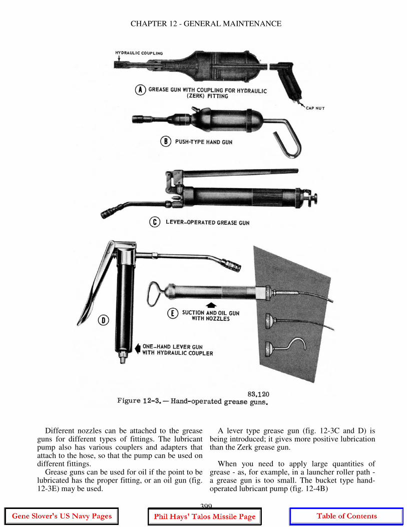
CHAPTER 12 - GENERAL MAINTENANCE
Different nozzles can be attached to the grease guns for different types of fittings. The lubricant pump also has various couplers and adapters that attach to the hose, so that the pump can be used on different fittings. Grease guns can be used for oil if the point to be lubricated has the proper fitting, or an oil gun (fig. 12-3E) may be used.
A lever type grease gun (fig. 12-3C and D) is being introduced; it gives more positive lubrication than the Zerk grease gun. When you need to apply large quantities of grease - as, for example, in a launcher roller path - a grease gun is too small. The bucket type hand-operated lubricant pump (fig. 12-4B)
399
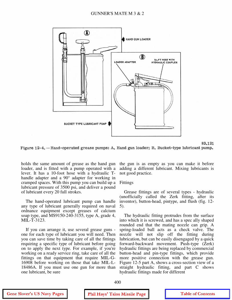
GUNNER'S MATE M 3 & 2
holds the same amount of grease as the hand gun loader, and is fitted with a pump operated with a lever. It has a 10-foot hose with a hydraulic T-handle adapter and a 90° adapter for working in cramped spaces. With this pump you can build up a lubricant pressure of 3500 psi, and deliver a pound of lubricant every 20 full strokes. The hand-operated lubricant pump can handle any type of lubricant generally required on naval ordnance equipment except greases of calcium soap type, and MS9150-240-3155, type A, grade 4, MIL-T-3123. If you can arrange it, use several grease guns - one for each type of lubricant you will need. Then you can save time by taking care of all the fittings requiring a specific type of lubricant before going on to apply the next type. For example, if you're working on a ready service ring, take care of all the fittings on that equipment that require MIL-G-16908 before working on those that take MIL-L-18486A. If you must use one gun for more than one lubricant, be sure
the gun is as empty as you can make it before adding a different lubricant. Mixing lubricants is not good practice. Fittings Grease fittings are of several types - hydraulic (unofficially called the Zerk fitting, after its inventor), button-head, pintype, and flush (fig. 12-5). The hydraulic fitting protrudes from the surface into which it is screwed, and has a spec ally shaped rounded end that the mating nozzle can grip. A spring-loaded ball acts as a check valve. The nozzle will not slip off the fitting during lubrication, but can be easily disengaged by a quick forward-backward movement. Push-type (Zerk) hydraulic fittings are being replaced by commercial button-head and pin-type fittings, which provide more positive connection with the grease gun. Figure 12-5 part A, shows a cross-section view of a straight hydraulic fitting, and part C shows hydraulic fittings made for different
400
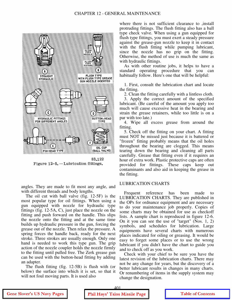
CHAPTER 12 - GENERAL MAINTENANCE
angles. They are made to fit most any angle, and with different threads and body lengths. The oil cut with ball valve (fig. 12-5F) is the most popular type for oil fittings. When using a gun equipped with nozzle for hydraulic type fittings (fig. 12-5A, C), just place the nozzle on the fitting and push forward on the handle. This slips the nozzle onto the fitting and at the same time builds up hydraulic pressure in the gun, forcing the grease out of the nozzle. Then relax the pressure. A spring forces the handle back, ready for the next stroke. Three strokes are usually enough. Only one hand is needed to work this type gun. The grip action of the nozzle coupler holds the nozzle firmly to the fitting until pulled free. The Zerk grease gun can be used with the button-head fitting by adding an adapter. The flush fitting (fig. 12-5B) is flush with (or below) the surface into which it is set, so that it will not foul moving parts. It is used also
where there is not sufficient clearance to ,install protruding fittings. The flush fitting also has a ball type check valve. When using a gun equipped for flush type fittings, you must exert a steady pressure against the grease-gun nozzle to keep it in contact with the flush fitting while pumping lubricant, since the nozzle has no grip on the fitting. Otherwise, the method of use is much the same as with hydraulic fittings. As with other routine jobs, it helps to have a standard operating procedure that you can habitually follow. Here's one that will be helpful: 1. First, consult the lubrication chart and locate the fitting. 2. Clean the fitting carefully with a lintless cloth. 3. Apply the correct amount of the specified lubricant. (Be careful of the amount you apply too much will cause excessive heat in the bearing and strain the grease retainers, while too little is on a par with too late.) 4. Wipe all excess grease from around the fitting. 5. Check off the fitting on your chart. A fitting must NOT be missed just because it is battered or "frozen" fitting probably means that the oil holes throughout the bearing are clogged. This means tearing down the bearing and cleaning all parts carefully. Grease that fitting even if it requires an hour of extra work. Plastic protective caps are often provided for fittings. These caps keep out contaminants and also aid in keeping the grease in the fitting. LUBRICATION CHARTS Frequent reference has been made to LUBRICATION CHARTS. They are published in the OPs for ordnance equipment and are necessary to do your maintenance job properly. Copies of some charts may be obtained for use as checkoff lists. A sample chart is reproduced in figure 12-6. On it you can see the use of "target" (Nos. 1, 2) symbols, and schedules for lubrication. Large equipments have several charts with numerous places indicated for oiling or greasing. It would be easy to forget some places or to use the wrong lubricant if you didn't have the chart to guide you and to check off as you work. Check with your chief to be sure you have the latest revision of the lubrication charts. There may not be any change for years, but the discovery of a better lubricant results in changes in many charts. Or renumbering of items in the supply system may change the designation.
401
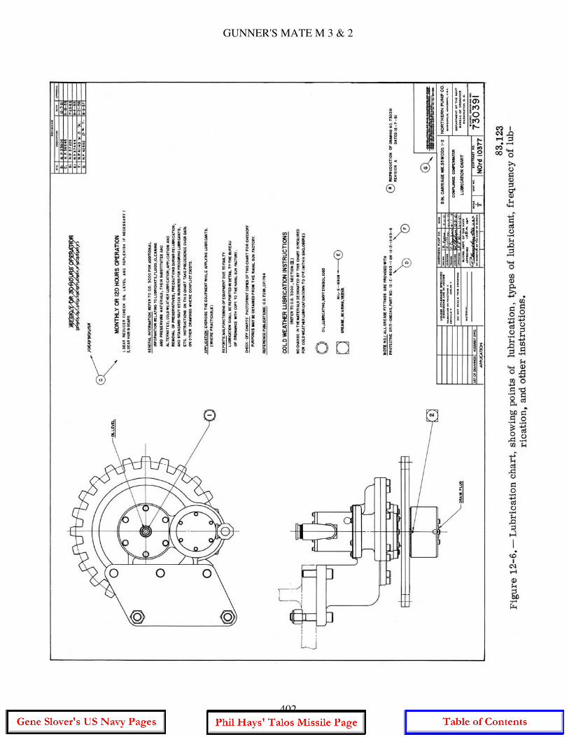
GUNNER'S MATE M 3 & 2
402

CHAPTER 12 - GENERAL MAINTENANCE
The change may have been issued as a pen-and-ink change which is written into each affected chart by personnel in charge of the OPs and charts on your ship, or it may be a reprinted chart with the new changes. Be sure you have the latest. Lubrication charts also show the kind of hydraulic fluid to be used and the fill level. LUBRICATION CHART SYMBOLS. - On lubrication charts, lubricants and hydraulic fluids are identified by symbols, each symbol signifying a specific oil or grease. Examples are shown in figure 12-6. The symbols are identified in OD 3000, or any OP lubrication chart. They may be changed from time to time. If your OPs and ODs are up to date, they will give you the CURRENT meaning of each symbol. ALTERNATES AND SUBSTITUTES. - If the lubricant prescribed in the OP or MRC for a piece of equipment is not available, you may find it necessary to use either an alternate or a substitute lubricant. A SUBSTITUTE lubricant is one that will fill the need for a limited time, but does not have all the essential properties of the prescribed lubricant. As soon as the prescribed lubricant becomes available, all of the substitute must be removed from the equipment, which must then be completely relubricated with the prescribed material. An ALTERNATE lubricant is one whose characteristics closely resemble those of the prescribed lubricant, so that its removal is not necessary when the prescribed material is available. Alternates and substitutes for prescribed lubricants (as well as for cleaning materials, hydraulic oils, and preservatives) are listed in OD 3000. If none of the listed lubricants is available and you must choose a substitute, keep in mind that the substitute should be as near as possible to the specified lubricant in lubricating and rustpreventive qualities, viscosity, and ability to withstand the temperature ranges of the equipment. In brief, when the prescribed stuff is not to be had, use an alternate if you can, a substitute if you must. HYDRAULICS The fluid used in hydraulic systems is often spoken of as hydraulic oil, and many of them have
an oil (petroleum) base. The term' 'hydraulic fluid" is more inclusive as it includes all liquids used in hydraulic systems. Three types of hydraulic fluids are water base, petroleum base, and synthetic base liquids. Various combinations of ingredients have been tried in each of these types. The Navy has tried quite a few of them and uses different ones in different situations. No "best" hydraulic fluid has been found. Use the one that is prescribed for the unit you are serving, and observe the precautions that go with it. For example, MIL-H-19457 (cellulube) is a fire-resistant hydraulic fluid used in the magazine hydraulic assemblies of GMLS Mk 12. However, it is highly corrosive to fibrous materials and to some paints, so you have to be careful not to spill any of it on such materials (as clothing, etc.). A fuller discussion of the types of hydraulic fluids and their properties may be found in Fluid Power, NavPers 16193-B, and in OD3000, Lubrication of Ordnance Equipment. Since a great deal of your maintenance work will involve the hydraulic components (of which there are many) in the missile system, it is well to know something about the medium involved. The same course also tells how to test the hydraulic fluid for contaminants, deterioration, and decomposition. Probably the most frequent cause of trouble in a hydraulic system is the presence of contaminants in the fluid. How does dirt get into a closed system'? Some can get in when the system is being filled with the hydraulic fluid, or when some is being added. Bits of metal from joints in the piping or tubing get broken off by the moving stream of fluid. Chemicals in the fluid can precipitate particles of materials in the fluid when the temperature or the pressure is too high, forming sludge. These and other causes of contamination are discussed in Fluid Power, NavPers 16193-B. Before you begin working on the hydraulic component, pull the MRC from the file and study it. The general rules and cautions for draining, flushing, and refilling hydraulic systems are given in Fluid Power, but the specific directions for your equipment are on the MRCs on your ship, and the OPs for the system.
CLEANING, PAINTING, AND PRESERVING
Besides the technical maintenance details on your gear, you will be responsible for cleaning, painting, and similar housekeeping work that every member of the crew is expected to do in maintaining the space he works and lives
403
GUNNER'S MATE M 3 & 2
in. It is the duty of the Division Officer to supervise the maintenance, preservation, and cleanliness of all spaces and equipment assigned to the division, but the activation of the tasks is usually undertaken by the division leading petty officer, and that may be a PO 3 or PO2. That means you have to know how to do the work and be able to teach others. Military Requirements for Petty Officer 3 & 2. NavPers 10056-C. gives you pointers on how to handle the assignments for supervising such work. As a Gunner's Mate M. most of your cleaning and preserving work will be done on metal surfaces, principally steel. The preservatives must protect the metal against rust and corrosion; the cleaning materials must clean the surface before the preservative is applied. Rust is caused by the slow burning (oxidation) of iron. When iron or steel rusts, it combines slowly with the oxygen in the air. Technically, corrosion is not exactly the same as rust, since its meaning includes metal being eaten away by acid, or by the action of salt water, or other substances. Rust and corrosion are dangerous and destructive saboteurs that attack unguarded metal at the slightest opportunity. The way to protect metal from rust and corrosion is to protect it from the air. Paint is a good protective, but many metal surfaces, such as moving parts, cannot be painted. The lubricants used on moving parts serve as rust preventives to some extent, but often this protection is not enough. These are temporary preservatives for protecting metal from water and weather. Light oils and greases are applied to exposed gun parts and mounts as temporary protection against corrosion. Bright steel work, such as exposed cam and linkage surfaces should have such protection. SLUSHING OILS, available in several grades, are provided for this purpose. All old oil and dirt should be cleaned from the part and the surface thoroughly dried before new oil is applied. AUTHORIZED CLEANING AND PRESERVING MATERIALS Some lubricants (for example. preservative lubricating oil for use in small arms and light machine guns) have preservative additives (rust inhibitors) and can serve for short-term preservation, but NO preservative is intended for use as a lubricant. When lubrication is not desired. there are special preservatives (permanent type) which
may be brushed or sprayed on the surface to be protected, or in which the small parts of a mechanism may be dipped. After treatment, the preserved mechanism can be stored for a long period. (The length of time depends on the characteristics of the preservative, the kind of storage, etc.) A rust preventive that can be used either to protect exterior surfaces or (as when pumped through a hydraulic system) for preserving interior surfaces, tubes, etc., is the THINFILM POLAR TYPE compound, which is available in several grades. HARD-FILM compound, also in several grades, is for metal exterior surfaces only. Rust preventives are NOT lubricants, and should not be used instead of lubricants. Before treating metal surfaces with rust preventives, BE SURE TO REMOVE ALL TRACES OF RUST AND CORROSION, AND ALL OF THE OLD LUBRICANT. BE SURE TO REMOVE ALL OF THE RUST PREVENTIVE before adding lubricant to ordnance equipment that has been stored with rust-preventive compound coating. OP 1208 (third revision) Instructions for Inactivation, Maintenance, and Activation of Ordnance in Vessels in Inactive Status, gives step-by step instructions for removing preservatives from launchers and other ordnance equipment. Chapter 5 of OD 3000, Lubrication of Ordnance Equipment (fourth revision) deals with cleaners and preservatives. It contains a chart of all cleaning and preserving materials authorized for use on ordnance materials. This chart gives the specification number, characteristics, applications, federal stock number, container size, and substitutes, while the text elaborates on the use of each item. Some of the materials will be described very briefly in the following pages. DRY-CLEANING SOLVENT (Varsol or Stoddard Solvent) is useful for cleaning away old grease, oil and rust preventives. However, its hard on rubber (use soap and water on that). Because of its irritating, flammable fumes, it should be used only where there is plenty of ventilation and where there are fire extinguishers handy. Diesel fuel or kerosene can also be used for the same purposes as dry-cleaning solvent. The correct solvent MUST be used since some solvents leave a residue or cause corrosion. Therefore, ALWAYS check the OP for the equipment. Spraying or splashing of the solvent must be avoided during cleaning. If the solvent were to fall upon a bearing surface, it would cut or
404
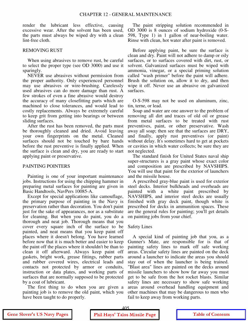
CHAPTER 12 - GENERAL MAINTENANCE
render the lubricant less effective, causing excessive wear. After the solvent has been used, the parts must always be wiped dry with a clean lint-free cloth. REMOVING RUST When using abrasives to remove rust, be careful to select the proper type (see OD 3000) and use it sparingly. NEVER use abrasives without permission from the proper authority. Only experienced personnel may use abrasives or wire-brushing. Carelessly used abrasives can do more damage than rust. A few strokes of even a fine abrasive would destroy the accuracy of many closefitting parts which are machined to close tolerances, and would lead to costly replacements. Always be extremely careful to keep grit from getting into bearings or between sliding surfaces. After the rust has been removed, the parts must be thoroughly cleaned and dried. Avoid leaving your own fingerprints on the metal. Cleaned surfaces should not be touched by bare hands before the rust preventive is finally applied. When the surface is clean and dry, you are ready to start applying paint or preservative. PAINTING POINTERS Painting is one of your important maintenance jobs. Instructions for using the chipping hammer in preparing metal surfaces for painting are given in Basic Handtools, NavPers 10085-A. Except for special applications like camouflage, the primary purpose of painting in the Navy is preservation rather than decoration. You don't paint just for the sake of appearances, nor as a substitute for cleaning. But when you do paint, you do a thorough and neat job. Thorough means that you cover every square inch of the surface to be painted, and neat means that you keep paint off places where it doesn't belong. You have learned before now that it is much better and easier to keep the paint off the places where it shouldn't be than to clean it off afterward. Always keep paint off gaskets, bright work, grease fittings, rubber parts and rubber covered wires, electrical leads and contacts not protected by armor or conduits, instruction or data plates, and working parts of surfaces that are normally supposed to be protected by a coat of lubricant. The first thing to do when you are given a painting job is to remove the old paint, which you have been taught to do properly.
The paint stripping solution recommended in OD 3000 is 8 ounces of sodium hydroxide (0-S-598, Type 1) in 1 gallon of near-boiling water. Rinse with clean, hot water after paint is removed. Before applying paint, be sure the surface is clean and dry. Paint will not adhere to damp or oily surfaces, or to surfaces covered with dirt, rust, or solvent. Galvanized surfaces must be wiped with ammonia, vinegar, or a special priming solution called "wash primer" before the paint will adhere. Brush the solution on, allow it to dry, and then wipe it off. Never use an abrasive on galvanized surfaces. O-S-598 may not be used on aluminum, zinc, tin, terne, or lead. Soap and water are one answer to the problem of removing all dirt and traces of old oil or grease from metal surfaces to be treated with rust preventives, paint, or other preservative. Wash away all soap; then see that the surfaces are DRY, and finally, apply rust preventives (or paint) without delay. It's sometimes hard to get at pockets or cavities in which water collects; be sure they are not neglected. The standard finish for United States naval ship super-structures is a gray paint whose exact color and composition are prescribed by NAVSHIPS. You will use that paint for the exterior of launchers and the missile house. A prescribed gray-blue paint is used for exterior steel decks. Interior bulkheads and overheads are painted with a white paint prescribed by NAVSHIPS, and interior steel decks are usually finished with gray deck paint, though white is prescribed for decks in ammunition spaces. These are the general rules for painting; you'll get details on painting jobs from your chief. Safety Lines A special kind of painting job that you, as a Gunner's Mate, are responsible for is that of painting safety lines to mark off safe working areas. Circular safety lines are painted on the deck around a launcher to indicate the areas you should stay out of when the launcher is being trained. "Blast area" lines are painted on the decks around missile launchers to show how far away you must get to be safe from the hot rocket blasts. Similar safety lines are necessary to show safe working areas around overhead handling equipment and other machines that may be dangerous to men who fail to keep away from working parts.
405

GUNNER'S MATE M 3 & 2
CLEANING ELECTRICAL COMPONENTS Ever since you were handed a paint brush aboard ship, you have been warned not to paint electrical equipment. If you were headless, you had to painstakingly clean it off, and you surely have learned your lesson on that score. However, dust and dirt on electrical equipment still require removal regularly. When cleaning electrical and electronic equipment, always use an approved cleaning agent. Alcohol should never be used for cleaning electrical equipment. Not only is it afire hazard, but it also damages many kinds of insulation. Cleaning Electrical Contacts and Switches SWITCH MAINTENANCE. - While the switch itself is relatively simple to check- it sometimes offers difficulty in maintenance because it is inaccessible. After a visual inspection of the connections and the switch, a continuity test will indicate any malfunctions. When the switch mechanism is found to be defective, it normally is not repairable and therefore should be replaced. When enclosed switches are used, failure to seal properly around cable openings causes the most difficulty. Atmospheric changes permit "breathing" of moist air into enclosures with improperly sealed cable openings, and the moisture in the air may condense within the switch enclosure. The condensation can short across the switch terminals and can corrode the switch actuators in a manner that may make them inoperative. This difficulty can be corrected by careful sealing of openings or by using hermetically-sealed switches. Hermetically-sealed switches will also prevent dust and dirt from reaching the contacts and thereby causing high resistance and open circuits. Some switches are damaged during installation, particularly those with plastic housings. Proper care in installing or replacing plastic enclosed switches will eliminate this. Some switches depend upon pressure for their operation. These switches have adjustments so that they will operate at the correct time or pressure. In many cases if the adjustments are not accurate- damage can result. RELAY MAINTENANCE. - The relay is one of the most dependable electromechanical devices in use but, like any other mechanical or electrical device. relays occasionally wear out or become inoperative for one reason or another. Should relay inspection show that a relay has exceeded its
safe life, the relay should be removed immediately and replaced with another of the same type. Care should be exercised in obtaining the same type replacement because relays are rated in both voltage and amperage. As guides for spotting potential relay trouble during preventive maintenance, the following are suggested. Check for charred or burned insulation on the relay. Check for darkened or charred terminal leads coming from the relay. Both of these indicate overheating. If there is even a slight indication that the relay has overheated, it should be replaced with a new relay of the same type. An occasional cause of relay trouble is not the fault of the relay at all, but is due to overheating caused by the power terminal connectors not being tight enough. This should always be checked on preventive maintenance. It is not recommended that covers be removed from semi sealed relays in the field. Removal of a cover in the field, although it might give useful information to a trained eye, may result in entry of dust or other foreign material which may cause contact discontinuity. What is even more serious, removal of the cover may result in loss of or damage to the cover gasket. One of the prime advantages of hermetically-sealed relays is that they cannot be taken apart. Relays can be ruined by the use of sandpaper or emery cloth for cleaning the contacts. A BURNISHING TOOL should be used for this purpose. Two types of burnishing tools are stocked at naval supply activities, and either type can be obtained through regular supply channels. The appearance and use of one kind of burnishing tool are shown in figure 12-7 A. The surfaces of the tool that are used to clean the relay contacts should not be touched by the fingers prior to use; and. after use, the burnisher should be cleaned with alcohol. When relays contain bent contacts, no attempt should be made to straighten them with long nose pliers. Such as attempt often causes further damage with the result that the entire relay must be replaced. Bent contacts can be straightened effectively by using a CONTACT BENDER. The bender can be made locally from 0.125-diameter rod stock according to the dimensions shown in figure 12-7B. Be sure the power is off and remains off while you are working on an electrical contact or switch, or relay.
406
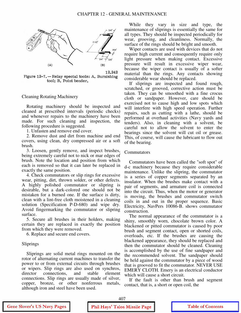
CHAPTER 12 - GENERAL MAINTENANCE
Cleaning Rotating Machinery Rotating machinery should be inspected and cleaned at prescribed intervals (periodic checks) and whenever repairs to the machinery have been made. For such cleaning and inspection, the following procedure is suggested. 1. Unfasten and remove end cover. 2. Remove dust and dirt from machine and end covers, using clean, dry compressed air or a soft brush. 3. Loosen, gently remove, and inspect brushes, being extremely careful not to nick or mar edges of brush. Note the location and position from which each is removed so that it can later be replaced in exactly the same position. 4. Check commutators or slip rings for excessive wear, pitting, dirt, thrown solder, or other defects. A highly polished commutator or slipring is desirable, but a dark-colored one should not be mistaken for a burned one. If the surface is dirty, clean with a lint-free cloth moistened in a cleaning solution (Specification P-D-680) and wipe dry. Avoid fingermarking the commutator or slipring surface. 5. Secure all brushes in their holders, making certain they are replaced in exactly the position from which they were removed. 6. Replace and secure end covers. Sliprings Sliprings are solid metal rings mounted on the rotor of alternating current machines to transfer the power to or from external circuits through brushes or wipers. Slip rings are also used on synchros, director connections, and stable element connections. Slip rings are usually made of silver, copper, bronze, or other nonferrous metals, although iron and steel have been used.
While they vary in size and type, the maintenance of sliprings is essentially the same for all types. They should be inspected periodically for wear, grooving, and cleanliness. Normally, the surface of the rings should be bright and smooth. Wiper contacts are used with devices that do not require high current and consequently require only light pressure when making contact. Excessive pressure will result in excessive wiper wear, because the wiper contact is usually of a softer material than the rings. Any contacts showing considerable wear should be replaced. If sliprings are inspected and found rough, scratched, or grooved, corrective action must be taken. They can be smoothed with a fine crocus cloth or sandpaper. However, care should be exercised not to cause high and low spots which will interfere with high speed operation. Further repairs, such as cutting with a lathe, should be performed at overhaul activities (Navy yards and tenders). Also, in cleaning with a solvent, be careful not to allow the solvent to enter the bearings since the solvent will cut oil or grease. This, of course, will cause the lubricant to flow out of the bearing. Commutators Commutators have been called the "soft spot" of d-c machinery because they require considerable maintenance. Unlike the slipring, the commutator is a series of copper segments separated by an insulator. When the brushes make contact with a pair of segments, and armature coil is connected into the circuit. Thus, when the motor or generator is moving, the brushes and commutator switch coils in and out in the proper sequence. Basic Electricity, NavPers 10086-B. shows commutator construction. The normal appearance of the commutator is a shiny, smoothly worn, chocolate brown color. A blackened or pitted commutator is caused by poor brush and segment contact, open or shorted coils, overloads, etc. If the brushes are causing the blackened appearance, they should be replaced and then the commutator should be cleaned. Cleaning is accomplished by the use of fine sandpaper and the recommended solvent. The sandpaper should be held against the commutator by a piece of wood that is grooved to fit the commutator. NEVER USE EMERY CLOTH. Emery is an electrical conductor which will cause a short circuit. If the fault is other than brush and segment contact, that is, a short or open coil, the
407
GUNNER'S MATE M 3 & 2
machine should be replaced and sent to overhaul. Another fairly common defect is HIGH MICA. As the copper of the commutator wears down, the mica, which is the insulation separating the segments, does not. Consequently, it may be higher than the segments. The high mica gives a bounce to the brush every time it passes underneath; this results in arcing because the brush is constantly breaking contact. High mica can be spotted by rubbing your fingernail over the surface of the commutator. There should be a small depression between each segment. If there is high mica, this depression disappears. Undercutting is the remedy for high mica, and this operation is normally reserved for the overhaul activities. PROTECTION AGAINST MOISTURE Aside from mechanical injury, the biggest source of electrical trouble on board ship is moisture. And salt water moisture is the worst kind because it is a conductor of electricity. Thus, when a cable or box becomes saturated with salt water, two things happen: First, a current path to the ship's hull is formed which is a ground; and second, especially where dissimilar metals are involved, electrolysis and corrosion occur, and the connections or wire fittings are slowly eaten away. The battle against moisture is never-ending. Moisture creeps into the smallest openings. Watertight covers must be kept watertight. When you remove a cover, check the condition of the gasket, the knife edge, and the securing bolts or dogs. Where possible, when checking an electrical circuit, use a connection box in a protected space. When moisture is discovered in an instrument or connection box, dry it out with a hot-air blower or an electric lamp. A reasonable degree of protection against the accumulation of moisture is obtained by a daily energizing and workout of the equipment. Variations in temperature cause air to be breathed through any opening or vent in the equipment. As the temperature rises, the air inside a piece of equipment expands and is partly expelled. When the temperature falls, the air inside the equipment contracts and outside air is admitted. As the air cools, condensation or sweating takes place. Electrical heaters are installed in some instruments to eliminate this source of moisture. The heater keeps the interior of the instrument at a temperature higher than that of the surrounding air. In many instruments, the circuit to the heater bypasses the
power switch, and voltage may be present even though the power switch is off. Remember this when working around the heater circuit. Some equipments use an air drier, or desiccator unit, to moisture proof the mechanisms within the unit. The unit is sealed by dust covers and is airtight except for the connection to the air drier. The air drier consists of a unit that contains silica gel crystals. The silica gel crystals absorb moisture from the air within the unit. SALT AND FUNGUS. - Salt and fungus found in your equipment should be removed immediately. A salt, when moisture is present, will corrode metals and is a conductor of electricity. Fungus growth causes decay, rapid deterioration of insulating materials, and shorts or grounds in electrical circuits. Under some circumstances you can use fresh water to remove them. After cleaning the equipment, however, make sure the water is completely evaporated. An approved cleaning solvent, inhibited methyl chloroform (O-T-620), can be used to clean away salt or fungus. But inhibited methyl chloroform will attack electrical insulating materials and bare ferrous surfaces if it is not completely evaporated or otherwise removed at the completion of the cleaning operation. Contact time with this solvent should be limited because it is toxic. Care in the use of this solvent should be exercised since concentrations of the vapor can be fatal. Adequate ventilation is necessary when it is used.
MAINTENANCE SKILLS AND PROCESSES
SOLDERING A discussion of soldering is found in Basic Electricity, NavPers 10086-B and in Basic Handtools, NavPers 10085-A. Here we will review the highlights of that discussion and then consider some aspects peculiar to your work. Soldering is the uniting of two or more metals by means of fusible alloy. There are two general classes of solder, hard and soft. The differences between the two are in composition, melting temperature, and strength. Soft solder, and alloy of tin and lead, is used in electronic wiring. In most naval electronic equipment, a solder of 60 parts tin and 40 parts lead is preferred because it flows at a lower temperature and solidifies faster than standard tin-lead solders. Use only rosin flux in soldering electrical connections. Besides the soldering iron (copper) discussed in the basic text, soldering guns are also used by
408
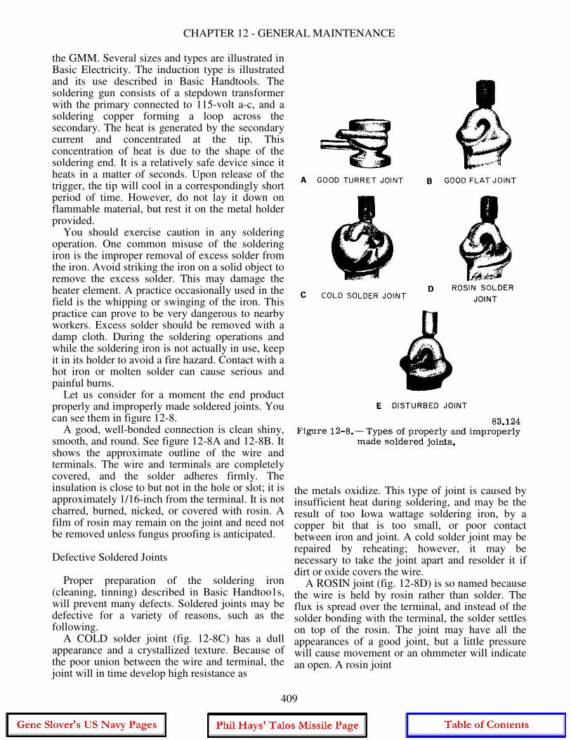
CHAPTER 12 - GENERAL MAINTENANCE
the GMM. Several sizes and types are illustrated in Basic Electricity. The induction type is illustrated and its use described in Basic Handtools. The soldering gun consists of a stepdown transformer with the primary connected to 115-volt a-c, and a soldering copper forming a loop across the secondary. The heat is generated by the secondary current and concentrated at the tip. This concentration of heat is due to the shape of the soldering end. It is a relatively safe device since it heats in a matter of seconds. Upon release of the trigger, the tip will cool in a correspondingly short period of time. However, do not lay it down on flammable material, but rest it on the metal holder provided. You should exercise caution in any soldering operation. One common misuse of the soldering iron is the improper removal of excess solder from the iron. Avoid striking the iron on a solid object to remove the excess solder. This may damage the heater element. A practice occasionally used in the field is the whipping or swinging of the iron. This practice can prove to be very dangerous to nearby workers. Excess solder should be removed with a damp cloth. During the soldering operations and while the soldering iron is not actually in use, keep it in its holder to avoid a fire hazard. Contact with a hot iron or molten solder can cause serious and painful burns. Let us consider for a moment the end product properly and improperly made soldered joints. You can see them in figure 12-8. A good, well-bonded connection is clean shiny, smooth, and round. See figure 12-8A and 12-8B. It shows the approximate outline of the wire and terminals. The wire and terminals are completely covered, and the solder adheres firmly. The insulation is close to but not in the hole or slot; it is approximately 1/16-inch from the terminal. It is not charred, burned, nicked, or covered with rosin. A film of rosin may remain on the joint and need not be removed unless fungus proofing is anticipated. Defective Soldered Joints Proper preparation of the soldering iron (cleaning, tinning) described in Basic Handtoo1s, will prevent many defects. Soldered joints may be defective for a variety of reasons, such as the following. A COLD solder joint (fig. 12-8C) has a dull appearance and a crystallized texture. Because of the poor union between the wire and terminal, the joint will in time develop high resistance as
the metals oxidize. This type of joint is caused by insufficient heat during soldering, and may be the result of too Iowa wattage soldering iron, by a copper bit that is too small, or poor contact between iron and joint. A cold solder joint may be repaired by reheating; however, it may be necessary to take the joint apart and resolder it if dirt or oxide covers the wire. A ROSIN joint (fig. 12-8D) is so named because the wire is held by rosin rather than solder. The flux is spread over the terminal, and instead of the solder bonding with the terminal, the solder settles on top of the rosin. The joint may have all the appearances of a good joint, but a little pressure will cause movement or an ohmmeter will indicate an open. A rosin joint
409
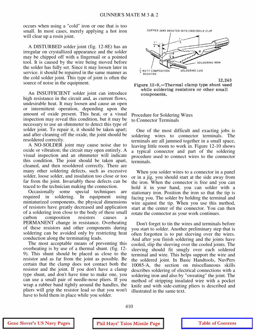
GUNNER'S MATE M 3 & 2
occurs when using a "cold" iron or one that is too small. In most cases, merely applying a hot iron will clear up a rosin joint. A DISTURBED solder joint (fig. 12-8E) has an irregular on crystallized appearance and the solder may be chipped off with a fingernail or a pointed tool. It is caused by the wire being moved before the solder has fully set. Since it may loosen later in service. it should be repaired in the same manner as the cold solder joint. This type of joint is often the source of noise in the equipment. An INSUFFICIENT solder joint can introduce high resistance in the circuit and, as current flows, undesirable heat. It may loosen and cause an open or intermittent operation, depending upon the amount of oxide present. This heat, or a visual inspection may reveal this condition, but it may be necessary to use an ohmmeter to detect this type of solder joint. To repair it, it should be taken apart; and after cleaning off the oxide, the joint should be resoldered correctly. A NO-SOLDER joint may cause noise due to oxide or vibration; the circuit may open entirely. A visual inspection and an ohmmeter will indicate this condition. The joint should be taken apart, cleaned, and then resoldered correctly. There are many other soldering defects, such as excessive solder, loose solder, and insulation too close or too far from the joint. Invariably these defects can be traced to the technician making the connection. Occasionally some special techniques are required in soldering. In equipment using miniaturized components, the physical dimensions of resistors have greatly decreased and application of a soldering iron close to the body of these small carbon composition resistors causes a PERMANENT change in resistance. Overheating of these resistors and other components during soldering can be avoided only by restricting heat conduction along the terminating leads. The most acceptable means of preventing this overheating is by use of a thermal shunt. (fig. 12-9). This shunt should be placed as close to the resistor and as far from the joint as possible. Be certain that the clamp does not contact both the resistor and the joint. If you don't have a clamp type shunt, and don't have time to make one, you can use a small pair of needle-nose pliers. If you wrap a rubber band tightly around the handles, the pliers will grip the resistor lead so that you won't have to hold them in place while you solder.
Procedure for Soldering Wires to Connector Terminals One of the most difficult and exacting jobs is soldering wires to connector terminals. The terminals are all jammed together in a small space, leaving little room to work in. Figure 12-10 shows a typical connector and part of the soldering procedure used to connect wires to the connector terminals. When you solder wires to a connector in a panel or in a jig, you should start at the side away from the iron. When the connector is free and you can hold it in your hand, you can solder with a stationary iron. Position the iron so that the tip is facing you. The solder by holding the terminal and wire against the tip. When you use this method, start at the center of the connector. You can then rotate the connector as your work continues. Don't forget to tin the wires and terminals before you start to solder. Another preliminary step that is often forgotten is to put sleeving over the wires. And after you finish soldering and the joints have cooled, slip the sleeving over the cooled joints. The sleeving should fit snugly over each soldered terminal and wire. This helps support the wire and the soldered joint. In Basic Handtools, NavPers 10085-A, the section on miscellaneous skills describes soldering of electrical connections with a soldering iron and also by "sweating" the joint. The method of stripping insulated wire with a pocket knife and with side-cutting pliers is described and illustrated in the same text.
410

CHAPTER 12 - GENERAL MAINTENANCE
Mechanical Connections for Soldering No connection should depend upon the strength of solder alone for security, because solder is relatively soft. All electrical connections should be made mechanically strong before they are soldered. If you crimp or wrap the wire tightly around the terminal before you begin to solder, you will have a secure base upon which to solder. When properly done, crimping or wrapping prevents disturbing the joint while you are soldering and while the solder is cooling. To make a good mechanical connection you don't have to wrap the wire around the terminal two or three times. Just wrap the stripped end of the wire around the terminal 1 1/2 turns. These are enough turns to make the connection mechanically strong. If you put on more turns, they add nothing to the strength of the connection and simply make it more difficult to remove them from the terminal. Be careful to bring the end of the insulation as close to the terminal as possible without allowing insulation to interfere with the soldering operation. The wire should be wrapped around the terminal so that the tension on the wire will be transmitted to the terminal and not to the solder. Sometimes you may have to crimp a wire wrap to make a good mechanical connection. Use a pair of pliers to squeeze the wire wrap against the terminal. After you finish making the connection, and before you begin soldering, cut off the ends of the leads. Leave about 1/16 inch of lead from the connection. This will leave enough wire to get a grip on when you need to remove the wire.
Types of Terminals There are four basic types of terminals: 1. Turret or stud terminal. 2. Flat terminal. 3. Hook or eyelet terminal. 4. Split terminal. The TURRET or STUD terminal is used primarily on component mounting boards; see figure 12-11. To make the wrap, lead the wire directly to one side of the terminal. Wrap the lead 1 1/2 turns around the terminal, and crimp if necessary. On the turret terminal. it is best to wrap the component (resistor, capacitor. and so forth) lead on the upper portion of the terminal, and the connecting wires or wire on the lower part. (See figure 12-12). For easy maintenance, it is best to wrap the wire over the terminal post from the bottom up and to be consistent in either clockwise or counterclockwise wrapping. Clockwise wrapping is preferred because there is a natural tendency for people to attempt unwinding the wire in a counterclockwise direction. The FLAT. PERFORATED terminal (fig. 12-13) is used on most tube sockets, potentiometers, wafer switches, and micro-switches. To make the wrap, insert the wire through the hole and wrap the wire 1 1/2 turns around the body of the terminal. If you use heavy wire, or space does not permit you to wrap properly, you can make a good mechanical connection by crimping. Just feed the wire through the hole, bend the wire
411
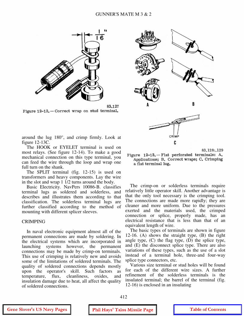
GUNNER'S MATE M 3 & 2
around the lug 180°, and crimp firmly. Look at figure 12-13C. The HOOK or EYELET terminal is used on most relays. (See figure 12-14). To make a good mechanical connection on this type terminal, you can feed the wire through the loop and wrap one full turn on the shank. The SPLIT terminal (fig. 12-15) is used on transformers and heavy components. Lay the wire in the slot and wrap 1 1/2 turns around the body. Basic Electricity. NavPers 10086-B. classifies terminal lugs as soldered and solderless, and describes and illustrates them according to that classification. The solderless terminal lugs are further classified according to the method of mounting with different splicer sleeves. CRIMPING In naval electronic equipment almost all of the permanent connections are made by soldering. In the electrical systems which are incorporated in launching systems however, the permanent connections may be made by crimp-on terminals. This use of crimping is relatively new and avoids some of the limitations of soldered terminals. The quality of soldered connections depends mostly upon the operator's skill. Such factors as temperature, flux, cleanliness, oxides, and insulation damage due to heat, all affect the quality of soldered connections.
The crimp-on or solderless terminals require relatively little operator skill. Another advantage is that the only tool necessary is the crimping tool. The connections are made more rapidly; they are cleaner and more uniform. Due to the pressures exerted and the materials used, the crimped connection or splice, properly made, has an electrical resistance that is less than that of an equivalent length of wire. The basic types of terminals are shown in figure 12-16. (A) shows the straight type, (B) the right angle type, (C) the flag type, (D) the splice type, and (E) the disconnect splice type. There are also variations of these types, such as the use of a slot instead of a terminal hole, three-and four-way splice type connectors, etc. Various size terminal or stud holes will be found for each of the different wire sizes. A further refinement of the solderless terminals is the insulated terminal; the barrel of the terminal (fig. 12-16) is enclosed in an insulating
412
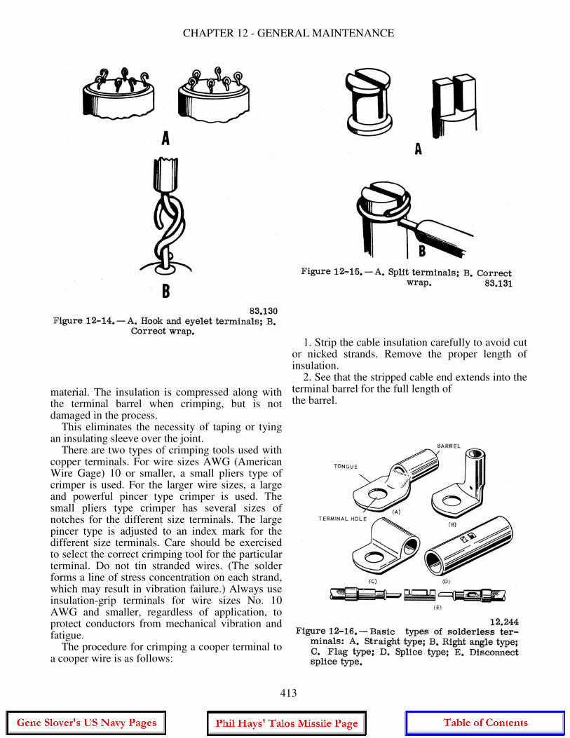
CHAPTER 12 - GENERAL MAINTENANCE
material. The insulation is compressed along with the terminal barrel when crimping, but is not damaged in the process. This eliminates the necessity of taping or tying an insulating sleeve over the joint. There are two types of crimping tools used with copper terminals. For wire sizes AWG (American Wire Gage) 10 or smaller, a small pliers type of crimper is used. For the larger wire sizes, a large and powerful pincer type crimper is used. The small pliers type crimper has several sizes of notches for the different size terminals. The large pincer type is adjusted to an index mark for the different size terminals. Care should be exercised to select the correct crimping tool for the particular terminal. Do not tin stranded wires. (The solder forms a line of stress concentration on each strand, which may result in vibration failure.) Always use insulation-grip terminals for wire sizes No. 10 AWG and smaller, regardless of application, to protect conductors from mechanical vibration and fatigue. The procedure for crimping a cooper terminal to a cooper wire is as follows:
1. Strip the cable insulation carefully to avoid cut or nicked strands. Remove the proper length of insulation. 2. See that the stripped cable end extends into the terminal barrel for the full length of the barrel.
413
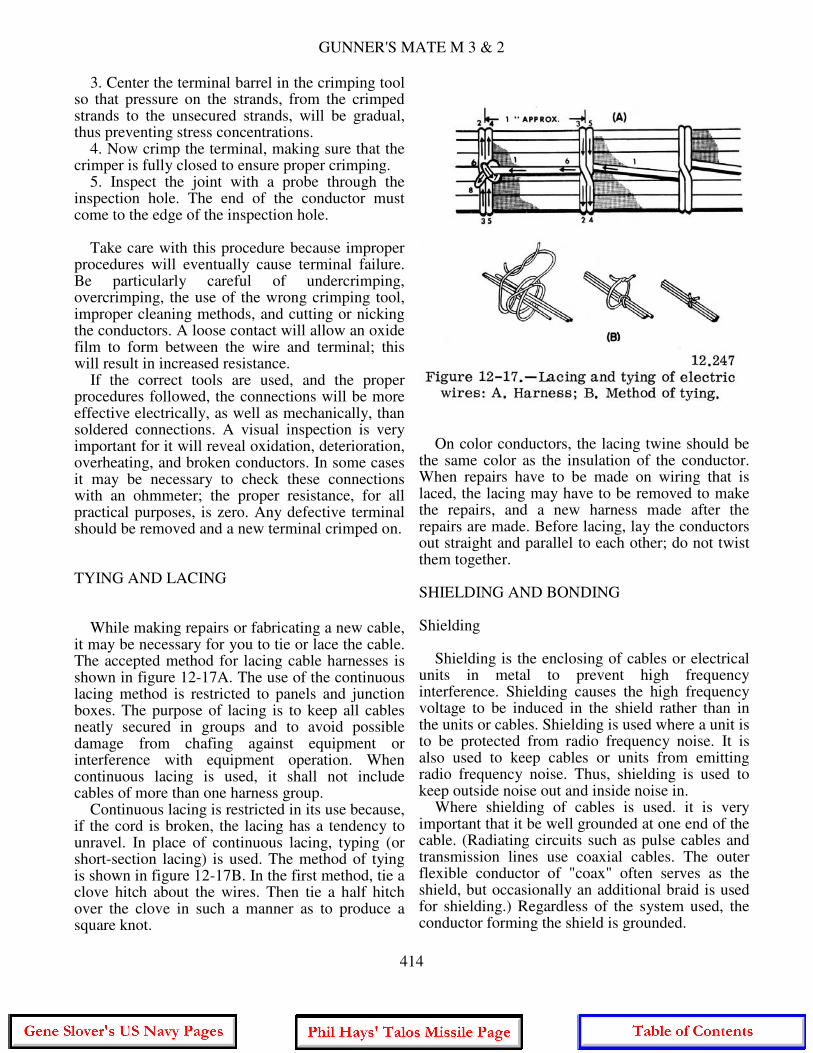
GUNNER'S MATE M 3 & 2
3. Center the terminal barrel in the crimping tool so that pressure on the strands, from the crimped strands to the unsecured strands, will be gradual, thus preventing stress concentrations. 4. Now crimp the terminal, making sure that the crimper is fully closed to ensure proper crimping. 5. Inspect the joint with a probe through the inspection hole. The end of the conductor must come to the edge of the inspection hole. Take care with this procedure because improper procedures will eventually cause terminal failure. Be particularly careful of undercrimping, overcrimping, the use of the wrong crimping tool, improper cleaning methods, and cutting or nicking the conductors. A loose contact will allow an oxide film to form between the wire and terminal; this will result in increased resistance. If the correct tools are used, and the proper procedures followed, the connections will be more effective electrically, as well as mechanically, than soldered connections. A visual inspection is very important for it will reveal oxidation, deterioration, overheating, and broken conductors. In some cases it may be necessary to check these connections with an ohmmeter; the proper resistance, for all practical purposes, is zero. Any defective terminal should be removed and a new terminal crimped on. TYING AND LACING While making repairs or fabricating a new cable, it may be necessary for you to tie or lace the cable. The accepted method for lacing cable harnesses is shown in figure 12-17A. The use of the continuous lacing method is restricted to panels and junction boxes. The purpose of lacing is to keep all cables neatly secured in groups and to avoid possible damage from chafing against equipment or interference with equipment operation. When continuous lacing is used, it shall not include cables of more than one harness group. Continuous lacing is restricted in its use because, if the cord is broken, the lacing has a tendency to unravel. In place of continuous lacing, typing (or short-section lacing) is used. The method of tying is shown in figure 12-17B. In the first method, tie a clove hitch about the wires. Then tie a half hitch over the clove in such a manner as to produce a square knot.
On color conductors, the lacing twine should be the same color as the insulation of the conductor. When repairs have to be made on wiring that is laced, the lacing may have to be removed to make the repairs, and a new harness made after the repairs are made. Before lacing, lay the conductors out straight and parallel to each other; do not twist them together. SHIELDING AND BONDING Shielding Shielding is the enclosing of cables or electrical units in metal to prevent high frequency interference. Shielding causes the high frequency voltage to be induced in the shield rather than in the units or cables. Shielding is used where a unit is to be protected from radio frequency noise. It is also used to keep cables or units from emitting radio frequency noise. Thus, shielding is used to keep outside noise out and inside noise in. Where shielding of cables is used. it is very important that it be well grounded at one end of the cable. (Radiating circuits such as pulse cables and transmission lines use coaxial cables. The outer flexible conductor of "coax" often serves as the shield, but occasionally an additional braid is used for shielding.) Regardless of the system used, the conductor forming the shield is grounded.
414
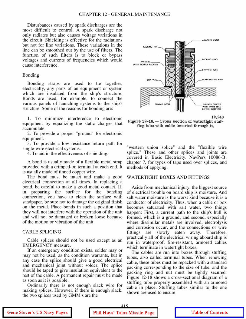
CHAPTER 12 - GENERAL MAINTENANCE
Disturbances caused by spark discharges are the most difficult to control. A spark discharge not only radiates but also causes voltage variations in the circuit. Shielding is effective for the radiations but not for line variations. These variations in the line can be smoothed out by the use of filters. The function of such filters is to block or bypass voltages and currents of frequencies which would cause interference. Bonding
Bonding straps are used to tie together, electrically, any parts of an equipment or system which are insulated from the ship's structure. Bonds are used, for example, to connect the various panels of launching systems to the ship's structure. Some of the reasons for bonding are: 1. To minimize interference to electronic equipment by equalizing the static charges that accumulate. 2. To provide a proper "ground" for electronic equipment. 3. To provide a low resistance return path for single-wire electrical systems. 4. To aid in the effectiveness of shielding.
A bond is usually made of a flexible metal strap provided with a crimped-on terminal at each end. It is usually made of tinned copper wire. The bond must be intact and make a good electrical connection at all times. In replacing a bond, be careful to make a good metal contact. If, in preparing the surface for the bonding connection, you have to clean the surface with sandpaper, be sure not to damage the original finish on the metal. Place bonds in such a position that they will not interfere with the operation of the unit and will not be damaged or broken loose because of the motion or vibration of the unit. CABLE SPLICING
Cable splices should not be used except as an EMERGENCY measure. If an emergency condition exists, solder may or may not be used, as the condition warrants, but in any case the splice should give a good electrical and mechanical joint without solder. The splice should be taped to give insulation equivalent to the rest of the cable. A permanent repair must be made as soon as it is possible. Ordinarily there is not enough slack wire for making splices. However, if there is enough slack, the two splices used by GMM s are the
"western union splice" and the "flexible wire splice." These and other splices and joints are covered in Basic Electricity. NavPers 10086-B; chapter 7, for types of tape used over splices, and methods of applying. WATERTIGHT BOXES AND FITTINGS Aside from mechanical injury, the biggest source of electrical trouble on board ship is moisture. And salt water moisture is the worst kind because it is a conductor of electricity. Thus, when a cable or box becomes saturated with salt water, two things happen: First, a current path to the ship's hull is formed, which is a ground; and second, especially where dissimilar metals are involved, electrolysis and corrosion occur, and the connections or wire fittings are slowly eaten away. Therefore, practically all of the electrical wiring aboard ship is run in waterproof, fire-resistant, armored cables which terminate in watertight boxes. The cables are run into boxes through stuffing tubes, also called terminal tubes. When renewing cable, these tubes must be repacked with a standard packing corresponding to the size of tube, and the packing ring and nut must be tightly secured. Figure 12-18 shows a cross-sectional diagram of a stuffing tube properly assembled with an armored cable in place. Stuffing tubes similar to the one shown are used to ensure
415
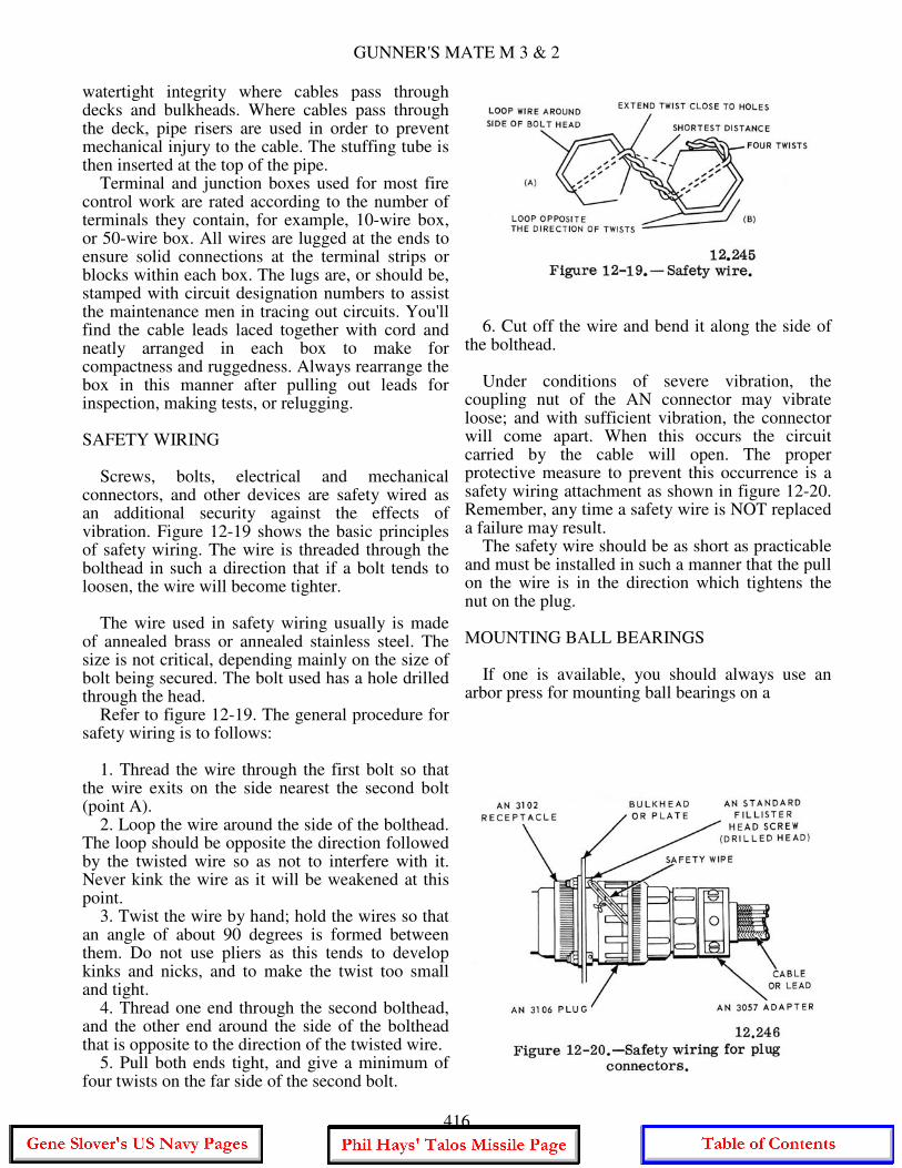
GUNNER'S MATE M 3 & 2
watertight integrity where cables pass through decks and bulkheads. Where cables pass through the deck, pipe risers are used in order to prevent mechanical injury to the cable. The stuffing tube is then inserted at the top of the pipe. Terminal and junction boxes used for most fire control work are rated according to the number of terminals they contain, for example, 10-wire box, or 50-wire box. All wires are lugged at the ends to ensure solid connections at the terminal strips or blocks within each box. The lugs are, or should be, stamped with circuit designation numbers to assist the maintenance men in tracing out circuits. You'll find the cable leads laced together with cord and neatly arranged in each box to make for compactness and ruggedness. Always rearrange the box in this manner after pulling out leads for inspection, making tests, or relugging. SAFETY WIRING Screws, bolts, electrical and mechanical connectors, and other devices are safety wired as an additional security against the effects of vibration. Figure 12-19 shows the basic principles of safety wiring. The wire is threaded through the bolthead in such a direction that if a bolt tends to loosen, the wire will become tighter. The wire used in safety wiring usually is made of annealed brass or annealed stainless steel. The size is not critical, depending mainly on the size of bolt being secured. The bolt used has a hole drilled through the head. Refer to figure 12-19. The general procedure for safety wiring is to follows: 1. Thread the wire through the first bolt so that the wire exits on the side nearest the second bolt (point A). 2. Loop the wire around the side of the bolthead. The loop should be opposite the direction followed by the twisted wire so as not to interfere with it. Never kink the wire as it will be weakened at this point. 3. Twist the wire by hand; hold the wires so that an angle of about 90 degrees is formed between them. Do not use pliers as this tends to develop kinks and nicks, and to make the twist too small and tight. 4. Thread one end through the second bolthead, and the other end around the side of the bolthead that is opposite to the direction of the twisted wire. 5. Pull both ends tight, and give a minimum of four twists on the far side of the second bolt.
6. Cut off the wire and bend it along the side of the bolthead. Under conditions of severe vibration, the coupling nut of the AN connector may vibrate loose; and with sufficient vibration, the connector will come apart. When this occurs the circuit carried by the cable will open. The proper protective measure to prevent this occurrence is a safety wiring attachment as shown in figure 12-20. Remember, any time a safety wire is NOT replaced a failure may result. The safety wire should be as short as practicable and must be installed in such a manner that the pull on the wire is in the direction which tightens the nut on the plug. MOUNTING BALL BEARINGS If one is available, you should always use an arbor press for mounting ball bearings on a
416
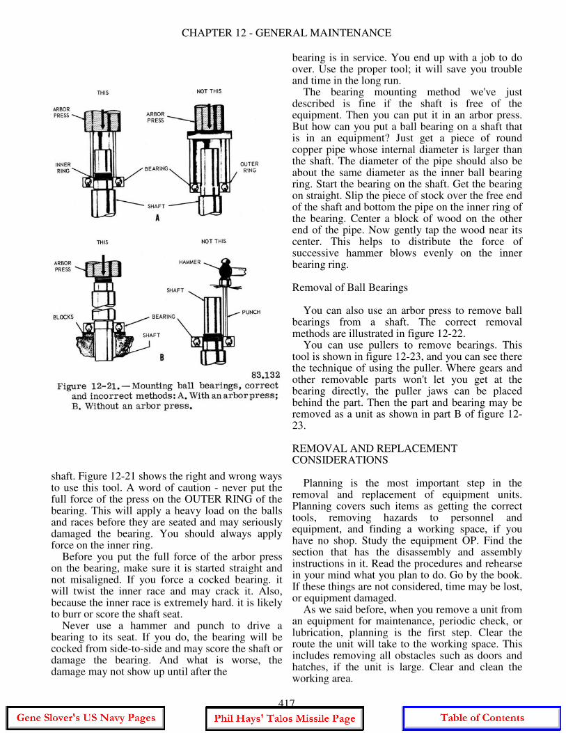
CHAPTER 12 - GENERAL MAINTENANCE
shaft. Figure 12-21 shows the right and wrong ways to use this tool. A word of caution - never put the full force of the press on the OUTER RING of the bearing. This will apply a heavy load on the balls and races before they are seated and may seriously damaged the bearing. You should always apply force on the inner ring. Before you put the full force of the arbor press on the bearing, make sure it is started straight and not misaligned. If you force a cocked bearing. it will twist the inner race and may crack it. Also, because the inner race is extremely hard. it is likely to burr or score the shaft seat. Never use a hammer and punch to drive a bearing to its seat. If you do, the bearing will be cocked from side-to-side and may score the shaft or damage the bearing. And what is worse, the damage may not show up until after the
bearing is in service. You end up with a job to do over. Use the proper tool; it will save you trouble and time in the long run. The bearing mounting method we've just described is fine if the shaft is free of the equipment. Then you can put it in an arbor press. But how can you put a ball bearing on a shaft that is in an equipment? Just get a piece of round copper pipe whose internal diameter is larger than the shaft. The diameter of the pipe should also be about the same diameter as the inner ball bearing ring. Start the bearing on the shaft. Get the bearing on straight. Slip the piece of stock over the free end of the shaft and bottom the pipe on the inner ring of the bearing. Center a block of wood on the other end of the pipe. Now gently tap the wood near its center. This helps to distribute the force of successive hammer blows evenly on the inner bearing ring. Removal of Ball Bearings You can also use an arbor press to remove ball bearings from a shaft. The correct removal methods are illustrated in figure 12-22. You can use pullers to remove bearings. This tool is shown in figure 12-23, and you can see there the technique of using the puller. Where gears and other removable parts won't let you get at the bearing directly, the puller jaws can be placed behind the part. Then the part and bearing may be removed as a unit as shown in part B of figure 12-23. REMOVAL AND REPLACEMENT CONSIDERATIONS Planning is the most important step in the removal and replacement of equipment units. Planning covers such items as getting the correct tools, removing hazards to personnel and equipment, and finding a working space, if you have no shop. Study the equipment OP. Find the section that has the disassembly and assembly instructions in it. Read the procedures and rehearse in your mind what you plan to do. Go by the book. If these things are not considered, time may be lost, or equipment damaged. As we said before, when you remove a unit from an equipment for maintenance, periodic check, or lubrication, planning is the first step. Clear the route the unit will take to the working space. This includes removing all obstacles such as doors and hatches, if the unit is large. Clear and clean the working area.
417
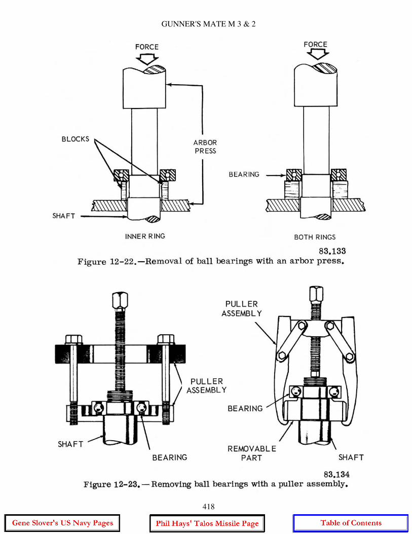
GUNNER'S MATE M 3 & 2
418
CHAPTER 12 - GENERAL MAINTENANCE
Before you remove the unit, disconnect all cables. Be sure you tag and identify each lead. You'll need this information when you reinstall the unit. Since only cables with electrical connectors have to be unplugged, there is, of course, no tagging problem here. But you must note the alignment of mechanical connections. If the connections have zero positions, they should be disconnected when the unit is on zero. Mark with a scribe the mating gears or any other part that will give you a zero reference. If you install a unit the same way you removed it, this will save you a lot of time in the realignment process. Common and special tools should be obtained and laid out. If the unit is heavy, get a chain fall. Get a Boatswain's Mate to help you, if you haven't had much experience with rigging. Explain to your strikers the entire removal or replacement procedure. Tell each man what his specific job is and what you want him to do. You will issue all instructions. Time them so that the procedure will go smoothly and effectively. Work cautiously. This eliminates the possibility of injury to your men and damage to the equipment. Observe all safety precautions. When the unit is in the shop, or at the working space, you should follow certain precautions before you disassemble the unit. Clean the outside of it. When you remove the covers inspect the gaskets. If you find them damaged, get new ones. In conclusion, plan every job before you start it. If you've never done it before, assemble and study every maintenance aid about the job that you can think of. Get the OP and MRC and study them. Look over the appropriate ordnance drawing. Talk over the job at hand with someone with more experience. Before you discard any part, be sure to check supplies and confirm that there is a part to replace. You might have to make a temporary repair of the old part. The MRC states whether the part is to be repaired or replaced, and by whom. The Supply Department should have all the necessary parts, but check to be sure before you deep six anything. Reinstallation Reinstallation of major units is usually just the reverse of the removal procedure. You should take special pains to see that gear meshes, and coupling and linkage connections, are made properly. The meshing of gears is extremely important. An incorrect gear mesh causes excessive wear
and binding. This shortens the life of the equipment. The gear faces must face squarely. If the mesh is square but too tight, there will be no lost motion. This may sound like an ideal situation. But it is not. No lost motion results in excessive gear wear. Before you connect couplings, check their shafts for alignment. If the shafts are at an angle to each other, they may bind. When you connect linkages, the connecting pin or bolt must be checked to ensure that when the linkage is moved it will not catch or bend. Be careful when you plug electrical connectors into their receptacles. You might bend or break the connecting pins. Make all connections tight. Brushes Brushes are found in numerous sizes and shapes and are made of various materials and compounds. Many brushes used in electrical equipment are made of a composition of graphite and other forms of carbon. In all probability, the majority of the maintenance you will perform on rotating machinery will be concerned with brushes. Brushes should be checked for wear, chipping, oil soaking, sticking in the brush holders, spring tension, length, and area of contact with the commutator. If for any reason a brush is removed and is to be replaced, it should be marked or tagged so it may be replaced in the same brush holder in the same position it occupied before removal. Never attempt to change the location of the brushes. Brushes that show excessive or improper wear, chipping, or are oil soaked, should be replaced. Care should be exercised in obtaining the correct replacement. It is important that the brushes be changed before they are completely worn away, in order to prevent damage to the equipment in which they are used. In order that the technician can tell when replacement is necessary, a brush marking system has been developed. Brushes are marked by a readily noticeable groove in their edges to indicate allowable wear. This groove extends from the top of the brush down to a point 75% of the brush wearing depth. (The top is the end opposite the wearing face.) Thus, if the brush is worn down to the groove, it must be replaced. If no groove is present, consult the equipment OP for acceptable minimum brush lengths. In the replacement of brushes, you will find that some new brushes are ready to use. That is. the brush face is slightly concave so that it
419
GUNNER'S MATE M 3 & 2
fits tightly on the commutator. However, because other new brushes are NOT ready for use, they must be sanded in. This sanding, or seating, can be accomplished by wrapping fine sandpaper around the commutator. The paper is placed sand side up with a lap following the direction of normal rotation of the device, and is held in place by a rubber band. Do NOT use glue or tape. The brushes are placed in their holder under spring tension, and the armature is rotated slowly by hand in the direction of normal rotation. In so doing, the contact surfaces of the brushes are sanded until their curved surfaces match the curvature of the commutator. The carbon dust from the brushes must be removed from the device by using dry compressed air, followed by cleaning with solvent.
TORQUE WRENCHES There are times when, for engineering reasons, a definite pressure must be applied to threaded fasteners (nuts and bolts, as they are commonly called). This pressure can properly be applied by a torque wrench. Proper torque aids the locking of all types of thread locking fasteners. After tightening, nuts and bolts are held by the static friction of the nut and bolt head against the surface of the items being held together and the friction on the threads of the nut and bolt against each other. This friction is caused by the clamping force created by a slight stretching of the bolt when the nut is tightened. The metal being slightly elastic will pull back towards its original dimensions creating large clamping forces. Excessive tightening will cause the metal to pass its limit of elasticity and cause a permanent stretch. The principle of torque is based on the fundamental law of the lever, that is, force times distance equals a moment, or torque, about a point. Torque is often called a torsional or twisting moment. It is a moment which tends to twist a body about an axis of rotation. If a common end wrench is used to tighten a bolt for example, a force times a distance, a torque is applied to overcome the resistance of the bolt to turning. Figure 12-24 shows three torque wrenches, the deflecting beam, dial indicating, and the micrometer setting type. The deflecting beam which operates on the deflecting beam principle is probably the simplest and most common type evolved from the three principles listed in the preceding paragraph. The primary component is the beam or measuring element. It is alloy steel and may be round, double round, straight
flat, or tapered flat. To one end of the beam is attached a head piece containing the drive square (tang) and fixed pointer mounting. A yoke is attached to the other end. Mounted on the yoke is the torque scale handle and, when provided, the signaling mechanism. As a force is applied to the handle, the beam deflects with the scale. The pointer remains fixed, hence a torque is indicated on the scale. The torsion bar or rigid case type wrench, also shown in fig. 12-24, has its actuating element enclosed in a rigid frame with a removable access cover. The deflecting beam, used in some rigid case wrenches, is similar to that explained above. The third torque wrench shown is the micrometer setting type. To use the micrometer setting type, unlock the grip and adjust the handle to the desired setting on the micrometer type scale, then relock the grip. Install the required socket or adapter to the square drive of the handle. Place the wrench assembly on the nut or bolt and pull in a clockwise direction with a smooth, steady motion. There are several different types of torque wrenches, but all of them have two basic parts - something that will deflect with the load and something to show how much the sensing element has deflected. The torque wrench should be calibrated frequently. One that hasn't been recently calibrated and isn't normally stored in its protective case is a dangerous tool. You can't expect to get a meaningful reading from a precision instrument which has been abused. The flat and round beam types will normally give true readings as long as their pointers indicate zero and the drive heads are tight. Because this type can be kept in calibration, they are recommended for shipboard use. Other type wrenches that indicate by means of dial indicator or by releasing or signaling when a preset load is reached are more sensitive to shock and dirt, hence should be calibrated whenever possible. A minimum of 30 days between calibration is recommended. Never check one torque wrench against another. An important point to remember is: "Always use the proper size wrench;" one with the desired torque near the 3/4 mark of full scale. When torquing, the critical maneuver is the application of force to the wrench handle. It must be applied slowly and evenly until the desired torque value is indicated on the wrench scale. When installing a unit which is circular
420
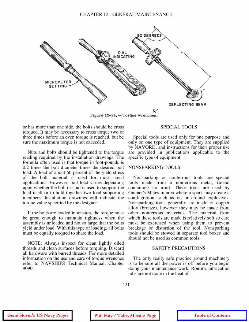
CHAPTER 12 - GENERAL MAINTENANCE
or has more than one side, the bolts should be cross torqued. It may be necessary to cross torque two or three times before an even torque is reached, but be sure the maximum torque is not exceeded. Nuts and bolts should be tightened to the torque reading required by the installation drawings. The formula often used is that torque in foot-pounds is 0.2 times the bolt diameter times the desired bolt load. A load of about 60 percent of the yield stress of the bolt material is used for most naval applications. However, bolt load varies depending upon whether the bolt or stud is used to support the load itself or to hold together two load supporting members. Installation drawings will indicate the torque value specified by the designer. If the bolts are loaded in tension, the torque must be great enough to maintain tightness when the assembly is unloaded and not so large that the bolts yield under load. With this type of loading, all bolts must be equally torqued to share the load. NOTE: Always inspect for clean lightly oiled threads and clean surfaces before torquing. Discard all hardware with burred threads. For more detailed information on the use and care of torque wrenches refer to NAVSHIPS Technical Manual, Chapter 9090.
SPECIAL TOOLS Special tools are used only for one purpose and only on one type of equipment. They are supplied by NAVORD, and instructions for their proper use are provided in publications applicable to the specific type of equipment. NONSPARKING TOOLS Nonsparking or nonferrous tools are special tools made from a nonferrous metal, (metal containing no iron). These tools are used by Gunner's Mates in area where a spark may create a conflagration, such as on or around explosives. Nonsparking tools generally are made of copper alloy (bronze), however they may be made from other nonferrous materials. The material from which these tools are made is relatively soft so care must be exercised when using them to prevent breakage or distortion of the tool. Nonsparking tools should be stowed in separate tool boxes and should not be used as common tools.
SAFETY PRECAUTIONS The only really safe practice around machinery is to be sure all the power is off before you begin doing your maintenance work. Routine lubrication jobs are not done in the heat of
421
GUNNER'S MATE M 3 & 2
battle, so there is no excuse for having any of the machinery running. If you must use power to rotate or move some of the equipment, be sure no one is in the way of the moving parts, and observe all safety precautions. That means a safety watch must be maintained. Never wear loose or torn clothing or neckerchiefs that can get entangled in machinery. Gloves, long sleeves, rings, and bracelets should not be worn while working on machinery. Wipe up any spilled oil or grease at once. Be careful to keep lubricants away from electrical contacts, from electric wires, and from all rubber parts. All petroleum products have a bad effect on rubber. Overpacking of bearings can cause runoff of lubricants which might then contact electrical parts or rubber parts. Obey NO SMOKING rules. When it is necessary to use kerosene or dry-cleaning solvent to remove caked or gummy lubricants before applying fresh lubricant, observe fire precautions and ventilation requirements. Remember also that these solvents are skin irritants. When you've finished, recharge the lubricating guns, clean up, and stow the gear. Check your chart once more to be sure you haven It slipped up anywhere. Some new type lubricants for use at low temperatures contain substances harmful to the skin. Observe the caution on the containers. In spite of repeated precautions and warnings about the danger of fumes, fatal and near-fatal accidents continue to occur. Whenever work is undertaken in a small compartment with any toxic solvent, such as those used in paints, trichlorethane, or dry-cleaning solvent, adequate precautions must be taken before the work is begun. Even though the outcome is not fatal. exposure to toxic fumes can do permanent damage to the kidneys, brain, or nervous system.
Precautions should include: (1) Sufficient mechanical ventilation to reduce the concentration of toxic fumes to a safe level. When possible, ventilation should include an exhaust for fumes as well as an intake for fresh air. (2) When a safe level of ventilation is doubtful, workers in the compartment should wear an air line respirator provided with a pure air supply. (3) Men working in a compartment where fumes may be above a safe toxic level should always work in pairs, so that one man remains outside the compartment as a safety watch at all times. The man outside should have a respirator so he won't be overcome if he has to go into the compartment to bring out an overcome man. (4) Under no circumstance is 1.1.1-trichlorethane (methyl chloroform) to be used in a closed compartment. As a petty officer, you must see that the regulations are observed by the men in your charge. Basic Military Requirements, NavPers 10054C, contains several pages of safety rules in the chapter on seamanship. Basic Electricity, NavPers 10086-B, devotes a whole chapter to electrical safety. Appendix III of Basic Handtools, NavPers 10085-A, consists of electrical safety rules, and all the OPs for the equipment have a summary, in the front of the book of the safety rules scattered through the volume. The illustrated chart of instructions for mouth-to-mouth resuscitation should be posted in one or more places in the working spaces. The danger from electricity is present in all parts of the ship. Special safety rules applicable to a particular component or to a particular maintenance process are given on the MRC for that part or process.
422

CHAPTER 13
COMMON TEST EQUIPMENT
AND LOGICAL TROUBLESHOOTING
In preceding chapters we have presented the basic operating principles of missile launching systems, and explained how they fit into the shipboard missile weapons system. But an understanding of the theory of operation is only part of the knowledge you need for successful maintenance of launching system equipment. You must be able to use test equipment and to troubleshoot. In this chapter we will cover test equipment used to measure electrical quantities, and the basic techniques for troubleshooting electronic circuitry. The device that you will use most frequently in your maintenance tasks is the meter. For this reason, we shall first review meters before we discuss other test equipment and troubleshooting techniques. You will find a more complete coverage of meters in chapter 15 of Basic Electricity, NavPers 10086-B.
REVIEW OF METER OPERATION We want to emphasize that a thorough understanding of the construction, operation, and limitations of electrical measuring instruments, coupled with the theory of circuit operation, is essential in serving and maintaining electrical equipment. Remember that the best and most expensive measuring instrument is of NO use to the man who does not know what he is measuring or what the readings indicate. The three types of meters that you will most often use are ammeter, ohmmeter, and voltmeter. It is well to pay special attention to each application in this review. AMMETER The ammeter is used to measure current. The GMM uses the ammeter to acquire further information while performing an operational check on a malfunctioning launching system to further localize the malfunction to a specific unit. The
ammeter must always be placed in series with the circuit to be measured. The ammeter consists of a basic meter movement and a combination of shunt resistors in parallel with it. The ammeters used in missile systems test equipment and component test sets usually are panel-mounted instruments. In these applications they can be used to detect the current drain of the major electrical circuits and thus provide a valuable first step in finding trouble. When ammeters are not included as parts of the equipment, current measurements can be made only after the circuit wiring has been opened and the meter inserted in series with a suspected part. A multiposition switch or a series of pin jacks allows the use of various shunt resistors to give different current ranges. When using an ammeter, always have the meter on the highest range before connecting it into a circuit. OHMMETER The ohmmeter is widely used by GMM's in making resistance measurements and continuity checks. You will find wide use for this instrument in checking cables and locating malfunctioning components in electrical circuits. The ohmmeter consists of a basic meter movement connected as an ammeter, a voltage source, and one or more resistors used to adjust the current through the meter movement. The meter must be adjusted for "zero resistance" prior to making resistance measurements. MAKE SURE YOU DON'T USE AN OHMMETER ON AN ENERGIZED CIRCUIT. If you do, the meter will make smoke and burn out. The theory and construction of the series type and the shunt type ohmmeters are discussed in Basic Electricity, NavPers 10086-B, which also describes a more specialized type of instrument, the megohmmeter, or meggar. The use of resistance checks for locating defective parts in electronic circuits is somewhat similar to the process of voltage checking. As with the voltmeter, the observed values are compared with the normal
423

GUNNER'S MATE M 3 & 2
values given in the equipment manual to identify the malfunctioning part. This method, like voltage checking, is most effective after the trouble has been isolated to a single stage. VOLTMETER The voltmeter uses the basic meter movement with a high resistance in series. The value of this series resistance is determined by the current necessary for full-scale deflection of the meter, and the voltage being measured. Because the current is directly proportional to the voltage applied, the scale can be calibrated directly in volts for a fixed series resistance. The sensitivity of voltmeters is given in ohms per volt, and may be determined by dividing the resistance of the meter, plus the series resistance, by the full-scale reading in volts. This is the same as saying that the sensitivity is equal to the reciprocal of the current (in amperes). Thus, the sensitivity of a 100-microampere movement is the reciprocal of 0.0001 ampere, or 10,000 ohms per volt. The sensitivity of the meter depends on the strength of the permanent magnet field and the weight of the moving coil. The sensitivity of a voltmeter is an indication of how accurately it measures voltages in a circuit. In many cases, a sensitivity of 1,000 ohms per volt is satisfactory; however, if the circuit in which the voltage is being measured has high resistance, a greater sensitivity is required for accuracy. The higher the sensitivity rating, the higher the resistance in the meter branch of the circuit, and the less serious the effect of shunting the circuit. If a meter of low ohms per volt is used to measure the voltage in a high resistance circuit, the effect of the meter shunting load being measured will result in an inaccurate reading. Thus, the higher the sensitivity, the more accurate the reading. Like the ammeter and ohmmeter, the voltmeter normally utilizes several resistors with a switching arrangement to permit multirange operation. Be sure to set the selector switch for maximum voltage range before connecting the meter to an energized circuit. MULTIMETERS During troubleshooting, you, as a technician are often required to measure voltage, current, and resistance. To eliminate the necessity of obtaining three or more meters, you will use
a multimeter. The multimeter combines a voltmeter, ammeter, and ohmmeter in one unit. It includes all the necessary switches, jacks, and additional devices. By proper arrangement of parts, the multimeter can be built into a small, compact unit utilizing one meter movement; capable of being switched to different ranges. A typical multimeter circuit is shown in figure 13-1. A three-range milliammeter, a three-range voltmeter with a sensitivity of 2,000 ohms per volt, and a two-range ohmmeter are combined in this circuit. A 0-500 microampere meter movement with a resistance of 100 ohms is the basic meter movement for the multimeter. The AN/PSM-4 is a multimeter commonly used in the Navy. There are three controls on the face (fig. 13-2) of the instrument. The 10 position rotary switch in the lower left corner is used as a function selector. (Five of these positions set up ohmmeter connections within the instrument. For these resistance positions, the function selector also acts as a range selector.) The 8-position switch in the lower righthand corner selects ranges of voltage and current. The ZERO-OHMS control is continuously variable and is used to adjust the meter circuit sensitivity to compensate for battery aging in the ohmmeter circuits. It is used to set the pointer at full scale (indicating zero ohms) when the function selector is set at any resistance range and the test probes are shorted together. Prior to using the meter for measuring volts, amps, or ohms, be sure that the meter movement is on zero. Observe the meter face, making sure that the indicating pointer is pointing to the left hand side of the meter, and the pointer is on zero for volts, and infinity for ohms. If the pointer is not on zero, make correction by the turn screw head located at the base of the meter face. VACUUM TUBE VOLTMETER The ordinary voltmeter is practically useless for measuring voltages in high-impedance circuits. The electronic voltmeter is a highly sensitive instrument for accurately measuring a-c voltages from 250 microvolts to 500 volts, within a wide frequency range. The meter consists essentially of a multistage amplifier terminated by two crystal diodes, connected in a bridge circuit, and a meter movement to indicate rectified current. One such meter is designed with shaped pole pieces so that the indications
424
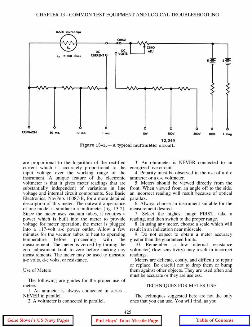
CHAPTER 13 - COMMON TEST EQUIPMENT AND LOGICAL TROUBLESHOOTING
are proportional to the logarithm of the rectified current which is accurately proportional to the input voltage over the working range of the instrument. A unique feature of the electronic voltmeter is that it gives meter readings that are substantially independent of variations in line voltage and internal circuit components. See Basic Electronics, NavPers 10087-B, for a more detailed description of this meter. The outward appearance of one model is similar to a multimeter (fig. 13-2). Since the meter uses vacuum tubes, it requires a power which is built into the meter to provide voltage for meter operation; the meter is plugged into a 117-volt a-c power outlet. Allow a few minutes for the vacuum tubes to heat to operating temperature before proceeding with the measurement. The meter is zeroed by turning the zero adjustment knob to zero before making any measurements. The meter may be used to measure a-c volts, d-c volts, or resistance. Use of Meters The following are guides for the proper use of meters. 1. An ammeter is always connected in series - NEVER in parallel. 2. A voltmeter is connected in parallel.
3. An ohmmeter is NEVER connected to an energized live circuit. 4. Polarity must be observed in the use of a d-c ammeter or a d-c voltmeter. 5. Meters should be viewed directly from the front. When viewed from an angle off to the side, an incorrect reading will result because of optical parallax. 6. Always choose an instrument suitable for the measurement desired. 7. Select the highest range FIRST, take a reading, and then switch to the proper range. 8. In using any meter, choose a scale which will result in an indication near midscale. 9. Do not expect to obtain a meter accuracy greater than the guaranteed limits. 10. Remember, a low internal resistance voltmeter) (low sensitivity) may result in incorrect readings. Meters are delicate, costly, and difficult to repair or replace. Be careful not to drop them or bump them against other objects. They are used often and must be accurate or they are useless.
TECHNIQUES FOR METER USE The techniques suggested here are not the only ones that you can use. You will find, as you
425
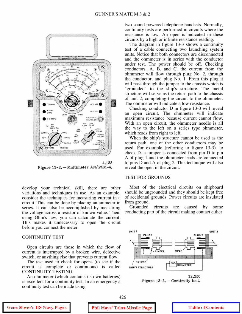
GUNNER'S MATE M 3 & 2
develop your technical skill, there are other variations and techniques in use. As an example, consider the techniques for measuring current in a circuit. This can be done by placing an ammeter in series. It can also be accomplished by measuring the voltage across a resistor of known value. Then, using Ohm's law, you can calculate the current. This makes it unnecessary to open the circuit before you connect the meter. CONTINUITY TEST Open circuits are those in which the flow of current is interrupted by a broken wire, defective switch, or anything else that prevents current flow. The test used to check for opens (to see if the circuit is complete or continuous) is called CONTINUITY TESTING. An ohmmeter (which contains its own batteries) is excellent for a continuity test. In an emergency a continuity test can be made using
two sound-powered telephone handsets. Normally, continuity tests are performed in circuits where the resistance is low. An open is indicated in these circuits by a high or infinite resistance reading. The diagram in figure 13-3 shows a continuity test of a cable connecting two launching system units. Notice that both connectors are disconnected and the ohmmeter is in series with the conductor under test. The power should be off. Checking conductors. A. B. and C. the current from the ohmmeter will flow through plug No. 2, through the conductor, and plug No. 1. From this plug it will pass through the jumper to the chassis which is "grounded" to the ship's structure. The metal structure will serve as the return path to the chassis of unit 2, completing the circuit to the ohmmeter. The ohmmeter will indicate a low resistance. Checking conductor D in figure 13-3 will reveal an open circuit. The ohmmeter will indicate maximum resistance because current cannot flow. With an open circuit, the ohmmeter needle is all the way to the left on a series type ohmmeter, which reads from right to left. When the ship's structure cannot be used as the return path, one of the other conductors may be used. For example (referring to figure 13-3). to check D. a jumper is connected from pin D to pin A of plug 1 and the ohmmeter leads are connected to pins D and A of plug 2. This technique will also reveal the open in the circuit. TEST FOR GROUNDS Most of the electrical circuits on shipboard should be ungrounded and they should be kept free of accidental grounds. Power circuits are insulated from ground. Grounded circuits are caused by some conducting part of the circuit making contact either
426
CHAPTER 13 - COMMON TEST EQUIPMENT AND LOGICAL TROUBLESHOOTING
directly or indirectly with the metallic structure of the ship. Grounds may have many causes. The two most common are the fraying of insulation from a wire allowing the bare wire to come in contact with the metal ground, and moisture soaked insulation. Grounds usually are indicated by blown fuses or tripped circuit breakers. Blown fuses or tripped circuit breakers, however, may also result from a short other than ground. A high resistance ground may also occur where not enough current can flow to rupture the fuse or open the circuit breaker. In testing for grounds, the ohmmeter may be used. By measuring the resistance to ground of any point in a circuit, you can determine if the point is grounded. Take another look at figure 133. If you remove the jumper, you can test for ground on each conductor of the cable. This is accomplished by connecting one meter lead to ground and the other to each of the pins of one of the plugs. A low resistance will indicate that a pin is grounded. Both plugs must be removed from their units; if only one plug is removed, a false indication is possible since a conductor may be grounded within the unit. Grounding is required as a safety measure on certain installed and semiportable electrical equipment and on portable electrical equipment such as handtools. Grounded type plugs and receptacles are required for portable tools. The approved method of installing and testing grounded type plugs, cords, tools, and receptacles is given in Basic Handtools, NAVPERS 10085-A, in the Appendix Ill, which quotes the rules directly from NAVSHIPS 0901-000-0020 (formerly NavShips 250,000, Vol. II), Technical Manual. Articles 60-21 to 60-40, quoted in part in Basic Handtools. are required study for all hands. The NAVSHIPS volume also includes instructions for artificial respiration, additional safety precautions, instructions and regulations for use of extension cords, and use of personal electrical equipment, such as electric shavers, etc. Ground detector voltmeters are permanently installed on many Navy ships for measuring the insulation resistance to ground from d-c circuits and equipment. TEST FOR SHORTS A short circuit, other than a grounded one. is one in which two conductors accidentally touch each other, directly or through another conducting element. Two conductors with frayed insulation may touch and cause a short. Too much solder
on the pin of a connector may short it to the adjacent pin. In a short circuit, enough current may flow to blow a fuse or open a circuit breaker. However, it is entirely possible to have a short between two cables carrying signals; such a short may not be indicated by a blown fuse. Other indications of a short may be smoke, sparks, flame, and the odor of charring insulation. The charred insulation locates the point where the short occurred; however, many circuits are so enclosed they cannot be seen. As when checking for a ground, the device used for checking for a short is the ohmmeter. If you measure the resistance between two conductors, a short between them will be indicated by a low resistance reading. In figure 13-3, by removing the jumper and disconnecting both plugs, a short test may be made. This is performed by measuring the resistance between the two suspected conductors. Shorts are not reserved for cables; they occur in many components, such as transformers, motor windings, capacitors, etc. To check a component for a possible short, measure its resistance. Compare your reading with the resistance given on schematics or in the equipment OP. VOLTAGE TEST The voltage test must be made with the power applied; therefore, the prescribed safety precautions MUST be followed to prevent injury to personnel and damage to equipment. You will find in your maintenance work that the voltage test is of utmost importance. It is used not only in isolating casualties to major components but also in the maintenance of subassemblies, units, and circuits. Before checking a circuit voltage, check the voltage of the power source to be sure that it is normal. Obviously, the voltmeter is used for voltage tests. In using the voltmeter, make certain that the meter used is designated for the type of current (a-c or d-c) to be tested, and that it has a scale of adequate range. Since defective parts in a circuit may cause higher than normal voltages at the point of test, the highest voltmeter range available should be used at first. Once a reading has been obtained, determine if a lower scale can be used without damaging the meter movement. If so, use the lower scale, so as to obtain a more accurate reading. Another consideration in the circuit voltage test is the resistance and current in the circuit. A low resistance in a high current circuit would
427
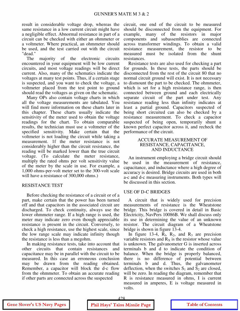
GUNNER'S MATE M 3 & 2
result in considerable voltage drop, whereas the same resistance in a low current circuit might have a negligible effect. Abnormal resistance in part of a circuit can be checked with either an ohmmeter or a voltmeter. Where practical, an ohmmeter should be used, and the test carried out with the circuit "dead." The majority of the electronic circuits encountered in your equipment will be low current circuits, and most voltage readings will be direct current. Also, many of the schematics indicate the voltages at many test points. Thus, if a certain stage is suspected, and you want to check the voltage, a voltmeter placed from the test point to ground should read the voltages as given on the schematic. Many OPs also contain voltage charts in which all the voltage measurements are tabulated. You will find more information on these charts later in this chapter. These charts usually indicate the sensitivity of the meter used to obtain the voltage readings for the chart. To obtain comparable results, the technician must use a voltmeter of the specified sensitivity. Make certain that the voltmeter is not loading the circuit while taking a measurement. 1f the meter resistance is not considerably higher than the circuit resistance, the reading will be marked lower than the true circuit voltage. (To calculate the meter resistance, multiply the rated ohms per volt sensitivity value of the meter by the scale in use. For example, a 1,000 ohms-per-volt meter set to the 300-volt scale will have a resistance of 300,000 ohms.) RESISTANCE TEST Before checking the resistance of a circuit or of a part, make certain that the power has been turned off and that capacitors in the associated circuit are discharged. To check continuity, always use the lower ohmmeter range. If a high range is used, the meter may indicate zero even though appreciable resistance is present in the circuit. Conversely, to check a high resistance, use the highest scale, since the low range scale may indicate infinity though the resistance is less than a megohm. In making resistance tests, take into account that other circuits that contain resistances and capacitance may be in parallel with the circuit to be measured. In this case an erroneous conclusion may be drawn from the reading obtained. Remember, a capacitor will block the d-c flow from the ohmmeter. To obtain an accurate reading if other parts are connected across the suspected
circuit, one end of the circuit to be measured should be disconnected from the equipment. For example, many of the resistors in major components and subassemblies are connected across transformer windings. To obtain a valid resistance measurement, the resistor to be measured must be isolated from the shunt resistances. Resistance tests are also used for checking a part for grounds. In these tests, the parts should be disconnected from the rest of the circuit 80 that no normal circuit ground will exist. It is not necessary to dismount the part to be checked. The ohmmeter, which is set for a high resistance range, is then connected between ground and each electrically separate circuit of the part under test. Any resistance reading less than infinity indicates at least a partial ground. Capacitors suspected of being short circuited can also be checked by a resistance measurement. To check a capacitor suspected of being open, temporarily shunt a known perfect capacitor across it, and recheck the performance of the circuit.
ACCURATE MEASUREMENT OF RESISTANCE, CAPACITANCE,
AND INDUCTANCE
An instrument employing a bridge circuit should be used in the measurement of resistance, capacitance, and inductance where a high degree of accuracy is desired. Bridge circuits are used in both a-c and d-c measuring instruments. Both types will be discussed in this section. USE OF D-C BRIDGES
A circuit that is widely used for precision measurements of resistance is the Wheatstone bridge. This bridge is covered in detail in Basic Electricity, NavPers 10086B. We shall discuss only its use in determining the value of an unknown resistor. The circuit diagram of a Wheatstone bridge is shown in figure 13-4. In figure 13-4, Rl, R2, and R3 are precision variable resistors and RX is the resistor whose value is unknown. The galvanometer G is inserted across terminals b and d to indicate the condition of balance. When the bridge is properly balanced, there is no difference of potential between terminals b and d. Thus, the galvanometer deflection, when the switches S1 and S2 are closed, will be zero. In reading the diagram, remember that R is resistance measured in ohms, I is current measured in amperes, E is voltage measured in volts.
428
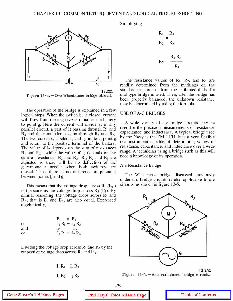
CHAPTER 13 - COMMON TEST EQUIPMENT AND LOGICAL TROUBLESHOOTING
The operation of the bridge is explained in a few logical steps. When the switch S2 is closed, current will flow from the negative terminal of the battery to point a. Here the current will divide as in any parallel circuit, a part of it passing through R1 and R2 and the remainder passing through RS and RX. The two currents, labeled I1 and I2, unite at point c and return to the positive terminal of the battery. The value of I2 depends on the sum of resistances R1 and R2 , while the value of I2 depends on the sum of resistances R3 and RX. R1, R2 and R3 are adjusted so there will be no deflection of the galvanometer needle when both switches are closed. Thus, there is no difference of potential between points b and d. This means that the voltage drop across R1 (E1.) is the same as the voltage drop across R3 (E3). By similar reasoning, the voltage drops across R2 and RX, that is E2 and EX, are also equal. Expressed algebraically, E1 = E3 or I1 Rl = I2 R3 and E2 = EX or I1 R1 = I2 RX Dividing the voltage drop across R1 and R3 by the respective voltage drop across R2 and RX, I1 R1 I2 R3
-------- = ---------- I1 R2 I2 RX
Simplifying Rl R3 --- = --- R2 RX R2 R3 RX = -------- Rl The resistance values of R1, R2, and R3 are readily determined from the markings on the standard resistors, or from the calibrated dials if a dial type bridge is used. Then, after the bridge has been properly balanced, the unknown resistance may be determined by using the formula. USE OF A-C BRIDGES A wide variety of a-c bridge circuits may be used for the precision measurements of resistance, capacitance, and inductance. A typical bridge used by the Navy is the ZM-11/U. It is a very flexible test instrument capable of determining values of resistance, capacitance, and inductance over a wide range. A technician using a bridge such as this will need a knowledge of its operation. A-c Resistance Bridge The Wheatstone bridge discussed previously under d-c bridge circuits is also applicable to a-c circuits, as shown in figure 13-5.
429
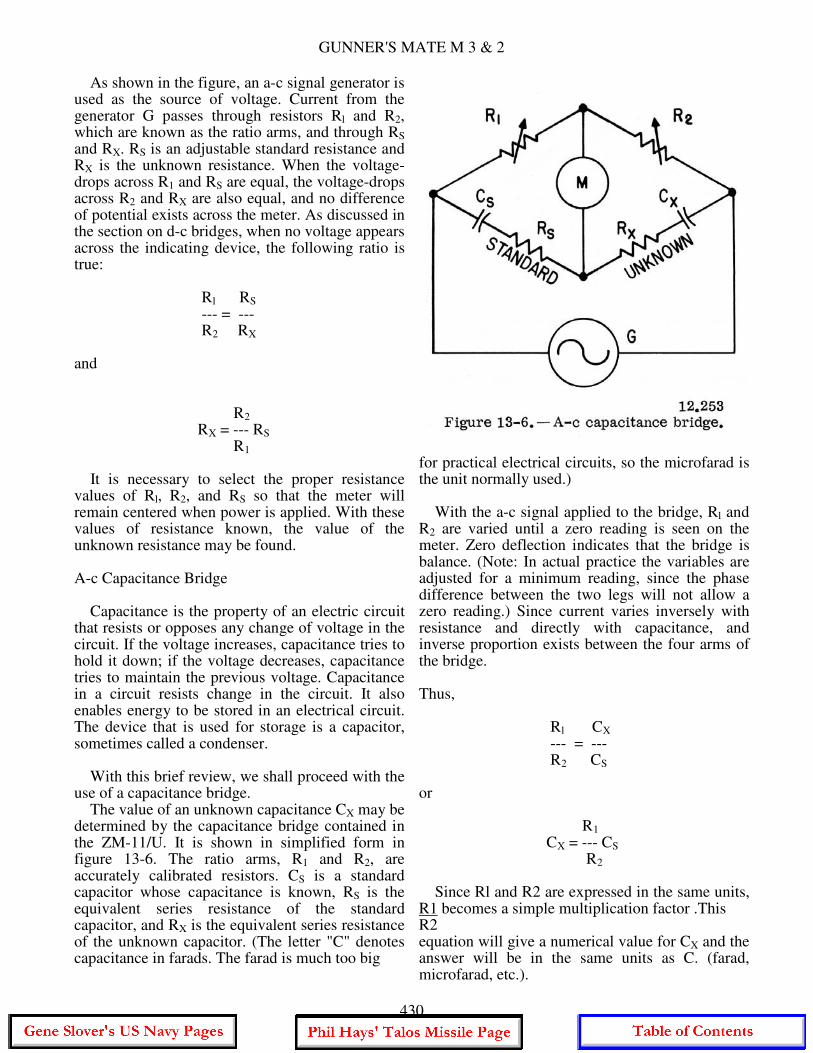
GUNNER'S MATE M 3 & 2
As shown in the figure, an a-c signal generator is used as the source of voltage. Current from the generator G passes through resistors Rl and R2, which are known as the ratio arms, and through RS and RX. RS is an adjustable standard resistance and RX is the unknown resistance. When the voltage-drops across R1 and RS are equal, the voltage-drops across R2 and RX are also equal, and no difference of potential exists across the meter. As discussed in the section on d-c bridges, when no voltage appears across the indicating device, the following ratio is true: Rl RS --- = --- R2 RX and R2 RX = --- RS R1 It is necessary to select the proper resistance values of Rl, R2, and RS so that the meter will remain centered when power is applied. With these values of resistance known, the value of the unknown resistance may be found. A-c Capacitance Bridge Capacitance is the property of an electric circuit that resists or opposes any change of voltage in the circuit. If the voltage increases, capacitance tries to hold it down; if the voltage decreases, capacitance tries to maintain the previous voltage. Capacitance in a circuit resists change in the circuit. It also enables energy to be stored in an electrical circuit. The device that is used for storage is a capacitor, sometimes called a condenser. With this brief review, we shall proceed with the use of a capacitance bridge. The value of an unknown capacitance CX may be determined by the capacitance bridge contained in the ZM-11/U. It is shown in simplified form in figure 13-6. The ratio arms, R1 and R2, are accurately calibrated resistors. CS is a standard capacitor whose capacitance is known, RS is the equivalent series resistance of the standard capacitor, and RX is the equivalent series resistance of the unknown capacitor. (The letter "C" denotes capacitance in farads. The farad is much too big
for practical electrical circuits, so the microfarad is the unit normally used.) With the a-c signal applied to the bridge, Rl and R2 are varied until a zero reading is seen on the meter. Zero deflection indicates that the bridge is balance. (Note: In actual practice the variables are adjusted for a minimum reading, since the phase difference between the two legs will not allow a zero reading.) Since current varies inversely with resistance and directly with capacitance, and inverse proportion exists between the four arms of the bridge. Thus, Rl CX --- = --- R2 CS or R1 CX = --- CS R2 Since Rl and R2 are expressed in the same units, R1 becomes a simple multiplication factor .This R2 equation will give a numerical value for CX and the answer will be in the same units as C. (farad, microfarad, etc.).
430
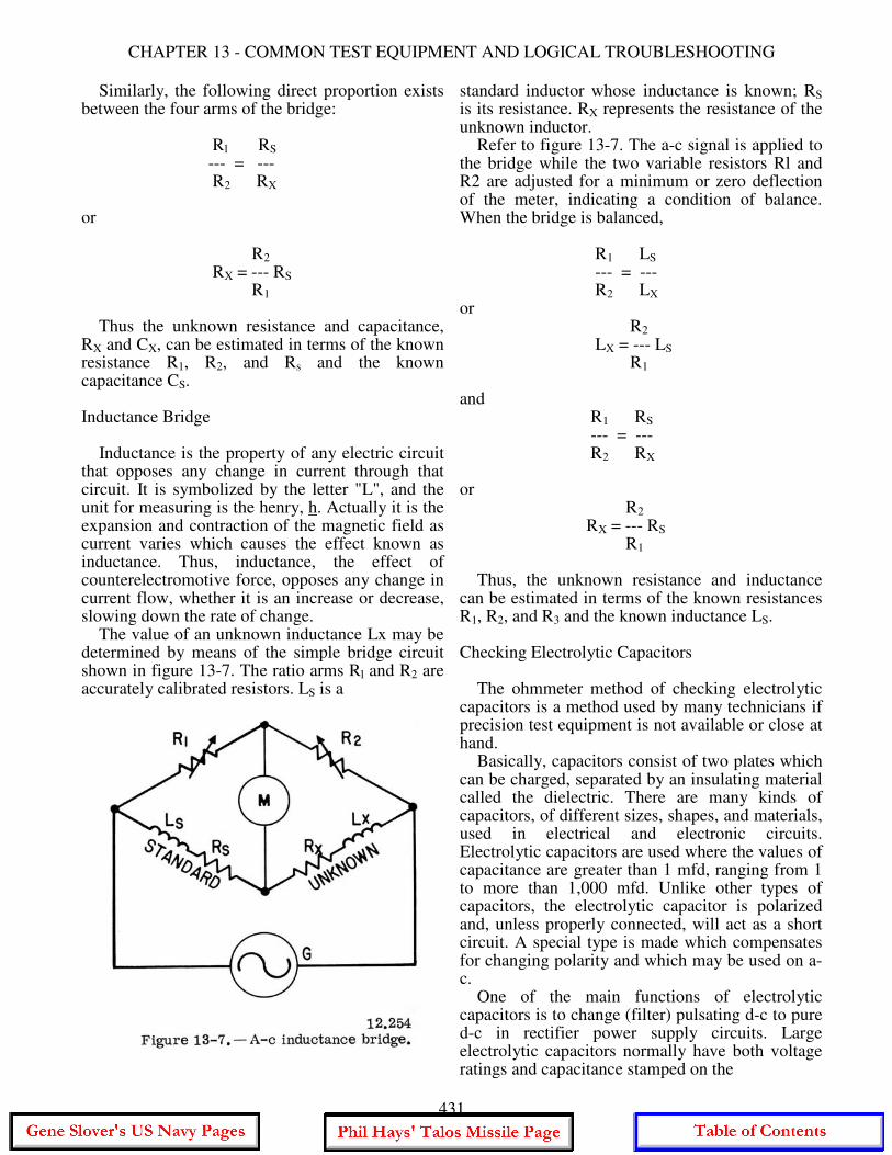
CHAPTER 13 - COMMON TEST EQUIPMENT AND LOGICAL TROUBLESHOOTING
Similarly, the following direct proportion exists between the four arms of the bridge: Rl RS --- = --- R2 RX or R2 RX = --- RS R1 Thus the unknown resistance and capacitance, RX and CX, can be estimated in terms of the known resistance R1, R2, and Rs and the known capacitance CS. Inductance Bridge Inductance is the property of any electric circuit that opposes any change in current through that circuit. It is symbolized by the letter "L", and the unit for measuring is the henry, h. Actually it is the expansion and contraction of the magnetic field as current varies which causes the effect known as inductance. Thus, inductance, the effect of counterelectromotive force, opposes any change in current flow, whether it is an increase or decrease, slowing down the rate of change. The value of an unknown inductance Lx may be determined by means of the simple bridge circuit shown in figure 13-7. The ratio arms Rl and R2 are accurately calibrated resistors. LS is a
standard inductor whose inductance is known; RS is its resistance. RX represents the resistance of the unknown inductor. Refer to figure 13-7. The a-c signal is applied to the bridge while the two variable resistors Rl and R2 are adjusted for a minimum or zero deflection of the meter, indicating a condition of balance. When the bridge is balanced, R1 LS --- = --- R2 LX or R2 LX = --- LS R1 and R1 RS --- = --- R2 RX or R2 RX = --- RS R1 Thus, the unknown resistance and inductance can be estimated in terms of the known resistances R1, R2, and R3 and the known inductance LS. Checking Electrolytic Capacitors The ohmmeter method of checking electrolytic capacitors is a method used by many technicians if precision test equipment is not available or close at hand. Basically, capacitors consist of two plates which can be charged, separated by an insulating material called the dielectric. There are many kinds of capacitors, of different sizes, shapes, and materials, used in electrical and electronic circuits. Electrolytic capacitors are used where the values of capacitance are greater than 1 mfd, ranging from 1 to more than 1,000 mfd. Unlike other types of capacitors, the electrolytic capacitor is polarized and, unless properly connected, will act as a short circuit. A special type is made which compensates for changing polarity and which may be used on a-c. One of the main functions of electrolytic capacitors is to change (filter) pulsating d-c to pure d-c in rectifier power supply circuits. Large electrolytic capacitors normally have both voltage ratings and capacitance stamped on the
431
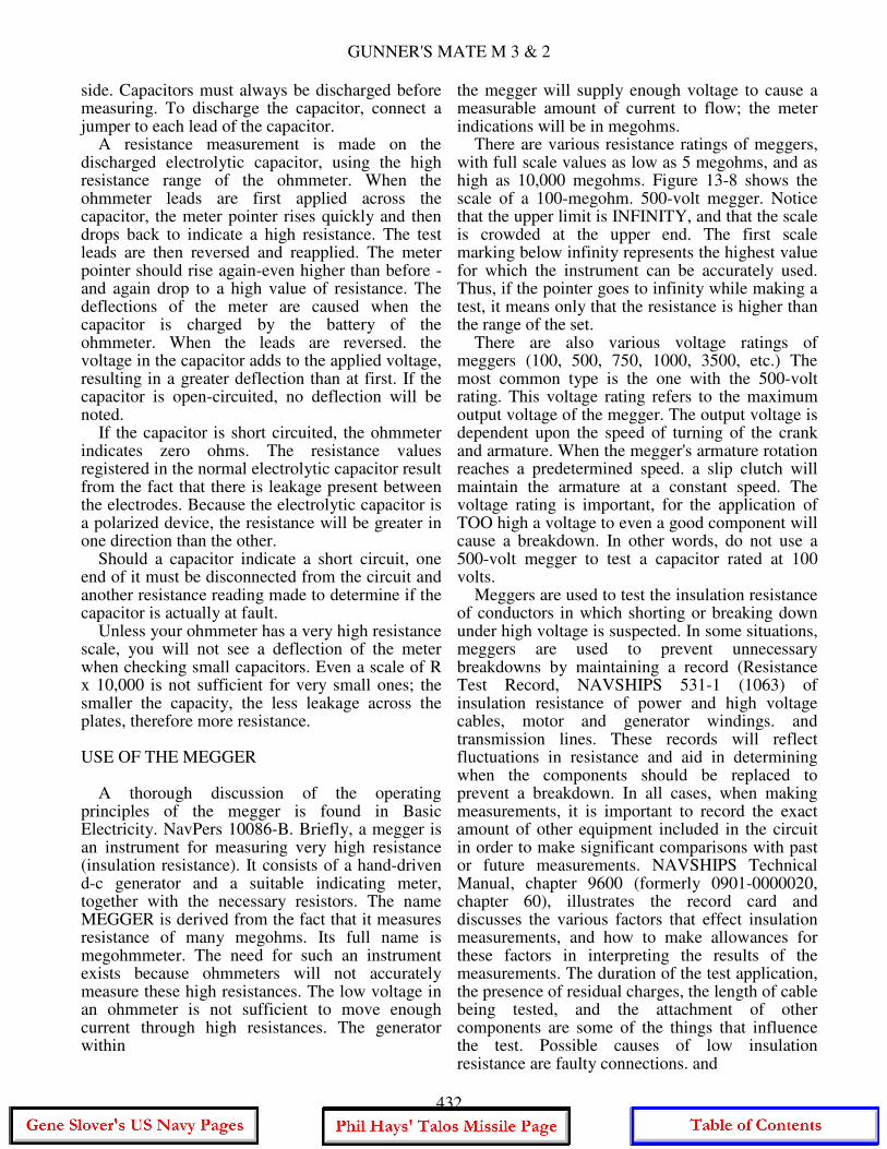
GUNNER'S MATE M 3 & 2
side. Capacitors must always be discharged before measuring. To discharge the capacitor, connect a jumper to each lead of the capacitor. A resistance measurement is made on the discharged electrolytic capacitor, using the high resistance range of the ohmmeter. When the ohmmeter leads are first applied across the capacitor, the meter pointer rises quickly and then drops back to indicate a high resistance. The test leads are then reversed and reapplied. The meter pointer should rise again-even higher than before - and again drop to a high value of resistance. The deflections of the meter are caused when the capacitor is charged by the battery of the ohmmeter. When the leads are reversed. the voltage in the capacitor adds to the applied voltage, resulting in a greater deflection than at first. If the capacitor is open-circuited, no deflection will be noted. If the capacitor is short circuited, the ohmmeter indicates zero ohms. The resistance values registered in the normal electrolytic capacitor result from the fact that there is leakage present between the electrodes. Because the electrolytic capacitor is a polarized device, the resistance will be greater in one direction than the other. Should a capacitor indicate a short circuit, one end of it must be disconnected from the circuit and another resistance reading made to determine if the capacitor is actually at fault. Unless your ohmmeter has a very high resistance scale, you will not see a deflection of the meter when checking small capacitors. Even a scale of R x 10,000 is not sufficient for very small ones; the smaller the capacity, the less leakage across the plates, therefore more resistance. USE OF THE MEGGER A thorough discussion of the operating principles of the megger is found in Basic Electricity. NavPers 10086-B. Briefly, a megger is an instrument for measuring very high resistance (insulation resistance). It consists of a hand-driven d-c generator and a suitable indicating meter, together with the necessary resistors. The name MEGGER is derived from the fact that it measures resistance of many megohms. Its full name is megohmmeter. The need for such an instrument exists because ohmmeters will not accurately measure these high resistances. The low voltage in an ohmmeter is not sufficient to move enough current through high resistances. The generator within
the megger will supply enough voltage to cause a measurable amount of current to flow; the meter indications will be in megohms. There are various resistance ratings of meggers, with full scale values as low as 5 megohms, and as high as 10,000 megohms. Figure 13-8 shows the scale of a 100-megohm. 500-volt megger. Notice that the upper limit is INFINITY, and that the scale is crowded at the upper end. The first scale marking below infinity represents the highest value for which the instrument can be accurately used. Thus, if the pointer goes to infinity while making a test, it means only that the resistance is higher than the range of the set. There are also various voltage ratings of meggers (100, 500, 750, 1000, 3500, etc.) The most common type is the one with the 500-volt rating. This voltage rating refers to the maximum output voltage of the megger. The output voltage is dependent upon the speed of turning of the crank and armature. When the megger's armature rotation reaches a predetermined speed. a slip clutch will maintain the armature at a constant speed. The voltage rating is important, for the application of TOO high a voltage to even a good component will cause a breakdown. In other words, do not use a 500-volt megger to test a capacitor rated at 100 volts. Meggers are used to test the insulation resistance of conductors in which shorting or breaking down under high voltage is suspected. In some situations, meggers are used to prevent unnecessary breakdowns by maintaining a record (Resistance Test Record, NAVSHIPS 531-1 (1063) of insulation resistance of power and high voltage cables, motor and generator windings. and transmission lines. These records will reflect fluctuations in resistance and aid in determining when the components should be replaced to prevent a breakdown. In all cases, when making measurements, it is important to record the exact amount of other equipment included in the circuit in order to make significant comparisons with past or future measurements. NAVSHIPS Technical Manual, chapter 9600 (formerly 0901-0000020, chapter 60), illustrates the record card and discusses the various factors that effect insulation measurements, and how to make allowances for these factors in interpreting the results of the measurements. The duration of the test application, the presence of residual charges, the length of cable being tested, and the attachment of other components are some of the things that influence the test. Possible causes of low insulation resistance are faulty connections. and
432

CHAPTER 13 - COMMON TEST EQUIPMENT AND LOGICAL TROUBLESHOOTING
accumulations of dirt or foreign material. Moisture is damaging to all insulation, varying with the type of insulation, and this will effect the megger test. A comparison of the results of successive test would reveal such progressive deterioration. Although the instruction in NAVSHIPS Technical Manual were written for ship's electricians, the conditions that affect insulation resistance on ship's power and lighting equipment have the same effect on missile launching systems, and will influence the megger readings in the same way. In the course of general maintenance and upkeep of a missile launching system, it is always possible that insulation resistance tests must be made. Therefore, GMMs should become familiar with the megger and how to use it. Precautions When Making Megger Tests. Precautions to be followed in the use of the megger are listed below: 1. When making a megger test, the equipment must NOT be live. It must be disconnected entirely from its source of Supply before it is tested. 2. Observe all rules for safety in preparing equipment for test and in testing, especially when testing installed high voltage apparatus. 3. Use well-insulated test leads, especially when using high range meggers. After the leads are connected to the instrument and before connecting them to the component to be tested, operate the megger and make sure there is no leak between the leads. The reading should be
infinity. To make certain the leads are not disconnected or broken, touch the test ends of the leads together while turning the crank slowly. The reading should be approximately zero. 4. When using high range meggers, take proper precautions against electric shock, especially while the component is under test. There is sufficient amount of capacitance in most electrical equipment to "store up" enough energy from the megger generator to give a very disagreeable and even dangerous shock. Owing to a high protective resistance in the megger, its open circuit voltage is not as dangerous, but care should be exercised. 5. Equipment having considerable capacitance should be discharged before and after making megger tests in order to avoid the danger of receiving a shock. This can be accomplished by grounding or short circuiting the terminals of the equipment under test. 6. Make sure that the connections on removable test leads on portable meters are secure. One report has been received of a test lead that came adrift, touched a rocket motor, and fired it. 7. Never implicitly trust insulation when considering personal safety. Insulation may look perfect yet not prevent a shock. Sufficient leakage current may be present to cause a fatal shock. Be sure power and control circuits are deenergized before beginning work on any part. Tag switches open so no one will close them while you are testing. NAVSHIPS Form 3960 (3-63) may be used for tagging switches open. You just need to write in your name and rate before attaching the tag. You remove the tag (no one else may do it)
433

GUNNER'S MATE M 3 & 2
when you have completed your work on the circuit and are ready to reenergize it.
TUBE TESTING Although each electron tube purchased by the Navy has been thoroughly tested electrically and mechanically, it is possible, nevertheless, for tubes to be damaged in shipment, storage, or handling. Therefore, a tube should be tested before it is used the first time. Electron tubes do not last indefinitely. Coated cathodes lose their power to emit electrons because the coating flakes off. Likewise, impregnated emitters of filament type tubes become depleted with age. There are other factors that cause electron tubes to function improperly-for example, defective seals permit air to leak into the tube and "poison" the emitting surface, and vibration or excessive voltage may cause internal shorts or opens. Whenever electronic equipment operates subnormally, one of the first maintenance procedures is to check the tubes with a tube tester. This often results in finding weak tubes and replacing them prior to failure;. As a GMM you are responsible for operating tube testers. The practice of wholesale removal and test of electron tubes on a periodic basis is not to be done. This routine type of tube testing has been specified in some maintenance manuals but revised editions will delete this requirement. The revised procedure will call for tube testing only if the equipment containing the tube is not performing properly. Isolate the cause, identify the tube that appears to be at fault, and remove and test that one. If test shows the tube to be good, return it to its socket, and continue your search for the cause of the trouble. Do not interchange tubes if it can be avoided. If the test shows the tube to be at fault, put in a new tube of the same kind, testing it first. Sometimes a new tube will not work in a particular socket, and several new ones may have to be tried. TYPES OF TESTERS Two types of tube testers are in general use. One, the EMISSION-TYPE tester, indicates the relative value of a tube in terms of its ability to emit electrons from the cathode. The second and more accurate type is the MUTUAL-CONDUCTANCE (or transconductance) tube tester. This tube tester not only gives an indication of the electron emission, but also indicates the ability of the grid voltages to control the plate current.
The end of the useful life of a tube usually is preceded by a reduction in electron emissivity that is, the cathode no longer supplies the number of electrons necessary for proper operation of the tube. In the emission tester, the proper voltages are applied to each electrode in the tube, and a meter indicates the plate current. If the tube has an open element or is at the end of its useful life, the emission tester gives an indication of this defect in the lower, or reject, portion of the meter scale. A tube may have normal emission and still not operate properly because tube efficiency depends on the ability of the grid voltage to control the plate current. The emission-type tester indicates only the plate current, and not the ability of the grid to control the plate current. The transconductance type tube tester, however, indicates how the tube operates, not merely the condition of the emitting surface. The terms "mutual conductance" and "transconductance" are used interchangeably in many texts. The Navy Department prefers transconductance but many commercial tube testers are marked "mutual conductance." When the prefix "dynamic" is used, as in "dynamic transconductance," it means that the characteristics of the tube in operation are being tested. The difference between the dynamic and static characteristics lies in the effect produced by the load impedance on the operation of the tube. Most tube testers, other than the emission type, test the dynamic characteristics by placing the tube in a working circuit. TYPICAL TUBE TESTER The tube tester shown in figure 13-9 is a typical portable tube tester of the dynamic mutual-transconductance type designed to test electron tubes of the standard type and many of the miniature and subminiature types. A multimeter section, using the same indicator, is also incorporated in the equipment to permit measurements of a-c and d-c volts, d-c mils, and resistance and capacitance in a number of ranges. This combination tube tester and multimeter is also called a vacuum tube analyzer. The equipment is capable of checking accurately all receiving tubes of filament or cathode type, and of 4-, 5-,6-, 7-prong, octal, loktal, naval, 7 pin miniature, subminiature, and acorn types. The tube tester has a roller chart (shown through "windows," lower part of fig. 13-9) indicating the tubes that may be tested. Listed opposite the tube designations is a series of
434

CHAPTER 13 - COMMON TEST EQUIPMENT AND LOGICAL TROUBLESHOOTING
numbers and letters which indicate the position of each switch and potentiometer of the SELECTORS and also the correct pushbutton to push. These switch positions connect the tube into a circuit that is comparable to the operating circuit of the tube. When the potentiometers are adjusted to the values indicated on the chart, the correct operating voltages are applied to the tube so that it can be checked under operating conditions. As newer tubes than those listed on the roller chart are used in equipments, other charts are published, giving the new switch positions and potentiometer settings. When conditions warrant, new roller charts incorporating the latest tubes are prepared. TESTS MADE WITH TUBE TESTER Let us now consider each of the individual tests performed by the instrument, one at a time. These tests are: (1) line voltage test, (2) short circuit test, (3) noise test, (4) rectifier test, (5) mutual-conductance test, (6) gas test, and (7) tests performed by means of the multimeter section.
Line Voltage Test It is necessary to maintain rated voltage across the primary of the power transformer if the meter of the tube tester is to register correctly. Therefore, a variable resistor is connected in series with the power input leads so that the voltage applied to the primary may be adjusted to the correct value. A special switch (the line-adjustment switch, lower left in fig. 13-9) connects the meter to the line, so that you can see when the line adjustment control is correctly set. The line voltage should be adjusted after the filament switch is in the correct position and the tube is in the test socket. Some tubes draw a high filament current, and would load down the operating voltage of the equipment if the line were adjusted first. The tube tester is designed to accurately test tubes under certain operating conditions, but the operating voltages must be accurate to accomplish this purpose. Correct line voltage adjustments will result in the required operating voltages.
435
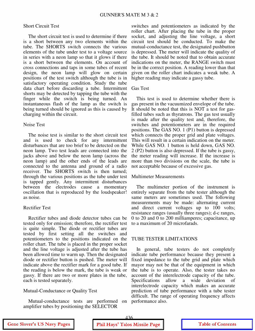
GUNNER'S MATE M 3 & 2
Short Circuit Test The short circuit test is used to determine if there is a short between any two elements within the tube. The SHORTS switch connects the various elements of the tube under test to a voltage source in series with a neon lamp so that it glows if there is a short between the elements. On account of cross connections and taps in some tubes of recent design, the neon lamp will glow on certain positions of the test switch although the tube is in satisfactory operating condition. Study the tube data chart before discarding a tube. Intermittent shorts may be detected by tapping the tube with the finger while the switch is being turned. An instantaneous flash of the lamp as the switch is being turned should be ignored as this is caused by charging within the circuit. Noise Test The noise test is similar to the short circuit test and is used to check for any intermittent disturbances that are too brief to be detected on the neon lamp. Two test leads are connected into the jacks above and below the neon lamp (across the neon lamp) and the other ends of the leads are connected to the antenna and ground of a radio receiver. The SHORTS switch is then turned; through the various positions as the tube under test is tapped gently. Any intermittent disturbances between the electrodes cause a momentary oscillation that is reproduced by the loudspeaker! as noise. Rectifier Test Rectifier tubes and diode detector tubes can be tested only for emission; therefore, the rectifier test is quite simple. The diode or rectifier tubes are tested by first setting all the switches and potentiometers to the positions indicated on the roller chart. The tube is placed in the proper socket and the line voltage is adjusted after the tube has been allowed time to warm up. Then the designated diode or rectifier button is pushed. The meter will indicate above the rectifier mark for a good tube. If the reading is below the mark, the tube is weak or gassy. If there are two or more plates in the tube, each is tested separately. Mutual-Conductance or Quality Test Mutual-conductance tests are performed on amplifier tubes by positioning the SELECTOR
switches and potentiometers as indicated by the roller chart. After placing the tube in the proper socket, and adjusting the line voltage, a short circuit test should be conducted. To make the mutual-conductance test, the designated pushbutton is depressed. The meter will indicate the quality of the tube. It should be noted that to obtain accurate indications on the meter, the RANGE switch must be in the correct position. A reading lower than that given on the roller chart indicates a weak tube. A higher reading may indicate a gassy tube. Gas Test This test is used to determine whether there is gas present in the vacuumized envelope of the tube. It should be noted that this is NOT a test for gas-filled tubes such as thyratrons. The gas test usually is made after the quality test and, therefore, the switches and potentiometers are in the required positions. The GAS NO. 1 (P1) button is depressed which connects the proper grid and plate voltages. This will result in a certain indication on the meter. While GAS NO. 1 button is held down, GAS NO. 2 (P2) button is also depressed. If the tube is gassy, the meter reading will increase. If the increase is more than two divisions on the scale, the tube is not acceptable because of excessive gas. Multimeter Measurements The multimeter portion of the instrument is entirely separate from the tube tester although the same meters are sometimes used. The following measurements may be made: alternating current and direct current voltages up to 100 volts; resistance ranges (usually three ranges); d-c ranges, 0 to 20 and 0 to 200 milliamperes; capacitance, up to a maximum of 20 microfarads. TUBE TESTER LIMITATIONS In general, tube testers do not completely indicate tube performance because they present a fixed impedance to the tube grid and plate which mayor may not be that of the equipment in which the tube is to operate. Also, the tester takes no account of the interelectrode capacity of the tube. Specifications allow a wide deviation of interelectrode capacity which makes an accurate prediction of tube performance with a tube tester difficult. The range of operating frequency affects performance also.
436
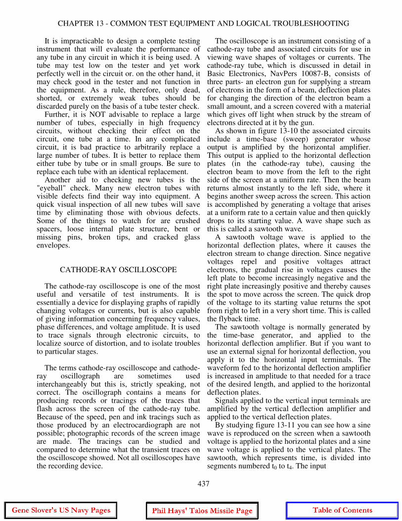
CHAPTER 13 - COMMON TEST EQUIPMENT AND LOGICAL TROUBLESHOOTING
It is impracticable to design a complete testing instrument that will evaluate the performance of any tube in any circuit in which it is being used. A tube may test low on the tester and yet work perfectly well in the circuit or. on the other hand, it may check good in the tester and not function in the equipment. As a rule, therefore, only dead, shorted, or extremely weak tubes should be discarded purely on the basis of a tube tester check. Further, it is NOT advisable to replace a large number of tubes, especially in high frequency circuits, without checking their effect on the circuit, one tube at a time. In any complicated circuit, it is bad practice to arbitrarily replace a large number of tubes. It is better to replace them either tube by tube or in small groups. Be sure to replace each tube with an identical replacement. Another aid to checking new tubes is the "eyeball" check. Many new electron tubes with visible defects find their way into equipment. A quick visual inspection of all new tubes will save time by eliminating those with obvious defects. Some of the things to watch for are crushed spacers, loose internal plate structure, bent or missing pins, broken tips, and cracked glass envelopes.
CATHODE-RAY OSCILLOSCOPE The cathode-ray oscilloscope is one of the most useful and versatile of test instruments. It is essentially a device for displaying graphs of rapidly changing voltages or currents, but is also capable of giving information concerning frequency values, phase differences, and voltage amplitude. It is used to trace signals through electronic circuits, to localize source of distortion, and to isolate troubles to particular stages. The terms cathode-ray oscilloscope and cathode-ray oscillograph are sometimes used interchangeably but this is, strictly speaking, not correct. The oscillograph contains a means for producing records or tracings of the traces that flash across the screen of the cathode-ray tube. Because of the speed, pen and ink tracings such as those produced by an electrocardiograph are not possible; photographic records of the screen image are made. The tracings can be studied and compared to determine what the transient traces on the oscilloscope showed. Not all oscilloscopes have the recording device.
The oscilloscope is an instrument consisting of a cathode-ray tube and associated circuits for use in viewing wave shapes of voltages or currents. The cathode-ray tube, which is discussed in detail in Basic Electronics, NavPers 10087-B, consists of three parts- an electron gun for supplying a stream of electrons in the form of a beam, deflection plates for changing the direction of the electron beam a small amount, and a screen covered with a material which gives off light when struck by the stream of electrons directed at it by the gun. As shown in figure 13-10 the associated circuits include a time-base (sweep) generator whose output is amplified by the horizontal amplifier. This output is applied to the horizontal deflection plates (in the cathode-ray tube), causing the electron beam to move from the left to the right side of the screen at a uniform rate. Then the beam returns almost instantly to the left side, where it begins another sweep across the screen. This action is accomplished by generating a voltage that arises at a uniform rate to a certain value and then quickly drops to its starting value. A wave shape such as this is called a sawtooth wave. A sawtooth voltage wave is applied to the horizontal deflection plates, where it causes the electron stream to change direction. Since negative voltages repel and positive voltages attract electrons, the gradual rise in voltages causes the left plate to become increasingly negative and the right plate increasingly positive and thereby causes the spot to move across the screen. The quick drop of the voltage to its starting value returns the spot from right to left in a very short time. This is called the flyback time. The sawtooth voltage is normally generated by the time-base generator, and applied to the horizontal deflection amplifier. But if you want to use an external signal for horizontal deflection, you apply it to the horizontal input terminals. The waveform fed to the horizontal deflection amplifier is increased in amplitude to that needed for a trace of the desired length, and applied to the horizontal deflection plates. Signals applied to the vertical input terminals are amplified by the vertical deflection amplifier and applied to the vertical deflection plates. By studying figure 13-11 you can see how a sine wave is reproduced on the screen when a sawtooth voltage is applied to the horizontal plates and a sine wave voltage is applied to the vertical plates. The sawtooth, which represents time, is divided into segments numbered t0 to t4. The input
437
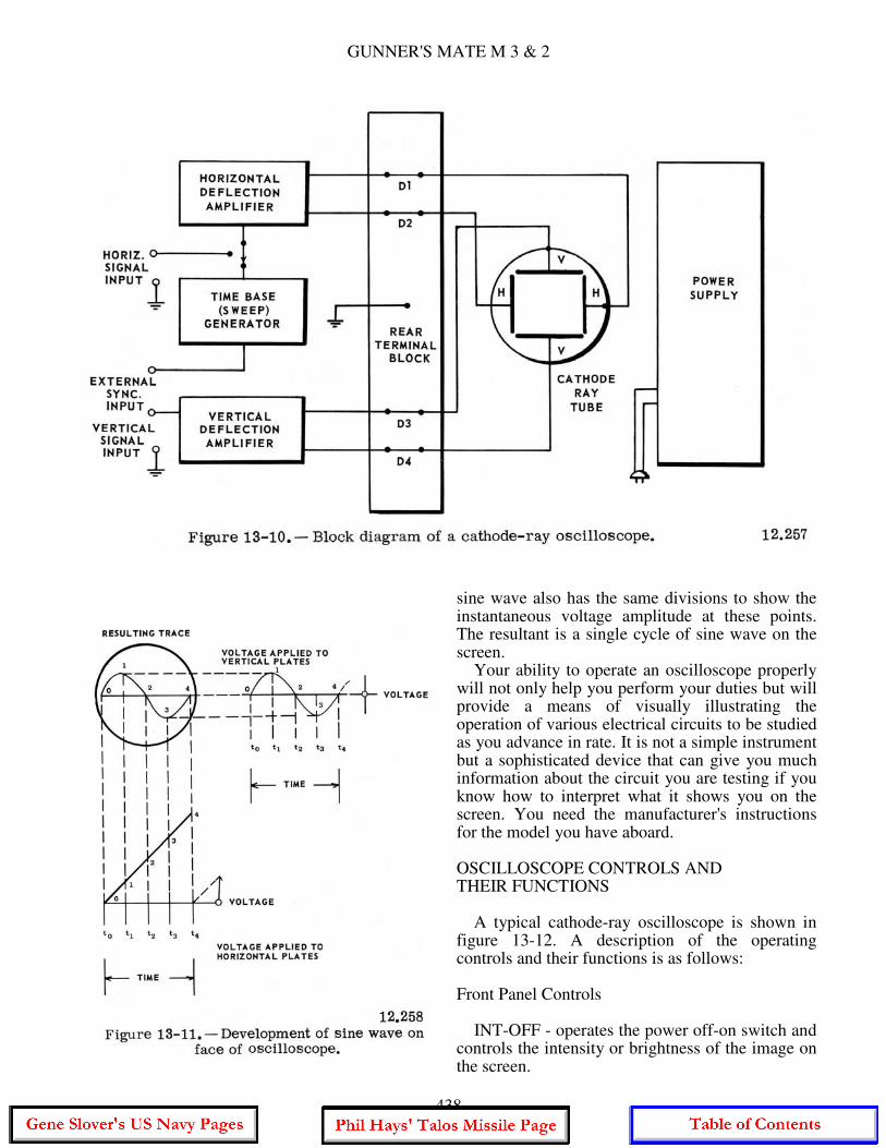
GUNNER'S MATE M 3 & 2
sine wave also has the same divisions to show the instantaneous voltage amplitude at these points. The resultant is a single cycle of sine wave on the screen. Your ability to operate an oscilloscope properly will not only help you perform your duties but will provide a means of visually illustrating the operation of various electrical circuits to be studied as you advance in rate. It is not a simple instrument but a sophisticated device that can give you much information about the circuit you are testing if you know how to interpret what it shows you on the screen. You need the manufacturer's instructions for the model you have aboard. OSCILLOSCOPE CONTROLS AND THEIR FUNCTIONS A typical cathode-ray oscilloscope is shown in figure 13-12. A description of the operating controls and their functions is as follows: Front Panel Controls INT-OFF - operates the power off-on switch and controls the intensity or brightness of the image on the screen.
438

CHAPTER 13 - COMMON TEST EQUIPMENT AND LOGICAL TROUBLESHOOTING
FOCUS - adjusts the focus or sharpness of the trace on the cathode-ray tube. HOR. POS. and VERT. POS (Left-right. down-up) - used to adjust the position of the trace on the screen, either horizontally or vertically. Horizontal Amp. Panel HOR. ATTEN. - selects the source of signal. a-c with attenuation sweep, or d-c. The signal is then fed to the horizontal amplifier. HOR. GAIN - controls the gain of the horizontal amplifier. DC - connection for d-c input to the horizontal amplifier. AC - connection for a-c input to the horizontal amplifier.
GND - connection for ground when using either a-c or d-c inputs to the horizontal amplifier. Sweep Circuit Osc. Panel COARSE FREQUENCY - provides a coarse adjustment of the sweep frequency. VERNIER FREQUENCY - provides a fine or vernier adjustment of the sweep frequency. Sync. Circuit Panel SYNC. SELECTOR - provides for the selection of the synchronizing voltage source as follows: LINE - signal is taken from input to power supply.
439

GUNNER'S MATE M 3 & 2
EXT. - signal is supplied by an external source connected to the EXT. terminal. INT. - signal is taken from the input to the vertical amplifier. LOCKING - selects the polarity and amplitude of synchronizing voltage applied to the sweep circuit oscillator. EXT. - input for external synchronizing voltage. Z AXIS - connection for external voltage to be used in intensity modulation of the electron beam. LINE - a source of the line supply frequency. Vertical Amp. Panel VERT. ATTEN. - provides for attenuation of a-c signals or d-c input without attenuation. VERT. GAIN - controls the gain of the vertical amplifier. DC - connection for d-c input to the vertical amplifier. AC - connection for a-c input to the vertical amplifier. GND - connection for ground when using either a-c or d-c inputs to the vertical amplifier. OPERATION The operation of the OS-8C/U cathode-ray oscilloscope for observation of waveforms is relatively easy, in that the signal to be observed is applied to the a-c terminal of the vertical amplifier and that the horizontal sweep frequency need only be synchronized with it. The steps for operating the OS-8C/U are listed below: 1. The signal to be observed is connected to the a-c input terminal of the vertical amplifier, and the ground connection of the input signal is connected to the GND terminal. 2. The INT-OFF control is turned clockwise to switch the power on. After the oscilloscope has warmed up, adjust the brightness or intensity of the trace to a comfortable level. 3. Set the COARSE FREQUENCY control to the lowest frequency. 4. Set the SYNC SELECTOR switch to the INT. position. 5. Set the VERT. GAIN and the VERT. ATTEN. controls for suitable deflection. 6. Set the HOR. GAIN control for desired pattern width. 7. Slowly rotate the VERNIER FREQUENCY control until the desired pattern appears and is steady.
8. If the number of cycles is too great, the COARSE FREQUENCY control is adjusted a step higher until the desired number of cycles appear and are steady. This may require readjustment of the VERNIER FREQUENCY control. 9. The trace can then be locked in synchronization by adjusting the LOCKING control, either positive or negative, until the pattern appears steady and fixed. When it is desired to use an external synchronizing voltage, it can be connected into the EXT. synchronization terminal. The SYNC. SELECTOR must be turned to EXT. The other controls are adjusted as above. When it is desired to use line voltage for synchronization, the SYNC. SELECTOR is turned to LINE and the other controls are adjusted as above. PRECAUTIONS WITH OSCILLOSCOPE The principal precaution to be observed in the use of cathode-ray tubes is not to permit the beam to remain for a long period of time on one portion of the cathode-ray tube screen as this may cause the tube to become burned or streaked. To prolong tube life, the intensity and focus controls should always be adjusted for minimum readable brilliance to produce the smallest practicable spot or narrowest line. Cathode-ray tubes should be handled with extreme care. If a cathode-ray tube is broken, the relative high external pressure will cause the tube to implode (burst inwardly), which will result in the inner metal parts and glass fragments being expelled violently outward. In addition to the danger from the flying fragments, the inner coatings of some tubes are poisonous if absorbed into the blood stream. Cuts from such coated glass can cause serious, even fatal, illness. Therefore, do not break defective tubes when preparing to dispose of them. Place the removed tube in the empty box of the replacement tube, and don't leave it around on work benches, etc. Safety glasses and gloves should be worn while handling CRT tubes. The case of the oscilloscope offers some protection to the tube, but do not handle it roughly. When stowed, it should be secured so it will not shift about.
SERVICING TRANSISTOR CIRCUITS After you have worked with vacuum tube equipment, you will find that maintaining and
440
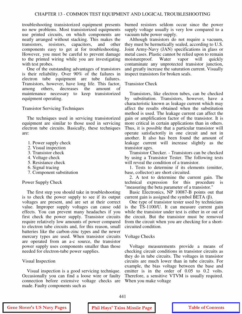
CHAPTER 13 - COMMON TEST EQUIPMENT AND LOGICAL TROUBLESHOOTING
troubleshooting transistorized equipment presents no new problems. Most transistorized equipments use printed circuits, on which components are neatly arranged without stacking. This makes the transistors, resistors, capacitors, and other components easy to get at for troubleshooting. However, you must be careful to prevent damage to the printed wiring while you are investigating with test probes. One of the outstanding advantages of transistors is their reliability. Over 90% of the failures in electron tube equipment are tube failures. Transistors, however, have long life. This factor, among others, decreases the amount of maintenance necessary to keep transistorized equipment operating. Transistor Servicing Techniques The techniques used in servicing transistorized equipment are similar to those used in servicing electron tube circuits. Basically, these techniques are:
1. Power supply check 2. Visual inspection 3. Transistor check 4. Voltage check 5. Resistance check 6. Signal tracing 7. Component substitution
Power Supply Check The first step you should take in troubleshooting is to check the power supply to see if its output voltages are present, and are set at their correct value. Improper supply voltages can cause odd effects. You can prevent many headaches if you first check the power supply. Transistor circuits require relatively low amounts of power compared to electron tube circuits and, for this reason, small batteries like the carbon-zinc types and the newer mercury types are used. When transistor circuits are operated from an a-c source, the transistor power supply uses components smaller than those needed for electron-tube power supplies. Visual Inspection Visual inspection is a good servicing technique. Occasionally you can find a loose wire or faulty connection before extensive voltage checks are made. Faulty components such as
burned resistors seldom occur since the power supply voltage usually is very low compared to a vacuum tube power supply. Although transistors do not require a vacuum, they must be hermetically sealed, according to U.S. Joint Army-Navy (JAN) specifications in glass or metal cases. Plastic cannot be relied upon to remain moistureproof. Water vapor will quickly contaminate any unprotected transistor junction, and greatly increase the saturation current. Visually inspect transistors for broken seals. Transistor Check Transistors, like electron tubes, can be checked by substitution. Transistors, however, have a characteristic known as leakage current which may affect the results obtained when the substitution method is used. The leakage current can affect the gain or amplification factor of the transistor. It is more critical in certain applications than in others. Thus, it is possible that a particular transistor will operate satisfactorily in one circuit and not in another. It also has been found the amount of leakage current will increase slightly as the transistor ages. Transistor Checker. - Transistors can be checked by using a Transistor Tester. The following tests will reveal the condition of a transistor. 1. Tests to determine if its elements (emitter, base, collector) are short circuited. 2. A test to determine the current gain. The technical expression for this procedure is "measuring the beta parameter of a transistor." Basic Electronics, NP 10087-B points out that current gain is assigned the symbol BETA (β). One type of transistor tester used by technicians is the TS-1100/U. It can measure current gain while the transistor under test is either in or out of the circuit. But the transistor must be removed from the circuit when you are checking for a short-circuited condition. Voltage Checks Voltage measurements provide a means of checking circuit conditions in transistor circuits as they do in tube circuits. The voltages in transistor circuits are much lower than in tube circuits. For example, the bias voltage between the base and emitter is in the order of 0.05 to 0.2 volts. Therefore, a sensitive VTVM is usually required. When you make voltage
441
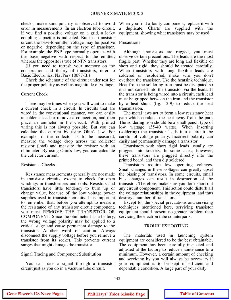
GUNNER'S MATE M 3 & 2
checks, make sure polarity is observed to avoid error in measurements. In an electron tube circuit, if you find a positive voltage on a grid, a leaky coupling capacitor is indicated. But in a transistor circuit the base-to-emitter voltage may be positive or negative, depending on the type of transistor. For example, the PNP type normally operates with the base negative with respect to the emitter, whereas the opposite is true of NPN transistors. (If you need to refresh your memory on the construction and theory of transistors, refer to Basic Electronics, NavPers 10087-B.) Check the schematic of the circuit under test for the proper polarity as well as magnitude of voltage. Current Check There may be times when you will want to make a current check in a circuit. In circuits that are wired in the conventional manner, you can easily unsolder a lead or remove a connection, and then place an ammeter in the circuit. With printed wiring this is not always possible. But you can calculate the current by using Ohm's law. For example, if the collector is to be measured, measure the voltage drop across the collector resistor (load) and measure the resistor with an ohmmeter. By using Ohm's law, you can calculate the collector current. Resistance Checks Resistance measurements generally are not made in transistor circuits, except to check for open windings in transformers and coils. Resistors and transistors have little tendency to burn up or change value, because of the low voltage power supplies used in transistor circuits. It is important to remember that, before you attempt to measure the resistance of any transistor circuit component, you must REMOVE THE TRANSISTOR OR COMPONENT. Since the ohmmeter has a battery, the wrong voltage polarity may be applied to a critical stage and cause permanent damage to the transistor. Another word of caution. Always disconnect the supply voltage before you remove a transistor from its socket. This prevents current surges that might damage the transistor. Signal Tracing and Component Substitution You can trace a signal through a transistor circuit just as you do in a vacuum tube circuit.
When you find a faulty component, replace it with a duplicate. Charts are supplied with the equipment, showing what transistors may be used. Precautions Although transistors are rugged, you must observe certain precautions. The leads are the most fragile part. Whether they are long and flexible or short and rigid, they should be treated carefully. When transistors with long flexible leads are soldered or resoldered, make sure you don't overheat the transistor. Use the heatsink technique. Heat from the soldering iron must be dissipated so it is not carried into the transistor via the leads. If the transistor is being wired into a circuit, each lead must be gripped between the iron and the transistor by a heat shunt (fig. 12-9) to reduce the heat transmission. The metal jaws act to form a low resistance heat path which conducts the heat away from the part. The soldering iron should be a small pencil type of low wattage (35-40 watts). When inserting (soldering) the transistor leads into a circuit, be careful of voltage polarity. Incorrect polarity can easily and permanently damage a transistor. Transistors with short rigid leads usually are plugged into sockets. In some cases, however, these transistors are plugged directly into the printed board, and then dip soldered. Transistors require low operating voltages. Small changes in these voltages can greatly upset the biasing of transistors. In some circuits, small bias changes can result in destruction of the transistor. Therefore, make sure you don't short out any circuit component. This action could disturb all the voltage relationships in the equipment, and thus destroy a number of transistors. Except for the special precautions and servicing techniques mentioned here, servicing transistor equipment should present no greater problem than servicing the electron tube counterparts.
TROUBLESHOOTING The materials used in launching system equipment are considered to be the best obtainable. The equipment has been carefully inspected and adjusted at the factory to reduce maintenance to a minimum. However, a certain amount of checking and servicing by you will always be necessary if your equipment is to be kept in efficient and dependable condition. A large part of your daily
442
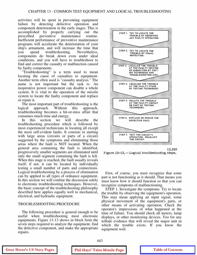
CHAPTER 13 - COMMON TEST EQUIPMENT AND LOGICAL TROUBLESHOOTING
activities will be spent in preventing equipment failure by detecting defective operation and component deterioration in the early stages. This is accomplished by properly carrying out the prescribed preventive maintenance routine. Inefficient performance of preventive maintenance programs will accelerate the deterioration of your ship's armament, and will increase the time that you spend troubleshooting. Nevertheless, components do break down even under ideal conditions, and you will have to troubleshoot to find and correct the casualty or malfunction caused by faulty components. "Troubleshooting" is a term used to mean locating the cause of casualties to equipment. Another term often used is "casualty analysis." The name is not important but the task is. An inoperative power component can disable a whole system. It is vital to the operation of the missile system to locate the faulty component and replace or repair it. The most important part of troubleshooting is the logical approach. Without this approach, troubleshooting becomes a hit-or-miss affair that consumes much time and energy. In this section we will describe the troubleshooting procedure which is followed by most experienced technicians in locating all except the most self-evident faults. It consists in starting with large areas (circuits or parts of a circuit) suggested by the symptoms and eliminating those areas where the fault is NOT located. When the general area containing the fault is identified, progressively smaller segments are eliminated until only the small segment containing the fault is left. When this stage is reached, the fault usually reveals itself; if not. it can be located by individually testing a small number of parts and connections. Logical troubleshooting by a process of elimination can by applied to all types of ordnance equipment. In this section we will confine the discussion solely to electronic troubleshooting techniques. However, the basic concept of the troubleshooting philosophy described here applies equally well to mechanical, electrical, and hydraulic equipment. TROUBLESHOOTING PROCEDURE The following procedure is general enough to be useful when troubleshooting most electronic equipments. Figure 13-13 shows in block form the seven steps required to analyze the equipment, find the defective component, and make the appropriate repairs.
First, of course, you must recognize that some part is not functioning as it should. That means you must know how it should function so that you can recognize symptoms of malfunctioning. STEP 1. Investigate the symptoms. Try to locate the trouble by observing the equipment's operation. This may mean applying an input signal, some physical movement of the equipment's parts, or other means of activating operation. Check the operator's impressions of what happened at the time of failure. You should check all meters, lamp displays, or other monitoring devices. Too for any telltale evidence that will reveal the major unit in which the trouble exists. If you know the equipment well.
443
GUNNER'S MATE M 3 & 2
you can generally tell in what functional circuit the fault exists by observing the operation of the equipment and meter or lamp indications. This first step is the beginning of the process of casualty analysis using effect-to-cause reasoning. You see the effect (symptoms); now you must analyze the evidence to find the cause of trouble. STEP 2. An internal visual check is the logical second step in finding a defective component. Look for loose connections, burned parts, controls which are not working properly, resistors which are discolored, tubes without glowing filaments, or any other abnormal indications. Many casualties do not result in symptoms which can be detected directly by our senses, so it is necessary to resort to other means of detecting failures. The next steps require the use of test equipment. STEPS 3, 4, and 5. Troubleshooting steps 3, 4, and 5 consist of localizing the trouble to the faulty part. If the trouble has not resolved itself from a logical solution of the data available in steps 1 and 2, you must then utilize the troubleshooting aids listed below. They are discussed in more detail later in this section. In conjunction with the troubleshooting aids and logical reasoning, tracing a signal from its source through a circuit is the best technique for isolating the trouble to a section, stage, or part. The use of test equipment is required. It is used to measure or indicate the presence of a signal at the various check points. The signal can be traced from the source until it is lost at some checkpoint, or you can start at the output of the circuit and work backward until you find the defective stage. To find the defective part is a matter of checking a small number of elements. Look for the simplest defects first. STEP 6. This entails the replacement or repair of the defective part. You know that ALL replacements or repairs should duplicate the defective part. In an emergency two resistors or two capacitors properly connected may be used to duplicate the value of the defective part. However, such substitutes are always temporary. The permanent replacement should be made as soon as the correct parts are available. Remember, permanent replacements are always exact duplicates. STEP 7. Test the circuit and equipment operation. Readjust the circuit if necessary. After you make either temporary or permanent
repairs, always test the equipment. Use the operational tests given in the applicable OP or log or Planned Maintenance System cards, if available. They contain information telling you what adjustments are required and how to make them. SYSTEM TROUBLESHOOTING AIDS Basically, the purpose of corrective maintenance is to restore the system's operation to acceptable standards. To restore the system to its operational standard, the operation and standards must be known. If the missile loader, for example, is expected to load a missile every 37 seconds but it takes 2 minutes per missile, it is not operating up to standard and you must find where the fault lies. The OPs for the system contain detailed information on the operation of the system as well as the functions of the units of the system. The Planned Maintenance System tells you what tests and maintenance are to be performed. One-Function Schematic Diagrams These drawings show the internal and interconnecting circuitry between all parts of the weapon system. Each depicts in a single diagram all circuits involved in one particular function, (quantity or signal) of a system. This eliminates the need for using many separate diagrams for each of the equipments involved in the particular function. Circuit information is displayed by functional flow from left to right. The unit in which the signal originates is on the left of the drawing; the unit that ultimately receives the signal is to the right. All major equipments, terminal boards, patch panels, dials, plugs, and other electrical components are labeled. These one-function diagrams are not only an aid in troubleshooting but they provide a key to the understanding of the entire weapon system. The OPs containing one-function diagrams are unclassified, and therefore are readily available to missile system personnel. Figure 13-14 shows an example of a simplified one-function diagram. Data Functional Diagrams These diagrams show data transmission and functional circuits relevant to weapon system loops or modes of operations. Primary data flow is depicted as heavy lines. Each diagram emphasizes all alternate and test inputs and all points
444

CHAPTER 13 - COMMON TEST EQUIPMENT AND LOGICAL TROUBLESHOOTING
of data readout such as servodials, test points, and 'scope indications for a particular loop or mode. By tracing the primary data flow lines you can quickly determine which components are significant to fault isolation and functional understanding. Each missile weapon system has its own set of data functional diagrams. For example, OP 3472, volume 8, contains the data functional diagrams for DDG 2-24 Class Tartar Guided Missile Weapon System. Control Functional Diagrams These diagrams are provided only for the more complex control circuits. The diagrams show the time-related, ON-OFF stages of lamps, relays, switches, and other control devices for the various control circuits, with primary data flow depicted as heavy lines. Use of these diagrams will enable you to quickly determine the desired ON-OFF stage of the various control or control related devices. A comparison with
the actual circuit indications will isolate a fault to specific functional areas or to components in the control circuit. Fault Directories In the PMS (Planned Maintenance System), tests are keyed to the troubleshooting procedures. The fault directories are the primary means of determining the appropriate troubleshooting aids for an indication of a fault observed in the system tests. Each fault directory lists the various phases of the associated test in corresponding sequence, with the probable faults which may occur during each phase of the test. References to the most appropriate troubleshooting documents associated with each test indication are provided by the directory. In most cases, the referenced documents are functional diagrams and fault logic diagrams. The Indicator Directory is the primary means of determining the appropriate troubleshooting
445
GUNNER'S MATE M 3 & 2
documents for an indication of a fault observed on a specific indicator during random operation of the system. This directory provides an alphabetical listing of all indicators shown in the functional diagrams. The listing references the most appropriate diagrams associated with each indicator. Fault Logic Diagrams These diagrams will enable you to rapidly isolate faults encountered in system tests. Each diagram (fig. 13-15) begins with a statement describing the fault. The first block in the diagram contains a question about the fault that may be answered either "yes" or "no". If the answer is yes, you proceed to the next block via the solid line; if the answer is no, you would follow the broken line leaving the box, which tells you what to check. The second block (via the solid line) contains a yes or no question similar to the one in the first block. You again determine the proper answer to the question and proceed to the next block according to the answer obtained. This process is repeated until you are referred to a block containing a statement describing the action required to correct the fault. Figure 13-15 is a simple example of a fault logic diagram; others are more extensive. Indications that occur normally during the system tests and which can be helpful in fault analysis are presented in the diagrams as questions. Blocks that contain fault correction procedures reference functional diagrams, further troubleshooting procedures, or the fault-troubleshooting documentation reference table associated with each fault logic diagram. EQUIPMENT TROUBLESHOOTING AIDS When the defective or improperly adjusted component has been found, equipment or unit troubleshooting aids come into use to help you restore the component to its proper functioning state. These aids include: (1) servicing block diagrams, (2) schematic diagrams, (3) voltage distribution diagrams, (4) voltage and resistance charts, and (5) equipment troubleshooting pyramids. A brief description of each of these follows. The troubleshooting charts have long been the basis of maintenance work. You will find them in numerous publications about your equipment, or posted on or near your equipment.
Troubleshooting Charts Troubleshooting charts give a systematic procedure for locating malfunctions in an equipment. The chart lists easily observed or measured symptoms of improper equipment functioning, the probable cause, and the corrective action to be taken by the technician. In most cases, troubles cannot be pinpointed to a particular circuit element (tube, resistor, capacitor, etc.) by means of the chart. However, the fault can be localized to a particular circuit and the faulty element then localized by checking tubes, taking waveforms, and measuring voltage and resistance. Before using the charts, observe all external indications of trouble. Check for blown fuses, open interlocks and switches, and the proper setting of operating controls. You may recognize this time-tested aid under other names. Block Diagrams This troubleshooting aid should enable the technician to see, in a general way, the course of each circuit. From it you can perceive the relationship between circuits and components. Also, you can determine the general location of the test points for checking the condition of the equipment. The servicing block diagram should aid you in localizing the trouble to a small segment. It thus stands, in usage, in an intermediate position between the trouble chart and the schematic diagrams. Schematic Diagrams A schematic diagram shows how the parts of a circuit are connected for the operation of the equipment. It does not tell how the parts look or how they are constructed. Each component is illustrated by a symbol. A set of schematics enables the technician to trace the passage of energy throughout the entire equipment, and to test the operating condition of each part and connection. Voltage Distribution Diagrams These diagrams trace the distribution of the supply voltages throughout the equipment. The diagrams show all the relays, contacts, switches, and access points for that particular voltage distribution.
446
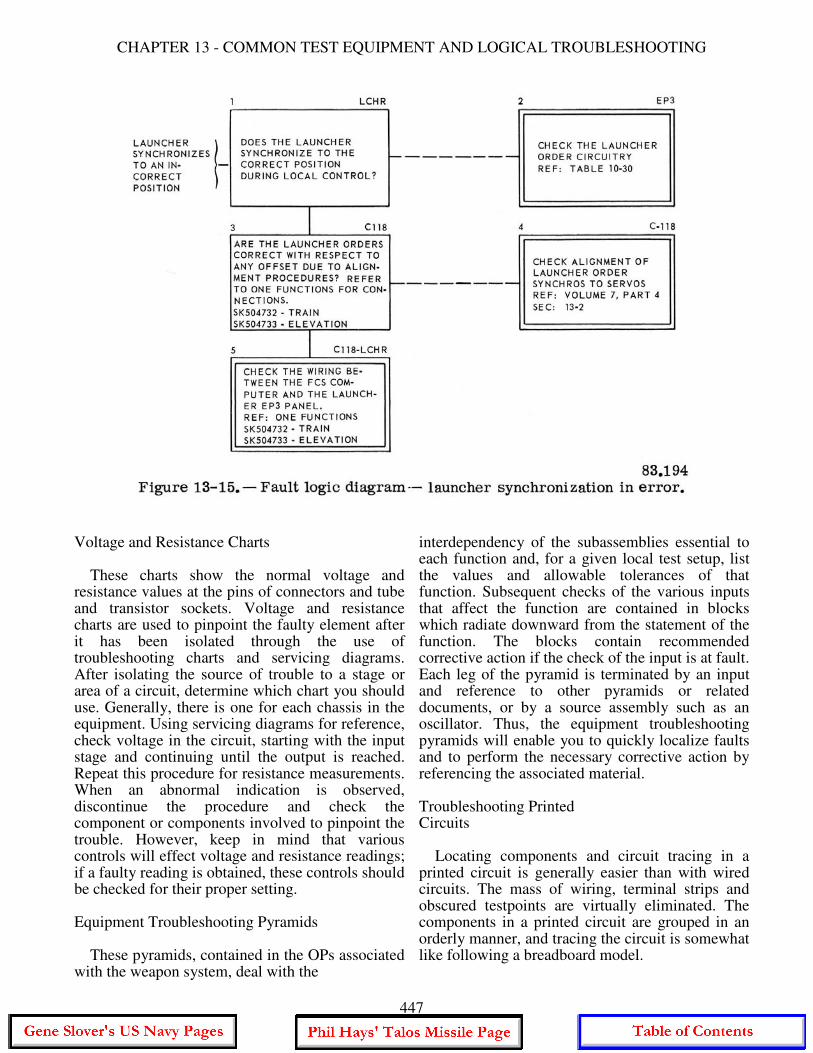
CHAPTER 13 - COMMON TEST EQUIPMENT AND LOGICAL TROUBLESHOOTING
Voltage and Resistance Charts These charts show the normal voltage and resistance values at the pins of connectors and tube and transistor sockets. Voltage and resistance charts are used to pinpoint the faulty element after it has been isolated through the use of troubleshooting charts and servicing diagrams. After isolating the source of trouble to a stage or area of a circuit, determine which chart you should use. Generally, there is one for each chassis in the equipment. Using servicing diagrams for reference, check voltage in the circuit, starting with the input stage and continuing until the output is reached. Repeat this procedure for resistance measurements. When an abnormal indication is observed, discontinue the procedure and check the component or components involved to pinpoint the trouble. However, keep in mind that various controls will effect voltage and resistance readings; if a faulty reading is obtained, these controls should be checked for their proper setting. Equipment Troubleshooting Pyramids These pyramids, contained in the OPs associated with the weapon system, deal with the
interdependency of the subassemblies essential to each function and, for a given local test setup, list the values and allowable tolerances of that function. Subsequent checks of the various inputs that affect the function are contained in blocks which radiate downward from the statement of the function. The blocks contain recommended corrective action if the check of the input is at fault. Each leg of the pyramid is terminated by an input and reference to other pyramids or related documents, or by a source assembly such as an oscillator. Thus, the equipment troubleshooting pyramids will enable you to quickly localize faults and to perform the necessary corrective action by referencing the associated material. Troubleshooting Printed Circuits Locating components and circuit tracing in a printed circuit is generally easier than with wired circuits. The mass of wiring, terminal strips and obscured testpoints are virtually eliminated. The components in a printed circuit are grouped in an orderly manner, and tracing the circuit is somewhat like following a breadboard model.
447
GUNNER'S MATE M 3 & 2
Chapters 4 and 5 in Blueprint Reading and Sketching, NavPers 10077-C, illustrate electrical and electronic diagrams, and give instructions for reading them.
PRECAUTIONS AND TECHNIQUES IN MAKING ELECTRICAL MEASUREMENTS
Some safety rules were given in the discussion of the use of each test instrument. Some additional precautions are given here for each type of measurement. VOLTAGE MEASUREMENT Most troubles can be found by taking voltage measurements. These measurements can be made easily since they are always made between two points in a circuit and the operation of the circuit need not be interrupted. Unless otherwise indicated in the voltage chart, voltages usually are measured between the indicated points and a common return. Always use a meter that has the same ohms-per-volt sensitivity as the one used originally to develop the voltage chart. The type of reference meter used will be stated on the chart, but your meter does not have to be an exact duplicate. It must have the same sensitivity rating, otherwise erroneous readings will result due to differences in circuit loading. Always begin voltage measurements by setting the voltmeter on the highest range, so that the voltmeter will not be overloaded. Then, if necessary to obtain increased accuracy, set the voltmeter to a lower range. Always use the range that gives maximum voltage reading. In checking cathode voltage, remember that a reading can be obtained when the cathode resistor is actually open, the resistance of the meter acting as a cathode resistor. Certain precautions must be followed when measuring voltages above a few hundred volts since high voltages are dangerous and can be fatal. When it is necessary to measure high voltages, observe the following rules. 1. Connect the common (ground) lead to the voltmeter. 2. Place one hand in your pocket. 3. If the voltage is more than 300 volts, shut off the power, connect the hot test lead, step away from the voltmeter, turn on the power, and note the reading on the voltmeter. Do not touch any part of the voltmeter, particularly
when it is necessary to measure the voltage between two points both of which are above ground. It is essential that the voltmeter resistance be at least 10 times as large as the resistance of the circuit across which the voltage is measured. If the voltmeter resistance is comparable to the circuit resistance, the voltmeter will indicate a lower voltage than the actual voltage present when the voltmeter is not in the circuit. When a voltmeter is loading a circuit, the effect can be noted by comparing the voltage reading on two successive ranges. If the voltage readings on the two ranges do not agree, voltmeter loading is excessive. The reading (not the deflection) on the highest range will be greater than on the lowest range. If the voltmeter is loading the circuit heavily, the deflection of the pointer will remain nearly the same when the voltmeter is shifted from one range to another. To minimize voltmeter loading in high resistance circuits, use the highest voltmeter range. Although only a small deflection will be obtained (possibly only 5 divisions on a 100 division scale), the accuracy of the voltage measurement will be increased. The decreased loading of the voltmeter will more than compensate for the inaccuracy which results from reading only a small deflection on the scale of the voltmeter. MEASUREMENT OF CURRENT Current measurements other than those indicated by the panel meters ordinarily are not required in troubleshooting. Under special circumstances, where the voltage and resistance measurements alone are not sufficient to localize the trouble, a current measurement can be made by opening the circuit and connecting an ammeter in series. This procedure is not recommended except in very difficult cases. CAUTION: A meter has least protection against damage when it is used to measure current. Always set the current range to the highest value. Then, if necessary, decrease the range to give a more accurate reading. Avoid working close to full-scale reading because this increases the danger of overload. In most cases, the current to be measured flows through a resistance which is either known or can be measured with an ohmmeter. The current flowing in the circuit can be determined by dividing the voltage drop across the resistor by its resistance value. The drop across the cathode resistor is a convenient method of determining the cathode current.
448
CHAPTER 13 - COMMON TEST EQUIPMENT AND LOGICAL TROUBLESHOOTING
When the meter is inserted in a circuit to measure current, it should always be inserted away from the r-f end of the resistor. For example, when measuring plate current, do not insert the meter next to the plate of the tube, but insert it next to the end of the resistor which connects to the power supply. This precaution is necessary to keep the meter from affecting the r-f voltages. MEASUREMENT OF RESISTANCE Before making resistance measurements, turn off the power. An ohmmeter is essentially a low range voltmeter and battery. If it is connected to a circuit to which power is being applied, the needle will be forced off scale and the voltmeter movement may be burned out. Capacitors must always be discharged before resistance measurements are made. This is very important when checking power supplies that are disconnected from their load. The discharge of the capacitor through the meter will burn out the meter movement and, in some cases, may endanger life. In a parallel circuit, the total resistance is less than the smallest resistance in the circuit. This is important to remember when troubleshooting with the aid of a schematic diagram. It is important to know when to use the low resistance range of an ohmmeter. When checking circuit continuity, the ohmmeter should be set on the lowest range. If a medium or high range is used, the pointer may indicate zero ohms, although the resistance may be as high as 500 ohms. When checking high resistance or measuring the leakage resistance of capacitors or cables, the highest range should be used. If a low range is used in this case, the pointer will indicate infinite ohms, although the actual resistance may be less than a megohm. When you measure resistance and find it less than you expected, make a careful study of the schematic to be certain that there are no parallel resistances. Before replacing a resistor because its resistance measures too low, disconnect one terminal from the circuit and measure its resistance again to make sure that the low reading does not occur because some part of the circuit is in parallel with the resistor. In some cases it will not be possible to check a resistor because it has a low resistance transformer winding connected across it. If the resistor must be checked, disconnect one terminal from the circuit before measuring its resistance.
When checking a grid resistance, a false reading may be obtained if the tube is still warm and the cathode is emitting electrons. Allow the tube to cool, or connect the ohmmeter test leads so that the negative lead is applied to the grid. Tolerance is the normal difference to be expected between the rated value of the resistor and its actual value. Most general purpose resistors have a tolerance of 20 percent. For example, the grid resistor of a stage might have a rated value of 1 megohm. If the resistor were measured and found to have a value between 0.8 megohm and 1.2 megohms, it would be considered normal. As a rule, the ordinary resistors used in circuits are not replaced unless their values are off more than 20 percent. Some precision resistors and potentiometers are used. When a resistor is used whose value must be very close to its rated value, the tolerance is stated on the diagram and in the maintenance parts list. Tolerance values for transformer windings are generally between 1 and 5 percent. As a rule, suspect a transformer which shows a resistance deviating by more than 5 percent from its rated value. Always allow the transformer to cool before the resistance test is made. Resistance in Electrolytic Capacitors The measurement of resistance in electrolytic capacitors with an ohmmeter was described earlier in this chapter. Note that the capacitor must be discharged before making measurements. Capacitors retain their charge for some time after being disconnected from the power supply. WHAT NOT TO TEST Certain missile components and equipment must not be tested at all on shipboard except by specially trained personnel or under special circumstances. Launcher firing circuits shall not be tested when rockets or missiles are on the launcher. Continuity tests of rocket initiating elements shall not be conducted aboard ship. Rocket motor igniter circuits shall not be tested aboard ship. No mechanical operations of any kind - machining, cutting, welding, drilling, etc. - on solid propellant rocket motors shall be permitted aboard ship. No disassembly is permitted on rocket motors without specific permission from the competent authority.
449

GUNNER'S MATE M 3 & 2
No steel instruments or tools which may cause sparks shall be used for cleaning or scraping explosive or flammable components of missiles, except as authorized by Naval Ordnance Systems Command. Under no circumstances shall attempts be made to disassemble or repair any fuze system aboard ship. Fuzes shall not be tested either mechanically or electrically aboard ship except as specifically authorized by NAVORD. Igniters shall not be disassembled or tested aboard ship unless specifically authorized and strictly in accordance with instructions from NAVORD. No electrical check shall be made of the cable connector of the S&A device unless specifically authorized by current directives.
SAFETY PRECAUTIONS The duties of the GMM require constant vigilance in the observance of safety precautions. These safety precautions include those concerning work with electrical and electronic equipment, work involving the handling of explosive ordnance material, work in the vicinity of equipment capable of starting fires or generating toxic gases, work done on high pressure hydraulic and pneumatic systems, and work done with small power tools. In addition to being thoroughly familiar with safety precautions, the GMM must know the authorized methods for treating burns and for giving artificial respiration to persons suffering from electric shock. Because of the many specialized devices you will use, and because of the potential hazards in your work, you should consider the formation of safe and intelligent work habits as being equal in importance to the development of technical knowledge and skills. You should always strive to exhibit the attitudes and practices which are characteristic of "safety mindedness." One of your objectives should be to become a safety specialist, trained in recognizing and correcting dangerous conditions and in avoiding unsafe actions. This section is in no way an exhaustive treatment of safety practices. Each GMM is expected to observe all of the safety precautions set forth in local directives, in equipment maintenance manuals, and in United States Navy Ordnance Safety Precautions, OP 3347. NAVSO P-2455, Department of the Navy Safety Precautions for Shore Activities, contains many safety precautions that are also applicable aboard ship. Safety rules for electrical and electronic equipment
aboard ship are collected in chapter 9670 (formerly ch. 67) in NAVSHIPS 0901-963-0000 (formerly) vol. III of BUSHIPS Technical Manual 250-000). Also every equipment OP contains a section on safety precautions. It is up to you to familiarize yourself thoroughly with all publications concerning safety. Many of the safety regulations have developed as a result of actual experience, so give them every possible consideration. CAUSES OF ACCIDENTS The precautions set forth in OP 3347 apply generally to operation of ordnance equipment and to the handling of explosives. However, the Navy does not expect blind adherence to them during extraordinary occasions; it is equally important that each individual use his own ability and initiative to prevent accidents during unforeseen conditions. For this reason it will be well for you to review a few of the basic causes of accidents. There are four closely related causes of accidents: CARELESSNESS, INEXPERIENCE, OVERCONFIDENCE, and FATIGUE. CARELESSNESS is something most human beings have to overcome. You have to cultivate good working habits-you must learn to coordinate your mental and physical actions to a point where you can concentrate on the important parts of the job at hand without having to worry about the minor mechanical functions pertaining to it. INEXPERIENCE can be the cause of accidents regardless of how careful the individual intends to be. The best solution to this problem is NEVER GUESS- you must learn to ask questions about things you are unfamiliar with or are not completely sure about. Beginners have a tendency to be overeager, and desire to put their hands to work. Eagerness is a good trait in any person, but you must realize that men with more experience usually know best. Work into a job gradually, and be particular about thoroughness; always be conscious of correct procedures in doing things. Train your mind and hands to function correctly so as to protect yourself and others from physical injury. For example, when you work with a screwdriver, be sure that your left hand (or right hand, if you are left-handed) is clear of the screwdriver bit, otherwise a slip of the screwdriver may drive the bit completely through your hand or may gouge deep into your arm. If you practice correct methods from the start, they'll become automatic before you realize it.
450

CHAPTER 13 - COMMON TEST EQUIPMENT AND LOGICAL TROUBLESHOOTING
OVERCONFIDENCE can come to both young and old, experienced and inexperienced. It is usually more closely associated with inexperience. Often, however, men grow overconfident when they become thoroughly familiar with a particular job, and have a tendency toward carelessness. To put it briefly, be confident that you know a job; but beware of overconfidence, because it may invite mistakes which can cause accidents. FATIGUE is the cause of a large percentage of accidents. You might be highly efficient when you have energy to burn, but it's another story when you get tired; your physical actions slow up and become inaccurate. Always prepare yourself for the task ahead by learning how much endurance it requires, and then get the necessary sleep, recreation, food, and exercise to keep on your toes. Remember, to be alert and to feel your best is extremely important on the job, and you can only enjoy this feeling by keeping yourself in good physical condition. In addition to studying safety precautions contained in OP 3347, and in this chapter, you are also referred to Ordnance Safety Precautions, OP 1014. The case studies and precautions set forth in this publication not only provide interesting reading, but also may save your life! The case histories (with pictures) of accidents in the Navy show the need for some of the safety rules you may consider unnecessary. OPERATING ORDNANCE EQUIPMENT Let us repeat-you should acquaint yourself thoroughly with the safety regulations provided in the appropriate OP and with those regulations posted aboard ship, before operating equipment. You will be taught how to apply many of these precautions while you are learning to operate ordnance equipment. The following list of general precautions will assist you. 1. Always inspect all training and elevating areas to make certain that all persons are clear, and that the areas are free of obstructions before operating directors, turrets, guns, or missile launchers. 2. Always use warning bells where provided before training or elevating gun mounts, turrets, or launchers during routine work and practices (except during GQ). . Before leaving directors, turrets, guns, or launchers, always train and elevate them to their securing positions: place all controls in the inoperative position, and deenergize all power supplied to them.
4. Whenever possible, have the regular operators posted at their stations before operating a director, turret, gun or launcher from a dummy director. 5. Slew directors, guns, and launchers only when it is necessary during practices. Be sure no one is in the path of the moving machinery. 6. All telephone stations should be manned when operating systems automatically or remotely. 7. Notify all operators and persons concerned before shifting a system from one mode of control to another. 8. Never operate directors, turrets, launchers, or guns in automatic without having the regular operators posted at their stations. 9. Do not hesitate to stop any person from operating ordnance equipment if he may cause a casualty to himself, the equipment, or to any other person. SAFETY PRECAUTIONS FOR MISSILE ELECTRICAL AND ELECTRONIC WORK Most of the safety rules for electrical work also apply to the operation, repair, and maintenance of missile electronic equipment. Furthermore, special precautions must be taken against the high voltages normally present in electronic devices, against dangerous effects of radiated energy, and against possible injury when handling electronic parts. The standard safety measures to be taken by personnel engaged in work on electronic equipment include the following: 1. Do not work on electronic apparatus with wet hands or while wearing wet clothing or any clothing which is loose and flapping. 2. When working within 4 feet of electronic equipment, do not wear clothing with exposed zippers, metal buttons or any type of metal fastener. No flammable articles such as celluloid cap visors should be worn. 3. Personnel should remove rings, wristwatches, bracelets, and similar metal articles when working on or within 4 feet of electronic equipment having exposed current-carrying parts. 4. When working on or near electronic apparatus, personnel shall wear high-cut shoes with sewed soles or safety shoes with nonconducting soles, if these are available. The use of thin soled shoes and those with metal plates or hobnails is prohibited. 5. Danger signs and suitable guards should be provided to warn all personnel wherever live
451
GUNNER'S MATE M 3 & 2
parts of electric circuits and equipment are exposed when the voltages involved are 50 volts or greater. 6. Insulated floor covering should be used in work areas where electronic equipment is serviced, particularly where the deck or walls are of metal. 7. Interlocks, overload relays, fuses, and other protective devices should never be altered or disconnected except during replacement; nor should any safety circuit be modified without specific authorization. 8. Metal enclosures for electrical and electronic equipment must be kept effectively grounded. 9. Adjustments, repair, and maintenance of missile radars, radio units, and test equipment must be done only by duly authorized personnel. 10. Adjustment of transmitters and other high voltage equipment should not be attempted while the motor-generator is running or while the rectifiers are energized, unless the adjustments can be made by the use of exterior controls provided for the purpose. 11. Except in emergencies, or when authorized by the proper authority, repairs should not be made on energized electronic equipment. If such work is necessary, it should be undertaken only by experienced personnel. 12. NEVER WORK ALONE near high voltage equipment. 13. Exercise caution when using tools with metal parts, metal tapes, cloth tapes with embedded metal threads, and cleaning equipment containing metal parts. None of these should be used in any area within 4 feet of electronic equipment or wiring having exposed current carrying parts. 14. When working around electronic circuits, keep your mind on your work. 15. Exercise as much care to avoid contact with low voltages as with high voltages. NEVER TAKE A SHOCK INTENTIONALLY FROM ANY SOURCE. This is a dangerous practice and is STRICTLY FORBIDDEN. If a particular circuit operates normally at 600 volts or less, and it is necessary to determine whether it is energized, use a voltmeter, voltage tester, or other suitable indicating instrument. DO NOT draw arcs with screwdrivers, etc. 16. Before you touch the terminals of apparently deenergized equipments, short them together and to ground, using a suitable insulated shorting device. 17. When nearby transmitting equipment is in operation, be on the alert to avoid shocks and
burns resulting from contact with antennas, antenna leads, and other exposed parts. 18. Special precautions concerning ordnance material should be observed before energizing transmitters. Electromagnetic radiations is a term used to describe energy radiated by radio and radar transmitting equipment. This energy is more commonly referred to as radio waves, radio frequency energy, or RF energy. RAD HAZ is an abbreviation for radiation hazards and is generally associated with the effects of radiation on humans. HERO is an abbreviation for hazards of electromagnetic radiation to ordnance. These terms are relatively new, although their effects have been known for some time. A thorough study has been made to establish the causes and the results of damage to the human body due to exposure of the body to radiation from various sources. The electromagnetic radiation from radar transmitters can ignite electric primers, flares, and similar sensitive ammunition components. In addition to ordnance items, the effects of radiation on combustible materials such as gasoline and other fuels is equally hazardous. Experiments with animals have revealed that high-intensity microwave radiation has destructive effects upon living organs. It has also been found that pain cannot always be relied upon to warn an individual of a dangerous radiation field. The most vulnerable parts of the body are those not effectively cooled by the blood stream. Damage to the body organs is believed to be entirely due to the heat generated as a result of the absorption of microwave energy by the body's tissues and not due to any mysterious property of the microwave radiation. Exposure of humans to microwave radiation of 10 centimeter (cm) wavelength region is considered to be the most dangerous, since the maximum heating occurs a few centimeters beneath the surface of the skin. The sensory nerves at the surface of the skin will not indicate the degree of internal heat produced and, unfortunately, the retina of the eye is situated at the zone of maximum heating. NAVORD OP 3565, Technical Manual, Radio Frequency Hazards to Ordnance, Personnel, and Fuel, tells more in detail the hazards of r-f radiation and the precautions necessary.
452
CHAPTER 13 - COMMON TEST EQUIPMENT AND LOGICAL TROUBLESHOOTING
HANDLING OF COMPONENTS Static electric charges carried on the human body can burn out crystal diodes which are often used in missile radar receivers. When installing a crystal, the cartridge should be held with the fingers touching one end only. The hand holding the unit should then be grounded against the missile airframe before the end of the crystal is brought into contact with the holder. Before you touch a capacitor, either connected in a deenergized circuit or disconnected entirely, you should short circuit the terminals to be sure that the capacitor is completely discharged. A suitable insulated lead or grounding bar should be used for this purpose. (Grounded shorting prods should be attached permanently to workbenches where electronic units are regularly serviced or overhauled.) There is no established case history of anyone having been killed by direct microwave radiated energy - yet. There is ample evidence that eye cataracts and various degrees of sterility have been caused by this radiation power. There is much evidence to further indicate the lethal capability of microwave radiation at power levels now readily available and in common usage. Aside from shock hazard there are two common types of radiation hazards associated with the use of high frequency, high-powered microwave equipment. One is the direct RF radiation from waveguides or antennas. The other is the X-radiation that can be generated in, and escape from, certain high voltage tubes. The swept area of tracking radars cannot be limited so personnel must keep out of the danger area and fuel and explosives must not be exposed in the danger area. The danger areas should be posted with warning signs. Never enter an area posted for microwave radiation until the transmitter is turned off and will remain off until further notice. Never look into an open waveguide or radar set connected to an energized transmitter. Care should be taken when using tools made of magnetic materials near radar magnetrons, since the tool can be pulled by the magnet into contact with dangerous high voltage circuits. Fuses should be removed and replaced only after the circuit has been completely deenergized. When a fuse "blows" it should be replaced only with a fuse of the same current rating. When possible, the circuit should be checked carefully before making the replacement, since the burned out fuse usually results from a circuit fault.
GENERAL SAFETY PRECAUTIONS Although many specific safety precautions are laid down for you in the three main publications that cover safety, there are a few general precautions which you should remember. Let's start by discussing the handling of handtools and power tools. Handling Tools and Machinery Many accidents occur because of the improper handling of tools. In general, these accidents occur in the form of physical injury to the person operating the tools. The following list gives the more -important general precautions to follow. 1. Whenever chipping, buffing, or grinding with handtools and powered tools, always wear goggles as a protection to the eyes. Little chips from a spinning grind wheel, or a bristle from a revolving wire brush can easily put out an eye. Many of these machines are provided with a guard; be sure to use it. 2. Always ground the provided ground lead located at the plug of portable tools such as electric drills to protect yourself from shock in case a ground occurs within the tool. 3. When working with sharp handtools, always work so that the tool is moved or thrust away from the body. 4. Never wear loose clothing or a neckerchief when working with rotating tools or machinery. Such clothing may become caught in the spinning parts and drag you bodily into the machine, causing severe physical injury. 5. Never use metal handtools on energized electrical equipment or circuits because you may get shocked, or the tool may cause a short circuit, causing molten copper to be blown into your face and eyes. 6. Never use handtools around running machinery, nor perform adjustments to running machinery unless absolutely necessary. 7. Never lay handtools on top of running machinery where vibration may cause the tool to fall into exposed working parts. 8. In the event your division officer deems it necessary to work on high voltage (exceeding 50 volts to ground) electric equipment while in an energized state, wear rubber gloves and use tools with insulated handles, and stand on an insulated mat. Always work with one hand in order to prevent the possibility of a circuit through your body from arm to arm.
453
GUNNER'S MATE M 3 & 2
9. When working with tools, always work in a physically comfortable position, and keep the weight of your body well centered. Electrical Work The following list is in addition to those precautions on handtools and machinery, and is applicable to all electrical work. This list will help you prevent electric shock or burns during daily work. 1. Whenever possible, operate electric switches and controls with one hand. 2. Do not block high voltage protective cutouts on doors or covers to keep the circuit energized with the cover off. It is intended that work be performed on such electrical equipment while the circuit is deenergized. 3. Always be sure that all condensers are fully discharged before commencing work on a deenergized high voltage circuit. Use an insulated shorting bar for this purpose. 4. Tag the switch OPEN (open the switch and place a tag on it stating "This circuit was ordered open for repairs and shall not be closed except by direct order of ______________.") at the switchboard supplying power to the circuit on which you wish to work. When possible, remove the fuses protecting the circuit and place them in your tool box for safekeeping until the job is complete.
5. Always remove fuses with fuse pliers, and never remove fuses until after opening the switch connecting the circuit to the source of supply. Never replace a fuse with one LARGER than the circuit is designed to take. 6. Utmost precaution should be observed when inspecting behind an open-back switchboard in an energized state. 7. Never use an incandescent test lamp unless its voltage rating is greater than the highest voltage which may be tested. 8. Always test a supposedly deenergized circuit with a voltage tester before commencing work on the circuit. 9. Never work on an electric circuit or network without first thoroughly acquainting yourself with its arrangement and with its points of power feed. Common Safety Features in Electronic Equipment You should be aware of the safety features that are generally included in electronic equipment. Some of the common safety features are interlock switches, bleeder resistors, current limiting resistors, insulating controls, and powerline safety devices such as fuses. Keep in mind that these features cannot always be counted on to function. Don't develop a false sense of security just because an equipment has safety features.
454

CHAPTER 14
LAUNCHER CHECKS, MISSILE
REPLENISHMENT AND SERVICING
INTRODUCTION
The material in the preceding chapters, pertaining to guided missile launching systems and their component parts, serves as background information for the GMM in the performance of his primary technical duties. Among the more important of classes duty which we have not covered are power drive performance tests, missile handling, and missile component replacement, which are discussed in this chapter. Launcher performance testing and the basic principles behind this process is the subject matter of the first section of this chapter. In the second section we will cover missile replenishment in port and at sea. The last section describes the preparations required for missile operational tests and the replacement of missile components.
POWER DRIVE PERFORMANCE TESTS The automatic control equipment discussed in this section comprises the train and elevation power drives for launchers. A power drive is a part of the basic automatic servosystem. Power drives can be automatically controlled from a remote station which consists of a director or computer. The automatic control equipment is designed to comply with the nature and source of the signal, the weight of the load to be moved, and the type of damping required to eliminate random movements and to ensure accuracy and rapidity of response. Automatic control is used in ordnance equipment for light loads (computers and indicators) and for heavy loads (gun mounts, turrets, fire control directors, and missile launchers). You learned in chapter 7, Fundamentals of Servomechanisms, that the output of a perfect servo (one which responds instantaneously to an input signal) is an exact duplicate of its
input. If, for example, the input shaft is rotated 10°, the servo output shaft will rotate through an angle of 10°. Assuming both shafts are in agreement and that the input shaft will rotate at, say, a constant speed, the output shaft will follow this constant speed input and will stay synchronized with it. In a perfect servo the output would never fall out of step with the input, regardless of the kind of input shaft motion. But, as you know, power drive servos are not perfect, and the output position and motion do not always represent the input. So, there will always be some angular difference between the two shafts. For example, they may not be at the same angular position, or one may be rotating faster or slower than the other. But if the error between the input and output remains within certain limits under all types of input conditions, then we can say that a particular power drive servo is performing properly. Who determines what these prescribed limits are? NAVORDSYSCOM does. When the engineers in NAVORDSYSCOM set down specification for private contractors to build a power drive servo, the engineers define the limits. For example, the specifications may say that the launcher must follow a constant velocity signal of 10° per second and stay synchronized with 5 minutes of arc. This means that the output shaft position must not go beyond ± 5 minutes of the input shaft position. Now, to make sure that the launcher manufacturer has built the power drive to meet this specification, NAVORDSYSCOM engineers will go aboard the ship on which the launcher is installed and run a series of tests. One of these tests will determine if the launcher follows a 10°/sec constant velocity signal and does not lag or lead it by more than 5 minutes. If the launcher power drive servo does not meet this particular requirement, NAVORDSYSCOM engineers will not accept the drive until it does. So, the contractor adjusts the servo until it follows the constant velocity signal with an error of 5 minutes or less, and a permanent
455
GUNNER'S MATE M 3 & 2
record in the form of a tape is made to prove this fact. This record (called an acceptance test) is kept aboard the ship as evidence that the power drive servo can and has met this particular performance standard. It gives you something to shoot for, and also a record for later comparison. You can run the same test later and then compare your test results with those of the acceptance test. When yours are as good or better than the acceptance test results, then the power drive servo is performing at its best. How can we tell whether a power drive is in top working order? By looking at it? NO. That is not the correct answer. However, it is an answer of sorts because many technicians (GMMs, GMGs, and FTs) use this "eyeball" technique for checking power drive performance. You can tell if a power drive is working at its worst, however, by watching the action of the load. For example, if the launcher overtravels three or four times when synchronizing to a fixed order signal, the most casual observer will notice that something is wrong with the drive. Or, if the launcher hunts as the director tracks a target, you know immediately something is wrong. But how can you tell from looking at the launcher if the source of trouble is in the tracking radar, director, computer, or in the power drive itself? The only way you can isolate the source of trouble is to disconnect the launcher from the computer (and the rest of the weapon control system) and run a test on the launcher drive itself. A dummy director is used to run the test. The dummy director provides an alternate source of signals, thus bypassing the FC system. From what we've just said, you can see that it is impossible to tell if a power drive servo is working at top efficiency just by watching it operate. We must have some means of measuring its performance and then comparing this with a set of standards. Dummy directors and error recorders are the test instruments used for dynamic (motion) testing of train and elevation power drives. Dummy directors are sources of electrical signals that are fed into the power drives under test. Figure 14-1 shows schematically how these two test units are hooked up. The error recorder makes a record of the test on a pair of paper tapes. One tape indicates the difference (error) between the signal from the dummy director and the power drive response. The other tape records the velocity of the power drive.
To test a launcher in remote control, electrical signals which represent constant velocity I simple harmonic motion, or a fixed position, are transmitted from the dummy director to the power drive servo under test. The error recorder receives a signal corresponding to launcher response, velocity, or position, depending on the type of test. As the launcher moves in answer to the changing test order signal, the error recorder makes a permanent record of the instantaneous difference between launcher order and the power drive output. The magnitudes of the errors are determined by measuring from a reference line the displacement of the curve produced by the error recorder. The curves obtained from a dynamic accuracy test should be compared with the curves taken when the equipment was accepted by NAVORDSYSCOM. These records are kept on the ship, to be used for comparison. If the curves from the performance tests show rough response action, or a velocity or position lag in excess of that specified for the particular launcher, the power drive should be checked for malfunctioning parts. Also, the controls should be adjusted to bring the dynamic accuracy tests within allowable limits of error. These tests are performed quarterly, during shipyard overhaul, and whenever the- launching system seems not to be operating properly. The dummy director and the error recorder are normally used together and are kept aboard repair ships and in Navy shipyards. The Mk 1 Mod 6 dummy director and magnetic oscillograph originally were issued as standard test equipment to all missile ships. Error recording by means of magnetic oscillograph (direct writing on graph paper) can be performed by using either a stylus which writes with ink or an electric stylus which writes on special magnetic paper. In conjunction with a magnetic oscillograph, a limiter-demodulator unit must be used to calibrate, attenuate, balance, limit, and filter the error signal before it is fed to the recorder. The instruments necessary for error recording on a missile launching system are connected into the test panel without changing the normal wiring between the fire control system and the missile launching system. Switches on the test panel are marked so the operator can see which ones to use. Receptacles on the test panel receive the cables from the test instruments.
456
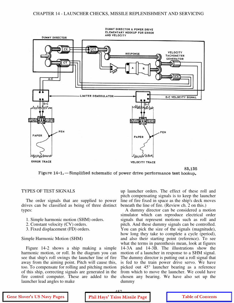
CHAPTER 14 - LAUNCHER CHECKS, MISSILE REPLENISHMENT AND SERVICING
TYPES OF TEST SIGNALS The order signals that are supplied to power drives can be classified as being of three distinct types: 1. Simple harmonic motion (SHM) orders. 2. Constant velocity (CV) orders. 3. Fixed displacement (FD) orders. Simple Harmonic Motion (SHM) Figure 14-2 shows a ship making a simple harmonic motion, or roll. In the diagram you can see that ship's roll swings the launcher line of fire away from the aiming point. Pitch will cause this, too. To compensate for rolling and pitching motion of this ship, correcting signals are generated in the fire control computer. These are added to the launcher lead angles to make
up launcher orders. The effect of these roll and pitch compensating signals is to keep the launcher line of fire fixed in space as the ship's deck moves beneath the line of fire. (Review ch. 2 on this.) A dummy director can be considered a motion simulator which can reproduce electrical order signals that represent motions such as roll and pitch. And these dummy signals can be controlled. You can pick the size of the signals (magnitude), how long they take to complete a cycle (period), and also their starting point (reference). To see what the terms in parenthesis mean, look at figures 14-3A and 14-3B. The illustrations show the motion of a launcher in response to a SHM signal. The dummy director is putting out a roll signal that is fed to the train power drive servo. We have picked out 45° launcher bearing as a reference from which to move the launcher. We could have chosen any bearing. We have also set up the dummy
457
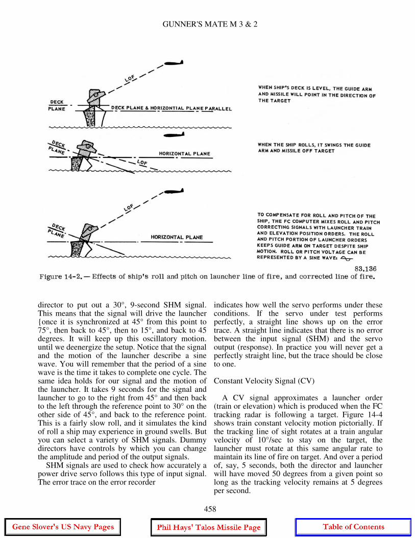
GUNNER'S MATE M 3 & 2
director to put out a 30°, 9-second SHM signal. This means that the signal will drive the launcher {once it is synchronized at 45° from this point to 75°, then back to 45°, then to 15°, and back to 45 degrees. It will keep up this oscillatory motion. until we deenergize the setup. Notice that the signal and the motion of the launcher describe a sine wave. You will remember that the period of a sine wave is the time it takes to complete one cycle. The same idea holds for our signal and the motion of the launcher. It takes 9 seconds for the signal and launcher to go to the right from 45° and then back to the left through the reference point to 30° on the other side of 45°, and back to the reference point. This is a fairly slow roll, and it simulates the kind of roll a ship may experience in ground swells. But you can select a variety of SHM signals. Dummy directors have controls by which you can change the amplitude and period of the output signals. SHM signals are used to check how accurately a power drive servo follows this type of input signal. The error trace on the error recorder
indicates how well the servo performs under these conditions. If the servo under test performs perfectly, a straight line shows up on the error trace. A straight line indicates that there is no error between the input signal (SHM) and the servo output (response). In practice you will never get a perfectly straight line, but the trace should be close to one. Constant Velocity Signal (CV) A CV signal approximates a launcher order (train or elevation) which is produced when the FC tracking radar is following a target. Figure 14-4 shows train constant velocity motion pictorially. If the tracking line of sight rotates at a train angular velocity of 10°/sec to stay on the target, the launcher must rotate at this same angular rate to maintain its line of fire on target. And over a period of, say, 5 seconds, both the director and launcher will have moved 50 degrees from a given point so long as the tracking velocity remains at 5 degrees per second.
458
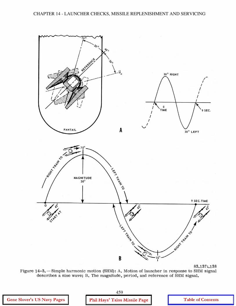
CHAPTER 14 - LAUNCHER CHECKS, MISSILE REPLENISHMENT AND SERVICING
459
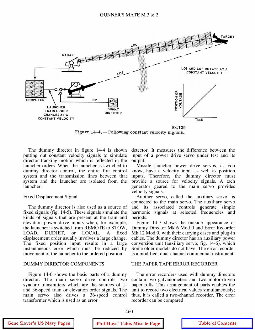
GUNNER'S MATE M 3 & 2
The dummy director in figure 14-4 is shown putting out constant velocity signals to simulate director tracking motion which is reflected in the launcher orders. When the launcher is switched to dummy director control, the entire fire control system and the transmission lines between that system and the launcher are isolated from the launcher. Fixed Displacement Signal The dummy director is also used as a source of fixed signals (fig. 14-5). These signals simulate the kinds of signals that are present at the train and elevation power drive inputs when, for example, the launcher is switched from REMOTE to STOW, LOAD, DUDJET, or LOCAL. A fixed displacement order usually involves a large change. The fixed position input results in a large instantaneous error which must be reduced by movement of the launcher to the ordered position. DUMMY DIRECTOR COMPONENTS Figure 14-6 shows the basic parts of a dummy director. The main servo drive controls two synchro transmitters which are the sources of 1- and 36-speed train or elevation order signals. The main servo also drives a 36-speed control transformer which is used as an error
detector. It measures the difference between the input of a power drive servo under test and its output. Missile launcher power drive servos, as you know, have a velocity input as well as position inputs. Therefore, the dummy director must provide a source for velocity signals. A tach generator geared to the main servo provides velocity signals. Another servo, called the auxiliary servo, is connected to the main servo. The auxiliary servo and its associated controls generate simple harmonic signals at selected frequencies and periods. Figure 14-7 shows the outside appearance of Dummy Director Mk 6 Mod 0 and Error Recorder Mk 12 Mod 0, with their carrying cases and plug-in cables. The dummy director has an auxiliary power conversion unit (auxiliary servo, fig. 14-6), which Some older models do not have. The error recorder is a modified, dual-channel commercial instrument. THE PAPER TAPE ERROR RECORDER The error recorders used with dummy directors contain two galvanometers and two motor-driven paper rolls. This arrangement of parts enables the unit to record two electrical values simultaneously; thus, it is called a two-channel recorder. The error recorder can be compared
460
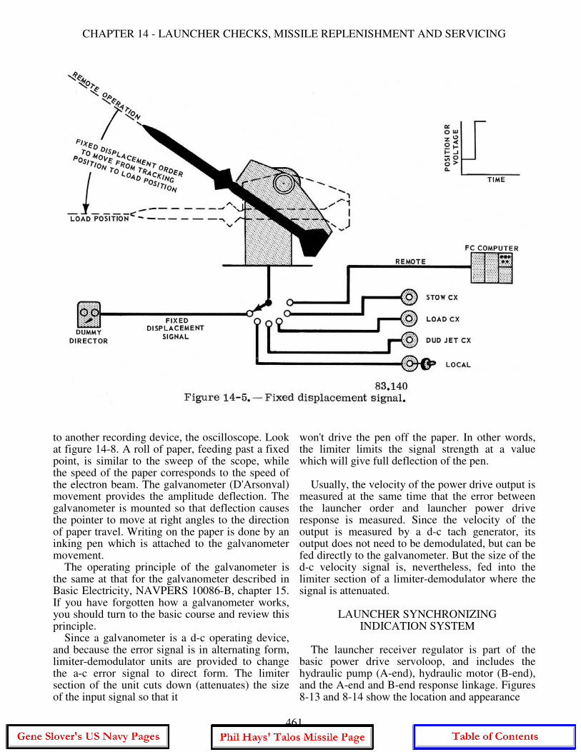
CHAPTER 14 - LAUNCHER CHECKS, MISSILE REPLENISHMENT AND SERVICING
to another recording device, the oscilloscope. Look at figure 14-8. A roll of paper, feeding past a fixed point, is similar to the sweep of the scope, while the speed of the paper corresponds to the speed of the electron beam. The galvanometer (D'Arsonval) movement provides the amplitude deflection. The galvanometer is mounted so that deflection causes the pointer to move at right angles to the direction of paper travel. Writing on the paper is done by an inking pen which is attached to the galvanometer movement. The operating principle of the galvanometer is the same at that for the galvanometer described in Basic Electricity, NAVPERS 10086-B, chapter 15. If you have forgotten how a galvanometer works, you should turn to the basic course and review this principle. Since a galvanometer is a d-c operating device, and because the error signal is in alternating form, limiter-demodulator units are provided to change the a-c error signal to direct form. The limiter section of the unit cuts down (attenuates) the size of the input signal so that it
won't drive the pen off the paper. In other words, the limiter limits the signal strength at a value which will give full deflection of the pen. Usually, the velocity of the power drive output is measured at the same time that the error between the launcher order and launcher power drive response is measured. Since the velocity of the output is measured by a d-c tach generator, its output does not need to be demodulated, but can be fed directly to the galvanometer. But the size of the d-c velocity signal is, nevertheless, fed into the limiter section of a limiter-demodulator where the signal is attenuated.
LAUNCHER SYNCHRONIZING INDICATION SYSTEM
The launcher receiver regulator is part of the basic power drive servoloop, and includes the hydraulic pump (A-end), hydraulic motor (B-end), and the A-end and B-end response linkage. Figures 8-13 and 8-14 show the location and appearance
461
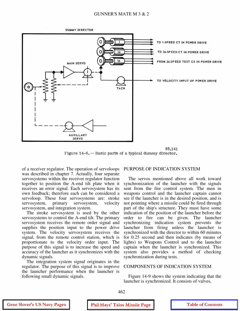
GUNNER'S MATE M 3 & 2
of a receiver regulator. The operation of servoloops was described in chapter 7. Actually, four separate servosystems within the receiver regulator function together to position the A-end tilt plate when it receives an error signal. Each servosystem has its own feedback; therefore each can be considered a servoloop. These four servosystems are: stroke servosystem, primary servosystem, velocity servosystem, and integration system. The stroke servosystem is used by the other servosystems to control the A-end tilt. The primary servosystem receives the remote order signal and supplies the position input to the power drive system. The velocity servosystem receives the signal, from the remote control station, which is proportionate to the velocity order input. The purpose of this signal is to increase the speed and accuracy of the launcher as it synchronizes with the dynamic signals. The integration system signal originates in the regulator. The purpose of this signal is to improve the launcher performance when the launcher is following small dynamic signals.
PURPOSE OF INDICATION SYSTEM The servos mentioned above all work toward synchronization of the launcher with the signals sent from the fire control system. The men in weapons control and the launcher captain cannot see if the launcher is in the desired position, and is not pointing where a missile could be fired through part of the ship's structure. They must have some indication of the position of the launcher before the order to fire can be given. The launcher synchronizing indication system prevents the launcher from firing unless the launcher is synchronized with the director to within 60 minutes for 0.25 second and then indicates (by means of lights) to Weapons Control and to the launcher captain when the launcher is synchronized. This system also provides a method of checking synchronization during tests. COMPONENTS OF INDICATION SYSTEM Figure 14-9 shows the system indicating that the launcher is synchronized. It consists of valves,
462
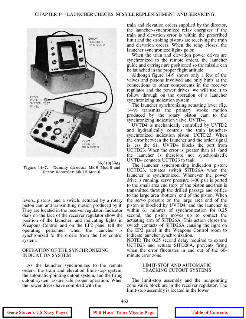
CHAPTER 14 - LAUNCHER CHECKS, MISSILE REPLENISHMENT AND SERVICING
levers, pistons, and a switch, actuated by a rotary piston cam and transmitting motion produced by it. They are located in the receiver regulator. Indicator dials on the face of the receiver regulator show the position of the launcher, and indicating lights in Weapons Control and on the EP2 panel tell the operating personnel when the launcher is synchronized to the orders from the fire control system. OPERATION OF THE SYNCHRONIZING INDICATION SYSTEM As the launcher synchronizes to the remote orders, the train and elevation limit-stop system, the automatic-pointing cutout system, and the firing cutout system assure safe proper operation. When the power drives have complied with the
train and elevation orders supplied by the director, the launcher-synchronized relay energizes if the train and elevation error is within the prescribed limit and the stroking pistons are receiving the train and elevation orders. When the relay closes, the launcher synchronized lights go on. When the train and elevation power drives are synchronized to the remote orders, the launcher guide and carriage are positioned so the missile can be launched in the proper flight attitude. Although figure 14-9 shows only a few of the valves and pistons involved and only hints at the connections to other components in the receiver regulator and the power drives, we will use it to follow through on the operation of a launcher synchronizing indication system. The launcher synchronizing actuating lever (fig. 14-9) transmits the primary stroke motion produced by the rotary piston cam to the synchronizing indication valve, UVTD4. UVTD4 is mechanically controlled by UVTD2 and hydraulically controls the train launcher-synchronized indication piston, UCTD23. When the error between the launcher and the order signal is less the 61', UVTD4 blocks the port from UCTD23. When the error is greater than 61' (and the launcher is therefore not synchronized), UVTD4 connects UCTD23 to tank. The launcher synchronizing indication piston, UCTD23, actuates switch SITD26A when the launcher is synchronized. Whenever the power drive is running, servo pressure (400 psi) is ported to the small area end (top) of the piston and then is transmitted through the drilled passage and orifice to the large area (bottom) end of the piston. When the servo pressure on the large area end of the piston is blocked by UVTD4, and the launcher is within 61 minutes of synchronization for 0.25 second, the piston moves up to contact the actuating arm of SITD26A. This action closes the switch contacts of SITD26A causing the light on the EP2 panel in the Weapons Control room to indicate launcher synchronization. NOTE: The 0.25 second delay required to extend UCTD23 and actuate SITD26A, prevents firing when the error fluctuates in and out of the 60-minute error zone.
LIMIT-STOP AND AUTOMATIC TRACKING CUTOUT SYSTEMS
The limit-stop assembly and the nonpointing zone valve block are in the receiver regulator. The limit-stop assembly is located in the lower
463
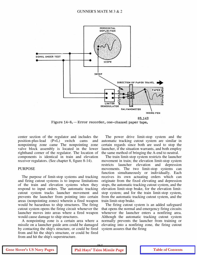
GUNNER'S MATE M 3 & 2
center section of the regulator and includes the position-plus-lead (P+L) switch cams and nonpointing zone came The nonpointing zone valve block assembly is located in the lower righthand corner of the regulator. The location of components is identical in train and elevation receiver regulators. (See chapter 8, figure 8-14). PURPOSE The purpose of limit-stop systems and tracking and firing cutout systems is to impose limitations of the train and elevation systems when they respond to input orders. The automatic tracking cutout system tracks launcher movement and prevents the launcher from pointing into certain areas (nonpointing zones) wherein a fired weapon would be hazardous to ship structures. The firing cutout system opens the firing circuit whenever the launcher moves into areas where a fired weapon would cause damage to ship structures. A nonpointing zone is a certain area where a missile on a launcher guide arm could be damaged by contacting the ship's structure, or could be fired from and hit the ship's structure, or could be fired from and hit the ship's superstructure.
The power drive limit-stop system and the automatic tracking cutout system are similar in certain regards since both are used to stop the launcher, if the situation warrants, and both employ the same method of bringing the A-end to neutral. The train limit-stop system restricts the launcher movement in train; the elevation limit-stop system restricts launcher elevation and depression movements. The two limit-stop systems can function simultaneously or individually. Each receives its own actuating orders which can originate from the fixed elevating and depression stops, the automatic tracking cutout system, and the elevation limit-stop brake, for the elevation limit-stop system; and for the train limit-stop system, from the automatic tracking cutout system, and the train limit-stop brake. The firing cutout system is an added safeguard that opens the normal and emergency firing circuits whenever the launcher enters a nonfiring area. Although the automatic tracking cutout system normally prevents the launcher from training or elevating into a nonfiring zone, the firing cutout system assures that the firing
464
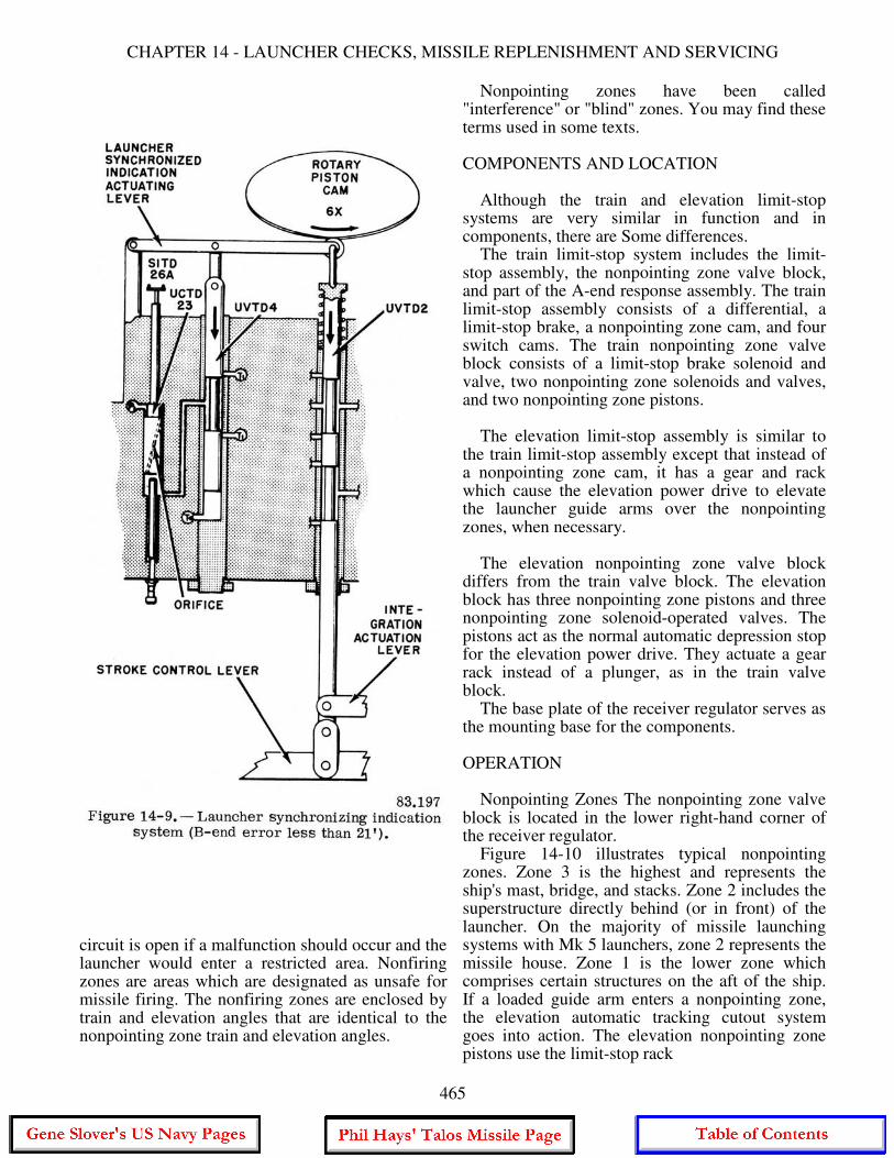
CHAPTER 14 - LAUNCHER CHECKS, MISSILE REPLENISHMENT AND SERVICING
circuit is open if a malfunction should occur and the launcher would enter a restricted area. Nonfiring zones are areas which are designated as unsafe for missile firing. The nonfiring zones are enclosed by train and elevation angles that are identical to the nonpointing zone train and elevation angles.
Nonpointing zones have been called "interference" or "blind" zones. You may find these terms used in some texts. COMPONENTS AND LOCATION Although the train and elevation limit-stop systems are very similar in function and in components, there are Some differences. The train limit-stop system includes the limit-stop assembly, the nonpointing zone valve block, and part of the A-end response assembly. The train limit-stop assembly consists of a differential, a limit-stop brake, a nonpointing zone cam, and four switch cams. The train nonpointing zone valve block consists of a limit-stop brake solenoid and valve, two nonpointing zone solenoids and valves, and two nonpointing zone pistons. The elevation limit-stop assembly is similar to the train limit-stop assembly except that instead of a nonpointing zone cam, it has a gear and rack which cause the elevation power drive to elevate the launcher guide arms over the nonpointing zones, when necessary. The elevation nonpointing zone valve block differs from the train valve block. The elevation block has three nonpointing zone pistons and three nonpointing zone solenoid-operated valves. The pistons act as the normal automatic depression stop for the elevation power drive. They actuate a gear rack instead of a plunger, as in the train valve block. The base plate of the receiver regulator serves as the mounting base for the components. OPERATION Nonpointing Zones The nonpointing zone valve block is located in the lower right-hand corner of the receiver regulator. Figure 14-10 illustrates typical nonpointing zones. Zone 3 is the highest and represents the ship's mast, bridge, and stacks. Zone 2 includes the superstructure directly behind (or in front) of the launcher. On the majority of missile launching systems with Mk 5 launchers, zone 2 represents the missile house. Zone 1 is the lower zone which comprises certain structures on the aft of the ship. If a loaded guide arm enters a nonpointing zone, the elevation automatic tracking cutout system goes into action. The elevation nonpointing zone pistons use the limit-stop rack
465
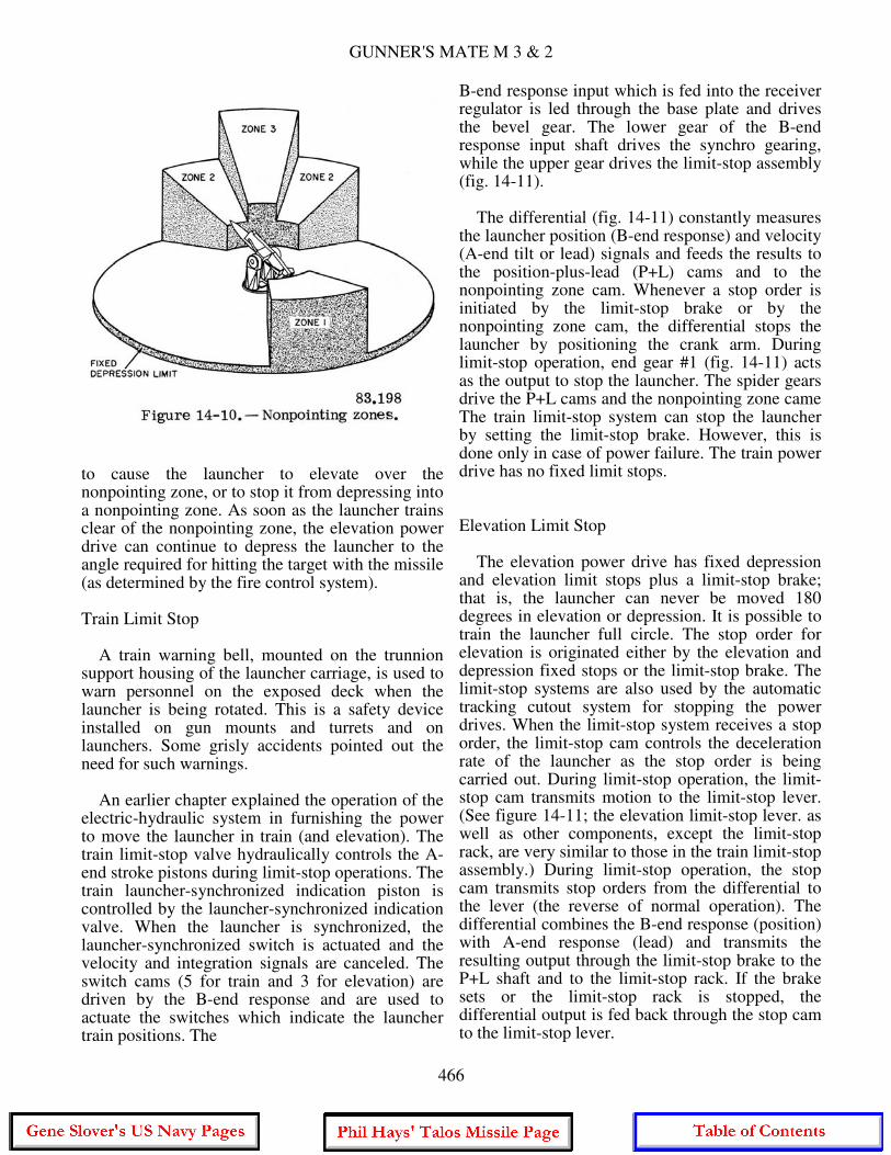
GUNNER'S MATE M 3 & 2
to cause the launcher to elevate over the nonpointing zone, or to stop it from depressing into a nonpointing zone. As soon as the launcher trains clear of the nonpointing zone, the elevation power drive can continue to depress the launcher to the angle required for hitting the target with the missile (as determined by the fire control system). Train Limit Stop A train warning bell, mounted on the trunnion support housing of the launcher carriage, is used to warn personnel on the exposed deck when the launcher is being rotated. This is a safety device installed on gun mounts and turrets and on launchers. Some grisly accidents pointed out the need for such warnings. An earlier chapter explained the operation of the electric-hydraulic system in furnishing the power to move the launcher in train (and elevation). The train limit-stop valve hydraulically controls the A-end stroke pistons during limit-stop operations. The train launcher-synchronized indication piston is controlled by the launcher-synchronized indication valve. When the launcher is synchronized, the launcher-synchronized switch is actuated and the velocity and integration signals are canceled. The switch cams (5 for train and 3 for elevation) are driven by the B-end response and are used to actuate the switches which indicate the launcher train positions. The
B-end response input which is fed into the receiver regulator is led through the base plate and drives the bevel gear. The lower gear of the B-end response input shaft drives the synchro gearing, while the upper gear drives the limit-stop assembly (fig. 14-11). The differential (fig. 14-11) constantly measures the launcher position (B-end response) and velocity (A-end tilt or lead) signals and feeds the results to the position-plus-lead (P+L) cams and to the nonpointing zone cam. Whenever a stop order is initiated by the limit-stop brake or by the nonpointing zone cam, the differential stops the launcher by positioning the crank arm. During limit-stop operation, end gear #1 (fig. 14-11) acts as the output to stop the launcher. The spider gears drive the P+L cams and the nonpointing zone came The train limit-stop system can stop the launcher by setting the limit-stop brake. However, this is done only in case of power failure. The train power drive has no fixed limit stops. Elevation Limit Stop The elevation power drive has fixed depression and elevation limit stops plus a limit-stop brake; that is, the launcher can never be moved 180 degrees in elevation or depression. It is possible to train the launcher full circle. The stop order for elevation is originated either by the elevation and depression fixed stops or the limit-stop brake. The limit-stop systems are also used by the automatic tracking cutout system for stopping the power drives. When the limit-stop system receives a stop order, the limit-stop cam controls the deceleration rate of the launcher as the stop order is being carried out. During limit-stop operation, the limit-stop cam transmits motion to the limit-stop lever. (See figure 14-11; the elevation limit-stop lever. as well as other components, except the limit-stop rack, are very similar to those in the train limit-stop assembly.) During limit-stop operation, the stop cam transmits stop orders from the differential to the lever (the reverse of normal operation). The differential combines the B-end response (position) with A-end response (lead) and transmits the resulting output through the limit-stop brake to the P+L shaft and to the limit-stop rack. If the brake sets or the limit-stop rack is stopped, the differential output is fed back through the stop cam to the limit-stop lever.
466
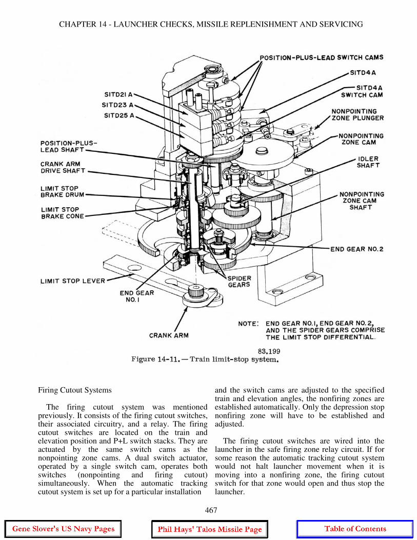
CHAPTER 14 - LAUNCHER CHECKS, MISSILE REPLENISHMENT AND SERVICING
Firing Cutout Systems The firing cutout system was mentioned previously. It consists of the firing cutout switches, their associated circuitry, and a relay. The firing cutout switches are located on the train and elevation position and P+L switch stacks. They are actuated by the same switch cams as the nonpointing zone cams. A dual switch actuator, operated by a single switch cam, operates both switches (nonpointing and firing cutout) simultaneously. When the automatic tracking cutout system is set up for a particular installation
and the switch cams are adjusted to the specified train and elevation angles, the nonfiring zones are established automatically. Only the depression stop nonfiring zone will have to be established and adjusted. The firing cutout switches are wired into the launcher in the safe firing zone relay circuit. If for some reason the automatic tracking cutout system would not halt launcher movement when it is moving into a nonfiring zone, the firing cutout switch for that zone would open and thus stop the launcher.
467
GUNNER'S MATE M 3 & 2
Automatic Tracking Cutout System The automatic tracking cutout system actuates the train and/or elevation limit-stop system whenever a nonpointing zone is encountered and the launcher is not on a return-to-lad order. The train cutout system receives mechanical inputs from the train system but is dependent on electrical inputs to indicate the elevation position. Basically, train cutout operation and elevation cutout operation are similar in function - both use hydraulic means to actuate their limit-stop systems. The train position response, which is supplied by the train B-end, is conveyed through the gear train in the synchro gear assembly to the train position switch cams, of which there are three, one for each zone. The switches operated by these cam are wired into the elevation nonpointing zone solenoids. (The switch cam shown in figure 14-11 appear circular, but they are curved and shaped for each installation.) Whenever position-plus-lead movement drives a stop cam lobe against the stop pin (positioned by an extended piston), P+L movement is halted and a stop order is supplied to the train limit stop system. Since the operation of the train nonpointing zone pistons is determined by the associated solenoid-operated valves and the elevation nonpointing zone switches are wired into these solenoid circuits, piston operation is actually determined by the elevation position. Therefore, automatic tracking cutout operation in train not only depends on the mechanical P+L response to the train nonpointing zone stop cam but also on the elevation position at the time. The elevation system cutout operation is similar to the train cutout operation. Like the train system, the elevation system receives mechanical inputs from the elevation position and P+L response and electrical indication from the train system. The elevation position response drives the elevation switch cams. The elevation automatic tracking cutout system operates by changing the position of the launcher depression limits whenever a loaded launcher guide arm enters a nonpointing zone. Nonpointing zone pistons use the limit stop rack to prevent the launcher from depressing into a nonpointing zone or to cause the launcher to elevate over the zone. The pistons are hydraulically controlled by solenoid-operated valves. The nonpointing zone solenoids are controlled by position and P+L cams in the train receiver regulator. If the launcher approaches a nonpointing zone, the
solenoid for that zone in the elevation receiver regulator deenergizes. The piston then extends and contacts the limit-stop rack and stops the elevation power drive. As soon as the launcher trains clear of the nonpointing zone, the solenoid again energizes and the elevation power drive can continue. When the launcher guide is empty and the launcher is on a return-to-load order, relays complete a bypass circuit to the train and elevation nonpointing zone solenoids. The manner in which these relay contacts are wired into the solenoid circuits allows the position and P+L switches to be bypassed on return-to-load. This permits the launcher to pass through the nonpointing zone or zones and follow the shortest route so it can synchronize to load position with the least delay.
MISSILE REPLENISHMENT AND STRIKEDOWN
A ship at sea can be loaded with missiles, boosters, and associated components from an ammunition ship. A ship can also be replenished in port from alongside a pier or from a barge. Replenishment by helicopter has been used at times. Replenishment at sea may be accomplished by means of anyone of four transfer methods. 1. The Burtoning method. 2. The constant tension highline method. 3. The modified housefall method. 4. The Fast Automatic Shuttle Transfer method (FAST, for short). We will cover only the modified housefall and FAST methods because they are the methods most commonly used in the fleet. Figure 5-12 in Seaman, NavPers 10120-E, shows a regular housefall rig being used for transfer of ammunition. MODIFIED HOUSEFALL The modified housefall rig is shown in figure 14-12. Completely assembled missiles and boosters (less wing and fins) are removed from their containers, suspended in a transfer dolly (called a grasshopper) and transferred from the ammunition ship to the missile ship. Missiles or boosters arrive on the 01- or 02-level (depending on the type of ship) atop the deckhouse
468
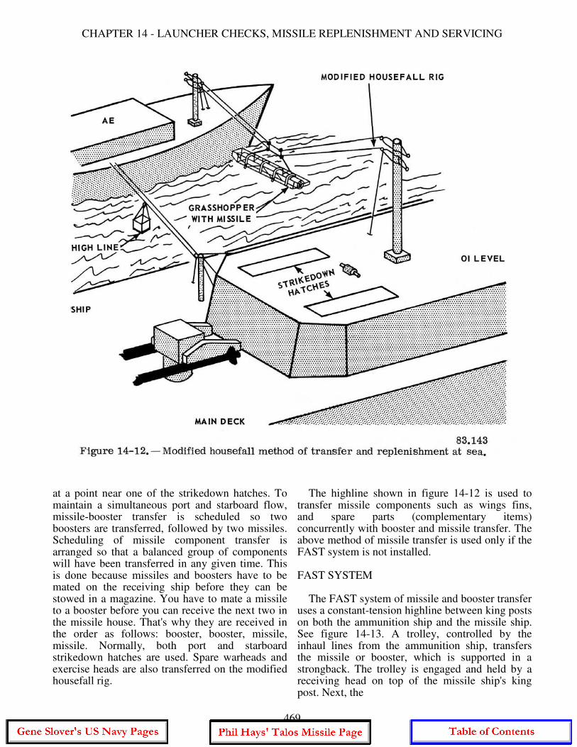
CHAPTER 14 - LAUNCHER CHECKS, MISSILE REPLENISHMENT AND SERVICING
at a point near one of the strikedown hatches. To maintain a simultaneous port and starboard flow, missile-booster transfer is scheduled so two boosters are transferred, followed by two missiles. Scheduling of missile component transfer is arranged so that a balanced group of components will have been transferred in any given time. This is done because missiles and boosters have to be mated on the receiving ship before they can be stowed in a magazine. You have to mate a missile to a booster before you can receive the next two in the missile house. That's why they are received in the order as follows: booster, booster, missile, missile. Normally, both port and starboard strikedown hatches are used. Spare warheads and exercise heads are also transferred on the modified housefall rig.
The highline shown in figure 14-12 is used to transfer missile components such as wings fins, and spare parts (complementary items) concurrently with booster and missile transfer. The above method of missile transfer is used only if the FAST system is not installed. FAST SYSTEM The FAST system of missile and booster transfer uses a constant-tension highline between king posts on both the ammunition ship and the missile ship. See figure 14-13. A trolley, controlled by the inhaul lines from the ammunition ship, transfers the missile or booster, which is supported in a strongback. The trolley is engaged and held by a receiving head on top of the missile ship's king post. Next, the
469
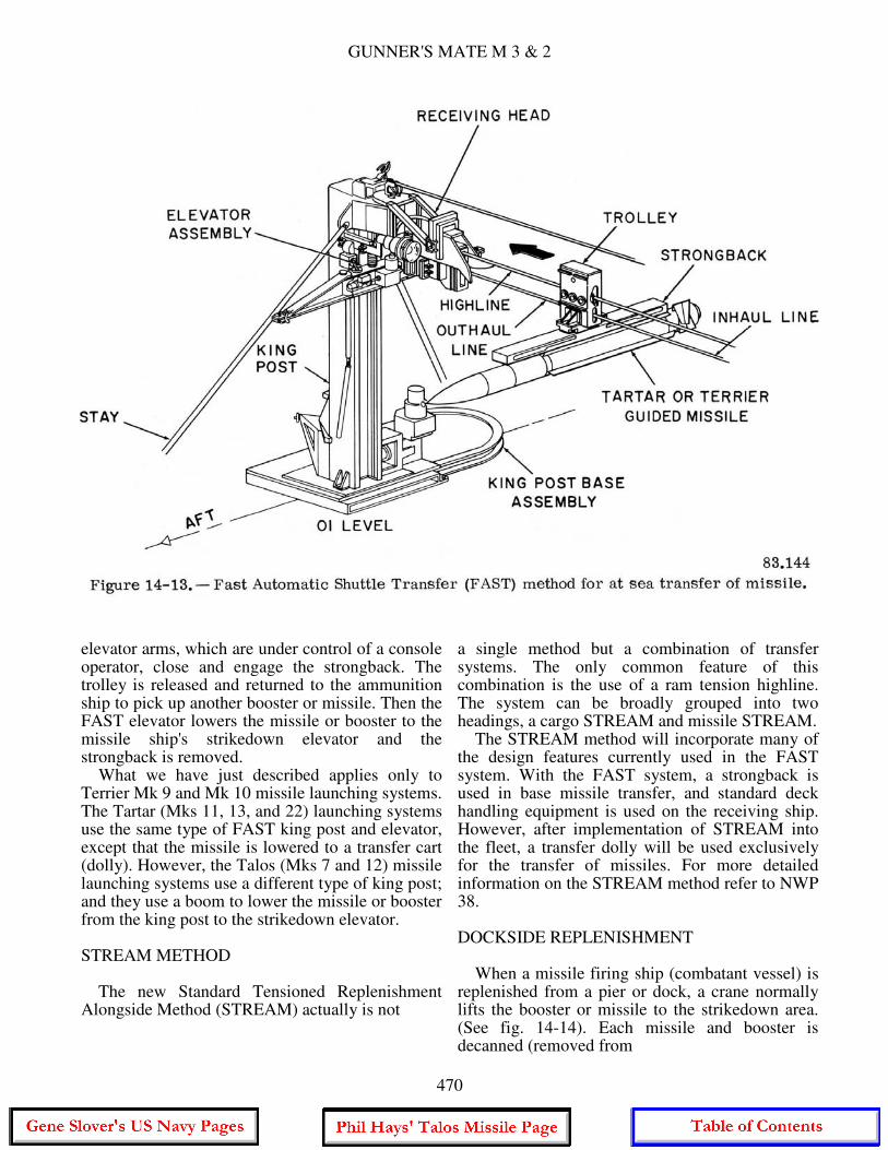
GUNNER'S MATE M 3 & 2
elevator arms, which are under control of a console operator, close and engage the strongback. The trolley is released and returned to the ammunition ship to pick up another booster or missile. Then the FAST elevator lowers the missile or booster to the missile ship's strikedown elevator and the strongback is removed. What we have just described applies only to Terrier Mk 9 and Mk 10 missile launching systems. The Tartar (Mks 11, 13, and 22) launching systems use the same type of FAST king post and elevator, except that the missile is lowered to a transfer cart (dolly). However, the Talos (Mks 7 and 12) missile launching systems use a different type of king post; and they use a boom to lower the missile or booster from the king post to the strikedown elevator. STREAM METHOD The new Standard Tensioned Replenishment Alongside Method (STREAM) actually is not
a single method but a combination of transfer systems. The only common feature of this combination is the use of a ram tension highline. The system can be broadly grouped into two headings, a cargo STREAM and missile STREAM. The STREAM method will incorporate many of the design features currently used in the FAST system. With the FAST system, a strongback is used in base missile transfer, and standard deck handling equipment is used on the receiving ship. However, after implementation of STREAM into the fleet, a transfer dolly will be used exclusively for the transfer of missiles. For more detailed information on the STREAM method refer to NWP 38. DOCKSIDE REPLENISHMENT When a missile firing ship (combatant vessel) is replenished from a pier or dock, a crane normally lifts the booster or missile to the strikedown area. (See fig. 14-14). Each missile and booster is decanned (removed from
470
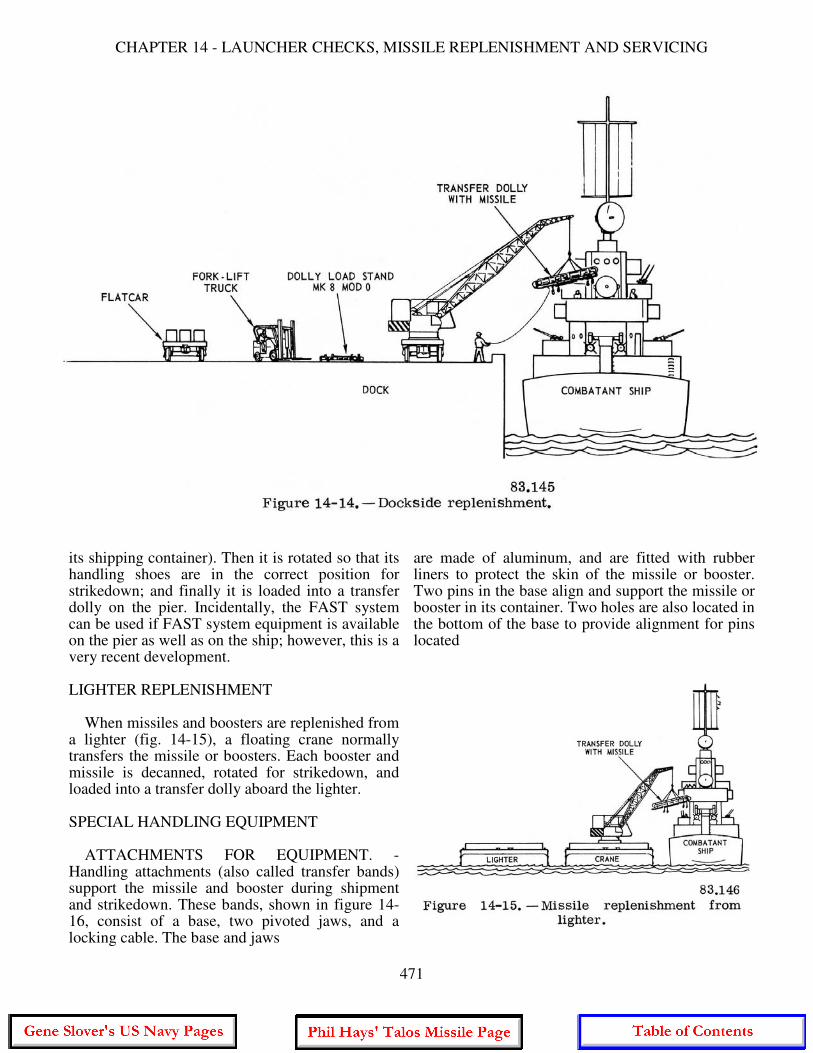
CHAPTER 14 - LAUNCHER CHECKS, MISSILE REPLENISHMENT AND SERVICING
its shipping container). Then it is rotated so that its handling shoes are in the correct position for strikedown; and finally it is loaded into a transfer dolly on the pier. Incidentally, the FAST system can be used if FAST system equipment is available on the pier as well as on the ship; however, this is a very recent development. LIGHTER REPLENISHMENT When missiles and boosters are replenished from a lighter (fig. 14-15), a floating crane normally transfers the missile or boosters. Each booster and missile is decanned, rotated for strikedown, and loaded into a transfer dolly aboard the lighter. SPECIAL HANDLING EQUIPMENT ATTACHMENTS FOR EQUIPMENT. -Handling attachments (also called transfer bands) support the missile and booster during shipment and strikedown. These bands, shown in figure 14-16, consist of a base, two pivoted jaws, and a locking cable. The base and jaws
are made of aluminum, and are fitted with rubber liners to protect the skin of the missile or booster. Two pins in the base align and support the missile or booster in its container. Two holes are also located in the bottom of the base to provide alignment for pins located
471
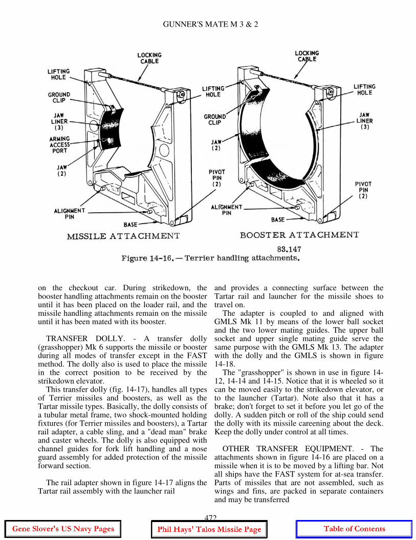
GUNNER'S MATE M 3 & 2
on the checkout car. During strikedown, the booster handling attachments remain on the booster until it has been placed on the loader rail, and the missile handling attachments remain on the missile until it has been mated with its booster. TRANSFER DOLLY. - A transfer dolly (grasshopper) Mk 6 supports the missile or booster during all modes of transfer except in the FAST method. The dolly also is used to place the missile in the correct position to be received by the strikedown elevator. This transfer dolly (fig. 14-17), handles all types of Terrier missiles and boosters, as well as the Tartar missile types. Basically, the dolly consists of a tubular metal frame, two shock-mounted holding fixtures (for Terrier missiles and boosters), a Tartar rail adapter, a cable sling, and a "dead man" brake and caster wheels. The dolly is also equipped with channel guides for fork lift handling and a nose guard assembly for added protection of the missile forward section. The rail adapter shown in figure 14-17 aligns the Tartar rail assembly with the launcher rail
and provides a connecting surface between the Tartar rail and launcher for the missile shoes to travel on. The adapter is coupled to and aligned with GMLS Mk 11 by means of the lower ball socket and the two lower mating guides. The upper ball socket and upper single mating guide serve the same purpose with the GMLS Mk 13. The adapter with the dolly and the GMLS is shown in figure 14-18. The "grasshopper" is shown in use in figure 14-12, 14-14 and 14-15. Notice that it is wheeled so it can be moved easily to the strikedown elevator, or to the launcher (Tartar). Note also that it has a brake; don't forget to set it before you let go of the dolly. A sudden pitch or roll of the ship could send the dolly with its missile careening about the deck. Keep the dolly under control at all times. OTHER TRANSFER EQUIPMENT. - The attachments shown in figure 14-16 are placed on a missile when it is to be moved by a lifting bar. Not all ships have the FAST system for at-sea transfer. Parts of missiles that are not assembled, such as wings and fins, are packed in separate containers and may be transferred
472
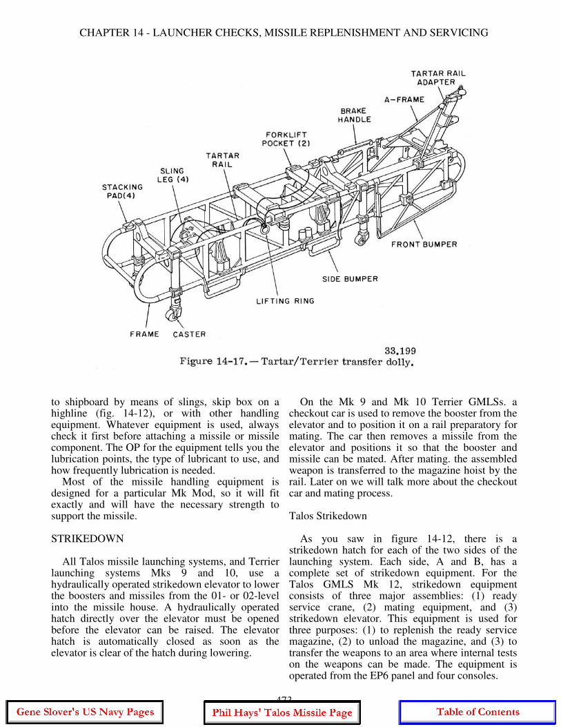
CHAPTER 14 - LAUNCHER CHECKS, MISSILE REPLENISHMENT AND SERVICING
to shipboard by means of slings, skip box on a highline (fig. 14-12), or with other handling equipment. Whatever equipment is used, always check it first before attaching a missile or missile component. The OP for the equipment tells you the lubrication points, the type of lubricant to use, and how frequently lubrication is needed. Most of the missile handling equipment is designed for a particular Mk Mod, so it will fit exactly and will have the necessary strength to support the missile. STRIKEDOWN All Talos missile launching systems, and Terrier launching systems Mks 9 and 10, use a hydraulically operated strikedown elevator to lower the boosters and missiles from the 01- or 02-level into the missile house. A hydraulically operated hatch directly over the elevator must be opened before the elevator can be raised. The elevator hatch is automatically closed as soon as the elevator is clear of the hatch during lowering.
On the Mk 9 and Mk 10 Terrier GMLSs. a checkout car is used to remove the booster from the elevator and to position it on a rail preparatory for mating. The car then removes a missile from the elevator and positions it so that the booster and missile can be mated. After mating. the assembled weapon is transferred to the magazine hoist by the rail. Later on we will talk more about the checkout car and mating process. Talos Strikedown As you saw in figure 14-12, there is a strikedown hatch for each of the two sides of the launching system. Each side, A and B, has a complete set of strikedown equipment. For the Talos GMLS Mk 12, strikedown equipment consists of three major assemblies: (1) ready service crane, (2) mating equipment, and (3) strikedown elevator. This equipment is used for three purposes: (1) to replenish the ready service magazine, (2) to unload the magazine, and (3) to transfer the weapons to an area where internal tests on the weapons can be made. The equipment is operated from the EP6 panel and four consoles.
473
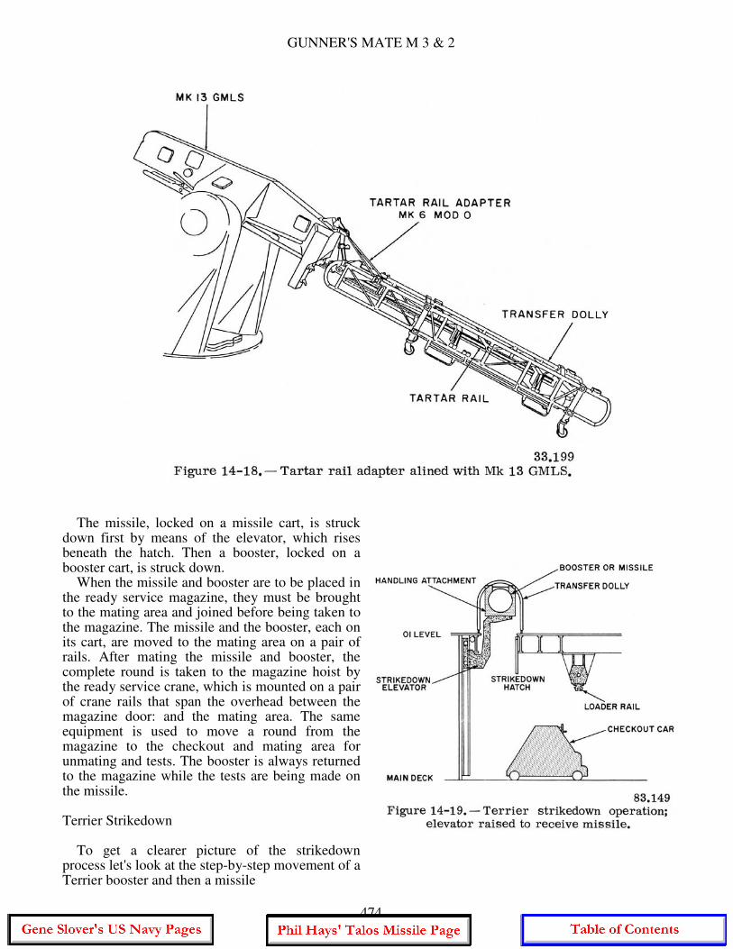
GUNNER'S MATE M 3 & 2
The missile, locked on a missile cart, is struck down first by means of the elevator, which rises beneath the hatch. Then a booster, locked on a booster cart, is struck down. When the missile and booster are to be placed in the ready service magazine, they must be brought to the mating area and joined before being taken to the magazine. The missile and the booster, each on its cart, are moved to the mating area on a pair of rails. After mating the missile and booster, the complete round is taken to the magazine hoist by the ready service crane, which is mounted on a pair of crane rails that span the overhead between the magazine door: and the mating area. The same equipment is used to move a round from the magazine to the checkout and mating area for unmating and tests. The booster is always returned to the magazine while the tests are being made on the missile. Terrier Strikedown To get a clearer picture of the strikedown process let's look at the step-by-step movement of a Terrier booster and then a missile
474
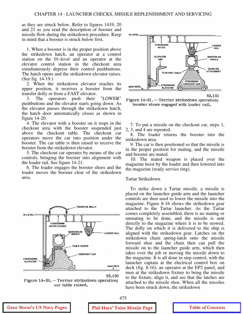
CHAPTER 14 - LAUNCHER CHECKS, MISSILE REPLENISHMENT AND SERVICING
as they are struck below. Refer to figures 1419, 20 and 21 as you read the description of booster and missile flow during the strikedown procedure. Keep in mind that a booster is struck below first. 1. When a booster is in the proper position above the strikedown hatch, an operator at a control station on the 01-level and an operator at the elevator control station in the checkout area simultaneously depress their control pushbuttons. The hatch opens and the strikedown elevator raises. (See fig. 14-19.) 2. When the strikedown elevator reaches its upper position, it receives a booster from the transfer dolly or from a FAST elevator. 3. The operators push their "LOWER" pushbuttons and the elevator starts going down. As the elevator passes through the strikedown hatch, the hatch door automatically closes as shown in figure 14-20. 4. The elevator with a booster on it stops in the checkout area with the booster suspended just above the checkout table. The checkout car operators move the car into position under the booster. The car table is then raised to receive the booster from the strikedown elevator. 5. The checkout car operates by means of the car controls, bringing the booster into alignment with the loader rail. See figure 14-21. 6. The loader engages the booster shoes and the loader moves the booster clear of the strikedown area.
7. To put a missile on the checkout car, steps 1, 2, 3, and 4 are repeated. 8. The loader returns the booster into the strikedown area. 9. The car is then positioned so that the missile is in the proper position for mating, and the missile and booster are mated. 10. The mated weapon is placed over the magazine hoist by the loader and then lowered into the magazine (ready service ring). Tartar Strikedown To strike down a Tartar missile, a missile is placed on the launcher guide arm and the launcher controls are then used to lower the missile into the magazine. Figure 8-16 shows the strikedown gear attached to the Tartar launcher. As the Tartar comes completely assembled, there is no mating or unmating to be done, and the missile is sent directly to the magazine where it is to be stowed. The dolly on which it is delivered to the ship is aligned with the strikedown gear. Latches on the strikedown chain spring-latch onto the missile forward shoe and the chain then can pull the missile on to the launcher guide arm, which then takes over the job or moving the missile down to the magazine. It is all done in step control, with the launcher captain at the electrical control box on deck (fig. 8-16), an operator at the EP2 panel, and men at the strikedown fixture to bring the missile to the fixture, align it, and see that the latches are attached to the missile shoe. When all the missiles have been struck down, the strikedown
475
GUNNER'S MATE M 3 & 2
fixture is removed from the launcher and is stowed. The same fixture is used to bring missiles up from the magazine to be offloaded. Responsibility for Missile Strikedown Equipment The strikedown gear attached to the Tartar launcher is ordnance equipment but the rails on the deck on which you move the dolly are ship's equipment. The elevators and cranes used to move the larger missiles, the Terrier and Talos, are ship's equipment. The GMMs who use ship's equipment must exercise responsible care and give routine maintenance, but the prime responsibility for its repair and major maintenance belongs to the ship's engineering department. Always check the equipment before using it. Do not assume that it is all right. The size, weight, and dangerous characteristics of missiles and boosters make it imperative that they be moved safely. MISSILE COMPONENT STOWAGE A storeroom for the stowage of missile components and a magazine for the stowage of missile warheads are both located two decks below the checkout area. The magazine and the store room are connected to the checkout area by a trunk and hoist. The location of the stowage spaces varies with the type of ship and the missiles carried. If you have missiles (Terrier and Talos) that have wings and fins to be assembled when preparing for firing, the wings, and fins are stowed in racks in the loading area of the launching system. Tartar missiles have their wings attached and folded, so there is no need for separate stowage, except for spare parts. A dumbwaiter type of elevator operated by an electric hoist is used to move those to or from the missile component storeroom. Stowage Precautions Classes of dangers can be grouped as general personnel, mechanical, electrical, and explosive. To these we might add: danger from liquid fuels, and danger from radioactive material. Below are a few specific precautions to review. A. Missiles and components must be securely fastened in storage, stowage racks, and magazine ready service rings. B. ALWAYS inspect handling equipment before using.
C. Missiles and components must NOT be placed in or removed from stowage racks and/or areas without using the proper handling equipment. D. All arming devices must be in the SAFE position during stowage. E. Arming tools must be kept in a designated place at all times, except when in actual use. F. Ground wires must be attached to boosters and missiles in stowage, during check-out, and while being transported from one area to another. G. Booster rocket components must be handled with care. A cracked propellant grain could result in an explosion when ignited. H. Explosive and propellant components must be stowed in approved magazines in which the temperature range does not exceed the limits specified by NAVORDSYSCOM. General Precautions A. All missile operations must be in accordance with shipboard safety precautions. B. The handling of sustainers, booster's warheads, and other propelling or explosive devices must conform with explosive handling practices aboard ship. C. Only those personnel who are engaged in the operation in progress should be permitted in the immediate area of the missile. D. Only approved nonsparking tools are to be used in the vicinity of explosives or propelling charges. E. Only the correct handling equipment is to be used for lifting missiles and components thereof. F. Electrical equipment must be shielded and grounded to prevent accidental ignition of propellants or explosives or injury to personnel. G. Working areas must be clear of obstructions, loose cabling, hose, and unneeded equipment. H. Electrical igniters or detonators (booster charges) shall not be exposed within 50 feet of, or stowed in any compartment with, any exposed electronic transmitting equipment, exposed antenna, or antenna lead, except where such apparatus or antenna is part of a missile test set, or is an integral part of the missile concerned. I. Use extreme care in handling pressurized air hoses and couplings. Compressed air can exert sufficient force to severely injure personnel and/or equipment. HANDLING BELOW DECKS When you have only Tartar missiles, stowage does not require any handling below decks as
476
CHAPTER 14 - LAUNCHER CHECKS, MISSILE REPLENISHMENT AND SERVICING
the missiles are struck down to the magazine by the launcher. To offload missiles, the operation is reversed. Missile checkout is performed on the launcher guide. To replace a component in the missile, the guide arm, with the missile on it, is trained to an area where ship handling equipment is available. Again, there is no below deck handling. Checkout Car The checkout car is mechanically and electrically operated. The car is used for strikedown, strikeup, mating, and checkout operations. The chassis can be moved vertically by means of the "Up-and-down" control, and can be moved forward and aft by means of the "Forward-aft" control. The car table (fig. 14-21) can be axially adjusted by means of the "Roll" control, and can be tilted by means of the "Float" control. Missile and Booster Carts The missile and booster carts used to hold the missile and the booster of Talos are driven by separate chain drives. Each chain drive engages its cart when the elevator reaches the main deck with its missile or booster load, and drives it to the mating area, following the rails that lead from the elevator, through the flametight doors, to the mating area. After the missile and booster have been mated, the carts are released and returned to their positions near the elevator. There are several differences in construction of the carts; they cannot be interchanged. Ready Service Crane The ready service crane is used to transport the mated weapon from the mating area to an empty tray on the missile magazine hoist. When the tray receives the weapon, the hoist is at the strikedown level. The crane is mounted on a pair of crane rails that span the overhead between the magazine door and the mating area. It is operated from a control panel on the magazine platform. The crane raises the weapon by means of its strongback, which has shoe grips that seat on the booster shoes of the missile and lock on. The strongback is raised and lowered by hydraulic actuators.
MISSILE MATING AND SERVICING RESPONSIBILITIES OF GMM The GMM assigned to a guided missile launching system is responsible for the handling, custody, and care of the missile used by that system. The responsibility includes the following tasks: 1. Unmating/mating. 2. Warhead and exercise head exchange. 3. Assembly and disassembly. 4. Preparation of missile for tests. 5. Missile servicing (preventive maintenance). GMMs are not solely responsible for performing the missile system tests or for the test equipment. These responsibilities are shared by the fire control technicians. The GMMs (joins the booster and missile) all Terrier, Talos, and Standard ER missiles during strikedown and unmates these same missiles before they can be offloaded (struck up). Missiles must be mated and unmated every time they are tested (checked out) and whenever it is necessary to change warheads or install exercise heads. The areas of responsibility for GMMs are in a changing state, tending toward more responsibility for the missile round. A review of the quals reveals a concentration on care and testing of the launching system. At the E-5 level, the GMM is responsible for positioning the missile and preparing it for testing. The deletion of the former Missile Technician rating is causing a shift in duties of the GMM with regard to the missile. As a practical matter, GMMs are already being given more responsibility for the testing of the missile round. Testing of missiles aboard ship is being reduced, however. TESTING AND REPAIRING As soon as practical after the missiles have been brought aboard ship, a missile system test (MST) , commonly called "missile checkout," must be performed. Thereafter, periodic checkouts will be conducted at intervals established by NAVORDSYSCOM. For example, NAVORDSYSCOM at the time of this writing requires that BT-3 Terrier missiles be checked at 3-month intervals for the first three times and 6-month intervals subsequently. Both initial and periodic tests are conducted in areas (stations) especially provided with missile component handling equipment and test sets.
477
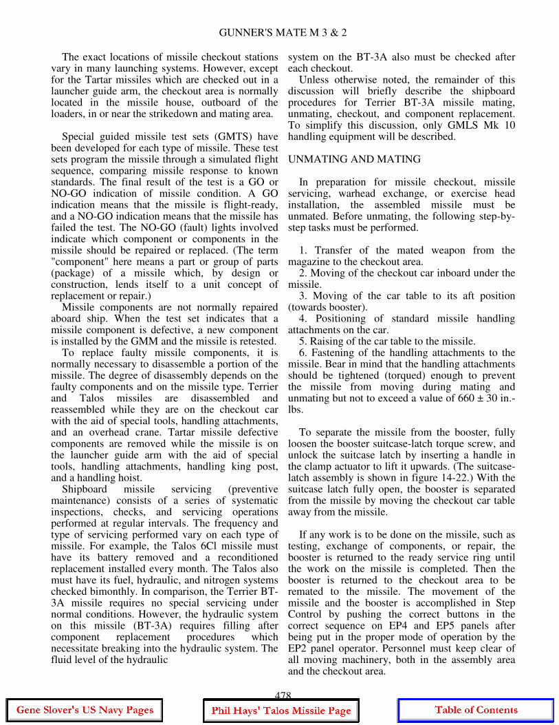
GUNNER'S MATE M 3 & 2
The exact locations of missile checkout stations vary in many launching systems. However, except for the Tartar missiles which are checked out in a launcher guide arm, the checkout area is normally located in the missile house, outboard of the loaders, in or near the strikedown and mating area. Special guided missile test sets (GMTS) have been developed for each type of missile. These test sets program the missile through a simulated flight sequence, comparing missile response to known standards. The final result of the test is a GO or NO-GO indication of missile condition. A GO indication means that the missile is flight-ready, and a NO-GO indication means that the missile has failed the test. The NO-GO (fault) lights involved indicate which component or components in the missile should be repaired or replaced. (The term "component" here means a part or group of parts (package) of a missile which, by design or construction, lends itself to a unit concept of replacement or repair.) Missile components are not normally repaired aboard ship. When the test set indicates that a missile component is defective, a new component is installed by the GMM and the missile is retested. To replace faulty missile components, it is normally necessary to disassemble a portion of the missile. The degree of disassembly depends on the faulty components and on the missile type. Terrier and Talos missiles are disassembled and reassembled while they are on the checkout car with the aid of special tools, handling attachments, and an overhead crane. Tartar missile defective components are removed while the missile is on the launcher guide arm with the aid of special tools, handling attachments, handling king post, and a handling hoist. Shipboard missile servicing (preventive maintenance) consists of a series of systematic inspections, checks, and servicing operations performed at regular intervals. The frequency and type of servicing performed vary on each type of missile. For example, the Talos 6Cl missile must have its battery removed and a reconditioned replacement installed every month. The Talos also must have its fuel, hydraulic, and nitrogen systems checked bimonthly. In comparison, the Terrier BT-3A missile requires no special servicing under normal conditions. However, the hydraulic system on this missile (BT-3A) requires filling after component replacement procedures which necessitate breaking into the hydraulic system. The fluid level of the hydraulic
system on the BT-3A also must be checked after each checkout. Unless otherwise noted, the remainder of this discussion will briefly describe the shipboard procedures for Terrier BT-3A missile mating, unmating, checkout, and component replacement. To simplify this discussion, only GMLS Mk 10 handling equipment will be described. UNMATING AND MATING In preparation for missile checkout, missile servicing, warhead exchange, or exercise head installation, the assembled missile must be unmated. Before unmating, the following step-by-step tasks must be performed. 1. Transfer of the mated weapon from the magazine to the checkout area. 2. Moving of the checkout car inboard under the missile. 3. Moving of the car table to its aft position (towards booster). 4. Positioning of standard missile handling attachments on the car. 5. Raising of the car table to the missile. 6. Fastening of the handling attachments to the missile. Bear in mind that the handling attachments should be tightened (torqued) enough to prevent the missile from moving during mating and unmating but not to exceed a value of 660 ± 30 in.-lbs. To separate the missile from the booster, fully loosen the booster suitcase-latch torque screw, and unlock the suitcase latch by inserting a handle in the clamp actuator to lift it upwards. (The suitcase-latch assembly is shown in figure 14-22.) With the suitcase latch fully open, the booster is separated from the missile by moving the checkout car table away from the missile. If any work is to be done on the missile, such as testing, exchange of components, or repair, the booster is returned to the ready service ring until the work on the missile is completed. Then the booster is returned to the checkout area to be remated to the missile. The movement of the missile and the booster is accomplished in Step Control by pushing the correct buttons in the correct sequence on EP4 and EP5 panels after being put in the proper mode of operation by the EP2 panel operator. Personnel must keep clear of all moving machinery, both in the assembly area and the checkout area.
478
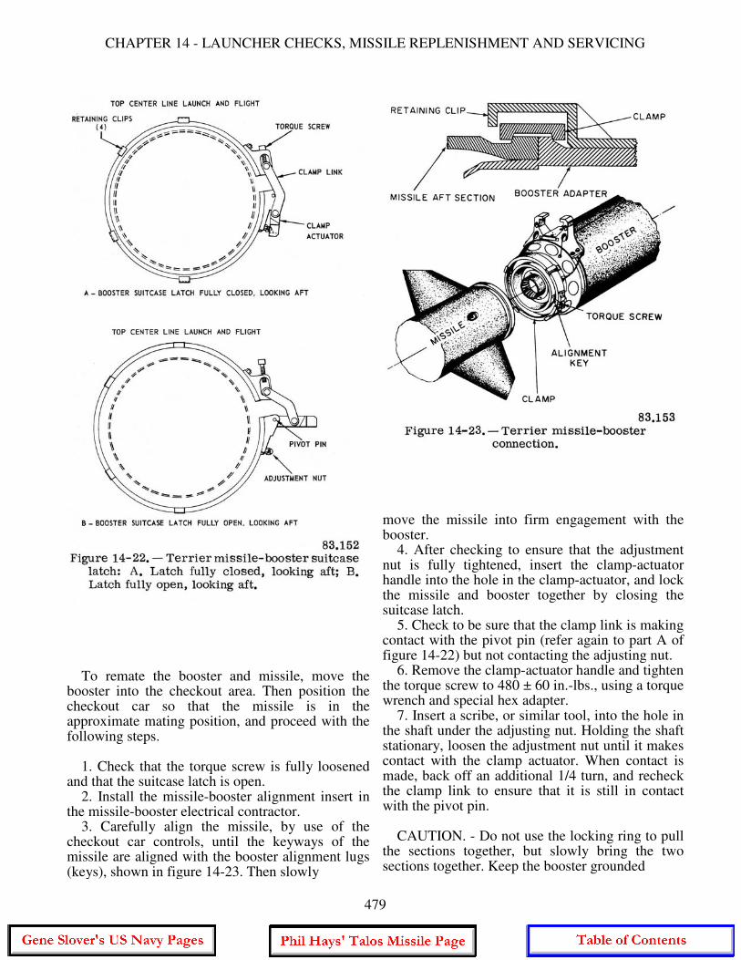
CHAPTER 14 - LAUNCHER CHECKS, MISSILE REPLENISHMENT AND SERVICING
To remate the booster and missile, move the booster into the checkout area. Then position the checkout car so that the missile is in the approximate mating position, and proceed with the following steps. 1. Check that the torque screw is fully loosened and that the suitcase latch is open. 2. Install the missile-booster alignment insert in the missile-booster electrical contractor. 3. Carefully align the missile, by use of the checkout car controls, until the keyways of the missile are aligned with the booster alignment lugs (keys), shown in figure 14-23. Then slowly
move the missile into firm engagement with the booster. 4. After checking to ensure that the adjustment nut is fully tightened, insert the clamp-actuator handle into the hole in the clamp-actuator, and lock the missile and booster together by closing the suitcase latch. 5. Check to be sure that the clamp link is making contact with the pivot pin (refer again to part A of figure 14-22) but not contacting the adjusting nut. 6. Remove the clamp-actuator handle and tighten the torque screw to 480 ± 60 in.-lbs., using a torque wrench and special hex adapter. 7. Insert a scribe, or similar tool, into the hole in the shaft under the adjusting nut. Holding the shaft stationary, loosen the adjustment nut until it makes contact with the clamp actuator. When contact is made, back off an additional 1/4 turn, and recheck the clamp link to ensure that it is still in contact with the pivot pin. CAUTION. - Do not use the locking ring to pull the sections together, but slowly bring the two sections together. Keep the booster grounded
479
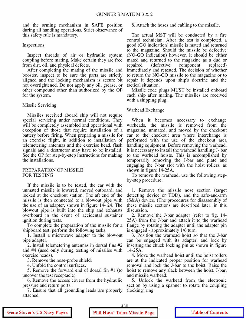
GUNNER'S MATE M 3 & 2
and the arming mechanism in SAFE position during all handling operations. Strict observance of this safety rule is mandatory. Inspections Inspect threads of air or hydraulic system coupling before mating. Make certain they are free from dirt, oil, and physical defects. After completing the mating of the missile and booster, inspect to be sure the parts are strictly aligned and the locking mechanism is secure bit not overtightened. Do not apply any oil, grease, or other compound other than authorized by the OP for the system. Missile Servicing Missiles received aboard ship will not require special servicing under normal conditions. They will be completely assembled and operational with exception of those that require installation of a battery before firing. When preparing a missile for an exercise flight, in addition to installation of telemetering antennas and the exercise head, flash signals and a destructor may have to be installed. See the OP for step-by-step instructions for making the installations. PREPARATION OF MISSILE FOR TESTING If the missile is to be tested, the car with the unmated missile is lowered, moved outboard, and locked at the checkout station. The aft end of the missile is then connected to a blowout pipe with the use of an adapter, shown in figure 14- 24. The blowout pipe is built into the ship and exhausts overboard in the event of accidental sustainer ignition during tests. To complete the preparation of the missile for a shipboard test, perform the following tasks. 1. Install a microwave adapter to the blowout pipe adapter. 2. Install telemetering antennas in dorsal fins #2 and #4 (used only during testing of missiles with exercise heads). 3. Remove the nose-probe shield. 4. Unfold the control surfaces. 5. Remove the forward end of dorsal fin #1 (to uncover the test receptacle). 6. Remove the access covers from the hydraulic pressure and return ports. 7. Ensure that all grounding leads are properly attached.
8. Attach the hoses and cabling to the missile. The actual MST will be conducted by a fire control technician. After the test is completed. a good (GO indication) missile is mated and returned to the magazine. Should the missile be defective (NO-GO indication) however. it should be either mated and returned to the magazine as a dud or repaired (defective component replaced) immediately and retested. The decision of whether to return the NO-GO missile to the magazine or to repair it depends upon ship's doctrine and the tactical situation. Missile code plugs MUST be installed onboard each ship after mating. The missiles are received with a shipping plug. Warhead Exchange When it becomes necessary to exchange warheads, the missile is removed from the magazine, unmated, and moved by the checkout car to the checkout area where interchange is performed with the use of the checkout area handling equipment. Before removing the warhead. it is necessary to install the warhead handling J- bar to the warhead hoists. This is accomplished by temporarily removing the J-bar and plate and engaging the J-bar slot with the hoist rollers. as shown in figure 14-25A. To remove the warhead, use the following step-by-step procedure. 1. Remove the missile nose section (target detecting device or TDD), and the safe-and-arm (S&A) device. (The procedures for disassembly of these missile sections are described later. in this discussion. 2. Remove the J-bar adapter (refer to fig. 14-25A) from the J-bar and attach it to the warhead flange by rotating the adapter until the adapter pin is engaged - approximately 1/6 turn. 3. Position the warhead hoist so that the J-bar can be engaged with its adapter, and lock by inserting the chuck locking pin as shown in figure 14-25A. 4. Move the warhead hoist until the hoist rollers are at the indicated proper position for warhead removal and lock the J-bar to the hoist. Raise the hoist to remove any slack between the hoist, J-bar, and missile warhead. 5. Unlock the warhead from the electronic section by using a spanner to rotate the coupling (locking) ring.
480
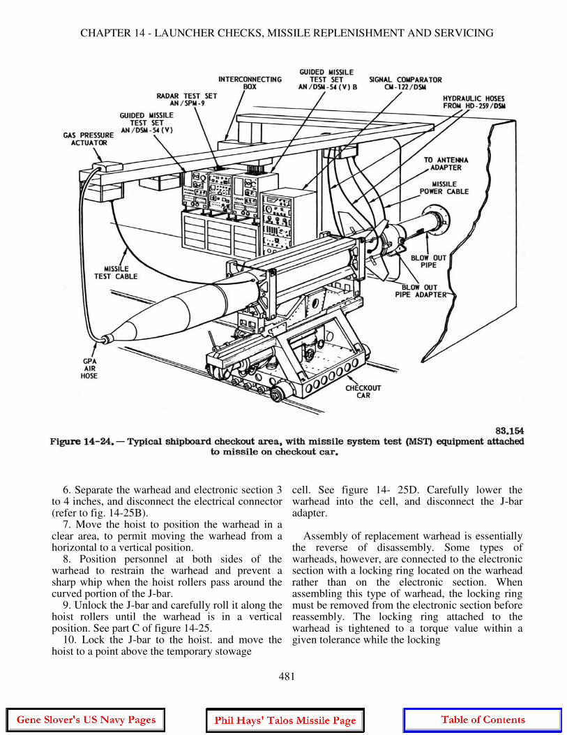
CHAPTER 14 - LAUNCHER CHECKS, MISSILE REPLENISHMENT AND SERVICING
6. Separate the warhead and electronic section 3 to 4 inches, and disconnect the electrical connector (refer to fig. 14-25B). 7. Move the hoist to position the warhead in a clear area, to permit moving the warhead from a horizontal to a vertical position. 8. Position personnel at both sides of the warhead to restrain the warhead and prevent a sharp whip when the hoist rollers pass around the curved portion of the J-bar. 9. Unlock the J-bar and carefully roll it along the hoist rollers until the warhead is in a vertical position. See part C of figure 14-25. 10. Lock the J-bar to the hoist. and move the hoist to a point above the temporary stowage
cell. See figure 14- 25D. Carefully lower the warhead into the cell, and disconnect the J-bar adapter. Assembly of replacement warhead is essentially the reverse of disassembly. Some types of warheads, however, are connected to the electronic section with a locking ring located on the warhead rather than on the electronic section. When assembling this type of warhead, the locking ring must be removed from the electronic section before reassembly. The locking ring attached to the warhead is tightened to a torque value within a given tolerance while the locking
481
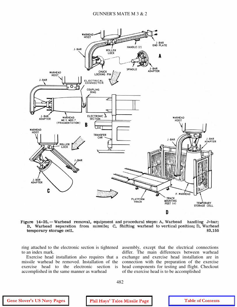
GUNNER'S MATE M 3 & 2
ring attached to the electronic section is tightened to an index mark. Exercise head installation also requires that a missile warhead be removed. Installation of the exercise head to the electronic section is accomplished in the same manner as warhead
assembly, except that the electrical connections differ. The main differences between warhead exchange and exercise head installation are in connection with the preparation of the exercise head components for testing and flight. Checkout of the exercise head is to be accomplished
482

CHAPTER 14 - LAUNCHER CHECKS, MISSILE REPLENISHMENT AND SERVICING
by a missile system test within 30 days of the exercise firing. It should be noted that 30 days is the extreme limit. In actual practice, most commanding officers and weapons officers will require a MST within two or three days of the flight. Before the exercise head is tested, both batteries must be charged and degassed. The batteries can be charged after they are removed from the exercise head or while they are still in the head, provided that the head can remain in the vertical position both during the charging procedure and during degassing. After battery charging, 12 hours of degassing are required before missile tests can be conducted. Assuming that the system test of a missile assembled with an exercise head is conducted before an exercise firing, the exercise head is normally returned with the mated missile to the magazine. This means that if a destructor charge is used, it must be installed before the exercise head is secured to the electronic section. The exercise head is normally received with a dummy destructor charge installed, which must be removed before installation of a live destructor. An arming and firing device is installed with the destructor. A flash signal (smokepot) may be used during training or evaluation flights to visually indicate fuze activation when the target is intercepted. Exercise warheads are normally received with two dummy flash signals installed. These signals are located 180° apart, near the forward end of the exercise head. Installation of the live flash signal requires only an exchange of one of the dummy signals the live signal and one electrical connection with the missile fuze section. It is necessary to remove the fuze section, however, or to install the flash signal before the fuze section is assembled to the warhead. The flash signal can be assembled in the exercise head either before or after the exercise head is assembled to the missile electronic section. After installation of the flash signal, the exercise head must be kept grounded, and must also be handled and stored as a pyrotechnic item. The charged and vented batteries must also be installed in the front end of the exercise head before installation of the fuze section. When the fuze section has been installed in the exercise head, a MST can be performed. After the MST, the batteries are removed, topped off, recharged, degassed, and reinstalled in the exercise head. Because degassing requires
12 hours, the MST should be run at least 16 hours before firing. Component Replacement When a component of the BT-3A missile has been proved faulty, it should be replaced in accordance with the instructions in the applicable OP. The following discussion briefly describes component replacement, but is not intended to be used as instructions for missile assembly and disassembly. To attempt a detailed description of assembly and disassembly would require a book by itself. A list of general component replacement instructions for all types of missiles follows. 1. When provided, special tools shall always be used to assemble and disassemble a missile. 2. Only identical or authorized replacement parts shall be used to replace defective components. 3. All areas requiring sealing compound shall be recoated when components are reassembled, to preserve watertight integrity. 4. During component replacement, a visual inspection of all preformed packings (O-rings, grommets, washers, etc.) shall be conducted to determine if replacement is needed. 5. Safety lockwire removed during component replacement shall be carefully replaced with NEW safety wire. 6. Make certain that all loosened nuts, bolts, screws, and electrical and hydraulic fittings are tightened to their specified values. 7. When hydraulic components are removed, all ports should be covered for protection from foreign matter, and only clean, lintfree rags should be used to wipe and absorb hydraulic fluid leakage. The control surfaces of BT-3A missiles are mounted in machined sockets and retained by snap rings. Removal of the control surfaces is required only when it is necessary to replace components in the missile aft section or when a defective control surface is noted. To remove a control surface, perform the following basic steps. 1. Unfold the control surface until latched in the flight position. 2. Loosen the wedge setscrew, shown in figure 14-26, four or five turns, using the special setscrew adapter.
483
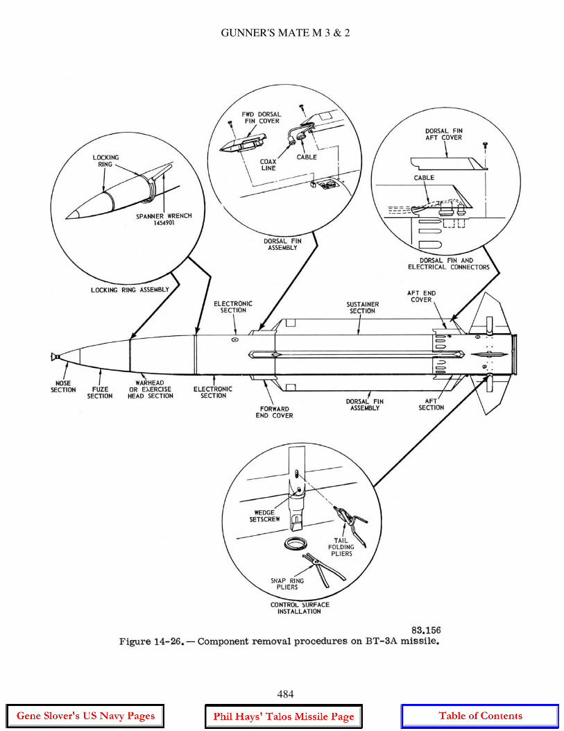
GUNNER'S MATE M 3 & 2
484
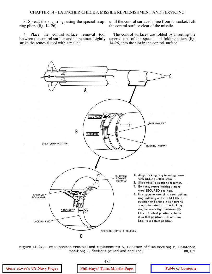
CHAPTER 14 - LAUNCHER CHECKS, MISSILE REPLENISHMENT AND SERVICING
3. Spread the snap ring, using the special snap-ring pliers (fig. 14-26). 4. Place the control-surface removal tool between the control surface and its retainer. Lightly strike the removal tool with a mallet
until the control surface is free from its socket. Lift the control surface clear of the missile. The control surfaces are folded by inserting the tapered tips of the special tail folding pliers (fig. 14-26) into the slot in the control surface
485
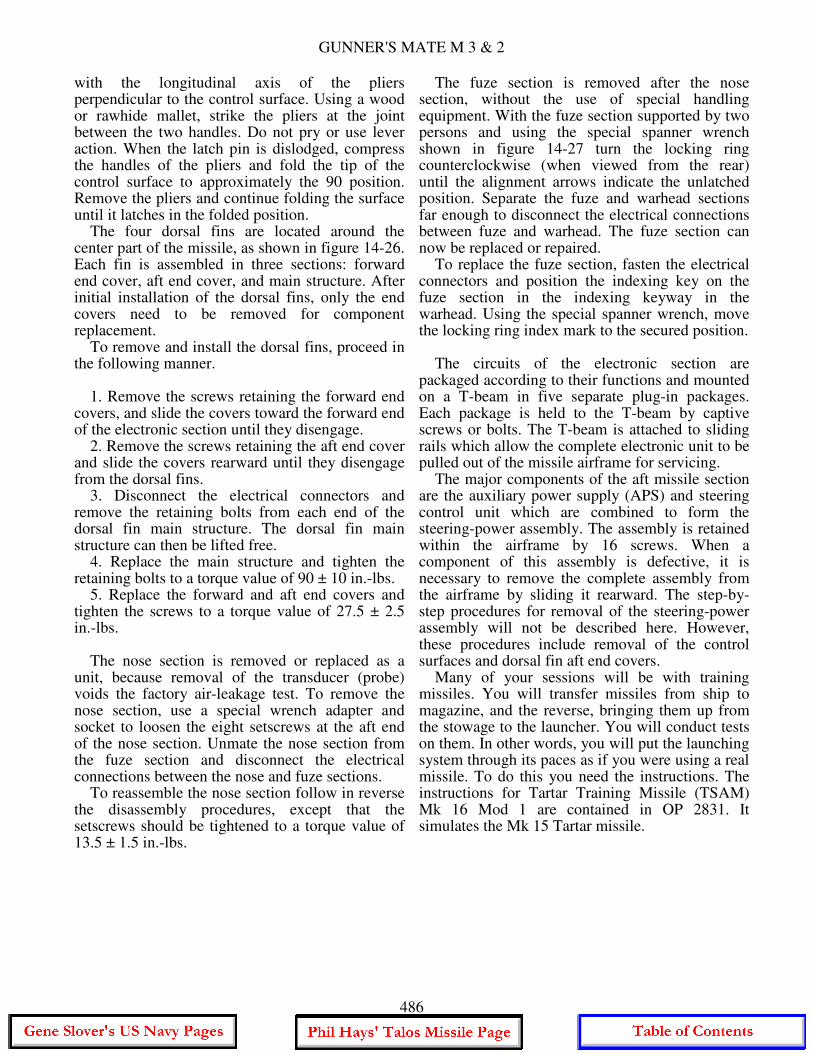
GUNNER'S MATE M 3 & 2
with the longitudinal axis of the pliers perpendicular to the control surface. Using a wood or rawhide mallet, strike the pliers at the joint between the two handles. Do not pry or use lever action. When the latch pin is dislodged, compress the handles of the pliers and fold the tip of the control surface to approximately the 90 position. Remove the pliers and continue folding the surface until it latches in the folded position. The four dorsal fins are located around the center part of the missile, as shown in figure 14-26. Each fin is assembled in three sections: forward end cover, aft end cover, and main structure. After initial installation of the dorsal fins, only the end covers need to be removed for component replacement. To remove and install the dorsal fins, proceed in the following manner. 1. Remove the screws retaining the forward end covers, and slide the covers toward the forward end of the electronic section until they disengage. 2. Remove the screws retaining the aft end cover and slide the covers rearward until they disengage from the dorsal fins. 3. Disconnect the electrical connectors and remove the retaining bolts from each end of the dorsal fin main structure. The dorsal fin main structure can then be lifted free. 4. Replace the main structure and tighten the retaining bolts to a torque value of 90 ± 10 in.-lbs. 5. Replace the forward and aft end covers and tighten the screws to a torque value of 27.5 ± 2.5 in.-lbs. The nose section is removed or replaced as a unit, because removal of the transducer (probe) voids the factory air-leakage test. To remove the nose section, use a special wrench adapter and socket to loosen the eight setscrews at the aft end of the nose section. Unmate the nose section from the fuze section and disconnect the electrical connections between the nose and fuze sections. To reassemble the nose section follow in reverse the disassembly procedures, except that the setscrews should be tightened to a torque value of 13.5 ± 1.5 in.-lbs.
The fuze section is removed after the nose section, without the use of special handling equipment. With the fuze section supported by two persons and using the special spanner wrench shown in figure 14-27 turn the locking ring counterclockwise (when viewed from the rear) until the alignment arrows indicate the unlatched position. Separate the fuze and warhead sections far enough to disconnect the electrical connections between fuze and warhead. The fuze section can now be replaced or repaired. To replace the fuze section, fasten the electrical connectors and position the indexing key on the fuze section in the indexing keyway in the warhead. Using the special spanner wrench, move the locking ring index mark to the secured position. The circuits of the electronic section are packaged according to their functions and mounted on a T-beam in five separate plug-in packages. Each package is held to the T-beam by captive screws or bolts. The T-beam is attached to sliding rails which allow the complete electronic unit to be pulled out of the missile airframe for servicing. The major components of the aft missile section are the auxiliary power supply (APS) and steering control unit which are combined to form the steering-power assembly. The assembly is retained within the airframe by 16 screws. When a component of this assembly is defective, it is necessary to remove the complete assembly from the airframe by sliding it rearward. The step-by-step procedures for removal of the steering-power assembly will not be described here. However, these procedures include removal of the control surfaces and dorsal fin aft end covers. Many of your sessions will be with training missiles. You will transfer missiles from ship to magazine, and the reverse, bringing them up from the stowage to the launcher. You will conduct tests on them. In other words, you will put the launching system through its paces as if you were using a real missile. To do this you need the instructions. The instructions for Tartar Training Missile (TSAM) Mk 16 Mod 1 are contained in OP 2831. It simulates the Mk 15 Tartar missile.
486
CHAPTER 15
INFORMATION: INPUT AND OUTPUT
This chapter deals with paperwork covered in the Qualifications under Administration. As a member of the weapons department you have a share in its administration. True, most of your working day is spent in keeping the launching system in working condition. However, it is your work, ability, and training, plus your equipment, that is being administered and you have some say in the administration policies. The operational and maintenance policies on your equipment are based in part on data obtained from the records and reports that you make. Thus, administration is a tool to aid you, and is well worth the paperwork involved. The assistance you receive from administration is not always apparent; but the paperwork is yet, in the name of expediency, sometimes disregarded or slighted. When this happens, everyone loses because something is taken away from the organization. Your big job is to keep launching system equipment in top working order. To help you do this, the Navy provides many publications and other written material pertinent to the maintenance task. In return, the Navy requires you to provide written reports on how well you are maintaining your equipment. By a roundabout way there is a constant flow of information between you and the Navy, principally between you and NAVORDSYSCOM. Your information may leave your ship in the form of a letter or report which is processed by a machine or an individual of the Command. It is possible that information you have supplied will trigger some kind of action in the Command. To illustrate, let's assume you have sent in five failure reports on the same relay. You may think that this recurring casualty happens only in your particular equipment, but ten other ships have also sent similar reports to the Command. An engineer in the guided missile launching system section in NAVORDSYSCOM sees a failure pattern and analyzes the relay circuit. He detects a faulty circuit design.
Than he makes a design change to correct the relay failures. The engineer writes instructions on how to rewire the existing relay circuit and sends these instructions to all ships that have your launching system. These instructions are called Ordnance Alterations - OrdAlts for short. If the circuit change is not complicated or requires minor changes to equipment, you will make the circuit alterations. Thus, we have completed a correspondence loop, or in Navy jargon, we have "feedback." You have fed information to NAVORDSYSCOM and it has fed back information to you. This feedback system is very important. Any break in the loop destroys the effectiveness of the system. Don't you break it. WEAPONS DEPARTMENT Before going into the administrative aspects of the weapons department, let's review the department organization. The weapons department of combat vessels whose main armament consists of guns or missile launching systems is headed by a weapons officer who, in turn, is responsible to the commanding officer. Within the weapons department are several divisions which are designated by special letters or numbers. Each division is headed by an officer who is responsible to the weapons officer. Figure 15-1 shows a typical weapons department organization on a combat ship. As an example of how a division operates, we will use the F division. Personnel in the F division man the gun and missile launching system fire control equipment and the plotting room. The F division personnel are further divided into units that are assigned to specific systems. Each unit operates and maintains the particular system to which it is assigned. A relatively new concept of division designation within the weapons department has recently been implemented in the fleet. The divisions
487
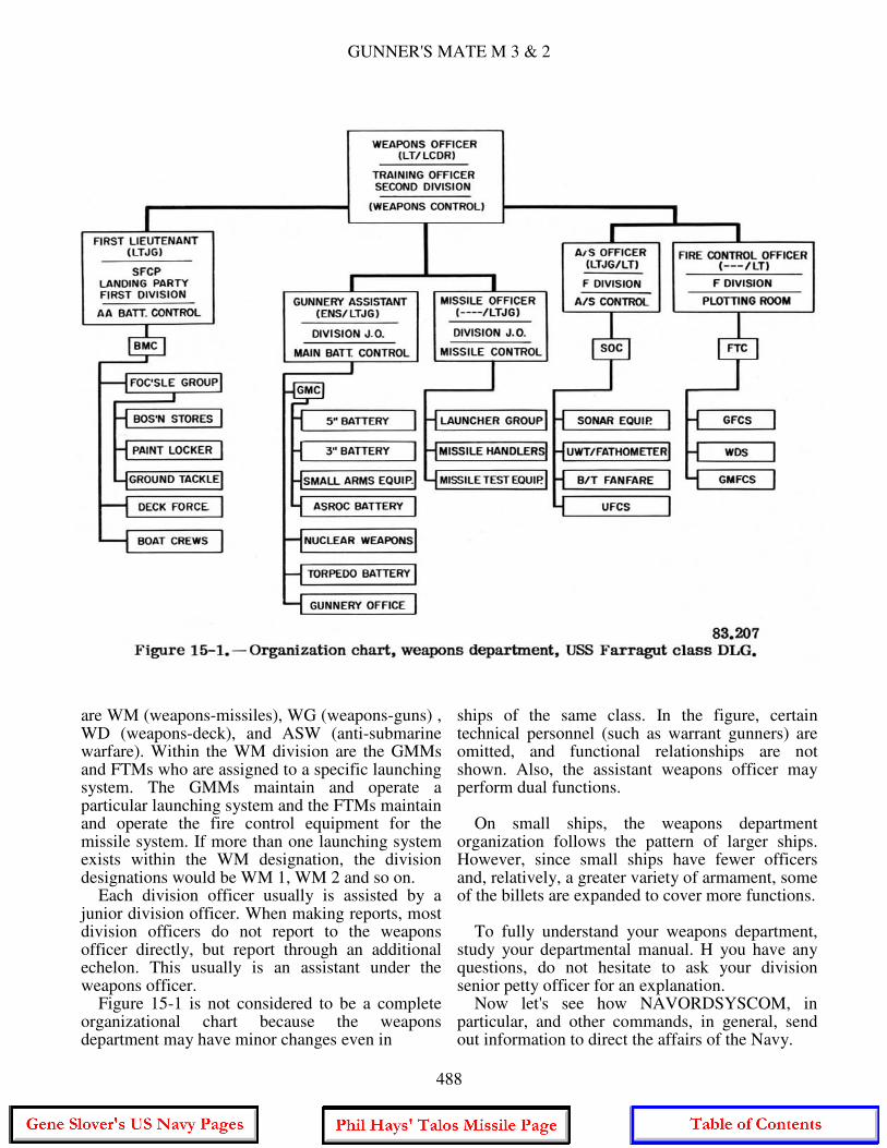
GUNNER'S MATE M 3 & 2
are WM (weapons-missiles), WG (weapons-guns) , WD (weapons-deck), and ASW (anti-submarine warfare). Within the WM division are the GMMs and FTMs who are assigned to a specific launching system. The GMMs maintain and operate a particular launching system and the FTMs maintain and operate the fire control equipment for the missile system. If more than one launching system exists within the WM designation, the division designations would be WM 1, WM 2 and so on. Each division officer usually is assisted by a junior division officer. When making reports, most division officers do not report to the weapons officer directly, but report through an additional echelon. This usually is an assistant under the weapons officer. Figure 15-1 is not considered to be a complete organizational chart because the weapons department may have minor changes even in
ships of the same class. In the figure, certain technical personnel (such as warrant gunners) are omitted, and functional relationships are not shown. Also, the assistant weapons officer may perform dual functions. On small ships, the weapons department organization follows the pattern of larger ships. However, since small ships have fewer officers and, relatively, a greater variety of armament, some of the billets are expanded to cover more functions. To fully understand your weapons department, study your departmental manual. H you have any questions, do not hesitate to ask your division senior petty officer for an explanation. Now let's see how NAVORDSYSCOM, in particular, and other commands, in general, send out information to direct the affairs of the Navy.
488
CHAPTER 15 - INFORMATION: INPUT AND OUTPUT
THE NAVY DIRECTIVE SYSTEM
Your maintenance work is governed to a large extent by directives. The Commands and offices of the Navy Department issue directives. Fleet and force commanders and district commandants also issue directives to subordinate commands. Your own ship or station issues directives to departments and divisions within you ship's organizational structure. For uniformity, ease of filing, and quick identification, each directive, regardless of the originator, is numbered according to a standard system. SECNAVINST 5210.11A. Department of the Navy Standard Subject Identification Codes, spells out the numbering system. But before we talk more about how directives are numbered, you should know the kinds of directives. There are two types of directives: 1. INSTRUCTIONS, which contain information of continuing nature or require continuing action, or action which must be taken but cannot be completed in less than 6 months. An instruction can be used as a reference for a long time and is effective until the originator cancels it. 2. NOTICES, on the other hand, are directives of one-shot nature, or those which contain information or action applicable for a brief time only (usually 6 months or less. but in no case more than 1 year). A Notice has the same force and effect as an Instruction but does not have permanent reference value. It therefore contains a paragraph which indicates when it shall be cancelled. When the exact length of time a Notice is to remain in effect cannot be determined at the time it is issued, the specific date for record purposes is set far enough into the future to allow all necessary use of the notice. You can better understand how directives are identified and numbered by considering some typical examples: (a) (b) (c) NAVORD INST 8200.1 OPNAV INST 1500.8 BUPERS INST 1440.5B BUPERS NOTE 1223 (a) The authorized abbreviation of the originator is placed here. (b) This part refers to the type of release (Notice or Instruction).
(c) This is the subject number which is determined by the subject matter of the directive, and is obtained from the Table of Subject Classification Numbers. You will find this table in SECNAVINST 5210.11A. The table is too long to reproduce here. But to give you some idea of what is in the instruction, here is a list of the 13 major subject groups:
1000-1999: Military Personnel (The OPNAV Instruction, BUPERS Inst, and BU- PERS Note, above, fall into this category.) 2000-2999: Communications 3000-3999: Operations and Readiness 4000-4999: Logistics 5000-5999: General Administration Management 6000-6999: Medicine and Dentistry 7000-7999: Financial Management 8000-8999: Ordnance (From maintenance viewpoint, most important) 9000-9999: Ship's Design and Ship's Material 10000-10999: General Material 11000-11999: Facilities and Activities Ashore 12000-12999: Civilian Personnel 13000-13999: Aeronautical and Astronautical Material
These major subject groups are subdivided into primary, secondary, and sometimes tertiary breakdowns. Complete information on how Ute major groups are broken down is in the SECNAVINST we have mentioned. When you get a spare moment, go to the ship's office and look over the instruction. In particular, study the information concerning the 8000-8999 major group and it's subgroups. These groups and subgroups will be of interest to you because they are guided missile weapons directives.
489

GUNNER'S MATE M 3 & 2
To point up the importance of directives in the maintenance task, the information in NAVORD INST 8200 is about synchros, tachometer generators, and other rotating electrical components. This instruction directs you to disconnect synchros and tach-generators from the circuit during a ground test. This procedure prevents putting a high breakdown voltage across the windings of a synchro or tachometer: generator.
TECHNICAL PUBLICATIONS ORDNANCE PAMPHLETS The main source of technical information on operation and maintenance of ordnance is the Ordnance Pamphlet (OP for short). NAV-ORDSYSCOM publishes these technical manuals, each under its own OP number. They may be prepared by some other naval activity, by the manufacturer, by a commercial specialist in such publications, or by the Command itself. OPs dealing with ordnance equipment are organized according to the following general outline: Introduction Physical description Theory and functional description How to operate Maintenance of equipment In the introduction you will find a brief explanation of what the equipment is, where it is used, what it is intended to do, and the like, as well as a description of the difference among various marks and mods, if appropriate. The section on physical description gives you a word picture of the equipment. Many illustrations of equipment are used in this section so you can easily identify the major parts. The functional description explains in detail how such things as electrical, electronic, and hydraulic circuits in the equipment work. The operating principles of mechanical systems are also explained here. The equipment operation section tells you what switches and other control devices to manipulate so you can put the equipment through its paces. Maintenance procedures are described in another section. Usually a whole volume is devoted to maintenance. OPs on small equipments usually devote one chapter to each heading, though with complex
systems each topic may require an entire volume. Thus there are variations but the main topic list above. or one much like it. is used by OP writers as their checklist; it shows what information you can expect to find in standard OPs on equipment, and approximately where to find it. Some OPs (for example, OP 2213, Pyrotechnic, Screening. and Marking Devices) take up a subject matter AREA rather than a specific item of ordnance gear; such OPs do not follow the standard outline above. OP O OP O is the official list of OPs. It is a consolidated listing of all publications and forms which pertain to ordnance activities. OP O is divided into three parts: Part 1. NAVORD Ordnance Publications (OPs) consists of a complete numeric listing of all OPs. It includes Special Projects. Do Not List. Cog I. Non-Cog I. Under Preparation. Cancelled and obsolete publications. Part 2. NAVORD Ordnance Data (ODs) this part consists of a complete numerical listing of all ODs. It includes Cog I, Non-Cog I, CTDO, Non-CTDO, under preparation, Special Projects, Do Not List, Reserved Cancelled and Obsolete publications. Part 3. Subject Index is a listing of all NAVORD OPs and ODs listed in this publication under equipment identification. Most Ops are massive publications; some require 4 or 5 volumes. Their preparation is costly in terms of both time and money. So, when one is issued, it's likely to be a rather long time before it can be replaced by a revised edition. But ordnance equipment is changing all the time, and the OPs on every piece of equipment must be kept up to date. This is done by issuing changes. A change is a leaflet or pamphlet that specifies in detail actual text alterations in the OP to which it applies. Changes are issued automatically to the same distribution list as the OP concerned. When received, the change should be attached inside the front cover of the OP, and the text and illustration changes called for should be entered promptly in the OP itself. There is a good chance you will make these changes. Make every effort to enter the changes as soon as received.
490

CHAPTER 15 - INFORMATION: INPUT AND OUTPUT
Publications issued between revisions of OP O are listed in the Naval Ordnance Bulletin, a classified publication issued quarterly to give information on new developments and changes. Interpreting OPs As mentioned before, it requires several volumes to describe in detail all the parts of a missile launching system, its operation, and its maintenance. OP O lists them by number. title, and subject classification, and tells on what ships each system is installed. Suppose we take as an example the Terrier Launching System Mk 10 Mod 7. The chart in Appendix A of OP O tells us that this system is installed on DLGs 26 through 34 and DLG(N) 35. Turning to the listing by number and title, we see that there are four volumes of OP 3114. Earlier mods of the Mk 10 Launching system, which do not have the Asroc capability, are described in other OPs (OP 2351 being one of them) consisting of three volumes and several volumes of Illustrated Parts Breakdown (IPBs). Many of the components of the Mod 7 are identical with earlier mods. Other OPs are referenced for detailed descriptions of those components, such as OP 2350 for the launcher. Volume 1 of OP 3114 gives the general description and operation of Guided Missile Launching System Mk 10 Mod 7, and the physical and functional description of the ready service mechanism, plus safety precautions. Volume 2 describes the special maintenance tools; volume 3 contains lubrication charts and electrical schematics; and volume 4 describes magazine components, loader components, and miscellaneous systems. As you read the description, refer often to the illustrations accompanying the text and locate the parts named. Notice the placement of the components on your ship. Since the OP is written for the missile system installation on your class of ship, this should not be hard to do. You might take the illustration with you to help you identify components. The illustration reproduced as figure 5-13 in this manual, for example, points out the approximate location of components of the assembler. Figure 5-14 points out parts of a component. When you know where the components are and what they look like, it is easier to visualize what takes place when the equipment is operated. In fact, the OP says, "Personnel should have some familiarity with the Mk 10 Mod 7 launching system before attempting to follow figures 1-19
and 1-20." These figures in the OP show Asroc automatic operation and Terrier automatic operation. The need for combining the study of the manual with use of the illustrations is indicated by this statement from the OP; "It is imperative that the reader have available wiring diagrams 2206727 and 2206728 while reading the following text. The diagrams illustrate the firing circuitry and the associated relays. These diagrams are included in Volume 3 of this OP." When you have seen the components of the launching system so that you have in mind their appearance and their location, you'll find it much easier to follow the steps in operation when you read them in the OP. ORDNANCE DATA Ordnance Data (ODs) are a kind of catchall. They are used for publishing advance information or instructions on ordnance equipment installation and alignment data, parallax data, and other miscellaneous information, such as tables of weights and dimensions. Formerly, ODs were used for publication of test and inspection data. Ordnance Reports are now used for this purpose. ODs are numbered consecutively by the issuing agency. ODs, like OPs, are listed in OP O. One OD that is required reading for you, and for all other Gunner's Mates, is OD 3000, Lubrication of Ordnance Equipment. It is the one OD that your ship's library of ordnance publications must not be without. Other ODs may be useful to you, depending on the type ship you are aboard and its armament; but for that information you should consult OP O. If they are not already in your ship's library, they can be ordered. ORDNANCE ALTERATIONS The publications discussed so far have to do with installation, operation, maintenance of ordnance material, but not with any changes that must be made to ordnance material. At the same time, such changes must be made uniformly so that all items of a given type will continue to conform to standard specifications of performance and interchangeability. When changes must be made to ordnance material already in the hands of the fleet, they are usually made by means of a publication
491

GUNNER'S MATE M 3 & 2
called an ORDNANCE ALTERATION (symbol: OrdAlt). OrdAlts are numbered serially and are classified not only by security level but also by priority as either Urgent, Emergency, or Routine. They are issued only to ships and other activities which have in active service the items affected by them. OrdAlts are more than mere sources of information; they constitute a basis for requisitioning material required by the alterations involved. OrdAlts are listed in NAVORD OrdAlt 00, List of Alterations to Ordnance Equipment for All Classes of Vessels, Aircraft, and Shore Stations, which also indicates their current status; you will not find them in OP O. Alterations which are extensive enough to modify materially the military characteristics of a ship are authorized by CNO, and are issued as NavAlts or ShipAlts by the technical bureau having cognizance over the equipment concerned. The NAVORDSYSCOM issues those NavAlts that deal with ordnance equipment, and they are listed under both OrdAlt and NavAlt numbers in NAVORD OrdAlt 00. Naval Air Systems Command (NAVAIRSYSCOM) issues instructions for ordnance used by the air arm of the Navy. This includes missiles delivered by air, such as the Sidewinder, Bullpup, and Sparrow. REPORTS, FORMS, AND RECORDS You probably have heard the so-called joke about the man who did a little repair job on a piece of equipment in 5 minutes but it took him 2 hours to write up his report on it. The reports are necessary; the use of forms is intended to reduce the time required for making reports as well as to improve their accuracy, and to produce uniformity that makes it possible to use machine processing of data. REPORTS In administering as large and complex an organization as the Navy, it is necessary to establish reporting procedures to keep the technical commands and other management activities continuously informed about the status of operations throughout a farflung network of ships and shore activities. Evaluations of new equipments, and of the methods of using them, are constantly underway. The results of these evaluations are sent to the various technical commands and the Chief of Naval Operations through
the appropriate reporting channels. So you can see that the reporting procedures have a definite and valid purpose because they pave the way to improvements in equipments and operations. Not only is the Navy's operational readiness improved, but your job is made easier. Always keep in mind when you are making out a log or report, that you are contributing to these improvements. Make sure that what you put into a report is accurate. Many occasions will arise when you will provide information that will go into, say, an ordnance inventory. In this case you will have to record name plate data from every ordnance item in your system. Such things as mark, mod, and serial numbers must be read accurately. Name plates are sometimes put in out-of-the-way places. Those that are easy to find may have a light coat of paint on them. But regardless of how difficult it may be to see the data, make certain that what you put down on paper is correct. The ordnance inventory that leaves your ship is used, among other things, to allocate spare parts. Now then, what is a report? Broadly speaking, a report is any narrative, tabular, or graphic type of information transmitted from one office or command to another. Who requires reports? Besides NAVORDSYSCOM, the Chief of Naval Operations, fleet, force, and type commanders require reports on ordnance matters. But in this chapter we will just talk about reports that are sent to NAVORDSYSCOM and activities under its control. Report Symbols Like notices and instructions, reports are coded. In fact, they use the same identifying and numbering system. For example, we will use the report symbol- NAVORD 8000/. The numbers to the left of the diagonal mark indicate the subject classification number- or what the report is reporting on. In our example, it is general ordnance material. Any number to the right of the diagonal line is the sequential number of the reporting symbol in this subject matter area. The tie-in with the Navy Directives System facilitates filing and referencing of reports. NAVORDSYSCOM Policy on Reports NAVORDSYSCOM and its activities are required to keep reports from any source at
492
CHAPTER 15 - INFORMATION: INPUT AND OUTPUT
a minimum, especially those from the fleet. The people in the Command are aware that your maintenance duties keep you busy. But when you must make out a report, prepare it carefully and submit it on time. Regard all reports objectively; forms or formats are tools only. You should make every effort to provide the information available or obviously needed in your reports, rather than conform blindly to filling out forms or formats. Recurring Reports If you are on a ship in the operating forces, you will find recurring reports listed in OPNAVINST 5214.1C (current). This list shows the report symbol, title, form number, controlling directive, frequency of reporting, and preparing activities for each report. Reports may also be required by the Type Commander, SOPA, Operational Commander, or other Commands.
SHIP ARMAMENT INVENTORY LIST/ ORDALT REQUIREMENT
The Ship Armament Inventory List (SAIL) is produced on ORDLIS data-processing equipment. It replaces the Ordnance Inventory/ORDALT Status Reporting Program formerly used. Each ship has two copies of SAIL. Prior to a scheduled overhaul, one copy should be annotated with ORDALTs that have been completed since the last printing; this copy should be sent to NAVORDSYSCOM 7 months prior to the scheduled availability. The other copy is kept on board. Revised copies of the SAIL will be sent to each ship before overhaul. After completion of overhaul, annotate the SAIL to indicate all changes, deletions, additions, and corrections and forward a copy to NAVORDSYSCOM. Changes made at other times are reported on Ship Armament Inventory List (SAIL) Change Report, NAVORD Form 8000/2. NAVORDSYSCOM again revises the SAIL to include the changes made at overhaul. When you receive the revised SAIL, destroy the previous one. The SAIL lists in sequence the following: all items pertaining to missile launchers, turrets, mounts, rocket launchers, projectors, torpedo tubes and depth charge release equipment; target designation systems (TDS), and weapons direction system (WDS); all items pertaining to missile test and telemetering equipment; and all items pertaining to target control systems.
The ORDALT Accomplishment Requirements (OAR) list is issued by NAVORDSYSCOM about 6 months prior to the overhaul of a ship. It shows the ORDALTs in the order of priority of accomplishment, the estimated man-hours required to accomplish, and the cost of each. The ship receives one copy, which must be given a thorough review and a report submitted within two weeks. The report must list all the ORDALTs completed after the "Prior to Overhaul" SAIL was submitted, ORDALTs that are on the OAR list but are not applicable, and a list of all the ORDALT material on board. The report goes to NAVORDSYSCOM, NAVSHIPSYSCOM, and the Ship's Parts Control Center (SPCC). They amend the OAR list, requisition supplies, and plan to accomplish as much of the additional work as is possible within the limits of the funds appropriated and the time available. ORDALT Requirement (OAR) Lists are also published by NAVORDSYSCOM for new ships and major conversion ships. The lists are reviewed by the ship and the shipyard, and revisions submitted as in the case of ships in the active fleet. Within 10 days after completion of overhaul, the fitting-out yard submits a report of what has been accomplished. A revised SAIL, including information from the latest OAR, is then issued by NAVORDSYSCOM and sent to the ship. FORMS Definition and Purpose of Forms Forms are any printed labels and tags, placards, signs, decals, drawing formats, form letters, and any other duplicated or printed papers which require clerical fill-ins or have blank spaces for the insertion of information to complete their meaning. Forms are used for requisitioning repair parts, recording information, and reporting. Completing a form requires careful reading and checking the correct answers but it is much simpler and quicker than writing up a narrative report. Besides, it makes possible the accurate tabulation of results which are used as the basis for command decisions at all levels. Form Numbers The assignment of a NAVORD form number to a form shows that, before the form is issued,
493
GUNNER'S MATE M 3 & 2
the originating activity has checked the form to make sure it does not duplicate or overlap existing forms. Sometimes the form number is the same as the reporting symbol. But this is not always true. You might even find a form with the same number as the Instruction that initiated the form. You can see that there can be confusion in identifying a form or instruction. The program is designed to eliminate and to prevent approval of unnecessary forms; to consolidate all similar forms; to standardize and simplify forms and related procedures; to ensure economical production, utilization, distribution, and stowage of forms; and to provide a central source of information about all forms. You can find a list of forms, full information on their distribution, and instructions for requisitioning them in NAVSUP 2002. Incidentally, NAVORDSYSCOM welcomes recommendations from the fleet for the improvement of forms. New Forms Whenever new weapons or equipments are brought into the Navy, extra reports on all phases are needed so the performance of the new weapons or equipment can be evaluated. New report forms are introduced, tried, and revised, and some are discarded. Detailed instructions are issued to tell you how the reports are to be filled out. NAVORDINST 8821.3A gives procedures for Standardized Fleet Data Collection for Surface Missile Systems (SMS) and enclosed (with instructions) examples of NAVORD Form 8821/5, Non-Expendable SMS Equipment Status Log; NAVORD Form 8821/8, SMS Firing Report; and NAVORD Report Symbol 8821-10, Commanding Officers Narrative Report on Surface Missile Systems. These have replaced earlier forms used in reporting on missile system performance. To be of value in spotting deficiencies in the missile system, the facts recorded in the reports must be accurate. When you supply data to the person filling out the report, be sure you give correct information. Reports used in the Maintenance Data Collection Subsystem (MDCS) are described in Military Requirements for Petty Officer 3 & 2, NAVPERS 10056-C, Chapter 13. All the forms described are of importance to you. As a GMM 2 you will be required to assist in the preparation of OPNAV Form 4700-6, Weekly schedule. The use of OPNAV Form 4790/2K is also described in Military Requirements for Petty Officer 3 & 2, NAVPERS 10056-C. This is
the form you have to fill out when you are unable to complete the maintenance work on a particular piece of equipment and it must be deferred until you can get parts and assistance from a repair facility. OPNAV Form 4790/2K is also used to report certain completed maintenance actions and as a work request. All details on this form must be carefully and accurately filled in. When used for deferred action, it may be several months before you can get repair assistance, and some important information could easily be forgotten in that time, so timely and accurate filling in of the form is essential. SHIPBOARD ORDNANCE LOGS AND RECORDS Logs An ordnance log is a book which you record chronologically information about tests, overhauls, repairs, alterations, maintenance work, and operating performance on certain ordnance equipment. The type commanders administrative inspection check off list determines the minimum requirements for logkeeping on your ship. It is anticipated that when the 3-M system becomes fully implemented in the Navy, the number of logs to be kept will be drastically reduced. However, because the documentation under the 3-M system does not give adequate life history of specific equipment, many rough and smooth logs are still required. Why keep an ordnance log? What is its practical value? An ordnance log serves a number of purposes. It gives the NAVORDSYSCOM a complete accounting of equipment operation. Such logs, over a period of years, help shape the policy of the Command as to the design of parts and the types of material used. A well-kept log is handy to YOU as a casualty reference. If a casualty occurs that has happened before, the log can be consulted for the method of repair previously used. If a certain type of repair method has proved unsatisfactory, repetition of that method can be prevented by referring to the log. When a new man takes over a piece of launching system equipment or the system itself, he can refer to the equipment logs and become familiar with the equipment's peculiarities. Alterations to equipment, and replacement of old equipment with new, have greatly increased ordnance efficiency over the years.
494
CHAPTER 15 - INFORMATION: INPUT AND OUTPUT
These advances result from analysis of present equipment performance. This analysis must be based on accurate and complete data. Ordnance logs are an important source of this data. There are four general types of logs: smooth logs, rough logs, printed form logs, and maintenance checkoff lists. Deck logs and engineering logs were described in Seaman, NAVPERS 10120-E, with instructions given for keeping them. Small Arms Log The small arms log should show all pertinent information on all small arms aboard ship. It should list the weapons by serial number and type. Log entries should include any repairs, modifications, and types of casualties of each weapon, results of small arms inventories, and the location of each weapon. Magazine Log These logs are a record of the location and the material condition of ammunition, missiles, and pyrotechnics stored on board ship. The logs also record the condition of magazines and sprinkling systems. The GMM in charge of a magazine group maintains the log. It is a smooth log and kept in a bound ledger. The following items are usually included in the log. 1. Location and compartment number of all spaces where ammunition, missiles, or any explosive components are regularly stored. 2. Location of all maximum/minimum thermometers to be checked daily by the magazine petty officer. 3. Chronological entry of all scheduled tests, inspections, and repairs accomplished on any unit within the magazine. 4. List of equipment and components comprising the pyrotechnic allowance and the locations of each of these components. 5. Record of inspection section, usually in the back of the log. 6. Checkoff lists for inspections. Magazine Temperature Log As a striker or GMM, you will be expected to keep a magazine temperature log. This log shows the daily maximum and minimum temperature of missile magazines. Temperatures are also recorded daily on temperature cards
posted in each magazine, warhead stowage space, and pyrotechnic locker. Space is provided on this card for recording the maximum and minimum temperatures and for the initials of the person taking the readings. After you take the magazine temperatures, you must make out a daily temperature report. One copy goes to the commanding officer via the officer of the deck and another copy to the weapons officer. The magazine temperature log can be divided into two sections. The first section contains a chronological record of daily maximum and minimum magazine temperatures. The second section has a chronological record of monthly tests of sprinkler systems. The maximum-minimum thermometer was illustrated in figure 10-19 and the method of reading it was described in the accompanying text. The forms used for recording the temperatures may be prepared aboard each ship, and therefore will show variations, or they may be prescribed by the Command. Figure 15-2 shows sample forms that may be used. The inspection of the magazines containing conventional ammunition components is done by the GMGs. The daily magazine temperatures are copied from the cards into a magazine log, which is the permanent record of all the magazine temperatures. Temperatures in excess of 100° F should be copied in red ink, or another color that will stand out. A separate section of the magazine log should be set aside for recording the results of the weekly sprinkling system tests. There will not be any smokeless powder samples, so you can ignore that question if it appears on the form. The temperature limit for missile propellants, however, is the same as for smokeless powder. When the temperature approaches this limit, the magazine may be cooled by turning on the ventilation. If the missile spaces are air conditioned, as they are on some new ships, you are not likely to have this problem. The temperature still has to be checked at least once a day to guard against possible breakdowns of the air conditioning system. Any time that the temperature is above 100° F, temperatures must be read and recorded every hour, and measures for cooling the area must be begun. MISSILE LOGS As Soon as a missile is brought on board, it must be entered and identified on the missile log. A record is kept of what happens to each
495

GUNNER'S MATE M 3 & 2
missile, so that each missile has its own log. Always enter the date whenever you make an entry. Rough Missile Logs The missile log may be a ledger type notebook in which you write each item relating to the missile. The log should be neat, with each entry legibly written and clearly dated. The entries should be in sequence and orderly so the person who transfers them to the smooth log (usually the weapons officer) can see at once when each entry begins and ends and can read it easily. Smooth Missile Battery Log This log is a permanent record of important rough log items. The smooth log is not a copy of the launcher log or other equipment rough logs, but a condensation or amplification of
the rough logs. The smooth log writer, usually the missile officer, takes special care to include items applicable to entry in the Ordnance History or other form used in place of it. All smooth logs are typewritten and kept in a looseleaf binder in the weapons office. Printed Form Logs NAVORDSYSCOM issues these for certain equipment. They are simply forms in which data are entered. They can be classed as smooth logs because they provide a legible and complete record. They also have a NAVORD Form number. Maintenance Checkoff Lists These are printed by either the type commander, or the ship. Essentially they form a smooth log.
496

CHAPTER 15 - INFORMATION: INPUT AND OUTPUT
There are many other logs in which records must be kept, but the ones we have just covered concern you. For a complete list of logs and records that must be kept by the weapons department, see the appropriate ship's instruction. MATERIAL RECORDS Standardized material records have been established to keep track of all work done on each piece of equipment aboard ship. As a member of the weapons department, you will primarily be involved with the records concerning ordnance equipment. Some record forms that have been in use in the past are being phased out to make way for the forms used in the 3-M system and the Maintenance Data Collection Subsystem. Ordnance History Cards The ordnance history cards and the shipboard 3-M system comprise the most important material records of the weapons department aboard ship. The weapons officer is responsible for maintaining these records in an up-to-date and useful manner. The retained copies of the 3-M system schedules now are the principal sources of maintenance information on new construction. On older vessels, in addition to the retained copies of the 3-M schedules, material history is maintained on ordnance history cards. How maintenance history records are maintained depends on the type ship and how much change over from old type maintenance system to the 3-M system has been accomplished. Many of the former sources of maintenance history are replaced by the 3-M system. Various logs are also used in the weapons department for maintenance history information. An ordnance history card contains the current history of each piece on board. Any information considered necessary in compiling a comprehensive history (major repairs, Ordalts accomplished, field changes made, etc.) is included on these cards. These history cards are retained as long as the equipment remains on board even if the vessel is placed out of service. In the event that a unit of equipment is transferred, the history card should accompany it. A complete material history of an ordnance unit is important in determining maintenance, operational practices, safety precautions, and equipment capability. These cards can also be used as inventory records and should be grouped in a binder so that all cards for a given piece
of ordnance, a gun mount for example, or located together for easy ordnance inventories. Information can be obtained for these cards from battery logs, smooth logs and a visual inspection of the equipment. NUCLEAR WEAPONS REPORTS AND RECORDS On ships that have nuclear weapons other than the nuclear warheads in missiles, the GMTs have the responsibility for all reports on them. The warheads contained in the assembled missiles are not the object of separate reports by you, but are shown in the report on the number and type of missiles aboard. The location, condition, and disposition of all nuclear material must be precisely accounted for to the Defense Atomic Support Agency (DASA). Rules for peacetime operation of nuclear weapon systems issued by the Chief of Naval Operations along with official Naval Ordnance Systems Command special weapons check lists are mandatory directives which must be followed.
SPECIAL WEAPONS PUBLICATIONS Special weapons publications which you will use are products of the Joint Atomic Weapons Publications System. The system was established by an agreement signed jointly by the Department of Defense and the Atomic Energy Commission. All Joint Atomic Weapons Publications (JAWPs) are assigned a Defense Atomic Support Agency Technical Publication (DASA TP) number. The short title for a specific JAWP consists of two parts: (1) a letter-numeral group which identifies the organization having an interest in the equipment described in the publications, (2) a letter and/or manual group that codes the publication to a specific subject. When reference to a JAWP is necessary between any of the services or agencies, the identifying designation of DASA TP is given. However, when reference to a JAWP is within a service or agency, the applicable identifying designation is used. For example, within the Navy Establishment, a JAWP is referred to as a NAVY SWOP (Special Weapons Ordnance Publication). Publications pertaining to specific weapons system applications of a particular weapon will be identified by decimal numbers following the mark number; i.e., NAVY SWOP W25.21-X, a Mark 45 warhead used in the Terrier missile.
497

GUNNER'S MATE M 3 & 2
Decimal numbers assigned, and presently in use or scheduled for use, are shown in NAVY SWOP 0-1. DISTRIBUTION OF NAVY SWOPS The Naval Ammunition Depot, McAlester, Oklahoma, maintains a NAVY SWOP Allowance list for each activity receiving NAVY SWOPs. This allowance list is kept current from the Naval Atomic Planning Support and Capabilities Report (NAPSAC), letter requests, and advanced planning information. Periodically, a copy of the allowance list is forwarded to the activity concerned for review. A copy is forwarded to the Type Commander, where appropriate, so that reference can be made to publications held by the ship. Distribution of NAVY SWOPs is made by NAD McAlester in accordance with the allowance list. NAD McAlester is the stocking and mailing point for all NAVY SWOPs except EODPs (Explosive Ordnance Disposal Publications). These are procured from the EODF (Explosive Ordnance Disposal Facility) at Indian Head, Maryland. SPECIAL WEAPON OPERATION AND SAFETY The operation of each type of nuclear weapon is described in the applicable NAVY SWOP. Nuclear weapons will be handled and stored in accordance with NAVY swap 50-1 and SWOPs of the 20 series. No ammunition assemblies or components shall be disassembled or modified unless authorized. NUCLEAR WEAPON SECURITY The Chief of Naval Operations is responsible for regulations for the security of classified matter. Basic security measures are set forth in U.S. Navy Regulations 1948, chapter 15, and OPNAVINST 5510.1 series. Specific references to classification policy, security of Restricted Data, security instructions for handling, transporting, and storing nuclear weapons components, and other security requirements are prescribed in OPNAVINST series 5510.
THE 3-M SYSTEM During your studies of Military Requirements for Petty Officer 3 & 2, NavPers 10056-C, you learned about the Navy Maintenance and
Material Management (3-M)System is now being implemented in the fleet. The 3-M system is not covered in detail in this chapter. However, to refresh your memory on the details we will review some of the objectives of the 3-M system and its subsystems, which include the planned maintenance subsystem (PMS) and the maintenance data collection subsystem (MDCS). The 3-M system is not designed as a cure for all equipment problems and attendant maintenance resource demands, nor does it eliminate the need for good leadership. The system is designed to: (1) reduce complex maintenance to simplified procedures that are easily identified and managed; (2) define the minimum maintenance required (preventive or corrective) and schedule and control its performance; (3) describe the methods and tools to be used; and (4) provide for the detection and prevention of impending casualties. An effective 3-M system permits a ship to forecast and plan man-power and material needs, schedule maintenance, estimate and evaluate material readiness, and detect areas for improving training and maintenance techniques. 3-M SUBSYSTEMS There are two subsystems of the 3-M system that are primary for shipboard personnel. The two subsystems are the Planned Maintenance and the Maintenance Data Collection Subsystems. When fully implemented and properly used, these two subsystems will: Increase reliability. The reliability will be increased by regular planned maintenance thereby reducing the need for major corrective maintenance. Increase Economy. Planned maintenance saves the cost of major repairs and/or equipment replacement. Provide Better Planning. The 3-M system takes into account the many shipboard operations, upkeep, and employment schedules through advanced planning. Simplify Records. Simplifies the recording of necessary data for shipboard maintenance management. The MDC subsystem reduces paperwork aboard ship, superceding various reports and forms. The Planned Maintenance Subsystem uses the Planned Maintenance System Manual, OPNAV
498

CHAPTER 15 - INFORMATION: INPUT AND OUTPUT
43P1. This is the Departmental Master Manual which identifies all the available planned maintenance requirements for the equipments maintained by a specific department. The master manual also contains information concerning fundamentals of the PMS and is used by the department head in planning, scheduling, and supervising the required planned maintenance. Planned Maintenance Subsystem To set up the maintenance requirements for a weapons system and its associated equipment, data is collected from the fleet, system commands, equipment manufacturers, and other sources. The data is then analyzed to determine the necessary maintenance requirement for a given system. After the determination has been made, the necessary maintenance procedures are listed on standard Maintenance Requirement Cards (MRC) and distributed to the fleet. Eventually, every ship will receive MRCs for every piece of ordnance equipment on board ship. MR cards are covered in Military Requirements for Petty Officer 3 & 2. Maintenance Data Collection Subsystem The Maintenance Data Collection Subsystem provides a means of recording maintenance actions (planned or corrective) in a form suitable for machine processing; this permits evaluation of equipment performance, repair parts used, delays incurred, reasons for the delays, and man-hours required to maintain the equipment. The Planned Maintenance Subsystem differs from the Maintenance Data Collection Subsystem in that the PMS tells when, how, and by whom the maintenance is to be performed; the MDCS informs the collection center what was done, who repaired the equipment, how long it took, and what repair parts were required to accomplish it. To list all this information so data processing machines can use it, it must be reduced to codes. The Equipment Identification Code Manual (EIC Manual) lists the codes you will need. At first it may seem difficult to enter information by means of a code letter but, after a while, you will know many of the codes without having to look them up. However. be sure you are right because the data processing machine can't tell when you have put in a wrong code letter - you have to do it right.
The information is punched onto cards which are fed to the data processing machine to collect and collate the information. Summaries of the results can point out the need for changes. One such change is the reduction in the number of tests of missiles required of GMMs.
SUPPLIES Although the supply department is responsible for supplies, you need to know how to identify what you want to get, how to write out the request, and how to report on your use of the supplies. The publications containing the stock numbers are maintained in the supply department. Cooperation with supply personnel is essential in accomplishing your own duties. SUPPLY DUTIES OF THE GMM Small quantities of consumable supplies are kept in the weapons department. Included are quantities of paint, greases, oils, cleaning materials, etc., and also Some frequently used small repair parts. As the materials are used, the GMM in charge of the supplies must make replacements. He has to know how to fill out the request form that he takes to the supply department to requisition supplies. These forms are illustrated and explained in Military Requirements for Petty Officer 3 & 2, NAVPERS 10056-C. The same text gives you information on sources of identification numbers for materials and spare parts. The Federal Stock Number is the most important identification number. All the FSNs are given in the Federal Supply Catalogs, but you may not have to use those to look up a number because the FSN for your equipment is usually given in several other sources. One of these is the COSAL, also described and illustrated in the above text, although no ordnance or weapons sections are shown. COSAL AND WHAT IT MEANS The Coordinated Shipboard Allowance list (COSAL) is the list of all operating equipment and equipage aboard a particular ship. Although the segments of the COSAL illustrated in your military requirements text are not ordnance items (except some propellants in the alphabetical listing), they show you the format of the COSAL. The ordnance segment uses the same arrangement of information. It has three parts. Part 1 lists
499

GUNNER'S MATE M 3 & 2
the ordnance equipment and the major components, and gives the component identification numbers. Part 2 lists the repair parts allowed for the ship. The quantity of each and the Federal Stock Number is given. Anything listed in Part 2 is available aboard ship. Part 3 of the COSAL . is the final authorized on- board allowance quantity for a repair part. This is of most use to the Storekeeper. Items that are common to more than one department are totaled in this section. For example, a particular type of switch may be used in various applications on the ship. Part 3 of the COSAL will tell how many are to be on board and how many are allotted to each department. For a more detailed explanation of COSAL and how it is used, refer to Military Requirements for Petty Officer 3 & 2, NAVPERS 10056-C. SOURCES OF ORDNANCE IDENTIFICATION The publications most often used to identify ordnance material are: 1. The ordnance parts of the Federal Supply Catalog for identifying repair parts for requisitioning. 2. Illustrated Parts Breakdown of Ordnance Equipment (IPB). This publication is prepared by Ships Parts Control Center (SPCC). Each IPB is published for one particular type or piece of equipment, and describes and illustrates the relationship of all assemblies and parts comprising the equipment. IPB 0000 is an index of all IPBs. These were published by the former Ordnance Supply Office (OSO), now absorbed by Ship's Parts Control Center (SPCC). 3. Coordinated Shipboard Allowance List (COSAL), which was previously discussed. One of the most important sources of identification is the information on nameplates. This may include the manufacturer's name, make or model number, size, voltage, and like information. Identification publications such as manufacturer's technical manuals may help you in identifying an item. ORDNANCE IDENTIFICATION DATA Ordnance identification data are important in identifying ordnance items. They should be used on all requests for material if the stock number is not available. These data include:
The MARK NUMBER, which identifies the particular model of a certain type of ordnance equipment. A MODIFICATION NUMBER (Mod), which indicates a modification of the basic mark number. Modifications are numbered serially, beginning with zero, for each separate mark. An IDENTIFYING NUMBER, which is the number assigned to the blueprint plan of an ordnance component or assembly. It may be a drawing number, a list of drawing numbers (LD), a sketch number, or an assembly number. A PIECE NUMBER, which is a subdivision of the drawing number and identifies by a serial designation every item appearing on a given drawing. Sometimes the drawing and piece numbers are stamped or etched on the part itself. Piece numbers are rarely used in later type ordnance assembly drawings. It is now standard practice that each item in a drawing will have its own separate drawing number. A revision letter is often added to identify a particular revision of a drawing or list of drawings used in the manufacture of a part. SAFEGUARDING CLASSIFIED MATTER The security of the United States in general, and of naval operations in particular, depends in part upon the success attained in the safeguarding of classified information. Security is not a separate burden to be imposed on personnel, but an integral part of the routine duties performed by personnel. The ideal to be sought of all personnel is that they automatically exercise proper discretion in the discharge of their duties and do not think of security of information as something separate and apart from other things. In this way, security of classified information becomes a natural element and poses no additional burden. You will find some basic information on security in chapter 7 of Military Requirements for Petty Officer 3 & 2, NAVPERS 10056-C. In Seaman, NAVPERS 10120-E, you learned about logging classified mail, and how to handle classified correspondence. Some general pointers on security of classified information were given in Basic Military Requirements, NAVPERS 10054-C. Publications giving any information on nuclear weapons or components have the additional classification of RESTRICTED. The material
500
CHAPTER 15 - INFORMATION: INPUT AND OUTPUT
may be marked Confidential Restricted Data, Secret Restricted Data, or Top Secret Restricted Data. There is also Formerly Restricted Data. These also have the additional line "Atomic Energy Act of 1954" just below the classification. The old Restricted classification, not applied to nuclear information, has been discontinued. Complete instructions on classified matters are found in OPNAVINST 5510.1C, "Department of the Navy Security Manual for Classified Information." This publication is one with which you should become familiar. Use it as the authoritative source of reference whenever a question of security arises.
The Two-Man Rule The two-man rule is defined in OPNAV INSTRUCTION 05510.83. It is a security measure in relation to nuclear weapons and their components, including nuclear warheads. The two-man rule requires that a minimum of two authorized persons, each capable of detecting incorrect or unauthorized procedures with respect to the task being performed, and familiar with pertinent security requirements, will be present during all operations which require admittance to any portion of a nuclear weapon/delivery system which could permit its launching, arming, firing, or releasing.
501

INDEX
A
A-c bridges, 429-432 A-end response assembly, 210 Acceleration, 38 Accelerometers, 72 Advancement in rate,
active duty requirements, 5 inactive duty requirements, 6 preparation for, 4 qualifications for, 3 sources of information, 9
Aerodynamics, 32-38 Air density, effect on projectile, 15-17 Alarm and sensing devices in missile magazines, 277 Ammeter, 423 Atmosphere, 32
higher atmospheres, 35 intermediate layers, 34 ionosphere, 34 mesophere, 34 stratosphere, 34 thermosphere, 34 troposphere, 33
Atmospheric jets, 52 Atomic and thermonuclear warheads, 261 Automatic and semiautomatic firing systems, 298 Automatic pistol, .45 caliber, 299 Automatic reset timing relays, 237 Automatic tracking cutout system, 468
B
B-end response assembly, 210 Bibliography for Advancement Study, NAVPERS 10052, 8 Biological warheads, 260 Blasting caps, 377-382 Block diagrams, 446 Browning automatic rifle, 354-364
Browning .30 caliber M1919A4 machinegun, 335- 342 Browning .50 caliber M2 machinegun, 342-345 BT-3 flight termination system, 274
C
Carbon dioxide fire suppression system, 283-285 Cathode-ray oscilloscope, 437-440
controls and functions, 438-440 precautions with, 440
Checkout car, 477 Chemical warheads, 260 Classified matter safeguarding, 500 Circuit breakers, 231 Continuity test, 426 Continuous rod warheads, 261 Control functional diagrams, 445 Coriolis, effect on projectile, 18 Corrective maintenance defined, 388 COSAL, 499
D
Data functional diagrams, 444 D-c bridges, 428 Demodulators, 183-185 Demolition, 377-386
blasting caps, 377-382 charges, 377 procedure for locating breaks in firing circuit, 384 procedure for preparing and setting off, 382- 384 safety precautions, 385
Director assignment console, 158-160 Distress signals, 270 Doppler principle, 86 Drift, effect on trajectory, 22 DUD jettison devices, 214
502

INDEX
E
Electrical devices used in launching systems, 224-247
control circuits, 238-247 firing circuit, 241-247 power control circuit, 238-241 safety precautions, 247 switches, 224-229 barrel switches, 228 circuit breakers, 231 interlock switches, 228 power relays or contactors, 230 relay principles, 229-238 rotary switches, 225-228 stepping relays, 233 time-delay relays, 235-238
Electrical measurements, precautions and tech- niques in making, 448-450 Electrohydraulic servovalve, 188-190 Electrolytic capacitors, 431 Elevation limit stop, 466 Equipment troubleshooting pyramids, 447 Error, detector, 172-178 Error reducers, 185-190 Explosive pellet warhead, 260 Explosives, 248-258, 272-276
application of in rim, 272-276 BT-3 flight termination system, 274 missile sections and their explosives, 272- 274
chemical nature of, 250 disposing of damaged or defective explosives, 275 history of, 249 military, 249
characteristics of, 254-258 classification of, 250 composition, 250 method of initiating, 252 nature of reaction, 251 sensitivity, 251 service use of, 253
nonmilitary, 248 propellants, 249
External blast warheads, 258
F
Fast system, 469 Fault directories, 445 Fault logic diagrams, 446 Feedback loops, 67 Feeder systems, 103, 108 Fire control, principles of application, 24-31 Fire control systems, elements of, 12
Fire suppression systems, 278 Firing circuit, 241 Firing cutout systems, 467 Flash signals, 271 Flight principles, 35-44
acceleration, 38 aerodynamic forces, 35-38 basic motions, 35 mach numbers and speed regions, 38 missile airframes, 43 stability and lift in modern missiles, 39-43
Foam used in firefighting, 286 .45 caliber automatic pistol, 299 Fragmentation warheads, 258 Fuzes, types of, 262-264
G
Gas laws, 47 Gas test, 436 Gases under pressure, 44 Gravity, effect on projectile, 13-15, 28 Guidance phases, 75 Guidance systems, types of, 75-80 Guided missile launching systems, 101-151
description of, 101-104 safety precautions, 150 Talos, 121-144 Tartar, 144-150 Terrier, 104-121
Gun and missile weapons system, 152-169 functions and problems of fire control, 162 intersystem communications, 167 location and operation of consoles, 161 units,
basic weapon components, 154 control units, 153, 156 delivery units, 154, 157, 163 destructive units, 154, 157, 166 detecting units, 152 h, target detection, location and identification units, 155 weapons direction equipment, 157-161
Gunner's Mate (Missiles) rating, 1-10 advancement, 3 billets, 2 enlisted rating structure, 1 leadership, 2
Gyroscopes, 69
H
Hand grenades, 375-377
procedure for throwing, 375 safety precautions, 376 types and characteristics, 375
503

GUNNER'S MATE M 3 & 2
Handguns, 299-308
assembly, 303 cycle of operation, 304 disassembly, 299-303 .45 caliber automatic pistol, 299 safeties, 303 .38 caliber Smith and Wesson revolver, 305-308
Hitting a moving target from a moving ship, 11- 31 basic fire control principles, 11, 24-31
application of principles, 24-31 elements of fire control systems, 12
definitions, 11 influence of trajectory,
by interior forces, 21 by outside forces, 13-21
HT-3 Terrier missile, 59 Hybrid propulsion, 56 Hydraulics and pneumatics in missile systems, 197-223
air operated power unit, 213 DUD jettison devices, 214 : hydraulic pneumatic power used inside sys- tem, 216 hydraulic power in strikedown, mate and loading operations, 212 launcher power drives, 204-210 maintenance of equipment, 216, 220-222 pneumatic operated handling equipment, 215 pneumatic test sets, 215 power drives for smaller launching systems, 212 safety precautions, 222 terminology, 197-204
I
Inductance bridge, 431 Initial velocity, effect on trajectory, 21 Ionosphere, 34
J
Jet propulsion systems, 47-56
atmospheric jets, 52 components of, 49-52 hybrid propulsion, 56 rockets, 53-56
K
Kelvin scale, 47
L
Landing party, 366-375
equipment, 367-372, 374 organization of, 366 shelter, 372-374
Launcher checks, missile replenishment and servicing, 455-586
dummy director components, 460 launcher synchronizing indication system, 461-463 limit stop and automatic tracking cutout sys- tems, 463-468 missile mating and servicing, 477
preparation of missile for testing, 480- , 486 responsibilities of GMM, 477 testing and repairing, 477 unmating and mating, 478
missile replenishment and strikedown, 468-477 dockside replenishment, 470 FAST system, 469 handling below decks, 476 lighter replenishment, 471 missile component stowage, 476 modified housefall rig, 468 special handling equipment, 471-473 steam method, 470 strikedown, 473-476
paper tape error recorder, 460 power drive performance test, 455-461 test signals, 457-460
Launcher power drive, 172-190, 204-210 demodulators, 183-185 error detector, 172-178 error reducer, 185-190 receiver-regulators, train and elevation, 207 servoamplifier section, 181-183 synchro transmission 36:1, disadvantages of, 178-181
Limit-stop system, 210 Line-throwing gun, .45 caliber, 333-335 Liquid propellant rockets, 55 Liquid propellants, 51 Liquid-fuel engines, prepackaged, 56 Logs, 494-496
M
M1 carbine, .30 caliber, 314-318 M1 rifle, .30 caliber, 308-314 M3A1 .30 caliber submachinegun, 352-354 M14 rifle, 318 M16E1 rifle, 318-325
504

INDEX
M60. 7.62-mm machinegun, 345-350 Mach numbers and speed regions, 38 Magazine log, 495 Magazines, 276, 279
alarm and sensing devices in, 277 relative humidity indicators, 277 sprinklers in, 279 temperature checking, 276
Maintenance checkoff lists, 496 Maintenance Data Collection Subsystem, 499 Maintenance Data Collection System, 395 Maintenance, general, 387-422
cleaning, painting, and preserving, 403-408 definition of, 387 levels, 389 lubrication, 396-403
charts, 401 fittings, 400 functions of lubricants, 397 grease guns, 398-400 greases, 398 hydraulic fluids, 403 oils, 397 qualities of lubricants, 396 tools, 398-401
Maintenance Data Collection System, 395 Navy Maintenance and Material Management System, 394 ordnance drawings, 389 planned maintenance, 393-396 safety precautions, 421 skills and processes, 408-420
cable splicing, 415 crimping, 412-414 removal and replacement considerations, 417-420 safety wiring, 416 shielding and bonding, 414 soldering, 408-412 tying and lacing, 414 watertight boxes and fittings, 415
special tools, 421 torque wrenches, 420
Maintenance of hydraulic and pneumatic equip- ment, 220-222
care of equipment, 221 periodic inspection, 220 system flushing, 220 troubleshooting, 221 valves, 221
Markers, location, marine, 264 Material records, 497 Mesosphere, 34 Meter operation, 423-425 Missile and booster carts, 477 Missile component stowage, 476
Missile flight and jet propulsion, 32-63 aerodynamics, 32-35 basic flight principles, 35-44
acceleration, 38 aerodynamic forces, 35-38 basic motions, 35 Mach numbers and speed regions, 38 missile airframes, 43 stability and lift in modern missiles, 39-43
jet propulsion, principle of, 47-56 atmospheric jets, 52 components of systems, 49-52 hybrid propulsion, 56 rockets, 53-56
missile propulsion systems, 44-47 surface-to-air missiles, 50-63
Standard missile round, 62 Talos missile round, 56-58 Tartar missile round, 60-62 Terrier guided missile round, 58-60
Missile guidance and control, 64-100 classification of Navy missiles, 87 components and instruments, 68-73 Doppler principle, 86 feedback loops, 67 guidance phases, 75 sensors and pickoffs, 73-75 subsystems and components, 64 surface-to-air missiles, 88-100
Standard, 95-98 Talos, 98-100 Tartar, 92-95 Terrier, 89-92
types of guidance systems, 75-80 beam-rider, 80-83 command, 79-80 homing, 83-86 self-contained guidance systems, 75-77 surface-to-air, 77-79
Missile logs, 495 Missile propulsion systems, 44-47 Missile sections and their explosives, 272-273 Missiles, Navy classification of, 87 Modified housefall rig, 468 Multimeter, 424 Multimeter measurements, 436 Mutual-conductance, quality test, 436
N
NavPers 10052, Bibliography for Advancement Study, 8 Navy Directive System, 489 Navy lights, 270
505

GUNNER'S MATE M 3 & 2
Navy Maintenance and Material Management Sys- tem, 394 Navy SWOP allowance list, 498 Noise test, 436 Nonpointing zones, 465 Nuclear weapons reports and records, 497
O
Ohmmeter, 423 One-function schematic diagrams, 444 Ordnance alteration, 491 Ordnance Data, 491 Ordnance drawings, 389-393 Ordnance history cards, 497 Ordnance identification, data and sources of, 500 Ordnance Pamphlets, 490 Oscillation, 191-196 Overlay relay, 235
P
Parallax, 20, 28 Planned maintenance, 393-396 Planned maintenance subsystem, 499 Pneumatic power, 213
air operated unit, 213 DUD jettison devices, 214 handling equipment, 215 maintenance, 216 tests sets, 215
Power control circuit, 238 Power drive performance test, 455-561 Power relays or contactors, 230 Precession, 69 Preventive maintenance defined, 387 Printed circuits, troubleshooting, 447 Printed form logs, 496 Propellants, 22, 249 Pyrotechnics, 264
depth charge markers, 264 distress signals, 270 flash signals, 271 Navy lights, 270 signal lights, 268-270 smoke and flare markers, 265-268 stowage of, 271
Q
Quals Manual, 4
R
Ramjet engine, 52 Rate gyros, 71 Rate training manuals, 8 Ready service crane, 477 Record of Practical Factors, 7 Rectifier test, 436 Relative humidity indicators, 277 Relay principles, 229-238
circuit breakers, 231 power relays or contactors, 230 stepping relays, 233 time-delay relays, 235-238
Reports, forms, and records, administrative, 492 Representative shipboard weapons system, 155- 157
control units, 156 delivery units, 157 destructive units, 157 target detection, location and identification, 155
Resistance test, 428 Rim, application of explosive in, 272-276 Rocket fuels, 50 Rotary switches, 225-228
J type, 225 JR type, 226-228
Rough missile log, 496
S
Safety ,
demolition, 385 electrical devices used in launching systems, 247 general maintenance, 421 guided missile launching systems, 150 hand grenades, 376 hydraulics and pneumatics in missile systems, 222 small arms, 364 test equipment and troubleshooting, 450-454
Safing and arming (S & A) devices, 264 Schematic diagrams, 446 Sensitive meter type relay, 236 Sensors and pickoffs, 73-75 Servomechanisms, application of, 170-196
expanded version of, 171 launcher power drive, components of, 172- 190
demodulators, 183-185 error detector, 172-178 error reducer, 185-190
506

INDEX
Servomechanisms, launcher power drive, compo- nents of - Continued
servoamplifier section, 181-183 synchro transmission 36:1, disadvantages of, 178-181
quality and performance of servos, how to im- prove, 190-196
acceleration feedback, 194 integral control, 195 movable CT stator method, 192 oscillation, 191-196 output-rate damping (feedback method), 192-194 overshooting, 191
Shaped charge warheads, 259 Ship Armament Inventory List, 493 Short circuit test, 436 Shotguns, 325-333
Winchester M12, 330-333 Winchester M97, 325-330
Shoulder weapons, 308-325 M14 rifle, 318 M16E1 rifle, 318-325 .30 caliber M1 carbine, 314-318 .30 caliber M1 rifle, 308-314
Signal lights, 268-270 Small arms, 297
automatic and semiautomatic firing systems, 298 handguns, 299-308
assembly, 303 cycle of operation, 304 disassembly, 299-303 .45 caliber automatic pistol, 299 safeties, 303 .38 caliber Smith and Wesson revolver, 305-308
line-throwing gun, .45 caliber, 333-335 machine guns, 335-350
Browning machine gun, caliber .30, M1919A4, 335 Browning machine gun, caliber .50, M2, 342-345 M60, 7.62-mm, machine gun, 345-350
operating principles, 298 safety precautions, 364-366 shotguns, 325-333
Winchester M12, 330-333 Winchester M97, 325-330
shoulder weapons, 308-325 M14 rifle, 318 M16E1 rifle, 318-325 .30 caliber M1 carbine, 314-318 .30 caliber M1 rifle, 308-314
submachine guns, 350-364 Browning automatic rifle, 354-364 M3A1 .45 caliber, 352
Small arms log, 495 Smith and Wesson .38 caliber revolver, 305-308 Smoke and flare markers, 265-268 Smooth missile battery log, 496 Solid propellant engines, 53 Solid propellants, 51 Sprinklers in missile magazines, 279-296
automatic control devices, 289-291 carbon dioxide system, 283-286 safety, 294-296 salt water system, 279-283 sprinkler system testing, 291 use of foam in firefighting, 286 water-injection system, 287
Stabilization, 19 Standard missile round, 62 Standard missiles, 95-98 Stepping relays, 233 Stowage of pyrotechnics, 271 Stratosphere, 34 Strikedown, 473-476 Subsonic flight, 39 Supplies, administrative aspect of, 499 Surface-to-air missiles, 56-63, 88-100
Standard missile round, 62 Talos missile round, 56-58 Tartar missile round, 60-62 Terrier guided missile round, 58-60
Synchro transmission 36:1, disadvantages of, 178-181
T
Talos, 90-100 Talos launching system, 121-144
control, 140-143 feeder system Mk 11, 133-139 functioning, 143 Mk 7 launcher, 122-131 train and elevation power drives, 131
Talos missile round, 56-58 Talos strikedown, 373 Target selection and tracking console, 158 Tartar, 92-95 Tartar firing circuit, 241 Tartar launching system, 144-150
control panels, 148-150 functioning, 150 launcher, 144-146 magazines, 146-148
Tartar missile round, 60-62 Tartar strikedown, 475 Technical publications, 490 Terrier, 89-92 Terrier guided missile round, 58-60
507

GUNNER'S MATE M 3 & 2
Terrier launching system, 104-121
feeder system, 108-116 launcher, 116-120 location and arrangement aboard ship, 104-108 operation, 120
Terrier strikedown, 474 Test equipment and troubleshooting, 423-454
cathode-ray oscilloscope, 437-440 electrical measurements, precautions and techniques in making, 448-450 meter operation, 423-428 resistance, capacitance, and inductance, 428-434
a-c bridges, 429-432 d-c bridges, 428 megger, 432-434
safety precautions, 450-454 transistor circuits, servicing, 440-442 troubleshooting, 442-448 tube testing, 434-437
Test for grounds, 426 Test for shorts, 427 Test signals, 457-460 Thermosphere, 34 3-M subsystem, 498 3-M System, 498 Time-delay relays, 235 Train limit stop, 466 Training films, 10 Trajectory, influence of,
by interior forces, 21 condition of propellant, 22 drift, 22 initial velocity, 21
by outside forces, 13-21 air density, 15-17 coriolis, 18 gravity, 13-15 parallax, 20 stabilization, 19 trunnion tilt, 19 wind, 17
Transistor circuits, servicing, 440-442 Troposphere, 33 Trunnion tilt, 19 Tube testing, 434-437 Two-man rule, security measure, 501
V
Vacuum tube voltmeter, 424 Voltage and resistance charts, 447 Voltage distribution diagrams, 446 Voltage test, 427 Voltmeter, 424
W
Warhead exchange, 480-483 Warheads, 258-264
fuzes, 262-264 safing and arming (8 & A) devices, 264 types of, 258
Water-injection fire suppression system, 287-289 Weapons assignment console, 160 Weapons direction equipment, 157-161
director assignment console, 158-160 location and operation of consoles, 161 target selection and tracking console, 158 weapons assignment console, 160
Weapons publications, 497 Weapons system concept, 152-155
basic weapon components, 154 control units, 153 delivery units, 154 destructive units, 154 detecting units, 152
Winchester M12, 330-333 Winchester M97, 325-330 Wind, effect on projectile, 17, 28
� U.S. GOVERNMENT PRINTING OFFICE: 1972-483-620/20
508

INSIDE REAR COVER