Embed Size (px)
Citation preview

lable at ScienceDirect
Journal of Cleaner Production xxx (2013) 1e8
Contents lists avai
Journal of Cleaner Production
journal homepage: www.elsevier .com/locate/ jc lepro
Global warming footprint of the electrochemical reduction of carbondioxide to formate
A. Dominguez-Ramos a,*, B. Singh b, X. Zhang b,c, E.G. Hertwich b, A. Irabien a
aDepartamento de Ingeniería Química y Química Inorgánica, ETSIIyT, Universidad de Cantabria, Avda. Los Castros s/n, Santander 39005, Spainb Industrial Ecology Programme, Department of Energy and Process Engineering, Norwegian University of Science and Technology (NTNU), Trondheim 7491,Norwayc State Key Lab of Multi-phase Complex Systems, Institute of Process Engineering, Chinese Academy of Sciences, Beijing 100190, China
a r t i c l e i n f o
Article history:Received 26 July 2013Accepted 16 November 2013Available online xxx
Keywords:Environmental sustainability analysisLife cycle assessmentElectrochemical reductionCarbon capture and utilization
* Corresponding author. Tel.: þ34 942 206749.E-mail addresses: [email protected], emp
(A. Dominguez-Ramos).
0959-6526/$ e see front matter � 2013 Elsevier Ltd.http://dx.doi.org/10.1016/j.jclepro.2013.11.046
Please cite this article in press as: Domingueformate, Journal of Cleaner Production (201
a b s t r a c t
Carbon dioxide Capture and Storage (CCS) is an important technological option for climate changemitigation. Utilization (U) of this captured CO2 as raw material for Electrochemical Reduction (ER) hasbeen suggested as a valorization option to produce organics such as formate-based products. Previouswork has focused on the influence of operating conditions or the selected cathodic material on thefaradaic efficiency and distribution of products. The environmental sustainability of formate productionthrough the ER of CO2 has been assumed rather than investigated. In this study, we perform a life cycleassessment, focusing on resources and greenhouse gas (GHG) emissions. Even though the processesreported in the literature result in a wide range of GHG emissions for the ER of CO2 to formate-basedproducts from 32 to 519 kg CO2-eq.$(kg HCOO
�)�1, this is higher than the current commercial produc-tion processes (3.1 kg CO2-eq.$(kg HCOO�)�1). The consumption of chemicals by the electrolysis and ofsteam in the purification of the final formate products are found to be the dominant causes of envi-ronmental burdens of the integrated process. A future scenario under very optimistic conditions suggests0.33 kg CO2-eq.$(kg HCOO�)�1 thus presenting a potential pathway to an environmentally sustainableCO2 utilization option.
� 2013 Elsevier Ltd. All rights reserved.
1. Introduction
The idea of utilizing CO2 captured from power plants and otherpoint sources to produce chemicals is gaining increasing attention(Quadrelli et al., 2011). Potential products include methanol,dimethyl ether, olefins, carbonates and formic acid (Chaplin andWragg, 2003; Gattrell et al., 2006; Gattrell et al., 2007; Gonçalveset al., 2010; Graves et al., 2011; Kuhl et al., 2012; Lee and Tak,2001; Schizodimou and Kyriacou, 2012; Subramanian et al., 2007;Whipple and Kenis, 2010). It has even been suggested that thereduction of CO2 could be used as a method of storing surplus peakelectricity (Olah, 2004, 2005; Olah et al., 2009).
However, since the capture of CO2 and its electrochemicalreduction into organic products needs additional chemicals andenergy, the net profile of the utilization of captured CO2 can benegative. According to Irabien et al. (2009) the two main elementsthat can be used to determine the environmental sustainability of
All rights reserved.
z-Ramos, A., et al., Global wa3), http://dx.doi.org/10.1016/j
products or processes are the Natural Resources Sustainability (NRS)and the Environmental Burdens Sustainability (EBS). On the otherhand, the life cycle approach can be well adopted to perform theenvironmental sustainability assessment (ESA) of CO2 utilizationoptions. Life cycle assessment (LCA) is a well-established tool tocheck or assess for any problem-shifting in environmental impacts(Finnveden et al., 2009), providing a holistic view of the environ-mental sustainability of the selected scope. For sustainability con-cerns, it is expected that the effect from the obtained products overthe whole life cycle should be lower than the actual products to besubstituted. In this paper, we investigate the environmental sus-tainability of producing formate or formic acid (depending on pH)by electrochemical reduction of CO2 and compare this productionroute to the conventional synthesis pathways.
The formate/formic acid product could function as a carbonbased energy vector for the storage of excess of electricity fromrenewable sources. Direct Formic Acid Fuel Cells (DFAFCs) areenvisaged for low power appliances (Cai et al., 2012; Kunduet al., 2007). While the energy density of formic acid with5.9 MJ$(kg HCOOH)�1 is lower than that of methanol21.9 MJ$(kg CH3OH)�1 (Demirci, 2007), formic acid has a relatively
rming footprint of the electrochemical reduction of carbon dioxide to.jclepro.2013.11.046

A. Dominguez-Ramos et al. / Journal of Cleaner Production xxx (2013) 1e82
higher electrocatalytic oxidation rate and lower membrane cross-over, which are barriers for Direct Methanol Fuel Cells (Rees andCompton, 2011; Rice et al., 2002). Also, the transport and storageof formic acid are simpler thanmethanol (Cai et al., 2012; Rice et al.,2002). Potential markets for formic acid are the leather industry,agriculture (BASF, 2012; Reutemann and Kieczka, 2011) and po-tential substitution of strong acids at steel pickling (Mantra VentureGroup, 2010).
The aim of this work is to present an environmental sustain-ability assessment (ESA) of the production of formate-basedproducts (formate/formic) via electrochemical reduction (ER) ofCO2 captured at a coal combustion plant (as CO2 source) equippedwith a carbon dioxide capture unit, leading to a Carbon Capture,Storage and Utilization system (CCS&U). The quantification of thelife cycle GHG emissions could help in the detection and under-standing of the critical steps, thus identifying the potential possi-bilities for improvement of the ER process. The present work isdivided into four sections including this introduction. The secondsection describes the system and methodology used in theassessment. A shared structure for the CCS&U system is divided intothree levels: 1st reaction; 2nd reaction and purification; and 3rdreaction and purification within the post-combustion power plant.The individual inventories and hypothesis for each level aredescribed. The third section is devoted to the results and discussion.The NRS at the reaction level is firstly presented as an introductionto the EBS analysis focused on the greenhouse gas emission of thereaction and purification level, which is the core of this work andtherefore described in detail. A long-term future improvement inthe purification step together with a complete reduction in theconsumption of chemicals was included in order to evaluate thetheoretical potential of the technology. A proposal to improve theenvironmental sustainability of formate production via ER route ismade. Main conclusions are presented in the last section.
Fig. 1. Process flowchart of the suggested process structure for the com
Please cite this article in press as: Dominguez-Ramos, A., et al., Global waformate, Journal of Cleaner Production (2013), http://dx.doi.org/10.1016/j
2. Methodology
This study assumes a hypothetical facility which includes theelectrochemical reduction of CO2 to formate-based products con-nected to a coal-fired power plant equipped with a carbon captureunit (we assume post-combustion based on amine as solvent). Adetailed flowchart of the process structure for the carbon dioxidecapture, transport, storage and utilization (CCS&U) is presented inFig. 1, which shows four main sections: combustion; capture;transport and storage; and electrochemical reduction (includingelectrochemical reactor and purification sub-sections which are themain focus of this work).
The captured CO2 is split into two fractions: (i) the fraction foruse as raw material for the ER process and (ii) the fraction forcompression, transport and storage. The fraction of the capturedCO2 sent to the ER process is defined as the Derivation Ratio (DR).The stream is assumed to be pure CO2 with enough pressure for theER process. The larger CO2 fraction is supplied to compression,transport and storage, and only relatively low values of DR arefound to be technically plausible for conversion to formate. In theER process, the CO2 is reduced to formate-based products in thecathodic compartment in the presence of chemicals acting assupporting electrolytes. A parallel cathodic reaction produceshydrogen. At the anodic compartment themain involved reaction isthe production of oxygen. The electricity produced by the generatoris partially split into: (i) final electricity distributed to the grid; (ii)energy for the capture process (including capture, desorption andcompression); and (iii) energy for the ER process. Alternatively, theelectricity needed in the ER process can also be supplied by PV orwind power. Additional steam is needed for the distillation of theaqueous formate produced in the ER process. The energy fortransport and storage is withdrawn from external sources (corre-sponding grid mix).
bustion plant and the CCS&U unit (including system boundaries).
rming footprint of the electrochemical reduction of carbon dioxide to.jclepro.2013.11.046
A. Dominguez-Ramos et al. / Journal of Cleaner Production xxx (2013) 1e8 3
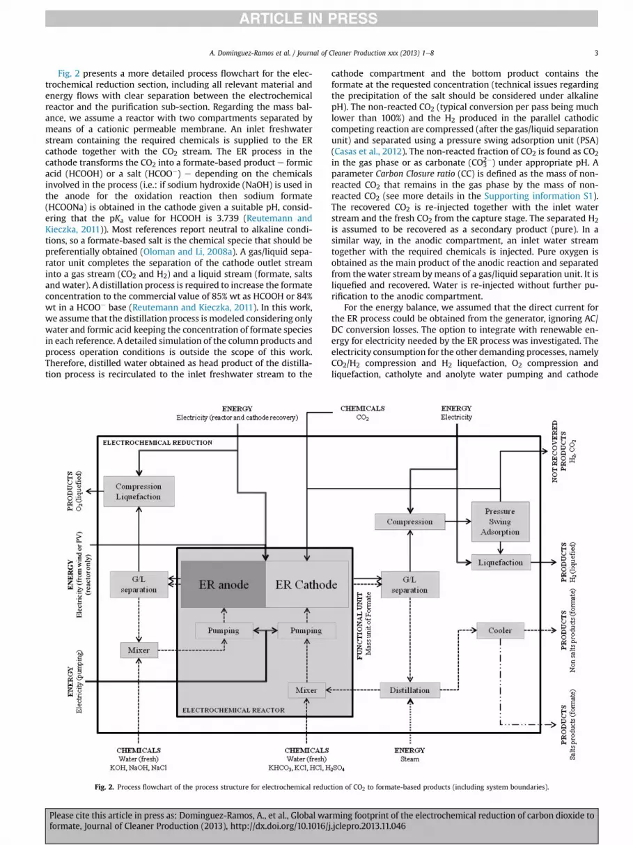
Fig. 2 presents a more detailed process flowchart for the elec-trochemical reduction section, including all relevant material andenergy flows with clear separation between the electrochemicalreactor and the purification sub-section. Regarding the mass bal-ance, we assume a reactor with two compartments separated bymeans of a cationic permeable membrane. An inlet freshwaterstream containing the required chemicals is supplied to the ERcathode together with the CO2 stream. The ER process in thecathode transforms the CO2 into a formate-based product e formicacid (HCOOH) or a salt (HCOO�) e depending on the chemicalsinvolved in the process (i.e.: if sodium hydroxide (NaOH) is used inthe anode for the oxidation reaction then sodium formate(HCOONa) is obtained in the cathode given a suitable pH, consid-ering that the pKa value for HCOOH is 3.739 (Reutemann andKieczka, 2011)). Most references report neutral to alkaline condi-tions, so a formate-based salt is the chemical specie that should bepreferentially obtained (Oloman and Li, 2008a). A gas/liquid sepa-rator unit completes the separation of the cathode outlet streaminto a gas stream (CO2 and H2) and a liquid stream (formate, saltsandwater). A distillation process is required to increase the formateconcentration to the commercial value of 85% wt as HCOOH or 84%wt in a HCOO� base (Reutemann and Kieczka, 2011). In this work,we assume that the distillation process is modeled considering onlywater and formic acid keeping the concentration of formate speciesin each reference. A detailed simulation of the column products andprocess operation conditions is outside the scope of this work.Therefore, distilled water obtained as head product of the distilla-tion process is recirculated to the inlet freshwater stream to the
Fig. 2. Process flowchart of the process structure for electrochemical reduc
Please cite this article in press as: Dominguez-Ramos, A., et al., Global waformate, Journal of Cleaner Production (2013), http://dx.doi.org/10.1016/j
cathode compartment and the bottom product contains theformate at the requested concentration (technical issues regardingthe precipitation of the salt should be considered under alkalinepH). The non-reacted CO2 (typical conversion per pass being muchlower than 100%) and the H2 produced in the parallel cathodiccompeting reaction are compressed (after the gas/liquid separationunit) and separated using a pressure swing adsorption unit (PSA)(Casas et al., 2012). The non-reacted fraction of CO2 is found as CO2in the gas phase or as carbonate (CO3
2�) under appropriate pH. Aparameter Carbon Closure ratio (CC) is defined as the mass of non-reacted CO2 that remains in the gas phase by the mass of non-reacted CO2 (see more details in the Supporting information S1).The recovered CO2 is re-injected together with the inlet waterstream and the fresh CO2 from the capture stage. The separated H2is assumed to be recovered as a secondary product (pure). In asimilar way, in the anodic compartment, an inlet water streamtogether with the required chemicals is injected. Pure oxygen isobtained as the main product of the anodic reaction and separatedfrom thewater stream bymeans of a gas/liquid separation unit. It isliquefied and recovered. Water is re-injected without further pu-rification to the anodic compartment.
For the energy balance, we assumed that the direct current forthe ER process could be obtained from the generator, ignoring AC/DC conversion losses. The option to integrate with renewable en-ergy for electricity needed by the ER process was investigated. Theelectricity consumption for the other demanding processes, namelyCO2/H2 compression and H2 liquefaction, O2 compression andliquefaction, catholyte and anolyte water pumping and cathode
tion of CO2 to formate-based products (including system boundaries).
rming footprint of the electrochemical reduction of carbon dioxide to.jclepro.2013.11.046

A. Dominguez-Ramos et al. / Journal of Cleaner Production xxx (2013) 1e84
recovery, is also withdrawn from the generator. Heat as steam andcold water are the utilities used in the distillation step.
Literature reports different figures of merit for the electro-chemical reduction process, reflecting the different approaches ofthe studies, aiming mostly at improving the faradic efficiency bymodifying the operating conditions. To determine a harmonized setof data, usable to perform an LCA study, four relevant references areselected leading to five different cases or scenarios (R1eR5) and aresummarized in Table 1. R1 was selected because of the relevantcathode area for formate production at lab scale (within currentpublished data), and R2e5 were used as they have a clear largescale oriented approach proposing mass and energy balances forthe ER process (supported by experimental data). The workdescribed in R1 provides only experimental data and R2 proposesthe production of formate at large scale assuming that the mainelements involved in the reaction arewater and carbon dioxide (themain figures for the proposal are based on experimental numbersobtained from previous works of the same authors). On the otherhand, R3 is a patent document which provides complete mass andenergy balance for a hypothetical large scale process: once againthe support for the provided numbers are based on experimentaldata given in the document. Therefore, the main difference be-tween R2 and R3 is the assumption on use of chemicals (R2 pro-poses a hypothetical scenario with no chemical consumption). Bothscenarios R4 and R5 are obtained from the samework: the scenarioR4 has lower energy consumption than R5 because of the use ofchemicals in the anode, which leads to a lower anode overpotentialand in turn a lower total applied voltage; R5 has a higher energyconsumption pertaining to the use of wastewater as proton source,but with a lower consumption of chemicals.
The data from the selected references is adapted to obtain a lifecycle inventory (LCI) for materials and energy use in the five cases(R1eR5) using mass and energy balances. After that compilation,the following procedure includes the adaptation of the original datapresented in selected references in accordance with the formerlydefined process structure. Once all the information is gathered andadapted from the five references, the next step consists of solvingthe mass and energy balances leading to the detailed LCI of thewhole facility including those for the ER which is directly depen-dent on the process parameters. Supporting information S1 con-tains a detailed explanation of themass and energy balances for thewhole facility and the ER section, the process of adapting the valuesfrom the references to the shared structure, and the main param-eters (DR, CC and energy source among others). Table 2 presents theLCI for 1 kgHCOO� at the outlet of the reactor, assuming that thefinal concentration of formate at the bottom of the distillationcolumn is 84% wt. It shows the contributions of infrastructure,energy, chemicals, water and valuable products. The current pro-cess structure assumes that the different salts and acids can beperfectly separated and are considered as avoided products. In thecase of the anodic compartment, there is no output stream and the
Table 1Selected references for the global warming footprint of the ER of CO2 to formate.
Reference numberused in this work
Case 1(R1)
Case 2(R2)
Source Li and Oloman(2007)
Oloman and Li(2008a)
Data origin Experimental Proposed mass andenergy balance(supported inexperimental)
Scenariodescription
322 cm2 cathodereactor
Hypothetical largescale scenario
Please cite this article in press as: Dominguez-Ramos, A., et al., Global waformate, Journal of Cleaner Production (2013), http://dx.doi.org/10.1016/j
actual consumption of chemicals is the amount added to therecirculation in order to make up for the concentration within therequired range. The formation and processing of carbonates are notfurther considered here. The life cycle inventory corresponding tothe ER infrastructure is explained in Supporting Information S2.
In Table 2, infrastructure values show that the required cathodearea for R1e3 (3.2�10�6e4.4�10�6 m2$(kg HCOO�)�1) is lowerthan for R4 and R5 (2.6�10�5 m2$(kg HCOO�)�1. This is due to thefact that the Specific Production Capacity (SPC) values defined as thereaction rate per unit of anodic area, in the case of R4 and R5 areabout one order of magnitude lower than those for R1e3. Theelectricity consumption of the electrolysis varies between 5.3 and8.9 kWh$(kg HCOO�)�1) due to different reactions rates, cell po-tentials, etc., as previously discussed. The low formate concentra-tion obtained in R4 and R5 when compared to R1e3 significantlyincreases the consumption of water at the cathode, as heat (steam),and as cooling water. The high steam consumption of5169 MJ$(kg HCOO�)�1 results from the dilute product. In case R1,7.6 kg KOH and 3.4 kg KCl are needed per kg HCOO� (Table 2). In thecase of the hypothetical process R2, no chemicals are needed toperform the reaction, and an alternative source of salts (as sup-porting electrolytes) is needed to keep the values of the energyconsumption for the reactor below reasonable levels. In the case ofR5, small amounts of acid (H2SO4) and salts (NaCl) are neededbecause of the use of wastewater as proton source.
In general, the ER section uses electricity produced by the powerstation that supplies the CO2. To investigate the potential benefit ofutilizing renewable energy, an additional sixth case corresponds tothe integration of PV as energy source in the case R1 (electricityonly for the ER) rather than the use of electricity from the coalstation, leading to the case R1-PV. On other hand, because of thelarge consumption of steam in the distillation step, an alternativeoption of extractive distillation using N,N-dibutylformamide forpurification of dilute formic acid stream is evaluated (Auer et al.,2003). In this case, the formate as formic acid is obtained as adistillate product. Heat requirements for the process are assumedto correspond to the latent heat of vaporization of pure formic acid(483 J g�1) (Linstrom and Mallard, 2012). Therefore, a new case,based on themost optimistic possibilities, is defined based again onR1, and named R1-Long-Term (abbreviated as R1-LT). It includesextractive distillation and PV energy source (for ER only) and 100%hypothetical reduction of chemicals. This reduction of chemicals issimilar to that proposed in case R5. Finally, available references inthe ecoinvent database (Ecoinvent Centre, 2008) provide green-house gas emissions for the different existing processes for theproduction of formic acid/formate salts of 0.8 and 3.1 kg CO2-eq.$(kg HCOO�)�1 for sodium formate (via reaction of formalde-hyde with acetaldehyde) and formic acid (from methyl formateroute), respectively. The former values are used as references inFig. 3. Consequently, seven different cases are defined: five for theoriginal five references (R1e5), a sixth case for the integration of PV
Case 3(R3)
Case 4 (R4) Case 5 (R5)
Oloman and Li(2008b)
Agarwal et al.(2011)
Agarwal et al.(2011)
Proposed mass andenergy balance(supportedin experimental)
Proposed mass andenergy balanceþExperimental
Proposed mass andenergy balanceþExperimental
Use of CO2, waterand NaOH
Consumablechemicals
Wastewater aschemical
rming footprint of the electrochemical reduction of carbon dioxide to.jclepro.2013.11.046

Table 2Life cycle inventory for the electrochemical reduction of CO2according to the five selected cases (Li and Oloman, 2007; Oloman and Li, 2008a; Oloman and Li, 2008b; Agarwalet al., 2011) and the default process parameters per mass unit of formate produced (functional unit 1 kgHCOO� at the outlet of the reactor). Bold figures are used to highlightthose numbers directly provided from the modified data references.
Infrastructure Units R1 R2 R3 R4 R5
Electrochemical reactor m2 3.48�10�6 4.44�10�6 3.18�10�6 2.61�10�5 2.61�10�5
Cathode m2 1.52�10�4 1.94�10�4 1.39�10�4 1.05�10�3 1.05�10�3
Anode m2 1.39�10�4 1.78�10�4 1.27�10�4 1.05�10�3 1.05�10�3
EnergyElectricityElectrochemical reduction kWh 7.99 8.89 6.36 5.33 7.09Pumping liquids kWh 0.011 0.003 0.005 1.46 1.46H2/CO2 compression and H2 liquefaction kWh 0.170 0.032 0.048 8.71 8.71Compression and liquefaction kWh 0.055 0.044 0.031 0.045 0.045Cathode recovery kWh 0.033 0.037 0.027 0.978 1.30
HeatDistillation MJ 150 35 121 5169 5169
ChemicalsCatholyteCO2 (from capture) kg 4.18 0.978 1.73 293 293KHCO3 kg 1.02 e e e
KCl kg 3.39 e e e
HCl kg e e e 1.697 0.002H2SO4 kg e e e e e
AnolyteKOH kg 7.65 e e e e
NaOH kg e e 1.575 1.860 e
NaCl kg e e e e 0.002
WaterCatholytenet H2O kg 0.985 0.198 0.384 71.9 71.9
Anolytenet H2O kg 0.635 0.504 0.355 0.517 0.518
Cooling waternet H2O kg 446 105 362 15,461 15,461
Valuable products (final products)HCOONa kg e e 1.28 e e
HCOOK kg 1.87 e e e e
HCOOH kg e 1.02 0.158 1.02 1.02Na2CO3 kg e e e 2.47 e
K2CO3 kg 6.03 e e e e
Na2SO4 kg e e e e 0.002K2SO4 kg e e e e e
NaHCO3 kg e e e e e
KHCO3 kg 1.02 e e e e
NaCl kg e e e e e
KCl kg 0.476 e e e e
NaOH kg e e e e e
KOH kg e e e e e
H2 liquefied kg 0.021 0.009 0.007 0.008 0.008O2 liquefied kg 0.564 0.448 0.316 0.460 0.460
A. Dominguez-Ramos et al. / Journal of Cleaner Production xxx (2013) 1e8 5
energy in R1 (R1-PV) and a final optimistic case R1-LT. These casesor scenarios are then compared with the conventional routes offormate production.
3. Results and discussion
3.1. Natural resource sustainability
Table 3 presents the four main resources (total primary energy,materials as total amount of chemicals, water and land) needed forthe production of 1 kg of dilute formate at different concentrationsemerging at the output of the reactor of each of the five selectedcases. It shows that case R4 (with a value of 66.3 MJ pri-mary$(kg HCOO�)�1) has the lowest energy usage which is about
Please cite this article in press as: Dominguez-Ramos, A., et al., Global waformate, Journal of Cleaner Production (2013), http://dx.doi.org/10.1016/j
67% of the value proposed in case R1. R2 has the highest energy usewith 111 MJ primary$(kg HCOO�)�1. The integration of PV energydiminishes the total amount of primary energy in R1-PV and R1-LTagainst R1 by 29%. The amount of materials also shows a highvariability (0.0e12.1 kg materials$(kg HCOO�)�1). Scenarios R2 andR1-LT are based on the hypothesis that no additional chemicals arerequired by the process. A low chemical use is indicated for case R5.In cases R4 and R5, the lower consumption of chemicals in R5 iscoupled with a higher energy demand than in R4, arguing for acareful management of the concentration of the supporting elec-trolytes. The amount of CO2 utilized is excluded from the use ofnatural resources as the aim is to use as much as possible. The netconsumption of water (consumed for O2 and H2 production) anddirect land use are obtained from the defined process structure. For
rming footprint of the electrochemical reduction of carbon dioxide to.jclepro.2013.11.046
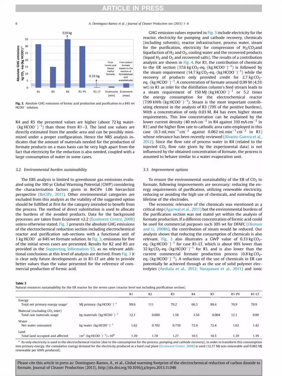
Fig. 3. Absolute GHG emissions of formic acid production and purification to a 84% wtHCOO� solution.
A. Dominguez-Ramos et al. / Journal of Cleaner Production xxx (2013) 1e86
R4 and R5 the presented values are higher (about 72 kg water-$(kg HCOO�)�1) than those from R1e3. The land use values aredirectly estimated from the anodic area and can be possibly mini-mized under a proper configuration. Hence the NRS analysis in-dicates that the amount of materials needed for the production offormate products on a mass basis can be very high apart from thefact that electricity for the reduction is also needed, coupled with alarge consumption of water in some cases.
3.2. Environmental burden sustainability
The EBS analysis is limited to greenhouse gas emissions evalu-ated using the 100 yr Global Warming Potential (GWP) consideringthe characterization factors given in ReCiPe 1.06 hierarchistperspective (ReCiPe, 2011). Other environmental categories areexcluded from this analysis as the viability of the suggested optionshould be fulfilled at first for the category intended to benefit fromthe process. The method of direct substitution is used to allocatethe burdens of the avoided products. Data for the backgroundprocesses are taken from Ecoinvent v2.2 (Ecoinvent Centre, 2008)unless otherwise stated. Fig. 3 presents the absolute GHG emissionsof the electrochemical reduction section including electrochemicalreactor and purification sub-sections with a functional unit of1 kgHCOO� as 84% wt formate solution. In Fig. 3, emissions for fiveof the initial seven cases are presented. Results for R2 and R5 areprovided in the Supporting Information S3, as no relevant addi-tional conclusions at this level of analysis are derived. From Fig. 3 itis clear only future developments as in R1-LT are able to providebetter values than the value presented for the reference of com-mercial production of formic acid.
Table 3Natural resources sustainability for the ER reactor for the seven cases (reactor level not
R1
EnergyTotal net primary energy usagea MJ primary$(kg HCOO�)�1 99.6
Material (excluding CO2 inlet)Total raw materials usage kg materials$(kg HCOO�)�1 12.1
WaterNet water consumed kg water$(kg HCOO�)�1 1.62
LandTotal land occupied and affected (m2$(kg HCOO�)�1)�104 1.39
a As only electricity is used in the electrochemical reactor (due to the consumption forinto primary energy, the cumulative energy demand for the electricity produced at a harrenewable per kWh produced).
Please cite this article in press as: Dominguez-Ramos, A., et al., Global waformate, Journal of Cleaner Production (2013), http://dx.doi.org/10.1016/j
GHG emission values reported in Fig. 3 include electricity for thereactor, electricity for pumping and cathode recovery, chemicals(including solvents), reactor infrastructure, process water, steamfor the purification, electricity for compression of H2/CO2andliquefaction of H2 and O2, cooling water and the recovered products(liquid H2 and O2 and recovered salts). The results of a contributionanalysis are shown in Fig. 4. For R1, the contribution of chemicalsto the ER section (17.6 kg CO2-eq.$(kg HCOO�)�1) is followed bythe steam requirement (14.7 kg CO2-eq.$(kg HCOO�)�1) while therecovery of products only provided credit for 2.7 kg CO2-eq.$(kg HCOO�)�1. A concentration of formate around 0.99 M (4.5%wt) in R1 as inlet for the distillation column’s feed stream leads toa steam requirement of 150 MJ$(kg HCOO�)�1 or 5.2 timesthe energy consumption for the electrochemical reactor(7.99 kWh$(kg HCOO�)�1). Steam is the most important contrib-uting element in the analysis of R3 (79% of the positive burdens).With a concentration of only 0.03 M, R4 has even higher steamrequirements. This low concentration can be explained by thelower current density (40 mA cm�2 in R4 against 310 mA cm�2 inR1) and the higher flow rate to cathodic area ratio employed in thiscase (0.3 mLmin�1 cm�2 against 0.062 mLmin�1 cm�2 in R1)whose relevance has been recently reviewed (Alvarez-Guerra et al.,2012). Since the flow rate of process water in R4 (related to theinjected CO2 flow rate given by the experimental data) is notinfluenced by the obtained concentration of formate, the process isassumed to behave similar to a water evaporation unit.
3.3. Improvement options
To ensure the environmental sustainability of the ER of CO2 toformate, following improvements are necessary: reducing the en-ergy requirements of purification, utilizing renewable electricity,reducing or avoiding the high use of chemicals, and extending thelifetime of the electrodes.
The economic relevance of the chemicals was mentioned as acritical step (Agarwal et al., 2011) but the environmental burdens ofthe purification section was not stated yet within the analysis offormate production. If a different concentration of formic acid couldbe used for commercial purposes such 30% wt for DFAFC (Olomanand Li, 2008b), the contribution of steam would be reduced. Ouranalysis shows that reducing the consumption of chemicals is alsorelevant. Fig. 3 also illustrates a GWP value of 0.33 kg CO2-eq.$(kg HCOO�)�1 for case R1-LT, which is about 99% lower than32 kg CO2-eq.$(kg HCOO�)�1 for R1, and is also lower than thecurrent commercial formate production process (0.8 kg CO2-eq.$(kg HCOO�)�1). A reduction of the use of chemicals in ER canpotentially be achieved through as the use of solid polymer elec-trolytes (Aeshala et al., 2012; Narayanan et al., 2011) and ionic
including purification section).
R2 R3 R4 R5 R1-PV R1-LT
111 79.2 66.3 88.4 70.9 70.9
0.000 1.58 3.56 0.004 12.1 0.00
0.702 0.739 72.4 72.4 1.62 1.42
1.78 1.27 10.5 10.5 1.39 1.39
the process, pumping and cathode recovery), in order to transform this consumptiond coal plant (Ecoinvent Centre, 2008) is used (12.37 MJ non-renewable and 0.082 MJ
rming footprint of the electrochemical reduction of carbon dioxide to.jclepro.2013.11.046

Fig. 4. Distribution of GHG emissions in the Electrochemical Reduction section -Electrochemical reactor and purification sub-sections-(functional unit 1 kg HCOO� at the outlet ofthe reactor, equivalent to 84% wt HCOO� solution after purification).
A. Dominguez-Ramos et al. / Journal of Cleaner Production xxx (2013) 1e8 7
liquids (ILs) (Martindale and Compton, 2012; Rosen et al., 2011;Zhao et al., 2004).
This study also finds (as also stated by the referred literature)lifetime of the electrodes as a critical process parameter. Lifetime inthe order of thousands of hours is needed in order to have apotentially viable process with an environmentally beneficial pro-file, or else, a regeneration technique for the electrodes is needed tobe developed with minimal consumption of chemicals and energy.
4. Conclusions
Based on the data provided by the literature on the electro-chemical reduction of CO2 to formate and some assumptions, ouranalysis indicates that the requirements of energy (as steam andelectricity) and materials (as chemicals) are too high to ensureenvironmental sustainability of this process. Integration ofrenewable energy, alternative purification process to conventionaldistillation and reduction in the consumption of chemicals aretherefore required to ensure a sustainable process.
Acknowledgments
The authors gratefully acknowledge the financial support ofthe Ministry of Economy and Competitiveness of Spain throughthe project ENE2010-14828. Dr. Antonio Dominguez-Ramosthanks also the University of Cantabria for the financial supportto complete a research stay in the Department of Energy andProcess Engineering of the Norwegian University of Science andTechnology (NTNU).
Appendix A. Supplementary data
Supplementary data related to this article can be found at http://dx.doi.org/10.1016/j.jclepro.2013.11.046.
Please cite this article in press as: Dominguez-Ramos, A., et al., Global waformate, Journal of Cleaner Production (2013), http://dx.doi.org/10.1016/j
References
Aeshala, L.M., Rahman, S.U., Verma, A., 2012. Effect of solid polymer electrolyte onelectrochemical reduction of CO2. Separ. Purif. Technol. 94, 131e137.
Agarwal, A.S., Zhai, Y., Hill, D., Sridhar, N., 2011. The electrochemical reduction ofcarbon dioxide to formate/formic acid: Engineering and economic feasibility.ChemSusChem 4, 1301e1310.
Alvarez-Guerra, M., Quintanilla, S., Irabien, A., 2012. Conversion of carbon dioxideinto formate using a continuous electrochemical reduction process in a leadcathode. Chem. Eng. J. 207e208, 278e284.
Auer, H., Bessling, B., Hammer, H., Hasse, H., Sauer, F., Vicari, M., Wagner, G., Adrian,T., 2003. Utilization of an Extracting Agent as Antifoaming Agent in the Pro-duction of Anhydrous Formic Acid. Patent: US 2003/0009057A1. US 2003/0009057 A1.
BASF, 2012. Tradition of Ideas: Formic Acid.Cai, W., Yan, L., Li, C., Liang, L., Xing, W., Liu, C., 2012. Development of a 30 W class
direct formic acid fuel cell stack with high stability and durability. Int. J.Hydrogen Energy 37, 3425e3432.
Casas, N., Schell, J., Pini, R., Mazzotti, M., 2012. Fixed bed adsorption of CO2/H2mixtures on activated carbon: experiments and modeling. Adsorption 18, 1e19.
Chaplin, R.P.S., Wragg, A.A., 2003. Effects of process conditions and electrode ma-terial on reaction pathways for carbon dioxide electroreduction with particularreference to formate formation. J. Appl. Electrochem. 33, 1107e1123.
Demirci, U.B., 2007. Direct liquid-feed fuel cells: thermodynamic and environ-mental concerns. J. Power Sources 169, 239e246.
Ecoinvent Centre, 2008. Ecoinvent data. Version: 2.2. Swiss Centre for Life CycleInventories. www.ecoinvent.ch.
Finnveden, G., Hauschild, M.Z., Ekvall, T., Guinée, J., Heijungs, R., Hellweg, S.,Koehler, A., Pennington, D., Suh, S., 2009. Recent developments in life cycleassessment. J. Environ. Manage 91, 1e21.
Gattrell, M., Gupta, N., Co, A., 2007. Electrochemical reduction of CO2 to hydrocar-bons to store renewable electrical energy and upgrade biogas. Energ. Convers.Manage 48, 1255e1265.
Gattrell, M., Gupta, N., Co, A., 2006. A review of the aqueous electrochemicalreduction of CO2 to hydrocarbons at copper. J. Electroanal. Chem. 594, 1e19.
Gonçalves, M.R., Gomes, A., Condeço, J., Fernandes, R., Pardal, T., Sequeira, C.A.C.,Branco, J.B., 2010. Selective electrochemical conversion of CO2 to C2 hydrocar-bons. Energy Convers. Manage. 51, 30e32.
Graves, C., Ebbesen, S.D., Mogensen, M., Lackner, K.S., 2011. Sustainable hydrocarbonfuels by recycling CO2 and H2O with renewable or nuclear energy. Renew.Sustain. Energy Rev. 15, 1e23.
Irabien, A., Aldaco, R., Dominguez-Ramos, A., 2009. Environmental sustainabilitynormalization of industrial processes. Comput. Aided Chem. Eng. 26, 1105e1109.
rming footprint of the electrochemical reduction of carbon dioxide to.jclepro.2013.11.046

A. Dominguez-Ramos et al. / Journal of Cleaner Production xxx (2013) 1e88
Kuhl, K.P., Cave, E.R., Abram, D.N., Jaramillo, T.F., 2012. New insights into the elec-trochemical reduction of carbon dioxide on metallic copper surfaces. EnergyEnviron. Sci. 5, 7050e7059.
Kundu, A., Jang, J.H., Gil, J.H., Jung, C.R., Lee, H.R., Kim, S.-., Ku, B., Oh, Y.S., 2007. Micro-fuel cells e current development and applications. J. Power Sources 170, 67e78.
Lee, J., Tak, Y., 2001. Electrocatalytic activity of Cu electrode in electroreduction ofCO2. Electrochim. Acta 46, 3015e3022.
Li, H., Oloman, C., 2007. Development of a continuous reactor for the electro-reduction of carbon dioxide to formate e part 2: scale-up. J. Appl. Electrochem.37, 1107e1117.
Linstrom, P.J., Mallard, W.G., 2012. NIST Chemistry WebBook, NIST StandardReference Database Number 69. National Institute of Standards and Technology,Gaithersburg MD, 20899.
Mantra Venture Group, 2010. An alternative to carbon sequestration: electro-reduction of CO2. Steel Times Int. (Environ.), 1e2.
Martindale, B.C.M., Compton, R.G., 2012. Formic acid electro-synthesis from carbondioxide in a room temperature ionic liquid. Chem. Commun. 48, 6487e6489.
Narayanan, S.R., Haines, B., Soler, J., Valdez, T.I., 2011. Electrochemical conversion ofcarbon dioxide to formate in alkaline polymer electrolyte membrane cells.J. Electrochem. Soc. 158, A167eA173.
Olah, G.A., 2005. Beyond oil and gas: the methanol economy. Angew. Chem. Int. Ed.44, 2636e2639.
Olah, G.A., 2004. Perspective: after oil and gas: methanol economy. Catal. Lett. 93,1e2.
Olah, G.A., Goeppert, A., Prakash, G.K.S., 2009. Chemical recycling of carbon dioxideto methanol and dimethyl ether: from greenhouse gas to renewable, environ-mentally carbon neutral fuels and synthetic hydrocarbons. J. Org. Chem. 74,487e498.
Please cite this article in press as: Dominguez-Ramos, A., et al., Global waformate, Journal of Cleaner Production (2013), http://dx.doi.org/10.1016/j
Oloman, C., Li, H., 2008b. Continuous Co-current Electrochemical Reduction ofCarbondioxide. Patent: US2008/0223727. US2008/0223727 A1.
Oloman, C., Li, H., 2008a. Electrochemical processing of carbon dioxide. Chem-SusChem 1, 385e391.
Quadrelli, E.A., Centi, G., Duplan, J.L., Perathoner, S., 2011. Carbon dioxide recycling:emerging large-scale technologies with industrial potential. ChemSusChem 4,1194e1215.
ReCiPe, July 2011. ReCiPe Method v.1.06. http://www.lcia-recipe.net/.Rees, N.V., Compton, R.G., 2011. Sustainable energy: a review of formic acid elec-
trochemical fuel cells. J. Solid State Electrochem. 15, 2095e2100.Reutemann, W., Kieczka, H., 2011. Formic acid. In: Ullmann’s Encyclopedia of In-
dustrial Chemistry. Wiley Online Library.Rice, C., Ha, S., Masel, R.I., Waszczuk, P., Wieckowski, A., Barnard, T., 2002. Direct
formic acid fuel cells. J. Power Sources 111, 83e89.Rosen, B.A., Salehi-Khojin, A., Thorson, M.R., Zhu, W., Whipple, D.T., Kenis, P.J.A.,
Masel, R.I., 2011. Ionic liquid-mediated selective conversion of CO2 to CO at lowoverpotentials. Science 334, 643e644.
Schizodimou, A., Kyriacou, G., 2012. Acceleration of the reduction of carbon dioxidein the presence of multivalent cations. Electrochim. Acta 78, 171e176.
Subramanian, K., Asokan, K., Jeevarathinam, D., Chandrasekaran, M., 2007. Elec-trochemical membrane reactor for the reduction of carbon dioxide to formate.J. Appl. Electrochem. 37, 255e260.
Whipple, D.T., Kenis, P.J.A., 2010. Prospects of CO2 utilization via direct heteroge-neous electrochemical reduction. J. Phys. Chem. Lett. 1, 3451e3458.
Zhao, G., Jiang, T., Han, B., Li, Z., Zhang, J., Liu, Z., He, J., Wu, W., 2004. Electro-chemical reduction of supercritical carbon dioxide in ionic liquid 1-n-butyl-3-methylimidazolium hexafluorophosphate. J. Supercrit. Fluids 32, 287e291.
rming footprint of the electrochemical reduction of carbon dioxide to.jclepro.2013.11.046


![ECOLOGICAL FOOTPRINT AN]) APPROPRIAThD](https://img.dokumen.tips/doc/110x75/631ff3fd9353b08ff5016f1a/ecological-footprint-an-appropriathd-.jpg)


