Embed Size (px)
Citation preview

GI 275™ Pilot’s Guide

SYSTEM OVERVIEW
FLIGHT INSTRUMENTS
EIS
NAVIGATION
HAZARD AVOIDANCE
AUTOPILOT
IVSI
ADDITIONAL FEATURES
APPENDICES
INDEX

© 2019-2022 Garmin Ltd. or its subsidiaries. All rights reserved.
This manual reflects the operation of System Software Version 2.42 or later. Some differences in operation may be observed when comparing the information in this manual to earlier or later software versions.
Garmin International, Inc.1200 East 151st StreetOlathe, Kansas 66062, U.S.A.
Garmin (Europe) Ltd.Liberty House, Hounsdown Business ParkSouthampton, Hampshire SO40 9LR U.K.
Garmin AT, Inc.2345 Turner Road SESalem, OR 97302, U.S.A.
Garmin CorporationNo. 68, Zhangshu 2nd RoadXizhi District, New Taipei City, Taiwan
Contact Garmin Product Support or view warranty information at flygarmin.com.
Except as expressly provided herein, no part of this manual may be reproduced, copied, transmitted, disseminated, downloaded, or stored in any storage medium, for any purpose without the express written permission of Garmin. Garmin hereby grants permission to download a single copy of this manual and of any revision to this manual onto a hard drive or other electronic storage medium to be viewed for personal use, provided that such electronic or printed copy of this manual or revision must contain the complete text of this copyright notice and provided further that any unauthorized commercial distribution of this manual or any revision hereto is strictly prohibited.
Garmin®, SafeTaxi®, and MapSource® are registered trademarks of Garmin Ltd. or its subsidiaries. ANT+™ , GI 275™ , and Safe Glide™ are trademarks of Garmin Ltd. or its subsidiaries. These trademarks may not be used without the express permission of Garmin.
Jeppesen® is a registered trademark of Jeppesen, Inc. NavData™ is a trademark of Jeppesen, Inc. SiriusXM Weather is provided by SiriusXM Satellite Radio, Inc. The Bluetooth® word mark and logos are registered trademarks owned by Bluetooth SIG, Inc. and any use of such marks by Garmin is under license. This product is ANT+™ certified. Visit www.thisisant.com/directory for a list of compatible products and apps.
Printed in the U.S.A.
Garmin GI 275 Pilot's Guide190-02246-01 Rev. H
Garmin GI 275 Pilot's Guide 190-02246-01 Rev. H
Warnings, Cautions & Notes
WARNING: Do not use Terrain information for primary terrain avoidance. Terrain information is intended only to enhance situational awareness.
WARNING: Always refer to current aeronautical charts and NOTAMs for verification of displayed aeronautical information. Displayed aeronautical data may not incorporate the latest NOTAM information.
WARNING: Do not use geometric altitude for compliance with air traffic control altitude requirements. The primary barometric altimeter must be used for compliance with all air traffic control altitude regulations, requirements, instructions, and clearances.
WARNING: Do not use Basemap information (land and water data) as the sole means of navigation. Basemap data is intended only to supplement other approved navigation data sources and should be considered only an aid to enhance situational awareness.
WARNING: Do not rely solely upon the display of traffic information to accurately depict all of the traffic within range of the aircraft. Due to lack of equipment, poor signal reception, and/or inaccurate information from aircraft or ground stations, traffic may be present that is not represented on the display.
WARNING: Do not use datalink weather information for maneuvering in, near, or around areas of hazardous weather. Information contained within datalink weather products may not accurately depict current weather conditions.
WARNING: Do not use the indicated datalink weather product age to determine the age of the weather information shown by the datalink weather product. Due to time delays inherent in gathering and processing weather data for datalink transmission, the weather information shown by the datalink weather product may be older than the indicated weather product age.
WARNING: Do not rely on the displayed minimum safe altitude (MSAs) as the sole source of obstacle and terrain avoidance information. Always refer to current aeronautical charts for appropriate minimum clearance altitudes.
Garmin GI 275 Pilot's Guide190-02246-01 Rev. H
Warnings, Cautions & Notes
WARNING: Do not operate this equipment without first obtaining qualified instruction.
WARNING: Do not use GPS to navigate to any active waypoint identified as a ‘NON WGS84 WPT’ by a system message. ‘NON WGS84 WPT’ waypoints are derived from an unknown map reference datum that may be incompatible with the map reference datum used by GPS (known as WGS84) and may be positioned in error as displayed.
WARNING: Do not rely on the Autopilot to level the aircraft at the minimum approach altitude when flying an approach with vertical guidance.
WARNING: Do not rely solely upon datalink services to provide Temporary Flight Restriction (TFR) information. Always confirm TFR information through official sources such as Flight Service Stations or Air Traffic Control.
WARNING: Do not use SafeTaxi® information as the primary method of flight guidance during ground operations. SafeTaxi® does not have NOTAM or ATIS information regarding the current active runway, condition, or complete information about the position of hold lines.
WARNING: Do not rely solely upon the display of traffic information for collision avoidance maneuvering. The traffic display does not under any circumstances or conditions relieve the pilot’s responsibility to see and avoid other aircraft.
WARNING: Always use traffic information shown on system displays only as an aid to visually acquiring traffic. Traffic avoidance maneuvers are based upon Traffic Resolution Advisories, ATC guidance, or positive visual acquisition of conflicting traffic.
WARNING: Do not rely on the accuracy of heading indications in the following geographic areas (due to variations in the earth’s magnetic field): North of 72° North latitude at all longitudes; South of 70° South latitude at all longitudes; North of 65° North latitude between longitude 75° W and 120° W. (Northern Canada); North of 70° North latitude between longitude 70° W and 128° W. (Northern Canada); North of 70° North latitude between longitude 85° E and 114° E. (Northern Russia); South of 55° South latitude between longitude 120° E and 165° E. (Region south of Australia and New Zealand).
Garmin GI 275 Pilot's Guide 190-02246-01 Rev. H
Warnings, Cautions & Notes
WARNING: Do not rely on information from a lightning detection system display as the sole basis for hazardous weather avoidance. Range limitations and interference may cause the system to display inaccurate or incomplete information. Refer to documentation from the lightning detection system manufacturer for detailed information about the system.
WARNING: Use appropriate primary systems for navigation, and for terrain, obstacle, and traffic avoidance. Garmin SVT is intended as an aid to situational awareness only and may not provide either the accuracy or reliability upon which to solely base decisions and/or plan maneuvers to avoid terrain, obstacles, or traffic.
WARNING: Do not use the Garmin SVT runway depiction as the sole means for determining the proximity of the aircraft to the runway or for maintaining the proper approach path angle during landing.
CAUTION: Do not clean display surfaces with abrasive cloths or cleaners containing ammonia. They will harm the anti-reflective coating.
CAUTION: Do not allow repairs to be made by anyone other than an authorized Garmin service center. Unauthorized repairs or modifications could void both the warranty and affect the airworthiness of the aircraft.
NOTE All visual depictions contained within this document, including screen images, are subject to change and may not reflect the most current system and aviation databases. Depictions of equipment may differ slightly from the actual equipment.
NOTE: Refer to the current, pertinent flight manual for operational conditions and alert/advisory corrective procedures.
NOTE: The United States government operates the Global Positioning System and is solely responsible for its accuracy and maintenance. The GPS system is subject to changes which could affect the accuracy and performance of all GPS equipment. Portions of the system utilize GPS as a precision electronic NAVigation AID (NAVAID). Therefore, as with all NAVAIDs, information presented by the system can be misused or misinterpreted and, therefore, become unsafe.
Garmin GI 275 Pilot's Guide190-02246-01 Rev. H
Warnings, Cautions & Notes
NOTE: This device complies with part 15 of the FCC Rules. Operation is subject to the following two conditions: (1) this device may not cause harmful interference, and (2) this device must accept any interference received, including interference that may cause undesired operation. Anatel Warning: Este equipamento não tem direito a proteção contra interferência prejudicial e não pode causar interferências em sistemas devidamente autorizados.
NOTE: Interference from GPS repeaters operating inside nearby hangars can cause an intermittent loss of attitude and heading displays while the aircraft is on the ground. Moving the aircraft more than 100 yards away from the source of the interference should alleviate the condition.
NOTE: Use of polarized eyewear may cause the Multi-Function Instrument (MFI) to appear dim or blank.
NOTE: This product, its packaging, and its components contain chemicals known to the State of California to cause cancer, birth defects, or reproductive harm. This notice is being provided in accordance with California’s Proposition 65. If you have any questions or would like additional information, please refer to our web site at www.garmin.com/prop65.
NOTE: Operating the system in the vicinity of metal buildings, metal structures, or electromagnetic fields can cause sensor differences that may result in nuisance miscompare annunciations during start up, shut down, or while taxiing. If one or more of the sensed values are unavailable, the annunciation indicates no comparison is possible.
NOTE: The internal GPS is only for VFR use.
NOTE: Terrain and obstacle alerting is not available north of 89º North latitude and south of 89º South latitude. This is due to limitations present within the Terrain database and the system’s ability to process the data representing the affected areas.
Garmin GI 275 Pilot's Guide 190-02246-01 Rev. H
Warnings, Cautions & Notes
NOTE: The nose of the ‘own ship’ symbol represents the location of the aircraft. The center of any traffic symbol represents the location of that traffic. The traffic and own ship symbols are an abstract representation and do not reflect the physical extent of the aircraft/traffic, and should not replace other methods for identifying traffic.
NOTE: Traffic surveillance is not available during the system test. Use caution when performing a system test during flight.
NOTE: During system startup, if the Autopilot is engaged (though not typical), the MFI will automatically disengage the Autopilot when the sensors initiate alignment at startup.
NOTE: The wireless card on the MFI may take up to two minutes before wireless functionality is available.
NOTE: The system responds to a terminal procedures based on data coded within that procedure in the Navigation Database. Differences in system operation may be observed among similar types of procedures due to differences in the Navigation Database coding specific to each procedure.
NOTE: The FAA has asked Garmin to remind pilots who fly with Garmin database-dependent avionics of the following:
• It is the pilot’s responsibility to remain familiar with all FAA regulatory and advisory guidance and information related to the use of databases in the National Airspace System.
• Garmin equipment will only recognize and use databases that are obtained from Garmin or Jeppesen. Databases obtained from Garmin or Jeppesen that have a Type 2 Letter of Authorization (LOA) from the FAA are assured compliance with all data quality requirements (DQRs). A copy of the Type 2 LOA is available for each applicable database and can be viewed at flygarmin.com by selecting ‘Aviation Database Declarations.’
Garmin GI 275 Pilot's Guide190-02246-01 Rev. H
Warnings, Cautions & Notes
• Use of a current Garmin or Jeppesen database in your Garmin equipment is required for compliance with established FAA regulatory guidance, but does not constitute authorization to fly any and all terminal procedures that may be presented by the system. It is the pilot’s responsibility to operate in accordance with established pertinent aircraft documents and regulatory guidance or limitations as applicable to the pilot, the aircraft, and installed equipment.
NOTE: The pilot/operator must review and be familiar with Garmin’s database exclusion list as discussed in SAIB CE-14-04 to determine what data may be incomplete. The database exclusion list can be viewed at flygarmin.com by selecting ‘Database Exclusions List.’
NOTE: The pilot/operator must have access to Garmin and Jeppesen database alerts and consider their impact on the intended aircraft operation. The database alerts can be viewed at flygarmin.com by selecting ‘Aviation Database Alerts.’
NOTE: Garmin requests the flight crew report any observed discrepancies related to database information. These discrepancies could come in the form of an incorrect procedure; incorrectly identified terrain, obstacles and fixes; or any other displayed item used for navigation or communication in the air or on the ground. Go to flygarmin.com and select ‘Aviation Data Error Report.'
NOTE: Although the Jeppesen Navigation Database and the Garmin Navigation Database contain much of the same information, pilots may notice differences in behavior, nearest list functionality, direct-to functionality, and 'Map' Page display due to data content variations.
NOTE: Some data contained in the terrain and obstacle databases comes from government agencies. Garmin accurately processes and cross-validates the data, but cannot guarantee the accuracy and completeness of the data.
NOTE: After performing a navigation database update, cross check with any external navigator which is providing flight plan data and verify all flight plan(s) (routes) are current. If there is an obsolete aviation point in a saved route, the route is locked and unusable. A new route with current navigation database points will need to be created.

Garmin GI 275 Pilot's Guide 190-02246-01 Rev. H
Warnings, Cautions & Notes
Blank Page

Garmin GI 275 Pilot's Guide190-02246-01 Rev. H
Software License Agreement
SOFTWARE LICENSE AGREEMENT
BY USING THE DEVICE, COMPONENT OR SYSTEM MANUFACTURED OR SOLD BY GARMIN (“THE GARMIN PRODUCT”), YOU AGREE TO BE BOUND BY THE TERMS AND CONDITIONS OF THE FOLLOWING SOFTWARE LICENSE AGREEMENT. PLEASE READ THIS AGREEMENT CAREFULLY. Garmin Ltd. and its subsidiaries (“Garmin”) grants you a limited license to use the software embedded in the Garmin Product (the “Software”) in binary executable form in the normal operation of the Garmin Product. Title, ownership rights, and intellectual property rights in and to the Software remain with Garmin and/or its third-party providers. You acknowledge that the Software is the property of Garmin and/or its third-party providers and is protected under the United States of America copyright laws and international copyright treaties. You further acknowledge that the structure, organization, and code of the Software are valuable trade secrets of Garmin and/or its third-party providers and that the Software in source code form remains a valuable trade secret of Garmin and/or its third-party providers. You agree not to reproduce, decompile, disassemble, modify, reverse assemble, reverse engineer, or reduce to human readable form the Software or any part thereof or create any derivative works based on the Software. You agree not to export or re-export the Software to any country in violation of the export control laws of the United States of America.

Garmin GI 275 Pilot's Guide 190-02246-01 Rev. H
Software License Agreement
Blank Page
Garmin GI 275 Pilot's Guide190-02246-01 Rev. H
Record of Revisions
Part Number Rev. DatePage
RangeDescription
190-02246-01 H
G
F
E
D
C
B
A
February, 2022
July, 2021
April, 2021
January, 2021
December 2020
December, 2020
August, 2020
September, 2019
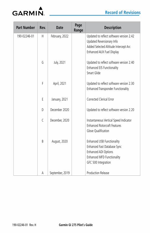
Updated to reflect software version 2.42Updated Reversionary InfoAdded Selected Altitude Intercept ArcEnhanced AUX Fuel Display
Updated to reflect software version 2.40Enhanced EIS FunctionalitySmart Glide
Updated to reflect software version 2.30Enhanced Transponder Functionality
Corrected Clerical Error
Updated to reflect software version 2.20
Instantaneous Vertical Speed IndicatorEnhanced Rotorcraft FeaturesGlove Qualification
Enhanced USB FunctionalityEnhanced Fast Database SyncEnhanced ADI OptionsEnhanced MFD FunctionalityGFC 500 Integration
Production Release

Garmin GI 275 Pilot's Guide 190-02246-01 Rev. H
Record of Revisions
Blank Page
Garmin GI 275 Pilot's Guide190-02246-01 Rev. H i
Table of Contents
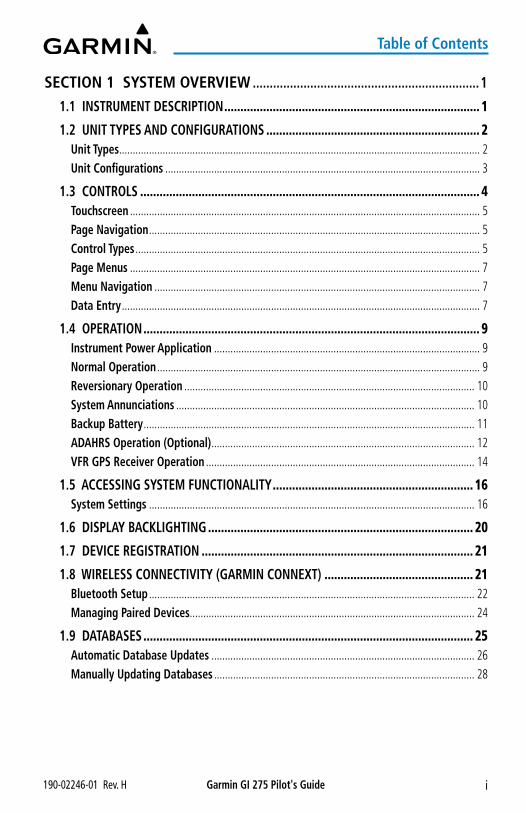
SECTION 1 SYSTEM OVERVIEW ...................................................................1
1.1 INSTRUMENT DESCRIPTION ............................................................................... 1
1.2 UNIT TYPES AND CONFIGURATIONS .................................................................. 2Unit Types ..................................................................................................................................... 2Unit Configurations .................................................................................................................... 3
1.3 CONTROLS ......................................................................................................... 4Touchscreen ................................................................................................................................. 5Page Navigation .......................................................................................................................... 5Control Types ............................................................................................................................... 5Page Menus ................................................................................................................................. 7Menu Navigation ........................................................................................................................ 7Data Entry .................................................................................................................................... 7
1.4 OPERATION ........................................................................................................ 9Instrument Power Application .................................................................................................. 9Normal Operation ....................................................................................................................... 9Reversionary Operation ........................................................................................................... 10System Annunciations .............................................................................................................. 10Backup Battery .......................................................................................................................... 11ADAHRS Operation (Optional) ................................................................................................. 12VFR GPS Receiver Operation ................................................................................................... 14
1.5 ACCESSING SYSTEM FUNCTIONALITY .............................................................. 16System Settings ........................................................................................................................ 16
1.6 DISPLAY BACKLIGHTING .................................................................................. 20
1.7 DEVICE REGISTRATION .................................................................................... 21
1.8 WIRELESS CONNECTIVITY (GARMIN CONNEXT) .............................................. 21Bluetooth Setup ........................................................................................................................ 22Managing Paired Devices......................................................................................................... 24
1.9 DATABASES ...................................................................................................... 25Automatic Database Updates ................................................................................................. 26Manually Updating Databases ................................................................................................ 28
Garmin GI 275 Pilot's Guide 190-02246-01 Rev. Hii
Table of Contents
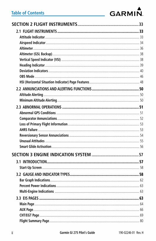
SECTION 2 FLIGHT INSTRUMENTS .............................................................33
2.1 FLIGHT INSTRUMENTS ..................................................................................... 33Attitude Indicator ..................................................................................................................... 33Airspeed Indicator .................................................................................................................... 34Altimeter .................................................................................................................................... 36Altimeter (GSL Backup) ............................................................................................................ 38Vertical Speed Indicator (VSI) ................................................................................................. 38Heading Indicator ..................................................................................................................... 39Deviation Indicators ................................................................................................................. 40OBS Mode .................................................................................................................................. 46HSI (Horizontal Situation Indicator) Page Features .............................................................. 48
2.2 ANNUNCIATIONS AND ALERTING FUNCTIONS ................................................. 50Altitude Alerting ....................................................................................................................... 50Minimum Altitude Alerting ...................................................................................................... 50
2.3 ABNORMAL OPERATIONS ................................................................................ 51Abnormal GPS Conditions ....................................................................................................... 51Comparator Annunciations ...................................................................................................... 52Loss of Primary Flight Information ......................................................................................... 53AHRS Failure .............................................................................................................................. 53Reversionary Sensor Annunciations ....................................................................................... 54Unusual Attitudes ..................................................................................................................... 55Smart Glide Activation ............................................................................................................. 56
SECTION 3 ENGINE INDICATION SYSTEM ...............................................57
3.1 INTRODUCTION ................................................................................................ 57Start-Up Screen ......................................................................................................................... 58
3.2 GAUGE AND INDICATOR TYPES ........................................................................ 58Bar Graph Indications............................................................................................................... 62Percent Power Indications ....................................................................................................... 63Multi-Engine Indications ......................................................................................................... 63
3.3 EIS PAGES ........................................................................................................ 63Main Page .................................................................................................................................. 64AUX Page.................................................................................................................................... 66CHT/EGT Page ............................................................................................................................ 69Flight Summary Page ................................................................................................................ 80
Garmin GI 275 Pilot's Guide190-02246-01 Rev. H iii
Table of Contents
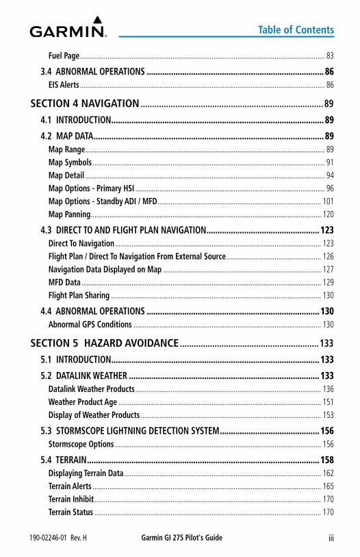
Fuel Page .................................................................................................................................... 83
3.4 ABNORMAL OPERATIONS ................................................................................ 86EIS Alerts .................................................................................................................................... 86
SECTION 4 NAVIGATION ...............................................................................89
4.1 INTRODUCTION ................................................................................................ 89
4.2 MAP DATA ........................................................................................................ 89Map Range ................................................................................................................................. 89Map Symbols ............................................................................................................................. 91Map Detail ................................................................................................................................. 94Map Options - Primary HSI ...................................................................................................... 96Map Options - Standby ADI / MFD ........................................................................................ 101Map Panning ............................................................................................................................ 120
4.3 DIRECT TO AND FLIGHT PLAN NAVIGATION ................................................... 123Direct To Navigation ............................................................................................................... 123Flight Plan / Direct To Navigation From External Source ................................................... 126Navigation Data Displayed on Map ..................................................................................... 127MFD Data ................................................................................................................................. 129Flight Plan Sharing ................................................................................................................. 130
4.4 ABNORMAL OPERATIONS .............................................................................. 130Abnormal GPS Conditions ..................................................................................................... 130
SECTION 5 HAZARD AVOIDANCE ............................................................133
5.1 INTRODUCTION .............................................................................................. 133
5.2 DATALINK WEATHER ...................................................................................... 133Datalink Weather Products .................................................................................................... 136Weather Product Age ............................................................................................................. 151Display of Weather Products ................................................................................................. 153
5.3 STORMSCOPE LIGHTNING DETECTION SYSTEM ............................................. 156Stormscope Options ............................................................................................................... 156
5.4 TERRAIN ......................................................................................................... 158Displaying Terrain Data .......................................................................................................... 162Terrain Alerts ........................................................................................................................... 165Terrain Inhibit .......................................................................................................................... 170Terrain Status .......................................................................................................................... 170
Garmin GI 275 Pilot's Guide 190-02246-01 Rev. Hiv
Table of Contents
Synthetic Vision Terrain .......................................................................................................... 171
5.5 TRAFFIC .......................................................................................................... 172Display of Traffic Information................................................................................................ 172Traffic Data by Source ............................................................................................................ 178
SECTION 6 AUTOPILOT ...............................................................................191
6.1 OVERVIEW...................................................................................................... 191
6.2 FLIGHT CONTROL ........................................................................................... 192Pitch Axis and Trim .................................................................................................................. 192Roll Axis ................................................................................................................................... 192Yaw Axis ................................................................................................................................... 192
6.3 AUTOPILOT OPERATION ................................................................................. 192Command Bars ........................................................................................................................ 192Engaging the Autopilot .......................................................................................................... 193Disengaging the Autopilot .................................................................................................... 194
6.4 GARMIN GFC 500 AUTOPILOT (OPTIONAL) .................................................... 195GFC 500 AFCS Configuration ................................................................................................. 195GMC 507 Mode Controller ..................................................................................................... 196GSA 28 Servo ........................................................................................................................... 196
6.5 AFCS SYSTEM ARCHITECTURE ........................................................................ 197GI 275 AFCS Status Box.......................................................................................................... 197AFCS Operation ....................................................................................................................... 197GMC 507 Controls ................................................................................................................... 198Engaging The Autopilot.......................................................................................................... 199Disengaging The Autopilot .................................................................................................... 200Overpowering Autopilot Servos ........................................................................................... 200Flight Director Operation....................................................................................................... 200Vertical Modes ........................................................................................................................ 202Lateral Modes.......................................................................................................................... 209
6.6 GFC 500 AFCS ALERTS.................................................................................... 217Trim Alerts ................................................................................................................................ 217Speed Alerts ............................................................................................................................ 217GFC 500 Messages And Annunciations ................................................................................ 217
Garmin GI 275 Pilot's Guide190-02246-01 Rev. H v
Table of Contents
6.7 ELECTRONIC STABILITY & PROTECTION (ESP) (GFC 500) ............................... 218Roll Engagement ..................................................................................................................... 219Pitch Engagement ................................................................................................................... 220Airspeed Protection (GFC 500 Only) ..................................................................................... 221
SECTION 7 INSTANTANEOUS VERTICAL SPEED INDICATOR ...........223
7.1 OVERVIEW...................................................................................................... 223
7.2 VERTICAL SPEED / RA DISPLAY ...................................................................... 223
7.3 RESOLUTION ADVISORIES .............................................................................. 223
7.4 TRAFFIC DISPLAY ........................................................................................... 224
7.5 CONTROLS AND ANNUNCIATIONS ................................................................. 227
7.6 ALTITUDE FILTERING ...................................................................................... 228
7.7 ALTITUDE TYPE ............................................................................................... 228
7.8 TRAFFIC COLLISION AVOIDANCE SYSTEM (TCAS) MODE ............................... 229
7.9 FAILURE ANNUNCIATIONS ............................................................................. 229Vertical Speed Fail (X) ............................................................................................................ 229RA Fail ...................................................................................................................................... 230TCAS Fail .................................................................................................................................. 231TD Fail ....................................................................................................................................... 232
SECTION 8 ADDITIONAL FEATURES .......................................................233
8.1 OVERVIEW...................................................................................................... 233
8.2 SAFETAXI® ...................................................................................................... 233
8.3 RADAR ALTIMETER (OPTIONAL) ..................................................................... 236Overview .................................................................................................................................. 236Radar Altimeter Test ............................................................................................................... 238
8.4 FLIGHT DATA LOGGING .................................................................................. 239Wireless Flight Data Logging With Connext ........................................................................ 239Exporting Flight Data With a USB Drive............................................................................... 239Data Parameters ..................................................................................................................... 240
8.5 GARMIN PILOT WATCH CONNECTIVITY (OPTIONAL) ...................................... 242
Garmin GI 275 Pilot's Guide 190-02246-01 Rev. Hvi
Table of Contents
8.6 SYNTHETIC VISION TECHNOLOGY (SVT™) (OPTIONAL) ................................... 245SVT Features ............................................................................................................................ 246SVT Troubleshooting ............................................................................................................... 250
8.7 ADI - MISC. FIELD (OPTIONAL) ...................................................................... 251
8.8 TRANSPONDER CONTROL (OPTIONAL) ......................................................... 253Transponder Operation .......................................................................................................... 253Select Transponder ................................................................................................................. 253Ident ......................................................................................................................................... 254Standby .................................................................................................................................... 254On ............................................................................................................................................. 254Altitude Reporting .................................................................................................................. 254VFR ............................................................................................................................................ 255Selecting a Squawk Code ...................................................................................................... 255Flight ID ................................................................................................................................... 257
SECTION 9 APPENDICES ............................................................................259
APPENDIX A: ANNUNCIATIONS, ALERTS AND GLOVE QUALIFICATION ................. 259Alert Level Definitions ........................................................................................................... 259System Messages .................................................................................................................... 261Glove Qualification ................................................................................................................. 265
APPENDIX B: DATABASE INFORMATION .............................................................. 277Available Databases ............................................................................................................... 278Database Troubleshooting Tips ............................................................................................. 279
APPENDIX C: AVIATION TERMS AND ACRONYMS ................................................ 281
APPENDIX D: DISPLAY SYMBOLS ......................................................................... 299VFR Symbols ............................................................................................................................ 299IFR Symbols ............................................................................................................................. 300Airspace Symbols .................................................................................................................... 301
INDEX .....................................................................................................................I-1
Garmin GI 275 Pilot's Guide190-02246-01 Rev. H 1
System Overview
System
Overview
Flight Instrum
entsEIS
Navigation
Hazard
AvoidanceA
utopilotIVSI
Additional Features
Appendices
Index
SECTION 1 SYSTEM OVERVIEW
NOTE: All visual depictions contained within this document, including screen images, are subject to change and may not reflect the most current system and aviation databases. Depictions of equipment may differ slightly from the actual equipment.
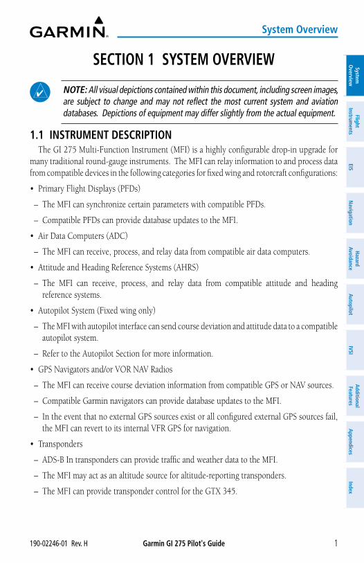
1.1 INSTRUMENT DESCRIPTIONThe GI 275 Multi-Function Instrument (MFI) is a highly configurable drop-in upgrade for
many traditional round-gauge instruments. The MFI can relay information to and process data from compatible devices in the following categories for fixed wing and rotorcraft configurations:
• Primary Flight Displays (PFDs)
– The MFI can synchronize certain parameters with compatible PFDs.
– Compatible PFDs can provide database updates to the MFI.
• Air Data Computers (ADC)
– The MFI can receive, process, and relay data from compatible air data computers.
• Attitude and Heading Reference Systems (AHRS)
– The MFI can receive, process, and relay data from compatible attitude and heading reference systems.
• Autopilot System (Fixed wing only)
– The MFI with autopilot interface can send course deviation and attitude data to a compatible autopilot system.
– Refer to the Autopilot Section for more information.
• GPS Navigators and/or VOR NAV Radios
– The MFI can receive course deviation information from compatible GPS or NAV sources.
– Compatible Garmin navigators can provide database updates to the MFI.
– In the event that no external GPS sources exist or all configured external GPS sources fail, the MFI can revert to its internal VFR GPS for navigation.
• Transponders
– ADS-B In transponders can provide traffic and weather data to the MFI.
– The MFI may act as an altitude source for altitude-reporting transponders.
– The MFI can provide transponder control for the GTX 345.
Garmin GI 275 Pilot's Guide 190-02246-01 Rev. H2
System Overview
Syst
em
Ove
rvie
wFl
ight
In
stru
men
tsEI
SN
avig
atio
nH
azar
d Av
oida
nce
Aut
opilo
tIV
SIA
dditi
onal
Fe
atur
esA
ppen
dice
sIn
dex
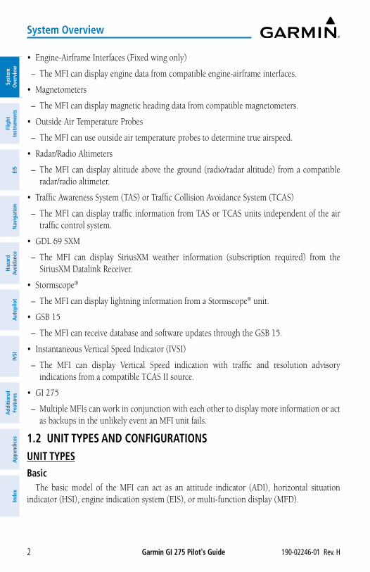
• Engine-Airframe Interfaces (Fixed wing only)
– The MFI can display engine data from compatible engine-airframe interfaces.
• Magnetometers
– The MFI can display magnetic heading data from compatible magnetometers.
• Outside Air Temperature Probes
– The MFI can use outside air temperature probes to determine true airspeed.
• Radar/Radio Altimeters
– The MFI can display altitude above the ground (radio/radar altitude) from a compatible radar/radio altimeter.
• Traffic Awareness System (TAS) or Traffic Collision Avoidance System (TCAS)
– The MFI can display traffic information from TAS or TCAS units independent of the air traffic control system.
• GDL 69 SXM
– The MFI can display SiriusXM weather information (subscription required) from the SiriusXM Datalink Receiver.
• Stormscope®
– The MFI can display lightning information from a Stormscope® unit.
• GSB 15
– The MFI can receive database and software updates through the GSB 15.
• Instantaneous Vertical Speed Indicator (IVSI)
– The MFI can display Vertical Speed indication with traffic and resolution advisory indications from a compatible TCAS II source.
• GI 275
– Multiple MFIs can work in conjunction with each other to display more information or act as backups in the unlikely event an MFI unit fails.
1.2 UNIT TYPES AND CONFIGURATIONSUNIT TYPESBasic
The basic model of the MFI can act as an attitude indicator (ADI), horizontal situation indicator (HSI), engine indication system (EIS), or multi-function display (MFD).
Garmin GI 275 Pilot's Guide190-02246-01 Rev. H 3
System Overview
System
Overview
Flight Instrum
entsEIS
Navigation
Hazard
AvoidanceA
utopilotIVSI
Additional Features
Appendices
Index
To act as an attitude indicator, the basic MFI must have an external AHRS source. To display air data, the basic MFI must have an external air data computer. To show magnetic heading, all MFIs must have an external magnetometer.
The basic version with an NVIS friendly encoder halo light is available, which provides the 'green' tint backlit knob
With Internal ADAHRS (Air Data and Attitude and Heading Reference System)The MFI with internal ADAHRS can do everything the basic MFI does and additionally
contains its own air data and AHRS source, as well as interface to Garmin's fixed wing GFC 500 or GFC 600 autopilot, saving weight and expense.
An ADAHRS version with an NVIS friendly encoder halo light is available, which provides the 'green' tint backlit knob.
With Internal ADAHRS and Autopilot InterfaceFor fixed wing installations, the MFI with autopilot interface expands the MFI with internal
ADAHRS capability and has interfaces to connect to an external autopilot or AFCS, letting the MFI provide heading/course error and attitude to compatible autopilot and AFCS devices.
UNIT CONFIGURATIONSPrimary ADI
A Primary ADI replaces the traditional attitude indicator. It may additionally show airspeed, altitude, vertical speed, and heading. Terrain is displayed with the optional SVT enablement.
Standby ADI or MFDStandby ADI or MFD units provide additional capability to the aircraft and display
information (e.g., maps) or external data (e.g., radar altimeter). Standby ADI units act as a backup ADI if the Primary ADI fails or the pilot reverts the display.
Primary HSIThe Primary HSI displays course deviation information based on the selected NAVAID. An
HSI Map shows course deviation information overlaid on a map centered around the aircraft's current GPS position.
Standby HSIThe Standby HSI acts as a Primary HSI under normal conditions but as a backup ADI if a
Primary ADI fails.
EISFor fixed wing installations, EIS units replace traditional mechanical engine instruments and
additional information like engine temperatures and provide features like engine lean assisting.
Garmin GI 275 Pilot's Guide 190-02246-01 Rev. H4
System Overview
Syst
em
Ove
rvie
wFl
ight
In
stru
men
tsEI
SN
avig
atio
nH
azar
d Av
oida
nce
Aut
opilo
tIV
SIA
dditi
onal
Fe
atur
esA
ppen
dice
sIn
dex
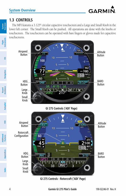
1.3 CONTROLSThe MFI features a 3.125" circular capacitive touchscreen and a Large and Small Knob in the
lower left corner. The Small Knob can be pushed. All operations are done with the knobs or touchscreen. The touchscreen can be operated with bare fingers or gloves made for capacitive touchscreens.
GI 275 Controls ('ADI' Page)
Airspeed Button
HDG Button
Large KnobSmall Knob
BARO Button
Altitude Button
GI 275 Controls - Rotorcraft ('ADI' Page)
Airspeed Button
HDG ButtonLarge KnobSmall Knob
BARO Button
Altitude Button
Rotorcraft Configuration
Garmin GI 275 Pilot's Guide190-02246-01 Rev. H 5
System Overview
System
Overview
Flight Instrum
entsEIS
Navigation
Hazard
AvoidanceA
utopilotIVSI
Additional Features
Appendices
Index
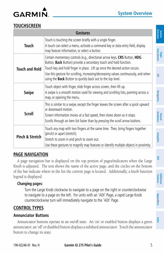
TOUCHSCREENGestures
TouchTouch is touching the screen briefly with a single finger. A touch can select a menu, activate a command key or data entry field, display map feature information, or select a button.
Touch and Hold
Certain momentary controls (e.g., directional arrow keys, CRS Button, HDG Button, Back Button) provide a secondary touch and hold function. Touch key and hold finger in place. Lift up once the desired action occurs. Use this gesture for scrolling, increasing/decreasing values continuously, and when using the Back Button to quickly back out to the top level.
SwipeTouch object with finger, slide finger across screen, then lift up.A swipe is a smooth motion used for viewing and scrolling lists, panning across a map, or opening the menu.
Scroll
This is similar to a swipe, except the finger leaves the screen after a quick upward or downward motion.Screen information moves at a fast speed, then slows down as it stops.Scrolls through an item list faster than by pressing the scroll arrow buttons.
Pinch & Stretch
Touch any map with two fingers at the same time. Then, bring fingers together (pinch) or apart (stretch).Stretch to zoom in and pinch to zoom out.Use these gestures to magnify map features or identify multiple objects in proximity.
PAGE NAVIGATIONA page navigation bar is displayed on the top portion of pages/indicators when the Large
Knob is adjusted. The text shows the name of the active page, and the circles on the bottom of the bar indicate where in the list the current page is located. Additionally, a knob function legend is displayed.
Changing pages: Turn the Large Knob clockwise to navigate to a page on the right or counterclockwise
to navigate to a page on the left. For units with an 'ADI' Page, a rapid Large Knob counterclockwise turn will immediately navigate to the 'ADI' Page.
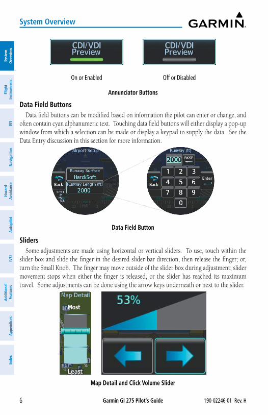
CONTROL TYPESAnnunciator Buttons
Annunciator buttons operate in an on/off state. An ‘on’ or enabled button displays a green annunciator; an ‘off’ or disabled button displays a subdued annunciator. Touch the annunciator button to change its state.
Garmin GI 275 Pilot's Guide 190-02246-01 Rev. H6
System Overview
Syst
em
Ove
rvie
wFl
ight
In
stru
men
tsEI
SN
avig
atio
nH
azar
d Av
oida
nce
Aut
opilo
tIV
SIA
dditi
onal
Fe
atur
esA
ppen
dice
sIn
dex
Annunciator Buttons
On or Enabled Off or Disabled
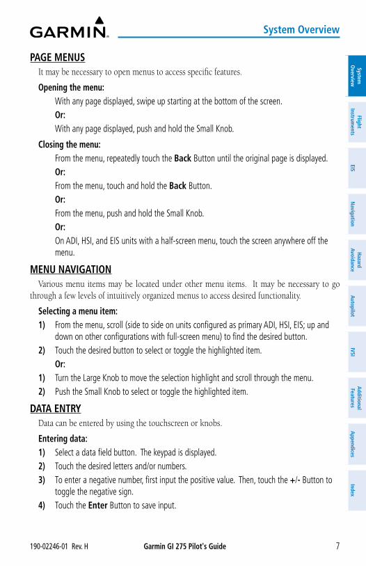
Data Field ButtonsData field buttons can be modified based on information the pilot can enter or change, and
often contain cyan alphanumeric text. Touching data field buttons will either display a pop-up window from which a selection can be made or display a keypad to supply the data. See the Data Entry discussion in this section for more information.
Data Field Button
SlidersSome adjustments are made using horizontal or vertical sliders. To use, touch within the
slider box and slide the finger in the desired slider bar direction, then release the finger; or, turn the Small Knob. The finger may move outside of the slider box during adjustment; slider movement stops when either the finger is released, or the slider has reached its maximum travel. Some adjustments can be done using the arrow keys underneath or next to the slider.
Map Detail and Click Volume Slider
Garmin GI 275 Pilot's Guide190-02246-01 Rev. H 7
System Overview
System
Overview
Flight Instrum
entsEIS
Navigation
Hazard
AvoidanceA
utopilotIVSI
Additional Features
Appendices
Index
PAGE MENUSIt may be necessary to open menus to access specific features.
Opening the menu: With any page displayed, swipe up starting at the bottom of the screen.
Or: With any page displayed, push and hold the Small Knob.
Closing the menu: From the menu, repeatedly touch the Back Button until the original page is displayed.
Or: From the menu, touch and hold the Back Button.
Or: From the menu, push and hold the Small Knob.
Or: On ADI, HSI, and EIS units with a half-screen menu, touch the screen anywhere off the
menu.
MENU NAVIGATIONVarious menu items may be located under other menu items. It may be necessary to go
through a few levels of intuitively organized menus to access desired functionality.
Selecting a menu item:1) From the menu, scroll (side to side on units configured as primary ADI, HSI, EIS; up and
down on other configurations with full-screen menu) to find the desired button.2) Touch the desired button to select or toggle the highlighted item.
Or:1) Turn the Large Knob to move the selection highlight and scroll through the menu.2) Push the Small Knob to select or toggle the highlighted item.
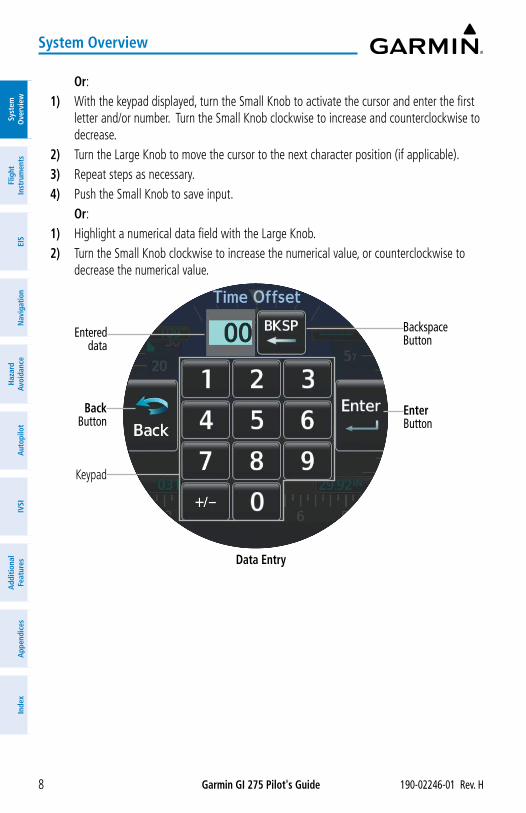
DATA ENTRYData can be entered by using the touchscreen or knobs.
Entering data:1) Select a data field button. The keypad is displayed.2) Touch the desired letters and/or numbers.3) To enter a negative number, first input the positive value. Then, touch the +/- Button to
toggle the negative sign.4) Touch the Enter Button to save input.
Garmin GI 275 Pilot's Guide 190-02246-01 Rev. H8
System Overview
Syst
em
Ove
rvie
wFl
ight
In
stru
men
tsEI
SN
avig
atio
nH
azar
d Av
oida
nce
Aut
opilo
tIV
SIA
dditi
onal
Fe
atur
esA
ppen
dice
sIn
dex
Or:1) With the keypad displayed, turn the Small Knob to activate the cursor and enter the first
letter and/or number. Turn the Small Knob clockwise to increase and counterclockwise to decrease.
2) Turn the Large Knob to move the cursor to the next character position (if applicable).3) Repeat steps as necessary.4) Push the Small Knob to save input. Or:1) Highlight a numerical data field with the Large Knob.2) Turn the Small Knob clockwise to increase the numerical value, or counterclockwise to
decrease the numerical value.
Data Entry
Entered data
Back Button
Enter Button
Backspace Button
Keypad
Garmin GI 275 Pilot's Guide190-02246-01 Rev. H 9
System Overview
System
Overview
Flight Instrum
entsEIS
Navigation
Hazard
AvoidanceA
utopilotIVSI
Additional Features
Appendices
Index
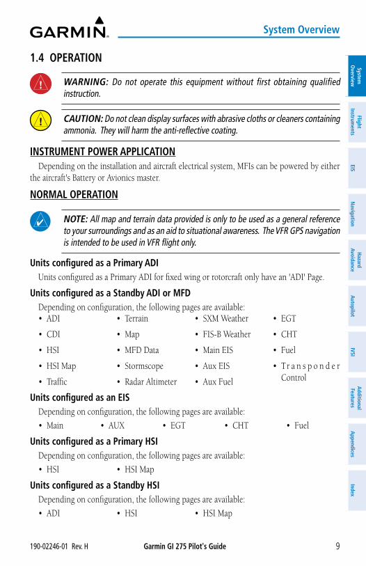
1.4 OPERATION
WARNING: Do not operate this equipment without first obtaining qualified instruction.
CAUTION: Do not clean display surfaces with abrasive cloths or cleaners containing ammonia. They will harm the anti-reflective coating.
INSTRUMENT POWER APPLICATIONDepending on the installation and aircraft electrical system, MFIs can be powered by either
the aircraft's Battery or Avionics master.
NORMAL OPERATION
NOTE: All map and terrain data provided is only to be used as a general reference to your surroundings and as an aid to situational awareness. The VFR GPS navigation is intended to be used in VFR flight only.
Units configured as a Primary ADIUnits configured as a Primary ADI for fixed wing or rotorcraft only have an 'ADI' Page.
Units configured as a Standby ADI or MFDDepending on configuration, the following pages are available:• ADI
• CDI
• HSI
• HSI Map
• Traffic
• Terrain
• Map
• MFD Data
• Stormscope
• Radar Altimeter
• SXM Weather
• FIS-B Weather
• Main EIS
• Aux EIS
• Aux Fuel
• EGT
• CHT
• Fuel
• Tr a n s p o n d e r Control
Units configured as an EISDepending on configuration, the following pages are available:
• Main • AUX • EGT • CHT • Fuel
Units configured as a Primary HSIDepending on configuration, the following pages are available:
• HSI • HSI Map
Units configured as a Standby HSIDepending on configuration, the following pages are available:
• ADI • HSI • HSI Map
Garmin GI 275 Pilot's Guide 190-02246-01 Rev. H10
System Overview
Syst
em
Ove
rvie
wFl
ight
In
stru
men
tsEI
SN
avig
atio
nH
azar
d Av
oida
nce
Aut
opilo
tIV
SIA
dditi
onal
Fe
atur
esA
ppen
dice
sIn
dex
REVERSIONARY OPERATIONWhen a unit configured as a Standby ADI or Standby HSI detects compatible interconnected
instruments (another MFI, G500/600 TXi, etc.) have a fault, the unit exclusively behaves as a Primary ADI until the fault is resolved. Alternatively, the crew can manually select reversionary operation modes from panel-mounted switches, i.e. the rotation of the outer knob counter-clockwise or engages the reversionary switch.
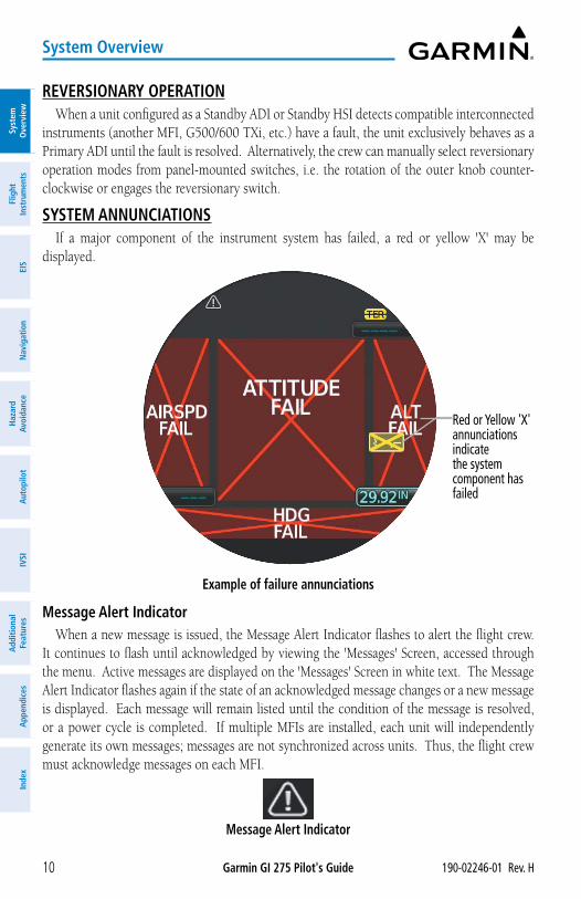
SYSTEM ANNUNCIATIONSIf a major component of the instrument system has failed, a red or yellow 'X' may be
displayed.
Example of failure annunciations
Red or Yellow 'X' annunciations indicate the system component has failed
Message Alert IndicatorWhen a new message is issued, the Message Alert Indicator flashes to alert the flight crew.
It continues to flash until acknowledged by viewing the 'Messages' Screen, accessed through the menu. Active messages are displayed on the 'Messages' Screen in white text. The Message Alert Indicator flashes again if the state of an acknowledged message changes or a new message is displayed. Each message will remain listed until the condition of the message is resolved, or a power cycle is completed. If multiple MFIs are installed, each unit will independently generate its own messages; messages are not synchronized across units. Thus, the flight crew must acknowledge messages on each MFI.
Message Alert Indicator
Garmin GI 275 Pilot's Guide190-02246-01 Rev. H 11
System Overview
System
Overview
Flight Instrum
entsEIS
Navigation
Hazard
AvoidanceA
utopilotIVSI
Additional Features
Appendices
Index
BACKUP BATTERYSome units have a backup battery installed to enable device functionality even with a total
loss of aircraft power. Backup batteries are required for units configured as a Standby using the internal ADC and AHRS sensors. When on the ground and aircraft power is lost, an "External power lost. Shutting down in x" countdown begins with an option to Stay On or Pwr Off. The unit must be manually shut down after aircraft power is lost and the Stay On Button is selected. If airborne and power is lost, an "External power lost." message is displayed.
NOTE: While the unit operates on the backup battery, the system will load-shed any ARINC 429 interface. In this instance, certain data may be lost due to the operation while on backup battery.
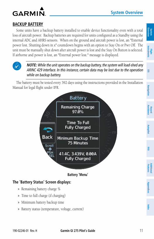
The battery must be tested every 392 days using the instructions provided in the Installation Manual for legal flight under IFR.
Battery 'Menu'
The 'Battery Status' Screen displays:
» Remaining battery charge %
» Time to full charge (if charging)
» Minimum battery backup time
» Battery status (temperature, voltage, current)
Garmin GI 275 Pilot's Guide 190-02246-01 Rev. H12
System Overview
Syst
em
Ove
rvie
wFl
ight
In
stru
men
tsEI
SN
avig
atio
nH
azar
d Av
oida
nce
Aut
opilo
tIV
SIA
dditi
onal
Fe
atur
esA
ppen
dice
sIn
dex
Viewing backup battery status: From any page, open the menu and select System > Battery.
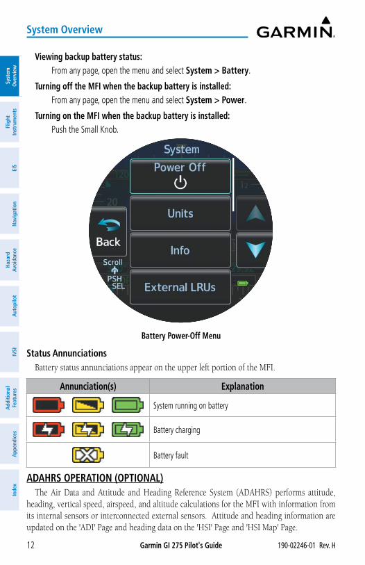
Turning off the MFI when the backup battery is installed: From any page, open the menu and select System > Power.
Turning on the MFI when the backup battery is installed: Push the Small Knob.
Battery Power-Off Menu
Status AnnunciationsBattery status annunciations appear on the upper left portion of the MFI.
Annunciation(s) Explanation
System running on battery
Battery charging
Battery fault
ADAHRS OPERATION (OPTIONAL)The Air Data and Attitude and Heading Reference System (ADAHRS) performs attitude,
heading, vertical speed, airspeed, and altitude calculations for the MFI with information from its internal sensors or interconnected external sensors. Attitude and heading information are updated on the 'ADI' Page and heading data on the 'HSI' Page and 'HSI Map' Page.
Garmin GI 275 Pilot's Guide190-02246-01 Rev. H 13
System Overview
System
Overview
Flight Instrum
entsEIS
Navigation
Hazard
AvoidanceA
utopilotIVSI
Additional Features
Appendices
Index
During system initialization, the AHRS displays the message ‘AHRS ALIGN, KEEP WINGS LEVEL’ over the attitude indicator. If a heading indicator is configured, a red 'X' will be displayed until the instrument receives valid heading data. The AHRS should display valid attitude and heading fields typically within the first minute of power application.
The AHRS can align itself both during flight and while taxiing. The realign can occur provided the MFI is restarted while in straight and level flight or while taxiing in straight and level conditions (+/- 5 ° pitch, +/- 10° roll). When realigning, the ADI’s attitude information is removed and replaced with an annunciation instructing the pilot to attempt to maintain straight and level flight. Depending on the conditions, airborne and taxiing alignments are usually successful within 1-2 minutes.
Heading indications are corrected for shifts and variations in the Earth’s magnetic field by applying the Magnetic Field Variation Database. The Magnetic Field Variation Database is derived from the International Geomagnetic Reference Field (IGRF). The IGRF is a mathematical model that describes the Earth’s main magnetic field and its annual rate of change. The database is updated approximately every 5 years through a Navigation database update. Failure to update this database could lead to erroneous heading information being displayed to the crew.
Any failure of the AHRS sensors results in loss of attitude and heading information and failure of ADC sensors results in loss of air data information (indicated by red ‘X’ flags over the corresponding flight instruments). If the MFI senses the magnetic heading measurement is valid, but possibly outside of the internal accuracy limits, the numeric heading value will be displayed in yellow.
If the magnetometer input fails, the heading output is flagged as invalid with a red 'X' but track information is displayed instead if valid GPS data are available.
In installations that include multiple air data and AHRS units (MFI supports up to two external air data and AHRS sources in addition to the internal ADAHRS source if equipped), if data from an air data or AHRS source is lost, the MFI can display data from alternate sources. A data failure condition is annunciated by 'X's over instruments, miscompare flags, or no compare flags. Data source switching is not automatic. Reversionary sensor selection is annunciated near the relevant data field or at the top of the display.
Manually switching AHRS or ADC sensors:1) From the 'ADI' Page, open the menu.2) Select the ADI Options or Options Button.3) Select the Sensors Button.4) Select the AHRS or ADC Button, then the desired AHRS or ADC source.
NOTE: Manual switching of AHRS or ADC sensors is not available if the GI 275 is interfaced to a GFC 500 Autopilot.
Garmin GI 275 Pilot's Guide 190-02246-01 Rev. H14
System Overview
Syst
em
Ove
rvie
wFl
ight
In
stru
men
tsEI
SN
avig
atio
nH
azar
d Av
oida
nce
Aut
opilo
tIV
SIA
dditi
onal
Fe
atur
esA
ppen
dice
sIn
dex
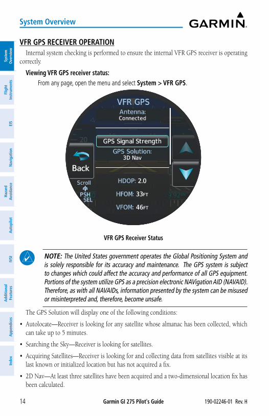
VFR GPS RECEIVER OPERATIONInternal system checking is performed to ensure the internal VFR GPS receiver is operating
correctly.
Viewing VFR GPS receiver status: From any page, open the menu and select System > VFR GPS.
VFR GPS Receiver Status
NOTE: The United States government operates the Global Positioning System and is solely responsible for its accuracy and maintenance. The GPS system is subject to changes which could affect the accuracy and performance of all GPS equipment. Portions of the system utilize GPS as a precision electronic NAVigation AID (NAVAID). Therefore, as with all NAVAIDs, information presented by the system can be misused or misinterpreted and, therefore, become unsafe.
The GPS Solution will display one of the following conditions:
• Autolocate—Receiver is looking for any satellite whose almanac has been collected, which can take up to 5 minutes.
• Searching the Sky—Receiver is looking for satellites.
• Acquiring Satellites—Receiver is looking for and collecting data from satellites visible at its last known or initialized location but has not acquired a fix.
• 2D Nav—At least three satellites have been acquired and a two-dimensional location fix has been calculated.
Garmin GI 275 Pilot's Guide190-02246-01 Rev. H 15
System Overview
System
Overview
Flight Instrum
entsEIS
Navigation
Hazard
AvoidanceA
utopilotIVSI
Additional Features
Appendices
Index
• 2D Diff Nav—At least three satellites have been acquired and a two-dimensional location fix has been calculated, with SBAS corrections applied.
• 3D Nav—At least four satellites have been acquired and a three-dimensional fix has been calculated.
• 3D Diff Nav—At least four satellites have been acquired and a three-dimensional fix has been calculated, with SBAS corrections applied.
• Lost Satellite Reception—the receiver is no longer tracking enough satellites for a valid position fix.
Acquiring SatellitesWhen the receiver is in the process of acquiring enough satellite signals for navigation, the
receiver uses satellite orbital data (collected continuously from the satellites) and last known position to determine the satellites that should be in view. “Acquiring Satellites” is indicated as the solution until a sufficient number of satellites have been acquired for computing a solution.
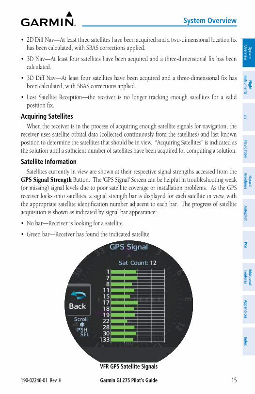
Satellite InformationSatellites currently in view are shown at their respective signal strengths accessed from the
GPS Signal Strength Button. The 'GPS Signal' Screen can be helpful in troubleshooting weak (or missing) signal levels due to poor satellite coverage or installation problems. As the GPS receiver locks onto satellites, a signal strength bar is displayed for each satellite in view, with the appropriate satellite identification number adjacent to each bar. The progress of satellite acquisition is shown as indicated by signal bar appearance:
• No bar—Receiver is looking for a satellite
• Green bar—Receiver has found the indicated satellite
VFR GPS Satellite Signals
Garmin GI 275 Pilot's Guide 190-02246-01 Rev. H16
System Overview
Syst
em
Ove
rvie
wFl
ight
In
stru
men
tsEI
SN
avig
atio
nH
azar
d Av
oida
nce
Aut
opilo
tIV
SIA
dditi
onal
Fe
atur
esA
ppen
dice
sIn
dex
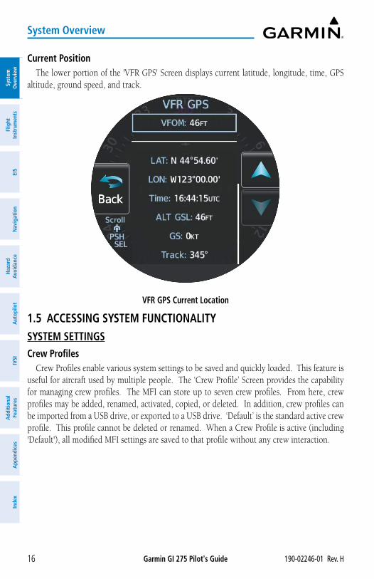
Current PositionThe lower portion of the 'VFR GPS' Screen displays current latitude, longitude, time, GPS
altitude, ground speed, and track.
VFR GPS Current Location
1.5 ACCESSING SYSTEM FUNCTIONALITYSYSTEM SETTINGSCrew Profiles
Crew Profiles enable various system settings to be saved and quickly loaded. This feature is useful for aircraft used by multiple people. The ‘Crew Profile’ Screen provides the capability for managing crew profiles. The MFI can store up to seven crew profiles. From here, crew profiles may be added, renamed, activated, copied, or deleted. In addition, crew profiles can be imported from a USB drive, or exported to a USB drive. ‘Default’ is the standard active crew profile. This profile cannot be deleted or renamed. When a Crew Profile is active (including 'Default'), all modified MFI settings are saved to that profile without any crew interaction.
Garmin GI 275 Pilot's Guide190-02246-01 Rev. H 17
System Overview
System
Overview
Flight Instrum
entsEIS
Navigation
Hazard
AvoidanceA
utopilotIVSI
Additional Features
Appendices
Index
Accessing Crew Profile options: From any page, open the menu and select System > Crew Profile.
Creating a Crew Profile:1) From the 'Crew Profile' Screen, select New.2) Input a Crew Profile name (up to 8 characters).3) Touch the Enter Button or push the Small Knob. 4) A "New crew profile will be created with the current system settings." message appears.5) Select the Create/Act Button to create the profile.
NOTE: If the MFI is at the maximum crew profile limit, no crew profiles can be imported.
NOTE: If more than 50 crew profiles are available on the USB drive, only the first 50 profiles are listed for import.
Importing a Crew Profile using USB device:1) Insert a USB drive into the USB dongle or optional GSB 15.2) From any page, open the menu; select System > USB > Enable USB, then back out
one level and select Crew Profile.3) Select the Import Button.4) Select the name of the profile to import (cannot import a profile which has the same
name as the currently active profile).5) If a duplicate profile name exists, an "Importing this profile will overwrite profile (profile
name) Confirm import?" message appears. Select the OK Button.6) An "Import Successful!" message appears. Select the OK Button.
Switching Crew Profiles:1) From the 'Crew Profile' Screen, select the desired inactive profile.2) Select the Activate Button.
Renaming Crew Profiles:1) From the 'Crew Profile' Screen, select the desired profile ('Default' and the active profile
cannot be renamed).2) Select the Rename Button.3) Input the updated Crew Profile name.4) Touch the Enter Button or push the Small Knob to accept changes.
Garmin GI 275 Pilot's Guide 190-02246-01 Rev. H18
System Overview
Syst
em
Ove
rvie
wFl
ight
In
stru
men
tsEI
SN
avig
atio
nH
azar
d Av
oida
nce
Aut
opilo
tIV
SIA
dditi
onal
Fe
atur
esA
ppen
dice
sIn
dex
Exporting Crew Profiles using a USB device:1) Insert a USB drive into the USB dongle or optional GSB 15.2) From any page, open the menu; select System > USB > Enable USB, then back out
one level and select Crew Profile.3) Select the profile to export.4) Select the Export Button.5) If a duplicate profile name exists, an "Export profile (profile name)? Export will overwrite
any profile on the storage device with this name." message appears. Select the OK Button.
6) An "Export Successful!" message appears. Select the OK Button.
Deleting Crew Profiles:1) From the 'Crew Profile' Screen, select the desired profile ('Default' cannot be deleted).2) Select the Delete Button.3) Confirm deletion by selecting the OK Button.
Date/TimeThe MFI will automatically set system time from GPS or connected compatible Garmin
devices. By default, system time is displayed in UTC (also called Zulu Time). If there is no GPS time source, it is possible to manually set the date and time.
Accessing MFI system date and time settings: From any page, open the menu and select System > Setup > Date / Time.
Changing MFI time display format:1) From any page, open the menu and select System > Setup > Date / Time > Time
Options > Time Format.2) Select the desired setting (12 Hour, 24 Hour, UTC).
Changing MFI time display offset:1) From any page, open the menu and select System > Setup > Date / Time > Time
Options > Time Format.2) Select either the 12 Hour Button or the 24 Hour Button.3) Select the Time Offset (Hr) Data Field.
a) Use the Large Knob to highlight the Time Offset (Hr) Data Field.b) Use the Small Knob to adjust the number of hours local time is offset from UTC. Or:a) Select the Time Offset (Hr) Data Field. A keypad is displayed. b) Use the keypad or Small Knob to set number of hours local time is offset from UTC.c) Touch the Enter Button or push the Small Knob to save changes.
Garmin GI 275 Pilot's Guide190-02246-01 Rev. H 19
System Overview
System
Overview
Flight Instrum
entsEIS
Navigation
Hazard
AvoidanceA
utopilotIVSI
Additional Features
Appendices
Index
Manually setting MFI system date: From any page, open the menu and select System > Setup > Date / Time > Set
Date.a) Use the Large Knob and highlight the Year, Month, or Day Data Field.b) Use the Small Knob to adjust the data field value. Changes are saved automatically. Or:a) Select the Year, Month, or Day Data Field. A keypad is displayed. b) Use the keypad to enter the desired value for the data field. Touch the Enter Button
or push the Small Knob to save changes.
Manually setting MFI system time: From any page, open the menu and select System > Setup > Date / Time > Set
Time.a) Use the Large Knob and highlight the Hour or Minute Data Field.b) Use the Small Knob to adjust the data field value. Changes are saved automatically. Or:a) Select the Hour or Minute Data Field. A keypad is displayed. b) Use the keypad to enter the desired value for the data field. Touch the Enter Button
or push the Small Knob to save changes.
Units of MeasureThe MFI can display barometric pressure, altitude, distance, fuel, navigation angle, and
temperature in a variety of units of measure.
Opening the Units Menu: From any page, open the menu and select System > Units.
Adjusting barometric pressure units:1) From the 'Units' Menu, select the BARO Pressure Data Field.2) Select the desired units of measure (inHg, hPa, or mb).
NOTE: Altitude unit adjustments do not affect altimeter display units. Contact a Garmin dealer or installer for altimeter unit adjustment. Contact a Garmin Dealer or installer for unit adjustment.
Adjusting altitude units:1) From the 'Units' Menu, select the Altitude Data Field.2) Select the desired units of measure (Feet or Meters).
Garmin GI 275 Pilot's Guide 190-02246-01 Rev. H20
System Overview
Syst
em
Ove
rvie
wFl
ight
In
stru
men
tsEI
SN
avig
atio
nH
azar
d Av
oida
nce
Aut
opilo
tIV
SIA
dditi
onal
Fe
atur
esA
ppen
dice
sIn
dex
Adjusting distance units:1) From the 'Units' Menu, select the Distance Data Field.2) Select the desired units of measure (Nautical Miles or Kilometers).
Adjusting fuel computer units:
NOTE: Fuel unit adjustments do not affect fuel quantity or fuel flow gauges. Contact a Garmin Dealer or installer for unit adjustment.
1) From the 'Units' Menu, select the Fuel Computer Data Field.2) Select the desired units of measure (Gallons, Liters, or Pounds).
Adjusting navigation angle units:1) From the 'Units' Menu, select the Nav Angle Data Field.2) Select the desired units of measure (Magnetic or True).
Adjusting temperature units:
NOTE: Temperature unit adjustments do not affect temperature gauges. Contact a Garmin Dealer or installer for unit adjustment.
1) From the 'Units' Menu, select the Temperature Data Field.2) Select the desired units of measure (Celsius or Fahrenheit).
Airport RunwaysSetting airport criteria affects which airports are displayed on the Direct To 'Nearest' Menu.
See the Navigation Section for details.
1.6 DISPLAY BACKLIGHTINGThe MFI has a built-in photocell to detect ambient lighting conditions and adjusts its
display brightness accordingly. In certain installations, the MFI is integrated with the aircraft lighting dimming bus and will respond to dimming bus changes. If automatic or dimming bus brightness changes are inadequate, display brightness can be adjusted from the MFI directly.
Adjusting display brightness:1) From any page, open the menu and select Backlight.2) Use the arrow buttons or turn the Small Knob to adjust display brightness offset.3) Select the Back Button to save settings.
Garmin GI 275 Pilot's Guide190-02246-01 Rev. H 21
System Overview
System
Overview
Flight Instrum
entsEIS
Navigation
Hazard
AvoidanceA
utopilotIVSI
Additional Features
Appendices
Index
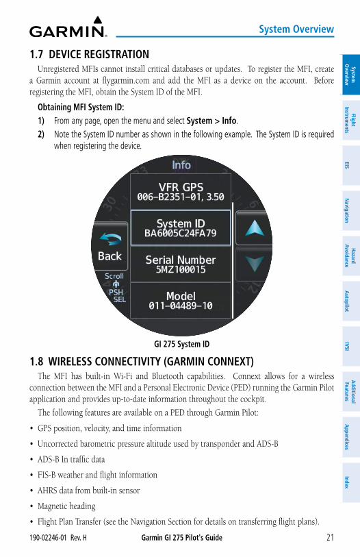
1.7 DEVICE REGISTRATIONUnregistered MFIs cannot install critical databases or updates. To register the MFI, create
a Garmin account at flygarmin.com and add the MFI as a device on the account. Before registering the MFI, obtain the System ID of the MFI.
Obtaining MFI System ID:1) From any page, open the menu and select System > Info.2) Note the System ID number as shown in the following example. The System ID is required
when registering the device.
GI 275 System ID
1.8 WIRELESS CONNECTIVITY (GARMIN CONNEXT)The MFI has built-in Wi-Fi and Bluetooth capabilities. Connext allows for a wireless
connection between the MFI and a Personal Electronic Device (PED) running the Garmin Pilot application and provides up-to-date information throughout the cockpit.
The following features are available on a PED through Garmin Pilot:
• GPS position, velocity, and time information
• Uncorrected barometric pressure altitude used by transponder and ADS-B
• ADS-B In traffic data
• FIS-B weather and flight information
• AHRS data from built-in sensor
• Magnetic heading
• Flight Plan Transfer (see the Navigation Section for details on transferring flight plans).

Garmin GI 275 Pilot's Guide 190-02246-01 Rev. H22
System Overview
Syst
em
Ove
rvie
wFl
ight
In
stru
men
tsEI
SN
avig
atio
nH
azar
d Av
oida
nce
Aut
opilo
tIV
SIA
dditi
onal
Fe
atur
esA
ppen
dice
sIn
dex
BLUETOOTH SETUPThe mobile device must be ‘paired’ with the system in order to use the various functions.
Pairing is accomplished once for each device. After the initial pairing, with 'Auto-Reconnect' enabled, your PED will automatically reconnect with the MFI. The pairing operation is completed from the mobile device and the Garmin Pilot application. For additional references, see the device Bluetooth pairing instructions and the connection instructions in the Garmin Pilot application.
NOTE: The MFI allows pairing of up to 13 Bluetooth devices, with four simultaneous device connections.
Pairing a PED using Bluetooth:1) From any page, open the menu and select System > Wireless.2) The MFI may take up to two minutes for wireless capability to initialize. When wireless
capability is ready, select the Continue Button.
Waiting for Wireless3) Select the Pair a Device Button. The following screen is displayed while you connect
your PED using Bluetooth. See your PED's instruction manual for details on how to connect your device using Bluetooth.
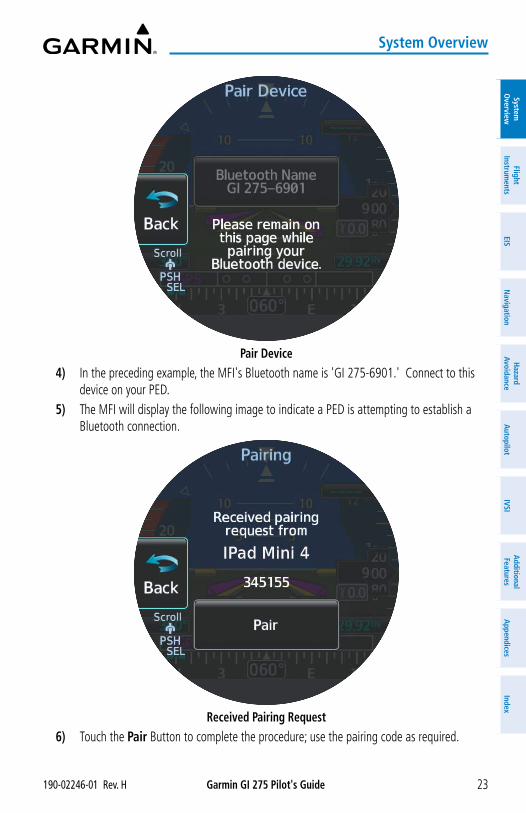
Garmin GI 275 Pilot's Guide190-02246-01 Rev. H 23
System Overview
System
Overview
Flight Instrum
entsEIS
Navigation
Hazard
AvoidanceA
utopilotIVSI
Additional Features
Appendices
Index
Pair Device4) In the preceding example, the MFI's Bluetooth name is 'GI 275-6901.' Connect to this
device on your PED.5) The MFI will display the following image to indicate a PED is attempting to establish a
Bluetooth connection.
Received Pairing Request6) Touch the Pair Button to complete the procedure; use the pairing code as required.
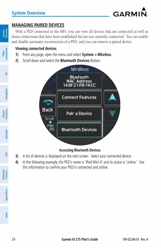
Garmin GI 275 Pilot's Guide 190-02246-01 Rev. H24
System Overview
Syst
em
Ove
rvie
wFl
ight
In
stru
men
tsEI
SN
avig
atio
nH
azar
d Av
oida
nce
Aut
opilo
tIV
SIA
dditi
onal
Fe
atur
esA
ppen
dice
sIn
dex
MANAGING PAIRED DEVICESWith a PED connected to the MFI, you can view all devices that are connected as well as
those connections that have been established but are not currently connected. You can enable and disable automatic reconnection of a PED, and you can remove a paired device.
Viewing connected devices1) From any page, open the menu and select System > Wireless. 2) Scroll down and select the Bluetooth Devices Button.
Accessing Bluetooth Devices3) A list of devices is displayed on the next screen. Select your connected device. 4) In the following example, the PED's name is 'IPad Mini 4' and its status is 'online.' Use
this information to confirm your PED is connected and online.
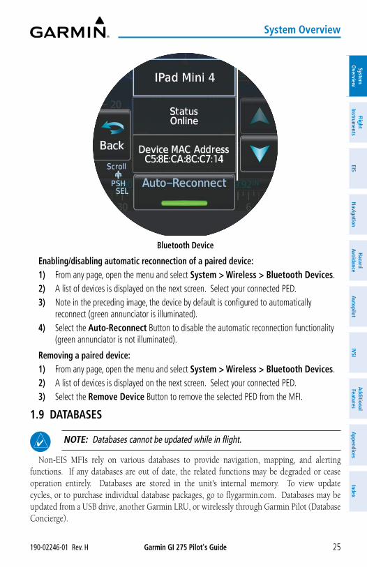
Garmin GI 275 Pilot's Guide190-02246-01 Rev. H 25
System Overview
System
Overview
Flight Instrum
entsEIS
Navigation
Hazard
AvoidanceA
utopilotIVSI
Additional Features
Appendices
Index
Bluetooth Device
Enabling/disabling automatic reconnection of a paired device:1) From any page, open the menu and select System > Wireless > Bluetooth Devices.2) A list of devices is displayed on the next screen. Select your connected PED. 3) Note in the preceding image, the device by default is configured to automatically
reconnect (green annunciator is illuminated).4) Select the Auto-Reconnect Button to disable the automatic reconnection functionality
(green annunciator is not illuminated).
Removing a paired device:1) From any page, open the menu and select System > Wireless > Bluetooth Devices.2) A list of devices is displayed on the next screen. Select your connected PED.3) Select the Remove Device Button to remove the selected PED from the MFI.
1.9 DATABASES
NOTE: Databases cannot be updated while in flight.
Non-EIS MFIs rely on various databases to provide navigation, mapping, and alerting functions. If any databases are out of date, the related functions may be degraded or cease operation entirely. Databases are stored in the unit's internal memory. To view update cycles, or to purchase individual database packages, go to flygarmin.com. Databases may be updated from a USB drive, another Garmin LRU, or wirelessly through Garmin Pilot (Database Concierge).
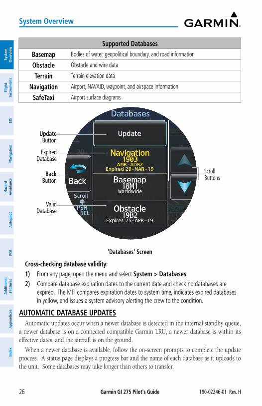
Garmin GI 275 Pilot's Guide 190-02246-01 Rev. H26
System Overview
Syst
em
Ove
rvie
wFl
ight
In
stru
men
tsEI
SN
avig
atio
nH
azar
d Av
oida
nce
Aut
opilo
tIV
SIA
dditi
onal
Fe
atur
esA
ppen
dice
sIn
dex
Supported DatabasesBasemap Bodies of water, geopolitical boundary, and road information
Obstacle Obstacle and wire data
Terrain Terrain elevation data
Navigation Airport, NAVAID, waypoint, and airspace information
SafeTaxi Airport surface diagrams
'Databases' Screen
Update Button
Expired Database
Valid Database
Back Button
ScrollButtons
Cross-checking database validity:1) From any page, open the menu and select System > Databases.2) Compare database expiration dates to the current date and check no databases are
expired. The MFI compares expiration dates to system time, indicates expired databases in yellow, and issues a system advisory alerting the crew to the condition.
AUTOMATIC DATABASE UPDATESAutomatic updates occur when a newer database is detected in the internal standby queue,
a newer database is on a connected compatible Garmin LRU, a newer database is within its effective dates, and the aircraft is on the ground.
When a newer database is available, follow the on-screen prompts to complete the update process. A status page displays a progress bar and the name of each database as it uploads to the unit. Some databases may take longer than others to transfer.
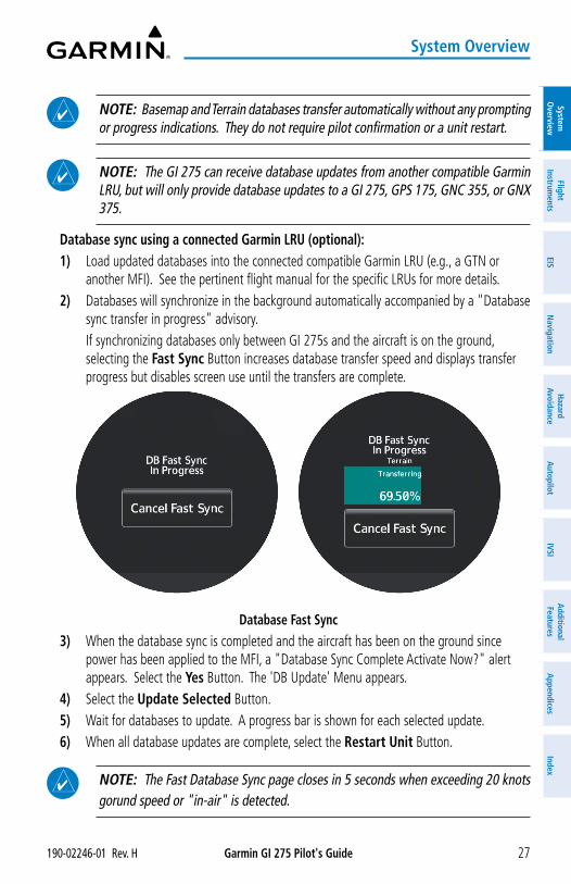
Garmin GI 275 Pilot's Guide190-02246-01 Rev. H 27
System Overview
System
Overview
Flight Instrum
entsEIS
Navigation
Hazard
AvoidanceA
utopilotIVSI
Additional Features
Appendices
Index
NOTE: Basemap and Terrain databases transfer automatically without any prompting or progress indications. They do not require pilot confirmation or a unit restart.
NOTE: The GI 275 can receive database updates from another compatible Garmin LRU, but will only provide database updates to a GI 275, GPS 175, GNC 355, or GNX 375.
Database sync using a connected Garmin LRU (optional):1) Load updated databases into the connected compatible Garmin LRU (e.g., a GTN or
another MFI). See the pertinent flight manual for the specific LRUs for more details.2) Databases will synchronize in the background automatically accompanied by a "Database
sync transfer in progress" advisory. If synchronizing databases only between GI 275s and the aircraft is on the ground,
selecting the Fast Sync Button increases database transfer speed and displays transfer progress but disables screen use until the transfers are complete.
Database Fast Sync3) When the database sync is completed and the aircraft has been on the ground since
power has been applied to the MFI, a "Database Sync Complete Activate Now?" alert appears. Select the Yes Button. The 'DB Update' Menu appears.
4) Select the Update Selected Button.5) Wait for databases to update. A progress bar is shown for each selected update. 6) When all database updates are complete, select the Restart Unit Button.
NOTE: The Fast Database Sync page closes in 5 seconds when exceeding 20 knots gorund speed or "in-air" is detected.
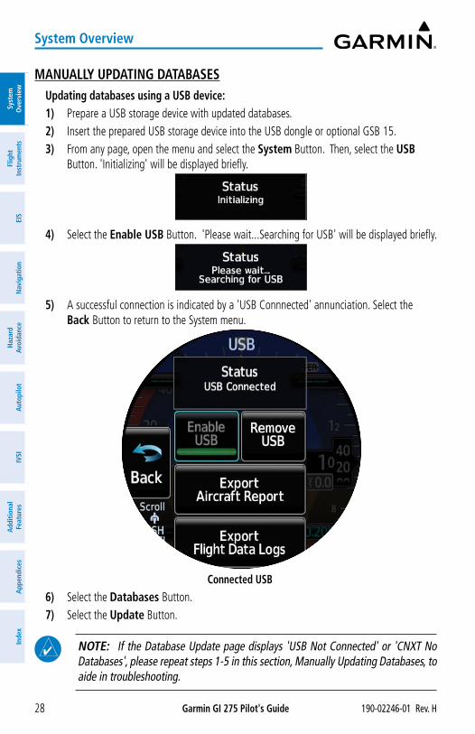
Garmin GI 275 Pilot's Guide 190-02246-01 Rev. H28
System Overview
Syst
em
Ove
rvie
wFl
ight
In
stru
men
tsEI
SN
avig
atio
nH
azar
d Av
oida
nce
Aut
opilo
tIV
SIA
dditi
onal
Fe
atur
esA
ppen
dice
sIn
dex
MANUALLY UPDATING DATABASESUpdating databases using a USB device:1) Prepare a USB storage device with updated databases.2) Insert the prepared USB storage device into the USB dongle or optional GSB 15. 3) From any page, open the menu and select the System Button. Then, select the USB
Button. 'Initializing' will be displayed briefly.
4) Select the Enable USB Button. 'Please wait...Searching for USB' will be displayed briefly.
5) A successful connection is indicated by a 'USB Connnected' annunciation. Select the Back Button to return to the System menu.
Connected USB6) Select the Databases Button.7) Select the Update Button.
NOTE: If the Database Update page displays 'USB Not Connected' or 'CNXT No Databases', please repeat steps 1-5 in this section, Manually Updating Databases, to aide in troubleshooting.
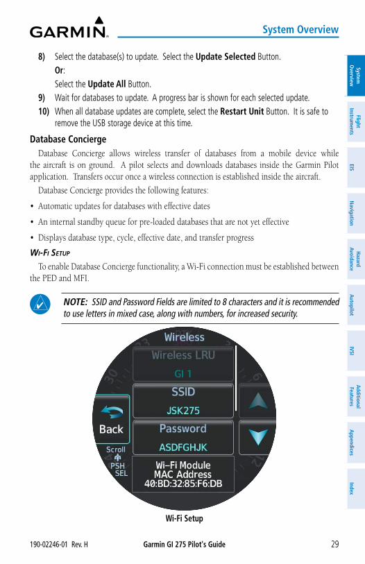
Garmin GI 275 Pilot's Guide190-02246-01 Rev. H 29
System Overview
System
Overview
Flight Instrum
entsEIS
Navigation
Hazard
AvoidanceA
utopilotIVSI
Additional Features
Appendices
Index
8) Select the database(s) to update. Select the Update Selected Button. Or: Select the Update All Button.9) Wait for databases to update. A progress bar is shown for each selected update. 10) When all database updates are complete, select the Restart Unit Button. It is safe to
remove the USB storage device at this time.
Database ConciergeDatabase Concierge allows wireless transfer of databases from a mobile device while
the aircraft is on ground. A pilot selects and downloads databases inside the Garmin Pilot application. Transfers occur once a wireless connection is established inside the aircraft.
Database Concierge provides the following features:
• Automatic updates for databases with effective dates
• An internal standby queue for pre-loaded databases that are not yet effective
• Displays database type, cycle, effective date, and transfer progress
Wi-Fi Setup
To enable Database Concierge functionality, a Wi-Fi connection must be established between the PED and MFI.
NOTE: SSID and Password Fields are limited to 8 characters and it is recommended to use letters in mixed case, along with numbers, for increased security.
Wi-Fi Setup
Garmin GI 275 Pilot's Guide 190-02246-01 Rev. H30
System Overview
Syst
em
Ove
rvie
wFl
ight
In
stru
men
tsEI
SN
avig
atio
nH
azar
d Av
oida
nce
Aut
opilo
tIV
SIA
dditi
onal
Fe
atur
esA
ppen
dice
sIn
dex
Setting the Wi-Fi name (SSID) and password:1) From any page, open the menu and select System > Wireless. 2) Select the SSID Data Field.3) Input the desired Wi-Fi SSID name for the PED to connect to.4) Select the Password Data Field.5) Input the desired Wi-Fi password for the PED to use when connecting to the MFI.
Updating databases through Garmin Pilot (Database Concierge):1) Prepare a mobile device with the Garmin Pilot mobile application and updated databases.
See the Garmin Pilot for iOS or Garmin Pilot for Android user manual for details. 2) Connect the mobile device to the MFI.3) From any page, open the menu and select the System Button. Then, select the
Databases Button.4) Select the Update Button.5) Select the Connext Button.6) Select the database(s) to update. Touch the Update Button. 7) Wait for databases to update. A progress bar is shown for each selected update. 8) When all database updates are complete, select the Restart Unit Button. It is safe to
disconnect the mobile device at this time.
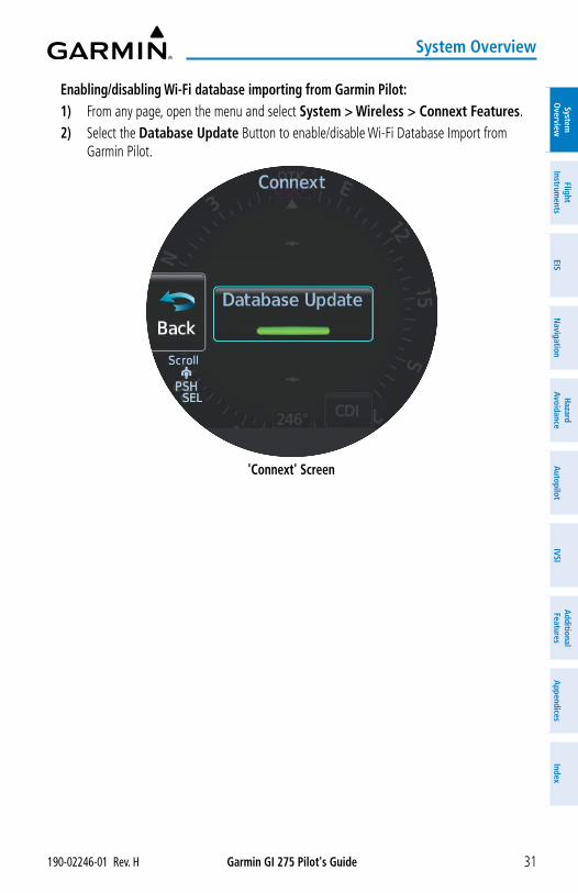
Garmin GI 275 Pilot's Guide190-02246-01 Rev. H 31
System Overview
System
Overview
Flight Instrum
entsEIS
Navigation
Hazard
AvoidanceA
utopilotIVSI
Additional Features
Appendices
Index
Enabling/disabling Wi-Fi database importing from Garmin Pilot:1) From any page, open the menu and select System > Wireless > Connext Features. 2) Select the Database Update Button to enable/disable Wi-Fi Database Import from
Garmin Pilot.
'Connext' Screen
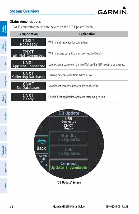
Garmin GI 275 Pilot's Guide 190-02246-01 Rev. H32
System Overview
Syst
em
Ove
rvie
wFl
ight
In
stru
men
tsEI
SN
avig
atio
nH
azar
d Av
oida
nce
Aut
opilo
tIV
SIA
dditi
onal
Fe
atur
esA
ppen
dice
sIn
dex
Status AnnunciationsWi-Fi connection status annunciates on the 'DB Update' Screen.
Annunciation Explanation
Wi-Fi is not yet ready for connection.
Wi-Fi is active, but a PED must connect to the MFI.
Connection is complete. Garmin Pilot on the PED needs to be opened.
Loading database info from Garmin Pilot.
No relevant database updates are on the PED.
Garmin Pilot application open and streaming to unit.
'DB Update' Screen
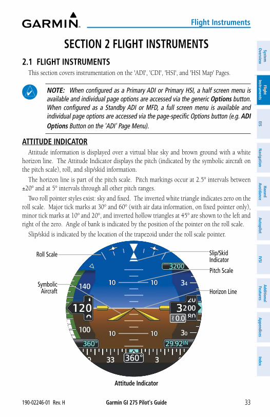
Garmin GI 275 Pilot's Guide190-02246-01 Rev. H 33
Flight Instruments
System
Overview
Flight Instrum
entsEIS
Navigation
Hazard
AvoidanceA
utopilotIVSI
Additional Features
Appendices
Index
SECTION 2 FLIGHT INSTRUMENTS2.1 FLIGHT INSTRUMENTS
This section covers instrumentation on the 'ADI', 'CDI', 'HSI', and 'HSI Map' Pages.
NOTE: When configured as a Primary ADI or Primary HSI, a half screen menu is available and individual page options are accessed via the generic Options button. When configured as a Standby ADI or MFD, a full screen menu is available and individual page options are accessed via the page-specific Options button (e.g. ADI Options Button on the 'ADI' Page Menu).
ATTITUDE INDICATORAttitude information is displayed over a virtual blue sky and brown ground with a white
horizon line. The Attitude Indicator displays the pitch (indicated by the symbolic aircraft on the pitch scale), roll, and slip/skid information.
The horizon line is part of the pitch scale. Pitch markings occur at 2.5° intervals between ±20° and at 5° intervals through all other pitch ranges.
Two roll pointer styles exist: sky and fixed. The inverted white triangle indicates zero on the roll scale. Major tick marks at 30° and 60° (with air data information, on fixed pointer only), minor tick marks at 10° and 20°, and inverted hollow triangles at 45° are shown to the left and right of the zero. Angle of bank is indicated by the position of the pointer on the roll scale.
Slip/skid is indicated by the location of the trapezoid under the roll scale pointer.
Attitude Indicator
Roll Scale
Symbolic Aircraft Horizon Line
Pitch Scale
Slip/Skid Indicator
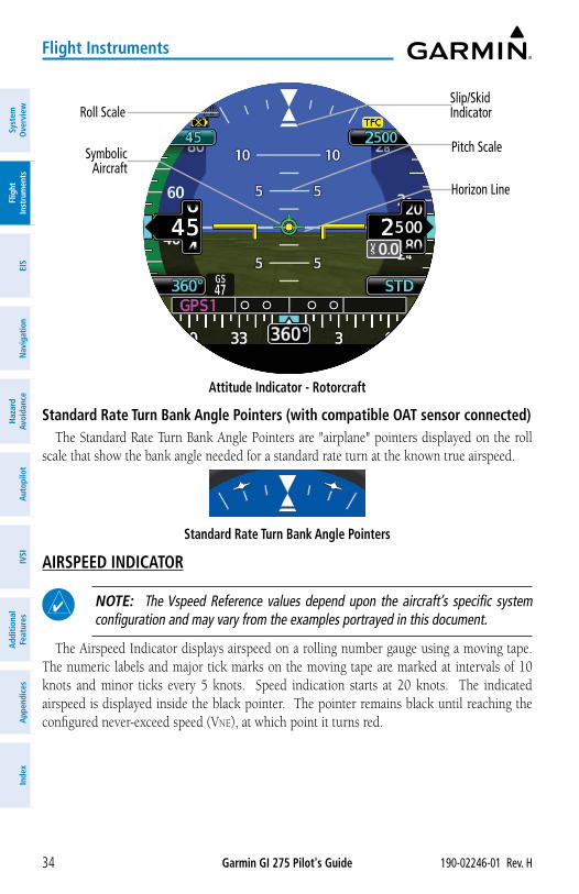
Garmin GI 275 Pilot's Guide 190-02246-01 Rev. H34
Flight Instruments
Syst
em
Ove
rvie
wFl
ight
In
stru
men
tsEI
SN
avig
atio
nH
azar
d Av
oida
nce
Aut
opilo
tIV
SIA
dditi
onal
Fe
atur
esA
ppen
dice
sIn
dex
Attitude Indicator - Rotorcraft
Roll Scale
Symbolic Aircraft
Horizon Line
Pitch Scale
Slip/Skid Indicator
Standard Rate Turn Bank Angle Pointers (with compatible OAT sensor connected)The Standard Rate Turn Bank Angle Pointers are "airplane" pointers displayed on the roll
scale that show the bank angle needed for a standard rate turn at the known true airspeed.
Standard Rate Turn Bank Angle Pointers
AIRSPEED INDICATOR
NOTE: The Vspeed Reference values depend upon the aircraft’s specific system configuration and may vary from the examples portrayed in this document.
The Airspeed Indicator displays airspeed on a rolling number gauge using a moving tape. The numeric labels and major tick marks on the moving tape are marked at intervals of 10 knots and minor ticks every 5 knots. Speed indication starts at 20 knots. The indicated airspeed is displayed inside the black pointer. The pointer remains black until reaching the configured never-exceed speed (Vne), at which point it turns red.
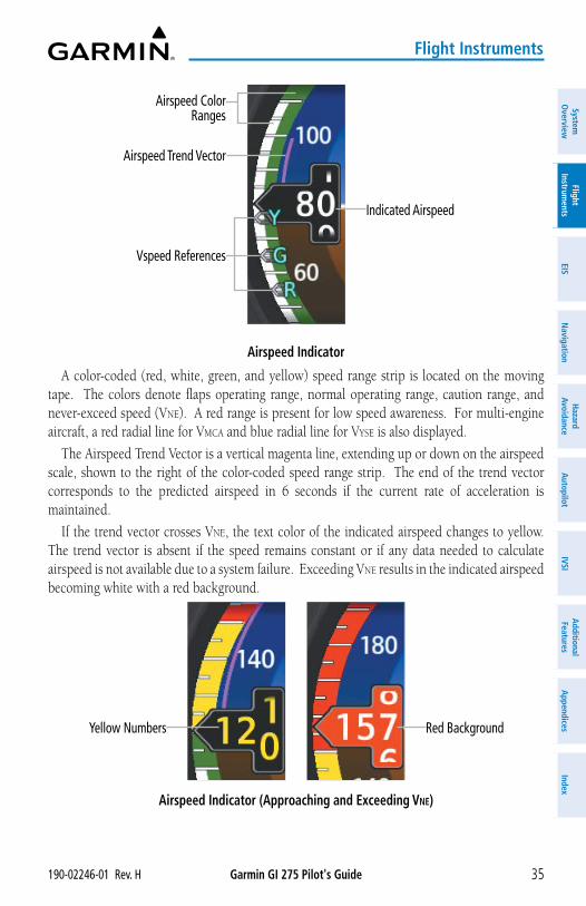
Garmin GI 275 Pilot's Guide190-02246-01 Rev. H 35
Flight Instruments
System
Overview
Flight Instrum
entsEIS
Navigation
Hazard
AvoidanceA
utopilotIVSI
Additional Features
Appendices
Index
Airspeed Indicator
Indicated Airspeed
Airspeed Trend Vector
Airspeed Color Ranges
Vspeed References
A color-coded (red, white, green, and yellow) speed range strip is located on the moving tape. The colors denote flaps operating range, normal operating range, caution range, and never-exceed speed (Vne). A red range is present for low speed awareness. For multi-engine aircraft, a red radial line for Vmca and blue radial line for Vyse is also displayed.
The Airspeed Trend Vector is a vertical magenta line, extending up or down on the airspeed scale, shown to the right of the color-coded speed range strip. The end of the trend vector corresponds to the predicted airspeed in 6 seconds if the current rate of acceleration is maintained.
If the trend vector crosses Vne, the text color of the indicated airspeed changes to yellow. The trend vector is absent if the speed remains constant or if any data needed to calculate airspeed is not available due to a system failure. Exceeding Vne results in the indicated airspeed becoming white with a red background.
Airspeed Indicator (Approaching and Exceeding Vne)
Red BackgroundYellow Numbers
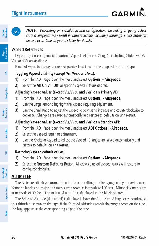
Garmin GI 275 Pilot's Guide 190-02246-01 Rev. H36
Flight Instruments
Syst
em
Ove
rvie
wFl
ight
In
stru
men
tsEI
SN
avig
atio
nH
azar
d Av
oida
nce
Aut
opilo
tIV
SIA
dditi
onal
Fe
atur
esA
ppen
dice
sIn
dex
NOTE: Depending on installation and configuration, exceeding or going below certain airspeeds may result in various actions including warnings and/or autopilot disconnects. Consult your installer for details.
Vspeed ReferencesDepending on configuration, various Vspeed references ("bugs") including Glide, Vx, Vy,
Vle, and Vr are available.
Enabled Vspeeds display at their respective locations on the airspeed indicator tape.
Toggling Vspeed visibility (except Vle, Vmca, and Vyse):1) From the 'ADI' Page, open the menu and select Options > Airspeeds.2) Select the All On, All Off, or specific Vspeed Buttons desired.
Adjusting Vspeed values (except Vle, Vmca, and Vyse) on a Primary ADI:1) From the 'ADI' Page, open the menu and select Options > Airspeeds.2) Use the Large Knob to highlight the Vspeed requiring adjustment.3) Use the Small Knob to adjust the Vspeed, clockwise to increase and counterclockwise to
decrease. Changes are saved automatically and restore to defaults on unit restart.
Adjusting Vspeed values (except Vle, Vmca, and Vyse) on a Standby ADI:1) From the 'ADI' Page, open the menu and select ADI Options > Airspeeds.2) Select the Vspeed requiring adjustment.3) Use the Knobs or keypad to adjust the Vspeed. Changes are saved automatically and
restore to defaults on unit restart.
Restoring Vspeed default values:1) From the 'ADI' Page, open the menu and select Options > Airspeeds.2) Select the Restore Defaults Button. All crew-adjusted Vspeed values will restore to
configured defaults.
ALTIMETERThe Altimeter displays barometric altitude on a rolling number gauge using a moving tape.
Numeric labels and major tick marks are shown at intervals of 100 feet. Minor tick marks are at intervals of 50 feet. The indicated altitude is displayed in the black pointer.
The Selected Altitude (if enabled) is displayed above the Altimeter. A bug corresponding to this altitude is shown on the tape; if the Selected Altitude exceeds the range shown on the tape, the bug appears at the corresponding edge of the tape.
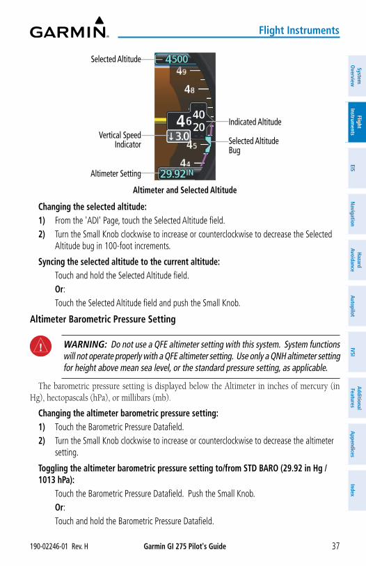
Garmin GI 275 Pilot's Guide190-02246-01 Rev. H 37
Flight Instruments
System
Overview
Flight Instrum
entsEIS
Navigation
Hazard
AvoidanceA
utopilotIVSI
Additional Features
Appendices
Index
Altimeter and Selected Altitude
Indicated Altitude
Selected Altitude Bug
Vertical Speed Indicator
Selected Altitude
Altimeter Setting
Changing the selected altitude:1) From the 'ADI' Page, touch the Selected Altitude field.2) Turn the Small Knob clockwise to increase or counterclockwise to decrease the Selected
Altitude bug in 100-foot increments.
Syncing the selected altitude to the current altitude: Touch and hold the Selected Altitude field. Or: Touch the Selected Altitude field and push the Small Knob.
Altimeter Barometric Pressure Setting
WARNING: Do not use a QFE altimeter setting with this system. System functions will not operate properly with a QFE altimeter setting. Use only a QNH altimeter setting for height above mean sea level, or the standard pressure setting, as applicable.
The barometric pressure setting is displayed below the Altimeter in inches of mercury (in Hg), hectopascals (hPa), or millibars (mb).
Changing the altimeter barometric pressure setting:1) Touch the Barometric Pressure Datafield.2) Turn the Small Knob clockwise to increase or counterclockwise to decrease the altimeter
setting.
Toggling the altimeter barometric pressure setting to/from STD BARO (29.92 in Hg / 1013 hPa): Touch the Barometric Pressure Datafield. Push the Small Knob. Or: Touch and hold the Barometric Pressure Datafield.
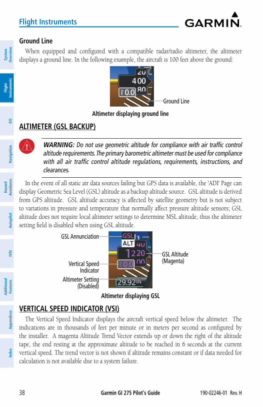
Garmin GI 275 Pilot's Guide 190-02246-01 Rev. H38
Flight Instruments
Syst
em
Ove
rvie
wFl
ight
In
stru
men
tsEI
SN
avig
atio
nH
azar
d Av
oida
nce
Aut
opilo
tIV
SIA
dditi
onal
Fe
atur
esA
ppen
dice
sIn
dex
Ground LineWhen equipped and configured with a compatible radar/radio altimeter, the altimeter
displays a ground line. In the following example, the aircraft is 100 feet above the ground:
Altimeter displaying ground line
Ground Line
ALTIMETER (GSL BACKUP)
WARNING: Do not use geometric altitude for compliance with air traffic control altitude requirements. The primary barometric altimeter must be used for compliance with all air traffic control altitude regulations, requirements, instructions, and clearances.
In the event of all static air data sources failing but GPS data is available, the 'ADI' Page can display Geometric Sea Level (GSL) altitude as a backup altitude source. GSL altitude is derived from GPS altitude. GSL altitude accuracy is affected by satellite geometry but is not subject to variations in pressure and temperature that normally affect pressure altitude sensors; GSL altitude does not require local altimeter settings to determine MSL altitude, thus the altimeter setting field is disabled when using GSL altitude.
Altimeter displaying GSL
GSL Altitude (Magenta)Vertical Speed
Indicator
GSL Annunciation
Altimeter Setting (Disabled)
VERTICAL SPEED INDICATOR (VSI)The Vertical Speed Indicator displays the aircraft vertical speed below the altimeter. The
indications are in thousands of feet per minute or in meters per second as configured by the installer. A magenta Altitude Trend Vector extends up or down the right of the altitude tape, the end resting at the approximate altitude to be reached in 6 seconds at the current vertical speed. The trend vector is not shown if altitude remains constant or if data needed for calculation is not available due to a system failure.
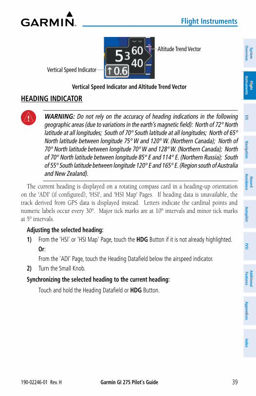
Garmin GI 275 Pilot's Guide190-02246-01 Rev. H 39
Flight Instruments
System
Overview
Flight Instrum
entsEIS
Navigation
Hazard
AvoidanceA
utopilotIVSI
Additional Features
Appendices
Index
Vertical Speed Indicator and Altitude Trend Vector
Altitude Trend Vector
Vertical Speed Indicator
HEADING INDICATOR
WARNING: Do not rely on the accuracy of heading indications in the following geographic areas (due to variations in the earth’s magnetic field): North of 72° North latitude at all longitudes; South of 70° South latitude at all longitudes; North of 65° North latitude between longitude 75° W and 120° W. (Northern Canada); North of 70° North latitude between longitude 70° W and 128° W. (Northern Canada); North of 70° North latitude between longitude 85° E and 114° E. (Northern Russia); South of 55° South latitude between longitude 120° E and 165° E. (Region south of Australia and New Zealand).
The current heading is displayed on a rotating compass card in a heading-up orientation on the 'ADI' (if configured), 'HSI', and 'HSI Map' Pages. If heading data is unavailable, the track derived from GPS data is displayed instead. Letters indicate the cardinal points and numeric labels occur every 30°. Major tick marks are at 10° intervals and minor tick marks at 5° intervals.
Adjusting the selected heading:1) From the 'HSI' or 'HSI Map' Page, touch the HDG Button if it is not already highlighted. Or: From the 'ADI' Page, touch the Heading Datafield below the airspeed indicator.2) Turn the Small Knob.
Synchronizing the selected heading to the current heading:
Touch and hold the Heading Datafield or HDG Button.
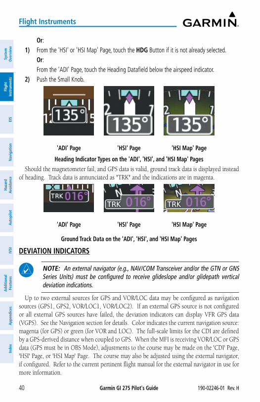
Garmin GI 275 Pilot's Guide 190-02246-01 Rev. H40
Flight Instruments
Syst
em
Ove
rvie
wFl
ight
In
stru
men
tsEI
SN
avig
atio
nH
azar
d Av
oida
nce
Aut
opilo
tIV
SIA
dditi
onal
Fe
atur
esA
ppen
dice
sIn
dex
Or:1) From the 'HSI' or 'HSI Map' Page, touch the HDG Button if it is not already selected. Or: From the 'ADI' Page, touch the Heading Datafield below the airspeed indicator.2) Push the Small Knob.
Heading Indicator Types on the 'ADI', 'HSI', and 'HSI Map' Pages
'ADI' Page 'HSI' Page 'HSI Map' Page
Should the magnetometer fail, and GPS data is valid, ground track data is displayed instead of heading. Track data is annunciated as "TRK" and the indications are in magenta.
Ground Track Data on the 'ADI', 'HSI', and 'HSI Map' Pages
'HSI' Page'ADI' Page 'HSI Map' Page
DEVIATION INDICATORS
NOTE: An external navigator (e.g., NAV/COM Transceiver and/or the GTN or GNS Series Units) must be configured to receive glideslope and/or glidepath vertical deviation indications.
Up to two external sources for GPS and VOR/LOC data may be configured as navigation sources (GPS1, GPS2, VOR/LOC1, VOR/LOC2). If an external GPS source is not configured or all external GPS sources have failed, the deviation indicators can display VFR GPS data (VGPS). See the Navigation section for details. Color indicates the current navigation source: magenta (for GPS) or green (for VOR and LOC). The full-scale limits for the CDI are defined by a GPS-derived distance when coupled to GPS. When the MFI is receiving VOR/LOC or GPS data (GPS must be in OBS Mode), adjustments to the course may be made on the 'CDI' Page, 'HSI' Page, or 'HSI Map' Page. The course may also be adjusted using the external navigator, if configured. Refer to the current pertinent flight manual for the external navigator in use for more information.
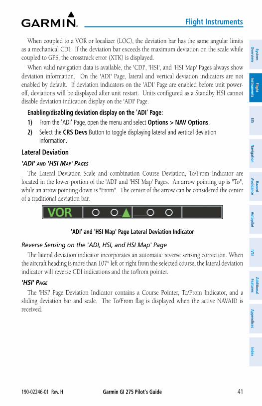
Garmin GI 275 Pilot's Guide190-02246-01 Rev. H 41
Flight Instruments
System
Overview
Flight Instrum
entsEIS
Navigation
Hazard
AvoidanceA
utopilotIVSI
Additional Features
Appendices
Index
When coupled to a VOR or localizer (LOC), the deviation bar has the same angular limits as a mechanical CDI. If the deviation bar exceeds the maximum deviation on the scale while coupled to GPS, the crosstrack error (XTK) is displayed.
When valid navigation data is available, the 'CDI', 'HSI', and 'HSI Map' Pages always show deviation information. On the 'ADI' Page, lateral and vertical deviation indicators are not enabled by default. If deviation indicators on the 'ADI' Page are enabled before unit power-off, deviations will be displayed after unit restart. Units configured as a Standby HSI cannot disable deviation indication display on the 'ADI' Page.
Enabling/disabling deviation display on the 'ADI' Page:1) From the 'ADI' Page, open the menu and select Options > NAV Options.2) Select the CRS Devs Button to toggle displaying lateral and vertical deviation
information.
Lateral Deviation
'ADi' AnD 'HSi MAp' pAgeS
The Lateral Deviation Scale and combination Course Deviation, To/From Indicator are located in the lower portion of the 'ADI' and 'HSI Map' Pages. An arrow pointing up is "To", while an arrow pointing down is "From". The center of the arrow can be considered the center of a traditional deviation bar.
'ADI' and 'HSI Map' Page Lateral Deviation Indicator
Reverse Sensing on the 'ADI, HSI, and HSI Map' Page
The lateral deviation indicator incorporates an automatic reverse sensing correction. When the aircraft heading is more than 107° left or right from the selected course, the lateral deviation indicator will reverse CDI indications and the to/from pointer.
'HSi' pAge
The 'HSI' Page Deviation Indicator contains a Course Pointer, To/From Indicator, and a sliding deviation bar and scale. The To/From flag is displayed when the active NAVAID is received.
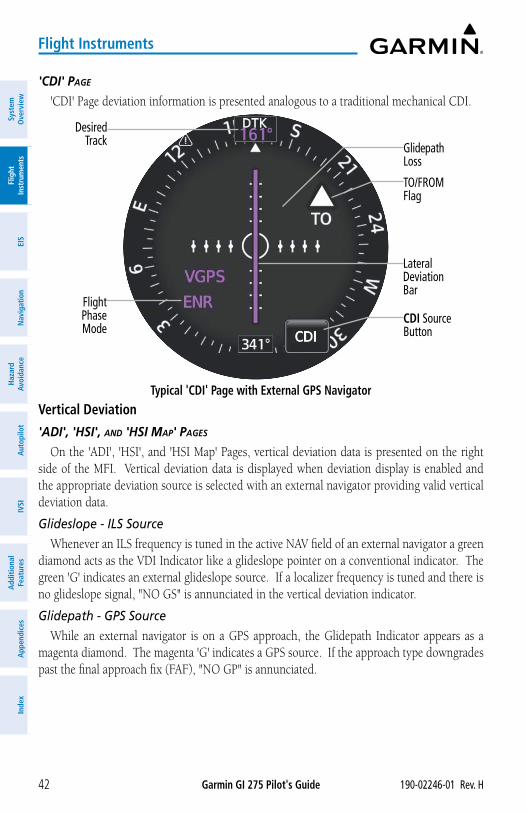
Garmin GI 275 Pilot's Guide 190-02246-01 Rev. H42
Flight Instruments
Syst
em
Ove
rvie
wFl
ight
In
stru
men
tsEI
SN
avig
atio
nH
azar
d Av
oida
nce
Aut
opilo
tIV
SIA
dditi
onal
Fe
atur
esA
ppen
dice
sIn
dex
'CDi' pAge
'CDI' Page deviation information is presented analogous to a traditional mechanical CDI.
Typical 'CDI' Page with External GPS Navigator
Desired Track
Flight Phase Mode
TO/FROM Flag
Glidepath Loss
CDI Source Button
Lateral Deviation Bar
Vertical Deviation
'ADi', 'HSi', AnD 'HSi MAp' pAgeS
On the 'ADI', 'HSI', and 'HSI Map' Pages, vertical deviation data is presented on the right side of the MFI. Vertical deviation data is displayed when deviation display is enabled and the appropriate deviation source is selected with an external navigator providing valid vertical deviation data.
Glideslope - ILS Source
Whenever an ILS frequency is tuned in the active NAV field of an external navigator a green diamond acts as the VDI Indicator like a glideslope pointer on a conventional indicator. The green 'G' indicates an external glideslope source. If a localizer frequency is tuned and there is no glideslope signal, "NO GS" is annunciated in the vertical deviation indicator.
Glidepath - GPS Source
While an external navigator is on a GPS approach, the Glidepath Indicator appears as a magenta diamond. The magenta 'G' indicates a GPS source. If the approach type downgrades past the final approach fix (FAF), "NO GP" is annunciated.
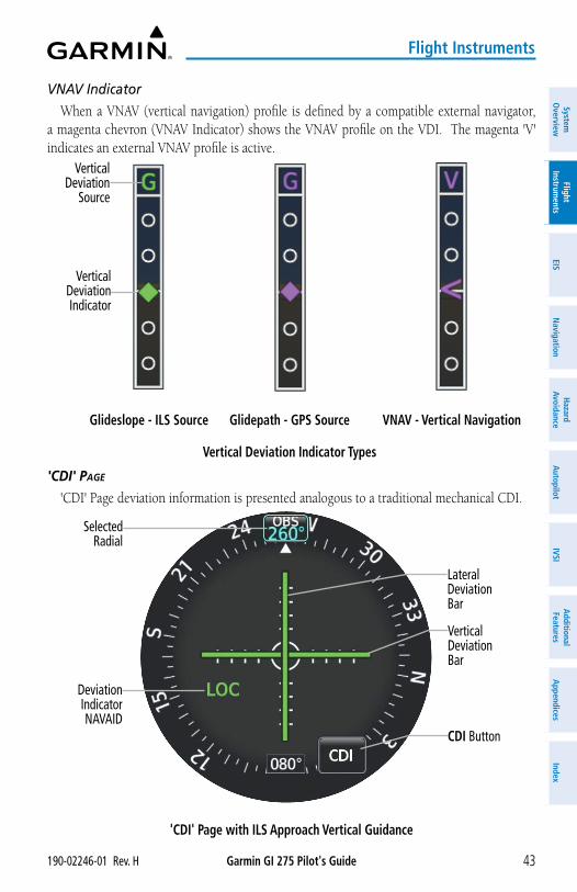
Garmin GI 275 Pilot's Guide190-02246-01 Rev. H 43
Flight Instruments
System
Overview
Flight Instrum
entsEIS
Navigation
Hazard
AvoidanceA
utopilotIVSI
Additional Features
Appendices
Index
VNAV Indicator
When a VNAV (vertical navigation) profile is defined by a compatible external navigator, a magenta chevron (VNAV Indicator) shows the VNAV profile on the VDI. The magenta 'V' indicates an external VNAV profile is active.
Vertical Deviation Indicator Types
Glideslope - ILS Source
Vertical Deviation Indicator
Vertical Deviation
Source
Glidepath - GPS Source VNAV - Vertical Navigation
'CDi' pAge
'CDI' Page deviation information is presented analogous to a traditional mechanical CDI.
'CDI' Page with ILS Approach Vertical Guidance
Selected Radial
Deviation Indicator NAVAID
Vertical Deviation Bar
CDI Button
Lateral Deviation Bar
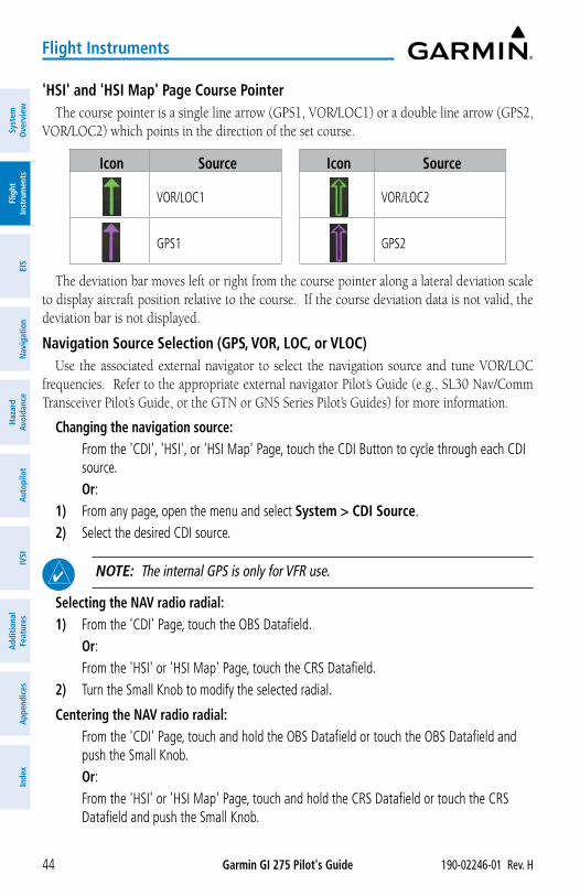
Garmin GI 275 Pilot's Guide 190-02246-01 Rev. H44
Flight Instruments
Syst
em
Ove
rvie
wFl
ight
In
stru
men
tsEI
SN
avig
atio
nH
azar
d Av
oida
nce
Aut
opilo
tIV
SIA
dditi
onal
Fe
atur
esA
ppen
dice
sIn
dex
'HSI' and 'HSI Map' Page Course PointerThe course pointer is a single line arrow (GPS1, VOR/LOC1) or a double line arrow (GPS2,
VOR/LOC2) which points in the direction of the set course.
Icon Source Icon Source
VOR/LOC1 VOR/LOC2
GPS1 GPS2
The deviation bar moves left or right from the course pointer along a lateral deviation scale to display aircraft position relative to the course. If the course deviation data is not valid, the deviation bar is not displayed.
Navigation Source Selection (GPS, VOR, LOC, or VLOC)Use the associated external navigator to select the navigation source and tune VOR/LOC
frequencies. Refer to the appropriate external navigator Pilot’s Guide (e.g., SL30 Nav/Comm Transceiver Pilot’s Guide, or the GTN or GNS Series Pilot’s Guides) for more information.
Changing the navigation source: From the 'CDI', 'HSI', or 'HSI Map' Page, touch the CDI Button to cycle through each CDI
source. Or:1) From any page, open the menu and select System > CDI Source.2) Select the desired CDI source.
NOTE: The internal GPS is only for VFR use.
Selecting the NAV radio radial:1) From the 'CDI' Page, touch the OBS Datafield. Or: From the 'HSI' or 'HSI Map' Page, touch the CRS Datafield.2) Turn the Small Knob to modify the selected radial.
Centering the NAV radio radial: From the 'CDI' Page, touch and hold the OBS Datafield or touch the OBS Datafield and
push the Small Knob. Or: From the 'HSI' or 'HSI Map' Page, touch and hold the CRS Datafield or touch the CRS
Datafield and push the Small Knob.
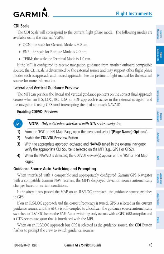
Garmin GI 275 Pilot's Guide190-02246-01 Rev. H 45
Flight Instruments
System
Overview
Flight Instrum
entsEIS
Navigation
Hazard
AvoidanceA
utopilotIVSI
Additional Features
Appendices
Index
CDI ScaleThe CDI Scale will correspond to the current flight phase mode. The following modes are
available using the internal VGPS:
» OCN: the scale for Oceanic Mode is 4.0 nm.
» ENR: the scale for Enroute Mode is 2.0 nm.
» TERM: the scale for Terminal Mode is 1.0 nm.
If the MFI is configured to receive navigation guidance from another onboard compatible source, the CDI scale is determined by the external source and may support other flight phase modes such as approach and missed approach. See the pertinent flight manual for the external source for more information.
Lateral and Vertical Guidance PreviewThe MFI can preview the lateral and vertical guidance pointers on the correct final approach
course when an ILS, LOC, BC, LDA, or SDF approach is active in the external navigator and the navigator is using GPS until intercepting the final approach NAVAID.
Enabling CDI/VDI Preview:
NOTE: Only valid when interfaced with GTN series navigator.
1) From the 'HSI' or 'HSI Map' Page, open the menu and select '(Page Name) Options'.2) Enable the CDI/VDI Preview Button. 3) With the appropriate approach activated and NAVAID tuned in the external navigator,
verify the appropriate CDI Source is selected on the MFI (e.g., GPS1 or GPS2).4) When the NAVAID is detected, the CDI/VDI Preview(s) appear on the 'HSI' or 'HSI Map'
Pages.
Guidance Source Auto-Switching and PromptingWhen interfaced with a compatible and appropriately configured Garmin GPS Navigator
with a compatible Garmin NAV receiver, the MFI's displayed deviation source automatically changes based on certain conditions.
If the aircraft has passed the MAP on an ILS/LOC approach, the guidance source switches to GPS.
If on an ILS/LOC approach and the correct frequency is tuned, GPS is selected as the current guidance source, and the AFCS is roll-coupled to a localizer, the guidance source automatically switches to ILS/LOC before the FAF. Auto-switching only occurs with a GFC 600 autopilot and a GTN series navigator that is interfaced with the MFI.
When on an ILS/LOC approach but GPS is selected as the guidance source, the CDI Button flashes to prompt the crew to switch guidance sources.
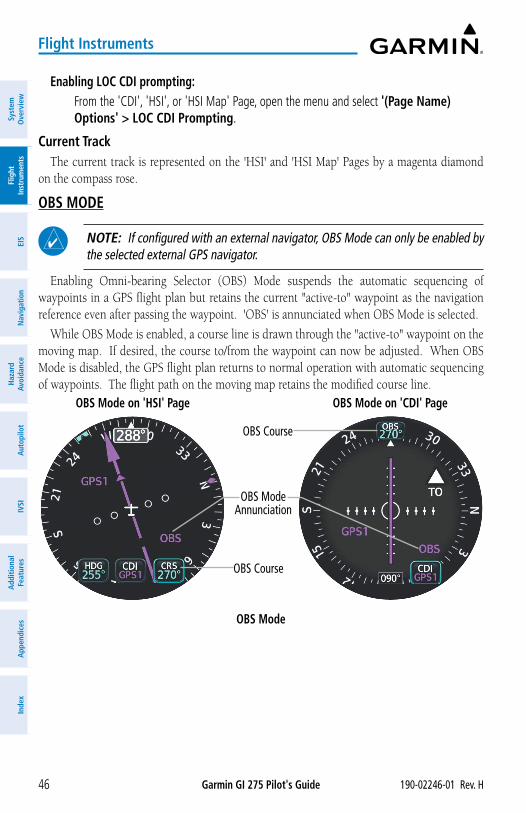
Garmin GI 275 Pilot's Guide 190-02246-01 Rev. H46
Flight Instruments
Syst
em
Ove
rvie
wFl
ight
In
stru
men
tsEI
SN
avig
atio
nH
azar
d Av
oida
nce
Aut
opilo
tIV
SIA
dditi
onal
Fe
atur
esA
ppen
dice
sIn
dex
Enabling LOC CDI prompting: From the 'CDI', 'HSI', or 'HSI Map' Page, open the menu and select '(Page Name)
Options' > LOC CDI Prompting.
Current TrackThe current track is represented on the 'HSI' and 'HSI Map' Pages by a magenta diamond
on the compass rose.
OBS MODE
NOTE: If configured with an external navigator, OBS Mode can only be enabled by the selected external GPS navigator.
Enabling Omni-bearing Selector (OBS) Mode suspends the automatic sequencing of waypoints in a GPS flight plan but retains the current "active-to" waypoint as the navigation reference even after passing the waypoint. 'OBS' is annunciated when OBS Mode is selected.
While OBS Mode is enabled, a course line is drawn through the "active-to" waypoint on the moving map. If desired, the course to/from the waypoint can now be adjusted. When OBS Mode is disabled, the GPS flight plan returns to normal operation with automatic sequencing of waypoints. The flight path on the moving map retains the modified course line.
OBS Mode
OBS Mode Annunciation
OBS Course
OBS Course
OBS Mode on 'HSI' Page OBS Mode on 'CDI' Page
Garmin GI 275 Pilot's Guide190-02246-01 Rev. H 47
Flight Instruments
System
Overview
Flight Instrum
entsEIS
Navigation
Hazard
AvoidanceA
utopilotIVSI
Additional Features
Appendices
Index
Setting the course in OBS Mode (with external GPS navigator configured):1) Activate OBS Mode using the external GPS navigator.2) Use the external navigator to set the OBS course.
Or: From the 'HSI' or 'HSI Map' Page, touch the CRS Button. Use the Knob to select the OBS
course.Or:
From the 'CDI' Page, touch the OBS Button. Use the Knob to select the OBS course.Or:
From the 'CDI', 'HSI', or 'HSI Map' Page, open the menu and select '(Page Name) Options' > CRS Options.
SUSP ModeIf automatic waypoint sequencing is suspended, "SUSP" will be annunciated on any Page
displaying course deviations ('ADI', 'CDI', 'HSI', and 'HSI Map'). For information on SUSP Mode using an external navigator, see the current pertinent flight manual for that navigator.
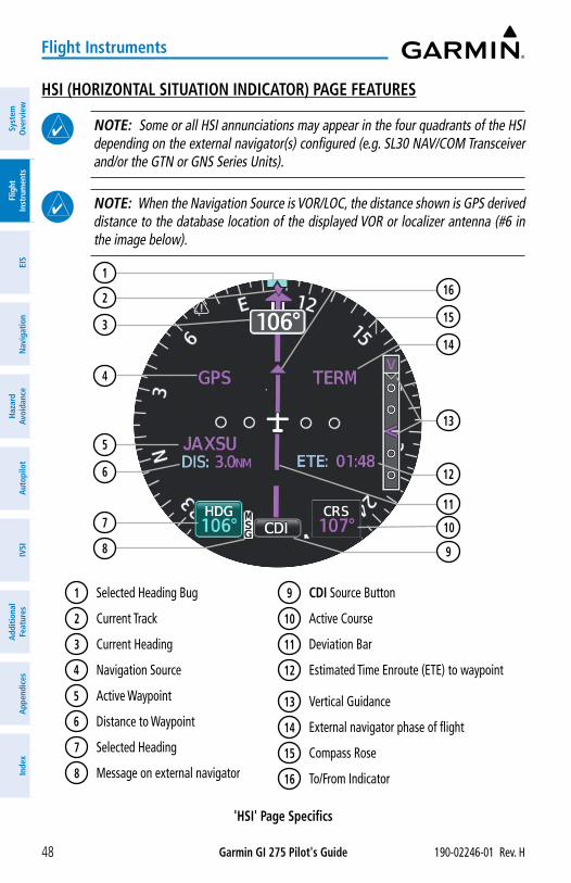
Garmin GI 275 Pilot's Guide 190-02246-01 Rev. H48
Flight Instruments
Syst
em
Ove
rvie
wFl
ight
In
stru
men
tsEI
SN
avig
atio
nH
azar
d Av
oida
nce
Aut
opilo
tIV
SIA
dditi
onal
Fe
atur
esA
ppen
dice
sIn
dex
HSI (HORIZONTAL SITUATION INDICATOR) PAGE FEATURES
NOTE: Some or all HSI annunciations may appear in the four quadrants of the HSI depending on the external navigator(s) configured (e.g. SL30 NAV/COM Transceiver and/or the GTN or GNS Series Units).
NOTE: When the Navigation Source is VOR/LOC, the distance shown is GPS derived distance to the database location of the displayed VOR or localizer antenna (#6 in the image below).
'HSI' Page Specifics
1 Selected Heading Bug
2 Current Track
3 Current Heading
4 Navigation Source
5 Active Waypoint
6 Distance to Waypoint
7 Selected Heading
8 Message on external navigator
9 CDI Source Button
10 Active Course
11 Deviation Bar
12 Estimated Time Enroute (ETE) to waypoint
13 Vertical Guidance
14 External navigator phase of flight
15 Compass Rose
16 To/From Indicator
3
1
2
13
4
8 9
10
11
12
14
15
16
5
6
7
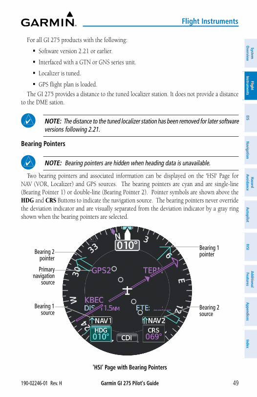
Garmin GI 275 Pilot's Guide190-02246-01 Rev. H 49
Flight Instruments
System
Overview
Flight Instrum
entsEIS
Navigation
Hazard
AvoidanceA
utopilotIVSI
Additional Features
Appendices
Index
For all GI 275 products with the following:
� Software version 2.21 or earlier.
� Interfaced with a GTN or GNS series unit.
� Localizer is tuned.
� GPS flight plan is loaded.
The GI 275 provides a distance to the tuned localizer station. It does not provide a distance to the DME sation.
NOTE: The distance to the tuned localizer station has been removed for later software versions following 2.21.
Bearing Pointers
NOTE: Bearing pointers are hidden when heading data is unavailable.
Two bearing pointers and associated information can be displayed on the 'HSI' Page for NAV (VOR, Localizer) and GPS sources. The bearing pointers are cyan and are single-line (Bearing Pointer 1) or double-line (Bearing Pointer 2). Pointer symbols are shown above the HDG and CRS Buttons to indicate the navigation source. The bearing pointers never override the deviation indicator and are visually separated from the deviation indicator by a gray ring shown when the bearing pointers are selected.
'HSI' Page with Bearing Pointers
Primary navigation
source
Bearing 2 pointer
Bearing 1 source
Bearing 2 source
Bearing 1 pointer
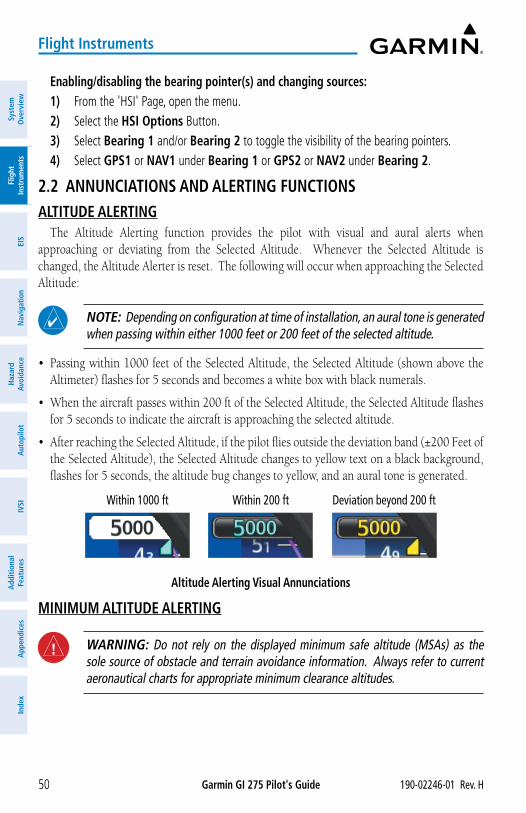
Garmin GI 275 Pilot's Guide 190-02246-01 Rev. H50
Flight Instruments
Syst
em
Ove
rvie
wFl
ight
In
stru
men
tsEI
SN
avig
atio
nH
azar
d Av
oida
nce
Aut
opilo
tIV
SIA
dditi
onal
Fe
atur
esA
ppen
dice
sIn
dex
Enabling/disabling the bearing pointer(s) and changing sources:1) From the 'HSI' Page, open the menu.2) Select the HSI Options Button.3) Select Bearing 1 and/or Bearing 2 to toggle the visibility of the bearing pointers.4) Select GPS1 or NAV1 under Bearing 1 or GPS2 or NAV2 under Bearing 2.
2.2 ANNUNCIATIONS AND ALERTING FUNCTIONSALTITUDE ALERTING
The Altitude Alerting function provides the pilot with visual and aural alerts when approaching or deviating from the Selected Altitude. Whenever the Selected Altitude is changed, the Altitude Alerter is reset. The following will occur when approaching the Selected Altitude:
NOTE: Depending on configuration at time of installation, an aural tone is generated when passing within either 1000 feet or 200 feet of the selected altitude.
• Passing within 1000 feet of the Selected Altitude, the Selected Altitude (shown above the Altimeter) flashes for 5 seconds and becomes a white box with black numerals.
• When the aircraft passes within 200 ft of the Selected Altitude, the Selected Altitude flashes for 5 seconds to indicate the aircraft is approaching the selected altitude.
• After reaching the Selected Altitude, if the pilot flies outside the deviation band (±200 Feet of the Selected Altitude), the Selected Altitude changes to yellow text on a black background, flashes for 5 seconds, the altitude bug changes to yellow, and an aural tone is generated.
Altitude Alerting Visual Annunciations
Within 1000 ft Within 200 ft Deviation beyond 200 ft
MINIMUM ALTITUDE ALERTING
WARNING: Do not rely on the displayed minimum safe altitude (MSAs) as the sole source of obstacle and terrain avoidance information. Always refer to current aeronautical charts for appropriate minimum clearance altitudes.
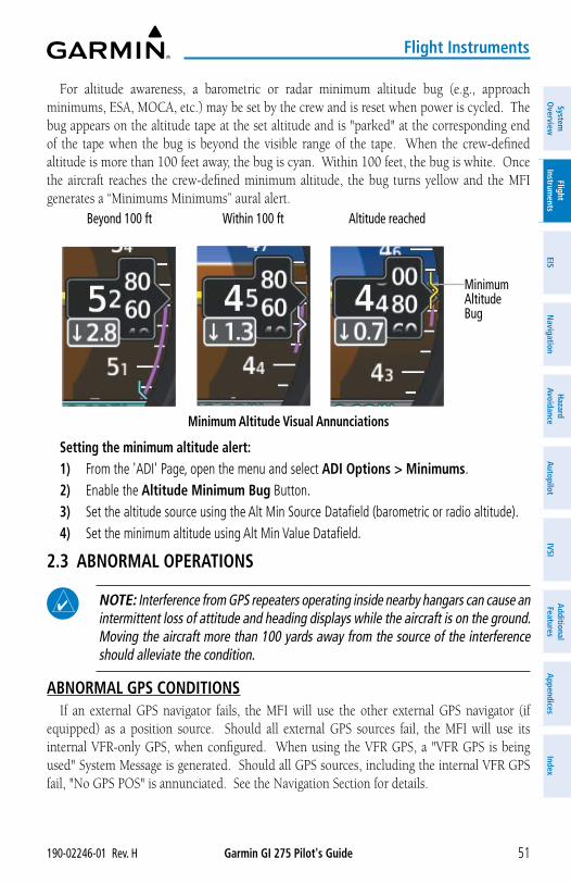
Garmin GI 275 Pilot's Guide190-02246-01 Rev. H 51
Flight Instruments
System
Overview
Flight Instrum
entsEIS
Navigation
Hazard
AvoidanceA
utopilotIVSI
Additional Features
Appendices
Index
For altitude awareness, a barometric or radar minimum altitude bug (e.g., approach minimums, ESA, MOCA, etc.) may be set by the crew and is reset when power is cycled. The bug appears on the altitude tape at the set altitude and is "parked" at the corresponding end of the tape when the bug is beyond the visible range of the tape. When the crew-defined altitude is more than 100 feet away, the bug is cyan. Within 100 feet, the bug is white. Once the aircraft reaches the crew-defined minimum altitude, the bug turns yellow and the MFI generates a “Minimums Minimums” aural alert.
Minimum Altitude Visual Annunciations
Beyond 100 ft Within 100 ft Altitude reached
Minimum Altitude Bug
Setting the minimum altitude alert:1) From the 'ADI' Page, open the menu and select ADI Options > Minimums.2) Enable the Altitude Minimum Bug Button.3) Set the altitude source using the Alt Min Source Datafield (barometric or radio altitude). 4) Set the minimum altitude using Alt Min Value Datafield.
2.3 ABNORMAL OPERATIONS
NOTE: Interference from GPS repeaters operating inside nearby hangars can cause an intermittent loss of attitude and heading displays while the aircraft is on the ground. Moving the aircraft more than 100 yards away from the source of the interference should alleviate the condition.
ABNORMAL GPS CONDITIONSIf an external GPS navigator fails, the MFI will use the other external GPS navigator (if
equipped) as a position source. Should all external GPS sources fail, the MFI will use its internal VFR-only GPS, when configured. When using the VFR GPS, a "VFR GPS is being used" System Message is generated. Should all GPS sources, including the internal VFR GPS fail, "No GPS POS" is annunciated. See the Navigation Section for details.
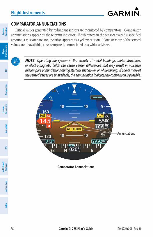
Garmin GI 275 Pilot's Guide 190-02246-01 Rev. H52
Flight Instruments
Syst
em
Ove
rvie
wFl
ight
In
stru
men
tsEI
SN
avig
atio
nH
azar
d Av
oida
nce
Aut
opilo
tIV
SIA
dditi
onal
Fe
atur
esA
ppen
dice
sIn
dex
COMPARATOR ANNUNCIATIONSCritical values generated by redundant sensors are monitored by comparators. Comparator
annunciations appear by the relevant indicator. If differences in the sensors exceed a specified amount, a miscompare annunciation appears as a yellow caution. If one or more of the sensed values are unavailable, a no compare is annunciated as a white advisory.
NOTE: Operating the system in the vicinity of metal buildings, metal structures, or electromagnetic fields can cause sensor differences that may result in nuisance miscompare annunciations during start up, shut down, or while taxiing. If one or more of the sensed values are unavailable, the annunciation indicates no comparison is possible.
Comparator Annunciations
Annunciations
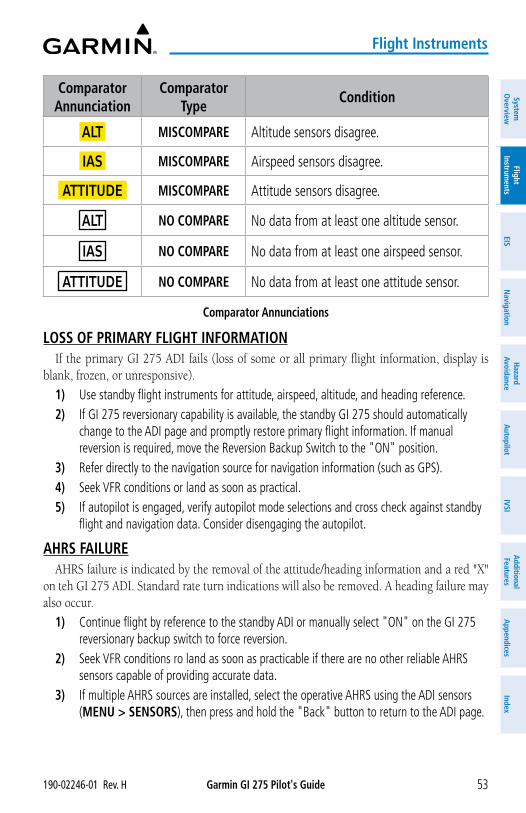
Garmin GI 275 Pilot's Guide190-02246-01 Rev. H 53
Flight Instruments
System
Overview
Flight Instrum
entsEIS
Navigation
Hazard
AvoidanceA
utopilotIVSI
Additional Features
Appendices
Index
Comparator Annunciation
Comparator Type
Condition
ALT MISCOMPARE Altitude sensors disagree.
IAS MISCOMPARE Airspeed sensors disagree.
ATTITUDE MISCOMPARE Attitude sensors disagree.
ALT NO COMPARE No data from at least one altitude sensor.
IAS NO COMPARE No data from at least one airspeed sensor.
ATTITUDE NO COMPARE No data from at least one attitude sensor.
Comparator Annunciations
LOSS OF PRIMARY FLIGHT INFORMATIONIf the primary GI 275 ADI fails (loss of some or all primary flight information, display is
blank, frozen, or unresponsive).
1) Use standby flight instruments for attitude, airspeed, altitude, and heading reference.2) If GI 275 reversionary capability is available, the standby GI 275 should automatically
change to the ADI page and promptly restore primary flight information. If manual reversion is required, move the Reversion Backup Switch to the "ON" position.
3) Refer directly to the navigation source for navigation information (such as GPS).4) Seek VFR conditions or land as soon as practical.5) If autopilot is engaged, verify autopilot mode selections and cross check against standby
flight and navigation data. Consider disengaging the autopilot.
AHRS FAILUREAHRS failure is indicated by the removal of the attitude/heading information and a red "X"
on teh GI 275 ADI. Standard rate turn indications will also be removed. A heading failure may also occur.
1) Continue flight by reference to the standby ADI or manually select "ON" on the GI 275 reversionary backup switch to force reversion.
2) Seek VFR conditions ro land as soon as practicable if there are no other reliable AHRS sensors capable of providing accurate data.
3) If multiple AHRS sources are installed, select the operative AHRS using the ADI sensors (MENU > SENSORS), then press and hold the "Back" button to return to the ADI page.
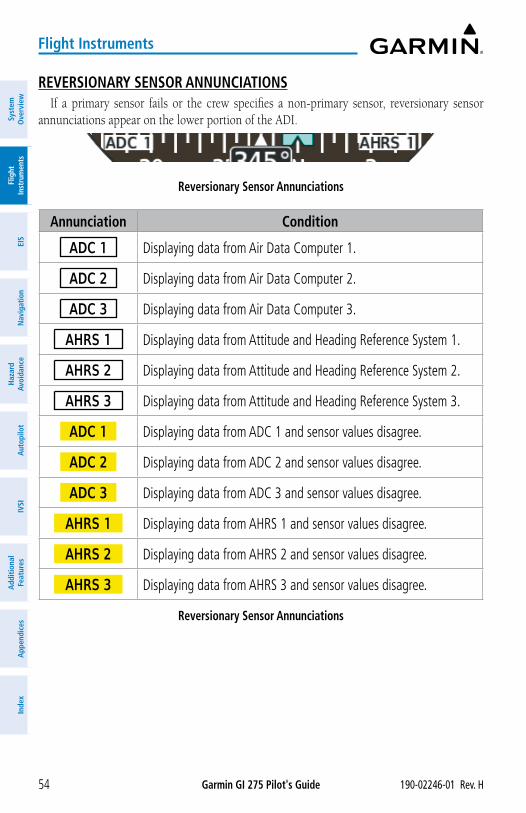
Garmin GI 275 Pilot's Guide 190-02246-01 Rev. H54
Flight Instruments
Syst
em
Ove
rvie
wFl
ight
In
stru
men
tsEI
SN
avig
atio
nH
azar
d Av
oida
nce
Aut
opilo
tIV
SIA
dditi
onal
Fe
atur
esA
ppen
dice
sIn
dex
REVERSIONARY SENSOR ANNUNCIATIONSIf a primary sensor fails or the crew specifies a non-primary sensor, reversionary sensor
annunciations appear on the lower portion of the ADI.
Reversionary Sensor Annunciations
Annunciation Condition
ADC 1 Displaying data from Air Data Computer 1.
ADC 2 Displaying data from Air Data Computer 2.
ADC 3 Displaying data from Air Data Computer 3.
AHRS 1 Displaying data from Attitude and Heading Reference System 1.
AHRS 2 Displaying data from Attitude and Heading Reference System 2.
AHRS 3 Displaying data from Attitude and Heading Reference System 3.
ADC 1 Displaying data from ADC 1 and sensor values disagree.
ADC 2 Displaying data from ADC 2 and sensor values disagree.
ADC 3 Displaying data from ADC 3 and sensor values disagree.
AHRS 1 Displaying data from AHRS 1 and sensor values disagree.
AHRS 2 Displaying data from AHRS 2 and sensor values disagree.
AHRS 3 Displaying data from AHRS 3 and sensor values disagree.
Reversionary Sensor Annunciations
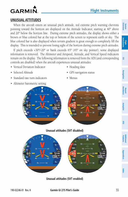
Garmin GI 275 Pilot's Guide190-02246-01 Rev. H 55
Flight Instruments
System
Overview
Flight Instrum
entsEIS
Navigation
Hazard
AvoidanceA
utopilotIVSI
Additional Features
Appendices
Index
UNUSUAL ATTITUDESWhen the aircraft enters an unusual pitch attitude, red extreme pitch warning chevrons
pointing toward the horizon are displayed on the Attitude Indicator, starting at 40° above and 20° below the horizon line. During extreme pitch attitudes, the display shows either a brown or blue colored bar at the top or bottom of the screen to represent earth or sky. The blue colored bar is also displayed when terrain gradient is great enough to completely fill the display. This is intended to prevent losing sight of the horizon during extreme pitch attitudes.
If pitch exceeds +30°/-20° or bank exceeds 65° (45° on sky pointer), some displayed information is removed. The Altimeter and Airspeed, Attitude, and Vertical Speed indicators remain on the display. The following information is removed from the ADI (and corresponding controls are disabled) when the aircraft experiences unusual attitudes:
• Vertical Deviation Indicator
• Selected Altitude
• Standard rate turn indicators
• Altimeter barometric setting
• Heading data
• GPS navigation status
• Menus
Unusual attitudes (SVT disabled)
Unusual attitudes (SVT enabled)
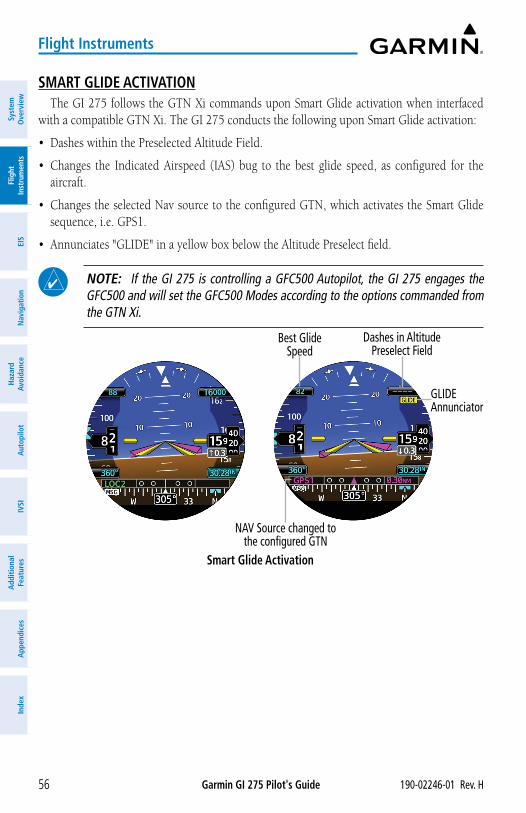
Garmin GI 275 Pilot's Guide 190-02246-01 Rev. H56
Flight Instruments
Syst
em
Ove
rvie
wFl
ight
In
stru
men
tsEI
SN
avig
atio
nH
azar
d Av
oida
nce
Aut
opilo
tIV
SIA
dditi
onal
Fe
atur
esA
ppen
dice
sIn
dex
SMART GLIDE ACTIVATIONThe GI 275 follows the GTN Xi commands upon Smart Glide activation when interfaced
with a compatible GTN Xi. The GI 275 conducts the following upon Smart Glide activation:
• Dashes within the Preselected Altitude Field.
• Changes the Indicated Airspeed (IAS) bug to the best glide speed, as configured for the aircraft.
• Changes the selected Nav source to the configured GTN, which activates the Smart Glide sequence, i.e. GPS1.
• Annunciates "GLIDE" in a yellow box below the Altitude Preselect field.
NOTE: If the GI 275 is controlling a GFC500 Autopilot, the GI 275 engages the GFC500 and will set the GFC500 Modes according to the options commanded from the GTN Xi.
Smart Glide Activation
Dashes in Altitude Preselect Field
GLIDE Annunciator
Best Glide Speed
NAV Source changed to the configured GTN
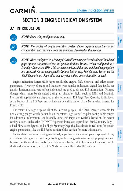
Garmin GI 275 Pilot's Guide190-02246-01 Rev. H 57
Engine Indication System
System
Overview
Flight Instrum
entsEIS
Navigation
Hazard
AvoidanceA
utopilotIVSI
Additional Features
Appendices
Index
SECTION 3 ENGINE INDICATION SYSTEM3.1 INTRODUCTION
NOTE: Fixed wing configurations only.
NOTE: The display of Engine Indication System Pages depends upon the current configuration and may vary from the examples discussed in this section.
NOTE: When configured as a Primary EIS, a half screen menu is available and individual page options are accessed via the generic Options Button. When configured as a Standby ADI or as an MFD, a full screen menu is available and individual page options are accessed via the page-specific Options button (e.g. Fuel Options Button on the 'Fuel' Page Menu). Page titles may vary depending on configuration as well.
Engine Indication System (EIS) Pages can display engine, fuel, electrical, and other system parameters. A variety of gauge and indicator types (analog indicators, digital data fields, bar graphs, horizontal and vertical bar indicators) are used to display EIS information. Primary Gauges which must be displayed during all phases of flight, such as RPM and Manifold Pressure (if applicable) are displayed at the top of each EIS Page. Fuel Quantity is displayed at the bottom of the EIS Page, and will always be visible on top of the Menu when opened for Primary EIS.
The 'Main' EIS Page displays all of the alerting gauges. The 'AUX' Page is available for non-alerting gauges which do not fit on the 'Main' Page, as well as pilot configurable gauges for additional information. Additionally, other EIS Pages are available based on the sensor configurations, such as the CHT/EGT Page with lean assist capabilities. Fuel Summary Page if a Fuel Flow is configured, and a Flight Summary Page that lists details in real-time for certain engine parameters. See the EIS Pages portion of this section for more information.
Engine data is constantly being monitored, regardless of the current page displayed. If any exceedance of engine parameters (according to the configuration) occurs, a pop-up alert will be issued so the condition can be quickly reviewed by the pilot. For more information on EIS alerts and annunciations, see the EIS Alerts portion at the end of this section.
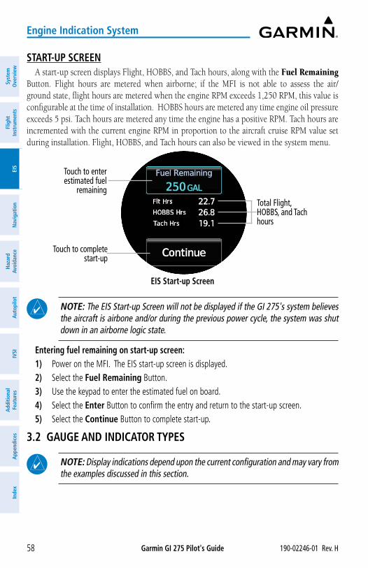
Garmin GI 275 Pilot's Guide 190-02246-01 Rev. H58
Engine Indication System
Syst
em
Ove
rvie
wFl
ight
In
stru
men
tsEI
SN
avig
atio
nH
azar
d Av
oida
nce
Aut
opilo
tIV
SIA
dditi
onal
Fe
atur
esA
ppen
dice
sIn
dex
START-UP SCREENA start-up screen displays Flight, HOBBS, and Tach hours, along with the Fuel Remaining
Button. Flight hours are metered when airborne; if the MFI is not able to assess the air/ground state, flight hours are metered when the engine RPM exceeds 1,250 RPM, this value is configurable at the time of installation. HOBBS hours are metered any time engine oil pressure exceeds 5 psi. Tach hours are metered any time the engine has a positive RPM. Tach hours are incremented with the current engine RPM in proportion to the aircraft cruise RPM value set during installation. Flight, HOBBS, and Tach hours can also be viewed in the system menu.
EIS Start-up Screen
Touch to enter estimated fuel
remaining Total Flight, HOBBS, and Tach hours
Touch to complete start-up
NOTE: The EIS Start-up Screen will not be displayed if the GI 275's system believes the aircraft is airbone and/or during the previous power cycle, the system was shut down in an airborne logic state.
Entering fuel remaining on start-up screen:1) Power on the MFI. The EIS start-up screen is displayed. 2) Select the Fuel Remaining Button. 3) Use the keypad to enter the estimated fuel on board. 4) Select the Enter Button to confirm the entry and return to the start-up screen.5) Select the Continue Button to complete start-up.
3.2 GAUGE AND INDICATOR TYPES
NOTE: Display indications depend upon the current configuration and may vary from the examples discussed in this section.
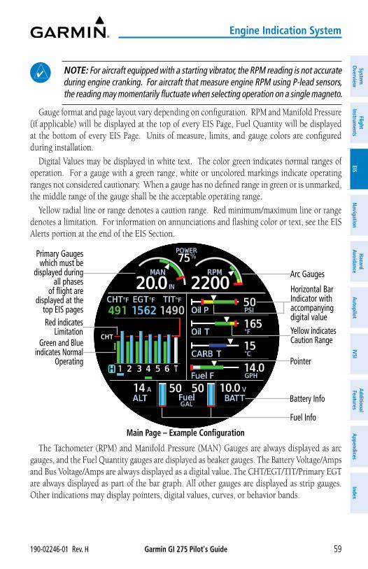
Garmin GI 275 Pilot's Guide190-02246-01 Rev. H 59
Engine Indication System
System
Overview
Flight Instrum
entsEIS
Navigation
Hazard
AvoidanceA
utopilotIVSI
Additional Features
Appendices
Index
NOTE: For aircraft equipped with a starting vibrator, the RPM reading is not accurate during engine cranking. For aircraft that measure engine RPM using P-lead sensors, the reading may momentarily fluctuate when selecting operation on a single magneto.
Gauge format and page layout vary depending on configuration. RPM and Manifold Pressure (if applicable) will be displayed at the top of every EIS Page, Fuel Quantity will be displayed at the bottom of every EIS Page. Units of measure, limits, and gauge colors are configured during installation.
Digital Values may be displayed in white text. The color green indicates normal ranges of operation. For a gauge with a green range, white or uncolored markings indicate operating ranges not considered cautionary. When a gauge has no defined range in green or is unmarked, the middle range of the gauge shall be the acceptable operating range.
Yellow radial line or range denotes a caution range. Red minimum/maximum line or range denotes a limitation. For information on annunciations and flashing color or text, see the EIS Alerts portion at the end of the EIS Section.
Main Page – Example Configuration
Primary Gauges which must be
displayed during all phases
of flight are displayed at the
top EIS pages
Horizontal Bar Indicator with accompanying digital value
Pointer
Arc Gauges
Green and Blue indicates Normal
Operating
Battery Info
Fuel Info
Yellow indicates Caution Range
Red indicates Limitation
The Tachometer (RPM) and Manifold Pressure (MAN) Gauges are always displayed as arc gauges, and the Fuel Quantity gauges are displayed as beaker gauges. The Battery Voltage/Amps and Bus Voltage/Amps are always displayed as a digital value. The CHT/EGT/TIT/Primary EGT are always displayed as part of the bar graph. All other gauges are displayed as strip gauges. Other indications may display pointers, digital values, curves, or behavior bands.
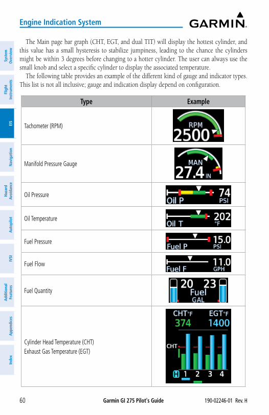
Garmin GI 275 Pilot's Guide 190-02246-01 Rev. H60
Engine Indication System
Syst
em
Ove
rvie
wFl
ight
In
stru
men
tsEI
SN
avig
atio
nH
azar
d Av
oida
nce
Aut
opilo
tIV
SIA
dditi
onal
Fe
atur
esA
ppen
dice
sIn
dex
The Main page bar graph (CHT, EGT, and dual TIT) will display the hottest cylinder, and this value has a small hysteresis to stabilize jumpiness, leading to the chance the cylinders might be within 3 degrees before changing to a hotter cylinder. The user can always use the small knob and select a specific cylinder to display the associated temperature.
The following table provides an example of the different kind of gauge and indicator types. This list is not all inclusive; gauge and indication display depend on configuration.
Type Example
Tachometer (RPM)
Manifold Pressure Gauge
Oil Pressure
Oil Temperature
Fuel Pressure
Fuel Flow
Fuel Quantity
Cylinder Head Temperature (CHT)Exhaust Gas Temperature (EGT)
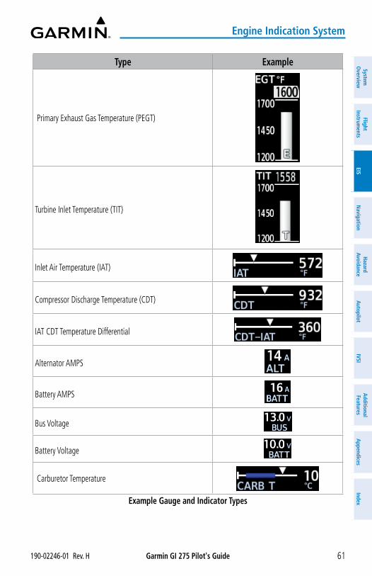
Garmin GI 275 Pilot's Guide190-02246-01 Rev. H 61
Engine Indication System
System
Overview
Flight Instrum
entsEIS
Navigation
Hazard
AvoidanceA
utopilotIVSI
Additional Features
Appendices
Index
Type Example
Primary Exhaust Gas Temperature (PEGT)
Turbine Inlet Temperature (TIT)
Inlet Air Temperature (IAT)
Compressor Discharge Temperature (CDT)
IAT CDT Temperature Differential
Alternator AMPS
Battery AMPS
Bus Voltage
Battery Voltage
Carburetor Temperature
Example Gauge and Indicator Types
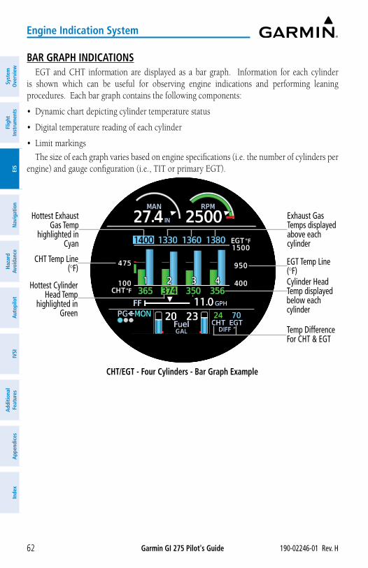
Garmin GI 275 Pilot's Guide 190-02246-01 Rev. H62
Engine Indication System
Syst
em
Ove
rvie
wFl
ight
In
stru
men
tsEI
SN
avig
atio
nH
azar
d Av
oida
nce
Aut
opilo
tIV
SIA
dditi
onal
Fe
atur
esA
ppen
dice
sIn
dex
BAR GRAPH INDICATIONSEGT and CHT information are displayed as a bar graph. Information for each cylinder
is shown which can be useful for observing engine indications and performing leaning procedures. Each bar graph contains the following components:
• Dynamic chart depicting cylinder temperature status
• Digital temperature reading of each cylinder
• Limit markings
The size of each graph varies based on engine specifications (i.e. the number of cylinders per engine) and gauge configuration (i.e., TIT or primary EGT).
CHT/EGT - Four Cylinders - Bar Graph Example
EGT Temp Line (°F)
Hottest Exhaust Gas Temp
highlighted in Cyan
Exhaust Gas Temps displayed above each cylinder
Hottest Cylinder Head Temp
highlighted in Green
Cylinder Head Temp displayed below each cylinder
CHT Temp Line (°F)
Temp Difference For CHT & EGT
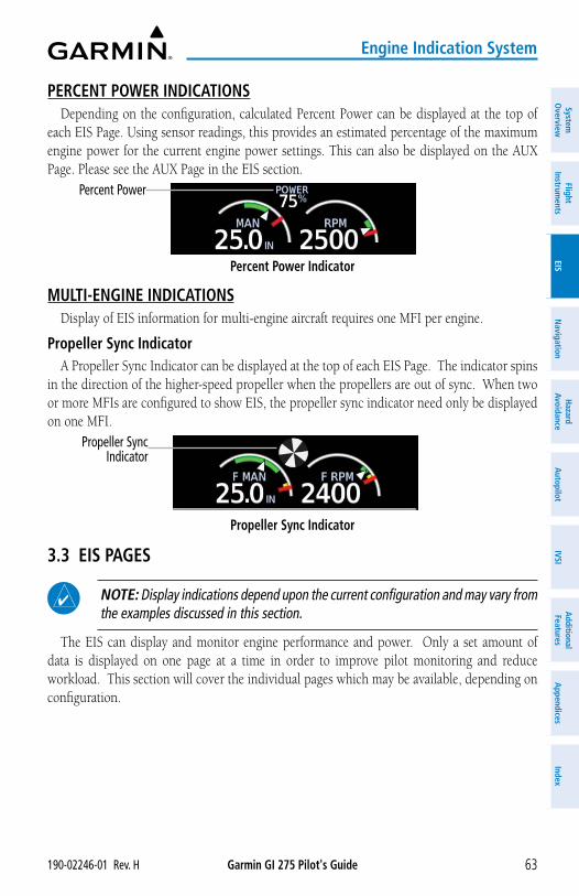
Garmin GI 275 Pilot's Guide190-02246-01 Rev. H 63
Engine Indication System
System
Overview
Flight Instrum
entsEIS
Navigation
Hazard
AvoidanceA
utopilotIVSI
Additional Features
Appendices
Index
PERCENT POWER INDICATIONSDepending on the configuration, calculated Percent Power can be displayed at the top of
each EIS Page. Using sensor readings, this provides an estimated percentage of the maximum engine power for the current engine power settings. This can also be displayed on the AUX Page. Please see the AUX Page in the EIS section.
Percent Power Indicator
Percent Power
MULTI-ENGINE INDICATIONS
Display of EIS information for multi-engine aircraft requires one MFI per engine.
Propeller Sync IndicatorA Propeller Sync Indicator can be displayed at the top of each EIS Page. The indicator spins
in the direction of the higher-speed propeller when the propellers are out of sync. When two or more MFIs are configured to show EIS, the propeller sync indicator need only be displayed on one MFI.
Propeller Sync Indicator
Propeller Sync Indicator
3.3 EIS PAGES
NOTE: Display indications depend upon the current configuration and may vary from the examples discussed in this section.
The EIS can display and monitor engine performance and power. Only a set amount of data is displayed on one page at a time in order to improve pilot monitoring and reduce workload. This section will cover the individual pages which may be available, depending on configuration.
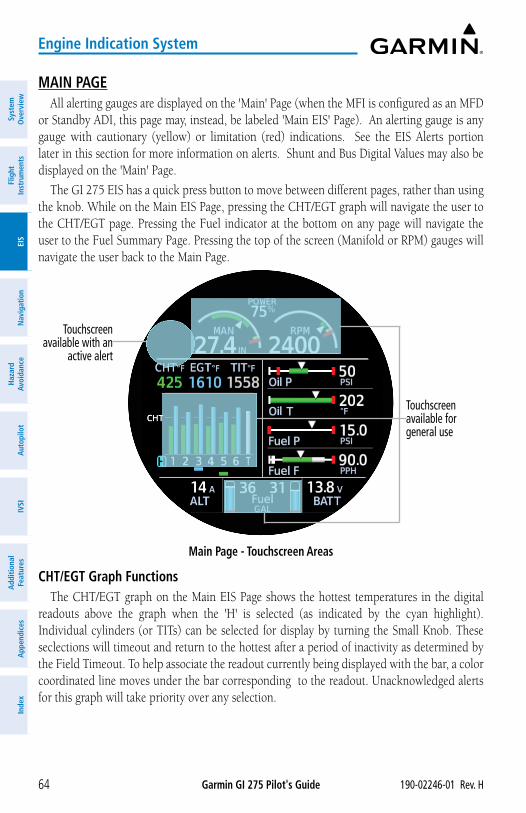
Garmin GI 275 Pilot's Guide 190-02246-01 Rev. H64
Engine Indication System
Syst
em
Ove
rvie
wFl
ight
In
stru
men
tsEI
SN
avig
atio
nH
azar
d Av
oida
nce
Aut
opilo
tIV
SIA
dditi
onal
Fe
atur
esA
ppen
dice
sIn
dex
MAIN PAGEAll alerting gauges are displayed on the 'Main' Page (when the MFI is configured as an MFD
or Standby ADI, this page may, instead, be labeled 'Main EIS' Page). An alerting gauge is any gauge with cautionary (yellow) or limitation (red) indications. See the EIS Alerts portion later in this section for more information on alerts. Shunt and Bus Digital Values may also be displayed on the 'Main' Page.
The GI 275 EIS has a quick press button to move between different pages, rather than using the knob. While on the Main EIS Page, pressing the CHT/EGT graph will navigate the user to the CHT/EGT page. Pressing the Fuel indicator at the bottom on any page will navigate the user to the Fuel Summary Page. Pressing the top of the screen (Manifold or RPM) gauges will navigate the user back to the Main Page.
Main Page - Touchscreen Areas
Touchscreen available with an
active alert
Touchscreen available for general use
CHT/EGT Graph FunctionsThe CHT/EGT graph on the Main EIS Page shows the hottest temperatures in the digital
readouts above the graph when the 'H' is selected (as indicated by the cyan highlight). Individual cylinders (or TITs) can be selected for display by turning the Small Knob. These seclections will timeout and return to the hottest after a period of inactivity as determined by the Field Timeout. To help associate the readout currently being displayed with the bar, a color coordinated line moves under the bar corresponding to the readout. Unacknowledged alerts for this graph will take priority over any selection.
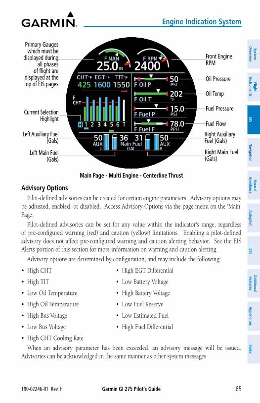
Garmin GI 275 Pilot's Guide190-02246-01 Rev. H 65
Engine Indication System
System
Overview
Flight Instrum
entsEIS
Navigation
Hazard
AvoidanceA
utopilotIVSI
Additional Features
Appendices
Index
Main Page - Multi Engine - Centerline Thrust
Primary Gauges which must be
displayed during all phases
of flight are displayed at the top of EIS pages
Current Selection Highlight
Front Engine RPM
Right Auxiliary Fuel (Gals)
Left Auxiliary Fuel (Gals)
Right Main Fuel (Gals)
Left Main Fuel (Gals)
Oil Pressure
Oil Temp
Fuel Pressure
Fuel Flow
Advisory OptionsPilot-defined advisories can be created for certain engine parameters. Advisory options may
be adjusted, enabled, or disabled. Access Advisory Options via the page menu on the 'Main' Page.
Pilot-defined advisories can be set for any value within the indicator's range, regardless of pre-configured warning (red) and caution (yellow) limitations. Enabling a pilot-defined advisory does not affect pre-configured warning and caution alerting behavior. See the EIS Alerts portion of this section for more information on warning and caution alerting.
Advisory options are determined by configuration, and may include the following:
• High CHT • High EGT Differential
• High TIT • Low Battery Voltage
• Low Oil Temperature • High Battery Voltage
• High Oil Temperature • Low Fuel Reserve
• High Bus Voltage • Low Estimated Fuel
• Low Bus Voltage • High Fuel Differential
• High CHT Cooling Rate
When an advisory parameter has been exceeded, an advisory message will be issued. Advisories can be acknowledged in the same manner as other system messages.
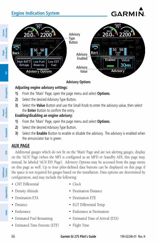
Garmin GI 275 Pilot's Guide 190-02246-01 Rev. H66
Engine Indication System
Syst
em
Ove
rvie
wFl
ight
In
stru
men
tsEI
SN
avig
atio
nH
azar
d Av
oida
nce
Aut
opilo
tIV
SIA
dditi
onal
Fe
atur
esA
ppen
dice
sIn
dex
Advisory Options
Advisory Type Button
Advisory Value
Advisory Enabled
Adjusting engine advisory settings:1) From the 'Main' Page, open the page menu and select Options. 2) Select the desired Advisory Type Button.3) Select the Value Button and use the Small Knob to enter the advisory value, then select
the Enter Button to confirm the entry. Enabling/disabling an engine advisory:1) From the 'Main' Page, open the page menu and select Options. 2) Select the desired Advisory Type Button.3) Select the Enable Button to enable or disable the advisory. The advisory is enabled when
the annunciator bar is green.
AUX PAGEAdditional gauges which do not fit on the 'Main' Page and are not alerting gauges, display
on the 'AUX' Page (when the MFI is configured as an MFD or Standby ADI, this page may, instead, be labeled 'AUX EIS' Page). Advisory Options may be accessed from the page menu on this page as well. Up to four pilot-defined data buttons can be displayed on this page if the space is not required for gauges based on the installation. Data options are determined by configuration, and may include the following:
• CHT Differential • Clock
• Density Altitude • Destination Distance
• Destination ETA • Destination ETE
• Distance • EGT Differential Temp
• Endurance • Endurance at Destination
• Estimated Fuel Remaining • Estimated Time of Arrival (ETA)
• Estimated Time Enroute (ETE) • Flight Time
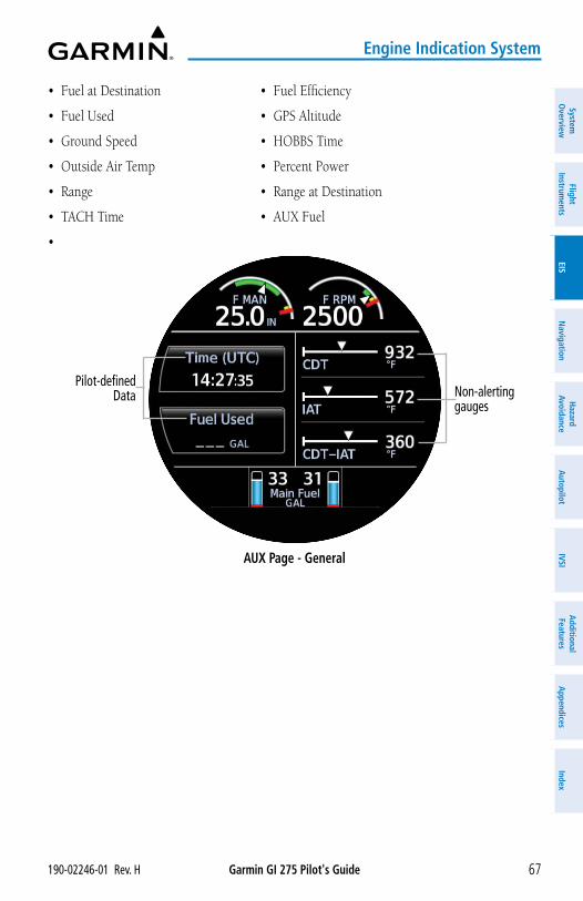
Garmin GI 275 Pilot's Guide190-02246-01 Rev. H 67
Engine Indication System
System
Overview
Flight Instrum
entsEIS
Navigation
Hazard
AvoidanceA
utopilotIVSI
Additional Features
Appendices
Index
• Fuel at Destination • Fuel Efficiency
• Fuel Used • GPS Altitude
• Ground Speed • HOBBS Time
• Outside Air Temp • Percent Power
• Range • Range at Destination
• TACH Time • AUX Fuel
•
AUX Page - General
Non-alerting gauges
Pilot-defined Data
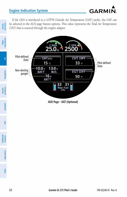
Garmin GI 275 Pilot's Guide 190-02246-01 Rev. H68
Engine Indication System
Syst
em
Ove
rvie
wFl
ight
In
stru
men
tsEI
SN
avig
atio
nH
azar
d Av
oida
nce
Aut
opilo
tIV
SIA
dditi
onal
Fe
atur
esA
ppen
dice
sIn
dex
If the GEA is interfaced to a GTP59 Outside Air Temperature (OAT) probe, the OAT can be selected in the AUX page button options. This value represents the Total Air Temperature (TAT) that is sourced through the engine adapter.
AUX Page - OAT (Optional)
Pilot-defined Data
Non-alerting gauges
Pilot-defined Data
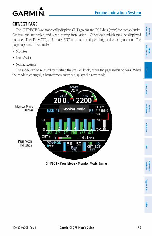
Garmin GI 275 Pilot's Guide190-02246-01 Rev. H 69
Engine Indication System
System
Overview
Flight Instrum
entsEIS
Navigation
Hazard
AvoidanceA
utopilotIVSI
Additional Features
Appendices
Index
CHT/EGT PAGEThe 'CHT/EGT' Page graphically displays CHT (green) and EGT data (cyan) for each cylinder.
Graduations are scaled and sized during installation. Other data which may be displayed includes: Fuel Flow, TIT, or Primary EGT information, depending on the configuration. The page supports three modes:
• Monitor
• Lean Assist
• Normalization
The mode can be selected by rotating the smaller knob, or via the page menu options. When the mode is changed, a banner momentarily displays the new mode.
CHT/EGT - Page Mode - Monitor Mode Banner
Page Mode Indication
Monitor Mode Banner
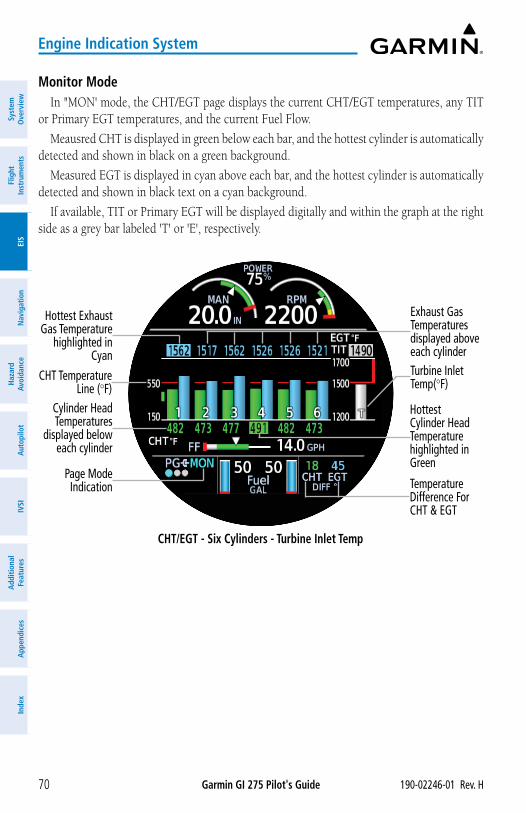
Garmin GI 275 Pilot's Guide 190-02246-01 Rev. H70
Engine Indication System
Syst
em
Ove
rvie
wFl
ight
In
stru
men
tsEI
SN
avig
atio
nH
azar
d Av
oida
nce
Aut
opilo
tIV
SIA
dditi
onal
Fe
atur
esA
ppen
dice
sIn
dex
Monitor ModeIn "MON' mode, the CHT/EGT page displays the current CHT/EGT temperatures, any TIT
or Primary EGT temperatures, and the current Fuel Flow.
Meausred CHT is displayed in green below each bar, and the hottest cylinder is automatically detected and shown in black on a green background.
Measured EGT is displayed in cyan above each bar, and the hottest cylinder is automatically detected and shown in black text on a cyan background.
If available, TIT or Primary EGT will be displayed digitally and within the graph at the right side as a grey bar labeled 'T' or 'E', respectively.
CHT/EGT - Six Cylinders - Turbine Inlet Temp
Turbine Inlet Temp(°F)
Hottest Exhaust Gas Temperature
highlighted in Cyan
Exhaust Gas Temperatures displayed above each cylinder
Hottest Cylinder Head Temperature highlighted in Green
Cylinder Head Temperatures
displayed below each cylinder
CHT Temperature Line (°F)
Temperature Difference For CHT & EGT
Page Mode Indication
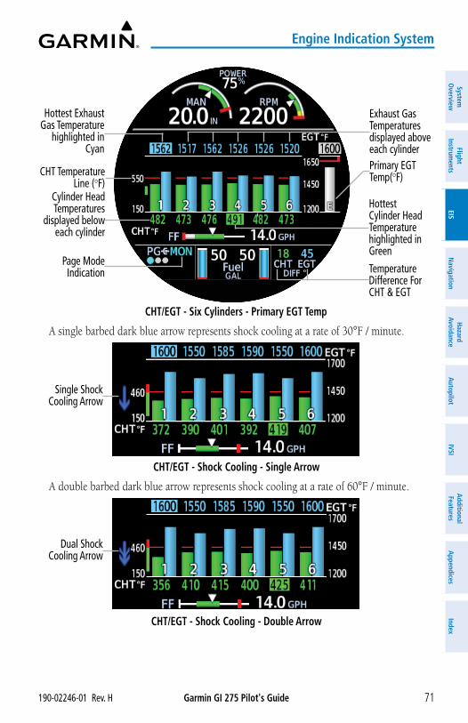
Garmin GI 275 Pilot's Guide190-02246-01 Rev. H 71
Engine Indication System
System
Overview
Flight Instrum
entsEIS
Navigation
Hazard
AvoidanceA
utopilotIVSI
Additional Features
Appendices
Index
CHT/EGT - Six Cylinders - Primary EGT Temp
Primary EGT Temp(°F)
Hottest Exhaust Gas Temperature
highlighted in Cyan
Exhaust Gas Temperatures displayed above each cylinder
Hottest Cylinder Head Temperature highlighted in Green
Cylinder Head Temperatures
displayed below each cylinder
CHT Temperature Line (°F)
Temperature Difference For CHT & EGT
Page Mode Indication
A single barbed dark blue arrow represents shock cooling at a rate of 30°F / minute.
CHT/EGT - Shock Cooling - Single Arrow
Single Shock Cooling Arrow
A double barbed dark blue arrow represents shock cooling at a rate of 60°F / minute.
CHT/EGT - Shock Cooling - Double Arrow
Dual Shock Cooling Arrow
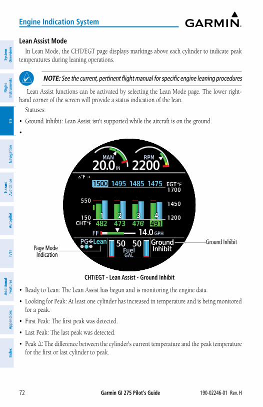
Garmin GI 275 Pilot's Guide 190-02246-01 Rev. H72
Engine Indication System
Syst
em
Ove
rvie
wFl
ight
In
stru
men
tsEI
SN
avig
atio
nH
azar
d Av
oida
nce
Aut
opilo
tIV
SIA
dditi
onal
Fe
atur
esA
ppen
dice
sIn
dex
Lean Assist ModeIn Lean Mode, the CHT/EGT page displays markings above each cylinder to indicate peak
temperatures during leaning operations.
NOTE: See the current, pertinent flight manual for specific engine leaning procedures
Lean Assist functions can be activated by selecting the Lean Mode page. The lower right-hand corner of the screen will provide a status indication of the lean.
Statuses:
• Ground Inhibit: Lean Assist isn't supported while the aircraft is on the ground.
•
CHT/EGT - Lean Assist - Ground Inhibit
Ground InhibitPage Mode Indication
• Ready to Lean: The Lean Assist has begun and is monitoring the engine data.
• Looking for Peak: At least one cylinder has increased in temperature and is being monitored for a peak.
• First Peak: The first peak was detected.
• Last Peak: The last peak was detected.
• Peak D: The difference between the cylinder's current temperature and the peak temperature for the first or last cylinder to peak.
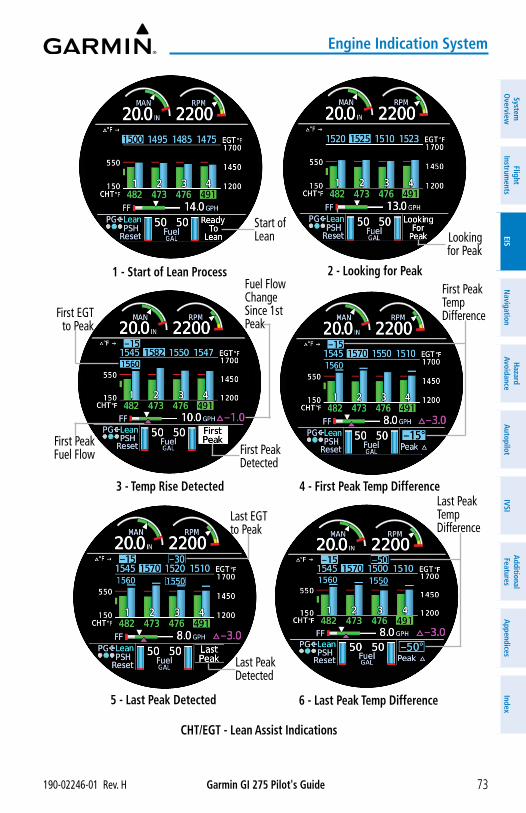
Garmin GI 275 Pilot's Guide190-02246-01 Rev. H 73
Engine Indication System
System
Overview
Flight Instrum
entsEIS
Navigation
Hazard
AvoidanceA
utopilotIVSI
Additional Features
Appendices
Index
CHT/EGT - Lean Assist Indications
Looking for Peak
Last Peak Detected
Last EGT to Peak
Last Peak Temp Difference
First Peak Detected
First EGT to Peak
First Peak Fuel Flow
Fuel Flow Change Since 1st Peak
Start of Lean
1 - Start of Lean Process 2 - Looking for Peak
3 - Temp Rise Detected 4 - First Peak Temp Difference
5 - Last Peak Detected 6 - Last Peak Temp Difference
First Peak Temp Difference
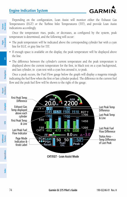
Garmin GI 275 Pilot's Guide 190-02246-01 Rev. H74
Engine Indication System
Syst
em
Ove
rvie
wFl
ight
In
stru
men
tsEI
SN
avig
atio
nH
azar
d Av
oida
nce
Aut
opilo
tIV
SIA
dditi
onal
Fe
atur
esA
ppen
dice
sIn
dex
Depending on the configuration, Lean Assist will monitor either the Exhaust Gas Temperatures (EGT) or the Turbine Inlet Temperatures (TIT), and provide Lean Assist indications accordingly.
Once the temperature rises, peaks, or decreases, as configured by the system, peak temperature is determined, and the following will occur:
• The peak temperature will be indicated above the corresponding cylinder bar with a cyan line for EGT, or gray line for TIT.
• If enough space is available on the display, the peak temperature will be displayed above the line.
• The difference between the cylinder's current temperature and the peak temperature is displayed above the current temperature for the first, in black text on a cyan background, and last cylinder, in cyan text with a cyan box around it, to peak.
Once a peak occurs, the Fuel Flow gauge below the graph will display a magenta triangle indicating the fuel flow when the first or last cylinder peaked. The difference in the current fuel flow and the peak fuel flow will be shown to the right of the gauge.
Last Peak Temp Difference
CHT/EGT - Lean Assist Mode
First Peak Temp Difference
First Peak Temp & Line
Exhaust Gas Temp displayed
above each cylinder
Page Mode Indication & Knob Label
Last Peak Temp & Line
Last Peak Fuel Flow Difference
Status Area - Temp Difference of Last Peak
Last Peak Fuel Flow Indicator
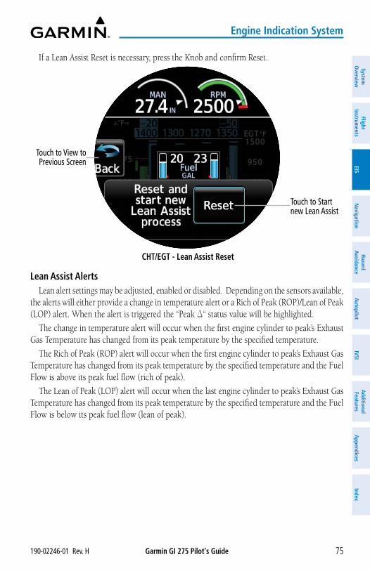
Garmin GI 275 Pilot's Guide190-02246-01 Rev. H 75
Engine Indication System
System
Overview
Flight Instrum
entsEIS
Navigation
Hazard
AvoidanceA
utopilotIVSI
Additional Features
Appendices
Index
If a Lean Assist Reset is necessary, press the Knob and confirm Reset.
CHT/EGT - Lean Assist Reset
Touch to Start new Lean Assist
Touch to View to Previous Screen
Lean Assist AlertsLean alert settings may be adjusted, enabled or disabled. Depending on the sensors available,
the alerts will either provide a change in temperature alert or a Rich of Peak (ROP)/Lean of Peak (LOP) alert. When the alert is triggered the “Peak D“ status value will be highlighted.
The change in temperature alert will occur when the first engine cylinder to peak’s Exhaust Gas Temperature has changed from its peak temperature by the specified temperature.
The Rich of Peak (ROP) alert will occur when the first engine cylinder to peak’s Exhaust Gas Temperature has changed from its peak temperature by the specified temperature and the Fuel Flow is above its peak fuel flow (rich of peak).
The Lean of Peak (LOP) alert will occur when the last engine cylinder to peak’s Exhaust Gas Temperature has changed from its peak temperature by the specified temperature and the Fuel Flow is below its peak fuel flow (lean of peak).
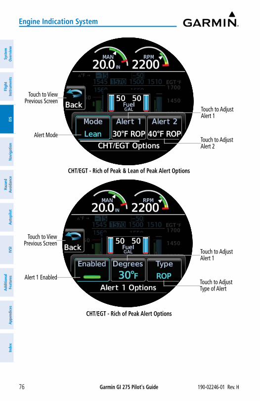
Garmin GI 275 Pilot's Guide 190-02246-01 Rev. H76
Engine Indication System
Syst
em
Ove
rvie
wFl
ight
In
stru
men
tsEI
SN
avig
atio
nH
azar
d Av
oida
nce
Aut
opilo
tIV
SIA
dditi
onal
Fe
atur
esA
ppen
dice
sIn
dex
CHT/EGT - Rich of Peak & Lean of Peak Alert Options
Touch to View Previous Screen
Alert ModeTouch to Adjust Alert 2
Touch to Adjust Alert 1
CHT/EGT - Rich of Peak Alert Options
Touch to View Previous Screen
Alert 1 EnabledTouch to Adjust Type of Alert
Touch to Adjust Alert 1
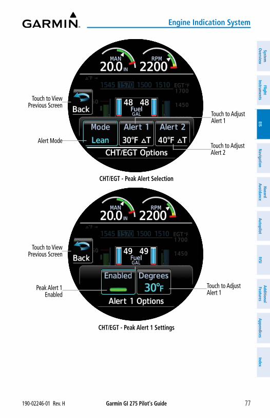
Garmin GI 275 Pilot's Guide190-02246-01 Rev. H 77
Engine Indication System
System
Overview
Flight Instrum
entsEIS
Navigation
Hazard
AvoidanceA
utopilotIVSI
Additional Features
Appendices
Index
CHT/EGT - Peak Alert Selection
Touch to View Previous Screen
Alert ModeTouch to Adjust Alert 2
Touch to Adjust Alert 1
CHT/EGT - Peak Alert 1 Settings
Touch to View Previous Screen
Peak Alert 1 Enabled
Touch to Adjust Alert 1
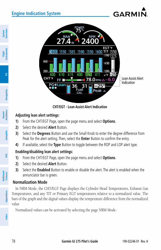
Garmin GI 275 Pilot's Guide 190-02246-01 Rev. H78
Engine Indication System
Syst
em
Ove
rvie
wFl
ight
In
stru
men
tsEI
SN
avig
atio
nH
azar
d Av
oida
nce
Aut
opilo
tIV
SIA
dditi
onal
Fe
atur
esA
ppen
dice
sIn
dex
CHT/EGT - Lean Assist Alert Indication
Lean Assist Alert Indication
Adjusting lean alert settings:1) From the CHT/EGT Page, open the page menu and select Options. 2) Select the desired Alert Button. 3) Select the Degrees Button and use the Small Knob to enter the degree difference from
Peak for the alert setting. Then, select the Enter Button to confirm the entry. 4) If available, select the Type Button to toggle between the ROP and LOP alert type.
Enabling/disabling lean alert settings:1) From the CHT/EGT Page, open the page menu and select Options. 2) Select the desired Alert Button. 3) Select the Enabled Button to enable or disable the alert. The alert is enabled when the
annunciator bar is green.
Normalization ModeIn NRM Mode, the CHT/EGT Page displays the Cylinder Head Temperatures, Exhaust Gas
Temperatures, and any TIT or Primary EGT temperatures relative to a normalized value. The bars of the graph and the digital values display the temperature difference from the normalized value
Normalized values can be activated by selecting the page NRM Mode.
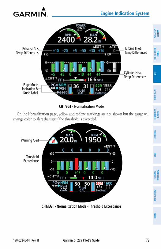
Garmin GI 275 Pilot's Guide190-02246-01 Rev. H 79
Engine Indication System
System
Overview
Flight Instrum
entsEIS
Navigation
Hazard
AvoidanceA
utopilotIVSI
Additional Features
Appendices
Index
CHT/EGT - Normalization Mode
Exhaust Gas Temp Differences
Page Mode Indication & Knob Label
Turbine Inlet Temp Differences
Cylinder Head Temp Differences
On the Normalization page, yellow and redline markings are not shown but the gauge will change color to alert the user if the threshold is exceeded.
CHT/EGT - Normalization Mode - Threshold Exceedance
Threshold Exceedance
Warning Alert
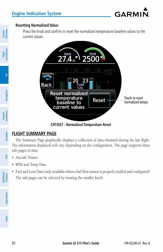
Garmin GI 275 Pilot's Guide 190-02246-01 Rev. H80
Engine Indication System
Syst
em
Ove
rvie
wFl
ight
In
stru
men
tsEI
SN
avig
atio
nH
azar
d Av
oida
nce
Aut
opilo
tIV
SIA
dditi
onal
Fe
atur
esA
ppen
dice
sIn
dex
Resetting Normalized Value: Press the knob and confirm to reset the normalized temperature baseline values to the
current values.
CHT/EGT - Normalized Temperature Reset
Touch to reset normalized temps
FLIGHT SUMMARY PAGEThe Summary Page graphically displays a collection of data obtained during the last flight.
The information displayed will vary depending on the configuration. The page supports three sub-pages of data:
• Aircraft Timers
• RPM and Temp Data
• Fuel and Lean Data (only available when a fuel flow sensor is properly istalled and configured)
The sub-pages can be selected by rotating the smaller knob.
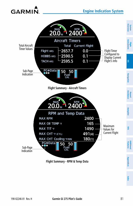
Garmin GI 275 Pilot's Guide190-02246-01 Rev. H 81
Engine Indication System
System
Overview
Flight Instrum
entsEIS
Navigation
Hazard
AvoidanceA
utopilotIVSI
Additional Features
Appendices
Index
Flight Summary - Aircraft Timers
Flight Timer Configured to Display Current Flight's Info
Total Aircraft Timer Values
Sub-Page Indication
Flight Summary - RPM & Temp Data
Maximum Values for Current Flight
Sub-Page Indication
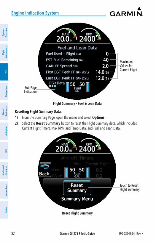
Garmin GI 275 Pilot's Guide 190-02246-01 Rev. H82
Engine Indication System
Syst
em
Ove
rvie
wFl
ight
In
stru
men
tsEI
SN
avig
atio
nH
azar
d Av
oida
nce
Aut
opilo
tIV
SIA
dditi
onal
Fe
atur
esA
ppen
dice
sIn
dex
Flight Summary - Fuel & Lean Data
Maximum Values for Current Flight
Sub-Page Indication
Resetting Flight Summary Data:1) From the Summary Page, open the menu and select Options.2) Select the Reset Summary button to reset the Flight Summary data, which includes
Current Flight Timers, Max RPM and Temp Data, and Fuel and Lean Data.
Reset Flight Summary
Touch to Reset Flight Summary
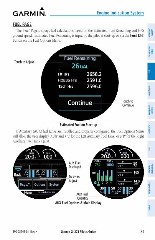
Garmin GI 275 Pilot's Guide190-02246-01 Rev. H 83
Engine Indication System
System
Overview
Flight Instrum
entsEIS
Navigation
Hazard
AvoidanceA
utopilotIVSI
Additional Features
Appendices
Index
FUEL PAGEThe 'Fuel' Page displays fuel calculations based on the Estimated Fuel Remaining and GPS
ground speed. Estimated Fuel Remaining is input by the pilot at start-up or via the Fuel EST Button on the Fuel Options Menu.
Touch to Continue
Estimated Fuel on Start-up
Touch to Adjust
If Auxiliary (AUX) fuel tanks are installed and properly configured, the Fuel Options Menu will allow the user display 'AUX' and a 'L' for the Left Auxiliary Fuel Tank, or a 'R' for the Right Auxiliary Fuel Tank (gals).
AUX Fuel Options & Main Display
AUX Fuel Displayed
AUX Fuel Quantity
Touch to Adjust
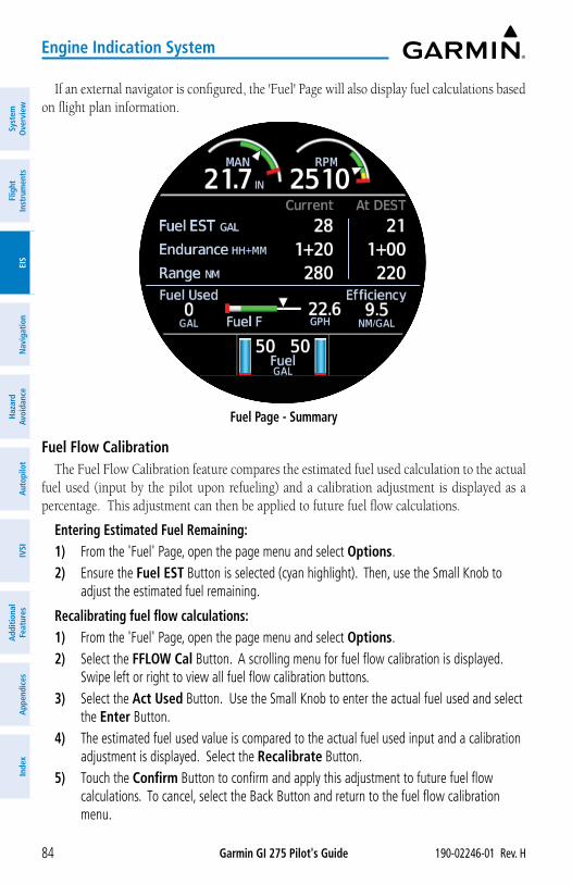
Garmin GI 275 Pilot's Guide 190-02246-01 Rev. H84
Engine Indication System
Syst
em
Ove
rvie
wFl
ight
In
stru
men
tsEI
SN
avig
atio
nH
azar
d Av
oida
nce
Aut
opilo
tIV
SIA
dditi
onal
Fe
atur
esA
ppen
dice
sIn
dex
If an external navigator is configured, the 'Fuel' Page will also display fuel calculations based on flight plan information.
Fuel Page - Summary
Fuel Flow CalibrationThe Fuel Flow Calibration feature compares the estimated fuel used calculation to the actual
fuel used (input by the pilot upon refueling) and a calibration adjustment is displayed as a percentage. This adjustment can then be applied to future fuel flow calculations.
Entering Estimated Fuel Remaining:1) From the 'Fuel' Page, open the page menu and select Options. 2) Ensure the Fuel EST Button is selected (cyan highlight). Then, use the Small Knob to
adjust the estimated fuel remaining.
Recalibrating fuel flow calculations:1) From the 'Fuel' Page, open the page menu and select Options. 2) Select the FFLOW Cal Button. A scrolling menu for fuel flow calibration is displayed.
Swipe left or right to view all fuel flow calibration buttons. 3) Select the Act Used Button. Use the Small Knob to enter the actual fuel used and select
the Enter Button. 4) The estimated fuel used value is compared to the actual fuel used input and a calibration
adjustment is displayed. Select the Recalibrate Button.5) Touch the Confirm Button to confirm and apply this adjustment to future fuel flow
calculations. To cancel, select the Back Button and return to the fuel flow calibration menu.
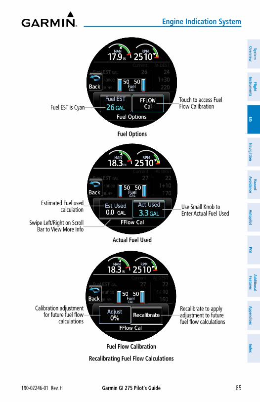
Garmin GI 275 Pilot's Guide190-02246-01 Rev. H 85
Engine Indication System
System
Overview
Flight Instrum
entsEIS
Navigation
Hazard
AvoidanceA
utopilotIVSI
Additional Features
Appendices
Index
Fuel Options
Touch to access Fuel Flow CalibrationFuel EST is Cyan
Actual Fuel Used
Use Small Knob to Enter Actual Fuel Used
Estimated Fuel used calculation
Swipe Left/Right on Scroll Bar to View More Info
Fuel Flow Calibration
Recalibrate to apply adjustment to future fuel flow calculations
Calibration adjustment for future fuel flow
calculations
Recalibrating Fuel Flow Calculations
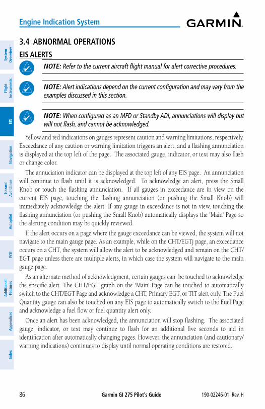
Garmin GI 275 Pilot's Guide 190-02246-01 Rev. H86
Engine Indication System
Syst
em
Ove
rvie
wFl
ight
In
stru
men
tsEI
SN
avig
atio
nH
azar
d Av
oida
nce
Aut
opilo
tIV
SIA
dditi
onal
Fe
atur
esA
ppen
dice
sIn
dex
3.4 ABNORMAL OPERATIONSEIS ALERTS
NOTE: Refer to the current aircraft flight manual for alert corrective procedures.
NOTE: Alert indications depend on the current configuration and may vary from the examples discussed in this section.
NOTE: When configured as an MFD or Standby ADI, annunciations will display but will not flash, and cannot be acknowledged.
Yellow and red indications on gauges represent caution and warning limitations, respectively. Exceedance of any caution or warning limitation triggers an alert, and a flashing annunciation is displayed at the top left of the page. The associated gauge, indicator, or text may also flash or change color.
The annuciation indicator can be displayed at the top left of any EIS page. An annunciation will continue to flash until it is acknowledged. To acknowledge an alert, press the Small Knob or touch the flashing annunciation. If all gauges in exceedance are in view on the current EIS page, touching the flashing annunciation (or pushing the Small Knob) will immediately acknowledge the alert. If any gauge in exceedance is not in view, touching the flashing annunciation (or pushing the Small Knob) automatically displays the 'Main' Page so the alerting condition may be quickly reviewed.
If the alert occurs on a page where the gauge exceedance can be viewed, the system will not navigate to the main gauge page. As an example, while on the CHT/EGTj page, an exceedance occurs on a CHT, the system will allow the alert to be acknowledged and remain on the CHT/EGT page unless there are multiple alerts, in which case the system will navigate to the main gauge page.
As an alternate method of acknowledgment, certain gauges can be touched to acknowledge the specific alert. The CHT/EGT graph on the 'Main' Page can be touched to automatically switch to the CHT/EGT Page and acknowledge a CHT, Primary EGT, or TIT alert only. The Fuel Quantity gauge can also be touched on any EIS page to automatically switch to the Fuel Page and acknowledge a fuel flow or fuel quantity alert only.
Once an alert has been acknowledged, the annunciation will stop flashing. The associated gauge, indicator, or text may continue to flash for an additional five seconds to aid in identification after automatically changing pages. However, the annunciation (and cautionary/warning indications) continues to display until normal operating conditions are restored.
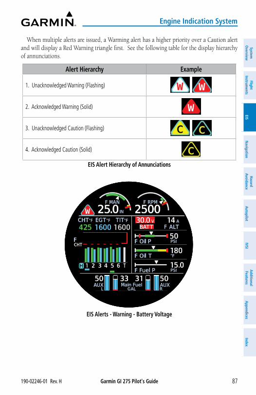
Garmin GI 275 Pilot's Guide190-02246-01 Rev. H 87
Engine Indication System
System
Overview
Flight Instrum
entsEIS
Navigation
Hazard
AvoidanceA
utopilotIVSI
Additional Features
Appendices
Index
When multiple alerts are issued, a Warming alert has a higher priority over a Caution alert and will display a Red Warning triangle first. See the following table for the display hierarchy of annunciations.
Alert Hierarchy Example
1. Unacknowledged Warning (Flashing)
2. Acknowledged Warning (Solid)
3. Unacknowledged Caution (Flashing)
4. Acknowledged Caution (Solid)
EIS Alert Hierarchy of Annunciations
EIS Alerts - Warning - Battery Voltage
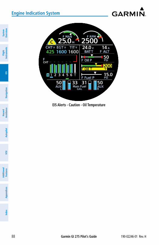
Garmin GI 275 Pilot's Guide 190-02246-01 Rev. H88
Engine Indication System
Syst
em
Ove
rvie
wFl
ight
In
stru
men
tsEI
SN
avig
atio
nH
azar
d Av
oida
nce
Aut
opilo
tIV
SIA
dditi
onal
Fe
atur
esA
ppen
dice
sIn
dex
EIS Alerts - Caution - Oil Temperature
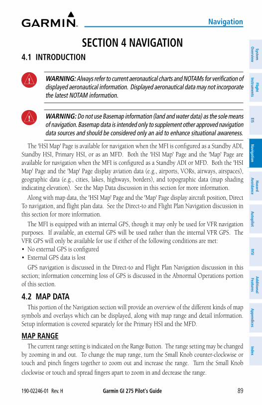
Garmin GI 275 Pilot's Guide190-02246-01 Rev. H 89
Navigation
System
Overview
Flight Instrum
entsEIS
Navigation
Hazard
AvoidanceA
utopilotIVSI
Additional Features
Appendices
Index
SECTION 4 NAVIGATION4.1 INTRODUCTION
WARNING: Always refer to current aeronautical charts and NOTAMs for verification of displayed aeronautical information. Displayed aeronautical data may not incorporate the latest NOTAM information.
WARNING: Do not use Basemap information (land and water data) as the sole means of navigation. Basemap data is intended only to supplement other approved navigation data sources and should be considered only an aid to enhance situational awareness.
The 'HSI Map' Page is available for navigation when the MFI is configured as a Standby ADI, Standby HSI, Primary HSI, or as an MFD. Both the 'HSI Map' Page and the 'Map' Page are available for navigation when the MFI is configured as a Standby ADI or MFD. Both the 'HSI Map' Page and the 'Map' Page display aviation data (e.g., airports, VORs, airways, airspaces), geographic data (e.g., cities, lakes, highways, borders), and topographic data (map shading indicating elevation). See the Map Data discussion in this section for more information.
Along with map data, the 'HSI Map' Page and the 'Map' Page display aircraft position, Direct To navigation, and flight plan data. See the Direct-to and Flight Plan Navigation discussion in this section for more information.
The MFI is equipped with an internal GPS, though it may only be used for VFR navigation purposes. If available, an external GPS will be used rather than the internal VFR GPS. The VFR GPS will only be available for use if either of the following conditions are met:• No external GPS is configured• External GPS data is lost
GPS navigation is discussed in the Direct-to and Flight Plan Navigation discussion in this section; information concerning loss of GPS is discussed in the Abnormal Operations portion of this section.
4.2 MAP DATAThis portion of the Navigation section will provide an overview of the different kinds of map
symbols and overlays which can be displayed, along with map range and detail information. Setup information is covered separately for the Primary HSI and the MFD.
MAP RANGEThe current range setting is indicated on the Range Button. The range setting may be changed
by zooming in and out. To change the map range, turn the Small Knob counter-clockwise or touch and pinch fingers together to zoom out and increase the range. Turn the Small Knob
clockwise or touch and spread fingers apart to zoom in and decrease the range.
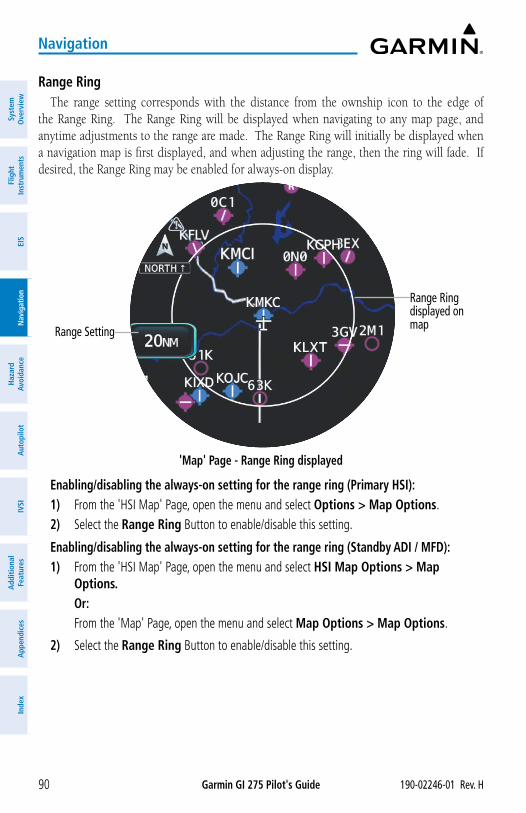
Garmin GI 275 Pilot's Guide 190-02246-01 Rev. H90
Navigation
Syst
em
Ove
rvie
wFl
ight
In
stru
men
tsEI
SN
avig
atio
nH
azar
d Av
oida
nce
Aut
opilo
tIV
SIA
dditi
onal
Fe
atur
esA
ppen
dice
sIn
dex
Range RingThe range setting corresponds with the distance from the ownship icon to the edge of
the Range Ring. The Range Ring will be displayed when navigating to any map page, and anytime adjustments to the range are made. The Range Ring will initially be displayed when a navigation map is first displayed, and when adjusting the range, then the ring will fade. If desired, the Range Ring may be enabled for always-on display.
'Map' Page - Range Ring displayed
Range Ringdisplayed on mapRange Setting
Enabling/disabling the always-on setting for the range ring (Primary HSI):1) From the 'HSI Map' Page, open the menu and select Options > Map Options.2) Select the Range Ring Button to enable/disable this setting.
Enabling/disabling the always-on setting for the range ring (Standby ADI / MFD):1) From the 'HSI Map' Page, open the menu and select HSI Map Options > Map
Options.Or:
From the 'Map' Page, open the menu and select Map Options > Map Options.
2) Select the Range Ring Button to enable/disable this setting.
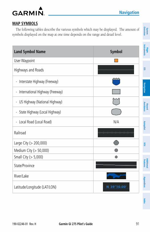
Garmin GI 275 Pilot's Guide190-02246-01 Rev. H 91
Navigation
System
Overview
Flight Instrum
entsEIS
Navigation
Hazard
AvoidanceA
utopilotIVSI
Additional Features
Appendices
Index
MAP SYMBOLSThe following tables describe the various symbols which may be displayed. The amount of
symbols displayed on the map at one time depends on the range and detail level.
Land Symbol Name Symbol
User Waypoint
Highways and Roads
- Interstate Highway (Freeway)
- International Highway (Freeway)
- US Highway (National Highway)
- State Highway (Local Highway)
- Local Road (Local Road) N/A
Railroad
Large City (> 200,000)
Medium City (> 50,000)
Small City (> 5,000)
State/Province
River/Lake
Latitude/Longitude (LAT/LON)
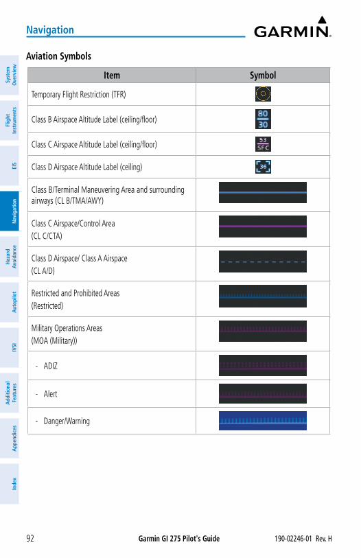
Garmin GI 275 Pilot's Guide 190-02246-01 Rev. H92
Navigation
Syst
em
Ove
rvie
wFl
ight
In
stru
men
tsEI
SN
avig
atio
nH
azar
d Av
oida
nce
Aut
opilo
tIV
SIA
dditi
onal
Fe
atur
esA
ppen
dice
sIn
dex
Aviation Symbols
Item Symbol
Temporary Flight Restriction (TFR)
Class B Airspace Altitude Label (ceiling/floor)
Class C Airspace Altitude Label (ceiling/floor)
Class D Airspace Altitude Label (ceiling)
Class B/Terminal Maneuvering Area and surrounding airways (CL B/TMA/AWY)
Class C Airspace/Control Area(CL C/CTA)
Class D Airspace/ Class A Airspace(CL A/D)
Restricted and Prohibited Areas(Restricted)
Military Operations Areas(MOA (Military))
- ADIZ
- Alert
- Danger/Warning
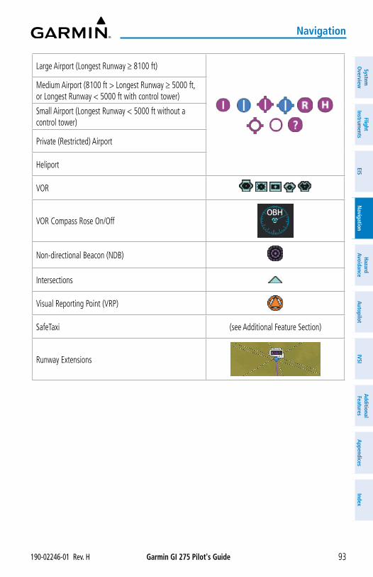
Garmin GI 275 Pilot's Guide190-02246-01 Rev. H 93
Navigation
System
Overview
Flight Instrum
entsEIS
Navigation
Hazard
AvoidanceA
utopilotIVSI
Additional Features
Appendices
Index
Large Airport (Longest Runway ≥ 8100 ft)
Medium Airport (8100 ft > Longest Runway ≥ 5000 ft, or Longest Runway < 5000 ft with control tower)
Small Airport (Longest Runway < 5000 ft without a control tower)
Private (Restricted) Airport
Heliport
VOR
VOR Compass Rose On/Off
Non-directional Beacon (NDB)
Intersections
Visual Reporting Point (VRP)
SafeTaxi (see Additional Feature Section)
Runway Extensions
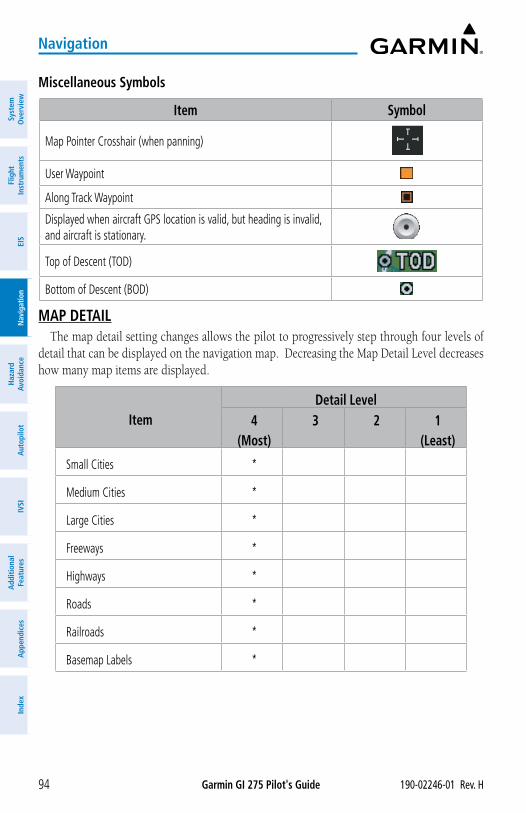
Garmin GI 275 Pilot's Guide 190-02246-01 Rev. H94
Navigation
Syst
em
Ove
rvie
wFl
ight
In
stru
men
tsEI
SN
avig
atio
nH
azar
d Av
oida
nce
Aut
opilo
tIV
SIA
dditi
onal
Fe
atur
esA
ppen
dice
sIn
dex
Miscellaneous Symbols
Item Symbol
Map Pointer Crosshair (when panning)
User Waypoint
Along Track Waypoint
Displayed when aircraft GPS location is valid, but heading is invalid, and aircraft is stationary.
Top of Descent (TOD)
Bottom of Descent (BOD)
MAP DETAILThe map detail setting changes allows the pilot to progressively step through four levels of
detail that can be displayed on the navigation map. Decreasing the Map Detail Level decreases how many map items are displayed.
ItemDetail Level
4(Most)
3 2 1(Least)
Small Cities *
Medium Cities *
Large Cities *
Freeways *
Highways *
Roads *
Railroads *
Basemap Labels *
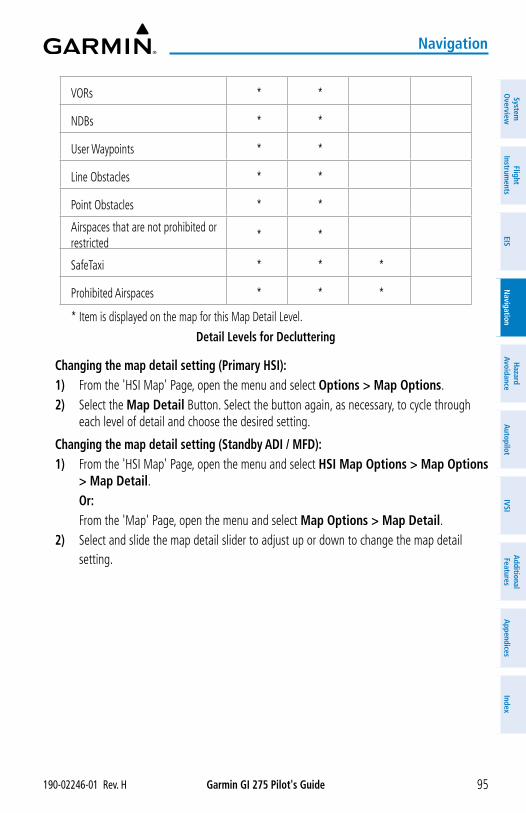
Garmin GI 275 Pilot's Guide190-02246-01 Rev. H 95
Navigation
System
Overview
Flight Instrum
entsEIS
Navigation
Hazard
AvoidanceA
utopilotIVSI
Additional Features
Appendices
Index
VORs * *
NDBs * *
User Waypoints * *
Line Obstacles * *
Point Obstacles * *
Airspaces that are not prohibited or restricted
* *
SafeTaxi * * *
Prohibited Airspaces * * *
* Item is displayed on the map for this Map Detail Level.
Detail Levels for Decluttering
Changing the map detail setting (Primary HSI):1) From the 'HSI Map' Page, open the menu and select Options > Map Options.2) Select the Map Detail Button. Select the button again, as necessary, to cycle through
each level of detail and choose the desired setting.
Changing the map detail setting (Standby ADI / MFD):1) From the 'HSI Map' Page, open the menu and select HSI Map Options > Map Options
> Map Detail.Or:
From the 'Map' Page, open the menu and select Map Options > Map Detail.2) Select and slide the map detail slider to adjust up or down to change the map detail
setting.
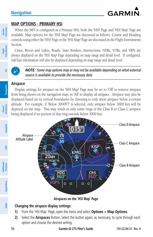
Garmin GI 275 Pilot's Guide 190-02246-01 Rev. H96
Navigation
Syst
em
Ove
rvie
wFl
ight
In
stru
men
tsEI
SN
avig
atio
nH
azar
d Av
oida
nce
Aut
opilo
tIV
SIA
dditi
onal
Fe
atur
esA
ppen
dice
sIn
dex
MAP OPTIONS - PRIMARY HSIWhen the MFI is configured as a Primary HSI, both the 'HSI' Page and 'HSI Map' Page are
available. Map options for the 'HSI Map' Page are discussed as follows. Course and Heading controls using either the 'HSI' Page or the 'HSI Map' Page are discussed in the Flight Instruments Section.
Cities, Rivers and Lakes, Roads, State Borders, Intersections, NDBs, VORs, and VRPs are always displayed on the 'HSI Map' Page depending on map range and detail level. If configured, SafeTaxi information will also be displayed depending on map range and detail level.
NOTE: Some map options may or may not be available depending on what external source is available to provide the necessary data
AirspaceDisplay settings for airspace on the 'HSI Map' Page may be set to 'Off' to remove airspace
from being shown on the navigation map, or 'All' to display all airspace. Airspace may also be displayed based on its vertical boundaries by choosing to only show airspace below a certain altitude. For example, if 'Below 3000FT' is selected, only airspace below 3000 feet will be depicted on the map. This may result in only some rings of the Class B or Class C airspace being displayed if no portion of that ring extends below 3000 feet.
Airspaces on the 'HSI Map' Page
Airspace Altitude Label
Class D Airspace
Class C Airspace
Class B Airspace
Changing the airspace display settings:1) From the 'HSI Map' Page, open the menu and select Options > Map Options.2) Select the Airspaces Button. Select the button again, as necessary, to cycle through each
option and choose the desired setting.
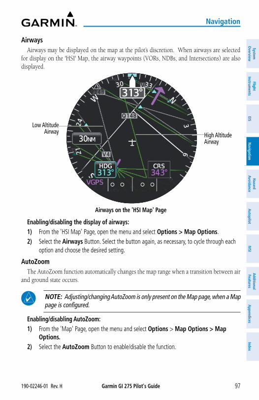
Garmin GI 275 Pilot's Guide190-02246-01 Rev. H 97
Navigation
System
Overview
Flight Instrum
entsEIS
Navigation
Hazard
AvoidanceA
utopilotIVSI
Additional Features
Appendices
Index
AirwaysAirways may be displayed on the map at the pilot’s discretion. When airways are selected
for display on the 'HSI' Map, the airway waypoints (VORs, NDBs, and Intersections) are also displayed.
Airways on the 'HSI Map' Page
High Altitude Airway
Low AltitudeAirway
Enabling/disabling the display of airways:1) From the 'HSI Map' Page, open the menu and select Options > Map Options.2) Select the Airways Button. Select the button again, as necessary, to cycle through each
option and choose the desired setting.
AutoZoomThe AutoZoom function automatically changes the map range when a transition between air
and ground state occurs.
NOTE: Adjusting/changing AutoZoom is only present on the Map page, when a Map page is configured.
Enabling/disabling AutoZoom:1) From the 'Map' Page, open the menu and select Options > Map Options > Map
Options.2) Select the AutoZoom Button to enable/disable the function.
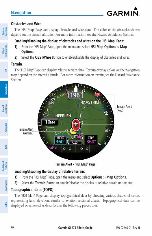
Garmin GI 275 Pilot's Guide 190-02246-01 Rev. H98
Navigation
Syst
em
Ove
rvie
wFl
ight
In
stru
men
tsEI
SN
avig
atio
nH
azar
d Av
oida
nce
Aut
opilo
tIV
SIA
dditi
onal
Fe
atur
esA
ppen
dice
sIn
dex
Obstacles and WireThe 'HSI Map' Page can display obstacle and wire data. The color of the obstacles shown
depend on the aircraft altitude. For more information, see the Hazard Avoidance Section.
Enabling/disabling the display of obstacles and wires on the 'HSI Map' Page:1) From the 'HSI Map' Page, open the menu and select HSI Map Options > Map
Options.2) Select the OBST/Wire Button to enable/disable the display of obstacles and wires.
TerrainThe 'HSI Map' Page can display relative terrain data. Terrain overlay colors on the navigation
map depend on the aircraft altitude. For more information on terrain, see the Hazard Avoidance Section.
Terrain Alert - 'HSI Map' Page
Terrain Alert (Red)
Terrain Alert (Amber)
Enabling/disabling the display of relative terrain:1) From the 'HSI Map' Page, open the menu and select Options > Map Options.2) Select the Terrain Button to enable/disable the display of relative terrain on the map.
Topographical data (TOPO)The 'HSI Map' Page can display topographical data by showing various shades of colors
representing land elevation, similar to aviation sectional charts. Topographical data can be displayed or removed as described in the following procedures.
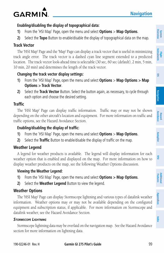
Garmin GI 275 Pilot's Guide190-02246-01 Rev. H 99
Navigation
System
Overview
Flight Instrum
entsEIS
Navigation
Hazard
AvoidanceA
utopilotIVSI
Additional Features
Appendices
Index
Enabling/disabling the display of topographical data:1) From the 'HSI Map' Page, open the menu and select Options > Map Options.
2) Select the Topo Button to enable/disable the display of topographical data on the map.
Track VectorThe 'HSI Map' Page and the 'Map' Page can display a track vector that is useful in minimizing
track angle error. The track vector is a dashed cyan line segment extended to a predicted location. The track vector look-ahead time is selectable (30 sec, 60 sec (default), 2 min, 5 min, 10 min, 20 min) and determines the length of the track vector.
Changing the track vector display settings:1) From the 'HSI Map' Page, open the menu and select Options > Map Options > Map
Options > Track Vector.2) Select the Track Vector Button. Select the button again, as necessary, to cycle through
each option and choose the desired setting.
TrafficThe 'HSI Map' Page can display traffic information. Traffic may or may not be shown
depending on the other aircraft's location and equipment. For more information on traffic and traffic options, see the Hazard Avoidance Section.
Enabling/disabling the display of traffic:1) From the 'HSI Map' Page, open the menu and select Options > Map Options.2) Select the Traffic Button to enable/disable the display of traffic on the map.
Weather LegendA legend for weather products is available. The legend will display information for each
weather option that is enabled and displayed on the map. For more information on how to display weather products on the map, see the following Weather Options discussion.
Viewing the Weather Legend:1) From the 'HSI Map' Page, open the menu and select Options > Map Options.2) Select the Weather Legend Button to view the legend.
Weather OptionsThe 'HSI Map' Page can display Stormscope lightning and various types of datalink weather
information. Weather options may or may not be available depending on the configured equipment and subscription status, if applicable. For more information on Stormscope and datalink weather, see the Hazard Avoidance Section.
StorMSCope LigHtning
Stormscope lightning data may be overlaid on the navigation map. See the Hazard Avoidance section for more information on lightning data.
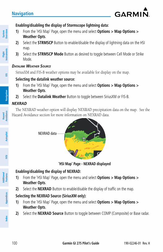
Garmin GI 275 Pilot's Guide 190-02246-01 Rev. H100
Navigation
Syst
em
Ove
rvie
wFl
ight
In
stru
men
tsEI
SN
avig
atio
nH
azar
d Av
oida
nce
Aut
opilo
tIV
SIA
dditi
onal
Fe
atur
esA
ppen
dice
sIn
dex
Enabling/disabling the display of Stormscope lightning data:1) From the 'HSI Map' Page, open the menu and select Options > Map Options >
Weather Opts.2) Select the STRMSCP Button to enable/disable the display of lightning data on the HSI
map.3) Select the STRMSCP Mode Button as desired to toggle between Cell Mode or Strike
Mode.
DAtALink WeAtHer SourCe
SiriusXM and FIS-B weather options may be available for display on the map.
Selecting the datalink weather source:1) From the 'HSI Map' Page, open the menu and select Options > Map Options >
Weather Opts.2) Select the Datalink Weather Button to toggle between SiriusXM or FIS-B.
neXrAD
The NEXRAD weather option will display NEXRAD precipitation data on the map. See the Hazard Avoidance section for more information on NEXRAD data.
'HSI Map' Page - NEXRAD displayed
NEXRAD data
Enabling/disabling the display of NEXRAD:1) From the 'HSI Map' Page, open the menu and select Options > Map Options >
Weather Opts.2) Select the NEXRAD Button to enable/disable the display of traffic on the map.
Selecting the NEXRAD Source (SiriusXM only):1) From the 'HSI Map' Page, open the menu and select Options > Map Options >
Weather Opts.2) Select the NEXRAD Source Button to toggle between COMP (Composite) or Base radar.
Garmin GI 275 Pilot's Guide190-02246-01 Rev. H 101
Navigation
System
Overview
Flight Instrum
entsEIS
Navigation
Hazard
AvoidanceA
utopilotIVSI
Additional Features
Appendices
Index
MAP OPTIONS - STANDBY ADI / MFDWhen the MFI is configured as a Standby ADI or an MFD, both the 'HSI Map' Page and 'Map'
Page are available. This section will discuss the map options available for the 'HSI Map' Page and the 'Map' Page.
NOTE: Some map options may or may not be available depending on what external source is available to provide the necessary data.
AirportsAirports/heliports are always displayed on the 'HSI Map' Page depending on map range and
detail level. Airports/heliports may be displayed on the 'Map' Page at the pilot’s discretion, by changing the display settings for private, small, medium, and large airports.
Enabling/disabling the display of Airports on the 'Map' Page:1) From the 'Map' Page, open the menu and select Map Options > Aviation Options.2) Select the Airports Button to enable/disable the display of airports.
Changing display settings for each airport type on the 'Map' Page:1) From the 'Map' Page, open the menu and select Map Options > Aviation Options >
Airport Options.2) Select the desired Airport Type Button to enable/disable the display of that type of airport. 3) If necessary, select the desired Airport Range Button to display a list of range display
settings. Select the desired range display setting for that airport type. 4) Repeat Steps 2 and 3 as necessary for each airport type.
Enabling/disabling the display of Heliports on the 'Map' Page:1) From the 'Map' Page, open the menu and select Map Options > Map Options >
Aviation Options.2) Select the Heliports Button to enable/disable the display of heliports.3) If necessary, select the Heliports RNG Button to display a list of range display settings.
Select the desired range display setting.
AirspaceThe following types of airspaces can be displayed: Class B/TMA, Class C/TCA, Class D,
Restricted/Prohibited, MOA (Military), Air Defense Identification Zone (ADIZ), and other airspace provided by the navigation database.
More information on panning the map and reviewing each airspace displayed is discussed later in this section.
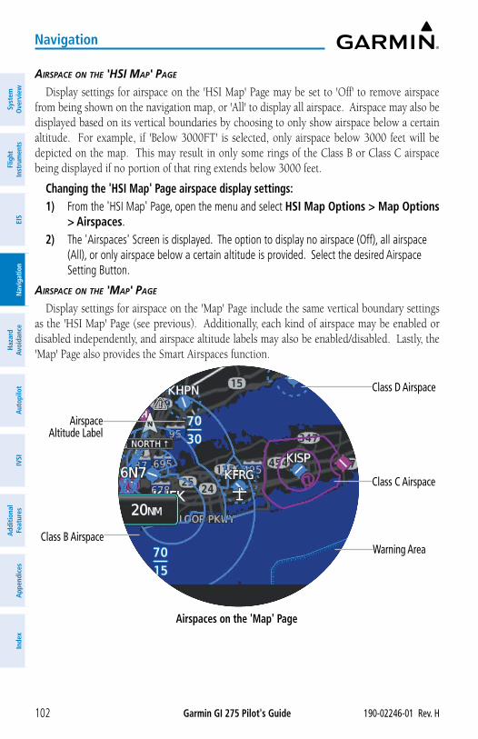
Garmin GI 275 Pilot's Guide 190-02246-01 Rev. H102
Navigation
Syst
em
Ove
rvie
wFl
ight
In
stru
men
tsEI
SN
avig
atio
nH
azar
d Av
oida
nce
Aut
opilo
tIV
SIA
dditi
onal
Fe
atur
esA
ppen
dice
sIn
dex
AirSpACe on tHe 'HSi MAp' pAge
Display settings for airspace on the 'HSI Map' Page may be set to 'Off' to remove airspace from being shown on the navigation map, or 'All' to display all airspace. Airspace may also be displayed based on its vertical boundaries by choosing to only show airspace below a certain altitude. For example, if 'Below 3000FT' is selected, only airspace below 3000 feet will be depicted on the map. This may result in only some rings of the Class B or Class C airspace being displayed if no portion of that ring extends below 3000 feet.
Changing the 'HSI Map' Page airspace display settings:1) From the 'HSI Map' Page, open the menu and select HSI Map Options > Map Options
> Airspaces.2) The 'Airspaces' Screen is displayed. The option to display no airspace (Off), all airspace
(All), or only airspace below a certain altitude is provided. Select the desired Airspace Setting Button.
AirSpACe on tHe 'MAp' pAge
Display settings for airspace on the 'Map' Page include the same vertical boundary settings as the 'HSI Map' Page (see previous). Additionally, each kind of airspace may be enabled or disabled independently, and airspace altitude labels may also be enabled/disabled. Lastly, the 'Map' Page also provides the Smart Airspaces function.
Airspaces on the 'Map' Page
Airspace Altitude Label
Class D Airspace
Class C Airspace
Class B AirspaceWarning Area
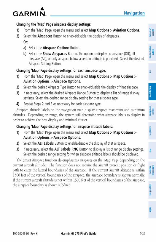
Garmin GI 275 Pilot's Guide190-02246-01 Rev. H 103
Navigation
System
Overview
Flight Instrum
entsEIS
Navigation
Hazard
AvoidanceA
utopilotIVSI
Additional Features
Appendices
Index
Changing the 'Map' Page airspace display settings:1) From the 'Map' Page, open the menu and select Map Options > Aviation Options.2) Select the Airspaces Button to enable/disable the display of airspaces. Or:
a) Select the Airspace Options Button.b) Select the Show Airspaces Button. The option to display no airspace (Off), all
airspace (All), or only airspace below a certain altitude is provided. Select the desired Airspace Setting Button.
Changing 'Map' Page display settings for each airspace type:1) From the 'Map' Page, open the menu and select Map Options > Map Options >
Aviation Options > Airspace Options.2) Select the desired Airspace Type Button to enable/disable the display of that airspace. 3) If necessary, select the desired Airspace Range Button to display a list of range display
settings. Select the desired range display setting for that airspace type. 4) Repeat Steps 2 and 3 as necessary for each airspace type. Airspace altitude labels on the navigation map display airspace maximum and minimum
altitudes. Depending on range, the system will determine what airspace labels to display in order to achieve the best display and minimal clutter.
Changing 'Map' Page display settings for airspace altitude labels:1) From the 'Map' Page, open the menu and select Map Options > Map Options >
Aviation Options > Airspace Options.2) Select the ALT Labels Button to enable/disable the display of that airspace. 3) If necessary, select the ALT Labels RNG Button to display a list of range display settings.
Select the desired range setting for when airspace altitude labels should be displayed. The Smart Airspace function de-emphasizes airspaces on the 'Map' Page depending on the
current aircraft altitude. The function does not require the aircraft present position or flight path to enter the lateral boundaries of the airspace. If the current aircraft altitude is within 1500 feet of the vertical boundaries of the airspace, the airspace boundary is shown normally. If the current aircraft altitude is not within 1500 feet of the vertical boundaries of the airspace, the airspace boundary is shown subdued.
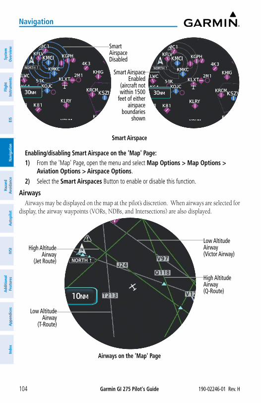
Garmin GI 275 Pilot's Guide 190-02246-01 Rev. H104
Navigation
Syst
em
Ove
rvie
wFl
ight
In
stru
men
tsEI
SN
avig
atio
nH
azar
d Av
oida
nce
Aut
opilo
tIV
SIA
dditi
onal
Fe
atur
esA
ppen
dice
sIn
dex
Smart Airspace
Smart Airspace Disabled
Smart Airspace Enabled
(aircraft not within 1500
feet of either airspace
boundaries shown
Enabling/disabling Smart Airspace on the 'Map' Page:1) From the 'Map' Page, open the menu and select Map Options > Map Options >
Aviation Options > Airspace Options.
2) Select the Smart Airspaces Button to enable or disable this function.
AirwaysAirways may be displayed on the map at the pilot’s discretion. When airways are selected for
display, the airway waypoints (VORs, NDBs, and Intersections) are also displayed.
Airways on the 'Map' Page
High AltitudeAirway
(Jet Route)
Low Altitude Airway(Victor Airway)
High Altitude Airway(Q-Route)
Low AltitudeAirway
(T-Route)
Garmin GI 275 Pilot's Guide190-02246-01 Rev. H 105
Navigation
System
Overview
Flight Instrum
entsEIS
Navigation
Hazard
AvoidanceA
utopilotIVSI
Additional Features
Appendices
Index
Enabling/disabling the display of airways on the 'HSI Map' Page:1) From the 'HSI Map' Page, open the menu and select HSI Map Options > Map Options
> Airways.2) Select the Airways Button and select the Off, All, High, or Low Button to display the
desired airways.
Enabling/disabling the display of airways on the 'Map' Page:1) From the 'Map' Page, open the menu and select Map Options > Aviation Options.2) Select the Airways Button and select the All, High, or Low Button to display the
desired airways. Or: Select the Low Airways Button and the High Airways Button as necessary to enable/
disable the desired airways.
Selecting an airway range for the 'Map' Page:1) From the 'Map' Page, open the menu and select Map Options > Aviation Options.2) Select the Low Airways RNG Button. Then, select the button for the desired range
setting.3) Select the High Airways RNG Button. Then, select the button for the desired range
setting.
AutoZooM on tHe 'MAp' pAge
AutoZoom adjusts the range on the 'Map' Page when waypoint sequencing occurs for the active flight plan. Control of the ranges at which the auto zoom occurs is done by setting the minimum and maximum ‘look forward’ times. These settings determine the minimum and maximum range to display based upon the aircraft’s ground speed.
Enabling/disabling AutoZoom on the 'Map' Page:1) From the 'Map' Page, open the menu and select Map Options > Map Options.2) Select the AutoZoom Button to enable/disable the function.
Setting the minimum and maximum range for AutoZoom:1) From the 'Map' Page, open the menu and select Map Options > Map Options.2) Select the AutoZoom Min Button. Then, select the button for the desired minimum
range setting. 3) Select the AutoZoom Max Button. Then, select the button for the desired maximum
range setting.
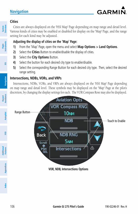
Garmin GI 275 Pilot's Guide 190-02246-01 Rev. H106
Navigation
Syst
em
Ove
rvie
wFl
ight
In
stru
men
tsEI
SN
avig
atio
nH
azar
d Av
oida
nce
Aut
opilo
tIV
SIA
dditi
onal
Fe
atur
esA
ppen
dice
sIn
dex
CitiesCities are always displayed on the 'HSI Map' Page depending on map range and detail level.
Various kinds of cities may be enabled or disabled for display on the 'Map' Page, and the range setting for each kind may be adjusted.
Adjusting the display of cities on the 'Map' Page:1) From the 'Map' Page, open the menu and select Map Options > Land Options.2) Select the Cities Button to enable/disable the display of cities. 3) Select the City Options Button.4) Select the button for each desired city type to enable/disable.5) Select the corresponding Range Button for each desired city type. Then, select the desired
range setting.
Intersections, NDBs, VORs, and VRPsIntersections, NDBs, VORs, and VRPs are always displayed on the 'HSI Map' Page depending
on map range and detail level. These symbols may be displayed on the 'Map' Page at the pilot’s discretion, by changing the display settings for each. The VOR Compass Rose may also be displayed.
VOR, NDB, Intersections Options
Touch to Enable
Range Button
Garmin GI 275 Pilot's Guide190-02246-01 Rev. H 107
Navigation
System
Overview
Flight Instrum
entsEIS
Navigation
Hazard
AvoidanceA
utopilotIVSI
Additional Features
Appendices
Index
Enabling/disabling the display of Intersections, NDBs, VORs, and VRPs on the 'Map' Page:1) From the 'Map' Page, open the menu and select Map Options > Map Options >
Aviation Options.2) Select the corresponding button for the desired item to enable/disable.3) If necessary, select the corresponding Range Button to display a list of range settings.
Select the desired range display setting.
LAT/LON LinesLAT/LON lines may only be displayed on the 'Map' Page.
Enabling/disabling the display of LAT/LON lines on the 'Map' Page:1) From the 'Map' Page, open the menu and select Map Options > Map Options.
2) Select the LAT/LON Lines Button to enable/disable.
Map OrientationOrientation is not adjustable for the 'HSI Map' Page.
The 'Map' Page can be shown in one of three different orientation options, allowing flexibility in determining aircraft position relative to other items on the map (North Up) or for determining where map items are relative to where the aircraft is going (Track Up), or to the current heading (HDG UP).
» North Up (NORTH) aligns the top of the map display to north (default setting).
» Track Up (TRK) aligns the top of the map display to the current ground track.
» Heading Up (HDG) Up aligns the top of the map display to the current aircraft heading.
Changing the 'Map' Page orientation:1) From the 'Map' Page, open the menu and select Map Options > Map Options >
Orientation.
2) Select the North Up, Track Up, or Heading Up Button.
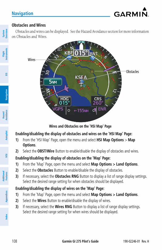
Garmin GI 275 Pilot's Guide 190-02246-01 Rev. H108
Navigation
Syst
em
Ove
rvie
wFl
ight
In
stru
men
tsEI
SN
avig
atio
nH
azar
d Av
oida
nce
Aut
opilo
tIV
SIA
dditi
onal
Fe
atur
esA
ppen
dice
sIn
dex
Obstacles and WiresObstacles and wires can be displayed. See the Hazard Avoidance section for more information
on Obstacles and Wires.
Wires and Obstacles on the 'HSI Map' Page
Obstacles
Wires
Enabling/disabling the display of obstacles and wires on the 'HSI Map' Page:1) From the 'HSI Map' Page, open the menu and select HSI Map Options > Map
Options.2) Select the OBST/Wire Button to enable/disable the display of obstacles and wires.
Enabling/disabling the display of obstacles on the 'Map' Page:1) From the 'Map' Page, open the menu and select Map Options > Land Options.2) Select the Obstacles Button to enable/disable the display of obstacles.3) If necessary, select the Obstacles RNG Button to display a list of range display settings.
Select the desired range setting for when obstacles should be displayed.
Enabling/disabling the display of wires on the 'Map' Page:1) From the 'Map' Page, open the menu and select Map Options > Land Options.2) Select the Wires Button to enable/disable the display of wires.3) If necessary, select the Wires RNG Button to display a list of range display settings.
Select the desired range setting for when wires should be displayed.
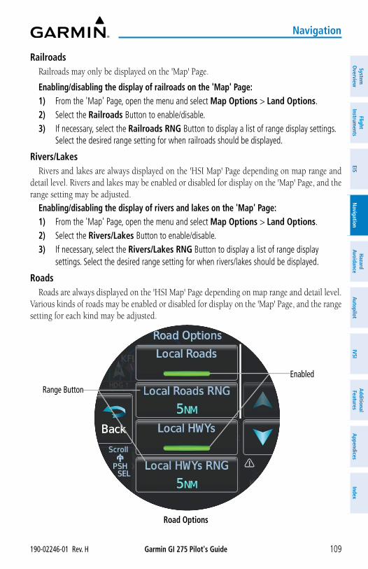
Garmin GI 275 Pilot's Guide190-02246-01 Rev. H 109
Navigation
System
Overview
Flight Instrum
entsEIS
Navigation
Hazard
AvoidanceA
utopilotIVSI
Additional Features
Appendices
Index
RailroadsRailroads may only be displayed on the 'Map' Page.
Enabling/disabling the display of railroads on the 'Map' Page:1) From the 'Map' Page, open the menu and select Map Options > Land Options.2) Select the Railroads Button to enable/disable.3) If necessary, select the Railroads RNG Button to display a list of range display settings.
Select the desired range setting for when railroads should be displayed.
Rivers/LakesRivers and lakes are always displayed on the 'HSI Map' Page depending on map range and
detail level. Rivers and lakes may be enabled or disabled for display on the 'Map' Page, and the range setting may be adjusted.
Enabling/disabling the display of rivers and lakes on the 'Map' Page:1) From the 'Map' Page, open the menu and select Map Options > Land Options.2) Select the Rivers/Lakes Button to enable/disable.3) If necessary, select the Rivers/Lakes RNG Button to display a list of range display
settings. Select the desired range setting for when rivers/lakes should be displayed.
RoadsRoads are always displayed on the 'HSI Map' Page depending on map range and detail level.
Various kinds of roads may be enabled or disabled for display on the 'Map' Page, and the range setting for each kind may be adjusted.
Road Options
Enabled
Range Button
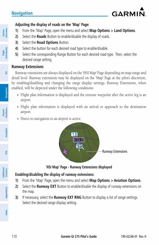
Garmin GI 275 Pilot's Guide 190-02246-01 Rev. H110
Navigation
Syst
em
Ove
rvie
wFl
ight
In
stru
men
tsEI
SN
avig
atio
nH
azar
d Av
oida
nce
Aut
opilo
tIV
SIA
dditi
onal
Fe
atur
esA
ppen
dice
sIn
dex
Adjusting the display of roads on the 'Map' Page:1) From the 'Map' Page, open the menu and select Map Options > Land Options.2) Select the Roads Button to enable/disable the display of roads. 3) Select the Road Options Button.4) Select the button for each desired road type to enable/disable.5) Select the corresponding Range Button for each desired road type. Then, select the
desired range setting.
Runway ExtensionsRunway extensions are always displayed on the 'HSI Map' Page depending on map range and
detail level. Runway extensions may be displayed on the 'Map' Page at the pilot’s discretion, by enabling/disabling and changing the range display settings. Runway Extensions, when enabled, will be depicted under the following conditions:
» Flight plan information is displayed and the enroute waypoint after the active leg is an airport.
» Flight plan information is displayed with an arrival or approach to the destination airport.
» Direct-to navigation to an airport is active.
'HSI Map' Page - Runway Extensions displayed
Runway Extensions
Enabling/disabling the display of runway extensions:1) From the 'Map' Page, open the menu and select Map Options > Aviation Options.2) Select the Runway EXT Button to enable/disable the display of runway extensions on
the map.3) If necessary, select the Runway EXT RNG Button to display a list of range settings.
Select the desired range display setting.
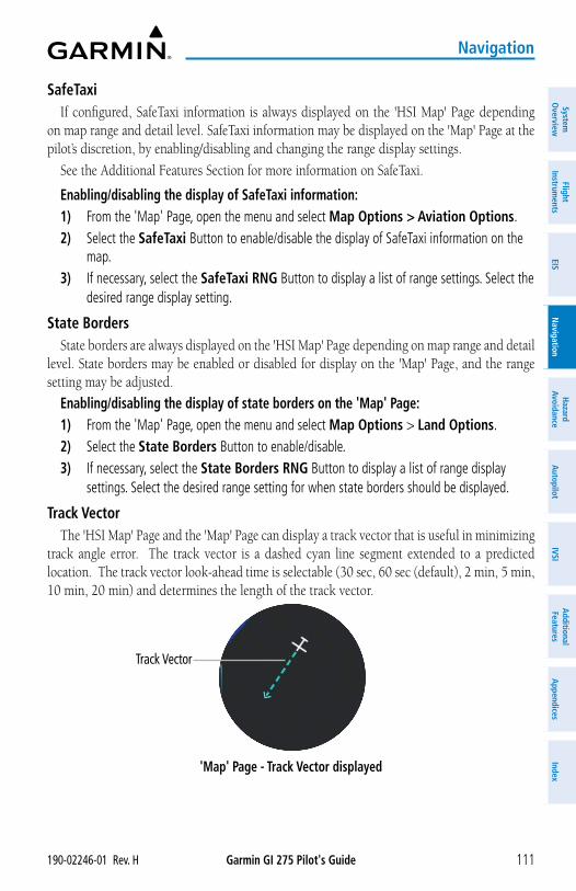
Garmin GI 275 Pilot's Guide190-02246-01 Rev. H 111
Navigation
System
Overview
Flight Instrum
entsEIS
Navigation
Hazard
AvoidanceA
utopilotIVSI
Additional Features
Appendices
Index
SafeTaxiIf configured, SafeTaxi information is always displayed on the 'HSI Map' Page depending
on map range and detail level. SafeTaxi information may be displayed on the 'Map' Page at the pilot’s discretion, by enabling/disabling and changing the range display settings.
See the Additional Features Section for more information on SafeTaxi.
Enabling/disabling the display of SafeTaxi information:1) From the 'Map' Page, open the menu and select Map Options > Aviation Options.2) Select the SafeTaxi Button to enable/disable the display of SafeTaxi information on the
map.3) If necessary, select the SafeTaxi RNG Button to display a list of range settings. Select the
desired range display setting.
State BordersState borders are always displayed on the 'HSI Map' Page depending on map range and detail
level. State borders may be enabled or disabled for display on the 'Map' Page, and the range setting may be adjusted.
Enabling/disabling the display of state borders on the 'Map' Page:1) From the 'Map' Page, open the menu and select Map Options > Land Options.2) Select the State Borders Button to enable/disable.3) If necessary, select the State Borders RNG Button to display a list of range display
settings. Select the desired range setting for when state borders should be displayed.
Track VectorThe 'HSI Map' Page and the 'Map' Page can display a track vector that is useful in minimizing
track angle error. The track vector is a dashed cyan line segment extended to a predicted location. The track vector look-ahead time is selectable (30 sec, 60 sec (default), 2 min, 5 min, 10 min, 20 min) and determines the length of the track vector.
'Map' Page - Track Vector displayed
Track Vector
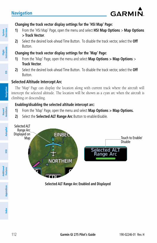
Garmin GI 275 Pilot's Guide 190-02246-01 Rev. H112
Navigation
Syst
em
Ove
rvie
wFl
ight
In
stru
men
tsEI
SN
avig
atio
nH
azar
d Av
oida
nce
Aut
opilo
tIV
SIA
dditi
onal
Fe
atur
esA
ppen
dice
sIn
dex
Changing the track vector display settings for the 'HSI Map' Page:1) From the 'HSI Map' Page, open the menu and select HSI Map Options > Map Options
> Track Vector.2) Select the desired look-ahead Time Button. To disable the track vector, select the Off
Button.
Changing the track vector display settings for the 'Map' Page:1) From the 'Map' Page, open the menu and select Map Options > Map Options >
Track Vector.2) Select the desired look-ahead Time Button. To disable the track vector, select the Off
Button.
Selected Altitude Intercept ArcThe 'Map' Page can display the location along with current track where the aircraft will
intercept the selected altitude. The location will be shown as a cyan arc when the aircraft is climbing or descending.
Enabling/disabling the selected altitude intercept arc:1) From the 'Map' Page, open the menu and select Map Options > Map Options. 2) Select the Selected ALT Range Arc Button to enable/disable.
Selected ALT Range Arc Enabled and Displayed
Selected ALT Range Arc
Displayed on Map Touch to Enable/
Disable
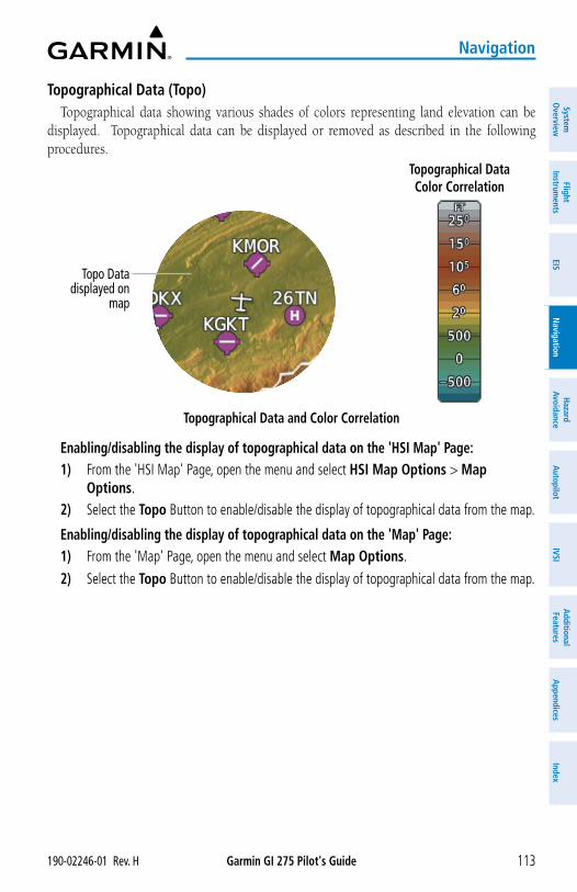
Garmin GI 275 Pilot's Guide190-02246-01 Rev. H 113
Navigation
System
Overview
Flight Instrum
entsEIS
Navigation
Hazard
AvoidanceA
utopilotIVSI
Additional Features
Appendices
Index
Topographical Data (Topo)Topographical data showing various shades of colors representing land elevation can be
displayed. Topographical data can be displayed or removed as described in the following procedures.
Topographical Data Color Correlation
Topographical Data and Color Correlation
Topo Data displayed on
map
Enabling/disabling the display of topographical data on the 'HSI Map' Page:1) From the 'HSI Map' Page, open the menu and select HSI Map Options > Map
Options.2) Select the Topo Button to enable/disable the display of topographical data from the map.
Enabling/disabling the display of topographical data on the 'Map' Page:1) From the 'Map' Page, open the menu and select Map Options.
2) Select the Topo Button to enable/disable the display of topographical data from the map.
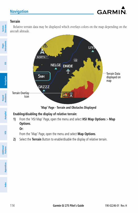
Garmin GI 275 Pilot's Guide 190-02246-01 Rev. H114
Navigation
Syst
em
Ove
rvie
wFl
ight
In
stru
men
tsEI
SN
avig
atio
nH
azar
d Av
oida
nce
Aut
opilo
tIV
SIA
dditi
onal
Fe
atur
esA
ppen
dice
sIn
dex
TerrainRelative terrain data may be displayed which overlays colors on the map depending on the
aircraft altitude.
'Map' Page - Terrain and Obstacles Displayed
Terrain Datadisplayed on map
Terrain Overlay Icon
Enabling/disabling the display of relative terrain:1) From the 'HSI Map' Page, open the menu and select HSI Map Options > Map
Options.Or:
From the 'Map' Page, open the menu and select Map Options.
2) Select the Terrain Button to enable/disable the display of relative terrain.
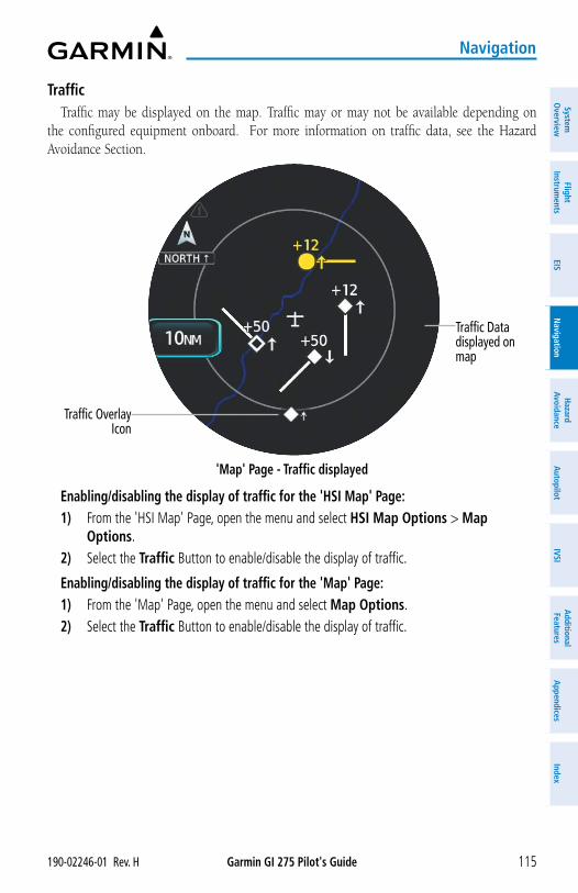
Garmin GI 275 Pilot's Guide190-02246-01 Rev. H 115
Navigation
System
Overview
Flight Instrum
entsEIS
Navigation
Hazard
AvoidanceA
utopilotIVSI
Additional Features
Appendices
Index
TrafficTraffic may be displayed on the map. Traffic may or may not be available depending on
the configured equipment onboard. For more information on traffic data, see the Hazard Avoidance Section.
'Map' Page - Traffic displayed
Traffic Datadisplayed on map
Traffic Overlay Icon
Enabling/disabling the display of traffic for the 'HSI Map' Page:1) From the 'HSI Map' Page, open the menu and select HSI Map Options > Map
Options.2) Select the Traffic Button to enable/disable the display of traffic.
Enabling/disabling the display of traffic for the 'Map' Page:1) From the 'Map' Page, open the menu and select Map Options.2) Select the Traffic Button to enable/disable the display of traffic.
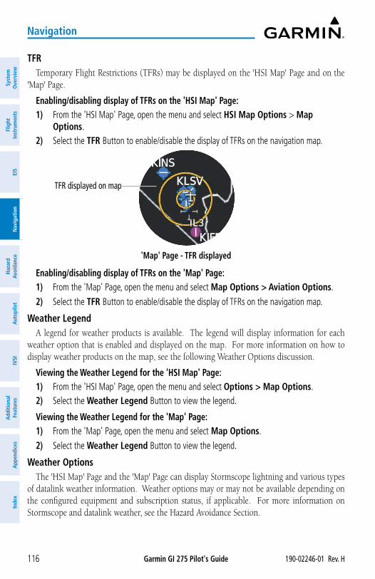
Garmin GI 275 Pilot's Guide 190-02246-01 Rev. H116
Navigation
Syst
em
Ove
rvie
wFl
ight
In
stru
men
tsEI
SN
avig
atio
nH
azar
d Av
oida
nce
Aut
opilo
tIV
SIA
dditi
onal
Fe
atur
esA
ppen
dice
sIn
dex
TFRTemporary Flight Restrictions (TFRs) may be displayed on the 'HSI Map' Page and on the
'Map' Page.
Enabling/disabling display of TFRs on the 'HSI Map' Page:1) From the 'HSI Map' Page, open the menu and select HSI Map Options > Map
Options.2) Select the TFR Button to enable/disable the display of TFRs on the navigation map.
'Map' Page - TFR displayed
TFR displayed on map
Enabling/disabling display of TFRs on the 'Map' Page:1) From the 'Map' Page, open the menu and select Map Options > Aviation Options.
2) Select the TFR Button to enable/disable the display of TFRs on the navigation map.
Weather LegendA legend for weather products is available. The legend will display information for each
weather option that is enabled and displayed on the map. For more information on how to display weather products on the map, see the following Weather Options discussion.
Viewing the Weather Legend for the 'HSI Map' Page:1) From the 'HSI Map' Page, open the menu and select Options > Map Options.2) Select the Weather Legend Button to view the legend.
Viewing the Weather Legend for the 'Map' Page:1) From the 'Map' Page, open the menu and select Map Options.
2) Select the Weather Legend Button to view the legend.
Weather OptionsThe 'HSI Map' Page and the 'Map' Page can display Stormscope lightning and various types
of datalink weather information. Weather options may or may not be available depending on the configured equipment and subscription status, if applicable. For more information on Stormscope and datalink weather, see the Hazard Avoidance Section.
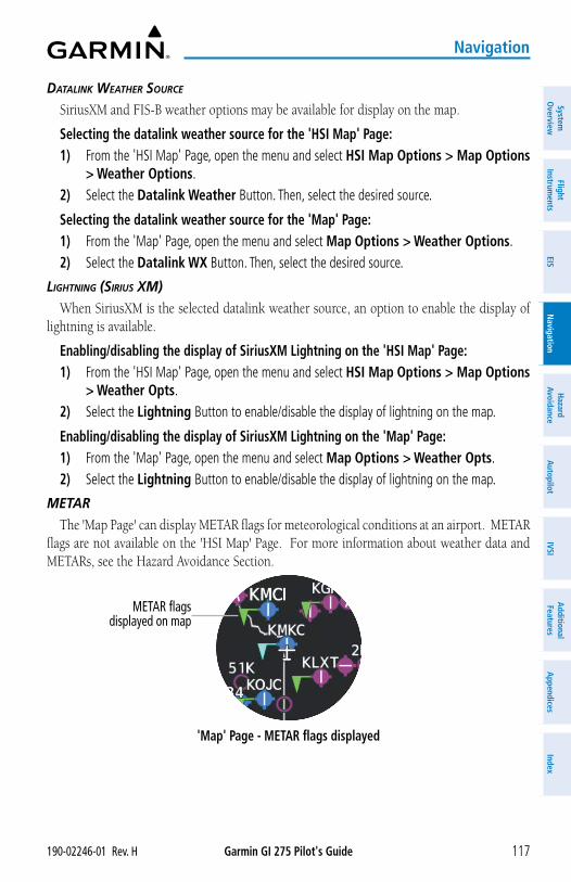
Garmin GI 275 Pilot's Guide190-02246-01 Rev. H 117
Navigation
System
Overview
Flight Instrum
entsEIS
Navigation
Hazard
AvoidanceA
utopilotIVSI
Additional Features
Appendices
Index
DAtALink WeAtHer SourCe
SiriusXM and FIS-B weather options may be available for display on the map.
Selecting the datalink weather source for the 'HSI Map' Page:1) From the 'HSI Map' Page, open the menu and select HSI Map Options > Map Options
> Weather Options.2) Select the Datalink Weather Button. Then, select the desired source.
Selecting the datalink weather source for the 'Map' Page:1) From the 'Map' Page, open the menu and select Map Options > Weather Options.2) Select the Datalink WX Button. Then, select the desired source.
LigHtning (SiriuS XM)
When SiriusXM is the selected datalink weather source, an option to enable the display of lightning is available.
Enabling/disabling the display of SiriusXM Lightning on the 'HSI Map' Page:1) From the 'HSI Map' Page, open the menu and select HSI Map Options > Map Options
> Weather Opts.2) Select the Lightning Button to enable/disable the display of lightning on the map.
Enabling/disabling the display of SiriusXM Lightning on the 'Map' Page:1) From the 'Map' Page, open the menu and select Map Options > Weather Opts.2) Select the Lightning Button to enable/disable the display of lightning on the map.
MetAr
The 'Map Page' can display METAR flags for meteorological conditions at an airport. METAR flags are not available on the 'HSI Map' Page. For more information about weather data and METARs, see the Hazard Avoidance Section.
'Map' Page - METAR flags displayed
METAR flags displayed on map
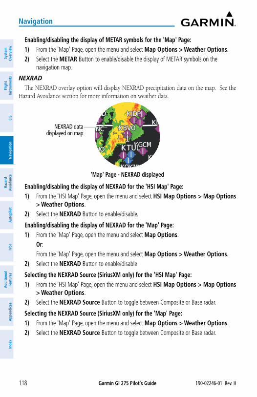
Garmin GI 275 Pilot's Guide 190-02246-01 Rev. H118
Navigation
Syst
em
Ove
rvie
wFl
ight
In
stru
men
tsEI
SN
avig
atio
nH
azar
d Av
oida
nce
Aut
opilo
tIV
SIA
dditi
onal
Fe
atur
esA
ppen
dice
sIn
dex
Enabling/disabling the display of METAR symbols for the 'Map' Page:1) From the 'Map' Page, open the menu and select Map Options > Weather Options.2) Select the METAR Button to enable/disable the display of METAR symbols on the
navigation map.
neXrAD
The NEXRAD overlay option will display NEXRAD precipitation data on the map. See the Hazard Avoidance section for more information on weather data.
'Map' Page - NEXRAD displayed
NEXRAD data displayed on map
Enabling/disabling the display of NEXRAD for the 'HSI Map' Page:1) From the 'HSI Map' Page, open the menu and select HSI Map Options > Map Options
> Weather Options.2) Select the NEXRAD Button to enable/disable.
Enabling/disabling the display of NEXRAD for the 'Map' Page:1) From the 'Map' Page, open the menu and select Map Options. Or: From the 'Map' Page, open the menu and select Map Options > Weather Options.2) Select the NEXRAD Button to enable/disable
Selecting the NEXRAD Source (SiriusXM only) for the 'HSI Map' Page:1) From the 'HSI Map' Page, open the menu and select HSI Map Options > Map Options
> Weather Options.2) Select the NEXRAD Source Button to toggle between Composite or Base radar.
Selecting the NEXRAD Source (SiriusXM only) for the 'Map' Page:1) From the 'Map' Page, open the menu and select Map Options > Weather Options.2) Select the NEXRAD Source Button to toggle between Composite or Base radar.
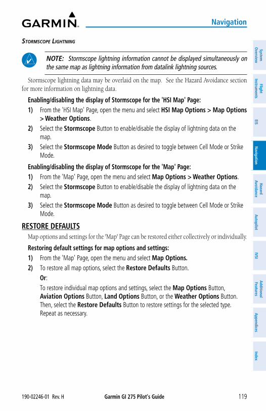
Garmin GI 275 Pilot's Guide190-02246-01 Rev. H 119
Navigation
System
Overview
Flight Instrum
entsEIS
Navigation
Hazard
AvoidanceA
utopilotIVSI
Additional Features
Appendices
Index
StorMSCope LigHtning
NOTE: Stormscope lightning information cannot be displayed simultaneously on the same map as lightning information from datalink lightning sources.
Stormscope lightning data may be overlaid on the map. See the Hazard Avoidance section for more information on lightning data.
Enabling/disabling the display of Stormscope for the 'HSI Map' Page:1) From the 'HSI Map' Page, open the menu and select HSI Map Options > Map Options
> Weather Options.2) Select the Stormscope Button to enable/disable the display of lightning data on the
map.3) Select the Stormscope Mode Button as desired to toggle between Cell Mode or Strike
Mode.
Enabling/disabling the display of Stormscope for the 'Map' Page:1) From the 'Map' Page, open the menu and select Map Options > Weather Options.2) Select the Stormscope Button to enable/disable the display of lightning data on the
map.3) Select the Stormscope Mode Button as desired to toggle between Cell Mode or Strike
Mode.
RESTORE DEFAULTSMap options and settings for the 'Map' Page can be restored either collectively or individually.
Restoring default settings for map options and settings:1) From the 'Map' Page, open the menu and select Map Options.2) To restore all map options, select the Restore Defaults Button. Or: To restore individual map options and settings, select the Map Options Button,
Aviation Options Button, Land Options Button, or the Weather Options Button. Then, select the Restore Defaults Button to restore settings for the selected type. Repeat as necessary.
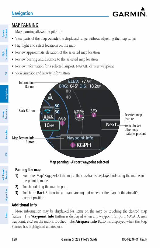
Garmin GI 275 Pilot's Guide 190-02246-01 Rev. H120
Navigation
Syst
em
Ove
rvie
wFl
ight
In
stru
men
tsEI
SN
avig
atio
nH
azar
d Av
oida
nce
Aut
opilo
tIV
SIA
dditi
onal
Fe
atur
esA
ppen
dice
sIn
dex
MAP PANNINGMap panning allows the pilot to:
• View parts of the map outside the displayed range without adjusting the map range
• Highlight and select locations on the map
• Review approximate elevation of the selected map location
• Review bearing and distance to the selected map location
• Review information for a selected airport, NAVAID or user waypoint
• View airspace and airway information
Map panning - Airport waypoint selected
Information Banner
Selected map feature
Map Feature Info Button
Back Button
Select to see other mapfeatures present
Panning the map:1) From the 'Map' Page, select the map. The crosshair is displayed indicating the map is in
the panning mode.2) Touch and drag the map to pan.3) Touch the Back Button to exit map panning and re-center the map on the aircraft’s
current position
Additional InfoMore information may be displayed for items on the map by touching the desired map
feature. The Waypoint Info Button is displayed when any waypoint (airport, NAVAID, user waypoint, etc.) on the map is touched. The Airspace Info Button is displayed when the Map Pointer has highlighted an airspace.
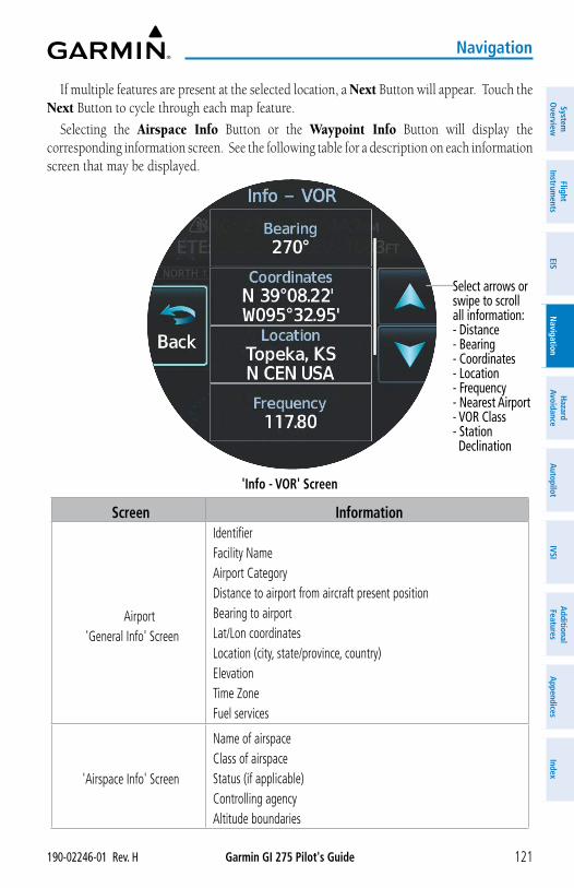
Garmin GI 275 Pilot's Guide190-02246-01 Rev. H 121
Navigation
System
Overview
Flight Instrum
entsEIS
Navigation
Hazard
AvoidanceA
utopilotIVSI
Additional Features
Appendices
Index
If multiple features are present at the selected location, a Next Button will appear. Touch the Next Button to cycle through each map feature.
Selecting the Airspace Info Button or the Waypoint Info Button will display the corresponding information screen. See the following table for a description on each information screen that may be displayed.
'Info - VOR' Screen
Select arrows or swipe to scroll all information:- Distance- Bearing- Coordinates- Location- Frequency- Nearest Airport- VOR Class- Station Declination
Screen Information
Airport 'General Info' Screen
IdentifierFacility NameAirport CategoryDistance to airport from aircraft present positionBearing to airportLat/Lon coordinatesLocation (city, state/province, country)ElevationTime ZoneFuel services
'Airspace Info' Screen
Name of airspaceClass of airspaceStatus (if applicable)Controlling agencyAltitude boundaries
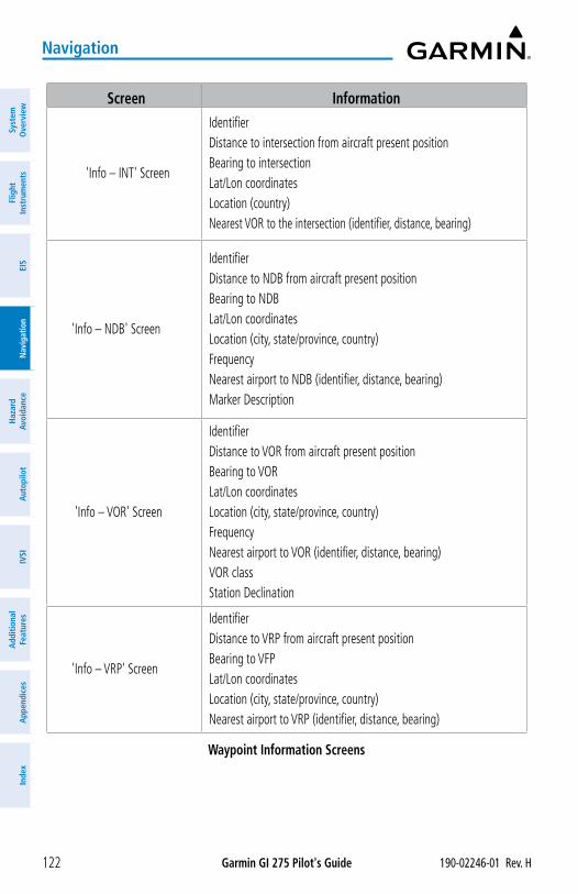
Garmin GI 275 Pilot's Guide 190-02246-01 Rev. H122
Navigation
Syst
em
Ove
rvie
wFl
ight
In
stru
men
tsEI
SN
avig
atio
nH
azar
d Av
oida
nce
Aut
opilo
tIV
SIA
dditi
onal
Fe
atur
esA
ppen
dice
sIn
dex
Screen Information
'Info – INT' Screen
IdentifierDistance to intersection from aircraft present positionBearing to intersectionLat/Lon coordinatesLocation (country)Nearest VOR to the intersection (identifier, distance, bearing)
'Info – NDB' Screen
IdentifierDistance to NDB from aircraft present positionBearing to NDBLat/Lon coordinatesLocation (city, state/province, country)FrequencyNearest airport to NDB (identifier, distance, bearing)Marker Description
'Info – VOR' Screen
IdentifierDistance to VOR from aircraft present positionBearing to VORLat/Lon coordinatesLocation (city, state/province, country)FrequencyNearest airport to VOR (identifier, distance, bearing)VOR classStation Declination
'Info – VRP' Screen
IdentifierDistance to VRP from aircraft present positionBearing to VFPLat/Lon coordinatesLocation (city, state/province, country)Nearest airport to VRP (identifier, distance, bearing)
Waypoint Information Screens
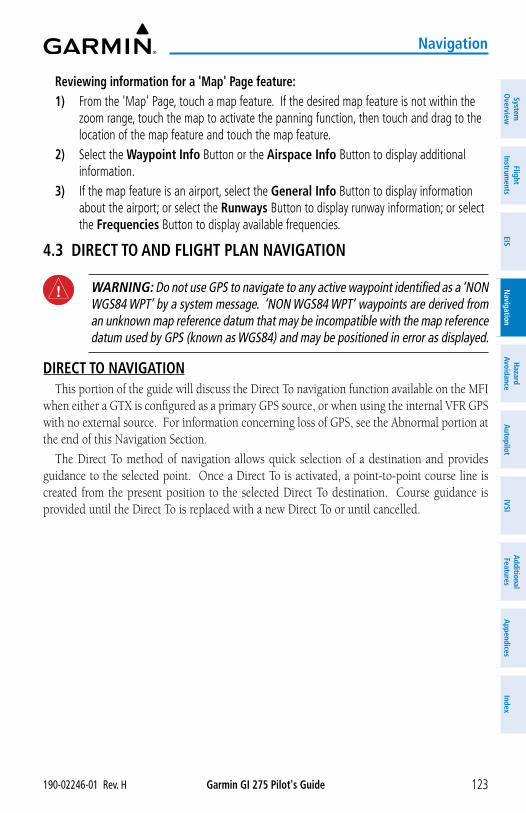
Garmin GI 275 Pilot's Guide190-02246-01 Rev. H 123
Navigation
System
Overview
Flight Instrum
entsEIS
Navigation
Hazard
AvoidanceA
utopilotIVSI
Additional Features
Appendices
Index
Reviewing information for a 'Map' Page feature:1) From the 'Map' Page, touch a map feature. If the desired map feature is not within the
zoom range, touch the map to activate the panning function, then touch and drag to the location of the map feature and touch the map feature.
2) Select the Waypoint Info Button or the Airspace Info Button to display additional information.
3) If the map feature is an airport, select the General Info Button to display information about the airport; or select the Runways Button to display runway information; or select the Frequencies Button to display available frequencies.
4.3 DIRECT TO AND FLIGHT PLAN NAVIGATION
WARNING: Do not use GPS to navigate to any active waypoint identified as a ‘NON WGS84 WPT’ by a system message. ‘NON WGS84 WPT’ waypoints are derived from an unknown map reference datum that may be incompatible with the map reference datum used by GPS (known as WGS84) and may be positioned in error as displayed.
DIRECT TO NAVIGATIONThis portion of the guide will discuss the Direct To navigation function available on the MFI
when either a GTX is configured as a primary GPS source, or when using the internal VFR GPS with no external source. For information concerning loss of GPS, see the Abnormal portion at the end of this Navigation Section.
The Direct To method of navigation allows quick selection of a destination and provides guidance to the selected point. Once a Direct To is activated, a point-to-point course line is created from the present position to the selected Direct To destination. Course guidance is provided until the Direct To is replaced with a new Direct To or until cancelled.
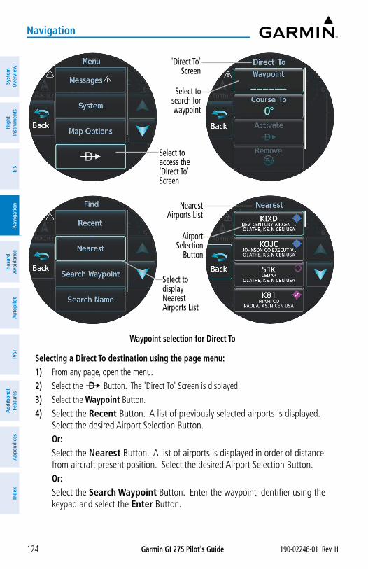
Garmin GI 275 Pilot's Guide 190-02246-01 Rev. H124
Navigation
Syst
em
Ove
rvie
wFl
ight
In
stru
men
tsEI
SN
avig
atio
nH
azar
d Av
oida
nce
Aut
opilo
tIV
SIA
dditi
onal
Fe
atur
esA
ppen
dice
sIn
dex
Select to search for waypoint
'Direct To' Screen
Select to access the 'Direct To' Screen
Waypoint selection for Direct To
Airport Selection
Button
Nearest Airports List
Select todisplayNearest Airports List
Selecting a Direct To destination using the page menu:1) From any page, open the menu.2) Select the ¯ Button. The 'Direct To' Screen is displayed.3) Select the Waypoint Button.4) Select the Recent Button. A list of previously selected airports is displayed.
Select the desired Airport Selection Button.Or:
Select the Nearest Button. A list of airports is displayed in order of distance from aircraft present position. Select the desired Airport Selection Button.Or:
Select the Search Waypoint Button. Enter the waypoint identifier using the keypad and select the Enter Button.
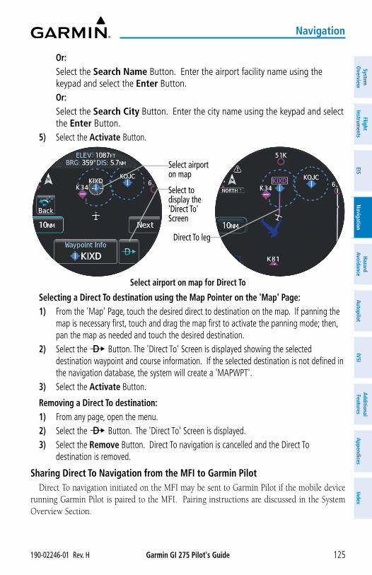
Garmin GI 275 Pilot's Guide190-02246-01 Rev. H 125
Navigation
System
Overview
Flight Instrum
entsEIS
Navigation
Hazard
AvoidanceA
utopilotIVSI
Additional Features
Appendices
Index
Or: Select the Search Name Button. Enter the airport facility name using the
keypad and select the Enter Button.Or:
Select the Search City Button. Enter the city name using the keypad and select the Enter Button.
5) Select the Activate Button.
Select airport on map for Direct To
Select airport on map
Direct To leg
Select to display the 'Direct To' Screen
Selecting a Direct To destination using the Map Pointer on the 'Map' Page:1) From the 'Map' Page, touch the desired direct to destination on the map. If panning the
map is necessary first, touch and drag the map first to activate the panning mode; then, pan the map as needed and touch the desired destination.
2) Select the ¯ Button. The 'Direct To' Screen is displayed showing the selected destination waypoint and course information. If the selected destination is not defined in the navigation database, the system will create a 'MAPWPT'.
3) Select the Activate Button.
Removing a Direct To destination:1) From any page, open the menu.2) Select the ¯ Button. The 'Direct To' Screen is displayed.3) Select the Remove Button. Direct To navigation is cancelled and the Direct To
destination is removed.
Sharing Direct To Navigation from the MFI to Garmin PilotDirect To navigation initiated on the MFI may be sent to Garmin Pilot if the mobile device
running Garmin Pilot is paired to the MFI. Pairing instructions are discussed in the System Overview Section.
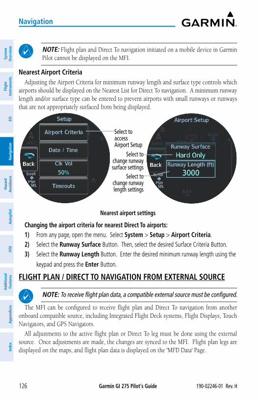
Garmin GI 275 Pilot's Guide 190-02246-01 Rev. H126
Navigation
Syst
em
Ove
rvie
wFl
ight
In
stru
men
tsEI
SN
avig
atio
nH
azar
d Av
oida
nce
Aut
opilo
tIV
SIA
dditi
onal
Fe
atur
esA
ppen
dice
sIn
dex
NOTE: Flight plan and Direct To navigation initiated on a mobile device in Garmin Pilot cannot be displayed on the MFI.
Nearest Airport CriteriaAdjusting the Airport Criteria for minimum runway length and surface type controls which
airports should be displayed on the Nearest List for Direct To navigation. A minimum runway length and/or surface type can be entered to prevent airports with small runways or runways that are not appropriately surfaced from being displayed.
Nearest airport settings
Select toaccessAirport Setup
Select to change runway surface settings
Select to change runway length settings
Changing the airport criteria for nearest Direct To airports:1) From any page, open the menu. Select System > Setup > Airport Criteria.2) Select the Runway Surface Button. Then, select the desired Surface Criteria Button.3) Select the Runway Length Button. Enter the desired minimum runway length using the
keypad and press the Enter Button.
FLIGHT PLAN / DIRECT TO NAVIGATION FROM EXTERNAL SOURCE
NOTE: To receive flight plan data, a compatible external source must be configured.
The MFI can be configured to receive flight plan and Direct To navigation from another onboard compatible source, including Integrated Flight Deck systems, Flight Displays, Touch Navigators, and GPS Navigators.
All adjustments to the active flight plan or Direct To leg must be done using the external source. Once adjustments are made, the changes are synced to the MFI. Flight plan legs are displayed on the maps, and flight plan data is displayed on the 'MFD Data' Page.
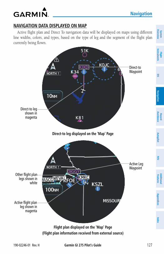
Garmin GI 275 Pilot's Guide190-02246-01 Rev. H 127
Navigation
System
Overview
Flight Instrum
entsEIS
Navigation
Hazard
AvoidanceA
utopilotIVSI
Additional Features
Appendices
Index
NAVIGATION DATA DISPLAYED ON MAPActive flight plan and Direct To navigation data will be displayed on maps using different
line widths, colors, and types, based on the type of leg and the segment of the flight plan currently being flown.
Direct-to leg displayed on the 'Map' Page
Direct-toWaypoint
Direct-to leg shown in magenta
Flight plan displayed on the 'Map' Page(Flight plan information received from external source)
Active Leg Waypoint
Active flight plan leg shown in
magenta
Other flight plan legs shown in
white
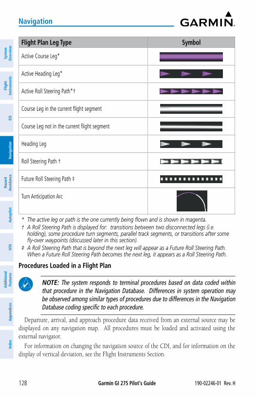
Garmin GI 275 Pilot's Guide 190-02246-01 Rev. H128
Navigation
Syst
em
Ove
rvie
wFl
ight
In
stru
men
tsEI
SN
avig
atio
nH
azar
d Av
oida
nce
Aut
opilo
tIV
SIA
dditi
onal
Fe
atur
esA
ppen
dice
sIn
dex
Flight Plan Leg Type Symbol
Active Course Leg*
Active Heading Leg*
Active Roll Steering Path*†
Course Leg in the current flight segment
Course Leg not in the current flight segment
Heading Leg
Roll Steering Path †
Future Roll Steering Path ‡
Turn Anticipation Arc
* The active leg or path is the one currently being flown and is shown in magenta.† A Roll Steering Path is displayed for: transitions between two disconnected legs (i.e.
holding), some procedure turn segments, parallel track segments, or transitions after some fly-over waypoints (discussed later in this section).
‡ A Roll Steering Path that is beyond the next leg will appear as a Future Roll Steering Path. When a Future Roll Steering Path becomes the next leg, it appears as a Roll Steering Path.
Procedures Loaded in a Flight Plan
NOTE: The system responds to terminal procedures based on data coded within that procedure in the Navigation Database. Differences in system operation may be observed among similar types of procedures due to differences in the Navigation Database coding specific to each procedure.
Departure, arrival, and approach procedure data received from an external source may be displayed on any navigation map. All procedures must be loaded and activated using the external navigator.
For information on changing the navigation source of the CDI, and for information on the display of vertical deviation, see the Flight Instruments Section.
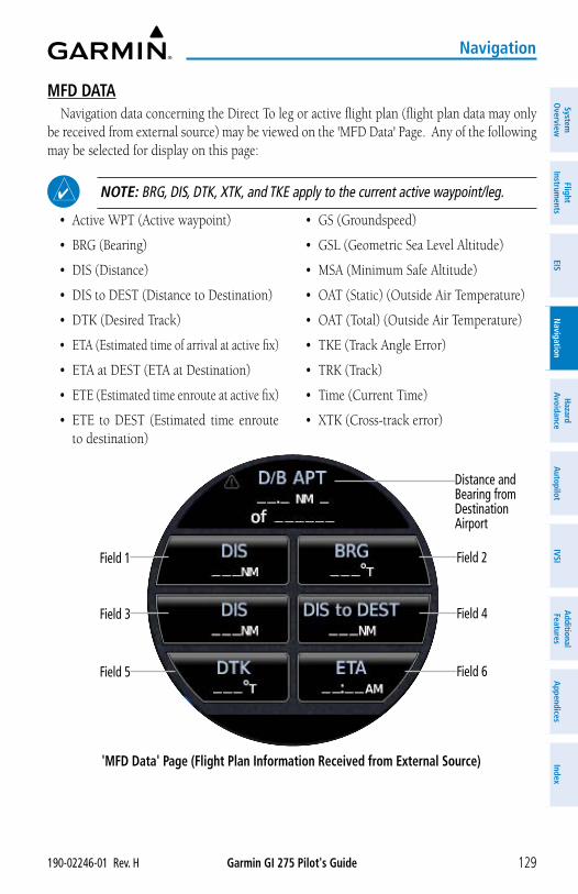
Garmin GI 275 Pilot's Guide190-02246-01 Rev. H 129
Navigation
System
Overview
Flight Instrum
entsEIS
Navigation
Hazard
AvoidanceA
utopilotIVSI
Additional Features
Appendices
Index
MFD DATANavigation data concerning the Direct To leg or active flight plan (flight plan data may only
be received from external source) may be viewed on the 'MFD Data' Page. Any of the following may be selected for display on this page:
NOTE: BRG, DIS, DTK, XTK, and TKE apply to the current active waypoint/leg.
• Active WPT (Active waypoint)
• BRG (Bearing)
• DIS (Distance)
• DIS to DEST (Distance to Destination)
• DTK (Desired Track)
• ETA (Estimated time of arrival at active fix)
• ETA at DEST (ETA at Destination)
• ETE (Estimated time enroute at active fix)
• ETE to DEST (Estimated time enroute to destination)
• GS (Groundspeed)
• GSL (Geometric Sea Level Altitude)
• MSA (Minimum Safe Altitude)
• OAT (Static) (Outside Air Temperature)
• OAT (Total) (Outside Air Temperature)
• TKE (Track Angle Error)
• TRK (Track)
• Time (Current Time)
• XTK (Cross-track error)
'MFD Data' Page (Flight Plan Information Received from External Source)
Distance and Bearing fromDestination Airport
Field 1 Field 2
Field 3 Field 4
Field 5 Field 6
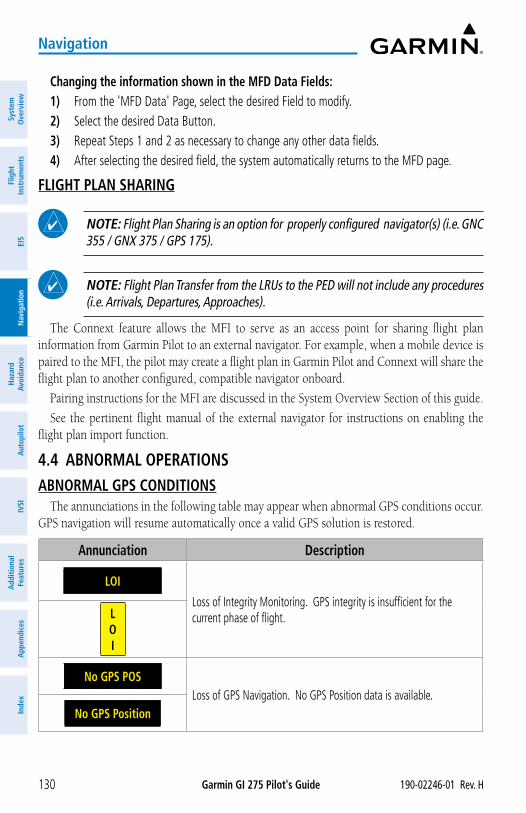
Garmin GI 275 Pilot's Guide 190-02246-01 Rev. H130
Navigation
Syst
em
Ove
rvie
wFl
ight
In
stru
men
tsEI
SN
avig
atio
nH
azar
d Av
oida
nce
Aut
opilo
tIV
SIA
dditi
onal
Fe
atur
esA
ppen
dice
sIn
dex
Changing the information shown in the MFD Data Fields:1) From the 'MFD Data' Page, select the desired Field to modify.2) Select the desired Data Button.3) Repeat Steps 1 and 2 as necessary to change any other data fields.4) After selecting the desired field, the system automatically returns to the MFD page.
FLIGHT PLAN SHARING
NOTE: Flight Plan Sharing is an option for properly configured navigator(s) (i.e. GNC 355 / GNX 375 / GPS 175).
NOTE: Flight Plan Transfer from the LRUs to the PED will not include any procedures (i.e. Arrivals, Departures, Approaches).
The Connext feature allows the MFI to serve as an access point for sharing flight plan information from Garmin Pilot to an external navigator. For example, when a mobile device is paired to the MFI, the pilot may create a flight plan in Garmin Pilot and Connext will share the flight plan to another configured, compatible navigator onboard.
Pairing instructions for the MFI are discussed in the System Overview Section of this guide.
See the pertinent flight manual of the external navigator for instructions on enabling the flight plan import function.
4.4 ABNORMAL OPERATIONSABNORMAL GPS CONDITIONS
The annunciations in the following table may appear when abnormal GPS conditions occur. GPS navigation will resume automatically once a valid GPS solution is restored.
Annunciation Description
LOI
Loss of Integrity Monitoring. GPS integrity is insufficient for the current phase of flight.L
OI
No GPS POSLoss of GPS Navigation. No GPS Position data is available.
No GPS Position
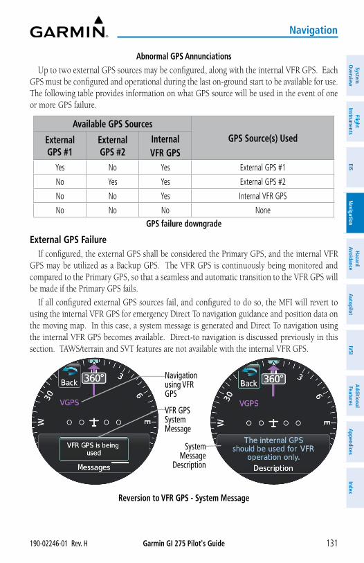
Garmin GI 275 Pilot's Guide190-02246-01 Rev. H 131
Navigation
System
Overview
Flight Instrum
entsEIS
Navigation
Hazard
AvoidanceA
utopilotIVSI
Additional Features
Appendices
Index
Abnormal GPS AnnunciationsUp to two external GPS sources may be configured, along with the internal VFR GPS. Each
GPS must be configured and operational during the last on-ground start to be available for use. The following table provides information on what GPS source will be used in the event of one or more GPS failure.
Available GPS SourcesGPS Source(s) UsedExternal
GPS #1External GPS #2
InternalVFR GPS
Yes No Yes External GPS #1
No Yes Yes External GPS #2
No No Yes Internal VFR GPS
No No No NoneGPS failure downgrade
External GPS FailureIf configured, the external GPS shall be considered the Primary GPS, and the internal VFR
GPS may be utilized as a Backup GPS. The VFR GPS is continuously being monitored and compared to the Primary GPS, so that a seamless and automatic transition to the VFR GPS will be made if the Primary GPS fails.
If all configured external GPS sources fail, and configured to do so, the MFI will revert to using the internal VFR GPS for emergency Direct To navigation guidance and position data on the moving map. In this case, a system message is generated and Direct To navigation using the internal VFR GPS becomes available. Direct-to navigation is discussed previously in this section. TAWS/terrain and SVT features are not available with the internal VFR GPS.
Reversion to VFR GPS - System Message
Navigation using VFR GPS
System Message
Description
VFR GPS System Message
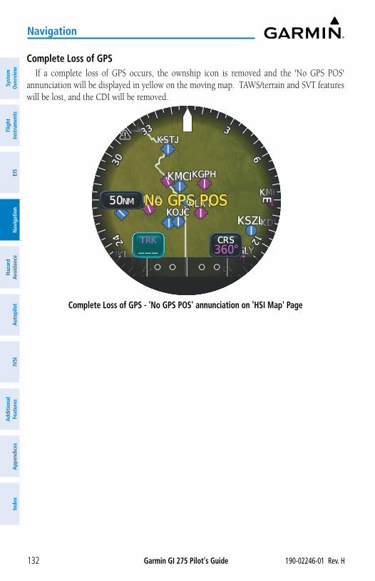
Garmin GI 275 Pilot's Guide 190-02246-01 Rev. H132
Navigation
Syst
em
Ove
rvie
wFl
ight
In
stru
men
tsEI
SN
avig
atio
nH
azar
d Av
oida
nce
Aut
opilo
tIV
SIA
dditi
onal
Fe
atur
esA
ppen
dice
sIn
dex
Complete Loss of GPSIf a complete loss of GPS occurs, the ownship icon is removed and the 'No GPS POS'
annunciation will be displayed in yellow on the moving map. TAWS/terrain and SVT features will be lost, and the CDI will be removed.
Complete Loss of GPS - 'No GPS POS' annunciation on 'HSI Map' Page

Garmin GI 275 Pilot's Guide190-02246-01 Rev. H 133
Hazard Avoidance
System
Overview
Flight Instrum
entsEIS
Navigation
Hazard
AvoidanceA
utopilotIVSI
Additional Features
Appendices
Index
SECTION 5 HAZARD AVOIDANCE5.1 INTRODUCTION
Hazard avoidance features are designed to aid situational awareness and provide advisory information regarding potential hazards to flight safety associated with weather, terrain, and air traffic.
• Weather
– SiriusXM Weather
– Flight Information Services-Broadcast (FIS-B)
– Stormscope
• Terrain Avoidance
– Terrain Proximity
– Terrain-FLTA / Helicopter Terrain - HFLTA
– TAWS-B / HTAWS (external TAWS system required)
• Traffic
– Traffic Information Service (TIS)
– Traffic Advisory System (TAS) / Traffic Alert and Collision Avoidance System (TCAS)
– Automatic Dependent Surveillance-Broadcast (ADS-B) Traffic
5.2 DATALINK WEATHER
WARNING: Do not use datalink weather information for maneuvering in, near, or around areas of hazardous weather. Information contained within datalink weather products may not accurately depict current weather conditions.
WARNING: Do not use the indicated datalink weather product age to determine the age of the weather information shown by the datalink weather product. Due to time delays inherent in gathering and processing weather data for datalink transmission, the weather information shown by the datalink weather product may be older than the indicated weather product age.
Datalink weather services, including SiriusXM Weather and Flight Information Services-Broadcast (FIS-B) may be transmitted from a ground station or satellite and received for display on the MFI.
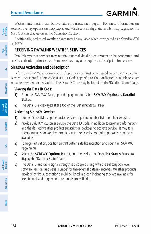
Garmin GI 275 Pilot's Guide 190-02246-01 Rev. H134
Hazard Avoidance
Syst
em
Ove
rvie
wFl
ight
In
stru
men
tsEI
SN
avig
atio
nH
azar
d Av
oida
nce
Aut
opilo
tIV
SIA
dditi
onal
Fe
atur
esA
ppen
dice
sIn
dex
Weather information can be overlaid on various map pages. For more information on weather overlay options on map pages, and which unit configurations offer map pages, see the Map Options discussion in the Navigation Section.
Additionally, dedicated weather pages may be available when configured as a Standby ADI or MFD.
RECEIVING DATALINK WEATHER SERVICESDatalink weather services may require external datalink equipment to be configured and
service activation prior to use. Some services may also require a subscription for services.
SiriusXM Activation and SubscriptionBefore SiriusXM Weather may be displayed, service must be activated by SiriusXM customer
service. An identification code (Data ID Code) specific to the configured datalink receiver must be provided for activation. The Data ID Code may be found on the 'Datalink Status' Page.
Viewing the Data ID Code: 1) From the 'SXM WX' Page, open the page menu. Select SXM WX Options > Datalink
Status.2) The Data ID is displayed at the top of the 'Datalink Status' Page.
Activating SiriusXM Service: 1) Contact SiriusXM using the customer service phone number listed on their website.2) Provide SiriusXM customer service the Data ID Code, in addition to payment information,
and the desired weather product subscription package to activate service. It may take several minutes for weather products in the selected subscription package to become available.
3) To begin activation, position aircraft within satellite reception and open the 'SXM WX' Page menu.
4) Select the SXM WX Options Button, and then select the Datalink Status Button to display the 'Datalink Status' Page.
5) The Data ID and radio signal strength is displayed along with the subscription level, software version, and serial number for the external datalink receiver. Weather products provided by the subscription should be listed in green indicating they are available for use. Items listed in gray indicate data is unavailable.
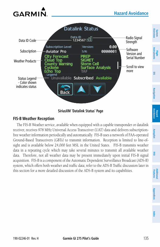
Garmin GI 275 Pilot's Guide190-02246-01 Rev. H 135
Hazard Avoidance
System
Overview
Flight Instrum
entsEIS
Navigation
Hazard
AvoidanceA
utopilotIVSI
Additional Features
Appendices
Index
SiriusXM 'Datalink Status' Page
Radio Signal StrengthData ID Code
Software Version and Serial Number
Subscription
Scroll to view more
Weather Products
Status Legend- Color shown
indicates status
FIS-B Weather ReceptionThe FIS-B Weather service, available when equipped with a capable transponder or datalink
receiver, receives 978 MHz Universal Access Transceiver (UAT) data and delivers subscription-free weather information periodically and automatically. FIS-B uses a network of FAA-operated Ground-Based Transceivers (GBTs) to transmit information. Reception is limited to line-of-sight and is available below 24,000 feet MSL in the United States. FIS-B transmits weather data in a repeating cycle which may take several minutes to transmit all available weather data. Therefore, not all weather data may be present immediately upon initial FIS-B signal acquisition. FIS-B is a component of the Automatic Dependent Surveillance Broadcast (ADS-B) system, which offers both weather and traffic data; refer to the ADS-B Traffic discussion later in this section for a more detailed discussion of the ADS-B system and its capabilities.
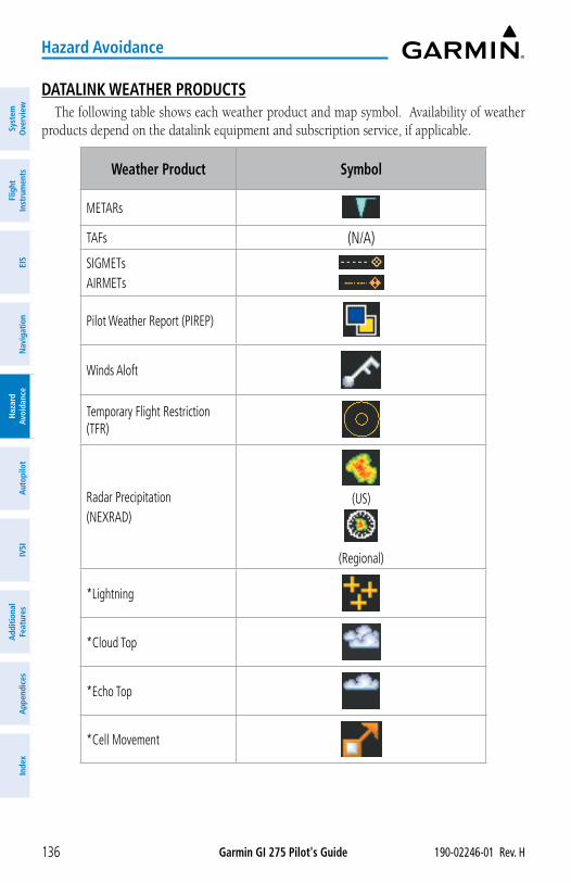
Garmin GI 275 Pilot's Guide 190-02246-01 Rev. H136
Hazard Avoidance
Syst
em
Ove
rvie
wFl
ight
In
stru
men
tsEI
SN
avig
atio
nH
azar
d Av
oida
nce
Aut
opilo
tIV
SIA
dditi
onal
Fe
atur
esA
ppen
dice
sIn
dex
DATALINK WEATHER PRODUCTSThe following table shows each weather product and map symbol. Availability of weather
products depend on the datalink equipment and subscription service, if applicable.
Weather Product Symbol
METARs
TAFs (N/A)
SIGMETsAIRMETs
Pilot Weather Report (PIREP)
Winds Aloft
Temporary Flight Restriction (TFR)
Radar Precipitation(NEXRAD)
(US)
(Regional)
*Lightning
*Cloud Top
*Echo Top
*Cell Movement
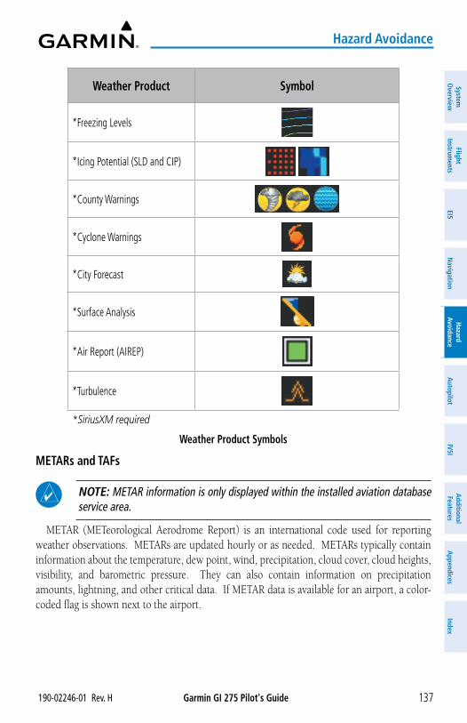
Garmin GI 275 Pilot's Guide190-02246-01 Rev. H 137
Hazard Avoidance
System
Overview
Flight Instrum
entsEIS
Navigation
Hazard
AvoidanceA
utopilotIVSI
Additional Features
Appendices
Index
Weather Product Symbol
*Freezing Levels
*Icing Potential (SLD and CIP)
*County Warnings
*Cyclone Warnings
*City Forecast
*Surface Analysis
*Air Report (AIREP)
*Turbulence
*SiriusXM required
Weather Product Symbols
METARs and TAFs
NOTE: METAR information is only displayed within the installed aviation database service area.
METAR (METeorological Aerodrome Report) is an international code used for reporting weather observations. METARs are updated hourly or as needed. METARs typically contain information about the temperature, dew point, wind, precipitation, cloud cover, cloud heights, visibility, and barometric pressure. They can also contain information on precipitation amounts, lightning, and other critical data. If METAR data is available for an airport, a color-coded flag is shown next to the airport.
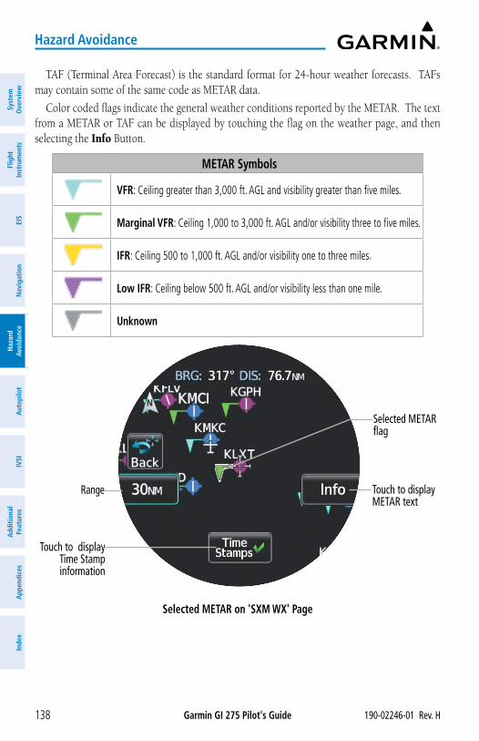
Garmin GI 275 Pilot's Guide 190-02246-01 Rev. H138
Hazard Avoidance
Syst
em
Ove
rvie
wFl
ight
In
stru
men
tsEI
SN
avig
atio
nH
azar
d Av
oida
nce
Aut
opilo
tIV
SIA
dditi
onal
Fe
atur
esA
ppen
dice
sIn
dex
TAF (Terminal Area Forecast) is the standard format for 24-hour weather forecasts. TAFs may contain some of the same code as METAR data.
Color coded flags indicate the general weather conditions reported by the METAR. The text from a METAR or TAF can be displayed by touching the flag on the weather page, and then selecting the Info Button.
METAR Symbols
VFR: Ceiling greater than 3,000 ft. AGL and visibility greater than five miles.
Marginal VFR: Ceiling 1,000 to 3,000 ft. AGL and/or visibility three to five miles.
IFR: Ceiling 500 to 1,000 ft. AGL and/or visibility one to three miles.
Low IFR: Ceiling below 500 ft. AGL and/or visibility less than one mile.
Unknown
Selected METAR on 'SXM WX' Page
Selected METAR flag
Touch to display METAR text
Range
Touch to display Time Stamp information
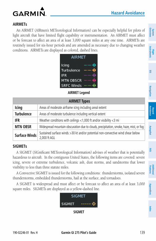
Garmin GI 275 Pilot's Guide190-02246-01 Rev. H 139
Hazard Avoidance
System
Overview
Flight Instrum
entsEIS
Navigation
Hazard
AvoidanceA
utopilotIVSI
Additional Features
Appendices
Index
AIRMETsAn AIRMET (AIRmen’s METeorological Information) can be especially helpful for pilots of
light aircraft that have limited flight capability or instrumentation. An AIRMET must affect or be forecast to affect an area of at least 3,000 square miles at any one time. AIRMETs are routinely issued for six-hour periods and are amended as necessary due to changing weather conditions. AIRMETs are displayed as colored, dashed lines.
AIRMET Legend
AIRMET TypesIcing Areas of moderate airframe icing including areal extent
Turbulence Areas of moderate turbulence including vertical extent
IFR Weather conditions with ceilings <1,000 ft and/or visibility <3 mi
MTN OBSR Widespread mountain obscuration due to clouds, precipitation, smoke, haze, mist, or fog
Surface Winds Sustained surface winds >30 kt and/or potential non-convective wind shear below 2,000 ft AGL
SIGMETsA SIGMET (SIGnificant METeorological Information) advises of weather that is potentially
hazardous to aircraft. In the contiguous United States, the following items are covered: severe icing, severe or extreme turbulence, volcanic ash, dust storms, and sandstorms that lower visibility to less than three statute miles.
A Convective SIGMET is issued for the following conditions: thunderstorms, isolated severe thunderstorms, embedded thunderstorms, hail at the surface, and tornadoes.
A SIGMET is widespread and must affect or be forecast to affect an area of at least 3,000 square miles. SIGMETs are displayed as a yellow-dashed line.
SIGMET
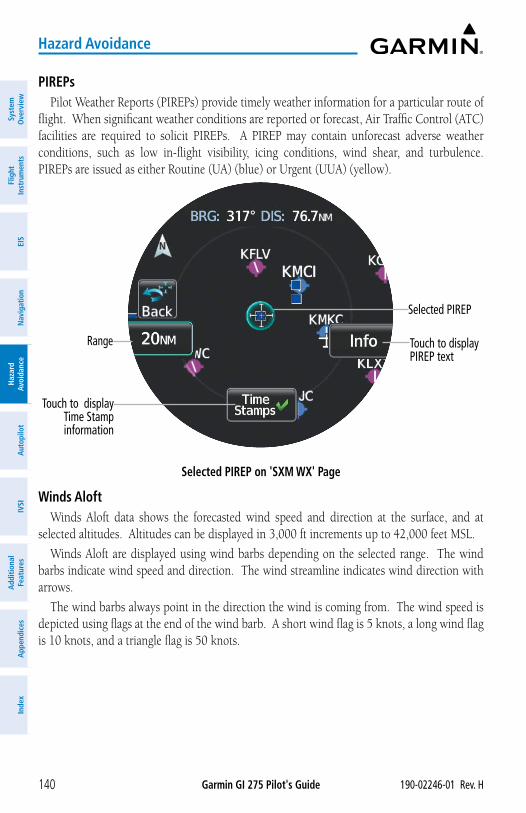
Garmin GI 275 Pilot's Guide 190-02246-01 Rev. H140
Hazard Avoidance
Syst
em
Ove
rvie
wFl
ight
In
stru
men
tsEI
SN
avig
atio
nH
azar
d Av
oida
nce
Aut
opilo
tIV
SIA
dditi
onal
Fe
atur
esA
ppen
dice
sIn
dex
PIREPsPilot Weather Reports (PIREPs) provide timely weather information for a particular route of
flight. When significant weather conditions are reported or forecast, Air Traffic Control (ATC) facilities are required to solicit PIREPs. A PIREP may contain unforecast adverse weather conditions, such as low in-flight visibility, icing conditions, wind shear, and turbulence. PIREPs are issued as either Routine (UA) (blue) or Urgent (UUA) (yellow).
Selected PIREP on 'SXM WX' Page
Selected PIREP
Touch to display PIREP text
Range
Touch to display Time Stamp information
Winds AloftWinds Aloft data shows the forecasted wind speed and direction at the surface, and at
selected altitudes. Altitudes can be displayed in 3,000 ft increments up to 42,000 feet MSL.
Winds Aloft are displayed using wind barbs depending on the selected range. The wind barbs indicate wind speed and direction. The wind streamline indicates wind direction with arrows.
The wind barbs always point in the direction the wind is coming from. The wind speed is depicted using flags at the end of the wind barb. A short wind flag is 5 knots, a long wind flag is 10 knots, and a triangle flag is 50 knots.
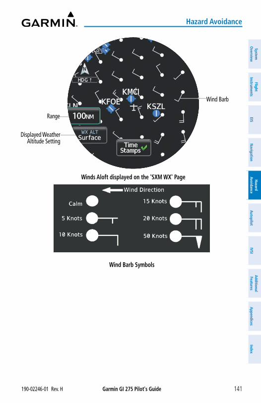
Garmin GI 275 Pilot's Guide190-02246-01 Rev. H 141
Hazard Avoidance
System
Overview
Flight Instrum
entsEIS
Navigation
Hazard
AvoidanceA
utopilotIVSI
Additional Features
Appendices
Index
Winds Aloft displayed on the 'SXM WX' Page
Wind Barb
Range
Displayed Weather Altitude Setting
Wind Barb Symbols
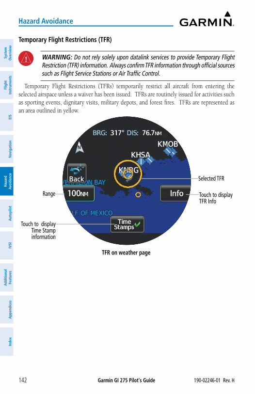
Garmin GI 275 Pilot's Guide 190-02246-01 Rev. H142
Hazard Avoidance
Syst
em
Ove
rvie
wFl
ight
In
stru
men
tsEI
SN
avig
atio
nH
azar
d Av
oida
nce
Aut
opilo
tIV
SIA
dditi
onal
Fe
atur
esA
ppen
dice
sIn
dex
Temporary Flight Restrictions (TFR)
WARNING: Do not rely solely upon datalink services to provide Temporary Flight Restriction (TFR) information. Always confirm TFR information through official sources such as Flight Service Stations or Air Traffic Control.
Temporary Flight Restrictions (TFRs) temporarily restrict all aircraft from entering the selected airspace unless a waiver has been issued. TFRs are routinely issued for activities such as sporting events, dignitary visits, military depots, and forest fires. TFRs are represented as an area outlined in yellow.
TFR on weather page
Selected TFR
Touch to display TFR Info
Range
Touch to display Time Stamp information
Garmin GI 275 Pilot's Guide190-02246-01 Rev. H 143
Hazard Avoidance
System
Overview
Flight Instrum
entsEIS
Navigation
Hazard
AvoidanceA
utopilotIVSI
Additional Features
Appendices
Index
NEXRADNEXRAD (NEXt-generation RADar) is a network of multiple high-resolution Doppler
radar sites that are operated by the National Weather Service (NWS). NEXRAD data provides centralized meteorological information for the continental United States and selected overseas locations. The maximum range of a single NEXRAD radar site is 250 nm. In addition to a wide array of services, the NEXRAD network provides important information about severe weather and air traffic safety. NEXRAD data is not real-time. The lapsed time between collection, processing, and dissemination of NEXRAD images can be significant and may not reflect the current radar synopsis.
Composite NEXRAD data is composed of the maximum reflectivity from the individual radar sweeps. The display of the information is color-coded to indicate the weather severity level.
The display of radar coverage is always active when NEXRAD is selected. Areas where NEXRAD radar coverage is not currently available or is not being collected will be depicted as 'No Radar Coverage' until coverage is restored.
There are possible abnormalities regarding displayed NEXRAD images. Some, but not all, of those include:
» Ground clutter
» Strobes and spurious radar data
» Sun strobes (when the radar antenna points directly at the sun)
» Military aircraft deploy metallic dust (chaff) which can cause alterations in radar scans
» Interference from buildings or mountains, which may cause shadows
Certain limitations exist regarding the NEXRAD radar displays. Some, but not all, are listed for the pilot’s awareness:
» NEXRAD base reflectivity does not provide sufficient information to determine cloud layers or precipitation characteristics (hail vs. rain). For example, it is not possible to distinguish between wet snow, wet hail, and rain.
» NEXRAD base reflectivity is sampled at the minimum antenna elevation angle. An individual NEXRAD site cannot depict high altitude storms at close ranges and has no information about storms directly over the site.
» Radar coverage only extends to 55°N.
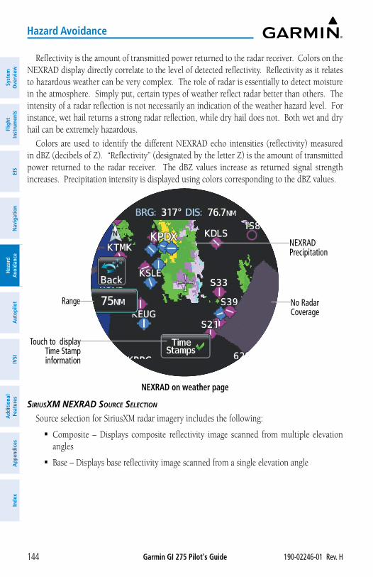
Garmin GI 275 Pilot's Guide 190-02246-01 Rev. H144
Hazard Avoidance
Syst
em
Ove
rvie
wFl
ight
In
stru
men
tsEI
SN
avig
atio
nH
azar
d Av
oida
nce
Aut
opilo
tIV
SIA
dditi
onal
Fe
atur
esA
ppen
dice
sIn
dex
Reflectivity is the amount of transmitted power returned to the radar receiver. Colors on the NEXRAD display directly correlate to the level of detected reflectivity. Reflectivity as it relates to hazardous weather can be very complex. The role of radar is essentially to detect moisture in the atmosphere. Simply put, certain types of weather reflect radar better than others. The intensity of a radar reflection is not necessarily an indication of the weather hazard level. For instance, wet hail returns a strong radar reflection, while dry hail does not. Both wet and dry hail can be extremely hazardous.
Colors are used to identify the different NEXRAD echo intensities (reflectivity) measured in dBZ (decibels of Z). “Reflectivity” (designated by the letter Z) is the amount of transmitted power returned to the radar receiver. The dBZ values increase as returned signal strength increases. Precipitation intensity is displayed using colors corresponding to the dBZ values.
NEXRAD on weather page
NEXRAD Precipitation
No Radar Coverage
Range
Touch to display Time Stamp information
SiriuSXM neXrAD SourCe SeLeCtion
Source selection for SiriusXM radar imagery includes the following:
� Composite – Displays composite reflectivity image scanned from multiple elevation angles
� Base – Displays base reflectivity image scanned from a single elevation angle
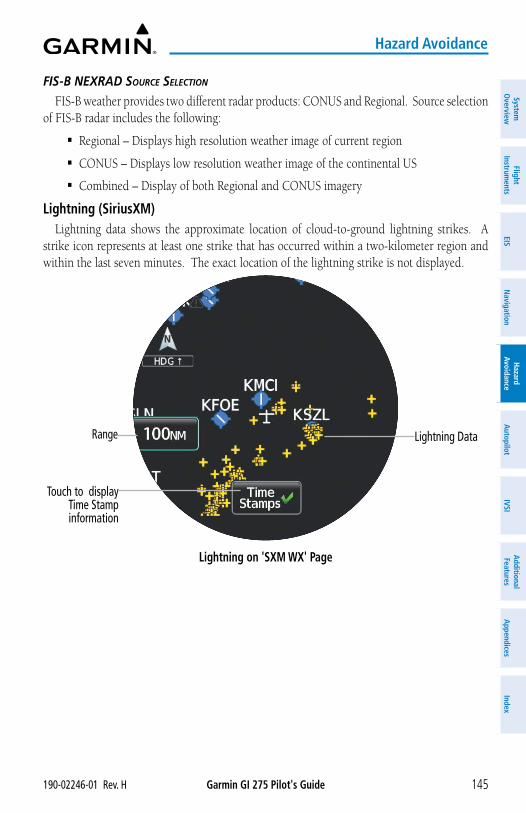
Garmin GI 275 Pilot's Guide190-02246-01 Rev. H 145
Hazard Avoidance
System
Overview
Flight Instrum
entsEIS
Navigation
Hazard
AvoidanceA
utopilotIVSI
Additional Features
Appendices
Index
FiS-B neXrAD SourCe SeLeCtion
FIS-B weather provides two different radar products: CONUS and Regional. Source selection of FIS-B radar includes the following:
� Regional – Displays high resolution weather image of current region
� CONUS – Displays low resolution weather image of the continental US
� Combined – Display of both Regional and CONUS imagery
Lightning (SiriusXM)Lightning data shows the approximate location of cloud-to-ground lightning strikes. A
strike icon represents at least one strike that has occurred within a two-kilometer region and within the last seven minutes. The exact location of the lightning strike is not displayed.
Lightning on 'SXM WX' Page
Lightning DataRange
Touch to display Time Stamp information
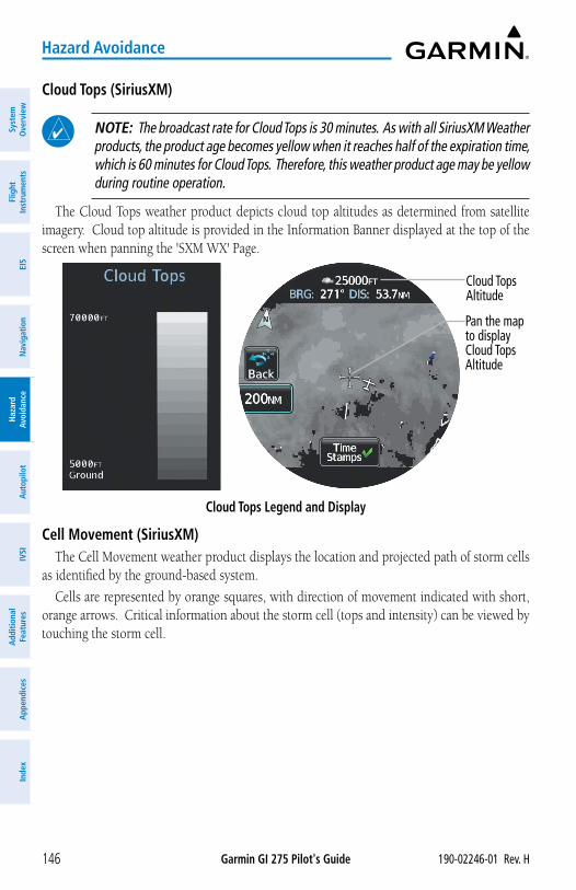
Garmin GI 275 Pilot's Guide 190-02246-01 Rev. H146
Hazard Avoidance
Syst
em
Ove
rvie
wFl
ight
In
stru
men
tsEI
SN
avig
atio
nH
azar
d Av
oida
nce
Aut
opilo
tIV
SIA
dditi
onal
Fe
atur
esA
ppen
dice
sIn
dex
Cloud Tops (SiriusXM)
NOTE: The broadcast rate for Cloud Tops is 30 minutes. As with all SiriusXM Weather products, the product age becomes yellow when it reaches half of the expiration time, which is 60 minutes for Cloud Tops. Therefore, this weather product age may be yellow during routine operation.
The Cloud Tops weather product depicts cloud top altitudes as determined from satellite imagery. Cloud top altitude is provided in the Information Banner displayed at the top of the screen when panning the 'SXM WX' Page.
Cloud Tops Legend and Display
Cloud Tops Altitude
Pan the map to display Cloud Tops Altitude
Cell Movement (SiriusXM)The Cell Movement weather product displays the location and projected path of storm cells
as identified by the ground-based system.
Cells are represented by orange squares, with direction of movement indicated with short, orange arrows. Critical information about the storm cell (tops and intensity) can be viewed by touching the storm cell.
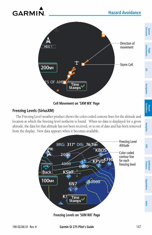
Garmin GI 275 Pilot's Guide190-02246-01 Rev. H 147
Hazard Avoidance
System
Overview
Flight Instrum
entsEIS
Navigation
Hazard
AvoidanceA
utopilotIVSI
Additional Features
Appendices
Index
Cell Movement on 'SXM WX' Page
Direction of movement
Storm Cell
Freezing Levels (SiriusXM)The Freezing Level weather product shows the color-coded contour lines for the altitude and
location at which the freezing level isotherm is found. When no data is displayed for a given altitude, the data for that altitude has not been received, or is out of date and has been removed from the display. New data appears when it becomes available.
Freezing Levels on 'SXM WX' Page
Freezing LevelAltitude
Color coded contour line for each freezing level
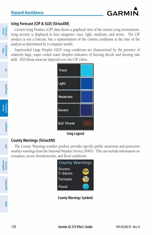
Garmin GI 275 Pilot's Guide 190-02246-01 Rev. H148
Hazard Avoidance
Syst
em
Ove
rvie
wFl
ight
In
stru
men
tsEI
SN
avig
atio
nH
azar
d Av
oida
nce
Aut
opilo
tIV
SIA
dditi
onal
Fe
atur
esA
ppen
dice
sIn
dex
Icing Forecast (CIP & SLD) (SiriusXM)Current Icing Product (CIP) data shows a graphical view of the current icing environment.
Icing severity is displayed in four categories: trace. light, moderate, and severe. The CIP product is not a forecast, but a representation of the current conditions at the time of the analysis as determined by a computer model.
Supercooled Large Droplet (SLD) icing conditions are characterized by the presence of relatively large, super cooled water droplets indicative of freezing drizzle and freezing rain aloft. SLD threat areas are depicted over the CIP colors.
Icing Legend
County Warnings (SiriusXM)The County Warnings weather product provides specific public awareness and protection
weather warnings from the National Weather Service (NWS). This can include information on tornadoes, severe thunderstorms, and flood conditions.
County Warnings Symbols
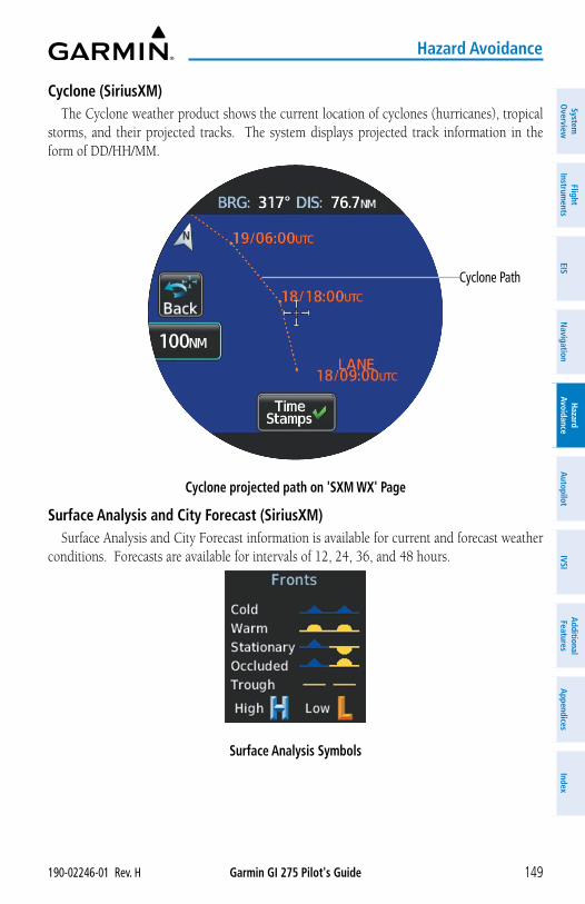
Garmin GI 275 Pilot's Guide190-02246-01 Rev. H 149
Hazard Avoidance
System
Overview
Flight Instrum
entsEIS
Navigation
Hazard
AvoidanceA
utopilotIVSI
Additional Features
Appendices
Index
Cyclone (SiriusXM)The Cyclone weather product shows the current location of cyclones (hurricanes), tropical
storms, and their projected tracks. The system displays projected track information in the form of DD/HH/MM.
Cyclone projected path on 'SXM WX' Page
Cyclone Path
Surface Analysis and City Forecast (SiriusXM)Surface Analysis and City Forecast information is available for current and forecast weather
conditions. Forecasts are available for intervals of 12, 24, 36, and 48 hours.
Surface Analysis Symbols
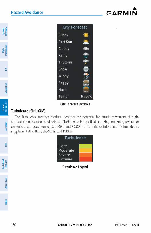
Garmin GI 275 Pilot's Guide 190-02246-01 Rev. H150
Hazard Avoidance
Syst
em
Ove
rvie
wFl
ight
In
stru
men
tsEI
SN
avig
atio
nH
azar
d Av
oida
nce
Aut
opilo
tIV
SIA
dditi
onal
Fe
atur
esA
ppen
dice
sIn
dex
City Forecast Symbols
Turbulence (SiriusXM)The Turbulence weather product identifies the potential for erratic movement of high-
altitude air mass associated winds. Turbulence is classified as light, moderate, severe, or extreme, at altitudes between 21,000 ft and 45,000 ft. Turbulence information is intended to supplement AIRMETs, SIGMETs, and PIREPs.
Turbulence Legend
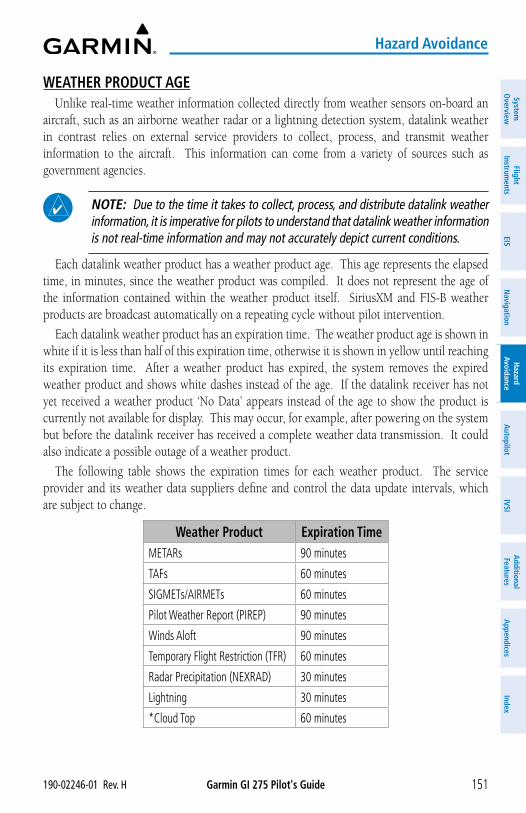
Garmin GI 275 Pilot's Guide190-02246-01 Rev. H 151
Hazard Avoidance
System
Overview
Flight Instrum
entsEIS
Navigation
Hazard
AvoidanceA
utopilotIVSI
Additional Features
Appendices
Index
WEATHER PRODUCT AGEUnlike real-time weather information collected directly from weather sensors on-board an
aircraft, such as an airborne weather radar or a lightning detection system, datalink weather in contrast relies on external service providers to collect, process, and transmit weather information to the aircraft. This information can come from a variety of sources such as government agencies.
NOTE: Due to the time it takes to collect, process, and distribute datalink weather information, it is imperative for pilots to understand that datalink weather information is not real-time information and may not accurately depict current conditions.
Each datalink weather product has a weather product age. This age represents the elapsed time, in minutes, since the weather product was compiled. It does not represent the age of the information contained within the weather product itself. SiriusXM and FIS-B weather products are broadcast automatically on a repeating cycle without pilot intervention.
Each datalink weather product has an expiration time. The weather product age is shown in white if it is less than half of this expiration time, otherwise it is shown in yellow until reaching its expiration time. After a weather product has expired, the system removes the expired weather product and shows white dashes instead of the age. If the datalink receiver has not yet received a weather product ‘No Data’ appears instead of the age to show the product is currently not available for display. This may occur, for example, after powering on the system but before the datalink receiver has received a complete weather data transmission. It could also indicate a possible outage of a weather product.
The following table shows the expiration times for each weather product. The service provider and its weather data suppliers define and control the data update intervals, which are subject to change.
Weather Product Expiration TimeMETARs 90 minutes
TAFs 60 minutes
SIGMETs/AIRMETs 60 minutes
Pilot Weather Report (PIREP) 90 minutes
Winds Aloft 90 minutes
Temporary Flight Restriction (TFR) 60 minutes
Radar Precipitation (NEXRAD) 30 minutes
Lightning 30 minutes
*Cloud Top 60 minutes
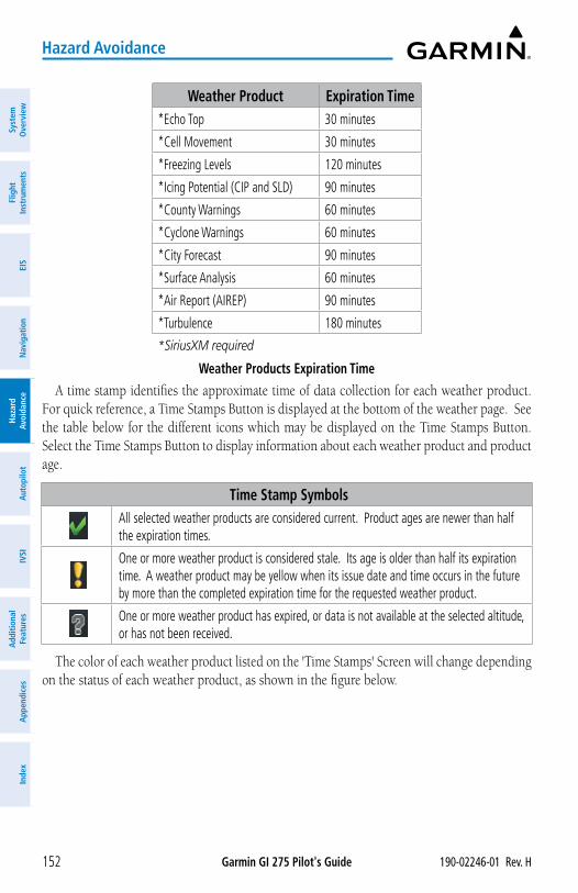
Garmin GI 275 Pilot's Guide 190-02246-01 Rev. H152
Hazard Avoidance
Syst
em
Ove
rvie
wFl
ight
In
stru
men
tsEI
SN
avig
atio
nH
azar
d Av
oida
nce
Aut
opilo
tIV
SIA
dditi
onal
Fe
atur
esA
ppen
dice
sIn
dex
Weather Product Expiration Time*Echo Top 30 minutes
*Cell Movement 30 minutes
*Freezing Levels 120 minutes
*Icing Potential (CIP and SLD) 90 minutes
*County Warnings 60 minutes
*Cyclone Warnings 60 minutes
*City Forecast 90 minutes
*Surface Analysis 60 minutes
*Air Report (AIREP) 90 minutes
*Turbulence 180 minutes
*SiriusXM required
Weather Products Expiration TimeA time stamp identifies the approximate time of data collection for each weather product.
For quick reference, a Time Stamps Button is displayed at the bottom of the weather page. See the table below for the different icons which may be displayed on the Time Stamps Button. Select the Time Stamps Button to display information about each weather product and product age.
Time Stamp SymbolsAll selected weather products are considered current. Product ages are newer than half the expiration times.
One or more weather product is considered stale. Its age is older than half its expiration time. A weather product may be yellow when its issue date and time occurs in the future by more than the completed expiration time for the requested weather product.
One or more weather product has expired, or data is not available at the selected altitude, or has not been received.
The color of each weather product listed on the 'Time Stamps' Screen will change depending on the status of each weather product, as shown in the figure below.
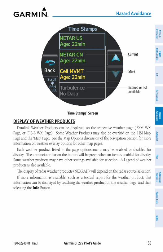
Garmin GI 275 Pilot's Guide190-02246-01 Rev. H 153
Hazard Avoidance
System
Overview
Flight Instrum
entsEIS
Navigation
Hazard
AvoidanceA
utopilotIVSI
Additional Features
Appendices
Index
'Time Stamps' Screen
Current
Stale
Expired or not available
DISPLAY OF WEATHER PRODUCTSDatalink Weather Products can be displayed on the respective weather page ('SXM WX'
Page, or 'FIS-B WX' Page). Some Weather Products may also be overlaid on the 'HSI Map' Page and the 'Map' Page. See the Map Options discussion of the Navigation Section for more information on weather overlay options for other map pages.
Each weather product listed in the page options menu may be enabled or disabled for display. The annunciator bar on the button will be green when an item is enabled for display. Some weather products may have other settings available for selection. A Legend of weather products is also available.
The display of radar weather products (NEXRAD) will depend on the radar source selection.
If more information is available, such as a textual report for the weather product, that information can be displayed by touching the weather product on the weather page, and then selecting the Info Button.
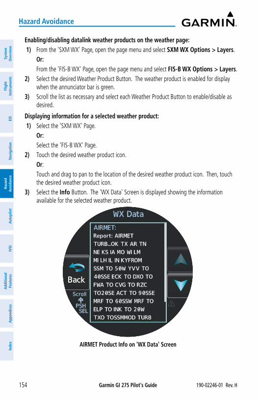
Garmin GI 275 Pilot's Guide 190-02246-01 Rev. H154
Hazard Avoidance
Syst
em
Ove
rvie
wFl
ight
In
stru
men
tsEI
SN
avig
atio
nH
azar
d Av
oida
nce
Aut
opilo
tIV
SIA
dditi
onal
Fe
atur
esA
ppen
dice
sIn
dex
Enabling/disabling datalink weather products on the weather page: 1) From the 'SXM WX' Page, open the page menu and select SXM WX Options > Layers.
Or: From the 'FIS-B WX' Page, open the page menu and select FIS-B WX Options > Layers.2) Select the desired Weather Product Button. The weather product is enabled for display
when the annunciator bar is green. 3) Scroll the list as necessary and select each Weather Product Button to enable/disable as
desired.
Displaying information for a selected weather product: 1) Select the 'SXM WX' Page.
Or: Select the 'FIS-B WX' Page.2) Touch the desired weather product icon. Or: Touch and drag to pan to the location of the desired weather product icon. Then, touch
the desired weather product icon. 3) Select the Info Button. The 'WX Data' Screen is displayed showing the information
available for the selected weather product.
AIRMET Product Info on 'WX Data' Screen
Garmin GI 275 Pilot's Guide190-02246-01 Rev. H 155
Hazard Avoidance
System
Overview
Flight Instrum
entsEIS
Navigation
Hazard
AvoidanceA
utopilotIVSI
Additional Features
Appendices
Index
Viewing the Legend of weather products:1) From the 'SXM WX' Page, open the page menu and select SXM WX Options.
Or: From the 'FIS-B WX' Page, open the page menu and select FIS-B WX Options.2) Select the Legend Button. A legend of selected weather products is displayed.
Changing the altitude setting for the Winds Aloft, Icing, and Turbulence on the weather page: 1) Select the 'SXM WX' Page.
Or: Select the 'FIS-B WX' Page.2) When Winds Aloft, Icing, and/or Turbulence is enabled for display, the WX ALT Button
is displayed on the weather page. Touch the WX ALT Button. The button is highlighted indicating it is active.
3) Turn the Small Knob clockwise to increase the altitude setting or counter-clockwise to decrease the altitude setting.
Changing the AIRMET settings:1) From the 'SXM WX' Page, open the page menu and select SXM WX Options > Layers.
Or: From the 'FIS-B WX' Page, open the page menu and select FIS-B WX Options > Layers.2) Select the AIRMET Settings Button to display the 'AIRMET Setup' Screen. 3) Scroll the list as necessary and select each AIRMET Type Button to enable/disable as
desired.
Changing the county warnings settings:1) From the 'SXM WX' Page, open the page menu and select SXM WX Options > Layers.2) Select the County Warning Settings Button to display the 'County Setup' Screen. 3) Select each Warning Type Button to enable/disable as desired.
Selecting which surface analysis and/or city forecast to display:1) From the 'SXM WX' Page, open the page menu and select SXM WX Options > Layers.2) Select the Surface Analysis Button to display the 'Forecast' Screen. A list of available
surface analysis forecasts is displayed. Or: Select the City Forecast Button to display the 'Forecast' Screen. A list of available city
forecasts is displayed. 3) Select the desired Forecast Button, or select the Off Button to disable the display of the
forecast.
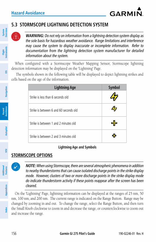
Garmin GI 275 Pilot's Guide 190-02246-01 Rev. H156
Hazard Avoidance
Syst
em
Ove
rvie
wFl
ight
In
stru
men
tsEI
SN
avig
atio
nH
azar
d Av
oida
nce
Aut
opilo
tIV
SIA
dditi
onal
Fe
atur
esA
ppen
dice
sIn
dex
5.3 STORMSCOPE LIGHTNING DETECTION SYSTEM
WARNING: Do not rely on information from a lightning detection system display as the sole basis for hazardous weather avoidance. Range limitations and interference may cause the system to display inaccurate or incomplete information. Refer to documentation from the lightning detection system manufacturer for detailed information about the system.
When configured with a Stormscope Weather Mapping Sensor, Stormscope lightning detection information may be displayed on the 'Lightning' Page.
The symbols shown in the following table will be displayed to depict lightning strikes and cells based on the age of the information.
Lightning Age Symbol
Strike is less than 6 seconds old
Strike is between 6 and 60 seconds old
Strike is between 1 and 2 minutes old
Strike is between 2 and 3 minutes old
Lightning Age and Symbols
STORMSCOPE OPTIONS
NOTE: When using Stormscope, there are several atmospheric phenomena in addition to nearby thunderstorms that can cause isolated discharge points in the strike display mode. However, clusters of two or more discharge points in the strike display mode do indicate thunderstorm activity if these points reappear after the screen has been cleared.
On the 'Lightning' Page, lightning information can be displayed at the ranges of 25 nm, 50 nm, 100 nm, and 200 nm. The current range is indicated on the Range Button. Range may be changed by zooming in and out. To change the range, select the Range Button, and then turn the Small Knob clockwise to zoom in and decrease the range, or counterclockwise to zoom out and increase the range.
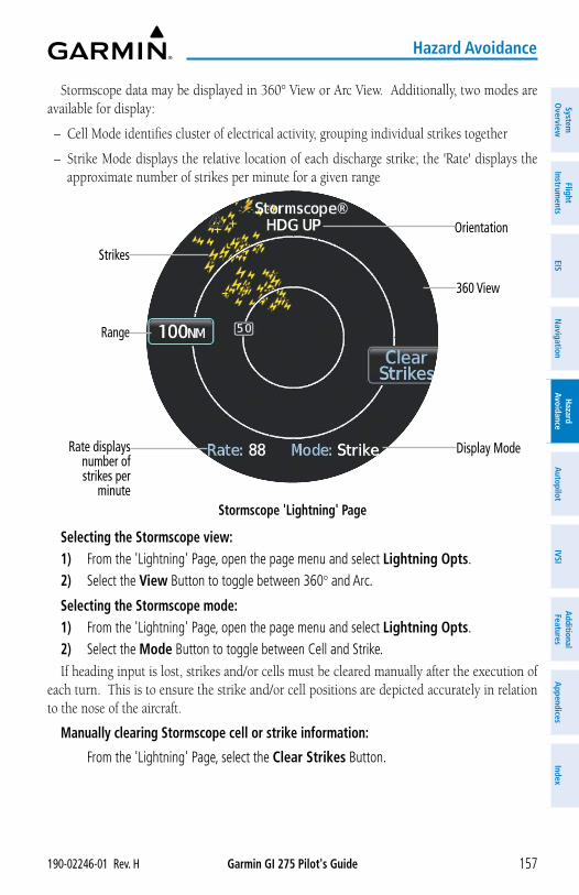
Garmin GI 275 Pilot's Guide190-02246-01 Rev. H 157
Hazard Avoidance
System
Overview
Flight Instrum
entsEIS
Navigation
Hazard
AvoidanceA
utopilotIVSI
Additional Features
Appendices
Index
Stormscope data may be displayed in 360° View or Arc View. Additionally, two modes are available for display:
– Cell Mode identifies cluster of electrical activity, grouping individual strikes together
– Strike Mode displays the relative location of each discharge strike; the 'Rate' displays the approximate number of strikes per minute for a given range
Stormscope 'Lightning' Page
Orientation
Strikes
360 View
Display Mode
Range
Rate displays number of strikes per
minute
Selecting the Stormscope view:1) From the 'Lightning' Page, open the page menu and select Lightning Opts.2) Select the View Button to toggle between 360° and Arc.
Selecting the Stormscope mode:1) From the 'Lightning' Page, open the page menu and select Lightning Opts.2) Select the Mode Button to toggle between Cell and Strike. If heading input is lost, strikes and/or cells must be cleared manually after the execution of
each turn. This is to ensure the strike and/or cell positions are depicted accurately in relation to the nose of the aircraft.
Manually clearing Stormscope cell or strike information:
From the 'Lightning' Page, select the Clear Strikes Button.
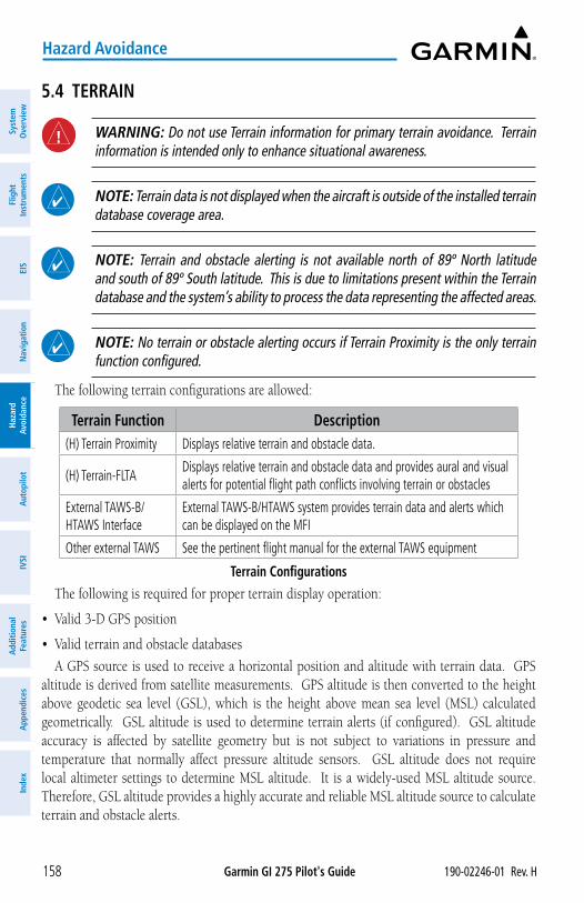
Garmin GI 275 Pilot's Guide 190-02246-01 Rev. H158
Hazard Avoidance
Syst
em
Ove
rvie
wFl
ight
In
stru
men
tsEI
SN
avig
atio
nH
azar
d Av
oida
nce
Aut
opilo
tIV
SIA
dditi
onal
Fe
atur
esA
ppen
dice
sIn
dex
5.4 TERRAIN
WARNING: Do not use Terrain information for primary terrain avoidance. Terrain information is intended only to enhance situational awareness.
NOTE: Terrain data is not displayed when the aircraft is outside of the installed terrain database coverage area.
NOTE: Terrain and obstacle alerting is not available north of 89º North latitude and south of 89º South latitude. This is due to limitations present within the Terrain database and the system’s ability to process the data representing the affected areas.
NOTE: No terrain or obstacle alerting occurs if Terrain Proximity is the only terrain function configured.
The following terrain configurations are allowed:
Terrain Function Description(H) Terrain Proximity Displays relative terrain and obstacle data.
(H) Terrain-FLTA Displays relative terrain and obstacle data and provides aural and visual alerts for potential flight path conflicts involving terrain or obstacles
External TAWS-B/HTAWS Interface
External TAWS-B/HTAWS system provides terrain data and alerts which can be displayed on the MFI
Other external TAWS See the pertinent flight manual for the external TAWS equipment
Terrain ConfigurationsThe following is required for proper terrain display operation:
• Valid 3-D GPS position
• Valid terrain and obstacle databases
A GPS source is used to receive a horizontal position and altitude with terrain data. GPS altitude is derived from satellite measurements. GPS altitude is then converted to the height above geodetic sea level (GSL), which is the height above mean sea level (MSL) calculated geometrically. GSL altitude is used to determine terrain alerts (if configured). GSL altitude accuracy is affected by satellite geometry but is not subject to variations in pressure and temperature that normally affect pressure altitude sensors. GSL altitude does not require local altimeter settings to determine MSL altitude. It is a widely-used MSL altitude source. Therefore, GSL altitude provides a highly accurate and reliable MSL altitude source to calculate terrain and obstacle alerts.
Garmin GI 275 Pilot's Guide190-02246-01 Rev. H 159
Hazard Avoidance
System
Overview
Flight Instrum
entsEIS
Navigation
Hazard
AvoidanceA
utopilotIVSI
Additional Features
Appendices
Index
The terrain and obstacle databases are referenced to MSL. Using the GPS position and GSL altitude, a 2-D terrain display is created, showing the surrounding terrain and obstacles relative to the position and altitude of the aircraft. Furthermore, when configured with (H) Terrain-FLTA, GPS position and GSL altitude are used to calculate and “predict” the aircraft’s flight path in relation to the surrounding terrain and obstacles. In this manner, the (H) Terrain-FLTA can provide advanced alerts of predicted dangerous terrain conditions.
Baro-corrected altitude (or indicated altitude) is derived by adjusting the altimeter setting for local atmospheric conditions. The most accurate baro-corrected altitude can be achieved by frequently updating the altimeter setting to the nearest reporting station along the flight path. However, because actual atmospheric conditions seldom match the standard conditions defined by the International Standard Atmosphere (ISA) model (where pressure, temperature, and lapse rates have fixed values), it is common for the baro-corrected altitude (as read from the altimeter) to differ from the GSL altitude.
Terrain functionality uses colors and symbols to represent terrain and obstacles (with heights greater than 200 feet above ground level, AGL) present in the databases relative to aircraft altitude. The colors automatically change as the aircraft altitude changes.
Terrain above or within 100 feet below the aircraft altitude is depicted in red. Terrain between 100 feet and 1000 feet below the aircraft altitude is depicted in yellow. The color black indicates terrain is more than 1000 feet below the aircraft altitude. For the helicopter terrain depictions, Terrain above 250 feet of the rotorcraft altitude is depicted in Red. Terrain between 250 feet and 0 (zero) feet is depicted as Orange. Terrain between 0 (zero) feet and 250 feet below is depicted as yellow. Terrain between 250 feet and 500 feet below is depicted as green. Terrain more than 500 feet below is depicted as black.
For additional safety, wire obstacle data is provided by Garmin’s WireAware™ database. The database mainly includes Hazardous Obstacle Transmission (HOT) power lines which are typically high voltage transmission lines depicted on VFR Sectional charts and are considered of special interest to fixed-wing pilots. These include power lines which are in close proximity to airports/heliports and power lines which span rivers, valleys, and canyons.
It is important to note the database does not contain all power lines. In fact, WireAware database coverage is mostly limited to HOT power lines. Furthermore, WireAware obstacle database coverage exists mainly in the United States; with limited coverage in portions of Canada and Mexico.
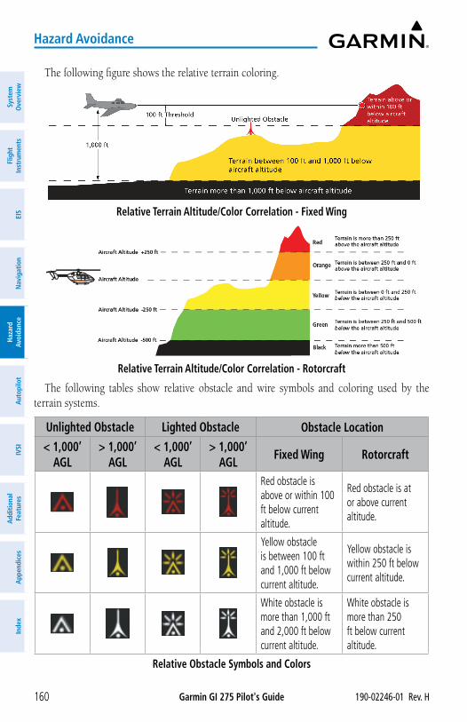
Garmin GI 275 Pilot's Guide 190-02246-01 Rev. H160
Hazard Avoidance
Syst
em
Ove
rvie
wFl
ight
In
stru
men
tsEI
SN
avig
atio
nH
azar
d Av
oida
nce
Aut
opilo
tIV
SIA
dditi
onal
Fe
atur
esA
ppen
dice
sIn
dex
The following figure shows the relative terrain coloring.
Relative Terrain Altitude/Color Correlation - Fixed Wing
Relative Terrain Altitude/Color Correlation - Rotorcraft
The following tables show relative obstacle and wire symbols and coloring used by the terrain systems.
Unlighted Obstacle Lighted Obstacle Obstacle Location
< 1,000’ AGL
> 1,000’ AGL
< 1,000’ AGL
> 1,000’ AGL
Fixed Wing Rotorcraft
Red obstacle is above or within 100 ft below current altitude.
Red obstacle is at or above current altitude.
Yellow obstacle is between 100 ft and 1,000 ft below current altitude.
Yellow obstacle is within 250 ft below current altitude.
White obstacle is more than 1,000 ft and 2,000 ft below current altitude.
White obstacle is more than 250 ft below current altitude.
Relative Obstacle Symbols and Colors
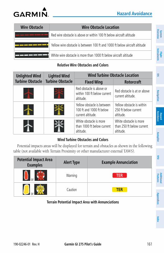
Garmin GI 275 Pilot's Guide190-02246-01 Rev. H 161
Hazard Avoidance
System
Overview
Flight Instrum
entsEIS
Navigation
Hazard
AvoidanceA
utopilotIVSI
Additional Features
Appendices
Index
Wire Obstacle Wire Obstacle Location
Red wire obstacle is above or within 100 ft below aircraft altitude
Yellow wire obstacle is between 100 ft and 1000 ft below aircraft altitude
White wire obstacle is more than 1000 ft below aircraft altitude
Relative Wire Obstacles and Colors
Unlighted Wind Turbine Obstacle
Lighted Wind Turbine Obstacle
Wind Turbine Obstacle LocationFixed Wing Rotorcraft
Red obstacle is above or within 100 ft below current altitude.
Red obstacle is at or above current altitude.
Yellow obstacle is between 100 ft and 1000 ft below current altitude.
Yellow obstacle is within 250 ft below current altitude.
White obstacle is more than 1000 ft below current altitude.
White obstacle is more than 250 ft below current altitude.
Wind Turbine Obstacles and ColorsPotential impacts areas will be displayed for terrain and obstacles as shown in the following
table (not available with Terrain Proximity or other manufacturer external TAWS).
Potential Impact Area Examples
Alert Type Example Annunciation
or Warning TER
or Caution TER
Terrain Potential Impact Area with Annunciations
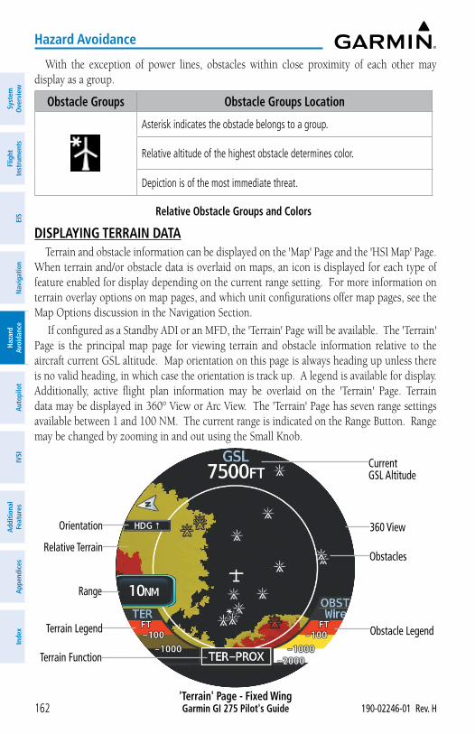
Garmin GI 275 Pilot's Guide 190-02246-01 Rev. H162
Hazard Avoidance
Syst
em
Ove
rvie
wFl
ight
In
stru
men
tsEI
SN
avig
atio
nH
azar
d Av
oida
nce
Aut
opilo
tIV
SIA
dditi
onal
Fe
atur
esA
ppen
dice
sIn
dex
With the exception of power lines, obstacles within close proximity of each other may display as a group.
Obstacle Groups Obstacle Groups Location
Asterisk indicates the obstacle belongs to a group.
Relative altitude of the highest obstacle determines color.
Depiction is of the most immediate threat.
Relative Obstacle Groups and Colors
DISPLAYING TERRAIN DATATerrain and obstacle information can be displayed on the 'Map' Page and the 'HSI Map' Page.
When terrain and/or obstacle data is overlaid on maps, an icon is displayed for each type of feature enabled for display depending on the current range setting. For more information on terrain overlay options on map pages, and which unit configurations offer map pages, see the Map Options discussion in the Navigation Section.
If configured as a Standby ADI or an MFD, the 'Terrain' Page will be available. The 'Terrain' Page is the principal map page for viewing terrain and obstacle information relative to the aircraft current GSL altitude. Map orientation on this page is always heading up unless there is no valid heading, in which case the orientation is track up. A legend is available for display. Additionally, active flight plan information may be overlaid on the 'Terrain' Page. Terrain data may be displayed in 360° View or Arc View. The 'Terrain' Page has seven range settings available between 1 and 100 NM. The current range is indicated on the Range Button. Range may be changed by zooming in and out using the Small Knob.
'Terrain' Page - Fixed Wing
Current GSL Altitude
Terrain Function
360 View
Obstacle Legend
Range
Terrain Legend
Orientation
Relative TerrainObstacles
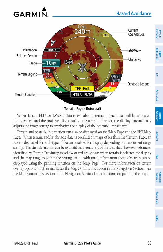
Garmin GI 275 Pilot's Guide190-02246-01 Rev. H 163
Hazard Avoidance
System
Overview
Flight Instrum
entsEIS
Navigation
Hazard
AvoidanceA
utopilotIVSI
Additional Features
Appendices
Index
'Terrain' Page - Rotorcraft
Current GSL Altitude
Terrain Function
360 View
Obstacle Legend
Range
Terrain Legend
OrientationRelative Terrain
Obstacles
When Terrain-FLTA or TAWS-B data is available, potential impact areas will be indicated. If an obstacle and the projected flight path of the aircraft intersect, the display automatically adjusts the range setting to emphasize the display of the potential impact area.
Terrain and obstacle information can also be displayed on the 'Map' Page and the 'HSI Map' Page. When terrain and/or obstacle data is overlaid on maps other than the 'Terrain' Page, an icon is displayed for each type of feature enabled for display depending on the current range setting. Terrain information can be overlaid independently of obstacle data; however, obstacles identified by Terrain Proximity as yellow or red are shown when terrain is selected for display and the map range is within the setting limit. Additional information about obstacles can be displayed using the panning function on the 'Map' Page. For more information on terrain overlay options on other maps, see the Map Options discussion in the Navigation Section. See the Map Panning discussion of the Navigation Section for instructions on panning the map.
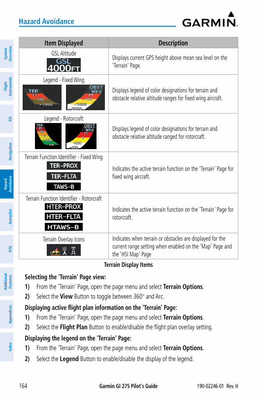
Garmin GI 275 Pilot's Guide 190-02246-01 Rev. H164
Hazard Avoidance
Syst
em
Ove
rvie
wFl
ight
In
stru
men
tsEI
SN
avig
atio
nH
azar
d Av
oida
nce
Aut
opilo
tIV
SIA
dditi
onal
Fe
atur
esA
ppen
dice
sIn
dex
Item Displayed DescriptionGSL Altitude
Displays current GPS height above mean sea level on the 'Terrain' Page.
Legend - Fixed Wing
Displays legend of color designations for terrain and obstacle relative altitude ranges for fixed wing aircraft.
Legend - Rotorcraft
Displays legend of color designations for terrain and obstacle relative altitude ranged for rotorcraft.
Terrain Function Identifier - Fixed Wing
Indicates the active terrain function on the 'Terrain' Page for fixed wing aircraft.
Terrain Function Identifier - Rotorcraft
Indicates the active terrain function on the 'Terrain' Page for rotorcraft.
Terrain Overlay Icons Indicates when terrain or obstacles are displayed for the current range setting when enabled on the 'Map' Page and the 'HSI Map' Page
Terrain Display Items
Selecting the 'Terrain' Page view:1) From the 'Terrain' Page, open the page menu and select Terrain Options.2) Select the View Button to toggle between 360° and Arc.
Displaying active flight plan information on the 'Terrain' Page:1) From the 'Terrain' Page, open the page menu and select Terrain Options.2) Select the Flight Plan Button to enable/disable the flight plan overlay setting.
Displaying the legend on the 'Terrain' Page:1) From the 'Terrain' Page, open the page menu and select Terrain Options.
2) Select the Legend Button to enable/disable the display of the legend.
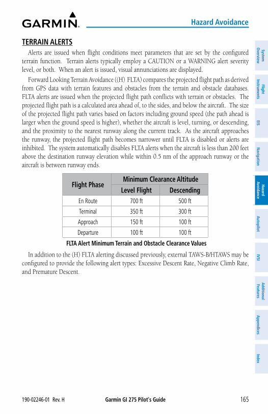
Garmin GI 275 Pilot's Guide190-02246-01 Rev. H 165
Hazard Avoidance
System
Overview
Flight Instrum
entsEIS
Navigation
Hazard
AvoidanceA
utopilotIVSI
Additional Features
Appendices
Index
TERRAIN ALERTSAlerts are issued when flight conditions meet parameters that are set by the configured
terrain function. Terrain alerts typically employ a CAUTION or a WARNING alert severity level, or both. When an alert is issued, visual annunciations are displayed.
Forward Looking Terrain Avoidance ((H) FLTA) compares the projected flight path as derived from GPS data with terrain features and obstacles from the terrain and obstacle databases. FLTA alerts are issued when the projected flight path conflicts with terrain or obstacles. The projected flight path is a calculated area ahead of, to the sides, and below the aircraft. The size of the projected flight path varies based on factors including ground speed (the path ahead is larger when the ground speed is higher), whether the aircraft is level, turning, or descending, and the proximity to the nearest runway along the current track. As the aircraft approaches the runway, the projected flight path becomes narrower until FLTA is disabled or alerts are inhibited. The system automatically disables FLTA alerts when the aircraft is less than 200 feet above the destination runway elevation while within 0.5 nm of the approach runway or the aircraft is between runway ends.
Flight PhaseMinimum Clearance Altitude
Level Flight DescendingEn Route 700 ft 500 ft
Terminal 350 ft 300 ft
Approach 150 ft 100 ft
Departure 100 ft 100 ft
FLTA Alert Minimum Terrain and Obstacle Clearance Values
In addition to the (H) FLTA alerting discussed previously, external TAWS-B/HTAWS may be configured to provide the following alert types: Excessive Descent Rate, Negative Climb Rate, and Premature Descent.
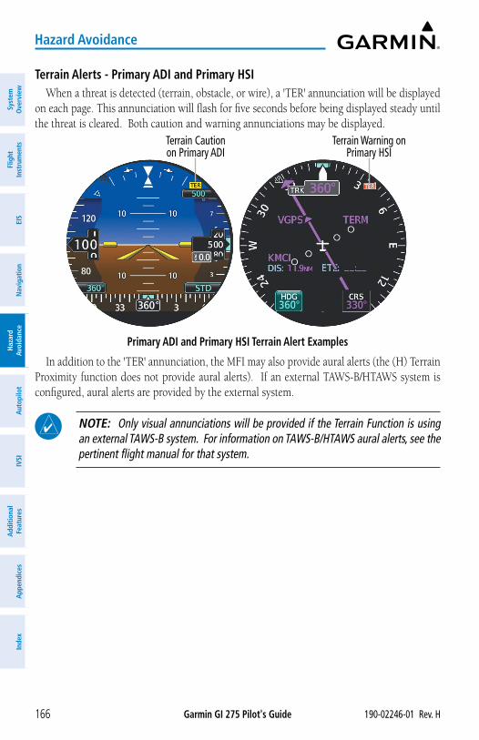
Garmin GI 275 Pilot's Guide 190-02246-01 Rev. H166
Hazard Avoidance
Syst
em
Ove
rvie
wFl
ight
In
stru
men
tsEI
SN
avig
atio
nH
azar
d Av
oida
nce
Aut
opilo
tIV
SIA
dditi
onal
Fe
atur
esA
ppen
dice
sIn
dex
Terrain Alerts - Primary ADI and Primary HSIWhen a threat is detected (terrain, obstacle, or wire), a 'TER' annunciation will be displayed
on each page. This annunciation will flash for five seconds before being displayed steady until the threat is cleared. Both caution and warning annunciations may be displayed.
Primary ADI and Primary HSI Terrain Alert Examples
Terrain Warning on Primary HSI
Terrain Caution on Primary ADI
In addition to the 'TER' annunciation, the MFI may also provide aural alerts (the (H) Terrain Proximity function does not provide aural alerts). If an external TAWS-B/HTAWS system is configured, aural alerts are provided by the external system.
NOTE: Only visual annunciations will be provided if the Terrain Function is using an external TAWS-B system. For information on TAWS-B/HTAWS aural alerts, see the pertinent flight manual for that system.
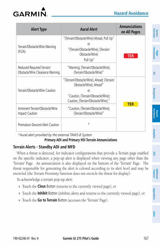
Garmin GI 275 Pilot's Guide190-02246-01 Rev. H 167
Hazard Avoidance
System
Overview
Flight Instrum
entsEIS
Navigation
Hazard
AvoidanceA
utopilotIVSI
Additional Features
Appendices
Index
Alert Type Aural AlertAnnunciations on All Pages
Terrain/Obstacle/Wire Warning (FLTA)
"(Terrain/Obstacle/Wire) Ahead, Pull Up"or
“(Terrain/Obstacle/Wire), (Terrain/Obstacle/Wire)
Pull Up”TER
Reduced Required Terrain/Obstacle/Wire Clearance Warning
"Warning; (Terrain/Obstacle/Wire), (Terrain/Obstacle/Wire)"
Terrain/Obstacle/Wire Caution
“(Terrain/Obstacle/Wire), Ahead; (Terrain/Obstacle/Wire), Ahead”
or"Caution, (Terrain/Obstacle/Wire); Caution, (Terrain/Obstacle/Wire),"
TERImminent Terrain/Obstacle/Wire Impact Caution
“Caution; (Terrain/Obstacle/Wire), (Terrain/Obstacle/Wire)”
Premature Descent Alert Caution *
*Aural alert provided by the external TAWS-B SystemPrimary ADI and Primary HSI Terrain Annunciations
Terrain Alerts - Standby ADI and MFDWhen a threat is detected, for indicator configurations that provide a Terrain page enabled
on the specific indicator, a pop-up alert is displayed when viewing any page other than the 'Terrain' Page. An annunciation is also displayed on the bottom of the 'Terrain' Page. The threat responsible for generating the alert is colored according to its alert level and may be encircled (the Terrain Proximity function does not encircle the threat for display).
To acknowledge a terrain pop-up alert:
» Touch the Close Button (returns to the currently viewed page), or
» Touch the Inhibit Button (inhibits alerts and returns to the currently viewed page), or
» Touch the Go to Terrain Button (accesses the 'Terrain' Page).
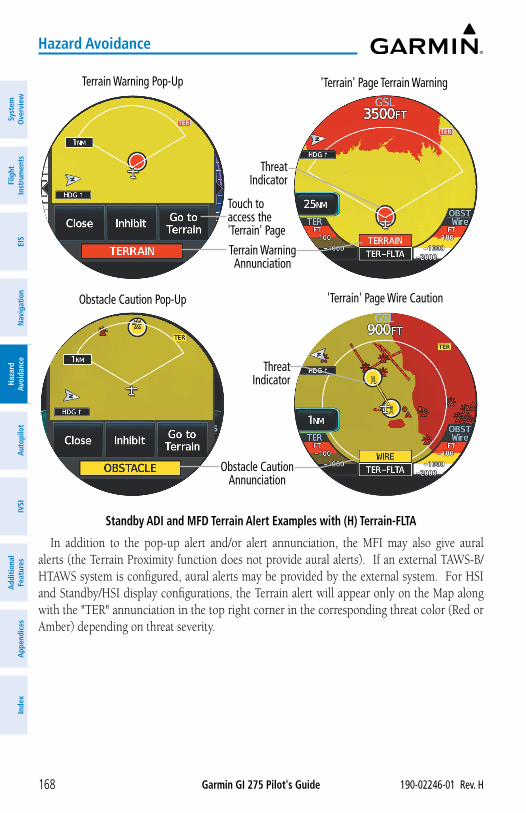
Garmin GI 275 Pilot's Guide 190-02246-01 Rev. H168
Hazard Avoidance
Syst
em
Ove
rvie
wFl
ight
In
stru
men
tsEI
SN
avig
atio
nH
azar
d Av
oida
nce
Aut
opilo
tIV
SIA
dditi
onal
Fe
atur
esA
ppen
dice
sIn
dex
'Terrain' Page Terrain Warning
Touch to access the 'Terrain' Page
Standby ADI and MFD Terrain Alert Examples with (H) Terrain-FLTA
Threat Indicator
Terrain Warning Pop-Up
Terrain Warning Annunciation
Obstacle Caution Pop-Up
Threat Indicator
'Terrain' Page Wire Caution
Obstacle Caution Annunciation
In addition to the pop-up alert and/or alert annunciation, the MFI may also give aural alerts (the Terrain Proximity function does not provide aural alerts). If an external TAWS-B/HTAWS system is configured, aural alerts may be provided by the external system. For HSI and Standby/HSI display configurations, the Terrain alert will appear only on the Map along with the "TER" annunciation in the top right corner in the corresponding threat color (Red or Amber) depending on threat severity.
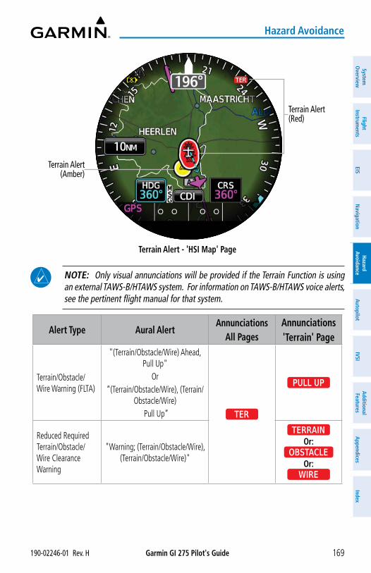
Garmin GI 275 Pilot's Guide190-02246-01 Rev. H 169
Hazard Avoidance
System
Overview
Flight Instrum
entsEIS
Navigation
Hazard
AvoidanceA
utopilotIVSI
Additional Features
Appendices
Index
Terrain Alert - 'HSI Map' Page
Terrain Alert (Red)
Terrain Alert (Amber)
NOTE: Only visual annunciations will be provided if the Terrain Function is using an external TAWS-B/HTAWS system. For information on TAWS-B/HTAWS voice alerts, see the pertinent flight manual for that system.
Alert Type Aural AlertAnnunciations
All PagesAnnunciations 'Terrain' Page
Terrain/Obstacle/Wire Warning (FLTA)
"(Terrain/Obstacle/Wire) Ahead, Pull Up"
Or“(Terrain/Obstacle/Wire), (Terrain/
Obstacle/Wire) Pull Up” TER
PULL UP
Reduced Required Terrain/Obstacle/Wire Clearance Warning
"Warning; (Terrain/Obstacle/Wire), (Terrain/Obstacle/Wire)"
TERRAINOr:
OBSTACLEOr:
WIRE
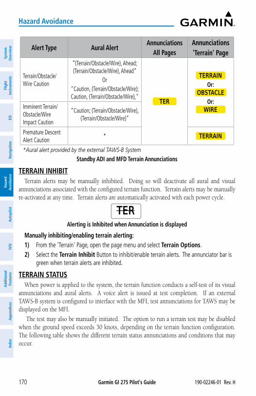
Garmin GI 275 Pilot's Guide 190-02246-01 Rev. H170
Hazard Avoidance
Syst
em
Ove
rvie
wFl
ight
In
stru
men
tsEI
SN
avig
atio
nH
azar
d Av
oida
nce
Aut
opilo
tIV
SIA
dditi
onal
Fe
atur
esA
ppen
dice
sIn
dex
Alert Type Aural AlertAnnunciations
All PagesAnnunciations 'Terrain' Page
Terrain/Obstacle/Wire Caution
“(Terrain/Obstacle/Wire), Ahead; (Terrain/Obstacle/Wire), Ahead”
Or"Caution, (Terrain/Obstacle/Wire); Caution, (Terrain/Obstacle/Wire),"
TER
TERRAIN
Or:OBSTACLE
Or:WIREImminent Terrain/
Obstacle/Wire Impact Caution
“Caution; (Terrain/Obstacle/Wire), (Terrain/Obstacle/Wire)”
Premature Descent Alert Caution
* TERRAIN
*Aural alert provided by the external TAWS-B System
Standby ADI and MFD Terrain Annunciations
TERRAIN INHIBITTerrain alerts may be manually inhibited. Doing so will deactivate all aural and visual
annunciations associated with the configured terrain function. Terrain alerts may be manually re-activated at any time. Terrain alerts are automatically activated with each power cycle.
Alerting is Inhibited when Annunciation is displayed
TER
Manually inhibiting/enabling terrain alerting:1) From the 'Terrain' Page, open the page menu and select Terrain Options.2) Select the Terrain Inhibit Button to inhibit/enable terrain alerts. The annunciator bar is
green when terrain alerts are inhibited.
TERRAIN STATUSWhen power is applied to the system, the terrain function conducts a self-test of its visual
annunciations and aural alerts. A voice alert is issued at test completion. If an external TAWS-B system is configured to interface with the MFI, test annunciations for TAWS may be displayed on the MFI.
The test may also be manually initiated. The option to run a terrain test may be disabled when the ground speed exceeds 30 knots, depending on the terrain function configuration. The following table shows the different terrain status annunciations and conditions that may occur.
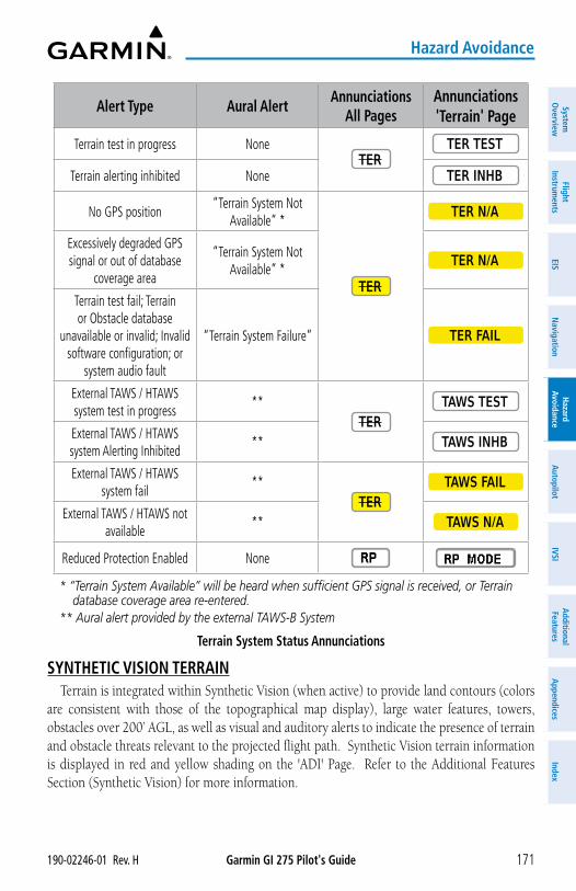
Garmin GI 275 Pilot's Guide190-02246-01 Rev. H 171
Hazard Avoidance
System
Overview
Flight Instrum
entsEIS
Navigation
Hazard
AvoidanceA
utopilotIVSI
Additional Features
Appendices
Index
Alert Type Aural AlertAnnunciations
All PagesAnnunciations 'Terrain' Page
Terrain test in progress NoneTER
TER TEST
Terrain alerting inhibited None TER INHB
No GPS position“Terrain System Not
Available” *
TER
TER N/A
Excessively degraded GPS signal or out of database
coverage area
“Terrain System Not Available” *
TER N/A
Terrain test fail; Terrain or Obstacle database
unavailable or invalid; Invalid software configuration; or
system audio fault
“Terrain System Failure” TER FAIL
External TAWS / HTAWS system test in progress
**TER
TAWS TEST
External TAWS / HTAWS system Alerting Inhibited
** TAWS INHB
External TAWS / HTAWS system fail
**TER
TAWS FAIL
External TAWS / HTAWS not available
** TAWS N/A
Reduced Protection Enabled None
* “Terrain System Available” will be heard when sufficient GPS signal is received, or Terrain database coverage area re-entered.
** Aural alert provided by the external TAWS-B System
Terrain System Status Annunciations
SYNTHETIC VISION TERRAINTerrain is integrated within Synthetic Vision (when active) to provide land contours (colors
are consistent with those of the topographical map display), large water features, towers, obstacles over 200’ AGL, as well as visual and auditory alerts to indicate the presence of terrain and obstacle threats relevant to the projected flight path. Synthetic Vision terrain information is displayed in red and yellow shading on the 'ADI' Page. Refer to the Additional Features Section (Synthetic Vision) for more information.
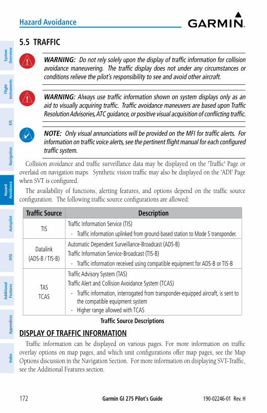
Garmin GI 275 Pilot's Guide 190-02246-01 Rev. H172
Hazard Avoidance
Syst
em
Ove
rvie
wFl
ight
In
stru
men
tsEI
SN
avig
atio
nH
azar
d Av
oida
nce
Aut
opilo
tIV
SIA
dditi
onal
Fe
atur
esA
ppen
dice
sIn
dex
5.5 TRAFFIC
WARNING: Do not rely solely upon the display of traffic information for collision avoidance maneuvering. The traffic display does not under any circumstances or conditions relieve the pilot’s responsibility to see and avoid other aircraft.
WARNING: Always use traffic information shown on system displays only as an aid to visually acquiring traffic. Traffic avoidance maneuvers are based upon Traffic Resolution Advisories, ATC guidance, or positive visual acquisition of conflicting traffic.
NOTE: Only visual annunciations will be provided on the MFI for traffic alerts. For information on traffic voice alerts, see the pertinent flight manual for each configured traffic system.
Collision avoidance and traffic surveillance data may be displayed on the 'Traffic' Page or overlaid on navigation maps. Synthetic vision traffic may also be displayed on the 'ADI' Page when SVT is configured.
The availability of functions, alerting features, and options depend on the traffic source configuration. The following traffic source configurations are allowed:
Traffic Source Description
TISTraffic Information Service (TIS)
- Traffic information uplinked from ground-based station to Mode S transponder.
Datalink (ADS-B / TIS-B)
Automatic Dependent Surveillance-Broadcast (ADS-B)Traffic Information Service-Broadcast (TIS-B)
- Traffic information received using compatible equipment for ADS-B or TIS-B
TAS TCAS
Traffic Advisory System (TAS)Traffic Alert and Collision Avoidance System (TCAS)
- Traffic information, interrogated from transponder-equipped aircraft, is sent to the compatible equipment system
- Higher range allowed with TCAS
Traffic Source Descriptions
DISPLAY OF TRAFFIC INFORMATIONTraffic information can be displayed on various pages. For more information on traffic
overlay options on map pages, and which unit configurations offer map pages, see the Map Options discussion in the Navigation Section. For more information on displaying SVT-Traffic, see the Additional Features section.
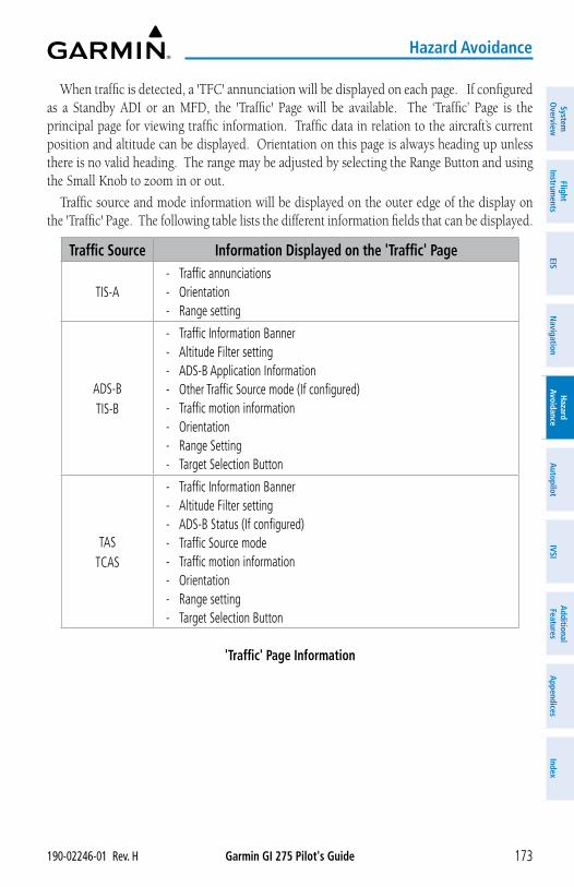
Garmin GI 275 Pilot's Guide190-02246-01 Rev. H 173
Hazard Avoidance
System
Overview
Flight Instrum
entsEIS
Navigation
Hazard
AvoidanceA
utopilotIVSI
Additional Features
Appendices
Index
When traffic is detected, a 'TFC' annunciation will be displayed on each page. If configured as a Standby ADI or an MFD, the 'Traffic' Page will be available. The ‘Traffic’ Page is the principal page for viewing traffic information. Traffic data in relation to the aircraft’s current position and altitude can be displayed. Orientation on this page is always heading up unless there is no valid heading. The range may be adjusted by selecting the Range Button and using the Small Knob to zoom in or out.
Traffic source and mode information will be displayed on the outer edge of the display on the 'Traffic' Page. The following table lists the different information fields that can be displayed.
Traffic Source Information Displayed on the 'Traffic' Page
TIS-A - Traffic annunciations - Orientation - Range setting
ADS-BTIS-B
- Traffic Information Banner - Altitude Filter setting - ADS-B Application Information - Other Traffic Source mode (If configured) - Traffic motion information - Orientation - Range Setting - Target Selection Button
TAS TCAS
- Traffic Information Banner - Altitude Filter setting - ADS-B Status (If configured) - Traffic Source mode - Traffic motion information - Orientation - Range setting - Target Selection Button
'Traffic' Page Information
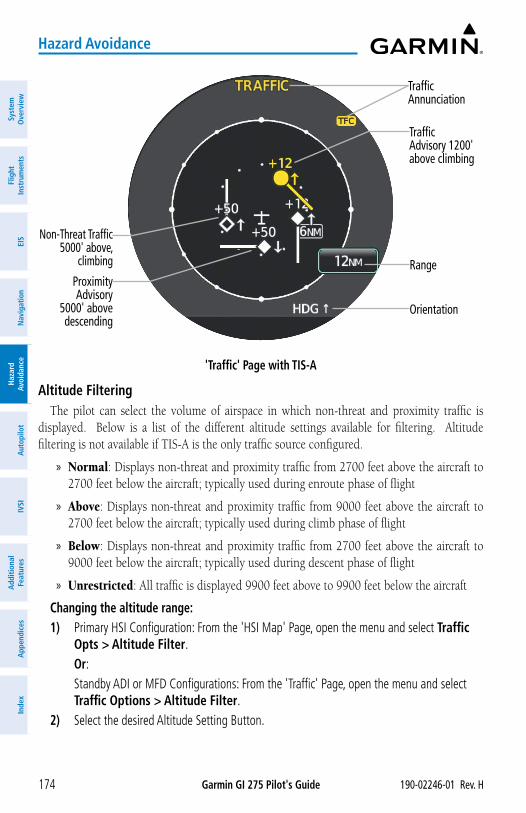
Garmin GI 275 Pilot's Guide 190-02246-01 Rev. H174
Hazard Avoidance
Syst
em
Ove
rvie
wFl
ight
In
stru
men
tsEI
SN
avig
atio
nH
azar
d Av
oida
nce
Aut
opilo
tIV
SIA
dditi
onal
Fe
atur
esA
ppen
dice
sIn
dex
'Traffic' Page with TIS-A
Traffic Annunciation
Proximity Advisory
5000' above descending
Range
Non-Threat Traffic5000' above,
climbing
Traffic Advisory 1200' above climbing
Orientation
Altitude FilteringThe pilot can select the volume of airspace in which non-threat and proximity traffic is
displayed. Below is a list of the different altitude settings available for filtering. Altitude filtering is not available if TIS-A is the only traffic source configured.
» Normal: Displays non-threat and proximity traffic from 2700 feet above the aircraft to 2700 feet below the aircraft; typically used during enroute phase of flight
» Above: Displays non-threat and proximity traffic from 9000 feet above the aircraft to 2700 feet below the aircraft; typically used during climb phase of flight
» Below: Displays non-threat and proximity traffic from 2700 feet above the aircraft to 9000 feet below the aircraft; typically used during descent phase of flight
» Unrestricted: All traffic is displayed 9900 feet above to 9900 feet below the aircraft
Changing the altitude range:1) Primary HSI Configuration: From the 'HSI Map' Page, open the menu and select Traffic
Opts > Altitude Filter. Or: Standby ADI or MFD Configurations: From the 'Traffic' Page, open the menu and select
Traffic Options > Altitude Filter. 2) Select the desired Altitude Setting Button.
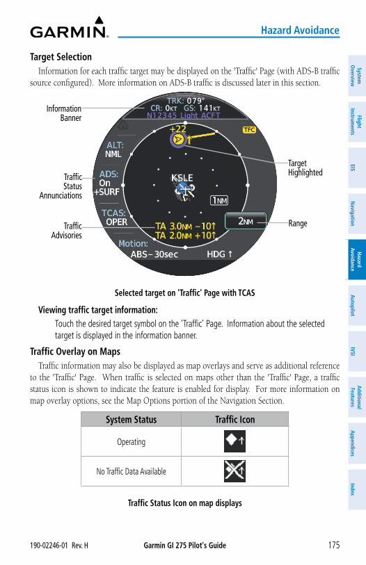
Garmin GI 275 Pilot's Guide190-02246-01 Rev. H 175
Hazard Avoidance
System
Overview
Flight Instrum
entsEIS
Navigation
Hazard
AvoidanceA
utopilotIVSI
Additional Features
Appendices
Index
Target SelectionInformation for each traffic target may be displayed on the 'Traffic' Page (with ADS-B traffic
source configured). More information on ADS-B traffic is discussed later in this section.
Selected target on 'Traffic' Page with TCAS
Information Banner
Range
Traffic Status
Annunciations
Target Highlighted
Traffic Advisories
Viewing traffic target information: Touch the desired target symbol on the 'Traffic' Page. Information about the selected
target is displayed in the information banner.
Traffic Overlay on MapsTraffic information may also be displayed as map overlays and serve as additional reference
to the 'Traffic' Page. When traffic is selected on maps other than the 'Traffic' Page, a traffic status icon is shown to indicate the feature is enabled for display. For more information on map overlay options, see the Map Options portion of the Navigation Section.
System Status Traffic Icon
Operating
No Traffic Data Available
Traffic Status Icon on map displays
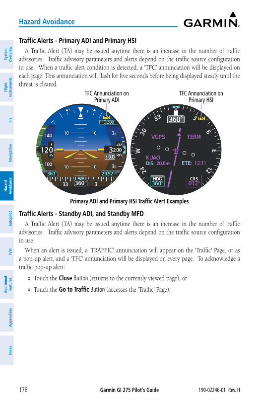
Garmin GI 275 Pilot's Guide 190-02246-01 Rev. H176
Hazard Avoidance
Syst
em
Ove
rvie
wFl
ight
In
stru
men
tsEI
SN
avig
atio
nH
azar
d Av
oida
nce
Aut
opilo
tIV
SIA
dditi
onal
Fe
atur
esA
ppen
dice
sIn
dex
Traffic Alerts - Primary ADI and Primary HSIA Traffic Alert (TA) may be issued anytime there is an increase in the number of traffic
advisories. Traffic advisory parameters and alerts depend on the traffic source configuration in use. When a traffic alert condition is detected, a 'TFC' annunciation will be displayed on each page. This annunciation will flash for five seconds before being displayed steady until the threat is cleared.
Primary ADI and Primary HSI Traffic Alert Examples
TFC Annunciation on Primary HSI
TFC Annunciation on Primary ADI
Traffic Alerts - Standby ADI, and Standby MFDA Traffic Alert (TA) may be issued anytime there is an increase in the number of traffic
advisories. Traffic advisory parameters and alerts depend on the traffic source configuration in use.
When an alert is issued, a 'TRAFFIC' annunciation will appear on the 'Traffic' Page, or as a pop-up alert, and a 'TFC' annunciation will be displayed on every page. To acknowledge a traffic pop-up alert:
» Touch the Close Button (returns to the currently viewed page), or
» Touch the Go to Traffic Button (accesses the 'Traffic' Page).
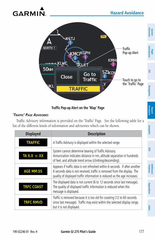
Garmin GI 275 Pilot's Guide190-02246-01 Rev. H 177
Hazard Avoidance
System
Overview
Flight Instrum
entsEIS
Navigation
Hazard
AvoidanceA
utopilotIVSI
Additional Features
Appendices
Index
Traffic Pop-up Alert on the 'Map' Page
Traffic Pop-up Alert
Touch to go to the 'Traffic' Page
'trAFFiC' pAge ADviSorieS
Traffic Advisory information is provided on the 'Traffic' Page. See the following table for a list of the different kinds of information and advisories which can be shown.
Displayed Description
TRAFFIC A Traffic Advisory is displayed within the selected range.
TA X.X ± XXSystem cannot determine bearing of Traffic Advisory. Annunciation indicates distance in nm, altitude separation in hundreds of feet, and altitude trend arrow (climbing/descending).
AGE MM:SSAppears if traffic data is not refreshed within 6 seconds. If after another 6 seconds data is not received, traffic is removed from the display. The quality of displayed traffic information is reduced as the age increases.
TRFC COASTThe displayed data is not current (6 to 12 seconds since last message). The quality of displayed traffic information is reduced when this message is displayed.
TRFC RMVDTraffic is removed because it is too old for coasting (12 to 60 seconds since last message). Traffic may exist within the selected display range, but it is not displayed.
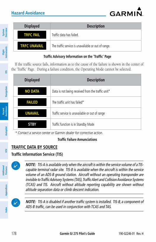
Garmin GI 275 Pilot's Guide 190-02246-01 Rev. H178
Hazard Avoidance
Syst
em
Ove
rvie
wFl
ight
In
stru
men
tsEI
SN
avig
atio
nH
azar
d Av
oida
nce
Aut
opilo
tIV
SIA
dditi
onal
Fe
atur
esA
ppen
dice
sIn
dex
Displayed Description
TRFC FAIL Traffic data has failed.
TRFC UNAVAIL The traffic service is unavailable or out of range.
Traffic Advisory Information on the 'Traffic' Page
If the traffic source fails, information as to the cause of the failure is shown in the center of the ‘Traffic’ Page. During a failure condition, the Operating Mode cannot be selected.
Displayed Description
NO DATA Data is not being received from the traffic unit*
FAILED The traffic unit has failed*
UNAVAIL Traffic service is unavailable or out of range
STBY Traffic function is in Standby Mode STANDBY
* Contact a service center or Garmin dealer for corrective action.
Traffic Failure Annunciations
TRAFFIC DATA BY SOURCETraffic Information Service (TIS)
NOTE: TIS-A is available only when the aircraft is within the service volume of a TIS-capable terminal radar site. TIS-B is available when the aircraft is within the service volume of an ADS-B ground station. Aircraft without an operating transponder are invisible to Traffic Advisory Systems (TAS), Traffic Alert and Collision Avoidance Systems (TCAS) and TIS. Aircraft without altitude reporting capability are shown without altitude separation data or climb descent indication.
NOTE: TIS-A is disabled if another traffic system is installed. TIS-B, a component of ADS-B traffic, can be used in conjunction with TCAS and TAS.
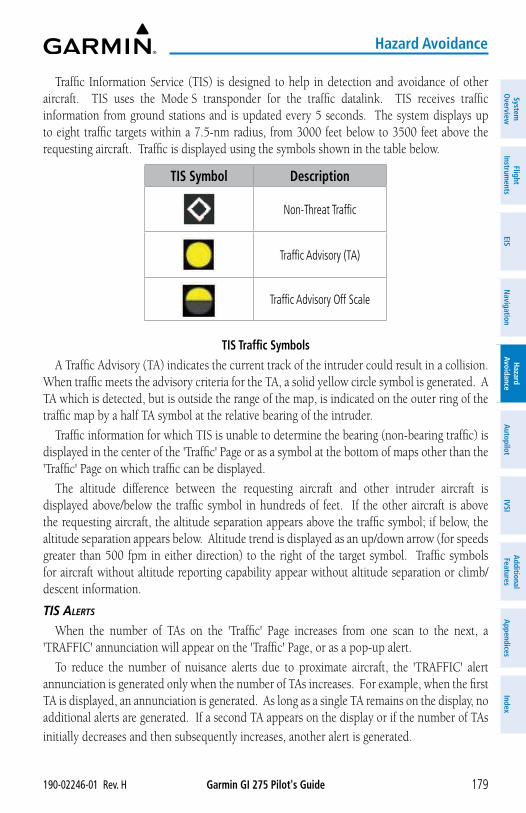
Garmin GI 275 Pilot's Guide190-02246-01 Rev. H 179
Hazard Avoidance
System
Overview
Flight Instrum
entsEIS
Navigation
Hazard
AvoidanceA
utopilotIVSI
Additional Features
Appendices
Index
Traffic Information Service (TIS) is designed to help in detection and avoidance of other aircraft. TIS uses the Mode S transponder for the traffic datalink. TIS receives traffic information from ground stations and is updated every 5 seconds. The system displays up to eight traffic targets within a 7.5-nm radius, from 3000 feet below to 3500 feet above the requesting aircraft. Traffic is displayed using the symbols shown in the table below.
TIS Symbol Description
Non-Threat Traffic
Traffic Advisory (TA)
Traffic Advisory Off Scale
TIS Traffic SymbolsA Traffic Advisory (TA) indicates the current track of the intruder could result in a collision.
When traffic meets the advisory criteria for the TA, a solid yellow circle symbol is generated. A TA which is detected, but is outside the range of the map, is indicated on the outer ring of the traffic map by a half TA symbol at the relative bearing of the intruder.
Traffic information for which TIS is unable to determine the bearing (non-bearing traffic) is displayed in the center of the 'Traffic' Page or as a symbol at the bottom of maps other than the 'Traffic' Page on which traffic can be displayed.
The altitude difference between the requesting aircraft and other intruder aircraft is displayed above/below the traffic symbol in hundreds of feet. If the other aircraft is above the requesting aircraft, the altitude separation appears above the traffic symbol; if below, the altitude separation appears below. Altitude trend is displayed as an up/down arrow (for speeds greater than 500 fpm in either direction) to the right of the target symbol. Traffic symbols for aircraft without altitude reporting capability appear without altitude separation or climb/descent information.
tiS ALertS
When the number of TAs on the 'Traffic' Page increases from one scan to the next, a 'TRAFFIC' annunciation will appear on the 'Traffic' Page, or as a pop-up alert.
To reduce the number of nuisance alerts due to proximate aircraft, the 'TRAFFIC' alert annunciation is generated only when the number of TAs increases. For example, when the first TA is displayed, an annunciation is generated. As long as a single TA remains on the display, no additional alerts are generated. If a second TA appears on the display or if the number of TAs
initially decreases and then subsequently increases, another alert is generated.
Garmin GI 275 Pilot's Guide 190-02246-01 Rev. H180
Hazard Avoidance
Syst
em
Ove
rvie
wFl
ight
In
stru
men
tsEI
SN
avig
atio
nH
azar
d Av
oida
nce
Aut
opilo
tIV
SIA
dditi
onal
Fe
atur
esA
ppen
dice
sIn
dex
The annunciation 'UNAVAILABLE' is generated when the TIS service becomes unavailable or is out of range. TIS may be unavailable in the radar coverage area due to the following:
� Radar site TIS Mode S sensor is not operational or is out of service
� Traffic or requesting aircraft is beyond the maximum range of the TIS-capable Mode S radar site
� Traffic or requesting aircraft is above the radar site in the cone of silence and out of range of an adjacent site
� Traffic or requesting aircraft is below radar coverage; in flat terrain, the coverage extends from about 3000 feet upward at 55 miles; terrain and obstacles around the radar site can further decrease radar coverage in all directions
� Traffic does not have an operating transponder
tiS SySteM StAtuS
The system performs an automatic test of TIS when power is applied to the system. If TIS passes the test, TIS enters Standby Mode (on the ground) or Operating Mode (in the air). If TIS fails the test after power is applied to the system, an annunciation is shown in the center of the 'Traffic' Page.
When the aircraft is on the ground, TIS automatically enters Standby Mode. STBY will be annunciated on the 'Traffic' Page. Also, the Traffic Status Icon on other maps will be crossed out (also the case whenever TIS has failed).
Once the aircraft is airborne, TIS switches to Operating Mode and traffic information is displayed. The mode can be changed manually by using the page menu.
Manually switching between TIS modes:1) From the 'Traffic' Page, open the page menu and select Traffic Options.
2) Select the Traffic Status Button to toggle between 'Standby' or 'Operate' modes.
Datalink Traffic
WARNING: Do not rely solely upon the display of traffic information to accurately depict all of the traffic information within range of the aircraft. Due to lack of equipment, poor signal reception, and/or inaccurate information from other aircraft, traffic may be present but not represented on the display.
NOTE: If equipped, ADS-B Traffic can be shared with certain Bluetooth connected devices. Refer to System Overview Section for Bluetooth pairing instructions.
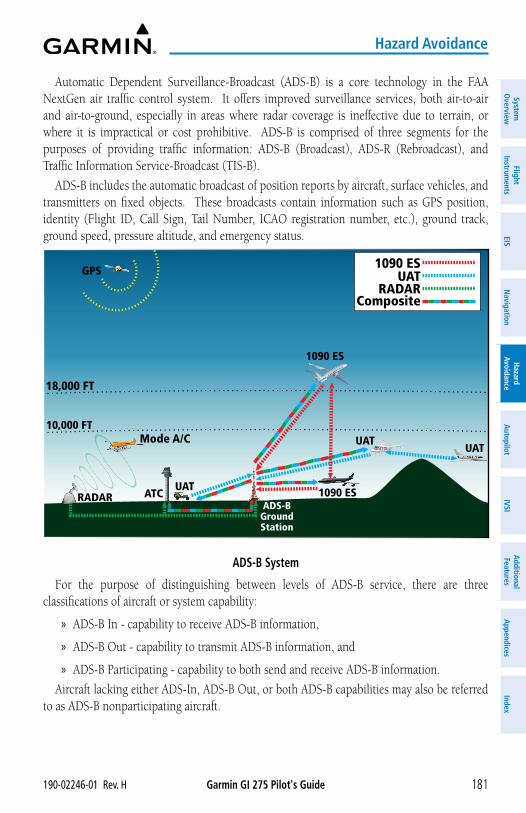
Garmin GI 275 Pilot's Guide190-02246-01 Rev. H 181
Hazard Avoidance
System
Overview
Flight Instrum
entsEIS
Navigation
Hazard
AvoidanceA
utopilotIVSI
Additional Features
Appendices
Index
Automatic Dependent Surveillance-Broadcast (ADS-B) is a core technology in the FAA NextGen air traffic control system. It offers improved surveillance services, both air-to-air and air-to-ground, especially in areas where radar coverage is ineffective due to terrain, or where it is impractical or cost prohibitive. ADS-B is comprised of three segments for the purposes of providing traffic information: ADS-B (Broadcast), ADS-R (Rebroadcast), and Traffic Information Service-Broadcast (TIS-B).
ADS-B includes the automatic broadcast of position reports by aircraft, surface vehicles, and transmitters on fixed objects. These broadcasts contain information such as GPS position, identity (Flight ID, Call Sign, Tail Number, ICAO registration number, etc.), ground track, ground speed, pressure altitude, and emergency status.
18,000 FT
10,000 FT
GPS
RADAR ATC
1090 ESUAT
RADARComposite
ADS-BGround Station
Mode A/C
1090 ES
1090 ES
UATUAT
UAT
ADS-B System
For the purpose of distinguishing between levels of ADS-B service, there are three classifications of aircraft or system capability:
» ADS-B In - capability to receive ADS-B information,
» ADS-B Out - capability to transmit ADS-B information, and
» ADS-B Participating - capability to both send and receive ADS-B information.
Aircraft lacking either ADS-In, ADS-B Out, or both ADS-B capabilities may also be referred to as ADS-B nonparticipating aircraft.
Garmin GI 275 Pilot's Guide 190-02246-01 Rev. H182
Hazard Avoidance
Syst
em
Ove
rvie
wFl
ight
In
stru
men
tsEI
SN
avig
atio
nH
azar
d Av
oida
nce
Aut
opilo
tIV
SIA
dditi
onal
Fe
atur
esA
ppen
dice
sIn
dex
The ADS-B system operates on two frequencies: 1090 MHz and 978 MHz. Both frequencies provide the same traffic information. An aircraft may be ADS-B In, Out, or participating on one or both frequencies, depending on the installed equipment. The 1090 MHz frequency portion of ADS-B is known as 1090 Extended Squitter (1090 ES). The 978 MHz portion of ADS-B is known as Universal Access Transceiver (UAT).
Because it is not required that ADS-B In capable aircraft be able to receive ADS-B data on both the 1090 MHz and 978 MHz datalinks, a method exists to get data from one datalink to the other. ADS-R is the rebroadcast of ADS-B data by FAA ground stations, which provide this service by taking traffic data from one link and rebroadcasting it on the other. For example, if two aircraft are in the service volume for a ground station, and one is transmitting on 1090 MHz and the other is transmitting on 978 MHz, the ground station retransmits the data from each aircraft on the other link to ensure the two aircraft can “see” each other as traffic.
For example, if another aircraft can only receive 978 MHz UAT information, it cannot directly ‘see’ another aircraft sending only 1090 ES information aircraft unless an ADS-R ground station in the vicinity rebroadcasts the 1090 ES data over the 978 MHz UAT frequency. This is also true for an aircraft that can only receive 1090 ES data; it would need an ADS-R ground station to ‘see’ another aircraft operating on the UAT frequency.
TIS-B (Traffic Information Service-Broadcast) provides a link between the secondary surveillance radar (SSR)-based system ATC uses and the ADS-B-based system. When an ADS-B Out capable aircraft is within the service volume of an FAA ADS-B ground station, the ground station broadcasts a portion of the ATC radar data to the aircraft. This aircraft is then included in the list of aircraft being provided TIS-B service and is then considered a “TIS-B participant.”
TIS-B coverage is available when the aircraft is within ground station coverage, in SSR coverage, and the other aircraft is also in SSR coverage, and is transmitting its altitude.
The ground station provides ATC radar information for other aircraft within ±3,500 feet and 15 NM of the participant, to include altitude, position, ground speed, and ground track. TIS-B broadcasts occur once every three to thirteen seconds, depending on the characteristics of the ground station providing the TIS-B service.
The symbols used to display ADS-B traffic are shown in the following table. Above or below the traffic symbol is the traffic identifier, and altitude. A small up or down arrow next to the traffic symbol indicates that traffic is climbing or descending at a rate of at least 500 feet per minute.
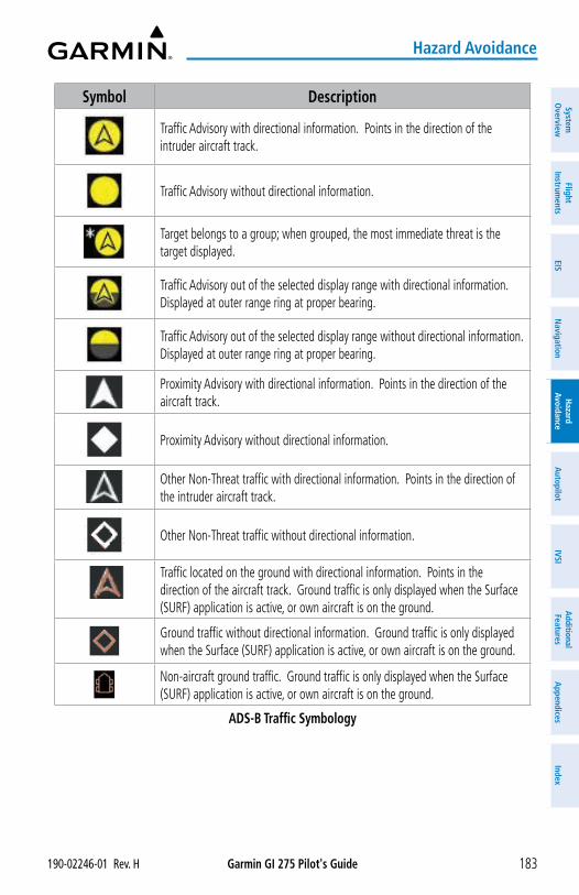
Garmin GI 275 Pilot's Guide190-02246-01 Rev. H 183
Hazard Avoidance
System
Overview
Flight Instrum
entsEIS
Navigation
Hazard
AvoidanceA
utopilotIVSI
Additional Features
Appendices
Index
Symbol Description
Traffic Advisory with directional information. Points in the direction of the intruder aircraft track.
Traffic Advisory without directional information.
Target belongs to a group; when grouped, the most immediate threat is the target displayed.
Traffic Advisory out of the selected display range with directional information. Displayed at outer range ring at proper bearing.
Traffic Advisory out of the selected display range without directional information. Displayed at outer range ring at proper bearing.
Proximity Advisory with directional information. Points in the direction of the aircraft track.
Proximity Advisory without directional information.
Other Non-Threat traffic with directional information. Points in the direction of the intruder aircraft track.
Other Non-Threat traffic without directional information.
Traffic located on the ground with directional information. Points in the direction of the aircraft track. Ground traffic is only displayed when the Surface (SURF) application is active, or own aircraft is on the ground.
Ground traffic without directional information. Ground traffic is only displayed when the Surface (SURF) application is active, or own aircraft is on the ground.
Non-aircraft ground traffic. Ground traffic is only displayed when the Surface (SURF) application is active, or own aircraft is on the ground.
ADS-B Traffic Symbology
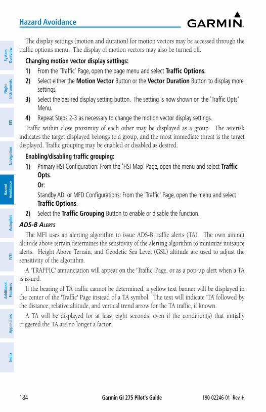
Garmin GI 275 Pilot's Guide 190-02246-01 Rev. H184
Hazard Avoidance
Syst
em
Ove
rvie
wFl
ight
In
stru
men
tsEI
SN
avig
atio
nH
azar
d Av
oida
nce
Aut
opilo
tIV
SIA
dditi
onal
Fe
atur
esA
ppen
dice
sIn
dex
The display settings (motion and duration) for motion vectors may be accessed through the traffic options menu. The display of motion vectors may also be turned off.
Changing motion vector display settings:1) From the 'Traffic' Page, open the page menu and select Traffic Options.2) Select either the Motion Vector Button or the Vector Duration Button to display more
settings. 3) Select the desired display setting button. The setting is now shown on the 'Traffic Opts'
Menu. 4) Repeat Steps 2-3 as necessary to change the motion vector display settings. Traffic within close proximity of each other may be displayed as a group. The asterisk
indicates the target displayed belongs to a group, and the most immediate threat is the target displayed. Traffic grouping may be enabled or disabled as desired.
Enabling/disabling traffic grouping:1) Primary HSI Configuration: From the 'HSI Map' Page, open the menu and select Traffic
Opts. Or: Standby ADI or MFD Configurations: From the 'Traffic' Page, open the menu and select
Traffic Options. 2) Select the Traffic Grouping Button to enable or disable the function.
ADS-B ALertS
The MFI uses an alerting algorithm to issue ADS-B traffic alerts (TA). The own aircraft altitude above terrain determines the sensitivity of the alerting algorithm to minimize nuisance alerts. Height Above Terrain, and Geodetic Sea Level (GSL) altitude are used to adjust the sensitivity of the algorithm.
A 'TRAFFIC' annunciation will appear on the 'Traffic' Page, or as a pop-up alert when a TA is issued.
If the bearing of TA traffic cannot be determined, a yellow text banner will be displayed in the center of the 'Traffic' Page instead of a TA symbol. The text will indicate ‘TA’ followed by the distance, relative altitude, and vertical trend arrow for the TA traffic, if known.
A TA will be displayed for at least eight seconds, even if the condition(s) that initially triggered the TA are no longer a factor.
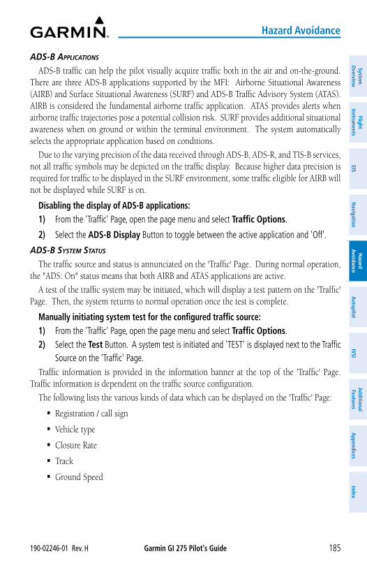
Garmin GI 275 Pilot's Guide190-02246-01 Rev. H 185
Hazard Avoidance
System
Overview
Flight Instrum
entsEIS
Navigation
Hazard
AvoidanceA
utopilotIVSI
Additional Features
Appendices
Index
ADS-B AppLiCAtionS
ADS-B traffic can help the pilot visually acquire traffic both in the air and on-the-ground. There are three ADS-B applications supported by the MFI: Airborne Situational Awareness (AIRB) and Surface Situational Awareness (SURF) and ADS-B Traffic Advisory System (ATAS). AIRB is considered the fundamental airborne traffic application. ATAS provides alerts when airborne traffic trajectories pose a potential collision risk. SURF provides additional situational awareness when on ground or within the terminal environment. The system automatically selects the appropriate application based on conditions.
Due to the varying precision of the data received through ADS-B, ADS-R, and TIS-B services, not all traffic symbols may be depicted on the traffic display. Because higher data precision is required for traffic to be displayed in the SURF environment, some traffic eligible for AIRB will not be displayed while SURF is on.
Disabling the display of ADS-B applications:1) From the 'Traffic' Page, open the page menu and select Traffic Options.
2) Select the ADS-B Display Button to toggle between the active application and 'Off'.
ADS-B SySteM StAtuS
The traffic source and status is annunciated on the 'Traffic' Page. During normal operation, the "ADS: On" status means that both AIRB and ATAS applications are active.
A test of the traffic system may be initiated, which will display a test pattern on the 'Traffic' Page. Then, the system returns to normal operation once the test is complete.
Manually initiating system test for the configured traffic source:1) From the 'Traffic' Page, open the page menu and select Traffic Options. 2) Select the Test Button. A system test is initiated and 'TEST' is displayed next to the Traffic
Source on the 'Traffic' Page. Traffic information is provided in the information banner at the top of the 'Traffic' Page.
Traffic information is dependent on the traffic source configuration.
The following lists the various kinds of data which can be displayed on the 'Traffic' Page:
� Registration / call sign
� Vehicle type
� Closure Rate
� Track
� Ground Speed
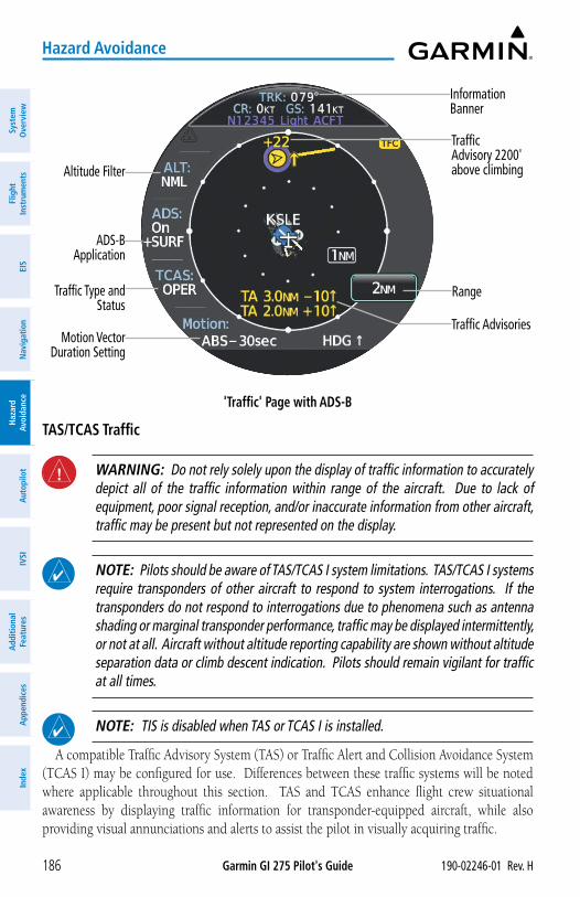
Garmin GI 275 Pilot's Guide 190-02246-01 Rev. H186
Hazard Avoidance
Syst
em
Ove
rvie
wFl
ight
In
stru
men
tsEI
SN
avig
atio
nH
azar
d Av
oida
nce
Aut
opilo
tIV
SIA
dditi
onal
Fe
atur
esA
ppen
dice
sIn
dex
'Traffic' Page with ADS-B
Information Banner
Range
Traffic Advisory 2200' above climbingAltitude Filter
ADS-B Application
Traffic Type and Status
Motion Vector Duration Setting
Traffic Advisories
TAS/TCAS Traffic
WARNING: Do not rely solely upon the display of traffic information to accurately depict all of the traffic information within range of the aircraft. Due to lack of equipment, poor signal reception, and/or inaccurate information from other aircraft, traffic may be present but not represented on the display.
NOTE: Pilots should be aware of TAS/TCAS I system limitations. TAS/TCAS I systems require transponders of other aircraft to respond to system interrogations. If the transponders do not respond to interrogations due to phenomena such as antenna shading or marginal transponder performance, traffic may be displayed intermittently, or not at all. Aircraft without altitude reporting capability are shown without altitude separation data or climb descent indication. Pilots should remain vigilant for traffic at all times.
NOTE: TIS is disabled when TAS or TCAS I is installed.
A compatible Traffic Advisory System (TAS) or Traffic Alert and Collision Avoidance System (TCAS I) may be configured for use. Differences between these traffic systems will be noted where applicable throughout this section. TAS and TCAS enhance flight crew situational awareness by displaying traffic information for transponder-equipped aircraft, while also providing visual annunciations and alerts to assist the pilot in visually acquiring traffic.
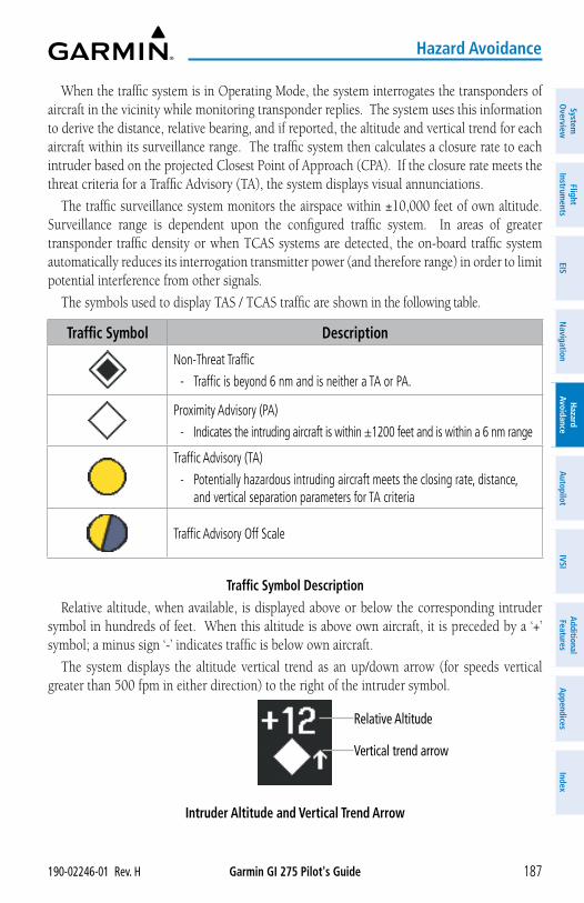
Garmin GI 275 Pilot's Guide190-02246-01 Rev. H 187
Hazard Avoidance
System
Overview
Flight Instrum
entsEIS
Navigation
Hazard
AvoidanceA
utopilotIVSI
Additional Features
Appendices
Index
When the traffic system is in Operating Mode, the system interrogates the transponders of aircraft in the vicinity while monitoring transponder replies. The system uses this information to derive the distance, relative bearing, and if reported, the altitude and vertical trend for each aircraft within its surveillance range. The traffic system then calculates a closure rate to each intruder based on the projected Closest Point of Approach (CPA). If the closure rate meets the threat criteria for a Traffic Advisory (TA), the system displays visual annunciations.
The traffic surveillance system monitors the airspace within ±10,000 feet of own altitude. Surveillance range is dependent upon the configured traffic system. In areas of greater transponder traffic density or when TCAS systems are detected, the on-board traffic system automatically reduces its interrogation transmitter power (and therefore range) in order to limit potential interference from other signals.
The symbols used to display TAS / TCAS traffic are shown in the following table.
Traffic Symbol Description
Non-Threat Traffic
- Traffic is beyond 6 nm and is neither a TA or PA.
Proximity Advisory (PA)
- Indicates the intruding aircraft is within ±1200 feet and is within a 6 nm range
Traffic Advisory (TA)
- Potentially hazardous intruding aircraft meets the closing rate, distance, and vertical separation parameters for TA criteria
Traffic Advisory Off Scale
Traffic Symbol DescriptionRelative altitude, when available, is displayed above or below the corresponding intruder
symbol in hundreds of feet. When this altitude is above own aircraft, it is preceded by a ‘+’ symbol; a minus sign ‘-’ indicates traffic is below own aircraft.
The system displays the altitude vertical trend as an up/down arrow (for speeds vertical greater than 500 fpm in either direction) to the right of the intruder symbol.
Intruder Altitude and Vertical Trend Arrow
Relative Altitude
Vertical trend arrow
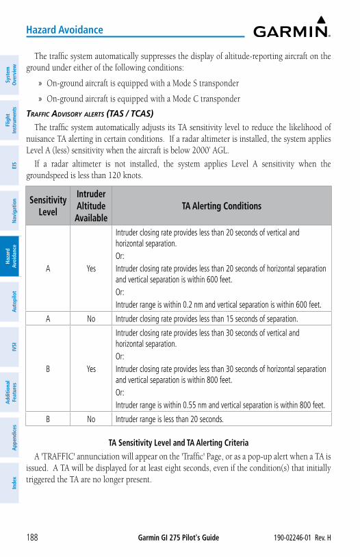
Garmin GI 275 Pilot's Guide 190-02246-01 Rev. H188
Hazard Avoidance
Syst
em
Ove
rvie
wFl
ight
In
stru
men
tsEI
SN
avig
atio
nH
azar
d Av
oida
nce
Aut
opilo
tIV
SIA
dditi
onal
Fe
atur
esA
ppen
dice
sIn
dex
The traffic system automatically suppresses the display of altitude-reporting aircraft on the ground under either of the following conditions:
» On-ground aircraft is equipped with a Mode S transponder
» On-ground aircraft is equipped with a Mode C transponder
trAFFiC ADviSory ALertS (tAS / tCAS)
The traffic system automatically adjusts its TA sensitivity level to reduce the likelihood of nuisance TA alerting in certain conditions. If a radar altimeter is installed, the system applies Level A (less) sensitivity when the aircraft is below 2000’ AGL.
If a radar altimeter is not installed, the system applies Level A sensitivity when the groundspeed is less than 120 knots.
Sensitivity Level
Intruder Altitude Available
TA Alerting Conditions
A Yes
Intruder closing rate provides less than 20 seconds of vertical and horizontal separation.Or:Intruder closing rate provides less than 20 seconds of horizontal separation and vertical separation is within 600 feet.Or:Intruder range is within 0.2 nm and vertical separation is within 600 feet.
A No Intruder closing rate provides less than 15 seconds of separation.
B Yes
Intruder closing rate provides less than 30 seconds of vertical and horizontal separation.Or:Intruder closing rate provides less than 30 seconds of horizontal separation and vertical separation is within 800 feet.Or:Intruder range is within 0.55 nm and vertical separation is within 800 feet.
B No Intruder range is less than 20 seconds.
TA Sensitivity Level and TA Alerting CriteriaA 'TRAFFIC' annunciation will appear on the 'Traffic' Page, or as a pop-up alert when a TA is
issued. A TA will be displayed for at least eight seconds, even if the condition(s) that initially triggered the TA are no longer present.
Garmin GI 275 Pilot's Guide190-02246-01 Rev. H 189
Hazard Avoidance
System
Overview
Flight Instrum
entsEIS
Navigation
Hazard
AvoidanceA
utopilotIVSI
Additional Features
Appendices
Index
tAS / tCAS SySteM StAtuS
NOTE: Traffic surveillance is not available during the system test. Use caution when performing a system test during flight.
The traffic system provides a system test mode to ensure the system is operating normally. The test takes ten seconds to complete. When the system test is initiated, a test pattern of traffic symbols appears on the 'Traffic' Page.
When the system test is complete, the traffic system enters Standby Mode. Standby mode will be indicated white in the center of the 'Traffic' Page. Otherwise, the status of the traffic system will be indicated in the Traffic Source field on the 'Traffic' Page.
Manually initiating system test for the configured traffic source:1) From the 'Traffic' Page, open the page menu and select Traffic Options. 2) Select the Test Button. A system test is initiated and 'TEST' is displayed next to the Traffic
Source on the 'Traffic' Page.
Garmin GI 275 Pilot's Guide 190-02246-01 Rev. H190
Hazard Avoidance
Syst
em
Ove
rvie
wFl
ight
In
stru
men
tsEI
SN
avig
atio
nH
azar
d Av
oida
nce
Aut
opilo
tIV
SIA
dditi
onal
Fe
atur
esA
ppen
dice
sIn
dex
Blank Page
Garmin GI 275 Pilot's Guide190-02246-01 Rev. H 191
Autopilot
System
Overview
Flight Instrum
entsEIS
Navigation
Hazard
AvoidanceA
utopilotIVSI
Additional Features
Appendices
Index
SECTION 6 AUTOPILOT6.1 OVERVIEW
WARNING: Do not rely on the Autopilot to level the aircraft at the minimum approach altitude when flying an approach with vertical guidance.
NOTE: Fixed Wing configurations only.
NOTE: Refer to the applicable Flight Director / AFCS Controller Manual for further information on how to operate an external Flight Director / AFCS Controller, if configured.
The GI 275 Multi-Function Instrument (MFI) receives and analyzes inputs from an external Flight Director, which in turn provides pitch, roll, and yaw gyro outputs to an Autopilot. The Autopilot operates the flight control servos which provides automatic flight control.
The MFI is capable of providing Yaw Damper control. The Yaw Damper reduces Dutch Roll tendencies and coordinates turns. It can operate independent of the Autopilot and may be used during normal hand-flown maneuvers. Yaw rate commands are limited by the Yaw Damper.
NOTE: An external Flight Director / AFCS Controller is required to fully operate the Autopilot capabilities of the MFI.
To utilize the Autopilot functionality, the following hardware is required:
• GI 275-20 (Basic with ADAHRS and Autopilot Interface)
• GMU 11 Magnetometer or GMU 44B (if applicable)
• Flight Director (if applicable)
• AFCS Controller (if applicable)
The MFI is also capable of displaying Flight Director information when connected to an external Flight Director. If configured, the following functions are provided:
• The capability to have GPS 1/2 and NAV 1/2 inputs for source selection from a navigation system and output signals for NAV and GPSS steering
• The capability to capture vertical navigation (e.g., glideslope, glidepath)
• The capability to provide CDI/VDI preview if a GTN (GPS/NAV/COM/MFD) is installed
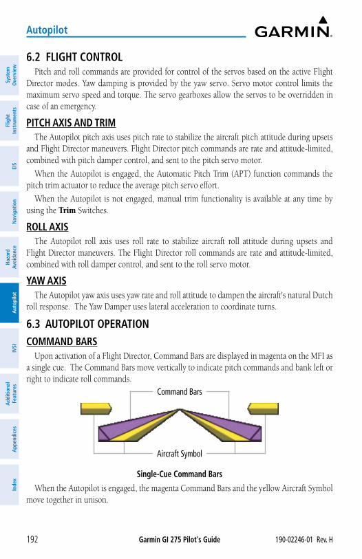
Garmin GI 275 Pilot's Guide 190-02246-01 Rev. H192
Autopilot
Syst
em
Ove
rvie
wFl
ight
In
stru
men
tsEI
SN
avig
atio
nH
azar
d Av
oida
nce
Aut
opilo
tIV
SIA
dditi
onal
Fe
atur
esA
ppen
dice
sIn
dex
6.2 FLIGHT CONTROLPitch and roll commands are provided for control of the servos based on the active Flight
Director modes. Yaw damping is provided by the yaw servo. Servo motor control limits the maximum servo speed and torque. The servo gearboxes allow the servos to be overridden in case of an emergency.
PITCH AXIS AND TRIMThe Autopilot pitch axis uses pitch rate to stabilize the aircraft pitch attitude during upsets
and Flight Director maneuvers. Flight Director pitch commands are rate and attitude-limited, combined with pitch damper control, and sent to the pitch servo motor.
When the Autopilot is engaged, the Automatic Pitch Trim (APT) function commands the pitch trim actuator to reduce the average pitch servo effort.
When the Autopilot is not engaged, manual trim functionality is available at any time by using the Trim Switches.
ROLL AXISThe Autopilot roll axis uses roll rate to stabilize aircraft roll attitude during upsets and
Flight Director maneuvers. The Flight Director roll commands are rate and attitude-limited, combined with roll damper control, and sent to the roll servo motor.
YAW AXISThe Autopilot yaw axis uses yaw rate and roll attitude to dampen the aircraft's natural Dutch
roll response. The Yaw Damper uses lateral acceleration to coordinate turns.
6.3 AUTOPILOT OPERATIONCOMMAND BARS
Upon activation of a Flight Director, Command Bars are displayed in magenta on the MFI as a single cue. The Command Bars move vertically to indicate pitch commands and bank left or right to indicate roll commands.
Single-Cue Command Bars
Aircraft Symbol
Command Bars
When the Autopilot is engaged, the magenta Command Bars and the yellow Aircraft Symbol move together in unison.
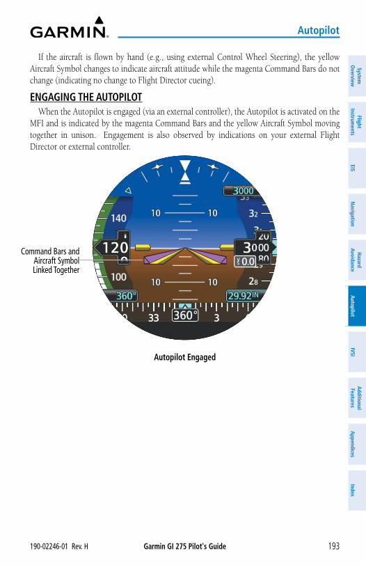
Garmin GI 275 Pilot's Guide190-02246-01 Rev. H 193
Autopilot
System
Overview
Flight Instrum
entsEIS
Navigation
Hazard
AvoidanceA
utopilotIVSI
Additional Features
Appendices
Index
If the aircraft is flown by hand (e.g., using external Control Wheel Steering), the yellow Aircraft Symbol changes to indicate aircraft attitude while the magenta Command Bars do not change (indicating no change to Flight Director cueing).
ENGAGING THE AUTOPILOTWhen the Autopilot is engaged (via an external controller), the Autopilot is activated on the
MFI and is indicated by the magenta Command Bars and the yellow Aircraft Symbol moving together in unison. Engagement is also observed by indications on your external Flight Director or external controller.
Autopilot Engaged
Command Bars and Aircraft Symbol Linked Together
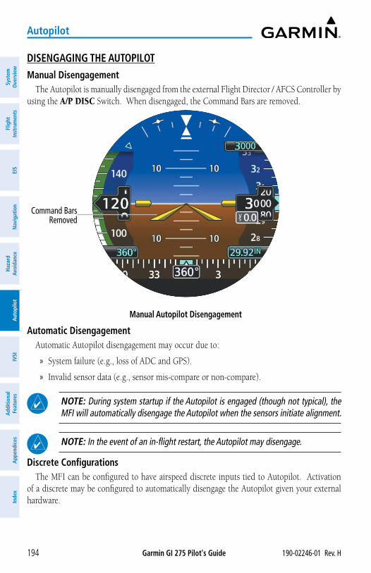
Garmin GI 275 Pilot's Guide 190-02246-01 Rev. H194
Autopilot
Syst
em
Ove
rvie
wFl
ight
In
stru
men
tsEI
SN
avig
atio
nH
azar
d Av
oida
nce
Aut
opilo
tIV
SIA
dditi
onal
Fe
atur
esA
ppen
dice
sIn
dex
DISENGAGING THE AUTOPILOTManual Disengagement
The Autopilot is manually disengaged from the external Flight Director / AFCS Controller by using the A/P DISC Switch. When disengaged, the Command Bars are removed.
Manual Autopilot Disengagement
Command Bars Removed
Automatic DisengagementAutomatic Autopilot disengagement may occur due to:
» System failure (e.g., loss of ADC and GPS).
» Invalid sensor data (e.g., sensor mis-compare or non-compare).
NOTE: During system startup if the Autopilot is engaged (though not typical), the MFI will automatically disengage the Autopilot when the sensors initiate alignment.
NOTE: In the event of an in-flight restart, the Autopilot may disengage.
Discrete ConfigurationsThe MFI can be configured to have airspeed discrete inputs tied to Autopilot. Activation
of a discrete may be configured to automatically disengage the Autopilot given your external hardware.
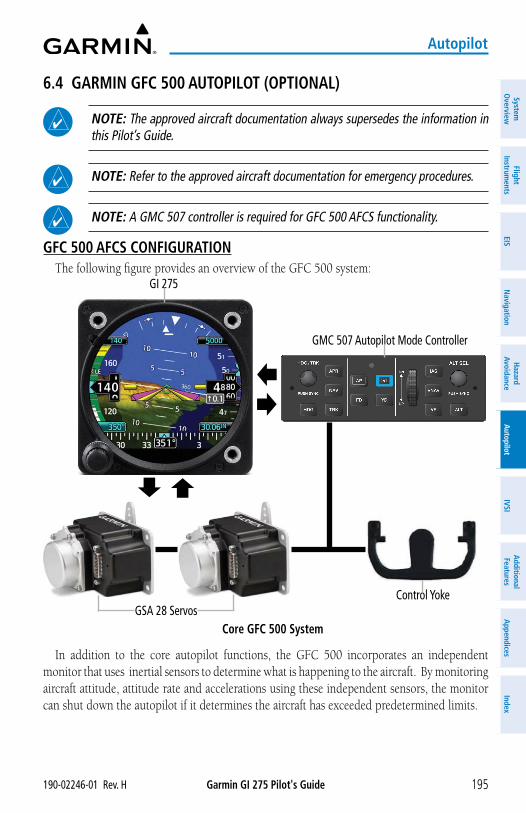
Garmin GI 275 Pilot's Guide190-02246-01 Rev. H 195
Autopilot
System
Overview
Flight Instrum
entsEIS
Navigation
Hazard
AvoidanceA
utopilotIVSI
Additional Features
Appendices
Index
6.4 GARMIN GFC 500 AUTOPILOT (OPTIONAL)
NOTE: The approved aircraft documentation always supersedes the information in this Pilot’s Guide.
NOTE: Refer to the approved aircraft documentation for emergency procedures.
NOTE: A GMC 507 controller is required for GFC 500 AFCS functionality.
GFC 500 AFCS CONFIGURATIONThe following figure provides an overview of the GFC 500 system:
GI 275
GMC 507 Autopilot Mode Controller
GSA 28 ServosControl Yoke
Core GFC 500 System
In addition to the core autopilot functions, the GFC 500 incorporates an independent monitor that uses inertial sensors to determine what is happening to the aircraft. By monitoring aircraft attitude, attitude rate and accelerations using these independent sensors, the monitor can shut down the autopilot if it determines the aircraft has exceeded predetermined limits.
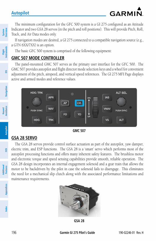
Garmin GI 275 Pilot's Guide 190-02246-01 Rev. H196
Autopilot
Syst
em
Ove
rvie
wFl
ight
In
stru
men
tsEI
SN
avig
atio
nH
azar
d Av
oida
nce
Aut
opilo
tIV
SIA
dditi
onal
Fe
atur
esA
ppen
dice
sIn
dex
The minimum configuration for the GFC 500 system is a GI 275 configured as an Attitude Indicator and two GSA 28 servos (in the pitch and roll positions). This will provide Pitch, Roll, Track, and Air Data modes only.
If navigation modes are desired, a GI 275 connected to a compatible navigation source (e.g., a GTN 6XX/7XX) is an option.
The basic GFC 500 system is comprised of the following equipment:
GMC 507 MODE CONTROLLERThe panel-mounted GMC 507 serves as the primary user interface for the GFC 500. The
GMC 507 provides autopilot and flight director mode selection keys and a wheel for convenient adjustment of the pitch, airspeed, and vertical speed references. The GI 275 MFI Page displays active and armed modes and reference values.
GMC 507
GSA 28 SERVOThe GSA 28 servos provide control surface actuation as part of the autopilot, yaw damper,
electric trim, and ESP functions. The GSA 28 is a ‘smart’ servo which performs most of the autopilot processing functions and offers many inherent safety features. The brushless motor and electronic torque and speed sensing capabilities provide smooth, reliable operation. The GSA 28 design incorporates an internal engagement solenoid and a gear train that allows the motor to be backdriven by the pilot in case the solenoid fails to disengage. This eliminates the need for a mechanical slip clutch along with the associated performance limitations and maintenance requirements.
GSA 28
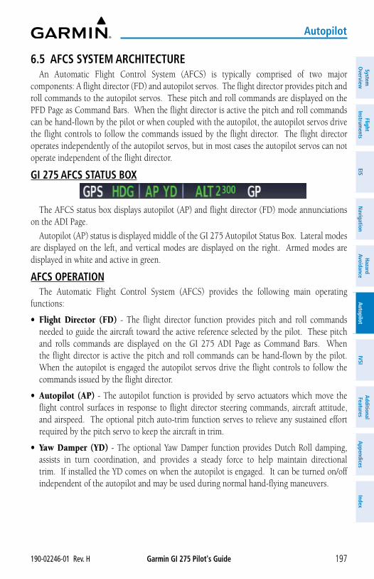
Garmin GI 275 Pilot's Guide190-02246-01 Rev. H 197
Autopilot
System
Overview
Flight Instrum
entsEIS
Navigation
Hazard
AvoidanceA
utopilotIVSI
Additional Features
Appendices
Index
6.5 AFCS SYSTEM ARCHITECTUREAn Automatic Flight Control System (AFCS) is typically comprised of two major
components: A flight director (FD) and autopilot servos. The flight director provides pitch and roll commands to the autopilot servos. These pitch and roll commands are displayed on the PFD Page as Command Bars. When the flight director is active the pitch and roll commands can be hand-flown by the pilot or when coupled with the autopilot, the autopilot servos drive the flight controls to follow the commands issued by the flight director. The flight director operates independently of the autopilot servos, but in most cases the autopilot servos can not operate independent of the flight director.
GI 275 AFCS STATUS BOX
The AFCS status box displays autopilot (AP) and flight director (FD) mode annunciations on the ADI Page.
Autopilot (AP) status is displayed middle of the GI 275 Autopilot Status Box. Lateral modes are displayed on the left, and vertical modes are displayed on the right. Armed modes are displayed in white and active in green.
AFCS OPERATIONThe Automatic Flight Control System (AFCS) provides the following main operating
functions:
• Flight Director (FD) - The flight director function provides pitch and roll commands needed to guide the aircraft toward the active reference selected by the pilot. These pitch and rolls commands are displayed on the GI 275 ADI Page as Command Bars. When the flight director is active the pitch and roll commands can be hand-flown by the pilot. When the autopilot is engaged the autopilot servos drive the flight controls to follow the commands issued by the flight director.
• Autopilot (AP) - The autopilot function is provided by servo actuators which move the flight control surfaces in response to flight director steering commands, aircraft attitude, and airspeed. The optional pitch auto-trim function serves to relieve any sustained effort required by the pitch servo to keep the aircraft in trim.
• Yaw Damper (YD) - The optional Yaw Damper function provides Dutch Roll damping, assists in turn coordination, and provides a steady force to help maintain directional trim. If installed the YD comes on when the autopilot is engaged. It can be turned on/off independent of the autopilot and may be used during normal hand-flying maneuvers.
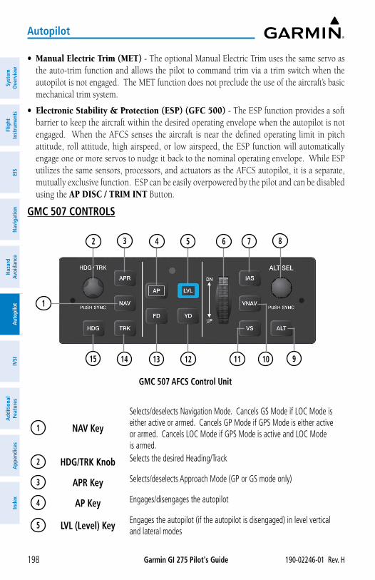
Garmin GI 275 Pilot's Guide 190-02246-01 Rev. H198
Autopilot
Syst
em
Ove
rvie
wFl
ight
In
stru
men
tsEI
SN
avig
atio
nH
azar
d Av
oida
nce
Aut
opilo
tIV
SIA
dditi
onal
Fe
atur
esA
ppen
dice
sIn
dex
• Manual Electric Trim (MET) - The optional Manual Electric Trim uses the same servo as the auto-trim function and allows the pilot to command trim via a trim switch when the autopilot is not engaged. The MET function does not preclude the use of the aircraft’s basic mechanical trim system.
• Electronic Stability & Protection (ESP) (GFC 500) - The ESP function provides a soft barrier to keep the aircraft within the desired operating envelope when the autopilot is not engaged. When the AFCS senses the aircraft is near the defined operating limit in pitch attitude, roll attitude, high airspeed, or low airspeed, the ESP function will automatically engage one or more servos to nudge it back to the nominal operating envelope. While ESP utilizes the same sensors, processors, and actuators as the AFCS autopilot, it is a separate, mutually exclusive function. ESP can be easily overpowered by the pilot and can be disabled using the AP DISC / TRIM INT Button.
GMC 507 CONTROLS
13 12
3 4 5
14
7
10 9
1
11
6 82
15
GMC 507 AFCS Control Unit
1 NAV Key
Selects/deselects Navigation Mode. Cancels GS Mode if LOC Mode is either active or armed. Cancels GP Mode if GPS Mode is either active or armed. Cancels LOC Mode if GPS Mode is active and LOC Mode is armed.
2 HDG/TRK Knob Selects the desired Heading/Track
3 APR Key Selects/deselects Approach Mode (GP or GS mode only)
4 AP Key Engages/disengages the autopilot
5 LVL (Level) Key Engages the autopilot (if the autopilot is disengaged) in level vertical and lateral modes
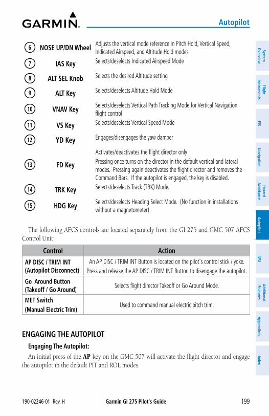
Garmin GI 275 Pilot's Guide190-02246-01 Rev. H 199
Autopilot
System
Overview
Flight Instrum
entsEIS
Navigation
Hazard
AvoidanceA
utopilotIVSI
Additional Features
Appendices
Index
6 NOSE UP/DN Wheel Adjusts the vertical mode reference in Pitch Hold, Vertical Speed, Indicated Airspeed, and Altitude Hold modes
7 IAS Key Selects/deselects Indicated Airspeed Mode
8 ALT SEL Knob Selects the desired Altitude setting
9 ALT Key Selects/deselects Altitude Hold Mode
10 VNAV Key Selects/deselects Vertical Path Tracking Mode for Vertical Navigation flight control
11 VS Key Selects/deselects Vertical Speed Mode
12 YD Key Engages/disengages the yaw damper
13 FD Key
Activates/deactivates the flight director onlyPressing once turns on the director in the default vertical and lateral modes. Pressing again deactivates the flight director and removes the Command Bars. If the autopilot is engaged, the key is disabled.
14 TRK Key Selects/deselects Track (TRK) Mode.
15 HDG Key Selects/deselects Heading Select Mode. (No function in installations without a magnetometer)
The following AFCS controls are located separately from the GI 275 and GMC 507 AFCS Control Unit:
Control Action
AP DISC / TRIM INT (Autopilot Disconnect)
An AP DISC / TRIM INT Button is located on the pilot's control stick / yoke. Press and release the AP DISC / TRIM INT Button to disengage the autopilot.
Go Around Button (Takeoff / Go Around)
Selects flight director Takeoff or Go Around Mode.
MET Switch (Manual Electric Trim)
Used to command manual electric pitch trim.
ENGAGING THE AUTOPILOTEngaging The Autopilot:An initial press of the AP key on the GMC 507 will activate the flight director and engage
the autopilot in the default PIT and ROL modes.
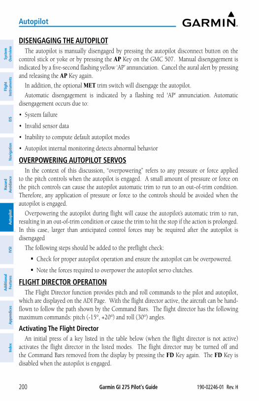
Garmin GI 275 Pilot's Guide 190-02246-01 Rev. H200
Autopilot
Syst
em
Ove
rvie
wFl
ight
In
stru
men
tsEI
SN
avig
atio
nH
azar
d Av
oida
nce
Aut
opilo
tIV
SIA
dditi
onal
Fe
atur
esA
ppen
dice
sIn
dex
DISENGAGING THE AUTOPILOTThe autopilot is manually disengaged by pressing the autopilot disconnect button on the
control stick or yoke or by pressing the AP Key on the GMC 507. Manual disengagement is indicated by a five-second flashing yellow ‘AP’ annunciation. Cancel the aural alert by pressing and releasing the AP Key again.
In addition, the optional MET trim switch will disengage the autopilot.
Automatic disengagement is indicated by a flashing red 'AP' annunciation. Automatic disengagement occurs due to:
• System failure
• Invalid sensor data
• Inability to compute default autopilot modes
• Autopilot internal monitoring detects abnormal behavior
OVERPOWERING AUTOPILOT SERVOSIn the context of this discussion, “overpowering” refers to any pressure or force applied
to the pitch controls when the autopilot is engaged. A small amount of pressure or force on the pitch controls can cause the autopilot automatic trim to run to an out-of-trim condition. Therefore, any application of pressure or force to the controls should be avoided when the autopilot is engaged.
Overpowering the autopilot during flight will cause the autopilot’s automatic trim to run, resulting in an out-of-trim condition or cause the trim to hit the stop if the action is prolonged. In this case, larger than anticipated control forces may be required after the autopilot is disengaged
The following steps should be added to the preflight check:
� Check for proper autopilot operation and ensure the autopilot can be overpowered.
� Note the forces required to overpower the autopilot servo clutches.
FLIGHT DIRECTOR OPERATIONThe Flight Director function provides pitch and roll commands to the pilot and autopilot,
which are displayed on the ADI Page. With the flight director active, the aircraft can be hand-flown to follow the path shown by the Command Bars. The flight director has the following maximum commands: pitch (-15°, +20°) and roll (30°) angles.
Activating The Flight DirectorAn initial press of a key listed in the table below (when the flight director is not active)
activates the flight director in the listed modes. The flight director may be turned off and the Command Bars removed from the display by pressing the FD Key again. The FD Key is disabled when the autopilot is engaged.
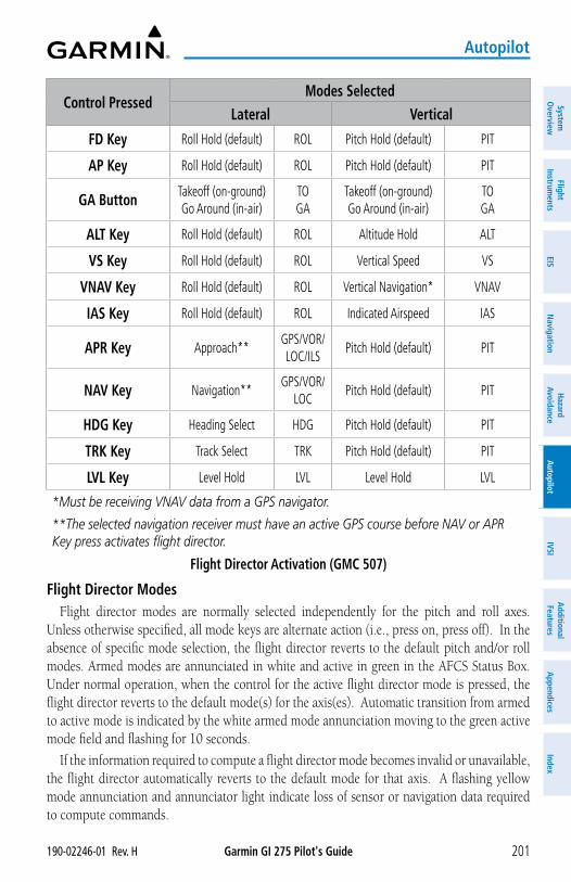
Garmin GI 275 Pilot's Guide190-02246-01 Rev. H 201
Autopilot
System
Overview
Flight Instrum
entsEIS
Navigation
Hazard
AvoidanceA
utopilotIVSI
Additional Features
Appendices
Index
Control PressedModes Selected
Lateral Vertical
FD Key Roll Hold (default) ROL Pitch Hold (default) PIT
AP Key Roll Hold (default) ROL Pitch Hold (default) PIT
GA Button Takeoff (on-ground) Go Around (in-air)
TO GA
Takeoff (on-ground) Go Around (in-air)
TO GA
ALT Key Roll Hold (default) ROL Altitude Hold ALT
VS Key Roll Hold (default) ROL Vertical Speed VS
VNAV Key Roll Hold (default) ROL Vertical Navigation* VNAV
IAS Key Roll Hold (default) ROL Indicated Airspeed IAS
APR Key Approach**GPS/VOR/LOC/ILS
Pitch Hold (default) PIT
NAV Key Navigation**GPS/VOR/
LOCPitch Hold (default) PIT
HDG Key Heading Select HDG Pitch Hold (default) PIT
TRK Key Track Select TRK Pitch Hold (default) PIT
LVL Key Level Hold LVL Level Hold LVL
*Must be receiving VNAV data from a GPS navigator.
**The selected navigation receiver must have an active GPS course before NAV or APR Key press activates flight director.
Flight Director Activation (GMC 507)
Flight Director ModesFlight director modes are normally selected independently for the pitch and roll axes.
Unless otherwise specified, all mode keys are alternate action (i.e., press on, press off). In the absence of specific mode selection, the flight director reverts to the default pitch and/or roll modes. Armed modes are annunciated in white and active in green in the AFCS Status Box. Under normal operation, when the control for the active flight director mode is pressed, the flight director reverts to the default mode(s) for the axis(es). Automatic transition from armed to active mode is indicated by the white armed mode annunciation moving to the green active mode field and flashing for 10 seconds.
If the information required to compute a flight director mode becomes invalid or unavailable, the flight director automatically reverts to the default mode for that axis. A flashing yellow mode annunciation and annunciator light indicate loss of sensor or navigation data required to compute commands.
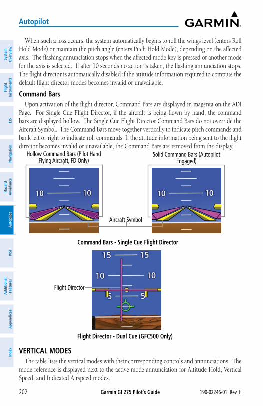
Garmin GI 275 Pilot's Guide 190-02246-01 Rev. H202
Autopilot
Syst
em
Ove
rvie
wFl
ight
In
stru
men
tsEI
SN
avig
atio
nH
azar
d Av
oida
nce
Aut
opilo
tIV
SIA
dditi
onal
Fe
atur
esA
ppen
dice
sIn
dex
When such a loss occurs, the system automatically begins to roll the wings level (enters Roll Hold Mode) or maintain the pitch angle (enters Pitch Hold Mode), depending on the affected axis. The flashing annunciation stops when the affected mode key is pressed or another mode for the axis is selected. If after 10 seconds no action is taken, the flashing annunciation stops. The flight director is automatically disabled if the attitude information required to compute the default flight director modes becomes invalid or unavailable.
Command BarsUpon activation of the flight director, Command Bars are displayed in magenta on the ADI
Page. For Single Cue Flight Director, if the aircraft is being flown by hand, the command bars are displayed hollow. The Single Cue Flight Director Command Bars do not override the Aircraft Symbol. The Command Bars move together vertically to indicate pitch commands and bank left or right to indicate roll commands. If the attitude information being sent to the flight director becomes invalid or unavailable, the Command Bars are removed from the display.
Hollow Command Bars (Pilot Hand Flying Aircraft, FD Only)
Solid Command Bars (Autopilot Engaged)
Command Bars - Single Cue Flight Director
Flight Director - Dual Cue (GFC500 Only)
Aircraft Symbol
Flight Director
VERTICAL MODESThe table lists the vertical modes with their corresponding controls and annunciations. The
mode reference is displayed next to the active mode annunciation for Altitude Hold, Vertical Speed, and Indicated Airspeed modes.
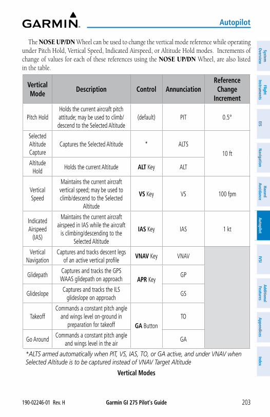
Garmin GI 275 Pilot's Guide190-02246-01 Rev. H 203
Autopilot
System
Overview
Flight Instrum
entsEIS
Navigation
Hazard
AvoidanceA
utopilotIVSI
Additional Features
Appendices
Index
The NOSE UP/DN Wheel can be used to change the vertical mode reference while operating under Pitch Hold, Vertical Speed, Indicated Airspeed, or Altitude Hold modes. Increments of change of values for each of these references using the NOSE UP/DN Wheel, are also listed in the table.
Vertical Mode
Description Control AnnunciationReference
Change Increment
Pitch HoldHolds the current aircraft pitch attitude; may be used to climb/descend to the Selected Altitude
(default) PIT 0.5°
Selected Altitude Capture
Captures the Selected Altitude * ALTS10 ft
Altitude Hold
Holds the current Altitude ALT Key ALT
Vertical Speed
Maintains the current aircraft vertical speed; may be used to climb/descend to the Selected
Altitude
VS Key VS 100 fpm
Indicated Airspeed
(IAS)
Maintains the current aircraft airspeed in IAS while the aircraft
is climbing/descending to the Selected Altitude
IAS Key IAS 1 kt
Vertical Navigation
Captures and tracks descent legs of an active vertical profile
VNAV Key VNAV
GlidepathCaptures and tracks the GPS WAAS glidepath on approach APR Key
GP
GlideslopeCaptures and tracks the ILS
glideslope on approachGS
TakeoffCommands a constant pitch angle
and wings level on-ground in preparation for takeoff GA Button
TO
Go AroundCommands a constant pitch angle
and wings level in the airGA
*ALTS armed automatically when PIT, VS, IAS, TO, or GA active, and under VNAV when Selected Altitude is to be captured instead of VNAV Target Altitude
Vertical Modes
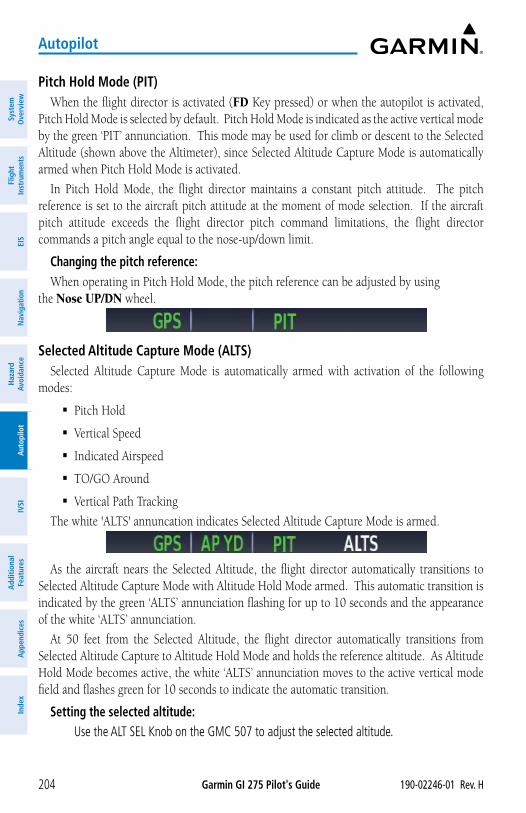
Garmin GI 275 Pilot's Guide 190-02246-01 Rev. H204
Autopilot
Syst
em
Ove
rvie
wFl
ight
In
stru
men
tsEI
SN
avig
atio
nH
azar
d Av
oida
nce
Aut
opilo
tIV
SIA
dditi
onal
Fe
atur
esA
ppen
dice
sIn
dex
Pitch Hold Mode (PIT)When the flight director is activated (FD Key pressed) or when the autopilot is activated,
Pitch Hold Mode is selected by default. Pitch Hold Mode is indicated as the active vertical mode by the green ‘PIT’ annunciation. This mode may be used for climb or descent to the Selected Altitude (shown above the Altimeter), since Selected Altitude Capture Mode is automatically armed when Pitch Hold Mode is activated.
In Pitch Hold Mode, the flight director maintains a constant pitch attitude. The pitch reference is set to the aircraft pitch attitude at the moment of mode selection. If the aircraft pitch attitude exceeds the flight director pitch command limitations, the flight director commands a pitch angle equal to the nose-up/down limit.
Changing the pitch reference:When operating in Pitch Hold Mode, the pitch reference can be adjusted by using
the Nose UP/DN wheel.
Selected Altitude Capture Mode (ALTS)Selected Altitude Capture Mode is automatically armed with activation of the following
modes:
� Pitch Hold
� Vertical Speed
� Indicated Airspeed
� TO/GO Around
� Vertical Path Tracking
The white 'ALTS' annuncation indicates Selected Altitude Capture Mode is armed.
As the aircraft nears the Selected Altitude, the flight director automatically transitions to Selected Altitude Capture Mode with Altitude Hold Mode armed. This automatic transition is indicated by the green ‘ALTS’ annunciation flashing for up to 10 seconds and the appearance of the white ‘ALTS’ annunciation.
At 50 feet from the Selected Altitude, the flight director automatically transitions from Selected Altitude Capture to Altitude Hold Mode and holds the reference altitude. As Altitude Hold Mode becomes active, the white ‘ALTS’ annunciation moves to the active vertical mode field and flashes green for 10 seconds to indicate the automatic transition.
Setting the selected altitude: Use the ALT SEL Knob on the GMC 507 to adjust the selected altitude.
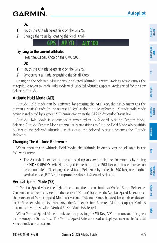
Garmin GI 275 Pilot's Guide190-02246-01 Rev. H 205
Autopilot
System
Overview
Flight Instrum
entsEIS
Navigation
Hazard
AvoidanceA
utopilotIVSI
Additional Features
Appendices
Index
Or:1) Touch the Altitude Select field on the GI 275. 2) Change the value by rotating the Small Knob.
Syncing to the current altitude: Press the ALT SeL Knob on the GMC 507. Or:1) Touch the Altitude Select field on the GI 275.2) Sync current altitude by pushing the Small Knob. Changing the Selected Altitude while Selected Altitude Capture Mode is active causes the
autopilot to revert to Pitch Hold Mode with Selected Altitude Capture Mode armed for the new Selected Altitude.
Altitude Hold Mode (ALT)Altitude Hold Mode can be activated by pressing the ALT Key; the AFCS maintains the
current aircraft altitude (to the nearest 10 feet) as the Altitude Reference. Altitude Hold Mode active is indicated by a green ‘ALT’ annunciation in the GI 275 Autopilot Status Box.
Altitude Hold Mode is automatically armed when in Selected Altitude Capture Mode. Selected Altitude Capture Mode automatically transitions to Altitude Hold Mode when within 50 feet of the Selected Altitude. In this case, the Selected Altitude becomes the Altitude Reference.
Changing The Altitude ReferenceWhen operating in Altitude Hold Mode, the Altitude Reference can be adjusted in the
following ways:
� The Altitude Reference can be adjusted up or down in 10-foot increments by rolling the NOSE UP/DN Wheel. Using this method, up to 200 feet of altitude change can be commanded. To change the Altitude Reference by more the 200 feet, use another vertical mode (PIT, VS) to capture the desired Selected Altitude.
Vertical Speed Mode (VS)In Vertical Speed Mode, the flight director acquires and maintains a Vertical Speed Reference.
Current aircraft vertical speed (to the nearest 100 fpm) becomes the Vertical Speed Reference at the moment of Vertical Speed Mode activation. This mode may be used for climb or descent to the Selected Altitude (shown above the Altimeter) since Selected Altitude Capture Mode is automatically armed when Vertical Speed Mode is selected.
When Vertical Speed Mode is activated by pressing the VS Key, ‘VS’ is annunciated in green in the Autopilot Status Box. The Vertical Speed Reference is also displayed next to the Vertical Speed mode annunciation.
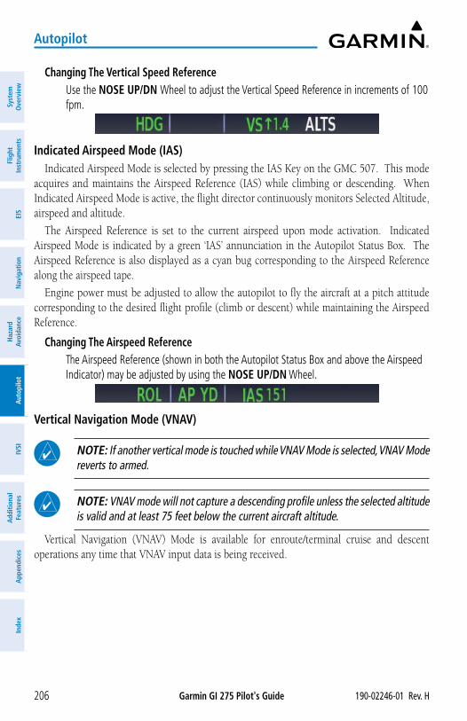
Garmin GI 275 Pilot's Guide 190-02246-01 Rev. H206
Autopilot
Syst
em
Ove
rvie
wFl
ight
In
stru
men
tsEI
SN
avig
atio
nH
azar
d Av
oida
nce
Aut
opilo
tIV
SIA
dditi
onal
Fe
atur
esA
ppen
dice
sIn
dex
Changing The Vertical Speed Reference Use the NOSE UP/DN Wheel to adjust the Vertical Speed Reference in increments of 100
fpm.
Indicated Airspeed Mode (IAS)Indicated Airspeed Mode is selected by pressing the IAS Key on the GMC 507. This mode
acquires and maintains the Airspeed Reference (IAS) while climbing or descending. When Indicated Airspeed Mode is active, the flight director continuously monitors Selected Altitude, airspeed and altitude.
The Airspeed Reference is set to the current airspeed upon mode activation. Indicated Airspeed Mode is indicated by a green ‘IAS’ annunciation in the Autopilot Status Box. The Airspeed Reference is also displayed as a cyan bug corresponding to the Airspeed Reference along the airspeed tape.
Engine power must be adjusted to allow the autopilot to fly the aircraft at a pitch attitude corresponding to the desired flight profile (climb or descent) while maintaining the Airspeed Reference.
Changing The Airspeed Reference The Airspeed Reference (shown in both the Autopilot Status Box and above the Airspeed
Indicator) may be adjusted by using the NOSE UP/DN Wheel.
Vertical Navigation Mode (VNAV)
NOTE: If another vertical mode is touched while VNAV Mode is selected, VNAV Mode reverts to armed.
NOTE: VNAV mode will not capture a descending profile unless the selected altitude is valid and at least 75 feet below the current aircraft altitude.
Vertical Navigation (VNAV) Mode is available for enroute/terminal cruise and descent operations any time that VNAV input data is being received.
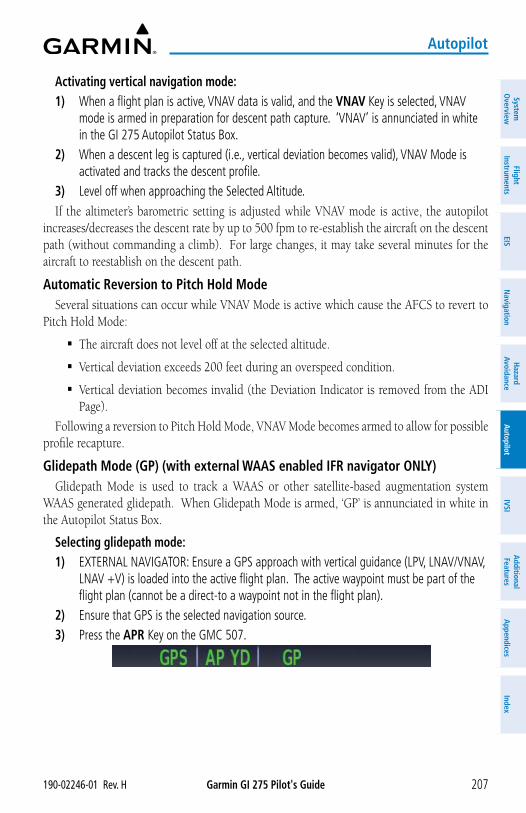
Garmin GI 275 Pilot's Guide190-02246-01 Rev. H 207
Autopilot
System
Overview
Flight Instrum
entsEIS
Navigation
Hazard
AvoidanceA
utopilotIVSI
Additional Features
Appendices
Index
Activating vertical navigation mode:1) When a flight plan is active, VNAV data is valid, and the VNAV Key is selected, VNAV
mode is armed in preparation for descent path capture. ‘VNAV’ is annunciated in white in the GI 275 Autopilot Status Box.
2) When a descent leg is captured (i.e., vertical deviation becomes valid), VNAV Mode is activated and tracks the descent profile.
3) Level off when approaching the Selected Altitude.If the altimeter’s barometric setting is adjusted while VNAV mode is active, the autopilot
increases/decreases the descent rate by up to 500 fpm to re-establish the aircraft on the descent path (without commanding a climb). For large changes, it may take several minutes for the aircraft to reestablish on the descent path.
Automatic Reversion to Pitch Hold ModeSeveral situations can occur while VNAV Mode is active which cause the AFCS to revert to
Pitch Hold Mode:
� The aircraft does not level off at the selected altitude.
� Vertical deviation exceeds 200 feet during an overspeed condition.
� Vertical deviation becomes invalid (the Deviation Indicator is removed from the ADI Page).
Following a reversion to Pitch Hold Mode, VNAV Mode becomes armed to allow for possible profile recapture.
Glidepath Mode (GP) (with external WAAS enabled IFR navigator ONLY)Glidepath Mode is used to track a WAAS or other satellite-based augmentation system
WAAS generated glidepath. When Glidepath Mode is armed, ‘GP’ is annunciated in white in the Autopilot Status Box.
Selecting glidepath mode:1) EXTERNAL NAVIGATOR: Ensure a GPS approach with vertical guidance (LPV, LNAV/VNAV,
LNAV +V) is loaded into the active flight plan. The active waypoint must be part of the flight plan (cannot be a direct-to a waypoint not in the flight plan).
2) Ensure that GPS is the selected navigation source.3) Press the APR Key on the GMC 507.
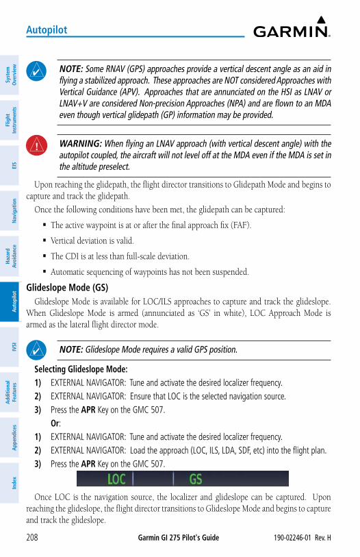
Garmin GI 275 Pilot's Guide 190-02246-01 Rev. H208
Autopilot
Syst
em
Ove
rvie
wFl
ight
In
stru
men
tsEI
SN
avig
atio
nH
azar
d Av
oida
nce
Aut
opilo
tIV
SIA
dditi
onal
Fe
atur
esA
ppen
dice
sIn
dex
NOTE: Some RNAV (GPS) approaches provide a vertical descent angle as an aid in flying a stabilized approach. These approaches are NOT considered Approaches with Vertical Guidance (APV). Approaches that are annunciated on the HSI as LNAV or LNAV+V are considered Non-precision Approaches (NPA) and are flown to an MDA even though vertical glidepath (GP) information may be provided.
WARNING: When flying an LNAV approach (with vertical descent angle) with the autopilot coupled, the aircraft will not level off at the MDA even if the MDA is set in the altitude preselect.
Upon reaching the glidepath, the flight director transitions to Glidepath Mode and begins to capture and track the glidepath.
Once the following conditions have been met, the glidepath can be captured:
� The active waypoint is at or after the final approach fix (FAF).
� Vertical deviation is valid.
� The CDI is at less than full-scale deviation.
� Automatic sequencing of waypoints has not been suspended.
Glideslope Mode (GS)Glideslope Mode is available for LOC/ILS approaches to capture and track the glideslope.
When Glideslope Mode is armed (annunciated as ‘GS’ in white), LOC Approach Mode is armed as the lateral flight director mode.
NOTE: Glideslope Mode requires a valid GPS position.
Selecting Glideslope Mode:1) EXTERNAL NAVIGATOR: Tune and activate the desired localizer frequency.2) EXTERNAL NAVIGATOR: Ensure that LOC is the selected navigation source.3) Press the APR Key on the GMC 507. Or:1) EXTERNAL NAVIGATOR: Tune and activate the desired localizer frequency.2) EXTERNAL NAVIGATOR: Load the approach (LOC, ILS, LDA, SDF, etc) into the flight plan.3) Press the APR Key on the GMC 507.
Once LOC is the navigation source, the localizer and glideslope can be captured. Upon reaching the glideslope, the flight director transitions to Glideslope Mode and begins to capture and track the glideslope.
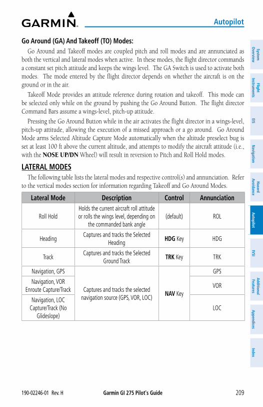
Garmin GI 275 Pilot's Guide190-02246-01 Rev. H 209
Autopilot
System
Overview
Flight Instrum
entsEIS
Navigation
Hazard
AvoidanceA
utopilotIVSI
Additional Features
Appendices
Index
Go Around (GA) And Takeoff (TO) Modes:Go Around and Takeoff modes are coupled pitch and roll modes and are annunciated as
both the vertical and lateral modes when active. In these modes, the flight director commands a constant set pitch attitude and keeps the wings level. The GA Switch is used to activate both modes. The mode entered by the flight director depends on whether the aircraft is on the ground or in the air.
Takeoff Mode provides an attitude reference during rotation and takeoff. This mode can be selected only while on the ground by pushing the Go Around Button. The flight director Command Bars assume a wings-level, pitch-up attitude.
Pressing the Go Around Button while in the air activates the flight director in a wings-level, pitch-up attitude, allowing the execution of a missed approach or a go around. Go Around Mode arms Selected Altitude Capture Mode automatically when the altitude preselect bug is set at least 100 ft above the current altitude, and attempts to modify the aircraft attitude (i.e., with the NOSE UP/DN Wheel) will result in reversion to Pitch and Roll Hold modes.
LATERAL MODESThe following table lists the lateral modes and respective control(s) and annunciation. Refer
to the vertical modes section for information regarding Takeoff and Go Around Modes.
Lateral Mode Description Control Annunciation
Roll HoldHolds the current aircraft roll attitude or rolls the wings level, depending on
the commanded bank angle(default) ROL
HeadingCaptures and tracks the Selected
HeadingHDG Key HDG
TrackCaptures and tracks the Selected
Ground TrackTRK Key TRK
Navigation, GPS
Captures and tracks the selected navigation source (GPS, VOR, LOC)
NAV Key
GPS
Navigation, VOR Enroute Capture/Track
VOR
Navigation, LOC Capture/Track (No
Glideslope)LOC
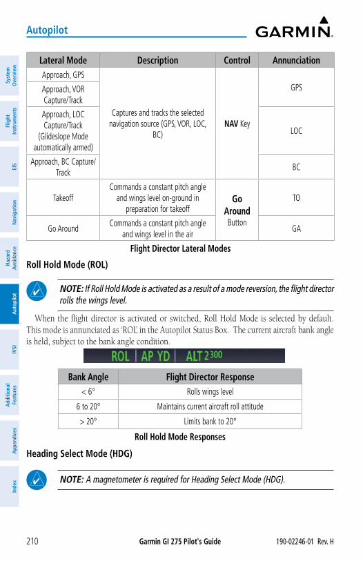
Garmin GI 275 Pilot's Guide 190-02246-01 Rev. H210
Autopilot
Syst
em
Ove
rvie
wFl
ight
In
stru
men
tsEI
SN
avig
atio
nH
azar
d Av
oida
nce
Aut
opilo
tIV
SIA
dditi
onal
Fe
atur
esA
ppen
dice
sIn
dex
Lateral Mode Description Control AnnunciationApproach, GPS
Captures and tracks the selected navigation source (GPS, VOR, LOC,
BC)NAV Key
GPSApproach, VOR Capture/Track
Approach, LOC Capture/Track
(Glideslope Mode automatically armed)
LOC
Approach, BC Capture/Track
BC
TakeoffCommands a constant pitch angle
and wings level on-ground in preparation for takeoff
Go Around Button
TO
Go AroundCommands a constant pitch angle
and wings level in the airGA
Flight Director Lateral Modes
Roll Hold Mode (ROL)
NOTE: If Roll Hold Mode is activated as a result of a mode reversion, the flight director rolls the wings level.
When the flight director is activated or switched, Roll Hold Mode is selected by default. This mode is annunciated as ‘ROL’ in the Autopilot Status Box. The current aircraft bank angle is held, subject to the bank angle condition.
Bank Angle Flight Director Response< 6° Rolls wings level
6 to 20° Maintains current aircraft roll attitude
> 20° Limits bank to 20°
Roll Hold Mode Responses
Heading Select Mode (HDG)
NOTE: A magnetometer is required for Heading Select Mode (HDG).
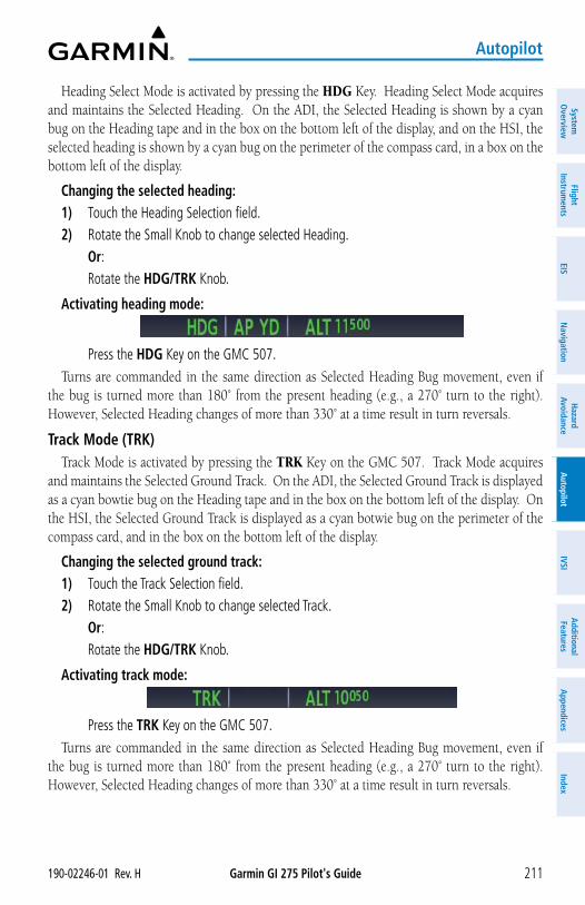
Garmin GI 275 Pilot's Guide190-02246-01 Rev. H 211
Autopilot
System
Overview
Flight Instrum
entsEIS
Navigation
Hazard
AvoidanceA
utopilotIVSI
Additional Features
Appendices
Index
Heading Select Mode is activated by pressing the HDG Key. Heading Select Mode acquires and maintains the Selected Heading. On the ADI, the Selected Heading is shown by a cyan bug on the Heading tape and in the box on the bottom left of the display, and on the HSI, the selected heading is shown by a cyan bug on the perimeter of the compass card, in a box on the bottom left of the display.
Changing the selected heading:1) Touch the Heading Selection field.2) Rotate the Small Knob to change selected Heading. Or: Rotate the HDG/TRK Knob.
Activating heading mode:
Press the HDG Key on the GMC 507. Turns are commanded in the same direction as Selected Heading Bug movement, even if
the bug is turned more than 180˚ from the present heading (e.g., a 270˚ turn to the right). However, Selected Heading changes of more than 330˚ at a time result in turn reversals.
Track Mode (TRK)Track Mode is activated by pressing the TRK Key on the GMC 507. Track Mode acquires
and maintains the Selected Ground Track. On the ADI, the Selected Ground Track is displayed as a cyan bowtie bug on the Heading tape and in the box on the bottom left of the display. On the HSI, the Selected Ground Track is displayed as a cyan botwie bug on the perimeter of the compass card, and in the box on the bottom left of the display.
Changing the selected ground track:1) Touch the Track Selection field.2) Rotate the Small Knob to change selected Track. Or: Rotate the HDG/TRK Knob.
Activating track mode:
Press the TRK Key on the GMC 507.Turns are commanded in the same direction as Selected Heading Bug movement, even if
the bug is turned more than 180˚ from the present heading (e.g., a 270˚ turn to the right). However, Selected Heading changes of more than 330˚ at a time result in turn reversals.
Garmin GI 275 Pilot's Guide 190-02246-01 Rev. H212
Autopilot
Syst
em
Ove
rvie
wFl
ight
In
stru
men
tsEI
SN
avig
atio
nH
azar
d Av
oida
nce
Aut
opilo
tIV
SIA
dditi
onal
Fe
atur
esA
ppen
dice
sIn
dex
Navigation Mode (GPS, VOR, LOC)
NOTE: The GI 275 must have a valid GPS position for VOR and LOC Modes.
NOTE: Dual navigators are supported for the GFC 500.
NOTE: When intercepting a flight plan leg, the flight director gives commands to capture the active leg at approximately a 45° angle to the track between the waypoints defining the active leg. The flight director does not give commands fly to the starting waypoint of the active leg.
Pressing the NAV Key selects Navigation Mode. Navigation Mode acquires and tracks the navigation source. The flight director follows GPS roll steering commands when GPS is the navigation source. Navigation Mode can also be used to fly non-precision GPS, VOR, and LOC approaches where vertical guidance is not required.
If the Course Deviation Indicator (CDI) shows greater than one dot when the NAV Key is pressed, the selected mode is armed. If the CDI is less than one dot, Navigation Mode is automatically captured when the NAV Key is pressed. The armed annunciation appears in white to the left of the active roll mode.
If Navigation Mode is active and any of the following occur, the AFCS reverts to Roll Hold Mode (wings rolled level):
� Active navigation source manually switched
� Navigation input is lost
� GPS reception is lost
Approaches Without Vertical Guidance
NOTE: The selected navigation receiver must have an active GPS course for the flight director to enter Approach Mode.
Press the NAV Key to arm/activate GPS (LNAV only) lateral mode. The lateral mode acquires and tracks the selected navigation source, depending on the loaded approach. Press NAV when the CDI is greater than one dot to arm the selected mode (annunciated in white). Press NAV when the CDI deviation is less than one dot to activate, capture and track the selected navigation source.
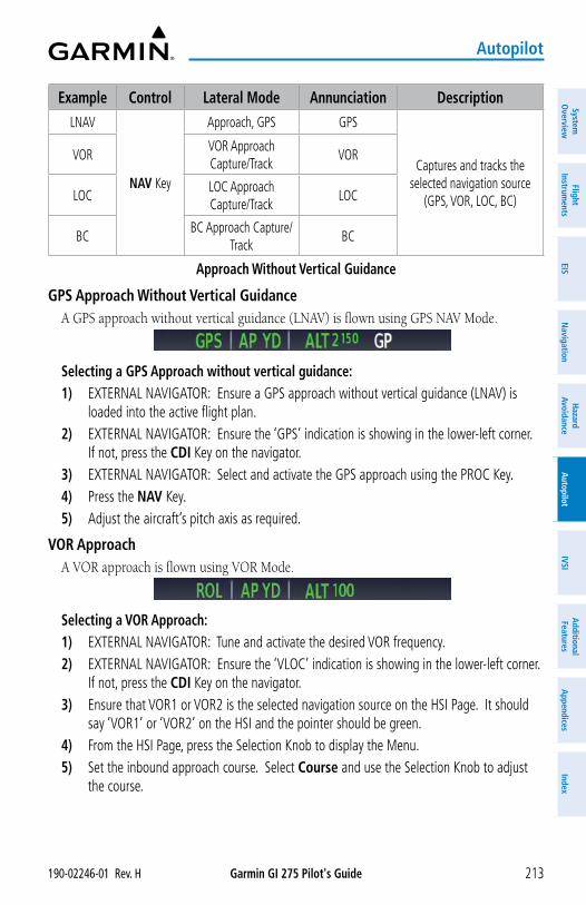
Garmin GI 275 Pilot's Guide190-02246-01 Rev. H 213
Autopilot
System
Overview
Flight Instrum
entsEIS
Navigation
Hazard
AvoidanceA
utopilotIVSI
Additional Features
Appendices
Index
Example Control Lateral Mode Annunciation DescriptionLNAV
NAV Key
Approach, GPS GPS
Captures and tracks the selected navigation source
(GPS, VOR, LOC, BC)
VORVOR Approach Capture/Track
VOR
LOCLOC Approach Capture/Track
LOC
BCBC Approach Capture/
TrackBC
Approach Without Vertical Guidance
GPS Approach Without Vertical GuidanceA GPS approach without vertical guidance (LNAV) is flown using GPS NAV Mode.
Selecting a GPS Approach without vertical guidance:1) EXTERNAL NAVIGATOR: Ensure a GPS approach without vertical guidance (LNAV) is
loaded into the active flight plan.2) EXTERNAL NAVIGATOR: Ensure the ‘GPS’ indication is showing in the lower-left corner.
If not, press the CDI Key on the navigator.3) EXTERNAL NAVIGATOR: Select and activate the GPS approach using the PROC Key.4) Press the NAV Key.5) Adjust the aircraft’s pitch axis as required.
VOR ApproachA VOR approach is flown using VOR Mode.
Selecting a VOR Approach:1) EXTERNAL NAVIGATOR: Tune and activate the desired VOR frequency.2) EXTERNAL NAVIGATOR: Ensure the ‘VLOC’ indication is showing in the lower-left corner.
If not, press the CDI Key on the navigator.3) Ensure that VOR1 or VOR2 is the selected navigation source on the HSI Page. It should
say ‘VOR1’ or ‘VOR2’ on the HSI and the pointer should be green.4) From the HSI Page, press the Selection Knob to display the Menu.5) Set the inbound approach course. Select Course and use the Selection Knob to adjust
the course.
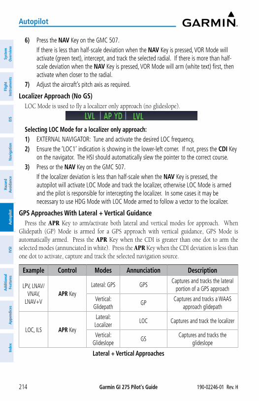
Garmin GI 275 Pilot's Guide 190-02246-01 Rev. H214
Autopilot
Syst
em
Ove
rvie
wFl
ight
In
stru
men
tsEI
SN
avig
atio
nH
azar
d Av
oida
nce
Aut
opilo
tIV
SIA
dditi
onal
Fe
atur
esA
ppen
dice
sIn
dex
6) Press the NAV Key on the GMC 507. If there is less than half-scale deviation when the NAV Key is pressed, VOR Mode will
activate (green text), intercept, and track the selected radial. If there is more than half-scale deviation when the NAV Key is pressed, VOR Mode will arm (white text) first, then activate when closer to the radial.
7) Adjust the aircraft’s pitch axis as required.
Localizer Approach (No GS)LOC Mode is used to fly a localizer only approach (no glideslope).
Selecting LOC Mode for a localizer only approach:1) EXTERNAL NAVIGATOR: Tune and activate the desired LOC frequency,2) Ensure the ‘LOC1’ indication is showing in the lower-left corner. If not, press the CDI Key
on the navigator. The HSI should automatically slew the pointer to the correct course.3) Press or the NAV Key on the GMC 507. If the localizer deviation is less than half-scale when the NAV Key is pressed, the
autopilot will activate LOC Mode and track the localizer, otherwise LOC Mode is armed and the pilot is responsible for intercepting the localizer. In some cases it may be necessary to use HDG Mode with LOC Mode armed to follow a vector to the localizer.
GPS Approaches With Lateral + Vertical GuidancePress the APR Key to arm/activate both lateral and vertical modes for approach. When
Glidepath (GP) Mode is armed for a GPS approach with vertical guidance, GPS Mode is automatically armed. Press the APR Key when the CDI is greater than one dot to arm the selected modes (annunciated in white). Press the APR Key when the CDI deviation is less than one dot to activate, capture and track the selected navigation source.
Example Control Modes Annunciation Description
LPV, LNAV/VNAV,
LNAV+VAPR Key
Lateral: GPS GPSCaptures and tracks the lateral
portion of a GPS approach
Vertical: Glidepath
GPCaptures and tracks a WAAS
approach glidepath
LOC, ILS APR Key
Lateral: Localizer
LOC Captures and track the localizer
Vertical: Glideslope
GSCaptures and tracks the
glideslope
Lateral + Vertical Approaches
Garmin GI 275 Pilot's Guide190-02246-01 Rev. H 215
Autopilot
System
Overview
Flight Instrum
entsEIS
Navigation
Hazard
AvoidanceA
utopilotIVSI
Additional Features
Appendices
Index
GPS Approach with Vertical Guidance
NOTE: To cancel Glidepath (GP) Mode without cancelling GPS Mode, press NAV once. Pressing it a second time cancels GPS Mode.
When Glidepath (GP) Mode is armed for a GPS approach with vertical guidance, GPS Mode is automatically armed.
Selecting a GPS approach with vertical guidance:1) EXTERNAL NAVIGATOR: Ensure a GPS approach with vertical guidance (LPV, LNAV/VNAV,
LNAV+V) is loaded into the active flight plan.2) EXTERNAL NAVIGATOR: Ensure the ‘GPS’ indication is showing in the lower-left corner.
If not, press the CDI Key.3) EXTERNAL NAVIGATOR: Select and activate the GPS approach using the PROC Key.4) Press the APR Key.
Localizer with GlideslopeLOC Mode (lateral) and GS Mode (vertical) are both armed by pressing the APR Key on the
GMC 507. LOC/ILS approach captures are inhibited if the difference between aircraft heading and localizer course exceeds 105˚.
NOTE: To cancel Glideslope (GS) Mode without cancelling LOC Mode, press NAV once. Pressing it a second time cancels LOC Mode.
Selecting LOC Mode with GS Mode:1) EXTERNAL NAVIGATOR: Tune and activate the desired LOC frequency.2) EXTERNAL NAVIGATOR: Ensure the ‘LOC1’ indication is showing in the lower-left corner.
If not, press the CDI Key. The HSI should automatically slew the pointer to the correct course.
3) Press the APR Key on the GMC 507. This simultaneously selects LOC Mode and GS (Glideslope) Mode. If the localizer deviation
is less than half-scale when the APR Key is pressed, the autopilot will activate LOC Mode and track the localizer, otherwise LOC Mode is armed and the pilot is responsible for intercepting the localizer.
If the following occurs, the autopilot reverts to Roll Hold Mode (wings rolled level):
� Approach Mode is active and the Navigation source is manually switched
� The localizer signal is lost
If the Glideslope signal is lost , GS Mode will revert to Pitch Hold Mode and hold the last pitch attitude.
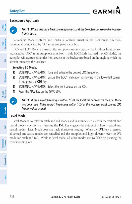
Garmin GI 275 Pilot's Guide 190-02246-01 Rev. H216
Autopilot
Syst
em
Ove
rvie
wFl
ight
In
stru
men
tsEI
SN
avig
atio
nH
azar
d Av
oida
nce
Aut
opilo
tIV
SIA
dditi
onal
Fe
atur
esA
ppen
dice
sIn
dex
Backcourse Approach
NOTE: When making a backcourse approach, set the Selected Course to the localizer front course.
Backcourse Mode captures and tracks a localizer signal in the backcourse direction. Backcourse is indicated by ‘BC’ in the autopilot status box.
If GS and LOC Mode are armed, the autopilot can only capture the localizer front course, indicated by ‘LOC’ in the autopilot status box. If only LOC Mode is armed (not GS Mode), the autopilot will capture either the front course or the backcourse based on the angle at which the aircraft intercepts the localizer.
Selecting BC Mode:1) EXTERNAL NAVIGATOR: Tune and activate the desired LOC frequency.2) EXTERNAL NAVIGATOR: Ensure the ‘LOC1’ indication is showing in the lower-left corner.
If not, press the CDI Key.3) EXTERNAL NAVIGATOR: Select the front course on the CDI.4) Press the NAV Key on the GMC 507.
NOTE: If the aircraft heading is within 75˚ of the localizer backcourse then BC Mode will be armed. If the aircraft heading is within 105˚ of the localizer front course, LOC Mode will be armed.
Level ModeLevel Mode is coupled in pitch and roll modes and is annunciated as both the vertical and
lateral modes when active. Pressing the LVL Key engages the autopilot in Level vertical and lateral modes. Level Mode does not track altitude or heading. When the LVL Key is pressed all armed and active modes are cancelled and the autopilot and flight director revert to LVL mode for pitch and roll. While in level mode, all other modes are available by pressing the corresponding key.
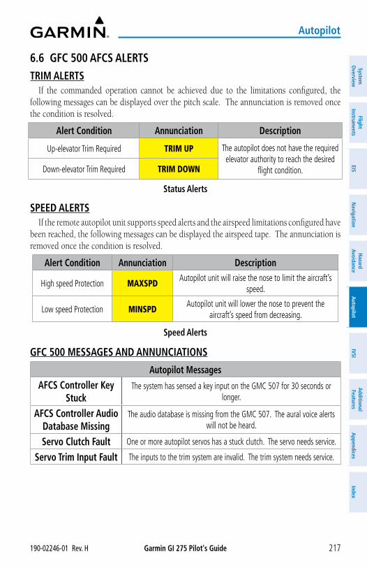
Garmin GI 275 Pilot's Guide190-02246-01 Rev. H 217
Autopilot
System
Overview
Flight Instrum
entsEIS
Navigation
Hazard
AvoidanceA
utopilotIVSI
Additional Features
Appendices
Index
6.6 GFC 500 AFCS ALERTSTRIM ALERTS
If the commanded operation cannot be achieved due to the limitations configured, the following messages can be displayed over the pitch scale. The annunciation is removed once the condition is resolved.
Alert Condition Annunciation Description
Up-elevator Trim Required TRIM UP The autopilot does not have the required elevator authority to reach the desired
flight condition.Down-elevator Trim Required TRIM DOWN
Status Alerts
SPEED ALERTSIf the remote autopilot unit supports speed alerts and the airspeed limitations configured have
been reached, the following messages can be displayed the airspeed tape. The annunciation is removed once the condition is resolved.
Alert Condition Annunciation Description
High speed Protection MAXSPDAutopilot unit will raise the nose to limit the aircraft’s
speed.
Low speed Protection MINSPDAutopilot unit will lower the nose to prevent the
aircraft’s speed from decreasing.
Speed Alerts
GFC 500 MESSAGES AND ANNUNCIATIONS
Autopilot Messages
AFCS Controller Key Stuck
The system has sensed a key input on the GMC 507 for 30 seconds or longer.
AFCS Controller Audio Database Missing
The audio database is missing from the GMC 507. The aural voice alerts will not be heard.
Servo Clutch Fault One or more autopilot servos has a stuck clutch. The servo needs service.
Servo Trim Input Fault The inputs to the trim system are invalid. The trim system needs service.
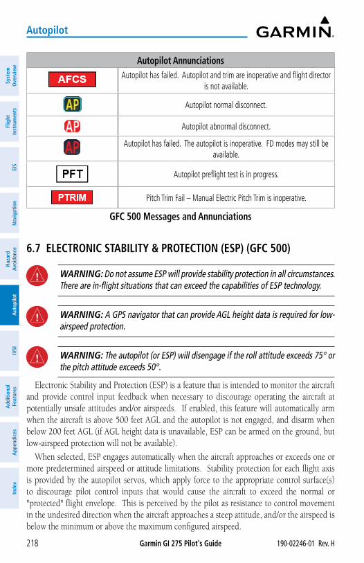
Garmin GI 275 Pilot's Guide 190-02246-01 Rev. H218
Autopilot
Syst
em
Ove
rvie
wFl
ight
In
stru
men
tsEI
SN
avig
atio
nH
azar
d Av
oida
nce
Aut
opilo
tIV
SIA
dditi
onal
Fe
atur
esA
ppen
dice
sIn
dex
Autopilot AnnunciationsAutopilot has failed. Autopilot and trim are inoperative and flight director
is not available.
Autopilot normal disconnect.
Autopilot abnormal disconnect.
Autopilot has failed. The autopilot is inoperative. FD modes may still be available.
Autopilot preflight test is in progress.
Pitch Trim Fail – Manual Electric Pitch Trim is inoperative.
GFC 500 Messages and Annunciations
6.7 ELECTRONIC STABILITY & PROTECTION (ESP) (GFC 500)
WARNING: Do not assume ESP will provide stability protection in all circumstances. There are in-flight situations that can exceed the capabilities of ESP technology.
WARNING: A GPS navigator that can provide AGL height data is required for low-airspeed protection.
WARNING: The autopilot (or ESP) will disengage if the roll attitude exceeds 75° or the pitch attitude exceeds 50°.
Electronic Stability and Protection (ESP) is a feature that is intended to monitor the aircraft and provide control input feedback when necessary to discourage operating the aircraft at potentially unsafe attitudes and/or airspeeds. If enabled, this feature will automatically arm when the aircraft is above 500 feet AGL and the autopilot is not engaged, and disarm when below 200 feet AGL (if AGL height data is unavailable, ESP can be armed on the ground, but low-airspeed protection will not be available).
When selected, ESP engages automatically when the aircraft approaches or exceeds one or more predetermined airspeed or attitude limitations. Stability protection for each flight axis is provided by the autopilot servos, which apply force to the appropriate control surface(s) to discourage pilot control inputs that would cause the aircraft to exceed the normal or "protected" flight envelope. This is perceived by the pilot as resistance to control movement in the undesired direction when the aircraft approaches a steep attitude, and/or the airspeed is below the minimum or above the maximum configured airspeed.
Garmin GI 275 Pilot's Guide190-02246-01 Rev. H 219
Autopilot
System
Overview
Flight Instrum
entsEIS
Navigation
Hazard
AvoidanceA
utopilotIVSI
Additional Features
Appendices
Index
As the aircraft deviates further from the normal attitude and/or airspeed, the force increases proportionally (up to an established maximum) to encourage control movement in the direction necessary to return to the normal attitude and/or airspeed range.
When ESP has been engaged for more than 10 seconds (cumulative; not necessarily consecutive seconds) of a 20-second interval, the autopilot can be configured to engage with the flight director in Level Mode, bringing the aircraft into level flight. An aural “Engaging Autopilot” alert is played and the flight director mode annunciation will indicate ‘LVL’ for vertical and lateral modes.
Level mode as activated by ESP is limited by altitude. ESP will not be able to activate Level mode until the aircraft climbs above 2000 feet AGL. ESP will be locked out of automatically activating Level mode after the aircraft descends below 1500 feet AGL as well. Also note that Level mode as activated by ESP is different than manually selected Level mode. Manually selected Level mode is not limited by altitude at all.
NOTE: If AGL height data is unavailable automatic engagement of Level mode is not supported.
ESP is enabled or disabled from the ADI Page Menu.
Enabling/Disabling ESP using the GI 275 Menu:1) From the ADI Page, press and hold the Selection Knob, or swipe up on the screen, to
display the Menu.2) Rotate the knob or swipe across the menu items to select ESP3) Press the knob or touch the ESP menu button to enable or disable ESP.
ROLL ENGAGEMENTRoll Limit Indicators displayed on the roll scale are configurable between 45º and 60º right
and left, indicating where ESP will engage. As roll attitude exceeds the configured limit, ESP will engage and the Roll Limit Indicators will move to 15º less than the configured ESP bank limit. The Roll Limit Indicator now indicates where ESP will disengage as roll attitude decreases.
Once engaged, the torque applied by ESP is at its maximum when bank angle is 15º more than the configured bank limit, and tapers to the minimum applied torque when the bank angle is 15º less than the configured bank limit. The force increases as roll attitude increases and decreases as roll attitude decreases. The applied force is intended to encourage pilot input to return the airplane to a more normal roll attitude. When beyond 15º of the configured bank limit, the maximum torque is held until the aircraft returns inside the protected envelope.
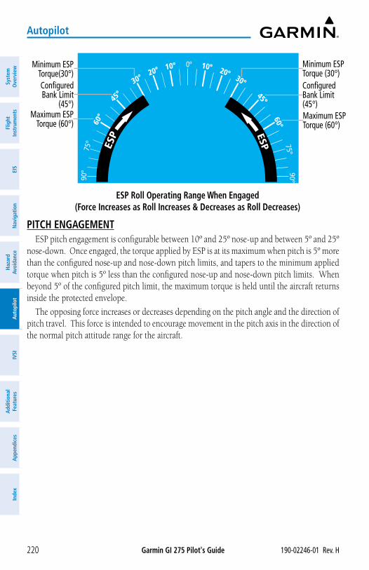
Garmin GI 275 Pilot's Guide 190-02246-01 Rev. H220
Autopilot
Syst
em
Ove
rvie
wFl
ight
In
stru
men
tsEI
SN
avig
atio
nH
azar
d Av
oida
nce
Aut
opilo
tIV
SIA
dditi
onal
Fe
atur
esA
ppen
dice
sIn
dex
ESP Roll Operating Range When Engaged (Force Increases as Roll Increases & Decreases as Roll Decreases)
0º 10º10º 20º20º30º30º
45º45º60º60
º
75º75º
90º90º
Configured Bank Limit (45°)
Minimum ESP Torque (30°)
Maximum ESP Torque (60°)
Maximum ESP Torque (60°)
Minimum ESP Torque(30°)Configured Bank Limit
(45°)
PITCH ENGAGEMENTESP pitch engagement is configurable between 10º and 25º nose-up and between 5º and 25º
nose-down. Once engaged, the torque applied by ESP is at its maximum when pitch is 5º more than the configured nose-up and nose-down pitch limits, and tapers to the minimum applied torque when pitch is 5º less than the configured nose-up and nose-down pitch limits. When beyond 5º of the configured pitch limit, the maximum torque is held until the aircraft returns inside the protected envelope.
The opposing force increases or decreases depending on the pitch angle and the direction of pitch travel. This force is intended to encourage movement in the pitch axis in the direction of the normal pitch attitude range for the aircraft.
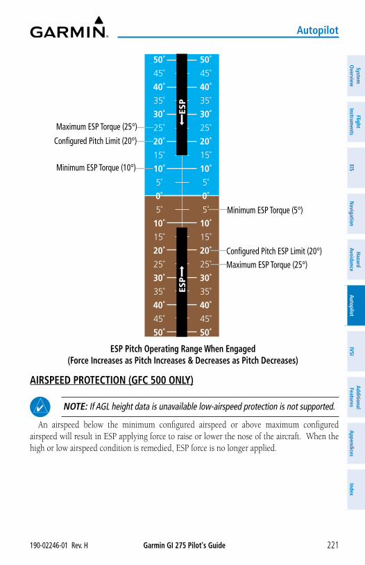
Garmin GI 275 Pilot's Guide190-02246-01 Rev. H 221
Autopilot
System
Overview
Flight Instrum
entsEIS
Navigation
Hazard
AvoidanceA
utopilotIVSI
Additional Features
Appendices
Index
ESP Pitch Operating Range When Engaged (Force Increases as Pitch Increases & Decreases as Pitch Decreases)
30˚
25˚
20˚
15˚
10˚
5˚
0˚
5˚
10˚
15˚
20˚
25˚
30˚
30˚
25˚
20˚
15˚
10˚
5˚
0˚
5˚
10˚
15˚
20˚
25˚
30˚
35˚
40˚
45˚
50˚
35˚
40˚
45˚
50˚
50˚
45˚
40˚
35˚
50˚
45˚
40˚
35˚
ESP
ESP
Maximum ESP Torque (25°)
Configured Pitch Limit (20°)
Minimum ESP Torque (10°)
Minimum ESP Torque (5°)
Configured Pitch ESP Limit (20°)
Maximum ESP Torque (25°)
AIRSPEED PROTECTION (GFC 500 ONLY)
NOTE: If AGL height data is unavailable low-airspeed protection is not supported.
An airspeed below the minimum configured airspeed or above maximum configured airspeed will result in ESP applying force to raise or lower the nose of the aircraft. When the high or low airspeed condition is remedied, ESP force is no longer applied.
Garmin GI 275 Pilot's Guide 190-02246-01 Rev. H222
Autopilot
Syst
em
Ove
rvie
wFl
ight
In
stru
men
tsEI
SN
avig
atio
nH
azar
d Av
oida
nce
Aut
opilo
tIV
SIA
dditi
onal
Fe
atur
esA
ppen
dice
sIn
dex
Blank Page
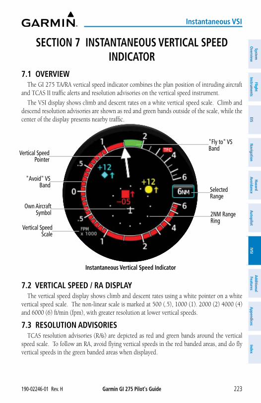
Garmin GI 275 Pilot's Guide190-02246-01 Rev. H 223
Instantaneous VSI
System
Overview
Flight Instrum
entsEIS
Navigation
Hazard
AvoidanceA
utopilotIVSI
Additional Features
Appendices
Index
SECTION 7 INSTANTANEOUS VERTICAL SPEED INDICATOR
7.1 OVERVIEWThe GI 275 TA/RA vertical speed indicator combines the plan position of intruding aircraft
and TCAS II traffic alerts and resolution advisories on the vertical speed instrument.
The VSI display shows climb and descent rates on a white vertical speed scale. Climb and descend resolution advisories are shown as red and green bands outside of the scale, while the center of the display presents nearby traffic.
Instantaneous Vertical Speed Indicator
Vertical Speed Scale
Vertical Speed Pointer
Own Aircraft Symbol
Selected Range
2NM Range Ring
"Fly to" VS Band
"Avoid" VS Band
7.2 VERTICAL SPEED / RA DISPLAYThe vertical speed display shows climb and descent rates using a white pointer on a white
vertical speed scale. The non-linear scale is marked at 500 (.5), 1000 (1). 2000 (2) 4000 (4) and 6000 (6) ft/min (fpm), with greater resolution at lower vertical speeds.
7.3 RESOLUTION ADVISORIESTCAS resolution advisories (RA’s) are depicted as red and green bands around the vertical
speed scale. To follow an RA, avoid flying vertical speeds in the red banded areas, and do fly vertical speeds in the green banded areas when displayed.
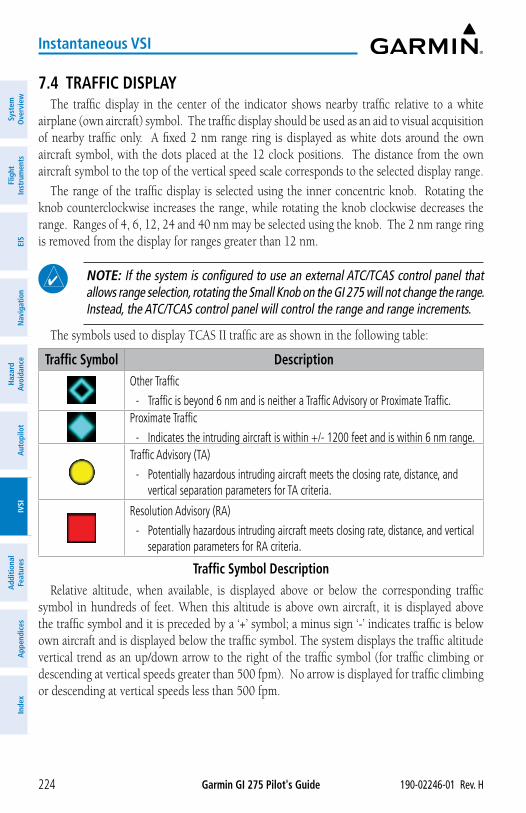
Garmin GI 275 Pilot's Guide 190-02246-01 Rev. H224
Instantaneous VSI
Syst
em
Ove
rvie
wFl
ight
In
stru
men
tsEI
SN
avig
atio
nH
azar
d Av
oida
nce
Aut
opilo
tIV
SIA
dditi
onal
Fe
atur
esA
ppen
dice
sIn
dex
7.4 TRAFFIC DISPLAYThe traffic display in the center of the indicator shows nearby traffic relative to a white
airplane (own aircraft) symbol. The traffic display should be used as an aid to visual acquisition of nearby traffic only. A fixed 2 nm range ring is displayed as white dots around the own aircraft symbol, with the dots placed at the 12 clock positions. The distance from the own aircraft symbol to the top of the vertical speed scale corresponds to the selected display range.
The range of the traffic display is selected using the inner concentric knob. Rotating the knob counterclockwise increases the range, while rotating the knob clockwise decreases the range. Ranges of 4, 6, 12, 24 and 40 nm may be selected using the knob. The 2 nm range ring is removed from the display for ranges greater than 12 nm.
NOTE: If the system is configured to use an external ATC/TCAS control panel that allows range selection, rotating the Small Knob on the GI 275 will not change the range. Instead, the ATC/TCAS control panel will control the range and range increments.
The symbols used to display TCAS II traffic are as shown in the following table:
Traffic Symbol DescriptionOther Traffic
- Traffic is beyond 6 nm and is neither a Traffic Advisory or Proximate Traffic. Proximate Traffic
- Indicates the intruding aircraft is within +/- 1200 feet and is within 6 nm range.Traffic Advisory (TA)
- Potentially hazardous intruding aircraft meets the closing rate, distance, and vertical separation parameters for TA criteria.
Resolution Advisory (RA)
- Potentially hazardous intruding aircraft meets closing rate, distance, and vertical separation parameters for RA criteria.
Traffic Symbol DescriptionRelative altitude, when available, is displayed above or below the corresponding traffic
symbol in hundreds of feet. When this altitude is above own aircraft, it is displayed above the traffic symbol and it is preceded by a ‘+’ symbol; a minus sign ‘-’ indicates traffic is below own aircraft and is displayed below the traffic symbol. The system displays the traffic altitude vertical trend as an up/down arrow to the right of the traffic symbol (for traffic climbing or descending at vertical speeds greater than 500 fpm). No arrow is displayed for traffic climbing or descending at vertical speeds less than 500 fpm.
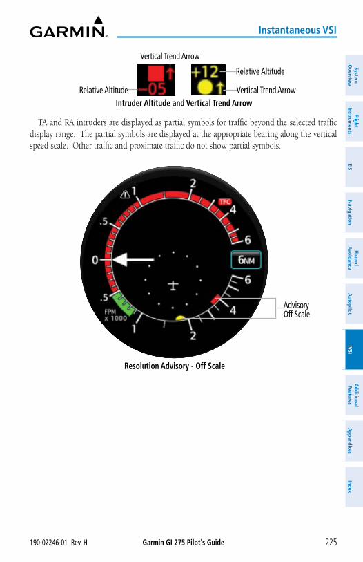
Garmin GI 275 Pilot's Guide190-02246-01 Rev. H 225
Instantaneous VSI
System
Overview
Flight Instrum
entsEIS
Navigation
Hazard
AvoidanceA
utopilotIVSI
Additional Features
Appendices
Index
Intruder Altitude and Vertical Trend Arrow
Relative Altitude
Vertical Trend ArrowRelative Altitude
Vertical Trend Arrow
TA and RA intruders are displayed as partial symbols for traffic beyond the selected traffic display range. The partial symbols are displayed at the appropriate bearing along the vertical speed scale. Other traffic and proximate traffic do not show partial symbols.
Resolution Advisory - Off Scale
Advisory Off Scale
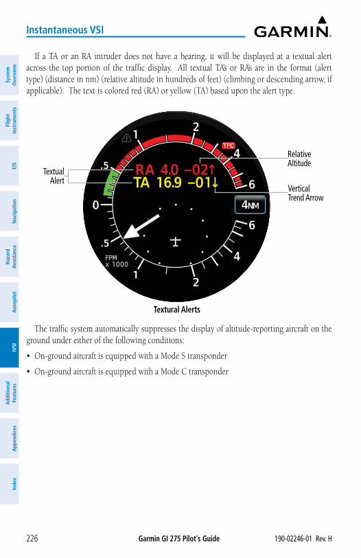
Garmin GI 275 Pilot's Guide 190-02246-01 Rev. H226
Instantaneous VSI
Syst
em
Ove
rvie
wFl
ight
In
stru
men
tsEI
SN
avig
atio
nH
azar
d Av
oida
nce
Aut
opilo
tIV
SIA
dditi
onal
Fe
atur
esA
ppen
dice
sIn
dex
If a TA or an RA intruder does not have a bearing, it will be displayed at a textual alert across the top portion of the traffic display. All textual TA’s or RA’s are in the format (alert type) (distance in nm) (relative altitude in hundreds of feet) (climbing or descending arrow, if applicable). The text is colored red (RA) or yellow (TA) based upon the alert type.
Textural Alerts
Relative Altitude
Vertical Trend Arrow
Textual Alert
The traffic system automatically suppresses the display of altitude-reporting aircraft on the ground under either of the following conditions:
• On-ground aircraft is equipped with a Mode S transponder
• On-ground aircraft is equipped with a Mode C transponder
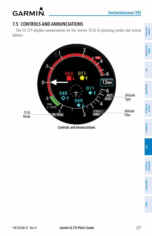
Garmin GI 275 Pilot's Guide190-02246-01 Rev. H 227
Instantaneous VSI
System
Overview
Flight Instrum
entsEIS
Navigation
Hazard
AvoidanceA
utopilotIVSI
Additional Features
Appendices
Index
7.5 CONTROLS AND ANNUNCIATIONSThe GI 275 displays annunciations for the various TCAS II operating modes and system
failures.
Controls and Annunciations
Altitude Type
TCAS Mode
Altitude Filter
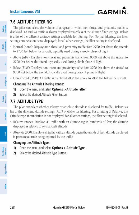
Garmin GI 275 Pilot's Guide 190-02246-01 Rev. H228
Instantaneous VSI
Syst
em
Ove
rvie
wFl
ight
In
stru
men
tsEI
SN
avig
atio
nH
azar
d Av
oida
nce
Aut
opilo
tIV
SIA
dditi
onal
Fe
atur
esA
ppen
dice
sIn
dex
7.6 ALTITUDE FILTERINGThe pilot can select the volume of airspace in which non-threat and proximity traffic is
displayed. TA and RA traffic is always displayed regardless of the altitude filter settings. Below is a list of the different altitude settings available for filtering. For Normal filtering, the filter setting annunciation is not displayed; for all other settings, the filter setting is displayed.
• Normal (none): Displays non-threat and proximity traffic from 2700 feet above the aircraft to 2700 feet below the aircraft; typically used during enroute phase of flight
• Above (ABV): Displays non-threat and proximity traffic from 9000 feet above the aircraft to 2700 feet below the aircraft; typically used during climb phase of flight
• Below (BLW): Displays non-threat and proximity traffic from 2700 feet above the aircraft to 9000 feet below the aircraft; typically used during descent phase of flight
• Unrestricted (UNR): All traffic is displayed 9900 feet above to 9900 feet below the aircraft
Changing The Altitude Filtering Range:1) Open the menu and select Options > Altitude Filter.2) Select the desired Altitude Filter Button.
7.7 ALTITUDE TYPEThe pilot can select whether relative or absolute altitude is displayed for traffic. Below is a
list of the different altitude settings (ALT) available for filtering. For a setting of Relative, the altitude type annunciation is not displayed; for all other settings, the filter setting is displayed.
• Relative (none): Displays all traffic with an altitude tag in hundreds of feet; the altitude displayed is relative to own aircraft altitude
• Absolute (000): Displays all traffic with an altitude tag in thousands of feet; altitude displayed is pressure altitude being reported by the traffic
Changing the Altitude Type:1) Open the menu and select Options > Altitude Type.2) Select the desired Altitude Type Button.
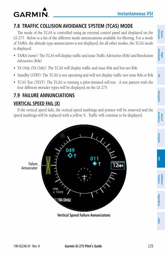
Garmin GI 275 Pilot's Guide190-02246-01 Rev. H 229
Instantaneous VSI
System
Overview
Flight Instrum
entsEIS
Navigation
Hazard
AvoidanceA
utopilotIVSI
Additional Features
Appendices
Index
7.8 TRAFFIC COLLISION AVOIDANCE SYSTEM (TCAS) MODEThe mode of the TCAS is controlled using an external control panel and displayed on the
GI 275. Below is a list of the different mode annunciations available for filtering. For a mode of TA/RA, the altitude type annunciation is not displayed; for all other modes, the TCAS mode is displayed.
• TA/RA (none): The TCAS will display traffic and issue Traffic Advisories (RA’s) and Resolution Advisories (RA’s)
• TA Only (TA Only): The TCAS will display traffic and issue RA’s and but not RA’s
• Standby (STBY): The TCAS is not operating and will not display traffic nor issue RA’s or RA’s
• TCAS Test (TEST): The TCAS is running a pilot-initiated self-test. A test pattern with the four different intruder types will be displayed on the GI 275.
7.9 FAILURE ANNUNCIATIONSVERTICAL SPEED FAIL (X)
If the vertical speed fails, the vertical speed markings and pointer will be removed and the speed markings will be replaced with a yellow X. Traffic will continue to be displayed.
Vertical Speed Failure Annunciatons
Failure Annunciator
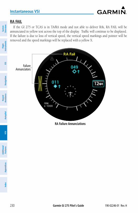
Garmin GI 275 Pilot's Guide 190-02246-01 Rev. H230
Instantaneous VSI
Syst
em
Ove
rvie
wFl
ight
In
stru
men
tsEI
SN
avig
atio
nH
azar
d Av
oida
nce
Aut
opilo
tIV
SIA
dditi
onal
Fe
atur
esA
ppen
dice
sIn
dex
RA FAILIf the GI 275 or TCAS is in TA/RA mode and not able to deliver RA’s, RA FAIL will be
annunciated in yellow text across the top of the display. Traffic will continue to be displayed. If the failure is due to loss of vertical speed, the vertical speed markings and pointer will be removed and the speed markings will be replaced with a yellow X.
RA Failure Annunciations
Failure Annunciators
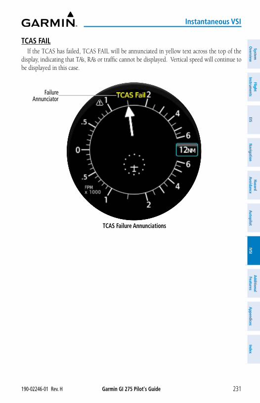
Garmin GI 275 Pilot's Guide190-02246-01 Rev. H 231
Instantaneous VSI
System
Overview
Flight Instrum
entsEIS
Navigation
Hazard
AvoidanceA
utopilotIVSI
Additional Features
Appendices
Index
TCAS FAILIf the TCAS has failed, TCAS FAIL will be annunciated in yellow text across the top of the
display, indicating that TA’s, RA’s or traffic cannot be displayed. Vertical speed will continue to be displayed in this case.
TCAS Failure Annunciations
Failure Annunciator
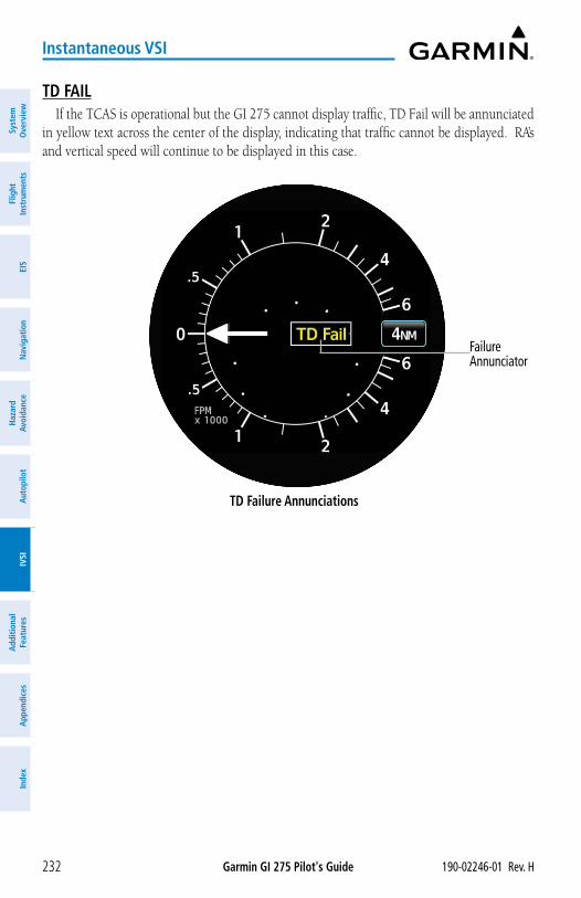
Garmin GI 275 Pilot's Guide 190-02246-01 Rev. H232
Instantaneous VSI
Syst
em
Ove
rvie
wFl
ight
In
stru
men
tsEI
SN
avig
atio
nH
azar
d Av
oida
nce
Aut
opilo
tIV
SIA
dditi
onal
Fe
atur
esA
ppen
dice
sIn
dex
TD FAILIf the TCAS is operational but the GI 275 cannot display traffic, TD Fail will be annunciated
in yellow text across the center of the display, indicating that traffic cannot be displayed. RA’s and vertical speed will continue to be displayed in this case.
TD Failure Annunciations
Failure Annunciator
Garmin GI 275 Pilot's Guide190-02246-01 Rev. H 233
Additional Features
System
Overview
Flight Instrum
entsEIS
Navigation
Hazard
AvoidanceA
utopilotIVSI
Additional Features
Appendices
Index
SECTION 8 ADDITIONAL FEATURES8.1 OVERVIEW
Additional features of the GI 275 Multi-Function Instrument (MFI) include the following:
• SafeTaxi®
• Radar Altimeter (Optional)
• Flight Data Logging
• Garmin Pilot Watch Connectivity (Optional)
• Synthetic Vision Technology (Optional)
• ADI's Misc. Field (Optional)
• Transponder Control
SafeTaxi® diagrams provide detailed taxiway, runway, and ramp information at more than 1,000 airports in the United States.
The optional Radar Altimeter feature on the MFI displays the height above terrain in real-time, directly below the aircraft by using compatible hardware.
The Flight Data Logging feature automatically connects and stores critical flight and engine data to Garmin Pilot through Connext or to a USB device through Garmin's proprietary GSB 15. Approximately 1,000 flight hours can be recorded for each 1GB of available space.
The optional Garmin Pilot Watch can connect to the MFI using a Bluetooth Low Energy (BLE) network. This connection establishes a real-time data transfer of flight information from the aircraft to the Garmin Pilot Watch.
The optional Synthetic Vision Technology (SVT™) depicts a forward-looking attitude display of the terrain and traffic immediately in front of the aircraft on the 'ADI' Page.
The ADI's Misc. Field can be configured to display True Airspeed (TAS), Ground Speed (GS), Air Temperature (OAT, ISA, TAT), or Wind (Direction and Velocity).
8.2 SAFETAXI®
WARNING: Do not use SafeTaxi® information as the primary method of flight guidance during ground operations. SafeTaxi® does not have NOTAM or ATIS information regarding the current active runway, condition, or complete information about the position of hold lines.
NOTE: With the availability of SafeTaxi®, it is still advisable to carry another source of charts on board the aircraft.
SafeTaxi® is an enhanced feature that provides greater map detail when viewing airports at close range on the 'HSI Map' or 'Map' Page. Map options are configurable. When SafeTaxi is enabled, the map reveals taxiways with identifying letters/numbers, airport Hot Spots, and airport landmarks including ramps, buildings, control towers, and other prominent features. SafeTaxi® features default to being viewed at or less than 1 nm and can be configured out to 5 nm. Resolution is greater at lower map ranges.
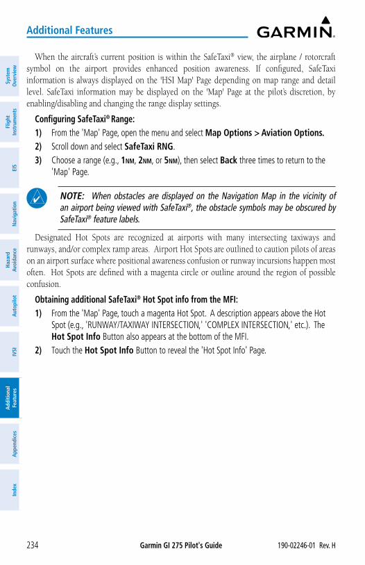
Garmin GI 275 Pilot's Guide 190-02246-01 Rev. H234
Additional Features
Syst
em
Ove
rvie
wFl
ight
In
stru
men
tsEI
SN
avig
atio
nH
azar
d Av
oida
nce
Aut
opilo
tIV
SIA
dditi
onal
Fe
atur
esA
ppen
dice
sIn
dex
When the aircraft’s current position is within the SafeTaxi® view, the airplane / rotorcraft symbol on the airport provides enhanced position awareness. If configured, SafeTaxi information is always displayed on the 'HSI Map' Page depending on map range and detail level. SafeTaxi information may be displayed on the 'Map' Page at the pilot’s discretion, by enabling/disabling and changing the range display settings.
Configuring SafeTaxi® Range:1) From the 'Map' Page, open the menu and select Map Options > Aviation Options.2) Scroll down and select SafeTaxi RNG.3) Choose a range (e.g., 1nm, 2nm, or 5nm), then select Back three times to return to the
'Map' Page.
NOTE: When obstacles are displayed on the Navigation Map in the vicinity of an airport being viewed with SafeTaxi®, the obstacle symbols may be obscured by SafeTaxi® feature labels.
Designated Hot Spots are recognized at airports with many intersecting taxiways and runways, and/or complex ramp areas. Airport Hot Spots are outlined to caution pilots of areas on an airport surface where positional awareness confusion or runway incursions happen most often. Hot Spots are defined with a magenta circle or outline around the region of possible confusion.
Obtaining additional SafeTaxi® Hot Spot info from the MFI:1) From the 'Map' Page, touch a magenta Hot Spot. A description appears above the Hot
Spot (e.g., 'RUNWAY/TAXIWAY INTERSECTION,' 'COMPLEX INTERSECTION,' etc.). The Hot Spot Info Button also appears at the bottom of the MFI.
2) Touch the Hot Spot Info Button to reveal the 'Hot Spot Info' Page.
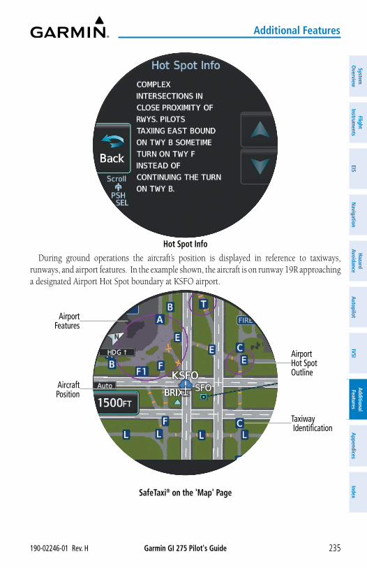
Garmin GI 275 Pilot's Guide190-02246-01 Rev. H 235
Additional Features
System
Overview
Flight Instrum
entsEIS
Navigation
Hazard
AvoidanceA
utopilotIVSI
Additional Features
Appendices
Index
Hot Spot InfoDuring ground operations the aircraft’s position is displayed in reference to taxiways,
runways, and airport features. In the example shown, the aircraft is on runway 19R approaching a designated Airport Hot Spot boundary at KSFO airport.
SafeTaxi® on the 'Map' Page
Airport Hot Spot Outline
Airport Features
Aircraft Position
Taxiway Identification
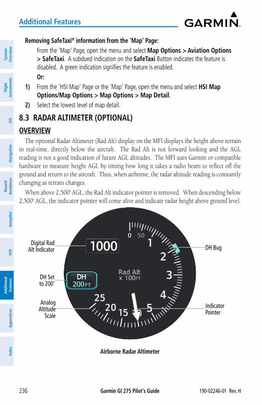
Garmin GI 275 Pilot's Guide 190-02246-01 Rev. H236
Additional Features
Syst
em
Ove
rvie
wFl
ight
In
stru
men
tsEI
SN
avig
atio
nH
azar
d Av
oida
nce
Aut
opilo
tIV
SIA
dditi
onal
Fe
atur
esA
ppen
dice
sIn
dex
Removing SafeTaxi® information from the 'Map' Page: From the 'Map' Page, open the menu and select Map Options > Aviation Options
> SafeTaxi. A subdued indication on the SafeTaxi Button indicates the feature is disabled. A green indication signifies the feature is enabled.Or:
1) From the 'HSI Map' Page or the 'Map' Page, open the menu and select HSI Map Options/Map Options > Map Options > Map Detail.
2) Select the lowest level of map detail.
8.3 RADAR ALTIMETER (OPTIONAL)OVERVIEW
The optional Radar Altimeter (Rad Alt) display on the MFI displays the height above terrain in real-time, directly below the aircraft. The Rad Alt is not forward looking and the AGL reading is not a good indication of future AGL altitudes. The MFI uses Garmin or compatible hardware to measure height AGL by timing how long it takes a radio beam to reflect off the ground and return to the aircraft. Thus, when airborne, the radar altitude reading is constantly changing as terrain changes.
When above 2,500' AGL, the Rad Alt indicator pointer is removed. When descending below 2,500' AGL, the indicator pointer will come alive and indicate radar height above ground level.
Airborne Radar Altimeter
Digital Rad Alt Indicator
DH Set to 200'
Analog Altitude
Scale
DH Bug
Indicator Pointer
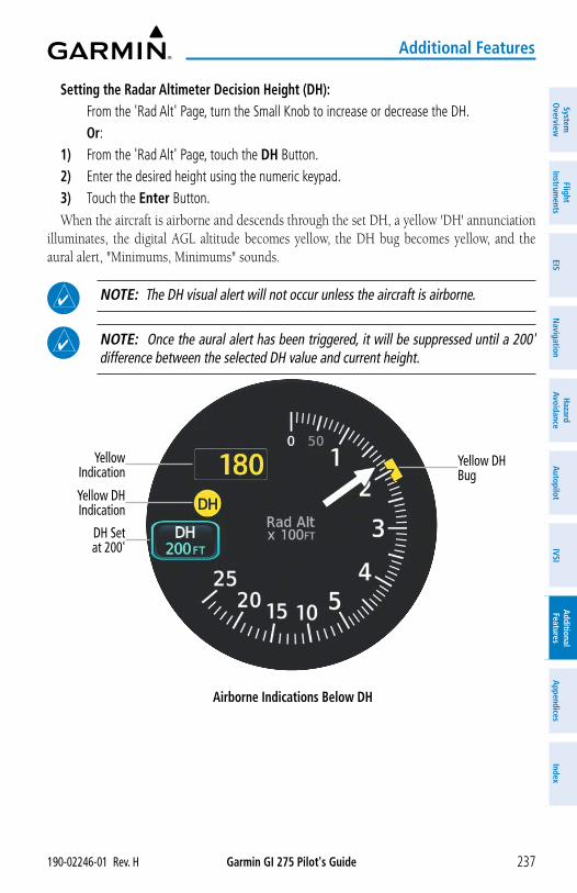
Garmin GI 275 Pilot's Guide190-02246-01 Rev. H 237
Additional Features
System
Overview
Flight Instrum
entsEIS
Navigation
Hazard
AvoidanceA
utopilotIVSI
Additional Features
Appendices
Index
Setting the Radar Altimeter Decision Height (DH): From the 'Rad Alt' Page, turn the Small Knob to increase or decrease the DH. Or:1) From the 'Rad Alt' Page, touch the DH Button.2) Enter the desired height using the numeric keypad.3) Touch the Enter Button.When the aircraft is airborne and descends through the set DH, a yellow 'DH' annunciation
illuminates, the digital AGL altitude becomes yellow, the DH bug becomes yellow, and the aural alert, "Minimums, Minimums" sounds.
NOTE: The DH visual alert will not occur unless the aircraft is airborne.
NOTE: Once the aural alert has been triggered, it will be suppressed until a 200' difference between the selected DH value and current height.
Yellow Indication
DH Set at 200'
Yellow DH Indication
Yellow DH Bug
Airborne Indications Below DH
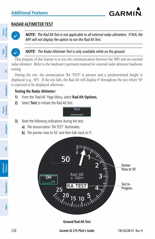
Garmin GI 275 Pilot's Guide 190-02246-01 Rev. H238
Additional Features
Syst
em
Ove
rvie
wFl
ight
In
stru
men
tsEI
SN
avig
atio
nH
azar
d Av
oida
nce
Aut
opilo
tIV
SIA
dditi
onal
Fe
atur
esA
ppen
dice
sIn
dex
RADAR ALTIMETER TEST
NOTE: The Rad Alt Test is not applicable to all external radar altimeters. If N/A, the MFI will not display the option to run the Rad Alt Test.
NOTE: The Radar Altimeter Test is only available while on the ground.
This purpose of this feature is to test the communication between the MFI and an external radar altimeter. Refer to the hardware's pertinent manual for external radar altimeter hardware testing.
During the test, the annunciation 'RA TEST' is present and a predetermined height is displayed (e.g., 50'). If the test fails, the Rad Alt will display 0' throughout the test where 50' is expected to be displayed otherwise.
Testing the Radar Altimeter:1) From the 'Rad Alt' Page Menu, select Rad Alt Options.2) Select Test to initiate the Rad Alt Test.
3) Note the following indications during the test:a) The annunciation 'RA TEST' illuminates.b) The pointer rises to 50' and then falls back to 0'.
Ground Rad Alt Test
Test In-Progress
Pointer Rises to 50'
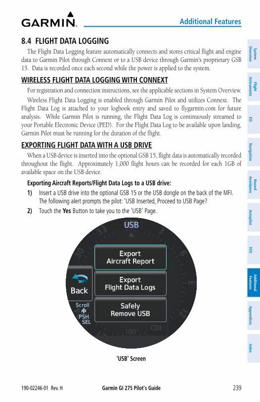
Garmin GI 275 Pilot's Guide190-02246-01 Rev. H 239
Additional Features
System
Overview
Flight Instrum
entsEIS
Navigation
Hazard
AvoidanceA
utopilotIVSI
Additional Features
Appendices
Index
8.4 FLIGHT DATA LOGGINGThe Flight Data Logging feature automatically connects and stores critical flight and engine
data to Garmin Pilot through Connext or to a USB device through Garmin's proprietary GSB 15. Data is recorded once each second while the power is applied to the system.
WIRELESS FLIGHT DATA LOGGING WITH CONNEXTFor registration and connection instructions, see the applicable sections in System Overview.
Wireless Flight Data Logging is enabled through Garmin Pilot and utilizes Connext. The Flight Data Log is attached to your logbook entry and saved to flygarmin.com for future analysis. While Garmin Pilot is running, the Flight Data Log is continuously streamed to your Portable Electronic Device (PED). For the Flight Data Log to be available upon landing, Garmin Pilot must be running for the duration of the flight.
EXPORTING FLIGHT DATA WITH A USB DRIVEWhen a USB device is inserted into the optional GSB 15, flight data is automatically recorded
throughout the flight. Approximately 1,000 flight hours can be recorded for each 1GB of available space on the USB device.
Exporting Aircraft Reports/Flight Data Logs to a USB drive:1) Insert a USB drive into the optional GSB 15 or the USB dongle on the back of the MFI.
The following alert prompts the pilot: 'USB Inserted, Proceed to USB Page?2) Touch the Yes Button to take you to the 'USB' Page.
'USB' Screen
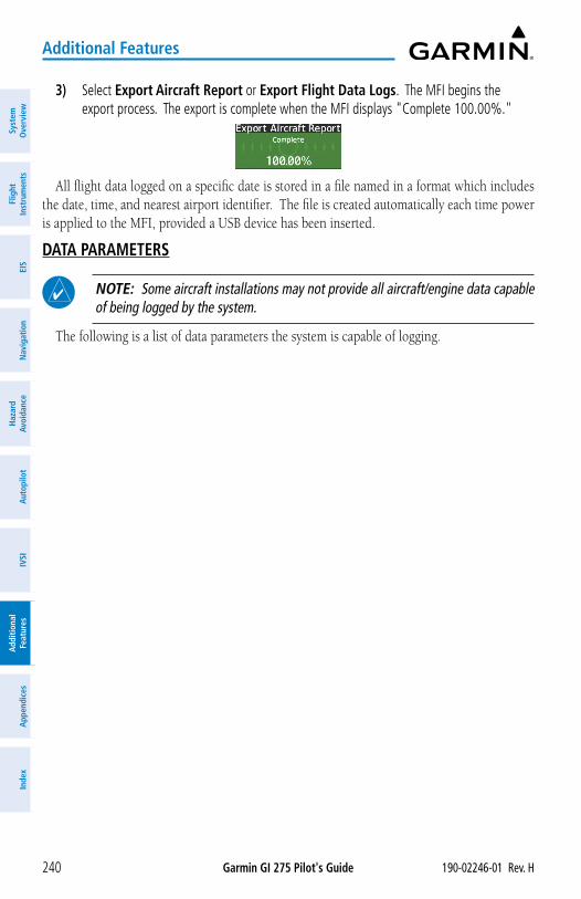
Garmin GI 275 Pilot's Guide 190-02246-01 Rev. H240
Additional Features
Syst
em
Ove
rvie
wFl
ight
In
stru
men
tsEI
SN
avig
atio
nH
azar
d Av
oida
nce
Aut
opilo
tIV
SIA
dditi
onal
Fe
atur
esA
ppen
dice
sIn
dex
3) Select Export Aircraft Report or Export Flight Data Logs. The MFI begins the export process. The export is complete when the MFI displays "Complete 100.00%."
All flight data logged on a specific date is stored in a file named in a format which includes the date, time, and nearest airport identifier. The file is created automatically each time power is applied to the MFI, provided a USB device has been inserted.
DATA PARAMETERS
NOTE: Some aircraft installations may not provide all aircraft/engine data capable of being logged by the system.
The following is a list of data parameters the system is capable of logging.
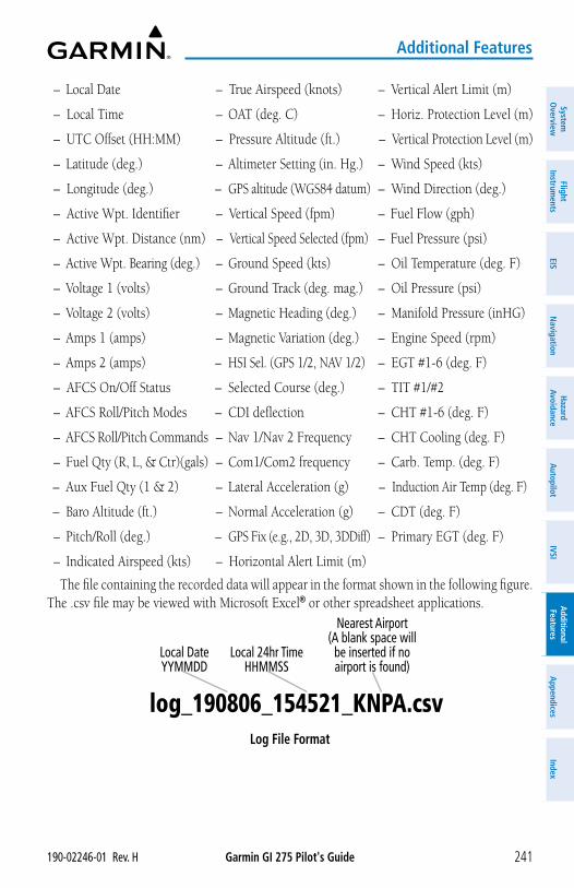
Garmin GI 275 Pilot's Guide190-02246-01 Rev. H 241
Additional Features
System
Overview
Flight Instrum
entsEIS
Navigation
Hazard
AvoidanceA
utopilotIVSI
Additional Features
Appendices
Index
– Local Date
– Local Time
– UTC Offset (HH:MM)
– Latitude (deg.)
– Longitude (deg.)
– Active Wpt. Identifier
– Active Wpt. Distance (nm)
– Active Wpt. Bearing (deg.)
– Voltage 1 (volts)
– Voltage 2 (volts)
– Amps 1 (amps)
– Amps 2 (amps)
– AFCS On/Off Status
– AFCS Roll/Pitch Modes
– AFCS Roll/Pitch Commands
– Fuel Qty (R, L, & Ctr)(gals)
– Aux Fuel Qty (1 & 2)
– Baro Altitude (ft.)
– Pitch/Roll (deg.)
– Indicated Airspeed (kts)
– True Airspeed (knots)
– OAT (deg. C)
– Pressure Altitude (ft.)
– Altimeter Setting (in. Hg.)
– GPS altitude (WGS84 datum)
– Vertical Speed (fpm)
– Vertical Speed Selected (fpm)
– Ground Speed (kts)
– Ground Track (deg. mag.)
– Magnetic Heading (deg.)
– Magnetic Variation (deg.)
– HSI Sel. (GPS 1/2, NAV 1/2)
– Selected Course (deg.)
– CDI deflection
– Nav 1/Nav 2 Frequency
– Com1/Com2 frequency
– Lateral Acceleration (g)
– Normal Acceleration (g)
– GPS Fix (e.g., 2D, 3D, 3DDiff)
– Horizontal Alert Limit (m)
– Vertical Alert Limit (m)
– Horiz. Protection Level (m)
– Vertical Protection Level (m)
– Wind Speed (kts)
– Wind Direction (deg.)
– Fuel Flow (gph)
– Fuel Pressure (psi)
– Oil Temperature (deg. F)
– Oil Pressure (psi)
– Manifold Pressure (inHG)
– Engine Speed (rpm)
– EGT #1-6 (deg. F)
– TIT #1/#2
– CHT #1-6 (deg. F)
– CHT Cooling (deg. F)
– Carb. Temp. (deg. F)
– Induction Air Temp (deg. F)
– CDT (deg. F)
– Primary EGT (deg. F)
The file containing the recorded data will appear in the format shown in the following figure. The .csv file may be viewed with Microsoft Excel® or other spreadsheet applications.
Log File Format
Local DateYYMMDD
Local 24hr TimeHHMMSS
Nearest Airport(A blank space will
be inserted if no airport is found)
log_190806_154521_KNPA.csv
Garmin GI 275 Pilot's Guide 190-02246-01 Rev. H242
Additional Features
Syst
em
Ove
rvie
wFl
ight
In
stru
men
tsEI
SN
avig
atio
nH
azar
d Av
oida
nce
Aut
opilo
tIV
SIA
dditi
onal
Fe
atur
esA
ppen
dice
sIn
dex
8.5 GARMIN PILOT WATCH CONNECTIVITY (OPTIONAL)The Garmin Pilot Watch can be connected to the MFI through a Bluetooth Low Energy
(BLE) network. Once connected, the following information is sent real-time to the Garmin Pilot Watch:
• Indicated Airspeed (IAS)
• True Airspeed (TAS)
• Vertical Speed
• Pressure Altitude
• Wind Speed
• Wind Direction
• Outside Air Temperature (OAT)
– Static and Total
• Height Above Terrain (HAT)
• Density Altitude
The Garmin Watch must be ‘paired’ with the MFI in order to use the various functions. Pairing is accomplished once for each device. After the initial pairing, with 'Auto-Reconnect' enabled, your Garmin Watch will automatically reconnect with the MFI. The pairing operation is completed from the Garmin Watch and the MFI. The MFI can connect three Bluetooth devices and one BLE device. For Garmin Watch specific instructions, see the Garmin Pilot Owner's Manual.
NOTE: The aircraft must be on the ground to pair the Garmin Pilot Watch.
NOTE: The wireless card on the MFI may take up to two minutes after startup before wireless functionality is available.
Pairing the Garmin Watch with the MFI:1) Place the Garmin Watch in pairing mode. Reference the operating manual for the Garmin
Watch for detailed pairing instructions. 2) On the MFI, open the menu and select System > Wireless.3) Scroll down and select Pair a Device. On the 'Pair Device' Screen, the MFI will display
its Bluetooth name and prompt the pilot to "Please remain on this page while pairing your Bluetooth device."
4) Once the MFI receives the pairing request from the Garmin, a pairing message will prompt the pilot. Press the Pair Button. After the connection is established, the Garmin Watch will show 'Status Connected.'
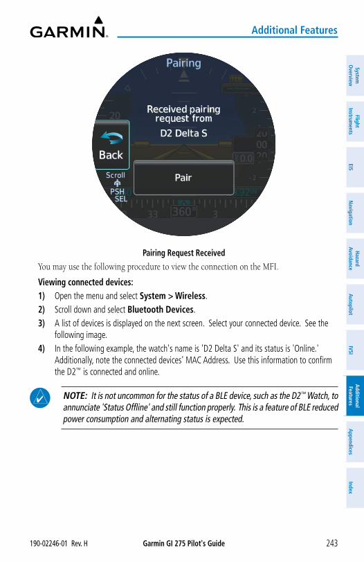
Garmin GI 275 Pilot's Guide190-02246-01 Rev. H 243
Additional Features
System
Overview
Flight Instrum
entsEIS
Navigation
Hazard
AvoidanceA
utopilotIVSI
Additional Features
Appendices
Index
Pairing Request ReceivedYou may use the following procedure to view the connection on the MFI.
Viewing connected devices:1) Open the menu and select System > Wireless.2) Scroll down and select Bluetooth Devices.3) A list of devices is displayed on the next screen. Select your connected device. See the
following image.4) In the following example, the watch's name is 'D2 Delta S' and its status is 'Online.'
Additionally, note the connected devices' MAC Address. Use this information to confirm the D2™ is connected and online.
NOTE: It is not uncommon for the status of a BLE device, such as the D2™ Watch, to annunciate 'Status Offline' and still function properly. This is a feature of BLE reduced power consumption and alternating status is expected.
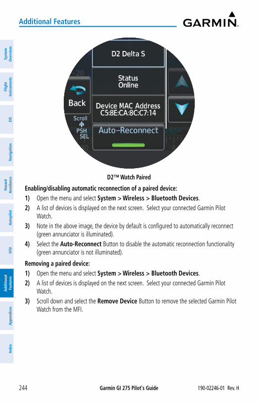
Garmin GI 275 Pilot's Guide 190-02246-01 Rev. H244
Additional Features
Syst
em
Ove
rvie
wFl
ight
In
stru
men
tsEI
SN
avig
atio
nH
azar
d Av
oida
nce
Aut
opilo
tIV
SIA
dditi
onal
Fe
atur
esA
ppen
dice
sIn
dex
D2™ Watch Paired
Enabling/disabling automatic reconnection of a paired device:1) Open the menu and select System > Wireless > Bluetooth Devices.2) A list of devices is displayed on the next screen. Select your connected Garmin Pilot
Watch.3) Note in the above image, the device by default is configured to automatically reconnect
(green annunciator is illuminated).4) Select the Auto-Reconnect Button to disable the automatic reconnection functionality
(green annunciator is not illuminated).
Removing a paired device:1) Open the menu and select System > Wireless > Bluetooth Devices.2) A list of devices is displayed on the next screen. Select your connected Garmin Pilot
Watch.3) Scroll down and select the Remove Device Button to remove the selected Garmin Pilot
Watch from the MFI.
Garmin GI 275 Pilot's Guide190-02246-01 Rev. H 245
Additional Features
System
Overview
Flight Instrum
entsEIS
Navigation
Hazard
AvoidanceA
utopilotIVSI
Additional Features
Appendices
Index
8.6 SYNTHETIC VISION TECHNOLOGY (SVT™) (OPTIONAL)
WARNING: Use appropriate primary systems for navigation, and for terrain, obstacle, and traffic avoidance. Garmin SVT™ is intended as an aid to situational awareness only and may not provide either the accuracy or reliability upon which to solely base decisions and/or plan maneuvers to avoid terrain, obstacles, or traffic.
NOTE: When configured as a Primary ADI, a half screen menu is available and individual page options are accessed through the generic Options Button. When configured as a Standby ADI or MFD, a full screen menu is available and individual page options are accessed through the ADI Options Button on the 'ADI' Page Menu.
NOTE: A free trial for SVT is configured for the first 660 minutes of flight time. Trial status and time remaining may be viewed by opening the SVT Options menu from the 'ADI' Page.
The optional Synthetic Vision Technology (SVT™) depicts a forward-looking attitude display of the topography immediately in front of the aircraft on the 'ADI' Page. Displayed pitch range on the attitude indicator changes based on whether SVT is displayed. The depicted imagery is derived from the aircraft attitude, heading, GPS three-dimensional position, and a 9.9 arc-second database of terrain, obstacles, and other relevant features. SVT will not display without a valid GPS position. The terrain data resolution of 9.9 arc-seconds, meaning that terrain elevation contours are stored in squares measuring 9.9 arc-seconds on each side, is required for the operation of SVT. Loss of any of the required data, including temporary loss of the GPS signal, will cause SVT to be disabled until the required data is restored.
The terrain display is intended for situational awareness only. It may not provide the accuracy or fidelity on which to base decisions and plan maneuvers to avoid terrain or obstacles. Navigation must not be predicated solely upon the use of the synthetic terrain or obstacle data displayed by SVT.
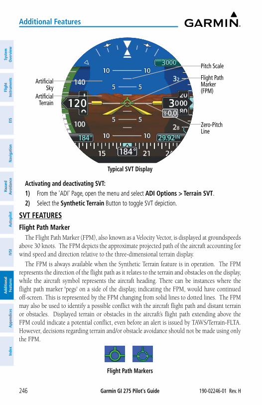
Garmin GI 275 Pilot's Guide 190-02246-01 Rev. H246
Additional Features
Syst
em
Ove
rvie
wFl
ight
In
stru
men
tsEI
SN
avig
atio
nH
azar
d Av
oida
nce
Aut
opilo
tIV
SIA
dditi
onal
Fe
atur
esA
ppen
dice
sIn
dex
Artificial Sky
Artificial Terrain
Zero-Pitch Line
Pitch Scale
Flight Path Marker (FPM)
Typical SVT Display
Activating and deactivating SVT:1) From the 'ADI' Page, open the menu and select ADI Options > Terrain SVT.2) Select the Synthetic Terrain Button to toggle SVT depiction.
SVT FEATURESFlight Path Marker
The Flight Path Marker (FPM), also known as a Velocity Vector, is displayed at groundspeeds above 30 knots. The FPM depicts the approximate projected path of the aircraft accounting for wind speed and direction relative to the three-dimensional terrain display.
The FPM is always available when the Synthetic Terrain feature is in operation. The FPM represents the direction of the flight path as it relates to the terrain and obstacles on the display, while the aircraft symbol represents the aircraft heading. There can be instances where the flight path marker 'pegs' on a side of the display, indicating the FPM, would have continued off-screen. This is represented by the FPM changing from solid lines to dotted lines. The FPM may also be used to identify a possible conflict with the aircraft flight path and distant terrain or obstacles. Displayed terrain or obstacles in the aircraft’s flight path extending above the FPM could indicate a potential conflict, even before an alert is issued by TAWS/Terrain-FLTA. However, decisions regarding terrain and/or obstacle avoidance should not be made using only the FPM.
Flight Path Markers
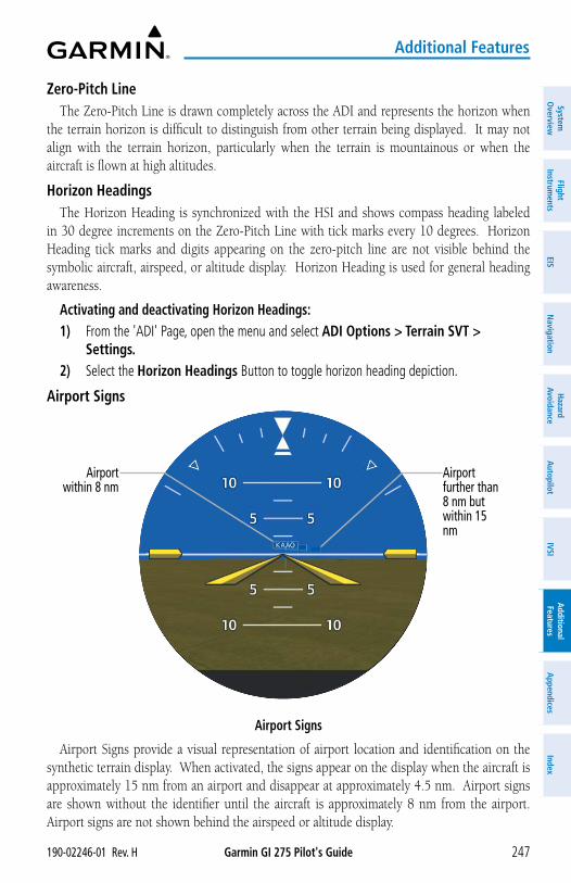
Garmin GI 275 Pilot's Guide190-02246-01 Rev. H 247
Additional Features
System
Overview
Flight Instrum
entsEIS
Navigation
Hazard
AvoidanceA
utopilotIVSI
Additional Features
Appendices
Index
Zero-Pitch LineThe Zero-Pitch Line is drawn completely across the ADI and represents the horizon when
the terrain horizon is difficult to distinguish from other terrain being displayed. It may not align with the terrain horizon, particularly when the terrain is mountainous or when the aircraft is flown at high altitudes.
Horizon HeadingsThe Horizon Heading is synchronized with the HSI and shows compass heading labeled
in 30 degree increments on the Zero-Pitch Line with tick marks every 10 degrees. Horizon Heading tick marks and digits appearing on the zero-pitch line are not visible behind the symbolic aircraft, airspeed, or altitude display. Horizon Heading is used for general heading awareness.
Activating and deactivating Horizon Headings:1) From the 'ADI' Page, open the menu and select ADI Options > Terrain SVT >
Settings.2) Select the Horizon Headings Button to toggle horizon heading depiction.
Airport Signs
Airport Signs
Airport within 8 nm
Airport further than 8 nm but within 15 nm
Airport Signs provide a visual representation of airport location and identification on the synthetic terrain display. When activated, the signs appear on the display when the aircraft is approximately 15 nm from an airport and disappear at approximately 4.5 nm. Airport signs are shown without the identifier until the aircraft is approximately 8 nm from the airport. Airport signs are not shown behind the airspeed or altitude display.
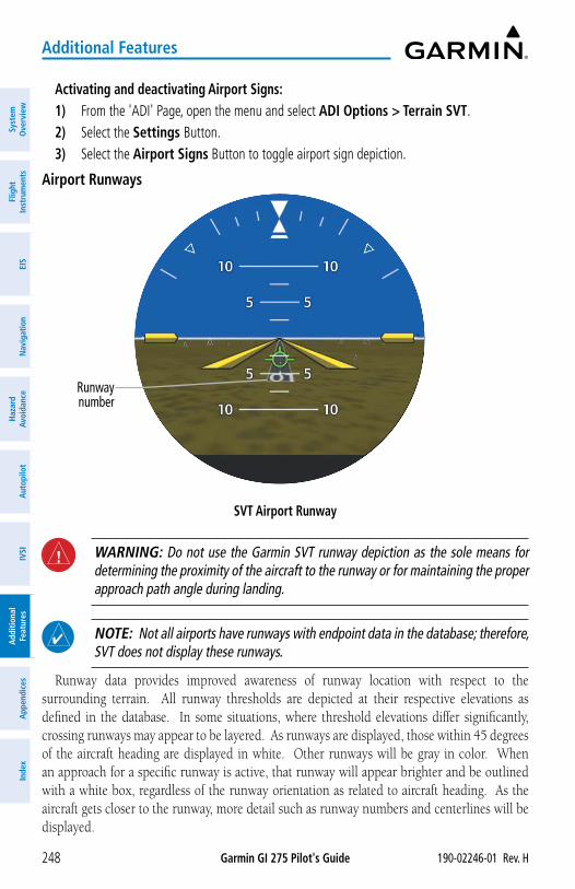
Garmin GI 275 Pilot's Guide 190-02246-01 Rev. H248
Additional Features
Syst
em
Ove
rvie
wFl
ight
In
stru
men
tsEI
SN
avig
atio
nH
azar
d Av
oida
nce
Aut
opilo
tIV
SIA
dditi
onal
Fe
atur
esA
ppen
dice
sIn
dex
Activating and deactivating Airport Signs:1) From the 'ADI' Page, open the menu and select ADI Options > Terrain SVT.2) Select the Settings Button.3) Select the Airport Signs Button to toggle airport sign depiction.
Airport Runways
SVT Airport Runway
Runway number
WARNING: Do not use the Garmin SVT runway depiction as the sole means for determining the proximity of the aircraft to the runway or for maintaining the proper approach path angle during landing.
NOTE: Not all airports have runways with endpoint data in the database; therefore, SVT does not display these runways.
Runway data provides improved awareness of runway location with respect to the surrounding terrain. All runway thresholds are depicted at their respective elevations as defined in the database. In some situations, where threshold elevations differ significantly, crossing runways may appear to be layered. As runways are displayed, those within 45 degrees of the aircraft heading are displayed in white. Other runways will be gray in color. When an approach for a specific runway is active, that runway will appear brighter and be outlined with a white box, regardless of the runway orientation as related to aircraft heading. As the aircraft gets closer to the runway, more detail such as runway numbers and centerlines will be displayed.
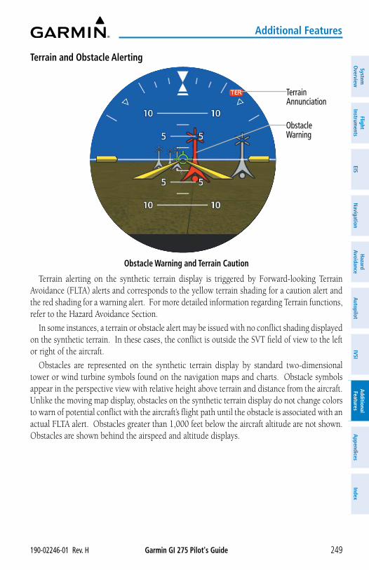
Garmin GI 275 Pilot's Guide190-02246-01 Rev. H 249
Additional Features
System
Overview
Flight Instrum
entsEIS
Navigation
Hazard
AvoidanceA
utopilotIVSI
Additional Features
Appendices
Index
Terrain and Obstacle Alerting
Obstacle Warning and Terrain Caution
Terrain Annunciation
Obstacle Warning
Terrain alerting on the synthetic terrain display is triggered by Forward-looking Terrain Avoidance (FLTA) alerts and corresponds to the yellow terrain shading for a caution alert and the red shading for a warning alert. For more detailed information regarding Terrain functions, refer to the Hazard Avoidance Section.
In some instances, a terrain or obstacle alert may be issued with no conflict shading displayed on the synthetic terrain. In these cases, the conflict is outside the SVT field of view to the left or right of the aircraft.
Obstacles are represented on the synthetic terrain display by standard two-dimensional tower or wind turbine symbols found on the navigation maps and charts. Obstacle symbols appear in the perspective view with relative height above terrain and distance from the aircraft. Unlike the moving map display, obstacles on the synthetic terrain display do not change colors to warn of potential conflict with the aircraft’s flight path until the obstacle is associated with an actual FLTA alert. Obstacles greater than 1,000 feet below the aircraft altitude are not shown. Obstacles are shown behind the airspeed and altitude displays.
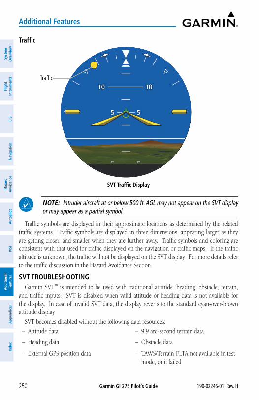
Garmin GI 275 Pilot's Guide 190-02246-01 Rev. H250
Additional Features
Syst
em
Ove
rvie
wFl
ight
In
stru
men
tsEI
SN
avig
atio
nH
azar
d Av
oida
nce
Aut
opilo
tIV
SIA
dditi
onal
Fe
atur
esA
ppen
dice
sIn
dex
Traffic
SVT Traffic Display
Traffic
NOTE: Intruder aircraft at or below 500 ft. AGL may not appear on the SVT display or may appear as a partial symbol.
Traffic symbols are displayed in their approximate locations as determined by the related traffic systems. Traffic symbols are displayed in three dimensions, appearing larger as they are getting closer, and smaller when they are further away. Traffic symbols and coloring are consistent with that used for traffic displayed on the navigation or traffic maps. If the traffic altitude is unknown, the traffic will not be displayed on the SVT display. For more details refer to the traffic discussion in the Hazard Avoidance Section.
SVT TROUBLESHOOTINGGarmin SVT™ is intended to be used with traditional attitude, heading, obstacle, terrain,
and traffic inputs. SVT is disabled when valid attitude or heading data is not available for the display. In case of invalid SVT data, the display reverts to the standard cyan-over-brown attitude display.
SVT becomes disabled without the following data resources:
– Attitude data
– Heading data
– External GPS position data
– 9.9 arc-second terrain data
– Obstacle data
– TAWS/Terrain-FLTA not available in test mode, or if failed
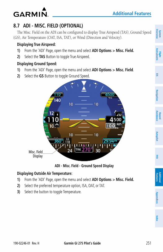
Garmin GI 275 Pilot's Guide190-02246-01 Rev. H 251
Additional Features
System
Overview
Flight Instrum
entsEIS
Navigation
Hazard
AvoidanceA
utopilotIVSI
Additional Features
Appendices
Index
8.7 ADI - MISC. FIELD (OPTIONAL)The Misc. Field on the ADI can be configured to display True Airspeed (TAS), Ground Speed
(GS), Air Temperature (OAT, ISA, TAT), or Wind (Direction and Velocity).
Displaying True Airspeed: 1) From the 'ADI' Page, open the menu and select ADI Options > Misc. Field.2) Select the TAS Button to toggle True Airspeed.
Displaying Ground Speed:1) From the 'ADI' Page, open the menu and select ADI Options > Misc. Field.2) Select the GS Button to toggle Ground Speed.
ADI - Misc. Field - Ground Speed Display
Misc. Field Display
Displaying Outside Air Temperature:1) From the 'ADI' Page, open the menu and select ADI Options > Misc. Field.2) Select the preferred temperature option, ISA, OAT, or TAT.3) Select the button to toggle Temperature.
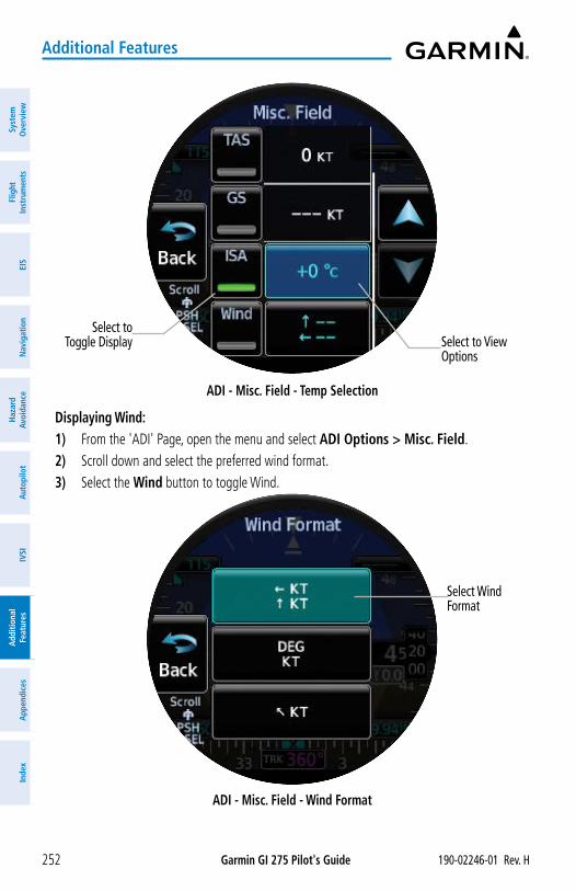
Garmin GI 275 Pilot's Guide 190-02246-01 Rev. H252
Additional Features
Syst
em
Ove
rvie
wFl
ight
In
stru
men
tsEI
SN
avig
atio
nH
azar
d Av
oida
nce
Aut
opilo
tIV
SIA
dditi
onal
Fe
atur
esA
ppen
dice
sIn
dex
ADI - Misc. Field - Temp Selection
Select to View Options
Select to Toggle Display
Displaying Wind:1) From the 'ADI' Page, open the menu and select ADI Options > Misc. Field. 2) Scroll down and select the preferred wind format.3) Select the Wind button to toggle Wind.
ADI - Misc. Field - Wind Format
Select Wind Format
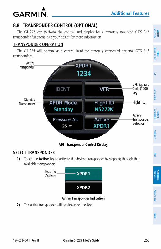
Garmin GI 275 Pilot's Guide190-02246-01 Rev. H 253
Additional Features
System
Overview
Flight Instrum
entsEIS
Navigation
Hazard
AvoidanceA
utopilotIVSI
Additional Features
Appendices
Index
8.8 TRANSPONDER CONTROL (OPTIONAL)The GI 275 can perform the control and display for a remotely mounted GTX 345
transponder functions. See your dealer for more information.
TRANSPONDER OPERATIONThe GI 275 will operate as a control head for remotely connected optional GTX 345
transponders.
ADI - Transponder Control Display
Active Transponder Selection
VFR Squawk Code (1200) Key
Active Transponder
Flight I.D. Standby
Transponder
SELECT TRANSPONDER1) Touch the Active key to activate the desired transponder by stepping through the
available transponders.
Active Transponder Indication
Touch to Activate
2) The active transponder will be shown on the key.
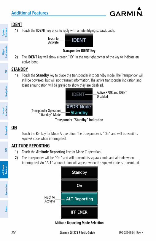
Garmin GI 275 Pilot's Guide 190-02246-01 Rev. H254
Additional Features
Syst
em
Ove
rvie
wFl
ight
In
stru
men
tsEI
SN
avig
atio
nH
azar
d Av
oida
nce
Aut
opilo
tIV
SIA
dditi
onal
Fe
atur
esA
ppen
dice
sIn
dex
IDENT1) Touch the IDENT key once to reply with an identifying squawk code.
Touch to Activate
Transponder IDENT Key
2) The IDENT key will show a green "ID" in the top right corner of the key to indicate an active Ident.
STANDBY1) Touch the Standby key to place the transponder into Standby mode. The Transponder will
still be powered, but will not transmit information. The active transponder indication and Ident annunciation will be greyed to show they are disabled.
Transponder "Standby" Indication
Transponder Operation "Standby" Mode
Active XPDR and IDENT Disabled
ON Touch the On key for Mode A operation. The transponder is "On" and will transmit its
squawk code when interrogated.
ALTITUDE REPORTING1) Touch the Altitude Reporting key for Mode C operation.2) The transponder will be "On" and will transmit its squawk code and altitude when
interrogated. An "ALT" annunciation will appear when the squawk code is transmitted.
Altitude Reporting Mode Selection
Touch to Activate
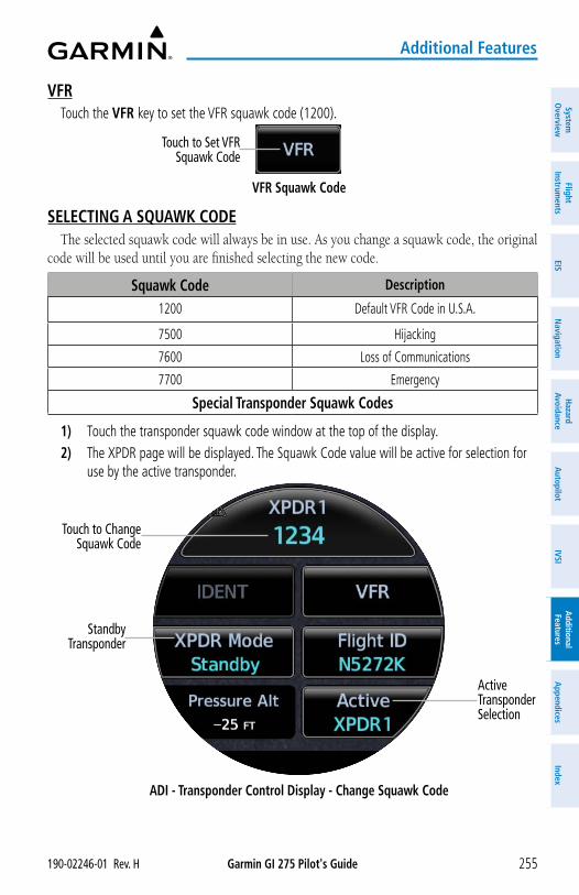
Garmin GI 275 Pilot's Guide190-02246-01 Rev. H 255
Additional Features
System
Overview
Flight Instrum
entsEIS
Navigation
Hazard
AvoidanceA
utopilotIVSI
Additional Features
Appendices
Index
VFRTouch the VFR key to set the VFR squawk code (1200).
Touch to Set VFR Squawk Code
VFR Squawk Code
SELECTING A SQUAWK CODEThe selected squawk code will always be in use. As you change a squawk code, the original
code will be used until you are finished selecting the new code.
Squawk Code Description
1200 Default VFR Code in U.S.A.
7500 Hijacking
7600 Loss of Communications
7700 Emergency
Special Transponder Squawk Codes
1) Touch the transponder squawk code window at the top of the display.2) The XPDR page will be displayed. The Squawk Code value will be active for selection for
use by the active transponder.
ADI - Transponder Control Display - Change Squawk Code
Active Transponder Selection
Touch to Change Squawk Code
Standby Transponder
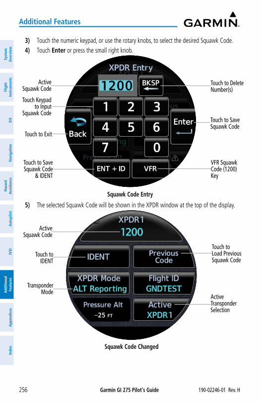
Garmin GI 275 Pilot's Guide 190-02246-01 Rev. H256
Additional Features
Syst
em
Ove
rvie
wFl
ight
In
stru
men
tsEI
SN
avig
atio
nH
azar
d Av
oida
nce
Aut
opilo
tIV
SIA
dditi
onal
Fe
atur
esA
ppen
dice
sIn
dex
3) Touch the numeric keypad, or use the rotary knobs, to select the desired Squawk Code. 4) Touch Enter or press the small right knob.
Squawk Code Entry
VFR Squawk Code (1200) Key
Active Squawk Code
Touch to Save Squawk Code
Touch to Save Squawk Code
& IDENT
Touch to Delete Number(s)
Touch Keypad to Input
Squawk Code
Touch to Exit
5) The selected Squawk Code will be shown in the XPDR window at the top of the display.
Squawk Code Changed
Active Transponder Selection
Active Squawk Code
Touch to Load Previous Squawk Code
Touch to IDENT
Transponder Mode
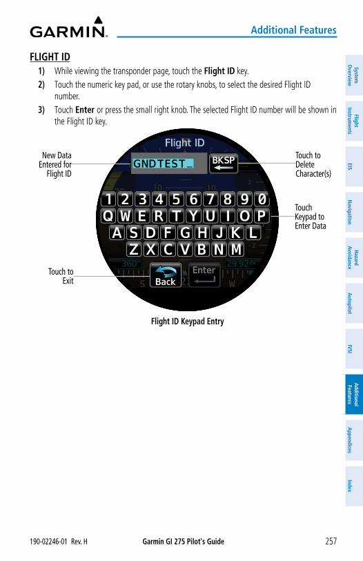
Garmin GI 275 Pilot's Guide190-02246-01 Rev. H 257
Additional Features
System
Overview
Flight Instrum
entsEIS
Navigation
Hazard
AvoidanceA
utopilotIVSI
Additional Features
Appendices
Index
FLIGHT ID1) While viewing the transponder page, touch the Flight ID key. 2) Touch the numeric key pad, or use the rotary knobs, to select the desired Flight ID
number.3) Touch Enter or press the small right knob. The selected Flight ID number will be shown in
the Flight ID key.
Flight ID Keypad Entry
Touch to Delete Character(s)
New Data Entered for
Flight ID
Touch Keypad to Enter Data
Touch to Exit
Garmin GI 275 Pilot's Guide 190-02246-01 Rev. H258
Additional Features
Syst
em
Ove
rvie
wFl
ight
In
stru
men
tsEI
SN
avig
atio
nH
azar
d Av
oida
nce
Aut
opilo
tIV
SIA
dditi
onal
Fe
atur
esA
ppen
dice
sIn
dex
Blank Page
Garmin GI 275 Pilot's Guide190-02246-01 Rev. H 259
Appendix A
System
Overview
Flight Instrum
entsEIS
Navigation
Hazard
AvoidanceA
utopilotIVSI
Additional Features
Appendices
Index
SECTION 9 APPENDICESAPPENDIX A: ANNUNCIATIONS, ALERTS AND GLOVE QUALIFICATION
The following types of annunciations and alerts can be displayed:
• Alert Annunciations
• Message Alert Indicator
• System Messages and Advisory Alerts
ALERT LEVEL DEFINITIONSAlert Annunciations vary in color and type depending on the alert level. The annunciation is
displayed in text form on the pertinent page. If an alert is issued, and the corresponding page is not currently displayed, a pop-up alert will be generated. Additionally, the corresponding gauge or indicator may change color. If a major component of the instrument system has failed, a red or yellow 'X' may be displayed.
The instrument may also issue audio alert tones or voice alerts when specific conditions are met. For function specific aural alerts, see the function's corresponding section of this guide for more information.
EIS Alerts are displayed in the Annunciation Banner on all EIS Pages. For more information on EIS Alerts, see the EIS Alerts discussion in the EIS Section.
Alerting levels are defined below in order of priority:
• Warning: This level of alert requires immediate pilot attention. A warning alert is annunciated in red text and depending on the alert, may be accompanied by an aural alert.
• Caution: This level of alert indicates the existence of abnormal conditions on the aircraft that may require pilot intervention. A caution alert is annunciated in yellow text and may be accompanied by an aural alert.
• Advisory: This level of alert provides general information to the pilot. A message advisory alert is annunciated in white text.
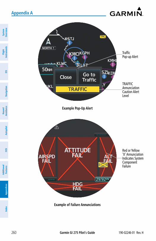
Garmin GI 275 Pilot's Guide 190-02246-01 Rev. H260
Appendix A
Syst
em
Ove
rvie
wFl
ight
In
stru
men
tsEI
SN
avig
atio
nH
azar
d Av
oida
nce
Aut
opilo
tIV
SIA
dditi
onal
Fe
atur
esA
ppen
dice
sIn
dex
Example Pop-Up Alert
Traffic Pop-up Alert
TRAFFIC Annunciation Caution Alert Level
Example of Failure Annunciations
Red or Yellow 'X' Annunciation Indicates System Component Failure
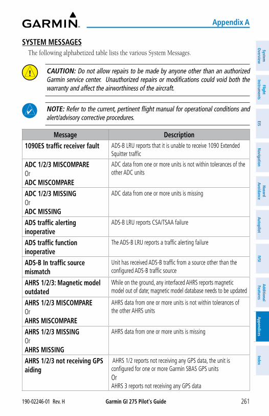
Garmin GI 275 Pilot's Guide190-02246-01 Rev. H 261
Appendix A
System
Overview
Flight Instrum
entsEIS
Navigation
Hazard
AvoidanceA
utopilotIVSI
Additional Features
Appendices
Index
SYSTEM MESSAGESThe following alphabetized table lists the various System Messages.
CAUTION: Do not allow repairs to be made by anyone other than an authorized Garmin service center. Unauthorized repairs or modifications could void both the warranty and affect the airworthiness of the aircraft.
NOTE: Refer to the current, pertinent flight manual for operational conditions and alert/advisory corrective procedures.
Message Description1090ES traffic receiver fault ADS-B LRU reports that it is unable to receive 1090 Extended
Squitter traffic
ADC 1/2/3 MISCOMPARE Or ADC MISCOMPARE
ADC data from one or more units is not within tolerances of the other ADC units
ADC 1/2/3 MISSING Or ADC MISSING
ADC data from one or more units is missing
ADS traffic alerting inoperative
ADS-B LRU reports CSA/TSAA failure
ADS traffic function inoperative
The ADS-B LRU reports a traffic alerting failure
ADS-B In traffic source mismatch
Unit has received ADS-B traffic from a source other than the configured ADS-B traffic source
AHRS 1/2/3: Magnetic model outdated
While on the ground, any interfaced AHRS reports magnetic model out of date; magnetic model database needs to be updated
AHRS 1/2/3 MISCOMPARE Or AHRS MISCOMPARE
AHRS data from one or more units is not within tolerances of the other AHRS units
AHRS 1/2/3 MISSING Or AHRS MISSING
AHRS data from one or more units is missing
AHRS 1/2/3 not receiving GPS aiding
AHRS 1/2 reports not receiving any GPS data, the unit is configured for one or more Garmin SBAS GPS units Or AHRS 3 reports not receiving any GPS data
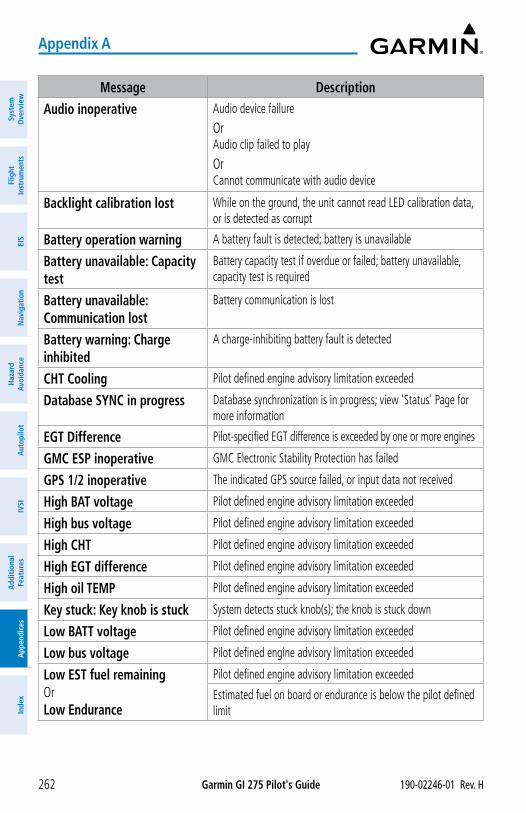
Garmin GI 275 Pilot's Guide 190-02246-01 Rev. H262
Appendix A
Syst
em
Ove
rvie
wFl
ight
In
stru
men
tsEI
SN
avig
atio
nH
azar
d Av
oida
nce
Aut
opilo
tIV
SIA
dditi
onal
Fe
atur
esA
ppen
dice
sIn
dex
Message DescriptionAudio inoperative Audio device failure
OrAudio clip failed to play
OrCannot communicate with audio device
Backlight calibration lost While on the ground, the unit cannot read LED calibration data, or is detected as corrupt
Battery operation warning A battery fault is detected; battery is unavailable
Battery unavailable: Capacity test
Battery capacity test if overdue or failed; battery unavailable, capacity test is required
Battery unavailable: Communication lost
Battery communication is lost
Battery warning: Charge inhibited
A charge-inhibiting battery fault is detected
CHT Cooling Pilot defined engine advisory limitation exceeded
Database SYNC in progress Database synchronization is in progress; view 'Status' Page for more information
EGT Difference Pilot-specified EGT difference is exceeded by one or more engines
GMC ESP inoperative GMC Electronic Stability Protection has failed
GPS 1/2 inoperative The indicated GPS source failed, or input data not received
High BAT voltage Pilot defined engine advisory limitation exceeded
High bus voltage Pilot defined engine advisory limitation exceeded
High CHT Pilot defined engine advisory limitation exceeded
High EGT difference Pilot defined engine advisory limitation exceeded
High oil TEMP Pilot defined engine advisory limitation exceeded
Key stuck: Key knob is stuck System detects stuck knob(s); the knob is stuck down
Low BATT voltage Pilot defined engine advisory limitation exceeded
Low bus voltage Pilot defined engine advisory limitation exceeded
Low EST fuel remaining Or Low Endurance
Pilot defined engine advisory limitation exceeded
Estimated fuel on board or endurance is below the pilot defined limit
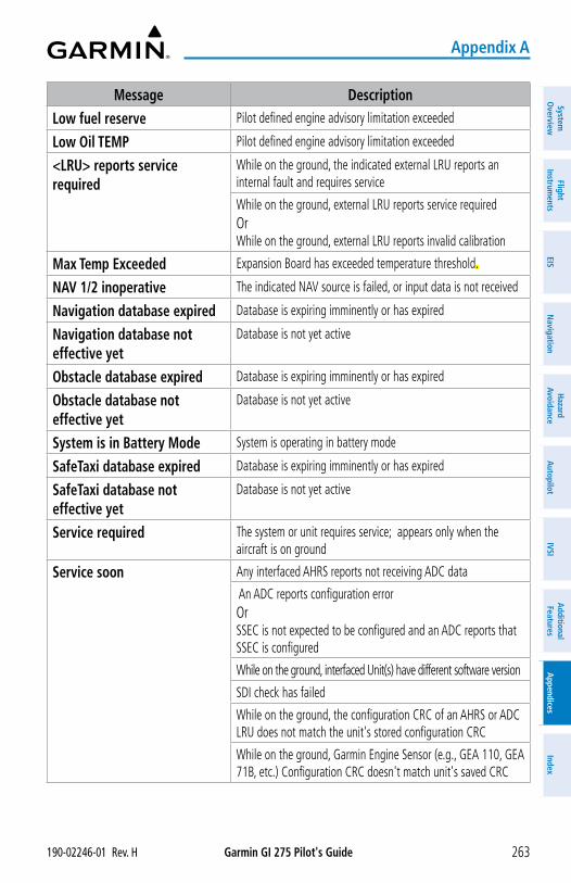
Garmin GI 275 Pilot's Guide190-02246-01 Rev. H 263
Appendix A
System
Overview
Flight Instrum
entsEIS
Navigation
Hazard
AvoidanceA
utopilotIVSI
Additional Features
Appendices
Index
Message DescriptionLow fuel reserve Pilot defined engine advisory limitation exceeded
Low Oil TEMP Pilot defined engine advisory limitation exceeded
<LRU> reports service required
While on the ground, the indicated external LRU reports an internal fault and requires service
While on the ground, external LRU reports service required Or While on the ground, external LRU reports invalid calibration
Max Temp Exceeded Expansion Board has exceeded temperature threshold..
NAV 1/2 inoperative The indicated NAV source is failed, or input data is not received
Navigation database expired Database is expiring imminently or has expired
Navigation database not effective yet
Database is not yet active
Obstacle database expired Database is expiring imminently or has expired
Obstacle database not effective yet
Database is not yet active
System is in Battery Mode System is operating in battery mode
SafeTaxi database expired Database is expiring imminently or has expired
SafeTaxi database not effective yet
Database is not yet active
Service required The system or unit requires service; appears only when the aircraft is on ground
Service soon Any interfaced AHRS reports not receiving ADC data
An ADC reports configuration error Or SSEC is not expected to be configured and an ADC reports that SSEC is configured
While on the ground, interfaced Unit(s) have different software version
SDI check has failed
While on the ground, the configuration CRC of an AHRS or ADC LRU does not match the unit's stored configuration CRC
While on the ground, Garmin Engine Sensor (e.g., GEA 110, GEA 71B, etc.) Configuration CRC doesn't match unit's saved CRC
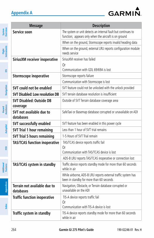
Garmin GI 275 Pilot's Guide 190-02246-01 Rev. H264
Appendix A
Syst
em
Ove
rvie
wFl
ight
In
stru
men
tsEI
SN
avig
atio
nH
azar
d Av
oida
nce
Aut
opilo
tIV
SIA
dditi
onal
Fe
atur
esA
ppen
dice
sIn
dex
Message DescriptionService soon The system or unit detects an internal fault but continues to
function; appears only when the aircraft is on ground
When on the ground, Stormscope reports invalid heading data
When on the ground, external LRU reports configuration module needs service
SiriusXM receiver inoperative SiriusXM receiver has failed
Or Communication with GDL 69/69A is lost
Stormscope inoperative Stormscope reports failure
Communication with Stormscope is lost
SVT could not be enabled SVT feature could not be unlocked with the unlock provided
SVT Disabled: Low resolution DB SVT terrain database resolution is insufficient
SVT Disabled: Outside DB coverage
Outside of SVT Terrain database coverage area
SVT not available due to databases
SafeTaxi or Basemap database corrupted or unavailable on ADI
SVT successfully enabled SVT feature has been enabled in this power cycle
SVT Trial 1 hour remaining Less than 1 hour of SVT trial remains
SVT Trial 5 hours remaining 1-5 Hours of SVT Trial remain
TAS/TCAS function inoperative TAS/TCAS device reports traffic fail Or Communication with TAS/TCAS device is lost
ADS-B LRU reports TAS/TCAS inoperative or connection lost
TAS/TCAS system in standby Traffic device reports standby mode for more than 60 seconds while in air
While airborne, ADS-B LRU reports external traffic system has been in standby for more than 60 seconds
Terrain not available due to databases
Navigation, Obstacle, or Terrain database corrupted or unavailable on the ADI
Traffic function inoperative TIS-A device reports traffic fail Or Communication with TIS-A device is lost
Traffic system in standby TIS-A device reports standby mode for more than 60 seconds while in air
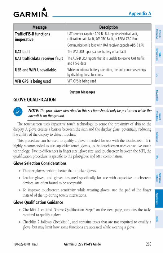
Garmin GI 275 Pilot's Guide190-02246-01 Rev. H 265
Appendix A
System
Overview
Flight Instrum
entsEIS
Navigation
Hazard
AvoidanceA
utopilotIVSI
Additional Features
Appendices
Index
Message DescriptionTraffic/FIS-B functions inoperative
UAT receiver capable ADS-B LRU reports electrical fault, calibration data fault, SW CRC Fault, or FPGA CRC Fault
Communication is lost with UAT receiver capable ADS-B LRU
UAT fault The UAT LRU reports a low battery or fan fault
UAT traffic/data receiver fault The ADS-B LRU reports that it is unable to receive UAT traffic and FIS-B data
USB and WiFi Unavailable While on internal battery operation, the unit conserves energy by disabling these functions.
VFR GPS is being used VFR GPS is being used
System Messages
GLOVE QUALIFICATION
NOTE: The procedures described in this section should only be performed while the aircraft is on the ground.
The touchscreen uses capacitive touch technology to sense the proximity of skin to the display. A glove creates a barrier between the skin and the display glass, potentially reducing the ability of the display to detect touches.
This procedure can be used to qualify a glove intended for use with the touchscreen. It is highly recommended to use capacitive touch gloves, as the touchscreen uses capacitive touch technology. Due to differences in finger size, glove size, and touchscreen between the MFI, the qualification procedure is specific to the pilot/glove and MFI combination.
Glove Selection Considerations
» Thinner gloves perform better than thicker gloves.
» Leather gloves, and gloves designed specifically for use with capacitive touchscreen devices, are often found to be acceptable.
» To improve touchscreen sensitivity while wearing gloves, use the pad of the finger instead of the tip during touch interactions.
Glove Qualification Guidance
» Checklist 1 entitled "Glove Qualification Steps" on the next page, contains the tasks required to qualify a glove.
» Checklist 2 follows Checklist 1, and contains tasks that are not required to qualify a glove, but may limit how some functions are accessed while wearing a glove.
Garmin GI 275 Pilot's Guide 190-02246-01 Rev. H266
Appendix A
Syst
em
Ove
rvie
wFl
ight
In
stru
men
tsEI
SN
avig
atio
nH
azar
d Av
oida
nce
Aut
opilo
tIV
SIA
dditi
onal
Fe
atur
esA
ppen
dice
sIn
dex
Glove Qualification StepsComplete only the tasks for the capabilities relevant to the installed MFI.
1. Sit in the pilot's seat.
2. Start the MFI in normal mode.
3. Perform the tasks listed in each checklist, tapping each key with a non-gloved finger. It is not necessary to record any results for this step.
4. Repeat step 3 using a gloved hand.
5. For each task, determine whether the touchscreen response is the same, or worse, without the glove.
NOTE: For some items, the touch keypad or dual rotary knob may be used as long as the response is adequate with gloved hands.
6. Record the results in the applicable column. Items that may cause the operation to be worse will include, but are not limited to:
4Multiple attempts to select a key.
4Unintentional selection of adjacent key(s).
4Excessive force on the touchscreen to select a key
7. If all applicable tasks produce the same response, with and without a glove, the pilot may use the glove in flight.
Glove Qualification ProcedurePilot:______________________________________________________________
Glove Description:____________________________________________________
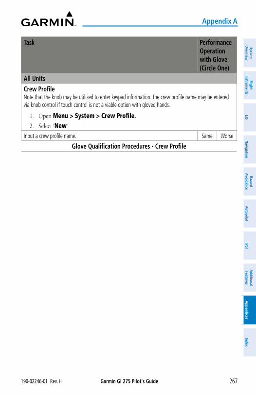
Garmin GI 275 Pilot's Guide190-02246-01 Rev. H 267
Appendix A
System
Overview
Flight Instrum
entsEIS
Navigation
Hazard
AvoidanceA
utopilotIVSI
Additional Features
Appendices
Index
Task Performance Operation with Glove (Circle One)
All UnitsCrew ProfileNote that the knob may be utilized to enter keypad information. The crew profile name may be entered via knob control if touch control is not a viable option with gloved hands.
1. Open Menu > System > Crew Profile.2. Select 'New'
Input a crew profile name. Same Worse
Glove Qualification Procedures - Crew Profile
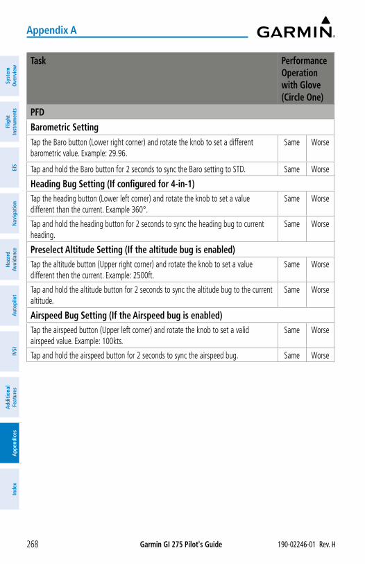
Garmin GI 275 Pilot's Guide 190-02246-01 Rev. H268
Appendix A
Syst
em
Ove
rvie
wFl
ight
In
stru
men
tsEI
SN
avig
atio
nH
azar
d Av
oida
nce
Aut
opilo
tIV
SIA
dditi
onal
Fe
atur
esA
ppen
dice
sIn
dex
Task Performance Operation with Glove (Circle One)
PFDBarometric SettingTap the Baro button (Lower right corner) and rotate the knob to set a different barometric value. Example: 29.96.
Same Worse
Tap and hold the Baro button for 2 seconds to sync the Baro setting to STD. Same Worse
Heading Bug Setting (If configured for 4-in-1)Tap the heading button (Lower left corner) and rotate the knob to set a value different than the current. Example 360°.
Same Worse
Tap and hold the heading button for 2 seconds to sync the heading bug to current heading.
Same Worse
Preselect Altitude Setting (If the altitude bug is enabled)Tap the altitude button (Upper right corner) and rotate the knob to set a value different then the current. Example: 2500ft.
Same Worse
Tap and hold the altitude button for 2 seconds to sync the altitude bug to the current altitude.
Same Worse
Airspeed Bug Setting (If the Airspeed bug is enabled)Tap the airspeed button (Upper left corner) and rotate the knob to set a valid airspeed value. Example: 100kts.
Same Worse
Tap and hold the airspeed button for 2 seconds to sync the airspeed bug. Same Worse
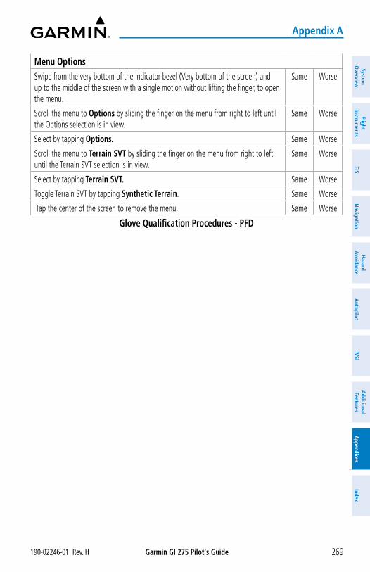
Garmin GI 275 Pilot's Guide190-02246-01 Rev. H 269
Appendix A
System
Overview
Flight Instrum
entsEIS
Navigation
Hazard
AvoidanceA
utopilotIVSI
Additional Features
Appendices
Index
Menu OptionsSwipe from the very bottom of the indicator bezel (Very bottom of the screen) and up to the middle of the screen with a single motion without lifting the finger, to open the menu.
Same Worse
Scroll the menu to Options by sliding the finger on the menu from right to left until the Options selection is in view.
Same Worse
Select by tapping Options. Same Worse
Scroll the menu to Terrain SVT by sliding the finger on the menu from right to left until the Terrain SVT selection is in view.
Same Worse
Select by tapping Terrain SVT. Same Worse
Toggle Terrain SVT by tapping Synthetic Terrain. Same Worse
Tap the center of the screen to remove the menu. Same Worse
Glove Qualification Procedures - PFD
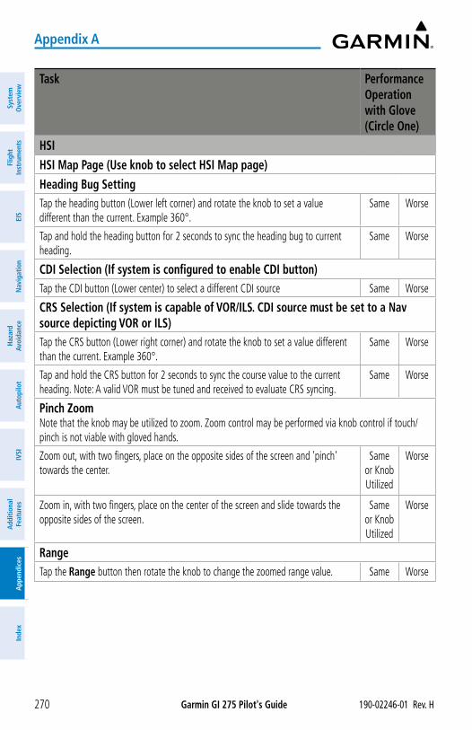
Garmin GI 275 Pilot's Guide 190-02246-01 Rev. H270
Appendix A
Syst
em
Ove
rvie
wFl
ight
In
stru
men
tsEI
SN
avig
atio
nH
azar
d Av
oida
nce
Aut
opilo
tIV
SIA
dditi
onal
Fe
atur
esA
ppen
dice
sIn
dex
Task Performance Operation with Glove (Circle One)
HSIHSI Map Page (Use knob to select HSI Map page)Heading Bug SettingTap the heading button (Lower left corner) and rotate the knob to set a value different than the current. Example 360°.
Same Worse
Tap and hold the heading button for 2 seconds to sync the heading bug to current heading.
Same Worse
CDI Selection (If system is configured to enable CDI button)Tap the CDI button (Lower center) to select a different CDI source Same Worse
CRS Selection (If system is capable of VOR/ILS. CDI source must be set to a Nav source depicting VOR or ILS)Tap the CRS button (Lower right corner) and rotate the knob to set a value different than the current. Example 360°.
Same Worse
Tap and hold the CRS button for 2 seconds to sync the course value to the current heading. Note: A valid VOR must be tuned and received to evaluate CRS syncing.
Same Worse
Pinch ZoomNote that the knob may be utilized to zoom. Zoom control may be performed via knob control if touch/pinch is not viable with gloved hands.
Zoom out, with two fingers, place on the opposite sides of the screen and 'pinch' towards the center.
Same or Knob Utilized
Worse
Zoom in, with two fingers, place on the center of the screen and slide towards the opposite sides of the screen.
Same or Knob Utilized
Worse
RangeTap the Range button then rotate the knob to change the zoomed range value. Same Worse
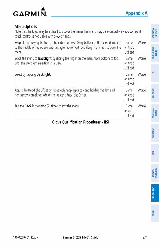
Garmin GI 275 Pilot's Guide190-02246-01 Rev. H 271
Appendix A
System
Overview
Flight Instrum
entsEIS
Navigation
Hazard
AvoidanceA
utopilotIVSI
Additional Features
Appendices
Index
Menu OptionsNote that the knob may be utilized to access the menu. The menu may be accessed via knob control if touch control is not viable with gloved hands.
Swipe from the very bottom of the indicator bezel (Very bottom of the screen) and up to the middle of the screen with a single motion without lifting the finger, to open the menu.
Same or Knob Utilized
Worse
Scroll the menu to Backlight by sliding the finger on the menu from bottom to top, until the Backlight selection is in view.
Same or Knob Utilized
Worse
Select by tapping Backlight. Same or Knob Utilized
Worse
Adjust the Backlight Offset by repeatedly tapping or tap and holding the left and right arrows on either side of the percent Backlight Offset.
Same or Knob Utilized
Worse
Tap the Back button two (2) times to exit the menu. Same or Knob Utilized
Worse
Glove Qualification Procedures - HSI
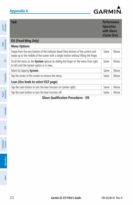
Garmin GI 275 Pilot's Guide 190-02246-01 Rev. H272
Appendix A
Syst
em
Ove
rvie
wFl
ight
In
stru
men
tsEI
SN
avig
atio
nH
azar
d Av
oida
nce
Aut
opilo
tIV
SIA
dditi
onal
Fe
atur
esA
ppen
dice
sIn
dex
Task Performance Operation with Glove (Circle One)
EIS (Fixed Wing Only)Menu OptionsSwipe from the very bottom of the indicator bezel (Very bottom of the screen) and swipe up to the middle of the screen with a single motion without lifting the finger.
Same Worse
Scroll the menu to the System options by sliding the finger on the menu from right to left until the System option is in view.
Same Worse
Select by tapping System. Same Worse
Tap the center of the screen to remove the menu. Same Worse
Lean (Use knob to select EGT page)Tap the Lean button to turn the lean function on (center right). Same Worse
Tap the Lean button to turn the lean function off. Same Worse
Glove Qualification Procedures - EIS
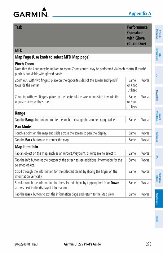
Garmin GI 275 Pilot's Guide190-02246-01 Rev. H 273
Appendix A
System
Overview
Flight Instrum
entsEIS
Navigation
Hazard
AvoidanceA
utopilotIVSI
Additional Features
Appendices
Index
Task Performance Operation with Glove (Circle One)
MFDMap Page (Use knob to select MFD Map page)Pinch ZoomNote that the knob may be utilized to zoom. Zoom control may be performed via knob control if touch/pinch is not viable with gloved hands.
Zoom out, with two fingers, place on the opposite sides of the screen and ‘pinch’ towards the center.
Same or Knob Utilized
Worse
Zoom in, with two fingers, place on the center of the screen and slide towards the opposite sides of the screen.
Same or Knob Utilized
Worse
RangeTap the Range button and rotate the knob to change the zoomed range value. Same Worse
Pan ModeTouch a point on the map and slide across the screen to pan the display. Same Worse
Tap the Back button to re-center the map. Same Worse
Map Item InfoTap an object on the map, such as an Airport, Waypoint, or Airspace, to select it. Same Worse
Tap the Info button at the bottom of the screen to see additional information for the selected object.
Same Worse
Scroll through the information for the selected object by sliding the finger on the information vertically.
Same Worse
Scroll through the information for the selected object by tapping the Up or Down arrows next to the displayed information.
Same Worse
Tap the Back button to exit the information page and return to the Map view. Same Worse
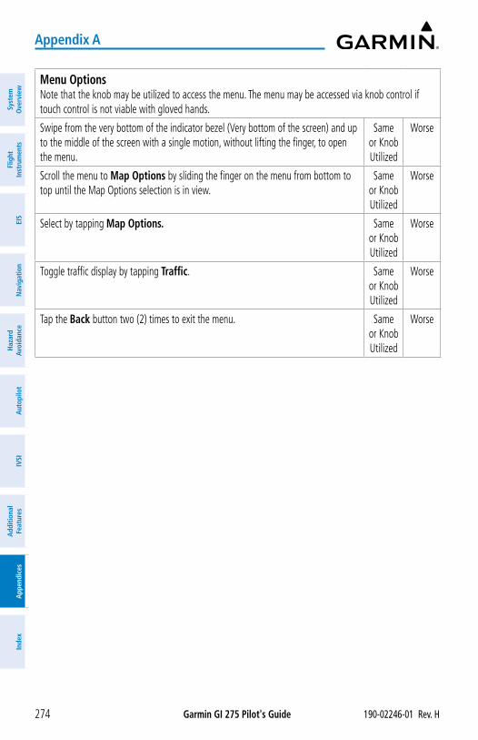
Garmin GI 275 Pilot's Guide 190-02246-01 Rev. H274
Appendix A
Syst
em
Ove
rvie
wFl
ight
In
stru
men
tsEI
SN
avig
atio
nH
azar
d Av
oida
nce
Aut
opilo
tIV
SIA
dditi
onal
Fe
atur
esA
ppen
dice
sIn
dex
Menu OptionsNote that the knob may be utilized to access the menu. The menu may be accessed via knob control if touch control is not viable with gloved hands.
Swipe from the very bottom of the indicator bezel (Very bottom of the screen) and up to the middle of the screen with a single motion, without lifting the finger, to open the menu.
Same or Knob Utilized
Worse
Scroll the menu to Map Options by sliding the finger on the menu from bottom to top until the Map Options selection is in view.
Same or Knob Utilized
Worse
Select by tapping Map Options. Same or Knob Utilized
Worse
Toggle traffic display by tapping Traffic. Same or Knob Utilized
Worse
Tap the Back button two (2) times to exit the menu. Same or Knob Utilized
Worse
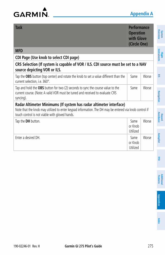
Garmin GI 275 Pilot's Guide190-02246-01 Rev. H 275
Appendix A
System
Overview
Flight Instrum
entsEIS
Navigation
Hazard
AvoidanceA
utopilotIVSI
Additional Features
Appendices
Index
Task Performance Operation with Glove (Circle One)
MFDCDI Page (Use knob to select CDI page)CRS Selection (If system is capable of VOR / ILS. CDI source must be set to a NAV source depicting VOR or ILS.Tap the OBS button (top center) and rotate the knob to set a value different than the current selection, i.e. 360°.
Same Worse
Tap and hold the OBS button for two (2) seconds to sync the course value to the current course. (Note: A valid VOR must be tuned and received to evaluate CRS syncing).
Same Worse
Radar Altimeter Minimums (If system has radar altimeter interface)Note that the knob may utilized to enter keypad information. The DH may be entered via knob control if touch control is not viable with gloved hands.
Tap the DH button. Same or Knob Utilized
Worse
Enter a desired DH. Same or Knob Utilized
Worse
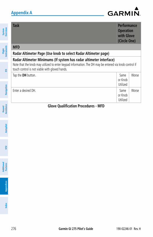
Garmin GI 275 Pilot's Guide 190-02246-01 Rev. H276
Appendix A
Syst
em
Ove
rvie
wFl
ight
In
stru
men
tsEI
SN
avig
atio
nH
azar
d Av
oida
nce
Aut
opilo
tIV
SIA
dditi
onal
Fe
atur
esA
ppen
dice
sIn
dex
Task Performance Operation with Glove (Circle One)
MFDRadar Altimeter Page (Use knob to select Radar Altimeter page)Radar Altimeter Minimums (If system has radar altimeter interface)Note that the knob may utilized to enter keypad information. The DH may be entered via knob control if touch control is not viable with gloved hands.
Tap the DH button. Same or Knob Utilized
Worse
Enter a desired DH. Same or Knob Utilized
Worse
Glove Qualification Procedures - MFD
Garmin GI 275 Pilot's Guide190-02246-01 Rev. H 277
Appendix B
System
Overview
Flight Instrum
entsEIS
Navigation
Hazard
AvoidanceA
utopilotIVSI
Additional Features
Appendices
Index
APPENDIX B: DATABASE INFORMATION
NOTE: The pilot/operator must review and be familiar with Garmin’s database exclusion list as discussed in SAIB CE-14-04 to determine what data may be incomplete. The database exclusion list can be viewed at flygarmin.com by selecting ‘Database Exclusions List.’
NOTE: The pilot/operator must have access to Garmin and Jeppesen database alerts and consider their impact on the intended aircraft operation. The database alerts can be viewed at flygarmin.com by selecting ‘Aviation Database Alerts.’
NOTE: If the pilot/operator wants or needs to adjust the database, contact Garmin Product Support.
NOTE: The FAA has asked Garmin to remind pilots who fly with Garmin database-dependent avionics of the following:
• It is the pilot’s responsibility to remain familiar with all FAA regulatory and advisory guidance and information related to the use of databases in the National Airspace System.
• Garmin equipment will only recognize and use databases that are obtained from Garmin or Jeppesen. Databases obtained from Garmin or Jeppesen that have a Type 2 Letter of Authorization (LOA) from the FAA are assured compliance with all data quality requirements (DQRs). A copy of the Type 2 LOA is available for each applicable database and can be viewed at flygarmin.com by selecting ‘Aviation Database Declarations.’
• Use of a current Garmin or Jeppesen database in your Garmin equipment is required for compliance with established FAA regulatory guidance, but does not constitute authorization to fly any and all terminal procedures that may be presented by the system. It is the pilot’s responsibility to operate in accordance with established pertinent aircraft documents and regulatory guidance or limitations as applicable to the pilot, the aircraft, and installed equipment.
NOTE: Garmin requests the flight crew report any observed discrepancies related to database information. These discrepancies could come in the form of an incorrect procedure; incorrectly identified terrain, obstacles and fixes; or any other displayed item used for navigation or communication in the air or on the ground. Go to flygarmin.com and select ‘Aviation Data Error Report.'
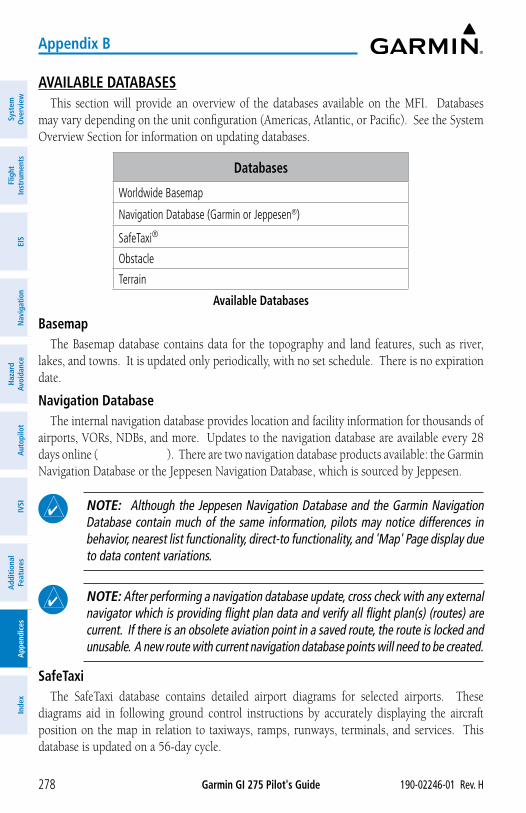
Garmin GI 275 Pilot's Guide 190-02246-01 Rev. H278
Appendix B
Syst
em
Ove
rvie
wFl
ight
In
stru
men
tsEI
SN
avig
atio
nH
azar
d Av
oida
nce
Aut
opilo
tIV
SIA
dditi
onal
Fe
atur
esA
ppen
dice
sIn
dex
AVAILABLE DATABASESThis section will provide an overview of the databases available on the MFI. Databases
may vary depending on the unit configuration (Americas, Atlantic, or Pacific). See the System Overview Section for information on updating databases.
Databases
Worldwide Basemap
Navigation Database (Garmin or Jeppesen®)
SafeTaxi®
Obstacle
Terrain
Available Databases
BasemapThe Basemap database contains data for the topography and land features, such as river,
lakes, and towns. It is updated only periodically, with no set schedule. There is no expiration date.
Navigation DatabaseThe internal navigation database provides location and facility information for thousands of
airports, VORs, NDBs, and more. Updates to the navigation database are available every 28 days online (flygarmin.com). There are two navigation database products available: the Garmin Navigation Database or the Jeppesen Navigation Database, which is sourced by Jeppesen.
NOTE: Although the Jeppesen Navigation Database and the Garmin Navigation Database contain much of the same information, pilots may notice differences in behavior, nearest list functionality, direct-to functionality, and 'Map' Page display due to data content variations.
NOTE: After performing a navigation database update, cross check with any external navigator which is providing flight plan data and verify all flight plan(s) (routes) are current. If there is an obsolete aviation point in a saved route, the route is locked and unusable. A new route with current navigation database points will need to be created.
SafeTaxiThe SafeTaxi database contains detailed airport diagrams for selected airports. These
diagrams aid in following ground control instructions by accurately displaying the aircraft position on the map in relation to taxiways, ramps, runways, terminals, and services. This database is updated on a 56-day cycle.
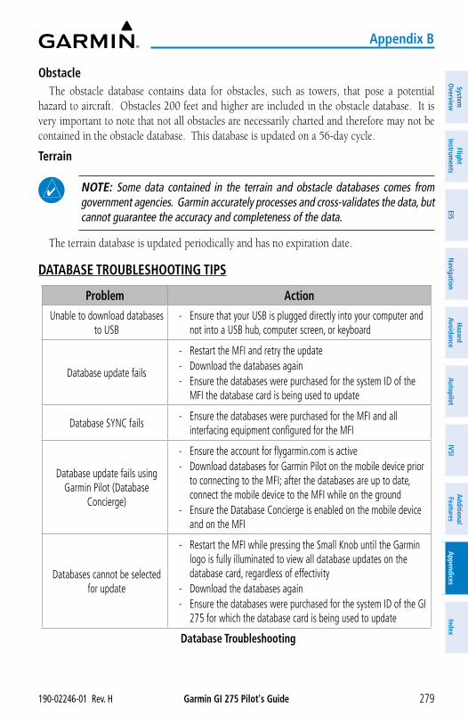
Garmin GI 275 Pilot's Guide190-02246-01 Rev. H 279
Appendix B
System
Overview
Flight Instrum
entsEIS
Navigation
Hazard
AvoidanceA
utopilotIVSI
Additional Features
Appendices
Index
ObstacleThe obstacle database contains data for obstacles, such as towers, that pose a potential
hazard to aircraft. Obstacles 200 feet and higher are included in the obstacle database. It is very important to note that not all obstacles are necessarily charted and therefore may not be contained in the obstacle database. This database is updated on a 56-day cycle.
Terrain
NOTE: Some data contained in the terrain and obstacle databases comes from government agencies. Garmin accurately processes and cross-validates the data, but cannot guarantee the accuracy and completeness of the data.
The terrain database is updated periodically and has no expiration date.
DATABASE TROUBLESHOOTING TIPS
Problem Action
Unable to download databases to USB
- Ensure that your USB is plugged directly into your computer and not into a USB hub, computer screen, or keyboard
Database update fails
- Restart the MFI and retry the update - Download the databases again - Ensure the databases were purchased for the system ID of the
MFI the database card is being used to update
Database SYNC fails - Ensure the databases were purchased for the MFI and all
interfacing equipment configured for the MFI
Database update fails using Garmin Pilot (Database
Concierge)
- Ensure the account for flygarmin.com is active - Download databases for Garmin Pilot on the mobile device prior
to connecting to the MFI; after the databases are up to date, connect the mobile device to the MFI while on the ground
- Ensure the Database Concierge is enabled on the mobile device and on the MFI
Databases cannot be selected for update
- Restart the MFI while pressing the Small Knob until the Garmin logo is fully illuminated to view all database updates on the database card, regardless of effectivity
- Download the databases again - Ensure the databases were purchased for the system ID of the GI
275 for which the database card is being used to update
Database Troubleshooting
Garmin GI 275 Pilot's Guide 190-02246-01 Rev. H280
Appendix B
Syst
em
Ove
rvie
wFl
ight
In
stru
men
tsEI
SN
avig
atio
nH
azar
d Av
oida
nce
Aut
opilo
tIV
SIA
dditi
onal
Fe
atur
esA
ppen
dice
sIn
dex
Blank Page
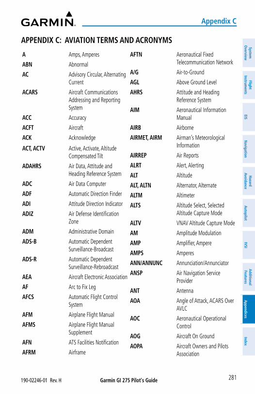
Garmin GI 275 Pilot's Guide190-02246-01 Rev. H
Appendix C
281
System
Overview
Flight Instrum
entsEIS
Navigation
Hazard
AvoidanceA
utopilotIVSI
Additional Features
Appendices
Index
A Amps, Amperes
ABN Abnormal
AC Advisory Circular, Alternating Current
ACARS Aircraft Communications Addressing and Reporting System
ACC Accuracy
ACFT Aircraft
ACK Acknowledge
ACT, ACTV Active, Activate, Altitude Compensated Tilt
ADAHRS Air Data, Attitude and Heading Reference System
ADC Air Data Computer
ADF Automatic Direction Finder
ADI Attitude Direction Indicator
ADIZ Air Defense Identification Zone
ADM Administrative Domain
ADS-B Automatic Dependent Surveillance-Broadcast
ADS-R Automatic Dependent Surveillance-Rebroadcast
AEA Aircraft Electronic Association
AF Arc to Fix Leg
AFCS Automatic Flight Control System
AFM Airplane Flight Manual
AFMS Airplane Flight Manual Supplement
AFN ATS Facilities Notification
AFRM Airframe
AFTN Aeronautical Fixed Telecommunication Network
A/G Air-to-Ground
AGL Above Ground Level
AHRS Attitude and Heading Reference System
AIM Aeronautical Information Manual
AIRB Airborne
AIRMET, AIRM Airman’s Meteorological Information
AIRREP Air Reports
ALRT Alert, Alerting
ALT Altitude
ALT, ALTN Alternator, Alternate
ALTM Altimeter
ALTS Altitude Select, Selected Altitude Capture Mode
ALTV VNAV Altitude Capture Mode
AM Amplitude Modulation
AMP Amplifier, Ampere
AMPS Amperes
ANN/ANNUNC Annunciation/Annunciator
ANSP Air Navigation Service Provider
ANT Antenna
AOA Angle of Attack, ACARS Over AVLC
AOC Aeronautical Operational Control
AOG Aircraft On Ground
AOPA Aircraft Owners and Pilots Association
APPENDIX C: AVIATION TERMS AND ACRONYMS
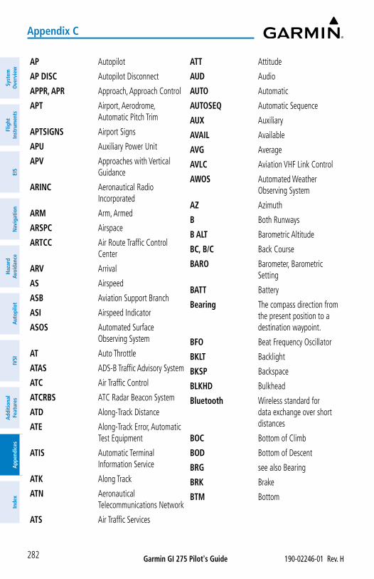
Garmin GI 275 Pilot's Guide 190-02246-01 Rev. H
Appendix C
282
Syst
em
Ove
rvie
wFl
ight
In
stru
men
tsEI
SN
avig
atio
nH
azar
d Av
oida
nce
Aut
opilo
tIV
SIA
dditi
onal
Fe
atur
esA
ppen
dice
sIn
dex
AP Autopilot
AP DISC Autopilot Disconnect
APPR, APR Approach, Approach Control
APT Airport, Aerodrome, Automatic Pitch Trim
APTSIGNS Airport Signs
APU Auxiliary Power Unit
APV Approaches with Vertical Guidance
ARINC Aeronautical Radio Incorporated
ARM Arm, Armed
ARSPC Airspace
ARTCC Air Route Traffic Control Center
ARV Arrival
AS Airspeed
ASB Aviation Support Branch
ASI Airspeed Indicator
ASOS Automated Surface Observing System
AT Auto Throttle
ATAS ADS-B Traffic Advisory System
ATC Air Traffic Control
ATCRBS ATC Radar Beacon System
ATD Along-Track Distance
ATE Along-Track Error, Automatic Test Equipment
ATIS Automatic Terminal Information Service
ATK Along Track
ATN Aeronautical Telecommunications Network
ATS Air Traffic Services
ATT Attitude
AUD Audio
AUTO Automatic
AUTOSEQ Automatic Sequence
AUX Auxiliary
AVAIL Available
AVG Average
AVLC Aviation VHF Link Control
AWOS Automated Weather Observing System
AZ Azimuth
B Both Runways
B ALT Barometric Altitude
BC, B/C Back Course
BARO Barometer, Barometric Setting
BATT Battery
Bearing The compass direction from the present position to a destination waypoint.
BFO Beat Frequency Oscillator
BKLT Backlight
BKSP Backspace
BLKHD Bulkhead
Bluetooth Wireless standard for data exchange over short distances
BOC Bottom of Climb
BOD Bottom of Descent
BRG see also Bearing
BRK Brake
BTM Bottom
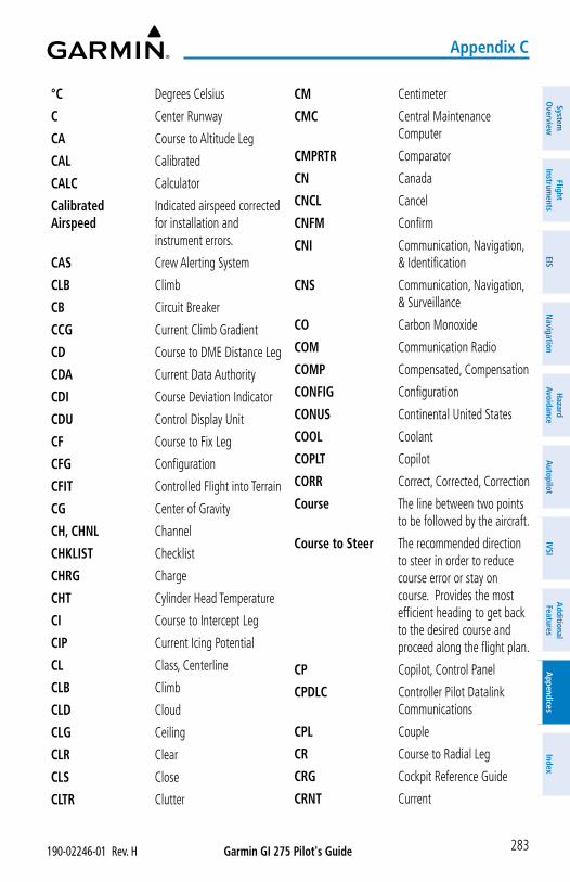
Garmin GI 275 Pilot's Guide190-02246-01 Rev. H
Appendix C
283
System
Overview
Flight Instrum
entsEIS
Navigation
Hazard
AvoidanceA
utopilotIVSI
Additional Features
Appendices
Index
°C Degrees Celsius
C Center Runway
CA Course to Altitude Leg
CAL Calibrated
CALC Calculator
Calibrated Airspeed
Indicated airspeed corrected for installation and instrument errors.
CAS Crew Alerting System
CLB Climb
CB Circuit Breaker
CCG Current Climb Gradient
CD Course to DME Distance Leg
CDA Current Data Authority
CDI Course Deviation Indicator
CDU Control Display Unit
CF Course to Fix Leg
CFG Configuration
CFIT Controlled Flight into Terrain
CG Center of Gravity
CH, CHNL Channel
CHKLIST Checklist
CHRG Charge
CHT Cylinder Head Temperature
CI Course to Intercept Leg
CIP Current Icing Potential
CL Class, Centerline
CLB Climb
CLD Cloud
CLG Ceiling
CLR Clear
CLS Close
CLTR Clutter
CM Centimeter
CMC Central Maintenance Computer
CMPRTR Comparator
CN Canada
CNCL Cancel
CNFM Confirm
CNI Communication, Navigation, & Identification
CNS Communication, Navigation, & Surveillance
CO Carbon Monoxide
COM Communication Radio
COMP Compensated, Compensation
CONFIG Configuration
CONUS Continental United States
COOL Coolant
COPLT Copilot
CORR Correct, Corrected, Correction
Course The line between two points to be followed by the aircraft.
Course to Steer The recommended direction to steer in order to reduce course error or stay on course. Provides the most efficient heading to get back to the desired course and proceed along the flight plan.
CP Copilot, Control Panel
CPDLC Controller Pilot Datalink Communications
CPL Couple
CR Course to Radial Leg
CRG Cockpit Reference Guide
CRNT Current
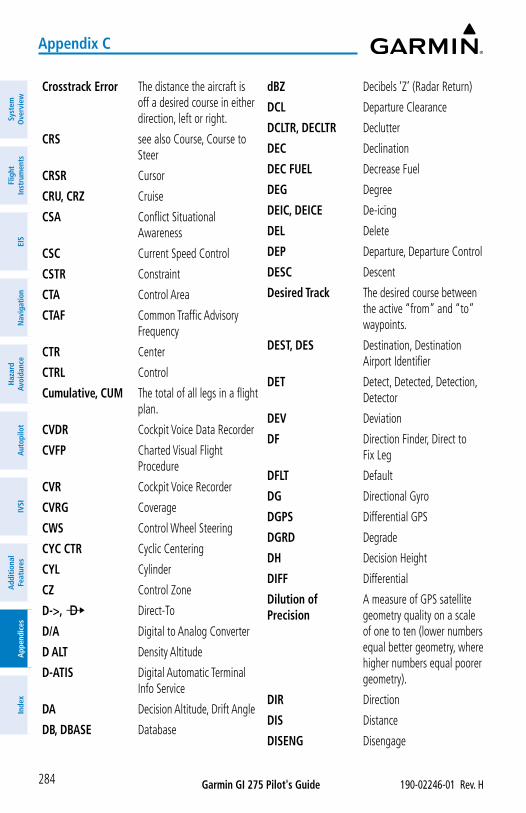
Garmin GI 275 Pilot's Guide 190-02246-01 Rev. H
Appendix C
284
Syst
em
Ove
rvie
wFl
ight
In
stru
men
tsEI
SN
avig
atio
nH
azar
d Av
oida
nce
Aut
opilo
tIV
SIA
dditi
onal
Fe
atur
esA
ppen
dice
sIn
dex
Crosstrack Error The distance the aircraft is off a desired course in either direction, left or right.
CRS see also Course, Course to Steer
CRSR Cursor
CRU, CRZ Cruise
CSA Conflict Situational Awareness
CSC Current Speed Control
CSTR Constraint
CTA Control Area
CTAF Common Traffic Advisory Frequency
CTR Center
CTRL Control
Cumulative, CUM The total of all legs in a flight plan.
CVDR Cockpit Voice Data Recorder
CVFP Charted Visual Flight Procedure
CVR Cockpit Voice Recorder
CVRG Coverage
CWS Control Wheel Steering
CYC CTR Cyclic Centering
CYL Cylinder
CZ Control Zone
D->, ¯ Direct-To
D/A Digital to Analog Converter
D ALT Density Altitude
D-ATIS Digital Automatic Terminal Info Service
DA Decision Altitude, Drift Angle
DB, DBASE Database
dBZ Decibels ‘Z’ (Radar Return)
DCL Departure Clearance
DCLTR, DECLTR Declutter
DEC Declination
DEC FUEL Decrease Fuel
DEG Degree
DEIC, DEICE De-icing
DEL Delete
DEP Departure, Departure Control
DESC Descent
Desired Track The desired course between the active “from” and “to” waypoints.
DEST, DES Destination, Destination Airport Identifier
DET Detect, Detected, Detection, Detector
DEV Deviation
DF Direction Finder, Direct to Fix Leg
DFLT Default
DG Directional Gyro
DGPS Differential GPS
DGRD Degrade
DH Decision Height
DIFF Differential
Dilution of Precision
A measure of GPS satellite geometry quality on a scale of one to ten (lower numbers equal better geometry, where higher numbers equal poorer geometry).
DIR Direction
DIS Distance
DISENG Disengage
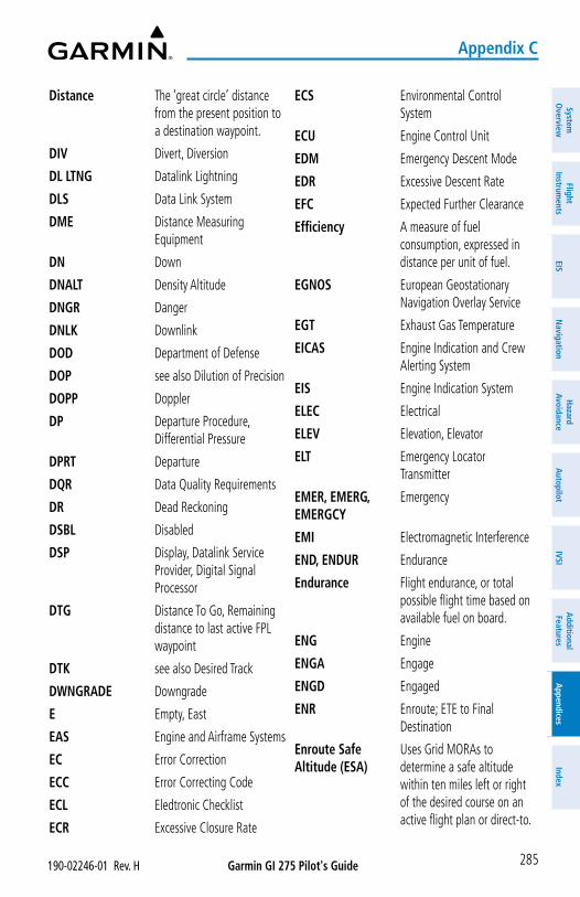
Garmin GI 275 Pilot's Guide190-02246-01 Rev. H
Appendix C
285
System
Overview
Flight Instrum
entsEIS
Navigation
Hazard
AvoidanceA
utopilotIVSI
Additional Features
Appendices
Index
Distance The ‘great circle’ distance from the present position to a destination waypoint.
DIV Divert, Diversion
DL LTNG Datalink Lightning
DLS Data Link System
DME Distance Measuring Equipment
DN Down
DNALT Density Altitude
DNGR Danger
DNLK Downlink
DOD Department of Defense
DOP see also Dilution of Precision
DOPP Doppler
DP Departure Procedure, Differential Pressure
DPRT Departure
DQR Data Quality Requirements
DR Dead Reckoning
DSBL Disabled
DSP Display, Datalink Service Provider, Digital Signal Processor
DTG Distance To Go, Remaining distance to last active FPL waypoint
DTK see also Desired Track
DWNGRADE Downgrade
E Empty, East
EAS Engine and Airframe Systems
EC Error Correction
ECC Error Correcting Code
ECL Eledtronic Checklist
ECR Excessive Closure Rate
ECS Environmental Control System
ECU Engine Control Unit
EDM Emergency Descent Mode
EDR Excessive Descent Rate
EFC Expected Further Clearance
Efficiency A measure of fuel consumption, expressed in distance per unit of fuel.
EGNOS European Geostationary Navigation Overlay Service
EGT Exhaust Gas Temperature
EICAS Engine Indication and Crew Alerting System
EIS Engine Indication System
ELEC Electrical
ELEV Elevation, Elevator
ELT Emergency Locator Transmitter
EMER, EMERG, EMERGCY
Emergency
EMI Electromagnetic Interference
END, ENDUR Endurance
Endurance Flight endurance, or total possible flight time based on available fuel on board.
ENG Engine
ENGA Engage
ENGD Engaged
ENR Enroute; ETE to Final Destination
Enroute Safe Altitude (ESA)
Uses Grid MORAs to determine a safe altitude within ten miles left or right of the desired course on an active flight plan or direct-to.
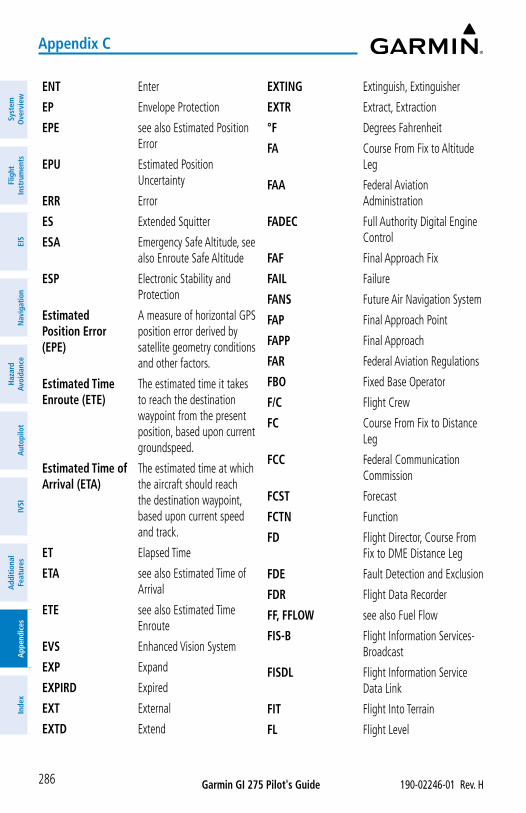
Garmin GI 275 Pilot's Guide 190-02246-01 Rev. H
Appendix C
286
Syst
em
Ove
rvie
wFl
ight
In
stru
men
tsEI
SN
avig
atio
nH
azar
d Av
oida
nce
Aut
opilo
tIV
SIA
dditi
onal
Fe
atur
esA
ppen
dice
sIn
dex
ENT Enter
EP Envelope Protection
EPE see also Estimated Position Error
EPU Estimated Position Uncertainty
ERR Error
ES Extended Squitter
ESA Emergency Safe Altitude, see also Enroute Safe Altitude
ESP Electronic Stability and Protection
Estimated Position Error (EPE)
A measure of horizontal GPS position error derived by satellite geometry conditions and other factors.
Estimated Time Enroute (ETE)
The estimated time it takes to reach the destination waypoint from the present position, based upon current groundspeed.
Estimated Time of Arrival (ETA)
The estimated time at which the aircraft should reach the destination waypoint, based upon current speed and track.
ET Elapsed Time
ETA see also Estimated Time of Arrival
ETE see also Estimated Time Enroute
EVS Enhanced Vision System
EXP Expand
EXPIRD Expired
EXT External
EXTD Extend
EXTING Extinguish, Extinguisher
EXTR Extract, Extraction
°F Degrees Fahrenheit
FA Course From Fix to Altitude Leg
FAA Federal Aviation Administration
FADEC Full Authority Digital Engine Control
FAF Final Approach Fix
FAIL Failure
FANS Future Air Navigation System
FAP Final Approach Point
FAPP Final Approach
FAR Federal Aviation Regulations
FBO Fixed Base Operator
F/C Flight Crew
FC Course From Fix to Distance Leg
FCC Federal Communication Commission
FCST Forecast
FCTN Function
FD Flight Director, Course From Fix to DME Distance Leg
FDE Fault Detection and Exclusion
FDR Flight Data Recorder
FF, FFLOW see also Fuel Flow
FIS-B Flight Information Services-Broadcast
FISDL Flight Information Service Data Link
FIT Flight Into Terrain
FL Flight Level
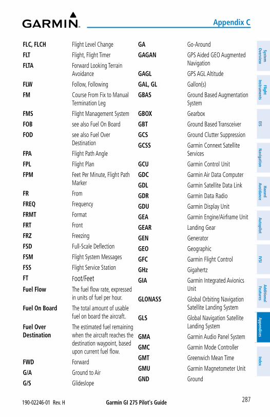
Garmin GI 275 Pilot's Guide190-02246-01 Rev. H
Appendix C
287
System
Overview
Flight Instrum
entsEIS
Navigation
Hazard
AvoidanceA
utopilotIVSI
Additional Features
Appendices
Index
FLC, FLCH Flight Level Change
FLT Flight, Flight Timer
FLTA Forward Looking Terrain Avoidance
FLW Follow, Following
FM Course From Fix to Manual Termination Leg
FMS Flight Management System
FOB see also Fuel On Board
FOD see also Fuel Over Destination
FPA Flight Path Angle
FPL Flight Plan
FPM Feet Per Minute, Flight Path Marker
FR From
FREQ Frequency
FRMT Format
FRT Front
FRZ Freezing
FSD Full-Scale Deflection
FSM Flight System Messages
FSS Flight Service Station
FT Foot/FeetFuel Flow The fuel flow rate, expressed
in units of fuel per hour.
Fuel On Board The total amount of usable fuel on board the aircraft.
Fuel Over Destination
The estimated fuel remaining when the aircraft reaches the destination waypoint, based upon current fuel flow.
FWD Forward
G/A Ground to Air
G/S Glideslope
GA Go-Around
GAGAN GPS Aided GEO Augmented Navigation
GAGL GPS AGL Altitude
GAL, GL Gallon(s)
GBAS Ground Based Augmentation System
GBOX Gearbox
GBT Ground Based Transceiver
GCS Ground Clutter Suppression
GCSS Garmin Connext Satellite Services
GCU Garmin Control Unit
GDC Garmin Air Data Computer
GDL Garmin Satellite Data Link
GDR Garmin Data Radio
GDU Garmin Display Unit
GEA Garmin Engine/Airframe Unit
GEAR Landing Gear
GEN Generator
GEO Geographic
GFC Garmin Flight Control
GHz Gigahertz
GIA Garmin Integrated Avionics Unit
GLONASS Global Orbiting Navigation Satellite Landing System
GLS Global Navigation Satellite Landing System
GMA Garmin Audio Panel System
GMC Garmin Mode Controller
GMT Greenwich Mean Time
GMU Garmin Magnetometer Unit
GND Ground
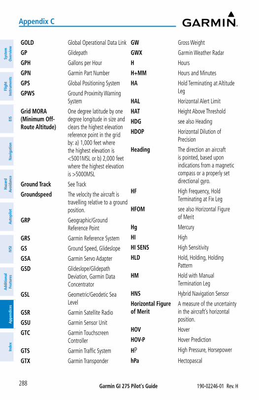
Garmin GI 275 Pilot's Guide 190-02246-01 Rev. H
Appendix C
288
Syst
em
Ove
rvie
wFl
ight
In
stru
men
tsEI
SN
avig
atio
nH
azar
d Av
oida
nce
Aut
opilo
tIV
SIA
dditi
onal
Fe
atur
esA
ppen
dice
sIn
dex
GOLD Global Operational Data Link
GP Glidepath
GPH Gallons per Hour
GPN Garmin Part Number
GPS Global Positioning System
GPWS Ground Proximity Warning System
Grid MORA (Minimum Off-Route Altitude)
One degree latitude by one degree longitude in size and clears the highest elevation reference point in the grid by: a) 1,000 feet where the highest elevation is <5001MSL or b) 2,000 feet where the highest elevation is >5000MSL
Ground Track See Track
Groundspeed The velocity the aircraft is travelling relative to a ground position.
GRP Geographic/Ground Reference Point
GRS Garmin Reference System
GS Ground Speed, Glideslope
GSA Garmin Servo Adapter
GSD Glideslope/Glidepath Deviation, Garmin Data Concentrator
GSL Geometric/Geodetic Sea Level
GSR Garmin Satellite Radio
GSU Garmin Sensor Unit
GTC Garmin Touchscreen Controller
GTS Garmin Traffic System
GTX Garmin Transponder
GW Gross Weight
GWX Garmin Weather Radar
H Hours
H+MM Hours and Minutes
HA Hold Terminating at Altitude Leg
HAL Horizontal Alert Limit
HAT Height Above Threshold
HDG see also Heading
HDOP Horizontal Dilution of Precision
Heading The direction an aircraft is pointed, based upon indications from a magnetic compass or a properly set directional gyro.
HF High Frequency, Hold Terminating at Fix Leg
HFOM see also Horizontal Figure of Merit
Hg Mercury
HI High
HI SENS High Sensitivity
HLD Hold, Holding, Holding Pattern
HM Hold with Manual Termination Leg
HNS Hybrid Navigation Sensor
Horizontal Figure of Merit
A measure of the uncertainty in the aircraft’s horizontal position.
HOV Hover
HOV-P Hover Prediction
HP High Pressure, Horsepower
hPa Hectopascal
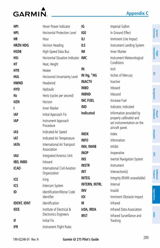
Garmin GI 275 Pilot's Guide190-02246-01 Rev. H
Appendix C
289
System
Overview
Flight Instrum
entsEIS
Navigation
Hazard
AvoidanceA
utopilotIVSI
Additional Features
Appendices
Index
HPI Hover Power Indicator
HPL Horizontal Protection Level
HR Hour
HRZN HDG Horizon Heading
HSDB High-Speed Data Bus
HSI Horizontal Situation Indicator
HT Heat, Height
HTR Heater
HUL Horizontal Uncertainty Level
HWND Headwind
HYD Hydraulic
Hz Hertz (cycles per second)
HZN Horizon
I Inner Marker
IAF Initial Approach Fix
IAP Instrument Approach Procedure
IAS Indicated Air Speed
IAT Indicated Air Temperature
IATA International Air Transport Association
IAU Integrated Avionics Unit
IBD, INBD Inboard
ICAO International Civil Aviation Organization
ICE Icing
ICS Intercom System
ID Identification/Morse Code Identifier
IDENT, IDNT Identification
IEEE Institute of Electrical & Electronics Engineers
IF Initial Fix
IFR Instrument Flight Rules
IG Imperial Gallon
IGE In Ground Effect
ILI Imminent Line Impact
ILS Instrument Landing System
IM Inner Marker
IMC Instrument Meteorological Conditions
IN Inch
IN Hg, “HG Inches of Mercury
INACTV Inactive
INBD Inboard
INBND Inbound
INC FUEL Increase Fuel
IND Indicator, Indicated
Indicated Information provided by properly calibrated and set instrumentation on the aircraft panel.
INDX Index
INFO Information
INH, INHIB Inhibit
INOP Inoperative
INS Inertial Navigation System
INSTR Instrument
INT Intersection(s)
INTEG Integrity (RAIM unavailable)
INTERN, INTRL Internal
INV Invalid
IOI Imminent Obstacle Impact
IR Infrared
IrDA, IRDA Infrared Data Association
IRST Infrared Surveillance and Tracking
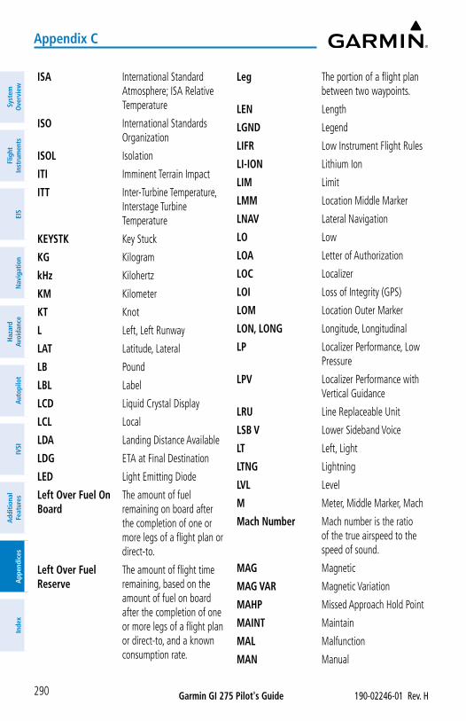
Garmin GI 275 Pilot's Guide 190-02246-01 Rev. H
Appendix C
290
Syst
em
Ove
rvie
wFl
ight
In
stru
men
tsEI
SN
avig
atio
nH
azar
d Av
oida
nce
Aut
opilo
tIV
SIA
dditi
onal
Fe
atur
esA
ppen
dice
sIn
dex
ISA International Standard Atmosphere; ISA Relative Temperature
ISO International Standards Organization
ISOL Isolation
ITI Imminent Terrain Impact
ITT Inter-Turbine Temperature, Interstage Turbine Temperature
KEYSTK Key Stuck
KG Kilogram
kHz Kilohertz
KM Kilometer
KT Knot
L Left, Left Runway
LAT Latitude, Lateral
LB Pound
LBL Label
LCD Liquid Crystal Display
LCL Local
LDA Landing Distance Available
LDG ETA at Final Destination
LED Light Emitting Diode
Left Over Fuel On Board
The amount of fuel remaining on board after the completion of one or more legs of a flight plan or direct-to.
Left Over Fuel Reserve
The amount of flight time remaining, based on the amount of fuel on board after the completion of one or more legs of a flight plan or direct-to, and a known consumption rate.
Leg The portion of a flight plan between two waypoints.
LEN Length
LGND Legend
LIFR Low Instrument Flight Rules
LI-ION Lithium Ion
LIM Limit
LMM Location Middle Marker
LNAV Lateral Navigation
LO Low
LOA Letter of Authorization
LOC Localizer
LOI Loss of Integrity (GPS)
LOM Location Outer Marker
LON, LONG Longitude, Longitudinal
LP Localizer Performance, Low Pressure
LPV Localizer Performance with Vertical Guidance
LRU Line Replaceable Unit
LSB V Lower Sideband Voice
LT Left, Light
LTNG Lightning
LVL Level
M Meter, Middle Marker, Mach
Mach Number Mach number is the ratio of the true airspeed to the speed of sound.
MAG Magnetic
MAG VAR Magnetic Variation
MAHP Missed Approach Hold Point
MAINT Maintain
MAL Malfunction
MAN Manual
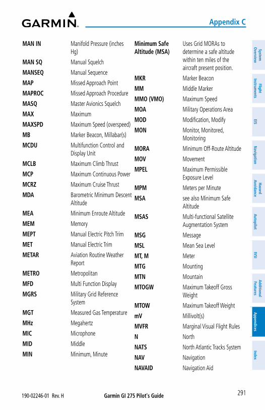
Garmin GI 275 Pilot's Guide190-02246-01 Rev. H
Appendix C
291
System
Overview
Flight Instrum
entsEIS
Navigation
Hazard
AvoidanceA
utopilotIVSI
Additional Features
Appendices
Index
MAN IN Manifold Pressure (inches Hg)
MAN SQ Manual Squelch
MANSEQ Manual Sequence
MAP Missed Approach Point
MAPROC Missed Approach Procedure
MASQ Master Avionics Squelch
MAX Maximum
MAXSPD Maximum Speed (overspeed)
MB Marker Beacon, Millabar(s)
MCDU Multifunction Control and Display Unit
MCLB Maximum Climb Thrust
MCP Maximum Continuous Power
MCRZ Maximum Cruise Thrust
MDA Barometric Minimum Descent Altitude
MEA Minimum Enroute Altitude
MEM Memory
MEPT Manual Electric Pitch Trim
MET Manual Electric Trim
METAR Aviation Routine Weather Report
METRO Metropolitan
MFD Multi Function Display
MGRS Military Grid Reference System
MGT Measured Gas Temperature
MHz Megahertz
MIC Microphone
MID Middle
MIN Minimum, Minute
Minimum Safe Altitude (MSA)
Uses Grid MORAs to determine a safe altitude within ten miles of the aircraft present position.
MKR Marker Beacon
MM Middle Marker
MMO (VMO) Maximum Speed
MOA Military Operations Area
MOD Modification, Modify
MON Monitor, Monitored, Monitoring
MORA Minimum Off-Route Altitude
MOV Movement
MPEL Maximum Permissible Exposure Level
MPM Meters per Minute
MSA see also Minimum Safe Altitude
MSAS Multi-functional Satellite Augmentation System
MSG Message
MSL Mean Sea Level
MT, M Meter
MTG Mounting
MTN Mountain
MTOGW Maximum Takeoff Gross Weight
MTOW Maximum Takeoff Weight
mV Millivolt(s)
MVFR Marginal Visual Flight Rules
N North
NATS North Atlantic Tracks System
NAV Navigation
NAVAID Navigation Aid
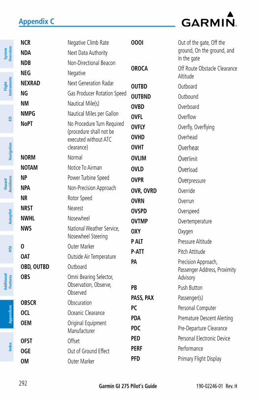
Garmin GI 275 Pilot's Guide 190-02246-01 Rev. H
Appendix C
292
Syst
em
Ove
rvie
wFl
ight
In
stru
men
tsEI
SN
avig
atio
nH
azar
d Av
oida
nce
Aut
opilo
tIV
SIA
dditi
onal
Fe
atur
esA
ppen
dice
sIn
dex
NCR Negative Climb Rate
NDA Next Data Authority
NDB Non-Directional Beacon
NEG Negative
NEXRAD Next Generation Radar
NG Gas Producer Rotation Speed
NM Nautical Mile(s)
NMPG Nautical Miles per Gallon
NoPT No Procedure Turn Required (procedure shall not be executed without ATC clearance)
NORM Normal
NOTAM Notice To Airman
NP Power Turbine Speed
NPA Non-Precision Approach
NR Rotor Speed
NRST Nearest
NWHL Nosewheel
NWS National Weather Service, Nosewheel Steering
O Outer Marker
OAT Outside Air Temperature
OBD, OUTBD Outboard
OBS Omni Bearing Selector, Observation, Observe, Observed
OBSCR Obscuration
OCL Oceanic Clearance
OEM Original Equipment Manufacturer
OFST Offset
OGE Out of Ground Effect
OM Outer Marker
OOOI Out of the gate, Off the ground, On the ground, and In the gate
OROCA Off Route Obstacle Clearance Altitude
OUTBD Outboard
OUTBND Outbound
OVBD Overboard
OVFL Overflow
OVFLY Overfly, Overflying
OVHD Overhead
OVHT Overheat
OVLIM Overlimit
OVLD Overload
OVPR Overpressure
OVR, OVRD Override
OVRN Overrun
OVSPD Overspeed
OVTMP Overtemperature
OXY Oxygen
P ALT Pressure Altitude
P-ATT Pitch Attitude
PA Precision Approach, Passenger Address, Proximity Advisory
PB Push Button
PASS, PAX Passenger(s)
PC Personal Computer
PDA Premature Descent Alerting
PDC Pre-Departure Clearance
PED Personal Electronic Device
PERF Performance
PFD Primary Flight Display
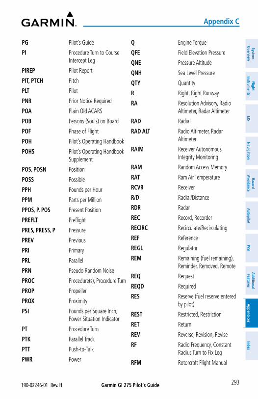
Garmin GI 275 Pilot's Guide190-02246-01 Rev. H
Appendix C
293
System
Overview
Flight Instrum
entsEIS
Navigation
Hazard
AvoidanceA
utopilotIVSI
Additional Features
Appendices
Index
PG Pilot’s Guide
PI Procedure Turn to Course Intercept Leg
PIREP Pilot Report
PIT, PTCH Pitch
PLT Pilot
PNR Prior Notice Required
POA Plain Old ACARS
POB Persons (Souls) on Board
POF Phase of Flight
POH Pilot’s Operating Handbook
POHS Pilot’s Operating Handbook Supplement
POS, POSN Position
POSS Possible
PPH Pounds per Hour
PPM Parts per Million
PPOS, P. POS Present Position
PREFLT Preflight
PRES, PRESS, P Pressure
PREV Previous
PRI Primary
PRL Parallel
PRN Pseudo Random Noise
PROC Procedure(s), Procedure Turn
PROP Propeller
PROX Proximity
PSI Pounds per Square Inch, Power Situation Indicator
PT Procedure Turn
PTK Parallel Track
PTT Push-to-Talk
PWR Power
Q Engine Torque
QFE Field Elevation Pressure
QNE Pressure Altitude
QNH Sea Level Pressure
QTY Quantity
R Right, Right Runway
RA Resolution Advisory, Radio Altimeter, Radar Altimeter
RAD Radial
RAD ALT Radio Altimeter, Radar Altimeter
RAIM Receiver Autonomous Integrity Monitoring
RAM Random Access Memory
RAT Ram Air Temperature
RCVR Receiver
R/D Radial/Distance
RDR Radar
REC Record, Recorder
RECIRC Recirculate/Recirculating
REF Reference
REGL Regulator
REM Remaining (fuel remaining), Reminder, Removed, Remote
REQ Request
REQD Required
RES Reserve (fuel reserve entered by pilot)
REST Restricted, Restriction
RET Return
REV Reverse, Revision, Revise
RF Radio Frequency, Constant Radius Turn to Fix Leg
RFM Rotorcraft Flight Manual
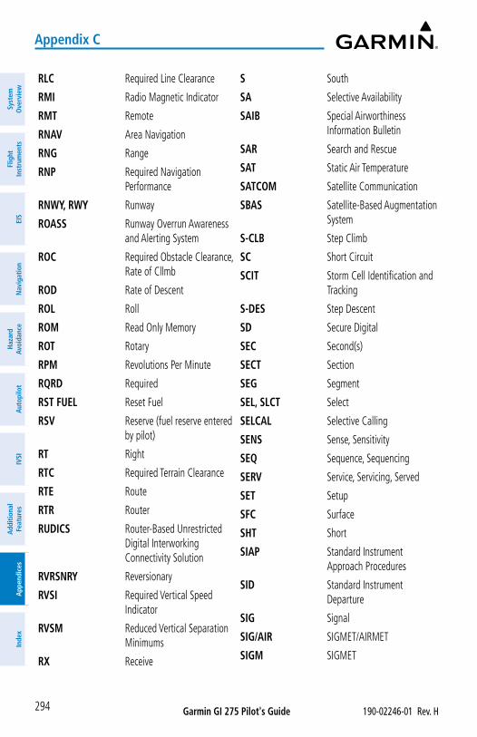
Garmin GI 275 Pilot's Guide 190-02246-01 Rev. H
Appendix C
294
Syst
em
Ove
rvie
wFl
ight
In
stru
men
tsEI
SN
avig
atio
nH
azar
d Av
oida
nce
Aut
opilo
tIV
SIA
dditi
onal
Fe
atur
esA
ppen
dice
sIn
dex
RLC Required Line Clearance
RMI Radio Magnetic Indicator
RMT Remote
RNAV Area Navigation
RNG Range
RNP Required Navigation Performance
RNWY, RWY Runway
ROASS Runway Overrun Awareness and Alerting System
ROC Required Obstacle Clearance, Rate of Cllmb
ROD Rate of Descent
ROL Roll
ROM Read Only Memory
ROT Rotary
RPM Revolutions Per Minute
RQRD Required
RST FUEL Reset Fuel
RSV Reserve (fuel reserve entered by pilot)
RT Right
RTC Required Terrain Clearance
RTE Route
RTR Router
RUDICS Router-Based Unrestricted Digital Interworking Connectivity Solution
RVRSNRY Reversionary
RVSI Required Vertical Speed Indicator
RVSM Reduced Vertical Separation Minimums
RX Receive
S South
SA Selective Availability
SAIB Special Airworthiness Information Bulletin
SAR Search and Rescue
SAT Static Air Temperature
SATCOM Satellite Communication
SBAS Satellite-Based Augmentation System
S-CLB Step Climb
SC Short Circuit
SCIT Storm Cell Identification and Tracking
S-DES Step Descent
SD Secure Digital
SEC Second(s)
SECT Section
SEG Segment
SEL, SLCT Select
SELCAL Selective Calling
SENS Sense, Sensitivity
SEQ Sequence, Sequencing
SERV Service, Servicing, Served
SET Setup
SFC Surface
SHT Short
SIAP Standard Instrument Approach Procedures
SID Standard Instrument Departure
SIG Signal
SIG/AIR SIGMET/AIRMET
SIGM SIGMET
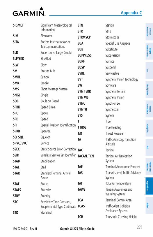
Garmin GI 275 Pilot's Guide190-02246-01 Rev. H
Appendix C
295
System
Overview
Flight Instrum
entsEIS
Navigation
Hazard
AvoidanceA
utopilotIVSI
Additional Features
Appendices
Index
SIGMET Significant Meteorological Information
SIM Simulator
SITA Societe Internationale de Telecommunications
SLD Supercooled Large Droplet
SLP/SKD Slip/Skid
SLW Slow
SM Statute Mile
SMBL Symbol
SMK Smoke
SMS Short Message System
SNGL Single
SOB Souls on Board
SPBK Speed Brake
SPC Space
SPD Speed
SPI Special Position Identification
SPKR Speaker
SQ, SQL Squelch
SRVC, SVC Service
SSEC Static Source Error Correction
SSID Wireless Service Set Identifier
STAB Stabilization
STAL Stall
STAR Standard Terminal Arrival Route
STAT Status
STATS Statistics
STBY Standby
STC Sensitivity Time Constant, Supplemental Type Certificate
STD Standard
STN Station
STR Strip
STRMSCP Stormscope
SUA Special Use Airspace
SUB Substitute
SUPPRESS Suppression
SURF Surface
SUSP Suspend
SVBL Serviceable
SVT Synthetic Vision Technology
SW Software
SYN TERR Synthetic Terrain
SYN VIS Synthetic Vision
SYNC Synchronize
SYNTH Synthesizer
SYS System
T True
T HDG True Heading
T/R Thrust Reverser
TA Traffic Advisory, Transition Altitude
TAC Tactical
TACAN, TCN Tactical Air Navigation System
TAF Terminal Aerodrome Forecast
TAS True Airspeed, Traffic Advisory System
TAT Total Air Temperature
TAWS Terrain Awareness and Warning System
TCA Terminal Control Area
TCAS Traffic Alert Collision Avoidance System
TCH Threshold Crossing Height
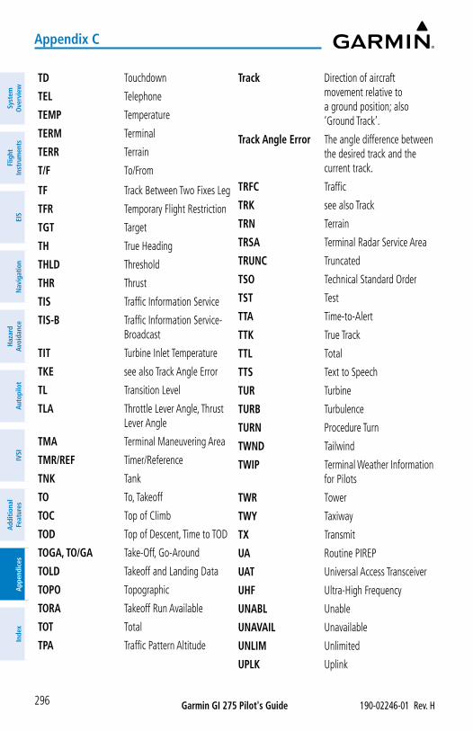
Garmin GI 275 Pilot's Guide 190-02246-01 Rev. H
Appendix C
296
Syst
em
Ove
rvie
wFl
ight
In
stru
men
tsEI
SN
avig
atio
nH
azar
d Av
oida
nce
Aut
opilo
tIV
SIA
dditi
onal
Fe
atur
esA
ppen
dice
sIn
dex
TD Touchdown
TEL Telephone
TEMP Temperature
TERM Terminal
TERR Terrain
T/F To/From
TF Track Between Two Fixes Leg
TFR Temporary Flight Restriction
TGT Target
TH True Heading
THLD Threshold
THR Thrust
TIS Traffic Information Service
TIS-B Traffic Information Service-Broadcast
TIT Turbine Inlet Temperature
TKE see also Track Angle Error
TL Transition Level
TLA Throttle Lever Angle, Thrust Lever Angle
TMA Terminal Maneuvering Area
TMR/REF Timer/Reference
TNK Tank
TO To, Takeoff
TOC Top of Climb
TOD Top of Descent, Time to TOD
TOGA, TO/GA Take-Off, Go-Around
TOLD Takeoff and Landing Data
TOPO Topographic
TORA Takeoff Run Available
TOT Total
TPA Traffic Pattern Altitude
Track Direction of aircraft movement relative to a ground position; also ‘Ground Track’.
Track Angle Error The angle difference between the desired track and the current track.
TRFC Traffic
TRK see also Track
TRN Terrain
TRSA Terminal Radar Service Area
TRUNC Truncated
TSO Technical Standard Order
TST Test
TTA Time-to-Alert
TTK True Track
TTL Total
TTS Text to Speech
TUR Turbine
TURB Turbulence
TURN Procedure Turn
TWND Tailwind
TWIP Terminal Weather Information for Pilots
TWR Tower
TWY Taxiway
TX Transmit
UA Routine PIREP
UAT Universal Access Transceiver
UHF Ultra-High Frequency
UNABL Unable
UNAVAIL Unavailable
UNLIM Unlimited
UPLK Uplink
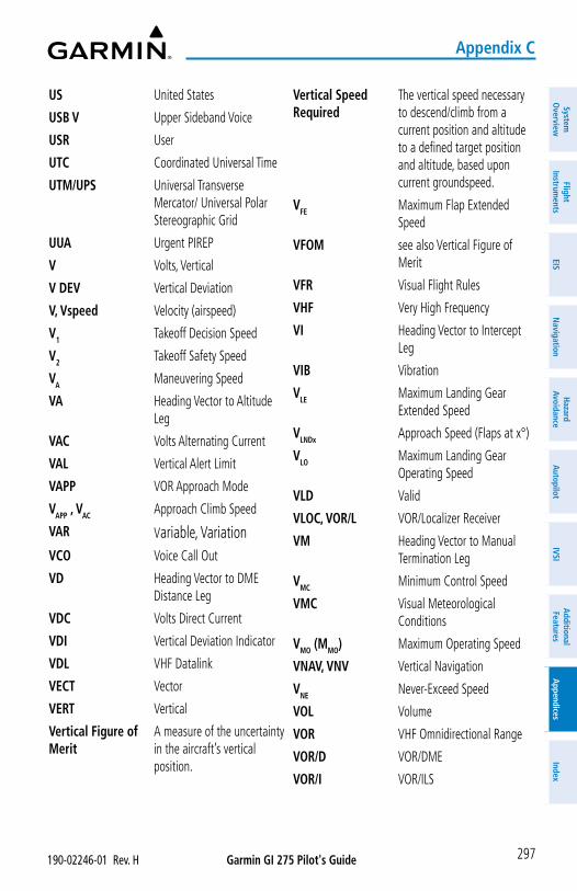
Garmin GI 275 Pilot's Guide190-02246-01 Rev. H
Appendix C
297
System
Overview
Flight Instrum
entsEIS
Navigation
Hazard
AvoidanceA
utopilotIVSI
Additional Features
Appendices
Index
US United States
USB V Upper Sideband Voice
USR User
UTC Coordinated Universal Time
UTM/UPS Universal Transverse Mercator/ Universal Polar Stereographic Grid
UUA Urgent PIREP
V Volts, Vertical
V DEV Vertical Deviation
V, Vspeed Velocity (airspeed)
V1 Takeoff Decision Speed
V2 Takeoff Safety Speed
VA Maneuvering Speed
VA Heading Vector to Altitude Leg
VAC Volts Alternating Current
VAL Vertical Alert Limit
VAPP VOR Approach Mode
VAPP , VAC Approach Climb Speed
VAR Variable, VariationVCO Voice Call Out
VD Heading Vector to DME Distance Leg
VDC Volts Direct Current
VDI Vertical Deviation Indicator
VDL VHF Datalink
VECT Vector
VERT Vertical
Vertical Figure of Merit
A measure of the uncertainty in the aircraft’s vertical position.
Vertical Speed Required
The vertical speed necessary to descend/climb from a current position and altitude to a defined target position and altitude, based upon current groundspeed.
VFE Maximum Flap Extended Speed
VFOM see also Vertical Figure of Merit
VFR Visual Flight Rules
VHF Very High Frequency
VI Heading Vector to Intercept Leg
VIB Vibration
VLE Maximum Landing Gear Extended Speed
VLNDx Approach Speed (Flaps at x°)
VLO Maximum Landing Gear Operating Speed
VLD Valid
VLOC, VOR/L VOR/Localizer Receiver
VM Heading Vector to Manual Termination Leg
VMC Minimum Control Speed
VMC Visual Meteorological Conditions
VMO (MMO) Maximum Operating Speed
VNAV, VNV Vertical Navigation
VNE Never-Exceed Speed
VOL Volume
VOR VHF Omnidirectional Range
VOR/D VOR/DME
VOR/I VOR/ILS
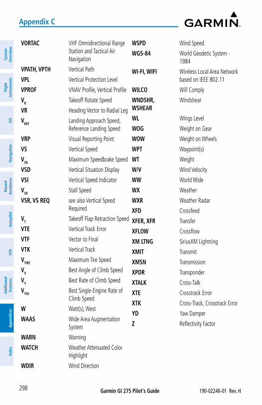
Garmin GI 275 Pilot's Guide 190-02246-01 Rev. H
Appendix C
298
Syst
em
Ove
rvie
wFl
ight
In
stru
men
tsEI
SN
avig
atio
nH
azar
d Av
oida
nce
Aut
opilo
tIV
SIA
dditi
onal
Fe
atur
esA
ppen
dice
sIn
dex
VORTAC VHF Omnidirectional Range Station and Tactical Air Navigation
VPATH, VPTH Vertical Path
VPL Vertical Protection Level
VPROF VNAV Profile, Vertical Profile
VR Takeoff Rotate Speed
VR Heading Vector to Radial Leg
VREF Landing Approach Speed, Reference Landing Speed
VRP Visual Reporting Point
VS Vertical Speed
VSB Maximum Speedbrake Speed
VSD Vertical Situation Display
VSI Vertical Speed Indicator
VSR Stall Speed
VSR, VS REQ see also Vertical Speed Required
VT Takeoff Flap Retraction Speed
VTE Vertical Track Error
VTF Vector to Final
VTK Vertical Track
VTIRE Maximum Tire Speed
VX Best Angle of Climb Speed
VY Best Rate of Climb Speed
VYSE Best Single-Engine Rate of Climb Speed
W Watt(s), West
WAAS Wide Area Augmentation System
WARN Warning
WATCH Weather Attenuated Color Highlight
WDIR Wind Direction
WSPD Wind Speed
WGS-84 World Geodetic System - 1984
WI-FI, WIFI Wireless Local Area Network based on IEEE 802.11
WILCO Will Comply
WNDSHR, WSHEAR
Windshear
WL Wings Level
WOG Weight on Gear
WOW Weight on Wheels
WPT Waypoint(s)
WT Weight
W/V Wind Velocity
WW World Wide
WX Weather
WXR Weather Radar
XFD Crossfeed
XFER, XFR Transfer
XFLOW Crossflow
XM LTNG SiriusXM Lightning
XMIT Transmit
XMSN Transmission
XPDR Transponder
XTALK Cross-Talk
XTE Crosstrack Error
XTK Cross-Track, Crosstrack Error
YD Yaw Damper
Z Reflectivity Factor
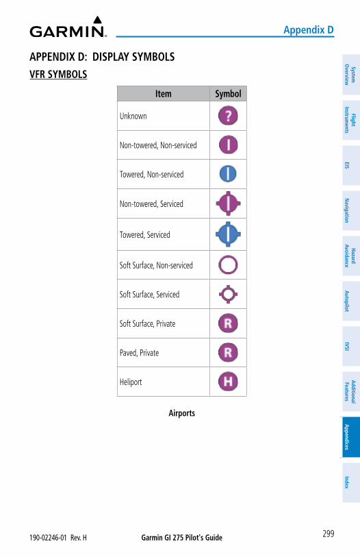
Garmin GI 275 Pilot's Guide190-02246-01 Rev. H
Appendix D
299
System
Overview
Flight Instrum
entsEIS
Navigation
Hazard
AvoidanceA
utopilotIVSI
Additional Features
Appendices
Index
APPENDIX D: DISPLAY SYMBOLSVFR SYMBOLS
Item Symbol
Unknown
Non-towered, Non-serviced
Towered, Non-serviced
Non-towered, Serviced
Towered, Serviced
Soft Surface, Non-serviced
Soft Surface, Serviced
Soft Surface, Private
Paved, Private
Heliport
Airports
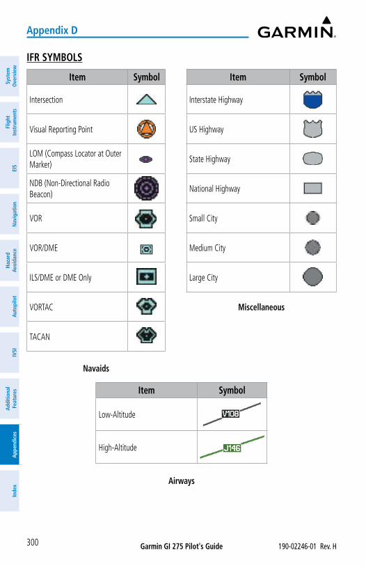
Garmin GI 275 Pilot's Guide 190-02246-01 Rev. H
Appendix D
300
Syst
em
Ove
rvie
wFl
ight
In
stru
men
tsEI
SN
avig
atio
nH
azar
d Av
oida
nce
Aut
opilo
tIV
SIA
dditi
onal
Fe
atur
esA
ppen
dice
sIn
dex
IFR SYMBOLS
Item Symbol Item Symbol
Intersection Interstate Highway
Visual Reporting Point US Highway
LOM (Compass Locator at Outer Marker)
State Highway
NDB (Non-Directional Radio Beacon)
National Highway
VOR Small City
VOR/DME Medium City
ILS/DME or DME Only Large City
VORTAC Miscellaneous
TACAN
Navaids
Item Symbol
Low-Altitude
High-Altitude
Airways
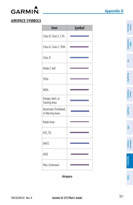
Garmin GI 275 Pilot's Guide190-02246-01 Rev. H
Appendix D
301
System
Overview
Flight Instrum
entsEIS
Navigation
Hazard
AvoidanceA
utopilotIVSI
Additional Features
Appendices
Index
AIRSPACE SYMBOLS
Item Symbol
Class B, Class E, CTA
Class A, Class C, TMA
Class D
Mode C Veil
TRSA
MOA
Danger, Alert, or Training Area
Restricted, Prohibited, or Warning Area
Radar Area
ATZ, TIZ
MATZ
ADIZ
Misc./Unknown
Airspace
Garmin GI 275 Pilot's Guide 190-02246-01 Rev. H
Appendix D
302
Syst
em
Ove
rvie
wFl
ight
In
stru
men
tsEI
SN
avig
atio
nH
azar
d Av
oida
nce
Aut
opilo
tIV
SIA
dditi
onal
Fe
atur
esA
ppen
dice
sIn
dex
Blank Page
Garmin GI 275 Pilot's Guide190-02246-01 Rev. H
Index
I-1
System
Overview
Flight Instrum
entsEIS
Navigation
Hazard
AvoidanceA
utopilotIVSI
Additional Features
Appendices
Index
Index
AAcquiring Satellites 15Acronyms 281ADS-B 181, 182, 183, 185, 186Advisory 259AFCS Controller 191Air Data and Attitude and Heading Ref-
erence System (ADAHRS) 12AIRMET 139, 155Airport Signs 247Airspace 101Airspeed Indicator 34Airspeed Trend Vector 35Alerting Gauges 64Alert Level Definitions 259Altimeter 36–38Altitude Alerting 50Annunciations and Alerts 10, 259, 260Approach Vertical Guidance 43Attitude Indicator 33Autopilot 191
Disengage 194AutoZoom 113Aviation Terms and Acronyms 281
BBarometric Setting, Altimeter 37Basemap 278Battery 11, 12Bearing Pointers 49Bluetooth 21, 22
CCaution 259Caution, EIS 86CDI Scale 45CDI Source 41, 44Cell Movement 146
City Forecast 149, 155Cloud Tops 146Command Bars 192Comparator Annunciations 52Compatible Devices 1Connext 21, 31Controls 4County Warnings 148, 155Course Pointer 44Crew Profiles 16Current Icing Product (CIP) 148Cyclone 149Cylinder Head Temperature (CHT) 62
DD2 Pilot Watch Connectivity 242Database Concierge 30Databases 25, 27, 28, 277, 278Database Troubleshooting 279Data Entry 7–8Datalink Weather 133, 134Date/Time 18Decision Height, Radar Altimeter 237Direct To 123, 124, 125, 127Discrete Configurations 194Display Backlighting 20
EEAS 285EICAS 285EIS 285EIS Pages 63Engine Advisories 66Engine Indication System (EIS) 57
Abnormal Operations 86Advisory Options 65Alerting Gauges 64Alerts 86Annunciations 86CHT Page 80
Garmin GI 275 Pilot's Guide 190-02246-01 Rev. H
Index
I-2
Syst
em
Ove
rvie
wFl
ight
In
stru
men
tsEI
SN
avig
atio
nH
azar
d Av
oida
nce
Aut
opilo
tIV
SIA
dditi
onal
Fe
atur
esA
ppen
dice
sIn
dex
EGT Page 69Fuel Page 80Gauge and Indicator Types 58, 60, 61Gauge Coloring 59Main Page 64Multi-Engine Indications 63Start-up Screen 58
Excessive Descent Rate (EDR) 165Exhaust Gas Temperature (EGT) 62, 69,
70, 71External GPS Source 126
FFIS-B Weather 135, 145Flight Data Logging 224, 239Flight Director 191Flight Instruments 33Flight Path Marker 246Flight Plan 123, 127, 129
Leg Type 128Forward Looking Terrain Avoidance
(FLTA) 165Freezing Levels 147Fuel Calculations 83Fuel Flow Calibration 84Fuel Remaining 58, 83
GGarmin Pilot 21, 30, 31, 32, 125Geodetic Sea Level (GSL) 158, 162, 164GFC 500 195, 196, 198, 212, 217, 218,
221Glidepath 42, 43Glidepath Mode (GP) 207Glideslope 42, 43Glove Qualification 259, 265, 266, 267,
269, 271, 272, 276GPS 14, 126GPS Downgrade 130GPS Failure 131, 132
Ground Line 38Ground Track (TRK) Indicator 40GSL Altitude 38
HHeading Indicator 39Heading Sync 39Horizon Headings 247Horizon Line 33, 34Horizontal Situation Indicator (HSI) 48HSI Map Options 96, 101
IIcing 148Initialization 13
LLand Symbols 91Lateral Deviation Indicator 41Lean Assist 73, 75, 85Lightning 117
MMap
Airways 97, 105Detail 94Orientation 107Range 89
Map Range 89Map Symbols 299Menu 7Message Alert Indicator 10METARs 117, 137MFD Data 129, 130Minimum Altitude Alerting 50, 51Miscompare 13, 52Multi-Function Instrument (MFI) 1
NNavigation Database 278Navigation Source 44
Garmin GI 275 Pilot's Guide190-02246-01 Rev. H
Index
I-3
System
Overview
Flight Instrum
entsEIS
Navigation
Hazard
AvoidanceA
utopilotIVSI
Additional Features
Appendices
Index
Nearest Airport 124, 126Negative Climb Rate (NCR) 165NEXRAD 116, 143, 144Non-Threat Traffic 179, 183, 187
OOBS Mode 46Obstacle Database 279Orientation 107
PPage Menus 7Page Navigation 5Pairing 22, 24, 25Personal Electronic Device (PED) 21PIREP 140Pop-up Alert 259, 260Position 16Power Application 9Premature Descent Alert (PDA) 165Preview, Lateral and Vertical Guid-
ance 45Primary Gauges 59, 65Propeller Sync 63Proximity Advisory (PA) 183, 187
RRadar Altimeter 223, 236
Test 238Range Ring 119Range Setting (Zoom) 89Registration 21Reversionary 10, 13, 53
SSafeTaxi 233SafeTaxi Database 278Satellite Information 15Selected Altitude 204, 205Selected Altitude Capture Mode 204,
205, 209
Selected Heading 211SIGMET 139SiriusXM Weather
Activation 134Cell Movement 146Cloud Tops 146County Warnings 148Data ID Code 134Datalink Status 134, 135Freezing Level 147NEXRAD 143Surface Analysis 149Turbulence 150Winds Aloft 140
Slip/Skid Indicator 33Standard Baro 37Standard Rate Turn Bank Angle Point-
ers 34Stormscope 99, 119, 156, 157Supercooled Large Droplet (SLD) 148Surface Analysis 146, 149, 155Suspend Mode (SUSP) 47Symbolic Aircraft 33, 34Symbols 299Synthetic Vision Technology (SVT) 245
Display Features 246Terrain and Obstacle Alerting 249Traffic 250Troubleshooting 250
System ID 21System Messages 261
TTAFs 137TAWS-B 163Temporary Flight Restrictions
(TFRS) 116, 142Terrain 98, 114, 158
Alerts 165
Garmin GI 275 Pilot's Guide 190-02246-01 Rev. H
Index
I-4
Syst
em
Ove
rvie
wFl
ight
In
stru
men
tsEI
SN
avig
atio
nH
azar
d Av
oida
nce
Aut
opilo
tIV
SIA
dditi
onal
Fe
atur
esA
ppen
dice
sIn
dex
Configurations 158Inhibit 167Legend 162, 164Test 170View 162Wire Obstacles 161
Terrain Database 279Terrain Proximity 163Time Stamp 152Topographical Data 113Track Vector 103Traffic 172
Alerts 176Altitude Filtering 174Configurations 172Status Icon 175Target Selection 175
Traffic Advisory System (TAS) 186, 188, 189
Traffic Advisory (TA) 179, 183, 187Traffic Alert and Collision Avoidance
System (TCAS) 186, 188, 189Traffic Information Service (TIS) 172,
178, 180Traffic Page 174
Annunciations 178Turbulence 150
UUnit Configurations 3
EIS 3MFD 3Primary ADI 3Primary HSI 3Standby ADI 3Standby HSI 3
Units of Measure 19Unit Types 2
Basic 2
With Internal ADAHRS 3With Internal ADAHRS/Autopilot 3
Unusual Attitudes 55Updating Databases 27, 28
VVertical Deviation Indicator (VDI) 43Vertical Guidance 43Vertical Speed Indicator (VSI) 38VFR GPS 14, 40, 51, 89, 131VNAV Indicator 43Vspeed References 36
WWarning 259Warning, EIS 86Waypoints
Information 122Weather Product Age 151, 152, 153Weather Products 136
Enabling/Disabling 154Legend 155
Wi-Fi Setup 29Winds Aloft 140, 141, 155WireAware 159, 161Wireless 21, 30, 32
YYaw Damper 191
ZZero Pitch Line 247Zoom, Range Setting 89


Garmin International, Inc. 1200 East 151st Street
Olathe, KS 66062, U.S.A.
Garmin AT, Inc.2345 Turner Road SE
Salem, OR 97302, U.S.A.
Garmin (Europe) Ltd.Liberty House, Hounsdown Business ParkSouthampton, Hampshire SO40 9LR U.K.
Garmin CorporationNo. 68, Zhangshu 2nd Road
Xizhi District, New Taipei City, Taiwan
Contact Garmin Product Support or view warranty information at flygarmin.com.
190-02246-01 Rev. H© 2019-2022 Garmin Ltd. or its subsidiaries


