Embed Size (px)
Citation preview
Prepared in cooperation with the U.S. Environmental Protection Agency
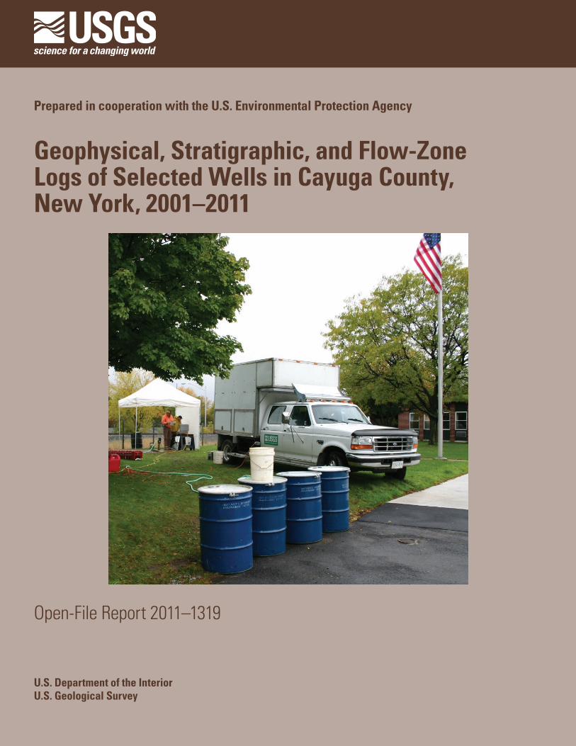
Geophysical, Stratigraphic, and Flow-ZoneLogs of Selected Wells in Cayuga County, New York, 2001–2011
Open-File Report 2011–1319
U.S. Department of the InteriorU.S. Geological Survey

Cover. Geophysical logging at monitor well CY–229 (EPA-20) near Clark Street in Auburn, New York, in 2005.
i
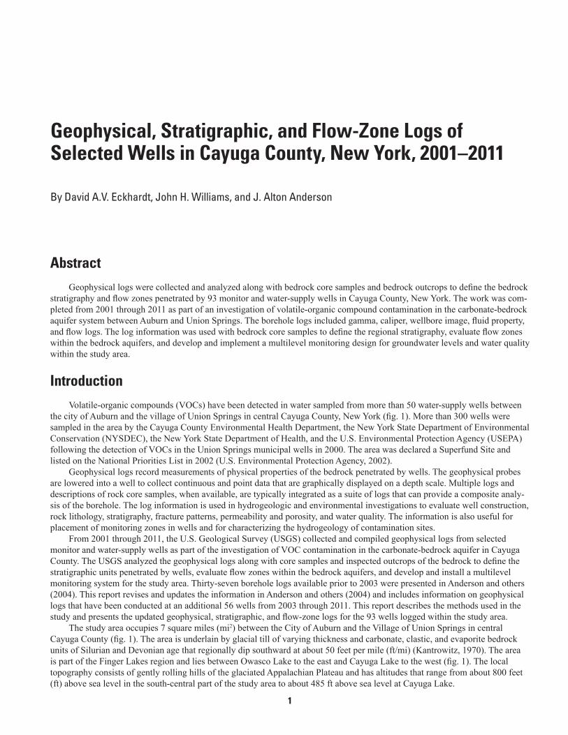
Geophysical, Stratigraphic, and Flow-Zone Logs of Selected Wells in Cayuga County, New York, 2001–2011
By David A.V. Eckhardt, John H. Williams, and J. Alton Anderson
Prepared in cooperation with the U.S. Environmental Protection Agency
Open-File Report 2011–1319
U.S. Department of the InteriorU.S. Geological Survey
ii
U.S. Department of the InteriorKEN SALAZAR, Secretary
U.S. Geological SurveyMarcia K. McNutt, Director
U.S. Geological Survey, Reston, Virginia: 2012
For more information on the USGS—the Federal source for science about the Earth, its natural and living resources, natural hazards, and the environment—visit http://www.usgs.gov or call 1–888–ASK–USGS.
For an overview of USGS information products, including maps, imagery, and publications, visit http://www.usgs.gov/pubprod
To order this and other USGS information products, visit http://store.usgs.gov
Any use of trade, product, or firm names is for descriptive purposes only and does not imply endorsement by the U.S. Government.
Although this report is in the public domain, permission must be secured from the individual copyright owners to reproduce any copyrighted materials contained within this report.
Suggested citation:Eckhardt, D.A., Williams, J.H., and Anderson, J.A., 2012, Geophysical, stratigraphic, and flow-zone logs of selected wells in Cayuga County, New York, 2001–2011: U.S. Geological Survey Open-File Report 2011–1319, 13 p., available at http://pubs.usgs.gov/of/2011/1319.

iii
Acknowledgments
The authors thank the following individuals for their cooperation and assistance: Isabel Rodrigues, Robert Alvey, Donald Bussey, Jack Harmon, Alan Humphrey, and John DiMartino of the U.S. Environmental Protection Agency; Charles Ver Straeten of the New York State Geological Survey; Kevin Kelly of the New York State Department of Environmental Conservation; Eileen O’Connor, Mary Jump, Nick Colas, and Bruce Natale of Cayuga County; Edward Trufant and Robert Kneaskern of the Village of Union Springs; Paul Hare of the General Electric Company; Ralph Morse of O’Brien and Gere Engineers, Inc.; and the residents who graciously allowed access to their wells.
iv
Contents
Acknowledgments ........................................................................................................................................iiiAbstract ...........................................................................................................................................................1Introduction.....................................................................................................................................................1Description of Wells ......................................................................................................................................3Description of Logs ........................................................................................................................................3
Geophysical Logs ..................................................................................................................................3Stratigraphic Logs...............................................................................................................................10Flow-Zone Logs ...................................................................................................................................11
Selected References ...................................................................................................................................11
Figures 1. Map showing location of study area and selected wells and outcrops in Cayuga
County, New York ..........................................................................................................................2
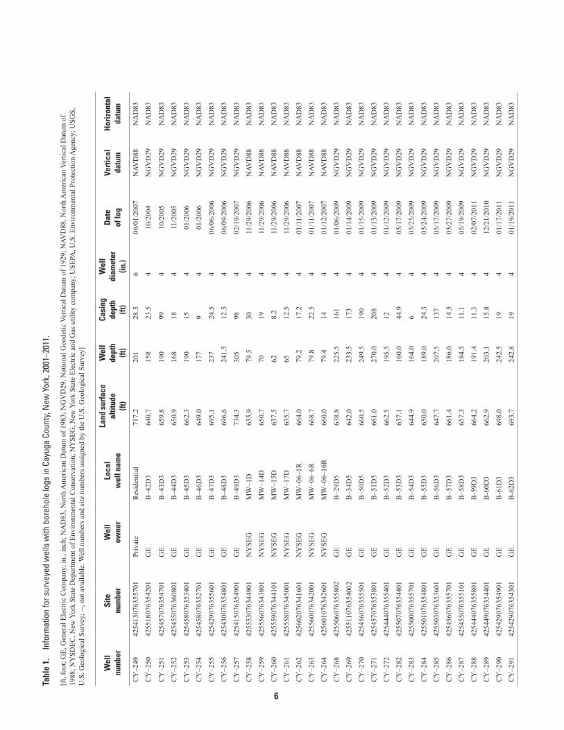
Tables 1. Information for surveyed wells with borehole logs in Cayuga County, New York,
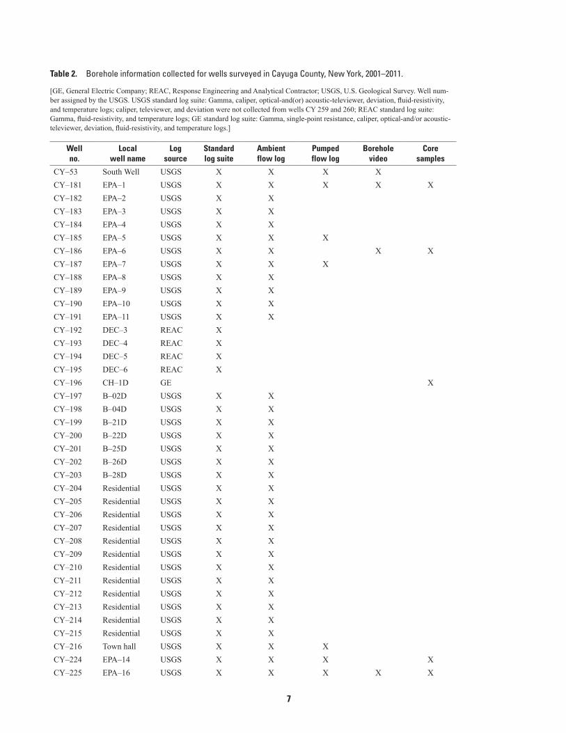
2001–2011 .......................................................................................................................................4 2. Borehole information collected for wells surveyed in Cayuga County, New York,
2001–2011 .......................................................................................................................................7
v
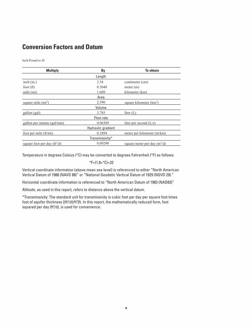
Conversion Factors and Datum
Inch/Pound to SI
Multiply By To obtain
Lengthinch (in.) 2.54 centimeter (cm)foot (ft) 0.3048 meter (m)mile (mi) 1.609 kilometer (km)
Areasquare mile (mi2) 2.590 square kilometer (km2)
Volumegallon (gal) 3.785 liter (L)
Flow rategallon per minute (gal/min) 0.06309 liter per second (L/s)
Hydraulic gradientfoot per mile (ft/mi) 0.1894 meter per kilometer (m/km)
Transmissivity*square foot per day (ft2/d) 0.09290 square meter per day (m2/d)
Temperature in degrees Celsius (°C) may be converted to degrees Fahrenheit (°F) as follows:
°F=(1.8×°C)+32
Vertical coordinate information (above mean sea level) is referenced to either “North American Vertical Datum of 1988 (NAVD 88)” or “National Geodetic Vertical Datum of 1929 (NGVD 29).”
Horizontal coordinate information is referenced to “North American Datum of 1983 (NAD83)”
Altitude, as used in this report, refers to distance above the vertical datum.
*Transmissivity: The standard unit for transmissivity is cubic foot per day per square foot times foot of aquifer thickness [(ft3/d)/ft2]ft. In this report, the mathematically reduced form, foot squared per day (ft2/d), is used for convenience.
vi
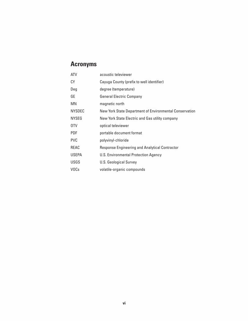
AcronymsATV acoustic televiewer
CY Cayuga County (prefix to well identifier)
Deg degree (temperature)
GE General Electric Company
MN magnetic north
NYSDEC New York State Department of Environmental Conservation
NYSEG New York State Electric and Gas utility company
OTV optical televiewer
PDF portable document format
PVC polyvinyl-chloride
REAC Response Engineering and Analytical Contractor
USEPA U.S. Environmental Protection Agency
USGS U.S. Geological Survey
VOCs volatile-organic compounds
1
Geophysical, Stratigraphic, and Flow-Zone Logs of Selected Wells in Cayuga County, New York, 2001–2011
By David A.V. Eckhardt, John H. Williams, and J. Alton Anderson
AbstractGeophysical logs were collected and analyzed along with bedrock core samples and bedrock outcrops to define the bedrock
stratigraphy and flow zones penetrated by 93 monitor and water-supply wells in Cayuga County, New York. The work was com-pleted from 2001 through 2011 as part of an investigation of volatile-organic compound contamination in the carbonate-bedrock aquifer system between Auburn and Union Springs. The borehole logs included gamma, caliper, wellbore image, fluid property, and flow logs. The log information was used with bedrock core samples to define the regional stratigraphy, evaluate flow zones within the bedrock aquifers, and develop and implement a multilevel monitoring design for groundwater levels and water quality within the study area.
IntroductionVolatile-organic compounds (VOCs) have been detected in water sampled from more than 50 water-supply wells between
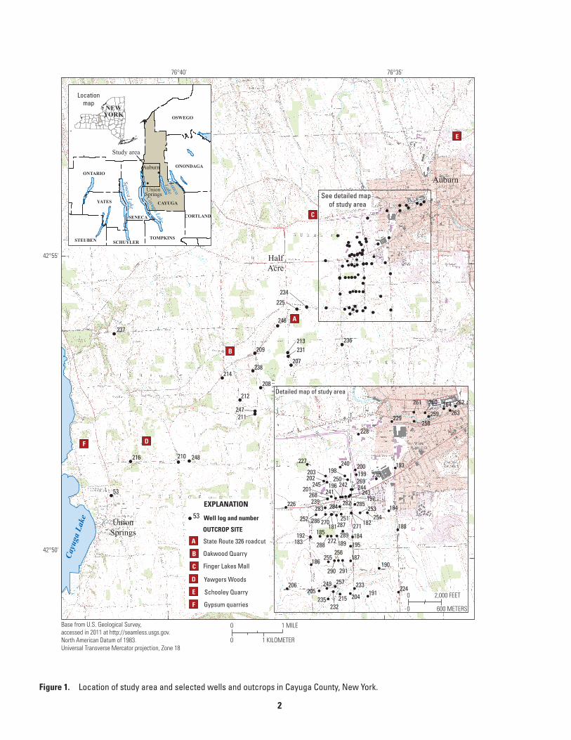
the city of Auburn and the village of Union Springs in central Cayuga County, New York (fig. 1). More than 300 wells were sampled in the area by the Cayuga County Environmental Health Department, the New York State Department of Environmental Conservation (NYSDEC), the New York State Department of Health, and the U.S. Environmental Protection Agency (USEPA) following the detection of VOCs in the Union Springs municipal wells in 2000. The area was declared a Superfund Site and listed on the National Priorities List in 2002 (U.S. Environmental Protection Agency, 2002).
Geophysical logs record measurements of physical properties of the bedrock penetrated by wells. The geophysical probes are lowered into a well to collect continuous and point data that are graphically displayed on a depth scale. Multiple logs and descriptions of rock core samples, when available, are typically integrated as a suite of logs that can provide a composite analy-sis of the borehole. The log information is used in hydrogeologic and environmental investigations to evaluate well construction, rock lithology, stratigraphy, fracture patterns, permeability and porosity, and water quality. The information is also useful for placement of monitoring zones in wells and for characterizing the hydrogeology of contamination sites.
From 2001 through 2011, the U.S. Geological Survey (USGS) collected and compiled geophysical logs from selected monitor and water-supply wells as part of the investigation of VOC contamination in the carbonate-bedrock aquifer in Cayuga County. The USGS analyzed the geophysical logs along with core samples and inspected outcrops of the bedrock to define the stratigraphic units penetrated by wells, evaluate flow zones within the bedrock aquifers, and develop and install a multilevel monitoring system for the study area. Thirty-seven borehole logs available prior to 2003 were presented in Anderson and others (2004). This report revises and updates the information in Anderson and others (2004) and includes information on geophysical logs that have been conducted at an additional 56 wells from 2003 through 2011. This report describes the methods used in the study and presents the updated geophysical, stratigraphic, and flow-zone logs for the 93 wells logged within the study area.
The study area occupies 7 square miles (mi2) between the City of Auburn and the Village of Union Springs in central Cayuga County (fig. 1). The area is underlain by glacial till of varying thickness and carbonate, clastic, and evaporite bedrock units of Silurian and Devonian age that regionally dip southward at about 50 feet per mile (ft/mi) (Kantrowitz, 1970). The area is part of the Finger Lakes region and lies between Owasco Lake to the east and Cayuga Lake to the west (fig. 1). The local topography consists of gently rolling hills of the glaciated Appalachian Plateau and has altitudes that range from about 800 feet (ft) above sea level in the south-central part of the study area to about 485 ft above sea level at Cayuga Lake.
2eckhardt_fig 01
53
248
247
246
238
237
236
234
231
225
216
214
213
212
211
210
209
208
207
272
271270
269
268
264263
262261 260
259258
257
256255
254253
252 251
250
249
245 244243
240
239
235
233
230
229
228
227
226
224215
206205
203202
200
195
194
193
192
191
190
189
188
187186
185183
242241
232
204
201
199198
197
196
184
182181287
286
285283 284 282
291290
289288
CAYUGA
ONTARIO
OSWEGO
YATES
ONONDAGA
TOMPKINS
CORTLAND
STEUBEN SCHUYLER
SENECA
Seneca Lake
Cayuga LakeOwasco
Lake
Auburn
UnionSprings
Locationmap
Study area
76°35'76°40'
42°55'
42°50'
UnionSprings
A
B
C
DF
E
See detailed map of study area
Detailed map of study area
Cayu
ga L
ake
Auburn
EXPLANATION
53 Well log and number
OUTCROP SITE
D
F
A
B
C
E
State Route 326 roadcut
Oakwood Quarry
Finger Lakes Mall
Yawgers Woods
Schooley Quarry
Gypsum quarries
HalfAcre
Cayu
ga L
ake
NEWYORK
0 2,000 FEET
0 600 METERS
0 1 MILE
0 1 KILOMETER
Base from U.S. Geological Survey, accessed in 2011 at http://seamless.usgs.gov. North American Datum of 1983.Universal Transverse Mercator projection, Zone 18
Figure 1. Location of study area and selected wells and outcrops in Cayuga County, New York.
3
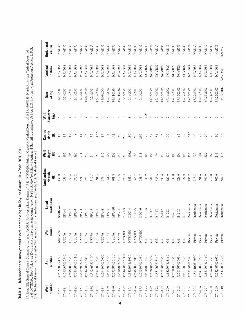
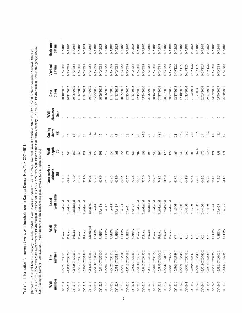
Description of WellsGeophysical logs were collected from 93 wells―26 USEPA and NYSDEC monitor wells, 38 private monitor wells, 20 pri-
vate residential wells, 7 monitor wells owned by a utility company, and 2 municipal wells. Core samples were examined from 41 wells, and the lithologic, stratigraphic, structural, and faunal descriptions are available from three of the cored wells (CY–181, CY–186, and CY–196) to supplement the geophysical logs. The well locations are shown in figure 1, and well information and logging dates are given in table 1. The types and sources of logs and core samples collected from the wells are given in table 2. The logs are available online for display and download in log Ascii standard (LAS), portable document format (PDF), and WellCad (WCL) formats. Below is a link to the Web site for online access:
http://ny.water.usgs.gov/projects/geologs.
Most monitor wells (table 1) were constructed as test wells with open 4-inch (in.)-diameter boreholes below steel casing that is sealed with grout into the bedrock. After logging was completed, the USEPA boreholes were completed with multizone monitoring systems of 1.5-in.-diameter polyvinyl-chloride (PVC) casing and inflated packers that isolate as many as 10 discrete stratigraphic intervals, except CY–191, which remains as an open borehole. Four monitor wells (CY–192—CY–195) were constructed by the NYSDEC as test wells with multiple telescopic steel casings and an open-hole interval near the bottom. The private monitor wells, which are associated with a former industrial facility, were completed after logging the 4-in.-diameter open boreholes with grouted 2-in.-diameter PVC casing and screens with sand-packed discrete intervals near the bottom. Natural gamma logs were collected in seven of the private monitor wells through the completed 2-in.-diameter PVC casing. One private monitor well (CY–196) was not accessible for logging, but its core is described. Twenty wells constructed for domestic water supply were completed as 6-in.-diameter open holes below steel casing set into the top of bedrock. Well CY–216 is used for a municipal town hall and is cased more than 100 ft into bedrock. Well CY–53 provides municipal water supply and is an open borehole below steel casing that terminates near the top of bedrock.
Description of LogsThe geophysical logs collected from November 2001 through January 2011 include natural gamma, single-point resistance,
mechanical-and acoustic-caliper, optical-televiewer (OTV) and acoustic-televiewer (ATV), single-point resistance, fluid-resis-tivity, temperature, and flow logs (appendix 1). The geophysical logs and rock core descriptions presented in this report were collected from 58 wells by the USGS, 4 wells by a USEPA contractor, and 31 wells by a private contractor.
The geophysical logs summarized in this report are available in LAS, text file (TXT), PDF, and WCL formats from the USGS geophysical log archive at http://ny.water.usgs.gov/projects/geologs/. The WellCad Reader1 program, which may be obtained free of charge through http://www.alt.lu/downloads.htm, allows the logs to be displayed, tabulated, and printed at user-specified vertical scales. Core samples for selected wells are available for inspection at the USGS office in Ithaca, N.Y. The following sections describe details of the composite geophysical, flow-zone, and stratigraphic logs that are summarized in tables 1 and 2.
Geophysical Logs
The geophysical logs used in this investigation are described briefly below. The logs include natural gamma, caliper, single-point resistance, wellbore image, fluid properties, and flowmeter. Gamma logs were collected by a borehole tool that senses natural gamma radiation from the earth material around the wellbore. The caliper logs were collected by mechanical and acousti-cal methods. Wellbore-image logs were collected with video cameras and ATVs and OTVs. Fluid-property logs included fluid-resistivity and temperature measurements. Flowmeter logs were collected by heat-pulse, electromagnetic, and spinner methods. Additional information on geophysical logs and logging for groundwater investigations is presented in Keys (1990), American Society for Testing and Materials (2010), and Williams and Lane (1998).
Gamma logs measure the gamma radiation of rocks surrounding the wellbore. Major natural gamma emitters are uranium, thorium, and daughter (radioactive decay) products of potassium-40. Rock units with relatively high gamma radiation when compared with other lithologic units include shales, bentonites, and other argillaceous units as well as phosphate-rich zones. The gamma tool has a vertical resolution of 1 to 2 ft. Gamma logs collected in open holes and through steel and PVC casing were the primary logs used for lithologic identification and stratigraphic correlation.
1Use of the trade name WellCAD Reader in this report is for identification purposes only and does not constitute endorsement by the U.S. Geological Survey.
4
Tabl
e 1.
In
form
atio
n fo
r sur
veye
d w
ells
with
bor
ehol
e lo
gs in
Cay
uga
Coun
ty, N
ew Y
ork,
200
1–20
11.
[ft,
foot
; GE,
Gen
eral
Ele
ctric
Com
pany
; in.
, inc
h; N
AD
83, N
orth
Am
eric
an D
atum
of 1
983;
NG
VD
29, N
atio
nal G
eode
tic V
ertic
al D
atum
of 1
929;
NAV
D88
, Nor
th A
mer
ican
Ver
tical
Dat
um o
f 19
88; N
YSD
EC, N
ew Y
ork
Stat
e D
epar
tmen
t of E
nviro
nmen
tal C
onse
rvat
ion;
NY
SEG
, New
Yor
k St
ate
Elec
tric
and
Gas
util
ity c
ompa
ny; U
SEPA
, U.S
. Env
ironm
enta
l Pro
tect
ion
Age
ncy;
USG
S,
U.S
. Geo
logi
cal S
urve
y; --
, not
ava
ilabl
e. W
ell n
umbe
rs a
nd si
te n
umbe
rs a
ssig
ned
by th
e U
.S. G
eolo
gica
l Sur
vey]
Wel
lnu
mbe
r
Site
num
ber
Wel
low
ner
Loca
lw
ell n
ame
Land
sur
face
altit
ude
(ft)
Wel
lde
pth
(ft)
Casi
ngde
pth
(ft)
Wel
ldi
amet
er(in
.)
Dat
eof
log
Vert
ical
datu
mH
oriz
onta
lda
tum
CY
–53
4250
5607
6412
201
Mun
icip
alSo
uth
Wel
l43
9.0
120
188
11/1
3/20
02N
AVD
88N
AD
83
CY
–181
4254
5607
6355
401
USE
PAEP
A–1
658.
318
713
410
/24/
2001
NAV
D88
NA
D83
CY
–182
4254
5807
6353
801
USE
PAEP
A–2
659.
420
519
412
/13/
2001
NAV
D88
NA
D83
CY
–183
4254
4307
6361
101
USE
PAEP
A–3
670.
219
58
412
/10/
2001
NAV
D88
NA
D83
CY
–184
4254
4307
6353
701
USE
PAEP
A–4
671.
721
114
412
/12/
2001
NAV
D88
NA
D83
CY
–185
4254
4307
6360
301
USE
PAEP
A–5
675.
121
010
24
07/0
9/20
02N
AVD
88N
AD
83
CY
–186
4254
2607
6361
001
USE
PAEP
A–6
719.
524
432
410
/24/
2001
NAV
D88
NA
D83
CY
–187
4254
2907
6353
801
USE
PAEP
A–7
691.
325
013
.54
03/1
2/20
04N
AVD
88N
AD
83
CY
–188
4254
4807
6350
001
USE
PAEP
A–8
679.
124
219
403
/09/
2004
NAV
D88
NA
D83
CY
–189
4254
4407
6354
901
USE
PAEP
A–9
661.
520
210
34
07/1
0/20
02N
AVD
88N
AD
83
CY
–190
4254
2507
6351
301
USE
PAEP
A–1
070
1.9
262
142
403
/11/
2004
NAV
D88
NA
D83
CY
–191
4254
0707
6352
401
USE
PAEP
A–1
171
2.6
250
150
407
/11/
2002
NAV
D88
NA
D83
CY
–192
4254
4307
6361
102
NY
SDEC
DEC
–367
0.5
310
290
810
/16/
2001
NAV
D88
NA
D83
CY
–193
4255
2507
6350
301
NY
SDEC
DEC
–464
3.3
198.
518
08
10/1
6/20
01N
AVD
88N
AD
83
CY
–194
4254
5907
6350
801
NY
SDEC
DEC
–566
5.7
285
266
810
/16/
2001
NAV
D88
NA
D83
CY
–195
4254
3807
6353
801
NY
SDEC
DEC
–668
1.7
311
290
810
/16/
2001
NAV
D88
NA
D83
CY
–196
4255
0707
6354
701
GE
CH
–1D
636.
910
070
1.25
--N
GV
D29
NA
D83
CY
–197
4255
0707
6354
001
GE
B–0
2D64
3.1
100
692
07/1
6/20
02N
GV
D29
NA
D83
CY
–198
4255
1907
6354
401
GE
B–0
4D63
8.8
9681
207
/16/
2002
NG
VD
29N
AD
83
CY
–199
4255
2007
6353
501
GE
B–2
1D63
0.0
130
852
07/1
6/20
02N
GV
D29
NA
D83
CY
–200
4255
2307
6353
601
GE
B–2
2D62
9.0
130
100
207
/16/
2002
NG
VD
29N
AD
83
CY
–201
4255
0707
6355
501
GE
B–2
5D63
9.0
100
852
07/1
6/20
02N
GV
D29
NA
D83
CY
–202
4255
1607
6360
101
GE
B–2
6D62
8.0
100
852
07/1
7/20
02N
GV
D29
NA
D83
CY
–203
4255
1907
6355
901
GE
B–2
8D62
7.0
100
852
07/1
7/20
02N
GV
D29
NA
D83
CY
–204
4254
1007
6353
801
Priv
ate
Res
iden
tial
737.
722
264
.56
08/2
6/20
02N
AVD
88N
AD
83
CY
–205
4254
1107
6360
301
Priv
ate
Res
iden
tial
718.
522
240
608
/27/
2002
NAV
D88
NA
D83
CY
–206
4254
1207
6362
901
Priv
ate
Res
iden
tial
691.
620
425
608
/28/
2002
NAV
D88
NA
D83
CY
–207
4253
1307
6371
601
Priv
ate
Res
iden
tial
760.
032
229
609
/23/
2002
NAV
D88
NA
D83
CY
–208
4252
4907
6375
801
Priv
ate
Res
iden
tial
717.
026
925
609
/24/
2002
NAV
D88
NA
D83
CY
–209
4253
2407
6380
701
Priv
ate
Res
iden
tial
705.
024
330
609
/25/
2002
NAV
D88
NA
D83
CY
–210
4251
3207
6395
001
Priv
ate
Res
iden
tial
587.
217
832
610
/08/
2002
NAV
D88
NA
D83
5
Tabl
e 1.
In
form
atio
n fo
r sur
veye
d w
ells
with
bor
ehol
e lo
gs in
Cay
uga
Coun
ty, N
ew Y
ork,
200
1–20
11.
[ft,
foot
; GE,
Gen
eral
Ele
ctric
Com
pany
; in.
, inc
h; N
AD
83, N
orth
Am
eric
an D
atum
of 1
983;
NG
VD
29, N
atio
nal G
eode
tic V
ertic
al D
atum
of 1
929;
NAV
D88
, Nor
th A
mer
ican
Ver
tical
Dat
um o
f 19
88; N
YSD
EC, N
ew Y
ork
Stat
e D
epar
tmen
t of E
nviro
nmen
tal C
onse
rvat
ion;
NY
SEG
, New
Yor
k St
ate
Elec
tric
and
Gas
util
ity c
ompa
ny; U
SEPA
, U.S
. Env
ironm
enta
l Pro
tect
ion
Age
ncy;
USG
S,
U.S
. Geo
logi
cal S
urve
y; --
, not
ava
ilabl
e. W
ell n
umbe
rs a
nd si
te n
umbe
rs a
ssig
ned
by th
e U
.S. G
eolo
gica
l Sur
vey]
Wel
lnu
mbe
r
Site
num
ber
Wel
low
ner
Loca
lw
ell n
ame
Land
sur
face
altit
ude
(ft)
Wel
lde
pth
(ft)
Casi
ngde
pth
(ft)
Wel
ldi
amet
er(in
.)
Dat
eof
log
Vert
ical
datu
mH
oriz
onta
lda
tum
CY
–211
4252
2207
6380
501
Priv
ate
Res
iden
tial
711.
027
325
610
/10/
2002
NAV
D88
NA
D83
CY
–212
4252
3607
6382
601
Priv
ate
Res
iden
tial
684.
624
016
610
/11/
2002
NAV
D88
NA
D83
CY
–213
4253
2507
6372
101
Priv
ate
Res
iden
tial
734.
028
953
610
/08/
2002
NAV
D88
NA
D83
CY
–214
4252
5807
6385
101
Priv
ate
Res
iden
tial
639.
416
220
611
/12/
2002
NAV
D88
NA
D83
CY
–215
4254
0907
6354
601
Priv
ate
Res
iden
tial
723.
022
139
611
/14/
2002
NAV
D88
NA
D83
CY
–216
4251
3107
6405
601
Mun
icip
alTo
wn
hall
499.
612
011
26
10/0
7/20
02N
AVD
88N
AD
83
CY
–224
4254
1107
6345
901
USE
PAEP
A–1
471
7.3
377
114
405
/25/
2006
NAV
D88
NA
D83
CY
–225
4254
1007
6371
001
USE
PAEP
A–1
668
8.9
291
174
10/2
6/20
05N
AVD
88N
AD
83
CY
–226
4255
0207
6363
201
USE
PAEP
A–1
765
0.1
219
174
10/2
6/20
05N
AVD
88N
AD
83
CY
–227
4255
2607
6361
501
USE
PAEP
A–1
863
7.5
155
284
11/2
1/20
05N
AVD
88N
AD
83
CY
–228
4255
4407
6353
401
USE
PAEP
A–1
963
3.9
161
434
11/1
5/20
05N
AVD
88N
AD
83
CY
–229
4255
5907
6351
101
USE
PAEP
A–2
064
3.5
155
334
10/2
5/20
05N
AVD
88N
AD
83
CY
–230
4255
1807
6351
901
USE
PAEP
A–2
163
3.7
171
384
12/1
3/20
05N
AVD
88N
AD
83
CY
–231
4253
2207
6372
101
USE
PAEP
A–2
373
2.8
327
184
11/1
5/20
05N
AVD
88N
AD
83
CY
–232
4254
1107
6355
201
Priv
ate
Res
iden
tial
726.
120
740
612
/15/
2005
NAV
D88
NA
D83
CY
–233
4254
1307
6343
501
Priv
ate
Res
iden
tial
725.
019
867
.56
05/2
4/20
06N
AVD
88N
AD
83
CY
–234
4254
1307
6365
601
Priv
ate
Res
iden
tial
722.
020
633
605
/26/
2006
NAV
D88
NA
D83
CY
–235
4254
0707
6355
601
Priv
ate
Res
iden
tial
727.
924
079
608
/16/
2006
NAV
D88
NA
D83
CY
–236
4253
3507
6360
601
Priv
ate
Res
iden
tial
748.
329
948
.56
08/1
7/20
06N
AVD
88N
AD
83
CY
–237
4253
4207
6412
301
Priv
ate
Res
iden
tial
505.
042
.520
608
/21/
2006
NAV
D88
NA
D83
CY
–238
4253
0707
6380
901
Priv
ate
Res
iden
tial
710.
232
755
608
/22/
2006
NAV
D88
NA
D83
CY
–239
4255
0607
6355
801
GE
B–2
9D3
638.
316
021
412
/17/
2003
NG
VD
29N
AD
83
CY
–240
4255
2407
6354
601
GE
B–3
0D3
629.
714
025
.24
12/1
0/20
03N
GV
D29
NA
D83
CY
–241
4255
0707
6355
101
GE
B–3
1D3
641.
916
018
.24
01/1
3/20
04N
GV
D29
NA
D83
CY
–242
4255
0807
6354
701
GE
B–3
2D3
636.
816
024
.34
01/2
2/20
04N
GV
D29
NA
D83
CY
–243
4255
0907
6354
001
GE
B–3
3D3
642.
116
7.4
23.5
403
/200
4N
GV
D29
NA
D83
CY
–244
4255
1107
6354
001
GE
B–3
4D3
642.
217
024
402
/05/
2004
NG
VD
29N
AD
83
CY
–245
4255
1607
6355
901
GE
B–4
1D3
632.
113
6.5
70.2
409
/21/
2004
NG
VD
29N
AD
83
CY
–246
4253
5307
6373
601
USE
PAEP
A–2
472
4.1
321
825
04/0
9/20
07N
AVD
88N
AD
83
CY
–247
4252
2607
6380
501
USE
PAEP
A–2
571
2.5
351
112
505
/30/
2007
NAV
D88
NA
D83
CY
–248
4251
3207
6393
501
USE
PAEP
A–2
658
1.4
271
525
05/3
0/20
07N
AVD
88N
AD
83
6
Tabl
e 1.
In
form
atio
n fo
r sur
veye
d w
ells
with
bor
ehol
e lo
gs in
Cay
uga
Coun
ty, N
ew Y
ork,
200
1–20
11.
[ft,
foot
; GE,
Gen
eral
Ele
ctric
Com
pany
; in.
, inc
h; N
AD
83, N
orth
Am
eric
an D
atum
of 1
983;
NG
VD
29, N
atio
nal G
eode
tic V
ertic
al D
atum
of 1
929;
NAV
D88
, Nor
th A
mer
ican
Ver
tical
Dat
um o
f 19
88; N
YSD
EC, N
ew Y
ork
Stat
e D
epar
tmen
t of E
nviro
nmen
tal C
onse
rvat
ion;
NY
SEG
, New
Yor
k St
ate
Elec
tric
and
Gas
util
ity c
ompa
ny; U
SEPA
, U.S
. Env
ironm
enta
l Pro
tect
ion
Age
ncy;
USG
S,
U.S
. Geo
logi
cal S
urve
y; --
, not
ava
ilabl
e. W
ell n
umbe
rs a
nd si
te n
umbe
rs a
ssig
ned
by th
e U
.S. G
eolo
gica
l Sur
vey]
Wel
lnu
mbe
r
Site
num
ber
Wel
low
ner
Loca
lw
ell n
ame
Land
sur
face
altit
ude
(ft)
Wel
lde
pth
(ft)
Casi
ngde
pth
(ft)
Wel
ldi
amet
er(in
.)
Dat
eof
log
Vert
ical
datu
mH
oriz
onta
lda
tum
CY
–249
4254
1307
6355
701
Priv
ate
Res
iden
tial
717.
220
128
.56
06/0
1/20
07N
AVD
88N
AD
83
CY
–250
4255
1807
6354
201
GE
B–4
2D3
640.
715
823
.54
10/2
004
NG
VD
29N
AD
83
CY
–251
4254
5707
6354
701
GE
B–4
3D3
659.
819
099
410
/200
5N
GV
D29
NA
D83
CY
–252
4254
5507
6360
801
GE
B–4
4D3
650.
916
818
411
/200
5N
GV
D29
NA
D83
CY
–253
4254
5807
6353
401
GE
B–4
5D3
662.
319
015
401
/200
6N
GV
D29
NA
D83
CY
–254
4254
5807
6352
701
GE
B–4
6D3
649.
017
79
401
/200
6N
GV
D29
NA
D83
CY
–255
4254
2907
6355
601
GE
B–4
7D3
695.
123
724
.54
06/0
6/20
06N
GV
D29
NA
D83
CY
–256
4254
3007
6354
801
GE
B–4
8D3
696.
624
1.5
12.5
406
/09/
2006
NG
VD
29N
AD
83
CY
–257
4254
1507
6354
901
GE
B–4
9D3
734.
330
598
402
/19/
2007
NG
VD
29N
AD
83
CY
–258
4255
5307
6344
901
NY
SEG
MW
–1D
635.
979
.530
411
/29/
2006
NAV
D88
NA
D83
CY
–259
4255
5607
6343
801
NY
SEG
MW
–14D
650.
770
194
11/2
9/20
06N
AVD
88N
AD
83
CY
–260
4255
5907
6344
101
NY
SEG
MW
–15D
637.
562
8.2
411
/29/
2006
NAV
D88
NA
D83
CY
–261
4255
5807
6345
001
NY
SEG
MW
–17D
635.
765
12.5
411
/29/
2006
NAV
D88
NA
D83
CY
–262
4256
0207
6341
601
NY
SEG
MW
–06–
1R66
4.0
79.2
17.2
401
/11/
2007
NAV
D88
NA
D83
CY
–263
4255
6007
6342
001
NY
SEG
MW
–06–
6R66
8.7
79.8
22.5
401
/11/
2007
NAV
D88
NA
D83
CY
–264
4256
0107
6342
601
NY
SEG
MW
–06–
16R
660.
079
.414
401
/12/
2007
NAV
D88
NA
D83
CY
–268
4255
0607
6355
802
GE
B–2
9D5
638.
822
5.5
161
401
/06/
2009
NG
VD
29N
AD
83
CY
–269
4255
1107
6354
002
GE
B–3
4D5
642.
023
3.5
173
401
/14/
2009
NG
VD
29N
AD
83
CY
–270
4254
5607
6355
501
GE
B–5
0D5
660.
524
9.5
190
401
/15/
2009
NG
VD
29N
AD
83
CY
–271
4254
5707
6353
801
GE
B–5
1D5
661.
027
0.0
208
401
/13/
2009
NG
VD
29N
AD
83
CY
–272
4254
4407
6355
401
GE
B–5
2D3
662.
519
5.5
124
01/1
2/20
09N
GV
D29
NA
D83
CY
–282
4255
0707
6354
401
GE
B–5
3D3
637.
116
0.0
44.9
405
/17/
2009
NG
VD
29N
AD
83
CY
–283
4255
0007
6355
701
GE
B–5
4D3
644.
916
4.0
64
05/2
5/20
09N
GV
D29
NA
D83
CY
–284
4255
0107
6354
801
GE
B–5
5D3
650.
018
9.0
24.3
405
/24/
2009
NG
VD
29N
AD
83
CY
–285
4255
0307
6353
601
GE
B–5
6D3
647.
720
7.5
137
405
/17/
2009
NG
VD
29N
AD
83
CY
–286
4254
5607
6355
701
GE
B–5
7D3
661.
418
6.0
14.5
405
/27/
2009
NG
VD
29N
AD
83
CY
–287
4254
5507
6355
101
GE
B–5
8D3
657.
318
4.5
11.1
405
/19/
2009
NG
VD
29N
AD
83
CY
–288
4254
4407
6355
801
GE
B-5
9D3
664.
219
1.4
11.3
402
/07/
2011
NG
VD
29N
AD
83
CY
–289
4254
4907
6354
401
GE
B-6
0D3
662.
920
3.1
15.8
412
/21/
2010
NG
VD
29N
AD
83
CY
–290
4254
2907
6354
901
GE
B-6
1D3
698.
024
2.5
194
01/1
7/20
11N
GV
D29
NA
D83
CY
–291
4254
2907
6354
301
GE
B-6
2D3
693.
724
2.8
194
01/1
9/20
11N
GV
D29
NA
D83
7
Table 2. Borehole information collected for wells surveyed in Cayuga County, New York, 2001–2011.
[GE, General Electric Company; REAC, Response Engineering and Analytical Contractor; USGS, U.S. Geological Survey. Well num-ber assigned by the USGS. USGS standard log suite: Gamma, caliper, optical-and(or) acoustic-televiewer, deviation, fluid-resistivity, and temperature logs; caliper, televiewer, and deviation were not collected from wells CY 259 and 260; REAC standard log suite: Gamma, fluid-resistivity, and temperature logs; GE standard log suite: Gamma, single-point resistance, caliper, optical-and/or acoustic-televiewer, deviation, fluid-resistivity, and temperature logs.]
Wellno.
Localwell name
Logsource
Standardlog suite
Ambientflow log
Pumpedflow log
Boreholevideo
Coresamples
CY–53 South Well USGS X X X XCY–181 EPA–1 USGS X X X X XCY–182 EPA–2 USGS X XCY–183 EPA–3 USGS X XCY–184 EPA–4 USGS X XCY–185 EPA–5 USGS X X XCY–186 EPA–6 USGS X X X XCY–187 EPA–7 USGS X X XCY–188 EPA–8 USGS X XCY–189 EPA–9 USGS X XCY–190 EPA–10 USGS X XCY–191 EPA–11 USGS X XCY–192 DEC–3 REAC XCY–193 DEC–4 REAC XCY–194 DEC–5 REAC XCY–195 DEC–6 REAC XCY–196 CH–1D GE XCY–197 B–02D USGS X X CY–198 B–04D USGS X X CY–199 B–21D USGS X X CY–200 B–22D USGS X X CY–201 B–25D USGS X X CY–202 B–26D USGS X X CY–203 B–28D USGS X X CY–204 Residential USGS X XCY–205 Residential USGS X XCY–206 Residential USGS X XCY–207 Residential USGS X XCY–208 Residential USGS X XCY–209 Residential USGS X XCY–210 Residential USGS X XCY–211 Residential USGS X XCY–212 Residential USGS X XCY–213 Residential USGS X XCY–214 Residential USGS X XCY–215 Residential USGS X XCY–216 Town hall USGS X X XCY–224 EPA–14 USGS X X X XCY–225 EPA–16 USGS X X X X X
8
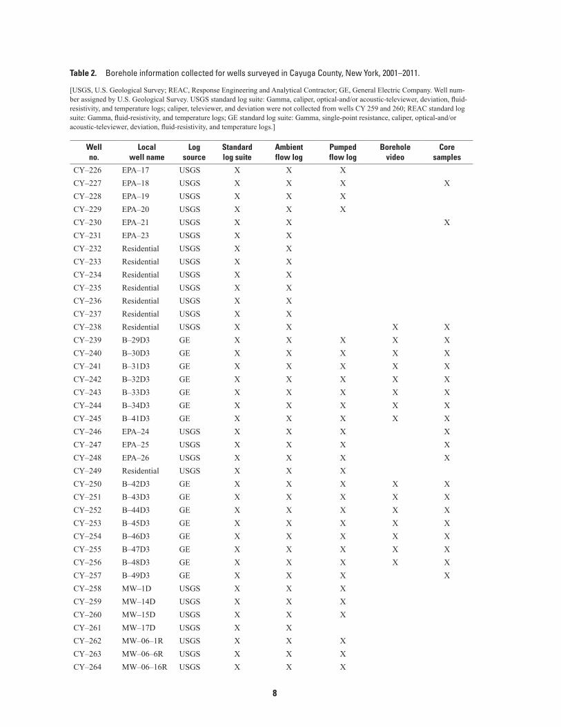
Table 2. Borehole information collected for wells surveyed in Cayuga County, New York, 2001–2011.
[USGS, U.S. Geological Survey; REAC, Response Engineering and Analytical Contractor; GE, General Electric Company. Well num-ber assigned by U.S. Geological Survey. USGS standard log suite: Gamma, caliper, optical-and/or acoustic-televiewer, deviation, fluid-resistivity, and temperature logs; caliper, televiewer, and deviation were not collected from wells CY 259 and 260; REAC standard log suite: Gamma, fluid-resistivity, and temperature logs; GE standard log suite: Gamma, single-point resistance, caliper, optical-and/or acoustic-televiewer, deviation, fluid-resistivity, and temperature logs.]
Wellno.
Localwell name
Logsource
Standardlog suite
Ambientflow log
Pumpedflow log
Boreholevideo
Coresamples
CY–226 EPA–17 USGS X X XCY–227 EPA–18 USGS X X X XCY–228 EPA–19 USGS X X XCY–229 EPA–20 USGS X X XCY–230 EPA–21 USGS X X XCY–231 EPA–23 USGS X XCY–232 Residential USGS X XCY–233 Residential USGS X XCY–234 Residential USGS X XCY–235 Residential USGS X XCY–236 Residential USGS X XCY–237 Residential USGS X XCY–238 Residential USGS X X X XCY–239 B–29D3 GE X X X X XCY–240 B–30D3 GE X X X X XCY–241 B–31D3 GE X X X X XCY–242 B–32D3 GE X X X X XCY–243 B–33D3 GE X X X X XCY–244 B–34D3 GE X X X X XCY–245 B–41D3 GE X X X X XCY–246 EPA–24 USGS X X X XCY–247 EPA–25 USGS X X X XCY–248 EPA–26 USGS X X X XCY–249 Residential USGS X X XCY–250 B–42D3 GE X X X X XCY–251 B–43D3 GE X X X X XCY–252 B–44D3 GE X X X X XCY–253 B–45D3 GE X X X X XCY–254 B–46D3 GE X X X X XCY–255 B–47D3 GE X X X X XCY–256 B–48D3 GE X X X X XCY–257 B–49D3 GE X X X XCY–258 MW–1D USGS X X XCY–259 MW–14D USGS X X XCY–260 MW–15D USGS X X XCY–261 MW–17D USGS X XCY–262 MW–06–1R USGS X X XCY–263 MW–06–6R USGS X X XCY–264 MW–06–16R USGS X X X
9
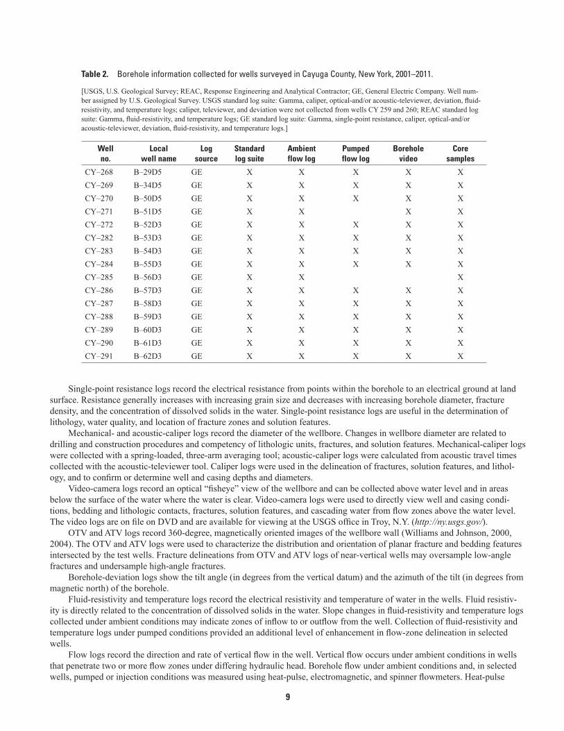
Table 2. Borehole information collected for wells surveyed in Cayuga County, New York, 2001–2011.
[USGS, U.S. Geological Survey; REAC, Response Engineering and Analytical Contractor; GE, General Electric Company. Well num-ber assigned by U.S. Geological Survey. USGS standard log suite: Gamma, caliper, optical-and/or acoustic-televiewer, deviation, fluid-resistivity, and temperature logs; caliper, televiewer, and deviation were not collected from wells CY 259 and 260; REAC standard log suite: Gamma, fluid-resistivity, and temperature logs; GE standard log suite: Gamma, single-point resistance, caliper, optical-and/or acoustic-televiewer, deviation, fluid-resistivity, and temperature logs.]
Wellno.
Localwell name
Logsource
Standardlog suite
Ambientflow log
Pumpedflow log
Boreholevideo
Coresamples
CY–268 B–29D5 GE X X X X XCY–269 B–34D5 GE X X X X XCY–270 B–50D5 GE X X X X XCY–271 B–51D5 GE X X X XCY–272 B–52D3 GE X X X X XCY–282 B–53D3 GE X X X X XCY–283 B–54D3 GE X X X X XCY–284 B–55D3 GE X X X X XCY–285 B–56D3 GE X X XCY–286 B–57D3 GE X X X X XCY–287 B–58D3 GE X X X X XCY–288 B–59D3 GE X X X X XCY–289 B–60D3 GE X X X X XCY–290 B–61D3 GE X X X X XCY–291 B–62D3 GE X X X X X
Single-point resistance logs record the electrical resistance from points within the borehole to an electrical ground at land surface. Resistance generally increases with increasing grain size and decreases with increasing borehole diameter, fracture density, and the concentration of dissolved solids in the water. Single-point resistance logs are useful in the determination of lithology, water quality, and location of fracture zones and solution features.
Mechanical- and acoustic-caliper logs record the diameter of the wellbore. Changes in wellbore diameter are related to drilling and construction procedures and competency of lithologic units, fractures, and solution features. Mechanical-caliper logs were collected with a spring-loaded, three-arm averaging tool; acoustic-caliper logs were calculated from acoustic travel times collected with the acoustic-televiewer tool. Caliper logs were used in the delineation of fractures, solution features, and lithol-ogy, and to confirm or determine well and casing depths and diameters.
Video-camera logs record an optical “fisheye” view of the wellbore and can be collected above water level and in areas below the surface of the water where the water is clear. Video-camera logs were used to directly view well and casing condi-tions, bedding and lithologic contacts, fractures, solution features, and cascading water from flow zones above the water level. The video logs are on file on DVD and are available for viewing at the USGS office in Troy, N.Y. (http://ny.usgs.gov/).
OTV and ATV logs record 360-degree, magnetically oriented images of the wellbore wall (Williams and Johnson, 2000, 2004). The OTV and ATV logs were used to characterize the distribution and orientation of planar fracture and bedding features intersected by the test wells. Fracture delineations from OTV and ATV logs of near-vertical wells may oversample low-angle fractures and undersample high-angle fractures.
Borehole-deviation logs show the tilt angle (in degrees from the vertical datum) and the azimuth of the tilt (in degrees from magnetic north) of the borehole.
Fluid-resistivity and temperature logs record the electrical resistivity and temperature of water in the wells. Fluid resistiv-ity is directly related to the concentration of dissolved solids in the water. Slope changes in fluid-resistivity and temperature logs collected under ambient conditions may indicate zones of inflow to or outflow from the well. Collection of fluid-resistivity and temperature logs under pumped conditions provided an additional level of enhancement in flow-zone delineation in selected wells.
Flow logs record the direction and rate of vertical flow in the well. Vertical flow occurs under ambient conditions in wells that penetrate two or more flow zones under differing hydraulic head. Borehole flow under ambient conditions and, in selected wells, pumped or injection conditions was measured using heat-pulse, electromagnetic, and spinner flowmeters. Heat-pulse
10
flowmeters, which are used in a stationary measurement mode, determines vertical flow based on the travel time of a ther-mal pulse between a set of upper and lower thermisters (Hess, 1982; Herman, 2006). The heat-pulse flowmeter used by the USGS, which was configured with a flexible rubber diverter fitted to the borehole diameter, has a measurement range of 0.005 to 1.0 gallon per minute (gal/min). The heat-pulse flowmeter used by the private contractor, which was not configured with a diverter, has a measurement range of 0.2 to 6.5 gal/min in the 4-in. diameter monitor wells in which it was deployed. Electro-magnetic flowmeters (Young and Pearson, 1995), which are used in stationary and trolling modes, measure fluid velocity based on Faraday’s Law; in application, the flow of the electrically-conductive fluid (water) through a magnetic field induced by the flowmeter generates a measurable voltage gradient that is proportional to the fluid’s velocity. The electromagnetic flowmeter used by the USGS, which was configured with a flexible rubber diverter fitted to the borehole diameter, has a measurement range of 0.05 to 10 gal/min. Spinner flowmeters measure vertical flow by recording the rotation rate of a multiple-bladed impel-ler mounted with adjustable needle bearings on a freely rotating shaft (Keys, 1990). The spinner flowmeter used by the private contractor in a trolling mode has a low-threshold measurement of 2.1 gal/min in the 4-in. diameter monitor wells in which it was deployed.
Stratigraphic Logs
The stratigraphic logs delineate the geologic formations and members penetrated by the wells. The stratigraphy of central New York has been described by Harris (1905), Luther (1910), Oliver (1954), Rickard (1962, 1975, 1989), Demicco and others (1992), Brett and Ver Straeten (1994), and Brett and others (2000). The stratigraphic units penetrated by 41 of the 93 wells were identified by characterization of available core samples and their correlation to gamma logs. The stratigraphic units penetrated by wells without rock core samples were identified by characteristic signatures in the gamma logs; supporting information from the OTV and ATV logs was used where available.
The wells penetrate limestones, dolostones, shales, sandstones, and evaporites of Silurian to Devonian age. The identified stratigraphic units of Silurian age, in ascending order, are the Camillus Shale; the Fiddlers Green, Forge Hollow, and Oxbow Members of the Bertie Formation; the Cobleskill Limestone; and the lower part of the Chrysler Member of the Rondout Forma-tion. The contact between the Camillus Shale and the Fiddlers Green dolostone (basal unit of the Bertie Formation) was identi-fied in wells from characteristic core-sample lithologies and gamma signatures. The upper part of the Forge Hollow Member of the Bertie Formation (referred to as the D3 flow zone) is gypsum and argillaceous gypsiferous dolostone that has significant solution features that are seen in many borehole logs as open voids, typically within the top 15 ft of the Forge Hollow Mem-ber contact with the overlying Oxbow Member. The presence of the Akron Dolomite, which may interfinger locally with the Cobleskill Limestone as an equivalent dolomitized facies (Brett and others, 2000) and which may be penetrated by some wells, could not be confirmed through the geophysical log analysis.
The identified stratigraphic units of Devonian age, in ascending order, are the upper part of the Chrysler Member of the Rondout Formation; the Olney Member of the Manlius Formation; the Edgecliff, Nedrow, Moorehouse, and Seneca Members of the Onondaga Limestone; the Union Springs, Cherry Valley Limestone, and Oatka Creek Members of the Marcellus Shale; and the Mottville and Delphi Station Members of the Skaneateles Formation. The Mottville shale and sandstone and the Delphi Station shale, which were penetrated in only a few wells, were tentatively identified from characteristic thicknesses and gamma signatures. The Mottville Member is partly exposed in a road cut along State Route 326, about 1 mile (mi) south of Half Acre, N.Y. (fig. 1, outcrop site A).
The Oriskany Sandstone and the Springvale Sandstone of the Tri-States Group in central New York are discontinuously present between the Manlius Formation and Onondaga Limestone (Brett and others, 2000). The Oriskany and Springvale were not present in rock cores from wells nor in exposures at the Oakwood quarry (fig. 1, outcrop site B) or along State Route 5 and U.S. Route 20 near the Finger Lakes Mall (fig. 1, outcrop site C). However, a 3-ft-thick section of the Oriskany Sandstone is present at the Yawgers Woods outcrop (fig. 1, outcrop site D) described by Luther (1910). At the Schooley quarry (fig. 1, out-crop site E), no Oriskany Sandstone is present but a thin discontinuous bed of the Springvale Sandstone with its characteristic phosphate nodules is present. The Oriskany Sandstone and Springvale Sandstone were not identified through the geophysical log analysis, although relatively thin sections of these units may be penetrated by some of the wells. Clasts of reworked phosphate nodules from the Springvale Sandstone are present at the base of the Edgecliff Member of the Onondaga Limestone in many of the rock cores and in exposures at the Oakwood and Schooley quarries and along State Route 5 and U.S. Route 20 near the Finger Lakes Mall. The phosphate nodules produce a characteristic gamma peak that facilitates the identification of the contact between the Onondaga and Manlius Formations, which is a major erosional unconformity. Another significant gamma peak is produced by the Tioga Bentonite, which is a thin volcanic ash deposit at the contact of the Seneca and Moorehouse Members of the Onondaga Limestone (Ver Straeten, 2004).
Repeated stratigraphic sections were identified within the Manlius Formation in well CY–205, the Manlius and Onondaga Formations in well CY–212, and the Onondaga Formation and the Marcellus Shale in wells CY–215 and CY–225. The repeated
11
sections are likely owing to localized thrust faults similar to that described by Conkin and Conkin (1984) and Duskin (1969) west and east of the study area.
Flow-Zone Logs
The flow-zone logs define the distribution and relative hydraulic head of flow zones penetrated by selected wells. The dis-tribution and character of flow zones were determined by the integrated analysis of the caliper, OTV and ATV, fluid-resistivity, temperature, and flow logs. At least one feature within each zone was designated as an hydraulically active fracture or solution feature that contributes to the measured ambient or pumped flows (Paillet, 1998; 2000). Most flow zones were associated with bedding-related permeability including bedding fractures and solution features.
The ambient water levels measured in the open-hole multi-zone wells are composite hydraulic heads that reflect the transmissivity-weighted average of the heads of the penetrated flow zones (Bennett and others, 1982, Williams and Lane, 1998). Heads in inflow zones are higher than the composite water level, and outflow zones are lower than the composite water level.
Selected References
American Society for Testing and Materials, 2010, Standard guide for planning and conducting borehole geophysical logging—ASTM D5753–05(2010), in Soil and rock; American Society for Testing and Materials Annual Book of ASTM Standards, v. 04.08, 8 p.
Anderson, J.A., Williams, J.H., Eckhardt, D.A.V., and Miller, T.S., 2004, Geophysical, stratigraphic, and flow-zone logs of selected test, monitor, and water-supply wells in Cayuga County, New York: U.S. Geological Survey Open-File Report 2003–468, 10 p. plus appendix, accessed April 4, 2011, at http://ny.water.usgs.gov/pubs/of/of03468/.
Bennett, G.D., Kontis, A.L., and Larson, S.P., 1982, Representation of multiaquifer-well effects in three-dimensional ground-water flow simulation: Ground Water, v. 20, no. 3, p. 334–341.
Brett, C.E., and Ver Straeten, C.A., 1994, Stratigraphy and facies relationships of the Eifelian Onondaga Limestone (Middle Devonian) in western and central New York state, in New York State Geological Association, 66th annual meeting, Rochester, N.Y., Oct. 7–9, 1994, Field trip guidebook: New York State Geological Association Guidebook 66, p. 221–269. [Edited by C.E. Brett and James Scatteday.]
Brett, C.E., Ver Straeten, C.A., and Baird, G.C., 2000, Anatomy of a composite sequence boundary—The Silurian-Devonian contact in western New York state, in New York State Geological Association, 72d annual meeting, Geneva, N.Y., Sept. 29–Oct. 1, 2000, Field trip guidebook: New York State Geological Association Guidebook 72, p. 39–72. [Edited by D.L. Wood-row and D.B. McKinney.]
Conkin, J.E., and Conkin, B.M., 1984, Devonian metabentonites in the eastern United States and southern Ontario; Their identi-ties, stratigraphic positions, and correlation, pt. 1 of Paleozoic metabentonites of North America: University of Louisville Studies in Paleontology and Stratigraphy, no.16, p. 92–93.
Demicco, R.V., Lowenstien, T.K., and Browne, K.M., 1992, Comparative sedimentology of the lower Manlius Formation near Hamilton, New York, in New York State Geological Association, 66th annual meeting, Hamilton, N.Y., Sept. 18–20, 1992, Field trip guidebook: New York State Geological Association Guidebook 64, p. 57–71. [Edited by R.H. April.]
Duskin, D.J., 1969, Economic geology of the gypsum deposits at Union Springs, New York: Ithaca, N.Y., Cornell University M.S. thesis, 134 p.
Harris, G.D., 1905, Guide to the geology of Union Springs: Cornell University Elementary Natural History Series, no. 3, 12 p.
Herman, G.C., 2006, Field tests using a heat-pulse flow meter to determine its accuracy for flow measurements in bedrock wells: New Jersey Geological Survey Technical Memorandum 06–1, 8 p.
Hess, A.E., 1982, A heat-pulse flowmeter for measuring low velocities in boreholes: U.S. Geological Survey Open-File Report 82–699, 44 p.
Kantrowitz, I.H., 1970, Ground-water resources in the eastern Oswego River basin, New York: New York State Water Resources Commission Basin Planning Report ORB–2, 47 p.
12
Keys, W.S., 1990, Borehole geophysics applied to ground-water investigations: U.S. Geological Survey Techniques of Water-Resources Investigations, book 2, chap. E2, p. 150.
Luther, D.D., 1910, Geology of the Auburn-Genoa quadrangles: New York State Museum Bulletin 137, 32 p.
Oliver, W.A., 1954, Stratigraphy of the Onondaga Limestone (Devonian) in central New York: Geological Society of America Bulletin, v. 65, no. 7, p. 621–652.
Paillet, F.L., 1998, Flow modeling and permeability estimation using borehole flow logs in heterogeneous fractured formations: Water Resources Research, v. 34, no. 5, p. 997–1010.
Paillet, F.L., 2000, A field technique for estimating aquifer parameters using flow data: Ground Water, v. 38, no. 4, p. 510–521.
Rickard, L.V., 1962, Late Cayugan (Upper Silurian) and Helderbergian (Lower Devonian) stratigraphy in New York state: New York State Museum Science Service Bulletin 386, 157 p.
Rickard, L.V., 1975, Correlation of the Silurian and Devonian rocks in New York state: New York State Museum Map and Chart Series, no. 24, 4 plates, 16-p. text.
Rickard, L.V., 1989, Stratigraphy of the subsurface Lower and Middle Devonian of New York, Pennsylvania, Ohio, and Ontario: New York State Museum Map and Chart Series, no. 39, 40 plates, 59-p. text.
U.S. Environmental Protection Agency, 2002, NPL site narrative for Cayuga County ground water contamination site: U.S. Environmental Protection Agency, accessed October 28, 2011, at http://www.epa.gov/superfund/sites/nplsnl/n0204289.pdf.
Ver Straeten, C.A., 2004, K-bentonites, volcanic ash preservation, and implications for Early to Middle Devonian volcanism in the Acadian orogen, eastern North America: Geological Society of America Bulletin, v. 116, no. 3/4, p. 474–489.
Williams, J.H., 2008, Flow-log analysis for hydraulic characterization of selected test wells at the Indian Point Energy Center, Buchanan, New York: U.S. Geological Survey Open-File Report 2008–1123, 30 p., accessed April 4, 2011, at http://pubs.usgs.gov/of/2008/1123/.
Williams, J.H., and Johnson, C.D., 2000, Borehole-wall imaging with acoustic and optical televiewers for fractured-bedrock aquifer investigations, in International Symposium on Borehole Geophysics for Minerals, Geotechnical, and Groundwater Applications, 7th, Golden, Colo., October 24–26, 2000, Proceedings: Minerals and Geotechnical Logging Society, p. 43–53.
Williams, J.H., and Johnson, C.D., 2004, Acoustic and optical borehole-wall imaging for fractured-rock aquifer studies: Journal of Applied Geophysics, v. 55, issue 1–2, p. 151–159.
Williams, J.H., and Lane, J.W., 1998, Advances in borehole geophysics for groundwater investigations: U.S. Geological Survey Fact Sheet 2002–98, 4 p.
Young, S.C., and Pearson, H.S., 1995, The electromagnetic borehole flowmeter—Description and application: Ground Water Monitoring and Remediation Review, v. 15, no. 4, p. 138–147.
13
Appendix 1. Explanations For Abbreviations Used in Composites of Geophysical, Stratigraphic, and Flow-Zone Logs for Selected Wells, Cayuga County, New York, 2001–2011
The logs are available for display and download in log Ascii standard (LAS), portable document format (PDF), and WellCad (WCL) formats from the USGS geophysical log archive at http://ny.water.usgs.gov/projects/geologs. The WellCad Reader program, which may be obtained free of charge through http://www.alt.lu/downloads.htm, allows the logs to be displayed, tabulated, and printed at user-specified vertical scales.
Explanation
Depth—Depth, in feet below land surface at specified vertical scale
Form—Stratigraphic formation
Mmb—Stratigraphic member
Gamma—Natural gamma radiation, in counts per second
Mech Cal—Mechanical three-arm caliper, borehole diameter in inches
Acou Cal—Acoustic caliper from travel times collected with acoustic televiewer, borehole diameter in inches
ATV—Acoustic-televiewer image; 360-degree acoustic image of borehole wall; MN indicates log oriented to magnetic north; HS indicates log oriented to high side of borehole wall
OTV—Optical-televiewer image; 360-degree optical image of borehole wall; MN indicates log oriented to magnetic north; HS indicates log oriented to high side of borehole wall
SPR—Single-point resistance, in ohms
Fl Res—Fluid resistivity, in ohms per meter; blue line indicates log collected under ambient conditions; red line indicates log collected under pumped conditions (pmp) ; green line indicates log collected under injection conditions (inj)
Temp—Temperature, in degrees Celsius; blue line indicates log collected under ambient conditions; red line indicates log collected under pumped conditions (pmp) ; green line indicates log collected under injection conditions (inj)
Flow—Borehole flow measured by stationary flowmeter, in gallons per minute; ND indicates log collected without flow diverter; blue disk indicates log collected under ambient conditions; red square indicates log collected under pumped conditions (pmp); green triangle indicates log collected under injection conditions (inj)
Troll—Borehole flow measured by trolling flowmeter; scale adjusted to matched stationary flowmeter measurements; blue line indicates log collected under ambient conditions; red line indicates log collected under pumped conditions (pmp)
Flow zone—Flow zone; blue line indicates ambient composite hydraulic head; yellow line indicates inflow zone with head higher than composite head; red line indicates outflow zone with head lower than composite head; black line designates base of casing
Azi MN—Borehole deviation azimuth from magnetic north, in degrees.
Tilt—Borehole deviation angle from vertical, in degrees

14

Prepared by the Pembroke Publishing Service Center
For additional information write to:New York Water Science CenterU.S. Geological Survey30 Brown Rd.Ithaca, NY 14850
Information requests:(518) 285-5602or visit our Web site at:http://ny.water.usgs.gov

Eckhardt and others—G
eophysical, Stratigraphic, and Flow-Zone Logs in Cayuga County, N
Y, 2001–2011—Open-File Report 2011-1319