Embed Size (px)
Citation preview

1
CIVIL ENGINEERING
INTRODUCTION Geology, one of the core science
disciplines with physics, chemistry, and biology, is the search for knowledge about the Earth, how it formed, evolved, and how it works. Geology is often presented in the broader context of Geosciences; a grouping of disciplines specifically looking for knowledge about the interaction between Earth

2
CIVIL ENGINEERING
Types of GEOLOGICAL STRUCTURES Foliation Folds Faults Joints Unconformities

3
CIVIL ENGINEERING

4
CIVIL ENGINEERING
geologic structures up until now, we have focused our attention mostly on!
flat-lying rocks, i.e. sedimentary or volcanic layers!not all

5
CIVIL ENGINEERING
Geological structures. dynamically produced patterns or
arrangements of rock or sediment that result from forces acting within the Earth

6
CIVIL ENGINEERING
Strike Direction of a line formed by the
intersection of a foliation plane & a horizontal plane.
It is a horizontal line on a surface of rock beds.
If the beds are not horizontal, lines joining the points with same elevation (on one foliation plane) are called strike lines.
6

7
CIVIL ENGINEERING

8
CIVIL ENGINEERING
Measuring the strike
Strike is usually reported as a measurement of compass direction. Due north is considered to be 000°, due east is 090°, due south is 180 °, due west 270°, northwest 045° etc.
The compass was held parallel to the strike line & the orientation read relative to magnetic north.
8

9
CIVIL ENGINEERING
By definition, a strike line trends in 2 directions exactly 180° apart. It is needed to specify only one direction. By convention, the smaller of the 2 numbers is considered.
Line 1 strikes at 45°, line 2 strikes at 55°, and line 3 strikes at 60°.
9

10
CIVIL ENGINEERING
10
N 300 E N 550 W
900
00

11
CIVIL ENGINEERING
Dip
The amount and direction of inclination is also used to describe orientation of bedding.
The dip is defined as the amount of inclination measured from the horizontal plane downwards.
11

12
CIVIL ENGINEERING
Measurement of dip The dip is reported as degrees
measured downward from a horizontal plane.
By convention, the dip of an inclined bed cannot exceed 90°.
Beds with dips of 90° are said to be vertical. Beds that have been overturned have technically been rotated more than 90°, but their dips are still reported as less than 90°.
12

13
CIVIL ENGINEERING
13

14
CIVIL ENGINEERING The long side of the symbol records the strike direction (N45°E) and the smaller tick shows the direction of dip (SE).
The number gives the amount of dip (30°)
14

15
CIVIL ENGINEERING
Determination of strike A strike line joins points of equal elevation on a
particular bedding plane. The strike line is always at right angles to the dip
direction. In determining the strike line, two points of equal
elevation of a particular boundary of a bed on a geological map are located.
The line formed by joining these two points will give a strike line. Its altitude will be the same as that of the corresponding contour.
15

16
CIVIL ENGINEERING
(A) Determination of strike & dip directionon a map(B) Determination of dip by graphical method
16

17
CIVIL ENGINEERING
Determination of dip direction
The dip will be at right angles to the strike direction.
In order to find the dip direction, a line xy is drawn at right angles to the strike lines.
Dip direction is from the strike of higher elevation to that of lower elevation. It is indicated by the arrow on the xy line.
Amount of dip
17

18
CIVIL ENGINEERING
18

19
CIVIL ENGINEERING
What are Folds? Warps in rock layers and occur bended
upwards, downwards, or sideways. Compression forces are the main causes of
folds. Folds are important causes of mountain
formation.
19

20
CIVIL ENGINEERING
Fold Terminology
20
crest

21
CIVIL ENGINEERING
Folds Can be defined as the curved or zig-zag
structure shown by rock beds. They consist of arches & troughs
alternatively & generally occur in groups. Two main types.
Anticline Syncline
21

22
CIVIL ENGINEERING
Anticline
An up-fold where the limbs dip away from the axis of fold on either side.
22
23
CIVIL ENGINEERING
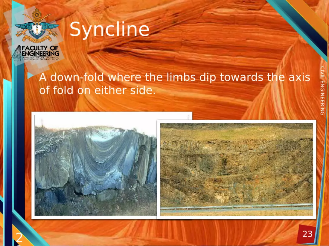
Syncline
A down-fold where the limbs dip towards the axis of fold on either side.
23

24
CIVIL ENGINEERING
24

25
CIVIL ENGINEERING
Geometry of a fold Fold axis – Line joining planes of sharpest
folding. Axial plane – Includes axis and divides the
fold symmetrically as possible Plunging fold – If the fold axis is not
horizontal, fold is called plunging. Plunge – Angle between horizontal plane &
axis Limbs – Sloping sides of a fold
25

26
CIVIL ENGINEERING
Plunging folds
26
RPK

27
CIVIL ENGINEERING
27
28
CIVIL ENGINEERING
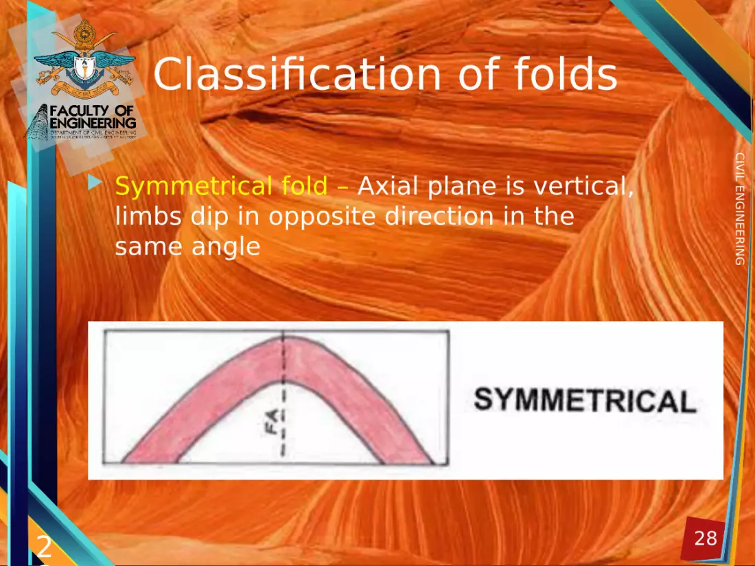
Classification of folds
Symmetrical fold – Axial plane is vertical, limbs dip in opposite direction in the same angle
28

29
CIVIL ENGINEERING
Asymmetrical fold - Axial plane is inclined, Limbs dip in opposite direction at different angles
29

30
CIVIL ENGINEERING
Overturned fold – An asymmetrical fold whose one limb is turned past the vertical. Axial plane is inclined & both limbs dip in the same direction.
30

31
CIVIL ENGINEERING
Recumbent fold - The folding is so intense both limbs become almost horizontal. The Axial plane also becomes nearly horizontal.
31

32
CIVIL ENGINEERING
32

33
CIVIL ENGINEERING
Recumbent folds
33

34
CIVIL ENGINEERING
Overturned folds
34

35
CIVIL ENGINEERING
Faultfault, in geology, a planar or gently curved fracture in the rocks of the Earth’s crust, where compressional or tensional forces cause relative displacement of the rocks on the opposite sides of the fractureFaults may be vertical, horizontal, or inclined at any angle

36
CIVIL ENGINEERING
• When rocks slip past each other in faulting, the upper or overlying block along the fault plane is called the hanging wall, or headwall;
• the block below is called the footwall. • The fault strike is the direction of the line
of intersection between the fault plane and the surface of the Earth.
• The dip of a fault plane is its angle of inclination measured from the horizontal.
• Faults are classified according to their angle of dip and their relative displacementz

37
CIVIL ENGINEERING
There are three kind of fault call as,
• Normal dip-slip faults• Reverse dip-slip faults• Strike-slip faults

38
CIVIL ENGINEERING
Normal faultNormal dip-slip faults are produced by vertical compression as the Earth’s crust lengthens. The hanging wall slides down relative to the footwall. Normal faults are common; they bound many of the mountain ranges of the world and many of the rift valleys found along spreading margins of tectonic plates

39
CIVIL ENGINEERING
Reverse dip-slip faults Reverse dip-slip faults result from horizontal compressional forces caused by a shortening, or contraction, of the Earth’s crust. The hanging wall moves up and over the footwall.

40
CIVIL ENGINEERING
Strike-slip faultStrike-slip (also called transcurrent, wrench, or lateral) faults are similarly caused by horizontal compression, but they release their energy by rock displacement in a horizontal direction almost parallel to the compressional force

41
CIVIL ENGINEERING
Joints

42
CIVIL ENGINEERING
TYPES OF JOINT Tension Joints – Due to tensional forces.
Relatively open & have rough & irregular surfaces.
Shear Joints – Due to compression forces involved in folding & faulting of rocks. Rather clean cut & tightly closed.
Strike Joints – Run parallel to the strike of the country rocks.
Dip Joints – Run parallel to the direction of dip of the country rocks.

43
CIVIL ENGINEERING
JOINTS… Advantages
Good source of ground water Disadvantages
In rock quarries blasting become difficult & rock quality is poor Outer & Inner breaks in tunnels More liable to landslides, rockslides & mudflows Foundation problems Excavation need more supports

44
CIVIL ENGINEERINGUNCONFORMITIES

45
CIVIL ENGINEERING
Unconformities An unconfAormity is an old
erosion surface which separates younger series of rocks from the older series. Angular Unconformities Disconformities Nonconformities

46
CIVIL ENGINEERING
Development of an Unconformity
46

47
CIVIL ENGINEERING
Angular Unconformity
An unconformity in which the upper and lower layers are not parallel
47
48
CIVIL ENGINEERING
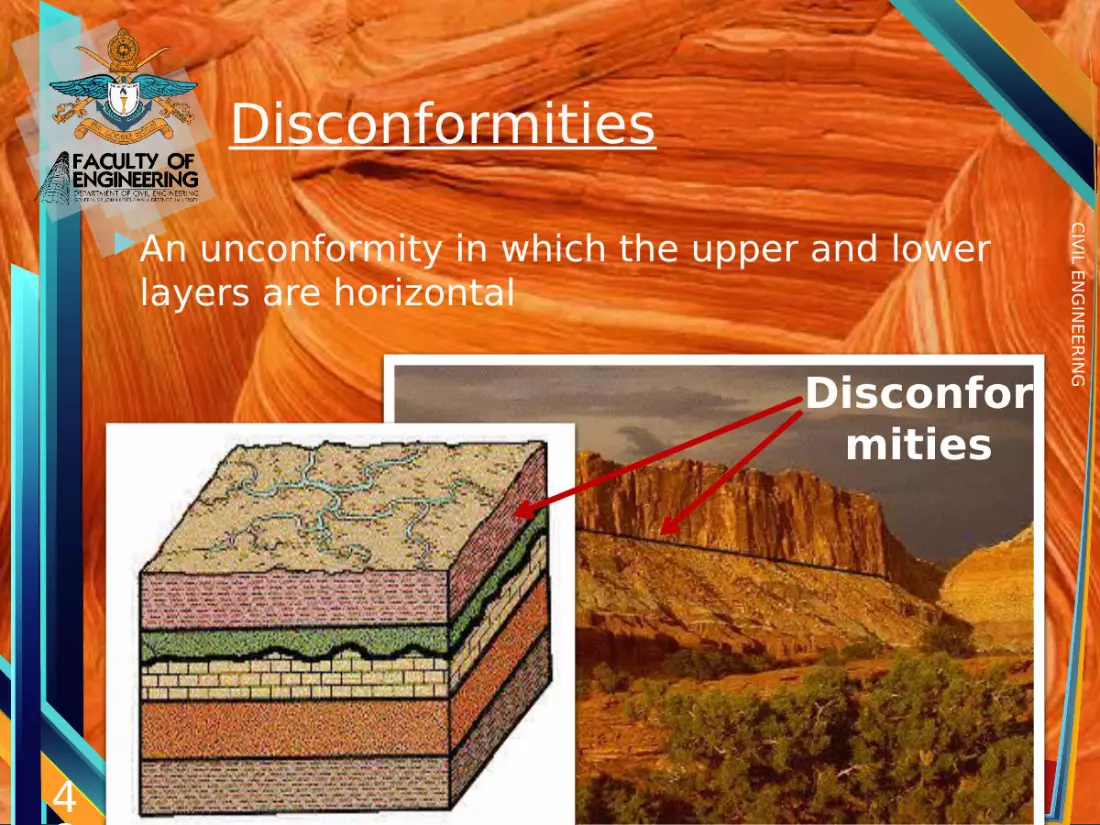
DisconformitiesAn unconformity in which the upper and lower
layers are horizontal
48
Disconformities

49
CIVIL ENGINEERING
Nonconforty
When bedded sedimentary rocks overlie the non-bedded igneous mass, the structure is called “Nonconforty”.
49

50
CIVIL ENGINEERING
Angular unconformity on San Miguel Island, May, 2004

51
CIVIL ENGINEERING
Nonconformity in Canada Halcon, February, 2007
52
CIVIL ENGINEERING
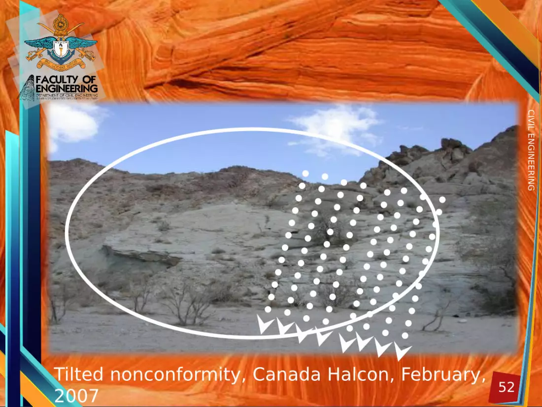
Tilted nonconformity, Canada Halcon, February, 2007


