Embed Size (px)
Citation preview
Generalised Asynchronous Arbiter
Stanislavs Golubcovs, Andrey Mokhov, Alex Bystrov, Danil Sokolov, Alex YakovlevSchool of Engineering, Newcastle University, UK
Abstract—The paper presents the design of a generalised asyn-chronous arbiter with a two-stage architecture that efficientlyhandles requests from multiple concurrent channels. The firststage of the arbiter monitors the incoming requests and lockstheir state as soon as one or more requests are detected. Thesecond stage performs arbitration based on the locked stateof the requests and produces the corresponding grant signals.The separation of the two stages is crucial for reducing thecomplexity of the arbitration logic, which allows us to obtainpractical implementations for complex arbitration protocols.
Several application examples of the generalised arbiter areproposed and evaluated in terms of scalability with respect tothe growing number of request channels. The presented designsare verified to have no hazards or deadlocks using methodsbased on circuit Petri nets.
1. Motivation
In electronic systems arbiters are circuits that controlaccess to one or more shared resources such as memory,various data processors or communication channels. Arbitersmake discrete grant decisions based on the order and/orcombination of requests from several independent sources.A basic example: two transmitters need to send data over ashared channel. They cannot use the channel simultaneously,therefore they request a dedicated arbiter to grant access tothe shared resource. The arbiter in its turn guarantees thatthe resource is available before granting anyone access.
In synchronous systems, an arbiter works with theclocked input signals, whose grant logic is a regular syn-chronous automaton, and its implementation can be derivedby the standard electronic computer-aided design (ECAD)tools. With the reducing transistor size, larger scale designsconsist of multiple communicating systems (or cores) ona single chip. In such systems it becomes an increasinglycomplicated task to drive multiple individual cores by asingle clock, which has led to the design of cores that areasynchronous with respect to each other. The communica-tion between the cores in such systems can be done via anetwork of connections. Without special assumptions such acommunication medium becomes a shared resource betweenthe mutually concurrent asynchronous subsystems.
This shift from a discrete to continuous-time paradigmhas a profound effect on the design of arbiters, particu-larly affecting their parts that compare the arrival time ofinput signals. It was discovered that such continuous-timedecision-making circuits may produce malformed glitch
pulses due to the phenomenon of metastability [1]. It wasalso shown that the metastability may cause unboundeddelay in response of circuits [2], the effect which was gener-alised as a manifestation of a very old philosophical problemof “Buridan’s Ass” attributed to the French philosopher of14th century Jean Buridan. This fundamental problem ofchoice is formulated as the following principle: “A discretedecision based upon an input having a continuous range ofvalues cannot be made within a bounded length of time” [3].
Since the discovery of metastability, dozens of asyn-chronous arbiters/synchronizers have been published [4].The most notable designs are, probably, a cascaded serialsynchronizer [5] and two-way asynchronous arbiter [6], [7],[8]. A particular case of the former is a two-flop designwidely used in interfaces to synchronous circuits. It usesthe clock to form a sufficiently long time interval to letthe unstable meta-state to resolve itself. The latter is a set-reset asynchronous latch with an added analogue circuitsuppressing propagation of the meta-state voltage to theoutputs. The former is slow, as it delays propagation ofsignals by at least two clock cycles, and the latter has anunbounded latency, which limits its use to self-timed designsunsupported by mainstream ECAD (Electronic Computer-Aided Design) tools.
In this paper we take advantage of the low latency prop-erty of asynchronous arbiters and address the issue of lack ofdesign flow for complex asynchronous arbitration systemsadequate for modern on-chip communication structures,such as complex buses and networks on a chip (NoC) [9].We use a standard architecture of a synchronous arbiter andmap it into the asynchronous domain, thus enabling ex-tremes of complexity and arriving to universal solutions. Wedemonstrate the flexibility of the logic design by showingthe implementations of the m-of-n, priority, and "nacking"arbiters, and a general event processor.
More specifically, our contributions are as follows:• Novel generalised arbiter with a scalable two-stage
architecture and event-driven operation.• Formal modelling and verification of the generalised
arbiter using circuit Petri nets.• Exploration of design trade-offs for latency, through-
put and area by pipelining synchronisation and ar-bitration stages.
2. Baseline
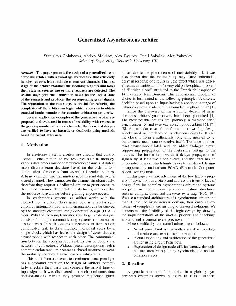
A generic structure of an arbiter in a globally syn-chronous system is shown in Figure 1a. It is a standard
...
Clock
FSM
blockPriority
Sync. gra
nts
sync.
req
ues
ts
(a) Interface.
D
Clk
D
Clk
... ...
...asyn
c. r
eques
ts
syn
c. r
eques
ts Priorityblock
Sync.FSM
Clock
(b) Synchronizing asynchronous signals.
latency (depends on setup time violation)
Clock
sync. request
async. request
(c) Latency of synchronizers.
Figure 1: Synchronous arbiter.
synchronous automaton which takes the bus access requestscoming from the master devices on a bus and, in the nextclock cycle, computes the outputs, which are grant signals.Note that such a circuit can implement any computablepriority function, with an arbitrary number of requests andarbitrary number of simultaneous grants (the case of m-of-narbitration). The complexity and scalability of the priorityfunction are the major advantages of synchronous arbitersin comparison to the majority of existing asynchronoussolutions. If a synchronous arbiter has to be used with anasynchronous bus, for example VME IEEE-1014 or anyother, it needs to have its asynchronous inputs synchronisedto the internal clock, as shown in Figure 1b. The synchro-nizers, effectively, lock the input request signals and enableits processing by standard synchronous circuits. For a slowexternal bus and fast internal clock it is a valid solution.However, for an SoC with fast on-chip communication fabricthis solution can be viewed as a slow option, because thetwo-flop synchronizers add a delay of two or three clockperiods to the latency, see Figure 1c.
The severity of the two-flop synchronizer latency prob-lem is easy to illustrate. For example, for a typical 90nmprocess the metastability resolution constant τ [10], [11]is approximately 50ps [12], which means the time neededfor reliable metastability resolution should be chosen asTmin ≈ 40τ = 2ns, thus leading to the minimum synchro-nizer latency of 4ns (two clock cycles) and minimum 6nslatency of the whole arbiter in Figure 1b. In our approachthe two-flop synchronizers are replaced with asynchronousarbiters equipped with metastability filters [7], which do notinclude the worst-case delay into every synchronisation cy-cle, completely eliminate the risk of synchronization failures(whilst the two-flop synchronizers only reduce the failureprobability to an acceptable level), and have a reasonablyshort average propagation delay. This leads to a significantlatency reduction, as demonstrated in Section 4.4, wherean asynchronous arbiter has approximately 1ns latency.Such a dramatic improvement, however, comes at a price.
2−wayarb.
2−wayarb.
2−wayarb.
Request Locking
Control Block
Asynchronous
wrapper
Pri
ori
ty b
lock
Sel
f−ti
med
log
ic
asy
nch
rono
us
requ
ests
gra
nts
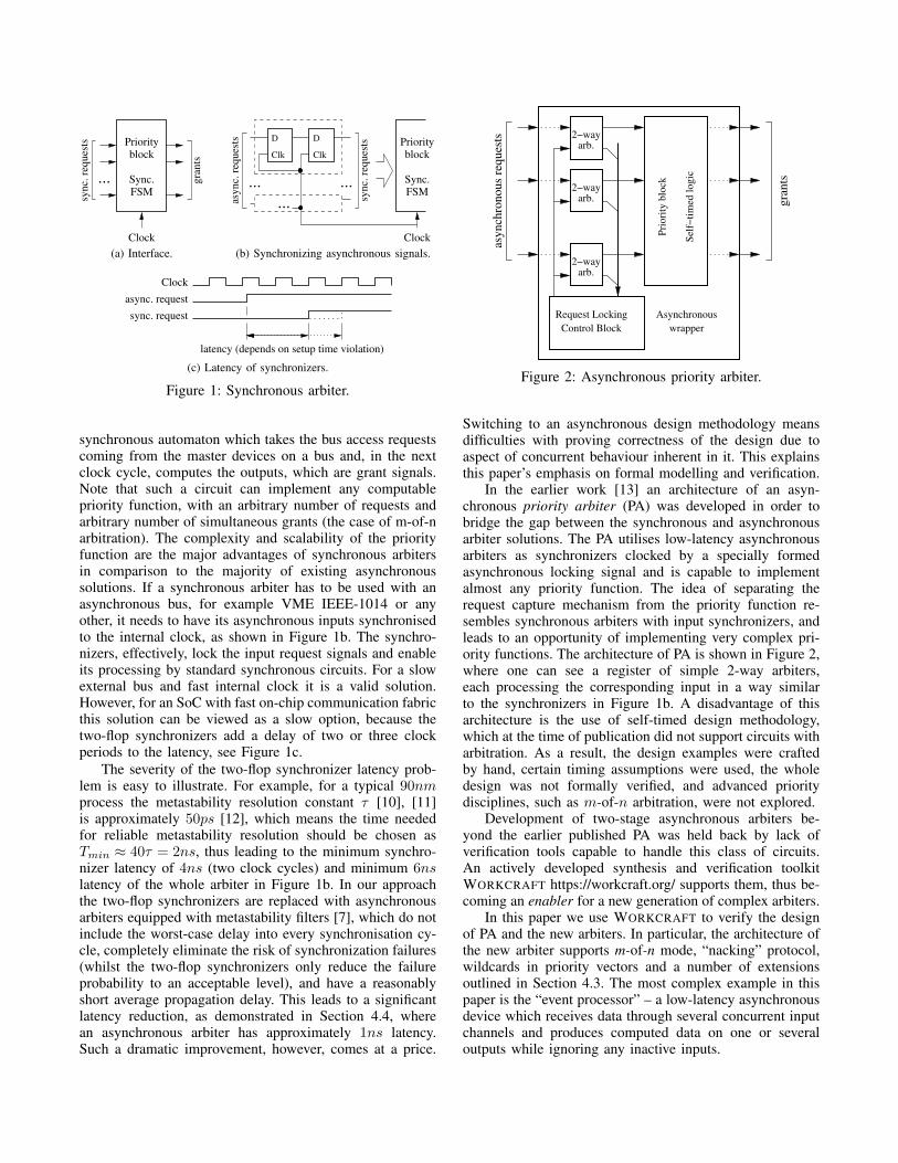
Figure 2: Asynchronous priority arbiter.
Switching to an asynchronous design methodology meansdifficulties with proving correctness of the design due toaspect of concurrent behaviour inherent in it. This explainsthis paper’s emphasis on formal modelling and verification.
In the earlier work [13] an architecture of an asyn-chronous priority arbiter (PA) was developed in order tobridge the gap between the synchronous and asynchronousarbiter solutions. The PA utilises low-latency asynchronousarbiters as synchronizers clocked by a specially formedasynchronous locking signal and is capable to implementalmost any priority function. The idea of separating therequest capture mechanism from the priority function re-sembles synchronous arbiters with input synchronizers, andleads to an opportunity of implementing very complex pri-ority functions. The architecture of PA is shown in Figure 2,where one can see a register of simple 2-way arbiters,each processing the corresponding input in a way similarto the synchronizers in Figure 1b. A disadvantage of thisarchitecture is the use of self-timed design methodology,which at the time of publication did not support circuits witharbitration. As a result, the design examples were craftedby hand, certain timing assumptions were used, the wholedesign was not formally verified, and advanced prioritydisciplines, such as m-of-n arbitration, were not explored.
Development of two-stage asynchronous arbiters be-yond the earlier published PA was held back by lack ofverification tools capable to handle this class of circuits.An actively developed synthesis and verification toolkitWORKCRAFT https://workcraft.org/ supports them, thus be-coming an enabler for a new generation of complex arbiters.
In this paper we use WORKCRAFT to verify the designof PA and the new arbiters. In particular, the architecture ofthe new arbiter supports m-of-n mode, “nacking” protocol,wildcards in priority vectors and a number of extensionsoutlined in Section 4.3. The most complex example in thispaper is the “event processor” – a low-latency asynchronousdevice which receives data through several concurrent inputchannels and produces computed data on one or severaloutputs while ignoring any inactive inputs.
3. Generalised arbiter
3.1. Basic Structure
The basic structure of the Generalised Arbiter is in-herited from the Priority Arbiter where the grant stage isseparated from the synchronization stage. The choice ofthis structure is motivated by its good scalability becauseadditional request rows can be added without significantlatency increase. One can describe the behaviour of thisarbiter with the following steps:
1) Wait until there is a change on at least one of therequest lines.
2) Freeze (or lock) all input request states.3) For the given stable set of requests, produce grants
according to some desired granting logic.4) Release locked requests and return to step 1.
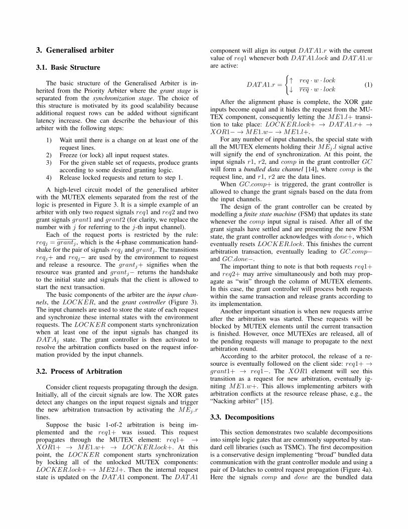
A high-level circuit model of the generalised arbiterwith the MUTEX elements separated from the rest of thelogic is presented in Figure 3. It is a simple example of anarbiter with only two request signals req1 and req2 and twogrant signals grant1 and grant2 (for clarity, we replace thenumber with j for referring to the j-th input channel).
Each of the request ports is restricted by the rule:reqj = grantj , which is the 4-phase communication hand-shake for the pair of signals reqj and grantj . The transitionsreqj+ and reqj− are used by the environment to requestand release a resource. The grantj+ signifies when theresource was granted and grantj− returns the handshaketo the initial state and signals that the client is allowed tostart the next transaction.
The basic components of the arbiter are the input chan-nels, the LOCKER, and the grant controller (Figure 3).The input channels are used to store the state of each requestand synchronize these internal states with the environmentrequests. The LOCKER component starts synchronizationwhen at least one of the input signals has changed itsDATAj state. The grant controller is then activated toresolve the arbitration conflicts based on the request infor-mation provided by the input channels.
3.2. Process of Arbitration
Consider client requests propagating through the design.Initially, all of the circuit signals are low. The XOR gatesdetect any changes on the input request signals and triggerthe new arbitration transaction by activating the MEj .rlines.
Suppose the basic 1-of-2 arbitration is being im-plemented and the req1+ was issued. This requestpropagates through the MUTEX element: req1+ →XOR1+ → ME1.w+ → LOCKER.lock+. At thispoint, the LOCKER component starts synchronizationby locking all of the unlocked MUTEX components:LOCKER.lock+ → ME2.l+. Then the internal requeststate is updated on the DATA1 component. The DATA1
component will align its output DATA1.r with the currentvalue of req1 whenever both DATA1.lock and DATA1.ware active:
DATA1.r =
{↑ req · w · lock↓ req · w · lock
(1)
After the alignment phase is complete, the XOR gateinputs become equal and it hides the request from the MU-TEX component, consequently letting the ME1.l+ transi-tion to take place: LOCKER.lock+ → DATA1.r+ →XOR1− →ME1.w− →ME1.l+.
For any number of input channels, the special state withall the MUTEX elements holding their MEj .l signal activewill signify the end of synchronization. At this point, theinput signals r1, r2, and comp in the grant controller GCwill form a bundled data channel [14], where comp is therequest line, and r1, r2 are the data lines.
When GC.comp+ is triggered, the grant controller isallowed to change the grant signals based on the data fromthe input channels.
The design of the grant controller can be created bymodelling a finite state machine (FSM) that updates its statewhenever the comp input signal is raised. After all of thegrant signals have settled and are presenting the new FSMstate, the grant controller acknowledges with done+, whicheventually resets LOCKER.lock. This finishes the currentarbitration transaction, eventually leading to GC.comp−and GC.done−.
The important thing to note is that both requests req1+and req2+ may arrive simultaneously and both may prop-agate as “win” through the column of MUTEX elements.In this case, the grant controller will process both requestswithin the same transaction and release grants according toits implementation.
Another important situation is when new requests arriveafter the arbitration was started. These requests will beblocked by MUTEX elements until the current transactionis finished. However, once MUTEXes are released, all ofthe pending requests will manage to propagate to the nextarbitration round.
According to the arbiter protocol, the release of a re-source is eventually followed on the client side: req1+ →grant1+ → req1−. The XOR1 element will see thistransition as a request for new arbitration, eventually ig-niting ME1.w+. This allows implementing arbiters witharbitration conflicts at the resource release phase, e.g., the“Nacking arbiter” [15].
3.3. Decompositions
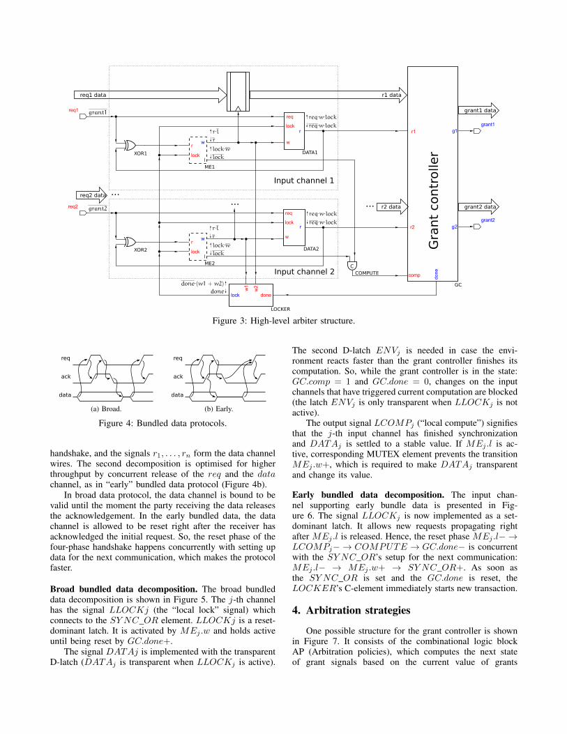
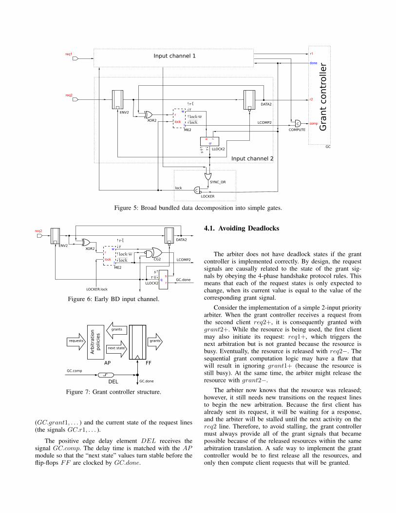
This section demonstrates two scalable decompositionsinto simple logic gates that are commonly supported by stan-dard cell libraries (such as TSMC). The first decompositionis a conservative design implementing “broad” bundled datacommunication with the grant controller module and using apair of D-latches to control request propagation (Figure 4a).Here the signals comp and done are the bundled data
ME1
ME2
XOR1
LOCKER
GC
XOR2
DATA1
DATA2
COMPUTE
C
Gra
nt
contr
oller
Input channel 1
Input channel 2
req1 data r1 data
grant1 data
grant2 datar2 data......req2 data ...
Figure 3: High-level arbiter structure.
data
req
ack
(a) Broad.
data
req
ack
(b) Early.
Figure 4: Bundled data protocols.
handshake, and the signals r1, . . . , rn form the data channelwires. The second decomposition is optimised for higherthroughput by concurrent release of the req and the datachannel, as in “early” bundled data protocol (Figure 4b).
In broad data protocol, the data channel is bound to bevalid until the moment the party receiving the data releasesthe acknowledgement. In the early bundled data, the datachannel is allowed to be reset right after the receiver hasacknowledged the initial request. So, the reset phase of thefour-phase handshake happens concurrently with setting updata for the next communication, which makes the protocolfaster.
Broad bundled data decomposition. The broad bundleddata decomposition is shown in Figure 5. The j-th channelhas the signal LLOCKj (the “local lock” signal) whichconnects to the SY NC_OR element. LLOCKj is a reset-dominant latch. It is activated by MEj .w and holds activeuntil being reset by GC.done+.
The signal DATAj is implemented with the transparentD-latch (DATAj is transparent when LLOCKj is active).
The second D-latch ENVj is needed in case the envi-ronment reacts faster than the grant controller finishes itscomputation. So, while the grant controller is in the state:GC.comp = 1 and GC.done = 0, changes on the inputchannels that have triggered current computation are blocked(the latch ENVj is only transparent when LLOCKj is notactive).
The output signal LCOMPj (“local compute”) signifiesthat the j-th input channel has finished synchronizationand DATAj is settled to a stable value. If MEj .l is ac-tive, corresponding MUTEX element prevents the transitionMEj .w+, which is required to make DATAj transparentand change its value.
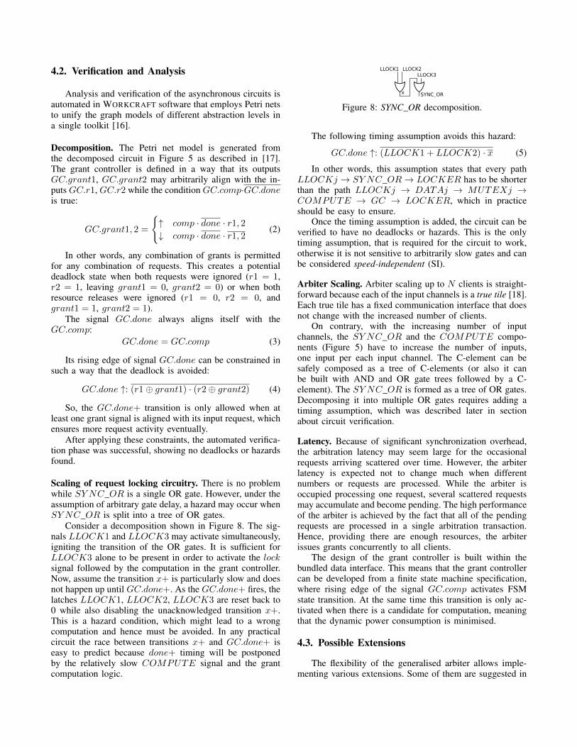
Early bundled data decomposition. The input chan-nel supporting early bundle data is presented in Fig-ure 6. The signal LLOCKj is now implemented as a set-dominant latch. It allows new requests propagating rightafter MEj .l is released. Hence, the reset phase MEj .l− →LCOMPj− → COMPUTE → GC.done− is concurrentwith the SY NC_OR’s setup for the next communication:MEj .l− → MEj .w+ → SY NC_OR+. As soon asthe SY NC_OR is set and the GC.done is reset, theLOCKER’s C-element immediately starts new transaction.
4. Arbitration strategies
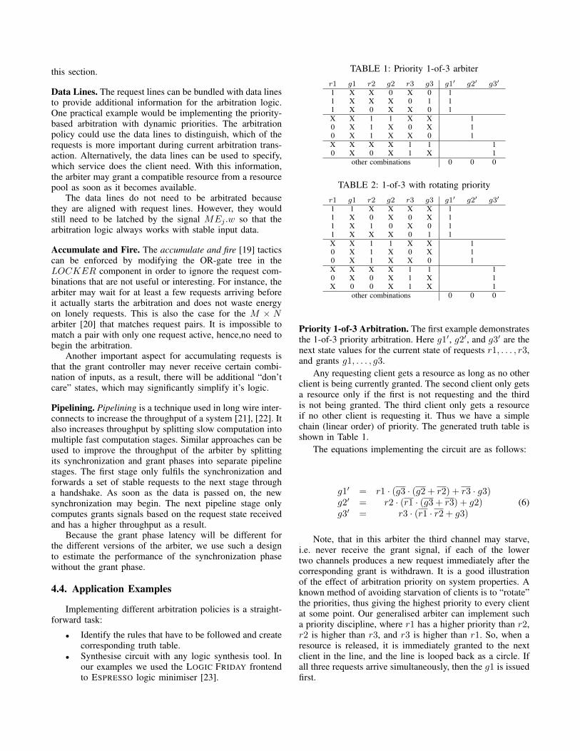
One possible structure for the grant controller is shownin Figure 7. It consists of the combinational logic blockAP (Arbitration policies), which computes the next stateof grant signals based on the current value of grants
ME2
XOR2
lockC
COMPUTE
C
DATA2
LLOCK2
SYNC_OR
Input channel 1
Input channel 2
Gra
nt
contr
oller
LOCKER
GC
LCOMP2
ENV2
Figure 5: Broad bundled data decomposition into simple gates.
ME2
XOR2
LCOMP2
ENV2
DATA2
LLOCK2
CG2
LOCKER.lock
GC.done
req2
Figure 6: Early BD input channel.
Arb
itra
tion
policie
s
AP
GC.done
requests
next state
grants
DEL
GC.comp
grants
FF
Figure 7: Grant controller structure.
(GC.grant1, . . . ) and the current state of the request lines(the signals GC.r1, . . . ).
The positive edge delay element DEL receives thesignal GC.comp. The delay time is matched with the APmodule so that the “next state” values turn stable before theflip-flops FF are clocked by GC.done.
4.1. Avoiding Deadlocks
The arbiter does not have deadlock states if the grantcontroller is implemented correctly. By design, the requestsignals are causally related to the state of the grant sig-nals by obeying the 4-phase handshake protocol rules. Thismeans that each of the request states is only expected tochange, when its current value is equal to the value of thecorresponding grant signal.
Consider the implementation of a simple 2-input priorityarbiter. When the grant controller receives a request fromthe second client req2+, it is consequently granted withgrant2+. While the resource is being used, the first clientmay also initiate its request: req1+, which triggers thenext arbitration but is not granted because the resource isbusy. Eventually, the resource is released with req2−. Thesequential grant computation logic may have a flaw thatwill result in ignoring grant1+ (because the resource isstill busy). At the same time, the arbiter might release theresource with grant2−.
The arbiter now knows that the resource was released;however, it still needs new transitions on the request linesto begin the new arbitration. Because the first client hasalready sent its request, it will be waiting for a response,and the arbiter will be stalled until the next activity on thereq2 line. Therefore, to avoid stalling, the grant controllermust always provide all of the grant signals that becamepossible because of the released resources within the samearbitration translation. A safe way to implement the grantcontroller would be to first release all the resources, andonly then compute client requests that will be granted.
4.2. Verification and Analysis
Analysis and verification of the asynchronous circuits isautomated in WORKCRAFT software that employs Petri netsto unify the graph models of different abstraction levels ina single toolkit [16].
Decomposition. The Petri net model is generated fromthe decomposed circuit in Figure 5 as described in [17].The grant controller is defined in a way that its outputsGC.grant1, GC.grant2 may arbitrarily align with the in-puts GC.r1, GC.r2 while the condition GC.comp·GC.doneis true:
GC.grant1, 2 =
{↑ comp · done · r1, 2↓ comp · done · r1, 2
(2)
In other words, any combination of grants is permittedfor any combination of requests. This creates a potentialdeadlock state when both requests were ignored (r1 = 1,r2 = 1, leaving grant1 = 0, grant2 = 0) or when bothresource releases were ignored (r1 = 0, r2 = 0, andgrant1 = 1, grant2 = 1).
The signal GC.done always aligns itself with theGC.comp:
GC.done = GC.comp (3)
Its rising edge of signal GC.done can be constrained insuch a way that the deadlock is avoided:
GC.done ↑: (r1⊕ grant1) · (r2⊕ grant2) (4)
So, the GC.done+ transition is only allowed when atleast one grant signal is aligned with its input request, whichensures more request activity eventually.
After applying these constraints, the automated verifica-tion phase was successful, showing no deadlocks or hazardsfound.
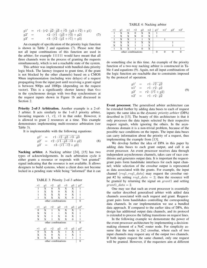
Scaling of request locking circuitry. There is no problemwhile SY NC_OR is a single OR gate. However, under theassumption of arbitrary gate delay, a hazard may occur whenSY NC_OR is split into a tree of OR gates.
Consider a decomposition shown in Figure 8. The sig-nals LLOCK1 and LLOCK3 may activate simultaneously,igniting the transition of the OR gates. It is sufficient forLLOCK3 alone to be present in order to activate the locksignal followed by the computation in the grant controller.Now, assume the transition x+ is particularly slow and doesnot happen up until GC.done+. As the GC.done+ fires, thelatches LLOCK1, LLOCK2, LLOCK3 are reset back to0 while also disabling the unacknowledged transition x+.This is a hazard condition, which might lead to a wrongcomputation and hence must be avoided. In any practicalcircuit the race between transitions x+ and GC.done+ iseasy to predict because done+ timing will be postponedby the relatively slow COMPUTE signal and the grantcomputation logic.
SYNC_OR
LLOCK1 LLOCK2LLOCK3
x
Figure 8: SYNC_OR decomposition.
The following timing assumption avoids this hazard:
GC.done ↑: (LLOCK1 + LLOCK2) · x (5)
In other words, this assumption states that every pathLLOCKj → SY NC_OR→ LOCKER has to be shorterthan the path LLOCKj → DATAj → MUTEXj →COMPUTE → GC → LOCKER, which in practiceshould be easy to ensure.
Once the timing assumption is added, the circuit can beverified to have no deadlocks or hazards. This is the onlytiming assumption, that is required for the circuit to work,otherwise it is not sensitive to arbitrarily slow gates and canbe considered speed-independent (SI).
Arbiter Scaling. Arbiter scaling up to N clients is straight-forward because each of the input channels is a true tile [18].Each true tile has a fixed communication interface that doesnot change with the increased number of clients.
On contrary, with the increasing number of inputchannels, the SY NC_OR and the COMPUTE compo-nents (Figure 5) have to increase the number of inputs,one input per each input channel. The C-element can besafely composed as a tree of C-elements (or also it canbe built with AND and OR gate trees followed by a C-element). The SY NC_OR is formed as a tree of OR gates.Decomposing it into multiple OR gates requires adding atiming assumption, which was described later in sectionabout circuit verification.
Latency. Because of significant synchronization overhead,the arbitration latency may seem large for the occasionalrequests arriving scattered over time. However, the arbiterlatency is expected not to change much when differentnumbers or requests are processed. While the arbiter isoccupied processing one request, several scattered requestsmay accumulate and become pending. The high performanceof the arbiter is achieved by the fact that all of the pendingrequests are processed in a single arbitration transaction.Hence, providing there are enough resources, the arbiterissues grants concurrently to all clients.
The design of the grant controller is built within thebundled data interface. This means that the grant controllercan be developed from a finite state machine specification,where rising edge of the signal GC.comp activates FSMstate transition. At the same time this transition is only ac-tivated when there is a candidate for computation, meaningthat the dynamic power consumption is minimised.
4.3. Possible Extensions
The flexibility of the generalised arbiter allows imple-menting various extensions. Some of them are suggested in
this section.
Data Lines. The request lines can be bundled with data linesto provide additional information for the arbitration logic.One practical example would be implementing the priority-based arbitration with dynamic priorities. The arbitrationpolicy could use the data lines to distinguish, which of therequests is more important during current arbitration trans-action. Alternatively, the data lines can be used to specify,which service does the client need. With this information,the arbiter may grant a compatible resource from a resourcepool as soon as it becomes available.
The data lines do not need to be arbitrated becausethey are aligned with request lines. However, they wouldstill need to be latched by the signal MEj .w so that thearbitration logic always works with stable input data.
Accumulate and Fire. The accumulate and fire [19] tacticscan be enforced by modifying the OR-gate tree in theLOCKER component in order to ignore the request com-binations that are not useful or interesting. For instance, thearbiter may wait for at least a few requests arriving beforeit actually starts the arbitration and does not waste energyon lonely requests. This is also the case for the M × Narbiter [20] that matches request pairs. It is impossible tomatch a pair with only one request active, hence,no need tobegin the arbitration.
Another important aspect for accumulating requests isthat the grant controller may never receive certain combi-nation of inputs, as a result, there will be additional “don’tcare” states, which may significantly simplify it’s logic.
Pipelining. Pipelining is a technique used in long wire inter-connects to increase the throughput of a system [21], [22]. Italso increases throughput by splitting slow computation intomultiple fast computation stages. Similar approaches can beused to improve the throughput of the arbiter by splittingits synchronization and grant phases into separate pipelinestages. The first stage only fulfils the synchronization andforwards a set of stable requests to the next stage througha handshake. As soon as the data is passed on, the newsynchronization may begin. The next pipeline stage onlycomputes grants signals based on the request state receivedand has a higher throughput as a result.
Because the grant phase latency will be different forthe different versions of the arbiter, we use such a designto estimate the performance of the synchronization phasewithout the grant phase.
4.4. Application Examples
Implementing different arbitration policies is a straight-forward task:
• Identify the rules that have to be followed and createcorresponding truth table.
• Synthesise circuit with any logic synthesis tool. Inour examples we used the LOGIC FRIDAY frontendto ESPRESSO logic minimiser [23].
TABLE 1: Priority 1-of-3 arbiter
r1 g1 r2 g2 r3 g3 g1′ g2′ g3′
1 X X 0 X 0 11 X X X 0 1 11 X 0 X X 0 1X X 1 1 X X 10 X 1 X 0 X 10 X 1 X X 0 1X X X X 1 1 10 X 0 X 1 X 1
other combinations 0 0 0
TABLE 2: 1-of-3 with rotating priority
r1 g1 r2 g2 r3 g3 g1′ g2′ g3′
1 1 X X X X 11 X 0 X 0 X 11 X 1 0 X 0 11 X X X 0 1 1X X 1 1 X X 10 X 1 X 0 X 10 X 1 X X 0 1X X X X 1 1 10 X 0 X 1 X 1X 0 0 X 1 X 1
other combinations 0 0 0
Priority 1-of-3 Arbitration. The first example demonstratesthe 1-of-3 priority arbitration. Here g1′, g2′, and g3′ are thenext state values for the current state of requests r1, . . . , r3,and grants g1, . . . , g3.
Any requesting client gets a resource as long as no otherclient is being currently granted. The second client only getsa resource only if the first is not requesting and the thirdis not being granted. The third client only gets a resourceif no other client is requesting it. Thus we have a simplechain (linear order) of priority. The generated truth table isshown in Table 1.
The equations implementing the circuit are as follows:
g1′ = r1 · (g3 · (g2 + r2) + r3 · g3)g2′ = r2 · (r1 · (g3 + r3) + g2)g3′ = r3 · (r1 · r2 + g3)
(6)
Note, that in this arbiter the third channel may starve,i.e. never receive the grant signal, if each of the lowertwo channels produces a new request immediately after thecorresponding grant is withdrawn. It is a good illustrationof the effect of arbitration priority on system properties. Aknown method of avoiding starvation of clients is to “rotate”the priorities, thus giving the highest priority to every clientat some point. Our generalised arbiter can implement sucha priority discipline, where r1 has a higher priority than r2,r2 is higher than r3, and r3 is higher than r1. So, when aresource is released, it is immediately granted to the nextclient in the line, and the line is looped back as a circle. Ifall three requests arrive simultaneously, then the g1 is issuedfirst.
g1′ = r1 · (r2 · g2 · g3 + r3 · (g3 + r2) + g1)g2′ = r2 · (r1 · (g3 + r3) + g2)g3′ = r3 · (r2 · (g1 + r1) + g3)
(7)
An example of specification of the priority logic functionis shown in Table 2 and equations (7). Please note thatnot all input combinations of this function are used inthe arbiter; for example 111111 would have meant that allthree channels were in the process of granting the requestssimultaneously, which is not a reachable state of the system.
This arbiter was implemented with bundled-data prioritylogic block. The latency (request to grant time, if the grantis not blocked by the other channels) based on a CMOS90nm implementation (including wire delays) of a requestpropagating from the input port until receiving a grant signalis between 900ps and 1000ps (depending on the requestvector). This is a significantly shorter latency than 6nsin the synchronous design with two-flop synchronisers atthe request inputs shown in Figure 1b and discussed inSection 2.
Priority 2-of-3 Arbitration. Another example is a 2-of-3 arbiter. It acts similarly to the 1-of-3 priority arbiter,favouring requests r1, r2, r3 in that order. However, itis allowed to grant 2 resources at a time. This exampledemonstrates implementing multi-resource arbitration (seeTable 3).
It is implementable with the following equations:
g1′ = r1 · r2 · g2 · r3 · g3g2′ = r2 · (r1 · g3 · r3 + g2)g3′ = r3 · (r1 · r2 + g3)
(8)
Nacking arbiter. A Nacking arbiter [24], [15] has twotypes of acknowledgements. In each arbitration cycle iteither grants a resource or responds with “not granted”signal indicating that the resource is not available. It allowsdesigners to build systems, where a client does not becomelocked in a pending state while being “informed” that it can
TABLE 3: Priority 2-of-3 arbiter
r1 g1 r2 g2 r3 g3 g1′
1 X 0 X X X 11 X X 0 X X 11 X X X 0 X 11 X X X X 0 1
other combinations 0
r1 g1 r2 g2 r3 g3 g2′
0 X 1 X X X 1X X 1 1 X X 1X X 1 X 0 X 1X X 1 X X 0 1
other combinations 0
r1 g1 r2 g2 r3 g3 g3′
0 X X X 1 X 1X X 0 X 1 X 1X X X X 1 1 1
other combinations 0
TABLE 4: Nacking arbiter
r1 g1 n1 r2 g2 n2 g1′ n1′ g2′ n2′
1 X X 0 X X 11 X X X 0 X 11 X X 1 1 X 10 X X 1 X X 1X X X 1 1 X 11 X X 1 0 X 1
other combinations 0 0 0 0
do something else in this time. An example of the priorityfunction of a two-way nacking arbiter is constructed in Ta-ble 4 and equations (9). Again, not all input combinations ofthe logic function are reachable due to constraints imposedby the protocol of operation.
g1′ = r1 · r2 · g2n1′ = r1 · r2 · g2g2′ = r2 · (r1 + g2)n2′ = r1 · r2 · g2
(9)
Event processor. The generalised arbiter architecture canbe extended further by adding data buses to each of requestinputs; the same idea as the dynamic priority arbiter (DPA)described in [13]. The beauty of this architecture is that itonly processes the data inputs selected by their respectiverequest signals, while ignoring the others. In the asyn-chronous domain it is a non-trivial problem, because of thepossible race conditions on the inputs. The input data busescan carry information about the priority of a request, thusimplementing the example from [13].
We develop further the idea of DPA in this paper byadding data buses to each grant output, and call it anevent processor. An event processor receives data throughindependent asynchronous channels, takes care of race con-ditions and generates output data. It is important the request-grant pairs form handshake interfaces for each input chan-nel; while selection of the crossbar output is representedas data associated with the grants. For example, the inputchannel (req1, req1_data) may request the crossbar out-put #2 by setting req1_data = 2; then the resource willbe granted by returning the signal on grant1 and settinggrant1_data = 2.
One may see that such an event processor is essentiallythe earlier described generalised arbiter with added datachannels associated with each request and grant. Request-grant pairs form handshakes controlling the correspondingdata channels. In our implementation we use a bundleddata approach. If compared to the earlier idea of DPA, thisdesign has additional output data channels, and its protocolis extended to process the falling transitions on request lines.
In the following example we demonstrate the power ofthe event processor architecture by implementing a decision-making element of a NoC router node. For simplicity as-sume that the node is 2x2 crossbar, where each of twoinput channels may request any of the output two channels.If both inputs request the same channel, only one requestwill be granted. However, if the requesters aim at different
Priority logic inputs Priority logic outputs Cond. Commentr1 w1 g1 d1 r2 w2 g2 d2 g′1 d′1 g′2 d′20 0 0 0 both requests removed0 1 a 0 0 1 sel(a) r2 added
one
req.
0 1 1 a 0 1 a r1 removed1 a 0 0 1 sel(a) 0 r1 added1 1 a 0 1 a 0 r2 removed1 01 0 1 01 0 1 01 0 conflict on resource
two
new
req-
s1 01 0 1 10 0 1 01 1 10 mutually exclusive wildcards1 10 0 1 01 0 1 10 1 01 mutually exclusive wildcards1 10 0 1 10 0 0 1 10 conflict on resource1 11 0 1 01 0 1 10 1 01 one broad wildcard1 11 0 1 10 0 1 01 1 10 one broad wildcard1 01 0 1 11 0 1 01 1 10 one broad wildcard1 10 0 1 11 0 1 10 1 01 one broad wildcard1 11 0 1 11 0 1 sel(11), e.g.10 1 11\d′1, e.g. 01 both wildcards are broad1 1 a 1 b 0 1 a 0 a = b conflict on resource
new
&ol
d
1 1 a 1 b 0 1 a 1 b\a a 6= b one broad wildcard1 a 0 1 1 b 0 1 b a = b conflict on resource1 a 0 1 1 b 1 a\b 1 b a 6= b one broad wildcard
TABLE 5: Event processor for a 2x2 crossbar controller.
0
0.001
0.002
0.003
0.004
0.005
2 4 8 16 32 48 64
Are
a (
mm
2 )
Number of inputs
(a) Area.
0
0.2
0.4
0.6
0.8
1.0
2 4 8 16 32 48 64
Late
ncy
(ns)
Number of inputs
(b) Latency.
0
10
20
30
40
2 4 8 16 32 48 64
0
0.2
0.4
0.6
0.8
Tota
l thr
ough
put (
x10
9 )
Cha
nne
l thr
ough
put (
x10
9 )
Number of inputs
50 1.0
(c) Throughput.
Figure 9: Pipelined arbiter performance.
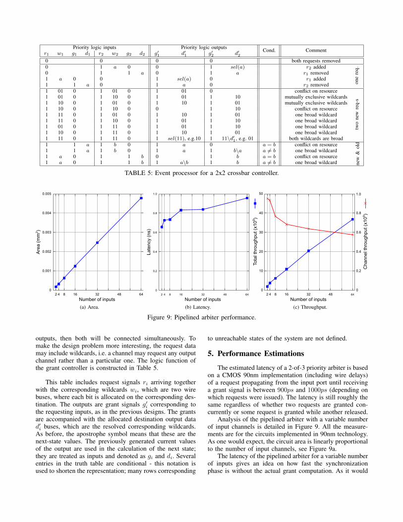
outputs, then both will be connected simultaneously. Tomake the design problem more interesting, the request datamay include wildcards, i.e. a channel may request any outputchannel rather than a particular one. The logic function ofthe grant controller is constructed in Table 5.
This table includes request signals ri arriving togetherwith the corresponding wildcards wi, which are two wirebuses, where each bit is allocated on the corresponding des-tination. The outputs are grant signals g′i corresponding tothe requesting inputs, as in the previous designs. The grantsare accompanied with the allocated destination output datad′i buses, which are the resolved corresponding wildcards.As before, the apostrophe symbol means that these are thenext-state values. The previously generated current valuesof the output are used in the calculation of the next state;they are treated as inputs and denoted as gi and di. Severalentries in the truth table are conditional - this notation isused to shorten the representation; many rows corresponding
to unreachable states of the system are not defined.
5. Performance Estimations
The estimated latency of a 2-of-3 priority arbiter is basedon a CMOS 90nm implementation (including wire delays)of a request propagating from the input port until receivinga grant signal is between 900ps and 1000ps (depending onwhich requests were issued). The latency is still roughly thesame regardless of whether two requests are granted con-currently or some request is granted while another released.
Analysis of the pipelined arbiter with a variable numberof input channels is detailed in Figure 9. All the measure-ments are for the circuits implemented in 90nm technology.As one would expect, the circuit area is linearly proportionalto the number of input channels, see Figure 9a.
The latency of the pipelined arbiter for a variable numberof inputs gives an idea on how fast the synchronizationphase is without the actual grant computation. As it would
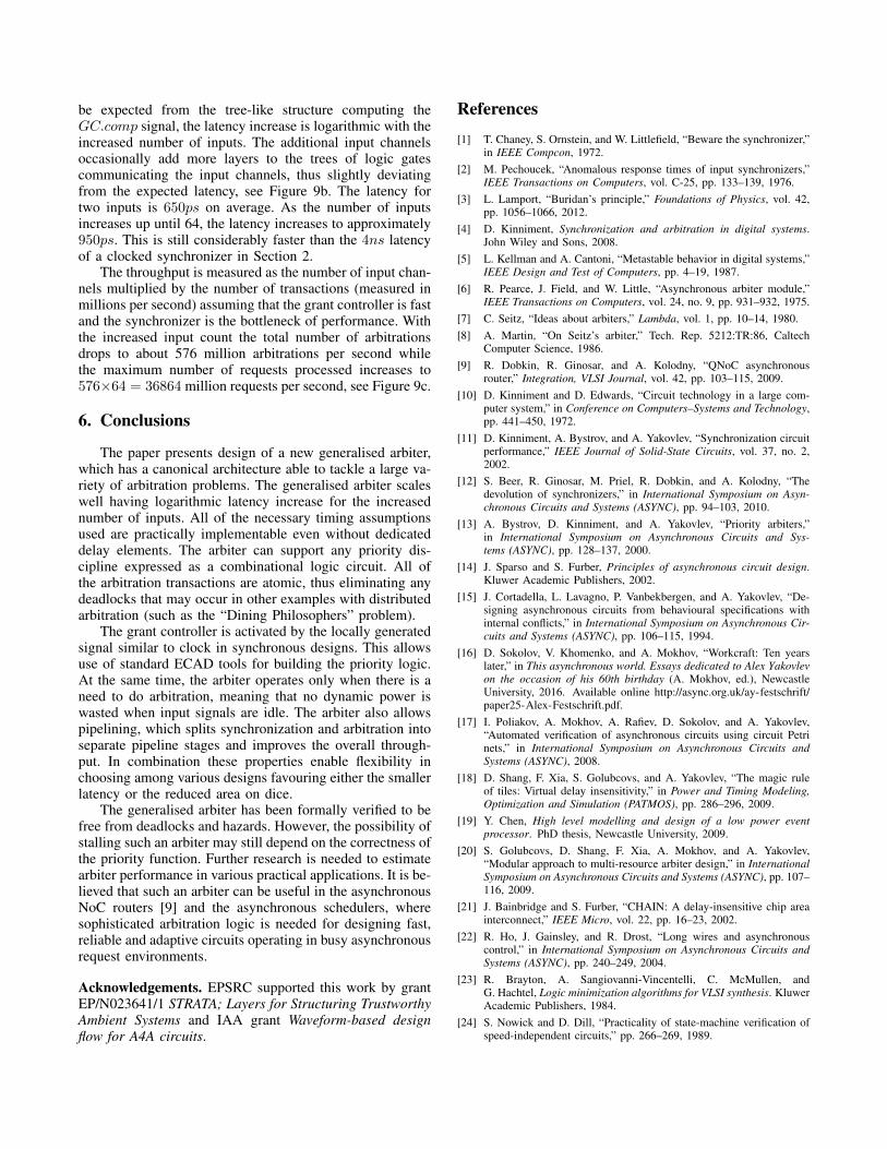
be expected from the tree-like structure computing theGC.comp signal, the latency increase is logarithmic with theincreased number of inputs. The additional input channelsoccasionally add more layers to the trees of logic gatescommunicating the input channels, thus slightly deviatingfrom the expected latency, see Figure 9b. The latency fortwo inputs is 650ps on average. As the number of inputsincreases up until 64, the latency increases to approximately950ps. This is still considerably faster than the 4ns latencyof a clocked synchronizer in Section 2.
The throughput is measured as the number of input chan-nels multiplied by the number of transactions (measured inmillions per second) assuming that the grant controller is fastand the synchronizer is the bottleneck of performance. Withthe increased input count the total number of arbitrationsdrops to about 576 million arbitrations per second whilethe maximum number of requests processed increases to576×64 = 36864 million requests per second, see Figure 9c.
6. Conclusions
The paper presents design of a new generalised arbiter,which has a canonical architecture able to tackle a large va-riety of arbitration problems. The generalised arbiter scaleswell having logarithmic latency increase for the increasednumber of inputs. All of the necessary timing assumptionsused are practically implementable even without dedicateddelay elements. The arbiter can support any priority dis-cipline expressed as a combinational logic circuit. All ofthe arbitration transactions are atomic, thus eliminating anydeadlocks that may occur in other examples with distributedarbitration (such as the “Dining Philosophers” problem).
The grant controller is activated by the locally generatedsignal similar to clock in synchronous designs. This allowsuse of standard ECAD tools for building the priority logic.At the same time, the arbiter operates only when there is aneed to do arbitration, meaning that no dynamic power iswasted when input signals are idle. The arbiter also allowspipelining, which splits synchronization and arbitration intoseparate pipeline stages and improves the overall through-put. In combination these properties enable flexibility inchoosing among various designs favouring either the smallerlatency or the reduced area on dice.
The generalised arbiter has been formally verified to befree from deadlocks and hazards. However, the possibility ofstalling such an arbiter may still depend on the correctness ofthe priority function. Further research is needed to estimatearbiter performance in various practical applications. It is be-lieved that such an arbiter can be useful in the asynchronousNoC routers [9] and the asynchronous schedulers, wheresophisticated arbitration logic is needed for designing fast,reliable and adaptive circuits operating in busy asynchronousrequest environments.
Acknowledgements. EPSRC supported this work by grantEP/N023641/1 STRATA; Layers for Structuring TrustworthyAmbient Systems and IAA grant Waveform-based designflow for A4A circuits.
References
[1] T. Chaney, S. Ornstein, and W. Littlefield, “Beware the synchronizer,”in IEEE Compcon, 1972.
[2] M. Pechoucek, “Anomalous response times of input synchronizers,”IEEE Transactions on Computers, vol. C-25, pp. 133–139, 1976.
[3] L. Lamport, “Buridan’s principle,” Foundations of Physics, vol. 42,pp. 1056–1066, 2012.
[4] D. Kinniment, Synchronization and arbitration in digital systems.John Wiley and Sons, 2008.
[5] L. Kellman and A. Cantoni, “Metastable behavior in digital systems,”IEEE Design and Test of Computers, pp. 4–19, 1987.
[6] R. Pearce, J. Field, and W. Little, “Asynchronous arbiter module,”IEEE Transactions on Computers, vol. 24, no. 9, pp. 931–932, 1975.
[7] C. Seitz, “Ideas about arbiters,” Lambda, vol. 1, pp. 10–14, 1980.[8] A. Martin, “On Seitz’s arbiter,” Tech. Rep. 5212:TR:86, Caltech
Computer Science, 1986.[9] R. Dobkin, R. Ginosar, and A. Kolodny, “QNoC asynchronous
router,” Integration, VLSI Journal, vol. 42, pp. 103–115, 2009.[10] D. Kinniment and D. Edwards, “Circuit technology in a large com-
puter system,” in Conference on Computers–Systems and Technology,pp. 441–450, 1972.
[11] D. Kinniment, A. Bystrov, and A. Yakovlev, “Synchronization circuitperformance,” IEEE Journal of Solid-State Circuits, vol. 37, no. 2,2002.
[12] S. Beer, R. Ginosar, M. Priel, R. Dobkin, and A. Kolodny, “Thedevolution of synchronizers,” in International Symposium on Asyn-chronous Circuits and Systems (ASYNC), pp. 94–103, 2010.
[13] A. Bystrov, D. Kinniment, and A. Yakovlev, “Priority arbiters,”in International Symposium on Asynchronous Circuits and Sys-tems (ASYNC), pp. 128–137, 2000.
[14] J. Sparso and S. Furber, Principles of asynchronous circuit design.Kluwer Academic Publishers, 2002.
[15] J. Cortadella, L. Lavagno, P. Vanbekbergen, and A. Yakovlev, “De-signing asynchronous circuits from behavioural specifications withinternal conflicts,” in International Symposium on Asynchronous Cir-cuits and Systems (ASYNC), pp. 106–115, 1994.
[16] D. Sokolov, V. Khomenko, and A. Mokhov, “Workcraft: Ten yearslater,” in This asynchronous world. Essays dedicated to Alex Yakovlevon the occasion of his 60th birthday (A. Mokhov, ed.), NewcastleUniversity, 2016. Available online http://async.org.uk/ay-festschrift/paper25-Alex-Festschrift.pdf.
[17] I. Poliakov, A. Mokhov, A. Rafiev, D. Sokolov, and A. Yakovlev,“Automated verification of asynchronous circuits using circuit Petrinets,” in International Symposium on Asynchronous Circuits andSystems (ASYNC), 2008.
[18] D. Shang, F. Xia, S. Golubcovs, and A. Yakovlev, “The magic ruleof tiles: Virtual delay insensitivity,” in Power and Timing Modeling,Optimization and Simulation (PATMOS), pp. 286–296, 2009.
[19] Y. Chen, High level modelling and design of a low power eventprocessor. PhD thesis, Newcastle University, 2009.
[20] S. Golubcovs, D. Shang, F. Xia, A. Mokhov, and A. Yakovlev,“Modular approach to multi-resource arbiter design,” in InternationalSymposium on Asynchronous Circuits and Systems (ASYNC), pp. 107–116, 2009.
[21] J. Bainbridge and S. Furber, “CHAIN: A delay-insensitive chip areainterconnect,” IEEE Micro, vol. 22, pp. 16–23, 2002.
[22] R. Ho, J. Gainsley, and R. Drost, “Long wires and asynchronouscontrol,” in International Symposium on Asynchronous Circuits andSystems (ASYNC), pp. 240–249, 2004.
[23] R. Brayton, A. Sangiovanni-Vincentelli, C. McMullen, andG. Hachtel, Logic minimization algorithms for VLSI synthesis. KluwerAcademic Publishers, 1984.
[24] S. Nowick and D. Dill, “Practicality of state-machine verification ofspeed-independent circuits,” pp. 266–269, 1989.


