Embed Size (px)
Citation preview
SPARE PARTS DIAGRAM FOR
First Choice Group Blakeney Way, Kingswood Lakeside Cannock, Staffs, WS11 8LD TEL: 01543 577778 FAX: 01543504141 Email: [email protected] Web: www.firstchoice-cs.co.uk
Gas Oven Range
PNC: 178609
Model: TCF/G9UK
Doc. Nr.: 2 - 05 845Da Ser. Nr. / From ser. nr.: 830.... Ed.2008 09
CATALOGO PARTI DI RICAMBIOSPARE PARTS CATALOGUE
Marchio / Brand: ElectroluxFactory code: 9PDX
Indice Index Pag. 1 Mobile e componenti Structure and components
2 Impianto gas Gas components 3 - 5 Lista ricambi Spare parts list
PNC Model Ref. Page Note
178609 TCF/G9UK - 1...5 6 GAS BURNERS ON LARGE OVEN 900 MM
6 FUOCHI SU FORNO GRANDE N7006 GAS BURNERS ON LARGE OVEN N700
ELECTROLUX PROFESSIONAL
Modular PlatformViale Treviso, 1533170 Pordenone - ItalyFax: +39 0434-380577
Doc. Nr.: 2 - 05 845Da Ser. Nr. / From ser. nr.: 830..... Ed.2008 09Page: 1
6 FUOCHI SU FORNO GRANDE N7006 GAS BURNERS ON LARGE OVEN N700
1
4
3
11
10
7
6 16
1315
9
8
17
22
19
21
35
36
37
40
38
26
30
27
28
33
31
29
22
25
24
45
44
43
2
5
12
14
2023
3236
42
4647
48 49
39
18
34
37
41
50
5152
21a
Doc. Nr.: 2 - 05 845Da Ser. Nr. / From ser. nr.: 830.... Ed.2008 09Page: 2
6 FUOCHI SU FORNO GRANDE N7006 GAS BURNERS ON LARGE OVEN N700
68
B*8280
79
85
60
818079
71
75
61
62
63
64
65
64
66
67
68
69
70
A*
86
8788
909192
9394
78
89
78 71
7975 E*
83
8483
7374 76
7772
D*
C*
95
Doc. Nr.: 2 - 05 845Da Ser. Nr. / From ser. nr.: 830..... Ed.2008 09
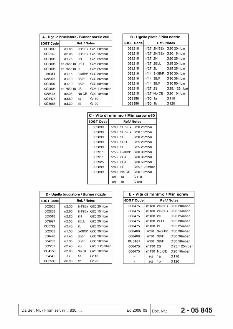
6DGT Code
0C2809 ø1.85 2H/2E+ G20 20mbar
0C0142 ø2.05 2H/2E+ G20 15mbar
0C2808 ø1.75 2H G20 25mbar
0C2806 ø1.85/2.10 2ELL G25 20mbar
0C2805 ø1.75/2.10 2L G25 25mbar
059314 ø1.15 3+3B/P G30 30mbar
0A2076 ø1.10 3B/P G30 36mbar
0C2807 ø1.10 3B/P G30 50mbar
0C2805 ø1.75/2.10 2S G25.1 25mbar
0A2475 ø2.25 No CE G20 10mbar
0C5475 ø3.50 1a G110
0C3658 ø3.30 1b G120
Ref. / Notes
A - Ugello bruciatore / Burner nozzle ø60
6DGT Code
002865 ø2.30 2H/2E+ G20 20mbar
002268 ø2.60 2H/2E+ G20 15mbar
055018 ø2.20 2H G20 25mbar
003997 ø2.55 2ELL G25 20mbar
0C0729 ø2.40 2L G25 25mbar
002862 ø1.50 3+3B/P G30 30mbar
056470 ø1.45 3B/P G30 36mbar
004732 ø1.35 3B/P G30 50mbar
002267 ø2.45 2S G25.1 25mbar
0C4150 ø2.80 No CE G20 10mbar
054545 ø7 1a G110
0C3590 ø6.90 1b G120
Ref. / Notes
D - Ugello bruciatore / Burner nozzle
6DGT Code
059215 n°27 2H/2E+ G20 20mbar
059215 n°27 2H/2E+ G20 15mbar
059215 n°27 2H G20 25mbar
059215 n°27 2ELL G25 20mbar
059215 n°27 2L G25 25mbar
059216 n°14 3+3B/P G30 30mbar
059216 n°14 3B/P G30 36mbar
059216 n°14 3B/P G30 50mbar
059215 n°27 2S G25.1 25mbar
059215 n°27 No CE G20 10mbar
059356 n°50 1a G110
059356 n°50 1b G120
Ref./ Notes
B - Ugello pilota / Pilot nozzle
6DGT Code
006475 n°130 2H/2E+ G20 20mbar
006475 n°130 2H/2E+ G20 15mbar
006475 n°130 2H G20 25mbar
006475 n°130 2ELL G25 20mbar
006475 n°130 2L G25 25mbar
006466 n°90 3+3B/P G30 30mbar
006466 n°90 3B/P G30 36mbar
0C5481 n°80 3B/P G30 50mbar
006475 n°130 2S G25.1 25mbar
006475 n°130 No CE G20 10mbar
- adj 1a G110
- adj 1b G120
Ref./ Notes
E - Vite di minimo / Min screw
6DGT Code
002899 n°80 2H/2E+ G20 20mbar
002899 n°80 2H/2E+ G20 15mbar
002899 n°80 2H G20 25mbar
002899 n°80 2ELL G25 20mbar
002899 n°80 2L G25 25mbar
002911 n°55 3+3B/P G30 30mbar
002911 n°55 3B/P G30 36mbar
002925 n°50 3B/P G30 50mbar
002899 n°80 2S G25.1 25mbar
002899 n°80 No CE G20 10mbar
- adj 1a G110
- adj 1b G120
Ref./ Notes
C - Vite di minimo / Min screw ø60
Doc. Nr.: 2 - 05 845Da Ser. Nr. / From ser. nr.: 830.... Ed.2008 09Page: 3
PNC Model Ref. Note
178609 TCF/G9UK - 6 GAS BURNERS ON LARGE OVEN 900 MM
6 FUOCHI SU FORNO GRANDE N7006 GAS BURNERS ON LARGE OVEN N700
PosFactory
Code6 DgtCode
Descrizione DescriptionRef. / Notes
Pagina 1 Page 1
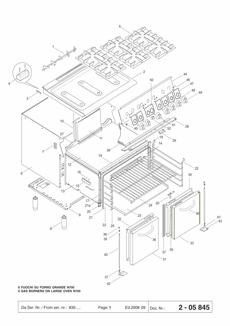
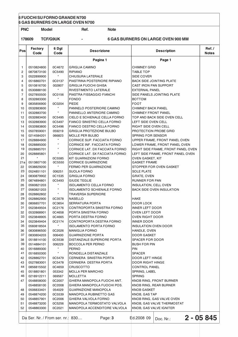
1 0510824800 0C4672 GRIGLIA CAMINO CHIMNEY GRID
2 0870873100 0C5490 RIPIANO TABLE TOP
3 0522899900 * CHIUSURA LATERALE SIDE COVER
4 0516860701 0C0137 PIASTRINA POSTERIORE RIPIANO BACK SIDE JOINTING PLATE
5 0510816700 002807 GRIGLIA FUOCHI GHISA CAST IRON PAN SUPPORT
6 0530888100 * RIVESTIMENTO LATERALE EXTERNAL PANEL
7 0527850500 0C0156 PIASTRA FISSAGGIO FIANCHI SIDE PANELS JOINTING PLATE
8 0532883300 * FONDO BOTTOM
9 0835856900 0C0204 PIEDE FOOT
10 0532883600 * PANNELO POSTERIORE CAMINO CHIMNEY BACK PANEL
11 0532883700 * PANNELLO ANTERIORE CAMINO CHIMNEY FRONT PANEL
12 0532883400 0C5495 CIELO E SCHIENALE CELLA FORNO TOP AND BACK SIDE OVEN CELL
13 0532883900 0C5497 FIANCO SINISTRO CELLA FORNO LEFT SIDE OVEN CELL
14 0532883800 0C5496 FIANCO DESTRO CELLA FORNO RIGHT SIDE OVEN CELL
15 0507859001 059219 GRIGLIA PROTEZIONE BULBO PROTECTION PROBE GRID
16 0214584201 066823 MOLLE PER BULBO SPRING FOR SENSOR
17 0528884900 * CORNICE SUP. FACCIATA FORNO UPPER FRAME, FRONT PANEL OVEN
18 0528885000 * CORNICE INF. FACCIATA FORNO LOWER FRAME, FRONT PANEL OVEN19 0528885701 * CORNICE LAT. DX FACCIATA FORNO RIGHT SIDE FRAME, FRONT PANEL OVEN
20 0528885801 * CORNICE LAT. SX FACCIATA FORNO LEFT SIDE FRAME, FRONT PANEL OVEN21 * 0C5585 KIT GUARNIZIONI FORNO OVEN GASKET, KIT
21a 0513807100 0C5550 CORNICE GUARNIZIONE GASKET FRAME
22 0538829200 * FERMO PER GUARNIZIONE STOPPER FOR OVEN GASKET23 0524851101 006251 SUOLA FORNO SOLE PLATE
24 0830879902 0C1535 GRIGLIA FORNO GRATE, OVEN25 0874894801 0C5493 GIUDE TEGLIE RUNNER FOR PAN
26 0560821203 * ISOLAMENTO CELLA FORNO INSULATION, CELL OVEN27 0560821203 * ISOLAMENTO SCHIENALE FORNO BACK SIDE OVEN INSULATION
28 0528862802 * TRAVERSA SUPERIORE29 0528862900 0C3578 NASELLO HAKE
30 0806857701 0C3654 SERRATURA PORTA DOOR LOCK31 0523849504 0C2176 CONTROPORTA SINISTRA FORNO INNER LEFT DOOR
32 0532868901 0C4658 PORTA SINISTRA FORNO OVEN LEFT DOOR33 0523848905 0C4665 PORTA DESTRA FORNO OVEN RIGHT DOOR
34 0523849404 0C2174 CONTROPORTA DESTRA FORNO INNER DOOR35 0560818504 * ISOLAMENTO PORTA FORNO INSULATION OVEN DOOR
36 0830896500 0C2026 MANIGLIA FORNO HANDLE, OVEN37 0830804203 006400 GUARNIZIONE PORTA DOOR GASKET
38 0518814100 0C5538 DISTANZIALE SUPERIORE PORTA SPACER FOR DOOR39 0514884101 006229 BOCCOLA PER PERNO BUSH FOR PIN
40 0516889300 * PERNO PIN41 0516850300 * RONDELLA DISTANZIALE SPACER
42 0528862701 0C5479 CERNIERA SINISTRA PORTA DOOR LEFT HINGE
43 0527883001 0C5478 CERNIERA DESTRA PORTA DOOR RIGHT HINGE44 0856815502 0C4659 CRUSCOTTO CONTROL PANEL
45 0518801801 053342 MOLLA PER MARCHIO SPRING, LABEL46 0218912211 069567 MOLLETTA SPRING
47 0548858000 0C2007 GHIERA MANOPOLA FUOCHI ANT. KNOB RING, FRONT BURNER
0548858100 0C2008 GHIERA MANOPOLA FUOCHI POS. KNOB RING, REAR BURNER
48 0506833401 054029 GUARNIZIONE MANOPOLA KNOB GASKET
49 0548874200 0C5539 MANOPOLA RUBINETTO GAS KNOB, GAS TAP
50 0548857901 0C2006 GHIERA VALVOLA FORNO KNOB RING, GAS VALVE OVEN
51 0548873200 0C5256 MANOPOLA TERMOSTATO VALVOLA KNOB, GAS VALVE THERMOSTAT
52 0548863300 0C2021 MANOPOLA ACCENDITORE VALVOLA KNOB, GAS VALVE IGNITER
Doc. Nr.: 2 - 05 845Da Ser. Nr. / From ser. nr.: 830..... Ed.2008 09Page: 4
PNC Model Ref. Note
178609 TCF/G9UK - 6 GAS BURNERS ON LARGE OVEN 900 MM
6 FUOCHI SU FORNO GRANDE N7006 GAS BURNERS ON LARGE OVEN N700
PosFactory
Code6 DgtCode
Descrizione DescriptionRef. / Notes
Pagina 2 Page 2
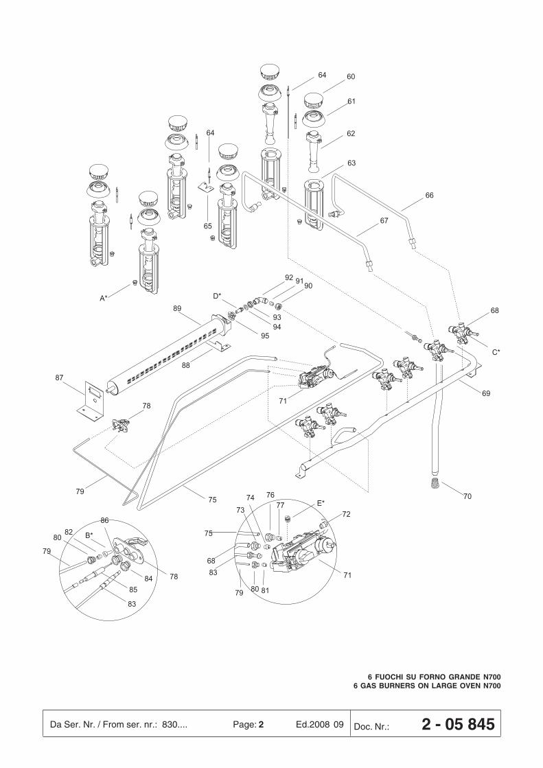
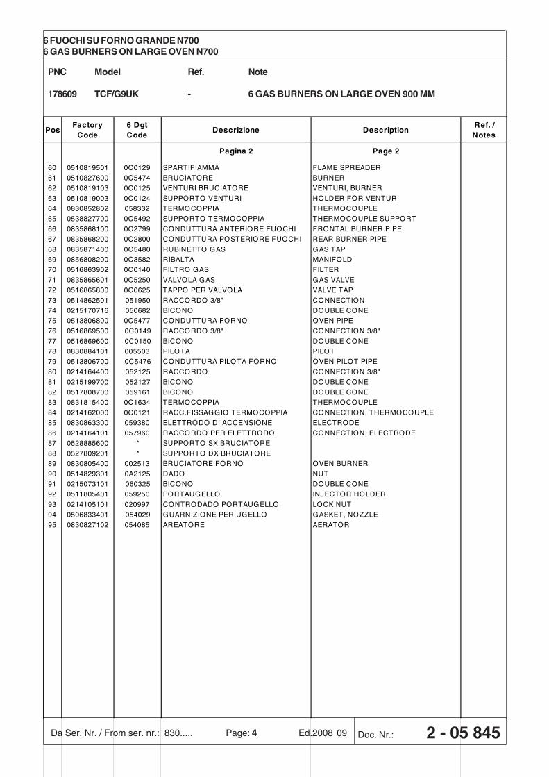
60 0510819501 0C0129 SPARTIFIAMMA FLAME SPREADER
61 0510827600 0C5474 BRUCIATORE BURNER
62 0510819103 0C0125 VENTURI BRUCIATORE VENTURI, BURNER
63 0510819003 0C0124 SUPPORTO VENTURI HOLDER FOR VENTURI
64 0830852802 058332 TERMOCOPPIA THERMOCOUPLE
65 0538827700 0C5492 SUPPORTO TERMOCOPPIA THERMOCOUPLE SUPPORT
66 0835868100 0C2799 CONDUTTURA ANTERIORE FUOCHI FRONTAL BURNER PIPE
67 0835868200 0C2800 CONDUTTURA POSTERIORE FUOCHI REAR BURNER PIPE
68 0835871400 0C5480 RUBINETTO GAS GAS TAP
69 0856808200 0C3582 RIBALTA MANIFOLD
70 0516863902 0C0140 FILTRO GAS FILTER
71 0835865601 0C5250 VALVOLA GAS GAS VALVE
72 0516865800 0C0625 TAPPO PER VALVOLA VALVE TAP
73 0514862501 051950 RACCORDO 3/8" CONNECTION
74 0215170716 050682 BICONO DOUBLE CONE
75 0513806800 0C5477 CONDUTTURA FORNO OVEN PIPE
76 0516869500 0C0149 RACCORDO 3/8" CONNECTION 3/8"
77 0516869600 0C0150 BICONO DOUBLE CONE
78 0830884101 005503 PILOTA PILOT
79 0513806700 0C5476 CONDUTTURA PILOTA FORNO OVEN PILOT PIPE
80 0214164400 052125 RACCORDO CONNECTION 3/8"
81 0215199700 052127 BICONO DOUBLE CONE
82 0517808700 059161 BICONO DOUBLE CONE
83 0831815400 0C1634 TERMOCOPPIA THERMOCOUPLE
84 0214162000 0C0121 RACC.FISSAGGIO TERMOCOPPIA CONNECTION, THERMOCOUPLE
85 0830863300 059380 ELETTRODO DI ACCENSIONE ELECTRODE
86 0214164101 057960 RACCORDO PER ELETTRODO CONNECTION, ELECTRODE
87 0528885600 * SUPPORTO SX BRUCIATORE
88 0527809201 * SUPPORTO DX BRUCIATORE
89 0830805400 002513 BRUCIATORE FORNO OVEN BURNER
90 0514829301 0A2125 DADO NUT
91 0215073101 060325 BICONO DOUBLE CONE
92 0511805401 059250 PORTAUGELLO INJECTOR HOLDER
93 0214105101 020997 CONTRODADO PORTAUGELLO LOCK NUT
94 0506833401 054029 GUARNIZIONE PER UGELLO GASKET, NOZZLE
95 0830827102 054085 AREATORE AERATOR
17
INDEX
I. INSTALLATION DIAGRAM / COMBINING APPLIANCES / TABLES ...................................................................................... 2
II. DATAPLATE and TECHNICAL DATA...................................................................................................................................... 18
III. GENERAL INFORMATION ...................................................................................................................................................... 19
IV. THE ENVIRONMENT ............................................................................................................................................................... 20
V. INSTALLATION ........................................................................................................................................................................ 20
1. REFERENCE STANDARDS .................................................................................................................................................... 20
2. UNPACKING ............................................................................................................................................................................. 20
3. POSITIONING .......................................................................................................................................................................... 20
4. FUME EXHAUST AND VENTILATION..................................................................................................................................... 21
5. CONNECTIONS ....................................................................................................................................................................... 22
6. SAFETY THERMOSTAT ........................................................................................................................................................... 23
7. BEFORE LEAVING .................................................................................................................................................................. 23
8. HANDRAIL ............................................................................................................................................................................... 24
VI. INSTRUCTIONS FOR THE USER ............................................................................................................................................ 25
1. COOKTOP USE ....................................................................................................................................................................... 25
2. OVEN USE ............................................................................................................................................................................... 26
VII. CLEANING ............................................................................................................................................................................... 27
1. EXTERNAL PARTS .................................................................................................................................................................. 27
2. OTHER SURFACES ................................................................................................................................................................. 27
3. PERIODS OF DISUSE ............................................................................................................................................................. 27
4. INTERNAL PARTS ................................................................................................................................................................... 27
VIII. MAINTENANCE ...................................................................................................................................................................... 28
1. MAINTENANCE ....................................................................................................................................................................... 28
2. LIST OF COMPONENTS ......................................................................................................................................................... 28
18
MODELS
Power supply voltage V - - - - - - 400 400 230 -
Electrical pow er absorbed kW - - - - - - 6 6 6 -
Phases N° - - - - - - 3N 3N 3 -
Frequency Hz - - - - - - 50/60 50/60 50/60 -
ISO 7/1 connection Ø 1/2" 1/2" 1/2" 1/2" 1/2" 1/2" 1/2" 1/2" 1/2" 1/2"
Cooktop burners Ø60 (5.50-1.4 kW ) Nr. 2 4 4 6 4 6 4 6 4 6
Cooktop nominal heat output kW 11 22 22 33 22 33 22 33 22 33
A1 A1 A1 A1 A1 A1 A1 A1 A1 A1
Oven type - - - - - Gas Gas Electr ic Ele ctr ic Ele ctr ic Gas
Oven max. heat output kW - - - - 6 6 - - - 9
Oven min. heat output kW - - - - - - - - - -
Nominal heat output kW 11 22 22 33 28 39 22 33 22 42
MODELS
Power supply voltage V - - - - - - 400 400 230
Electrical pow er absorbed kW - - - - - - 6 6 6
Phases N° - - - - - - 3N 3N 3
Frequency Hz - - - - - - 50/60 50/60 50/60
ISO 7/1 connection Ø 1/2" 1/2" 1/2" 1/2" 1/2" 1/2" 1/2" 1/2" 1/2"
Cooktop burners Ø60 (5.50-1.4 kW ) Nr. 2 4 4 6 4 6 4 6 4
Cooktop nominal heat output kW 11 22 22 33 28 33 22 33 22
A1 A1 A1 A1 A1 A1 A1 A1 A1
Oven type - - - - - Gas Gas Electr ic Ele ctr ic Ele ctr ic
Oven max. heat output kW - - - - 6 6 - - -
Oven min. heat output kW - - - - - - - - -
Nominal heat output kW 11 22 22 33 34 39 28 39 28
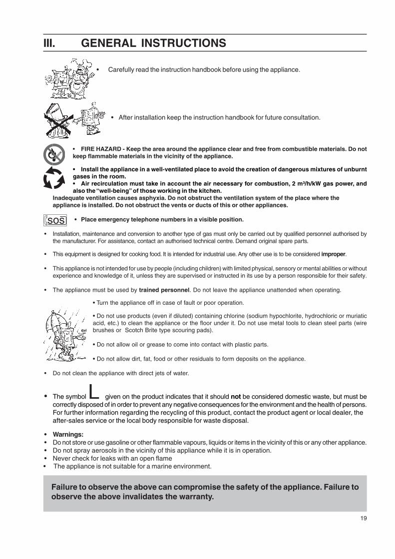
TABLE A - Gas/electrical appliance technical data
Type of construction
+CF/T2800m m
+CF/T31200m m
+C/T1400m m
+C/T2800m m
+CV/T2800m m
+CV/T31200m m
+CF/M 31200m m
KCGFE1200QCGFE1200A
+CF/M 2E5800m m
+CF/M T2E5800m m
+CF/W2800m m
+CF/W31200m m
TABLE A - Town Gas/electric appliance technical data
TECHNICAL DATA
+CF/G9800m m
+C/G2800m m
KCG800AQCG800A
Type of construction
TECHNICAL DATA
+C/G1400m m
KCG400AQCG400A
+CV/G2800m m
KCGV800AQCGV800A
+CV/G31200m m
KCGV1200AQCGV1200A
+CF/G2800m m
KCGFG800AQCGFG800A
+CF/G31200m m
KCGFG1200AQCGFG1200A
+CF/M 2800m m
KCGFE800AQCGFE800A
II. DATAPLATE and TECHNICAL DATA
IMPORTANTThis manual contains information relevant to various appliances. See the appliance dataplate located under thecontrol panel in order to identify the appliance (see fig. above).
M O D E L S
P o w e r s up p ly vo lta g e V 3 8 0 - 4 0 0 3 8 0 -4 0 0 3 8 0 -4 0 0 3 8 0 - 4 0 0 3 8 0 -4 0 0 3 8 0 -4 0 0 3 8 0 - 4 0 0 3 8 0 -4 0 0
P h a s e s N° 3 N 3 N 3 N 3 N 3 N 3 N 3 N 3 N
Fre q u e n c y Hz 5 0 /6 0 5 0 /6 0 5 0 /6 0 5 0 /6 0 5 0 /6 0 5 0 /6 0 5 0 /6 0 5 0 /6 0
Co o k to p ho t-p la te s (2 .6 k W ) Nr . 2 4 4 6 4 4 4 4
Co o k to p ho t-p la te m a x . p o w e r k W 5 ,2 1 0 ,4 1 0 ,4 1 5 ,6 1 0 ,4 1 0 ,4 1 0 ,4 1 0 ,4
O ve n m a x . po w e r k W - - - - 6 - 6 -
No m ina l m a x . p o w e r k W 4 ,5 - 5 ,2 9 - 1 0 ,4 9 - 1 0 ,4 1 3 ,8 - 1 5 ,6 1 4 ,6 - 1 6 ,4 9 - 1 0 ,4 1 4 ,6 - 1 6 ,4 9 - 1 0 ,4
P o w e r c a b le s e c t io n m m 2 4 4 4 6 4 4 4 4
+C V /E2 Q8 0 0 m m
+C /E14 0 0 m m
+C /E28 0 0 m m
+C V /E28 0 0 m mT EC H N IC A L D A T A
+C F/E28 0 0 m m
+C /E2 Q8 0 0 m m
+C F/E2 Q8 0 0 m m
+C V /E31 2 0 0 m m
T A B L E A - E le c tric a l a p p lia n c e te c h n ic a l d a ta
19
III. GENERAL INSTRUCTIONS
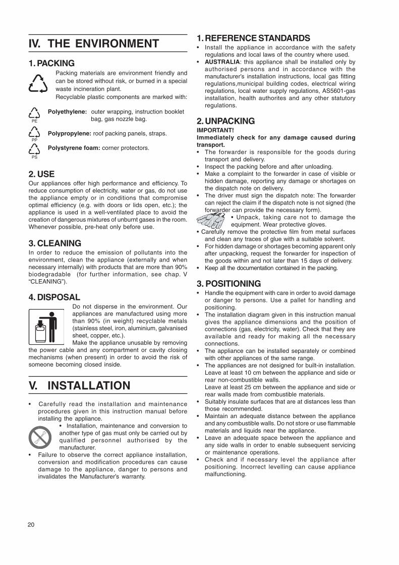
• Carefully read the instruction handbook before using the appliance.
• After installation keep the instruction handbook for future consultation.
• FIRE HAZARD - Keep the area around the appliance clear and free from combustible materials. Do notkeep flammable materials in the vicinity of the appliance.
• Install the appliance in a well-ventilated place to avoid the creation of dangerous mixtures of unburntgases in the room.• Air recirculation must take in account the air necessary for combustion, 2 m³/h/kW gas power, andalso the “well-being” of those working in the kitchen.
Inadequate ventilation causes asphyxia. Do not obstruct the ventilation system of the place where theappliance is installed. Do not obstruct the vents or ducts of this or other appliances.
• Place emergency telephone numbers in a visible position.
• Installation, maintenance and conversion to another type of gas must only be carried out by qualified personnel authorised bythe manufacturer. For assistance, contact an authorised technical centre. Demand original spare parts.
• This equipment is designed for cooking food. It is intended for industrial use. Any other use is to be considered improper.
• This appliance is not intended for use by people (including children) with limited physical, sensory or mental abilities or withoutexperience and knowledge of it, unless they are supervised or instructed in its use by a person responsible for their safety.
• The appliance must be used by trained personnel. Do not leave the appliance unattended when operating.
• Turn the appliance off in case of fault or poor operation.
• Do not use products (even if diluted) containing chlorine (sodium hypochlorite, hydrochloric or muriaticacid, etc.) to clean the appliance or the floor under it. Do not use metal tools to clean steel parts (wirebrushes or Scotch Brite type scouring pads).
• Do not allow oil or grease to come into contact with plastic parts.
• Do not allow dirt, fat, food or other residuals to form deposits on the appliance.
• Do not clean the appliance with direct jets of water.
• The symbol L given on the product indicates that it should not be considered domestic waste, but must becorrectly disposed of in order to prevent any negative consequences for the environment and the health of persons.For further information regarding the recycling of this product, contact the product agent or local dealer, theafter-sales service or the local body responsible for waste disposal.
• Warnings:• Do not store or use gasoline or other flammable vapours, liquids or items in the vicinity of this or any other appliance.• Do not spray aerosols in the vicinity of this appliance while it is in operation.• Never check for leaks with an open flame• The appliance is not suitable for a marine environment.
.
Failure to observe the above can compromise the safety of the appliance. Failure toobserve the above invalidates the warranty.
sos
20
IV. THE ENVIRONMENT
1. PACKINGPacking materials are environment friendly andcan be stored without risk, or burned in a specialwaste incineration plant.Recyclable plastic components are marked with:
Polyethylene: outer wrapping, instruction booklet bag, gas nozzle bag.
Polypropylene: roof packing panels, straps.
Polystyrene foam: corner protectors.
2. USEOur appliances offer high performance and efficiency. Toreduce consumption of electricity, water or gas, do not usethe appliance empty or in conditions that compromiseoptimal efficiency (e.g. with doors or lids open, etc.); theappliance is used in a well-ventilated place to avoid thecreation of dangerous mixtures of unburnt gases in the room.Whenever possible, pre-heat only before use.
3. CLEANINGIn order to reduce the emission of pollutants into theenvironment, clean the appliance (externally and whennecessary internally) with products that are more than 90%biodegradable (for further information, see chap. V“CLEANING”).
4. DISPOSALDo not disperse in the environment. Ourappliances are manufactured using morethan 90% (in weight) recyclable metals(stainless steel, iron, aluminium, galvanisedsheet, copper, etc.).Make the appliance unusable by removing
the power cable and any compartment or cavity closingmechanisms (when present) in order to avoid the risk ofsomeone becoming closed inside.
V. INSTALLATION• Carefully read the installation and maintenance
procedures given in this instruction manual beforeinstalling the appliance.
• Installation, maintenance and conversion toanother type of gas must only be carried out byqualified personnel authorised by themanufacturer.
• Failure to observe the correct appliance installation,conversion and modification procedures can causedamage to the appliance, danger to persons andinvalidates the Manufacturer’s warranty.
PE
PP
PS
1. REFERENCE STANDARDS• Install the appliance in accordance with the safety
regulations and local laws of the country where used.• AUSTRALIA: this appliance shall be installed only by
authorised persons and in accordance with themanufacturer’s installation instructions, local gas fittingregulations,municipal building codes, electrical wiringregulations, local water supply regulations, AS5601-gasinstallation, health authorites and any other statutoryregulations.
2. UNPACKINGIMPORTANT!Immediately check for any damage caused duringtransport.• The forwarder is responsible for the goods during
transport and delivery.• Inspect the packing before and after unloading.• Make a complaint to the forwarder in case of visible or
hidden damage, reporting any damage or shortages onthe dispatch note on delivery.
• The driver must sign the dispatch note: The forwardercan reject the claim if the dispatch note is not signed (theforwarder can provide the necessary form).
• Unpack, taking care not to damage theequipment. Wear protective gloves.
• Carefully remove the protective film from metal surfacesand clean any traces of glue with a suitable solvent.
• For hidden damage or shortages becoming apparent onlyafter unpacking, request the forwarder for inspection ofthe goods within and not later than 15 days of delivery.
• Keep all the documentation contained in the packing.
3. POSITIONING• Handle the equipment with care in order to avoid damage
or danger to persons. Use a pallet for handling andpositioning.
• The installation diagram given in this instruction manualgives the appliance dimensions and the position ofconnections (gas, electricity, water). Check that they areavailable and ready for making all the necessaryconnections.
• The appliance can be installed separately or combinedwith other appliances of the same range.
• The appliances are not designed for built-in installation.Leave at least 10 cm between the appliance and side orrear non-combustible walls.Leave at least 25 cm between the appliance and side orrear walls made from combustible materials.
• Suitably insulate surfaces that are at distances less thanthose recommended.
• Maintain an adequate distance between the applianceand any combustible walls. Do not store or use flammablematerials and liquids near the appliance.
• Leave an adequate space between the appliance andany side walls in order to enable subsequent servicingor maintenance operations.
• Check and if necessary level the appliance afterpositioning. Incorrect levelling can cause appliancemalfunctioning.
21
3.1. COMBINING APPLIANCES• (Fig.1A) Remove the control panels of the appliances by
undoing the 4 fixing screws.• (Fig.1B) Remove the fixing screw nearest the control
panel, from each side to be joined.• (Fig.1D) Bring the appliances together and level them by
turning the feet until the tops match.• (Fig.1C) Turn one of the two plates inside the appliances
180º.• (Fig.1E) From inside the control panel of the same
appliance, join them at the front side, screwing one TEM5x40 screw (supplied) on the opposite insert.
3.2. FLOOR FIXINGTo avoid accidental tipping of built-in half-module appliances installedseparately, fix them to the floor carefully following the instructionsenclosed with the corresponding accessory (F206136).
3.3 INSTALLATION ON BRIDGE, CANTILEVERFRAME OR CEMENT PLINTHCarefully follow the instructions enclosed with thecorresponding accessory.Follow the instructions supplied with the optional productchosen.
3.4. SEALING GAPS BETWEEN APPLIANCESFollow the instructions supplied with the optional sealingpaste pack.
4. FUME EXHAUST AND VENTILATION• Only install the appliance in a well-ventilated place.• Do not obstruct the ventilation systemin any way.• Do not obstruct the vent and dischargeholes of this appliance or others presentin the room.WARNING! Inadequate ventilationcauses appliance malfunction and cancause asphyxia and danger for persons.
• For Australia, ventilation must be in accordance withaustralian building codes and kitchen exhaust hoods mustcomply with AS/NZS1668.1 and AS 1668.2
4.1 TYPE “A1” APPLIANCESType “A1” appliances must be positioned under an extractorhood.
Make sure the hood removes the steam and fumes generatedby the equipment during cooking.
4.2 TYPE “B” APPLIANCESEquip type “B” appliances with a fume exhaust systemconforming to current regulations.
4.2.1 CONNECTION FLUE• Remove the grill from the fume exhaust.• Install the connection flue, following the instructions
supplied with the accessory (optional).
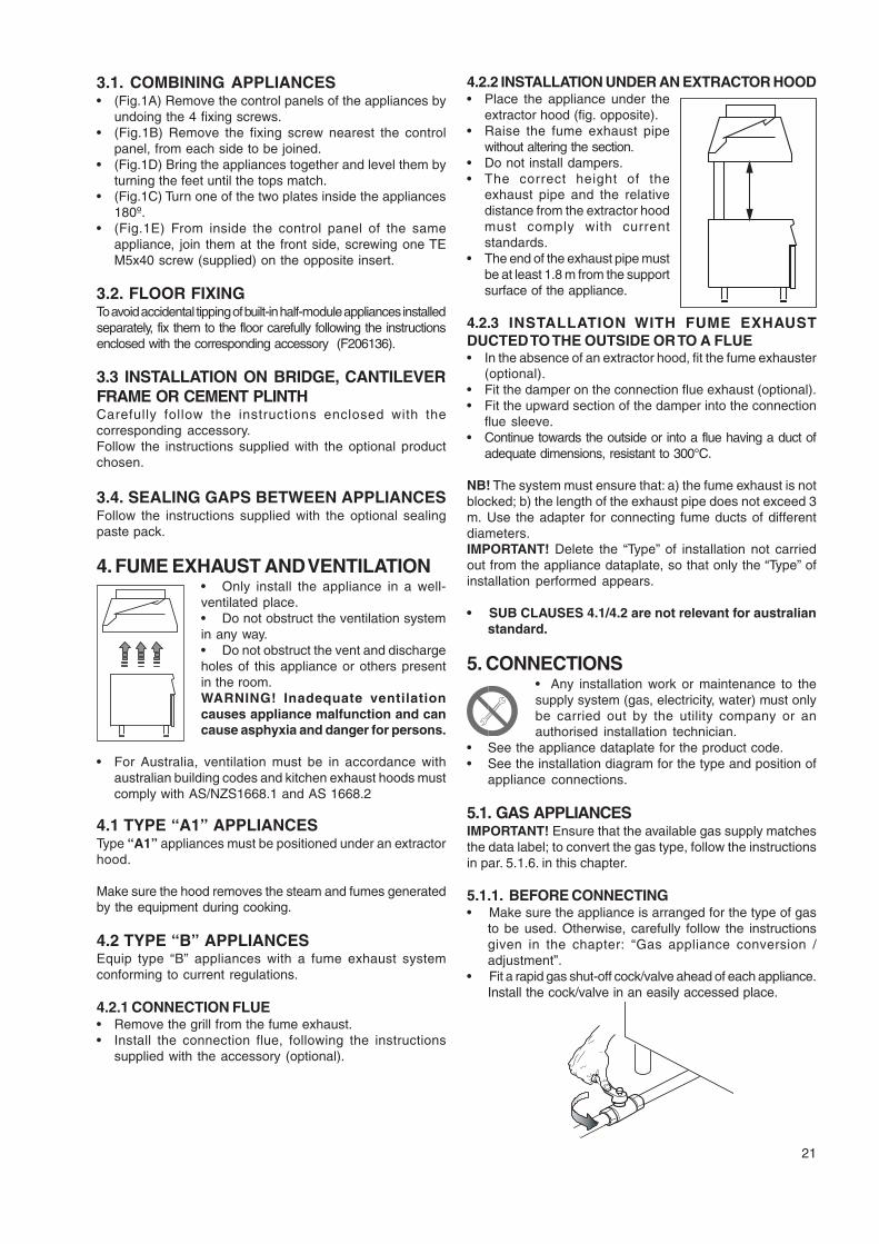
4.2.2 INSTALLATION UNDER AN EXTRACTOR HOOD• Place the appliance under the
extractor hood (fig. opposite).• Raise the fume exhaust pipe
without altering the section.• Do not install dampers.• The correct height of the
exhaust pipe and the relativedistance from the extractor hoodmust comply with currentstandards.
• The end of the exhaust pipe mustbe at least 1.8 m from the supportsurface of the appliance.
4.2.3 INSTALLATION WITH FUME EXHAUSTDUCTED TO THE OUTSIDE OR TO A FLUE• In the absence of an extractor hood, fit the fume exhauster
(optional).• Fit the damper on the connection flue exhaust (optional).• Fit the upward section of the damper into the connection
flue sleeve.• Continue towards the outside or into a flue having a duct of
adequate dimensions, resistant to 300°C.
NB! The system must ensure that: a) the fume exhaust is notblocked; b) the length of the exhaust pipe does not exceed 3m. Use the adapter for connecting fume ducts of differentdiameters.IMPORTANT! Delete the “Type” of installation not carriedout from the appliance dataplate, so that only the “Type” ofinstallation performed appears.
• SUB CLAUSES 4.1/4.2 are not relevant for australianstandard.
5. CONNECTIONS• Any installation work or maintenance to thesupply system (gas, electricity, water) must onlybe carried out by the utility company or anauthorised installation technician.
• See the appliance dataplate for the product code.• See the installation diagram for the type and position of
appliance connections.
5.1. GAS APPLIANCESIMPORTANT! Ensure that the available gas supply matchesthe data label; to convert the gas type, follow the instructionsin par. 5.1.6. in this chapter.
5.1.1. BEFORE CONNECTING• Make sure the appliance is arranged for the type of gas
to be used. Otherwise, carefully follow the instructionsgiven in the chapter: “Gas appliance conversion /adjustment”.
• Fit a rapid gas shut-off cock/valve ahead of each appliance.Install the cock/valve in an easily accessed place.
22
• Clean the pipes to remove any dust, dirt or foreign matterwhich could block the supply.
• The gas supply line must ensure the gas flow necessaryfor full operation of all the appliances connected to thesystem. A supply line with insufficient flow will affect correctoperation of the appliances connected to it.
• Caution! Incorrect levelling of the appliance can affectcombustion and cause malfunctioning.
5.1.2. CONNECTION• See the installation diagram for the position of the gas
connection on the bottom of the appliance.• Remove the protective plastic cover (if present) from the
appliance gas union before connecting.• After installation, use soapy water to check connections
for leaks.• The gas conection is male 1/2” BSP.
5.1.3. SUPPLY PRESSURE CHECKMake sure the appliance is suitable for the type of gasavailable, according to that given on the dataplate (otherwise,follow the instructions of par. “Conversion to another type ofgas”). The supply pressure must be measured with theappliance operating, using a manometer (min. 0.1 mbar).• Remove the control panel.• Remove retaining screw “N” from the pressure point and
connect the manometer “O” (fig. 2A).• Compare the value read on the manometer with that given
in table B (see handbook Appendix)• If the manometer gives a pressure outside the range of
values in table B, do not start the appliance, and consultthe gas company.
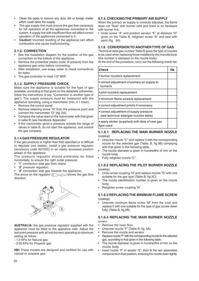
5.1.4 GAS PRESSURE REGULATORIf the gas pressure is higher than that specified or is difficultto regulate (not stable), install a gas pressure regulator(accessory code 927225) in an easily accessed positionahead of the appliance.The pressure regulator should preferably be fittedhorizontally, to ensure the right outlet pressure:• “1” connection side gas from mains.• “2” pressure regulator;• “3” connection side gas towards the appliance;The arrow on the regulator ( ) shows the gas flowdirection.
3
1
2
AUSTRALIA: the gas pressure regulator supplied with theappliance must be fitted to the appliance inlet. Adjust thetest point pressure with all hob burners operating at maximumsetting as follow:- 1.0 KPa for Natural gas- 2.65 KPa for Propane gas
NB! These models are designed and certified for use withnatural or propane gas.
5.1.5. CHECKING THE PRIMARY AIR SUPPLYWhen the primary air supply is correctly adjusted, the flamedoes not “float” with burner cold and there is no flarebackwith burner hot.• Undo screw “A” and position aerator “E” at distance “H”
given on the Table B, retighten screw “A” and seal withpaint (fig. 3A).
5.1.6 CONVERSION TO ANOTHER TYPE OF GAS“Technical data/gas nozzles” Table B gives the type of nozzlesto be used when replacing those installed by the manufacturer(the number is stamped on the nozzle body).At the end of the procedure, carry out the following check-list:
Check Ok
• burner nozzle/s replacement
• correct adjustment of primary air supply to burner/s
• pilot nozzle/s replacement
• minimum flame screw/s replacement
• correct adjustment pilot/s if necessary
• correct adjustment of supply pressure (see technical data/gas nozzles table)
• apply sticker (supplied) with data of new gas type used
5.1.6.1 REPLACING THE MAIN BURNER NOZZLE(cooktop)• Unscrew nozzle “C” and replace it with the corresponding
nozzle for the selected gas (Table. B, fig.3B) complyingwith that given in the following table.
• The nozzle diameter is given in hundredths of mm on thenozzle body.
• Fully retighten nozzle “C”.
5.1.6.2 REPLACING THE PILOT BURNER NOZZLE(cooktop)• Undo screw coupling “H” and replace nozzle “G” with one
suitable for the gas type (Table B, fig.3C).• The nozzle identification number is given on the nozzle
body.• Retighten screw coupling “H”.
5.1.6.3 REPLACING THE MINIMUM FLAME SCREW(cooktop)• Unscrew minimum flame screw “M” from the cock and
replace it with one suitable for the type of gas (screw downfully) (Table B, fig.2B).
5.1.6.4 REPLACING THE MAIN BURNER NOZZLE(oven)• Remove the oven floor.• Unscrew nozzle “F” (Table B, fig. 3A).• Remove the nozzle and aerator.• Replace nozzle “F” with the corresponding nozzle for the selected
gas, according to that given in the following table.• The nozzle diameter is given in hundredths of mm on the
nozzle body.• Insert nozzle “F” in aerator “E”, then fit the two assembled
components in their position, screwing the nozzle down tightly.
23
5.1.6.5 REPLACING THE PILOT BURNER NOZZLE(oven)• Undo screw coupling “H” and replace nozzle “G” with
one suitable for the gas type (Table B, fig.3D).• The nozzle diameter is given in hundredths of mm on the
nozzle body.• Retighten coupling “H”.
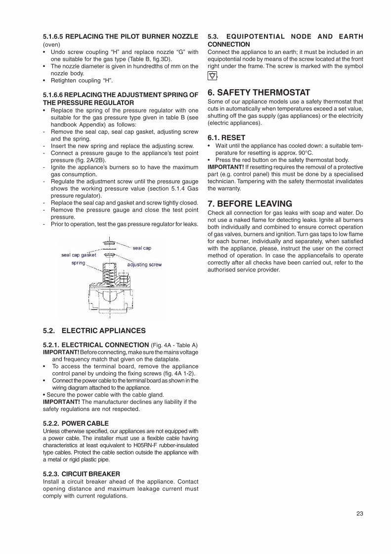
5.1.6.6 REPLACING THE ADJUSTMENT SPRING OFTHE PRESSURE REGULATOR• Replace the spring of the pressure regulator with one
suitable for the gas pressure type given in table B (seehandbook Appendix) as follows:
- Remove the seal cap, seal cap gasket, adjusting screwand the spring.
- Insert the new spring and replace the adjusting screw.- Connect a pressure gauge to the appliance’s test point
pressure (fig. 2A/2B).- Ignite the appliance’s burners so to have the maximum
gas consumption.- Regulate the adjustment screw until the pressure gauge
shows the working pressure value (section 5.1.4 Gaspressure regulator).
- Replace the seal cap and gasket and screw tightly closed.- Remove the pressure gauge and close the test point
pressure.- Prior to operation, test the gas pressure regulator for leaks.
5.2. ELECTRIC APPLIANCES
5.2.1. ELECTRICAL CONNECTION (Fig. 4A - Table A)IMPORTANT! Before connecting, make sure the mains voltage
and frequency match that given on the dataplate.• To access the terminal board, remove the appliance
control panel by undoing the fixing screws (fig. 4A 1-2).• Connect the power cable to the terminal board as shown in the
wiring diagram attached to the appliance.• Secure the power cable with the cable gland.IMPORTANT! The manufacturer declines any liability if thesafety regulations are not respected.
5.2.2. POWER CABLEUnless otherwise specified, our appliances are not equipped witha power cable. The installer must use a flexible cable havingcharacteristics at least equivalent to H05RN-F rubber-insulatedtype cables. Protect the cable section outside the appliance witha metal or rigid plastic pipe.
5.2.3. CIRCUIT BREAKERInstall a circuit breaker ahead of the appliance. Contactopening distance and maximum leakage current mustcomply with current regulations.
5.3. EQUIPOTENTIAL NODE AND EARTHCONNECTIONConnect the appliance to an earth; it must be included in anequipotential node by means of the screw located at the frontright under the frame. The screw is marked with the symbol
.
6. SAFETY THERMOSTATSome of our appliance models use a safety thermostat thatcuts in automatically when temperatures exceed a set value,shutting off the gas supply (gas appliances) or the electricity(electric appliances).
6.1. RESET• Wait until the appliance has cooled down: a suitable tem-
perature for resetting is approx. 90°C.• Press the red button on the safety thermostat body.IMPORTANT! If resetting requires the removal of a protectivepart (e.g. control panel) this must be done by a specialisedtechnician. Tampering with the safety thermostat invalidatesthe warranty.
7. BEFORE LEAVINGCheck all connection for gas leaks with soap and water. Donot use a naked flame for detecting leaks. Ignite all burnersboth individually and combined to ensure correct operationof gas valves, burners and ignition. Turn gas taps to low flamefor each burner, individually and separately, when satisfiedwith the appliance, please, instruct the user on the correctmethod of operation. In case the appliancefails to operatecorrectly after all checks have been carried out, refer to theauthorised service provider.
24
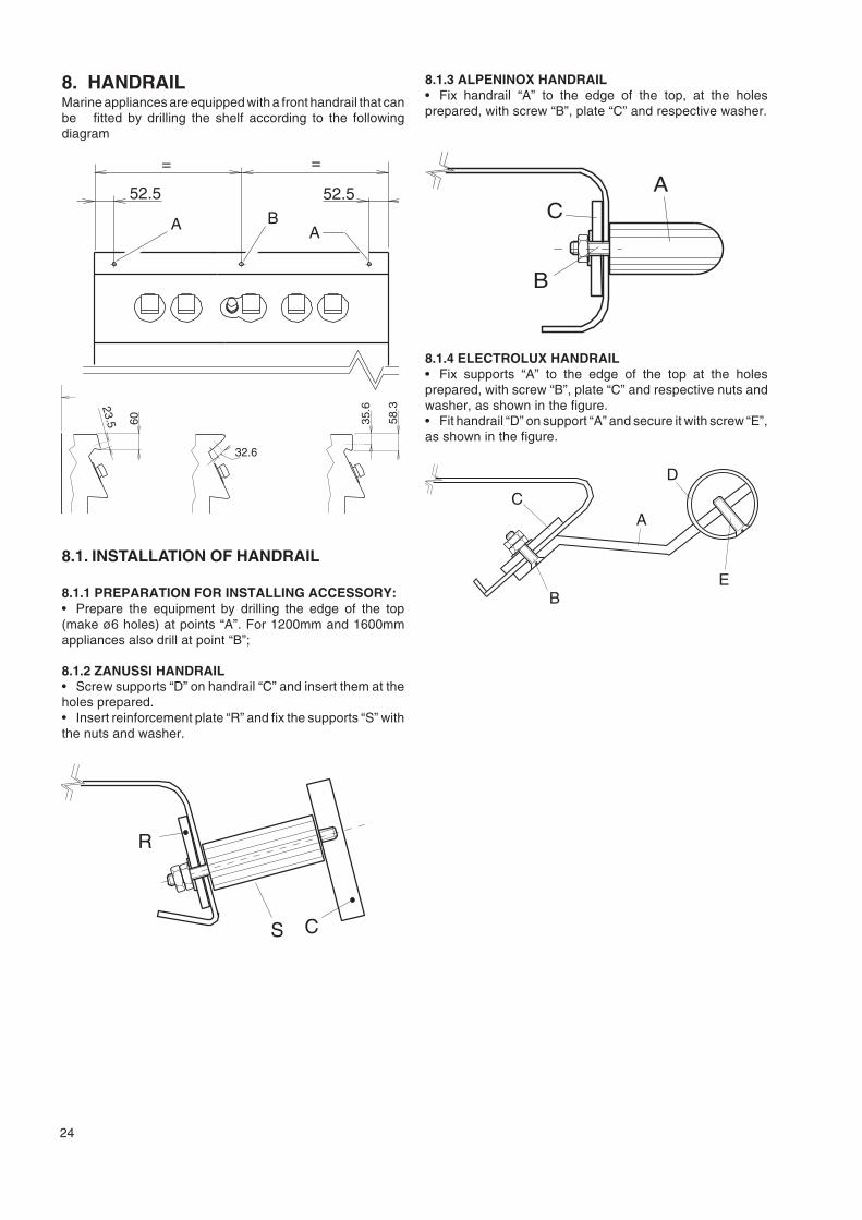
8. HANDRAILMarine appliances are equipped with a front handrail that canbe fitted by drilling the shelf according to the followingdiagram
52.5
=
BA A
=
52.5
A
23.5 60
A
32.6
58.3
35.6
8.1. INSTALLATION OF HANDRAIL
8.1.1 PREPARATION FOR INSTALLING ACCESSORY:• Prepare the equipment by drilling the edge of the top(make ø6 holes) at points “A”. For 1200mm and 1600mmappliances also drill at point “B”;
8.1.2 ZANUSSI HANDRAIL• Screw supports “D” on handrail “C” and insert them at theholes prepared.• Insert reinforcement plate “R” and fix the supports “S” withthe nuts and washer.
S C
R
1a
8.1.3 ALPENINOX HANDRAIL• Fix handrail “A” to the edge of the top, at the holesprepared, with screw “B”, plate “C” and respective washer.
1bAC
B
8.1.4 ELECTROLUX HANDRAIL• Fix supports “A” to the edge of the top at the holesprepared, with screw “B”, plate “C” and respective nuts andwasher, as shown in the figure.• Fit handrail “D” on support “A” and secure it with screw “E”,as shown in the figure.
C
B
A
D
E
1c
25
IV. INSTRUCTIONS FOR THEUSER
1. COOKTOP USE
GAS MODELS
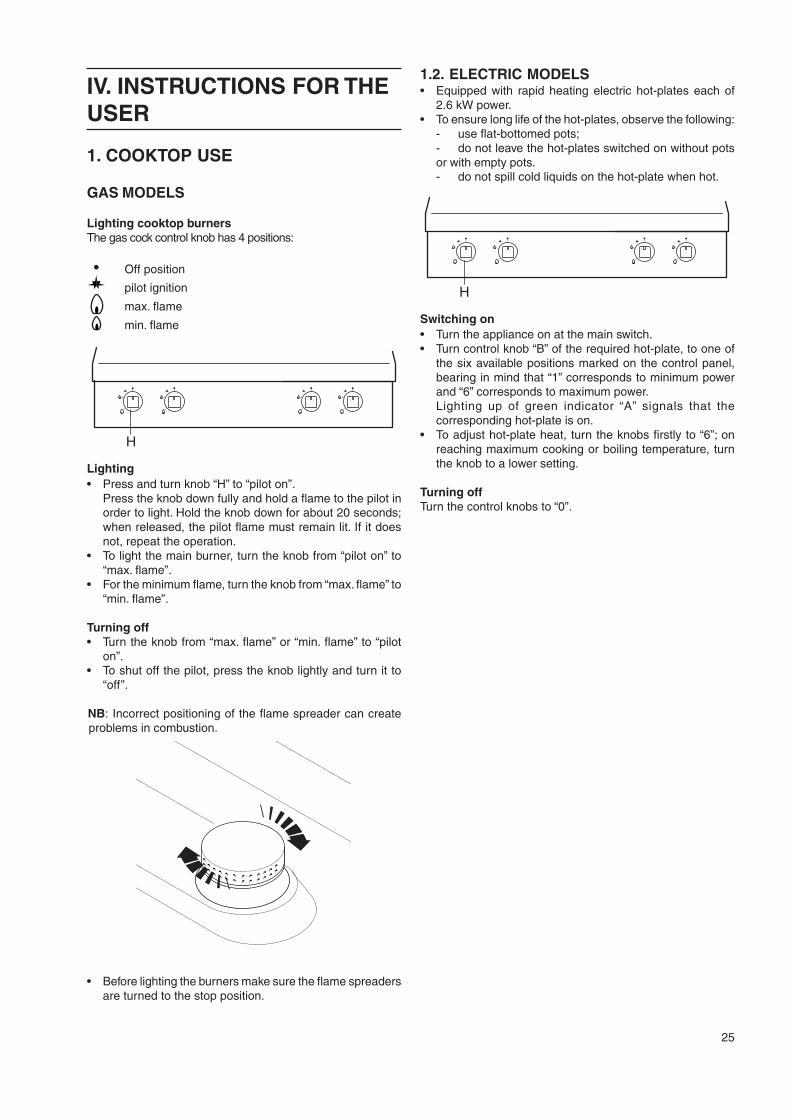
Lighting cooktop burnersThe gas cock control knob has 4 positions:
Off position
pilot ignition
max. flame
min. flame
H
Lighting• Press and turn knob “H” to “pilot on”.
Press the knob down fully and hold a flame to the pilot inorder to light. Hold the knob down for about 20 seconds;when released, the pilot flame must remain lit. If it doesnot, repeat the operation.
• To light the main burner, turn the knob from “pilot on” to“max. flame”.
• For the minimum flame, turn the knob from “max. flame” to“min. flame”.
Turning off• Turn the knob from “max. flame” or “min. flame” to “pilot
on”.• To shut off the pilot, press the knob lightly and turn it to
“off”.
NB: Incorrect positioning of the flame spreader can createproblems in combustion.
• Before lighting the burners make sure the flame spreadersare turned to the stop position.
1.2. ELECTRIC MODELS• Equipped with rapid heating electric hot-plates each of
2.6 kW power.• To ensure long life of the hot-plates, observe the following:
- use flat-bottomed pots;- do not leave the hot-plates switched on without potsor with empty pots.- do not spill cold liquids on the hot-plate when hot.
H
Switching on• Turn the appliance on at the main switch.• Turn control knob “B” of the required hot-plate, to one of
the six available positions marked on the control panel,bearing in mind that “1” corresponds to minimum powerand “6” corresponds to maximum power.Lighting up of green indicator “A” signals that thecorresponding hot-plate is on.
• To adjust hot-plate heat, turn the knobs firstly to “6”; onreaching maximum cooking or boiling temperature, turnthe knob to a lower setting.
Turning offTurn the control knobs to “0”.
26
2. OVEN USE
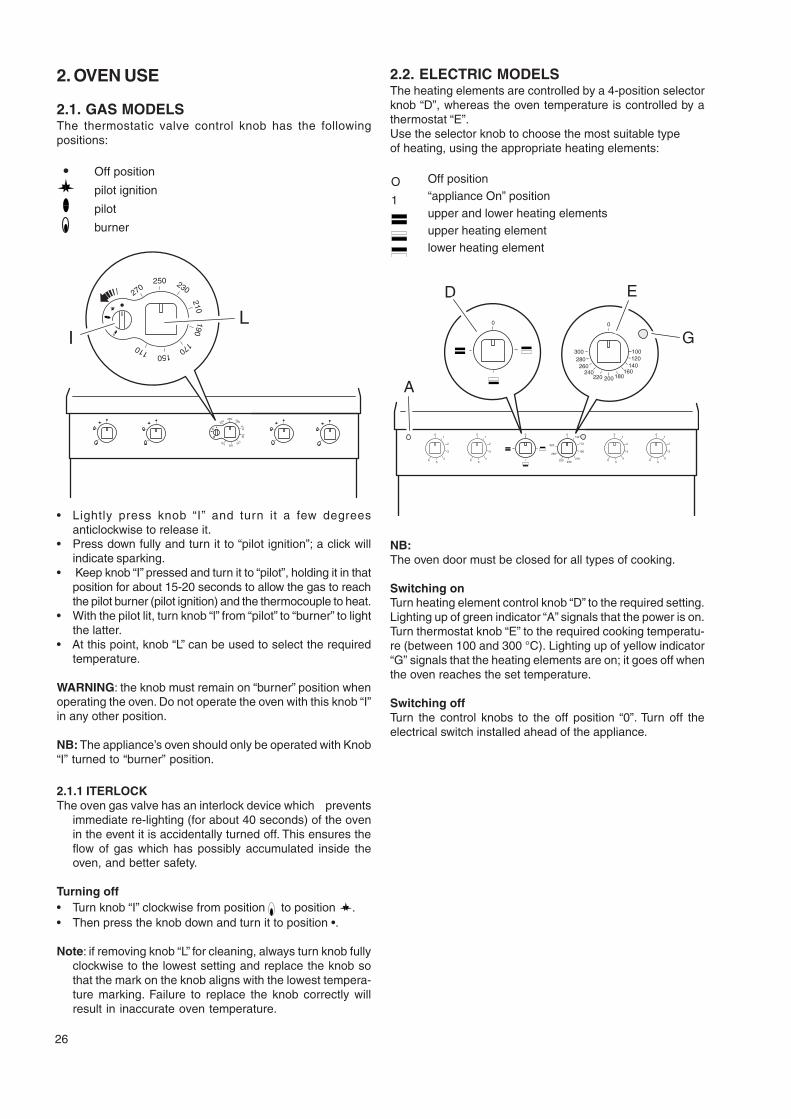
2.1. GAS MODELSThe thermostatic valve control knob has the followingpositions:
Off position
pilot ignition
pilot
burner
L
270250 230
210190
170150110
270250 230
210190
170150110
I
• Lightly press knob “I” and turn it a few degreesanticlockwise to release it.
• Press down fully and turn it to “pilot ignition”; a click willindicate sparking.
• Keep knob “I” pressed and turn it to “pilot”, holding it in thatposition for about 15-20 seconds to allow the gas to reachthe pilot burner (pilot ignition) and the thermocouple to heat.
• With the pilot lit, turn knob “l” from “pilot” to “burner” to lightthe latter.
• At this point, knob “L” can be used to select the requiredtemperature.
WARNING: the knob must remain on “burner” position whenoperating the oven. Do not operate the oven with this knob “I”in any other position.
NB: The appliance’s oven should only be operated with Knob“I” turned to “burner” position.
2.1.1 ITERLOCKThe oven gas valve has an interlock device which prevents
immediate re-lighting (for about 40 seconds) of the ovenin the event it is accidentally turned off. This ensures theflow of gas which has possibly accumulated inside theoven, and better safety.
Turning off• Turn knob “I” clockwise from position to position .• Then press the knob down and turn it to position •.
Note: if removing knob “L” for cleaning, always turn knob fullyclockwise to the lowest setting and replace the knob sothat the mark on the knob aligns with the lowest tempera-ture marking. Failure to replace the knob correctly willresult in inaccurate oven temperature.
2.2. ELECTRIC MODELSThe heating elements are controlled by a 4-position selectorknob “D”, whereas the oven temperature is controlled by athermostat “E”.Use the selector knob to choose the most suitable typeof heating, using the appropriate heating elements:
Off position“appliance On” positionupper and lower heating elementsupper heating elementlower heating element
D E
G
01
2
3
45
6
01
2
3
45
6
0 0140
170
190
210230250
280
320
01
2
3
45
6
01
2
3
45
6
A
00
200220240
260
300280
100120
140160
180
NB:The oven door must be closed for all types of cooking.
Switching onTurn heating element control knob “D” to the required setting.Lighting up of green indicator “A” signals that the power is on.Turn thermostat knob “E” to the required cooking temperatu-re (between 100 and 300 °C). Lighting up of yellow indicator“G” signals that the heating elements are on; it goes off whenthe oven reaches the set temperature.
Switching offTurn the control knobs to the off position “0”. Turn off theelectrical switch installed ahead of the appliance.
O
1
27
V. CLEANINGCAUTION!Before carrying out any cleaning operation, disconnect theappliance from the power supply.
1. EXTERNAL PARTSSATIN-FINISH STEEL SURFACES (daily)• Clean all steel surfaces: dirt can be easily removed as
soon as it forms.• Remove grime, fat and other cooking residuals from steel
surfaces when cool using soapy water, with or withoutdetergent, and a cloth or sponge. Dry the surfacesthoroughly after cleaning.
• In case of encrusted grime, fat or food residuals go overwith a cloth or sponge, wiping with the grain of the satinfinish, and rinsing often: rubbing in a circular motioncombined with the particles of dirt on the cloth/spongecould ruin the steel’s satin finish.
• Metal objects can ruin or damage the steel: ruinedsurfaces become dirty more easily and are more subjectto corrosion.
• Restore the satin finish if necessary.
SURFACES BLACKENED BY HEAT (when necessary)Exposure to high temperatures can cause the formation ofdark marks. These do not constitute damage and can beremoved by following the instructions given in the previousparagraph.
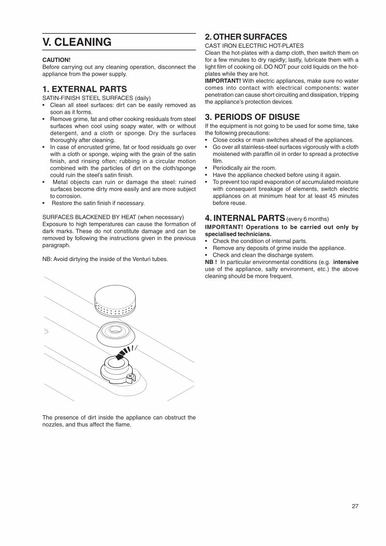
NB: Avoid dirtying the inside of the Venturi tubes.
The presence of dirt inside the appliance can obstruct thenozzles, and thus affect the flame.
2. OTHER SURFACESCAST IRON ELECTRIC HOT-PLATESClean the hot-plates with a damp cloth, then switch them onfor a few minutes to dry rapidly; lastly, lubricate them with alight film of cooking oil. DO NOT pour cold liquids on the hot-plates while they are hot.IMPORTANT! With electric appliances, make sure no watercomes into contact with electrical components: waterpenetration can cause short circuiting and dissipation, trippingthe appliance’s protection devices.
3. PERIODS OF DISUSEIf the equipment is not going to be used for some time, takethe following precautions:• Close cocks or main switches ahead of the appliances.• Go over all stainless-steel surfaces vigorously with a cloth
moistened with paraffin oil in order to spread a protectivefilm.
• Periodically air the room.• Have the appliance checked before using it again.• To prevent too rapid evaporation of accumulated moisture
with consequent breakage of elements, switch electricappliances on at minimum heat for at least 45 minutesbefore reuse.
4. INTERNAL PARTS (every 6 months)IMPORTANT! Operations to be carried out only byspecialised technicians.• Check the condition of internal parts.• Remove any deposits of grime inside the appliance.• Check and clean the discharge system.NB ! In particular environmental conditions (e.g. intensiveuse of the appliance, salty environment, etc.) the abovecleaning should be more frequent.
28
VI. MAINTENANCE1. MAINTENENCEAll the components requiring maintenance are accessiblefrom the front of the appliance, after removing the controlpanel and front panel. Disconnect the power supply beforeopening the appliance
1.1 BRIEF TROUBLESHOOTING GUIDEEven in normal appliance operating conditions, malfunctionscan occasionally occur.
- The pilot burner of open burners does not lightPossible causes:
• Insufficient pressure in gas pipes.• Nozzle blocked.• Faulty gas cock.
- The oven pilot burner does not lightPossible causes:
• Igniter not properly fixed or connected• The piezoelectric ignition or igniter cable are damaged.• Insufficient pressure in gas pipes• Worn nozzle• Faulty gas valve
- The pilot burner goes out when the “pilot ignition” knob isreleasedPossible causes:
• The pilot burner is not heating the thermocouple sufficiently.• Faulty thermocouple.• The gas cock and/or gas valve knob is not being pressed enough.• Lack of gas pressure to the cock and/or valve.• Faulty gas cock or gas valve.
- The pilot burner is still lit but the main burner does not lightPossible causes:
• Loss of pressure in gas supply pipe.• Blocked nozzle or faulty gas cock or valve.• Gas outlet holes on burner clogged.
- The oven temperature cannot be adjusted.Possible causes:
• Faulty thermostat bulb.• Faulty gas valve.• Faulty electric thermostat.• Electric safety thermostat tripped.
ABNORMAL OPERATIONAny of the following are considered to be abnormal operation
and may require servicing:• incomplete ignition of the burner;• yellow tipping of the burner flame;• burner failing to remain alight;• gas valves are difficult to turn;• burner exitinguished by operation of oven door.In case the appliance fails to operate correctly, contact the
authorised service provider in your area.
INSTRUCTIONS FOR REPLACING COMPONENTS (to becarried out only by an authorised installer).Remove the front panel to access:
GAS COCK• Unscrew the pilot and thermocouple pipe, unscrew the
gas inlet and outlet connections.• For installation carry out the same procedure in reverse order.
PILOT BURNER, THERMOCOUPLE, IGNITER ASSEMBLY• To replace the igniter and thermocouple loosen the fixing
screws and remove the components.• To replace the pilot burner undo the gas pipe, remove the
pilot burner assembly• Replace the components, proceeding in reverse order to
refit the parts.MAIN BURNER• Unscrew the gas connection from the nozzle holder• Undo the screws fixing the burner to the support• Remove the pilot burner assembly by undoing the screws• For installation carry out the same procedure in reverse order,
making sure that when positioning the burner the centeringpins, located at the back of the burner, enter their specialseats
1.2 MAINTENENCE SCHEDULE• It is reccommended the appliance is inspected and
serviced by an authorized person at least every 12months. For this purpose it is reccommended to draw upa maintenece contract.
2. LIST OF COMPONENTSCOOKTOP• Gas cockType “PINTOSSI”, PEL 21S, bridle fittingType “COPRECI”, Model CPMM 18700, bridle fitting
• Main burnerType “CELX””
• Pilot burnerType “CELX””
• ThermocoupleType “SIT”, Model 0.290 thread M8x1.Type “ORKLY”, thread M8x1.
GAS OVEN• Gas valveType “MERTIK”, Model GV 31 -T
• Main burnerType “Polidoro”, in AISI 430
• Pilot burnerType “SIT”, Model 0.140 thread M9x1
• ThermocoupleType “SIT”, Model 0.200 thread M9x1.Type “ORKLY”, thread M8x1.
ELECTRIC OVEN• SwitchType “EGO”, Model 41.4
• Work thermostatType “EGO”, Model 55.325
• Safety thermostatType “EGO”, Model 55.34
• Electric heating elementType “EGO”, 400V 1.5 kWType “RICA”, 400V 1.5 kWType “EGO”, 230V 1.5 kWType “RICA”, 230V 1.5 kW
.