Embed Size (px)
Citation preview

Gas - Liquid Separation Operations
Objectives
• Review of literature related to basic concepts
and the physical principles which explain the
separation processes.
• How to insert and obtain the necessary
information for the dynamic dimensioning
and analysis for these separation systems.

Layout of Chapter 6
Basic Concepts and Principles of separation processes
Available Modules in Aspen Plus
Shortcut methods
Rigorous methods
Modules available in Aspen Hysys
Distillation introductory example
Absorption introductory example
Enhanced Distillation
Nonequilibrium models
Columns thermal and hydraulic analysis
summary

Distillation Separation

Commercial Distillation Columns (1)

Commercial Distillation Columns (2)
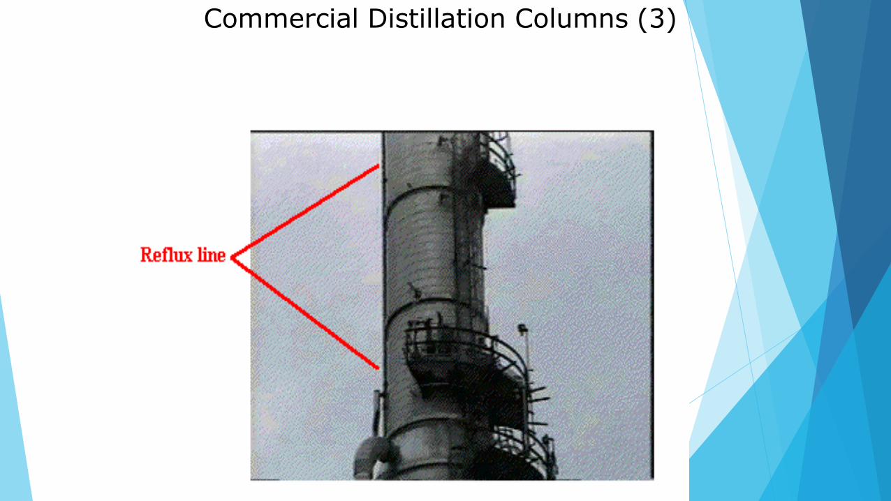
Commercial Distillation Columns (3)

Commercial Distillation Columns (4)

Commercial Distillation Columns (5)

Commercial Distillation Columns (6)


Algorithm for multicomponent
distillation using FUG method

Specifications for debutanizer


Fenske equation
Derivation of the Fenske equation
The concept behind the Fenske equation is really simple.
The column schematized here beside with the hypothesis of total reflux (no feed no products) is taken into consideration. Then the equilibrium and the mass balance equation are written for the two key components starting from the reboiler stage (see envelope in the figure).
(3) Equilibrium:
yB,LK= kLK xB,LK
yB,HK= kHK xB,HK
(4) Mass balance :
V' yB,LK = L' xN,LK
V'= L'
Please for the derivation of the Fenske's equation, see the attached pdf file.


A number of simulation were carried out using the equilibrium model of
Aspen-Hysys for different column configuration (number of equilibrium
stages and feed stage location) and for differing operation specifications
(reflux ratio and bottom product rate). Only the specifications and results
of our final simulation are reported here.


Unit Specifications (2)

Distillation Models
Shortcut


RADFRAC
This a model enables to simulate any type of vapor-liquid
fractioning operation. Among these operation are included:
Simple distillation
Absorption
Absorption with reboiler
Splitting
Splitting with reboiler
Extractive and azeotrpic distillation
Reactive distillation


RADFRAC can calculate the following
Two phase systems
Three phase systems
Systems with boiling points very near or very far apart


Modules available in Aspen Hysys

Distillation Introductory Example A mixture of ethyl benzene and styrene : DSTWU model


Absorption and Stripping


Chemical absorption ( reactive absorption)
Non-electrolyte approach
• Amine
streams
- for the removal of sour gases (H2S, CO2) from hydrocarbon
using MEA, MDEA or DEA.
- for modeling systems with CO2, NH3, H2S, and other • Sour
compounds dissolved in water.
• PPAq - used for the modeling of ionic type compounds, such as HCl or
HNO3, which dissolve in water and disassociate.
Electrolyte approach
• Ideal
• Pitzer
• NRTL for electrolyte 1982
• NRTL for electrolyte 1986

Amine Model The chemical reactions in an H2S-CO2-Amine system are described by the following
reactions:
1. RR'NH2+ <-----> H+ + RR'NH K1
2. RR'NCOO + H2O <-----> RR'NH + HCO3- K2
3. CO2 + H2O <-----> HCO3- + H+ K3
4. HCO3- <-----> CO3-- + H+ K4
5. H2S <-----> HS- + H+ K5
6. HS- <-----> S-- + H+ K6
7. H2O <-----> H+ + OH- K7
where R and R' represent alcohol groups. The reaction equations are solved
simultaneously to obtain the free concentration of H2S and CO2. The partial pressure of
H2S and CO2 are calculated by the Henry's constants and free concentration in the liquid
phase. Reference: Kent, R. L. and Eisenberg, Hydrocarbon Processing, Feb. 1976, p. 8

SOUR WATER Model The chemical reactions in H2S-CO2-NH3 systems are represented by the following
reactions:
1. CO2 + H2O <-----> HCO3- + H+
K1
2. HCO3-
<----->
CO3--
+
H+
K2
3. NH3 + H+ <-----> NH4+
K3
4. NH3 + HCO3- <-----> H2NCOO- + H2O
K4
5. H2S <-----> HS- + H+
K5
6. HS- <-----> S-- + H+
K6
Volatility Data from Aqueous Sour Water Systems by Grant M, Wilson EPA
Grant No. R804364010. K7
H2O Reference: EPA-60<0-/2---8-0--0>67 A NH+ew Correlatio+n of NH2, CO2O, aHn-d H2S
The addition of NaOH or Carbolic acid is also considered in CHEMCAD.

Partial Pressures of Aqueous mixtures
Model (PPAQ) 1. The K-value of the solute is calculated by the following equation,
K = PP/(XPT) = (PP/PT)/X
PP = the solute partial pressure, calculated by interpolating the user-
provided
table
PT =
X =
the system pressure
the liquid molar concentration of the solute
2. The K-value of water is calculated using the partial pressure data given in the
.PPA file.
3. K-values for all other components are calculated using Henry's Gas Law.
4. If the HGL data is not present for a given compound, the program will fall back to the MSRK method. If the MSRK
parameters for a given compound are not present the program the SRK method
• HCl or HNO3 is already considered in CHEMCAD.

Simulate absorber using Aspen-Plus

Using sensitivity analysis to explore major variables

Extractor Calculations
1.Liquid-Liquid Equilibrium (LLE)
2.Regression LLE data
3.LLE Phase Diagram
4.Three Phase Equilibrium
(Three Phase Flash)
5.Extractor Calculation

Regression LLE data
Toluene(1)/Acetone(2)/Water(3) Experimental Data (mole fraction)
T Deg C X11 X21 X12 X22
30.00 0.9755 0.0204 0.0001 0.0050
30.00 0.9504 0.0450 0.0001 0.0108
30.00 0.9218 0.0722 0.0001 0.0164
30.00 0.8551 0.1329 0.0002 0.0305
30.00 0.7581 0.2169 0.0003 0.0508
30.00 0.5933 0.3526 0.0005 0.0837
30.00 0.4455 0.4625 0.0010 0.1208
30.00 0.3360 0.5487 0.0020 0.1537

Toluene/Acetone/Water at 30.00 C
Mole Percent of (3)
Mole Percent of (2)

NRTL Model
The NRTL equation has the following form:

UNIQUAC Model
UNIQUAC equation
Where

WILSON Model
WILSON equation
where

Rules for Successful Regression
1. Suggestion: Use mole fractions for VLE and LLE data input.
2.Use the VLLS option if two liquid phase are likely to be present.
3. When doing ternary VLE regression, the third NRTL parameter,
alpha, will have a default value of 0.3 if there is no value in the BIP
list. You can define the alpha with the BIP command.
3. When doing ternary LLE regression, the third NRTL parameter,
alpha, will have a default value of 0.2 if there is no value in the BIP
list. You can define the alpha with the BIP command.

4.Choose regression data in the range of process requirements.
5.Plot the model fit with the data points. Reasonable curve or not?
6.If the model looks good but a better fit is required, reduce the
relative and absolute tolerances.
7.Parameter sets are not unique. Once you have minimized error, you
may try a different set of starting estimates.
8.Certain systems are better fit specific models.
Wilson for strong hyperbolic characteristics (i.e. HCN-H2O).
Data with strong inflections bordering on or including immiscibility
may be better fit with 3-parameter (or higher) model such as NRTL.


