Embed Size (px)
Citation preview
G41D3 BIOS Manual
i
BIOS Setup .................................................................................................1
1 Main Menu...............................................................................................3
2 Advanced Menu.......................................................................................7
3 PCIPnP Menu........................................................................................18
4 Boot Menu..............................................................................................21
5 Chipset Menu.........................................................................................24
6 Performance Menu...............................................................................29
7 Exit Menu...............................................................................................32
G41D3 BIOS Manual
1
BIOS Setup
Introduction The purpose of this manual is to describe the settings in the AMI BIOS Setup program on this motherboard. The Setup program allows users to modify the basic system configuration and save these settings to CMOS RAM. The power of CMOS RAM is supplied by a battery so that it retains the Setup information when the power is turned off. Basic Input-Output System (BIOS) determines what a computer can do without accessing programs from a disk. This system controls most of the input and output devices such as keyboard, mouse, serial ports and disk drives. BIOS activates at the first stage o f the booting process, loading and executing the operating system. Some additional features, such as virus and password prot ection or chipset fine-tuning options are also included in BIOS. The rest of this manual will to guide you through the options and settings in BIOS Setup.
Plug and Play Support This AMI BIOS supports the Plug and Play Version 1.0A specification.
EPA Green PC Support This AMI BIOS supports Version 1.03 of the EPA Green PC specification.
APM Support This AMI BIOS supports Version 1.1&1.2 of the Advanced Power Management (APM) speci fication. Power management features are implemented via the System Management Int errupt (SMI). Sleep and Suspend power management modes are supported. Power to the hard disk drives and video monitors can also be managed by this AMI BIOS.
ACPI Support AMI ACPI BIOS support Version 1.0/2.0 of Advanced Configuration and Power interface specifi cation (ACPI). It provides ASL code for power management and device configuration capabilities as defined in the ACPI specification, developed by Microsoft, Intel and Toshiba.
G41D3 BIOS Manual
2
PCI Bus Support This AMI BIOS also supports Version 2.3 of the Intel PCI (Peripheral Component Interconnect) local bus speci fication.
DRAM Support DDR3 SDRAM (Double Data Rate III Synchronous DRAM) is supported.
Supported CPUs This AMI BIOS supports the Intel CPU.
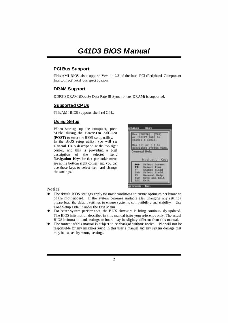
Using Setup When starting up the computer, press <Del> during the Power-On Self-Test (POST) to enter the BIOS setup utility. In the BIOS setup utility, you will see General Help description at the top right corner, and this is providing a brief description of the selected item. Navigation Keys for that particular menu are at the bottom right corner, and you can use these keys to select item and change the settings.
Notice ! The default BIOS settings apply for most conditions to ensure optimum performance
of the motherboard. If the system becomes unstable after changing any settings, please load the default settings to ensure system’s compatibility and stability. Use Load Setup Default under the Exit Menu.
! For better system perform ance, the BIOS firmware is being continuously updated. The BIOS information described in this manual is for your reference only. The actual BIOS information and settings on board may be slightly different from this manual.
! The content of this manual is subject to be changed without notice. We will not be responsible for any mistakes found in this user’s manual and any system damage that may be caused by wrong-settings.
General Help
Navigation Keys
G41D3 BIOS Manual
3
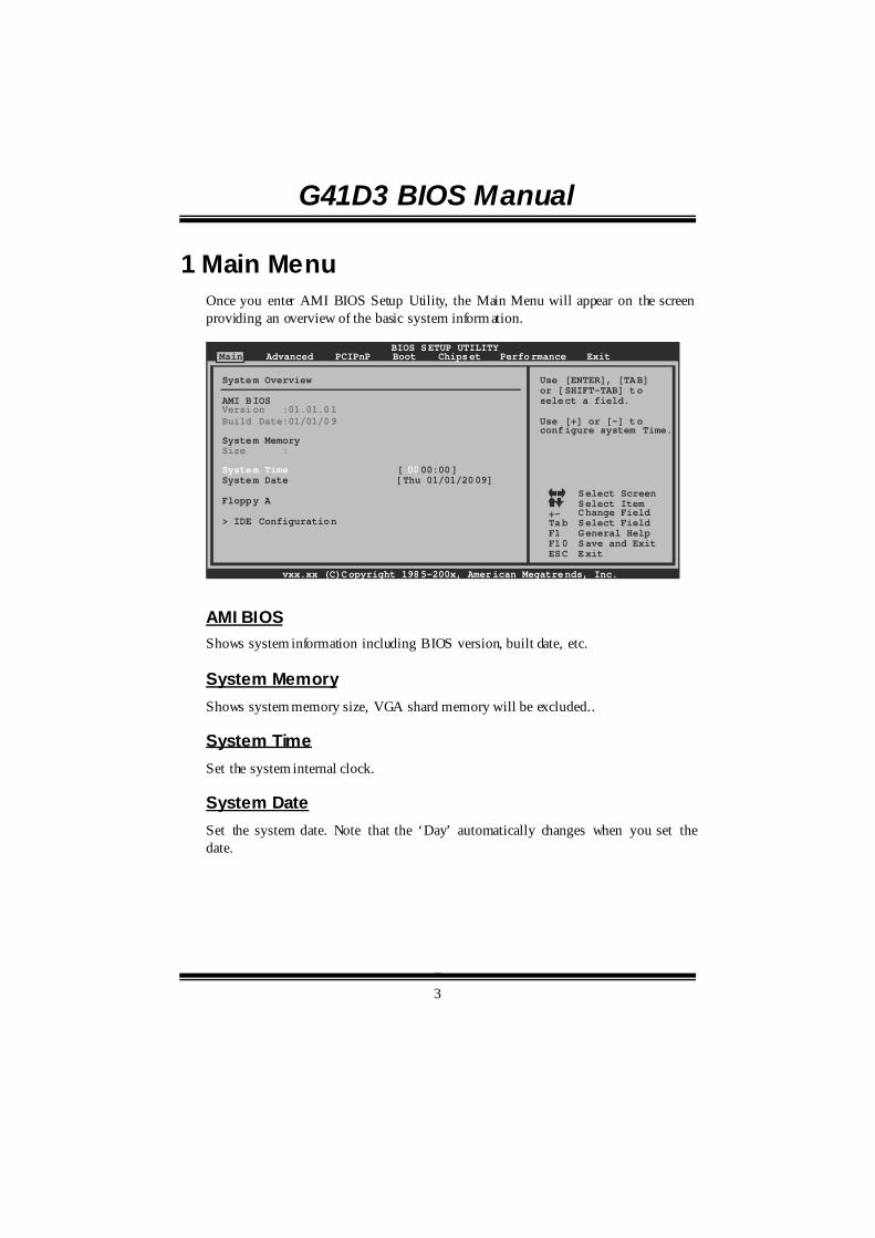
1 Main Menu Once you enter AMI BIOS Setup Utility, the Main Menu will appear on the screen providing an overview of the basic system inform ation.
BIOS SETUP UTILITYMain Advanced PCIPnP Boot Chipset Performance
vxx.xx (C)Copyright 1985-200x, American Megatrends, Inc.
Select ScreenSelect ItemChange FieldSelect FieldGeneral HelpSave and ExitExit
+-TabF1F10ESC
Use [ENTER], [TAB] or [SHIFT-TAB] to select a field.
Use [+] or [-] toconfigure system Time.
System Overview
AMI BIOS
System Memory
[ :00:00]System Date [Thu 01/01/2009]
Floppy A
> IDE Configuration
Version :01.01.01Build Date:01/01/09
Size :
System Time 00
Exit
AMI BIOS Shows system information including BIOS version, built date, etc.
System Memory Shows system memory size, VGA shard memory will be excluded..
System Time Set the system internal clock.
System Date Set the system date. Note that the ‘Day’ automatically changes when you set the date.
G41D3 BIOS Manual
4
Floppy A Select the type of floppy disk drive installed in your system. Options: 360K, 5.25 in / 1.2M, 5.25 in / 720K, 3.5 in / 1.44M, 3.5 in /
2.88M, 3.5 in / None
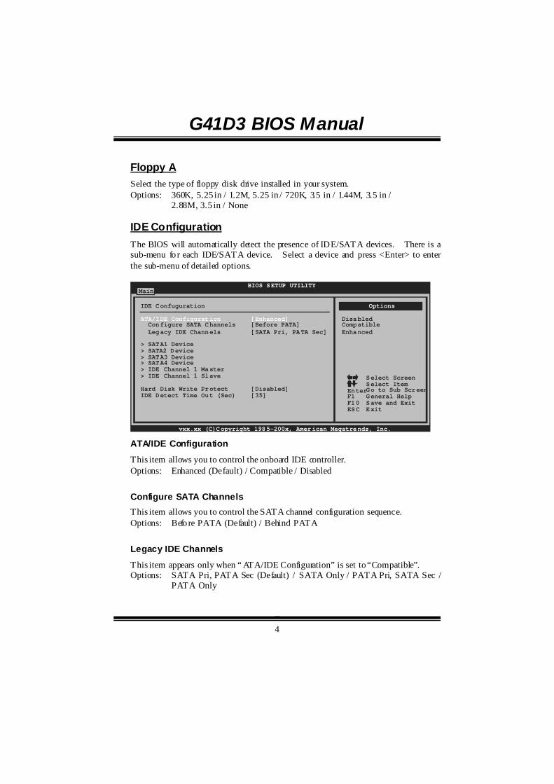
IDE Configuration The BIOS will automatically detect the presence of IDE/SATA devices. There is a sub-menu fo r each IDE/SATA device. Select a device and press <Enter> to enter the sub-menu of detailed options.
BIOS SETUP UTILITYMain
vxx.xx (C)Copyright 1985-200x, American Megatrends, Inc.
Select ScreenSelect ItemGo to Sub ScreenGeneral HelpSave and ExitExit
EnterF1F10ESC
IDE Confuguration
Configure SATA Channels [Before PATA] Legacy IDE Channels [SATA Pri, PATA Sec]
> SATA1 Device>
Hard Disk Write Protect [Disabled]IDE Detect Time Out (Sec) [35]
SATA2 Device> SATA3 Device> SATA4 Device> IDE Channel 1 Master> IDE Channel 1 Slave
ATA/IDE Configuration [Enhanced]
Options
DisabledCompatibleEnhanced
ATA/IDE Configuration
This item allows you to control the onboard IDE controller. Options: Enhanced (Default) / Compatible / Disabled
Configure SATA Channels This item allows you to control the SATA channel configuration sequence. Options: Befo re PATA (Default) / Behind PATA
Legacy IDE Channels
This item appears only when “ ATA/IDE Configuration” is set to “Compatible”. Options: SATA Pri, PATA Sec (Default) / SATA Only / PATA Pri, SATA Sec /
PATA Only
G41D3 BIOS Manual
5
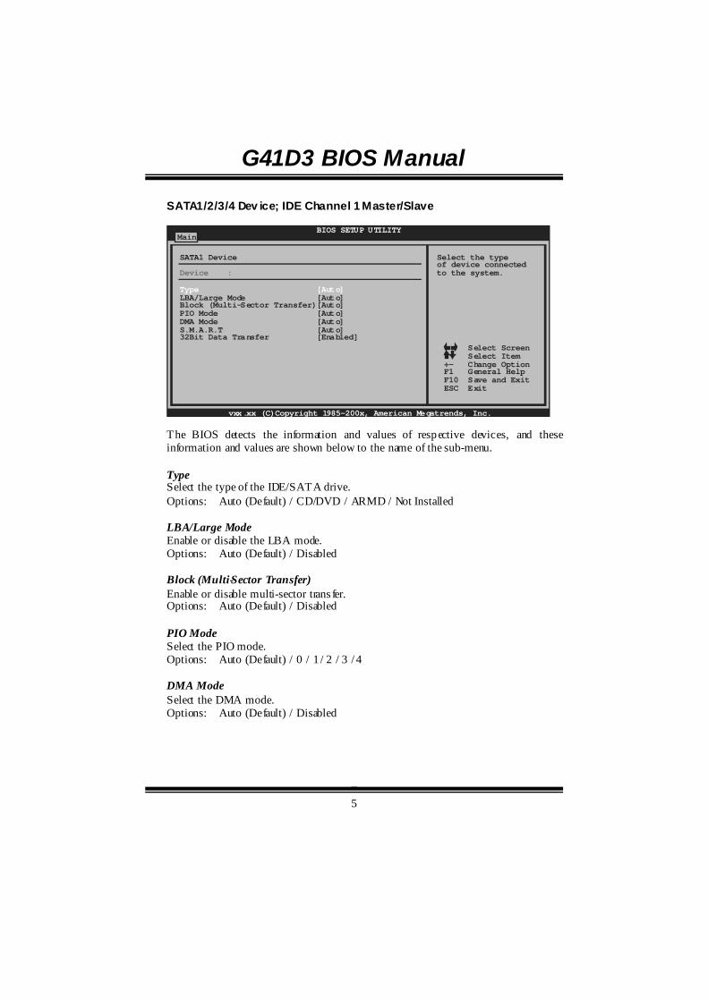
SATA1/2/3/4 Dev ice; IDE Channel 1 Master/Slave
BIOS SETUP UTILITYMain
vxx.xx (C)Copyright 1985-200x, American Megatrends, Inc.
Select ScreenSelect ItemChange OptionGeneral HelpSave and ExitExit
+-F1F10ESC
Select the typeof device connectedto the system.
SATA1 Device
LBA/Large Mode [Auto]Block (Multi-Sector Transfer)[Auto]PIO Mode [Auto]DMA Mode [Auto]S.M.A.R.T [Auto]32Bit Data Transfer [Enabled]
Device :
Type [Auto]
The BIOS detects the information and values of respective devices, and these information and values are shown below to the name of the sub-menu. Type Select the type of the IDE/SATA drive. Options: Auto (Default) / CD/DVD / ARMD / Not Installed LBA/Large Mode Enable or disable the LBA mode. Options: Auto (Default) / Disabled Block (Multi-Sector Transfer) Enable or disable multi-sector trans fer. Options: Auto (Default) / Disabled PIO Mode Select the PIO mode. Options: Auto (Default) / 0 / 1 / 2 / 3 / 4 DMA Mode Select the DMA mode. Options: Auto (Default) / Disabled

G41D3 BIOS Manual
6
S.M.A.R.T Set the Smart Monitoring, Analysis, and Reporting Technology. Options: Auto (Default) / Disabled / Enabled 32Bit Data Transfer Enable or disable 32-bit data transfer. Options: Enabled (Default) / Disabled
Hard Disk Write Protect
Disable or enable device write protection. This will be effective only if the device is accessed through BIOS. Options: Disabled (Default) / Enabled
IDE Detect Time Out (Sec) Select the time out value for detecting IDE/SATA devices. Options: 35 (Default) / 30 / 25 / 20 / 15 / 10 / 5 / 0
G41D3 BIOS Manual
7
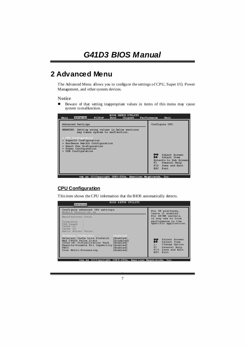
2 Advanced Menu The Advanced Menu allows you to configure the settings o f CPU, Super I/O, Power Management, and other system devices. Notice ! Beware of that setting inappropriate values in items of this menu may cause
system to malfunction.
BIOS SETUP UTILITYMain Advanced PCIPnP Boot Chipset Performance
vxx.xx (C)Copyright 1985-200x, American Megatrends, Inc.
Select ScreenSelect ItemGo to Sub ScreenGeneral HelpSave and ExitExit
EnterF1F10ESC
Configure CPU.Advanced Settings
WARNING: Setting wrong values in below sections may cause system to malfunction.
> USB Configuration
> SuperIO Configuration> Hardware Health Configuration> Smart Fan Configuration> Power Configuration
> CPU Configuration
Exit
CPU Configuration This item shows the CPU information that the BIOS automatically detects.
BIOS SETUP UTILITYAdvanced
vxx.xx (C)Copyright 1985-200x, American Megatrends, Inc.
Select ScreenSelect ItemChange OptionGeneral HelpSave and ExitExit
+-F1F10ESC
For UP platforms, leave it enabled.For DP/MP servers,it may use to tuneperformance to thespecific application.
Configure advanced CPU settingsModule Version:xx.xx
Manufacturer:Intel
Frequency :FSB Speed :Cache L1 :Cache L2 :Ratio Actual Value:
Hardware Prefetcher [Enabled]Adjacent Cache Line Prefetch [Enabled]Max CPUID Value Limit [Disabled]Intel(R) Virtualization Tech [Enabled]Execute-Disable Bit Capability[Enabled]PECI [Enabled]Core Multi-Processing [Enabled]
G41D3 BIOS Manual
8
Hardware Prefetcher
The processor has a hardware prefetcher that automatically analyzes its requirements and prefetches dat a and instructions from the memory into the Level 2 cache that are likely to be required in the near future. This reduces the latency associated with memory reads. Options: Enabled (Default) / Disabled
Adjacent Cache Line Prefetch
The processor has a hardware adjacent cache line prefet ch mechanism that automatically fetches an extra 64-byte cache line whenever the processor requests for a 64-byte cache line. This reduces cache latency by making the next cache line immediately available if the processor requires it as well. Options: Enabled (Default) / Disabled
Max CPUID Value Limit
When the computer is booted up, the operating system executes the CPUID instruction to identify the processor and its capabilities. Befo re it can do so, it must first query the processor to find out the highest input value CPUID recognizes. This determines the kind of basic information CPUID can provide the operating system. Options: Disabled (Default) / Enabled
Intel(R) Virtualization Tech
Virtualization Technology can virtually separate your system resource into several parts, thus enhance the performance when running virtual machines or multi interface systems. Options: Enabled (Default) / Disabled
Execute-Disable Bit Capability
This item allows you to configure the Execut e Disabled Bit function, which protects your system from buffer overflow attacks. Options: Enabled (Default) / Disabled
PECI
This item allows you to control the PECI function for the processor which supports Platform Environment Control Interface for better therm al management. Options: Enabled (Default) / Disabled
G41D3 BIOS Manual
9
Core Multi-Processing
This item allows multi-processing function for multi-core processors. Options: Enabled (Default) / Disabled
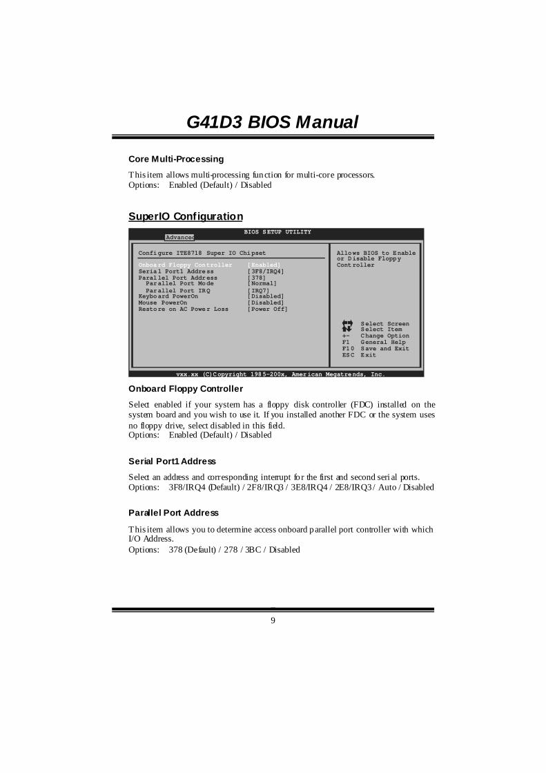
SuperIO Configuration BIOS SETUP UTILITY
Advanced
vxx.xx (C)Copyright 1985-200x, American Megatrends, Inc.
Select ScreenSelect ItemChange OptionGeneral HelpSave and ExitExit
+-F1F10ESC
Allows BIOS to Enableor Disable FloppyController
Configure ITE8718 Super IO Chipset
Onboard Floppy Controller [Enabled]Serial Port1 Address [3F8/IRQ4]Parallel Port Address [378] Parallel Port Mode [Normal] Parallel Port IRQ [IRQ7]Keyboard PowerOn [Disabled]Mouse PowerOn [Disabled]Restore on AC Power Loss [Power Off]
Onboard Floppy Controller
Select enabled if your system has a floppy disk controller (FDC) installed on the system board and you wish to use it. If you installed another FDC or the system uses no floppy drive, select disabled in this field. Options: Enabled (Default) / Disabled
Serial Port1 Address
Select an address and corresponding interrupt fo r the first and second seri al ports. Options: 3F8/IRQ4 (Default) / 2F8/IRQ3 / 3E8/IRQ4 / 2E8/IRQ3 / Auto / Disabled
Parallel Port Address
This item allows you to determine access onboard parallel port controller with which I/O Address. Options: 378 (Default) / 278 / 3BC / Disabled
G41D3 BIOS Manual
10
Parallel Port Mode
This item allows you to determine how the parallel port should function. Options: Normal (Default) Using Parallel port as Standard Printer Port. EPP Using Parallel Port as Enhanced Parallel Port. ECP Using Parallel port as Extended Capabilities Port. ECP+EPP Using Parallel port as ECP & EPP mode.
ECP Mode DMA Channel
This item allows you to select parallel port ECP DMA. Options: DMA3 (Default) / DMA0 / DMA1
Parallel Port IRQ
This item allows you to select the IRQ for the onboard parallel port. Options: IRQ7 (Default) / IRQ5 / Disabled
Keyboard Pow erOn
This item allows you to control the keyboard power on function. Options: Disabled (Default) / Specific Key / Stroke Key / Any Key
Specific Key Enter This item will show only when Keyboard PowerOn is set “Specific Key.”
Stroke Keys Selected
This item will show only when Keyboard PowerOn is set “Stroke Key.” Options: Ctrl+F1 (Default) / Wake Key / Power Key / Ctrl+F2 / Ctrl+F3 /
Ctrl +F4 / Ctrl+F5 / Ctrl+F6
Mouse PowerOn
This item allows you to control the mouse power on function. Options: Disabled (Default) / Enabled
G41D3 BIOS Manual
11
Restore on AC Power Loss
This setting specifies how your system should behave after a power fail or interrupts occurs. By choosing Disabled will leave the computer in the power off state. Choosing Enabled will restore the system to the status before power failure or interrupt occurs. Options: Power Off (Default) / Power ON / Last State
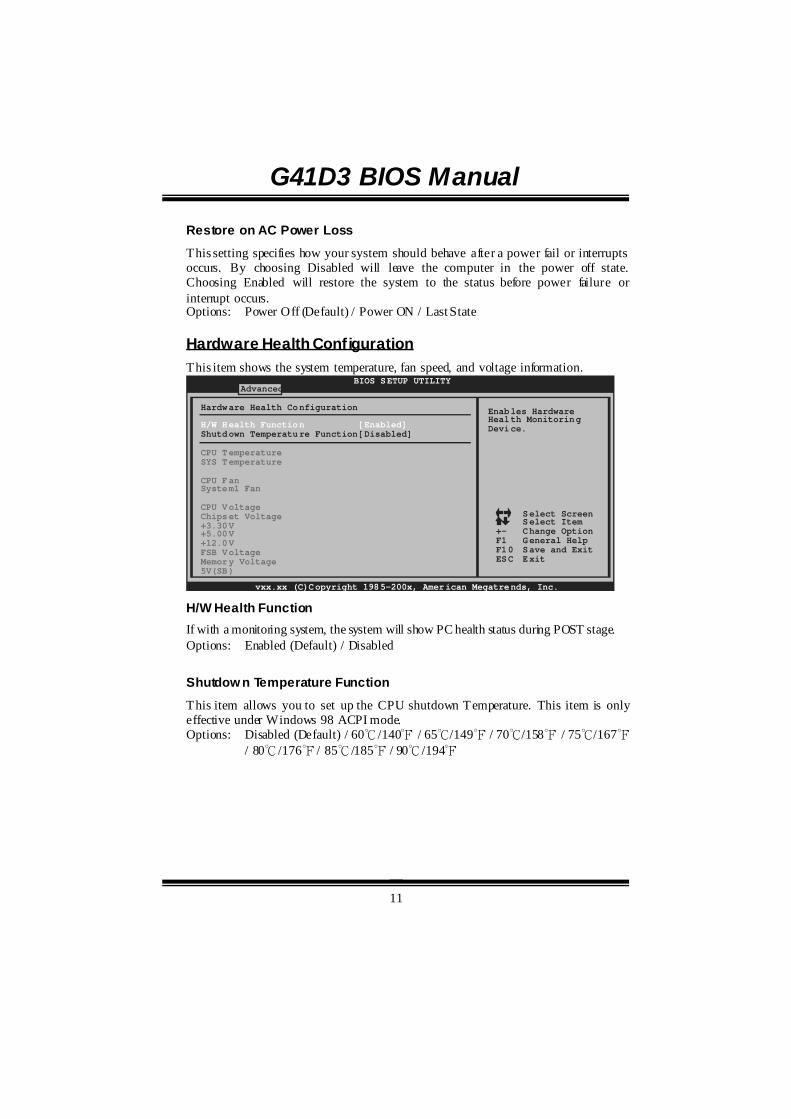
Hardware Health Configuration This item shows the system temperature, fan speed, and voltage information.
Advanced
Hardware Health Configuration
H/W Health Function [Enabled]Shutdown Temperature Function[Disabled]
CPU TemperatureSYS Temperature
CPU FanSystem1 Fan
CPU VoltageChipset Voltage+3.30V+5.00V+12.0VFSB VoltageMemory Voltage5V(SB)
BIOS SETUP UTILITY
vxx.xx (C)Copyright 1985-200x, American Megatrends, Inc.
Select ScreenSelect ItemChange OptionGeneral HelpSave and ExitExit
+-F1F10ESC
Enables HardwareHealth MonitoringDevice.
H/W Health Function If with a monitoring system, the system will show PC health status during POST stage. Options: Enabled (Default) / Disabled
Shutdow n Temperature Function
This item allows you to set up the CPU shutdown Temperature. This item is only effective under Windows 98 ACPI mode. Options: Disabled (Default) / 60℃/140℉ / 65℃/149℉ / 70℃/158℉ / 75℃/167℉
/ 80℃/176℉ / 85℃/185℉ / 90℃/194℉
G41D3 BIOS Manual
12
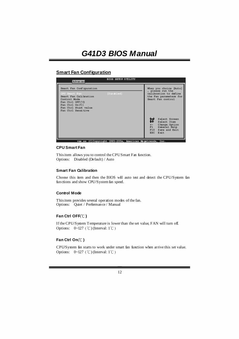
Smart Fan Configuration BIOS SETUP UTILITY
Advanced
vxx.xx (C)Copyright 1985-200x, American Megatrends, Inc.
Select ScreenSelect ItemChange OptionGeneral HelpSave and ExitExit
+-F1F10ESC
When you choice [Auto], please run thecalibration to definethe Fan parameters forSmart Fan control
Smart Fan Configuration
CPU Smart Fan [Disabled]Smart Fan CalibrationControl ModeFan Ctrl OFF( C)o
Fan Ctrl On(C)Fan Ctrl Start valueFan Ctrl Sensitive
o
CPU Smart Fan
This item allows you to control the CPU Smart Fan function. Options: Disabled (Default) / Auto
Smart Fan Calibration
Choose this item and then the BIOS will auto test and detect the CPU/System fan functions and show CPU/System fan speed.
Control Mode
This item provides several operation modes of the fan. Options: Quiet / Performance / Manual
Fan Ctrl OFF(℃ )
If the CPU/System Temperature is lower than the set value, FAN will turn off. Options: 0~127 (℃) (Interval: 1℃)
Fan Ctrl On(℃ )
CPU/System fan starts to work under smart fan function when arrive this set value. Options: 0~127 (℃) (Interval: 1℃)
G41D3 BIOS Manual
13
Fan Ctrl Start Value
When CPU/System temperature arrives to the set value, the CPU/System fan will work under Smart Fan Function mode. Options: 0~127 (Interval: 1)
Fan Ctrl Sensitive
Increasing the value will raise the speed of CPU/System fan. Options: 1~127 (Interval: 1)
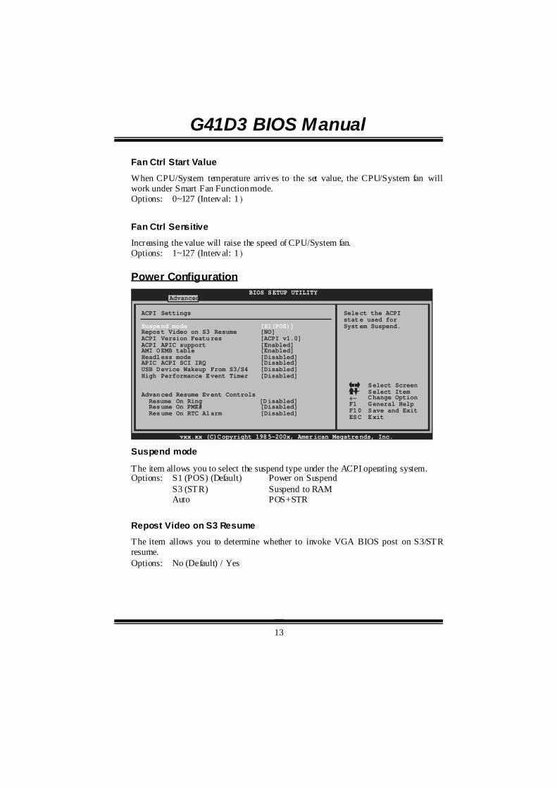
Power Configuration BIOS SETUP UTILITY
Advanced
vxx.xx (C)Copyright 1985-200x, American Megatrends, Inc.
Select ScreenSelect ItemChange OptionGeneral HelpSave and ExitExit
+-F1F10ESC
Select the ACPIstate used forSystem Suspend.
ACPI Settings
Advanced Resume Event Controls
Suspend mode [S1(POS)]Repost Video on S3 Resume [NO]ACPI Version Features [ACPI v1.0]ACPI APIC support [Enabled]AMI OEMB table [Enabled]Headless mode [Disabled]APIC ACPI SCI IRQ [Disabled]USB Device Wakeup From S3/S4 [Disabled]High Performance Event Timer [Disabled]
Resume On PME# [Disabled] Resume On RTC Alarm [Disabled]
Resume On Ring [Disabled]
Suspend mode
The item allows you to select the suspend type under the ACPI operating system. Options: S1 (POS) (Default) Power on Suspend S3 (STR) Suspend to RAM Auto POS+STR
Repost Video on S3 Resume
The item allows you to determine whether to invoke VGA BIOS post on S3/STR resume. Options: No (Default) / Yes
G41D3 BIOS Manual
14
ACPI Version Features
The item allows you to select the version of ACPI. Options: ACPI v1.0 (Default) / ACPI v2.0 / ACPI v3.0
ACPI APIC support
This item is used to enable or disable the motherboard's APIC (Advanced Programmable Interrupt Controller). The APIC provides multiprocessor support, more IRQs and faster interrupt handling. Options: Enabled (Default) / Disabled
AMI OEMB table
Set this value to allow the ACPI BIOS to add a pointer to an OEMB table in the Root System Description Table (RSDT) table. Options: Enabled (Default) / Disabled
Headless mode
This is a server-speci fic feature. A headless server is one that operates without a keyboard, monitor or mouse. To run in headless mode, both BIOS and operating system (e.g. Windows Server 2003) must support headless operation. Options: Disabled (Default) / Enabled
APIC ACPI SCI IRQ
Options: Disabled (Default) / Enabled
USB Dev ice Wakeup from S3/S4
This item allows you to enable or disabled the USB resume from S3/S4 function. Options: Disabled (Default) / Enabled
High Performance Event Timer
This item allows you to enable or disabled the HPET. Options: Disabled (Default) / Enabled

G41D3 BIOS Manual
15
HPET Memory Address
This item allows you to set the memory address of HPET. Options: FED00000h (Default) / FED01000h / FED02000h / FED03000h
Resume On Ring
This item allows you to control the wake on ring function. Options: Disabled (Default) / Enabled
Resume On PME# When you select Enabled, a PME signal from PCI card returns the system to Full ON state. For this function to work, you may need a LAN add-on card which supports the Wake on LAN function. Set the Wake on LAN (WOL) jumper on motherboard to enable if applicabl e. Options: Disabled (Default) / Enabled
Resume On RTC Alarm
When “ Enabled”, you can set the date and time at which the RTC (real-time clock) alarm awakens the system from Suspend mode. Options: Disabled (Default) / Enabled
RTC Alarm Date (Days)
You can choose which date the system will boot up.
RTC Alarm Time
You can choose the system boot up time, input hour, minute and second to specify.
G41D3 BIOS Manual
16
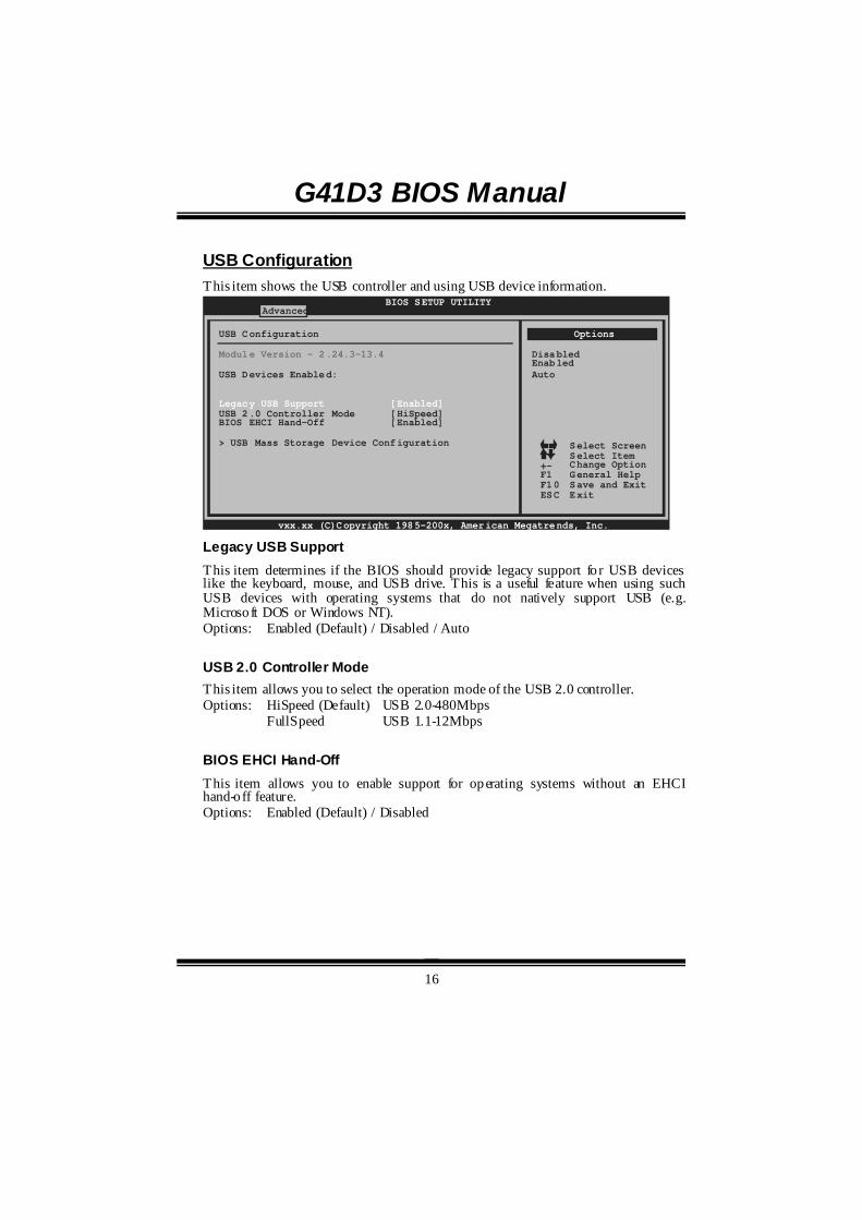
USB Configuration This item shows the USB controller and using USB device information.
BIOS SETUP UTILITYAdvanced
vxx.xx (C)Copyright 1985-200x, American Megatrends, Inc.
Select ScreenSelect ItemChange OptionGeneral HelpSave and ExitExit
+-F1F10ESC
USB Configuration
USB Devices Enabled:
Module Version - 2.24.3-13.4
Legacy USB Support [Enabled]USB 2.0 Controller Mode [HiSpeed]BIOS EHCI Hand-Off [Enabled]
> USB Mass Storage Device Configuration
Options
DisabledEnabledAuto
Legacy USB Support This item determines if the BIOS should provide legacy support fo r USB devices like the keyboard, mouse, and USB drive. This is a useful feature when using such USB devices with operating systems that do not natively support USB (e.g. Microsoft DOS or Windows NT). Options: Enabled (Default) / Disabled / Auto
USB 2.0 Controller Mode This item allows you to select the operation mode of the USB 2.0 controller. Options: HiSpeed (Default) USB 2.0-480Mbps FullSpeed USB 1.1-12Mbps
BIOS EHCI Hand-Off This item allows you to enable support for operating systems without an EHCI hand-off feature. Options: Enabled (Default) / Disabled

G41D3 BIOS Manual
17
USB Mass Storage Dev ice Configuration
BIOS SETUP UTILITYAdvanced
vxx.xx (C)Copyright 1985-200x, American Megatrends, Inc.
Select ScreenSelect ItemChange OptionGeneral HelpSave and ExitExit
+-F1F10ESC
Number of secondsPOST waits for theUSB mass storagedevice after startunit command.
USB Mass Storage Device Configuration
USB Mass Storage Reset Delay [20 Sec]
Emulation Type [Auto]
Device #
USB Mass Storage Reset Delay This item allows you to set the reset delay for USB mass storage device. Options: 20 Sec (Default) / 10 Sec / 30 Sec / 40 Sec Emulation Type This item allows you to select the emulation type of the USB mass storage device. Options: Auto (Default) / Floppy / Forced FDD / Hard Disk / CDROM
G41D3 BIOS Manual
18
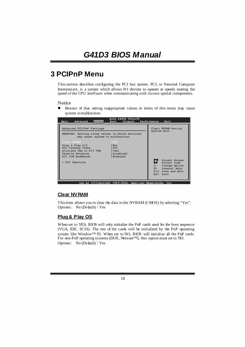
3 PCIPnP Menu This section describes configuring the PCI bus system. PCI, or Personal Computer Interconnect, is a system which allows I/O devices to operate at speeds nearing the speed o f the CPU itself uses when communicating with its own special components. Notice ! Beware of that setting inappropriate values in items of this menu may cause
system to malfunction. BIOS SETUP UTILITY
Main Advanced PCIPnP Boot Chipset Performance
vxx.xx (C)Copyright 1985-200x, American Megatrends, Inc.
Select ScreenSelect ItemChange OptionGeneral HelpSave and ExitExit
+-F1F10ESC
Clear NVRAM duringSystem Boot.
Advanced PCI/PnP Settings
WARNING: Setting wrong values in below sections may cause system to malfunction.
Plug & Play O/S [No]PCI Latency Timer [64]Allocate IRQ to PCI VGA [Yes]Palette Snooping [Disabled]PCI IDE BusMaster [Enabled]
> PCI Resource
Clear NVRAM [No]
Exit
Clear NVRAM This item allows you to clear the data in the NVRAM (CMOS) by selecting “Yes”. Options: No (Default) / Yes
Plug & Play OS When set to YES, BIOS will only initialize the PnP cards used for the boot sequence (VGA, IDE, SCSI). The rest of the cards will be initialized by the PnP operating system like Window™ 95. When set to NO, BIOS will initialize all the PnP cards. For non-PnP operating systems (DOS, Netware™), this option must set to NO. Options: No (Default) / Yes
G41D3 BIOS Manual
19
PCI Latency Timer This item controls how long a PCI device can hold the PCI bus before another takes over. The longer the latency, the longer the PCI device can retain control of the bus before handing it over to another PCI device. Options: 64 (Default) / 32 / 96 / 128 / 160 / 192 / 224 / 248
Allocate IRQ to PCI VGA This item allows BIOS to choose a IRQ to assign for the PCI VGA card. Options: Yes (Default) / No
Palette Snooping Some old graphic controllers need to “ snoop” on the VGA palette and then map it to their display as a way to provide boot information and VGA compatibility. This item allows such snooping to take place. Options: Disabled (Default) / Enabled
PCI IDE BusMaster This item is a toggle for the built-in driver that allows the onboard IDE controller to perform DMA (Direct Memory Access) trans fers. Options: Enabled (Default) / Disabled
PCI Resource BIOS SETUP UTILITY
PCIPnP
vxx.xx (C)Copyright 1985-200x, American Megatrends, Inc.
Select ScreenSelect ItemChange OptionGeneral HelpSave and ExitExit
+-F1F10ESC
Available: SpecifiedIRQ is available to beused by PCI/PnPdevices.Reserved: SpecifiedIRQ is reserved foruse by Legacy ISAdevices.
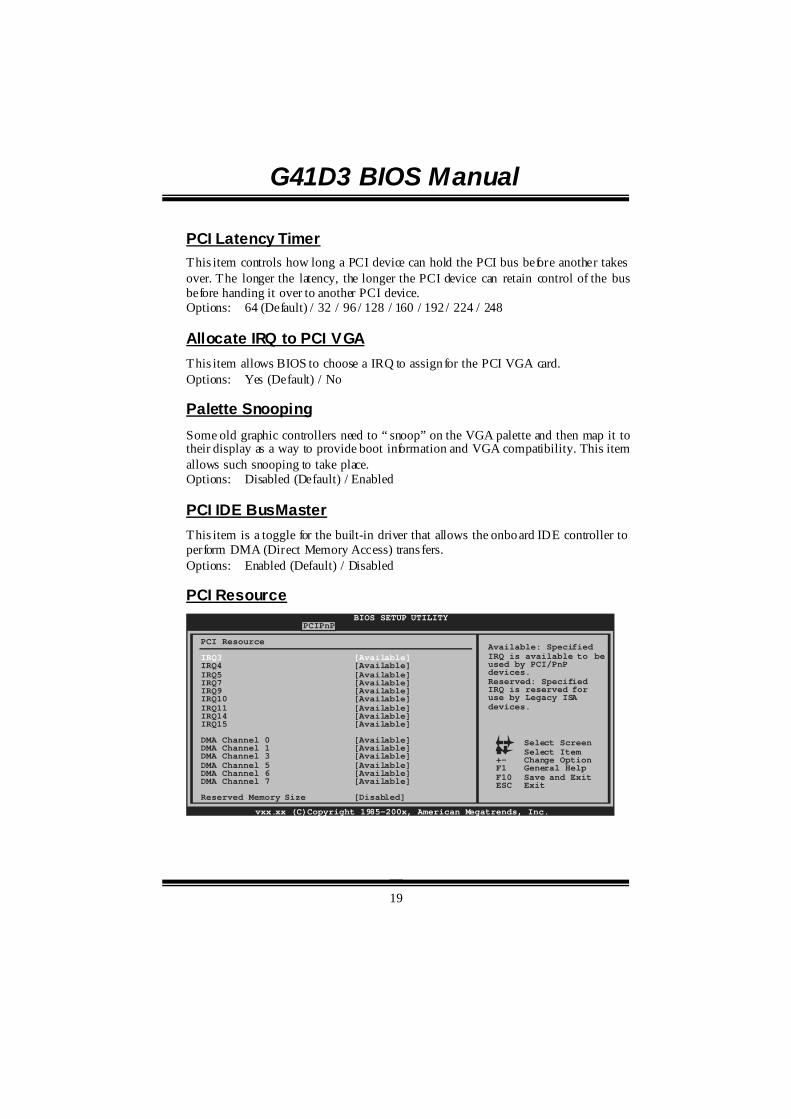
PCI Resource
IRQ3 [Available]IRQ4 [Available]IRQ5 [Available]IRQ7 [Available]IRQ9 [Available]IRQ10 [Available]IRQ11 [Available]IRQ14 [Available]IRQ15 [Available]
DMA Channel 0 [Available]DMA Channel 1 [Available]DMA Channel 3 [Available]DMA Channel 5 [Available]DMA Channel 6 [Available]DMA Channel 7 [Available]
Reserved Memory Size [Disabled]
G41D3 BIOS Manual
20
IRQ3/4/5/7/9/10/11/14/15
These items will allow you to assign each system interrupt a type, depending on the type of device using the interrupt. The option “Available” means the IRQ is going to assign automatically. Options: Available (Default) / Reserved
DMA Channel 0/1/3/5/6/7 These items will allow you to assign each DMA channel a type, depending on the type of device using the channel. The option “ Available” means the channel is going to assign automatically. Options: Available (Default) / Reserved
Reserved Memory Size This item allows BIOS to reserve cert ain memory size for speci fic PCI device. Options: Disabled (Default) / 16K / 32K / 64K
G41D3 BIOS Manual
21
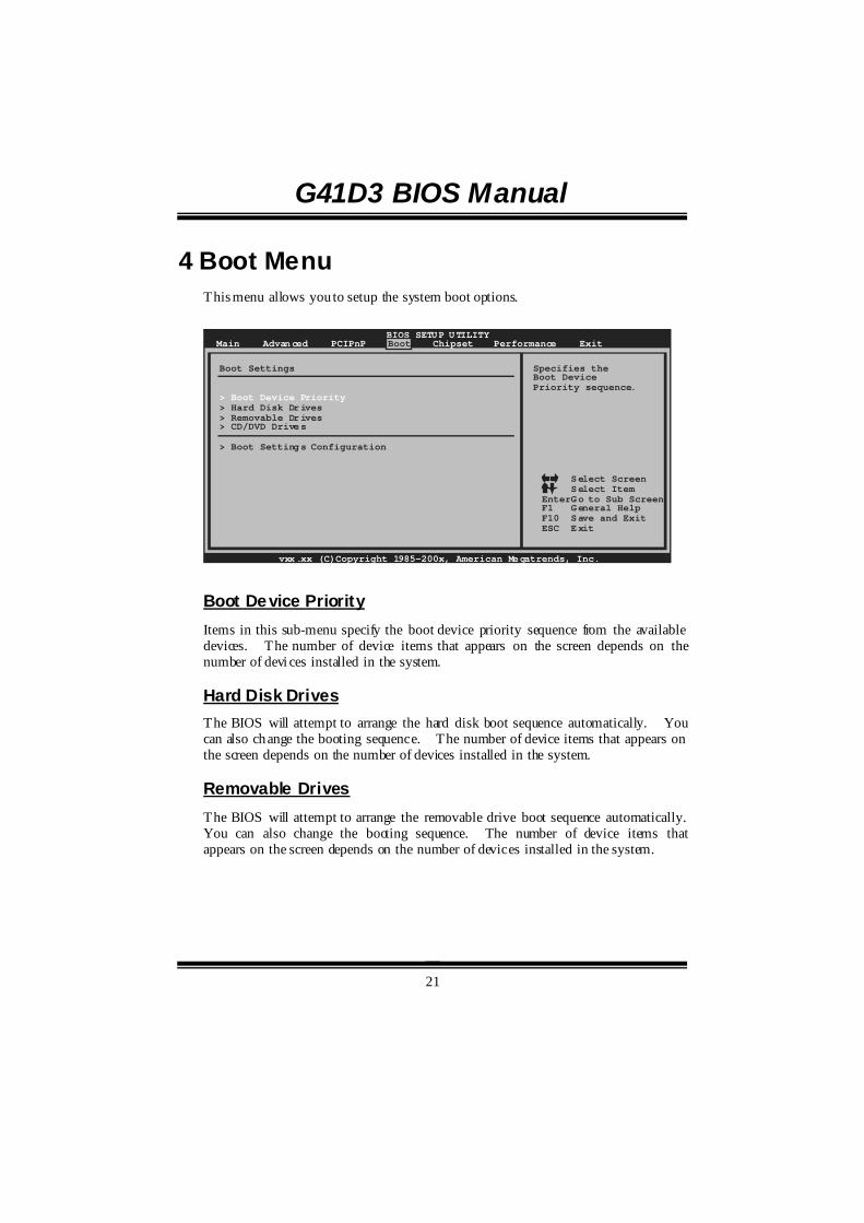
4 Boot Menu This menu allows you to setup the system boot options.
BIOS SETUP UTILITYMain Advanced PCIPnP Boot Chipset Performance
vxx.xx (C)Copyright 1985-200x, American Megatrends, Inc.
Select ScreenSelect ItemGo to Sub ScreenGeneral HelpSave and ExitExit
EnterF1F10ESC
Specifies theBoot DevicePriority sequence.
Boot Settings
> Hard Disk Drives> Removable Drives> CD/DVD Drives
> Boot Settings Configuration
> Boot Device Priority
Exit
Boot Device Priority Items in this sub-menu specify the boot device priority sequence from the available devices. The number of device items that appears on the screen depends on the number of devi ces installed in the system.
Hard Disk Drives The BIOS will attempt to arrange the hard disk boot sequence automatically. You can also change the booting sequence. The number of device items that appears on the screen depends on the number of devices installed in the system.
Removable Drives The BIOS will attempt to arrange the removable drive boot sequence automatically. You can also change the booting sequence. The number of device items that appears on the screen depends on the number of devices installed in the system.
G41D3 BIOS Manual
22
CD/DVD Drives The BIOS will attempt to arrange the CD/DVD drive boot sequence automatically. You can also change the booting sequence. The number of device items that appears on the screen depends on the number of devices installed in the system.
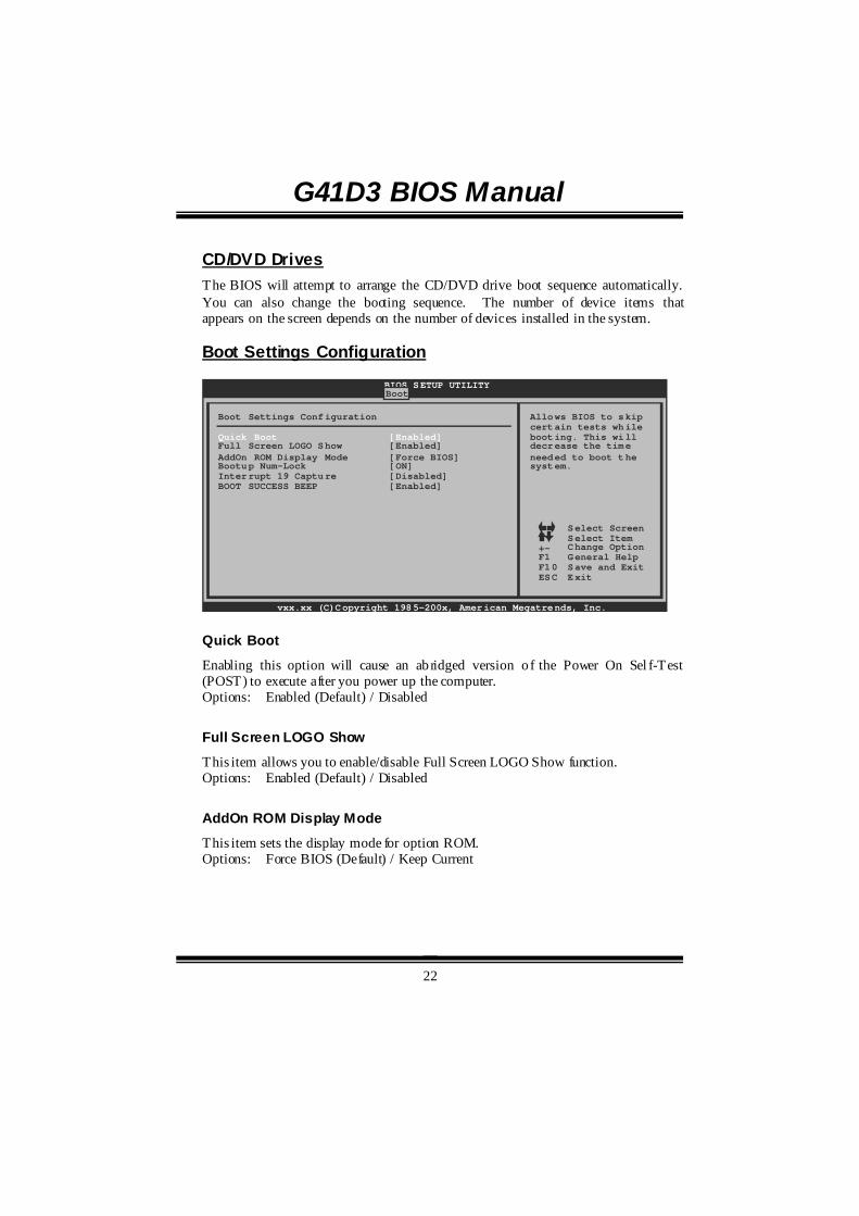
Boot Settings Configuration
BIOS SETUP UTILITYBoot
vxx.xx (C)Copyright 1985-200x, American Megatrends, Inc.
Select ScreenSelect ItemChange OptionGeneral HelpSave and ExitExit
+-F1F10ESC
Allows BIOS to skipcertain tests whilebooting. This willdecrease the timeneeded to boot thesystem.
Boot Settings Configuration
Full Screen LOGO Show [Enabled]AddOn ROM Display Mode [Force BIOS]Bootup Num-Lock [ON]Interrupt 19 Capture [Disabled]BOOT SUCCESS BEEP [Enabled]
Quick Boot [Enabled]
Quick Boot
Enabling this option will cause an ab ridged version o f the Power On Sel f-Test (POST) to execute after you power up the computer. Options: Enabled (Default) / Disabled
Full Screen LOGO Show
This item allows you to enable/disable Full Screen LOGO Show function. Options: Enabled (Default) / Disabled
AddOn ROM Display Mode
This item sets the display mode for option ROM. Options: Force BIOS (Default) / Keep Current

G41D3 BIOS Manual
23
Bootup Num-Lock
Selects the NumLock State after the system switched on. Options: ON (Default) / OFF
Interrupt 19 Capture
Interrupt 19 is the software interrupt that handles the boot disk function. When set to Enabled, this item allows the option ROMs to trap interrupt 19. Options: Disabled (Default) / Enabled
BOOT SUCCESS BEEP When this item is set to Enabled, BIOS will let user know boot success with beep. Options: Enabled (Default) / Disabled
G41D3 BIOS Manual
24
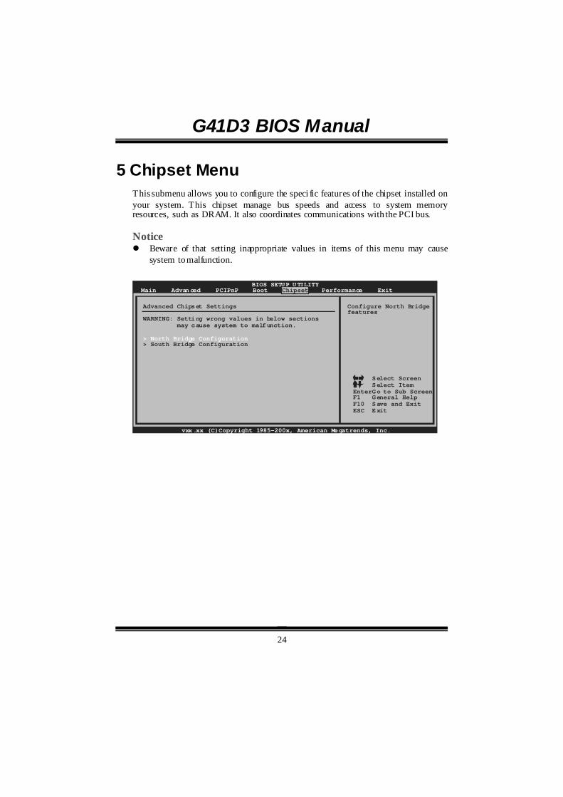
5 Chipset Menu This submenu allows you to configure the speci fic features of the chipset installed on your system. This chipset manage bus speeds and access to system memory resources, such as DRAM. It also coordinates communications with the PCI bus. Notice ! Beware of that setting inappropriate values in items of this menu may cause
system to malfunction.
BIOS SETUP UTILITYMain Advanced PCIPnP Boot Chipset Performance
vxx.xx (C)Copyright 1985-200x, American Megatrends, Inc.
Select ScreenSelect ItemGo to Sub ScreenGeneral HelpSave and ExitExit
EnterF1F10ESC
Advanced Chipset Settings
WARNING: Setting wrong values in below sections may cause system to malfunction.
> South Bridge Configuration> North Bridge Configuration
Exit
Configure North Bridgefeatures
G41D3 BIOS Manual
25
North Bridge Configuration BIOS SETUP UTILITY
Chipset
vxx.xx (C)Copyright 1985-200x, American Megatrends, Inc.
Select ScreenSelect ItemChange OptionGeneral HelpSave and ExitExit
+-F1F10ESC
North Bridge Chipset Configuration
PEG Port Configuration
Memory Hole [Disabled]
Initiate Graphic Adapter [PEG/PCI]IGD Graphics Mode Select [Enabled, 32MB]
PEG Port [Auto]
> Video Function Configuration
Memory Remap Feature [Enabled] PCI MMIO Allocation:
IGD GTT Graphics memory size [No VT mode, 2MB]
ENABLE: Allowremapping ofoverlapped PCI memoryabove the totalphysical memory.
DISABLE: Do not allowremapping of memory.
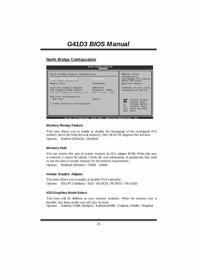
Memory Remap Feature
This item allows you to enable or disable the remapping of the overlapped PCI memory above the total physical memory. Only 64-bit OS supports this function. Options: Enabled (Default) / Disabled
Memory Hole
You can reserve this area of system memory for ISA adapter ROM. When this area is reserved it cannot be cached. Check the user information of peripherals that need to use this area o f system memory for the memory requirements. Options: Disabled (Default) / 15MB – 16MB
Initiate Graphic Adapter This item allows you to enable or disable VGA controller. Options: PEG/PCI (Default) / IGD / PCI/IGD / PCI/PEG / PEG/IGD
IGD Graphics Mode Select
This item will be different as your memory modules. When the memory size is decided, this frame buffer size will also be fixed. Options: Enabled,32MB (Default) / Enabled,64MB / Enabled,128MB / Disabled
G41D3 BIOS Manual
26
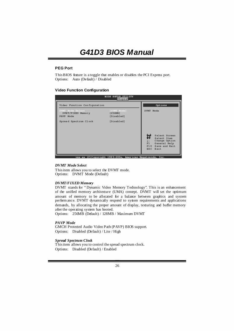
PEG Port
This BIOS feature is a toggle that enables or disables the PCI Express port. Options: Auto (Default) / Disabled
Video Function Configuration BIOS SETUP UTILITY
Chipset
vxx.xx (C)Copyright 1985-200x, American Megatrends, Inc.
Select ScreenSelect ItemChange OptionGeneral HelpSave and ExitExit
+-F1F10ESC
Video Function Configuration
DVMT/FIXED Memory [256MB]PAVP Mode [Disabled]
Spread Spectrum Clock [Disabled]
DVMT Mode Select [DVMT Mode]
Options
DVMT Mode
DVMT Mode Select This item allows you to select the DVMT mode. Options: DVMT Mode (Default) DVMT/FIXED Memory DVMT stands for “ Dynamic Video Memory Technology”. This is an enhancement of the unified memory architecture (UMA) concept. DVMT will set the optimum amount of memory to be allocated for a balance between graphics and system perform ance. DVMT dynamically respond to system requirements and applications demands, by allocating the proper amount of display, texturing and buffer memory after the operating system has booted. Options: 256MB (Default) / 128MB / Maximum DVMT PAVP Mode GMCH Protected Audio Video Path (PAVP) BIOS support. Options: Disabled (Default) / Lite / High Spread Spectrum Clock This item allows you to control the spread spectrum clock. Options: Disabled (Default) / Enabled
G41D3 BIOS Manual
27
South Bridge Configuration BIOS SETUP UTILITY
Chipset
vxx.xx (C)Copyright 1985-200x, American Megatrends, Inc.
Select ScreenSelect ItemChange OptionGeneral HelpSave and ExitExit
+-F1F10ESC
South Bridge Chipset Configuration
USB 2.0 Controller [Enabled]Audio Controller [Azalia]
Onboard Lan Control [Enabled]Onboard Lan Boot ROM [Disabled]
SMBUS Controller [Enabled]
SLP_S4# Min. Assertion Width [1 to 2 seconds]
USB Functions [8 USB Ports]
MAC ID Information
Options
Disabled2 USB Ports4 USB Ports6 USB Ports8 USB Ports
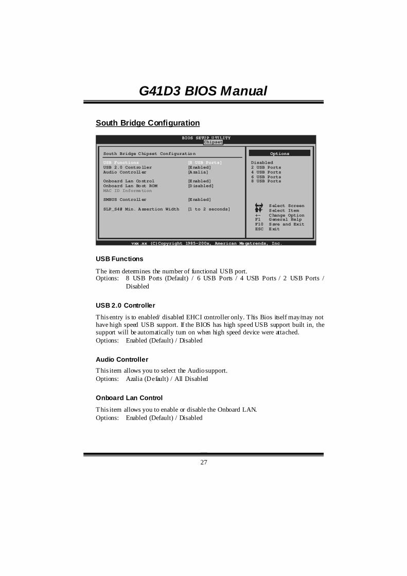
USB Functions
The item determines the number of functional USB port. Options: 8 USB Ports (Default) / 6 USB Ports / 4 USB Ports / 2 USB Ports /
Disabled
USB 2.0 Controller
This entry is to enabled/ disabled EHCI controller only. This Bios itself may/may not have high speed USB support. If the BIOS has high speed USB support built in, the support will be automatically turn on when high speed device were attached. Options: Enabled (Default) / Disabled
Audio Controller This item allows you to select the Audio support. Options: Azalia (Default) / All Disabled
Onboard Lan Control
This item allows you to enable or disable the Onboard LAN. Options: Enabled (Default) / Disabled

G41D3 BIOS Manual
28
Onboard Lan Boot Rom
This item allows you to select the status of Onboard LAN Boot ROM. Options: Disabled (Default) / Enabled
MAC ID Information
This item shows the LAN MAC ID.
SMBUS Controller
This BIOS feature controls the I/O buffers fo r the SMBus. Options: Enabled (Default) / Disabled
SLP_S4# Min. Assertion Width
Options: 1 to 2 seconds (Default) / 4 to 5 seconds / 3 to 4 seconds / 2 to 3 seconds
G41D3 BIOS Manual
29
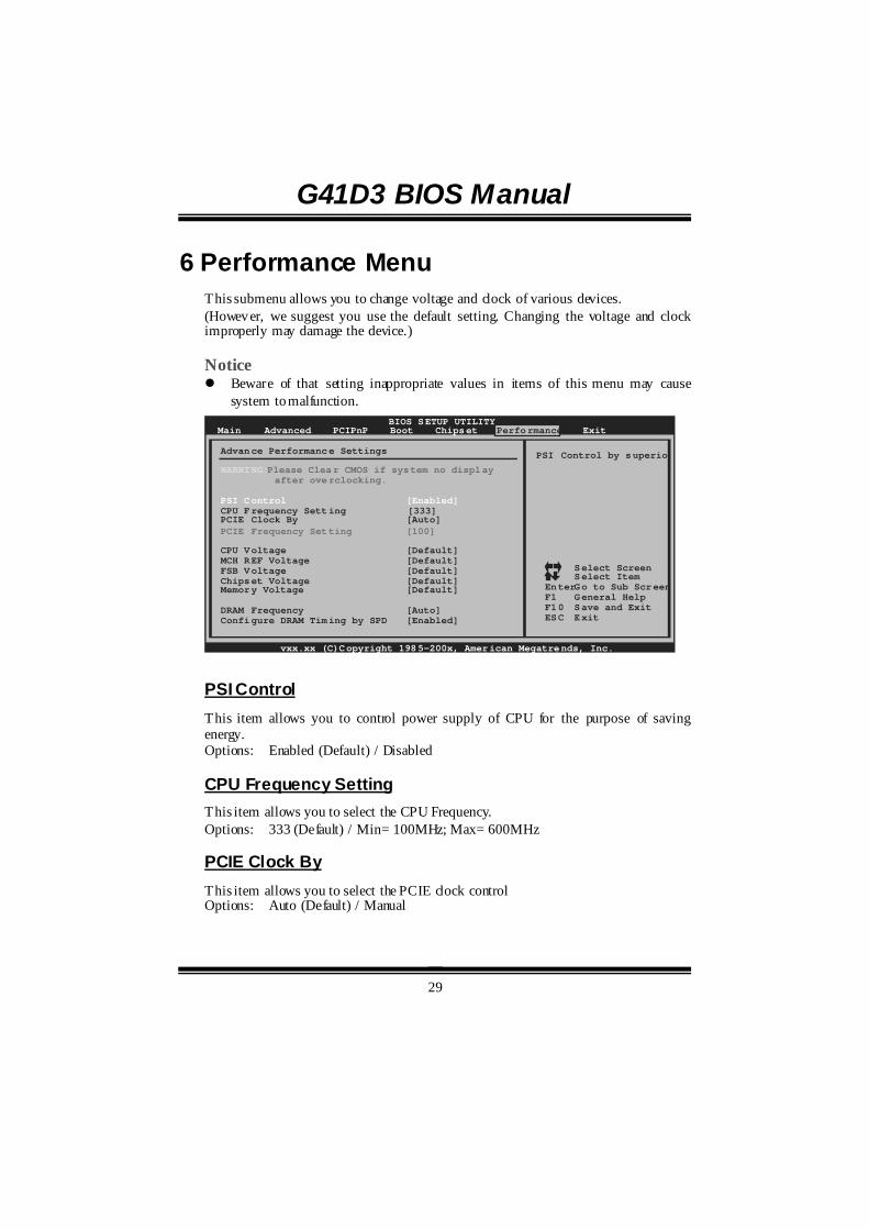
6 Performance Menu This submenu allows you to change voltage and clock of various devices. (However, we suggest you use the default setting. Changing the voltage and clock improperly may damage the device.) Notice ! Beware of that setting inappropriate values in items of this menu may cause
system to malfunction. BIOS SETUP UTILITY
Main Advanced PCIPnP Boot Chipset Performance
vxx.xx (C)Copyright 1985-200x, American Megatrends, Inc.
Select ScreenSelect ItemGo to Sub ScreenGeneral HelpSave and ExitExit
EnterF1F10ESC
Advance Performance Settings
WARNING:Please Clear CMOS if system no display after overclocking.
PSI Control [Enabled]CPU Frequency SettingPCIE Clock By [Auto]
CPU Voltage [Default]MCH REF Voltage [Default]FSB Voltage [Default]Chipset Voltage [Default]Memory Voltage [Default]
DRAM Frequency [Auto]Configure DRAM Timing by SPD [Enabled]
[333]
PCIE Frequency Setting [100]
Exit
PSI Control by superio
PSI Control This item allows you to control power supply of CPU for the purpose of saving energy. Options: Enabled (Default) / Disabled
CPU Frequency Setting This item allows you to select the CPU Frequency. Options: 333 (Default) / Min= 100MHz; Max= 600MHz
PCIE Clock By This item allows you to select the PCIE clock control Options: Auto (Default) / Manual
G41D3 BIOS Manual
30
PCIE Frequency Setting This item allows you to select the PCIE clock control Options: 100 (Default) / Min=100; Max=150
CPU Voltage This item allows you to select CPU Voltage Control. Options: Default (Default) / +5% / +10% / +15%
MCH REF Voltage This item allows you to select MCH REF Voltage Control. Options: Default (Default) / 0.63*VTT / 0.61*VTT / 0.58*VTT
FSB Voltage This item allows you to select FSB Voltage Control. Options: Default (Default) / +0.1V / +0.2V / +0.3V
Chipset Voltage This item allows you to select Chipset Voltage Control. Options: Default (Default) / +0.1V / +0.2V / +0.3V
Memory Voltage This item allows you to select Memory Voltage Control. Options: Default (Default) / +0.05V / +0.10V / +0.15V / +0.20V / +0.25V /
+0.30V / +0.35V
DRAM Frequency This item allows you to control the Memory Clock. Options: Auto (Default) / DDR3-800 / DDR3-1066
Configure DRAM Timing by SPD Options: Enabled (Default) / Disabled
DRAM tCL Options: 3 (Default) / 3 ~ 10

G41D3 BIOS Manual
31
DRAM tRAS Options: 9 (Default) / 9 ~ 24
DRAM tRP Options: 3 (Default) / 3 ~ 10
DRAM tRCD Options: 3 (Default) / 3 ~ 10
DRAM tWR Options: 3 (Default) / 3 ~ 15
DRAM tRFC Options: 15 (Default) / 15 ~ 78
DRAM tWTR Options: 2 (Default) / 2 ~ 15
DRAM tRRD Options: 2 (Default) / 2 ~ 15
DRAM tRTP Options: 2 (Default) / 2 ~ 15
G41D3 BIOS Manual
32
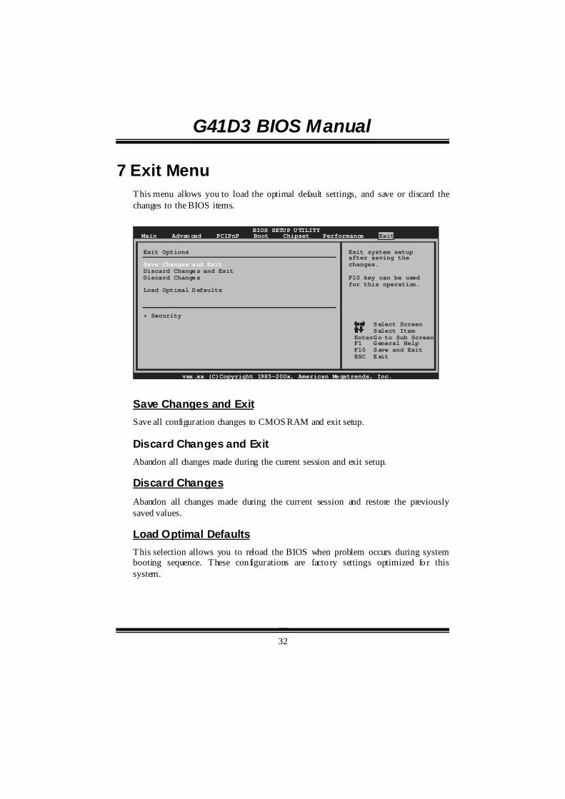
7 Exit Menu This menu allows you to load the optimal default settings, and save or discard the changes to the BIOS items.
BIOS SETUP UTILITYMain Advanced PCIPnP Boot Chipset Performance
vxx.xx (C)Copyright 1985-200x, American Megatrends, Inc.
Select ScreenSelect ItemGo to Sub ScreenGeneral HelpSave and ExitExit
EnterF1F10ESC
Exit system setupafter saving thechanges.
F10 key can be usedfor this operation.
Exit Options
Save Changes and ExitDiscard Changes and ExitDiscard Changes
Load Optimal Defaults
> Security
Exit
Save Changes and Exit Save all configuration changes to CMOS RAM and exit setup.
Discard Changes and Exit Abandon all changes made during the current session and exit setup.
Discard Changes Abandon all changes made during the current session and restore the previously saved values.
Load Optimal Defaults This selection allows you to reload the BIOS when problem occurs during system booting sequence. These configurations are facto ry settings optimized fo r this system.
G41D3 BIOS Manual
33
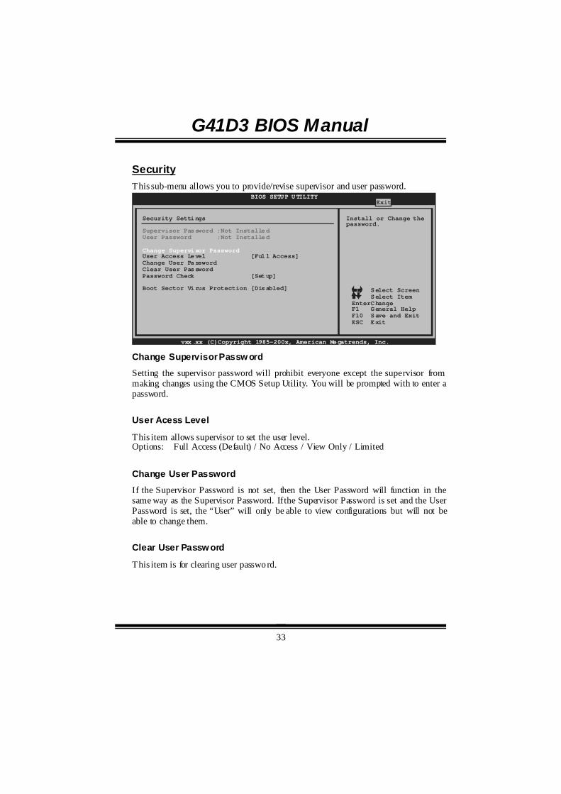
Security This sub-menu allows you to provide/revise supervisor and user password.
BIOS SETUP UTILITY
vxx.xx (C)Copyright 1985-200x, American Megatrends, Inc.
Select ScreenSelect ItemChangeGeneral HelpSave and ExitExit
EnterF1F10ESC
Install or Change thepassword.
Security Settings
Supervisor Password :Not InstalledUser Password :Not Installed
Change Supervisor PasswordUser Access Level [Full Access]Change User PasswordClear User PasswordPassword Check [Setup]
Boot Sector Virus Protection [Disabled]
Exit
Change Supervisor Passw ord
Setting the supervisor password will prohibit everyone except the supervisor from making changes using the CMOS Setup Utility. You will be prompted with to enter a password.
User Acess Level
This item allows supervisor to set the user level. Options: Full Access (Default) / No Access / View Only / Limited
Change User Password
If the Supervisor Password is not set, then the User Password will function in the same way as the Supervisor Password. If the Supervisor Password is set and the User Password is set, the “User” will only be able to view configurations but will not be able to change them.
Clear User Passw ord
This item is for clearing user password.

G41D3 BIOS Manual
34
Passw ord Check
This item is for setting the timing that checking password. Options: Setup (Default) / Always
Boot Sector Virus Protection
This option allows you to choose the VIRUS Warning feature that is used to protect the IDE Hard Disk boot sector. If this function is enabled and an attempt is made to write to the boot sector, BIOS will display a warning message on the screen and sound an alarm beep. Options: Disabled (Default) / Enabled


