Embed Size (px)
Citation preview
FUZZY VAULT FINGERPRINT CRYPTOGRAPHY: EXPERIMENTAL
AND SIMULATION STUDIES
by
Alex J. Kotlarchyk
A Thesis Submitted to the Faculty of
The College of Engineering and Computer Science
in Partial Fulfillment of the Requirements for the Degree of
Master of Science
Florida Atlantic University
Boca Raton, Florida
August, 2006
FUZZY VAULT FINGERPRINT CRYPTOGRAPHY: EXPERIMENTAL AND SIMULATION STUDIES
by Alex J. Kotlarchyk
This thesis (or dissertation) was prepared under the direction of the candidate's thesis advisors, Dr. Abhijit Pandya, Departments of Computer Science and Engineering, and Dr. Hanqi Zhuang, Department of Electrical Engineering, and has been approved by the members of his supervisory committee. It was submitted to the faculty of The College of Engineering and Computer Science and was accepted in partial fulfillment of the requirements for the degree of Master of Science.
SUPERVISORY COMMITTEE:
-advisor, Dr. Hanqi Zhuang
~ L . ./
Memj6'ed Rajput
?-acto~ Date
11
ACKNOWLEDGEMENTS
I would like to thank the members of my committee, especially Dr. Hanqi Zhuang, for his
expertise, criticism, and patient guidance throughout this research. I am grateful to Dr.
Abhijit Pandya for his valuable input and guidance. Thanks also go to Dr. Saeed Rajput
for his help in understanding error correction codes. Finally, I would like to thank fellow
graduate student, Hesong (Harry) Huang, for his help with some of the more difficult
mathematical concepts, especially his assistance with understanding and implementing
the Berlekamp-Welch algorithm. Equally important, I am indebted to the aforementioned
people for their friendship.
This research was made possible by funding from the DoD DISA Federal Secure
Telecommunications Network research program.
lll
Author:
Title:
Institution:
Thesis Advisor:
Degree:
Year:
ABSTRACT
Alex J. Kotlarchyk
Fuzzy Vault Fingerprint Cryptography: Experimental and
Simulation Studies
Florida Atlantic University
Dr. Abhijit S. Pandya
Master of Science
2006
The fuzzy vault scheme introduced by Juels and Sudan [Jue02] was implemented in a
fingerprint cryptography system using COTS software. This system proved to be
unsuccessful. Failure analysis led to a series of simulations to investigate the parameters
and system thresholds necessary for such a system to perform adequately and as guidance
for constructing similar systems in the future . First, a discussion of the role ofbiometrics
in data security and cryptography is presented, followed by a review of the key
developments leading to the development of the fuzzy vault scheme. The relevant
mathematics and algorithms are briefly explained. This is followed by a detailed
description of the implementation and simulation of the fuzzy vault scheme. Finally,
conclusions drawn from analysis of the results of this research are presented.
IV
TABLE OF CONTENTS
LIST OF TABLES ......... .. ..... ...... .......... .... .... .... ... ....... .............. ...... ........................... ....... vii
LIST OF FIGURES .... .... ................ ...... ..... ........ ........ ............ ................ ..... .. .. ..... .. ........... viii
1. INTRODUCTION ....... ........ ......... .... ..... .... ........ ............. .... .......... ......... ............ .... ...... 1
1.1 . Objective and Motivation .......... ........................ ................................................ .. 1
1.2. Background ..... ...... .................... ........... ......................... ...... ....... .. ..... ........... .... ... 1
1.2.1 . Biometrics and Data Security ... ................................ ... ...... .................. ... ... .. 1
1.2.2. Biometric Cryptography .... ........................ .......... ...... ....... ...... .. .......... .... ... 13
1.2.3. Fuzzy Vault Scheme ........ ............ ...... .... ................................................ .... 17
1.3. Scope/Contribution .......... ..... ...... ... ......... .... ....... ............... ...... ..... .............. .... .... 18
1.4. Organization of the Thesis ........... ........... ..... .......... ... .......................... ........ ...... 19
2. MATHEMATICAL AND ALGORITHMIC FOUNDATIONS ...... .......... ... ... ... ... .. 20
2.1. Introduction ....................................................................................................... 20
2.2. Galois Fields ...................................................................................................... 20
2.3. Reed-Solomon Codes .. ................................................... .......... .... ............. .... .... 21
2.4. Berlekamp-Welch Algorithm .. ....................................... .... ........ .... ....... ............ 23
2.5. Summary ........ ... .......... ..... ......... ...... ............... .... .................................... ......... .. 28
3. FUZZY VAULT SCHEME IMPLEMENTATION ...... ...... ..... .... ......... ........ ... ..... ... 29
3 .1. Introduction ...... ............ ....... .. ........... .... ............................................ ................. 29
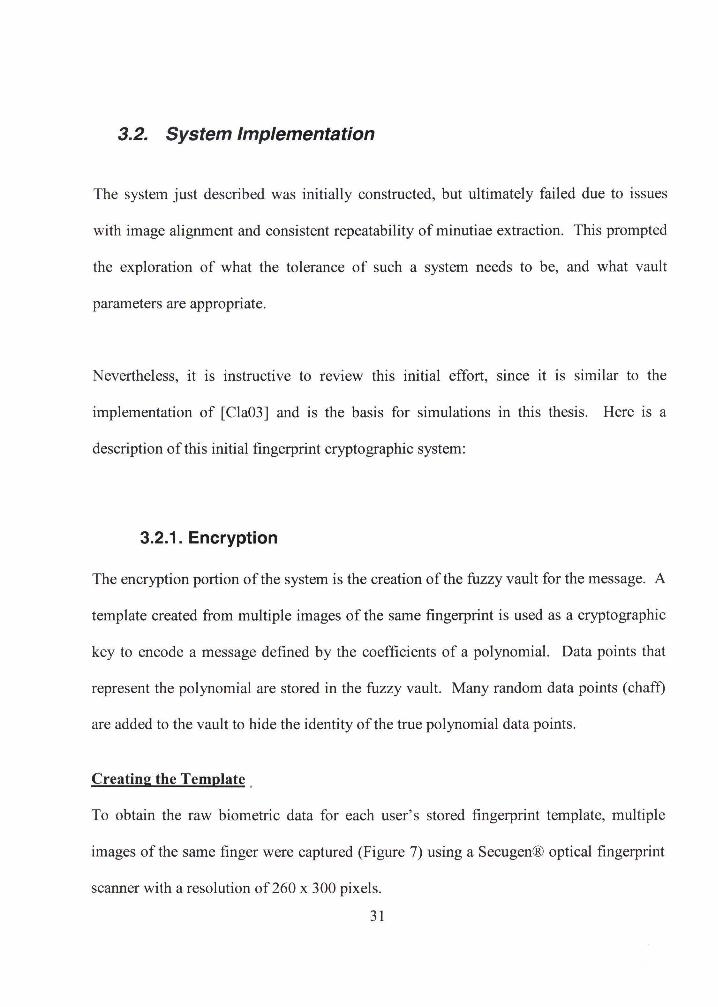
3.2. System Implementation ............ .... ................................................. ... ...... ..... ...... 31
v
3.2.1. Encryption ... .. ..... .... ............ ........... ............. ... .............. ................. ......... .... 31
3.2.2. Decryption ........................ ............. ............ .... ............. ..................... .......... 35
3.2.3. Analysis ... ......... ......................................... .... .......... ..... ...... ....... ........ .... ... . 37
3.3. Summary ... .................... ..................... ........................... ... .... .... .... ........ ............. 38
4. SIMULATIONS AND RESULTS ....... ...... ... ........ ........ ..... .. .. .................. .. ............... 39
4.1. Introduction ..... ............ .... .... ... ........... .... .......... ........ ...... ..................... ............... 39
4.2. Simulation Setup and Software Modules .......................................................... 39
4.3 . Results and Analysis .... .................. .. ........ ............................... ...... ........ ....... ..... 46
4.3.1. Effects of Single Parameters ...... ........... ... .......... ... ...... ... .......... ...... .... ....... 47
4.3.2. Effects of Multiple Parameters ........... ............ ........................................... 56
4.4. Summary ............... .... ..... ... ..... .. ... ..... ........ ........ .......... ...... ....... .... ... .. .............. .. . 58
5. CONCLUSIONS ............... ....... ............ .... ..... ...... .... ...... .. .. ... ................. .................... 60
5.1. Summary ........... ........ ................ ... ......... .... ... ....... ........ ...... .......... ...... ........ ... ..... 60
5.2. Future Work .............. ......... ............... ................................................................ 63
REFERENCES .......... ................. ........... .... ....... ........... .... ... ... ............. ............. ... ............... 65
APPENDIX ....................................................................................................................... 70
Vl

LIST OF TABLES
Table 1. Equivalence of units to Euclidean distance ... .... ........................... ........... ... ........ 40
Vll
LIST OF FIGURES
Figure 1. Biometric enrollment and verification ..... ........... ................... ............ .... ............. 3
Figure 2. Use cases of a biometric system (enrollment, verification, identification)
[Mal03] ..................... ........ ...... .... ...... .. ....... ... ................... ........ .... .... ........ ........ .... .. ...... 5
Figure 3. Threats to a biometric authentication system [Sho04] ........................................ 7
Figure 4. An example of a fuzzy commitment scheme for a 1 O-bit password ........ ..... .... 15
Figure 5. RS encoded block ... .......... ....... ... ... .......................................... ..... ...... ....... ....... 23
Figure 6. Fingerprint minutiae fuzzy vault message encryption/decryption ..... .... ... .... .... 30
Figure 7. Captured fingerprint. ......................................................................................... 32
Figure 8. Minutiae extraction ... .............................................. ..... ....... .............................. 33
Figure 9. Flowchart of individual simulation ........ .... ....................... .............. ........... ...... . 42
Figure 10. Effect of ntrue parameter. ......... .... .... .... .. ........... ..... .......................... ........ ...... 4 7
Figure 11 . Effect of nchaff parameter. ............................................................................. 48
Figure 12. Effect of thresh parameter.. ............................................. ................................ 49
Figure 13. Effect ofvarylive parameter ........ ........... ..... ..... ................... .... .... ........ ........... 50
Figure 14. varylive histograms where success = O(a), l{b), 2(c), and 3(d) .. ...... ............. .. 53
Figure 15. Success rate at varylive thresholds .................................................................. 55
Figure 16. Success rate at varylive, thresh= 4 ... ...... .... ..................................................... 56
Figure 17. Effect of (nchaff I ntrue) ratio .. ........ ........ ................... ..... ... ...... ...................... 57
Figure 18. Effect of (thresh - varylive) difference ........................................................... 58
Vlll
1. INTRODUCTION
1. 1. Objective and Motivation
Since the introduction by Juels and Sudan in 2002 of the fuzzy vault scheme [Jue02] for
biometric cryptography, there has been some research into the application of this scheme
for data security. After implementing a fuzzy vault scheme for fingerprints using COTS
hardware and software, the system failed. This was the motivation to investigate the
tolerance necessary for such a system to function and to see the effect of different vault
and tolerance parameters. The objective of this thesis is to simulate an application
implementing the fuzzy vault scheme, and determine the consequences on varying
several of the vault and tolerance parameters.
1.2. Background
1.2.1. Biometrics and Data Security
A fundamental component of human interaction with computers is authentication.
Explosive advances in computing power have made possible the biometric technologies
of today. Several factors have recently contributed to make biometrics an increasingly
feasible solution for securing access to computers and networks: i) reduced cost, ii)
1
reduced size, iii) increased accuracy, iv) increased ease of use, and v) recognized industry
standards.
The International Biometric Group, an industry consulting and research firm, predicts
that industry revenues from biometric technologies will grow to more than $4 billion by
2007, with about 75 percent of the demand coming from government-related investments
[Jon04] . As biometric technology improves and its price decreases, we can expect to see
a proliferation of biometric technology in many facets of our society.
A primary advantage of biometric systems is user convenience. Biometrics are always
with the user, so there is nothing to forget (like a password) or misplace (like a token).
Given the intense current interest in homeland security, not to mention medical, corporate
and commercial applications, the use of biometric data in secure applications is certain to
expand greatly. Although not yet commonplace, biometric technology can now be found
at the consumer level. Already, there are television commercials touting biometrics for
security on devices, such as the fingerprint recognition system available on the IBM
ThinkPad [Hin04]. In the future, cell phones equipped with fingerprint recognition
technology may be used to authenticate credit card users when making point-of-sale
purchases by phone [HafDO].
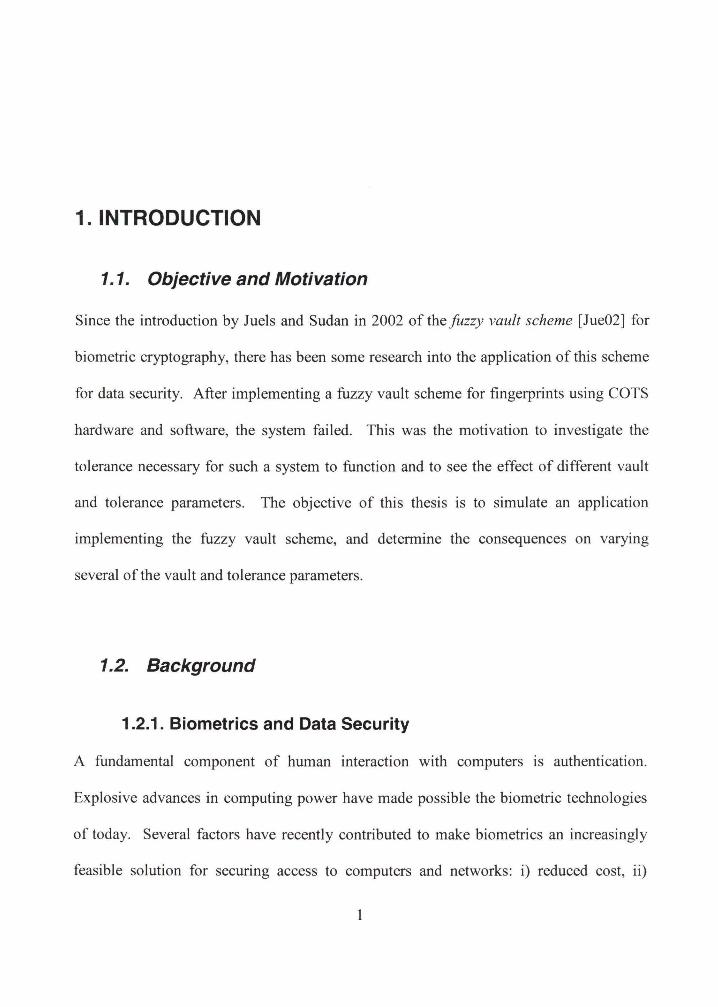
The components of a biometric authentication system are shown in the Figure 1:
2
Enrollment
Verification
Figure 1. Biometric enrollment and verification.
The capture (measure) device is used to gather the raw biometric information. Examples
of such devices are cameras, fingerprint readers, and iris scanners. Processing of the raw
data is then performed where subsampling and transformation of the data occurs to
generate a much smaller biometric template. Typical template sizes range from 9 bytes
for a hand-scan, to as large as 10000 bytes for voice recognition. During the enrollment
process, templates for each user are stored in a database. At authentication time, a new
template is generated from the user by the same process as during enrollment. This new
template is then compared to the user's previously enrolled template in the database. A
yes or no determination is then made as to whether the two templates match. This
comparison is different than traditional password matching where an exact match is
3
required. Since an individual's biometric data may be somewhat different at each
presentation due to a variety of factors (age, capture device, angle of presentation,
lighting, etc.), matching is inexact and performed within a predetermined threshold. The
tradeoff involved here is that the smaller the threshold, the higher the false rejection rate
(FRR), and the higher the threshold, the higher the false acceptance rate (FAR).
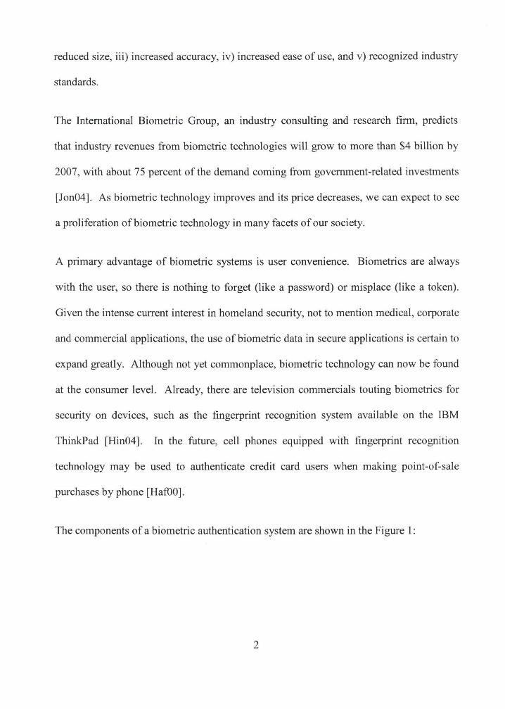
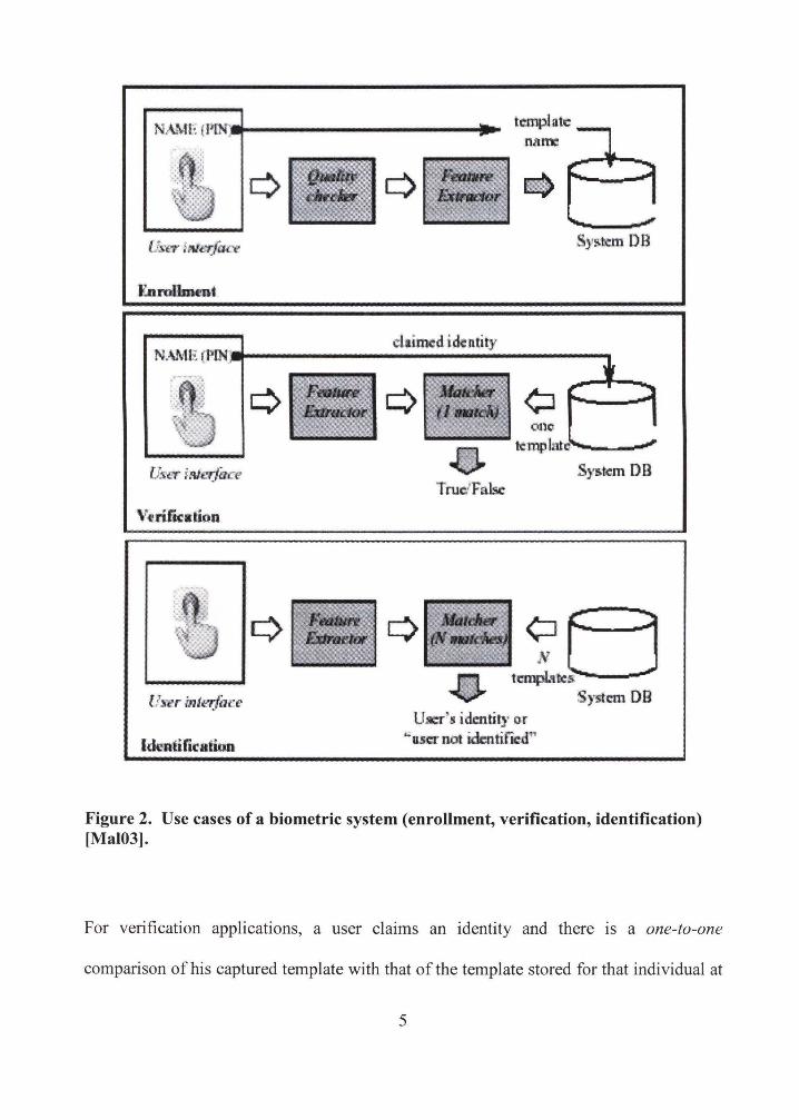
Biometrics can be used for both verification (authentication) and identification
applications. These two procedures, along with the enrollment procedure common to
both types of application, comprise the three use cases of a biometric system and are
illustrated in Figure 2 [Mal03).
4
N . .WH (PlN'• ..,._ __________ ..
Enrollment
ldmtirreation
one ttmp)at . ------
User's identity or "uer not idc:n tificd"
Sys.t.em DB
Figure 2. Use cases of a biometric system (enrollment, verification, identification) [Mal03].
For verification applications, a user claims an identity and there is a one-to-one
comparison ofhis captured template with that of the template stored for that individual at
5
the time of enrollment. In identification applications, no claim of identity needs to be
involved. In fact, the subject may not even be aware that his biometric data is being
captured. In this case, there is a one-to-many comparison between the captured template
and the multiple stored templates. Moreover, it is reasonable to combine both
verification and identification applications to answer the compound query, "Are you who
you claim to be (verification), and if not, who are you (identification)?"
When discussing biometric security, two different contexts need to be considered. First,
there is the use of biometric data as a means of authentication. Second, there is need to
protect the biometric data itself because of its personal nature. Interestingly, although
personal, raw biometric data is usually not actively hidden (face, fingerprint, iris). This is
different than a password which is supposed to be secret, or a token which is supposed to
be kept out of reach of others. Therefore, a potential attacker has a much easier time
obtaining a copy of one's biometric than his/her password or token. In addition, even
though raw biometric data may be relatively easy for others to obtain, the individual still
wants to control the use of the information. For example, a picture of one's face is easy
to obtain, but he/she would still want to control how it is distributed.
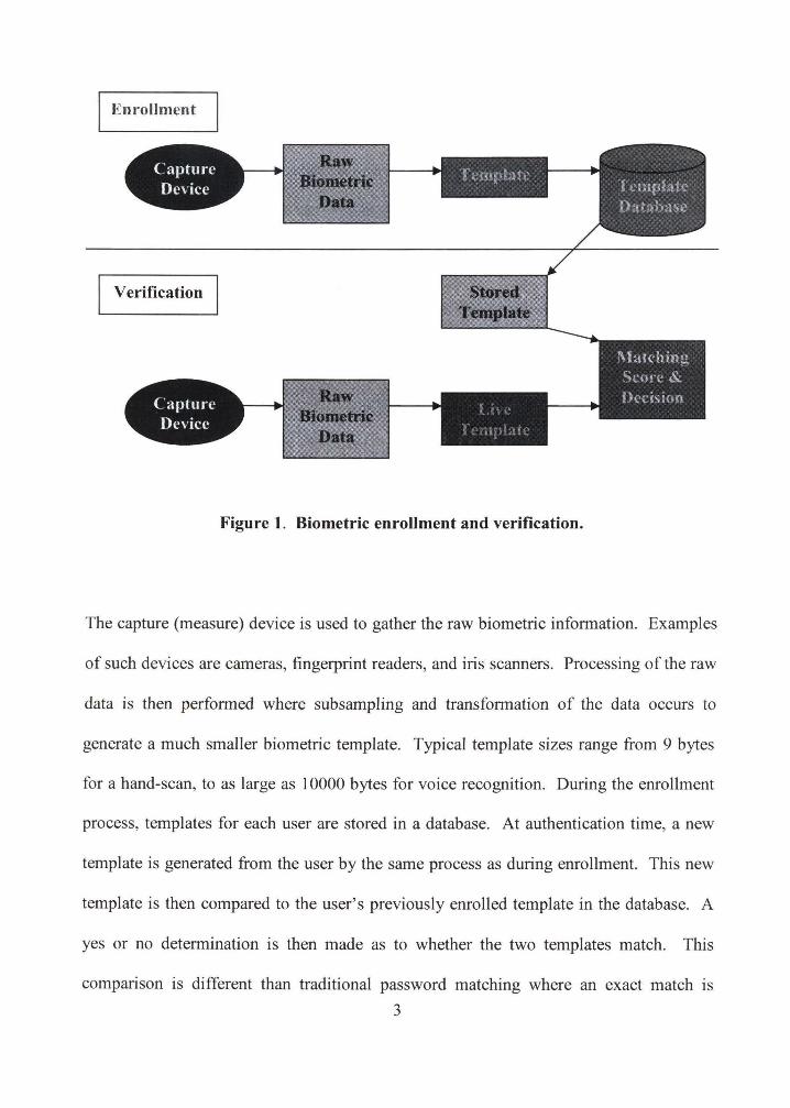
The biometric authentication system is open to attack at any point in the system. Figure 3
[Sho04] illustrates the avenues and types of attacks.
6
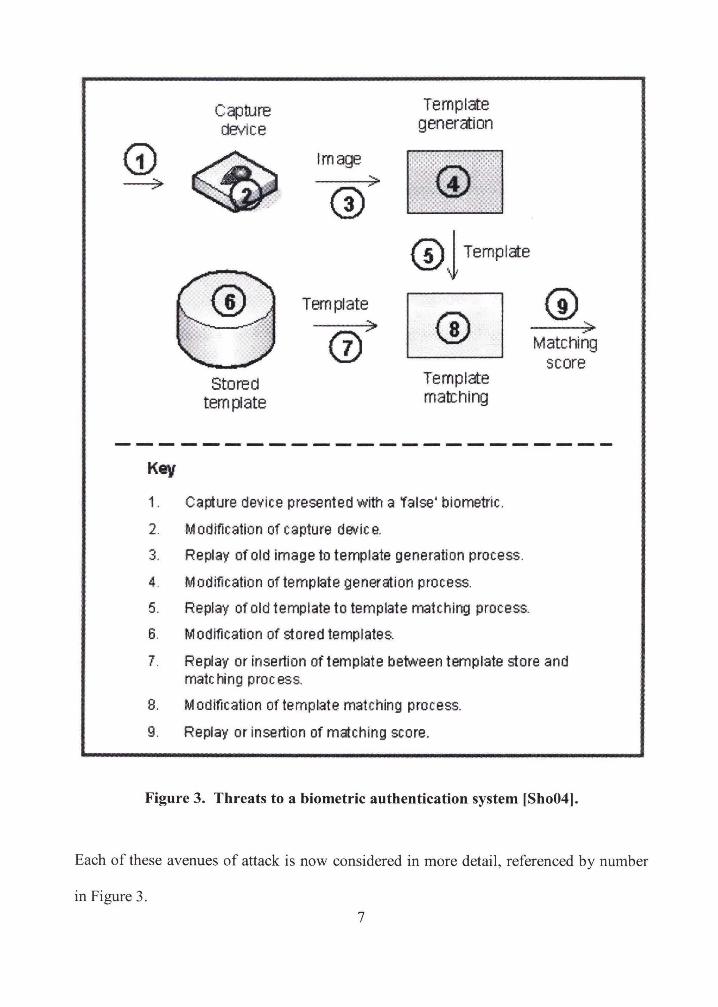
Capture Template device generation
G) ~
Image
~ ---;;;..
(i/ @j Templ<te
Template (i) > a/ ~ Matching
score Stored Template
template mab:hing
Key
1. Capture device presented with a 'false' biometric.
2. Modtfication of capture device.
3. Replay of old image to template generation process.
4. Modtfication of template generation process.
5. Replay of old template to template matching process.
6. Modification of stored templates.
7. Replay or insertion of template betvveen template store and matching process.
8. Modification of template matching process.
9. Replay or insertion of matching score.
Figure 3. Threats to a biometric authentication system [Sho04].
Each of these avenues of attack is now considered in more detail, referenced by number
in Figure 3.
7
1) There are various methods in which a false representations of the true biometric
data source may be impersonated [BDPOl, Mat02]:
a. An effortless impersonation. The impostor makes no active effort to fake
an identity, but is recognized by the system anyway. This type of attack
may succeed if i) the system FAR threshold is too high, ii) by chance, the
imposter has similar enough biometric characteristics to the actual user,
iii) the impostor can make multiple attempts so that verification can take
place against multiple templates, thereby increasing the chance of a
random close match.
b. Mimicry. The attacker could try to reproduce biometric characteristics by
changing his own characteristics without the use of artifacts. Methods
include voice impersonation, signature forging, or hand contortions. This
type of attack comes about because of the public nature of many
biometrics (voice recordings, photographs, signatures).
c. Use of an artifact. Again, due to the public nature of many biometric
characteristics, copies can be made, often without the cooperation or even
the awareness of the victim. Often, decidedly low-tech artifacts can be
easily produced. Fake fingers molded from gelatin (the "gummy" finger
attack [Mat02]) or silicon have also been known to fool optical sensors.
Cloned faces or video clips have been used to defeat face recognition
systems. A voice recording may be used to fool a voice recognition
system. Eye photographs have been tried in attempts to fool an iris
recognition system, but since the photo does not reflect the illuminating
8
infrared light back at the camera the way a face would, this attempt was
thwarted [Bra05]. Such "liveness" detection can be incorporated into
most biometric technologies to defeat artifact attacks [San04]
d. Attack against a weak template. This is an attack against is known or
assumed to be weaker than others. An insecure template with a wide
threshold value can be enrolled from a bad or noisy image. Such an attack
may succeed if the FAR is much higher for some templates than for
others. For instance, it is possible that some threshold values may have
been relaxed for individuals in a face-recognition program if they
sometimes wear glasses.
e. Individual with a similar biometric. A person who naturally has similar
biometric characteristics, such as a twin, may impersonate the enrollee.
This is similar to (a), but in this case, the attacker is targeting a biometric
characteristic of a known enrollee.
f. Use of a residual image. Several methods of latent fingerprint reactivation
on capacitor sensors, using the fatty oil residue left behind by the previous
user, have been tried. These include i) breathing on the sensor, ii) using a
thin-walled plastic bag of warm water, and iii) dusting with graphite (then
pressing with clear plastic tape).
g. Attack against a poor enrollment image. Noisy images may be generated
unintentionally at enrollment or intentionally at verification. Fingerprint
systems may recognize noise as minutiae points and cause a sufficient
template match for verification. Alternatively, a voice recognition system
9
that has a template enrolled that is 'too quiet' (e.g., enrollee pauses too
long before speaking), the template may consist of almost all noise. Even
with a threshold for acceptance of voice sample, this problem may persist
if ambient noise is greater than this threshold. The biometric system
should have reasonable data quality standards to prevent these scenarios.
h. Forged template on a biometric token. Biometric information may be
included on an identification card. They can be forged to contain the
biometric information of an imposter
1. Illegal enrollment. An imposter may be enrolled. This is not the fault of
the biometric system, but rather the security system in place to ensure that
individual credentials are verified before enrollment.
A biometric system may also be compromised by the enrolled biometric. Rather
than an impostor using a false biometric, the enrollee may be forced into
submitting the biometric under duress or while unconscious. There is also the
gruesome possibility that the original biometric source can be stolen, as in a
severed finger or other detached body part!
2) The capture device may be modified to transmit false biometric data. This
pertains to securing all components ofthe wireless device itself.
3) Old images may be replayed to the template creation process.
4) The process by which templates are created may be modified.
5) Old templates may be replayed to the template matching process.
10
6) Stored templates may be modified in some way.
7) After storage, templates may be replayed or inserted into the template matching
process.
8) The template matching process may be modified.
9) All previous security measures can be invalidated if a replay of the matching
score can be inserted at the appropriate point in the system. Another attack using
the matching score is the 'hillclimbing' attack [Bio01]. Here, the quality of the
attacker's biometric data is improved by incorporating data from sequentially
tested false biometric data that improves the matching score, eventually
incorporating enough appropriate modifications to be successful.
Note: It is usually not a good idea to use an identification system for authorization since
an attacker would only need one attempt to match against all the templates in the
database. This is especially true for systems with large template databases. In a
password secured system, this would be equivalent to a user being authorized if his
password matched any password on the system.
Another security consideration when choosing a biometric is keyspace. Keyspace is the
span of available keys. The longer the key length, the more possible combinations
(codewords) a potential attacker would have to test. For instance, a token that generates
12 random digits could generate 1012 possible codewords. The typical keyspace for a
traditional password-protected system using an 8-character password made up from the
full 62 ASCII alphanumeric characters theoretically results in over 1014 codewords.
11
However, most users do not select from the full complement of ASCII characters, so the
average keyspace is only about 106 codewords. Therefore, in practice, the 12-digit token
is more secure than the 8-character password [0Go02].
The effective keyspace for a biometric can be estimated as the inverse of the FAR. Using
1999 and 2000 test data, the keyspace for some common biometrics was found to be
[0Go02]:
Iris
Fingerprint
Voice
Face
1 06 codewords
1 04 codewords
1 03 codewords
1 0 to 1 00 codewords.
As the accuracy of the biometric technologies improves, there will be a corresponding
improvement in keyspace.
One way to improve keyspace with biometrics is to require more than one biometric. For
example, fingerprints from more than one finger could be requested. Alternatively,
completely different biometrics (multimodal) could be verified, such as face and
fingerprint [Dah03]. Also, so-called 'soft' biometrics (gender, height, race, eye color,
etc.) might be used in combination with standard biometrics [Jai04].
12
1.2.2. Biometric Cryptography
Currently, an active area of research is biometric cryptography, whereby biometric data is
used as an encryption key (reviewed in [Ulu04]). Though biometric encryption is
theoretically appealing, there are significant application difficulties to overcome. It is
well-known that for encryption, keys at both the sender and receiver sides must match
exactly. However, repeated capture ofbiometric data from the same subject usually does
not result in identical data in each capture. For example, multiple fingerprint images of
the same finger will result in non-identical, but similar, minutiae (location and number)
extraction. This is due to several factors , including sensing errors, alignment errors,
presentation angles, finger deformation, skin oils, dirt, etc.
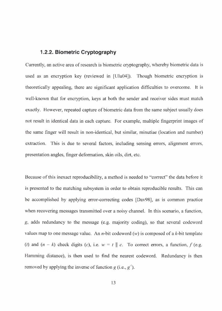
Because of this inexact reproducibility, a method is needed to "correct" the data before it
is presented to the matching subsystem in order to obtain reproducible results. This can
be accomplished by applying error-correcting codes [Dav98], as is common practice
when recovering messages transmitted over a noisy channel. In this scenario, a function,
g, adds redundancy to the message (e.g. majority coding), so that several codeword
values map to one message value. Ann-bit codeword (w) is composed of a k-bit template
(t) and (n - k) check digits (c), i.e. w = t II c. To correct errors, a function, f (e.g.
Hamming distance), is then used to find the nearest codeword. Redundancy is then
removed by applying the inverse of function g (i.e. , g·1) .
13
Example:
Message: m 0 1 0 (3 bits)
Transmission: t = g(m) = 000 111 000 (9 bits)
Received Transmission (w/ errors): t' = 010 111 100 (9bits)
Corrected Transmission: j{t') t = 000 111 000 (9bits)
Reconstructed message: g-'(t) = m = 0 1 0 (3 bits)
[Dav98] also introduced the idea of protected template, where the template is the message
to protect. This template is defined as C(t) = h(g(t)), where tis a biometric template, g is
a redundancy function, and h is a hash function/table (one-way, no collisions). At
enrollment, C(t) and check bits are stored. At verification, the newly determined
template is corrected using the check bits, hashed, and then compared. Security is
enhanced since a hash of the template information is stored, rather than the original
biometric template. This also allows for the creation of a cancelable biometric key, since
if template information is compromised, the system can be protected by changing the
hash function/table. However, this system tends to generate very large error-correcting
codes, making it impractical for actual implementations. Also, the security of this system
is difficult to prove and its error tolerance may be inadequate.
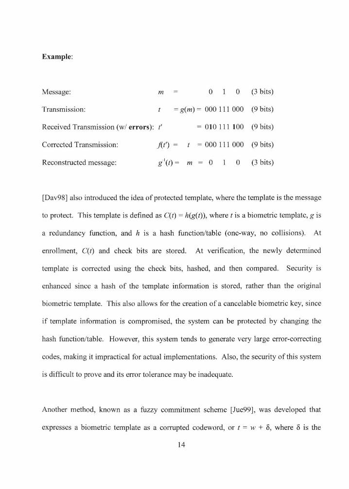
Another method, known as a fuzzy commitment scheme [Jue99], was developed that
expresses a biometric template as a corrupted codeword, or t = w + o, where o is the
14

distance from the codeword. First a random codeword, w, is chosen. Next, the
difference from the codeword, or o = t- w, is computed, and it is stored along with a hash
of the codeword, C{t) = (h(w), 8). At verification, the stored C(t) is retrieved, and
attempted to be decoded using a newly created ("live") template, t'. This is done by
computing w' = j(t' - o) and then comparing (error-correcting) h(w') to h(w). An example
of this scheme is illustrated in Figure 4.
Enroll (Encrypt)
-------·
01010 10101
"stored"
"live"
1101011101
•------- Verify (Decrypt)
Figure 4. An example of a fuzzy commitment scheme for a 10-bit password.
Note: All values are represented in binary.
Suppose that a user password at enrollment has been hashed and is represented by:
c = 00000 111 11
In addition, the user's biometric template at enrollment was:
15
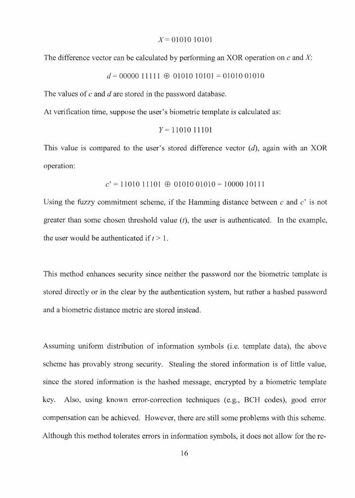
X=01010 10101
The difference vector can be calculated by performing an XOR operation on c and X:
d = 00000 1 11 1 1 EB 0 1 0 1 0 1 0 1 0 1 = 0 1 0 1 0 0 1 0 1 0
The values of c and d are stored in the password database.
At verification time, suppose the user's biometric template is calculated as:
Y= 1101011101
This value is compared to the user's stored difference vector (d), again with an XOR
operation:
c' = 11010 11101 EB 01010 01010 = 10000 10111
Using the fuzzy commitment scheme, if the Hamming distance between c and c' is not
greater than some chosen threshold value (t) , the user is authenticated. In the example,
the user would be authenticated if t > 1.
This method enhances security since neither the password nor the biometric template is
stored directly or in the clear by the authentication system, but rather a hashed password
and a biometric distance metric are stored instead.
Assuming uniform distribution of information symbols (i.e. template data), the above
scheme has provably strong security. Stealing the stored information is of little value,
since the stored information is the hashed message, encrypted by a biometric template
key. Also, using known error-correction techniques (e.g., BCH codes), good error
compensation can be achieved. However, there are still some problems with this scheme.
Although this method tolerates errors in information symbols, it does not allow for the re-
16
ordering (or addition and deletion) of symbols. Also, proving security over non-uniform
distribution of information symbols is problematic.
1.2.3. Fuzzy Vault Scheme
Building upon the ideas of the fuzzy commitment scheme, another verswn, usmg
something called a fuzzy vault [Jue02], was developed. In this scheme, the message m is
encoded as coefficients of a k-degree polynomial, in x (data points on the polynomial)
over a finite field Fq. This polynomial is then evaluated at the data points (= X) in the
input template to determine f{X) (= Y). These (X, Y) pairs, known as true points,
constitute the locking set of what is to become the fuzzy vault. To hide the identity of the
true points, many false points (chaff) are then added to the set of true points. This
completes the fuzzy vault, which is then stored.
The security of the fuzzy vault scheme is based upon the difficulty of the polynomial
reconstruction problem, or as described later, the problem of decoding Reed-Solomon
codes. For an overview of research related to cryptography based on polynomial
reconstruction, see [Kia04).
To unlock the vault and recover the message, the data points (X') from the "live" template
(the unlocking set) are used for decryption. If a substantial number (i.e. within the
symbol-correcting capability of the system) of these data points overlap (after error
correction) the true points in the stored vault, then the message can be successfully
recovered. The main advantage to this system is that the order of the data points does not
17
matter. Also, it can be shown to be secure, if there are sufficient chaff points in the vault
relative to the number of true points.
The fuzzy vault scheme has even been implemented in hardware. [Yan05a] built a
microcoded coprocessor for embedded biometric authentication systems that uses the
fuzzy vault scheme to encode machine-generated data sets (PINs).
1.3. Scope/Contribution
In the previous section, the technology and research leading to the development of the
fuzzy vault scheme have been reviewed. Although variations of this scheme have been
studied from a theoretical perspective [Adl05, Dod04, Jue02, Tuy04, Tuy05, Ulu04a) and
there have been several attempted implementations related to the scheme using
fingerprint [Cla03, Yan04, Yan05], iris [Hao05), and dynamic handwritten signature
[Fre06, Kua05] biometrics, it is unclear what the precise effects of varying vault
parameters and matching thresholds would have on specific applications.
The contribution of this thesis is to study through simulation the effects of varying vault
parameters and tolerance thresholds, usmg as a model a fuzzy vault
encryption/decryption system that might be constructed using commercial-off-the-shelf
(COTS) hardware and software. It is hoped that the results of this study can be used as a
guide for setting vault parameters and tolerance thresholds for future implementations of
the fuzzy vault scheme.
18
1.4. Organization of the Thesis
This thesis is organized into five sections:
In Section 1, the objective and motivation for the thesis are stated. The general
background developments and research leading to the fuzzy vault scheme (biometrics
used for data security and biometric cryptography) are reviewed followed by a
description of the fuzzy vault scheme itself. This section also includes the scope and
contribution of the thesis, along with this description of the thesis outline.
In Section 2, key mathematical concepts (Galois fields and Reed-Solomon codes)
pertinent to the fuzzy-vault scheme are reviewed. The Berlekamp-Welch algorithm
implemented in the simulated implementation is also described.
Section 3 begins with a detailed description implemented fuzzy vault system. Analysis of
this inadequate performance of this system inspired the creation of the fuzzy vault
simulation system described in the next section.
Section 4 describes the setup and execution of the simulations. Results of simulations are
presented when executed under a range of specified system parameters/thresholds. The
results are analyzed as to the effect of these parameters.
Conclusions that can be drawn from the simulations are noted in Section 5. Possible
future studies suggested by these results are also discussed.
19
2. MATHEMATICAL AND ALGORITHMIC FOUNDATIONS
2. 1. Introduction
The fuzzy vault scheme relies on methods of error correction commonly used in data
communications to recover information sent over noisy transmission lines. The method
often chosen in conjunction with the fuzzy vault scheme is Reed-Solomon (RS) [Ree60]
coding which uses Galois field (GF) computations. The specific algorithm implemented
in the simulation code in this thesis is the Berlekamp-Welch (BW) algorithm [Ber86].
These fundamental concepts are now reviewed as background material to the fuzzy vault
implementation simulated in this thesis.
2.2. Galois Fields
A Galois field is a finite field with order q = p" elements where p is a prime integer. By
definition, arithmetic operations (addition, subtraction, multiplication, division, etc.) on
field elements of a finite field always have a result within the field. An element with
order (q- 1) in GF(q) is called a primitive element in GF(q). All non-zero elements in
GF(q) can be represented as (q-1) consecutive powers of a primitive element a . All
elements in GF(2m) are formed by the elements {O,l,a} .
20
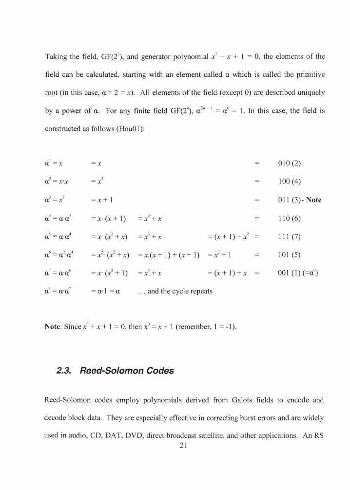
Taking the field, GF(23), and generator polynomial x3 + x + I = 0, the elements of the
field can be calculated, starting with an element called a which is called the primitive
root (in this case, a= 2 = x). All elements of the field (except 0) are described uniquely
by a power of a. For any finite field GF(2"), a 2" -
1 = a0 = 1. In this case, the field is
constructed as follows (HouOI ):
I 010(2) a =x =x
2 2 100 (4) a =x·x =x
3 3 =x+1 OI1 (3)- Note a =x
4 3 =x·(x+1) =x2 +x II0(6) a =a·a
5 4 = x· (x2 + x) =x3 +x =(x+I)+x 2 111 (7) a =a·a
6 2 4 =/· (x2 +x) = x.(x + 1) + (x + 1) =x2 +I 101 (5) a =a ·a
7 6 =x· (x2 + 1) =x3 +x = (x + 1) + x 001 (1) (=a0) a =a·a
8 7 = a· I= a .. . and the cycle repeats a =a·a
Note: Since x3 + x + 1 = 0, then x3 = x + 1 (remember, 1 = -1).
2.3. Reed-Solomon Codes
Reed-Solomon codes employ polynomials derived from Galois fields to encode and
decode block data. They are especially effective in correcting burst errors and are widely
used in audio, CD, DAT, DVD, direct broadcast satellite, and other applications. An RS 21
code can be used to correct multiple, random, error patterns. An (n, k) code can be
defined where an encoder accepts k information symbols and appends separately a set of
r redundant symbols (parity bits) derived from the information symbols, so that n = k + r.
An (n, k) code is cyclic if a cyclic shift of a codeword is also a codeword. A cyclic
binary code (for digital coding) can be specified such that codewords are binary
polynomials with specific roots in GF(2m). Inherited from the generator polynomial,
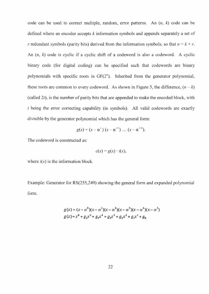
these roots are common to every codeword. As shown in Figure 5, the difference, (n - k)
(called 2t), is the number of parity bits that are appended to make the encoded block, with
t being the error correcting capability (in symbols). All valid codewords are exactly
divisible by the generator polynomial which has the general form:
( ) ( i ) ( i+ l) ( i+2t) gx = x-a x-a ... x-a .
The codeword is constructed as:
c(x) = g(x) · i(x),
where i(x) is the information block.
Example: Generator for RS(255,249) showing the general form and expanded polynomial
form.
g(x)- (x- a 0)(x- a 1)(x- a 2 )(x- a 3)(x- a 4 )(x - a 5)
g(x)=x6 + &Xs + g~x• + gr'l + gzxl + glx' +go
22
From the example, it can be seen that the original terms are expanded and simplified. The
g coefficients (g5
, g4
, g3, g
2, g
1, g
0) are constants made up of additions and multiplications
of a 0, a' , a 2
, a \ a 4, and a 5 and can be computed using Galois field computations.
n
k 2t
DATA PARITY
Figure 5. RS encoded block
Reed-Solomon codes are cyclic codes but are non-binary, with symbols made up of m-bit
(m > 2) sequences. RS codes achieve the largest possible code minimum distance for any
linear code with the same encoder input and output block lengths. The distance between
two codewords for nonbinary codes is defined as the number of symbols in which the
sequences differ. Given a symbol sizes, the maximum codeword length (n) for an RS
code is : n = 2s - 1. Given 2t parity symbols, an RS code can correct up to 2t symbol
errors in known positions (erasures) or detect and correct up to t symbol errors in
unknown positions.
2.4. Berlekamp-Welch Algorithm
To explain the Berlekamp-Welch algorithm, the following discussion is adapted from
[Vaz06].
23
Suppose that Alice sends Bob a message over a noisy channel. When Bob receives the
message, some of the transmitted packets have been corrupted, but it is not known which
packets are corrupt and which are not. Using RS encoding (see previous section), Alice
must transmit (k + 2t) characters to enable Bob to recover from t general errors.
Therefore, the message is encoded as a polynomial P(x) of degree ( k- 1) such that: cJ =
P(j), for 1 -:::_j-:::_ (k + 2t).
The received message is R(j), for 1 -:::_j-:::_ (k + 2t). It differs from the polynomial P(x) at t
points. Bob now needs to reconstruct P(x) from the (k + 2t) values (the polynomial
reconstruction problem). If Bob can find any polynomial P'(x) of degree (k- 1) that
agrees with R(x) at (k + t) points, then P'(x) = P(x). This is because out of the (k + t)
points, there are at most, t errors. Therefore, on at least k points, P'(x) = P(x). The
transmitted polynomial of degree (k- 1) is uniquely defined by its values at k points.
The polynomial reconstruction (PR) problem can be stated as follows [Kia04a]:
Given a set of points over a finite field { (z;, Y;) }";~ 1 , and parameters [ n, k, w ], recover all
polynomials p of degree less than k such that p(z) i= y;, for at most w distinct indexes,
iE{1, ... ,n}.
A unique solution can only be guaranteed when w -:::_ (n - k) I 2. The BW algorithm can
be used to recover the solution in polynomial-time given this constraint of w.
24
The key idea is to describe the received message, R(x) (which is not a polynomial
because of the errors) as a polynomial ratio. The t positions at which errors occurred are
defined as el, ... ,e,. The error locator polynomial is then defined as:
E(x) = (x - e1) (x - e2) ... (x- ek).
At exactly the t points at which errors occurred, E(x) = 0. For all (k + 2t) points where 1
:S x :S (k + 2t), P(x)E(x) = R(x)E(x). At points x at which no error occurred, this is true
because P(x) = R(x). At points x at which an error occurred, this is true because E(x) = 0.
Let Q(x) = P(x)E(x). Specified by (k + t) coefficients, Q(x) is a polynomial of degree (k +
t - 1 ). Described by (k + 1) coefficients, E(x) is a polynomial of degree t. There are only
t unknowns because the coefficient of x' is 1. There are also (k + 2t) linear equations in
Q(x) = R(x)E(x) for 1 :::::; x :::::; (k + 2t). For these equations, the unknowns are the
coefficients of the polynomials Q(x) and E(x). The known values are the received values
for R(x).
The BW algorithm is illustrated by the following example (non-finite fields are used to
simplify the calculations):
The information packets to be sent are "1 ", "3", and "7" (therefore, k = 3). By
interpolation, we find the polynomial:
P(X) =X +X+ 1.
25
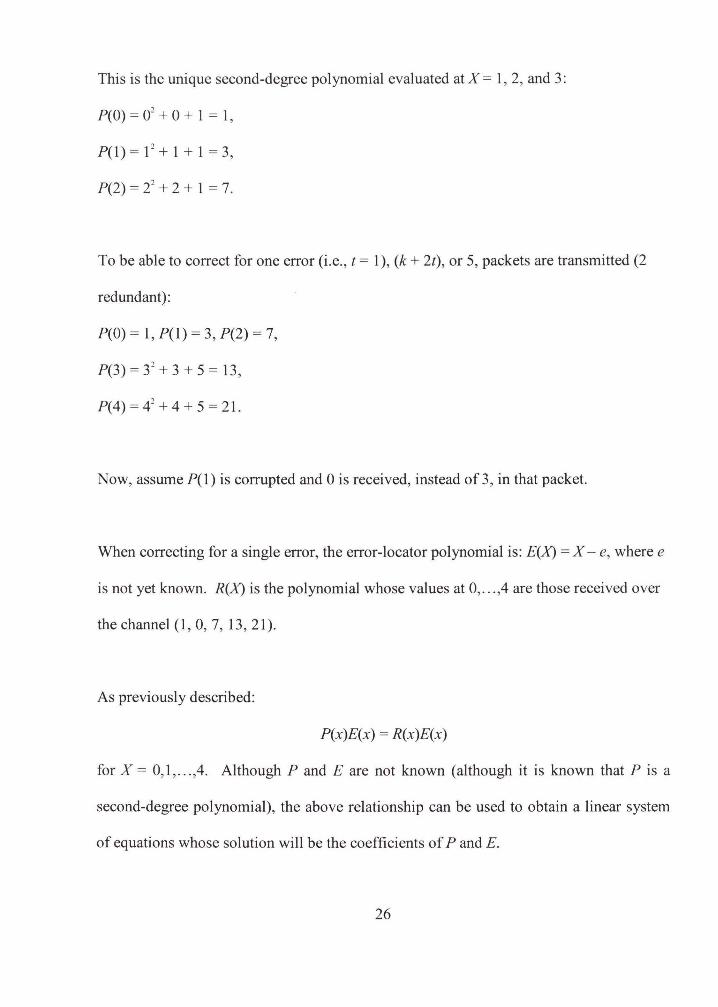
This is the unique second-degree polynomial evaluated at X = 1, 2, and 3:
P(O) = 02 + 0 + 1 = 1,
P(l) = 1 2 + 1 + 1 = 3,
P(2) = 22 + 2 + 1 = 7.
To be able to correct for one error (i.e., t = 1 ), (k + 2t), or 5, packets are transmitted (2
redundant):
P(O) = 1, P(1) = 3, P(2) = 7,
P(3) = 32 + 3 + 5 = 13,
P( 4) = 4 2 + 4 + 5 = 21.
Now, assume P( 1) is corrupted and 0 is received, instead of 3, in that packet.
When correcting for a single error, the error-locator polynomial is: E(X) =X- e, where e
is not yet known. R(X) is the polynomial whose values at 0, ... ,4 are those received over
the channel (1, 0, 7, 13, 21).
As previously described:
P(x)E(x) = R(x)E(x)
for X= 0,1, ... ,4. Although P and E are not known (although it is known that Pis a
second-degree polynomial), the above relationship can be used to obtain a linear system
of equations whose solution will be the coefficients of P and E.
26

Let
Q(X) = P(X)E(X) = aX + bX + eX+ d,
where a, b, e, d represent the unknown coefficients to be determined. Also,
aX + bX + eX+ d = R(X)E(X) = R(X)(X- e),
which can be rewritten as:
aX + bX + eX+ d + R(X)e = R(X)X.
Five linear equations are generated when substituting X = 0, X = 1, ... , X= 4 into the
above formula:
a(0)3 + b(0)2 + e(O) + d + (1 )e = 1 (0);
a(1)3 +b(1)2 +e(l)+d+ (O)e= 0(1);
a(2)3 + b(2)2 + e(2) + d + (7)e = 7(2);
a(3)3 + b(3)
2 + e(3) + d + (13)e = 13(3);
a(4)3 + b(4)2 + e(4) + d + (21)e = 21(4);
d+ e = 0
a+ b+ e+d 0
8a + 4b + 2e + d + 7 e = 14
27a+ 9b+3e+d+13e= 39
64a + 16b + 4e + d + 21 e = 84.
The result of solving this system of linear equations is: a = 1, b = 0, e = 0, d = -1, e = 1.
This enables the generation of the polynomials Q(X) and E(X). P(X) is then computed as
the quotient Q(X) I E(X). The original, uncorrupted values can now be recovered from
P(X).
27
2.5. Summary
With this mathematical background of pertinent error correction codes and the
explanation of the BW algorithm, the implementation of the fuzzy vault scheme can now
be understood. As implemented in this thesis, the fuzzy vault scheme uses the BW
algorithm for error correction with calculations performed in a Galois field.
28
3. FUZZY VAULT SCHEME IMPLEMENTATION
3. 1. Introduction
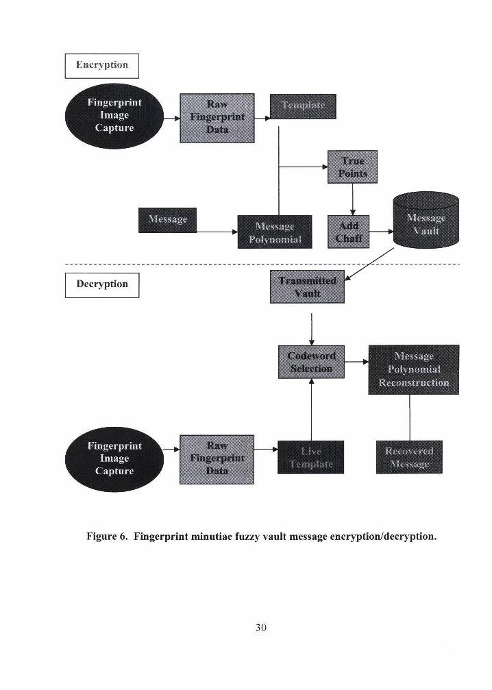
Simulation of the fuzzy vault scheme was modeled after a system that could be built
using COTS hardware and software, using fingerprint minutiae as the biometric. An
outline of such a fingerprint cryptography system under depicted in Figure 6. A message
is encrypted using a fingerprint template generated at enrollment and then decryption is
attempted using a fingerprint template generated from a live scan. Components of the
system that are common to both the encryption and decryption procedures are the
template creation activities of image capture, image normalization, and minutiae
coordinate/angle extraction. Explanation of the figure is detailed in the next subsections.
29
Decryption
l\h•ssag<.' Pol~ nomial
Jh·i.'O\ t'ft'd
\irSS2-"C ""
Figure 6. Fingerprint minutiae fuzzy vault message encryption/decryption.
30
3.2. System Implementation
The system just described was initially constructed, but ultimately failed due to issues
with image alignment and consistent repeatability of minutiae extraction. This prompted
the exploration of what the tolerance of such a system needs to be, and what vault
parameters are appropriate.
Nevertheless, it is instructive to review this initial effort, since it is similar to the
implementation of [Cla03] and is the basis for simulations in this thesis. Here is a
description of this initial fingerprint cryptographic system:
3.2.1. Encryption
The encryption portion of the system is the creation of the fuzzy vault for the message. A
template created from multiple images of the same fingerprint is used as a cryptographic
key to encode a message defined by the coefficients of a polynomial. Data points that
represent the polynomial are stored in the fuzzy vault. Many random data points (chaff)
are added to the vault to hide the identity of the true polynomial data points.
Creating the Template
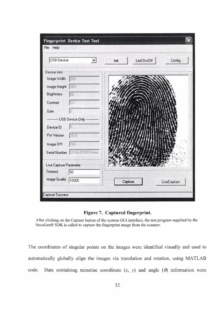
To obtain the raw biometric data for each user's stored fingerprint template, multiple
images of the same finger were captured (Figure 7) using a Secugen® optical fingerprint
scanner with a resolution of 260 x 300 pixels.
31
Fingerprint Device Test Tool ~ File Help
luss Device I nit Led On/Off Config ...
Device Info
Image Width (260
Image Height f::Joo Brightness I so Contrast 143 Gain 12 ----·-·····USB Device Only··············
DevicelD In Fw'Version 12031
Image DPI I soD
Serial Number l srJ :~~:?.10000h:xx:-: ' . · ·".. .. t. i t ~ .. ' ~A -. '
~ ~ :t,; v! "' r Live Capture Parameter~~""'-----.
, ........ ~ -. ;"' .., ' .~ .• ...,
Timeout 150 L..c..=-=-~----,---~---~~-.
Image Quality j10000 Capture I LiveCapture
Capture Success
Figure 7. Captured fingerprint.
After clicking on the Capture button of the system GUI interface, the test program supplied by the SecuGen® SDK is called to capture the fingerprint image from the scanner.
The coordinates of singular points on the images were identified visually and used to
automatically globally align the images via translation and rotation, using MATLAB
code. Data containing minutiae coordinate (x, y) and angle ( 8) information were
32

extracted from the aligned images using MA TLAB-based software (Figure 8), developed
at the Center for Unified Biometrics and Sensors (CUBS), University of Buffalo
(www.cubs.buffalo.edu).
Capture Normalize
Q Lock
Figure 8. Minutiae extraction.
2: 87186 90
13: 197186 71 4: 128 161 279 1S: 186 135 71 Is: 77129112 17: 135 125 21 ;8: 149 185 1 09 is: 141 1 as 11 11 0: 154 257 1 09 p 1 : 168 197 99
1
12: 160 270 286 13: 1 04 259 279 j14: 186 198 1 00 j15 171 89 50
1
16: 85 63136 17: 232 186 71 118: 114 39 14 7 1119: 39 123 280 1.0: 88 44 311 .~
Minutiae
In the already normalized fingerprint image shown in the left pane, identified minutiae points are shown in red. The right pane lists these points individually in the following format: minutia number, x-coordinate, y-coordinate, theta (angle).
To obtain repeatable data points, only those data points found to occur (within a
predefined threshold) in more than half of the individual's scans were used to create the
33
fingerprint template. The X-value (codeword) for the true data points is calculated by
concatenating either (xl[y), (xiiB), or CYIIB), where the decryption process will concatenate
the identical data variables.
The encryption template created the X-values for the true points in the message vault. To
create the corresponding Y-values for the true fuzzy vault (X, Y) pairs, the message
polynomial is evaluated for each X.
Since it is desirable that all values be constrained to a finite size, all symbols are defined
to be within a finite field and all calculations are performed using finite field operations.
In practice, data communications (especially with error-correction) often use finite fields
referred to as Galois Fields (GF). In particular, GF(2") fields are used, where the 2
indicates that the field is described over binary numbers and n is the degree of the
generating polynomial (GP) [Hou01). The system described in this paper uses GF
calculations performed by using the MA TLAB Communications Toolbox.
Creating the Message Polynomial
The symbols of the message are encoded as the coefficients of a k-degree polynomial.
For example, the string "Hello", or ASCII (72,101,108,108,111), could be represented by
the41h-degreepolynomial: 72x4 + 101x3 + 108x2 + 108x + 111.
Creating the Message Vault
34
To hide the identity of the true points, many false points (chaff) are added to the vault.
The false points are added far enough away from true points so they do not cause
attraction of values within the fuzziness (threshold distance) of the true points. Also, they
are placed outside the threshold distance of other chaff points since they would otherwise
be redundant.
As a final step in the vault creation, all points in the vault are sorted, resulting in a
mixture of true and false points from which the true points must be discovered when
decrypting the message. The message vault is now ready for transmission.
3.2.2. Decryption
The message vault is received and is attempted to be decrypted by the input template
created from a live fingerprint scan. The minutiae data from the live template (X') are
compared to the X values (codewords) in the vault pairs. If enough (i.e., within error
correction capability of the system) true codewords overlap, then the message can be
recovered through polynomial reconstruction.
Creating the Live Template
The template creation process is identical to the process used during encryption, except
that data captured from only a single scan is processed. The resulting data is identified as
X'. See Figure 8 again for an example of minutiae extracted from a normalized
fingerprint.
35
Selecting the Codewords
To reconstruct the message polynomial, the user must identify true codewords from the
vault, since the corresponding (X, Y) pairs define the polynomial. The X' data is used to
select the true codewords from the vault. Since biometric data are expected to be inexact
(due to acquisition characteristics, sensor noise, etc.), X' template values are matched to X
vault values within a predefined threshold distance, thus allowing for exact symbol
matching. This is the "fuzziness" built into the system, since multiple X' values (i.e.,
those within the threshold distance of X values) will result in a single X value.
Reconstructing the Message Polynomial
The message polynomial is attempted to be reconstructed using the (X, Y) pairs identified
by the live template. A valid live template may contain more/less/different minutiae than
those extracted when the original template was created. However, if there is significant
overlap of X and X' codewords, the message can still be recovered by using a typical
telecommunications error-correcting scheme for recovery of data over a noisy channel,
such as a Reed-Solomon (RS) code.
As reviewed earlier, RS(k,t) codes are those in which codewords consist oft symbols and
each codeword corresponds to a unique polynomial p of degree less than k over finite
field F of cardinality q. Therefore, there are l total codewords.
The specific method used for error-correction m the implemented system is the
Berlekamp-Welch algorithm, also used by [Yan05]. Given m pairs of points {X:, Y,),
36
where i =I ,2, ... ,m, there exists a polynomial p(x), of degree at most d, such that }'; = p(X)
for all but k values of (x;, }';). Using the BW algorithm, if 2k + d < m, this condition can
be verified by finding the solution for a linear constraint system:
N(x;) = }'; * W(x;), i =I,2, ... ,m, where deg(W) ~ k .
p(x) = N / W is the result polynomial after the 2k + d +I unknowns are calculated. For
more detail on the BW algorithm, see Section 2.4.
Recovering the Message
The recovered message is simply made up of the coefficients of the reconstructed
message polynomial. It is usually the case that an invalid live template will result in a
polynomial that cannot be reconstructed within the error tolerance of the system, and
therefore no message is decrypted.
3.2.3. Analysis
This implementation of the fuzzy vault scheme failed due to several reasons. First, the
enrollment template did not contain enough consistent points when compared to the live
scan. The result was that a significant number of minutiae in the live scan were not
matched in the enrollment template. Secondly, the identification of singular points was
performed visually, affecting the accuracy of fingerprint image alignment. Finally, the
alignment points were selected manually by mouse-clicking on the selected points in the
fingerprint image, which also contributed to alignment error. These factors combined to
37
exceed the tolerance of the system as designed and inspired the investigation into the
parameters that such a system would require to perform adequately.
3.3. Summary
Although an actual fuzzy vault cryptographic was constructed, it did not perform
adequately. Reasons for the system's failure led to an effort to determine, through
simulation, the necessary tolerance, based on several parameters, that an adequate system
would need to have.
38
4. SIMULATIONS AND RESULTS
4.1. Introduction
The fuzzy vault scheme was implemented as a simulation written entirely in MA TLAB.
The MA TLAB Communications Toolbox was used to perform Galois field calculations.
Specific system parameters were varied iteratively during simulation and the results
analyzed as to the effect of these parameters and the system tolerance to error.
4.2. Simulation Setup and Software Modules
The MA TLAB code for the simulation can be found in the Appendix. The modules are
described as follows:
encdecall: This is the driving script for the simulation. An eight symbol message (k) is
used as the message to be sent. Therefore, if sixteen points (n) are extracted from the
vault for decoding, (n- k) I 2, or four, symbols can be corrected using the BW algorithm.
The specific system parameters that were varied during simulation were:
ntrue: the number of true vault points. range: 25 to 60, incremented by 5.
nchaff: the number of false vault points. range: 0 to 500, incremented by 100.
39
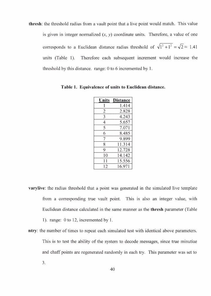
thresh: the threshold radius from a vault point that a live point would match. This value
is given in integer normalized (x, y) coordinate units. Therefore, a value of one
corresponds to a Euclidean distance radius threshold of .J1 2 + 12 = J2 ~ 1.41
units (Table 1 ). Therefore each subsequent increment would increase the
threshold by this distance. range: 0 to 6 incremented by 1.
Table 1. Equivalence of units to Euclidean distance.
Units Distance 1 1.414 2 2.828 3 4.243 4 5.657 5 7.071 6 8.485 7 9.899 8 11.314 9 12.728 10 14.142 11 15.556 12 16.971
varylive: the radius threshold that a point was generated in the simulated live template
from a corresponding true vault point. This is also an integer value, with
Euclidean distance calculated in the same manner as the thresh parameter (Table
1 ). range: 0 to 12, incremented by 1.
ntry: the number of times to repeat each simulated test with identical above parameters.
This is to test the ability of the system to decode messages, since true minutiae
and chaff points are regenerated randomly in each try. This parameter was set to
3.
40

In this script, the aforementioned parameters are changed within the specified ranges in
nested loops. Therefore, there were a total of 13104 simulations run (8 ntrue x 6 nchaff
x 7 thresh x 13 varylive x 3 ntry).
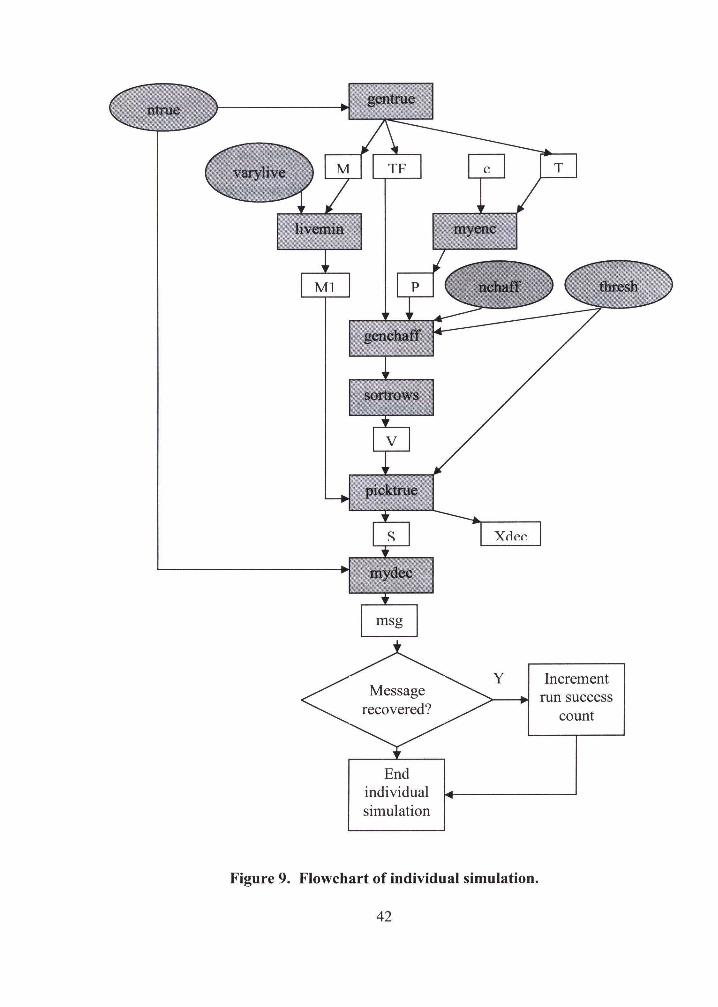
The flowchart of the individual simulation run is shown in Figure 9. A description of
each module follows which defines the inputs and outputs shown in the flowchart
(symbols will be introduced gradually in the text following the figure):
41
End individual simulation
Y Increment run success
count
Figure 9. Flowchart of individual simulation.
42
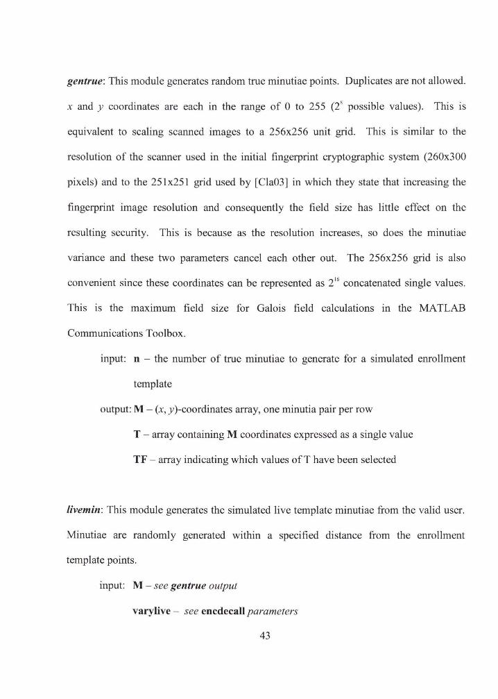
gentrue: This module generates random true minutiae points. Duplicates are not allowed.
x and y coordinates are each in the range of 0 to 255 (i possible values). This is
equivalent to scaling scanned images to a 256x256 unit grid. This is similar to the
resolution of the scanner used in the initial fingerprint cryptographic system (260x300
pixels) and to the 251 x251 grid used by [ Cla03] in which they state that increasing the
fingerprint image resolution and consequently the field size has little effect on the
resulting security. This is because as the resolution increases, so does the minutiae
variance and these two parameters cancel each other out. The 256x256 grid is also
convenient since these coordinates can be represented as 2 16 concatenated single values.
This is the maximum field size for Galois field calculations in the MA TLAB
Communications Toolbox.
input: n - the number of true minutiae to generate for a simulated enrollment
template
output: M - (x, y)-coordinates array, one minutia pair per row
T - array containing M coordinates expressed as a single value
TF- array indicating which values ofT have been selected
livemin: This module generates the simulated live template minutiae from the valid user.
Minutiae are randomly generated within a specified distance from the enrollment
template points.
input: M - see gentrue output
varylive - see encdecall parameters
43
output: Ml- (x', y')-coordinate array, one minutia pair per row
myenc: This is the routine that encodes a message as coefficients of a polynomial. The
polynomial is evaluated at every true point supplied.
input: c- the message, as an input array of symbols. A fixed 8-symbol message
was used during the simulation.
X - array of points to evaluate the polynomial at. This is from the T
output of the gentrue module.
output: P - array of (X, f)-pairs, one pair per row. Note that the X-coordinate
(from the input) is the simulated, scaled, concatenated (x, y)-coordinate of
the pixel from the fingerprint image. The Y-coordinate is generated from
the polynomial evaluated at the X-coordinate.
genchaff: this module generates random false vault points which are outside of a
specified radius of true points and other false points.
input: P -see myenc output
TF- see gentrue output. Updated inside this routine to reflect addition of
chaff points.
nchaff- see encdecall parameters
thresh - see encdecall parameters
output: V - vault array containing all true and chaff points, one (X, Y)-pair per
row.
44
Note: After this module completes, the rows of V are sorted to mix the true and false
points together so that the identity of the true points is obscured.
picktrue: this routine chooses vault points from the vault based on the simulated live
minutiae template.
input: Ml - see livemin output
V -see sorted genchaff output
thresh - see encdecall parameters
output: S - array of selected vault points, one (X, Y)-pair per row
Xdec - array of Ml points represented as concatenated values
mydec: This routine attempts to recover the message by using the Berlekamp-Welch
algorithm to reconstruct the polynomial. If the polynomial capnot be reconstructed, the
message cannot be recovered (null message). The message also cannot be recovered if
there is a remainder calculated during polynomial recovery. Otherwise the message is
successfully recovered.
input: V - see sorted genchaff output
nencpts - the number of points used to encode the message. See ntrue
parameter
output: msg- the recovered message (null , if failed)
45
x2xy: this routine converts a single concatenated point value to its corresponding (x, y)
coordinates. It is not called by the script, but by the other modules, as needed, usually
before calculating distance between points.
input: xy - the concatenated point value
output: x - the x-coordinate
y - they-coordinate
4.3. Results and Analysis
Total simulations = 3 tries (a simulation set) of 4368 simulations with identical
parameters= 13104.
The distribution of the number of successful message recoveries from each set of 3 tries -
0:2256
1:240
2:227
3: 1645
The simulated effects on successful message recovery, when varying the parameters
ntrue, nchaff, thresh, and vary live, are now examined through a series of box plots. In
these plots, the box has lines at the lower quartile, median, and upper quartile values.
Lines extending from each end of the box, known as whiskers, show the extent of the rest
of the data. Outliers (indicated by '+' in the box plot) are data with values beyond the
46
end of the whiskers. In each plot, specific parameters (y-axis) are plotted against the
number of successful messages recovered in ntry = 3 attempts (x-axis).
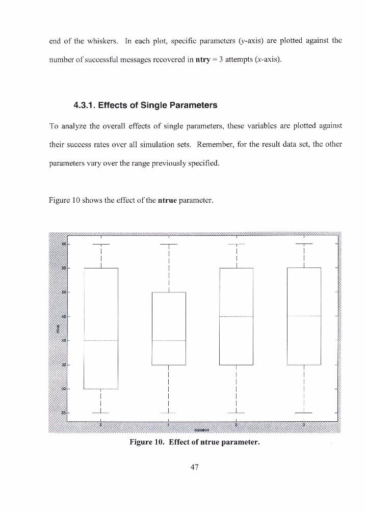
4.3.1. Effects of Single Parameters
To analyze the overall effects of single parameters, these variables are plotted against
their success rates over all simulation sets. Remember, for the result data set, the other
parameters vary over the range previously specified.
Figure 10 shows the effect of the ntrue parameter.
-,-- -r -,-- -,--I I I I I I I I I I I I
I I I
I I I I I I I I I I I I
I I I I I I I I
_j_ _j_ _j_ _j_
Figure 10. Effect of ntrue parameter.
47
Within the range simulated, this parameter has little significant effect. This result is
expected because the number of true points is small in relation to the number of total
vault points.
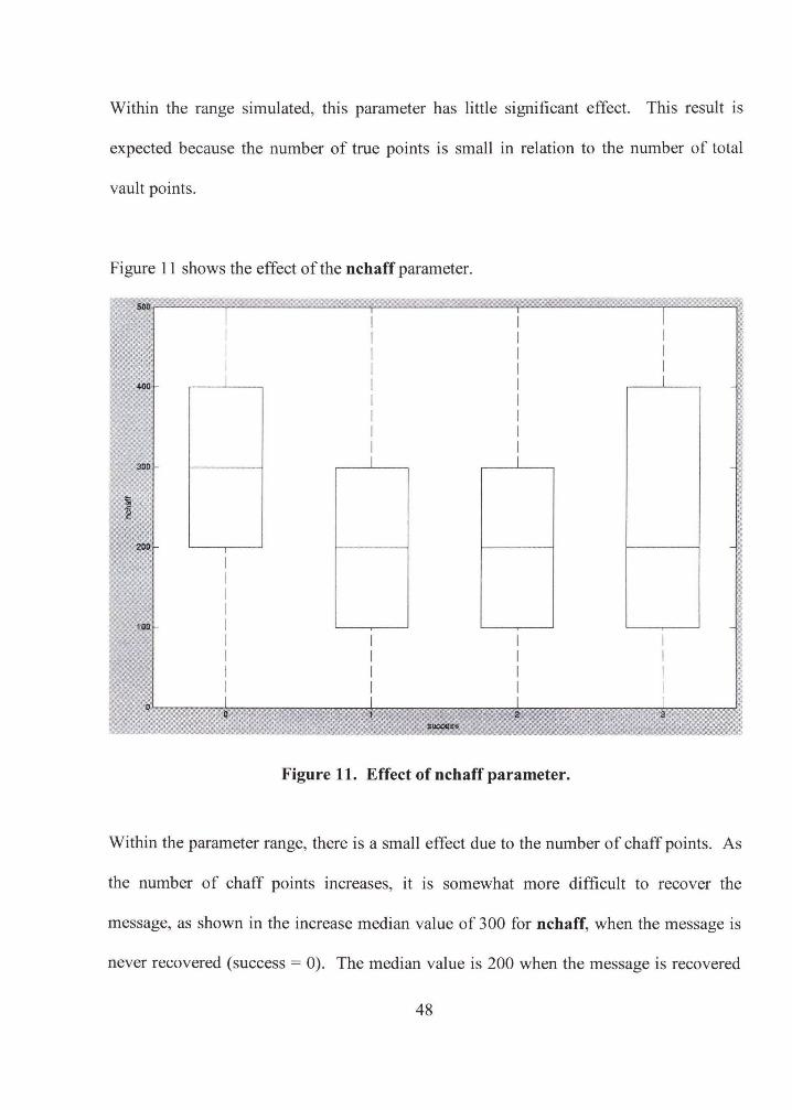
Figure 11 shows the effect of the nchaff parameter.
300
100
I I I I I I I I I I
I I I I I I I I I I
Figure 11. Effect of nchaff parameter.
Within the parameter range, there is a small effect due to the number of chaff points. As
the number of chaff points increases, it is somewhat more difficult to recover the
message, as shown in the increase median value of 300 for nchaff, when the message is
never recovered (success = 0). The median value is 200 when the message is recovered
48
at least once. This result is expected because as the number of chaff points increases, it is
more likely that a live minutia point will be confused with it.
Figure 12 shows the effect of the thresh parameter.
5
2 ,, ;;~
I I I I I I I I
I I I I
I I I I I I I I
I I I I
I I I I I I I I
Figure 12. Effect of thresh parameter.
I I I l
As the value of the thresh parameter increases, the success rate increases. This is shown
in the box plot, where the median value for no message recovery is 2 and the median
value for all messages recovered is 4. The median thresh value for 1 message recovered
(4) is actually higher than for 2 messages recovered (3), but this is probably not
significant because of the much smaller absolute numbers of these recovery values; also,
note that the upper and lower quartile markers for these success values are identical.
49
This effect of this parameter is expected since the greater the thresh parameter, the more
tolerance for matching true points.
Figure 13 shows the effect of the vary live parameter.
12
I I 1t I I + -r-
I I 10 I I +
I I 9 I I +
I 8 I -r-I I I 7 I
f ~ I J I I
> I "" 5
I I I I
I I I I 4 I I I
I I I 3 I I I
I I I 2 I I I
I I I "' ___l_ ___l_ ___l_ 1
J) 0 1 ,,, 2,
8U0088S
Figure 13. Effect of varylive parameter.
This parameter is clearly shown to be negatively correlated with success. As the
variation of the live fingerprint image increasingly differs from the one used for vault
creation, the success rate is lower. This is the expected result since higher values of
50

varylive increase the chance that live image minutiae are outside the bounds of the
thresh parameter. The number of simulations at each success rate is shown in Figure 14.
51
a)
b)
52
c)
d)
5
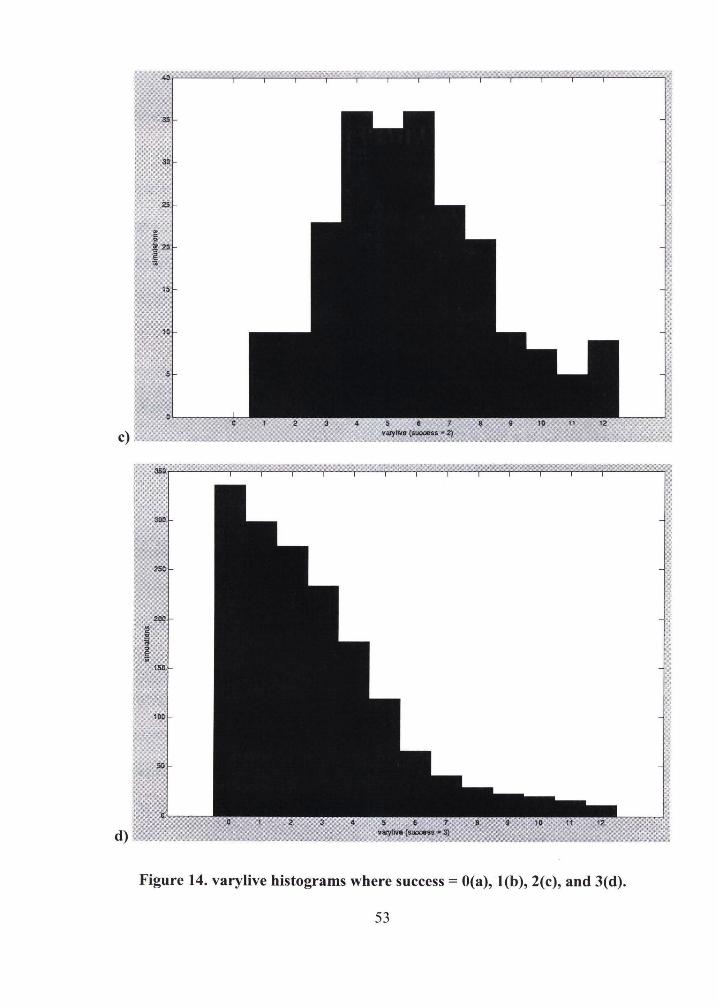
Figure 14. varylive histograms where success= O(a), l(b), 2(c), and 3(d).
53
This breakdown is provided so that the number of simulation sets contributing to each
success rate for different varylive threshold values can be clearly identified. These
histograms show that when there is no live minutiae variation from true vault points,
messages are always decrypted successfully. This is illustrated in the histograms by the
absence of a bar in the '0' column in Figures 14a- 14c, and by the high bar in the '0'
column in Figure 14d. The simulation sets in which messages are always decrypted
(Figure 14d) declines steadily decreases. When varylive is 12 (distance= 16.97), it is a
rare occurrence. This certainly explains why the earlier attempt to build the fingerprint
fuzzy vault system failed to perform, since a review of the selected true minutiae vault
points obtained from live extracted minutiae showed an average distance variance close
to 13.
The reverse trend is illustrated for the case when messages are never decrypted (Figure
14a). Here, increased variation of the live minutiae points increases the number of
simulation sets with no message recovery.
The histograms for when the message is sometimes recovered (Figures 14b and 14c) can
be explained by the difference in the point matching threshold. This parameter (thresh)
only varies from 0 to 6, while varylive goes from 0 to 12. Therefore, when the varylive
value is below that of thresh (and that will be more the case as thresh increases),
message recovery is likely. As the varylive values increase beyond the maximum thresh
54
value ( 6), the successful message recovery declines. This relationship of varylive to
thresh is further explored in the next section.
A clear illustration of the effect of the varylive threshold IS illustrated m Figure 15.
Here, the success rate at each value of vary live is presented.
"- -, go
& -·-·-' ,, -· -'· , ,
80 " " 70
)'
G:.. \ /
' /
60 ' ' ,
~ ! 50 t!
~ i
\ / - -- - success . 0
~J / . ~ .. ·~· ·-- success . 1
/ -- B- ·- success •2
\ / ··········C ........ success •3
' 4Q r ,
I 't),
/ ' ;jO ' / '•
\
/ \ / '·,
20. h, ·-"-
; '>.
'
" . ~' ::.:~. ~.~. ~.~· ~ -:< ~. ~ ~ c: "' = = ""-~ "ii"?:::::rc :.:.~~:-:.:.!;:"~:-::-":. :c· 4 5
Figure 15. Success rate at varylive thresholds.
Figure 16 examines what the success rates look like at the previously determined optimal
thresh value of 4. Here, there is all messages are recovered up to a varylive value of 3.
Therefore, a robust messaging system would need to satisfy these tolerances.
55
30
20
10
' ·.
\ \ / \
\ /
,. ---
Figure 16. Success rate at varylive, thresh= 4.
4.3.2. Effects of Multiple Parameters
- - - - - success '"' o
· · ·· · .,. - · · ·· sucx:ess ,. 1
- a- - success • 2
· ········0 ······· success - 3
The effect of some of the parameters in combination is now examined. These particular
combinations, and the manner in which they were combined, were chosen because it
made logical sense to do so.
The ratio of chaff points to true points can be expressed as (nchaff I ntrue). The effect
of this ratio on message recovery is shown in Figure 17.
56
~' 20
\ · ··o;
19
18
17
-r -,--- -,---16
I I I I 15 I I I I 14 I I I I
I I I I 13
I I I I 12 I I I I
~ 11 I I I I '1e l I I I i 10 I I I '§ 9 I I l
s I
7
5
4
3 I I
2 I I
I I
Figure 17. Effect of (nchaff I ntrue) ratio.
The median value for the ratio approaches 7 when messages are never recovered, as
opposed to a value close to 4 when message recovery is successful. However, the boxes
overlap significantly, indicating that there are probably other contributing parameters that
mute the effect of this ratio.
Finally, the effect of the difference between the point matching threshold and the live
image, point variation threshold (thresh - varylive) is shown in Figure 18.
57
6'
5 I I
4 I 3 g 2
I I 0 -----r- I I
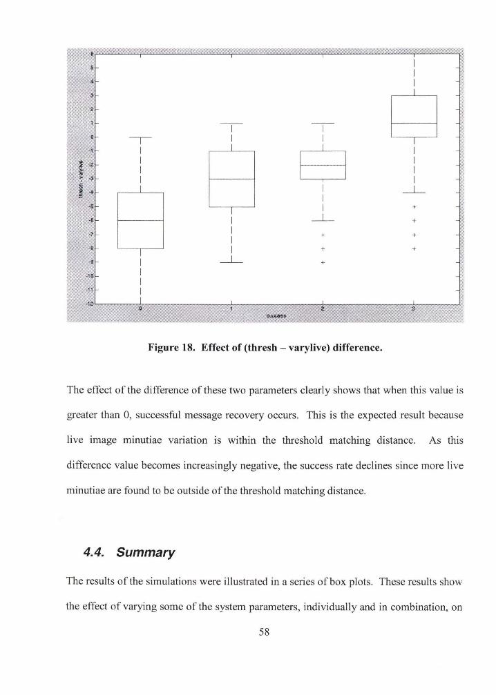
-1 I I
B I .• ,; -2 I I
' I I ~ .. I I > -3
l::. m -4 I I _j__ = I
-5 I + I
·6 I _j__ +
-7 I + + I
-8 I I + +
-9 I _j__ +
-10 I I
-11 I ·12
0 suocess
Figure 18. Effect of (thresh- varylive) difference.
The effect of the difference of these two parameters clear I y shows that when this value is
greater than 0, successful message recovery occurs. This is the expected result because
live image minutiae variation is within the threshold matching distance. As this
difference value becomes increasingly negative, the success rate declines since more live
minutiae are found to be outside of the threshold matching distance.
4.4. Summary
The results of the simulations were illustrated in a series of box plots. These results show
the effect of varying some of the system parameters, individually and in combination, on
58

successful message recovery. Parameters were correlated to success rates and specific
threshold breakpoint values were noted.
59
5. CONCLUSIONS
5. 1. Summary
A fingerprint fuzzy vault cryptographic system was attempted using COTS hardware and
software. It was discovered that this system did not have the necessary accuracy to be
functional, most of which was probably due to imprecise image alignment. This led to an
investigation of the fuzzy vault scheme through simulated scenarios using various vault
and tolerance parameters.
From an analysis of the data obtained from the simulations, the following conclusions
were drawn:
• The number of true points, when considered alone, had no significant effect on
the performance of the system (Figure 1 0). This can be attributed to the fact that
the true points represent a small proportion of the total vault points.
• The number of chaff points necessary to cause any significant interference with
true point matching, is near 200 (Figure 11 ).
• However, the ratio of chaff points to true points does affect the system. As shown
in Figure 17, when this ratio is more than 8:1, there is an increased likelihood of
unsuccessful decryption. At this level, enough chaff points are now near enough
60
to true points, so that the "fuzzy" minutiae points obtained from the live image are
sometimes are matched with chaff points instead of true points. This is an
interesting finding since vault security depends on a relatively large number of
chaff points to "hide" the true points. More worrisome, it appears that this ratio
may need to be below 4:1 to minimize the problem.
• A matching threshold radius, Euclidean distance over 5.66 (nthresh = 4) units,
was found to be best for consistent message recovery (Figure 12). However, it
may be possible, depending on other system parameters, to go as low as a distance
of 2.83 (nthresh = 2) units.
• The varylive radius threshold value appears to have the clearest individual effect
on fuzzy vault performance (Figure 13). Very consistent recovery performance is
obtained when this value is below 4 (distance= 5.66). This is not surprising since
this is the same as the optimal thresh value. When the varylive value goes above
9, message recovery rarely occurred, but this may partly be because the upper
thresh value simulated was only 6. Even when thresh is 1 (distance = 1.41 ), the
message recovery rate (for success = 3) is about 89% (Figure 15). This rate of
success is probably unacceptable for a cryptographic system in the real world.
However this is somewhat misleading since Figure 15 shows success rates over
all simulations. When the thresh value is fixed at the empirically determined
optimal value of 4 (Figure 16), it can be seen that, given the right combination of
minutiae matching threshold and live minutiae variation, the possibility of
building a robust fuzzy vault fingerprint cryptography system exists.
61
• The implemented system had an average live variation distance of nearly 13. This
was the major reason for system failure since this amount of variation is way
beyond system tolerance.
• The results of the (nthresh- varylive) evaluation (Figure 18) indicate that, as
would be expected, the system works best when the variation of live minutiae
points from true vault points is within the point matching threshold of the system.
Message recovery is rare if the varylive value exceeds that of the nthresh value
by more than 5 (distance = 7.07) units.
The above vault parameters and system thresholds may be useful as a guide when
attempting to use COTS software and hardware to build a fuzzy vault fingerprint
cryptographic system. The simulations indicate that it may be difficult to include enough
chaff points in such a system to be acceptably secure. One way to include more chaff
points would be to decrease the point matching threshold distance. But as the simulations
show, image alignment would need to be accurate enough so that the variation of minutia
points from live images was within the point matching threshold. Even with improved
alignment, a scanner with increased precision than the one simulated would be necessary
because, as noted above, the system is inadequate at even the level of one percent
variation of live minutiae from true vault minutiae. This precision would allow for a
larger normalized pixel grid and therefore a larger vault size. Each normalized unit
would then equate to a smaller distance and the characteristics of such a system may
result in acceptable recovery rates below a certain live minutiae variation threshold.
62
Performance could perhaps also be increased if chaff points were located at twice the
threshold distance from true points than they could be located from other chaff points.
This would prevent true points from being mistaken for chaff points (as would be more
the case as the number of chaff points increases) since true points within matching
threshold distance would now be closer to true vault points than to any chaff points.
However this would have two detrimental side effects. First, an attacker could use this
difference in thresholds between true and chaff points to identify true points, thereby
compromising security. Second, the maximum total number of points that the vault could
hold would decrease by half the number of true points, since the threshold for true points
is now doubled.
5.2. Future Work
It is important to note that the parameters and thresholds suggested by the simulations be
used as a guide to developing a fuzzy vault scheme similar to the one described,
implemented with COTS fingerprint hardware now commonly available. The actual
system constructed failed because it did not meet these system requirements. Most likely
this was due to imprecise alignment of fingerprint images. Solving this issue appears to
be the main obstacle since the better aligned the fingerprints, the lower the distance
matching threshold needs to be, and consequently more chaff points may be packed into
the vault to increase security. The alignment problem, specifically related to the fuzzy
vault scheme has apparently been addressed by [Chu05], but the full text of their paper
could not be obtained in time for review for this thesis. In the available abstract, they
63
claim to have performed automatic alignment of fingerprint features by using a geometric
hashing technique used for model-based object recognition applications. Their
preliminary results indicate that this technique was shown to be successful when applied
to fuzzy fingerprint vault systems. Therefore, it would be of interest to see if their
alignment method, when applied to the failed fingerprint cryptography system described
in this thesis, enables the system to perform adequately.
In the future, simulations of fuzzy vault systems for biometrics other than fingerprint
minutiae could be run to obtain guidelines for appropriate vault parameters and system
tolerances necessary in those environments. It is expected that they would be different
because, as noted earlier, template sizes vary widely for different biometrics.
64
REFERENCES
[AdiOS] Adler, A. (2005): "Vulnerabilities in biometric encryption systems," in T.
Kanade, A. Jain, and N. K. Ratha, editors, Lecture Notes in Computer Science,
Springer Berlin I Heidelberg, vol. 3546, p. 1100.
[BDP01] (2001): Biometric Device Protection Profile (BDPP). (draft). UK Government
Biometrics Working Group:
http://www .cesg.gov. uklsite/astlbiometrics/media/bdpp082. pdf
[Ber86] Berlekamp, E. R. and Welch, L. (1986): Error Correction for Algebraic Block
Codes, U.S. Patent No. 4633470.
[Bio01] (2001) The BioAPI Specification Version 1.1:
http://www .bioapi.org/N ew%20Downloads%20(Add%20to%20Site )/BIOAPI%2
Ol.l.doc
[Bra05] Brandt, A. (2005): "Hands on: gummi bears trick a fingerprint scanner," PC
WORLD: http://www.pcworld.com/news/article/O,aid, 116573,pg,5,00.asp.
[Cla03] Clancy, T. C., Kiyavash, N., and Lin, D. J. (2003): "Secure smartcard-based
fingerprint authentication," in WBMA '03: Proc. 2003 ACM SIGMM workshop on
Biometrics methods and applications, pp. 45-52, ACM Press, New York, NY.
[Chu05] Chung, Y., Moon, D., Lee, S., Jung, S., Kim, T., Ahn, D. (2005): "Automatic
alignment of fingerprint features for fuzzy fingerprint vault. CISC 2005: pp. 358-
369.
65
[Dah03) Dahel, S. K., and Xiao, Q. (2003): Accuracy performance analysis of
multimodal biometrics. Information Assurance Workshop 2003. IEEE Systems,
Man and Cybernetics Society, June 2003: pp.170-173.
[Dav98] Davida, G. 1. , Frankel, Y. , and Matt, B. J. (1998): "On enabling secure
applications through off-line biometric identification," in Proc. 1998 IEEE Symp.
Privacy and Security, pp. 148-157.
[Dod04] Dodis, Y. , Reyzin, L. , and Smith, A. (2004): "Fuzzy extractors: how to generate
strong keys from biometrics and other noisy data," in C. Cachin and J.
Camenisch, editors, Lecture Notes in Computer Science, Springer Berlin I
Heidelberg, vol. 3027, pp. 523-540.
[Fre06] Freire-Santos, M. , Fierrez-Aguilar, J. , and Ortega-Garcia, J. (2006):
"Cryptographic key generation using handwritten signature," A TVS-Biometrics
Research Lab., Escuela Politecnica Superior, Universidad Autonoma de Madrid,
E-28049 Madrid, Spain.
http://fierrez.ii.uam.es/docs/2006_SPIE_KeyGenSignature_Freire.pdf
[HafDO] Hafner, K. (2000): Will that be cash or cell phone? The New York Times,
2/2/2000.
[Hao05) Hao, F. , Anderson, R. and Daugman, J. (2005): "Combining cryptography with
biometrics effectively," Technical Report UCAM-CL-TR-640, University of
Cambridge Computer Laboratory, Cambridge, UK, July 2005.
[Hin04] Hino, A. and Cannady, S. (2004): The IBM integrated fingerprint reader. IBM
Corp. White Paper.
http://www.pc.ibm.com/us/pdf/Fingerprint_Reader_white_paper.pdf.
66
[HouOl] Houghton, A. (2001): Error Codingfor Engineers, Kluwer.
[Jai04] Jain, A. K., Pankanti, S., Prabhakar, S., Hong, L., and Ross, A. (2004):
Biometrics: a grand challenge. Proc. of !CPR (2004).
[Jon04] Jones, R. (2004): Homeland security seen spurring biometrics. MSNBC, 1/20/04.
http: //www.biometricgroup.com/in_the_news/01_20_04.html.
[Jue99] Juels, A. and Wattenberg, M. (1999): "A fuzzy commitment scheme", in G.
Tsudik, editor, Sixth ACM Conference on Computer and Communications
Security, pp. 28-36. ACM Press, 1999.
[Jue02] Juels, A. and Sudan, M. (2002): "A fuzzy vault scheme," Proc. IEEE
International Symposium on Information Theory, 2002.
[Kia04] Kiayias, A. and Yung, M. (2004): "Directions in polynomial reconstruction
based cryptography," IEICE Transactions, vol. E87-A, no. 5, pp. 978-985, May 5,
2004.
[Kia04a] Kiayias, A. and Yung, M. (2004): "Cryptanalyzing the polynomial
reconstruction based public-key system under optimal parameter choice," Proc.
I Oth International Conference on the Theory and Application of Cryptology and
Information Security (ASIACRYPT 2004), Lecture Notes in Computer Science,
vol. 3329 Springer 2004, pp. 401-416, Jeju Island, Korea, December 5-9, 2004.
[Kua05] Kuan, Y. W., Goh, A., Ngo, D., Teoh, A. (2005): "Cryptographic keys from
dynamic hand-signatures with biometric secrecy preservation and
replaceability," Fourth IEEE Workshop on Automatic Identification Advanced
Technologies, pp. 27-32.
67
[Ma103] Maltoni, D., Maio, D., Jain, A. K., and Prabhakar, S. (2003): Handbook of
Fingerprint Recognition. Springer Verlag, New York.
[Mat02] Matsumoto, T., Matsumoto, H., Yamada, K., and Hoshino, S. (2002): "Impact of
artificial "gummy" fingers on fingerprint systems," in Proceedings of SPIE Vol.
#4677, Optical Security and Counterfeit Deterrence Techniques IV, Yokohama,
Japan, January 2002. Yokohama National University.
[0Go02] O'Gorman, L. (2002): "Securing business's front door- password, token, and
biometric authentication," A vaya Labs Research:
http://www .research.avayalabs.com/ techreport/ ALR -2002-042-paper. pdf.
[Ree60] Reed, I. S. and Solomon, G. (1960): "Polynomial codes over certain finite
fields," SIAM J of Applied Math., vol. 8, pp. 300-304.
[San04] Sandstrom, M. (2004): "Liveness detection in fingerprint recognition systems,"
Master's thesis, Linkoping Tekniska Hogskola:
http://www.ep.liu.se/exjobblisy/2004/3557/exjobb.pdf.
[Sho04] Shorter, K. and Nice, I. (2004): "Biometrics and security - an introduction,"
QinetiQ White Paper:
http://www .qinetiq .com/home/ core_skills/know ledge_information_and_systems/t
rusted_information_management/whi te_paper_index .Par. 001 7 .File. pdf
[Tuy04] Tuyls, P., Goseling, J. (2004) "Capacity and examples of template-protecting
biometric authentication systems," in D. Maltoni and A. K. Jain, editors, Lecture
Notes in Computer Science, vol. 3087, Jan 2004, pp. 158-170.
[Tuy05] Tuyls, P., Akkermans, A. H. M., Kevenaar, T. A. M., Schrijen G.-J ., Bazen, A.
M., and Veldhuis, R. N. J. (2005): "Practical biometric authentication with
68
template protection," in Lecture Notes in Computer Science, vol. 3546, Jun 2005,
pp 436-446.
[Ulu04] Uludag, U., and Jain, A. (2004): "Fuzzy fingerprint vault," Proc. Workshop:
Biometrics: Challenges Arising from Theory to Practice, pp. 13--16, August
2004.
[Ulu04a] Uludag, U., Pankanti, S., Prabhakar, S., and Jain, A. K. (2004): "Biometric
cryptosystems: issues and challenges," Proc. IEEE, 9216, June 2004.
[Vaz06] Vazirani, U. [2006] "Discrete mathematics for CS, Lecture 9 - Error correction
codes," http: / /www-inst.eecs. berkeley.edu/~cs70/sp06/lectures/lecture 12. pdf
[Yan04) Yang, S. and Verbauwhede, I. M. (2004): "Secure fuzzy vault based fingerprint
verification system," in Asilomar Conference on Signals, Systems, and
Computers, vol. 1, pp. 577-581, November 2004.
[Yan05] Yang, S. and Verbauwhede, I. (2005): "Automatic secure fingerprint verification
system based on fuzzy vault scheme," IEEE International Conference on
Acoustics, Speech, and Signal Processing (ICASSP 2005), pp. 609-612, March
2005.
[Yan05a) Yang, S., Schaumont, P., and Verbauwhede, I. (2005): "Microcoded
coprocessor for embedded secure biometric authentication systems,"
IEEEIACMIIFIP International Conference on Hardware- Software Codesign and
System Synthesis (CODES+ISSS'05), Sept. 2005.
69
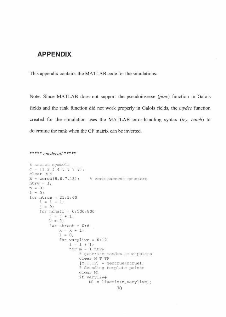
APPENDIX
This appendix contains the MA TLAB code for the simulations.
Note: Since MATLAB does not support the pseudoinverse (pinv) function in Galois
fields and the rank function did not work properly in Galois fields, the mydec function
created for the simulation uses the MA TLAB error-handling syntax (try, catch) to
determine the rank when the GF matrix can be inverted.
***** encdecall *****
% secret symbols c=[12345678]; clear RUN R = zeros(8,6,7 ,13); % zero success counters ntry = 3; n = 0; i = 0; for ntrue 25:5:60
i = i + 1; j = 0; for nchaff = 0:100:500
j = j + 1; k = 0; for thresh = 0:6
k = k + 1; 1 = 0; for varylive = 0:12
1 = 1 + 1; form= 1:ntry
% generate random tr~e points clear H T TF [M,T,TF] = gentrue(ntrue); 'I; decoding template points clear Ml if varylive
M1 = livemin(M,varylive);
70
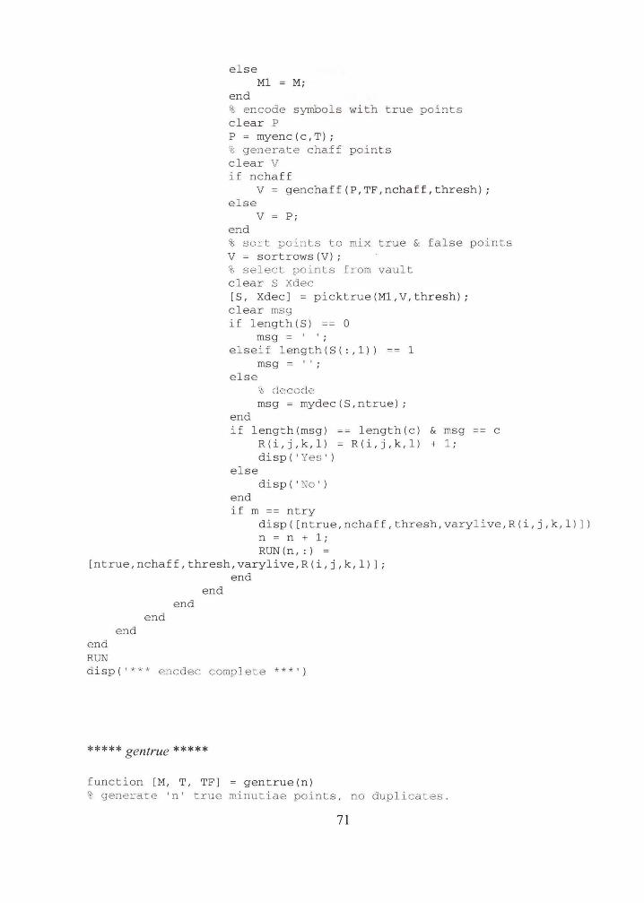
else M1 M;
end % encode s ymb ols wi th true points clear P P = rnyenc ( c, T) ; % generate chaff p oints clear v if nchaff
V genchaff(P,TF,nchaff,thresh); else
v P· '
end % sort points to mix t rue & fa l s e p o i nts V = sortrows (V); % select points from vault clear S Xdec [S, Xdec] = picktrue(M1,V,thresh); clear msg if length(S) == 0
msg = ' ' ;
elseif length(S(:,1)) 1 msg = ' ' ;
else 'b decode msg = mydec(S,ntrue);
end if length(msg) == length(c) & msg c
else
R(i,j,k,l) = R(i,j,k,l) + 1; disp(' Yes ')
disp(' No' ) end if m == ntry
disp([ntrue,nchaff,thresh,varylive,R(i,j,k,l)]) n = n + 1; RUN(n,:) =
[ntrue,nchaff,thresh,varylive,R(i,j,k,l)]; end
end RUN
end end
end end
disp( '*** encdec complete*** ')
***** gentrue *****
function [M, T, TF] = gentrue(n) % generate 'n' true minutiae points, no duplicates .
71
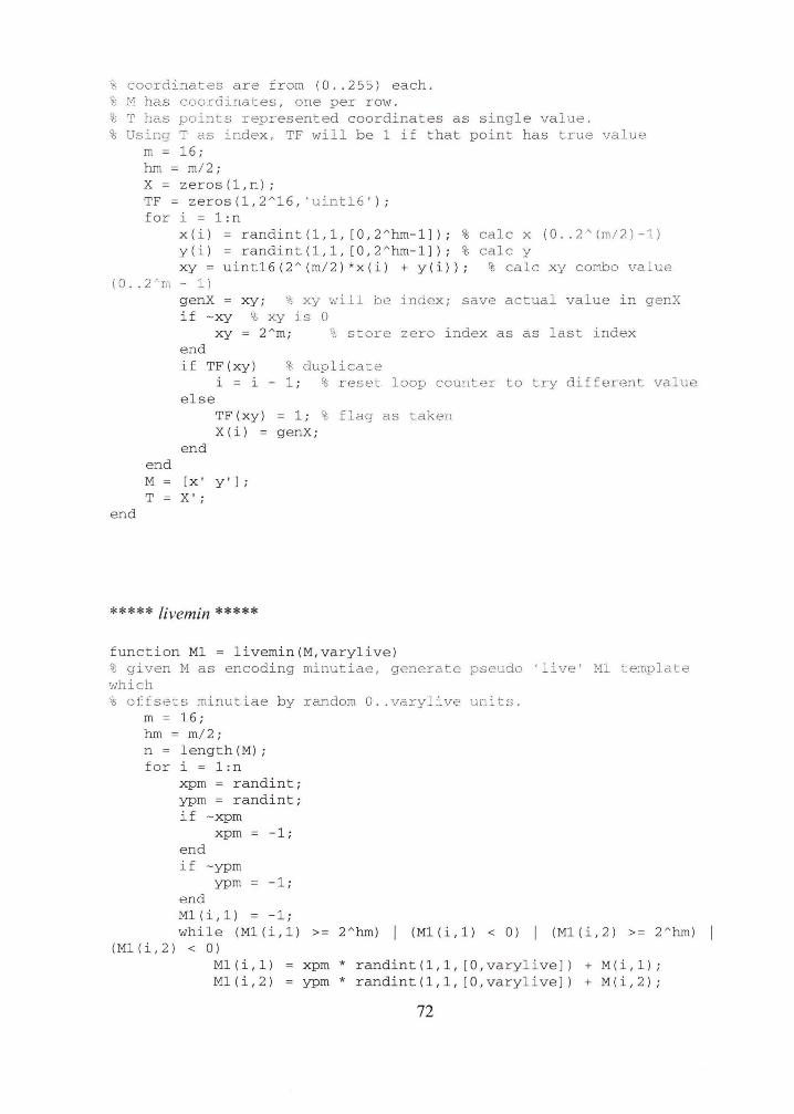
%coordinates are from (0 . . 255) each . % M has coordinates , one per row . ~; T has points represented coordinates as single value. % Using T as index, TF will be 1 if that point has true value
m = 16; hm = m/ 2; X= zeros(1,n); TF = zeros(1,2 " 16, 'uint16' ); for i = 1:n
x(i) = randint(1,1, [0 , 2 " hm-1]) ; %calc x (0 . . 2"(m/2)-1) y(i) = randint(1,1, [0,2 " hm-1]); %calc y xy = uint16 (2" (m/2) *x(i) + y (i)); !I; calc xy combo value
( 0 . . 2 ·'m - 1) genX if -xy
xy; % xy will be index; save actual value in genX % xy is 0
xy = 2"m; % store zero index as as last index end
~; duplicate if TF(xy) i = i
else TF(xy) X(i) =
- 1; % reset loop counter to try different value
end end M [x' y•]; T = X';
end
***** livemin *****
= 1; % flag as taken genX ;
function M1 = livemin(M,varylive) ~; given M as encoding minutiae, generate pseudo 'live' M1 template which % otfsets minutiae by random 0 . . varylive units.
m = 16; hm = m/2; n = length (M) ; for i = 1 : n
xpm = randint; ypm = randint; if -xpm
xpm = -1; end if -ypm
ypm -1; end M1 ( i ,1) -1; while (M1(i ,1)
( M1 ( i , 2 ) < 0 ) M1(i,1) M1(i,2)
>= 2"hm) ( M1 ( i , 1 ) < 0 ) (M1(i,2) >= 2 " hm)
xpm * randint(1,1, [O,varylive]) + M(i,1); ypm * randint(1,1, [O, varylive]) + M(i,2);
72
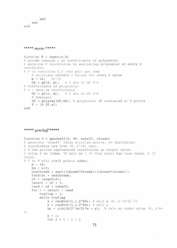
end end
end
***** myenc *****
function P = myenc(c,X) ~s encode message c as coefficients of polynomial . % c;;enerate Y coord.:i..nates by evaluating polynomial at every X coordinate . % P is resulting X,Y (one pair per row)
% calculate encoded Y values for every X value m = 16; %2"16 GX = gf(X, m); %X are in GF 2"m
% Coefficients of polynomial % c = data as coefficients
end
GC = gf(c, m); %care in GF 2"m ~> Evaluate GY = polyval(GC,GX); %polynomial GC evaluated at X points P = [X GY . X);
***** genchaff*****
function V = genchaff(P, TF, nchaff, thresh) %generate 'nchaff' false minutiae points, no duplicates. % coordinates are from (0 .. 2"16) each . % P has points represented coordinates as single value. % Using P as index, TF will be 1 if that point has true value , 2 i f false. % V :i..s P with chaff points added.
m = 16;
1)
hm = m/2; onethresh = sqrt((thresh*thresh)+(thresh*thresh)); thrdist = onethresh; nP = length(P); istart = nP + 1; iend = nP + nchaff; for i = istart : iend
tryf lag = 1; while tryflag
x = randint(1,1,2"hm); % calc x (0 .. 2 ''(m/2)-1) y = randint(1,1,2"hm); %calc y xy = uint16(2 " (m/ 2)*x + y); %calc xy combo value (0 .. 2'm-
k = 1; for j = 1 i - 1
73
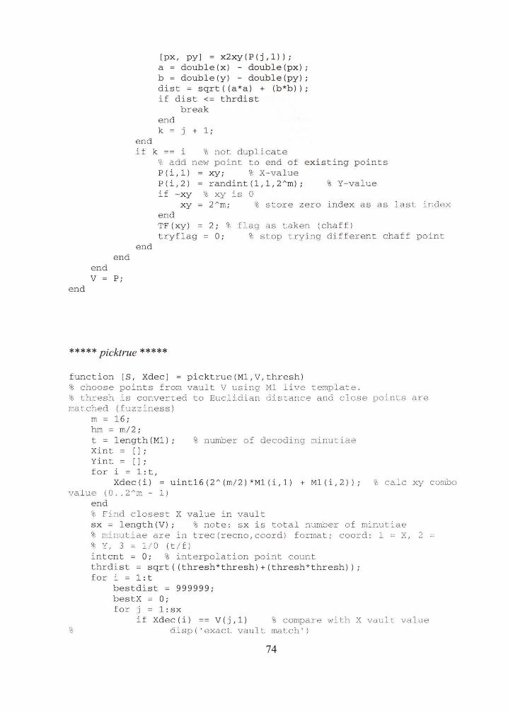
end end V = P;
end
end
[px, py] = x2xy(P(j,1)); a = double(x) - double(px); b = double(y) - double(py); dist = sqrt((a*a) + (b*b)); if dist <= thrdist
break end k = j + 1;
if k == i % not duplicate % add new point to end of existing points P(i,1) = xy; % X-value P(i,2) = randint(1,1,2Am); % Y-value if -xy % xy is 0
xy 2Am ; % store zero index as as last index end TF(xy) 2; % flag as taken (chaff) tryflag = 0; % stop trying different chaff point.
end
***** picktrue *****
function [S, Xdec] = picktrue(M1,V,thresh) % choose points from vault V using Ml live template . % thresh is converted to Euclidian distance and close points are matched (fuzziness)
m = 16; hm = m/2; t = length(M1); % number of decoding minutiae Xint = []; Yint = []; for i = 1:t,
Xdec(i) uint16(2 A(m/2 )*M1(i,1) + M1(i,2)); %calc xy combo value (0 .. 2Am- 1)
end % Find closest X value in vault sx = length(V); % note : sx is total number of minutiae %minutiae are in t.rec(recno,coord) format; coord: 1 =X, 2 ~; Y, 3 = 1/0 (t/f)
intent = 0; % interpolation point count thrdist = sqrt((thresh*thresh)+(thresh*thresh)); for i = 1:t
bestdist = 999999; bestX = 0; for j = 1:sx
if Xdec (i) == V(j,1) %compare with X vault value disp ('exact. vault match' )
74
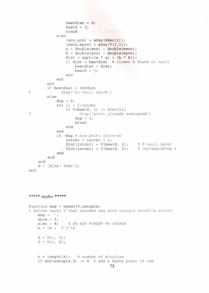
%
%
end
end
e l se
end end
bestdist = 0; bestX = j ; break
[xco,yco) = x2xy(Xdec(i)); [mxco,myco) = x2xy(V(j,1)); a = double(xco) - double(rnxco); b = double (y co) - double(myco); dist = sqrt((a * a) + (b *b)); if dist < bes t dist % closer X f ou nd in vault
bestdi s t = d ist; bestX = j ;
end
if bestdist > thrdist
else
end
disp ('no vault match')
dup = 0 ; for ii 1 : intcnt
if V (bestX, 1) Xint (ii ) disp ( ' point. already evaluated ')
dup = 1 ; break
end end if -dup % new point selected
intent = intent + 1; Xi nt(intcnt) V(bestX, 1); Yint( i ntcnt) = V (bestX , 2);
end
% X vault point % corresponding Y
S = [Xi nt ' Yint ');
***** mydec ***** function msg = mydec (V, n encp ts) % decode vault V that encoded msg with nencpts encoding points
msg = ' ' ; more = 1; mlen = 8 ; m 16
!{; DO NOT FORGET TO CHANGE % 2"16
X V( : , 1);
Y V( :, 2) ;
n = length(X) ; % number of minutiae if mod(nencpts,2 ) -= 0 % add a dummy point if odd
75
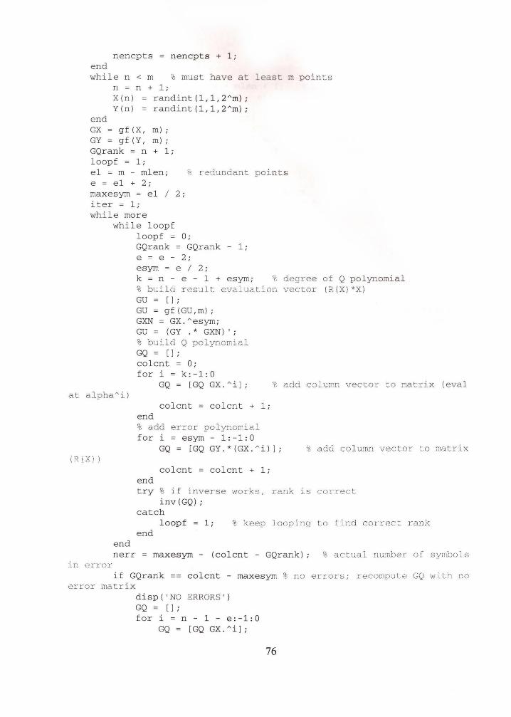
nencpts nencpts + 1; end while n < m % must have at least m points
n = n + 1; X(n) randint(1,1,2Am); Y(n) = randint(1,1,2Am);
end GX = g f (X, m) ; GY = g f ( Y, m) ; GQrank = n + 1; loopf = 1; e1 = m - mlen; e = e1 + 2; maxesym = e1 I 2; iter = 1; while more
~~ :red:unda.nt points
while loopf loopf = 0; GQrank = GQrank - 1; e = e - 2; esym = e I 2; k = n - e - 1 + esym; % degree of Q polynomial
at alpha"i)
(R(X))
end
%build result evaluation vector (R(X)*X) GU = []; GU = gf(GU,m); GXN = GX . Aesym; GU = ( GY . * GXN) ' ; % build Q polynomial GQ = []; colcnt = 0; for i = k:-1:0
GQ = [GQ GX.Ai];
colcnt = colcnt + 1; end % add error polynomial for i = esym - 1:-1:0
% add column vector to matrix (eval
GQ = [GQ GY.*(GX.Ai)]; % add column vector to matrix
colcnt = colcnt + 1; end try % if inverse works, rank is correct
inv(GQ); catch
loopf = 1; % keep looping to find correct rank end
nerr = maxesym - (colcnt - GQrank); % actual number of symbols in error
if GQrank == colcnt - maxesym % no errors; recompute GQ with no error matrix
disp ( 'NO ERRORS') GQ = [];
for i = n - 1 - e:-1:0 GQ = [GQ GX. Ail;
76
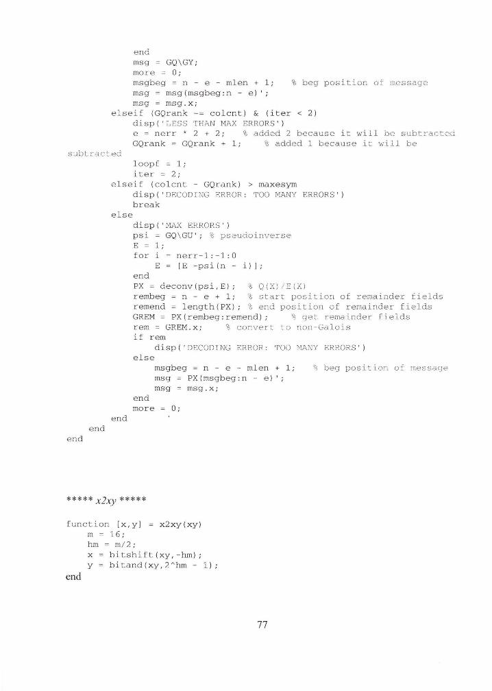
end msg = GQ \GY ; more = 0; msgbeg = n - e - mlen + 1; msg = msg(msgbeg:n - e)'; msg = msg.x;
% beg position of message
elseif (GQrank -= colcnt) & (iter < 2) disp ( 'LESS 'l'H!>J'J MAX ERRORS '} e = nerr * 2 + 2; % added 2 because it will be subtracted GQrank = GQrank + 1; % added 1 because it will be
subtracted
end end
loopf = 1; iter = 2;
else i f (colcnt - GQrank) > maxesym
else
end
disp ( ' DECODING ERROR : TOO M.l\NY ERRORS' ) break
disp ( ' tv!AX ERRORS' ) psi = GQ\GU'; % pseudoinverse E = 1 ; for i n err-1 :-1:0
E = [E -psi( n- i}]; e nd PX = deconv(ps i,E}; % Q(X)/E(Xl rembeg = n - e + 1; 't start position of remainder fields remend = length(PX); % end position of remainder fields GREM = PX ( rembeg: remend) ; '); get. remainder fields rem = GREM.x; ~ convert to non-Galois if rem
disp ( 'DECODING ERROR : TOO HANY ERRORS' ) else
end
msgbeg = n - e - mlen + 1; msg PX(msgbeg:n - e )'; msg = msg.x;
more = 0;
\\ beg position of message
***** xby *****
function [x,y] x2xy(xy) m = 16; hm = m/ 2; x bitshift(xy,-hm); y = bitand(xy,2Ahm- 1);
end
77