Embed Size (px)
Citation preview

FUR: Understanding Functional Reasoning M. DiManzo,* E. Trucco,t F. Giunchiglia,t and F. Riccit *Institute of Computer Science, University of Ancona, via Brecce Bianche, 60131 Ancona, Italy, and t DIST-University of Genova, via all’Opera Pia l l a , 16145 Genova, Italy
By functional reasoning we mean the ability of integrating shape, function, and plans in reasoning. The shape of many man-made objects, such as tools, is expressly designed to provide precise functionalities. Moreover, humans know how to use the same objects for different functions. In vision and reasoning we make use of complex information which is not exclusively based on geometric and spatial knowledge, but also on func- tional elements. They seem to play a role in object recognition and representation. This article is an insight in functional reasoning from the computational point of view. It introduces its concepts and its apparent ubiquity in human behavior. Some relevant computational literature is reported and discussed. The rest of the article is an outline of the FUR project, an attempt to develop a computational model for functional reasoning. The development state of the project is presented along with the implementation of a first prototype. Some experimental results are finally given.
I. INTRODUCTION
Suppose you find yourself in a supermarket. It is particularly hot and you begin to feel tired. So you look around for a chair, but you do not see one. Eventually, you see a case. You decide to sit down and rest a little.
Everything sounds obvious in this story. However, the decision to sit on a case is an example of our ability to recognize in an object other possible func- tions than those for which it was expressly designed. After all, chairs are meant to sit on and cases to contain things. Nevertheless we have no difficulty using cases as chairs if necessary, even if their shapes can hardly be related. Or suppose that you want to hang a picture on the wall in your dining room. The very first thing is of course to hit a nail into the wall; but let’s assume that there is no hammer around. All you happen to find is, say, a screwdriver. You are likely to use this as a hammer, probably hitting the nail with its handle. Again, two structurally different objects have been related through some functional
INTERNATIONAL JOURNAL OF INTELLIGENT SYSTEMS, VOL. 3, 471-457 (1989) 0 1989 John Wiley & Sons. Inc. CCC 0884-8 173/89/04043 1-27$04.00
432 DiMANZO ET AL.
properties. From the viewpoint of planning they can be even regarded as inter- changeable, in the sense that both of them can be used to achieve the same goal, that is, to hit the nail into the wall.
A. The Concept of Functional Reasoning
In everyday life, we show a puzzling ability to make use of the same object in many different ways. This suggests that a mental model is employed which associates that shape to several functionalities. As Freeman and Newel1 pointed out in a pioneering work,’ it is not difficult to notice that a pencil can print characters, punch holes in paper, serve as core for a ball of string, and tamp down pipe tobacco. We explore in this article the following problem: which knowledge representation model could support such reasoning? What- ever it might be, it should no doubt integrate structural and functional informa- tion: for it is the shape of the pencil that suggests to us the set of actions mentioned above. Conversely, once we decide to punch a hole in a sheet of paper we look for a pencil and not for, say, an eraser. This kind of representa- tion is responsible for the generation and refinement of a number of actions. As Brady and Agre2 point out, tools representations participate in plans and evolve with them, adapting to new situations, fixing the bugs of old tools and generat- ing new objects and plans.
Many examples could be given which show the ubiquity of functional reasoning in everyday life, including behaviors as complex as design (“the art of devising artifacts to attain goals”, as Simon3 characterized it), or simple activities as choosing the right tool for a job, or again recognizing an object from the function that its structure suggests. We often name things after the functions they provide: a “washing machine,” a “screwdriver,” and so forth, Psychologists have named the tendency of humans to become more or less fixated on one particular function of an object in problem solving functional $xity (see for instance Duncke?). These works demonstrated that much human reasoning exploits some sort of functional descriptions. In perception, J. J. Gibson5 claimed even that all the activities an object affords are directly per- ceived in the invariant properties of the object array, which is the basic concept of his theory of uffordunce. But functional reasoning does not seem to play a role only in humans. In a comprehensive study about the use and manufacture of tools by animals, Beck6 reports about many animal behaviors that can be classified as “use of tools”. These seem to aim mainly to extend the animal’s reach, increase the force to be applied on something or improve controls on liquids.
All this lets us hypothesize a cognitive model where function, shape, and plans are nicely integrated. It is of course inconceivable that all animals (includ- ing man) use the same representations, but it is reasonable to expect each to use one or more representations that are nicely tailored to the owner’s purposes, e.g., to identify a target object in a scene.

UNDERSTANDING FUR 433
B. Computational Approaches to Functional Reasoning
Seminal work about the use of functional information and how to relate function to structure has been done by Freeman and Newell.’ They pointed out that humans make extensive use of functional descriptions in everyday life and proposed a simple model for functional reasoning in design.
A proper model for the shape-function relation could provide powerful aid to an intelligent robot but is unfortunately far more complex than a simple one- to-one relation between actions and objects, e.g., hit-hammer, sit-chair, and so on. Moreover, functional descriptors of objects introduce an explicit link between structures and actions and therefore with the plans involving the rep- resented objects (Brady et al.,* Brady’). The problem here is how to represent the relation between the structural properties of objects and their function, which is in turn related to the actions they make possible.
In the seminal work by Newell and Freeman’ objects were classified ac- cording to their function. In their model, composing parts to get complex structures was possible if a part performed the function that another part re- quired. Matched functions were “consumed” inside the composed structure and not available for the resulting structure any longer. Two strategies were indicated for parts composing: forward chaining and backwards chaining. The former considers how to build a structure fulfilling a required function starting from a set of given objects; the latter how to build an assembly starting from the required function down to match the functional properties of single objects. Indeed, this work shed light onto the field of automated functional reasoning, but did not identify a general model for the shape-function relationship as well as a well-defined role for visual data.
Winston et a1.8 have suggested that functional descriptors could be learned in terms of structural features. They discuss the following advantage of the functional approach: it is often too hard to tell vision systems what things look like; it can be easier to talk about purpose and link purpose to functional constraints. This means that a unique descriptor could identify an object class and be used to recognize instances which look even very different from one another, provided they are recognized to perform the same function. A set of functional constraints was therefore added to structural descriptors. The sys- tem they developed used ACRONYM basic structural descriptions of 3-D ob- jects and matched them to a functional model to drive recognition and learning.
Ingrand and Latombeg have developed a system, SERF (Expert System for Functional Keasoning), where complex structures are deduced from func- tional constraints, that is a set of properties is related to the object function. Assemblies are generated composing simpler structures and functional con- straints propagate through the resulting levels. Here, too, a real paradigm for the shape-function relationship seems to be missed. The basic elements con- sidered are rather complex mechanical parts whose shape and function are taken for granted. Each basic element is associated to a number of functions providing a vocabulary for functional reasoning.

434 DIMANZO ET AL.
Brady and Agre,* introduced the “Mechanic’s Mate” project. Its first aim is to understand the interplay between planning and reasoning that involves tools and fasteners. This comprehends how function can be deduced from shape and vice versa, what Lowry called “reasoning between structure and function.”“’ An advantage of this kind of description has been pointed out2*” in terms of “functional improvisation,” e:g., deducing that the handle of a screw- driver can work as hammer head if needed. Another interesting point is that the shape-function relation is regarded as closely dependent on the dynamic repre- sentation of the world, which can be given in terms of naive physics models ( F ~ r b u s l ~ . ~ ~ and DeKleerI4). The basic tenet is that it is often difficult to sepa- rate the function of a tool from the plan in which it participates and with which it coevolved: plans and tools evolve together and differentiate with time.
11. THE FUR PROJECT
The FUR (Functional Reasoning) project aims to develop a computational model for the representation and use of functional knowledge. This section is an overview of the project and sketches its main ideas, targets, and its develop- ment to date.
A. Problems and Targets: Overview
The main goal of FUR is to model the integrated use of functional and structural information. This includes the relation between shape and function and its use in vision and (in the future) reasoning. Intelligent robots could benefit by such integrated model achieving greater flexibility in many tasks, from object recognition to planning.
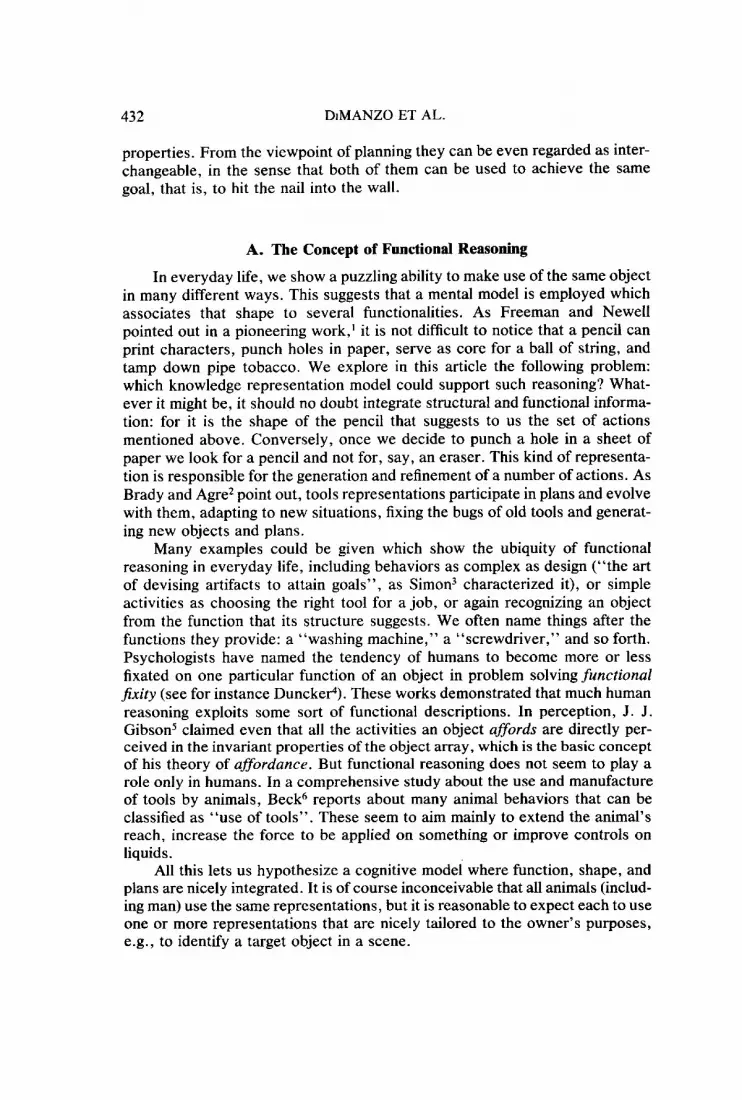
We introduce below a list of problems that the FUR prototype is expected to face in the future. The classification proposed is quite informal. In the following, “object” means the functional descriptor of an object, its integrated functional-structural representation; “structure” refers to a 3-D shaped model, e.g., the screwdriver shown in Figure 1.
0 Deducing function from shape: “What is this structure for?” (function identification) “Is this structure graspable?” (primitive function recognition)
0 Deducing shape from function: “Which of these structures can I use for grasping nuts?” (functional structure classification) “Which of these structures is a screwdriver? Is this structure a screw- driver?” (Junction-driven object identification) “What else can I use as screwdriver?” (functional improvisation)
“Which known objects are designed for containing liquids?” (func- tion-driven classijkation)
0 Abstract functional reasoning:

UNDEKSTANDING FUR 435
Figure 1. An octree-screwdriver. Universe resolution is 128 x 128 x 128.
“Which objects can be of use in a (given) plan?” (function-driven plan specijication) “What is the most plausible plan involving these objects?” (function- driven plan recognition)
The final output of FUR is expected to be twofold. First, a theory of functional reasoning will be defined. Such theory should consist of
(1) a multi-level model of functional reasoning about 3-D objects, includ- ing an object representation formalism. This should allow to describe both the structure of objects and their function.
( 2 ) a functional representation of plans in the same formalism.
Second, a software prototype implementing the theory will be developed. This system should:
enable users to define objects and run experiments with them. Object are represented in FUR by semantic functional descriptors (SFD’s), which are built using a catalogue of predefined functional primitives; enable users to define an environment, that i s the 3-D solid model of a scene and a set of SFD’s. In the future, the 3-D model should be obtained from stereo processing of camera-acquired images; solve at least a first subset of the above mentioned problems in the user-defined environment.
The next sections reports briefly about theoretical and implementative work done to date.
B. A Computational Model for Functional Reasoning
It is interesting to notice that some tasks involving functional reasoning require manipulation of solid shapes, while others can be performed rather independently of 3-D geometry. For example, when you feel thirsty it is imme- diate to formulate a plan whose first steps are probably going to the kitchen and looking for a glass or cup. The formulation of such a plan per se is quite

436 DIMANZO ET AL.
TASKS AND PLANS "sit down" REPRESENTATION
"take a glass and drink
S F D ' s
"a CHAIR cangive support.
block rotations backwds..
is stable on a plane" I-
FUNCTION MODELING
GRASP-+ size constraints
EQUILIB. +bark. projection
A
I 1 GEOMETRIC PRIMITIVES
J.
3-0 model
Figure 2. The FUR model for reasoning about shape and function.
independent of the shape of the particular container that you will actually find in the end, while geometric reasoning has a definite importance in the subtask of identifying a glass in the crockery shelf.
This suggests a possible hierarchy of levels for reasoning between shape and function, sketched in Figure 2 and explained in the following.
Geometric reasoning takes place on a 3-D representation of a scene. This is the level of geometry: a vocabulary of geometric primitives is defined, which computes structural properties of bodies as e.g., concavities, baricentrum, vol- ume, and so forth. They constitute the interface between the 3-D model and the function level, in that primitive functions are represented solely in terms of entities of this level (see Section 111-A).

UNDERSTANDING FUR 437
Thefunction modeling level describes a set of primitive functions in terms of geometric constraints. The shape-function relation is made explicit in the functional experts (FE’s) representing primitive functions. FE’s structure will be discussed in the next section.
The object representation level uses FE’s and geometric relations to de- scribe objects. This is accomplished composing FE’s to build SFD’s, which integrate functional and structural properties (e.g., a hierarchical structural decomposition along with the function performed by each subpart).
The plans representation level uses SFD’s and FE’s for function-driven planning. This comprehends generating or recognizing plans basing on the functions they involve. At this level, primitive actions as regarded as the basic planning element (say an elementuly plun) which can be directly connected to geometric constraints through the corresponding FE. This level has not yet been investigated and will not be discussed in this article.
C. FUR: State of the Art
The FUR theory is being developed under two main assumptions:
(1) the functional goal of most man-made objects can be expressed in terms of some very common, basic functionalities; such functions (called primitive functions) are described in turn by frame-like struc- tures.
(2) most man-made objects can be hierarchically decomposed in subparts. Each SFD suggests a hierarchical decomposition for the object it de- scribes, associating each subpart to a basic function. As pointed out before, however, the one-to-one relation between the shape of a sub- part and its function is not satisfactory. The same shape can accom- plish different functions in different objects, that is in different func- tional contexts. Incidentally, this is what makes functional improvisation possible.
Primitive functions are implemented by funrtional experts, which collect information about the conditions under which a function is possible. As de- tailed later, these conditions can be expressed through sets of geometric con- straints for a number of common functions. In this sense, one typical activity of the FUR system is to decide whether an object can accomplish a given (maybe primitive) function, e.g., whether a bolthead can be grasped by a given spanner, or to find all graspable objects in a scene, or again the grasping points in an object .
An initial phase was devoted to the detailed analysis of some actions and the development of a first list of functional primitives (DiManzo et al.15-17). The task considered in this phase was function-driven object recognition. Refine- ments of the theory and consideration of more general tasks led to a critical revision of the set of functional experts. The study of the shape-function relation from this viewpoint introduced a number of restrictions on the kind of representable functions.lX This is discussed with some detail in Section Ill-B.

438 DiMANZO ET AL.
In essence, mere geometry has been completely embedded in the first level (Fig. 2), while functions are modeled in terms of geometric primitives at a higher level. Therefore, structure and function primitives occupy now two different abstraction levels in the model.
D. The Geometric Reasoning Level
We suppose that a 3-D model of a scene is available, as it could be gener- ated by early processing of a stereo pair or a sequence of images of the same scene (see for instance Herman and Kanade,I9 Grimson,20 Morass0 and San- din?'). Many FUR tasks take this representation as their input data, e.g., primitive function recognition or function-driven object identification. Oc- trees22-z4 have been employed for modeling solid bodies. Figures 3 and Figure 1 show typical scenes considered.
An octree-based solid-modeler has been implemented. It enables a user to create 3-D objects and environments from scratch or to manipulate them.
FE ' s are implemented as semantic networks whose elements belong to the Geometric Reasoning Level. These are divided in three groups:
(1) geometric experts; (2) geometric functions; and ( 3 ) geometric predicates.
Geometric experts can operate in different modes: searching particular spatial structures, e.g., holes or concavities (search mode); or verifying the
Figure 3. An octree-chair. Resolution is 128 x 128 X 128.
UNDERSTANDING FUR 439
validity of particular spatial relations, for instance whether two objects can be considered perpendicular (uerrfy mode).
Geometric functions simply return a result once their input case(s) is in- stantiated. The result can be numerical (e.g., a volume, an orientation), or identify a 3-D structure (e.g., the top surface of an object).
Predicates simply verify whether a given spatial relations hold. All their arguments must be instantiated.
All the elements of the above mentioned groups are in turn based on a set of octree primitiues, which manipulate directly the octree model (e.g., for computing structural properties of solids). They are therefore the basic blocks for FE's, that is for representing the shape-function relation. There are more than forty octree primitives defined in the system and a detailed discussion would take too long here. Table 1 lists the names of the experts, functions, and predicates defined at this level with reference to the current FE vocabulary. It must be stressed that such entities are by no means to be considered an exhaus- tive library of geometric processing programs, but a provisional set depending on the catalogue of FE's defined to date.
It is also important to make clear that the geometric level is the real bridge connecting the 3-D geometric world to the functional representation of objects and actions in the model. FE's are nothing but networks of geometric entities defined in this level, embedding the basic interplay between shape and func- tion. They have been the main focus of this research. As a consequence, a sophisticated representation of 3-D objects has nut been our major concern and the prototype system has been tested with simplified 3-D object models.
E. Uncertainty
If the analysis of a scene does not take place on a clean, solid model (e.g., built by hand by the user) but on a set of volumes reconstructed by low- and intermediate-level vision processes, as we hope to do in the future, it becomes mandatory to cope with uncertainty. Uncertainty refers here to a number of things, which we will broadly divide in two qualitatively different classes. The following considerations have been written keeping in mind the recognition task, even though their validity is not restricted to it.
First, it is partly due to the noise introduced by early processing. This makes a 3-D reconstruction miss some volumes and/or distort the shape of some others. In the case of objects recognition, therefore, a direct matching against geometric models becomes quite difficult. Second, it is not trivial to individuate models able to discriminate equally well among instances of the same object class (say different chairs) and among different object classes (say chairs for stools). In some (realistic) cases, the distinction can be quite subtle. A nice example regarding hammers is given by Brady and Conne1l.l' In this sense a computational system can be unclear about, for example, an object classified as an acceptable instance by two distinct models.
We have chosen to treat the first point introducing uncertainty estimates (uncertainty coefficients) which quantify the perceptual reliability of the vol- umes described. These coefficients are supposed to be evaluated by the low-

P
P
0
Tabl
e 1.
Som
e pr
imiti
ves
and
expe
rts
of th
e ge
omet
ric
leve
l. G
eom
etri
c L
evel
Pro
cedu
res
~~
Geo
met
ric E
xper
ts
PLA
CED
-ON
3D
-IN
H
OL
E
CO
NC
AV
ITY
- ~
BOTT
-SR
F TO
P-SR
F SI
DE
-SR
F O
RIE
NT
Geo
met
ric F
unct
ions
A
REA
L
EN
GT
H
VO
LUM
E H
EIG
HT
SEC
TIO
N
PLA
CE
-VO
L
BAR
IC
PRO
JEC
T-2D
BU
ILD
-CO
NST
Rl
BU
ILD
-CO
NST
R2
PLA
NE
IN
TER
SEC
TIO
N
DIR
-PE
W-T
O
CU
BE
O
RIE
NT
-AX
IS
PAR
AL
LE
LPO
ID
CO
NE
PA
RA
LL
-PL
AN
E
SOL
ID-A
NG
LE
IN
TE
RPO
LA
TIO
N
Geo
met
ric
Pred
icat
es
2D-I
N
PAR
AL
LE
L

UNDERSTANDING FUR 44 1
level processes generating the solid model of the scene. Currently they are assigned by hand to each part of the octree model. Uncertainty coefficients are processed by the geometric primitives at the geometric reasoning level, which propagates it to the subsequent FE’s and SFD’s analysis. Details about the uncertainty propagation technique implemented are given in Section V-B.
As to the second point, it is the object representation adopted that should be flexible enough to pick as much information as required by the task. This means that the representation itself should support different strategies of analy- sis.
Our solution here is to focus on functional aspects at the object representa- tion level. Discriminating among object classes is performed on the basis of functional properties explicitly stated in the SFD. Structural details relevant to discrimination inside the same class are treated inside the geometric reasoning level. In other words, we say that chairs differ logically from cups for func- tional considerations, while the difference between two chairs does not affect their common functional properties. Classification is possible once subparts strongly related to primitive functionalities are detected, and this relation does not imply any precise structure but only a set of geometric constraints.
111. THE FUNCTION MODELING LEVEL
At the Function Modeling level the primitive functions are represented composing geometric experts, functions, and predicates into FE’s, expressing the basic shape-function relation through networks of geometric constraints.
A. The Concept of Primitive Function
In the analysis of many common classes of objects a small number of functional design goals come out repeatedly as, for instance, supporting, con- tainment, graspability and so on. Many object classes can therefore be success- fully characterized referring to this basic set of goals. Basically, objects are recognized as members of a specific class if and only if they accomplish a proper subset of goals. Since such goals describe expected object perfor- mances, we refer to them as primitive functions or functional primitives, and use them as basic building blocks to define the overall functional characteristics which distinguish each object class.
The conditions for an object subpart to perform a specific primitive func- tion depend mostly on its shape. They may also depend on properties of other objects, e.g., their shape, size, position and so on. For example, only the smallest gas ring of a gas stove can be used to heat tea or coffee in small pots, although all the rings usually have the same shape.
B. What Functional Experts Can’t Do
Not every function can be expressed solely in terms of geometric relations. A set of geometric constraints can express that your hand can grasp pencils,

442 DiMANZO ET AL.
telephone receivers, and hockey sticks (but not computer terminals unless they have special handles), but in other cases an action is declared possible on the basis of properties which are not geometric. To hit a nail into the wall requires first of all to apply a great force in a short time. One can hit a nail with a hammer but also with a spanner or a shoe heel, which have definitely different shapes. In general, the action “hit” establishes rather loose a constraint be- tween the shape of the actor and that of the object, surely much looser than that imposed by “grasp” between hand and handle.
The necessary conditions for considering an object a tool for hitting are met by everything graspable but also, and probably more important, to which a proper speed can be impressed. The crucial condition here seems more dy- namic in nature than geometric. Incidentally, such a tool should of course be also light and hard enough, but this has no influence on its shape. Actions like “hit” are probably best modeled in terms of naive physics (Hayes,2s For-
DeKleerl4) in that the understanding of the pertaining tools involves some sort of dynamic knowledge, probably of the kind discussed by Mc- Kloskeyz6 or Clement.z7 An interesting analysis of the structure-function rela- tion from the point of view of qualitative physics is given by Kuipers.28
For the time being, the class of primitive functions modeled in FUR en- compasses only those actions whose feasibility conditions can be expressed through structural relations. Each FE contains the set of geometric constraints that a shape must satisfy to accomplish (that is to be considered a tool for) the represented function.
Figure 4. Explicit (a) and nonexplicit (b) supporting of surfaces.

UNDERSTANDING FUR 443
Another major assumption is that the functional analysis takes place on the basis of explicit information in the scene. To give an example, the analysis of Figure 4(a) would identify the legs of the table as supporting the table plane. Rut for the shelves in Figure 4(b) instability would be declared, since nothing sup- ports them explicitly. Needless to say, a human observer would of course think of some sort of hooks.
C. What Functional Experts Can Do
The FE’s introduced at present are SUPPORT, GRASP, ENTER, CON- TAIN, HANG, CUT, PIERCE, STOP, PLUG, EQUILIBRIUM.
The activity of FE’s can take place in three basic modes.
(1) Search mode. The expert looks in the 3-D model of the scene for elements satisfying its functional constraints. This is used to identify possible object subparts in 8 scene. For instance, the recognition of a hammer in a scene could start searching its handle through GRASP. In a complex scene containing many objects and just one hammer, however, the set of hypotheses for the hammer handle, generated by GRASP, is likely to contain other graspable objects besides the hammer handle. Such spurious candidates must be filtered out by the structural constraints imposed by the interrelations among functional experts in the hammer descriptor. This will be detailed in Section IV.
(2) Verify mode. The expert verifies that a given structure satisfies its functional constraints. This is used to filter out hypotheses accepted and com- municated by other experts in the same descriptor which are incompatible with the expert constraints. In the hammer recognition example, for instance, two separate sets of hypotheses are generated as head and handle candidates. In verify mode, an expert consider each possible couple (in a given order) and drops possible hammer handles which are not connected to acceptable hammer heads (and vice versa).
(3) Generate mode. The expert generates a 3-D model for one possible shape satisfying its functional constraints. For instance, the GRASP expert is in this mode required to “imagine” whatever shape which can be grasped by (or which can grasp) some known object. This activity points out nicely the need for integration between shape and function in that a solid model must be produced from a function descriptor.
D. The Structure of Functional Experts
In FUR, the function of an object is regarded as the composition of concur- rent elementary subfunctions, attached to its subparts. For example, we can say that the main design target of a chair is to support a sitting human body comfortably and to block its backwards rotation, which is a by-words descrip- tion of its typical use. Basic functions of the subparts are here expressed through the sentences “to support a sitting human body” and “to block its rotation”. This can be translated into a semantic network representing the

444 DiMANZO ET AL.
sentence. The major components of the network are the function descriptors. In FUR, they are represented as nodes from which semantic cases (arcs) depart. The action performer fills the actor case and the object affected by the action the object case. FUR FE’s resemble closely Schank’s conceptualiza- t i o n ~ , ~ ~ keeping mostly the same terminology and adding some features.
As an example, consider the sentence “a spanner head can grasp a nut”. This sentence describes the function of an object and is represented by the FE in Figure 5. The actor of the GRASP FE is the spanner head. It is part of the spanner SFD, where it is linked to other FE’s. The double quotes refer to a structure for which the system has already a model.
The arcs defined in FUR for FE networks are divided in three groups.
( 1 ) Semantic cases. The actor (a) and object (0) cases, which have a defi- nite linguistic meaning. They correspond to parts of the 3-D scene model or to entities whose geometry is known by default, e.g., a human hand, which are indicated in double quotes (see Fig. 5). A third case, instrument ( i ) , identifies what let the actor perform the action.
(2) Modifiers. The direction (6) and quantify (q) arcs. They constrain the activity of the FE to take place in a given direction or to consider some inequal- ities (e.g., to search a body whose volume is greater than a given value).
(3) Result. The R and I arcs. Objects’ SFD’s are systems of cooperating functional experts. These must be synchronized to each other on the basis of the information they exchange. Result arcs point to objects produced by the FE’s activity, leading to the instantiation of variables in the SFD. In the exam- ple of Figure 5, the R arc indicates that the spanner head is the entity produced by the search of the GRASP FE. In particular, R arcs indicate the instantiation of a variable as a result of the FE activity, and its binding to an object subpart through a is arc; r arcs, if present, refer to subparts of (part-of) the objects pointed by a R-is structure (see for instance the SUPPORT FE in the chair SFD drawn in Fig. 7).
Unspecified parts of objects are referred to by variables, indicated by capital letters. Thus the graph in Figure 5 reads as follows: “an object X, labelled (spanner) head, can grasp a given nut”. It is interesting to note that, depending on which variables are instantiated, a FE can switch from mode to mode and accomplish different tasks. The object case of the GRASP FE in Figure 5, e.g., is a variable X : this means that the FE will work in search mode, trying to find acceptable candidates for X. However, if X were already instan- tiated, a call onto GRASP would be interpreted as a request to verify that the conditions making a GRASP functionality possible actually hold between actor
spanner I I head
R
Figure 5. FUR graph for the sentence “a spanner can grasp a nut”.

UNDERSTANDING FUR 44s
and object. Notice that to instance X means to change the graph representation in Figure 5 . In this sense, the SFD graphs given throughout the article are indicative, in that they represent mostly the networks employed for function- driven object recognition. Different variable instantiations, that is, different functioning combinations inside a single SFD, would lead to different graphs, whose structure and semantics is nevertheless governed by the rules intro- duced here.
Two types of declarative arcs p-e used: is and part-of. An is arc links a variable to its label. A part-ofarc specifies a subpart relation between the two objects it connects. For example, the is arc in Figure 5 states that object X , once identified by the expert, will be considered the spanner head. This will be in turn a subpart of the spanner as indicated by the part-ojarc in the spanner SFD (given in the next section).
E. Inside Functional Experts
FE’s are described by networks of geometric constraints. Nevertheless, a FE graph as a whole refers to afunction, thus embedding the basic relation between shape and function. As an example, we introduce here the internal structure of the support FE (Fig. 6 ) , that is the model of the shape-function relation for the function of giving support to something.
The support network employs the geometric experts placed-on, 3D-in and 2D-in. They can behave differently according to the current functioning
Figure 6. The internal structure of SUPPOKT.

446 DIMANZO ET AL.
mode of support (Section 111-C), mainly searching for new hypotheses or veri- fying relations between given objects. Like FE’s, geometric experts can start off even if some variable filling their semantic cases is not instantiated. Which variables are instantiated is in fact what let experts switch between their functioning modes.
The task of placed-on is to decide whether a surface can be placed on another one. This includes checks about the size of the supporting area and the degree of compatibility between the two surfaces. The candidate surface is supposed to be a part of an object which can be passed to the expert (verify mode) or must be searched for in the scene (search mode). The 3D-in and 2D- in experts work similarly, deciding or looking for containment between two volumes or surfaces.
A second type of geometric entities used in the support FE are the func- tions, returning a result once their input parameter have been instantiated. Such functions are baric, orient, project-2D, orient-axis, place-vol and max- section. A third type comprehends the constraints. These can:
(1) restrict the search of a geometric expert in a given subvolume (the
(2) express inequalities about the amount of some entities, thus restricting
Let’s see now how the support FE (Fig. 6 ) reads when it must find a support for a given structure. OBJ is the object (here an instantiated hypothe- sis) which is supposed to be supported by X (to be instantiated). Therefore X and OBJ are respectively the “actor” and the “object” semantic cases. The placed-on geometric expert checks the compatibility between the bottom sur- face of X and the top surface of OBJ under two constraints: first, X must be large enough to support actually OBJ (VRIF constraint); second, its top surface must have a proper height (hRIF). Moreover, the baricentrum P of VRIF must project to a point PI inside (2d-in) the supporting surface. Finally, there must be room enough over X to place OBJ. This discards objects which have accept- able surfaces but also cluttering subparts protruding over it.
inside constraint acting on 3D-in), or
the set of candidates (e.g., “S < Srif” in support).
IV. THE OBJECT REPRESENTATION LEVEL
Here we come to the FUR level where semantic functional descriptors are defined. They are obtained composing FE ’s in semantic networks representing objects. The SFD structures identify the overall object decomposition, while the single FE’s specify the functionality of each subpart. In this way a structural decomposition is immediately visible in the descriptor, and functional informa- tion explicitly stated. Functional reasoning can take place about the whole object or its subparts. In the following some examples of SFD’s are shown.
A. Building Functional Semantic Descriptors: the Chair
A first complete example of SFD is given in Figure 7. The characteristic chair subparts are immediately visible (part-of arcs): a seat and a seat-back.

UNDERSTANDING FUK 447
part-of L seat - surface
ns,h,b" & SUPPORT x
part-at R
lane'' & EQUILIBRIUM & chair t-- Figure 7. FUR representation (SFD) of a chair.
Their function is respectively to support a sitting human body and to prevent its rotation backwards (s top) . It is also necessary to check that the whole structure is stable over the supporting plane, which is accomplished by the equilibrium FE. A seat surface candidate would be produced as the result of the support analysis in search mode. Its shape must allow a human body to sit stable and comfortably on it. The legs are regarded as part of the seat, and make the seat surface (and the whole supporting object) remain in equilibrium. An example of task involving the chair SFD is given in Section VI.
B. The Spanner
A second example is the spanner SFD. It is shown in Figure 8. From the hierarchical viewpoint, it is suggested that a spanner is composed of two sub- parts, head and handle. Its main functional properties are to be able to grasp
R spanner
R Figure 8. FUR representation (SFD) of a spanner.

448 DiMANZO ET AL.
nuts with its head and to have a handle which must be easily grasped by a hand Both the nut and the hand are objects whose structure is known a priori, which is indicated by the double quotes. Notice that nongeometric essential features, such as weight, are not accounted for in this description. As discussed in Section 111-B, only information is represented which can be found explicitZy in the 3-D model of a scene.
V. IMPLEMENTATION: DISTRIBUTING FUNCTIONAL KNOWLEDGE
The formal scheme described above has been implemented as a network of active independent entities which cooperate through message exchange. We call such entities actors, even if they have little to do with the formal actor model of co rnpu ta t i~n .~~ FUR actors are divided in two classes: expert-actors (EXA’s) and ego-actors (EGA’s).
The EXA’s correspond to the FE’s (primitive functions) in the semantic descriptors. They implement the conditions which make possible the action they describe. EXA’s in a semantic descriptor do not know explicitly about the existence of other EXA’s: they are not connected directly to one another nor can they directly communicate. They can exchange information only with their closest neighbors, that is actors of the second class. Therefore the structure of EXA’s is totally independent of the particular object descriptor of which it becomes part. The activity of EXA’s has been discussed in Section 111-C: to find possible entities in the 3-D model which can exploit the represented func- tion (search mode), or to verify a relation supposedly holding between two objects (verify mode), or again to “imagine” a shape which can work as a tool for the function they describe (generate mode). When in search mode, an EXA generates usually a number of candidates, called local hypotheses, each of which consists basically of apointer to a substructure in the 3-D model, a local evidence coeficient quantifying the local consistency of the hypothesis and a weight referring to the significance of the EXA within the SFD. Given a 3-D scene model, this corresponds to answering such questions as “what could I use for unscrewing this bolt nut?” or deciding where to take a seat and so on.
EXA’s weights are justified by two observations: first, the same FE can appear in the representation of several different objects, but with different significance. Second, the FE’s within a same SFD can have different signifi- cance with respect to the design goal of the object. In this sense, the fact that something can support a human body comfortably and firmly seems to be the most important condition for a chair.
Local hypotheses are merged subsequently into compound structures, which is the task of the second class of actors.
The EGA’s correspond to the semantic roles of the SFD. They drive the formation of compound hypotheses for objects decomposable in subparts and evaluate their uncertainty. EGA’s describe the subparts of the object associ- ated to the SD: they know how to compose substructures and to evaluate their consistency using the local evidence coefficients. In other words, they receive

UNDERSTANDING FUR 449
local hypotheses referring to candidate subparts, consisting basically of a pointer to a structure in the 3-D model, its local evidence and the weight of the generating EXA, and evaluate the consistency of the resulting compound hy- pothesis. Such a process stretches throughout the network creating more and more complex entities in the 3-D model until the so-called target EGA is reached, that is, the EGA referring to the whole object.
A. System Architecture
The architecture of the system currently implemented is shown in Figure 9. Two input files must be supplied by the user: the octree model of a scene and a symbolic representation of the SFD’s the system must know about. The octree is currently generated using a simple interactive solid modeler with graphics facilities. The SFD file is hand-generated and processed by the SFD compiler, which has access to the FE vocabulary. The compiler has the follow- ing tasks:
(1) to create an ordered list of the experts, according to theirpriority. This
(2) To initialize storage areas for EGA’s, including slots to be filled with
(a) EGA’s not connected through an R or r arc and their evidence
(b) other EGA’S, about the direction of the connecting arc and their
(c) the evidence of the EGA itself; (d) information about the expert connected through an R or r arc; (e) information about the evidence threshold of the EGA:
information will be used by the scheduler.
information about:
coefficients ;
evidence coefficients;
(3) To initialize storage areas for EXA’s, including slots to be filled with
(a) whether the EXA will be the first to be activated in the network; (b) the functioning mode of the EXA; (c) what its semantic cases are in the network.
information regarding:
(4) To define the target EGA in the network.
As a result, an EGA-EXA network is generated and run under control of the scheduler. A mailbox is used for simulating the cooperation among Fe’s through message exchange. Details about a running example are given in Sec- tion VI.
B. Evidence Evaluation for Composed Hypotheses
As an example of evidence evaluation for compound hypotheses, we re- port here how the target EGA composes the coefficients attached to the local candidates. For instance, in the chair SFD, the target EGA chair will receive such coefficients from seat, seat-back and legs; analogously, in the spanner

450
- - r -
DiMANZO ET AL.
- FE VOCABULARY
L I
l-----l
: :
OCTREE
MODELER SFD COMPILER
Figure 9. Prototype system architecture.
SFD, the target EGA spanner gets local evidence coefficients from handle and head. The evidence coefficient e is defined in general as
i= 1
where ci is the evidence coefficient of the ith connected EGA and n is the number of all the subparts composing to the considered EGA and sending it an evidence coefficient. In each EGA, the ci undergo the constraint
3 c i = 1 i- 1
This imposes an evidence equal to one in the ideal case where ci = 1 for all i, which means that all candidates proposed fit perfectly the model (no uncer- tainty). In this case the EGA performing the evidence calculation would assign an evidence of one to the compound hypothesis. The ci coefficients are actually evaluated as
where wi is the weight of the EXA producing the ith EGA candidate, e.g., seat from support in the chair SFD or head from grasp in the spanner SFD. T is

UNDERSTANDING FUR 45 I
given by
n
T = & ; i- I
It is worth reminding that only EXA’s have weights quantifying their sig- nificance in the evidence computation, while EGA’s are endowed with thresh- olds. The acceptance or refusal of a hypothesis inside an EGA depends defi- nitely on the comparison between ei and such user-defined threshold (see Section VI).
No difference exists for the time being among arcs with different labels from the point of view of uncertainty. We observe, however, that most of the SFD’s that we considered presented EGA’s with incoming part-of arcs (as chair, seat, and back in the chair SFD), or arcs which are semantic cases of some EXA. For the former class, the calculation shown above holds; for the latter, only those EGA’s are considered in the evidence computation which are nor produced by r arcs, in that such EGA’s are always part-of another EGA generated by the R arc of the same FE (see Section III-D).
C. Network Scheduling
Different subparts of a SFD can be active simultaneously and cooperate exchanging hypotheses. As to synchronization, two situations are basically possible.
( 1 ) A FE has a case filler which must be produced by another FE in search mode. Analogously, a FE asks another for verification of an hypothe- sis. In this case the activity of the two FE’s is logically synchronized, in that the first one will wait for the other to generate a candidate or an answer. Therefore, clusters of FE’s synchronized by hypotheses gen- eration can be identified in a SFD network.
(2) Simple networks like those shown in this article can be considered as composed by a single synchronized cluster of FE’s, in the sense ex- plained above. It is, however, conceivable to model more complex objects with this formalism (possibly engineered devices) and describe them by larger networks composed by several such clusters. The activ- ity of the FE’s belonging to different groups would be in this case completely asynchronous, making it necessary some mechanism of parallelism simulation. In our implementation EXA and EGA coordi- nate their activity exchanging messages.
Both communication and parallelism are simulated in the system by means of a scheduler whose tasks is threefold:
(1) to divide time into activity slots, where a group of actors can work concurrently;

452 DiMANZO ET AL.
(2) to control the message exchange exploring a mailbox, where actors leave their messages for other actors. Each message contains a sender address, a receiver address, a priority, and an information field.
(3) to organize the activity groups composed by actors which can execute in the same slot. Exploring the state of the mailbox at the end of each slot the scheduler creates an activation queue which encodes the se- quence of the actors to be activated in the next slot.
An essential scheduler cycle can be written as follows:
scheduler-cycle( ) create-queue-from(mai1box) ; while (queue-is-not-empty) do
serve (first-in-queue) if (interr-in-mailbox) then backtr-cycle( );
end end.
The meaning of the if statement is the following. When an EGA rejects a compound hypothesis another one must be formulated. It might be simply the case that some functional substructures needs a more detailed investigation; or some might be even quite wrong. In both cases, the rejecting EGA starts a backtracking exploring the current candidates. The reactivation is accom- plished by means offail messages. They have the highest priority and are placed in the mailbox by the rejecting EGA. The receiver of a fail message is scheduled before any other actor is the activation queue. This enables the scheduler to delete from the queue those actors whose activity has become meaningless after dismantling the hypothesis.
VI. A RUNNING EXAMPLE: FUNCTION-DRIVEN OBJECT RECOGNITION
Given the scene shown in Figure 10, suppose the chair SFD must decide which object is a chair. We suppose in this example that the system does not yet know about chairs, so that the user must feed it with a chair SFD. This is accomplished creating an input file which contains a user-friendly description of the chair SFD (shown in Fig. 7), the only one required in this task. A second input file contains the octree representing the scene shown in Figure 10.
The SFD Definition file is divided in two sections specifying respectively:
(a) the EXA’s, EGA’s, and constants used in the SFD. Constants repre- sent extern objects mentioned in the SFD for which a (generally rough) shape model is provided, e.g., “sitting human body” in the chair SFD or “hand” in the spanner SFD.
(b) how they connect in the SFD network, which weights are assigned to each EXA and the minimum evidence value to accept a candidate local

UNDERSTANDING FUR 453
hypothesis (for EGA's). In our example, the input file describing the chair SFD contains the following lines:
/*-----Instances-----*/ expert-actor support(w,a,o,R,r), stop(w,a,o,R,ind),
equilibrium(w ,a,o,d);
ego-actor seat-surf(s,is-on,part-of),seat(s,part-of), back(s, \part-of), chair(s);
constant sitting-human-body, plane;
/*-----Connectivity and evidence-----*/
support( 100, seat, sitting-human-bod y , seat, seat- surf); stop(80,back,sitting-human-body,back,seat-surf); equilibrium(70,chair,plane,seat-surf);
seat-surf(0.9,sitting-human-body,seat); seat(0.9,chair); back(0.85 ,chair) ; chair(0.9);
The ind parameter of STOP (first section) indicates that the EXA is indi- rectly connected to an EGA. Notice that is arcs are not mentioned in the input file; this is because such arcs are in fact redundant, as always implied by R arcs. They are used in the graph notation to indicate that local hypotheses will be generated for an EGA by a search activity.
The SFD compiler translates first the input file into the actual EGA-EXA network, that is its internal representation of the chair. The network is subse- quently run by the scheduler. The identification task meant for the network is specified by the variable instantiation in the SFD input file. indicated in the constant section.
Figure 10. Test scene: finding the chair among similar objects

454 DiMANZO ET AL.
Each EXA declared in the input file has a weight. Weights express the relevance of the FE in the object (SFD) context: in the chair case, for instance, the most important functionality is to give SUPPORT to a sitting human body. Weights are assigned by the user in the second section of the input file as the first parameter of each EXA. The network activity is started by the EXA associated to the maximum weight. This information is converted by the SFD compiler into a first, auxiliary message destinated to this EXA and left in the mailbox before the real activity of the network starts.
In our example, the first FE to be activated is SUPPORT. It looks for surfaces on which a sitting human body could comfortably sit (search mode). This search relies on the PLACED-ON geometric expert inside SUPPORT and produces four local hypotheses: the seat of the chair, the seat back, the stool, and the table surfaces. Each surface also defines a direction for SUPPORT (normal to the surface). The reason for not extracting only the horizontal sur- faces is that the candidate chair might be found in any orientation, e.g., lying on its back. SUPPORT extracts next the objects containing the surfaces, exploring the solid model in the direction defined.
Notice that at this point all possible supports for a sitting human body have been identified. This shows how the program can act as a “functional impro- viser” (“what else can I use as a chair?”). The basic idea is to identify the FE associated to the function and have it work in search mode under loose evi- dence constraints. Each one of the objects selected could, in fact, provide the main design function of a chair. Incidentally, the geometric reasoning involved in such tasks is in general complex and time consuming, depending on the structure of the octree examined. The development of faster algorithms for octrees analysis, e.g., exploiting where possible the intrinsic multiresolution features of octrees, is a fundamental point to be explored in the future.
Back to our example: the chair seat back as seat candidate is discarded at this point, since no possible support is found in the associated direction. In terms of the SUPPORT graph (Fig. 6), this means that no possible instantiation for X is found (object case of PLACED-ON).
As the analysis proceeds, the remaining wrong seat hypotheses (stool and table) are filtered out by the connectivity constraints imposed by the network structure. Each hypotheses is examined at a time, being passed as a message to STOP by SUPPORT which waits for a response message. The seat-surface candidates are passed to STOP through the seat-surface EXA, which receives the current hypothesis and forwards it to STOP for further analysis. STOP tries to find a suitable candidate for Y (seat-back EGA), looking for a possible seat- back in the proximity of the candidate seat. The size of the region of space in which this search takes place actually is constrained by that of the sitting human body. Such dependencies on a priori known objects are expressed through dotted lines in the graphs. Examples are the h,f, Vrf and S,$ in the SUPPORT graph.
The search performed by STOP discards both the stool and the table as seat candidates, for which no seat back is found. To do this STOP returns a negative evidence to the seat-surface EGA, therefore starting a backtrack

UNDERSTANDING FUR 455
cycle which aims to replace the rejected seat-surface hypothesis with an ac- ceptable one. In this case SUPPORT discards the stool hypothesis (passed first) and proposes the table, which again makes the STOP search fail. The last hypothesis to be tried is the seat-surface of the actual chair in the scene, for which STOP finds eventually a valid seat-back candidate. At this point only one compound hypothesis (seat + seat-back) is possible-the chair in the scene. The chair EGA receives the related messages from its subpart EGA’s and asks EQUILIBRIUM for a check (verify mode) on the overall structure identified. The answer is a message containing a positive evidence which is greater than the threshold of the chair EGA. The structure is consequently accepted as the only chair instance in the scene.
VII. DISCUSSION
We have described in this document the current state of the FUR project- an attempt to develop a computational model integrating shape, function, and plans. A hierarchical organization of functional knowledge as related to the shape of objects has been presented, and a formalism for expressing this knowl- edge at different levels introduced. We have shortly discussed some examples showing how a program implementing this model can work for different tasks on a 3-D world.
There is however a number of open points, among which:
(1) the development of fast, effective algorithms for octrees analysis, as well as how to make use of the intrinsic multiresolution features of octrees to speed up the search activity of experts;
(2) an extension of the current vocabulary of primitive functions (FE’s). In particular, actions loosely constraining the shape of actor and object (like HIT) seems to be worth investigating. This analysis will lead to add kinematics to the current model, thus accounting for typically dynamics tools like hammers or planes;
(3) the plans representation level, which does not exist at present. It should enable the system to link the FE’s and SFD’s in the framework of a planning activity, interpreting FE’s as elementary plans;
(4) a more accurate uncertainty model for handling noisy scene recon- structions generated by a state-of-the-art vision system.
The authors thank Marco Fiorillo and Mario Carbonaro who have implemented the kernel of the FUR prototype program, This work has been supported by the ESPRIT P419 project “Human Movements Understanding” and the Italian Department of Edu- cation (MPI-ASS1 Project).
References
1. P. Freeman and A. Newell, “A Model for Functional Reasoning in Design,” In
2. M. Brady, P. Agre, D. Braunegg, and J. Connell, “The Mechanic’s Mate,” In ECAI Proc. NCAI-71, Morgan Kaufmann, London, 1971.

456 DiMANZO ET AL.
3. 4. 5.
6. 7.
8.
9.
10.
1 1 .
12.
13.
14.
15.
16.
17.
18.
19.
20.
21.
22.
23.
24.
25.
26.
27.
84: Advances in Artificial Intelligence, Tim O’Shea (Ed.), Elsevier Science Pub- lisher B.V., North-Holland, Amsterdam, 1984. H. Simon, The Science of Artificial, The MIT Press, Cambridge, MA, 1969. K. Duncker, “On Problem Solving,” Psychology Monographs LVIZI, (1945). J.J. Gibson, An Ecological Approach to Visual Perception, Houghton Mifflin, Bos- ton, MA, 1979. B.B. Beck, Animal Tools Behauior, Garland Publishing, New York, 1980. M. Brady, “Artificial Intelligence and Robotics,” Artificial Intelligence, XXVI, 79- 121 (1985). P. Winston, T. Binford, B. Katz, and M. Lowry, “Learning physical descriptions from functional definitions, examples, and precedents,” Robotics Research 3, 1 17- 135 (1984). F. Ingrand and J.-C. Latombe, Functional Reasoning for Automatic Fixture De- sign, Clearwater Beach, Florida, 1984. M. Lowry, “Reasoning between Structure and Function,” In Proc. Image Under- standing Workshop, Baumann, Science Application Inc., 1982. M. Brady and J. Connell, “Generating and Generalizing Models of Visual Ob- jects,” Artificial Intelligence, XXXI, 159-183 (1987). K. Forbus, “Qualitative Process Theory,” Artificial Intelligence, XXIV, 85-168 ( 1984). K. Forbus, “Spatial and Qualitative Aspects of Reasoning about Motion,” In Proc. AAAI, Austin, 1980. K. DeKleer, “A Qualitative Physics Based on Confluences,” Artificial Intelligence,
M. DiManzo, G. Adorni, F. Ricci, A. Batistoni, and C. Ferrari, “Qualitative Theo- ries for Functional Description of Objects,” Esprit Report P419-TK4- WP2-DIl, Genova, May 1986. M. DiManzo, F. Ricci, A. Batistoni, and C. Ferrari, “A Framework for Object Functional Descriptions,” In Proc. 2nd Intern. Con$ on Art$ Znfell,, Marseille, December 1986. M. DiManzo, G. Adorni, F. Ricci, and F. Giunchiglia, “Building Functional De- scriptions,” In Proceeding 5th ROVISEC, Amsterdam, October 1985, M. DiManzo, E. Trucco, F. Giunchiglia, and F. Ricci, “The FUR Project: Under- standing Functional Reasoning,” In Proc. ZAPR Conference, Cefalh, September 1987. M. Herman and T. Kande, “Incremental Reconstruction of 3-D Scenes from Multi- ple, Complex Images, Artificial Intelligence. XXX, 289-341 (1986). W.E.L. Crimson, “Computational Experiments with a Feature-Based Stereo Algo- rithm,” IEEE Trans. on Part. Anal. Mach. Intell. PAMI-7, 17-34 (1985). P. Morasso and G. Sandini, “3D Reconstruction from Multiple Stereo Views,” In Image Analysis and Processing, V. Cantoni, S . Levialdi, and G. Musso (Ed.), Plenum, New York, 1986, pp. 121-127. D. Meagher, “Geometrical Modeling using Octree Encoding,” Computer Graphics and Image Processing XZX, 129-147. C. Jackins and S.L. Tanimoto, “Oct-trees and their Use in Representing 3-D Ob- jects,” Computer Graphics and Image Processing XIV, 249-270 (1980). H. Chen and T. Huang, “Octrees: Construction, Representation, and Manipula- tion,” In Proc. SPIE C o d . on Intelligent Robots and Computer Vision, D. Casa- sent (Ed.), SPIE 579, Cambridge, MA, 1985. P. Hayes, Naive Physics I : Ontology for Liquids, Working Paper 35, Institute pour les Etudes Semantique et Cognitive, Geneva, 1978. M. McKloskey, “Naive Theories of Motion,” In Mental Models, D. Gentner and A. Stevens (Ed.), Erlbaum, 1983, pp. 299-324. J. Clement, “A Conceptual Model Discussed by Galileo and Used Intuitively by
XXIV, 7-83 (1984).

UNDERSTANDING FUR 45 7
Physics Students,” In Mental Models, D. Gentner and A. Stevens (Eds.), Erlbaum, 1983, pp. 325-340.
28. B. Kuipers, “Commonsense Reasoning about Causality: Deriving Structure from Behavior,” Art8cial Intelligence, XXIV, 169-204 (1984).
29. R. Schank, Conceptid Information Processing, North-Holland, Amsterdam, 1975. 30. C. Hewitt, “Viewing Control Structures as Patterns of Passing Messages,” Art&
cia1 Intelligence, VIII, (1977).


