Embed Size (px)
Citation preview

LECTURE NOTE
On
Fundamentals of Unit Operation
(3rd
semester)
Subject code – HNCE0201
Prepared By
Brahmotri Sahoo
Assistant Professor
Chemical Engineering Department
Indira Gandhi Institute of Technology, Sarang
Dhenkanal, Odisha (India)- 759146

HNCE0201 Fundamentals of Unit Operations 3L-1T-0P 4 Credits
Objective of the course:
This course will enable students
1. To know the fundamental concepts of fluid mechanics, heat and mass transfer.
2. To solve the engineering problems related to fluid flow, heat and mass transfer.
3. To understand the design concepts of fluid and particulate technology.
Module-1(10 Hours)
Fluid definition and classification, Rheological behavior of fluids & Newton’s Law of viscosity. Fluid statics-Pascal’s law, Hydrostatic equilibrium, Barometric equation and pressure
measurement(problems),Basic equations of fluid flow – Continuity equation, Euler’s equation and Bernoulli equation; Types of flow – laminar and turbulent; Reynolds experiment; Flow
through circular and non circular conduits – Hagen Poiseuille equation (no derivation).Flow
past immersed bodies – drag and drag co-efficients, application of KozneyKarmen & Burke
Plummer equation; Flow through stagnant fluids – theory of Settling and Sedimentation –
Equipments (cyclones, thickners) Conceptual numericals.
Module-2 (10 Hours)
Different types of flow measuring devices, flow measurements – Orifice meter, Venturimeter,
Rotameter. Pumps – types of pumps (Centrifugal & Reciprocating pumps), application of
Bernoulli’s equation for Energy calculations in pumps.Properties and handling of particulate solids – characterization of solid particles, average particle size, screen analysis- Conceptual
numericals of differential and cumulative analysis. Size reduction –characteristics of
comminuted products, crushing laws, working principle of ball mill., Mixing – types of mixers
(ribbon and muller mixer), power number and power number calculation; Filtration & types,
filtration equipments (plate and frame, rotary drum). Conceptual numericals.
Module-3 (10 Hours)
Modes of heat transfer; Conduction – steady state heat conduction through unilayer and
multilayer walls, cylinders; Insulation, critical thickness of insulation. Convection- Forced and
Natural convection, principles of heat transfer co-efficents, log mean temperature difference,
individual and overall heat transfer co-efficients, fouling factor; Condensation – film wise and
drop wise (no derivation). Conceptual numericals.
Module-4 (10 Hours)
Heat transfer equipments – double pipe heat exchanger, shell and tube heat exchanger.
Diffusion – Fick’s law of diffusion. Types of diffusion. Steady state molecular diffusion in fluids at rest and laminar flow (stagnant / unidirection and bi direction). Mass, heat and
momentum transfer analogies. Measurement of diffusivity, Mass transfer coefficients and their
correlations. Interphase mass transfer- equilibrium, diffusion between phases. Conceptual
numericals.
Text Books

1. Unit operations in Chemical Engineering by Warren L. McCabe , Julian C. Smith
& Peter Harriot, McGraw-Hill Education ( India) Edition 2014.
2. Transport Process Principles and Unit Operations by Christie Geankoplis, Prentice Hall
of India.
3. Fluid Mechanics by K L Kumar, S Chand & Company Ltd.
4. Introduction to Chemical Engineering by Badger W.I. and Banchero, J.T.,
Tata McGraw Hill New York, 1997.
5. Mass Transfer Operations by Robert E. Treybal. McGraw-Hill Education
Course Outcomes:
Course outcomes:
After studying this course, students will be able to
1. State and describe the nature and properties of the fluids.
2. Study the different flow measuring instruments.
3. Study and understand the principles of various size reduction, conveying
equipments, sedimentation and mixing tanks.
4. Comprehend the laws governing the heat and mass transfer operations to solve
the problems.

Module-3
Introduction
Heat transfer is the science that seeks to predict the energy transfer that may take
place between the material bodies as a result of temperature different.
So the science of heat transfer seeks not only to explain how energy may be
transferred but also to predict the rate at which it exchange will take place under
certain specified condition.
Modes of Heat Transfer
There are three modes of heat transfer
Conduction
Convection
Radiation
Conduction
If a temperature gradient exits in a continuous substance, heat can flow unaccompanied by
any observable motion of matter. Heat flow of this kind is called conduction.
When a temperature gradient exit in a body there is an energy transfer from the high
temperature region to the lower temperature region, that energy is transfer by conduction.
The heat transfer per unit area is proportional to the temperature gradient.
Mathematically it’s denoted as, - Q = KA
This is known as Fourier’s Law of Heat Conduction.
Here Q= ⁄
Where q= Heat flux, (W/ )
A= Area through which heat transfer occurs,
Basically it is the heat transfer rate in the x direction per unit area perpendicular to the
direction of transfer, and it is proportional to the temperature gradient, in this direction.
The parameter K is a transport property known as the thermal conductivity (W/m. K) and is a
characteristic of the wall material. The minus (-) sign is a consequence of the fact that hat is
transferred in the direction of decreasing temperature.

Steady state one dimensional heat conduction
Consider a flat slab of thermal conductivity k and heat transfer area Ax is the length measure
from the hot side of the wall
Assumption
K is independent of temperature
The area of the wall is very large in comparison to its thickness so that heat losses from
the edges are negligible.
The direction of heat flow is perpendicular to the wall
Q/A = -k
∫ ∫
Where R = resistance across the slab = difference in temperature
Compound Resistance in series
Figure 1 Compound wall consists of three layers
Consider a flat slab consisted of a series of layers.
Let be , , are the thickness of layers A, B, C.

, , are the temperature drop across the layers A,B ,C.
A = area of the compound wall which are perpendicular to the plane of heat transfer , ,
+ +
]
= +
+ ]
R = + +
So
Steady state heat conduction through a cylinder of variable area
Figure 2 A cylinder of variable area
Let’s consider a hollow cylinder of inside radius ‘ ’ and outer radius and length ‘L’
Assumption
The heat flow occurs is the radial direction
Heat flux (q) = so Q = qA

At steady state condition, there can’t be any accumulation of heat, if we make a heat balance over a thin cylindrical cell of radius r and thickness So rate of heat input must be equal to the rate of heat output.
= 0
= 0
r = ( =
Integrating it form starting point to end point we get,
∫ ∫
log r
Putting boundary condition
1. T= , r= 2. T= , r=
Now we get,
Now putting value of we get, = As we know And Q = qA
So
Q =
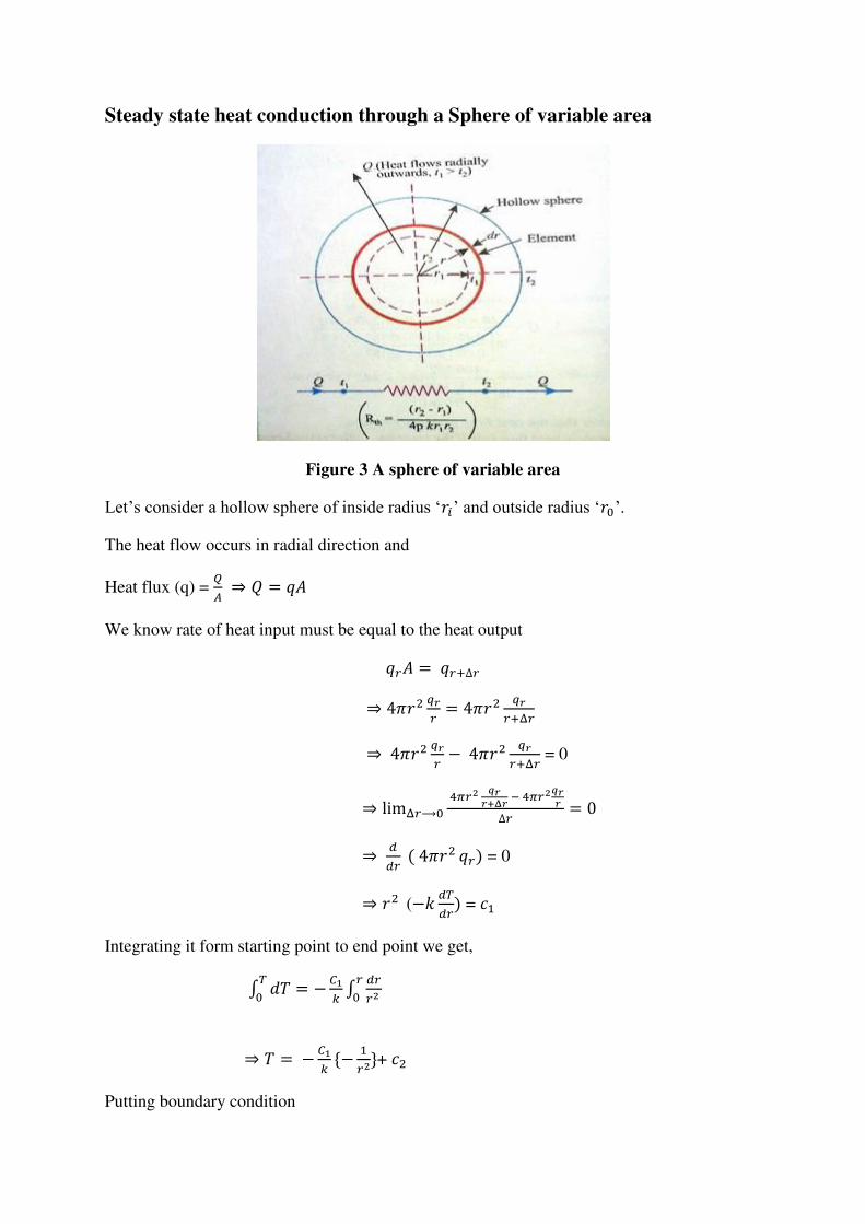
Steady state heat conduction through a Sphere of variable area
Figure 3 A sphere of variable area
Let’s consider a hollow sphere of inside radius ‘ ’ and outside radius ‘ ’.
The heat flow occurs in radial direction and
Heat flux (q) =
We know rate of heat input must be equal to the heat output
= 0
= 0
( =
Integrating it form starting point to end point we get,
∫ ∫
+
Putting boundary condition

1. T= , r= 2. T= , r=
Now we get, As you know,
Q =
And A = So
Q =
1-D unsteady state heat conduction of flat slab
Let’s consider a small amount of slab of the thickness dx at a distance ‘x’ from left side of slab. Temperature gradient at ‘x’ at definite instant of time is
. The heat input in time
interval dt at x is
Heat output in the time interval is ( ) ------1
Accumulation = ρ A dx ----------2
Equating equation 1 & 2 we get,
For 3-D heat equation, =

Heat transfer by conduction in a three-dimensional body, where the
temperature may be changing with time and heat sources are present
within the body:
Consider the general case where the temperature may be changing with time and heat sourses
may be present within the body.
By making an energy balance around the element of thickness dx:
Energy conducted in left face + heat generated within the element = Change in internal
energy + energy conducted out from the right face (1)
Energy in the left face , x
TKAqx
Energy generated within the element = Adxq.
Change in internal energy = dxT
cA
Energy out from the right face,
dxx
TK
xx
TKA
x
TKAq
dxx
dxx
Where, .
q = energy generated per unit volume.

C = specific heat of the material.
= density of the material.
Putting all the above values in equation no-1 and solving, we get:
T
cqx
TK
x
.
(2)
Which is the unsteady state heat conduction equation in one dimension.
If we will consider the heat conduction equation in all the three direction, then the equation
becomes:
E
qqqqqqq dzzdyydxxgenzyx (3)
Where,x
TKdydzqx
dydzdxx
TK
xx
TKq dxx
y
TKdxdzq y
dxdzdyy
TK
yy
TKq dyy
z
TKdxdyqz
dxdydzz
TK
zz
TKq dzz
dxdydzqqgen
.
T
cdxdydzd
dE
So that the general three-dimensional heat conduction equation becomes:
T
cqz
TK
zy
TK
yx
TK
x
.

T
K
q
z
T
y
T
x
T 1.
2
2
2
2
2
2
General heat conduction equation in cylindrical co-ordinate
Figure 4 Heat conduction analyses in a cylindrical co-ordinates
The volume of the element = r d heat generation per unit volume per unit time
K = thermal conductivity, ρ = density, = specific gravity
In (x - ) plane i.e. in radial direction, = - k (r d ) d = +
dr
Subtracting equation (ii) from (i) we get
d = = k (d )
d
= k r (d ) d
Similarly,
In r-z plane i.e. in tangential direction,
d = k r (d ) d

In r - plane i.e. in axial direction,
d = k r (d ) d
Net heat accumulation = k r (d ) [ ] d
Total heat generation ( ) = (r dr dz d ) d
Energy stored = ρ (r d ) d
So as we know
Net heat accumulation + total heat generated = Energy stored
So mathematically, + =
=
General heat conduction equation in Spherical co-ordinate
Figure 5 Heat conduction analyses in spherical co-ordinates
The volume of the element = r sin θ d Heat generation per unit volume per unit time
K = thermal conductivity, ρ = density, = specific gravity
In (r - ) plane i.e. in tangential direction,

= - k (r d ) d ----------i
= + r sin θ. d ------ii
Subtracting equation (ii) from (i) we get
d = ’
= k ( ) d
Similarly,
In r - plane i.e. in radial direction,
d = k ( ) d
In plane i.e. in axial direction,
d = k ( ) d
Net heat accumulation = k ( ) [ ( ) ] d
Total heat generation ( ) = ( ) d
Energy stored = ρ ( ) d
So as we know
Net heat accumulation + total heat generated = Energy stored
So mathematically,
( ) + =
=
Critical thickness of insulation
We know that adding more insulation to a wall or to the attic always decreases heat transfer.
The thicker is the insulation; the lower is the heat transfer rate. This is expected, since the
heat transfer area A is constant, and adding insulation always increases the thermal resistance
of the wall without increasing the convection resistance. Adding insulation to a cylindrical
pipe or a spherical shell, however, is a different matter. The additional insulation increases
the conduction resistance of the insulation layer but decreases the convection resistance of the

surface because of the increase in the outer surface area for convection. The heat transfer
from the pipe may increase or decrease, depending on which effect dominates.
Figure 6 Critical radius of insulation
Critical radius of cylinder
Figure 7 Critical insulation thicknesses for a cylinder
Let’s consider a solid cylinder of radius insulated with an insulation of thickness ( )
in the above figure.
L = length of the cylinder = surface temperature of the cylinder = temperature of air = heat transfer co-efficient at the outer surface of the insulation
K = thermal conductivity of insulating material
Then the rate of heat transfer from the surface of the solid cylinder to the surrounding is
given by
Q =

From the above equation we get,
If increases then factor increases but
decreases
So Q becomes maximum when,
[ ] = 0
Solving this finally we get
K =
0
2h
Kr
Critical radius of sphere
Figure-8 Critical insulation thickness for a sphere
Let’s consider a sphere of radius insulated with an insulation of thickness ( ) in the
above figure.
A = Surface area of the sphere = surface temperature of the sphere = temperature of air

= heat transfer co-efficient at the outer surface of the insulation
K = thermal conductivity of insulating material
Then the rate of heat transfer from the surface of the sphere to the surrounding is given by
0
2
221
12
1
4
1
4 hrrKr
rr
ttQ air
So Q becomes maximum when,
ohrrKr
rr
dr
d2
221
12
2 4
1
4 =0
01
0
2
221
12
2
hrrKr
rr
dr
d
0111
0
2
2212
hrKrKrdr
d
021
0
3
2
2
2
hrKr
0
3
2
2
22 hrKr
Convection
Whenever a solid body exposed to a moving fluid having a temperature different from that of
the body, energy is carried or convected from or to the body by the fluid.
Convection is the heat transfer between solid surface and fluid system in motion is
ThAQ
Where, Q=rate of heat flow across surface
h=individual heat transfer coefficient
A=area of heat transfer
∆T=Temperature difference between two surface
Convection is divided into types:-
1. Natural convection
2. Forced convection

1. Natural convection
Natural convection is the mechanism or type of heat transfer, in which the fluid motion is
generated by density differences in the fluid occurring due to temperature gradients.
Figure 1 Natural or free convection of air
Let the plate is maintained at the isothermal temperature wT which is higher than the
surrounding fluid temperature T . So the fluid near the wall on getting heated, moves up due
to the effect of buoyancy and is raplaced by the cold fluid moving towards the wall. Thus a
circulation current is set up due to the density difference.
In natural convection Nusselt number is a function Prandtl number and grassoff’s number i.e.
Nu=f(Pr,Gr)
2. Force convection
Force convection is the mechanism or type of heat transfer, in which fluid motion is
generated by external source (like a pump, fan, suction device etc).
Fan

Figure 2 Forced convection of air
When the mass motion of the fluid is caused by an external device, like a pump, compressor,
blower or fan, the process is called forced convection. Here fluid is made to flow along the
hot surface due to the pressure difference generated by the device and heat is transferred from
the wall to the fluid.
In forced convection Nusselt number is a function Prandtl number and Reynold’s number i.e.
Nu=f(Re,Pr)
Newton′s laws of cooling
According to this law, the rate of heat flux is directly propotional to temperature difference .
Regimes of heat transfer in fluids
A fluid is being heated or cooled may be flowing in laminar flow ,in turbulent flow or in
transition range between laminar and turbulent flow. Also fluid will flow in forced & natural
convection. The direction of flow of fluid may be parallel to the heating surface, so that
boundary layer thickness is least prominent or if the direction of flow is perpendicular or at
an angle to the heating surface. Then the boundary layer separation takes place ,because of
condition of flow at entrance of a tube differ from those well downstream from the entrance,
the velocity field and the assosciated temperature field may depend from the distance of tube
entrance and also depends upon situation , fluid flow through a preliminary length of
unheated or un cooled pipe, so that fully developed velocity field is established .The
temperature field is created within an existing velocity field.
Figure 3 thermal and hydrodynamic boundary layers on a entirely heated flat plate
Hydrodynamic boundary layer
A boundary layer developes within which the velocity varies from u=0 to u= at the outer
boundary layer.This boundary layer is called hydrodynamic boundary layer and shown by
above figure.

Thermal boundary layer
The penetration of heat by the transfer from the plate to the fluids change the temperature of
the fluid near the surface of the plate and temperature gradient is generated.The temperature
gradient is confined to a layer next to the wall and within the layer,temperature varies from
T= to T= .The boundary layer is called thermal boundary layer as shown by above
figure.
The thermal boundary layer thinner than hydrodynamic boundary layer at all distance from
leading edge of X.
Relationship between thickness of two boundary layer at a given point along the plate
depends on the dimensionless number is known as prandtl number (Pr).
Mathematically,
For, Pr 1, TBL HBL (eg.-most liquids)
Pr=1, TBL=HBL (eg.-gases)
Pr 1, TBL HBL (eg.-liquid metals)

Individual overall heat transfer coefficient
In the above figure the metal wall of the tube separate the warm fluid on the right to the cold
fluid on the left. The change in temperature with the distances shown by the line .Thus the temperature profile is divided into three parts:-
Through the metal wall and,
Through each of the two fluid
Figure 5 Temperature gradient in forced convection
The overall effect is therefore study in terms of individual parts. When one fluid flows
through a single pipe three zones are visible:-
Laminar sub layer
Buffer zone
Turbulent core
The velocity gradient is large near the wall, small in the turbulent core and rapid change in
the buffer layer. Similarly in the case of the temperature gradient it is larger at the wall
(through laminar sub layer), small in the turbulent core and rapid change in the buffer zone.
The overall resistance to the flow of heat from hot fluid to cold fluid is a result of three
separate resistances operating in series.
The individual or surface heat transfer coefficient h defined by the equation:-
h = (1)

=local heat flux based on the area in contact with fluid.
T=local average temperature of the fluid =Temperature of the wall in contact with the fluid.
Heat transfer by conduction is given by:- (2)
Normal distance measured into fluid from wall
(3)
Nu= (4)
Dimensionless group that is nusset number is the ratio of temperature gradient near the wall
to the temperature gradient across entire pipe.
Another interpretation of nusset number can be obtained by considering the gradient that
would exist if all the resistance to heat transfer were in a laminar layer in which heat transfer
was only by conduction.
= = h ( - (5)
h=
Nu= (6)
Therefore,this nusselt number is the ratio of the tube diameter to the equivalent thickness of
laminar layer.Sometimes
x=film thickness (7)
(8)
Where are inside and outside area of the tube.

Calculation of overall heat transfer coefficient from individual heat
transfer coefficient:
The rate of heat transfer through the tube wall is given by the differential form,
w
wcwhm
Lx
TTk
Ad
dq (1)
Where, wcwh TT → Temperature difference through the tube wall
mk → Thermal conductivity of the wall
wx → Tube wall thickness
LAd
dq → Local heat flux based on logarithmic mean of inside and outside area of tube.
(2)
ii
whhdAh
dqTT1
(3)
oo
cwcdAh
dqTT1
From eq-1,
Lm
w
wcwhAdk
xdqTT
The temperature difference ch TT ,
cwcwcwhwhhch TTTTTTTT
ooLm
w
ii
chdAhAdk
x
dAhdqTT
11 (4)
If the heat transfer rate is calculated based on the outside area,
oL
o
m
w
i
o
i
ch
o
hAd
dA
k
x
dA
dA
h
TT
dA
dq
11
Again i
o
i
o
D
D
dA
dA and
L
o
L
o
D
D
Ad
dA

The eq-6 can be reduced to:
oL
ow
i
o
i
ch
o
hD
D
k
x
D
D
h
TT
dA
dq
11
(5)
Also ch TTUTUdA
dq (6)
Comparing eq-5 and eq-6,
oL
o
m
w
i
o
i
o
hD
D
k
x
D
D
h
U11
1
(7)
The overall heat transfer co-efficient based on the outside area of the tube.
Similarly the overall heat transfer co-efficient based on the inside area of the tube is given by:
iL
i
m
w
o
i
o
i
hD
D
k
x
D
D
h
U11
1
(8)
Fouling factor
In actual service, the heat transfer surface do not remain clean. Scale, dirt and other solid
deposits form on one or both the sides of the tubes ,provide additional resistance to heat flow
and reduce the overall coefficient. The effect of such deposits is taken into account by adding
a term to equation of overall coefficient.
L
o
m
w
i
o
ii
o
ioo
o
D
D
k
x
D
D
hdD
D
hhdh
U1111
1 (9)
L
i
m
w
o
i
oo
i
oii
i
D
D
k
x
D
D
hdD
D
hhdh
U1111
1 (10)
Where ihd and ohd are the fouling factors for the scale deposits on the inside and outside of
tube surfaces respectively.

Condensation
Heat transfer to a surface occurs by condensation when the surface temperature is less than
the saturation temperature of an adjoining vapor. A vapor may condense on a cold surface in
one of two ways, which are well described by the terms drop wise and film type condensation.
Film type condensation
Entire surface is covered by the condensate, which flows continuously from the
surface and provides a resistance to heat transfer between the vapor and the surface.
Condensate wets the surface and forms a liquid film on the surface that slides down
under the influence of gravity.
Thickness of the liquid film increases in the flow direction as more vapor Condenses
on the film.
Thermal resistance is reduced through use of short vertical surfaces and horizontal
cylinders.
Characteristic of clean, uncontaminated surfaces.
Drop wise condensation
Surface is covered by drops ranging from a few micrometers to agglomerations
visible to the naked eye.
Condensed vapor forms droplet on the surface instead of a continuous film, and the
Surface is covered by countless droplets of varying diameter.
Thermal resistance is greatly reduced due to absence of a continuous film.
Surface coatings may be applied to inhibit wetting and stimulate drop wise
condensation.
Figure 1 (a)Film type
condensation
Figure 1 (b) Drop wise
condensation
Rate of heat transfer in drop wise condensation is 18 times more than that of film wise
condensation. Due to the present of film in film wise condensation it decreases the rate of
heat transfer.

Coefficients for film-type condensation
The basic equations for the rate of heat transfer in film-type condensation were first derived
by Nusselt. The Nusselt equations are based no the following assumptions.
The vapor and the liquid at theoutside boundary of the liquid layer are in
thermodynamic equilibrium, so that the only resistance to the flow of heat is that
offered by the layer of condensate flowing downword in laminar flow under the
action of gravity.
The velocity of the liquid at the wall is zero, that the velocity of the liquid at the
outside of the film is not influenced by the velocity of the vapor, and that the
temperatures of the wall and the vapor are constant.
The physical properties of the liquid are taken at the mean film temperature.
Solved Examples
A. Short answer types
1. Walls of acubical oven are are of thickness L, and they are made up of thermal
conductivity K. the temperature inside the oven is 100 oC and the inside heat ransfer
coefficient is 3K/L. if the wall temperature on the outside is held at 25 oC, what is the
inside wall temperature in degrees C?
Answer:
We know KL
T
KLKLq w
3
100
3
75
KL
T
KL
w
3
100
34
75
wT 100475
CTw 25.81
2. The heat flux (from outside to inside) across an insulating wall with thermal conductivity
K= 0.04 W/mK and thickness 0.16 m is 10 W/m2. The temperature of the inside wall is -
5oC. What is the temperature of the outside wall?
Answer:
We know q = K∆T/∆L; ∆T = 10×0.16/0.04 = 40
Therefore the outside temperature = -5+40 = 35oC

3. A composite flat wall of a furnace is made up of two materials A and B. the thermal
conductivity of A is twice that of material B, while the thickness of layer A is half that of
B. if the temperature at the two sides of the wall are 400 and 1200 K, then what is the
temperature drop across the layer of material A?
Answer:
K
L
T
K
L
K
L
2
2
2
2
800
KL
T
KL 445
800 1
KT 16058001
4. For turbulent flow in a tube, the heat transfer coefficient is obtained from Dittus-Boilter
correlation. If the tube diameter is halved and the flow rate is doubled, then the heat
transfer co-efficient is changed by what factor?
Answer: 33.08.0 PrRe023.0Nu
33.08.0KCDvKhD P
2.08.0 Dvh
Given that:
12 2QQ and 212 DD
From equation of continuity:
vDQ2
2
2
221
2
11 ; vDQvDQ
2
2
12
2
21
2
1 22 vDvDvD
12 8vv
Hence
06.65.08
28 2.08.0
2.0
1
8.0
1
2.0
1
8.0
1
2.0
1
8.0
1
2.0
2
8.0
2
1
2
Dv
Dv
Dv
Dv
h
h
5. The Sieder-Tate correlation for heat transfer in turbulent flow in a pipe gives 8.0ReNu ,
where Nu is the Nusselt number and Re is the reynold’s number for the flow. Assuming that this relation is valid, derive the relationship between heat transfer coefficient (h) and
the pipe diameter (D).
Answer: 8.0ReNu

8.0
Dv
K
hD
2.0 Dh
6. The variation of thermal conductivity of a metal with temperature is often correlated
using an expression of the form
aTkk 0
Where k is the thermal conductivity, and T is the temperature in K. what is the units of ‘a’ in SI system?
Answer: W/m. K
B. Long answer types
1. A thermopane window consists of two sheets of glass each 6 mm thick, separated by a
layer of stagnant air also 6 mm thick. Find the percentage reduction in heat loss from this
pane as compared to that of a single sheet of glass 6 mm thickness. The temperature drop
between inside and outside remains same at 15 oC. thermal conductivity of glass is 30
times that of air.
Solution:
kL
Tq
Let k be the thermal conductivity of glass. Then thermal conductivity of air is k/30.
k
kkk
q192
15
63066
151
kk
q6
15
6
152
(1) (2)
Air

Reduction in heat loss =
%9.96100615
19215615100
2
12
q
2. The wall of a cold storage unit comprises a brick layer (thickness mB 1.0 , thermal
conductivity KB = 1.4 W/m. K) and an inner layer of polyurethane foam (thickness δP =
0.05m, thermal conductivity KB = 0.015 W/m. K). Assume one dimentional heat transfer
by conduction through the composite wall, and that the inner surface of the polyurethane
layer is at a temperature Tc and the outer surface of the brick layer at temperature Th.
Solution:
Let Ti be the temperature at the contact of the two layers. Then
P
CiP
B
ihb TTkTTkqAQ
By assuming the numerators and the denominators, heat flux q is obtained as
PPBB
Ch
kk
TTq
Rate of heat gain Q = qA
PPBB
Ch
kk
TTAQ

WQ 3818015.005.04.01.0
1040260
3. The outside surface temperature of a pipe ( radious = 0.1 m) is 400 K. The pipe is losing
heat to atmosphere, which is at 300 K. the film heat transfer coefficient is 10 W/m2. K.
To reduce the rate of heat loss, the pipe is insulated by a 50 mm thick layer of asbestos (k
= 0.5 W/m. K). Calculate the percentage reduction in the rate of heat loss.
Solution:
Rate of heat loss without insulation (Q1) = hA∆T
= 10×∏D×(400-300)
= 200
Rate of heat loss with insulation (Q2) = ba RR
T
Where
4055.01.0
05.01.0ln
5.02
1ln
2
1
0
1
r
r
kRa
Therefore
mWQ /4.135)3333.04055.0(
3004002
Reduction in heat loss = 1001
21 Q
QQ= 32.3%
4. An asbestos pad, square in cross-section, measures 0.05 m on a side and increases linearly
to 0.1 m on the side at the other end as shown in the figure. The length of the pad is 0.15
3333.01005.01.02
1
2
1
1
hr
Rb

m. if the small end is held at 600 K and the larger end at 300 K. what will be the heat
transfer flow rate if the other four sides are insulated. Assume one directional heat flow.
Thermal conductivity of asbestos is 0.173 W/m. K.
Solution:
Variable area with respect to x:
A =
15.0
05.005.01.01.005.005.0 x
= 0.0025+0.05x
= 0.05(0.05+x)
Heat balance for the pad at a distance x from the small end, with thickness ∆x,
0 dxxxxx AqAq
Dividing by ∆x, and in the limit as ∆x→0,
0
dx
Aqd
00tan qAtconsAq
Where A0 = 0.05×0.05 = 0.0025 m2
Writing the heat conduction equation,
00qAdx
dTkAAq
Substituting for A,
00025.005.005.0 qdx
dTxk

Rearranging and integrating,
15.0
0
0
300
60005.0173.005.0
0025.0
x
dxqdT
Solving, 14390 q W/m2
The heat flow rate = A0q0 = 0.0025×1439 = 3.6 Watt
5. A liquid metal flows at a rate of 5 kg/sec through a 5 cm diameter stainless steel tube. It
enters at 425 oC and is heated to 450
oC as it passes through the tube. If a constant heat
flux is maintained along the tube and the tube wall is at a temperature 20 oC higher than
the liquid metal bulk temperature, calculate the area required to affect the heat transfer.
At constant heat flux, 827.00185.082.4 PeNu
Relation holds good.
Properties of the compound:
µ = 1.34 × 10⁻³
kg/m. sec
Cp = 0.149 kJ/kg. K
K = 15.6 W/m. K
Pr = 0.013
Solution:
Heat transfer rate Q,
625.18425450149.05.
TCmQ p kW
Estimation of heat transfer coefficient h:
Dv
N Re
Since, 2
.
4 D
m
v
Therefore, 2
.
4D
mv
Hence,
95018
05.041034.1
505.0Re
23
Pe = Re. Pr = 95018×0.013 = 1235.2
Therefore from the given relation,

49.112.12350185.082.40185.082.4827.0827.0 PeNu
Since khDNu ,
358505.0
49.116.15
D
kNuh W/ m
2. K
Estimation of heat transfer area A;
Rate of heat transfer by convection Q = hA∆T
Therefore, 26.0203585
18625
Th
QA m
2
Area required to affect the heat transfer = 0.26 m2