Embed Size (px)
Citation preview
This article was downloaded by: 10.3.98.104On: 22 Jan 2022Access details: subscription numberPublisher: CRC PressInforma Ltd Registered in England and Wales Registered Number: 1072954 Registered office: 5 Howick Place, London SW1P 1WG, UK
Metal–Air and Metal–Sulfur Batteries: Fundamentals andApplications
Vladimir Neburchilov, Jiujun Zhang
Aluminum–Air Batteries Fundamentals and Applications
Publication detailshttps://www.routledgehandbooks.com/doi/10.1201/9781315372280-4
Vladimir Neburchilov, Jiujun ZhangPublished online on: 24 Aug 2016
How to cite :- Vladimir Neburchilov, Jiujun Zhang. 24 Aug 2016, Aluminum–Air BatteriesFundamentals and Applications from: Metal–Air and Metal–Sulfur Batteries: Fundamentals andApplications CRC PressAccessed on: 22 Jan 2022https://www.routledgehandbooks.com/doi/10.1201/9781315372280-4
PLEASE SCROLL DOWN FOR DOCUMENT
Full terms and conditions of use: https://www.routledgehandbooks.com/legal-notices/terms
This Document PDF may be used for research, teaching and private study purposes. Any substantial or systematic reproductions,re-distribution, re-selling, loan or sub-licensing, systematic supply or distribution in any form to anyone is expressly forbidden.
The publisher does not give any warranty express or implied or make any representation that the contents will be complete oraccurate or up to date. The publisher shall not be liable for an loss, actions, claims, proceedings, demand or costs or damageswhatsoever or howsoever caused arising directly or indirectly in connection with or arising out of the use of this material.
Dow
nloa
ded
By:
10.
3.98
.104
At:
17:0
2 22
Jan
202
2; F
or: 9
7813
1537
2280
, cha
pter
3, 1
0.12
01/9
7813
1537
2280
-4
65
3 Aluminum–Air BatteriesFundamentals and Applications
Fei Ding, Jun Zong, Sihui Wang, Hai Zhong, Qingqing Zhang, and Qing Zhao
CONTENTS
3.1 Introduction ....................................................................................................663.1.1 History ................................................................................................663.1.2 AAB Chemistry .................................................................................. 673.1.3 AAB Battery Components ..................................................................693.1.4 Electrochemical Performance............................................................. 703.1.5 Applications ........................................................................................ 713.1.6 Economics and Market ....................................................................... 72
3.2 AAB Anodes .................................................................................................. 723.2.1 Introduction ........................................................................................ 723.2.2 Anode Types and Design .................................................................... 733.2.3 Electrochemical Performance............................................................. 73
3.2.3.1 Binary Aluminum Alloys .................................................... 733.2.3.2 Ternary and Quaternary Aluminum Alloys ........................77
3.2.4 Electrochemical Test Procedures........................................................ 783.2.5 Failure Mode Analysis and Mitigation Strategies ..............................803.2.6 Anode Fabrication ..............................................................................80
3.3 AAB Cathode .................................................................................................803.3.1 Introduction ........................................................................................803.3.2 Cathode Types (Including Bifunctional Electrodes) and Design ....... 813.3.3 Electrochemical Performance............................................................. 81
3.3.3.1 Noble Metals and Alloys...................................................... 813.3.3.2 Transition-Metal Oxides ...................................................... 833.3.3.3 Other Catalytic Materials ....................................................84
3.3.4 Electrochemical Test Procedures........................................................843.3.5 Failure Mode Analysis and Mitigation Strategies ..............................843.3.6 Cathode Fabrication ............................................................................84
3.4 AAB Electrolytes............................................................................................853.4.1 Introduction ........................................................................................853.4.2 Electrolyte Types ................................................................................85
3.4.2.1 Aqueous Electrolytes ...........................................................853.4.2.2 Nonaqueous Electrolytes .....................................................87
Dow
nloa
ded
By:
10.
3.98
.104
At:
17:0
2 22
Jan
202
2; F
or: 9
7813
1537
2280
, cha
pter
3, 1
0.12
01/9
7813
1537
2280
-466 Metal–Air and Metal–Sulfur Batteries: Fundamentals and Applications
3.1 INTRODUCTION
3.1.1 history
Metal–air batteries (metal = Li, Zn, Al, Mg, Fe, and Ca) have much higher specific energies than most currently available primary and rechargeable batteries [1,2], so they have been attracting many works in the electrochemistry research. Among these systems, the aluminum–air battery (AAB) is one important member with a practical specific energy density of 400 Wh kg−1 [1,2]. AAB is also one of the most developed members due to the low cost and abundance of aluminum metal. The AAB is typically used as a primary metal–air battery with an aluminum anode and an air-breathing cathode in contact with an aqueous electrolyte, typically sodium hydroxide, potassium hydroxide, or sodium chloride [3].
3.4.3 Correlation between Electrolyte Properties and Battery Performance ........................................................................................88
3.4.4 Compatibility between Electrolyte and Separator .............................. 893.4.5 Failure Mode Analysis and Mitigation Strategies ..............................90
3.5 AAB Separators ..............................................................................................933.5.1 Introduction ........................................................................................933.5.2 Separator Types and Their Physicochemical Properties ....................943.5.3 Correlation between Separator Properties and Battery
Performance ....................................................................................943.5.4 Failure Mode Analysis and Mitigation Strategies ..............................95
3.6 AAB Current Collectors .................................................................................953.6.1 Introduction ........................................................................................953.6.2 Current Collector Types and Their Physicochemical Properties .......963.6.3 Correlation between Current Collector Properties and Battery
Performance ........................................................................................963.6.4 Failure Mode Analysis and Mitigation Strategies ..............................96
3.7 AAB Manufacture ..........................................................................................963.7.1 Introduction ........................................................................................963.7.2 Anode Manufacture ............................................................................973.7.3 Cathode Manufacture .........................................................................983.7.4 Electrolyte Preparation .......................................................................993.7.5 Current Collectors, Seal, and Seal Case Manufacture ..................... 1003.7.6 Battery Assembling .......................................................................... 100
3.7.6.1 Liquid Electrolyte Aluminum–Air Battery ....................... 1013.7.6.2 Gel Electrolyte–Based Aluminum–Air Batteries .............. 1013.7.6.3 All-Solid-State AABs ........................................................ 101
3.7.7 Battery Maintenance......................................................................... 1023.7.8 Battery Tests and Performance Diagnosis ........................................ 1023.7.9 Battery Safety ................................................................................... 103
3.8 AAB Technology Challenges and Perspectives ........................................... 1033.9 Summary ...................................................................................................... 104References .............................................................................................................. 105
Dow
nloa
ded
By:
10.
3.98
.104
At:
17:0
2 22
Jan
202
2; F
or: 9
7813
1537
2280
, cha
pter
3, 1
0.12
01/9
7813
1537
2280
-467Aluminum–Air Batteries
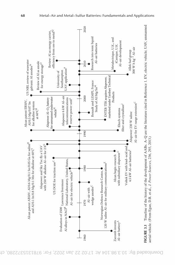
A significant amount of work was carried out on AAB in the 1960s and the early 1970s; the related work on AAB in the past 50 years was already summarized by some researchers as shown in Figure 3.1 [1], most of which are accessible as pub-lications and patents, while others (such as internal company reports) are more restricted. The related works mainly focused on the AAB electrochemistry and their developing applications. Great efforts in the field were received to solve the prob-lems associated with the air electrode, thermal management, and the reversibility of the system. Just in 2014, an electric car which was equipped with an AAB system and developed by two companies (Phinergy, United States, and Alcoa, Israel) made its track debut [4]. When used to supplement a lithium-ion battery, the battery can extend the range of an electric car by about 1600 km (994 miles) [4]. The reports give us enough confidence to believe that the AAB has the promising prospects in the applications. The AAB will become the ideal power in the twenty-first century.
3.1.2 AAb chEmistry
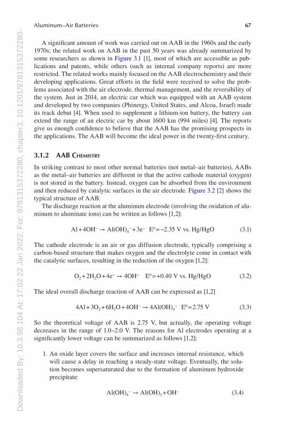
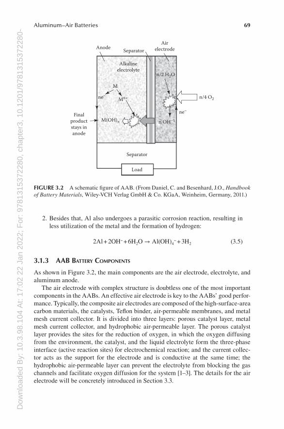
In striking contrast to most other normal batteries (not metal–air batteries), AABs as the metal–air batteries are different in that the active cathode material (oxygen) is not stored in the battery. Instead, oxygen can be absorbed from the environment and then reduced by catalytic surfaces in the air electrode. Figure 3.2 [2] shows the typical structure of AAB.
The discharge reaction at the aluminum electrode (involving the oxidation of alu-minum to aluminate ions) can be written as follows [1,2]:
Al + 4OH− → Al(OH)4− + 3e− E0 = −2.35 V vs. Hg/HgO (3.1)
The cathode electrode is an air or gas diffusion electrode, typically comprising a carbon-based structure that makes oxygen and the electrolyte come in contact with the catalytic surfaces, resulting in the reduction of the oxygen [1,2]:
O2 + 2H2O + 4e− → 4OH− E0 = +0.40 V vs. Hg/HgO (3.2)
The ideal overall discharge reaction of AAB can be expressed as [1,2]
4Al + 3O2 + 6H2O + 4OH− → 4Al(OH)4− E0 = 2.75 V (3.3)
So the theoretical voltage of AAB is 2.75 V, but actually, the operating voltage decreases in the range of 1.0–2.0 V. The reasons for Al electrodes operating at a significantly lower voltage can be summarized as follows [1,2]:
1. An oxide layer covers the surface and increases internal resistance, which will cause a delay in reaching a steady-state voltage. Eventually, the solu-tion becomes supersaturated due to the formation of aluminum hydroxide precipitate:
Al(OH)4− → Al(OH)3 + OH− (3.4)
Downloaded By: 10.3.98.104 At: 17:02 22 Jan 2022; For: 9781315372280, chapter3, 10.1201/9781315372280-468 Metal–Air and Metal–Sulfur Batteries: Fundamentals and Applications
Alle
k fu
el g
roup
300
W h
kg–1
Al–
air
Alu
pow
er 2
30 W
salin
e
Alc
an b
egin
rese
arch
with
subs
idia
ry a
lupo
wer
C
Al–
air f
or E
V ra
nge
exte
nsio
nC
Vol
tek
EV w
ith le
ad–a
cid
and
4.5
kW A
l–ai
r bat
terie
sF
Nor
weg
ian
Def
ence
Res
earc
h C
entr
e,12
0 W
salin
e A
l–ai
r for
mili
tary
com
mun
icat
ions
E
Zaro
mb
inve
nts
Al–
air b
atte
ryA
Al–
air w
ithw
edge
ano
desC
Rese
arch
into
ioni
c liq
uid
Al–
air b
atte
ries
Revi
ew: A
l as e
nerg
y ca
rrie
r,ef
ficie
ncy
from
ore
to m
etal
Q
Revi
ew o
f Al a
s ano
defo
r ene
rgy
stor
ageO
US
NRL
revi
ew o
f sea
wat
erga
lvan
ic A
l ano
desN
Alc
an p
aten
t EB5
0V,
Al/0
.5 M
g/0.
07 S
nfo
r alk
alin
e sy
stem
at 6
0°C
K
Alu
pow
er A
l–O
2 bat
tery
for u
nman
ned
unde
rwat
erve
hicle
H
Alc
an p
aten
t AB5
0V, A
l/0.6
Mg/
0.1
Sn/0
.05
Ga
for s
alin
eH
and
Al/0
.1 In
/0.8
Mg/
0.1
Mn
for a
lkal
ine
at 6
0°C
I
Alu
pow
er a
nd S
ky T
ec fl
y a
UA
Vw
ith 2
50 W
alk
alin
e A
l–ai
r for
2 h
G
US
DO
E fo
r tra
ctio
n us
eC
Law
renc
e liv
erm
ore
Nat
iona
l Lab
orat
ory,
Uni
ted
Stat
es,
Al–
air f
or e
lect
ric v
ehic
leD
Eval
uatio
n of
250
0A
l allo
ys in
NA
ClB
Alu
pow
er 6
kW
Al–
air
tele
com
mun
icat
ions
rese
rve
pow
er u
nitL
Uni
vers
ity o
f So
utha
mpt
onU
AV
app
licat
ionP
Rena
ult a
nd L
EMPI
, Fra
nce
Stud
y of
Al/M
g/Sn
M
ENTE
R-TE
K ac
quire
s Alu
pow
er,
mar
kete
d un
der Y
ardn
ey T
echn
ical
Prod
ucts
Elte
ch sy
stem
sfil
ter a
nd c
ryst
allis
erJ
2020
2000
1990
1970
1960
Met
alec
triq
ue, U
.K.,
and
iCan
ique
, U.K
.A
l–ai
r dev
elop
men
t
1980
2010
FIG
UR
E 3.
1 T
imel
ine
of t
he h
isto
ry o
f th
e de
velo
pmen
t of
AA
Bs.
A–Q
are
the
lite
ratu
re c
ited
in R
efer
ence
1. E
V, e
lect
ric
vehi
cle;
UA
V, u
nman
ned
aeri
al v
ehic
le. (
From
Ega
n, D
.R. e
t al.,
J. P
ower
Sou
rces
, 236
, 293
, 201
3.)
Dow
nloa
ded
By:
10.
3.98
.104
At:
17:0
2 22
Jan
202
2; F
or: 9
7813
1537
2280
, cha
pter
3, 1
0.12
01/9
7813
1537
2280
-469Aluminum–Air Batteries
2. Besides that, Al also undergoes a parasitic corrosion reaction, resulting in less utilization of the metal and the formation of hydrogen:
2Al + 2OH− + 6H2O → Al(OH)4− + 3H2 (3.5)
3.1.3 AAb bAttEry comPonEnts
As shown in Figure 3.2, the main components are the air electrode, electrolyte, and aluminum anode.
The air electrode with complex structure is doubtless one of the most important components in the AABs. An effective air electrode is key to the AABs’ good perfor-mance. Typically, the composite air electrodes are composed of the high- surface-area carbon materials, the catalysts, Teflon binder, air-permeable membranes, and metal mesh current collector. It is divided into three layers: porous catalyst layer, metal mesh current collector, and hydrophobic air-permeable layer. The porous catalyst layer provides the sites for the reduction of oxygen, in which the oxygen diffusing from the environment, the catalyst, and the liquid electrolyte form the three-phase interface (active reaction sites) for electrochemical reaction; and the current collec-tor acts as the support for the electrode and is conductive at the same time; the hydrophobic air-permeable layer can prevent the electrolyte from blocking the gas channels and facilitate oxygen diffusion for the system [1–3]. The details for the air electrode will be concretely introduced in Section 3.3.
Airelectrode
M
Mn+ne–
Separator
Alkalineelectrolyte
M(OH)n
n/2 H2O
n OH–1
n/4 O2
ne–
Anode
Separator
Load
Finalproductstays inanode
FIGURE 3.2 A schematic figure of AAB. (From Daniel, C. and Besenhard, J.O., Handbook of Battery Materials, Wiley-VCH Verlag GmbH & Co. KGaA, Weinheim, Germany, 2011.)
Dow
nloa
ded
By:
10.
3.98
.104
At:
17:0
2 22
Jan
202
2; F
or: 9
7813
1537
2280
, cha
pter
3, 1
0.12
01/9
7813
1537
2280
-470 Metal–Air and Metal–Sulfur Batteries: Fundamentals and Applications
Typically, the electrolytes used in AABs are aqueous alkaline solution (such as sodium hydroxide or potassium hydroxide) and neutral saline (such as sodium chloride) as mentioned in Section 3.1.1 [3]. The reason that neutral saline electro-lytes are also used is that they exhibit a lower open-circuit corrosion rate and a lower risk to the health of the system compared with caustic solutions. However, the higher conductivity and Al(OH)3 solubility of alkaline solutions can facilitate the delivery of high cell power (175 W kg−1) and energy densities (400 Wh kg−1) compared with saline systems (30 W kg−1, 220 Wh kg−1) [3]. It is attractive for high-power applications such as standby batteries, unmanned underwater vehicles, electric vehicles, and so on. The details for the electrolytes will be concretely introduced in Section 3.4.
Another important component of AABs is the aluminum anode. It is not so sim-ple as that component of the aluminum anode is just the superpure aluminum metal. In fact, the superpure aluminum is unsuitable for use as the anode of AABs, espe-cially in uninhibited alkaline electrolytes. The reasons are as follows: (1) a passive hydroxide layer will form on the surface, resulting in the high overpotential during anodic dissolution; and (2) it also suffers from the high corrosion currents as water is reduced on preferential surface sites evolving hydrogen, which is significantly harmful to the health of the system. One effective method is to alloy the superpure aluminum with other elements (such as Sn, In, Ga) to improve its electrochemical performance [1]. Also, it must be noted that impurities such as copper, iron, and silicon can aggravate self-corrosion. There are also some other effective methods to improve the performance of the anode, which will be concretely introduced in Section 3.2.
The separators of AABs play important roles in separating the two electrodes and allowing normal ion diffusion, ensuring the operation of the system. The details of the separators will be concretely introduced in Section 3.5.
3.1.4 ElEctrochEmicAl PErformAncE
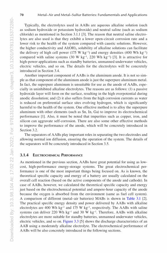
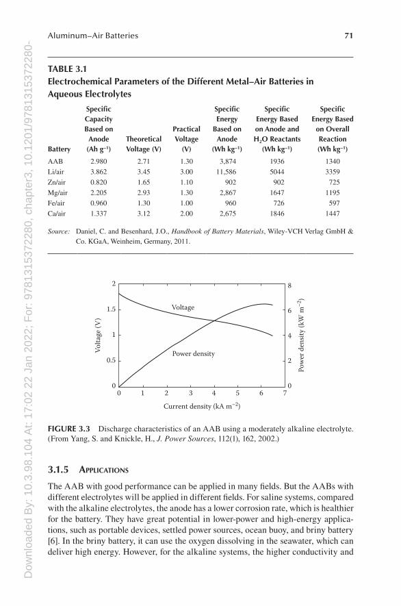
As mentioned in the previous section, AABs have great potential for using as low-cost, high-performance energy-storage systems. The great electrochemical per-formance is one of the most important things being focused on. As is known, the theoretical specific capacity and energy of a battery are usually calculated on the overall cell reaction (based on the active components of the anode and cathode). In case of AABs, however, we calculated the theoretical specific capacity and energy just based on the electrochemical potential and ampere-hour capacity of the anode because the oxygen is absorbed from the environment (same as fuel cell system). A comparison of different (metal–air batteries) MABs is shown in Table 3.1 [2]. The practical specific energy density and power delivered by AABs with alkaline electrolytes are 400 Wh kg−1 and 175 W kg−1, respectively. The AABs with saline systems can deliver 220 Wh kg−1 and 30 W kg−1. Therefore, AABs with alkaline electrolytes are more suitable for standby batteries, unmanned underwater vehicles, electric vehicles, and so on. Figure 3.3 [5] shows the discharge characteristics of an AAB using a moderately alkaline electrolyte. The electrochemical performance of AABs will be also concretely introduced in the following sections.
Dow
nloa
ded
By:
10.
3.98
.104
At:
17:0
2 22
Jan
202
2; F
or: 9
7813
1537
2280
, cha
pter
3, 1
0.12
01/9
7813
1537
2280
-471Aluminum–Air Batteries
3.1.5 APPlicAtions
The AAB with good performance can be applied in many fields. But the AABs with different electrolytes will be applied in different fields. For saline systems, compared with the alkaline electrolytes, the anode has a lower corrosion rate, which is healthier for the battery. They have great potential in lower-power and high-energy applica-tions, such as portable devices, settled power sources, ocean buoy, and briny battery [6]. In the briny battery, it can use the oxygen dissolving in the seawater, which can deliver high energy. However, for the alkaline systems, the higher conductivity and
TABLE 3.1Electrochemical Parameters of the Different Metal–Air Batteries in Aqueous Electrolytes
Battery
Specific Capacity Based on Anode (Ah g−1)
Theoretical Voltage (V)
Practical Voltage
(V)
Specific Energy
Based on Anode
(Wh kg−1)
Specific Energy Based on Anode and H2O Reactants
(Wh kg−1)
Specific Energy Based
on Overall Reaction (Wh kg−1)
AAB 2.980 2.71 1.30 3,874 1936 1340
Li/air 3.862 3.45 3.00 11,586 5044 3359
Zn/air 0.820 1.65 1.10 902 902 725
Mg/air 2.205 2.93 1.30 2,867 1647 1195
Fe/air 0.960 1.30 1.00 960 726 597
Ca/air 1.337 3.12 2.00 2,675 1846 1447
Source: Daniel, C. and Besenhard, J.O., Handbook of Battery Materials, Wiley-VCH Verlag GmbH & Co. KGaA, Weinheim, Germany, 2011.
6
Current density (kA m–2)
54
Power densityVolta
ge (V
)
Pow
er d
ensit
y (k
W m
–2)
Voltage
32
2 8
6
4
2
1
0
0.5
1.5
100
7
FIGURE 3.3 Discharge characteristics of an AAB using a moderately alkaline electrolyte. (From Yang, S. and Knickle, H., J. Power Sources, 112(1), 162, 2002.)
Dow
nloa
ded
By:
10.
3.98
.104
At:
17:0
2 22
Jan
202
2; F
or: 9
7813
1537
2280
, cha
pter
3, 1
0.12
01/9
7813
1537
2280
-472 Metal–Air and Metal–Sulfur Batteries: Fundamentals and Applications
Al(OH)3 solubility of alkaline solutions can facilitate the delivery of higher power. It is greatly attractive for high-power applications such as standby batteries, battlefield power devices (Special Operation Forces Aluminum Air), unmanned underwater vehicles, electric vehicles, and so on [6]. Unmanned underwater vehicles include unmanned submarine, mine sweeping devices, long-range torpedo, and so on [6]. Also note that the major technical gaps of AABs toward the commercialization are the hydrogen evolution and parasitic corrosion reaction of the anode.
3.1.6 Economics And mArkEt
The reports about Phinergy, United States, and Alcoa, Israel, are good evidence to prove that the AAB has promising prospects in the economics and market. For now, though, it seems like that AAB only serves as a range extender and a standard lithium battery is still the primary energy source. Phinergy has also reported that it has signed a contract with a global automaker to bring AAB to the production of cars in 2017, though it did not give a clear statement if AAB would be used as a range extender or as the primary power source. It is a positive signal that the electric vehicles (EVs) equipped with AABs will ship into the market and hold a certain market share in the immediate future. Besides that, the AAB will also hold a certain market share in the smart grid, consumer electronics (such as mobile phone, portable computer, electronic camera), aerospace and defense, and so on.
3.2 AAB ANODES
3.2.1 introduction
Aluminum is of interest as a battery anode for a number of reasons: (1) its ability to transfer three electrons per atom, (2) its low atomic mass, and (3) its high negative standard potential. These characteristics lead to a high theoretical energy density of 8.1 Wh g−1 in AAB. In addition, the large natural abundance and the low production cost of aluminum make it extremely appealing for use in battery systems [7].
Thermodynamically, an aluminum anode should exhibit a potential of 1.66 V in saline and 2.35 V in alkali electrolyte. However, practical aluminum electrodes operate at a significantly lower potential because (a) aluminum is normally covered by an oxide film that causes a delay in reaching a steady-state voltage due to internal resistance and (b) aluminum undergoes a parasitic corrosion reaction, resulting in less than 100% utilization of the metal and the evolution of hydrogen. The discharg-ing reaction of an aluminum electrode in alkaline media is
Al + 4OH− – 3e− = Al(OH)4− E = 2.4 V vs. SHE [8] (3.6)
The progressive consumption of hydroxyl ions at the aluminum electrode makes the electrolyte saturated with the aluminate. Eventually, the aluminate concentration exceeds the supersaturation and a crystalline form of aluminum hydroxide precipi-tates with the regeneration of hydroxyl ions:
Al(OH)4− = Al(OH)3 + OH− (3.7)
Dow
nloa
ded
By:
10.
3.98
.104
At:
17:0
2 22
Jan
202
2; F
or: 9
7813
1537
2280
, cha
pter
3, 1
0.12
01/9
7813
1537
2280
-473Aluminum–Air Batteries
In addition to the electrochemical consumption of the anode, aluminum is thermo-dynamically unstable in an alkaline electrolyte and reacts with the electrolyte to generate hydrogen:
2Al + 6H2O = 2Al(OH)3 + 3H2 (3.8)
This parasitic corrosion reaction, or self-discharge, degrades the coulombic efficiency of the anode and must be suppressed in order to minimize the capacity loss [9].
3.2.2 AnodE tyPEs And dEsign
Research on anode for AABs has focused on aluminum alloy anode and pure alumi-num anode, which was chosen by the corresponding electrolyte systems.
Most of the anodes used for AABs did not need great efforts for physics design, except the size, which should be appreciated for the cells. But great efforts have been made on anode ingredient design for better cells performance, for example, using alloyed materials as anode. An effective alloying element should possess the following properties: (1) a melting point below the melting temperature of aluminum (657°C), (2) good solid solubility in the aluminum matrix, (3) a higher nobility than aluminum in the electrochemical series as determined from the Pourbaix diagram [10,11], (4) good solubility in an alkaline electrolyte, and (5) a high hydrogen overpo-tential [12]. According to these rules, research on anode alloys for AABs has focused on Mg, Zn, Pb, Sn, Ga, In, Mn, Hg, and Tl alloying elements.
3.2.3 ElEctrochEmicAl PErformAncE
Several studies have investigated the effect of alloying elements on more commer-cially pure aluminum.
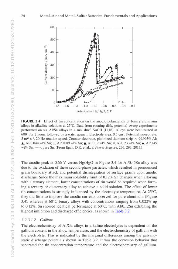
3.2.3.1 Binary Aluminum Alloys3.2.3.1.1 TinThe dissolution behavior of Al/Sn binary alloys is influenced by the structure, con-centration, and electrochemistry of tin along with the electrolyte temperature. The upper limit for the tin concentration in a binary aluminum alloy for use in AABs is 0.12 wt%, as this is the maximum that can be accommodated in solid solution in the aluminum matrix. A suitable solution heat treatment involves heating at 600°C for several hours, then water quenching [13,14]. An Al/0.12Sn alloy showed the most anodic behavior among a range of Al/Sn binary alloys in a 4 mol dm−3 NaOH solu-tion at 25°C (see Figure 3.4). This alloy showed enhanced anodic currents compared to pure aluminum over a potential range corresponding to the region of stability for tin, as discussed earlier [15,16]. Concentrations of tin lower than 0.12% in a 25°C electrolyte most likely had fewer tin deposits formed during the dissolution deposition process to accommodate film-free dissolution of aluminum. The alloys with tin levels greater than 0.12% did not improve the anodic current peak at 1.0 V versus Hg/HgO (see Figure 3.4) because the excess tin was present as second-phase particles on their grain boundaries, which are ineffective at activating aluminum.
Dow
nloa
ded
By:
10.
3.98
.104
At:
17:0
2 22
Jan
202
2; F
or: 9
7813
1537
2280
, cha
pter
3, 1
0.12
01/9
7813
1537
2280
-474 Metal–Air and Metal–Sulfur Batteries: Fundamentals and Applications
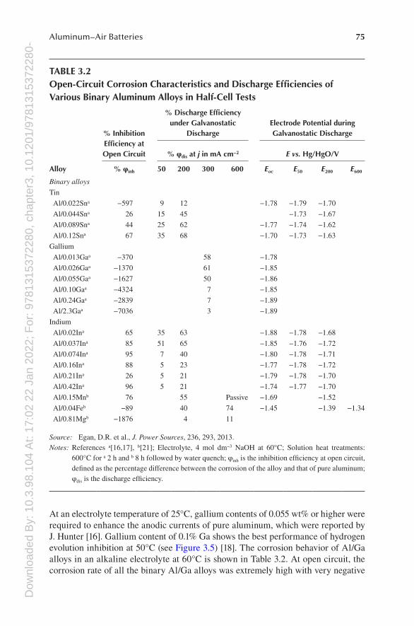
The anodic peak at 0.66 V versus Hg/HgO in Figure 3.4 for Al/0.45Sn alloy was due to the oxidation of these second-phase particles, which resulted in pronounced grain boundary attack and potential disintegration of surface grains upon anodic discharge. Since the maximum solubility limit of 0.12% Sn changes when alloying with a ternary element, lower concentrations of tin would be required when form-ing a ternary or quaternary alloy to achieve a solid solution. The effect of lower tin concentrations is strongly influenced by the electrolyte temperature. At 25°C, they did little to improve the anodic currents observed for pure aluminum (Figure 3.4), whereas at 60°C binary alloys with concentrations ranging from 0.022% up to 0.12%, Sn showed identical performance at 60°C, with Al/0.12Sn exhibiting the highest inhibition and discharge efficiencies, as shown in Table 3.2.
3.2.3.1.2 GalliumThe electrochemistry of Al/Ga alloys in alkaline electrolytes is dependent on the gallium content in the alloy, temperature, and the electrochemistry of gallium with the electrolyte. This is indicated by the marginal differences among the galvano-static discharge potentials shown in Table 3.2. It was the corrosion behavior that separated the tin concentration temperature and the electrochemistry of gallium.
–0.2–0.4–0.6–0.8
Potential vs. Hg/HgO, E/V–1.0–1.2–1.4–1.6–1.8
0
100
Cur
rent
den
sity,
j (m
A c
m–2
)
200
300
400
500
600
FIGURE 3.4 Effect of tin concentration on the anodic polarization of binary aluminum alloys in alkaline solutions at 25°C. Data from rotating disk, potential sweep experiments performed on six Al/Sn alloys in 4 mol dm−3 NaOH [11,16]. Alloys were heat-treated at 600° for 2 hours followed by a water quench. Electrode area: 0.5 cm2. Potential sweep rate: 5 mV s−1. 20 Hz rotation speed. Counter electrode, platinized titanium strip. ○, 99.995% Al; ▲, Al/0.044 wt% Sn; ◇, Al/0.089 wt% Sn; ■, Al/0.12 wt% Sn; ▽, Al/0.23 wt% Sn; ◆, Al/0.45 wt% Sn; -----, pure Sn. (From Egan, D.R. et al., J. Power Sources, 236, 293, 2013.)
Dow
nloa
ded
By:
10.
3.98
.104
At:
17:0
2 22
Jan
202
2; F
or: 9
7813
1537
2280
, cha
pter
3, 1
0.12
01/9
7813
1537
2280
-475Aluminum–Air Batteries
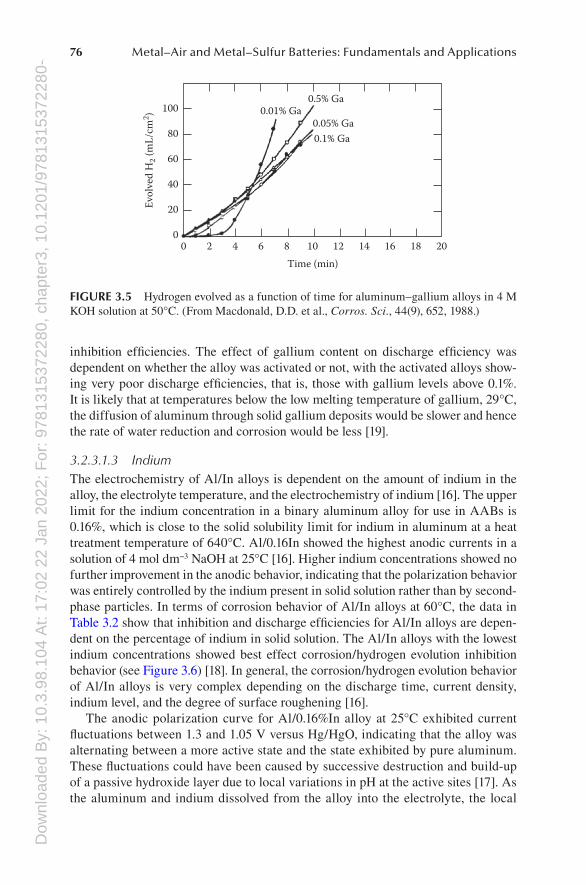
At an electrolyte temperature of 25°C, gallium contents of 0.055 wt% or higher were required to enhance the anodic currents of pure aluminum, which were reported by J. Hunter [16]. Gallium content of 0.1% Ga shows the best performance of hydrogen evolution inhibition at 50°C (see Figure 3.5) [18]. The corrosion behavior of Al/Ga alloys in an alkaline electrolyte at 60°C is shown in Table 3.2. At open circuit, the corrosion rate of all the binary Al/Ga alloys was extremely high with very negative
TABLE 3.2Open-Circuit Corrosion Characteristics and Discharge Efficiencies of Various Binary Aluminum Alloys in Half-Cell Tests
Alloy
% Inhibition Efficiency at Open Circuit
% Discharge Efficiency under Galvanostatic
Discharge Electrode Potential during Galvanostatic Discharge
% φdis at j in mA cm−2 E vs. Hg/HgO/V
% φinh 50 200 300 600 Eoc E50 E200 E600
Binary alloys
Tin
Al/0.022Sna −597 9 12 −1.78 −1.79 −1.70
Al/0.044Sna 26 15 45 −1.73 −1.67
Al/0.089Sna 44 25 62 −1.77 −1.74 −1.62
Al/0.12Sna 67 35 68 −1.70 −1.73 −1.63
Gallium
Al/0.013Gaa −370 58 −1.78
Al/0.026Gaa −1370 61 −1.85
Al/0.055Gaa −1627 50 −1.86
Al/0.10Gaa −4324 7 −1.85
Al/0.24Gaa −2839 7 −1.89
Al/2.3Gaa −7036 3 −1.89
Indium
Al/0.02Ina 65 35 63 −1.88 −1.78 −1.68
Al/0.037Ina 85 51 65 −1.85 −1.76 −1.72
Al/0.074Ina 95 7 40 −1.80 −1.78 −1.71
Al/0.16Ina 88 5 23 −1.77 −1.78 −1.72
Al/0.21Ina 26 5 21 −1.79 −1.78 −1.70
Al/0.42Ina 96 5 21 −1.74 −1.77 −1.70
Al/0.15Mnb 76 55 Passive −1.69 −1.52
Al/0.04Feb −89 40 74 −1.45 −1.39 −1.34
Al/0.81Mgb −1876 4 11
Source: Egan, D.R. et al., J. Power Sources, 236, 293, 2013.Notes: References a[16,17], b[21]; Electrolyte, 4 mol dm−3 NaOH at 60°C; Solution heat treatments:
600°C for a 2 h and b 8 h followed by water quench; φinh is the inhibition efficiency at open circuit, defined as the percentage difference between the corrosion of the alloy and that of pure aluminum; φdis is the discharge efficiency.
Dow
nloa
ded
By:
10.
3.98
.104
At:
17:0
2 22
Jan
202
2; F
or: 9
7813
1537
2280
, cha
pter
3, 1
0.12
01/9
7813
1537
2280
-476 Metal–Air and Metal–Sulfur Batteries: Fundamentals and Applications
inhibition efficiencies. The effect of gallium content on discharge efficiency was dependent on whether the alloy was activated or not, with the activated alloys show-ing very poor discharge efficiencies, that is, those with gallium levels above 0.1%. It is likely that at temperatures below the low melting temperature of gallium, 29°C, the diffusion of aluminum through solid gallium deposits would be slower and hence the rate of water reduction and corrosion would be less [19].
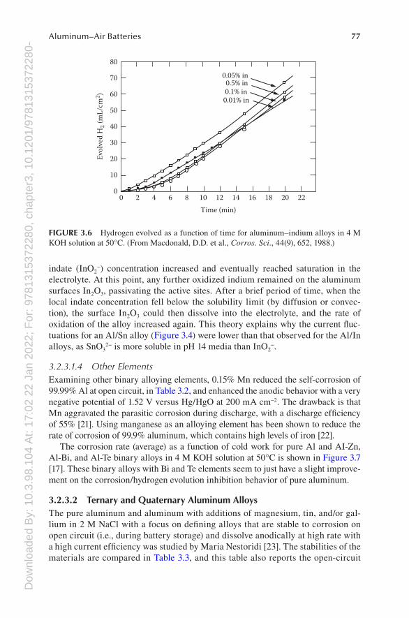
3.2.3.1.3 IndiumThe electrochemistry of Al/In alloys is dependent on the amount of indium in the alloy, the electrolyte temperature, and the electrochemistry of indium [16]. The upper limit for the indium concentration in a binary aluminum alloy for use in AABs is 0.16%, which is close to the solid solubility limit for indium in aluminum at a heat treatment temperature of 640°C. Al/0.16In showed the highest anodic currents in a solution of 4 mol dm−3 NaOH at 25°C [16]. Higher indium concentrations showed no further improvement in the anodic behavior, indicating that the polarization behavior was entirely controlled by the indium present in solid solution rather than by second-phase particles. In terms of corrosion behavior of Al/In alloys at 60°C, the data in Table 3.2 show that inhibition and discharge efficiencies for Al/In alloys are depen-dent on the percentage of indium in solid solution. The Al/In alloys with the lowest indium concentrations showed best effect corrosion/hydrogen evolution inhibition behavior (see Figure 3.6) [18]. In general, the corrosion/hydrogen evolution behavior of Al/In alloys is very complex depending on the discharge time, current density, indium level, and the degree of surface roughening [16].
The anodic polarization curve for Al/0.16%In alloy at 25°C exhibited current fluctuations between 1.3 and 1.05 V versus Hg/HgO, indicating that the alloy was alternating between a more active state and the state exhibited by pure aluminum. These fluctuations could have been caused by successive destruction and build-up of a passive hydroxide layer due to local variations in pH at the active sites [17]. As the aluminum and indium dissolved from the alloy into the electrolyte, the local
20181614
Time (min)
Evol
ved
H2 (
mL/
cm2 )
0.1% Ga0.05% Ga
0.5% Ga0.01% Ga
1210864200
20
40
60
80
100
FIGURE 3.5 Hydrogen evolved as a function of time for aluminum–gallium alloys in 4 M KOH solution at 50°C. (From Macdonald, D.D. et al., Corros. Sci., 44(9), 652, 1988.)
Dow
nloa
ded
By:
10.
3.98
.104
At:
17:0
2 22
Jan
202
2; F
or: 9
7813
1537
2280
, cha
pter
3, 1
0.12
01/9
7813
1537
2280
-477Aluminum–Air Batteries
indate (InO2−) concentration increased and eventually reached saturation in the
electrolyte. At this point, any further oxidized indium remained on the aluminum surfaces In2O3, passivating the active sites. After a brief period of time, when the local indate concentration fell below the solubility limit (by diffusion or convec-tion), the surface In2O3 could then dissolve into the electrolyte, and the rate of oxidation of the alloy increased again. This theory explains why the current fluc-tuations for an Al/Sn alloy (Figure 3.4) were lower than that observed for the Al/In alloys, as SnO3
2− is more soluble in pH 14 media than InO2−.
3.2.3.1.4 Other ElementsExamining other binary alloying elements, 0.15% Mn reduced the self-corrosion of 99.99% Al at open circuit, in Table 3.2, and enhanced the anodic behavior with a very negative potential of 1.52 V versus Hg/HgO at 200 mA cm−2. The drawback is that Mn aggravated the parasitic corrosion during discharge, with a discharge efficiency of 55% [21]. Using manganese as an alloying element has been shown to reduce the rate of corrosion of 99.9% aluminum, which contains high levels of iron [22].
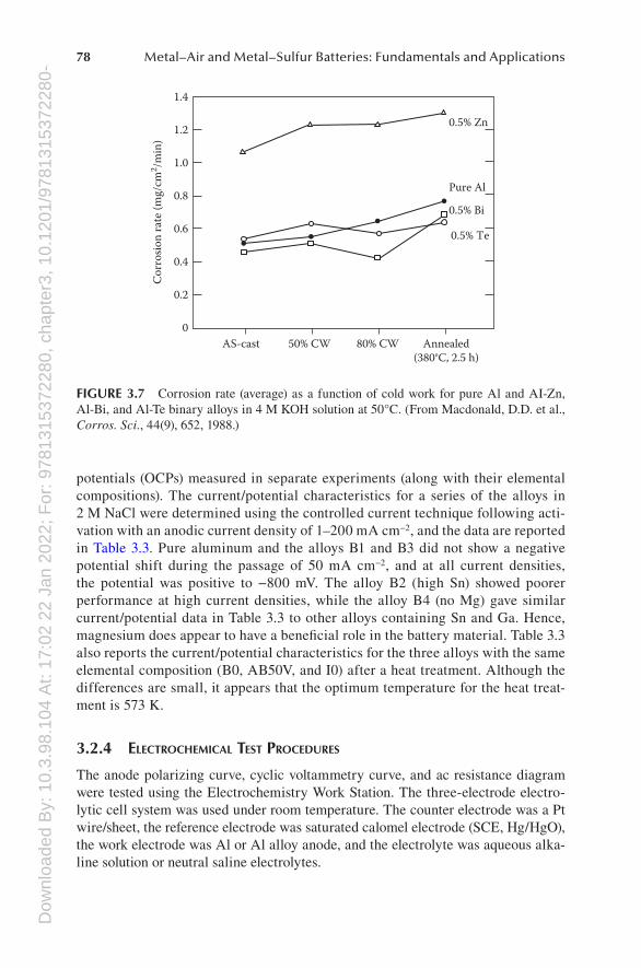
The corrosion rate (average) as a function of cold work for pure Al and AI-Zn, Al-Bi, and Al-Te binary alloys in 4 M KOH solution at 50°C is shown in Figure 3.7 [17]. These binary alloys with Bi and Te elements seem to just have a slight improve-ment on the corrosion/hydrogen evolution inhibition behavior of pure aluminum.
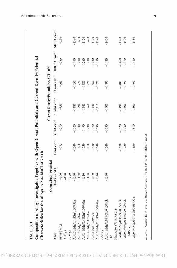
3.2.3.2 Ternary and Quaternary Aluminum AlloysThe pure aluminum and aluminum with additions of magnesium, tin, and/or gal-lium in 2 M NaCl with a focus on defining alloys that are stable to corrosion on open circuit (i.e., during battery storage) and dissolve anodically at high rate with a high current efficiency was studied by Maria Nestoridi [23]. The stabilities of the materials are compared in Table 3.3, and this table also reports the open-circuit
12
Time (min)
Evol
ved
H2 (
mL/
cm2 )
0.05% in0.5% in0.1% in
0.01% in
10864200
10
20
30
40
50
60
70
80
14 16 18 20 22
FIGURE 3.6 Hydrogen evolved as a function of time for aluminum–indium alloys in 4 M KOH solution at 50°C. (From Macdonald, D.D. et al., Corros. Sci., 44(9), 652, 1988.)
Dow
nloa
ded
By:
10.
3.98
.104
At:
17:0
2 22
Jan
202
2; F
or: 9
7813
1537
2280
, cha
pter
3, 1
0.12
01/9
7813
1537
2280
-478 Metal–Air and Metal–Sulfur Batteries: Fundamentals and Applications
potentials (OCPs) measured in separate experiments (along with their elemental compositions). The current/potential characteristics for a series of the alloys in 2 M NaCl were determined using the controlled current technique following acti-vation with an anodic current density of 1–200 mA cm−2, and the data are reported in Table 3.3. Pure aluminum and the alloys B1 and B3 did not show a negative potential shift during the passage of 50 mA cm−2, and at all current densities, the potential was positive to −800 mV. The alloy B2 (high Sn) showed poorer performance at high current densities, while the alloy B4 (no Mg) gave similar current/potential data in Table 3.3 to other alloys containing Sn and Ga. Hence, magnesium does appear to have a beneficial role in the battery material. Table 3.3 also reports the current/potential characteristics for the three alloys with the same elemental composition (B0, AB50V, and I0) after a heat treatment. Although the differences are small, it appears that the optimum temperature for the heat treat-ment is 573 K.
3.2.4 ElEctrochEmicAl tEst ProcEdurEs
The anode polarizing curve, cyclic voltammetry curve, and ac resistance diagram were tested using the Electrochemistry Work Station. The three-electrode electro-lytic cell system was used under room temperature. The counter electrode was a Pt wire/sheet, the reference electrode was saturated calomel electrode (SCE, Hg/HgO), the work electrode was Al or Al alloy anode, and the electrolyte was aqueous alka-line solution or neutral saline electrolytes.
Pure Al
0.5% Zn
0.5% Bi
0.5% Te
Annealed(380°C, 2.5 h)
Cor
rosio
n ra
te (m
g/cm
2 /min
)
80% CW50% CWAS-cast0
0.2
0.4
0.6
0.8
1.0
1.2
1.4
FIGURE 3.7 Corrosion rate (average) as a function of cold work for pure Al and AI-Zn, Al-Bi, and Al-Te binary alloys in 4 M KOH solution at 50°C. (From Macdonald, D.D. et al., Corros. Sci., 44(9), 652, 1988.)
Downloaded By: 10.3.98.104 At: 17:02 22 Jan 2022; For: 9781315372280, chapter3, 10.1201/9781315372280-479Aluminum–Air Batteries
TAB
LE 3
.3C
ompo
siti
on o
f Allo
ys I
nves
tiga
ted
Toge
ther
wit
h O
pen-
Cir
cuit
Pot
enti
als
and
Cur
rent
Den
sity
/Pot
enti
al
Cha
ract
eris
tics
for
the
Allo
ys in
2 M
NaC
l at
293
K
Allo
y O
pen
Cir
cuit
Pot
enti
al
(mV
) vs
. SC
E
Cur
rent
Den
sity
/Pot
enti
al v
s. S
CE
(mV
)
1 m
A c
m−
24
mA
cm
−2
10 m
A c
m−
250
mA
cm
−2
100
mA
cm
−2
50 m
A c
m−
2
99.9
99%
Al
−80
0−
775
−77
0−
750
−66
0−
530
−23
0
AlM
g3−
820
AlM
g5−
890
Al/0
.5%
Mg/
0.1%
Sn/0
.05%
Ga
−15
30−
1540
−15
20−
1480
−14
50−
1440
−13
90
Al/0
.4%
Mg/
0.1%
Sn−
850
−86
0−
800
−79
0−
770
−74
0−
680
Al/0
.4%
Mg/
0.4%
Sn/0
.03%
Ga
−15
10−
1530
−14
90−
1440
−13
80−
1260
−11
20
Al/0
.4%
Mg/
0.03
%G
a−
800
−81
0−
790
−76
0−
720
−70
0−
620
Al/0
.1%
Sn/0
.03%
Ga
−15
00−
1530
−14
90−
1440
−13
80−
1260
−11
20
Al/0
.6%
Mg/
0.1%
Sn/0
.05%
Ga
AB
50V
−15
30−
1540
−15
30−
1510
−14
70−
1440
−13
80
Al/0
.4%
Mg/
0.07
%Sn
/0.0
5%G
aI0
−15
30−
1540
−15
30−
1500
−14
90−
1480
−14
50
Hea
ted
to 8
73 K
for
2 h
Al/0
.5%
Mg/
0.1%
Sn/0
.05%
Ga
−15
30−
1520
−14
90−
1480
−14
60−
1390
Al/0
.6%
Mg/
0.1%
Sn/0
.05%
Ga
AB
50V
−15
30−
1520
−15
00−
1490
−14
70−
1400
Al/0
.4%
Mg/
0.07
%Sn
/0.0
5%G
aI0
−15
50−
1530
−15
00−
1490
−14
80−
1450
Sour
ce:
Nes
tori
di, M
. et a
l., J
. Pow
er S
ourc
es, 1
78(1
), 4
45, 2
008,
Tab
les
1 an
d 2.
Dow
nloa
ded
By:
10.
3.98
.104
At:
17:0
2 22
Jan
202
2; F
or: 9
7813
1537
2280
, cha
pter
3, 1
0.12
01/9
7813
1537
2280
-480 Metal–Air and Metal–Sulfur Batteries: Fundamentals and Applications
3.2.5 fAilurE modE AnAlysis And mitigAtion strAtEgiEs
In an AAB using either alkaline or brine electrolytes, the positive electrode reaction is O2 + 2H2O + 4e− → 4OH− and the negative electrode reaction is Al – 3e− → Al(III), and it is essential to the battery performance sought that both the Al anode and air cathode can operate at a current density 100 mA cm−2. With a neutral brine elec-trolyte, the Al(III) is largely formed as a solid oxide and/or hydroxide, and the per-formance of the battery depends critically on the form of this precipitate; it should neither form a passivating film on the aluminum surface nor inhibit the air cathode. In addition, the Al material used as the negative electrode must be stable to corro-sion during battery storage, that is, the chemical reactions of 4Al + 3O2 + 6H2O → 4Al(III) + 12OH− and 2Al + 6H2O → 2Al(III) + 3H2 + 6OH− should not occur either at the OCP or during anodic discharge (if all the Al is to be converted into electrical energy). It is the competing demands of stability to corrosion and rapid anodic dis-solution that make the identification of appropriate aluminum alloys difficult.
To overcome this problem, many researchers have used aluminum alloys of high purity grades possibly doped with elements like Ga, In, Sn, Mg, Mn, and Tl, which act as corrosion inhibitors without increasing the overpotential for aluminum dissolution.
3.2.6 AnodE fAbricAtion
Raw materials are commercial pure aluminum, Mg, Zn, Pb, Sn, Ga, In, Mn, Hg, and Tl materials. The nominal composition of the experiment alloys used Al as host materials, and other elements were chosen by requirement. Raw material ingots were cut, dried, and weighed to the required amount of materials and melted in a high-temperature equipment under argon atmosphere at 500°C–800°C. The molten alloy was poured in a preheated cast iron dye. After cold to room temperature, demold and cut it into an appropriate size for batteries requirement.
3.3 AAB CATHODE
3.3.1 introduction
The air cathode (often a gas diffusion electrode) is one of the most expensive com-ponents of a metal–air battery and is largely responsible for determining the cell performance [24].
The applications of oxygen reduction are strongly dependent on the products involved, either OH− or HO2
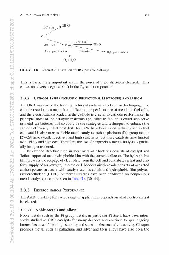
− [25]. Oxygen reduction is considered to occur mainly through two pathways [26]: (1) a 4e− reduction reaction without the intermediate formation of hydrogen peroxide and (2) an initial reduction reaction producing H2O2, which is possibly then further reduced to OH−. Figure 3.8 shows the schematic illus-tration of ORR possible pathways.
The actual pathway of oxygen reduction depends on the electrode materials and the electrolyte medium. It is important to mention that in a neutral electrolyte, such as NaCl, O2 reduction leads to the formation of OH− and an increase in pH.
Dow
nloa
ded
By:
10.
3.98
.104
At:
17:0
2 22
Jan
202
2; F
or: 9
7813
1537
2280
, cha
pter
3, 1
0.12
01/9
7813
1537
2280
-481Aluminum–Air Batteries
This is particularly important within the pores of a gas diffusion electrode. This causes an adverse negative shift in the O2 reduction potential.
3.3.2 cAthodE tyPEs (including bifunctionAl ElEctrodEs) And dEsign
The ORR was one of the limiting factors of metal–air fuel cell in discharging. The cathode reaction is a major factor affecting the performance of metal–air fuel cells, and the electrocatalyst loaded in the cathode is crucial to cathode performance. In principle, most of the catalytic materials applicable to fuel cells could also serve in metal–air batteries and so could be the strategies and techniques to enhance the cathode efficiency. Electrocatalysts for ORR have been extensively studied in fuel cells and Li–air batteries. Noble metal catalysts such as platinum (Pt)-group metals [27–29] have excellent activity and high selectivity, but these catalysts have limited availability and high cost. Therefore, the use of nonprecious metal catalysts is gradu-ally being considered.
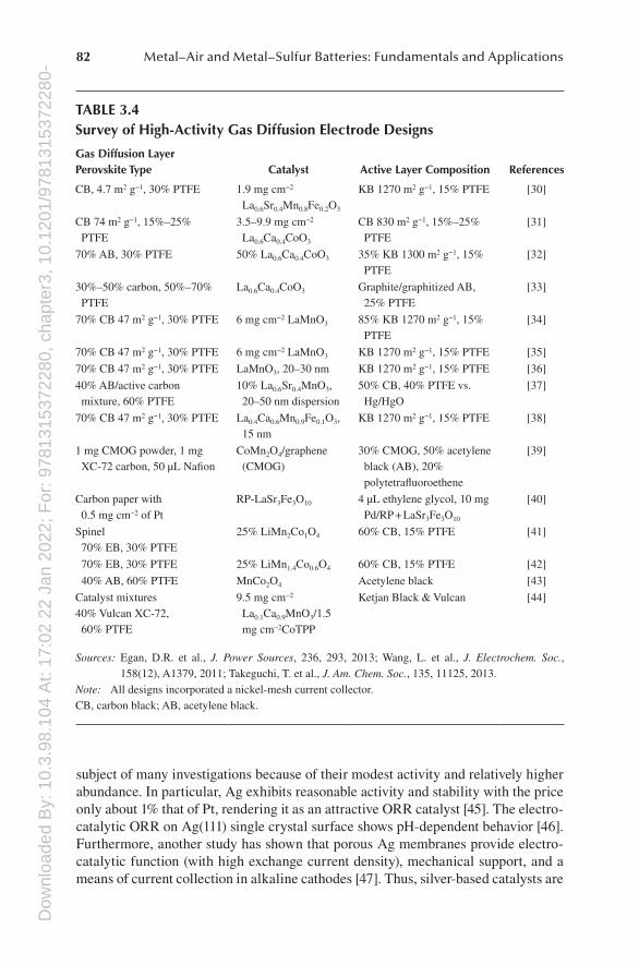
The cathode structure used in most metal–air batteries consists of catalyst and Teflon supported on a hydrophobic film with the current collector. The hydrophobic film prevents the seepage of electrolyte from the cell and contributes a fast and uni-form supply of air (oxygen) into the cell. Modern air electrode consists of activated carbon porous structure with catalyst such as cobalt and hydrophobic film polytet-rafluoroethylene (PTFE). Numerous studies have been conducted on nonprecious metal catalysts, as can be seen in Table 3.4 [30–44].
3.3.3 ElEctrochEmicAl PErformAncE
The AAB versatility for a wide range of applications depends on what electrocatalyst is selected.
3.3.3.1 Noble Metals and AlloysNoble metals such as the Pt-group metals, in particular Pt itself, have been inten-sively studied as ORR catalysts for many decades and continue to spur ongoing interest because of their high stability and superior electrocatalytic activity. Cheaper precious metals such as palladium and silver and their alloys have also been the
2H2O
H2O2
O2
2H2O
H2O2 in solutionDiffusionDisproportionation
4H+ + 4e–
+ 2H+ +2e–
O2 + H2O
2H+ +2e–
FIGURE 3.8 Schematic illustration of ORR possible pathways.
Dow
nloa
ded
By:
10.
3.98
.104
At:
17:0
2 22
Jan
202
2; F
or: 9
7813
1537
2280
, cha
pter
3, 1
0.12
01/9
7813
1537
2280
-482 Metal–Air and Metal–Sulfur Batteries: Fundamentals and Applications
subject of many investigations because of their modest activity and relatively higher abundance. In particular, Ag exhibits reasonable activity and stability with the price only about 1% that of Pt, rendering it as an attractive ORR catalyst [45]. The electro-catalytic ORR on Ag(111) single crystal surface shows pH-dependent behavior [46]. Furthermore, another study has shown that porous Ag membranes provide electro-catalytic function (with high exchange current density), mechanical support, and a means of current collection in alkaline cathodes [47]. Thus, silver-based catalysts are
TABLE 3.4Survey of High-Activity Gas Diffusion Electrode Designs
Gas Diffusion Layer Perovskite Type Catalyst Active Layer Composition References
CB, 4.7 m2 g−1, 30% PTFE 1.9 mg cm−2 La0.6Sr0.4Mn0.8Fe0.2O3
KB 1270 m2 g−1, 15% PTFE [30]
CB 74 m2 g−1, 15%–25% PTFE
3.5–9.9 mg cm−2 La0.6Ca0.4CoO3
CB 830 m2 g−1, 15%–25% PTFE
[31]
70% AB, 30% PTFE 50% La0.6Ca0.4CoO3 35% KB 1300 m2 g−1, 15% PTFE
[32]
30%–50% carbon, 50%–70% PTFE
La0.6Ca0.4CoO3 Graphite/graphitized AB, 25% PTFE
[33]
70% CB 47 m2 g−1, 30% PTFE 6 mg cm−2 LaMnO3 85% KB 1270 m2 g−1, 15% PTFE
[34]
70% CB 47 m2 g−1, 30% PTFE 6 mg cm−2 LaMnO3 KB 1270 m2 g−1, 15% PTFE [35]
70% CB 47 m2 g−1, 30% PTFE LaMnO3, 20–30 nm KB 1270 m2 g−1, 15% PTFE [36]
40% AB/active carbon mixture, 60% PTFE
10% La0.6Sr0.4MnO3, 20–50 nm dispersion
50% CB, 40% PTFE vs. Hg/HgO
[37]
70% CB 47 m2 g−1, 30% PTFE La0.4Ca0.6Mn0.9Fe0.1O3, 15 nm
KB 1270 m2 g−1, 15% PTFE [38]
1 mg CMOG powder, 1 mg XC-72 carbon, 50 μL Nafion
CoMn2O4/graphene (CMOG)
30% CMOG, 50% acetylene black (AB), 20% polytetrafluoroethene
[39]
Carbon paper with 0.5 mg cm−2 of Pt
RP-LaSr3Fe3O10 4 μL ethylene glycol, 10 mg Pd/RP + LaSr3Fe3O10
[40]
Spinel70% EB, 30% PTFE
25% LiMn2Co1O4 60% CB, 15% PTFE [41]
70% EB, 30% PTFE 25% LiMn1.4Co0.6O4 60% CB, 15% PTFE [42]
40% AB, 60% PTFE MnCo2O4 Acetylene black [43]
Catalyst mixtures40% Vulcan XC-72, 60% PTFE
9.5 mg cm−2 La0.1Ca0.9MnO3/1.5 mg cm−2CoTPP
Ketjan Black & Vulcan [44]
Sources: Egan, D.R. et al., J. Power Sources, 236, 293, 2013; Wang, L. et al., J. Electrochem. Soc., 158(12), A1379, 2011; Takeguchi, T. et al., J. Am. Chem. Soc., 135, 11125, 2013.
Note: All designs incorporated a nickel-mesh current collector.CB, carbon black; AB, acetylene black.
Dow
nloa
ded
By:
10.
3.98
.104
At:
17:0
2 22
Jan
202
2; F
or: 9
7813
1537
2280
, cha
pter
3, 1
0.12
01/9
7813
1537
2280
-483Aluminum–Air Batteries
more adaptive to be used in alkaline electrolytes and are promising cathode materi-als with good balance between cost and performance.
3.3.3.2 Transition-Metal OxidesIn terms of high energy density applications, manganese oxide [48] (such as MnO, Mn3O4, Mn2O3, MnO2, Mn5O8, Mn3O4, Mn2O3, MnO2, and MnOOH) has received increased attention due to its high chemical stability as well as low cost, low toxicity, and high catalytic activity. The influence of composition on the properties has been scarcely investigated. One trend is that the ORR catalytic activity correlates with the Mn valence [49], but a clear relationship remains to be established. However, it is obvious that the crystallographic structures and morphologies greatly affect the performance of manganese oxides [50]. For MnO2-based catalysts, the activity fol-lows an order of α- > β- > γ-MnO2, which is attributed to a combinative effect of their intrinsic tunnel size and electrical conductivity.
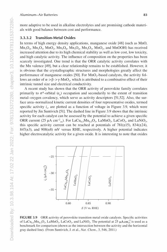
A recent study has shown that the ORR activity of perovskite family correlates primarily to σ*-orbital (eg) occupation and secondarily to the extent of transition metal–oxygen covalency, which serve as activity descriptors [51,52]. Also, the sur-face area–normalized kinetic current densities of four representative oxides, termed specific activity is, are plotted as a function of voltage in Figure 3.9, which were reported by Jin Suntivich [51]. The dashed line in Figure 3.9 shows that the intrinsic activity for each catalyst can be assessed by the potential to achieve a given specific ORR current (25 μA cm−2
ox). For LaCu0.5Mn0.5O3, LaMnO3, LaCoO3, and LaNiO3, this specific activity current can be reached at potentials of 781(±15), 834(±24), 847(±3), and 908(±8) mV versus RHE, respectively. A higher potential indicates higher electrocatalytic activity for a given oxide. It is interesting to note that oxides
0.900.85
–35
–30
–25
E (V vs. RHE)0.80
LaN
iO3
LaCo
O3
LaM
nO3
LaCu
0.5M
n 0.5O
3
i s (µ
A cm
ox)
–2
FIGURE 3.9 ORR activity of perovskite transition metal oxide catalysts. Specific activities of LaCu0.5Mn0.5O3, LaMnO3, LaCoO3, and LaNiO3. The potential at 25 mAcmox
-2 is used as a benchmark for comparison (shown as the intersection between the activity and the horizontal gray dashed line). (From Suntivich, J. et al., Nat. Chem., 3, 546, 2011.)
Dow
nloa
ded
By:
10.
3.98
.104
At:
17:0
2 22
Jan
202
2; F
or: 9
7813
1537
2280
, cha
pter
3, 1
0.12
01/9
7813
1537
2280
-484 Metal–Air and Metal–Sulfur Batteries: Fundamentals and Applications
such as LaMnO3 and LaNiO3 have intrinsic ORR activity comparable to the state-of-the-art Pt/C. According to this, the prominent bifunctional electrochemical per-formances of perovskite composites suggest their promising use in rechargeable metal–air batteries.
3.3.3.3 Other Catalytic MaterialsThe exclusive use of platinum is not feasible for the future widespread deploy-ment of electrochemical devices based on oxygen electrodes. Development of well- performing noble metal-free cathode catalysts is the ultimate solution to the obstacle of Pt cost and scarcity. One of the carbonaceous [53] materials has attracted exten-sive attention either as catalyst supports or as metal-free catalysts in electrocatalytic chemistry of oxygen. Also, tremendous effort has been directed to the development of inorganic–organic [54] composite materials as noble metal-free catalysts for oxy-gen electrochemistry. Both of them are highly valuable cathode catalysts candidate for practical metal–air batteries despite relatively fewer applications to date.
3.3.4 ElEctrochEmicAl tEst ProcEdurEs
The performances of the air electrode were evaluated using an electrochemical workstation. The counter electrode was a Pt wire, the reference electrode is Hg/HgO, and the electrolyte was aqueous alkaline solution or neutral saline electrolyte. Electrochemical test procedures were normal ORR test by Rotating disk electrode method and constant discharge method test by electrochemical workstation, which have been introduced in fuel cells and lithium second batteries.
3.3.5 fAilurE modE AnAlysis And mitigAtion strAtEgiEs
The discharge capacity of most catalysts used so far has shown unsatisfactory results, especially at current densities of substantial use for the power or electric vehicle utilities. One of the major problems associated is how to reduce the overpotential of oxygen reduction.
Electrocatalysts for the oxygen reduction have been searched extensively to date, covering metals, organometals, oxides, sulfides, carbides, and nitrides. Noble metal catalysts like Pt and Ag are fairly active, but less expensive catalysts, if available, are definitely more desirable. In this sense, single and mixed oxides of transition metals have drawn attention of many researchers for the use in alkaline electro-lyte. Especially, high expectation has been directed to some kinds of perovskite-type oxides since Meadowcroft [55] first pointed out the potentiality of these oxides to replace Pt catalyst. Perovskites are excellent alternatives to noble metals as low-cost catalysts. Mixed with high-surface-area carbons, perovskites exhibit excellent cathodic oxygen reduction properties in alkaline electrolytes.
3.3.6 cAthodE fAbricAtion
The air electrode is consisted of a microporous gas diffusion layer, a porous nickel foam substrate as a current collector, and a catalyst layer. The gas diffusion layer is
Dow
nloa
ded
By:
10.
3.98
.104
At:
17:0
2 22
Jan
202
2; F
or: 9
7813
1537
2280
, cha
pter
3, 1
0.12
01/9
7813
1537
2280
-485Aluminum–Air Batteries
prepared by corresponding materials and binder. After mixing materials and binder together and getting a paste, the mixture paste is coated on one side of a porous nickel foam current collector. The catalyst layer of air electrode was prepared by mixing catalyst agents, conductive agents, and binders by weight proportion. The slurry was dried at temperature around 100°C to give a dough-like paste. The cata-lyst paste was coated on to the other side of the porous nickel foam substrate. The air electrode was finally treated by pressure and high temperature.
3.4 AAB ELECTROLYTES
3.4.1 introduction
Like other battery systems, the electrolyte that separates the two electrodes to avoid short circuit and provides OH− for maintaining the electrochemical reactions plays an important part in AAB. The battery performance strongly depends on the choice of electrolyte. Aqueous electrolytes are widely used in Al–air primary battery because of their high ionic conductivity, and the major development effort has focused on two types of aqueous electrolyte, which are alkaline and saline electrolytes. For the alka-line electrolytes, they also have the ability of regulating the reduced oxygen ion into hydroxide anion [3]. However, the Al anode suffers from severe self-discharge and passivation/corrosion in aqueous electrolyte, leading to the low coulombic efficiency and short battery shelf life. Besides, AAB generates heat during both idle and dis-charge, resulting in high rate of water loss for the aqueous electrolyte and accelerated corrosion rates [56]. It leads to hazardous and runaway conditions and also severely decreases the battery shelf life [57]. To overcome these obstacles, investigation of electrolyte additives and new electrolyte systems are promoted to inhibit the anode corrosion and self-discharge for AAB.
3.4.2 ElEctrolytE tyPEs
3.4.2.1 Aqueous ElectrolytesAqueous solutions are simple to operate, low in cost, and with less environmental pollution [9]. The aqueous electrolyte widely used in AAB is typically a neutral saline (sodium chloride, potassium chloride, or seawater) solution or alkaline solu-tion (sodium hydroxide or potassium hydroxide) [1].
AABs employing saline electrolytes have been studied mostly for low-power equipment, such as emergency lighting, portable equipment, stationary standby power sources, and marine applications. Compared with alkaline electrolyte, neu-tral saline electrolytes are less caustic, resulting in a lower corrosion rate and a lower risk to health. The corrosion rate in saline electrolyte is linearly proportional to the current density, and it starts from near zero at zero current [6]. A 12 wt% solution of sodium chloride, which is near the maximum conductivity, is considered as suitable neutral electrolyte. Current densities are limited to 30–50 mA/cm2 in consideration of the conductivity of the electrolyte [6]. When operated in seawater, only limited current capability can be obtained because of the lower conductivity of seawater [58].
Dow
nloa
ded
By:
10.
3.98
.104
At:
17:0
2 22
Jan
202
2; F
or: 9
7813
1537
2280
, cha
pter
3, 1
0.12
01/9
7813
1537
2280
-486 Metal–Air and Metal–Sulfur Batteries: Fundamentals and Applications
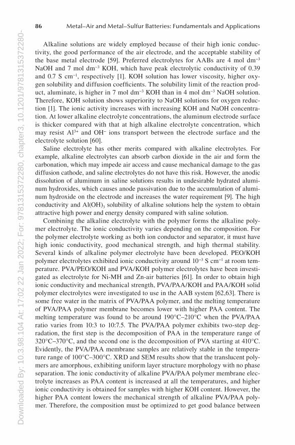
Alkaline solutions are widely employed because of their high ionic conduc-tivity, the good performance of the air electrode, and the acceptable stability of the base metal electrode [59]. Preferred electrolytes for AABs are 4 mol dm−3 NaOH and 7 mol dm−3 KOH, which have peak electrolytic conductivity of 0.39 and 0.7 S cm−1, respectively [1]. KOH solution has lower viscosity, higher oxy-gen solubility and diffusion coefficients. The solubility limit of the reaction prod-uct, aluminate, is higher in 7 mol dm−3 KOH than in 4 mol dm−3 NaOH solution. Therefore, KOH solution shows superiority to NaOH solutions for oxygen reduc-tion [1]. The ionic activity increases with increasing KOH and NaOH concentra-tion. At lower alkaline electrolyte concentrations, the aluminum electrode surface is thicker compared with that at high alkaline electrolyte concentration, which may resist Al3+ and OH− ions transport between the electrode surface and the electrolyte solution [60].
Saline electrolyte has other merits compared with alkaline electrolytes. For example, alkaline electrolytes can absorb carbon dioxide in the air and form the carbonation, which may impede air access and cause mechanical damage to the gas diffusion cathode, and saline electrolytes do not have this risk. However, the anodic dissolution of aluminum in saline solutions results in undesirable hydrated alumi-num hydroxides, which causes anode passivation due to the accumulation of alumi-num hydroxide on the electrode and increases the water requirement [9]. The high conductivity and Al(OH)3 solubility of alkaline solutions help the system to obtain attractive high power and energy density compared with saline solution.
Combining the alkaline electrolyte with the polymer forms the alkaline poly-mer electrolyte. The ionic conductivity varies depending on the composition. For the polymer electrolyte working as both ion conductor and separator, it must have high ionic conductivity, good mechanical strength, and high thermal stability. Several kinds of alkaline polymer electrolyte have been developed. PEO/KOH polymer electrolytes exhibited ionic conductivity around 10−3 S cm−1 at room tem-perature. PVA/PEO/KOH and PVA/KOH polymer electrolytes have been investi-gated as electrolyte for Ni-MH and Zn-air batteries [61]. In order to obtain high ionic conductivity and mechanical strength, PVA/PAA/KOH and PAA/KOH solid polymer electrolytes were investigated to use in the AAB system [62,63]. There is some free water in the matrix of PVA/PAA polymer, and the melting temperature of PVA/PAA polymer membrane becomes lower with higher PAA content. The melting temperature was found to be around 190°C–210°C when the PVA/PAA ratio varies from 10:3 to 10:7.5. The PVA/PAA polymer exhibits two-step deg-radation, the first step is the decomposition of PAA in the temperature range of 320°C–370°C, and the second one is the decomposition of PVA starting at 410°C. Evidently, the PVA/PAA membrane samples are relatively stable in the tempera-ture range of 100°C–300°C. XRD and SEM results show that the translucent poly-mers are amorphous, exhibiting uniform layer structure morphology with no phase separation. The ionic conductivity of alkaline PVA/PAA polymer membrane elec-trolyte increases as PAA content is increased at all the temperatures, and higher ionic conductivity is obtained for samples with higher KOH content. However, the higher PAA content lowers the mechanical strength of alkaline PVA/PAA poly-mer. Therefore, the composition must be optimized to get good balance between
Dow
nloa
ded
By:
10.
3.98
.104
At:
17:0
2 22
Jan
202
2; F
or: 9
7813
1537
2280
, cha
pter
3, 1
0.12
01/9
7813
1537
2280
-487Aluminum–Air Batteries
enhanced ionic conductivity and reasonable mechanical properties for the solid polymer electrolyte applications.
3.4.2.2 Nonaqueous ElectrolytesPractical Al electrodes operate at significantly lower potentials in aqueous elec-trolyte because that Al is normally covered with an oxide/hydroxide surface film, resulting in a voltage delay. Al anode experiences a considerable parasitic corrosion reaction in aqueous solutions, which leads to a low Al utilization accompanied by a massive hydrogen gas evolution. For the aqueous electrolyte, progressive consump-tion of hydroxyl ions occurs at the Al electrode and the electrolyte progressively saturates with aluminate during discharge. When aluminate concentration exceeds the supersaturation, crystalline of aluminum hydroxide precipitates, resulting in loss of the ionic conductivity of the solution.
To resolve these problems, researchers have focused their attention on room temperature ionic liquids (RTILs) as AAB electrolytes since they are extremely nonvolatile, highly stable, and highly conductive. Moreover, Al is not prone to the parasitic hydrogen generation reaction in RTILs. Another attractive advantage is that electrodeposition of Al, which cannot be obtained from aqueous solutions at moderate temperatures, becomes easier in ionic liquid [64]. The evolution of hydro-gen occurs before the deposition of aluminum in alkaline electrolyte; therefore, it is essential to explore nonaqueous electrolytes for AAB if rechargeable AABs are to be obtained.
RTILs are low-temperature molten salts, composed mostly of organic ions. The ions often have a delocalized or shielded charge configuration, and this is responsible for the low melting point of the salt. The application of RTILs as AAB electrolytes is a relatively new area of study that is steadily gaining attraction in the electro-chemical and engineering communities. RTILs are not currently used in commercial devices due to the high cost and the short history of investigation.
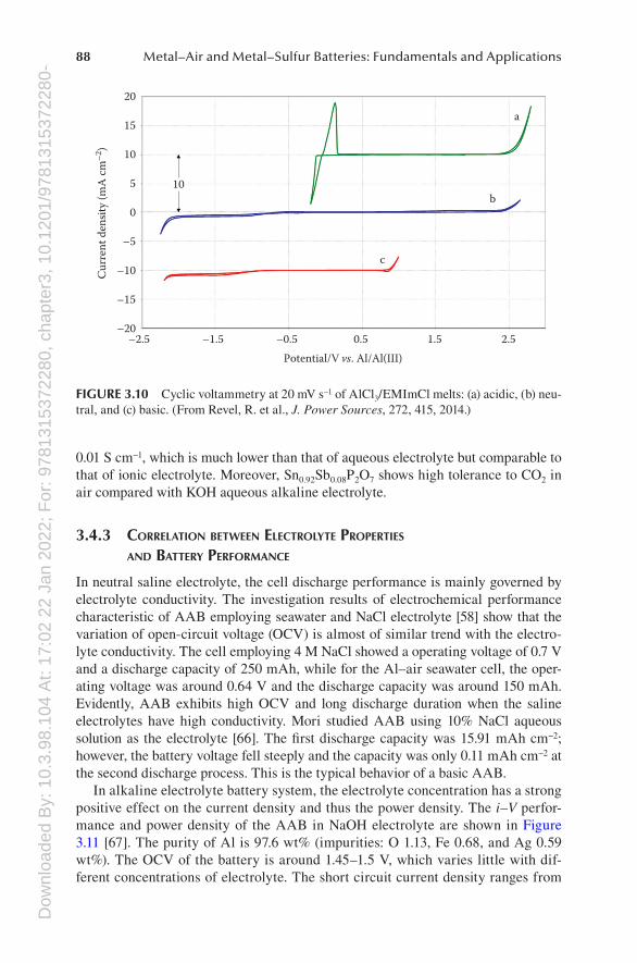
Chloroaluminate ionic liquids exhibit Lewis acid–base chemistry, and chloro-acidity is the major determinant in speciation, reactivity, and electrochemistry in chloroaluminate ionic liquids. The composition of the melt determines its chloro-acidity. AlCl3/[EMIm]Cl ionic liquids have been investigated as AAB electrolyte [3]. With a AlCl3 mole fraction less than 0.5, these room temperature melts are basic. At AlCl3 mole fractions greater than 0.5, these melts may be regarded as acidic. Room temperature conductivity at the level of 10 mS cm−1 is typical of ionic liquids based on EMIm+ cation. Figure 3.10 shows the cyclic voltammetry of AlCl3/[EMIm]Cl ionic liquids. The electrochemical windows of the neutral melt window (4.6 V) is extraordinarily wide compared with the acidic (2.6 V) and basic (3.1 V) ones.
Another kind of nonaqueous electrolyte should be the anhydrous hydroxide con-ductor solid electrolyte that can be applied in rechargeable AAB. Research in this field has been developed since 2013; therefore, results for rechargeable AAB are quite limited. Hibino et al. have done the investigation on all-solid-state recharge-able AAB applying a hydroxide ion-conducting Sb(v)-doped SnP2O7 as electrolyte. This series of compounds have hydroxide ion exchange capability in the bulk of SnP2O7 by charge compensation through the partial substitution of Sn4+ with Sb5+ [65]. Sn0.92Sb0.08P2O7 exhibited the highest hydroxide ion conductivities above
Dow
nloa
ded
By:
10.
3.98
.104
At:
17:0
2 22
Jan
202
2; F
or: 9
7813
1537
2280
, cha
pter
3, 1
0.12
01/9
7813
1537
2280
-488 Metal–Air and Metal–Sulfur Batteries: Fundamentals and Applications
0.01 S cm−1, which is much lower than that of aqueous electrolyte but comparable to that of ionic electrolyte. Moreover, Sn0.92Sb0.08P2O7 shows high tolerance to CO2 in air compared with KOH aqueous alkaline electrolyte.
3.4.3 corrElAtion bEtWEEn ElEctrolytE ProPErtiEs And bAttEry PErformAncE
In neutral saline electrolyte, the cell discharge performance is mainly governed by electrolyte conductivity. The investigation results of electrochemical performance characteristic of AAB employing seawater and NaCl electrolyte [58] show that the variation of open-circuit voltage (OCV) is almost of similar trend with the electro-lyte conductivity. The cell employing 4 M NaCl showed a operating voltage of 0.7 V and a discharge capacity of 250 mAh, while for the Al–air seawater cell, the oper-ating voltage was around 0.64 V and the discharge capacity was around 150 mAh. Evidently, AAB exhibits high OCV and long discharge duration when the saline electrolytes have high conductivity. Mori studied AAB using 10% NaCl aqueous solution as the electrolyte [66]. The first discharge capacity was 15.91 mAh cm−2; however, the battery voltage fell steeply and the capacity was only 0.11 mAh cm−2 at the second discharge process. This is the typical behavior of a basic AAB.
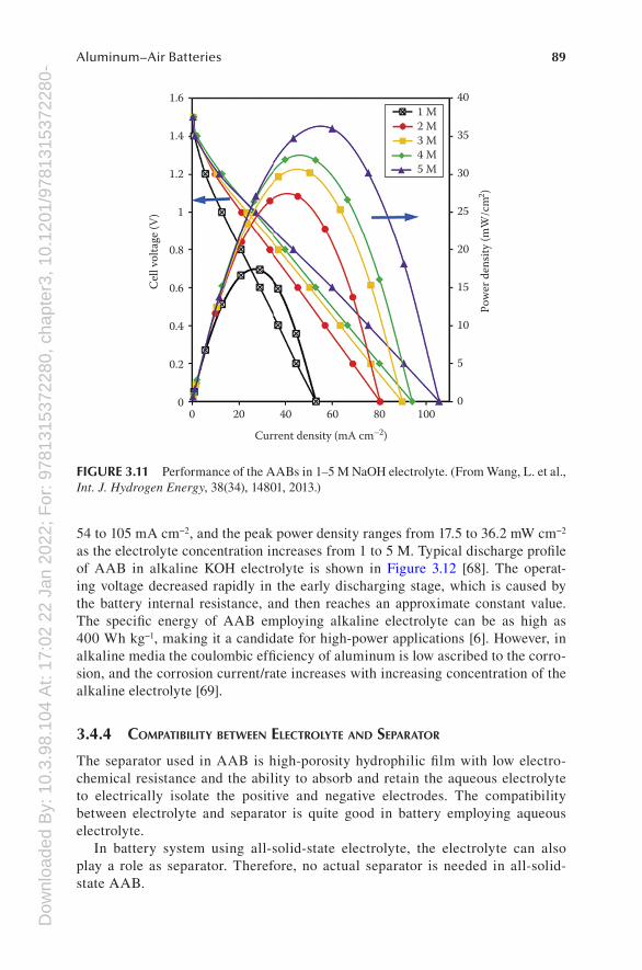
In alkaline electrolyte battery system, the electrolyte concentration has a strong positive effect on the current density and thus the power density. The i–V perfor-mance and power density of the AAB in NaOH electrolyte are shown in Figure 3.11 [67]. The purity of Al is 97.6 wt% (impurities: O 1.13, Fe 0.68, and Ag 0.59 wt%). The OCV of the battery is around 1.45–1.5 V, which varies little with dif-ferent concentrations of electrolyte. The short circuit current density ranges from
2.51.50.5
c
b
a
Potential/V vs. Al/Al(III)
–0.5–1.5–2.5
20
15
10
Cur
rent
den
sity
(mA
cm
–2)
5
0
–5
–10
–15
–20
10
FIGURE 3.10 Cyclic voltammetry at 20 mV s−1 of AlCl3/EMImCl melts: (a) acidic, (b) neu-tral, and (c) basic. (From Revel, R. et al., J. Power Sources, 272, 415, 2014.)
Dow
nloa
ded
By:
10.
3.98
.104
At:
17:0
2 22
Jan
202
2; F
or: 9
7813
1537
2280
, cha
pter
3, 1
0.12
01/9
7813
1537
2280
-489Aluminum–Air Batteries
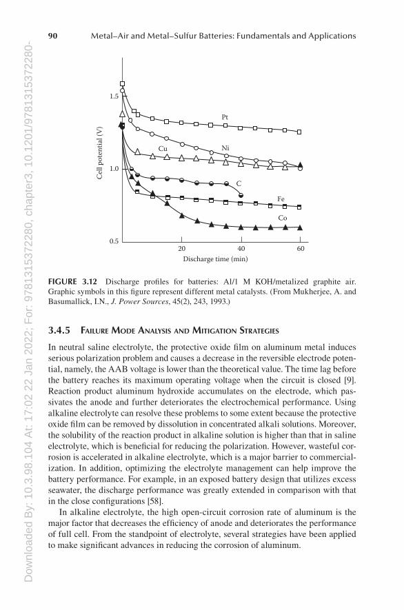
54 to 105 mA cm−2, and the peak power density ranges from 17.5 to 36.2 mW cm−2 as the electrolyte concentration increases from 1 to 5 M. Typical discharge profile of AAB in alkaline KOH electrolyte is shown in Figure 3.12 [68]. The operat-ing voltage decreased rapidly in the early discharging stage, which is caused by the battery internal resistance, and then reaches an approximate constant value. The specific energy of AAB employing alkaline electrolyte can be as high as 400 Wh kg−1, making it a candidate for high-power applications [6]. However, in alkaline media the coulombic efficiency of aluminum is low ascribed to the corro-sion, and the corrosion current/rate increases with increasing concentration of the alkaline electrolyte [69].
3.4.4 comPAtibility bEtWEEn ElEctrolytE And sEPArAtor
The separator used in AAB is high-porosity hydrophilic film with low electro-chemical resistance and the ability to absorb and retain the aqueous electrolyte to electrically isolate the positive and negative electrodes. The compatibility between electrolyte and separator is quite good in battery employing aqueous electrolyte.
In battery system using all-solid-state electrolyte, the electrolyte can also play a role as separator. Therefore, no actual separator is needed in all-solid-state AAB.
0100806040200
5
10
Pow
er d
ensit
y (m
W/c
m2 )
Cel
l vol
tage
(V)
Current density (mA cm–2)
15
20
25
30
35
401.6
1.4
1.2
1
0.8
0.6
0.4
0.2
0
1 M2 M3 M4 M5 M
FIGURE 3.11 Performance of the AABs in 1–5 M NaOH electrolyte. (From Wang, L. et al., Int. J. Hydrogen Energy, 38(34), 14801, 2013.)
Dow
nloa
ded
By:
10.
3.98
.104
At:
17:0
2 22
Jan
202
2; F
or: 9
7813
1537
2280
, cha
pter
3, 1
0.12
01/9
7813
1537
2280
-490 Metal–Air and Metal–Sulfur Batteries: Fundamentals and Applications
3.4.5 fAilurE modE AnAlysis And mitigAtion strAtEgiEs
In neutral saline electrolyte, the protective oxide film on aluminum metal induces serious polarization problem and causes a decrease in the reversible electrode poten-tial, namely, the AAB voltage is lower than the theoretical value. The time lag before the battery reaches its maximum operating voltage when the circuit is closed [9]. Reaction product aluminum hydroxide accumulates on the electrode, which pas-sivates the anode and further deteriorates the electrochemical performance. Using alkaline electrolyte can resolve these problems to some extent because the protective oxide film can be removed by dissolution in concentrated alkali solutions. Moreover, the solubility of the reaction product in alkaline solution is higher than that in saline electrolyte, which is beneficial for reducing the polarization. However, wasteful cor-rosion is accelerated in alkaline electrolyte, which is a major barrier to commercial-ization. In addition, optimizing the electrolyte management can help improve the battery performance. For example, in an exposed battery design that utilizes excess seawater, the discharge performance was greatly extended in comparison with that in the close configurations [58].
In alkaline electrolyte, the high open-circuit corrosion rate of aluminum is the major factor that decreases the efficiency of anode and deteriorates the performance of full cell. From the standpoint of electrolyte, several strategies have been applied to make significant advances in reducing the corrosion of aluminum.
6040
Pt
1.5
1.0
Ni
Fe
Co
C
Cu
Discharge time (min)
Cel
l pot
entia
l (V
)
200.5
FIGURE 3.12 Discharge profiles for batteries: Al/1 M KOH/metalized graphite air. Graphic symbols in this figure represent different metal catalysts. (From Mukherjee, A. and Basumallick, I.N., J. Power Sources, 45(2), 243, 1993.)
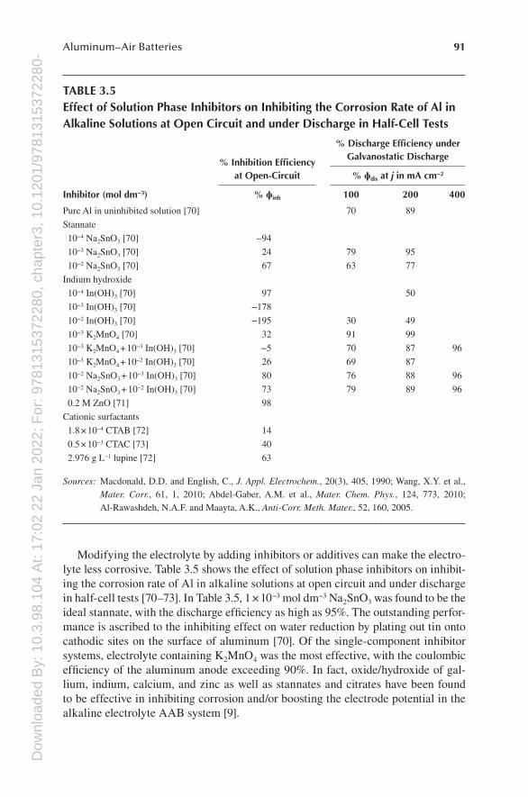
Dow
nloa
ded
By:
10.
3.98
.104
At:
17:0
2 22
Jan
202
2; F
or: 9
7813
1537
2280
, cha
pter
3, 1
0.12
01/9
7813
1537
2280
-491Aluminum–Air Batteries
Modifying the electrolyte by adding inhibitors or additives can make the electro-lyte less corrosive. Table 3.5 shows the effect of solution phase inhibitors on inhibit-ing the corrosion rate of Al in alkaline solutions at open circuit and under discharge in half-cell tests [70–73]. In Table 3.5, 1 × 10⁻³ mol dm−3 Na2SnO3 was found to be the ideal stannate, with the discharge efficiency as high as 95%. The outstanding perfor-mance is ascribed to the inhibiting effect on water reduction by plating out tin onto cathodic sites on the surface of aluminum [70]. Of the single-component inhibitor systems, electrolyte containing K2MnO4 was the most effective, with the coulombic efficiency of the aluminum anode exceeding 90%. In fact, oxide/hydroxide of gal-lium, indium, calcium, and zinc as well as stannates and citrates have been found to be effective in inhibiting corrosion and/or boosting the electrode potential in the alkaline electrolyte AAB system [9].
TABLE 3.5Effect of Solution Phase Inhibitors on Inhibiting the Corrosion Rate of Al in Alkaline Solutions at Open Circuit and under Discharge in Half-Cell Tests
Inhibitor (mol dm−3)
% Inhibition Efficiency at Open-Circuit
% Discharge Efficiency under Galvanostatic Discharge
% ϕdis at j in mA cm−2
% ϕinh 100 200 400
Pure Al in uninhibited solution [70] 70 89
Stannate
10−4 Na2SnO3 [70] −94
10−3 Na2SnO3 [70] 24 79 95
10−2 Na2SnO3 [70] 67 63 77
Indium hydroxide
10−4 In(OH)3 [70] 97 50
10−3 In(OH)3 [70] −178
10−2 In(OH)3 [70] −195 30 49
10−3 K2MnO4 [70] 32 91 99
10−3 K2MnO4 + 10−3 In(OH)3 [70] −5 70 87 96
10−3 K2MnO4 + 10−2 In(OH)3 [70] 26 69 87
10−2 Na2SnO3 + 10−3 In(OH)3 [70] 80 76 88 96
10−2 Na2SnO3 + 10−2 In(OH)3 [70] 73 79 89 96
0.2 M ZnO [71] 98
Cationic surfactants
1.8 × 10⁻⁴ CTAB [72] 14
0.5 × 10⁻³ CTAC [73] 40
2.976 g L−1 lupine [72] 63
Sources: Macdonald, D.D. and English, C., J. Appl. Electrochem., 20(3), 405, 1990; Wang, X.Y. et al., Mater. Corr., 61, 1, 2010; Abdel-Gaber, A.M. et al., Mater. Chem. Phys., 124, 773, 2010; Al-Rawashdeh, N.A.F. and Maayta, A.K., Anti-Corr. Meth. Mater., 52, 160, 2005.
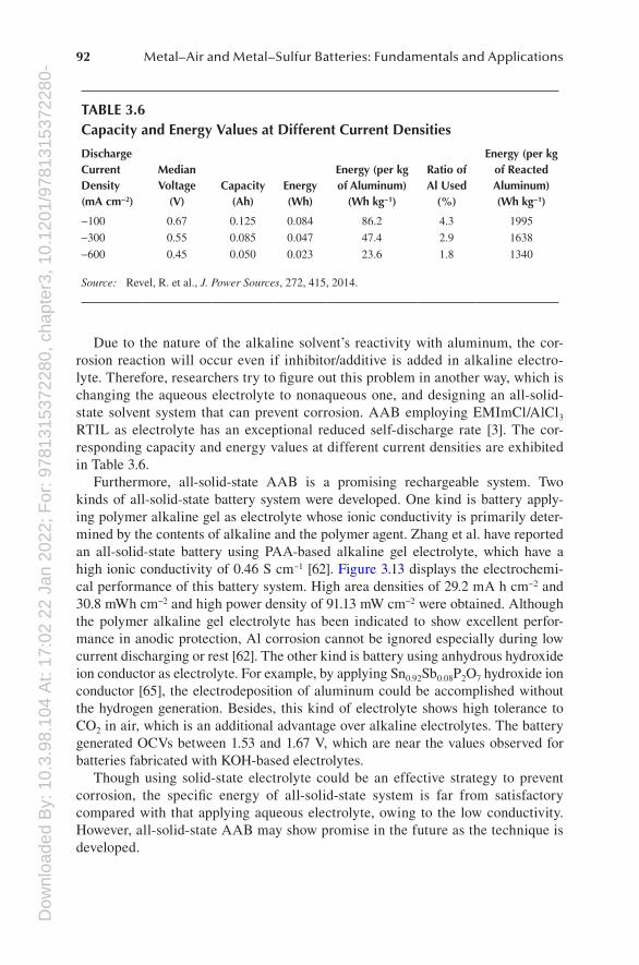
Dow
nloa
ded
By:
10.
3.98
.104
At:
17:0
2 22
Jan
202
2; F
or: 9
7813
1537
2280
, cha
pter
3, 1
0.12
01/9
7813
1537
2280
-492 Metal–Air and Metal–Sulfur Batteries: Fundamentals and Applications
Due to the nature of the alkaline solvent’s reactivity with aluminum, the cor-rosion reaction will occur even if inhibitor/additive is added in alkaline electro-lyte. Therefore, researchers try to figure out this problem in another way, which is changing the aqueous electrolyte to nonaqueous one, and designing an all-solid-state solvent system that can prevent corrosion. AAB employing EMImCl/AlCl3 RTIL as electrolyte has an exceptional reduced self-discharge rate [3]. The cor-responding capacity and energy values at different current densities are exhibited in Table 3.6.
Furthermore, all-solid-state AAB is a promising rechargeable system. Two kinds of all-solid-state battery system were developed. One kind is battery apply-ing polymer alkaline gel as electrolyte whose ionic conductivity is primarily deter-mined by the contents of alkaline and the polymer agent. Zhang et al. have reported an all-solid-state battery using PAA-based alkaline gel electrolyte, which have a high ionic conductivity of 0.46 S cm−1 [62]. Figure 3.13 displays the electrochemi-cal performance of this battery system. High area densities of 29.2 mA h cm−2 and 30.8 mWh cm−2 and high power density of 91.13 mW cm−2 were obtained. Although the polymer alkaline gel electrolyte has been indicated to show excellent perfor-mance in anodic protection, Al corrosion cannot be ignored especially during low current discharging or rest [62]. The other kind is battery using anhydrous hydroxide ion conductor as electrolyte. For example, by applying Sn0.92Sb0.08P2O7 hydroxide ion conductor [65], the electrodeposition of aluminum could be accomplished without the hydrogen generation. Besides, this kind of electrolyte shows high tolerance to CO2 in air, which is an additional advantage over alkaline electrolytes. The battery generated OCVs between 1.53 and 1.67 V, which are near the values observed for batteries fabricated with KOH-based electrolytes.
Though using solid-state electrolyte could be an effective strategy to prevent corrosion, the specific energy of all-solid-state system is far from satisfactory compared with that applying aqueous electrolyte, owing to the low conductivity. However, all-solid-state AAB may show promise in the future as the technique is developed.
TABLE 3.6Capacity and Energy Values at Different Current Densities
Discharge Current Density (mA cm−2)
Median Voltage
(V) Capacity
(Ah) Energy (Wh)
Energy (per kg of Aluminum)
(Wh kg−1)
Ratio of Al Used
(%)
Energy (per kg of Reacted Aluminum) (Wh kg−1)
−100 0.67 0.125 0.084 86.2 4.3 1995
−300 0.55 0.085 0.047 47.4 2.9 1638
−600 0.45 0.050 0.023 23.6 1.8 1340
Source: Revel, R. et al., J. Power Sources, 272, 415, 2014.
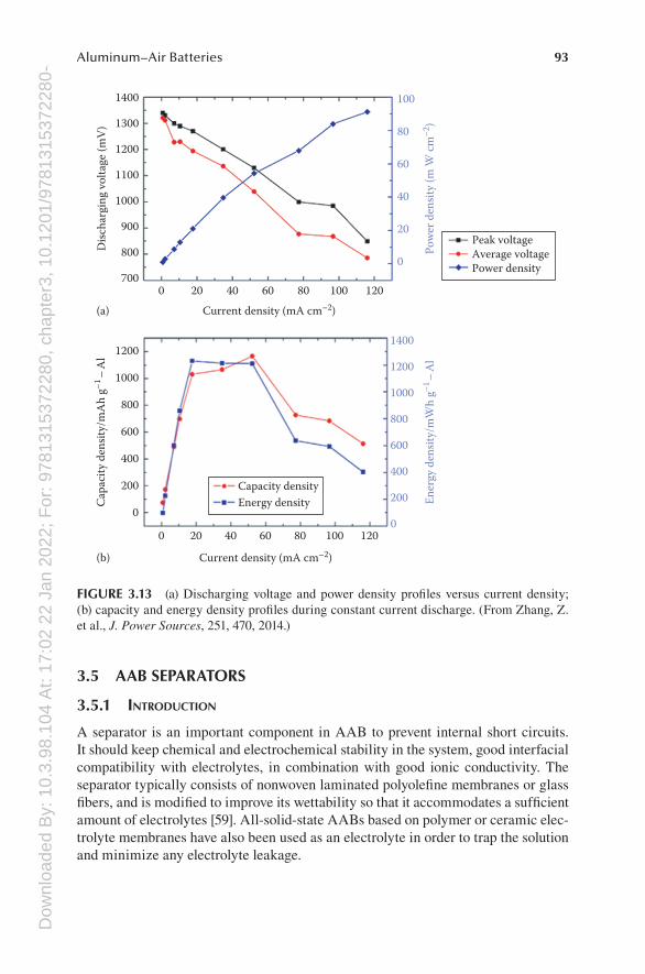
Dow
nloa
ded
By:
10.
3.98
.104
At:
17:0
2 22
Jan
202
2; F
or: 9
7813
1537
2280
, cha
pter
3, 1
0.12
01/9
7813
1537
2280
-493Aluminum–Air Batteries
3.5 AAB SEPARATORS
3.5.1 introduction
A separator is an important component in AAB to prevent internal short circuits. It should keep chemical and electrochemical stability in the system, good interfacial compatibility with electrolytes, in combination with good ionic conductivity. The separator typically consists of nonwoven laminated polyolefine membranes or glass fibers, and is modified to improve its wettability so that it accommodates a sufficient amount of electrolytes [59]. All-solid-state AABs based on polymer or ceramic elec-trolyte membranes have also been used as an electrolyte in order to trap the solution and minimize any electrolyte leakage.
120
120
100
100
80
80
Current density (mA cm–2)
Current density (mA cm–2)
Disc
harg
ing
volta
ge (m
V)
Cap
acity
den
sity/
mA
h g–1
–A
l
60
60
40
40
20
20
0
0
0
200
400
600
800
1000
12001400
1400
1300
1200
1100
1000
900
(a)
(b)
800
700
100
80
60
40
20
0
Ener
gy d
ensit
y/m
Wh
g–1–
Al
Pow
er d
ensit
y (m
W c
m–2
)
1200
1000
800
400
200
0
600
Capacity densityEnergy density
Peak voltageAverage voltagePower density
FIGURE 3.13 (a) Discharging voltage and power density profiles versus current density; (b) capacity and energy density profiles during constant current discharge. (From Zhang, Z. et al., J. Power Sources, 251, 470, 2014.)
Dow
nloa
ded
By:
10.
3.98
.104
At:
17:0
2 22
Jan
202
2; F
or: 9
7813
1537
2280
, cha
pter
3, 1
0.12
01/9
7813
1537
2280
-494 Metal–Air and Metal–Sulfur Batteries: Fundamentals and Applications
3.5.2 sEPArAtor tyPEs And thEir PhysicochEmicAl ProPErtiEs
Typical polyolefine membranes are Celgard® (manufactured by Celgard LLC, Charlotte, NC). They are polyethylene (PE), polypropylene (PP), and the com-posite of the two polyolefines. Commercial separators possess a pore diameter of 0.03–0.1 μm and a porosity of 30%–50%. The melting points of PE and PP are 135°C and 165°C, respectively.
Poly(vinyl alcohol) (PVA)- and poly(acrylic acid) (PAA)-based solid polymer elec-trolyte membranes with high ionic conductivity, good thermal, and mechanical prop-erties were also used in AAB batteries. The highest room temperature value in ionic conductivity for the alkaline solid PVA/PAA polymer electrolyte membranes was 0.301 S cm−1 when the weight ratio of PVA:PAA is 10:7.5. Uniform morphology was achieved in the membrane structure. There was no apparent phase separation and the PVA/PAA polymer membrane samples appeared translucent under illumination [63].
Yuxin Zuo et al. prepared the polyacrylic acid (PAA)-based alkaline gel electro-lyte used in all-solid-state AAB to prevent leakage. An alkaline solution with pH 14.7 and monomers with a cross-linker were gelled by a polymerization initiator. The optimal gel electrolyte exhibits an ionic conductivity of 460 mS cm−1 at 25°C, which is close to that of aqueous electrolytes [62].
A solid electrolyte based on Al2(WO4)3 and Sb(V)-doped SnP2O7 was also inves-tigated for secondary AAB in recent years.
3.5.3 corrElAtion bEtWEEn sEPArAtor ProPErtiEs And bAttEry PErformAncE
The cell power and energy densities of AAB based on polyolefine separators are up to 175 W kg−1 and 400 Wh kg−1, respectively [6].
Solid polymer electrolyte membranes are key components in the development of an electrochemical or battery system. Some polymers that exhibit hydrophilic characteristics have received much attention for electrolyte membranes in recent years. The first theoretical study of solid polymer electrolyte was carried out by Wright et al. [74,75] and was devoted to the ionic nature for the conducting behav-ior. Armand et al. [76] described the potential use of solid polymer electrolytes in secondary batteries. Later, Fauvarque et al. reported that alkaline PE-potassium hydroxide (KOH) polymer electrolytes exhibited room temperature ionic conductiv-ity around 10−3 S cm−1 [77,78].
The PAA-based alkaline gel electrolyte is used in all-solid-state AAB to prevent leakage. The optimal gel electrolyte exhibits an ionic conductivity of 460 mS cm−1 at 25°C, which is close to that of aqueous electrolytes. The AAB peak capacity and energy density considering only Al can reach 1166 mAh g−1 and 1230 mWh g−1, respectively, during constant current discharge. The battery prototype also exhibits a high power density of 91.13 mW cm−2. If the battery is a laminated structure, area densities of 29.2 mAh cm−2 and 30.8 mWh cm−2 are presented to appraise the perfor-mance of the whole cell [62].
A KOH solution gelled with hydrophonics gel (HPG) has been used as an electro-lyte for AAB in order to trap the solution and minimize any electrolyte leakage [79].
Dow
nloa
ded
By:
10.
3.98
.104
At:
17:0
2 22
Jan
202
2; F
or: 9
7813
1537
2280
, cha
pter
3, 1
0.12
01/9
7813
1537
2280
-495Aluminum–Air Batteries
The energy density was very low at 183 W h kg−1-Al due to the extremely high resis-tance of the gel restricting the discharge current density to below 10 mA cm−2, the use of a 95 wt% pure anode, and anode passivation by a layer of Al(OH)3.
The solid-state PVA/PAA polymer electrolyte membranes were prepared by a solution casting method from PVA polymer, acrylic acid monomer, a cross-linker, and KOH after polymerized by an initiator. The resulting homogeneous polymer solution was then used for solution casting to form PVA/PAA polymer membranes. The PVA/PAA polymer membranes were further immersed in 32 wt% KOH solution to obtain the gel separators. The cell’s discharge performance was extremely poor with a peak power density of 1.2 mW cm−2 at a low current density of 1.2 mA cm−2 due to passivation of the aluminum surface by the discharge product [63].
The conductivity of gel electrolytes would need to be improved for its viable usage. Gel and solid polymer electrolytes have low solubility for Al(OH)4 ions meaning that during anodic discharge the Al(OH)3 cannot dissolve into the electrolyte to form alu-minate. The conductivity of these electrolytes is also insufficient to replenish the OH− ions consumed at the electrode surface, resulting in passivation of the aluminum.
A ceramic aluminum ion conductor Al2(WO4)3 can prevent anode corrosion due to direct contact with the alkaline electrolyte while retaining aluminum ion conduc-tion. R. Mori has combined both approaches by placing Al2(WO4)3 as an aluminum ion conductor, both on the anode and air cathode sides, and succeeded in prepar-ing AAB with stable cell properties [80,81]. Sb(V)-doped SnP2O7 with hydroxide ion exchange capability was also investigated as a solid electrolyte for rechargeable AAB [65]. This battery generated an OCV of 1.6 V with a discharge capacity of 800 mAh gelectrode
-1 .
3.5.4 fAilurE modE AnAlysis And mitigAtion strAtEgiEs
For secondary AAB, Al dendrite growth during long-term cycling often breaks through separators. This leads to short circuits and sometimes even catastrophic failure. The mitigation strategy is to reinforce the strength of separators by establish-ing a strong mechanical barrier to suppress the dendrite growth. Some researchers have attempted to trap electrolyte solution into a hydroponic gelling agent or polymer membrane to minimize electrolyte leakage. These solid-state electrolytes based on polymers or ceramic with good ionic conductivity can be a promising candidate for the separator of AAB. Another approach is adding additives into the electrolytes to block dendrite growth, as lithium–air batteries, but there are few studies about it.
3.6 AAB CURRENT COLLECTORS
3.6.1 introduction
The current collector of the air electrode should have high electrical conductivity, gas permeability to allow oxygen diffusion, and stability with respect to the oxida-tion power of oxygen. A nickel mesh is generally used for this purpose [59]. What’s more, a nickel, stainless steel, titanium slice, or mesh and glassy carbon rod were also prelaminated onto the carbon electrode as a current collector.
Dow
nloa
ded
By:
10.
3.98
.104
At:
17:0
2 22
Jan
202
2; F
or: 9
7813
1537
2280
, cha
pter
3, 1
0.12
01/9
7813
1537
2280
-496 Metal–Air and Metal–Sulfur Batteries: Fundamentals and Applications
A copper, nickel mesh, or copper disk was pressed into the aluminum foil and extended to the outside of the cell as the anode current collector. Then AAB were assembled by stacking the cathode-tape disk, one separator disk soaked in the elec-trolytes, and one aluminum disk [82].
3.6.2 currEnt collEctor tyPEs And thEir PhysicochEmicAl ProPErtiEs
The current collectors of AAB should keep chemical and electrochemical stability and have good conductivity in the electrolytes in open-circuit or charge-discharge condition.
The composition of the cathode current collector electrode includes nickel, stain-less steel, and titanium. They can be mesh or slice. For the anode current collector, a copper, nickel mesh, or copper disk is mostly used.
3.6.3 corrElAtion bEtWEEn currEnt collEctor ProPErtiEs And bAttEry PErformAncE
The conductivity and weight of electrochemically and chemically stable current col-lectors can influence the performance of AAB. For high power density of AAB, cur-rent collectors with good conductivity are in favor. The smaller the weight of current collectors is, the higher the specific energy AAB can output. During large current discharge, the conductivity and cross-sectional area of current collectors should be enough to support the large current. Otherwise, a huge amount of heat is generated, which results in a large resistance impairing the performance of AAB.
3.6.4 fAilurE modE AnAlysis And mitigAtion strAtEgiEs
The current collectors of AAB sometimes can be corrupted by the electrolytes dur-ing working process. The sealing of AAB is necessary to keep the batteries in good condition, and effective heat management method can also benefit for AAB opera-tion during both idle and discharge periods.
Besides, it may come into being serious problems if AABs get improper manage-ment during the operation, such as overcharging, overdischarging, and imbalance of voltage among the cells. So in AAB program, designing reliable controlling system is essential on the working platform.
3.7 AAB MANUFACTURE
3.7.1 introduction
The world has a lot of interest, and motivation comes from fossil energy–based elec-tricity to electricity generated from renewable energy, such as solar or wind power generation. Nowadays, large solar or wind power generation is feasible. For meet-ing the continuous energy needs and effectively balancing the cycle of these energy properties, the development of new energy storage system is very important. Several groups have developed a potential of these characteristics based on the ionic liquid
Dow
nloa
ded
By:
10.
3.98
.104
At:
17:0
2 22
Jan
202
2; F
or: 9
7813
1537
2280
, cha
pter
3, 1
0.12
01/9
7813
1537
2280
-497Aluminum–Air Batteries
electrolytes for rechargeable AAB. The performance of the aluminum battery appli-cation is summarized: “aluminum is a very attractive anode material for energy stor-age and conversion.” [83]
The high energy density and theoretical capacity belonging to aluminum is a huge advantage. Some other advantages of AAB with the production of a solid in liquid electrolyte solution has been discussed for vehicle propulsion, but with the formation of the oxide film, the high corrosion rates of aluminum, parasitic hydro-gen evolution, and decrease in reversible electrode potential are serious problems and eager to be settled down to realize the practical application. Therefore, the AAB manufacture is the indispensable factor, which should be considered for the practi-cal applications.
The United States, Canada, Israel, and other countries in the development of AAB as a power supply improve the utilization of aluminum, reducing the cost of air elec-trode catalyst and increasing the life cycle. In the late 1980s, the former Yugoslavia Belgrade Institute of metallurgy and the U.S. electric technology research company have developed neutral and alkaline aluminum air battery by adding an aluminum electrode for 1600 km of operation of the electric vehicle; in the 1990s, Al launched the energy density for 220 Wh kg−1 AAB; more than 4000 electric cars equipped with that have trial run; the United States launched the energy density of AAB, 300 Wh kg−1 in 1994, and a breakthrough in the integrated technology. The bat-tery capacity can reach above 5000 Ah; America Laurence Livermore National Laboratory in the United States funded by the Department of energy replaced the internal combustion engine (ICE) with the metal air battery. The Dow Chemical company associating with Voltek company successfully improved battery efficiency from 65% to more than 90%; in 2014, Israel Phinergy company and Alcoa Corp have made progress in the miniaturization of AAB, and the two companies are cooper-ating to develop AAB with the density energy 300 Wh kg−1, so that 100 kg AAB Citroen C1 electric car can reach 1600 km.
3.7.2 AnodE mAnufActurE
Aluminum is a good anode material, with standard electrode potential in neutral electrolyte −1.65 V (vs. SCE) and in the strong alkaline electrolyte 2.35 V (vs. SCE), but the electrode potential of the aluminum anode in the strong alkaline battery can be moved to −1.5 to 2.0 V and will be changed to about −1.2 V at the discharge current density of 100 mA cm−2. This situation is caused by the following several reasons: First, the passivation film on the surface of the aluminum surface can cause the electrochemical activity of the aluminum to be suppressed. Second, aluminum as a two-property-metal element, in the strong alkaline electrolyte environment, has the reaction of a serious hydrogen evolution corrosion, resulting in electrode potential positive shift and decrease of the battery current efficiency. The corrosion reaction product of aluminum hydroxide colloid and the electrolyte conductivity is decreased and the corrosion will not stop even at the rest state. So anode manufacturing is really a big problem that needs to be solved.
To solve that, two methods are used to improve the heat treatment process of aluminum alloy. Industrial grade aluminum (99.0%) contains impurities, such as
Dow
nloa
ded
By:
10.
3.98
.104
At:
17:0
2 22
Jan
202
2; F
or: 9
7813
1537
2280
, cha
pter
3, 1
0.12
01/9
7813
1537
2280
-498 Metal–Air and Metal–Sulfur Batteries: Fundamentals and Applications
iron (0.5%), silicon, copper, manganese, magnesium, and zinc. It will result in the corrosion of hydrogen evolution at the interface of aluminum intensifies; and the existence of iron can result in increasing exponentially for the electrochemical cor-rosion. Some elements can be added into the aluminum and not only improve the chemical activity but also enhance the resistance to corrosion of the alloy compo-sition, such as gallium indium, tin, zinc, bismuth, cadmium, lead, and so on; the destruction of the passivation film on alumina and aluminum electrode could meet the requirements of large current discharge. Shu et al. [84] propose that aluminum alloys with lead, mercury, cadmium, tin, indium, and other elements have a higher hydrogen evolution overpotential and can improve the hydrogen evolution potential and inhibit the corrosion of aluminum, meanwhile improving the utilization rate of the anode. Manganese offsets the adverse effects of iron in the alloy because manganese can combine with the iron to form (Fe,Mn)Al6 similar to the matrix aluminum chemical activity and does not exacerbate the matrix corrosion, and mercury, lead, and thallium are toxic. In summary, gallium indium and magnesium are the most important basic elements; for the activation and corrosion protection of aluminum, and lead, bismuth, tin, zinc, cadmium, and manganese can be added appropriately in order to enhance the electrochemical performance.
The current efficiency and corrosion morphology of the aluminum electrode depend on the microstructure. In addition to the influence of alloying, microstruc-ture is also influenced by heat treatment process. Heat treatment is mainly by chang-ing the distribution of trace elements in the aluminum alloy and the microstructure of the alloy surface, which affects the properties of the alloy. The optimum heat treatment process can be found by the appropriate orthogonal experiment. Xiaofeng Liu summarized the effects of quenching and annealing heat treatment process of aluminum and chemical properties: after annealing, the aluminum alloy material is activated, the open-circuit electrode potential is about 300 mV, and the working elec-trode potential is negatively shifted to 10 mV; after quenching, the working potential of the aluminum alloy material is negatively shifted from 20 to 40 mV. Heat treat-ment technology can reduce the vacancy dislocation and other structural defects in the crystal structure of the aluminum alloy, so that the uniformity of the alloy can be improved and can reduce the corrosion of the anode.
3.7.3 cAthodE mAnufActurE
Air electrode is the key to the component of AAB and is also the core of related research. The air electrode is essentially an oxygen electrode, and the working prin-ciple is the theory of gas diffusion electrode. They should form as many effective gas–solid–liquid–phase electrochemical active sites as possible in the electrode. The air electrode is composed of three layers: the porous catalytic layer, the metal mesh current collector, and the waterproof layer. The porous catalytic layer is the main site of oxygen reduction, where the diffusion of oxygen reduction catalyst and the forma-tion of a three-phase interface at the junction of the thin layer electrolyte; the conduc-tive current collector has the main function of conduction and mechanical support; the waterproof breathable layer has the structure that is porous and hydrophobic,
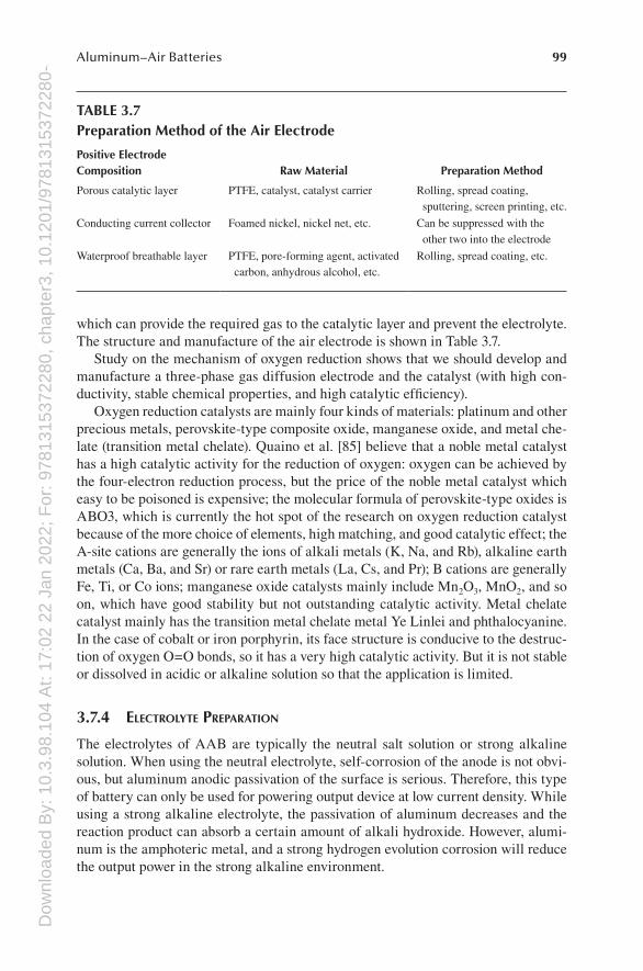
Dow
nloa
ded
By:
10.
3.98
.104
At:
17:0
2 22
Jan
202
2; F
or: 9
7813
1537
2280
, cha
pter
3, 1
0.12
01/9
7813
1537
2280
-499Aluminum–Air Batteries
which can provide the required gas to the catalytic layer and prevent the electrolyte. The structure and manufacture of the air electrode is shown in Table 3.7.
Study on the mechanism of oxygen reduction shows that we should develop and manufacture a three-phase gas diffusion electrode and the catalyst (with high con-ductivity, stable chemical properties, and high catalytic efficiency).
Oxygen reduction catalysts are mainly four kinds of materials: platinum and other precious metals, perovskite-type composite oxide, manganese oxide, and metal che-late (transition metal chelate). Quaino et al. [85] believe that a noble metal catalyst has a high catalytic activity for the reduction of oxygen: oxygen can be achieved by the four-electron reduction process, but the price of the noble metal catalyst which easy to be poisoned is expensive; the molecular formula of perovskite-type oxides is ABO3, which is currently the hot spot of the research on oxygen reduction catalyst because of the more choice of elements, high matching, and good catalytic effect; the A-site cations are generally the ions of alkali metals (K, Na, and Rb), alkaline earth metals (Ca, Ba, and Sr) or rare earth metals (La, Cs, and Pr); B cations are generally Fe, Ti, or Co ions; manganese oxide catalysts mainly include Mn2O3, MnO2, and so on, which have good stability but not outstanding catalytic activity. Metal chelate catalyst mainly has the transition metal chelate metal Ye Linlei and phthalocyanine. In the case of cobalt or iron porphyrin, its face structure is conducive to the destruc-tion of oxygen O=O bonds, so it has a very high catalytic activity. But it is not stable or dissolved in acidic or alkaline solution so that the application is limited.
3.7.4 ElEctrolytE PrEPArAtion
The electrolytes of AAB are typically the neutral salt solution or strong alkaline solution. When using the neutral electrolyte, self-corrosion of the anode is not obvi-ous, but aluminum anodic passivation of the surface is serious. Therefore, this type of battery can only be used for powering output device at low current density. While using a strong alkaline electrolyte, the passivation of aluminum decreases and the reaction product can absorb a certain amount of alkali hydroxide. However, alumi-num is the amphoteric metal, and a strong hydrogen evolution corrosion will reduce the output power in the strong alkaline environment.
TABLE 3.7Preparation Method of the Air Electrode
Positive Electrode Composition Raw Material Preparation Method
Porous catalytic layer PTFE, catalyst, catalyst carrier Rolling, spread coating, sputtering, screen printing, etc.
Conducting current collector Foamed nickel, nickel net, etc. Can be suppressed with the other two into the electrode
Waterproof breathable layer PTFE, pore-forming agent, activated carbon, anhydrous alcohol, etc.
Rolling, spread coating, etc.
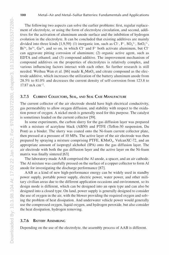
Dow
nloa
ded
By:
10.
3.98
.104
At:
17:0
2 22
Jan
202
2; F
or: 9
7813
1537
2280
, cha
pter
3, 1
0.12
01/9
7813
1537
2280
-4100 Metal–Air and Metal–Sulfur Batteries: Fundamentals and Applications
The following two aspects can solve the earlier problems: first, regular replace-ment of electrolyte, or using the form of electrolyte circulation, and second, addi-tives for the activation of aluminum anode surface and the inhibition of hydrogen evolution in the electrolyte. It can be concluded that existing additives are mainly divided into three kinds [1,9,59]: (1) inorganic ion, such as Cl−, F−, SO4
2−, SnO32−,
Bi3+, In3+, Ga3+, and so on, in which Cl− and F− both activate aluminum, but Cl− can aggravate pitting corrosion of aluminum; (2) organic active agent, such as EDTA and ethanol; and (3) compound additive. The improvement mechanism of compound additives on the properties of electrolytes is relatively complex, and various influencing factors interact with each other. So further research is still needed. Weihua Wan et al. [86] made K2MnO4 and citrate compound as the elec-trode additive, which increases the utilization of the battery aluminum anode from 28.5% to 81.0% and decreases the current density of self-corrosion from 123.8 to 17.87 mA cm−2.
3.7.5 currEnt collEctors, sEAl, And sEAl cAsE mAnufActurE
The current collector of the air electrode should have high electrical conductivity, gas permeability to allow oxygen diffusion, and stability with respect to the oxida-tion power of oxygen. A nickel mesh is generally used for this purpose. The catalyst is sometimes loaded on the current collector [59].
In some experiments, the carbon slurry for the gas diffusion layer was prepared with a mixture of acetylene black (AB50) and PTFE (Teflon-30 suspension, Du Pont) as a binder. The slurry was coated onto the Ni-foam current collector plate, then pressed at a pressure of 10 MPa. The active layer of the air electrode was then prepared by spraying a mixture comprising PTFE, KMnO4, VulcanXC-72, and an appropriate amount of isopropyl alchohol (IPA) onto the gas diffusion layer. The air electrode with both the gas diffusion layer and the active layer on the Ni-foam matrix was finally sintered [63].
The laboratory-made AAB comprised the Al anode, a spacer, and an air cathode. The Al mixture was carefully pressed on the surface of a copper collector to form Al anode for investigating the discharge performance [87].
AAB as a kind of new high-performance energy can be widely used in standby power supply, portable power supply, electric power, water power, and other mili-tary civilian areas due to the different application occasions and environment, so its design mode is different, which can be designed into an open type and can also be designed into a closed type. On land, power supply is generally designed to consider the use of oxygen in the air, with the blower providing the required oxygen and solv-ing the problem of heat dissipation. And underwater vehicle power would generally use the compressed oxygen, liquid oxygen, and hydrogen peroxide, but also consider the heat dissipation, hydrogen removing.
3.7.6 bAttEry AssEmbling
Depending on the use of the electrolyte, the assembly process of AAB is different.
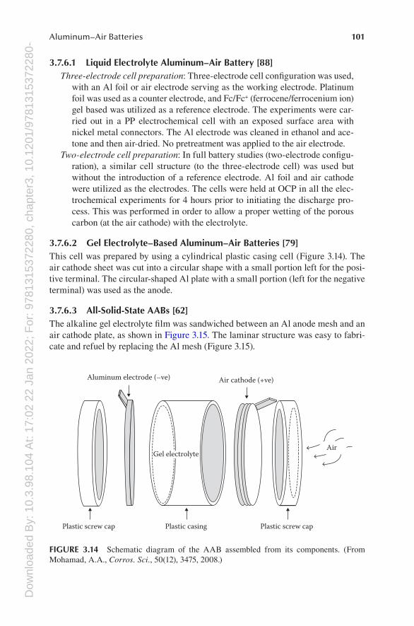
Dow
nloa
ded
By:
10.
3.98
.104
At:
17:0
2 22
Jan
202
2; F
or: 9
7813
1537
2280
, cha
pter
3, 1
0.12
01/9
7813
1537
2280
-4101Aluminum–Air Batteries
3.7.6.1 Liquid Electrolyte Aluminum–Air Battery [88]Three-electrode cell preparation: Three-electrode cell configuration was used,
with an Al foil or air electrode serving as the working electrode. Platinum foil was used as a counter electrode, and Fc/Fc+ (ferrocene/ferrocenium ion) gel based was utilized as a reference electrode. The experiments were car-ried out in a PP electrochemical cell with an exposed surface area with nickel metal connectors. The Al electrode was cleaned in ethanol and ace-tone and then air-dried. No pretreatment was applied to the air electrode.
Two-electrode cell preparation: In full battery studies (two-electrode configu-ration), a similar cell structure (to the three-electrode cell) was used but without the introduction of a reference electrode. Al foil and air cathode were utilized as the electrodes. The cells were held at OCP in all the elec-trochemical experiments for 4 hours prior to initiating the discharge pro-cess. This was performed in order to allow a proper wetting of the porous carbon (at the air cathode) with the electrolyte.
3.7.6.2 Gel Electrolyte–Based Aluminum–Air Batteries [79]This cell was prepared by using a cylindrical plastic casing cell (Figure 3.14). The air cathode sheet was cut into a circular shape with a small portion left for the posi-tive terminal. The circular-shaped Al plate with a small portion (left for the negative terminal) was used as the anode.
3.7.6.3 All-Solid-State AABs [62]The alkaline gel electrolyte film was sandwiched between an Al anode mesh and an air cathode plate, as shown in Figure 3.15. The laminar structure was easy to fabri-cate and refuel by replacing the Al mesh (Figure 3.15).
Plastic screw cap
Air
Air cathode (+ve)Aluminum electrode (–ve)
Plastic casingPlastic screw cap
Gel electrolyte
FIGURE 3.14 Schematic diagram of the AAB assembled from its components. (From Mohamad, A.A., Corros. Sci., 50(12), 3475, 2008.)
Dow
nloa
ded
By:
10.
3.98
.104
At:
17:0
2 22
Jan
202
2; F
or: 9
7813
1537
2280
, cha
pter
3, 1
0.12
01/9
7813
1537
2280
-4102 Metal–Air and Metal–Sulfur Batteries: Fundamentals and Applications
3.7.7 bAttEry mAintEnAncE
AAB is a nonpolluting, long-lasting, stable, and reliable power supply, but also a very environment-friendly battery. AAB has many advantages, such as large specific energy, light weight, no toxicity and risk, and so on. In addition, another advantage of AAB is maintenance convenience. According to the technical scheme, users do not need to charge their batteries as long as (every 1–2 months) they inject water or replace the useless electrolyte to support the chemical reaction, assigning a technical staff carry out the maintenance every year. After a long time, the anode electrode is consumed and only needs to replace the anode aluminum module.
3.7.8 bAttEry tEsts And PErformAncE diAgnosis
When the parts are assembled into a required battery, we need to test the perfor-mance of the batteries. The discharge performance of the AABs was studied by
Ni current collectorAl mesh anode
Polymer alkalinegel electrolyte
Porous air cathode
(a)
(b)
IonizationK2S2O2
Initiation Ploymerization
MBACross-link
AA moremer
Three-dimensionalPAA matrix
PAAchains
PotassiumOxygenNitrogenCarbonSulfurHydrogen
FIGURE 3.15 (a) Schematic of all-solid-state AAB with a laminar structure. (b) Illustration of the polymerization process from AA monomers to a PAA matrix. Particles represent dif-ferent atoms distinguished by color, white for hydrogen, gray for carbon, red for oxygen, yellow for sulfur, blue for nitrogen, and purple for potassium, respectively. (From Zhang, Z. et al., J. Power Sources, 251, 470, 2014.)
Dow
nloa
ded
By:
10.
3.98
.104
At:
17:0
2 22
Jan
202
2; F
or: 9
7813
1537
2280
, cha
pter
3, 1
0.12
01/9
7813
1537
2280
-4103Aluminum–Air Batteries
constant current discharge testing at different current densities. The Land test system was used. The weight of the anodes was measured both before and after discharge. The anode utilization (η), capacity density, and energy density were calculated using the following formulas [89]:
η = 100It/(ΔmF/9) (3.9)
Capacity density = Ih/Δm (3.10)
Energy density = UIh/Δm (3.11)
whereη is the anode utilization, %I is the current, AΔm is the weight loss, gF is the Faraday constantt is the time, sU is the average voltage, Vh is the discharge time, h
Conductivity measurements were performed at room temperature by impedance spectroscopy with a commercial sensor with internal digitated electrodes on a poly-imide support. Electrolyte electrochemical windows were measured using a cycling voltammetry technique with a tungsten working electrode rotating at 250 turn min−1 and a scan rate of 20 mV s−1. Corrosion rates were measured applying a linear polar-ization on an aluminum wire as working electrode and a scan rate of 1 mV s−1 for a potential range of ±50 mV around the OCV [3].
3.7.9 bAttEry sAfEty
In high-power output, the heat output system must be equipped with the heat output system. Another security problem for the AAB is the leak. In practical application, how to ensure the battery does not leak is also a serious problem to be solved. Battery in the actual use of the process is needed to avoid the bumps of the battery and pre-vent fluctuations in output current. There are potential safety hazards in the presence of localized electrochemical reactions in the presence of impurities in aluminum.
3.8 AAB TECHNOLOGY CHALLENGES AND PERSPECTIVES
As a coin, everything has two sides: challenges and perspectives. There are a num-ber of technical problems or challenges that need to be solved to make AAB suit-able for practical applications. As mentioned in former sections, anodes made of pure aluminum are severely corroded by the electrolytes (especially in the aqueous alkaline electrolytes), so the aluminum is usually alloyed with tin or other elements. Additionally, the hydrated alumina created during the reaction process forms a gel-like substance at the anode and reduces the electricity output, which is a big problem
Dow
nloa
ded
By:
10.
3.98
.104
At:
17:0
2 22
Jan
202
2; F
or: 9
7813
1537
2280
, cha
pter
3, 1
0.12
01/9
7813
1537
2280
-4104 Metal–Air and Metal–Sulfur Batteries: Fundamentals and Applications
that should be considered in the development work on AAB. Therein, additives can be one of the solutions that make the alumina to be formed the powder rather than the gel. The air cathode is made from polymers and catalyst layer, which can facili-tate oxygen diffusion and ensure the normal operation of the system. In view of the importance of the cathode, further development work on air cathodes is really neces-sary, including air-permeable membranes, carbon, catalysts, and so on. Additionally, the cell design and maintenance are also the factors needed for consideration.
However, the promising perspectives still exist for AAB. Aluminum as the “fuel” for vehicles has been studied by Yang and Knickle [5]. They have analyzed it from many aspects, that is, driving ranges, cost, and total fuel efficiency. The AAB sys-tem can generate enough and power for driving ranges and acceleration similar to gasoline powered car. The cost of aluminum as an anode can be as low as $1.1 kg−1 as long as the reaction product is recycled. The total fuel efficiency during the cycle process in AAB electric vehicles can be 20% comparable to that of ICE vehicles (13%). The designed battery energy density is projected as 2000 Wh kg−1. The cost of a battery system can be $29 kW−1. AAB EVs life-cycle analysis was conducted and the AAB EVs can be projected to have a travel range comparable to ICEs. From this analysis, AAB EVs are the most promising candidates for replacing ICEs. Besides that, AAB with limited shelf life is no longer the case with modern designs. So these batteries can be used as reserve batteries in some telephone exchanges as a backup power source. AAB also could be used to power laptop computer, cell phones, other consumer electronics, and so on.
3.9 SUMMARY
AABs have great potentials for using as low-cost, high-performance energy-storage systems, so AAB has attracted great much attention from our researchers. Due to the existence of the overpotentials in the two electrodes and the consumption of water, the practical operation voltage, power, and energy are lower than that of the theoretical. However, though, the performance of AAB still can surpass that of most battery systems. This is the reason that we concretely introduce the AAB in the Chapter 3.
We have introduced the air cathode, aluminum anode, the AAB electrolytes, separators, current collectors, and something about AAB manufacture. Typically, the composite air electrodes are composed of the high-surface-area carbon materi-als, the catalysts, Teflon binder, air-permeable membranes, and metal mesh current collector. Further development work on air cathodes is really necessary. The electro-lytes used in AABs include aqueous alkaline solution, aqueous neutral saline, ionic liquid, solid-state electrolyte, and so on. Some electrolyte additives are also needed to improve the performance of AAB. Anodes made of pure aluminum are severely corroded by the electrolytes (especially in the aqueous alkaline electrolytes), so the aluminum is usually alloyed with tin or other elements. Additionally, the cell design and maintenance are also the aspects mentioned in the last sections of the chapter.
In summary, the AAB with promising perspectives for applications in many fields can become the ideal power in the twenty-first century, but the road for solving the problems is tough and long.
Dow
nloa
ded
By:
10.
3.98
.104
At:
17:0
2 22
Jan
202
2; F
or: 9
7813
1537
2280
, cha
pter
3, 1
0.12
01/9
7813
1537
2280
-4105Aluminum–Air Batteries
REFERENCES
1. D.R. Egan et al., Developments in electrode materials and electrolytes for aluminium–air batteries, Journal of Power Sources, 236 (2013), 293.
2. C. Daniel and J.O. Besenhard, Metal-air batteries, in Handbook of Battery Materials. Wiley-VCH Verlag GmbH & Co. KGaA, Weiheim, Germany (2011) p. 759.
3. R. Revel, T. Audichon, and S. Gonzalez, Non-aqueous aluminium–air battery based on ionic liquid electrolyte, Journal of Power Sources, 272 (2014), 415.
4. Cleantech Canada Staff, http://www.canadianmanufacturing.com/environment-and-safety/alcoa-phinergy-developing-aluminum-air-ev-battery-138049/, June 2, 2014.
5. S. Yang and H. Knickle, Design and analysis of aluminum/air battery system for elec-tric vehicles, Journal of Power Sources, 112(1) (2002), 162.
6. D. Linden and T.B. Reddy, Metal/air batteries, in Handbook of Batteries. McGraw-Hill, New York (2001).
7. M. Nestoridi, Al air batteries: The concept—Electrochemistry, in The Study of Aluminium Anodes for High Power Density Al-Air Batteries with Brine Electrolytes. PhD thesis, University of Southampton, Southampton, U.K. (2009) p. 3.
8. S.-I. Pyun and S.-M. Moon, Corrosion mechanism of pure aluminium in aqueous alka-line solution, Journal of Solid State Electrochemistry, 4(5) (2000), 267.
9. Q. Li and N.J. Bjerrum, Aluminum as anode for energy storage and conversion: A review, Journal of Power Sources, 110(1) (2002), 1.
10. H.Z. Wang et al., A review on hydrogen production using aluminum and aluminum alloys, Renewable and Sustainable Energy Reviews, 13(4) (2009), 845.
11. J.A. Hunter, Aluminium batteries, EP326338A2 (1989). 12. C.D. Tuck, Aluminum air batteries, in Modern Battery Technology. Ellis Horwood,
West Sussex, England (1991) pp. 489–490. 13. J.A. Hunter et al., Aluminium batteries, US5004654 A (1991). 14. K.R. Van Horn, Aluminum and alloy, in Aluminum: Properties, Physical Metallurgy
and Phase Diagrams. American Society for Metals, Ohio (1967), pp. 49–54. 15. K.-K. Lee and K.-B. Kim, Electrochemical impedance characteristics of pure Al and
Al-Sn alloys in NaOH solution, Corrosion Science, 43(3) (2001), 561. 16. J.A. Hunter, The anodic behaviour of aluminium alloys in alkaline electrolytes. PhD
thesis, University of Oxford, Oxford, England (1989). 17. C. Zhang and S.M. Park, The anodic oxidation of nickel in alkaline media studied by
spectroelectrochemical techniques, Journal of the Electrochemical Society, 134(12) (1987), 2966.
18. D.D. Macdonald et al., Evaluation of alloy anodes for aluminum-air batteries: Corrosion studies, Corrosion Science, 44(9) (1988), 652.
19. C.D.S. Tuck, J.A. Hunter, and G.M. Scamans, The electrochemical behavior of Al–Ga alloys in alkaline and neutral electrolytes, Journal of the Electrochemical Society, 134(12) (1987), 2970.
20. W. Wilhelmsen et al., The electrochemical behaviour of Al in alloys in alkaline electro-lytes, Electrochimica Acta, 36(1) (1991), 79.
21. P.W. Jeffrey, W. Halliop, and F.N. Smith, Aluminium anode alloy, EP209402A1 (1987). 22. E.J. Rudd and D.W. Gibbons, High energy density aluminum/oxygen cell, Journal of
Power Sources, 47(3) (1994), 329. 23. M. Nestoridi et al., The study of aluminium anodes for high power density Al/air bat-
teries with brine electrolytes, Journal of Power Sources, 178(1) (2008), 445. 24. V. Neburchilov et al., A review on air cathodes for zinc–air fuel cells, Journal of Power
Sources, 195(5) (2010), 1271. 25. C.-C. Chang and T.-C. Wen, An investigation of thermally prepared electrodes for oxygen
reduction in alkaline solution, Materials Chemistry and Physics, 47(2–3) (1997), 203.
Dow
nloa
ded
By:
10.
3.98
.104
At:
17:0
2 22
Jan
202
2; F
or: 9
7813
1537
2280
, cha
pter
3, 1
0.12
01/9
7813
1537
2280
-4106 Metal–Air and Metal–Sulfur Batteries: Fundamentals and Applications
26. E. Yeager, Electrocatalysts for O2 reduction, Electrochimica Acta, 29(11) (1984), 1527.
27. L.Q. Hoa et al., Direct energy extraction from brown macroalgae–derived alginate by gold nanoparticles on functionalized carbon nanotubes, ChemCatChem, 6(1) (2014), 135.
28. J. Xu et al., Three-dimensional structural engineering for energy-storage devices: From microscope to macroscope, ChemElectroChem, 1(6) (2014), 975.
29. N.M. Marković et al., Oxygen reduction reaction on Pt and Pt bimetallic surfaces: A selective review, Fuel Cells, 1(2) (2001), 105.
30. M. Yuasa et al., Reverse micelle-based preparation of carbon-supported La1−xSrx Mn1−yFeyO3+δ for oxygen reduction electrode, Journal of the Electrochemical Society, 151(10) (2004), A1690.
31. Y. Shimizu et al., Bi-functional oxygen electrode using large surface area La1−xCax CoO3 for rechargeable metal-air battery, Journal of the Electrochemical Society, 137(11) (1990), 3430.
32. S. Müller et al., A study of carbon-catalyst interaction in bifunctional air electrodes for zinc-air batteries, Journal of New Materials for Electrochemical Systems, 2 (1999), 227.
33. M. Bursell, M. Pirjamali, and Y. Kiros, La0.6Ca0.4CoO3, La0.1Ca0.9MnO3 and LaNiO3 as bifunctional oxygen electrodes, Electrochimica Acta, 47(10) (2002), 1651.
34. M. Hayashi et al., Enhanced electrocatalytic activity for oxygen reduction over carbon-supported LaMnO3 prepared by reverse micelle method, Electrochemical and Solid-State Letters, 1(6) (1998), 268.
35. M. Hayashi et al., Reverse micelle assisted dispersion of lanthanum manganite on car-bon support for oxygen reduction cathode, Journal of the Electrochemical Society, 151(1) (2004), A158.
36. J. Lukaszewicz et al., New approach towards preparation of efficient gas diffusion-type oxygen reduction electrode, Journal of Materials Science, 41(19) (2006), 6215.
37. L. Guangchuan et al., Influence of alkali metal cation (Li (I), Na (I), K (I)) on the con-struction of chiral and achiral heterometallic coordination polymers, Journal of Rare Earths, 25(Supplement 2) (2007), 264.
38. M. Yuasa et al., High-performance oxygen reduction catalyst using carbon-supported La-Mn-based perovskite-type oxide, Electrochemical and Solid-State Letters, 14(5) (2011), A67.
39. L. Wang et al., CoMn2O4 spinel nanoparticles grown on graphene as bifunctional cata-lyst for lithium-air batteries, Journal of the Electrochemical Society, 158(12) (2011), A1379.
40. T. Takeguchi et al., Layered perovskite oxide: A reversible air electrode for oxygen evolution/reduction in rechargeable metal-air batteries, Journal of the American Chemical Society, 135 (2013), 11125.
41. N. Li et al., Electrocatalytic activity of spinel-type oxides LiMn2−xMxO4 with large specific surface areas for metal-air battery, Journal of Power Sources, 74(2) (1998), 255.
42. N. Li et al., Spinel-type oxides LiMn2−xMxO4 [M=Co, Fe, (CoFe)] as electrocatalyst for oxygen evolution/reduction in alkaline solution, Journal of Applied Electrochemistry, 29(11) (1999), 1351.
43. T. Nissinen et al., Microwave synthesis of catalyst spinel MnCo2O4 for alkaline fuel cell, Journal of Power Sources, 106(1–2) (2002), 109.
44. Y. Kiros, Cathodes à diffusion d’air pour piles à combustible, WO 02/075827 A1 (2002).
Dow
nloa
ded
By:
10.
3.98
.104
At:
17:0
2 22
Jan
202
2; F
or: 9
7813
1537
2280
, cha
pter
3, 1
0.12
01/9
7813
1537
2280
-4107Aluminum–Air Batteries
45. J.S. Spendelow and A. Wieckowski, Electrocatalysis of oxygen reduction and small alcohol oxidation in alkaline media, Physical Chemistry Chemical Physics, 9(21) (2007), 2654.
46. B.B. Blizanac, P.N. Ross, and N.M. Markovic, Oxygen electroreduction on Ag(111): The pH effect, Electrochimica Acta, 52(6) (2007), 2264.
47. F. Bidault and A. Kucernak, A novel cathode for alkaline fuel cells based on a porous silver membrane, Journal of Power Sources, 195(9) (2010), 2549.
48. M. Yuasa et al., Bi-functional oxygen electrodes using LaMnO3/LaNiO3 for recharge-able metal-air batteries, Journal of the Electrochemical Society, 158(5) (2011), A605.
49. L. Mao et al., Mechanistic study of the reduction of oxygen in air electrode with man-ganese oxides as electrocatalysts, Electrochimica Acta, 48(8) (2003), 1015.
50. F. Cheng et al., MnO2-based nanostructures as catalysts for electrochemical oxygen reduction in alkaline media, Chemistry of Materials, 22(3) (2010), 898.
51. J. Suntivich et al., Design principles for oxygen-reduction activity on perovskite oxide catalysts for fuel cells and metal–air batteries, Natural Chemistry, 3(7) (2011), 546.
52. F. Cheng and J. Chen, ChemInform abstract: Metal-air batteries: From oxygen reduc-tion electrochemistry to cathode catalysts, Chemical Society Reviews, 41(6) (2012), 2172.
53. D. Higgins et al., Activated and nitrogen-doped exfoliated graphene as air electrodes for metal–air battery applications, Journal of Materials Chemistry A, 1(7) (2013), 2639.
54. S. Xu et al., A novel cathode catalyst for aluminum-air fuel cells: Activity and dura-bility of polytetraphenylporphyrin iron (II) absorbed on carbon black, International Journal of Hydrogen Energy, 39(35) (2014), 20171.
55. D.B. Meadowcroft, Low-cost oxygen electrode material, Nature, 226(5248) (1970), 847. 56. R.S.M. Patnaik et al., Heat management in aluminium/air batteries: Sources of heat,
Journal of Power Sources, 50(3) (1994), 331. 57. M.A. Rahman, X. Wang, and C. Wen, High energy density metal-air batteries: A
review, Journal of the Electrochemical Society, 160(10) (2013), A1759. 58. M. Akmal, R. Othman, and M.H. Ani, Comparative electrochemical performance char-
acteristics of aluminium-air cell employing seawater and NaCl electrolytes, Advanced Materials Research, 701 (2013), 314.
59. H. Arai and M. Hayashi, Secondary batteries—Metal-air systems | Overview (second-ary and primary), in Encyclopedia of Electrochemical Power Sources (Eds. Chris K. Dyer, Patrick T. Moseley, Zempachi Ogumi, David A. J. Rand, Bruno Scrosati, Jürgen Garche), Elsevier, Amsterdam, the Netherlands (2009), p. 347.
60. D. Chu and R.F. Savinell, Experimental data on aluminum dissolution in KOH electro-lytes, Electrochimica Acta, 36(10) (1991), 1631.
61. G.M. Wu, S.J. Lin, and C.C. Yang, Preparation and characterization of PVA/PAA membranes for solid polymer electrolytes, Journal of Membrane Science, 275(1–2) (2006), 127.
62. Z. Zhang et al., All-solid-state Al–air batteries with polymer alkaline gel electrolyte, Journal of Power Sources, 251 (2014), 470.
63. G.M. Wu, S.J. Lin, and C.C. Yang, Alkaline Zn-air and Al-air cells based on novel solid PVA/PAA polymer electrolyte membranes, Journal of Membrane Science, 280(1–2) (2006), 802.
64. T. Jiang et al., Electrodeposition of aluminium from ionic liquids: Part I—electrode-position and surface morphology of aluminium from aluminium chloride (AlCl 3)– 1-ethyl-3-methylimidazolium chloride ([EMIm] Cl) ionic liquids, Surface and Coatings Technology, 201(1–2) (2006), 1.
Dow
nloa
ded
By:
10.
3.98
.104
At:
17:0
2 22
Jan
202
2; F
or: 9
7813
1537
2280
, cha
pter
3, 1
0.12
01/9
7813
1537
2280
-4108 Metal–Air and Metal–Sulfur Batteries: Fundamentals and Applications
65. T. Hibino, K. Kobayashi, and M. Nagao, An all-solid-state rechargeable aluminum–air battery with a hydroxide ion-conducting Sb (V)-doped SnP2O7 electrolyte, Journal of Materials Chemistry A, 1(47) (2013), 14844.
66. R. Mori, A novel aluminium–air rechargeable battery with Al2O3 as the buffer to sup-press byproduct accumulation directly onto an aluminium anode and air cathode, RSC Advances, 4(57) (2014), 30346.
67. L. Wang et al., A hybrid aluminum/hydrogen/air cell system, International Journal of Hydrogen Energy, 38(34) (2013), 14801.
68. A. Mukherjee and I.N. Basumallick, Metallized graphite as an improved cathode mate-rial for aluminium/air batteries, Journal of Power Sources, 45(2) (1993), 243.
69. C.-H. Wu et al., Inhibiting ability of chelating agent on aluminum corrosion in alkaline solution, ECS Transactions, 50(25) (2013), 23.
70. D.D. Macdonald and C. English, Development of anodes for aluminium/air batteries— solution phase inhibition of corrosion, Journal of Applied Electrochemistry, 20(3) (1990), 405.
71. X.Y. Wang et al., The effects of polyethylene glycol (PEG) as an electrolyte additive on the corrosion behavior and electrochemical performances of pure aluminum in an alkaline zincate solution, Materials and Corrosion, 61 (2010), 1.
72. A.M. Abdel-Gaber et al., Novel package for inhibition of aluminium corrosion in alka-line solutions, Materials Chemistry and Physics, 124 (2010), 773.
73. N.A.F. Al-Rawashdeh and A.K. Maayta, Cationic surfactant as corrosion inhibitor for aluminum in acidic and basic solutions, Anti-Corrosion Methods and Materials, 52 (2005), 160.
74. D.E. Fenton, J.M. Parker, and P.V. Wright, Complexes of alkali metal ions with poly(ethylene oxide), Polymer, 14(11) (1973), 589.
75. P.V. Wright, Electrical conductivity in ionic complexes of poly(ethylene oxide), British Polymer Journal, 7(5) (1975), 319.
76. M. Armand et al., Poly-ethers as solid electrolytes, in Fast Ion Transport in Solids (Eds. Vashishta, P., Mundy, J.N., and Shenoy, G.K.), North Holland, Amsterdan, the Netherlands (1979), pp. 131–134.
77. J.F. Fauvarque et al., Alkaline poly(ethylene oxide) solid polymer electrolytes. Application to nickel secondary batteries, Electrochimica Acta, 40(13–14) (1995), 2449.
78. S. Guinot et al., A new class of PEO-based SPEs: Structure, conductivity and applica-tion to alkaline secondary batteries, Electrochimica Acta, 43(10–11) (1998), 1163.
79. A.A. Mohamad, Electrochemical properties of aluminum anodes in gel electrolyte-based aluminum-air batteries, Corrosion Science, 50(12) (2008), 3475.
80. R. Mori, A new structured aluminium-air secondary battery with a ceramic aluminium ion conductor, RSC Advances, 3(29) (2013), 11547.
81. R. Mori, A novel aluminium-air secondary battery with long-term stability, RSC Advances, 4(4) (2014), 1982.
82. N.S. Hudak, Chloroaluminate-doped conducting polymers as positive electrodes in rechargeable aluminum batteries, The Journal of Physical Chemistry C, 118(10) (2014), 5203.
83. M. Parans Paranthaman et al., Chapter 13—Aluminum-ion batteries for medium- and large-scale energy storage, in Advances in Batteries for Medium and Large-Scale Energy Storage (Eds. C. Menictas, M. Skyllas-Kazacos, T. M. Lim), Woodhead Publishing, U.K. (2015), p. 463.
84. F. Shu et al., Research progress in Al alloy anodes for alkaline Al-air battery, Battery Bimonthly, 35(2) (2005), 158.
85. P. Quaino et al., Why is gold such a good catalyst for oxygen reduction in alkaline media? Angewandte Chemie International Edition, 51(52) (2012), 12997.
Dow
nloa
ded
By:
10.
3.98
.104
At:
17:0
2 22
Jan
202
2; F
or: 9
7813
1537
2280
, cha
pter
3, 1
0.12
01/9
7813
1537
2280
-4109Aluminum–Air Batteries
86. W. Wan, Y. Tang, and Z. Lu, Effect of additives in the alkaline electrolyte on anode behavior of aluminum, Battery Bimonthly, 38(1) (2008), 40.
87. C. Li et al., Metallic aluminum nanorods: Synthesis via vapor-deposition and applica-tions in Al/air batteries, Chemistry of Materials, 19(24) (2007), 5812.
88. D. Gelman, B. Shvartsev, and Y. Ein-Eli, Aluminum–air battery based on an ionic liquid electrolyte, Journal of Materials Chemistry A, 2(47) (2014), 20237.
89. L. Fan and H. Lu, The effect of grain size on aluminum anodes for Al-air batteries in alkaline electrolytes, Journal of Power Sources, 284 (2015), 409.