Embed Size (px)
Citation preview
FRP Pipe Failures & Lessons to be learnedPaulin Webinar April 2008
Scope of Webinar
Experience basis for present webinar
Part 1. Failures in GRP Pipe System a survey
Part 2. Measures to avoid failures.
The Role of system design & code compliance if any
Some details of System Design by Analysis
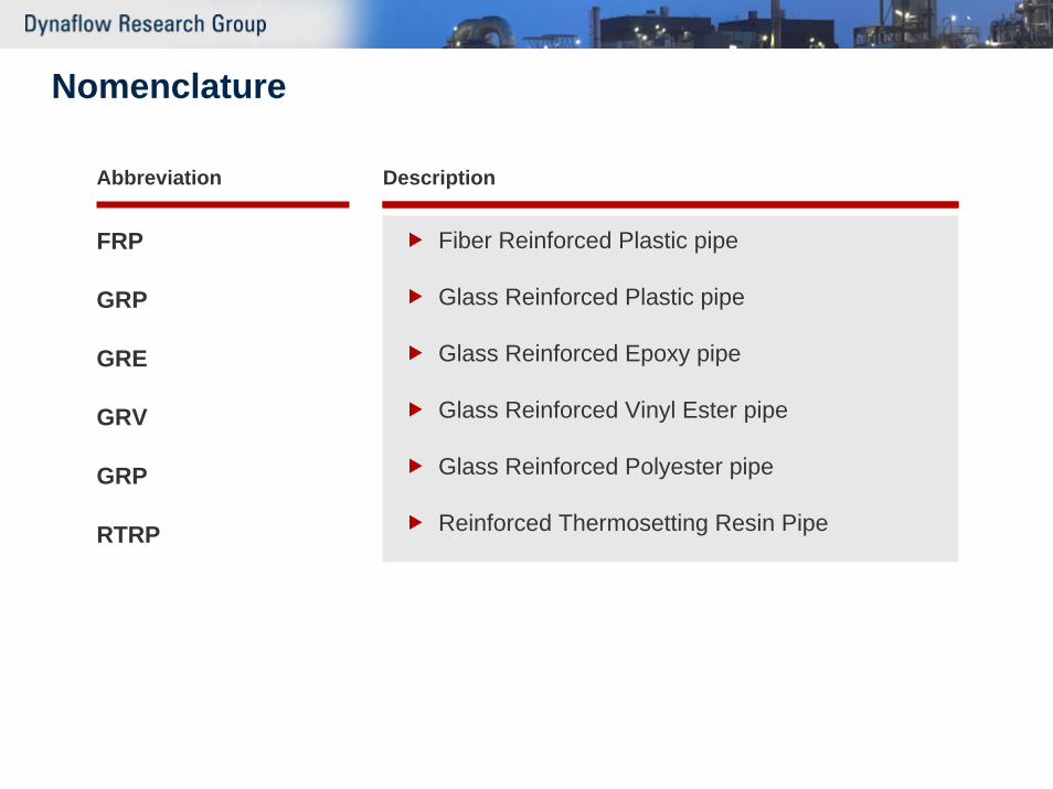
Nomenclature
Abbreviation
FRP
GRP
GRE
GRV
GRP
RTRP
Description
Fiber Reinforced Plastic pipe
Glass Reinforced Plastic pipe
Glass Reinforced Epoxy pipe
Glass Reinforced Vinyl Ester pipe
Glass Reinforced Polyester pipe
Reinforced Thermosetting Resin Pipe
50 Years Fiberglass pipe. A commodity?? Why Glass Reinforced Plastic - revisited
Corrosion Resistance (low maintenance costs)
Low weight (easy handling)
Low friction (low pressure loss)
Large flexibility (relatively low loads due to expansion)
Large variety in possible shapes
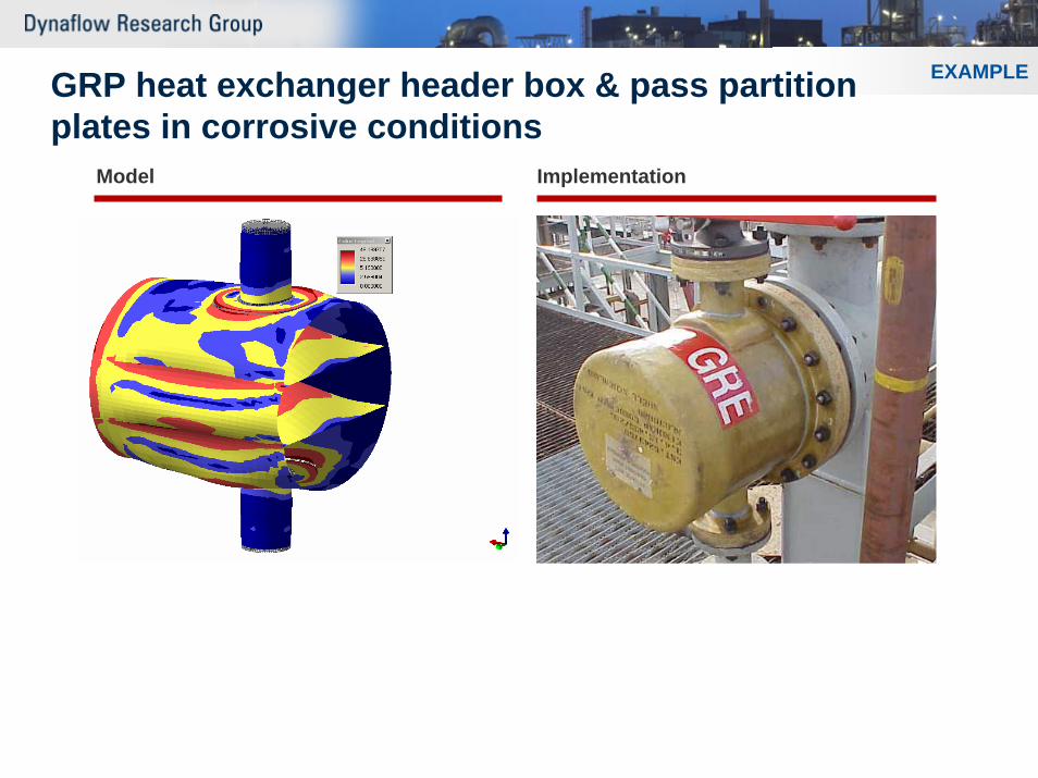
EXAMPLEGRP heat exchanger header box & pass partitionplates in corrosive conditions
Model Implementation
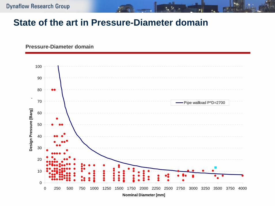
State of the art in Pressure-Diameter domain
Pressure-Diameter domain
0
10
20
30
40
50
60
70
80
90
100
0 250 500 750 1000 1250 1500 1750 2000 2250 2500 2750 3000 3250 3500 3750 4000
Nominal Diameter [mm]
Des
ign
Pres
sure
[Bar
g]
.
Pipe wallload P*D=2700
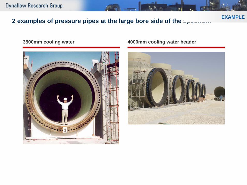
2 examples of pressure pipes at the large bore side of the spectrum
3500mm cooling water 4000mm cooling water header
EXAMPLE
Variety of GRP pipes & fittings
Manufacturing process of pipe and fittingsHand Lay-up, contact moldedFilament wound
Winding angleCentrifugially castedWith and without filler (sand)
Resin systemsPolyesterVinyl esterEpoxy
Various curing agents
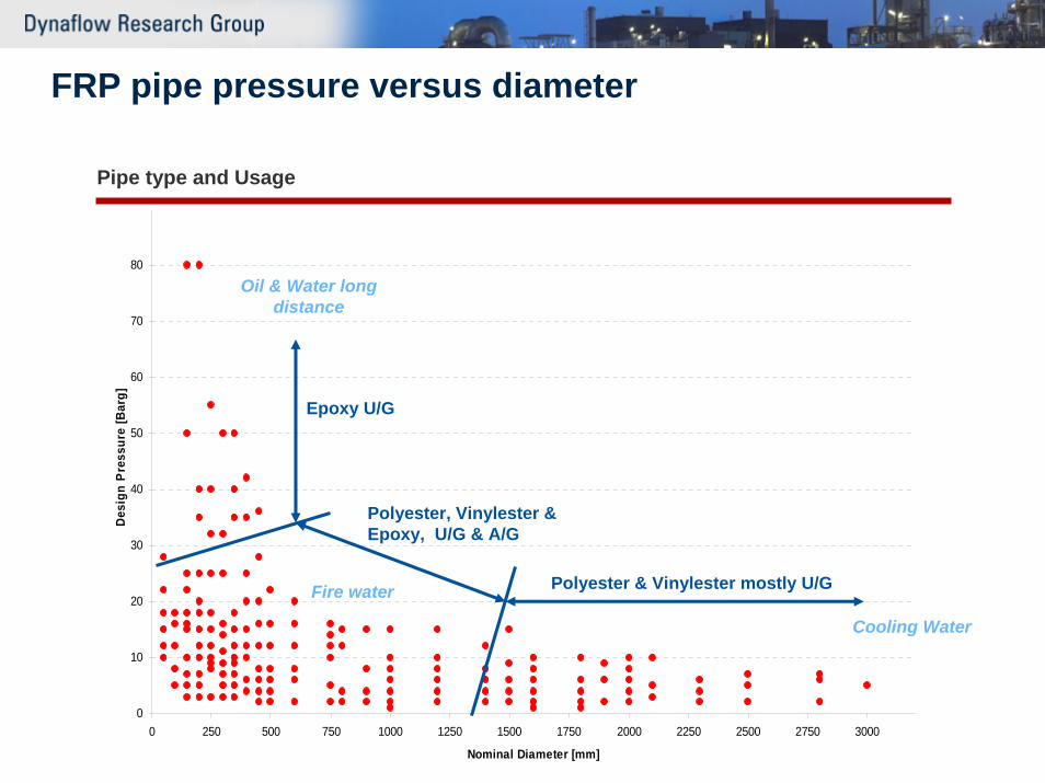
FRP pipe pressure versus diameter
Pipe type and Usage
0
10
20
30
40
50
60
70
80
0 250 500 750 1000 1250 1500 1750 2000 2250 2500 2750 3000
Nominal Diameter [mm]
Des
ign
Pre
ssur
e [B
arg]
Epoxy U/G
Polyester, Vinylester &Epoxy, U/G & A/G
Polyester & Vinylester mostly U/G
Oil & Water long distance
Cooling Water
Fire water
Typical for GRP large variety of jointing systems
Tensile resistantFull pressure trust capability
Cement, lamination, mechanical lock joint, flangeApplication: U/G & A/G and in hybrid systems
Non-tensile resistantNo or only limited pressure trust capability
Double bell couplers, bell and spigot seal jointApplication: U/G & A/G in long straight pipe lines (with special supporting)
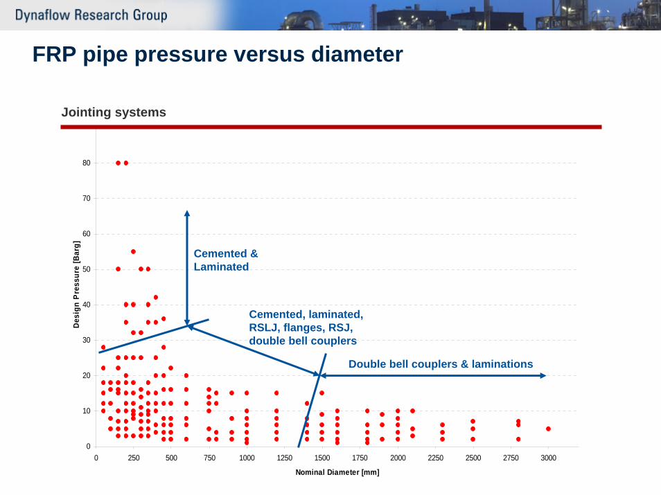
FRP pipe pressure versus diameter
Jointing systems
0
10
20
30
40
50
60
70
80
0 250 500 750 1000 1250 1500 1750 2000 2250 2500 2750 3000
Nominal Diameter [mm]
Des
ign
Pre
ssur
e [B
arg]
Cemented & Laminated
Cemented, laminated, RSLJ, flanges, RSJ, double bell couplers
Double bell couplers & laminations
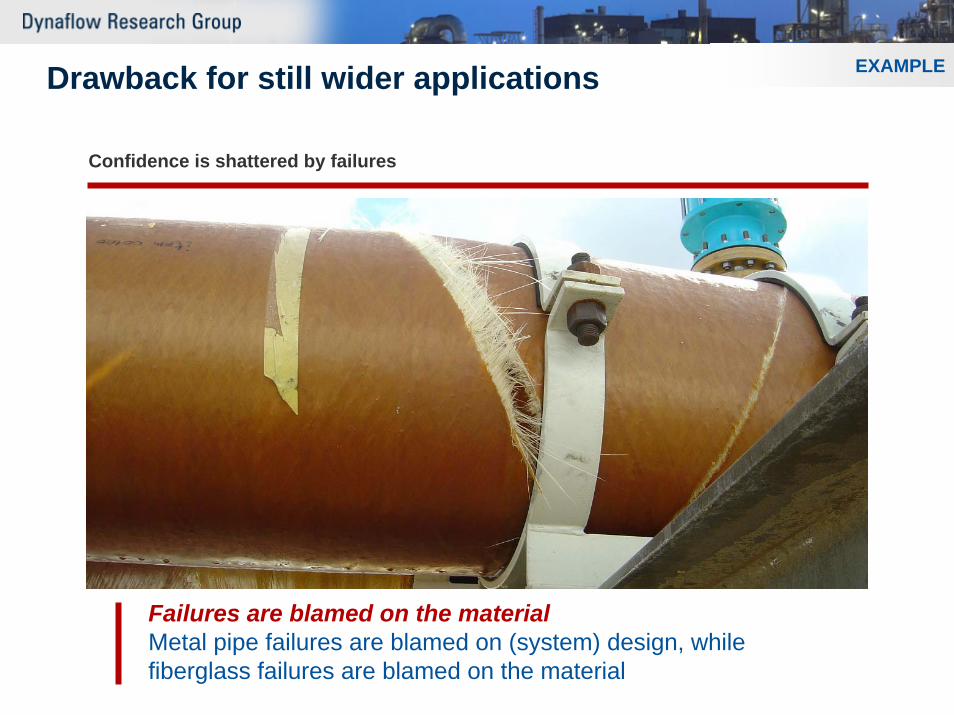
Drawback for still wider applications
Failures are blamed on the materialMetal pipe failures are blamed on (system) design, while fiberglass failures are blamed on the material
Confidence is shattered by failures
EXAMPLE
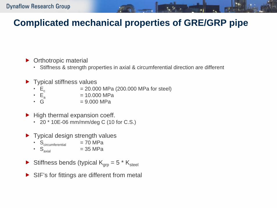
Complicated mechanical properties of GRE/GRP pipe
Orthotropic materialStiffness & strength properties in axial & circumferential direction are different
Typical stiffness valuesEc = 20.000 MPa (200.000 MPa for steel)Ea = 10.000 MPaG = 9.000 MPa
High thermal expansion coeff.20 * 10E-06 mm/mm/deg C (10 for C.S.)
Typical design strength valuesScircumferential = 70 MPaSaxial = 35 MPa
Stiffness bends (typical Kgrp = 5 * Ksteel
SIF’s for fittings are different from metal
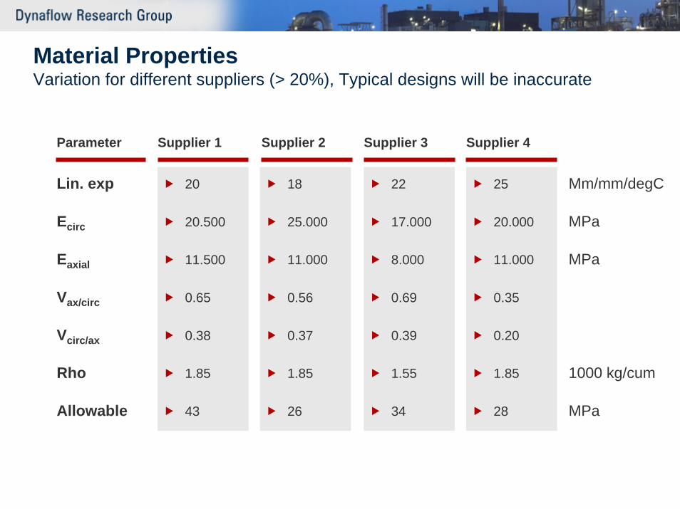
Material PropertiesVariation for different suppliers (> 20%), Typical designs will be inaccurate
Lin. exp
Ecirc
Eaxial
Vax/circ
Vcirc/ax
Rho
Allowable
Parameter
20
20.500
11.500
0.65
0.38
1.85
43
Supplier 1 Supplier 2 Supplier 3 Supplier 4
18
25.000
11.000
0.56
0.37
1.85
26
22
17.000
8.000
0.69
0.39
1.55
34
25
20.000
11.000
0.35
0.20
1.85
28
Mm/mm/degC
MPa
MPa
1000 kg/cum
MPa
GRP-pipe systemsWhen, where and why do failures occur
WhenSmall part (<5%) of the failures occurs during installation or operationMost of the failures occur during hydro-testing (pressure testing)
WhereJoints (89%)Fittings (10%), bends, tees, reducersPlane pipe (1%)
WhyDue to material defects (<2%)Defective installation (49%)Overloading of material due to shortcomings in design (49%)
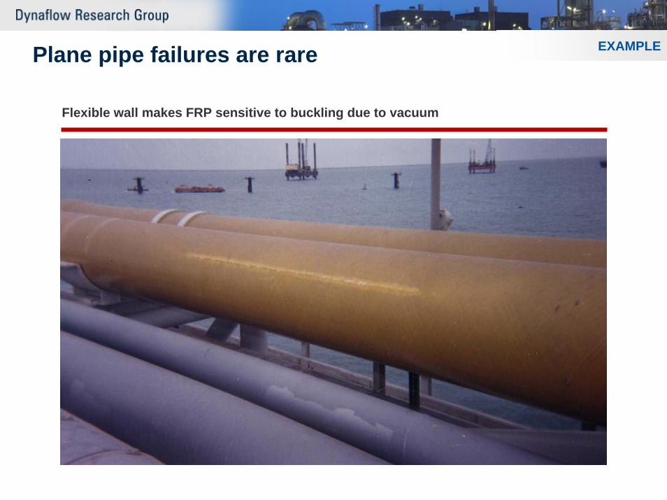
Plane pipe failures are rare
Flexible wall makes FRP sensitive to buckling due to vacuum
EXAMPLE
Some failures occur at fittingsTypes of fittings
BendsMolded bends (failures occur next to the bend)Mitered bends (failures at the miter joints)
Tees (failures of the intersection)Filament wound tees (typical d/D > 0.4)Contact moulded tees (typical d/D < 0.25)
Reducers
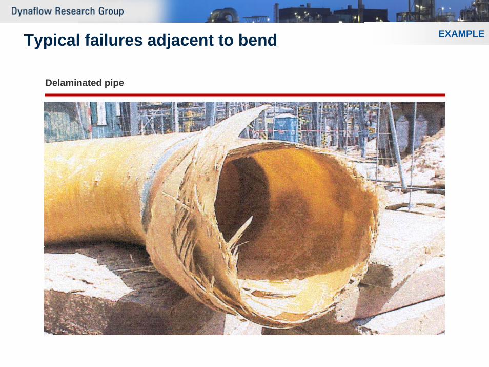
Typical failures adjacent to bend
Delaminated pipe
EXAMPLE
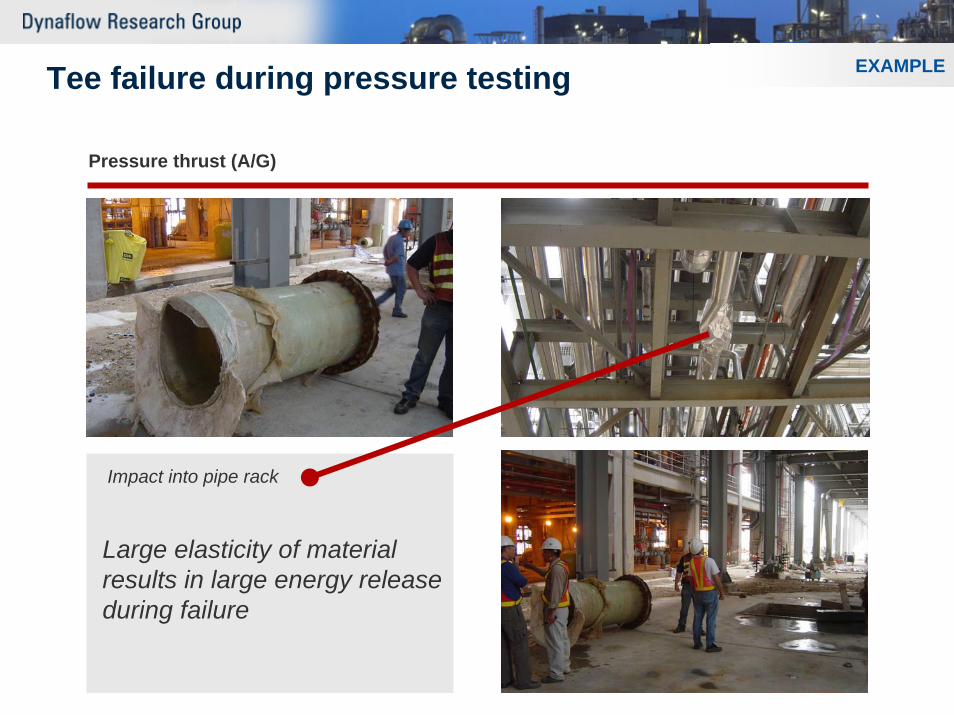
Tee failure during pressure testing
Pressure thrust (A/G)
EXAMPLE
Impact into pipe rack
Large elasticity of material results in large energy release during failure
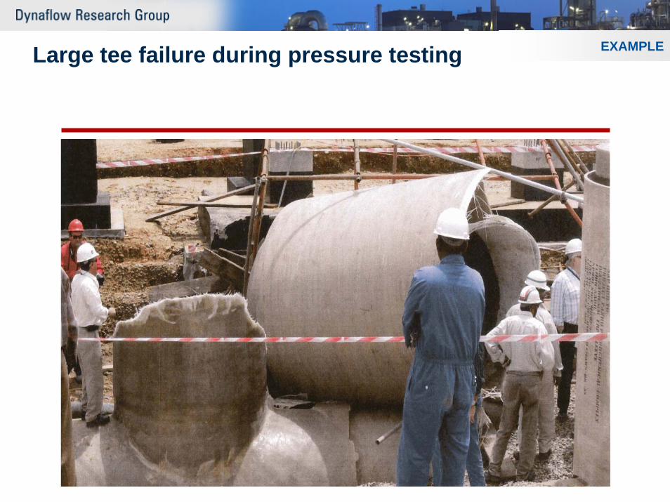
Large tee failure during pressure testing EXAMPLE
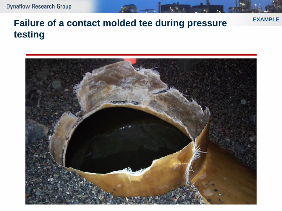
EXAMPLEFailure of a contact molded tee during pressuretesting
Most failures occur at joints
Types of jointsCemented jointsLaminated jointsMechanical joints
Flanged jointsLock joints
Ideally no defective joints
Reality 0.1% (1 out of 1000) of installed joints show a defect as a result of manufacturing of the joint at site
Non destructive test methods are poorDefect only appear during hydro-test
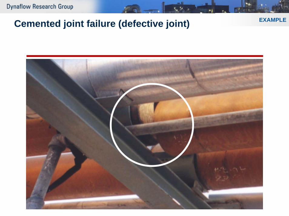
EXAMPLECemented joint failure (defective joint)
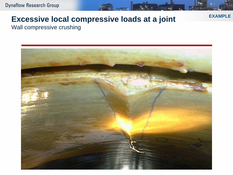
EXAMPLEExcessive local compressive loads at a jointWall compressive crushing
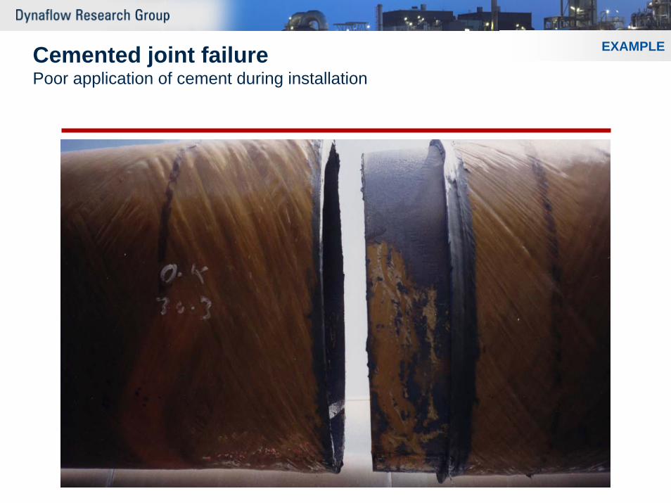
EXAMPLECemented joint failurePoor application of cement during installation
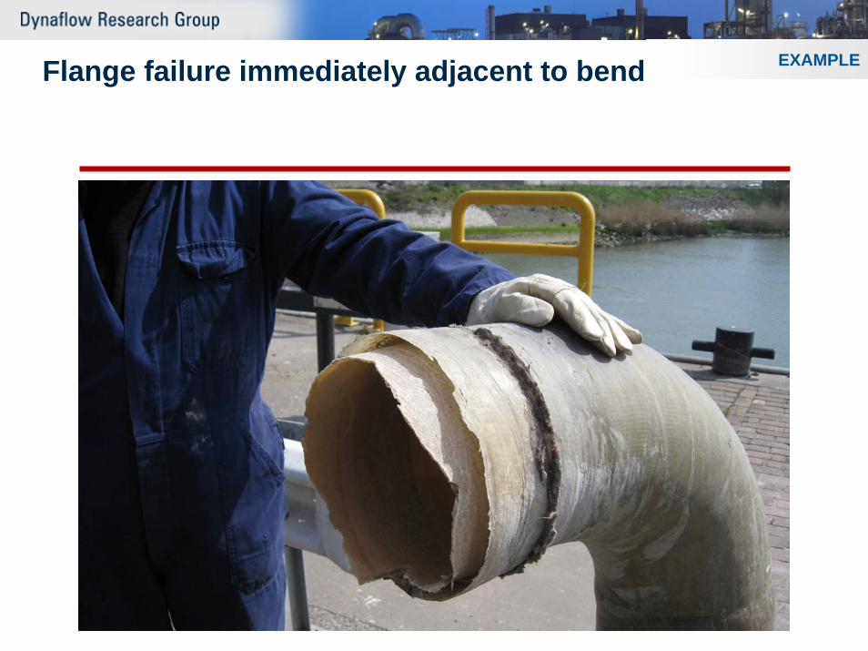
EXAMPLEFlange failure immediately adjacent to bend
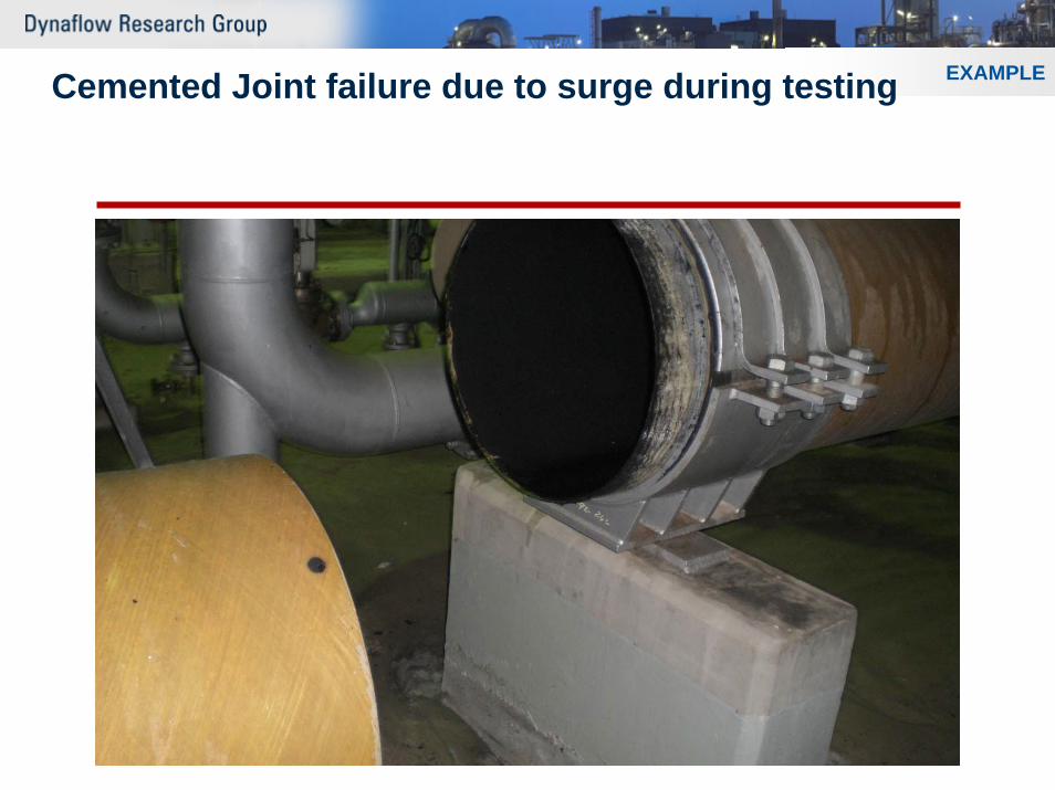
EXAMPLECemented Joint failure due to surge during testing
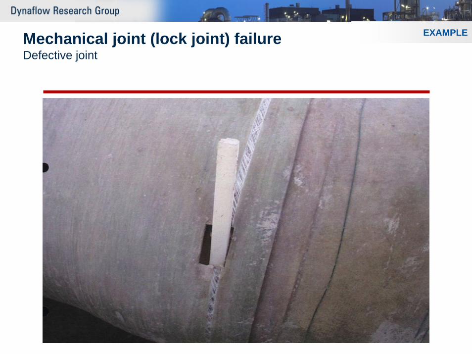
EXAMPLEMechanical joint (lock joint) failureDefective joint
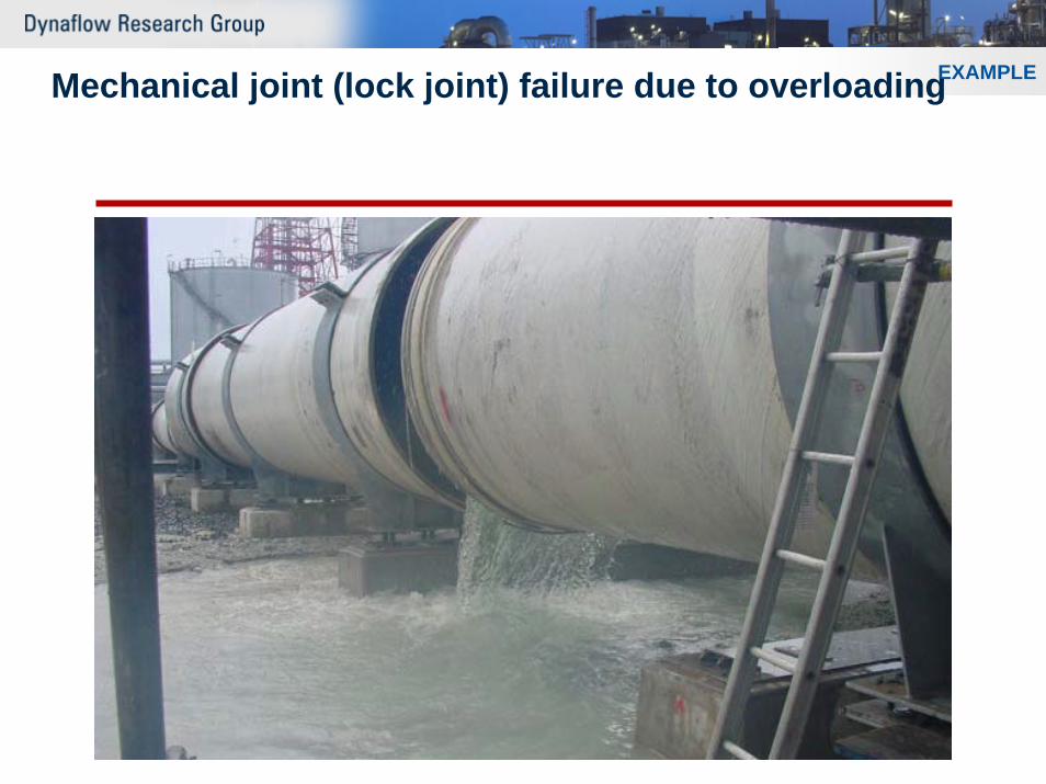
EXAMPLEMechanical joint (lock joint) failure due to overloading
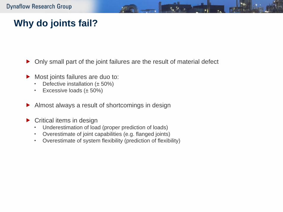
Why do joints fail?
Only small part of the joint failures are the result of material defect
Most joints failures are duo to:Defective installation (± 50%)Excessive loads (± 50%)
Almost always a result of shortcomings in design
Critical items in designUnderestimation of load (proper prediction of loads)Overestimate of joint capabilities (e.g. flanged joints)Overestimate of system flexibility (prediction of flexibility)
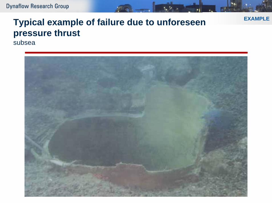
EXAMPLETypical example of failure due to unforeseenpressure thrustsubsea
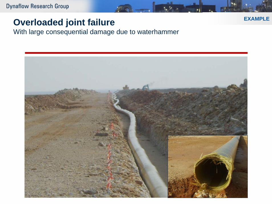
EXAMPLEOverloaded joint failureWith large consequential damage due to waterhammer
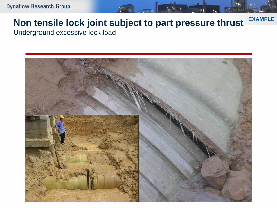
EXAMPLENon tensile lock joint subject to part pressure thrustUnderground excessive lock load
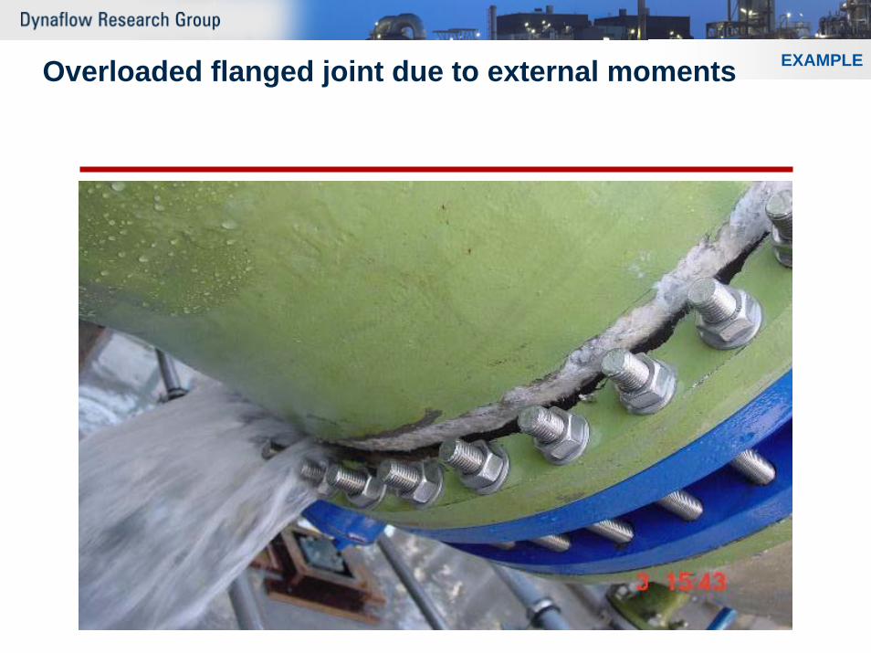
EXAMPLEOverloaded flanged joint due to external moments
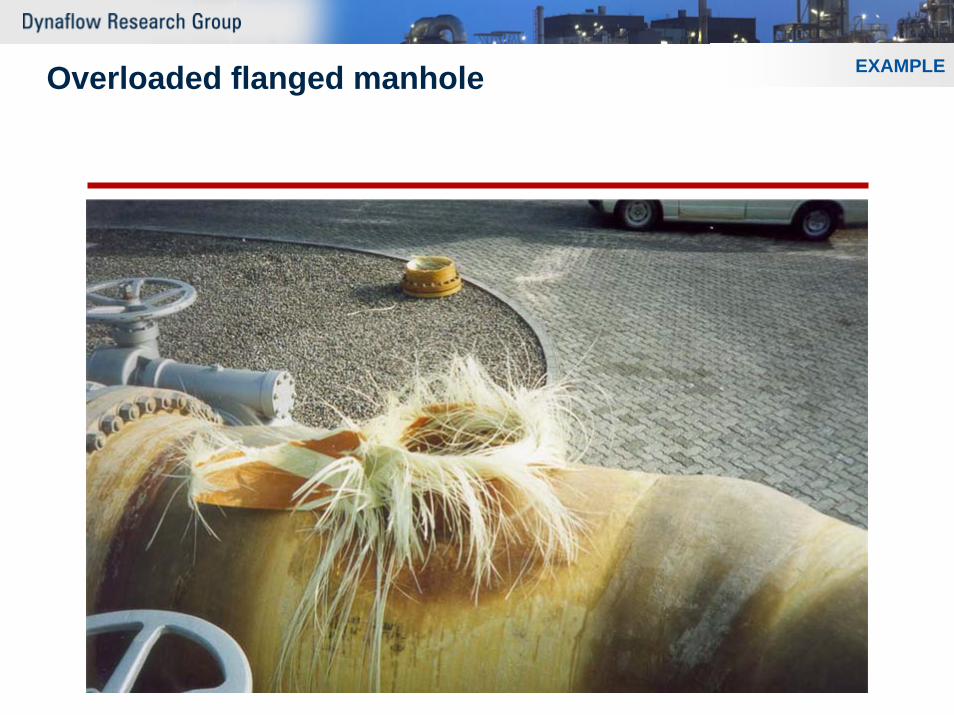
EXAMPLEOverloaded flanged manhole
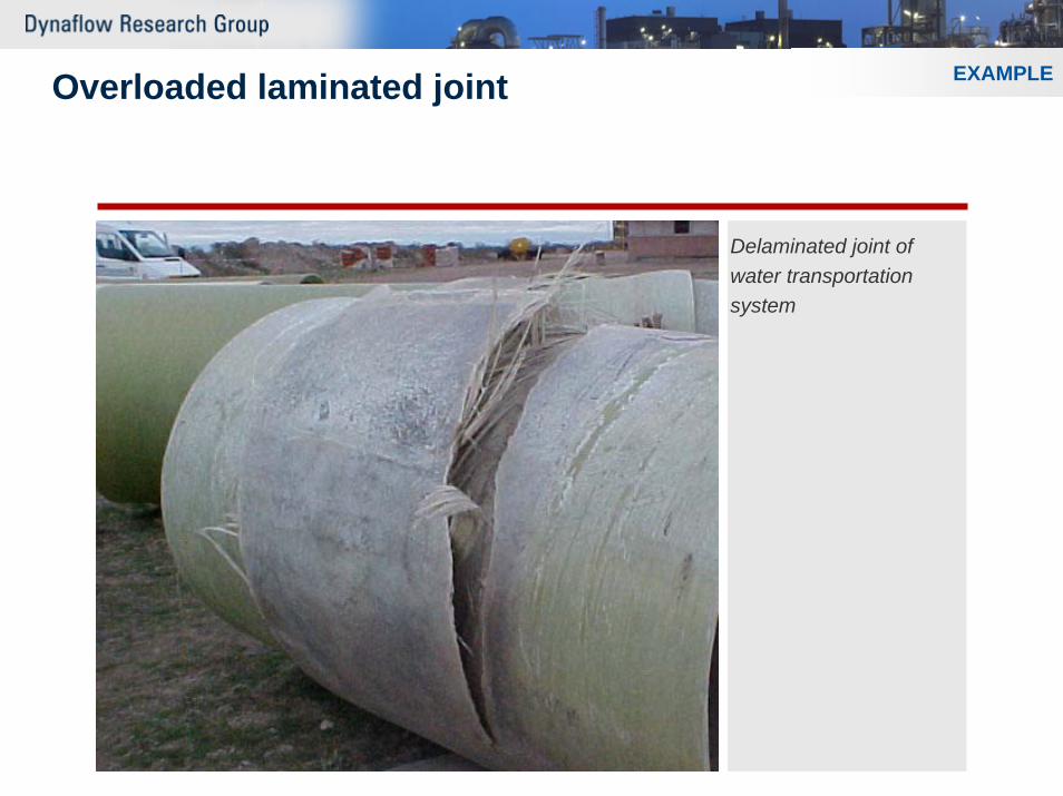
EXAMPLEOverloaded laminated joint
Delaminated joint of water transportation system
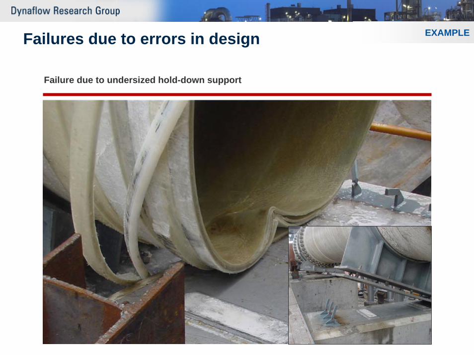
EXAMPLEFailures due to errors in design
Failure due to undersized hold-down support
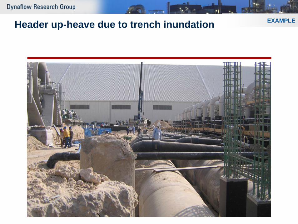
EXAMPLEHeader up-heave due to trench inundation
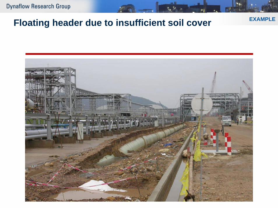
EXAMPLEFloating header due to insufficient soil cover
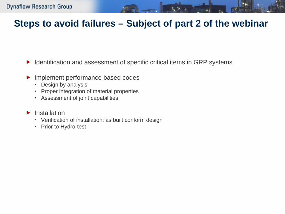
Steps to avoid failures – Subject of part 2 of the webinar
Identification and assessment of specific critical items in GRP systems
Implement performance based codesDesign by analysisProper integration of material propertiesAssessment of joint capabilities
InstallationVerification of installation: as built conform designPrior to Hydro-test


