Embed Size (px)
Citation preview
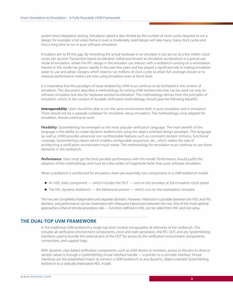
E M U L A T I O N WH
IT
EP
AP
ER
w w w . m e n t o r . c o m
FROM SIMULATION TO EMULATION – A FULLY REUSABLE UVM FRAMEWORK
ANOOP SAHA, MENTOR GRAPHICS
w w w. m ento r.co m2
From Simulation to Emulation – A Fully Reusable UVM Framework
INTRODUCTIONAccording to the 2012 functional verification study done by the Wilson Research Group, more than half of total
ASIC and FPGA development time is spent in verification, justifiably so. Design bugs, if not isolated and fixed at
an early stage, get very tricky and exponentially costlier to resolve later. It is therefore critical to ensure that the
verification process is complete; in that it has covered as many scenarios as possible before tape out. This
contrasts with the technological advances in the wider semiconductor ecosystem, which are shrinking the time
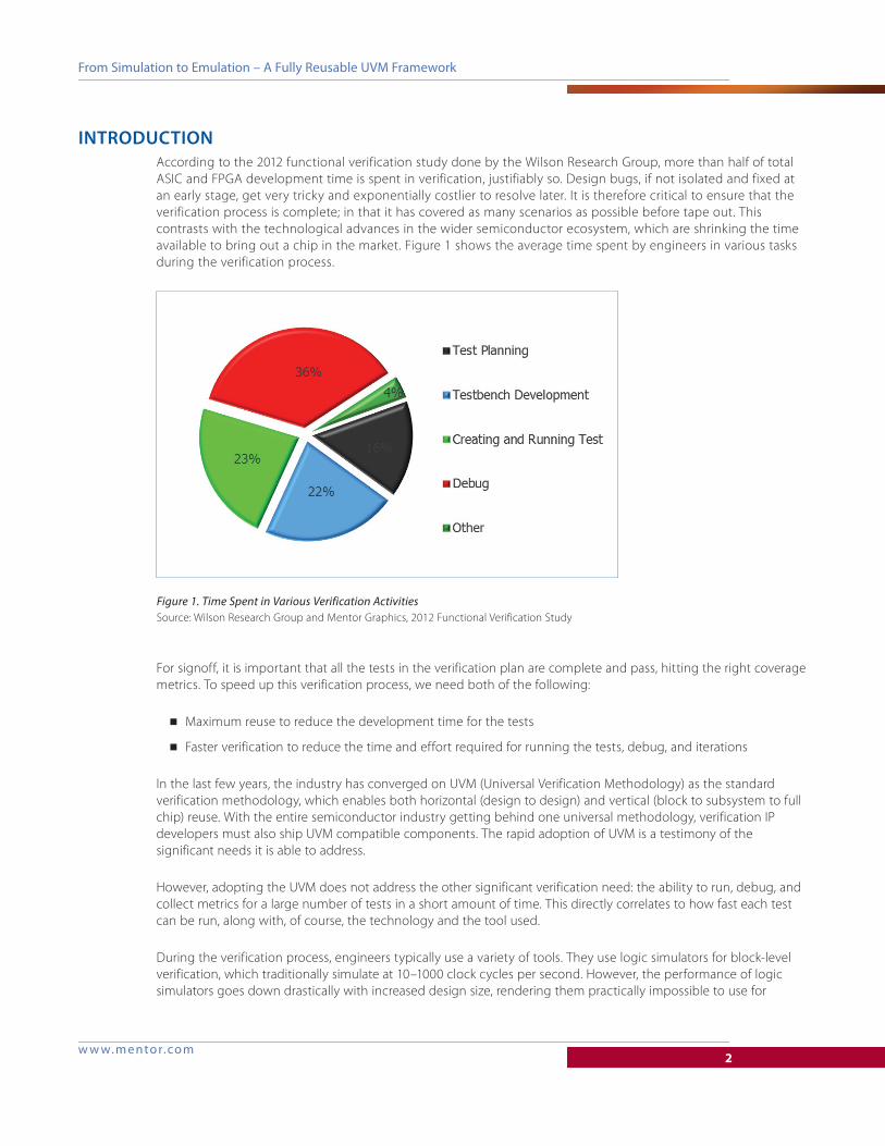
available to bring out a chip in the market. Figure 1 shows the average time spent by engineers in various tasks
during the verification process.
For signoff, it is important that all the tests in the verification plan are complete and pass, hitting the right coverage
metrics. To speed up this verification process, we need both of the following:
■ Maximum reuse to reduce the development time for the tests
■ Faster verification to reduce the time and effort required for running the tests, debug, and iterations
In the last few years, the industry has converged on UVM (Universal Verification Methodology) as the standard
verification methodology, which enables both horizontal (design to design) and vertical (block to subsystem to full
chip) reuse. With the entire semiconductor industry getting behind one universal methodology, verification IP
developers must also ship UVM compatible components. The rapid adoption of UVM is a testimony of the
significant needs it is able to address.
However, adopting the UVM does not address the other significant verification need: the ability to run, debug, and
collect metrics for a large number of tests in a short amount of time. This directly correlates to how fast each test
can be run, along with, of course, the technology and the tool used.
During the verification process, engineers typically use a variety of tools. They use logic simulators for block-level
verification, which traditionally simulate at 10–1000 clock cycles per second. However, the performance of logic
simulators goes down drastically with increased design size, rendering them practically impossible to use for
Figure 1. Time Spent in Various Verification ActivitiesSource: Wilson Research Group and Mentor Graphics, 2012 Functional Verification Study
w w w. m ento r.co m3
From Simulation to Emulation – A Fully Reusable UVM Framework
system-level integration testing. Simulation speed is also limited by the number of clock cycles required to run a
design; for example, a full video frame in even a moderately sized design will take many, many clock cycles and
thus a long time to run in pure software simulation.
Emulators aim to fill this gap. By mimicking the actual hardware in an emulator it can be run at a few million clock
cycles per second. Transaction-based acceleration (otherwise known as simulation acceleration) is a special use
mode of emulation, where the RTL design in the emulator can interact with a testbench running on a workstation.
Interest in this mode has grown rapidly in the past few years and has played a significant role in making emulation
easier to use and adopt. Designs which need to run millions of clock cycles to attain full coverage closure or to
measure performance metrics are now using emulation even at block level.
It is imperative that the paradigm of reuse enabled by UVM must continue to be facilitated in the context of
emulation. This document describes a methodology for writing UVM testbenches that can be used not only for
software simulation but also for hardware-assisted acceleration. The methodology derives from the principles of
emulation, which, in the context of reusable verification methodology, should give the following benefits:
Interoperability: Users should be able to run the same environment both in pure simulation and in emulation.
There should not be a separate codebase for simulation versus emulation. The methodology, once adapted for
emulation, should continue to work.
Flexibility: SystemVerilog has emerged as the most popular verification language. The main benefit of this
language is the ability to create dynamic testbenches using the object oriented design paradigm. This language
(as well as UVM) provides advanced non-synthesizable features such as constraint random stimulus, functional
coverage, SystemVerilog classes which enables configurable sequences, etc., which makes the task of
architecting a verification environment much easier. The methodology for emulation must continue to use these
elements in the testbench.
Performance: Users must get the best possible performance with this model. Performance should justify the
adoption of this methodology and must be a few orders of magnitude faster than pure software simulation.
When a testbench is architected for emulation, there are essentially two components in a UVM testbench model:
■ An HDL static component — which includes the DUT — runs on the emulator at full emulation clock speed
■ The HVL dynamic testbench — the behavioral portion — which runs on the workstation simulator
The two are completely independent and separate domains. However, interaction is possible between the HDL and HVL
domains, and performance can be maximized with infrequent interactions between the two. One of the most optimal
approaches is that of remote procedure calls — functions defined in HDL can be called from HVL and vice versa.
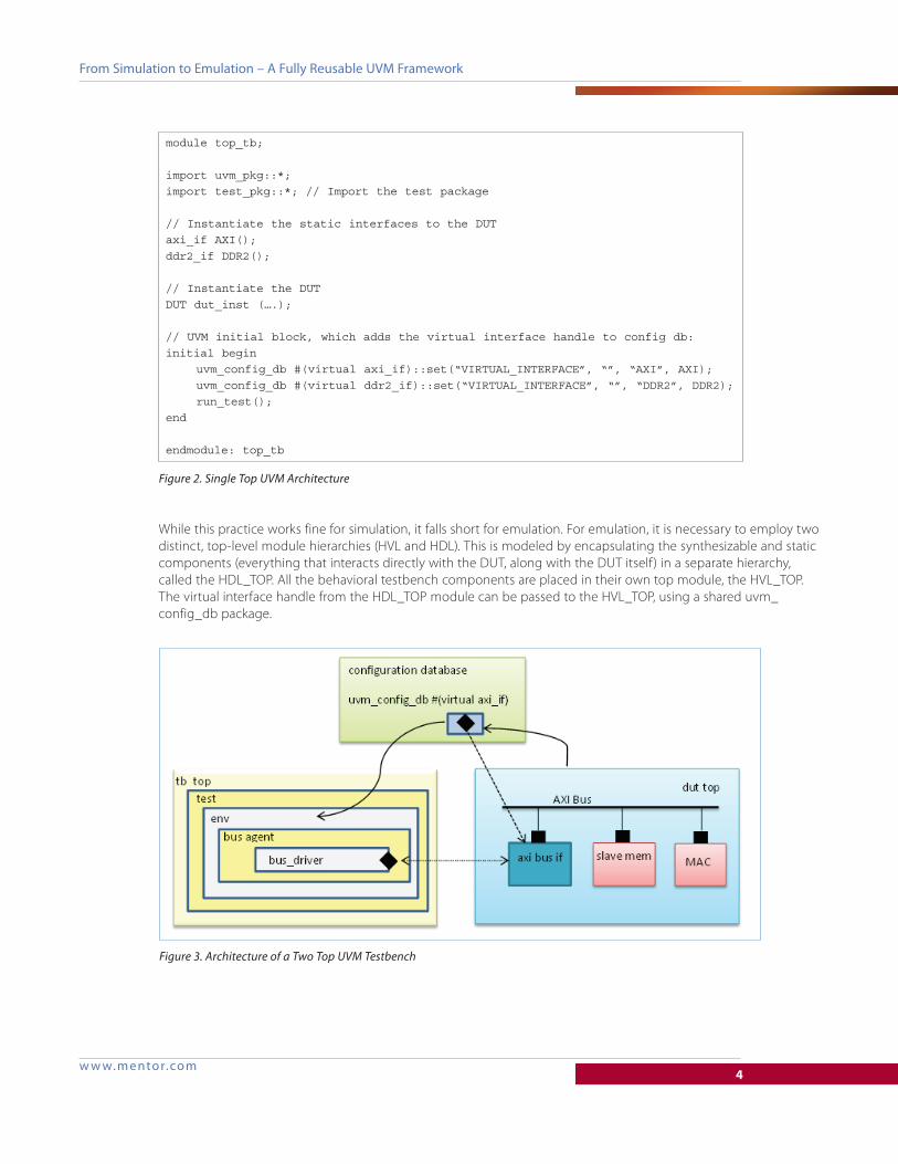
THE DUAL-TOP UVM FRAMEWORKIn the traditional UVM testbench a single top-level module encapsulates all elements of the testbench. This
includes all verification environment components, clock and reset generators, the RTL DUT, and any SystemVerilog
interfaces used to bundle the external pins of the DUT for access by the verification environment components,
connections, and support logic.
With dynamic class-based verification components, such as UVM drivers or monitors, access to the pins to drive or
sample values is through a SystemVerilog virtual interface handle — a pointer to a concrete interface. Virtual
interfaces are the established means to connect a UVM testbench or any dynamic, object-oriented SystemVerilog
testbench to a statically elaborated HDL model.
w w w. m ento r.co m4
From Simulation to Emulation – A Fully Reusable UVM Framework
While this practice works fine for simulation, it falls short for emulation. For emulation, it is necessary to employ two
distinct, top-level module hierarchies (HVL and HDL). This is modeled by encapsulating the synthesizable and static
components (everything that interacts directly with the DUT, along with the DUT itself) in a separate hierarchy,
called the HDL_TOP. All the behavioral testbench components are placed in their own top module, the HVL_TOP.
The virtual interface handle from the HDL_TOP module can be passed to the HVL_TOP, using a shared uvm_
config_db package.
module top_tb;
import uvm_pkg::*;import test_pkg::*; // Import the test package
// Instantiate the static interfaces to the DUTaxi_if AXI();ddr2_if DDR2();
// Instantiate the DUTDUT dut_inst (….);
// UVM initial block, which adds the virtual interface handle to config db:initial begin uvm_config_db #(virtual axi_if)::set(“VIRTUAL_INTERFACE”, “”, “AXI”, AXI); uvm_config_db #(virtual ddr2_if)::set(“VIRTUAL_INTERFACE”, “”, “DDR2”, DDR2); run_test();end
endmodule: top_tb
Figure 2. Single Top UVM Architecture
Figure 3. Architecture of a Two Top UVM Testbench
w w w. m ento r.co m5
From Simulation to Emulation – A Fully Reusable UVM Framework
Instead of the traditional single-top environment, if emulation is a possible objective (which most likely it will
be), it is better to architect a two-top UVM environment right at the block level. The HDL side must be
synthesizable and should contain essentially all clock synchronous code (namely the RTL DUT, clock, and reset
generators) and the BFM code for driving and sampling DUT interface signals. The HVL side should contain all
other (untimed) testbench code, including the various transaction-level testbench generation and analysis
components and proxies for the HDL transactors.
The above configuration is the first step towards emulation. Another critical aspect of transaction-based
acceleration is the infrequency of communication between the HDL and HVL module hierarchies. In the above
configuration, the bus driver directly accesses the pin interface and applies the stimulus directly as part of the BFM
model. The abstraction bridge between the protocol level and the transaction level is formed by the testbench
components, like drivers and monitors. These are the components which convert “what is being transferred” into
“how it must be transferred,” or vice versa, in accordance with the protocol. The DUT pins are bundled inside
SystemVerilog interfaces and accessed directly from within these components using the virtual interface construct.
For emulation, since BFMs are naturally timed, these must be part of the HDL top-level module hierarchy, while
dynamic class objects are generally not synthesizable and must be part of the HVL hierarchy. In addition, a
transactor layer component usually has some high-level code next to its BFM portion that is not synthesizable
either; for example, a transaction-level interface to upstream components in the testbench layer. All BFMs must
therefore be “surgically” extracted (from UVM drivers/monitors) and modeled instead as synthesizable
SystemVerilog HDL modules or interfaces.
Using this principle, it is possible without much difficulty to write powerful state machines to implement
synthesizable BFMs. Furthermore, when modeling these BFMs as SystemVerilog interfaces, it is possible to continue
to utilize virtual interfaces to bind the dynamic HVL and static HDL sides. The key difference with conventional
SystemVerilog object-oriented testbenches is that the BFMs have moved from the HVL to the HDL side, and the
HVL-HDL connection must now be a transaction-based interface between the testbench and BFM interfaces. That
is, testbench components may no longer access signals in a SystemVerilog interface directly, but only indirectly by
calling (transaction-level) functions and tasks declared inside a BFM interface.
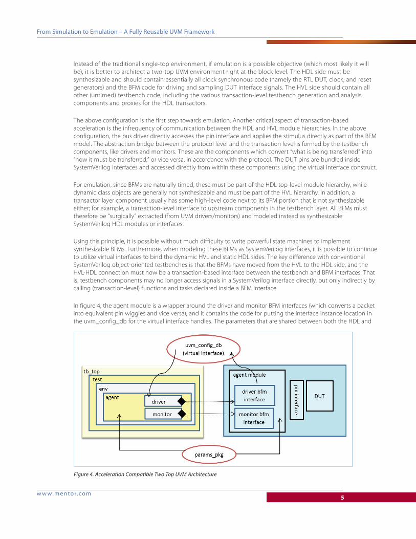
In figure 4, the agent module is a wrapper around the driver and monitor BFM interfaces (which converts a packet
into equivalent pin wiggles and vice versa), and it contains the code for putting the interface instance location in
the uvm_config_db for the virtual interface handles. The parameters that are shared between both the HDL and
Figure 4. Acceleration Compatible Two Top UVM Architecture
w w w. m ento r.co m6
From Simulation to Emulation – A Fully Reusable UVM Framework
HVL (e.g., the ones which define the topological configuration or bus width) are part of a params_pkg, which is
shared between the two.
One important consideration here is to ensure the untimed nature of the entire HVL. This is recommended to avoid
any # delays in the UVM testbench. Such delays interfere with the normal execution of emulation, and negatively
impact emulation performance. UVM sequences should avoid delays entirely, as delays make UVM sequences non-
reusable. Instead, use another mechanism for synchronization. Any delays, if they are required, should be modeled
as time advance calls, where time is advanced indirectly through an HVL to HDL function call.
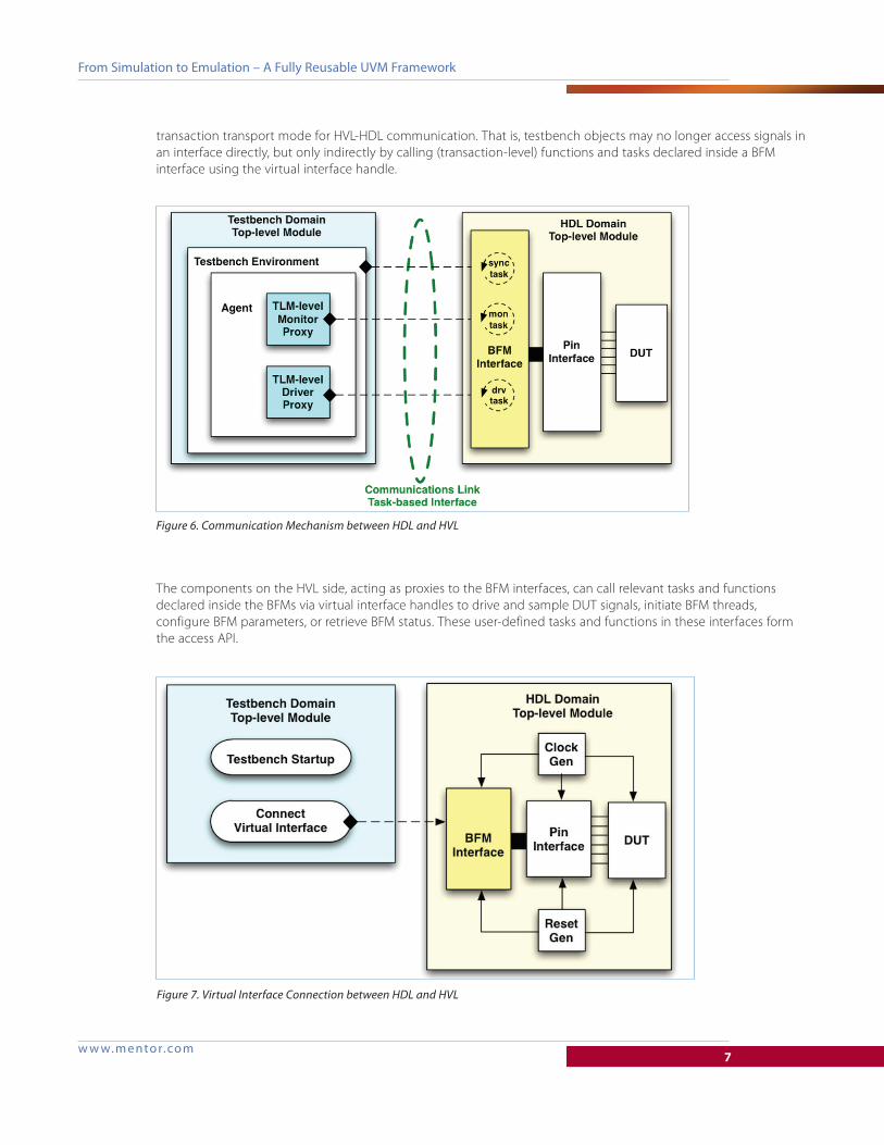
COMMUNICATION BETWEEN HDL AND HVLOnce the dual-top architecture has been created, the communication mechanism between the HVL and HDL
domains must be established. The two domains must interact with each other at the transaction level. That is, there
must not be any cross-hierarchy member access between the two blocks. For this, we use a remote function call.
The UVM proxy class has the virtual interface handle to the BFM interface. As suggested above, the use of virtual
interface handles on the HVL side, bound to concrete interface instances on the HDL side, enables a reusable
module dut_top;import test_params_pkg::*;
axi_driver_if driver_bfm ();axi_monitor_if monitor_bfm();ddr2_bfm ddr2_bfm();
// Instantiate the static pin interfaces to the DUTaxi_if AXI();ddr2_if DDR2();
// Instantiate the DUTDUT dut_inst (….);
// Generate the clocksinitial begin clk = 0; forever #5 clk = ~clk;end
// Add the virtual interface handle to config db:initial begin import uvm_pkg::*; uvm_config_db #(virtual axi_driver_if)::set ( “VIRTUAL_INTERFACE”, “”, “AXI_DRIVER”, driver_bfm); uvm_config_db #(virtual axi_monitor_if)::set ( “VIRTUAL_INTERFACE”, “”, “AXI_MONITOR”, monitor_bfm); uvm_config_db #(virtual ddr2_bfm)::set (“VIRTUAL_INTERFACE”, “”, “DDR2”, ddr2_bfm);end
endmodule: dut_top
module top_tb;
import uvm_pkg::*;import test_params_pkg::*import test_pkg::*; // Import the test package
initial begin run_test();end
endmodule: top_tb
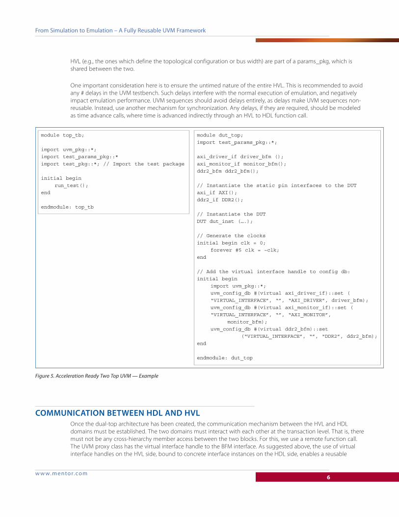
Figure 5. Acceleration Ready Two Top UVM — Example
w w w. m ento r.co m7
From Simulation to Emulation – A Fully Reusable UVM Framework
transaction transport mode for HVL-HDL communication. That is, testbench objects may no longer access signals in
an interface directly, but only indirectly by calling (transaction-level) functions and tasks declared inside a BFM
interface using the virtual interface handle.
The components on the HVL side, acting as proxies to the BFM interfaces, can call relevant tasks and functions
declared inside the BFMs via virtual interface handles to drive and sample DUT signals, initiate BFM threads,
configure BFM parameters, or retrieve BFM status. These user-defined tasks and functions in these interfaces form
the access API.
Figure 6. Communication Mechanism between HDL and HVL
Figure 7. Virtual Interface Connection between HDL and HVL
w w w. m ento r.co m8
From Simulation to Emulation – A Fully Reusable UVM Framework
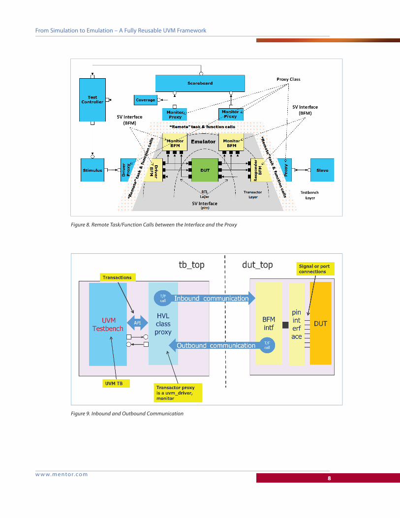
Figure 8. Remote Task/Function Calls between the Interface and the Proxy
Figure 9. Inbound and Outbound Communication
w w w. m ento r.co m9
From Simulation to Emulation – A Fully Reusable UVM Framework
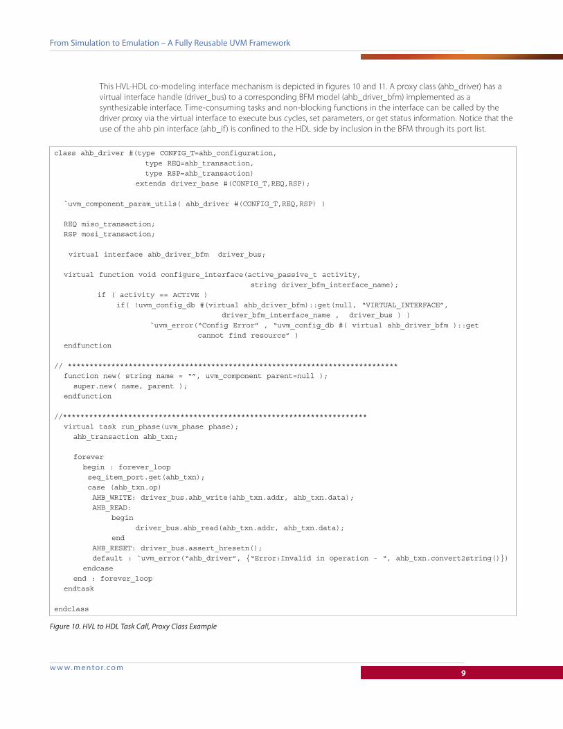
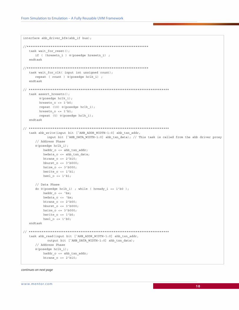
This HVL-HDL co-modeling interface mechanism is depicted in figures 10 and 11. A proxy class (ahb_driver) has a
virtual interface handle (driver_bus) to a corresponding BFM model (ahb_driver_bfm) implemented as a
synthesizable interface. Time-consuming tasks and non-blocking functions in the interface can be called by the
driver proxy via the virtual interface to execute bus cycles, set parameters, or get status information. Notice that the
use of the ahb pin interface (ahb_if) is confined to the HDL side by inclusion in the BFM through its port list.
class ahb_driver #(type CONFIG_T=ahb_configuration, type REQ=ahb_transaction, type RSP=ahb_transaction) extends driver_base #(CONFIG_T,REQ,RSP);
`uvm_component_param_utils( ahb_driver #(CONFIG_T,REQ,RSP) )
REQ miso_transaction; RSP mosi_transaction;
virtual interface ahb_driver_bfm driver_bus;
virtual function void configure_interface(active_passive_t activity, string driver_bfm_interface_name); if ( activity == ACTIVE ) if( !uvm_config_db #(virtual ahb_driver_bfm)::get(null, “VIRTUAL_INTERFACE”, driver_bfm_interface_name , driver_bus ) ) `uvm_error(“Config Error” , “uvm_config_db #( virtual ahb_driver_bfm )::get cannot find resource” ) endfunction
// **************************************************************************** function new( string name = “”, uvm_component parent=null ); super.new( name, parent ); endfunction
//********************************************************************** virtual task run_phase(uvm_phase phase); ahb_transaction ahb_txn; forever begin : forever_loop seq_item_port.get(ahb_txn); case (ahb_txn.op) AHB_WRITE: driver_bus.ahb_write(ahb_txn.addr, ahb_txn.data); AHB_READ: begin driver_bus.ahb_read(ahb_txn.addr, ahb_txn.data); end AHB_RESET: driver_bus.assert_hresetn(); default : `uvm_error(“ahb_driver”, {“Error:Invalid in operation - “, ahb_txn.convert2string()}) endcase end : forever_loop endtask
endclass
Figure 10. HVL to HDL Task Call, Proxy Class Example
w w w. m ento r.co m10
From Simulation to Emulation – A Fully Reusable UVM Framework
interface ahb_driver_bfm(ahb_if bus);
//****************************************************************** task wait_for_reset(); if ( !hresetn_i ) @(posedge hresetn_i) ; endtask
//****************************************************************** task wait_for_clk( input int unsigned count); repeat ( count ) @(posedge hclk_i) ; endtask
// **************************************************************************** task assert_hresetn(); @(posedge hclk_i); hresetn_o <= 1’b0; repeat (10) @(posedge hclk_i); hresetn_o <= 1’b1; repeat (5) @(posedge hclk_i); endtask
// **************************************************************************** task ahb_write(input bit [`AHB_ADDR_WIDTH-1:0] ahb_txn_addr, input bit [`AHB_DATA_WIDTH-1:0] ahb_txn_data); // This task is called from the ahb driver proxy // Address Phase @(posedge hclk_i); haddr_o <= ahb_txn_addr; hwdata_o <= ahb_txn_data; htrans_o <= 2’b10; hburst_o <= 3’b000; hsize_o <= 3’b000; hwrite_o <= 1’b1; hsel_o <= 1’b1;
// Data Phase do @(posedge hclk_i) ; while ( hready_i == 1’b0 ); haddr_o <= ‘bx; hwdata_o <= ‘bx; htrans_o <= 2’b00; hburst_o <= 3’b000; hsize_o <= 3’b000; hwrite_o <= 1’b0; hsel_o <= 1’b0; endtask
// **************************************************************************** task ahb_read(input bit [`AHB_ADDR_WIDTH-1:0] ahb_txn_addr, output bit [`AHB_DATA_WIDTH-1:0] ahb_txn_data); // Address Phase @(posedge hclk_i); haddr_o <= ahb_txn_addr; htrans_o <= 2’b10;
continues on next page
w w w. m ento r.co m11
From Simulation to Emulation – A Fully Reusable UVM Framework
For modeling flexibility and completeness, a transaction-level HVL-HDL co-modeling interface can be defined in
both directions. Similar to an HVL proxy class calling tasks and functions declared in an HDL interface, one can
define how an HDL interface can call functions declared in an HVL class. This enables transaction-based HVL-HDL
communication initiated from the HDL side. We refer to this as “outbound communication” in figure 9 above.
Specifically, a BFM interface may call relevant class member functions of its proxy object on the HVL side, for
instance, to provide sampled transactions for analysis or indicate other status information. The handle of a BFM
interface to the proxy class can be assigned inside the proxy itself via its virtual interface handle to the BFM. Access
to any data members of the proxy class are not permitted inside the BFM interface, just as cross-signal references
into the BFM are not allowed. Due to language rules on matching types, the proxy class definition, together with
any types it depends on, must be imported inside the BFM interface via packages.
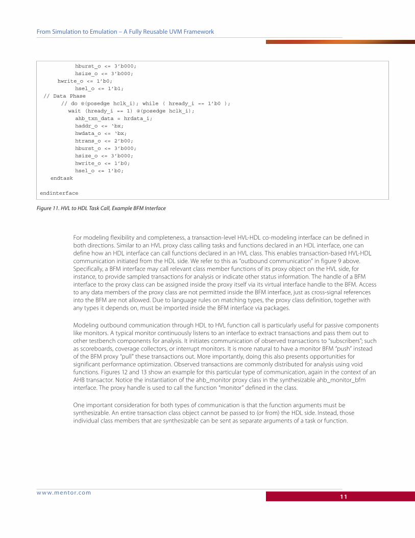
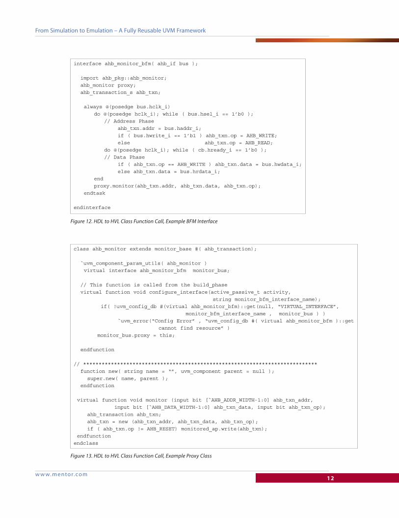
Modeling outbound communication through HDL to HVL function call is particularly useful for passive components
like monitors. A typical monitor continuously listens to an interface to extract transactions and pass them out to
other testbench components for analysis. It initiates communication of observed transactions to “subscribers”; such
as scoreboards, coverage collectors, or interrupt monitors. It is more natural to have a monitor BFM “push” instead
of the BFM proxy “pull” these transactions out. More importantly, doing this also presents opportunities for
significant performance optimization. Observed transactions are commonly distributed for analysis using void
functions. Figures 12 and 13 show an example for this particular type of communication, again in the context of an
AHB transactor. Notice the instantiation of the ahb_monitor proxy class in the synthesizable ahb_monitor_bfm
interface. The proxy handle is used to call the function “monitor” defined in the class.
One important consideration for both types of communication is that the function arguments must be
synthesizable. An entire transaction class object cannot be passed to (or from) the HDL side. Instead, those
individual class members that are synthesizable can be sent as separate arguments of a task or function.
hburst_o <= 3’b000; hsize_o <= 3’b000; hwrite_o <= 1’b0; hsel_o <= 1’b1; // Data Phase // do @(posedge hclk_i); while ( hready_i == 1’b0 ); wait (hready_i == 1) @(posedge hclk_i); ahb_txn_data = hrdata_i; haddr_o <= ‘bx; hwdata_o <= ‘bx; htrans_o <= 2’b00; hburst_o <= 3’b000; hsize_o <= 3’b000; hwrite_o <= 1’b0; hsel_o <= 1’b0; endtask
endinterface
Figure 11. HVL to HDL Task Call, Example BFM Interface
w w w. m ento r.co m12
From Simulation to Emulation – A Fully Reusable UVM Framework
interface ahb_monitor_bfm( ahb_if bus ); import ahb_pkg::ahb_monitor; ahb_monitor proxy; ahb_transaction_s ahb_txn;
always @(posedge bus.hclk_i) do @(posedge hclk_i); while ( bus.hsel_i == 1’b0 ); // Address Phase ahb_txn.addr = bus.haddr_i; if ( bus.hwrite_i == 1’b1 ) ahb_txn.op = AHB_WRITE; else ahb_txn.op = AHB_READ; do @(posedge hclk_i); while ( cb.hready_i == 1’b0 ); // Data Phase if ( ahb_txn.op == AHB_WRITE ) ahb_txn.data = bus.hwdata_i; else ahb_txn.data = bus.hrdata_i; end proxy.monitor(ahb_txn.addr, ahb_txn.data, ahb_txn.op); endtask
endinterface
Figure 12. HDL to HVL Class Function Call, Example BFM Interface
class ahb_monitor extends monitor_base #( ahb_transaction);
`uvm_component_param_utils( ahb_monitor ) virtual interface ahb_monitor_bfm monitor_bus;
// This function is called from the build_phase virtual function void configure_interface(active_passive_t activity, string monitor_bfm_interface_name); if( !uvm_config_db #(virtual ahb_monitor_bfm)::get(null, “VIRTUAL_INTERFACE”, monitor_bfm_interface_name , monitor_bus ) ) `uvm_error(“Config Error” , “uvm_config_db #( virtual ahb_monitor_bfm )::get cannot find resource” ) monitor_bus.proxy = this; endfunction
// **************************************************************************** function new( string name = “”, uvm_component parent = null ); super.new( name, parent ); endfunction
virtual function void monitor (input bit [`AHB_ADDR_WIDTH-1:0] ahb_txn_addr, input bit [`AHB_DATA_WIDTH-1:0] ahb_txn_data, input bit ahb_txn_op); ahb_transaction ahb_txn; ahb_txn = new (ahb_txn_addr, ahb_txn_data, ahb_txn_op); if ( ahb_txn.op != AHB_RESET) monitored_ap.write(ahb_txn); endfunctionendclass
Figure 13. HDL to HVL Class Function Call, Example Proxy Class
w w w. m ento r.co m13
From Simulation to Emulation – A Fully Reusable UVM Framework
In many applications, however, the transaction object may also contain a dynamic array or a queue as a data
member. The dynamic array is applied to the DUT across multiple cycles, and the size can vary across transactions.
A classic example for a dynamic size packet is an Ethernet transaction, as shown in figure 14.
Obviously the dynamic array cannot be sent through a single function call argument from the testbench to a BFM
interface (or vice versa). One modeling instrument for such streaming communication are called SCE-MI pipes —
described in the Accellera SCE-MI 2.2 standard.
SCE-MI pipes implement a communication paradigm much like a mailbox, where producer and consumer are
running independent threads. Additionally, they take advantage of the fact that a typical transaction is consumed
or produced by the DUT over a number of clock cycles. This allows a transaction object to be broken down into
elements — corresponding to the number of bytes consumed (or produced) by the DUT in one clock cycle. The
implementation follows a protocol that results in the best performance by optimizing data and control transfers.
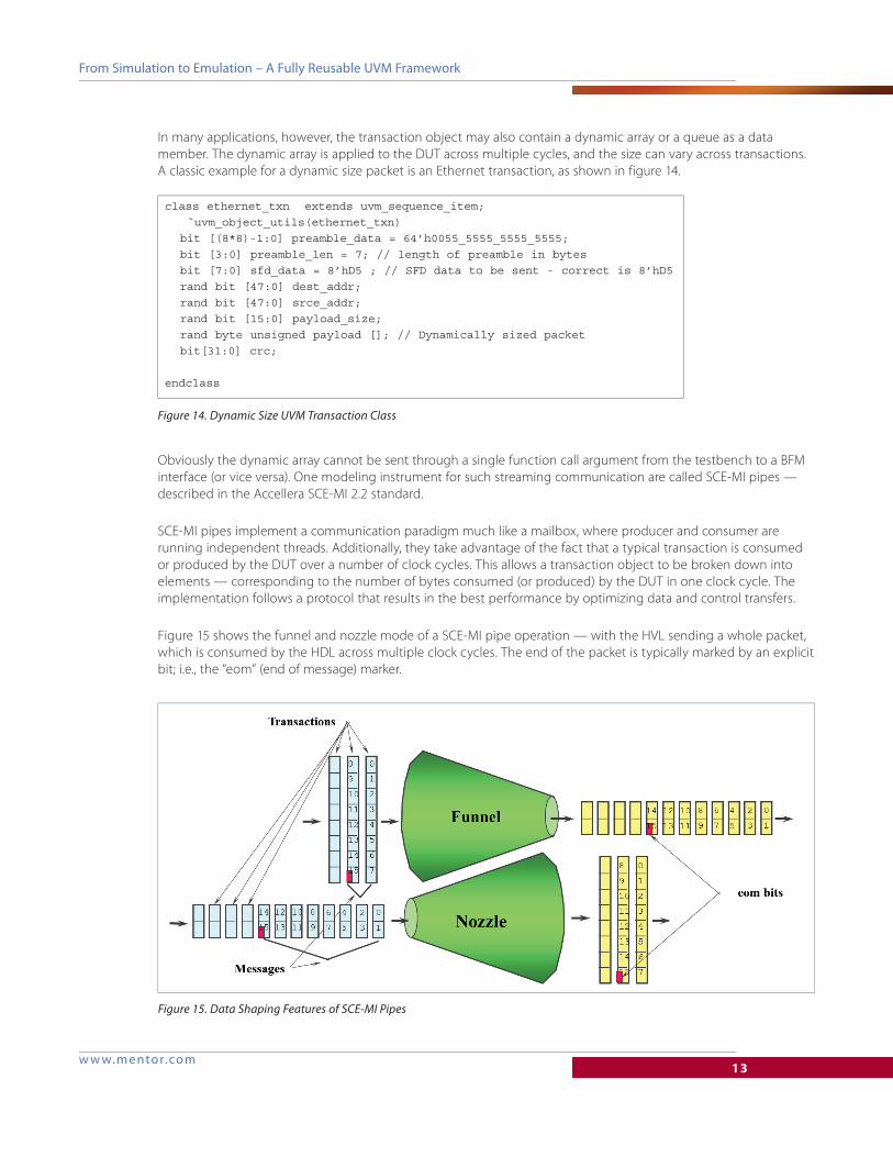
Figure 15 shows the funnel and nozzle mode of a SCE-MI pipe operation — with the HVL sending a whole packet,
which is consumed by the HDL across multiple clock cycles. The end of the packet is typically marked by an explicit
bit; i.e., the “eom” (end of message) marker.
class ethernet_txn extends uvm_sequence_item; `uvm_object_utils(ethernet_txn) bit [(8*8)-1:0] preamble_data = 64’h0055_5555_5555_5555; bit [3:0] preamble_len = 7; // length of preamble in bytes bit [7:0] sfd_data = 8’hD5 ; // SFD data to be sent - correct is 8’hD5 rand bit [47:0] dest_addr; rand bit [47:0] srce_addr; rand bit [15:0] payload_size; rand byte unsigned payload []; // Dynamically sized packet bit[31:0] crc;
endclass
Figure 14. Dynamic Size UVM Transaction Class
Figure 15. Data Shaping Features of SCE-MI Pipes
w w w. m ento r.co m14
From Simulation to Emulation – A Fully Reusable UVM Framework
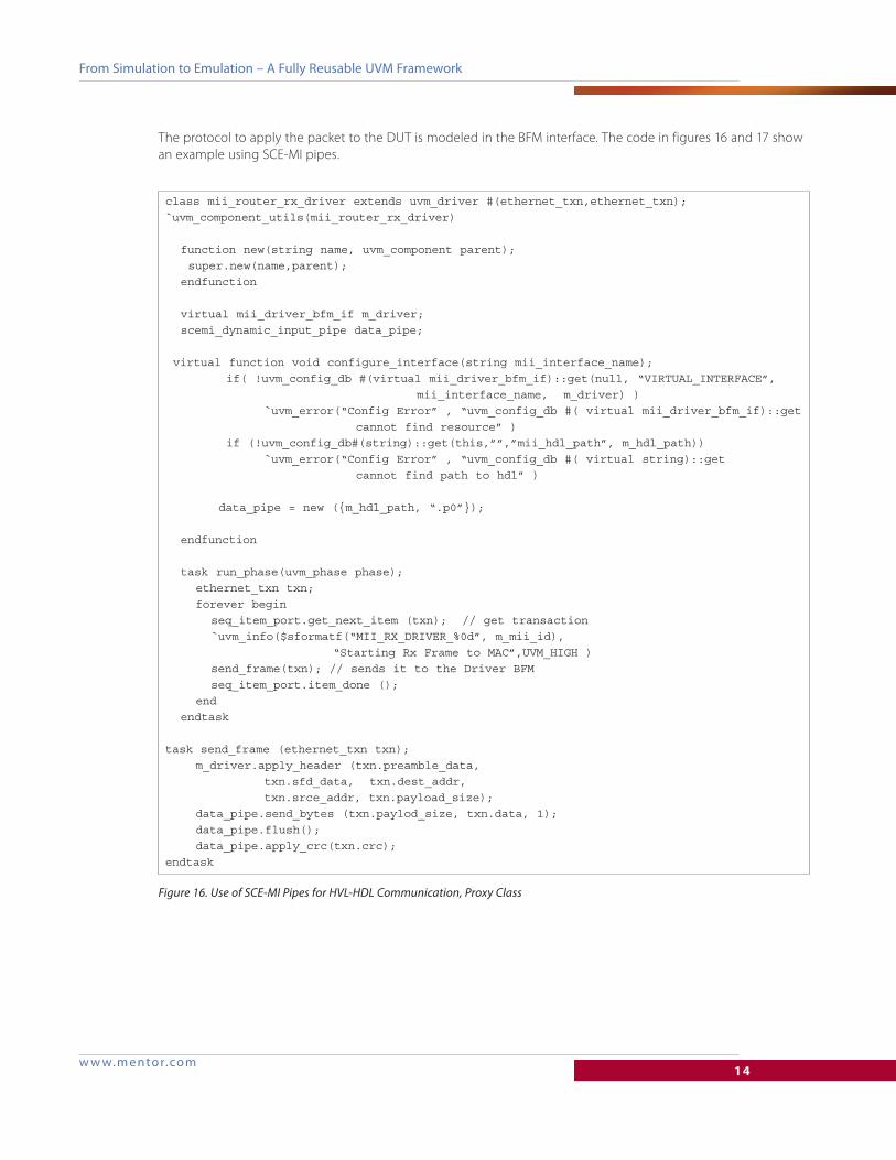
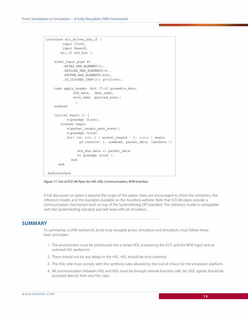
The protocol to apply the packet to the DUT is modeled in the BFM interface. The code in figures 16 and 17 show
an example using SCE-MI pipes.
class mii_router_rx_driver extends uvm_driver #(ethernet_txn,ethernet_txn);`uvm_component_utils(mii_router_rx_driver)
function new(string name, uvm_component parent); super.new(name,parent); endfunction
virtual mii_driver_bfm_if m_driver; scemi_dynamic_input_pipe data_pipe;
virtual function void configure_interface(string mii_interface_name); if( !uvm_config_db #(virtual mii_driver_bfm_if)::get(null, “VIRTUAL_INTERFACE”, mii_interface_name, m_driver) ) `uvm_error(“Config Error” , “uvm_config_db #( virtual mii_driver_bfm_if)::get cannot find resource” ) if (!uvm_config_db#(string)::get(this,””,”mii_hdl_path”, m_hdl_path)) `uvm_error(“Config Error” , “uvm_config_db #( virtual string)::get cannot find path to hdl” )
data_pipe = new ({m_hdl_path, “.p0”}); endfunction
task run_phase(uvm_phase phase); ethernet_txn txn; forever begin seq_item_port.get_next_item (txn); // get transaction `uvm_info($sformatf(“MII_RX_DRIVER_%0d”, m_mii_id), “Starting Rx Frame to MAC”,UVM_HIGH ) send_frame(txn); // sends it to the Driver BFM seq_item_port.item_done (); end endtask
task send_frame (ethernet_txn txn); m_driver.apply_header (txn.preamble_data, txn.sfd_data, txn.dest_addr, txn.srce_addr, txn.payload_size); data_pipe.send_bytes (txn.paylod_size, txn.data, 1); data_pipe.flush(); data_pipe.apply_crc(txn.crc);endtask
Figure 16. Use of SCE-MI Pipes for HVL-HDL Communication, Proxy Class
w w w. m ento r.co m15
From Simulation to Emulation – A Fully Reusable UVM Framework
A full discussion on pipes is beyond the scope of this paper. Users are encouraged to check the semantics, the
reference model, and the examples available on the Accellera website. Note that SCE-MI pipes provide a
communication mechanism built on top of the SystemVerilog DPI standard. The reference model is compatible
with the SystemVerilog standard and will work with all simulators.
SUMMARYTo summarize, a UVM testbench, to be truly reusable across simulation and emulation, must follow these
basic principles:
1. The environment must be partitioned into a timed HDL (containing the DUT and the BFM logic) and an
untimed HVL testbench.
2. There should not be any delays in the HVL. HVL should be truly untimed.
3. The HDL side must comply with the synthesis rules allowed by the tool of choice for the emulation platform.
4. All communication between HVL and HDL must be through remote function calls. No HDL signals should be
accessed directly from any HVL class.
interface mii_driver_bfm_if ( input Clock, input ResetN, mii_if eth_bus );
scemi_input_pipe #( .BYTES_PER_ELEMENT(1), .PAYLOAD_MAX_ELEMENTS(4), .BUFFER_MAX_ELEMENTS(400), .IS_CLOCKED_INTF(1)) p0(Clock);
task apply_header (bit [7:0] preamble_data, sfd_data, dest_addr, srce_addr, payload_size); … endtask
initial begin // { @(posedge Clock); forever begin @(packet_length_sent_event); @(posedge Clock) for( int i=0; i < packet_length - 1; i=i+1 ) begin p0.receive( 1, numRead, packet_data, lastData ); eth_bus.data <= packet_data; @( posedge Clock ); end end
endinterface
Figure 17. Use of SCE-MI Pipes for HVL-HDL Communication, BFM Interface
TECH12100-wMGC 07-14
©2014 Mentor Graphics Corporation, all rights reserved. This document contains information that is proprietary to Mentor Graphics Corporation and may be duplicated in whole or in part by the original recipient for internal business purposes only, provided that this entire notice appears in all copies. In accepting this document, the recipient agrees to make every reasonable effort to prevent unauthorized use of this information. All trademarks mentioned in this document are the trademarks of their respective owners.
F o r t h e l a t e s t p r o d u c t i n f o r m a t i o n , c a l l u s o r v i s i t : w w w . m e n t o r . c o m
From Simulation to Emulation – A Fully Reusable UVM Framework
By following these rules for architecting all UVM testbench environments at the block level, the switch to emulation
becomes inherently a simple task. The UVC (UVM verification component) for every block will thus consist of UVM
classes for sequences/coverage/configuration and reporting, the driver and monitor proxy classes, and, most
importantly, the timed HDL BFM implemented in a synthesizable interface.
In this paper, we introduced the concept of an acceleration ready UVM framework, as well as why it is needed, how
to create it, and its benefits. By following the principles presented here, users will be able to write block-level UVM
environments, such that these can be reused directly in emulation. The approach discussed in this paper has
provided remarkable results in various customer environments. When running on an emulator, depending on the
size of the design, this framework can give a 50 to 5000X performance gain over pure simulation. Not only that,
adoption of this framework has significantly reduced the development time of a testbench environment suited for
emulation. By combining this new approach with other capabilities provided by an emulator in simulation
acceleration mode (including assertions, functional coverage, power aware, advanced replay-based debug,
reporting, and profiling), users command a complete solution that can be used for block, subsystem, and system-
level verification.


