Embed Size (px)
Citation preview

Procedia Engineering 81 ( 2014 ) 1836 – 1841
1877-7058 © 2014 The Authors. Published by Elsevier Ltd. This is an open access article under the CC BY-NC-ND license
(http://creativecommons.org/licenses/by-nc-nd/3.0/).
Selection and peer-review under responsibility of the Department of Materials Science and Engineering, Nagoya University doi: 10.1016/j.proeng.2014.10.242
ScienceDirect
Available online at www.sciencedirect.com
11th International Conference on Technology of Plasticity, ICTP 2014, 19-24 October 2014, Nagoya Congress Center, Nagoya, Japan
Frictional properties of AZ80 and ZE10 magnesium alloys under
dry and lubricated contact conditions
Maziar Ramezani*,a
, Thomas Neitzerta, Timotius Pasang
a, Miguel Angel Sellès
b
a Department of Mechanical Engineering, Auckland University of Technology, New Zealand b Department of Materials and Mechanical Engineering, Universitat Politècnica de València, Alcoy, Spain
Abstract
The frictional properties of two types of magnesium alloys, i.e. AZ80 and ZE10 were investigated. A purpose-developed sheet
metal forming simulator was used to conduct the experiments under constant plastic deformation. Both lubricated and dry
sliding contact conditions were simulated and the effect of key process parameters such as contact pressure and sliding velocity
on the frictional properties of these alloys were investigated. Due to the different sliding velocities, the contact pressure rose
during each experiment which enables the measurement of the coefficient of friction for a wide range of contact pressures. The
results showed an increase in the friction coefficients of both alloys with increasing contact pressure. Furthermore, a decrease of
the friction coefficient was observed for higher sliding velocities.
© 2014 The Authors. Published by Elsevier Ltd.
Selection and peer-review under responsibility of Nagoya University and Toyohashi University of Technology.
Keywords: AZ80; ZE10; Dry contact; Friction; Lubricated contact; Magnesium.
1. Introduction
In sheet metal forming, as the punch draws the sheet metal into the die, frictional forces at the die shoulder and
over the punch face influence the workpiece deformation [1]. Since friction is important in determining and
* Corresponding author, Tel: +64 22 322 8807 ; Fax: +64 9 921 9973 ; Email: [email protected]
© 2014 The Authors. Published by Elsevier Ltd. This is an open access article under the CC BY-NC-ND license
(http://creativecommons.org/licenses/by-nc-nd/3.0/).
Selection and peer-review under responsibility of the Department of Materials Science and Engineering, Nagoya University

1837 Maziar Ramezani et al. / Procedia Engineering 81 ( 2014 ) 1836 – 1841
controlling workpiece deformation in forming processes, detailed knowledge of friction forces is needed for
process design and control [2]. In addition, in sheet metal forming frictional forces are important boundary
conditions and so must be known for accurate analytical and numerical modelling [3]. Accurate measurements of
coefficient of friction can provide valuable information for process model development and validation [4].
In sheet metal forming, the workpiece experiences bulk plastic deformation, new surfaces are created and local
surface deformation occurs on a plastically deforming substrate [5]. The importance and unique features of friction
in sheet metal forming have led to the development of a sheet metal forming simulator apparatus which simulates
the workpiece deformation in forming operations. The main concept of the apparatus is the measurement of
coefficient of friction as a metal strip is pulled over the cylindrical surface of a steel pin [6].
In this paper, frictional properties of rolled sheets of two commercial magnesium alloys, AZ80 (8Al–0.5Zn–
0.1Mn in wt.%) and ZE10 (1.3Zn–0.2Ce–0.1La in wt.%), with thickness of 0.8 mm were investigated with the
sheet metal forming simulator. The effects of dry and lubricated contact conditions and test variables on the
measured coefficient of friction are reported here. No research has been done before on the frictional behaviour of
AZ80 and ZE10 alloys under plastic deformation and the results of this research can be used for understanding
frictional conditions of magnesium alloys under forming operations at room temperature and improve the
formability of these alloys.
2. Sheet Metal Forming Simulator
The principle of sheet metal forming simulator can be seen in Fig. 1. The metal strip is bent while sliding over a
cylindrical pin. The bending of the strip as it moves over the cylindrical pin restrains workpiece flow and induce
plastic deformation in the workpiece.
The displacements x l and x2 are measured by the rotary sensor, while cylinder forces F1 and F2 are recorded by
load cells. The coefficient of friction is calculated by using the following relations with the assumption of plane
strain condition. In Fig. 2 the case of a moving metal strip in the direction of actuator 2 can be seen. During the
movement in this direction, a friction force FR arises between the die and the metal strip which is working against
the movement [7], in this case in the direction of actuator 1. The actuator force F2 is calculated as:
,12 RB FFFF
(1)
where FR is the friction force; FB is the bending force; and F1 and F2 are actuator forces in left and right cylinders,
respectively. In the sheet metal forming simulator apparatus, the most important values, which need to be
measured or rather adjusted, are the displacements x1 and x2 as well as the cylinder forces F1 and F2 and the
Fig. 1. Principal structure of the sheet metal forming simulator.
Two rotary displacement sensors are attached in the middle part of the apparatus under the strip. The entrance
and exit displacements x1 and x2 and the sliding velocities at the entrance, v1 and exit, v2 of the specimen are
measured or rather calculated by these rotary sensors. It is assumed that the contact pressure is uniformly
distributed over the contact area and it is the average value p. Considering the general equilibrium condition, the
1838 Maziar Ramezani et al. / Procedia Engineering 81 ( 2014 ) 1836 – 1841
resulting force P1 which arises through the contact pressure between the die and the workpiece is:
,2
sin 121 PFF
(2)
F2>F1, which implies a faster movement of cylinder 2 rather than
cylinder 1, the friction tension f defines the effective tangential tension resulting from the friction.
,12 wxFF crf (3)
where crx is the real contact length, and w is the width of the specimen. The projected line between the die and
the workpiece can be defined as:
.2
sin2 rxc (4)
The uniformly distributed contact pressure p multiplied with the projected length xc is equal to the resulting force
P1.
.2
sin21 wrpP
(5)
Combining Eqs. (2) and (5) the average value for the contact pressure can be obtained:
.2
21 pwr
FF
(6)
The definition of the coefficient of friction can be seen in the following equation:
.pf (7)
The bending force is calculated as follow:
,2
tan2
2
r
wtF
sy
B (8)
where y is the yield strength of the specimen; st is the thickness of the specimen; is the bending angle and r
is the pin radius. It can be inferred from Eq. (8) that the dimension and the yield strength of the specimen influence
the bending force. Due to the substitution of the tension f from Eq. (3) and the contact pressure p from Eq. (6),
and taking the bending force into consideration, the coefficient of friction can be calculated by the following
equation: (in case of F2>F1)
.2
sin21
12
FF
FFF B
(9)
3. Results and Discussions
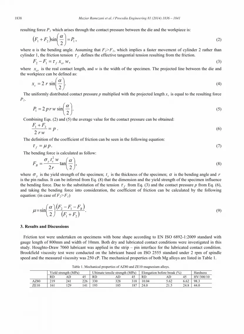
Friction test were undertaken on specimens with bone shape according to EN ISO 6892-1:2009 standard with
gauge length of 800mm and width of 10mm. Both dry and lubricated contact conditions were investigated in this
study. Houghto-Draw 7060 lubricant was applied in the strip – pin interface for the lubricated contact condition.
Brookfield viscosity test were conducted on the lubricant based on ISO 2555 standard under 2 rpm of spindle
speed and the measured viscosity was 250 cP. The mechanical properties of both Mg alloys are listed in Table 1.
Table 1. Mechanical properties of AZ80 and ZE10 magnesium alloys.
Yield strength (MPa) Ultimate tensile strength (MPa) Elongation before break (%) Hardness
RD AD 45 RD AD 45 RD AD 45 HV/300/10
AZ80 219 241 226 330 328 318 10.04 5.62 6.62 98.3
ZE10 161 129 141 193 185 187 24.0 21.5 24.8 44.0

1839 Maziar Ramezani et al. / Procedia Engineering 81 ( 2014 ) 1836 – 1841
Fig. 2. Principle values measured or rather controlled by sheet metal forming simulator.
Optical microscopy and SEM pictures of AZ80 and ZE10 alloys are presented in Figs. 3 - 5. From Fig. 3(a) it is
obvious that AZ80 was rolled, since there are many dislocations or twin lines induced by deformation. Large
amount of second phase precipitates is present, majority of which concentrates at grain boundaries or imperfections,
such as dislocation lines. Grains are of different shape and equiaxed; based on grain shape alone it is impossible to
estimate the rolling direction. To better see the precipitates, SEM was used. From Fig. 4, large amount of
precipitates can be seen even on micro-scale. Also it is obvious that there are at least two types of precipitates:
spherical and needle-like, and needle- -phase matrix.
Fig. 3. (a) AZ80, (b) ZE10, 100x magnification.
Fig. 4. AZ80, SEM, 1000x and 4000x magnification.

1840 Maziar Ramezani et al. / Procedia Engineering 81 ( 2014 ) 1836 – 1841
Fig. 5. ZE10, SEM, 1000x and 4000x magnification.
In Fig. 3 it can be seen that for ZE10 the number of dislocation or twin lines is much less than AZ80. Moreover,
the number of precipitates is very small and they cannot be seen on optical microscopy pictures. Only at higher
magnification SEM pictures (Fig. 5) small second phase precipitates can be observed, which tend to accumulate at
grain boundaries or along dislocation and twin lines. Grains are equiaxed and of different size, and it is impossible
to estimate the rolling direction. Based on received microstructure pictures and literature analysis results, it can be
assumed that as-obtained ZE10 sheets were annealed after rolling.
Fig. 6. Effect of sliding velocity and contact pressure on friction coefficient for ZE10 and AZ80 Mg alloys under dry and lubricated contacts.
1841 Maziar Ramezani et al. / Procedia Engineering 81 ( 2014 ) 1836 – 1841
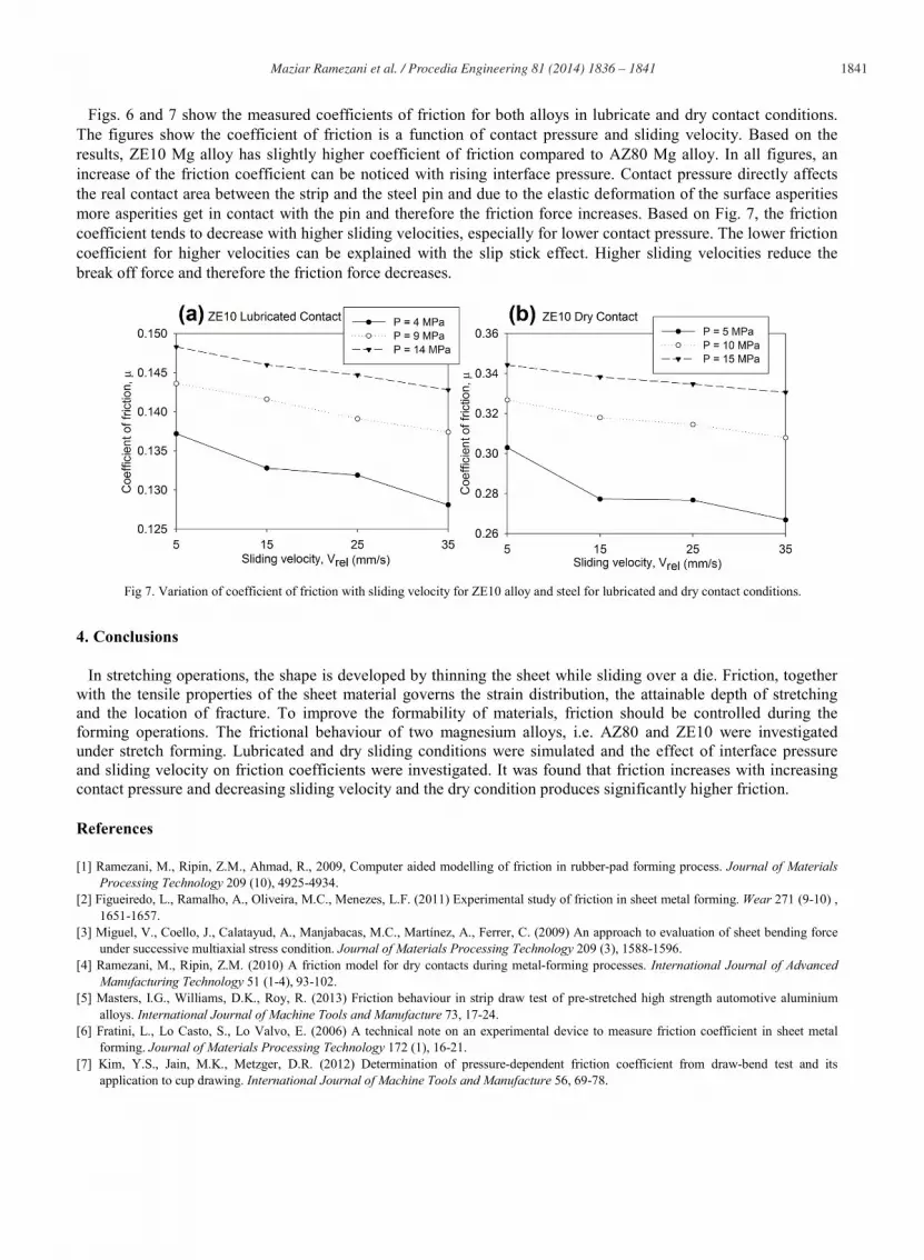
Figs. 6 and 7 show the measured coefficients of friction for both alloys in lubricate and dry contact conditions.
The figures show the coefficient of friction is a function of contact pressure and sliding velocity. Based on the
results, ZE10 Mg alloy has slightly higher coefficient of friction compared to AZ80 Mg alloy. In all figures, an
increase of the friction coefficient can be noticed with rising interface pressure. Contact pressure directly affects
the real contact area between the strip and the steel pin and due to the elastic deformation of the surface asperities
more asperities get in contact with the pin and therefore the friction force increases. Based on Fig. 7, the friction
coefficient tends to decrease with higher sliding velocities, especially for lower contact pressure. The lower friction
coefficient for higher velocities can be explained with the slip stick effect. Higher sliding velocities reduce the
break off force and therefore the friction force decreases.
Fig 7. Variation of coefficient of friction with sliding velocity for ZE10 alloy and steel for lubricated and dry contact conditions.
4. Conclusions
In stretching operations, the shape is developed by thinning the sheet while sliding over a die. Friction, together
with the tensile properties of the sheet material governs the strain distribution, the attainable depth of stretching
and the location of fracture. To improve the formability of materials, friction should be controlled during the
forming operations. The frictional behaviour of two magnesium alloys, i.e. AZ80 and ZE10 were investigated
under stretch forming. Lubricated and dry sliding conditions were simulated and the effect of interface pressure
and sliding velocity on friction coefficients were investigated. It was found that friction increases with increasing
contact pressure and decreasing sliding velocity and the dry condition produces significantly higher friction.
References
[1] Ramezani, M., Ripin, Z.M., Ahmad, R., 2009, Computer aided modelling of friction in rubber-pad forming process. Journal of Materials
Processing Technology 209 (10), 4925-4934.
[2] Figueiredo, L., Ramalho, A., Oliveira, M.C., Menezes, L.F. (2011) Experimental study of friction in sheet metal forming. Wear 271 (9-10) ,
1651-1657.
[3] Miguel, V., Coello, J., Calatayud, A., Manjabacas, M.C., Martínez, A., Ferrer, C. (2009) An approach to evaluation of sheet bending force
under successive multiaxial stress condition. Journal of Materials Processing Technology 209 (3), 1588-1596.
[4] Ramezani, M., Ripin, Z.M. (2010) A friction model for dry contacts during metal-forming processes. International Journal of Advanced
Manufacturing Technology 51 (1-4), 93-102.
[5] Masters, I.G., Williams, D.K., Roy, R. (2013) Friction behaviour in strip draw test of pre-stretched high strength automotive aluminium
alloys. International Journal of Machine Tools and Manufacture 73, 17-24.
[6] Fratini, L., Lo Casto, S., Lo Valvo, E. (2006) A technical note on an experimental device to measure friction coefficient in sheet metal
forming. Journal of Materials Processing Technology 172 (1), 16-21.
[7] Kim, Y.S., Jain, M.K., Metzger, D.R. (2012) Determination of pressure-dependent friction coefficient from draw-bend test and its
application to cup drawing. International Journal of Machine Tools and Manufacture 56, 69-78.


