Embed Size (px)
Citation preview
arX
iv:2
010.
0925
7v1
[ee
ss.S
P] 1
9 O
ct 2
020
1
Frequency-Hopping MIMO Radar-Based
Communications: An OverviewKai Wu, J. Andrew Zhang, Senior Member, IEEE, Xiaojing Huang, Senior Member, IEEE, and
Y. Jay Guo, Fellow, IEEE
Abstract—Enabled by the advancement in radio frequencytechnologies, the convergence of radar and communication sys-tems becomes increasingly promising and is envisioned as akey feature of future 6G networks. Recently, the frequency-hopping (FH) MIMO radar is introduced to underlay dual-function radar-communication (DFRC) systems. Superior tomany previous radar-centric DFRC designs, the symbol rate ofFH-MIMO radar-based DFRC (FH-MIMO DFRC) can exceedthe radar pulse repetition frequency. However, many practicalissues, particularly those regarding effective data communi-cations, are unexplored/unsolved. To promote the awarenessand general understanding of the novel DFRC, this articleis devoted to providing a timely introduction of FH-MIMODFRC. We comprehensively review many essential aspects of thenovel DFRC: channel/signal models, signaling strategies, modu-lation/demodulation processing and channel estimation methods,to name a few. We also highlight major remaining issues in FH-MIMO DFRC and suggest potential solutions to shed light onfuture research works.
Index Terms—Multi-Functional RF Systems (MFRFS), jointcommunication and radar/radio sensing (JCAS), dual-functionradar-communication (DFRC), frequency hopping (FH), MIMO,timing offset and channel estimation.
I. INTRODUCTION
Enabled by the advancement in radio frequency (RF) tech-
nologies and signal processing, the convergence of multi-
functional RF systems becomes increasingly promising and
is envisioned as a key feature of future 6G networks [1].
Among numerous RF systems, including wireless communi-
cations, radio sensing, mobile computing, localization, etc.,
the former two have achieved significant progress recently on
their integration. This is evidenced by several timely overview,
survey and tutorial papers [2]–[5].
Driven by the spectrum scarcity cost saving, co-existence
between the two RF functions has been investigated in the past
few years, with focus on mitigating the interference between
the two functions [2]. Thanks to the shared commonalities
in terms of signal processing algorithms, hardware and, to
some extent, system architecture, joint communication and
radar/radio sensing (JCAS), also referred to as dual-function
radar-communication (DFRC), is emerging as an effective
solution for integrating wireless communication and radio
Manuscript received XXX, XX, 2020. This work is partially funded by theNSW Defence Innovation Network and the NSW State Government throughPilot Project grant DINPP-19-20 10.01
K. Wu, J. A. Zhang, X. Huang and Y. J. Guo are with the GlobalBig Data Technologies Centre, University of Technology Sydney, Sydney,NSW 2007, Australia (e-mail: [email protected]; [email protected];[email protected]; [email protected]).
sensing [3]. Substantially different from the co-existence of
the two RF functions, JCAS/DFRC aims to design and use a
single transmitted signal for both communication and sensing,
enabling a majority of the transmitter modules and receiver
hardware to be shared.
The design of JCAS/DFRC can be communication-centric
or radar-centric [4]. The former performs radar sensing using
ubiquitous communication signals, e.g., IEEE 802.11p [6] and
IEEE 802.11ad [7], whereas the later embeds information
bits into existing radar waveform or specifically optimized
dual-function waveforms [4]. Regarding the communication-
centric JCAS, it is worth mentioning a recently proposed
perceptive mobile network (PMN) [3]. Integrating sensing
function into mobile networks, the PMN is envisaged to
revolutionize future 5G and beyond networks by offering ubiq-
uitous sensing capabilities for numerous smart applications,
such as smart city/factory. Compared with the communication-
centric counterpart, radar-centric designs, which has also been
typically referred to as DFRC, generally have superior radar
sensing performance, given the sensing-dedicated waveform.
Driven by automotive applications, early DFRC tended
to employ frequency modulated radar waveforms [8]. The
advancement of MIMO radars has made the recent DFRC
designs leaning towards this new radar paradigm [4], [5],
[9]. Some researchers optimize the beam pattern of a MIMO
radar to perform conventional modulations, such as phase shift
keying (PSK) and amplitude shift keying, using sidelobes in
the MIMO radiation patterns; others optimize radar waveform
to perform non-traditional modulations, such as waveform
shuffling and code shift keying (see [5], [9] and the references
therein). Most previous DFRC works embed one communica-
tion symbol within one or multiple radar pulses; hence the
communication symbol rate is limited by the pulse repetition
frequency (PRF) of the underlying radar.
In some recently reported research [10]–[15], frequency-
hopping MIMO (FH-MIMO) radar is introduced to DFRC,
which breaks the above limit and substantially increases the
communication symbol rate to multiples of (e.g., 15 times)
PRF. Pioneering in conceiving the novel DFRC architecture
based on FH-MIMO radar (FH-MIMO DFRC), the research
reported in [10]–[15] focuses on analyzing the impact of
information modulation on the radar ranging performance.
Yet, little attention is paid to effective implementation of data
communications. Some latest research reported in [16]–[18]
develops methods to address the practical issues, e.g., channel
estimation and synchronization, in FH-MIMO DFRC.
Motivated by the rapidly increasing interest in DFRC and
2
MIMO Tx
MIMO Rx
UAV
Civilian aeroplane
LoS (solid)
NLoS (dash)
AoD
0
(AoA)
(AoD)0
Bird swarm
HAP
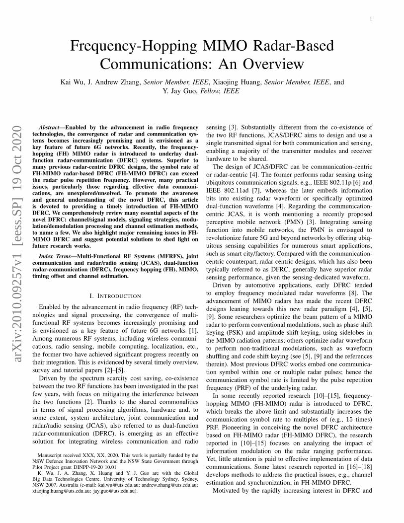
Fig. 1. A promising scenario of FH-MIMO DFRC, where an FH-MIMO radar is placed in a high-altitude platform to perform air surveillance and meanwhilecommunicate with an aircraft that can be a UAV, a CAP or an HAP.
the lack of awareness and general understanding of FH-MIMO
DFRC, this article aims to provide a timely introduction of the
novel DFRC architecture. We start by discussing the potential
applications and channel scenarios of FH-MIMO DFRC and
also the commonly used signal model in the literature. Then,
we survey the existing signaling strategies for FH-MIMO
DFRC, illustrate their modulation and demodulation methods,
and also compare the signaling strategies from various aspects.
We further discuss the issue of channel estimation in FH-
MIMO DFRC, reporting recently developed solutions. Finally,
we highlight the major issues unsolved in FH-MIMO DFRC
and suggest potential solutions to shed light on future research
directions. It is noteworthy that this article provides a better
coverage of the communication aspects, of FH-MIMO DFRC,
which are rarely dealt with in prior works.
II. SCENARIOS AND SIGNAL MODEL FOR FH-MIMO
DFRC
FH-MIMO radar is pulse-based and hence is likely to be
employed in applications requiring a large range coverage,
such as long-range air-surveillance [19]. Besides, such radar
is generally placed in high altitudes, “looking” ahead and
above, so as to reduce ground clutters and co-frequency
interference from terrestrial wireless systems. Therefore, FH-
MIMO DFRC is promising for providing ground-to-air (G2A)
communications for different types of aircraft, as depicted in
Fig. 1. The aircraft can be an unmanned aerial vehicle (UAV),
a civilian aeroplane (CAP) or a high-altitude platform (HAP).
With careful designs, FH-MIMO DFRC can greatly benefit the
underlying RF functions, as detailed below.
Benefiting Radar: FH-MIMO DFRC could potentially pro-
vide a radar with secure, long-range, low-latency, and high-
speed wireless broadband connections to airplanes or warships
over very wide areas (hundreds to thousands of kilometers,
at least one-way link). The communication links provided
by FH-MIMO DFRC are achieved via the careful reuse of
the powerful radar infrastructures, without compromising the
radar capabilities in detecting, tracking and identifying targets.
Compared with typical communication systems, modern/future
radar systems have transmitters with much higher power,
much larger antenna arrays with very narrow beams and
beam steering capability, and receivers with much higher
sensitivity. Therefore, FH-MIMO DFRC can provide almost
unparalleled communication links that typical communication
systems, such as VHF radio and satellite, can hardly provide.
Besides, the integrated solution can achieve significant saving
on cost, size, and weight, compared to having separate wireless
communication and radar devices.
Benefiting Mobile Communications: The G2A link provided
by FH-MIMO DFRC may also help support seamless wireless
coverage, as expected to be realized by future 6G networks.
In particular, FH-MIMO DFRC can contribute to building
the integrated space and terrestrial network (ISTN) which is
envisioned to be at the core of 6G communication systems
[20]. To this end, employing satellites, in combination with
FH-MIMO DFRC, may provide a more cost-effective solution
to providing wireless connectivity for people and vehicles
in remote rural areas and in the air, as well as at sea,
as compared with the solutions solely relying on satellites.
Against the above potential scenarios, we depict the channel
models suitable for FH-MIMO DFRC below.
A. Channel Model Suitable for FH-MIMO DFRC
The channel distribution for FH-MIMO DFRC can vary
with the altitude of an airborne user equipment (UE). The
typical altitudes of UAVs, CAPs and HAPs are 103 m, 10×103
m and 20 × 103 m above the sea level, respectively [21].
Therefore, in FH-MIMO DFRC, the following flat-fading
channel distributions are likely to be present.
1) Rayleigh channel is likely to exist between the radar and
a UAV, particularly when the line-of-sight (LoS) path is
blocked by a high-rise building and there exist numerous
scattering paths; see Fig. 1.
2) Rician channel can be common between the radar and
a CAP, where only few NLoS paths are present and are
possibly much weaker than the LoS path;
3) Additive white Gaussian noise (AWGN) channel can
prevail between the radar and an HAP where the LoS
dominates the channel with negligible NLoS paths.
The geometric Saleh-Valenzuela (SV) channel model [22],
with flexible parameters, can be adapted for depicting the three
distributions. For ease of illustration, assume that a single
antenna is equipped at the UE, which is also widely considered

3
in the related works [10]–[17]. Accordingly, the SV channel
model can be given by
h =P−1∑
p=0
βpaM (up) (1)
where aM (up) denotes the M -dimensional steering vector of
the radar transmitter array in the direction of up. The m-th
element of aM (up) is e−jmup (m = 0, 1, · · · ,M−1). Here, up
is the beamspace-domain angle-of-departure (AoD) [22] which
is given by π sinφp with φp denoting the physical direction;
see Fig. 1 for the case of p = 0.
Depending on the values of P and βp ∀p, the SV channel
can be simplified to the three classical channels illustrated
above. Specifically, the SV channel model can become
1) Rayleigh channel, given P ≫ 1 and varβp ≈varβp′ ∀p, p′;
2) Rician channel, given P > 1 and varβ0 ≫varβp ∀p > 0; and
3) AWGN channel, given P = 1.
So far, most of works only considered AWGN channels for
MIMO-DFRC, with exceptions in, e.g., [17].
B. Signal Model
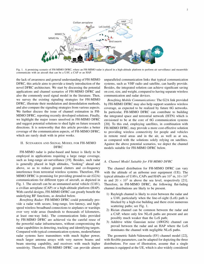
The FH-MIMO radar is based on fast frequency hopping.
Namely, each pulse is divided into H sub-pulses, also referred
to as hops [14]. The centroid frequency of the transmitted
signal changes randomly across hops and antennas, as il-
lustrated in Fig. 2. Denote the radar bandwidth as B. By
dividing the frequency band evenly into K sub-bands, each
sub-band has the bandwidth of B/K . Out of the K centroid
frequencies, M(< K) frequencies are selected to be the
hopping frequencies per hop, one for each antenna. Let khmdenote the index of the sub-band selected by antenna m at hop
h. To ensure the waveform orthogonality of FH-MIMO radar,
the following constraints are imposed for the radar [23],
khm 6= khm′ (∀m 6= m′, ∀h); ∆ , BT/K ∈ I+, (2)
where T is the time duration of a hop.
At hop h, the m-th antenna of the radar transmitter transmits
a single-tone signal, i.e.,
shm(i) = ej2πikhm∆, i = 0, 1, · · · , L− 1, (3)
where L = ⌊T/Ts⌉ is the number of samples per hop and
Ts is the sampling interval. Here, ⌊·⌉ rounds to the closest
integer. Based on the channel model given in (1) and the radar-
transmitted signal given in (3), the UE-received signal can be
modeled as
yh(i) = hHsh(i) + ξh(i), (4)
s.t. sh(i) = [sh0(i)Fh0(i), · · · , sh(M−1)(i)Fh(M−1)(i)]T
where (·)H denotes the conjugate transpose, and ξh(i) is
an AWGN. Note that the above signal model is obtained
based on a perfect timing, which may be challenging to
realize in practice, as will be discussed in Section III-B.
Also note that Fhm(i) is multiplied to the radar signal to
indicate the information embedded in the radar waveform. In
different signaling schemes, Fhm(i) can vary, as reviewed in
the following section.
III. OVERVIEW OF EXISTING SIGNALING STRATEGIES FOR
FH-MIMO DFRC
Several signaling strategies have been specifically designed
for FH-MIMO DFRC. Overall, the existing strategies can be
categorized into two groups, one based on conventional phase
modulations [10]–[13] and the other exploiting the diversity in
frequency hopping [14]. In this section, the existing signaling
strategies are first reviewed with their modulation and demod-
ulation processing illustrated. Then the strategies are compared
from various aspects.
A. Information Modulation
1) Phase Modulations: In [10], [11], phase shift keying
(PSK) is introduced to FH-MIMO DFRC by embedding PSK
phases into radar signals. More specifically, a constant phase
Fhm(i) = ejhm is taken in (4), where hm ∈ ΩJ (J ≥ 1)
and ΩJ =
0, · · · , 2π(2J−1)2J
is the J-bit PSK constella-
tion. In [12], the differential PSK (DPSK) is proposed to
replace PSK, so as to reduce range sidelobes and out-of-
band transmission. To further improve the spectral shape of
the modulated radar signal, the continuous phase modulation
(CPM) is introduced in FH-MIMO DFRC [13]. The underlying
principle is that signals with smoother modulating phase
correspond to lower out-of-band transmission.
2) Hopping Frequency-based Modulation: In [14], the
combinations of hopping frequencies are used to convey infor-
mation bits, referred to as frequency hopping code selection
(FHCS). As illustrated earlier, only M out of K sub-bands are
selected each hop as hopping frequencies. Thus, there are CMK
combinations of hopping frequencies, and the combinations
can be employed to convey up to ⌊log2 CMK ⌋ number of
information bits per radar hop, where ⌊·⌋ rounds towards the
negative infinity.
3) Comparing Two Modulation Methods and Discussions:
Both modulation methods will lead to changes to the original
FH-MIMO radar system, but in a different manner. The phase
modulations change the phases of radar signals, and the phases
can severely vary over antennas and hops, depending on
the information bits to be sent. In contrast, FHCS leaves
the phases unaltered but changes the hopping frequencies
over hops. A windfall of the phase modulations is that the
periodic spikes in the sidelobe regions of the range ambiguity
function are suppressed, which will be explained shortly. This
beneficial feature is not shared by FHCS-modulated waveform
which has similar range ambiguity function to the original
radar waveform, since both waveforms are essentially based
on randomly selected hopping frequencies. Nevertheless, a
prominent advantage of FHCS over phase modulations is
the reduced complexity in information demodulation and the
improved robustness against channel estimation errors, as will
be illustrated in Section III-B.
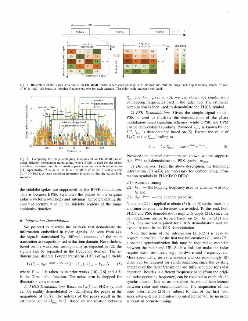
Fig. 3 compares the range ambiguity functions of an FH-
MIMO radar under different modulations. We see the afore-
mentioned spikes in both the original radar waveform and the
FHCS-modulated one. These spikes are attributed to the re-
use of sub-bands as hopping frequencies over hops; refer to
[10] for an in-depth analysis. We also see from Fig. 3 that
4
Pulse 0 tPulse 1 Pulse 2
00 01
radartra
nsm
itterantenna
hop
02 03
10 11 12 13
20 21 22 23
40 41 42 43
antenna 4, hop 2
Hops in aradar pulse
(b)
PRT
radartra
nsm
itterantenna
30 31 32 33
0
1
2
3
4
Sub band
5
6
7
8
9
hop
00 01 02 03
10 11 12 13
20 21 22 23
40 41 42 43
30 31 32 33
reord
erin
g
Hops in aradar pulse
Fig. 2. Illustration of the signal structure of an FH-MIMO radar, where each radar pulse is divided into multiple hops, each hop randomly selects M (outof K in total) sub-bands as hopping frequencies, one for each antenna. The color scale indicates sub-band.
-200 -100 0 100 200Distance, m
-20
-15
-10
-5
0
Ran
ge a
mbg
uity
fun
ctio
n, d
B
oroginalphase modulatedFHCS
-40 -20 0 20 40
-10
-8
-6
-4
-2 spikes are suppressedby phase modulation
peoridic spikes
Fig. 3. Comparing the range ambiguity functions of an FH-MIMO radarunder different information modulations, where BPSK is used for the phasemodulated waveform and the simulation parameters are set with reference to[14]. Specifically, H = M = 10, B = 100 MHz, K = 20, T = 0.2µs andTs = 1/(10B). A large sampling frequency is taken so that the curves looksmoother.
the sidelobe spikes are suppressed by the BPSK modulation.
This is because BPSK scrambles the phases of the original
radar waveform over hops and antennas, hence preventing the
coherent accumulation in the sidelobe regions of the range
ambiguity function.
B. Information Demodulation
We proceed to describe the methods that demodulate the
information embedded in radar signals. As seen from (4),
the signals transmitted by different antennas of the radar
transmitter are superimposed in the time domain. Nevertheless,
based on the waveform orthogonality as depicted in (2), the
signals can be separated in the frequency domain. The L-
dimensional discrete Fourier transform (DFT) of yh(i) yields
Yh(l) = β0e−jmu0ejhmδ(l − l∗hm), l∗hm = khm∆, (5)
where P = 1 is taken as in prior works [10]–[16] and δ(l)is the Dirac delta function. The noise term is dropped for
illustration convenience.
1) FHCS Demodulation: Based on Yh(l), an FHCS symbol
can be readily demodulated by identifying the peaks in the
magnitude of Yh(l). The indexes of the peaks result in the
estimated set of l∗hm ∀m. Based on the relation between
l∗hm and khm given in (5), we can obtain the combination
of hopping frequencies used in the radar hop. The estimated
combination is then used to demodulate the FHCS symbol.
2) PSK Demodulation: Given the simple signal model,
PSK is used to illustrate the demodulation of the phase
modulation-based signaling schemes; while DPSK and CPM
can be demodulated similarly. Provided khm is known by the
UE, l∗hm is then obtained based on (5). Extract the value of
Yh(l) at l = l∗hm, leading to
Yhm = Yh(l∗
hm) = β0e−jmu0ejhm . (6)
Provided that channel parameters are known, we can suppress
β0e−jmu0 and demodulate the PSK symbol hm.
3) Discussions: From the above description, the following
information (I1)-(I3) are necessary for demodulating infor-
mation symbols in FH-MIMO DFRC:
(I1) Accurate timing;
(I2) khm — the hopping frequency used by antenna m at hop
h; and
(I3) β0e−jmu0 — the channel response.
Note that (I1) is applied to obtain (5) from (4) so that inter-hop
and inter-antenna interferences are avoided. To this end, both
FHCS and PSK demodulations implicitly apply (I1), since the
demodulations are performed based on (5). As for (I2) and
(I3), they are not required for FHCS demodulation and are
explicitly used in the PSK demodulation.
Note that none of the information (I1)-(I3) is easy to
acquire in practice. For the first two information (I1) and (I2),
a specific synchronization link may be required to establish
between the radar and UE. Such a link can make the radar
require extra resources, e.g., hardware and frequency etc.
More specifically, an extra antenna and correspondingly RF
chain can be required for synchronization, since the existing
antennas of the radar transmitter are fully occupied for radar
detection. Besides, a different frequency band (from the origi-
nal radar operating frequency) can be required to establish the
synchronization link so as to reduce the mutual interference
between radar and communications. The acquisition of the
third information (I3) is subject to that of the first two,
since inter-antenna and inter-hop interference will be incurred
without an accurate timing.
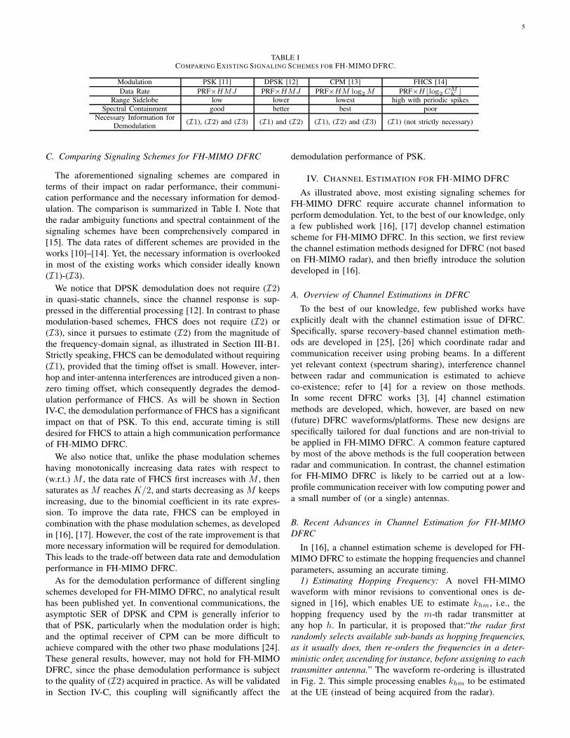
5
TABLE ICOMPARING EXISTING SIGNALING SCHEMES FOR FH-MIMO DFRC.
Modulation PSK [11] DPSK [12] CPM [13] FHCS [14]
Data Rate PRF×HMJ PRF×HMJ PRF×HM log2 M PRF×H⌊log2 CM
K⌋
Range Sidelobe low lower lowest high with periodic spikes
Spectral Containment good better best poor
Necessary Information forDemodulation
(I1), (I2) and (I3) (I1) and (I2) (I1), (I2) and (I3) (I1) (not strictly necessary)
C. Comparing Signaling Schemes for FH-MIMO DFRC
The aforementioned signaling schemes are compared in
terms of their impact on radar performance, their communi-
cation performance and the necessary information for demod-
ulation. The comparison is summarized in Table I. Note that
the radar ambiguity functions and spectral containment of the
signaling schemes have been comprehensively compared in
[15]. The data rates of different schemes are provided in the
works [10]–[14]. Yet, the necessary information is overlooked
in most of the existing works which consider ideally known
(I1)-(I3).
We notice that DPSK demodulation does not require (I2)
in quasi-static channels, since the channel response is sup-
pressed in the differential processing [12]. In contrast to phase
modulation-based schemes, FHCS does not require (I2) or
(I3), since it pursues to estimate (I2) from the magnitude of
the frequency-domain signal, as illustrated in Section III-B1.
Strictly speaking, FHCS can be demodulated without requiring
(I1), provided that the timing offset is small. However, inter-
hop and inter-antenna interferences are introduced given a non-
zero timing offset, which consequently degrades the demod-
ulation performance of FHCS. As will be shown in Section
IV-C, the demodulation performance of FHCS has a significant
impact on that of PSK. To this end, accurate timing is still
desired for FHCS to attain a high communication performance
of FH-MIMO DFRC.
We also notice that, unlike the phase modulation schemes
having monotonically increasing data rates with respect to
(w.r.t.) M , the data rate of FHCS first increases with M , then
saturates as M reaches K/2, and starts decreasing as M keeps
increasing, due to the binomial coefficient in its rate expres-
sion. To improve the data rate, FHCS can be employed in
combination with the phase modulation schemes, as developed
in [16], [17]. However, the cost of the rate improvement is that
more necessary information will be required for demodulation.
This leads to the trade-off between data rate and demodulation
performance in FH-MIMO DFRC.
As for the demodulation performance of different singling
schemes developed for FH-MIMO DFRC, no analytical result
has been published yet. In conventional communications, the
asymptotic SER of DPSK and CPM is generally inferior to
that of PSK, particularly when the modulation order is high;
and the optimal receiver of CPM can be more difficult to
achieve compared with the other two phase modulations [24].
These general results, however, may not hold for FH-MIMO
DFRC, since the phase demodulation performance is subject
to the quality of (I2) acquired in practice. As will be validated
in Section IV-C, this coupling will significantly affect the
demodulation performance of PSK.
IV. CHANNEL ESTIMATION FOR FH-MIMO DFRC
As illustrated above, most existing signaling schemes for
FH-MIMO DFRC require accurate channel information to
perform demodulation. Yet, to the best of our knowledge, only
a few published work [16], [17] develop channel estimation
scheme for FH-MIMO DFRC. In this section, we first review
the channel estimation methods designed for DFRC (not based
on FH-MIMO radar), and then briefly introduce the solution
developed in [16].
A. Overview of Channel Estimations in DFRC
To the best of our knowledge, few published works have
explicitly dealt with the channel estimation issue of DFRC.
Specifically, sparse recovery-based channel estimation meth-
ods are developed in [25], [26] which coordinate radar and
communication receiver using probing beams. In a different
yet relevant context (spectrum sharing), interference channel
between radar and communication is estimated to achieve
co-existence; refer to [4] for a review on those methods.
In some recent DFRC works [3], [4] channel estimation
methods are developed, which, however, are based on new
(future) DFRC waveforms/platforms. These new designs are
specifically tailored for dual functions and are non-trivial to
be applied in FH-MIMO DFRC. A common feature captured
by most of the above methods is the full cooperation between
radar and communication. In contrast, the channel estimation
for FH-MIMO DFRC is likely to be carried out at a low-
profile communication receiver with low computing power and
a small number of (or a single) antennas.
B. Recent Advances in Channel Estimation for FH-MIMO
DFRC
In [16], a channel estimation scheme is developed for FH-
MIMO DFRC to estimate the hopping frequencies and channel
parameters, assuming an accurate timing.
1) Estimating Hopping Frequency: A novel FH-MIMO
waveform with minor revisions to conventional ones is de-
signed in [16], which enables UE to estimate khm, i.e., the
hopping frequency used by the m-th radar transmitter at
any hop h. In particular, it is proposed that:“the radar first
randomly selects available sub-bands as hopping frequencies,
as it usually does, then re-orders the frequencies in a deter-
ministic order, ascending for instance, before assigning to each
transmitter antenna.” The waveform re-ordering is illustrated
in Fig. 2. This simple processing enables khm to be estimated
at the UE (instead of being acquired from the radar).
6
-400 -300 -200 -100 0 100 200 300 400Distance, m
-30
-25
-20
-15
-10
-5
0R
ange
am
bgui
ty f
unct
ion,
dB
re-orderingoriginal
-20 -10 0 10 20
-15
-10
-5
0
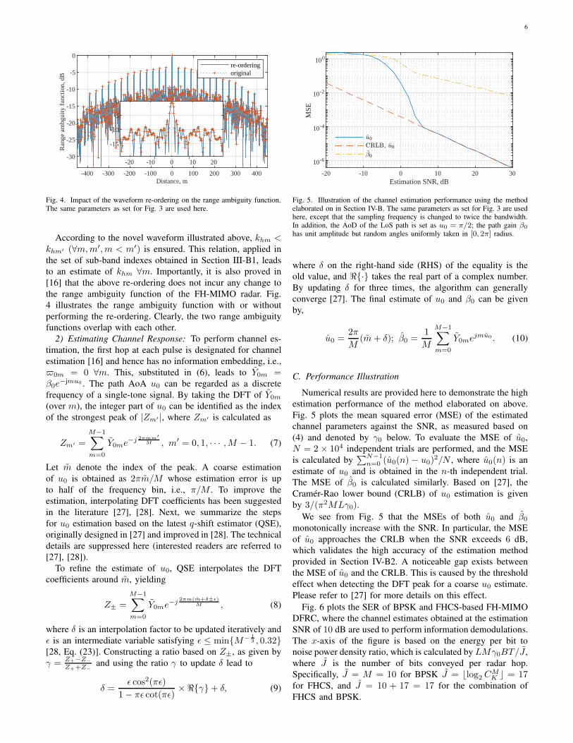
Fig. 4. Impact of the waveform re-ordering on the range ambiguity function.The same parameters as set for Fig. 3 are used here.
According to the novel waveform illustrated above, khm <khm′ (∀m,m′,m < m′) is ensured. This relation, applied in
the set of sub-band indexes obtained in Section III-B1, leads
to an estimate of khm ∀m. Importantly, it is also proved in
[16] that the above re-ordering does not incur any change to
the range ambiguity function of the FH-MIMO radar. Fig.
4 illustrates the range ambiguity function with or without
performing the re-ordering. Clearly, the two range ambiguity
functions overlap with each other.
2) Estimating Channel Response: To perform channel es-
timation, the first hop at each pulse is designated for channel
estimation [16] and hence has no information embedding, i.e.,
0m = 0 ∀m. This, substituted in (6), leads to Y0m =β0e
−jmu0 . The path AoA u0 can be regarded as a discrete
frequency of a single-tone signal. By taking the DFT of Y0m
(over m), the integer part of u0 can be identified as the index
of the strongest peak of |Zm′ |, where Zm′ is calculated as
Zm′ =
M−1∑
m=0
Y0me−j 2πmm′
M , m′ = 0, 1, · · · ,M − 1. (7)
Let m denote the index of the peak. A coarse estimation
of u0 is obtained as 2πm/M whose estimation error is up
to half of the frequency bin, i.e., π/M . To improve the
estimation, interpolating DFT coefficients has been suggested
in the literature [27], [28]. Next, we summarize the steps
for u0 estimation based on the latest q-shift estimator (QSE),
originally designed in [27] and improved in [28]. The technical
details are suppressed here (interested readers are referred to
[27], [28]).
To refine the estimate of u0, QSE interpolates the DFT
coefficients around m, yielding
Z± =
M−1∑
m=0
Y0me−j2πm(m+δ±ǫ)
M , (8)
where δ is an interpolation factor to be updated iteratively and
ǫ is an intermediate variable satisfying ǫ ≤ minM−13 , 0.32
[28, Eq. (23)]. Constructing a ratio based on Z±, as given by
γ = Z+−Z−
Z++Z−and using the ratio γ to update δ lead to
δ =ǫ cos2(πǫ)
1− πǫ cot(πǫ)×ℜγ+ δ, (9)
-20 -10 0 10 20 30Estimation SNR, dB
10-6
10-4
10-2
100
MSE
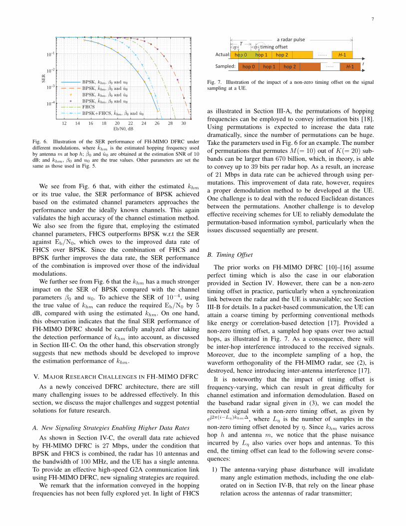
Fig. 5. Illustration of the channel estimation performance using the methodelaborated on in Section IV-B. The same parameters as set for Fig. 3 are usedhere, except that the sampling frequency is changed to twice the bandwidth.In addition, the AoD of the LoS path is set as u0 = π/2; the path gain β0
has unit amplitude but random angles uniformly taken in [0, 2π] radius.
where δ on the right-hand side (RHS) of the equality is the
old value, and ℜ· takes the real part of a complex number.
By updating δ for three times, the algorithm can generally
converge [27]. The final estimate of u0 and β0 can be given
by,
u0 =2π
M(m+ δ); β0 =
1
M
M−1∑
m=0
Y0mejmu0 . (10)
C. Performance Illustration
Numerical results are provided here to demonstrate the high
estimation performance of the method elaborated on above.
Fig. 5 plots the mean squared error (MSE) of the estimated
channel parameters against the SNR, as measured based on
(4) and denoted by γ0 below. To evaluate the MSE of u0,
N = 2 × 10⁴ independent trials are performed, and the MSE
is calculated by∑N−1
n=0 (u0(n) − u0)2/N , where u0(n) is an
estimate of u0 and is obtained in the n-th independent trial.
The MSE of β0 is calculated similarly. Based on [27], the
Cramer-Rao lower bound (CRLB) of u0 estimation is given
by 3/(π2MLγ0).
We see from Fig. 5 that the MSEs of both u0 and β0
monotonically increase with the SNR. In particular, the MSE
of u0 approaches the CRLB when the SNR exceeds 6 dB,
which validates the high accuracy of the estimation method
provided in Section IV-B2. A noticeable gap exists between
the MSE of u0 and the CRLB. This is caused by the threshold
effect when detecting the DFT peak for a coarse u0 estimate.
Please refer to [27] for more details on this effect.
Fig. 6 plots the SER of BPSK and FHCS-based FH-MIMO
DFRC, where the channel estimates obtained at the estimation
SNR of 10 dB are used to perform information demodulations.
The x-axis of the figure is based on the energy per bit to
noise power density ratio, which is calculated by LMγ0BT/J ,
where J is the number of bits conveyed per radar hop.
Specifically, J = M = 10 for BPSK J = ⌊log2 CMK ⌋ = 17
for FHCS, and J = 10 + 17 = 17 for the combination of
FHCS and BPSK.
7
12 14 16 18 20 22 24 26 28 30Eb/N0, dB
10-4
10-3
10-2
10-1
SER
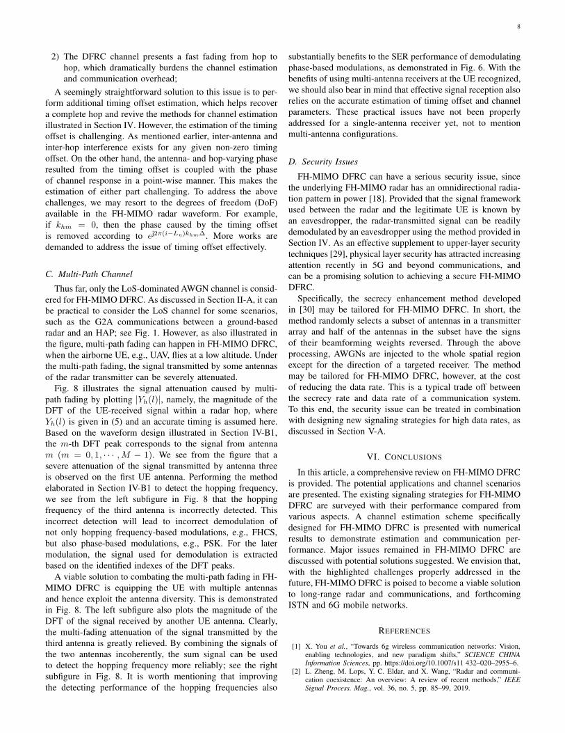
Fig. 6. Illustration of the SER performance of FH-MIMO DFRC under
different modulations, where khm is the estimated hopping frequency used
by antenna m at hop h; β0 and u0 are obtained at the estimation SNR of 10dB; and khm, β0 and u0 are the true values. Other parameters are set thesame as those used in Fig. 5.
We see from Fig. 6 that, with either the estimated khmor its true value, the SER performance of BPSK achieved
based on the estimated channel parameters approaches the
performance under the ideally known channels. This again
validates the high accuracy of the channel estimation method.
We also see from the figure that, employing the estimated
channel parameters, FHCS outperforms BPSK w.r.t the SER
against Eb/N0, which owes to the improved data rate of
FHCS over BPSK. Since the combination of FHCS and
BPSK further improves the data rate, the SER performance
of the combination is improved over those of the individual
modulations.
We further see from Fig. 6 that the khm has a much stronger
impact on the SER of BPSK compared with the channel
parameters β0 and u0. To achieve the SER of 10−4, using
the true value of khm can reduce the required Eb/N0 by 5dB, compared with using the estimated khm. On one hand,
this observation indicates that the final SER performance of
FH-MIMO DFRC should be carefully analyzed after taking
the detection performance of khm into account, as discussed
in Section III-C. On the other hand, this observation strongly
suggests that new methods should be developed to improve
the estimation performance of khm.
V. MAJOR RESEARCH CHALLENGES IN FH-MIMO DFRC
As a newly conceived DFRC architecture, there are still
many challenging issues to be addressed effectively. In this
section, we discuss the major challenges and suggest potential
solutions for future research.
A. New Signaling Strategies Enabling Higher Data Rates
As shown in Section IV-C, the overall data rate achieved
by FH-MIMO DFRC is 27 Mbps, under the condition that
BPSK and FHCS is combined, the radar has 10 antennas and
the bandwidth of 100 MHz, and the UE has a single antenna.
To provide an effective high-speed G2A communication link
using FH-MIMO DFRC, new signaling strategies are required.
We remark that the information conveyed in the hopping
frequencies has not been fully explored yet. In light of FHCS
samples
a radar pulse
MIMOTx
hop 0 hop 1
t
comm
T
hop 2 H 1
ed
samples
MIMORx(a)
ntenna Taking consecutive
sub bands, alsoknown to the UE(b)
sub bandrandom
hop 0 hop 1 hop 2 H 1
Actual:
Sampled:
timing offset
Fig. 7. Illustration of the impact of a non-zero timing offset on the signalsampling at a UE.
as illustrated in Section III-A, the permutations of hopping
frequencies can be employed to convey information bits [18].
Using permutations is expected to increase the data rate
dramatically, since the number of permutations can be huge.
Take the parameters used in Fig. 6 for an example. The number
of permutations that permutes M(= 10) out of K(= 20) sub-
bands can be larger than 670 billion, which, in theory, is able
to convey up to 39 bits per radar hop. As a result, an increase
of 21 Mbps in data rate can be achieved through using per-
mutations. This improvement of data rate, however, requires
a proper demodulation method to be developed at the UE.
One challenge is to deal with the reduced Euclidean distances
between the permutations. Another challenge is to develop
effective receiving schemes for UE to reliably demodulate the
permutation-based information symbol, particularly when the
issues discussed sequentially are present.
B. Timing Offset
The prior works on FH-MIMO DFRC [10]–[16] assume
perfect timing which is also the case in our elaboration
provided in Section IV. However, there can be a non-zero
timing offset in practice, particularly when a synchronization
link between the radar and the UE is unavailable; see Section
III-B for details. In a packet-based communication, the UE can
attain a coarse timing by performing conventional methods
like energy or correlation-based detection [17]. Provided a
non-zero timing offset, a sampled hop spans over two actual
hops, as illustrated in Fig. 7. As a consequence, there will
be inter-hop interference introduced to the received signals.
Moreover, due to the incomplete sampling of a hop, the
waveform orthogonality of the FH-MIMO radar, see (2), is
destroyed, hence introducing inter-antenna interference [17].
It is noteworthy that the impact of timing offset is
frequency-varying, which can result in great difficulty for
channel estimation and information demodulation. Based on
the baseband radar signal given in (3), we can model the
received signal with a non-zero timing offset, as given by
ej2π(i−Lη)khm∆, where Lη is the number of samples in the
non-zero timing offset denoted by η. Since khm varies across
hop h and antenna m, we notice that the phase nuisance
incurred by Lη also varies over hops and antennas. To this
end, the timing offset can lead to the following severe conse-
quences:
1) The antenna-varying phase disturbance will invalidate
many angle estimation methods, including the one elab-
orated on in Section IV-B, that rely on the linear phase
relation across the antennas of radar transmitter;
8
2) The DFRC channel presents a fast fading from hop to
hop, which dramatically burdens the channel estimation
and communication overhead;
A seemingly straightforward solution to this issue is to per-
form additional timing offset estimation, which helps recover
a complete hop and revive the methods for channel estimation
illustrated in Section IV. However, the estimation of the timing
offset is challenging. As mentioned earlier, inter-antenna and
inter-hop interference exists for any given non-zero timing
offset. On the other hand, the antenna- and hop-varying phase
resulted from the timing offset is coupled with the phase
of channel response in a point-wise manner. This makes the
estimation of either part challenging. To address the above
challenges, we may resort to the degrees of freedom (DoF)
available in the FH-MIMO radar waveform. For example,
if khm = 0, then the phase caused by the timing offset
is removed according to ej2π(i−Lη)khm∆. More works are
demanded to address the issue of timing offset effectively.
C. Multi-Path Channel
Thus far, only the LoS-dominated AWGN channel is consid-
ered for FH-MIMO DFRC. As discussed in Section II-A, it can
be practical to consider the LoS channel for some scenarios,
such as the G2A communications between a ground-based
radar and an HAP; see Fig. 1. However, as also illustrated in
the figure, multi-path fading can happen in FH-MIMO DFRC,
when the airborne UE, e.g., UAV, flies at a low altitude. Under
the multi-path fading, the signal transmitted by some antennas
of the radar transmitter can be severely attenuated.
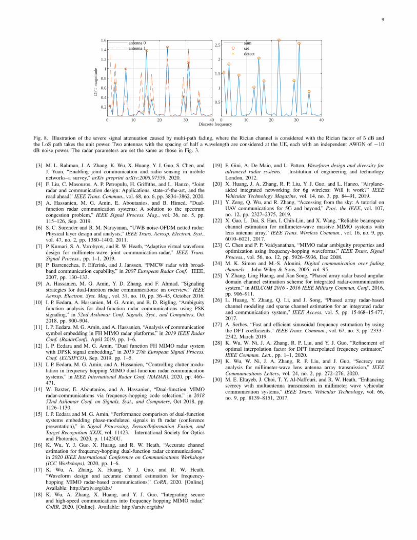
Fig. 8 illustrates the signal attenuation caused by multi-
path fading by plotting |Yh(l)|, namely, the magnitude of the
DFT of the UE-received signal within a radar hop, where
Yh(l) is given in (5) and an accurate timing is assumed here.
Based on the waveform design illustrated in Section IV-B1,
the m-th DFT peak corresponds to the signal from antenna
m (m = 0, 1, · · · ,M − 1). We see from the figure that a
severe attenuation of the signal transmitted by antenna three
is observed on the first UE antenna. Performing the method
elaborated in Section IV-B1 to detect the hopping frequency,
we see from the left subfigure in Fig. 8 that the hopping
frequency of the third antenna is incorrectly detected. This
incorrect detection will lead to incorrect demodulation of
not only hopping frequency-based modulations, e.g., FHCS,
but also phase-based modulations, e.g., PSK. For the later
modulation, the signal used for demodulation is extracted
based on the identified indexes of the DFT peaks.
A viable solution to combating the multi-path fading in FH-
MIMO DFRC is equipping the UE with multiple antennas
and hence exploit the antenna diversity. This is demonstrated
in Fig. 8. The left subfigure also plots the magnitude of the
DFT of the signal received by another UE antenna. Clearly,
the multi-fading attenuation of the signal transmitted by the
third antenna is greatly relieved. By combining the signals of
the two antennas incoherently, the sum signal can be used
to detect the hopping frequency more reliably; see the right
subfigure in Fig. 8. It is worth mentioning that improving
the detecting performance of the hopping frequencies also
substantially benefits to the SER performance of demodulating
phase-based modulations, as demonstrated in Fig. 6. With the
benefits of using multi-antenna receivers at the UE recognized,
we should also bear in mind that effective signal reception also
relies on the accurate estimation of timing offset and channel
parameters. These practical issues have not been properly
addressed for a single-antenna receiver yet, not to mention
multi-antenna configurations.
D. Security Issues
FH-MIMO DFRC can have a serious security issue, since
the underlying FH-MIMO radar has an omnidirectional radia-
tion pattern in power [18]. Provided that the signal framework
used between the radar and the legitimate UE is known by
an eavesdropper, the radar-transmitted signal can be readily
demodulated by an eavesdropper using the method provided in
Section IV. As an effective supplement to upper-layer security
techniques [29], physical layer security has attracted increasing
attention recently in 5G and beyond communications, and
can be a promising solution to achieving a secure FH-MIMO
DFRC.
Specifically, the secrecy enhancement method developed
in [30] may be tailored for FH-MIMO DFRC. In short, the
method randomly selects a subset of antennas in a transmitter
array and half of the antennas in the subset have the signs
of their beamforming weights reversed. Through the above
processing, AWGNs are injected to the whole spatial region
except for the direction of a targeted receiver. The method
may be tailored for FH-MIMO DFRC, however, at the cost
of reducing the data rate. This is a typical trade off between
the secrecy rate and data rate of a communication system.
To this end, the security issue can be treated in combination
with designing new signaling strategies for high data rates, as
discussed in Section V-A.
VI. CONCLUSIONS
In this article, a comprehensive review on FH-MIMO DFRC
is provided. The potential applications and channel scenarios
are presented. The existing signaling strategies for FH-MIMO
DFRC are surveyed with their performance compared from
various aspects. A channel estimation scheme specifically
designed for FH-MIMO DFRC is presented with numerical
results to demonstrate estimation and communication per-
formance. Major issues remained in FH-MIMO DFRC are
discussed with potential solutions suggested. We envision that,
with the highlighted challenges properly addressed in the
future, FH-MIMO DFRC is poised to become a viable solution
to long-range radar and communications, and forthcoming
ISTN and 6G mobile networks.
REFERENCES
[1] X. You et al., “Towards 6g wireless communication networks: Vision,enabling technologies, and new paradigm shifts,” SCIENCE CHINAInformation Sciences, pp. https://doi.org/10.1007/s11 432–020–2955–6.
[2] L. Zheng, M. Lops, Y. C. Eldar, and X. Wang, “Radar and communi-cation coexistence: An overview: A review of recent methods,” IEEE
Signal Process. Mag., vol. 36, no. 5, pp. 85–99, 2019.
9
0 10 20 30 40Discrete frequency
0.2
0.4
0.6
0.8
1
1.2
1.4
1.6
DFT
mag
nitu
de
antenna 0antenna 1
0 10 20 30 40
0.5
1
1.5
2
2.5 sumsetdetect
Fig. 8. Illustration of the severe signal attenuation caused by multi-path fading, where the Rician channel is considered with the Rician factor of 5 dB andthe LoS path takes the unit power. Two antennas with the spacing of half a wavelength are considered at the UE, each with an independent AWGN of −10dB noise power. The radar parameters are set the same as those in Fig. 3.
[3] M. L. Rahman, J. A. Zhang, K. Wu, X. Huang, Y. J. Guo, S. Chen, andJ. Yuan, “Enabling joint communication and radio sensing in mobilenetworks–a survey,” arXiv preprint arXiv:2006.07559, 2020.
[4] F. Liu, C. Masouros, A. P. Petropulu, H. Griffiths, and L. Hanzo, “Jointradar and communication design: Applications, state-of-the-art, and theroad ahead,” IEEE Trans. Commun., vol. 68, no. 6, pp. 3834–3862, 2020.
[5] A. Hassanien, M. G. Amin, E. Aboutanios, and B. Himed, “Dual-function radar communication systems: A solution to the spectrumcongestion problem,” IEEE Signal Process. Mag., vol. 36, no. 5, pp.115–126, Sep. 2019.
[6] S. C. Surender and R. M. Narayanan, “UWB noise-OFDM netted radar:Physical layer design and analysis,” IEEE Trans. Aerosp. Electron. Syst.,vol. 47, no. 2, pp. 1380–1400, 2011.
[7] P. Kumari, S. A. Vorobyov, and R. W. Heath, “Adaptive virtual waveformdesign for millimeter-wave joint communication-radar,” IEEE Trans.Signal Process., pp. 1–1, 2019.
[8] P. Barrenechea, F. Elferink, and J. Janssen, “FMCW radar with broad-band communication capability,” in 2007 European Radar Conf. IEEE,2007, pp. 130–133.
[9] A. Hassanien, M. G. Amin, Y. D. Zhang, and F. Ahmad, “Signalingstrategies for dual-function radar communications: an overview,” IEEE
Aerosp. Electron. Syst. Mag., vol. 31, no. 10, pp. 36–45, October 2016.
[10] I. P. Eedara, A. Hassanien, M. G. Amin, and B. D. Rigling, “Ambiguityfunction analysis for dual-function radar communications using PSKsignaling,” in 52nd Asilomar Conf. Signals, Syst., and Computers, Oct2018, pp. 900–904.
[11] I. P. Eedara, M. G. Amin, and A. Hassanien, “Analysis of communicationsymbol embedding in FH MIMO radar platforms,” in 2019 IEEE Radar
Conf. (RadarConf), April 2019, pp. 1–6.
[12] I. P. Eedara and M. G. Amin, “Dual function FH MIMO radar systemwith DPSK signal embedding,” in 2019 27th European Signal Process.
Conf. (EUSIPCO), Sep. 2019, pp. 1–5.
[13] I. P. Eedara, M. G. Amin, and A. Hassanien, “Controlling clutter modu-lation in frequency hopping MIMO dual-function radar communicationsystems,” in IEEE International Radar Conf. (RADAR), 2020, pp. 466–471.
[14] W. Baxter, E. Aboutanios, and A. Hassanien, “Dual-function MIMOradar-communications via frequency-hopping code selection,” in 201852nd Asilomar Conf. on Signals, Syst., and Computers, Oct 2018, pp.1126–1130.
[15] I. P. Eedara and M. G. Amin, “Performance comparison of dual-functionsystems embedding phase-modulated signals in fh radar (conferencepresentation),” in Signal Processing, Sensor/Information Fusion, and
Target Recognition XXIX, vol. 11423. International Society for Opticsand Photonics, 2020, p. 114230U.
[16] K. Wu, Y. J. Guo, X. Huang, and R. W. Heath, “Accurate channelestimation for frequency-hopping dual-function radar communications,”in 2020 IEEE International Conference on Communications Workshops
(ICC Workshops), 2020, pp. 1–6.
[17] K. Wu, A. Zhang, X. Huang, Y. J. Guo, and R. W. Heath,“Waveform design and accurate channel estimation for frequency-hopping MIMO radar-based communications,” CoRR, 2020. [Online].Available: http://arxiv.org/abs/
[18] K. Wu, A. Zhang, X. Huang, and Y. J. Guo, “Integrating secureand high-speed communications into frequency hopping MIMO radar,”CoRR, 2020. [Online]. Available: http://arxiv.org/abs/
[19] F. Gini, A. De Maio, and L. Patton, Waveform design and diversity for
advanced radar systems. Institution of engineering and technologyLondon, 2012.
[20] X. Huang, J. A. Zhang, R. P. Liu, Y. J. Guo, and L. Hanzo, “Airplane-aided integrated networking for 6g wireless: Will it work?” IEEE
Vehicular Technology Magazine, vol. 14, no. 3, pp. 84–91, 2019.[21] Y. Zeng, Q. Wu, and R. Zhang, “Accessing from the sky: A tutorial on
UAV communications for 5G and beyond,” Proc. the IEEE, vol. 107,no. 12, pp. 2327–2375, 2019.
[22] X. Gao, L. Dai, S. Han, I. Chih-Lin, and X. Wang, “Reliable beamspacechannel estimation for millimeter-wave massive MIMO systems withlens antenna array,” IEEE Trans. Wireless Commun., vol. 16, no. 9, pp.6010–6021, 2017.
[23] C. Chen and P. P. Vaidyanathan, “MIMO radar ambiguity properties andoptimization using frequency-hopping waveforms,” IEEE Trans. Signal
Process., vol. 56, no. 12, pp. 5926–5936, Dec 2008.[24] M. K. Simon and M.-S. Alouini, Digital communication over fading
channels. John Wiley & Sons, 2005, vol. 95.[25] Y. Zhang, Ling Huang, and Jian Song, “Phased array radar based angular
domain channel estimation scheme for integrated radar-communicationsystem,” in MILCOM 2016 - 2016 IEEE Military Commun. Conf., 2016,pp. 906–911.
[26] L. Huang, Y. Zhang, Q. Li, and J. Song, “Phased array radar-basedchannel modeling and sparse channel estimation for an integrated radarand communication system,” IEEE Access, vol. 5, pp. 15 468–15 477,2017.
[27] A. Serbes, “Fast and efficient sinusoidal frequency estimation by usingthe DFT coefficients,” IEEE Trans. Commun., vol. 67, no. 3, pp. 2333–2342, March 2019.
[28] K. Wu, W. Ni, J. A. Zhang, R. P. Liu, and Y. J. Guo, “Refinement ofoptimal interpolation factor for DFT interpolated frequency estimator,”IEEE Commun. Lett., pp. 1–1, 2020.
[29] K. Wu, W. Ni, J. A. Zhang, R. P. Liu, and J. Guo, “Secrecy rateanalysis for millimeter-wave lens antenna array transmission,” IEEE
Communications Letters, vol. 24, no. 2, pp. 272–276, 2020.[30] M. E. Eltayeb, J. Choi, T. Y. Al-Naffouri, and R. W. Heath, “Enhancing
secrecy with multiantenna transmission in millimeter wave vehicularcommunication systems,” IEEE Trans. Vehicular Technology, vol. 66,no. 9, pp. 8139–8151, 2017.


