Embed Size (px)
Citation preview
FIXED FORMAT DJ MIXER
USERS MANUAL
Formula Sound Direct UK
https://formulasounddirect.com
FF- 4.2L
FF – 4.2 INTRODUCTION
The features and layout of the FF-4.2 were determined in collaboration with leading loudspeaker manufacturers Funktion One.
The FF-4.2 has 4 channels; each channel has two inputs selectable by a push switch. Thereis also a fifth input which is the console microphone input.
The FF4.2L has linear faders and the FF4.2R has rotary, both versions can have internal orexternal power supply, external power supply versions are denoted by a suffix “P”.
Channel 1 is switchable between low impedance microphone and stereo balanced line input. Phantom power is available for the microphones (recessed switch) and gain adjustment (recessed). Channels 2 to 4 are switchable between a stereo line input and a phono (RIAA) input.
Each channel has a gain control, 4 band “full kill” EQ, selectable variable frequency high and low pass filters, 2 x AUX switches, cue switch, channel fader and 12 LED level indication plus clip LED.
The variable frequency high pass filter is adjustable from 20Hz to 2Khz; the variable frequency low pass filter is adjustable from 20Khz to 2Khz.
Channel 1 has a compressor selected by a switch, the compressor threshold is indicated byan LED and the threshold and ratio may be adjusted by recessed pots in the base of the unit. The compressor acts on both Mic and balanced line inputs.
Channel 1 MIC is on a separate MIC buss, there is a recessed switch in the base of the unitthat allows the MIC buss to be included in the booth or post booth (as the console MIC).
Channel 1 is not assignable to cross fader; channels 2 – 4 are assignable to cross fader. The cross fader has a fader curve control located just above the cross fader.
Console MIC is upper right on the FF4.2 and includes recessed phantom power switch and recessed gain trim. There is volume control, 3 band EQ (+5dB to -26dB); MIC ON/OFF switch and cue switch on the front panel.
The master output is balanced stereo on XLR’s, master level is indicated ona stereo 12 LED meter with volume control below the meter. There is an insert (stereo jack) in the master output enabled by a push switch.
The booth output is also balanced stereo on XLR’s, the booth level is indicated on a stereo 12 LED meter with volume control below the meter. There is also a balance pan control and mono select switch for the booth.
The AUX 1 and AUX 2 outputs are both balanced stereo on dual jack sockets with a level control on the front panel.
There are two headphone outputs (1/4” jack and 3.5mm jack) with volume control and cue balance pots; there is also a split switch and pre/post EQ switch (pre EQ is also pre high pass and low pass filter).
There is also a balanced stereo zone output with connection for remote zone control panel (remote panel not included), the zone output may be switched to mono via recessed switch.
There is also record output on phono sockets, switchable (recessed) mono/sub bass balanced output and remote mute connection.

Mechanical and Power Supply
Dimensions (Excluding. Knobs & connectors):
Width 342mm (13.5") Height 355.3mm (14"-8RU) Depth 110mm (4.33").
Power Supply
The internal power supply version has a fully regulated power supply that is designed to operate on 220-240Vac or 110-120Vac. Voltage is factory set.
The external power supply version has a fully regulated power supply (designated PSU 6) in a separate case, connecting to the mixer by a 6 bin circular connector. Voltage is factory set.
When using a remote power supply, the power supply should be connected to the FF4.2 before switching power on.
DAMAGE MAY RESULT IF THE UNIT IS CONNECTED TO THE WRONG SUPPLY VOLTAGE.
Fuses
Mains fuse sizes are 1A anti-surge for 220-240Vac and 2A anti-surge for 110-120Vac operation.
It is important for safety reasons that the correct fuse ratings are always used.
Appendixes:
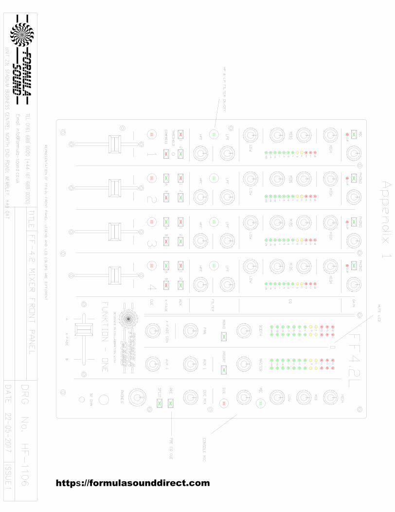
Appendix 1 - Front panel detail
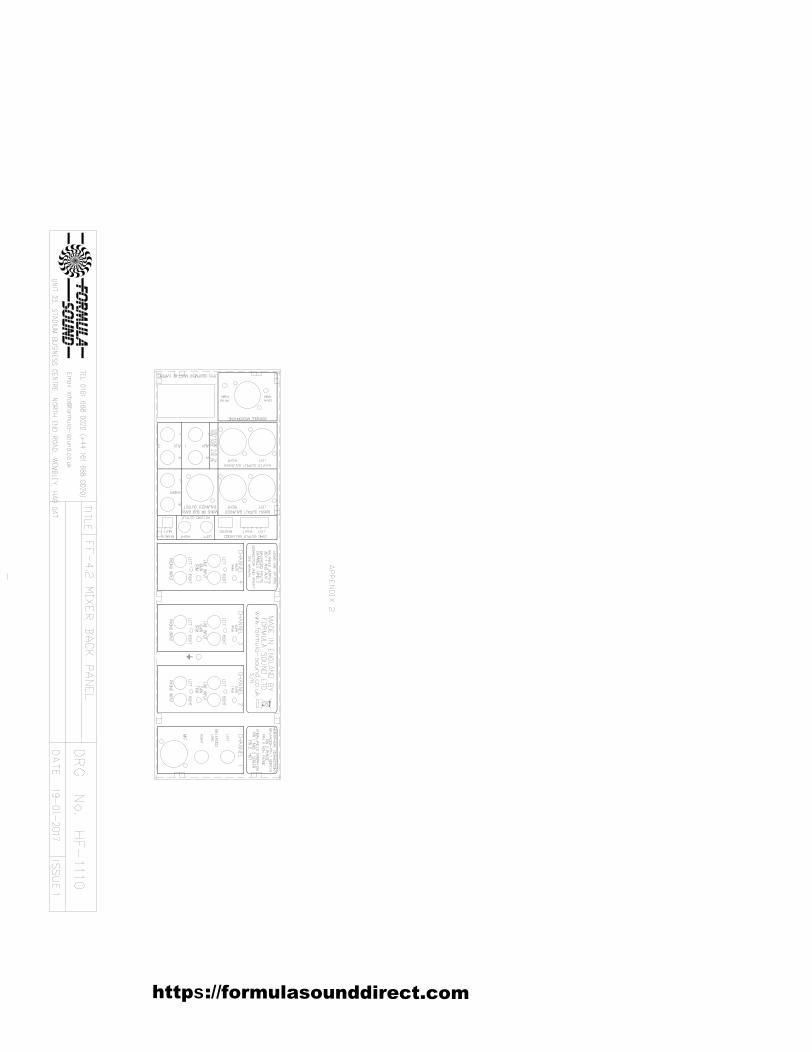
Appendix 2 - Back panel detail
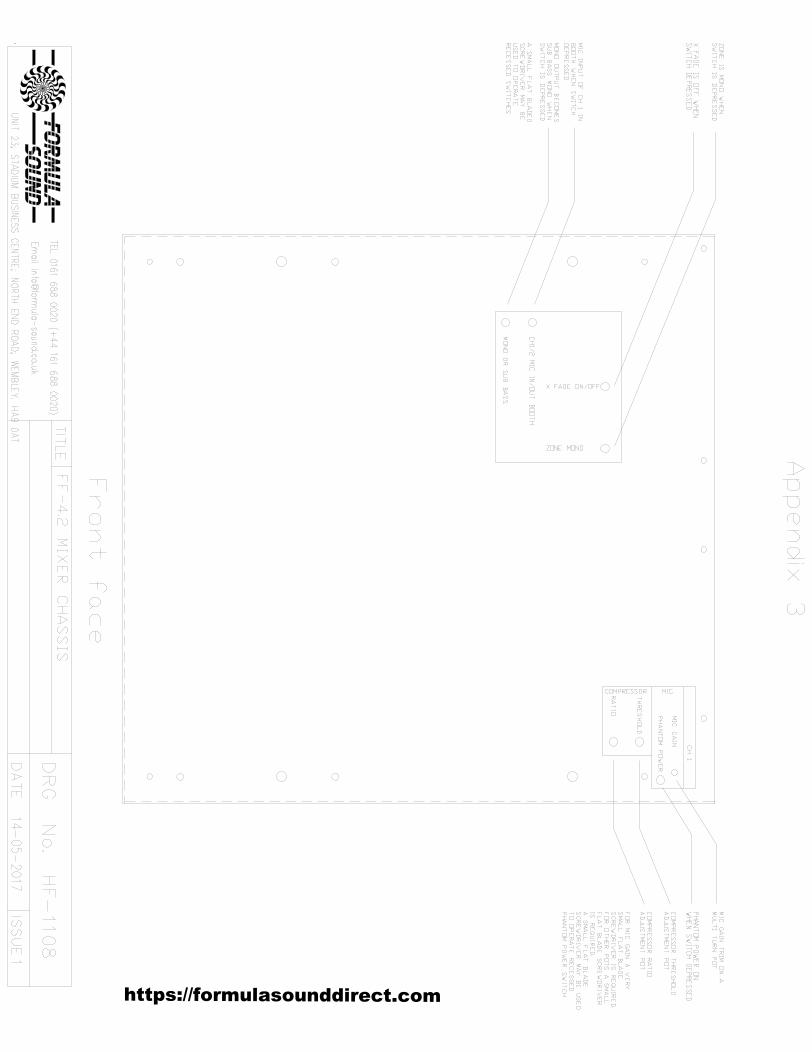
Appendix 3 - Base adjustments
://formulasounddirect.comshttp
Input Channels
All 4 channels have 2 inputs; the required input is selected on an input select switch at the top of the channel.
There is also a GAIN control on each channel to set the maximum level and a linear channel fader to control the level sent to the output.
All channels have a “full kill” 4 band EQ; the EQ band frequencies are approximatelyBass up to 140Hz, Low Mid 140Hz to 750Hz, High Mid 750Hz to 4.3KHz and Treble above 4.3Khz.
Each channel has variable frequency high pass and low pass filters that are selected by a switch. The low pass filter is variable from 20KHz to 2KHz and the high pass filter is variable from 20Hz to 2KHz. The filters should be selected before the audio is routed to the output as there may be a small click if the filter is selected live.
These filters operate best with a signal level of around 0dB, the filters on any channelshould be selected before the audio is routed to the output as there may be a small audible click if the filters are selected live. Once selected the filters can be set to 20Hz and 20KHz where they have a minimal effect and the frequencies adjusted either live or on cue.
Each channel has a 12 LED meter to indicate channel level, left and right are summedto mono and the level adjusted by -6dB so that the input meter indicates an average ofleft and right indicated in the output (the channel indication will show the same level as left and right output meter indication if left and right are equal).
Each channel also has a clip LED to indicate when the input is excessive or clipping.
All channels have 2 AUX sends operated on switches and a CUE select switch for headphone monitoring.
Channel 1
A microphone input on an XLR and a balanced stereo line input on a pair of ¼” jack sockets is provided. The input to be used is selected by an input select switch.
The microphone input has a gain trim and phantom power switch recessed in the baseof the unit (see appendix 3). Phantom power is on when the switch is depressed.
The microphone can be routed to be included in the booth or excluded from the boothby a switch in the base of the unit (see appendix 3). Microphone signal is included in the booth when the switch is depressed.
The stereo balanced line input may be strapped for unbalanced operation.Channel 1 has a compressor selected by a switch, the compressor operates on both microphone and line inputs.
The compressor is factory set for a threshold of 0dB, a threshold LED between the COMP and AUX 2 switch indicates when the compression threshold is reached.
The compressor is factory set for a soft compression when selected, the threshold andcompression ratio may be adjusted by controls that are recessed in the base of the unit(see appendix 3).
The compression threshold can be adjusted by putting a piece of music that has an even level through the channel and set the gain control so the channel meter indicates the level you want to set the compressor threshold to. Adjust the compressor threshold control until the threshold level LED just comes on, adjust back and forth a few times to be sure you are at the right point.
Route the music to the output and set so the output meter indicates the same as the input meter, check the compressor threshold LED is still on (increase the GAIN setting if it is not until the LED comes on), then increase the GAIN setting by 6dB onthe channel meter and check the change in the output meter. The change in the outputmeter should be less because it is compressed.
The amount of compression can be calculated, 1dB change on output meter is 6:1, 2dB change would be 3:1, 3dB change would be 2:1 and 4dB change would be 1.5:1 compression ratio. The ratio is change in input divided by change in output so if 6dB change in input produces 3dB change in output the ratio is 6dB/3dB = 2 or 2:1.
Adjust the ratio control as required, if the output level is similar to the input level there is little compression, if the output level is nearly 6dB less than the input then there is approaching maximum compression. A 6dB change in input is used in this example a larger or smaller change can be used.
The compressor should be selected before the audio is routed to the output, as there may be a small audible click if the compressor is selected live.
The compressor is particularly useful for vocals and the high pass filter may be used to remove some of the effects of breathing into a microphone by setting it to about a quarter turn.
Channels 2 – 4
A stereo line input and a stereo phono input are the two inputs on channels 3 – 6 which are selectable on the input select switch. Both are on phono sockets.
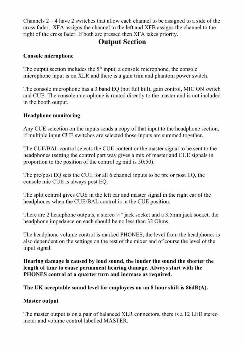
Channels 2 – 4 have 2 switches that allow each channel to be assigned to a side of thecross fader, XFA assigns the channel to the left and XFB assigns the channel to the right of the cross fader. If both are pressed then XFA takes priority.
Output Section
Console microphone
The output section includes the 5th input, a console microphone, the console microphone input is on XLR and there is a gain trim and phantom power switch.
The console microphone has a 3 band EQ (not full kill), gain control, MIC ON switchand CUE. The console microphone is routed directly to the master and is not includedin the booth output.
Headphone monitoring
Any CUE selection on the inputs sends a copy of that input to the headphone section, if multiple input CUE switches are selected those inputs are summed together.
The CUE/BAL control selects the CUE content or the master signal to be sent to the headphones (setting the control part way gives a mix of master and CUE signals in proportion to the position of the control eg mid is 50:50).
The pre/post EQ sets the CUE for all 6 channel inputs to be pre or post EQ, the console mic CUE is always post EQ.
The split control gives CUE in the left ear and master signal in the right ear of the headphones when the CUE/BAL control is in the CUE position.
There are 2 headphone outputs, a stereo ¼” jack socket and a 3.5mm jack socket, the headphone impedance on each should be no less than 32 Ohms.
The headphone volume control is marked PHONES, the level from the headphones isalso dependent on the settings on the rest of the mixer and of course the level of the input signal.
Hearing damage is caused by loud sound, the louder the sound the shorter the length of time to cause permanent hearing damage. Always start with the PHONES control at a quarter turn and increase as required.
The UK acceptable sound level for employees on an 8 hour shift is 86dB(A).
Master output
The master output is on a pair of balanced XLR connectors, there is a 12 LED stereo meter and volume control labelled MASTER.
There is also an insert in the master output stage on a pair of ¼” jack sockets, the insert is enabled by a switch marked INSERT.Note the send path is always active, the insert switch bringing in the return path.
Booth output
The booth output is on a pair of balanced XLR connectors; there is a 12 LED stereo meter and volume control labelled BOOTH.
There is a MONO select switch that sums the booth left and right to mono. There is a PAN control that operates in stereo mode, with MONO selected the PAN pot has no effect.
AUX 1 and AUX 2
The AUX 1 contains a summed signal of each channel with AUX 1 selected, the levelof the summed AUX 1 signal is adjusted by the volume control marked AUX 1. The AUX 1 signal is balanced stereo on a pair of ¼” jack sockets. AUX 2 operates in the same way as AUX 1.
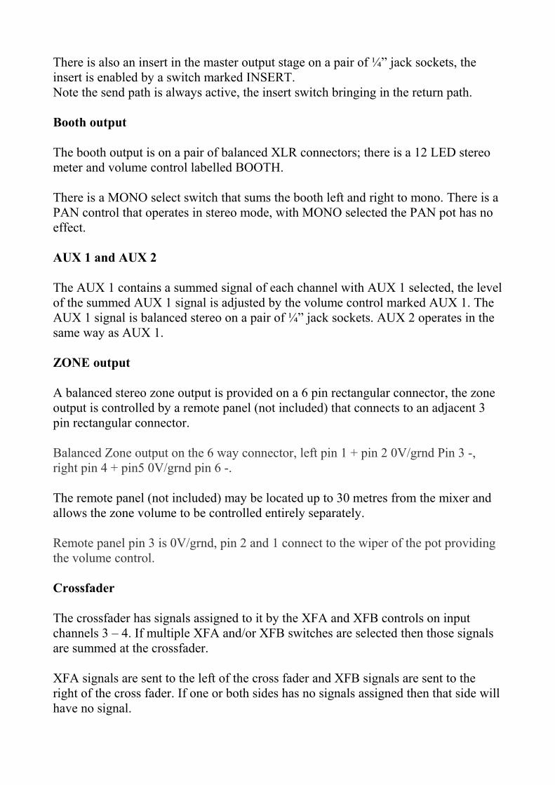
ZONE output
A balanced stereo zone output is provided on a 6 pin rectangular connector, the zone output is controlled by a remote panel (not included) that connects to an adjacent 3 pin rectangular connector.
Balanced Zone output on the 6 way connector, left pin 1 + pin 2 0V/grnd Pin 3 -, right pin 4 + pin5 0V/grnd pin 6 -.
The remote panel (not included) may be located up to 30 metres from the mixer and allows the zone volume to be controlled entirely separately.
Remote panel pin 3 is 0V/grnd, pin 2 and 1 connect to the wiper of the pot providing the volume control.
Crossfader
The crossfader has signals assigned to it by the XFA and XFB controls on input channels 3 – 4. If multiple XFA and/or XFB switches are selected then those signals are summed at the crossfader.
XFA signals are sent to the left of the cross fader and XFB signals are sent to the right of the cross fader. If one or both sides has no signals assigned then that side willhave no signal.
The signal from the crossfader that is routed to the output is dependent on the position of the crossfader, with crossfader set full left any XFA selection is sent to theoutput and with the crossfader full right any XFB selection is sent to the output.
With the crossfader in centre position equal amounts of XFA and XFB will be sent tothe output, with the crossfader off to one side (but not at end) a mix of XFA and XFBwill be sent to the output. The relative level of XFA and XFB will depend on the position of the crossfader, more to the left and XFA will be larger and more to the right and XFB will be larger.
The rate at which the signal changes from XFA to XFB as the crossfader moves left to right (or vice versa) can be adjusted by the contour control.
A recessed switch in the base of the unit can switch the crossfader off.
MONO or SUB BASS output
There is an output on a balanced XLR that can be MONO or MONO SUB BASS; there is a recessed switch on the base of the unit for selection.
Record output
A record output is provided on a pair of phono style sockets.
Remote mute
The remote mute connection is on a 2 pin rectangular connector, shorting pin 1 and pin 2 will mute the mixer with the exception of the console microphone and any channel 1 and/or 2 microphones set post booth.
This may be used to interface to a fire alarm, if the alarm has a set of isolated contactsthat close on alarm then these may be used directly, otherwise an isolating interface relay will be required.
Formula Sound DirectUK
https://formulasounddirect.com

FORMULA SOUND LIMITED
UNIT 23; STADIUM BUSINESS CENTRE; NORTH END ROAD; WEMBLEY; MIDDLESEX; HA9 0AT
TELEPHONE +44 (0)208-900-0947 FAX +44 (0)208-903-8657
www.formula-sound.co.uk email [email protected]
E.U. CERTIFICATE OF CONFORMITY
We declare that the products listed conform to the following directives and standards
89/336/EEC amended by 92/31/EEC and 93/68/EEC
BS EN 50082-1 BS EN 50081-1
PRODUCT TYPE
FF 4.2L, FF4.2LP, FF4.2R & FF4.2RP
The CE mark was first applied in 1995
Signed
B. J. Penaligon General Manager
Attention
The attention of the specifier, purchaser, installer, or user is drawn to the fact that good wiring practice must be observed when connecting the above equipment. Good quality connectors and screened cables must be used for all audio connections. Twin screened cables should be used for all balanced lines.
THIS EQUIPMENT MUST BE EARTHED
CONSULT THE USERS MANUAL FOR TECHNICAL DETAILS
://formulasounddirect.comshttp
https://formulasounddirect.com
https://formulasounddirect.com
https://formulasounddirect.com


