Embed Size (px)
Citation preview
F
NCa
b
c
d
a
1f
hiidot
0d
Nuclear Engineering and Design 239 (2009) 2582–2595
Contents lists available at ScienceDirect
Nuclear Engineering and Design
journa l homepage: www.e lsev ier .com/ locate /nucengdes
lexible conversion ratio fast reactors: Overview
eil E. Todreas a,∗, Pavel Hejzlar a, Anna Nikiforova a, Robert Petroski b, Eugene Shwageraus c,.J. Fong d, Michael J. Driscoll a, M.A. Elliott a, George Apostolakis a
Massachusetts Institute of Technology, Department of Nuclear Science and Engineering, 77 Massachusetts Avenue, Cambridge, MA 02139, USATerraPower, LLC, Bellevue, WA, USADepartment of Nuclear Engineering, Ben Gurion University of the Negev, IsraelNuclear Regulatory Commission, Washington, DC, USA
r t i c l e i n f o a b s t r a c t
Conceptual designs of lead-cooled and liquid salt-cooled fast flexible conversion ratio reactors were devel-oped. The performance achievable by the unity conversion ratio cores of these reactors was comparedto an existing supercritical carbon dioxide-cooled (S-CO2) fast reactor design and an uprated versionof an existing sodium-cooled fast reactor. All concepts have cores rated at 2400 MWt. The cores of theliquid-cooled reactors are placed in a large-pool-type vessel with dual-free level, which also contains fourintermediate heat exchangers (IHXs) coupling a primary coolant to a compact and efficient supercriticalCO2 Brayton cycle power conversion system. The S-CO2 reactor is directly coupled to the S-CO2 Braytoncycle power conversion system. Decay heat is removed passively using an enhanced reactor vessel aux-iliary cooling system (RVACS) and a passive secondary auxiliary cooling system (PSACS). The selection ofthe water-cooled versus air-cooled heat sink for the PSACS as well as the analysis of the probability thatthe PSACS may fail to complete its mission was performed using risk-informed methodology. In additionto these features, all reactors were designed to be self-controllable. Further, the liquid-cooled reactorsutilized common passive decay heat removal systems whereas the S-CO2 uses reliable battery poweredblowers for post-LOCA decay heat removal to provide flow in well defined regimes and to accommodateinadvertent bypass flows. The multiple design limits and challenges which constrained the executionof the four fast reactor concepts are elaborated. These include principally neutronics and materials chal-lenges. The neutronic challenges are the large positive coolant reactivity feedback, small fuel temperaturecoefficient, small effective delayed neutron fraction, large reactivity swing and the transition betweendifferent conversion ratio cores. The burnup, temperature and fluence constraints on fuels, cladding and
vessel materials are elaborated for three categories of material – materials currently available, availableon a relatively short time scale and available only with significant development effort. The selected fuelsare the metallic U–TRU–Zr (10% Zr) for unity conversion ratio and TRU–Zr (75% Zr) for zero conversionratio. The principal selected cladding and vessel materials are HT-9 and A533 or A508, respectively, forand 9l (OD
current availability, T-91strengthened ferritic stee
. Background and motivation for flexible conversion ratioast reactors
In the 1960s and 1970s fast spectrum reactor designs having aigh conversion ratio were pursued worldwide to maximize breed-
ng. However this anticipated need for breeders did not materialize
n subsequent years since low cost uranium resources were abun-ant due to slowed nuclear power growth. Nevertheless concernsver accumulation of long-lived actinides in spent light water reac-or (LWR) fuel and slow progress on a permanent waste repository∗ Corresponding author.E-mail address: [email protected] (N.E. Todreas).
029-5493/$ – see front matter © 2009 Elsevier B.V. All rights reserved.oi:10.1016/j.nucengdes.2009.07.014
Cr–1Mo steel for relatively short-term availability and oxide dispersionS) available only with significant development.
© 2009 Elsevier B.V. All rights reserved.
have stimulated reevaluation of fuel cycle options. High amongthem has been the transition to a fleet of fast spectrum reactors ofunity conversion ratio (CR = 1) to provide needed electricity gener-ation by a transuranic (TRU) sustainable fuel cycle regime. Reactorsoperating in such a closed cycle in time would also manage thelegacy LWR spent fuel actinides, since these actinides would beneeded to provide the large start up fuel inventory for these unityconversion ratio reactors. However the alternative path of a fleet ofdedicated fertile-free fast burner (CR = 0) reactors to manage both
legacy LWR spent fuel and that from the continued operation ofLWRs is another option.While long-term simulations of these options performed by oth-ers as well as ourselves (Romano et al., 2006; Aquien et al., 2006)have elucidated the relative characteristics of the fuel cycle regimes
ering a
oHsCfldweiTfl
dztattifbbktsilctilnc
1
acitbepT
2
3
4
1
di2tcnt
N.E. Todreas et al. / Nuclear Engine
f each strategy, it is far from clear which path might be adopted.ence the concept arises of a fast reactor plant which can be fueled
equentially with cores of both approaches, i.e. a transition fromR = 0 to CR = 1 cores. Specifically the need exists to evaluate theexible conversion fast reactor that can effectively respond to theynamically changing needs/priorities of the nuclear industry asell as those of society, by managing TRUs such that resources are
ffectively used and the waste burden is minimized while maintain-ng high safety, proliferation resistance, and attractive economics.his project addresses such needs by developing a reactor with aexible conversion ratio.
Since it was not possible with the resources available to performetailed designs for the full spectrum of conversion ratios betweenero and the largest conversion ratio (CR) for maximized breeding,wo target reactor designs were considered: one with CR = 0 aimingt the reduction of the existing TRU stockpile, second with CR ∼ 1.0o achieve a TRU sustainable fuel cycle. Although it is recognizedhat the likely choice for the burner reactor design would likely ben the range CR = 0.2–0.3 the CR = 0 target was selected to confirmeasibility of the most challenging design in terms of reactivity feed-acks and reactor control. The latter option of CR = 1.0 is selectedecause conversion ratios greater than unity typically require blan-ets where high grade plutonium can be generated, compromisinghe proliferation resistance goal. Moreover, fuel cycle simulationtudies have shown that fuel cycles with such reactors can eas-ly deplete legacy TRUs (Aquien et al., 2006). The CR = 1.0 core isoaded with LWR-grade TRU as a fissile component for the firstore. Subsequent cores are fueled with recycled TRU with the addi-ion of natural or depleted uranium. Fertile blanket regions are notncluded, thus increasing proliferation resistance. The CR = 0 core isoaded with LWR-grade TRU as the fissile component with zirco-ium as the sole matrix component. This first and all subsequentores are fertile-free designs to promote the rate of TRU destruction.
.1. Selected coolant concepts
This flexible conversion ratio fast reactor can be achieved usingvariety of coolants – lead, sodium, liquid salts or gas (helium or
arbon dioxide). The project goal is to confirm the design feasibil-ty of the limiting CR reactor cases, CR = 0 and CR = 1, and comparehe results for a range of these coolants on a consistent designasis. Conceptual designs for sodium and carbon dioxide reactorsxist. Designs for lead and liquid salt reactors were executed in thisroject and then cross compared with the other coolant designs.hus the designs to be compared are:
1. A lead-cooled fast reactor with flexible conversion ratio (LFR),developed in this project.
. A liquid salt-cooled reactor with flexible conversion ratio (LSFR),developed in this project.
. A gas-cooled fast reactor (GFR) with unity conversion ratio devel-oped at MIT under a NERI project (Handwerk et al., 2006, 2007).
. An uprated version of a sodium-cooled actinide burning reactor(ABR), designated the (SFR), based on an ANL 1000 MWt design(Hoffman et al., 2006).
.2. Sequence of papers in this set
Following this overview paper the lead- and salt-cooled reactoresigns which have been developed in this project are presented
n papers 2 and 3 of this set (Nikiforova et al.,2009; Petroski et al.,
009). All steady state and transient performance characteristics ofhese plants are presented in these two papers. Detailed neutronicharacteristics of the lead-cooled design are found in the referencedeutronics conference paper (Shwageraus and Hejzlar, 2008) whilehose of the salt-cooled design are presented in Paper 4 of this setnd Design 239 (2009) 2582–2595 2583
(Shwageraus et al., 2009). The metal fuels specified for the zeroand unity conversion ratio cores, respectively, have decay heat gen-eration rates different from each other by virtue of different TRUloadings as well as being different from the ANS Standard heat ratesfor PWRs. Paper 5 (Shwageraus and Hejzlar, 2009) describes themethodology used to calculate the decay heat for these TRU bear-ing fuels as well as the decay heat curves for these fuels comparedto the standard PWR time history. Paper 6 (Elliott and Apostolakis,2009) describes the application of a risk-informed methodology forthe selection of the ultimate heat sink for the supplemental decayheat removal (DHR) system. Paper 7 (Fong et al., 2009) presentsthe analysis of the reliability of the passive decay heat removal sys-tem adopted for these reactor concepts. This special set of papersconcludes with Paper 8 (Hejzlar et al., 2009) which presents thecross-comparison of the four selected fast reactor coolant concepts.The final report of this project (Todreas and Hejzlar, 2008) pro-vides a comprehensive description of the work summarized in theseseven papers.
2. Design challenges and constraints
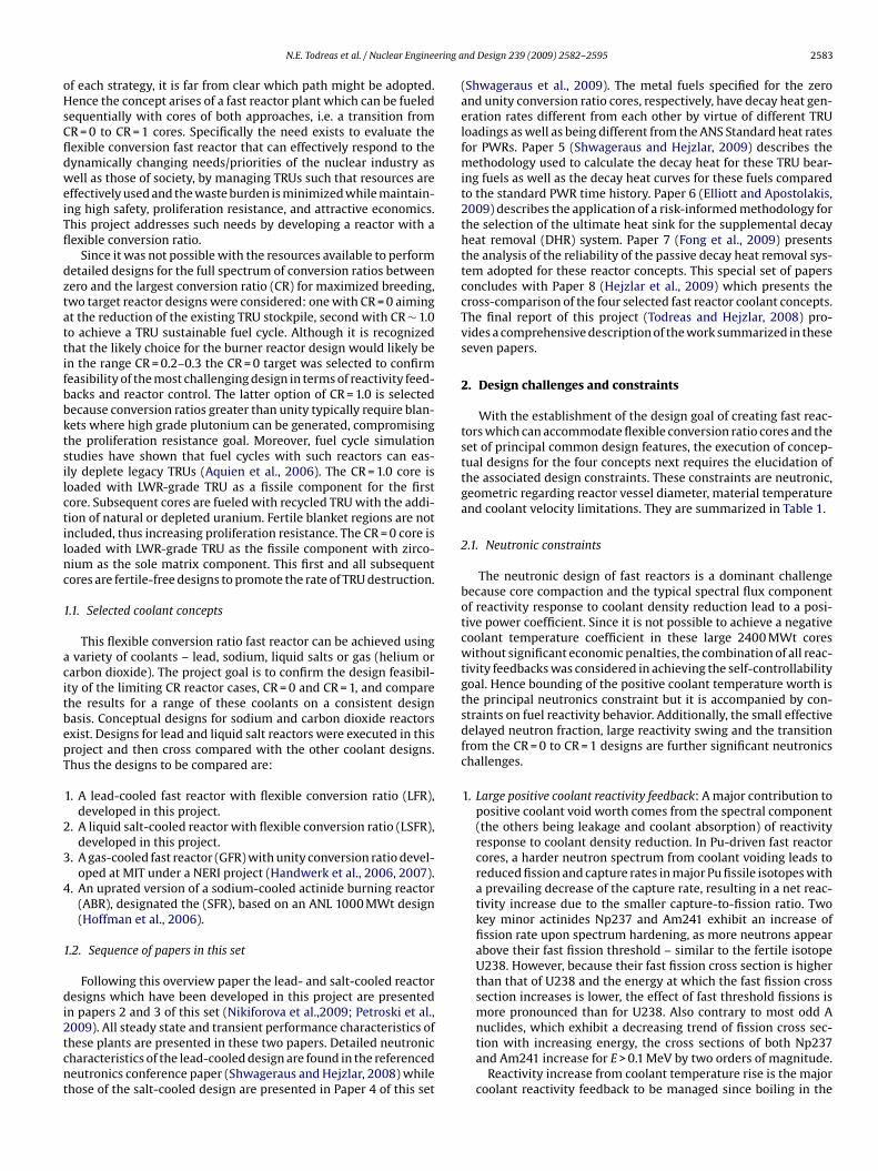
With the establishment of the design goal of creating fast reac-tors which can accommodate flexible conversion ratio cores and theset of principal common design features, the execution of concep-tual designs for the four concepts next requires the elucidation ofthe associated design constraints. These constraints are neutronic,geometric regarding reactor vessel diameter, material temperatureand coolant velocity limitations. They are summarized in Table 1.
2.1. Neutronic constraints
The neutronic design of fast reactors is a dominant challengebecause core compaction and the typical spectral flux componentof reactivity response to coolant density reduction lead to a posi-tive power coefficient. Since it is not possible to achieve a negativecoolant temperature coefficient in these large 2400 MWt coreswithout significant economic penalties, the combination of all reac-tivity feedbacks was considered in achieving the self-controllabilitygoal. Hence bounding of the positive coolant temperature worth isthe principal neutronics constraint but it is accompanied by con-straints on fuel reactivity behavior. Additionally, the small effectivedelayed neutron fraction, large reactivity swing and the transitionfrom the CR = 0 to CR = 1 designs are further significant neutronicschallenges.
1. Large positive coolant reactivity feedback: A major contribution topositive coolant void worth comes from the spectral component(the others being leakage and coolant absorption) of reactivityresponse to coolant density reduction. In Pu-driven fast reactorcores, a harder neutron spectrum from coolant voiding leads toreduced fission and capture rates in major Pu fissile isotopes witha prevailing decrease of the capture rate, resulting in a net reac-tivity increase due to the smaller capture-to-fission ratio. Twokey minor actinides Np237 and Am241 exhibit an increase offission rate upon spectrum hardening, as more neutrons appearabove their fast fission threshold – similar to the fertile isotopeU238. However, because their fast fission cross section is higherthan that of U238 and the energy at which the fast fission crosssection increases is lower, the effect of fast threshold fissions ismore pronounced than for U238. Also contrary to most odd A
nuclides, which exhibit a decreasing trend of fission cross sec-tion with increasing energy, the cross sections of both Np237and Am241 increase for E > 0.1 MeV by two orders of magnitude.Reactivity increase from coolant temperature rise is the majorcoolant reactivity feedback to be managed since boiling in the
2584 N.E. Todreas et al. / Nuclear Engineering and Design 239 (2009) 2582–2595
Table 1Summary of design constraints for fast reactors.
Cladding limits Steady state membrane temperature 650 ◦Ca
Transient inner temperature 725 ◦CFluence (E > 0.1 MeV) 3.3–4.0 × 10²³ n/cm2
Irradiation damage 150–200 dpa
Fuel limits Maximum temperature (CR = 0/CR = 1) 1200/1000 ◦CPeak burnupb (CR = 0/CR = 1) Heavy metal loading dependent/150 MWd/kg
Vessel limits Steady state maximum membrane temperature 430 ◦CTransient maximum membrane temperature 750 ◦CFluence (above 1 MeV) 5E + 19 n/cm2
Maximum coolant velocity 3 m/s
Neutronic constraints Proliferation Pu isotopic composition Same or dirtier than LWR spent fuelReactivity coefficients A/Bc Ld: ≤1.25; Sd: ≤1.62
C�Tc/Bc L: ≥1, ≤2.2; S: ≥1, ≤2.7��TOP/Bc L: ≤1.25; S: ≤1.62
Vessel sizee Outer vessel diameter 9.2–10 mVessel height 19.5 m
a For the CR = 0 core, which has a content of Pu larger than 20 wt%, a smaller limit than 650 ◦C may be required, driven by fuel/cladding chemical interaction (FCCI) issuessince Pu may form a eutectic with iron resulting in cladding thinning. A large amount of Zr in the fertile-free fuel will mitigate FCCI and the exact limit is currently uncertain.Also, a zirconium liner can be developed to prevent this eutectic formation. The 650 ◦C limit is consistent with the achievable category of materials, which were selected forthe analyses in the project and assume successful completion of ongoing R&D on materials development.
b Alloy-type fuel, taking into account cladding stress for given cladding dimensions and temperature limits, based on earlier analyses.isited
2
3
4
used with most reactor concepts under investigation in this project,such as oxide or carbide fuels, which are currently under studyin the French SFR program (Buiron et al., 2007) and in India, or
c Reactivity coefficient ratios. These limits are preliminary and will have to be revd L stands for lead-cooled core, S for salt-cooled core.e S-PRISM (a non-pressurized vessel) dimensions taken as guidance.
liquid coolants is of low probable occurrence. The liquid saltcoolants are significantly more challenging than the other threecoolants because of their (1) much higher thermal expansioncoefficient (and thus correspondingly large coolant density andneutron spectrum changes) and (2) low mass nuclides whichprovide more moderation. Various design approaches whichwere explored to minimize the reactivity coolant temperaturecoefficient, such as a tight lattice to minimize coolant fraction,pancake and parfait cores, and consideration of streaming fuelassemblies are discussed in Paper 4 (Shwageraus and Hejzlar,2009).
. Small fuel temperature coefficient: The hard spectrum of the leadand liquid salt-cooled cores leads to a decrease of absorption ratein resonances. This results in a significant drop in the Dopplereffect. For the CR = 0 core, the amount of fertile isotopes is verysmall, further reducing the fuel temperature coefficient. Hence,other measures to attain a reasonable value of negative fueltemperature feedback need to be employed such as reactiv-ity changes from thermal expansion of the fuel, which are alsoprompt.
. Small effective delayed neutron fraction: This fraction is smallsince the high-mass number isotopes, which fission, have a smalldelayed neutron yield. Moreover, delayed neutrons are emittedat lower energies than prompt neutrons and are thus more likelyto be parasitically absorbed in control rods and structural materi-als. This reduces the effective delayed neutron fraction and raisesconcerns regarding the controllability of critical reactors. TheCR = 0 core is expected to have the lower ˇeff because the sig-nificant degree of U238 fission in the CR = 1 core will increaseˇeff.
. Large reactivity swing: The fertile-free design with CR = 0 willexhibit a large reactivity swing in the absence of fertile isotopes.This is a significant challenge because there is no efficient burn-able poison for fast spectrum reactors except for relatively large
loadings of Np237 or Am241 which are transmuted to fissile iso-topes. However, this option is not attainable because the TRUvector is fixed to that of spent LWR fuel. Also complicating thisoption are the issues of large positive coolant temperature coef-ficient for highly Np237 and Am241 loaded cores and fuel cycledepending on core temperatures; constants A, B, and C are defined in Section 3.2.2.
implications.1 One possible approach to reduce reactivity swingis to significantly decrease cycle length. This approach is unde-sirable because it leads to a very short cycle length of less than6 months, which is economically unattractive for utilities. Theeffective way to accommodate the significant reactivity swingin a fertile-free burner without large penalty on cycle length isthrough a large number of double-entry control rods (Hejzlar etal., 2004a). This same approach is used for lead- and salt-cooledcores in this project.
5. Transition between different conversion ratio cores: Flexible con-version ratio implies the need for the exchangeability of fuelassemblies to allow the gradual transition between CR = 0 andCR = 1 designs. This requirement imposes two additional con-straints on the core design:• The major issue is the need for a large number of control rods
for the CR = 0 core to accommodate the large reactivity swing.Moreover, the CRDs have to be double-entry rods to avoidsuper-prompt criticality during seismic events. This requiresavailable space for these rods below the core. Hence, the CR = 1core will have to use similar rods, even though this core doesnot require them.
• Control rod penetrations through the vessel head have to be atthe same position for both cores. However, it is possible to plugselected positions, if these are no longer needed after transitionfrom the CR = 0 to the CR = 1 core.
2.2. Material constraints – burnup and temperature
A metallic fuel was selected for all reactor concepts compared,except for the GFR, where it was not possible because of high coretemperatures. Although there are other fuel forms that could be
nitride fuels explored in Russia for the BREST LFR (Adamov et al.,
1 Separating Np237 and Am241 from plutonium is undesirable because the sepa-rated plutonium stream is a proliferation concern.
ering and Design 239 (2009) 2582–2595 2585
1pfspw
tsfngNta
2
3
2
iUwwwbndtfitwtiiuasm
1ftithfwsff
af
2
mcl
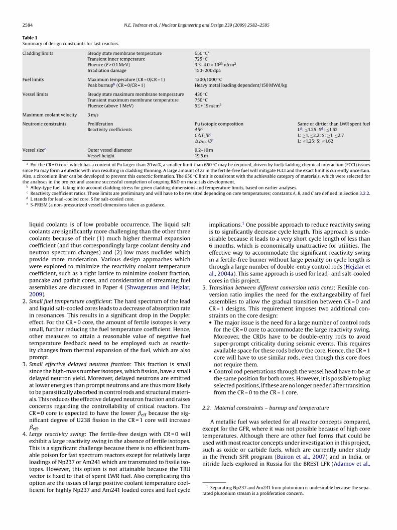
Table 2Service limits for cladding and vessel materials*.
Now Achievable Stretch
Cladding Material HT-9 T-91 ODSa
12Cr–1Mob 9Cr–1MoVNbc
Date of material availability Now 2010d 2015e
Max temperature 550 ◦C 625–650 ◦C 700 ◦CSteady state 725 ◦C 725 ◦C 725 ◦CTransients (not reusable) 2 m/s 3 m/s 3 m/sVelocity (SS)f
Vessel Material A533 or A508 9Cr–1Mo steelg
(SS 316)h
Date in hand Now 2012d
Max temperature (Now) 500 ◦CSteady state 347 ◦C 550 ◦CTransient (reusable) (430 ◦C)
550 ◦C(700 ◦C)
a Oxide dispersion strengthened ferritic steel, similar composition as HT-9 plusyttria dispersion.
b Typical composition Cr(11.95%)–Mo(1%)–Ni(0.6%)–Mn(0.6%)–W(0.52%)–Si(0.38%)–V(0.3%)–C(0.2%).
c 9Cr–1MoVNb class used extensively for boiler applications and similar in com-position to HT-9.
d Long-term testing and qualification still needed.e Can be made reliably for clad service at an earlier date but fabrication and weld-
ing is difficult and requires development. Long-term testing and qualification stillneeded.
f Only for lead-cooled reactor.g Fabrication is an order of magnitude harder than A533/A508.h For lead-cooled reactor, thin liner material that is corrosion resistant and pre-
N.E. Todreas et al. / Nuclear Engine
997), metallic fuel has been chosen for consistency with the US SFRrogram, which uses metallic fuel and because of its superior per-
ormance in unprotected transients, since achievement of inherenthutdown in accidents with failure to scram was one of the majorroject goals. Other fuel forms could be also potentially used, butere not investigated in this project.
The selection of cladding material poses a challenge sincehe cladding is exposed to corrosive coolants, high temperatures,tresses from fission gas build-up, and high fast fluence. Highast neutron flux excludes austenitic steels because of their highickel content, which promotes extensive swelling due to heliumeneration from the (n, ˛) reaction of nickel isotopes Ni58 andi60 Therefore, ferritic–martensitic stainless steels were chosen as
he candidate materials. Three material categories are consideredccording to their time availability:
1. Currently available materials that do not require development(designated “Now”).
. Materials achievable on a relatively short time scale (designated“Achievable”), and
. Materials that require significant development effort and timebefore they could be adopted (designated “Stretch”).
.2.1. FuelTemperature limits for fuel appear in Table 1. The burnup limit
s set at 150 MWd/kgHM (average) and 200 MWd/kgHM (peak) for–TRU–Zr (10% Zr) fuel. This is based on irradiation experienceith ternary (U–Pu–Zr) metal alloy pins in HT-9 ferritic cladding,hich have achieved a 200 MWd/kg peak discharge burnup andere qualified and demonstrated for a 150 MWd/kg peak discharge
urnup and a 100 MWd/kg average burnup (Hill et al., 1999). Theseumerical constraints on the burnup can be relaxed for the CR = 0esign, where fertile material is absent and the major fraction ofhe fuel is the zirconium matrix (∼75% Zr in comparison to 10% Zror the ternary metallic fuel). Therefore, for given energy producedn the fuel (and thus for a given amount of fission gases releasedo the fission plenum) the attainable burnup is much higher. Also,ith such a large fraction of zirconium, these fuels might be able
o withstand even higher burnups. However, research and exper-mental demonstration of fuel that can withstand these burnupss required. Therefore, for TRU–Zr fuels of CR = 0 cores, burnup val-es to give the same burnup per fuel volume as the above values aredopted as limits. A smear density of 75% will be taken as the target,ince it was proven to achieve high burnups without pellet-claddingechanical interactions (Pahl et al., 1990).
The limiting fuel temperature for U–Pu–Zr alloy with 10 wt% Zr is000 ◦C. The same temperature limit will be adopted for U–TRU–Zruel for the CR = 1.0 core, albeit more research is needed to confirmhe effect of small amounts of minor actinides on the fuel alloy melt-ng point. This assumption should be reasonably accurate becausehe minor actinides constitute only a small fraction of the fuel andave chemical properties that are similar to plutonium. The fuel
or the CR = 0 core contains significantly larger zirconium content,hich will result in a higher melting point. Hejzlar et al. (2004a)
uggest that a limit of 1200 ◦C should be a conservative limit forertile-free zirconium-based fuel. The same limit has been adoptedor fertile-free fuel here.
The S-CO2 cooled reactor has been designed with temperaturend burnup limits of 1800 ◦C and 150 MWD/kg applied to its oxideuel.
.2.2. SteelsTemperature limits adopted for the cladding and vessel steel
aterials of the reactors are summarized in Table 2. Each of theseategories is listed in a separate column in Table 2 which gives twoimits for each material. The first limit is for long-term steady state
vents liquid-metal embrittlement of the vessel is needed.* For the ODS cladding of the S-CO2 gas-cooled reactor, steady-state and transient
(reusable) limits of 800 ◦C and 1200 ◦C were used.
operation and is determined by two factors: (1) chemical com-patibility with coolant, e.g. corrosion limits and (2) mechanicalperformance, which is characterized by material strength and resis-tance to creep under stress. The second limit is for transients thatsignificantly challenge the material and that are very rare or may noteven occur during the reactor lifetime (for example unprotected, i.e.without scram, accidents) when the material can be exposed to hightemperatures for shorter time periods. In these cases, the materialmust maintain its integrity, but would not be reusable after suchan occurrence. This limit is determined either by the transforma-tion temperature from ferrite to austenite or by the incipience offuel to cladding chemical interaction, which can occur in metal-lic fuels. For cladding materials a non-reusable limit is given sincecladding can be replaced. For the vessel, lower limits that allowreuse are specified since the vessel cannot be replaced during theplant lifetime.
2.2.2.1. Cladding. The reference cladding material for the “Now”category is ferritic–martensitic stainless steel HT-9 (Fe–12Cr–1Mo)Pb–Bi–Sn eutectic-bonded with the fuel for the lead- and salt-cooled reactors and sodium bonded for SFR. This steel exhibits verygood resistance to irradiation-induced swelling with no swellingup to 3.3–4.0 × 10²³ n/cm2 (E > 0.1 MeV) or 150–200 dpa (Dubberleyet al., 2000). The drawback for operation in lead-cooled reactorsis its high corrosion rate for temperatures above 550 ◦C, whichis well below the temperatures allowable by mechanical perfor-mance. Therefore, the limit of 550 ◦C is used as the maximumtemperature for long-term operation. The key question is whatcladding temperature limit to adopt for the liquid salt of choice,
NaCl–KCl–MgCl2. Data for corrosion rates for this salt are not avail-able, but it is expected that the corrosion rate will be smaller thanthat of lead coolant based on the known performance of lead andthe more benign performance of the selected ternary chloride saltfor most of the steels tested including a Cr–Mo steel comparable to
2 ering a
tttmt
athopctfpo7tf
clraasmcHTSailcvatttlssttHic
Schftfaalstthwcsr
586 N.E. Todreas et al. / Nuclear Engine
he T-91 steel selected here (Susskind et al., 1960). Thus, the sameemperature as for lead – 550 ◦C – was selected as the maximumemperature limit for the liquid salt-cooled concept. This choice of
aximum temperature will have to be confirmed with corrosionests.
The transient temperature limit for cladding of both the lead-nd salt-cooled cores was selected to be 725 ◦C because this is theemperature below which no fuel/cladding chemical interactionas been observed. Beyond this temperature, significant diffusionf actinides into the cladding from the fuel can create low-melting-oint regions, resulting in thinning and subsequent failure of theladding (Pahl et al., 1990). Furthermore, it is important to keephe cladding material temperature below the transformation fromerrite to austenite because this transition results in significantroperty as well as volume changes. This transformation dependsn material composition and for 12Cr–MoVNb steels ranges from60 ◦C to 850 ◦C (Klueh and Harris, 2001). This is slightly higherhan the limit from fuel/cladding chemical interaction, hence theormer limit is applied.
The drawback of the HT-9 steel for lead-cooled reactor appli-ation is its chemical compatibility temperature limit, which isower than the mechanical performance limit. This significantlyeduces the design space available to maximize plant efficiencynd thus improve economy. Therefore, under development at MITre advanced ferritic–martensitic steels with a new alloy claddingurface that will raise the corrosion-limited temperature to theechanical performance limit. The new material will use a high
hrome boiler tube material T-91 similar in composition to that ofT-9 as a base, with a corrosion resistant alloy cladding surface.he T-91 (9Cr–1MoVNb) steel is ASME code approved to 649 ◦C forection III, Class 2 and 3 components and was also very recentlypproved for Subsection NH for Class 1 applications. There are lim-ts to code applicability involving time and temperature plus otherimits, such as 1% strain on cladding. Since the fuel of the CR = 1ore has a longer residence time than the CR = 0 core (6.5 yearsersus 5 years) and because creep limited lifetime affects temper-ture limits, the range between 625 ◦C and 650 ◦C was adopted forhe Achievable case. This provides more margin to work with forhe CR = 0 core, which has higher radial power peaking. Of course,he pins and cladding have to be designed to satisfy the 1% strainimit and creep limited lifetime at these temperatures. The tran-ient temperature limit is the same (725 ◦C) as for HT-9 for theame reasons as discussed above. Also, it is important to note thathese materials are quenched and tempered and 725 ◦C is abovehe tempering temperature (typically in the 550–600 ◦C range).ence, neither HT-9 nor T-91 can be reused if this temperature
s achieved. The same limits were adopted for liquid salt-cooledores.
Additionally ODS steel is considered as the candidate for thetretch case category for both the lead and liquid salt-cooled con-epts. Oxide dispersion strengthened ferritic–martensitic steelsave been developed for application as fuel cladding material for
ast breeder reactors. The major advantages of these alloys are (1)heir strength and creep resistance at high temperatures (∼700 ◦Cor steady state, 725 ◦C for transient) which are typically betternd degrade more slowly with temperature than niobium (Nb)nd molybdenum (Mo) refractory alloys; (2) they are relativelyightweight and less expensive than refractory alloys; (3) their lowwelling and embrittlement with exposure to high-energy neu-rons (>0.1 MeV) up to high fluences; and (4) their high resistanceo oxidation and nitration at high temperatures which simplifies
andling and assembly. However, the manufacturing of long pins,hole assemblies and welding of ODS steel will require signifi-ant development. Moreover, while extensive R&D effort has beenpent on developing these materials, actual manufacturing expe-ience has been insignificant. In fact, the major suppliers of these
nd Design 239 (2009) 2582–2595
materials, Special Metals (Huntington, West Virginia) and one ortwo European/Asian sources, have essentially ceased production ofthese materials as a commercial product. Therefore, these steelswere put into the Stretch category. The temperature limit adoptedfor long-term steady state operation is 700 ◦C. The transient limitselected is 725 ◦C as for HT-9 because the composition is similarand the issue of significant diffusion of actinides into the claddingapplies as well. Since the GFR achieves high peak cladding temper-ature, ODS is the only candidate for its cladding material, hencethe GFR use of ODS is in the Stretch category. The higher differentlimits upon which the S-CO2 reactor was designed are given in asupplemental note in Table 2.
Finally, it needs to be noted that there are two issues that willrequire more R&D to be able to confirm these limits:
1. For CR = 0 designs, the content of plutonium is relatively high;because plutonium migrates to the fuel periphery, it may form aeutectic at temperatures lower than the adopted limit of 650 ◦Cfor the Achievable case. Currently there are no data available forfertile-free fuels. Hence, experiments will be needed to confirmthe adopted temperature limit on cladding. If eutectic forma-tion begins to occur at lower temperatures, addition of a barrier,such as zirconium liner or multilayer metal foil (Taylor andWadekamper, 1994), should be used to keep the limit at 650 ◦C.Otherwise, the core outlet temperature would have to be low-ered, resulting in reduced plant efficiency, negatively impactingeconomics.
2. The bond material Pb–Bi–Sn has been proposed as a bond for UO2fuel and Zircaloy-4 cladding for LWRs, but there is no experiencewith this bond for metallic fuel and steel cladding. Therefore, anR&D program would be required to confirm compatibility of thisbond with metallic fuel and T-91 steel under irradiation.
2.2.2.2. Vessel. For the vessel, two materials are considered. Thecurrently available A533 or A508 plate and forging steels are listedin Section II for Class 1 service with an upper continuous operatingtemperature limit of 347 ◦C. For transients, the physical upper tem-perature limit is determined by the tempering temperature of thematerial during fabrication. To remain below the tempering tem-perature these steels should not be heated above 550 ◦C, which wastaken as the transient limit. However, it needs to be noted thatalthough the long-term operation temperature limit is relativelylow, A533 or A508 compatibility with lead coolant may be an issuebecause of the relatively high nickel content in these steels. The sol-ubility of nickel in liquid lead can be as high as 20 wt%. Thus, a linerresistant to corrosion in lead alloys would be needed. Moreover, theupper temperature limit of 347 ◦C is too close to the melting pointof lead of 327 ◦C, making it difficult to design a reactor where thedesirable core inlet temperature is above 400 ◦C and where passivedecay heat removal is through the vessel. This is even more chal-lenging for our preferred salt coolant, which has a melting point of396 ◦C, well above the material limit of 347 ◦C.
The high-chromium ferritic–martensitic steel 9Cr–1Mo steel isa candidate in the achievable category. For this steel there aredata from the U.S. and Japanese fast reactor development programsfor temperatures up to 500 ◦C. Therefore, this temperature limitwas adopted for steady state operation. The transient limit for the9Cr–1Mo steel is the same as for the A533 class steel (550 ◦C) sinceit is determined by the tempering temperature. Note that there is
a difference in transient limits between the cladding and the ves-sel, since the cladding limit is a non-reusable limit, i.e. claddingcannot be re-used after exposure to these temperatures, while thevessel can be reused after reaching the 550 ◦C limit. Several noteson 9Cr–1Mo steel are in order:
ering a
2
34
5
TAb
vfistauhC8dgt7awly
sam
2
brfesdtd
tmpac
N.E. Todreas et al. / Nuclear Engine
1. In the Japanese designs, the life of components was limited to 10years.
. Fabrication is an order of magnitude harder than for A533/A508steels.
. Welding is difficult, requiring careful post-weld heat treatment.
. This steel is susceptible to thermal aging, which causes a decreasein strength.
. The code case needs to be developed. The current ASME Code,Subsection NH limits time dependent deformation (creep) to“insignificant” amounts. For high temperature operation a con-siderable effort must be spent and some work is in progressrelated to the next generation nuclear plant (NGNP) and theGlobal Nuclear Energy Partnership (GNEP) programs to rational-ize/modify the ASME code to allow “significant” time dependentdeformation. The ramifications for non-destructive inspectionsand monitoring of the vessel during life will also be very signifi-cant.
herefore, more R&D and testing to overcome the above issues plusSME code development will be needed before 9Cr–1Mo steel cane used.
However, the 550 ◦C transient temperature limit of the 9Cr–1Moessel wall steel may still be too low to dissipate decay heatrom the vessel. Therefore, stainless steel 316 (SS316) was alsoncluded in the table as a potential candidate, even though it isignificantly more expensive than other candidates. The advan-age is that the code for this steel exists, hence the steel is in thevailable Now category. The ASME Code, Subsection NH, which reg-lates the design of pressure retaining components, shows that itas higher allowable stress than other materials for the design oflass 1 components for elevated temperature service (SS304, Alloy00H and 2.5Cr–1Mo). This steel was also used for the S-PRISMesign. Buongiorno has shown that for a guard vessel of thicknessreater than 15 cm and diameter of 6 m, the temperature limit forransients of lower frequency (Level C Service Loadings), is about50 ◦C (Buongiorno, 2001). Because of the larger vessel in the lead-nd salt-cooled designs, we adopted the limit of 700 ◦C, whichill have to be confirmed by analysis. The steady state operation
imit is 430 ◦C if the lifetime of the vessel is to be more than 34ears.
The French selected SS316 for Super-Phenix while the Russianselected chrome–nickel steels for all of their BN reactors (Cr18Ni9)nd BREST-1200 (Cr16Ni10). However, their selection process forore recent SFRs is not yet available.
.3. Vessel size constraint
The reactor/guard vessel radius is established as demonstratedy Boardman (Boardman et al., 2000) for passive decay heatemoval using the RVACS concept by either the required vessel sur-ace area for decay heat removal or the required cross sectionalx-core annular area for IHXs and primary coolant pumps. Con-idering these factors as well as the desire to remain close to pastesign dimensions the vessel diameters and wall thicknesses forhe lead- and salt-cooled reactors were both set at the followingimensions:
Guard vessel 10.2 m OD and 0.1 m wall thicknessReactor vessel 9.94 m OD and 0.05 m wall thickness
While the sodium plant was uprated to 2400 MWt and coupled
o the S-CO2 power conversion cycle in this project, the place-ent of sodium to S-CO2 IHXs in the ex-core annular vessel spaceoses a unique challenge since CO2 chemically reacts with sodiumlthough at a slower rate and without hydrogen production asompared with water. Hence the sodium/CO2 IHXs would have
nd Design 239 (2009) 2582–2595 2587
to be designed with double walls having helium leak detectioncapability between the walls. Further, the feasibility of fitting four600 MWt double-wall IHXs into a sodium vessel of 10.2 m wouldhave to be confirmed. However, because the helium gap is 7 �m,having an effective thermal conductivity of the gap plus outer wallof 24 W/mK per the experimental measurements of Kubo et al.(1997), the double-wall design does not require a large increaseof IHX volume. This increase can be compensated by the muchhigher sodium conductivity than lead or salt and more space avail-able due to the smaller sodium-cooled core. Hence, it is expectedthat placement of sodium/CO2 IHXs in the 2400 MWt vessel will befeasible.
Finally, since all the liquid coolant concepts have the potentialof high pressure S-CO2 ingress into the core, the double-free-levelreactor vessel has been adopted as discussed in Section 3.4. Theheight of the reactor vessel is about 19 m. The lower density of thesalt coupled with the constrained maximum level-separation dis-tance in this dual-level design allows a much smaller IHX pressuredrop for the salt design compared to the lead design. In order tokeep the primary-side pressure drop below this constraint, whilemaintaining a reasonable heat exchanger length and secondary-side pressure loss, it was necessary to make more room in thedowncomer by using a bottlenecked chimney above the core in thesalt-cooled reactor vessel.
Hence, it is expected that placement of sodium/CO2 IHXs in the2400 MWt vessel will be feasible using the same double-level flowpath arrangement as for LFR and LSFR, which prevents entrance ofCO2 from ruptured IHX into the core, as explained in more detail inSection 3.2.4.
2.4. Coolant velocity constraint
Surfaces exposed to flowing lead have to satisfy velocity lim-its. The cladding materials of lead–bismuth cooled reactors used inRussian submarines required that the velocity not exceed a 2 m/slimit. This is because these steels rely on Fe-oxide protection, andoxide can become unstable at higher velocities. The newer materialswith Si or Al oxide based films for protection under development atMIT should allow higher velocity limits. Thus, the limit of 3 m/s wasadopted for ferritic–martensitic steels with the new alloy claddingsurface, with the expectation that further development can raisethis limit to 4 m/s or higher. No such limit is needed for the othercoolant designs. However, because liquid salts have high viscositiesand tend to have high pressure drop, we adopted the core pressuredrop limit of 1MPa for the liquid salt-cooled concept. These limitsare also included in Table 2.
3. Principal features selected
This section provides the rationale for the selected four primarysystem coolants as well as the six major design features adopted forall reactors to provide a common basis for their cross-comparison.A summary of the resulting four reactor concepts is presented inPaper 5 (Hejzlar et al., 2009). Full details for the lead- and salt-cooled reactors designed in this project are presented in Papers 2(Nikiforova et al., 2009) and 3 (Petroski et al., 2009), respectively.
3.1. Coolant selection
The basis for the choices of lead, supercritical carbon dioxide andthe ternary NaCl–KCl–MgCl2 salt are presented next. The last paperof this set (Hejzlar et al., 2009) presents a comprehensive compar-ison of the key figures of merit for the four coolants evaluated inthis project.
2 ering a
3
lct(paatccf
otbb2
laibstittlll
3
cchpa
2
3
4
588 N.E. Todreas et al. / Nuclear Engine
.1.1. Lead vs. lead–bismuthThe neutronic and thermal hydraulic behavior of lead and
ead–bismuth coolants is similar. The key differences between theseoolants involve the coolant melting point and the production ofhe polonium isotope 210Po. The higher melting point of pure lead327 ◦C for lead versus 125 ◦C for lead–bismuth) requires that thelant be designed to maintain the coolant liquid at higher temper-tures. While similar challenges have been successfully faced fornumber of liquid metal reactor systems (Na, K, NaK), the rela-
ively high melting temperature of lead heralds the need for a moreomplex design solution with higher-temperature heaters and foronsideration of off-normal events which could result in coolantreezing.
The second important issue related specifically to the choicef a lead–bismuth eutectic coolant is the generation of 210Po, aoxic alpha-emitter of approximately 140 days half-life, from 209Biy neutron capture. While 210Po is also produced from pure leady the neutron capture reaction on 208Pb, the concentration of10Po in a lead coolant is expected to be only 1% of that in aead–bismuth coolant for the same reactor rating. We selected leads the coolant of choice for the following reasons: (1) coolant freez-ng is of less concern in conjunction with use of a supercritical CO2alance of plant, (2) the reactivity coefficient ratios that satisfy theelf-controllability criteria make it possible to avoid coolant inletemperatures that would lead to coolant freezing, (3) poloniumssues are substantially mitigated, (4) lead is less corrosive to struc-ural materials than lead–bismuth, (5) lead is substantially cheaperhan lead–bismuth eutectic, and (6) lead is abundant, allowing aarge-scale deployment of reactors, while bismuth resources areimited so that the cost of bismuth would likely significantly esca-ate with the depletion of the reserves (Todreas et al., 2004).
.1.2. CO2 vs. heliumMost of the gas cooled fast reactors studied used helium as their
oolant. This is because helium is an inert gas and does not pose anyorrosion issues even at high temperatures and because it has theighest thermal conductivity among gases, reducing the film tem-erature, which is typically high for gas coolants. However, heliumlso poses some challenges:
1. For the Generation IV design with enhanced emphasis on pas-sive cooling, helium has mediocre heat transport capacity undernatural circulation due to its very low density. For example, ithas been shown by Williams et al. (2004) that helium requirestwo times higher containment pressure after LOCA to remove 2%decay power than CO2.
. When coupled to a Brayton power cycle, helium requires highcore outlet temperatures to achieve high efficiency. Dostal et al.(2006) have shown that the helium Brayton cycle requires a tur-bine inlet temperature of 850 ◦C to match the efficiency of thesupercritical CO2 cycle at a turbine inlet temperature of 650 ◦C.Since materials strength is reduced significantly for tempera-tures above 650 ◦C, the design of helium cooled highly efficientsystems bring a number of material development challenges.
. Under post LOCA passive decay heat removal conditions, heliumcoolant is susceptible to Ledinegg type instabilities. This phe-nomenon occurs in laminar flow and was derived analyticallyand observed in the hot channel using a computer code (Hejzlaret al., 2004b, 2005). It is a consequence of the large dependence ofhelium kinematic viscosity on temperature and the small heliumdensity, and thus small gravity head. On the other hand, heavy
gases, such as CO2, do not exhibit this type of instability in thetemperature range of interest.. Although helium has negligible absorption cross section andis neutronically transparent, it still results in a small positivecoolant void worth after depressurization. This is because it
nd Design 239 (2009) 2582–2595
has non-negligible moderating power under pressure. Becauseduring a large LOCA, pressure loss can occur rapidly, the self-controllability criteria (Handwerk et al., 2007) require coolantvoid worth to be negative. This turned out extremely difficultto achieve for helium, but possible for supercritical CO2.Thisfinding was rather surprising, given the eight times higher mod-erating power and three times higher number density of CO2at 20 MPa than helium at 8 MPa CO2, which results in a morepronounced spectrum hardening. However, the high numberdensity and large scattering cross section of CO2 allow a designerto reduce coolant void worth through the leakage effect, while itis extremely difficult to affect leakage of helium cooled cores.
Because of these drawbacks of helium coolant, and because of thebenefits of the supercritical CO2 power conversion system, in par-ticular its compactness, simplicity and high efficiency at mediumtemperature, supercritical CO2 was selected as the coolant of choicefor the GFR. Moreover, it is noted that the supercritical CO2 cycletemperature range matches well the liquid metal- and salt-cooledreactor core temperature rise. Helium cooled reactors require muchhigher temperatures to achieve attractive efficiency than those pos-sible with sodium or lead-cooled systems.
3.1.3. Liquid salt choiceThe initial list of potential liquid salt candidates included 13 fluo-
ride and eight chloride salts. Fluoride salt selection was performedin two stages. First salts containing rubidium, boron, and lithiumwere eliminated. Boron and lithium would require isotopic enrich-ment for use in a fast reactor, and there is currently no world marketfor rubidium; therefore, salts containing these elements would beprohibitively expensive at the scale required. This first screeningeliminated most of the possible candidates, leaving just one beryl-lium salt, NaF–BeF2, and three zirconium salts: NaF–ZrF4, KF–ZrF4,and NaF–KF–ZrF4. Neutronic and thermal hydraulics analyses ofNaF–BeF2 revealed that it is far too moderating and viscous for usein fast reactor applications. The melting point of NaF–ZrF4, 500 ◦C,is too close to the cladding temperature limit of 650 ◦C to allow anacceptable power density. This left KF–ZrF4 and NaF–KF–ZrF4 as theprimary fluorides of interest. While both salts have similar proper-ties, the ternary salt was the most promising fluoride candidatebecause of its lower melting point.
In the second stage, chloride salts were reviewed using asimilar salt selection process. Salts containing lithium were elim-inated because the high absorption cross section of Li-6 wouldnecessitate isotopic enrichment, which would be prohibitivelyexpensive at the scale required. This left NaCl–MgCl2, KCl–MgCl2,and NaCl–KCl–MgCl2 as the three salt systems of interest. For theNaCl–MgCl2 system, there is only enough information availableabout the 58% NaCl–42% MgCl2 eutectic to permit analysis. Thesethree salt mixtures all have similar thermal hydraulic and neutronicproperties. Since thermal hydraulics were limiting for fluorides,thermal hydraulics analysis was performed for each salt to deter-mine the most promising candidate. A summary of the results foreach salt candidate is given in Table 3. Fixed conditions were used,including a 700 kPa core pressure drop and coolant inlet tempera-ture 100 ◦C above the melting point. Included for comparison arevalues for the most promising fluoride candidate, NaF–KF–ZrF4.
Chloride salt thermal hydraulic performance is greatly superiorto that of fluoride salts. The primary reason for this is an approxi-mately five times lower viscosity over the operating temperaturesof interest. Low viscosity improves coolant flow rate and heat trans-
fer, as seen by the much higher coolant velocities and much lowerfilm �Ts shown in Table 3. In addition, chloride salts exhibit sig-nificantly smaller coolant temperature reactivity coefficients thanfluoride salts, due to their smaller thermal expansion coefficientand smaller moderating power. Each of the selected chloride salts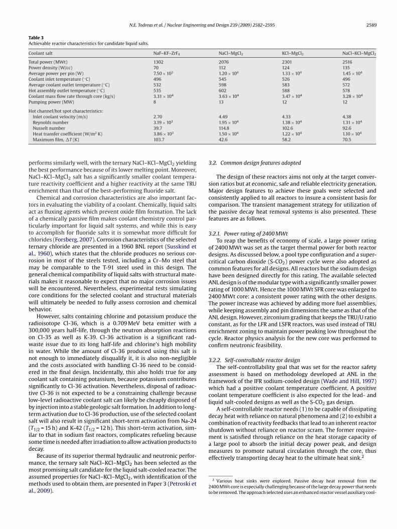
N.E. Todreas et al. / Nuclear Engineering and Design 239 (2009) 2582–2595 2589
Table 3Achievable reactor characteristics for candidate liquid salts.
Coolant salt NaF–KF–ZrF4 NaCl–MgCl2 KCl–MgCl2 NaCl–KCl–MgCl2
Total power (MWt) 1302 2076 2301 2516Power density (W/cc) 70 112 124 135Average power per pin (W) 7.50 × 10³ 1.20 × 10⁴ 1.33 × 10⁴ 1.45 × 10⁴
Coolant inlet temperature (◦C) 496 545 526 496Average coolant outlet temperature (◦C) 532 598 583 572Hot assembly outlet temperature (◦C) 535 602 588 578Coolant mass flow rate through core (kg/s) 3.31 × 10⁴ 3.63 × 10⁴ 3.47 × 10⁴ 3.28 × 10⁴
Pumping power (MW) 8 13 12 12
Hot channel/hot spot characteristics:Inlet coolant velocity (m/s) 2.70 4.49 4.33 4.38Reynolds number 3.19 × 10³ 1.95 × 10⁴ 1.38 × 10⁴ 1.31 × 10⁴
ptNte
taottctarmgrwcwb
r3owinaecstlbts(isd
mmama
ment is satisfied through reliance on the heat storage capacity ofa large pool to absorb the initial decay power peak, and designmeasures to promote natural circulation through the core, thuseffectively transporting decay heat to the ultimate heat sink.2
Nusselt number 39.7Heat transfer coefficient (W/m2 K) 3.86 × 10³
Maximum film, �T (K) 103.7
erforms similarly well, with the ternary NaCl–KCl–MgCl2 yieldinghe best performance because of its lower melting point. Moreover,aCl–KCl–MgCl2 salt has a significantly smaller coolant tempera-
ure reactivity coefficient and a higher reactivity at the same TRUnrichment than that of the best-performing fluoride salt.
Chemical and corrosion characteristics are also important fac-ors in evaluating the viability of a coolant. Chemically, liquid saltsct as fluxing agents which prevent oxide film formation. The lackf a chemically passive film makes coolant chemistry control par-icularly important for liquid salt systems, and while this is easyo accomplish for fluoride salts it is somewhat more difficult forhlorides (Forsberg, 2007). Corrosion characteristics of the selectedernary chloride are presented in a 1960 BNL report (Susskind etl., 1960), which states that the chloride produces no serious cor-osion in most of the steels tested, including a Cr–Mo steel that
ay be comparable to the T-91 steel used in this design. Theeneral chemical compatibility of liquid salts with structural mate-ials makes it reasonable to expect that no major corrosion issuesill be encountered. Nevertheless, experimental tests simulating
ore conditions for the selected coolant and structural materialsill ultimately be needed to fully assess corrosion and chemical
ehavior.However, salts containing chlorine and potassium produce the
adioisotope Cl-36, which is a 0.709 MeV beta emitter with a00,000 years half-life, through the neutron absorption reactionsn Cl-35 as well as K-39. Cl-36 activation is a significant rad-aste issue due to its long half-life and chlorine’s high mobility
n water. While the amount of Cl-36 produced using this salt isot enough to immediately disqualify it, it is also non-negligiblend the costs associated with handling Cl-36 need to be consid-red in the final design. Incidentally, this also holds true for anyoolant salt containing potassium, because potassium contributesignificantly to Cl-36 activation. Nevertheless, disposal of radioac-ive Cl-36 is not expected to be a constraining challenge becauseow-level radioactive coolant salt can likely be cheaply disposed ofy injection into a stable geologic salt formation. In addition to long-erm activation due to Cl-36 production, use of the selected coolantalt will also result in significant short-term activation from Na-24T1/2 = 15 h) and K-42 (T1/2 = 12 h). This short-term activation, sim-lar to that in sodium fast reactors, complicates refueling becauseome time is needed after irradiation to allow activation products toecay.
Because of its superior thermal hydraulic and neutronic perfor-
ance, the ternary salt NaCl–KCl–MgCl2 has been selected as theost promising salt candidate for the liquid salt-cooled reactor. Thessumed properties for NaCl–KCl–MgCl2, with identification of theethods used to obtain them, are presented in Paper 3 (Petroski et
l., 2009).
114.8 102.6 92.61.50 × 104 1.22 × 10⁴ 1.10 × 10⁴
42.6 58.2 70.5
3.2. Common design features adopted
The design of these reactors aims not only at the target conver-sion ratios but at economic, safe and reliable electricity generation.Major design features to achieve these goals were selected andconsistently applied to all reactors to insure a consistent basis forcomparison. The transient management strategy for utilization ofthe passive decay heat removal systems is also presented. Thesefeatures are as follows.
3.2.1. Power rating of 2400 MWtTo reap the benefits of economy of scale, a large power rating
of 2400 MWt was set as the target thermal power for both reactordesigns. As discussed below, a pool type configuration and a super-critical carbon dioxide (S-CO2) power cycle were also adopted ascommon features for all designs. All reactors but the sodium designhave been designed directly for this rating. The available selectedANL design is of the modular type with a significantly smaller powerrating of 1000 MWt. Hence the 1000 MWt SFR core was enlarged to2400 MWt core: a consistent power rating with the other designs.The power increase was achieved by adding more fuel assemblies,while keeping assembly and pin dimensions the same as that of theANL design. However, zirconium grading that keeps the TRU/U ratioconstant, as for the LFR and LSFR reactors, was used instead of TRUenrichment zoning to maintain power peaking low throughout thecycle. Reactor physics analysis for the new core was performed toconfirm neutronic feasibility.
3.2.2. Self-controllable reactor designThe self-controllability goal that was set for the reactor safety
assessment is based on methodology developed at ANL in theframework of the IFR sodium-cooled design (Wade and Hill, 1997)which had a positive coolant temperature coefficient. A positivecoolant temperature coefficient is also expected for the lead- andliquid salt-cooled designs as well as the S-CO2 gas design.
A self-controllable reactor needs (1) to be capable of dissipatingdecay heat with reliance on natural phenomena and (2) to exhibit acombination of reactivity feedbacks that lead to an inherent reactorshutdown without reliance on reactor scram. The former require-
2 Various heat sinks were explored. Passive decay heat removal from the2400 MWt core is especially challenging because of the large decay power that needsto be removed. The approach selected uses an enhanced reactor vessel auxiliary cool-
2 ering a
atamaratotbcpcp
Tatat(rda
3
cafgbhcsflccctpC
bh
iT
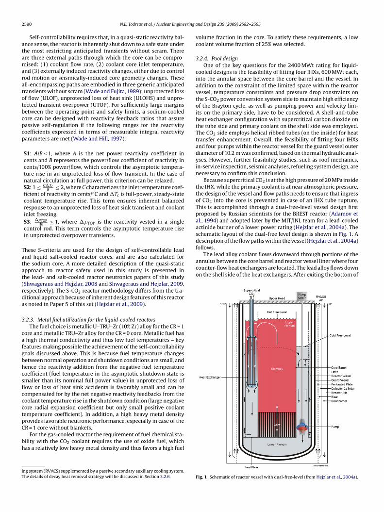
follows.The lead alloy coolant flows downward through portions of the
annulus between the core barrel and reactor vessel liner where fourcounter-flow heat exchangers are located. The lead alloy flows downon the shell side of the heat exchangers. After exiting the bottom of
590 N.E. Todreas et al. / Nuclear Engine
Self-controllability requires that, in a quasi-static reactivity bal-nce sense, the reactor is inherently shut down to a safe state underhe most restricting anticipated transients without scram. Therere three external paths through which the core can be compro-ised: (1) coolant flow rate, (2) coolant core inlet temperature,
nd (3) externally induced reactivity changes, either due to controlod motion or seismically-induced core geometry changes. Thesell-encompassing paths are embodied in three generic anticipatedransients without scram (Wade and Fujita, 1989): unprotected lossf flow (ULOF), unprotected loss of heat sink (ULOHS) and unpro-ected transient overpower (UTOP). For sufficiently large marginsetween the operating point and safety limits, a sodium-cooledore can be designed with reactivity feedback ratios that assureassive self-regulation if the following ranges for the reactivityoefficients expressed in terms of measurable integral reactivityarameters are met (Wade and Hill, 1997):
S1: A/B ≤ 1, where A is the net power reactivity coefficient incents and B represents the power/flow coefficient of reactivity incents/100% power/flow, which controls the asymptotic tempera-ture rise in an unprotected loss of flow transient. In the case ofnatural circulation at full power, this criterion can be relaxed.S2: 1 ≤ C�Tc
B ≤ 2, where C characterizes the inlet temperature coef-ficient of reactivity in cents/◦C and �Tc is full-power, steady-statecoolant temperature rise. This term ensures inherent balancedresponse to an unprotected loss of heat sink transient and coolantinlet freezing.S3: ��TOP
|B| ≤ 1, where ��TOP is the reactivity vested in a singlecontrol rod. This term controls the asymptotic temperature risein unprotected overpower transients.
hese S-criteria are used for the design of self-controllable leadnd liquid salt-cooled reactor cores, and are also calculated forhe sodium core. A more detailed description of the quasi-staticpproach to reactor safety used in this study is presented inhe lead- and salt-cooled reactor neutronics papers of this studyShwageraus and Hejzlar, 2008 and Shwageraus and Hejzlar, 2009,espectively). The S-CO2 reactor methodology differs from the tra-itional approach because of inherent design features of this reactors noted in Paper 5 of this set (Hejzlar et al., 2009).
.2.3. Metal fuel utilization for the liquid-cooled reactorsThe fuel choice is metallic U–TRU–Zr (10% Zr) alloy for the CR = 1
ore and metallic TRU–Zr alloy for the CR = 0 core. Metallic fuel hashigh thermal conductivity and thus low fuel temperatures – key
eatures making possible the achievement of the self-controllabilityoals discussed above. This is because fuel temperature changesetween normal operation and shutdown conditions are small, andence the reactivity addition from the negative fuel temperatureoefficient (fuel temperature in the asymptotic shutdown state ismaller than its nominal full power value) in unprotected loss ofow or loss of heat sink accidents is favorably small and can beompensated for by the net negative reactivity feedbacks from theoolant temperature rise in the shutdown condition (large negativeore radial expansion coefficient but only small positive coolantemperature coefficient). In addition, a high heavy metal density
rovides favorable neutronic performance, especially in case of theR = 1 core without blankets.For the gas-cooled reactor the requirement of fuel chemical sta-ility with the CO2 coolant requires the use of oxide fuel, whichas a relatively low heavy metal density and thus favors a high fuel
ng system (RVACS) supplemented by a passive secondary auxiliary cooling system.he details of decay heat removal strategy will be discussed in Section 3.2.6.
nd Design 239 (2009) 2582–2595
volume fraction in the core. To satisfy these requirements, a lowcoolant volume fraction of 25% was selected.
3.2.4. Pool designOne of the key questions for the 2400 MWt rating for liquid-
cooled designs is the feasibility of fitting four IHXs, 600 MWt each,into the annular space between the core barrel and the vessel. Inaddition to the constraint of the limited space within the reactorvessel, temperature constraints and pressure drop constraints onthe S-CO2 power conversion system side to maintain high efficiencyof the Brayton cycle, as well as pumping power and velocity lim-its on the primary side, have to be considered. A shell-and-tubeheat exchanger configuration with supercritical carbon dioxide onthe tube side and primary coolant on the shell side was employed.The CO2 side employs helical ribbed tubes (on the inside) for heattransfer enhancement. Overall, the feasibility of fitting four IHXsand four pumps within the reactor vessel for the guard vessel outerdiameter of 10.2 m was confirmed, based on thermal hydraulic anal-yses. However, further feasibility studies, such as roof mechanics,in-service inspection, seismic analyses, refueling system design, arenecessary to confirm this conclusion.
Because supercritical CO2 is at the high pressure of 20 MPa insidethe IHX, while the primary coolant is at near atmospheric pressure,the design of the vessel and flow paths needs to ensure that ingressof CO2 into the core is prevented in case of an IHX tube rupture.This is accomplished through a dual-free-level vessel design firstproposed by Russian scientists for the BREST reactor (Adamov etal., 1994) and adopted later by the MIT/INL team for a lead-cooledactinide burner of a lower power rating (Hejzlar et al., 2004a). Theschematic layout of the dual-free level design is shown in Fig. 1. Adescription of the flow paths within the vessel (Hejzlar et al., 2004a)
Fig. 1. Schematic of reactor vessel with dual-free-level (from Hejzlar et al., 2004a).
N.E. Todreas et al. / Nuclear Engineering a
trttcuflTrc
3
aaNsoltcvtvr
bo
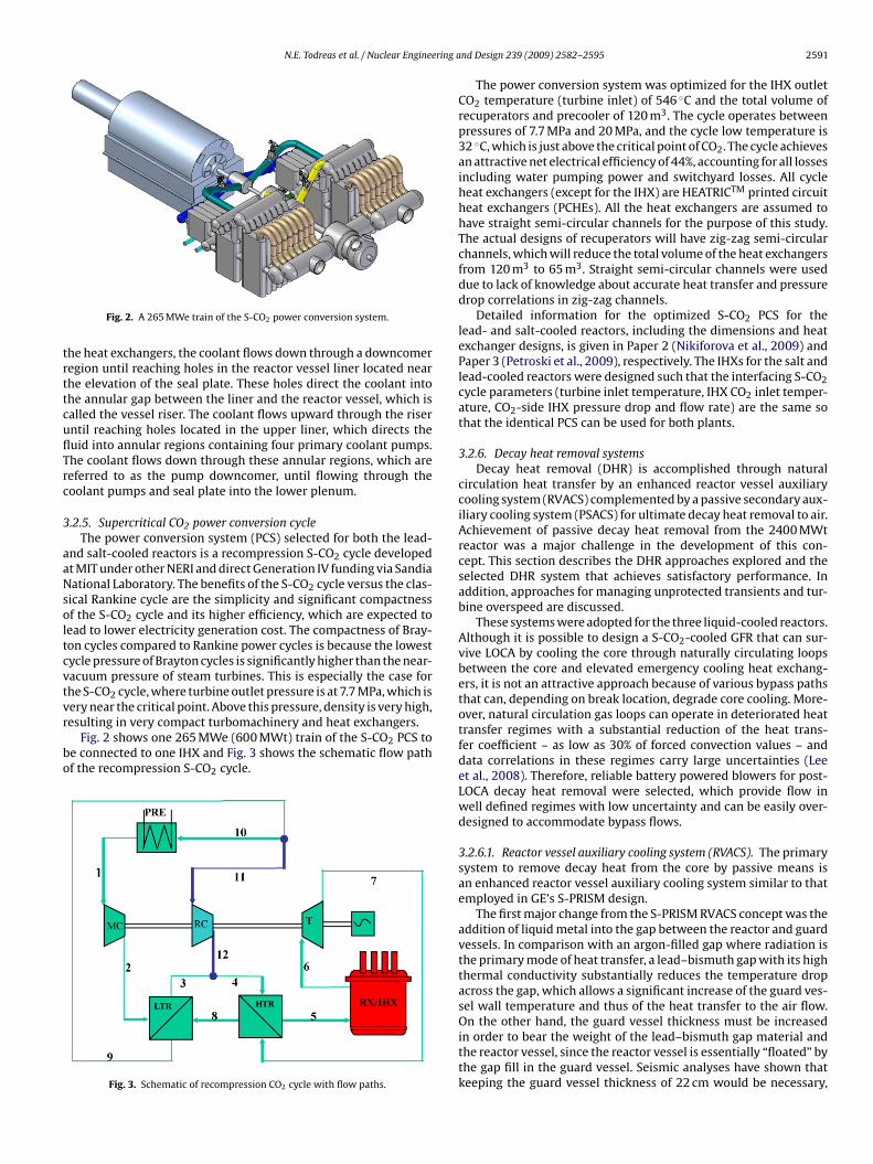
Fig. 2. A 265 MWe train of the S-CO2 power conversion system.
he heat exchangers, the coolant flows down through a downcomeregion until reaching holes in the reactor vessel liner located nearhe elevation of the seal plate. These holes direct the coolant intohe annular gap between the liner and the reactor vessel, which isalled the vessel riser. The coolant flows upward through the riserntil reaching holes located in the upper liner, which directs theuid into annular regions containing four primary coolant pumps.he coolant flows down through these annular regions, which areeferred to as the pump downcomer, until flowing through theoolant pumps and seal plate into the lower plenum.
.2.5. Supercritical CO2 power conversion cycleThe power conversion system (PCS) selected for both the lead-
nd salt-cooled reactors is a recompression S-CO2 cycle developedt MIT under other NERI and direct Generation IV funding via Sandiaational Laboratory. The benefits of the S-CO2 cycle versus the clas-
ical Rankine cycle are the simplicity and significant compactnessf the S-CO2 cycle and its higher efficiency, which are expected to
ead to lower electricity generation cost. The compactness of Bray-on cycles compared to Rankine power cycles is because the lowestycle pressure of Brayton cycles is significantly higher than the near-acuum pressure of steam turbines. This is especially the case forhe S-CO2 cycle, where turbine outlet pressure is at 7.7 MPa, which is
ery near the critical point. Above this pressure, density is very high,esulting in very compact turbomachinery and heat exchangers.Fig. 2 shows one 265 MWe (600 MWt) train of the S-CO2 PCS toe connected to one IHX and Fig. 3 shows the schematic flow pathf the recompression S-CO2 cycle.
Fig. 3. Schematic of recompression CO2 cycle with flow paths.
nd Design 239 (2009) 2582–2595 2591
The power conversion system was optimized for the IHX outletCO2 temperature (turbine inlet) of 546 ◦C and the total volume ofrecuperators and precooler of 120 m3. The cycle operates betweenpressures of 7.7 MPa and 20 MPa, and the cycle low temperature is32 ◦C, which is just above the critical point of CO2. The cycle achievesan attractive net electrical efficiency of 44%, accounting for all lossesincluding water pumping power and switchyard losses. All cycleheat exchangers (except for the IHX) are HEATRICTM printed circuitheat exchangers (PCHEs). All the heat exchangers are assumed tohave straight semi-circular channels for the purpose of this study.The actual designs of recuperators will have zig-zag semi-circularchannels, which will reduce the total volume of the heat exchangersfrom 120 m3 to 65 m3. Straight semi-circular channels were useddue to lack of knowledge about accurate heat transfer and pressuredrop correlations in zig-zag channels.
Detailed information for the optimized S-CO2 PCS for thelead- and salt-cooled reactors, including the dimensions and heatexchanger designs, is given in Paper 2 (Nikiforova et al., 2009) andPaper 3 (Petroski et al., 2009), respectively. The IHXs for the salt andlead-cooled reactors were designed such that the interfacing S-CO2cycle parameters (turbine inlet temperature, IHX CO2 inlet temper-ature, CO2-side IHX pressure drop and flow rate) are the same sothat the identical PCS can be used for both plants.
3.2.6. Decay heat removal systemsDecay heat removal (DHR) is accomplished through natural
circulation heat transfer by an enhanced reactor vessel auxiliarycooling system (RVACS) complemented by a passive secondary aux-iliary cooling system (PSACS) for ultimate decay heat removal to air.Achievement of passive decay heat removal from the 2400 MWtreactor was a major challenge in the development of this con-cept. This section describes the DHR approaches explored and theselected DHR system that achieves satisfactory performance. Inaddition, approaches for managing unprotected transients and tur-bine overspeed are discussed.
These systems were adopted for the three liquid-cooled reactors.Although it is possible to design a S-CO2-cooled GFR that can sur-vive LOCA by cooling the core through naturally circulating loopsbetween the core and elevated emergency cooling heat exchang-ers, it is not an attractive approach because of various bypass pathsthat can, depending on break location, degrade core cooling. More-over, natural circulation gas loops can operate in deteriorated heattransfer regimes with a substantial reduction of the heat trans-fer coefficient – as low as 30% of forced convection values – anddata correlations in these regimes carry large uncertainties (Leeet al., 2008). Therefore, reliable battery powered blowers for post-LOCA decay heat removal were selected, which provide flow inwell defined regimes with low uncertainty and can be easily over-designed to accommodate bypass flows.
3.2.6.1. Reactor vessel auxiliary cooling system (RVACS). The primarysystem to remove decay heat from the core by passive means isan enhanced reactor vessel auxiliary cooling system similar to thatemployed in GE’s S-PRISM design.
The first major change from the S-PRISM RVACS concept was theaddition of liquid metal into the gap between the reactor and guardvessels. In comparison with an argon-filled gap where radiation isthe primary mode of heat transfer, a lead–bismuth gap with its highthermal conductivity substantially reduces the temperature dropacross the gap, which allows a significant increase of the guard ves-sel wall temperature and thus of the heat transfer to the air flow.
On the other hand, the guard vessel thickness must be increasedin order to bear the weight of the lead–bismuth gap material andthe reactor vessel, since the reactor vessel is essentially “floated” bythe gap fill in the guard vessel. Seismic analyses have shown thatkeeping the guard vessel thickness of 22 cm would be necessary,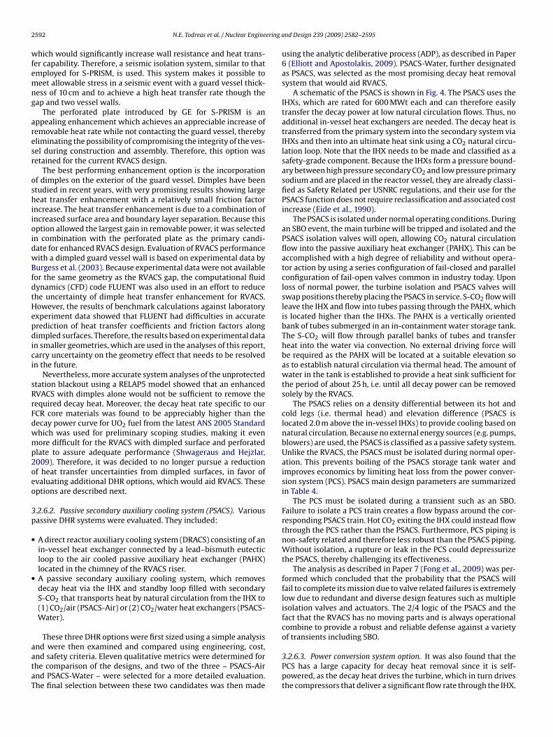
2 ering a
wfemng
aresr
oshiioidwBfdtHepdici
sRrFdwmp2oeo
3p
•
•
aataT
592 N.E. Todreas et al. / Nuclear Engine
hich would significantly increase wall resistance and heat trans-er capability. Therefore, a seismic isolation system, similar to thatmployed for S-PRISM, is used. This system makes it possible toeet allowable stress in a seismic event with a guard vessel thick-
ess of 10 cm and to achieve a high heat transfer rate though theap and two vessel walls.
The perforated plate introduced by GE for S-PRISM is anppealing enhancement which achieves an appreciable increase ofemovable heat rate while not contacting the guard vessel, therebyliminating the possibility of compromising the integrity of the ves-el during construction and assembly. Therefore, this option wasetained for the current RVACS design.
The best performing enhancement option is the incorporationf dimples on the exterior of the guard vessel. Dimples have beentudied in recent years, with very promising results showing largeeat transfer enhancement with a relatively small friction factor
ncrease. The heat transfer enhancement is due to a combination ofncreased surface area and boundary layer separation. Because thisption allowed the largest gain in removable power, it was selected
n combination with the perforated plate as the primary candi-ate for enhanced RVACS design. Evaluation of RVACS performanceith a dimpled guard vessel wall is based on experimental data by
urgess et al. (2003). Because experimental data were not availableor the same geometry as the RVACS gap, the computational fluidynamics (CFD) code FLUENT was also used in an effort to reducehe uncertainty of dimple heat transfer enhancement for RVACS.owever, the results of benchmark calculations against laboratoryxperiment data showed that FLUENT had difficulties in accuraterediction of heat transfer coefficients and friction factors alongimpled surfaces. Therefore, the results based on experimental data
n smaller geometries, which are used in the analyses of this report,arry uncertainty on the geometry effect that needs to be resolvedn the future.
Nevertheless, more accurate system analyses of the unprotectedtation blackout using a RELAP5 model showed that an enhancedVACS with dimples alone would not be sufficient to remove theequired decay heat. Moreover, the decay heat rate specific to ourCR core materials was found to be appreciably higher than theecay power curve for UO2 fuel from the latest ANS 2005 Standardhich was used for preliminary scoping studies, making it evenore difficult for the RVACS with dimpled surface and perforated
late to assure adequate performance (Shwageraus and Hejzlar,009). Therefore, it was decided to no longer pursue a reductionf heat transfer uncertainties from dimpled surfaces, in favor ofvaluating additional DHR options, which would aid RVACS. Theseptions are described next.
.2.6.2. Passive secondary auxiliary cooling system (PSACS). Variousassive DHR systems were evaluated. They included:
A direct reactor auxiliary cooling system (DRACS) consisting of anin-vessel heat exchanger connected by a lead–bismuth eutecticloop to the air cooled passive auxiliary heat exchanger (PAHX)located in the chimney of the RVACS riser.A passive secondary auxiliary cooling system, which removesdecay heat via the IHX and standby loop filled with secondaryS-CO2 that transports heat by natural circulation from the IHX to(1) CO2/air (PSACS-Air) or (2) CO2/water heat exchangers (PSACS-Water).
These three DHR options were first sized using a simple analysis
nd were then examined and compared using engineering, cost,nd safety criteria. Eleven qualitative metrics were determined forhe comparison of the designs, and two of the three – PSACS-Airnd PSACS-Water – were selected for a more detailed evaluation.he final selection between these two candidates was then madend Design 239 (2009) 2582–2595
using the analytic deliberative process (ADP), as described in Paper6 (Elliott and Apostolakis, 2009). PSACS-Water, further designatedas PSACS, was selected as the most promising decay heat removalsystem that would aid RVACS.
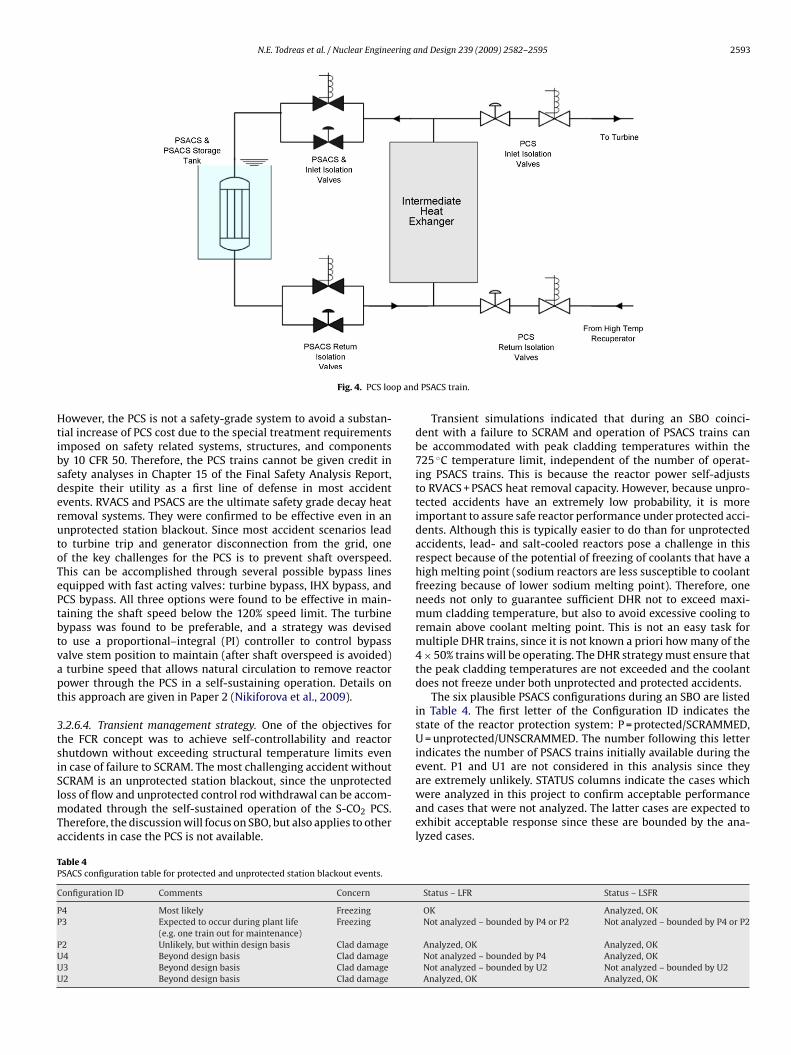
A schematic of the PSACS is shown in Fig. 4. The PSACS uses theIHXs, which are rated for 600 MWt each and can therefore easilytransfer the decay power at low natural circulation flows. Thus, noadditional in-vessel heat exchangers are needed. The decay heat istransferred from the primary system into the secondary system viaIHXs and then into an ultimate heat sink using a CO2 natural circu-lation loop. Note that the IHX needs to be made and classified as asafety-grade component. Because the IHXs form a pressure bound-ary between high pressure secondary CO2 and low pressure primarysodium and are placed in the reactor vessel, they are already classi-fied as Safety Related per USNRC regulations, and their use for thePSACS function does not require reclassification and associated costincrease (Eide et al., 1990).
The PSACS is isolated under normal operating conditions. Duringan SBO event, the main turbine will be tripped and isolated and thePSACS isolation valves will open, allowing CO2 natural circulationflow into the passive auxiliary heat exchanger (PAHX). This can beaccomplished with a high degree of reliability and without opera-tor action by using a series configuration of fail-closed and parallelconfiguration of fail-open valves common in industry today. Uponloss of normal power, the turbine isolation and PSACS valves willswap positions thereby placing the PSACS in service. S-CO2 flow willleave the IHX and flow into tubes passing through the PAHX, whichis located higher than the IHXs. The PAHX is a vertically orientedbank of tubes submerged in an in-containment water storage tank.The S-CO2 will flow through parallel banks of tubes and transferheat into the water via convection. No external driving force willbe required as the PAHX will be located at a suitable elevation soas to establish natural circulation via thermal head. The amount ofwater in the tank is established to provide a heat sink sufficient forthe period of about 25 h, i.e. until all decay power can be removedsolely by the RVACS.
The PSACS relies on a density differential between its hot andcold legs (i.e. thermal head) and elevation difference (PSACS islocated 2.0 m above the in-vessel IHXs) to provide cooling based onnatural circulation. Because no external energy sources (e.g. pumps,blowers) are used, the PSACS is classified as a passive safety system.Unlike the RVACS, the PSACS must be isolated during normal oper-ation. This prevents boiling of the PSACS storage tank water andimproves economics by limiting heat loss from the power conver-sion system (PCS). PSACS main design parameters are summarizedin Table 4.
The PCS must be isolated during a transient such as an SBO.Failure to isolate a PCS train creates a flow bypass around the cor-responding PSACS train. Hot CO2 exiting the IHX could instead flowthrough the PCS rather than the PSACS. Furthermore, PCS piping isnon-safety related and therefore less robust than the PSACS piping.Without isolation, a rupture or leak in the PCS could depressurizethe PSACS, thereby challenging its effectiveness.
The analysis as described in Paper 7 (Fong et al., 2009) was per-formed which concluded that the probability that the PSACS willfail to complete its mission due to valve related failures is extremelylow due to redundant and diverse design features such as multipleisolation valves and actuators. The 2/4 logic of the PSACS and thefact that the RVACS has no moving parts and is always operationalcombine to provide a robust and reliable defense against a varietyof transients including SBO.
3.2.6.3. Power conversion system option. It was also found that thePCS has a large capacity for decay heat removal since it is self-powered, as the decay heat drives the turbine, which in turn drivesthe compressors that deliver a significant flow rate through the IHX.
N.E. Todreas et al. / Nuclear Engineering and Design 239 (2009) 2582–2595 2593
op and
HtibsderutoTePtbtvapt
3tsiSlmTa
TP
C
PP
PUUU
Fig. 4. PCS lo
owever, the PCS is not a safety-grade system to avoid a substan-ial increase of PCS cost due to the special treatment requirementsmposed on safety related systems, structures, and componentsy 10 CFR 50. Therefore, the PCS trains cannot be given credit inafety analyses in Chapter 15 of the Final Safety Analysis Report,espite their utility as a first line of defense in most accidentvents. RVACS and PSACS are the ultimate safety grade decay heatemoval systems. They were confirmed to be effective even in annprotected station blackout. Since most accident scenarios leado turbine trip and generator disconnection from the grid, onef the key challenges for the PCS is to prevent shaft overspeed.his can be accomplished through several possible bypass linesquipped with fast acting valves: turbine bypass, IHX bypass, andCS bypass. All three options were found to be effective in main-aining the shaft speed below the 120% speed limit. The turbineypass was found to be preferable, and a strategy was devisedo use a proportional–integral (PI) controller to control bypassalve stem position to maintain (after shaft overspeed is avoided)turbine speed that allows natural circulation to remove reactor
ower through the PCS in a self-sustaining operation. Details onhis approach are given in Paper 2 (Nikiforova et al., 2009).
.2.6.4. Transient management strategy. One of the objectives forhe FCR concept was to achieve self-controllability and reactorhutdown without exceeding structural temperature limits evenn case of failure to SCRAM. The most challenging accident without
CRAM is an unprotected station blackout, since the unprotectedoss of flow and unprotected control rod withdrawal can be accom-odated through the self-sustained operation of the S-CO2 PCS.herefore, the discussion will focus on SBO, but also applies to otherccidents in case the PCS is not available.
able 4SACS configuration table for protected and unprotected station blackout events.
onfiguration ID Comments Concern
4 Most likely Freezing3 Expected to occur during plant life
(e.g. one train out for maintenance)Freezing
2 Unlikely, but within design basis Clad damage4 Beyond design basis Clad damage3 Beyond design basis Clad damage2 Beyond design basis Clad damage
PSACS train.
Transient simulations indicated that during an SBO coinci-dent with a failure to SCRAM and operation of PSACS trains canbe accommodated with peak cladding temperatures within the725 ◦C temperature limit, independent of the number of operat-ing PSACS trains. This is because the reactor power self-adjuststo RVACS + PSACS heat removal capacity. However, because unpro-tected accidents have an extremely low probability, it is moreimportant to assure safe reactor performance under protected acci-dents. Although this is typically easier to do than for unprotectedaccidents, lead- and salt-cooled reactors pose a challenge in thisrespect because of the potential of freezing of coolants that have ahigh melting point (sodium reactors are less susceptible to coolantfreezing because of lower sodium melting point). Therefore, oneneeds not only to guarantee sufficient DHR not to exceed maxi-mum cladding temperature, but also to avoid excessive cooling toremain above coolant melting point. This is not an easy task formultiple DHR trains, since it is not known a priori how many of the4 × 50% trains will be operating. The DHR strategy must ensure thatthe peak cladding temperatures are not exceeded and the coolantdoes not freeze under both unprotected and protected accidents.
The six plausible PSACS configurations during an SBO are listedin Table 4. The first letter of the Configuration ID indicates thestate of the reactor protection system: P = protected/SCRAMMED,U = unprotected/UNSCRAMMED. The number following this letterindicates the number of PSACS trains initially available during theevent. P1 and U1 are not considered in this analysis since they
are extremely unlikely. STATUS columns indicate the cases whichwere analyzed in this project to confirm acceptable performanceand cases that were not analyzed. The latter cases are expected toexhibit acceptable response since these are bounded by the ana-lyzed cases.Status – LFR Status – LSFR
OK Analyzed, OKNot analyzed – bounded by P4 or P2 Not analyzed – bounded by P4 or P2
Analyzed, OK Analyzed, OKNot analyzed – bounded by P4 Analyzed, OKNot analyzed – bounded by U2 Not analyzed – bounded by U2Analyzed, OK Analyzed, OK
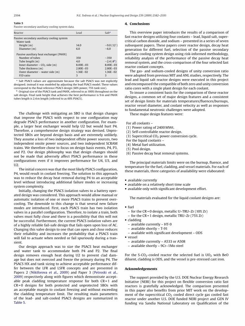
2594 N.E. Todreas et al. / Nuclear Engineering a
Table 5Passive secondary auxiliary cooling system data.
Reactor Lead Salta
Passive secondary auxiliary cooling systemWater tank
Height (m) 14.0 ∼9.0 (12†)Diameter (m) 6.0 ∼6.0
Passive auxiliary heat exchanger (PAHX)Number of tubes 350 ∼350Tube length (m) 4.0 ∼2.4 (4b)Inner diameter – CO2 side (m) 8.00E−03 8.00E−03Tube thickness (m) 2.80E−03 2.80E−03Outer diameter – water side (m) 1.36E−02 1.36E−02P/D ratio 3 3
a Salt PSACS values are approximate because the salt PSACS was not explicitlydesigned; instead it was modeled by adjusting the lead PSACS model. These valuescorrespond to the final reference PSACS design (60% power, 75% tank size).
b
st
tdpTtTitancU
Pwls
aacmvvboCtws
adaPfP2aCatoT
reactors is gratefully acknowledged. The comparison presented
Original size of the PSACS tank and PAHX, referred to as 100% throughout on thealt design. Final tank height that achieves the best performance is 9 m and PAHXubes length is 2.4 m length (referred to as 60% PSACS).
The challenge with mitigating an SBO is that design changeshat improve the PSACS with respect to one configuration mayegrade PSACS performance in another configuration. For exam-le, a larger heat exchanger would help U2 but would hurt P4.herefore, a comprehensive design strategy was devised. Unpro-ected SBOs are beyond design basis and are extremely unlikely.hey assume a loss of two independent offsite power sources, two
ndependent onsite power sources, and two independent SCRAMrains. We therefore chose to focus on design basis events, P4, P3,nd P2. Our design philosophy was that design changes shouldot be made that adversely affect PSACS performance in theseonfigurations even if it improves performance for U4, U3, and2.
The initial concern was that the most likely PSACS configuration,4, would result in coolant freezing. The solution to this approachas to reduce the decay heat removal during P4 to an acceptable
evel without introducing additional failure modes or increasingystem complexity.
Initially, changing the PSACS isolation valves to a battery oper-ted design was considered. This approach would allow manual orutomatic isolation of one or more PSACS trains to prevent over-ooling. The downside to this change is that several new failureodes are introduced. First, each PSACS train has two isolation
alves in a parallel configuration. Therefore, to isolate a train, bothalves must fully close and there is a possibility that this will note successful. Furthermore, the current PSACS isolation valves aref a highly reliable fail-safe design that fails open upon loss of AC.hanging this valve design to one that can open and close reducesheir reliability and increases the probability that a PSACS trainill fail to actuate when needed or fail spuriously during a tran-
ient.Our design approach was to size the PSACS heat exchanger
nd water tank to accommodate both P4 and P2. The finalesign removes enough heat during U2 to prevent clad dam-ge but does not overcool and freeze the primary during P4. TheSACS HX and tank sizing to achieve acceptable performance dif-er between the LFR and LSFR concepts and are presented inapers 2 (Nikiforova et al., 2009) and Paper 3 (Petroski et al.,009) respectively along with figures which demonstrate accept-ble peak cladding temperature response for both CR = 1 andR = 0 designs for both protected and unprotected SBOs with
n acceptable margin to coolant freezing and without exceedinghe cladding temperature limit. The resulting main parametersf the lead- and salt-cooled PSACS designs are summarized inable 5.nd Design 239 (2009) 2582–2595
4. Conclusions
This overview paper introduces the results of a comparison offast reactor designs utilizing four coolants – lead, liquid salt, super-critical carbon dioxide, and sodium – presented in a series of sevensubsequent papers. These papers cover reactor design, decay heatgeneration for different fuel, selection of the passive secondaryauxiliary cooling system design using risk-informed methodology,reliability analysis of the performance of the passive decay heatremoval system, and the cross-comparison of the four selected fastreactor coolant concepts.
The gas- and sodium-cooled designs of unity conversion ratiowere adopted from previous MIT and ANL studies, respectively. Thelead and liquid salt reactor designs were executed in this projectand encompassed the compatible of both zero and unity conversionratio cores with a single plant design for each coolant.
To insure a consistent basis for the comparison of these reactordesigns, a common set of major design features and a consistentset of design limits for materials temperatures/fluences/burnups,reactor vessel diameter, and coolant velocity as well as responsesto fundamental neutronic challenges were adopted.
These major design features were:
For all coolants –(1) Power rating of 2400 MWt.(2) Self-controllable reactor design.(3) Supercritical CO2 power conversion cycle.For the liquid coolants –(4) Metal fuel utilization.(5) Pool design.(6) Passive decay heat removal systems.
The principal materials limits were on the burnup, fluence, andtemperature for the fuel, cladding, and vessel materials. For each ofthese materials, three categories of availability were elaborated:
• available currently• available on a relatively short time scale• available only with significant development effort.
The materials evaluated for the liquid coolant designs are:
• fuel– for the CR = 0 design, metallic U–TRU–Zr (10% Zr)– for the CR = 1 design, metallic TRU–Zr (75% Zr)
• cladding– available currently – HT-9– available shortly – T-91– available with significant development – ODS
• vessel– available currently – A533 or A508– available shortly – 9Cr–1Mo steel
For the S-CO2-cooled reactor the selected fuel is UO2 with BeOdiluent, cladding is ODS, and the vessel is pre-stressed cast iron.
Acknowledgements
The support provided by the U.S. DOE Nuclear Energy ResearchInitiative (NERI) for this project on flexible conversion ratio fast
in this paper also benefits from prior MIT work on the develop-ment of the supercritical CO2 cooled direct cycle gas cooled fastreactor under another U.S. DOE funded NERI project and GEN IVfunding via Sandia National Laboratory on Qualification of the
ering a
SAeip
R
A
A
A
A
B
B
B
B
D
D
E
E
F
FH
H
H
H
N.E. Todreas et al. / Nuclear Engine
upercritical CO2 Power Conversion Cycle for Advanced Reactorpplications. Finally, we want to acknowledge all the help thatxperts from laboratories and industry provided during this projectn various areas, as named in the acknowledgements of individualapers.
eferences
damov, E., Orlov, V., Filin, A., Leonov, V., Sila-Novitski, A., Smirnov, V., Tsikunov, V.,1997. The next generation of fast reactors. Nucl. Eng. Des. 173, 143–150.
damov, E., Tsikunov, V., Filin, A., 1994. Conceptual design of BREST-300 lead-cooledfast reactor. In: Proceedings of the ARS’94 International Topical Meeting onAdvanced Reactor Safety, Pittsburgh, PA, April 17–21.
NSI/ANS-5.1-2005. Decay Heat Power in Light Water Reactors, American NuclearSociety, Chicago, IL, 2005.
quien, A., Kazimi, M.S., Hejzlar, P., 2006. Transuranics Recycling in Various Reac-tor/Fuel Cycle Systems, Trans. Am. Nucl. Soc., Vol. 95, Albuquerque, NM, USA,November 12–16, 2006.
oardman, C., Dubberley, A., Carrol, D., Hui, M., Fanning, A., Kwant, W., 2000. ADescription of the S-PRISM Plant. In: Proceedings of ICONE 8, Baltimore, MD,USA.
uiron, L., et al., 2007. Innovative core designs for Generation IV sodium-cooled fastreactors. In: Proceedings of the International Congress on Advances in NuclearPower Plants, ICAPP’07, Paper 7383, Nice, France.
uongiorno, J., 2001. Temperature limits for heavy-liquid-metal reactor vessels.Trans. Am. Nucl. Soc. 85, 45–46.
urgess, N.K., Oliveira, M.M., Ligrani, P.M., 2003. Nusselt number behavior on deepdimpled surfaces within a channel. J. Heat Transfer 125, 11–18.
ostal, V., Hejzlar, P., Driscoll, M.J., 2006. High performance supercritical car-bon dioxide cycle for next generation nuclear reactors. Nucl. Tech. 154 (June),265–282.
ubberley, A.E., Boardman, C.E., Yoshida, K., Wu, T., 2000. SuperPRISM oxide andmetal fuel core designs, ICONE-8002. In: Proceedings of ICONE-8, 8th Interna-tional Conference on Nuclear Engineering, Baltimore, MD, April 2–6.
ide, S., Chmielewski, V., Swantz, T., 1990. Generic component failure data forlight water and liquid sodium reactor PRAs, Document EGG-SSRE-8875, IdahoNational Engineering Laboratory.
lliott, M.A., Apostolakis, G., 2009. Application of risk-informed design methods toselect the PSACS ultimate heat sink. Nucl. Eng. Des. 239, 2654–2659.
ong, C.J., Apostolakis, G., Hejzlar, P., Todreas, N.E., Driscoll, M.J., this issue. Incorpo-rating reliability analysis into FCR design. Nucl. Eng. Des.
orsberg, C.W., Private communication, April 2007.andwerk, C.S., Driscoll, M.J., Hejzlar, P., 2006. Use of beryllium oxide to shape power
and reduce void reactivity in gas-cooled fast reactors, PHYSOR 2006, Vancouver,Canada, September 10–14, 2006.
andwerk, C.S., Hejzlar, P., Driscoll, M.J., 2007. Core Design and Performance Assess-ment for a Supercritical CO2-Cooled Fast Reactor, MIT-ANP-TR-113, PhD Thesis,Department of Nuclear Engineering and Sciences, Massachusetts Institute of
Technology.ejzlar, P., Buongiorno, J., MacDonald, P.E., Todreas, N.E., 2004a. Design strategy andconstraints for medium-power lead-alloy-cooled actinide burners. Nucl. Tech.147 (3), 321–343.
ejzlar, P., Pope, M.J., Williams, W.C., Driscoll, M.J., 2005. Gas cooled fast reactor forGeneration IV service. Prog. Nucl. Energy 47 (1–4), 271–282.
nd Design 239 (2009) 2582–2595 2595
Hejzlar, P., Todreas, N.E., Driscoll, M.J., Petroski, R., Nikiforova, A., Shwageraus, E.,2009. Cross comparison of fast reactor concepts with various coolants. Nucl.Eng. Des. 239, 2672–2691.
Hejzlar, P., Williams, W.C., Driscoll, M.J., 2004b. Hot channel flow starvation of heliumcooled GFRs in laminar natural convection. Trans. Am. Nucl. Soc., vol. 91, Wash-ington, DC, November 14–18, 2004, p. 202.
Hill, R.N., Cahalan, J.E., Khalil, H.S., Wade, D.C., 1999. Development of small, fastreactor core design using lead-based coolant. In: Proceedings of the Global 1999International Conference, Jackson Hole, WY, August 1999.
Hoffman, E.A, Yang, W.S., Hill, R.N., 2006. Preliminary Core Design Studies for theAdvanced Burner Reactor over a Wide Range of Conversion Ratios, ANL-AFCI-177,Advanced Fuel Cycle Initiative, Argonne National Laboratory.
Klueh, R.L., Harris, D.R., 2001. High-Chromium Ferritic and Martensitic Steels forNuclear Applications. American Society for Testing and Materials, West Con-shocken.
Kubo, A., et al., 1997. Feasibility Study on the Reliable Steam Generator with Heli-cally Coiled Double Wall Tubes on FBR, International Conference on NuclearEngineering, ICONE 5-2327, Nice, France, May 26–30, 1997.
Lee, J.I., Hejzlar, P., Saha, P., Stahle, P., Kazimi, M.S., McEligot, D.M., 2008. Deterioratedturbulent heat transfer of gas up-flow in a circular tube: experimental data. Int.J. Heat Mass Transfer 51, 3259–3266.
Nikiforova, A., Hejzlar, P., Todreas, N.E., 2009. Lead cooled flexible conversion ratiofast reactor. Nucl. Eng. Des. 239, 2596–2611.
Pahl, R.G., Porter, D.L., Lahm, C.E., Hofman, G.L., 1990. Experimental studies of U-Pu-Zr fast reactor fuel pins in the experimental breeder reactor-II. MetallurgicalTrans. A 21A, 1863–1870.
Petroski, R., Hejzlar, P., Todreas, N., 2009. Liquid salt cooled flexible conversion ratiofast reactor. Nucl. Eng. Des. 239, 2612–2625.
Romano, A., Boscher, T., Hejzlar, P., Kazimi, M., Todreas, N.E., 2006. Implications ofalternative strategies for actinide management in nuclear reactors. Nucl. Sci. Eng.154, 1–27.
Shwageraus, E., Hejzlar, P., 2008. Flexible conversion ratio lead-cooled reactordesign. In: International Conference on Reactor Physics, Interlaken, Switzerland,September 14–19.
Shwageraus, E., Hejzlar, P., Driscoll, M.J., 2009. Liquid salt cooled flexible conversionratio fast reactor: neutronic design. Nucl. Eng. Des. 239, 2626–2645.
Shwageraus, E., Hejzlar, P., 2009. Decay heat in fast reactors with transuranics fuels.Nucl. Eng. Des. 239, 2646–2653.
Susskind, H., Hill, F.B., Green, L., Kalish, S., Kukacka, L.E., McNulty, W.E., Wirsing Jr.,E., 1960. Corrosion Studies for a Fused Salt-Liquid Metal Extraction Process forthe Liquid Metal Fuel Reactor, BNL-585.
Taylor, I.N., Wadekamper, D.C., 1994. Tolerant Metal Fuel/Cladding Barrier andRelated Method of Installation, U.S. Patent #5,301,218, April 5, 1994.
Todreas, N.E., Hejzlar, P., 2008. Flexible Conversion Ratio Fast Reactor Systems Eval-uation, Final Report, MIT-NFC-PR-101, Massachusetts Institute of Technology,Cambridge, MA, June 2008.
Todreas, N.E., MacDonald, P.E., Hejzlar, P., Buongiorno, J., Loewen, E.P., 2004. Medium-power lead-alloy reactors: missions for this reactor technology. Nucl. Tech. 147(September (3)), 305–320.
Wade, D.C., Hill, R.N., 1997. The design rationale of the IFR. Prog. Nucl. Energy 31
(January (1)), 13–42.Wade, D.C., Fujita, E.K., 1989. Trends versus reactor size of passive reactivity shut-down and control performance. Nucl. Sci. Eng. 103, 182–195.
Williams, W.C., Hejzlar, P., Driscoll, M.J., 2004. Decay heat removal from GFR coreby natural convection. In: International Congress on Advances in Nuclear PowerPlants ICAPP’04, Paper 4166, Pittsburgh, USA, June 13–17.