Embed Size (px)
Citation preview

Flexi-Flanger V1.0 (Document Version: Draft)
Page | 1
Flexi-Flanger V1.0
by DrAlx
Overview
This circuit is largely based on the schematics for the EM3207 Flanger and TZF modification posted by Thomeeque on www.diystompboxes.com. So my thanks go to him for making those available. The circuit will run off a 9V power supply (10V is the absolute max). The main differences with the original design are:
● A toggle switch for 3 modes (Regular Flanger/Vibrato/Through-Zero). "Filter Matrix” mode is also available as in the regular EM3207.
● A toggle switch for Additive/Subtractive flanging. ● Different filter designs. There are active low pass filters before and after the BBDs. ● For all flanger modes, the two signal paths are balanced (i.e. filtered in the same way). ● It is a compact strip-board design (2.9 inches by 3.5 inches) that will just about fit a 1590BB enclosure.
That was one of my design goals. The diagrams in this document are exactly what I used to both design and build the circuit, so they are verified.
The strip-board design relies on using a copper foil ground plane on the component side of the board. The procedure for making this ground plane is described in the following link:
http://www.instructables.com/id/Method-of-applying-a-copper-ground-plane-to-strip-/
Read that before attempting a strip-board build. The first picture in that link shows an early test version of this circuit. The design in this document is a later revision that has a few more components to give an improved filter section before the BBDs.
Instructions
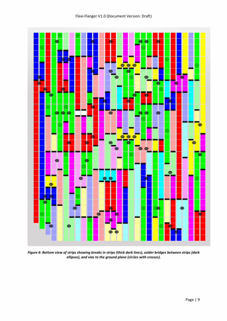
1) Cut the strip-board to the correct size (29 strips with 35 holes per strip). Then with the strips facing you and running vertically, remove a small triangular region in the bottom left corner of the board as shown in Figure 6. This will make it easier to fit the board in a 1590BB enclosure (by avoiding the “shoulder” in the corner of the box where a screw hole is located). It also helps to avoid confusion with board orientation when comparing the diagrams in this document with the physical board.
2) Cut all the breaks in the copper strips using Figure 6 as a guide. The breaks are shown as thick horizontal lines. Note that all breaks lie between holes so they need to be cut with a sharp knife. Take extra care in places which will result in a strip that is only one hole long.
3) Check all holes are free of debris and then apply the copper foil ground plane to the component side
of the board.
4) Cut holes in the ground plane using the technique described in the Instructable. Figure 5 shows a plan view of the ground plane. The circles show the locations where holes need to be cut.
5) Apply vias (i.e. short wire stubs) between the ground plane and the strips as described in the
Instructable. The locations of the vias are shown in Figure 5 (ground plane view) and Figure 6 (strip-side view). The vias are shown as circles with a cross through them. After all the vias have been soldered in place, solder the foils seams if you have overlapping pieces of foil.

Flexi-Flanger V1.0 (Document Version: Draft)
Page | 2
6) Apply clear adhesive-backed plastic to the ground plane as described in the Instructable. The ground plane will then be totally sealed. Before each component is soldered in place, a hole must be made in the plastic using a needle.
7) Solder components in order of increasing height (i.e. jumper wires first, electrolytic capacitors last).
Make sure there are no accidental connections to the ground plane by testing each component leg when it is first placed in the board and after it is soldered in place. Figure 4 and Figure 6 show strips that are connected to ground in green (not light green). If you test a component leg and find that it has a ground connection, then refer to those two figures because the ground connection may actually be desired. Also note that not all strips shown in green will be wired to ground at this stage of the construction. Only the strips with vias to the ground plane will be grounded at this stage. Other strips will be grounded later on using solder bridges (Step 9).
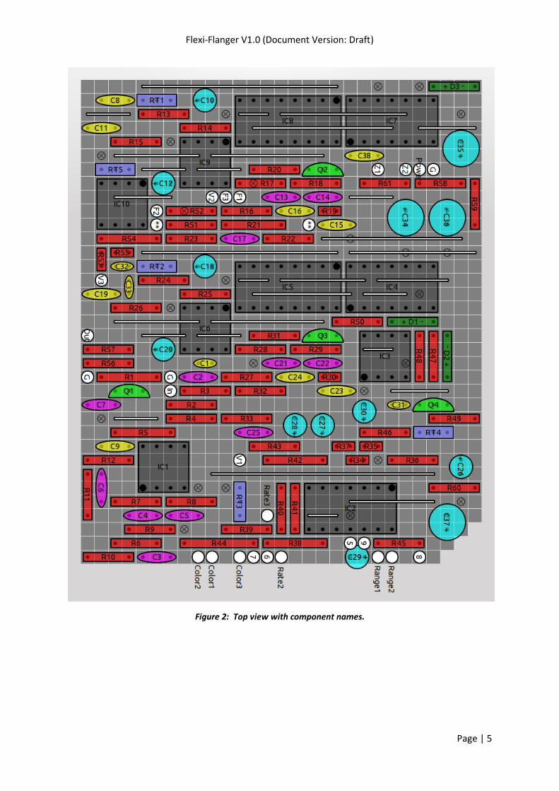
Special Note: In Figure 2 and Figure 3 there are 2 locations marked with a double star “**”. These
two holes should be connected together with a jumper wire (which I could not show in the diagram
like the other jumper wires). You should be able to run the wire on the top surface of the board by
bending it as it comes out of one “**” hole and running it along the gap between R51 and R23 to the
other “**” hole.
After all on-board components have been soldered, solder wires to all off-board components (i.e.
sockets, pots, switches).
8) Pot terminals should be wired to the points on the board marked "Range", "Rate", "Color", and "Z"
(which is an abbreviation for "Through Zero Point"). The pot terminals are numbered with the
convention that terminal 2 is always the middle terminal of the pot, and terminal 1 is the terminal
that is shorted out when the pot is fully counter-clockwise.
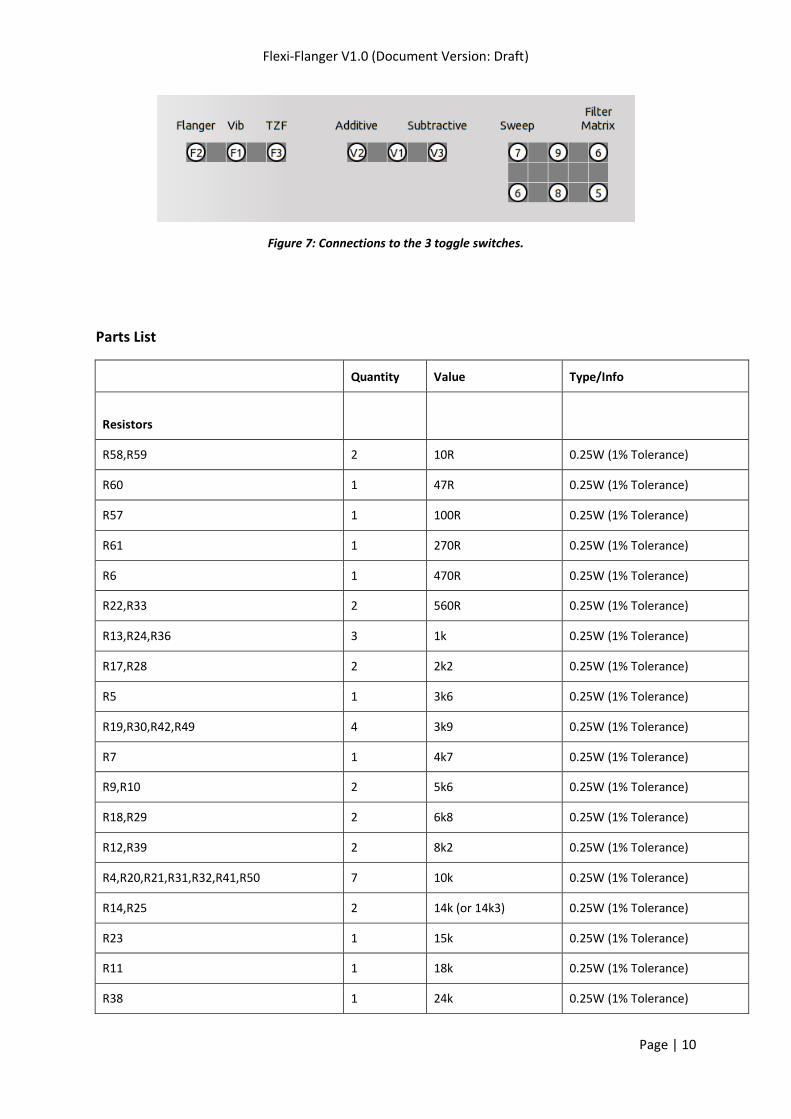
9) Toggle switch wiring is shown in Figure 7. The switch for (Additive/Subtractive) flanging is SPDT. The
switch to choose (Regular Flanging/Vibrato/TZF) is SPDT-centre off. The switch to change between
(Filter Matrix/Sweep) mode is DPDT. (If you're wondering why the points are numbered from 5 to 9
instead of from 1 to 5 it is because I used the same numbers as the EM3207 schematic for the filter
matrix switch).
10) I suggest using screened cable for the input and output connections. You could use screened cable
for the toggle switches too but I found no need to do that. The board was quiet enough without.
11) Once all off-board connections have been made, the final thing to do is to join adjacent strips with
solder bridges using Figure 6 as a reference. The solder bridges are indicated by dark ellipses.
12) For each IC, solder a 100nF ceramic capacitor between the power supply pins on the strip side of the
board. These capacitors are not shown in the diagrams. I recommend only doing this once you’ve got
the board basically working.
13) Alignment procedure (trim-pots).
For alignment, use regular additive flanging and enable Filter Matrix mode. Put the Color and Range
Pots at maximum.
RT1 and RT2 set the bias voltages for the BBDs IC9 and IC6 respectively. To set the bias voltage on
one of these ICs, measure the supply voltage (Vdd) at pin 5 of the IC. The bias voltage (measured) at
pin 3 should be set to (0.42 + 0.54 * Vdd). If you have scope then you can tweak things futher to give
minimum distortion. Repeat the procedure for the other BBD.

Flexi-Flanger V1.0 (Document Version: Draft)
Page | 3
RT3 sets the maximum feedback level of the “Color” pot . The circuit should not oscillate like the
EM3207. Set it to between 20% and 50%. You could set it to 100% but you’ll get more clock noise.
RT4 sets the clock range for the regular flanger part of the circuit. Aim for around 8ms. To do this by
ear, mute the guitar strings with the left hand and then slap down on all the strings over the pickups
so that the pedal gives a short metallic “twang” sound. Adjust RT4 until the pitch of that sound
matches a low B on the guitar (i.e. A-string, 2nd fret).
RT5 sets the wet/dry mix ratio for regular flanger mode. The idea is that the dry signal needs to be
attenuated slightly in order for it to match the amplitude of the wet signal that has gone through the
BBD. You need a scope to do this properly. Anything between 75% and 100% will sound fine. The
Vibrato and TZF modes are not affected by this since they only contain wet signal (i.e. that has passed
through a BBD).
14) Setting the Through-Zero Point control pot: The through-zero point is the interesting part of the
sweep. In my opinion, it is best to configure things so that the through-zero point occurs at the high
end of the sweep (shortest time delay) rather than the middle of the sweep. This will allow the point
to be crossed (or rather “bounced off”) slowly. It is best to set the through-zero point using
subtractive flanging with a slow sweep and Color pot at minimum, since you will be able to hear the
volume drop as the zero point is approached and the 2 signal paths cancel. If the zero point is near
the end of the sweep, you will hear 2 drops in volume close to each other. Adjust the Through-Zero
Point control pot to move the drops in volume closer together in time. When the two drops in
volume have merged into a single drop in volume, the zero point will be at the end of the sweep. You
can then change the Rate and Color pots and swap to Additive flanging. If you change the Range pot,
you will need to reset the through-zero point. If I were redesigning the circuit, I would make it easier
to set the through-zero point at the end of the sweep (e.g. by allowing it to be set in filter matrix
mode) since the method described here (using sweep mode) is harder to do and takes longer.

Flexi-Flanger V1.0 (Document Version: Draft)
Page | 4
Figure 1: Circuit schematic.
Flexi-Flanger V1.0 (Document Version: Draft)
Page | 5
Figure 2: Top view with component names.

Flexi-Flanger V1.0 (Document Version: Draft)
Page | 6
Figure 3: Top view with component values/types.

Flexi-Flanger V1.0 (Document Version: Draft)
Page | 7
Figure 4: “X-Ray view” from top showing strips on bottom.

Flexi-Flanger V1.0 (Document Version: Draft)
Page | 8
Figure 5: Top view of ground plane showing locations of holes for components (dark circles), and vias to the strips (circles with crosses).
Flexi-Flanger V1.0 (Document Version: Draft)
Page | 9
Figure 6: Bottom view of strips showing breaks in strips (thick dark lines), solder bridges between strips (dark ellipses), and vias to the ground plane (circles with crosses).
Flexi-Flanger V1.0 (Document Version: Draft)
Page | 10
Figure 7: Connections to the 3 toggle switches.
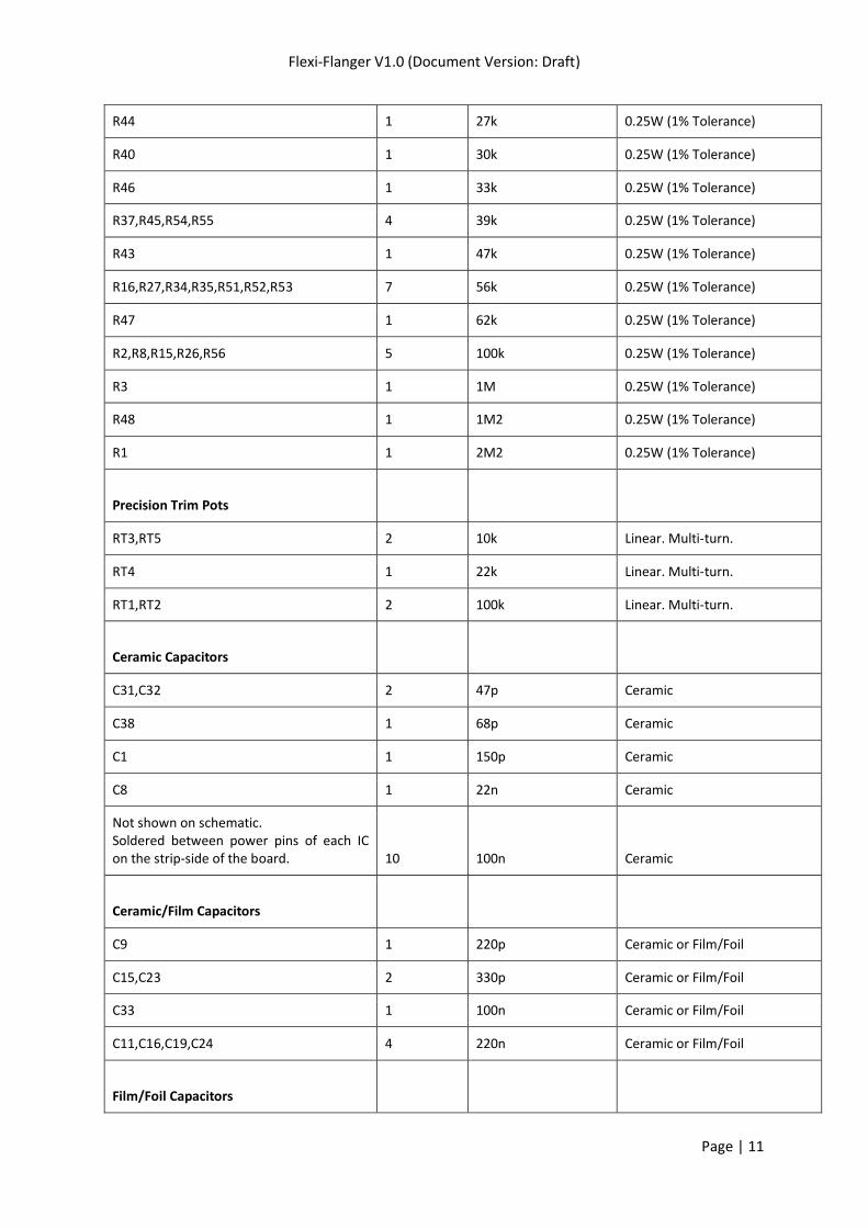
Parts List
Quantity Value Type/Info
Resistors
R58,R59 2 10R 0.25W (1% Tolerance)
R60 1 47R 0.25W (1% Tolerance)
R57 1 100R 0.25W (1% Tolerance)
R61 1 270R 0.25W (1% Tolerance)
R6 1 470R 0.25W (1% Tolerance)
R22,R33 2 560R 0.25W (1% Tolerance)
R13,R24,R36 3 1k 0.25W (1% Tolerance)
R17,R28 2 2k2 0.25W (1% Tolerance)
R5 1 3k6 0.25W (1% Tolerance)
R19,R30,R42,R49 4 3k9 0.25W (1% Tolerance)
R7 1 4k7 0.25W (1% Tolerance)
R9,R10 2 5k6 0.25W (1% Tolerance)
R18,R29 2 6k8 0.25W (1% Tolerance)
R12,R39 2 8k2 0.25W (1% Tolerance)
R4,R20,R21,R31,R32,R41,R50 7 10k 0.25W (1% Tolerance)
R14,R25 2 14k (or 14k3) 0.25W (1% Tolerance)
R23 1 15k 0.25W (1% Tolerance)
R11 1 18k 0.25W (1% Tolerance)
R38 1 24k 0.25W (1% Tolerance)
Flexi-Flanger V1.0 (Document Version: Draft)
Page | 11
R44 1 27k 0.25W (1% Tolerance)
R40 1 30k 0.25W (1% Tolerance)
R46 1 33k 0.25W (1% Tolerance)
R37,R45,R54,R55 4 39k 0.25W (1% Tolerance)
R43 1 47k 0.25W (1% Tolerance)
R16,R27,R34,R35,R51,R52,R53 7 56k 0.25W (1% Tolerance)
R47 1 62k 0.25W (1% Tolerance)
R2,R8,R15,R26,R56 5 100k 0.25W (1% Tolerance)
R3 1 1M 0.25W (1% Tolerance)
R48 1 1M2 0.25W (1% Tolerance)
R1 1 2M2 0.25W (1% Tolerance)
Precision Trim Pots
RT3,RT5 2 10k Linear. Multi-turn.
RT4 1 22k Linear. Multi-turn.
RT1,RT2 2 100k Linear. Multi-turn.
Ceramic Capacitors
C31,C32 2 47p Ceramic
C38 1 68p Ceramic
C1 1 150p Ceramic
C8 1 22n Ceramic
Not shown on schematic. Soldered between power pins of each IC on the strip-side of the board. 10 100n Ceramic
Ceramic/Film Capacitors
C9 1 220p Ceramic or Film/Foil
C15,C23 2 330p Ceramic or Film/Foil
C33 1 100n Ceramic or Film/Foil
C11,C16,C19,C24 4 220n Ceramic or Film/Foil
Film/Foil Capacitors
Flexi-Flanger V1.0 (Document Version: Draft)
Page | 12
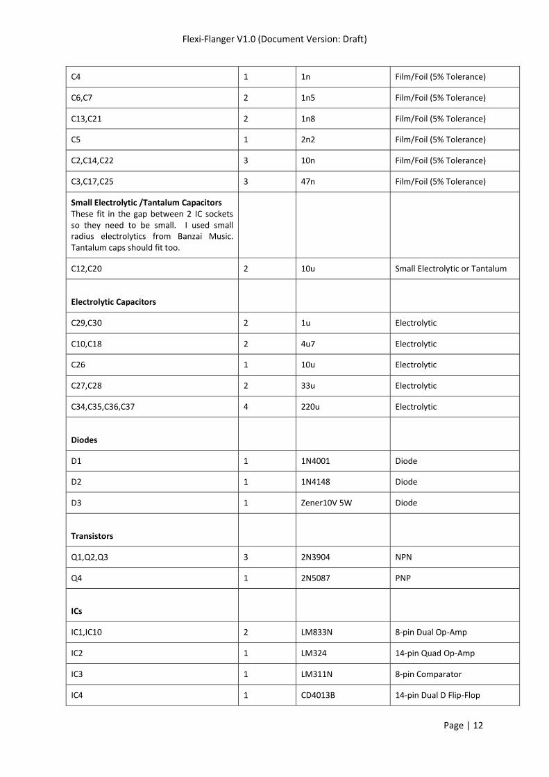
C4 1 1n Film/Foil (5% Tolerance)
C6,C7 2 1n5 Film/Foil (5% Tolerance)
C13,C21 2 1n8 Film/Foil (5% Tolerance)
C5 1 2n2 Film/Foil (5% Tolerance)
C2,C14,C22 3 10n Film/Foil (5% Tolerance)
C3,C17,C25 3 47n Film/Foil (5% Tolerance)
Small Electrolytic /Tantalum Capacitors These fit in the gap between 2 IC sockets so they need to be small. I used small radius electrolytics from Banzai Music. Tantalum caps should fit too.
C12,C20 2 10u Small Electrolytic or Tantalum
Electrolytic Capacitors
C29,C30 2 1u Electrolytic
C10,C18 2 4u7 Electrolytic
C26 1 10u Electrolytic
C27,C28 2 33u Electrolytic
C34,C35,C36,C37 4 220u Electrolytic
Diodes
D1 1 1N4001 Diode
D2 1 1N4148 Diode
D3 1 Zener10V 5W Diode
Transistors
Q1,Q2,Q3 3 2N3904 NPN
Q4 1 2N5087 PNP
ICs
IC1,IC10 2 LM833N 8-pin Dual Op-Amp
IC2 1 LM324 14-pin Quad Op-Amp
IC3 1 LM311N 8-pin Comparator
IC4 1 CD4013B 14-pin Dual D Flip-Flop

Flexi-Flanger V1.0 (Document Version: Draft)
Page | 13
IC5,IC8 2 CD4049B 16-pin Hex Inverter
IC6,IC9 2 MN3207 / BL3207 8-Pin Bucket Brigade Delay
IC7 1 CD4047 14-pin Multivibrator
IC Sockets I use “precision” sockets from Banzai Music. They have much better board clearance than the cheaper sockets so it is easier to run jumper wires under them.
5 8-pin Precision Socket
3 14-pin Precision Socket
2 16-pin Precision Socket
Control Pots
Color 1 10k-B Alpha Pot 9mm
Through-Zero Point 1 25k-B Alpha Pot 9mm
Range 1 100k-B Alpha Pot 9mm
Rate 1 1M-C Alpha Pot 9mm
Switches
Filter Matrix Switch 1 DPDT Toggle Switch
Add/Subtract Switch 1 SPDT Toggle Switch
Flanger/Vibrato/TZF Switch 1 SPDT (centre off) Toggle Switch
Footswitch 1 3PDT Footswitch (True Bypass)
Sockets
Power Socket 1 Boss Style Power Socket
In/Out Sockets 2 6.35mm Phono Socket (Mono)
Enclosure
1 1590BB or larger Die-cast Enclosure
Ground Plane Materials
1 Adhesive copper foil
1 Clear adhesive backed plastic

Flexi-Flanger V1.0 (Document Version: Draft)
Page | 14


