Embed Size (px)
Citation preview
ARIB STD-T64-C.S0044-C v1.0
Interoperability Specification for cdma2000 Air Interface
Refer to "Industrial Property Rights (IPR)" in the preface of ARIB STD-T64 for Related Industrial
Property Rights. Refer to "Notice" in the preface of ARIB STD-T64 for Copyrights
Original Specification 1
2
3
4
This standard, ARIB STD-T64-C.S0044-C v1.0, was prepared by 3GPP2-WG of Association of
Radio Industries and Businesses (ARIB) based upon the 3GPP2 specification, C.S0044-C v1.0.
Modification to the original specification 5
6
7
None.
Notes 8
9
10
None.
3GPP2 C.S0044-C v1.0
August 2012
Interoperability Specification for cdma2000 Air 1
Interface 2
3GPP2 and its Organizational Partners claim copyright in this document and individual Organizational Partners may copyright and issue documents or standards publications in individual Organizational Partner's name based on this document. Requests for reproduction of this document should be directed to the 3GPP2 Secretariat at [email protected]. Requests to reproduce individual Organizational Partner's documents should be directed to that Organizational Partner. See www.3gpp2.org for more information.
3

3GPP2 C.S0044-C v1.0
This page intentionally left blank.1
3GPP2 C.S0044-C v1.0
i
CONTENTS 1
Interoperability Specification for cdma2000 Air Interface ................................................................ 1 2
FOREWORD .................................................................................................................................... i 3
Introduction ................................................................................................................................... i 4
Testing Objective .......................................................................................................................... i 5
Execution Strategy ........................................................................................................................ i 6
Supplementary Terms and Definitions ......................................................................................... ii 7
Tolerances ................................................................................................................................ xvii 8
References ............................................................................................................................... xvii 9
1 Miscellaneous Air Interface Tests ........................................................................................ 1-1 10
1.1 Call Setup under Various PSIST Settings ....................................................................... 1-1 11
1.2 Registration Attempts with Different PSIST Settings ....................................................... 1-6 12
1.3 Short Message Service with Different PSIST Settings .................................................... 1-7 13
1.4 Quick Paging Channel CCI ............................................................................................. 1-9 14
1.5 Mobile Station Response to Status Request Message ................................................. 1-11 15
1.6 SYNC Channel Support for Mobile Stations not capable of TD, or not capable of QPCH 16 or RC>2 .................................................................................................................................. 1-13 17
1.7 Sync Channel support for Mobile Stations not capable of TD, but capable of QPCH or 18 RC>2 1-15 19
1.8 Sync Channel Support for Mobile Stations capable of TD and QPCH or RC>2 ........... 1-17 20
1.9 Hashing F-CCCH, F-CCCH slot .................................................................................... 1-20 21
1.10 CDMA Channel Hashing on F-PCH for Mobile Stations not capable of QPCH or RC>222 1-21 23
1.11 CDMA Channel Hashing on F-PCH for Mobile Stations capable of QPCH or RC>2 1-22 24
1.12 CDMA Channel Hashing on F-BCCH; Mobile Station not capable of either TD or 25 QPCH (RC>2) ......................................................................................................................... 1-23 26
1.13 CDMA Channel Hashing on F-BCCH; Mobile Station not capable of TD (STS) but 27 capable of QPCH (RC>2) ....................................................................................................... 1-25 28
1.14 CDMA Channel Hashing on F-BCCH; Mobile Station capable of both TD (STS) and 29 QPCH (RC>2) ......................................................................................................................... 1-26 30
1.15 F-CCCH SUPPORT .................................................................................................. 1-28 31
1.16 Paging Indicator on the Quick Paging Channel ........................................................ 1-28 32
2 Basic Call Processing Tests ................................................................................................ 2-1 33
2.1 Mobile Originated Voice Calls ......................................................................................... 2-1 34
3GPP2 C.S0044-C v1.0
ii
2.2 Mobile Station Terminated Voice Calls ........................................................................... 2-4 1
2.3 Busy Tone ....................................................................................................................... 2-7 2
2.4 Mobile Station Origination Call with Inter Band Channel Assignment ............................. 2-8 3
2.5 Mobile Station Terminated Call with Inter Band Channel Assignment ............................ 2-9 4
2.6 DTMF ............................................................................................................................ 2-10 5
2.7 Slot Cycle Index ............................................................................................................ 2-11 6
2.8 Reverse Radio Link Failure ........................................................................................... 2-13 7
2.9 Channel Assignment from CDMA to Analog ................................................................. 2-14 8
2.10 Network Busy ............................................................................................................ 2-15 9
2.11 Release Order on the Access Channel ..................................................................... 2-16 10
2.12 True IMSI Support, Land Party to Mobile Station Call, Matching MCC and IMSI_11_12, 11 True IMSI addressing supported by the base station and mobile station ............................... 2-17 12
2.13 True IMSI Support, Land Party to Mobile Station Call, Matching MCC and IMSI_11_12, 13 True IMSI addressing supported by the base station with MIN-based addressing supported by 14 the mobile station. ................................................................................................................... 2-18 15
2.14 True IMSI Support, Land Party to Mobile Station Call, Matching MCC and IMSI_11_12, 16 True IMSI addressing not supported by the base station ....................................................... 2-19 17
2.15 True IMSI Support, Land Party to Mobile Station Call, Different MCC and IMSI_11_1218 2-20 19
2.16 PACA Origination, User Terminates While Still In Queue ......................................... 2-21 20
2.17 PACA Origination, Idle Handoff While in Queue ....................................................... 2-22 21
2.18 PACA Origination, Traffic Channel Becomes Available ............................................ 2-23 22
2.19 PACA Origination, Features Interaction .................................................................... 2-24 23
2.20 PACA Origination, Permanent Invocation ................................................................. 2-25 24
2.21 PACA Origination, PACA Disabled for Mobile Station .............................................. 2-26 25
2.22 Service Configuration and Negotiation without SYNC_ID ......................................... 2-27 26
2.23 Service Configuration and Negotiation with SYNC_ID .............................................. 2-31 27
2.24 Intra-Band Channel Assignment ............................................................................... 2-34 28
2.25 Silent-Retry ............................................................................................................... 2-35 29
2.26 MSID, MCC, and IMSI ............................................................................................... 2-37 30
2.27 RL RC 8 / FL RC 11 Parameter Change using RCPM ............................................. 2-40 31
2.28 RL RC 8 / FL RC 11 Parameter Change using GEM ................................................ 2-42 32
2.29 Forward Link Error with RC11/RC12 ......................................................................... 2-44 33
2.30 Traffic Channel Assignment in QoF .......................................................................... 2-46 34
3GPP2 C.S0044-C v1.0
iii
2.31 Call recovery Request Message ............................................................................... 2-47 1
2.32 General Overhead Information Message .................................................................. 2-49 2
2.33 SO 33 call set-up with RC 11 and RC 8 .................................................................... 2-50 3
3 Handoff Tests ...................................................................................................................... 3-1 4
3.1 Soft Handoff with Dynamic Threshold ............................................................................. 3-1 5
3.2 Soft Handoff without Dynamic Threshold ........................................................................ 3-6 6
3.3 Hard Handoff Between Frequencies in the Same Band Class ...................................... 3-11 7
3.4 Hard Handoff from CDMA to Analog ............................................................................. 3-13 8
3.5 Soft Handoff in Fading ................................................................................................... 3-14 9
3.6 Hard Handoff in Fading ................................................................................................. 3-18 10
3.7 Hard Handoff Between Different Band Classes ............................................................ 3-21 11
3.8 Hard Handoff with and without Return on Failure ......................................................... 3-22 12
3.9 Search Window Size and Offset (Traffic State) ............................................................. 3-24 13
3.10 Search Window Size and Offset (Idle State) ............................................................. 3-33 14
3.11 Channel Assignment into Soft Handoff (CASHO) ..................................................... 3-40 15
3.12 Traffic Channel Preamble during Hard Handoff Between Frequencies in same band . 3-16 41 17
3.13 Hopping Pilot Beacon ................................................................................................ 3-43 18
3.14 Hard Handoff between Frequencies with Different Radio Configurations ................. 3-45 19
3.15 Handoff on Same Frequency with Different Radio Configurations ............................ 3-46 20
3.16 Hard Handoff while in the Waiting for Mobile Station Answer Substate .................... 3-48 21
3.17 Mobile Assisted Inter-Frequency Hard Handoff (CDMA to CDMA) ........................... 3-50 22
3.18 Mobile Assisted Inter-Frequency Hard Handoff (CDMA to Analog) .......................... 3-52 23
3.19 Hard Handoff between Frequencies with Different Protocol Revisions ..................... 3-54 24
4 Power Control ...................................................................................................................... 4-1 25
4.1 Forward Traffic Channel Power Control .......................................................................... 4-1 26
4.2 Fast Forward Power Control (FFPC) ............................................................................... 4-5 27
4.3 Lowest Rate Reverse Fundamental Channel Gating .................................................... 4-52 28
4.4 R-FCH Gating during Soft Handoff ................................................................................ 4-54 29
5 Registrations ........................................................................................................................ 5-1 30
5.1 Power-Up Registration .................................................................................................... 5-1 31
5.2 Power - Down Registration .............................................................................................. 5-3 32
5.3 Distance-Based Registration ........................................................................................... 5-5 33
3GPP2 C.S0044-C v1.0
iv
5.4 Timer-Based Registration ................................................................................................ 5-8 1
5.5 Parameter-Change Registration ...................................................................................... 5-9 2
5.6 Zone-Based Registration ............................................................................................... 5-10 3
6 Authentication ...................................................................................................................... 6-1 4
6.1 Shared Secret Data (SSD) Initialized when A-Key is Changed ...................................... 6-1 5
6.2 Shared Secret Data Update ............................................................................................ 6-2 6
6.3 Mismatched A-Keys ........................................................................................................ 6-4 7
6.4 Activating Voice Privacy on Call Setup ........................................................................... 6-5 8
6.5 Activating Voice Privacy at the Mobile Station When a Call Is Active ............................. 6-6 9
6.6 Signaling Message Encryption on Forward Traffic Channel ........................................... 6-7 10
6.7 Signaling Message Encryption on Reverse Traffic Channel ........................................... 6-8 11
6.8 Hard Handoffs between Base Stations with Signaling Message Encryption Active ...... 6-10 12
6.9 Authentication upon Originations .................................................................................. 6-11 13
6.10 Hard Handoff from CDMA to Analog with Signaling Message Encryption Active ..... 6-12 14
7 Service Redirection test cases ............................................................................................ 7-1 15
7.1 Global Service Redirection between Band Classes ........................................................ 7-1 16
7.2 Global Service Redirection between CDMA and a Non-CDMA System ......................... 7-2 17
7.3 Global Service Redirection between Channels in the Same Band Class ....................... 7-4 18
7.4 Service Redirection between Band Classes ................................................................... 7-5 19
7.5 Service Redirection between CDMA and a Non-CDMA System ..................................... 7-7 20
7.6 Service Redirection between Channels in the Same Band Class ................................... 7-8 21
7.7 Extended Global Service Redirection between Band Classes ...................................... 7-10 22
7.8 Extended Global Service Redirection between CDMA and a Non-CDMA System ....... 7-11 23
7.9 Extended Global Service Redirection between Channels in the Same Band Class ..... 7-13 24
8 Short Message Service ........................................................................................................ 8-1 25
8.1 Mobile Station Terminated SMS Tests ............................................................................ 8-1 26
8.2 Mobile Station Originated SMS Tests ............................................................................. 8-8 27
8.3 Broadcast SMS Delivery on the Common Channel ...................................................... 8-14 28
8.4 Mobile Station Terminated Enhanced Messaging Services [EMS] Tests: .................... 8-16 29
8.5 Mobile Station Originated Enhanced Messaging Services [EMS] Tests: ...................... 8-25 30
9 Subscriber Calling Features ................................................................................................ 9-1 31
9.1 Call Forwarding Unconditional (CFU) .............................................................................. 9-1 32
3GPP2 C.S0044-C v1.0
v
9.2 Call Forwarding Busy (CFB) ............................................................................................ 9-1 1
9.3 Call Forwarding Default (CFD) ........................................................................................ 9-2 2
9.4 Call Forwarding No Answer (CFNA) ............................................................................... 9-3 3
9.5 Three-Way Calling ........................................................................................................... 9-4 4
9.6 Call Alerting ..................................................................................................................... 9-5 5
9.7 Calling Party Number for Mobile station Terminated Call Setup ..................................... 9-6 6
9.8 Calling Party Number for Call Waiting ............................................................................. 9-7 7
9.9 Call Waiting ..................................................................................................................... 9-8 8
9.10 Voice Mail Message Waiting Notification from the Idle State ...................................... 9-9 9
9.11 Voice Mail Message Waiting Notification from the Conversation State .................... 9-10 10
9.12 Calling Party Name Presentation during Call Setup ................................................. 9-11 11
9.13 Calling Name Presentation (CNAP) during Conversation State ............................... 9-12 12
9.14 Display Records sent in the Feature Notification Message. ...................................... 9-13 13
9.15 Display Records Sent in the Flash With Information Message ................................. 9-14 14
9.16 Display Records Sent in the Alert with Information Message ................................... 9-15 15
9.17 TTY/TDD ................................................................................................................... 9-16 16
9.18 WLL Call Waiting Indicator Support .......................................................................... 9-18 17
9.19 Answer Holding ......................................................................................................... 9-20 18
9.20 User Selective Call Forwarding ................................................................................. 9-22 19
10 Asynchronous Data and Fax Services ............................................................................... 10-1 20
10.1 Send/Receive Fax ..................................................................................................... 10-1 21
10.2 Upload/Download Binary File .................................................................................... 10-3 22
10.3 Simultaneous Two-way File Transfer/Carrier Detect ................................................ 10-4 23
10.4 Compound AT Command, Initialization and Connection Delay ................................ 10-6 24
10.5 Escaping to Command Mode .................................................................................... 10-7 25
10.6 Air Interface Data Compression ................................................................................ 10-8 26
10.7 RLP Operation in a Poor RF Environment .............................................................. 10-10 27
10.8 RLP Abort and TCP Retransmit Test ...................................................................... 10-11 28
10.9 Internet Control Message Protocol (ICMP) Requests/Replies ................................ 10-13 29
10.10 Reflection of AT Command Parameters ................................................................. 10-14 30
11 Low Speed Packet Data .................................................................................................... 11-1 31
11.1 Forward File Transfer ................................................................................................ 11-1 32
3GPP2 C.S0044-C v1.0
vi
11.2 Reverse File Transfer ................................................................................................ 11-1 1
11.3 Bi-directional File Transfer ........................................................................................ 11-2 2
11.4 Mobile Station Packet Data Inactivity Timer .............................................................. 11-3 3
12 Medium Speed Packet Data .............................................................................................. 12-1 4
12.1 Forward File Transfer with Fundamental and Supplemental Code Channels ........... 12-1 5
12.2 Forward File Transfer with Variable Supplemental Code Channels ......................... 12-2 6
12.3 MSPD Call Setup, No Negotiation ............................................................................ 12-3 7
12.4 MSPD Call Setup, Negotiation to a Different MSPD Service Option ........................ 12-4 8
12.5 MSPD Call Setup, Negotiation to LSPD .................................................................... 12-5 9
12.6 MSPD Call Setup, Mobile Station Maximum Multiplex Option Less than Base Station 10 Maximum Multiplex Option ..................................................................................................... 12-7 11
12.7 MSPD Call Setup, Mobile station Maximum Multiplex Option Greater than Base 12 Station Maximum Multiplex Option ......................................................................................... 12-8 13
12.8 Allocation/De-allocation of Supplemental Code Channels ........................................ 12-9 14
12.9 No Transmission on Supplemental Code Channels ............................................... 12-11 15
12.10 Soft Handoff with Supplemental Code Channels .................................................... 12-12 16
12.11 Adding Supplemental Code Channels during Soft Handoff .................................... 12-13 17
12.12 Hard Handoff to an MSPD-Capable System ........................................................... 12-15 18
12.13 Bi-Directional File Transfers with Forward Supplemental Code Channels ............. 12-17 19
12.14 Rм Interface Flow Control ........................................................................................ 12-18 20
12.15 Dormant Timer ........................................................................................................ 12-19 21
12.16 Packet Zone ID ....................................................................................................... 12-20 22
13 High Speed Packet Data ................................................................................................... 13-1 23
13.1 Forward File Transfer ................................................................................................ 13-1 24
13.2 Reverse File Transfer ................................................................................................ 13-2 25
13.3 Bi-directional File Transfer ........................................................................................ 13-3 26
13.4 Service Option Control Message Processing ............................................................ 13-5 27
13.5 Changing Encoding Type on Supplemental Channel during Hard Handoff .............. 13-7 28
13.6 Control Hold Mode Transitions ................................................................................ 13-10 29
13.7 Soft Handoff of Fundamental Channel/Dedicated Control Channel and Supplemental 30 Channels ............................................................................................................................... 13-15 31
13.8 Soft Handoff of Fundamental Channel or Dedicated Control Channel only ............ 13-18 32
13.9 Adding Supplemental Channels during Soft Handoff .............................................. 13-20 33
3GPP2 C.S0044-C v1.0
vii
13.10 Hard Handoff during Data Transfer ......................................................................... 13-21 1
13.11 Hard Handoff to a different Radio Configuration ..................................................... 13-23 2
13.12 Mobile Station Packet Data Inactivity Timer ............................................................ 13-25 3
13.13 Mobile Station and Base Station Operating in Different States ............................... 13-26 4
13.14 RLP Operation in Rayleigh Fading Environment .................................................... 13-29 5
13.15 Release Order Processing ...................................................................................... 13-30 6
13.16 Hysteresis Activation Timer ..................................................................................... 13-32 7
13.17 Hysteresis Timer ..................................................................................................... 13-33 8
14 Over-The-Air Services ....................................................................................................... 14-1 9
14.1 OTASP Download Request Processing .................................................................... 14-1 10
14.2 OTASP PUZL Download Request Processing .......................................................... 14-4 11
14.3 OTASP 3GPD Download Request Processing ......................................................... 14-6 12
14.4 OTASP SSPR Download Request Processing ....................................................... 14-10 13
14.5 OTASP For System Selection and Preferred Roaming - Oversize PRL ................. 14-12 14
14.6 OTAPA Download Request Processing .................................................................. 14-13 15
14.7 Call Origination during an OTAPA Download Session ............................................ 14-16 16
15 Position Determination Tests ............................................................................................. 15-1 17
15.1 Position Determination Tests for GPS, AFLT and Hybrid ......................................... 15-1 18
16 Concurrent Services .......................................................................................................... 16-1 19
16.1 Setup Mobile Station Originated Data Call while Voice Call or Teleservice Call is in 20 Progress ................................................................................................................................. 16-1 21
16.2 Setup Mobile Station terminated Data Call while Voice Call or Teleservice Call is in 22 Progress ................................................................................................................................. 16-5 23
16.3 Setup Mobile Station Originated Voice Call while Data Call or Teleservice Call is in 24 Progress ................................................................................................................................. 16-7 25
16.4 Setup Mobile Station terminated Voice Call while Data Call or Teleservice Call is in 26 Progress ............................................................................................................................... 16-11 27
16.5 Mobile Station Release of a Single Call While Voice and Data Calls are in Progress 16-28 13 29
16.6 Base Station Release of a Single Call While Voice and Data Calls are in Progress .. 16-30 15 31
16.7 Correct Handling of Call Control Signaling .............................................................. 16-17 32
16.8 Analog Handoff Direction Message Terminates All Calls Except One .................... 16-21 33
3GPP2 C.S0044-C v1.0
viii
16.9 Release A Mobile Station in Concurrent Calls with a Release A Base Station Hands off 1 to Pre-Release A Base Station ............................................................................................. 16-22 2
16.10 Release A Mobile Station Hands off between Release A Base Station with Change in 3 Concurrent Calls Support ..................................................................................................... 16-23 4
17 Emergency Calls ................................................................................................................ 17-1 5
17.1 Global Emergency Call Support When Mobile Station is in Idle State ...................... 17-1 6
17.2 Global Emergency Call Support When Mobile Station is in Voice Call. .................... 17-1 7
17.3 Global Emergency Call Support When Mobile Station is in a Data Call ................... 17-2 8
17.4 Emergency Call on a System that is Negative on PRL or SID List ........................... 17-3 9
17.5 Optional Emergency Calls ......................................................................................... 17-4 10
18 HRPD ................................................................................................................................. 18-1 11
18.1 HRPD Acquisition and Idle Mode Operation ............................................................. 18-1 12
18.2 HRPD Session Establishment ................................................................................... 18-1 13
18.3 HRPD Session Configuration and Management with Subnet change ...................... 18-2 14
18.4 AT Color Code and UATI24 ...................................................................................... 18-2 15
18.5 HRPD Connection Setup ......................................................................................... 18-3 16
18.6 AN Packet Data Inactivity Timer ............................................................................... 18-4 17
18.7 Forward File Transfer ................................................................................................ 18-5 18
18.8 Reverse File Transfer ................................................................................................ 18-7 19
18.9 Bidirectional File Transfer ......................................................................................... 18-8 20
18.10 RLP Operation in Severely Degraded Channel ........................................................ 18-8 21
18.11 Softer and Soft Handoff – Active HRPD Mode .......................................................... 18-9 22
18.12 HRPD Control Channel Monitoring and Overhead Message Updates ................... 18-11 23
18.13 Control Channel Rate .............................................................................................. 18-11 24
18.14 HRPD ConnectionDeny .......................................................................................... 18-12 25
18.15 HRPD Keep Alive Mechanism ................................................................................ 18-13 26
18.16 Intra-band HRPD-HRPD System Re-Selection (Connected State) ........................ 18-14 27
18.17 Inter-band HRPD-HRPD System Re-Selection (Connected State) ........................ 18-15 28
18.18 Intra-band HRPD-HRPD System Re-selection (Idle State) ..................................... 18-16 29
18.19 Inter-band HRPD-HRPD System Re-selection (Idle State) ..................................... 18-16 30
18.20 HRPD Terminal Authentication ............................................................................... 18-17 31
18.21 PPP Session in Adverse Conditions - Disconnect cable between AT and PC. ...... 18-18 32
18.22 Unicast ReverseRateLimit ....................................................................................... 18-19 33
3GPP2 C.S0044-C v1.0
ix
18.23 HRPD Location Update Protocol Tests ................................................................... 18-20 1
18.24 Idle State Channel Hashing .................................................................................... 18-20 2
18.25 Inter-frequency Active Handoff ................................................................................ 18-21 3
18.26 Typical HRPD Rev-A Session Configuration .......................................................... 18-23 4
18.27 Multiple Reservations bound to one RLP ................................................................ 18-24 5
18.28 Maximum Open Reservations, Activated RLP and MAC flows ............................... 18-26 6
18.29 QoS Release upon PDSN initiated LCP termination ............................................... 18-27 7
18.30 QoS Release upon AT Initiated PPP Termination .................................................. 18-29 8
18.31 Access Persistence Vector ..................................................................................... 18-30 9
18.32 AT Data Over Signaling Message Transmission .................................................... 18-31 10
18.33 AN Data Over Signaling Message Transmission .................................................... 18-32 11
18.34 Voice Origination in HRPD Idle Mode ..................................................................... 18-34 12
18.35 Voice Termination in HRPD Idle Mode ................................................................... 18-35 13
18.36 SMS Origination in HRPD Idle Mode ...................................................................... 18-36 14
18.37 SMS Termination in HRPD Idle Mode ..................................................................... 18-36 15
18.38 Voice Origination in HRPD Active Mode ................................................................. 18-37 16
18.39 Voice Termination in HRPD Active Mode ............................................................... 18-38 17
18.40 SMS Origination in HRPD Active Mode .................................................................. 18-40 18
18.41 SMS Termination in HRPD Active Mode ................................................................. 18-41 19
18.42 Voice Origination in HRPD Dormant Mode ............................................................. 18-41 20
18.43 Voice Termination in HRPD Dormant Mode ........................................................... 18-43 21
18.44 SMS Origination in HRPD Dormant Mode .............................................................. 18-44 22
18.45 SMS Termination in HRPD Dormant Mode ............................................................. 18-45 23
18.46 Inter Revision Handoffs - Dormant HRPD Rev A to HRPD Rev 0 .......................... 18-46 24
18.47 Inter Revision Handoffs - Active HRPD Rev A to HRPD Rev 0 .............................. 18-47 25
18.48 Inter Revision Handoffs – Dormant HRPD Rev 0 to HRPD Rev A ......................... 18-49 26
18.49 Inter Revision Handoffs – Active HRPD Rev 0 to HRPD Rev A ............................. 18-50 27
18.50 Inter Technology Switching – Dormant HRPD to cdma2000 1x ............................. 18-52 28
18.51 Inter Technology Switching – Active HRPD to cdma2000 1x ................................. 18-53 29
18.52 Inter Technology Switching – Dormant cdma2000 1x to HRPD ............................. 18-55 30
18.53 Inter RNC Dormant Hand-off (Rev A to Rev A) ....................................................... 18-56 31
18.54 Inter RNC Active Hand-off (Rev A to Rev A) ........................................................... 18-57 32
3GPP2 C.S0044-C v1.0
x
18.55 Inter RNC Dormant Hand-off (Rev A to Rev 0) ....................................................... 18-58 1
18.56 Inter RNC Active Hand-off (Rev A to Rev 0) ........................................................... 18-59 2
18.57 Inter RNC Dormant Hand-off (Rev 0 to Rev A) ....................................................... 18-60 3
18.58 Inter RNC Active Hand-off (Rev 0 to Rev A) ........................................................... 18-61 4
18.59 Inter-Band Active Hand-off ...................................................................................... 18-62 5
18.60 RLP Activation ......................................................................................................... 18-64 6
18.61 QoS Set Up ............................................................................................................. 18-65 7
18.62 Successful negotiation of Enhanced Idle State Protocol ......................................... 18-67 8
18.63 Unsuccessful Enhanced Idle State Protocol due to AN rejection ............................ 18-69 9
18.64 SlottedMode Attribute Negotiation for Enhanced Idle State Protocol ...................... 18-70 10
18.65 Channel Hashing during Enhanced Idle State Protocol .......................................... 18-72 11
18.66 Channel Hashing during Enhanced Idle State Protocol - Hashing to AN 2 Only .... 18-73 12
18.67 QoS Signaling upon PPP resynchronization ........................................................... 18-74 13
18.68 AT behavior upon Rejection of Reservation Request by AN .................................. 18-75 14
18.69 AT behavior upon Receiving ProfileType set to NULL ............................................ 18-76 15
18.70 ReservationKKIdleStateFwd and ReservationKKIdleStateRev set to 0 .................. 18-77 16
18.71 ReservationKKIdleState set to 1 ............................................................................. 18-79 17
18.72 ReservationKKIdleState set to 2 ............................................................................. 18-80 18
18.73 DRC Supervision Failure ......................................................................................... 18-82 19
18.74 Soft Handoff during DRC Supervision Timeout State ............................................. 18-84 20
18.75 DRC Supervision with MultiUserPacketsEnabled ................................................... 18-85 21
18.76 DRCTranslationOffset Verification .......................................................................... 18-86 22
18.77 DSC and DRC compliance during Soft handoff ...................................................... 18-86 23
18.78 DRC Compliance During Softer Handoff ................................................................. 18-87 24
18.79 MUP and Non Canonical SUP decoding by AT ...................................................... 18-89 25
18.80 Enhanced Control Channel Short MAC Packet ...................................................... 18-90 26
18.81 Enhanced Access Channel Probe Transmission .................................................... 18-92 27
18.82 RTC Interlace re-ordering with Subtype 3 RTCMAC .............................................. 18-94 28
18.83 Configuration of non-default attributes for Subtype 3 RTCMAC ............................. 18-95 29
18.84 MultiATPage message .......................................................................................... 18-108 30
18.85 LoadInformation message ..................................................................................... 18-109 31
18.86 Single Carrier Multi-Link ........................................................................................ 18-110 32
3GPP2 C.S0044-C v1.0
xi
19 xHRPD ............................................................................................................................... 19-1 1
19.1 xHRPD Acquisition and Idle Mode Operation ........................................................... 19-1 2
19.2 xHRPD Session Establishment ................................................................................. 19-1 3
19.3 xHRPD Session Configuration and Management with Subnet change .................... 19-1 4
19.4 AT Color Code and UATI24 ...................................................................................... 19-1 5
19.5 xHRPD Connection Setup ........................................................................................ 19-1 6
19.6 AN Packet Data Inactivity Timer ............................................................................... 19-1 7
19.7 Reserved ................................................................................................................... 19-2 8
19.8 Reserved ................................................................................................................... 19-2 9
19.9 Reserved ................................................................................................................... 19-2 10
19.10 RLP Operation in Severely Degraded Channel ........................................................ 19-2 11
19.11 Reserved ................................................................................................................... 19-3 12
19.12 xHRPD Control Channel Monitoring and Overhead Message Updates .................... 19-3 13
19.13 Control Channel Rate ................................................................................................ 19-3 14
19.14 xHRPD ConnectionDeny ........................................................................................... 19-3 15
19.15 xHRPD Keep Alive Mechanism ................................................................................. 19-3 16
19.16 Reserved ................................................................................................................... 19-3 17
19.17 Reserved ................................................................................................................... 19-3 18
19.18 Intra-band xHRPD-xHRPD System Re-selection (Idle State) ................................... 19-3 19
19.19 Inter-band xHRPD-xHRPD System Re-selection (Idle State) ................................... 19-4 20
19.20 xHRPD Terminal Authentication ............................................................................... 19-4 21
19.21 PPP Session in Adverse Conditions - Disconnect cable between AT and PC. ........ 19-4 22
19.22 Reserved ................................................................................................................... 19-4 23
19.23 Reserved ................................................................................................................... 19-4 24
19.24 Idle State Channel Hashing ...................................................................................... 19-4 25
19.25 Reserved ................................................................................................................... 19-5 26
19.26 Typical xHRPD Session Configuration ...................................................................... 19-5 27
19.27 Multiple Reservations bound to one RLP .................................................................. 19-6 28
19.28 Maximum Open Reservations, Activated RLP and MAC flows ................................. 19-9 29
19.29 QoS Release upon PDSN initiated LCP termination ............................................... 19-10 30
19.30 QoS Release upon AT Initiated PPP Termination .................................................. 19-11 31
19.31 Reserved ................................................................................................................. 19-12 32
3GPP2 C.S0044-C v1.0
xii
19.32 AT Data Over Signaling Message Transmission .................................................... 19-12 1
19.33 AN Data Over Signaling Message Transmission .................................................... 19-14 2
19.34 Voice Origination in xHRPD Idle Mode ................................................................... 19-15 3
19.35 Voice Termination in xHRPD Idle Mode .................................................................. 19-16 4
19.36 Reserve ................................................................................................................... 19-17 5
19.37 Reserve ................................................................................................................... 19-17 6
19.38 Voice Origination in xHRPD Active Mode ............................................................... 19-17 7
19.39 Voice Termination in xHRPD Active Mode .............................................................. 19-18 8
19.40 Reserved ................................................................................................................. 19-20 9
19.41 Reserved ................................................................................................................. 19-20 10
19.42 Reserved ................................................................................................................. 19-20 11
19.43 Reserved ................................................................................................................. 19-20 12
19.44 Reserved ................................................................................................................. 19-20 13
19.45 Reserved ................................................................................................................. 19-20 14
19.46 Reserved ................................................................................................................. 19-20 15
19.47 Reserved ................................................................................................................. 19-20 16
19.48 Reserved ................................................................................................................. 19-20 17
19.49 Reserved ................................................................................................................. 19-20 18
19.50 Reserved ................................................................................................................. 19-20 19
19.51 Reserved ................................................................................................................. 19-20 20
19.52 Reserved ................................................................................................................. 19-20 21
19.53 Inter RNC Dormant Hand-off (xHRPD to xHRPD) .................................................. 19-20 22
19.54 Reserved ................................................................................................................. 19-21 23
19.55 Reserved ................................................................................................................. 19-21 24
19.56 Reserved ................................................................................................................. 19-21 25
19.57 Reserved ................................................................................................................. 19-21 26
19.58 Reserved ................................................................................................................. 19-21 27
19.59 Reserved ................................................................................................................. 19-21 28
19.60 RLP Activation ......................................................................................................... 19-21 29
19.61 QoS Set Up ............................................................................................................. 19-23 30
19.62 Reserved ................................................................................................................. 19-26 31
19.63 Reserved ................................................................................................................. 19-26 32
3GPP2 C.S0044-C v1.0
xiii
19.64 Reserved ................................................................................................................. 19-26 1
19.65 Reserved ................................................................................................................. 19-26 2
19.66 Reserved ................................................................................................................. 19-26 3
19.67 QoS Signaling upon PPP resynchronization ........................................................... 19-26 4
19.68 AT behavior upon Rejection of Reservation Request by AN .................................. 19-27 5
19.69 AT behavior upon Receiving ProfileType set to NULL ............................................ 19-28 6
19.70 ReservationKKIdleStateFwd and ReservationKKIdleStateRev set to 0 .................. 19-29 7
19.71 ReservationKKIdleState set to 1 ............................................................................. 19-30 8
19.72 ReservationKKIdleState set to 2 ............................................................................. 19-31 9
19.73 CQI Supervision Failure .......................................................................................... 19-33 10
19.74 Reserved ................................................................................................................. 19-35 11
19.75 Reserved ................................................................................................................. 19-35 12
19.76 Reserved ................................................................................................................. 19-35 13
19.77 Reserved ................................................................................................................. 19-35 14
19.78 Reserved ................................................................................................................. 19-35 15
19.79 Reserved ................................................................................................................. 19-35 16
19.80 Enhanced Control Channel Short MAC Packet ...................................................... 19-35 17
19.81 Access Channel Probe Transmission ..................................................................... 19-37 18
19.82 Reserved ................................................................................................................. 19-39 19
19.83 Reserved ................................................................................................................. 19-39 20
19.84 Reserved ................................................................................................................. 19-39 21
19.85 Reserved ................................................................................................................. 19-39 22
19.86 Reserved ................................................................................................................. 19-39 23
19.87 Inter Technology Switching in Idle Mode – xHRPD to LTE ..................................... 19-39 24
19.88 Inter Technology Switching in Idle Mode – xHRPD to HRPD ................................. 19-40 25
19.89 Concurrent Voice and Data Service ........................................................................ 19-41 26
19.90 CALEA Requirement in Idle State ........................................................................... 19-43 27
20 Annex A - figures ............................................................................................................... 20-1 28
21 Annex B ............................................................................................................................. 21-1 29
21.1 Annex B.1 Power Ratios for Common and Traffic Channels .................................... 21-1 30
21.2 Annex B.2 CDMA Equations ..................................................................................... 21-5 31
21.3 Annex B.3 Message Parameter Values .................................................................... 21-8 32
3GPP2 C.S0044-C v1.0
xiv
22 Annex C - protocol capability response message Feature identifiers ................................ 22-1 1
23 Annex D Data Services Tests ............................................................................................ 23-1 2
23.1 Data Services Annex A: References ........................................................................ 23-1 3
23.2 Data Services Annex B: Description of Compressible Test Data Files .................... 23-1 4
23.3 Data Services Annex C: Standard ITU Fax Pages .................................................. 23-1 5
23.4 Data Services Annex D: Test Files .......................................................................... 23-2 6
24 Annex E: TTY/TDD Test Examples ................................................................................... 24-1 7
8
3GPP2 C.S0044-C v1.0
i
FOREWORD 1
Introduction 2
This foreword is not part of this document. This specification defines air interface interoperability 3 tests for CDMA/HRPD/xHRPD mobile stations/access terminals. It is applicable to 4 P_REV_IN_USE equal to or less than seven and/or access terminals supporting revision A of [24] 5
In this document, ‘mobile station’ or ‘access terminal’ (AT) refers to a subscriber terminal, 6 handset, PDA, wireless local loop unit, or any other CDMA/HRPD/xHRPD subscriber terminal 7 that communicates with the base station at the air interface. ‘Base station’ or ‘access network’ 8 refers to the composite functionality of the base station and connected network elements. A 9 cabled connection is typically used for the air interface connection between the mobile station and 10 base station. 11
Testing Objective 12
The objective of these tests is to demonstrate mobile station interoperability with base station 13 equipment compliant to the cdma2000®1 family of standards. References to the applicable 14 standard functionality are listed in the traceability section of each test case. 15
Execution Strategy 16
All features supported by the base station, such as Signaling Message Encryption, 17 Authentication, Voice Privacy, etc. should be enabled. 18
All applicable tests should be executed for all supported Band Classes and Radio Configurations. 19
The following general comments apply to all tests: 20
a. Whenever common channels and/or traffic channels are required to perform a test, and 21 their power ratios are not specified in the test, the power ratios specified in Annex B 22 should be used. Adjust the Orthogonal Channel Noise Simulator (OCNS) gain such that 23 power ratios (Ec/Ior) of all specified forward channels add up to one. If OCNS is not 24 available, the levels of code channels and attenuators should be adjusted to maintain 25 proper test parameters. 26
b. During handoff tests between sectors of the same cell, Channel 2 from the beta sector 27 shall have a maximum relative offset of 1 µs from Channel 1 of the alpha sector at the 28 mobile station antenna connector. 29
c. During soft and intersector handoff tests, the neighbor list of the base station in the test 30 shall include PN offsets of the other base station in the test. 31
1 cdma2000® is the trademark for the technical nomenclature for certain specifications and standards of the Organizational Partners (OP’s) of 3GPP2. Geographically (and as of the date of publication), cdma2000® is a registered trademark of the Telecommunications Industry Association (TIA-USA) in the United States.
3GPP2 C.S0044-C v1.0
ii
d. Pilot PN sequence offsets are denoted by Pi (i=1, 2, 3...). The following are assumed 1 unless otherwise specified: 2
• 0 <= Pi <= 511 3
• Pi not equal to Pj if i not equal to j 4
• Pi mod PILOT_INC = 0 5
e. Base stations should be configured for normal operation as specified in [2] unless 6 otherwise specified in a specific test. 7
f. Unless otherwise specified, the Reverse Traffic Channel should be operated at a 8 sufficiently high Eb/No to ensure insignificant (for example, less than 1%) frame error 9 rate (FER). 10
g. Overhead message fields should be those required for normal operation of the base 11 station unless otherwise specified in Annex B tables or in a specific test. 12
h. Values of time limits and other constants should be as specified in Annex B. 13
Supplementary Terms and Definitions 14
15 AC - See Authentication Center. 16
ACCOLC – Access Overload Class 17
Access Attempt - A sequence of one or more access probe sequences on the Access Channel 18 containing the same message. See also Access Probe and Access Probe Sequence. 19
Access Channel - A Reverse CDMA Channel used by mobile stations for communicating to the 20 base station. The Access Channel is used for short signaling message exchanges such as call 21 originations, responses to pages, and registrations. The Access Channel is a slotted random 22 access channel. 23
Access Channel Message - The information part of an access probe consisting of the message 24 body, length field, and CRC. 25
Access Channel Response Message - A message on the Access Channel generated to reply to 26 a message received from the base station. 27
Acknowledgment - A Layer 2 response by the mobile station or the base station confirming that 28 a signaling message was received correctly. 29
Action Time - The time at which the action implied by a message should take effect. 30
Active Set - The set of pilots associated with the CDMA Channels containing Forward Traffic 31 Channels assigned to a particular mobile station. 32
Advanced Forward Link Trilateration (AFLT) - A geolocation technique that utilizes the mobile 33 station’s measured time-difference-of-arrival of radio signals from the base stations (and, 34 possibly, other terrestrial measurements). 35
A-key - A secret, 64-bit pattern stored in the mobile station and HLR/AC. It is used to 36 generate/update the mobile station’s Shared Secret Data. 37
AMPS – Advanced Mobile Phone Service 38
AN- Access Network 39
3GPP2 C.S0044-C v1.0
iii
Assured Mode - Mode of delivery that guarantees (if a loss of channel is not declared) that a 1 PDU will be delivered to the peer. A PDU sent in assured mode is retransmitted by the LAC 2 sublayer, up to a maximum number of retransmissions, until the LAC entity at the sender receives 3 an acknowledgement for the PDU. See also Confirmation of Delivery. 4
AT – 1. Attention (condition in modem control). 2. Access Terminal 5
Authentication - A procedure used by a base station to validate a mobile station’s identity. 6
Authentication Center (AC) - An entity that manages the authentication information related to 7 the mobile station. 8
Autonomous Registration - A method of registration in which the mobile station registers 9 without an explicit command from the base station. 10
AWGN - Additive White Gaussian Noise. 11
Band Class - A set of frequency channels and a numbering scheme for these channels. 12
Base Station - A fixed station used for communicating with mobile stations. In this document, the 13 term base station refers to the entire cellular system infrastructure including transceiver 14 equipment and Mobile Switching Center. 15
bps - Bits per second. 16
BS – See base station. 17
Candidate Frequency - The frequency for which the base station specifies a search set, when 18 searching on other frequencies while performing mobile-assisted handoffs. 19
Candidate Set - The set of pilots that have been received with sufficient strength by the mobile 20 station to be successfully demodulated, but have not been placed in the Active Set by the base 21 station. See also Active Set, Neighbor Set, and Remaining Set. 22
CC – Channel Configuration 23
CCI – Base station Configuration Change Indicator (sent on QPCH) 24
CDMA - See Code Division Multiple Access. 25
Candidate Frequency - The Candidate Frequency specified for a search of CDMA pilots. 26
CDMA Channel - The set of channels transmitted between the base station and the mobile 27 stations within a given CDMA frequency assignment. See also Forward CDMA Channel and 28 Reverse CDMA Channel. 29
CFNA – Call Forwarding No Answer 30
Chip - See PN Chip. 31
CMT – Cellular Messaging Teleservice 32
CAN – Calling Party Name 33
CNAP – Calling Name Presentation 34
CNI – Calling Number Identification 35
Code Channel - A subchannel of a Forward CDMA Channel. A Forward CDMA Channel contains 36 64 code channels. Code channel zero is assigned to the Forward pilot channel. Code channels 1 37 through 7 may be assigned either to the Paging Channels or to the Traffic Channels. Code 38 channel 32 may be assigned either to a Sync Channel or to a Traffic Channel. The remaining 39 code channels may be assigned to Traffic Channels. 40
Code Division Multiple Access (CDMA) - A technique for spread-spectrum multiple-access 41 digital communications that creates channels through the use of unique code sequences. 42
3GPP2 C.S0044-C v1.0
iv
Configuration Change Indicator - A one-bit datum sent on the Quick Paging Channel. 1 Appearance of the Configuration Change Indicator in the Quick Paging Channel serves to alert a 2 slotted mode mobile station, operating in the idle state, that, after performing an idle handoff, it 3 should monitor the Paging Channel, in order to determine if it should update its stored 4 parameters. 5
Confirmation of Delivery - A notification sent by the LAC sublayer to Layer 3 at the sender, 6 when the LAC entity at the sender receives the acknowledgment for a specific PDU sent in 7 assured mode. 8
CPN – Calling Party Number 9
CPT – Cellular Paging Teleservice 10
CRC - See Cyclic Redundancy Code. 11
Cyclic Redundancy Code (CRC) - A class of linear error detecting codes which generate parity 12 check bits by finding the remainder of a polynomial division. 13
dBm - A measure of power expressed in terms of its ratio to one milliwatt. 14
Dedicated Control Channel - A portion of a Traffic Channel (Forward or Reverse) that carries a 15 combination of user data, signaling, and power control information. 16
Distance-Based Registration - An autonomous registration method in which the mobile station 17 registers whenever it enters a cell whose distance from the cell in which the mobile station last 18 registered exceeds a given threshold. 19
DTMF - See Dual-Tone Multifrequency 20
Dual-Tone Multifrequency (DTMF) - Signaling by the simultaneous transmission of two tones, 21 one from a group of low frequencies and another from a group of high frequencies. Each group of 22 frequencies consists of four frequencies. 23
Eb - Average energy per information bit for the Sync Channel, Paging Channel, or Forward Traffic 24 Channel at the mobile station antenna connector. 25
Eb/No - Energy-per-bit-to noise-per-hertz ratio. 26
Eb/Nt - The ratio of the combined received energy per bit to the effective noise power spectral 27 density for the Sync Channel, Paging Channel, or Forward Traffic Channel at the mobile station 28 antenna connector. 29
Ec - Average energy per PN chip for the Forward pilot channel, Sync Channel, Paging Channel, 30 Forward Traffic Channel, power control subchannel, or OCNS. 31
Ec/Io - A notation used to represent a dimensionless ratio of the average power of some code-32 distinguished CDMA signal channel, typically a pilot, to the total power comprised of signal plus 33 interference, within the signal bandwidth. It is usually expressed in dB units. 34
Ec/Ior - The ratio of the average transmit energy per PN chip for the Forward pilot channel, Sync 35 Channel, Paging Channel, Forward Traffic Channel, power control subchannel, or OCNS to the 36 total transmit power spectral density. 37
Erasure Indicator Bit (EIB)- A bit used in the Rate Set 2 Reverse Traffic Channel frame 38 structure to indicate an erased Forward Fundamental Code Channel or Forward Dedicated 39 Control Channel frame. 40
ESN - Electronic Serial Number 41
f-csch - Forward common signaling logical channel. 42
f-dsch - Forward dedicated signaling logical channel. 43
3GPP2 C.S0044-C v1.0
v
FER - Frame Error Rate of Forward Traffic Channel. The value of FER may be estimated by 1 using Service Option 2, 9, 30, or 31 (see TIA/EIA-126-C). 2
FFPC – Fast Forward Power Control 3
Flash - An indication sent on the CDMA Channel indicating that the receiver is to invoke special 4 processing. 5
Forward CDMA Channel - A CDMA Channel from a base station to mobile stations. The 6 Forward CDMA Channel contains one or more code channels that are transmitted on a CDMA 7 frequency assignment using a particular pilot PN offset. The code channels are associated with 8 the Forward pilot channel, Sync Channel, Paging Channels, and Traffic Channels. The Forward 9 CDMA Channel always carries a Forward pilot channel and may carry up to one Sync Channel, 10 up to seven Paging Channels, and up to 63 Traffic Channels, as long as the total number of 11 channels, including the Forward pilot channel, is no greater than 64. 12
F-CCCH - Forward Common Control Channel 13
Forward Dedicated Control Channel (F-DCCH) - A portion of a Forward Traffic Channel that 14 can carry a combination of primary data, secondary data, signaling, and power control 15 information. 16
Forward Fundamental Channel (F-FCH) - A portion of a Forward Traffic Channel that can carry 17 a combination of primary data, secondary data, signaling, and power control information. 18
Forward Pilot Channel (F-PICH) - A non-data-bearing direct-sequence spread spectrum signal 19 transmitted continuously by each CDMA base station. The Forward Pilot Channel allows a mobile 20 station to acquire the timing of the Forward CDMA Channel, provides a phase reference for 21 coherent demodulation, and provides a means for signal strength comparisons between base 22 stations for determining when to handoff. Different base stations are identified by different pilot 23 PN sequence time phases. See also Pilot PN Sequence, Pilot PN Sequence Offset. 24
Forward Supplemental Channel (F-SCH) - An optional portion of a Forward Traffic Channel 25 (Radio Configurations 3 and above) that operates in conjunction with a Fundamental Channel 26 and or the Dedicated Control Channel in that Traffic Channel, and (optionally) with other 27 Supplemental Channels to provide higher data rate services. 28
Forward Supplemental Code Channel (F-SCCH) - An optional portion of a Forward Traffic 29 Channel (Radio Configurations 1 and 2) that operates in conjunction with a Fundamental Channel 30 in that Traffic Channel, and (optionally) with other Supplemental Code Channels to provide higher 31 data rate services. 32
Forward Traffic Channel - A code channel used to transport user and signaling traffic from a 33 base station to a mobile station. 34
FPC – Forward Power Control 35
Frame - A basic timing interval in the system. For the Access Channel and Paging Channel a 36 frame is 20 ms long. For the Traffic Channel, the frame may be 20 ms or 5 ms long. For the Sync 37 Channel, a frame is 26.666... ms long. 38
Frame Offset - A time skewing of Traffic Channel frames from System Time in integer multiples 39 of 1.25 ms. The maximum frame offset is 18.75 ms. 40
FTP- File Transfer Protocol 41
GHz - Gigahertz (109 Hertz). 42
Global Positioning System (GPS) - A US government satellite system that provides location 43 and time information to users. See Navstar GPS Space Segment / Navigation User Interfaces 44 ICD-GPS-200 for specifications. 45
Good Frames - Frames not classified as bad frames. See also Bad Frames. 46
3GPP2 C.S0044-C v1.0
vi
Good Message - A received message is declared a good message if it is received with a correct 1 CRC. 2
GPS - Global Positioning System 3
Handoff - The act of transferring communication with a mobile station from one base station to 4 another. 5
Hard Handoff - A handoff characterized by a temporary disconnection of the Traffic Channel. 6 Hard handoffs occur when the mobile station is transferred between disjoint Active Sets, the 7 CDMA frequency assignment changes, the frame offset changes, or the mobile station is directed 8 from a CDMA Traffic Channel to an AMPS voice channel. See also Soft Handoff. 9
Hash Function - A function used by the mobile station to select one out of N available resources. 10 The hash function distributes the available resources uniformly among a random sample of 11 mobile stations. 12
Hopping Pilot Beacon - A pilot beacon that changes CDMA Frequency periodically to simulate 13 multiple base stations operating on different frequencies. The transmission of the hopping pilot 14 beacon is discontinuous on any CDMA Channel. 15
HRPD – High Rate Packet Data 16
HSPD – High Speed Packet Data 17
Idle Handoff - The act of transferring reception of the Paging Channel from one base station to 18 another, when the mobile station is in the Mobile Station Idle State. 19
IMSI - See International Mobile Station Identity 20
IMSI_M - MIN-based IMSI using the lower 10 digits to store the MIN. 21
IMSI_O - Operational value of IMSI used by the mobile station for operation with the base station. 22
IMSI_T - True IMSI not associated with MIN. This could be 15 digits or fewer. 23
IMSI_T_S – Supplement of MIN-based IMSI 24
International Mobile Station Identity (IMSI) - A method of identifying stations in the land mobile 25 service as specified in ITU-T Recommendation E.212. 26
Io - The total received power spectral density, including signal and interference, as measured at 27 the mobile station antenna connector. 28
Ioc - The power spectral density of a band-limited white noise source (simulating interference from 29 other cells) as measured at the mobile station antenna connector. 30
Ior - The total transmit power spectral density of the Forward CDMA Channel at the base station 31 antenna connector. 32
Îor - The received power spectral density of the Forward CDMA Channel as measured at the 33 mobile station antenna connector. 34
ITU – International Telecommunication Union 35
IWF – Inter-Working Function 36
LAC – Link Access Control 37
Layering - A method of organization for communication protocols in which the transmitted or 38 received information is transferred in pipeline fashion, within each station, in well-defined 39 encapsulated data units between otherwise decoupled processing entities (“layers”). A layer is 40 defined in terms of its communication protocol to a peer layer in another entity and the services it 41 offers to the next higher layer in its own entity. 42
3GPP2 C.S0044-C v1.0
vii
Layer 1 - Layer 1 provides for the transmission and reception of radio signals between the base 1 station and the mobile station. Also see Physical Layer. 2
Layer 2 - Layer 2 provides for the correct transmission and reception of signaling messages, 3 including partial duplicate detection. Layer 2 makes use of the services provided by Layer 1. 4
Layer 3 - Layer 3 provides the control messaging for the cellular or PCS telephone system. Layer 5 3 originates and terminates signaling messages according to the semantics and timing of the 6 communication protocol between the base station and the mobile station. Layer 3 makes use of 7 the services provided by Layer 2. 8
Long Code - A PN sequence with period (242) - 1 that is used for scrambling on the Forward 9 CDMA Channel and spreading on the Reverse CDMA Channel. The long code uniquely identifies 10 a mobile station on both the Reverse Traffic Channel and the Forward Traffic Channel. The long 11 code provides limited privacy. The long code also separates multiple Access Channels on the 12 same CDMA Channel. See also Public Long Code and Private Long Code. 13
Long Code Mask - A 42-bit binary number that creates the unique identity of the long code. See 14 also Public Long Code, Private Long Code, Public Long Code Mask, and Private Long Code 15 Mask. 16
LSPD – Low Speed Packet Data 17
MAC – Medium Access Control 18
MC – Message Center 19
MCC - See Mobile Country Code 20
MCSB - See Message Control and Status Block 21
MDR – Medium Data Rate 22
Mean Input Power - The total received calorimetric power measured in a specified bandwidth at 23 the antenna connector, including all internal and external signal and noise sources. 24
MHz - Megahertz (106 Hertz). 25
MIN/MSIN - See Mobile Identification Number 26
MNC - See Mobile Network Code 27
MO – Multiplex Option 28
MOB_P_REV – Protocol revision number supported by a mobile station 29
Mobile Country Code (MCC) - A part of the E.212 IMSI identifying the home country. See ITU-T 30 Recommendation E.212. 31
Mobile Directory Number - A dialable directory number that is not necessarily the same as the 32 mobile station’s air interface identification, i.e., MIN, IMSI_M or IMSI_T. 33
Mobile Identification Number (MIN) - The 34-bit number that is a digital representation of the 34 10-digit number assigned to a mobile station. 35
Mobile Network Code (MNC) - A part of the E.212 IMSI identifying the home network within the 36 home country. See ITU-T Recommendation E.212. 37
Mobile Station (MS) - A station that communicates with a base station while in motion or during 38 halts at unspecified points. 39
Mobile Station Identification Number (MSIN) - A part of the E.212 IMSI identifying the mobile 40 station within its home network. See ITU-T Recommendation E.212. 41
Mobile Station Originated Call - A call originating from a mobile station. 42
3GPP2 C.S0044-C v1.0
viii
Mobile Station Terminated Call - A call received by a mobile station (not to be confused with a 1 disconnect or call release). 2
MS – Mobile Station 3
MSC - See Mobile Switching Center 4
MSIN - See Mobile Station Identification Number 5
MSPD – Medium Speed Packet Data 6
Mobile Switching Center (MSC) - A configuration of equipment that provides radiotelephone 7 service. Also called the Mobile Telephone Switching Office (MTSO). 8
Multiplex Sublayer - One of the conceptual layers of the system that multiplexes and 9 demultiplexes signaling traffic and various connected user traffic. 10
MWI – Message Waiting Indicator 11
NAK- Negative Acknowledgement 12
NAM - See Number Assignment Module 13
National Mobile Station Identity (NMSI) - A part of the E.212 IMSI identifying the mobile station 14 within its home country. The NMSI consists of the MNC and the MSIN. See ITU-T 15 Recommendation E.212. 16
NDSS - See Network Directed System Selection. 17
Neighbor Set - The set of pilots associated with the CDMA Channels that are probable 18 candidates for handoff. Normally, the Neighbor Set consists of the pilots associated with CDMA 19 Channels that cover geographical areas near the mobile station. See also Active Set, Candidate 20 Set, Remaining Set, and Private Neighbor Set. 21
Network - A network is a subset of a cellular or PCS system, such as an area-wide cellular 22 network, a private group of base stations, or a group of base stations set up to handle a special 23 requirement. A network can be as small or as large as needed, as long as it is fully contained 24 within a system. See also System. 25
Network Directed System Selection (NDSS) - A feature that allows the mobile station to 26 automatically register with a preferred system while roaming, or to be automatically directed by a 27 service provider, typically the home service provider, to a suggested system, regardless of the 28 frequency band class, cellular band, or PCS frequency block. 29
Network Identification (NID) - A number that uniquely identifies a network within a cellular or 30 PCS system. See also System Identification. 31
NID - See Network Identification 32
NMSI - See National Mobile Station Identity 33
NNSCR – Non-negotiable Service Configuration Record 34
Non-Slotted Mode - An operation mode of the mobile station in which the mobile station 35 continuously monitors the Paging Channel. 36
ns - Nanosecond (10-9 second). 37
Nt - The effective noise power spectral density at the mobile station antenna connector. 38
NULL - Any value that is not in the specified range of a field. 39
Number Assignment Module (NAM) - A set of MIN/IMSI-related parameters stored in the 40 mobile station. 41
OA&M – Operation, Administration and Maintenance 42
OCNS – See Orthogonal Channel Noise Simulator 43
3GPP2 C.S0044-C v1.0
ix
OCNS Ec - Average energy per PN chip for the OCNS. 1
Ior
Ec OCNS - The ratio of the average transmit energy per PN chip for the OCNS to the total 2
transmit power spectral density. 3
OLPC – Outer Loop Power Control 4
OOK – On/Off keying 5
Order - A type of message that contains control codes for either the mobile station or the base 6 station. 7
Orthogonal Channel Noise Simulator (OCNS) - A hardware mechanism used to simulate the 8 users on the other orthogonal channels of a Forward CDMA Channel. 9
Orthogonal Transmit Diversity (OTD) - An optional method of transmission of the Forward 10 CDMA Channel that uses two antennas, each transmitting a fraction of the code symbols. It can 11 be used to enhance performance in the presence of multipath fading radio propagation. 12
OTAF – Over-the-air Function 13
OTAPA – Over-the-air Parameter Administration 14
OTASP – Over-the-air Service Programming 15
OTD - See Orthogonal Transmit Diversity 16
OUNS – Other User Noise Simulator Overhead Message - A message sent by the base station 17 on the Paging Channel to communicate base-station-specific and system-wide information to 18 mobile stations. 19
P_REV – Protocol revision level supported by a base station 20
P_REV_IN_USE – Protocol revision level currently in use by a mobile station 21
PACA - Priority Access and Channel Assignment. See PACA Call. 22
PACA Call - A priority mobile station originated call for which no traffic channel or voice channel 23 was immediately available, and which has been queued for a priority access channel assignment. 24
Packet - The unit of information exchanged between the service option applications of the base 25 station and the mobile station. 26
Paging - The act of seeking a mobile station when a call has been placed to that mobile station. 27
Paging Channel - A code channel in a CDMA channel used for transmission of control 28 information and pages from a base station to a mobile station. 29
Paging Channel Slot - An 80 ms interval on the Paging Channel. Mobile stations operating in the 30 slotted mode are assigned specific slots in which they monitor messages from the base station. 31
Paging Ec - Average energy per PN chip for the Paging Channel 32
Ior
Ec Paging - The ratio of the average transmit energy per PN chip for the Paging Channel to the 33
total transmit power spectral density. 34
Paging Indicator - A one-bit datum sent on the Quick Paging Channel. Quick paging indicators 35 are associated with mobile stations, in pairs, via a hashing algorithm. Appearance of both of its 36 indicators in its assigned Quick Paging Channel slot serves to alert a slotted mode mobile station, 37 operating in the idle state, that it should monitor the Paging Channel starting in the next slot. See 38 also Quick Paging Channel. 39
3GPP2 C.S0044-C v1.0
x
Parameter-Change Registration - A registration method in which the mobile station registers 1 when certain of its stored parameters change. 2
PCF – Packet Control Function 3
PCS - See Personal Communications Services 4
PCS System - See Personal Communications Services System 5
PDU - See Protocol Data Unit 6
Personal Communications Services (PCS) - A family of mobile and portable radio 7 communications services for individuals and businesses that may be integrated with a variety of 8 competing networks. Broadcasting is prohibited and fixed operations are to be ancillary to mobile 9 operations. 10
Personal Communication Services System - A configuration of equipment that provides PCS 11 radiotelephone services 12
Personal Communications Switching Center (PCSC) - See Mobile Switching Center (MSC) 13
Physical Channel - A communication path between stations, described in terms of the RF 14 characteristics such as coding, power control policies, etc. 15
Physical Layer - The part of the communication protocol between the mobile station and the 16 base station that is responsible for the transmission and reception of data. The physical layer in 17 the transmitting station is presented a frame by the multiplex sublayer and transforms it into an 18 over-the-air waveform. The physical layer in the receiving station transforms the waveform back 19 into a frame and presents it to the multiplex sublayer above it. 20
PI – See Paging Indicator 21
Pilot Beacon - A transmit-only base station that broadcasts a Forward pilot channel, a Sync 22 Channel, optionally a Paging Channel, but no Forward Traffic Channels. The mobile station 23 measures the pilot beacon to assist in CDMA hard handoffs and inter-frequency idle-mode 24 handoffs. 25
Pilot Ec - Average energy per PN chip for the Forward pilot channel 26
Pilot o
cIE - The ratio of the combined pilot energy per chip, Ec, to the total received power 27
spectral density (noise and signals), Io, of at most K usable multipath components at the mobile 28 station antenna connector (see 1.4). K is the number of demodulating elements supported by the 29 mobile station. 30
Ior
Ec Pilot - The ratio of the average transmit energy per PN chip for the Forward pilot channel to 31
the total transmit power spectral density. 32
Pilot PN Sequence - A pair of modified maximal length PN sequences with period 215
PN chips 33 used to spread the Forward CDMA Channel and the Reverse CDMA Channel. Different base 34 stations are identified by different pilot PN sequence offsets. 35
Pilot PN Sequence Offset - The time offset of a Forward Pilot Channel from CDMA System time, 36 as transmitted by the base station, expressed modulo the pilot period. 37
Pilot PN Sequence Offset Index - The pilot PN sequence offset in units of 64 PN chips of a 38 Forward Pilot Channel, relative to the zero offset pilot PN sequence. 39
Pilot Strength - The ratio of pilot power to total power in the signal bandwidth of a CDMA 40 Forward or Reverse Channel. See also Ec/Io. 41
PM – Privacy Mode 42
3GPP2 C.S0044-C v1.0
xi
PN - Pseudonoise 1
PN Chip - One bit in a PN sequence, or the time duration of such a bit. It corresponds to the 2 smallest modulation interval in a CDMA system. 3
PN Sequence – Pseudo-random noise sequence. A deterministic, periodic binary sequence 4 having limited statistical similarity to a Bernoulli (coin-tossing). 5
Power Control Bit - A bit sent in every 1.25 ms interval on the Forward Traffic Channel that 6 signals the mobile station to increase or decrease its transmit power. 7
Power Control Ec - Average energy per PN chip for the power control subchannel. For the case 8 when the power control sub-channel is assumed to be transmitted at the same power level that is 9 used for the 9600 bps or 14400 bps data rate, the following equations apply: For Rate Set 1, it is 10
equal to v11
v+
x (total Forward Traffic Channel energy per PN chip), where v equals 1 for 9600 11
bps, v equals 2 for 4800 bps, v equals 4 for 2400 bps, and v equals 8 for 1200 bps traffic data 12
rate. For Rate Set 2, it is equal to v23
v+
x (total Forward Traffic Channel energy per PN chip), 13
where v equals 1 for 14400 bps, v equals 2 for 7200 bps, v equals 4 for 3600 bps, and v equals 8 14 for 1800 bps traffic data rate. The total Forward Traffic Channel is comprised of traffic data and a 15 power control sub-channel. 16
v23v+
- The ratio of the average transmit energy per PN chip for the power control subchannel 17
to the total transmit power spectral density. 18
Power Control Group - A 1.25 ms interval on the Forward Traffic Channel and the Reverse 19 Traffic Channel. See also Power Control Bit. 20
Power-Down Registration - An autonomous registration method in which the mobile station 21 registers on power-down. 22
Power-Up Registration - An autonomous registration method in which the mobile station 23 registers on power-up. 24
PPP – Point-to-Point Protocol 25
Preamble - See Access Channel Preamble and Traffic Channel Preamble 26
Primary Traffic - The main traffic stream carried between the mobile station and the base station 27 on the Traffic Channel. See also Secondary Traffic and Signaling Traffic. 28
Private Long Code - The long code characterized by the private long code mask. See also Long 29 Code. 30
Private Long Code Mask - The long code mask used to form the private long code. See also 31 Public Long Code Mask and Long Code. 32
Private Neighbor Set - The set of pilots associated with the private system base stations that are 33 probable candidates for idle handoff. See also Active Set, Neighbor Set, Remaining Set, and 34 CDMA Tiered Services. 35
Protocol Data Unit - Encapsulated data communicated between peer layers on the mobile 36 station and base station. Unless specified otherwise, in this document PDU refers to the Layer 3 37 protocol data unit transferred at the interface between layer 3 and layer 2. 38
Protocol Stack - Conceptual model of the layered architecture for communication protocols (see 39 Layering) in which layers within a station are represented in the order of their numeric designation 40 and requiring that transferred data be processed sequentially by each layer, in the order of their 41 representation. Graphically, the “stack” is drawn vertically, with the layer having the lowest 42 numeric designation at the base. 43
3GPP2 C.S0044-C v1.0
xii
PSIST – Persistence Delay 1
Public Long Code - The long code characterized by the public long code mask. 2
Public Long Code Mask – The long code mask used to form the public long code. The mask 3 contains a permutation of the bits of the ESN, and also includes the channel number when used 4 for a Supplemental Code Channel. See also Private Long Code Mask and Long Code. 5
Public Safety Answering Point (PSAP) - A dispatch office that receives emergency calls from 6 the public. 7
PSTN – Public Switching Telephone Network 8
QPCH – See Quick Paging Channel 9
Quick Paging - A feature that permits mobile stations to further conserve battery power beyond 10 the savings achieved by slotted mode operation. See also Paging Indicator and Configuration 11 Change Indicator. 12
Quick Paging Channel (QPCH)- An uncoded, on-off-keyed (OOK) spread spectrum signal sent 13 by base stations to inform slotted mode mobile stations, operating in the idle state, whether to 14 monitor the Paging Channel. See also Quick Paging, Paging Indicator, and Configuration Change 15 Indicator. 16
Quick Paging Channel Slot - An 80 ms interval on the Quick Paging Channel. See also Paging 17 Indicator and Configuration Change Indicator. 18
r-csch - Reverse common signaling logical channel 19
r-dsch - Reverse dedicated signaling logical channel 20
Radio Configuration (RC) - A set of Forward Traffic Channel and Reverse Traffic Channel 21 transmission formats that are characterized by physical layer parameters such as transmission 22 rates, modulation characteristics and spreading rate. 23
RC - See Radio configuration. 24
Registration - The process by which a mobile station identifies its location and parameters to a 25 base station. 26
Registration Zone - A collection of one or more base stations treated as a unit when determining 27 whether a mobile station should perform zone-based registration. See also User Zone, with which 28 it should not be confused. 29
Release - A process that the mobile station and base station use to inform each other of call 30 disconnect. 31
Remaining Set - The set of all allowable pilot offsets as determined by PILOT_INC, excluding the 32 pilot offsets of the pilots in the Active Set, Candidate Set, and Neighbor Set. See also Active Set, 33 Candidate Set, and Neighbor Set. 34
Request - A layer 3 message generated by either the mobile station or the base station to 35 retrieve information, ask for service, or command an action. 36
Reservation - Air interface resources set up by the access network to carry a higher layer 37
flow. A Reservation is identified by its ReservationLabel. ReservationLabels are bound to 38
RLP Flows that carry higher layer flows. A Reservation can be either in the Open or Close 39
state. 40
Response - A layer 3 message generated as a result of another message, typically a request. 41
Reverse CDMA Channel - The CDMA Channel from the mobile station to the base station. From 42 the base station’s perspective, the Reverse CDMA Channel is the sum of all mobile station 43 transmissions on a CDMA frequency assignment. 44
3GPP2 C.S0044-C v1.0
xiii
Reverse Dedicated Control Channel (R-DCCH) - A portion of a Reverse Traffic Channel that 1 can carry a combination of primary data, secondary data, signaling, and power control 2 information. 3
Reverse Fundamental Channel (R-FCH) - A portion of a Reverse Traffic Channel that can carry 4 a combination of primary data, secondary data, signaling, and power control information. 5
Reverse Pilot Channel (R-PICH) - A non-data-bearing direct-sequence spread spectrum signal 6 transmitted by each CDMA mobile station whenever the Enhanced Access Channel, Reverse 7 Common Control Channel, or Reverse Traffic Channel is enabled. The Reverse Pilot Channel 8 allows a base station to acquire the timing of the Reverse CDMA Channel and provides a phase 9 reference for coherent demodulation. The Reverse Pilot Channel may be transmitted either 10 continuously or in gated mode. 11
Reverse Supplemental Channel (R-SCH) - An optional portion of a Reverse Traffic Channel 12 (Radio Configurations 3 and above) that operates in conjunction with a Fundamental Channel 13 and or the Dedicated Control Channel in that Traffic Channel, and (optionally) with other 14 Supplemental Channels to provide higher data rate services. 15
Reverse Supplemental Code Channel (R-SCCH) - An optional portion of a Reverse Traffic 16 Channel (Radio Configurations 1 and 2) that operates in conjunction with a Fundamental Channel 17 in that Traffic Channel, and (optionally) with other Supplemental Code Channels to provide higher 18 data rate services. 19
RF – Radio Frequency 20
RLP – Radio Link Protocol 21
SCCLT – Supplemental Code Channel List Table 22
SCR – Service Configuration Record 23
SDU - See Service Data Unit 24
Search Window - The range of PN sequence offsets that a mobile station searches for a pilot. 25
Search Window Offset - PN sequence offset used by the mobile station to position the search 26 window when searching for a pilot. 27
Secondary Traffic - An additional traffic stream that can be carried between the mobile station 28 and the base station on the Traffic Channel. See also Primary Traffic and Signaling Traffic. 29
Service Configuration - The common attributes used by the mobile station and the base station 30 to build and interpret Traffic Channel frames. A service configuration consists of Forward and 31 Reverse Traffic Channel multiplex options, Forward and Reverse Traffic Channel transmission 32 rates, and service option connections. Service Configuration is signaled via the Service 33 Configuration information record and the Non-Negotiable Service Configuration information 34 record. 35
Service Negotiation - The procedures used by the mobile station and base station to establish a 36 service configuration. See also Service Option Negotiation. 37
Service Option - A service compatibility of the system. Service options may be applications such 38 as voice, data, or facsimile. See (17). 39
Service Option Connection - A particular instance or session in which the service defined by a 40 service option is used. Associated with a service option connection are a reference, which is used 41 for uniquely identifying the service option connection, a service option, which specifies the 42 particular type of service in use, a Forward Traffic Channel traffic type, which specifies what type 43 of Forward Traffic Channel traffic is used to support the service option connection, and a Reverse 44 Traffic Channel traffic type, which specifies what type of Reverse Traffic Channel traffic is used by 45 the service option connection. 46
3GPP2 C.S0044-C v1.0
xiv
Service Option Negotiation - The procedures used by the mobile station and base station to 1 establish a service configuration. Service option negotiation is similar to service negotiation, but 2 allows less flexibility for specifying the attributes of the service configuration. See also Service 3 Negotiation. 4
Service Redirection - The process by which the base station alters the system selection made 5 by a mobile station. It can be used temporarily during maintenance and testing to divert 6 subscribers to an alternate system. 7
Serving Frequency - The CDMA frequency on which a mobile station is currently communicating 8 with one or more base stations. 9
Shared Secret Data (SSD) - A 128-bit pattern stored in the mobile station (in semi-permanent 10 memory) and known by the base station. SSD is a concatenation of two 64-bit subsets: SSD_A, 11 which is used to support the authentication procedures, and SSD_B, which serves as one of the 12 inputs to the process generating the encryption mask and private long code. 13
Short Message Services (SMS) - A suite of services such as SMS Text Delivery, Digital Paging 14 (i.e., Call Back Number - CBN), and Voice Mail Notification (VMN). 15
SID - See System Identification 16
Signaling Traffic - Control messages that are carried between the mobile station and the base 17 station on the Traffic Channel. See also Primary Traffic and Secondary Traffic. 18
Slotted Mode - An operation mode of the mobile station in which the mobile station monitors only 19 selected slots on the Paging Channel. 20
SME – Signaling Message Encryption 21
SO – Service Option 22
Soft Handoff - A handoff occurring while the mobile station is in the Mobile Station Control on the 23 Traffic Channel State. This handoff is characterized by commencing communications with a new 24 base station on the same CDMA frequency assignment before terminating communications with 25 the old base station. See Hard Handoff. 26
SPC - Service Programming Code 27
Space Time Spreading (STS) - A forward link transmission method which transmits all forward 28 link channel symbols on multiple antennas and spreads the symbols with complementary Walsh 29 or quasi-orthogonal functions. 30
SSD - See Shared Secret Data 31
STS – See Space Time Spreading 32
Supplemental Code Channel (SCCH)- An optional portion of a Traffic Channel (Forward or 33 Reverse) which operates in conjunction with a Fundamental Channel in that Traffic Channel, and 34 (optionally) with other Supplemental Code Channels to provide higher data rate services. On this 35 channel a combination of primary data, secondary data, or both (but never signaling information) 36 are transmitted. 37
Supplemental Ec - Average energy per PN chip for one Forward Supplemental Code Channel. 38
Supplemental Ior
Ec- The ratio of the average transmit energy per PN chip for one Forward 39
Supplemental to the total transmit power spectral density. 40
Sync Channel - Code channel 32 in the Forward CDMA Channel, which transports the 41 synchronization message to the mobile station. 42
Sync_Chip_Bit - Number of PN chips per Sync Channel bit, equal to 1024. 43
Sync Ec - Average energy per PN chip for the Sync Channel. 44
3GPP2 C.S0044-C v1.0
xv
Ior
Ec Sync - The ratio of the average transmit energy per PN chip for the Sync Channel to the 1
total transmit power spectral density. 2
System - A system is a cellular telephone service or personal communications service that 3 covers a geographic area such as a city, metropolitan region, county, or group of counties. See 4 also Network. 5
System Identification (SID) - A number uniquely identifying a cellular or PCS system 6
System Time - The time reference used by the system. System Time is synchronous to UTC 7 time (except for leap seconds) and uses the same time origin as GPS time. All base stations use 8 the same System Time (within a small error). Mobile stations use the same System Time, offset 9 by the propagation delay from the base station to the mobile station. See also Universal 10 Coordinated Time. 11
Target Frequency - The CDMA frequency assignment to which the base station directs a mobile 12 station in a handoff using an Extended Handoff Direction Message, a General Handoff Direction 13 Message, or a Universal Handoff Direction Message. 14
TCP – Transmission Control Protocol 15
Temporary Mobile Station Identity (TMSI) - A temporary mobile station identification assigned 16 by the base station. 17
TD – Transmit Diversity. See Orthogonal Transmit Diversity and Space Time Spreading. 18
TDSO – Test Data Service Option 19
TE – Terminal Equipment 20
TE2L – Terminal Equipment at land connection 21
TE2M – Terminal Equipment at mobile connection 22
Timer-Based Registration - A registration method in which the mobile station registers 23 whenever a counter reaches a predetermined value. The counter is incremented an average of 24 once per 80 ms period. 25
Time Reference - A reference established by the mobile station that is synchronous with the 26 earliest arriving multipath component used for demodulation. 27
TMSI - See Temporary Mobile Station Identity 28
TMSI Zone - The administrative zone that allows the TMSI to be reused. The TMSI_CODE has to 29 be unique within a TMSI zone but may be reused in a different TMSI zone. The TMSI zone is 30 identified by the field TMSI_ZONE. 31
Traffic Channel - A communication path between a mobile station and a base station used for 32 user and signaling traffic. The term Traffic Channel implies a Forward Traffic Channel and 33 Reverse Traffic Channel pair. See also Forward Traffic Channel and Reverse Traffic Channel. 34
Traffic Channel Preamble - A sequence of all-zero frames that is sent by the mobile station on 35 the Reverse Traffic Channel as an aid to Traffic Channel acquisition. 36
Traffic Ec - Average energy per PN chip for the Forward Fundamental Channel. For the case 37 when the power control sub-channel is assumed to be transmitted at the same power level used 38 for the 9600 bps or 14400 bps data rate, the following equations apply: For Rate Set 1, it is equal 39
to v11
11+
x (total Forward Fundamental Channel energy per PN chip), where v equals 1 for 9600 40
bps, v equals 2 for 4800 bps, v equals 4 for 2400 bps, and v equals 8 for 1200 bps traffic data 41
rate. For Rate Set 2, it is equal to v23
23+
x (total Forward Fundamental Channel energy per PN 42
3GPP2 C.S0044-C v1.0
xvi
chip), where v equals 1 for 14400 bps, v equals 2 for 7200 bps, v equals 4 for 3600 bps, and v 1 equals 8 for 1800 bps traffic data rate. The total Forward Fundamental Channel is comprised of 2 traffic data and a power control sub-channel. 3
Ior
Ec Traffic - The ratio of the average transmit energy per PN chip for the Forward Traffic 4
Channel to the total transmit power spectral density. 5
TSB – Technical Service Bulletin 6
Unique Challenge-Response Procedure - An exchange of information between a mobile station 7 and a base station for the purpose of confirming the mobile station’s identity. The procedure is 8 initiated by the base station and is characterized by the use of a challenge- specific random 9 number (i.e., RANDU) instead of the random variable broadcast globally (RAND). 10
Universal Coordinated Time (UTC) - An internationally agreed-upon time scale maintained by 11 the Bureau International de l’Heure (BIH) used as the time reference by nearly all commonly 12 available time and frequency distribution systems i.e., WWV, WWVH, LORAN-C, Transit, Omega, 13 and GPS. 14
User Zone - An area within which CDMA Tiered Services may be provided. It may correspond to 15 an RF coverage area, or it may be established independent of RF topology. User Zones are 16 classified as broadcast versus mobile-specific, and as active versus passive. See: Broadcast 17 User Zone, Mobile-Specific User Zone, Active User Zone, and Passive User Zone. See also 18 Registration Zone, with which it should not be confused. 19
UTC - Universal Temps Coordiné. See Universal Coordinated Time 20
V.42 – ITU-T Recommended error correction protocol 21
VJ – Van Jacobson compression 22
VMN – Voice Mail Notification 23
VMNI – Voice Mail Notification Indicator 24
Voice Privacy - The process by which user voice transmitted over a CDMA Traffic Channel is 25 afforded a modest degree of protection against eavesdropping over the air. 26
Walsh Chip - The shortest identifiable component of a Walsh function. There are 2N Walsh chips 27 in one Walsh function where N is the order of the Walsh function. On the Forward CDMA 28 Channel, one Walsh chip equals 1/1.2288 MHz, or 813.802 ns. On the Reverse CDMA Channel, 29 one Walsh chip equals 4/1.2288 MHz, or 3.255 µs. 30
Walsh Function - One of 2N time orthogonal binary functions (note that the functions are 31 orthogonal after mapping ‘0’ to 1 and ‘1’ to -1). 32
WLL – Wireless Local Loop 33
Zone-Based Registration - An autonomous registration method in which the mobile station 34 registers whenever it enters a zone that is not in the mobile station’s zone list. See also User 35 Zone Registration, with which it should not be confused. 36
Zone Timer - A timer used by the mobile station to remove outdated entries from its list of zones 37 in which it has previously registered. 38
µs - Microsecond (10-6 second). 39
3GPP2 C.S0044-C v1.0
xvii
Tolerances 1
CDMA System Parameter Tolerances 2
CDMA parameters are specified in Annex B. All parameters indicated are exact unless otherwise 3 specified. 4
Measurement Tolerances 5
Unless otherwise specified, a measurement tolerance, including the tolerance of the 6 measurement equipment, of ±10% is assumed. 7
Unless otherwise specified, the Ior/Ioc value shall be within ±0.1 dB of the value specified, and 8 the Ioc value shall be within ±5 dB of the value specified. 9
References 10
The following documents contain provisions, which through reference in this text, constitute 11 provisions of this document. At the time of publication, the editions indicated were valid. All 12 standards are subject to revision, and parties to agreements based on this Standard are 13 encouraged to investigate the possibility of applying the most recent editions of the standards 14 indicated below. ANSI and TIA maintain registers of currently valid national standards published 15 by them. Unless otherwise noted, references are considered normative. 16
3GPP2 C.S0044-C v1.0
xviii
Normative Reference
1. 3GPP2 C.S0002-A, Physical Layer Standard for cdma2000 Spread Spectrum Systems.
2. 3GPP2 C.S0003-A, Medium Access Control (MAC) Standard for cdma2000 Spread Spectrum Systems.
3. 3GPP2 C.S0004-A, Signaling Link Access Control (LAC) Standard for cdma2000 Spread Spectrum Systems.
4. 3GPP2 C.S0005-A, Upper Layer (Layer 3) Signaling Standard for cdma2000 Spread Spectrum Systems.
5. 3GPP2 C.S0010-B, Recommended Minimum Performance Standards for cdma2000 Spread Spectrum Base Stations.
6. 3GPP2 C.S0011-B, Recommended Minimum Performance Standards for cdma2000 Spread Spectrum Mobile Stations.
7. 3GPP2 C. S0026-0, Test Data Service Option (TDSO) for cdma2000 Spread Spectrum Systems.
8. 3GPP2 C. S0025-0, Markov Service Option (MSO) for cdma2000 Spread Spectrum Systems.
9. 3GPP2 C.S0013-A, Loopback Service Options (LSO) for cdma2000 Spread Spectrum Systems.
10. 3GPP2 X.S0011-001-C, cdma2000 Wireless IP Network Standard: Introduction
11. 3GPP2 A.S0008-A, Interoperability Specification (IOS) for High Rate Packet Data (HRPD) Radio Access Network Interfaces with Session Control in the Access Network.
12. 3GPP2 C.S0063-A, cdma2000 High Rate Packet Data Supplemental Services
13. 3GPP2 C.S0015-A, Short Message Service (SMS) for Wideband Spread Spectrum Systems - Release A, 2002
14. 3GPP2 C.S0016-B, Over-the-Air Service Provisioning of Mobile Stations in Spread Spectrum Systems, October 2002.
15. 3GPP2 C.S0017-0, Data Service Options for Wideband Spread Spectrum Systems
16. Reserved
17. 3GPP2 C.R1001-D, Administration of Parameter Value Assignment for TIA/EIA Spread Spectrum Standards – INFORMATIVE REFERENCE
18 3GPP2 C.S0014-0, Enhanced Variable Rate Codec, Speech Service Option 3 for Wideband Spread Spectrum Digital Systems
19 3GPP2 C.S0020-0, High Rate Speech Service Option 17 for Wideband Spread Spectrum
Communications Systems
20 TTY Forum. Seeking Solutions to TTY/TDD Through Wireless Digital Systems. TTY/TDD FORUM-13. Final.
21 3GPP2 C.S0006-A, Analog Signaling Standard for cdma2000 Spread Spectrum Systems.
22 3GPP2 S.R0006, Wireless Features Description
3GPP2 C.S0044-C v1.0
xix
23 IETF RFC-792, Internet Control Message Protocol
24 3GPP2 C.S0024-A, cdma2000 High Rate Packet Data Air Interface Specification
25 3GPP2 C.S0022-0, Position Determination Service Standards for Dual Mode Spread Spectrum Systems
26 3GPP2 A.S0009-A, Interoperability Specification (IOS) for High Rate Packet Data (HRPD) Radio Access Network Interfaces with Session Control in the Packet Control Function
27 3GPP2 C.S0029-0, Test Application Specification (TAS) for High Rate Packet Data Air Interface
28 3GPP2 X.S0011-002-C, cdma2000 Wireless IP Network Standard: Simple IP and Mobile IP Access Services
29 3GPP2 C.S0075-0, Interworking Specification for cdma2000 1x and High Rate Packet Data Systems
30 3GPP2 S.R0108-0 HRPD-cdma2000 1x Interoperability for Voice and Data System Requirements
31 3GPP2 C.S0098-100-0, Introduction to cdma2000 Extended Cell High Rate Packet Data (xHRPD) Air Interface Specification, January 2011
32 3GPP2 C.S0098-200-0, Physical Layer for Extended Cell cdma2000 High Rate Packet Data Air Interface Specification, January 2011
33 3GPP2 C.S0098-300-0, Upper Layers for Extended Cell cdma2000 High Rate Packet Data Air Interface Specification, January 2011
1
2
3

3GPP2 C.S0044-C v1.0
xx
1
This page intentionally left blank.2
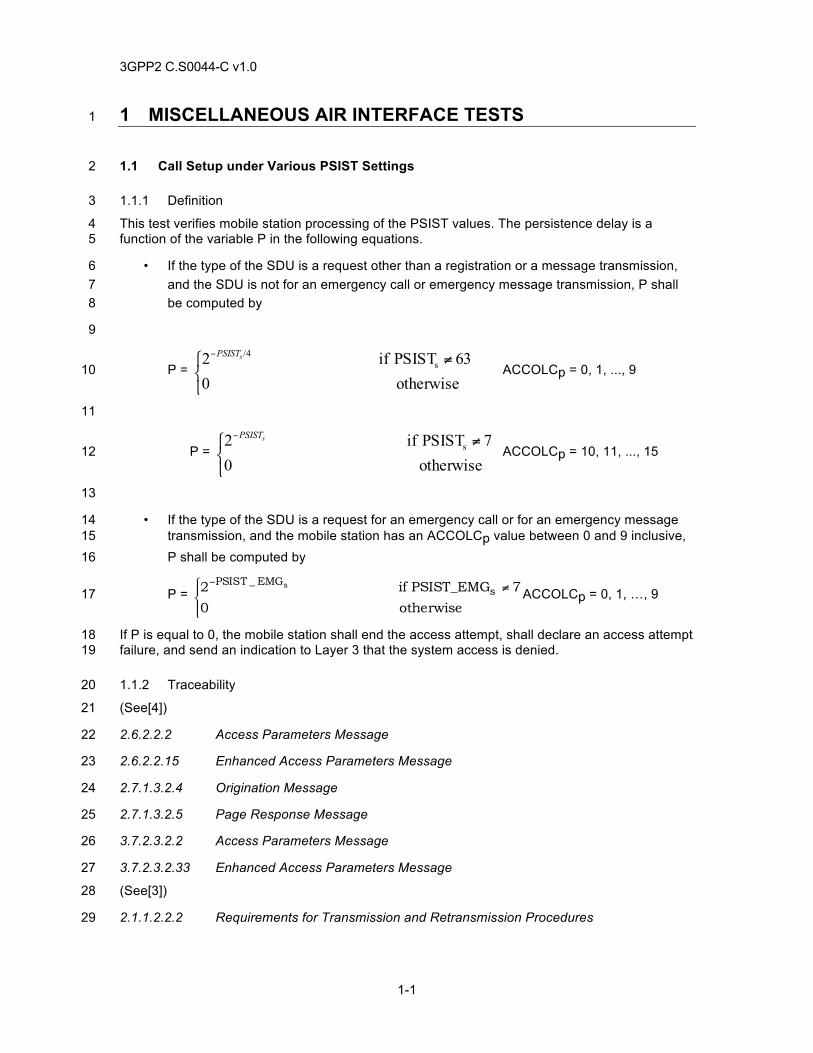
3GPP2 C.S0044-C v1.0
1-1
1 MISCELLANEOUS AIR INTERFACE TESTS 1
1.1 Call Setup under Various PSIST Settings 2
1.1.1 Definition 3
This test verifies mobile station processing of the PSIST values. The persistence delay is a 4 function of the variable P in the following equations. 5
• If the type of the SDU is a request other than a registration or a message transmission, 6 and the SDU is not for an emergency call or emergency message transmission, P shall 7 be computed by 8
9
P = ⎩⎨⎧ ≠−
otherwise 063 PSIST if 2 s
/4sPSIST
ACCOLCp = 0, 1, ..., 9 10
11
P = ⎩⎨⎧ ≠−
otherwise 07 PSIST if 2 s
sPSIST
ACCOLCp = 10, 11, ..., 15 12
13
• If the type of the SDU is a request for an emergency call or for an emergency message 14 transmission, and the mobile station has an ACCOLCp value between 0 and 9 inclusive, 15 P shall be computed by 16
P = ⎪⎩
⎪⎨⎧ ≠−
otherwise 0
7 PSIST_EMG if 2 sEMG_PSIST s
ACCOLCp = 0, 1, …, 9 17
If P is equal to 0, the mobile station shall end the access attempt, shall declare an access attempt 18 failure, and send an indication to Layer 3 that the system access is denied. 19
1.1.2 Traceability 20
(See[4]) 21
2.6.2.2.2 Access Parameters Message 22
2.6.2.2.15 Enhanced Access Parameters Message 23
2.7.1.3.2.4 Origination Message 24
2.7.1.3.2.5 Page Response Message 25
3.7.2.3.2.2 Access Parameters Message 26
3.7.2.3.2.33 Enhanced Access Parameters Message 27
(See[3]) 28
2.1.1.2.2.2 Requirements for Transmission and Retransmission Procedures 29
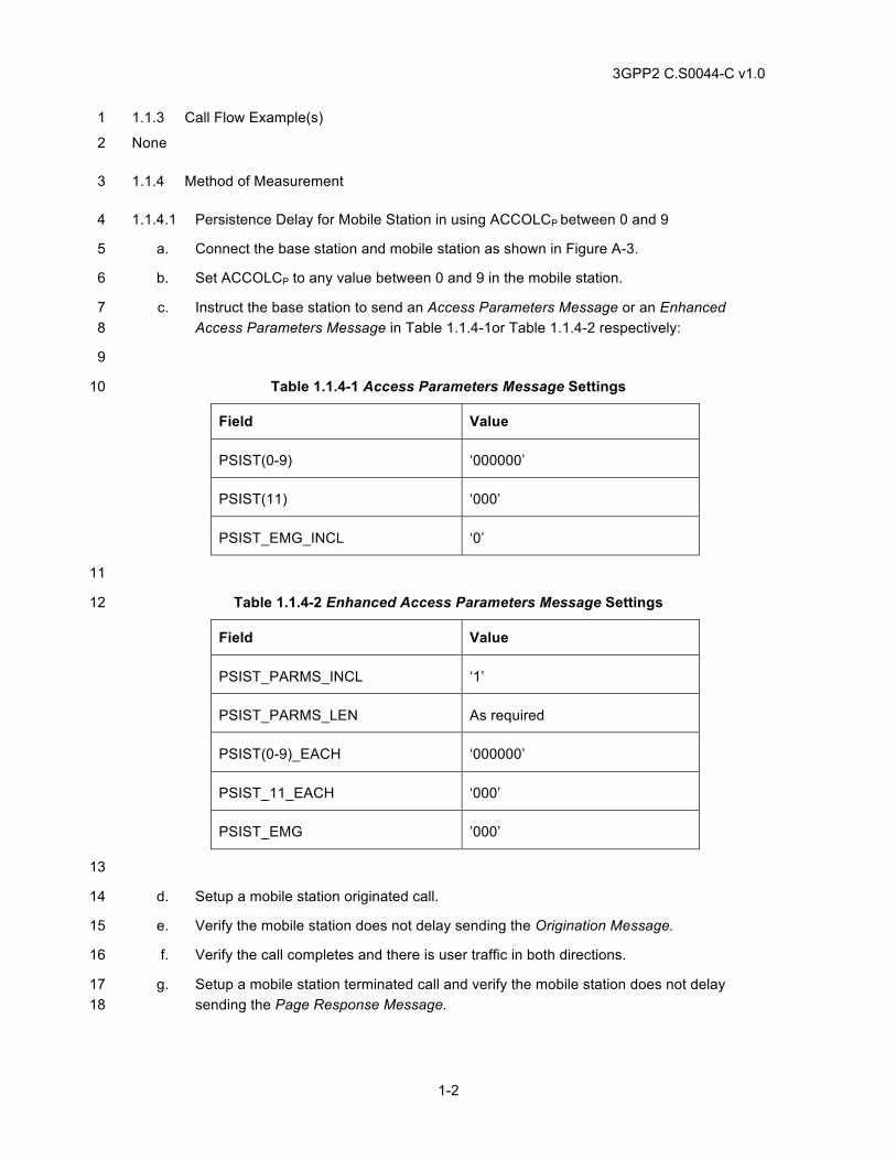
3GPP2 C.S0044-C v1.0
1-2
1.1.3 Call Flow Example(s) 1
None 2
1.1.4 Method of Measurement 3
1.1.4.1 Persistence Delay for Mobile Station in using ACCOLCP between 0 and 9 4
a. Connect the base station and mobile station as shown in Figure A-3. 5
b. Set ACCOLCP to any value between 0 and 9 in the mobile station. 6
c. Instruct the base station to send an Access Parameters Message or an Enhanced 7 Access Parameters Message in Table 1.1.4-1or Table 1.1.4-2 respectively: 8
9
Table 1.1.4-1 Access Parameters Message Settings 10
Field Value
PSIST(0-9) ‘000000’
PSIST(11) ‘000’
PSIST_EMG_INCL ‘0’
11
Table 1.1.4-2 Enhanced Access Parameters Message Settings 12
Field Value
PSIST_PARMS_INCL ‘1’
PSIST_PARMS_LEN As required
PSIST(0-9)_EACH ‘000000’
PSIST_11_EACH ‘000’
PSIST_EMG ’000’
13
d. Setup a mobile station originated call. 14
e. Verify the mobile station does not delay sending the Origination Message. 15
f. Verify the call completes and there is user traffic in both directions. 16
g. Setup a mobile station terminated call and verify the mobile station does not delay 17 sending the Page Response Message. 18
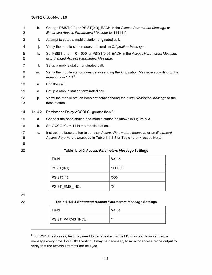
3GPP2 C.S0044-C v1.0
1-3
h. Change PSIST(0-9) or PSIST(0-9)_EACH in the Access Parameters Message or 1 Enhanced Access Parameters Message to ‘111111’. 2
i. Attempt to setup a mobile station originated call. 3
j. Verify the mobile station does not send an Origination Message. 4
k. Set PSIST(0_9) = ‘011000’ or PSIST(0-9)_EACH in the Access Parameters Message 5 or Enhanced Access Parameters Message. 6
l. Setup a mobile station originated call. 7
m. Verify the mobile station does delay sending the Origination Message according to the 8 equations in 1.1.12. 9
n. End the call. 10
o. Setup a mobile station terminated call. 11
p. Verify the mobile station does not delay sending the Page Response Message to the 12 base station. 13
1.1.4.2 Persistence Delay ACCOLCP greater than 9 14
a. Connect the base station and mobile station as shown in Figure A-3. 15
b. Set ACCOLCP = 11 in the mobile station. 16
c. Instruct the base station to send an Access Parameters Message or an Enhanced 17 Access Parameters Message in Table 1.1.4-3 or Table 1.1.4-4respectively: 18
19
Table 1.1.4-3 Access Parameters Message Settings 20
Field Value
PSIST(0-9) ‘000000’
PSIST(11) ‘000’
PSIST_EMG_INCL ‘0’
21
Table 1.1.4-4 Enhanced Access Parameters Message Settings 22
Field Value
PSIST_PARMS_INCL ‘1’
2 For PSIST test cases, test may need to be repeated, since MS may not delay sending a message every time. For PSIST testing, it may be necessary to monitor access probe output to verify that the access attempts are delayed.
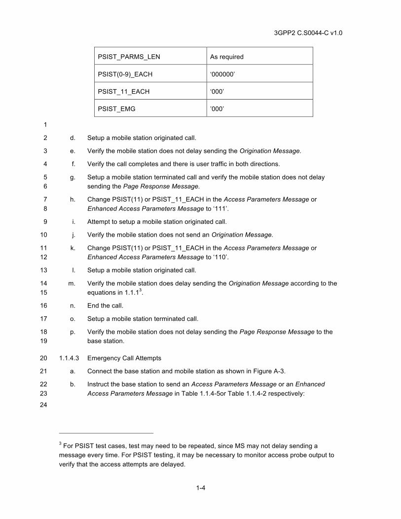
3GPP2 C.S0044-C v1.0
1-4
PSIST_PARMS_LEN As required
PSIST(0-9)_EACH ‘000000’
PSIST_11_EACH ‘000’
PSIST_EMG ’000’
1
d. Setup a mobile station originated call. 2
e. Verify the mobile station does not delay sending the Origination Message. 3
f. Verify the call completes and there is user traffic in both directions. 4
g. Setup a mobile station terminated call and verify the mobile station does not delay 5 sending the Page Response Message. 6
h. Change PSIST(11) or PSIST_11_EACH in the Access Parameters Message or 7 Enhanced Access Parameters Message to ‘111’. 8
i. Attempt to setup a mobile station originated call. 9
j. Verify the mobile station does not send an Origination Message. 10
k. Change PSIST(11) or PSIST_11_EACH in the Access Parameters Message or 11 Enhanced Access Parameters Message to ‘110’. 12
l. Setup a mobile station originated call. 13
m. Verify the mobile station does delay sending the Origination Message according to the 14 equations in 1.1.13. 15
n. End the call. 16
o. Setup a mobile station terminated call. 17
p. Verify the mobile station does not delay sending the Page Response Message to the 18 base station. 19
1.1.4.3 Emergency Call Attempts 20
a. Connect the base station and mobile station as shown in Figure A-3. 21
b. Instruct the base station to send an Access Parameters Message or an Enhanced 22 Access Parameters Message in Table 1.1.4-5or Table 1.1.4-2 respectively: 23
24
3 For PSIST test cases, test may need to be repeated, since MS may not delay sending a message every time. For PSIST testing, it may be necessary to monitor access probe output to verify that the access attempts are delayed.
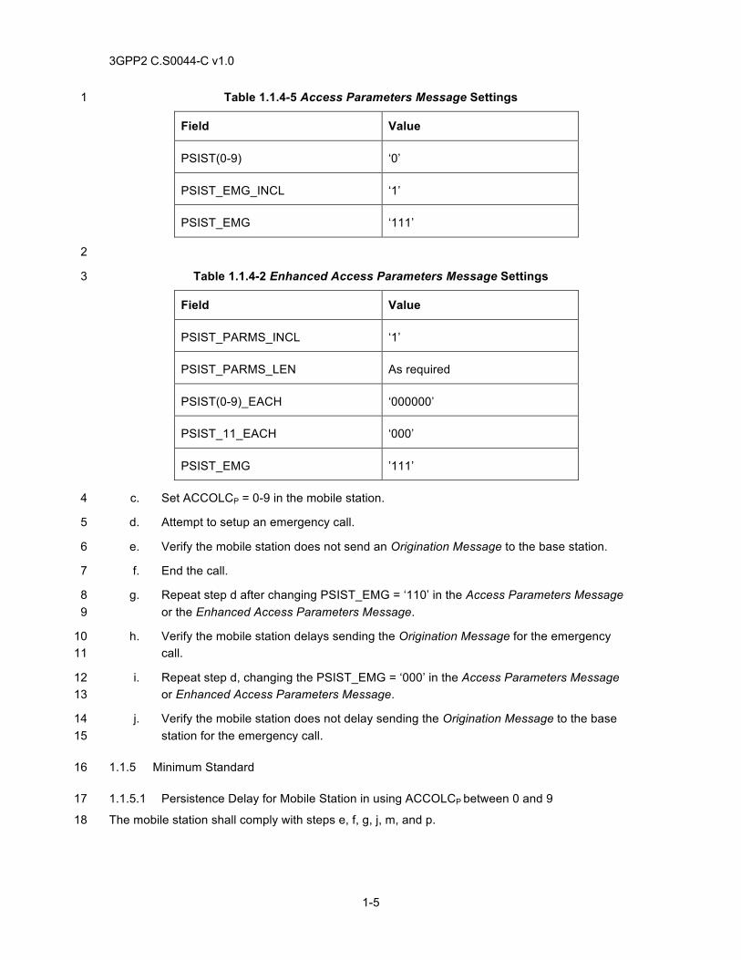
3GPP2 C.S0044-C v1.0
1-5
Table 1.1.4-5 Access Parameters Message Settings 1
Field Value
PSIST(0-9) ‘0’
PSIST_EMG_INCL ‘1’
PSIST_EMG ‘111’
2
Table 1.1.4-2 Enhanced Access Parameters Message Settings 3
Field Value
PSIST_PARMS_INCL ‘1’
PSIST_PARMS_LEN As required
PSIST(0-9)_EACH ‘000000’
PSIST_11_EACH ‘000’
PSIST_EMG ’111’
c. Set ACCOLCP = 0-9 in the mobile station. 4
d. Attempt to setup an emergency call. 5
e. Verify the mobile station does not send an Origination Message to the base station. 6
f. End the call. 7
g. Repeat step d after changing PSIST_EMG = ‘110’ in the Access Parameters Message 8 or the Enhanced Access Parameters Message. 9
h. Verify the mobile station delays sending the Origination Message for the emergency 10 call. 11
i. Repeat step d, changing the PSIST_EMG = ‘000’ in the Access Parameters Message 12 or Enhanced Access Parameters Message. 13
j. Verify the mobile station does not delay sending the Origination Message to the base 14 station for the emergency call. 15
1.1.5 Minimum Standard 16
1.1.5.1 Persistence Delay for Mobile Station in using ACCOLCP between 0 and 9 17
The mobile station shall comply with steps e, f, g, j, m, and p. 18
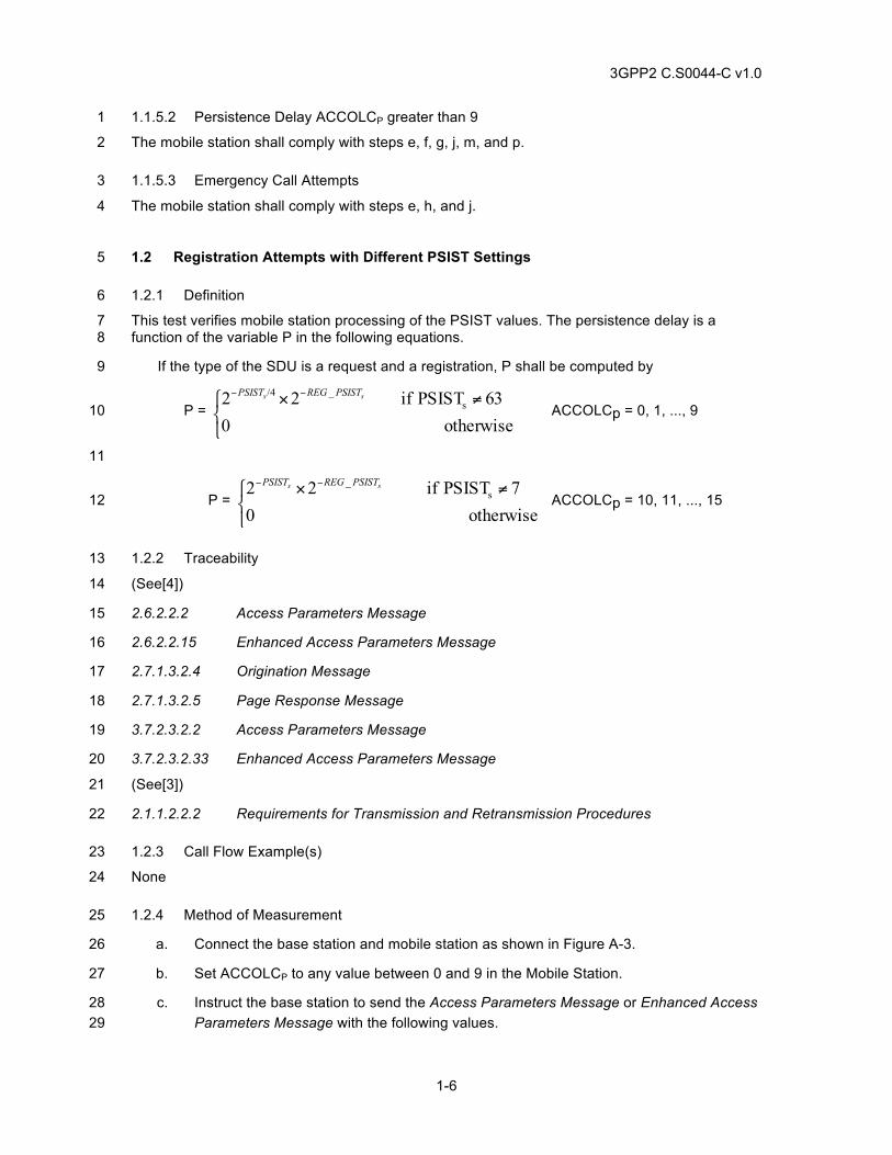
3GPP2 C.S0044-C v1.0
1-6
1.1.5.2 Persistence Delay ACCOLCP greater than 9 1
The mobile station shall comply with steps e, f, g, j, m, and p. 2
1.1.5.3 Emergency Call Attempts 3
The mobile station shall comply with steps e, h, and j. 4
1.2 Registration Attempts with Different PSIST Settings 5
1.2.1 Definition 6
This test verifies mobile station processing of the PSIST values. The persistence delay is a 7 function of the variable P in the following equations. 8
If the type of the SDU is a request and a registration, P shall be computed by 9
P = ⎩⎨⎧ ≠× −−
otherwise 063 PSIST if 22 s
_/4 ss PSISTREGPSIST
ACCOLCp = 0, 1, ..., 9 10
11
P = ⎩⎨⎧ ≠× −−
otherwise 07 PSIST if 22 s
_ ss PSISTREGPSIST
ACCOLCp = 10, 11, ..., 15 12
1.2.2 Traceability 13
(See[4]) 14
2.6.2.2.2 Access Parameters Message 15
2.6.2.2.15 Enhanced Access Parameters Message 16
2.7.1.3.2.4 Origination Message 17
2.7.1.3.2.5 Page Response Message 18
3.7.2.3.2.2 Access Parameters Message 19
3.7.2.3.2.33 Enhanced Access Parameters Message 20
(See[3]) 21
2.1.1.2.2.2 Requirements for Transmission and Retransmission Procedures 22
1.2.3 Call Flow Example(s) 23
None 24
1.2.4 Method of Measurement 25
a. Connect the base station and mobile station as shown in Figure A-3. 26
b. Set ACCOLCP to any value between 0 and 9 in the Mobile Station. 27
c. Instruct the base station to send the Access Parameters Message or Enhanced Access 28 Parameters Message with the following values. 29
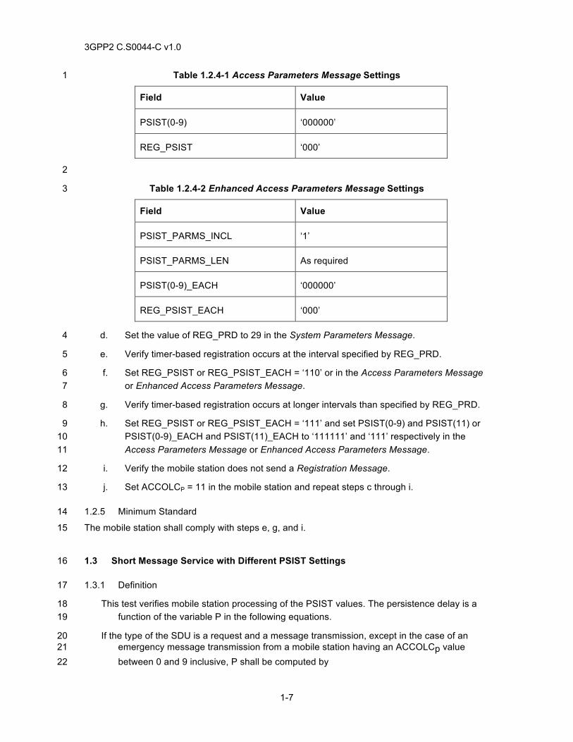
3GPP2 C.S0044-C v1.0
1-7
Table 1.2.4-1 Access Parameters Message Settings 1
Field Value
PSIST(0-9) ‘000000’
REG_PSIST ‘000’
2
Table 1.2.4-2 Enhanced Access Parameters Message Settings 3
Field Value
PSIST_PARMS_INCL ‘1’
PSIST_PARMS_LEN As required
PSIST(0-9)_EACH ‘000000’
REG_PSIST_EACH ‘000’
d. Set the value of REG_PRD to 29 in the System Parameters Message. 4
e. Verify timer-based registration occurs at the interval specified by REG_PRD. 5
f. Set REG_PSIST or REG_PSIST_EACH = ‘110’ or in the Access Parameters Message 6 or Enhanced Access Parameters Message. 7
g. Verify timer-based registration occurs at longer intervals than specified by REG_PRD. 8
h. Set REG_PSIST or REG_PSIST_EACH = ‘111’ and set PSIST(0-9) and PSIST(11) or 9 PSIST(0-9)_EACH and PSIST(11)_EACH to ‘111111’ and ‘111’ respectively in the 10 Access Parameters Message or Enhanced Access Parameters Message. 11
i. Verify the mobile station does not send a Registration Message. 12
j. Set ACCOLCP = 11 in the mobile station and repeat steps c through i. 13
1.2.5 Minimum Standard 14
The mobile station shall comply with steps e, g, and i. 15
1.3 Short Message Service with Different PSIST Settings 16
1.3.1 Definition 17
This test verifies mobile station processing of the PSIST values. The persistence delay is a 18 function of the variable P in the following equations. 19
If the type of the SDU is a request and a message transmission, except in the case of an 20 emergency message transmission from a mobile station having an ACCOLCp value 21 between 0 and 9 inclusive, P shall be computed by 22
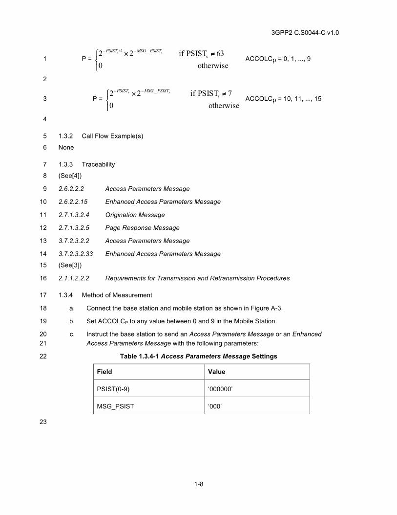
3GPP2 C.S0044-C v1.0
1-8
P = ⎩⎨⎧ ≠× −−
otherwise 063 PSIST if 22 s
_/4 ss PSISTMSGPSIST
ACCOLCp = 0, 1, ..., 9 1
2
P = ⎩⎨⎧ ≠× −−
otherwise 07 PSIST if 22 s
_ ss PSISTMSGPSIST
ACCOLCp = 10, 11, ..., 15 3
4
1.3.2 Call Flow Example(s) 5
None 6
1.3.3 Traceability 7
(See[4]) 8
2.6.2.2.2 Access Parameters Message 9
2.6.2.2.15 Enhanced Access Parameters Message 10
2.7.1.3.2.4 Origination Message 11
2.7.1.3.2.5 Page Response Message 12
3.7.2.3.2.2 Access Parameters Message 13
3.7.2.3.2.33 Enhanced Access Parameters Message 14
(See[3]) 15
2.1.1.2.2.2 Requirements for Transmission and Retransmission Procedures 16
1.3.4 Method of Measurement 17
a. Connect the base station and mobile station as shown in Figure A-3. 18
b. Set ACCOLCP to any value between 0 and 9 in the Mobile Station. 19
c. Instruct the base station to send an Access Parameters Message or an Enhanced 20 Access Parameters Message with the following parameters: 21
Table 1.3.4-1 Access Parameters Message Settings 22
Field Value
PSIST(0-9) ‘000000’
MSG_PSIST ‘000’
23
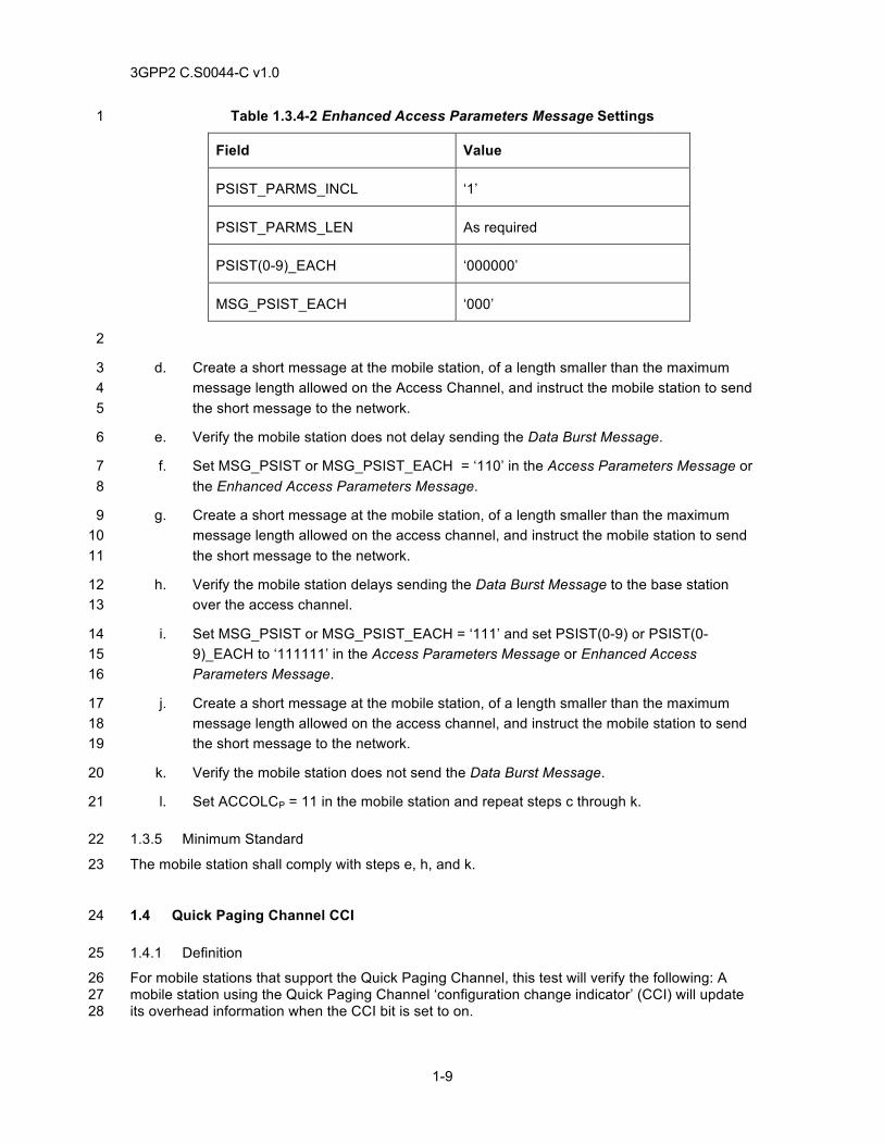
3GPP2 C.S0044-C v1.0
1-9
Table 1.3.4-2 Enhanced Access Parameters Message Settings 1
Field Value
PSIST_PARMS_INCL ‘1’
PSIST_PARMS_LEN As required
PSIST(0-9)_EACH ‘000000’
MSG_PSIST_EACH ‘000’
2
d. Create a short message at the mobile station, of a length smaller than the maximum 3 message length allowed on the Access Channel, and instruct the mobile station to send 4 the short message to the network. 5
e. Verify the mobile station does not delay sending the Data Burst Message. 6
f. Set MSG_PSIST or MSG_PSIST_EACH = ‘110’ in the Access Parameters Message or 7 the Enhanced Access Parameters Message. 8
g. Create a short message at the mobile station, of a length smaller than the maximum 9 message length allowed on the access channel, and instruct the mobile station to send 10 the short message to the network. 11
h. Verify the mobile station delays sending the Data Burst Message to the base station 12 over the access channel. 13
i. Set MSG_PSIST or MSG_PSIST_EACH = ‘111’ and set PSIST(0-9) or PSIST(0-14 9)_EACH to ‘111111’ in the Access Parameters Message or Enhanced Access 15 Parameters Message. 16
j. Create a short message at the mobile station, of a length smaller than the maximum 17 message length allowed on the access channel, and instruct the mobile station to send 18 the short message to the network. 19
k. Verify the mobile station does not send the Data Burst Message. 20
l. Set ACCOLCP = 11 in the mobile station and repeat steps c through k. 21
1.3.5 Minimum Standard 22
The mobile station shall comply with steps e, h, and k. 23
1.4 Quick Paging Channel CCI 24
1.4.1 Definition 25
For mobile stations that support the Quick Paging Channel, this test will verify the following: A 26 mobile station using the Quick Paging Channel ‘configuration change indicator’ (CCI) will update 27 its overhead information when the CCI bit is set to on. 28
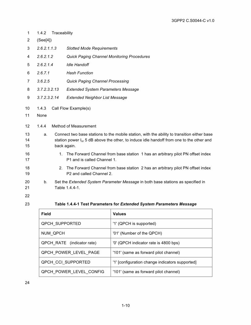
3GPP2 C.S0044-C v1.0
1-10
1.4.2 Traceability 1
(See[4]) 2
2.6.2.1.1.3 Slotted Mode Requirements 3
2.6.2.1.2 Quick Paging Channel Monitoring Procedures 4
2.6.2.1.4 Idle Handoff 5
2.6.7.1 Hash Function 6
3.6.2.5 Quick Paging Channel Processing 7
3.7.2.3.2.13 Extended System Parameters Message 8
3.7.2.3.2.14 Extended Neighbor List Message 9
1.4.3 Call Flow Example(s) 10
None 11
1.4.4 Method of Measurement 12
a. Connect two base stations to the mobile station, with the ability to transition either base 13 station power Ior 5 dB above the other, to induce idle handoff from one to the other and 14 back again. 15
1. The Forward Channel from base station 1 has an arbitrary pilot PN offset index 16 P1 and is called Channel 1. 17
2. The Forward Channel from base station 2 has an arbitrary pilot PN offset index 18 P2 and called Channel 2. 19
b. Set the Extended System Parameter Message in both base stations as specified in 20 Table 1.4.4-1. 21
22
Table 1.4.4-1 Test Parameters for Extended System Parameters Message 23
Field Values
QPCH_SUPPORTED '1' (QPCH is supported)
NUM_QPCH '01' (Number of the QPCH)
QPCH_RATE (indicator rate) '0' (QPCH indicator rate is 4800 bps)
QPCH_POWER_LEVEL_PAGE '101' (same as forward pilot channel)
QPCH_CCI_SUPPORTED '1' [configuration change indicators supported]
QPCH_POWER_LEVEL_CONFIG '101' (same as forward pilot channel)
24
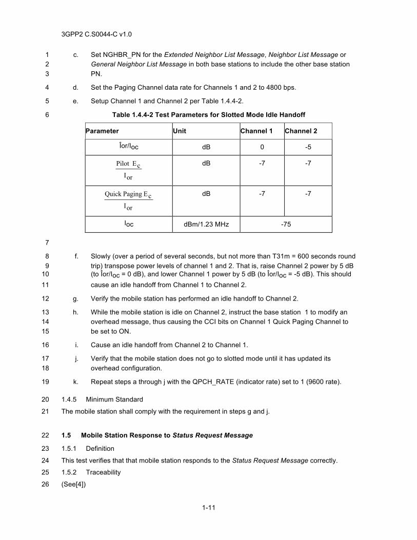
3GPP2 C.S0044-C v1.0
1-11
c. Set NGHBR_PN for the Extended Neighbor List Message, Neighbor List Message or 1 General Neighbor List Message in both base stations to include the other base station 2 PN. 3
d. Set the Paging Channel data rate for Channels 1 and 2 to 4800 bps. 4
e. Setup Channel 1 and Channel 2 per Table 1.4.4-2. 5
Table 1.4.4-2 Test Parameters for Slotted Mode Idle Handoff 6
Parameter Unit Channel 1 Channel 2
Îor/Ioc dB 0 -5
orIcEPilot
dB -7 -7
orIcE PagingQuick
dB -7 -7
Ioc dBm/1.23 MHz -75
7
f. Slowly (over a period of several seconds, but not more than T31m = 600 seconds round 8 trip) transpose power levels of channel 1 and 2. That is, raise Channel 2 power by 5 dB 9 (to Îor/Ioc = 0 dB), and lower Channel 1 power by 5 dB (to Îor/Ioc = -5 dB). This should 10 cause an idle handoff from Channel 1 to Channel 2. 11
g. Verify the mobile station has performed an idle handoff to Channel 2. 12
h. While the mobile station is idle on Channel 2, instruct the base station 1 to modify an 13 overhead message, thus causing the CCI bits on Channel 1 Quick Paging Channel to 14 be set to ON. 15
i. Cause an idle handoff from Channel 2 to Channel 1. 16
j. Verify that the mobile station does not go to slotted mode until it has updated its 17 overhead configuration. 18
k. Repeat steps a through j with the QPCH_RATE (indicator rate) set to 1 (9600 rate). 19
1.4.5 Minimum Standard 20
The mobile station shall comply with the requirement in steps g and j. 21
1.5 Mobile Station Response to Status Request Message 22
1.5.1 Definition 23
This test verifies that that mobile station responds to the Status Request Message correctly. 24
1.5.2 Traceability 25
(See[4]) 26
3GPP2 C.S0044-C v1.0
1-12
2.6.3.5 Mobile Station Origination Attempt Substate 1
2.6.4.1.2 Service Configuration and Negotiation 2
2.6.4.1.14 Processing the Service Configuration Record 3
2.6.4.1.15 Processing the Non-Negotiable Service Configuration Record 4
2.6.4.2 Traffic Channel Initialization Substate 5
2.7.1.3.2.4 Origination Message 6
2.7.1.3.2.5 Page Response Message 7
2.7.1.3.2.10 Extended Status Response Message 8
2.7.2.3.2.14 Service Connect Completion Message 9
2.7.2.3.2.16 Status Response Message 10
2.7.4 Information Records 11
3.6.3.5 Response to Origination Message 12
3.6.4.1.2 Service Configuration and Negotiation 13
3.7.2.3.2.15 Status Request Message 14
3.7.2.3.2.21 Extended Channel Assignment Message 15
3.7.3.3.2.20 Service Connect Message 16
3.7.5.7 Service Configuration 17
3.7.5.20 Non-Negotiable Service Configuration 18
1.5.3 Call Flow Example(s) 19
None 20
1.5.4 Method of Measurement 21
a. Ensure the mobile station is operating in the Idle State. 22
b. Instruct the base station to send a Status Request Message on the f-csch to request 23 one or more of the information records listed in section 2.7.4 of [4]. Verify that 24 QUAL_INFO_TYPE, QUAL_INFO_LEN and Type-specific fields in Status Request 25 Message are set to appropriate values. 26
c. Verify the following: 27
1. If P_REV_IN_USE is greater than 3: 28
a. The mobile station sends an Extended Status Response Message with 29 the QUAL_INFO_TYPE, QUAL_INFO_LEN, Type-specific fields set to 30 appropriate value, and requested information record(s) included; or 31
b. The mobile station sends a Mobile Station Reject Order with ORDQ = 32 6 if the mobile station does not support the band class and/or operating 33 mode specified in the Status Request Message; or 34
3GPP2 C.S0044-C v1.0
1-13
c. The mobile station sends a Mobile Station Reject Order with ORDQ = 1 8 if the information record would exceed the allowable length; or 2
d. The mobile station sends a Mobile Station Reject Order with ORDQ = 3 9 if the information record is not supported for the specified band class 4 and operating mode. 5
2. If P_REV_IN_USE is less than or equal to 3: 6
a. The mobile station sends a Status Response Message with the 7 appropriate QUAL_INFO_TYPE, QUAL_INFO_LEN, Type-specific 8 fields set to appropriate value, and requested information record(s) 9 included; or 10
b. The mobile station sends a Mobile Station Reject Order with ORDQ = 11 6 if the mobile station does not support the band class and/or operating 12 mode specified in the Status Request Message; or 13
c. The mobile station sends a Mobile Station Reject Order with ORDQ = 14 8 if the information record would exceed the allowable length; or 15
d. The mobile station sends a Mobile Station Reject Order with ORDQ = 16 9 if the information record is not supported for the specified band class 17 and operating mode. 18
d. Set up a mobile originated call. 19
e. Instruct the base station to send a Status Request Message on the f-dsch to request 20 one or more of the information records listed in section 2.7.4 of [4]. 21
f. Verify the following: 22
1. The mobile station sends a Status Response Message with the appropriate band 23 class, operating mode, and information record; or 24
2. The mobile station sends a Mobile Station Reject Order with ORDQ = 6 if the 25 mobile station does not support the band class and/or operating mode specified 26 in the Status Request Message; or 27
3. The mobile station sends a Mobile Station Reject Order with ORDQ = 9 if the 28 information record is not supported for the specified band class and operating 29 mode. 30
1.5.5 Minimum Standard 31
The mobile station shall comply with steps c and f. 32
1.6 SYNC Channel Support for Mobile Stations not capable of TD, or not capable of 33 QPCH or RC>2 34
1.6.1 Definition 35
This test verifies that the mobile station is able to respond correctly to the new fields of Sync 36 Channel Message sent by the base station if any, tune to appropriate CDMA channel and acquire 37 the system successfully. 38
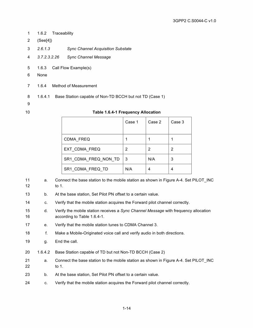
3GPP2 C.S0044-C v1.0
1-14
1.6.2 Traceability 1
(See[4]) 2
2.6.1.3 Sync Channel Acquisition Substate 3
3.7.2.3.2.26 Sync Channel Message 4
1.6.3 Call Flow Example(s) 5
None 6
1.6.4 Method of Measurement 7
1.6.4.1 Base Station capable of Non-TD BCCH but not TD (Case 1) 8
9
Table 1.6.4-1 Frequency Allocation 10
Case 1 Case 2 Case 3
CDMA_FREQ 1 1 1
EXT_CDMA_FREQ 2 2 2
SR1_CDMA_FREQ_NON_TD 3 N/A 3
SR1_CDMA_FREQ_TD N/A 4 4
a. Connect the base station to the mobile station as shown in Figure A-4. Set PILOT_INC 11 to 1. 12
b. At the base station, Set Pilot PN offset to a certain value. 13
c. Verify that the mobile station acquires the Forward pilot channel correctly. 14
d. Verify the mobile station receives a Sync Channel Message with frequency allocation 15 according to Table 1.6.4-1. 16
e. Verify that the mobile station tunes to CDMA Channel 3. 17
f. Make a Mobile-Originated voice call and verify audio in both directions. 18
g. End the call. 19
1.6.4.2 Base Station capable of TD but not Non-TD BCCH (Case 2) 20
a. Connect the base station to the mobile station as shown in Figure A-4. Set PILOT_INC 21 to 1. 22
b. At the base station, Set Pilot PN offset to a certain value. 23
c. Verify that the mobile station acquires the Forward pilot channel correctly. 24
3GPP2 C.S0044-C v1.0
1-15
d. Verify the mobile station receives a Sync Channel Message frequency allocation 1 according to Table 1.6.4-1. 2
e. Verify that the mobile station tunes to CDMA Channel 1. 3
f. Make a Mobile-Originated voice call and verify audio in both directions. 4
g. End the call. 5
1.6.4.3 Base Station capable of Non-TD BCCH and TD (Case 3) 6
a. Connect the base station to the mobile station as shown in Figure A-4. Set PILOT_INC 7 to 1. 8
b. At the base station, Set Pilot PN offset to a certain value. 9
c. Verify that the mobile station acquires the Forward pilot channel correctly. 10
d. Verify the mobile station receives a Sync Channel Message with frequency allocation 11 according to Table 1.6.4-1. 12
e. Verify that the mobile station tunes to CDMA Channel 3. 13
f. Make a Mobile-Originated voice call and verify audio in both directions. 14
g. End the call. 15
1.6.5 Minimum Standard 16
1.6.5.1 Base Station capable of Non-TD BCCH but not TD (Case 1) 17
The mobile station shall comply with steps c, e, and f. 18
1.6.5.2 Base Station capable of TD but not Non-TD BCCH (Case 2) 19
The mobile station shall comply with steps c, e, and f. 20
1.6.5.3 Base Station capable of Non-TD BCCH and TD (Case 3) 21
The mobile station shall comply with steps c, e, and f. 22
1.7 Sync Channel support for Mobile Stations not capable of TD, but capable of QPCH 23 or RC>2 24
1.7.1 Definition 25
This test verifies that the mobile station is able to respond correctly to the new fields of Sync 26 Channel Message sent by the base station if any, tune to appropriate CDMA channel and acquire 27 the system successfully. 28
1.7.2 Traceability 29
(See[4]) 30
2.6.1.3 Sync Channel Acquisition Substate 31
3.7.2.3.2.26 Sync Channel Message 32
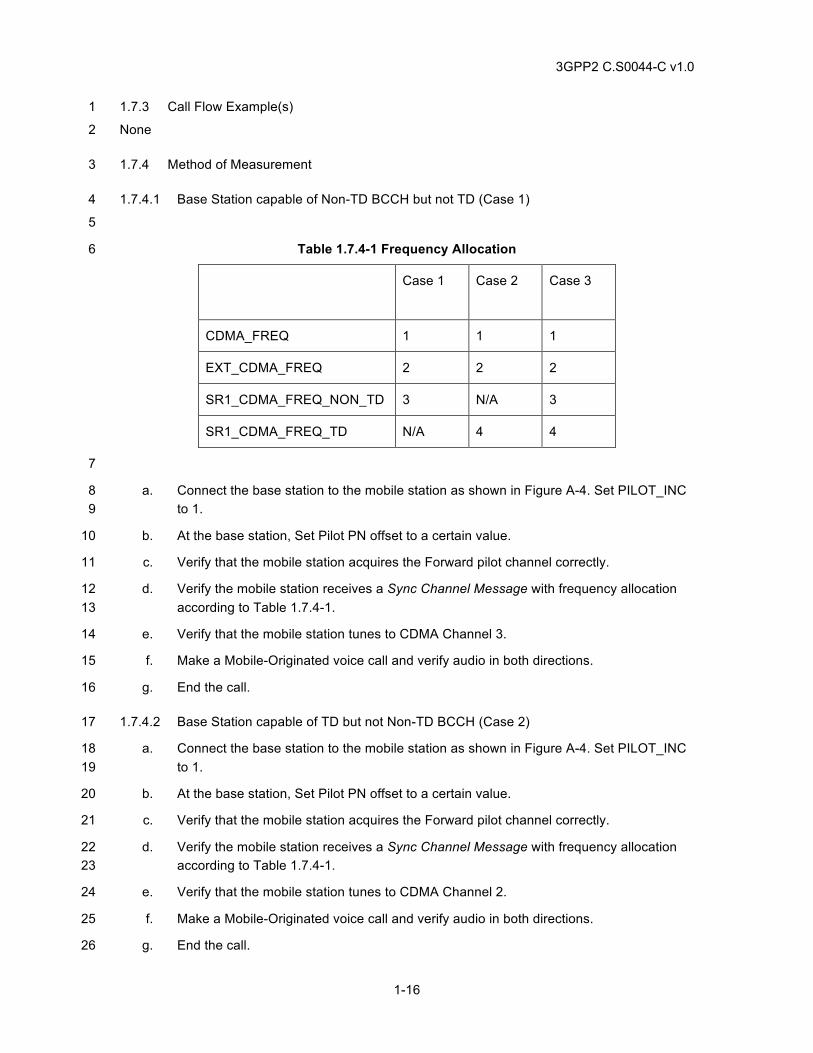
3GPP2 C.S0044-C v1.0
1-16
1.7.3 Call Flow Example(s) 1
None 2
1.7.4 Method of Measurement 3
1.7.4.1 Base Station capable of Non-TD BCCH but not TD (Case 1) 4
5
Table 1.7.4-1 Frequency Allocation 6
Case 1 Case 2 Case 3
CDMA_FREQ 1 1 1
EXT_CDMA_FREQ 2 2 2
SR1_CDMA_FREQ_NON_TD 3 N/A 3
SR1_CDMA_FREQ_TD N/A 4 4
7
a. Connect the base station to the mobile station as shown in Figure A-4. Set PILOT_INC 8 to 1. 9
b. At the base station, Set Pilot PN offset to a certain value. 10
c. Verify that the mobile station acquires the Forward pilot channel correctly. 11
d. Verify the mobile station receives a Sync Channel Message with frequency allocation 12 according to Table 1.7.4-1. 13
e. Verify that the mobile station tunes to CDMA Channel 3. 14
f. Make a Mobile-Originated voice call and verify audio in both directions. 15
g. End the call. 16
1.7.4.2 Base Station capable of TD but not Non-TD BCCH (Case 2) 17
a. Connect the base station to the mobile station as shown in Figure A-4. Set PILOT_INC 18 to 1. 19
b. At the base station, Set Pilot PN offset to a certain value. 20
c. Verify that the mobile station acquires the Forward pilot channel correctly. 21
d. Verify the mobile station receives a Sync Channel Message with frequency allocation 22 according to Table 1.7.4-1. 23
e. Verify that the mobile station tunes to CDMA Channel 2. 24
f. Make a Mobile-Originated voice call and verify audio in both directions. 25
g. End the call. 26
3GPP2 C.S0044-C v1.0
1-17
1.7.4.3 Base Station capable of Non-TD BCCH and TD (Case 3) 1
a. Connect the base station to the mobile station as shown in Figure A-4. Set PILOT_INC 2 to 1. 3
b. At the base station, Set Pilot PN offset to a certain value. 4
c. Verify that the mobile station acquires the Forward pilot channel correctly. 5
d. Verify the mobile station receives a Sync Channel Message with frequency allocation 6 according to Table 1.7.4-1. 7
e. Verify that the mobile station tunes to CDMA Channel 3. 8
f. Make a Mobile-Originated voice call and verify audio in both directions. 9
g. End the call. 10
1.7.5 Minimum Standard 11
1.7.5.1 Base Station capable of Non-TD BCCH but not TD (Case 1) 12
The mobile station shall comply with steps c, e, and f. 13
1.7.5.2 Base Station capable of TD but not Non-TD BCCH (Case 2) 14
The mobile station shall comply with steps c, e, and f. 15
1.7.5.3 Base Station capable of Non-TD BCCH and TD (Case 3) 16
The mobile station shall comply with steps c, e, and f. 17
1.8 Sync Channel Support for Mobile Stations capable of TD and QPCH or RC>2 18
1.8.1 Definition 19
This test verifies that the mobile station is able to respond correctly to the new fields of Sync 20 Channel Message sent by the base station if any, tune to appropriate CDMA channel and acquire 21 the system successfully. 22
1.8.2 Traceability 23
(see [4]) 24
2.6.1.3 Sync Channel Acquisition Substate 25
3.7.2.3.2.26 Sync Channel Message 26
1.8.3 Call Flow Example(s) 27
None 28
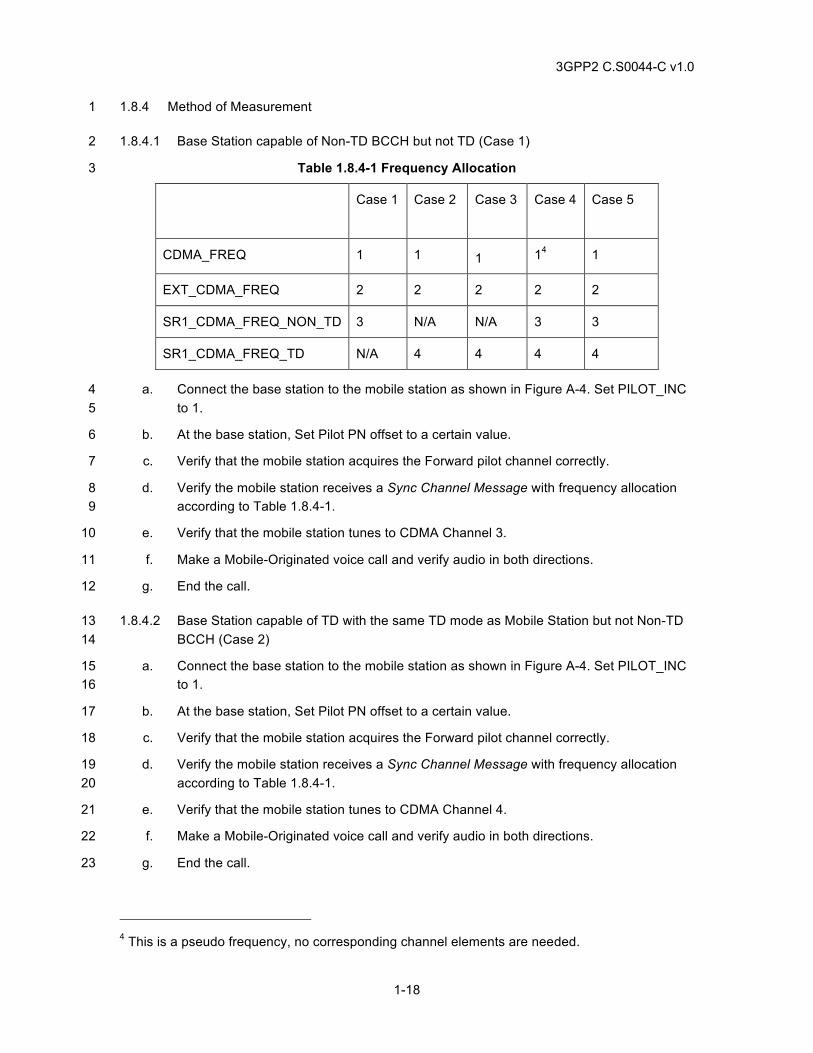
3GPP2 C.S0044-C v1.0
1-18
1.8.4 Method of Measurement 1
1.8.4.1 Base Station capable of Non-TD BCCH but not TD (Case 1) 2
Table 1.8.4-1 Frequency Allocation 3
Case 1 Case 2 Case 3 Case 4 Case 5
CDMA_FREQ 1 1 1 14 1
EXT_CDMA_FREQ 2 2 2 2 2
SR1_CDMA_FREQ_NON_TD 3 N/A N/A 3 3
SR1_CDMA_FREQ_TD N/A 4 4 4 4
a. Connect the base station to the mobile station as shown in Figure A-4. Set PILOT_INC 4 to 1. 5
b. At the base station, Set Pilot PN offset to a certain value. 6
c. Verify that the mobile station acquires the Forward pilot channel correctly. 7
d. Verify the mobile station receives a Sync Channel Message with frequency allocation 8 according to Table 1.8.4-1. 9
e. Verify that the mobile station tunes to CDMA Channel 3. 10
f. Make a Mobile-Originated voice call and verify audio in both directions. 11
g. End the call. 12
1.8.4.2 Base Station capable of TD with the same TD mode as Mobile Station but not Non-TD 13 BCCH (Case 2) 14
a. Connect the base station to the mobile station as shown in Figure A-4. Set PILOT_INC 15 to 1. 16
b. At the base station, Set Pilot PN offset to a certain value. 17
c. Verify that the mobile station acquires the Forward pilot channel correctly. 18
d. Verify the mobile station receives a Sync Channel Message with frequency allocation 19 according to Table 1.8.4-1. 20
e. Verify that the mobile station tunes to CDMA Channel 4. 21
f. Make a Mobile-Originated voice call and verify audio in both directions. 22
g. End the call. 23
4 This is a pseudo frequency, no corresponding channel elements are needed.
3GPP2 C.S0044-C v1.0
1-19
1.8.4.3 Base Station capable of TD with different TD mode as Mobile Station but not Non-TD 1 BCCH (Case 3) 2
a. Connect the base station to the mobile station as shown in Figure A-4. Set PILOT_INC 3 to 1. 4
b. At the base station, Set Pilot PN offset to a certain value. 5
c. Verify that the mobile station acquires the Forward pilot channel correctly. 6
d. Verify the mobile station receives a Sync Channel Message with frequency allocation 7 according to Table 1.8.4-1. 8
e. Verify that the mobile station tunes to CDMA Channel 2. 9
f. Make a Mobile-Originated voice call and verify audio in both directions. 10
g. End the call. 11
1.8.4.4 Base Station capable of Non-TD BCCH and TD with the same TD mode as Mobile 12 Station (Case 4) 13
a. Connect the base station to the mobile station as shown in Figure A-4. Set PILOT_INC 14 to 1. 15
b. At the base station, Set Pilot PN offset to a certain value. 16
c. Verify that the mobile station acquires the Forward pilot channel correctly. 17
d. Verify the mobile station receives a Sync Channel Message with frequency allocation 18 according to Table 1.8.4-1. 19
e. Verify that the mobile station tunes to CDMA Channel 4. 20
f. Make a Mobile-Originated voice call and verify audio in both directions. 21
g. End the call. 22
1.8.4.5 Base Station capable of Non-TD BCCH and TD with a different TD mode as Mobile 23 Station (Case 5) 24
a. Connect the base station to the mobile station as shown in Figure A-4. Set PILOT_INC 25 to 1. 26
b. At the base station, Set Pilot PN offset to a certain value. 27
c. Verify that the mobile station acquires the Forward pilot channel correctly. 28
d. Verify the mobile station receives a Sync Channel Message with frequency allocation 29 according to Table 1.8.4-1. 30
e. Verify that the mobile station tunes to CDMA Channel 3. 31
f. Make a Mobile-Originated voice call and verify audio in both directions. 32
g. End the call. 33
3GPP2 C.S0044-C v1.0
1-20
1.8.5 Minimum Standard 1
1.8.5.1 Base Station capable of Non-TD BCCH but not TD (Case 1) 2
The mobile station shall comply with steps c, e, and f. 3
1.8.5.2 Base Station capable of TD with the same TD mode as Mobile Station but not Non-TD 4 BCCH (Case 2) 5
The mobile station shall comply with steps c, e, and f. 6
1.8.5.3 Base Station capable of TD with different TD mode as Mobile Station but not Non-TD 7 BCCH (Case 3) 8
The mobile station shall comply with steps c, e, and f. 9
1.8.5.4 Base Station capable of Non-TD BCCH and TD with the same TD mode as Mobile 10 Station (Case 4) 11
The mobile station shall comply with steps c, e, and f. 12
1.8.5.5 Base Station capable of Non-TD BCCH and TD with a different TD mode as Mobile 13 Station (Case 5) 14
The mobile station shall comply with steps c, e, and f. 15
1.9 Hashing F-CCCH, F-CCCH slot 16
1.9.1 Definition 17
This test checks the ability to set and detect hashed F-CCCH’s and F-CCCH Slots. The IMSI’s 18 effect on hashed F-CCCH and Slot is also checked. 19
1.9.2 Traceability: 20
(See[4]) 21
2.6.7.1 Hash Function 22
3.6.2.1.2 Common Channel Determination 23
3.6.2.1.3 Paging Slot Determination 24
1.9.3 Call Flow Example(s) 25
None 26
1.9.4 Methods of Measurement 27
1.9.4.1 F-CCCH Number Hashing 28
a. Connect the base station and mobile station as shown in Figure A-1. 29
b. Configure the base station system with multiple F-CCCH’s (maximum seven) in MC-RR 30 Parameters Message. 31
3GPP2 C.S0044-C v1.0
1-21
c. Make a mobile terminated call, and verify audio in both directions. 1
1.9.4.2 F-CCCH Slot Number Hashing 2
a. Connect the base station and mobile station as shown in Figure A-4. 3
b. Configure the base station system with slotted mode capability. 4
c. Make a mobile terminated call, and verify audio in both directions. 5
1.9.5 Minimum Standard 6
1.9.5.1 F-CCCH Number Hashing 7
The mobile station shall comply with step c. 8
1.9.5.2 F-CCCH Slot Number Hashing 9
The mobile station shall comply with step c. 10
1.10 CDMA Channel Hashing on F-PCH for Mobile Stations not capable of QPCH or RC>2 11
1.10.1 Definition 12
This test checks the mobile station’s ability to do CDMA Channel hashing based on different 13 capability sets to select appropriate CDMA Channel and associated PCH. 14
1.10.2 Traceability 15
(see [4]) 16
2.6.2.2 Response to Overhead Information Operation 17
2.6.2.2.12.1 Extended CDMA Channel List Message on Paging Channel 18
2.6.7.1 Hash Function 19
3.6.2.1.1 CDMA Channel Determination 20
3.7.2.3.2.28 Extended CDMA Channel List Message 21
1.10.3 Call Flow Example(s) 22
None 23
1.10.4 Methods of Measurement 24
1.10.4.1 Base Station incapable of BCCH and QPCH or RC>2 (Case 1) 25
a. Turn off all forms of autonomous registration at the base station. 26
b. Connect the base station and mobile station as shown in Figure A-4, and configure the 27 base station with 1 Paging Channel on each of the 2 CDMA channels. 28
c. Verify that the base station sends an Extended CDMA Channel List Message with 29 RC_QPCH_SEL_INCL=’0’, TD_SEL_INCL=’0’ and NUM_FREQ=’0010’ or a CDMA 30 Channel List Message from the base station. 31
3GPP2 C.S0044-C v1.0
1-22
d. Make a mobile terminated call, and verify audio in both directions. 1
1.10.4.2 Base Station incapable of BCCH, capable of QPCH or RC>2 with Extended CDMA 2 Channel List Message sent (Case 2) 3
a. Turn off all forms of autonomous registration at the base station. 4
b. Connect the base station and mobile station as shown in Figure A-4, and configure the 5 base station with 1 Paging Channel on each of the 2 CDMA channels. 6
c. Send an Extended CDMA Channel List Message with RC_QPCH_SEL_INCL=’1’, 7 TD_SEL_INCL=’0’ and NUM_FREQ=’0010’ from the base station and make sure 8 RC_QPCH_HASH_IND is set to ‘1’ for freq 1 and 2. 9
d. Make a mobile terminated call, and verify audio in both directions. 10
1.10.5 Minimum Standard 11
1.10.5.1 Base Station incapable of BCCH and QPCH or RC>2 (Case 1) 12
The mobile station shall comply with step d. 13
1.10.5.2 Base Station incapable of BCCH, capable of QPCH or RC>2 with Extended CDMA 14 Channel List Message sent (Case 2) 15
The mobile station shall comply with step d. 16
1.11 CDMA Channel Hashing on F-PCH for Mobile Stations capable of QPCH or RC>2 17
1.11.1 Definition 18
This test checks the mobile station’s ability to do CDMA Channel hashing based on different 19 capability sets to select appropriate CDMA Channel and associated PCH. 20
1.11.2 Traceability 21
(see [4]) 22
2.6.2.2 Response to Overhead Information Operation 23
2.6.2.2.12.1 Extended CDMA Channel List Message on Paging Channel 24
2.6.7.1 Hash Function 25
3.6.2.1.1 CDMA Channel Determination 26
3.7.2.3.2.28 Extended CDMA Channel List Message 27
1.11.3 Call Flow Example(s) 28
None 29
3GPP2 C.S0044-C v1.0
1-23
1.11.4 Method of Measurement 1
1.11.4.1 Base Station incapable of BCCH and QPCH or RC>2 with Extended CDMA Channel 2 List Message sent (Case 1) 3
a. Turn off all forms of autonomous registration at the base station. 4
b. Connect the base station and mobile station as shown in Figure A-4, and configure the 5 base station with 1 Paging Channel on each of the 2 CDMA channels. 6
c. Send an Extended CDMA Channel List Message with RC_QPCH_SEL_INCL=’0’, 7 TD_SEL_INCL=’0’ and NUM_FREQ=’0010’ from the base station. 8
d. Make a mobile terminated call, and verify audio in both directions. 9
1.11.4.2 Base Station incapable of BCCH, capable of QPCH or RC>2 with Extended CDMA 10 Channel List Message sent (Case 2) 11
a. Turn off all forms of autonomous registration at the base station. 12
b. Connect the base station and mobile station as shown in Figure A-4, and configure the 13 base station with 1 Paging Channel on each of the 2 CDMA channels. 14
c. Send an Extended CDMA Channel List Message with RC_QPCH_SEL_INCL=’1’, 15 TD_SEL_INCL=’0’ and NUM_FREQ=’0010’ from the base station and make sure 16 RC_QPCH_HASH_IND is set to ‘1’ for freq 1 and 2. 17
d. Make a mobile terminated call, and verify audio in both directions. 18
1.11.5 Minimum Standard 19
1.11.5.1 Base Station incapable of BCCH and QPCH or RC>2 with Extended CDMA Channel 20 List Message sent (Case 1) 21
The mobile station shall comply with step d. 22
1.11.5.2 Base Station incapable of BCCH, capable of QPCH or RC>2 with Extended CDMA 23 Channel List Message sent (Case 2) 24
The mobile station shall comply with step d. 25
1.12 CDMA Channel Hashing on F-BCCH; Mobile Station not capable of either TD or 26 QPCH (RC>2) 27
1.12.1 Definition 28
This test checks the mobile station’s ability to do CDMA Channel (frequency) hashing based on 29 different capability sets to select appropriate CDMA Channels and associated primary BCCHs. 30
1.12.2 Traceability 31
(see [4]) 32
2.6.2.1.5 Primary Broadcast Control Channel Monitoring 33
3GPP2 C.S0044-C v1.0
1-24
2.6.2.2 Response to Overhead Information Operation 1
2.6.2.2.12.2 Extended CDMA Channel List Message On Primary Broadcast Control Channel 2
2.6.7.1 Hash Function 3
3.6.2.1.1 CDMA Channel Determination 4
3.7.2.3.2.28 Extended CDMA Channel List Message 5
1.12.3 Call Flow Example(s) 6
None 7
1.12.4 Method of Measurement 8
1.12.4.1 Base station operates without TD and QPCH, RC>2 (Case 1) 9
a. Turn off all forms of autonomous registration at the base station. 10
b. Connect the base station and mobile station as shown in Figure A-4, and configure the 11 base station with 1 primary BCCH on each of the 2 CDMA channels. 12
c. Send an Extended CDMA Channel List Message with RC_QPCH_SEL_INCL=’0’, 13 TD_SEL_INCL=’0’ and NUM_FREQ=’0010’ from the base station. 14
d. Make a mobile terminated call, and verify audio in both directions. 15
1.12.4.2 Base Station operates without TD (STS) but with QPCH (RC>2), (Case 2) 16
a. Turn off all forms of autonomous registration at the base station. 17
b. Connect the base station and mobile station as shown in Figure A-4, and configure the 18 base station with 1 primary BCCH on each of the 2 CDMA channels. 19
c. Send an Extended CDMA Channel List Message with RC_QPCH_SEL_INCL=’1’, 20 TD_SEL_INCL=’0’ and NUM_FREQ=’0010’ from the base station and make sure 21 RC_QPCH_HASH_IND is set to ‘1’ for freq 1 and 2 22
d. Make a mobile terminated call, and verify audio in both directions. 23
1.12.4.3 Base Station operates with TD (STS) and QPCH (RC>2) (Case 3) 24
a. Turn off all forms of autonomous registration at the base station. 25
b. Connect the base station and mobile station as shown in Figure A-4, and configure the 26 base station with 1 primary BCCH on each of the 2 CDMA channels. 27
c. Send an Extended CDMA Channel List Message with RC_QPCH_SEL_INCL=’1’, 28 TD_SEL_INCL=’1’ and NUM_FREQ=’0010’ from the base station and make sure 29 TD_HASH_IND is set to ‘1’ for frequency 1 and RC_QPCH_HASH_IND is set to ‘1’ for 30 frequency 1 and 2. 31
d. Make a mobile terminated call, and verify audio in both directions. 32
3GPP2 C.S0044-C v1.0
1-25
1.12.5 Minimum Standard 1
1.12.5.1 Base station operates without TD and QPCH, RC>2 (Case 1) 2
The mobile station shall comply with step d. 3
1.12.5.2 Base Station operates without TD (STS) but with QPCH (RC>2), (Case 2) 4
The mobile station shall comply with step d. 5
1.12.5.3 Base Station operates with TD (STS) and QPCH (RC>2) (Case 3) 6
The mobile station shall comply with step d. 7
1.13 CDMA Channel Hashing on F-BCCH; Mobile Station not capable of TD (STS) but 8 capable of QPCH (RC>2) 9
1.13.1 Definition 10
This test checks the mobile station’s ability to do CDMA Channel (frequency) hashing based on 11 different capability sets to select appropriate CDMA Channels and associated primary BCCH’s. 12
1.13.2 Traceability 13
(see [4]) 14
2.6.2.1.5 Primary Broadcast Control Channel Monitoring 15
2.6.2.2 Response to Overhead Information Operation 16
2.6.2.2.12.2 Extended CDMA Channel List Message On Primary Broadcast Control Channel 17
2.6.7.1 Hash Function 18
CDMA Channel Determination 19
3.7.2.3.2.28 Extended CDMA Channel List Message 20
1.13.3 Call Flow Example(s) 21
None 22
1.13.4 Method of Measurement 23
1.13.4.1 Base Station operates without TD (STS) and QPCH (RC>2) (Case 1) 24
a. Turn off all forms of autonomous registration at the base station. 25
b. Connect the base station and mobile station as shown in Figure A-4, and configure the 26 base station with 1 primary BCCH on each of the 2 CDMA channels. 27
c. Send an Extended CDMA Channel List Message with RC_QPCH_SEL_INCL=’0’, 28 TD_SEL_INCL=’0’ and NUM_FREQ=’0010’ from the base station. 29
d. Make a mobile terminated call, and verify audio in both directions. 30
3GPP2 C.S0044-C v1.0
1-26
1.13.4.2 Base Station operates without TD (STS) but with QPCH (RC>2) (Case 2) 1
a. Turn off all forms of autonomous registration at the base station. 2
b. Connect the base station and mobile station as shown in Figure A-4, and configure the 3 base station with 1 primary BCCH on each of the 2 CDMA channels. 4
c. Send an Extended CDMA Channel List Message with RC_QPCH_SEL_INCL=’1’, 5 TD_SEL_INCL=’0’ and NUM_FREQ=’0010’ from the base station and make sure 6 RC_QPCH_HASH_IND is set to ‘1’ for freq 1 and 2. 7
d. Make a mobile terminated call, and verify audio in both directions. 8
1.13.4.3 Base Station operates with TD (STS) and QPCH (RC>2) (Case 3) 9
a. Turn off all forms of autonomous registration at the base station. 10
b. Connect the base station and mobile station as shown in Figure A-4, and configure the 11 base station with 1 primary BCCH on each of the 2 CDMA channels. 12
c. Send an Extended CDMA Channel List Message with RC_QPCH_SEL_INCL=’1’, 13 TD_SEL_INCL=’1’ and NUM_FREQ=’0010’ from the base station and make sure 14 TD_HASH_IND is set to ‘1’ for frequency 1 and RC_QPCH_HASH_IND is set to ‘1’ for 15 frequencies 1 and 2. 16
d. Make a mobile terminated call, and verify audio in both directions. 17
1.13.5 Minimum Standard 18
1.13.6 Base Station operates without TD (STS) and QPCH (RC>2) (Case 1) 19
The mobile station shall comply with step d. 20
1.13.7 Base Station operates without TD (STS) but with QPCH (RC>2) (Case 2) 21
The mobile station shall comply with step d. 22
1.13.8 Base Station operates with TD (STS) and QPCH (RC>2) (Case 3) 23
The mobile station shall comply with step d. 24
1.14 CDMA Channel Hashing on F-BCCH; Mobile Station capable of both TD (STS) and 25 QPCH (RC>2) 26
1.14.1 Definition 27
This test checks the mobile station’s ability to do CDMA Channel (frequency) hashing based on 28 different capability sets to select appropriate CDMA Channels and associated primary BCCH’s. 29
1.14.2 Traceability 30
(see [4]) 31
2.6.2.1.5 Primary Broadcast Control Channel Monitoring 32
2.6.2.2 Response to Overhead Information Operation 33
3GPP2 C.S0044-C v1.0
1-27
2.6.2.2.12.2 Extended CDMA Channel List Message On Primary Broadcast Control Channel 1
2.6.7.1 Hash Function 2
3.6.2.1.1 CDMA Channel Determination 3
3.7.2.3.2.28 Extended CDMA Channel List Message 4
1.14.3 Call Flow Example(s) 5
None 6
1.14.4 Method of Measurement 7
None 8
1.14.4.1 Base Station operates without TD (STS) and QPCH (RC>2) (Case 1) 9
a. Turn off all forms of autonomous registration at the base station. 10
b. Connect the base station and mobile station as shown in Figure A-4, and configure the 11 base station with 1 primary BCCH on each of the 2 CDMA channels. 12
c. Send an Extended CDMA Channel List Message with RC_QPCH_SEL_INCL=’0’, 13 TD_SEL_INCL=’0’ and NUM_FREQ=’0010’ from the base station. 14
d. Make a mobile terminated call, and verify audio in both directions. 15
1.14.4.2 Base Station operates without TD (STS) but with QPCH (RC>2) (Case 2) 16
a. Turn off all forms of autonomous registration at the base station. 17
b. Connect the base station and mobile station as shown in Figure A-4, and configure the 18 base station with 1 primary BCCH on each of the 2 CDMA channels. 19
c. Send an Extended CDMA Channel List Message with RC_QPCH_SEL_INCL=’1’, 20 TD_SEL_INCL=’0’ and NUM_FREQ=’0010’ from the base station and make sure 21 RC_QPCH_HASH_IND is set to ‘1’ for frequency 1 and 2. 22
d. Make a mobile terminated call, and verify audio in both directions. 23
1.14.4.3 Base Station operates with TD (STS) and QPCH (RC>2) (Case 3) 24
a. Turn off all forms of autonomous registration at the base station. 25
b. Connect the base station and mobile station as shown in Figure A-4, and configure the 26 base station with 1 primary BCCH on each of the 2 CDMA channels. 27
c. Send an Extended CDMA Channel List Message with RC_QPCH_SEL_INCL=’1’, 28 TD_SEL_INCL=’1’ and NUM_FREQ=’0010’ from the base station and make sure 29 TD_HASH_IND is set to ‘1’ for frequency 1 and 2, RC_QPCH_HASH_IND is set to ‘1’ 30 for all the frequencies. 31
d. Make a mobile terminated call, and verify audio in both directions. 32
3GPP2 C.S0044-C v1.0
1-28
1.14.5 Minimum Standard 1
1.14.5.1 Base Station operates without TD (STS) and QPCH (RC>2) (Case 1) 2
The mobile station shall comply with step d. 3
1.14.5.2 Base Station operates without TD (STS) but with QPCH (RC>2) (Case 2) 4
The mobile station shall comply with step d. 5
1.14.5.3 Base Station operates with TD (STS) and QPCH (RC>2) (Case 3) 6
The mobile station shall comply with step d. 7
1.15 F-CCCH SUPPORT 8
1.15.1 Definition 9
This test checks the mobile station’s ability to process messages (L2 ACK, Extended Channel 10 Assignment Message) sent over F-CCCH correctly. 11
1.15.2 Traceability 12
(see [4]) 13
2.6.2.1.1 Forward Channel Monitoring Procedures 14
2.6.2.1.1.4 Common Channel Supervision 15
2.6.3.1.8 Paging Channel and Forward Common Control Channel Monitoring 16
1.15.3 Call Flow Example(s) 17
None 18
1.15.4 Method of Measurement 19
a. Connect the base station and mobile station as shown in Figure A-3. 20
b. Instruct the mobile station originate a voice call. 21
c. Verify the base station respond with a Layer 2 ACK and Extended Channel Assignment 22 Message over F-CCCH. 23
d. Verify the mobile station can set up the traffic channel for this voice call correctly. 24
1.15.5 Minimum Standard 25
The mobile station shall comply with step d. 26
1.16 Paging Indicator on the Quick Paging Channel 27
1.16.1 Definition 28
For mobile stations that support the Quick Paging Channel, this test will verify the following: 29
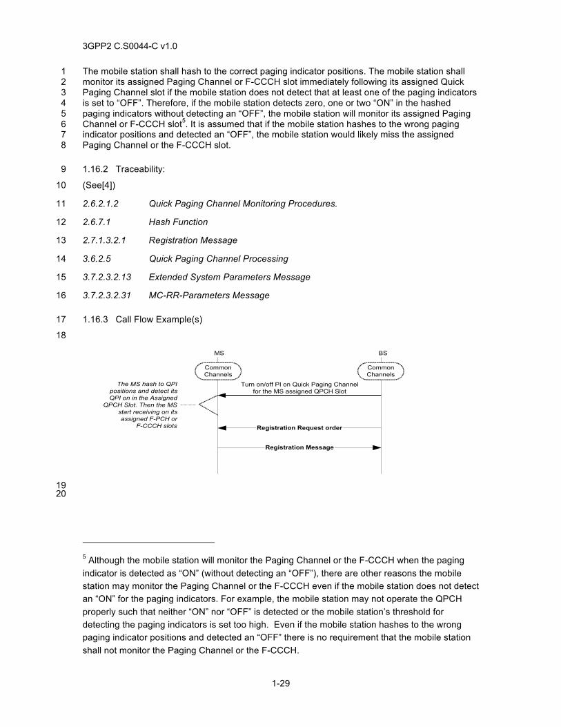
3GPP2 C.S0044-C v1.0
1-29
The mobile station shall hash to the correct paging indicator positions. The mobile station shall 1 monitor its assigned Paging Channel or F-CCCH slot immediately following its assigned Quick 2 Paging Channel slot if the mobile station does not detect that at least one of the paging indicators 3 is set to “OFF”. Therefore, if the mobile station detects zero, one or two “ON” in the hashed 4 paging indicators without detecting an “OFF”, the mobile station will monitor its assigned Paging 5 Channel or F-CCCH slot5. It is assumed that if the mobile station hashes to the wrong paging 6 indicator positions and detected an “OFF”, the mobile station would likely miss the assigned 7 Paging Channel or the F-CCCH slot. 8
1.16.2 Traceability: 9
(See[4]) 10
2.6.2.1.2 Quick Paging Channel Monitoring Procedures. 11
2.6.7.1 Hash Function 12
2.7.1.3.2.1 Registration Message 13
3.6.2.5 Quick Paging Channel Processing 14
3.7.2.3.2.13 Extended System Parameters Message 15
3.7.2.3.2.31 MC-RR-Parameters Message 16
1.16.3 Call Flow Example(s) 17
18
Registration Request order
BS
CommonChannels
MS
CommonChannels
Turn on/off PI on Quick Paging Channelfor the MS assigned QPCH Slot
The MS hash to QPIpositions and detect itsQPI on in the Assigned
QPCH Slot. Then the MSstart receiving on itsassigned F-PCH or
F-CCCH slots
Registration Message
19 20
5 Although the mobile station will monitor the Paging Channel or the F-CCCH when the paging indicator is detected as “ON” (without detecting an “OFF”), there are other reasons the mobile station may monitor the Paging Channel or the F-CCCH even if the mobile station does not detect an “ON” for the paging indicators. For example, the mobile station may not operate the QPCH properly such that neither “ON” nor “OFF” is detected or the mobile station’s threshold for detecting the paging indicators is set too high. Even if the mobile station hashes to the wrong paging indicator positions and detected an “OFF” there is no requirement that the mobile station shall not monitor the Paging Channel or the F-CCCH.
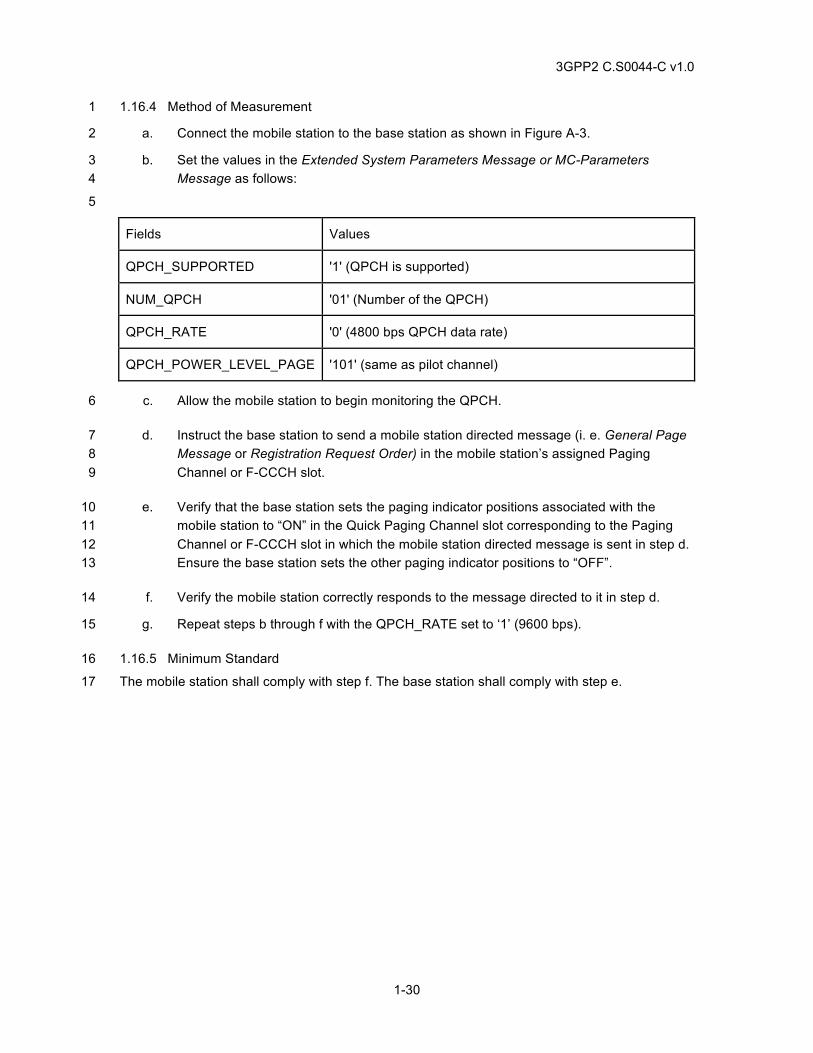
3GPP2 C.S0044-C v1.0
1-30
1.16.4 Method of Measurement 1
a. Connect the mobile station to the base station as shown in Figure A-3. 2
b. Set the values in the Extended System Parameters Message or MC-Parameters 3 Message as follows: 4
5
Fields Values
QPCH_SUPPORTED '1' (QPCH is supported)
NUM_QPCH '01' (Number of the QPCH)
QPCH_RATE '0' (4800 bps QPCH data rate)
QPCH_POWER_LEVEL_PAGE '101' (same as pilot channel)
c. Allow the mobile station to begin monitoring the QPCH. 6
d. Instruct the base station to send a mobile station directed message (i. e. General Page 7 Message or Registration Request Order) in the mobile station’s assigned Paging 8 Channel or F-CCCH slot. 9
e. Verify that the base station sets the paging indicator positions associated with the 10 mobile station to “ON” in the Quick Paging Channel slot corresponding to the Paging 11 Channel or F-CCCH slot in which the mobile station directed message is sent in step d. 12 Ensure the base station sets the other paging indicator positions to “OFF”. 13
f. Verify the mobile station correctly responds to the message directed to it in step d. 14
g. Repeat steps b through f with the QPCH_RATE set to ‘1’ (9600 bps). 15
1.16.5 Minimum Standard 16
The mobile station shall comply with step f. The base station shall comply with step e. 17
3GPP2 C.S0044-C v1.0
2-1
2 BASIC CALL PROCESSING TESTS 1
2.1 Mobile Originated Voice Calls 2
2.1.1 Definition 3
This tests voice service negotiation and call completion of mobile originated voice calls, for radio 4 configurations and voice service options supported by the mobile and base station. 5
2.1.2 Traceability 6
(see[4]) 7
2.2.6.2.5 Mobile Station Origination Operation 8
2.6.3.5 Mobile Station Origination Attempt Substate 9
2.6.4 Mobile Station Control on the Traffic Channel State 10
2.7.1.3.2.4 Origination Message 11
2.7.2.3.2.15 Service Option Control Message 12
3.6.3.5 Response to Origination Message 13
3.6.4 Traffic Channel Processing 14
3.7.2.3.2.21 Extended Channel Assignment Message 15
3.7.3.3.2.3 Alert With Information Message 16
3.7.3.3.2.20 Service Connect Message 17
2.7.2.3.2.12 Service Request Message 18
2.7.2.3.2.13 Service Response Message 19
2.7.2.3.2.14 Service Connect Completion Message 20
2.7.4.18 Service Configuration Record 21
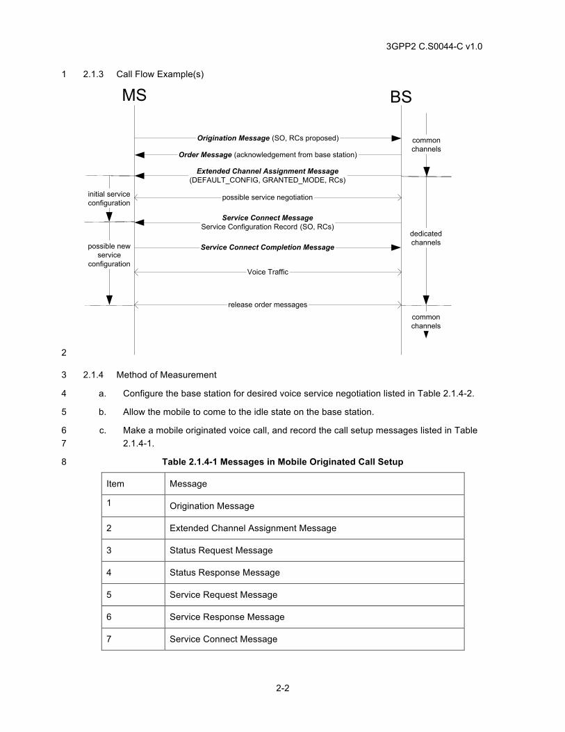
3GPP2 C.S0044-C v1.0
2-2
2.1.3 Call Flow Example(s) 1
Service Connect MessageService Configuration Record (SO, RCs)
Extended Channel Assignment Message(DEFAULT_CONFIG, GRANTED_MODE, RCs)
possible service negotiation
Order Message (acknowledgement from base station)
Origination Message (SO, RCs proposed)
release order messages
Voice Traffic
Service Connect Completion Message
MS BS
commonchannels
dedicatedchannels
commonchannels
initial serviceconfiguration
possible newservice
configuration
2
2.1.4 Method of Measurement 3
a. Configure the base station for desired voice service negotiation listed in Table 2.1.4-2. 4
b. Allow the mobile to come to the idle state on the base station. 5
c. Make a mobile originated voice call, and record the call setup messages listed in Table 6 2.1.4-1. 7
Table 2.1.4-1 Messages in Mobile Originated Call Setup 8
Item Message
1 Origination Message
2 Extended Channel Assignment Message
3 Status Request Message
4 Status Response Message
5 Service Request Message
6 Service Response Message
7 Service Connect Message
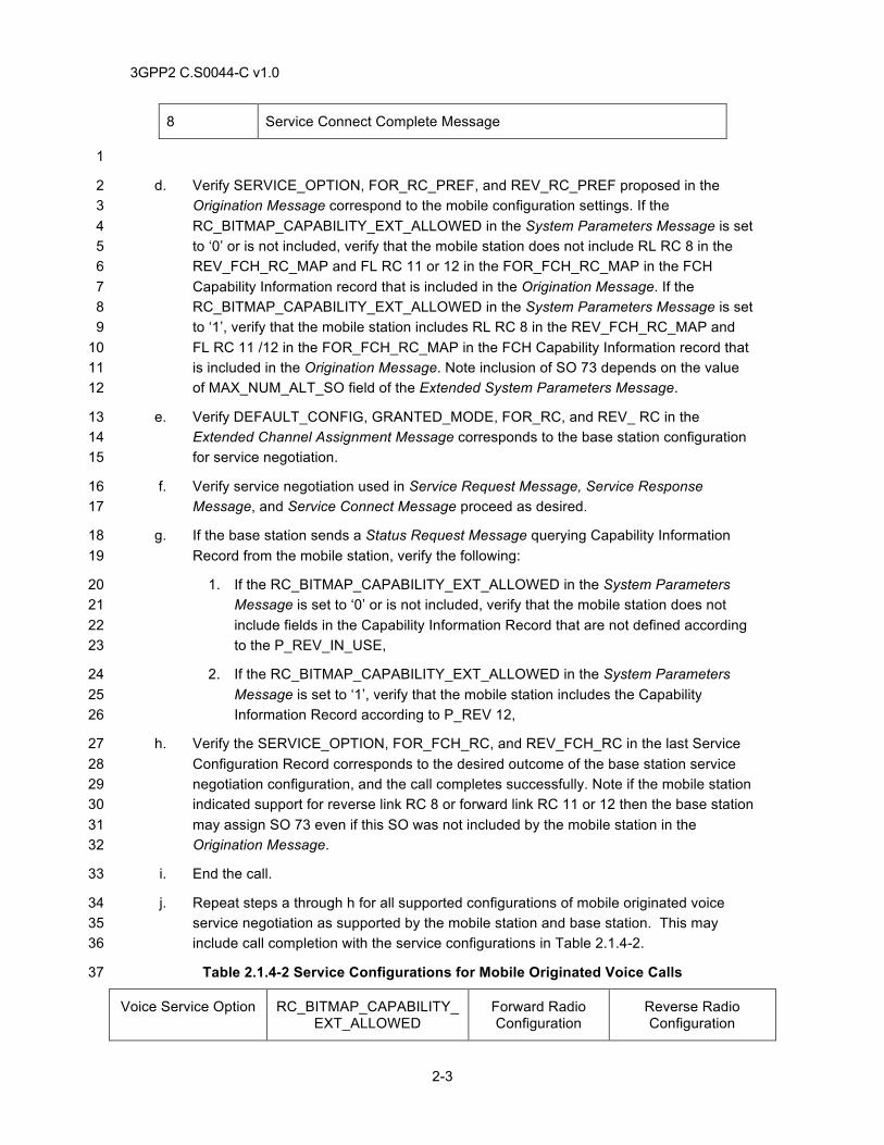
3GPP2 C.S0044-C v1.0
2-3
8 Service Connect Complete Message
1
d. Verify SERVICE_OPTION, FOR_RC_PREF, and REV_RC_PREF proposed in the 2 Origination Message correspond to the mobile configuration settings. If the 3 RC_BITMAP_CAPABILITY_EXT_ALLOWED in the System Parameters Message is set 4 to ‘0’ or is not included, verify that the mobile station does not include RL RC 8 in the 5 REV_FCH_RC_MAP and FL RC 11 or 12 in the FOR_FCH_RC_MAP in the FCH 6 Capability Information record that is included in the Origination Message. If the 7 RC_BITMAP_CAPABILITY_EXT_ALLOWED in the System Parameters Message is set 8 to ‘1’, verify that the mobile station includes RL RC 8 in the REV_FCH_RC_MAP and 9 FL RC 11 /12 in the FOR_FCH_RC_MAP in the FCH Capability Information record that 10 is included in the Origination Message. Note inclusion of SO 73 depends on the value 11 of MAX_NUM_ALT_SO field of the Extended System Parameters Message. 12
e. Verify DEFAULT_CONFIG, GRANTED_MODE, FOR_RC, and REV_ RC in the 13 Extended Channel Assignment Message corresponds to the base station configuration 14 for service negotiation. 15
f. Verify service negotiation used in Service Request Message, Service Response 16 Message, and Service Connect Message proceed as desired. 17
g. If the base station sends a Status Request Message querying Capability Information 18 Record from the mobile station, verify the following: 19
1. If the RC_BITMAP_CAPABILITY_EXT_ALLOWED in the System Parameters 20 Message is set to ‘0’ or is not included, verify that the mobile station does not 21 include fields in the Capability Information Record that are not defined according 22 to the P_REV_IN_USE, 23
2. If the RC_BITMAP_CAPABILITY_EXT_ALLOWED in the System Parameters 24 Message is set to ‘1’, verify that the mobile station includes the Capability 25 Information Record according to P_REV 12, 26
h. Verify the SERVICE_OPTION, FOR_FCH_RC, and REV_FCH_RC in the last Service 27 Configuration Record corresponds to the desired outcome of the base station service 28 negotiation configuration, and the call completes successfully. Note if the mobile station 29 indicated support for reverse link RC 8 or forward link RC 11 or 12 then the base station 30 may assign SO 73 even if this SO was not included by the mobile station in the 31 Origination Message. 32
i. End the call. 33
j. Repeat steps a through h for all supported configurations of mobile originated voice 34 service negotiation as supported by the mobile station and base station. This may 35 include call completion with the service configurations in Table 2.1.4-2. 36
Table 2.1.4-2 Service Configurations for Mobile Originated Voice Calls 37
Voice Service Option RC_BITMAP_CAPABILITY_EXT_ALLOWED
Forward Radio Configuration
Reverse Radio Configuration
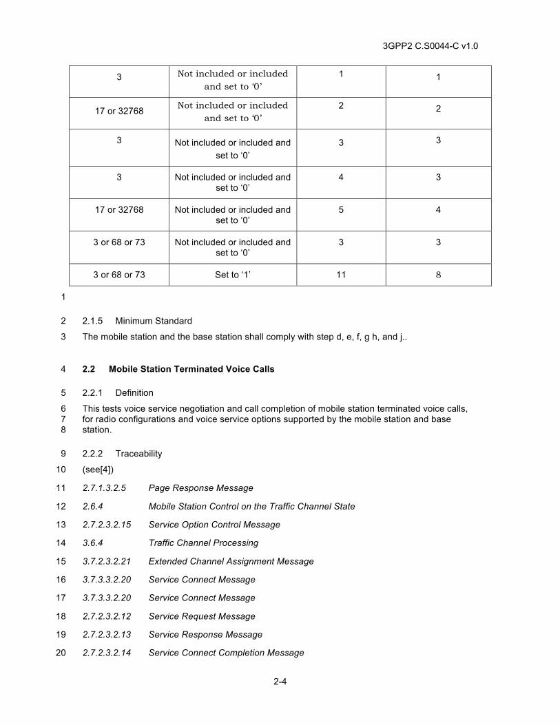
3GPP2 C.S0044-C v1.0
2-4
3 Not included or included and set to ‘0’
1 1
17 or 32768 Not included or included and set to ‘0’
2 2
3 Not included or included and set to ‘0’
3 3
3 Not included or included and set to ‘0’
4 3
17 or 32768 Not included or included and set to ‘0’
5 4
3 or 68 or 73 Not included or included and set to ‘0’
3 3
3 or 68 or 73 Set to ‘1’ 11 8
1
2.1.5 Minimum Standard 2
The mobile station and the base station shall comply with step d, e, f, g h, and j.. 3
2.2 Mobile Station Terminated Voice Calls 4
2.2.1 Definition 5
This tests voice service negotiation and call completion of mobile station terminated voice calls, 6 for radio configurations and voice service options supported by the mobile station and base 7 station. 8
2.2.2 Traceability 9
(see[4]) 10
2.7.1.3.2.5 Page Response Message 11
2.6.4 Mobile Station Control on the Traffic Channel State 12
2.7.2.3.2.15 Service Option Control Message 13
3.6.4 Traffic Channel Processing 14
3.7.2.3.2.21 Extended Channel Assignment Message 15
3.7.3.3.2.20 Service Connect Message 16
3.7.3.3.2.20 Service Connect Message 17
2.7.2.3.2.12 Service Request Message 18
2.7.2.3.2.13 Service Response Message 19
2.7.2.3.2.14 Service Connect Completion Message 20
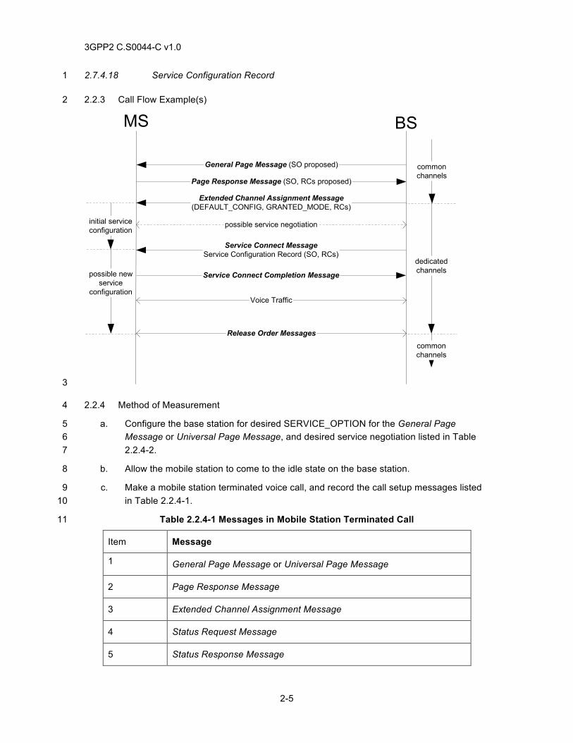
3GPP2 C.S0044-C v1.0
2-5
2.7.4.18 Service Configuration Record 1
2.2.3 Call Flow Example(s) 2
Service Connect MessageService Configuration Record (SO, RCs)
Extended Channel Assignment Message(DEFAULT_CONFIG, GRANTED_MODE, RCs)
possible service negotiation
Page Response Message (SO, RCs proposed)
General Page Message (SO proposed)
Release Order Messages
Voice Traffic
Service Connect Completion Message
MS BS
commonchannels
dedicatedchannels
commonchannels
initial serviceconfiguration
possible newservice
configuration
3
2.2.4 Method of Measurement 4
a. Configure the base station for desired SERVICE_OPTION for the General Page 5 Message or Universal Page Message, and desired service negotiation listed in Table 6 2.2.4-2. 7
b. Allow the mobile station to come to the idle state on the base station. 8
c. Make a mobile station terminated voice call, and record the call setup messages listed 9 in Table 2.2.4-1. 10
Table 2.2.4-1 Messages in Mobile Station Terminated Call 11
Item Message
1 General Page Message or Universal Page Message
2 Page Response Message
3 Extended Channel Assignment Message
4 Status Request Message
5 Status Response Message
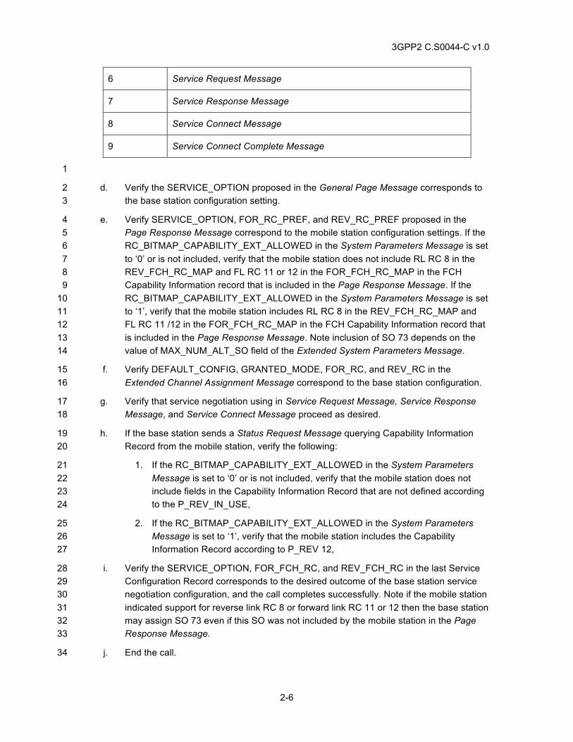
3GPP2 C.S0044-C v1.0
2-6
6 Service Request Message
7 Service Response Message
8 Service Connect Message
9 Service Connect Complete Message
1
d. Verify the SERVICE_OPTION proposed in the General Page Message corresponds to 2 the base station configuration setting. 3
e. Verify SERVICE_OPTION, FOR_RC_PREF, and REV_RC_PREF proposed in the 4 Page Response Message correspond to the mobile station configuration settings. If the 5 RC_BITMAP_CAPABILITY_EXT_ALLOWED in the System Parameters Message is set 6 to ‘0’ or is not included, verify that the mobile station does not include RL RC 8 in the 7 REV_FCH_RC_MAP and FL RC 11 or 12 in the FOR_FCH_RC_MAP in the FCH 8 Capability Information record that is included in the Page Response Message. If the 9 RC_BITMAP_CAPABILITY_EXT_ALLOWED in the System Parameters Message is set 10 to ‘1’, verify that the mobile station includes RL RC 8 in the REV_FCH_RC_MAP and 11 FL RC 11 /12 in the FOR_FCH_RC_MAP in the FCH Capability Information record that 12 is included in the Page Response Message. Note inclusion of SO 73 depends on the 13 value of MAX_NUM_ALT_SO field of the Extended System Parameters Message. 14
f. Verify DEFAULT_CONFIG, GRANTED_MODE, FOR_RC, and REV_RC in the 15 Extended Channel Assignment Message correspond to the base station configuration. 16
g. Verify that service negotiation using in Service Request Message, Service Response 17 Message, and Service Connect Message proceed as desired. 18
h. If the base station sends a Status Request Message querying Capability Information 19 Record from the mobile station, verify the following: 20
1. If the RC_BITMAP_CAPABILITY_EXT_ALLOWED in the System Parameters 21 Message is set to ‘0’ or is not included, verify that the mobile station does not 22 include fields in the Capability Information Record that are not defined according 23 to the P_REV_IN_USE, 24
2. If the RC_BITMAP_CAPABILITY_EXT_ALLOWED in the System Parameters 25 Message is set to ‘1’, verify that the mobile station includes the Capability 26 Information Record according to P_REV 12, 27
i. Verify the SERVICE_OPTION, FOR_FCH_RC, and REV_FCH_RC in the last Service 28 Configuration Record corresponds to the desired outcome of the base station service 29 negotiation configuration, and the call completes successfully. Note if the mobile station 30 indicated support for reverse link RC 8 or forward link RC 11 or 12 then the base station 31 may assign SO 73 even if this SO was not included by the mobile station in the Page 32 Response Message. 33
j. End the call. 34
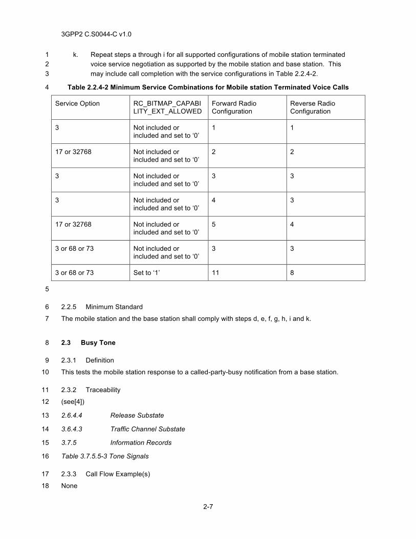
3GPP2 C.S0044-C v1.0
2-7
k. Repeat steps a through i for all supported configurations of mobile station terminated 1 voice service negotiation as supported by the mobile station and base station. This 2 may include call completion with the service configurations in Table 2.2.4-2. 3
Table 2.2.4-2 Minimum Service Combinations for Mobile station Terminated Voice Calls 4
Service Option RC_BITMAP_CAPABILITY_EXT_ALLOWED
Forward Radio Configuration
Reverse Radio Configuration
3 Not included or included and set to ‘0’
1 1
17 or 32768 Not included or included and set to ‘0’
2 2
3 Not included or included and set to ‘0’
3 3
3 Not included or included and set to ‘0’
4 3
17 or 32768 Not included or included and set to ‘0’
5 4
3 or 68 or 73 Not included or included and set to ‘0’
3 3
3 or 68 or 73 Set to ‘1’ 11 8
5
2.2.5 Minimum Standard 6
The mobile station and the base station shall comply with steps d, e, f, g, h, i and k. 7
2.3 Busy Tone 8
2.3.1 Definition 9
This tests the mobile station response to a called-party-busy notification from a base station. 10
2.3.2 Traceability 11
(see[4]) 12
2.6.4.4 Release Substate 13
3.6.4.3 Traffic Channel Substate 14
3.7.5 Information Records 15
Table 3.7.5.5-3 Tone Signals 16
2.3.3 Call Flow Example(s) 17
None 18
3GPP2 C.S0044-C v1.0
2-8
2.3.4 Method of Measurement 1
a. Allow the mobile station to come to the idle state on the base station. 2
b. Ensure the called party has no call-waiting or automatic voice mail enabled, and tie up 3 the line so that the mobile station will get a busy signal when it calls. 4
c. Attempt a mobile station originated call to the party. 5
d. Verify the mobile station plays a called-party-busy indication. 6
2.3.5 Minimum Standard 7
The mobile station shall comply with the requirement in steps d. 8
2.4 Mobile Station Origination Call with Inter Band Channel Assignment 9
2.4.1 Definition 10
This test verifies that the mobile station can initiate a call to a land party on aone band class and 11 then re-originate and completes the call the target band class after receiving a Channel 12 Assignment Message or Extended Channel Assignment Message with ASSIGN_MODE = ‘101’ 13 or ‘001’ respectively. 14
2.4.2 Traceability: 15
(See[4]) 16
2.6.2.4 Mobile Station Order and Message Processing Operation 17
2.6.3.5 Mobile Station Origination Attempt Substate 18
2.7.1.3.2.4 Origination Message 19
3.7.2.3.2.8 Channel Assignment Message 20
3.7.2.3.2.21 Extended Channel Assignment Message 21
2.4.3 Call Flow Example(s) 22
None 23
2.4.4 Method of Measurement 24
a. Connect the mobile station and base stations as shown in Figure A-2. Base station 1 25 operates in a band class that is different from base station 2. 26
b. Ensure the mobile station acquires base station 1. 27
c. Configure Base station 1 so that Inter Band Channel Assignment is enabled. 28
d. Setup mobile station originated voice call. 29
e. Verify the mobile station originates on the serving base station and receives a Channel 30 Assignment Message with ASSIGN MODE=‘101’ or an Extended Channel Assignment 31 Message with ASSIGN MODE=’001’. Verify that the Channel Assignment Message or 32 Extended Channel Assignment Message contains assignment for paging channel on 33 base station 2, and RESPOND=1. 34
3GPP2 C.S0044-C v1.0
2-9
f. Verify the mobile station re-sends a second Origination Message to base station 2 and 1 the call completes successfully. 2
g. Verify user data in both directions. 3
h. End the call. 4
i. Repeat Steps d through g, but provision Base station 2 to be Inter Band Channel 5 Assignment enabled. The mobile station will originate on base station 2 and then re-6 originate on base station 1 after receiving the Channel Assignment Message or 7 Extended Channel Assignment Message. 8
2.4.5 Minimum Standard 9
The mobile station and base station shall comply with steps e, f, g, and i. 10
2.5 Mobile Station Terminated Call with Inter Band Channel Assignment 11
2.5.1 Definition 12
This test verifies that the mobile station can receive a call from a land party on one band class 13 and then resends the Page Response Message autonomously and completes the call on the 14 target band class after receiving a Channel Assignment Message or Extended Channel 15 Assignment Message with ASSIGN_MODE = ‘101’ or ‘001’ respectively. 16
2.5.2 Traceability 17
(See[4]) 18
2.6.2.3 Mobile Station Page Match Operation 19
2.6.3.3 Page Response Substate 20
2.7.1.3.2.5 Page Response Message 21
3.7.2.3.2.8 Channel Assignment Message 22
3.7.2.3.2.21 Extended Channel Assignment Message 23
2.5.3 Call Flow Example(s) 24
None 25
2.5.4 Method of Measurement 26
a. Connect the mobile station and base stations as shown in Figure A-2. Base station 1 27 operates in a band class that is different from base station 2. 28
b. Ensure the mobile station acquires base station 1. 29
c. Configure base station 1 so that Inter Band Channel Assignment is enabled. 30
d. Setup mobile station terminated voice call. 31
e. Verify that the mobile station receives a Channel Assignment Message with ASSIGN 32 MODE=‘101’ or an Extended Channel Assignment Message with ASSIGN 33 MODE=’001’. Verify that the Channel Assignment Message or Extended Channel 34
3GPP2 C.S0044-C v1.0
2-10
Assignment Message contains assignment for paging channel on base station 2, and 1 RESPOND = ‘1’. 2
f. Verify the mobile station sends a second Page Response Message on the target base 3 station and the call completes. 4
g. Verify user data in both directions. 5
h. End the call. 6
i. Repeat Steps d through g, but provision Base station 2 to be Inter Band Channel 7 Assignment enabled. The mobile station will send the Page Response Message on 8 base station 2 and then re-send the Page Response Message on base station 1 after 9 receiving the Channel Assignment Message or Extended Channel Assignment 10 Message. 11
2.5.5 Minimum Standard 12
The mobile station and the base station shall comply with steps e, f, g, and i. 13
2.6 DTMF 14
2.6.1 Definition 15
This is a test for Dual-Tone Multi-frequency (DTMF), sent by the mobile station in a Send Burst 16 DTMF Message or a Continuous DTMF Tone Order. It verifies that sequencing and tone duration 17 of the Send Burst DTMF Message and the Continuous DTMF Tone Order are preserved. 18
2.6.2 Traceability 19
(see [4]) 20
2.7.2.3.2.7 Send Burst DTMF Message 21
2.7.2.3.2.1 Continuous DTMF Tone Order 22
3.7.3.3.2.9 Send Burst DTMF Message 23
Table 2.7.1.3.2.4-4 Representation of DTMF Digits 24
Table 2.7.2.3.2.7-1 Recommended DTMF Pulse Width 25
Table 2.7.2.3.2.7-2 Recommended Minimum Inter-digit Interval 26
Table 3.7.4-1 Order and Order Qual Codes Used on the f-csch and the f-dsch 27
Table 2.7.2.3-1 Messages on r-dsch 28
2.6.3 Call Flow Example(s) 29
None 30
2.6.4 Method of Measurement 31
a. Equip a landline with a DTMF decoder that can verify DTMF digits received and DTMF 32 tone duration. 33
3GPP2 C.S0044-C v1.0
2-11
b. Configure the mobile station to send short DTMF tones. 1
c. Allow the mobile station to come to the idle state on the base station, and set up a voice 2 call to the equipped land party. 3
d. Press the keys 1234567890*#. 4
e. Verify the mobile station sends a Send Burst DTMF Message for each key press. 5
f. Verify DTMF tones are received correctly. 6
g. End the call. 7
h. Configure the mobile station to use long DTMF tones. 8
i. Setup a mobile station originated call. 9
j. Direct the mobile station to perform the following steps in. 10
1. Press and hold any number key on the keypad for approximately 5 seconds. 11
2. Verify the mobile station sends a Continuous DTMF Tone Order with the 12 appropriate ORDQ value to start and stop the DTMF tone. 13
3. Direct the mobile station to send characters 0123456789 * as one or more Send 14 Burst DTMF Message(s). 15
4. Press and hold any number key on the keypad for approximately 5 seconds. 16
5. Again press and hold any number key on the keypad for approximately 5 17 seconds. 18
k. Verify all DTMF digits are decoded correctly and in the right order at the land party 19 DTMF decoder. 20
l. Verify the three 5-second key presses produce DTMF tones approximately 5 seconds in 21 duration. 22
2.6.5 Minimum Standard 23
The mobile station shall comply with requirements in steps e, f, k and l. 24
2.7 Slot Cycle Index 25
2.7.1 Definition 26
If the mobile station supports slotted operation, this test verifies the mobile station response to the 27 base station MAX_SLOT_CYCLE_INDEX setting for various settings of mobile station 28 SLOT_CYCLE_INDEX. 29
2.7.2 Traceability 30
(see [4]) 31
2.6.2.1.1 Forward Channel Monitoring Procedures 32
3.6.2.1.3 Paging Slot Determination 33
3.6.2.3 Mobile Station Directed Messages 34
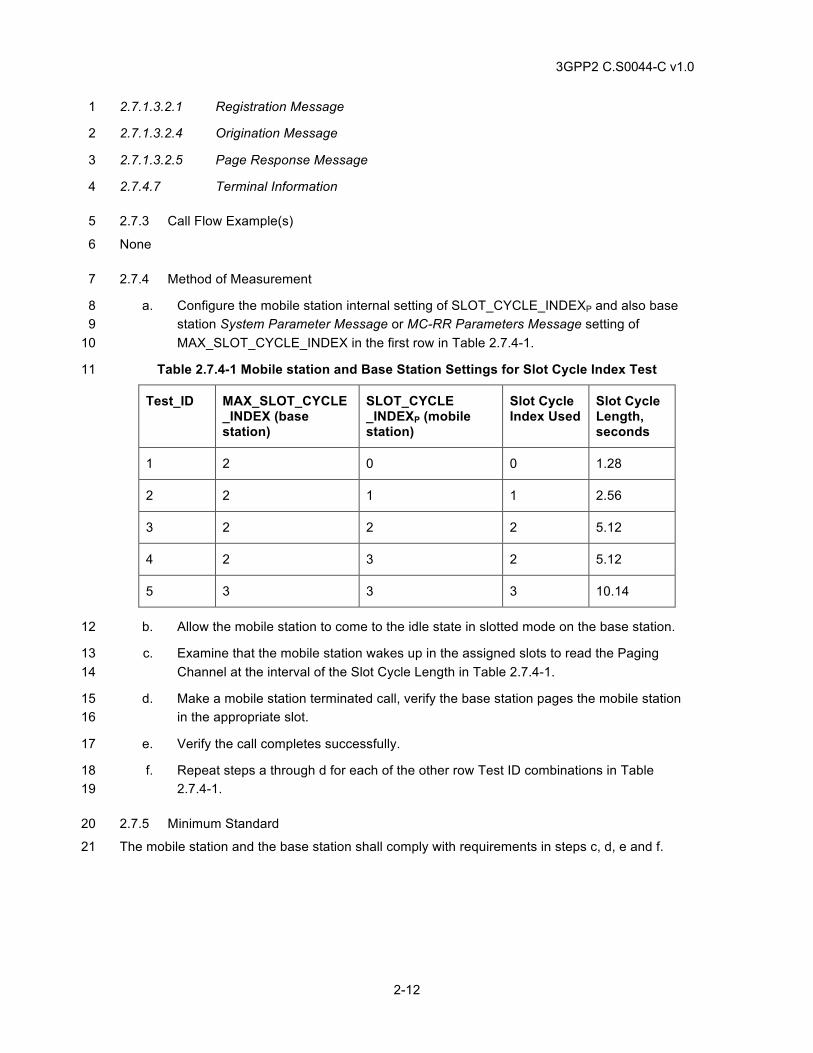
3GPP2 C.S0044-C v1.0
2-12
2.7.1.3.2.1 Registration Message 1
2.7.1.3.2.4 Origination Message 2
2.7.1.3.2.5 Page Response Message 3
2.7.4.7 Terminal Information 4
2.7.3 Call Flow Example(s) 5
None 6
2.7.4 Method of Measurement 7
a. Configure the mobile station internal setting of SLOT_CYCLE_INDEXP and also base 8 station System Parameter Message or MC-RR Parameters Message setting of 9 MAX_SLOT_CYCLE_INDEX in the first row in Table 2.7.4-1. 10
Table 2.7.4-1 Mobile station and Base Station Settings for Slot Cycle Index Test 11
Test_ID MAX_SLOT_CYCLE_INDEX (base station)
SLOT_CYCLE _INDEXP (mobile station)
Slot Cycle Index Used
Slot Cycle Length, seconds
1 2 0 0 1.28
2 2 1 1 2.56
3 2 2 2 5.12
4 2 3 2 5.12
5 3 3 3 10.14
b. Allow the mobile station to come to the idle state in slotted mode on the base station. 12
c. Examine that the mobile station wakes up in the assigned slots to read the Paging 13 Channel at the interval of the Slot Cycle Length in Table 2.7.4-1. 14
d. Make a mobile station terminated call, verify the base station pages the mobile station 15 in the appropriate slot. 16
e. Verify the call completes successfully. 17
f. Repeat steps a through d for each of the other row Test ID combinations in Table 18 2.7.4-1. 19
2.7.5 Minimum Standard 20
The mobile station and the base station shall comply with requirements in steps c, d, e and f. 21
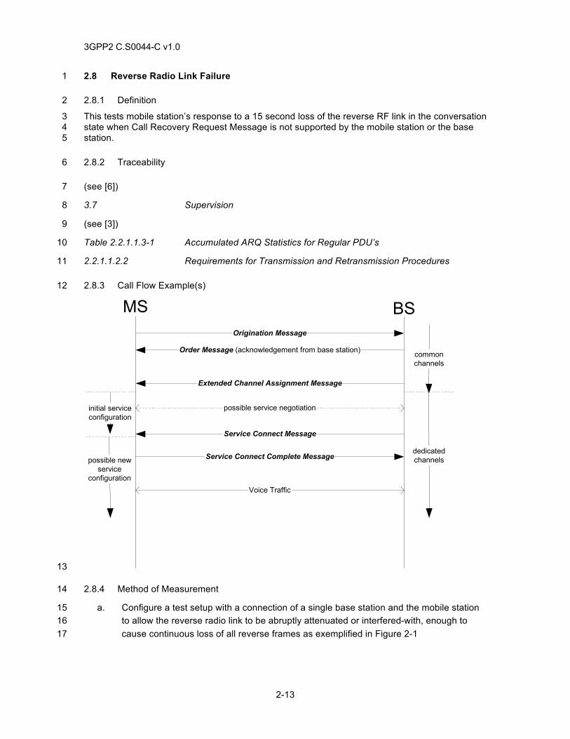
3GPP2 C.S0044-C v1.0
2-13
2.8 Reverse Radio Link Failure 1
2.8.1 Definition 2
This tests mobile station’s response to a 15 second loss of the reverse RF link in the conversation 3 state when Call Recovery Request Message is not supported by the mobile station or the base 4 station. 5
2.8.2 Traceability 6
(see [6]) 7
3.7 Supervision 8
(see [3]) 9
Table 2.2.1.1.3-1 Accumulated ARQ Statistics for Regular PDU’s 10
2.2.1.1.2.2 Requirements for Transmission and Retransmission Procedures 11
2.8.3 Call Flow Example(s) 12
Service Connect Message
Extended Channel Assignment Message
possible service negotiation
Order Message (acknowledgement from base station)
Origination Message
Voice Traffic
Service Connect Complete Message
MS BS
commonchannels
dedicatedchannels
initial serviceconfiguration
possible newservice
configuration
13
2.8.4 Method of Measurement 14
a. Configure a test setup with a connection of a single base station and the mobile station 15 to allow the reverse radio link to be abruptly attenuated or interfered-with, enough to 16 cause continuous loss of all reverse frames as exemplified in Figure 2-1 17
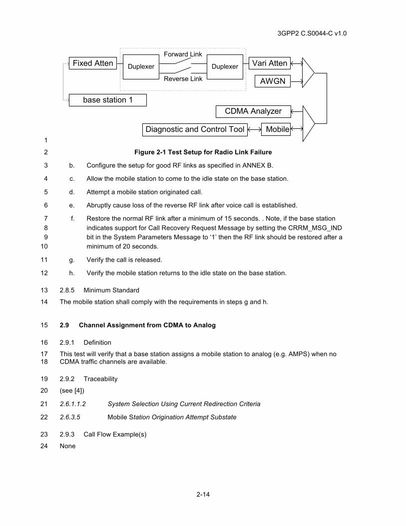
3GPP2 C.S0044-C v1.0
2-14
base station 1
AWGN
MobileDiagnostic and Control Tool
CDMA Analyzer
Fixed Atten Vari Atten
Reverse Link
Forward Link
DuplexerDuplexer
1
Figure 2-1 Test Setup for Radio Link Failure 2
b. Configure the setup for good RF links as specified in ANNEX B. 3
c. Allow the mobile station to come to the idle state on the base station. 4
d. Attempt a mobile station originated call. 5
e. Abruptly cause loss of the reverse RF link after voice call is established. 6
f. Restore the normal RF link after a minimum of 15 seconds. . Note, if the base station 7 indicates support for Call Recovery Request Message by setting the CRRM_MSG_IND 8 bit in the System Parameters Message to ‘1’ then the RF link should be restored after a 9 minimum of 20 seconds. 10
g. Verify the call is released. 11
h. Verify the mobile station returns to the idle state on the base station. 12
2.8.5 Minimum Standard 13
The mobile station shall comply with the requirements in steps g and h. 14
2.9 Channel Assignment from CDMA to Analog 15
2.9.1 Definition 16
This test will verify that a base station assigns a mobile station to analog (e.g. AMPS) when no 17 CDMA traffic channels are available. 18
2.9.2 Traceability 19
(see [4]) 20
2.6.1.1.2 System Selection Using Current Redirection Criteria 21
2.6.3.5 Mobile Station Origination Attempt Substate 22
2.9.3 Call Flow Example(s) 23
None 24
3GPP2 C.S0044-C v1.0
2-15
2.9.4 Method of Measurement 1
a. Connect the base station and mobile station as shown in Annex A Figure A - 5. 2
b. Take all CDMA traffic channel radio resources out of service or configure the base 3 station to behave in a similar fashion. Configure the base station to assign analog 4 channel. 5
c. Setup a mobile station originated call. 6
d. Verify that the base station sends a Channel Assignment Message or Extended 7 Channel Assignment Message with ASSIGN_MODE=‘011’ to assign the mobile station 8 an analog voice channel or with ASSIGN_MODE=‘010’ to acquire the analog system. 9
e. Verify the mobile station acquires the analog system. 10
f. Verify user data in both directions. 11
g. End call. 12
2.9.5 Minimum Standard 13
The mobile station and the base station shall comply with the requirements in steps d, e, and f. 14
2.10 Network Busy 15
2.10.1 Definition 16
This tests mobile station response to a base station blocking condition during mobile station call 17 origination. 18
2.10.2 Traceability 19
(see [4]) 20
Table 3.7.4-1 Order and Order Qualification Codes 21
3.6.2.3 Mobile Station Directed Messages, Reorder Order 22
Table 3.7.5.5-3 Tone Signals 23
3.6.3.5 Response to Origination Message 24
3.6.2.3 Mobile Station Directed Messages 25
2.10.3 Call Flow Example(s) 26
None 27
2.10.4 Method of Measurement 28
a. Allow the mobile station to come to the idle state on the base station. 29
b. Take all traffic channel resources out of service or configure the base station to behave 30 in a similar fashion. Configure the base station to send a network-busy indication. 31
c. Attempt a mobile station originated call. 32
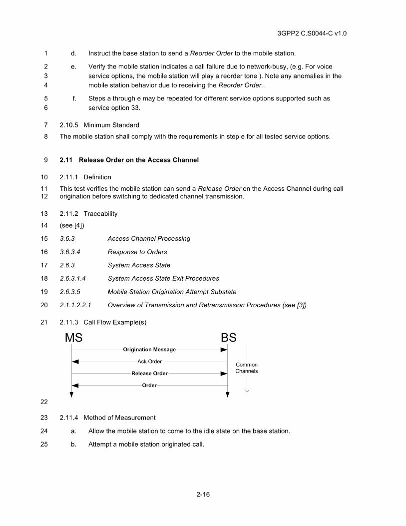
3GPP2 C.S0044-C v1.0
2-16
d. Instruct the base station to send a Reorder Order to the mobile station. 1
e. Verify the mobile station indicates a call failure due to network-busy, (e.g. For voice 2 service options, the mobile station will play a reorder tone ). Note any anomalies in the 3 mobile station behavior due to receiving the Reorder Order.. 4
f. Steps a through e may be repeated for different service options supported such as 5 service option 33. 6
2.10.5 Minimum Standard 7
The mobile station shall comply with the requirements in step e for all tested service options. 8
2.11 Release Order on the Access Channel 9
2.11.1 Definition 10
This test verifies the mobile station can send a Release Order on the Access Channel during call 11 origination before switching to dedicated channel transmission. 12
2.11.2 Traceability 13
(see [4]) 14
3.6.3 Access Channel Processing 15
3.6.3.4 Response to Orders 16
2.6.3 System Access State 17
2.6.3.1.4 System Access State Exit Procedures 18
2.6.3.5 Mobile Station Origination Attempt Substate 19
2.1.1.2.2.1 Overview of Transmission and Retransmission Procedures (see [3]) 20
2.11.3 Call Flow Example(s) 21
BSMSOrigination Message
CommonChannelsRelease Order
Order
Ack Order
22
2.11.4 Method of Measurement 23
a. Allow the mobile station to come to the idle state on the base station. 24
b. Attempt a mobile station originated call. 25
3GPP2 C.S0044-C v1.0
2-17
c. Shortly after the mobile station has received acknowledgement of its Origination 1 Message, terminate the call attempt from the mobile station side, e. g. press the mobile 2 station END key, before the mobile station switches to dedicated channel transmission. 3
d. Verify the mobile station sends a Release Order (normal release) on the Access 4 Channel in assured mode requiring confirmation of delivery, aborts the call attempt, and 5 returns to the idle state on the base station. 6
2.11.5 Minimum Standard 7
The mobile station shall comply with the requirements in step d. 8
2.12 True IMSI Support, Land Party to Mobile Station Call, Matching MCC and IMSI_11_12, 9 True IMSI addressing supported by the base station and mobile station 10
2.12.1 Definition 11
This test verifies that the base station pages the mobile station with True IMSI addressing 12 supported by the base station and mobile station when the MCC and IMSI_11_12 of the mobile 13 station match those sent by the base station in the Extended System Parameters Message or 14 ANSI-41 System Parameters Message. 15
2.12.2 Traceability 16
(See[4]) 17
2.3.1.1 Encoding of IMSI_M_S and IMSI_T_S 18
2.3.1 Mobile Station Identification Number 19
2.3.1.3 Encoding of the MCC_M and MCC_T 20
2.6.2.2.5 Extended System Parameters Message 21
2.7.4.24 IMSI_T 22
3.7.2.3.2.13 Service Response Message 23
2.12.3 Call Flow Example(s) 24
None 25
2.12.4 Method of Measurement 26
a. Allow the mobile station to come to the idle state on the base station. 27
b. Ensure the mobile station is programmed with the same values of MCC and 28 IMSI_11_12 used in the base station. Do not use MCC (wild card) value in the base 29 station. 30
c. Configure the base station to send the Extended System Parameters Message or 31 ANSI-41 System Parameters Message with the value IMSI_T_SUPPORTED=1. 32
d. Enable power-up registration. 33
3GPP2 C.S0044-C v1.0
2-18
e. Enable authentication. Configure the base station to disallow mobile station terminated 1 calls if authentication fails. 2
f. Power on the mobile station and wait for power-up registration to occur. 3
g. Initiate a land party to mobile station call. 4
h. Verify user data in both directions and end call at the mobile station. 5
2.12.5 Minimum Standard 6
The mobile station shall comply with step h. 7
2.13 True IMSI Support, Land Party to Mobile Station Call, Matching MCC and IMSI_11_12, 8 True IMSI addressing supported by the base station with MIN-based addressing 9 supported by the mobile station. 10
2.13.1 Definition 11
This test verifies that the base station pages the mobile station with True IMSI addressing 12 supported by the base station and MIN-based addressing supported by the mobile station when 13 the MCC and IMSI_11_12 of the mobile station match those sent by the base station in the 14 Extended System Parameter Message or ANSI-41 System Parameters Message. 15
2.13.2 Traceability 16
(see [4]) 17
2.3.1.1 Encoding of IMSI_M_S and IMSI_T_S 18
2.3.1 Mobile Station Identification Number 19
2.3.1.3 Encoding of the MCC_M and MCC_T 20
2.6.2.2.5 Extended System Parameters Message 21
2.7.4.24 IMSI_T 22
3.7.2.3.2.13 Service Response Message 23
2.13.3 Call Flow Example(s) 24
None 25
2.13.4 Method of Measurement 26
a. Allow the mobile station to come to the idle state on the base station. 27
b. Ensure the mobile station is programmed with the same values of MCC and 28 IMSI_11_12 used in the base station. Do not use MCC (wild card) value in the base 29 station. 30
c. Configure the base station to send the Extended System Parameters Message or 31 ANSI-41 System Parameters Message with the value IMSI_T_SUPPORTED=1. 32
d. Enable power on registration. 33
3GPP2 C.S0044-C v1.0
2-19
e. Enable authentication. Configure the base station to disallow mobile station terminated 1 calls if authentication fails. 2
f. Power on the mobile station and wait for power-up registration to occur. 3
g. Initiate a land party call to the mobile station. 4
h. Verify user data and end call at the mobile station. 5
2.13.5 Minimum Standard 6
The mobile station shall comply with step h. 7
2.14 True IMSI Support, Land Party to Mobile Station Call, Matching MCC and IMSI_11_12, 8 True IMSI addressing not supported by the base station 9
2.14.1 Definition 10
This test will verify the base station pages the mobile station when the base station does not 11 support True IMSI addressing, when the MCC and IMSI_11_12 of the mobile station match those 12 sent by the base station in the Extended System Parameters Message or ANSI-41 System 13 Parameters Message. 14
2.14.2 Traceability 15
(see [4]) 16
2.3.1.1 Encoding of IMSI_M_S and IMSI_T_S 17
2.3.1 Mobile Station Identification Number 18
2.3.1.3 Encoding of the MCC_M and MCC_T 19
2.6.2.2.5 Extended System Parameters Message 20
2.7.4.24 IMSI_T 21
3.7.2.3.2.13 Service Response Message 22
2.14.3 Call Flow Example(s) 23
None 24
2.14.4 Method of Measurement 25
a. Allow the mobile station to come to the idle state on the base station. 26
b. Ensure the mobile station is programmed with the same values of MCC and 27 IMSI_11_12 used in the base station. Do not use MCC (wild card) value in the base 28 station. 29
c. Configure the base station to send the Extended System Parameters Message or 30 ANSI-41 System Parameters Message with the value IMSI_T_SUPPORTED=0. 31
d. Enable power on registration. 32
3GPP2 C.S0044-C v1.0
2-20
e. Enable authentication. Configure the base station to disallow mobile station terminated 1 calls if authentication fails. 2
f. Power on the mobile station and wait for power-up registration to occur. 3
g. Initiate a land party call to the mobile station. 4
h. Verify user data and end call at the mobile station. 5
2.14.5 Minimum Standard 6
The mobile station shall comply with step h. 7
2.15 True IMSI Support, Land Party to Mobile Station Call, Different MCC and IMSI_11_12 8
2.15.1 Definition 9
This test verifies the base station selects one of the valid forms of paging channel address when 10 neither the MCC nor the IMSI_11_12 of the mobile station being addressed match those being 11 sent by the base station in the Extended System Parameters Message or ANSI-41 System 12 Parameters Message. 13
2.15.2 Traceability 14
(see [4]) 15
2.3.1.1 Encoding of IMSI_M_S and IMSI_T_S 16
2.3.1 Mobile Station Identification Number 17
2.3.1.3 Encoding of the MCC_M and MCC_T 18
2.6.2.2.5 Extended System Parameters Message 19
2.7.4.24 IMSI_T 20
3.7.2.3.2.13 Service Response Message 21
2.15.3 Call Flow Example(s) 22
None 23
2.15.4 Method of Measurement 24
a. Allow the mobile station to come to the idle state on the base station. 25
b. Ensure the mobile station is programmed with different values of MCC and IMSI_11_12 26 than those used in the base station. Do not use MCC (wild card) value in the base 27 station. 28
c. Configure the base station to send the Extended System Parameters Message or 29 ANSI-41 System Parameters Message with the value IMSI_T_SUPPORTED=1. 30
d. Enable power on registration. 31
e. Enable authentication. Configure the base station to disallow mobile station terminated 32 calls if authentication fails. 33
3GPP2 C.S0044-C v1.0
2-21
f. Power on the mobile station and wait for power-up registration to occur. 1
g. Initiate a land party call to the mobile station. 2
h. Verify user data and end call at the mobile station. 3
2.15.5 Minimum Standard 4
The mobile station shall comply with step h. 5
2.16 PACA Origination, User Terminates While Still In Queue 6
2.16.1 Definition 7
This test verifies that a PACA-capable mobile station, upon failure to originate a call due to lack of 8 available voice/traffic channels, shall re-attempt the origination using the PACA feature code. It 9 verifies that a currently queued mobile station properly informs the base station when a user 10 aborts waiting for traffic channel. 11
2.16.2 Traceability 12
(see [4]) 13
2.6.2 Mobile Station Idle State 14
2.6.2.8 Mobile Station PACA Cancel Operation 15
2.6.3.5 Mobile Station Origination Attempt Substate 16
2.7.1.3.2.4 Origination Message 17
2.7.1.3.2.9 PACA Cancel Message 18
3.7.2.3.2.20 PACA Message 19
2.16.3 Call Flow Example(s) 20
None 21
2.16.4 Method of Measurement 22
a. Allow the mobile station to come to the idle state on the base station. 23
b. At the base station, enable PACA feature for the mobile station, assign a PACA priority 24 level to the mobile station, and disable Permanent Invocation PACA for the mobile 25 station. 26
c. If the mobile station is capable of Slotted Mode, verify that the mobile station is 27 operating in the Slotted Mode. 28
d. Ensure PACA is enabled on base station. 29
e. Configure the base station to make all traffic channels busy. 30
f. Setup a mobile station originated call. 31
g. Verify the following: 32
1. Mobile station originates call with PACA_REORIG bit='0' in Origination Message. 33
3GPP2 C.S0044-C v1.0
2-22
2. Base station replies with Reorder Order. 1
3. Mobile station retries the origination with the PACA_REORIG bit='1' in the 2 Origination Message. 3
4. Base station sends PACA Message with PURPOSE='0000' and the mobile 4 station’s Queue Position (Q_POS). 5
5. Mobile station acknowledges PACA Message. 6
h. The mobile station user interface should indicate the origination has been successfully 7 queued. 8
i. Verify the mobile station remains in non-slotted mode. 9
j. End call to terminate queued origination. Verify that the mobile station sends a PACA 10 Cancel Message to the base station. 11
k. Verify the mobile station enters slotted mode if applicable. 12
2.16.5 Minimum Standard 13
The mobile station shall comply with the requirements in steps c, g, i, j, and k. 14
2.17 PACA Origination, Idle Handoff While in Queue 15
2.17.1 Definition 16
This test verifies that a PACA-capable mobile station already in a PACA queue shall re-originate 17 the PACA request when the mobile station performs an idle handoff. 18
2.17.2 Traceability 19
(see [4]) 20
2.6.2 Mobile Station Idle State 21
2.6.2.8 Mobile Station PACA Cancel Operation 22
2.6.3.5 Mobile Station Origination Attempt Substate 23
2.7.1.3.2.4 Origination Message 24
2.7.1.3.2.9 PACA Cancel Message 25
3.7.2.3.2.20 PACA Message 26
2.17.3 Call Flow Example(s) 27
None 28
2.17.4 Method of Measurement 29
a. Allow the mobile station to come to the idle state on the base station. 30
b. At the base station, enable PACA feature for the mobile station, assign a PACA priority 31 level to mobile station, and disable Permanent Invocation PACA for mobile station. 32
3GPP2 C.S0044-C v1.0
2-23
c. Ensure PACA is enabled on both base stations. 1
d. Configure both base stations to make all traffic channels busy. 2
e. Setup a mobile station originated call. 3
f. The mobile station user interface should indicate origination successfully queued. 4
g. Force an idle handoff from base station 1 to base station 2. 5
h. Verify the mobile station re-originates the PACA request with PACA_REORIG='1'. 6
i. Verify a PACA Message is received from base station 2 indicating the mobile station’s 7 position in the PACA queue of base station 2. 8
j. On the mobile station, originate a new call while still queued. 9
k. The mobile station user interface should indicate to the user that the first PACA call has 10 been cancelled. 11
2.17.5 Minimum Standard 12
The mobile station shall comply with the requirements in steps h, i and k. 13
2.18 PACA Origination, Traffic Channel Becomes Available 14
2.18.1 Definition 15
This test verifies that a currently PACA queued mobile station, when notified by the base station 16 of an available traffic channel, should properly alert the user that the origination can now be 17 completed. 18
2.18.2 Traceability 19
(see [4]) 20
2.6.2 Mobile Station Idle State 21
2.6.2.8 Mobile Station PACA Cancel Operation 22
2.6.3.5 Mobile Station Origination Attempt Substate 23
2.7.1.3.2.4 Origination Message 24
2.7.1.3.2.9 PACA Cancel Message 25
3.7.2.3.2.20 PACA Message 26
2.18.3 Call Flow Example(s) 27
None 28
2.18.4 Method of Measurement 29
a. Allow the mobile station to come to the idle state on the base station. 30
b. At the base station, enable PACA feature for the mobile station, assign a PACA priority 31 level to the mobile station, and disable Permanent Invocation PACA for the mobile 32 station. 33
3GPP2 C.S0044-C v1.0
2-24
c. Ensure PACA is enabled on the base station. 1
d. Configure the base station to make all traffic channels busy. 2
e. Setup a mobile station originated call. 3
f. If supported by the mobile station, verify that the mobile station user interface indicates 4 that an origination has been successfully queued. 5
g. Make at least one traffic channel available on the base station. 6
h. The base station shall page the mobile station, and the mobile station should indicate to 7 the user that the PACA call is proceeding. 8
i. Verify the call is completed and audio is present in both directions. 9
j. End call. 10
2.18.5 Minimum Standard 11
The mobile station shall comply with the requirements in steps f and i. 12
2.19 PACA Origination, Features Interaction 13
2.19.1 Definition 14
This test verifies that specific paging channel features, such as SMS and MWI, are delivered to 15 the mobile station while the mobile station is currently in a PACA queue. 16
2.19.2 Traceability 17
(see [4]) 18
2.6.2 Mobile Station Idle State 19
2.6.2.8 Mobile Station PACA Cancel Operation 20
2.6.3.5 Mobile Station Origination Attempt Substate 21
2.7.1.3.2.4 Origination Message 22
2.7.1.3.2.9 PACA Cancel Message 23
3.7.2.3.2.20 PACA Message 24
2.19.3 Call Flow Example(s) 25
None 26
2.19.4 Method of Measurement 27
a. Allow the mobile station to come to the idle state on the base station. 28
b. At the base station, enable PACA feature for the mobile station, assign a PACA priority 29 level to the mobile station, and disable Permanent Invocation PACA for the mobile 30 station. 31
c. Ensure PACA is enabled on the base station. 32
3GPP2 C.S0044-C v1.0
2-25
d. Configure the base station to make all traffic channels busy. 1
e. Setup a mobile station originated call. 2
f. Verify the mobile station user interface indicates that an origination has been 3 successfully queued. 4
g. Send an SMS message over the Paging Channel to the mobile station. Verify the 5 message is properly received by the mobile station. 6
h. Configure base station to send MWI to the mobile station. Verify MWI is displayed by 7 the mobile station. 8
i. End call. 9
2.19.5 Minimum Standard 10
The mobile station shall comply with the requirements in steps f, g, and h. 11
2.20 PACA Origination, Permanent Invocation 12
2.20.1 Definition 13
This test verifies that a PACA-capable mobile station with Permanent Invocation feature enabled 14 shall be placed in PACA queue even if PACA is not requested in Origination Message. 15
2.20.2 Traceability 16
(see [4]) 17
2.6.2 Mobile Station Idle State 18
2.6.2.8 Mobile Station PACA Cancel Operation 19
2.6.3.5 Mobile Station Origination Attempt Substate 20
2.7.1.3.2.4 Origination Message 21
2.7.1.3.2.9 PACA Cancel Message 22
3.7.2.3.2.20 PACA Message 23
2.20.3 Call Flow Example(s) 24
None 25
2.20.4 Method of Measurement 26
a. Allow the mobile station to come to the idle state on the base station. 27
b. At the base station, enable PACA feature for the mobile station, assign a PACA priority 28 level to the mobile station, and enabled Permanent Invocation PACA for the mobile 29 station. 30
c. Ensure PACA is enabled on the base station. 31
d. Configure the base station to make all traffic channels busy. 32
3GPP2 C.S0044-C v1.0
2-26
e. Setup a mobile station originated call. 1
f. Verify the following: 2
1. Mobile station originates call with PACA_REORIG bit='0' in Origination Message. 3
2. Due to Permanent Invocation, base station sends PACA Message with 4 PURPOSE='0000' and the mobile station's Queue Position (Q_POS). 5
3. Mobile station acknowledges PACA Message. 6
4. The mobile station user interface should indicate origination successfully queued. 7
g. Make at least one traffic channel available on the base station. 8
h. The base station shall page the mobile station, and the mobile station should indicate to 9 the user that the PACA call is proceeding. 10
i. Verify call completes and audio is present in both directions. 11
j. End call. 12
2.20.5 Minimum Standard 13
The mobile station shall comply with the requirements in steps f and j. 14
2.21 PACA Origination, PACA Disabled for Mobile Station 15
2.21.1 Definition 16
This test verifies that when a mobile station disabled for PACA attempts a PACA Origination, the 17 call shall fail. 18
2.21.2 Traceability 19
(see [4]) 20
2.6.2 Mobile Station Idle State 21
2.6.2.8 Mobile Station PACA Cancel Operation 22
2.6.3.5 Mobile Station Origination Attempt Substate 23
2.7.1.3.2.4 Origination Message 24
2.7.1.3.2.9 PACA Cancel Message 25
3.7.2.3.2.20 PACA Message 26
2.21.3 Call Flow Example(s) 27
None 28
2.21.4 Method of Measurement 29
a. Allow the mobile station to come to the idle state on the base station. 30
b. Ensure PACA is enabled on the base station. 31
3GPP2 C.S0044-C v1.0
2-27
c. At the base station, disable PACA feature for the mobile station. 1
d. Configure the base station to make all traffic channels busy. 2
e. Setup a mobile station originated call. 3
f. Verify the following: 4
1. Mobile station originates call with PACA_REORIG bit=0 in Origination Message. 5
2. Due to lack of available channels, base station replies with a Reorder Order. 6
3. Mobile station retries the origination with the PACA_REORIG bit = '1' in the 7 Origination Message. 8
4. A second call re-origination attempt is denied by the base station and a reorder 9 tone is generated at the mobile station. 10
2.21.5 Minimum Standard 11
The mobile station shall comply with the requirements in step f. 12
2.22 Service Configuration and Negotiation without SYNC_ID 13
2.22.1 Definition 14
This test verifies that the initial service configuration in effect is according to the value specified 15 via the GRANTED_MODE field of the Extended Channel Assignment Message. This test also 16 verifies that after service negotiation, the service configuration in use is the one specified by SCR 17 and NN-SCR agreed upon during service negotiation. 18
2.22.2 Traceability 19
(see [4]) 20
2.6.4.1.2 Mobile Station Service Configuration and Negotiation procedures 21
2.6.4.1.14 Processing the Service Configuration Record 22
2.6.4.1.15 Processing the Non-Negotiable Service Configuration Record 23
2.6.4.2 Traffic Channel Initialization Substate 24
2.7.1.3.2.4 Origination Message 25
2.7.1.3.2.5 Page Response Message 26
2.7.2.3.2.12 (Mobile Station) Service Request Message 27
2.7.2.3.2.13 (Mobile Station) Service Response Message 28
2.7.2.3.2.14 (Mobile Station) Service Connect Completion Message 29
2.7.4.18 Service Configuration information record 30
3.6.4.1.2 Base Station Service Configuration and Negotiation procedures 31
3.7.2.3.2.21 Extended Channel Assignment Message 32
3.7.3.3.2.18 (Base Station) Service Request Message 33
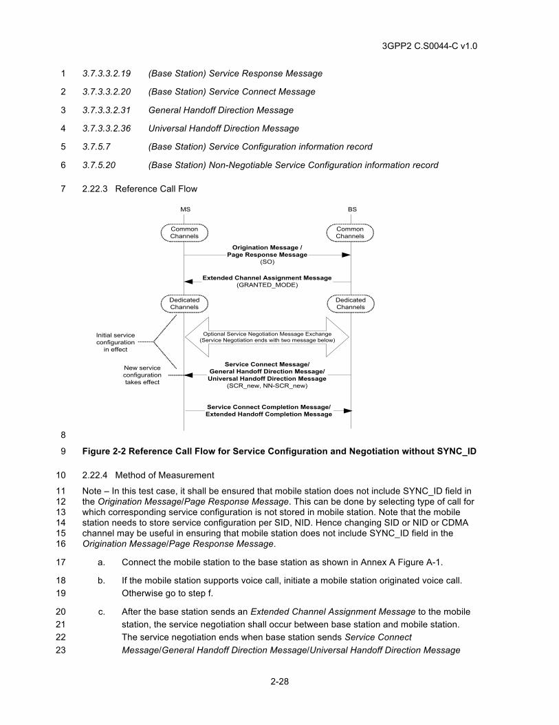
3GPP2 C.S0044-C v1.0
2-28
3.7.3.3.2.19 (Base Station) Service Response Message 1
3.7.3.3.2.20 (Base Station) Service Connect Message 2
3.7.3.3.2.31 General Handoff Direction Message 3
3.7.3.3.2.36 Universal Handoff Direction Message 4
3.7.5.7 (Base Station) Service Configuration information record 5
3.7.5.20 (Base Station) Non-Negotiable Service Configuration information record 6
2.22.3 Reference Call Flow 7
BS
DedicatedChannels
MS
DedicatedChannels
Service Connect Message/General Handoff Direction Message/Universal Handoff Direction Message
(SCR_new, NN-SCR_new)
New serviceconfigurationtakes effect
CommonChannels
CommonChannels
Origination Message /Page Response Message
(SO)
Extended Channel Assignment Message(GRANTED_MODE)
Initial serviceconfiguration
in effect
Service Connect Completion Message/Extended Handoff Completion Message
Optional Service Negotiation Message Exchange(Service Negotiation ends with two message below)
8
Figure 2-2 Reference Call Flow for Service Configuration and Negotiation without SYNC_ID 9
2.22.4 Method of Measurement 10
Note – In this test case, it shall be ensured that mobile station does not include SYNC_ID field in 11 the Origination Message/Page Response Message. This can be done by selecting type of call for 12 which corresponding service configuration is not stored in mobile station. Note that the mobile 13 station needs to store service configuration per SID, NID. Hence changing SID or NID or CDMA 14 channel may be useful in ensuring that mobile station does not include SYNC_ID field in the 15 Origination Message/Page Response Message. 16
a. Connect the mobile station to the base station as shown in Annex A Figure A-1. 17
b. If the mobile station supports voice call, initiate a mobile station originated voice call. 18 Otherwise go to step f. 19
c. After the base station sends an Extended Channel Assignment Message to the mobile 20 station, the service negotiation shall occur between base station and mobile station. 21 The service negotiation ends when base station sends Service Connect 22 Message/General Handoff Direction Message/Universal Handoff Direction Message 23
3GPP2 C.S0044-C v1.0
2-29
with SCR and NN-SCR to the mobile station and mobile station accepts the service 1 configuration by sending Service Connect Completion Message/Extended Handoff 2 Completion Message. 3
d. Verify the following: 4
1. If the base station sends Extended Channel Assignment Message with 5 GRANTED_MODE field set to ‘00’ in step c above 6
a. Prior to the new service configuration sent in the Service Connect 7 Message/General Handoff Direction Message/Universal Handoff 8 Direction Message takes effect, verify the following: 9
1. The service configuration in use is the one jointly specified by the 10 DEFAULT_CONFIG value sent in the Extended Channel 11 Assignment Message and the default Non-Negotiable part of the 12 service configuration parameters specified in the Traffic Channel 13 Initialization substate. 14
b. When the new service configuration sent in the Service Connect 15 Message/General Handoff Direction Message/Universal Handoff 16 Direction Message takes effect, verify the following: 17
1. The service configuration in use is the one specified by SCR and 18 NN-SCR in the Service Connect Message/General Handoff 19 Direction Message/Universal Handoff Direction Message sent by 20 the base station. 21
2. Verify user traffic on both directions. 22
3. The base station receives a Service Connect Completion 23 Message (if base station sends Service Connect Message) or an 24 Extended Handoff Completion Message (if base station sends 25 General Handoff Direction Message/Universal Handoff Direction 26 Message) from the mobile station. 27
2. If base station sends Extended Channel Assignment Message with 28 GRANTED_MODE field set to ‘01’ in step c above 29
a. Prior to the new service configuration sent in the Service Connect 30 Message/General Handoff Direction Message/Universal Handoff 31 Direction Message takes effect, verify the following: 32
1. The service configuration in use is the one jointly specified by the 33 default multiplex option that is derived from the radio 34 configuration corresponding to Table 3.7.2.3.2.21-7 of [4] and the 35 default Non-Negotiable part of the service configuration 36 parameters specified in the Traffic Channel Initialization 37 substate. 38
b. When the new service configuration sent in the Service Connect 39 Message/General Handoff Direction Message/Universal Handoff 40 Direction Message takes effect, verify the following: 41
3GPP2 C.S0044-C v1.0
2-30
1. The service configuration in use is the one specified by SCR and 1 NN-SCR in the Service Connect Message sent by the base 2 station. 3
2. Verify user traffic in both directions. 4
3. The base station receives a Service Connect Completion 5 Message (if base station sends Service Connect Message) or an 6 Extended Handoff Completion Message (if base station sends 7 General Handoff Direction Message/Universal Handoff Direction 8 Message) from the mobile station. 9
3. If base station sends Extended Channel Assignment Message with 10 GRANTED_MODE field set to ‘10’ in step c above 11
a. Prior to the new service configuration sent in the Service Connect 12 Message/General Handoff Direction Message/Universal Handoff 13 Direction Message takes effect, verify the following: 14
1. The service configuration in use is the one jointly specified by the 15 default multiplex option that is derived from the radio 16 configuration corresponding to Table 3.7.2.3.2.21-7 of [4] and the 17 default Non-Negotiable part of the service configuration 18 parameters specified in the Traffic Channel Initialization 19 Substate. 20
b. When the new service configuration sent in the Service Connect 21 Message/General Handoff Direction Message/Universal Handoff 22 Direction Message takes effect, verify the following: 23
1. The service configuration in use is the one specified by SCR and 24 NN-SCR in the Service Connect Message sent by the base 25 station. 26
2. Verify user traffic on both directions. 27
3. The base station receives a Service Connect Completion 28 Message (if base station sends Service Connect Message) or an 29 Extended Handoff Completion Message (if base station sends 30 General Handoff Direction Message/Universal Handoff Direction 31 Message) from the mobile station. 32
4. The mobile station does not send a Service Request Message to 33 the base station prior to the Service Connect Message/General 34 Handoff Direction Message/Universal Handoff Direction 35 Message is received from the base station. 36
e. Repeat steps a through d for mobile station terminated calls. In this case, Page 37 Response Message replaces Origination Message. 38
f. If mobile station supports data calls, repeat steps a to e above but with following 39 modification – In step b initiate data call in place of voice call. 40
3GPP2 C.S0044-C v1.0
2-31
2.22.5 Minimum Standard 1
The mobile station shall comply with step d. 2
2.23 Service Configuration and Negotiation with SYNC_ID 3
2.23.1 Definition 4
This test verifies that the mobile station can propose to use stored service configuration using 5 SYNC_ID in the Service Configuration and Negotiation process. 6
Note – This test assumes that the mobile station stores old service configuration with 7 corresponding SYNC_ID and uses SYNC_ID during call setup. If the mobile station does not use 8 SYNC_ID in call setup, then skip this test. This test also assumes that the base station sets 9 USE_SYNC_ID field to ‘1’ in Extended System Parameters Message and/or MC-RR Parameters 10 Message. If the base station is unable to do this, then skip this test. 11
2.23.2 Traceability 12
(see [4]) 13
2.6.2.2.5 Extended System Parameters Message 14
2.6.2.2.14.1 Stored Parameters 15
2.6.2.5 Mobile Station Origination Operation 16
2.6.3.3 Page Response Substate 17
2.6.3.5 Mobile Station Origination Attempt Substate 18
2.6.4.1.2 (Mobile Station) Service Configuration and Negotiation (procedures) 19
2.6.4.1.12 Processing the Service Configuration Record 20
2.6.4.1.13 Processing the Non-Negotiable Service Configuration Record 21
2.6.4.2 Traffic Channel Initialization Substate 22
2.6.4.4 Release Substate 23
2.6.6.2.5 Handoff Messages 24
2.6.6.2.5.1 Processing of Forward Traffic Channel Handoff Messages 25
2.7.1.3.2.4 Origination Message 26
2.7.1.3.2.5 Page Response Message 27
2.7.2.3.2.12 (Mobile Station) Service Request Message 28
2.7.2.3.2.13 (Mobile Station) Service Response Message 29
2.7.2.3.2.14 (Mobile Station) Service Connect Completion Message 30
2.7.4.18 (Mobile Station) Service Configuration (information record) 31
3.6.4.1.2 (Base Station) Service Configuration and Negotiation (procedures) 32
3.7.2.3.2.13 Extended System Parameters Message 33
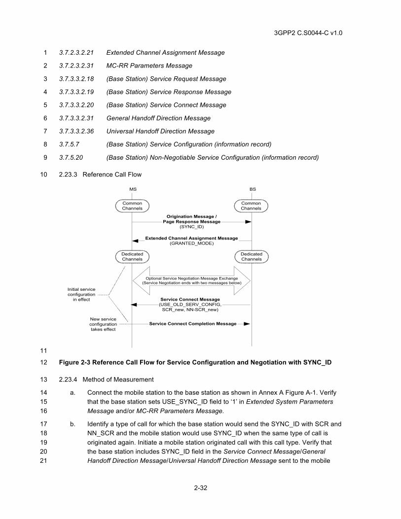
3GPP2 C.S0044-C v1.0
2-32
3.7.2.3.2.21 Extended Channel Assignment Message 1
3.7.2.3.2.31 MC-RR Parameters Message 2
3.7.3.3.2.18 (Base Station) Service Request Message 3
3.7.3.3.2.19 (Base Station) Service Response Message 4
3.7.3.3.2.20 (Base Station) Service Connect Message 5
3.7.3.3.2.31 General Handoff Direction Message 6
3.7.3.3.2.36 Universal Handoff Direction Message 7
3.7.5.7 (Base Station) Service Configuration (information record) 8
3.7.5.20 (Base Station) Non-Negotiable Service Configuration (information record) 9
2.23.3 Reference Call Flow 10
BS
DedicatedChannels
MS
DedicatedChannels
Service Connect Message(USE_OLD_SERV_CONFIG,
SCR_new, NN-SCR_new)
New serviceconfigurationtakes effect
CommonChannels
CommonChannels
Origination Message /Page Response Message
(SYNC_ID)
Extended Channel Assignment Message(GRANTED_MODE)
Initial serviceconfiguration
in effect
Service Connect Completion Message
Optional Service Negotiation Message Exchange(Service Negotiation ends with two messages below)
11
Figure 2-3 Reference Call Flow for Service Configuration and Negotiation with SYNC_ID 12
2.23.4 Method of Measurement 13
a. Connect the mobile station to the base station as shown in Annex A Figure A-1. Verify 14 that the base station sets USE_SYNC_ID field to ‘1’ in Extended System Parameters 15 Message and/or MC-RR Parameters Message. 16
b. Identify a type of call for which the base station would send the SYNC_ID with SCR and 17 NN_SCR and the mobile station would use SYNC_ID when the same type of call is 18 originated again. Initiate a mobile station originated call with this call type. Verify that 19 the base station includes SYNC_ID field in the Service Connect Message/General 20 Handoff Direction Message/Universal Handoff Direction Message sent to the mobile 21
3GPP2 C.S0044-C v1.0
2-33
station. Once the service configuration sent in the Service Connect Message/General 1 Handoff Direction Message/Universal Handoff Direction Message has taken effect, 2 disconnect the call. 3
c. Initiate a mobile station originated call with same call type as above. Verify that mobile 4 station includes SYNC_ID field in the Origination Message. 5
d. The service negotiation ends when base station sends Service Connect Message to the 6 mobile station and mobile station accepts the service configuration by sending Service 7 Connect Completion Message. 8
e. Verify the following: 9
1. If the base station sends Service Connect Message with 10 USE_OLD_SERV_CONFIG field set to ‘00’ 11
a. When the Service Connect Message takes effect, verify the following: 12
1. The service configuration in use is the one specified by SCR and 13 NN-SCR in the Service Connect Message sent by the base 14 station. 15
2. Verify user traffic (e.g. SO 33) on both directions. 16
3. The base station receives a Service Connect Completion 17 Message from the mobile station. 18
2. If the base station sends Service Connect Message with 19 USE_OLD_SERV_CONFIG field set to ‘01’ 20
a. When the new service configuration specified in the Service Connect 21 Message takes effect, verify the following: 22
1. The mobile station uses the stored service configuration. 23
2. Verify user traffic (e.g. SO 33) on both directions. 24
3. The base station receives a Service Connect Completion 25 Message from the mobile station. 26
3. If the base station sends Service Connect Message with 27 USE_OLD_SERV_CONFIG field set to ‘10’ 28
a. When the Service Connect Message takes effect, verify the following: 29
1. The mobile station uses the stored service configuration. 30
2. Verify user traffic (e.g. SO 33) on both directions. 31
3. The base station receives a Service Connect Completion 32 Message from the mobile station. 33
f. Repeat steps a through d for mobile station terminated calls. In this case, Origination 34 Message is replaced by Page Response Message. 35
2.23.5 Minimum Standard 36
The mobile station shall comply with step e. 37
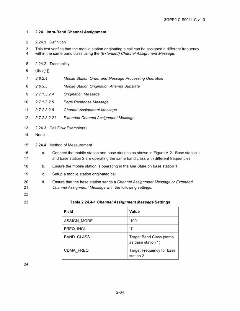
3GPP2 C.S0044-C v1.0
2-34
2.24 Intra-Band Channel Assignment 1
2.24.1 Definition 2
This test verifies that the mobile station originating a call can be assigned a different frequency 3 within the same band class using the (Extended) Channel Assignment Message. 4
2.24.2 Traceability: 5
(See[4]) 6
2.6.2.4 Mobile Station Order and Message Processing Operation 7
2.6.3.5 Mobile Station Origination Attempt Substate 8
2.7.1.3.2.4 Origination Message 9
2.7.1.3.2.5 Page Response Message 10
3.7.2.3.2.8 Channel Assignment Message 11
3.7.2.3.2.21 Extended Channel Assignment Message 12
2.24.3 Call Flow Example(s) 13
None 14
2.24.4 Method of Measurement 15
a. Connect the mobile station and base stations as shown in Figure A-2. Base station 1 16 and base station 2 are operating the same band class with different frequencies. 17
b. Ensure the mobile station is operating in the Idle State on base station 1. 18
c. Setup a mobile station originated call. 19
d. Ensure that the base station sends a Channel Assignment Message or Extended 20 Channel Assignment Message with the following settings: 21
22
Table 2.24.4-1 Channel Assignment Message Settings 23
Field Value
ASSIGN_MODE ‘100’
FREQ_INCL ‘1’
BAND_CLASS Target Band Class (same as base station 1)
CDMA_FREQ Target Frequency for base station 2
24
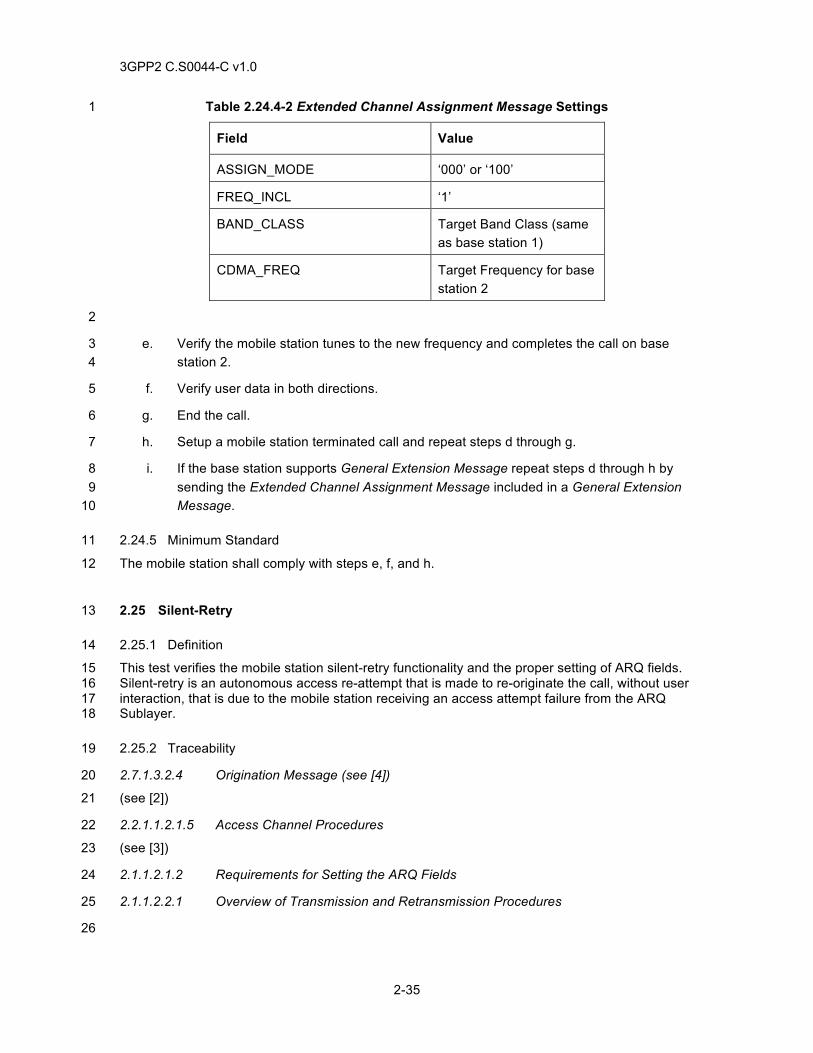
3GPP2 C.S0044-C v1.0
2-35
Table 2.24.4-2 Extended Channel Assignment Message Settings 1
Field Value
ASSIGN_MODE ‘000’ or ‘100’
FREQ_INCL ‘1’
BAND_CLASS Target Band Class (same as base station 1)
CDMA_FREQ Target Frequency for base station 2
2
e. Verify the mobile station tunes to the new frequency and completes the call on base 3 station 2. 4
f. Verify user data in both directions. 5
g. End the call. 6
h. Setup a mobile station terminated call and repeat steps d through g. 7
i. If the base station supports General Extension Message repeat steps d through h by 8 sending the Extended Channel Assignment Message included in a General Extension 9 Message. 10
2.24.5 Minimum Standard 11
The mobile station shall comply with steps e, f, and h. 12
2.25 Silent-Retry 13
2.25.1 Definition 14
This test verifies the mobile station silent-retry functionality and the proper setting of ARQ fields. 15 Silent-retry is an autonomous access re-attempt that is made to re-originate the call, without user 16 interaction, that is due to the mobile station receiving an access attempt failure from the ARQ 17 Sublayer. 18
2.25.2 Traceability 19
2.7.1.3.2.4 Origination Message (see [4]) 20
(see [2]) 21
2.2.1.1.2.1.5 Access Channel Procedures 22
(see [3]) 23
2.1.1.2.1.2 Requirements for Setting the ARQ Fields 24
2.1.1.2.2.1 Overview of Transmission and Retransmission Procedures 25
26
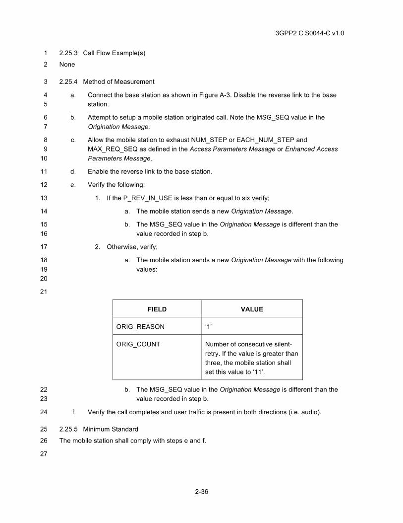
3GPP2 C.S0044-C v1.0
2-36
2.25.3 Call Flow Example(s) 1
None 2
2.25.4 Method of Measurement 3
a. Connect the base station as shown in Figure A-3. Disable the reverse link to the base 4 station. 5
b. Attempt to setup a mobile station originated call. Note the MSG_SEQ value in the 6 Origination Message. 7
c. Allow the mobile station to exhaust NUM_STEP or EACH_NUM_STEP and 8 MAX_REQ_SEQ as defined in the Access Parameters Message or Enhanced Access 9 Parameters Message. 10
d. Enable the reverse link to the base station. 11
e. Verify the following: 12
1. If the P_REV_IN_USE is less than or equal to six verify; 13
a. The mobile station sends a new Origination Message. 14
b. The MSG_SEQ value in the Origination Message is different than the 15 value recorded in step b. 16
2. Otherwise, verify; 17
a. The mobile station sends a new Origination Message with the following 18 values: 19 20
21
FIELD VALUE
ORIG_REASON ‘1’
ORIG_COUNT Number of consecutive silent-retry. If the value is greater than three, the mobile station shall set this value to ‘11’.
b. The MSG_SEQ value in the Origination Message is different than the 22 value recorded in step b. 23
f. Verify the call completes and user traffic is present in both directions (i.e. audio). 24
2.25.5 Minimum Standard 25
The mobile station shall comply with steps e and f. 26
27
3GPP2 C.S0044-C v1.0
2-37
2.26 MSID, MCC, and IMSI 1
2.26.1 Definition 2
These tests verify some protocol of the Mobile Station IDentifier number (MSID or MSIN), Mobile 3 Country Code (MCC), and International Mobile Station Identity (IMSI). Mobile station response to 4 three instances of base station PREF_MSID_TYPE are checked when the MCC and IMSI_11_12 5 of the mobile station and base station match do not match or are wildcard values. 6
2.26.2 Traceability 7
(see [4]) 8
3.7.2.3.2.13 Extended System Parameters Message 9
2.6.2.2.5 Extended System Parameters Message 10
2.6.2.3 Mobile Station Page Match Operation 11
2.3.1 Mobile Station Identification Number 12
2.3.1.1 Encoding of IMSI_M_S and IMSI_T_S 11 13
Table 3.7.2.3.2.13-1 Preferred MSID Types 14
3.6.2.2 Overhead Information 15
(see [3]) 16
2.1.1.3.1.1 Addressing 17
2.1.1.2.1.3 IMSI Class 18
2.26.2.1.1 Call Flow Diagram 19
None 20
2.26.3 Method of Measurement 21
For each step below with IMSI_CLASS = 0, set USE_TMSI = ‘0’ in the base station Extended 22 System Parameters Message or ANSI-41 System Parameters Message. Also program either the 23 mobile station or the base station for the values of MCC and IMSI_11_12, to achieve the 24 matching or non-matching conditions indicated. 25
a. PREF_MSID_TYPE = ‘00’. Configure the base station Extended System Parameters 26 Message with PREF_MSID_TYPE = ‘00’. Make a mobile station originated call and a 27 mobile station terminated call. Verify the mobile station sets MSID_TYPE = ’000’ and 28 sends IMSI_S and ESN in the Origination Message and Page Response Message. 29
b. PREF_MSID_TYPE = ‘10’, matching MCC and matching IMSI_11_12. Configure the 30 base station Extended System Parameters Message with PREF_MSID_TYPE = ‘10’. 31 Verify the values of both MCC and IMSI_11_12 are the same (match) in the mobile 32 station and base station. Make a mobile station originated call and a mobile station 33 terminated call. Verify the mobile station sets MSID_TYPE = ‘010’ and sends IMSI_S 34 (does not send MCC and IMSI_11_12) in the Origination Message and Page Response 35 Message. 36
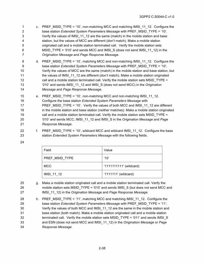
3GPP2 C.S0044-C v1.0
2-38
c. PREF_MSID_TYPE = ‘10’, non-matching MCC and matching IMSI_11_12. Configure the 1 base station Extended System Parameters Message with PREF_MSID_TYPE = ‘10’. 2 Verify the values of IMSI_11_12 are the same (match) in the mobile station and base 3 station, but the values of MCC are different (don’t match). Make a mobile station 4 originated call and a mobile station terminated call. Verify the mobile station sets 5 MSID_TYPE = ‘010’ and sends MCC and IMSI_S (does not send IMSI_11_12) in the 6 Origination Message and Page Response Message. 7
d. PREF_MSID_TYPE = ‘10’, matching MCC and non-matching IMSI_11_12. Configure the 8 base station Extended System Parameters Message with PREF_MSID_TYPE = ‘10’. 9 Verify the values of MCC are the same (match) in the mobile station and base station, but 10 the values of IMSI_11_12 are different (don’t match). Make a mobile station originated 11 call and a mobile station terminated call. Verify the mobile station sets MSID_TYPE = 12 ‘010’ and sends IMSI_11_12 and IMSI_S (does not send MCC) in the Origination 13 Message and Page Response Message. 14
e. PREF_MSID_TYPE = ‘10’, non-matching MCC and non-matching IMSI_11_12. 15 Configure the base station Extended System Parameters Message with 16 PREF_MSID_TYPE = ‘10’. Verify the values of both MCC and IMSI_11_12 are different 17 in the mobile station and base station (neither matches). Make a mobile station originated 18 call and a mobile station terminated call. Verify the mobile station sets MSID_TYPE = 19 ‘010’ and sends MCC, IMSI_11_12 and IMSI_S in the Origination Message and Page 20 Response Message. 21
f. PREF_MSID_TYPE = ‘10’, wildcard MCC and wildcard IMSI_11_12. Configure the base 22 station Extended System Parameters Message with the following fields. 23
24
Field Value
PREF_MSID_TYPE ‘10’
MCC ‘1111111111’ (wildcard)
IMSI_11_12 ‘1111111’ (wildcard)
g. Make a mobile station originated call and a mobile station terminated call. Verify the 25 mobile station sets MSID_TYPE = ‘010’ and sends IMSI_S (but does not send MCC and 26 IMSI_11_12) in the Origination Message and Page Response Message. 27
h. PREF_MSID_TYPE = ‘11’, matching MCC and matching IMSI_11_12. Configure the 28 base station Extended System Parameters Message with PREF_MSID_TYPE = ‘11’. 29 Verify the values of both MCC and IMSI_11_12 are the same in the mobile station and 30 base station (both match). Make a mobile station originated call and a mobile station 31 terminated call. Verify the mobile station sets MSID_TYPE = ‘011’ and sends IMSI_S 32 and ESN (does not send MCC and IMSI_11_12) in the Origination Message or Page 33 Response Message. 34
3GPP2 C.S0044-C v1.0
2-39
i. PREF_MSID_TYPE = ‘11’, non-matching MCC and matching IMSI_11_12. Configure the 1 base station Extended System Parameters Message with PREF_MSID_TYPE = ‘11’. 2 Verify the values of IMSI_11_12 are the same in the mobile station and base station 3 (match), but the values of MCC are different (don’t match). Make a mobile station 4 originated call and a mobile station terminated call. Verify the mobile station sets 5 MSID_TYPE = ‘011’ and sends MCC, IMSI_S and ESN (does not send IMSI_11_12) in 6 the Origination Message and Page Response Message. 7
j. PREF_MSID_TYPE = ‘11’, matching MCC and non-matching IMSI_11_12. Configure the 8 base station Extended System Parameters Message with PREF_MSID_TYPE = ‘11’. 9 Verify the values of MCC are the same in the mobile station and base station (match), but 10 the values of IMSI_11_12 are different (don’t match). Make a mobile station originated 11 call and a mobile station terminated call. Verify the mobile station sets MSID_TYPE = 12 ‘011’ and sends IMSI_11_12, IMSI_S and ESN (does not send MCC) in the Origination 13 Message and Page Response Message. 14
k. PREF_MSID_TYPE = ‘11’, non-matching MCC and non-matching IMSI_11_12. 15 Configure the base station Extended System Parameters Message with 16 PREF_MSID_TYPE = ‘11’. Verify the values of both MCC and IMSI_11_12 are different 17 in the mobile station and base station. Make a mobile station originated call and a mobile 18 station terminated call. Verify the mobile station sets MSID_TYPE = ‘011’ and sends 19 MCC, IMSI_11_12, IMSI_S, and ESN in the Origination Message and Page Response 20 Message. 21
l. PREF_MSID_TYPE = ‘11’, wildcard MCC and wildcard IMSI_11_12. Configure the base 22 station Extended System Parameters Message with the following fields. 23
24
Field Value
PREF_MSID_TYPE ‘11’
MCC ‘1111111111’ (wildcard)
IMSI_11_12 ‘1111111’ (wildcard)
25
m. Make a mobile station originated call and a mobile station terminated call. Verify the 26 mobile station sets MSID_TYPE = ‘011’ and sends IMSI_S and ESN (but does not send 27 MCC and IMSI_11_12) in the Origination Message and Page Response Message. 28
2.26.4 Minimum Standard 29
All calls shall complete normally. The mobile station shall comply with requirements in steps b 30 through m. 31
3GPP2 C.S0044-C v1.0
2-40
2.27 RL RC 8 / FL RC 11 Parameter Change using RCPM 1
2.27.1 Definition 2
This test verifies that the mobile station and base station can use Radio Configuration 3 Parameters Message for changing Reverse Link RC 8 and/or Forward Link RC 11 or RC 12 4 parameters. 5
2.27.2 Traceability: 6
(See[4]) 7
2.7.1.3.2.2 Order Message 8
2.7.1.3.2.5 Page Response Message 9
2.7.1.3.2.2.4 Origination Message 10
2.7.2.3.2.14 Service Connect Completion Message 11
3.7.2.3.2.17 General Page Message 12
3.7.2.3.2.21 Extended Channel Assignment Message 13
3.7.3.3.2.20 Service Connect Message 14
3.7.5.7 Service Configuration 15
3.7.3.3.2.51 Radio Configuration Parameters Message 16
2.27.3 Call Flow Example(s) 17
18
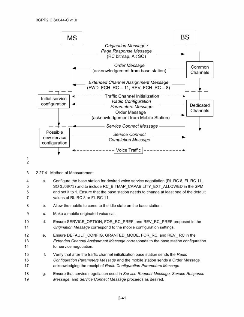
3GPP2 C.S0044-C v1.0
2-41
Origination Message / Page Response Message
(RC bitmap, Alt SO)
Order Message (acknowledgement from base station)
Extended Channel Assignment Message(FWD_FCH_RC = 11, REV_FCH_RC = 8)
Common Channels
Service Connect Message
Initial service configuration Dedicated
Channels
Possible new service configuration
Voice Traffic
MS BS
Traffic Channel Initialization
Service Connect Completion Message
Radio Configuration Parameters Message
Order Message(acknowledgement from Mobile Station)
1 2
2.27.4 Method of Measurement 3
a. Configure the base station for desired voice service negotiation (RL RC 8, FL RC 11, 4 SO 3,/68/73) and to include RC_BITMAP_CAPABILITY_EXT_ALLOWED in the SPM 5 and set it to 1. Ensure that the base station needs to change at least one of the default 6 values of RL RC 8 or FL RC 11. 7
b. Allow the mobile to come to the idle state on the base station. 8
c. Make a mobile originated voice call. 9
d. Ensure SERVICE_OPTION, FOR_RC_PREF, and REV_RC_PREF proposed in the 10 Origination Message correspond to the mobile configuration settings. 11
e. Ensure DEFAULT_CONFIG, GRANTED_MODE, FOR_RC, and REV_ RC in the 12 Extended Channel Assignment Message corresponds to the base station configuration 13 for service negotiation. 14
f. Verify that after the traffic channel initialization base station sends the Radio 15 Configuration Parameters Message and the mobile station sends a Order Message 16 acknowledging the receipt of Radio Configuration Parameters Message. 17
g. Ensure that service negotiation used in Service Request Message, Service Response 18 Message, and Service Connect Message proceeds as desired. 19
3GPP2 C.S0044-C v1.0
2-42
h. Ensure that the SERVICE_OPTION, FOR_FCH_RC, and REV_FCH_RC in the last 1 Service Configuration Record corresponds to the desired outcome of the base station 2 service negotiation configuration, and the call completes successfully. 3
i. End the call. 4
j. Setup a mobile station terminated call and repeat steps d through g. 5
2.27.5 Minimum Standard 6
The mobile station shall comply with steps f and h. 7
2.28 RL RC 8 / FL RC 11 Parameter Change using GEM 8
2.28.1 Definition 9
This test verifies that the mobile station and base station can use General Extension Message for 10 changing Reverse Link RC 8 and/or Forward Link RC 11 or RC 12 parameters during call 11 establishment. Implementation of General Extension Message is optional for the base station. 12
2.28.2 Traceability: 13
(See[4]) 14
2.7.1.3.2.2 Order Message 15
2.7.1.3.2.5 Page Response Message 16
2.7.1.3.2.2.4 Origination Message 17
2.7.2.3.2.14 Service Connect Completion Message 18
3.7.2.3.2.17 General Page Message 19
3.7.2.3.2.21 Extended Channel Assignment Message 20
3.7.3.3.2.20 Service Connect Message 21
3.7.5.7 Service Configuration 22
3.7.3.3.2.51 Radio Configuration Parameters Message 23
2.28.3 Call Flow Example(s) 24
25
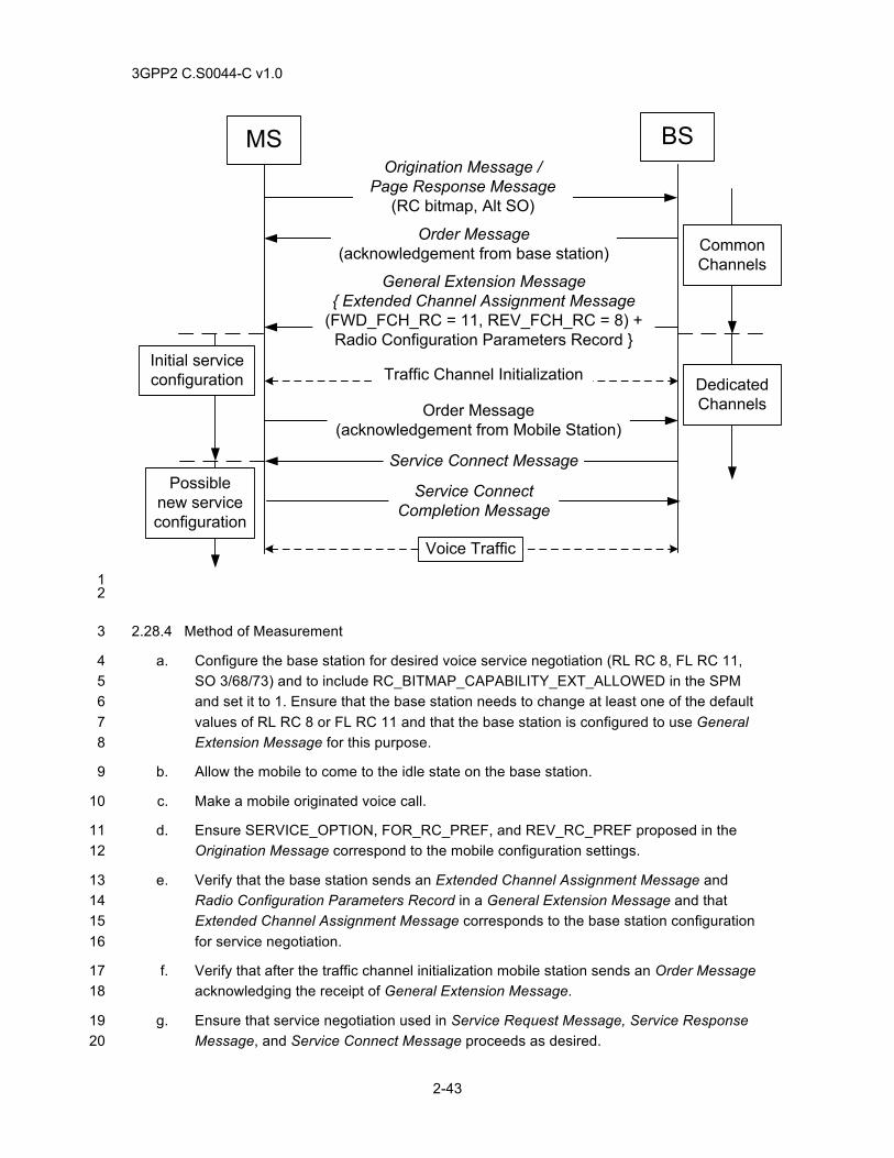
3GPP2 C.S0044-C v1.0
2-43
Origination Message / Page Response Message
(RC bitmap, Alt SO)
Order Message (acknowledgement from base station)
General Extension Message { Extended Channel Assignment Message
(FWD_FCH_RC = 11, REV_FCH_RC = 8) + Radio Configuration Parameters Record }
Common Channels
Service Connect Message
Initial service configuration Dedicated
Channels
Possible new service configuration
Voice Traffic
MS BS
Traffic Channel Initialization
Service Connect Completion Message
Order Message(acknowledgement from Mobile Station)
1 2
2.28.4 Method of Measurement 3
a. Configure the base station for desired voice service negotiation (RL RC 8, FL RC 11, 4 SO 3/68/73) and to include RC_BITMAP_CAPABILITY_EXT_ALLOWED in the SPM 5 and set it to 1. Ensure that the base station needs to change at least one of the default 6 values of RL RC 8 or FL RC 11 and that the base station is configured to use General 7 Extension Message for this purpose. 8
b. Allow the mobile to come to the idle state on the base station. 9
c. Make a mobile originated voice call. 10
d. Ensure SERVICE_OPTION, FOR_RC_PREF, and REV_RC_PREF proposed in the 11 Origination Message correspond to the mobile configuration settings. 12
e. Verify that the base station sends an Extended Channel Assignment Message and 13 Radio Configuration Parameters Record in a General Extension Message and that 14 Extended Channel Assignment Message corresponds to the base station configuration 15 for service negotiation. 16
f. Verify that after the traffic channel initialization mobile station sends an Order Message 17 acknowledging the receipt of General Extension Message. 18
g. Ensure that service negotiation used in Service Request Message, Service Response 19 Message, and Service Connect Message proceeds as desired. 20
3GPP2 C.S0044-C v1.0
2-44
h. Ensure that the SERVICE_OPTION, FOR_FCH_RC, and REV_FCH_RC fields in the 1 last Service Configuration Record corresponds to the desired outcome of the base 2 station service negotiation configuration, and the call completes successfully. 3
i. End the call. 4
j. Setup a mobile station terminated call and repeat steps d through g. 5
2.28.5 Minimum Standard 6
The mobile station shall comply with steps f and h. 7
2.29 Forward Link Error with RC11/RC12 8
2.29.1 Definition 9
This test verifies forward link error trigger functionality in the mobile station for different smart 10 blanking options for the RC11/RC12 assignment on the forward link that are supported by the 11 base station. In the method of measurement below base station should perform procedures only 12 for the FOR_FCH_BLANKING_DUTYCYCLE and FOR_N2M_IND values supported by the base 13 station. 14
2.29.2 Traceability: 15
(See[4]) 16
2.6.2.1.1.4 Common Channel Supervision 17
2.6.4.1.8 Forward Traffic Channel Supervision 18
2.6.4.1.8.1.1 Triggers 19
2.29.3 Call Flow Example(s) 20
None. 21
2.29.4 Method of Measurement 22
a. Configure the base station for desired voice service negotiation (RL RC 8, FL RC 11, 23 SO 3/68/73). 24
b. Allow the mobile station to come to the idle state on the base station. 25
c. Attempt a mobile station originated or terminated call. 26
d. Instruct the base station to assign RC11/RC12 on the forward fundamental channel and 27 to assign a value of ‘010’ for ‘FOR_FCH_BLANKING_DUTYCYCLE and ‘011’ for 28 FOR_N2M_IND using the Radio Configuration Parameters Message or the Radio 29 Configuration Parameters Record. Other values specified later in the test can be used if 30 these values are not supported. 31
e. Instruct the base station to transmit only guaranteed physical layer frames. This can be 32 achieved by using of SO 74 or by muting the mobile station other end in case of a 33 mobile to mobile call. 34
3GPP2 C.S0044-C v1.0
2-45
f. Abruptly cause loss of the forward RF link beginning in for a period greater than 1 FOR_N2M_IND guaranteed frames ( i.e. > (FOR_N2M_IND + 1) * 2 FOR_FCH_BLANKING_DUTYCYCLE * 20 ms) and less than 5 seconds. Note that 3 FOR_N2M_IND and FOR_FCH_BLANKING_DUTYCYCLE values are in number of 4 frames and not the actual attribute values. FOR_FCH_BLANKING_DUTYCYCLE value 5 of ‘000’, ‘001’ and ‘010’ correspond to 0, 4 and 8 frames respectively. FOR_N2M_IND 6 value of ‘000’, ‘001’, ‘010’, and ‘011’ correspond to 2, 4, 6 and 8 frames respectively. 7
g. Verify that the mobile station disables its reverse link transmitter after it receives 8 FOR_N2M_IND consecutive guaranteed FL frames with insufficient signal quality. 9
h. Verify that the mobile station starts its transmitter after receiving N3m (2) consecutive 10 guaranteed frames from on the forward link or if the mobile station receives the forward 11 fundamental channel with sufficient signal quality for a period of N3m × 20ms (= 40 ms). 12
i. Terminate the call. 13
j. Repeat steps c-g with the exception that the base station is continuously transmitting 14 frames to the mobile station. This can be achieved for example by using SO 74 and 15 generating critical 1/8th rate frames. 16
k. Verify that the mobile station starts its transmitter after receiving N3m (2) consecutive 17 frames from on the forward link or if the mobile station receives the forward 18 fundamental channel with sufficient signal quality for a period of N3m × 20ms (= 40 ms). 19
l. Repeat steps c-e. 20
m. Abruptly cause loss of the forward RF link beginning in for a period equal to 21 FOR_N2M_IND * FOR_FCH_BLANKING_DUTYCYCLE * 20 ms – 20 ms such that less 22 than FOR_N2M_IND guaranteed frames are lost. Note that 23 FOR_FCH_BLANKING_DUTYCYCLE and FOR_N2M_IND values are in number of 24 frames and not the actual attribute values. 25
n. Verify that the mobile station does not disable its reverse link transmitter. 26
o. Terminate the call. 27
p. Repeat steps c-o for FOR_N2M_IND attribute values of ‘000’, 001’ and ‘010’. 28
q. Repeat steps c-p for FOR_FCH_BLANKING_DUTYCYCLE attribute value of ‘001’. 29
r. Repeat steps c-e with FOR_FCH_BLANKING_DUTYCYCLE attribute value of ‘000’ and 30 configure the base station to continuously transmit frames to the mobile station. This 31 can be achieved for example by using SO 74 and generating critical 1/8th rate frames. 32
s. Abruptly cause loss of the forward RF link beginning in for a period greater than N2M 33 frames and less than 5 seconds. 34
t. Verify that the mobile station disables its reverse link transmitter after it receives N2M 35 consecutive FL frames with insufficient signal quality. 36
u. Verify that the mobile station starts its transmitter after receiving N3m (2) consecutive 37 frames from on the forward link or if the mobile station receives the forward 38 fundamental channel with sufficient signal quality for a period of N3m × 20ms (= 40 ms). 39
3GPP2 C.S0044-C v1.0
2-46
v. Terminate the call. 1
w. Repeat step c-e with FOR_FCH_BLANKING_DUTYCYCLE attribute value of ‘000’ and 2 configure the base station is continuously transmitting frames to the mobile station. This 3 can be achieved for example by using SO 74 and generating critical 1/8th rate frames.. 4
x. Abruptly cause loss of the forward RF link beginning in for a period less than N2M 5 frames. 6
y. Verify that the mobile station does not disable its reverse link transmitter. 7
z. Repeat steps r-y for FOR_N2M_IND attribute values of ‘000’, 001’ and ‘010’. Note, 8 FOR_N2M_IND value is not used when FOR_FCH_BLANKING_DUTYCYCLE attribute 9 value of ‘000’ is used. 10
aa. Repeat steps a-z with REV_FCH_BLANKING_DUTYCYCLE set to ‘000’. 11
2.29.5 Minimum Standard 12
The mobile station shall comply with steps g, h, k, n, t, u, and y. 13
2.30 Traffic Channel Assignment in QoF 14
2.30.1 Definition 15
This test verifies a call set-up with a QoF assignment instead of walsh channel. 16
2.30.2 Traceability: 17
(See[4]) 18
2.7.1.3.2.2 Order Message 19
2.7.1.3.2.5 Page Response Message 20
2.7.1.3.2.2.4 Origination Message 21
2.7.2.3.2.14 Service Connect Completion Message 22
3.7.2.3.2.17 General Page Message 23
3.7.2.3.2.21 Extended Channel Assignment Message 24
3.7.3.3.2.20 Service Connect Message 25
3.7.5.7 Service Configuration 26
3.7.3.3.2.51 Radio Configuration Parameters Message 27
2.30.3 Call Flow Example(s) 28
None. 29
2.30.4 Method of Measurement 30
a. Configure the base station for desired voice service negotiation (RL RC 8, FL RC 11, 31 SO 3/68/73) ), include RC_BITMAP_CAPABILITY_EXT_ALLOWED in the SPM 32 and sets it to 1, and to assign QoF instead of a walsh code in the Extended Channel 33
3GPP2 C.S0044-C v1.0
2-47
Assignment Message. Ensure that the base station needs to change at least one of the 1 default values of RL RC 8 or FL RC 11. 2
b. Attempt a mobile station originated or terminated call. 3 c. Ensure that the mobile station includes support for RC 11 in FOR_FCH_RC_MAP and 4
RC 8 in REV_FCH_RC_MAP in the Origination Message. 5 d. Ensure that the mobile station includes SO 74 in the SO or ALT_SO or SO_BITMAP 6
field in the origination message. 7 e. Instruct the base station to send an Extended Channel Assignment Message with 8
FOR_FCH_RC / FOR_RC set to 11 and REV_FCH_RC / FOR_RC set to 8 and to set 9 the QOF_MASK_ID_FCH set to ‘11’. 10
f. Ensure that the mobile station initializes the traffic channel. 11 g. Ensure that the base station to transmit Service Connect Message specifying the SO 12
73/68/3 in the SERVICE_OPTION field. 13 h. Ensure that the mobile station transmits Service Connect Completion Message to the 14
base station. 15 i. Instruct the base station to send a Radio Configuration Parameters Message with 16
QOF_SET_IN_USE set to ‘11’. 17 j. Verify that the mobile station starts transmitting and receiving frames for voice traffic. 18
k. Repeat the test by using General Extension Message containing with Extended 19 Channel Assignment Message and Radio Configuration Parameters Record. 20
2.30.5 Minimum Standard 21
The mobile station shall comply with step j. 22
2.31 Call recovery Request Message 23
2.31.1 Definition 24
This test verifies the Call Recovery Request Message functionality at the mobile station. 25
2.31.2 Traceability: 26
(See[4]) 27
2.6.2.1.1.4 Common Channel Supervision 28
2.6.4.1.8 Forward Traffic Channel Supervision 29
2.7.1.3.2.17 Call Recovery 1 Request Message 30
2.6.4.1.8.1.1 Triggers 31
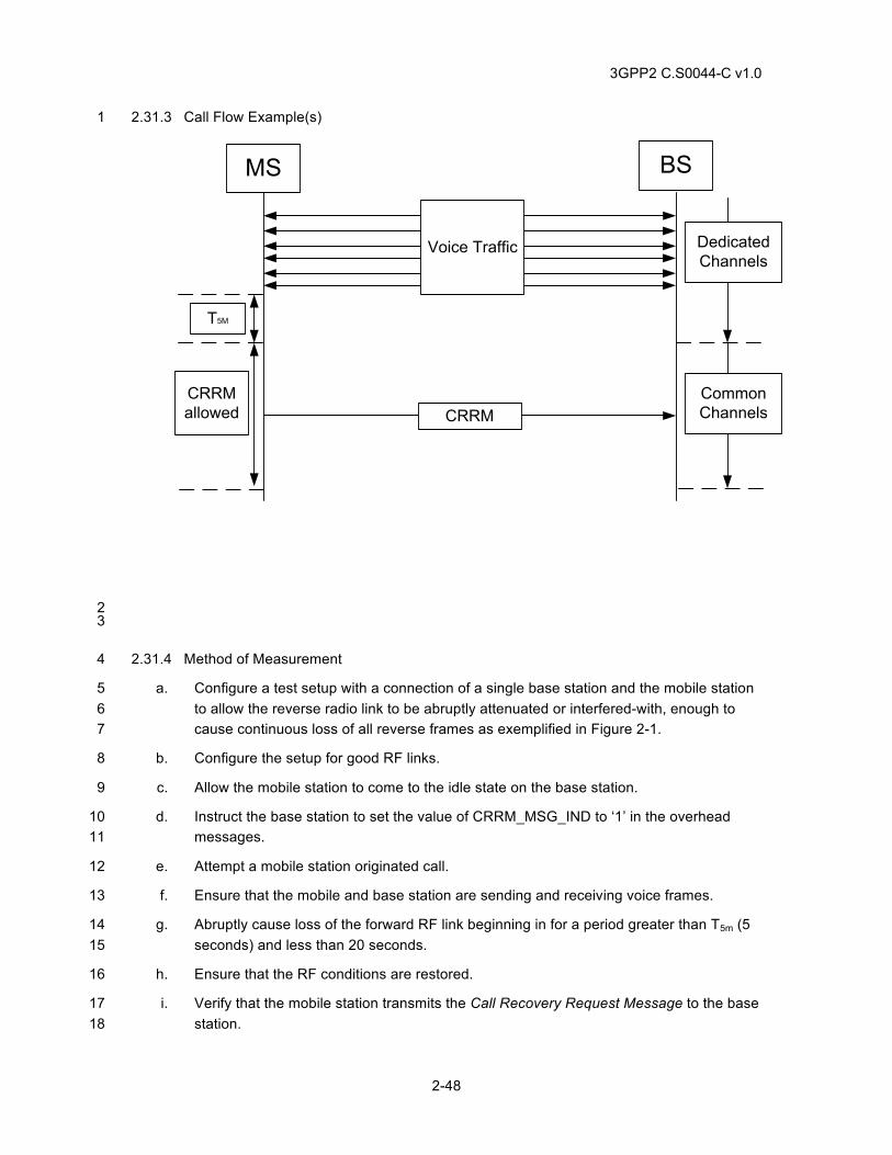
3GPP2 C.S0044-C v1.0
2-48
2.31.3 Call Flow Example(s) 1
Dedicated Channels
MS BS
Voice Traffic
T5M
CRRMallowed
Common ChannelsCRRM
2 3
2.31.4 Method of Measurement 4
a. Configure a test setup with a connection of a single base station and the mobile station 5 to allow the reverse radio link to be abruptly attenuated or interfered-with, enough to 6 cause continuous loss of all reverse frames as exemplified in Figure 2-1. 7
b. Configure the setup for good RF links. 8
c. Allow the mobile station to come to the idle state on the base station. 9
d. Instruct the base station to set the value of CRRM_MSG_IND to ‘1’ in the overhead 10 messages. 11
e. Attempt a mobile station originated call. 12
f. Ensure that the mobile and base station are sending and receiving voice frames. 13
g. Abruptly cause loss of the forward RF link beginning in for a period greater than T5m (5 14 seconds) and less than 20 seconds. 15
h. Ensure that the RF conditions are restored. 16
i. Verify that the mobile station transmits the Call Recovery Request Message to the base 17 station. 18
3GPP2 C.S0044-C v1.0
2-49
j. Ensure that the base station assigns a new traffic channel to the mobile station. 1
k. Verify that the mobile station reestablishes the original voice call. 2
l. Terminate the call. 3
m. Repeat steps c-f. 4
n. Abruptly cause loss of the forward RF link beginning in for a period greater than 20 5 seconds. 6
o. Ensure that the RF conditions are restored. 7
p. Verify that the mobile station does not transmit Call Recovery Request Message to the 8 base station. 9
q. Terminate the call. 10
r. Instruct the base station to set the value of CRRM_MSG_IND to ‘0’ in the overhead 11 messages. 12
s. Repeat steps c-h. 13
t. Verify that the mobile station does not transmit Call Recovery Request Message to the 14 base station. 15
2.31.5 Minimum Standard 16
The mobile station shall comply with step i, k, p, t. 17
2.32 General Overhead Information Message 18
2.32.1 Definition 19
This test verifies the General Overhead Information Message processing at the mobile station. 20
2.32.2 Traceability: 21
(See[4]) 22
2.6.2.2.22 General Overhead Information Message 23
3.7.2.3.2.42 General Overhead Information Message 24
3.7.2.3.2.31 MC-1 RR Parameters Message 25
3.7.2.3.2.1 System Parameters Message 26
2.32.3 Call Flow Example(s) 27
None. 28
2.32.4 Method of Measurement 29
a. Configure the base station to transmit General Overhead Information Message. 30
b. Instruct the base station to set the value of GEN_OVHD_INF_IND to ‘1’ and 31 GEN_OVHD_CYCLE_INDEX to ‘101’ in the overhead messages. 32
3GPP2 C.S0044-C v1.0
2-50
c. Allow the mobile station to become idle. 1
d. Attempt a mobile station originated call before the General Overhead Information 2 Message is received from the base station. 3
e. Verify that the mobile station transmits an Origination Message. 4
f. Terminate the call. 5
g. Allow the mobile station to become idle. 6
h. Attempt a mobile station terminated call before the General Overhead Information 7 Message is received from the base station. 8
i. Verify that the mobile station transmits a Page Response Message. 9
j. Terminate the call. 10
2.32.5 Minimum Standard 11
The mobile station shall comply with steps e and i. 12
2.33 SO 33 call set-up with RC 11 and RC 8 13
2.33.1 Definition 14
This test verifies SO 33 call set-up with FL RC 11 and RL RC 8 assignment. It also verifies 15 various power control mode assignments though Radio Configuration Parameters Message. This 16 test should be conducted for all FPC_MODE, RPC_MODE, and 17 REV_FCH_BLANKING_DUTYCYCLE supported by the base station and the mobile station. 18 Note, in the procedure below, FPC_MODE can also be changed through Radio Configuration 19 Parameters Message or a General Extension Message that carries Radio Configuration 20 Parameters Record. 21
2.33.2 Traceability: 22
See [1]) 23
2.1.3.1.11 Reverse Power Control Subchannel 24
(See [4]) 25
2.6.6.2.5.1, 3.6.6.2.2.12, 3.7.3.3.2.37 Extended Supplemental Channel Assignment Message 26
2.6.2.4, 2.6.3.3, 2.6.3.5, 3.6.3.3, 3.6.3.5, 3.7.2.3.2.21 Extended Channel Assignment Message 27
2.6.4.1.2, 2.6.4.1.2.2, 3.7.3.3.2.20, 3.7.5, 3.7.5.7, 3.7.5.20 Service Connect Message 28
2.33.3 Call Flow Example(s) 29
None. 30
2.33.4 Method of Measurement 31
a. Configure the base station for desired service negotiation and to include 32 RC_BITMAP_CAPABILITY_EXT_ALLOWED in the SPM and sets it to 1. 33
b. Set up a mobile station originated call using Service Option 33. 34
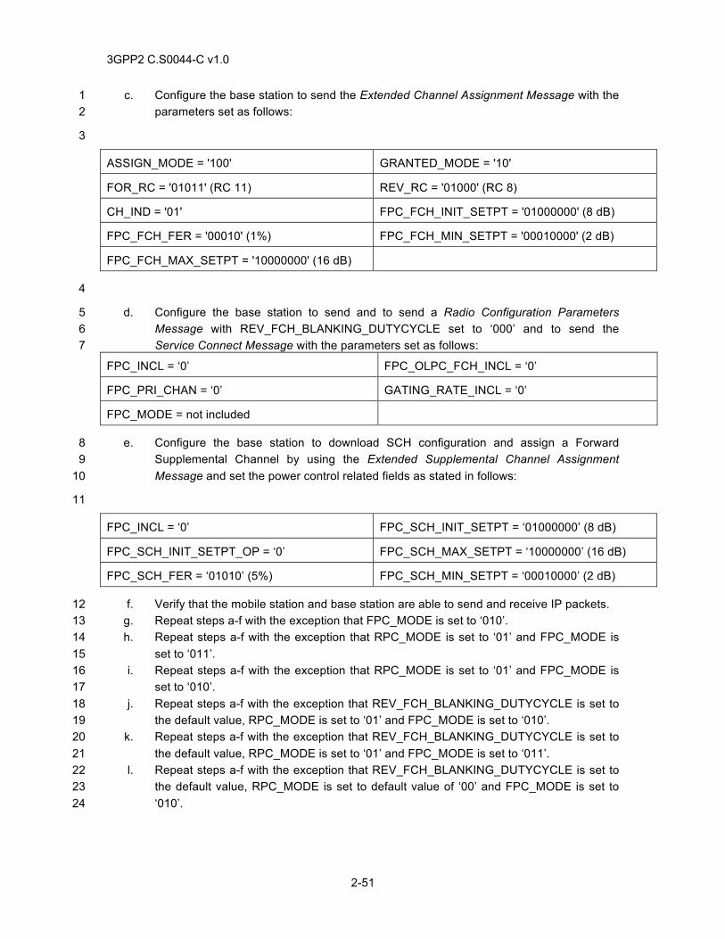
3GPP2 C.S0044-C v1.0
2-51
c. Configure the base station to send the Extended Channel Assignment Message with the 1 parameters set as follows: 2
3
ASSIGN_MODE = '100' GRANTED_MODE = '10'
FOR_RC = '01011' (RC 11) REV_RC = '01000' (RC 8)
CH_IND = '01' FPC_FCH_INIT_SETPT = '01000000' (8 dB)
FPC_FCH_FER = '00010' (1%) FPC_FCH_MIN_SETPT = '00010000' (2 dB)
FPC_FCH_MAX_SETPT = '10000000' (16 dB)
4
d. Configure the base station to send and to send a Radio Configuration Parameters 5 Message with REV_FCH_BLANKING_DUTYCYCLE set to ‘000’ and to send the 6 Service Connect Message with the parameters set as follows: 7
FPC_INCL = ‘0’ FPC_OLPC_FCH_INCL = ‘0’
FPC_PRI_CHAN = ‘0’ GATING_RATE_INCL = ‘0’
FPC_MODE = not included
e. Configure the base station to download SCH configuration and assign a Forward 8 Supplemental Channel by using the Extended Supplemental Channel Assignment 9 Message and set the power control related fields as stated in follows: 10
11
FPC_INCL = ‘0’ FPC_SCH_INIT_SETPT = ‘01000000’ (8 dB)
FPC_SCH_INIT_SETPT_OP = ‘0’ FPC_SCH_MAX_SETPT = ‘10000000’ (16 dB)
FPC_SCH_FER = ‘01010’ (5%) FPC_SCH_MIN_SETPT = ‘00010000’ (2 dB)
f. Verify that the mobile station and base station are able to send and receive IP packets. 12 g. Repeat steps a-f with the exception that FPC_MODE is set to ‘010’. 13 h. Repeat steps a-f with the exception that RPC_MODE is set to ‘01’ and FPC_MODE is 14
set to ‘011’. 15 i. Repeat steps a-f with the exception that RPC_MODE is set to ‘01’ and FPC_MODE is 16
set to ‘010’. 17 j. Repeat steps a-f with the exception that REV_FCH_BLANKING_DUTYCYCLE is set to 18
the default value, RPC_MODE is set to ‘01’ and FPC_MODE is set to ‘010’. 19 k. Repeat steps a-f with the exception that REV_FCH_BLANKING_DUTYCYCLE is set to 20
the default value, RPC_MODE is set to ‘01’ and FPC_MODE is set to ‘011’. 21 l. Repeat steps a-f with the exception that REV_FCH_BLANKING_DUTYCYCLE is set to 22
the default value, RPC_MODE is set to default value of ‘00’ and FPC_MODE is set to 23 ‘010’. 24
3GPP2 C.S0044-C v1.0
2-52
i. Repeat steps a and b, with the base station either not including 1 RC_BITMAP_CAPABILITY_EXT_ALLOWED in the SPM or including it and setting it to 2 0. 3
j. Instruct the base station to query REV_SCH Type-Specific Fields record and 4 FOR_SCH Type-Specific Fields record from the mobile station using Status Request 5 Message. 6
m. Verify that the mobile station does not include the RL RC 8 and FL RC 11 or 12 in the 7 REV_SCH_RC_MAP and FOR_SCH_RC_MAP fields respectively. 8
2.33.5 Minimum Standard 9
The mobile station shall comply with the requirement in step f for all cases and step o. 10
11
3GPP2 C.S0044-C v1.0
3-1
3 HANDOFF TESTS 1
3.1 Soft Handoff with Dynamic Threshold 2
3.1.1 Definition 3
This test verifies the mobile station and base station perform soft handoff. Soft handoff with and 4 without dynamic thresholds is verified. This test verifies both adding pilot to and dropping pilot 5 from the soft handoff Active Set. Tests 1 through 4 apply to cases when SOFT_SLOPE is not 6 equal to ‘000000’ (dynamic threshold enabled). 7
3.1.2 Traceability 8
(See[4]) 9
2.6.2.2.5 Extended System Parameters Message 10
2.6.4.1.4 Processing the In-Traffic System Parameters Message 11
2.6.6.2.3 Handoff Drop Timer 12
2.6.6.2.5.1 Processing of Forward Traffic Channel Handoff Messages 13
2.6.6.2.5.2 Processing of Reverse Traffic Channel Handoff Messages 14
2.6.6.2.6.2 Maintenance of the Candidate Set 15
2.6.6.2.6.3 Maintenance of the Neighbor Set 16
2.6.6.2.8.2.1 Restoring the Configuration 17
2.6.6.3 Examples 18
2.7.2.3.2.5 Pilot Strength Measurement Message 19
3.6.6.2.1.1 System Parameters 20
3.7.2.3.2.13 Extended System Parameters Message 21
3.7.3.3.2.7 In-Traffic System Parameters Message 22
3.7.3.3.2.17 Extended Handoff Direction Message 23
3.7.3.3.2.31 General Handoff Direction Message 24
3.7.3.3.2.36 Universal Handoff Direction Message 25
3.1.3 Call Flow Example(s) 26
None 27
3.1.4 Method of Measurement 28
a. Setup test as shown in Figure A-4. 29
1. The Forward Channel from sector α of base station 1 has an arbitrary pilot PN 30 offset index P1 and is called Channel 1. 31
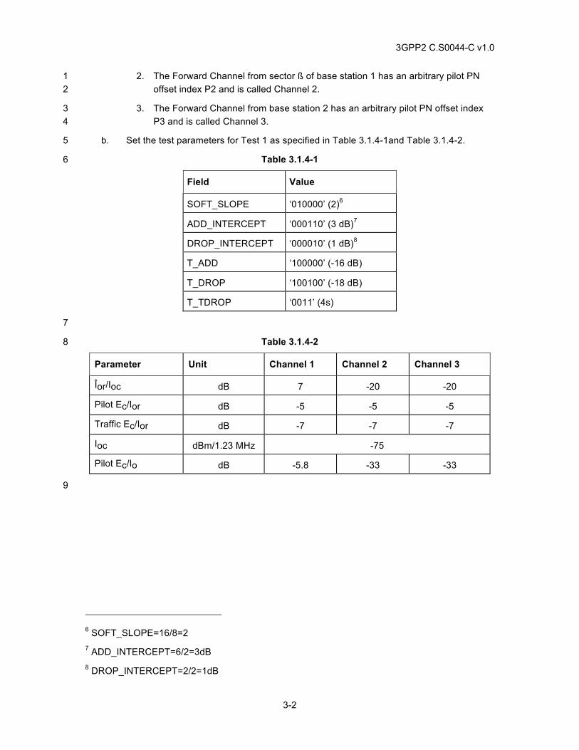
3GPP2 C.S0044-C v1.0
3-2
2. The Forward Channel from sector ß of base station 1 has an arbitrary pilot PN 1 offset index P2 and is called Channel 2. 2
3. The Forward Channel from base station 2 has an arbitrary pilot PN offset index 3 P3 and is called Channel 3. 4
b. Set the test parameters for Test 1 as specified in Table 3.1.4-1and Table 3.1.4-2. 5
Table 3.1.4-1 6
Field Value
SOFT_SLOPE ‘010000’ (2)6
ADD_INTERCEPT ‘000110’ (3 dB)7
DROP_INTERCEPT ‘000010’ (1 dB)8
T_ADD ‘100000’ (-16 dB)
T_DROP ‘100100’ (-18 dB)
T_TDROP ‘0011’ (4s)
7
Table 3.1.4-2 8
Parameter Unit Channel 1 Channel 2 Channel 3
Îor/Ioc dB 7 -20 -20
Pilot Ec/Ior dB -5 -5 -5
Traffic Ec/Ior dB -7 -7 -7
Ioc dBm/1.23 MHz -75
Pilot Ec/Io dB -5.8 -33 -33
9
6 SOFT_SLOPE=16/8=2 7 ADD_INTERCEPT=6/2=3dB 8 DROP_INTERCEPT=2/2=1dB
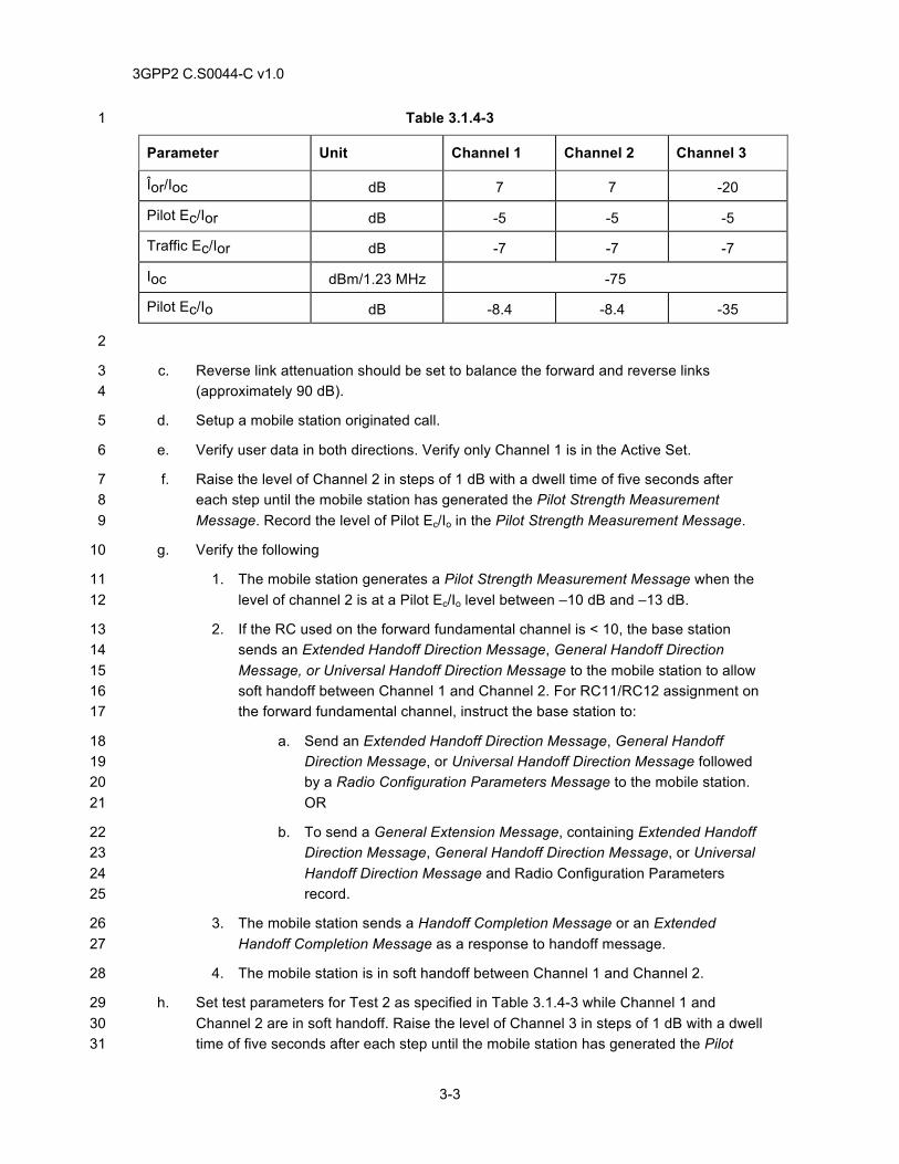
3GPP2 C.S0044-C v1.0
3-3
Table 3.1.4-3 1
Parameter Unit Channel 1 Channel 2 Channel 3
Îor/Ioc dB 7 7 -20
Pilot Ec/Ior dB -5 -5 -5
Traffic Ec/Ior dB -7 -7 -7
Ioc dBm/1.23 MHz -75
Pilot Ec/Io dB -8.4 -8.4 -35
2
c. Reverse link attenuation should be set to balance the forward and reverse links 3 (approximately 90 dB). 4
d. Setup a mobile station originated call. 5
e. Verify user data in both directions. Verify only Channel 1 is in the Active Set. 6
f. Raise the level of Channel 2 in steps of 1 dB with a dwell time of five seconds after 7 each step until the mobile station has generated the Pilot Strength Measurement 8 Message. Record the level of Pilot Ec/Io in the Pilot Strength Measurement Message. 9
g. Verify the following 10
1. The mobile station generates a Pilot Strength Measurement Message when the 11 level of channel 2 is at a Pilot Ec/Io level between –10 dB and –13 dB. 12
2. If the RC used on the forward fundamental channel is < 10, the base station 13 sends an Extended Handoff Direction Message, General Handoff Direction 14 Message, or Universal Handoff Direction Message to the mobile station to allow 15 soft handoff between Channel 1 and Channel 2. For RC11/RC12 assignment on 16 the forward fundamental channel, instruct the base station to: 17
a. Send an Extended Handoff Direction Message, General Handoff 18 Direction Message, or Universal Handoff Direction Message followed 19 by a Radio Configuration Parameters Message to the mobile station. 20 OR 21
b. To send a General Extension Message, containing Extended Handoff 22 Direction Message, General Handoff Direction Message, or Universal 23 Handoff Direction Message and Radio Configuration Parameters 24 record. 25
3. The mobile station sends a Handoff Completion Message or an Extended 26 Handoff Completion Message as a response to handoff message. 27
4. The mobile station is in soft handoff between Channel 1 and Channel 2. 28
h. Set test parameters for Test 2 as specified in Table 3.1.4-3 while Channel 1 and 29 Channel 2 are in soft handoff. Raise the level of Channel 3 in steps of 1 dB with a dwell 30 time of five seconds after each step until the mobile station has generated the Pilot 31
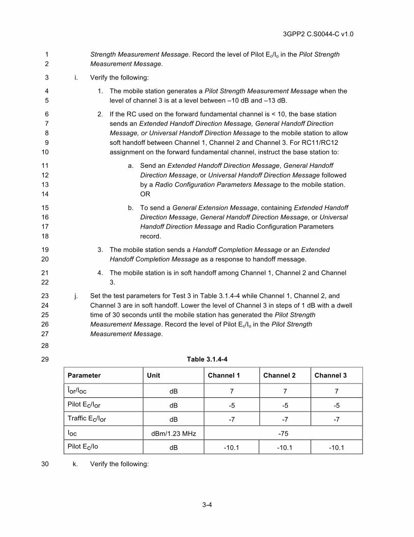
3GPP2 C.S0044-C v1.0
3-4
Strength Measurement Message. Record the level of Pilot Ec/Io in the Pilot Strength 1 Measurement Message. 2
i. Verify the following: 3
1. The mobile station generates a Pilot Strength Measurement Message when the 4 level of channel 3 is at a level between –10 dB and –13 dB. 5
2. If the RC used on the forward fundamental channel is < 10, the base station 6 sends an Extended Handoff Direction Message, General Handoff Direction 7 Message, or Universal Handoff Direction Message to the mobile station to allow 8 soft handoff between Channel 1, Channel 2 and Channel 3. For RC11/RC12 9 assignment on the forward fundamental channel, instruct the base station to: 10
a. Send an Extended Handoff Direction Message, General Handoff 11 Direction Message, or Universal Handoff Direction Message followed 12 by a Radio Configuration Parameters Message to the mobile station. 13 OR 14
b. To send a General Extension Message, containing Extended Handoff 15 Direction Message, General Handoff Direction Message, or Universal 16 Handoff Direction Message and Radio Configuration Parameters 17 record. 18
3. The mobile station sends a Handoff Completion Message or an Extended 19 Handoff Completion Message as a response to handoff message. 20
4. The mobile station is in soft handoff among Channel 1, Channel 2 and Channel 21 3. 22
j. Set the test parameters for Test 3 in Table 3.1.4-4 while Channel 1, Channel 2, and 23 Channel 3 are in soft handoff. Lower the level of Channel 3 in steps of 1 dB with a dwell 24 time of 30 seconds until the mobile station has generated the Pilot Strength 25 Measurement Message. Record the level of Pilot Ec/Io in the Pilot Strength 26 Measurement Message. 27
28
Table 3.1.4-4 29
Parameter Unit Channel 1 Channel 2 Channel 3
Îor/Ioc dB 7 7 7
Pilot Ec/Ior dB -5 -5 -5
Traffic Ec/Ior dB -7 -7 -7
Ioc dBm/1.23 MHz -75
Pilot Ec/Io dB -10.1 -10.1 -10.1
k. Verify the following: 30
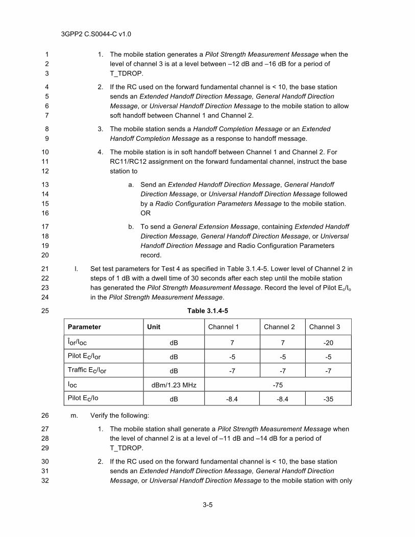
3GPP2 C.S0044-C v1.0
3-5
1. The mobile station generates a Pilot Strength Measurement Message when the 1 level of channel 3 is at a level between –12 dB and –16 dB for a period of 2 T_TDROP. 3
2. If the RC used on the forward fundamental channel is < 10, the base station 4 sends an Extended Handoff Direction Message, General Handoff Direction 5 Message, or Universal Handoff Direction Message to the mobile station to allow 6 soft handoff between Channel 1 and Channel 2. 7
3. The mobile station sends a Handoff Completion Message or an Extended 8 Handoff Completion Message as a response to handoff message. 9
4. The mobile station is in soft handoff between Channel 1 and Channel 2. For 10 RC11/RC12 assignment on the forward fundamental channel, instruct the base 11 station to 12
a. Send an Extended Handoff Direction Message, General Handoff 13 Direction Message, or Universal Handoff Direction Message followed 14 by a Radio Configuration Parameters Message to the mobile station. 15 OR 16
b. To send a General Extension Message, containing Extended Handoff 17 Direction Message, General Handoff Direction Message, or Universal 18 Handoff Direction Message and Radio Configuration Parameters 19 record. 20
l. Set test parameters for Test 4 as specified in Table 3.1.4-5. Lower level of Channel 2 in 21 steps of 1 dB with a dwell time of 30 seconds after each step until the mobile station 22 has generated the Pilot Strength Measurement Message. Record the level of Pilot Ec/Io 23 in the Pilot Strength Measurement Message. 24
Table 3.1.4-5 25
Parameter Unit Channel 1 Channel 2 Channel 3
Îor/Ioc dB 7 7 -20
Pilot Ec/Ior dB -5 -5 -5
Traffic Ec/Ior dB -7 -7 -7
Ioc dBm/1.23 MHz -75
Pilot Ec/Io dB -8.4 -8.4 -35
m. Verify the following: 26
1. The mobile station shall generate a Pilot Strength Measurement Message when 27 the level of channel 2 is at a level of –11 dB and –14 dB for a period of 28 T_TDROP. 29
2. If the RC used on the forward fundamental channel is < 10, the base station 30 sends an Extended Handoff Direction Message, General Handoff Direction 31 Message, or Universal Handoff Direction Message to the mobile station with only 32
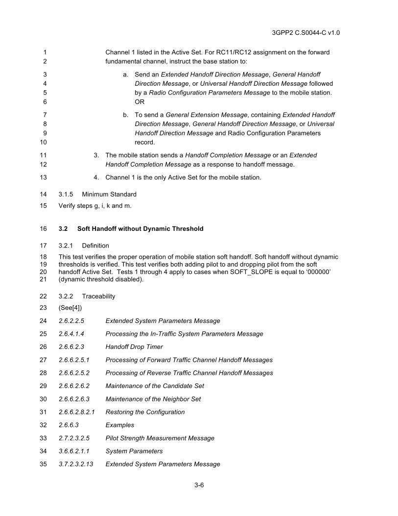
3GPP2 C.S0044-C v1.0
3-6
Channel 1 listed in the Active Set. For RC11/RC12 assignment on the forward 1 fundamental channel, instruct the base station to: 2
a. Send an Extended Handoff Direction Message, General Handoff 3 Direction Message, or Universal Handoff Direction Message followed 4 by a Radio Configuration Parameters Message to the mobile station. 5 OR 6
b. To send a General Extension Message, containing Extended Handoff 7 Direction Message, General Handoff Direction Message, or Universal 8 Handoff Direction Message and Radio Configuration Parameters 9 record. 10
3. The mobile station sends a Handoff Completion Message or an Extended 11 Handoff Completion Message as a response to handoff message. 12
4. Channel 1 is the only Active Set for the mobile station. 13
3.1.5 Minimum Standard 14
Verify steps g, i, k and m. 15
3.2 Soft Handoff without Dynamic Threshold 16
3.2.1 Definition 17
This test verifies the proper operation of mobile station soft handoff. Soft handoff without dynamic 18 thresholds is verified. This test verifies both adding pilot to and dropping pilot from the soft 19 handoff Active Set. Tests 1 through 4 apply to cases when SOFT_SLOPE is equal to ‘000000’ 20 (dynamic threshold disabled). 21
3.2.2 Traceability 22
(See[4]) 23
2.6.2.2.5 Extended System Parameters Message 24
2.6.4.1.4 Processing the In-Traffic System Parameters Message 25
2.6.6.2.3 Handoff Drop Timer 26
2.6.6.2.5.1 Processing of Forward Traffic Channel Handoff Messages 27
2.6.6.2.5.2 Processing of Reverse Traffic Channel Handoff Messages 28
2.6.6.2.6.2 Maintenance of the Candidate Set 29
2.6.6.2.6.3 Maintenance of the Neighbor Set 30
2.6.6.2.8.2.1 Restoring the Configuration 31
2.6.6.3 Examples 32
2.7.2.3.2.5 Pilot Strength Measurement Message 33
3.6.6.2.1.1 System Parameters 34
3.7.2.3.2.13 Extended System Parameters Message 35
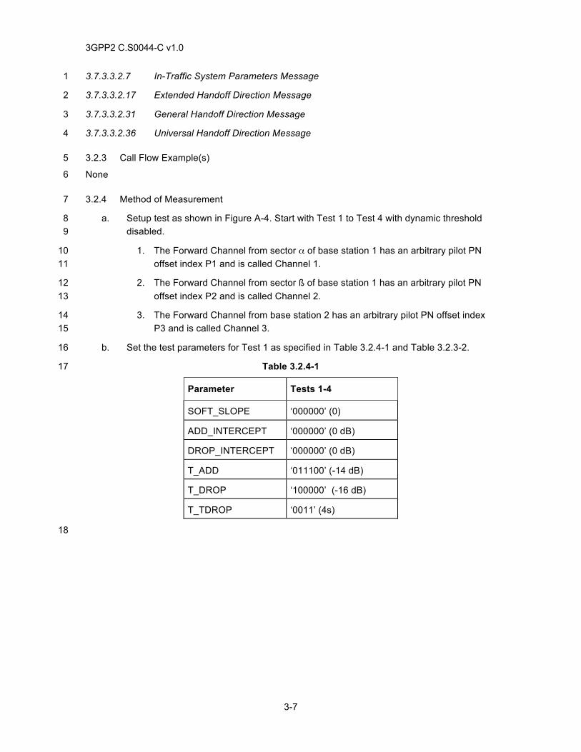
3GPP2 C.S0044-C v1.0
3-7
3.7.3.3.2.7 In-Traffic System Parameters Message 1
3.7.3.3.2.17 Extended Handoff Direction Message 2
3.7.3.3.2.31 General Handoff Direction Message 3
3.7.3.3.2.36 Universal Handoff Direction Message 4
3.2.3 Call Flow Example(s) 5
None 6
3.2.4 Method of Measurement 7
a. Setup test as shown in Figure A-4. Start with Test 1 to Test 4 with dynamic threshold 8 disabled. 9
1. The Forward Channel from sector α of base station 1 has an arbitrary pilot PN 10 offset index P1 and is called Channel 1. 11
2. The Forward Channel from sector ß of base station 1 has an arbitrary pilot PN 12 offset index P2 and is called Channel 2. 13
3. The Forward Channel from base station 2 has an arbitrary pilot PN offset index 14 P3 and is called Channel 3. 15
b. Set the test parameters for Test 1 as specified in Table 3.2.4-1 and Table 3.2.3-2. 16
Table 3.2.4-1 17
Parameter Tests 1-4
SOFT_SLOPE ‘000000’ (0)
ADD_INTERCEPT ‘000000’ (0 dB)
DROP_INTERCEPT ‘000000’ (0 dB)
T_ADD ‘011100’ (-14 dB)
T_DROP ‘100000’ (-16 dB)
T_TDROP ‘0011’ (4s)
18
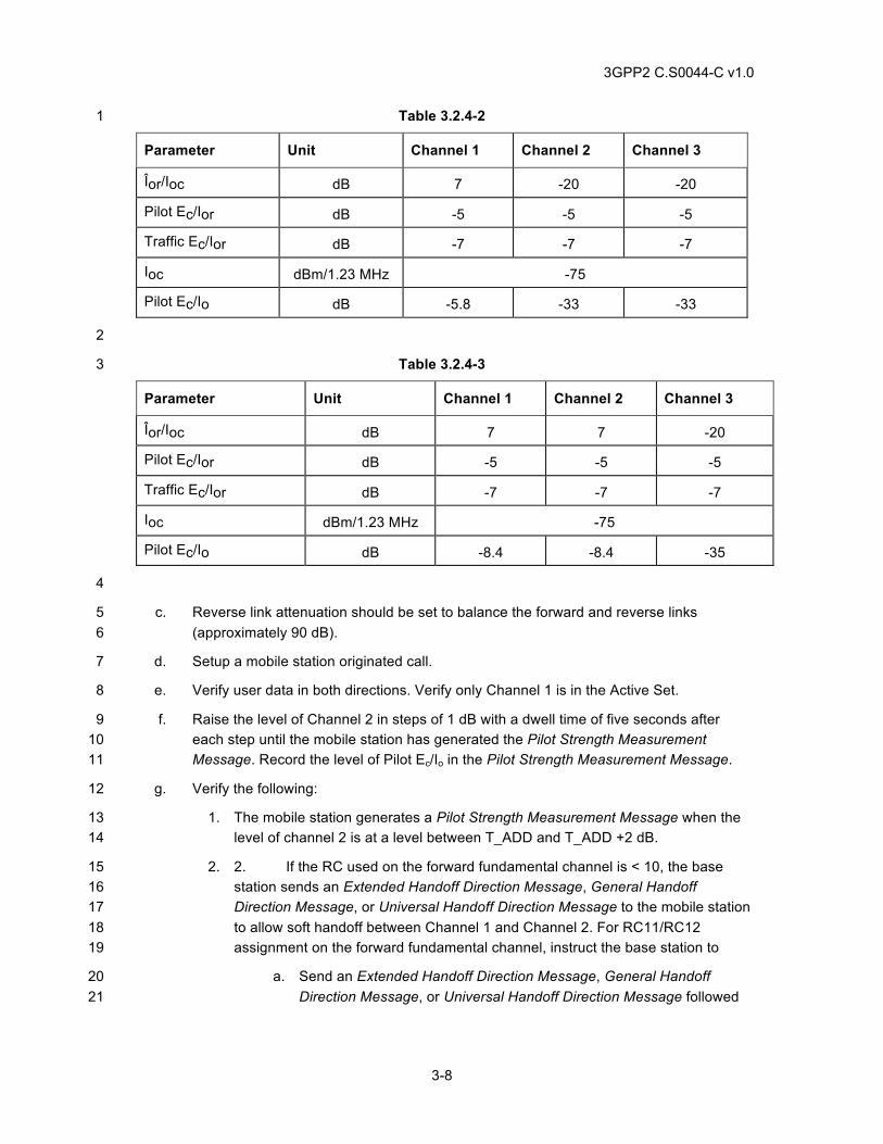
3GPP2 C.S0044-C v1.0
3-8
Table 3.2.4-2 1
Parameter Unit Channel 1 Channel 2 Channel 3
Îor/Ioc dB 7 -20 -20
Pilot Ec/Ior dB -5 -5 -5
Traffic Ec/Ior dB -7 -7 -7
Ioc dBm/1.23 MHz -75
Pilot Ec/Io dB -5.8 -33 -33
2
Table 3.2.4-3 3
Parameter Unit Channel 1 Channel 2 Channel 3
Îor/Ioc dB 7 7 -20
Pilot Ec/Ior dB -5 -5 -5
Traffic Ec/Ior dB -7 -7 -7
Ioc dBm/1.23 MHz -75
Pilot Ec/Io dB -8.4 -8.4 -35
4
c. Reverse link attenuation should be set to balance the forward and reverse links 5 (approximately 90 dB). 6
d. Setup a mobile station originated call. 7
e. Verify user data in both directions. Verify only Channel 1 is in the Active Set. 8
f. Raise the level of Channel 2 in steps of 1 dB with a dwell time of five seconds after 9 each step until the mobile station has generated the Pilot Strength Measurement 10 Message. Record the level of Pilot Ec/Io in the Pilot Strength Measurement Message. 11
g. Verify the following: 12
1. The mobile station generates a Pilot Strength Measurement Message when the 13 level of channel 2 is at a level between T_ADD and T_ADD +2 dB. 14
2. 2. If the RC used on the forward fundamental channel is < 10, the base 15 station sends an Extended Handoff Direction Message, General Handoff 16 Direction Message, or Universal Handoff Direction Message to the mobile station 17 to allow soft handoff between Channel 1 and Channel 2. For RC11/RC12 18 assignment on the forward fundamental channel, instruct the base station to 19
a. Send an Extended Handoff Direction Message, General Handoff 20 Direction Message, or Universal Handoff Direction Message followed 21
3GPP2 C.S0044-C v1.0
3-9
by a Radio Configuration Parameters Message to the mobile station. 1 OR 2
b. To send a General Extension Message, containing Extended Handoff 3 Direction Message, General Handoff Direction Message, or Universal 4 Handoff Direction Message and Radio Configuration Parameters 5 record. 6
3. The mobile station sends a Handoff Completion Message or an Extended 7 Handoff Completion Message as a response to handoff message. 8
4. The mobile station is in softer handoff between Channel 1 and Channel 2. 9
h. Set test parameters for Test 2 as specified in Table 3.2.4-3 while Channel 1 and 10 Channel 2 are in soft handoff. Raise the level of Channel 3 in steps of 1 dB with a dwell 11 time of five seconds after each step until the mobile station has generated the Pilot 12 Strength Measurement Message. Record the level of Pilot Ec/Io in the Pilot Strength 13 Measurement Message. 14
i. Verify the following: 15
1. The mobile station generates a Pilot Strength Measurement Message when the 16 level of channel 3 is at a level between T_ADD and T_ADD +3 dB. 17
2. If the RC used on the forward fundamental channel is < 10, the base station 18 sends an Extended Handoff Direction Message, General Handoff Direction 19 Message, or Universal Handoff Direction Message to the mobile station to allow 20 softer handoff between Channel 1, Channel 2 and Channel 3. For RC11/RC12 21 assignment on the forward fundamental channel, instruct the base station to: 22
a. Send an Extended Handoff Direction Message, General Handoff 23 Direction Message, or Universal Handoff Direction Message followed 24 by a Radio Configuration Parameters Message to the mobile station. 25 OR 26
b. To send a General Extension Message, containing Extended Handoff 27 Direction Message, General Handoff Direction Message, or Universal 28 Handoff Direction Message and Radio Configuration Parameters 29 record. 30
3. The mobile station sends a Handoff Completion Message or an Extended 31 Handoff Completion Message as a response to handoff message. 32
4. The mobile station is in softer handoff among Channel 1, Channel 2 and Channel 33 3. 34
j. Set the test parameters for Test 3 in Table 3.2.4-4 while Channel 1, Channel 2, and 35 Channel 3 are in soft handoff. Lower the level of Channel 3 in steps of 1 dB with a dwell 36 time of 30 seconds until the mobile station has generated the Pilot Strength 37 Measurement Message. Record the level of Pilot Ec/Io in the Pilot Strength 38 Measurement Message. 39
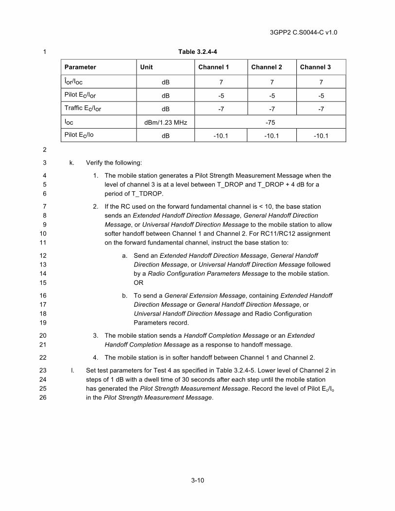
3GPP2 C.S0044-C v1.0
3-10
Table 3.2.4-4 1
Parameter Unit Channel 1 Channel 2 Channel 3
Îor/Ioc dB 7 7 7
Pilot Ec/Ior dB -5 -5 -5
Traffic Ec/Ior dB -7 -7 -7
Ioc dBm/1.23 MHz -75
Pilot Ec/Io dB -10.1 -10.1 -10.1
2
k. Verify the following: 3
1. The mobile station generates a Pilot Strength Measurement Message when the 4 level of channel 3 is at a level between T_DROP and T_DROP + 4 dB for a 5 period of T_TDROP. 6
2. If the RC used on the forward fundamental channel is < 10, the base station 7 sends an Extended Handoff Direction Message, General Handoff Direction 8 Message, or Universal Handoff Direction Message to the mobile station to allow 9 softer handoff between Channel 1 and Channel 2. For RC11/RC12 assignment 10 on the forward fundamental channel, instruct the base station to: 11
a. Send an Extended Handoff Direction Message, General Handoff 12 Direction Message, or Universal Handoff Direction Message followed 13 by a Radio Configuration Parameters Message to the mobile station. 14 OR 15
b. To send a General Extension Message, containing Extended Handoff 16 Direction Message or General Handoff Direction Message, or 17 Universal Handoff Direction Message and Radio Configuration 18 Parameters record. 19
3. The mobile station sends a Handoff Completion Message or an Extended 20 Handoff Completion Message as a response to handoff message. 21
4. The mobile station is in softer handoff between Channel 1 and Channel 2. 22
l. Set test parameters for Test 4 as specified in Table 3.2.4-5. Lower level of Channel 2 in 23 steps of 1 dB with a dwell time of 30 seconds after each step until the mobile station 24 has generated the Pilot Strength Measurement Message. Record the level of Pilot Ec/Io 25 in the Pilot Strength Measurement Message. 26
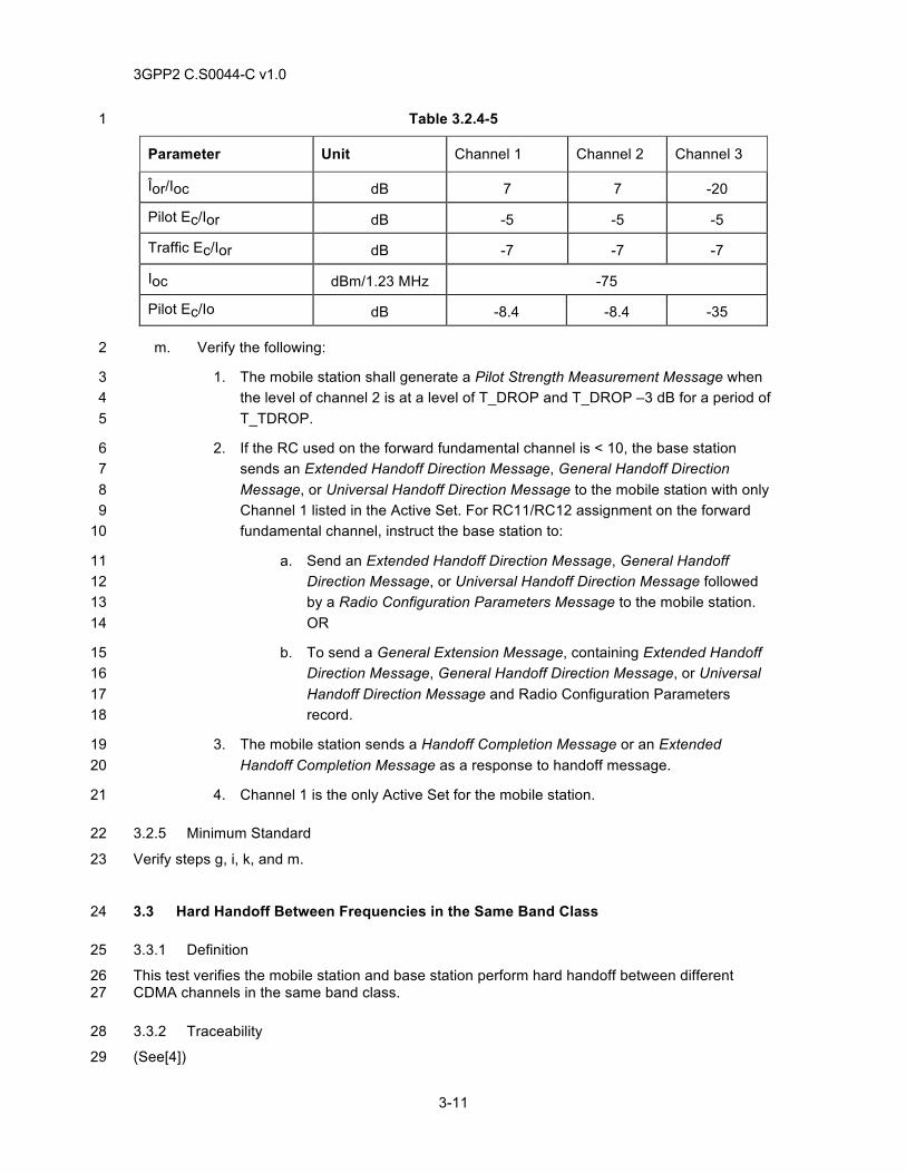
3GPP2 C.S0044-C v1.0
3-11
Table 3.2.4-5 1
Parameter Unit Channel 1 Channel 2 Channel 3
Îor/Ioc dB 7 7 -20
Pilot Ec/Ior dB -5 -5 -5
Traffic Ec/Ior dB -7 -7 -7
Ioc dBm/1.23 MHz -75
Pilot Ec/Io dB -8.4 -8.4 -35
m. Verify the following: 2
1. The mobile station shall generate a Pilot Strength Measurement Message when 3 the level of channel 2 is at a level of T_DROP and T_DROP –3 dB for a period of 4 T_TDROP. 5
2. If the RC used on the forward fundamental channel is < 10, the base station 6 sends an Extended Handoff Direction Message, General Handoff Direction 7 Message, or Universal Handoff Direction Message to the mobile station with only 8 Channel 1 listed in the Active Set. For RC11/RC12 assignment on the forward 9 fundamental channel, instruct the base station to: 10
a. Send an Extended Handoff Direction Message, General Handoff 11 Direction Message, or Universal Handoff Direction Message followed 12 by a Radio Configuration Parameters Message to the mobile station. 13 OR 14
b. To send a General Extension Message, containing Extended Handoff 15 Direction Message, General Handoff Direction Message, or Universal 16 Handoff Direction Message and Radio Configuration Parameters 17 record. 18
3. The mobile station sends a Handoff Completion Message or an Extended 19 Handoff Completion Message as a response to handoff message. 20
4. Channel 1 is the only Active Set for the mobile station. 21
3.2.5 Minimum Standard 22
Verify steps g, i, k, and m. 23
3.3 Hard Handoff Between Frequencies in the Same Band Class 24
3.3.1 Definition 25
This test verifies the mobile station and base station perform hard handoff between different 26 CDMA channels in the same band class. 27
3.3.2 Traceability 28
(See[4]) 29
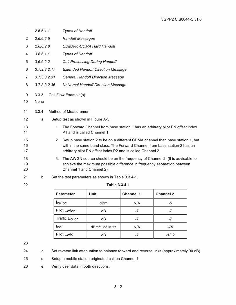
3GPP2 C.S0044-C v1.0
3-12
2.6.6.1.1 Types of Handoff 1
2.6.6.2.5 Handoff Messages 2
2.6.6.2.8 CDMA-to-CDMA Hard Handoff 3
3.6.6.1.1 Types of Handoff 4
3.6.6.2.2 Call Processing During Handoff 5
3.7.3.3.2.17 Extended Handoff Direction Message 6
3.7.3.3.2.31 General Handoff Direction Message 7
3.7.3.3.2.36 Universal Handoff Direction Message 8
3.3.3 Call Flow Example(s) 9
None 10
3.3.4 Method of Measurement 11
a. Setup test as shown in Figure A-5. 12
1. The Forward Channel from base station 1 has an arbitrary pilot PN offset index 13 P1 and is called Channel 1. 14
2. Setup base station 2 to be on a different CDMA channel than base station 1, but 15 within the same band class. The Forward Channel from base station 2 has an 16 arbitrary pilot PN offset index P2 and is called Channel 2. 17
3. The AWGN source should be on the frequency of Channel 2. (It is advisable to 18 achieve the maximum possible difference in frequency separation between 19 Channel 1 and Channel 2). 20
b. Set the test parameters as shown in Table 3.3.4-1. 21
Table 3.3.4-1 22
Parameter Unit Channel 1 Channel 2
Îor/Ioc dBm N/A -5
Pilot Ec/Ior dB -7 -7
Traffic Ec/Ior dB -7 -7
Ioc dBm/1.23 MHz N/A -75
Pilot Ec/Io dB -7 -13.2
23
c. Set reverse link attenuation to balance forward and reverse links (approximately 90 dB). 24
d. Setup a mobile station originated call on Channel 1. 25
e. Verify user data in both directions. 26
3GPP2 C.S0044-C v1.0
3-13
f. Initiate handoff from Channel 1 to Channel 2. Verify that base station 1 initiates handoff 1 from Channel 1 to Channel 2 by sending a General Handoff Direction Message, 2 Universal Handoff Direction Message, or an Extended Handoff Direction Message with 3 proper parameters (refer to tables in Annex B) to initiate handoff from Channel 1 to 4 Channel 2. 5
g. One second or more after base station 1 sends a General Handoff Direction Message, 6 a Universal Handoff Direction Message, or an Extended Handoff Direction Message 7 disconnect or attenuate the forward link of Channel 1. 8
h. Verify user data in both directions. 9
i. Monitor calls and record the length of any audio dropouts present. 10
j. Steps b through g may be repeated for the case where it is a hard handoff to soft 11 handoff on the same frequency with the following setup (see Figure A-4: one base 12 station configured with two sectors active): 13
1. The Forward Channel from base station 1 has an arbitrary pilot PN offset index 14 P1 and is called Channel 1. 15
2. The Forward Channel from sector α of base station 2 has an arbitrary pilot PN 16 offset index P2 and is called Channel 2. 17
3. The Forward Channel from sector ß of base station 2 has an arbitrary pilot PN 18 offset index P3 and is called Channel 3. 19
k. The expected results for steps h and i should be the same as the previous test. 20
3.3.5 Minimum Standard 21
In step h, the mobile station and base stations shall successfully execute the hard handoff. 22
3.4 Hard Handoff from CDMA to Analog 23
3.4.1 Definition 24
This test verifies the mobile station and base station perform hard hand off from a CDMA system 25 to an analog system. 26
3.4.2 Traceability 27
(See[4]) 28
2.6.6.1.1 Types of Handoff 29
2.6.6.2.9 CDMA-to-Analog Handoff 30
3.6.6.1.1 Types of Handoff 31
3.6.6.2.2 Call Processing During Handoff 32
3.7.3.3.2.6 Analog Handoff Direction Message 33
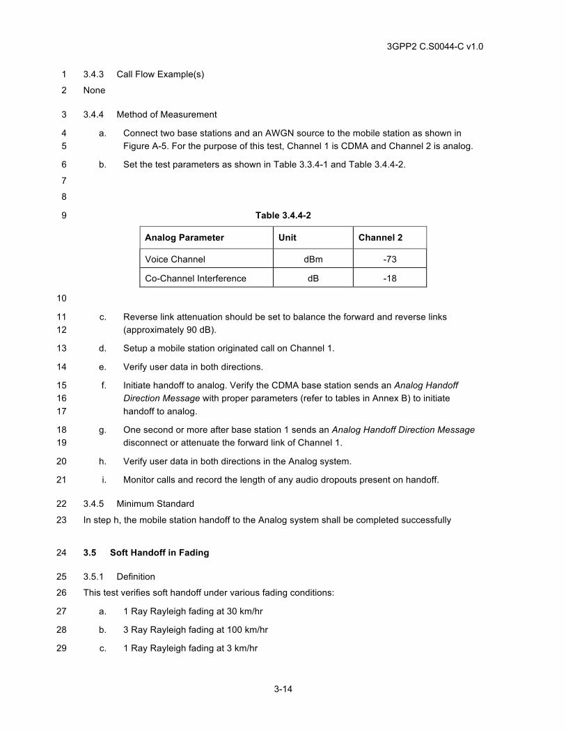
3GPP2 C.S0044-C v1.0
3-14
3.4.3 Call Flow Example(s) 1
None 2
3.4.4 Method of Measurement 3
a. Connect two base stations and an AWGN source to the mobile station as shown in 4 Figure A-5. For the purpose of this test, Channel 1 is CDMA and Channel 2 is analog. 5
b. Set the test parameters as shown in Table 3.3.4-1 and Table 3.4.4-2. 6
7
8
Table 3.4.4-2 9
Analog Parameter Unit Channel 2
Voice Channel dBm -73
Co-Channel Interference dB -18
10
c. Reverse link attenuation should be set to balance the forward and reverse links 11 (approximately 90 dB). 12
d. Setup a mobile station originated call on Channel 1. 13
e. Verify user data in both directions. 14
f. Initiate handoff to analog. Verify the CDMA base station sends an Analog Handoff 15 Direction Message with proper parameters (refer to tables in Annex B) to initiate 16 handoff to analog. 17
g. One second or more after base station 1 sends an Analog Handoff Direction Message 18 disconnect or attenuate the forward link of Channel 1. 19
h. Verify user data in both directions in the Analog system. 20
i. Monitor calls and record the length of any audio dropouts present on handoff. 21
3.4.5 Minimum Standard 22
In step h, the mobile station handoff to the Analog system shall be completed successfully 23
3.5 Soft Handoff in Fading 24
3.5.1 Definition 25
This test verifies soft handoff under various fading conditions: 26
a. 1 Ray Rayleigh fading at 30 km/hr 27
b. 3 Ray Rayleigh fading at 100 km/hr 28
c. 1 Ray Rayleigh fading at 3 km/hr 29
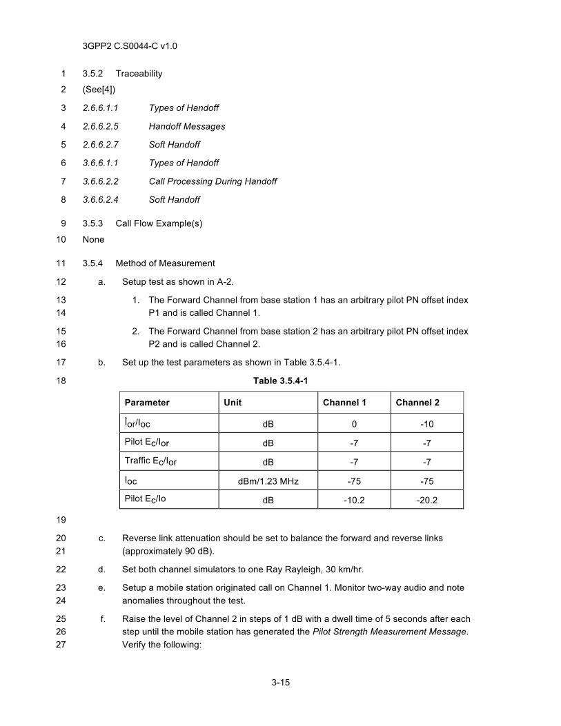
3GPP2 C.S0044-C v1.0
3-15
3.5.2 Traceability 1
(See[4]) 2
2.6.6.1.1 Types of Handoff 3
2.6.6.2.5 Handoff Messages 4
2.6.6.2.7 Soft Handoff 5
3.6.6.1.1 Types of Handoff 6
3.6.6.2.2 Call Processing During Handoff 7
3.6.6.2.4 Soft Handoff 8
3.5.3 Call Flow Example(s) 9
None 10
3.5.4 Method of Measurement 11
a. Setup test as shown in A-2. 12
1. The Forward Channel from base station 1 has an arbitrary pilot PN offset index 13 P1 and is called Channel 1. 14
2. The Forward Channel from base station 2 has an arbitrary pilot PN offset index 15 P2 and is called Channel 2. 16
b. Set up the test parameters as shown in Table 3.5.4-1. 17
Table 3.5.4-1 18
Parameter Unit Channel 1 Channel 2
Îor/Ioc dB 0 -10
Pilot Ec/Ior dB -7 -7
Traffic Ec/Ior dB -7 -7
Ioc dBm/1.23 MHz -75 -75
Pilot Ec/Io dB -10.2 -20.2
19
c. Reverse link attenuation should be set to balance the forward and reverse links 20 (approximately 90 dB). 21
d. Set both channel simulators to one Ray Rayleigh, 30 km/hr. 22
e. Setup a mobile station originated call on Channel 1. Monitor two-way audio and note 23 anomalies throughout the test. 24
f. Raise the level of Channel 2 in steps of 1 dB with a dwell time of 5 seconds after each 25 step until the mobile station has generated the Pilot Strength Measurement Message. 26 Verify the following: 27
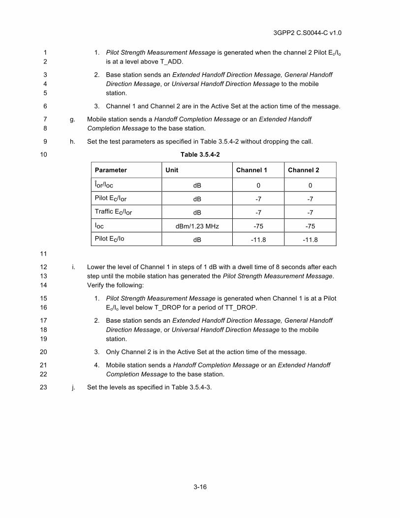
3GPP2 C.S0044-C v1.0
3-16
1. Pilot Strength Measurement Message is generated when the channel 2 Pilot Ec/Io 1 is at a level above T_ADD. 2
2. Base station sends an Extended Handoff Direction Message, General Handoff 3 Direction Message, or Universal Handoff Direction Message to the mobile 4 station. 5
3. Channel 1 and Channel 2 are in the Active Set at the action time of the message. 6
g. Mobile station sends a Handoff Completion Message or an Extended Handoff 7 Completion Message to the base station. 8
h. Set the test parameters as specified in Table 3.5.4-2 without dropping the call. 9
Table 3.5.4-2 10
Parameter Unit Channel 1 Channel 2
Îor/Ioc dB 0 0
Pilot Ec/Ior dB -7 -7
Traffic Ec/Ior dB -7 -7
Ioc dBm/1.23 MHz -75 -75
Pilot Ec/Io dB -11.8 -11.8
11
i. Lower the level of Channel 1 in steps of 1 dB with a dwell time of 8 seconds after each 12 step until the mobile station has generated the Pilot Strength Measurement Message. 13 Verify the following: 14
1. Pilot Strength Measurement Message is generated when Channel 1 is at a Pilot 15 Ec/Io level below T_DROP for a period of TT_DROP. 16
2. Base station sends an Extended Handoff Direction Message, General Handoff 17 Direction Message, or Universal Handoff Direction Message to the mobile 18 station. 19
3. Only Channel 2 is in the Active Set at the action time of the message. 20
4. Mobile station sends a Handoff Completion Message or an Extended Handoff 21 Completion Message to the base station. 22
j. Set the levels as specified in Table 3.5.4-3. 23
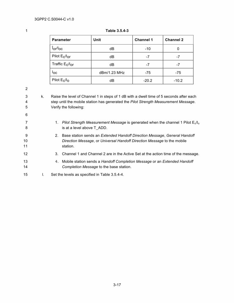
3GPP2 C.S0044-C v1.0
3-17
Table 3.5.4-3 1
Parameter Unit Channel 1 Channel 2
Îor/Ioc dB -10 0
Pilot Ec/Ior dB -7 -7
Traffic Ec/Ior dB -7 -7
Ioc dBm/1.23 MHz -75 -75
Pilot Ec/Io dB -20.2 -10.2
2
k. Raise the level of Channel 1 in steps of 1 dB with a dwell time of 5 seconds after each 3 step until the mobile station has generated the Pilot Strength Measurement Message. 4 Verify the following: 5
6
1. Pilot Strength Measurement Message is generated when the channel 1 Pilot Ec/Io 7 is at a level above T_ADD. 8
2. Base station sends an Extended Handoff Direction Message, General Handoff 9 Direction Message, or Universal Handoff Direction Message to the mobile 10 station. 11
3. Channel 1 and Channel 2 are in the Active Set at the action time of the message. 12
4. Mobile station sends a Handoff Completion Message or an Extended Handoff 13 Completion Message to the base station. 14
l. Set the levels as specified in Table 3.5.4-4. 15
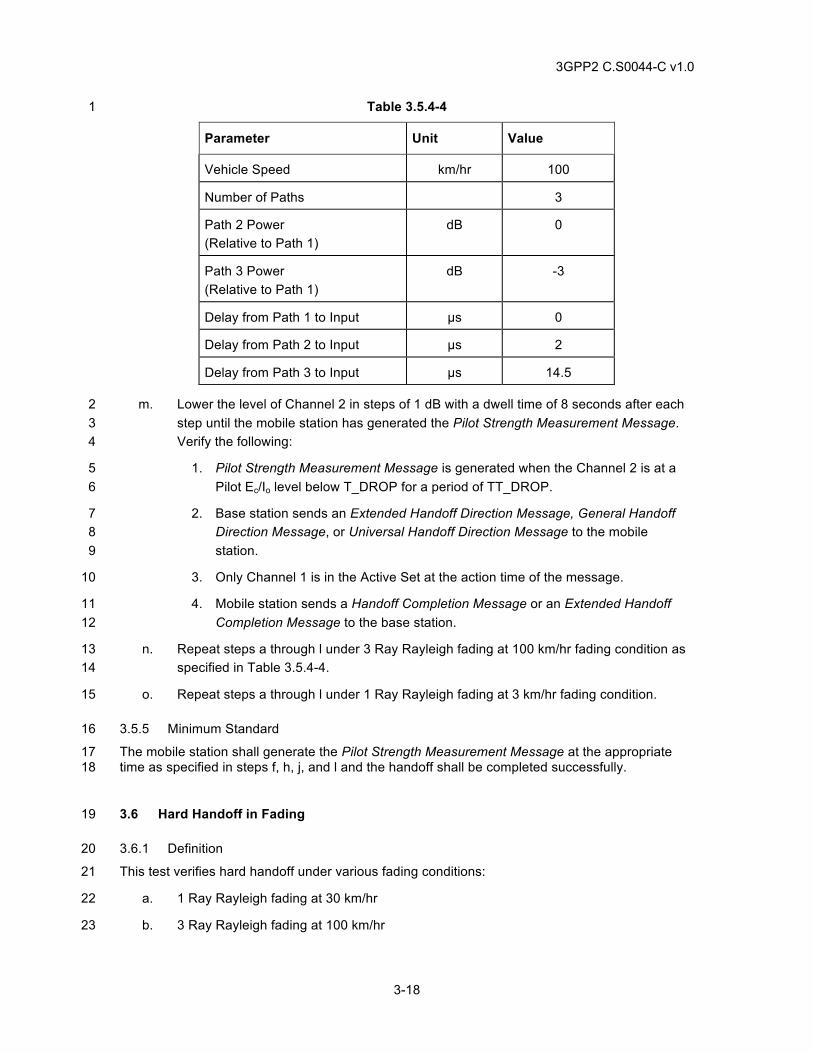
3GPP2 C.S0044-C v1.0
3-18
Table 3.5.4-4 1
Parameter Unit Value
Vehicle Speed km/hr 100
Number of Paths 3
Path 2 Power (Relative to Path 1)
dB 0
Path 3 Power (Relative to Path 1)
dB -3
Delay from Path 1 to Input µs 0
Delay from Path 2 to Input µs 2
Delay from Path 3 to Input µs 14.5
m. Lower the level of Channel 2 in steps of 1 dB with a dwell time of 8 seconds after each 2 step until the mobile station has generated the Pilot Strength Measurement Message. 3 Verify the following: 4
1. Pilot Strength Measurement Message is generated when the Channel 2 is at a 5 Pilot Ec/Io level below T_DROP for a period of TT_DROP. 6
2. Base station sends an Extended Handoff Direction Message, General Handoff 7 Direction Message, or Universal Handoff Direction Message to the mobile 8 station. 9
3. Only Channel 1 is in the Active Set at the action time of the message. 10
4. Mobile station sends a Handoff Completion Message or an Extended Handoff 11 Completion Message to the base station. 12
n. Repeat steps a through l under 3 Ray Rayleigh fading at 100 km/hr fading condition as 13 specified in Table 3.5.4-4. 14
o. Repeat steps a through l under 1 Ray Rayleigh fading at 3 km/hr fading condition. 15
3.5.5 Minimum Standard 16
The mobile station shall generate the Pilot Strength Measurement Message at the appropriate 17 time as specified in steps f, h, j, and l and the handoff shall be completed successfully. 18
3.6 Hard Handoff in Fading 19
3.6.1 Definition 20
This test verifies hard handoff under various fading conditions: 21
a. 1 Ray Rayleigh fading at 30 km/hr 22
b. 3 Ray Rayleigh fading at 100 km/hr 23
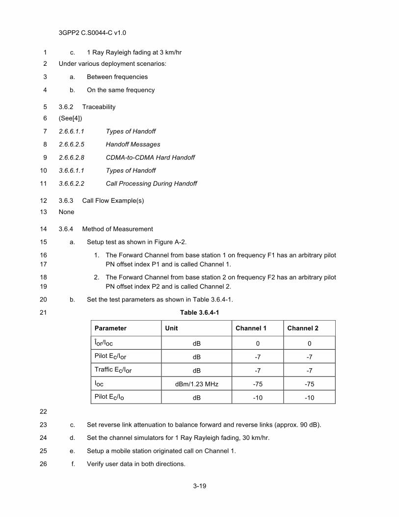
3GPP2 C.S0044-C v1.0
3-19
c. 1 Ray Rayleigh fading at 3 km/hr 1
Under various deployment scenarios: 2
a. Between frequencies 3
b. On the same frequency 4
3.6.2 Traceability 5
(See[4]) 6
2.6.6.1.1 Types of Handoff 7
2.6.6.2.5 Handoff Messages 8
2.6.6.2.8 CDMA-to-CDMA Hard Handoff 9
3.6.6.1.1 Types of Handoff 10
3.6.6.2.2 Call Processing During Handoff 11
3.6.3 Call Flow Example(s) 12
None 13
3.6.4 Method of Measurement 14
a. Setup test as shown in Figure A-2. 15
1. The Forward Channel from base station 1 on frequency F1 has an arbitrary pilot 16 PN offset index P1 and is called Channel 1. 17
2. The Forward Channel from base station 2 on frequency F2 has an arbitrary pilot 18 PN offset index P2 and is called Channel 2. 19
b. Set the test parameters as shown in Table 3.6.4-1. 20
Table 3.6.4-1 21
Parameter Unit Channel 1 Channel 2
Îor/Ioc dB 0 0
Pilot Ec/Ior dB -7 -7
Traffic Ec/Ior dB -7 -7
Ioc dBm/1.23 MHz -75 -75
Pilot Ec/Io dB -10 -10
22
c. Set reverse link attenuation to balance forward and reverse links (approx. 90 dB). 23
d. Set the channel simulators for 1 Ray Rayleigh fading, 30 km/hr. 24
e. Setup a mobile station originated call on Channel 1. 25
f. Verify user data in both directions. 26
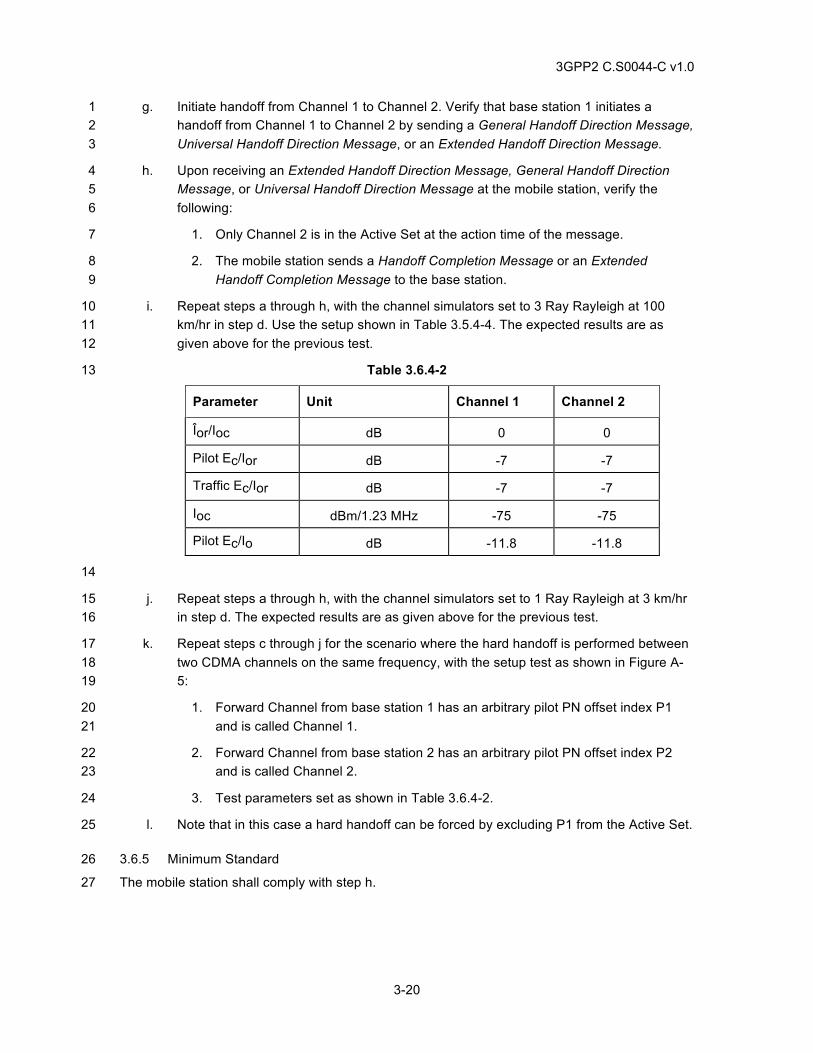
3GPP2 C.S0044-C v1.0
3-20
g. Initiate handoff from Channel 1 to Channel 2. Verify that base station 1 initiates a 1 handoff from Channel 1 to Channel 2 by sending a General Handoff Direction Message, 2 Universal Handoff Direction Message, or an Extended Handoff Direction Message. 3
h. Upon receiving an Extended Handoff Direction Message, General Handoff Direction 4 Message, or Universal Handoff Direction Message at the mobile station, verify the 5 following: 6
1. Only Channel 2 is in the Active Set at the action time of the message. 7
2. The mobile station sends a Handoff Completion Message or an Extended 8 Handoff Completion Message to the base station. 9
i. Repeat steps a through h, with the channel simulators set to 3 Ray Rayleigh at 100 10 km/hr in step d. Use the setup shown in Table 3.5.4-4. The expected results are as 11 given above for the previous test. 12
Table 3.6.4-2 13
Parameter Unit Channel 1 Channel 2
Îor/Ioc dB 0 0
Pilot Ec/Ior dB -7 -7
Traffic Ec/Ior dB -7 -7
Ioc dBm/1.23 MHz -75 -75
Pilot Ec/Io dB -11.8 -11.8
14
j. Repeat steps a through h, with the channel simulators set to 1 Ray Rayleigh at 3 km/hr 15 in step d. The expected results are as given above for the previous test. 16
k. Repeat steps c through j for the scenario where the hard handoff is performed between 17 two CDMA channels on the same frequency, with the setup test as shown in Figure A-18 5: 19
1. Forward Channel from base station 1 has an arbitrary pilot PN offset index P1 20 and is called Channel 1. 21
2. Forward Channel from base station 2 has an arbitrary pilot PN offset index P2 22 and is called Channel 2. 23
3. Test parameters set as shown in Table 3.6.4-2. 24
l. Note that in this case a hard handoff can be forced by excluding P1 from the Active Set. 25
3.6.5 Minimum Standard 26
The mobile station shall comply with step h. 27
3GPP2 C.S0044-C v1.0
3-21
3.7 Hard Handoff Between Different Band Classes 1
3.7.1 Definition 2
This test verifies hard handoff between two different band classes. Both band classes are 3 supported by the mobile station and base station. 4
3.7.2 Traceability 5
(see[4]) 6
2.6.6.1.1 Types of Handoff 7
2.6.6.2.5 Handoff Messages 8
2.6.6.2.8 CDMA-to-CDMA Hard Handoff 9
3.6.6.1.1 Types of Handoff 10
3.6.6.2.2 Call Processing During Handoff 11
3.7.3.3.2.17 Extended Handoff Direction Message 12
3.7.3.3.2.31 General Handoff Direction Message 13
3.7.3.3.2.36 Universal Handoff Direction Message 14
(see [1]) 15
2.1.1.1 Channel Spacing and Designation 16
3.7.3 Call Flow Example(s) 17
None 18
3.7.4 Method of Measurement 19
a. Setup test as shown in Figure A-5. 20
1. The Forward Channel from the base station 1 in Band Class X has an arbitrary 21 pilot PN offset index P1 and is called Channel 1. 22
2. The Forward Channel from the base station 2 in Band Class Y has an arbitrary 23 pilot PN offset index P2 and is called Channel 2. 24
b. Set the test parameters as shown in Table 3.7.4-1 25
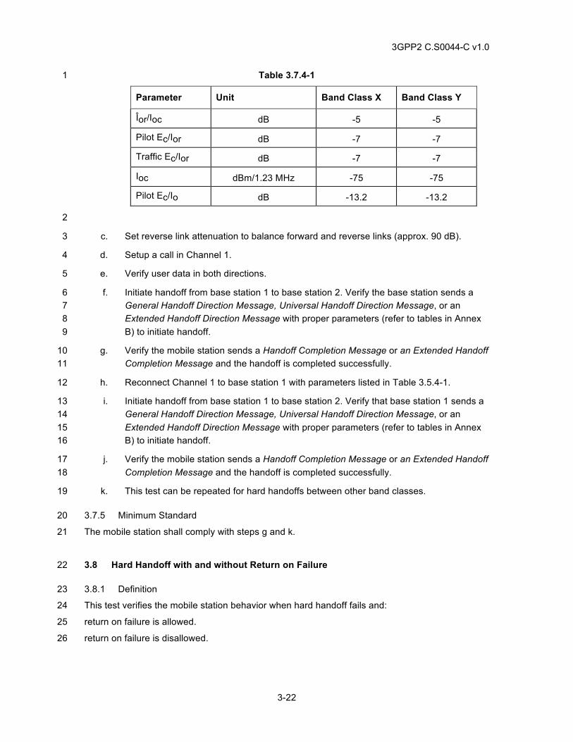
3GPP2 C.S0044-C v1.0
3-22
Table 3.7.4-1 1
Parameter Unit Band Class X Band Class Y
Îor/Ioc dB -5 -5
Pilot Ec/Ior dB -7 -7
Traffic Ec/Ior dB -7 -7
Ioc dBm/1.23 MHz -75 -75
Pilot Ec/Io dB -13.2 -13.2
2
c. Set reverse link attenuation to balance forward and reverse links (approx. 90 dB). 3
d. Setup a call in Channel 1. 4
e. Verify user data in both directions. 5
f. Initiate handoff from base station 1 to base station 2. Verify the base station sends a 6 General Handoff Direction Message, Universal Handoff Direction Message, or an 7 Extended Handoff Direction Message with proper parameters (refer to tables in Annex 8 B) to initiate handoff. 9
g. Verify the mobile station sends a Handoff Completion Message or an Extended Handoff 10 Completion Message and the handoff is completed successfully. 11
h. Reconnect Channel 1 to base station 1 with parameters listed in Table 3.5.4-1. 12
i. Initiate handoff from base station 1 to base station 2. Verify that base station 1 sends a 13 General Handoff Direction Message, Universal Handoff Direction Message, or an 14 Extended Handoff Direction Message with proper parameters (refer to tables in Annex 15 B) to initiate handoff. 16
j. Verify the mobile station sends a Handoff Completion Message or an Extended Handoff 17 Completion Message and the handoff is completed successfully. 18
k. This test can be repeated for hard handoffs between other band classes. 19
3.7.5 Minimum Standard 20
The mobile station shall comply with steps g and k. 21
3.8 Hard Handoff with and without Return on Failure 22
3.8.1 Definition 23
This test verifies the mobile station behavior when hard handoff fails and: 24
return on failure is allowed. 25
return on failure is disallowed. 26
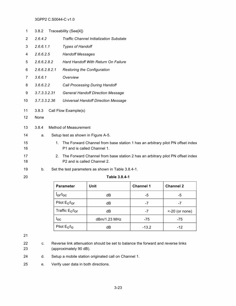
3GPP2 C.S0044-C v1.0
3-23
3.8.2 Traceability (See[4]) 1
2.6.4.2 Traffic Channel Initialization Substate 2
2.6.6.1.1 Types of Handoff 3
2.6.6.2.5 Handoff Messages 4
2.6.6.2.8.2 Hard Handoff With Return On Failure 5
2.6.6.2.8.2.1 Restoring the Configuration 6
3.6.6.1 Overview 7
3.6.6.2.2 Call Processing During Handoff 8
3.7.3.3.2.31 General Handoff Direction Message 9
3.7.3.3.2.36 Universal Handoff Direction Message 10
3.8.3 Call Flow Example(s) 11
None 12
3.8.4 Method of Measurement 13
a. Setup test as shown in Figure A-5. 14
1. The Forward Channel from base station 1 has an arbitrary pilot PN offset index 15 P1 and is called Channel 1. 16
2. The Forward Channel from base station 2 has an arbitrary pilot PN offset index 17 P2 and is called Channel 2. 18
b. Set the test parameters as shown in Table 3.8.4-1. 19
Table 3.8.4-1 20
Parameter Unit Channel 1 Channel 2
Îor/Ioc dB -5 -5
Pilot Ec/Ior dB -7 -7
Traffic Ec/Ior dB -7 <-20 (or none)
Ioc dBm/1.23 MHz -75 -75
Pilot Ec/Io dB -13.2 -12
21
c. Reverse link attenuation should be set to balance the forward and reverse links 22 (approximately 90 dB). 23
d. Setup a mobile station originated call on Channel 1. 24
e. Verify user data in both directions. 25
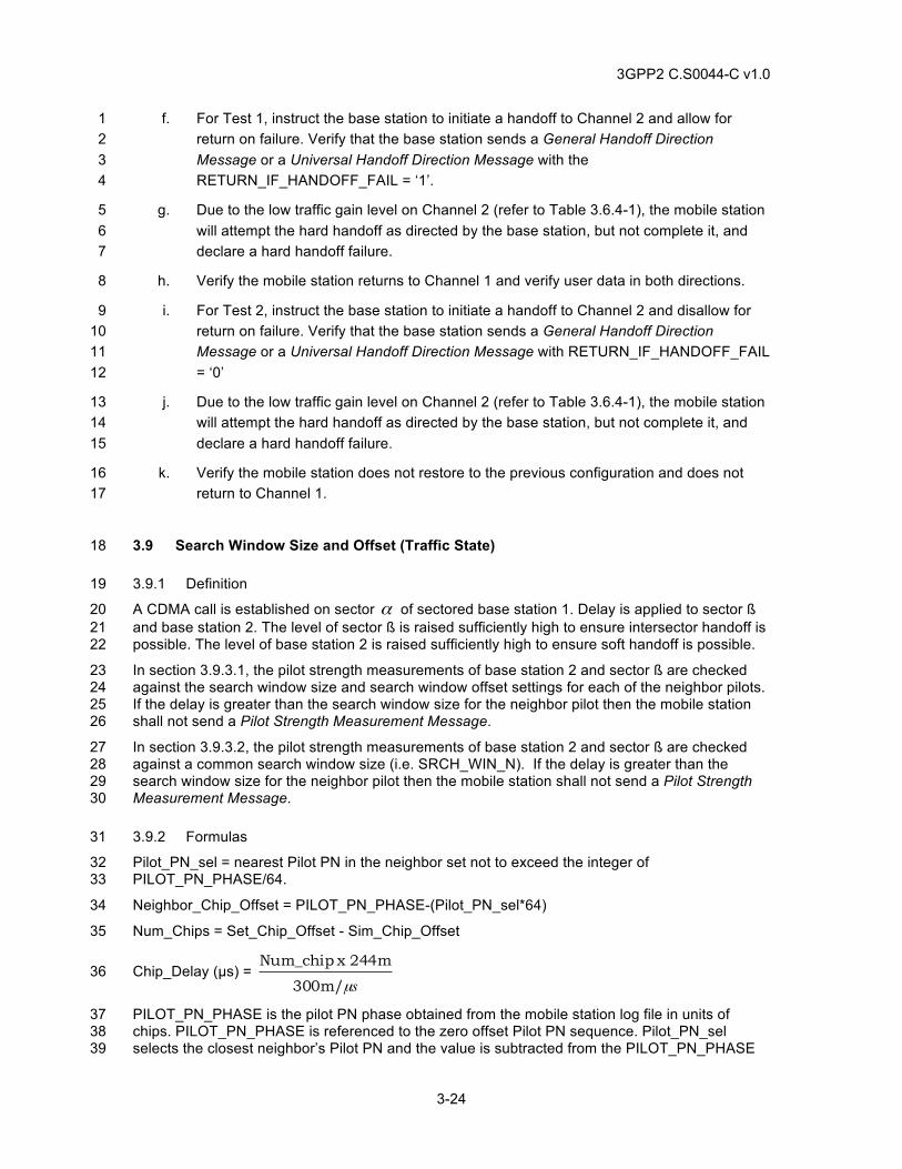
3GPP2 C.S0044-C v1.0
3-24
f. For Test 1, instruct the base station to initiate a handoff to Channel 2 and allow for 1 return on failure. Verify that the base station sends a General Handoff Direction 2 Message or a Universal Handoff Direction Message with the 3 RETURN_IF_HANDOFF_FAIL = ‘1’. 4
g. Due to the low traffic gain level on Channel 2 (refer to Table 3.6.4-1), the mobile station 5 will attempt the hard handoff as directed by the base station, but not complete it, and 6 declare a hard handoff failure. 7
h. Verify the mobile station returns to Channel 1 and verify user data in both directions. 8
i. For Test 2, instruct the base station to initiate a handoff to Channel 2 and disallow for 9 return on failure. Verify that the base station sends a General Handoff Direction 10 Message or a Universal Handoff Direction Message with RETURN_IF_HANDOFF_FAIL 11 = ‘0’ 12
j. Due to the low traffic gain level on Channel 2 (refer to Table 3.6.4-1), the mobile station 13 will attempt the hard handoff as directed by the base station, but not complete it, and 14 declare a hard handoff failure. 15
k. Verify the mobile station does not restore to the previous configuration and does not 16 return to Channel 1. 17
3.9 Search Window Size and Offset (Traffic State) 18
3.9.1 Definition 19
A CDMA call is established on sector α of sectored base station 1. Delay is applied to sector ß 20 and base station 2. The level of sector ß is raised sufficiently high to ensure intersector handoff is 21 possible. The level of base station 2 is raised sufficiently high to ensure soft handoff is possible. 22
In section 3.9.3.1, the pilot strength measurements of base station 2 and sector ß are checked 23 against the search window size and search window offset settings for each of the neighbor pilots. 24 If the delay is greater than the search window size for the neighbor pilot then the mobile station 25 shall not send a Pilot Strength Measurement Message. 26
In section 3.9.3.2, the pilot strength measurements of base station 2 and sector ß are checked 27 against a common search window size (i.e. SRCH_WIN_N). If the delay is greater than the 28 search window size for the neighbor pilot then the mobile station shall not send a Pilot Strength 29 Measurement Message. 30
3.9.2 Formulas 31
Pilot_PN_sel = nearest Pilot PN in the neighbor set not to exceed the integer of 32 PILOT_PN_PHASE/64. 33
Neighbor_Chip_Offset = PILOT_PN_PHASE-(Pilot_PN_sel*64) 34
Num_Chips = Set_Chip_Offset - Sim_Chip_Offset 35
Chip_Delay (µs) = sµ300m/
244m x Num_chip 36
PILOT_PN_PHASE is the pilot PN phase obtained from the mobile station log file in units of 37 chips. PILOT_PN_PHASE is referenced to the zero offset Pilot PN sequence. Pilot_PN_sel 38 selects the closest neighbor’s Pilot PN and the value is subtracted from the PILOT_PN_PHASE 39
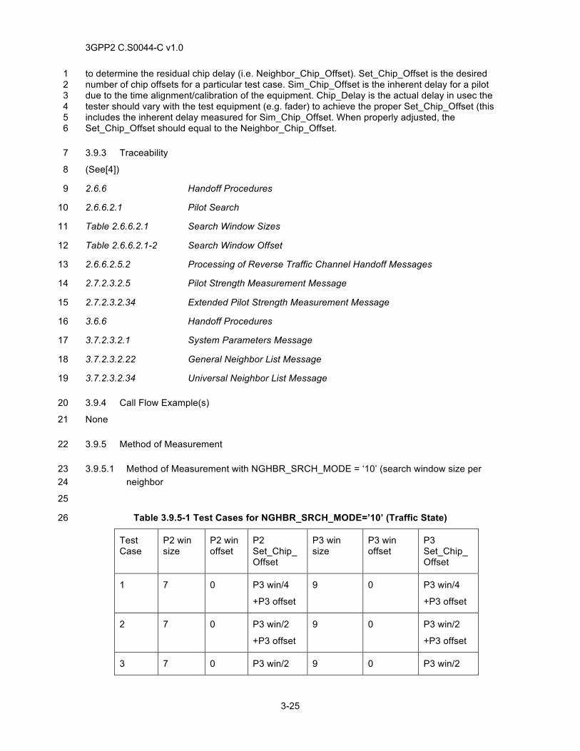
3GPP2 C.S0044-C v1.0
3-25
to determine the residual chip delay (i.e. Neighbor_Chip_Offset). Set_Chip_Offset is the desired 1 number of chip offsets for a particular test case. Sim_Chip_Offset is the inherent delay for a pilot 2 due to the time alignment/calibration of the equipment. Chip_Delay is the actual delay in usec the 3 tester should vary with the test equipment (e.g. fader) to achieve the proper Set_Chip_Offset (this 4 includes the inherent delay measured for Sim_Chip_Offset. When properly adjusted, the 5 Set_Chip_Offset should equal to the Neighbor_Chip_Offset. 6
3.9.3 Traceability 7
(See[4]) 8
2.6.6 Handoff Procedures 9
2.6.6.2.1 Pilot Search 10
Table 2.6.6.2.1 Search Window Sizes 11
Table 2.6.6.2.1-2 Search Window Offset 12
2.6.6.2.5.2 Processing of Reverse Traffic Channel Handoff Messages 13
2.7.2.3.2.5 Pilot Strength Measurement Message 14
2.7.2.3.2.34 Extended Pilot Strength Measurement Message 15
3.6.6 Handoff Procedures 16
3.7.2.3.2.1 System Parameters Message 17
3.7.2.3.2.22 General Neighbor List Message 18
3.7.2.3.2.34 Universal Neighbor List Message 19
3.9.4 Call Flow Example(s) 20
None 21
3.9.5 Method of Measurement 22
3.9.5.1 Method of Measurement with NGHBR_SRCH_MODE = ‘10’ (search window size per 23 neighbor 24
25
Table 3.9.5-1 Test Cases for NGHBR_SRCH_MODE=’10’ (Traffic State) 26
Test Case
P2 win size
P2 win offset
P2 Set_Chip_Offset
P3 win size
P3 win offset
P3 Set_Chip_Offset
1 7 0 P3 win/4
+P3 offset
9 0 P3 win/4
+P3 offset
2 7 0 P3 win/2
+P3 offset
9 0 P3 win/2
+P3 offset
3 7 0 P3 win/2 9 0 P3 win/2
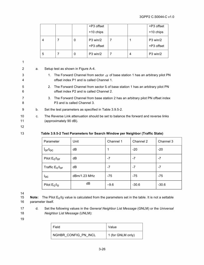
3GPP2 C.S0044-C v1.0
3-26
+P3 offset
+10 chips
+P3 offset
+10 chips
4 7 0 P3 win/2
+P3 offset
7 1 P3 win/2
+P3 offset
5 7 0 P3 win/2 7 4 P3 win/2
1
a. Setup test as shown in Figure A-4. 2
1. The Forward Channel from sector α of base station 1 has an arbitrary pilot PN 3 offset index P1 and is called Channel 1. 4
2. The Forward Channel from sector ß of base station 1 has an arbitrary pilot PN 5 offset index P2 and is called Channel 2. 6
3. The Forward Channel from base station 2 has an arbitrary pilot PN offset index 7 P3 and is called Channel 3. 8
b. Set the test parameters as specified in Table 3.9.5-2. 9
c. The Reverse Link attenuation should be set to balance the forward and reverse links 10 (approximately 90 dB). 11
12
Table 3.9.5-2 Test Parameters for Search Window per Neighbor (Traffic State) 13
Parameter Unit Channel 1 Channel 2 Channel 3
Îor/Ioc dB 1 -20 -20
Pilot Ec/Ior dB -7 -7 -7
Traffic Ec/Ior dB -7 -7 -7
Ioc dBm/1.23 MHz -75 -75 -75
Pilot Ec/Io dB –9.6 -30.6 -30.6
14 Note: The Pilot Ec/I0 value is calculated from the parameters set in the table. It is not a settable 15 parameter itself. 16
d. Set the following values in the General Neighbor List Message (GNLM) or the Universal 17 Neighbor List Message (UNLM): 18
19
Field Value
NGHBR_CONFIG_PN_INCL 1 (for GNLM only)
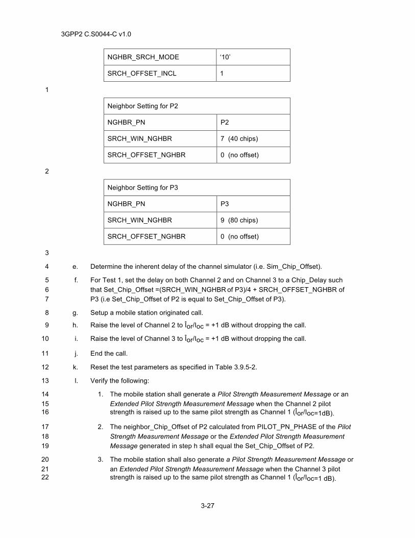
3GPP2 C.S0044-C v1.0
3-27
NGHBR_SRCH_MODE ‘10’
SRCH_OFFSET_INCL 1
1
Neighbor Setting for P2
NGHBR_PN P2
SRCH_WIN_NGHBR 7 (40 chips)
SRCH_OFFSET_NGHBR 0 (no offset)
2
Neighbor Setting for P3
NGHBR_PN P3
SRCH_WIN_NGHBR 9 (80 chips)
SRCH_OFFSET_NGHBR 0 (no offset)
3
e. Determine the inherent delay of the channel simulator (i.e. Sim_Chip_Offset). 4
f. For Test 1, set the delay on both Channel 2 and on Channel 3 to a Chip_Delay such 5 that Set_Chip_Offset =(SRCH_WIN_NGHBR of P3)/4 + SRCH_OFFSET_NGHBR of 6 P3 (i.e Set_Chip_Offset of P2 is equal to Set_Chip_Offset of P3). 7
g. Setup a mobile station originated call. 8
h. Raise the level of Channel 2 to Îor/Ioc = +1 dB without dropping the call. 9
i. Raise the level of Channel 3 to Îor/Ioc = +1 dB without dropping the call. 10
j. End the call. 11
k. Reset the test parameters as specified in Table 3.9.5-2. 12
l. Verify the following: 13
1. The mobile station shall generate a Pilot Strength Measurement Message or an 14 Extended Pilot Strength Measurement Message when the Channel 2 pilot 15 strength is raised up to the same pilot strength as Channel 1 (Îor/Ioc=1dB). 16
2. The neighbor_Chip_Offset of P2 calculated from PILOT_PN_PHASE of the Pilot 17 Strength Measurement Message or the Extended Pilot Strength Measurement 18 Message generated in step h shall equal the Set_Chip_Offset of P2. 19
3. The mobile station shall also generate a Pilot Strength Measurement Message or 20 an Extended Pilot Strength Measurement Message when the Channel 3 pilot 21 strength is raised up to the same pilot strength as Channel 1 (Îor/Ioc=1 dB). 22
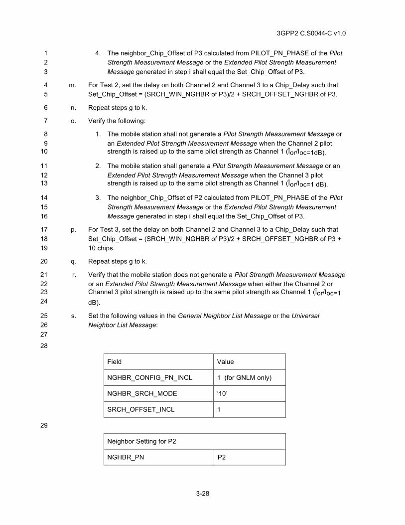
3GPP2 C.S0044-C v1.0
3-28
4. The neighbor_Chip_Offset of P3 calculated from PILOT_PN_PHASE of the Pilot 1 Strength Measurement Message or the Extended Pilot Strength Measurement 2 Message generated in step i shall equal the Set_Chip_Offset of P3. 3
m. For Test 2, set the delay on both Channel 2 and Channel 3 to a Chip_Delay such that 4 Set_Chip_Offset = (SRCH_WIN_NGHBR of P3)/2 + SRCH_OFFSET_NGHBR of P3. 5
n. Repeat steps g to k. 6
o. Verify the following: 7
1. The mobile station shall not generate a Pilot Strength Measurement Message or 8 an Extended Pilot Strength Measurement Message when the Channel 2 pilot 9 strength is raised up to the same pilot strength as Channel 1 (Îor/Ioc=1dB). 10
2. The mobile station shall generate a Pilot Strength Measurement Message or an 11 Extended Pilot Strength Measurement Message when the Channel 3 pilot 12 strength is raised up to the same pilot strength as Channel 1 (Îor/Ioc=1 dB). 13
3. The neighbor_Chip_Offset of P2 calculated from PILOT_PN_PHASE of the Pilot 14 Strength Measurement Message or the Extended Pilot Strength Measurement 15 Message generated in step i shall equal the Set_Chip_Offset of P3. 16
p. For Test 3, set the delay on both Channel 2 and Channel 3 to a Chip_Delay such that 17 Set_Chip_Offset = (SRCH_WIN_NGHBR of P3)/2 + SRCH_OFFSET_NGHBR of P3 + 18 10 chips. 19
q. Repeat steps g to k. 20
r. Verify that the mobile station does not generate a Pilot Strength Measurement Message 21 or an Extended Pilot Strength Measurement Message when either the Channel 2 or 22 Channel 3 pilot strength is raised up to the same pilot strength as Channel 1 (Îor/Ioc=1 23 dB). 24
s. Set the following values in the General Neighbor List Message or the Universal 25 Neighbor List Message: 26 27
28
Field Value
NGHBR_CONFIG_PN_INCL 1 (for GNLM only)
NGHBR_SRCH_MODE ‘10’
SRCH_OFFSET_INCL 1
29
Neighbor Setting for P2
NGHBR_PN P2
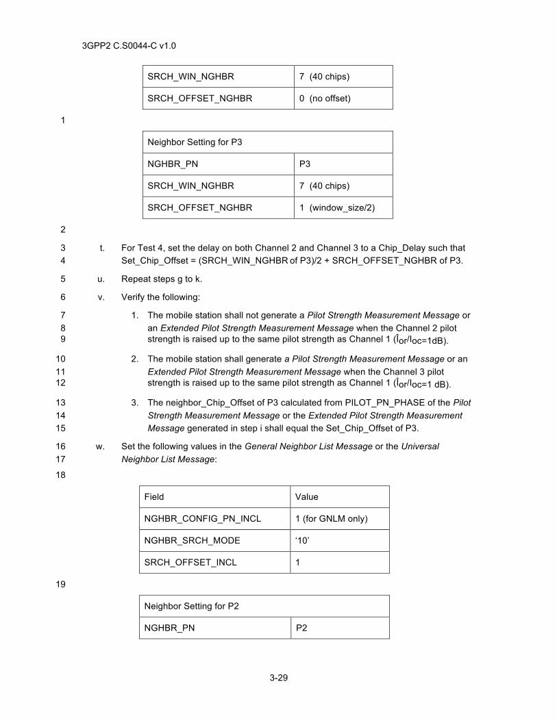
3GPP2 C.S0044-C v1.0
3-29
SRCH_WIN_NGHBR 7 (40 chips)
SRCH_OFFSET_NGHBR 0 (no offset)
1
Neighbor Setting for P3
NGHBR_PN P3
SRCH_WIN_NGHBR 7 (40 chips)
SRCH_OFFSET_NGHBR 1 (window_size/2)
2
t. For Test 4, set the delay on both Channel 2 and Channel 3 to a Chip_Delay such that 3 Set_Chip_Offset = (SRCH_WIN_NGHBR of P3)/2 + SRCH_OFFSET_NGHBR of P3. 4
u. Repeat steps g to k. 5
v. Verify the following: 6
1. The mobile station shall not generate a Pilot Strength Measurement Message or 7 an Extended Pilot Strength Measurement Message when the Channel 2 pilot 8 strength is raised up to the same pilot strength as Channel 1 (Îor/Ioc=1dB). 9
2. The mobile station shall generate a Pilot Strength Measurement Message or an 10 Extended Pilot Strength Measurement Message when the Channel 3 pilot 11 strength is raised up to the same pilot strength as Channel 1 (Îor/Ioc=1 dB). 12
3. The neighbor_Chip_Offset of P3 calculated from PILOT_PN_PHASE of the Pilot 13 Strength Measurement Message or the Extended Pilot Strength Measurement 14 Message generated in step i shall equal the Set_Chip_Offset of P3. 15
w. Set the following values in the General Neighbor List Message or the Universal 16 Neighbor List Message: 17
18
Field Value
NGHBR_CONFIG_PN_INCL 1 (for GNLM only)
NGHBR_SRCH_MODE ‘10’
SRCH_OFFSET_INCL 1
19
Neighbor Setting for P2
NGHBR_PN P2
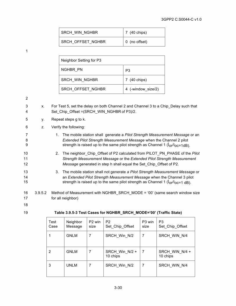
3GPP2 C.S0044-C v1.0
3-30
SRCH_WIN_NGHBR 7 (40 chips)
SRCH_OFFSET_NGHBR 0 (no offset)
1
Neighbor Setting for P3
NGHBR_PN P3
SRCH_WIN_NGHBR 7 (40 chips)
SRCH_OFFSET_NGHBR 4 (-window_size/2)
2
x. For Test 5, set the delay on both Channel 2 and Channel 3 to a Chip_Delay such that 3 Set_Chip_Offset =(SRCH_WIN_NGHBR of P3)/2. 4
y. Repeat steps g to k. 5
z. Verify the following: 6
1. The mobile station shall generate a Pilot Strength Measurement Message or an 7 Extended Pilot Strength Measurement Message when the Channel 2 pilot 8 strength is raised up to the same pilot strength as Channel 1 (Îor/Ioc=1dB). 9
2. The neighbor_Chip_Offset of P2 calculated from PILOT_PN_PHASE of the Pilot 10 Strength Measurement Message or the Extended Pilot Strength Measurement 11 Message generated in step h shall equal the Set_Chip_Offset of P2. 12
3. The mobile station shall not generate a Pilot Strength Measurement Message or 13 an Extended Pilot Strength Measurement Message when the Channel 3 pilot 14 strength is raised up to the same pilot strength as Channel 1 (Îor/Ioc=1 dB). 15
3.9.5.2 Method of Measurement with NGHBR_SRCH_MODE = ‘00’ (same search window size 16 for all neighbor) 17
18
Table 3.9.5-3 Test Cases for NGHBR_SRCH_MODE=’00’ (Traffic State) 19
Test Case
Neighbor Message
P2 win size
P2 Set_Chip_Offset
P3 win size
P3 Set_Chip_Offset
1 GNLM 7 SRCH_Win_N/2
7 SRCH_WIN_N/4
2 GNLM 7 SRCH_Win_N/2 + 10 chips
7 SRCH_WIN_N/4 + 10 chips
3 UNLM 7 SRCH_Win_N/2
7 SRCH_WIN_N/4
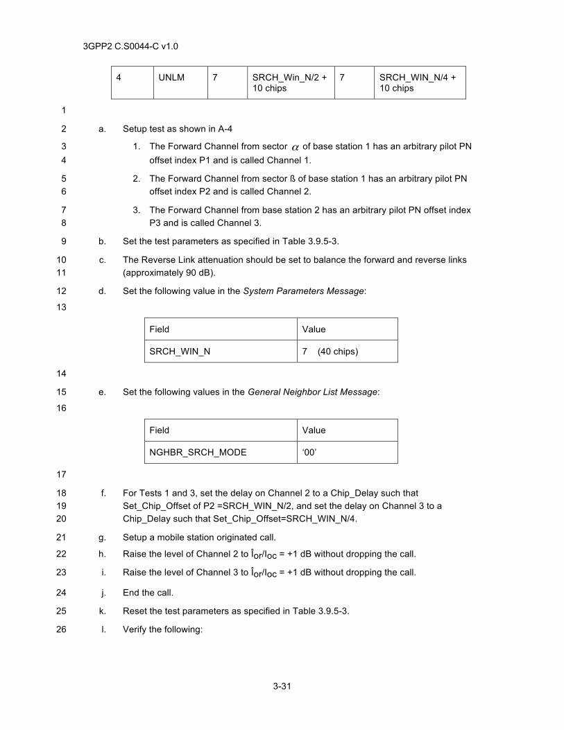
3GPP2 C.S0044-C v1.0
3-31
4 UNLM 7 SRCH_Win_N/2 + 10 chips
7 SRCH_WIN_N/4 + 10 chips
1
a. Setup test as shown in A-4 2
1. The Forward Channel from sector α of base station 1 has an arbitrary pilot PN 3 offset index P1 and is called Channel 1. 4
2. The Forward Channel from sector ß of base station 1 has an arbitrary pilot PN 5 offset index P2 and is called Channel 2. 6
3. The Forward Channel from base station 2 has an arbitrary pilot PN offset index 7 P3 and is called Channel 3. 8
b. Set the test parameters as specified in Table 3.9.5-3. 9
c. The Reverse Link attenuation should be set to balance the forward and reverse links 10 (approximately 90 dB). 11
d. Set the following value in the System Parameters Message: 12
13
Field Value
SRCH_WIN_N 7 (40 chips)
14
e. Set the following values in the General Neighbor List Message: 15
16
Field Value
NGHBR_SRCH_MODE ‘00’
17
f. For Tests 1 and 3, set the delay on Channel 2 to a Chip_Delay such that 18 Set_Chip_Offset of P2 =SRCH_WIN_N/2, and set the delay on Channel 3 to a 19 Chip_Delay such that Set_Chip_Offset=SRCH_WIN_N/4. 20
g. Setup a mobile station originated call. 21
h. Raise the level of Channel 2 to Îor/Ioc = +1 dB without dropping the call. 22
i. Raise the level of Channel 3 to Îor/Ioc = +1 dB without dropping the call. 23
j. End the call. 24
k. Reset the test parameters as specified in Table 3.9.5-3. 25
l. Verify the following: 26
3GPP2 C.S0044-C v1.0
3-32
1. The mobile station shall generate a Pilot Strength Measurement Message or an 1 Extended Pilot Strength Measurement Message when the Channel 2 pilot 2 strength is raised up to the same pilot strength as Channel 1 (Îor/Ioc=1dB). 3
2. The neighbor_Chip_Offset of P2 calculated from PILOT_PN_PHASE of the Pilot 4 Strength Measurement Message or the Extended Pilot Strength Measurement 5 Message generated in step h shall equal the Set_Chip_Offset of P2. 6
3. The mobile station shall also generate a Pilot Strength Measurement Message or 7 an Extended Pilot Strength Measurement Message when the Channel 3 pilot 8 strength is raised up to the same pilot strength as Channel 1 (Îor/Ioc=1 dB). 9
4. The neighbor_Chip_Offset of P3 calculated from PILOT_PN_PHASE of the Pilot 10 Strength Measurement Message or the Extended Pilot Strength Measurement 11 Message generated in step i shall equal the Set_Chip_Offset of P3. 12
m. For Tests 2 and 4, set the delay on Channel 2 to a Chip_Delay such that 13 Set_Chip_Offset of P2 =(SRCH_WIN_N/2)+10 chips, and set the delay on Channel 3 to 14 a Chip_Delay such that Set_Chip_Offset=(SRCH_WIN_N/4)+10 chips. 15
n. Repeat steps g to k. 16
o. Verify the following: 17
1. The mobile station shall not generate a Pilot Strength Measurement Message or 18 an Extended Pilot Strength Measurement Message when the Channel 2 pilot 19 strength is raised up to the same pilot strength as Channel 1 (Îor/Ioc=1dB). 20
2. The mobile station shall generate a Pilot Strength Measurement Message or an 21 Extended Pilot Strength Measurement Message when the Channel 3 pilot 22 strength is raised up to the same pilot strength as Channel 1 (Îor/Ioc=1 dB). 23
3. The neighbor_Chip_Offset of P2 calculated from PILOT_PN_PHASE of the Pilot 24 Strength Measurement Message or the Extended Pilot Strength Measurement 25 Message generated in step i shall equal the Set_Chip_Offset of P3. 26
p. Set the following values in the Universal Neighbor List Message: 27
28
Field Value
NGHBR_SRCH_MODE ‘00’
SRCH_WIN_N 7 (40 Chips)
29
q. For Tests 3 and 4 repeat steps b to o using parameter values in step t sent over the 30 Universal Neighbor List Message instead of the General Neighbor List Message. 31
3GPP2 C.S0044-C v1.0
3-33
3.9.6 Minimum Standard 1
3.9.6.1 For section 3.9.4.1: 2
Verify steps l, o, r, v and z for Tests 1 to 5. 3
3.9.6.2 For section 3.9.4.2: 4
Verify step l for Tests 1 and 3. 5
Verify step o for Tests 2 and 4. 6
3.10 Search Window Size and Offset (Idle State) 7
3.10.1 Definition 8
The mobile station is operating in idle state and monitoring sector α of base station 1. Delay is 9 applied to both sector ß of base station 1 and base station 2. The level of neighbor pilots are 10 raised sufficiently high to ensure idle handoff is possible. 11
In section 3.9.3.1, the pilot strength measurements of base station 2 and sector ß of base station 12 1 are checked against the search window size and search window offset settings for each of the 13 neighbor pilots. If the delay is greater than the search window size for the neighbor pilot then the 14 mobile station shall not idle handoff to that neighbor pilot. 15
In section 3.9.3.2, the pilot strength measurements of base station 2 and sector ß of base station 16 1are checked against a common search window size (i.e. SRCH_WIN_N). If the delay is greater 17 than the search window size for the neighbor pilot then the mobile station shall not idle handoff to 18 that neighbor pilot. 19
Formulas 20
Num_Chips = Set_Chip_Offset - Sim_Chip_Offset 21
Chip_Delay (µs) = sµ300m/
244m x Num_chip 22
Set_Chip_Offset is the desired number of chip offsets for a particular test case. Sim_Chip_Offset 23 is the inherent delay for a pilot due to the time alignment/calibration of the equipment. Chip_Delay 24 is the actual delay in usec the tester should vary with the test equipment (e.g. fader) to achieve 25 the proper Set_Chip_Offset (this includes the inherent delay measured for Sim_Chip_Offset. 26 When properly adjusted, the Set_Chip_Offset should equal to the neighbor pilot’s chip offset from 27 zero chip delay. 28
3.10.2 Traceability 29
(See[4]); 30
2.6.6 Handoff Procedures 31
2.6.6.2.1 Pilot Search 32
Table 2.6.6.2.1 Search Window Sizes 33
Table 2.6.6.2.1-2 Search Window Offset 34
3.6.6 Handoff Procedures 35
3.7.2.3.2 System Parameters Message 36
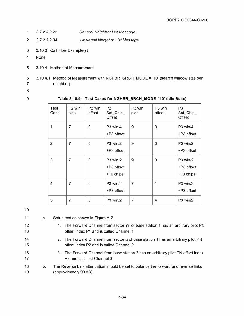
3GPP2 C.S0044-C v1.0
3-34
3.7.2.3.2.22 General Neighbor List Message 1
3.7.2.3.2.34 Universal Neighbor List Message 2
3.10.3 Call Flow Example(s) 3
None 4
3.10.4 Method of Measurement 5
3.10.4.1 Method of Measurement with NGHBR_SRCH_MODE = ‘10’ (search window size per 6 neighbor) 7
8
Table 3.10.4-1 Test Cases for NGHBR_SRCH_MODE=’10’ (Idle State) 9
Test Case
P2 win size
P2 win offset
P2 Set_Chip_Offset
P3 win size
P3 win offset
P3 Set_Chip_Offset
1 7 0 P3 win/4
+P3 offset
9 0 P3 win/4
+P3 offset
2 7 0 P3 win/2
+P3 offset
9 0 P3 win/2
+P3 offset
3 7 0 P3 win/2
+P3 offset
+10 chips
9 0 P3 win/2
+P3 offset
+10 chips
4 7 0 P3 win/2
+P3 offset
7 1 P3 win/2
+P3 offset
5 7 0 P3 win/2 7 4 P3 win/2
10
a. Setup test as shown in Figure A-2. 11
1. The Forward Channel from sector α of base station 1 has an arbitrary pilot PN 12 offset index P1 and is called Channel 1. 13
2. The Forward Channel from sector ß of base station 1 has an arbitrary pilot PN 14 offset index P2 and is called Channel 2. 15
3. The Forward Channel from base station 2 has an arbitrary pilot PN offset index 16 P3 and is called Channel 3. 17
b. The Reverse Link attenuation should be set to balance the forward and reverse links 18 (approximately 90 dB). 19
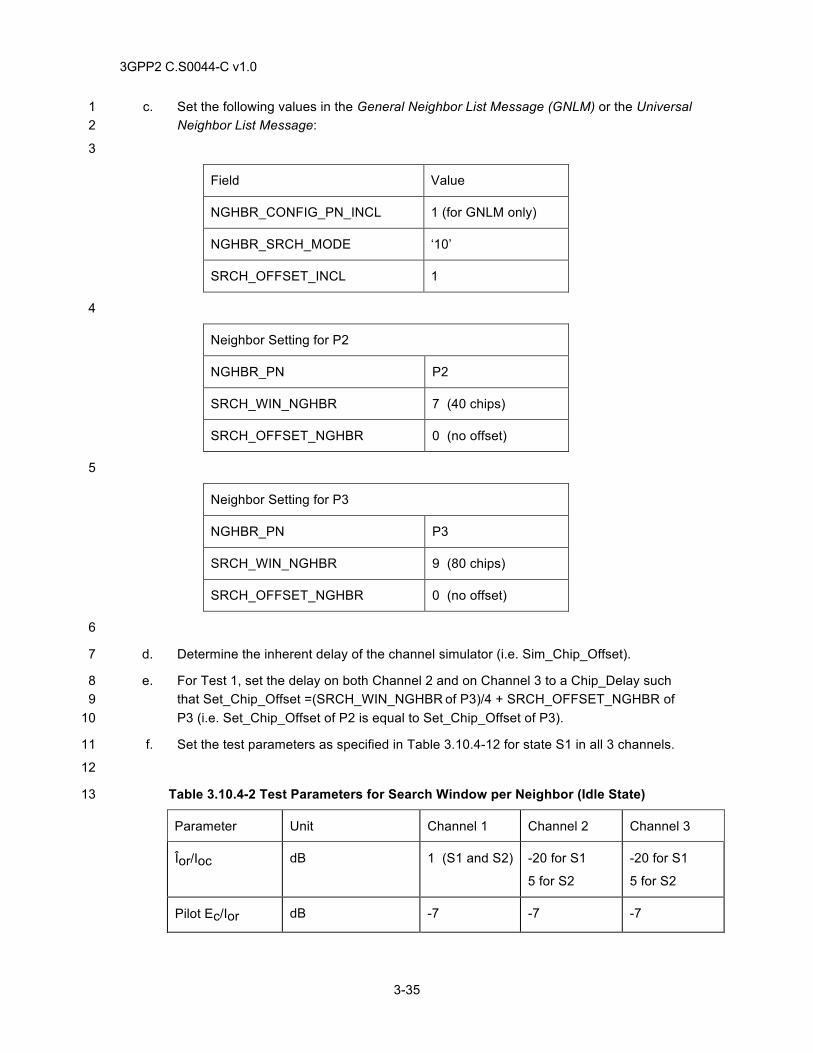
3GPP2 C.S0044-C v1.0
3-35
c. Set the following values in the General Neighbor List Message (GNLM) or the Universal 1 Neighbor List Message: 2
3
Field Value
NGHBR_CONFIG_PN_INCL 1 (for GNLM only)
NGHBR_SRCH_MODE ‘10’
SRCH_OFFSET_INCL 1
4
Neighbor Setting for P2
NGHBR_PN P2
SRCH_WIN_NGHBR 7 (40 chips)
SRCH_OFFSET_NGHBR 0 (no offset)
5
Neighbor Setting for P3
NGHBR_PN P3
SRCH_WIN_NGHBR 9 (80 chips)
SRCH_OFFSET_NGHBR 0 (no offset)
6
d. Determine the inherent delay of the channel simulator (i.e. Sim_Chip_Offset). 7
e. For Test 1, set the delay on both Channel 2 and on Channel 3 to a Chip_Delay such 8 that Set_Chip_Offset =(SRCH_WIN_NGHBR of P3)/4 + SRCH_OFFSET_NGHBR of 9 P3 (i.e. Set_Chip_Offset of P2 is equal to Set_Chip_Offset of P3). 10
f. Set the test parameters as specified in Table 3.10.4-12 for state S1 in all 3 channels. 11
12
Table 3.10.4-2 Test Parameters for Search Window per Neighbor (Idle State) 13
Parameter Unit Channel 1 Channel 2 Channel 3
Îor/Ioc dB 1 (S1 and S2) -20 for S1
5 for S2
-20 for S1
5 for S2
Pilot Ec/Ior dB -7 -7 -7
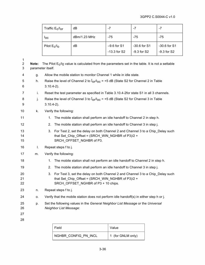
3GPP2 C.S0044-C v1.0
3-36
Traffic Ec/Ior dB -7 -7 -7
Ioc dBm/1.23 MHz -75 -75 -75
Pilot Ec/Io dB –9.6 for S1
-13.3 for S2
-30.6 for S1
-9.3 for S2
-30.6 for S1
-9.3 for S2
1 Note: The Pilot Ec/I0 value is calculated from the parameters set in the table. It is not a settable 2 parameter itself. 3
g. Allow the mobile station to monitor Channel 1 while in idle state. 4
h. Raise the level of Channel 2 to Îor/Ioc = +5 dB (State S2 for Channel 2 in Table 5 3.10.4-2). 6
i. Reset the test parameter as specified in Table 3.10.4-2for state S1 in all 3 channels. 7
j. Raise the level of Channel 3 to Îor/Ioc = +5 dB (State S2 for Channel 3 in Table 8 3.10.4-2). 9
k. Verify the following: 10
1. The mobile station shall perform an idle handoff to Channel 2 in step h. 11
2. The mobile station shall perform an idle handoff to Channel 3 in step j. 12
3. For Test 2, set the delay on both Channel 2 and Channel 3 to a Chip_Delay such 13 that Set_Chip_Offset = (SRCH_WIN_NGHBR of P3)/2 + 14 SRCH_OFFSET_NGHBR of P3. 15
l. Repeat steps f to j. 16
m. Verify the following: 17
1. The mobile station shall not perform an idle handoff to Channel 2 in step h. 18
2. The mobile station shall perform an idle handoff to Channel 3 in step j. 19
3. For Test 3, set the delay on both Channel 2 and Channel 3 to a Chip_Delay such 20 that Set_Chip_Offset = (SRCH_WIN_NGHBR of P3)/2 + 21 SRCH_OFFSET_NGHBR of P3 + 10 chips. 22
n. Repeat steps f to j. 23
o. Verify that the mobile station does not perform idle handoff(s) in either step h or j. 24
p. Set the following values in the General Neighbor List Message or the Universal 25 Neighbor List Message: 26
27
28
Field Value
NGHBR_CONFIG_PN_INCL 1 (for GNLM only)
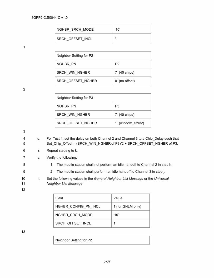
3GPP2 C.S0044-C v1.0
3-37
NGHBR_SRCH_MODE ‘10’
SRCH_OFFSET_INCL 1
1
Neighbor Setting for P2
NGHBR_PN P2
SRCH_WIN_NGHBR 7 (40 chips)
SRCH_OFFSET_NGHBR 0 (no offset)
2
Neighbor Setting for P3
NGHBR_PN P3
SRCH_WIN_NGHBR 7 (40 chips)
SRCH_OFFSET_NGHBR 1 (window_size/2)
3
q. For Test 4, set the delay on both Channel 2 and Channel 3 to a Chip_Delay such that 4 Set_Chip_Offset = (SRCH_WIN_NGHBR of P3)/2 + SRCH_OFFSET_NGHBR of P3. 5
r. Repeat steps g to k. 6
s. Verify the following: 7
1. The mobile station shall not perform an idle handoff to Channel 2 in step h. 8
2. The mobile station shall perform an idle handoff to Channel 3 in step j. 9
t. Set the following values in the General Neighbor List Message or the Universal 10 Neighbor List Message: 11
12
Field Value
NGHBR_CONFIG_PN_INCL 1 (for GNLM only)
NGHBR_SRCH_MODE ‘10’
SRCH_OFFSET_INCL 1
13
Neighbor Setting for P2
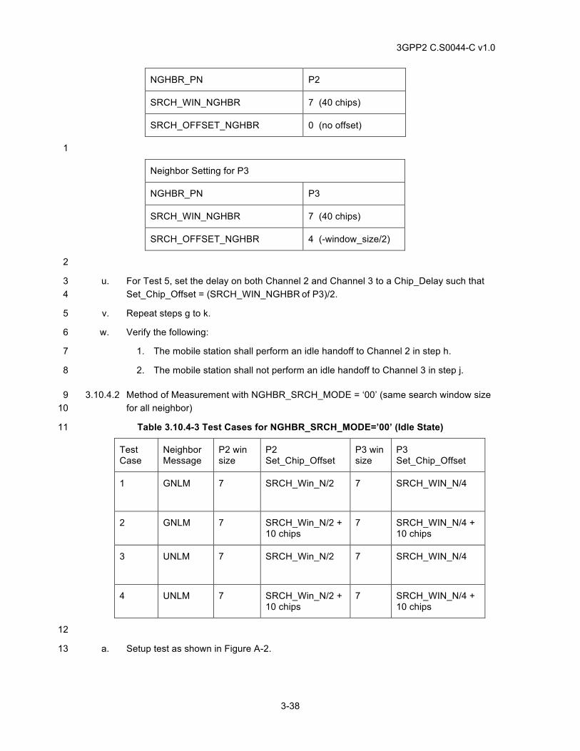
3GPP2 C.S0044-C v1.0
3-38
NGHBR_PN P2
SRCH_WIN_NGHBR 7 (40 chips)
SRCH_OFFSET_NGHBR 0 (no offset)
1
Neighbor Setting for P3
NGHBR_PN P3
SRCH_WIN_NGHBR 7 (40 chips)
SRCH_OFFSET_NGHBR 4 (-window_size/2)
2
u. For Test 5, set the delay on both Channel 2 and Channel 3 to a Chip_Delay such that 3 Set_Chip_Offset = (SRCH_WIN_NGHBR of P3)/2. 4
v. Repeat steps g to k. 5
w. Verify the following: 6
1. The mobile station shall perform an idle handoff to Channel 2 in step h. 7
2. The mobile station shall not perform an idle handoff to Channel 3 in step j. 8
3.10.4.2 Method of Measurement with NGHBR_SRCH_MODE = ‘00’ (same search window size 9 for all neighbor) 10
Table 3.10.4-3 Test Cases for NGHBR_SRCH_MODE=’00’ (Idle State) 11
Test Case
Neighbor Message
P2 win size
P2 Set_Chip_Offset
P3 win size
P3 Set_Chip_Offset
1 GNLM 7 SRCH_Win_N/2
7 SRCH_WIN_N/4
2 GNLM 7 SRCH_Win_N/2 + 10 chips
7 SRCH_WIN_N/4 + 10 chips
3 UNLM 7 SRCH_Win_N/2
7 SRCH_WIN_N/4
4 UNLM 7 SRCH_Win_N/2 + 10 chips
7 SRCH_WIN_N/4 + 10 chips
12
a. Setup test as shown in Figure A-2. 13
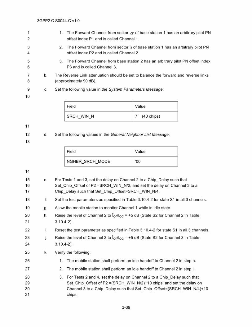
3GPP2 C.S0044-C v1.0
3-39
1. The Forward Channel from sector α of base station 1 has an arbitrary pilot PN 1 offset index P1 and is called Channel 1. 2
2. The Forward Channel from sector ß of base station 1 has an arbitrary pilot PN 3 offset index P2 and is called Channel 2. 4
3. The Forward Channel from base station 2 has an arbitrary pilot PN offset index 5 P3 and is called Channel 3. 6
b. The Reverse Link attenuation should be set to balance the forward and reverse links 7 (approximately 90 dB). 8
c. Set the following value in the System Parameters Message: 9
10
Field Value
SRCH_WIN_N 7 (40 chips)
11
d. Set the following values in the General Neighbor List Message: 12
13
Field Value
NGHBR_SRCH_MODE ‘00’
14
e. For Tests 1 and 3, set the delay on Channel 2 to a Chip_Delay such that 15 Set_Chip_Offset of P2 =SRCH_WIN_N/2, and set the delay on Channel 3 to a 16 Chip_Delay such that Set_Chip_Offset=SRCH_WIN_N/4. 17
f. Set the test parameters as specified in Table 3.10.4-2 for state S1 in all 3 channels. 18
g. Allow the mobile station to monitor Channel 1 while in idle state. 19
h. Raise the level of Channel 2 to Îor/Ioc = +5 dB (State S2 for Channel 2 in Table 20 3.10.4-2). 21
i. Reset the test parameter as specified in Table 3.10.4-2 for state S1 in all 3 channels. 22
j. Raise the level of Channel 3 to Îor/Ioc = +5 dB (State S2 for Channel 3 in Table 23 3.10.4-2). 24
k. Verify the following: 25
1. The mobile station shall perform an idle handoff to Channel 2 in step h. 26
2. The mobile station shall perform an idle handoff to Channel 2 in step j. 27
3. For Tests 2 and 4, set the delay on Channel 2 to a Chip_Delay such that 28 Set_Chip_Offset of P2 =(SRCH_WIN_N/2)+10 chips, and set the delay on 29 Channel 3 to a Chip_Delay such that Set_Chip_Offset=(SRCH_WIN_N/4)+10 30 chips. 31
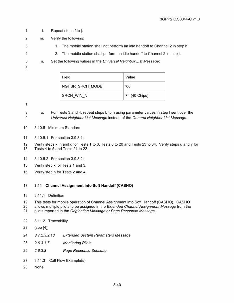
3GPP2 C.S0044-C v1.0
3-40
l. Repeat steps f to j. 1
m. Verify the following: 2
1. The mobile station shall not perform an idle handoff to Channel 2 in step h. 3
2. The mobile station shall perform an idle handoff to Channel 2 in step j. 4
n. Set the following values in the Universal Neighbor List Message: 5
6
Field Value
NGHBR_SRCH_MODE ‘00’
SRCH_WIN_N 7 (40 Chips)
7
o. For Tests 3 and 4, repeat steps b to n using parameter values in step t sent over the 8 Universal Neighbor List Message instead of the General Neighbor List Message. 9
3.10.5 Minimum Standard 10
3.10.5.1 For section 3.9.3.1: 11
Verify steps k, n and q for Tests 1 to 3, Tests 6 to 20 and Tests 23 to 34. Verify steps u and y for 12 Tests 4 to 5 and Tests 21 to 22. 13
3.10.5.2 For section 3.9.3.2: 14
Verify step k for Tests 1 and 3. 15
Verify step n for Tests 2 and 4. 16
3.11 Channel Assignment into Soft Handoff (CASHO) 17
3.11.1 Definition 18
This tests for mobile operation of Channel Assignment into Soft Handoff (CASHO). CASHO 19 allows multiple pilots to be assigned in the Extended Channel Assignment Message from the 20 pilots reported in the Origination Message or Page Response Message. 21
3.11.2 Traceability 22
(see [4]) 23
3.7.2.3.2.13 Extended System Parameters Message 24
2.6.3.1.7 Monitoring Pilots 25
2.6.3.3 Page Response Substate 26
3.11.3 Call Flow Example(s) 27
None 28
3GPP2 C.S0044-C v1.0
3-41
3.11.4 Method of Measurement 1
a. Connect the mobile station as shown in Figure A-5. Ensure both pilot Ec/Io values are 2 well above T_ADD. 3
b. Allow the mobile station to come to the idle state on one of the base stations. 4
c. Make a mobile station originated call. 5
d. Verify both base station pilots are reported in the Origination Message. 6
e. Verify the mobile station receives an Extended Channel Assignment Message 7 assigning both pilots and calls complete normally. 8
f. Repeat steps c-e for a mobile station terminated call with the exception that in step d 9 the Page Response Message is used instead of the Origination Message. 10
3.11.5 Minimum Standard 11
The mobile station shall comply with the requirements in steps d, e and f. 12
3.12 Traffic Channel Preamble during Hard Handoff Between Frequencies in same band 13
3.12.1 Definition 14
The mobile station is transitioned between base stations with different CDMA frequency (channel) 15 assignments in the same band. The Traffic Channel Preamble is a sequence of all-zero frames 16 that is sent by the mobile station on the Reverse Traffic Channel as an aid to Traffic Channel 17 acquisition. 18
3.12.2 Traceability 19
(See[4]) 20
2.6.6.1.1 Types of Handoff 21
2.6.6.2.5 Handoff Messages 22
2.6.6.2.8 CDMA-to-CDMA Hard Handoff 23
3.6.6.1.1 Types of Handoff 24
3.6.6.2.2 Call Processing During Handoff 25
(See[2]) 26
2.1.3.2.4 Reverse Pilot Channel Operation during RTC Preamble 27
2.1.3.6.2.3 Reverse Traffic Channel Preamble 28
3.12.3 Call Flow Example(s) 29
None 30
3.12.4 Method of Measurement 31
a. Setup test as shown in Figure A-2. 32
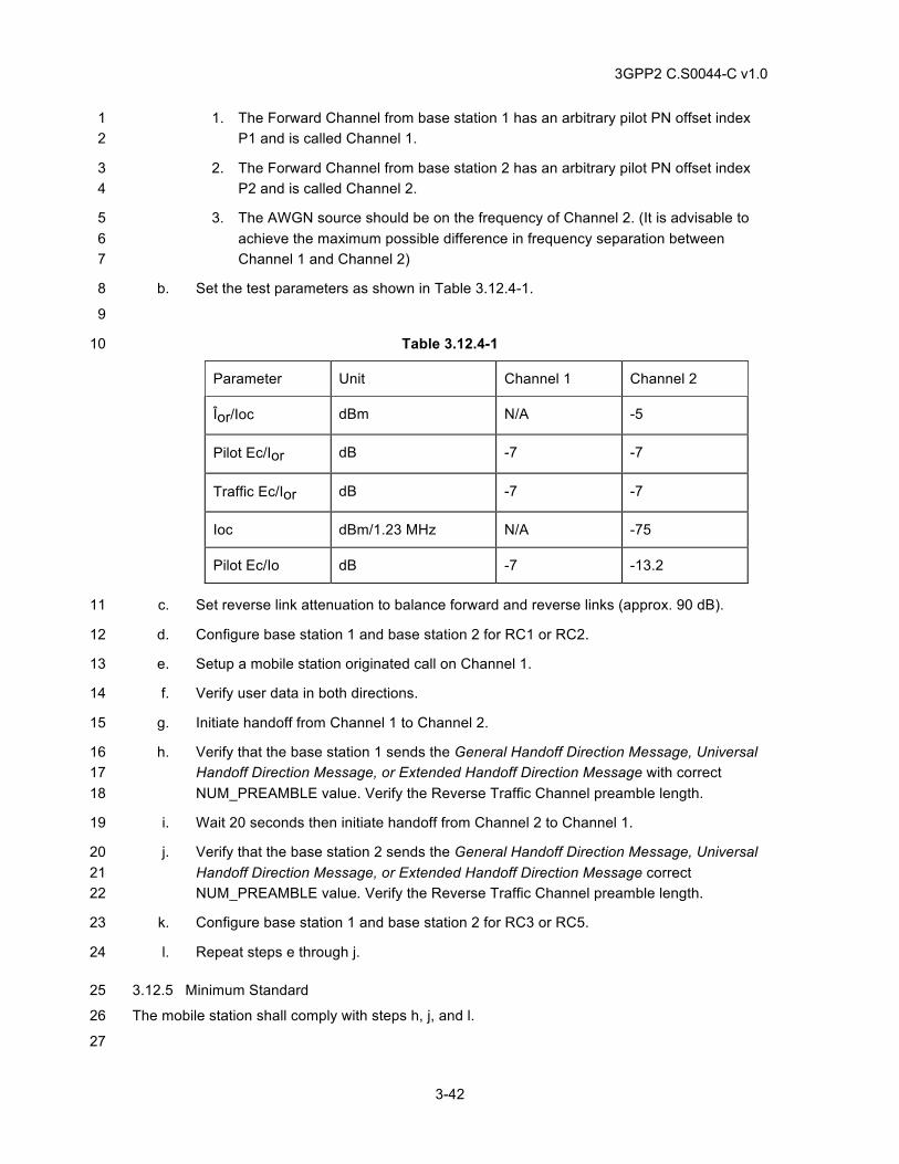
3GPP2 C.S0044-C v1.0
3-42
1. The Forward Channel from base station 1 has an arbitrary pilot PN offset index 1 P1 and is called Channel 1. 2
2. The Forward Channel from base station 2 has an arbitrary pilot PN offset index 3 P2 and is called Channel 2. 4
3. The AWGN source should be on the frequency of Channel 2. (It is advisable to 5 achieve the maximum possible difference in frequency separation between 6 Channel 1 and Channel 2) 7
b. Set the test parameters as shown in Table 3.12.4-1. 8
9
Table 3.12.4-1 10
Parameter Unit Channel 1 Channel 2
Îor/Ioc dBm N/A -5
Pilot Ec/Ior dB -7 -7
Traffic Ec/Ior dB -7 -7
Ioc dBm/1.23 MHz N/A -75
Pilot Ec/Io dB -7 -13.2
c. Set reverse link attenuation to balance forward and reverse links (approx. 90 dB). 11
d. Configure base station 1 and base station 2 for RC1 or RC2. 12
e. Setup a mobile station originated call on Channel 1. 13
f. Verify user data in both directions. 14
g. Initiate handoff from Channel 1 to Channel 2. 15
h. Verify that the base station 1 sends the General Handoff Direction Message, Universal 16 Handoff Direction Message, or Extended Handoff Direction Message with correct 17 NUM_PREAMBLE value. Verify the Reverse Traffic Channel preamble length. 18
i. Wait 20 seconds then initiate handoff from Channel 2 to Channel 1. 19
j. Verify that the base station 2 sends the General Handoff Direction Message, Universal 20 Handoff Direction Message, or Extended Handoff Direction Message correct 21 NUM_PREAMBLE value. Verify the Reverse Traffic Channel preamble length. 22
k. Configure base station 1 and base station 2 for RC3 or RC5. 23
l. Repeat steps e through j. 24
3.12.5 Minimum Standard 25
The mobile station shall comply with steps h, j, and l. 26
27
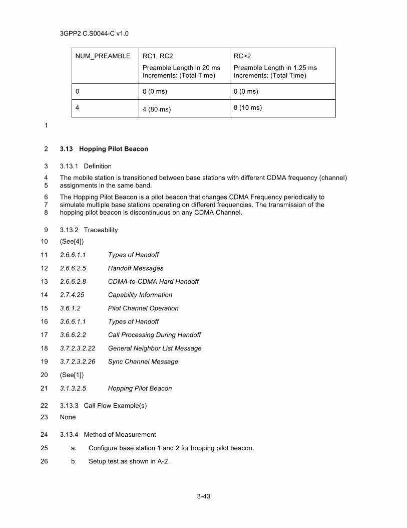
3GPP2 C.S0044-C v1.0
3-43
NUM_PREAMBLE RC1, RC2
Preamble Length in 20 ms Increments: (Total Time)
RC>2
Preamble Length in 1.25 ms Increments: (Total Time)
0 0 (0 ms) 0 (0 ms)
4 4 (80 ms) 8 (10 ms)
1
3.13 Hopping Pilot Beacon 2
3.13.1 Definition 3
The mobile station is transitioned between base stations with different CDMA frequency (channel) 4 assignments in the same band. 5
The Hopping Pilot Beacon is a pilot beacon that changes CDMA Frequency periodically to 6 simulate multiple base stations operating on different frequencies. The transmission of the 7 hopping pilot beacon is discontinuous on any CDMA Channel. 8
3.13.2 Traceability 9
(See[4]) 10
2.6.6.1.1 Types of Handoff 11
2.6.6.2.5 Handoff Messages 12
2.6.6.2.8 CDMA-to-CDMA Hard Handoff 13
2.7.4.25 Capability Information 14
3.6.1.2 Pilot Channel Operation 15
3.6.6.1.1 Types of Handoff 16
3.6.6.2.2 Call Processing During Handoff 17
3.7.2.3.2.22 General Neighbor List Message 18
3.7.2.3.2.26 Sync Channel Message 19
(See[1]) 20
3.1.3.2.5 Hopping Pilot Beacon 21
3.13.3 Call Flow Example(s) 22
None 23
3.13.4 Method of Measurement 24
a. Configure base station 1 and 2 for hopping pilot beacon. 25
b. Setup test as shown in A-2. 26
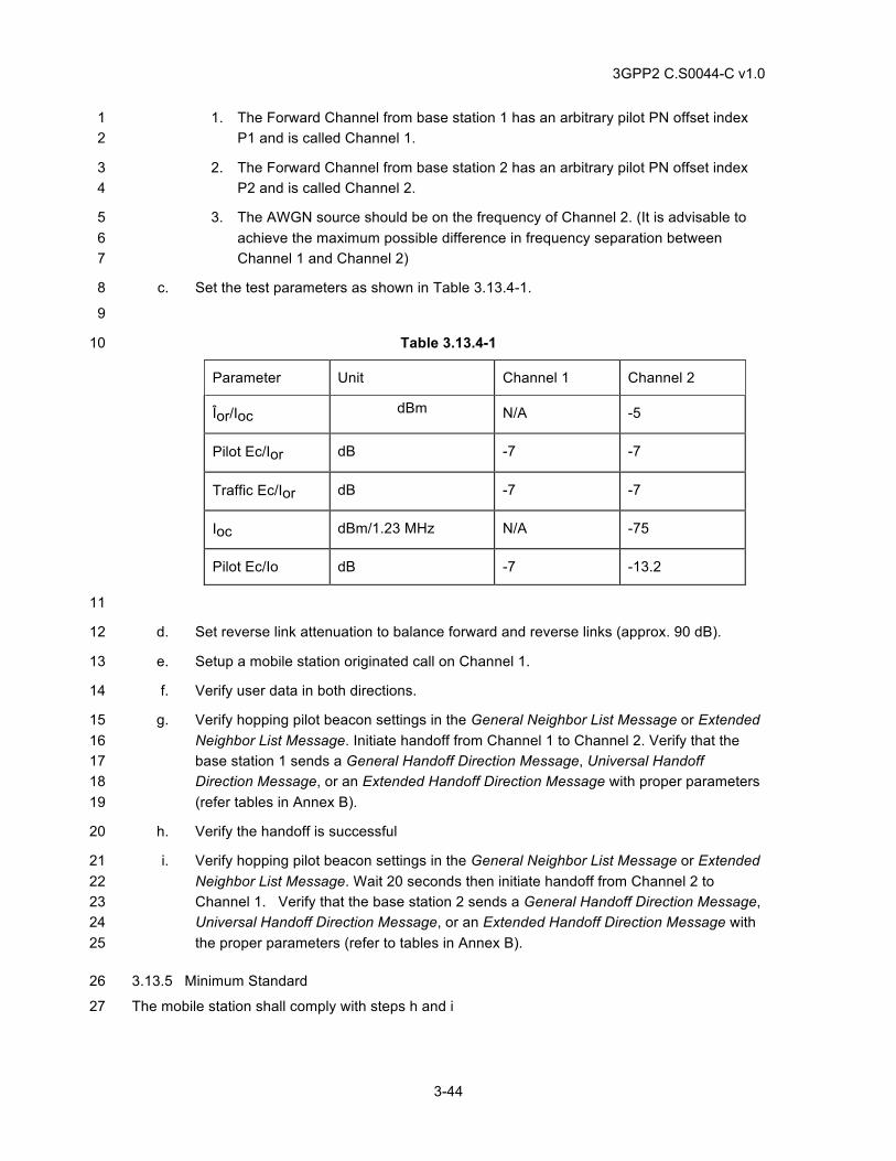
3GPP2 C.S0044-C v1.0
3-44
1. The Forward Channel from base station 1 has an arbitrary pilot PN offset index 1 P1 and is called Channel 1. 2
2. The Forward Channel from base station 2 has an arbitrary pilot PN offset index 3 P2 and is called Channel 2. 4
3. The AWGN source should be on the frequency of Channel 2. (It is advisable to 5 achieve the maximum possible difference in frequency separation between 6 Channel 1 and Channel 2) 7
c. Set the test parameters as shown in Table 3.13.4-1. 8
9
Table 3.13.4-1 10
Parameter Unit Channel 1 Channel 2
Îor/Ioc dBm N/A -5
Pilot Ec/Ior dB -7 -7
Traffic Ec/Ior dB -7 -7
Ioc dBm/1.23 MHz N/A -75
Pilot Ec/Io dB -7 -13.2
11
d. Set reverse link attenuation to balance forward and reverse links (approx. 90 dB). 12
e. Setup a mobile station originated call on Channel 1. 13
f. Verify user data in both directions. 14
g. Verify hopping pilot beacon settings in the General Neighbor List Message or Extended 15 Neighbor List Message. Initiate handoff from Channel 1 to Channel 2. Verify that the 16 base station 1 sends a General Handoff Direction Message, Universal Handoff 17 Direction Message, or an Extended Handoff Direction Message with proper parameters 18 (refer tables in Annex B). 19
h. Verify the handoff is successful 20
i. Verify hopping pilot beacon settings in the General Neighbor List Message or Extended 21 Neighbor List Message. Wait 20 seconds then initiate handoff from Channel 2 to 22 Channel 1. Verify that the base station 2 sends a General Handoff Direction Message, 23 Universal Handoff Direction Message, or an Extended Handoff Direction Message with 24 the proper parameters (refer to tables in Annex B). 25
3.13.5 Minimum Standard 26
The mobile station shall comply with steps h and i 27
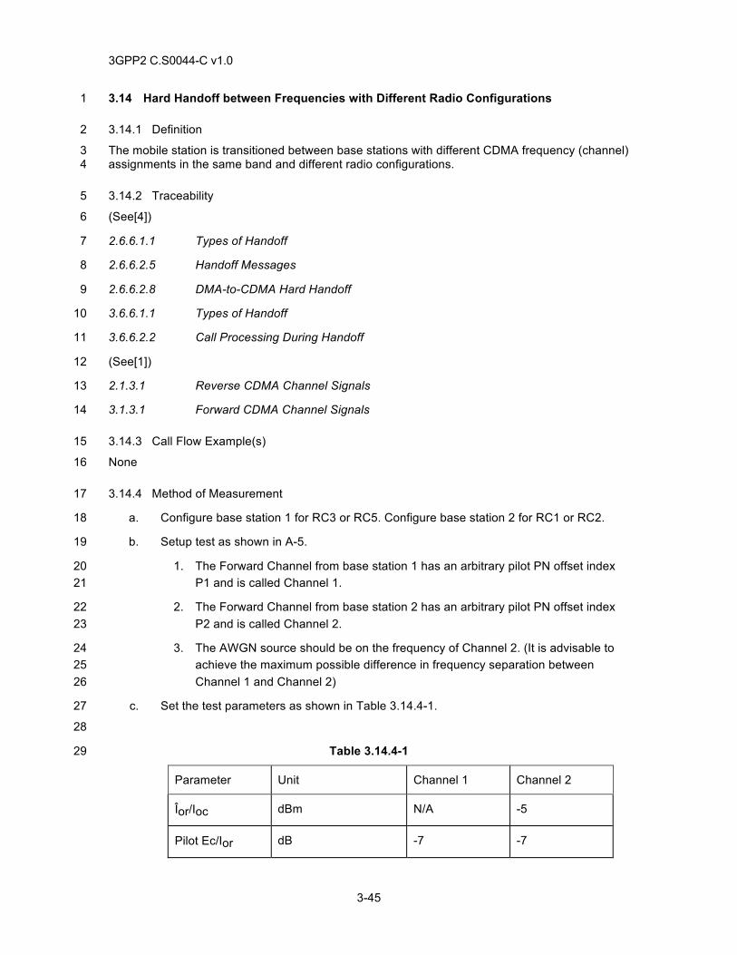
3GPP2 C.S0044-C v1.0
3-45
3.14 Hard Handoff between Frequencies with Different Radio Configurations 1
3.14.1 Definition 2
The mobile station is transitioned between base stations with different CDMA frequency (channel) 3 assignments in the same band and different radio configurations. 4
3.14.2 Traceability 5
(See[4]) 6
2.6.6.1.1 Types of Handoff 7
2.6.6.2.5 Handoff Messages 8
2.6.6.2.8 DMA-to-CDMA Hard Handoff 9
3.6.6.1.1 Types of Handoff 10
3.6.6.2.2 Call Processing During Handoff 11
(See[1]) 12
2.1.3.1 Reverse CDMA Channel Signals 13
3.1.3.1 Forward CDMA Channel Signals 14
3.14.3 Call Flow Example(s) 15
None 16
3.14.4 Method of Measurement 17
a. Configure base station 1 for RC3 or RC5. Configure base station 2 for RC1 or RC2. 18
b. Setup test as shown in A-5. 19
1. The Forward Channel from base station 1 has an arbitrary pilot PN offset index 20 P1 and is called Channel 1. 21
2. The Forward Channel from base station 2 has an arbitrary pilot PN offset index 22 P2 and is called Channel 2. 23
3. The AWGN source should be on the frequency of Channel 2. (It is advisable to 24 achieve the maximum possible difference in frequency separation between 25 Channel 1 and Channel 2) 26
c. Set the test parameters as shown in Table 3.14.4-1. 27
28
Table 3.14.4-1 29
Parameter Unit Channel 1 Channel 2
Îor/Ioc dBm N/A -5
Pilot Ec/Ior dB -7 -7
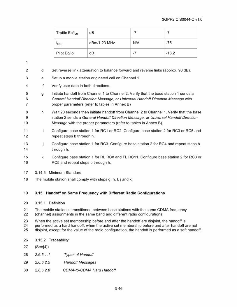
3GPP2 C.S0044-C v1.0
3-46
Traffic Ec/Ior dB -7 -7
Ioc dBm/1.23 MHz N/A -75
Pilot Ec/Io dB -7 -13.2
1
d. Set reverse link attenuation to balance forward and reverse links (approx. 90 dB). 2
e. Setup a mobile station originated call on Channel 1. 3
f. Verify user data in both directions. 4
g. Initiate handoff from Channel 1 to Channel 2. Verify that the base station 1 sends a 5 General Handoff Direction Message, or Universal Handoff Direction Message with 6 proper parameters (refer to tables in Annex B) 7
h. Wait 20 seconds then initiate handoff from Channel 2 to Channel 1. Verify that the base 8 station 2 sends a General Handoff Direction Message, or Universal Handoff Direction 9 Message with the proper parameters (refer to tables in Annex B). 10
i. Configure base station 1 for RC1 or RC2. Configure base station 2 for RC3 or RC5 and 11 repeat steps b through h. 12
j. Configure base station 1 for RC3. Configure base station 2 for RC4 and repeat steps b 13 through h. 14
k. Configure base station 1 for RL RC8 and FL RC11. Configure base station 2 for RC3 or 15 RC5 and repeat steps b through h. 16
3.14.5 Minimum Standard 17
The mobile station shall comply with steps g, h, I, j and k. 18
3.15 Handoff on Same Frequency with Different Radio Configurations 19
3.15.1 Definition 20
The mobile station is transitioned between base stations with the same CDMA frequency 21 (channel) assignments in the same band and different radio configurations. 22
When the active set membership before and after the handoff are disjoint, the handoff is 23 performed as a hard handoff; when the active set membership before and after handoff are not 24 disjoint, except for the value of the radio configuration, the handoff is performed as a soft handoff. 25
3.15.2 Traceability 26
(See[4]) 27
2.6.6.1.1 Types of Handoff 28
2.6.6.2.5 Handoff Messages 29
2.6.6.2.8 CDMA-to-CDMA Hard Handoff 30
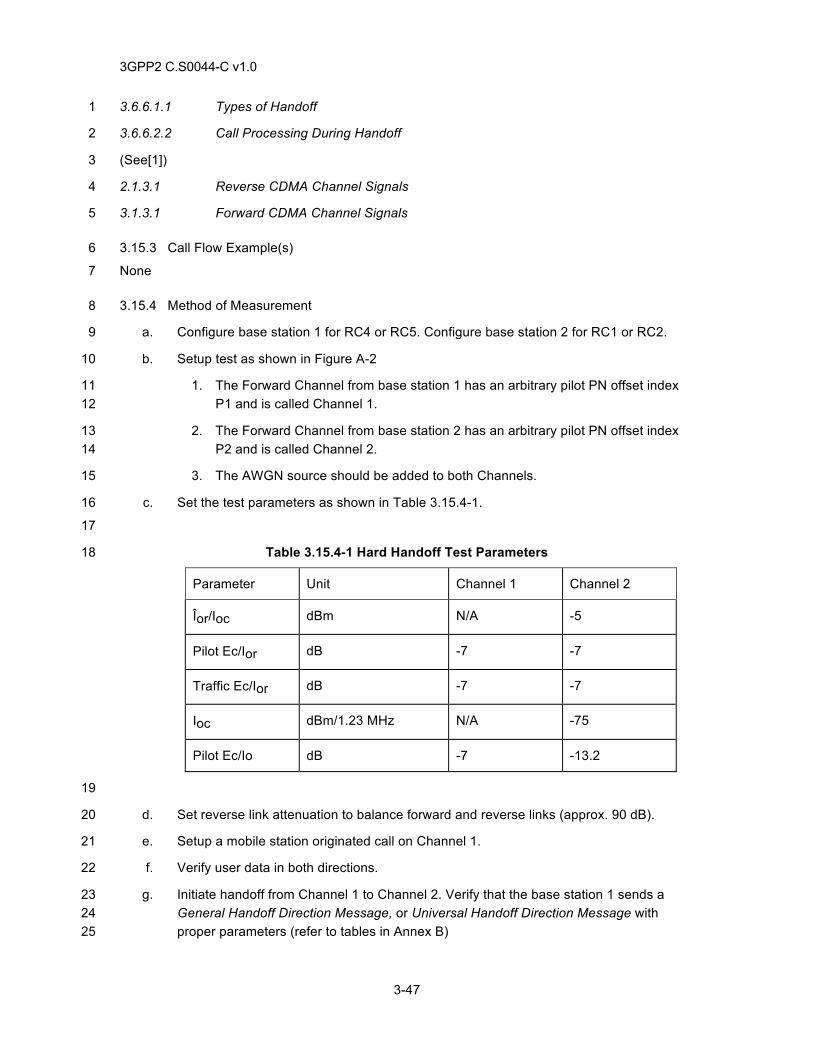
3GPP2 C.S0044-C v1.0
3-47
3.6.6.1.1 Types of Handoff 1
3.6.6.2.2 Call Processing During Handoff 2
(See[1]) 3
2.1.3.1 Reverse CDMA Channel Signals 4
3.1.3.1 Forward CDMA Channel Signals 5
3.15.3 Call Flow Example(s) 6
None 7
3.15.4 Method of Measurement 8
a. Configure base station 1 for RC4 or RC5. Configure base station 2 for RC1 or RC2. 9
b. Setup test as shown in Figure A-2 10
1. The Forward Channel from base station 1 has an arbitrary pilot PN offset index 11 P1 and is called Channel 1. 12
2. The Forward Channel from base station 2 has an arbitrary pilot PN offset index 13 P2 and is called Channel 2. 14
3. The AWGN source should be added to both Channels. 15
c. Set the test parameters as shown in Table 3.15.4-1. 16
17
Table 3.15.4-1 Hard Handoff Test Parameters 18
Parameter Unit Channel 1 Channel 2
Îor/Ioc dBm N/A -5
Pilot Ec/Ior dB -7 -7
Traffic Ec/Ior dB -7 -7
Ioc dBm/1.23 MHz N/A -75
Pilot Ec/Io dB -7 -13.2
19
d. Set reverse link attenuation to balance forward and reverse links (approx. 90 dB). 20
e. Setup a mobile station originated call on Channel 1. 21
f. Verify user data in both directions. 22
g. Initiate handoff from Channel 1 to Channel 2. Verify that the base station 1 sends a 23 General Handoff Direction Message, or Universal Handoff Direction Message with 24 proper parameters (refer to tables in Annex B) 25
3GPP2 C.S0044-C v1.0
3-48
h. Wait 20 seconds then initiate handoff from Channel 2 to Channel 1. Verify that the base 1 station 2 sends a General Handoff Direction Message, or Universal Handoff Direction 2 Message with the proper parameters (refer to tables in Annex B). Note the base station 3 may send the handoff message encapsulated in a General Extension Message if RL 4 RC 8 and FL RC 11 are assigned to the mobile station. 5
i. Configure base station 1 for RC1 or RC2. Configure base station 2 for RC4 or RC5 and 6 repeat steps b through h. 7
j. Configure base station 1 for RC3. Configure base station 2 for RC4 and repeat steps b 8 through h. 9
k. Configure base station 1 for RL RC8 and FL RC11. Configure base station 2 for RC3, 10 RC 4 or RC5 and repeat steps b through h. 11
l. Repeat steps a through j but with the following exception: Only base station 1 is used 12 for this test. The handoff messages are sent from base station 1 without changing the 13 active set, but changing the radio configuration. Thus the handoff messages simply 14 assign a new radio configuration from the same base station. 15
m. Verify that the handoff is performed as a soft handoff. 16
3.15.5 Minimum Standard 17
The mobile station shall comply with steps g, h, i, j, k and m. 18
3.16 Hard Handoff while in the Waiting for Mobile Station Answer Substate 19
3.16.1 Definition 20
This test verifies that if a hard handoff occurs while the mobile station is in the Waiting for Mobile 21 Station Answer Substate, the hard handoff will be completed successfully and the mobile station 22 shall enter the Conversation Substate on the new channel. 23
3.16.2 Traceability 24
(see [4]) 25
2.6.4 Mobile Station Control on the Traffic Channel State 26
2.6.4.3.2 Waiting for Mobile Station Answer Substate 27
2.6.4.4 Conversation Substate 28
2.6.6.2.5.1 Processing of the Forward Traffic Channel Handoff Messages 29
2.6.6.2.8 CDMA to CDMA Hard Handoff 30
3.6.4.3.1 Waiting for Order Substate 31
3.6.6.2.2 Call Processing during Handoff 32
3.7.3.3.2.17 Extended Handoff Direction Message 33
3.7.3.3.2.31 General Handoff Direction Message 34
3.7.3.3.2.36 Universal Handoff Direction Message 35
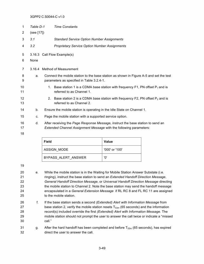
3GPP2 C.S0044-C v1.0
3-49
Table D-1 Time Constants 1
(see [17]) 2
3.1 Standard Service Option Number Assignments 3
3.2 Proprietary Service Option Number Assignments 4
3.16.3 Call Flow Example(s) 5
None 6
3.16.4 Method of Measurement 7
a. Connect the mobile station to the base station as shown in Figure A-5 and set the test 8 parameters as specified in Table 3.2.4-1. 9
1. Base station 1 is a CDMA base station with frequency F1, PN offset P1 and is 10 referred to as Channel 1. 11
2. Base station 2 is a CDMA base station with frequency F2, PN offset P2 and is 12 referred to as Channel 2. 13
b. Ensure the mobile station is operating in the Idle State on Channel 1. 14
c. Page the mobile station with a supported service option. 15
d. After receiving the Page Response Message, instruct the base station to send an 16 Extended Channel Assignment Message with the following parameters: 17
18
Field Value
ASSIGN_MODE '000' or '100'
BYPASS_ALERT_ANSWER '0'
19
e. While the mobile station is in the Waiting for Mobile Station Answer Substate (i.e. 20 ringing), instruct the base station to send an Extended Handoff Direction Message, 21 General Handoff Direction Message, or Universal Handoff Direction Message directing 22 the mobile station to Channel 2. Note the base station may send the handoff message 23 encapsulated in a General Extension Message if RL RC 8 and FL RC 11 are assigned 24 to the mobile station. 25
f. If the base station sends a second (Extended) Alert with Information Message from 26 base station 2, verify the mobile station resets T53m (65 seconds) and the information 27 record(s) included override the first (Extended) Alert with Information Message. The 28 mobile station should not prompt the user to answer the call twice or indicate a “missed 29 call.” 30
g. After the hard handoff has been completed and before T53m (65 seconds), has expired 31 direct the user to answer the call. 32
3GPP2 C.S0044-C v1.0
3-50
h. Verify the mobile station enters the Conversation Substate and user traffic is present in 1 both directions (i.e. audio). 2
i. End the call. 3
j. Repeat steps b through j using different service options and radio configurations 4 supported by the mobile station and base station. 5
k. Repeat steps b through j, changing Channel 2 to a band class that is different from 6 Channel 1 but is supported by the mobile station. 7
3.16.5 Minimum Standard 8
The mobile station shall comply with steps h and j. 9
3.17 Mobile Assisted Inter-Frequency Hard Handoff (CDMA to CDMA) 10
3.17.1 Definition 11
In an Inter-Frequency Hard Handoff test (also known as the Mobile Assisted Hard Handoff test), 12 when the mobile station is directed by the base station to perform a search on a Candidate 13 Frequency, the mobile station will search for a pilot in the Candidate Frequency Neighbor Set. 14 The mobile station will report back to the base station any pilot detected in the Candidate 15 Frequency Neighbor Set with a pilot Ec/Io above the value defined by CF_T_ADD. The base 16 station should then direct the mobile station to the Candidate Frequency and completes the hard 17 handoff. 18
3.17.2 Traceability 19
(see [4]) 20
2.6.6.2.5 Handoff Messages 21
2.6.6.2.8 CDMA-to-CDMA Hard Handoff 22
2.7.2.3.2.20 Candidate Frequency Search Report Message 23
3.6.6.2.2 Call Processing During Handoff 24
3.7.7.3.3.2.27 Candidate Frequency Search Request Message 25
3.17.3 Call Flow Example(s) 26
None 27
3.17.4 Method of Measurement 28
a. Setup test as shown in Figure A-5. 29
1. The Forward Channel from base station 1 has a CDMA frequency assignment F1 30 (any valid value), an arbitrary pilot PN offset index P1 and is called Channel 1. 31
2. The Forward Channel from base station 2 has a CDMA frequency assignment F2 32 (any valid value other than f1 in the same band class), an arbitrary pilot PN offset 33 index P2 and is called Channel 2. 34
35
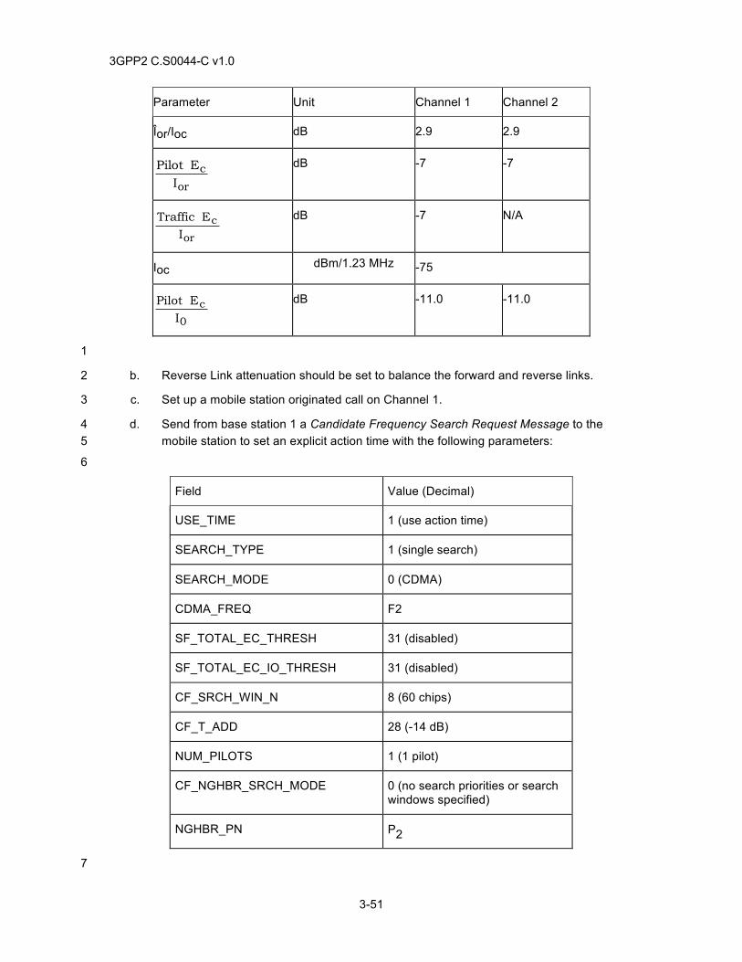
3GPP2 C.S0044-C v1.0
3-51
Parameter Unit Channel 1 Channel 2
Îor/Ioc dB 2.9 2.9
or
cI
EPilot dB -7 -7
or
cI
E Traffic
dB -7 N/A
Ioc dBm/1.23 MHz -75
0
cI
EPilot
dB -11.0 -11.0
1
b. Reverse Link attenuation should be set to balance the forward and reverse links. 2
c. Set up a mobile station originated call on Channel 1. 3
d. Send from base station 1 a Candidate Frequency Search Request Message to the 4 mobile station to set an explicit action time with the following parameters: 5
6
Field Value (Decimal)
USE_TIME 1 (use action time)
SEARCH_TYPE 1 (single search)
SEARCH_MODE 0 (CDMA)
CDMA_FREQ F2
SF_TOTAL_EC_THRESH 31 (disabled)
SF_TOTAL_EC_IO_THRESH 31 (disabled)
CF_SRCH_WIN_N 8 (60 chips)
CF_T_ADD 28 (-14 dB)
NUM_PILOTS 1 (1 pilot)
CF_NGHBR_SRCH_MODE 0 (no search priorities or search windows specified)
NGHBR_PN P2
7
3GPP2 C.S0044-C v1.0
3-52
e. Verify that the mobile station responds with a Candidate Frequency Search Report 1 Message. 2
f. Verify that base station 1 sends a General Handoff Direction Message, an Extended 3 Handoff Direction Message or a Universal Handoff Direction Message to initiate handoff 4 from base station 1 to base station 2. Note the base station may send the handoff 5 message encapsulated in a General Extension Message if RL RC 8 and FL RC 11 are 6 assigned to the mobile station. 7
g. Verify user data in both directions. 8
3.17.5 Minimum Standard 9
The mobile station shall comply with steps e and g. 10
3.18 Mobile Assisted Inter-Frequency Hard Handoff (CDMA to Analog) 11
3.18.1 Definition 12
In an Inter-Frequency Hard Handoff test (also known as the Mobile Assisted Hard Handoff test), 13 when the mobile station is directed by the base station to perform a search on a Candidate 14 Frequency, the mobile station will search for an analog channel in the Candidate Frequency 15 Analog Search Set and shall measure the mean input power on the analog frequency. The mobile 16 station will report back to the base station the signal strength of the analog channel searched. 17 The base station should then direct the mobile station to the Analog Channel and completes the 18 hard handoff. 19
3.18.2 Traceability 20
(see [4]) 21
2.6.6.2.5 Handoff Messages 22
2.6.6.2.8 CDMA-to-CDMA Hard Handoff 23
2.6.6.10.2 Candidate Frequency Analog Search Set 24
2.7.2.3.2.21 Candidate Frequency Search Report Message 25
3.6.6.2.2 Call Processing During Handoff 26
3.7.7.3.3.2.27 Candidate Frequency Search Request Message 27
3.18.3 Call Flow Example(s) 28
None 29
3.18.4 Method of Measurement 30
a. Setup test as shown in Figure A-5. 31
1. The Forward Channel from base station 1 has a CDMA frequency assignment F1 32 (any valid value), an arbitrary pilot PN offset index P1 and is called Channel 1. 33
2. The Forward Channel from base station 2 uses an analog frequency called 34 Channel 2. 35
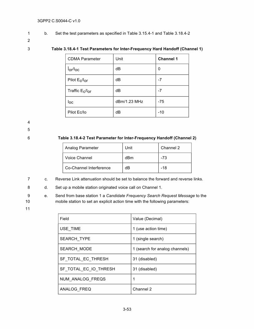
3GPP2 C.S0044-C v1.0
3-53
b. Set the test parameters as specified in Table 3.15.4-1 and Table 3.18.4-2 1
2
Table 3.18.4-1 Test Parameters for Inter-Frequency Hard Handoff (Channel 1) 3
CDMA Parameter Unit Channel 1
Îor/Ioc dB 0
Pilot Ec/Ior dB -7
Traffic Ec/Ior dB -7
Ioc dBm/1.23 MHz -75
Pilot Ec/Io dB -10
4
5
Table 3.18.4-2 Test Parameter for Inter-Frequency Handoff (Channel 2) 6
Analog Parameter Unit Channel 2
Voice Channel dBm -73
Co-Channel Interference dB -18
c. Reverse Link attenuation should be set to balance the forward and reverse links. 7
d. Set up a mobile station originated voice call on Channel 1. 8
e. Send from base station 1 a Candidate Frequency Search Request Message to the 9 mobile station to set an explicit action time with the following parameters: 10
11
Field Value (Decimal)
USE_TIME 1 (use action time)
SEARCH_TYPE 1 (single search)
SEARCH_MODE 1 (search for analog channels)
SF_TOTAL_EC_THRESH 31 (disabled)
SF_TOTAL_EC_IO_THRESH 31 (disabled)
NUM_ANALOG_FREQS 1
ANALOG_FREQ Channel 2
3GPP2 C.S0044-C v1.0
3-54
1
f. Verify that the mobile station responds with a Candidate Frequency Search Report 2 Message. 3
g. Verify that base station 1 sends an Analog Handoff Direction Message to initiate 4 handoff from base station 1 to base station 2. 5
h. Verify audio in both directions. 6
3.18.5 Minimum Standard 7
The mobile stations shall comply with steps f and h. 8
3.19 Hard Handoff between Frequencies with Different Protocol Revisions 9
3.19.1 Definition 10
This test verifies the mobile station is able perform a hard handoff between base stations 11 supporting using different protocol revisions (P_REV). 12
3.19.2 Traceability 13
(See[4]) 14
2.6.6.1.1 Types of Handoff 15
2.6.6.2.5 Handoff Messages 16
2.6.6.2.8 CDMA-to-CDMA Hard Handoff 17
3.6.6.1.1 Types of Handoff 18
3.6.6.2.2 Call Processing During Handoff 19
3.7.3.3.2.17 Extended Handoff Direction Message 20
3.7.3.3.2.31 General Handoff Direction Message 21
3.7.3.3.2.36 Universal Handoff Direction Message 22
3.19.3 Call Flow Example(s) 23
None 24
3.19.4 Method of Measurement 25
a. Configure base station one and base station two with different protocol revisions. 26
b. Verify the mobile station supports the protocol revisions on each base station. 27
c. Setup test as shown in Figure A-5. 28
1. The Forward Channel from base station one has an arbitrary pilot PN offset index 29 P1 and is called Channel 1. 30
2. The Forward Channel from base station two has an arbitrary pilot PN offset index 31 P2 and is called Channel 2. 32
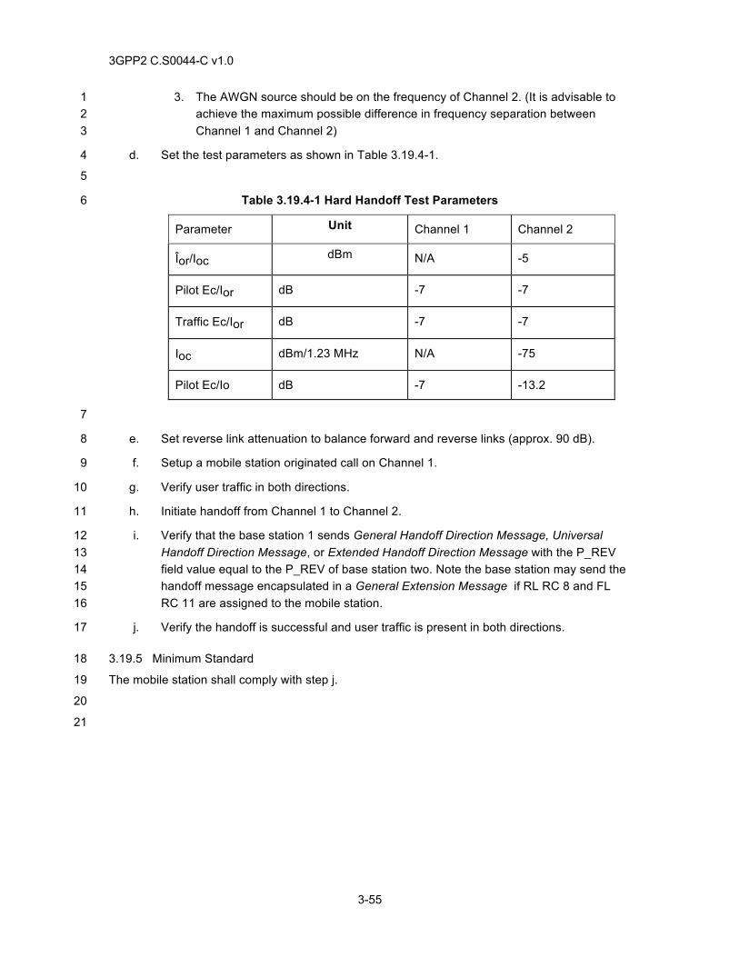
3GPP2 C.S0044-C v1.0
3-55
3. The AWGN source should be on the frequency of Channel 2. (It is advisable to 1 achieve the maximum possible difference in frequency separation between 2 Channel 1 and Channel 2) 3
d. Set the test parameters as shown in Table 3.19.4-1. 4
5
Table 3.19.4-1 Hard Handoff Test Parameters 6
Parameter Unit Channel 1 Channel 2
Îor/Ioc dBm N/A -5
Pilot Ec/Ior dB -7 -7
Traffic Ec/Ior dB -7 -7
Ioc dBm/1.23 MHz N/A -75
Pilot Ec/Io dB -7 -13.2
7
e. Set reverse link attenuation to balance forward and reverse links (approx. 90 dB). 8
f. Setup a mobile station originated call on Channel 1. 9
g. Verify user traffic in both directions. 10
h. Initiate handoff from Channel 1 to Channel 2. 11
i. Verify that the base station 1 sends General Handoff Direction Message, Universal 12 Handoff Direction Message, or Extended Handoff Direction Message with the P_REV 13 field value equal to the P_REV of base station two. Note the base station may send the 14 handoff message encapsulated in a General Extension Message if RL RC 8 and FL 15 RC 11 are assigned to the mobile station. 16
j. Verify the handoff is successful and user traffic is present in both directions. 17
3.19.5 Minimum Standard 18
The mobile station shall comply with step j. 19
20
21

3GPP2 C.S0044-C v1.0
3-56
No text.1
3GPP2 C.S0044-C v1.0
4-1
4 POWER CONTROL 1
4.1 Forward Traffic Channel Power Control 2
4.1.1 Definition 3
This test verifies that the mobile station reports frame error rate statistics at specified intervals if 4 the base station enables periodic reporting, and verifies that the mobile station reports frame error 5 rate statistics when the frame error rate reaches a specified threshold if the base station enables 6 threshold reporting. 7
4.1.2 Traceability: 8
(See[4]) 9
2.6.4.1.1 Forward Traffic Channel Power Control 10
2.7.2.3.2.6 Power Measurement Report Message 11
3.6.4.1.1 Forward Traffic Channel Power Control 12
3.7.3.3.2.10 Power Control Parameters Message 13
Applicability: Forward Link: RC 1 through RC 5, RC 11; Reverse Link: RC 1 through RC 4, RC 8 14
4.1.3 Call Flow Example(s) 15
None 16
4.1.4 Method of Measurement 17
a. Setup test as shown in Annex A Figure A-6. 18
b. Setup a mobile station originated call using the test parameters for Test 1 as specified 19 in Table 4.1.4-1. 20
c. Set the AWGN source power so the forward link average FER is between 0.5 and 21 1.0%. 22
d. Instruct the base station to send the Power Control Parameters Message to enable the 23 threshold reporting and disable the periodic reporting according to the base station 24 manufacturer's forward power control algorithm. 25
26
PWR_THRESH_ENABLE ‘1’ (Enable threshold reporting)
PWR_PERIOD_ENABLE ‘0’ (Disable periodic reporting)
27
e. Using Attenuator 1, alternately increase and decrease AWGN source output power by 5 28 dB from the original power set in step c. 29
f. Monitor forward traffic channel Ec/Ior and ensure power increases and decreases 30 corresponding to noise power from the AWGN source. 31

3GPP2 C.S0044-C v1.0
4-2
g. Monitor forward link FER at the mobile station. 1
2
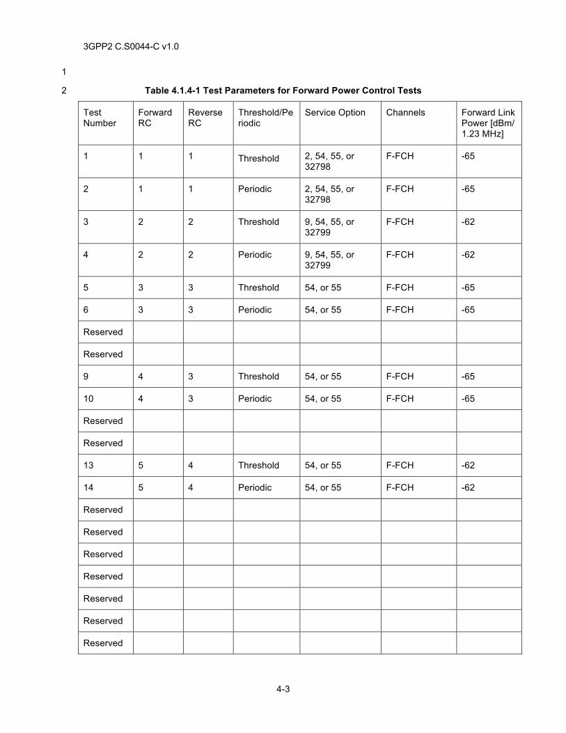
3GPP2 C.S0044-C v1.0
4-3
1
Table 4.1.4-1 Test Parameters for Forward Power Control Tests 2
Test Number
Forward RC
Reverse RC
Threshold/Periodic
Service Option Channels Forward Link Power [dBm/ 1.23 MHz]
1 1 1 Threshold 2, 54, 55, or 32798
F-FCH -65
2 1 1 Periodic 2, 54, 55, or 32798
F-FCH -65
3 2 2 Threshold 9, 54, 55, or 32799
F-FCH -62
4 2 2 Periodic 9, 54, 55, or 32799
F-FCH -62
5 3 3 Threshold 54, or 55 F-FCH -65
6 3 3 Periodic 54, or 55 F-FCH -65
Reserved
Reserved
9 4 3 Threshold 54, or 55 F-FCH -65
10 4 3 Periodic 54, or 55 F-FCH -65
Reserved
Reserved
13 5 4 Threshold 54, or 55 F-FCH -62
14 5 4 Periodic 54, or 55 F-FCH -62
Reserved
Reserved
Reserved
Reserved
Reserved
Reserved
Reserved
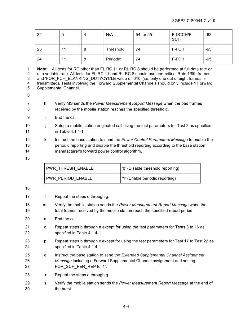
3GPP2 C.S0044-C v1.0
4-4
22 5 4 N/A 54, or 55 F-DCCH/F-SCH
-62
23 11 8 Threshold 74 F-FCH -65
24 11 8 Periodic 74 F-FCH -65
Note: All tests for RC other than FL RC 11 or RL RC 8 should be performed at full data rate or 1 at a variable rate. All tests for FL RC 11 and RL RC 8 should use non-critical Rate 1/8th frames 2 and ‘FOR_FCH_BLANKING_DUTYCYCLE value of ‘010’ (i.e. only one out of eight frames is 3 transmitted). Tests involving the Forward Supplemental Channels should only include 1 Forward 4 Supplemental Channel. 5
6
h. Verify MS sends the Power Measurement Report Message when the bad frames 7 received by the mobile station reaches the specified threshold. 8
i. End the call. 9
j. Setup a mobile station originated call using the test parameters for Test 2 as specified 10 in Table 4.1.4-1. 11
k. Instruct the base station to send the Power Control Parameters Message to enable the 12 periodic reporting and disable the threshold reporting according to the base station 13 manufacturer's forward power control algorithm. 14
15
PWR_THRESH_ENABLE ‘0’ (Disable threshold reporting)
PWR_PERIOD_ENABLE ‘1’ (Enable periodic reporting)
16
l. Repeat the steps e through g. 17
m. Verify the mobile station sends the Power Measurement Report Message when the 18 total frames received by the mobile station reach the specified report period. 19
n. End the call. 20
o. Repeat steps b through n except for using the test parameters for Tests 3 to 16 as 21 specified in Table 4.1.4-1. 22
p. Repeat steps b through c except for using the test parameters for Test 17 to Test 22 as 23 specified in Table 4.1.4-1. 24
q. Instruct the base station to send the Extended Supplemental Channel Assignment 25 Message including a Forward Supplemental Channel assignment and setting 26 FOR_SCH_FER_REP to ‘1’. 27
r. Repeat the steps e through g. 28
s. Verify the mobile station sends the Power Measurement Report Message at the end of 29 the burst. 30
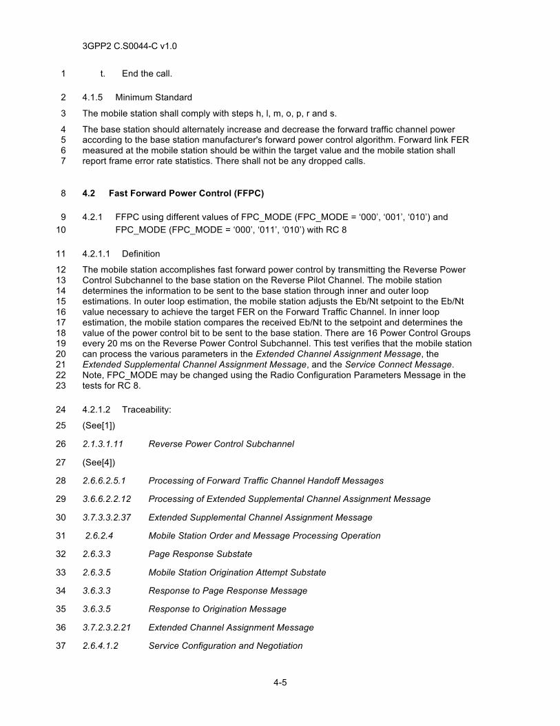
3GPP2 C.S0044-C v1.0
4-5
t. End the call. 1
4.1.5 Minimum Standard 2
The mobile station shall comply with steps h, l, m, o, p, r and s. 3
The base station should alternately increase and decrease the forward traffic channel power 4 according to the base station manufacturer's forward power control algorithm. Forward link FER 5 measured at the mobile station should be within the target value and the mobile station shall 6 report frame error rate statistics. There shall not be any dropped calls. 7
4.2 Fast Forward Power Control (FFPC) 8
4.2.1 FFPC using different values of FPC_MODE (FPC_MODE = ‘000’, ‘001’, ‘010’) and 9 FPC_MODE (FPC_MODE = ‘000’, ‘011’, ‘010’) with RC 8 10
4.2.1.1 Definition 11
The mobile station accomplishes fast forward power control by transmitting the Reverse Power 12 Control Subchannel to the base station on the Reverse Pilot Channel. The mobile station 13 determines the information to be sent to the base station through inner and outer loop 14 estimations. In outer loop estimation, the mobile station adjusts the Eb/Nt setpoint to the Eb/Nt 15 value necessary to achieve the target FER on the Forward Traffic Channel. In inner loop 16 estimation, the mobile station compares the received Eb/Nt to the setpoint and determines the 17 value of the power control bit to be sent to the base station. There are 16 Power Control Groups 18 every 20 ms on the Reverse Power Control Subchannel. This test verifies that the mobile station 19 can process the various parameters in the Extended Channel Assignment Message, the 20 Extended Supplemental Channel Assignment Message, and the Service Connect Message. 21 Note, FPC_MODE may be changed using the Radio Configuration Parameters Message in the 22 tests for RC 8. 23
4.2.1.2 Traceability: 24
(See[1]) 25
2.1.3.1.11 Reverse Power Control Subchannel 26
(See[4]) 27
2.6.6.2.5.1 Processing of Forward Traffic Channel Handoff Messages 28
3.6.6.2.2.12 Processing of Extended Supplemental Channel Assignment Message 29
3.7.3.3.2.37 Extended Supplemental Channel Assignment Message 30
2.6.2.4 Mobile Station Order and Message Processing Operation 31
2.6.3.3 Page Response Substate 32
2.6.3.5 Mobile Station Origination Attempt Substate 33
3.6.3.3 Response to Page Response Message 34
3.6.3.5 Response to Origination Message 35
3.7.2.3.2.21 Extended Channel Assignment Message 36
2.6.4.1.2 Service Configuration and Negotiation 37
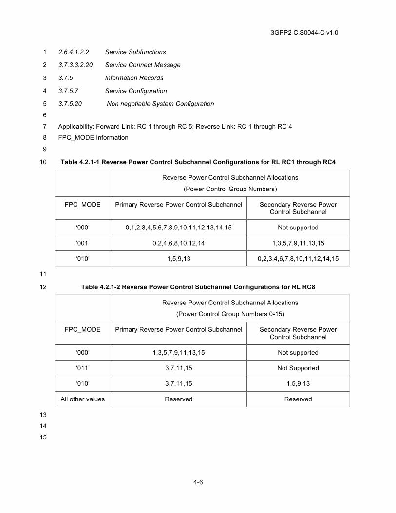
3GPP2 C.S0044-C v1.0
4-6
2.6.4.1.2.2 Service Subfunctions 1
3.7.3.3.2.20 Service Connect Message 2
3.7.5 Information Records 3
3.7.5.7 Service Configuration 4
3.7.5.20 Non negotiable System Configuration 5
6
Applicability: Forward Link: RC 1 through RC 5; Reverse Link: RC 1 through RC 4 7
FPC_MODE Information 8
9
Table 4.2.1-1 Reverse Power Control Subchannel Configurations for RL RC1 through RC4 10
Reverse Power Control Subchannel Allocations
(Power Control Group Numbers)
FPC_MODE Primary Reverse Power Control Subchannel Secondary Reverse Power Control Subchannel
‘000’ 0,1,2,3,4,5,6,7,8,9,10,11,12,13,14,15 Not supported
‘001’ 0,2,4,6,8,10,12,14 1,3,5,7,9,11,13,15
‘010’ 1,5,9,13 0,2,3,4,6,7,8,10,11,12,14,15
11
Table 4.2.1-2 Reverse Power Control Subchannel Configurations for RL RC8 12
Reverse Power Control Subchannel Allocations
(Power Control Group Numbers 0-15)
FPC_MODE Primary Reverse Power Control Subchannel Secondary Reverse Power Control Subchannel
‘000’ 1,3,5,7,9,11,13,15 Not supported
‘011’ 3,7,11,15 Not Supported
‘010’ 3,7,11,15 1,5,9,13
All other values Reserved Reserved
13
14
15
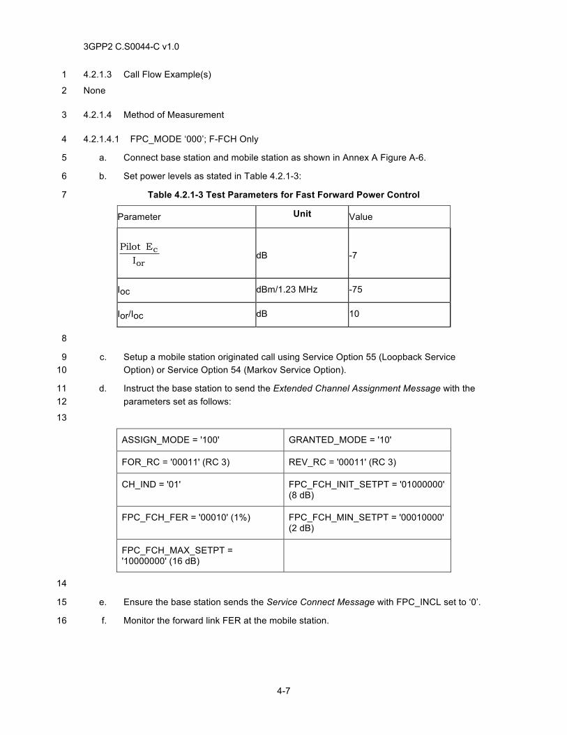
3GPP2 C.S0044-C v1.0
4-7
4.2.1.3 Call Flow Example(s) 1
None 2
4.2.1.4 Method of Measurement 3
4.2.1.4.1 FPC_MODE ‘000’; F-FCH Only 4
a. Connect base station and mobile station as shown in Annex A Figure A-6. 5
b. Set power levels as stated in Table 4.2.1-3: 6
Table 4.2.1-3 Test Parameters for Fast Forward Power Control 7
Parameter Unit Value
or
cI
EPilot
dB
-7
Ioc dBm/1.23 MHz -75
Ior/Ioc dB 10
8
c. Setup a mobile station originated call using Service Option 55 (Loopback Service 9 Option) or Service Option 54 (Markov Service Option). 10
d. Instruct the base station to send the Extended Channel Assignment Message with the 11 parameters set as follows: 12
13
ASSIGN_MODE = '100' GRANTED_MODE = '10'
FOR_RC = '00011' (RC 3) REV_RC = '00011' (RC 3)
CH_IND = '01' FPC_FCH_INIT_SETPT = '01000000' (8 dB)
FPC_FCH_FER = '00010' (1%) FPC_FCH_MIN_SETPT = '00010000' (2 dB)
FPC_FCH_MAX_SETPT = '10000000' (16 dB)
14
e. Ensure the base station sends the Service Connect Message with FPC_INCL set to ‘0’. 15
f. Monitor the forward link FER at the mobile station. 16
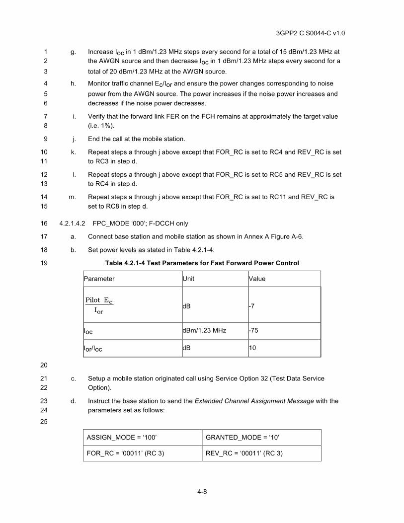
3GPP2 C.S0044-C v1.0
4-8
g. Increase Ioc in 1 dBm/1.23 MHz steps every second for a total of 15 dBm/1.23 MHz at 1 the AWGN source and then decrease Ioc in 1 dBm/1.23 MHz steps every second for a 2 total of 20 dBm/1.23 MHz at the AWGN source. 3
h. Monitor traffic channel Ec/Ior and ensure the power changes corresponding to noise 4 power from the AWGN source. The power increases if the noise power increases and 5 decreases if the noise power decreases. 6
i. Verify that the forward link FER on the FCH remains at approximately the target value 7 (i.e. 1%). 8
j. End the call at the mobile station. 9
k. Repeat steps a through j above except that FOR_RC is set to RC4 and REV_RC is set 10 to RC3 in step d. 11
l. Repeat steps a through j above except that FOR_RC is set to RC5 and REV_RC is set 12 to RC4 in step d. 13
m. Repeat steps a through j above except that FOR_RC is set to RC11 and REV_RC is 14 set to RC8 in step d. 15
4.2.1.4.2 FPC_MODE ‘000’; F-DCCH only 16
a. Connect base station and mobile station as shown in Annex A Figure A-6. 17
b. Set power levels as stated in Table 4.2.1-4: 18
Table 4.2.1-4 Test Parameters for Fast Forward Power Control 19
Parameter Unit Value
or
cI
EPilot
dB
-7
Ioc dBm/1.23 MHz -75
Ior/Ioc dB 10
20
c. Setup a mobile station originated call using Service Option 32 (Test Data Service 21 Option). 22
d. Instruct the base station to send the Extended Channel Assignment Message with the 23 parameters set as follows: 24
25
ASSIGN_MODE = ‘100’ GRANTED_MODE = ‘10’
FOR_RC = ‘00011’ (RC 3) REV_RC = ‘00011’ (RC 3)
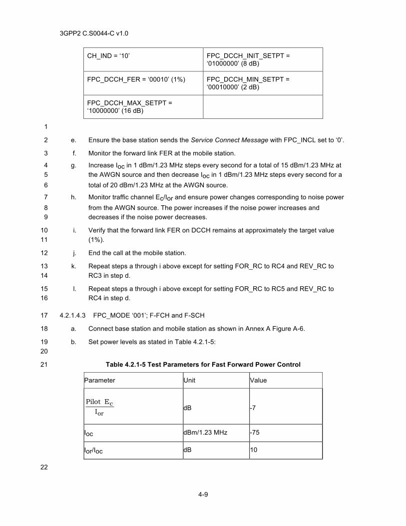
3GPP2 C.S0044-C v1.0
4-9
CH_IND = ‘10’ FPC_DCCH_INIT_SETPT = ‘01000000’ (8 dB)
FPC_DCCH_FER = ‘00010’ (1%) FPC_DCCH_MIN_SETPT = ‘00010000’ (2 dB)
FPC_DCCH_MAX_SETPT = ‘10000000’ (16 dB)
1
e. Ensure the base station sends the Service Connect Message with FPC_INCL set to ‘0’. 2
f. Monitor the forward link FER at the mobile station. 3
g. Increase Ioc in 1 dBm/1.23 MHz steps every second for a total of 15 dBm/1.23 MHz at 4 the AWGN source and then decrease Ioc in 1 dBm/1.23 MHz steps every second for a 5 total of 20 dBm/1.23 MHz at the AWGN source. 6
h. Monitor traffic channel Ec/Ior and ensure power changes corresponding to noise power 7 from the AWGN source. The power increases if the noise power increases and 8 decreases if the noise power decreases. 9
i. Verify that the forward link FER on DCCH remains at approximately the target value 10 (1%). 11
j. End the call at the mobile station. 12
k. Repeat steps a through i above except for setting FOR_RC to RC4 and REV_RC to 13 RC3 in step d. 14
l. Repeat steps a through i above except for setting FOR_RC to RC5 and REV_RC to 15 RC4 in step d. 16
4.2.1.4.3 FPC_MODE ‘001’; F-FCH and F-SCH 17
a. Connect base station and mobile station as shown in Annex A Figure A-6. 18
b. Set power levels as stated in Table 4.2.1-5: 19 20
Table 4.2.1-5 Test Parameters for Fast Forward Power Control 21
Parameter Unit Value
or
cI
EPilot
dB
-7
Ioc dBm/1.23 MHz -75
Ior/Ioc dB 10
22
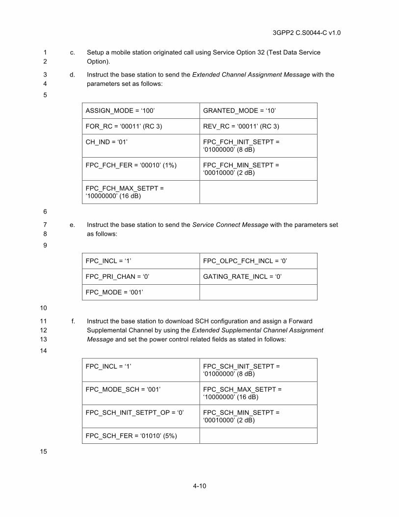
3GPP2 C.S0044-C v1.0
4-10
c. Setup a mobile station originated call using Service Option 32 (Test Data Service 1 Option). 2
d. Instruct the base station to send the Extended Channel Assignment Message with the 3 parameters set as follows: 4
5
ASSIGN_MODE = ‘100’ GRANTED_MODE = ‘10’
FOR_RC = ‘00011’ (RC 3) REV_RC = ‘00011’ (RC 3)
CH_IND = ‘01’ FPC_FCH_INIT_SETPT = ‘01000000’ (8 dB)
FPC_FCH_FER = ‘00010’ (1%) FPC_FCH_MIN_SETPT = ‘00010000’ (2 dB)
FPC_FCH_MAX_SETPT = ‘10000000’ (16 dB)
6
e. Instruct the base station to send the Service Connect Message with the parameters set 7 as follows: 8
9
FPC_INCL = ‘1’ FPC_OLPC_FCH_INCL = ‘0’
FPC_PRI_CHAN = ‘0’ GATING_RATE_INCL = ‘0’
FPC_MODE = ‘001’
10
f. Instruct the base station to download SCH configuration and assign a Forward 11 Supplemental Channel by using the Extended Supplemental Channel Assignment 12 Message and set the power control related fields as stated in follows: 13
14
FPC_INCL = ‘1’ FPC_SCH_INIT_SETPT = ‘01000000’ (8 dB)
FPC_MODE_SCH = ‘001’ FPC_SCH_MAX_SETPT = ‘10000000’ (16 dB)
FPC_SCH_INIT_SETPT_OP = ‘0’ FPC_SCH_MIN_SETPT = ‘00010000’ (2 dB)
FPC_SCH_FER = ‘01010’ (5%)
15
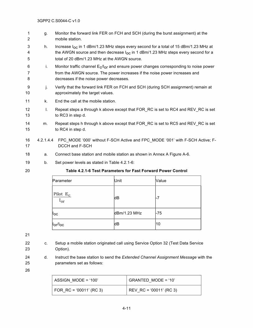
3GPP2 C.S0044-C v1.0
4-11
g. Monitor the forward link FER on FCH and SCH (during the burst assignment) at the 1 mobile station. 2
h. Increase Ioc in 1 dBm/1.23 MHz steps every second for a total of 15 dBm/1.23 MHz at 3 the AWGN source and then decrease Ioc in 1 dBm/1.23 MHz steps every second for a 4 total of 20 dBm/1.23 MHz at the AWGN source. 5
i. Monitor traffic channel Ec/Ior and ensure power changes corresponding to noise power 6 from the AWGN source. The power increases if the noise power increases and 7 decreases if the noise power decreases. 8
j. Verify that the forward link FER on FCH and SCH (during SCH assignment) remain at 9 approximately the target values. 10
k. End the call at the mobile station. 11
l. Repeat steps a through k above except that FOR_RC is set to RC4 and REV_RC is set 12 to RC3 in step d. 13
m. Repeat steps h through k above except that FOR_RC is set to RC5 and REV_RC is set 14 to RC4 in step d. 15
4.2.1.4.4 FPC_MODE ‘000’ without F-SCH Active and FPC_MODE ‘001’ with F-SCH Active; F-16 DCCH and F-SCH 17
a. Connect base station and mobile station as shown in Annex A Figure A-6. 18
b. Set power levels as stated in Table 4.2.1-6: 19
Table 4.2.1-6 Test Parameters for Fast Forward Power Control 20
Parameter Unit Value
or
cI
EPilot
dB
-7
Ioc dBm/1.23 MHz -75
Ior/Ioc dB 10
21
c. Setup a mobile station originated call using Service Option 32 (Test Data Service 22 Option). 23
d. Instruct the base station to send the Extended Channel Assignment Message with the 24 parameters set as follows: 25
26
ASSIGN_MODE = ‘100’ GRANTED_MODE = ‘10’
FOR_RC = ‘00011’ (RC 3) REV_RC = ‘00011’ (RC 3)
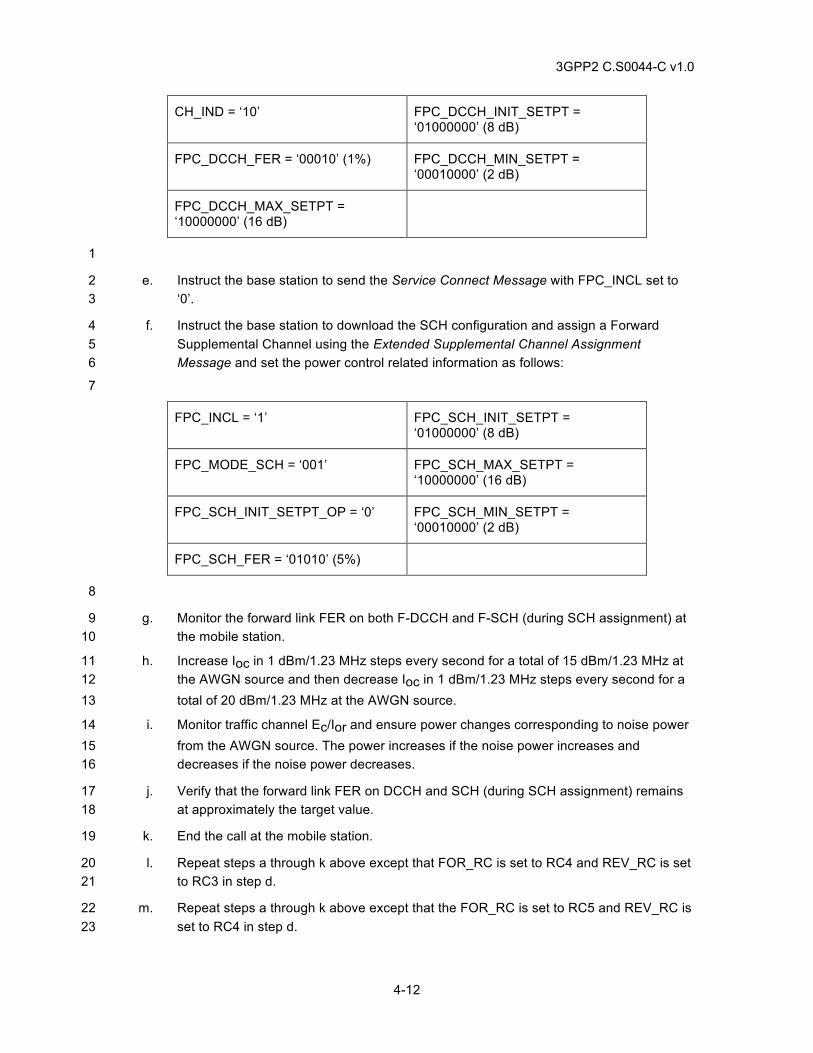
3GPP2 C.S0044-C v1.0
4-12
CH_IND = ‘10’ FPC_DCCH_INIT_SETPT = ‘01000000’ (8 dB)
FPC_DCCH_FER = ‘00010’ (1%) FPC_DCCH_MIN_SETPT = ‘00010000’ (2 dB)
FPC_DCCH_MAX_SETPT = ‘10000000’ (16 dB)
1
e. Instruct the base station to send the Service Connect Message with FPC_INCL set to 2 ‘0’. 3
f. Instruct the base station to download the SCH configuration and assign a Forward 4 Supplemental Channel using the Extended Supplemental Channel Assignment 5 Message and set the power control related information as follows: 6
7
FPC_INCL = ‘1’ FPC_SCH_INIT_SETPT = ‘01000000’ (8 dB)
FPC_MODE_SCH = ‘001’ FPC_SCH_MAX_SETPT = ‘10000000’ (16 dB)
FPC_SCH_INIT_SETPT_OP = ‘0’ FPC_SCH_MIN_SETPT = ‘00010000’ (2 dB)
FPC_SCH_FER = ‘01010’ (5%)
8
g. Monitor the forward link FER on both F-DCCH and F-SCH (during SCH assignment) at 9 the mobile station. 10
h. Increase Ioc in 1 dBm/1.23 MHz steps every second for a total of 15 dBm/1.23 MHz at 11 the AWGN source and then decrease Ioc in 1 dBm/1.23 MHz steps every second for a 12 total of 20 dBm/1.23 MHz at the AWGN source. 13
i. Monitor traffic channel Ec/Ior and ensure power changes corresponding to noise power 14 from the AWGN source. The power increases if the noise power increases and 15 decreases if the noise power decreases. 16
j. Verify that the forward link FER on DCCH and SCH (during SCH assignment) remains 17 at approximately the target value. 18
k. End the call at the mobile station. 19
l. Repeat steps a through k above except that FOR_RC is set to RC4 and REV_RC is set 20 to RC3 in step d. 21
m. Repeat steps a through k above except that the FOR_RC is set to RC5 and REV_RC is 22 set to RC4 in step d. 23
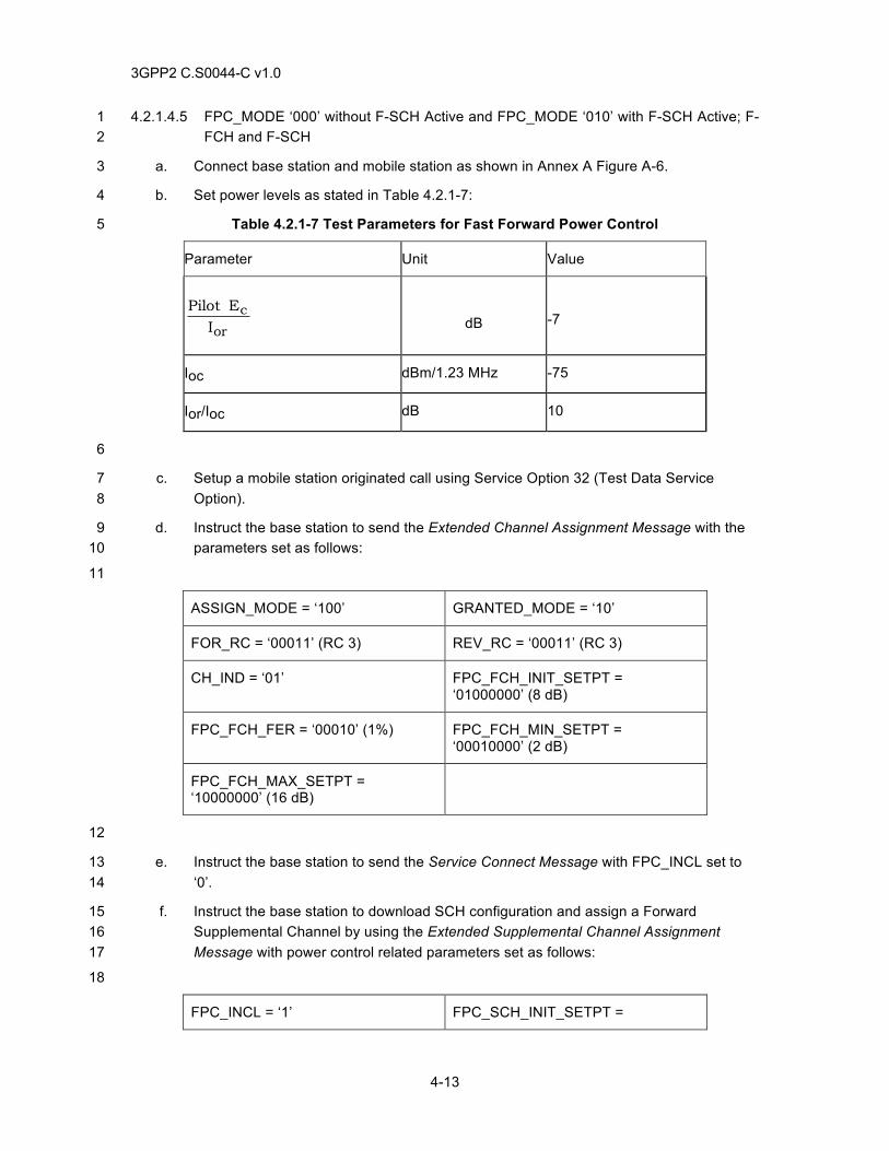
3GPP2 C.S0044-C v1.0
4-13
4.2.1.4.5 FPC_MODE ‘000’ without F-SCH Active and FPC_MODE ‘010’ with F-SCH Active; F-1 FCH and F-SCH 2
a. Connect base station and mobile station as shown in Annex A Figure A-6. 3
b. Set power levels as stated in Table 4.2.1-7: 4
Table 4.2.1-7 Test Parameters for Fast Forward Power Control 5
Parameter Unit Value
or
cI
EPilot
dB
-7
Ioc dBm/1.23 MHz -75
Ior/Ioc dB 10
6
c. Setup a mobile station originated call using Service Option 32 (Test Data Service 7 Option). 8
d. Instruct the base station to send the Extended Channel Assignment Message with the 9 parameters set as follows: 10
11
ASSIGN_MODE = ‘100’ GRANTED_MODE = ‘10’
FOR_RC = ‘00011’ (RC 3) REV_RC = ‘00011’ (RC 3)
CH_IND = ‘01’ FPC_FCH_INIT_SETPT = ‘01000000’ (8 dB)
FPC_FCH_FER = ‘00010’ (1%) FPC_FCH_MIN_SETPT = ‘00010000’ (2 dB)
FPC_FCH_MAX_SETPT = ‘10000000’ (16 dB)
12
e. Instruct the base station to send the Service Connect Message with FPC_INCL set to 13 ‘0’. 14
f. Instruct the base station to download SCH configuration and assign a Forward 15 Supplemental Channel by using the Extended Supplemental Channel Assignment 16 Message with power control related parameters set as follows: 17
18
FPC_INCL = ‘1’ FPC_SCH_INIT_SETPT =
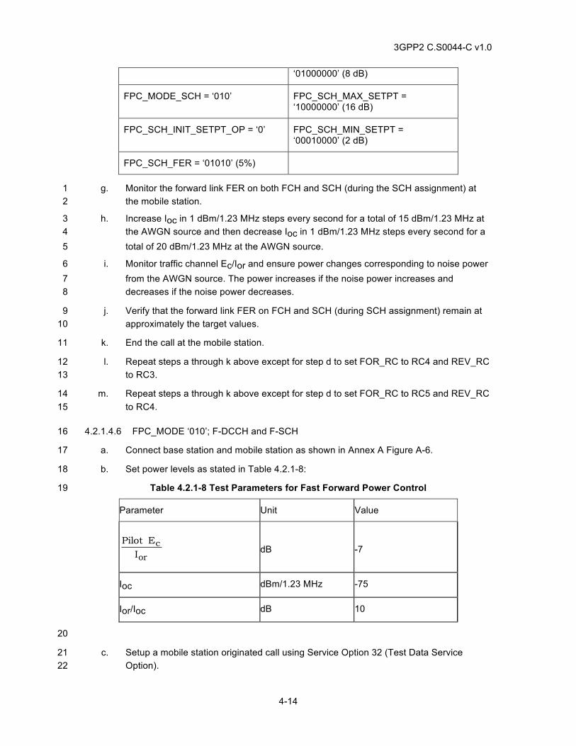
3GPP2 C.S0044-C v1.0
4-14
‘01000000’ (8 dB)
FPC_MODE_SCH = ‘010’ FPC_SCH_MAX_SETPT = ‘10000000’ (16 dB)
FPC_SCH_INIT_SETPT_OP = ‘0’ FPC_SCH_MIN_SETPT = ‘00010000’ (2 dB)
FPC_SCH_FER = ‘01010’ (5%)
g. Monitor the forward link FER on both FCH and SCH (during the SCH assignment) at 1 the mobile station. 2
h. Increase Ioc in 1 dBm/1.23 MHz steps every second for a total of 15 dBm/1.23 MHz at 3 the AWGN source and then decrease Ioc in 1 dBm/1.23 MHz steps every second for a 4 total of 20 dBm/1.23 MHz at the AWGN source. 5
i. Monitor traffic channel Ec/Ior and ensure power changes corresponding to noise power 6 from the AWGN source. The power increases if the noise power increases and 7 decreases if the noise power decreases. 8
j. Verify that the forward link FER on FCH and SCH (during SCH assignment) remain at 9 approximately the target values. 10
k. End the call at the mobile station. 11
l. Repeat steps a through k above except for step d to set FOR_RC to RC4 and REV_RC 12 to RC3. 13
m. Repeat steps a through k above except for step d to set FOR_RC to RC5 and REV_RC 14 to RC4. 15
4.2.1.4.6 FPC_MODE ‘010’; F-DCCH and F-SCH 16
a. Connect base station and mobile station as shown in Annex A Figure A-6. 17
b. Set power levels as stated in Table 4.2.1-8: 18
Table 4.2.1-8 Test Parameters for Fast Forward Power Control 19
Parameter Unit Value
or
cI
EPilot
dB
-7
Ioc dBm/1.23 MHz -75
Ior/Ioc dB 10
20
c. Setup a mobile station originated call using Service Option 32 (Test Data Service 21 Option). 22
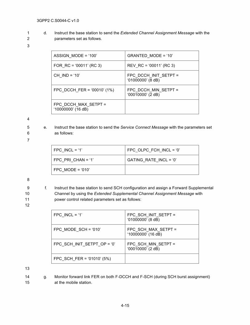
3GPP2 C.S0044-C v1.0
4-15
d. Instruct the base station to send the Extended Channel Assignment Message with the 1 parameters set as follows. 2
3
ASSIGN_MODE = ‘100’ GRANTED_MODE = ‘10’
FOR_RC = ‘00011’ (RC 3) REV_RC = ‘00011’ (RC 3)
CH_IND = ‘10’ FPC_DCCH_INIT_SETPT = ‘01000000’ (8 dB)
FPC_DCCH_FER = ‘00010’ (1%) FPC_DCCH_MIN_SETPT = ‘00010000’ (2 dB)
FPC_DCCH_MAX_SETPT = ‘10000000’ (16 dB)
4
e. Instruct the base station to send the Service Connect Message with the parameters set 5 as follows: 6
7
FPC_INCL = ‘1’ FPC_OLPC_FCH_INCL = ‘0’
FPC_PRI_CHAN = ‘1’ GATING_RATE_INCL = ‘0’
FPC_MODE = ‘010’
8
f. Instruct the base station to send SCH configuration and assign a Forward Supplemental 9 Channel by using the Extended Supplemental Channel Assignment Message with 10 power control related parameters set as follows: 11 12
FPC_INCL = ‘1’ FPC_SCH_INIT_SETPT = ‘01000000’ (8 dB)
FPC_MODE_SCH = ‘010’ FPC_SCH_MAX_SETPT = ‘10000000’ (16 dB)
FPC_SCH_INIT_SETPT_OP = ‘0’ FPC_SCH_MIN_SETPT = ‘00010000’ (2 dB)
FPC_SCH_FER = ‘01010’ (5%)
13
g. Monitor forward link FER on both F-DCCH and F-SCH (during SCH burst assignment) 14 at the mobile station. 15
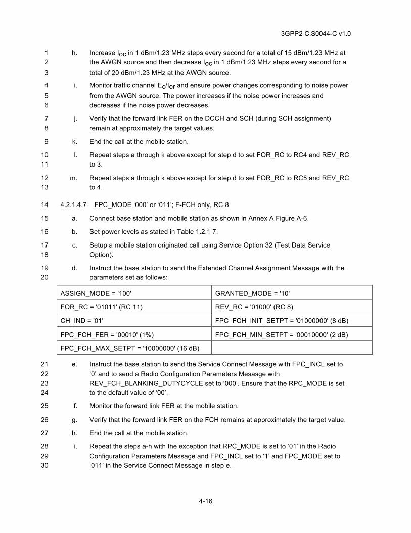
3GPP2 C.S0044-C v1.0
4-16
h. Increase Ioc in 1 dBm/1.23 MHz steps every second for a total of 15 dBm/1.23 MHz at 1 the AWGN source and then decrease Ioc in 1 dBm/1.23 MHz steps every second for a 2 total of 20 dBm/1.23 MHz at the AWGN source. 3
i. Monitor traffic channel Ec/Ior and ensure power changes corresponding to noise power 4 from the AWGN source. The power increases if the noise power increases and 5 decreases if the noise power decreases. 6
j. Verify that the forward link FER on the DCCH and SCH (during SCH assignment) 7 remain at approximately the target values. 8
k. End the call at the mobile station. 9
l. Repeat steps a through k above except for step d to set FOR_RC to RC4 and REV_RC 10 to 3. 11
m. Repeat steps a through k above except for step d to set FOR_RC to RC5 and REV_RC 12 to 4. 13
4.2.1.4.7 FPC_MODE ‘000’ or ‘011’; F-FCH only, RC 8 14
a. Connect base station and mobile station as shown in Annex A Figure A-6. 15
b. Set power levels as stated in Table 1.2.1 7. 16
c. Setup a mobile station originated call using Service Option 32 (Test Data Service 17 Option). 18
d. Instruct the base station to send the Extended Channel Assignment Message with the 19 parameters set as follows: 20
ASSIGN_MODE = '100' GRANTED_MODE = '10'
FOR_RC = '01011' (RC 11) REV_RC = '01000' (RC 8)
CH_IND = '01' FPC_FCH_INIT_SETPT = '01000000' (8 dB)
FPC_FCH_FER = '00010' (1%) FPC_FCH_MIN_SETPT = '00010000' (2 dB)
FPC_FCH_MAX_SETPT = '10000000' (16 dB)
e. Instruct the base station to send the Service Connect Message with FPC_INCL set to 21 ‘0’ and to send a Radio Configuration Parameters Mesasge with 22 REV_FCH_BLANKING_DUTYCYCLE set to ‘000’. Ensure that the RPC_MODE is set 23 to the default value of ‘00’. 24
f. Monitor the forward link FER at the mobile station. 25
g. Verify that the forward link FER on the FCH remains at approximately the target value. 26
h. End the call at the mobile station. 27
i. Repeat the steps a-h with the exception that RPC_MODE is set to ‘01’ in the Radio 28 Configuration Parameters Message and FPC_INCL set to ‘1’ and FPC_MODE set to 29 ‘011’ in the Service Connect Message in step e. 30
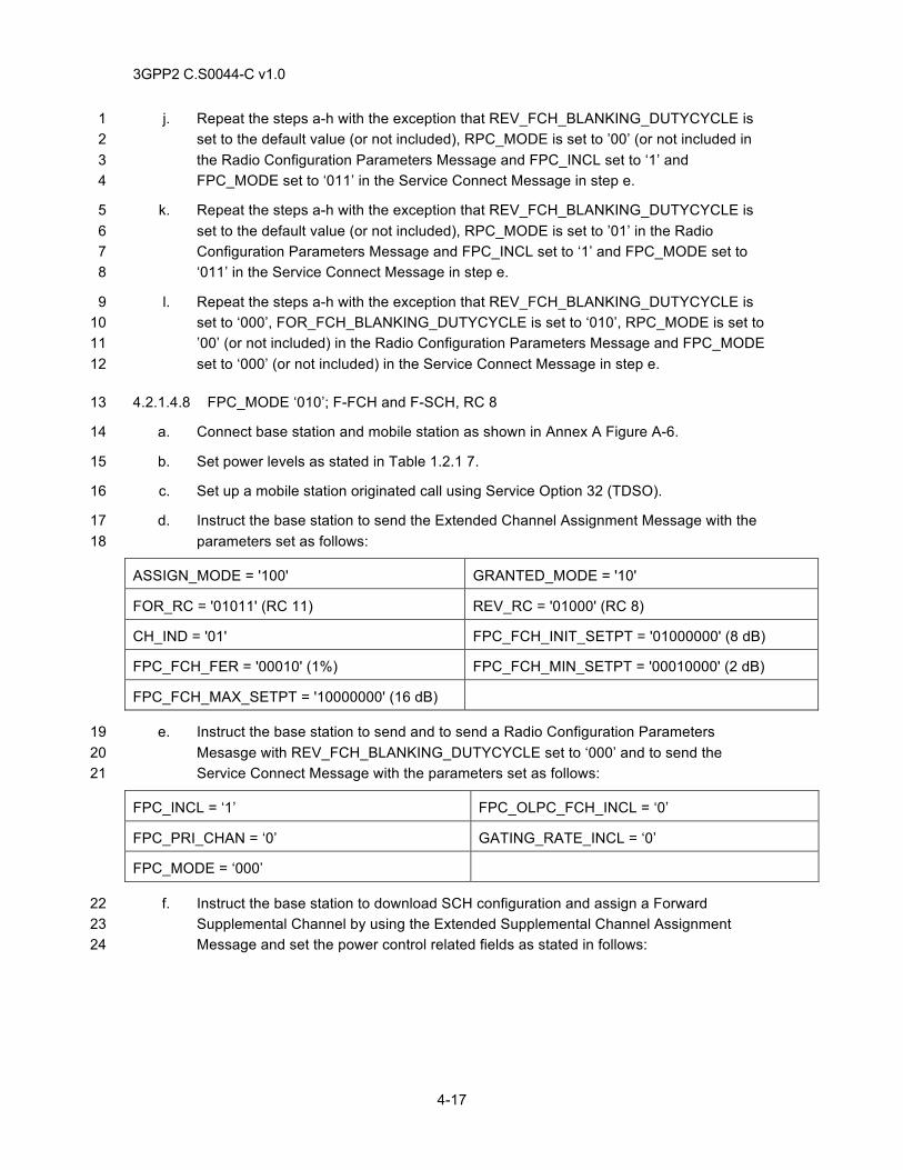
3GPP2 C.S0044-C v1.0
4-17
j. Repeat the steps a-h with the exception that REV_FCH_BLANKING_DUTYCYCLE is 1 set to the default value (or not included), RPC_MODE is set to ’00’ (or not included in 2 the Radio Configuration Parameters Message and FPC_INCL set to ‘1’ and 3 FPC_MODE set to ‘011’ in the Service Connect Message in step e. 4
k. Repeat the steps a-h with the exception that REV_FCH_BLANKING_DUTYCYCLE is 5 set to the default value (or not included), RPC_MODE is set to ’01’ in the Radio 6 Configuration Parameters Message and FPC_INCL set to ‘1’ and FPC_MODE set to 7 ‘011’ in the Service Connect Message in step e. 8
l. Repeat the steps a-h with the exception that REV_FCH_BLANKING_DUTYCYCLE is 9 set to ‘000’, FOR_FCH_BLANKING_DUTYCYCLE is set to ‘010’, RPC_MODE is set to 10 ’00’ (or not included) in the Radio Configuration Parameters Message and FPC_MODE 11 set to ‘000’ (or not included) in the Service Connect Message in step e. 12
4.2.1.4.8 FPC_MODE ‘010’; F-FCH and F-SCH, RC 8 13
a. Connect base station and mobile station as shown in Annex A Figure A-6. 14
b. Set power levels as stated in Table 1.2.1 7. 15
c. Set up a mobile station originated call using Service Option 32 (TDSO). 16
d. Instruct the base station to send the Extended Channel Assignment Message with the 17 parameters set as follows: 18
ASSIGN_MODE = '100' GRANTED_MODE = '10'
FOR_RC = '01011' (RC 11) REV_RC = '01000' (RC 8)
CH_IND = '01' FPC_FCH_INIT_SETPT = '01000000' (8 dB)
FPC_FCH_FER = '00010' (1%) FPC_FCH_MIN_SETPT = '00010000' (2 dB)
FPC_FCH_MAX_SETPT = '10000000' (16 dB)
e. Instruct the base station to send and to send a Radio Configuration Parameters 19 Mesasge with REV_FCH_BLANKING_DUTYCYCLE set to ‘000’ and to send the 20 Service Connect Message with the parameters set as follows: 21
FPC_INCL = ‘1’ FPC_OLPC_FCH_INCL = ‘0’
FPC_PRI_CHAN = ‘0’ GATING_RATE_INCL = ‘0’
FPC_MODE = ‘000’
f. Instruct the base station to download SCH configuration and assign a Forward 22 Supplemental Channel by using the Extended Supplemental Channel Assignment 23 Message and set the power control related fields as stated in follows: 24
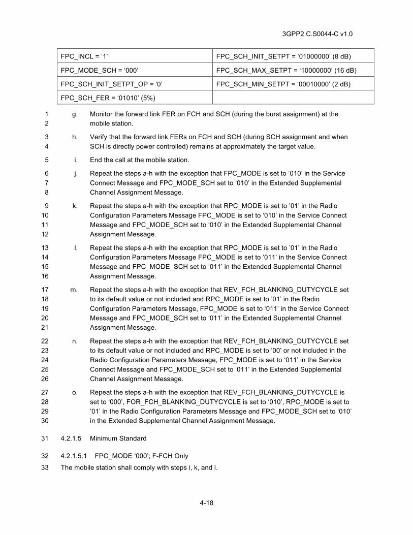
3GPP2 C.S0044-C v1.0
4-18
FPC_INCL = ‘1’ FPC_SCH_INIT_SETPT = ‘01000000’ (8 dB)
FPC_MODE_SCH = ‘000’ FPC_SCH_MAX_SETPT = ‘10000000’ (16 dB)
FPC_SCH_INIT_SETPT_OP = ‘0’ FPC_SCH_MIN_SETPT = ‘00010000’ (2 dB)
FPC_SCH_FER = ‘01010’ (5%)
g. Monitor the forward link FER on FCH and SCH (during the burst assignment) at the 1 mobile station. 2
h. Verify that the forward link FERs on FCH and SCH (during SCH assignment and when 3 SCH is directly power controlled) remains at approximately the target value. 4
i. End the call at the mobile station. 5
j. Repeat the steps a-h with the exception that FPC_MODE is set to ‘010’ in the Service 6 Connect Message and FPC_MODE_SCH set to ‘010’ in the Extended Supplemental 7 Channel Assignment Message. 8
k. Repeat the steps a-h with the exception that RPC_MODE is set to ’01’ in the Radio 9 Configuration Parameters Message FPC_MODE is set to ‘010’ in the Service Connect 10 Message and FPC_MODE_SCH set to ‘010’ in the Extended Supplemental Channel 11 Assignment Message. 12
l. Repeat the steps a-h with the exception that RPC_MODE is set to ’01’ in the Radio 13 Configuration Parameters Message FPC_MODE is set to ‘011’ in the Service Connect 14 Message and FPC_MODE_SCH set to ‘011’ in the Extended Supplemental Channel 15 Assignment Message. 16
m. Repeat the steps a-h with the exception that REV_FCH_BLANKING_DUTYCYCLE set 17 to its default value or not included and RPC_MODE is set to ’01’ in the Radio 18 Configuration Parameters Message, FPC_MODE is set to ‘011’ in the Service Connect 19 Message and FPC_MODE_SCH set to ‘011’ in the Extended Supplemental Channel 20 Assignment Message. 21
n. Repeat the steps a-h with the exception that REV_FCH_BLANKING_DUTYCYCLE set 22 to its default value or not included and RPC_MODE is set to ’00’ or not included in the 23 Radio Configuration Parameters Message, FPC_MODE is set to ‘011’ in the Service 24 Connect Message and FPC_MODE_SCH set to ‘011’ in the Extended Supplemental 25 Channel Assignment Message. 26
o. Repeat the steps a-h with the exception that REV_FCH_BLANKING_DUTYCYCLE is 27 set to ‘000’, FOR_FCH_BLANKING_DUTYCYCLE is set to ‘010’, RPC_MODE is set to 28 ’01’ in the Radio Configuration Parameters Message and FPC_MODE_SCH set to ‘010’ 29 in the Extended Supplemental Channel Assignment Message. 30
4.2.1.5 Minimum Standard 31
4.2.1.5.1 FPC_MODE ‘000’; F-FCH Only 32
The mobile station shall comply with steps i, k, and l. 33
3GPP2 C.S0044-C v1.0
4-19
4.2.1.5.2 FPC_MODE ‘000’; F-DCCH only 1
The mobile station shall comply with steps i, k, and l. 2
4.2.1.5.3 FPC_MODE ‘001’; F-FCH and F-SCH 3
The mobile station shall comply with steps j, l, and m. 4
4.2.1.5.4 FPC_MODE ‘000’ without F-SCH Active and FPC_MODE ‘001’ with F-SCH Active; F-5 DCCH and F-SCH 6
The mobile station shall comply with steps j, l, and m. 7
4.2.1.5.5 FPC_MODE ‘000’ without F-SCH Active and FPC_MODE ‘010’ with F-SCH Active; F-8 FCH and F-SCH 9
The mobile station shall comply with steps j, l, and m. 10
4.2.1.5.6 FPC_MODE ‘010’; F-DCCH and F-SCH 11
The mobile station shall comply with steps j, l, and m. 12
4.2.1.5.7 FPC_MODE ‘000’ or ‘011’; F-FCH Only, RC 8 13
The mobile station shall comply with step g. 14
4.2.1.5.8 FPC_MODE ‘010’; F-FCH and F-SCH, RC 8 15
The mobile station shall comply with step h. 16
17
4.2.2 Outer Loop Report 18
4.2.2.1 Definition 19
This test verifies that the mobile station shall send the Outer Loop Report Message if the Outer 20 Loop Report Request Order is received. Note, FPC_MODE may be changed using the Radio 21 Configuration Parameters Message in the tests for RC 8. 22
4.2.2.2 Traceability: 23
(See[1]) 24
2.1.3.1.10 Reverse Power Control Subchannel 25
(See[4]) 26
2.6.6.2.5.1 Processing of Forward Traffic Channel Handoff Messages 27
3.6.6.2.212 Processing of Extended Supplemental Channel Assignment Message 28
3.7.3.3.2.37 Extended Supplemental Channel Assignment Message 29
2.6.2.4 Mobile Station Order and Message Processing Operation 30
2.6.3.3 Page Response Substate 31
2.6.3.5 Mobile Station Origination Attempt Substate 32
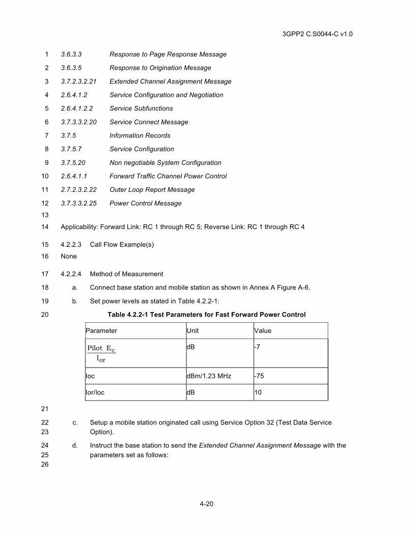
3GPP2 C.S0044-C v1.0
4-20
3.6.3.3 Response to Page Response Message 1
3.6.3.5 Response to Origination Message 2
3.7.2.3.2.21 Extended Channel Assignment Message 3
2.6.4.1.2 Service Configuration and Negotiation 4
2.6.4.1.2.2 Service Subfunctions 5
3.7.3.3.2.20 Service Connect Message 6
3.7.5 Information Records 7
3.7.5.7 Service Configuration 8
3.7.5.20 Non negotiable System Configuration 9
2.6.4.1.1 Forward Traffic Channel Power Control 10
2.7.2.3.2.22 Outer Loop Report Message 11
3.7.3.3.2.25 Power Control Message 12
13
Applicability: Forward Link: RC 1 through RC 5; Reverse Link: RC 1 through RC 4 14
4.2.2.3 Call Flow Example(s) 15
None 16
4.2.2.4 Method of Measurement 17
a. Connect base station and mobile station as shown in Annex A Figure A-6. 18
b. Set power levels as stated in Table 4.2.2-1: 19
Table 4.2.2-1 Test Parameters for Fast Forward Power Control 20
Parameter Unit Value
or
cI
EPilot
dB -7
Ioc dBm/1.23 MHz -75
Ior/Ioc dB 10
21
c. Setup a mobile station originated call using Service Option 32 (Test Data Service 22 Option). 23
d. Instruct the base station to send the Extended Channel Assignment Message with the 24 parameters set as follows: 25 26
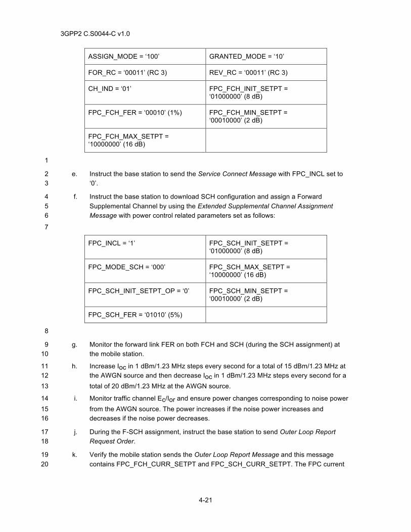
3GPP2 C.S0044-C v1.0
4-21
ASSIGN_MODE = ‘100’ GRANTED_MODE = ‘10’
FOR_RC = ‘00011’ (RC 3) REV_RC = ‘00011’ (RC 3)
CH_IND = ‘01’ FPC_FCH_INIT_SETPT = ‘01000000’ (8 dB)
FPC_FCH_FER = ‘00010’ (1%) FPC_FCH_MIN_SETPT = ‘00010000’ (2 dB)
FPC_FCH_MAX_SETPT = ‘10000000’ (16 dB)
1
e. Instruct the base station to send the Service Connect Message with FPC_INCL set to 2 ‘0’. 3
f. Instruct the base station to download SCH configuration and assign a Forward 4 Supplemental Channel by using the Extended Supplemental Channel Assignment 5 Message with power control related parameters set as follows: 6
7
FPC_INCL = ‘1’ FPC_SCH_INIT_SETPT = ‘01000000’ (8 dB)
FPC_MODE_SCH = ‘000’ FPC_SCH_MAX_SETPT = ‘10000000’ (16 dB)
FPC_SCH_INIT_SETPT_OP = ‘0’ FPC_SCH_MIN_SETPT = ‘00010000’ (2 dB)
FPC_SCH_FER = ‘01010’ (5%)
8
g. Monitor the forward link FER on both FCH and SCH (during the SCH assignment) at 9 the mobile station. 10
h. Increase Ioc in 1 dBm/1.23 MHz steps every second for a total of 15 dBm/1.23 MHz at 11 the AWGN source and then decrease Ioc in 1 dBm/1.23 MHz steps every second for a 12 total of 20 dBm/1.23 MHz at the AWGN source. 13
i. Monitor traffic channel Ec/Ior and ensure power changes corresponding to noise power 14 from the AWGN source. The power increases if the noise power increases and 15 decreases if the noise power decreases. 16
j. During the F-SCH assignment, instruct the base station to send Outer Loop Report 17 Request Order. 18
k. Verify the mobile station sends the Outer Loop Report Message and this message 19 contains FPC_FCH_CURR_SETPT and FPC_SCH_CURR_SETPT. The FPC current 20
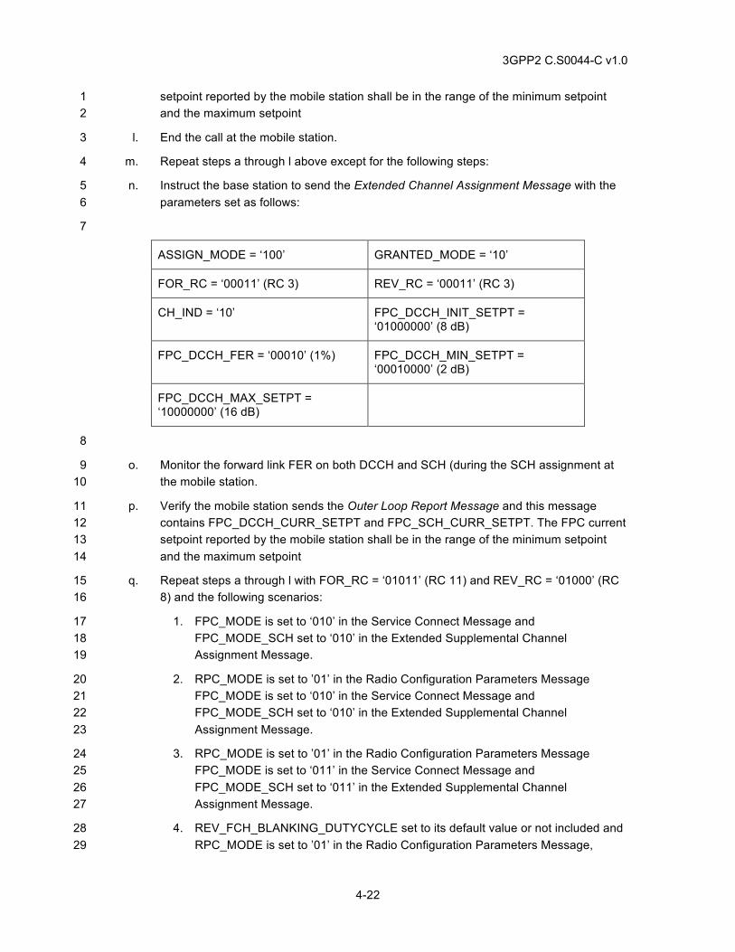
3GPP2 C.S0044-C v1.0
4-22
setpoint reported by the mobile station shall be in the range of the minimum setpoint 1 and the maximum setpoint 2
l. End the call at the mobile station. 3
m. Repeat steps a through l above except for the following steps: 4
n. Instruct the base station to send the Extended Channel Assignment Message with the 5 parameters set as follows: 6
7
ASSIGN_MODE = ‘100’ GRANTED_MODE = ‘10’
FOR_RC = ‘00011’ (RC 3) REV_RC = ‘00011’ (RC 3)
CH_IND = ‘10’ FPC_DCCH_INIT_SETPT = ‘01000000’ (8 dB)
FPC_DCCH_FER = ‘00010’ (1%) FPC_DCCH_MIN_SETPT = ‘00010000’ (2 dB)
FPC_DCCH_MAX_SETPT = ‘10000000’ (16 dB)
8
o. Monitor the forward link FER on both DCCH and SCH (during the SCH assignment at 9 the mobile station. 10
p. Verify the mobile station sends the Outer Loop Report Message and this message 11 contains FPC_DCCH_CURR_SETPT and FPC_SCH_CURR_SETPT. The FPC current 12 setpoint reported by the mobile station shall be in the range of the minimum setpoint 13 and the maximum setpoint 14
q. Repeat steps a through l with FOR_RC = ‘01011’ (RC 11) and REV_RC = ‘01000’ (RC 15 8) and the following scenarios: 16
1. FPC_MODE is set to ‘010’ in the Service Connect Message and 17 FPC_MODE_SCH set to ‘010’ in the Extended Supplemental Channel 18 Assignment Message. 19
2. RPC_MODE is set to ’01’ in the Radio Configuration Parameters Message 20 FPC_MODE is set to ‘010’ in the Service Connect Message and 21 FPC_MODE_SCH set to ‘010’ in the Extended Supplemental Channel 22 Assignment Message. 23
3. RPC_MODE is set to ’01’ in the Radio Configuration Parameters Message 24 FPC_MODE is set to ‘011’ in the Service Connect Message and 25 FPC_MODE_SCH set to ‘011’ in the Extended Supplemental Channel 26 Assignment Message. 27
4. REV_FCH_BLANKING_DUTYCYCLE set to its default value or not included and 28 RPC_MODE is set to ’01’ in the Radio Configuration Parameters Message, 29
3GPP2 C.S0044-C v1.0
4-23
FPC_MODE is set to ‘011’ in the Service Connect Message and 1 FPC_MODE_SCH set to ‘011’ in the Extended Supplemental Channel 2 Assignment Message. 3
5. REV_FCH_BLANKING_DUTYCYCLE set to its default value or not included and 4 RPC_MODE is set to ’00’ or not included in the Radio Configuration Parameters 5 Message, FPC_MODE is set to ‘011’ in the Service Connect Message and 6 FPC_MODE_SCH set to ‘011’ in the Extended Supplemental Channel 7 Assignment Message. 8
4.2.2.5 Minimum Standard 9
The mobile station shall comply with steps k, m, and p. 10
4.2.3 Fast Forward Power Control (FFPC) in Soft Handoff 11
4.2.3.1 Definition 12
The mobile station accomplishes fast forward power control by transmitting the Reverse Power 13 Control Subchannel to the base station on the Reverse Pilot Channel. The mobile station 14 determines the information to send to the base station through inner and outer closed loop 15 estimations. In outer loop estimation, the mobile station adjusts the Eb/Nt setpoints to the Eb/Nt 16 value necessary to achieve the target FER on the Forward Traffic Channel. In inner loop 17 estimation, the mobile station compares the received Eb/Nt to the setpoint and determines the 18 value of the power control bit to be sent to the base station. This test verifies that the mobile 19 station can perform FFPC while in soft handoff. This test also verifies that the mobile station can 20 process the various parameters in the Extended Channel Assignment Message, the Extended 21 Supplemental Channel Assignment Message, the Universal Handoff Direction Message, and the 22 Service Connect Message. 23
4.2.3.2 Traceability: 24
(See[1]) 25
2.1.3.1.11 Reverse Power Control Subchannel 26
(See[4]) 27
2.6.6.2.5.1 Processing of Forward Traffic Channel Handoff Messages 28
3.6.6.2.2.12 Processing of Extended Supplemental Channel Assignment Message 29
3.7.3.3.2.37 Extended Supplemental Channel Assignment Message 30
2.6.2.4 Mobile Station Order and Message Processing Operation 31
2.6.3.3 Page Response Substate 32
2.6.3.5 Mobile Station Origination Attempt Substate 33
3.6.3.3 Response to Page Response Message 34
3.6.3.5 Response to Origination Message 35
3.7.2.3.2.21 Extended Channel Assignment Message 36
2.6.4.1.2 Service Configuration and Negotiation 37
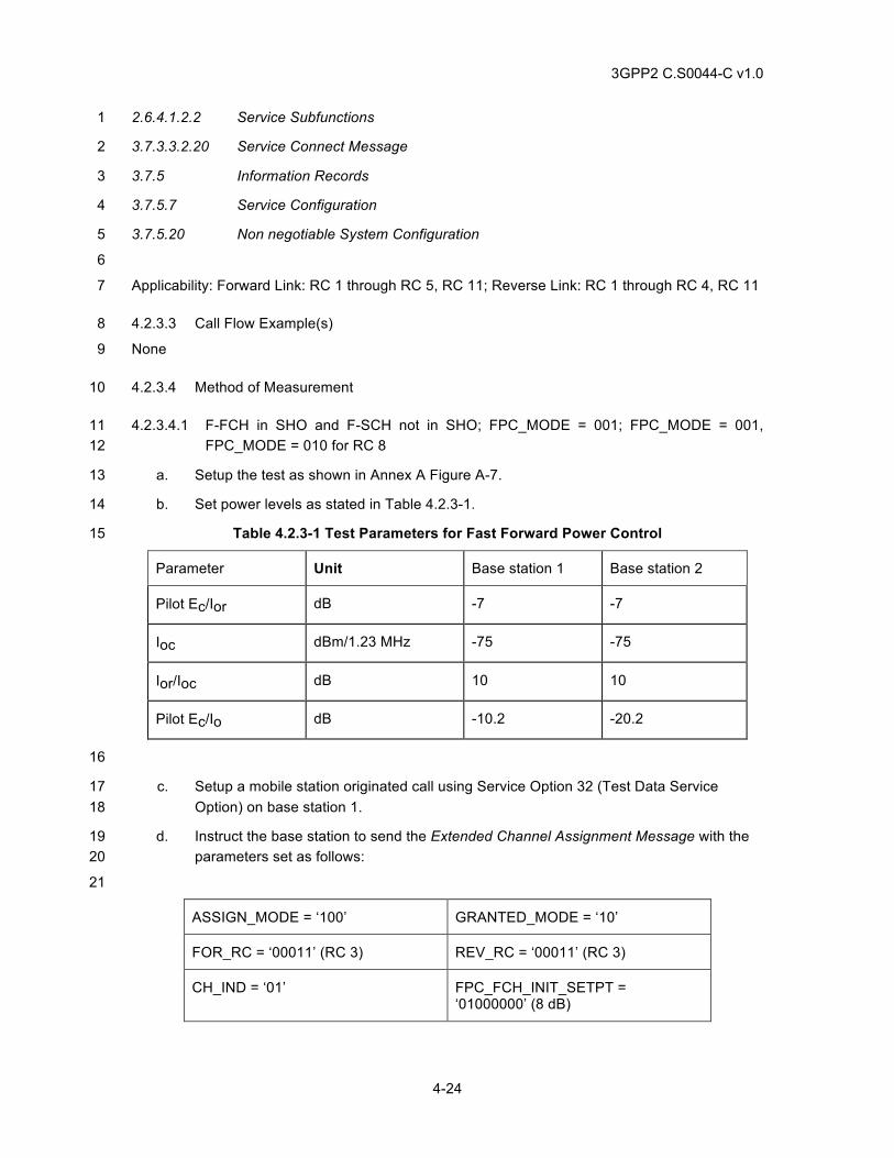
3GPP2 C.S0044-C v1.0
4-24
2.6.4.1.2.2 Service Subfunctions 1
3.7.3.3.2.20 Service Connect Message 2
3.7.5 Information Records 3
3.7.5.7 Service Configuration 4
3.7.5.20 Non negotiable System Configuration 5
6
Applicability: Forward Link: RC 1 through RC 5, RC 11; Reverse Link: RC 1 through RC 4, RC 11 7
4.2.3.3 Call Flow Example(s) 8
None 9
4.2.3.4 Method of Measurement 10
4.2.3.4.1 F-FCH in SHO and F-SCH not in SHO; FPC_MODE = 001; FPC_MODE = 001, 11 FPC_MODE = 010 for RC 8 12
a. Setup the test as shown in Annex A Figure A-7. 13
b. Set power levels as stated in Table 4.2.3-1. 14
Table 4.2.3-1 Test Parameters for Fast Forward Power Control 15
Parameter Unit Base station 1 Base station 2
Pilot Ec/Ior dB -7 -7
Ioc dBm/1.23 MHz -75 -75
Ior/Ioc dB 10 10
Pilot Ec/Io dB -10.2 -20.2
16
c. Setup a mobile station originated call using Service Option 32 (Test Data Service 17 Option) on base station 1. 18
d. Instruct the base station to send the Extended Channel Assignment Message with the 19 parameters set as follows: 20
21
ASSIGN_MODE = ‘100’ GRANTED_MODE = ‘10’
FOR_RC = ‘00011’ (RC 3) REV_RC = ‘00011’ (RC 3)
CH_IND = ‘01’ FPC_FCH_INIT_SETPT = ‘01000000’ (8 dB)
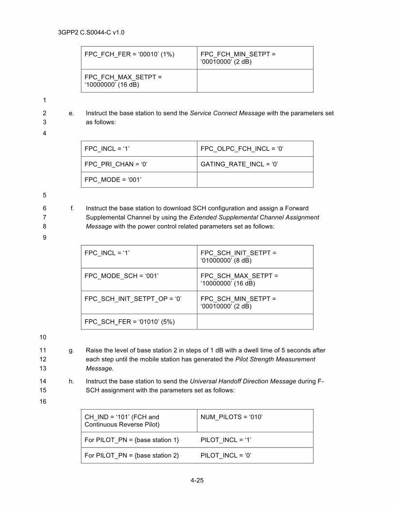
3GPP2 C.S0044-C v1.0
4-25
FPC_FCH_FER = ‘00010’ (1%) FPC_FCH_MIN_SETPT = ‘00010000’ (2 dB)
FPC_FCH_MAX_SETPT = ‘10000000’ (16 dB)
1
e. Instruct the base station to send the Service Connect Message with the parameters set 2 as follows: 3
4
FPC_INCL = ‘1’ FPC_OLPC_FCH_INCL = ‘0’
FPC_PRI_CHAN = ‘0’ GATING_RATE_INCL = ‘0’
FPC_MODE = ‘001’
5
f. Instruct the base station to download SCH configuration and assign a Forward 6 Supplemental Channel by using the Extended Supplemental Channel Assignment 7 Message with the power control related parameters set as follows: 8
9
FPC_INCL = ‘1’ FPC_SCH_INIT_SETPT = ‘01000000’ (8 dB)
FPC_MODE_SCH = ‘001’ FPC_SCH_MAX_SETPT = ‘10000000’ (16 dB)
FPC_SCH_INIT_SETPT_OP = ‘0’ FPC_SCH_MIN_SETPT = ‘00010000’ (2 dB)
FPC_SCH_FER = ‘01010’ (5%)
10
g. Raise the level of base station 2 in steps of 1 dB with a dwell time of 5 seconds after 11 each step until the mobile station has generated the Pilot Strength Measurement 12 Message. 13
h. Instruct the base station to send the Universal Handoff Direction Message during F-14 SCH assignment with the parameters set as follows: 15
16
CH_IND = ‘101’ (FCH and Continuous Reverse Pilot)
NUM_PILOTS = ‘010’
For PILOT_PN = {base station 1} PILOT_INCL = ‘1’
For PILOT_PN = {base station 2} PILOT_INCL = ‘0’
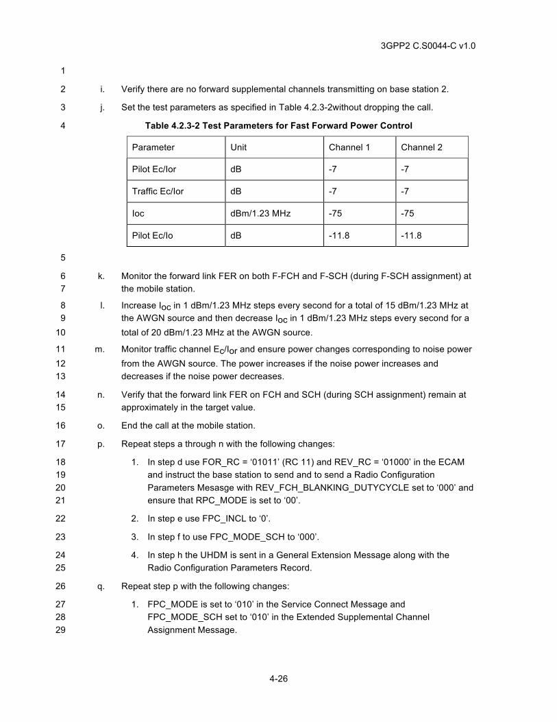
3GPP2 C.S0044-C v1.0
4-26
1
i. Verify there are no forward supplemental channels transmitting on base station 2. 2
j. Set the test parameters as specified in Table 4.2.3-2without dropping the call. 3
Table 4.2.3-2 Test Parameters for Fast Forward Power Control 4
Parameter Unit Channel 1 Channel 2
Pilot Ec/Ior dB -7 -7
Traffic Ec/Ior dB -7 -7
Ioc dBm/1.23 MHz -75 -75
Pilot Ec/Io dB -11.8 -11.8
5
k. Monitor the forward link FER on both F-FCH and F-SCH (during F-SCH assignment) at 6 the mobile station. 7
l. Increase Ioc in 1 dBm/1.23 MHz steps every second for a total of 15 dBm/1.23 MHz at 8 the AWGN source and then decrease Ioc in 1 dBm/1.23 MHz steps every second for a 9 total of 20 dBm/1.23 MHz at the AWGN source. 10
m. Monitor traffic channel Ec/Ior and ensure power changes corresponding to noise power 11 from the AWGN source. The power increases if the noise power increases and 12 decreases if the noise power decreases. 13
n. Verify that the forward link FER on FCH and SCH (during SCH assignment) remain at 14 approximately in the target value. 15
o. End the call at the mobile station. 16
p. Repeat steps a through n with the following changes: 17
1. In step d use FOR_RC = ‘01011’ (RC 11) and REV_RC = ‘01000’ in the ECAM 18 and instruct the base station to send and to send a Radio Configuration 19 Parameters Mesasge with REV_FCH_BLANKING_DUTYCYCLE set to ‘000’ and 20 ensure that RPC_MODE is set to ‘00’. 21
2. In step e use FPC_INCL to ‘0’. 22
3. In step f to use FPC_MODE_SCH to ‘000’. 23
4. In step h the UHDM is sent in a General Extension Message along with the 24 Radio Configuration Parameters Record. 25
q. Repeat step p with the following changes: 26
1. FPC_MODE is set to ‘010’ in the Service Connect Message and 27 FPC_MODE_SCH set to ‘010’ in the Extended Supplemental Channel 28 Assignment Message. 29
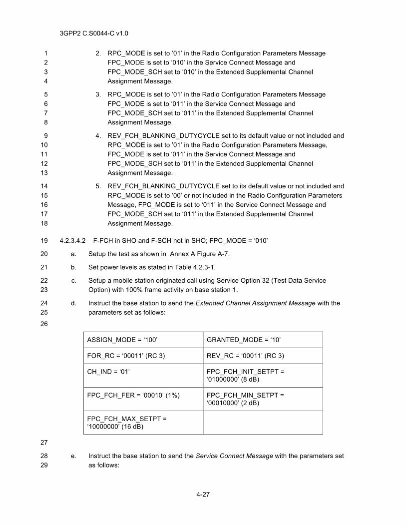
3GPP2 C.S0044-C v1.0
4-27
2. RPC_MODE is set to ’01’ in the Radio Configuration Parameters Message 1 FPC_MODE is set to ‘010’ in the Service Connect Message and 2 FPC_MODE_SCH set to ‘010’ in the Extended Supplemental Channel 3 Assignment Message. 4
3. RPC_MODE is set to ’01’ in the Radio Configuration Parameters Message 5 FPC_MODE is set to ‘011’ in the Service Connect Message and 6 FPC_MODE_SCH set to ‘011’ in the Extended Supplemental Channel 7 Assignment Message. 8
4. REV_FCH_BLANKING_DUTYCYCLE set to its default value or not included and 9 RPC_MODE is set to ’01’ in the Radio Configuration Parameters Message, 10 FPC_MODE is set to ‘011’ in the Service Connect Message and 11 FPC_MODE_SCH set to ‘011’ in the Extended Supplemental Channel 12 Assignment Message. 13
5. REV_FCH_BLANKING_DUTYCYCLE set to its default value or not included and 14 RPC_MODE is set to ’00’ or not included in the Radio Configuration Parameters 15 Message, FPC_MODE is set to ‘011’ in the Service Connect Message and 16 FPC_MODE_SCH set to ‘011’ in the Extended Supplemental Channel 17 Assignment Message. 18
4.2.3.4.2 F-FCH in SHO and F-SCH not in SHO; FPC_MODE = ‘010’ 19
a. Setup the test as shown in Annex A Figure A-7. 20
b. Set power levels as stated in Table 4.2.3-1. 21
c. Setup a mobile station originated call using Service Option 32 (Test Data Service 22 Option) with 100% frame activity on base station 1. 23
d. Instruct the base station to send the Extended Channel Assignment Message with the 24 parameters set as follows: 25
26
ASSIGN_MODE = ‘100’ GRANTED_MODE = ‘10’
FOR_RC = ‘00011’ (RC 3) REV_RC = ‘00011’ (RC 3)
CH_IND = ‘01’ FPC_FCH_INIT_SETPT = ‘01000000’ (8 dB)
FPC_FCH_FER = ‘00010’ (1%) FPC_FCH_MIN_SETPT = ‘00010000’ (2 dB)
FPC_FCH_MAX_SETPT = ‘10000000’ (16 dB)
27
e. Instruct the base station to send the Service Connect Message with the parameters set 28 as follows: 29
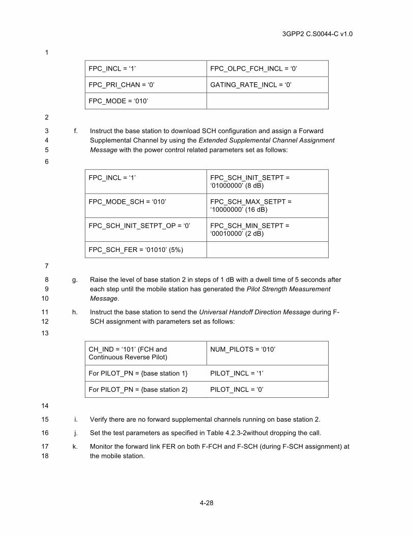
3GPP2 C.S0044-C v1.0
4-28
1
FPC_INCL = ‘1’ FPC_OLPC_FCH_INCL = ‘0’
FPC_PRI_CHAN = ‘0’ GATING_RATE_INCL = ‘0’
FPC_MODE = ‘010’
2
f. Instruct the base station to download SCH configuration and assign a Forward 3 Supplemental Channel by using the Extended Supplemental Channel Assignment 4 Message with the power control related parameters set as follows: 5
6
FPC_INCL = ‘1’ FPC_SCH_INIT_SETPT = ‘01000000’ (8 dB)
FPC_MODE_SCH = ‘010’ FPC_SCH_MAX_SETPT = ‘10000000’ (16 dB)
FPC_SCH_INIT_SETPT_OP = ‘0’ FPC_SCH_MIN_SETPT = ‘00010000’ (2 dB)
FPC_SCH_FER = ‘01010’ (5%)
7
g. Raise the level of base station 2 in steps of 1 dB with a dwell time of 5 seconds after 8 each step until the mobile station has generated the Pilot Strength Measurement 9 Message. 10
h. Instruct the base station to send the Universal Handoff Direction Message during F-11 SCH assignment with parameters set as follows: 12
13
CH_IND = ‘101’ (FCH and Continuous Reverse Pilot)
NUM_PILOTS = ‘010’
For PILOT_PN = {base station 1} PILOT_INCL = ‘1’
For PILOT_PN = {base station 2} PILOT_INCL = ‘0’
14
i. Verify there are no forward supplemental channels running on base station 2. 15
j. Set the test parameters as specified in Table 4.2.3-2without dropping the call. 16
k. Monitor the forward link FER on both F-FCH and F-SCH (during F-SCH assignment) at 17 the mobile station. 18
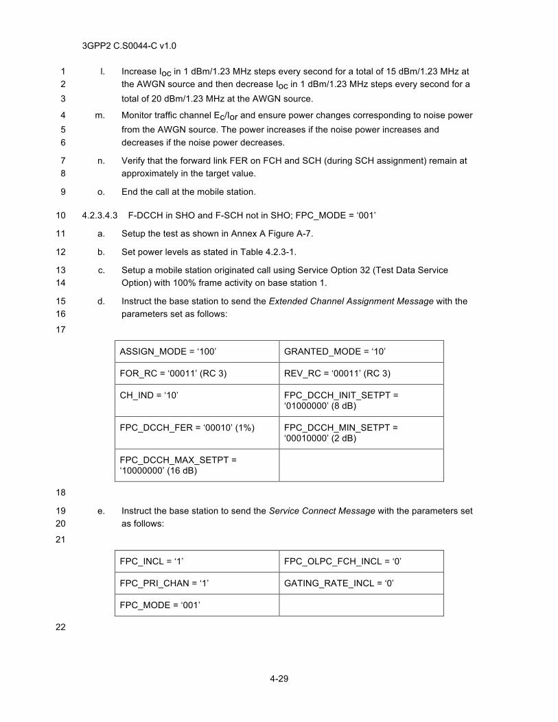
3GPP2 C.S0044-C v1.0
4-29
l. Increase Ioc in 1 dBm/1.23 MHz steps every second for a total of 15 dBm/1.23 MHz at 1 the AWGN source and then decrease Ioc in 1 dBm/1.23 MHz steps every second for a 2 total of 20 dBm/1.23 MHz at the AWGN source. 3
m. Monitor traffic channel Ec/Ior and ensure power changes corresponding to noise power 4 from the AWGN source. The power increases if the noise power increases and 5 decreases if the noise power decreases. 6
n. Verify that the forward link FER on FCH and SCH (during SCH assignment) remain at 7 approximately in the target value. 8
o. End the call at the mobile station. 9
4.2.3.4.3 F-DCCH in SHO and F-SCH not in SHO; FPC_MODE = ‘001’ 10
a. Setup the test as shown in Annex A Figure A-7. 11
b. Set power levels as stated in Table 4.2.3-1. 12
c. Setup a mobile station originated call using Service Option 32 (Test Data Service 13 Option) with 100% frame activity on base station 1. 14
d. Instruct the base station to send the Extended Channel Assignment Message with the 15 parameters set as follows: 16
17
ASSIGN_MODE = ‘100’ GRANTED_MODE = ‘10’
FOR_RC = ‘00011’ (RC 3) REV_RC = ‘00011’ (RC 3)
CH_IND = ‘10’ FPC_DCCH_INIT_SETPT = ‘01000000’ (8 dB)
FPC_DCCH_FER = ‘00010’ (1%) FPC_DCCH_MIN_SETPT = ‘00010000’ (2 dB)
FPC_DCCH_MAX_SETPT = ‘10000000’ (16 dB)
18
e. Instruct the base station to send the Service Connect Message with the parameters set 19 as follows: 20
21
FPC_INCL = ‘1’ FPC_OLPC_FCH_INCL = ‘0’
FPC_PRI_CHAN = ‘1’ GATING_RATE_INCL = ‘0’
FPC_MODE = ‘001’
22
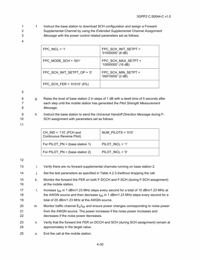
3GPP2 C.S0044-C v1.0
4-30
f. Instruct the base station to download SCH configuration and assign a Forward 1 Supplemental Channel by using the Extended Supplemental Channel Assignment 2 Message with the power control related parameters set as follows: 3
4
FPC_INCL = ‘1’ FPC_SCH_INIT_SETPT = ‘01000000’ (8 dB)
FPC_MODE_SCH = ‘001’ FPC_SCH_MAX_SETPT = ‘10000000’ (16 dB)
FPC_SCH_INIT_SETPT_OP = ‘0’ FPC_SCH_MIN_SETPT = ‘00010000’ (2 dB)
FPC_SCH_FER = ‘01010’ (5%)
5
g. Raise the level of base station 2 in steps of 1 dB with a dwell time of 5 seconds after 6 each step until the mobile station has generated the Pilot Strength Measurement 7 Message. 8
h. Instruct the base station to send the Universal Handoff Direction Message during F-9 SCH assignment with parameters set as follows: 10
11
CH_IND = ‘110’ (FCH and Continuous Reverse Pilot)
NUM_PILOTS = ‘010’
For PILOT_PN = {base station 1} PILOT_INCL = ‘1’
For PILOT_PN = {base station 2} PILOT_INCL = ‘0’
12
i. Verify there are no forward supplemental channels running on base station 2. 13
j. Set the test parameters as specified in Table 4.2.3-2without dropping the call. 14
k. Monitor the forward link FER on both F-DCCH and F-SCH (during F-SCH assignment) 15 at the mobile station. 16
l. Increase Ioc in 1 dBm/1.23 MHz steps every second for a total of 15 dBm/1.23 MHz at 17 the AWGN source and then decrease Ioc in 1 dBm/1.23 MHz steps every second for a 18 total of 20 dBm/1.23 MHz at the AWGN source. 19
m. Monitor traffic channel Ec/Ior and ensure power changes corresponding to noise power 20 from the AWGN source. The power increases if the noise power increases and 21 decreases if the noise power decreases. 22
n. Verify that the forward link FER on DCCH and SCH (during SCH assignment) remain at 23 approximately in the target value. 24
o. End the call at the mobile station. 25
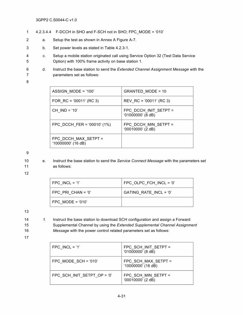
3GPP2 C.S0044-C v1.0
4-31
4.2.3.4.4 F-DCCH in SHO and F-SCH not in SHO; FPC_MODE = ‘010’ 1
a. Setup the test as shown in Annex A Figure A-7. 2
b. Set power levels as stated in Table 4.2.3-1. 3
c. Setup a mobile station originated call using Service Option 32 (Test Data Service 4 Option) with 100% frame activity on base station 1. 5
d. Instruct the base station to send the Extended Channel Assignment Message with the 6 parameters set as follows: 7
8
ASSIGN_MODE = ‘100’ GRANTED_MODE = 10
FOR_RC = ‘00011’ (RC 3) REV_RC = ‘00011’ (RC 3)
CH_IND = ‘10’ FPC_DCCH_INIT_SETPT = ‘01000000’ (8 dB)
FPC_DCCH_FER = ‘00010’ (1%) FPC_DCCH_MIN_SETPT = ‘00010000’ (2 dB)
FPC_DCCH_MAX_SETPT = ‘10000000’ (16 dB)
9
e. Instruct the base station to send the Service Connect Message with the parameters set 10 as follows: 11
12
FPC_INCL = ‘1’ FPC_OLPC_FCH_INCL = ‘0’
FPC_PRI_CHAN = ‘0’ GATING_RATE_INCL = ‘0’
FPC_MODE = ‘010’
13
f. Instruct the base station to download SCH configuration and assign a Forward 14 Supplemental Channel by using the Extended Supplemental Channel Assignment 15 Message with the power control related parameters set as follows: 16
17
FPC_INCL = ‘1’ FPC_SCH_INIT_SETPT = ‘01000000’ (8 dB)
FPC_MODE_SCH = ‘010’ FPC_SCH_MAX_SETPT = ‘10000000’ (16 dB)
FPC_SCH_INIT_SETPT_OP = ‘0’ FPC_SCH_MIN_SETPT = ‘00010000’ (2 dB)
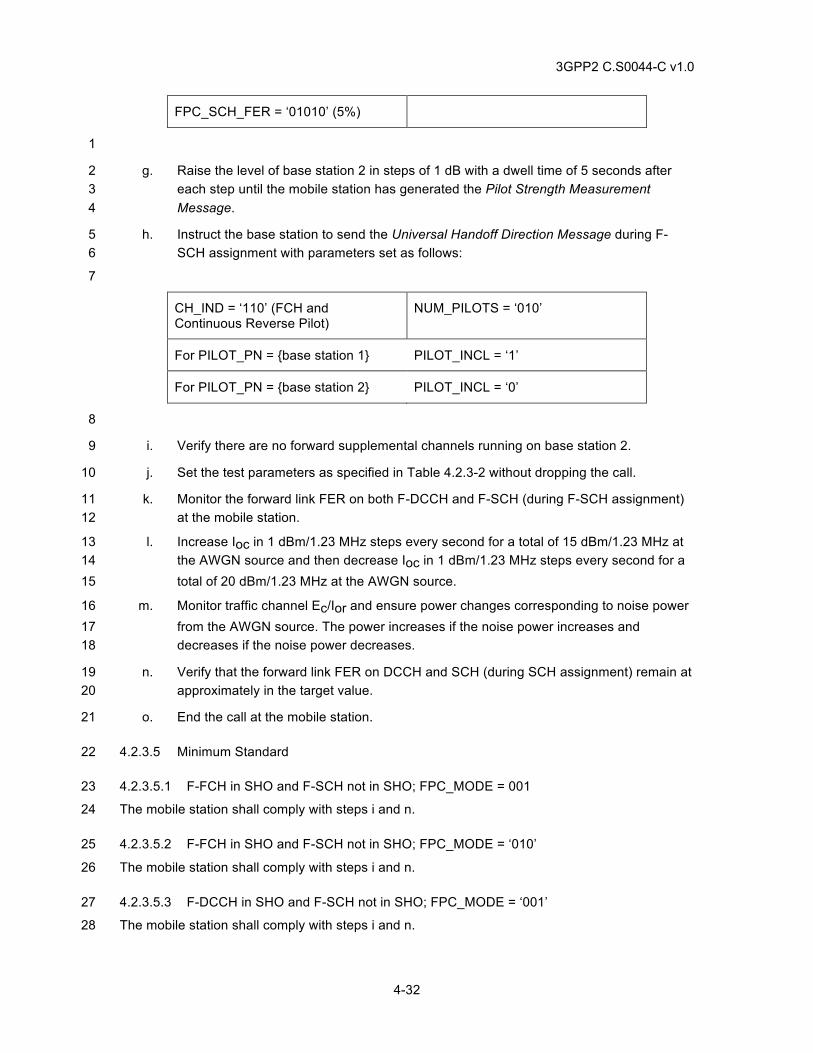
3GPP2 C.S0044-C v1.0
4-32
FPC_SCH_FER = ‘01010’ (5%)
1
g. Raise the level of base station 2 in steps of 1 dB with a dwell time of 5 seconds after 2 each step until the mobile station has generated the Pilot Strength Measurement 3 Message. 4
h. Instruct the base station to send the Universal Handoff Direction Message during F-5 SCH assignment with parameters set as follows: 6
7
CH_IND = ‘110’ (FCH and Continuous Reverse Pilot)
NUM_PILOTS = ‘010’
For PILOT_PN = {base station 1} PILOT_INCL = ‘1’
For PILOT_PN = {base station 2} PILOT_INCL = ‘0’
8
i. Verify there are no forward supplemental channels running on base station 2. 9
j. Set the test parameters as specified in Table 4.2.3-2 without dropping the call. 10
k. Monitor the forward link FER on both F-DCCH and F-SCH (during F-SCH assignment) 11 at the mobile station. 12
l. Increase Ioc in 1 dBm/1.23 MHz steps every second for a total of 15 dBm/1.23 MHz at 13 the AWGN source and then decrease Ioc in 1 dBm/1.23 MHz steps every second for a 14 total of 20 dBm/1.23 MHz at the AWGN source. 15
m. Monitor traffic channel Ec/Ior and ensure power changes corresponding to noise power 16 from the AWGN source. The power increases if the noise power increases and 17 decreases if the noise power decreases. 18
n. Verify that the forward link FER on DCCH and SCH (during SCH assignment) remain at 19 approximately in the target value. 20
o. End the call at the mobile station. 21
4.2.3.5 Minimum Standard 22
4.2.3.5.1 F-FCH in SHO and F-SCH not in SHO; FPC_MODE = 001 23
The mobile station shall comply with steps i and n. 24
4.2.3.5.2 F-FCH in SHO and F-SCH not in SHO; FPC_MODE = ‘010’ 25
The mobile station shall comply with steps i and n. 26
4.2.3.5.3 F-DCCH in SHO and F-SCH not in SHO; FPC_MODE = ‘001’ 27
The mobile station shall comply with steps i and n. 28
3GPP2 C.S0044-C v1.0
4-33
4.2.3.5.4 F-DCCH in SHO and F-SCH not in SHO; FPC_MODE = ‘010’ 1
The mobile station shall comply with steps i and n. 2
3
For all tests, the call shall not drop and the FER shall remain in the target value. 4
4.2.4 Change FPC_MODE During a Call 5
4.2.4.1 Definition 6
The mobile station accomplishes fast forward power control by transmitting the power control 7 subchannel to the base station on the R-PICH. The mobile station determines the information to 8 send to the base station through inner and outer closed loop estimations. In outer loop estimation, 9 the mobile station adjusts the Eb/Nt setpoints to the Eb/Nt value necessary to achieve the target 10 FER on the Forward Traffic Channel. 11
In inner loop estimation, the mobile station compares the received Eb/Nt to the setpoint and 12 determines the value of the power control bit to be sent to the base station. This test verifies that 13 the mobile station can process a change in FPC_MODE delivered by the Power Control 14 Message. 15
4.2.4.2 Traceability: 16
(see [1]) 17
2.1.3.1.10 Reverse Power Control Subchannel 18
(see [4]) 19
2.6.4.1.1.3 Processing the Power Control Message 20
3.7.3.3.2.25 Power Control Message 21
2.6.2.4 Mobile Station Order and Message Processing Operation 22
2.6.3.3 Page Response Substate 23
2.6.3.5 Mobile Station Origination Attempt Substate 24
3.6.3.3 Response to Page Response Message 25
3.6.3.5 Response to Origination Message 26
3.7.2.3.2.21 Extended Channel Assignment Message 27
2.6.4.1.2 Service Configuration and Negotiation 28
2.6.4.1.2.2 Service Subfunctions 29
3.7.3.3.2.20 Service Connect Message 30
3.7.5 Information Records 31
3.7.5.7 Service Configuration 32
3.7.5.20 Non negotiable System Configuration 33
Applicability: RC 3 and greater 34
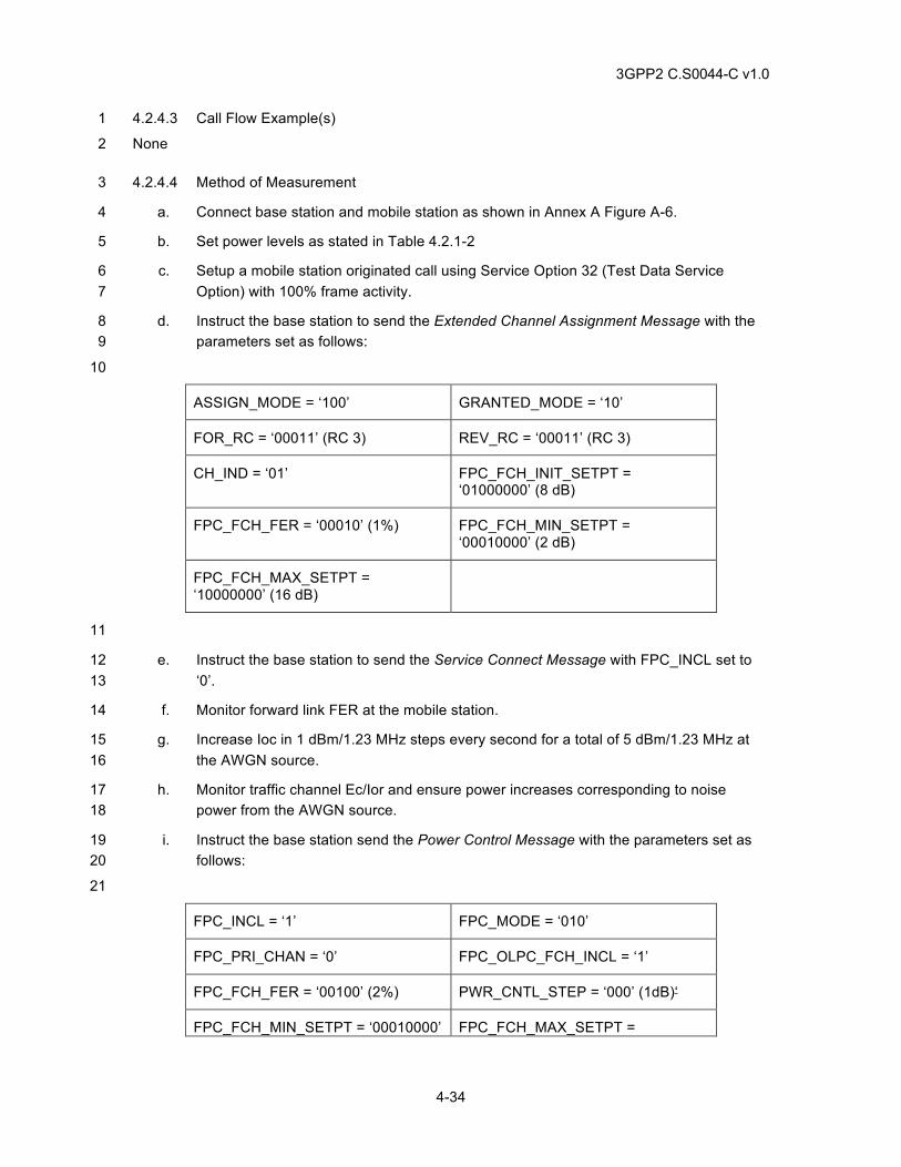
3GPP2 C.S0044-C v1.0
4-34
4.2.4.3 Call Flow Example(s) 1
None 2
4.2.4.4 Method of Measurement 3
a. Connect base station and mobile station as shown in Annex A Figure A-6. 4
b. Set power levels as stated in Table 4.2.1-2 5
c. Setup a mobile station originated call using Service Option 32 (Test Data Service 6 Option) with 100% frame activity. 7
d. Instruct the base station to send the Extended Channel Assignment Message with the 8 parameters set as follows: 9
10
ASSIGN_MODE = ‘100’ GRANTED_MODE = ‘10’
FOR_RC = ‘00011’ (RC 3) REV_RC = ‘00011’ (RC 3)
CH_IND = ‘01’ FPC_FCH_INIT_SETPT = ‘01000000’ (8 dB)
FPC_FCH_FER = ‘00010’ (1%) FPC_FCH_MIN_SETPT = ‘00010000’ (2 dB)
FPC_FCH_MAX_SETPT = ‘10000000’ (16 dB)
11
e. Instruct the base station to send the Service Connect Message with FPC_INCL set to 12 ‘0’. 13
f. Monitor forward link FER at the mobile station. 14
g. Increase Ioc in 1 dBm/1.23 MHz steps every second for a total of 5 dBm/1.23 MHz at 15 the AWGN source. 16
h. Monitor traffic channel Ec/Ior and ensure power increases corresponding to noise 17 power from the AWGN source. 18
i. Instruct the base station send the Power Control Message with the parameters set as 19 follows: 20
21
FPC_INCL = ‘1’ FPC_MODE = ‘010’
FPC_PRI_CHAN = ‘0’ FPC_OLPC_FCH_INCL = ‘1’
FPC_FCH_FER = ‘00100’ (2%) PWR_CNTL_STEP = ‘000’ (1dB)‘
FPC_FCH_MIN_SETPT = ‘00010000’ FPC_FCH_MAX_SETPT =
3GPP2 C.S0044-C v1.0
4-35
(2 dB) ‘10000000’ (16 dB)
FPC_OLPC_DCCH_INCL = ‘0’
FPC_DCCH_MIN_SEPT = N/A FPC_DCCH_MAX_SEPT = N/A
FPC_OLPC_SCH_M_INCL = ‘1’ FPC_SCH_M_FER = ‘00010’ (1%)
FPC_MIN_SCH_M_SETPT = ‘00010000’ (2 dB)
FPC_MAX_SCH_M_SETPT = ‘10000000’ (16 dB)
NUM_SUP = 1
1
j. Monitor forward link FER at the mobile station. 2
k. Increase Ioc in 1 dBm/1.23 MHz steps every second for a total of 5 dBm/1.23 MHz at 3 the AWGN source and then decrease Ioc in 1 dBm/1.23 MHz steps every second for a 4 total of 20 dBm/1.23 MHz at the AWGN source. 5
l. Monitor traffic channel Ec/Ior and ensure power changes corresponding to noise power 6 from the AWGN source. The power increases if the noise power increases and 7 decreases if the noise power decreases. 8
m. Verify that the forward link FER on FCH remains at approximately the target value. 9
n. End the call at the mobile station. 10
4.2.4.5 Minimum Standard 11
The mobile station shall comply with step m. 12
13
4.2.5 R-PICH in Gated Transmission Mode 14
4.2.5.1 Gating with the Reverse Dedicated Control Channel 15
4.2.5.1.1 Definition 16
The mobile station accomplishes fast forward power control by transmitting the power control 17 subchannel to the base station on the R-PICH. The power control subchannel can either be gated 18 (either at a rate of ½ or ¼) or not gated (a bit is transmitted on every PCG). Gating occurs only 19 when the Forward Dedicated Control Channel and the Reverse Dedicated Control Channel are 20 assigned and when there are no transmissions on the Reverse Dedicated Control Channel. This 21 test verifies that the mobile station can operate in the various gating transmission modes 22 specified in the Service Connect Message. 23
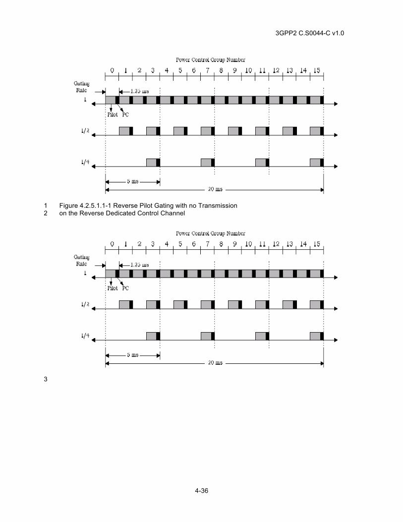
3GPP2 C.S0044-C v1.0
4-36
Figure 4.2.5.1.1-1 Reverse Pilot Gating with no Transmission 1 on the Reverse Dedicated Control Channel 2
3
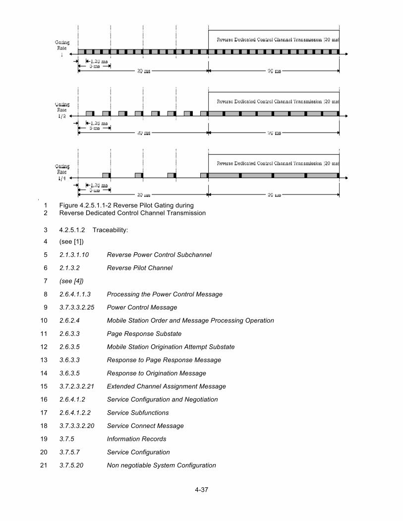
3GPP2 C.S0044-C v1.0
4-37
Figure 4.2.5.1.1-2 Reverse Pilot Gating during 1 Reverse Dedicated Control Channel Transmission 2
4.2.5.1.2 Traceability: 3
(see [1]) 4
2.1.3.1.10 Reverse Power Control Subchannel 5
2.1.3.2 Reverse Pilot Channel 6
(see [4]) 7
2.6.4.1.1.3 Processing the Power Control Message 8
3.7.3.3.2.25 Power Control Message 9
2.6.2.4 Mobile Station Order and Message Processing Operation 10
2.6.3.3 Page Response Substate 11
2.6.3.5 Mobile Station Origination Attempt Substate 12
3.6.3.3 Response to Page Response Message 13
3.6.3.5 Response to Origination Message 14
3.7.2.3.2.21 Extended Channel Assignment Message 15
2.6.4.1.2 Service Configuration and Negotiation 16
2.6.4.1.2.2 Service Subfunctions 17
3.7.3.3.2.20 Service Connect Message 18
3.7.5 Information Records 19
3.7.5.7 Service Configuration 20
3.7.5.20 Non negotiable System Configuration 21
3GPP2 C.S0044-C v1.0
4-38
1
Applicability: Forward Link: RC 1 through RC 5; Reverse Link: RC 1 through RC 4 2
4.2.5.1.3 Call Flow Example(s) 3
None 4
4.2.5.1.4 Method of Measurement 5
a. Connect base station and mobile station as shown in Annex A Figure A-6 6
b. Set power levels as stated in Table 4.2.1-3. 7
c. Setup a mobile station originated data call using Service Option 33. 8
d. Instruct the base station to send the Extended Channel Assignment Message has the 9 parameters set as follows: 10
11
ASSIGN_MODE = ‘100’ GRANTED_MODE = ‘10’
FOR_RC = ‘00011’ (RC 3) REV_RC = ‘00011’ (RC 3)
CH_IND = ‘10’ FPC_DCCH_INIT_SETPT = ‘01000000’ (8 dB)
FPC_DCCH_FER = ‘00010’ (1%) FPC_DCCH_MIN_SETPT = ‘00010000’ (2 dB)
FPC_DCCH_MAX_SETPT = ‘10000000’ (16 dB)
12
e. Instruct the base station to send the Service Connect Message has the parameters set 13 as follows: 14
15
FPC_INCL = ‘1’ FPC_OLPC_FCH_INCL = ‘0’
FPC_PRI_CHAN = ‘1’ FPC_OLPC_DCCH_INCL = ‘0’
FPC_MODE = ‘000’
GATING_RATE_INCL = ‘1’ PILOT_GATE_RATE = ‘01’ (gating at ½)
16
f. Instruct the base station to send the Extended Release Message with CH_IND set to 17 ‘100’. 18
g. Do not have any transmissions on the Reverse Dedicated Control Channel. 19
3GPP2 C.S0044-C v1.0
4-39
h. Instruct the base station to send a sufficient number of In-Traffic System Parameters 1 Messages with the same system configurations and without requiring the 2 acknowledgment on the reverse link DCCH so that the mobile station can measure 3 forward FER. 4
i. Monitor forward link FER at the mobile station. 5
j. Increase Ioc in 1 dBm/1.23 MHz steps every second for a total of 5 dBm/1.23 MHz at 6 the AWGN source and then decrease Ioc in 1 dBm/1.23 MHz steps every second for a 7 total of 20 dBm/1.23 MHz at the AWGN source. 8
k. Monitor traffic channel Ec/Ior and ensure power changes corresponding to noise power 9 from the AWGN source. The power increases if the noise power increases and 10 decreases if the noise power decreases. 11
l. Verify that the reverse Pilot Channel is gated at the specified rate and the forward link 12 FER on DCCH remains at approximately the target value 13
m. Instruct the mobile station to send the Data Burst Message on the Reverse Dedicated 14 Control Channel. 15
n. Monitor the forward link FER at mobile station. 16
o. Increase Ioc in 1 dBm/1.23 MHz steps every second for a total of 5 dBm/1.23 MHz at 17 the AWGN source and then decrease Ioc in 1 dBm/1.23 MHz steps every second for a 18 total of 20 dBm/1.23 MHz at the AWGN source. 19
p. Monitor traffic channel Ec/Ior and ensure power changes corresponding to noise power 20 from the AWGN source. The power increases if the noise power increases and 21 decreases if the noise power decreases. 22
q. Verify that the reverse Pilot Channel is gated at the target rate if no transmissions are 23 on the Reverse Dedicated Control Channel and the reverse Pilot Channel is not gated if 24 there are transmissions on the Reverse Dedicated Control Channel. 25
r. Verify that the forward link FER on DCCH remains at approximately the target value. 26
s. End the call at the mobile station. Repeat steps a through r above except for step e to 27 set PILOT_GATE_RATE to ‘10’ (gating at ¼). 28
4.2.5.1.5 Minimum Standard 29
Gating with the Reverse Dedicated Control Channel 30
The mobile station shall comply with steps l, q, and r. 31
4.2.5.2 Gating with the Reverse Fundamental Channel 32
4.2.5.2.1 Definition 33
The mobile station accomplishes fast forward power control by transmitting the power control 34 subchannel to the base station on the R-PICH. The power control subchannel can either be gated 35 or not gated. The R-FCH may be gated when no other Reverse Traffic Channel is assigned and 36 the data rate is 1500 bps for RC 3 and RC5 or 1800 bps for RC4. When the R-FCH is operated in 37 the gated mode and is at a data rate of 1500 bps for RC 3 and RC 5 or 1800bps for RC 4, the R-38 PICH shall have a transmission duty cycle of 50%. The R-PICH shall be transmitted in power 39
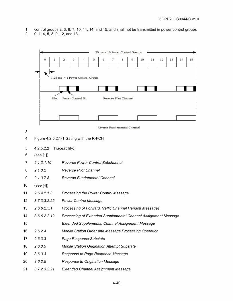
3GPP2 C.S0044-C v1.0
4-40
control groups 2, 3, 6, 7, 10, 11, 14, and 15, and shall not be transmitted in power control groups 1 0, 1, 4, 5, 8, 9, 12, and 13. 2
3
Figure 4.2.5.2.1-1 Gating with the R-FCH 4
4.2.5.2.2 Traceability: 5
(see [1]) 6
2.1.3.1.10 Reverse Power Control Subchannel 7
2.1.3.2 Reverse Pilot Channel 8
2.1.3.7.8 Reverse Fundamental Channel 9
(see [4]) 10
2.6.4.1.1.3 Processing the Power Control Message 11
3.7.3.3.2.25 Power Control Message 12
2.6.6.2.5.1 Processing of Forward Traffic Channel Handoff Messages 13
3.6.6.2.2.12 Processing of Extended Supplemental Channel Assignment Message 14
Extended Supplemental Channel Assignment Message 15
2.6.2.4 Mobile Station Order and Message Processing Operation 16
2.6.3.3 Page Response Substate 17
2.6.3.5 Mobile Station Origination Attempt Substate 18
3.6.3.3 Response to Page Response Message 19
3.6.3.5 Response to Origination Message 20
3.7.2.3.2.21 Extended Channel Assignment Message 21
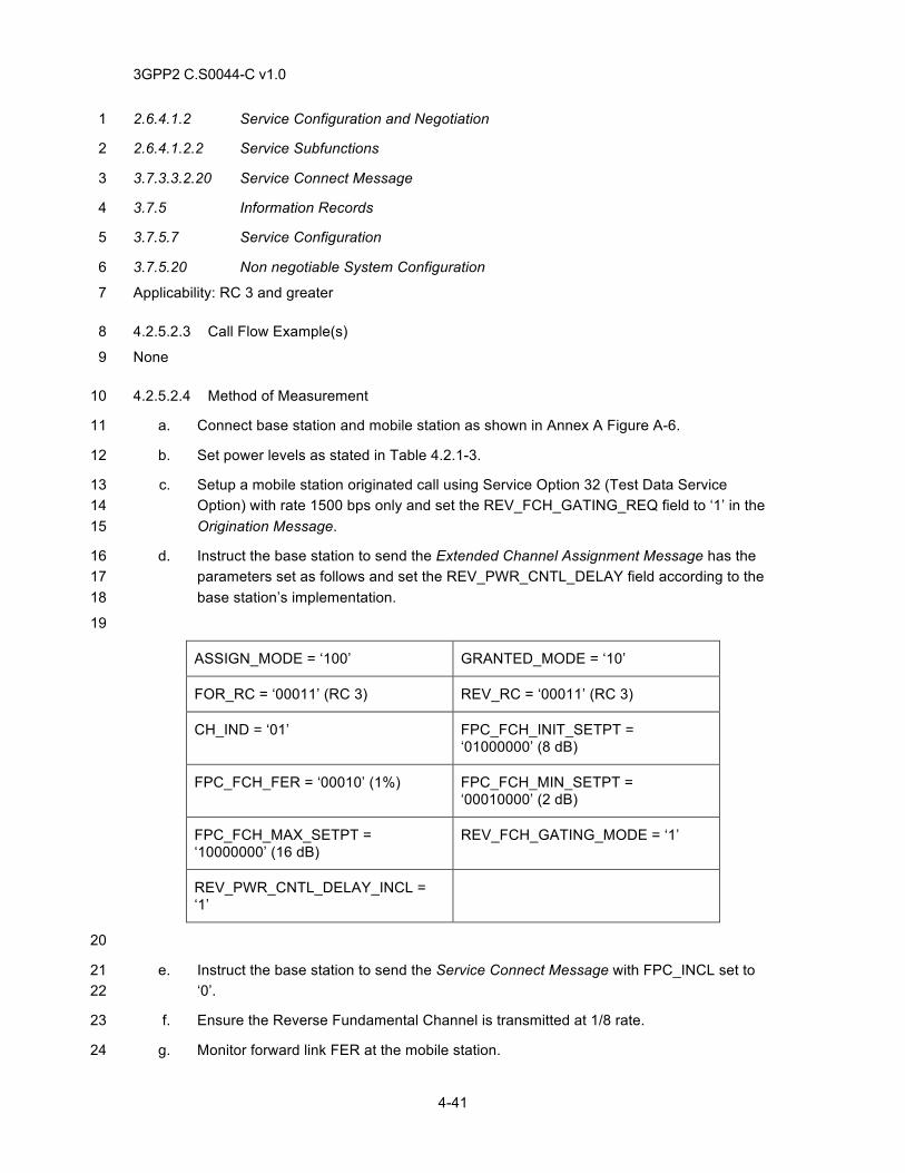
3GPP2 C.S0044-C v1.0
4-41
2.6.4.1.2 Service Configuration and Negotiation 1
2.6.4.1.2.2 Service Subfunctions 2
3.7.3.3.2.20 Service Connect Message 3
3.7.5 Information Records 4
3.7.5.7 Service Configuration 5
3.7.5.20 Non negotiable System Configuration 6
Applicability: RC 3 and greater 7
4.2.5.2.3 Call Flow Example(s) 8
None 9
4.2.5.2.4 Method of Measurement 10
a. Connect base station and mobile station as shown in Annex A Figure A-6. 11
b. Set power levels as stated in Table 4.2.1-3. 12
c. Setup a mobile station originated call using Service Option 32 (Test Data Service 13 Option) with rate 1500 bps only and set the REV_FCH_GATING_REQ field to ‘1’ in the 14 Origination Message. 15
d. Instruct the base station to send the Extended Channel Assignment Message has the 16 parameters set as follows and set the REV_PWR_CNTL_DELAY field according to the 17 base station’s implementation. 18
19
ASSIGN_MODE = ‘100’ GRANTED_MODE = ‘10’
FOR_RC = ‘00011’ (RC 3) REV_RC = ‘00011’ (RC 3)
CH_IND = ‘01’ FPC_FCH_INIT_SETPT = ‘01000000’ (8 dB)
FPC_FCH_FER = ‘00010’ (1%) FPC_FCH_MIN_SETPT = ‘00010000’ (2 dB)
FPC_FCH_MAX_SETPT = ‘10000000’ (16 dB)
REV_FCH_GATING_MODE = ‘1’
REV_PWR_CNTL_DELAY_INCL = ‘1’
20
e. Instruct the base station to send the Service Connect Message with FPC_INCL set to 21 ‘0’. 22
f. Ensure the Reverse Fundamental Channel is transmitted at 1/8 rate. 23
g. Monitor forward link FER at the mobile station. 24
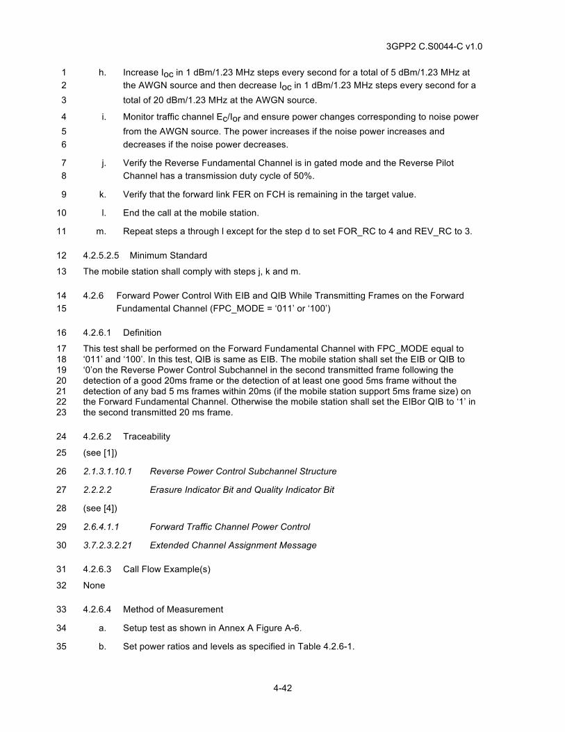
3GPP2 C.S0044-C v1.0
4-42
h. Increase Ioc in 1 dBm/1.23 MHz steps every second for a total of 5 dBm/1.23 MHz at 1 the AWGN source and then decrease Ioc in 1 dBm/1.23 MHz steps every second for a 2 total of 20 dBm/1.23 MHz at the AWGN source. 3
i. Monitor traffic channel Ec/Ior and ensure power changes corresponding to noise power 4 from the AWGN source. The power increases if the noise power increases and 5 decreases if the noise power decreases. 6
j. Verify the Reverse Fundamental Channel is in gated mode and the Reverse Pilot 7 Channel has a transmission duty cycle of 50%. 8
k. Verify that the forward link FER on FCH is remaining in the target value. 9
l. End the call at the mobile station. 10
m. Repeat steps a through l except for the step d to set FOR_RC to 4 and REV_RC to 3. 11
4.2.5.2.5 Minimum Standard 12
The mobile station shall comply with steps j, k and m. 13
4.2.6 Forward Power Control With EIB and QIB While Transmitting Frames on the Forward 14 Fundamental Channel (FPC_MODE = ‘011’ or ‘100’) 15
4.2.6.1 Definition 16
This test shall be performed on the Forward Fundamental Channel with FPC_MODE equal to 17 ‘011’ and ‘100’. In this test, QIB is same as EIB. The mobile station shall set the EIB or QIB to 18 ‘0’on the Reverse Power Control Subchannel in the second transmitted frame following the 19 detection of a good 20ms frame or the detection of at least one good 5ms frame without the 20 detection of any bad 5 ms frames within 20ms (if the mobile station support 5ms frame size) on 21 the Forward Fundamental Channel. Otherwise the mobile station shall set the EIBor QIB to ‘1’ in 22 the second transmitted 20 ms frame. 23
4.2.6.2 Traceability 24
(see [1]) 25
2.1.3.1.10.1 Reverse Power Control Subchannel Structure 26
2.2.2.2 Erasure Indicator Bit and Quality Indicator Bit 27
(see [4]) 28
2.6.4.1.1 Forward Traffic Channel Power Control 29
3.7.2.3.2.21 Extended Channel Assignment Message 30
4.2.6.3 Call Flow Example(s) 31
None 32
4.2.6.4 Method of Measurement 33
a. Setup test as shown in Annex A Figure A-6. 34
b. Set power ratios and levels as specified in Table 4.2.6-1. 35
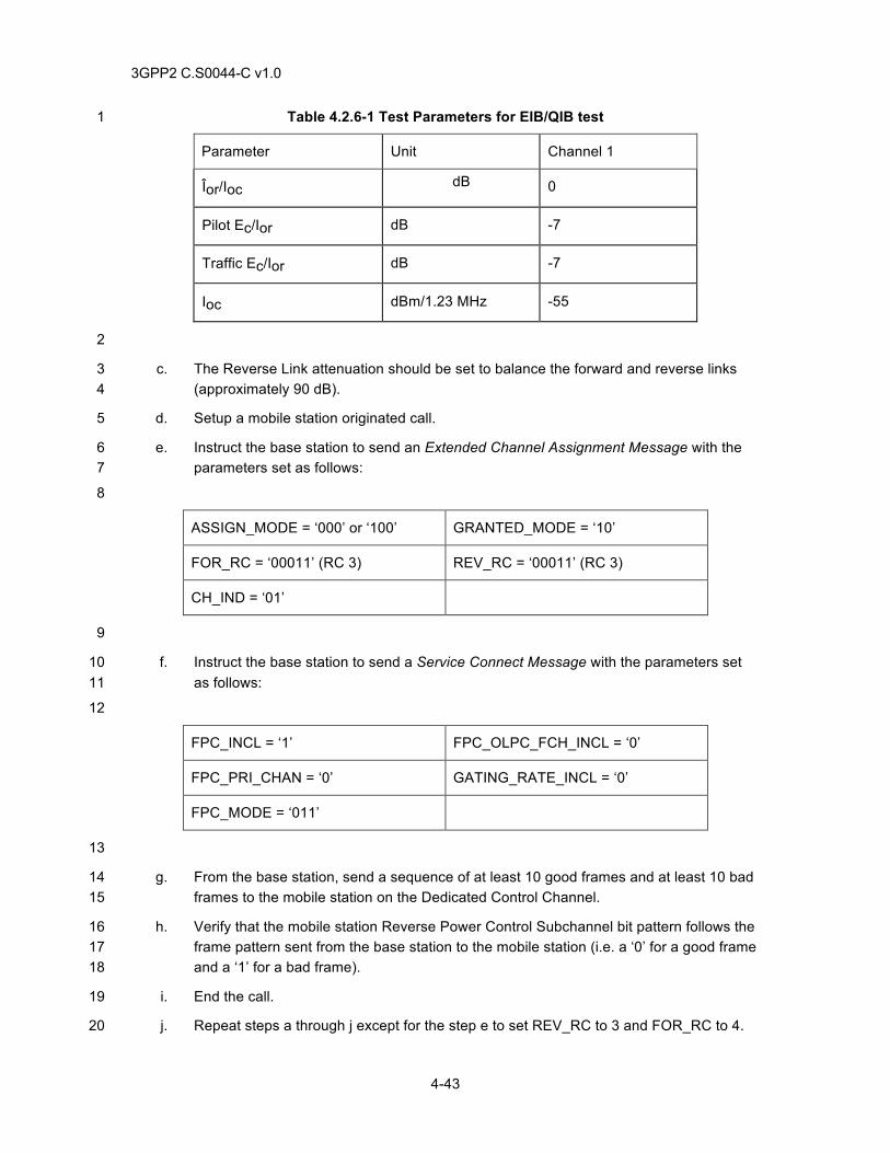
3GPP2 C.S0044-C v1.0
4-43
Table 4.2.6-1 Test Parameters for EIB/QIB test 1
Parameter Unit Channel 1
Îor/Ioc dB 0
Pilot Ec/Ior dB -7
Traffic Ec/Ior dB -7
Ioc dBm/1.23 MHz -55
2
c. The Reverse Link attenuation should be set to balance the forward and reverse links 3 (approximately 90 dB). 4
d. Setup a mobile station originated call. 5
e. Instruct the base station to send an Extended Channel Assignment Message with the 6 parameters set as follows: 7
8
ASSIGN_MODE = ‘000’ or ‘100’ GRANTED_MODE = ‘10’
FOR_RC = ‘00011’ (RC 3) REV_RC = ‘00011’ (RC 3)
CH_IND = ‘01’
9
f. Instruct the base station to send a Service Connect Message with the parameters set 10 as follows: 11
12
FPC_INCL = ‘1’ FPC_OLPC_FCH_INCL = ‘0’
FPC_PRI_CHAN = ‘0’ GATING_RATE_INCL = ‘0’
FPC_MODE = ‘011’
13
g. From the base station, send a sequence of at least 10 good frames and at least 10 bad 14 frames to the mobile station on the Dedicated Control Channel. 15
h. Verify that the mobile station Reverse Power Control Subchannel bit pattern follows the 16 frame pattern sent from the base station to the mobile station (i.e. a ‘0’ for a good frame 17 and a ‘1’ for a bad frame). 18
i. End the call. 19
j. Repeat steps a through j except for the step e to set REV_RC to 3 and FOR_RC to 4. 20
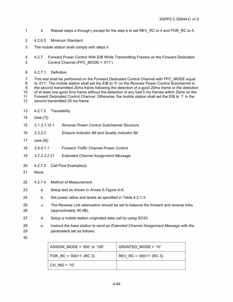
3GPP2 C.S0044-C v1.0
4-44
k. Repeat steps a through j except for the step e to set REV_RC to 4 and FOR_RC to 5. 1
4.2.6.5 Minimum Standard 2
The mobile station shall comply with steps h. 3
4.2.7 Forward Power Control With EIB While Transmitting Frames on the Forward Dedicated 4 Control Channel (FPC_MODE = ‘011’) 5
4.2.7.1 Definition 6
This test shall be performed on the Forward Dedicated Control Channel with FPC_MODE equal 7 to ‘011’. The mobile station shall set the EIB to ‘0’ on the Reverse Power Control Subchannel in 8 the second transmitted 20ms frame following the detection of a good 20ms frame or the detection 9 of at least one good 5ms frame without the detection of any bad 5 ms frames within 20ms on the 10 Forward Dedicated Control Channel. Otherwise, the mobile station shall set the EIB to ‘1’ in the 11 second transmitted 20 ms frame. 12
4.2.7.2 Traceability 13
(see [1]) 14
2.1.3.1.10.1 Reverse Power Control Subchannel Structure 15
2.2.2.2 Erasure Indicator Bit and Quality Indicator Bit 16
(see [4]) 17
2.6.4.1.1 Forward Traffic Channel Power Control 18
3.7.2.3.2.21 Extended Channel Assignment Message 19
4.2.7.3 Call Flow Example(s) 20
None 21
4.2.7.4 Method of Measurement 22
a. Setup test as shown in Annex A Figure A-6. 23
b. Set power ratios and levels as specified in Table 4.2.1-3. 24
c. The Reverse Link attenuation should be set to balance the forward and reverse links 25 (approximately 90 dB). 26
d. Setup a mobile station originated data call by using SO33. 27
e. Instruct the base station to send an Extended Channel Assignment Message with the 28 parameters set as follows: 29
30
ASSIGN_MODE = ‘000’ or ‘100’ GRANTED_MODE = ‘10’
FOR_RC = ‘00011’ (RC 3) REV_RC = ‘00011’ (RC 3)
CH_IND = ‘10’
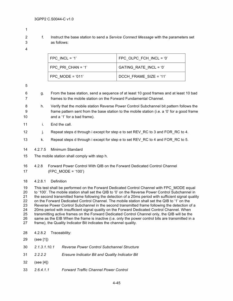
3GPP2 C.S0044-C v1.0
4-45
1
f. Instruct the base station to send a Service Connect Message with the parameters set 2 as follows: 3
4
FPC_INCL = ‘1’ FPC_OLPC_FCH_INCL = ‘0’
FPC_PRI_CHAN = ‘1’ GATING_RATE_INCL = ‘0’
FPC_MODE = ‘011’ DCCH_FRAME_SIZE = ‘11’
5
g. From the base station, send a sequence of at least 10 good frames and at least 10 bad 6 frames to the mobile station on the Forward Fundamental Channel. 7
h. Verify that the mobile station Reverse Power Control Subchannel bit pattern follows the 8 frame pattern sent from the base station to the mobile station (i.e. a ‘0’ for a good frame 9 and a ‘1’ for a bad frame). 10
i. End the call. 11
j. Repeat steps d through i except for step e to set REV_RC to 3 and FOR_RC to 4. 12
k. Repeat steps d through i except for step e to set REV_RC to 4 and FOR_RC to 5. 13
4.2.7.5 Minimum Standard 14
The mobile station shall comply with step h. 15
4.2.8 Forward Power Control With QIB on the Forward Dedicated Control Channel 16 (FPC_MODE = ‘100’) 17
4.2.8.1 Definition 18
This test shall be performed on the Forward Dedicated Control Channel with FPC_MODE equal 19 to ‘100’. The mobile station shall set the QIB to ‘0’ on the Reverse Power Control Subchannel in 20 the second transmitted frame following the detection of a 20ms period with sufficient signal quality 21 on the Forward Dedicated Control Channel. The mobile station shall set the QIB to ‘1’ on the 22 Reverse Power Control Subchannel in the second transmitted frame following the detection of a 23 20ms period with insufficient signal quality on the Forward Dedicated Control Channel. When 24 transmitting active frames on the Forward Dedicated Control Channel only, the QIB will be the 25 same as the EIB When the frame is inactive (i.e. only the power control bits are transmitted in a 26 frame), the Quality Indicator Bit indicates the channel quality. 27
4.2.8.2 Traceability: 28
(see [1]) 29
2.1.3.1.10.1 Reverse Power Control Subchannel Structure 30
2.2.2.2 Erasure Indicator Bit and Quality Indicator Bit 31
(see [4]) 32
2.6.4.1.1 Forward Traffic Channel Power Control 33
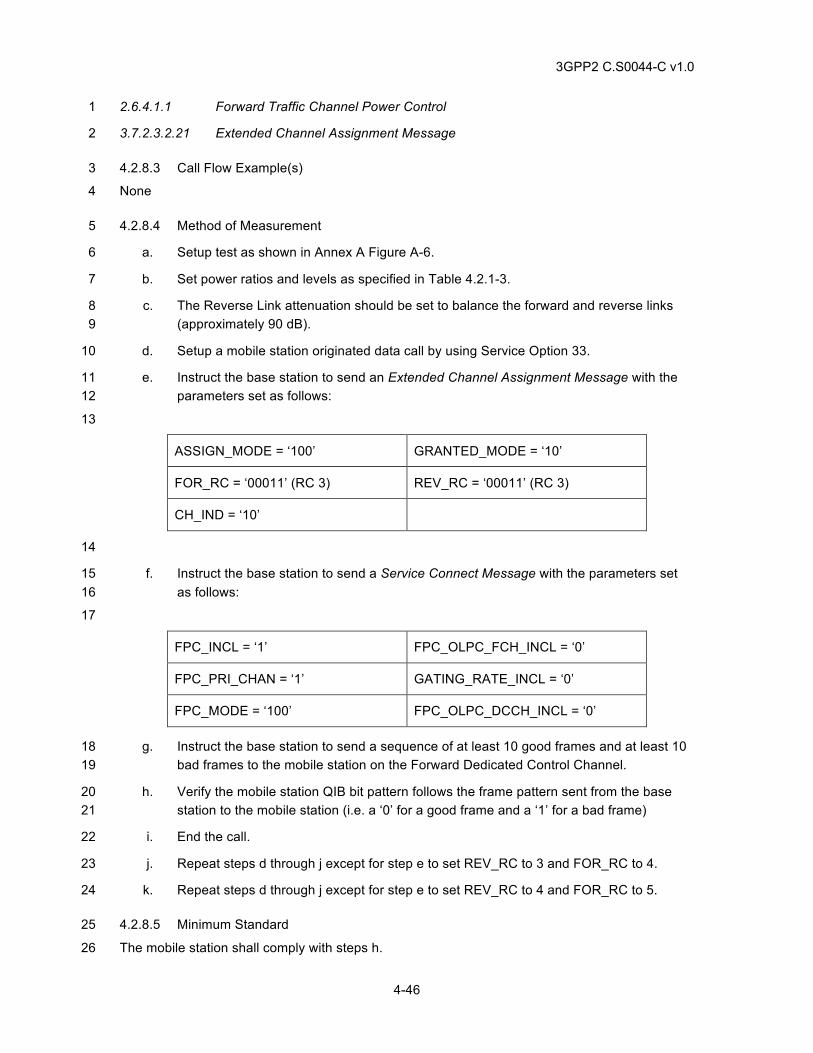
3GPP2 C.S0044-C v1.0
4-46
2.6.4.1.1 Forward Traffic Channel Power Control 1
3.7.2.3.2.21 Extended Channel Assignment Message 2
4.2.8.3 Call Flow Example(s) 3
None 4
4.2.8.4 Method of Measurement 5
a. Setup test as shown in Annex A Figure A-6. 6
b. Set power ratios and levels as specified in Table 4.2.1-3. 7
c. The Reverse Link attenuation should be set to balance the forward and reverse links 8 (approximately 90 dB). 9
d. Setup a mobile station originated data call by using Service Option 33. 10
e. Instruct the base station to send an Extended Channel Assignment Message with the 11 parameters set as follows: 12
13
ASSIGN_MODE = ‘100’ GRANTED_MODE = ‘10’
FOR_RC = ‘00011’ (RC 3) REV_RC = ‘00011’ (RC 3)
CH_IND = ‘10’
14
f. Instruct the base station to send a Service Connect Message with the parameters set 15 as follows: 16
17
FPC_INCL = ‘1’ FPC_OLPC_FCH_INCL = ‘0’
FPC_PRI_CHAN = ‘1’ GATING_RATE_INCL = ‘0’
FPC_MODE = ‘100’ FPC_OLPC_DCCH_INCL = ‘0’
g. Instruct the base station to send a sequence of at least 10 good frames and at least 10 18 bad frames to the mobile station on the Forward Dedicated Control Channel. 19
h. Verify the mobile station QIB bit pattern follows the frame pattern sent from the base 20 station to the mobile station (i.e. a ‘0’ for a good frame and a ‘1’ for a bad frame) 21
i. End the call. 22
j. Repeat steps d through j except for step e to set REV_RC to 3 and FOR_RC to 4. 23
k. Repeat steps d through j except for step e to set REV_RC to 4 and FOR_RC to 5. 24
4.2.8.5 Minimum Standard 25
The mobile station shall comply with steps h. 26
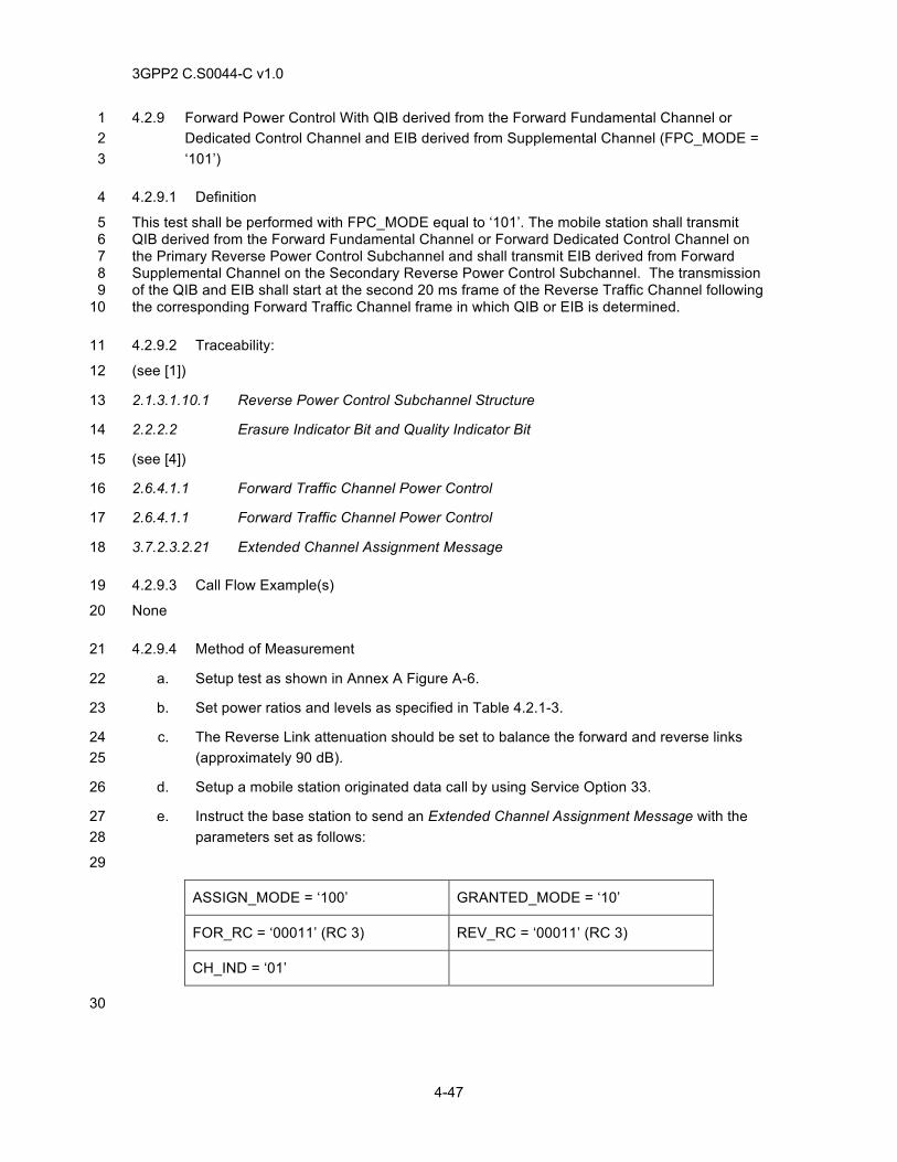
3GPP2 C.S0044-C v1.0
4-47
4.2.9 Forward Power Control With QIB derived from the Forward Fundamental Channel or 1 Dedicated Control Channel and EIB derived from Supplemental Channel (FPC_MODE = 2 ‘101’) 3
4.2.9.1 Definition 4
This test shall be performed with FPC_MODE equal to ‘101’. The mobile station shall transmit 5 QIB derived from the Forward Fundamental Channel or Forward Dedicated Control Channel on 6 the Primary Reverse Power Control Subchannel and shall transmit EIB derived from Forward 7 Supplemental Channel on the Secondary Reverse Power Control Subchannel. The transmission 8 of the QIB and EIB shall start at the second 20 ms frame of the Reverse Traffic Channel following 9 the corresponding Forward Traffic Channel frame in which QIB or EIB is determined. 10
4.2.9.2 Traceability: 11
(see [1]) 12
2.1.3.1.10.1 Reverse Power Control Subchannel Structure 13
2.2.2.2 Erasure Indicator Bit and Quality Indicator Bit 14
(see [4]) 15
2.6.4.1.1 Forward Traffic Channel Power Control 16
2.6.4.1.1 Forward Traffic Channel Power Control 17
3.7.2.3.2.21 Extended Channel Assignment Message 18
4.2.9.3 Call Flow Example(s) 19
None 20
4.2.9.4 Method of Measurement 21
a. Setup test as shown in Annex A Figure A-6. 22
b. Set power ratios and levels as specified in Table 4.2.1-3. 23
c. The Reverse Link attenuation should be set to balance the forward and reverse links 24 (approximately 90 dB). 25
d. Setup a mobile station originated data call by using Service Option 33. 26
e. Instruct the base station to send an Extended Channel Assignment Message with the 27 parameters set as follows: 28
29
ASSIGN_MODE = ‘100’ GRANTED_MODE = ‘10’
FOR_RC = ‘00011’ (RC 3) REV_RC = ‘00011’ (RC 3)
CH_IND = ‘01’
30
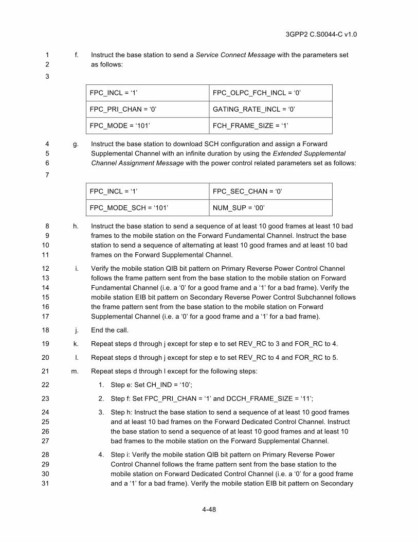
3GPP2 C.S0044-C v1.0
4-48
f. Instruct the base station to send a Service Connect Message with the parameters set 1 as follows: 2
3
FPC_INCL = ‘1’ FPC_OLPC_FCH_INCL = ‘0’
FPC_PRI_CHAN = ‘0’ GATING_RATE_INCL = ‘0’
FPC_MODE = ‘101’ FCH_FRAME_SIZE = ‘1’
g. Instruct the base station to download SCH configuration and assign a Forward 4 Supplemental Channel with an infinite duration by using the Extended Supplemental 5 Channel Assignment Message with the power control related parameters set as follows: 6
7
FPC_INCL = ‘1’ FPC_SEC_CHAN = ‘0’
FPC_MODE_SCH = ‘101’ NUM_SUP = ‘00’
h. Instruct the base station to send a sequence of at least 10 good frames at least 10 bad 8 frames to the mobile station on the Forward Fundamental Channel. Instruct the base 9 station to send a sequence of alternating at least 10 good frames and at least 10 bad 10 frames on the Forward Supplemental Channel. 11
i. Verify the mobile station QIB bit pattern on Primary Reverse Power Control Channel 12 follows the frame pattern sent from the base station to the mobile station on Forward 13 Fundamental Channel (i.e. a ‘0’ for a good frame and a ‘1’ for a bad frame). Verify the 14 mobile station EIB bit pattern on Secondary Reverse Power Control Subchannel follows 15 the frame pattern sent from the base station to the mobile station on Forward 16 Supplemental Channel (i.e. a ‘0’ for a good frame and a ‘1’ for a bad frame). 17
j. End the call. 18
k. Repeat steps d through j except for step e to set REV_RC to 3 and FOR_RC to 4. 19
l. Repeat steps d through j except for step e to set REV_RC to 4 and FOR_RC to 5. 20
m. Repeat steps d through l except for the following steps: 21
1. Step e: Set CH_IND = ‘10’; 22
2. Step f: Set FPC_PRI_CHAN = ‘1’ and DCCH_FRAME_SIZE = ‘11’; 23
3. Step h: Instruct the base station to send a sequence of at least 10 good frames 24 and at least 10 bad frames on the Forward Dedicated Control Channel. Instruct 25 the base station to send a sequence of at least 10 good frames and at least 10 26 bad frames to the mobile station on the Forward Supplemental Channel. 27
4. Step i: Verify the mobile station QIB bit pattern on Primary Reverse Power 28 Control Channel follows the frame pattern sent from the base station to the 29 mobile station on Forward Dedicated Control Channel (i.e. a ‘0’ for a good frame 30 and a ‘1’ for a bad frame). Verify the mobile station EIB bit pattern on Secondary 31
3GPP2 C.S0044-C v1.0
4-49
Reverse Power Control Subchannel follows the frame pattern sent from the base 1 station to the mobile station on Forward Supplemental Channel (i.e. a ‘0’ for a 2 good frame and a ‘1’ for a bad frame). 3
4.2.9.5 Minimum Standard 4
The mobile station shall comply with step i. 5
4.2.10 Forward Power Control With 400 bps data rate on the Forward Fundamental Channel or 6 Forward Dedicated Control Channel and EIB derived from Supplemental Channel 7 (FPC_MODE = ‘110’) 8
4.2.10.1 Definition 9
This test shall be performed with FPC_MODE equal to ‘110’. The mobile station shall transmit the 10 Primary Reverse Power Control Subchannel at a 400 bps data rate based on the Forward 11 Fundamental Channel or Forward Dedicated Control Channel, and shall transmit EIB derived 12 from Forward Supplemental Channel on the Secondary Reverse Power Control Subchannel. 13 The transmission of the power control bits on the Primary Reverse Power Control Subchannel is 14 based on inner and outer closed loop estimations. The transmission of the EIB on the Secondary 15 Reverse Power Control Subchannel shall start at the second frame (20ms frame) of the Reverse 16 Traffic Channel following the end of the corresponding Forward Supplemental Channel frame 17 from which the EIB is derived. 18
4.2.10.2 Traceability: 19
(see [1]) 20
2.1.3.1.10.1 Reverse Power Control Subchannel Structure 21
2.2.2.2 Erasure Indicator Bit and Quality Indicator Bit 22
(see [4]) 23
2.6.4.1.1 Forward Traffic Channel Power Control 24
2.6.4.1.1 Forward Traffic Channel Power Control 25
3.7.2.3.2.21 Extended Channel Assignment Message 26
4.2.10.3 Call Flow Example(s) 27
None 28
4.2.10.4 Method of Measurement 29
a. Setup test as shown in Annex A Figure A-6. 30
b. Set power ratios and levels as specified in Table 4.2.1-3. 31
c. The Reverse Link attenuation should be set to balance the forward and reverse links 32 (approximately 90 dB). 33
d. Setup a mobile station originated data call by using Service Option 33. 34
e. Instruct the base station to send an Extended Channel Assignment Message with the 35 parameters set as follows: 36
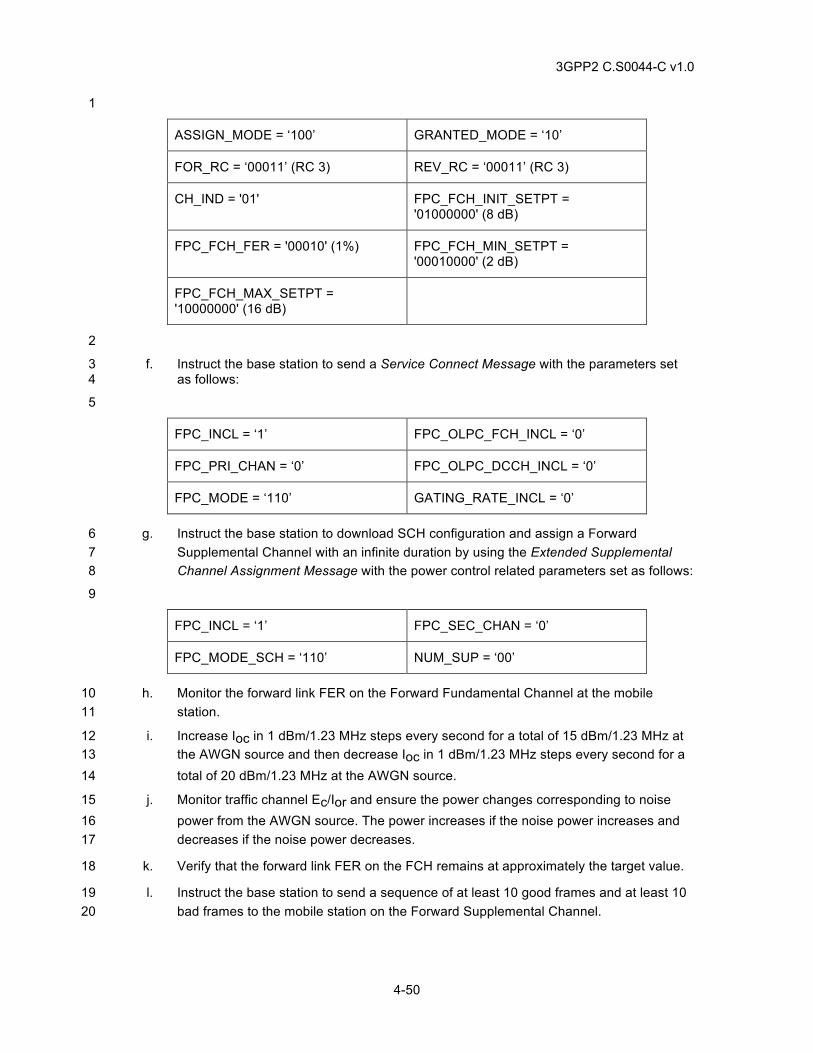
3GPP2 C.S0044-C v1.0
4-50
1
ASSIGN_MODE = ‘100’ GRANTED_MODE = ‘10’
FOR_RC = ‘00011’ (RC 3) REV_RC = ‘00011’ (RC 3)
CH_IND = '01' FPC_FCH_INIT_SETPT = '01000000' (8 dB)
FPC_FCH_FER = '00010' (1%) FPC_FCH_MIN_SETPT = '00010000' (2 dB)
FPC_FCH_MAX_SETPT = '10000000' (16 dB)
2
f. Instruct the base station to send a Service Connect Message with the parameters set 3 as follows: 4
5
FPC_INCL = ‘1’ FPC_OLPC_FCH_INCL = ‘0’
FPC_PRI_CHAN = ‘0’ FPC_OLPC_DCCH_INCL = ‘0’
FPC_MODE = ‘110’ GATING_RATE_INCL = ‘0’
g. Instruct the base station to download SCH configuration and assign a Forward 6 Supplemental Channel with an infinite duration by using the Extended Supplemental 7 Channel Assignment Message with the power control related parameters set as follows: 8
9
FPC_INCL = ‘1’ FPC_SEC_CHAN = ‘0’
FPC_MODE_SCH = ‘110’ NUM_SUP = ‘00’
h. Monitor the forward link FER on the Forward Fundamental Channel at the mobile 10 station. 11
i. Increase Ioc in 1 dBm/1.23 MHz steps every second for a total of 15 dBm/1.23 MHz at 12 the AWGN source and then decrease Ioc in 1 dBm/1.23 MHz steps every second for a 13 total of 20 dBm/1.23 MHz at the AWGN source. 14
j. Monitor traffic channel Ec/Ior and ensure the power changes corresponding to noise 15 power from the AWGN source. The power increases if the noise power increases and 16 decreases if the noise power decreases. 17
k. Verify that the forward link FER on the FCH remains at approximately the target value. 18
l. Instruct the base station to send a sequence of at least 10 good frames and at least 10 19 bad frames to the mobile station on the Forward Supplemental Channel. 20
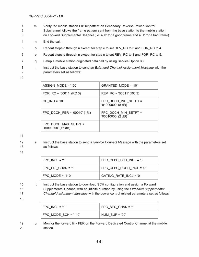
3GPP2 C.S0044-C v1.0
4-51
m. Verify the mobile station EIB bit pattern on Secondary Reverse Power Control 1 Subchannel follows the frame pattern sent from the base station to the mobile station 2 on Forward Supplemental Channel (i.e. a ‘0’ for a good frame and a ‘1’ for a bad frame) 3
n. End the call. 4
o. Repeat steps d through n except for step e to set REV_RC to 3 and FOR_RC to 4. 5
p. Repeat steps d through n except for step e to set REV_RC to 4 and FOR_RC to 5. 6
q. Setup a mobile station originated data call by using Service Option 33. 7
r. Instruct the base station to send an Extended Channel Assignment Message with the 8 parameters set as follows: 9
10
ASSIGN_MODE = ‘100’ GRANTED_MODE = ‘10’
FOR_RC = ‘00011’ (RC 3) REV_RC = ‘00011’ (RC 3)
CH_IND = ‘10’ FPC_DCCH_INIT_SETPT = ‘01000000’ (8 dB)
FPC_DCCH_FER = ‘00010’ (1%) FPC_DCCH_MIN_SETPT = ‘00010000’ (2 dB)
FPC_DCCH_MAX_SETPT = ‘10000000’ (16 dB)
11
s. Instruct the base station to send a Service Connect Message with the parameters set 12 as follows: 13
14
FPC_INCL = ‘1’ FPC_OLPC_FCH_INCL = ‘0’
FPC_PRI_CHAN = ‘1’ FPC_OLPC_DCCH_INCL = ‘0’
FPC_MODE = ‘110’ GATING_RATE_INCL = ‘0’
t. Instruct the base station to download SCH configuration and assign a Forward 15 Supplemental Channel with an infinite duration by using the Extended Supplemental 16 Channel Assignment Message with the power control related parameters set as follows: 17
18
FPC_INCL = ‘1’ FPC_SEC_CHAN = ‘1’
FPC_MODE_SCH = ‘110’ NUM_SUP = ‘00’
u. Monitor the forward link FER on the Forward Dedicated Control Channel at the mobile 19 station. 20
3GPP2 C.S0044-C v1.0
4-52
v. Increase Ioc in 1 dBm/1.23 MHz steps every second for a total of 15 dBm/1.23 MHz at 1 the AWGN source and then decrease Ioc in 1 dBm/1.23 MHz steps every second for a 2 total of 20 dBm/1.23 MHz at the AWGN source. 3
w. Monitor traffic channel Ec/Ior and ensure the power changes corresponding to noise 4 power from the AWGN source. The power increases if the noise power increases and 5 decreases if the noise power decreases. 6
x. Verify that the forward link FER on the DCCH remains at approximately the target value 7
y. Instruct the base station to send a sequence of at least 10 good frames and at least 10 8 bad frames to the mobile station on the Forward Supplemental Channel. 9
z. Verify the mobile station EIB bit pattern on Secondary Reverse Power Control 10 Subchannel follows the frame pattern sent from the base station to the mobile station 11 on Forward Supplemental Channel (i.e. a ‘0’ for a good frame and a ‘1’ for a bad frame) 12
aa. End the call. 13
bb. Repeat steps q through aa except for step r to set REV_RC to 3 and FOR_RC to 4. 14
cc. Repeat steps q through aa except for step r to set REV_RC to 4 and FOR_RC to 5. 15
4.2.10.5 Minimum Standard 16
The mobile station shall comply with steps k, m, x, z. 17
4.3 Lowest Rate Reverse Fundamental Channel Gating 18
4.3.1 Definition 19
This test verifies the mobile station, instructed by the base station, transmits the reverse 20 fundamental channel, with radio configurations 3 or 4, in a duty cycle of 50% when using data 21 rates of 1500 bps for RC3 and 1800 bps for RC4. 22
4.3.2 Traceability 23
(see [1]) 24
2.1.3.7.8 Reverse Fundamental Channel Gating 25
(see [4]) 26
2.2.6.2.5 Mobile Station Origination Operation 27
2.6.3 System Access State 28
2.6.3.5 Mobile Station Origination Attempt Substate 29
2.6.4 Mobile Station Control on the Traffic Channel State 30
2.7.1.3.2.4 Origination Message 31
2.7.2.3.2.15 Service Option Control Message 32
2.7.3 Orders 33
3.6.3.5 Response to Origination Message 1 34
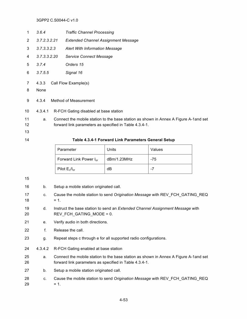
3GPP2 C.S0044-C v1.0
4-53
3.6.4 Traffic Channel Processing 1
3.7.2.3.2.21 Extended Channel Assignment Message 2
3.7.3.3.2.3 Alert With Information Message 3
3.7.3.3.2.20 Service Connect Message 4
3.7.4 Orders 15 5
3.7.5.5 Signal 16 6
4.3.3 Call Flow Example(s) 7
None 8
4.3.4 Method of Measurement 9
4.3.4.1 R-FCH Gating disabled at base station 10
a. Connect the mobile station to the base station as shown in Annex A Figure A-1and set 11 forward link parameters as specified in Table 4.3.4-1. 12
13
Table 4.3.4-1 Forward Link Parameters General Setup 14
Parameter Units Values
Forward Link Power Ior dBm/1.23MHz -75
Pilot Ec/Ior dB -7
15
b. Setup a mobile station originated call. 16
c. Cause the mobile station to send Origination Message with REV_FCH_GATING_REQ 17 = 1. 18
d. Instruct the base station to send an Extended Channel Assignment Message with 19 REV_FCH_GATING_MODE = 0. 20
e. Verify audio in both directions. 21
f. Release the call. 22
g. Repeat steps c through e for all supported radio configurations. 23
4.3.4.2 R-FCH Gating enabled at base station 24
a. Connect the mobile station to the base station as shown in Annex A Figure A-1and set 25 forward link parameters as specified in Table 4.3.4-1. 26
b. Setup a mobile station originated call. 27
c. Cause the mobile station to send Origination Message with REV_FCH_GATING_REQ 28 = 1. 29
3GPP2 C.S0044-C v1.0
4-54
d. Instruct the base station, to send the Extended Channel Assignment Message with 1 REV_FCH_GATING_MODE = 1. 2
e. Verify audio in both directions. 3
f. Instruct the mobile station to transmit data at 1500 bps (for RC3) or 1800 bps (for RC4) 4 on reverse fundamental channel (i.e. by setting the mobile station to Mute). 5
g. Verify transmission is gated at 50% - transmission is turned on and off every 2.5ms, or 6 every 2 Power Control Groups (). 7
h. Release the call. 8
i. Repeat steps c through e for all supported radio configurations. 9
j. Release the call. 10
4.3.5 Minimum Standard 11
4.3.5.1 R-FCH Gating disabled at base station 12
The mobile station shall comply with steps e and g. 13
4.3.5.2 R-FCH Gating enabled at base station 14
The mobile station shall comply with steps g and i. 15
4.4 R-FCH Gating during Soft Handoff 16
4.4.1 Definition 17
This test verifies the functionality of R-FCH gating during soft handoffs. 18
4.4.2 Traceability 19
(see [1]) 20
2.1.3.7.8 Reverse Fundamental Channel Gating 21
(see [4]) 22
2.2.6.2.5 Mobile Station Origination Operation 23
2.6.3 System Access State 24
2.6.3.5 Mobile Station Origination Attempt Substate 25
2.6.4 Mobile Station Control on the Traffic Channel State 26
2.7.1.3.2.4 Origination Message 27
2.7.2.3.2.15 Service Option Control Message 28
2.7.3 Orders 29
3.6.3.5 Response to Origination Message 10 30
3.6.4 Traffic Channel Processing 11 31
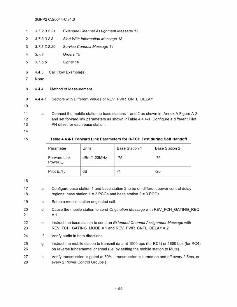
3GPP2 C.S0044-C v1.0
4-55
3.7.2.3.2.21 Extended Channel Assignment Message 12 1
3.7.3.3.2.3 Alert With Information Message 13 2
3.7.3.3.2.20 Service Connect Message 14 3
3.7.4 Orders 15 4
3.7.5.5 Signal 16 5
4.4.3 Call Flow Example(s) 6
None 7
4.4.4 Method of Measurement 8
4.4.4.1 Sectors with Different Values of REV_PWR_CNTL_DELAY 9
10
a. Connect the mobile station to base stations 1 and 2 as shown in Annex A Figure A-2 11 and set forward link parameters as shown inTable 4.4.4-1. Configure a different Pilot 12 PN offset for each base station. 13
14
Table 4.4.4-1 Forward Link Parameters for R-FCH Test during Soft Handoff 15
Parameter Units Base Station 1 Base Station 2
Forward Link Power Ior
dBm/1.23MHz -75 -75
Pilot Ec/Ior dB -7 -20
16
b. Configure base station 1 and base station 2 to be on different power control delay 17 regions: base station 1 = 2 PCGs and base station 2 = 3 PCGs. 18
c. Setup a mobile station originated call. 19
d. Cause the mobile station to send Origination Message with REV_FCH_GATING_REQ 20 = 1. 21
e. Instruct the base station to send an Extended Channel Assignment Message with 22 REV_FCH_GATING_MODE = 1 and REV_PWR_CNTL_DELAY = 2. 23
f. Verify audio in both directions. 24
g. Instruct the mobile station to transmit data at 1500 bps (for RC3) or 1800 bps (for RC4) 25 on reverse fundamental channel (i.e. by setting the mobile station to Mute). 26
h. Verify transmission is gated at 50% - transmission is turned on and off every 2.5ms, or 27 every 2 Power Control Groups (). 28
3GPP2 C.S0044-C v1.0
4-56
i. Raise the level of base station 2 in steps of 1 dB with a dwell time of 1 sec until base 1 station 1 sends an Universal Handoff Direction Message or General Handoff Direction 2 Message with REV_FCH_GATING_MODE = 0. 3
j. Verify mobile station has both base stations on its active pilot set list. 4
k. Verify mobile station transmission of 1500 bps (for RC3) or 1800 bps (for RC4) frames 5 is not gated at 50% duty cycle. 6
l. Release the call. 7
m. Repeat steps b through l for all support radio configurations. 8
4.4.4.2 Sectors with Same Value of REV_PWR_CNTL_DELAY 9
a. Connect the mobile station to base stations 1 and 2 as shown in Annex A Figure A-2 10 and set forward link parameters as shown inTable 4.4.4-1. Configure a different Pilot 11 PN offset for each base station but with the same frequency. 12
b. Configure base station 1 and base station 2 to be on the same power control delay 13 region = 2 PCGs. 14
c. Setup a mobile station originated call. 15
d. Verify the mobile station sends Origination Message with REV_FCH_GATING_REQ = 16 1. 17
e. Instruct the base station to send an Extended Channel Assignment Message with 18 REV_FCH_GATING_MODE = 1 and REV_PWR_CNTL_DELAY = 2. 19
f. Verify audio in both directions. 20
g. Instruct the mobile station to transmit data at 1500bps on reverse fundamental channel 21 (i.e. by setting the mobile station to Mute) 22
h. Verify transmission is gated at 50% - transmission is turned on and off every 2.5ms, or 23 every 2 Power Control Groups (). 24
i. Raise the level of base station 2 in steps of 1 dB with a dwell time of 1 sec until base 25 station 1 sends an Universal Handoff Direction Message or General Handoff Direction 26 Message, REV_FCH_GATING_MODE = 1. 27
j. Verify mobile station has both base stations on its active pilot set list. 28
k. Verify mobile station transmission of 1500 bps (for RC3) or 1800 bps (for RC4) frames 29 is gated at 50% duty cycle. 30
l. Lower the level of base station 1 in steps of 1 dB with a dwell time of 1 sec until base 31 station 2 sends an Universal Handoff Direction Message or General Handoff Direction 32 Message, with REV_FCH_GATING_MODE = 1 and REV_PWR_CNTL_DELAY = 2. 33
m. Verify mobile station has only base station 2 on its active pilot set list. 34
n. Verify mobile station transmission of 1500 bps (for RC3) or 1800 bps (for RC4) frames 35 is gated at 50% duty cycle. 36
o. Release the call. 37
3GPP2 C.S0044-C v1.0
4-57
p. Repeat steps b through o for all supported radio configurations. 1
4.4.5 Minimum Standard 2
4.4.5.1 Sectors with Same Value of REV_PWR_CNTL_DELAY 3
The mobile station shall comply with steps d, h, j, k and m. 4
4.4.5.2 Sectors with Different Values of REV_PWR_CNTL_DELAY 5
The mobile station shall comply with steps d, h, j, k, m, n, and p. 6
7

3GPP2 C.S0044-C v1.0
4-58
This page intentionally left blank. 1
3GPP2 C.S0044-C v1.0
5-1
5 REGISTRATIONS 1
5.1 Power-Up Registration 2
5.1.1 Definition 3
These tests verify proper power-up registration functionality. The mobile station registers when it 4 powers on, switches from using a different frequency block, switches from using a different band 5 class, switches from using an alternative operating mode, or switches from using the analog 6 system. To prevent multiple registrations when power is quickly turned on and off, the mobile 7 station delays T57m seconds before registering, after entering the Mobile Station Idle State. 8
5.1.2 Traceability 9
(see [4]) 10
2.6.5.1.1 Power-Up Registration 11
2.6.5.5.1.3 Entering the Mobile Station Idle State 12
2.6.5.5.2.1 Idle Registration Procedures 13
2.7.1.3.2.1 Registration Message 14
3.6.5 Registration 15
3.7.2.3.2.1 System Parameters Message 16
3.7.2.3.2.30 ANSI-41 System Parameters Message 17
5.1.3 Call Flow Example(s) 18
None 19
5.1.4 Method of Measurement 20
5.1.4.1 Power-up Registration Disabled 21
a. Connect the base station and mobile station as shown in Figure A-3. 22
b. Instruct the base station to set POWER_UP_REG = 0 in the System Parameters 23 Message or ANSI-41 System Parameters Message. 24
c. Power on the mobile station. 25
d. Verify the mobile station does not attempt power-up registration for at least 1 minute 26 after the mobile station enters the Mobile Station Idle State. 27
5.1.4.2 Power-up Registration Enabled 28
a. Connect the base station and mobile station as shown in Figure A-3. 29
b. Instruct the base station to set POWER_UP_REG = 1 in the System Parameters 30 Message or ANSI-41 System Parameters Message 31
c. Power on the mobile station. 32
3GPP2 C.S0044-C v1.0
5-2
d. Verify the mobile station sends a Registration Message with REG_TYPE = ‘0001’ no 1 sooner than 20 seconds (T57M) after entering Mobile Station Idle State. 2
5.1.4.3 Power-up Registration due to change in Operating Mode 3
a. Connect the base station and mobile station as shown in Figure A-5. (Base station 1 is 4 a CDMA base station and base station 2 is a non-CDMA base station. 5
b. Allow the mobile station to operate in the idle state on base station 2. 6
c. Configure base station 1 to set POWER_UP_REG = 1 in the System Parameters 7 Message or the ANSI-41 System Parameters Message. 8
d. Force the mobile station to acquire base station 1. 9
e. Verify the mobile station sends a Registration Message with REG_TYPE = ‘0001’ on 10 base station 1. 11
5.1.4.4 Power-up Registration entering into different Band Class 12
a. Connect the base station and mobile station as shown in Figure A-5. (Base station 1 13 and base station 2 are CDMA base stations using different band classes) 14
b. Instruct both base station 1 and base station 2 to set POWER_UP_REG = 1 in the 15 System Parameters Message or the ANSI-41 System Parameters Message. 16
c. Power on the mobile station. 17
d. Verify the mobile station sends a Registration Message with REG_TYPE = ‘0001’ on 18 base station 1. 19
e. Force the mobile station to acquire base station 2. 20
f. Verify the mobile station a Registration Message with REG_TYPE = ‘0001’ on base 21 station 2. 22
g. Force the mobile station to acquire base station 1. 23
h. Verify the mobile station performs power-up registration on base station 1. 24
5.1.4.5 Power-up Registration entering into Different Frequency Blocks 25
a. Connect the base station and mobile station as shown in Figure A-5. (Base station 1 26 and base station 2 are CDMA base stations using the same band class with 27 frequencies assignments in a different serving system.) 28
b. Instruct both base station 1 and base station 2 to set POWER_UP_REG = 1 in the 29 System Parameters Message or the ANSI-41 System Parameters Message while 30 ensuring all other forms of registration are disabled. 31
c. Power on the mobile station. 32
d. Verify the mobile station sends a Registration Message with REG_TYPE = ‘0001’ on 33 base station 1. 34
e. Force the mobile station to acquire base station 2. 35
3GPP2 C.S0044-C v1.0
5-3
f. Verify the mobile station sends a Registration Message with REG_TYPE = ‘0001’ on 1 base station 2. 2
5.1.5 Minimum Standard 3
5.1.5.1 Power-up Registration Disabled 4
The mobile station shall comply with step d. Power-up registration shall not occur. 5
5.1.5.2 Power-up Registration Enabled 6
The mobile station shall comply with step d. The mobile station shall perform the registration 7 process when it is powered on and after the power/initialization timer has expired. 8
5.1.5.3 Power-up Registration entering into different operating mode 9
The mobile station shall comply with step e. 10
5.1.5.4 Power-up Registration entering into different Band Class 11
The mobile station shall comply with steps d, f and h. 12
5.1.5.5 Power-up Registration entering into Different Frequency Blocks 13
The mobile station shall comply with steps d and f. 14
5.2 Power - Down Registration 15
5.2.1 Definition 16
These tests verify power-down registration functionality. The mobile station should be able to 17 recognize all base station registration settings. 18
The mobile station registers when it powers off if previously registered in the current serving 19 system. The mobile station should not perform power-down registration if it has not previously 20 registered in the system corresponding to its current SID and NID. 21
5.2.2 Traceability 22
(see [4]) 23
2.6.5.1.1 Power-Up Registration 24
2.6.5.1.2 Power-Down Registration 25
2.6.5.5.2.1 Idle Registration Procedures 26
2.7.1.3.2.1 Registration Message 27
3.6.5 Registration 28
3.7.2.3.2.1 System Parameters Message 29
3.7.2.3.2.30 ANSI - 41 System Parameters Message 30
5.2.3 Call Flow Example(s) 31
None 32
3GPP2 C.S0044-C v1.0
5-4
5.2.4 Method of Measurement 1
5.2.4.1 Power-down Registration Disabled 2
a. Connect the base station and mobile station as shown in Figure A-3. 3
b. Enable power-up registration (set POWER_UP_REG = 1 in the System Parameters 4 Message or ANSI - 41 System Parameter Message) while ensuring all other forms of 5 registration are disabled. 6
c. Power on the mobile station. 7
d. Verify the mobile station performs a power-up registration. 8
e. Power down the mobile station. 9
f. Verify power-down registration does not occur. 10
5.2.4.2 Power-down Registration of a Currently Registered Mobile Station 11
a. Connect the base station and mobile station as shown in Figure A-3. 12
b. Enable power-up registration (set POWER_UP_REG = 1) and power-down registration 13 (set POWER_DOWN_REG = 1) in the System Parameters Message or ANSI - 41 14 System Parameter Message) while ensuring all other forms of registration are disabled. 15
c. Power on the mobile station. 16
d. Verify power-up registration occurs. 17
e. Power down the mobile station. 18
f. Verify the mobile station sends a Registration Message with REG_TYPE = ’0011’. 19
5.2.4.3 Power-down Registration of an Unregistered Mobile Station in New System/Network 20
a. Connect the base station and mobile station as shown in Figure A-5. (Base station 1 21 and base station 2 are CDMA base stations using a different SID/NID). 22
b. Instruct base station 1 to set POWER_ UP = 1 and both base station 1 and base station 23 2 to set POWER_DOWN = 1 in the System Parameters Message or ANSI - 41 System 24 Parameter Message, and turn off all other types of registration. 25
c. Power on the mobile station. 26
d. Verify power-up registration on base station 1. 27
e. Force the mobile station to acquire base station 2. 28
f. Verify power-down registration does not occur on base station 2. 29
5.2.5 Minimum Standard 30
5.2.5.1 Power-down Registration Disabled 31
The mobile station shall comply with steps d and f. Power-down registration shall not occur. 32
3GPP2 C.S0044-C v1.0
5-5
5.2.5.2 Power-down Registration of a Currently Registered Mobile Station 1
The mobile station shall comply with steps d and f. The mobile station shall perform power-down 2 registration in a system/network where it is currently registered. 3
5.2.5.3 Power-down Registration of an Unregistered Mobile Station in a New System/Network 4
The mobile station shall comply with steps d and g. Power-down registration shall not occur in a 5 system/network where the mobile station is not currently registered. 6
5.3 Distance-Based Registration 7
5.3.1 Definition 8
These tests verify proper distance-based registration functionality. 9
The mobile station should be able to recognize all base station registration settings. 10
The mobile station registers when the distance between the current base station and the base 11 station in which it last registered exceeds a threshold. 12
5.3.2 Traceability 13
(see [4]) 14
2.6.5.1.1 Power-Up Registration 15
2.6.5.1.4 Distance-Based Registration 16
3.6.5 Registration 17
3.7.2.3.2.1 System Parameters Message 18
3.7.2.3.2.30 ANSI - 41 System Parameters Message 19
3.7.2.3.2.31 MC-RR Parameters Message 20
5.3.3 Call Flow Example(s) 21
None 22
5.3.4 Method of measurement 23
5.3.4.1 Distance-Based Registration Disabled 24
a. Connect the base station and mobile station as shown in Figure A-5. Use the 25 parameters in Table 5.3.4-1. 26
b. Configure base station 1 and base station 2 to send the System Parameters Message 27 or the ANSI - 41 System Parameters Message with REG_DIST, BASE_LAT and 28 BASE_LONG parameters as indicated in Table 5.3.4-2 (Test Case 1). 29
c. Instruct both base station 1 and base station 2 to set power-up registration (set 30 POWER_UP_REG = 1) in the System Parameters Message or the ANSI - 41 System 31 Parameters Message. 32
d. Power on the mobile station on base station 1. 33
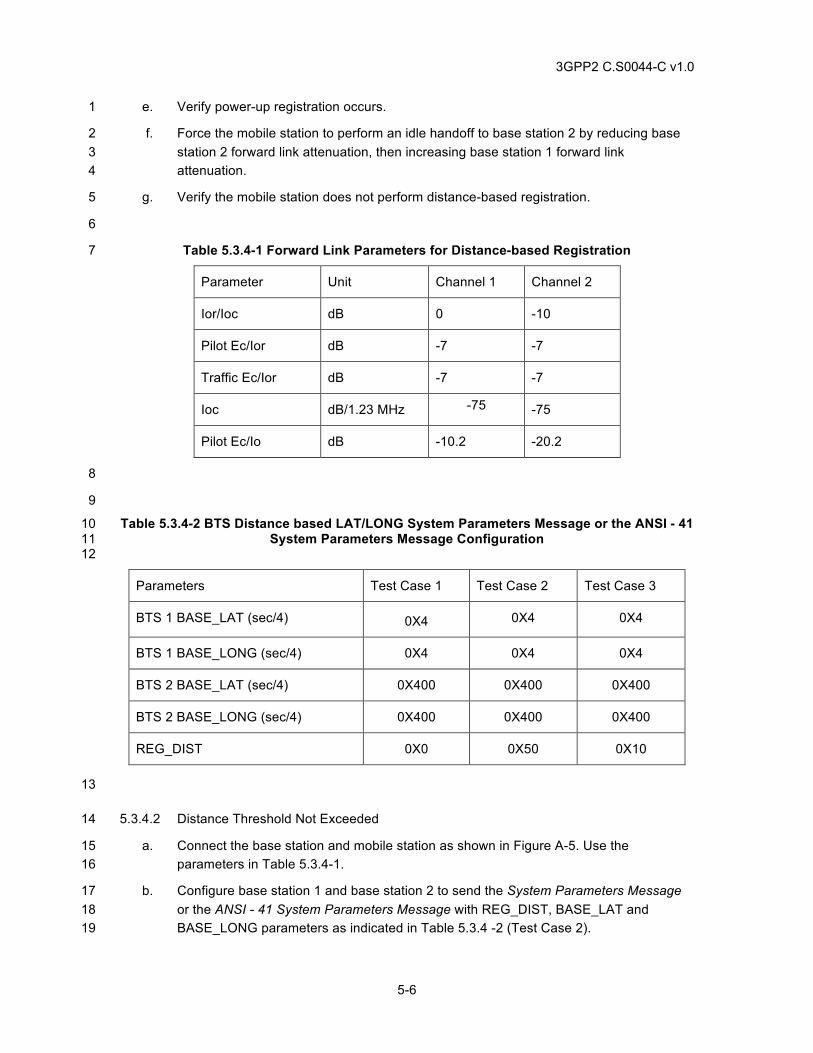
3GPP2 C.S0044-C v1.0
5-6
e. Verify power-up registration occurs. 1
f. Force the mobile station to perform an idle handoff to base station 2 by reducing base 2 station 2 forward link attenuation, then increasing base station 1 forward link 3 attenuation. 4
g. Verify the mobile station does not perform distance-based registration. 5
6
Table 5.3.4-1 Forward Link Parameters for Distance-based Registration 7
Parameter Unit Channel 1 Channel 2
Ior/Ioc dB 0 -10
Pilot Ec/Ior dB -7 -7
Traffic Ec/Ior dB -7 -7
Ioc dB/1.23 MHz -75 -75
Pilot Ec/Io dB -10.2 -20.2
8
9
Table 5.3.4-2 BTS Distance based LAT/LONG System Parameters Message or the ANSI - 41 10 System Parameters Message Configuration 11
12
Parameters Test Case 1 Test Case 2 Test Case 3
BTS 1 BASE_LAT (sec/4) 0X4 0X4 0X4
BTS 1 BASE_LONG (sec/4) 0X4 0X4 0X4
BTS 2 BASE_LAT (sec/4) 0X400 0X400 0X400
BTS 2 BASE_LONG (sec/4) 0X400 0X400 0X400
REG_DIST 0X0 0X50 0X10
13
5.3.4.2 Distance Threshold Not Exceeded 14
a. Connect the base station and mobile station as shown in Figure A-5. Use the 15 parameters in Table 5.3.4-1. 16
b. Configure base station 1 and base station 2 to send the System Parameters Message 17 or the ANSI - 41 System Parameters Message with REG_DIST, BASE_LAT and 18 BASE_LONG parameters as indicated in Table 5.3.4 -2 (Test Case 2). 19
3GPP2 C.S0044-C v1.0
5-7
c. Instruct both base station 1 and base station 2 to set power-up registration (set 1 POWER_UP_REG = 1) in the System Parameters Message or the ANSI - 41 System 2 Parameters Message. 3
d. Power on the mobile station. 4
e. Verify power-up registration occurs. 5
f. Force the mobile station to perform an idle handoff to base station 2 by reducing base 6 station 2 forward link attenuation, then increasing base station 1 forward link 7 attenuation. 8
g. Verify the mobile station does not perform distance-based registration. 9
5.3.4.3 Distance Threshold Exceeded 10
a. Connect the base station and mobile station as shown in Figure A-5. Use the 11 parameters in Table 5.3.4-1. 12
b. Configure base station 1 and base station 2 to send the System Parameters Message 13 or the ANSI - 41 System Parameters Message with REG_DIST, BASE_LAT and 14 BASE_LONG parameters as indicated in Table 5.3.4-2 (Test Case 3). 15
c. Instruct both base station 1 and base station 2 to set power-up registration (set 16 POWER_UP_REG = 1) in the System Parameters Message or the ANSI - 41 System 17 Parameters Message. 18
d. Power on the mobile station. 19
e. Verify power-up registration occurs. 20
f. Force mobile station to perform idle handoff to base station 2 by reducing base station 2 21 forward link attenuation, then increasing base station 1 forward link attenuation. 22
g. Verify the mobile station sends a Registration Message with REG_TYPE = ’0110’. 23
5.3.5 Minimum Standard 24
5.3.5.1 Distance-based Registration Disabled 25
The mobile station shall comply with step g. Distance-based registration shall not occur. 26
5.3.5.2 Distance Threshold Not Exceeded 27
The mobile station shall comply with step g. The mobile station shall not perform distance-based 28 registration when distance-based registration enabled and calculated value of DISTANCE is less 29 than REG_DIST. 30
5.3.5.3 Distance Threshold Exceeded 31
The mobile station shall comply with step g. The mobile station shall perform distance-based 32 registration when distance based registration is enabled and the calculated value of DISTANCE is 33 greater than REG_DIST. 34
3GPP2 C.S0044-C v1.0
5-8
5.4 Timer-Based Registration 1
5.4.1 Definition 2
These tests verify proper timer - based registration functionality. 3
The mobile station registers when a timer expires. 4
Timer-based registration is performed when the counter reaches a maximum value 5 (REG_COUNT_MAX) that is controlled by the base station via the REG_PRD field of the System 6 Parameters Message or ANSI-41 System Parameters Message. 7
The counter is reset when the mobile station powers on. The counter is reset after each 8 successful registration. 9
5.4.2 Traceability 10
(see [4]) 11
2.6.5.1.2 Power-Down Registration 12
2.6.5.1.3 Timer-Based Registration 13
2.7.1.3.2.1 Registration Message 14
3.6.5 Registration 15
3.7.2.3.2.1 System Parameters Message 16
3.7.2.3.2.30 ANSI- 41 System Parameters Message 17
5.4.3 Call Flow Example(s) 18
None 19
5.4.4 Method of Measurement 20
5.4.4.1 Timer-based Registration Disabled 21
a. Connect the base station and mobile station as shown in Figure A-3. 22
b. Instruct the base station to set POWER_UP_REG =1 and set REG_PRD = 0 in the 23 System Parameters Message or ANSI – 41 System Parameter Message. 24
c. Power on the mobile station. 25
d. Verify power-up registration occurs. 26
e. Verify the mobile station does not perform timer-based registration. 27
5.4.4.2 Mid-range Timer Value 28
a. Connect the base station and mobile station as shown in Figure A-3. 29
b. Instruct the base station to set POWER_UP_REG =0 and set REG_PRD = 38 (57.93 30 seconds) in the System Parameters Message or ANSI –41 System Parameter 31 Message. 32
c. Power on the mobile station. 33
3GPP2 C.S0044-C v1.0
5-9
d. Verify timer-based registration occurs approximately every 58 seconds. 1
5.4.5 Minimum Standard 2
5.4.5.1 Timer-based Registration Disabled 3
The mobile station shall comply with steps d and e. Timer-based registration shall not occur. 4
5.4.5.2 Mid-Range Timer Value 5
The mobile station shall comply with step d. The mobile station shall perform time-based 6 registration at the interval specified by the REG_PRD value. 7
5.5 Parameter-Change Registration 8
5.5.1 Definition 9
These tests verify proper parameter-change registration functionality. 10
Parameter-change registration is performed when a mobile station modifies any of the following 11 stored parameters: 12
a. The mobile station’s SID_NID_LIST does not match the base station’s SID and NID. 13
5.5.2 Traceability 14
(see [4]) 15
2.6.5.1.6 Parameter-Change Registration 16
3.6.5 Registration 17
3.7.2.3.2.1 System Parameters Message 18
3.7.2.3.2.30 ANSI - 41 System Parameters Message 19
5.5.3 Call Flow Example(s) 20
None 21
5.5.4 Method of Measurement 22
5.5.4.1 Parameter-Change Registration Disabled 23
a. Connect the base station and mobile station as shown in Figure A-5. Base station 1 and 24 base station 2 are CDMA base station operating in the same band class and 25 frequencies with different SID values. 26
b. Instruct the base station to set PARAMETER_REG = ‘0’ and disable all other forms of 27 registration (set equal to 0) in the System Parameters Message or ANSI - 41 System 28 Parameters Message. 29
c. Power on the mobile station and allow time for the mobile station to acquire base 30 station 1. 31
d. Force the mobile station to acquire base station 2. 32
3GPP2 C.S0044-C v1.0
5-10
e. Verify the mobile station does not send a Registration Message. 1
5.5.4.2 Parameter-Based Registration per SID-NID List change 2
a. Connect the base station and mobile station as shown in Figure A-5. (Base station 1 3 and base station 2 are CDMA base stations using different SID configurations). 4
b. Instruct both base station to set PARAMETER_REG = 1 while ensuring all other forms 5 of registration are disabled (set equal to 0) in the System Parameters Message or ANSI 6 - 41 System Parameters Message. 7
c. Power on the mobile station and allow time for the mobile station to acquire Base 8 Station 1. 9
d. Force the mobile station to acquire Base Station 2. 10
e. Verify the mobile station sends a Registration Message with REG_TYPE = ’0100’. 11
f. Repeat steps a through e with base station 1 and base station 2 using different NID 12 configurations. 13
5.5.5 Minimum Standard 14
5.5.5.1 Parameter-Change Registration Disabled 15
5.5.5.2 The mobile station shall comply with step e. Parameter-Based Registration per SID-NID 16 List change 17
The mobile station shall comply with step e. 18
5.6 Zone-Based Registration 19
5.6.1 Definition 20
These tests verify proper Zone-based registration functionality. 21
The mobile station registers when it enters a new zone that is not on its internally stored list of 22 visited registration zones. 23
The mobile station does not register when it performs an idle handoff into a zone that is on its 24 internally stored list of visited zones. 25
The mobile station should properly delete entries from its internally stored list of visited 26 registration zones. 27
5.6.2 Traceability 28
(see [4]) 29
2.6.5.1.1 Power-Up Registration 30
2.6.5.1.5 Zone-Based Registration 31
3.6.5 Registration 32
3.7.2.3.2.1 System Parameters Message 33
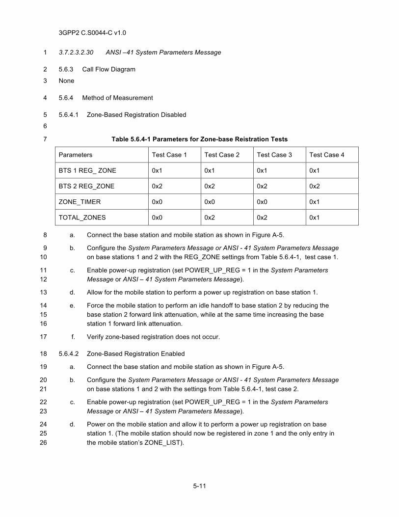
3GPP2 C.S0044-C v1.0
5-11
3.7.2.3.2.30 ANSI –41 System Parameters Message 1
5.6.3 Call Flow Diagram 2
None 3
5.6.4 Method of Measurement 4
5.6.4.1 Zone-Based Registration Disabled 5
6
Table 5.6.4-1 Parameters for Zone-base Reistration Tests 7
Parameters Test Case 1 Test Case 2 Test Case 3 Test Case 4
BTS 1 REG_ ZONE 0x1 0x1 0x1 0x1
BTS 2 REG_ZONE 0x2 0x2 0x2 0x2
ZONE_TIMER 0x0 0x0 0x0 0x1
TOTAL_ZONES 0x0 0x2 0x2 0x1
a. Connect the base station and mobile station as shown in Figure A-5. 8
b. Configure the System Parameters Message or ANSI - 41 System Parameters Message 9 on base stations 1 and 2 with the REG_ZONE settings from Table 5.6.4-1, test case 1. 10
c. Enable power-up registration (set POWER_UP_REG = 1 in the System Parameters 11 Message or ANSI – 41 System Parameters Message). 12
d. Allow for the mobile station to perform a power up registration on base station 1. 13
e. Force the mobile station to perform an idle handoff to base station 2 by reducing the 14 base station 2 forward link attenuation, while at the same time increasing the base 15 station 1 forward link attenuation. 16
f. Verify zone-based registration does not occur. 17
5.6.4.2 Zone-Based Registration Enabled 18
a. Connect the base station and mobile station as shown in Figure A-5. 19
b. Configure the System Parameters Message or ANSI - 41 System Parameters Message 20 on base stations 1 and 2 with the settings from Table 5.6.4-1, test case 2. 21
c. Enable power-up registration (set POWER_UP_REG = 1 in the System Parameters 22 Message or ANSI – 41 System Parameters Message). 23
d. Power on the mobile station and allow it to perform a power up registration on base 24 station 1. (The mobile station should now be registered in zone 1 and the only entry in 25 the mobile station’s ZONE_LIST). 26
3GPP2 C.S0044-C v1.0
5-12
e. Force the mobile station to perform an idle handoff to base station 2 by reducing the 1 base station 2 forward link attenuation, while at the same time increasing the base 2 station 1 forward link attenuation. 3
f. Verify the mobile station sends a Registration Message with REG_TYPE = ’0010’. (The 4 mobile station should now be registered in zone 2. Zone 1 and Zone 2 should be in the 5 mobile station’s ZONE_LIST). 6
g. Before the period of time specified by ZONE_TIMER has elapsed (one minute) and the 7 mobile station deletes zone 1 from it’s ZONE_LIST, force the mobile station to perform 8 an idle handoff back to base station 1. 9
h. Verify zone-based registration does not occur. (Zone 1 is still in the mobile station’s 10 ZONE_LIST). 11
5.6.4.3 Zone-Based Registration Timer 12
a. Connect the base station and mobile station as shown in Figure A-5. 13
b. Configure the System Parameters Message or ANSI - 41 System Parameters Message 14 on base stations 1 and 2 with the settings from Table 5.6.4-1, test case 3. 15
c. Enable power-up registration (set POWER_UP_REG = 1 in the System Parameters 16 Message or ANSI – 41 System Parameters Message). 17
d. Power on the mobile station and allow it to perform a power up registration on base 18 station 1. (The mobile station should now be registered in zone 1 and the only entry in 19 the mobile station’s ZONE_LIST). 20
e. Force the mobile station to perform an idle handoff to base station 2 by reducing the 21 base station 2 forward link attenuation, while at the same time increasing the base 22 station 1 forward link attenuation. 23
f. Verify zone-based registration occurs. (The mobile station should now be registered in 24 zone 2. Zone 1 and Zone 2 should be in the mobile station’s ZONE_LIST). 25
g. Wait for the period of time specified by ZONE_TIMER to elapse (one minute, after 26 which the mobile station should delete zone 1 from ZONE_LIST). 27
h. Force the mobile station to perform an idle handoff to base station 1. 28
i. Verify the mobile station sends a Registration Message with REG_TYPE = ’0010’. 29
5.6.4.4 Mobile Station ZONE_LIST Deletion 30
a. Connect the base station and mobile station as shown in Figure A-5. 31
b. Configure the System Parameters Message or ANSI - 41 System Parameters Message 32 on base stations 1 and 2 with the settings from Table 5.6.4-1, test case 4. 33
c. Enable power-up registration (set POWER_UP_REG = 1 in the System Parameters 34 Message or ANSI – 41 System Parameters Message). 35
3GPP2 C.S0044-C v1.0
5-13
d. Power on the mobile station and allow it to perform a power up registration on base 1 station 1. (The mobile station should now be registered in zone 1 and the only entry in 2 the mobile station’s ZONE_LIST). 3
e. Force the mobile station to perform an idle handoff to base station 2 by reducing the 4 base station 2 forward link attenuation, while at the same time increasing the base 5 station 1 forward link attenuation. 6
f. Verify the mobile station sends a Registration Message with REG_TYPE = ‘0010’. (The 7 mobile station is now registered in zone 2, and only zone 2 should be in mobile station’s 8 ZONE_LIST because the mobile station was forced to delete zone 1 from ZONE_LIST 9 to make room for zone 2). 10
g. Force the mobile station to perform an idle handoff back to base station 1. 11
h. Verify the mobile station sends a Registration Message with REG_TYPE = ’0010’. 12 (Zone 1 is not in ZONE_LIST). 13
5.6.5 Minimum Standard 14
5.6.5.1 Zone-Based Registration Disabled 15
The mobile station shall comply with step f. The mobile station shall not perform a zone-based 16 registration. 17
5.6.5.2 Zone-Based Registration Enabled 18
The mobile station shall comply with steps f, h. The mobile station performs a zone-based 19 registration. 20
5.6.5.3 Zone-Based Registration Timer 21
The mobile station shall comply with steps f, and i. The mobile station performs a zone-based 22 registration. 23
5.6.5.4 Mobile Station ZONE_LIST Deletion 24
The mobile station shall comply with steps f, h. The mobile station performs a zone-based 25 registration. 26
27
28

3GPP2 C.S0044-C v1.0
5-14
This page intentionally left blank.1
3GPP2 C.S0044-C v1.0
6-1
6 AUTHENTICATION 1
6.1 Shared Secret Data (SSD) Initialized when A-Key is Changed 2
6.1.1 Definition 3
This test verifies that when the A-Key is changed at both the base station and mobile station, 4 authentication of mobile station registrations, originations, and terminations and the Unique 5 Challenge-Response Procedure are successful. 6
6.1.2 Traceability: 7
(see [4]) 8
2.3.12.1 (MS) Authentication 9
2.6.5.1.3 Timer-Based Registration 10
3.3.1 (Base Station) Authentication 11
6.1.3 Call Flow Example(s) 12
None 13
6.1.4 Method of Measurement 14
a. Connect the base station and mobile station as shown in Annex A Figure A-1. 15
b. Power on the mobile station. 16
c. Initialize the A-Key to the same value in the mobile station and base station. 17
d. Ensure timer-based registration is enabled with the registration period (REG_PRD) set 18 to 29. 19
e. Verify the mobile station sends a Registration Message with REG_TYPE set to ‘0000’ 20 (i.e. timer-based registration) and which includes AUTHR, RANDC and COUNT. 21
f. Verify registration authentication is successful at the base station. 22
g. Setup a mobile station originated call. 23
h. Verify user data in both directions. 24
i. End the call. 25
j. Setup a mobile station terminated call. 26
k. Verify user data in both directions. 27
l. Instruct the base station to initiate a Unique Challenge-Response Procedure while on 28 the f/r-dsch. 29
m. Verify the following: 30
1. The base station sends an Authentication Challenge Message, 31
3GPP2 C.S0044-C v1.0
6-2
2. Upon receiving this message, the mobile station sends an Authentication 1 Challenge Response Message, and 2
3. The Unique Challenge-Response Procedure is successful. 3
n. End the call. 4
o. Instruct the base station to initiate a Unique Challenge-Response Procedure while on 5 the f/r-csch. 6
p. Verify the following: 7
1. The base station sends an Authentication Challenge Message, 8
2. Upon receiving this message, the mobile station sends an Authentication 9 Challenge Response Message, and 10
3. The Unique Challenge-Response Procedure is successful. 11
6.1.5 Minimum Standard 12
The mobile station shall comply with the following steps: e, h, k, m, p. 13
The base station shall comply with the following steps: f, h, k, m, p. 14
6.2 Shared Secret Data Update 15
6.2.1 Definition 16
This test verifies the mobile station and base station can perform a Shared Secret Data update on 17 the f/r-csch and f/r-dsch. 18
6.2.2 Traceability: 19
(see [4]) 20
2.3.12.1.4 Unique Challenge-Response Procedure 21
2.3.12.1.5 Updating the Shared Secret Data (SSD) 22
2.6.5.1.3 Timer-Based Registration 23
2.7.1.3.2.6 Authentication Challenge Response Message 24
3.7.2.3.2.1 System Parameters Message (f-csch) 25
3.7.2.3.2.10 Authentication Challenge Message (f-csch) 26
6.2.3 Call Flow Example(s) 27
None 28
6.2.4 Method of Measurement 29
a. Connect the base station and mobile station as shown in Annex A Figure A-1. 30
b. Power on the mobile station. 31
c. Initialize the A-Key to the same value in both the mobile station and base station. 32
3GPP2 C.S0044-C v1.0
6-3
d. Instruct the base station to initiate a Shared Secret Data update on the f/r-csch. 1
e. Verify the following: 2
1. The base station sends a SSD Update Message, 3
2. The mobile station sends a Base Station Challenge Order, 4
3. The base station sends a Base Station Challenge Confirmation Order, 5
4. The mobile station sends a SSD Update Confirmation Order, and 6
5. That the SSD Update Procedure is successful. 7
f. Ensure timer-based registration is enabled with the registration period (REG_PRD) set 8 to 29. 9
g. Wait for the mobile station to send the Registration Message with REG_TYPE set to 10 ‘0000’ (i.e. timer-based registration). 11
h. Verify the Registration Message includes AUTHR, COUNT and RANDC. 12
i. Verify registration authentication is successful at the base station. 13
j. Setup a mobile station originated call. 14
k. Verify user data in both directions. 15
l. Instruct the base station to initiate a Unique Challenge-Response Procedure on the f/r-16 dsch. 17
m. Verify the following: 18
1. The base station sends an Authentication Challenge Message, 19
2. Upon receiving this message, the mobile station sends a Authentication 20 Challenge Response Message, and 21
3. That the Unique Challenge-Response Procedure is successful. 22
n. End the call. 23
o. Instruct the base station to initiate a Unique Challenge-Response Procedure on the f/r-24 csch. 25
p. Verify the following: 26
1. The base station sends an Authentication Challenge Message, 27
2. Upon receiving this message, the mobile station sends a Authentication 28 Challenge Response Message, and 29
3. That the Unique Challenge-Response Procedure is successful. 30
q. Repeat steps c through p but with the following exception: 31
1. In step d, setup a call and initiate a Shared Secret Data update on the f/r-dsch, 32 and then end the call. 33
3GPP2 C.S0044-C v1.0
6-4
6.2.5 Minimum Standard 1
The mobile station shall comply with the following steps: e, h, k, m, p, q. 2
The base station shall comply with the following steps: e, i, k, m, p, q. 3
6.3 Mismatched A-Keys 4
6.3.1 Definition 5
This test verifies that when there is an A_KEY mismatch, authentication of registrations, 6 originations, terminations, and Unique Challenge-Response procedures will fail. 7
6.3.2 Traceability 8
(see [4]) 9
2.3.12.1.4 Unique Challenge-Response Procedure 10
2.3.12.1.5 Updating the Shared Secret Data (SSD) 11
2.7.1.3.2.6 Authentication Challenge Response Message 12
2.7.2.3.2.2 Authentication Challenge Response Message (r-dsch) 13
3.7.2.3.2.10 Authentication Challenge Message (f-csch) 14
3.7.2.3.2.1 SSD Update Message (f-csch) 15
3.7.3.3.2.2 Authentication Challenge Message (f-dsch) 16
3.7.3.3.2.13 SSD Update Message (f-dsch) 17
6.3.3 Call Flow Example(s) 18
None 19
6.3.4 Method of Measurement 20
a. Connect the base station and mobile station as shown in Annex A Figure A-1. 21
b. Power on the mobile station. 22
c. Initialize the A-Key to the same value in the mobile station and base station. 23
d. Instruct the base station to initiate a Shared Secret Data update on the f/r-csch. 24
e. Setup a mobile station originated call. 25
f. Verify user data in both directions. 26
g. End the call. 27
h. Change the A-Key in the mobile station. 28
i. Ensure timer-based registration is enabled with the registration period (REG_PRD) set 29 to 29. 30
j. Wait for the mobile station to send a Registration Message with REG_TYPE set to 31 ‘0000’ (i.e. timer-based registration). 32
3GPP2 C.S0044-C v1.0
6-5
k. Verify the Registration Message includes AUTHR, COUNT and RANDC. 1
l. Verify registration authentication fails at the base station due to an AUTHR mismatch. 2
m. Setup a mobile station originated call. 3
n. Verify that the call request was denied. 4
o. Setup a mobile station terminated call. 5
p. Verify the call fails due to an AUTHR mismatch. 6
q. Initiate at the base station a Shared Secret Data update on the f-csch. 7
r. Verify the SSD Update fails with an AUTHBS mismatch. 8
s. Initiate at the base station a Unique Challenge-Response Procedure on the f-csch. 9
t. Verify the Unique Challenge-Response Procedure fails with an AUTHU mismatch. 10
6.3.5 Minimum Standard 11
The mobile station shall comply with the following steps: f, k, n, p, r, t. 12
The base station shall comply with the following steps: f, l, p, r, t. 13
6.4 Activating Voice Privacy on Call Setup 14
6.4.1 Definition 15
This test verifies that Voice Privacy can be activated at call setup by the mobile station 16 subscriber. 17
6.4.2 Traceability: 18
(see [4]) 19
2.3.12.3 (MS) Voice Privacy 20
2.6.4.1.6 (MS) Long Code Transition Request Processing 21
2.7.1.3.2.4 Origination Message 22
2.7.1.3.2.5 Page Response Message 23
2.7.3 (Mobile Station) Orders 24
3.3.3 (Base Station) Voice Privacy 25
3.6.4.1.5 (Base Station) Long Code Transition Request Processing 26
3.6.4.3 Traffic Channel Substate 27
3.6.4.4 Release Substate 28
3.7.4 (Base Station) Orders 29
6.4.3 Call Flow Example(s) 30
None 31
3GPP2 C.S0044-C v1.0
6-6
6.4.4 Method of Measurement 1
a. Connect the base station and mobile station as shown in Annex A Figure A-1. 2
b. Ensure authentication is enabled. Verify the AUTH field of the Access Parameters 3 Message is set to ‘01’ or the ANSI-41 RAND Message is being transmitted. 4
c. Power on the mobile station. 5
d. Enable Voice Privacy in the mobile station and configure the base station to use voice 6 privacy. 7
e. Setup a mobile station originated call, and verify in the Origination Message the Voice 8 Privacy Mode Indicator (PM) is set to '1'. 9
f. Instruct the base station to send a Long Code Transition Request Order 10 (ORDQ='00000001') on the f-dsch. 11
g. Verify the mobile station responds with a Long Code Transition Response Order 12 (ORDQ='00000011') 13
h. If supported on the user interface, verify the mobile station indicates to the user that 14 Voice Privacy is active. 15
i. Verify that correct user data is received in both directions. 16
j. End the call. 17
k. Setup a mobile station terminated call, and verify in the Page Response Message the 18 voice privacy indicator (PM) is set to ‘1’ then repeat steps f through j. 19
6.4.5 Minimum Standard 20
The mobile station shall comply with the following steps: e, g, h, i, k. 21
The base station shall comply with the following steps: b, i. 22
6.5 Activating Voice Privacy at the Mobile Station When a Call Is Active 23
6.5.1 Definition 24
This test verifies that Voice Privacy can be activated at the mobile station when a call is active. 25
6.5.2 Traceability 26
(see [4]) 27
2.3.12.3 (Mobile Station) Voice Privacy 28
2.6.4.1.6 Long Code Transition Request Processing 29
2.7.1.3.2.4 Origination Message 30
2.7.1.3.2.5 Page Response Message 31
2.7.3 (Mobile Station) Orders 32
3.3.3 (Base Station) Voice Privacy 33
3GPP2 C.S0044-C v1.0
6-7
3.6.4.1.5 (Base Station) Long Code Transition Request Processing 1
3.6.4.3.1 Traffic Channel Substate 2
3.6.4.4 Release Substate 3
3.7.4 (Base Station) Orders 4
6.5.3 Call Flow Example(s) 5
None 6
6.5.4 Method of Measurement 7
a. Connect the base station and mobile station as shown in Annex A Figure A-1. 8
b. Configure the base station to use Voice Privacy. 9
c. Ensure authentication is enabled. Verify the AUTH field of the Access Parameters 10 Message is set to ‘01’ or the ANSI-41 RAND Message is being transmitted. 11
d. Power on the mobile station. 12
e. Setup a mobile station originated call. 13
f. Enable voice privacy at the mobile station. Verify the mobile station sends a Long Code 14 Transition Request Order with ORDQ set to ‘00000001’. 15
g. Verify the base station responds by sending a Long Code Transition Request Order 16 with ORDQ set to ‘00000001’. 17
h. Verify the mobile station responds with a Long Code Transition Response Order 18 (ORDQ='00000011'). 19
i. If supported on the user interface, verify the mobile station indicates Voice Privacy is 20 active. 21
j. Verify that correct user data is received in both directions. 22
k. End the call. 23
6.5.5 Minimum Standard 24
The mobile station shall comply with the following steps: f, h, i, j. 25
The base station shall comply with the following steps: c, g, j. 26
6.6 Signaling Message Encryption on Forward Traffic Channel 27
6.6.1 Definition 28
This test verifies that Signaling Message Encryption on f-dsch is performed correctly. 29
6.6.2 Traceability 30
(see [4]) 31
2.3.12.2 (Mobile Station) Signaling Message Encryption 32
3GPP2 C.S0044-C v1.0
6-8
2.7.4.4 (Mobile Station) Calling Party Number 1
3.3.2 (Base Station) Encryption 2
3.7.2.3.2.8 Channel Assignment Message (f-csch) 3
3.7.3.3.2.3 Alert With Information Message (f-dsch) 4
3.7.5.3 (Base Station) Calling Party Number 5
6.6.3 Call Flow Example(s) 6
None 7
6.6.4 Method of Measurement 8
a. Connect the base station and mobile station as shown in Annex A Figure A-1. 9
b. Activate the Calling Party Number (CPN) feature for the mobile station subscriber. 10
c. Ensure authentication is enabled. Verify the AUTH field of the Access Parameters 11 Message is set to ‘01’ or the ANSI-41 RAND Message is being transmitted. 12
d. Power on the mobile station. 13
e. Enable Signaling Message Encryption on the base station. 14
f. Setup a mobile station terminated call. 15
g. Verify the ENCRYPT_MODE field is set to '01' or ‘10’ in the transmitted Channel 16 Assignment Message or Extended Channel Assignment Message. 17
h. Verify the following: 18
1. Required fields in the appropriate messages are encrypted and can be correctly 19 decrypted. For example, certain fields of the Alert With Information Message will 20 be encrypted; but verification can be done on other messages as well. 21
2. The ENCRYPTION field in these messages is set to the same value as the 22 ENCRYPT_MODE field received in the Channel Assignment Message or 23 Extended Channel Assignment Message. 24
i. Verify the CPN is displayed on the mobile station during the alerting state. 25
j. Verify that correct user data is received in both directions. 26
k. End the call. 27
6.6.5 Minimum Standard 28
The mobile station shall comply with the following steps: h, i, j. 29
The base station shall comply with the following steps: c, g, h, j. 30
6.7 Signaling Message Encryption on Reverse Traffic Channel 31
6.7.1 Definition 32
This test verifies that Signaling Message Encryption on the r-dsch is performed correctly. 33
3GPP2 C.S0044-C v1.0
6-9
6.7.2 Traceability 1
(see [4]) 2
2.3.12.2 (Mobile Station) Signaling Message Encryption 3
2.7.2.3.2.7 Send Burst DTMF Message 4
3.3.2 (Base Station) Encryption 5
3.7.2.3.2.8 Channel Assignment Message (f-csch) 6
6.7.3 Call Flow Example(s) 7
None 8
6.7.4 Method of Measurement 9
a. Connect the base station and mobile station as shown in Annex A Figure A-1. 10
b. Ensure authentication is enabled. Verify the AUTH field of the Access Parameters 11 Message is set to ‘01’ or the ANSI-41 RAND Message is being transmitted. 12
c. Power on the mobile station. 13
d. Instruct the mobile station to send a Send Burst DTMF Message. 14
e. Enable Signaling Message Encryption on the base station. 15
f. Setup a mobile station call to a voice mail system or a paging system. 16
g. Verify the ENCRYPT_MODE field is set to '01' or ‘10’ in the transmitted Channel 17 Assignment Message or Extended Channel Assignment Message. 18
h. Verify the following: 19
1. Required fields in the appropriate messages are encrypted and can be correctly 20 decrypted. For example, certain fields of the Burst DTMF Message will be 21 encrypted; but verification can be done on other messages as well. 22
2. The ENCRYPTION field in these messages is set to the same value as the 23 ENCRYPT_MODE field received in the Channel Assignment Message or 24 Extended Channel Assignment Message. 25
i. Enter the appropriate pin code as burst DTMF tones. 26
j. Verify that either the voice mail system recognizes the DTMF tones and plays the 27 message back, or that the paging system accepts the pin and sends out the page. 28 Alternative procedures may be used to verify correct behavior. 29
k. End the call. 30
6.7.5 Minimum Standard 31
The mobile station shall comply with the following step: h. 32
The base station shall comply with the following steps: b, g, h, j. 33
3GPP2 C.S0044-C v1.0
6-10
6.8 Hard Handoffs between Base Stations with Signaling Message Encryption Active 1
6.8.1 Definition 2
This test verifies that when Signaling Message Encryption is used, the new base station activates 3 correct encryption upon handoff. 4
6.8.2 Traceability 5
(see [4]) 6
2.3.12.2 (Mobile Station) Signaling Message Encryption 7
2.6.6.2.8 CDMA-to-CDMA Hard Handoff 8
2.7.4.4 (Mobile Station) Calling Party Number. 9
3.3.2 (Base Station) Encryption 10
3.6.6.2.2.2 Extended Handoff Direction Message (call processing) 11
3.6.6.2.2.10 General Handoff Direction Message (call processing) 12
3.6.6.2.2.11 Universal Handoff Direction Message (call processing) 13
3.7.2.3.2.8 Channel Assignment Message (f-csch) 14
3.7.3.3.2.14 Flash With Information Message (f-dsch) 15
3.7.3.3.2.17 Extended Handoff Direction Message (f-dsch) 16
3.7.3.3.2.31 General Handoff Direction Message (f-dsch) 17
3.7.3.3.2.36 Universal Handoff Direction Message (f-dsch) 18
3.7.5.3 (Base Station) Calling Party Number 19
6.8.3 Call Flow Example(s) 20
None 21
6.8.4 Method of Measurement 22
a. Connect the base station and mobile station as shown in Annex A Figure A-5. 23
b. Activate Call Waiting and Caller ID on base station 2. 24
c. Ensure authentication is enabled. Verify the AUTH field of the Access Parameters 25 Message is set to ‘01’ or the ANSI-41 RAND Message is being transmitted. 26
d. Power on the mobile station. 27
e. Enable Signaling Message Encryption on both base stations. 28
f. Setup a mobile station originated call. 29
g. Verify ENCRYPT_MODE field is set to '01' or ‘10’ in the transmitted Channel 30 Assignment Message or Extended Channel Assignment Message. 31
h. Verify user data in both directions. 32
3GPP2 C.S0044-C v1.0
6-11
i. Cause a hard handoff from base station 1 to base station 2. 1
j. Verify ENCRYPT_MODE field is set to '01’ or ‘10’ in the transmitted Extended Handoff 2 Direction Message, General Handoff Direction Message, or Universal Handoff Direction 3 Message. 4
k. Setup another call to the mobile station and listen for the Call Waiting tone. 5
l. Verify the following: 6
1. Required fields in the appropriate messages are encrypted and can be correctly 7 decrypted. For example, certain fields of the Flash With Information Message will 8 be encrypted; but verification can be done on other messages as well. 9
2. The ENCRYPTION field in these messages is set to the same value as the 10 ENCRYPT_MODE field received in the Channel Assignment Message or 11 Extended Channel Assignment Message. 12
m. Verify that Calling Party Number (CPN) information is displayed on the mobile station 13 during alerting state. 14
n. Verify user data in both directions. 15
o. End the call. 16
6.8.5 Minimum Standard 17
The mobile station shall comply with the following steps: h, l, m, n. 18
The base station shall comply with the following steps: c, g, h, j, l, n. 19
6.9 Authentication upon Originations 20
6.9.1 Definition 21
This test verifies the mobile station can successfully Authenticate upon an origination. 22
6.9.2 Traceability 23
(see [4]) 24
2.3.12.1.5 Updating the Shared Secret Data (SSD) 25
2.7.1.3.2.6 Authentication Challenge Response Message 26
2.7.2.3.2.2 Authentication Challenge Response Message (r-dsch) 27
3.7.2.3.2.10 Authentication Challenge Message (f-csch) 28
3.7.2.3.2.11 SSD Update Message (f-csch) 29
3.7.3.3.2.2 Authentication Challenge Message (f-dsch) 30
3.7.3.3.2.13 SSD Update Message (f-dsch) 31
6.9.3 Call Flow Example(s) 32
None 33
3GPP2 C.S0044-C v1.0
6-12
6.9.4 Method of Measurement 1
a. Connect the base station and mobile station as shown in Annex A Figure A-5. 2
b. Power on the mobile station. 3
c. Initialize the A-Key to the same value in both the mobile station and base station. 4
d. Instruct the base station to initiate a Shared Secret Data update on the f/r-csch. 5
e. Verify the SSD Update was successful. 6
f. Setup a mobile station originated call (seven digits). 7
g. Verify user data in both directions and that authentication is successful. 8
h. End the call. 9
i. Setup a mobile station originated call (three digits such as *73). 10
j. Verify user data in both directions and that authentication is successful. 11
k. End the call. 12
l. Setup a mobile station originated call (four digits such as *123). 13
m. Verify user data in both directions and that authentication is successful. 14
n. End the call. 15
6.9.5 Minimum Standard 16
The mobile station shall comply with the following steps: e, g, j, and m. 17
The base station shall comply with the following steps: e, g, j, and m. 18
6.10 Hard Handoff from CDMA to Analog with Signaling Message Encryption Active 19
6.10.1 Definition 20
This test verifies that when Signaling Message Encryption is used, the new base station activates 21 Analog Signaling Message Encryption upon handoff. 22
6.10.2 Traceability 23
(see [4]) 24
2.3.12.2 (Mobile Station) Signaling Message Encryption 25
2.6.6.2.9 CDMA-Analog HO 26
2.7.4.4 (Mobile Station) Calling Party Number 27
3.3.2 (Base Station) Encryption 28
3.6.4.3 Traffic Channel Substate 29
3.7.2.3.2.8 Channel Assignment Message (f-csch) 30
3.7.3.3.2.3 Alert with Information Message (f-dsch) 31
3GPP2 C.S0044-C v1.0
6-13
3.7.3.3.2.6 Analog Handoff Direction Message 1
3.7.5.3 (Base Station) Calling Party Number. 2
6.10.3 Call Flow Example(s) 3
None 4
6.10.4 Method of Measurement 5
a. Connect the base station and mobile station as shown in Annex A Figure A-5. 6
b. Activate Call Waiting and Caller ID on Base station 2. 7
c. Ensure authentication is enabled. Verify the AUTH field of the Access Parameters 8 Message is set to ‘01’ or the ANSI-41 RAND Message is being transmitted. 9
d. Power on the mobile station. 10
e. Enable Signaling Message Encryption on both base stations. 11
f. Setup a mobile station originated call. 12
g. Verify ENCRYPT_MODE field is set to '01' or ‘10’ in the Channel Assignment Message 13 or Extended Channel Assignment Message transmitted. 14
h. Verify that correct user data is received in both directions. 15
i. Cause a CDMA to analog hard handoff from base station 1 to base station 2. 16
j. Verify ENCRYPT_MODE='01' and MEM=’1’ in the Analog Handoff Direction Message. 17
k. Setup another call to the mobile station, and listen for the Call Waiting tone. 18
l. Verify base station 2 sends an encrypted Alert with Information Message (analog). 19
m. Verify that the Calling Party Number (CPN) information is displayed on the mobile 20 station during the alerting state. 21
n. Verify that correct user data is received in both directions. 22
o. End the call. 23
6.10.5 Minimum Standard 24
The mobile station shall comply with the following steps: h, m, n. 25
The base station shall comply with the following steps: c, g, h, j, l, n. 26
27

3GPP2 C.S0044-C v1.0
6-14
This page intentionally left blank. 1
2
3GPP2 C.S0044-C v1.0
7-1
7 SERVICE REDIRECTION TEST CASES 1
7.1 Global Service Redirection between Band Classes 2
7.1.1 Definition 3
This test verifies that when a mobile station receives a Global Service Redirection Message 4 directing it to another band class, the mobile station acquires the appropriate system. 5
When testing Global Service Redirection, the base station must not broadcast an Extended 6 Global Service Redirection on any overhead channel. 7
7.1.2 Traceability 8
(see [4]) 9
2.6.1.1.2 System Selection Using Current Redirection Criteria 10
2.6.2.2 Response to Overhead Information Operation 11
2.6.2.2.6 Global Service Redirection Message 12
3.7.2.3.2.1 System Parameters Message 13
3.7.2.3.2.18 Global Service Redirection Message 14
7.1.3 Call Flow Example(s) 15
None 16
7.1.4 Method of Measurement 17
a. Connect the mobile station to the base station as shown in Figure A-5. For this test 18 case, base station 1 and base station 2 are in different band classes. 19
b. Verify the mobile station is operating in the Mobile Station Idle State on base station 1. 20
c. Ensure that the base station sends a Global Service Redirection Message with: 21
22
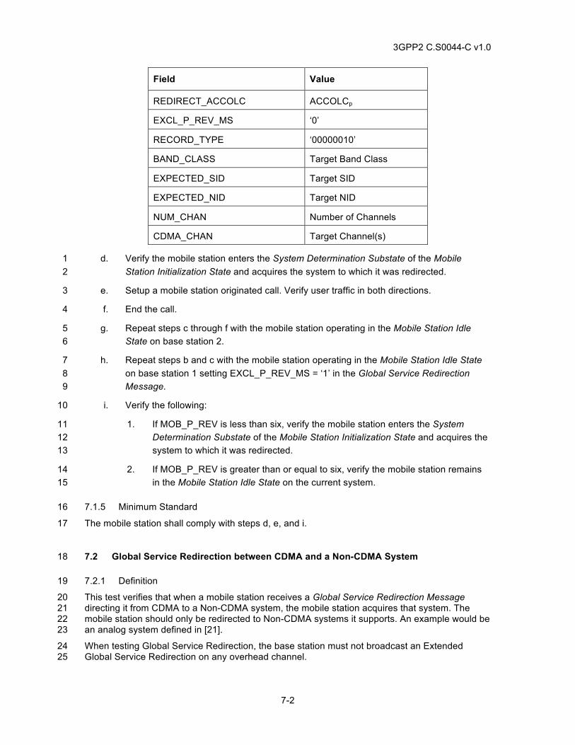
3GPP2 C.S0044-C v1.0
7-2
Field Value
REDIRECT_ACCOLC ACCOLCp
EXCL_P_REV_MS ‘0’
RECORD_TYPE ‘00000010’
BAND_CLASS Target Band Class
EXPECTED_SID Target SID
EXPECTED_NID Target NID
NUM_CHAN Number of Channels
CDMA_CHAN Target Channel(s)
d. Verify the mobile station enters the System Determination Substate of the Mobile 1 Station Initialization State and acquires the system to which it was redirected. 2
e. Setup a mobile station originated call. Verify user traffic in both directions. 3
f. End the call. 4
g. Repeat steps c through f with the mobile station operating in the Mobile Station Idle 5 State on base station 2. 6
h. Repeat steps b and c with the mobile station operating in the Mobile Station Idle State 7 on base station 1 setting EXCL_P_REV_MS = ‘1’ in the Global Service Redirection 8 Message. 9
i. Verify the following: 10
1. If MOB_P_REV is less than six, verify the mobile station enters the System 11 Determination Substate of the Mobile Station Initialization State and acquires the 12 system to which it was redirected. 13
2. If MOB_P_REV is greater than or equal to six, verify the mobile station remains 14 in the Mobile Station Idle State on the current system. 15
7.1.5 Minimum Standard 16
The mobile station shall comply with steps d, e, and i. 17
7.2 Global Service Redirection between CDMA and a Non-CDMA System 18
7.2.1 Definition 19
This test verifies that when a mobile station receives a Global Service Redirection Message 20 directing it from CDMA to a Non-CDMA system, the mobile station acquires that system. The 21 mobile station should only be redirected to Non-CDMA systems it supports. An example would be 22 an analog system defined in [21]. 23
When testing Global Service Redirection, the base station must not broadcast an Extended 24 Global Service Redirection on any overhead channel. 25
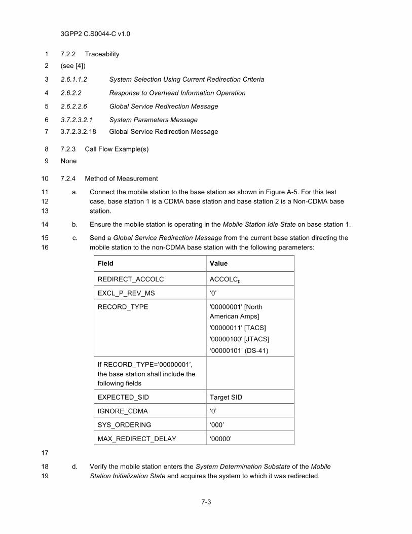
3GPP2 C.S0044-C v1.0
7-3
7.2.2 Traceability 1
(see [4]) 2
2.6.1.1.2 System Selection Using Current Redirection Criteria 3
2.6.2.2 Response to Overhead Information Operation 4
2.6.2.2.6 Global Service Redirection Message 5
3.7.2.3.2.1 System Parameters Message 6
3.7.2.3.2.18 Global Service Redirection Message 7
7.2.3 Call Flow Example(s) 8
None 9
7.2.4 Method of Measurement 10
a. Connect the mobile station to the base station as shown in Figure A-5. For this test 11 case, base station 1 is a CDMA base station and base station 2 is a Non-CDMA base 12 station. 13
b. Ensure the mobile station is operating in the Mobile Station Idle State on base station 1. 14
c. Send a Global Service Redirection Message from the current base station directing the 15 mobile station to the non-CDMA base station with the following parameters: 16
Field Value
REDIRECT_ACCOLC ACCOLCp
EXCL_P_REV_MS ‘0’
RECORD_TYPE '00000001' [North American Amps]
'00000011' [TACS]
'00000100' [JTACS]
‘00000101’ (DS-41)
If RECORD_TYPE=’00000001’, the base station shall include the following fields
EXPECTED_SID Target SID
IGNORE_CDMA ‘0’
SYS_ORDERING ‘000’
MAX_REDIRECT_DELAY ‘00000’
17
d. Verify the mobile station enters the System Determination Substate of the Mobile 18 Station Initialization State and acquires the system to which it was redirected. 19
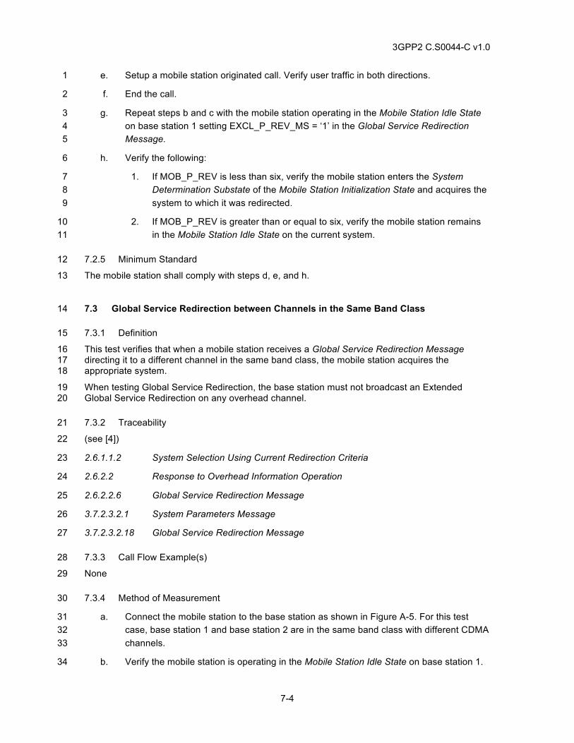
3GPP2 C.S0044-C v1.0
7-4
e. Setup a mobile station originated call. Verify user traffic in both directions. 1
f. End the call. 2
g. Repeat steps b and c with the mobile station operating in the Mobile Station Idle State 3 on base station 1 setting EXCL_P_REV_MS = ‘1’ in the Global Service Redirection 4 Message. 5
h. Verify the following: 6
1. If MOB_P_REV is less than six, verify the mobile station enters the System 7 Determination Substate of the Mobile Station Initialization State and acquires the 8 system to which it was redirected. 9
2. If MOB_P_REV is greater than or equal to six, verify the mobile station remains 10 in the Mobile Station Idle State on the current system. 11
7.2.5 Minimum Standard 12
The mobile station shall comply with steps d, e, and h. 13
7.3 Global Service Redirection between Channels in the Same Band Class 14
7.3.1 Definition 15
This test verifies that when a mobile station receives a Global Service Redirection Message 16 directing it to a different channel in the same band class, the mobile station acquires the 17 appropriate system. 18
When testing Global Service Redirection, the base station must not broadcast an Extended 19 Global Service Redirection on any overhead channel. 20
7.3.2 Traceability 21
(see [4]) 22
2.6.1.1.2 System Selection Using Current Redirection Criteria 23
2.6.2.2 Response to Overhead Information Operation 24
2.6.2.2.6 Global Service Redirection Message 25
3.7.2.3.2.1 System Parameters Message 26
3.7.2.3.2.18 Global Service Redirection Message 27
7.3.3 Call Flow Example(s) 28
None 29
7.3.4 Method of Measurement 30
a. Connect the mobile station to the base station as shown in Figure A-5. For this test 31 case, base station 1 and base station 2 are in the same band class with different CDMA 32 channels. 33
b. Verify the mobile station is operating in the Mobile Station Idle State on base station 1. 34
3GPP2 C.S0044-C v1.0
7-5
c. Send a Global Service Redirection Message from the current base station with: 1
2
Field Value
REDIRECT_ACCOLC ACCOLCp
EXCL_P_REV_MS ‘0’
RECORD_TYPE ‘00000010’
BAND_CLASS Target Band Class
EXPECTED_SID Target SID
EXPECTED_NID Target NID
NUM_CHAN Number of Channels
CDMA_CHAN Target Channel(s)
3
d. Verify the mobile station enters the System Determination Substate of the Mobile 4 Station Initialization State and acquires the system to which it was redirected. 5
e. Setup a mobile station originated call. Verify user traffic in both directions. 6
f. End the call. 7
g. Remove the channel for base station 2 from the mobiles station’s preferred roaming list 8 and repeat steps b through f. 9
h. Repeat steps b and c with the mobile station operating in the Mobile Station Idle State 10 on base station 1 setting EXCL_P_REV_MS = ‘1’ in the Global Service Redirection 11 Message. 12
i. Verify the following: 13
1. If MOB_P_REV is less than six, verify the mobile station enters the System 14 Determination Substate of the Mobile Station Initialization State and acquires the 15 system to which it was redirected. 16
2. If MOB_P_REV is greater than or equal to six, verify the mobile station remains 17 in the Mobile Station Idle State on the current system. 18
7.3.5 Minimum Standard 19
The mobile station shall comply with steps d, e, and i. 20
7.4 Service Redirection between Band Classes 21
7.4.1 Definition 22
This test verifies Network Directed System Selection (NDSS) functions correctly. This test verifies 23 that a mobile station is capable of being redirected between band classes when the Service 24
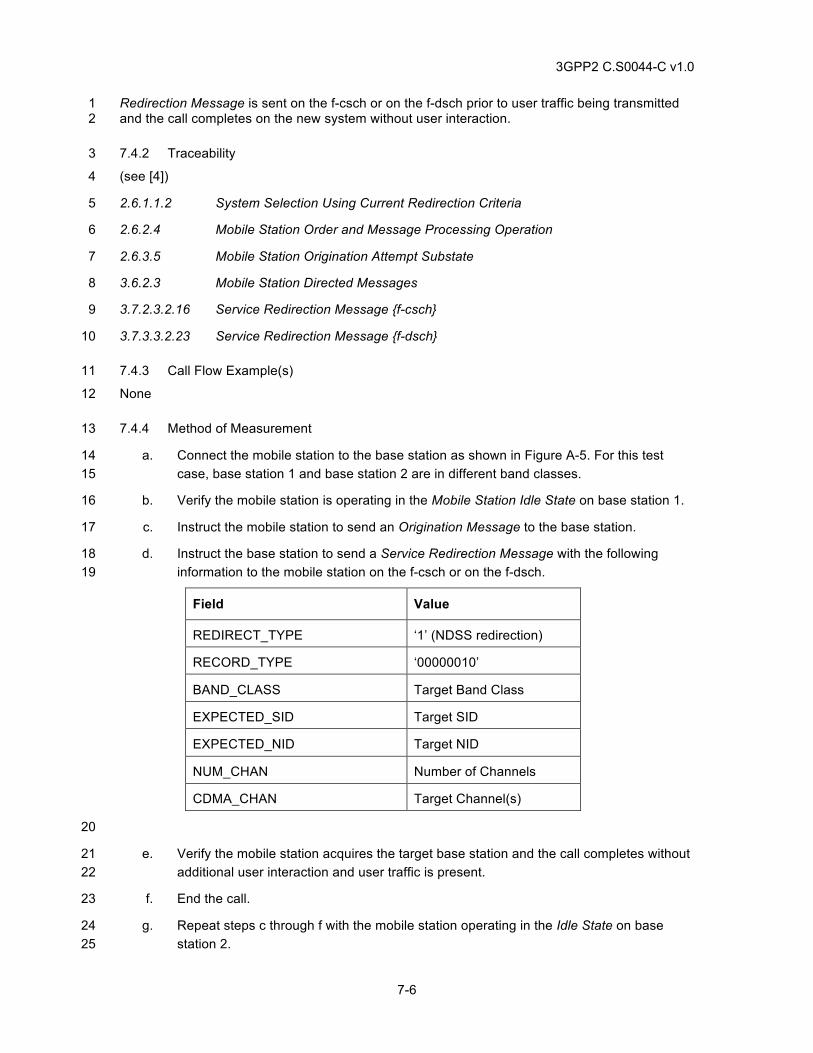
3GPP2 C.S0044-C v1.0
7-6
Redirection Message is sent on the f-csch or on the f-dsch prior to user traffic being transmitted 1 and the call completes on the new system without user interaction. 2
7.4.2 Traceability 3
(see [4]) 4
2.6.1.1.2 System Selection Using Current Redirection Criteria 5
2.6.2.4 Mobile Station Order and Message Processing Operation 6
2.6.3.5 Mobile Station Origination Attempt Substate 7
3.6.2.3 Mobile Station Directed Messages 8
3.7.2.3.2.16 Service Redirection Message {f-csch} 9
3.7.3.3.2.23 Service Redirection Message {f-dsch} 10
7.4.3 Call Flow Example(s) 11
None 12
7.4.4 Method of Measurement 13
a. Connect the mobile station to the base station as shown in Figure A-5. For this test 14 case, base station 1 and base station 2 are in different band classes. 15
b. Verify the mobile station is operating in the Mobile Station Idle State on base station 1. 16
c. Instruct the mobile station to send an Origination Message to the base station. 17
d. Instruct the base station to send a Service Redirection Message with the following 18 information to the mobile station on the f-csch or on the f-dsch. 19
Field Value
REDIRECT_TYPE ‘1’ (NDSS redirection)
RECORD_TYPE ‘00000010’
BAND_CLASS Target Band Class
EXPECTED_SID Target SID
EXPECTED_NID Target NID
NUM_CHAN Number of Channels
CDMA_CHAN Target Channel(s)
20
e. Verify the mobile station acquires the target base station and the call completes without 21 additional user interaction and user traffic is present. 22
f. End the call. 23
g. Repeat steps c through f with the mobile station operating in the Idle State on base 24 station 2. 25
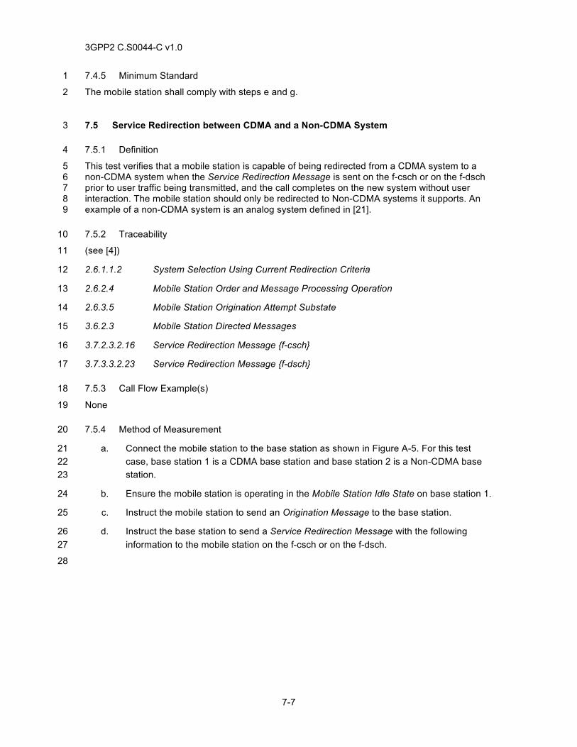
3GPP2 C.S0044-C v1.0
7-7
7.4.5 Minimum Standard 1
The mobile station shall comply with steps e and g. 2
7.5 Service Redirection between CDMA and a Non-CDMA System 3
7.5.1 Definition 4
This test verifies that a mobile station is capable of being redirected from a CDMA system to a 5 non-CDMA system when the Service Redirection Message is sent on the f-csch or on the f-dsch 6 prior to user traffic being transmitted, and the call completes on the new system without user 7 interaction. The mobile station should only be redirected to Non-CDMA systems it supports. An 8 example of a non-CDMA system is an analog system defined in [21]. 9
7.5.2 Traceability 10
(see [4]) 11
2.6.1.1.2 System Selection Using Current Redirection Criteria 12
2.6.2.4 Mobile Station Order and Message Processing Operation 13
2.6.3.5 Mobile Station Origination Attempt Substate 14
3.6.2.3 Mobile Station Directed Messages 15
3.7.2.3.2.16 Service Redirection Message {f-csch} 16
3.7.3.3.2.23 Service Redirection Message {f-dsch} 17
7.5.3 Call Flow Example(s) 18
None 19
7.5.4 Method of Measurement 20
a. Connect the mobile station to the base station as shown in Figure A-5. For this test 21 case, base station 1 is a CDMA base station and base station 2 is a Non-CDMA base 22 station. 23
b. Ensure the mobile station is operating in the Mobile Station Idle State on base station 1. 24
c. Instruct the mobile station to send an Origination Message to the base station. 25
d. Instruct the base station to send a Service Redirection Message with the following 26 information to the mobile station on the f-csch or on the f-dsch. 27
28
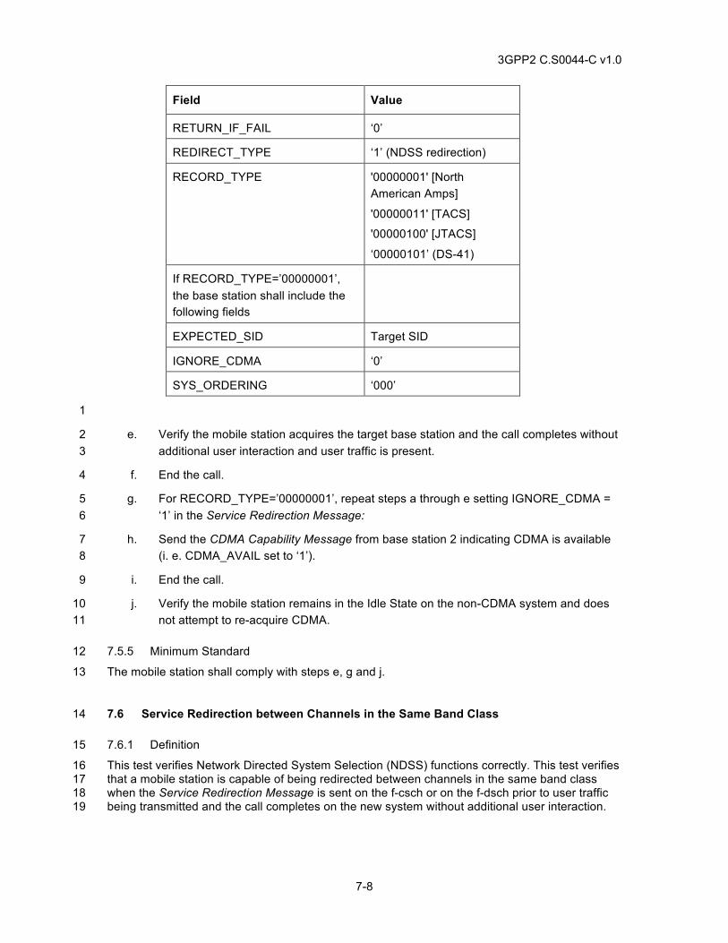
3GPP2 C.S0044-C v1.0
7-8
Field Value
RETURN_IF_FAIL ‘0’
REDIRECT_TYPE ‘1’ (NDSS redirection)
RECORD_TYPE '00000001' [North American Amps]
'00000011' [TACS]
'00000100' [JTACS]
‘00000101’ (DS-41)
If RECORD_TYPE=’00000001’, the base station shall include the following fields
EXPECTED_SID Target SID
IGNORE_CDMA ‘0’
SYS_ORDERING ‘000’
1
e. Verify the mobile station acquires the target base station and the call completes without 2 additional user interaction and user traffic is present. 3
f. End the call. 4
g. For RECORD_TYPE=’00000001’, repeat steps a through e setting IGNORE_CDMA = 5 ‘1’ in the Service Redirection Message: 6
h. Send the CDMA Capability Message from base station 2 indicating CDMA is available 7 (i. e. CDMA_AVAIL set to ‘1’). 8
i. End the call. 9
j. Verify the mobile station remains in the Idle State on the non-CDMA system and does 10 not attempt to re-acquire CDMA. 11
7.5.5 Minimum Standard 12
The mobile station shall comply with steps e, g and j. 13
7.6 Service Redirection between Channels in the Same Band Class 14
7.6.1 Definition 15
This test verifies Network Directed System Selection (NDSS) functions correctly. This test verifies 16 that a mobile station is capable of being redirected between channels in the same band class 17 when the Service Redirection Message is sent on the f-csch or on the f-dsch prior to user traffic 18 being transmitted and the call completes on the new system without additional user interaction. 19
3GPP2 C.S0044-C v1.0
7-9
7.6.2 Traceability 1
(see [4]) 2
2.6.1.1.2 System Selection Using Current Redirection Criteria 3
2.6.2.4 Mobile Station Order and Message Processing Operation 4
2.6.3.5 Mobile Station Origination Attempt Substate 5
3.6.2.3 Mobile Station Directed Messages 6
3.7.2.3.2.16 Service Redirection Message {f-csch} 7
3.7.3.3.2.23 Service Redirection Message {f-dsch} 8
7.6.3 Call Flow Example(s) 9
None 10
7.6.4 Method of Measurement 11
a. Connect the mobile station to the base station as shown in Figure A-5. For this test 12 case, base station 1 and base station 2 have different CDMA channels in the same 13 band class. 14
b. Verify the mobile station is operating in the Mobile Station Idle State on base station 1. 15
c. Instruct the mobile station to send an Origination Message to the base station. 16
d. Instruct the base station to send a Service Redirection Message with the following 17 information to the mobile station on the f-csch or on the f-dsch. 18
Field Value
RETURN_IF_FAIL ‘0’
REDIRECT_TYPE ‘1’ (NDSS redirection)
RECORD_TYPE ‘00000010’
EXPECTED_SID Target SID
EXPECTED_NID Target NID
NUM_CHAN Number of Channels
CDMA_CHAN Target Channel(s)
e. Verify the mobile station acquires the target base station and the call completes without 19 additional user interaction and user traffic is present. 20
f. End the call. 21
g. Repeat steps c through f with the mobile station operating in the Idle State on base 22 station 2. 23
h. Repeat steps b through d ensuring the mobile station cannot re-acquire base station 2 24 and setting RETURN_IF_FAIL = ‘1’ in the Service Redirection Message: 25
3GPP2 C.S0044-C v1.0
7-10
i. Verify the mobile station returns to base station 1 after failing to acquire base station 2. 1 The call may or may not complete depending on infrastructure implementation. 2
7.6.5 Minimum Standard 3
The mobile station shall comply with steps e, g, and i. 4
7.7 Extended Global Service Redirection between Band Classes 5
7.7.1 Definition 6
This test verifies that when a mobile station receives an Extended Global Service Redirection 7 Message directing it to another band class, the mobile station acquires the appropriate system. 8
7.7.2 Traceability 9
(see [4]) 10
2.6.1.1.2 System Selection Using Current Redirection Criteria 11
2.6.2.2 Response to Overhead Information Operation 12
2.6.2.2.11 Extended Global Service Redirection Message 13
3.7.2.3.2.1 System Parameters Message 14
3.7.2.3.2.27 Extended Global Service Redirection Message 15
3.7.2.3.2.31 MC-RR Parameters Message 16
7.7.3 Call Flow Example(s) 17
None 18
7.7.4 Method of Measurement 19
a. Connect the mobile station to the base station as shown in Figure A-5. For this test 20 case, base station 1 and base station 2 are in different band classes. 21
b. Verify the mobile station is operating in the Mobile Station Idle State on base station 1. 22
c. Send an Extended Global Service Redirection Message from the current base station 23 with: 24
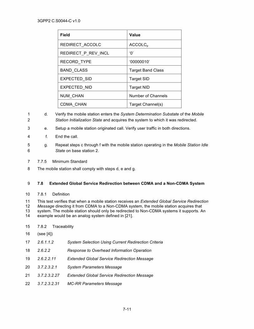
3GPP2 C.S0044-C v1.0
7-11
Field Value
REDIRECT_ACCOLC ACCOLCp
REDIRECT_P_REV_INCL ‘0’
RECORD_TYPE ‘00000010’
BAND_CLASS Target Band Class
EXPECTED_SID Target SID
EXPECTED_NID Target NID
NUM_CHAN Number of Channels
CDMA_CHAN Target Channel(s)
d. Verify the mobile station enters the System Determination Substate of the Mobile 1 Station Initialization State and acquires the system to which it was redirected. 2
e. Setup a mobile station originated call. Verify user traffic in both directions. 3
f. End the call. 4
g. Repeat steps c through f with the mobile station operating in the Mobile Station Idle 5 State on base station 2. 6
7.7.5 Minimum Standard 7
The mobile station shall comply with steps d, e and g. 8
7.8 Extended Global Service Redirection between CDMA and a Non-CDMA System 9
7.8.1 Definition 10
This test verifies that when a mobile station receives an Extended Global Service Redirection 11 Message directing it from CDMA to a Non-CDMA system, the mobile station acquires that 12 system. The mobile station should only be redirected to Non-CDMA systems it supports. An 13 example would be an analog system defined in [21]. 14
7.8.2 Traceability 15
(see [4]) 16
2.6.1.1.2 System Selection Using Current Redirection Criteria 17
2.6.2.2 Response to Overhead Information Operation 18
2.6.2.2.11 Extended Global Service Redirection Message 19
3.7.2.3.2.1 System Parameters Message 20
3.7.2.3.2.27 Extended Global Service Redirection Message 21
3.7.2.3.2.31 MC-RR Parameters Message 22
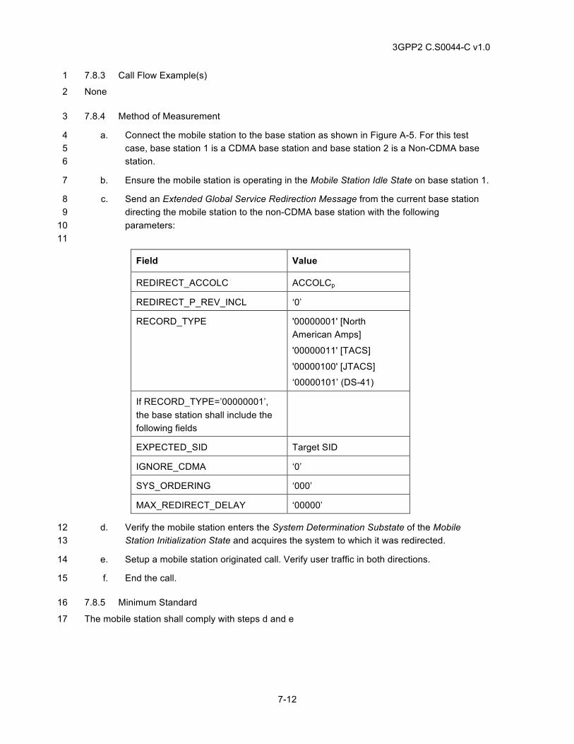
3GPP2 C.S0044-C v1.0
7-12
7.8.3 Call Flow Example(s) 1
None 2
7.8.4 Method of Measurement 3
a. Connect the mobile station to the base station as shown in Figure A-5. For this test 4 case, base station 1 is a CDMA base station and base station 2 is a Non-CDMA base 5 station. 6
b. Ensure the mobile station is operating in the Mobile Station Idle State on base station 1. 7
c. Send an Extended Global Service Redirection Message from the current base station 8 directing the mobile station to the non-CDMA base station with the following 9 parameters: 10 11
Field Value
REDIRECT_ACCOLC ACCOLCp
REDIRECT_P_REV_INCL ‘0’
RECORD_TYPE '00000001' [North American Amps]
'00000011' [TACS]
'00000100' [JTACS]
‘00000101’ (DS-41)
If RECORD_TYPE=’00000001’, the base station shall include the following fields
EXPECTED_SID Target SID
IGNORE_CDMA ‘0’
SYS_ORDERING ‘000’
MAX_REDIRECT_DELAY ‘00000’
d. Verify the mobile station enters the System Determination Substate of the Mobile 12 Station Initialization State and acquires the system to which it was redirected. 13
e. Setup a mobile station originated call. Verify user traffic in both directions. 14
f. End the call. 15
7.8.5 Minimum Standard 16
The mobile station shall comply with steps d and e 17
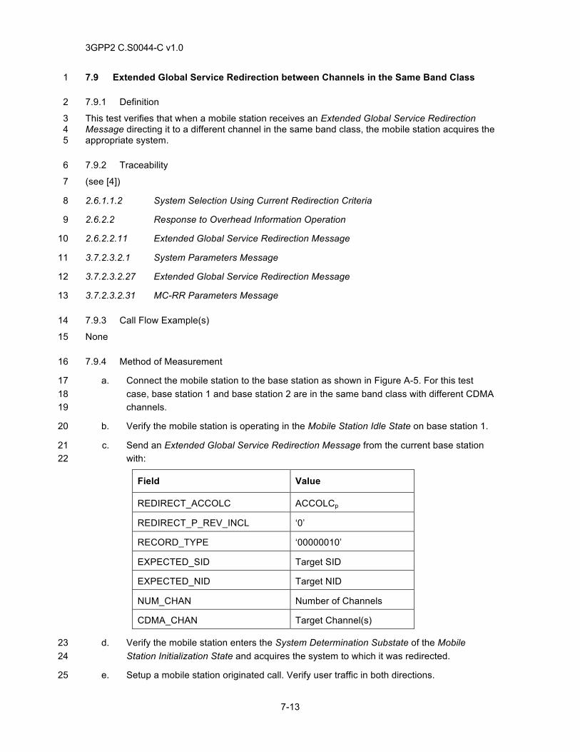
3GPP2 C.S0044-C v1.0
7-13
7.9 Extended Global Service Redirection between Channels in the Same Band Class 1
7.9.1 Definition 2
This test verifies that when a mobile station receives an Extended Global Service Redirection 3 Message directing it to a different channel in the same band class, the mobile station acquires the 4 appropriate system. 5
7.9.2 Traceability 6
(see [4]) 7
2.6.1.1.2 System Selection Using Current Redirection Criteria 8
2.6.2.2 Response to Overhead Information Operation 9
2.6.2.2.11 Extended Global Service Redirection Message 10
3.7.2.3.2.1 System Parameters Message 11
3.7.2.3.2.27 Extended Global Service Redirection Message 12
3.7.2.3.2.31 MC-RR Parameters Message 13
7.9.3 Call Flow Example(s) 14
None 15
7.9.4 Method of Measurement 16
a. Connect the mobile station to the base station as shown in Figure A-5. For this test 17 case, base station 1 and base station 2 are in the same band class with different CDMA 18 channels. 19
b. Verify the mobile station is operating in the Mobile Station Idle State on base station 1. 20
c. Send an Extended Global Service Redirection Message from the current base station 21 with: 22
Field Value
REDIRECT_ACCOLC ACCOLCp
REDIRECT_P_REV_INCL ‘0’
RECORD_TYPE ‘00000010’
EXPECTED_SID Target SID
EXPECTED_NID Target NID
NUM_CHAN Number of Channels
CDMA_CHAN Target Channel(s)
d. Verify the mobile station enters the System Determination Substate of the Mobile 23 Station Initialization State and acquires the system to which it was redirected. 24
e. Setup a mobile station originated call. Verify user traffic in both directions. 25

3GPP2 C.S0044-C v1.0
7-14
f. End the call. 1
g. Remove the channel for base station 2 from the mobile station’s preferred roaming list 2 and repeat steps b through f. 3
7.9.5 Minimum Standard 4
The mobile station shall comply with steps d and e. 5
6
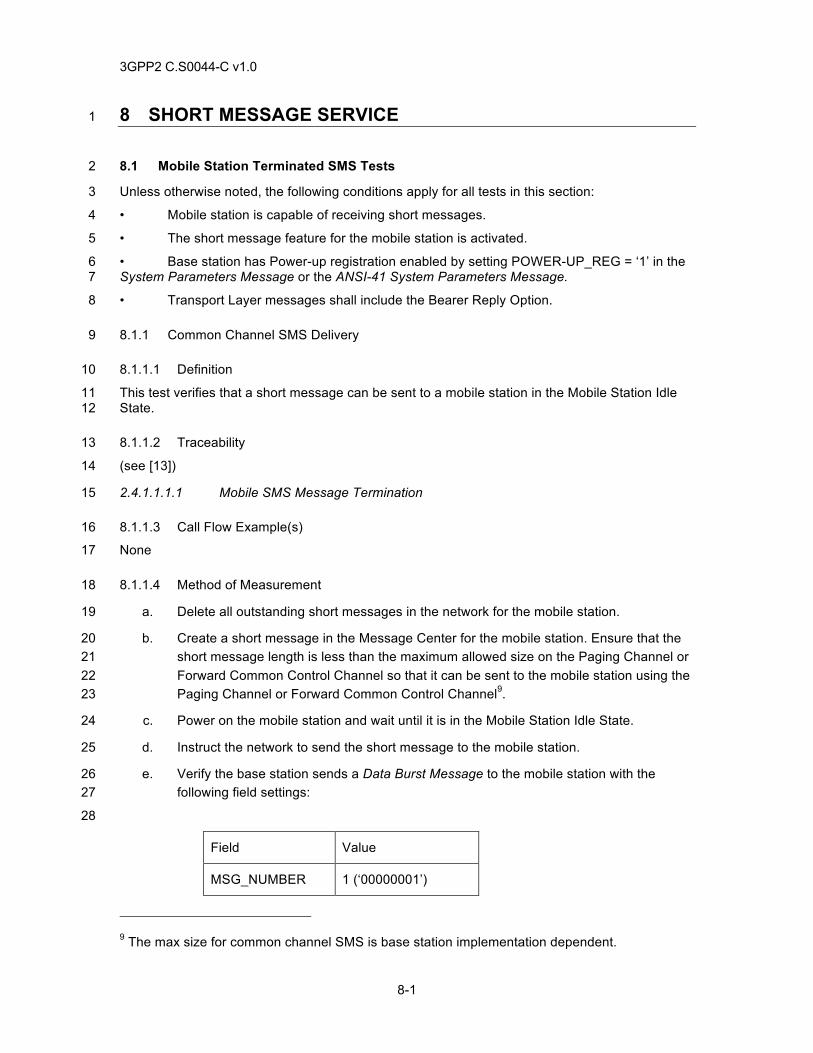
3GPP2 C.S0044-C v1.0
8-1
8 SHORT MESSAGE SERVICE 1
8.1 Mobile Station Terminated SMS Tests 2
Unless otherwise noted, the following conditions apply for all tests in this section: 3
• Mobile station is capable of receiving short messages. 4
• The short message feature for the mobile station is activated. 5
• Base station has Power-up registration enabled by setting POWER-UP_REG = ‘1’ in the 6 System Parameters Message or the ANSI-41 System Parameters Message. 7
• Transport Layer messages shall include the Bearer Reply Option. 8
8.1.1 Common Channel SMS Delivery 9
8.1.1.1 Definition 10
This test verifies that a short message can be sent to a mobile station in the Mobile Station Idle 11 State. 12
8.1.1.2 Traceability 13
(see [13]) 14
2.4.1.1.1.1 Mobile SMS Message Termination 15
8.1.1.3 Call Flow Example(s) 16
None 17
8.1.1.4 Method of Measurement 18
a. Delete all outstanding short messages in the network for the mobile station. 19
b. Create a short message in the Message Center for the mobile station. Ensure that the 20 short message length is less than the maximum allowed size on the Paging Channel or 21 Forward Common Control Channel so that it can be sent to the mobile station using the 22 Paging Channel or Forward Common Control Channel9. 23
c. Power on the mobile station and wait until it is in the Mobile Station Idle State. 24
d. Instruct the network to send the short message to the mobile station. 25
e. Verify the base station sends a Data Burst Message to the mobile station with the 26 following field settings: 27
28
Field Value
MSG_NUMBER 1 (‘00000001’)
9 The max size for common channel SMS is base station implementation dependent.
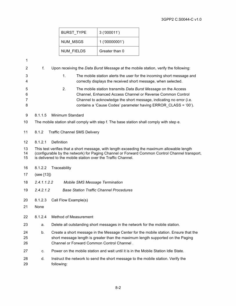
3GPP2 C.S0044-C v1.0
8-2
BURST_TYPE 3 (‘000011’)
NUM_MSGS 1 (‘00000001’)
NUM_FIELDS Greater than 0
1
f. Upon receiving the Data Burst Message at the mobile station, verify the following: 2
1. The mobile station alerts the user for the incoming short message and 3 correctly displays the received short message, when selected. 4
2. The mobile station transmits Data Burst Message on the Access 5 Channel, Enhanced Access Channel or Reverse Common Control 6 Channel to acknowledge the short message, indicating no error (i.e. 7 contains a ‘Cause Codes’ parameter having ERROR_CLASS = ‘00’). 8
8.1.1.5 Minimum Standard 9
The mobile station shall comply with step f. The base station shall comply with step e. 10
8.1.2 Traffic Channel SMS Delivery 11
8.1.2.1 Definition 12
This test verifies that a short message, with length exceeding the maximum allowable length 13 (configurable by the network) for Paging Channel or Forward Common Control Channel transport, 14 is delivered to the mobile station over the Traffic Channel. 15
8.1.2.2 Traceability 16
(see [13]) 17
2.4.1.1.2.2 Mobile SMS Message Termination 18
2.4.2.1.2 Base Station Traffic Channel Procedures 19
8.1.2.3 Call Flow Example(s) 20
None 21
8.1.2.4 Method of Measurement 22
a. Delete all outstanding short messages in the network for the mobile station. 23
b. Create a short message in the Message Center for the mobile station. Ensure that the 24 short message length is greater than the maximum length supported on the Paging 25 Channel or Forward Common Control Channel . 26
c. Power on the mobile station and wait until it is in the Mobile Station Idle State. 27
d. Instruct the network to send the short message to the mobile station. Verify the 28 following: 29
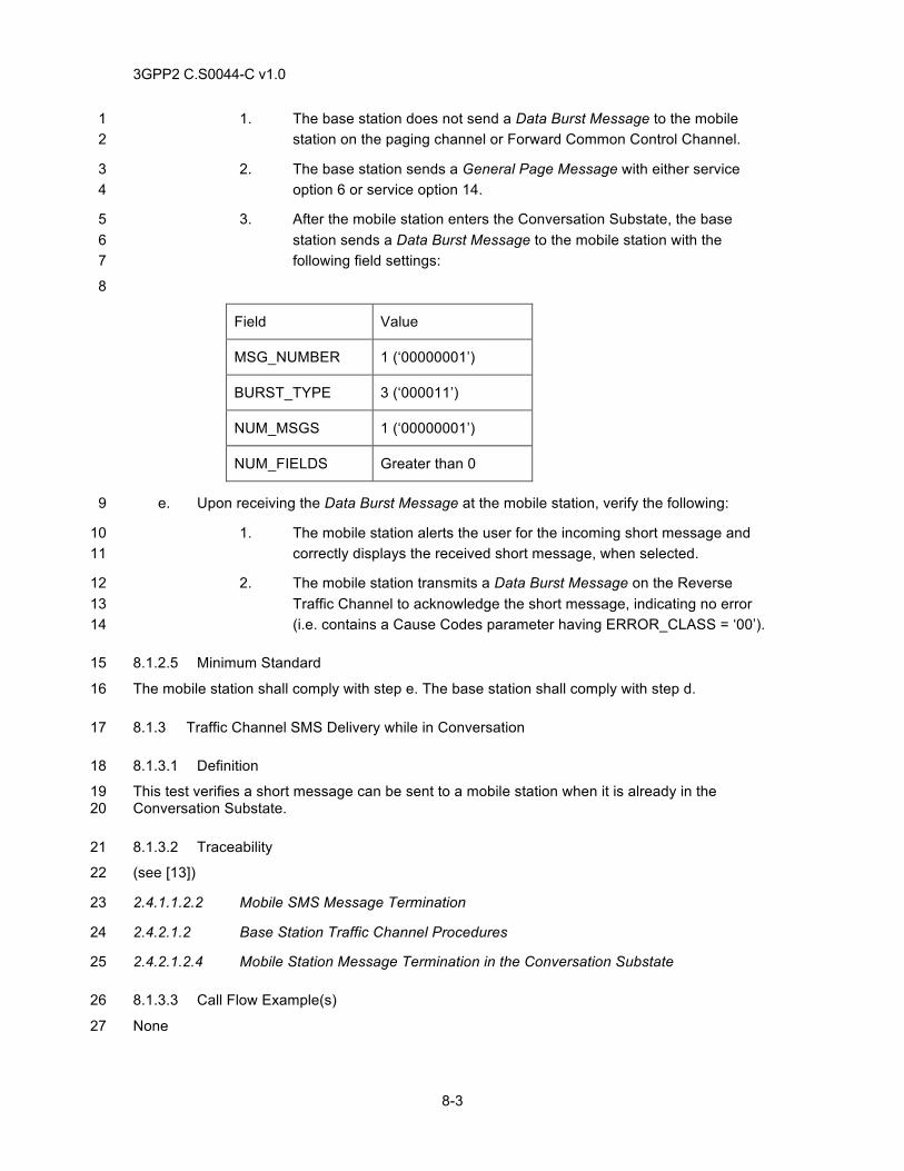
3GPP2 C.S0044-C v1.0
8-3
1. The base station does not send a Data Burst Message to the mobile 1 station on the paging channel or Forward Common Control Channel. 2
2. The base station sends a General Page Message with either service 3 option 6 or service option 14. 4
3. After the mobile station enters the Conversation Substate, the base 5 station sends a Data Burst Message to the mobile station with the 6 following field settings: 7
8
Field Value
MSG_NUMBER 1 (‘00000001’)
BURST_TYPE 3 (‘000011’)
NUM_MSGS 1 (‘00000001’)
NUM_FIELDS Greater than 0
e. Upon receiving the Data Burst Message at the mobile station, verify the following: 9
1. The mobile station alerts the user for the incoming short message and 10 correctly displays the received short message, when selected. 11
2. The mobile station transmits a Data Burst Message on the Reverse 12 Traffic Channel to acknowledge the short message, indicating no error 13 (i.e. contains a Cause Codes parameter having ERROR_CLASS = ‘00’). 14
8.1.2.5 Minimum Standard 15
The mobile station shall comply with step e. The base station shall comply with step d. 16
8.1.3 Traffic Channel SMS Delivery while in Conversation 17
8.1.3.1 Definition 18
This test verifies a short message can be sent to a mobile station when it is already in the 19 Conversation Substate. 20
8.1.3.2 Traceability 21
(see [13]) 22
2.4.1.1.2.2 Mobile SMS Message Termination 23
2.4.2.1.2 Base Station Traffic Channel Procedures 24
2.4.2.1.2.4 Mobile Station Message Termination in the Conversation Substate 25
8.1.3.3 Call Flow Example(s) 26
None 27
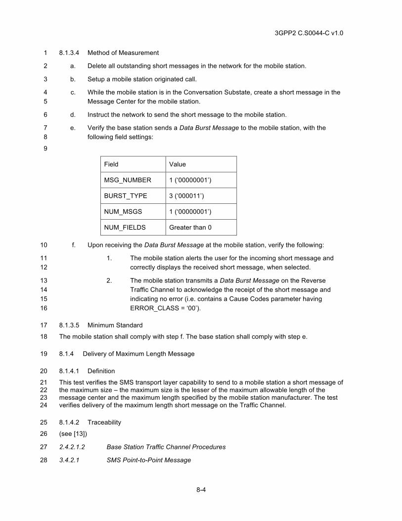
3GPP2 C.S0044-C v1.0
8-4
8.1.3.4 Method of Measurement 1
a. Delete all outstanding short messages in the network for the mobile station. 2
b. Setup a mobile station originated call. 3
c. While the mobile station is in the Conversation Substate, create a short message in the 4 Message Center for the mobile station. 5
d. Instruct the network to send the short message to the mobile station. 6
e. Verify the base station sends a Data Burst Message to the mobile station, with the 7 following field settings: 8
9
Field Value
MSG_NUMBER 1 (‘00000001’)
BURST_TYPE 3 (‘000011’)
NUM_MSGS 1 (‘00000001’)
NUM_FIELDS Greater than 0
f. Upon receiving the Data Burst Message at the mobile station, verify the following: 10
1. The mobile station alerts the user for the incoming short message and 11 correctly displays the received short message, when selected. 12
2. The mobile station transmits a Data Burst Message on the Reverse 13 Traffic Channel to acknowledge the receipt of the short message and 14 indicating no error (i.e. contains a Cause Codes parameter having 15 ERROR_CLASS = ‘00’). 16
8.1.3.5 Minimum Standard 17
The mobile station shall comply with step f. The base station shall comply with step e. 18
8.1.4 Delivery of Maximum Length Message 19
8.1.4.1 Definition 20
This test verifies the SMS transport layer capability to send to a mobile station a short message of 21 the maximum size – the maximum size is the lesser of the maximum allowable length of the 22 message center and the maximum length specified by the mobile station manufacturer. The test 23 verifies delivery of the maximum length short message on the Traffic Channel. 24
8.1.4.2 Traceability 25
(see [13]) 26
2.4.2.1.2 Base Station Traffic Channel Procedures 27
3.4.2.1 SMS Point-to-Point Message 28
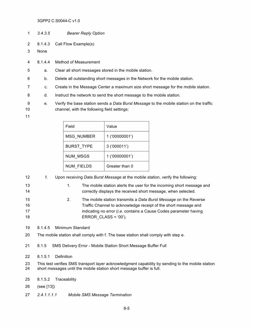
3GPP2 C.S0044-C v1.0
8-5
3.4.3.5 Bearer Reply Option 1
8.1.4.3 Call Flow Example(s) 2
None 3
8.1.4.4 Method of Measurement 4
a. Clear all short messages stored in the mobile station. 5
b. Delete all outstanding short messages in the Network for the mobile station. 6
c. Create in the Message Center a maximum size short message for the mobile station. 7
d. Instruct the network to send the short message to the mobile station. 8
e. Verify the base station sends a Data Burst Message to the mobile station on the traffic 9 channel, with the following field settings: 10
11
Field Value
MSG_NUMBER 1 (‘00000001’)
BURST_TYPE 3 (‘000011’)
NUM_MSGS 1 (‘00000001’)
NUM_FIELDS Greater than 0
f. Upon receiving Data Burst Message at the mobile station, verify the following: 12
1. The mobile station alerts the user for the incoming short message and 13 correctly displays the received short message, when selected. 14
2. The mobile station transmits a Data Burst Message on the Reverse 15 Traffic Channel to acknowledge receipt of the short message and 16 indicating no error (i.e. contains a Cause Codes parameter having 17 ERROR_CLASS = ‘00’). 18
8.1.4.5 Minimum Standard 19
The mobile station shall comply with f. The base station shall comply with step e. 20
8.1.5 SMS Delivery Error - Mobile Station Short Message Buffer Full 21
8.1.5.1 Definition 22
This test verifies SMS transport layer acknowledgment capability by sending to the mobile station 23 short messages until the mobile station short message buffer is full. 24
8.1.5.2 Traceability 25
(see [13]) 26
2.4.1.1.1.1 Mobile SMS Message Termination 27
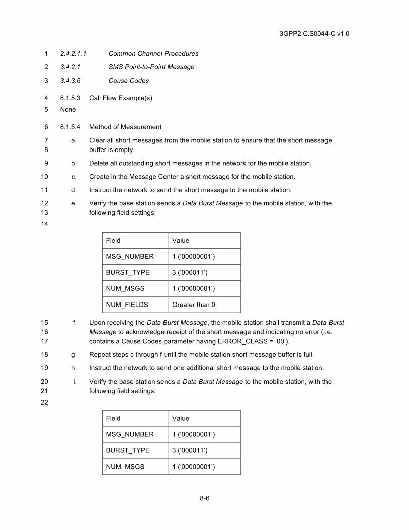
3GPP2 C.S0044-C v1.0
8-6
2.4.2.1.1 Common Channel Procedures 1
3.4.2.1 SMS Point-to-Point Message 2
3.4.3.6 Cause Codes 3
8.1.5.3 Call Flow Example(s) 4
None 5
8.1.5.4 Method of Measurement 6
a. Clear all short messages from the mobile station to ensure that the short message 7 buffer is empty. 8
b. Delete all outstanding short messages in the network for the mobile station. 9
c. Create in the Message Center a short message for the mobile station. 10
d. Instruct the network to send the short message to the mobile station. 11
e. Verify the base station sends a Data Burst Message to the mobile station, with the 12 following field settings: 13
14
Field Value
MSG_NUMBER 1 (‘00000001’)
BURST_TYPE 3 (‘000011’)
NUM_MSGS 1 (‘00000001’)
NUM_FIELDS Greater than 0
f. Upon receiving the Data Burst Message, the mobile station shall transmit a Data Burst 15 Message to acknowledge receipt of the short message and indicating no error (i.e. 16 contains a Cause Codes parameter having ERROR_CLASS = ‘00’). 17
g. Repeat steps c through f until the mobile station short message buffer is full. 18
h. Instruct the network to send one additional short message to the mobile station. 19
i. Verify the base station sends a Data Burst Message to the mobile station, with the 20 following field settings: 21
22
Field Value
MSG_NUMBER 1 (‘00000001’)
BURST_TYPE 3 (‘000011’)
NUM_MSGS 1 (‘00000001’)
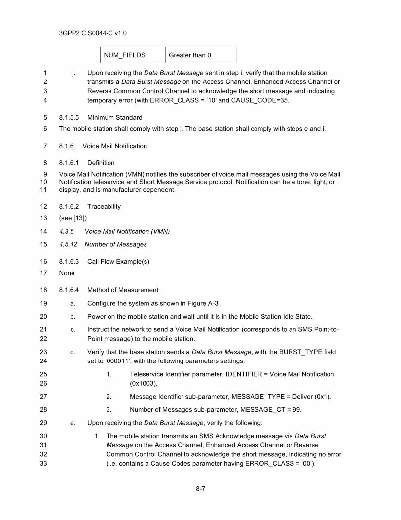
3GPP2 C.S0044-C v1.0
8-7
NUM_FIELDS Greater than 0
j. Upon receiving the Data Burst Message sent in step i, verify that the mobile station 1 transmits a Data Burst Message on the Access Channel, Enhanced Access Channel or 2 Reverse Common Control Channel to acknowledge the short message and indicating 3 temporary error (with ERROR_CLASS = ‘10’ and CAUSE_CODE=35. 4
8.1.5.5 Minimum Standard 5
The mobile station shall comply with step j. The base station shall comply with steps e and i. 6
8.1.6 Voice Mail Notification 7
8.1.6.1 Definition 8
Voice Mail Notification (VMN) notifies the subscriber of voice mail messages using the Voice Mail 9 Notification teleservice and Short Message Service protocol. Notification can be a tone, light, or 10 display, and is manufacturer dependent. 11
8.1.6.2 Traceability 12
(see [13]) 13
4.3.5 Voice Mail Notification (VMN) 14
4.5.12 Number of Messages 15
8.1.6.3 Call Flow Example(s) 16
None 17
8.1.6.4 Method of Measurement 18
a. Configure the system as shown in Figure A-3. 19
b. Power on the mobile station and wait until it is in the Mobile Station Idle State. 20
c. Instruct the network to send a Voice Mail Notification (corresponds to an SMS Point-to-21 Point message) to the mobile station. 22
d. Verify that the base station sends a Data Burst Message, with the BURST_TYPE field 23 set to ‘000011’, with the following parameters settings: 24
1. Teleservice Identifier parameter, IDENTIFIER = Voice Mail Notification 25 (0x1003). 26
2. Message Identifier sub-parameter, MESSAGE_TYPE = Deliver (0x1). 27
3. Number of Messages sub-parameter, MESSAGE_CT = 99. 28
e. Upon receiving the Data Burst Message, verify the following: 29
1. The mobile station transmits an SMS Acknowledge message via Data Burst 30 Message on the Access Channel, Enhanced Access Channel or Reverse 31 Common Control Channel to acknowledge the short message, indicating no error 32 (i.e. contains a Cause Codes parameter having ERROR_CLASS = ‘00’). 33
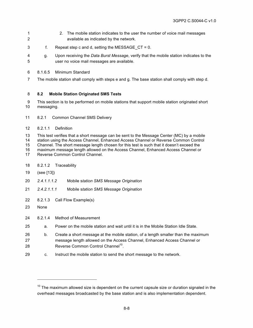
3GPP2 C.S0044-C v1.0
8-8
2. The mobile station indicates to the user the number of voice mail messages 1 available as indicated by the network. 2
f. Repeat step c and d, setting the MESSAGE_CT = 0. 3
g. Upon receiving the Data Burst Message, verify that the mobile station indicates to the 4 user no voice mail messages are available. 5
8.1.6.5 Minimum Standard 6
The mobile station shall comply with steps e and g. The base station shall comply with step d. 7
8.2 Mobile Station Originated SMS Tests 8
This section is to be performed on mobile stations that support mobile station originated short 9 messaging. 10
8.2.1 Common Channel SMS Delivery 11
8.2.1.1 Definition 12
This test verifies that a short message can be sent to the Message Center (MC) by a mobile 13 station using the Access Channel, Enhanced Access Channel or Reverse Common Control 14 Channel. The short message length chosen for this test is such that it doesn’t exceed the 15 maximum message length allowed on the Access Channel, Enhanced Access Channel or 16 Reverse Common Control Channel. 17
8.2.1.2 Traceability 18
(see [13]) 19
2.4.1.1.1.2 Mobile station SMS Message Origination 20
2.4.2.1.1.1 Mobile station SMS Message Origination 21
8.2.1.3 Call Flow Example(s) 22
None 23
8.2.1.4 Method of Measurement 24
a. Power on the mobile station and wait until it is in the Mobile Station Idle State. 25
b. Create a short message at the mobile station, of a length smaller than the maximum 26 message length allowed on the Access Channel, Enhanced Access Channel or 27 Reverse Common Control Channel10. 28
c. Instruct the mobile station to send the short message to the network. 29
10 The maximum allowed size is dependent on the current capsule size or duration signaled in the overhead messages broadcasted by the base station and is also implementation dependent.
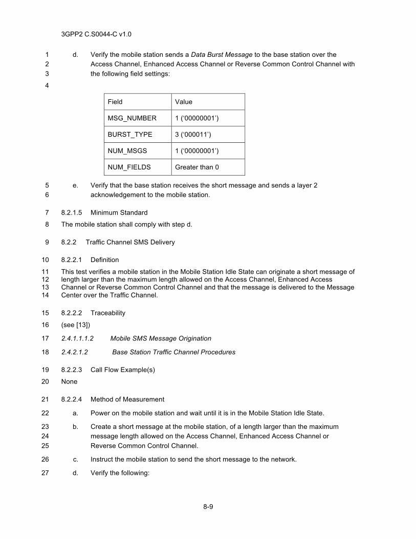
3GPP2 C.S0044-C v1.0
8-9
d. Verify the mobile station sends a Data Burst Message to the base station over the 1 Access Channel, Enhanced Access Channel or Reverse Common Control Channel with 2 the following field settings: 3
4
Field Value
MSG_NUMBER 1 (‘00000001’)
BURST_TYPE 3 (‘000011’)
NUM_MSGS 1 (‘00000001’)
NUM_FIELDS Greater than 0
e. Verify that the base station receives the short message and sends a layer 2 5 acknowledgement to the mobile station. 6
8.2.1.5 Minimum Standard 7
The mobile station shall comply with step d. 8
8.2.2 Traffic Channel SMS Delivery 9
8.2.2.1 Definition 10
This test verifies a mobile station in the Mobile Station Idle State can originate a short message of 11 length larger than the maximum length allowed on the Access Channel, Enhanced Access 12 Channel or Reverse Common Control Channel and that the message is delivered to the Message 13 Center over the Traffic Channel. 14
8.2.2.2 Traceability 15
(see [13]) 16
2.4.1.1.1.2 Mobile SMS Message Origination 17
2.4.2.1.2 Base Station Traffic Channel Procedures 18
8.2.2.3 Call Flow Example(s) 19
None 20
8.2.2.4 Method of Measurement 21
a. Power on the mobile station and wait until it is in the Mobile Station Idle State. 22
b. Create a short message at the mobile station, of a length larger than the maximum 23 message length allowed on the Access Channel, Enhanced Access Channel or 24 Reverse Common Control Channel. 25
c. Instruct the mobile station to send the short message to the network. 26
d. Verify the following: 27
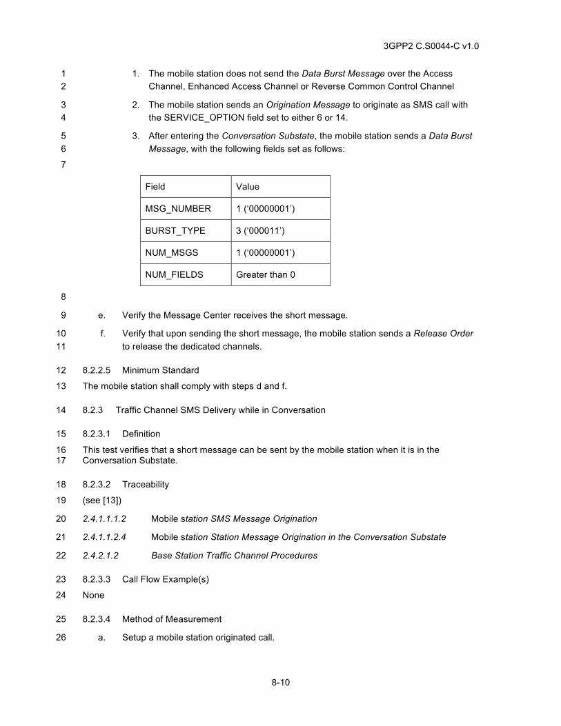
3GPP2 C.S0044-C v1.0
8-10
1. The mobile station does not send the Data Burst Message over the Access 1 Channel, Enhanced Access Channel or Reverse Common Control Channel 2
2. The mobile station sends an Origination Message to originate as SMS call with 3 the SERVICE_OPTION field set to either 6 or 14. 4
3. After entering the Conversation Substate, the mobile station sends a Data Burst 5 Message, with the following fields set as follows: 6
7
Field Value
MSG_NUMBER 1 (‘00000001’)
BURST_TYPE 3 (‘000011’)
NUM_MSGS 1 (‘00000001’)
NUM_FIELDS Greater than 0
8
e. Verify the Message Center receives the short message. 9
f. Verify that upon sending the short message, the mobile station sends a Release Order 10 to release the dedicated channels. 11
8.2.2.5 Minimum Standard 12
The mobile station shall comply with steps d and f. 13
8.2.3 Traffic Channel SMS Delivery while in Conversation 14
8.2.3.1 Definition 15
This test verifies that a short message can be sent by the mobile station when it is in the 16 Conversation Substate. 17
8.2.3.2 Traceability 18
(see [13]) 19
2.4.1.1.1.2 Mobile station SMS Message Origination 20
2.4.1.1.2.4 Mobile station Station Message Origination in the Conversation Substate 21
2.4.2.1.2 Base Station Traffic Channel Procedures 22
8.2.3.3 Call Flow Example(s) 23
None 24
8.2.3.4 Method of Measurement 25
a. Setup a mobile station originated call. 26
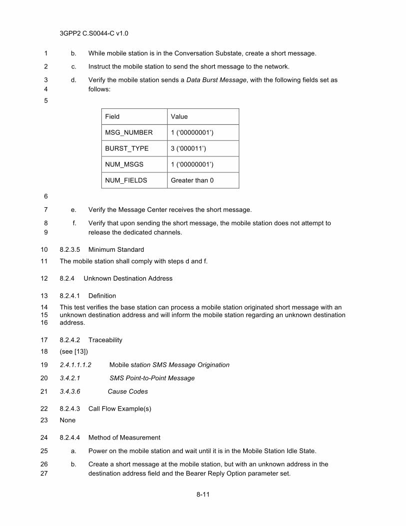
3GPP2 C.S0044-C v1.0
8-11
b. While mobile station is in the Conversation Substate, create a short message. 1
c. Instruct the mobile station to send the short message to the network. 2
d. Verify the mobile station sends a Data Burst Message, with the following fields set as 3 follows: 4
5
Field Value
MSG_NUMBER 1 (‘00000001’)
BURST_TYPE 3 (‘000011’)
NUM_MSGS 1 (‘00000001’)
NUM_FIELDS Greater than 0
6
e. Verify the Message Center receives the short message. 7
f. Verify that upon sending the short message, the mobile station does not attempt to 8 release the dedicated channels. 9
8.2.3.5 Minimum Standard 10
The mobile station shall comply with steps d and f. 11
8.2.4 Unknown Destination Address 12
8.2.4.1 Definition 13
This test verifies the base station can process a mobile station originated short message with an 14 unknown destination address and will inform the mobile station regarding an unknown destination 15 address. 16
8.2.4.2 Traceability 17
(see [13]) 18
2.4.1.1.1.2 Mobile station SMS Message Origination 19
3.4.2.1 SMS Point-to-Point Message 20
3.4.3.6 Cause Codes 21
8.2.4.3 Call Flow Example(s) 22
None 23
8.2.4.4 Method of Measurement 24
a. Power on the mobile station and wait until it is in the Mobile Station Idle State. 25
b. Create a short message at the mobile station, but with an unknown address in the 26 destination address field and the Bearer Reply Option parameter set. 27
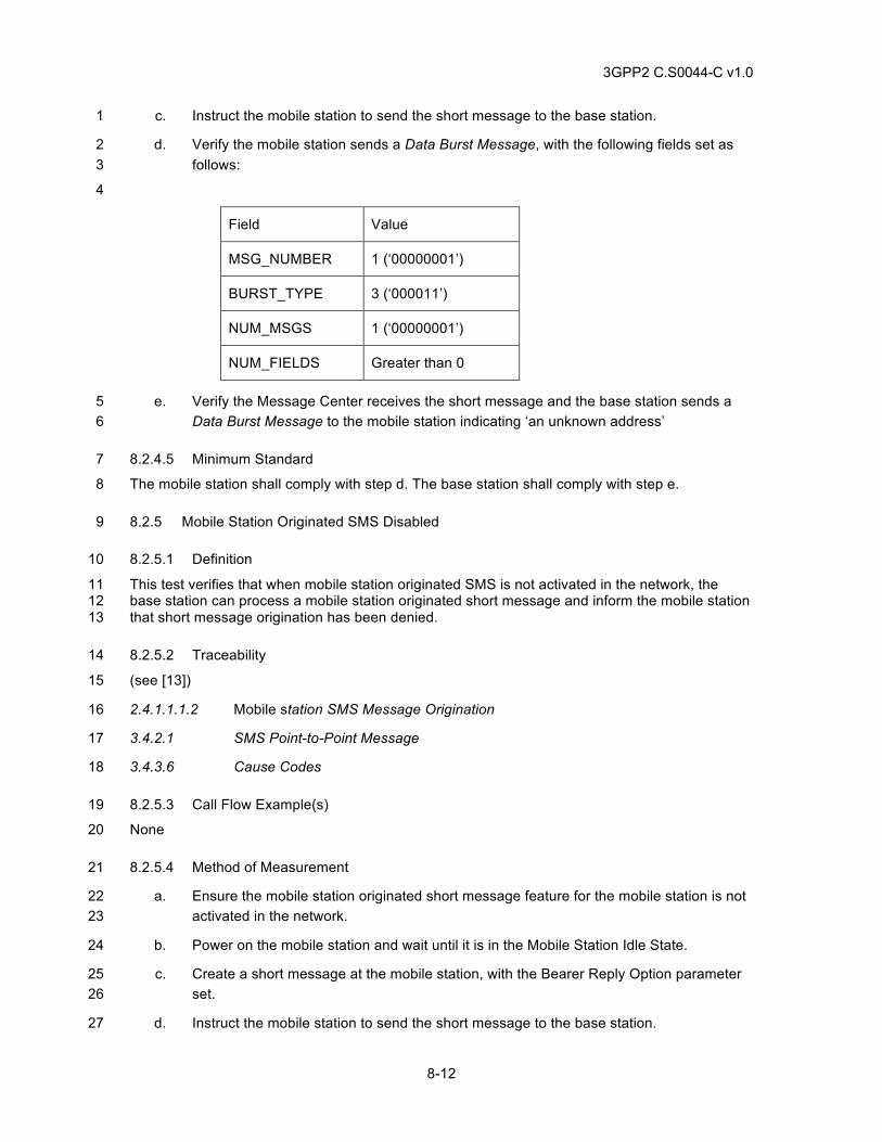
3GPP2 C.S0044-C v1.0
8-12
c. Instruct the mobile station to send the short message to the base station. 1
d. Verify the mobile station sends a Data Burst Message, with the following fields set as 2 follows: 3
4
Field Value
MSG_NUMBER 1 (‘00000001’)
BURST_TYPE 3 (‘000011’)
NUM_MSGS 1 (‘00000001’)
NUM_FIELDS Greater than 0
e. Verify the Message Center receives the short message and the base station sends a 5 Data Burst Message to the mobile station indicating ‘an unknown address’ 6
8.2.4.5 Minimum Standard 7
The mobile station shall comply with step d. The base station shall comply with step e. 8
8.2.5 Mobile Station Originated SMS Disabled 9
8.2.5.1 Definition 10
This test verifies that when mobile station originated SMS is not activated in the network, the 11 base station can process a mobile station originated short message and inform the mobile station 12 that short message origination has been denied. 13
8.2.5.2 Traceability 14
(see [13]) 15
2.4.1.1.1.2 Mobile station SMS Message Origination 16
3.4.2.1 SMS Point-to-Point Message 17
3.4.3.6 Cause Codes 18
8.2.5.3 Call Flow Example(s) 19
None 20
8.2.5.4 Method of Measurement 21
a. Ensure the mobile station originated short message feature for the mobile station is not 22 activated in the network. 23
b. Power on the mobile station and wait until it is in the Mobile Station Idle State. 24
c. Create a short message at the mobile station, with the Bearer Reply Option parameter 25 set. 26
d. Instruct the mobile station to send the short message to the base station. 27
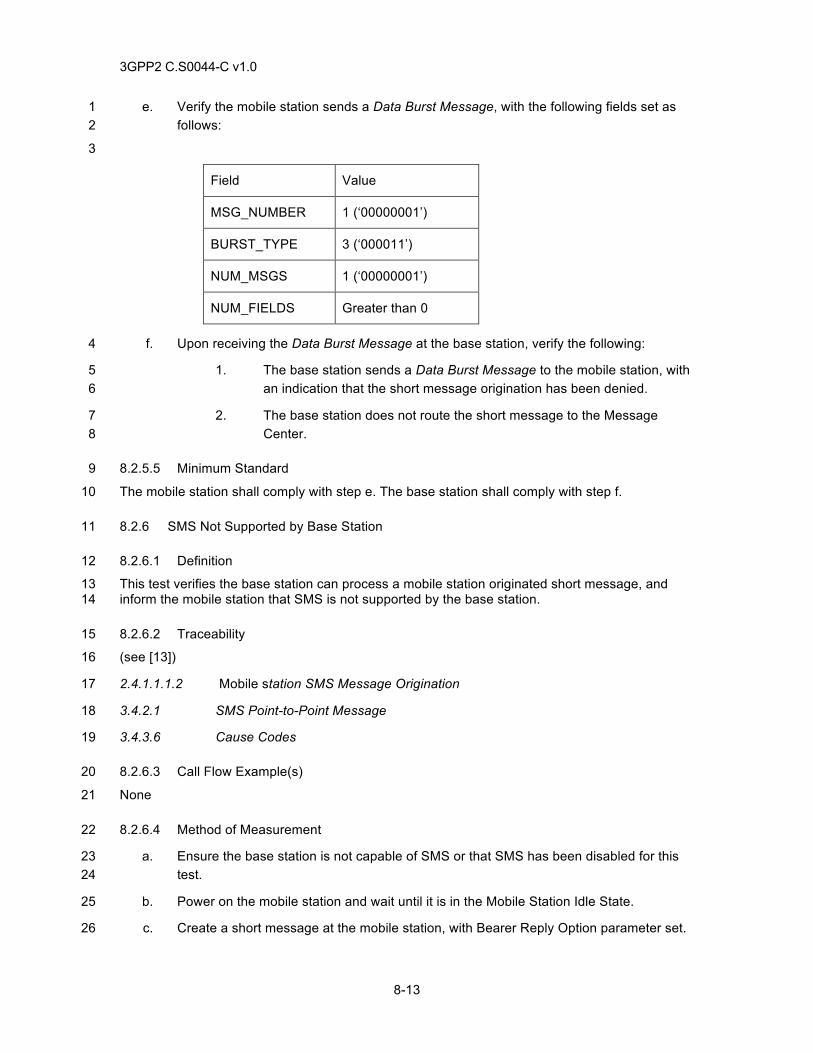
3GPP2 C.S0044-C v1.0
8-13
e. Verify the mobile station sends a Data Burst Message, with the following fields set as 1 follows: 2
3
Field Value
MSG_NUMBER 1 (‘00000001’)
BURST_TYPE 3 (‘000011’)
NUM_MSGS 1 (‘00000001’)
NUM_FIELDS Greater than 0
f. Upon receiving the Data Burst Message at the base station, verify the following: 4
1. The base station sends a Data Burst Message to the mobile station, with 5 an indication that the short message origination has been denied. 6
2. The base station does not route the short message to the Message 7 Center. 8
8.2.5.5 Minimum Standard 9
The mobile station shall comply with step e. The base station shall comply with step f. 10
8.2.6 SMS Not Supported by Base Station 11
8.2.6.1 Definition 12
This test verifies the base station can process a mobile station originated short message, and 13 inform the mobile station that SMS is not supported by the base station. 14
8.2.6.2 Traceability 15
(see [13]) 16
2.4.1.1.1.2 Mobile station SMS Message Origination 17
3.4.2.1 SMS Point-to-Point Message 18
3.4.3.6 Cause Codes 19
8.2.6.3 Call Flow Example(s) 20
None 21
8.2.6.4 Method of Measurement 22
a. Ensure the base station is not capable of SMS or that SMS has been disabled for this 23 test. 24
b. Power on the mobile station and wait until it is in the Mobile Station Idle State. 25
c. Create a short message at the mobile station, with Bearer Reply Option parameter set. 26
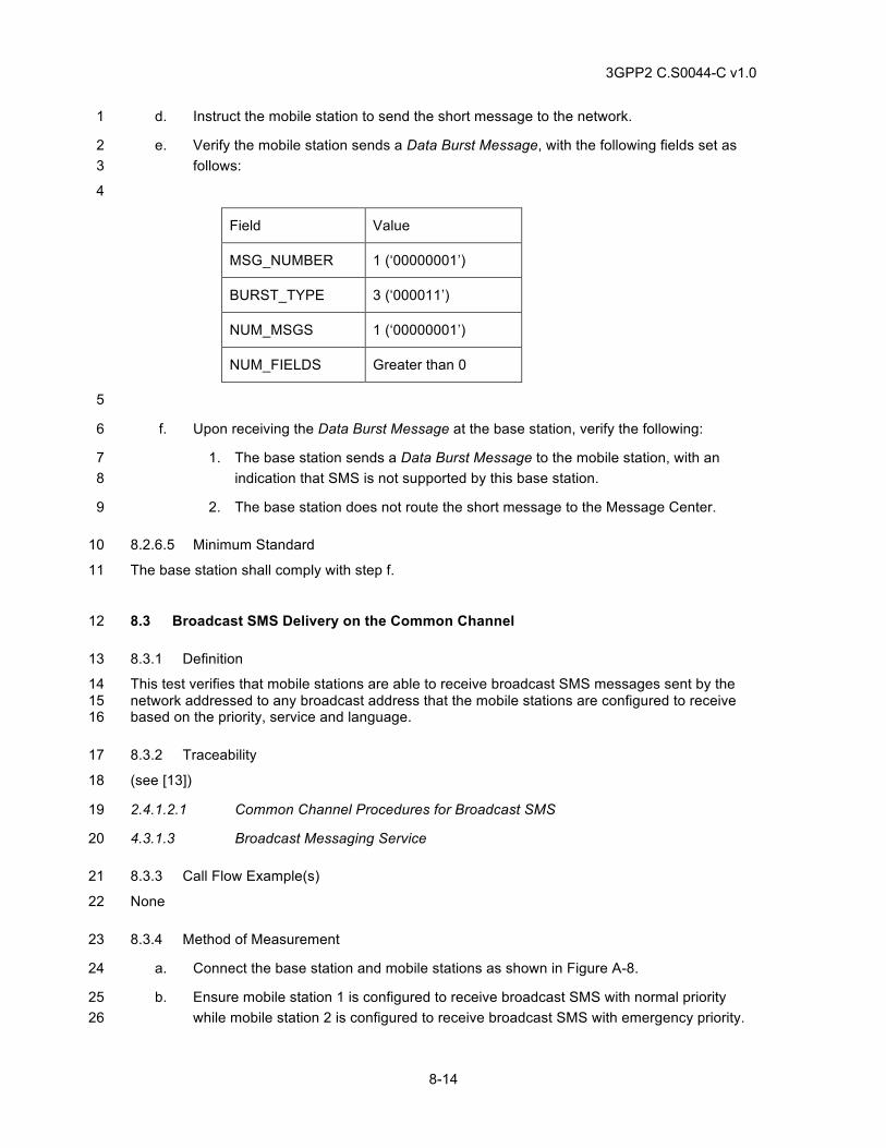
3GPP2 C.S0044-C v1.0
8-14
d. Instruct the mobile station to send the short message to the network. 1
e. Verify the mobile station sends a Data Burst Message, with the following fields set as 2 follows: 3
4
Field Value
MSG_NUMBER 1 (‘00000001’)
BURST_TYPE 3 (‘000011’)
NUM_MSGS 1 (‘00000001’)
NUM_FIELDS Greater than 0
5
f. Upon receiving the Data Burst Message at the base station, verify the following: 6
1. The base station sends a Data Burst Message to the mobile station, with an 7 indication that SMS is not supported by this base station. 8
2. The base station does not route the short message to the Message Center. 9
8.2.6.5 Minimum Standard 10
The base station shall comply with step f. 11
8.3 Broadcast SMS Delivery on the Common Channel 12
8.3.1 Definition 13
This test verifies that mobile stations are able to receive broadcast SMS messages sent by the 14 network addressed to any broadcast address that the mobile stations are configured to receive 15 based on the priority, service and language. 16
8.3.2 Traceability 17
(see [13]) 18
2.4.1.2.1 Common Channel Procedures for Broadcast SMS 19
4.3.1.3 Broadcast Messaging Service 20
8.3.3 Call Flow Example(s) 21
None 22
8.3.4 Method of Measurement 23
a. Connect the base station and mobile stations as shown in Figure A-8. 24
b. Ensure mobile station 1 is configured to receive broadcast SMS with normal priority 25 while mobile station 2 is configured to receive broadcast SMS with emergency priority. 26
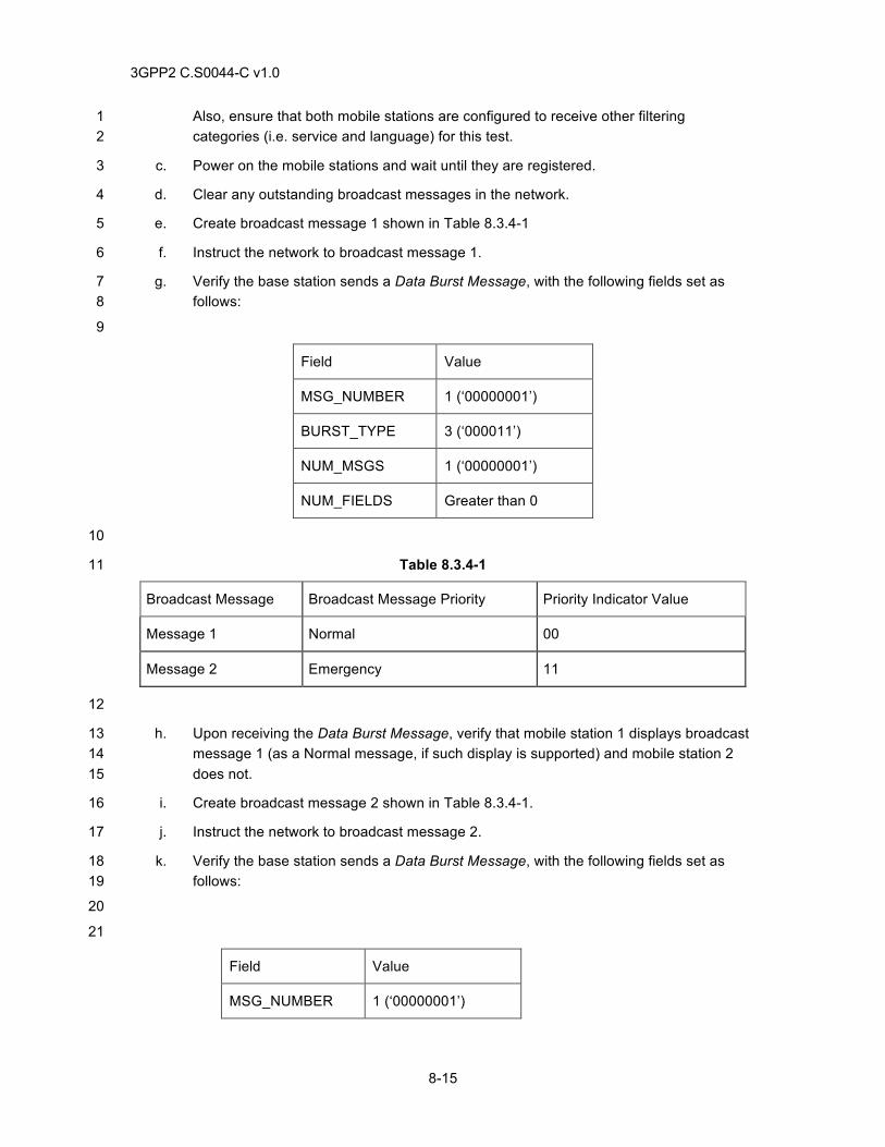
3GPP2 C.S0044-C v1.0
8-15
Also, ensure that both mobile stations are configured to receive other filtering 1 categories (i.e. service and language) for this test. 2
c. Power on the mobile stations and wait until they are registered. 3
d. Clear any outstanding broadcast messages in the network. 4
e. Create broadcast message 1 shown in Table 8.3.4-1 5
f. Instruct the network to broadcast message 1. 6
g. Verify the base station sends a Data Burst Message, with the following fields set as 7 follows: 8
9
Field Value
MSG_NUMBER 1 (‘00000001’)
BURST_TYPE 3 (‘000011’)
NUM_MSGS 1 (‘00000001’)
NUM_FIELDS Greater than 0
10
Table 8.3.4-1 11
Broadcast Message Broadcast Message Priority Priority Indicator Value
Message 1 Normal 00
Message 2 Emergency 11
12
h. Upon receiving the Data Burst Message, verify that mobile station 1 displays broadcast 13 message 1 (as a Normal message, if such display is supported) and mobile station 2 14 does not. 15
i. Create broadcast message 2 shown in Table 8.3.4-1. 16
j. Instruct the network to broadcast message 2. 17
k. Verify the base station sends a Data Burst Message, with the following fields set as 18 follows: 19
20
21
Field Value
MSG_NUMBER 1 (‘00000001’)
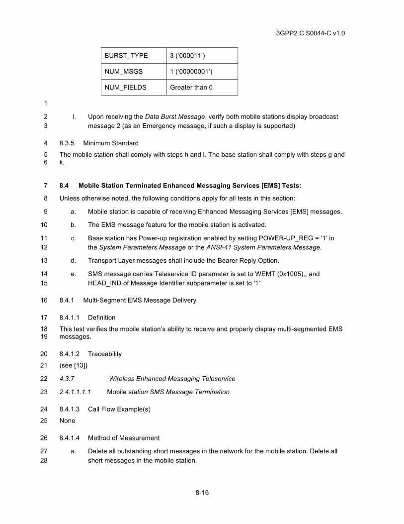
3GPP2 C.S0044-C v1.0
8-16
BURST_TYPE 3 (‘000011’)
NUM_MSGS 1 (‘00000001’)
NUM_FIELDS Greater than 0
1
l. Upon receiving the Data Burst Message, verify both mobile stations display broadcast 2 message 2 (as an Emergency message, if such a display is supported) 3
8.3.5 Minimum Standard 4
The mobile station shall comply with steps h and l. The base station shall comply with steps g and 5 k. 6
8.4 Mobile Station Terminated Enhanced Messaging Services [EMS] Tests: 7
Unless otherwise noted, the following conditions apply for all tests in this section: 8
a. Mobile station is capable of receiving Enhanced Messaging Services [EMS] messages. 9
b. The EMS message feature for the mobile station is activated. 10
c. Base station has Power-up registration enabled by setting POWER-UP_REG = ‘1’ in 11 the System Parameters Message or the ANSI-41 System Parameters Message. 12
d. Transport Layer messages shall include the Bearer Reply Option. 13
e. SMS message carries Teleservice ID parameter is set to WEMT (0x1005),, and 14 HEAD_IND of Message Identifier subparameter is set to '1' 15
8.4.1 Multi-Segment EMS Message Delivery 16
8.4.1.1 Definition 17
This test verifies the mobile station’s ability to receive and properly display multi-segmented EMS 18 messages. 19
8.4.1.2 Traceability 20
(see [13]) 21
4.3.7 Wireless Enhanced Messaging Teleservice 22
2.4.1.1.1.1 Mobile station SMS Message Termination 23
8.4.1.3 Call Flow Example(s) 24
None 25
8.4.1.4 Method of Measurement 26
a. Delete all outstanding short messages in the network for the mobile station. Delete all 27 short messages in the mobile station. 28
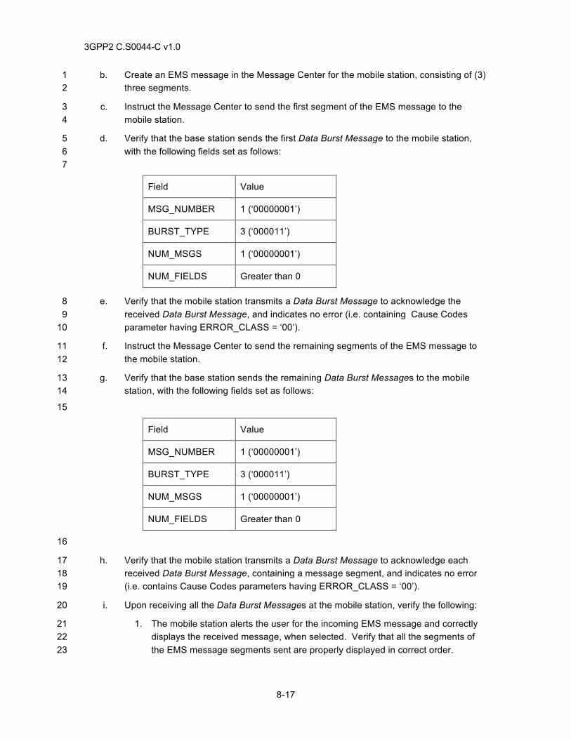
3GPP2 C.S0044-C v1.0
8-17
b. Create an EMS message in the Message Center for the mobile station, consisting of (3) 1 three segments. 2
c. Instruct the Message Center to send the first segment of the EMS message to the 3 mobile station. 4
d. Verify that the base station sends the first Data Burst Message to the mobile station, 5 with the following fields set as follows: 6 7
Field Value
MSG_NUMBER 1 (‘00000001’)
BURST_TYPE 3 (‘000011’)
NUM_MSGS 1 (‘00000001’)
NUM_FIELDS Greater than 0
e. Verify that the mobile station transmits a Data Burst Message to acknowledge the 8 received Data Burst Message, and indicates no error (i.e. containing Cause Codes 9 parameter having ERROR_CLASS = ‘00’). 10
f. Instruct the Message Center to send the remaining segments of the EMS message to 11 the mobile station. 12
g. Verify that the base station sends the remaining Data Burst Messages to the mobile 13 station, with the following fields set as follows: 14
15
Field Value
MSG_NUMBER 1 (‘00000001’)
BURST_TYPE 3 (‘000011’)
NUM_MSGS 1 (‘00000001’)
NUM_FIELDS Greater than 0
16
h. Verify that the mobile station transmits a Data Burst Message to acknowledge each 17 received Data Burst Message, containing a message segment, and indicates no error 18 (i.e. contains Cause Codes parameters having ERROR_CLASS = ‘00’). 19
i. Upon receiving all the Data Burst Messages at the mobile station, verify the following: 20
1. The mobile station alerts the user for the incoming EMS message and correctly 21 displays the received message, when selected. Verify that all the segments of 22 the EMS message segments sent are properly displayed in correct order. 23
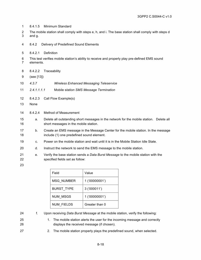
3GPP2 C.S0044-C v1.0
8-18
8.4.1.5 Minimum Standard 1
The mobile station shall comply with steps e, h, and i. The base station shall comply with steps d 2 and g. 3
8.4.2 Delivery of Predefined Sound Elements 4
8.4.2.1 Definition 5
This test verifies mobile station’s ability to receive and properly play pre-defined EMS sound 6 elements. 7
8.4.2.2 Traceability 8
(see [13]) 9
4.3.7 Wireless Enhanced Messaging Teleservice 10
2.4.1.1.1.1 Mobile station SMS Message Termination 11
8.4.2.3 Call Flow Example(s) 12
None 13
8.4.2.4 Method of Measurement 14
a. Delete all outstanding short messages in the network for the mobile station. Delete all 15 short messages in the mobile station. 16
b. Create an EMS message in the Message Center for the mobile station. In the message 17 include (1) one predefined sound element. 18
c. Power on the mobile station and wait until it is in the Mobile Station Idle State. 19
d. Instruct the network to send the EMS message to the mobile station. 20
e. Verify the base station sends a Data Burst Message to the mobile station with the 21 specified fields set as follow: 22
23
Field Value
MSG_NUMBER 1 (‘00000001’)
BURST_TYPE 3 (‘000011’)
NUM_MSGS 1 (‘00000001’)
NUM_FIELDS Greater than 0
f. Upon receiving Data Burst Message at the mobile station, verify the following: 24
1. The mobile station alerts the user for the incoming message and correctly 25 displays the received message (if chosen). 26
2. The mobile station properly plays the predefined sound, when selected. 27
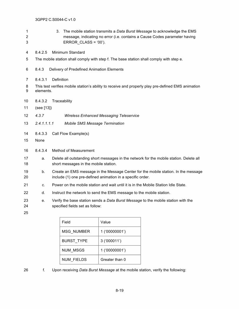
3GPP2 C.S0044-C v1.0
8-19
3. The mobile station transmits a Data Burst Message to acknowledge the EMS 1 message, indicating no error (i.e. contains a Cause Codes parameter having 2 ERROR_CLASS = ‘00’). 3
8.4.2.5 Minimum Standard 4
The mobile station shall comply with step f. The base station shall comply with step e. 5
8.4.3 Delivery of Predefined Animation Elements 6
8.4.3.1 Definition 7
This test verifies mobile station’s ability to receive and properly play pre-defined EMS animation 8 elements. 9
8.4.3.2 Traceability 10
(see [13]) 11
4.3.7 Wireless Enhanced Messaging Teleservice 12
2.4.1.1.1.1 Mobile SMS Message Termination 13
8.4.3.3 Call Flow Example(s) 14
None 15
8.4.3.4 Method of Measurement 16
a. Delete all outstanding short messages in the network for the mobile station. Delete all 17 short messages in the mobile station. 18
b. Create an EMS message in the Message Center for the mobile station. In the message 19 include (1) one pre-defined animation in a specific order. 20
c. Power on the mobile station and wait until it is in the Mobile Station Idle State. 21
d. Instruct the network to send the EMS message to the mobile station. 22
e. Verify the base station sends a Data Burst Message to the mobile station with the 23 specified fields set as follow: 24
25
Field Value
MSG_NUMBER 1 (‘00000001’)
BURST_TYPE 3 (‘000011’)
NUM_MSGS 1 (‘00000001’)
NUM_FIELDS Greater than 0
f. Upon receiving Data Burst Message at the mobile station, verify the following: 26
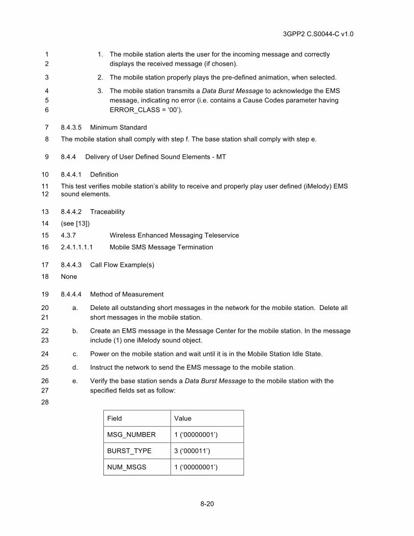
3GPP2 C.S0044-C v1.0
8-20
1. The mobile station alerts the user for the incoming message and correctly 1 displays the received message (if chosen). 2
2. The mobile station properly plays the pre-defined animation, when selected. 3
3. The mobile station transmits a Data Burst Message to acknowledge the EMS 4 message, indicating no error (i.e. contains a Cause Codes parameter having 5 ERROR_CLASS = ‘00’). 6
8.4.3.5 Minimum Standard 7
The mobile station shall comply with step f. The base station shall comply with step e. 8
8.4.4 Delivery of User Defined Sound Elements - MT 9
8.4.4.1 Definition 10
This test verifies mobile station’s ability to receive and properly play user defined (iMelody) EMS 11 sound elements. 12
8.4.4.2 Traceability 13
(see [13]) 14
4.3.7 Wireless Enhanced Messaging Teleservice 15
2.4.1.1.1.1 Mobile SMS Message Termination 16
8.4.4.3 Call Flow Example(s) 17
None 18
8.4.4.4 Method of Measurement 19
a. Delete all outstanding short messages in the network for the mobile station. Delete all 20 short messages in the mobile station. 21
b. Create an EMS message in the Message Center for the mobile station. In the message 22 include (1) one iMelody sound object. 23
c. Power on the mobile station and wait until it is in the Mobile Station Idle State. 24
d. Instruct the network to send the EMS message to the mobile station. 25
e. Verify the base station sends a Data Burst Message to the mobile station with the 26 specified fields set as follow: 27
28
Field Value
MSG_NUMBER 1 (‘00000001’)
BURST_TYPE 3 (‘000011’)
NUM_MSGS 1 (‘00000001’)
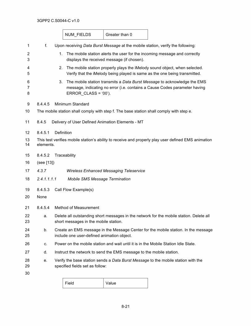
3GPP2 C.S0044-C v1.0
8-21
NUM_FIELDS Greater than 0
f. Upon receiving Data Burst Message at the mobile station, verify the following: 1
1. The mobile station alerts the user for the incoming message and correctly 2 displays the received message (if chosen). 3
2. The mobile station properly plays the iMelody sound object, when selected. 4 Verify that the iMelody being played is same as the one being transmitted. 5
3. The mobile station transmits a Data Burst Message to acknowledge the EMS 6 message, indicating no error (i.e. contains a Cause Codes parameter having 7 ERROR_CLASS = ‘00’). 8
8.4.4.5 Minimum Standard 9
The mobile station shall comply with step f. The base station shall comply with step e. 10
8.4.5 Delivery of User Defined Animation Elements - MT 11
8.4.5.1 Definition 12
This test verifies mobile station’s ability to receive and properly play user defined EMS animation 13 elements. 14
8.4.5.2 Traceability 15
(see [13]) 16
4.3.7 Wireless Enhanced Messaging Teleservice 17
2.4.1.1.1.1 Mobile SMS Message Termination 18
8.4.5.3 Call Flow Example(s) 19
None 20
8.4.5.4 Method of Measurement 21
a. Delete all outstanding short messages in the network for the mobile station. Delete all 22 short messages in the mobile station. 23
b. Create an EMS message in the Message Center for the mobile station. In the message 24 include one user-defined animation object. 25
c. Power on the mobile station and wait until it is in the Mobile Station Idle State. 26
d. Instruct the network to send the EMS message to the mobile station. 27
e. Verify the base station sends a Data Burst Message to the mobile station with the 28 specified fields set as follow: 29
30
Field Value
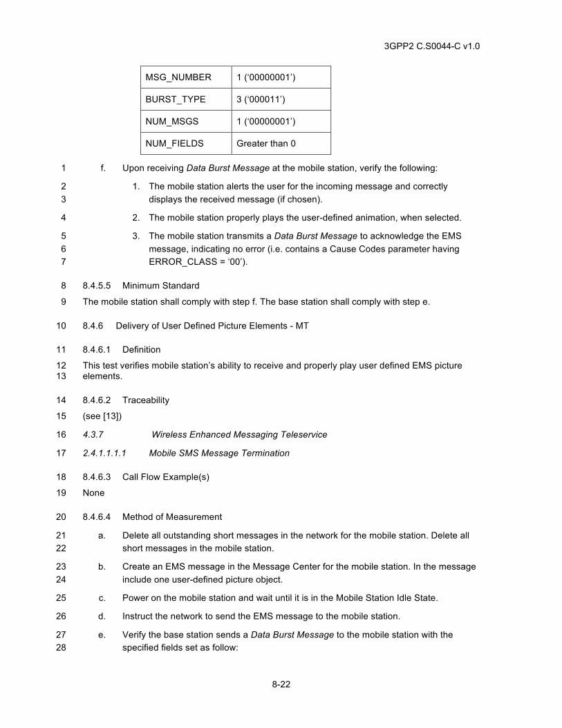
3GPP2 C.S0044-C v1.0
8-22
MSG_NUMBER 1 (‘00000001’)
BURST_TYPE 3 (‘000011’)
NUM_MSGS 1 (‘00000001’)
NUM_FIELDS Greater than 0
f. Upon receiving Data Burst Message at the mobile station, verify the following: 1
1. The mobile station alerts the user for the incoming message and correctly 2 displays the received message (if chosen). 3
2. The mobile station properly plays the user-defined animation, when selected. 4
3. The mobile station transmits a Data Burst Message to acknowledge the EMS 5 message, indicating no error (i.e. contains a Cause Codes parameter having 6 ERROR_CLASS = ‘00’). 7
8.4.5.5 Minimum Standard 8
The mobile station shall comply with step f. The base station shall comply with step e. 9
8.4.6 Delivery of User Defined Picture Elements - MT 10
8.4.6.1 Definition 11
This test verifies mobile station’s ability to receive and properly play user defined EMS picture 12 elements. 13
8.4.6.2 Traceability 14
(see [13]) 15
4.3.7 Wireless Enhanced Messaging Teleservice 16
2.4.1.1.1.1 Mobile SMS Message Termination 17
8.4.6.3 Call Flow Example(s) 18
None 19
8.4.6.4 Method of Measurement 20
a. Delete all outstanding short messages in the network for the mobile station. Delete all 21 short messages in the mobile station. 22
b. Create an EMS message in the Message Center for the mobile station. In the message 23 include one user-defined picture object. 24
c. Power on the mobile station and wait until it is in the Mobile Station Idle State. 25
d. Instruct the network to send the EMS message to the mobile station. 26
e. Verify the base station sends a Data Burst Message to the mobile station with the 27 specified fields set as follow: 28
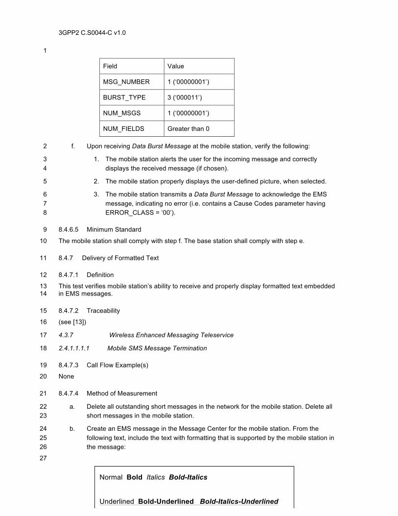
3GPP2 C.S0044-C v1.0
8-23
1
Field Value
MSG_NUMBER 1 (‘00000001’)
BURST_TYPE 3 (‘000011’)
NUM_MSGS 1 (‘00000001’)
NUM_FIELDS Greater than 0
f. Upon receiving Data Burst Message at the mobile station, verify the following: 2
1. The mobile station alerts the user for the incoming message and correctly 3 displays the received message (if chosen). 4
2. The mobile station properly displays the user-defined picture, when selected. 5
3. The mobile station transmits a Data Burst Message to acknowledge the EMS 6 message, indicating no error (i.e. contains a Cause Codes parameter having 7 ERROR_CLASS = ‘00’). 8
8.4.6.5 Minimum Standard 9
The mobile station shall comply with step f. The base station shall comply with step e. 10
8.4.7 Delivery of Formatted Text 11
8.4.7.1 Definition 12
This test verifies mobile station’s ability to receive and properly display formatted text embedded 13 in EMS messages. 14
8.4.7.2 Traceability 15
(see [13]) 16
4.3.7 Wireless Enhanced Messaging Teleservice 17
2.4.1.1.1.1 Mobile SMS Message Termination 18
8.4.7.3 Call Flow Example(s) 19
None 20
8.4.7.4 Method of Measurement 21
a. Delete all outstanding short messages in the network for the mobile station. Delete all 22 short messages in the mobile station. 23
b. Create an EMS message in the Message Center for the mobile station. From the 24 following text, include the text with formatting that is supported by the mobile station in 25 the message: 26
27
Normal Bold Italics Bold-Italics
Underlined Bold-Underlined Bold-Italics-Underlined Left-Justified
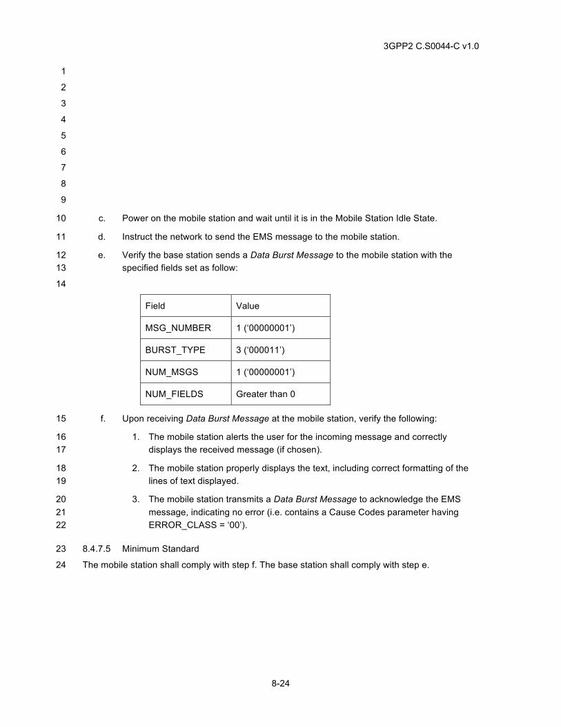
3GPP2 C.S0044-C v1.0
8-24
1
2
3
4
5
6
7
8
9
c. Power on the mobile station and wait until it is in the Mobile Station Idle State. 10
d. Instruct the network to send the EMS message to the mobile station. 11
e. Verify the base station sends a Data Burst Message to the mobile station with the 12 specified fields set as follow: 13
14
Field Value
MSG_NUMBER 1 (‘00000001’)
BURST_TYPE 3 (‘000011’)
NUM_MSGS 1 (‘00000001’)
NUM_FIELDS Greater than 0
f. Upon receiving Data Burst Message at the mobile station, verify the following: 15
1. The mobile station alerts the user for the incoming message and correctly 16 displays the received message (if chosen). 17
2. The mobile station properly displays the text, including correct formatting of the 18 lines of text displayed. 19
3. The mobile station transmits a Data Burst Message to acknowledge the EMS 20 message, indicating no error (i.e. contains a Cause Codes parameter having 21 ERROR_CLASS = ‘00’). 22
8.4.7.5 Minimum Standard 23
The mobile station shall comply with step f. The base station shall comply with step e. 24
3GPP2 C.S0044-C v1.0
8-25
8.5 Mobile Station Originated Enhanced Messaging Services [EMS] Tests: 1
8.5.1 Multi-Segment EMS Message Delivery 2
8.5.1.1 Definition 3
This test verifies mobile station’s ability to compose and send multi-segmented EMS messages. 4
8.5.1.2 Traceability 5
(see [13]) 6
4.3.7 Wireless Enhanced Messaging Teleservice 7
2.4.1.1.2 Mobile Station Traffic Channel Procedures 8
2.4.1.1.1.2 Mobile SMS Message Origination 9
8.5.1.3 Call Flow Example(s) 10
None 11
8.5.1.4 Method of Measurement 12
a. Power on the mobile station and wait until it is in the Mobile station Idle State. 13
b. Create an EMS message at the mobile station, consisting of three (3) segments. 14
c. Instruct the mobile station to send all the segments of the EMS message to the 15 Message Center. 16
d. Verify that the Message Center receives all the segments and sends an SMS 17 Acknowledgement for each segment to the mobile station. 18
e. Verify that upon sending the short message, the mobile station sends a Release Order 19 to release the dedicated channels. 20
8.5.1.5 Minimum Standard 21
The mobile station shall comply with step e. 22
8.5.2 Delivery of Predefined Sound Elements 23
8.5.2.1 Definition 24
This test verifies the mobile station’s ability to compose and send messages containing 25 predefined EMS sound elements. 26
8.5.2.2 Traceability 27
(see [13]) 28
4.3.7 Wireless Enhanced Messaging Teleservice 29
2.4.1.1.1.2 Mobile SMS Message Origination 30
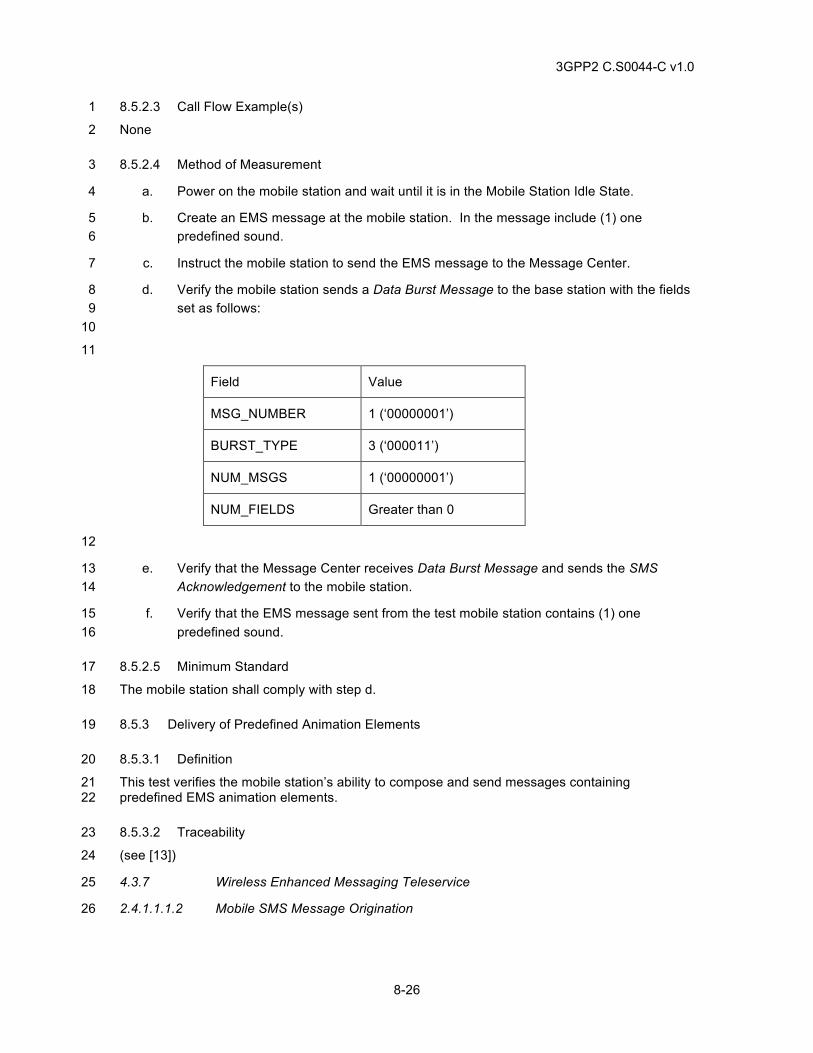
3GPP2 C.S0044-C v1.0
8-26
8.5.2.3 Call Flow Example(s) 1
None 2
8.5.2.4 Method of Measurement 3
a. Power on the mobile station and wait until it is in the Mobile Station Idle State. 4
b. Create an EMS message at the mobile station. In the message include (1) one 5 predefined sound. 6
c. Instruct the mobile station to send the EMS message to the Message Center. 7
d. Verify the mobile station sends a Data Burst Message to the base station with the fields 8 set as follows: 9 10
11
Field Value
MSG_NUMBER 1 (‘00000001’)
BURST_TYPE 3 (‘000011’)
NUM_MSGS 1 (‘00000001’)
NUM_FIELDS Greater than 0
12
e. Verify that the Message Center receives Data Burst Message and sends the SMS 13 Acknowledgement to the mobile station. 14
f. Verify that the EMS message sent from the test mobile station contains (1) one 15 predefined sound. 16
8.5.2.5 Minimum Standard 17
The mobile station shall comply with step d. 18
8.5.3 Delivery of Predefined Animation Elements 19
8.5.3.1 Definition 20
This test verifies the mobile station’s ability to compose and send messages containing 21 predefined EMS animation elements. 22
8.5.3.2 Traceability 23
(see [13]) 24
4.3.7 Wireless Enhanced Messaging Teleservice 25
2.4.1.1.1.2 Mobile SMS Message Origination 26
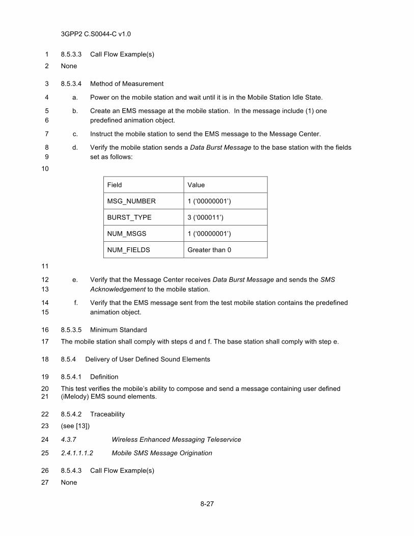
3GPP2 C.S0044-C v1.0
8-27
8.5.3.3 Call Flow Example(s) 1
None 2
8.5.3.4 Method of Measurement 3
a. Power on the mobile station and wait until it is in the Mobile Station Idle State. 4
b. Create an EMS message at the mobile station. In the message include (1) one 5 predefined animation object. 6
c. Instruct the mobile station to send the EMS message to the Message Center. 7
d. Verify the mobile station sends a Data Burst Message to the base station with the fields 8 set as follows: 9
10
Field Value
MSG_NUMBER 1 (‘00000001’)
BURST_TYPE 3 (‘000011’)
NUM_MSGS 1 (‘00000001’)
NUM_FIELDS Greater than 0
11
e. Verify that the Message Center receives Data Burst Message and sends the SMS 12 Acknowledgement to the mobile station. 13
f. Verify that the EMS message sent from the test mobile station contains the predefined 14 animation object. 15
8.5.3.5 Minimum Standard 16
The mobile station shall comply with steps d and f. The base station shall comply with step e. 17
8.5.4 Delivery of User Defined Sound Elements 18
8.5.4.1 Definition 19
This test verifies the mobile’s ability to compose and send a message containing user defined 20 (iMelody) EMS sound elements. 21
8.5.4.2 Traceability 22
(see [13]) 23
4.3.7 Wireless Enhanced Messaging Teleservice 24
2.4.1.1.1.2 Mobile SMS Message Origination 25
8.5.4.3 Call Flow Example(s) 26
None 27
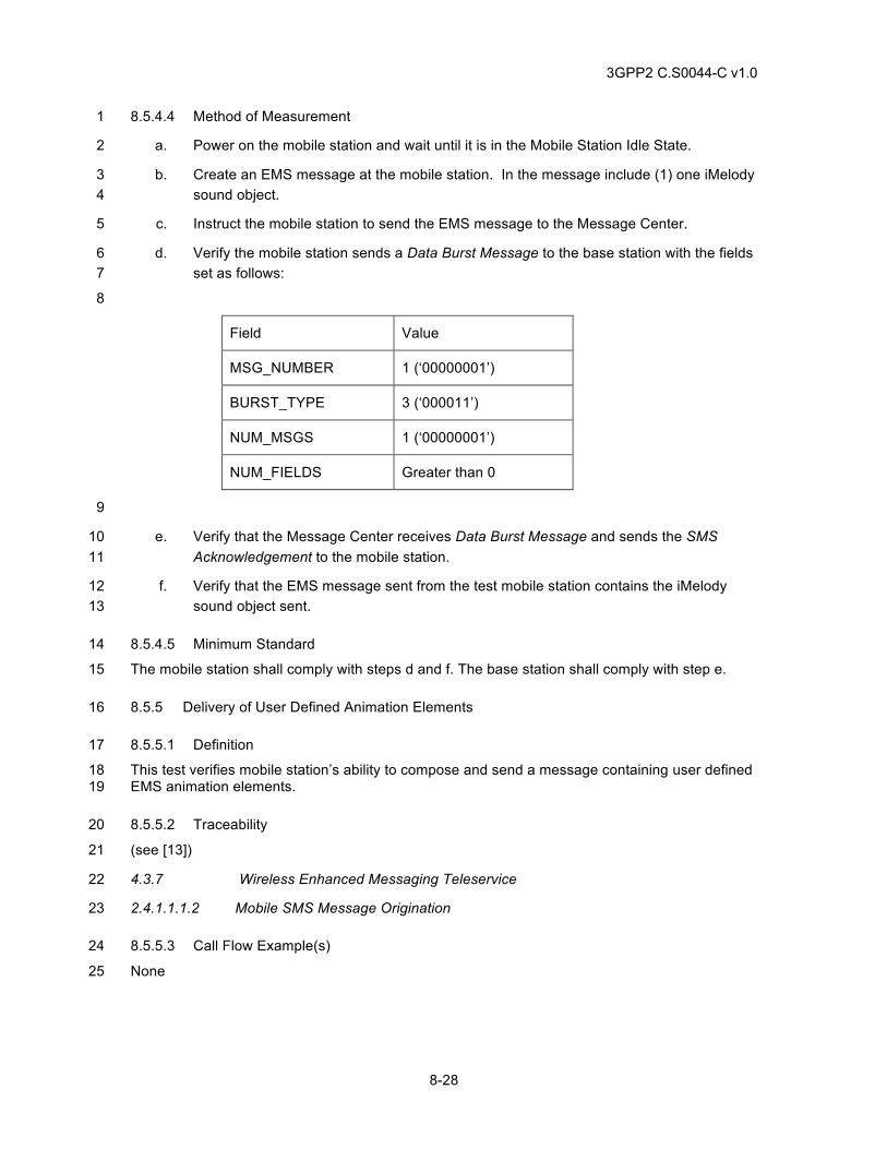
3GPP2 C.S0044-C v1.0
8-28
8.5.4.4 Method of Measurement 1
a. Power on the mobile station and wait until it is in the Mobile Station Idle State. 2
b. Create an EMS message at the mobile station. In the message include (1) one iMelody 3 sound object. 4
c. Instruct the mobile station to send the EMS message to the Message Center. 5
d. Verify the mobile station sends a Data Burst Message to the base station with the fields 6 set as follows: 7
8
Field Value
MSG_NUMBER 1 (‘00000001’)
BURST_TYPE 3 (‘000011’)
NUM_MSGS 1 (‘00000001’)
NUM_FIELDS Greater than 0
9
e. Verify that the Message Center receives Data Burst Message and sends the SMS 10 Acknowledgement to the mobile station. 11
f. Verify that the EMS message sent from the test mobile station contains the iMelody 12 sound object sent. 13
8.5.4.5 Minimum Standard 14
The mobile station shall comply with steps d and f. The base station shall comply with step e. 15
8.5.5 Delivery of User Defined Animation Elements 16
8.5.5.1 Definition 17
This test verifies mobile station’s ability to compose and send a message containing user defined 18 EMS animation elements. 19
8.5.5.2 Traceability 20
(see [13]) 21
4.3.7 Wireless Enhanced Messaging Teleservice 22
2.4.1.1.1.2 Mobile SMS Message Origination 23
8.5.5.3 Call Flow Example(s) 24
None 25
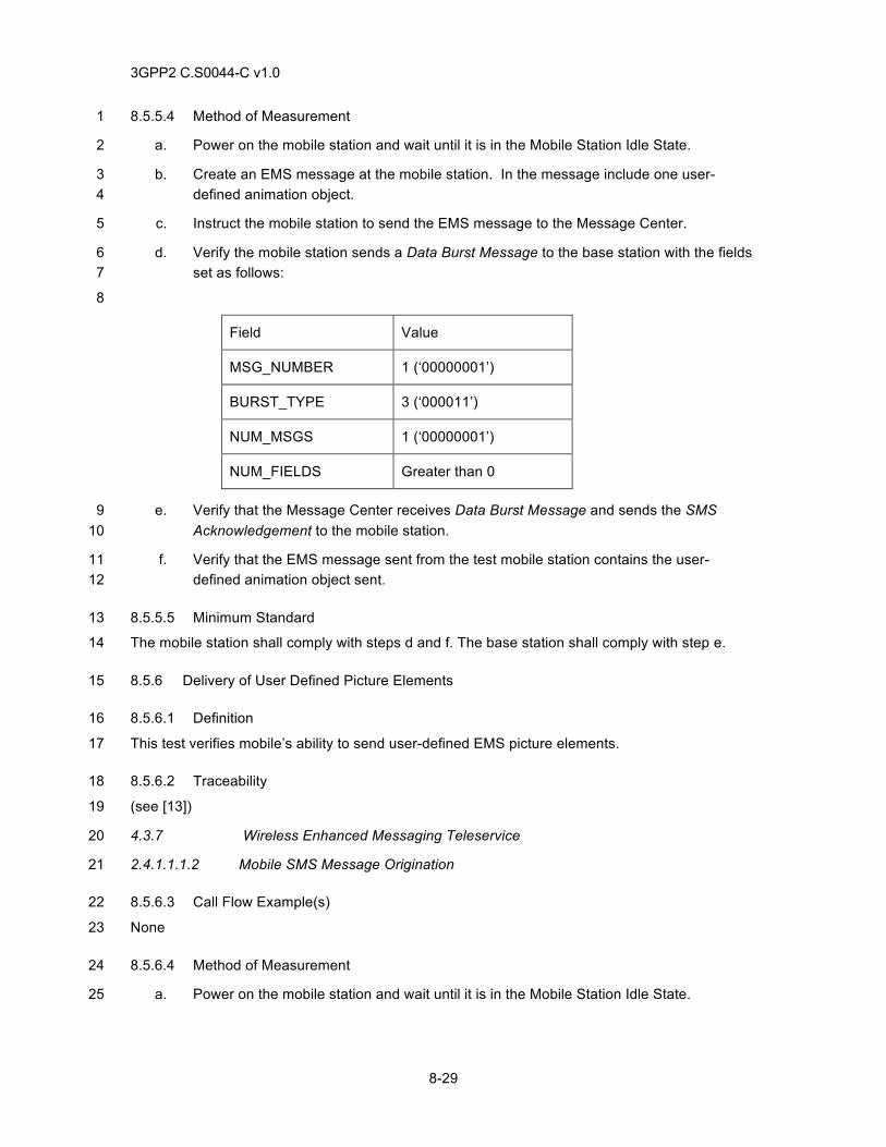
3GPP2 C.S0044-C v1.0
8-29
8.5.5.4 Method of Measurement 1
a. Power on the mobile station and wait until it is in the Mobile Station Idle State. 2
b. Create an EMS message at the mobile station. In the message include one user-3 defined animation object. 4
c. Instruct the mobile station to send the EMS message to the Message Center. 5
d. Verify the mobile station sends a Data Burst Message to the base station with the fields 6 set as follows: 7
8
Field Value
MSG_NUMBER 1 (‘00000001’)
BURST_TYPE 3 (‘000011’)
NUM_MSGS 1 (‘00000001’)
NUM_FIELDS Greater than 0
e. Verify that the Message Center receives Data Burst Message and sends the SMS 9 Acknowledgement to the mobile station. 10
f. Verify that the EMS message sent from the test mobile station contains the user-11 defined animation object sent. 12
8.5.5.5 Minimum Standard 13
The mobile station shall comply with steps d and f. The base station shall comply with step e. 14
8.5.6 Delivery of User Defined Picture Elements 15
8.5.6.1 Definition 16
This test verifies mobile’s ability to send user-defined EMS picture elements. 17
8.5.6.2 Traceability 18
(see [13]) 19
4.3.7 Wireless Enhanced Messaging Teleservice 20
2.4.1.1.1.2 Mobile SMS Message Origination 21
8.5.6.3 Call Flow Example(s) 22
None 23
8.5.6.4 Method of Measurement 24
a. Power on the mobile station and wait until it is in the Mobile Station Idle State. 25
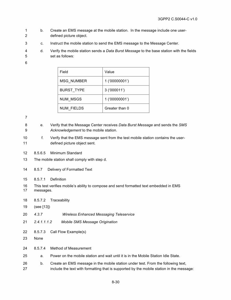
3GPP2 C.S0044-C v1.0
8-30
b. Create an EMS message at the mobile station. In the message include one user-1 defined picture object. 2
c. Instruct the mobile station to send the EMS message to the Message Center. 3
d. Verify the mobile station sends a Data Burst Message to the base station with the fields 4 set as follows: 5
6
Field Value
MSG_NUMBER 1 (‘00000001’)
BURST_TYPE 3 (‘000011’)
NUM_MSGS 1 (‘00000001’)
NUM_FIELDS Greater than 0
7
e. Verify that the Message Center receives Data Burst Message and sends the SMS 8 Acknowledgement to the mobile station. 9
f. Verify that the EMS message sent from the test mobile station contains the user-10 defined picture object sent. 11
8.5.6.5 Minimum Standard 12
The mobile station shall comply with step d. 13
8.5.7 Delivery of Formatted Text 14
8.5.7.1 Definition 15
This test verifies mobile’s ability to compose and send formatted text embedded in EMS 16 messages. 17
8.5.7.2 Traceability 18
(see [13]) 19
4.3.7 Wireless Enhanced Messaging Teleservice 20
2.4.1.1.1.2 Mobile SMS Message Origination 21
8.5.7.3 Call Flow Example(s) 22
None 23
8.5.7.4 Method of Measurement 24
a. Power on the mobile station and wait until it is in the Mobile Station Idle State. 25
b. Create an EMS message in the mobile station under test. From the following text, 26 include the text with formatting that is supported by the mobile station in the message: 27
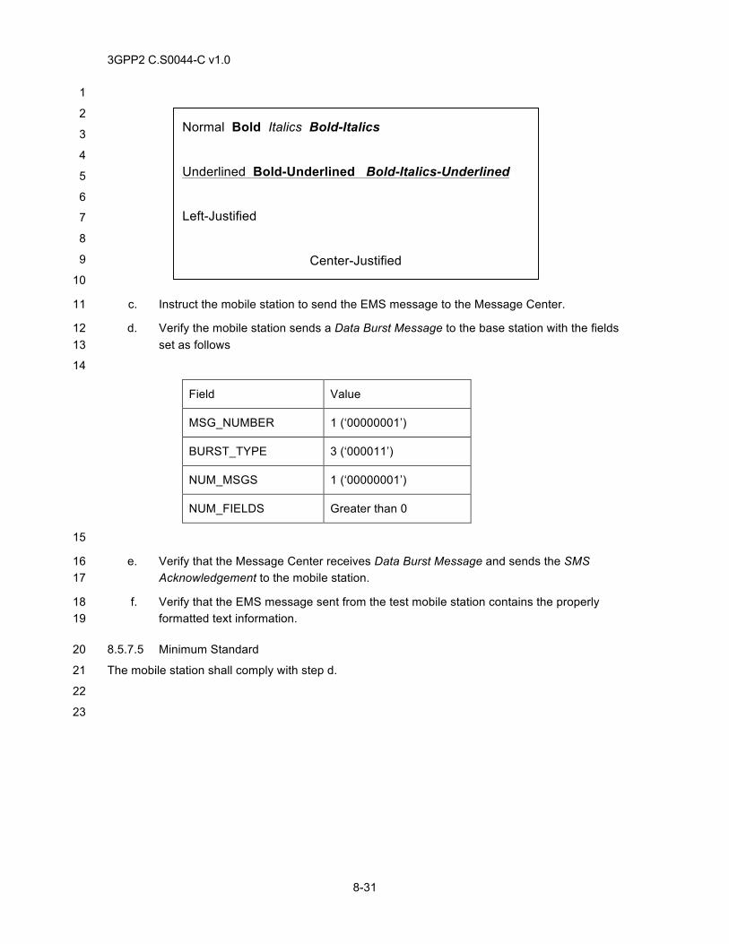
3GPP2 C.S0044-C v1.0
8-31
1
2
3
4
5
6
7
8
9
10
c. Instruct the mobile station to send the EMS message to the Message Center. 11
d. Verify the mobile station sends a Data Burst Message to the base station with the fields 12 set as follows 13
14
Field Value
MSG_NUMBER 1 (‘00000001’)
BURST_TYPE 3 (‘000011’)
NUM_MSGS 1 (‘00000001’)
NUM_FIELDS Greater than 0
15
e. Verify that the Message Center receives Data Burst Message and sends the SMS 16 Acknowledgement to the mobile station. 17
f. Verify that the EMS message sent from the test mobile station contains the properly 18 formatted text information. 19
8.5.7.5 Minimum Standard 20
The mobile station shall comply with step d. 21
22
23
Normal Bold Italics Bold-Italics
Underlined Bold-Underlined Bold-Italics-Underlined Left-Justified
Center-Justified
Right-Justified

3GPP2 C.S0044-C v1.0
8-32
This page intentionally left blank.1
3GPP2 C.S0044-C v1.0
9-1
9 SUBSCRIBER CALLING FEATURES 1
9.1 Call Forwarding Unconditional (CFU) 2
9.1.1 Definition 3
CFU permits a called subscriber to send incoming calls addressed to the called subscriber’s 4 Directory Number to another Directory Number (forward-to number). If this feature is active, calls 5 are forwarded regardless of the condition of the termination. 6
9.1.2 Traceability 7
(see [22]) 8
505 Call Forwarding—Unconditional 9
9.1.3 Call Flow Example(s) 10
None 11
9.1.4 Method of Measurement 12
a. Power on the mobile station and wait until it reaches Mobile Station Idle State. 13
b. Dial the CFU feature activation code, followed by the forward-to number, followed by 14 SEND. Verify feature update confirmation at the mobile station (confirming audio tones 15 from the network). 16
c. Setup a call from a land party to the mobile station. Verify call is forwarded and that if 17 the Network directs the mobile station to “Ping Ring” it plays a single burst of 500 ms. 18
d. Answer the call on the forward-to line, and verify the audio path. 19
e. End the call. 20
f. Dial the CFU deactivation feature code followed by SEND. Verify feature update 21 confirmation at the mobile station. 22
g. Verify that CFU has been deactivated, by calling the mobile station under test and 23 verifying that the mobile station rings and completes the call when answered. 24
9.1.5 Minimum Standard 25
The mobile station and the base station shall comply with steps b, c, d, f and g. 26
9.2 Call Forwarding Busy (CFB) 27
9.2.1 Definition 28
CFB permits a called subscriber to have the system send incoming calls to another Directory 29 Number (forward-to number) when the subscriber is engaged in a call or service. 30
9.2.2 Traceability 31
(see [22]) 32
3GPP2 C.S0044-C v1.0
9-2
502 Call Forwarding Busy 1
9.2.3 Call Flow Example(s) 2
None 3
9.2.4 Method of Measurement 4
a. Power on the mobile station and wait until it reaches Mobile Station Idle State. 5
b. Dial the CFB activation feature code, followed by the forward-to-number, followed by 6 SEND. Verify feature update confirmation at the mobile station (confirming audio tones 7 from the network). 8
c. Place the mobile station under test in a voice call. 9
d. Attempt a second call from a land party to the mobile station under test. Verify the call is 10 forwarded to the forward-to-number, and that if the Network directs the mobile station to 11 “Ping Ring” it plays a single burst of 500 ms. 12
e. Answer the call on the forward-to line, and verify the audio path. 13
f. End all calls. 14
g. Dial the CFB deactivation feature code followed by SEND. Verify feature update 15 confirmation at the mobile station. 16
h. Verify that CFB has been deactivated, e.g. by calling the mobile station under test while 17 busy and verifying that the second call is not forwarded. 18
9.2.5 Minimum Standard 19
The mobile station and the base station shall comply with steps b, c, d, f and g. 20
9.3 Call Forwarding Default (CFD) 21
9.3.1 Definition 22
CFD permits a called subscriber to have the system send incoming calls to another Directory 23 Number (forward-to-number) when the subscriber is engaged in a call, does not respond to 24 paging, does not answer the call within a specified period after being alerted or is otherwise 25 inaccessible. 26
9.3.2 Traceability 27
(see [22]) 28
503 Call Forwarding—Default 29
9.3.3 Call Flow Example(s) 30
None 31
9.3.4 Method of Measurement 32
a. Power on the mobile station and wait until it reaches Mobile Station Idle State. 33
3GPP2 C.S0044-C v1.0
9-3
b. Dial the CFD activation feature code, followed by the forward-to number, followed by 1 SEND. Verify feature update confirmation at the mobile station (confirming audio tones 2 from the network). 3
c. Attempt a call from a land party to the mobile station. Verify the call is forwarded and 4 that if the Network directs the mobile station to “Ping Ring” it plays a single burst of 500 5 ms. 6
d. Answer the call on the forward-to line, and verify the audio path. 7
e. End call. 8
f. Dial the CFD deactivation feature code followed by SEND. Verify feature update 9 confirmation at the mobile station. 10
g. Verify that CFD has been deactivated, by calling the mobile station under test and 11 verifying that the mobile station rings and does not forward. 12
9.3.5 Minimum Standard 13
The mobile station and the base station shall comply with steps b, c, d, f and g. 14
9.4 Call Forwarding No Answer (CFNA) 15
9.4.1 Definition 16
CFNA permits a called subscriber to have the system send incoming calls addressed to the called 17 subscriber’s Directory Number to another Directory Number (forward-to number) when the 18 subscriber fails to answer. 19
9.4.2 Traceability 20
(see [22]) 21
504 Call Forwarding—No Answer 22
9.4.3 Call Flow Example(s) 23
None 24
9.4.4 Method of Measurement 25
a. Power on the mobile station and wait until it reaches Mobile Station Idle State. 26
b. Dial the CFNA activation feature code, followed by the forward-to number, followed by 27 SEND. Verify feature update confirmation at the mobile station (confirming audio tones 28 from the network). 29
c. Setup a call from a land party to the mobile station. Verify the mobile station rings, but 30 when not answered, the call is forwarded to the forward-to number. 31
d. Answer the call on the forward-to line, and verify the audio path. 32
e. End the call. 33
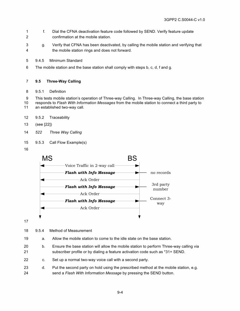
3GPP2 C.S0044-C v1.0
9-4
f. Dial the CFNA deactivation feature code followed by SEND. Verify feature update 1 confirmation at the mobile station. 2
g. Verify that CFNA has been deactivated, by calling the mobile station and verifying that 3 the mobile station rings and does not forward. 4
9.4.5 Minimum Standard 5
The mobile station and the base station shall comply with steps b, c, d, f and g. 6
9.5 Three-Way Calling 7
9.5.1 Definition 8
This tests mobile station’s operation of Three-way Calling. In Three-way Calling, the base station 9 responds to Flash With Information Messages from the mobile station to connect a third party to 10 an established two-way call. 11
9.5.2 Traceability 12
(see [22]) 13
522 Three Way Calling 14
9.5.3 Call Flow Example(s) 15
16
BSMSVoice Traffic in 2-way call
Ack Order
Flash with Info Message
Ack Order
Flash with Info Message
Ack Order
Flash with Info Message
no records
3rd partynumber
Connect 3-way
17
9.5.4 Method of Measurement 18
a. Allow the mobile station to come to the idle state on the base station. 19
b. Ensure the base station will allow the mobile station to perform Three-way calling via 20 subscriber profile or by dialing a feature activation code such as *31+ SEND. 21
c. Set up a normal two-way voice call with a second party. 22
d. Put the second party on hold using the prescribed method at the mobile station, e.g. 23 send a Flash With Information Message by pressing the SEND button. 24
3GPP2 C.S0044-C v1.0
9-5
e. Verify the second party is placed on hold and the mobile station alerts the user to 1 commence dialing the third party number, e. g. plays a dial tone. 2
f. Dial the third party number on the mobile station and send it out using the prescribed 3 method, e. g. send a Flash With Information Message containing the Keypad Facility 4 Information Record or the Called Party Number Information Record by pressing the 5 SEND button after entering dialed digits. 6
g. Verify the third party phone rings and answers with normal audio. 7
h. Connect all of the Three-Way Call parties, e. g. send a Flash With Information Message 8 by pressing the SEND button, and verify the three-way connection is established with 9 normal audio. 10
i. End the call. 11
j. Ensure the base station will not allow the mobile station to perform Three-way calling 12 via subscriber profile or by dialing a feature de-activation code such as *91+ SEND 13
9.5.5 Minimum Standard 14
The mobile station shall comply with the requirements in steps b, e, g, h, and j. 15
9.6 Call Alerting 16
9.6.1 Definition 17
This is a test for standard mobile station incoming call alerting (ringing). An incoming call alert is 18 played or displayed by the mobile station as a result of receiving an Alert With Information 19 Message or an Extended Alert with Information Message with a Signal information record. 20
9.6.2 Traceability 21
(see [4]) 22
Table 3.7.5.5-1 Signal Type 23
Table 3.7.5.5-2 Alert Pitches 24
Table 3.7.5.5-3 Tone Signals (SIGNAL_TYPE = ‘00’) 25
Table 3.7.5.5-4 ISDN Alerting (SIGNAL_TYPE = ‘01’) 26
Table 3.7.5.5-5 IS-54B Alerting (SIGNAL_TYPE = ‘10’) 27
Table 3.7.5-1 Information Record Types (base station) 28
9.6.3 Call Flow Example(s) 29
30
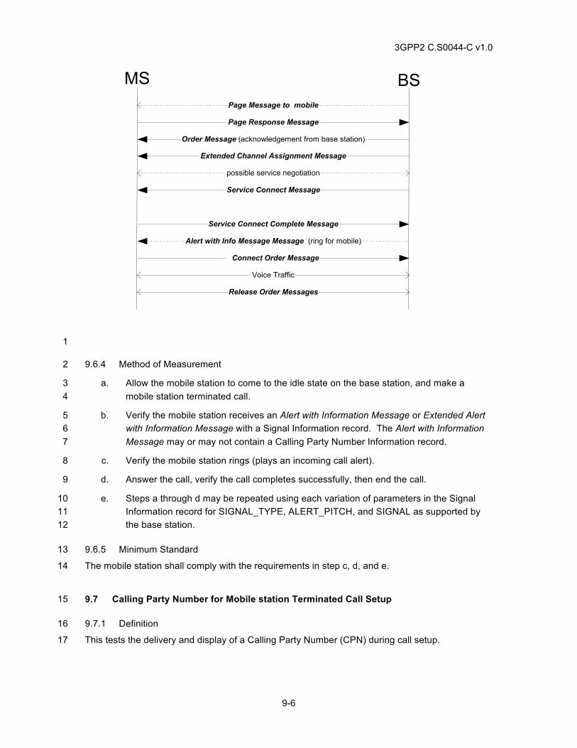
3GPP2 C.S0044-C v1.0
9-6
Service Connect Message
Extended Channel Assignment Message
possible service negotiation
Order Message (acknowledgement from base station)
Page Message to mobile
Page Response Message
Release Order Messages
Connect Order Message
Voice Traffic
Service Connect Complete Message
Alert with Info Message Message (ring for mobile)
MS BS
1
9.6.4 Method of Measurement 2
a. Allow the mobile station to come to the idle state on the base station, and make a 3 mobile station terminated call. 4
b. Verify the mobile station receives an Alert with Information Message or Extended Alert 5 with Information Message with a Signal Information record. The Alert with Information 6 Message may or may not contain a Calling Party Number Information record. 7
c. Verify the mobile station rings (plays an incoming call alert). 8
d. Answer the call, verify the call completes successfully, then end the call. 9
e. Steps a through d may be repeated using each variation of parameters in the Signal 10 Information record for SIGNAL_TYPE, ALERT_PITCH, and SIGNAL as supported by 11 the base station. 12
9.6.5 Minimum Standard 13
The mobile station shall comply with the requirements in step c, d, and e. 14
9.7 Calling Party Number for Mobile station Terminated Call Setup 15
9.7.1 Definition 16
This tests the delivery and display of a Calling Party Number (CPN) during call setup. 17
3GPP2 C.S0044-C v1.0
9-7
9.7.2 Traceability 1
(see [4]) 2
3.7.5.3 Calling Party Number 3
Table 2.7.1.3.2.4-2 Number Types 4
Table 2.7.1.3.2.4-3 Numbering Plan Identification 5
Table 2.7.4.4-1 Presentation Indicators 6
Table 3.7.5-1 Information Record Types (base station) 7
9.7.3 Call Flow Example(s) 8
None 9
9.7.4 Method of Measurement 10
a. Configure the base station to send a Calling Party Number for mobile station terminated 11 calls. 12
b. Allow the mobile station to come to the idle state on the base station, and initiate a 13 mobile station terminated call. 14
c. Verify the mobile station displays the correct Calling Party Number before answering 15 the call and then answer the call. 16
d. Repeat steps b to c for all Calling Party Number base station configurations, e.g. 17 parameters PI = ‘01’ (Presentation Restricted) and PI = ‘10’ (Number not available or 18 Unavailable), as supported by the base station, and verify the correct outcome. 19
9.7.5 Minimum Standard 20
The mobile station shall comply with requirements in steps c and d. In step d, for PI = ‘01’ 21 (Presentation Restricted) and PI = ‘10’ (Number not available or Unavailable), the mobile station 22 shall NOT display the Calling Party Number, but may display ‘No Caller ID’ or something to that 23 effect. 24
9.8 Calling Party Number for Call Waiting 25
9.8.1 Definition 26
This tests the delivery and display of a Calling Party Number (CPN) for Call Waiting calls. 27
9.8.2 Traceability 28
(see [4]) 29
3.7.5.3 Calling Party Number 30
3.7.5.22 Call Waiting Indicator 31
Table 3.7.5.16-2 Mandatory Control Tags and Display Text Tags 32
Table 2.7.1.3.2.4-2 Number Types 33
3GPP2 C.S0044-C v1.0
9-8
Table 2.7.1.3.2.4-3 Numbering Plan Identification 1
Table 2.7.4.4-1 Presentation Indicators 2
Table 3.7.5-1 Information Record Types (base station) 3
9.8.3 Call Flow Example(s) 4
None 5
9.8.4 Method of Measurement 6
a. Configure the base station to send a Calling Party Number for Call Waiting calls. 7
b. Set up a mobile station terminated voice call. 8
c. While this voice call is in progress, attempt a second call to the mobile station. 9
d. Verify the mobile station displays the correct Calling Party Number of the Call Waiting 10 caller. 11
e. Repeat steps b to d for all Calling Party Number base station configurations, e. g. CPN 12 parameters PI = ‘01’ (Presentation Restricted) and PI = ‘10’ (Number not available or 13 Unavailable), as supported by the base station, and verify the correct outcome. 14
9.8.5 Minimum Standard 15
The mobile station shall comply with requirements in steps d and e. In step e, for PI = ‘01’ 16 (Presentation Restricted) and PI = ‘10’ (Number not available or Unavailable), the mobile station 17 shall NOT display the Caller ID, but may display ‘No Caller ID’ or something to that effect. 18
9.9 Call Waiting 19
9.9.1 Definition 20
This test verifies mobile station call-waiting notification, alerting, and connection with Flash with 21 Information Messages or Extended Flash with Information Messages. It also checks the mobile 22 station ability to activate and deactivate the call-waiting feature on the network. 23
9.9.2 Traceability 24
(see [4]) 25
3.7.5.5 Signal 26
Table 2.7.4-1 Information Record Types (mobile station) 27
Table 3.7.5-1 Information Record Types (base station) 28
Table 3.7.5.5-5 IS-54B Alerting (SIGNAL_TYPE = ‘10’) 29
3.7.5.22 Call Waiting Indicator 30
9.9.3 Call Flow Example(s) 31
None 32
3GPP2 C.S0044-C v1.0
9-9
9.9.4 Method of Measurement 1
a. Allow the mobile station to come to the idle state on the base station. 2
b. Activate call waiting, e.g. make a dedicated call *41-SEND, and verify that the mobile 3 station plays or displays a notification that call waiting has been activated, e.g. audio 4 confirmation tones in the earpiece. 5
c. Verify the call-waiting activation call ends without user interaction (Base Station 6 releases the call), and the mobile station returns to the idle state on the base station. 7
d. Set up a voice call with the mobile station. While the first call is in progress, attempt a 8 second mobile station terminated call, and verify that a call-waiting alert is played at the 9 mobile station, e.g. tones in the earpiece. 10
e. Cause the mobile station to accept the second call, e.g. press SEND, and verify the 11 connection to the second caller with normal audio. 12
f. Cause the mobile station to flash back to the first call, e.g. press SEND, and verify the 13 connection to the first caller with normal audio. 14
g. Press END on the mobile station to end the call. Note: in some implementations, if the 15 mobile station subscriber ends a call waiting call while the other party is still waiting, the 16 base station will initiate a mobile station terminated call to re-connect the waiting party. 17 If this is the case, answer the call, then end that call too. 18
h. Deactivate call waiting on the base station, e.g. make a dedicated call *410-SEND, and 19 verify the mobile station plays or displays a notification that call waiting has been 20 disabled, e.g. tones in the earpiece. 21
i. Set up a new call with the mobile station. While the call is in progress, attempt another 22 mobile station terminated call, and verify that no call-waiting alert is played at the mobile 23 station. 24
9.9.5 Minimum Standard 25
The mobile station shall comply with the requirements in steps b, c, d, e, f, h, and i. 26
9.10 Voice Mail Message Waiting Notification from the Idle State 27
9.10.1 Definition 28
This test verifies mobile station response to message waiting notification while the mobile station 29 is in the idle state. Notification can be a tone, light, or display and is manufacturer dependent. 30
9.10.2 Traceability 31
(see [4]) 32
3.7.5.6 Message Waiting 33
3.7.2.3.2.12 Feature Notification Message 34
(see [22]) 35
5.1.3-A.1 Message Waiting Notification 36
3GPP2 C.S0044-C v1.0
9-10
9.10.3 Call Flow Example(s) 1
None 2
9.10.4 Method of Measurement 3
a. Power on the mobile station and allow it to come to the idle state on the base station. 4
b. Instruct the base station to send a voice mail message waiting notification, setting the 5 number of voice mail messages waiting to a value less than the maximum number the 6 mobile station can display. 7
c. Verify that any indication on the mobile station of the number of messages waiting 8 reflects the correct value.. 9
d. The mobile station may give an indication of the change in message waiting status. 10
e. Repeat steps b through c for a larger number of voice mail messages waiting. 11
f. Repeat steps b through c for a smaller non-zero number of voice mail messages 12 waiting 13
g. Repeat steps b through c, except in step b, send notification for zero voice mail 14 messages waiting, e. g. to clear the mobile station’s voice mail waiting indicator on the 15 mobile station. 16
9.10.5 Minimum Standard 17
The mobile station shall comply with the requirement in step c and may comply with step d. 18
9.11 Voice Mail Message Waiting Notification from the Conversation State 19
9.11.1 Definition 20
This test verifies mobile station’s response to message waiting notification while the mobile 21 station is in the conversation state. 22
9.11.2 Traceability 23
(see [4]) 24
3.7.5.6 Message Waiting 25
(see [22]) 26
5.1.3-A.1 Message Waiting Notification 27
9.11.3 Call Flow Example(s) 28
None 29
9.11.4 Method of Measurement 30
a. Power on the mobile station and allow it to come to the idle state on the base station. 31
b. Set up a call with the mobile station. 32
3GPP2 C.S0044-C v1.0
9-11
c. Instruct the base station to send a voice mail message waiting notification, setting the 1 number of voice mail messages waiting to a value less than the maximum number the 2 mobile station can display. 3
d. Verify that any indication on the mobile station of the number of messages waiting 4 reflects the correct value. 5
e. The mobile station may give an indication of the change in message waiting status. 6
f. Instruct the base station to send a voice mail message waiting notification, setting the 7 number of messages waiting to a value that exceeds the maximum number that can be 8 displayed by the mobile station. 9
g. Verify that any indication on the mobile station of the number of messages waiting 10 displays reflects the maximum number of messages that it can display. 11
9.11.5 Minimum Standard 12
The mobile station shall comply with the requirements in steps d and g and may comply with step 13 e. 14
9.12 Calling Party Name Presentation during Call Setup 15
9.12.1 Definition 16
This test will verify that the mobile station in the mobile station idle state properly displays the 17 calling name information contained in an Extended Display Information record. This test is only 18 applicable to mobile stations capable of displaying information sent by the base station.. 19
9.12.2 Traceability 20
(see [4]) 21
3.7.5.16 Extended Display, Calling Party Name 22
3.7.5.21 Multiple Character Extended Display 23
3.7.5.22 Call Waiting Indicator 24
Table 3.7.5.16-2 Mandatory Control Tags and Display Text Tags 25
Table 2.7.4.4-1 Presentation Indicators 26
Table 3.7.5-1 Information Record Types (base station) 27
9.12.3 Call Flow Example(s) 28
None 29
9.12.4 Method of Measurement 30
a. Ensure the mobile station has been configured to display Calling Party Name if it is 31 delivered and that the mobile station has not been pre-programmed with calling 32 name/number information (phone book). 33
b. Power on the mobile station and wait until it reaches Mobile Station Idle State. 34
3GPP2 C.S0044-C v1.0
9-12
c. Set up a mobile station terminated call. 1
d. Configure the base station to send a Feature Notification Message, Alert With 2 Information Message, or a Flash With Information Message with an Extended Display 3 information record with DISPLAY_TAG = ‘10001101’ (Calling Party Name) CPN. 4
e. Verify the mobile station receives and displays the information included in the Extended 5 Display Information Record. 6
f. Verify user data in both directions. 7
g. End call. 8
9.12.5 Minimum Standard 9
The mobile station shall comply with steps e, and f. 10
9.13 Calling Name Presentation (CNAP) during Conversation State 11
9.13.1 Definition 12
This test will verify that the mobile station in Conversation Substate (with call waiting enabled) 13
properly displays the Calling Party Name. This test is only applicable to mobile stations capable 14 of displaying information sent by the base station.. 15
9.13.2 Traceability 16
(see [4]) 17
3.7.5.16 Extended Display, Calling Party Name 18
3.7.5.21 Multiple Character Extended Display 19
3.7.5.22 Call Waiting Indicator 20
Table 3.7.5.16-2 Mandatory Control Tags and Display Text Tags 21
Table 2.7.4.4-1 Presentation Indicators 22
Table 3.7.5-1 Information Record Types (base station) 23
9.13.3 Call Flow Example(s) 24
None 25
9.13.4 Method of Measurement 26
a. Ensure mobile station is assigned Calling Party Name Presentation Class-of-Service, 27 and that the mobile station has not been pre-programmed with calling name/number 28 information (phone book). 29
b. Set up a mobile station originated call. 30
c. While the mobile station is in the Conversation Substate, set up another call to the 31 mobile station (i.e. call waiting). Configure the base station to send an Alert With 32
3GPP2 C.S0044-C v1.0
9-13
Information Message or Flash With Information Message with an Extended Display 1 Information Record with the DISPLAY_TAG = ‘10001101’ (Calling Party Name). 2
d. Verify the mobile station receives and displays the information included in the Extended 3 Display Information Record. 4
e. End both calls. 5
9.13.5 Minimum Standard 6
The mobile station shall comply with step d. 7
9.14 Display Records sent in the Feature Notification Message. 8
9.14.1 Definition 9
This test verifies that the mobile station displays Paging Channel and Forward Common Control 10 Channel Display Information Records, Extended Display Information Records and Multiple 11 Character Extended Display Records. This test also verifies that Display Information Records, 12 Extended Display Information Records and Multiple Character Extended Display Records do not 13 interfere with any other information records or features. This test is only applicable if the mobile 14 station has a display. 15
9.14.2 Traceability 16
(see [4]) 17
2.6.2.4 Mobile Station Order and Message Processing Operation 18
2.6.10.1 Alerting 19
3.7.2.3.2.12 Feature Notification Message 20
3.7.3.3.2.3 Alert with Information Message 21
3.7.3.3.2.14 Flash with Information Message 22
3.7.5 Information Records 23
9.14.3 Call Flow Example(s) 24
None 25
9.14.4 Method of Measurement 26
a. Verify the mobile station is in Idle State. 27
b. Instruct the base station to send a display record with no more than x characters where 28 x is the maximum number of characters supported by the mobile station’s display in a 29 Feature Notification Message on the Paging Channel or Forward Common Control 30 Channel. 31
c. Upon receiving the Feature Notification Message, verify the mobile station displays 32 characters as instructed in the Display Record contained in the Feature Notification 33 Message. 34
3GPP2 C.S0044-C v1.0
9-14
d. Instruct the base station to send a new Display Record of with no more than x 1 characters where x is the maximum number of characters supported by the mobile 2 station’s display in a Feature Notification Message. 3
e. Upon receiving the Feature Notification Message, verify the mobile station displays the 4 new characters as instructed in the Display Record and performs other information 5 records contained in the Feature Notification Message. 6
f. If supported by the mobile station and the base station, repeat steps b to e using the 7 Extended Display Record. 8
g. If supported by the mobile station and the base station, repeat steps b to e using the 9 Multiple Character Extended Display Record. 10
9.14.5 Minimum Standard 11
The mobile station shall comply with steps c, e, f and g. 12
9.15 Display Records Sent in the Flash With Information Message 13
9.15.1 Definition 14
This test verifies that the mobile station displays Traffic Channel Display Information Records, 15 Extended Display Information Records and Multiple Character Extended Display Records. This 16 test also verifies that Display Information Records, Extended Display Information Records and 17 Multiple Character Extended Display Records do not interfere with other information records or 18 features. This test is only applicable if the mobile station has a display. 19
9.15.2 Traceability 20
(See [4]) 21
2.6.2.4 Mobile Station Order and Message Processing Operation 22
2.6.10.1 Alerting 23
3.7.3.3.2.3 Alert with Information Message 24
3.7.3.3.2.14 Flash with Information Message 25
3.7.5 Information Records 26
9.15.3 Call Flow Example(s) 27
None 28
9.15.4 Method of Measurement 29
a. Setup a mobile station originated call. 30
b. Instruct the base station to send a Display Record with no more than x characters 31 where x is the maximum number of characters supported by the mobile station’s display 32 in a Flash With Information Message. 33
3GPP2 C.S0044-C v1.0
9-15
c. Upon receiving the Flash With Information Message, verify the mobile station displays 1 characters as instructed in the Display Record contained in the Flash with Information 2 Message. 3
d. Instruct the base station to send a new display record with no more than x characters 4 where x is the maximum number of characters supported by the mobile station’s display 5 contained in the Flash with Information Message. 6
e. Upon receiving the Flash With Information Message, verify the mobile station displays 7 the new characters as instructed in the Display Record. 8
f. If supported by the mobile station and the base station, repeat steps a to e using the 9 Extended Display Record. 10
g. If supported by the mobile station and the base station, repeat steps a to e using the 11 Multiple Character Extended Display Record. 12
9.15.5 Minimum Standard 13
The verifications in steps c and e in the traffic channel shall be successfully carried out for all 14 forms of display records supported. When various information records are sent to the mobile 15 station in the same message, the mobile station shall properly process all information records. If 16 display records are not supported in the mobile station, there shall be no negative impact on any 17 information records supported by the mobile station. There shall be no negative impact on any 18 supported feature or call processing when display records are sent to the mobile station in the 19 same message as other information records. 20
If supported by the mobile station, the most current display record shall be displayed on the 21 mobile station. 22
9.16 Display Records Sent in the Alert with Information Message 23
9.16.1 Definition 24
This test verifies the mobile station displays Display Information Records, Extended Display 25 Information Records and the Multiple Character Extended Display Record on the traffic channel. 26 This test also verifies that Display Information Records, Extended Display Information Records 27 and Multiple Character Extended Display Record do not interfere with other information records 28 or features. This is only applicable if the mobile station has a display. 29
9.16.2 Traceability 30
(See [4]) 31
2.6.2.4 Mobile Station Order and Message Processing Operation 32
2.6.10.1 Alerting 33
3.7.2.3.2.12 Feature Notification Message 34
3.7.3.3.2.3 Alert with Information Message 35
3.7.3.3.2.14 Flash with Information Message 36
3.7.5 Information Records 37
3GPP2 C.S0044-C v1.0
9-16
9.16.3 Call Flow Example(s) 1
None 2
9.16.4 Method of Measurement 3
a. Setup a mobile station terminated call. 4
b. Instruct the base station to send in an Alert With Information Message, a Display 5 Record with no more than x characters where x is the maximum number of characters 6 supported by the mobile station’s display, and a Calling Party Number Record. 7
c. Upon receiving the Alert With Information Message, verify the mobile station displays 8 the characters as instructed in the display record or extended display record and 9 displays the Calling Party Number in the Alert With Information Message. 10
d. If supported by the mobile station and the base station, repeat steps a to c using the 11 Extended Display Record. 12
e. If supported by the mobile station and the base station, repeat steps a to c using the 13 Multiple Character Extended Display Record. 14
9.16.5 Minimum Standard 15
The verifications in step c in the traffic channel shall be successfully carried out for all forms of 16 display records supported. When various information records are sent to the mobile station in the 17 same message, the mobile station shall process all information records. If display records are not 18 supported in the mobile station, there shall be no negative impact on information records 19 supported by the mobile station. There shall be no negative impact on any supported feature, or 20 on call processing when display records are sent to the mobile station in the same message as 21 other information records. 22
If supported by the mobile station, the most current display record shall be displayed on the 23 mobile station. 24
9.17 TTY/TDD 25
9.17.1 Definition 26
This test verifies the system ability to transfer TTY/TDD information in the forward and reverse 27 link directions. 28
9.17.2 Traceability: 29
(see [18,19 and 20]) 30
9.17.3 Call Flow Example(s) 31
None 32
9.17.4 Method of Measurement 33
9.17.4.1 Basic TTY/TDD Operation 34
a. Connect the mobile station as shown in Figure 9.18.4-1. 35
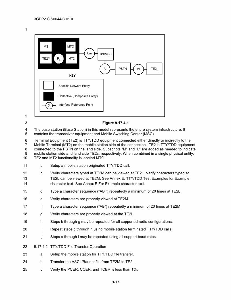
3GPP2 C.S0044-C v1.0
9-17
1
MS
TE2M
MTO
MT2Rn
Um BS/MSC
Ai PSTN TE2LW
Specific Network Entity
Collective (Composite Entity)
Interface Reference Point
KEY
X
2
Figure 9.17.4-1 3
The base station (Base Station) in this model represents the entire system infrastructure. It 4 contains the transceiver equipment and Mobile Switching Center (MSC). 5
Terminal Equipment (TE2) is TTY/TDD equipment connected either directly or indirectly to the 6 Mobile Terminal (MT2) on the mobile station side of the connection. TE2 is TTY/TDD equipment 7 connected to the PSTN on the land side. Subscripts "M" and "L" are added as needed to indicate 8 mobile station side and land side TE2s, respectively. When combined in a single physical entity, 9 TE2 and MT2 functionality is labeled MT0. 10
b. Setup a mobile station originated TTY/TDD call. 11
c. Verify characters typed at TE2M can be viewed at TE2L. Verify characters typed at 12 TE2L can be viewed at TE2M. See Annex E: TTY/TDD Test Examples for Example 13 character text. See Annex E For Example character text. 14
d. Type a character sequence (“AB ”) repeatedly a minimum of 20 times at TE2L 15
e. Verify characters are properly viewed at TE2M. 16
f. Type a character sequence (“AB”) repeatedly a minimum of 20 times at TE2M 17
g. Verify characters are properly viewed at the TE2L. 18
h. Steps b through g may be repeated for all supported radio configurations. 19
i. Repeat steps c through h using mobile station terminated TTY/TDD calls. 20
j. Steps a through i may be repeated using all support baud rates. 21
9.17.4.2 TTY/TDD File Transfer Operation 22
a. Setup the mobile station for TTY/TDD file transfer. 23
b. Transfer the ASCII/Baudot file from TE2M to TE2L. 24
c. Verify the PCER, CCER, and TCER is less than 1%. 25
3GPP2 C.S0044-C v1.0
9-18
d. Transfer the ASCII/Baudot file from TE2L to TE2M. 1
e. Verify the PCER, CCER, and TCER is less than 1%. 2
f. End the TTY/TDD call. 3
g. Steps a through f may be repeated for all supported radio configurations. 4
h. Repeat steps b through g for mobile station terminated calls. 5
i. Steps a through h may be repeated using all support baud rates. 6
9.17.4.3 Voice Carry Over (VCO) and Hearing Carry Over (HCO) Operation 7
a. Configure TE2M for VCO. 8
b. Setup a mobile station originated TTY/TDD call. 9
c. Verify outgoing messages can be spoken and incoming responses can be viewed. 10
d. End the TTY/TDD call. 11
e. Configure TE2M for HCO. 12
f. Setup a mobile station originated TTY/TDD call. 13
g. Verify outgoing messages can be typed and incoming responses can be heard through 14 a TE2M accessory speaker. 15
h. Verify characters typed at TE2M can be viewed at TE2L. 16
i. End the TTY/TDD call. 17
9.17.5 Minimum Standard 18
9.17.5.1 Basic TTY/TDD Operation 19
The mobile station shall comply with steps e and g for all tested and supported radio 20 configurations and baud rates for mobile station originated and terminated calls. 21
9.17.5.2 TTY/TDD Operation File Transfer 22
The mobile station shall comply with steps c and e for all tested and supported radio 23 configurations and baud rates for mobile station originated and terminated calls. 24
9.17.5.3 Voice Carry Over (VCO) and Hearing Carry Over (HCO) Operation 25
The mobile station shall comply with steps c, g and h. 26
9.18 WLL Call Waiting Indicator Support 27
9.18.1 Definition 28
This test verifies that a mobile station in a two-way conversation, with call waiting enabled, will 29 receive indicator of waiting calls. This test will verify that the mobile station will send a flash 30 request to connect to the waiting call. This test case is applicable only if WLL is supported. 31
3GPP2 C.S0044-C v1.0
9-19
9.18.2 Traceability 1
(see [4]) 2
2.7.2.3.2.3 Flash with Information Message 3
3.7.5.5 Signal 4
3.7.5.22 Call Waiting Indicator 5
9.18.3 Call Flow Example(s) 6
None 7
9.18.4 Method of Measurement 8
a. Ensure call waiting is enabled. 9
b. Make a mobile station to land party 1 voice call. Verify audio in both directions. 10
c. Setup a voice call from land party 2 to the mobile station. 11
d. Verify the base station sends a Flash With Information Message or Extended Flash 12 With Information Message with the Call Waiting Indicator Information Record as follows: 13
1. CALL_WAITING_INDICATOR field set to ’1’. 14
e. Press the hook (or FLASH button if available) in the mobile station to put land party 1 15 on hold and to connect to land party 2. Verify that the mobile station sends a Flash With 16 Information Message or an Extended Flash With Information Message to the base 17 station. Verify that no dial tone is generated in the mobile station. 18
f. Verify that voice path is established between the mobile station and land party 2. 19
g. Press the hook (or FLASH button if available) again in the mobile station to put land 20 party 2 on hold, and reconnect the voice path to land party 1. 21
h. Verify the mobile station sends a Flash With Information Message or Extended Flash 22 With Information Message to the base station. 23
i. Verify that voice path is established between the mobile station and land party 1. 24
j. End the call from land party 1. 25
k. Press hook (or FLASH button if available) again in the mobile station. Verify that the 26 mobile station sends a Flash With Information Message or Extended Flash With 27 Information Message to the base station. 28
l. Verify voice path is established between the mobile station and land party 2. 29
m. End the call to land party 2. 30
n. Make a mobile station to land party 1 voice call. Verify audio path is established in both 31 directions. 32
o. Setup a voice call from land party 2 to the mobile station. 33
3GPP2 C.S0044-C v1.0
9-20
p. Verify the base station sends a Flash With Information Message or Extended Flash 1 With Information Message with the Call Waiting Indicator Information Record as follows: 2 CALL_WAITING_INDICATOR field set to ’1’. 3
q. Do not answer this call waiting call at the mobile station. 4
r. Disconnect call from land party 2. 5
s. Verify the base station sends a Flash With Information Message or Extended Flash 6 With Information Message with the Call Waiting Indicator Information Record as follows: 7 CALL_WAITING_INDICATOR field set to ’0’. 8
t. Press the hook (or FLASH button if available) of the mobile station and verify that a dial 9 tone is generated. 10
u. Press the hook (or FLASH button if available) again and verify that voice path between 11 the mobile station and land party 1 is established. 12
v. End the call to land party 1. 13
9.18.5 Minimum Standard 14
The mobile station shall comply with the requirements in the following steps: e, h, i, k, t and u. 15
The base station shall comply with the requirements in the following steps: d, f, j, i, p, s, t and u. 16
The base station shall send a Call Waiting Indicator to the mobile station during a two-way 17 conversation indicating another call is waiting. The mobile station shall be able to switch between 18 land party 1 and land party 2 by sending a flash request. 19
9.19 Answer Holding 20
9.19.1 Definition 21
These tests verify that the mobile station that supports Answer Holding feature can perform the 22 following: 23
a. Activate answer holding when the incoming call is ringing in the Waiting for Mobile 24 Station Answer Substate or in the Conversation Substate 25
b. Deactivate answer holding in the Conversation Substate 26
9.19.2 Traceability 27
(see [4]) 28
2.6.10.1.2 Waiting for Mobile Station Answer Substate 29
2.6.10.2 Conversation Substate 30
2.7.2.3.2.3 Flash with Information Message 31
2.7.2.3.2.33 Extended Flash with Information Message 32
2.7.4.2 Keypad Facility 33
3.6.8.1.2 Waiting for Answer Substate 34
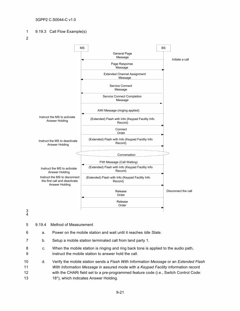
3GPP2 C.S0044-C v1.0
9-21
9.19.3 Call Flow Example(s) 1
2
MS BS
Extended Channel AssignmentMessage
Service ConnectMessage
AWI Message (ringing applied)
ConnectOrder
Conversation
ReleaseOrder
ReleaseOrder
Initiate a call
Disconnect the call
Page ResponseMessage
General PageMessage
Instruct the MS to activiateAnswer Holding
Service Connect CompletionMessage
(Extended) Flash with Info (Keypad Facility InfoRecord)
Instruct the MS to deactivateAnswer Holding
FWI Message (Call Waiting)
Instruct the MS to activiateAnswer Holding
Instruct the MS to disconnectthe first call and deactivate
Answer Holding
(Extended) Flash with Info (Keypad Facility InfoRecord)
(Extended) Flash with Info (Keypad Facility InfoRecord)
(Extended) Flash with Info (Keypad Facility InfoRecord)
3 4
9.19.4 Method of Measurement 5
a. Power on the mobile station and wait until it reaches Idle State. 6
b. Setup a mobile station terminated call from land party 1. 7
c. When the mobile station is ringing and ring back tone is applied to the audio path, 8 instruct the mobile station to answer hold the call. 9
d. Verify the mobile station sends a Flash With Information Message or an Extended Flash 10 With Information Message in assured mode with a Keypad Facility information record 11 with the CHARi field set to a pre-programmed feature code (i.e., Switch Control Code: 12 18*), which indicates Answer Holding. 13
3GPP2 C.S0044-C v1.0
9-22
e. Verify the mobile station sends a Connect Order in assured mode. 1
f. Instruct the mobile station to deactivate the answer holding. 2
g. Verify the mobile station sends a Flash With Information Message or an Extended Flash 3 With Information Message in assured mode with a Keypad Facility information record 4 with the CHARi field set to a pre-programmed feature code (i.e., Switch Control Code: 5 18*), which indicates Answer Holding. 6
h. Verify user data in both directions. 7
9.19.5 Minimum Standard 8
The mobile station shall comply with steps d, e, g and h. 9
9.20 User Selective Call Forwarding 10
9.20.1 Definition 11
These tests verify that the mobile station that supports User Selective Call Forwarding can 12 perform the following in both Waiting for Mobile Station Answer Substate and Conversation 13 Substate: 14
a. Forwarding incoming call to a pre-registered number 15
b. Forwarding incoming call to a number stored in the mobile station 16
c. Forwarding incoming call to network-based voice mail 17
9.20.2 Traceability 18
(See [4]) 19
2.6.10.1.2 Waiting for Mobile Station Answer Substate 20
2.6.10.2 Conversation Substate 21
2.7.2.3.2.3 Flash with Information Message 22
2.7.2.3.2.33 Extended Flash with Information Message 23
2.7.4.2 Keypad Facility 24
3.6.8.1.2 Waiting for Answer Substate 25
9.20.3 Call Flow Example(s) 26
None 27
9.20.4 Method of Measurement 28
9.20.4.1 User Selective Call Forwarding in the Waiting for Mobile Station Answer Substate 29
a. Power on the mobile station and wait until it reaches Idle State. 30
b. Dial user selective call forwarding feature activation code, followed by the forward-to 31 number, followed by SEND. Verify feature update confirmation at the mobile station. 32
3GPP2 C.S0044-C v1.0
9-23
c. Setup a mobile station terminated call from land party. 1
d. When the mobile station is ringing and ring back tone is applied to the audio path, 2 instruct the mobile station to forward the incoming call to the pre-registered number. 3
e. Verify the mobile station sends a Flash With Information Message or an Extended Flash 4 With Information Message in assured mode with a Keypad Facility information record 5 with the CHARi field set to a pre-programmed feature code (i.e., Switch Control Code: 6 0*), which indicates User Selective Call Forwarding to a pre-registered number. 7
f. Answer the call on the forwarded line, and verify the audio path. 8
g. End call. 9
h. Ensure the mobile station is in Idle State. 10
i. Setup a mobile station terminated call from land party. 11
j. When the mobile station is ringing and ring back tone is applied to the audio path, 12 instruct the mobile station to forward the incoming call to voice mail. 13
k. Verify the mobile station sends a Flash With Information Message or an Extended Flash 14 With Information Message in assured mode with a Keypad Facility information record 15 with the CHARi field set to a pre-programmed feature code (i.e. Switch Control Code: 16 17*) which indicates User Selective Call Forwarding to voice mail. 17
l. Verify the call is forwarded to voice mail. 18
m. Ensure the mobile station is in Idle State. 19
n. Program a forward-to-number in the mobile station. 20
o. Setup a mobile station terminated call from land party. 21
p. When the mobile station is ringing, and ring back tone is applied to the audio path, 22 instruct the mobile station to forward the incoming call to the number stored in the 23 mobile station. 24
q. Verify the mobile station sends a Flash With Information Message or an Extended Flash 25 With Information Message in assured mode with a Keypad Facility information record 26 with the CHARi field set to a pre-programmed feature code (i.e. Switch Control Code: 27 16*) plus the forward-to-number stored in the mobile station. 28
r. Answer the call on the forwarded line, and verify the audio path. 29
9.20.4.2 User Selective Call Forwarding while in the Conversation Substate 30
a. Setup a call between mobile station and land party 1 and verify user data in both 31 directions. 32
b. Setup a call from land party 2 to the mobile station. Wait for ring back on land party 2 33 and the call waiting notification on the mobile station. 34
c. Instruct the mobile station to forward the incoming call to the pre-registered number. 35
d. Verify the mobile station sends a Flash With Information Message or an Extended Flash 36 With Information Message in assured mode with a Keypad Facility information record 37
3GPP2 C.S0044-C v1.0
9-24
with the CHARi field set to a pre-programmed feature code (i.e., Switch Control Code: 1 0*), which indicates User Selective Call Forwarding to a pre-registered number. 2
e. Answer the call on the forwarded line, and verify the audio path. 3
f. End call. 4
g. Setup a call between mobile station and land party 1 and verify user data in both 5 directions. 6
h. Setup a call from land party 2 to the mobile station. Wait for ring back on land party 2 7 and the call waiting notification on the mobile station. 8
i. Instruct the mobile station to forward the incoming call to voice mail. 9
j. Verify the mobile station sends a Flash With Information Message or an Extended Flash 10 With Information Message in assured mode with a Keypad Facility information record 11 with the CHARi field set to a pre-programmed feature code (i.e. Switch Control Code: 12 17*) which indicates User Selective Call Forwarding to voice mail. 13
k. Verify the call is forwarded to voice mail. 14
l. End call. 15
m. Setup a call between mobile station and land party 1 and verify user data in both 16 directions. 17
n. Setup a call from land party 2 to the mobile station. Wait for ring back on land party 2 18 and the call waiting notification on the mobile station. 19
o. Instruct the mobile station to forward the incoming call to the forward-to-number stored 20 in the mobile station. 21
p. Verify the mobile station sends a Flash With Information Message or an Extended Flash 22 With Information Message in assured mode with a Keypad Facility information record 23 with the CHARi field set to a pre-programmed feature code (i.e. Switch Control Code: 24 16*) plus the forward-to-number stored in the mobile station. 25
q. Answer the call on the forwarded line, and verify the audio path. 26
r. End call. 27
9.20.5 Minimum Standard 28
9.20.5.1 User Selective Call Forwarding in the Waiting for Mobile Station Answer Substate 29
The mobile station shall comply with steps e, k, and q. 30
9.20.5.2 User Selective Call Forwarding while in the Conversation Substate 31
The mobile station shall comply with steps d, j, and p. 32
33
3GPP2 C.S0044-C v1.0
10-1
10 ASYNCHRONOUS DATA AND FAX SERVICES 1
10.1 Send/Receive Fax 2
10.1.1 Definition 3
These tests demonstrate cellular system ability to transmit and receive a medium size fax in a 4 timely manner. A fax call is originated by the mobile station and the test is then repeated using 5 land line origination. The mobile station will send and receive a digital and an analog Fax. 6
10.1.2 Traceability 7
(see [15]) 8
A.3 Data Service Options for Spread Spectrum Systems: AT Command Processing and the 9 Rm Interface 10
2.2 Data Service Selection 11
2.2.1 Service Selection for Async Data and Fax Services 12
4.0 AT COMMAND PROCESSING FOR ASYNC DATA AND FAX SERVICES 13
4.3 Service Class 2.0 AT Commands 14
7.3 Facsimile Service Class 2.0 AT Commands 15
A.4 Data Service Options for Spread Spectrum Systems: Async Data and Fax Services 16
2.2 The Application Interface 17
2.5.5 Requirements for Async Data and Fax 18
3.1 Service Option Number 19
3.2 Multiplex Option Interface 20
3.3 Procedures Using Service Option Negotiation 21
3.3.1.1 Mobile Station Requirements 22
3.4.1 Mobile Station Requirements 23
4.1.1 Mobile Origination 24
4.1.2 Mobile Termination 25
4.1.3 Service Option Change to Group-3 Facsimile Service 26
4.2 Connection Release 27
A.7 Data Service Options for Spread Spectrum Systems: Analog Fax Service 28
10.1.3 Call Flow Example(s) 29
None 30
3GPP2 C.S0044-C v1.0
10-2
10.1.4 Method of Measurement 1
10.1.4.1 Send/Receive Digital Fax 2
a. Prepare a file representing three different ITU standard fax pages for fax transfer. Data 3 Services Annex C lists standard fax pages to be used in the test. Ensure fax pages are 4 pre-scanned and pre-encoded. 5
b. Simultaneously start the transfer timer and the digital fax transfer from TE2M to TE2L. 6
c. At TE2L, wait for the fax call to be completed. Stop the transfer timer. 7
d. Record transfer time. Verify transfer time requirements per Data Services Annex C. 8
e. Repeat the test for the same fax sent from TE2L to TE2M. TE2M will receive a digital 9 fax. 10
f. Verify all faxes shall be successfully transferred. The received fax shall be of good 11 quality and complete. This can be verified by qualitative means (visually scanning the 12 received fax) or by quantitative means, for example, using ITU-T Recommendation 13 E.453 (08/94) Facsimile Image Quality as Corrupted by Transmission Induced Scan 14 Line Errors. 15
10.1.4.2 Send/Receive Analog Fax 16
a. Prepare a file representing three different ITU standard fax pages for fax transfer. Data 17 Services Annex C lists standard fax pages to be used in the test. Ensure fax pages are 18 pre-scanned and pre-encoded. 19
b. Attach an Analog Fax Machine to TE2M. 20
c. Simultaneously start the transfer timer and the analog fax transfer from TE2M to TE2L. 21
d. At TE2L, wait for the fax call to be completed. Stop the transfer timer. 22
e. Record transfer time. Verify transfer time requirements per Data Services Annex C. 23
f. Repeat test for the same fax sent from TE2L to TE2M. TE2M will receive an analog fax. 24
g. Verify all faxes shall be successfully transferred. The received fax shall be of good 25 quality and complete. This can be verified by qualitative means (visually scanning the 26 received fax) or by quantitative means, for example, using ITU-T Recommendation 27 E.453 (08/94) Facsimile Image Quality as Corrupted by Transmission Induced Scan 28 Line Errors. 29
h. Verify each analog fax transfer shall be completed within time denoted in Data Services 30 Annex C. 31
10.1.5 Minimum Standard 32
10.1.5.1 Send/Receive Digital Fax 33
The mobile station shall comply with steps d and f. 34
3GPP2 C.S0044-C v1.0
10-3
10.1.5.2 Send/Receive Analog Fax 1
The mobile station shall comply with steps e, g, and h. 2
10.2 Upload/Download Binary File 3
10.2.1 Definition 4
This test demonstrates cellular system ability to upload and download an ITU standard fax binary 5 file in a timely manner. The asynchronous data call is originated first by the mobile station. The 6 test is then repeated using land line origination. 7
10.2.2 Traceability 8
(see [15]) 9
A.3 Data Service Options for Spread Spectrum Systems: AT Command Processing and the Rm 10 Interface 11
2.2 Data Service Selection 12
2.2.1 Service Selection for Async Data and Fax Services 13
4.0 AT COMMAND PROCESSING FOR ASYNC DATA AND FAX SERVICES 14
4.3 Service Class 2.0 AT Commands 15
7.3 Facsimile Service Class 2.0 AT Commands 16
A.4 Data Service Options for Spread Spectrum Systems: Async Data and Fax Services 17
2.2 The Application Interface 18
2.5.5 Requirements for Async Data and Fax 19
3.1 Service Option Number 20
3.2 Multiplex Option Interface 21
3.3 Procedures Using Service Option Negotiation 22
3.3.1.1 Mobile Station Requirements 23
3.4.1 Mobile Station Requirements 24
4.1.1 Mobile Origination 25
4.1.2 Mobile Termination 26
4.1.3 Service Option Change to Group-3 Facsimile Service 27
4.2 Connection Release 28
10.2.3 Call Flow Example(s) 29
None 30
3GPP2 C.S0044-C v1.0
10-4
10.2.4 Method of Measurement 1
a. Prepare the RAND200.BIN 200,000 byte binary file for transfer (Data Services Annex 2 D). 3
b. Setup a data call from TE2M to TE2L. 4
c. Start transferring the binary file from TE2L to TE2M using Z-modem transfer protocol. 5 Start the transfer timer. 6
d. Stop the transfer timer when the confirmation of transfer completion is received from the 7 far end. 8
e. Record the transfer time. 9
1. Note: Transfer time should exclude call connection delay. 10
f. End the data call. 11
g. Setup a data call from TE2L to TE2M. 12
h. Repeat the test by transferring the file from TE2M to TE2L. 13
i. Verify: 14
1. All files shall be successfully transferred. 15
2. Received files shall be complete and identical in content to the original file. 16
3. Each file transfer shall be completed within time denoted in Data Services Annex 17 D. 18
4. Both the mobile station originated, and land line originated data calls shall be 19 established successfully. 20
10.2.5 Minimum Standard 21
The mobile station shall comply with step i. 22
10.3 Simultaneous Two-way File Transfer/Carrier Detect 23
10.3.1 Definition 24
This test demonstrates cellular system ability to simultaneously transfer data in the forward and 25 reverse link direction. This test verifies the base station can transmit changes in the status of 26 Carrier Detect and reflect its status on the Rm interface. 27
Note: Carrier Detect can be monitored by means of a hardware lead, or observed on the 28 application interface. 29
10.3.2 Traceability 30
(see [15]) 31
A.3 Data Service Options for Spread Spectrum Systems: AT Command Processingand the 32 Rm Interface 33
2.2 Data Service Selection 34
3GPP2 C.S0044-C v1.0
10-5
2.2.1 Service Selection for Async Data and Fax Services 1
4.0 AT COMMAND PROCESSING FOR ASYNC DATA AND FAX SERVICES 2
4.3 Service Class 2.0 AT Commands 3
7.3 Facsimile Service Class 2.0 AT Commands 4
A.4 Data Service Options for Spread Spectrum Systems: Async Data and Fax Services 5
2.2 The Application Interface 6
2.5.5 Requirements for Async Data and Fax 7
3.1 Service Option Number 8
3.2 Multiplex Option Interface 9
3.3 Procedures Using Service Option Negotiation 10
3.3.1.1 Mobile Station Requirements 11
3.4.1 Mobile Station Requirements 12
4.1.1 Mobile Origination 13
4.1.2 Mobile Termination 14
4.1.3 Service Option Change to Group-3 Facsimile Service 15
4.2 Connection Release 16
10.3.3 Call Flow Example(s) 17
None 18
10.3.4 Method of Measurement 19
a. Prepare the RAND200.ASC 200,000 byte ASCII file for transfer (Data Services Annex 20 D). 21
b. Ensure the Carrier Detect indicator is enabled at TE2M. 22
c. From TE2M, issue the command “AT&C1”, which requests the real-time status of 23 Carrier Detect be maintained on the Rm interface. 24
d. Verify the Carrier Detect indicator is OFF. 25
e. Setup a data call from TE2M to TE2L. Verify that Carrier Detect indicator goes ON, 26 when the base station modem has successfully trained. 27
f. Verify characters typed at TE2M can be viewed at TE2L. Verify characters typed at 28 TE2L can be viewed at TE2M. 29
1. Note: Once the File Capture is turned on, do not type any more characters on 30 the TE2L or the TE2M prior to initiating the file transfer (this is to ensure the 31 captured file is not corrupted by user keystrokes). 32
g. Turn on the File Capture at TE2M. 33
h. Turn on the File Capture at TE2L. 34
3GPP2 C.S0044-C v1.0
10-6
i. Simultaneously start the reverse link transfer timer and at TE2M send the 1 RAND200.ASC file to TE2L by using Raw ASCII protocol. 2
j. While TE2M is sending the file to TE2L, simultaneously start the forward link transfer 3 timer and instruct TE2L to send the same ASCII file to TE2M using a Raw ASCII 4 protocol. 5
1. Note: It is critical these transfers shall substantially overlap. 6
k. As each transfer completes, stop corresponding transfer timer and record transfer time. 7
l. After both transfers are complete, turn off the File Capture at both TE2M and TE2L. 8
m. End call. 9
n. At TE2M, verify that Carrier Detect indicator goes OFF when the call is ended. 10
o. Verify: 11
1. The file shall be successfully transferred in each direction. 12
2. Log files shall be complete and identical in content to the original files. 13
3. Each file transfer shall be completed within time denoted in Data Services Annex 14 D. 15
4. The Carrier Detect generated by the base station shall be accurately depicted on 16 the Rm interface. 17
10.3.5 Minimum Standard 18
The mobile station shall comply with steps d, e, f, n, and o. 19
10.4 Compound AT Command, Initialization and Connection Delay 20
10.4.1 Definition 21
This test verifies the base station can properly process a compound command line containing 22 both local and remote commands. This test verifies the mobile station can initialize and connect 23 the service option when the data call is negotiated with the base station, as well as measures 24 connection delay. 25
10.4.2 Traceability 26
(see [15]) 27
A.3 Data Service Options for Spread Spectrum Systems: AT Command Processing 28
and the Rm Interface 29
4.2.6 Basic Result Codes 30
Table 4.2.6-1. Result Code Sources 31
4.3.1.2.5 +FMI, +FMM, +FMR 32
4.4.1 General Requirements 33
Table 7.2-1 Extended AT Configuration Commands 34
3GPP2 C.S0044-C v1.0
10-7
Table 7.3.1-1 Fax Parameters 1
10.4.3 Call Flow Example(s) 2
None 3
10.4.4 Method of Measurement 4
a. Ensure the call is down. 5
b. At TE2M, issue AT command 6 “AT+CXT=1;+FCLASS=2.0;+GMI;+CGMI;+GMM;+CGMM”. This command string 7 requests mobile station manufacturer information, base station modem manufacturer 8 information, mobile station manufacturer model, and base station modem manufacturer 9 model. 10
c. Start the connection delay timer. 11
d. When the result is returned to the mobile station, stop the connection timer. 12
e. Record connection delay time in the test report. 13
f. Verify the response shall be correct in that it contains the information requested in the 14 command, and is followed by result code “OK”. Delay should not exceed ten seconds. 15
10.4.5 Minimum Standard 16
The mobile station shall comply with step f. 17
10.5 Escaping to Command Mode 18
10.5.1 Definition 19
This test verifies: 20
a. The MT2 application interface escapes to online command state when the user (or the 21 communications application) issues an escape sequence (such as "+++" with the 22 appropriate guard time). 23
b. The base station returns to online state when the user (or the application) issues the 24 command "ATO". 25
10.5.2 Traceability 26
(see [15]) 27
4.2.4 Call-Control Command Processing 28
4.4.2.1 Return to Online Command State 29
10.5.3 Call Flow Example(s) 30
None 31
3GPP2 C.S0044-C v1.0
10-8
10.5.4 Method of Measurement 1
a. Setup a data call from TE2M to TE2L. 2
b. Verify characters typed at TE2M can be viewed at TE2L. Verify that characters typed at 3 TE2L can be viewed at TE2M. 4
c. From TE2M issue the escape sequence +++. 5
d. Verify “OK” is returned, signifying that the MT2 is in the online command state. 6
e. At TE2M,issue the command “AT+CGMI" which requests base station manufacturer 7 information. Verify the response is appropriate, with trailing “OK”. 8
f. At TE2M, issue the command “ATO”, which should cause the MT2 to transition from 9 online command state to online state. 10
g. Verify characters typed at TE2M can be viewed at TE2L. Verify characters typed at 11 TE2L can be viewed at TE2M. 12
10.5.5 Minimum Standard 13
The mobile station shall comply with steps b, d, e and g. 14
10.6 Air Interface Data Compression 15
10.6.1 Definition 16
This test verifies successful compression option negotiation and the transfer of compressible files 17 and/or faxes between the MT2 and Inter-Working Function (IWF). The aforementioned is verified 18 for both mobile station originated and mobile station terminated data and fax transmissions. 19
Note: Although the files are compressible, they will be compressed only when both the MT2 20 and IWF support the type of compression in question. Even if the MT2 or IWF do not support a 21 certain type of compression, the test in question may be performed to ensure MT2 and IWF still 22 interoperate correctly when the user requests this type of compression. 23
10.6.2 Traceability 24
(see [15]) 25
A.3 Data Service Options for Spread Spectrum Systems: AT Command Processing 26
and the Rm Interface 27
Table 7.4.1-1 CDMA AT Parameter Commands 28
A.4 Data Service Options for Spread Spectrum Systems: Async Data and Fax 29 Services 30
2.2 The Application Interface 31
Table 2.2-2 Compression Options 32
Table 2.2-3 Group 3 Fax Compression Options 33
10.6.3 Call Flow Example(s) 34
None 35
3GPP2 C.S0044-C v1.0
10-9
10.6.4 Method of Measurement 1
a. Prepare the data file, COMPFILE.RAW (see Data Services Annex A), or the fax page, 2 FAX 1 (see Data Services Annex C) for transfer. 3
b. Configure the test setup for transfer of a data file or a fax file per Table 10.6.4-1. 4 V.42bis compression for data file transfers is controlled by the +CDS command. The 5 type of compression for fax file transfers is controlled by the +CFC command. When 6 V.42bis is selected for fax transfer, the parameters set in the +CDS command are used. 7
c. Setup a mobile station originated fax or async data call per Table 10.6.4-1. 8
Table 10.6.4-1 9
Test No.
File/Fax Compression Method
Direction of Transfer
Compression Enable
Fax Compression Mode
1 Data File none BS to MS +CDS=0 N/A
2 Data File V.42bis BS to MS +CDS=2 N/A
3 Data File V.42bis MS to BS +CDS=1 N/A
4 Data File V.42bis MS to BS +CDS=3 N/A
5 Fax File none BS to MS N/A +CFC=0
6 Fax File V.42bis BS to MS +CDS=2 +CFC=1
7 Fax File V.42bis MS to BS +CDS=1 +CFC=1
8 Fax File V.42bis MS to BS +CDS=3 +CFC=1
9 Fax File MMR BS to MS N/A +CFC=2
10 Fax File MMR MS to BS N/A +CFC=2
10
d. Make a file or fax transfer in the direction as stated in Table 10.6.4-1. Time each 11 transfer and record in the test report. 12
e. Testing may be repeated for all test cases, 1 through 10. 13
f. Verify: 14
1. All faxes shall be successfully sent and received. 15
2. The received fax page shall be complete in content, and each transfer shall be 16 completed within the time stated in Data Services Annex C. 17
3. All data files shall be successfully transferred. 18
4. The received files shall be complete and identical in content to the original file. 19 Each file transfer shall be completed within the time stated in Data Services Annex 20 B. 21
3GPP2 C.S0044-C v1.0
10-10
10.6.5 Minimum Standard 1
The mobile station shall comply with step f. 2
10.7 RLP Operation in a Poor RF Environment 3
10.7.1 Definition 4
This test exercises the Radio Link Protocol (RLP) layer's negative acknowledgments (NAKs), re-5 transmits, RLP aborts, RLP Resets, and FCSs. 6
Test conditions are intended to impose one or more occurrences of the following. 7
a. Single, double, and triple NAK RLP retransmit events. 8
b. RLP Abort 9
c. RLP Reset 10
d. This test verifies that RLP recovers erased data frames in various channel conditions. 11
10.7.2 Traceability 12
(see [15]) 13
A.2 Data Service Options for Spread Spectrum Systems: Radio Link Protocol 14
3.1 Non-Transparent RLP Procedures 15
3.1.1.1 Non-Encrypted Mode Initialization/Reset 16
3.1.2 Data Transfer 17
3.1.4 Segmentation of Retransmitted Data Frames 18
10.7.3 Call Flow Example(s) 19
None 20
10.7.4 Method of Measurement 21
a. Setup the mobile station and base station as shown in Figure A-9with an AWGN 22 generator placed in the forward link. 23
b. Environment Test Parameters 24
c. Adjust the level of the AWGN Generator so that the downlink frame error rate is 25 measured to be 3±1%. 26
d. Restore the RF link to a normal operating condition, maintaining the target frame error 27 rate (1 % or less). 28
e. Prepare RAND200.ASC 200,000 byte ASCII file for transfer (Data Services Annex D). 29
f. Setup a data call from TE2M to TE2L. 30
g. Verify characters typed at TE2M can be viewed at TE2L. Verify characters typed at 31 TE2L can be viewed at TE2M. 32
h. Turn File Capture on. 33
3GPP2 C.S0044-C v1.0
10-11
i. Simultaneously start the forward link transfer timer and at TE2L send the 1 RAND200.ASC file to TE2M by using Raw ASCII protocol. 2
j. As soon as the file transfer has started (and is still in progress), set the channel 3 conditions as calibrated in step b. These channel conditions shall be maintained for the 4 duration of the file transfer. 5
k. Stop the transfer timer and record the transfer time. 6
l. Turn off the File Capture. 7
m. End call. 8
n. Setup a data call from TE2M to TE2L. 9
o. Repeat steps g and h. 10
p. Simultaneously start the reverse link transfer timer and at TE2M send the 11 RAND200.ASC file to TE2L by using Raw ASCII protocol. 12
q. Repeat steps i through m. 13
r. Verify: 14
1. The file shall be successfully transferred. 15
2. The log file shall be complete and identical in content to the original file. 16
3. The transfer rate shall be no less than 70% of rates measured in test 10.3. 17
10.7.5 Minimum Standard 18
The mobile station shall comply with steps g and r. 19
10.8 RLP Abort and TCP Retransmit Test 20
10.8.1 Definition 21
This test causes the RLP layer to abort and reset due to extremely severe CDMA channel 22 conditions, and forces the TCP layer to retransmit packets. Channel degradation consists of 23 forcing consecutive frame erasures for periods greater than 2.6 seconds. 24
Note: 2.6 seconds corresponds to 130 consecutive frame erasures, but less than the time that 25 would cause the call to drop (typically 5 seconds). 26
10.8.2 Traceability 27
(see [15]) 28
A.2 Data Service Options for Spread Spectrum Systems: Radio Link Protocol 29
3.1 Non-Transparent RLP Procedures 30
3.1.1.1 Non-Encrypted Mode Initialization/Reset 31
3.1.2 Data Transfer 32
3.1.4 Segmentation of Retransmitted Data Frames 33
3GPP2 C.S0044-C v1.0
10-12
10.8.3 Call Flow Example(s) 1
None 2
10.8.4 Method of Measurement 3
a. Setup the mobile station and base station as shown in Figures Annex A Figure A-7 and 4 Annex A Figure A-8 for the forward and the reverse link tests respectively, with 5 PWR_THRESH_ENABLE and PWR_PERIOD_ENABLE set to 0. Disable forward link 6 power control at the base station. 7
b. Calibrate the test setup so that: 8
c. There is sufficient isolation with the switch open, that a call drops if the switch is left 9 open for more than 5 seconds 10
1. When switch is open, the forward and reverse links are disabled at the receiver. 11
2. When switch is closed, the forward and reverse links are enabled at the receiver. 12
3. Set the RF link to normal operating condition, which maintains the target frame 13 erasure rate (1% or less). 14
d. Prepare the RAND200.ASC 200,000 byte ASCII file transfer (Data Services Annex D) 15
e. Setup a call from TE2M to TE2L. 16
f. Verify characters typed at TE2M can be viewed at TE2L. Verify that characters typed at 17 TE2L can be viewed at TE2M. 18
g. Turn File Capture on. 19
h. Simultaneously start the forward link transfer timer and at TE2L send the 20 RAND200.ASC file to TE2M by using Raw ASCII protocol. 21
i. Once the file transfer has started (and is still in progress), open and close the switch in 22 an alternating fashion, for periods of T1 and T2 where: 23
1. T1 is the period when the switch is open (RF link impaired), and it is anywhere 24 between 2.6 and 5.0 seconds. 25
2. T2 is the period when the switch is closed (RF link restored), and it is a minimum 26 of 10 seconds. 27
j. Repeat opening and closing switch exactly three times while data transfer is occurring. 28
k. Stop the transfer timer and record the transfer time. 29
l. Turn the File Capture off. 30
m. End call. 31
n. Setup a data call from TE2M to TE2L. 32
o. Repeat steps f and g. 33
p. Simultaneously start the reverse link transfer timer and at TE2M send the 34 RAND200.ASC file to TE2L by using Raw ASCII protocol. 35
3GPP2 C.S0044-C v1.0
10-13
q. Repeat steps i through l. 1
r. Verify: 2
1. The file shall be successfully transferred in each direction. 3
2. Log files shall be complete and identical in content to the original files. 4
3. Transfer rates shall be no less than 50% of rates measured in test 10.3. 5
10.8.5 Minimum Standard 6
The mobile station shall comply with steps f and r. 7
10.9 Internet Control Message Protocol (ICMP) Requests/Replies 8
10.9.1 Definition 9
This test verifies the mobile station is able to: 10
a. Generate an ICMP Echo Response Message after receiving an Echo Request 11 Message. 12
b. Generate an ICMP Info Response Message after receiving an Info Request Message. 13
c. Generate an ICMP Time Stamp Response Message after receiving a Time Stamp 14 Request Message. 15
10.9.2 Traceability 16
(see [23]) 17
RFC-792 Internet Control Message Protocol 18
10.9.3 Call Flow Example(s) 19
None 20
10.9.4 Method of Measurement 21
a. At TE2M, issue a remote query command such as “AT+CXT=1;+FCLASS=2.0;+FMI?”, 22 requesting base station modem manufacturer information. This will establish a link to 23 the base station. 24
b. From the OA&M interface of the base station, issue the Echo Request Message by any 25 method specific to the base station manufacturer. 26
c. Optionally, step b may be repeated for Info Request/Response, or Time Stamp 27 Request/Response Messages. 28
d. Verify: 29
1. Echo response shall be received by base station as a response to Echo Request 30 Message. 31
2. If supported by mobile station, an Info response shall be received by base station 32 as a response to Info Request Message. 33
3GPP2 C.S0044-C v1.0
10-14
3. If supported by mobile station, a Time stamp response shall be received by base 1 station as a response to Time Stamp Request Message. 2
10.9.5 Minimum Standard 3
The mobile station shall comply with step d. 4
10.10 Reflection of AT Command Parameters 5
10.10.1 Definition 6
This test verifies a representative set of AT parameters can be setup in an IS-707-A call, 7 transferred to the base station at call origination, changed in the online command state, and have 8 their final values read at the mobile station after call completion. Commands tested are ATS10 9 and AT+CQD. 10
10.10.2 Traceability 11
(see [15]) 12
A.3 Data Service Options for Spread Spectrum Systems: AT Command Processing 13
and the Rm Interface 14
4.2.4 Call-Control Command Processing 15
7.4.1 CDMA AT Parameters 16
10.10.3 Call Flow Example(s) 17
None 18
10.10.4 Method of Measurement 19
a. Issue the following AT commands: ATS10=255 and AT+CQD=0” 20
b. Verify response is “OK” 21
c. Setup a data call from TE2M to TE2L. 22
d. After CONNECT is received, issue the escape sequence (such as ”+++”). 23
e. Verify the response is “OK” 24
f. Issue the following AT commands: ATS10? and AT+CQD?. 25
g. Verify response is: 26
1. 255 27
2. +CQD:0 28
3. OK 29
h. Issue the following AT commands: “ATS10=250 and AT+CQD=100” 30
i. Verify the response is “OK” 31
j. Issue the following AT commands: ATS10? and AT+CQD?. 32
3GPP2 C.S0044-C v1.0
10-15
k. Verify the response is: 1
1. 250 2
2. +CQD: 100 3
3. OK 4
l. Terminate the call via the “ATH0” command string. 5
m. Verify the response is “OK” and that the call ends. 6
n. Issue the following AT commands: ATS10? and AT+CQD 7
o. Verify response is: 8
1. 250 9
2. +CQD: 100 10
3. OK 11
p. Verify the “ERROR” response shall not be returned. 12
10.10.5 Minimum Standard 13
The mobile station shall comply with steps b, e, g, i, k, m, o, and p. 14
15
16

3GPP2 C.S0044-C v1.0
10-16
This page intentionally left blank.1
3GPP2 C.S0044-C v1.0
11-1
11 LOW SPEED PACKET DATA 1
11.1 Forward File Transfer 2
11.1.1 Definition 3
This test verifies that file transfer from remote host to mobile station can be successfully done 4 using the LSPD call. 5
11.1.2 Traceability 6
(see [15]) 7
1.4.2.2 Mobile Station Packet Data Service States 8
2.2.2 Service and Call Control Procedures 9
2.2.3 Initialization and Connection of Packet Data Service Options 10
11.1.3 Call Flow Example(s) 11
None 12
11.1.4 Method of Measurement 13
a. Connect the mobile station to the base station as shown in Annex A Figure A-6. 14
b. At the remote host prepare the RAND200.BIN 200,000 byte binary file for transfer (Data 15 Services Annex D). 16
c. Setup an FTP session using Service Option 7 for Rate Set 1 or Service Option 15 for 17 Rate Set 2 with the remote host. 18
d. Transfer the file from the remote host to the TE2M using the binary “get” command. 19
e. After the file transfer is completed, end the FTP session. Verify the file is successfully 20 transferred. 21
f. Steps b through e may be repeated for other data rates supported by both mobile 22 station and base station. 23
11.1.5 Minimum Standard 24
The mobile station shall comply with step e. 25
11.2 Reverse File Transfer 26
11.2.1 Definition 27
This test verifies that file transfer from mobile station to remote host can be successfully done 28 using the LSPD call. 29
11.2.2 Traceability 30
(see [15]) 31
3GPP2 C.S0044-C v1.0
11-2
1.4.2.2 Mobile Station Packet Data Service States 1
2.2.2 Service and Call Control Procedures 2
2.2.3 Initialization and Connection of Packet Data Service Options 3
11.2.3 Call Flow Example(s) 4
None 5
11.2.4 Method of Measurement 6
a. Connect the mobile station to the base station as shown in Annex A Figure A-6. 7
b. At the TE2M, prepare the RAND200.BIN 200,000 byte binary file for transfer (Data 8 Services Annex D). 9
c. Setup an FTP session using Service Option 7 for Rate Set 1 or Service Option 15 for 10 Rate Set 2 with the remote host. 11
d. Transfer the file from the TE2M to the remote host using the binary “put” command. 12
e. After the file transfer is completed, end the FTP session. Verify the file is successfully 13 transferred. 14
f. Steps b through e may be repeated for other data rates supported by both mobile 15 station and base station. 16
11.2.5 Minimum Standard 17
The mobile station shall comply with step e. 18
11.3 Bi-directional File Transfer 19
11.3.1 Definition 20
This test verifies that bi-directional file transfer can be successfully done using the LSPD call. 21
11.3.2 Traceability 22
(see [15]) 23
1.4.2.2 Mobile Station Packet Data Service States 24
2.2.2 Service and Call Control Procedures 25
2.2.3 Initialization and Connection of Packet Data Service Options 26
11.3.3 Call Flow Example(s) 27
None 28
11.3.4 Method of Measurement 29
a. Connect the mobile station to the base station as shown in Annex A Figure A-6. 30
3GPP2 C.S0044-C v1.0
11-3
b. Prepare the RAND200.BIN 200,000 byte binary file for transfer (Data Services Annex 1 D) at both the remote host and TE2M. 2
c. Setup an FTP session using Service Option 7 for Rate Set 1 or Service Option 15 for 3 Rate Set 2 with the remote host. 4
d. Transfer the file from the TE2M to the remote host. 5
e. Transfer the file from the Remote Host to the TE2M while the transfer in the reverse 6 direction is still proceeding. 7
f. After the file transfers are completed, end the FTP sessions. Verify the files are 8 successfully transferred. 9
g. Steps b through f may be repeated for different data rates that are supported by both 10 mobile station and base station. 11
11.3.5 Minimum Standard 12
The mobile station shall comply with step f. 13
11.4 Mobile Station Packet Data Inactivity Timer 14
11.4.1 Definition 15
This test is required for mobile stations that shall have a mobile station packet data inactivity 16 timer. This test verifies the mobile station releases the traffic channel after expiration of the 17 mobile station packet data inactivity timer. The test verifies the dormant link layer connection can 18 be re-activated. 19
11.4.2 Traceability 20
11.4.3 Call Flow Example(s) 21
None 22
11.4.4 Method of Measurement 23
a. Set the packet data inactivity timer at the MT2 to 20 seconds. 24
b. Ensure the base station packet data inactivity timer is disabled or set to a value of at 25 least 30 seconds. 26
c. Initiate a Telnet session to a remote host. 27
d. Record the IP address assigned to the mobile station. 28
e. Exit the Telnet session. 29
f. Wait for the mobile station packet data inactivity timer to expire. Verify the “in use” 30 indicator on the MT2 goes OFF. 31
g. Initiate a Telnet session to a remote host. 32
h. Record the IP address assigned to the mobile station. 33

3GPP2 C.S0044-C v1.0
11-4
i. Wait for the mobile station packet data inactivity timer to expire. Verify the “in use” 1 indicator on the MT2 goes OFF. 2
j. Issue a “ping” command from the remote host to the mobile station using the IP address 3 assigned to the mobile station. 4
11.4.5 Minimum Standard 5
The mobile station shall comply with steps f and i. 6
3GPP2 C.S0044-C v1.0
12-1
12 MEDIUM SPEED PACKET DATA 1
12.1 Forward File Transfer with Fundamental and Supplemental Code Channels 2
12.1.1 Definition 3
This test verifies the functionality of forward MSPD calls for various MUX options: 4
• No Supplemental Code Channels allocated (Test 1). 5
• One Supplemental Code Channel allocated (Test 2). 6
• N Supplemental Code Channels allocated, where N is the maximum number of 7 Supplemental Code Channels that can be supported by the system (Test 3). 8
12.1.2 Traceability: 9
(see [2]) 10
2.2.1.1.1.1.1 The Multiplex Sublayer 11
(see [4]) 12
3.6.6.2.2.9 Processing the Supplemental Channel Assignment Message 13
3.6.6.2.2.10 Processing the General Handoff Direction Message 14
(see [15]) 15
A-9; 2.2.2.1.1 Packet Data Service Control Procedures 16
12.1.3 Call Flow Example(s) 17
None 18
12.1.4 Method of Measurement 19
a. Prepare a file at the remote host for file transfer (see Annex D). 20
b. Setup an FTP session using Service Option 22 with the remote host. From the base 21 station, generate a General Handoff Direction Message or a Supplemental Channel 22 Assignment Message to allocate Supplemental Code Channels to the mobile station 23 according to the following conditions: 24
1) For Test 1, the base station shall allocate no Supplemental Code 25 Channel to the mobile station (i.e. MUX Option = 1). 26
2) For Test 2, the base station shall allocate one Supplemental Code 27 Channel to the mobile station (i.e. MUX Option = 3). 28
3) For Test 3, the base station shall allocate N Supplemental Code 29 Channels to the mobile station (i.e. MUX Option = 2N+1). 30
c. Transfer the file from the remote host to the TE2M using the binary “get” command. 31
d. Verify the file is successfully transferred. 32
e. After the file transfer is completed, end the FTP session 33
3GPP2 C.S0044-C v1.0
12-2
f. Repeat steps b through e for Tests 2 and 3. 1
g. Repeat steps b through f for Tests 1, 2, and 3 with Service Option 25. 2
12.1.5 Minimum Standard 3
Verify step d for all test cases. 4
12.2 Forward File Transfer with Variable Supplemental Code Channels 5
12.2.1 Definition 6
This test verifies the capability to transfer files from a remote host using FTP, with a variable 7 number of Supplemental Code Channels. This test is intended to exercise bursty data transfer 8 with variable peak transfer rates. 9
This test may require the use of an OA&M interface on the base station, or any other method 10 specific to the base station manufacturer, in order to vary the number of allocated Supplemental 11 Code Channels. 12
12.2.2 Traceability: 13
(see [2]) 14
2.2.1.1.1 The Multiplex Sublayer 15
(see [4]) 16
3.6.6.2.2.9 Processing the Supplemental Channel Assignment Message 17
3.6.6.2.2.10 Processing the General Handoff Direction Message 18
(see [15]) 19
A-9; 2.2.2.1.1 Packet Data Service Control Procedures 20
12.2.3 Call Flow Example(s) 21
None 22
12.2.4 Method of Measurement 23
a. Prepare a file at the remote host for file transfer (see Annex D). 24
b. Configure the mobile station’s maximum forward Supplemental Code Channels to N. 25
c. Configure the base station to support N Supplemental Code Channels. 26
d. Setup a mobile station originated call with Service Option 22, and establish an FTP 27 session. 28
e. From the base station, generate a General Handoff Direction Message to allocate N 29 Supplemental Code Channels to the mobile station. 30
f. Verify from the mobile station that N Supplemental Code Channels are being used. 31
g. Transfer the file from the remote host to TE2M using the binary “get” command. 32
3GPP2 C.S0044-C v1.0
12-3
h. During through the file transfer, configure the base station to generate a General 1 Handoff Direction Message or a Supplemental Channel Assignment Message to reduce 2 the number of Supplemental Code Channels allocated to the mobile station. 3
i. Verify the file is successfully transferred. 4
j. End FTP session. 5
k. Repeat steps d through j with Service Option 25. 6
12.2.5 Minimum Standard 7
Verify steps f and i for all test cases. 8
12.3 MSPD Call Setup, No Negotiation 9
12.3.1 Definition 10
This test verifies that the base station and the mobile station can successfully establish mobile 11 station-originated and mobile station-terminated calls using all combinations of supported Service 12 Option 22 and Service Option 25, using the default multiplex options. 13
12.3.2 Traceability: 14
(see [15]) 15
A9; 2.2.2.1.2.5 Dormant/Idle State 16
(see [2]) 17
2.2.1.1.1 The Multiplex Sublayer 18
12.3.3 Call Flow Example(s) 19
None 20
12.3.4 Method of Measurement 21
a. Prepare a file at both the remote host and the TE2M (see Annex D). 22
b. Configure the mobile station’s forward MUX Option to (2N+1) where N is the maximum 23 number of Supplemental Code Channels. 24
c. Configure the base station’s MUX Option to a value equal to (2N+1). 25
d. Setup a mobile station originated call with Service Option 22, and establish an FTP 26 session with the remote host. 27
e. Verify the call is completed with Service Option 22. 28
f. Verify that N Supplemental Code Channels are being used by the mobile station. 29
g. Transfer the file from remote host to TE2M using the binary “get” command and verify the 30 file is successfully transferred. 31
h. After the file transfer is completed in step f, transfer the file from the TE2M to the remote 32 host using the binary “put” command and verify the file is successfully transferred. 33
3GPP2 C.S0044-C v1.0
12-4
i. End FTP session. 1
j. Configure the base station’s MUX Option to a value equal to (2N+2). 2
k. Setup a mobile station originated call with Service Option 25, and establish an FTP 3 session with the remote host. 4
l. Verify the call is completed with Service Option 25. 5
m. Verify that N Supplemental Code Channels are being used by the mobile station. 6
n. Transfer the file from remote host to TE2M using the binary “get” command and verify the 7 file is successfully transferred. 8
o. After the file transfer is completed in step o, transfer the file from the TE2M to the remote 9 host using the binary “put” command and verify the file is successfully transferred. 10
p. End the FTP session. 11
12.3.5 Minimum Standard 12
The mobile station shall comply with steps e, f, g, h, l, m, n and o. 13
12.4 MSPD Call Setup, Negotiation to a Different MSPD Service Option 14
12.4.1 Definition 15
This test verifies that the base station and the mobile station can successfully negotiate from 16 Service Option 22 to Service Option 25, and vice versa. 17
12.4.2 Traceability: 18
(see [15]) 19
A9; 2.2.2.1.2.5 Dormant/Idle State 20
(see [2]) 21
2.2.1.1.1 The Multiplex Sublayer 22
12.4.3 Call Flow Example(s) 23
None 24
12.4.4 Method of Measurement 25
a. Prepare a file at both the remote host and the TE2M (see Annex D). 26
b. Configure the mobile station’s forward MUX Option to the default MUX Option. 27
c. Configure the base station’s Service Option to 25 and configure the base station’s MUX 28 Option to a value equal to or greater than the mobile station’s MUX Option number. 29
d. Setup a mobile station originated call using Service Option 22, and establish an FTP 30 session with the remote host. 31
e. Verify the call is negotiated to Service Option 25. 32
3GPP2 C.S0044-C v1.0
12-5
f. Transfer the file from the remote host to TE2M using the binary “get” command and verify 1 the file is successfully transferred. 2
g. After the file transfer is completed in step f, transfer the file from the TE2M to the remote 3 host using the binary “put” command and verify the file is successfully transferred. 4
h. End FTP session. 5
i. Configure the base station’s Service Option to 22. 6
j. Setup a mobile station originated call using Service Option 25 and establish an FTP 7 session with the remote host. 8
k. Verify the call is negotiated to Service Option 22. 9
l. Transfer the file from the remote host to TE2M using the binary “get” command and verify 10 the file is successfully transferred. 11
m. After the file transfer is completed in step l, transfer the file from the TE2M to the remote 12 host using the binary “put” command and verify the file is successfully transferred. 13
n. End FTP session. 14
12.4.5 Minimum Standard 15
The mobile station shall comply with steps e, f, g, k, l and m. 16
12.5 MSPD Call Setup, Negotiation to LSPD 17
12.5.1 Definition 18
This test verifies that the base station and the mobile station can successfully negotiate from 19 MSPD to LSPD service options. 20
12.5.2 Traceability: 21
(see [15]) 22
A9; 2.2.2.1.2.5 Dormant/Idle State 23
(see [2]) 24
2.2.1.1.1 The Multiplex Sublayer 25
12.5.3 Call Flow Example(s) 26
None 27
12.5.4 Method of Measurement 28
12.5.4.1 MSPD-Capable Mobile station 29
a. Prepare a file at both the remote host and the TE2M (see Annex D). 30
b. Configure the base station to Service Option 7. 31
c. Setup a mobile station originated call with Service Option 22, and establish an FTP 32 session with the remote host. 33
3GPP2 C.S0044-C v1.0
12-6
d. Verify the call is completed with Service Option 7. 1
e. Successively transfer files both directions and verify the files are successfully transferred. 2
f. End FTP session. 3
g. Configure the base station to Service Option 15. 4
h. Setup a mobile station originated call with Service Option 22, and establish an FTP 5 session with the remote host. 6
i. Verify the call is completed with Service Option 15. 7
j. Successively transfer files in both directions and verify the files are successfully 8 transferred. 9
k. End FTP session. 10
l. Configure the base station to Service Option 15. 11
m. Setup a mobile station originated call with Service Option 25, and establish an FTP 12 session with the remote host. 13
n. Verify the call is completed with Service Option 15. 14
o. Successively transfer files in both directions and verify the files are successfully 15 transferred. 16
p. End FTP session. 17
q. Configure the base station to Service Option 7 18
r. Setup a mobile station originated call with Service Option 25, and establish an FTP 19 session with the remote host. 20
s. Verify the call is completed with Service Option 7. 21
t. Successively transfer files in both directions and verify the files are successfully 22 transferred. 23
u. End FTP session. 24
12.5.4.2 Non MSPD-Capable Mobile station 25
a. Ensure the mobile station is not MDR capable. 26
b. Prepare a file at both the remote host and the TE2M. 27
c. Configure the mobile station with Service Option 15. This can be accomplished by issuing 28 the AT command AT+CMUX=2,2. 29
d. Configure the base station to page the mobile station with Service Option 22. 30
e. Set up a mobile station terminated call and establish an FTP session. 31
f. Verify the call is completed with Service Option 15. 32
g. Successively transfer files in both directions and verify the files are successfully 33 transferred. 34
3GPP2 C.S0044-C v1.0
12-7
h. End FTP session. 1
i. Configure the base station Service Option to 25. 2
j. Set up a mobile station terminated call and establish an FTP session. 3
k. Verify the call is completed with Service Option 15. 4
l. Successively transfer files in both directions and verify the files are successfully 5 transferred. 6
m. End FTP session. 7
12.5.5 Minimum Standard 8
In section 12.5.3.1, the mobile station shall comply with steps d, e, i, j, n, o, s and t. 9
In section 12.5.3.2, the mobile station shall comply with steps f, g, k and l. 10
12.6 MSPD Call Setup, Mobile Station Maximum Multiplex Option Less than Base Station 11 Maximum Multiplex Option 12
12.6.1 Definition 13
This test verifies that an MSPD call can be successfully established when the maximum multiplex 14 option supported by the mobile station is less than the maximum multiplex option supported by 15 the base station. 16
12.6.2 Traceability: 17
(see [15]) 18
A9; 2.2.2.1.2.5 Dormant/Idle State 19
A3; 7.4.1 CDMA AT Parameters 20
(see [2]) 21
2.2.1.1.1 The Multiplex Sublayer 22
12.6.3 Call Flow Example(s) 23
None 24
12.6.4 Method of Measurement 25
a. Prepare a file at both the remote host and the TE2M (see Annex D). 26
b. Configure the mobile station’s maximum forward MUX Option to (2n+1) where n is equal 27 to N or 6, whichever is smaller, where N is the maximum number of Supplemental Code 28 Channels supported by the mobile station (i.e. set AT+CMUX=2n+1,1) 29
c. Configure the base station’s MUX Option to a value equal to (2(n+1)+1). 30
d. Setup a mobile station originated call with Service Option 22, and establish an FTP 31 session. 32
e. Verify the number of Supplemental Code Channels used to establish FTP session is n. 33
3GPP2 C.S0044-C v1.0
12-8
f. Transfer the file from the remote host to TE2M using the binary “get” command and verify 1 the file is successfully transferred. 2
g. After the file transfer is completed in step f, transfer the file from the TE2M to the remote 3 host using the binary “put” command verify the file is successfully transferred. 4
h. End FTP session. 5
i. Repeat steps d through h with Service Option 25 by setting the maximum forward MUX 6 Option of the mobile station to (2n+2) and the MUX Option of the base station to 7 (2(n+1)+2). 8
12.6.5 Minimum Standard 9
The mobile station shall comply with steps e, f and g for all test cases. 10
12.7 MSPD Call Setup, Mobile station Maximum Multiplex Option Greater than Base 11 Station Maximum Multiplex Option 12
12.7.1 Definition 13
This test verifies that an MSPD call can be successfully established when the maximum multiplex 14 option supported by the mobile station is greater than the maximum multiplex option supported by 15 the base station. 16
12.7.2 Traceability: 17
(see [15]) 18
A3; 7.4.1 CDMA AT Parameters 19
A9; 2.2.2.1.2.5 Dormant/Idle State 20
(see [2]) 21
2.2.1.1.1 The Multiplex Sublayer 22
12.7.3 Call Flow Example(s) 23
None 24
12.7.4 Method of Measurement 25
a. Prepare a file at both the remote host and the TE2M (see Annex D). 26
b. Configure the mobile station’s maximum forward MUX Option to (2N+1) where N is the 27 maximum number of Supplemental Code Channels supported by the mobile station (i.e. 28 set AT+CMUX=2N+1,1) 29
c. Configure the base station’s MUX Option to a value equal to (2(N-1)+1). 30
d. Setup a mobile station originated call with Service Option 22, and establish an FTP 31 session. 32
e. Verify the number of Supplemental Code Channels used in establishing the FTP session 33 is (N-1). 34
3GPP2 C.S0044-C v1.0
12-9
f. Transfer the file from the remote host to TE2M using the binary “get” command and verify 1 the file is successfully transferred. 2
g. After the file transfer is completed in step f, transfer the file from the TE2M to the remote 3 host using the binary “put” command and verify the file is successfully transferred. 4
h. End FTP session. 5
i. Repeat steps d through h with Service Option 25 by setting the maximum forward MUX 6 Option of the mobile station to (2N+2) and MUX Option of the base station to (2(N-1)+2). 7
12.7.5 Minimum Standard 8
The mobile station shall comply with steps e, f and g for all test cases. 9
12.8 Allocation/De-allocation of Supplemental Code Channels 10
12.8.1 Definition 11
This test verifies allocation and de-allocation of up to N Supplemental Code Channels using the 12 General Handoff Direction Message (GHDM), and Supplemental Code Channel Assignment 13 Message (SCAM). N is the maximum number of forward Supplemental Code Channels that can 14 be supported by the system. The first test uses n Supplemental Code Channels, where n is any 15 number greater than zero and less than the maximum N. The second test uses the maximum N 16 Supplemental Code Channels. This test also exercises all supported values of the 17 FOR_SUP_CONFIG and USE_FOR_DURATION fields. 18
12.8.2 Traceability: 19
(see [2]) 20
2.2.1.1.1 The Multiplex Sublayer 21
(see [4]) 22
3.6.6.2.2.9 Processing the Supplemental Channel Assignment Message 23
3.6.6.2.2.10 Processing the General Handoff Direction Message 24
(see [15]) 25
A9; 2.2.2.1.1 Packet Data Service Control Procedures 26
12.8.3 Call Flow Example(s) 27
None 28
12.8.4 Method of Measurement 29
12.8.4.1 Allocation and De-Allocation of n Supplemental Code Channels using GHDM 30
a. Prepare a file at the remote host (see Annex D). 31
b. Configure the mobile station’s maximum forward MUX Option to (2N+1) where N is the 32 maximum number of Supplemental Code Channels supported by the mobile station (i.e. 33 set AT+CMUX=2N+1,1) 34
3GPP2 C.S0044-C v1.0
12-10
c. Setup a mobile station originated call with Service Option 22, and establish an FTP 1 session. 2
d. Verify only the forward Fundamental Code Channel is used in establishing the FTP 3 session. 4
e. Configure the base station to send a General Handoff Direction Message with 5 FOR_INCLUDED=1, FOR_SUP_CONFIG=3, USE_FOR_DURATION=0 and assign n 6 forward Supplemental Code Channels (where n < N and n > 0) to the mobile station. 7
f. Verify that n Supplemental Code Channels are being used by the mobile station. 8
g. Transfer the file from the remote host to TE2M using the binary “get” command and verify 9 the file is successfully transferred. 10
h. Configure the base station to send a General Handoff Direction Message with 11 FOR_INCLUDED=1, FOR_SUP_CONFIG=3, USE_FOR_DURATION=0 and assign 0 12 forward Supplemental Code Channels to the mobile station. 13
i. Verify that no Supplemental Code Channel is used by the mobile station. 14
j. Transfer the file from the remote host to TE2M using the binary “get” command and verify 15 the file is successfully transferred. 16
k. End FTP session. 17
l. Repeat steps c through k using Service Option 25. 18
12.8.4.2 Allocation and De-Allocation of N Supplemental Code Channels using SCAM 19
a. Prepare the RAND200.BIN byte binary file at the remote host. 20
b. Configure the mobile station’s maximum forward MUX Option to (2N+1) where N is the 21 maximum number of Supplemental Code Channels supported by the mobile station (i.e. 22 set AT+CMUX=2N+1,1) 23
c. Setup a mobile station originated call with Service Option 22, and establish an FTP 24 session. 25
d. Verify that only the forward Fundamental Code Channel is used in establishing the FTP 26 session. 27
e. Configure the base station to send a Supplemental Code Channel Assignment Message 28 with FOR_INCLUDED=1, FOR_SUP_CONFIG=3, USE_FOR_DURATION=0, 29 USE_FOR_HDM_SEQ=0 and assign N forward Supplemental Code Channels to the 30 mobile station. 31
f. Verify that N Supplemental Code Channels are used by the mobile station. 32
g. Transfer the file from the remote host to TE2M using the binary “get” command and verify 33 the file is successfully transferred. 34
h. Configure the base station to send a Supplemental Code Channel Assignment Message 35 with FOR_INCLUDED=1, FOR_SUP_CONFIG=3, USE_FOR_DURATION=0, 36 USE_FOR_HDM_SEQ=0 and assign 0 forward Supplemental Code Channels to the 37 mobile station. 38
3GPP2 C.S0044-C v1.0
12-11
i. Verify the number of Supplemental Code Channels used by the mobile station. 1
j. Transfer the file from the remote host to TE2M using the binary “get” command and verify 2 the file is successfully transferred. 3
k. End FTP session. 4
l. Repeat steps c through k using Service Option 25. 5
12.8.5 Minimum Standard 6
For section 12.8.3.1, the mobile station shall comply with steps d, f, g, I, j and l. 7
For section 12.8.3.2, the mobile station shall comply with steps d, f, g, I, j and l. 8
12.9 No Transmission on Supplemental Code Channels 9
12.9.1 Definition 10
This test verifies that data transfer is not interrupted if the base station stops transmitting on one 11 or more allocated Supplemental Code Channels. Note that if the base station does not allow a 12 Supplemental Code Channel to remain idle when there is no data to be transmitted on the 13 Supplemental Code Channel, this test may require the use of an OA&M interface on the base 14 station or some other method specific to the base-station manufacturer. 15
12.9.2 Traceability: 16
(see [2]) 17
2.2.1.1.1 The Multiplex Sublayer 18
(see [4]) 19
3.6.6.2.2.9 Processing the Supplemental Channel Assignment Message 20
3.6.6.2.2.10 Processing the General Handoff Direction Message 21
(see [15]) 22
A9; 2.2.2.1.1 Packet Data Service Control Procedures 23
12.9.3 Call Flow Example(s) 24
None 25
12.9.4 Method of Measurement 26
a. Prepare a file at the remote host (see Annex D). 27
b. Configure the mobile station’s maximum forward MUX Option to 5 or greater. 28
c. Setup a mobile station originated call with Service Option 22, and establish an FTP 29 session. 30
d. Configure the base station to send a General Handoff Direction Message or a 31 Supplemental Code Channel Assignment Message with FOR_INCLUDED=1, 32 FOR_SUP_CONFIG=3, USE_FOR_DURATION=0, USE_FOR_HDM_SEQ=0 and assign 33 2 forward Supplemental Code Channels to the mobile station. 34
e. Verify the MUX Option used in establishing the FTP session. 35
3GPP2 C.S0044-C v1.0
12-12
f. Transfer the file from the remote host to TE2M using the binary “get” command and verify 1 the file is successfully transferred. 2
g. Configure the base station to send data on the Fundamental Code Channel only while 3 the 2 Supplemental Code Channels are still active. 4
h. Transfer the file from the remote host to TE2M using the binary “get” command and verify 5 the file is successfully transferred. 6
i. End FTP session. 7
j. Repeat steps c through i with Service Option 25. 8
9
12.9.5 Minimum Standard 10
The mobile station shall comply with steps e, f and h for all test cases. 11
12.10 Soft Handoff with Supplemental Code Channels 12
12.10.1 Definition 13
This test verifies that the fundamental and Supplemental Code Channels can be put in two-way 14 soft handoff during an MSPD call with N Supplemental Code Channels active, where N is the 15 maximum number of Forward Supplemental Code Channels that can be supported by the 16 system. This test includes the following cases: 17
Fundamental Code Channel and Supplemental Code Channels in handoff, two cells transmit 18 Supplemental Code Channels. 19
Fundamental Code Channel in handoff, only one cell transmits Supplemental Code Channels. 20
12.10.2 Traceability: 21
(see [2]) 22
2.2.1.1.1 The Multiplex Sublayer 23
(see [4]) 24
3.6.6.2.2.10 Processing the General Handoff Direction Message 25
3.6.6.2.4 Soft Handoff 26
(see [15]) 27
A9; 2.2.2.1.1 Packet Data Service Control Procedures 28
12.10.3 Call Flow Example(s) 29
None 30
12.10.4 Method of Measurement 31
a. Prepare a file at the remote host (see Annex D). 32
3GPP2 C.S0044-C v1.0
12-13
b. Configure the mobile station’s maximum forward MUX Option to (2N+1) where N is the 1 maximum number of forward Supplemental Code Channels available for the mobile 2 station. 3
c. Configure each base station to support N Supplemental Code Channels. 4
d. Setup a mobile station originated call with Service Option 22, and establish an FTP 5 session with base station 1. 6
e. Configure the base station to set up N Forward Supplemental Code Channels in traffic 7 state. 8
f. Begin transferring the file from the remote host to TE2M using the binary “get” command. 9
g. While the file is being transferred, adjust the signal strength of base station 2 until both 10 base stations have equal transmit power. 11
h. Generate a General Handoff Direction Message for two-way soft-handoff with base 12 station 2. In both test cases 1 and 2, generate the GHDM with FOR_INCLUDED=1, 13 FOR_SUP_CONFIG=3, NUM_FOR_SUP=N, and USE_FOR_DURATION=0. 14
i. For Test 1: In the GHDM, set the FOR_SUP_INCLUDED=1 for each pilot to be included 15 in handoff and configure both base stations to send data on all Supplemental Code 16 Channels. 17
j. For Test 2: In the GHDM, set the FOR_SUP_INCLUDED=1 for base station 1 and 18 FOR_SUP_INCLUDED=0 for base station 2. Configure base station 1 to transmit data on 19 all Supplemental Code Channels. Configure base station 2 to transmit data on the 20 Fundamental Code Channel only. 21
k. Verify the file transfer continues after the handoff and data is successfully transferred. 22
l. End FTP session. 23
m. Repeat steps d through l with Service Option 25. 24
12.10.5 Minimum Standard 25
The mobile station shall comply with step k for all test cases. 26
12.11 Adding Supplemental Code Channels during Soft Handoff 27
12.11.1 Definition 28
This test verifies that N Supplemental Code Channels can be added in an MSPD call while in 29 two-way soft handoff on the Fundamental Code Channel, where N is the maximum number of 30 Supplemental Code Channels that can be supported by the system. This test includes the 31 following cases: 32
• N Supplemental Code Channels added on all cells. 33
• N Supplemental Code Channels added on one cell only. 34
3GPP2 C.S0044-C v1.0
12-14
12.11.2 Traceability: 1
(see [2]) 2
2.2.1.1.1 The Multiplex Sublayer 3
(see [4]) 4
3.6.6.2.2.10 Processing the General Handoff Direction Message 5
3.6.6.2.4 Soft Handoff 6
(see [15]) 7
A9; 2.2.2.1.1 Packet Data Service Control Procedures 8
12.11.3 Call Flow Example(s) 9
None 10
12.11.4 Method of Measurement 11
a. Prepare a file at the remote host (see Annex D). 12
b. Configure the mobile station’s maximum forward Supplemental Code Channels to N. 13
c. Configure each base station to support N Supplemental Code Channels. 14
d. Setup a mobile station originated call with Service Option 22, and establish an FTP 15 session with base station 1 on the Fundamental Code Channel only. 16
e. Adjust the signal strength of base station 2 until both base stations have equal transmit 17 power. 18
f. Verify the mobile station is in two-way handoff. 19
g. Begin transferring the file from the remote host to TE2M using the binary “get” command. 20
h. Generate a General Handoff Direction Message or a Supplemental Channel Assignment 21 Message with FOR_INCLUDED=1, FOR_SUP_CONFIG=3, NUM_FOR_SUP=N, and 22 USE_FOR_DURATION=0. 23
i. For Test Case 1: In the GHDM, set the FOR_SUP_INCLUDED=1 for each pilot to be 24 included in handoff and configure both base stations to send data on all Supplemental 25 Code Channels. 26
j. For Test Case 2: In the GHDM, set the FOR_SUP_INCLUDED=1 for base station 1 and 27 FOR_SUP_INCLUDED=0 for base station 2. Configure base station 1 to transmit data on 28 all Supplemental Code Channels. Configure base station 2 to transmit data on the 29 Fundamental Code Channel only. 30
k. Verify the file transfer continues after Supplemental Code Channel assignment during 31 handoff and the file is transferred successfully. 32
l. End FTP session. 33
m. Repeat steps d through l with Service Option 25. 34
3GPP2 C.S0044-C v1.0
12-15
12.11.5 Minimum Standard 1
The mobile station shall comply with steps f and k for all test cases. 2
12.12 Hard Handoff to an MSPD-Capable System 3
12.12.1 Definition 4
This test verifies hard handoff within the same P_REV system as well as hard handoff to a higher 5 P_REV system. 6
12.12.2 Traceability: 7
(see [2]) 8
2.2.1.1.1 The Multiplex Sublayer 9
(see [4]) 10
3.6.6.2.2.10 Processing the General Handoff Direction Message 11
3.6.6.2.4 Soft Handoff 12
(see [15]) 13
A9; 2.2.2.1.1 Packet Data Service Control Procedures 14
12.12.3 Call Flow Example(s) 15
None 16
12.12.4 Method of Measurement 17
12.12.4.1 Hard Handoff to Same P_REV 18
a. Prepare a file at the remote host (see Annex D). 19
b. Make sure the MOB_P_REV=4 or higher. 20
c. Base station 1 should be configured for P_REV=5 or higher. 21
d. Base station 2 should be configured for P_REV=5 or higher with a different frequency 22 channel from base station 1. 23
e. Configure the mobile station’s maximum forward Supplemental Code Channels to N. 24
f. Configure both base stations to support N Supplemental Code Channels. 25
g. Setup a mobile station originated call with Service Option 22 and establish an FTP 26 session with base station 1 with N Supplemental Code Channels. 27
h. Begin transferring the file from the remote host to TE2M using the binary “get” command. 28
i. While the file is being transferred, adjust the signal strength of base station 2 until both 29 base stations have equal transmit power. 30
j. At base station 1, setup a hard handoff to base station 2 using the Extended Handoff 31 Direction Message. 32
3GPP2 C.S0044-C v1.0
12-16
k. Verify the hard handoff is successful and that only the Fundamental Channel is active. 1
l. Verify that base station 2 generates a General Handoff Direction Message or a 2 Supplemental Channel Assignment Message to assign N Supplemental Code Channels 3 to the mobile station. 4
m. Verify at the base station that service negotiation is successful and that the mobile station 5 is using Service Option 22 with N Supplemental Code Channels. 6
n. Verify the file transfer continues after the hard handoff and the file is transferred 7 successfully. 8
o. End FTP session. 9
p. Repeat steps g through o with Service Option 25. 10
12.12.4.2 Hard Handoff to Higher P_REV 11
a. Prepare a file at the remote host (see Annex D). 12
b. Make sure the MOB_P_REV=4 or higher. 13
c. Base station 1 should be configured for P_REV=3. 14
d. Base station 2 should be configured for P_REV=5 or higher with a different frequency 15 channel from base station 1. 16
e. Configure the mobile station’s maximum forward Supplemental Code Channels to N. 17
f. Configure base station 2 to support N Supplemental Code Channels. 18
g. Setup a mobile station originated call with Service Option 7 and establish an FTP session 19 with base station 1 20
h. Verify that Service Option 7 is in use and only the Fundamental Code Channel is active. 21
i. Begin transferring the file from the remote host to TE2M using the binary “get” command. 22
j. While the file is being transferred, adjust the signal strength of base station 2 until both 23 base stations have equal transmit power. 24
k. At base station 1, setup a hard handoff to base station 2 using the Extended Handoff 25 Direction Message. 26
l. Verify the hard handoff is successful. 27
m. Verify at the mobile station that Service Option 7 is still in use. 28
n. Verify the file transfer continues after the hard handoff and the file is transferred 29 successfully. 30
o. End FTP session. 31
p. Repeat steps g through n with Service Option 15. 32
12.12.5 Minimum Standard 33
For section 12.12.3.1, the mobile station and the base station shall comply with steps k, l, m, n 34 and p. 35
3GPP2 C.S0044-C v1.0
12-17
For section 12.12.3.2, the mobile station and the base station shall comply with steps h, l, m, n 1 and p. 2
12.13 Bi-Directional File Transfers with Forward Supplemental Code Channels 3
12.13.1 Definition 4
This test verifies the capability to transfer files simultaneously on the Forward and Reverse Traffic 5 Channels between the mobile station and remote host using FTP, with forward Supplemental 6 Code Channels active. 7
12.13.2 Traceability: 8
(see [2]) 9
2.2.1.1.1 The Multiplex Sublayer 10
(see [4]) 11
3.6.6.2.2.10 Processing the General Handoff Direction Message 12
3.6.6.2.4 Soft Handoff 13
(see [15]) 14
A9; 2.2.2.1.1 Packet Data Service Control Procedures 15
12.13.3 Call Flow Example(s) 16
None 17
12.13.4 Method of Measurement 18
a. Prepare a file at both the remote host and the TE2M (see Annex D). 19
b. Configure the mobile station’s maximum forward Supplemental Code Channels to N. 20
c. Configure the base station to support N Supplemental Code Channels. 21
d. Setup a mobile station originated call with Service Option 22. 22
e. Establish two FTP sessions with the base station; one for the forward link and one for the 23 reverse link. 24
f. From the base station, generate a General Handoff Direction Message or a Supplemental 25 Channel Assignment Message to allocate N Supplemental Code Channels to the mobile 26 station. 27
g. Verify from the mobile station that N forward Supplemental Code Channels are being 28 used. The reverse link should be connected with the Fundamental Code Channel only. 29
h. Begin transferring the file from the remote host to TE2M using the binary “get” command. 30
i. While the file is being transferred on the forward link, begin transferring another file from 31 TE2M to the remote host on the reverse link using the binary “put” command. 32
j. Verify that both files are transferred successfully. 33
k. End two FTP sessions. 34
3GPP2 C.S0044-C v1.0
12-18
l. Repeat steps d through l with Service Option 25. 1
12.13.5 Minimum Standard 2
The mobile station and the base station shall comply with steps g and j for all test cases. 3
12.14 Rм Interface Flow Control 4
12.14.1 Definition 5
This test verifies flow control on the Rm Interface, when the Um interface data rate exceeds the Rm 6 interface baud rate. 7
12.14.2 Traceability: 8
(see [2]) 9
2.2.1.1.1 The Multiplex Sublayer 10
(see [4]) 11
3.6.6.2.2.10 Processing the General Handoff Direction Message 12
3.6.6.2.4 Soft Handoff 13
(see [15]) 14
A9; 2.2.2.1.1 Packet Data Service Control Procedures 15
12.14.3 Call Flow Example(s) 16
None 17
12.14.4 Method of Measurement 18
a. Prepare a file at the remote host (see Annex D). 19
b. Configure the mobile station’s maximum forward Supplemental Code Channels to N (N > 20 4 for Service Option 22, N > 3 for Service Option 25). 21
c. Configure the base station to support N Supplemental Code Channels. 22
d. Configure the RS-232 baud rate in the Rm interface to 4800 bps. 23
e. Setup a mobile station originated call with Service Option 22, and establish an FTP 24 session. 25
f. From the base station, generate a General Handoff Direction Message or a Supplemental 26 Channel Assignment Message to allocate N Supplemental Code Channels to the mobile 27 station. 28
g. Verify at the mobile station that N Supplemental Code Channels are in use. 29
h. Transfer the file from the remote host to TE2M using the binary “get” command. 30
i. Verify the file is transferred successfully. 31
j. End FTP session. 32
3GPP2 C.S0044-C v1.0
12-19
k. Repeat steps e through j with Service Option 25. 1
12.14.5 Minimum Standard 2
The mobile station shall comply with steps g and i for all test cases. 3
12.15 Dormant Timer 4
12.15.1 Definition 5
This test verifies the mobile station correctly processes the Service Option Control Message 6 which controls the Dormant Timer, and that the mobile station delays any attempt to send an 7 Origination Message requesting a MSPD service option until the Dormant Timer expires. 8
12.15.2 Traceability: 9
(see [4]) 10
3.7.3.3.2.21 Service Option Control Message 11
(see [15]) 12
A3; 7.4.1 CDMA AT Parameters 13
A9; 2.2.2.1.2.5 Dormant/Idle State 14
12.15.3 Call Flow Example(s) 15
None 16
12.15.4 Method of Measurement 17
a. Prepare a file at the remote host (see Annex D). 18
b. Configure the mobile station’s maximum forward Supplemental Code Channels to N. 19
c. Configure the mobile station’s inactivity timer to 20 seconds by issuing the AT command 20 AT+CTA=20. 21
d. Configure the base station to support N Supplemental Code Channels. 22
e. Setup a mobile station originated call with Service Option 22, and establish an FTP 23 session. 24
f. From the base station, generate a General Handoff Direction Message or a Supplemental 25 Channel Assignment Message to allocate N Supplemental Code Channels to the mobile 26 station. 27
g. From the base station, send the Service Option Control Message with the Packet Data 28 Dormant Timer set to 20 seconds. 29
h. Verify from the mobile station that N Supplemental Code Channels are being used. 30
i. Transfer the file from the remote host to TE2M using the binary “get” command and verify 31 the file is transferred successfully. 32
3GPP2 C.S0044-C v1.0
12-20
j. Wait for the packet data service call control function to enter the Dormant State due to 1 data inactivity (i.e. when the inactivity timer in the mobile station expires). 2
k. Setup a mobile station originated call with Service Option 22, and establish an FTP 3 session as soon as the packet data service call control function is in the Dormant State 4 mode. The time elapsed between the Release Order and the Origination Message should 5 be approximately 20 seconds. 6
l. After the call is re-established, transfer the file from the remote host to TE2M using the 7 binary “get” command and verify the file is transferred successfully. 8
m. End FTP session. 9
n. Repeat steps e through m with Service Option 25. 10
12.15.5 Minimum Standard 11
The mobile station shall comply with steps h, i and l. 12
12.16 Packet Zone ID 13
12.16.1 Definition 14
This test verifies the following: 15
When the mobile station detects a change in the Packet Zone ID in the Extended System 16 Parameters Message and the new Packet Zone ID is not in the Packet Zone ID List the mobile 17 station shall attempt to reconnect the packet data service option. 18
While the data is being transferred and the base station sends a new Packet Zone ID to the 19 mobile station in the Service Option Control Message, the mobile station shall continue to transfer 20 files in the new Packet Zone ID. 21
When the Dormant Timer is running and hasnot expired, the mobile station shall not re-originate a 22 data call. 23
24
12.16.2 Traceability: 25
(see [4]) 26
3.7.3.3.2.21 Service Option Control Message 27
(see [15]) 28
A9; 2.2.2.1.2.5 Dormant/Idle State 29
A9; 2.2.2.1.2.6 Dormant/Traffic State 30
12.16.3 Call Flow Example(s) 31
None 32
12.16.4 Method of Measurement 33
12.16.4.1 Mobile Station Idle State 34
a. Prepare a file at the remote host (see Annex D). 35
3GPP2 C.S0044-C v1.0
12-21
b. Configure the mobile station’s maximum forward Supplemental Code Channels to N. 1
c. Configure the base station to support N Supplemental Code Channels. 2
d. Configure the mobile station’s inactivity timer to 20 seconds by issuing an AT command. 3
e. Setup a mobile station originated call with Service Option 22, and establish an FTP 4 session 5
f. From the base station, generate a General Handoff Direction Message or a Supplemental 6 Channel Assignment Message to allocate N Supplemental Code Channels to the mobile 7 station. 8
g. Instruct the base station to send the Service Option Control Message to the mobile 9 station to enable the PACKET_ZONE_ID with a valid list of PACKET_ZONE_Ids. Specify 10 the number of packet data service identifiers that the mobile station is to retain in its 11 packet data zone identifiers list (the number shall be set to 2 or greater). Also set the 12 Packet Data Dormant Timer to 20 seconds. 13
h. Verify from the mobile station that N Supplemental Code Channels are being used. 14
i. Transfer the file from the remote host to TE2M using the binary “get” command. 15
j. Make sure there is no data to transmit for 20 seconds. 16
k. Verify the packet data service call control function enters the Dormant State and the 17 mobile station enters the Mobile Station Idle State due to data inactivity. 18
l. Change the PACKET_ZONE_ID of the serving system in the Extended System 19 Parameter Message. 20
m. Verify the mobile station reconnects to the same Service Option when it detects the new 21 PACKET_ZONE_ID. 22
n. After the call is re-established, transfer the file from the remote host to TE2M using the 23 binary “get” command and verify the file is transferred successfully. 24
o. End FTP session. 25
p. Repeat steps e through o with Service Option 25. 26
q. Repeat steps a through f. 27
r. Instruct the base station to send the Service Option Control Message to the mobile 28 station to set the Dormant Timer to the maximum value. 29
s. Repeat steps j through k. 30
t. Attempt to initiate an ftp session to a server at the mobile station. 31
u. Verify the MS does not send an Origination Message before the Dormant Timer expires. 32
12.16.4.2 Traffic Channel State 33
a. Prepare a file at the remote host (see Annex D). 34
b. Configure the mobile station’s maximum forward Supplemental Code Channels to N. 35
c. Configure the base station to support N Supplemental Code Channels. 36
3GPP2 C.S0044-C v1.0
12-22
d. Setup a mobile station originated call with Service Option 22, and establish an FTP 1 session 2
e. From the base station, generate a General Handoff Direction Message or a 3 Supplemental Channel Assignment Message to allocate N Supplemental Code 4 Channels to the mobile station. 5
f. From the base station, send a Service Option Control Message to the mobile station to 6 enable the PACKET_ZONE_ID with a valid list of PACKET_ZONE_IDs. 7
g. Verify from the mobile station that N Supplemental Code Channels are being used. 8
h. Begin transferring the file from the remote host to TE2M using the binary “get” 9 command. 10
i. While the file is being transferred, send the Service Option Control Message to the 11 mobile station with a change in the PACKET_ZONE_ID. 12
j. Change the PACKET_ZONE_ID of the serving system in the In-Traffic System 13 Parameter Message. 14
k. Verify the mobile station continues file transfer on the new PACKET_ZONE_ID. 15
l. End FTP session. 16
m. Repeat steps d through l with Service Option 25. 17
12.16.5 Minimum Standard 18
12.16.5.1 Mobile Station Idle State 19
The mobile station shall comply with steps h, k m, n and u 20
12.16.6 Traffic Channel State 21
For section 12.16.3.2, the mobile station shall comply with steps g and k for all test cases. 22
23
24
3GPP2 C.S0044-C v1.0
13-1
13 HIGH SPEED PACKET DATA 1
13.1 Forward File Transfer 2
13.1.1 Definition 3
This test verifies that file transfer from remote host to mobile station can be successfully done 4 using the HSPD call. 5
13.1.2 Traceability 6
(see [4]) 7
2.7.2.3.2.18 Supplemental Channel Request Message 8
2.7.2.3.2.28 Supplemental Channel Request Mini Message 9
3.6.6.2.2.12 Processing of Extended Supplemental Channel Assignment Message 10
3.7.3.3.2.24 Supplemental Channel Assignment Message 11
3.7.5.7.1 Channel Configuration for the Supplemental Channel 12
(see [15]) 13
1.4.2.2 Mobile Station Packet Data Service States 14
2.2.2 Service and Call Control Procedures 15
2.2.3 Initialization and Connection of Packet Data Service Options 16
2.2.7 High Speed Operation 17
13.1.3 Call Flow Example(s) 18
None 19
13.1.4 Method of Measurement 20
a. Connect the mobile station to the base station as shown in Figure A-3. 21
b. At the remote host prepare appropriate file (see Annex D) for data transfer11. 22
c. Setup an FTP session using Service Option 33 with the remote host12. 23
d. If supplemental channel is assigned, verify the base station sends a Universal Handoff 24 Direction Message, an Extended Supplemental Channel Assignment Message, or a 25 Forward Supplemental Channel Assignment Mini Message. 26
e. Transfer the file from the remote host to the TE2M using the binary “get” command. 27
11 The large FTP file size, coupled with a full constant buffer, is intended to trigger use of the
maximum data rate assignment supported by both mobile station and base station. 12 Ensure that sufficient Walsh code resources are available.
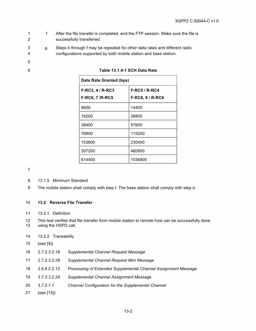
3GPP2 C.S0044-C v1.0
13-2
f. After the file transfer is completed, end the FTP session. Make sure the file is 1 successfully transferred. 2
g. Steps b through f may be repeated for other data rates and different radio 3 configurations supported by both mobile station and base station. 4
5
Table 13.1.4-1 SCH Data Rate 6
Data Rate Granted (bps)
F-RC3, 4 / R-RC3
F-RC6, 7 /R-RC5
F-RC5 / R-RC4
F-RC8, 9 / R-RC6
9600 14400
19200 28800
38400 57600
76800 115200
153600 230400
307200 460800
614400 1036800
7
13.1.5 Minimum Standard 8
The mobile station shall comply with step f. The base station shall comply with step d. 9
13.2 Reverse File Transfer 10
13.2.1 Definition 11
This test verifies that file transfer from mobile station to remote host can be successfully done 12 using the HSPD call. 13
13.2.2 Traceability 14
(see [4]) 15
2.7.2.3.2.18 Supplemental Channel Request Message 16
2.7.2.3.2.28 Supplemental Channel Request Mini Message 17
3.6.6.2.2.12 Processing of Extended Supplemental Channel Assignment Message 18
3.7.3.3.2.24 Supplemental Channel Assignment Message 19
3.7.5.7.1 Channel Configuration for the Supplemental Channel 20
(see [15]) 21
3GPP2 C.S0044-C v1.0
13-3
1.4.2.2 Mobile Station Packet Data Service States 1
2.2.2 Service and Call Control Procedures 2
2.2.3 Initialization and Connection of Packet Data Service Options 3
2.2.7 High Speed Operation 4
13.2.3 Call Flow Example(s) 5
None 6
13.2.4 Method of Measurement 7
a. Connect the mobile station to the base station as shown in Figure A-3. 8
b. At the TE2M prepare a file for data transfer. 9
c. Setup an FTP session using Service Option 33 with the remote host. 10
d. Transfer the file from the TE2M to the remote host using the binary “put” command. 11 Ensure that the total amount of data to be transferred at the mobile station is more than 12 an implementation defined threshold, or otherwise cause the mobile station to send a 13 Supplemental Channel Request Message or a Supplemental Channel Request Mini 14 Message with DURATION field set to a non-zero value. 15
e. If supplemental channel is assigned, verify the base station sends a Universal Handoff 16 Direction Message, an Extended Supplemental Channel Assignment Message, or a 17 Reverse Supplemental Channel Assignment Mini Message. 18
f. After the file transfer is completed, end the FTP session. Make sure that file is 19 successfully transferred. 20
g. Steps b through f should be executed for the maximum data rates13 supported by both 21 mobile station and base station. 22
h. Steps b through f may be repeated for other data rates and radio configurations 23 supported by both mobile station and base station. 24
13.2.5 Minimum Standard 25
The mobile station shall comply with step f. The base station shall comply with step e. 26
13.3 Bi-directional File Transfer 27
13.3.1 Definition 28
This test verifies that bi-directional file transfer can be successfully done using the HSPD call. 29
13.3.2 Traceability 30
(see [4]) 31
13 Make sure that transmit power is not limiting factor for maximum data rate assignment.
3GPP2 C.S0044-C v1.0
13-4
2.7.2.3.2.18 Supplemental Channel Request Message 1
2.7.2.3.2.28 Supplemental Channel Request Mini Message 2
3.6.6.2.2.12 Processing of Extended Supplemental Channel Assignment Message 3
3.7.3.3.2.24 Supplemental Channel Assignment Message 4
3.7.5.7.1 Channel Configuration for the Supplemental Channel 5
(see [15]) 6
1.4.2.2 Mobile Station Packet Data Service States 7
2.2.2 Service and Call Control Procedures 8
2.2.3 Initialization and Connection of Packet Data Service Options 9
2.2.7 High Speed Operation 10
13.3.3 Call Flow Example(s) 11
None 12
13.3.4 Method of Measurement 13
a. Connect the mobile station to the base station as shown in Figure A-3. 14
b. Prepare a file at both the remote host and TE2M for data transfer. 15
c. Setup an FTP session using Service Option 33 with the remote host. 16
d. Transfer the file from the TE2M to the remote host. Ensure that the total amount of data 17 to be transferred at the mobile station is more than an implementation defined 18 threshold, or otherwise cause the mobile station to send a Supplemental Channel 19 Request Message or a Supplemental Channel Request Mini Message with DURATION 20 field set to a non-zero value. 21
e. Transfer a file from the Remote Host to the TE2M while the transfer in the reverse 22 direction is still proceeding. 23
f. If forward supplemental channel is assigned, verify the base station sends a Universal 24 Handoff Direction Message, an Extended Supplemental Channel Assignment Message, 25 or a Forward Supplemental Channel Assignment Mini Message. 26
g. If reverse supplemental channel is assigned, verify the base station sends a Universal 27 Handoff Direction Message (can be same as one in step f), an Extended Supplemental 28 Channel Assignment Message (can be same as one in step f), or a Reverse 29 Supplemental Channel Assignment Mini Message. 30
h. Verify that files in both directions are successfully transferred and end the FTP session. 31
3GPP2 C.S0044-C v1.0
13-5
i. Steps c through f should be executed for the maximum forward14 and reverse15 data 1 rates that are supported by both mobile station and base station. 2
j. Steps c through f may be repeated for different data rates and radio configurations that 3 are supported by both mobile station and base station. 4
13.3.5 Minimum Standard 5
The mobile station shall comply with step h. The base station shall comply with steps f and g. 6
7
13.4 Service Option Control Message Processing 8
13.4.1 Definition 9
This test verifies the mobile station ability to process the Service Option Control Message. This 10 test also verifies the mobile station is able to establish a voice call while the packet data session 11 is dormant. 12
13.4.2 Traceabilities 13
(see [4]) 14
2.6.4.3 Traffic Channel Substate 15
3.6.4.3 Traffic Channel Substate 16
3.7.3.3.2.21 Service Option Control Message 17
(see [15]) 18
2.2.2.1 Mobile Station Procedures 19
2.2.2.2 Base Station Procedures 20
2.2.4 Packet Data Dormant Timer Control 21
14 Make sure that conditions to trigger maximum forward data rate assignment are fulfilled; such as large enough FTP file size, sufficient Walsh code resource etc. 15 Make sure that transmit power is not limiting factor for maximum reverse data rate assignment.
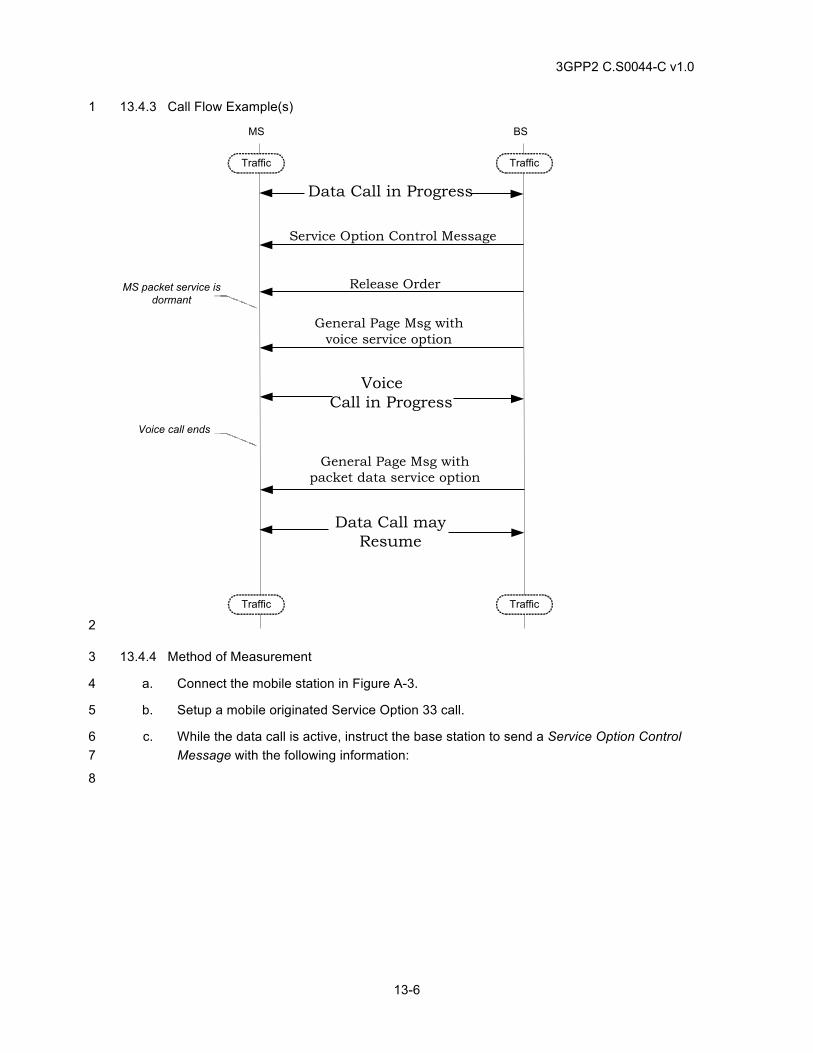
3GPP2 C.S0044-C v1.0
13-6
13.4.3 Call Flow Example(s) 1
Service Option Control Message
General Page Msg withvoice service option
BSMS
Traffic Traffic
TrafficTraffic
Release OrderMS packet service isdormant
Data Call in Progress
VoiceCall in Progress
Voice call ends
General Page Msg withpacket data service option
Data Call mayResume
2
13.4.4 Method of Measurement 3
a. Connect the mobile station in Figure A-3. 4
b. Setup a mobile originated Service Option 33 call. 5
c. While the data call is active, instruct the base station to send a Service Option Control 6 Message with the following information: 7
8
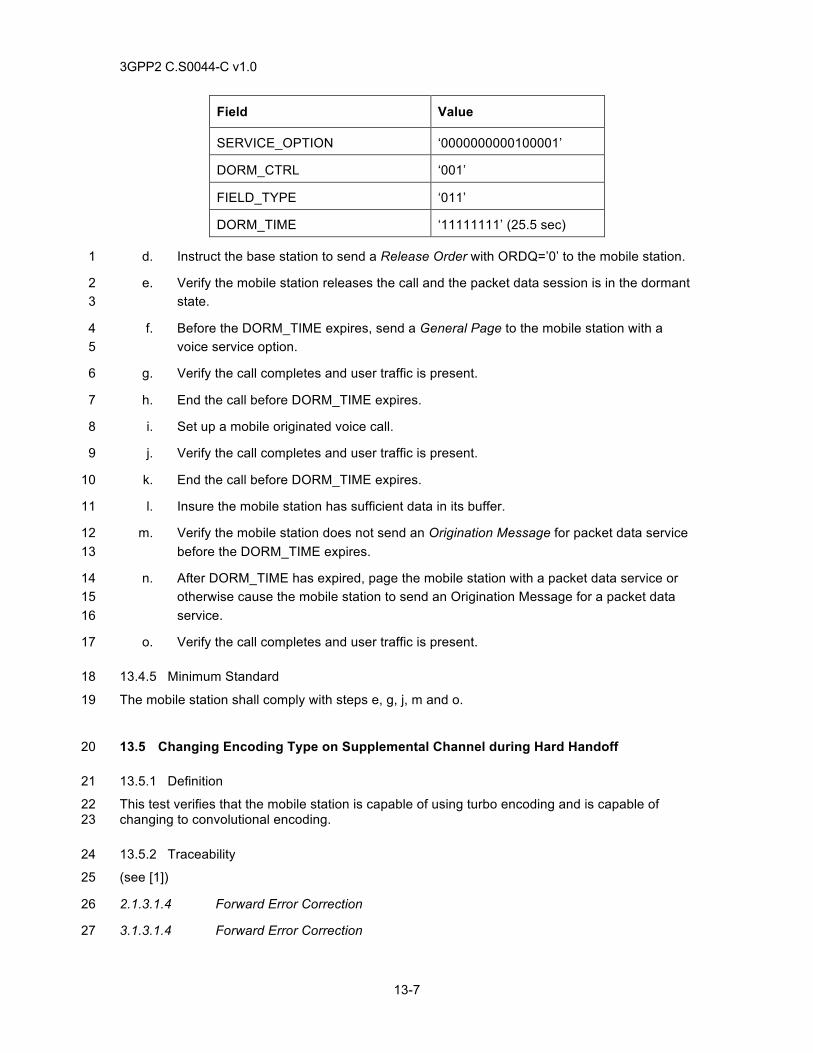
3GPP2 C.S0044-C v1.0
13-7
Field Value
SERVICE_OPTION ‘0000000000100001’
DORM_CTRL ‘001’
FIELD_TYPE ‘011’
DORM_TIME ‘11111111’ (25.5 sec)
d. Instruct the base station to send a Release Order with ORDQ=’0’ to the mobile station. 1
e. Verify the mobile station releases the call and the packet data session is in the dormant 2 state. 3
f. Before the DORM_TIME expires, send a General Page to the mobile station with a 4 voice service option. 5
g. Verify the call completes and user traffic is present. 6
h. End the call before DORM_TIME expires. 7
i. Set up a mobile originated voice call. 8
j. Verify the call completes and user traffic is present. 9
k. End the call before DORM_TIME expires. 10
l. Insure the mobile station has sufficient data in its buffer. 11
m. Verify the mobile station does not send an Origination Message for packet data service 12 before the DORM_TIME expires. 13
n. After DORM_TIME has expired, page the mobile station with a packet data service or 14 otherwise cause the mobile station to send an Origination Message for a packet data 15 service. 16
o. Verify the call completes and user traffic is present. 17
13.4.5 Minimum Standard 18
The mobile station shall comply with steps e, g, j, m and o. 19
13.5 Changing Encoding Type on Supplemental Channel during Hard Handoff 20
13.5.1 Definition 21
This test verifies that the mobile station is capable of using turbo encoding and is capable of 22 changing to convolutional encoding. 23
13.5.2 Traceability 24
(see [1]) 25
2.1.3.1.4 Forward Error Correction 26
3.1.3.1.4 Forward Error Correction 27
3GPP2 C.S0044-C v1.0
13-8
(see [4]) 1
2.7.2.3.2.18 Supplemental Channel Request Message 2
3.7.3.3.2.36 Universal Handoff Direction Message 3
3.7.3.3.2.37 Extended Supplemental Channel Assignment Message 4
13.5.3 Call Flow Example(s) 5
None 6
13.5.4 Method of Measurement 7
13.5.4.1 R-SCH Turbo Encoding to Convolutional Encoding 8
a. Connect the mobile station to the base station as shown in Figure A-5. 9
b. Ensure the mobile station supports turbo encoding and convolutional encoding. 10
c. Setup a mobile originated Service Option 33 call. 11
d. Instruct the base station to send a Service Connect Message with CODING=‘1’ in the 12 Service Configuration Record for the F-SCH and R-SCH (as supported by the mobile 13 station). 14
e. Verify the mobile station sends a Service Connect Completion Message. 15
f. Initiate a data transfer from the mobile station and verify the mobile station sends a 16 Supplemental Channel Request Message requesting a reverse supplemental channel. 17
g. Instruct the base station to send an Extended Supplemental Channel Assignment 18 Message assigning a reverse supplemental channel to the mobile station. 19
h. While the data transfer is in progress, instruct the base station to send a Universal 20 Handoff Direction Message with CODING=’0’ and a reverse supplemental channel 21 burst assignment. 22
i. Verify the mobile station sends a Handoff Completion Message or an Extended Handoff 23 Completion Message. 24
j. Verify the data transfer completes successfully using convolutional encoding. 25
k. End the call from the mobile station. 26
13.5.4.2 R-SCH Convolution Encoding to Turbo Encoding 27
a. Connect the mobile station to the base station as shown in Figure A-5. 28
b. Ensure the mobile station supports turbo encoding and convolutional encoding. 29
c. Setup a mobile originated Service Option 33 call. 30
d. Instruct the base station to send a Service Connect Message with CODING=‘0’ in the 31 Service Configuration Record for the F-SCH and R-SCH (as supported by the mobile 32 station). 33
e. Verify the mobile station sends a Service Connect Completion Message. 34
3GPP2 C.S0044-C v1.0
13-9
f. Initiate a data transfer from the mobile station and verify the mobile station sends a 1 Supplemental Channel Request Message requesting a reverse supplemental channel. 2
g. Instruct the base station to send an Extended Supplemental Channel Assignment 3 Message assigning a reverse supplemental channel to the mobile station. 4
h. While the data transfer is in progress, instruct the base station to send a Universal 5 Handoff Direction Message with CODING=’1’ and a reverse supplemental channel 6 burst assignment. 7
i. Verify the mobile station sends a Handoff Completion Message or an Extended Handoff 8 Completion Message. 9
j. Verify the data transfer completes successfully using turbo encoding (if the block size 10 per frame is at least 360 bits).. 11
k. End the call from the mobile station. 12
13.5.4.3 F-SCH Turbo Encoding to Convolutional Encoding 13
a. Connect the mobile station to the base station as shown in Figure A-5. 14
b. Ensure the mobile station supports turbo encoding and convolutional encoding. 15
c. Setup a mobile originated Service Option 33 call. 16
d. Instruct the base station to send a Service Connect Message with CODING=‘1’ in the 17 Service Configuration Record for the F-SCH and R-SCH (as supported by the mobile 18 station). 19
e. Verify the mobile station sends a Service Connect Completion Message. 20
f. Initiate a data transfer to the mobile station and verify the base station sends an 21 Extended Supplemental Channel Assignment Message assigning a F-SCH. 22
g. While the data transfer is in progress, instruct the base station to send a Universal 23 Handoff Direction Message with CODING=’0’ and a forward supplemental channel 24 burst assignment. 25
h. Verify the mobile station sends a Handoff Completion Message or an Extended Handoff 26 Completion Message. 27
i. Verify the data transfer completes successfully using convolutional encoding. 28
j. End the call from the mobile station. 29
13.5.4.4 F-SCH Convolutional Encoding to Turbo Encoding 30
a. Connect the mobile station to the base station as shown in Figure A-5. 31
b. Ensure the mobile station supports turbo encoding and convolutional encoding. 32
c. Setup a mobile originated Service Option 33 call. 33
d. Instruct the base station to send a Service Connect Message with CODING=‘0’ in the 34 Service Configuration Record for the F-SCH and R-SCH (as supported by the mobile 35 station). 36
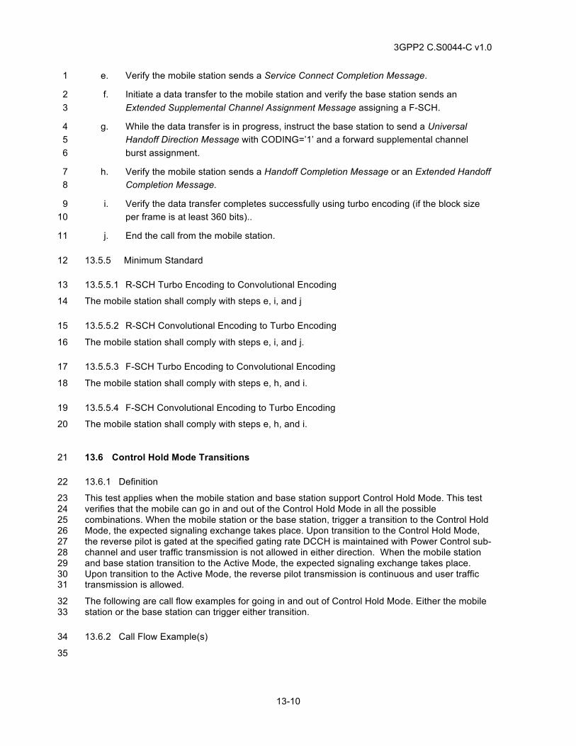
3GPP2 C.S0044-C v1.0
13-10
e. Verify the mobile station sends a Service Connect Completion Message. 1
f. Initiate a data transfer to the mobile station and verify the base station sends an 2 Extended Supplemental Channel Assignment Message assigning a F-SCH. 3
g. While the data transfer is in progress, instruct the base station to send a Universal 4 Handoff Direction Message with CODING=’1’ and a forward supplemental channel 5 burst assignment. 6
h. Verify the mobile station sends a Handoff Completion Message or an Extended Handoff 7 Completion Message. 8
i. Verify the data transfer completes successfully using turbo encoding (if the block size 9 per frame is at least 360 bits).. 10
j. End the call from the mobile station. 11
13.5.5 Minimum Standard 12
13.5.5.1 R-SCH Turbo Encoding to Convolutional Encoding 13
The mobile station shall comply with steps e, i, and j 14
13.5.5.2 R-SCH Convolutional Encoding to Turbo Encoding 15
The mobile station shall comply with steps e, i, and j. 16
13.5.5.3 F-SCH Turbo Encoding to Convolutional Encoding 17
The mobile station shall comply with steps e, h, and i. 18
13.5.5.4 F-SCH Convolutional Encoding to Turbo Encoding 19
The mobile station shall comply with steps e, h, and i. 20
13.6 Control Hold Mode Transitions 21
13.6.1 Definition 22
This test applies when the mobile station and base station support Control Hold Mode. This test 23 verifies that the mobile can go in and out of the Control Hold Mode in all the possible 24 combinations. When the mobile station or the base station, trigger a transition to the Control Hold 25 Mode, the expected signaling exchange takes place. Upon transition to the Control Hold Mode, 26 the reverse pilot is gated at the specified gating rate DCCH is maintained with Power Control sub-27 channel and user traffic transmission is not allowed in either direction. When the mobile station 28 and base station transition to the Active Mode, the expected signaling exchange takes place. 29 Upon transition to the Active Mode, the reverse pilot transmission is continuous and user traffic 30 transmission is allowed. 31
The following are call flow examples for going in and out of Control Hold Mode. Either the mobile 32 station or the base station can trigger either transition. 33
13.6.2 Call Flow Example(s) 34
35
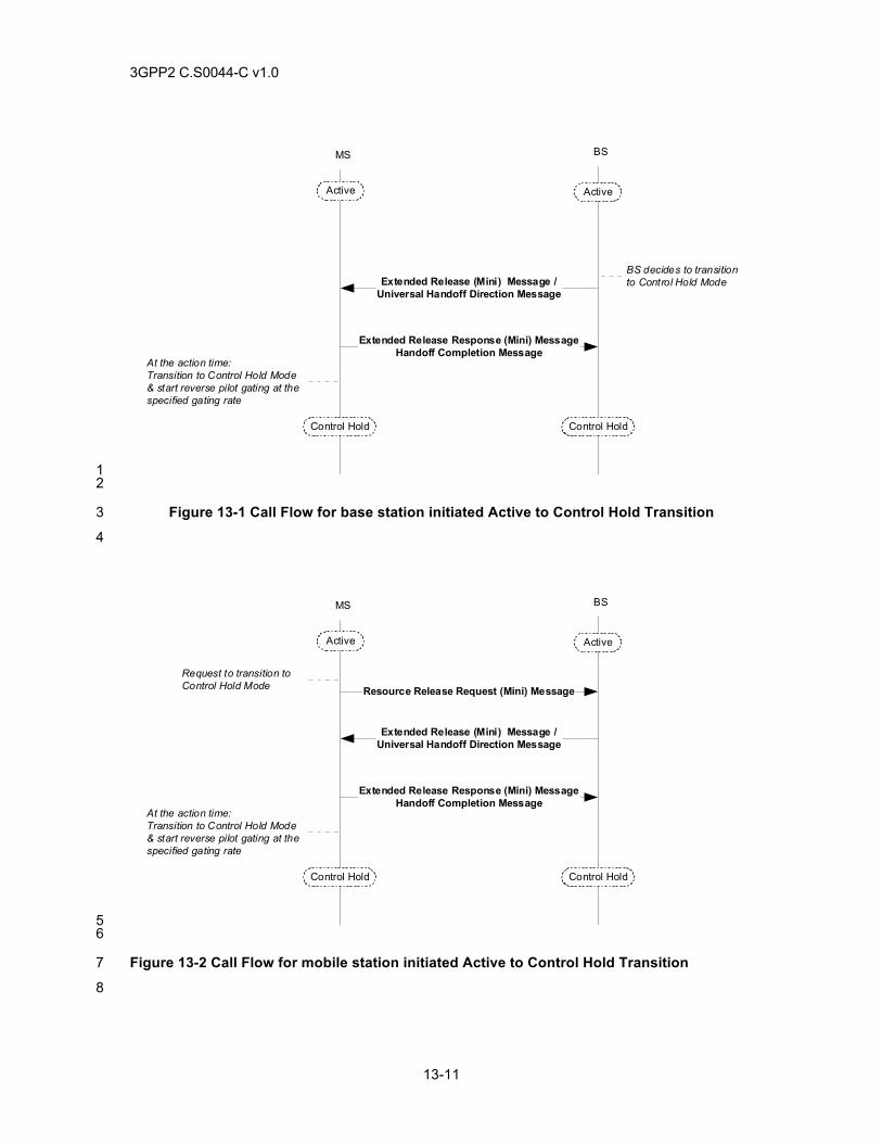
3GPP2 C.S0044-C v1.0
13-11
Extended Release (Mini) Message /Universal Handoff Direction Message
Extended Release Response (Mini) MessageHandoff Completion Message
At the action time:Transition to Control Hold Mode& start reverse pilot gating at thespecified gating rate
BSMS
Active Active
Control Hold Control Hold
BS decides to transitionto Control Hold Mode
1 2
Figure 13-1 Call Flow for base station initiated Active to Control Hold Transition 3
4
Extended Release (Mini) Message /Universal Handoff Direction Message
Extended Release Response (Mini) MessageHandoff Completion Message
At the action time:Transition to Control Hold Mode& start reverse pilot gating at thespecified gating rate
BSMS
Active Active
Control Hold Control Hold
Resource Release Request (Mini) MessageRequest to transition toControl Hold Mode
5 6
Figure 13-2 Call Flow for mobile station initiated Active to Control Hold Transition 7
8
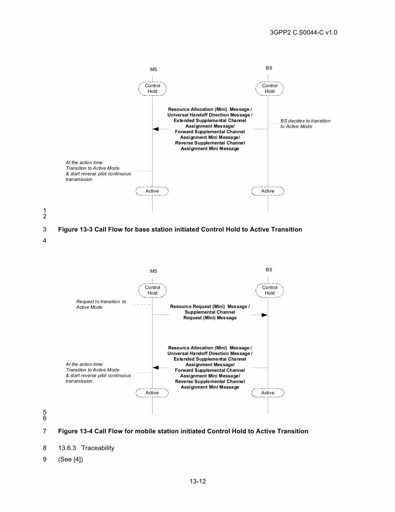
3GPP2 C.S0044-C v1.0
13-12
Resource Allocation (Mini) Message /Universal Handoff Direction Message /
Extended Supplemental ChannelAssignment Message/
Forward Supplemental ChannelAssignment Mini Message/
Reverse Supplemental ChannelAssignment Mini Message
At the action time:Transition to Active Mode& start reverse pilot continuoustransmission
BSMS
ControlHold
Active Active
BS decides to transitionto Active Mode
ControlHold
1 2
Figure 13-3 Call Flow for base station initiated Control Hold to Active Transition 3
4
Resource Allocation (Mini) Message /Universal Handoff Direction Message /
Extended Supplemental ChannelAssignment Message/
Forward Supplemental ChannelAssignment Mini Message/
Reverse Supplemental ChannelAssignment Mini Message
At the action time:Transition to Active Mode& start reverse pilot continuoustransmission
BSMS
ControlHold
Active Active
Request to transition toActive Mode
ControlHold
Resource Request (Mini) Message /Supplemental Channel
Request (Mini) Message
5 6
Figure 13-4 Call Flow for mobile station initiated Control Hold to Active Transition 7
13.6.3 Traceability 8
(See [4]) 9
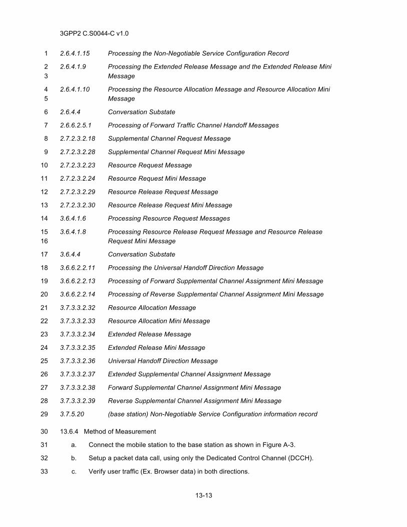
3GPP2 C.S0044-C v1.0
13-13
2.6.4.1.15 Processing the Non-Negotiable Service Configuration Record 1
2.6.4.1.9 Processing the Extended Release Message and the Extended Release Mini 2 Message 3
2.6.4.1.10 Processing the Resource Allocation Message and Resource Allocation Mini 4 Message 5
2.6.4.4 Conversation Substate 6
2.6.6.2.5.1 Processing of Forward Traffic Channel Handoff Messages 7
2.7.2.3.2.18 Supplemental Channel Request Message 8
2.7.2.3.2.28 Supplemental Channel Request Mini Message 9
2.7.2.3.2.23 Resource Request Message 10
2.7.2.3.2.24 Resource Request Mini Message 11
2.7.2.3.2.29 Resource Release Request Message 12
2.7.2.3.2.30 Resource Release Request Mini Message 13
3.6.4.1.6 Processing Resource Request Messages 14
3.6.4.1.8 Processing Resource Release Request Message and Resource Release 15 Request Mini Message 16
3.6.4.4 Conversation Substate 17
3.6.6.2.2.11 Processing the Universal Handoff Direction Message 18
3.6.6.2.2.13 Processing of Forward Supplemental Channel Assignment Mini Message 19
3.6.6.2.2.14 Processing of Reverse Supplemental Channel Assignment Mini Message 20
3.7.3.3.2.32 Resource Allocation Message 21
3.7.3.3.2.33 Resource Allocation Mini Message 22
3.7.3.3.2.34 Extended Release Message 23
3.7.3.3.2.35 Extended Release Mini Message 24
3.7.3.3.2.36 Universal Handoff Direction Message 25
3.7.3.3.2.37 Extended Supplemental Channel Assignment Message 26
3.7.3.3.2.38 Forward Supplemental Channel Assignment Mini Message 27
3.7.3.3.2.39 Reverse Supplemental Channel Assignment Mini Message 28
3.7.5.20 (base station) Non-Negotiable Service Configuration information record 29
13.6.4 Method of Measurement 30
a. Connect the mobile station to the base station as shown in Figure A-3. 31
b. Setup a packet data call, using only the Dedicated Control Channel (DCCH). 32
c. Verify user traffic (Ex. Browser data) in both directions. 33
3GPP2 C.S0044-C v1.0
13-14
d. Cause the mobile station and/or base station to initiate transition to the Control Hold 1 Mode because of out-of-data indication from the RLP. 2
e. Verify that one of the following two scenarios occurs: 3
1. Verify that the mobile station sends a Resource Release Request (Mini) 4 Message to the base station to request transition to the Control Hold Mode. 5 Verify that the base station accepts this request, via an Extended Release (Mini) 6 Message, or a Universal Handoff Direction Message. Verify that the mobile 7 station responds with an Extended Release Response (Mini) Message, or a 8 Extended Handoff Completion Message. 9
2. Verify that the base station sends an Extended Release Mini Message, or a 10 Universal Handoff Direction Message. Verify that the mobile station responds 11 with an Extended Release Response Mini Message, or an Extended Handoff 12 Completion Message. 13
f. Upon transition to Control Hold Mode, verify the following: 14
1. The reverse pilot is gated at the specified rate. 15
2. Dedicated Control Channel is maintained for signaling. 16
3. User traffic (Ex. Browser data) is not transmitted on either direction. NOTE: This 17 can be verified by attempting to send user traffic, while not granting any requests 18 to transition to the Active Mode. 19
4. Reverse Power Control Subchannel is maintained at the Forward Dedicated 20 Control Channel. 21
g. Depending on who initiated the transition to Control Hold Mode in e, and if possible, 22 change the control hold time on the network side to make the other alternative happen 23 in d. Repeat b through f. Results are as expected in f. 24
h. Execute steps b through f. 25
i. Instruct the base station to initiate the transition to Active Mode (e.g. Send a ping 26 command to the mobile station from the base station. 27
j. Verify that the base station initiates the transition to Active Mode, via a Resource 28 Allocation Message, a Resource Allocation Mini Message, a Universal Handoff 29 Direction Message, an Extended Supplemental Channel Assignment (Mini) Message, a 30 Forward Supplemental Channel Assignment Mini Message, or a Reverse Supplemental 31 Channel Assignment Mini Message. Verify that the mobile station responds accordingly. 32
k. Upon transition to the Active Mode, verify that: 33
1. The reverse pilot transmission is continuous 34
2. User traffic (Ex. Browser data) is transmitted. 35
l. Execute steps b through f. 36
m. Send a ping from the mobile station side to cause the mobile station to initiate the 37 transition to Active Mode. Verify that the mobile station sends a Resource Request 38 (Mini) Message, a Supplemental Channel Request (Mini) Message. Verify that the base 39
3GPP2 C.S0044-C v1.0
13-15
station sends a Resource Allocation (Mini) Message, a Universal Handoff Direction 1 Message, an Extended Supplemental Channel Assignment (Mini) Message, a Forward 2 Supplemental Channel Assignment Mini Message, or a Reverse Supplemental Channel 3 Assignment Mini Message. 4
n. Verify step k. 5
13.6.5 Minimum Standard 6
The mobile station and the base station shall comply with the requirements in the following steps: 7 e, f, j, k, m, and n. 8
13.7 Soft Handoff of Fundamental Channel/Dedicated Control Channel and Supplemental 9 Channels 10
13.7.1 Definition 11
This test verifies that the mobile station can successfully complete a soft handoff of the 12 fundamental, dedicated control channel, and supplemental channels during a data transfer. 13
13.7.2 Traceability 14
(see [4]) 15
2.7.2.3.2.18 Supplemental Channel Request Message 16
2.7.2.3.2.28 Pilot Strength Measurement Mini Message 17
2.7.2.32.34 Extended Pilot Strength Measure Message 18
2.7.2.3.2.28 Supplemental Channel Request Mini Message 19
3.6.6.2.2.12 Processing of Extended Supplemental Channel Assignment Message 20
3.7.3.3.2.24 Supplemental Channel Assignment Message 21
3.7.3.3.2.36 Universal Handoff Direction Message 22
3.7.5.7.1 Channel Configuration for the Supplemental Channel 23
(see [15]) 24
1.4.2.2 Mobile Station Packet Data Service States 25
2.2.2 Service and Call Control Procedures 26
2.2.3 Initialization and Connection of Packet Data Service Options 27
2.2.7 High Speed Operation 28
13.7.3 Call Flow Example(s) 29
None 30
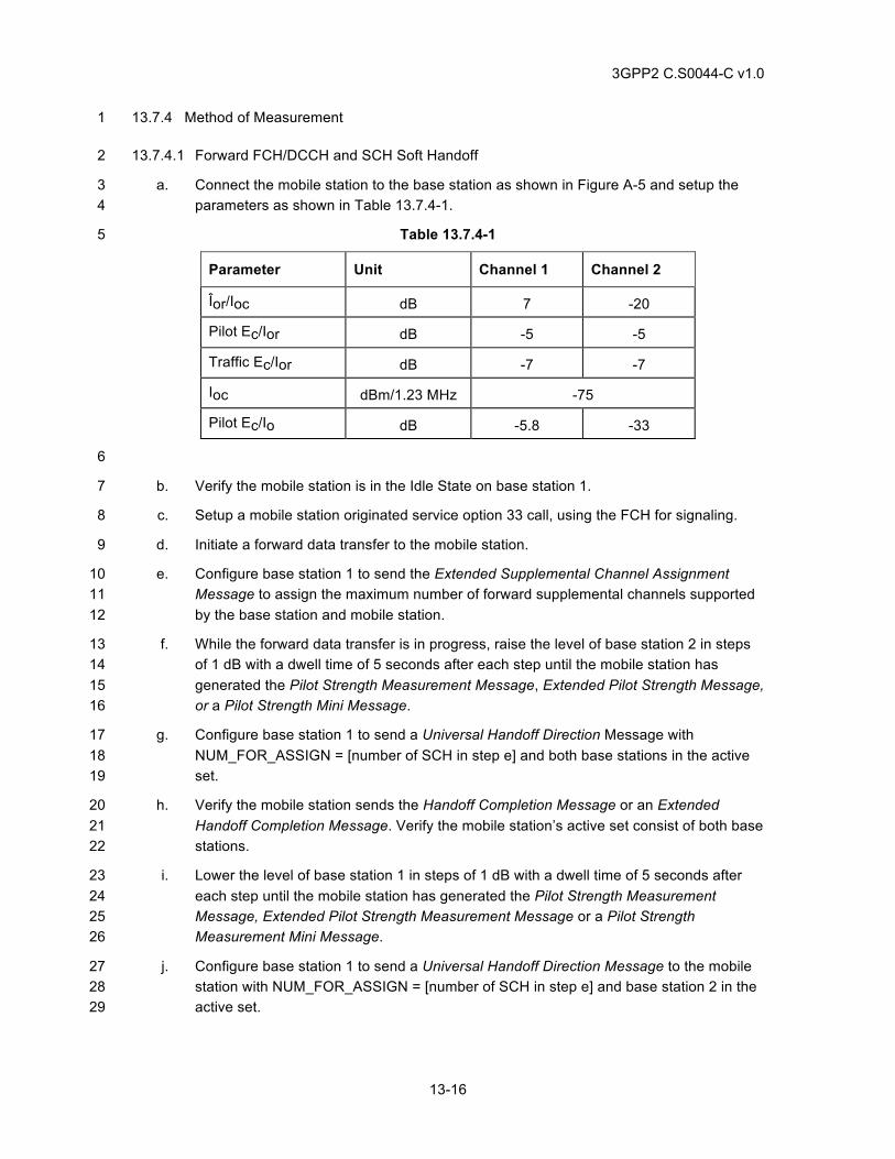
3GPP2 C.S0044-C v1.0
13-16
13.7.4 Method of Measurement 1
13.7.4.1 Forward FCH/DCCH and SCH Soft Handoff 2
a. Connect the mobile station to the base station as shown in Figure A-5 and setup the 3 parameters as shown in Table 13.7.4-1. 4
Table 13.7.4-1 5
Parameter Unit Channel 1 Channel 2
Îor/Ioc dB 7 -20
Pilot Ec/Ior dB -5 -5
Traffic Ec/Ior dB -7 -7
Ioc dBm/1.23 MHz -75
Pilot Ec/Io dB -5.8 -33
6
b. Verify the mobile station is in the Idle State on base station 1. 7
c. Setup a mobile station originated service option 33 call, using the FCH for signaling. 8
d. Initiate a forward data transfer to the mobile station. 9
e. Configure base station 1 to send the Extended Supplemental Channel Assignment 10 Message to assign the maximum number of forward supplemental channels supported 11 by the base station and mobile station. 12
f. While the forward data transfer is in progress, raise the level of base station 2 in steps 13 of 1 dB with a dwell time of 5 seconds after each step until the mobile station has 14 generated the Pilot Strength Measurement Message, Extended Pilot Strength Message, 15 or a Pilot Strength Mini Message. 16
g. Configure base station 1 to send a Universal Handoff Direction Message with 17 NUM_FOR_ASSIGN = [number of SCH in step e] and both base stations in the active 18 set. 19
h. Verify the mobile station sends the Handoff Completion Message or an Extended 20 Handoff Completion Message. Verify the mobile station’s active set consist of both base 21 stations. 22
i. Lower the level of base station 1 in steps of 1 dB with a dwell time of 5 seconds after 23 each step until the mobile station has generated the Pilot Strength Measurement 24 Message, Extended Pilot Strength Measurement Message or a Pilot Strength 25 Measurement Mini Message. 26
j. Configure base station 1 to send a Universal Handoff Direction Message to the mobile 27 station with NUM_FOR_ASSIGN = [number of SCH in step e] and base station 2 in the 28 active set. 29
3GPP2 C.S0044-C v1.0
13-17
k. Verify the mobile station sends a Handoff Completion Message or an Extended Handoff 1 Completion Message. 2
l. Verify the data transfer completes successfully. 3
m. End the call. 4
n. Repeat steps c through m using the DCCH for signaling. 5
13.7.4.2 Reverse FCH/DCCH and SCH Soft Handoff 6
a. Connect the mobile station to the base station as shown in Figure A-5 and setup the 7 parameters as shown in Table 13.7.4-1. 8
b. Verify the mobile station is in the Idle State on base station 1. 9
c. Setup a mobile station originated service option 33 call using the FCH for signaling. 10
d. Initiate a reverse data transfer from the mobile station. 11
e. After the mobile station sends a Supplemental Channel Request Message, configure 12 base station 1 to send an Extended Supplemental Channel Assignment Message to 13 assign the maximum number of reverse supplemental channels supported by the 14 network and mobile station. 15
f. While the reverse data transfer is in progress, raise the level of base station 2 in steps 16 of 1 dB with a dwell time of 5 seconds after each step until the mobile station has 17 generated the Pilot Strength Measurement, Extended Pilot Strength Measurement 18 Message or a Pilot Strength Measurement Mini Message. 19
g. Configure base station 1 to send a Universal Handoff Direction Message with 20 NUM_REV_ASSIGN = [number of SCH in step e] and both base stations in the active 21 set. 22
h. Verify the mobile station sends the Handoff Completion Message or an Extended 23 Handoff Completion Message. Verify the mobile station’s active set consist of both base 24 stations. 25
i. Lower the level of base station 1 in steps of 1 dB with a dwell time of 5 seconds after 26 each step until the mobile station has generated the Pilot Strength Measurement 27 Message, Extended Pilot Strength Measurement Message or a Pilot Strength 28 Measurement Mini Message. 29
j. Configure base station 2 to send a Universal Handoff Direction Message to the mobile 30 station with NUM_REV_ASSIGN = [number of SCH in step e] and base station 2 in the 31 active set. 32
k. Verify the mobile station sends a Handoff Completion Message or an Extended Handoff 33 Completion Message. 34
l. Verify the data transfer completes successfully. 35
m. End the call. 36
n. Repeat steps c through m using the DCCH. 37
3GPP2 C.S0044-C v1.0
13-18
13.7.5 Minimum Standard 1
13.7.5.1 Forward FCH/DCCH and SCH Soft Handoff 2
The mobile station shall comply with steps h, k, l, and n. 3
13.7.5.2 Reverse FCH/DCCH and SCH Soft Handoff 4
The mobile station shall comply with steps h, k, l, and n. 5
13.8 Soft Handoff of Fundamental Channel or Dedicated Control Channel only 6
13.8.1 Definition 7
This test verifies the mobile station can successfully complete a data transfer when only the 8 fundamental channel or dedicated control channel is in soft handoff. 9
13.8.2 Traceability 10
(see [4]) 11
2.7.2.3.2.18 Supplemental Channel Request Message 12
2.7.2.3.2.28 Supplemental Channel Request Mini Message 13
2.7.2.3.2.28 Pilot Strength Measurement Mini Message 14
2.7.2.32.34 Extended Pilot Strength Measure Message 15
3.6.6.2.2.12 Processing of Extended Supplemental Channel Assignment Message 16
3.7.3.3.2.24 Supplemental Channel Assignment Message 17
3.7.3.3.2.36 Universal Handoff Direction Message 18
3.7.5.7.1 Channel Configuration for the Supplemental Channel 19
(see [15]) 20
1.4.2.2 Mobile Station Packet Data Service States 21
2.2.2 Service and Call Control Procedures 22
2.2.3 Initialization and Connection of Packet Data Service Options 23
2.2.7 High Speed Operation 24
13.8.3 Call Flow Example(s) 25
None 26
13.8.4 Method of Measurement 27
13.8.4.1 Forward FCH/DCCH Only Soft Handoff 28
a. Connect the mobile station to the base station as shown in Figure A-5 and setup the 29 parameters as shown in Table 13.7.4-1. 30
b. Verify the mobile station is in the Idle State on base station 1. 31
3GPP2 C.S0044-C v1.0
13-19
c. Setup a mobile station originated service option 33 call using the FCH for signaling. 1
d. Initiate a forward data transfer to the mobile station. 2
e. Configure base station 1 to send the Extended Supplemental Channel Assignment 3 Message to assign the maximum number of forward supplemental channels supported 4 by the network and mobile station. 5
f. While the forward data transfer is in progress, raise the level of base station 2 in steps 6 of 1 dB with a dwell time of 5 seconds after each step until the mobile station has 7 generated the Pilot Strength Measurement Message, Extended Pilot Strength 8 Measurement Message or a Pilot Strength Measurement Mini Message. 9
g. Configure base station 1 to send a Universal Handoff Direction Message with 10 NUM_FOR_ASSIGN = 0 and both base stations in the active set. 11
h. Verify the mobile station sends the Handoff Completion Message or an Extended 12 Handoff Completion Message. Verify the mobile station’s active set consist of both base 13 stations. 14
i. Verify the data transfer completes successfully. 15
j. End the call. 16
k. Repeat steps c through j using the DCCH for signaling. 17
13.8.4.2 Reverse FCH/DCCH Only Soft Handoff 18
a. Connect the mobile station to the base station as shown in Figure A-5 and setup the 19 parameters as shown in Table 13.7.4-1. 20
b. Verify the mobile station is in the Idle State on base station 1. 21
c. Setup a mobile station originated service option 33 call using the FCH for signaling 22
d. Initiate a reverse data transfer from the mobile station. 23
e. After the mobile station sends a Supplemental Channel Request Message, Configure 24 base station 1 to send an Extended Supplemental Channel Assignment Message to 25 assign the maximum number of reverse supplemental channels supported by the 26 network and mobile station. 27
f. While the reverse data transfer is in progress, raise the level of base station 2 in steps 28 of 1 dB with a dwell time of 5 seconds after each step until the mobile station has 29 generated the Pilot Strength Measurement Message, Extended Pilot Strength 30 Measurement Message or a Pilot Strength Measurement Mini Message. 31
g. Configure base station 1 to send a Universal Handoff Direction Message with 32 NUM_REV_ASSIGN = 0 and both base stations in the active set. 33
h. Verify the mobile station sends the Handoff Completion Message or an Extended 34 Handoff Completion Message. Verify the mobile station’s active set consist of both base 35 stations. 36
i. Verify the data transfer completes successfully. 37
3GPP2 C.S0044-C v1.0
13-20
j. End the call. 1
k. Repeat steps c through j with the DCCH for signaling. 2
13.8.5 Minimum Standard 3
13.8.5.1 Forward FCH/DCCH Only Soft Handoff 4
The mobile station shall comply with steps h i, and k. 5
13.8.5.2 Reverse FCH/DCCH Soft Handoff Only 6
The mobile station shall comply with steps h, i, and k. 7
13.9 Adding Supplemental Channels during Soft Handoff 8
13.9.1 Definition 9
This test verifies that a supplemental channel(s) can be added in a service option 33 call while in 10 soft handoff on the fundamental channel or dedicated control channel. 11
13.9.2 Traceability 12
(see [4]) 13
2.7.2.3.2.18 Supplemental Channel Request Message 14
2.7.2.3.2.28 Pilot Strength Measurement Mini Message 15
2.7.2.32.34 Extended Pilot Strength Measure Message 16
2.7.2.3.2.28 Supplemental Channel Request Mini Message 17
3.6.6.2.2.12 Processing of Extended Supplemental Channel Assignment Message 18
3.7.3.3.2.24 Supplemental Channel Assignment Message 19
3.7.3.3.2.36 Universal Handoff Direction Message 20
3.7.5.7.1 Channel Configuration for the Supplemental Channel 21
(see [15]) 22
1.4.2.2 Mobile Station Packet Data Service States 23
2.2.2 Service and Call Control Procedures 24
2.2.3 Initialization and Connection of Packet Data Service Options 25
2.2.7 High Speed Operation 26
13.9.3 Call Flow Example(s) 27
None 28
13.9.4 Method of Measurement 29
a. Connect the mobile station to the base station as shown in Figure A-5 and setup the 30 parameters as shown in Table 13.7.4-1. 31
3GPP2 C.S0044-C v1.0
13-21
b. Verify the mobile station is in the Idle State on base station 1. 1
c. Setup a mobile station originated service option 33 call using the FCH for signaling. 2
d. Raise the level of base station 2 in steps of 1 dB with a dwell time of 5 seconds after 3 each step until the mobile station has generated the Pilot Strength Measurement 4 Message, Extended Pilot Strength Measurement Message, or a Pilot Strength 5 Measurement Mini Message. 6
e. Configure base station 1 to send a Universal Handoff Direction Message with 7 NUM_FOR_ASSIGN = 0 and both base stations in the active set. 8
f. Verify the mobile station sends the Handoff Completion Message or an Extended 9 Handoff Completion Message. Verify the mobile station’s active set consist of both base 10 stations. 11
g. Initiate a forward data transfer to the mobile station. 12
h. Configure base station 1 to send the Extended Supplemental Channel Assignment 13 Message with NUM_SUP_SHO = ‘001’ for the forward supplemental channel and 14 include both base station 1 and base station 2 for PILOT_PN values. 15
i. Verify the data transfer completes successfully. 16
j. End the call. 17
k. Repeat steps c through j using the DCCH for signaling. 18
13.9.5 Minimum Standard 19
The mobile station shall comply with steps f, i, and k. 20
13.10 Hard Handoff during Data Transfer 21
13.10.1 Definition 22
This test verifies the data transfer continues after hard handoff using the forward and reverse link. 23
13.10.2 Traceability 24
(see [4]) 25
2.7.2.3.2.18 Supplemental Channel Request Message 26
2.7.2.3.2.28 Supplemental Channel Request Mini Message 27
3.6.6.2.2.12 Processing of Extended Supplemental Channel Assignment Message 28
3.7.3.3.2.24 Supplemental Channel Assignment Message 29
3.7.3.3.2.36 Universal Handoff Direction Message 30
3.7.5.7.1 Channel Configuration for the Supplemental Channel 31
(see [15]) 32
1.4.2.2 Mobile Station Packet Data Service States 33
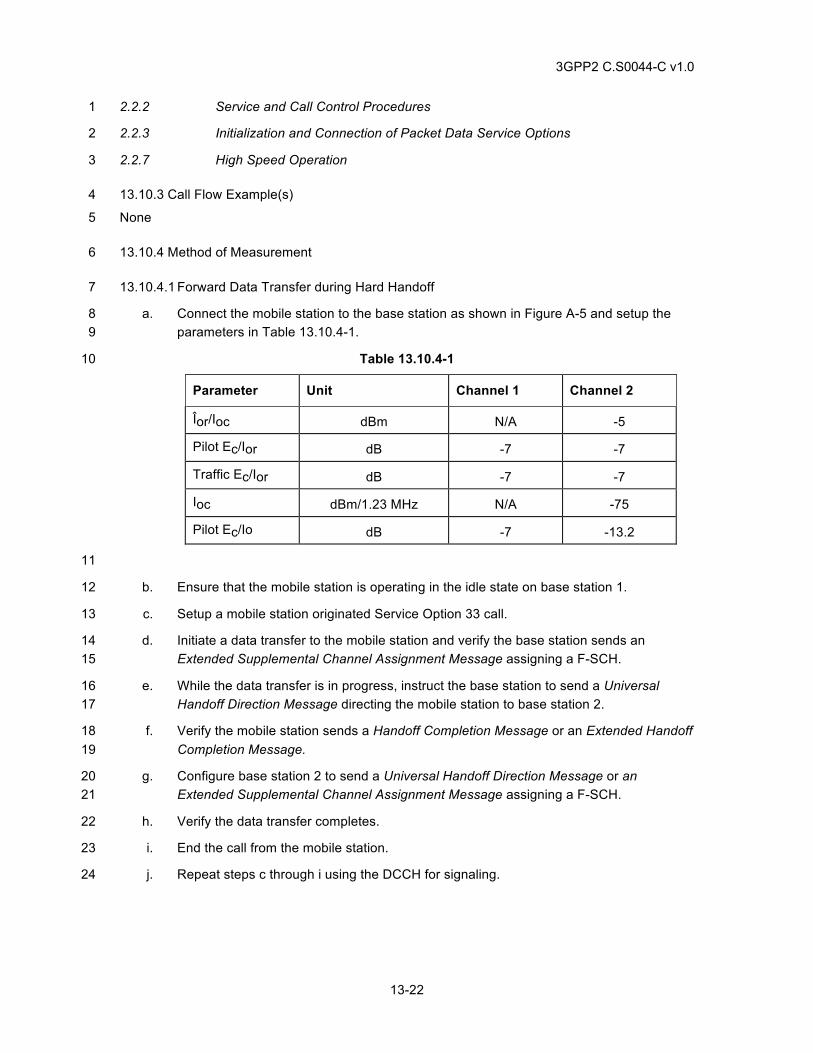
3GPP2 C.S0044-C v1.0
13-22
2.2.2 Service and Call Control Procedures 1
2.2.3 Initialization and Connection of Packet Data Service Options 2
2.2.7 High Speed Operation 3
13.10.3 Call Flow Example(s) 4
None 5
13.10.4 Method of Measurement 6
13.10.4.1 Forward Data Transfer during Hard Handoff 7
a. Connect the mobile station to the base station as shown in Figure A-5 and setup the 8 parameters in Table 13.10.4-1. 9
Table 13.10.4-1 10
Parameter Unit Channel 1 Channel 2
Îor/Ioc dBm N/A -5
Pilot Ec/Ior dB -7 -7
Traffic Ec/Ior dB -7 -7
Ioc dBm/1.23 MHz N/A -75
Pilot Ec/Io dB -7 -13.2
11
b. Ensure that the mobile station is operating in the idle state on base station 1. 12
c. Setup a mobile station originated Service Option 33 call. 13
d. Initiate a data transfer to the mobile station and verify the base station sends an 14 Extended Supplemental Channel Assignment Message assigning a F-SCH. 15
e. While the data transfer is in progress, instruct the base station to send a Universal 16 Handoff Direction Message directing the mobile station to base station 2. 17
f. Verify the mobile station sends a Handoff Completion Message or an Extended Handoff 18 Completion Message. 19
g. Configure base station 2 to send a Universal Handoff Direction Message or an 20 Extended Supplemental Channel Assignment Message assigning a F-SCH. 21
h. Verify the data transfer completes. 22
i. End the call from the mobile station. 23
j. Repeat steps c through i using the DCCH for signaling. 24
3GPP2 C.S0044-C v1.0
13-23
13.10.4.2 Reverse Data Transfer during Hard Handoff 1
a. Connect the mobile station to the base station as shown in Figure A-5 and setup the 2 parameters in Table 13.10.4-1. 3
b. Ensure that the mobile station is operating in the idle state on base station 1. 4
c. Setup a mobile station originated Service Option 33 call. 5
d. Initiate a data transfer from the mobile station and verify the mobile station sends a 6 Supplemental Channel Request Message requesting a reverse supplemental channel. 7
e. Instruct the base station to send an Extended Supplemental Channel Assignment 8 Message assigning a reverse supplemental channel to the mobile station. 9
f. While the data transfer is in progress, instruct the base station to send a Universal 10 Handoff Direction Message directing the mobile station to base station 2. 11
g. Verify the mobile station sends a Handoff Completion Message or an Extended Handoff 12 Completion Message. 13
h. Configure base station 2 to send a Universal Handoff Direction Message or an 14 Extended Supplemental Channel Assignment Message assigning a R-SCH. 15
i. Verify the data transfer completes successfully. 16
j. End the call from the mobile station. 17
k. Repeat steps c through j using the DCCH for signaling. 18
13.10.5 Minimum Standard 19
13.10.5.1 Forward Data Transfer during Hard Handoff 20
The mobile station shall comply with steps f, h and j. 21
13.10.5.2 Reverse Data Transfer during Hard Handoff 22
The mobile station shall comply with steps g, i, and k. 23
13.11 Hard Handoff to a different Radio Configuration 24
13.11.1 Definition 25
This test verifies hard handoff to a different radio configuration during an HSPD call. 26
13.11.2 Traceability 27
(see [4]) 28
2.7.2.3.2.18 Supplemental Channel Request Message 29
2.7.2.3.2.28 Supplemental Channel Request Mini Message 30
3.6.6.2.2.12 Processing of Extended Supplemental Channel Assignment Message 31
3.7.3.3.2.24 Supplemental Channel Assignment Message 32
3GPP2 C.S0044-C v1.0
13-24
3.7.3.3.2.36 Universal Handoff Direction Message 1
3.7.5.7.1 Channel Configuration for the Supplemental Channel 2
(see [15]) 3
1.4.2.2 Mobile Station Packet Data Service States 4
2.2.2 Service and Call Control Procedures 5
2.2.3 Initialization and Connection of Packet Data Service Options 6
2.2.7 High Speed Operation 7
13.11.3 Call Flow Example(s) 8
None 9
13.11.4 Method of Measurement 10
13.11.4.1 Forward Data Transfer during Hard Handoff 11
a. Connect the mobile station to the base station as shown in Figure A-5 and setup the 12 parameters in Table 13.10.4-1. 13
b. Ensure that the mobile station is operating in the idle state on base station 1. 14
c. Setup a mobile station originated Service Option 33 call. Note the FOR_FCH_RC, 15 REV_FCH_RC, and SCH_RC values. 16
d. Initiate a data transfer to the mobile station and verify the base station sends an 17 Extended Supplemental Channel Assignment Message assigning a F-SCH. 18
e. While the data transfer is in progress, instruct the base station to send a Universal 19 Handoff Direction Message changing the FOR_FCH_RC, REV_FCH_RC and SCH_RC 20 values in step c and directing the mobile station to base station 2. 21
f. Verify the mobile station sends a Handoff Completion Message or an Extended Handoff 22 Completion Message. 23
g. Configure base station 2 to send an Extended Supplemental Channel Assignment 24 Message assigning a F-SCH. 25
h. Verify the data transfer completes. 26
i. End the call from the mobile station. 27
j. This test may be repeated for all radio configurations supported. 28
k. Repeat steps c through j with the DCCH for signaling. 29
13.11.4.2 Reverse Data Transfer during Hard Handoff 30
a. Connect the mobile station to the base station as shown in Figure A-5 and setup the 31 parameters in Table 13.10.4-1. 32
b. Ensure that the mobile station is operating in the idle state on base station 1. 33
3GPP2 C.S0044-C v1.0
13-25
c. Setup a mobile station originated Service Option 33 call. Note the FOR_FCH_RC, 1 REV_FCH_RC, and SCH_RC values. 2
d. Initiate a data transfer from the mobile station and verify the mobile station sends a 3 Supplemental Channel Request Message requesting a reverse supplemental channel. 4
e. Instruct the base station to send an Extended Supplemental Channel Assignment 5 Message assigning a reverse supplemental channel to the mobile station. 6
f. While the data transfer is in progress, instruct the base station to send a Universal 7 Handoff Direction Message changing the FOR_FCH_RC, REV_FCH_RC and SCH_RC 8 values in step c directing the mobile station to base station 2. 9
g. Verify the mobile station sends a Handoff Completion Message or an Extended Handoff 10 Completion Message. 11
h. Configure base station 2 to send a Universal Handoff Direction Message or an 12 Extended Supplemental Channel Assignment Message assigning a R-SCH. 13
i. Verify the data transfer completes successfully. 14
j. End the call from the mobile station. 15
k. This test may be repeated for all radio configurations supported. 16
l. Repeat steps c through k using the DCCH for signaling 17
13.11.5 Minimum Standard 18
13.11.5.1 Forward Data Transfer during Hard Handoff 19
The mobile station shall comply with steps f, h, and k. 20
13.11.5.2 Reverse Data Transfer during Hard Handoff 21
The mobile station shall comply with steps g, i, and l. 22
13.12 Mobile Station Packet Data Inactivity Timer 23
13.12.1 Definition 24
This test is applicable for a mobile station implementing packet data inactivity timer. This test 25 verifies the mobile station releases the traffic channel after expiration of the mobile station packet 26 data Inactivity Timer. The test verifies the dormant link layer connection can be re-activated. 27
13.12.2 Traceability 28
2.2.2 Service and Call Control Procedures 29
13.12.3 Call Flow Example(s) 30
None 31
13.12.4 Method of Measurement 32
a. Set the packet data inactivity timer at the MT2 to 20 seconds. 33
3GPP2 C.S0044-C v1.0
13-26
b. Ensure the base station packet data inactivity timer is disabled or set to a value of at 1 least 30 seconds. 2
c. Initiate a Telnet session to a remote host. 3
d. Record the IP address assigned to the mobile station. 4
e. Exit the Telnet session. 5
f. Wait for the mobile station packet data inactivity timer to expire. Verify the “in use” 6 indicator on the MT2 goes OFF. 7
g. Initiate a Telnet session to a remote host. 8
h. Record the IP address assigned to the mobile station. 9
i. Wait for the mobile station packet data inactivity timer to expire. Verify the “in use” 10 indicator on the MT2 goes OFF. 11
j. Issue a continuous “ping” command from the remote host to the mobile station using 12 the IP address assigned to the mobile station. 13
k. Verify that the ping is successful. 14
13.12.5 Minimum Standard 15
The mobile station shall comply with steps f, i and k. 16
13.13 Mobile Station and Base Station Operating in Different States 17
13.13.1 Definition 18
This test verifies the mobile station and base station correct the condition of the mobile station 19 operating in the Null State and the base station/PCF operating in the Dormant State. [4] Permits 20 two standardized approaches for the mobile station to reject/release a General Page Message 21 containing Service Option 33 when the mobile station is in the Null State and the base 22 station/PCF is in the Dormant State. In both implementations, the mobile station and base 23 station/PCF shall transition to the Null State. 24
In the preferred implementation, a mobile station in the Null State will reject a General Page 25 Message containing Service Option 33 by sending a Page Response Message containing 26 Service Option = 0x00. The base station should send a Release Order to the mobile station. 27
In an alternate implementation, a mobile station in the Null State will accept a General Page 28 Message containing Service Option 33 by sending a Page Response Message containing 29 Service Option 33. After the base station assigns a traffic channel, the mobile station sends a 30 Release Order containing ORDQ=2 to release the call. 31
13.13.2 Traceability 32
(see [4]) 33
3.7.4.1 Page Response Substate 34
2.7.1.3.2.5 Page Response Message 35
3.6.2.3 Mobile Station Directed Messages 36
3.6.3.3 Responding to a Page Response Message 37
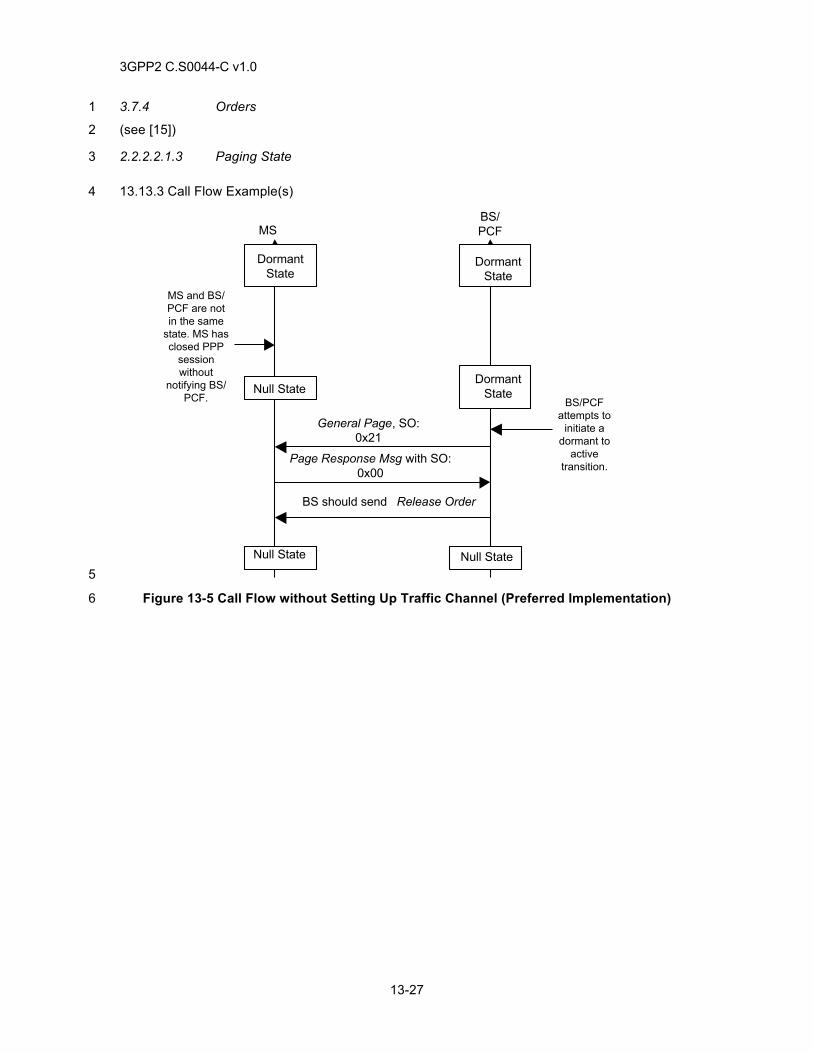
3GPP2 C.S0044-C v1.0
13-27
3.7.4 Orders 1
(see [15]) 2
2.2.2.2.1.3 Paging State 3
13.13.3 Call Flow Example(s) 4
DormantState
DormantState
MSBS/PCF
Null State
Null State Null State
General Page, SO:0x21
Page Response Msg with SO:0x00
BS should send Release Order
DormantState
MS and BS/PCF are notin the same
state. MS hasclosed PPP
sessionwithout
notifying BS/PCF. BS/PCF
attempts toinitiate a
dormant toactive
transition.
5
Figure 13-5 Call Flow without Setting Up Traffic Channel (Preferred Implementation) 6
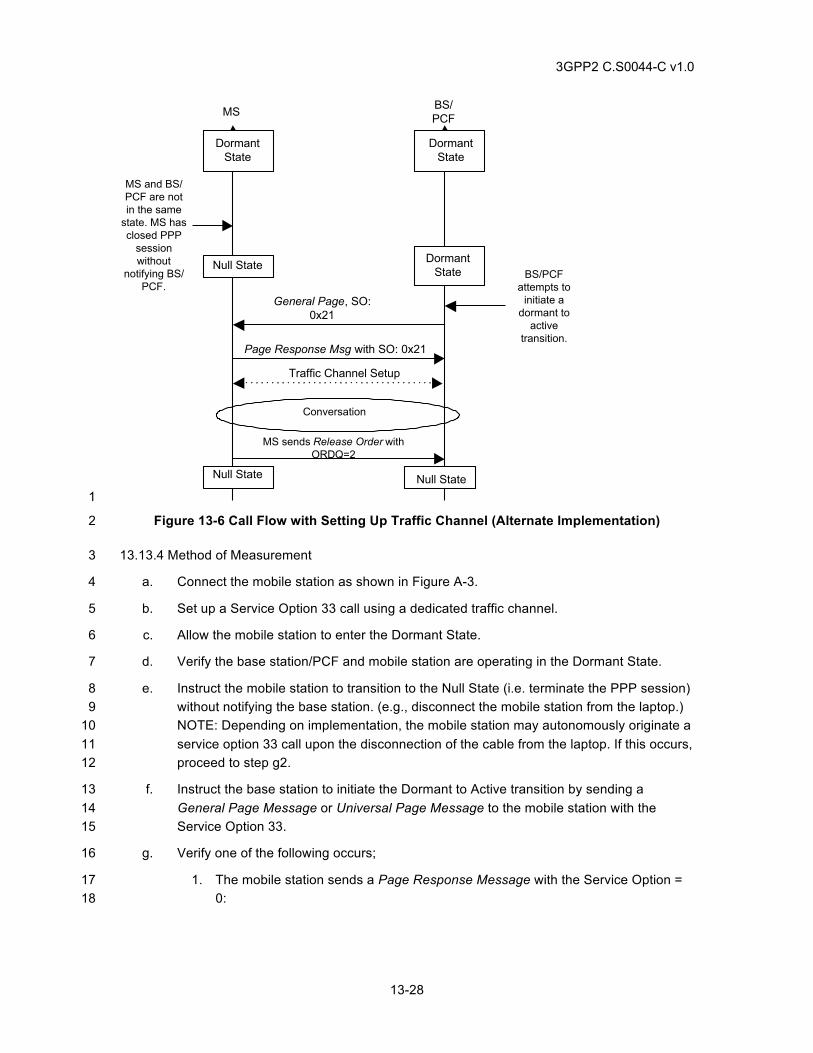
3GPP2 C.S0044-C v1.0
13-28
Traffic Channel Setup
DormantState
DormantState
MS BS/PCF
Null State DormantState
Null State Null State
General Page, SO:0x21
Page Response Msg with SO: 0x21
BS/PCFattempts to
initiate adormant to
activetransition.
MS and BS/PCF are notin the same
state. MS hasclosed PPP
sessionwithout
notifying BS/PCF.
Conversation
MS sends Release Order withORDQ=2
1
Figure 13-6 Call Flow with Setting Up Traffic Channel (Alternate Implementation) 2
13.13.4 Method of Measurement 3
a. Connect the mobile station as shown in Figure A-3. 4
b. Set up a Service Option 33 call using a dedicated traffic channel. 5
c. Allow the mobile station to enter the Dormant State. 6
d. Verify the base station/PCF and mobile station are operating in the Dormant State. 7
e. Instruct the mobile station to transition to the Null State (i.e. terminate the PPP session) 8 without notifying the base station. (e.g., disconnect the mobile station from the laptop.) 9 NOTE: Depending on implementation, the mobile station may autonomously originate a 10 service option 33 call upon the disconnection of the cable from the laptop. If this occurs, 11 proceed to step g2. 12
f. Instruct the base station to initiate the Dormant to Active transition by sending a 13 General Page Message or Universal Page Message to the mobile station with the 14 Service Option 33. 15
g. Verify one of the following occurs; 16
1. The mobile station sends a Page Response Message with the Service Option = 17 0: 18
3GPP2 C.S0044-C v1.0
13-29
a. The base station should send a Release Order to the mobile station 1 after receiving the Page Response Message with the Service Option = 2 0. 3
2. The mobile station sends a Page Response Message/Origination Message with 4 the Service Option = 33: 5
a. After the base station assigns a traffic channel, verify the mobile 6 station sends a Release Order with ORDQ=2. 7
h. Verify the mobile station and base station/PCF are now operating in the Null State. 8
13.13.5 Minimum Standard 9
The mobile station shall comply with steps g and h. 10
13.14 RLP Operation in Rayleigh Fading Environment 11
13.14.1 Definition 12
This test verifies data transfer under Rayleigh fading channel conditions. This test verifies that 13 RLP recovers erased data frames, and is intended to exercise RLP negative acknowledgements 14 (NAKs), retransmissions, and aborts in the forward and reverse directions. This test also verifies 15 the mobile station is able to successfully complete a network initiated dormant to active transition. 16
13.14.2 Traceability 17
(see [4]) 18
2.6.4.2 Traffic Channel Substate 19
(see [15]) 20
2.2.1 RLP Requirements 21
2.2.2 Service and Call Control Procedures 22
2.2.7 High Speed Operation 23
24
13.14.3 Call Flow Example(s) 25
None 26
13.14.4 Method of Measurement 27
a. Connect the mobile station to the base station as shown in Figure A-2. 28
b. Set the channel simulator using the parameters as specified in Table 3.5.4-4. 29
c. Ensure the mobile station currently has a PPP session established and is in the 30 dormant state. 31
d. Instruct the base station to initiate a dormant to active transition. 32
e. Verify the mobile station is able to transition to the active state. 33
f. Initiate a forward data transfer to the mobile station. 34
g. Verify the file transfer completes successfully. 35
3GPP2 C.S0044-C v1.0
13-30
h. Initiate a reverse data transfer from the mobile station. 1
i. Verify the file transfer completes. 2
j. Repeat steps c through i changing the channel simulator setting to one path at 3 km/hr. 3
13.14.5 Minimum Standard 4
The mobile station shall comply with steps e, g, i, and j. 5
13.15 Release Order Processing 6
13.15.1 Definition 7
This test case verifies the mobile station correctly processes the Release Order with ORDQ=2 8 when received on the f-csch. 9
13.15.2 Traceability 10
(see [4]) 11
2.7.1.3.2.4 Origination Message 12
3.7.5 Orders 13
(see [15]) 14
1.4.2.2 Mobile Station Packet Data Service States 15
2.2.2 Service and Call Control Procedures 16
2.2.3 Initialization and Connection of Packet Data Service Options 17
2.2.7 High Speed Operation 18
19
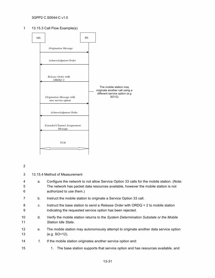
3GPP2 C.S0044-C v1.0
13-31
13.15.3 Call Flow Example(s) 1
Origination Message
Acknowledgment Order
Release Order withORDQ=2
Origination Message withnew service option
MS BS
Extended Channel AssignementMessage
TCH
Acknowledgment Order
The mobile station mayoriginate another call using adifferent service option (e.g
SO12)
2
13.15.4 Method of Measurement 3
a. Configure the network to not allow Service Option 33 calls for the mobile station. (Note: 4 The network has packet data resources available, however the mobile station is not 5 authorized to use them.) 6
b. Instruct the mobile station to originate a Service Option 33 call. 7
c. Instruct the base station to send a Release Order with ORDQ = 2 to mobile station 8 indicating the requested service option has been rejected. 9
d. Verify the mobile station returns to the System Determination Substate or the Mobile 10 Station Idle State. 11
e. The mobile station may autonomously attempt to originate another data service option 12 (e.g. SO=12). 13
f. If the mobile station originates another service option and: 14
1. The base station supports that service option and has resources available, and 15
3GPP2 C.S0044-C v1.0
13-32
2. The mobile station is authorized to use that service option, verify the following: 1
a. The new data call with the different service option is completed 2 successfully. 3
13.15.5 Minimum Standard 4
The mobile station shall comply with step d. If the mobile station supports step e, the mobile 5 station shall comply with step f. 6
13.16 Hysteresis Activation Timer 7
13.16.1 Definition 8
This test case verifies the mobile station implementation of Hysteresis Activation Timer. The 9 value of this timer is mobile station implementation dependent in the range of 0 to 30 seconds. 10
13.16.2 Traceability 11
(see [15]) 12
2.2.2.1.2.4 Dormant State 13
13.16.3 Call Flow Example(s) 14
None 15
13.16.4 Method of Measurement 16
a. Connect the mobile station to the base station as shown in Figure A-5. Configure base 17 station 1 and base station 2 to transmit different non-zero values of PACKET_ZONE_ID 18 field in Extended System Parameters Message or ANSI-41 System Parameters 19 Message. Connect both the base stations to same PDSN. 20
b. Allow the mobile station to go idle on base station 1. Instruct the mobile station to 21 originate a Service Option 33 call on base station 1. Transfer data on the Service 22 Option 33 call (e.g. perform ftp or ping). 23
c. Ensure that length of the packet zone list is set to one entry at the mobile station. 24 Ensure packet zone hysteresis is enabled at the mobile station. 25
d. Allow Mobile Station to go dormant on base station 1. For rest of the test ensure that 26 the mobile station does not have any data to send. 27
e. While the hysteresis activation timer is running perform following operations: 28
1. Allow Mobile Station to perform an idle handoff to base station 2. Verify that the 29 mobile station sends an Origination Message with DRS field set to ‘0’ to base 30 station 2. 31
2. Allow Mobile Station to perform an idle handoff to base station 1. Verify that the 32 mobile station sends an Origination Message with DRS field set to ‘0’ to base 33 station 1. 34
3GPP2 C.S0044-C v1.0
13-33
13.16.5 Minimum Standard 1
The mobile station shall comply with step e 2
13.17 Hysteresis Timer 3
13.17.1 Definition 4
This test case verifies the mobile station implementation of Hysteresis Timer. The value of this 5 timer is mobile station implementation dependent in the range of 0 to 60 seconds. 6
13.17.2 Traceability 7
(see [15]) 8
2.2.5 Packet Zone Reconnection Control 9
13.17.3 Call Flow Example(s) 10
None 11
13.17.4 Method of Measurement 12
a. Connect the mobile station to the base station as shown in Figure A-5. Configure base 13 station 1 and base station 2 to transmit different non-zero values of PACKET_ZONE_ID 14 field in Extended System Parameters Message or ANSI-41 System Parameters 15 Message. Connect both the base stations to same PDSN. 16
b. Allow the mobile station to go idle on base station 1. Instruct the mobile station to 17 originate a Service Option 33 call on base station 1. Transfer data on the Service 18 Option 33 call (e.g. perform ftp or ping). 19
c. Ensure that length of the packet zone list is set to one entry at the mobile station. 20 Ensure packet zone hysteresis is enabled at the mobile station. 21
d. Allow Mobile Station to go dormant on base station 1. Allow mobile station to remain in 22 dormant state for duration of the hysteresis activation timer. For rest of the test ensure 23 that the mobile station does not have any data to send. 24
e. Perform following operations within duration less than the value of hysteresis timer 25 configured at the mobile station: 26
1. Allow Mobile Station to perform an idle handoff to base station 2. Verify that the 27 mobile station sends an Origination Message with DRS field set to ‘0’ to base 28 station 2. 29
2. Allow Mobile Station to perform an idle handoff to base station 1. Verify that the 30 mobile station does not send an Origination Message. 31
f. Allow Mobile Station to remain idle on base station 1 for duration more than the value of 32 hysteresis timer configured at the mobile station. Verify that the mobile station sends an 33 Origination Message with DRS field set to ‘0’ to base station 1. Verify that the duration 34 between the Origination Message in step d.1 and the Origination Message in step e is 35 approximately equal to the value of hyesteresis timer configured at the mobile station. 36

3GPP2 C.S0044-C v1.0
13-34
13.17.5 Minimum Standard 1
The mobile station shall comply with steps e and f. 2
3

3GPP2 C.S0044-C v1.0
14-1
14 OVER-THE-AIR SERVICES 1
14.1 OTASP Download Request Processing 2
14.1.1 Definition 3
This test verifies a mobile station can initiate programming procedure and update its NAM 4 parameters. 5
14.1.2 Traceability 6
(see [14]) 7
3.2.1 User-Initiated Procedure 8
3.5.1 Message Contents 9
3.5.2 NAM Parameter Blocks 10
4.2.1 User-Initiated Procedure 11
4.3 Programming Data Download 12
4.5.1 Message Contents 13
4.5.2 NAM Parameter Blocks 14
4.5.4 Validation Parameter Blocks 15
14.1.3 Call Flow Example(s) 16
None 17
14.1.4 Method of Measurement 18
a. Connect the mobile station to the base station as shown in Figure A-1. 19
b. Confirm that the mobile station is programmed with a non-zero SPCp. 20
c. Setup a mobile originated OTASP call using *228 + one of the System Selection Codes 21 in Table 14.1.4-1. 22
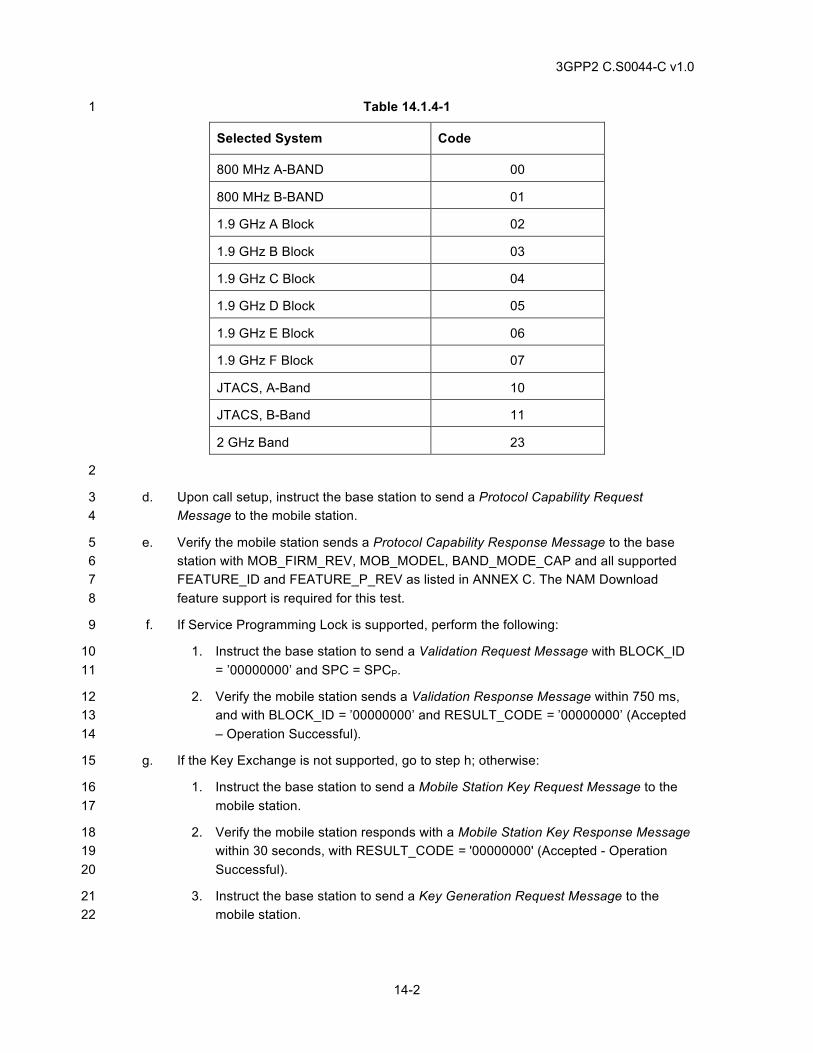
3GPP2 C.S0044-C v1.0
14-2
Table 14.1.4-1 1
Selected System Code
800 MHz A-BAND 00
800 MHz B-BAND 01
1.9 GHz A Block 02
1.9 GHz B Block 03
1.9 GHz C Block 04
1.9 GHz D Block 05
1.9 GHz E Block 06
1.9 GHz F Block 07
JTACS, A-Band 10
JTACS, B-Band 11
2 GHz Band 23
2
d. Upon call setup, instruct the base station to send a Protocol Capability Request 3 Message to the mobile station. 4
e. Verify the mobile station sends a Protocol Capability Response Message to the base 5 station with MOB_FIRM_REV, MOB_MODEL, BAND_MODE_CAP and all supported 6 FEATURE_ID and FEATURE_P_REV as listed in ANNEX C. The NAM Download 7 feature support is required for this test. 8
f. If Service Programming Lock is supported, perform the following: 9
1. Instruct the base station to send a Validation Request Message with BLOCK_ID 10 = ’00000000’ and SPC = SPCP. 11
2. Verify the mobile station sends a Validation Response Message within 750 ms, 12 and with BLOCK_ID = ’00000000’ and RESULT_CODE = ’00000000’ (Accepted 13 – Operation Successful). 14
g. If the Key Exchange is not supported, go to step h; otherwise: 15
1. Instruct the base station to send a Mobile Station Key Request Message to the 16 mobile station. 17
2. Verify the mobile station responds with a Mobile Station Key Response Message 18 within 30 seconds, with RESULT_CODE = '00000000' (Accepted - Operation 19 Successful). 20
3. Instruct the base station to send a Key Generation Request Message to the 21 mobile station. 22
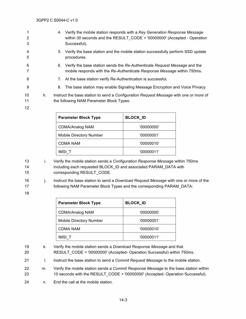
3GPP2 C.S0044-C v1.0
14-3
4. Verify the mobile station responds with a Key Generation Response Message 1 within 30 seconds and the RESULT_CODE = '00000000' (Accepted - Operation 2 Successful). 3
5. Verify the base station and the mobile station successfully perform SSD update 4 procedures. 5
6. Verify the base station sends the Re-Authenticate Request Message and the 6 mobile responds with the Re-Authenticate Response Message within 750ms. 7
7. At the base station verify Re-Authentication is successful. 8
8. The base station may enable Signaling Message Encryption and Voice Privacy. 9
h. Instruct the base station to send a Configuration Request Message with one or more of 10 the following NAM Parameter Block Types: 11
12
Parameter Block Type BLOCK_ID
CDMA/Analog NAM ‘00000000’
Mobile Directory Number ‘00000001’
CDMA NAM ‘00000010’
IMSI_T ‘00000011’
i. Verify the mobile station sends a Configuration Response Message within 750ms 13 including each requested BLOCK_ID and associated PARAM_DATA with 14 corresponding RESULT_CODE. 15
j. Instruct the base station to send a Download Request Message with one or more of the 16 following NAM Parameter Block Types and the corresponding PARAM_DATA: 17
18
Parameter Block Type BLOCK_ID
CDMA/Analog NAM ‘00000000’
Mobile Directory Number ‘00000001’
CDMA NAM ‘00000010’
IMSI_T ‘00000011’
k. Verify the mobile station sends a Download Response Message and that 19 RESULT_CODE = '00000000' (Accepted- Operation Successful) within 750ms. 20
l. Instruct the base station to send a Commit Request Message to the mobile station. 21
m. Verify the mobile station sends a Commit Response Message to the base station within 22 10 seconds with the RESULT_CODE = '00000000' (Accepted- Operation Successful). 23
n. End the call at the mobile station. 24
3GPP2 C.S0044-C v1.0
14-4
o. Verify the mobile station successfully stored the updated NAM information. 1
p. Setup a mobile station originated call and verify user traffic is present. 2
14.1.5 Minimum Standard 3
The mobile station shall comply with steps e, i, k, m, o, and p. If supported the mobile station shall 4 comply with steps f and i. The mobile station shall update its NAM information as received in the 5 Download Request Message. 6
14.2 OTASP PUZL Download Request Processing 7
14.2.1 Definition 8
This test verifies a mobile station can initiate programming procedure and update its Preferred 9 User Zone List (PUZL). 10
14.2.2 Traceability 11
(see [14]) 12
3.2.1 User-Initiated Procedure 13
3.5.1 Message Contents 14
3.5.6 PUZL Parameter Blocks 15
3.5.7 Preferred User Zone List (PUZL) 16
4.2.1 User-Initiated Procedure 17
4.3 Programming Data Download 18
4.5.1 Message Contents 19
4.5.4 Validation Parameter Blocks 20
4.5.6 PUZL Parameter Blocks 21
14.2.3 Call Flow Example(s) 22
None 23
14.2.4 Method of Measurement 24
a. Connect the mobile station to the base station as shown in Figure A-3. 25
b. Confirm that the mobile station is programmed with a non-zero SPCp. 26
c. Setup a mobile station originated OTASP call using *228 + one of the System Selection 27 Codes in Table 14.1.4-1. 28
d. Upon call setup, instruct the base station to send a Protocol Capability Request 29 Message to the mobile station. 30
e. Verify the mobile station sends a Protocol Capability Response Message to the base 31 station with MOB_FIRM_REV, MOB_MODEL, BAND_MODE_CAP and all supported 32
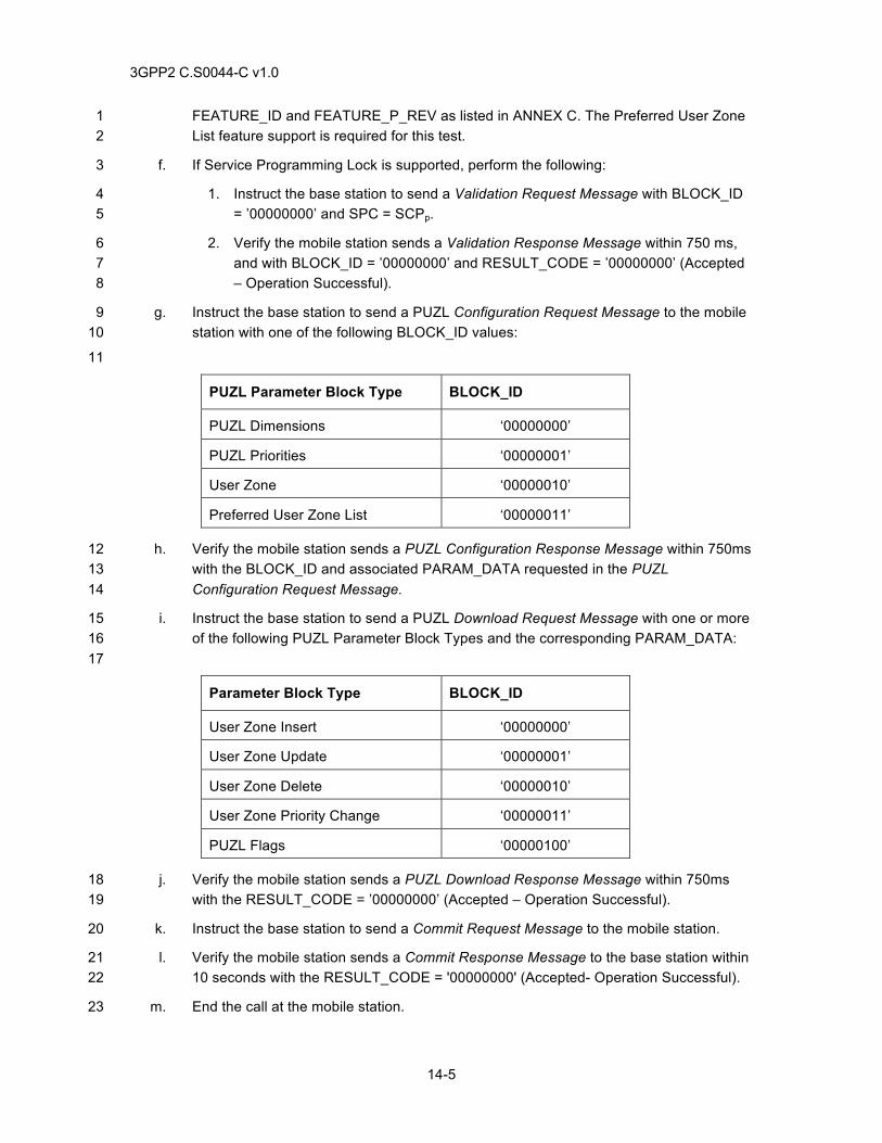
3GPP2 C.S0044-C v1.0
14-5
FEATURE_ID and FEATURE_P_REV as listed in ANNEX C. The Preferred User Zone 1 List feature support is required for this test. 2
f. If Service Programming Lock is supported, perform the following: 3
1. Instruct the base station to send a Validation Request Message with BLOCK_ID 4 = ’00000000’ and SPC = SCPp. 5
2. Verify the mobile station sends a Validation Response Message within 750 ms, 6 and with BLOCK_ID = ’00000000’ and RESULT_CODE = ’00000000’ (Accepted 7 – Operation Successful). 8
g. Instruct the base station to send a PUZL Configuration Request Message to the mobile 9 station with one of the following BLOCK_ID values: 10
11
PUZL Parameter Block Type BLOCK_ID
PUZL Dimensions ‘00000000’
PUZL Priorities ‘00000001’
User Zone ‘00000010’
Preferred User Zone List ‘00000011’
h. Verify the mobile station sends a PUZL Configuration Response Message within 750ms 12 with the BLOCK_ID and associated PARAM_DATA requested in the PUZL 13 Configuration Request Message. 14
i. Instruct the base station to send a PUZL Download Request Message with one or more 15 of the following PUZL Parameter Block Types and the corresponding PARAM_DATA: 16 17
Parameter Block Type BLOCK_ID
User Zone Insert ‘00000000’
User Zone Update ‘00000001’
User Zone Delete ‘00000010’
User Zone Priority Change ‘00000011’
PUZL Flags ‘00000100’
j. Verify the mobile station sends a PUZL Download Response Message within 750ms 18 with the RESULT_CODE = ’00000000’ (Accepted – Operation Successful). 19
k. Instruct the base station to send a Commit Request Message to the mobile station. 20
l. Verify the mobile station sends a Commit Response Message to the base station within 21 10 seconds with the RESULT_CODE = '00000000' (Accepted- Operation Successful). 22
m. End the call at the mobile station. 23
3GPP2 C.S0044-C v1.0
14-6
n. Verify the mobile station successfully stored the updated PUZL information. 1
14.2.5 Minimum Standard 2
The mobile station shall comply with steps e, h, j, l, and n. The mobile station shall update its 3 PUZL information as received in the PUZL Download Request Message. 4
14.3 OTASP 3GPD Download Request Processing 5
14.3.1 Definition 6
This test verifies a mobile station can initiate programming procedure and update its 3GPD 7 information. 8
14.3.2 Traceability 9
(see [14]) 10
3.2.1 User-Initiated Procedure 11
3.5.1 Message Contents 12
3.5.8 3GPD Parameter Blocks 13
4.2.1 User-Initiated Procedure 14
4.3 Programming Data Download 15
4.5.1 Message Contents 16
4.5.4 Validation Parameter Blocks 17
4.5.7 3GPD Parameter Blocks 18
14.3.3 Call Flow Example(s) 19
None 20
14.3.4 Method of Measurement 21
a. Connect the mobile station to the base station as shown in Figure A-3. 22
b. Confirm that the mobile station is programmed with a non-zero SPCp. 23
c. Setup a mobile station originated OTASP call using *228 + one of the System Selection 24 Codes in Table 14.1.4-1. 25
d. Upon call setup, instruct the base station to send a Protocol Capability Request 26 Message to the mobile station. 27
e. Verify the mobile station sends a Protocol Capability Response Message to the base 28 station with MOB_FIRM_REV, MOB_MODEL, BAND_MODE_CAP and all supported 29 FEATURE_ID and FEATURE_P_REV as listed in ANNEX C. The 3G Packet Data 30 feature support is required for this test. 31
f. If Service Programming Lock is supported, perform the following: 32
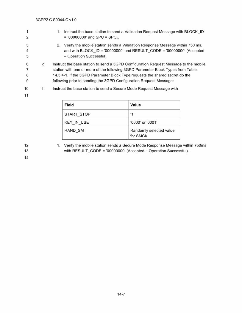
3GPP2 C.S0044-C v1.0
14-7
1. Instruct the base station to send a Validation Request Message with BLOCK_ID 1 = ’00000000’ and SPC = SPCp. 2
2. Verify the mobile station sends a Validation Response Message within 750 ms, 3 and with BLOCK_ID = ’00000000’ and RESULT_CODE = ’00000000’ (Accepted 4 – Operation Successful). 5
g. Instruct the base station to send a 3GPD Configuration Request Message to the mobile 6 station with one or more of the following 3GPD Parameter Block Types from Table 7 14.3.4-1. If the 3GPD Parameter Block Type requests the shared secret do the 8 following prior to sending the 3GPD Configuration Request Message: 9
h. Instruct the base station to send a Secure Mode Request Message with 10
11
Field Value
START_STOP ‘1’
KEY_IN_USE ‘0000’ or ‘0001’
RAND_SM Randomly selected value for SMCK
1. Verify the mobile station sends a Secure Mode Response Message within 750ms 12 with RESULT_CODE = ’00000000’ (Accepted – Operation Successful). 13
14
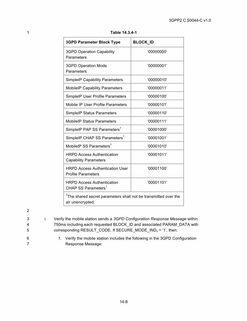
3GPP2 C.S0044-C v1.0
14-8
Table 14.3.4-1 1
3GPD Parameter Block Type BLOCK_ID
3GPD Operation Capability Parameters
‘00000000’
3GPD Operation Mode Parameters
‘00000001’
SimpleIP Capability Parameters ‘00000010’
MobileIP Capability Parameters ‘00000011’
SimpleIP User Profile Parameters ‘00000100’
Mobile IP User Profile Parameters ‘00000101’
SimpleIP Status Parameters ‘00000110’
MobileIP Status Parameters ‘00000111’
SimpleIP PAP SS Parameters1 ‘00001000’
SimpleIP CHAP SS Parameters1 ‘00001001’
MobileIP SS Parameters1 ‘00001010’
HRPD Access Authentication Capability Parameters
‘00001011’
HRPD Access Authentication User Profile Parameters
‘00001100’
HRPD Access Authentication CHAP SS Parameters1
‘00001101’
1The shared secret parameters shall not be transmitted over the air unencrypted.
2
i. Verify the mobile station sends a 3GPD Configuration Response Message within 3 750ms including each requested BLOCK_ID and associated PARAM_DATA with 4 corresponding RESULT_CODE. If SECURE_MODE_INDs = ‘1’, then: 5
1. Verify the mobile station includes the following in the 3GPD Configuration 6 Response Message: 7
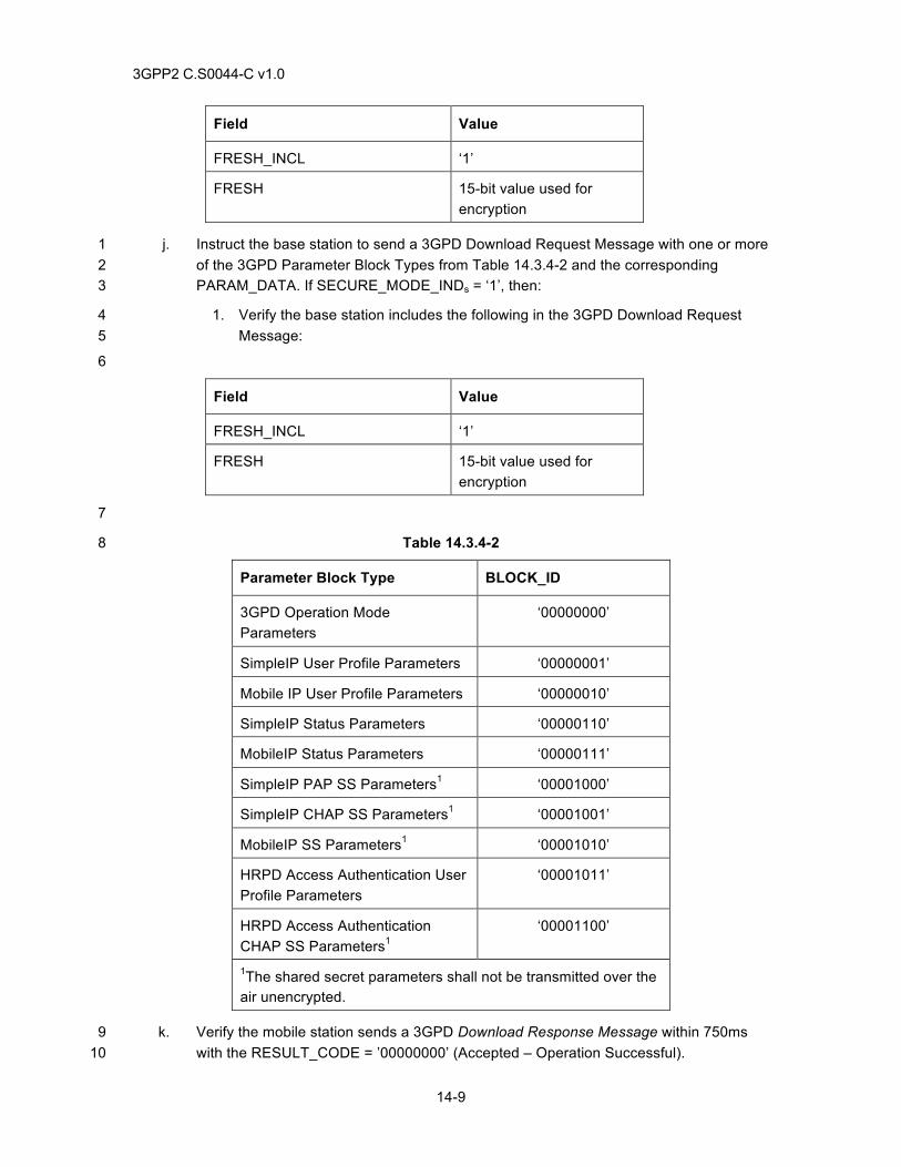
3GPP2 C.S0044-C v1.0
14-9
Field Value
FRESH_INCL ‘1’
FRESH 15-bit value used for encryption
j. Instruct the base station to send a 3GPD Download Request Message with one or more 1 of the 3GPD Parameter Block Types from Table 14.3.4-2 and the corresponding 2 PARAM_DATA. If SECURE_MODE_INDs = ‘1’, then: 3
1. Verify the base station includes the following in the 3GPD Download Request 4 Message: 5
6
Field Value
FRESH_INCL ‘1’
FRESH 15-bit value used for encryption
7
Table 14.3.4-2 8
Parameter Block Type BLOCK_ID
3GPD Operation Mode Parameters
‘00000000’
SimpleIP User Profile Parameters ‘00000001’
Mobile IP User Profile Parameters ‘00000010’
SimpleIP Status Parameters ‘00000110’
MobileIP Status Parameters ‘00000111’
SimpleIP PAP SS Parameters1 ‘00001000’
SimpleIP CHAP SS Parameters1 ‘00001001’
MobileIP SS Parameters1 ‘00001010’
HRPD Access Authentication User Profile Parameters
‘00001011’
HRPD Access Authentication CHAP SS Parameters1
‘00001100’
1The shared secret parameters shall not be transmitted over the air unencrypted.
k. Verify the mobile station sends a 3GPD Download Response Message within 750ms 9 with the RESULT_CODE = ’00000000’ (Accepted – Operation Successful). 10
3GPP2 C.S0044-C v1.0
14-10
l. Instruct the base station to send a Commit Request Message to the mobile station. 1
m. Verify the mobile station sends a Commit Response Message to the base station within 2 10 seconds with the RESULT_CODE = '00000000' (Accepted- Operation Successful). 3
n. End the call at the mobile station. 4
o. Verify the mobile station successfully stored the 3GPD information. 5
14.3.5 Minimum Standard 6
The mobile station shall comply with steps e, h, k, m and o. If SECURE_MODE_IND = ‘1’, the 7 mobile station shall comply with step g. The mobile station shall update its 3GPD information as 8 received in the 3GPD Download Request Message. 9
14.4 OTASP SSPR Download Request Processing 10
14.4.1 Definition 11
This test verifies a mobile station can initiate programming procedure and update its preferred 12 roaming list. 13
14.4.2 Traceability 14
(see [14]) 15
3.2.1 User-Initiated Procedure 16
3.5.1 Message Contents 17
3.5.3 SSPR Parameter Blocks 18
3.5.5 Preferred Roaming List and Extended Preferred Roaming List 19
4.2.1 User-Initiated Procedure 20
4.3 Programming Data Download 21
4.5.1 Message Contents 22
4.5.3 SSPR Parameter Blocks 23
4.5.4 Validation Parameter Blocks 24
14.4.3 Call Flow Example(s) 25
None 26
14.4.4 Method of Measurement 27
a. Connect the mobile station to the base station as shown in Figure A-4. 28
b. Confirm that the mobile station is programmed with a non-zero SPCp. 29
c. Setup a mobile originated OTASP call using *228 + one of the System Selection Codes 30 in Table 14.1.4-1. 31
d. Upon call setup, instruct the base station to send a Protocol Capability Request 32 Message to the mobile station. 33
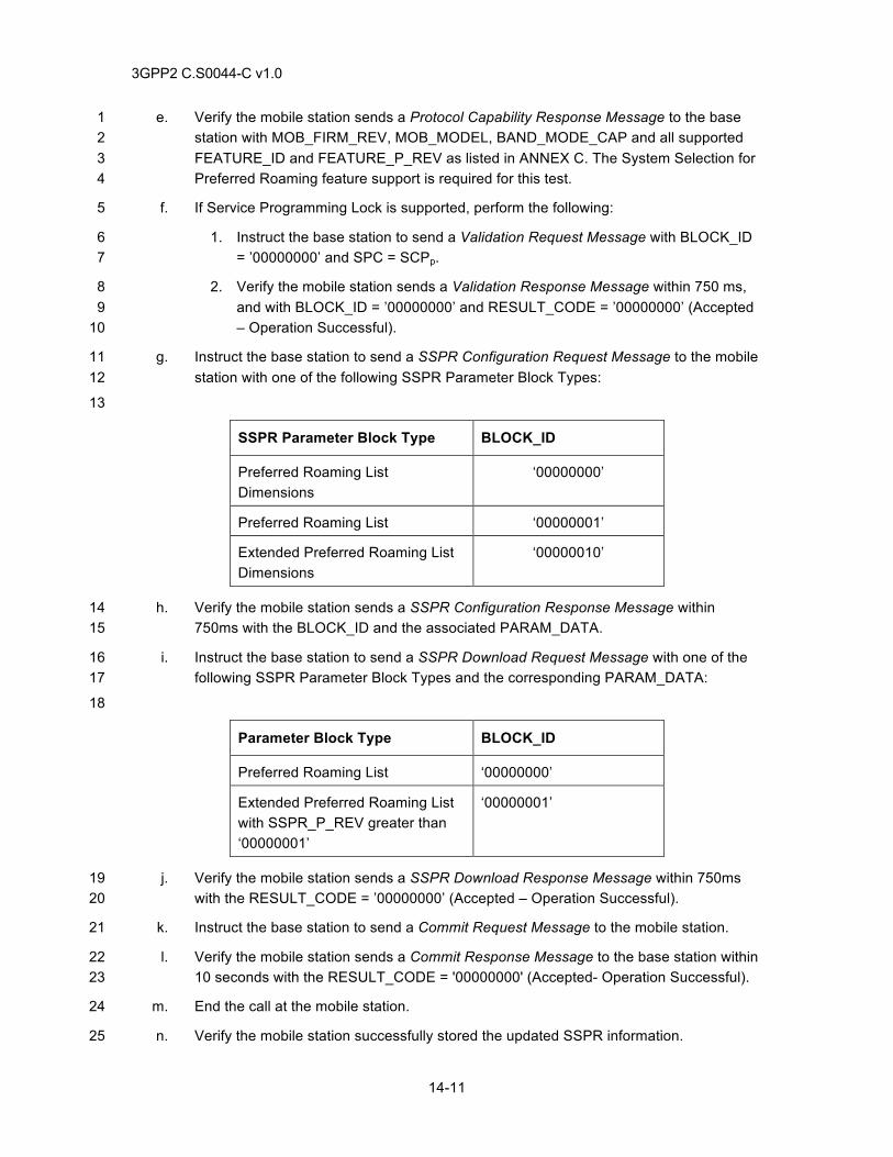
3GPP2 C.S0044-C v1.0
14-11
e. Verify the mobile station sends a Protocol Capability Response Message to the base 1 station with MOB_FIRM_REV, MOB_MODEL, BAND_MODE_CAP and all supported 2 FEATURE_ID and FEATURE_P_REV as listed in ANNEX C. The System Selection for 3 Preferred Roaming feature support is required for this test. 4
f. If Service Programming Lock is supported, perform the following: 5
1. Instruct the base station to send a Validation Request Message with BLOCK_ID 6 = ’00000000’ and SPC = SCPp. 7
2. Verify the mobile station sends a Validation Response Message within 750 ms, 8 and with BLOCK_ID = ’00000000’ and RESULT_CODE = ’00000000’ (Accepted 9 – Operation Successful). 10
g. Instruct the base station to send a SSPR Configuration Request Message to the mobile 11 station with one of the following SSPR Parameter Block Types: 12
13
SSPR Parameter Block Type BLOCK_ID
Preferred Roaming List Dimensions
‘00000000’
Preferred Roaming List ‘00000001’
Extended Preferred Roaming List Dimensions
‘00000010’
h. Verify the mobile station sends a SSPR Configuration Response Message within 14 750ms with the BLOCK_ID and the associated PARAM_DATA. 15
i. Instruct the base station to send a SSPR Download Request Message with one of the 16 following SSPR Parameter Block Types and the corresponding PARAM_DATA: 17
18
Parameter Block Type BLOCK_ID
Preferred Roaming List ‘00000000’
Extended Preferred Roaming List with SSPR_P_REV greater than ‘00000001’
‘00000001’
j. Verify the mobile station sends a SSPR Download Response Message within 750ms 19 with the RESULT_CODE = ’00000000’ (Accepted – Operation Successful). 20
k. Instruct the base station to send a Commit Request Message to the mobile station. 21
l. Verify the mobile station sends a Commit Response Message to the base station within 22 10 seconds with the RESULT_CODE = '00000000' (Accepted- Operation Successful). 23
m. End the call at the mobile station. 24
n. Verify the mobile station successfully stored the updated SSPR information. 25
3GPP2 C.S0044-C v1.0
14-12
14.4.5 Minimum Standard 1
The mobile station shall comply with steps e, h, j, l, and n. The mobile station shall update its 2 SSPR information as received in the SSPR Download Request Message. 3
14.5 OTASP For System Selection and Preferred Roaming - Oversize PRL 4
14.5.1 Definition 5
This test verifies that the PRL resident in a handset shall not be replaced if a new PRL of illegal 6 size is downloaded. 7
14.5.2 Traceability 8
(see [14]) 9
3.2.1 User-Initiated Procedure 10
3.5.1 Message Contents 11
3.5.3 SSPR Parameter Blocks 12
3.5.5 Preferred Roaming List and Extended Preferred Roaming List 13
4.2.1 User-Initiated Procedure 14
4.3 Programming Data Download 15
4.5.1 Message Contents 16
4.5.3 SSPR Parameter Blocks 17
4.5.4 Validation Parameter Blocks 18
14.5.3 Call Flow 19
None 20
14.5.4 Method of Measurement 21
a. Connect the mobile station to the base station as shown in Figure A-3. 22
b. Confirm that the mobile station is programmed with a non-zero SPCp. 23
c. Setup a mobile station originated OTASP call using *228 + one of the System Selection 24 Codes in Table 14.1.4-1. 25
d. Upon call setup, instruct the base station to send a Protocol Capability Request 26 Message to the mobile station. 27
e. Verify the mobile station sends a Protocol Capability Response Message to the base 28 station with MOB_FIRM_REV, MOB_MODEL, BAND_MODE_CAP and all supported 29 FEATURE_ID and FEATURE_P_REV as listed in ANNEX C. The System Selection for 30 Preferred Roaming feature support is required for this test. 31
f. If Service Programming Lock is supported, perform the following: 32
3GPP2 C.S0044-C v1.0
14-13
1. Instruct the base station to send a Validation Request Message with BLOCK_ID 1 = ’00000000’ and SPC = SCPp. 2
2. Verify the mobile station sends a Validation Response Message within 750 ms, 3 and with BLOCK_ID = ’00000000’ and RESULT_CODE = ’00000000’ (Accepted 4 – Operation Successful). 5
g. Instruct the base station to send a SSPR Configuration Request Message to the mobile 6 station. 7
h. Verify the mobile station sends a SSPR Configuration Response Message within 8 750ms with the requested BLOCK_ID and the associated PARAM_DATA. 9
i. Instruct the base station to send a SSPR Download Request Message to the mobile 10 station with values of SEGMENT_OFFSET in conjunction with SEGMENT_SIZE that 11 are inconsistent with the preferred roaming list storage capabilities of the mobile station. 12
j. Verify the mobile station sends a SSPR Download Response Message with 13 RESULT_CODE = ’00001000’ (Rejected – Preferred roaming list length mismatch). 14
k. Verify the mobile station does not transfer its new PR_LIST to semi-permanent memory 15 after receiving a Commit Request Message. 16
l. End call at the mobile station 17
14.5.5 Minimum Standard 18
The mobile station shall comply with step h, j, and k. The mobile station shall retain its original 19 PRL. 20
14.6 OTAPA Download Request Processing 21
14.6.1 Definition 22
This test verifies that the mobile station supports network initiated Over-the-Air-Parameter-23 Administration (OTAPA). This test also verifies the mobile station’s download request processing 24 is successful. 25
14.6.2 Traceability (see [14]) 26
3.2.2 Network-Initiated Procedure 27
3.4 Termination of the Programming Procedure 28
3.5.1 Message Contents 29
3.5.2 NAM Parameter Blocks 30
4.2.2 Network-Initiated Procedure 31
4.3 Programming Data Download 32
4.4 Termination of the Programming Procedure 33
4.5.1 Message Contents 34
4.5.2 NAM Parameter Blocks 35
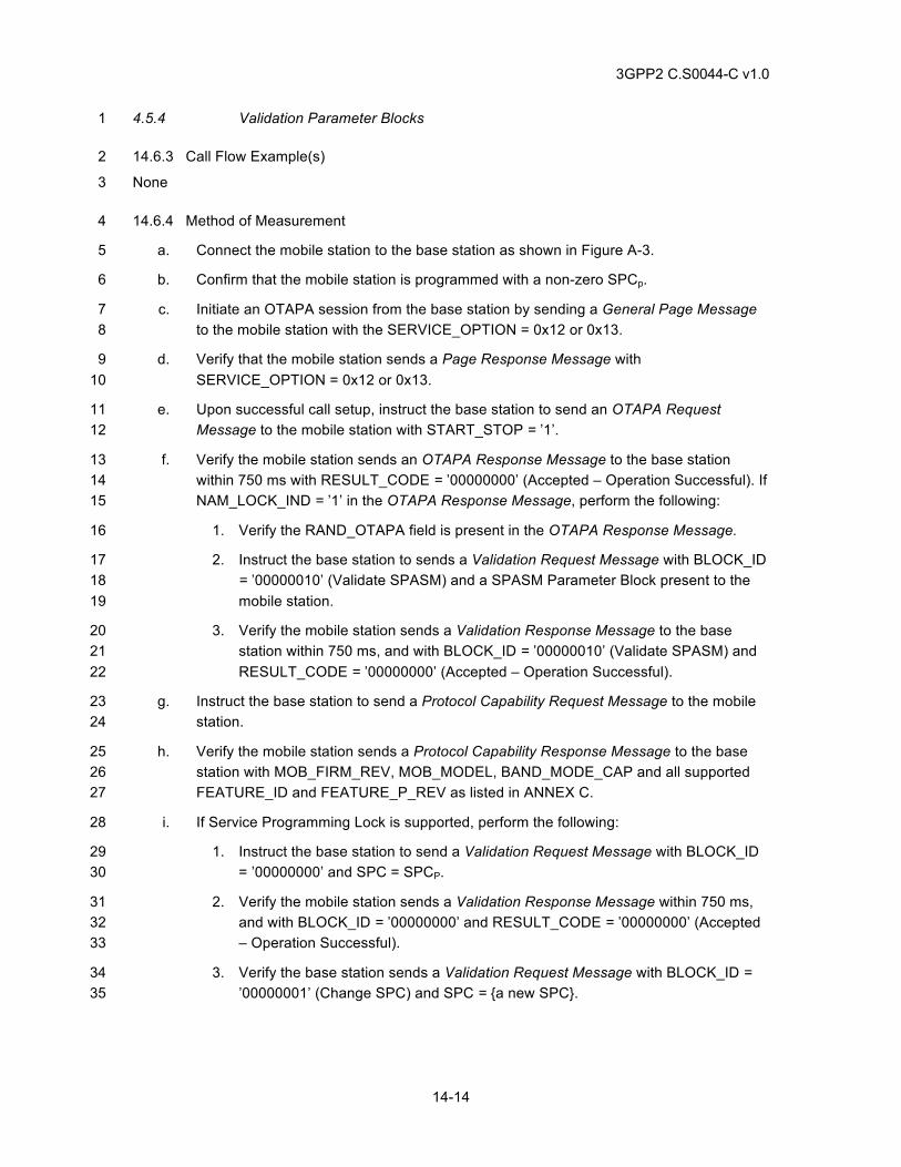
3GPP2 C.S0044-C v1.0
14-14
4.5.4 Validation Parameter Blocks 1
14.6.3 Call Flow Example(s) 2
None 3
14.6.4 Method of Measurement 4
a. Connect the mobile station to the base station as shown in Figure A-3. 5
b. Confirm that the mobile station is programmed with a non-zero SPCp. 6
c. Initiate an OTAPA session from the base station by sending a General Page Message 7 to the mobile station with the SERVICE_OPTION = 0x12 or 0x13. 8
d. Verify that the mobile station sends a Page Response Message with 9 SERVICE_OPTION = 0x12 or 0x13. 10
e. Upon successful call setup, instruct the base station to send an OTAPA Request 11 Message to the mobile station with START_STOP = ’1’. 12
f. Verify the mobile station sends an OTAPA Response Message to the base station 13 within 750 ms with RESULT_CODE = ’00000000’ (Accepted – Operation Successful). If 14 NAM_LOCK_IND = ’1’ in the OTAPA Response Message, perform the following: 15
1. Verify the RAND_OTAPA field is present in the OTAPA Response Message. 16
2. Instruct the base station to sends a Validation Request Message with BLOCK_ID 17 = ’00000010’ (Validate SPASM) and a SPASM Parameter Block present to the 18 mobile station. 19
3. Verify the mobile station sends a Validation Response Message to the base 20 station within 750 ms, and with BLOCK_ID = ’00000010’ (Validate SPASM) and 21 RESULT_CODE = ’00000000’ (Accepted – Operation Successful). 22
g. Instruct the base station to send a Protocol Capability Request Message to the mobile 23 station. 24
h. Verify the mobile station sends a Protocol Capability Response Message to the base 25 station with MOB_FIRM_REV, MOB_MODEL, BAND_MODE_CAP and all supported 26 FEATURE_ID and FEATURE_P_REV as listed in ANNEX C. 27
i. If Service Programming Lock is supported, perform the following: 28
1. Instruct the base station to send a Validation Request Message with BLOCK_ID 29 = ’00000000’ and SPC = SPCP. 30
2. Verify the mobile station sends a Validation Response Message within 750 ms, 31 and with BLOCK_ID = ’00000000’ and RESULT_CODE = ’00000000’ (Accepted 32 – Operation Successful). 33
3. Verify the base station sends a Validation Request Message with BLOCK_ID = 34 ’00000001’ (Change SPC) and SPC = {a new SPC}. 35
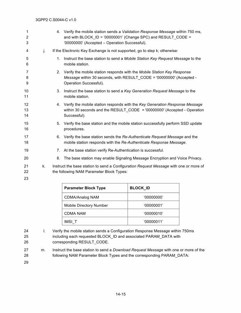
3GPP2 C.S0044-C v1.0
14-15
4. Verify the mobile station sends a Validation Response Message within 750 ms, 1 and with BLOCK_ID = ’00000001’ (Change SPC) and RESULT_CODE = 2 ’00000000’ (Accepted – Operation Successful). 3
j. If the Electronic Key Exchange is not supported, go to step k; otherwise: 4
1. Instruct the base station to send a Mobile Station Key Request Message to the 5 mobile station. 6
2. Verify the mobile station responds with the Mobile Station Key Response 7 Message within 30 seconds, with RESULT_CODE = '00000000' (Accepted - 8 Operation Successful). 9
3. Instruct the base station to send a Key Generation Request Message to the 10 mobile station. 11
4. Verify the mobile station responds with the Key Generation Response Message 12 within 30 seconds and the RESULT_CODE = '00000000' (Accepted - Operation 13 Successful). 14
5. Verify the base station and the mobile station successfully perform SSD update 15 procedures. 16
6. Verify the base station sends the Re-Authenticate Request Message and the 17 mobile station responds with the Re-Authenticate Response Message. 18
7. At the base station verify Re-Authentication is successful. 19
8. The base station may enable Signaling Message Encryption and Voice Privacy. 20
k. Instruct the base station to send a Configuration Request Message with one or more of 21 the following NAM Parameter Block Types: 22
23
Parameter Block Type BLOCK_ID
CDMA/Analog NAM ‘00000000’
Mobile Directory Number ‘00000001’
CDMA NAM ‘00000010’
IMSI_T ‘00000011’
l. Verify the mobile station sends a Configuration Response Message within 750ms 24 including each requested BLOCK_ID and associated PARAM_DATA with 25 corresponding RESULT_CODE. 26
m. Instruct the base station to send a Download Request Message with one or more of the 27 following NAM Parameter Block Types and the corresponding PARAM_DATA: 28
29
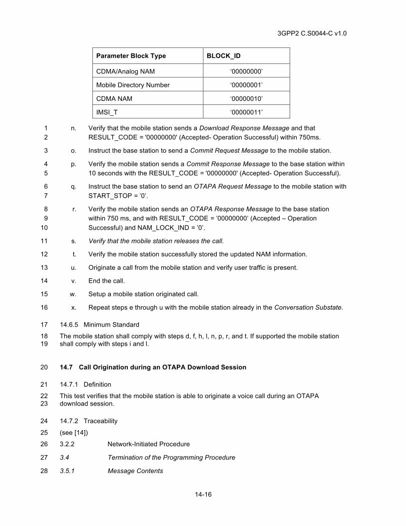
3GPP2 C.S0044-C v1.0
14-16
Parameter Block Type BLOCK_ID
CDMA/Analog NAM ‘00000000’
Mobile Directory Number ‘00000001’
CDMA NAM ‘00000010’
IMSI_T ‘00000011’
n. Verify that the mobile station sends a Download Response Message and that 1 RESULT_CODE = '00000000' (Accepted- Operation Successful) within 750ms. 2
o. Instruct the base station to send a Commit Request Message to the mobile station. 3
p. Verify the mobile station sends a Commit Response Message to the base station within 4 10 seconds with the RESULT_CODE = '00000000' (Accepted- Operation Successful). 5
q. Instruct the base station to send an OTAPA Request Message to the mobile station with 6 START_STOP = ’0’. 7
r. Verify the mobile station sends an OTAPA Response Message to the base station 8 within 750 ms, and with RESULT_CODE = ’00000000’ (Accepted – Operation 9 Successful) and NAM_LOCK_IND = ’0’. 10
s. Verify that the mobile station releases the call. 11
t. Verify the mobile station successfully stored the updated NAM information. 12
u. Originate a call from the mobile station and verify user traffic is present. 13
v. End the call. 14
w. Setup a mobile station originated call. 15
x. Repeat steps e through u with the mobile station already in the Conversation Substate. 16
14.6.5 Minimum Standard 17
The mobile station shall comply with steps d, f, h, l, n, p, r, and t. If supported the mobile station 18 shall comply with steps i and l. 19
14.7 Call Origination during an OTAPA Download Session 20
14.7.1 Definition 21
This test verifies that the mobile station is able to originate a voice call during an OTAPA 22 download session. 23
14.7.2 Traceability 24
(see [14]) 25
3.2.2 Network-Initiated Procedure 26
3.4 Termination of the Programming Procedure 27
3.5.1 Message Contents 28
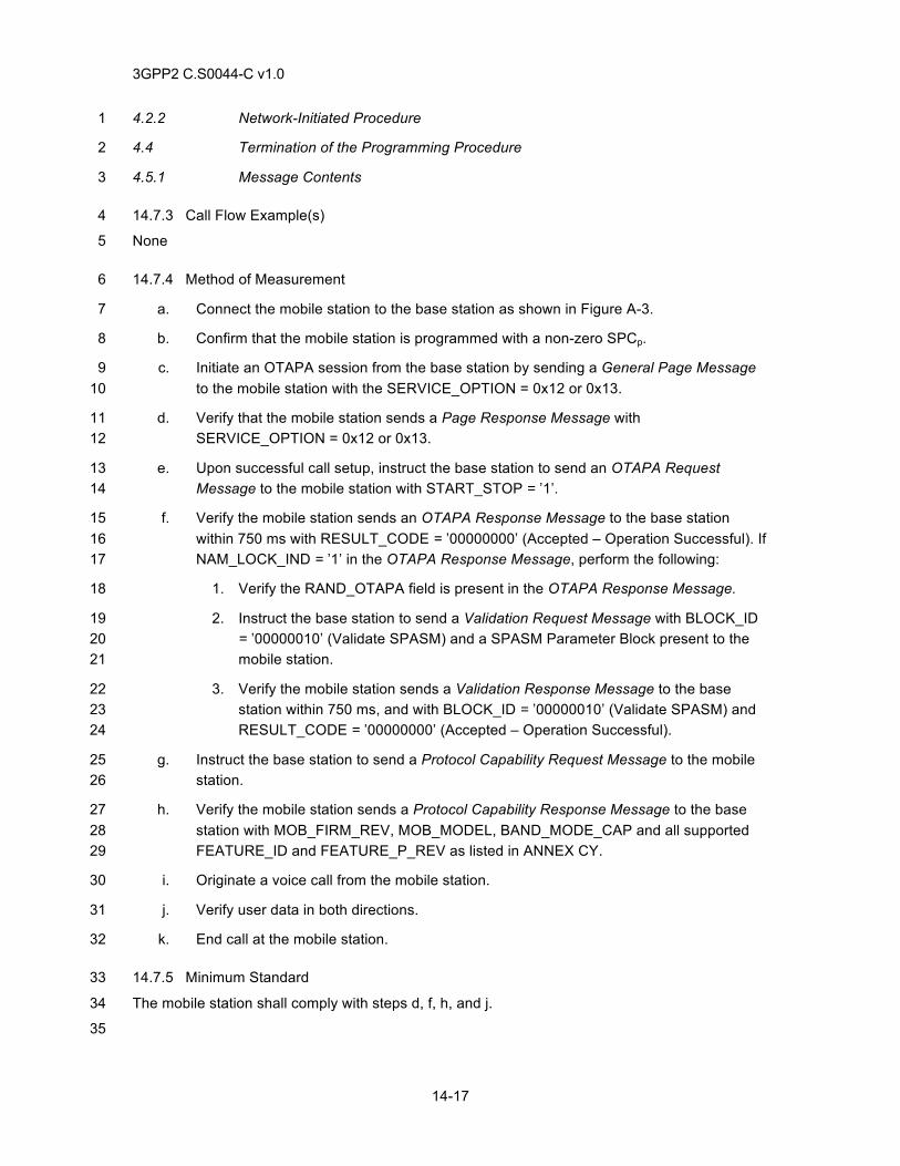
3GPP2 C.S0044-C v1.0
14-17
4.2.2 Network-Initiated Procedure 1
4.4 Termination of the Programming Procedure 2
4.5.1 Message Contents 3
14.7.3 Call Flow Example(s) 4
None 5
14.7.4 Method of Measurement 6
a. Connect the mobile station to the base station as shown in Figure A-3. 7
b. Confirm that the mobile station is programmed with a non-zero SPCp. 8
c. Initiate an OTAPA session from the base station by sending a General Page Message 9 to the mobile station with the SERVICE_OPTION = 0x12 or 0x13. 10
d. Verify that the mobile station sends a Page Response Message with 11 SERVICE_OPTION = 0x12 or 0x13. 12
e. Upon successful call setup, instruct the base station to send an OTAPA Request 13 Message to the mobile station with START_STOP = ’1’. 14
f. Verify the mobile station sends an OTAPA Response Message to the base station 15 within 750 ms with RESULT_CODE = ’00000000’ (Accepted – Operation Successful). If 16 NAM_LOCK_IND = ’1’ in the OTAPA Response Message, perform the following: 17
1. Verify the RAND_OTAPA field is present in the OTAPA Response Message. 18
2. Instruct the base station to send a Validation Request Message with BLOCK_ID 19 = ’00000010’ (Validate SPASM) and a SPASM Parameter Block present to the 20 mobile station. 21
3. Verify the mobile station sends a Validation Response Message to the base 22 station within 750 ms, and with BLOCK_ID = ’00000010’ (Validate SPASM) and 23 RESULT_CODE = ’00000000’ (Accepted – Operation Successful). 24
g. Instruct the base station to send a Protocol Capability Request Message to the mobile 25 station. 26
h. Verify the mobile station sends a Protocol Capability Response Message to the base 27 station with MOB_FIRM_REV, MOB_MODEL, BAND_MODE_CAP and all supported 28 FEATURE_ID and FEATURE_P_REV as listed in ANNEX CY. 29
i. Originate a voice call from the mobile station. 30
j. Verify user data in both directions. 31
k. End call at the mobile station. 32
14.7.5 Minimum Standard 33
The mobile station shall comply with steps d, f, h, and j. 34
35

3GPP2 C.S0044-C v1.0
14-18
This page intentionally left blank. 1
3GPP2 C.S0044-C v1.0
15-1
15 POSITION DETERMINATION TESTS 1
The position determination tests in this section apply to mobile stations and base stations that can 2 operate in various modes including GPS (Global Positioning System), AFLT (Advanced Forward 3 Link Trilateration), and Hybrid (GPS and AFLT). Note that for mobile stations that are capable of 4 calculating their location based on AFLT, that capability is not verified in this test. 5
15.1 Position Determination Tests for GPS, AFLT and Hybrid 6
15.1.1 Definition 7
The purpose of this test is to determine the interoperability of mobile station and base station 8 position determination sessions. This test requires that a network originated position 9 determination session be triggered by a mobile station originated call. 10
15.1.2 Traceability 11
(see [25]) 12
3.2.1 Position Determination Data Message Processing 13
3.2.2 Point-to-point Procedures 14
3.2.4 Reverse Link Message Format 15
3.2.4.2 Response Element Response Type 16
Annex B Request/Response Element Types 17
15.1.3 15.1.3 Call Flow Example(s) 18
None 19
15.1.4 15.1.4 Method of Measurement 20
a. Configure 3 base stations available to the mobile station. Ensure connectivity of the 21 base stations to a PDE. The base stations and the PDE shall be configured to allow a 22 specific mobile station originated call type to trigger the PDE to start a position 23 determination session with the mobile station (e.g. an emergency call; in the U.S. this 24 would be a 9-1-1 call). 25
b. Allow the mobile to become idle on the base station with a dominant PN, with mobile 26 CDMA receive power greater than -85 dBm and pilot Ec/Io greater than -12 dB. 27
c. If the mobile station and base station supports GPS position location, allow the mobile 28 station to receive GPS signals each with a power level of at least -130 dBm/1MHz. The 29 number of simulated GPS satellites shall be 4 or greater. 30
d. Setup a mobile station originated call using a dialed number or Service Option that 31 triggers the PDE to start a position determination session (e.g. an emergency call; in 32 the U.S. this would be a 9-1-1 call). 33
e. Verify the call completes. 34
f. Verify steps g through n. Note that the ordering of steps g through n does not represent 35 a required ordering of call flow events during the test. In addition to the messages 36
3GPP2 C.S0044-C v1.0
15-2
listed in steps g through n, there may be other position determination request elements 1 and response elements exchanged between the base station and mobile station during 2 the test. 3
g. If the base station sends a position determination Data Burst Message with burst type 4 ‘000101’ that includes a Position Determination Data Message with Request Mobile 5 Station Information (REQ_TYPE = ‘0010’), verify the mobile station sends a position 6 determination Data Burst Message with a burst type ‘000101’ that includes a Position 7 Determination Data Message with Provide Mobile Station Information (RESP_TYPE = 8 ‘0010’). 9
h. If the mobile station and base station supports GPS position determination and the 10 base station has previously set GPSC_ID to ‘1’ in the Provide Base Station Capability, 11 and if the mobile station has sent a position determination Data Burst Message with 12 burst type ‘000101’ that includes a Position Determination Data Message with Request 13 GPS Acquisition Assistance (REQ_TYPE = ‘0100’), verify the base station sends a 14 position determination Data Burst Message with a burst type ‘000101’ that includes a 15 Position Determination Data Message with Provide GPS Acquisition Assistance 16 (RESP_TYPE = ‘0100’) or a Reject Message with REJ_REASON set to ‘001’. 17
i. If the mobile station and base station supports GPS position determination and the 18 base station has previously set GPSC_ID to ‘1’ in the Provide Base Station Capability, 19 and if the mobile station has sent a position determination Data Burst Message with 20 burst type ‘000101’ that includes a Position Determination Data Message with Request 21 GPS Sensitivity Assistance (REQ_TYPE = ‘0101’), verify the base station sends a 22 position determination Data Burst Message with a burst type ‘000101’, that includes a 23 Position Determination Data Message with Provide GPS Sensitivity Assistance 24 (RESP_TYPE = ‘0101’) or a Reject Message with REJ_REASON set to ‘001’. 25
j. If the mobile station and base station supports GPS position determination and the 26 base station has previously set GPSC_ID to ‘1’ in the Provide Base Station Capability, 27 and if the mobile station has sent a position determination Data Burst Message with 28 burst type ‘000101’ that includes a Position Determination Data Message with Request 29 GPS Almanac (REQ_TYPE = ‘1000’), verify the base station sends a position 30 determination Data Burst Message with a burst type ‘000101’ that includes a Position 31 Determination Data Message with Provide GPS Almanac (RESP_TYPE = ‘1000’) or a 32 Reject Message with REJ_REASON set to ‘001’. 33
k. If the mobile station and base station supports GPS position determination and the 34 base station has previously set GPSC_ID to ‘1’ in the Provide Base Station Capability,, 35 and if the mobile station has sent a position determination Data Burst Message with 36 burst type ‘000101’ that includes a Position Determination Data Message with Request 37 GPS Ephemeris (REQ_TYPE = ‘1001’), verify the base station sends a position 38 determination Data Burst Message with a burst type ‘000101’, that includes a Position 39 Determination Data Message with Provide GPS Ephemeris (RESP_TYPE = ‘1001’) or a 40 Reject Message with REJ_REASON set to ‘001’. 41
l. If the mobile station and base station supports GPS position determination, and the 42 mobile station is capable of calculating its position based on GPS measurements as 43
3GPP2 C.S0044-C v1.0
15-3
indicated by LOC_CALC_CAP (Position Calculation Capability) field in the Provide 1 Mobile Station Information Response Element, and the base station has sent a position 2 determination Data Burst Message with burst type ‘000101’ that includes a Position 3 Determination Data Message with Request Location Response (REQ_TYPE = ‘0001’), 4 verify the mobile station sends a position determination Data Burst Message with a 5 burst type ‘000101’, that includes a Position Determination Data Message with Provide 6 Location Response (RESP_TYPE = ‘0001‘). 7
m. If the mobile station and base station supports GPS position determination, and the 8 base station has sent a position determination Data Burst Message with burst type 9 ‘000101’ that includes a Position Determination Data Message with Request 10 Pseudorange Measurement (REQ_TYPE = ‘0100’), verify the mobile station sends a 11 position determination Data Burst Message with a burst type ‘000101’, that includes a 12 Position Determination Data Message with Provide Pseudorange Measurement 13 (RESP_TYPE = ‘0100‘). 14
n. If the base station supports AFLT position determination, and the base station has sent 15 a position determination Data Burst Message with burst type ‘000101’ that includes a 16 Position Determination Data Message with Request Pilot Phase Measurement 17 (REQ_TYPE = ‘0101’), verify the mobile station sends a position determination Data 18 Burst Message with a burst type ‘000101’, that includes a Position Determination Data 19 Message with Provide Pilot Phase Measurement (RESP_TYPE = ‘0101‘). 20
15.1.5 Minimum Standard 21
The mobile station and base station shall comply with the requirements in the following steps: 22
For GPS position location the base station shall comply with steps h, i, j, k, l and the mobile 23 station shall comply with steps g, l and m. 24
For AFLT position location the base station shall comply with step l and the mobile station shall 25 comply with steps g and n. 26
For Hybrid position location the base station shall comply with steps h, i, j, and k, and the mobile 27 station shall comply with steps g, l, m, and n. 28
29
30

3GPP2 C.S0044-C v1.0
15-4
This page intentionally left blank.1
3GPP2 C.S0044-C v1.0
16-1
16 CONCURRENT SERVICES 1
16.1 Setup Mobile Station Originated Data Call while Voice Call or Teleservice Call is in 2 Progress 3
16.1.1 Definition 4
This test verifies that, when a voice call is already in progress, a mobile station originated data 5 call or teleservice call can be established successfully. 6
16.1.2 Traceability 7
(see [4]) 8
2.6.4.1.2.2.5 Waiting for Service Action Time Subfunction) 9
2.6.4.1.12 Processing the Service Configuration Record) 10
2.6.4.2 Traffic Channel Initialization Substate 11
2.6.4.3 Traffic Channel Substate 12
2.6.4.4 Release Substate 13
2.6.10 Call Control Processing 14
2.7.2.3.2.3 Flash with Information Message 15
2.7.2.3.2.32 Enhanced Origination Message 16
2.7.2.3.2.33 Extended Flash With Information Message 17
2.7.2.3.2.37 Call Cancel Message 18
2.7.2.3.2.29 Resource Release Request Message 19
2.7.2.3.2.30 Resource Release Request Mini Message 20
2.7.3.4 Mobile Station Reject Order 21
2.7.4.25 Capability Information 22
3.6.4.1.7 Response to Enhanced Origination Message 23
3.6.4.1.8 Processing Resource Release Request Message and Resource Release 24 Request Mini Message 25
3.6.4.2 Traffic Channel Initialization Substate 26
3.6.4.3 Traffic Channel Substate 27
3.6.8 Call Control Processing 28
3.7.2.3.2.13 Extended System Parameters Message 29
3.7.2.3.2.30 ANSI-41 System Parameters Message 30
3.7.3.3.2.26 Analog Handoff Direction Message 31
3.7.3.3.2.20 Service Connect Message 32
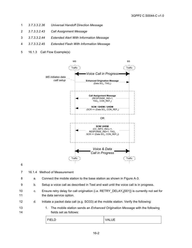
3GPP2 C.S0044-C v1.0
16-2
3.7.3.3.2.36 Universal Handoff Direction Message 1
3.7.3.3.2.43 Call Assignment Message 2
3.7.3.3.2.44 Extended Alert With Information Message 3
3.7.3.3.2.45 Extended Flash With Information Message 4
16.1.3 Call Flow Example(s) 5
Enhanced Origination Message(Data SOY, TAGY)
SCM / GHDM / UHDM (SCR += (Data SOY, CON_REFY)
BSMS
Traffic Traffic
TrafficTraffic
Call Assignment Message (RESPONSE_IND=1,
TAGY, CON_REFY)
SCM/ UHDM (CC_INFO_INCL=1,
RESPONSE_IND=1, TAGY SCR += (Data SOY, CON_REFY))
OR
MS initiates datacalll setup
Voice Call in Progress
Voice & DataCall in Progress
6
16.1.4 Method of Measurement 7
a. Connect the mobile station to the base station as shown in Figure A-3. 8
b. Setup a voice call as described in Test and wait until the voice call is in progress. 9
c. Ensure retry delay for call origination (i.e. RETRY_DELAYs[001]) is currently not set for 10 the data service option. 11
d. Initiate a packet data call (e.g. SO33) at the mobile station. Verify the following: 12
1. The mobile station sends an Enhanced Origination Message with the following 13 fields set as follows: 14
FIELD VALUE
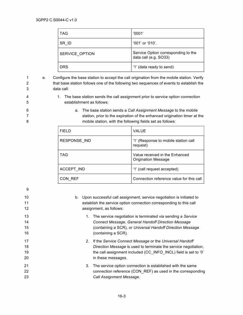
3GPP2 C.S0044-C v1.0
16-3
TAG ‘0001’
SR_ID ‘001’ or ‘010’.
SERVICE_OPTION Service Option corresponding to the data call (e.g. SO33)
DRS ‘1’ (data ready to send)
e. Configure the base station to accept the call origination from the mobile station. Verify 1 that base station follows one of the following two sequences of events to establish the 2 data call: 3
1. The base station sends the call assignment prior to service option connection 4 establishment as follows: 5
a. The base station sends a Call Assignment Message to the mobile 6 station, prior to the expiration of the enhanced origination timer at the 7 mobile station, with the following fields set as follows: 8
FIELD VALUE
RESPONSE_IND ‘1’ (Response to mobile station call request)
TAG Value received in the Enhanced Origination Message
ACCEPT_IND ‘1’ (call request accepted)
CON_REF Connection reference value for this call
9
b. Upon successful call assignment, service negotiation is initiated to 10 establish the service option connection corresponding to this call 11 assignment, as follows: 12
1. The service negotiation is terminated via sending a Service 13 Connect Message, General Handoff Direction Message 14 (containing a SCR), or Universal Handoff Direction Message 15 (containing a SCR). 16
2. If the Service Connect Message or the Universal Handoff 17 Direction Message is used to terminate the service negotiation, 18 the call assignment included (CC_INFO_INCL) field is set to ‘0’ 19 in these messages. 20
3. The service option connection is established with the same 21 connection reference (CON_REF) as used in the corresponding 22 Call Assignment Message. 23
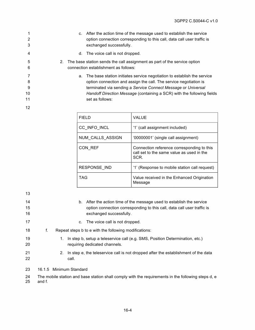
3GPP2 C.S0044-C v1.0
16-4
c. After the action time of the message used to establish the service 1 option connection corresponding to this call, data call user traffic is 2 exchanged successfully. 3
d. The voice call is not dropped. 4
2. The base station sends the call assignment as part of the service option 5 connection establishment as follows: 6
a. The base station initiates service negotiation to establish the service 7 option connection and assign the call. The service negotiation is 8 terminated via sending a Service Connect Message or Universal 9 Handoff Direction Message (containing a SCR) with the following fields 10 set as follows: 11
12
FIELD VALUE
CC_INFO_INCL ‘1’ (call assignment included)
NUM_CALLS_ASSIGN ‘00000001’ (single call assignment)
CON_REF Connection reference corresponding to this call set to the same value as used in the SCR.
RESPONSE_IND ‘1’ (Response to mobile station call request)
TAG Value received in the Enhanced Origination Message
13
b. After the action time of the message used to establish the service 14 option connection corresponding to this call, data call user traffic is 15 exchanged successfully. 16
c. The voice call is not dropped. 17
f. Repeat steps b to e with the following modifications: 18
1. In step b, setup a teleservice call (e.g. SMS, Position Determination, etc.) 19 requiring dedicated channels. 20
2. In step e, the teleservice call is not dropped after the establishment of the data 21 call. 22
16.1.5 Minimum Standard 23
The mobile station and base station shall comply with the requirements in the following steps d, e 24 and f. 25
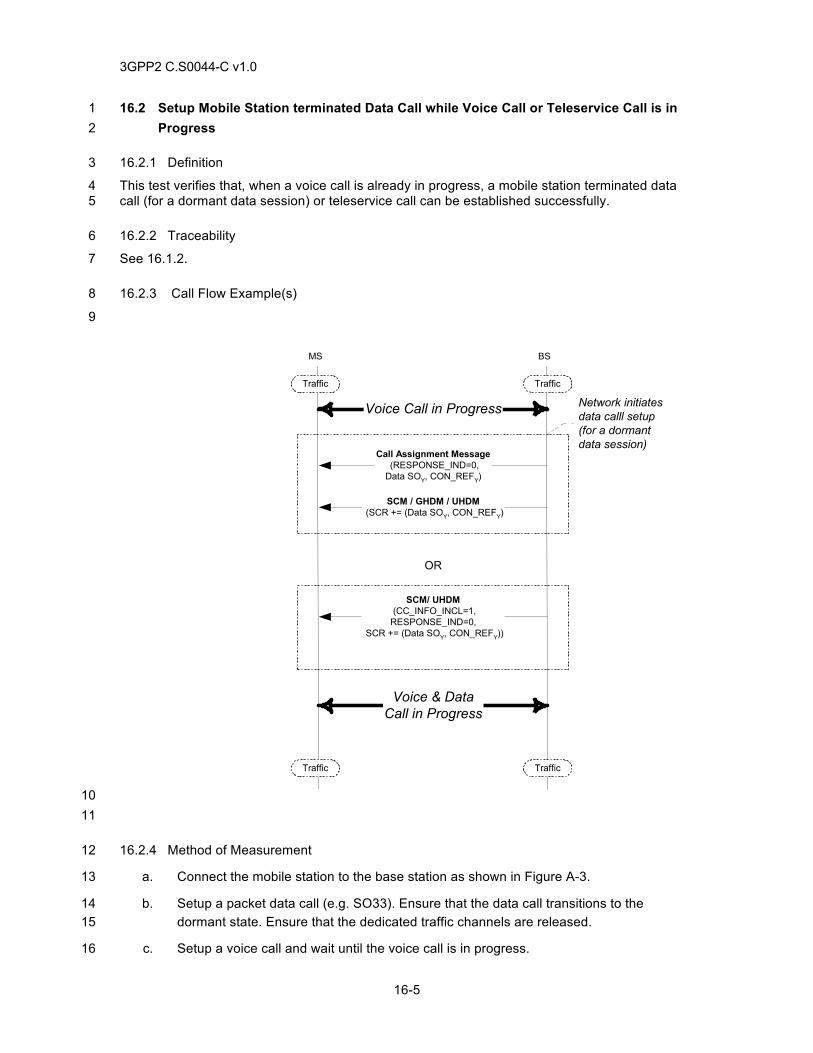
3GPP2 C.S0044-C v1.0
16-5
16.2 Setup Mobile Station terminated Data Call while Voice Call or Teleservice Call is in 1 Progress 2
16.2.1 Definition 3
This test verifies that, when a voice call is already in progress, a mobile station terminated data 4 call (for a dormant data session) or teleservice call can be established successfully. 5
16.2.2 Traceability 6
See 16.1.2. 7
16.2.3 Call Flow Example(s) 8
9
SCM / GHDM / UHDM (SCR += (Data SOY, CON_REFY)
BSMS
Traffic Traffic
TrafficTraffic
Call Assignment Message (RESPONSE_IND=0,Data SOY, CON_REFY)
SCM/ UHDM (CC_INFO_INCL=1,RESPONSE_IND=0,
SCR += (Data SOY, CON_REFY))
OR
Network initiatesdata calll setup(for a dormantdata session)
Voice Call in Progress
Voice & DataCall in Progress
10 11
16.2.4 Method of Measurement 12
a. Connect the mobile station to the base station as shown in Figure A-3. 13
b. Setup a packet data call (e.g. SO33). Ensure that the data call transitions to the 14 dormant state. Ensure that the dedicated traffic channels are released. 15
c. Setup a voice call and wait until the voice call is in progress. 16
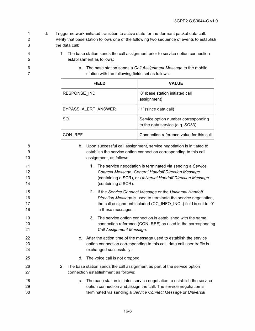
3GPP2 C.S0044-C v1.0
16-6
d. Trigger network-initiated transition to active state for the dormant packet data call. 1 Verify that base station follows one of the following two sequence of events to establish 2 the data call: 3
1. The base station sends the call assignment prior to service option connection 4 establishment as follows: 5
a. The base station sends a Call Assignment Message to the mobile 6 station with the following fields set as follows: 7
FIELD VALUE
RESPONSE_IND ‘0’ (base station initiated call assignment)
BYPASS_ALERT_ANSWER ‘1’ (since data call)
SO Service option number corresponding to the data service (e.g. SO33)
CON_REF Connection reference value for this call
b. Upon successful call assignment, service negotiation is initiated to 8 establish the service option connection corresponding to this call 9 assignment, as follows: 10
1. The service negotiation is terminated via sending a Service 11 Connect Message, General Handoff Direction Message 12 (containing a SCR), or Universal Handoff Direction Message 13 (containing a SCR). 14
2. If the Service Connect Message or the Universal Handoff 15 Direction Message is used to terminate the service negotiation, 16 the call assignment included (CC_INFO_INCL) field is set to ‘0’ 17 in these messages. 18
3. The service option connection is established with the same 19 connection reference (CON_REF) as used in the corresponding 20 Call Assignment Message. 21
c. After the action time of the message used to establish the service 22 option connection corresponding to this call, data call user traffic is 23 exchanged successfully. 24
d. The voice call is not dropped. 25
2. The base station sends the call assignment as part of the service option 26 connection establishment as follows: 27
a. The base station initiates service negotiation to establish the service 28 option connection and assign the call. The service negotiation is 29 terminated via sending a Service Connect Message or Universal 30
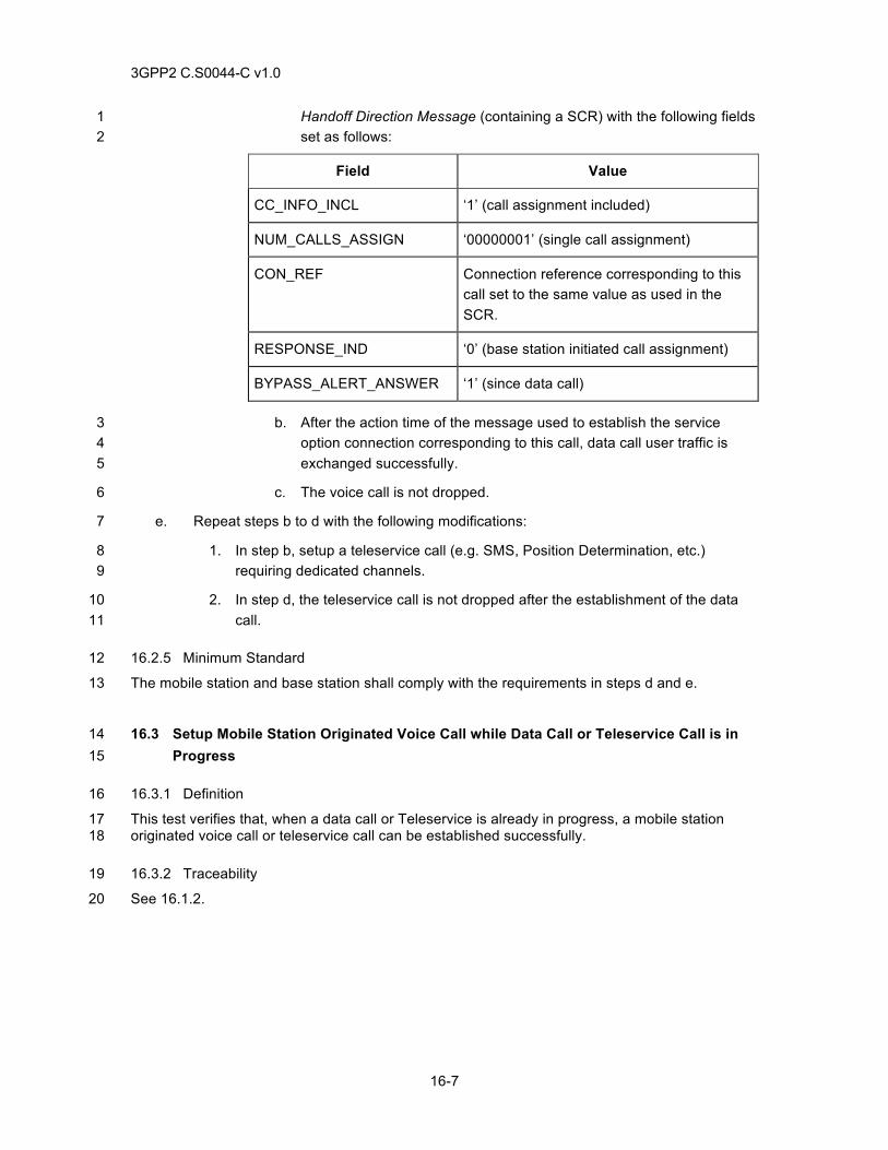
3GPP2 C.S0044-C v1.0
16-7
Handoff Direction Message (containing a SCR) with the following fields 1 set as follows: 2
Field Value
CC_INFO_INCL ‘1’ (call assignment included)
NUM_CALLS_ASSIGN ‘00000001’ (single call assignment)
CON_REF Connection reference corresponding to this call set to the same value as used in the SCR.
RESPONSE_IND ‘0’ (base station initiated call assignment)
BYPASS_ALERT_ANSWER ‘1’ (since data call)
b. After the action time of the message used to establish the service 3 option connection corresponding to this call, data call user traffic is 4 exchanged successfully. 5
c. The voice call is not dropped. 6
e. Repeat steps b to d with the following modifications: 7
1. In step b, setup a teleservice call (e.g. SMS, Position Determination, etc.) 8 requiring dedicated channels. 9
2. In step d, the teleservice call is not dropped after the establishment of the data 10 call. 11
16.2.5 Minimum Standard 12
The mobile station and base station shall comply with the requirements in steps d and e. 13
16.3 Setup Mobile Station Originated Voice Call while Data Call or Teleservice Call is in 14 Progress 15
16.3.1 Definition 16
This test verifies that, when a data call or Teleservice is already in progress, a mobile station 17 originated voice call or teleservice call can be established successfully. 18
16.3.2 Traceability 19
See 16.1.2. 20
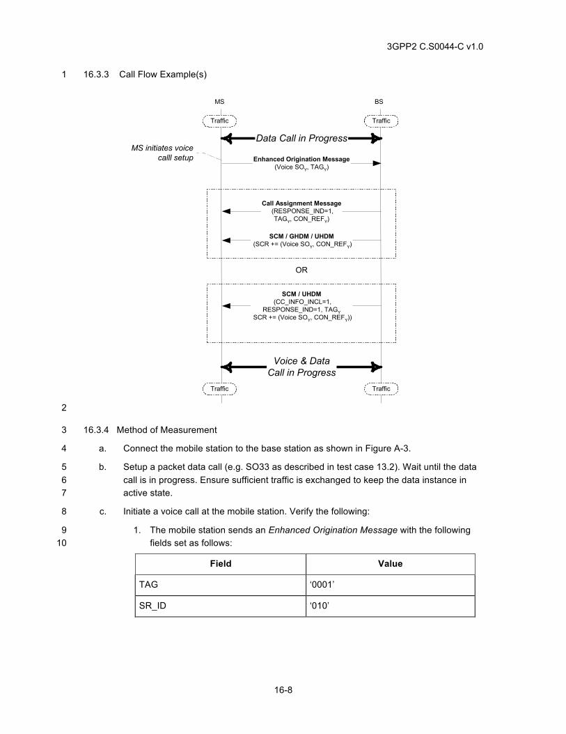
3GPP2 C.S0044-C v1.0
16-8
16.3.3 Call Flow Example(s) 1
Enhanced Origination Message(Voice SOY, TAGY)
SCM / GHDM / UHDM (SCR += (Voice SOY, CON_REFY)
BSMS
Traffic Traffic
TrafficTraffic
Call Assignment Message (RESPONSE_IND=1,
TAGY, CON_REFY)
SCM / UHDM (CC_INFO_INCL=1,
RESPONSE_IND=1, TAGY SCR += (Voice SOY, CON_REFY))
OR
MS initiates voicecalll setup
Data Call in Progress
Voice & DataCall in Progress
2
16.3.4 Method of Measurement 3
a. Connect the mobile station to the base station as shown in Figure A-3. 4
b. Setup a packet data call (e.g. SO33 as described in test case 13.2). Wait until the data 5 call is in progress. Ensure sufficient traffic is exchanged to keep the data instance in 6 active state. 7
c. Initiate a voice call at the mobile station. Verify the following: 8
1. The mobile station sends an Enhanced Origination Message with the following 9 fields set as follows: 10
Field Value
TAG ‘0001’
SR_ID ‘010’
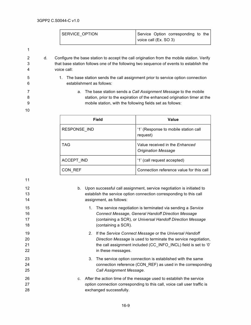
3GPP2 C.S0044-C v1.0
16-9
SERVICE_OPTION Service Option corresponding to the voice call (Ex. SO 3)
1
d. Configure the base station to accept the call origination from the mobile station. Verify 2 that base station follows one of the following two sequence of events to establish the 3 voice call: 4
1. The base station sends the call assignment prior to service option connection 5 establishment as follows: 6
a. The base station sends a Call Assignment Message to the mobile 7 station, prior to the expiration of the enhanced origination timer at the 8 mobile station, with the following fields set as follows: 9
10
Field Value
RESPONSE_IND ‘1’ (Response to mobile station call request)
TAG Value received in the Enhanced Origination Message
ACCEPT_IND ‘1’ (call request accepted)
CON_REF Connection reference value for this call
11
b. Upon successful call assignment, service negotiation is initiated to 12 establish the service option connection corresponding to this call 13 assignment, as follows: 14
1. The service negotiation is terminated via sending a Service 15 Connect Message, General Handoff Direction Message 16 (containing a SCR), or Universal Handoff Direction Message 17 (containing a SCR). 18
2. If the Service Connect Message or the Universal Handoff 19 Direction Message is used to terminate the service negotiation, 20 the call assignment included (CC_INFO_INCL) field is set to ‘0’ 21 in these messages. 22
3. The service option connection is established with the same 23 connection reference (CON_REF) as used in the corresponding 24 Call Assignment Message. 25
c. After the action time of the message used to establish the service 26 option connection corresponding to this call, voice call user traffic is 27 exchanged successfully. 28
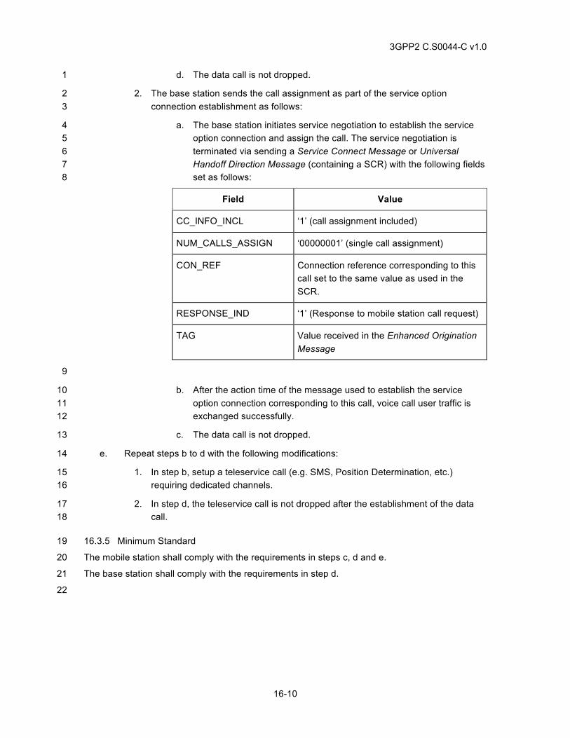
3GPP2 C.S0044-C v1.0
16-10
d. The data call is not dropped. 1
2. The base station sends the call assignment as part of the service option 2 connection establishment as follows: 3
a. The base station initiates service negotiation to establish the service 4 option connection and assign the call. The service negotiation is 5 terminated via sending a Service Connect Message or Universal 6 Handoff Direction Message (containing a SCR) with the following fields 7 set as follows: 8
Field Value
CC_INFO_INCL ‘1’ (call assignment included)
NUM_CALLS_ASSIGN ‘00000001’ (single call assignment)
CON_REF Connection reference corresponding to this call set to the same value as used in the SCR.
RESPONSE_IND ‘1’ (Response to mobile station call request)
TAG Value received in the Enhanced Origination Message
9
b. After the action time of the message used to establish the service 10 option connection corresponding to this call, voice call user traffic is 11 exchanged successfully. 12
c. The data call is not dropped. 13
e. Repeat steps b to d with the following modifications: 14
1. In step b, setup a teleservice call (e.g. SMS, Position Determination, etc.) 15 requiring dedicated channels. 16
2. In step d, the teleservice call is not dropped after the establishment of the data 17 call. 18
16.3.5 Minimum Standard 19
The mobile station shall comply with the requirements in steps c, d and e. 20
The base station shall comply with the requirements in step d. 21
22
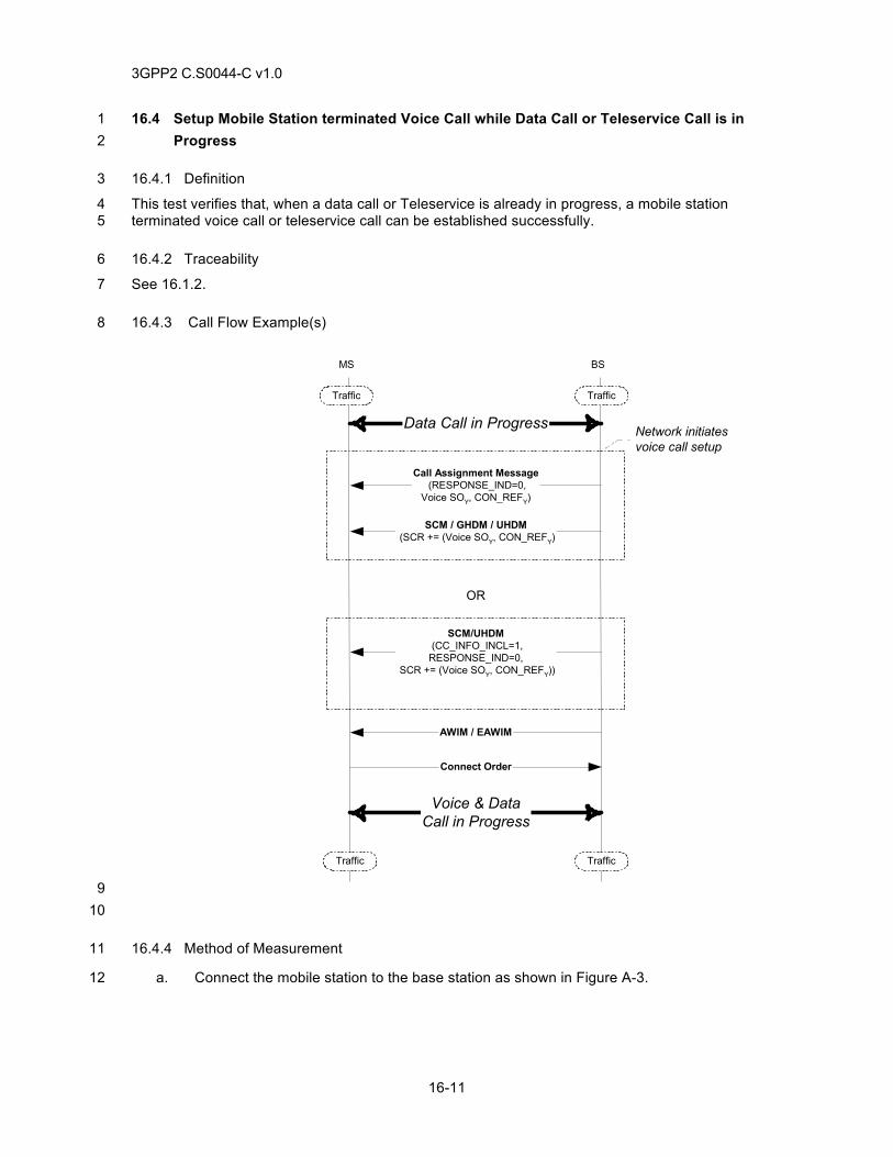
3GPP2 C.S0044-C v1.0
16-11
16.4 Setup Mobile Station terminated Voice Call while Data Call or Teleservice Call is in 1 Progress 2
16.4.1 Definition 3
This test verifies that, when a data call or Teleservice is already in progress, a mobile station 4 terminated voice call or teleservice call can be established successfully. 5
16.4.2 Traceability 6
See 16.1.2. 7
16.4.3 Call Flow Example(s) 8
SCM / GHDM / UHDM (SCR += (Voice SOY, CON_REFY)
BSMS
Traffic Traffic
TrafficTraffic
Call Assignment Message (RESPONSE_IND=0,
Voice SOY, CON_REFY)
SCM/UHDM (CC_INFO_INCL=1,RESPONSE_IND=0,
SCR += (Voice SOY, CON_REFY))
OR
Network initiatesvoice call setup
Data Call in Progress
Voice & DataCall in Progress
AWIM / EAWIM
Connect Order
9 10
16.4.4 Method of Measurement 11
a. Connect the mobile station to the base station as shown in Figure A-3. 12
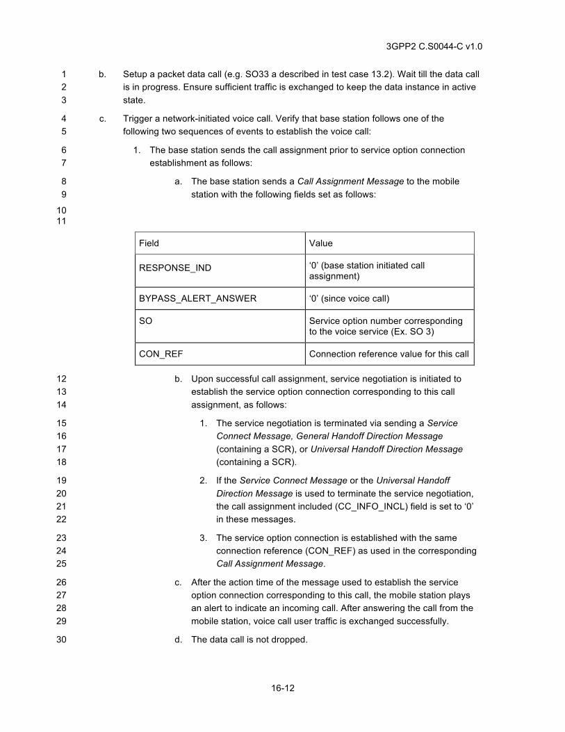
3GPP2 C.S0044-C v1.0
16-12
b. Setup a packet data call (e.g. SO33 a described in test case 13.2). Wait till the data call 1 is in progress. Ensure sufficient traffic is exchanged to keep the data instance in active 2 state. 3
c. Trigger a network-initiated voice call. Verify that base station follows one of the 4 following two sequences of events to establish the voice call: 5
1. The base station sends the call assignment prior to service option connection 6 establishment as follows: 7
a. The base station sends a Call Assignment Message to the mobile 8 station with the following fields set as follows: 9
10 11
Field Value
RESPONSE_IND ‘0’ (base station initiated call assignment)
BYPASS_ALERT_ANSWER ‘0’ (since voice call)
SO Service option number corresponding to the voice service (Ex. SO 3)
CON_REF Connection reference value for this call
b. Upon successful call assignment, service negotiation is initiated to 12 establish the service option connection corresponding to this call 13 assignment, as follows: 14
1. The service negotiation is terminated via sending a Service 15 Connect Message, General Handoff Direction Message 16 (containing a SCR), or Universal Handoff Direction Message 17 (containing a SCR). 18
2. If the Service Connect Message or the Universal Handoff 19 Direction Message is used to terminate the service negotiation, 20 the call assignment included (CC_INFO_INCL) field is set to ‘0’ 21 in these messages. 22
3. The service option connection is established with the same 23 connection reference (CON_REF) as used in the corresponding 24 Call Assignment Message. 25
c. After the action time of the message used to establish the service 26 option connection corresponding to this call, the mobile station plays 27 an alert to indicate an incoming call. After answering the call from the 28 mobile station, voice call user traffic is exchanged successfully. 29
d. The data call is not dropped. 30
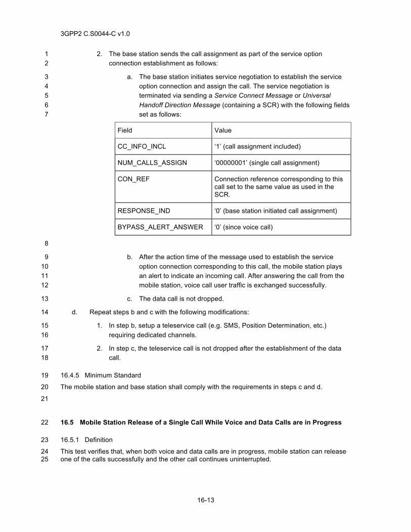
3GPP2 C.S0044-C v1.0
16-13
2. The base station sends the call assignment as part of the service option 1 connection establishment as follows: 2
a. The base station initiates service negotiation to establish the service 3 option connection and assign the call. The service negotiation is 4 terminated via sending a Service Connect Message or Universal 5 Handoff Direction Message (containing a SCR) with the following fields 6 set as follows: 7
Field Value
CC_INFO_INCL ‘1’ (call assignment included)
NUM_CALLS_ASSIGN ‘00000001’ (single call assignment)
CON_REF Connection reference corresponding to this call set to the same value as used in the SCR.
RESPONSE_IND ‘0’ (base station initiated call assignment)
BYPASS_ALERT_ANSWER ‘0’ (since voice call)
8
b. After the action time of the message used to establish the service 9 option connection corresponding to this call, the mobile station plays 10 an alert to indicate an incoming call. After answering the call from the 11 mobile station, voice call user traffic is exchanged successfully. 12
c. The data call is not dropped. 13
d. Repeat steps b and c with the following modifications: 14
1. In step b, setup a teleservice call (e.g. SMS, Position Determination, etc.) 15 requiring dedicated channels. 16
2. In step c, the teleservice call is not dropped after the establishment of the data 17 call. 18
16.4.5 Minimum Standard 19
The mobile station and base station shall comply with the requirements in steps c and d. 20
21
16.5 Mobile Station Release of a Single Call While Voice and Data Calls are in Progress 22
16.5.1 Definition 23
This test verifies that, when both voice and data calls are in progress, mobile station can release 24 one of the calls successfully and the other call continues uninterrupted. 25
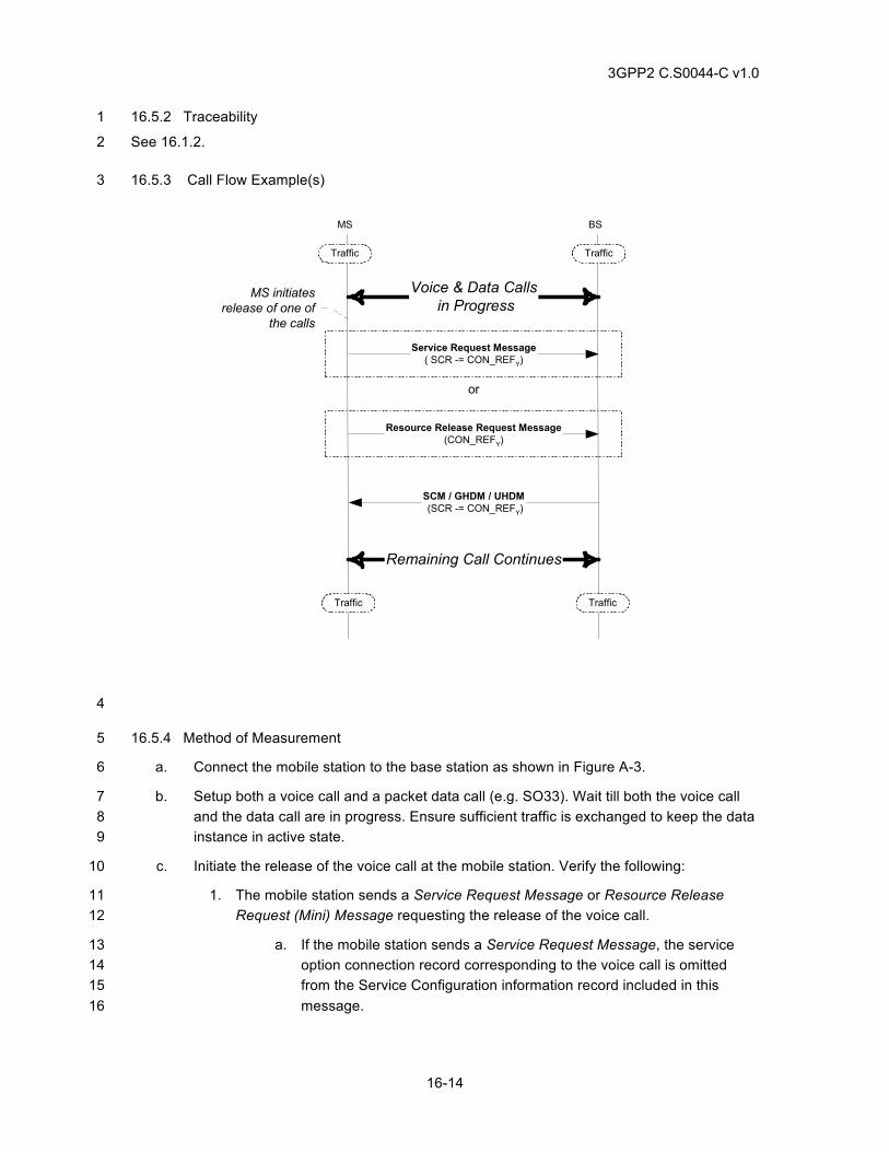
3GPP2 C.S0044-C v1.0
16-14
16.5.2 Traceability 1
See 16.1.2. 2
16.5.3 Call Flow Example(s) 3
SCM / GHDM / UHDM (SCR -= CON_REFY)
BSMS
Traffic Traffic
TrafficTraffic
MS initiatesrelease of one of
the calls
Voice & Data Calls in Progress
Remaining Call Continues
Service Request Message( SCR -= CON_REFY)
Resource Release Request Message(CON_REFY)
or
4
16.5.4 Method of Measurement 5
a. Connect the mobile station to the base station as shown in Figure A-3. 6
b. Setup both a voice call and a packet data call (e.g. SO33). Wait till both the voice call 7 and the data call are in progress. Ensure sufficient traffic is exchanged to keep the data 8 instance in active state. 9
c. Initiate the release of the voice call at the mobile station. Verify the following: 10
1. The mobile station sends a Service Request Message or Resource Release 11 Request (Mini) Message requesting the release of the voice call. 12
a. If the mobile station sends a Service Request Message, the service 13 option connection record corresponding to the voice call is omitted 14 from the Service Configuration information record included in this 15 message. 16
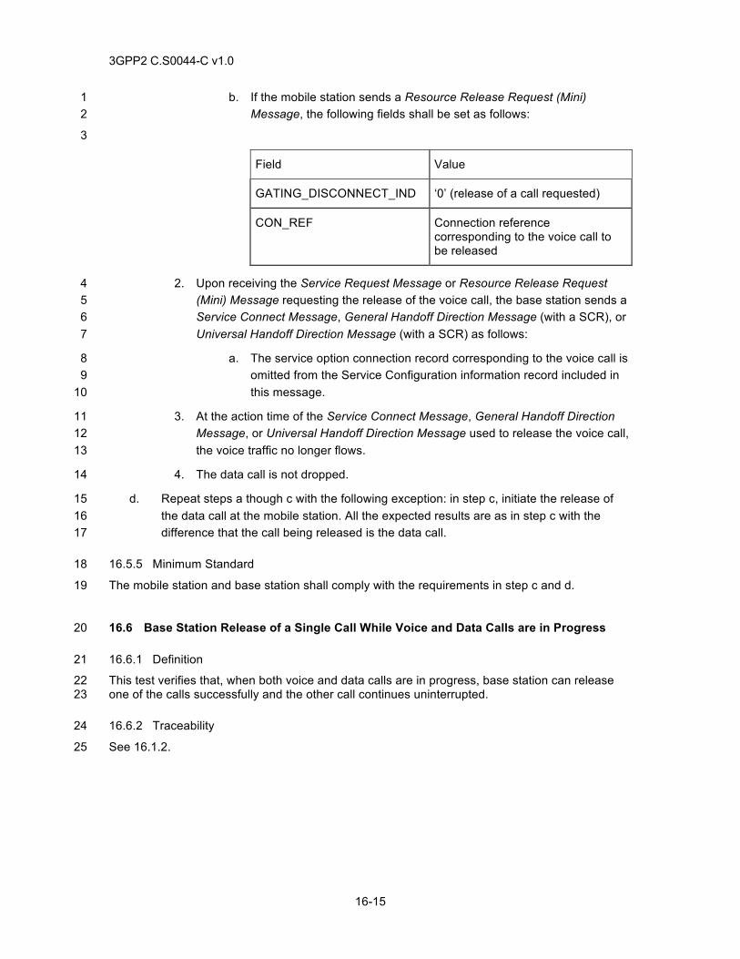
3GPP2 C.S0044-C v1.0
16-15
b. If the mobile station sends a Resource Release Request (Mini) 1 Message, the following fields shall be set as follows: 2
3
Field Value
GATING_DISCONNECT_IND ‘0’ (release of a call requested)
CON_REF Connection reference corresponding to the voice call to be released
2. Upon receiving the Service Request Message or Resource Release Request 4 (Mini) Message requesting the release of the voice call, the base station sends a 5 Service Connect Message, General Handoff Direction Message (with a SCR), or 6 Universal Handoff Direction Message (with a SCR) as follows: 7
a. The service option connection record corresponding to the voice call is 8 omitted from the Service Configuration information record included in 9 this message. 10
3. At the action time of the Service Connect Message, General Handoff Direction 11 Message, or Universal Handoff Direction Message used to release the voice call, 12 the voice traffic no longer flows. 13
4. The data call is not dropped. 14
d. Repeat steps a though c with the following exception: in step c, initiate the release of 15 the data call at the mobile station. All the expected results are as in step c with the 16 difference that the call being released is the data call. 17
16.5.5 Minimum Standard 18
The mobile station and base station shall comply with the requirements in step c and d. 19
16.6 Base Station Release of a Single Call While Voice and Data Calls are in Progress 20
16.6.1 Definition 21
This test verifies that, when both voice and data calls are in progress, base station can release 22 one of the calls successfully and the other call continues uninterrupted. 23
16.6.2 Traceability 24
See 16.1.2. 25
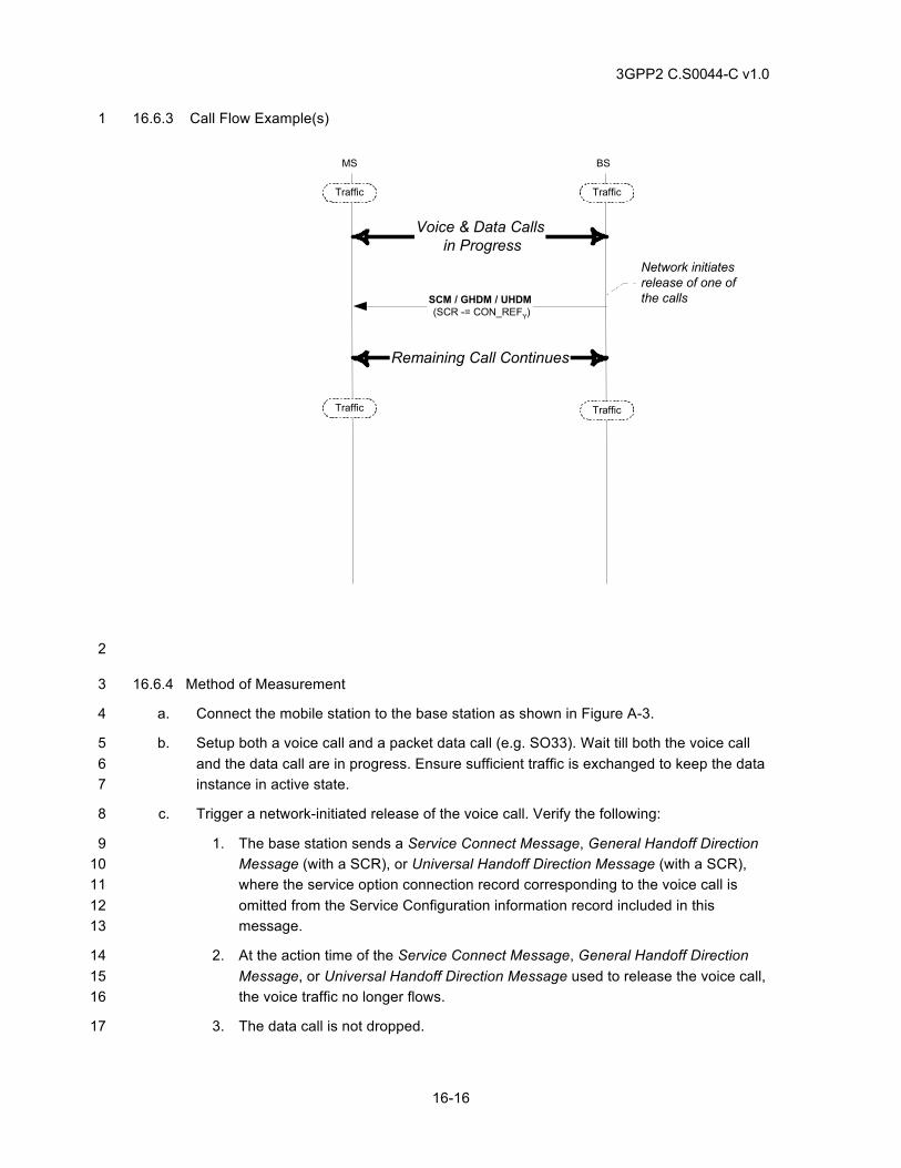
3GPP2 C.S0044-C v1.0
16-16
16.6.3 Call Flow Example(s) 1
SCM / GHDM / UHDM (SCR -= CON_REFY)
BSMS
Traffic Traffic
TrafficTraffic
Network initiatesrelease of one ofthe calls
Voice & Data Calls in Progress
Remaining Call Continues
2
16.6.4 Method of Measurement 3
a. Connect the mobile station to the base station as shown in Figure A-3. 4
b. Setup both a voice call and a packet data call (e.g. SO33). Wait till both the voice call 5 and the data call are in progress. Ensure sufficient traffic is exchanged to keep the data 6 instance in active state. 7
c. Trigger a network-initiated release of the voice call. Verify the following: 8
1. The base station sends a Service Connect Message, General Handoff Direction 9 Message (with a SCR), or Universal Handoff Direction Message (with a SCR), 10 where the service option connection record corresponding to the voice call is 11 omitted from the Service Configuration information record included in this 12 message. 13
2. At the action time of the Service Connect Message, General Handoff Direction 14 Message, or Universal Handoff Direction Message used to release the voice call, 15 the voice traffic no longer flows. 16
3. The data call is not dropped. 17
3GPP2 C.S0044-C v1.0
16-17
d. Repeat steps a though c with the following exception: in step c, initiate the release of 1 the data call at the mobile station. All the expected results are as in step c with the 2 difference that the call being released is the data call. 3
16.6.5 Minimum Standard 4
The mobile station and base station shall comply with the requirements in steps c and d. 5
16.7 Correct Handling of Call Control Signaling 6
16.7.1 Definition 7
This test verifies that, when one or more calls are in progress, mobile station initiated and network 8 initiated call control signaling messages are handled correctly. 9
16.7.2 Traceability 10
See 16.1.2. 11
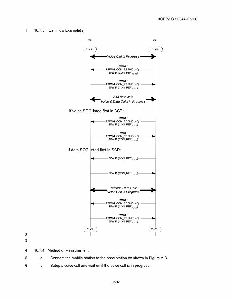
3GPP2 C.S0044-C v1.0
16-18
16.7.3 Call Flow Example(s) 1
BSMS
Traffic Traffic
TrafficTraffic
Voice Call in Progress
FWIM /EFWIM (CON_REFINCL=0) /
EFWIM (CON_REFVOICE)
FWIM /EFWIM (CON_REFINCL=0) /
EFWIM (CON_REFVOICE)
Add data call:Voice & Data Calls in Progress
FWIM /EFWIM (CON_REFINCL=0) /
EFWIM (CON_REFVOICE)
FWIM /EFWIM (CON_REFINCL=0) /
EFWIM (CON_REFVOICE)
EFWIM (CON_REFVOICE)
EFWIM (CON_REFVOICE)
Release Data Call:Voice Call in Progress
FWIM /EFWIM (CON_REFINCL=0) /
EFWIM (CON_REFVOICE)
FWIM /EFWIM (CON_REFINCL=0) /
EFWIM (CON_REFVOICE)
If voice SOC listed first in SCR:
If data SOC listed first in SCR:
2 3
16.7.4 Method of Measurement 4
a. Connect the mobile station to the base station as shown in Figure A-3. 5
b. Setup a voice call and wait until the voice call is in progress. 6
3GPP2 C.S0044-C v1.0
16-19
c. If applicable, trigger an action at the mobile station that will result in either a Flash With 1 Information Message or Extended Flash With Information Message for a voice call 2 being transmitted to the base station (Ex. Trigger an action that utilizes the Keypad 3 Facility information record). Verify the following: 4
1. The mobile station sends a Flash With Information Message, an Extended Flash 5 With Information Message with the CON_REF_INCL field set to ‘0’, or an 6 Extended Flash With Information Message with the CON_REF field set to the 7 connection reference corresponding to the voice call. 8
2. The information record is delivered correctly in the network. 9
d. If applicable, trigger an action at the network that will result in either a Flash With 10 Information Message or Extended Flash With Information Message being transmitted to 11 the mobile station (e.g. Trigger an action that utilizes the Display information record). 12 Verify the following: 13
1. The base station sends a Flash With Information Message, an Extended Flash 14 With Information Message with the CON_REF_INCL field set to ‘0’, or an 15 Extended Flash With Information Message with the CON_REF field set to the 16 connection reference corresponding to the voice call. 17
2. The information record is correctly handled in the mobile station. 18
e. Setup a mobile station originated or mobile station terminated packet data call (e.g. 19 SO33). When the base station sends a Service Connect Message, General Handoff 20 Direction Message, or Universal Handoff Direction Message to establish the service 21 option connection corresponding to the data call, note whether the service option 22 connection corresponding to the voice call or data call is listed as the first entry in the 23 SCR. 24
f. If applicable, trigger an action at the mobile station that will result in either a Flash With 25 Information Message or Extended Flash With Information Message for a voice call 26 being transmitted to the base station (Ex. Trigger an action that utilizes the Keypad 27 Facility information record). Verify the following: 28
1. If the service option connection corresponding to the voice call is listed as the 29 first entry in the SCR: 30
a. The mobile station sends a Flash With Information Message, an 31 Extended Flash With Information Message with the CON_REF_INCL 32 field set to ‘0’, or an Extended Flash With Information Message with 33 the CON_REF field set to the connection reference corresponding to 34 the voice call. 35
b. The information record is delivered correctly in the network. 36
2. If the service option connection corresponding to the data call is listed as the first 37 entry in the SCR: 38
a. The mobile station sends an (Extended) Flash With Information 39 Message with the CON_REF field set to the connection reference 40 corresponding to the voice call. 41
3GPP2 C.S0044-C v1.0
16-20
b. The information record is delivered correctly in the network. 1
g. If applicable, trigger an action at the network that will result in either a Flash With 2 Information Message or Extended Flash With Information Message for a voice call 3 being transmitted to the mobile station (Ex. Trigger an action that utilizes the Display 4 information record). Verify the following: 5
1. If the service option connection corresponding to the voice call is listed as the 6 first entry in the SCR: 7
a. The base station sends a Flash With Information Message, an 8 Extended Flash With Information Message with the CON_REF_INCL 9 field set to ‘0’, or an Extended Flash With Information Message with 10 the CON_REF field set to the connection reference corresponding to 11 the voice call. 12
b. The information record is correctly handled in the mobile station. 13
2. If the service option connection corresponding to the data call is listed as the first 14 entry in the SCR: 15
a. The base station sends an Extended Flash With Information Message 16 with the CON_REF field set to the connection reference corresponding 17 to the voice call. 18
b. The information record is correctly handled in the mobile station. 19
h. Perform a mobile station initiated or base station initiated release of the data call. Wait 20 till this operation is successful. 21
i. If applicable, trigger an action at the mobile station that will result in either a Flash With 22 Information Message or Extended Flash With Information Message for a voice call 23 being transmitted to the base station (Ex. Trigger an action that utilizes the Keypad 24 Facility information record). Verify the following: 25
1. The mobile station sends a Flash With Information Message, an Extended Flash 26 With Information Message with the CON_REF_INCL field set to ‘0’, or an 27 Extended Flash With Information Message with the CON_REF field set to the 28 connection reference corresponding to the voice call. 29
2. The information record is delivered correctly in the network. 30
j. If applicable, trigger an action at the network that will result in either a Flash With 31 Information Message or Extended Flash With Information Message being transmitted to 32 the mobile station for a voice call (Ex. Trigger an action that utilizes the Display 33 information record). Verify the following: 34
1. The base station sends a Flash With Information Message, an Extended Flash 35 With Information Message with the CON_REF_INCL field set to ‘0’, or an 36 Extended Flash With Information Message with the CON_REF field set to the 37 connection reference corresponding to the voice call. 38
2. The information record is correctly handled in the mobile station. 39
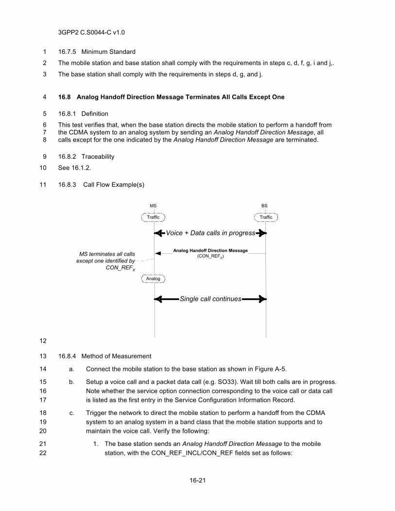
3GPP2 C.S0044-C v1.0
16-21
16.7.5 Minimum Standard 1
The mobile station and base station shall comply with the requirements in steps c, d, f, g, i and j,. 2
The base station shall comply with the requirements in steps d, g, and j. 3
16.8 Analog Handoff Direction Message Terminates All Calls Except One 4
16.8.1 Definition 5
This test verifies that, when the base station directs the mobile station to perform a handoff from 6 the CDMA system to an analog system by sending an Analog Handoff Direction Message, all 7 calls except for the one indicated by the Analog Handoff Direction Message are terminated. 8
16.8.2 Traceability 9
See 16.1.2. 10
16.8.3 Call Flow Example(s) 11
BSMS
Traffic Traffic
Analog
Voice + Data calls in progress
Analog Handoff Direction Message(CON_REFX)
MS terminates all callsexcept one identified by
CON_REFX
Single call continues
12
16.8.4 Method of Measurement 13
a. Connect the mobile station to the base station as shown in Figure A-5. 14
b. Setup a voice call and a packet data call (e.g. SO33). Wait till both calls are in progress. 15 Note whether the service option connection corresponding to the voice call or data call 16 is listed as the first entry in the Service Configuration Information Record. 17
c. Trigger the network to direct the mobile station to perform a handoff from the CDMA 18 system to an analog system in a band class that the mobile station supports and to 19 maintain the voice call. Verify the following: 20
1. The base station sends an Analog Handoff Direction Message to the mobile 21 station, with the CON_REF_INCL/CON_REF fields set as follows: 22
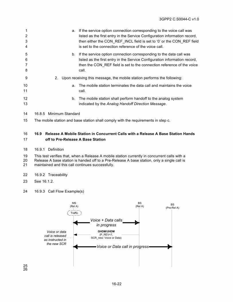
3GPP2 C.S0044-C v1.0
16-22
a. If the service option connection corresponding to the voice call was 1 listed as the first entry in the Service Configuration information record, 2 then either the CON_REF_INCL field is set to ‘0’ or the CON_REF field 3 is set to the connection reference of the voice call. 4
b. If the service option connection corresponding to the data call was 5 listed as the first entry in the Service Configuration information record, 6 then the CON_REF field is set to the connection reference of the voice 7 call. 8
2. Upon receiving this message, the mobile station performs the following: 9
a. The mobile station terminates the data call and maintains the voice 10 call. 11
b. The mobile station shall perform handoff to the analog system 12 indicated by the Analog Handoff Direction Message. 13
16.8.5 Minimum Standard 14
The mobile station and base station shall comply with the requirements in step c. 15
16.9 Release A Mobile Station in Concurrent Calls with a Release A Base Station Hands 16 off to Pre-Release A Base Station 17
16.9.1 Definition 18
This test verifies that, when a Release A mobile station currently in concurrent calls with a 19 Release A base station is handed off to a Pre-Release A base station, only a single call is 20 maintained and this call continues successfully. 21
16.9.2 Traceability 22
See 16.1.2. 23
16.9.3 Call Flow Example(s) 24
MS(Rel A)
Traffic
Voice + Data callsin progressGHDM/UHDM
(P_REV<7,SCR_new: Voice or Data)
Voice or datacall is releasedas instructed in
the new SCR
BS(Pre-Rel A)
Voice or Data call in progress
BS(Rel A)
25 26
3GPP2 C.S0044-C v1.0
16-23
1
16.9.4 Method of Measurement 2
a. Connect a MOB_P_REV 7 mobile station to base stations 1 and 2 as in Figure A-5. 3 Configure base station 1 to support P_REV=7 and base station 2 to support P_REV<7. 4
b. Setup a mobile station originated or mobile station terminated voice call on base station 5 1. 6
c. Set up a mobile station originated or mobile station terminated packet data call (e.g. 7 SO33). Wait till both voice and data calls are in progress. Ensure sufficient traffic is 8 exchanged to keep the data instance in active state. 9
d. Trigger base station 1 to direct the mobile station to handoff to base station 2. Verify the 10 following: 11
1. The base station shall send a General Handoff Direction Message or a Universal 12 Handoff Direction Message to the mobile station, with the Service Configuration 13 information record included and set as follows: 14
a. The service option connection corresponding to the call to be 15 maintained is included and uses the same connection reference value 16 (CON_REF) as currently used for this call. 17
b. The service option connection corresponding to the other call is 18 omitted. 19
2. At the action time of this message, the mobile station shall release the call 20 corresponding to the omitted service option connection and hands off to the base 21 station 2. 22
3. The remaining call continues successfully in the base station 2. 23
16.9.5 Minimum Standard 24
The mobile station and base station shall comply with the requirements in the following steps: 25 Step d. 26
27
16.10 Release A Mobile Station Hands off between Release A Base Station with Change in 28 Concurrent Calls Support 29
16.10.1 Definition 30
This test verifies that, when a Release A mobile station currently in call with a Release A base 31 station is handed off to another Release A base station, and where there is a change in 32 Concurrent Calls support, calls are released/added/maintained successfully. 33
16.10.2 Traceability 34
See 16.1.2. 35
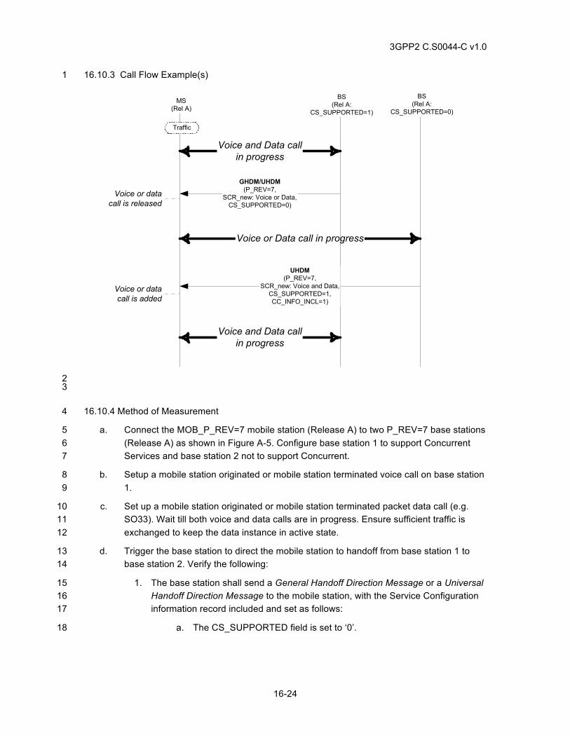
3GPP2 C.S0044-C v1.0
16-24
16.10.3 Call Flow Example(s) 1
MS(Rel A)
Traffic
Voice and Data callin progress
GHDM/UHDM(P_REV=7,
SCR_new: Voice or Data,CS_SUPPORTED=0)
Voice or datacall is released
BS(Rel A:
CS_SUPPORTED=0)
Voice or Data call in progress
BS(Rel A:
CS_SUPPORTED=1)
UHDM(P_REV=7,
SCR_new: Voice and Data,CS_SUPPORTED=1,CC_INFO_INCL=1)
Voice and Data callin progress
Voice or datacall is added
2 3
16.10.4 Method of Measurement 4
a. Connect the MOB_P_REV=7 mobile station (Release A) to two P_REV=7 base stations 5 (Release A) as shown in Figure A-5. Configure base station 1 to support Concurrent 6 Services and base station 2 not to support Concurrent. 7
b. Setup a mobile station originated or mobile station terminated voice call on base station 8 1. 9
c. Set up a mobile station originated or mobile station terminated packet data call (e.g. 10 SO33). Wait till both voice and data calls are in progress. Ensure sufficient traffic is 11 exchanged to keep the data instance in active state. 12
d. Trigger the base station to direct the mobile station to handoff from base station 1 to 13 base station 2. Verify the following: 14
1. The base station shall send a General Handoff Direction Message or a Universal 15 Handoff Direction Message to the mobile station, with the Service Configuration 16 information record included and set as follows: 17
a. The CS_SUPPORTED field is set to ‘0’. 18
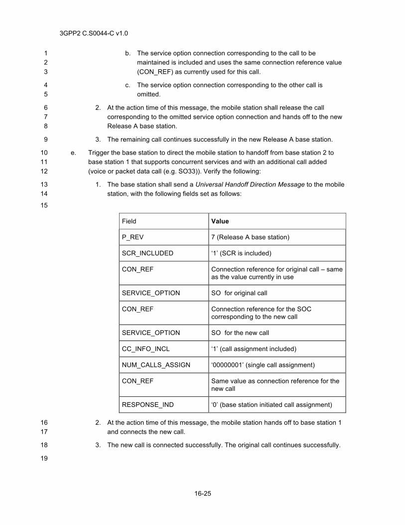
3GPP2 C.S0044-C v1.0
16-25
b. The service option connection corresponding to the call to be 1 maintained is included and uses the same connection reference value 2 (CON_REF) as currently used for this call. 3
c. The service option connection corresponding to the other call is 4 omitted. 5
2. At the action time of this message, the mobile station shall release the call 6 corresponding to the omitted service option connection and hands off to the new 7 Release A base station. 8
3. The remaining call continues successfully in the new Release A base station. 9
e. Trigger the base station to direct the mobile station to handoff from base station 2 to 10 base station 1 that supports concurrent services and with an additional call added 11 (voice or packet data call (e.g. SO33)). Verify the following: 12
1. The base station shall send a Universal Handoff Direction Message to the mobile 13 station, with the following fields set as follows: 14
15
Field Value
P_REV 7 (Release A base station)
SCR_INCLUDED ‘1’ (SCR is included)
CON_REF Connection reference for original call – same as the value currently in use
SERVICE_OPTION SO for original call
CON_REF Connection reference for the SOC corresponding to the new call
SERVICE_OPTION SO for the new call
CC_INFO_INCL ‘1’ (call assignment included)
NUM_CALLS_ASSIGN ‘00000001’ (single call assignment)
CON_REF Same value as connection reference for the new call
RESPONSE_IND ‘0’ (base station initiated call assignment)
2. At the action time of this message, the mobile station hands off to base station 1 16 and connects the new call. 17
3. The new call is connected successfully. The original call continues successfully. 18
19

3GPP2 C.S0044-C v1.0
16-26
16.10.5 Minimum Standard 1
The mobile station and base station shall comply with the requirements in steps d and e 2
3
3GPP2 C.S0044-C v1.0
17-1
17 EMERGENCY CALLS 1
17.1 Global Emergency Call Support When Mobile Station is in Idle State 2
17.1.1 Definition 3
This test verifies that the mobile station can originate a global emergency call during idle state 4 and that the base station processes this as an emergency call. 5
17.1.2 Traceability 6
(see [4]) 7
2.7.1.3.2.4 Origination Message 8
17.1.3 Call Flow Example(s) 9
None 10
17.1.4 Method of Measurement 11
a. If the mobile station is capable of recognizing emergency number by analyzing the 12 dialed digits, originate an emergency call from the mobile station by dialing an 13 emergency number. 14
b. Verify the GLOBAL_EMERGENCY_CALL field is set to ‘1’ in the Origination Message 15 and that the base station processes the origination as an emergency call. 16
c. End the call. 17
d. If the mobile station has a special interface to initiate an emergency call, originate an 18 emergency call from the mobile station using this special interface. 19
e. Verify that the mobile station sets the GLOBAL_EMERGENCY_CALL field to ‘1’ in the 20 Origination Message and that the base station processes the origination as an 21 emergency call. 22
f. End the call. 23
17.1.5 Minimum Standard 24
The mobile station shall comply with the following steps as supported: Step b and e. 25
The base station shall comply with the following steps as supported: Step b and e. 26
17.2 Global Emergency Call Support When Mobile Station is in Voice Call. 27
17.2.1 Definition 28
This test verifies that the mobile station can originate a global emergency call while another voice 29 call is in progress and that the base station processes this as an emergency call. This test is 30 applicable only to mobile stations not capable of concurrent services. 31
3GPP2 C.S0044-C v1.0
17-2
17.2.2 Traceability 1
(see [4]) 2
2.7.1.3.2.4 Origination Message 3
2.7.2.3.2.32 Enhanced Origination Message 4
2.7.2.3.2.3 Flash With Information Message 5
2.7.2.3.2.33 Extended Flash With Information Message 6
17.2.3 Call Flow Example(s) 7
None 8
17.2.4 Method of Measurement 9
a. Connect the base station to the mobile station as shown in Figure A-3. 10
b. Originate a voice call from the mobile station. Verify audio in both directions. 11
c. If the mobile station is capable of recognizing emergency number by analyzing the 12 dialed digits and the mobile station does not support concurrent service, originate an 13 emergency call from the mobile station by dialing an emergency number (e.g. dialing 9-14 1-1 and press SEND). 15
d. Verify that the mobile station sends a Flash With Information Message or an Extended 16 Flash With Information Message with the Global Emergency Call information record 17 included and that the base station processes the message as an emergency call. 18
e. End the call. 19
f. Originate a voice call from the mobile station. Verify audio in both directions. 20
g. If the mobile station has a special interface to initiate an emergency call, originate an 21 emergency call from the mobile station using this special interface. 22
h. Verify that the mobile station sends Flash With Information Message or Extended Flash 23 With Information Message with the Global Emergency Call information record included 24 and that the base station processes the origination as an emergency call. 25
i. End the call. 26
17.2.5 Minimum Standard 27
The mobile station shall comply with the following steps as supported: Step d and h. 28
The base station shall comply with the following steps as supported: Step d and h. 29
17.3 Global Emergency Call Support When Mobile Station is in a Data Call 30
17.3.1 Definition 31
This test verifies that the mobile station can originate a global emergency call when a packet data 32 call (Ex. SO33) is in progress and that the base station processes this as an emergency call. This 33 test is applicable if both the base station and mobile station support concurrent services. 34
3GPP2 C.S0044-C v1.0
17-3
17.3.2 Traceability 1
(see [4]) 2
2.7.1.3.2.4 Origination Message 3
2.7.2.3.2.32 Enhanced Origination Message 4
2.7.2.3.2.3 Flash With Information Message 5
2.7.2.3.2.33 Extended Flash With Information Message 6
17.3.3 Call Flow Example(s) 7
None 8
17.3.4 Method of Measurement 9
a. Connect the base station to the mobile station as shown in Figure A-3. 10
b. Originate a data call from the mobile station. 11
c. If the mobile station is capable of recognizing emergency number by analyzing the 12 dialed digits, then while the data call is up, originate an emergency call from the mobile 13 station by dialing an emergency number (e.g. dialing 9-1-1 and press SEND). 14
d. Verify the mobile station sends an Enhanced Origination Message with the 15 GLOBAL_EMERGENCY_CALL field set to ‘1’ and that the base station processes the 16 origination as an emergency call. 17
e. End the calls. 18
f. Originate a data call from the mobile station. 19
g. If the mobile station has a special interface to initiate an emergency call, then while the 20 data call us up, originate an emergency call from the mobile station using this special 21 interface. 22
h. Verify the mobile station sends an Enhanced Origination Message with the 23 GLOBAL_EMERGENCY_CALL field set to ‘1’ and that the base station processes the 24 origination as an emergency call. 25
i. End the calls. 26
17.3.5 Minimum Standard 27
The mobile station shall comply with the following steps as supported: Step d and h. 28
The base station shall comply with the following steps as supported: Step d and h. 29
17.4 Emergency Call on a System that is Negative on PRL or SID List 30
17.4.1 Definition 31
This test verifies that the mobile station acquires a system that is ‘negative’ in its (Extended) 32 Preferred Roaming List for an emergency call only. 33

3GPP2 C.S0044-C v1.0
17-4
17.4.2 Traceability 1
(see [14]) 2
3.5.5 Preferred Roaming List and Extended Preferred Roaming List 3
ANNEX C System Selection and Acquisition 4
17.4.3 Call Flow 5
None 6
17.4.4 Method of Measurement 7
a. Connect the mobile station and base station as shown in Figure A-3. 8
b. Program the base station’s SID into the PRL as a negative system. 9
c. Enable power-on registration. Disable all other forms of registration. 10
d. Power on the mobile station, and monitor it for a sufficient period of time to permit it to 11 acquire the base station (typically 30 seconds). 12
e. Verify the mobile station does not attempt to access the base station. 13
f. Setup an emergency call from the mobile station (911 in the United States). 14
g. Verify the mobile station sends an Origination Message to the base station. 15
h. Verify the emergency call is routed to the PSAP or equivalent emulation unit. 16
i. End the emergency call from the mobile station. 17
17.4.5 Minimum Standard 18
The mobile station shall comply with step e and g. 19
17.5 Optional Emergency Calls 20
17.5.1 Definition 21
The requirements in these test cases are applicable regionally. For example, in the U.S., the 22 FCC has certain requirements for the mobile station and the base station when an emergency 9-23 1-1 call is initiated. The purpose of this test is to determine the mobile station’s capability to 24 initiate an emergency call under 3 different initial conditions: (1) No calls active or dormant, (2) 25 data call is active and (3) data call in dormant mode. 26
17.5.2 Traceability 27
None 28
17.5.3 Call Flow Example(s) 29
None 30
17.5.4 Method of Measurement 31
a. Allow the mobile to become idle on the base station. 32
b. Originate emergency call from the mobile station and verify that the emergency call is 33 connected. Release the emergency call. 34
3GPP2 C.S0044-C v1.0
17-5
c. Setup SO33 call. While SO33 call is active, originate emergency call from the mobile 1 station and verify that the emergency call is connected. Release the emergency call. 2
d. Allow SO33 to go dormant. 3
e. While SO33 call is dormant, originate emergency call from the mobile station and verify 4 that the emergency call is connected. Release the emergency call. 5
17.5.5 Minimum Standard 6
The mobile station and base station shall comply with the requirements in steps b, c, and e 7 (according to applicable regional requirements). 8
9
10

3GPP2 C.S0044-C v1.0
17-6
This page intentionally left blank.1
3GPP2 C.S0044-C v1.0
18-1
18 HRPD 1
For HRPD test cases described in chapter 18, the terms mobile station and base station 2 represent the access terminal (AT) and access network (AN) respectively. 3
For all tests in Chapter 18, Session Security should be enabled if supported. 4
18.1 HRPD Acquisition and Idle Mode Operation 5
18.1.1 Definition 6
These tests will verify that AT acquires the HRPD system and performs idle monitoring of the 7 HRPD control channel. These tests also verify that upon losing HRPD system during idle 8 operation, AT tries to reacquire the HRPD system. 9
18.1.2 Traceability 10
(see [24]) 11
10.2.6.1.4.2.1 Initial Acquisition 12
18.1.3 Call Flow Example(s) 13
None 14
18.1.4 Method of measurement 15
a. Power up the AT. 16
b. Verify that the AT acquires HRPD system 17
c. Verify that after acquiring HRPD system, the AT performs idle monitoring of the control 18 channel on HRPD system 19
d. Disable the forward link to the AT. 20
e. Verify that AT declares system lost 21
f. Enable the forward link and verify that the AT re-acquires HRPD system. 22
18.1.5 Minimum Standard 23
The AT shall comply with c and f. 24
18.2 HRPD Session Establishment 25
18.2.1 Definition 26
This test verifies that during the HRPD session establishment, a Unicast AT Identifier (UATI) is 27 assigned to the AT. 28
18.2.2 Traceability 29
[see 24] 30
7 Session Layer, 8 Connection Layer, 10 MAC Layer 31
18.2.3 Call Flow Example(s) 32
None 33
18.2.4 Method of Measurement 34
a. Connect the AT to the AN as shown in figure A-3. 35
3GPP2 C.S0044-C v1.0
18-2
b. Ensure AT has not established HRPD session with AN (no UATI has been assigned by 1 AN) 2
c. Cause the AT to acquire HRPD AN. 3
d. Verify the AT issues a UATIRequest Message. 4
e. Verify the AN issues a UATIAssignment Message. Record the UATI. 5
f. Verify the AT issues a UATIComplete Message. 6
18.2.5 Minimum Standard 7
Verify steps d, e and f. 8
18.3 HRPD Session Configuration and Management with Subnet change 9
18.3.1 Definition 10
This test verifies session configuration and management associated with a subnet change. If the 11 AT moves to a new subnet and if the new subnet can retrieve the AT’s prior session configuration 12 from the old subnet, new session negotiations are not needed. If the “Prior session attribute” is 13 supported by the AN, it can use the previously negotiated set of session parameters. 14
18.3.2 Traceability 15
(see [24]) 16
Chapter 7 Session Layer 17
18.3.3 Call Flow Example(s) 18
None 19
18.3.4 Method of measurement 20
a. Power up the AT and place it where it can receive good HRPD signal. 21
b. Verify that AT acquires and goes to idle state. Verify that AT requests a UATI and AN 22 assigns it. 23
c. Verify that after receiving the UATIAssignment Message, the AT opens a new HRPD 24 connection and starts session negotiation using sets of ConfigRequest/ConfigResponse 25 messages. 26
d. After a HRPD session is opened successfully, power down the AT. 27
e. Move the AT to another subnet where prior session attribute is accepted and power up 28 the AT. 29
f. Verify that once the AT acquires the new subnet, the AT sends a ConfigRequest with 30 PriorSession attribute and ensure that the AN sends back a ConfigResponse accepting 31 the PriorSession attribute. Verify that AT does not go through a new set of session 32 negotiations after receiving the ConfigResponse from the AN. 33
18.3.5 Minimum Standard 34
The AT shall comply with steps b, c, e and f. 35
18.4 AT Color Code and UATI24 36
18.4.1 Definition 37
This test verifies that the AT is assigned a valid Color Code and UATI024 during an HRPD 38 session establishment. 39
3GPP2 C.S0044-C v1.0
18-3
18.4.2 Traceability 1
(see [24]) 2
7 Session Layer, 8 Connection Layer, 10 MAC Layer 3
Section 7.3.7.1.5.1 4
18.4.3 Call Flow Example(s) 5
None 6
18.4.4 Method of Measurement 7
a. Connect the AT to the AN as shown in Figure A-3. 8
b. Cause the AN to issue a new UATI to the AT. 9
c. Verify a valid Color Code (UATIColorCode) and UATI24 (UATI024) are assigned to the 10 AT in the UATIAssignment Message. Record the Color Code and UATI024. 11
d. If the AT receives a UATIAssignment message, verify that the AT transmits a 12 UATIComplete message. 13
18.4.5 Minimum Standard 14
Verify that the AN complies with step c. 15
Verify that the AT complies with step d. 16
18.5 HRPD Connection Setup 17
18.5.1 Definition 18
This test verifies that when the HRPD connection is idle (session active and PPP dormant), an AT 19 initiated ping and AN initiated ping shall be successful. This test will verify that AT can setup a 20 HRPD packet data connection when its state is idle. 21
18.5.2 Traceability 22
(see [24]) 23
7 Session Layer, 8 Connection Layer, 10 MAC Layer 24
18.5.3 Call Flow Example(s) 25
None 26
18.5.4 Method of Measurement 27
a. Connect the AT to the AN as shown in Figure A-3. 28
b. Set up an AT originated call and allow the PPP session to go dormant. 29
c. Ensure that the AT connection is idle on HRPD system 30
d. Issue a “ping” command from the AT to a remote host to setup an HRPD AT originated 31 connection. 32
e. Verify AT sends a Connection Request Message to AN and that AN sends a ACAck 33 and a TrafficChannelAssignment Message to the AT. Verify AT sends a 34 TrafficChannelCompleteMessage and that connection enters active state. 35
f. Verify the AN transmits the “ping” response from the remote host and the AT receives it. 36
3GPP2 C.S0044-C v1.0
18-4
g. Issue a “ping” command from the remote host to the AT using the IP address assigned 1 to the AT. 2
h. Verify the remote host receives a “ping” response from the AT. 3
i. Wait for connection AT to go idle. 4
j. Issue a “ping” command from the remote host to the AT using the IP address assigned 5 to the AT. 6
k. Verify the AT and the AN establish the HRPD connection and the remote host receives 7 a “ping” response from the AT. 8
18.5.5 Minimum Standard 9
The AT shall comply with steps e, f, h and k. 10
The AN shall comply with steps e, f, h and k. 11
18.6 AN Packet Data Inactivity Timer 12
18.6.1 Definition 13
This test is only required for access networks that have a packet data inactivity timer. This test 14 verifies the AN releases the traffic channel after expiration of the AN packet data inactivity timer. 15 The test verifies the link layer connection can be re-activated from idle state. 16
18.6.2 Traceability: 17
(see [24]) 18
7 Session Layer, 8 Connection Layer, 9 Security Layer, 10 MAC Layer 19
(see [26]) 20
2.4.1.2 Termination 21
18.6.3 Call Flow Example(s) 22
None 23
18.6.4 Method of Measurement 24
a. Connect the AT to the AN as shown in Figure A-3. 25
b. Set the PCF PPP inactivity timer to a value less than the mobile station PPP inactivity 26 timer. 27
c. Setup an HRPD AT originated connection. 28
d. Initiate a Telnet session to a remote host. 29
e. Record the IP address assigned to the AT. 30
f. Exit the Telnet session. 31
g. Wait for the AN packet data inactivity timer to expire. Verify the AN sends a 32 ConnectionClose Message with CloseReason = 0 (normal Close). Verify the AT sends 33 a ConnectionClose Message with CloseReason = 1 (Close Reply) and connection goes 34 to idle state. 35
h. Setup an HRPD AT originated connection. 36
i. Initiate a Telnet session to a remote host. 37
j. Record the IP address assigned to the AT. 38
3GPP2 C.S0044-C v1.0
18-5
k. Wait for the PCF PPP inactivity timer to expire. Verify the AT connection goes to idle 1 state. 2
l. Setup an HRPD AN originated connection by issuing a “ping” command from a remote 3 host to the AT using the IP address assigned to the AT. 4
m. Verify the host receives a “ping” response from the AT. 5
n. Wait for the PCF PPP inactivity timer to expire. Verify the AT connection goes to idle 6 state. 7
o. Setup an HRPD AT originated connection by issuing a “ping” command from the AT to 8 a remote host. 9
p. Verify the AT receives a “ping” response from the remote host. 10
11
18.6.5 Minimum Standard 12
The AT shall comply with steps g, k, n, and p. 13
The AN shall comply with steps g, and p. 14
18.7 Forward File Transfer 15
18.7.1 Definition 16
This test verifies HRPD forward link file transfer when in active HRPD mode. This test case may 17 be performed using Simple IP and/or Mobile IP. 18
18.7.2 Traceability: 19
(see [24]) 20
7 Session Layer, 8 Connection Layer, 10 MAC Layer 21
(see [26]) 22
3 HRPD IOS Call Flows 23
18.7.3 Call Flow Example(s) 24
None 25
18.7.4 Method of Measurement 26
a. Connect the AT to the AN as shown in Figure A-3. 27
b. At the remote host prepare the appropriate file, corresponding to the rate that will be 28 tested (Note: this will guarantee sufficient transfer time). 29
c. Configure the AT to negotiate default FTCMAC (HRPD Rev 0 configuration). 30
d. Setup an AT originated HRPD connection. 31
e. Adjust the RF quality in such a way that the AT requests mostly the DRC value 32 corresponding to the rate that will be tested. 33
f. Setup an FTP session with a remote host and start a file transfer in the forward link by 34 using a binary “get” command from the AT. 35
g. Verify the data transfer completes successfully. 36
h. Verify that for the duration of the test the PER for the packets received at the AT is less 37 than 1.25%. 38
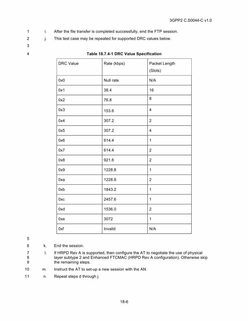
3GPP2 C.S0044-C v1.0
18-6
i. After the file transfer is completed successfully, end the FTP session. 1
j. This test case may be repeated for supported DRC values below. 2
3
Table 18.7.4-1 DRC Value Specification 4
DRC Value Rate (kbps) Packet Length
(Slots)
0x0 Null rate N/A
0x1 38.4 16
0x2 76.8 8
0x3 153.6 4
0x4 307.2 2
0x5 307.2 4
0x6 614.4 1
0x7 614.4 2
0x8 921.6 2
0x9 1228.8 1
0xa 1228.8 2
0xb 1843.2 1
0xc 2457.6 1
0xd 1536.0 2
0xe 3072 1
0xf Invalid N/A
5
k. End the session. 6
l. If HRPD Rev A is supported, then configure the AT to negotiate the use of physical 7 layer subtype 2 and Enhanced FTCMAC (HRPD Rev A configuration). Otherwise skip 8 the remaining steps. 9
m. Instruct the AT to set-up a new session with the AN. 10
n. Repeat steps d through j. 11
3GPP2 C.S0044-C v1.0
18-7
18.7.5 Minimum Standard 1
The AN and AT shall comply with step g. 2
The AN and AT should comply with step h. 3
18.8 Reverse File Transfer 4
18.8.1 Definition 5
This test verifies HRPD reverse link file transfer when in active HRPD mode. This test case may 6 be performed using Simple IP or Mobile IP. 7
18.8.2 Traceability: 8
(see [24]) 9
7 Session Layer, 8 Connection Layer, 10 MAC Layer 10
(see [26]) 11
3 HRPD IOS Call Flows 12
18.8.3 Call Flow Example(s) 13
None 14
18.8.4 Method of Measurement 15
a. Connect the AT to the AN as shown in Figure A-3. 16
b. Configure the AT to negotiate the use of Subtype 0 RTCMAC (HRPD Rev 0 17 configuration). 18
c. Cause the AT to acquire the AN. Setup an HRPD AT originated connection. 19
d. Setup a FTP session with a remote host and start a file transfer in the reverse link by 20 using a binary “put” command from the AT. 21
e. Verify the file transfer completes. 22
f. Verify that for the duration of the test the PER for the packets received at the AN is less 23 than 1.25%. 24
g. After the file transfer is completed, end the FTP session. 25
h. Instruct the AN to close the session with the AT. 26
i. If HRPD Rev A is supported, then configure the AT to negotiate the use of physical 27 layer subtype 2 and Subtype 3 RTC MAC (HRPD Rev A configuration). Otherwise skip 28 the remaining steps. 29
j. Instruct the AT to set-up a new session with the AN. 30
k. Repeat steps c to g. 31
18.8.5 Minimum Standard 32
The AN and the AT shall comply with step e. 33
The AN and the AT should comply with step f. 34
3GPP2 C.S0044-C v1.0
18-8
18.9 Bidirectional File Transfer 1
18.9.1 Definition 2
This test verifies bi-directional file transfer when in active HRPD mode. 3
18.9.2 Traceability: 4
(see [24]) 5
7 Session, 8 Connection Layer, 10 MAC Layer 6
(see [26]) 7
3 HRPD IOS Call Flows 8
18.9.3 Call Flow Example(s) 9
None 10
18.9.4 Method of Measurement 11
a. Connect the AT to the AN as shown in Figure A-3. 12
b. Cause the AT to acquire the AN. Setup an HRPD AT originated connection. 13
c. At the remote host prepare the appropriate file, corresponding to the rate that will be 14 tested (Note: this will guarantee sufficient transfer time). 15
d. Setup a FTP session (1) with a remote host and start a file transfer in the reverse link 16 by using a binary “put” command from the AT. 17
e. Setup another FTP session (2) and transfer a file from the Remote Host to the AT using 18 the binary “get” command while the transfer in the reverse direction is still proceeding. 19
f. Verify both file transfers complete. 20
g. After the file transfer, end both FTP sessions. 21
18.9.5 Minimum Standard 22
The AT shall comply with step f. 23
18.10 RLP Operation in Severely Degraded Channel 24
18.10.1 Definition 25
This test verifies RLP Operation in Severely Degraded Channel when in active HRPD mode. 26
18.10.2 Traceability: 27
(see [24]) 28
7 Session, 8 Connection Layer, 10 MAC Layer 29
(see [26]) 30
3 HRPD IOS Call Flows 31
See [12] 32
Chapters 2 and 3 33
18.10.3 Call Flow Example(s) 34
None 35
3GPP2 C.S0044-C v1.0
18-9
18.10.4 Method of Measurement 1
a. Connect the AT to the AN as shown in [Figure A-1]. At the remote host prepare the 2 appropriate file, corresponding to the rate that will be tested (Note: this will guarantee 3 sufficient transfer time). Refer to files in Data Services Annex D. 4
b. Set the channel simulator to one Ray 100 km/hr Rayleigh fading on the forward link. 5
c. Configure the AT to negotiate the use of Default Packet Application (HRPD Rev 0 6 configuration) bound to the Service Network. 7
d. Cause the AT to acquire the AN. Setup an AT originated HRPD call. 8
e. Setup a FTP session with a remote host and start a file transfer in the forward link by 9 using a binary “get” command from the AT. 10
f. Verify the AT sends a valid DRC value in the Data Rate Control Channel to the AN and 11 that the AN provides the AT with requested forward link coding and modulating 12 parameters. 13
g. Ensure data transfer rate is not limited by network limitations. 14
h. Verify the data transfer is successful. 15
i. After the file transfer is completed, end the FTP session. 16
j. Instruct the AN to close the session with the AT. 17
k. Configure the AT to negotiate the use of Multi-Flow Packet Application or Enhanced 18 Multi-Flow Packet Application (HRPD Rev A configuration) or Multi-Link Multi-Flow 19 Packet Application bound to the Service Network. 20
l. Repeat steps d to i. 21
18.10.5 Minimum Standard 22
The AT shall comply with steps f and h. 23
18.11 Softer and Soft Handoff – Active HRPD Mode 24
18.11.1 Definition 25
This test verifies soft handoff when AT is in active HRPD mode with file transfer in forward and 26 reverse directions. 27
18.11.2 Traceability: 28
(see [24]) 29
7 Session, 30
8 Connection Layer; 31
8.7.7.2.2 SetManagementSameChannelParameters Attribute 32
10 MAC Layer 33
(see [26]) 34
3 HRPD IOS Call Flows 35
18.11.3 Call Flow Example(s) 36
None 37
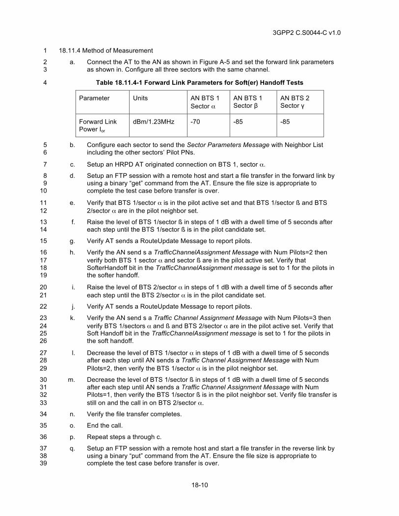
3GPP2 C.S0044-C v1.0
18-10
18.11.4 Method of Measurement 1
a. Connect the AT to the AN as shown in Figure A-5 and set the forward link parameters 2 as shown in. Configure all three sectors with the same channel. 3
Table 18.11.4-1 Forward Link Parameters for Soft(er) Handoff Tests 4
Parameter Units AN BTS 1 Sector α
AN BTS 1 Sector β
AN BTS 2 Sector γ
Forward Link Power Ior
dBm/1.23MHz -70 -85 -85
b. Configure each sector to send the Sector Parameters Message with Neighbor List 5 including the other sectors’ Pilot PNs. 6
c. Setup an HRPD AT originated connection on BTS 1, sector α. 7
d. Setup an FTP session with a remote host and start a file transfer in the forward link by 8 using a binary “get” command from the AT. Ensure the file size is appropriate to 9 complete the test case before transfer is over. 10
e. Verify that BTS 1/sector α is in the pilot active set and that BTS 1/sector ß and BTS 11 2/sector α are in the pilot neighbor set. 12
f. Raise the level of BTS 1/sector ß in steps of 1 dB with a dwell time of 5 seconds after 13 each step until the BTS 1/sector ß is in the pilot candidate set. 14
g. Verify AT sends a RouteUpdate Message to report pilots. 15
h. Verify the AN send s a TrafficChannelAssignment Message with Num Pilots=2 then 16 verify both BTS 1 sector α and sector ß are in the pilot active set. Verify that 17 SofterHandoff bit in the TrafficChannelAssignment message is set to 1 for the pilots in 18 the softer handoff. 19
i. Raise the level of BTS 2/sector α in steps of 1 dB with a dwell time of 5 seconds after 20 each step until the BTS 2/sector α is in the pilot candidate set. 21
j. Verify AT sends a RouteUpdate Message to report pilots. 22
k. Verify the AN send s a Traffic Channel Assignment Message with Num Pilots=3 then 23 verify BTS 1/sectors α and ß and BTS 2/sector α are in the pilot active set. Verify that 24 Soft Handoff bit in the TrafficChannelAssignment message is set to 1 for the pilots in 25 the soft handoff. 26
l. Decrease the level of BTS 1/sector α in steps of 1 dB with a dwell time of 5 seconds 27 after each step until AN sends a Traffic Channel Assignment Message with Num 28 Pilots=2, then verify the BTS 1/sector α is in the pilot neighbor set. 29
m. Decrease the level of BTS 1/sector ß in steps of 1 dB with a dwell time of 5 seconds 30 after each step until AN sends a Traffic Channel Assignment Message with Num 31 Pilots=1, then verify the BTS 1/sector ß is in the pilot neighbor set. Verify file transfer is 32 still on and the call in on BTS 2/sector α. 33
n. Verify the file transfer completes. 34
o. End the call. 35
p. Repeat steps a through c. 36
q. Setup an FTP session with a remote host and start a file transfer in the reverse link by 37 using a binary “put” command from the AT. Ensure the file size is appropriate to 38 complete the test case before transfer is over. 39
3GPP2 C.S0044-C v1.0
18-11
r. Repeat steps e through p. 1
18.11.5 Minimum Standard 2
The AT shall comply with steps g, j, l, m and n 3
The AN shall comply with steps e, h, k, l, m and n. 4
18.12 HRPD Control Channel Monitoring and Overhead Message Updates 5
18.12.1 Definition 6
This test will verify that the AT can successfully receive and update control channel messages. 7 And the AN can set various periodicities (within the allowed range, as defined in [24]) for these 8 messages. 9
18.12.2 Traceability 10
(see [24]) 11
8.4 Default Idle State Protocol 12
8.5 Enhanced Idle State Protocol 13
18.12.3 Call Flow Example(s) 14
None 15
18.12.4 Method of measurement 16
a. Power up the AT. 17
b. Configure the AT to operate in non-slotted (sleep disabled) mode 18
c. Monitor the periodicity of Sync message, Quickconfig message, SectorParameter 19 message, and AccessParameter message 20
d. Check the AN configuration for periodicity of these messages. Verify that received 21 messages have same periodicity as configured at the AN 22
e. Configure the AT to operate in slotted (sleep enabled) mode 23
f. Verify that AT receives and updates the overhead messages (QuickConfig and 24 SectorParameter messages) and performs the supervision of these messages 25 according to the procedures in overhead message protocol specified in [24]. 26
18.12.5 Minimum Standard 27
The AT shall comply with steps d and f. 28
18.13 Control Channel Rate 29
18.13.1 Definition 30
This test verifies correct monitoring of Control Channel by AT. 31
18.13.2 Traceability: 32
(see [24]) 33
10.2 Default Control Channel MAC Protocol 34
10.2.6.1.4.1.1 General Requirements 35
10.2 Enhanced Control Channel MAC Protocol 36
3GPP2 C.S0044-C v1.0
18-12
12.3 and 13.3 AN Requirements 1
12.3.1.3.1 and 13.3.1.3.1 Forward Channel Structure 2
12.3.1.3.2.2 and 13.3.1.3.2.2 Forward MAC Channel 3
12.3.1.3.2.4 and 13.3.1.3.2.4 Control Channel 4
18.13.3 Call Flow Example(s) 5
None 6
18.13.4 Method of Measurement 7
a. Configure Control Channel Rate to 38400 bps on AN. 8
b. Connect the AT to the AN as shown in Figure A-3 9
c. Verify AT is able to monitor SyncChannel Message, QuickConfig Message, Sector 10 Parameters Message and AccessParameters Message. 11
d. Instruct AT to request a UATI from AN and Setup an HRPD AT originated call. Issue a 12 “ping” from AT. 13
e. Release the call. 14
f. Configure Control Channel Rate to 76800 bps on AN and repeat steps b through e. 15
18.13.5 Minimum Standard 16
The AT shall comply with step c. 17
18.14 HRPD ConnectionDeny 18
18.14.1 Definition 19
This test verifies that if there is no traffic channel available, the AN will send a ConnectionDeny 20 Message to AT. This test also verifies that upon receiving a ConnectionDeny Message the AT will 21 enter idle state until it attempts to make another call. 22
18.14.2 Traceability: 23
(see [24]) 24
8.4 Default Idle State Protocol 25
8.4.6.1.6.1 AT Requirements 26
8.4.6.1.6.2 AN Requirements 27
8.4.6.2.3 ConnectionDeny 28
8.5 Enhanced Idle State Protocol 29
18.14.3 Call Flow Example(s) 30
None 31
18.14.4 Method of Measurement 32
a. Configure the AN to respond with a ConnectionDeny with reason “Network Busy” to a 33 ConnectionAttempt message. 34
b. Attempt to setup an AT originated HRPD connection. 35
3GPP2 C.S0044-C v1.0
18-13
c. Verify the AN sends a Connection Deny Message with Deny Reason 1 = Network Busy. 1
d. Verify the AT enters the AT Monitor (Idle) State until it attempts to setup a new call 2
18.14.5 Minimum Standard 3
The AT shall comply with step d. 4
The AN shall comply with step c. 5
18.15 HRPD Keep Alive Mechanism 6
18.15.1 Definition 7
This test verifies the proper functionality of keep alive mechanism. The AT and the AN shall 8 monitor the traffic flowing on the Forward Channel and Reverse Channel, respectively, directed to 9 or from the AT. If either the AT or the AN detects a period of inactivity of at least 10 TSMPClose/NSMPKeepAlive minutes, it may send a KeepAliveRequest message. The recipient of the 11 message shall respond by sending the KeepAliveResponse message. When a 12 KeepAliveResponse message is received, the AT shall not send another KeepAliveRequest 13 message for at least TSMPClose/NSMPKeepAlive minutes. 14
18.15.2 Traceability 15
(see [24]) 16
7.2.6.1.6.1 Keep Alive Functions 17
Table 7.2.711and Table 7.2.8 18
18.15.3 Call Flow Example(s) 19
None 20
18.15.4 Method of measurement 21
a. Power up the AT and place it where it can receive good HRPD signal. Configure the AN 22 to negotiate TSMPClose to 0x0005 with the AT. 23
b. Ensure that the AT acquires the AN and goes to idle state. 24
c. Terminate all data activities to and from the AT for a period greater than TSMPClose / 25 NSMPKeepAlive minutes. 26
d. Verify that after an inactivity period of TSMPClose / NSMPKeepAlive minutes if either the AT or 27 the AN sends a KeepAliveRequest and that the recipient of the KeepAliveRequest 28 message responds with a KeepAliveResponse message. 29
e. If the AT receives a KeepAliveResponse message, verify that the AT does not send 30 another KeepAliveRequest message for at least another TSMPClose / NSMPKeepAlive minutes 31
f. Power down the AT. Power up the AT after TSMPClose minutes. Verify that the AT 32 terminates the old session. 33
18.15.5 Minimum Standard 34
The AT shall comply with steps d, e and f. 35
The AN shall comply with step d. 36
3GPP2 C.S0044-C v1.0
18-14
18.16 Intra-band HRPD-HRPD System Re-Selection (Connected State) 1
18.16.1 Definition 2
This test verifies the AT performs HRPD system reselection between different channels in the 3 same band class. For this test case, the HRPD session and PPP session are connected and 4 active. The test will be performed while transferring data on the forward link and then repeated on 5 the reverse link. 6
18.16.2 Traceability: 7
(see [24]) 8
8.2 Default Air Link Management Protocol 9
8.2.6.1.2 Initialization State 10
8.4 Default Idle State Protocol 11
8.4.6.1.6 Connection Setup State 12
8.6 Default Connected State Protocol 13
8.5 Enhanced Idle State Protocol 14
(see [26]) 15
3.7.1 PCF-PCF Dormant Handoff with Successful Retrieval of HRPD Session 16 Information 17
18.16.3 Call Flow Example(s) 18
None 19
18.16.4 Method of Measurement 20
a. Connect the AT to AN 1 and AN 2 as shown in Figure A-5. 21
b. Configure AN 1 with different channel than AN 2. 22
c. Configure AN 2 not to be in the neighbor list of AN 1. 23
d. Cause the AT to acquire AN 1. Setup an HRPD AT originated connection. 24
e. Setup a FTP session with a remote host and start a file transfer in the forward link by 25 using a binary “get” command from the AT. 26
f. Before file transfer is complete increase forward link attenuation on AN 1 until AT can’t 27 monitor AN 1 signal. 28
g. Verify AT declares system lost and acquires AN 2 and reconnects HRPD connection. 29 Verify file transfer continues after selection AN 2. 30
h. Release connection. 31
i. Repeat steps b through g for file transfer in the reverse link by using a binary “put” 32 command from the AT instead of “get” (step e). 33
18.16.5 Minimum Standard 34
The AT shall comply with step g for all test cases. 35
3GPP2 C.S0044-C v1.0
18-15
18.17 Inter-band HRPD-HRPD System Re-Selection (Connected State) 1
18.17.1 Definition 2
This test verifies the AT performs HRPD system reselection between channels from different 3 band classes. For this test case, the HRPD session and PPP session are connected and active. 4 The test will be performed while transferring data on the forward link and then repeated on the 5 reverse link. 6
18.17.2 Traceability: 7
(see [24]) 8
8.2 Default Air Link Management Protocol 9
8.2.6.1.2 Initialization State 10
8.4 Default Idle State Protocol 11
8.4.6.1.6 Connection Setup State 12
8.6 Default Connected State Protocol 13
8.5 Enhanced Idle State Protocol 14
(see [26]) 15
3.7.1 PCF-PCF Dormant Handoff with Successful Retrieval of HRPD Session 16 Information 17
18.17.3 Call Flow Example(s) 18
None 19
18.17.4 Method of Measurement 20
a. Connect the AT to AN 1 and AN 2 as shown in Figure A-5. 21
b. Configure AN 1 to operate in a different band class than AN 2. 22
c. Cause the AT to acquire AN 1. Setup an HRPD AT originated connection. 23
d. Setup a FTP session with a remote host and start a file transfer in the forward link by 24 using a binary “get” command from the AT. 25
e. Before file transfer is complete increase forward link attenuation on AN 1 until AT can’t 26 monitor AN 1 signal. 27
f. Verify AT declares system lost and acquires AN 2 and reconnects HRPD call. Verify file 28 transfer continues after selection AN 2. 29
g. Release connection. 30
h. Repeat steps b through g for file transfer in the reverse link by using a binary “put” 31 command from the AT instead of “get” (step e). 32
18.17.5 Minimum Standard 33
The AT shall comply with step f for all test cases. 34
3GPP2 C.S0044-C v1.0
18-16
18.18 Intra-band HRPD-HRPD System Re-selection (Idle State) 1
18.18.1 Definition 2
This test verifies the AT performs HRPD reselection, while in idle state, between channels in the 3 same band class. This test is performed after the HRPD and PPP session have been established. 4 The PPP session for the AT shall be in the dormant state and the AT is not on the traffic channel 5 at the time of the system reselection. 6
18.18.2 Traceability 7
(see [24]) 8
8.2 Default Air Link Management Protocol 9
8.2.6.1.2 Initialization State 10
8.4 Default Idle State Protocol 11
8.4.6.1.6 Connection Setup State 12
8.6 Default Connected State Protocol 13
8.5 Enhanced Idle State Protocol 14
(see [26]) 15
3.7.1 PCF-PCF Dormant Handoff with Successful Retrieval of HRPD Session 16 Information 17
18.18.3 Call Flow Example(s) 18
None 19
18.18.4 Method of Measurement 20
a. Connect the AT to AN 1 and AN 2 as shown in Figure A-5. 21
b. Configure AN 1 with different channel than AN 2. 22
c. Configure AN 2 not to be in the neighbor list of AN 1. 23
d. Cause the AT to acquire AN 1. Setup an HRPD AT originated call. 24
e. Verify that the AT connection is idle. 25
f. Force the AT to handoff from AN 1 to AN 2 (i.e. by increasing forward link attenuation 26 on AN 1 until AT can’t monitor AN 1 RF signal). 27
g. Verify AT declares system lost and acquires AN 2. Issue a “ping” from AT and verify an 28 HRPD connection is successfully setup. 29
h. Issue a “ping” from remote host to AT IP address and verify there is a response. 30
18.18.5 Minimum Standard 31
The AT shall comply with steps e, g and h. 32
18.19 Inter-band HRPD-HRPD System Re-selection (Idle State) 33
18.19.1 Definition 34
This test verifies the AT, performs HRPD reselection, while in idle state, between channels from 35 different band classes. The test may be performed using Simple IP and/or Mobile IP. This test is 36 performed after the HRPD and PPP session have been established. The PPP session for the AT 37
3GPP2 C.S0044-C v1.0
18-17
shall be in the dormant state and the AT is not on the traffic channel at the time of the system 1 reselection. 2
18.19.2 Traceability 3
(see [24]) 4
8.2 Default Air Link Management Protocol 5
8.2.6.1.2 Initialization State 6
8.4 Default Idle State Protocol 7
8.4.6.1.6 Connection Setup State 8
8.6 Default Connected State Protocol 9
8.5 Enhanced Idle State Protocol 10
(see [26]) 11
3.7.1 PCF-PCF Dormant Handoff with Successful Retrieval of HRPD Session 12 Information 13
18.19.3 Call Flow Example(s) 14
None 15
18.19.4 Method of Measurement 16
a. Connect the AT to AN 1 and AN 2 as shown in Figure A-5. 17
b. Configure AN 1 to operate in a different band class than AN 2. 18
c. Cause the AT to acquire AN 1. 19
d. Verify that AT connection is idle. 20
e. Force the AT to handoff from AN 1 to AN 2 (i.e. by increasing forward link attenuation 21 on AN HRPD 1 until AT can’t monitor HRPD 1 RF signal). 22
f. Verify AT declares system lost and acquires AN 2. Issue a “ping” from AT and verify 23 HRPD call is successfully originated. 24
g. Issue a “ping” from remote host to AT IP address and verify there is a response. 25
18.19.5 Minimum Standard 26
The AT shall comply with steps d, f and g. 27
18.20 HRPD Terminal Authentication 28
18.20.1 Definition 29
This test verifies that when the User-name or the CHAP-password is incorrectly set at the AT the 30 network authentication fails. 31
18.20.2 Traceability: 32
(see [11]) 33
3.1.1 AT originates HRPD Session – Successful Terminal Authentication 34
3GPP2 C.S0044-C v1.0
18-18
3.1.2 AT originates HRPD Session – Unsuccessful Terminal Authentication 1
18.20.3 Call Flow Example(s) 2
None 3
18.20.4 Method of measurement 4
a. Configure the CHAP authentication to be enabled in the network. 5
b. Provision the AT with the correct information to successfully pass CHAP authentication. 6
c. Ensure the AT has a closed HRPD session. 7
d. Power up the AT and allow it to acquire the HRPD network. 8
e. If AN performs authentication immediately after the session negotiation, verify that AN 9 sends the CHAP Challenge message and initiates the network authentication 10
f. Verify that the network authentication passes and the HRPD remains connected. 11
g. If AN performs authentication just before the data call setup(s), set up a data call on the 12 HRPD system and verify that AN sends the CHAP Challenge message and initiates the 13 AN authentication 14
h. Verify that the network authentication passes and the HRPD call is successful. 15
i. End any HRPD calls. 16
j. Provision an incorrect User-name but a correct Chap-password in the AT for CHAP 17 authentication. 18
k. Ensure that the AT has a closed HRPD session 19
l. Power up the AT and place it where it can receive good HRPD signal 20
m. Ensure that AT successfully completes the session negotiation and negotiates the AN 21 stream as part of this procedure. 22
n. If AN performs authentication immediately after the session negotiation, verify that AN 23 sends the CHAP Challenge message and initiates the network authentication 24
o. Verify that the network authentication fails and the AN closes the HRPD session. 25
p. If AN performs authentication just before the data call setup(s), set up a data call on the 26 HRPD system and verify that AN sends the CHAP Challenge message and initiates the 27 AN authentication 28
q. Verify that the network authentication fails. 29
r. Repeat steps l to g by provisioning a correct User-name but an incorrect Chap-30 password in the AT for CHAP authentication. 31
18.20.5 Minimum Standard 32
The AT shall comply with steps f, h, and q. 33
The AN shall comply with steps e, f, h, n, o, p and q. 34
18.21 PPP Session in Adverse Conditions - Disconnect cable between AT and PC. 35
18.21.1 Definition 36
This test verifies AT sends an LCP Termination Request to the AN when it is disconnected from 37 the computer device. This causes the PDSN to close the PPP session. 38
3GPP2 C.S0044-C v1.0
18-19
18.21.2 Traceability: 1
(see [28]) 2
3.2.1 PPP Session 3
18.21.3 Call Flow Example(s) 4
None 5
18.21.4 Method of Measurement 6
a. Setup an AT originated HRPD connection. 7
b. Ensure that an IP address is assigned to the AT, and a PPP session is established 8 between PDSN and the AT. 9
c. Wait until the AT connection goes to idle state. 10
d. Close the PPP session from the AT to the AN without notifying the AN by disconnecting 11 the cable between the AT and the computer. 12
e. Verify that the AT transmits XOffRequest and ConnectionClose messages to the AN. 13
18.21.5 Minimum Standard 14
The AT shall comply with step e. 15
18.22 Unicast ReverseRateLimit 16
18.22.1 Definition 17
This test verifies the AT can successfully receive the UnicastReverseRateLimit Message with the 18 RateLimit value set to various values. This test is applicable to HRPD Rev 0 operation. Rev A AT 19 should be configured to negotiate Rev 0 supported protocol subtypes and default packet 20 application. 21
18.22.2 Traceability 22
(see [24]) 23
10.8.6.1.5.2 and 10.9.6.1.5.2 Rate Control 24
18.22.3 Call Flow Example(s) 25
None 26
18.22.4 Method of measurement 27
a. Configure the AT to negotiate Subtype 0 RTCMAC. Setup a connection. 28
b. Setup a FTP session with a remote host and start a file transfer in the reverse link by 29 using a binary “put” command from the AT. 30
c. Send a UnicastReverseRateLimit Message with the RateLimit value set to 1 (9.6 kbps) 31 to the AT. 32
d. Monitor the AT transmit rate and verify that the AT does not transmit above the value 33 set in step c. 34
e. Steps a to d may be repeated with the RateLimit values set to 2 (19.2kbps), 3 35 (38.4kbps), 4 (76.8kpbs), and 5 (153.6kbps). 36
18.22.5 Minimum Standard 37
The AT shall comply with step d for all test cases. 38
3GPP2 C.S0044-C v1.0
18-20
18.23 HRPD Location Update Protocol Tests 1
18.23.1 Definition 2
This test verifies the proper functionality of Location update feature. 3
18.23.2 Traceability 4
(see [24]) 5
3.5 and 4.6 Location Update Protocol 6
(see [12]) 7
Chapters 2 and 3. 8
18.23.3 Call Flow Example(s) 9
None 10
18.23.4 Method of measurement 11
a. Ensure that the Ranhandoff parameter is enabled at the AN. 12
b. Power up the AT and place it where it can receive good HRPD signal 13
c. Ensure that AT successfully completes the session negotiation. 14
d. Depending on the implementation, the AN can send LocationAssignment Message to 15 the AT. Upon receiving this LocationAssignment Message, verify that the AT sends a 16 LocationComplete Message and stores the Location Values in the Location Assignment 17 Message as the current Location Values. 18
e. Depending on the implementation, the AN can send LocationRequest Message. Upon 19 receipt of this message, verify that the AT responds with LocationNotification Message, 20 which shall contain the current Location values of the AT. 21
f. Originate a packet connection, verify that the connection can be successfully 22 established and the data can be transferred. Let the AT connection go idle. Move the 23 AT to an area where there is no HRPD signal. AT will lose the HRPD signal and go to 24 acquisition state. Move the AT to an area where there is a HRPD signal belonging to a 25 different subnet. AT shall acquire this system. Ensure that the AN rejects the 26 PriorSession restore request from the AT. AT shall negotiate session with this HRPD 27 system and once the session is negotiated, shall send an unsolicited 28 LocationNotification Message. Verify that this message is sent. 29
18.23.5 Minimum Standard 30
The AT shall comply with steps d, e, and f. 31
18.24 Idle State Channel Hashing 32
18.24.1 Definition 33
This test can be performed only if the AN supports more than one HRPD channels. 34
If multiple channels are advertised in the sector parameter message, AT uses hash function (as 35 specified in (See [24])) to select one of the advertised channels for idle state operation. The 36 primary purpose of channel hashing is to equally distribute the AN load on all available channels. 37
18.24.2 Traceability 38
(see [24]) 39
3GPP2 C.S0044-C v1.0
18-21
8.4.6.1.5.1.1 CDMA Channel Selection 1
10.4 Hash Function 2
18.24.3 Call Flow Example(s) 3
None 4
18.24.4 Method of measurement 5
a. Configure the AT roaming list with the primary channel. Configure the AT to negotiate 6 default idle state protocol. 7
b. Power up the AT. 8
c. Place AT where it can receive good HRPD signal. 9
d. If the AT has an open session with the AN, cause the AN to close the session. Cause 10 the AT to establish a new session with the AN. 11
e. Ensure that AT correctly acquires the primary channel listed in the roaming list. 12
f. After receiving the sector parameter messages with multiple channels, AT will try to 13 hash to a channel listed in SectorParameter message (it could be the same channel in 14 some cases). 15
g. Verify that if there are “n” channels listed in the sector parameter message and if this 16 test is repeated “m” number of times, AT will hash to each channel approximately “m/n” 17 times. In a subnet where SectorParameter message contains multiple channels, AT will 18 try to hash to a new channel every time a new session is opened. 19
h. Repeat steps d through g approximately 3n times. 20
i. Setup a HRPD data connection after channel hashing is complete to verify that AT can 21 setup a connection on the hashed channel. Let the call connection go idle. 22
j. Send a data page from the AN (on the hashed channel) and verify that AT can receive 23 a page on the hashed channel. 24
18.24.5 Minimum Standard 25
The AT shall comply with steps g, i and j. 26
18.25 Inter-frequency Active Handoff 27
18.25.1 Definition 28
This test verifies that the AT is able to successfully acquire a new AN with a different frequency 29 assignment during an active call. The AT will receive a new TrafficChannelAssignment message 30 with the target frequency information. Since there is no hard handoff mechanism in HRPD, using 31 the new TrafficChannelAssignment allows for faster acquisition of AN 2. 32
18.25.2 Traceability 33
(see [24]) 34
8.2 Default Air Link Management Protocol 35
8.2.6.1.2 Initialization State 36
8.4 Default Idle State Protocol 37
8.4.6.1.6 Connection Setup State 38
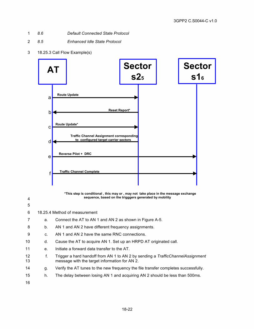
3GPP2 C.S0044-C v1.0
18-22
8.6 Default Connected State Protocol 1
8.5 Enhanced Idle State Protocol 2
18.25.3 Call Flow Example(s) 3
SectorAT
Reverse Pilot + DRC
Traffic Channel Complete
Traffic Channel Assignment correspondingto configured target carrier sectors
a Route Update
c
d
e
Sectors25
Sectors16
Reset Report*b
Route Update*
*This step is conditional , this may or , may not take place in the message exchangesequence, based on the trigggers generated by mobility
f
4 5
18.25.4 Method of measurement 6
a. Connect the AT to AN 1 and AN 2 as shown in Figure A-5. 7
b. AN 1 and AN 2 have different frequency assignments. 8
c. AN 1 and AN 2 have the same RNC connections. 9
d. Cause the AT to acquire AN 1. Set up an HRPD AT originated call. 10
e. Initiate a forward data transfer to the AT. 11
f. Trigger a hard handoff from AN 1 to AN 2 by sending a TrafficChannelAssignment 12 message with the target information for AN 2. 13
g. Verify the AT tunes to the new frequency the file transfer completes successfully. 14
h. The delay between losing AN 1 and acquiring AN 2 should be less than 500ms. 15
16
3GPP2 C.S0044-C v1.0
18-23
18.25.5 Minimum Standard 1
The AT shall comply with step g and should comply with step h. 2
18.26 Typical HRPD Rev-A Session Configuration 3
18.26.1 Definition 4
This test verifies the ability of AT and AN to use typical HRPD Rev A configuration. The use of 5 MFPA bound to the service network, Enhanced FTCMAC, RTCMAC subtype 3, Enhanced 6 CCMAC, Enhanced ACMAC and Physical layer Subtype 2 is verified. 7
18.26.2 Traceability 8
(see [24]) 9
4 Multi-Flow Packet Application 10
7.2.6.2.1 Session Close 11
8.5 Enhanced Idle State Protocol 12
10.3 Enhanced Control Channel MAC Protocol 13
10.5 Enhanced Access Channel MAC Protocol 14
10.7 Enhanced Forward Traffic Channel MAC Protocol 15
10.11 Subtype 3 Reverse Traffic Channel MAC Protocol 16
11.2 Subtype 2 Physical Layer 17
(see [12]) 18
Chapters 2 and 3. 19
18.26.3 Call Flow Example(s) 20
None 21
18.26.4 Method of measurement 22
a. Connect the AT to the AN as shown in Figure A-3. 23
b. Cause the AT to acquire the AN. 24
c. Configure the AT to negotiate the use of Multi-Flow Packet Application or Enhanced 25 Multi-Flow Packet Application or Multi-Link Multi-Flow Packet Application bound to the 26 service network, Physical layer subtype 2, Enhanced CCMAC, Enhanced ACMAC, 27 Enhanced FTCMAC, Enhanced Idle State Protocol and Subtype 3 RTC MAC. 28
d. If the AT has an established session with the AN, cause the AN to close the session by 29 transmitting a SessionClose message. 30
e. Power cycle the AT. 31
f. Verify that the AT establishes a session with the AN and acquires the HRPD system. 32
g. Cause the AT to initiate a data call with the AN. 33
h. Verify that the AT and the AN have successfully negotiated the use of Multi-Flow 34 Packet Application or Enhanced Multi-Flow Packet Application or Multi-Link Multi-Flow 35 Packet Application bound to the AN, Physical layer Subtype 2, Enhanced FTCMAC 36
3GPP2 C.S0044-C v1.0
18-24
Enhanced CCMAC, Enhanced ACMAC, Enhanced Idle State Protocol and Subtype 3 1 RTCMAC. 2
i. Cause the AT to transmit data to the AN. 3
j. Verify that the data is transmitted using the default RLP flow of the MFPA. 4
18.26.5 Minimum Standard 5
The AT shall comply with steps f, h and j. 6
The AN shall comply with step h. 7
18.27 Multiple Reservations bound to one RLP 8
18.27.1 Definition 9
In HRPD Rev A, multiple higher layer flows can be bound to a single RLP flow. This is done by 10 mapping the ReservationLabel associated with the higher layer flow in FlowNNReservationFwd 11 and FlowNNReservationRev attribute of the RLP Flow NN. This test verifies the ability of the AN 12 and the AT to successfully bind multiple reservations to a single RLP flow. 13
This test requires the ability to generate QoS requests from the AT, allocate QoS resources at the 14 AN and install traffic filtering at the PDSN. The application that causes the AT to generate QoS 15 requests could either reside at the AT or the TE. Further, it should be ensured that the application 16 is able to connect with the server/peer and receive and transmit data. This may require password 17 authentication when using commercial applications residing on the AT. 18
The following behavior is assumed for the application using the QoS. Starting the application will 19 cause ReservationKKQoSRequestFwd/Rev to be sent containing the requested Profile ID. Unless 20 otherwise specified, the Profile should be accepted by the AN. Closing the application will cause 21 the AT to transmit a ReservationKKQoSRequestFwd/Rev with ProfileType set to NULL. If 22 application is paused or restarted, it should turn the reservation to on state if the reservation is in 23 closed state. This application behavior is assumed for all QoS related tests in this chapter. 24
18.27.2 Traceability 25
(see [24]) 26
4.4.4 Procedures and Messages for the InUse Instance of the RLP 27
4.4.8 Complex Attributes of Multi-Flow Packet Application 28
(see 17]) 29 11.4 QoS ProfileType and ProfileValue Assignment 30 (see [10]) 31 (see [12]) 32 Chapters 2 and 3. 33
18.27.3 Call Flow Example(s) 34
None 35
18.27.4 Method of measurement 36
a. Connect the AT to the AN as shown in Figure A-3. 37
b. Cause the AT to acquire the AN. 38
c. Configure the AT to negotiate the use of Multi-Flow Packet Application or Enhanced 39 Multi-Flow Packet Application or Multi-Link Multi-Flow Packet Application bound to the 40 service network, Physical layer subtype 2, Enhanced FTCMAC and Subtype 3 RTC 41 MAC. 42
3GPP2 C.S0044-C v1.0
18-25
d. Configure the AN to activate only the default RLP flow during session configuration. 1
e. Configure the AN to use a value of 2 for MaxActivatedRLPFlowsFwd and 2 MaxActivatedRLPFlowRev. 3
f. If the AT has an established session with the AN, cause the AN to close the session by 4 transmitting a SessionClose message. 5
g. Cause the AT to negotiate a new session with the AN. 6
h. Cause the AT to establish a data call with the AN and allow the AT to go idle. 7
i. Cause the AT to generate a QoS request for one forward and one reverse link higher 8 layer flow. 9
j. Ensure that the AT transmits GAUP message(s) with ReservationKKQoSRequestFwd 10 with R_QoS_SUB_BLOB containing the specified Profile ID for forward higher layer 11 flows and ReservationKKQoSRequestRev with R_QoS_SUB_BLOB containing the 12 specified Profile ID for reverse higher layer flows. 13
k. Ensure that the AT constructs a Traffic Flow Template (TFT) with the desired packet 14 filters and sends an RSVP Resv [Create new TFT] message. 15
l. Ensure that the AN transmits AttributeUpdateAccept message(s) accepting the QoS 16 ReservationKKQoSRequestFwd / ReservationKKQoSRequestRev attributes from the 17 AT. 18
m. The AN should GAUP the ReservationKKQoSResponseFwd with G_QoS_BLOB 19 containing the set ID for primary Profile ID. 20
n. The AN should GAUP the ReservationKKQoSResponseRev with G_QoS_BLOB 21 containing the set ID for primary Profile ID. 22
o. The PDSN should install the desired packet filters and sends an RSVP ResvConf 23 message. 24
p. Ensure that the AT transmits AttributeUpdate message(s) to the AN accepting the AN’s 25 ReservationKKQosResponseFwd and ReservationKKQosResponseRev for the various 26 Reservarion Labels. 27
q. Ensure that the AN transmits a GAUP message for FlowNNIdentificationFwd (NN = 1) 28 and FlowNNIdentificationRev (NN = 1) in order to activate the forward and reverse link 29 flows. 30
r. Ensure that the AT transmits AttributeUpdateAccept message(s) accepting 31 FlowNNIdentificationFwd and FlowNNIdentificationRev arrtibutes. 32
s. The AN may need to transmit AttributeUpdateRequest message(s) negotiating the 33 FlowNNTimersFwd and FlowNNTimersRev for the Forward and Reverse link RLP flows 34 and various parameters of the RTCMAC flow. 35
t. If the AN transmits Attribute Update Request for the Forward and Reverse Link RLP 36 Flows and/or RTCMAC flows, the AT should transmit AttributeUpdateAccept 37 message(s) accepting RLP and RTCMAC parameters. 38
u. Ensure that the AN transmits a FlowNNReservationFwd to bind the reservation to 39 forward to RLP flow (NN = 0x01). 40
v. Ensure that the AN transmits a FlowNNReservationRev to bind the reservation to 41 reservation to RLP flow (NN = 0x01). 42
w. Ensure that the AT transmits an AttributeUpdateAccept message accepting the 43 FlowNNReservationFwd and FlowNNReservationRev values. 44
3GPP2 C.S0044-C v1.0
18-26
x. Ensure that the AN transmits AttributeUpdateReqest message containing 1 AssociatedFlowNN with substream field set to 1 to bind the RLP FlowNN (NN = 1) to an 2 RTCMAC flow. 3
y. Ensure that the AT transmits AttributeUpdateAccept message(s) to the AN accepting 4 the binding sent by the AN in AssociatedFlowsNN attribute. 5
z. Ensure that the AN transmits a GAUP message to set RTCMAC BucketLevelMaxNN 6 with a nonzero value in order to activate the RTCMAC flow. 7
aa. Ensure that the AT transmits AttributeUpdateAccept message to the AN accepting the 8 BucketLevelMaxNN value sent by the AN. 9
bb. Ensure that the AT sends ReservationOnRequest for both the forward and reverse 10 ReservationLabels using single ReservationOnRequest message. 11
cc. Ensure that AN sends ReservationAccept for both forward and reverse reservations. 12
dd. Repeat steps i to cc for 2 other QoS requests. 13
ee. Verify that both the forward and reverse RLP flows (NN = 1) are activated and the 14 reservation for all the higher layer flows are in the Open state. 15
ff. Start bidirectional data transfer for different higher layer flows and verify that data is 16 being sent/received on the correct RLP IDs. 17
gg. Ensure that the PDSN is sending data via the intended filter. 18
18.27.5 Minimum Standard 19
The AT shall comply with steps ee and ff. 20
The AN shall comply with steps ee and ff. 21
The PDSN should comply with steps o and gg. 22
18.28 Maximum Open Reservations, Activated RLP and MAC flows 23
18.28.1 Definition 24
The Maximum number of reservations that can be in open state in HRPD is governed by 25 MaxNumOpenReservationsFwd and MaxNumOpenReservationsRev (default value of 16). The 26 maximum number of open RLP flows is governed by MaxActivatedRLPFlowsFwd and 27 MaxActivatedRLPFlowsRev. The maximum number of active MAC flows is governed by 28
MaxNumActiveMACFlows This test verifies that AT and the AN can support up to 16 open 29 reservations, mapped to 8 RLP flows that are in turn mapped to 4 MAC flows. This test implicitly 30 verifies the ability of the AN and the AT to allow many to one binding from reservation labels to 31 RLP flows and RLP flows to MAC Flows. It also verifies the ability of the PDSN to create multiple 32 filters for the AT. 33
18.28.2 Traceability 34
(see [24]) 35
4.4.4 Procedures and Messages for the InUse Instance of the RLP 36
4.4.8 Complex Attributes of Multi-Flow Packet Application 37
(see [10]) 38
(see [12]) 39
Chapters 2 and 3 40
3GPP2 C.S0044-C v1.0
18-27
18.28.3 Call Flow Example(s) 1
None 2
18.28.4 Method of measurement 3
a. Connect the AT to the AN as shown in Figure A-3. 4
b. Cause the AT to acquire the AN. 5
c. Configure the AT to negotiate the use of Multi-Flow Packet Application or Enhanced 6 Multi-Flow Packet Application or Multi-Link Multi-Flow Packet Application bound to the 7 service network, Physical layer subtype 2, Enhanced FTCMAC and Subtype 3 RTC 8 MAC. 9
d. Configure the AN to activate only the default RLP flow during session configuration. 10
e. Configure the AN to use a value of 8 for MaxActivatedRLPFlowsFwd, 11 MaxActivatedRLPFlowRev, MaxNumRLPFlowsFwd and MaxNumRLPFlowsRev. 12
f. Configure the AN to set the MaxNumOpenReservationsFwd and 13 MaxNumOpenReservationsRev parameters of MaxReservations attribute to 16. 14
g. Configure the AN to grant the QoS request from the AT and to bind 2 QoS reservations 15 to one RLP flow for both the forward and reverse link flows, and to bind 2 RLP flows to 16 each RTCMAC Flow. 17
h. If the AT has an established session with the AN, cause the AN to close the session by 18 transmitting a SessionClose message. 19
i. Cause the AT to negotiate a new session with the AN. 20
j. Ensure that the AN activates only the default RLP flow during session configuration. 21
k. Cause the AT to establish a data call with the AN and allow the AT to go idle. 22
l. Using multiple applications, cause the AT to generate QoS requests for 16 forward and 23 reverse link flows. Wait for the AN to transmit ReservationAccept message for all the 24 reservations. 25
m. Verify that all 8 forward and reverse RLP flows are activated and all 16 reservations are 26 in Open state. 27
n. Start bidirectional data transfer for different higher layer flows and verify that data is 28 being sent/received on the correct RLP and MAC flows. 29
o. Ensure that the PDSN is sending data for each higher layer flow via the intended filter. 30
18.28.5 Minimum Standard 31
The AT shall comply with steps m and n. 32
The AN shall comply with steps m and n. 33
The PDSN should comply with step o. 34
18.29 QoS Release upon PDSN initiated LCP termination 35
18.29.1 Definition 36
When the PDSN terminates a PPP connection by transmitting an LCP termination message, the 37 AT and the AN should release all the resources allocated to the current QoS Reservations. The 38 PDSN should delete the TFT associated with the AT. 39
3GPP2 C.S0044-C v1.0
18-28
18.29.2 Traceability 1
(see [24]) 2
Chapter 4. Multi-Flow Packet Application 3
(see [12]) 4
Chapter 2 Enhanced Mult-Flow Packet Application 5
Chapter 3 Multi-Link Multi-Flow Packet Application 6
(see [10]) 7
(see [28]) 8
3.2.1 PPP Session 9
18.29.3 Call Flow Example(s) 10
None 11
18.29.4 Method of measurement 12
a. Connect the AT to the AN as shown in Figure A-3. 13
b. Cause the AT to acquire the AN. 14
c. Configure the AT to negotiate the use of Multi-Flow Packet Application or Enhanced 15 Multi-Flow Packet Application or Multi-Link Multi-Flow Packet Application bound to the 16 service network, Physical layer subtype 2, Enhanced FTCMAC and Subtype 3 RTC 17 MAC. 18
d. Configure the AN to grant the QoS request from the AT and to use a value of 0x00 for 19 ReservationKKIdleStateFwd and ReservationKKIdleStateRev attributes. 20
e. If the AT has an established session with the AN, cause the AN to close the session by 21 transmitting a SessionClose message. 22
f. Cause the AT to negotiate a new session with the AN. 23
g. Cause the AT to establish a data call with the AN and allow the AT to go idle. 24
h. Cause the AT to generate QoS requests for one forward and reverse link flow with 25 ReservationKKIdleStateFwd and ReservationKKIdleStateRev set to 0x00. Wait for the 26 AN to transmit ReservationAccept message for all the reservations. 27
i. Start data transfer and ensure that all reservations are in open state and that the data 28 is being transmitted using appropriate RLP flow IDs. 29
j. Cause the PDSN to transmit an LCP termination to the AT. 30
k. Verify that the AT terminated the PPP. 31
l. Ensure that the AN and AT release all QoS resources by verifying that the AT transmits 32 ReservationKKQoSRequest(s) with ProfileType set to NULL and 33 ReservationOffRequest message(s) for all the open reservation(s) and that the AN 34 responds with a ReservationAccept message(s). 35
m. The PDSN should delete all filters associated with the AT. 36
18.29.5 Minimum Standard 37
The AT shall comply with step k and l. 38
The AN shall comply with steps l. 39
The PDSN should comply with step m. 40
3GPP2 C.S0044-C v1.0
18-29
18.30 QoS Release upon AT Initiated PPP Termination 1
18.30.1 Definition 2
When the AT terminates the PPP session, the AT and the AN should release all QoS and the 3 PDSN should delete TFT related to the AT. 4
18.30.2 Traceability 5
(see [24]) 6
Chapter 4. 7
(see [10]) 8
(see [12]) 9
Chapters 2 and 3 10
18.30.3 Call Flow Example(s) 11
None 12
18.30.4 Method of measurement 13
a. Connect the AT to the AN as shown in Figure A-3. 14
b. Cause the AT to acquire the AN. 15
c. Configure the AT to negotiate the use of Multi-Flow Packet Application or Enhanced 16 Multi-Flow Packet Application or Multi-Link Multi-Flow Packet Application bound to the 17 service network, Physical layer subtype 2, Enhanced FTCMAC and Subtype 3 RTC 18 MAC. 19
d. Configure the AN to grant the QoS request from the AT and to use a value of 0x00 for 20 ReservationKKIdleStateFwd and ReservationKKIdleStateRev attributes. 21
e. If the AT has an established session with the AN, cause the AN to close the session by 22 transmitting a SessionClose message. 23
f. Cause the AT to negotiate a new session with the AN. 24
g. Cause the AT to establish a data call with the AN and allow the AT to go idle. 25
h. Cause the AT to generate Qos requests for one forward and reverse link flow. Wait for 26 the AN to transmit ReservationAccept message for all the reservations. 27
i. Start data transfer and verify that all reservations are in open state and that the data is 28 being transmitted using appropriate RLP flow IDs. 29
j. Cause the AT to terminate the PPP session. 30
k. Ensure that the AN and AT release all QoS resources by verifying that the AT transmits 31 ReservationKKQoSRequest(s) with ProfileType set to NULL and 32 ReservationOffRequest message(s) for all the open reservation(s) and that the AN 33 responds with a ReservationAccept message(s). 34
l. The PDSN should delete all filters associated with the AT. 35
18.30.5 Minimum Standard 36
The AT shall comply with step k. 37
The AN shall comply with steps k. 38
The PDSN should comply with step l. 39
3GPP2 C.S0044-C v1.0
18-30
18.31 Access Persistence Vector 1
18.31.1 Definition 2
This test verifies that the AT can properly interpret the persistence value from the 3 AccessParameters Message. The AN may control the load on the system by adjusting the 4 access persistence vector, APersistence, sent as part of the AccessParameters message. The 5 value of APersistence can be in the range from zero to 0x3F. If the value of APersistence is 6 0x3F, the AT shall use zero as the corresponding persistence probability. If the value of 7 APersistence(n) is not equal to 0x3F, the AT shall use the value obtained from 2-n/4 as the 8 corresponding persistence probability. There are 4 instances of APersistence, called NACMPAPersist, 9 that represent 4 AT types. The 4 instances of NACMPAPersist are: 10
0: Normal AT 11
1: Priority or Emergency AT 12
2: Test AT 13
3: Reserved. 14
18.31.2 Traceability 15
(see [24]) 16
10.4.6.1.4.1.4 Probe Sequence Transmission 17
10.5.7 Configuration Attributes 18
18.31.3 Call Flow Example(s) 19
None 20
18.31.4 Method of measurement 21
a. Connect the AT to the AN as shown in Figure A-3. 22
b. If the AT and AN support the Enhanced Access Channel MAC Protocol, ensure that the 23 default values are used for the parameters of APersistenceOverride and 24 AccessTerminalClassOverride. 25
c. Cause the AN to send an AccessParameters Message with the value of APersistence 26 equal to 0 for every instance of NACMPAPersist. 27
d. Attempt an AT originated HRPD connection. 28
e. Verify that the AT successfully established the HRPD connection. 29
f. End the connection. 30
g. Cause the AN to send an AccessParameters Message with the value of APersistence 31 equal to 0x3F for every instance of NACMPAPersist. 32
h. Cause the AT to send a message on the Access Channel. 33
i. Verify the attempt is not successful and that the AT returns a TransmissionFailed 34 indication. 35
j. Cause the AN to send an AccessParameters Message with the value of APersistence 36 equal to 0 for every instance of NACMPAPersist. 37
k. Attempt an AT originated HRPD connection. 38
l. Verify that the AT successfully established the HRPD connection. 39
m. End the connection. 40
3GPP2 C.S0044-C v1.0
18-31
18.31.5 Minimum Standard 1
The AT shall comply with step e, i and l. 2
18.32 AT Data Over Signaling Message Transmission 3
18.32.1 Definition 4
This test verifies that the AT can send a packet over the Access Channel to the AN. This is 5 accomplished by using the Data Over Signaling (DoS) Protocol. The size of the data packet that 6 the AT sends must be smaller than the Access Channel capsule size. Specifically, this test 7 validates that the delivery of higher layer packet using a DataOverSignaling Message transmitted 8 by the AT to the AN, and the MessageSequence increment for the DataOverSignaling Messages. 9 This test also validates the ability of the AN to acknowledge the DataOverSignaling Message with 10 a DataOverSignalingAck with appropriate AckSequence field when the AckRequired field in the 11 DataOverSignaling Message is set to 1. 12
18.32.2 Traceability 13
(see [24]) 14
4.5 Data Over Signaling Protocol 15
(see [12]) 16
Chapters 2 and 3 17
18.32.3 Call Flow Example(s) 18
None 19
18.32.4 Method of measurement 20
a. Connect the AT to the AN as shown in Figure A-3. 21
b. Cause the AT to acquire the AN. 22
c. Configure the AT to negotiate the use of Multi-Flow Packet Application or Enhanced 23 Multi-Flow Packet Application or Multi-Link Multi-Flow Packet Application bound to the 24 service network, Physical layer subtype 2, Enhanced CCMAC, Enhanced ACMAC, 25 Subtype 3 RTC MAC. 26
d. During Session Configuration, set the ProtocolIdentifier field of the 27 FlowNNHigherLayerProtocolRev (NN = 0xij) and FlowNNHigherLayerProtocolFwd (NN 28 = 0xij) to HDLC framing. 29
e. During Session Configuration, set the Active parameter of FlowNNIdentificationFwd 30 (NN = 0xij) attribute and FlowNNIdentificationRev (NN = 0xij attribute to 0x01. 31
f. Set the ReservationLabel for FlowNNReservationRev (NN = 0xij and 32 FlowNNReservationFwd (NN = 0xij) to High Priority Signaling. Set 33 FlowNNDataOverSignalingAllowedRev (NN = 0xij) to 0x01. Configure the AN to grant 34 the QoS request from the AT and to set ReservationKKIdleStateFwd and 35 ReservationKKIdleStateRev to 0x0 for ReservationLabel kk associated with High 36 Priority Signaling. 37
g. If the AT does not have an established PPP session, cause the AT to establish a PPP 38 session. 39
h. Instruct the AT to send a ReservationOn message for ReservationLabel kk associated 40 with High Priority Signaling data that is to be carried using DataOverSignaling message 41 to the AN and ensure that the AN responds with a ReservationAccept message. Instruct 42
3GPP2 C.S0044-C v1.0
18-32
the AT to send a ReservationOn message for ReservationLabel kk associated with High 1 Priority Signaling data that is to be carried using DataOverSignaling message from the 2 AN to the AT and ensure that the AN responds with a ReservationAccept message. 3
i. Allow the HRPD connection to become idle. 4
j. Transmit a packet from the AT directed to the AN using the DataOverSignaling 5 message and setting the AckRequired field of the DataOverSignaling message to ‘1’. 6 Ensure that the DataOverSignaling message is smaller than the maximum Access 7 Channel capsule size. 8
k. Verify that the AT transmits a DataOverSignaling Message with MessageID field set to 9 0x14, AckRequired field set to 1, Reset field set to 0, MessageSequence field set to 0, 10 and the HigherLayerPacket field set to entire higher layer packet. 11
l. Verify that if the AN received the DataOverSignaling Message, it transmits a 12 DataOverSignalingAck with MessageID set to 0x15 and AckSequence field set to zero 13 and the higher layer packet carried in the DataOverSignaling message is delivered to 14 the higher layer protocol. 15
m. Transmit a packet from the AT directed to the AN using the DataOverSignaling 16 message and setting the AckRequired field of the DataOverSignaling message to ‘1’. 17 Ensure that the DataOverSignaling message size is smaller than the maximum Access 18 Channel capsule size. 19
n. Verify that the AT transmits a DataOverSignaling Message with MessageSequence 20 field set to 1. 21
o. Verify that if the AN received the DataOverSignaling Message, it transmits a 22 DataOverSignalingAck with the AckSequence field set to one and the packet is 23 delivered to the higher layer protocol. 24
18.32.5 Minimum Standard 25
The AT shall comply with steps k and n. 26
The AN shall comply with steps l and o. 27
18.33 AN Data Over Signaling Message Transmission 28
18.33.1 Definition 29
This test verifies that the AN can send a packet over the Control Channel to the AT. This is 30 accomplished by using the Data Over Signaling (DoS) Protocol. Specifically, this test validates 31 the delivery of higher layer packet using of a DataOverSignaling Message transmitted by the AN 32 to the AT, and the MessageSequence increment for the DataOverSignaling Messages. This test 33 also validates the ability of the AT to acknowledge the DataOverSignaling Message with a 34 DataOverSignalingAck with appropriate AckSequence field when the AckRequired field in the 35 DataOverSignaling Message is set to 1. 36
18.33.2 Traceability 37
(see [24]) 38
4.5 Data Over Signaling Protocol 39
(see [12]) 40
Chapters 2 and 3 41
3GPP2 C.S0044-C v1.0
18-33
18.33.3 Call Flow Example(s) 1
None 2
18.33.4 Method of measurement 3
a. Connect the AT to the AN as shown in Figure A-3. 4
b. Cause the AT to acquire the AN. 5
c. Configure the AT to negotiate the use of Multi-Flow Packet Application or Enhanced 6 Multi-Flow Packet Application or Multi-Link Multi-Flow Packet Application bound to the 7 service network, Physical layer subtype 2, Enhanced CCMAC, Enhanced ACMAC, 8 Subtype 3 RTC MAC. 9
d. During Session Configuration, set the ProtocolIdentifier field of the 10 FlowNNHigherLayerProtocolRev (NN = 0xij) and FlowNNHigherLayerProtocolFwd (NN 11 = 0xij) to HDLC framing. 12
e. During Session Configuration, set the Active parameter of FlowNNIdentificationFwd 13 (NN = 0xij) attribute and FlowNNIdentificationRev (NN = 0xij) attribute to 0x01. 14
f. Set the ReservationLabel for FlowNNReservationRev (NN = 0xij) and 15 FlowNNReservationFwd (NN = 0xij) to High Priority Signaling. Set 16 FlowNNDataOverSignalingAllowedRev (NN = 0xij) to 0x01. Configure the AN to grant 17 the QoS request from the AT and to set ReservationKKIdleStateFwd and 18 ReservationKKIdleStateRev to 0x0 for ReservationLabel kk associated with High 19 Priority Signaling. 20
g. If the AT does not have an established PPP session, cause the AT to establish a PPP 21 session. 22
h. Instruct the AT to send a ReservationOn message for ReservationLabel kk associated 23 with High Priority Signaling data that is to be carried using DataOverSignaling message 24 to the AN and ensure that the AN responds with a ReservationAccept message. 25
i. Allow the HRPD connection to become idle. 26
j. Cause the AN to transmit a packet directed to the AT using the DataOverSignaling 27 message and setting the AckRequired field of the DataOverSignaling message to ‘1’. 28 Ensure that the DataOverSignaling Message size is less than the ControlChannel 29 capsule size (600 bytes). 30
k. Verify that the AN transmits a DataOverSignaling Message with MessageID field set to 31 0x14, AckRequired field set to 1, Reset field set to 0, MessageSequence field set to 0, 32 and the HigherLayerPacket field set to entire higher layer packet. 33
l. Verify that if the AT received the DataOverSignaling Message, it transmits a 34 DataOverSignalingAck with MessageID field set to 0x15 and AckSequence field set to 35 zero and the packet carried in the DataOverSignaling message is delivered to the 36 higher layer protocol. 37
m. Cause the AN to transmit a packet directed to the AT using the DataOverSignaling 38 message and setting the AckRequired field of the DataOverSignaling message to ‘1’. 39 Ensure that the DataOverSignaling message size is smaller than the Control Channel 40 capsule size (600 bytes). 41
n. Verify that the AN transmits a DataOverSignaling Message with MessageSequence 42 field set to 1. 43
o. Verify that if the AT received the DataOverSignaling Message, it transmits a 44 DataOverSignalingAck with the AckSequence field set to one and the packet carried in 45 the DataOverSignaling message is delivered to the higher layer protocol. 46
3GPP2 C.S0044-C v1.0
18-34
18.33.5 Minimum Standard 1
The AT shall comply with steps l and o. 2
The AN shall comply with steps k and n. 3
18.34 Voice Origination in HRPD Idle Mode 4
18.34.1 Definition 5
This test verifies a voice origination call when in idle HRPD mode. 6
18.34.2 Traceability 7
(see [29]) 8
(see [30]) 9
(see [24]) 10
Chapter 7 Session Layer 11
Chapter 8 Connection Layer 12
Chapter 10 MAC Layer 13
(see [26]) 14
Chapter 3 HRPD IOS Call Flows 15
(see [4]) 16
2.2.6.2.5 Mobile Station Origination Operation 17
2.6.3 System Access State 18
2.6.3.5 Mobile Station Origination Attempt Substate 19
2.6.4 Mobile Station Control on the Traffic Channel State 20
2.7.1.3.2.4 Origination Message 21
2.7.2.3.2.15 Service Option Control Message 22
2.7.3 Orders 23
3.6.3.5 Response to Origination Message 24
3.6.4 Traffic Channel Processing 25
3.7.2.3.2.21 Extended Channel Assignment Message 26
3.7.3.3.2.3 Alert With Information Message 27
3.7.3.3.2.20 Service Connect Message 28
3.7.4 Orders 29
3.7.5.5 Signal 30
18.34.3 Call Flow Example(s) 31
None. 32
18.34.4 Method of measurement 33
a. Connect the hybrid AT to the AN as shown in Figure A-5 with AN 1 configured as 34 cdma2000 1x and AN 2 configured as HRPD. 35
3GPP2 C.S0044-C v1.0
18-35
b. Initiate a voice call from the hybrid AT. 1
c. Verify the call completes and verify CDMA user data in both directions. 2
d. End the call. 3
18.34.5 Minimum Standard 4
The AT and AN shall comply with step c. 5
18.35 Voice Termination in HRPD Idle Mode 6
18.35.1 Definition 7
This test verifies a voice termination call when in idle HRPD mode. 8
18.35.2 Traceability 9
(see [29]) 10
(see [30]) 11
(see [24]) 12
Chapter 7 Session Layer 13
Chapter 8 Connection Layer 14
Chapter 10 MAC Layer 15
(see [26]) 16
Chapter 3 HRPD IOS Call Flows 17
(see [4]) 18
2.2.6.2.5 Mobile Station Origination Operation 19
2.6.3 System Access State 20
2.6.3.5 Mobile Station Origination Attempt Substate 21
2.6.4 Mobile Station Control on the Traffic Channel State 22
2.7.1.3.2.4 Origination Message 23
2.7.2.3.2.15 Service Option Control Message 24
2.7.3 Orders 25
3.6.3.5 Response to Origination Message 26
3.6.4 Traffic Channel Processing 27
3.7.2.3.2.21 Extended Channel Assignment Message 28
3.7.3.3.2.3 Alert With Information Message 29
3.7.3.3.2.20 Service Connect Message 30
3.7.4 Orders 31
3.7.5.5 Signal 32
18.35.3 Call Flow Example(s) 33
None 34
3GPP2 C.S0044-C v1.0
18-36
18.35.4 Method of measurement 1
a. Connect the hybrid AT to the AN as shown in Figure A-5 with AN 1 configured as 2 cdma2000 1x and AN 2 configured as HRPD. 3
b. Initiate a voice call to the hybrid AT. 4
c. Verify the call completes and verify CDMA user data in both directions. 5
d. End the call. 6
18.35.5 Minimum Standard 7
The AT and AN shall comply with step c. 8
18.36 SMS Origination in HRPD Idle Mode 9
18.36.1 Definition 10
This test verifies SMS Origination when in idle HRPD mode. 11
18.36.2 Traceability 12
(see [29]) 13
(see [30]) 14
(see [24]) 15
Chapter 7 Session Layer 16
Chapter 8 Connection Layer 17
Chapter 10 MAC Layer 18
(see [26]) 19
Chapter 3 HRPD IOS Call Flows 20
(see [13]) 21
18.36.3 Call Flow Example(s) 22
None 23
18.36.4 Method of measurement 24
a. Connect the hybrid AT to the AN as shown in Figure A-5 with AN 1 configured as 25 cdma2000 1x and AN 2 configured as HRPD. 26
b. Instruct the hybrid AT to send an SMS message to the network on the r-csch. 27
c. Verify SMS message is correctly sent to the SMS Message Center. 28
d. Instruct the hybrid AT to send an SMS message on the r-dsch. 29
e. Verify the SMS is correctly sent to the SMS Message Center. 30
18.36.5 Minimum Standard 31
The AT and AN shall comply with steps c and e. 32
18.37 SMS Termination in HRPD Idle Mode 33
18.37.1 Definition 34
This test verifies SMS termination when in idle HRPD mode. 35
3GPP2 C.S0044-C v1.0
18-37
18.37.2 Traceability 1
(see [29]) 2
(see [30]) 3
(see [24]) 4
Chapter 7 Session Layer 5
Chapter 8 Connection Layer 6
Chapter 10 MAC Layer 7
(see [26]) 8
Chapter 3 HRPD IOS Call Flows 9
(see [13]) 10
18.37.3 Call Flow Example(s) 11
None. 12
18.37.4 Method of measurement 13
a. Connect the hybrid AT to the AN as shown in Figure A-5 with AN 1 configured as 14 cdma2000 1x and AN 2 configured as HRPD. 15
b. Instruct the network to send an SMS message to the hybrid AT on the f-csch. 16
c. Verify SMS message is correctly received at the hybrid AT. 17
d. Instruct the network to send an SMS message to the hybrid AT on the f-dsch. 18
e. Verify the SMS message is correctly received at the hybrid AT. 19
18.37.5 Minimum Standard 20
The AT and AN shall comply with steps c and e. 21
18.38 Voice Origination in HRPD Active Mode 22
Note: A hybrid AT may not support this feature 23
18.38.1 Definition 24
This test verifies a voice origination call when in active HRPD mode. 25
18.38.2 Traceability 26
(see [29]) 27
(see [30]) 28
(see [24]) 29
Chapter 7 Session Layer 30
Chapter 8 Connection Layer 31
Chapter 10 MAC Layer 32
(see [26]) 33
Chapter 3 HRPD IOS Call Flows 34
(see [4]) 35
3GPP2 C.S0044-C v1.0
18-38
2.2.6.2.5 Mobile Station Origination Operation 1
2.6.3 System Access State 2
2.6.3.5 Mobile Station Origination Attempt Substate 3
2.6.4 Mobile Station Control on the Traffic Channel State 4
2.7.1.3.2.4 Origination Message 5
2.7.2.3.2.15 Service Option Control Message 6
2.7.3 Orders 7
3.6.3.5 Response to Origination Message 8
3.6.4 Traffic Channel Processing 9
3.7.2.3.2.21 Extended Channel Assignment Message 10
3.7.3.3.2.3 Alert With Information Message 11
3.7.3.3.2.20 Service Connect Message 12
3.7.4 Orders 13
3.7.5.5 Signal 14
18.38.3 Call Flow Example(s) 15
None 16
18.38.4 Method of measurement 17
a. Connect the hybrid AT to the AN as shown in Figure A-5 with AN 1 configured as 18 cdma2000 1x and AN 2 configured as HRPD. 19
b. Initiate a HRPD packet data call from the hybrid AT. 20
c. Issue a continuous “ping” command from the hybrid AT to a remote host. 21
d. Initiate a voice call from the hybrid AT. 22
e. Verify the call completes and verify CDMA user data in both directions. 23
f. End the voice call. 24
g. After call is released, verify that hybrid AT re-connects the HRPD packet data call and 25 pings are continuous on same ppp session. 26
h. End the HRPD packet data call. 27
18.38.5 Minimum Standard 28
The AT shall comply with steps e and g 29
The AN shall comply with step e. 30
18.39 Voice Termination in HRPD Active Mode 31
Note: A hybrid AT may not support this feature 32
18.39.1 Definition 33
This test verifies a voice termination call when in active HRPD mode. 34
18.39.2 Traceability 35
(see [29]) 36
3GPP2 C.S0044-C v1.0
18-39
(see [30]) 1
(see [24]) 2
Chapter 7 Session Layer 3
Chapter 8 Connection Layer 4
Chapter 10 MAC Layer 5
(see [26]) 6
Chapter 3 HRPD IOS Call Flows 7
(see [4]) 8
2.2.6.2.5 Mobile Station Origination Operation 9
2.6.3 System Access State 10
2.6.3.5 Mobile Station Origination Attempt Substate 11
2.6.4 Mobile Station Control on the Traffic Channel State 12
2.7.1.3.2.4 Origination Message 13
2.7.2.3.2.15 Service Option Control Message 14
2.7.3 Orders 15
3.6.3.5 Response to Origination Message 16
3.6.4 Traffic Channel Processing 17
3.7.2.3.2.21 Extended Channel Assignment Message 18
3.7.3.3.2.3 Alert With Information Message 19
3.7.3.3.2.20 Service Connect Message 20
3.7.4 Orders 21
3.7.5.5 Signal 22
18.39.3 Call Flow Example(s) 23
None 24
18.39.4 Method of measurement 25
a. Connect the hybrid AT to the AN as shown in Figure A-5 with AN 1 configured as 26 cdma2000 1x and AN 2 configured as HRPD. 27
b. Initiate a HRPD packet data call from the hybrid AT. 28
c. Issue a continuous “ping” command from the hybrid AT to a remote host. 29
d. Initiate a voice call to the AT. 30
e. Verify the call completes and verify CDMA user data in both directions. 31
f. End the voice call. 32
g. After call is released, verify that hybrid AT re-connects the HRPD packet data call on 33 the same PPP session and pings are continuous. 34
h. End the HRPD packet data call. 35
18.39.5 Minimum Standard 36
The AT shall comply with steps e and g 37
3GPP2 C.S0044-C v1.0
18-40
The AN shall comply with step e 1
18.40 SMS Origination in HRPD Active Mode 2
Note: A hybrid AT may not support this feature 3
18.40.1 Definition 4
This test verifies SMS Origination when in active HRPD mode. 5
18.40.2 Traceability 6
(see [29]) 7
(see [30]) 8
(see [24]) 9
Chapter 7 Session Layer 10
Chapter 8 Connection Layer 11
Chapter 10 MAC Layer 12
(see [26]) 13
Chapter 3 HRPD IOS Call Flows 14
(see [13]) 15
18.40.3 Call Flow Example(s) 16
None 17
18.40.4 Method of measurement 18
a. Connect the hybrid AT to the AN as shown in Figure A-5 with AN 1 configured as 19 cdma2000 1x and AN 2 configured as HRPD. 20
b. Initiate a HRPD packet data call from the hybrid AT. 21
c. Issue a continuous “ping” command from the hybrid AT to a remote host. 22
d. Instruct the hybrid AT to send an SMS message to the network on the r-csch 23
e. Verify SMS message is correctly sent to the SMS Message Center. 24
f. After SMS Origination procedure is completed, verify that hybrid AT starts sending and 25 receiving continuous pings on HRPD on the same PPP session. 26
g. Instruct the hybrid AT to send an SMS message to the network on the r-dsch. 27
h. Verify SMS message is correctly sent to the SMS Message Center. 28
i. After SMS Origination procedure is completed, verify that hybrid AT starts sending and 29 receiving continuous pings on HRPD on the same PPP session. 30
j. End the HRPD packet data call. 31
18.40.5 Minimum Standard 32
The AT shall comply with steps e, f, h and i 33
The AN shall comply with steps e and i. 34
3GPP2 C.S0044-C v1.0
18-41
18.41 SMS Termination in HRPD Active Mode 1
Note: A hybrid AT may not support this feature 2
18.41.1 Definition 3
This test verifies SMS termination when in active HRPD mode. 4
18.41.2 Traceability 5
(see [29]) 6
(see [30]) 7
(see [24]) 8
Chapter 7 Session Layer 9
Chapter 8 Connection Layer 10
Chapter 10 MAC Layer 11
(see [26]) 12
Chapter 3 HRPD IOS Call Flows 13
(see [13]) 14
18.41.3 Call Flow Example(s) 15
None 16
18.41.4 Method of measurement 17
a. Connect the hybrid AT to the AN as shown in Figure A-5 with AN 1 configured as 18 cdma2000 1x and AN 2 configured as HRPD. 19
b. Initiate a HRPD packet data call from the hybrid AT. 20
c. Issue a continuous “ping” command from the hybrid AT to a remote host. 21
d. Instruct the network to send an SMS message to the hybrid AT on the f-csch. 22
e. Verify SMS message is correctly received by the hybrid AT. 23
f. After SMS message is received, verify that hybrid AT starts sending and receiving 24 continuous pings on HRPD on the same PPP session. 25
g. Instruct the network to send an SMS message to the hybrid AT on the f-dsch. 26
h. Verify SMS message is correctly received by the hybrid AT. 27
i. After SMS message is received, verify that hybrid AT starts sending and receiving 28 continuous pings on HRPD on the same PPP session. 29
j. End the HRPD packet data call. 30
18.41.5 Minimum Standard 31
The AT shall comply with steps e, f, h and i 32
The AN shall comply with steps e and i. 33
18.42 Voice Origination in HRPD Dormant Mode 34
Note: A hybrid AT may not support this feature 35
3GPP2 C.S0044-C v1.0
18-42
18.42.1 Definition 1
This test verifies a voice origination call when in dormant HRPD mode. 2
18.42.2 Traceability 3
(see [29]) 4
(see [30]) 5
(see [24]) 6
Chapter 7 Session Layer 7
Chapter 8 Connection Layer 8
Chapter 10 MAC Layer 9
(see [26]) 10
Chapter 3 HRPD IOS Call Flows 11
(see [4]) 12
2.2.6.2.5 Mobile Station Origination Operation 13
2.6.3 System Access State 14
2.6.3.5 Mobile Station Origination Attempt Substate 15
2.6.4 Mobile Station Control on the Traffic Channel State 16
2.7.1.3.2.4 Origination Message 17
2.7.2.3.2.15 Service Option Control Message 18
2.7.3 Orders 19
3.6.3.5 Response to Origination Message 20
3.6.4 Traffic Channel Processing 21
3.7.2.3.2.21 Extended Channel Assignment Message 22
3.7.3.3.2.3 Alert With Information Message 23
3.7.3.3.2.20 Service Connect Message 24
3.7.4 Orders 25
3.7.5.5 Signal 26
18.42.3 Call Flow Example(s) 27
None 28
18.42.4 Method of measurement 29
a. Connect the hybrid AT to the AN as shown in Figure A-5 with AN 1 configured as 30 cdma2000 1x and AN 2 configured as HRPD. 31
b. Initiate a HRPD packet data call from the hybrid AT. 32
c. Wait for hybrid AT to go dormant. 33
d. Initiate a voice call from the hybrid AT. 34
e. Verify the call completes and verify CDMA user data in both directions. 35
f. End the voice call. 36
3GPP2 C.S0044-C v1.0
18-43
g. Verify that PPP connection is not dropped, hybrid AT is in dormant state and HRPD 1 session is active. 2
h. Issue a ping command and verify that pings are successful. 3
i. End the HRPD packet data call. 4
18.42.5 Minimum Standard 5
The AT shall comply with steps e, g and h 6
The AN shall comply with step e and h 7
18.43 Voice Termination in HRPD Dormant Mode 8
18.43.1 Definition 9
This test verifies a voice termination call when in dormant HRPD mode. 10
18.43.2 Traceability 11
(see [29]) 12
(see [30]) 13
(see [24]) 14
Chapter 7 Session Layer 15
Chapter 8 Connection Layer 16
Chapter 10 MAC Layer 17
(see [26]) 18
Chapter 3 HRPD IOS Call Flows 19
(see [4]) 20
2.2.6.2.5 Mobile Station Origination Operation 21
2.6.3 System Access State 22
2.6.3.5 Mobile Station Origination Attempt Substate 23
2.6.4 Mobile Station Control on the Traffic Channel State 24
2.7.1.3.2.4 Origination Message 25
2.7.2.3.2.15 Service Option Control Message 26
2.7.3 Orders 27
3.6.3.5 Response to Origination Message 28
3.6.4 Traffic Channel Processing 29
3.7.2.3.2.21 Extended Channel Assignment Message 30
3.7.3.3.2.3 Alert With Information Message 31
3.7.3.3.2.20 Service Connect Message 32
3.7.4 Orders 33
3.7.5.5 Signal 34
3GPP2 C.S0044-C v1.0
18-44
18.43.3 Call Flow Example(s) 1
None 2
18.43.4 Method of measurement 3
a. Connect the hybrid AT to the AN as shown in Figure A-5 with AN 1 configured as 4 cdma2000 1x and AN 2 configured as HRPD. 5
b. Initiate a HRPD packet data call from the hybrid AT. 6
c. Wait for hybrid AT to go dormant. 7
d. Initiate a voice call to the hybrid AT. 8
e. Verify the call completes and verify CDMA user data in both directions. 9
f. End the voice call. 10
g. Verify that PPP connection is not dropped and hybrid AT is in dormant state. 11
h. Issue a ping command and verify that pings are successful. 12
i. End the HRPD packet data call. 13
18.43.5 Minimum Standard 14
The AT shall comply with steps e, g and h 15
The AN shall comply with step e and h. 16
18.44 SMS Origination in HRPD Dormant Mode 17
18.44.1 Definition 18
This test verifies SMS Origination when in dormant HRPD mode. 19
18.44.2 Traceability 20
(see [29]) 21
(see [30]) 22
(see [24]) 23
Chapter 7 Session Layer 24
Chapter 8 Connection Layer 25
Chapter 10 MAC Layer 26
(see [26]) 27
Chapter 3 HRPD IOS Call Flows 28
(see [13]) 29
18.44.3 Call Flow Example(s) 30
None 31
18.44.4 Method of measurement 32
a. Connect the hybrid AT to the AN as shown in Figure A-5 with AN 1 configured as 33 cdma2000 1x and AN 2 configured as HRPD. 34
b. Initiate a HRPD packet data call from the hybrid AT. 35
c. Wait for hybrid AT to go dormant. 36
3GPP2 C.S0044-C v1.0
18-45
d. Instruct the hybrid AT to send an SMS message to the network on the r-csch. 1
e. Verify SMS message is correctly sent to the SMS Message Center. 2
f. Verify that PPP connection is not dropped and hybrid AT is in dormant state. 3
g. Issue a ping command and verify that pings are successful. 4
h. Wait for hybrid AT to go dormant. 5
i. Instruct the hybrid AT to send an SMS message to the network on the r-dsch. 6
j. Verify SMS message is correctly sent to the SMS Message Center. 7
k. Verify that PPP connection is not dropped and hybrid AT is in dormant state. 8
l. Issue a ping command from the remote host and verify that the ping is successful. 9
m. End the HRPD packet data call. 10
18.44.5 Minimum Standard 11
The AT shall comply with steps e, f, g, j, k and l. 12
The AN shall comply with steps e, g, j and l. 13
18.45 SMS Termination in HRPD Dormant Mode 14
18.45.1 Definition 15
This test verifies SMS termination when in dormant HRPD mode. 16
18.45.2 Traceability 17
(see [29]) 18
(see [30]) 19
(see [24]) 20
Chapter 7 Session Layer 21
Chapter 8 Connection Layer 22
Chapter 10 MAC Layer 23
(see [26]) 24
Chapter 3 HRPD IOS Call Flows 25
(see [13]) 26
18.45.3 Call Flow Example(s) 27
None 28
18.45.4 Method of measurement 29
a. Connect the hybrid AT to the AN as shown in Figure A-5 with AN 1 configured as 30 cdma2000 1x and AN 2 configured as HRPD. 31
b. Initiate a HRPD packet data call from the hybrid AT. 32
c. Wait for hybrid AT to go dormant. 33
d. Instruct the network to send an SMS message to the hybrid AT on the f-csch. 34
e. Verify SMS message is correctly received by the hybrid AT. 35
3GPP2 C.S0044-C v1.0
18-46
f. Verify that PPP connection is not dropped and hybrid AT is in dormant state. 1
g. Issue a ping command from the remote host and verify that the ping is successful. 2
h. Wait for hybrid AT to go dormant. 3
i. Instruct the network to send an SMS message to the hybrid AT on the f-dsch. 4
j. Verify SMS message is correctly received by the hybrid AT. 5
k. Verify that PPP connection is not dropped and hybrid AT is in dormant state. 6
l. Issue a ping command and verify that pings are successful. 7
m. End the HRPD packet data call. 8
18.45.5 Minimum Standard 9
The AT shall comply with steps e, f, g, j, k and l. 10
The AN shall comply with steps e, g, j and l. 11
18.46 Inter Revision Handoffs - Dormant HRPD Rev A to HRPD Rev 0 12
18.46.1 Definition 13
This test verifies inter-technology handoff from dormant HRPD RevA to HRPD Rev0 using mobile 14 IP. 15
18.46.2 Traceability 16
(see [29]) 17
(see [30]) 18
(see [24]) 19
Chapter 7 Session Layer 20
Chapter 8 Connection Layer 21
Chapter 10 MAC Layer 22
(see [26]) 23
Chapter 3 HRPD IOS Call Flows 24
(see [4]) 25
2.2.6.2.5 Mobile Station Origination Operation 26
2.6.3 System Access State 27
2.6.3.5 Mobile Station Origination Attempt Substate 28
2.6.4 Mobile Station Control on the Traffic Channel State 29
2.7.1.3.2.4 Origination Message 30
2.7.2.3.2.15 Service Option Control Message 31
2.7.3 Orders 32
3.6.3.5 Response to Origination Message 33
3.6.4 Traffic Channel Processing 34
3.7.2.3.2.21 Extended Channel Assignment Message 35
3.7.3.3.2.3 Alert With Information Message 36
3GPP2 C.S0044-C v1.0
18-47
3.7.3.3.2.20 Service Connect Message 1
3.7.4 Orders 2
3.7.5.5 Signal 3
18.46.3 Call Flow Example(s) 4
None 5
18.46.4 Method of measurement 6
a. Connect the hybrid AT to the AN as shown in Figure A-5 with AN 1 configured as HRPD 7 RevA and AN 2 configured as HRPD Rev0. 8
b. Configure the hybrid AT for mobile IP mode and during session configuration negotiate 9 one personality defined for HRPD Rev A and one personality defined for HRPD Rev 0. 10 Note, the session configuration with multiple personalities needs to be done with AN 11 configured with HRPD Rev A. 12
c. Cause the hybrid AT to acquire AN 1 configured as HRPD RevA and negotiate 2 13 personalities during the HRPD session configuration. 14
d. Initiate a HRPD RevA packet data call from the hybrid AT. 15
e. Record the IP address assigned to the hybrid AT. 16
f. Wait for hybrid AT to go dormant. 17
g. Instruct AN 1 configured as HRPD RevA to initiate handoff to AN 2 configured as HRPD 18 Rev0. 19
h. Ensure the AN 1 sends an AttributeUpdateRequest with the 20 SessionConfigurationToken instructing the AT to switch to the personality for the HRPD 21 Rev 0 network. 22
i. Verify the AT sends an AttributeUpdateAccept to the AN 1 and begins using the HRPD 23 Rev 0 personality. 24
j. Ensure that the hybrid AT is dormant for data (active pilot set) on AN 2 configured as 25 HRPD Rev0. 26
k. Issue a “ping” command from the remote host to the hybrid AT using the IP address 27 assigned to the AT in step e. 28
l. Verify the hybrid AT is active for data on AN 2 configured for HRPD Rev0, and verify 29 the remote host receives a “ping” response from the hybrid AT. 30
m. End the call. 31
18.46.5 Minimum Standard 32
The AT shall comply with steps i and l. 33
18.47 Inter Revision Handoffs - Active HRPD Rev A to HRPD Rev 0 34
18.47.1 Definition 35
This test verifies inter-technology handoff from active HRPD RevA to HRPD Rev0 using mobile 36 IP. 37
18.47.2 Traceability 38
(see [29]) 39
3GPP2 C.S0044-C v1.0
18-48
(see [30]) 1
(see [24]) 2
Chapter 7 Session Layer 3
Chapter 8 Connection Layer 4
Chapter 10 MAC Layer 5
(see [26]) 6
Chapter 3 HRPD IOS Call Flows 7
(see [4]) 8
2.2.6.2.5 Mobile Station Origination Operation 9
2.6.3 System Access State 10
2.6.3.5 Mobile Station Origination Attempt Substate 11
2.6.4 Mobile Station Control on the Traffic Channel State 12
2.7.1.3.2.4 Origination Message 13
2.7.2.3.2.15 Service Option Control Message 14
2.7.3 Orders 15
3.6.3.5 Response to Origination Message 16
3.6.4 Traffic Channel Processing 17
3.7.2.3.2.21 Extended Channel Assignment Message 18
3.7.3.3.2.3 Alert With Information Message 19
3.7.3.3.2.20 Service Connect Message 20
3.7.4 Orders 21
3.7.5.5 Signal 22
18.47.3 Call Flow Example(s) 23
None 24
18.47.4 Method of measurement 25
a. Connect the hybrid AT to the AN as shown in Figure A-5 with AN 1 configured as HRPD 26 RevA and AN 2 configured as HRPD Rev0. 27
b. Configure the hybrid AT for mobile IP mode and during session configuration negotiate 28 one personality defined for HRPD Rev A and one personality defined for HRPD Rev 0. 29 Note, the session configuration with multiple personalities needs to be done with AN 30 configured with HRPD Rev A. 31
c. Cause the hybrid AT to acquire AN 1 configured as HRPD RevA and negotiate 2 32 personalities during the HRPD session configuration. 33
d. Initiate a HRPD RevA packet data call from the hybrid AT. 34
e. Record the IP address assigned to the hybrid AT. 35
f. Issue a continuous “ping” command from the remote host to the hybrid AT using the IP 36 address assigned to the AT in step e. 37
g. Verify AT is active for data on AN 1 configured as HRPD RevA, and verify the remote 38 host receives a “ping” response from the AT. 39
3GPP2 C.S0044-C v1.0
18-49
h. Instruct AN 1 configured as HRPD RevA to initiate handoff to AN 2 configured as HRPD 1 Rev0. 2
i. Ensure the AN 1 sends an AttributeUpdateRequest with the 3 SessionConfigurationToken instructing the AT to switch to the personality for the HRPD 4 Rev 0 network. 5
j. Verify the AT sends an AttributeUpdateAccept to the AN 1. 6
k. Verify that the AN 1 transmits a ConnectionClose together with a 7 TrafficChannelAssignment message. 8
l. Verify that the AT reestablishes the connection and starts using the HRPD Rev 0 9 personality. 10
m. Verify hybrid AT is active for data on AN 2 configured as HRPD Rev0 and verify the 11 remote host receives a “ping” response from the hybrid AT. 12
n. End the call. 13
18.47.5 Minimum Standard 14
The AT shall comply with the steps g, j, l and m. 15
The AN shall comply with step k and m. 16
18.48 Inter Revision Handoffs – Dormant HRPD Rev 0 to HRPD Rev A 17
18.48.1 Definition 18
This test verifies inter-technology handoff from dormant HRPD Rev0 to HRPD RevA using mobile 19 IP. 20
18.48.2 Traceability 21
(see [29]) 22
(see [30]) 23
(see [24]) 24
Chapter 7 Session Layer 25
Chapter 8 Connection Layer 26
Chapter 10 MAC Layer 27
(see [26]) 28
Chapter 3 HRPD IOS Call Flows 29
(see [4]) 30
2.2.6.2.5 Mobile Station Origination Operation 31
2.6.3 System Access State 32
2.6.3.5 Mobile Station Origination Attempt Substate 33
2.6.4 Mobile Station Control on the Traffic Channel State 34
2.7.1.3.2.4 Origination Message 35
2.7.2.3.2.15 Service Option Control Message 36
2.7.3 Orders 37
3.6.3.5 Response to Origination Message 38
3GPP2 C.S0044-C v1.0
18-50
3.6.4 Traffic Channel Processing 1
3.7.2.3.2.21 Extended Channel Assignment Message 2
3.7.3.3.2.3 Alert With Information Message 3
3.7.3.3.2.20 Service Connect Message 4
3.7.4 Orders 5
3.7.5.5 Signal 6
18.48.3 Call Flow Example(s) 7
None 8
18.48.4 Method of measurement 9
a. Connect the hybrid AT to the AN as shown in Figure A-5 with AN 2 configured as HRPD 10 Rev0 and AN 1 configured as HRPD RevA. 11
b. Configure the hybrid AT for mobile IP mode and during session configuration negotiate 12 one personality defined for HRPD Rev A and one personality defined for HRPD Rev 0. 13 Note, the session configuration with multiple personalities needs to be done with AN 14 configured with HRPD Rev A. 15
c. Cause the hybrid AT to acquire AN 2 configured as HRPD Rev0. 16
d. Initiate a HRPD Rev0 packet data call from the hybrid AT. 17
e. Record the IP address assigned to the hybrid AT. 18
f. Wait for hybrid AT to go dormant. 19
g. Instruct AN 2 configured as HRPD Rev0 to initiate handoff to AN 1 configured as HRPD 20 RevA. 21
h. Ensure that hybrid AT is dormant for data (active pilot set) on AN 1 configured as HRPD 22 RevA. 23
i. Ensure the AN 1 sends an AttributeUpdateRequest with the 24 SessionConfigurationToken instructing the AT to switch to the personality for the HRPD 25 Rev A network. 26
j. Verify the AT sends an AttributeUpdateAccept to the AN 1 and begins using the HRPD 27 Rev A personality. 28
k. Issue a “ping” command from the remote host to the hybrid AT using the IP address 29 assigned to the AT in step e. 30
l. Verify the hybrid AT is active for data on AN 1 configured for HRPD RevA, and verify 31 the remote host receives a “ping” response from the hybrid AT. 32
m. End the call. 33
18.48.5 Minimum Standard 34
The AT and AN shall comply with steps j and l. 35
The AN shall comply with step l. 36
18.49 Inter Revision Handoffs – Active HRPD Rev 0 to HRPD Rev A 37
18.49.1 Definition 38
This test verifies inter-technology handoff from active HRPD Rev0 to HRPD RevA using mobile 39 IP. 40
3GPP2 C.S0044-C v1.0
18-51
18.49.2 Traceability 1
(see [29]) 2
(see [30]) 3
(see [24]) 4
Chapter 7 Session Layer 5
Chapter 8 Connection Layer 6
Chapter 10 MAC Layer 7
(see [26]) 8
Chapter 3 HRPD IOS Call Flows 9
(see [4]) 10
2.2.6.2.5 Mobile Station Origination Operation 11
2.6.3 System Access State 12
2.6.3.5 Mobile Station Origination Attempt Substate 13
2.6.4 Mobile Station Control on the Traffic Channel State 14
2.7.1.3.2.4 Origination Message 15
2.7.2.3.2.15 Service Option Control Message 16
2.7.3 Orders 17
3.6.3.5 Response to Origination Message 18
3.6.4 Traffic Channel Processing 19
3.7.2.3.2.21 Extended Channel Assignment Message 20
3.7.3.3.2.3 Alert With Information Message 21
3.7.3.3.2.20 Service Connect Message 22
3.7.4 Orders 23
3.7.5.5 Signal 24
18.49.3 Call Flow Example(s) 25
None 26
18.49.4 Method of measurement 27
a. Connect the hybrid AT to the AN as shown in Figure A-5 with AN 2 configured as HRPD 28 Rev0 and AN 1 configured as HRPD RevA. 29
b. Configure the hybrid AT for mobile IP mode and during session configuration negotiate 30 one personality defined for HRPD Rev A and one personality defined for HRPD Rev 0. 31 Note, the session configuration with multiple personalities needs to be done with AN 32 configured with HRPD Rev A. 33
c. Cause the hybrid AT to acquire AN 2 configured as HRPD Rev0. 34
d. Initiate a HRPD Rev0 packet data call from the hybrid AT. 35
e. Record the IP address assigned to the hybrid AT. 36
f. Issue a continuous “ping” command from the remote host to the hybrid AT using the IP 37 address assigned to the AT in step e. 38
3GPP2 C.S0044-C v1.0
18-52
g. Ensure that AT is active for data on AN 2 configured as HRPD Rev0, and verify the 1 remote host receives a “ping” response from the AT. 2
h. Instruct AN 2 configured as HRPD Rev0 to initiate handoff to AN 1 configured as HRPD 3 RevA. 4
i. Verify hybrid AT is active for data on AN 1 configured as HRPD RevA and verify the 5 remote host receives a “ping” response from the hybrid AT. (The AT will continue to use 6 the HRPD Rev 0 session configuration) 7
j. Terminate the ping session and allow the AT to go dormant on AN 1. 8
k. After the device has gone dormant, initiate another ping from the AT to the AN. 9
l. Verify the AT and AN 1 negotiate the HRPD session using the HRPD Rev A personality 10 and the call completes successfully. 11
m. End the call. 12
18.49.5 Minimum Standard 13
The AT shall comply with steps i and l. 14
The AN shall comply with step l. 15
18.50 Inter Technology Switching – Dormant HRPD to cdma2000 1x 16
18.50.1 Definition 17
This test verifies inter-technology switching from dormant HRPD to cdma2000 1x using mobile IP. 18 This test only applies to AT that are capable of switching from HRPD to cdma2000 1x while the 19 AT is dormant. The algorithm for switching is AT dependent and should be known before test 20 case execution. The test should be repeated using all supported revisions of [24] supported by 21 the AT and AN. 22
18.50.2 Traceability 23
(see [29]) 24
(see [30]) 25
(see [24]) 26
Chapter 7 Session Layer 27
Chapter 8 Connection Layer 28
Chapter 10 MAC Layer 29
(see [26]) 30
Chapter 3 HRPD IOS Call Flows 31
(see [4]) 32
2.2.6.2.5 Mobile Station Origination Operation 33
2.6.3 System Access State 34
2.6.3.5 Mobile Station Origination Attempt Substate 35
2.6.4 Mobile Station Control on the Traffic Channel State 36
2.7.1.3.2.4 Origination Message 37
2.7.2.3.2.15 Service Option Control Message 38
2.7.3 Orders 39
3GPP2 C.S0044-C v1.0
18-53
3.6.3.5 Response to Origination Message 1
3.6.4 Traffic Channel Processing 2
3.7.2.3.2.21 Extended Channel Assignment Message 3
3.7.3.3.2.3 Alert With Information Message 4
3.7.3.3.2.20 Service Connect Message 5
3.7.4 Orders 6
3.7.5.5 Signal 7
18.50.3 Call Flow Example(s) 8
None 9
18.50.4 Method of measurement 10
a. Connect the hybrid AT to the AN as shown in Figure A-5 with AN 1 configured as HRPD 11 and AN 2 configured as cdma2000 1x. 12
b. Configure the hybrid AT for mobile IP mode. 13
c. Cause the hybrid AT to acquire AN 1 configured as HRPD. 14
d. Initiate a HRPD packet data call from the hybrid AT. 15
e. Record the IP address assigned to the hybrid AT. 16
f. Wait for hybrid AT to go dormant. 17
g. Cause the AT terminal to switch from AN 1, configured as HRPD to AN 2 configured as 18 cdma2000 1x. 19
h. Verify hybrid AT is dormant for data (active pilot set) on AN 2 configured as cdma2000 20 1x. 21
i. Issue a “ping” command from the remote host to the hybrid AT using the IP address 22 assigned to the AT in step e. 23
j. Verify the hybrid AT is active for data on AN 2 configured for cdma2000 1x, and verify 24 the remote host receives a “ping” response from the hybrid AT. 25
k. End the call. 26
l. Repeat steps a-k using all supported revisions of [24] by the AT and AN. 27
18.50.5 Minimum Standard 28
The AT shall comply with steps h and j 29
The AN shall comply with step j. 30
18.51 Inter Technology Switching – Active HRPD to cdma2000 1x 31
18.51.1 Definition 32
This test verifies inter-technology switching from active HRPD to cdma2000 1x using mobile IP. 33 This test only applies to AT that are capable of switching from HRPD to cdma2000 1x while the 34 AT is active for data. The algorithm for switching is AT dependent and should be known before 35 test case execution. The test should be repeated using all supported revisions of [24] supported 36 by the AT and AN. 37
3GPP2 C.S0044-C v1.0
18-54
18.51.2 Traceability 1
(see [29]) 2
(see [30]) 3
(see [24]) 4
Chapter 7 Session Layer 5
Chapter 8 Connection Layer 6
Chapter 10 MAC Layer 7
(see [26]) 8
Chapter 3 HRPD IOS Call Flows 9
(see [4]) 10
2.2.6.2.5 Mobile Station Origination Operation 11
2.6.3 System Access State 12
2.6.3.5 Mobile Station Origination Attempt Substate 13
2.6.4 Mobile Station Control on the Traffic Channel State 14
2.7.1.3.2.4 Origination Message 15
2.7.2.3.2.15 Service Option Control Message 16
2.7.3 Orders 17
3.6.3.5 Response to Origination Message 18
3.6.4 Traffic Channel Processing 19
3.7.2.3.2.21 Extended Channel Assignment Message 20
3.7.3.3.2.3 Alert With Information Message 21
3.7.3.3.2.20 Service Connect Message 22
3.7.4 Orders 23
3.7.5.5 Signal 24
18.51.3 Call Flow Example(s) 25
None 26
18.51.4 Method of measurement 27
a. Connect the hybrid AT to the AN as shown in Figure A-5 with AN 1 configured as HRPD 28 and AN 2 configured as cdma2000 1x. 29
b. Configure the hybrid AT for mobile IP mode. 30
c. Cause the hybrid AT to acquire AN 1 configured as HRPD. 31
d. Initiate a HRPD packet data call from the hybrid AT. 32
e. Record the IP address assigned to the hybrid AT. 33
f. Issue a continuous “ping” command from the remote host to the hybrid AT using the IP 34 address assigned to the AT in step e. 35
g. Ensure that AT is active for data on AN 1 configured as HRPD and verify the remote 36 host receives a “ping” response from the AT. 37
3GPP2 C.S0044-C v1.0
18-55
h. Cause the AT terminal to switch from AN 1, configured as HRPD to AN 2 configured as 1 cdma2000 1x. 2
i. Verify hybrid AT is active for data on AN 2 configured as cdma2000 1x and verify the 3 remote host receives a “ping” response from the hybrid AT. 4
j. End the call. 5
k. Repeat steps a-k using all supported revisions of [24] by the AT and AN. 6
18.51.5 Minimum Standard 7
The AT and AN shall comply with step i 8
18.52 Inter Technology Switching – Dormant cdma2000 1x to HRPD 9
18.52.1 Definition 10
This test verifies inter-technology handoff from dormant cdma2000 1x to HRPD using mobile IP. 11 This test only applies to AT that are capable of switching from cdma2000 1x to HRPD while the 12 AT is dormant. The algorithm for switching is AT dependent and should be known before test 13 case execution. The test should be repeated using all supported revisions of [24] supported by 14 the AT and AN. 15
18.52.2 Traceability 16
(see [29]) 17
(see [30]) 18
(see [24]) 19
Chapter 7 Session Layer 20
Chapter 8 Connection Layer 21
Chapter 10 MAC Layer 22
(see [26]) 23
Chapter 3 HRPD IOS Call Flows 24
(see [4]) 25
2.2.6.2.5 Mobile Station Origination Operation 26
2.6.3 System Access State 27
2.6.3.5 Mobile Station Origination Attempt Substate 28
2.6.4 Mobile Station Control on the Traffic Channel State 29
2.7.1.3.2.4 Origination Message 30
2.7.2.3.2.15 Service Option Control Message 31
2.7.3 Orders 32
3.6.3.5 Response to Origination Message 33
3.6.4 Traffic Channel Processing 34
3.7.2.3.2.21 Extended Channel Assignment Message 35
3.7.3.3.2.3 Alert With Information Message 36
3.7.3.3.2.20 Service Connect Message 37
3.7.4 Orders 38
3GPP2 C.S0044-C v1.0
18-56
3.7.5.5 Signal 1
18.52.3 Call Flow Example(s) 2
None 3
18.52.4 Method of measurement 4
a. Connect the hybrid AT to the AN as shown in Figure A-5 with AN 1 configured as 5 cdma2000 1x and AN 2 configured as HRPD. 6
b. Configure the hybrid AT for mobile IP mode. 7
c. Cause the hybrid AT to acquire AN 1 configured as cdma2000 1x. 8
d. Initiate a cdma2000 1x packet data call from the hybrid AT. 9
e. Record the IP address assigned to the hybrid AT. 10
f. Wait for hybrid AT to go dormant. 11
g. Cause the AT terminal to switch from AN 1, configured as cdma2000 1x to AN 2 12 configured as HRPD. 13
h. Verify hybrid AT is dormant for data (active pilot set) on AN 2 configured as HRPD. 14
i. Issue a “ping” command from the remote host to the hybrid AT using the IP address 15 assigned to the AT in step e. 16
j. Verify the hybrid AT is active for data on AN 2 configured for HRPD, and verify the 17 remote host receives a “ping” response from the hybrid AT. 18
k. End the call 19
l. Repeat steps a-k using all supported revisions of [24] by the AT and AN. 20
18.52.5 Minimum Standard 21
The AT shall comply with steps h and j. 22
18.53 Inter RNC Dormant Hand-off (Rev A to Rev A) 23
18.53.1 Definition 24
This test verifies the Inter-RNC dormant handoff is successful. AN 1 and AN 2 have a different 25 RNC. Both AN 1 and AN 2 support HRPD Rev A. RNC 1 and RNC 2 have an A13 link 26 established. 27
18.53.2 Traceability 28
(see [24]) 29
8.2 Default Air Link Management Protocol 30
8.2.6.1.2 Initialization State 31
8.4 Default Idle State Protocol 32
8.4.6.1.6 Connection Setup State 33
8.6 Default Connected State Protocol 34
(see [26]) 35
3.7.1 PCF-PCF Dormant Handoff with Successful Retrieval of HRPD Session 36 Information 37
3GPP2 C.S0044-C v1.0
18-57
18.53.3 Call Flow Example(s) 1
None 2
18.53.4 Method of measurement 3
a. Connect the AT to AN 1 and AN 2 as shown in Figure A-5. 4
1. AN 1 and AN 2 have different frequency assignments. 5
2. AN 1 and AN 2 have different RNC connections. Each RNC is broadcasting a 6 different subnet. There is an A13 link between each RNC. 7
b. Cause the AT to acquire AN 1. Setup an HRPD AT originated call. 8
c. Ensure that the AT connection is idle and the PPP session is dormant. 9
d. Force the AT to handoff from AN 1 to AN 2. 10
e. After the AT has successfully acquired AN 2, issue a “ping” from AT. 11
f. Verify the AT successfully establishes an HRPD connection and call on AN 2, RNC 2. 12
18.53.5 Minimum Standard 13
The AT shall comply with step f. 14
18.54 Inter RNC Active Hand-off (Rev A to Rev A) 15
18.54.1 Definition 16
This test verifies the Inter-RNC active handoff is successful. AN 1 and AN 2 have a different 17 RNC. Both AN 1 and AN 2 support HRPD Rev A. RNC 1 and RNC 2 have an A13 link 18 established. 19
18.54.2 Traceability 20
(see [24]) 21
8.2 Default Air Link Management Protocol 22
8.2.6.1.2 Initialization State 23
8.4 Default Idle State Protocol 24
8.4.6.1.6 Connection Setup State 25
8.6 Default Connected State Protocol 26
(see [26]) 27
3.7.1 PCF-PCF Dormant Handoff with Successful Retrieval of HRPD Session 28 Information 29
18.54.3 Call Flow Example(s) 30
None 31
18.54.4 Method of measurement 32
a. Connect the AT to AN 1 and AN 2 as shown in Figure A-5. 33
1. AN 1 and AN 2 supports HRPD Rev A and have different frequency 34 assignments. 35
2. AN 1 and AN 2 have different RNC connections. Each RNC is broadcasting a 36 different subnet. There is an A13 link between each RNC. 37
3GPP2 C.S0044-C v1.0
18-58
b. Cause the AT to acquire AN 1. Set up an HRPD AT originated call. 1
c. Initiate a forward data transfer using the maximum supported data rate to the AT (i.e. 2 use the FTP “get” command from the AT) 3
d. Force the AT to handoff from AN 1 to AN 2 before the file transfer is completed. 4
e. Verify the AT successfully acquires AN 2, RNC 2, and the file transfer is completed. 5
18.54.5 Minimum Standard 6
The AT shall comply with step e. 7
18.55 Inter RNC Dormant Hand-off (Rev A to Rev 0) 8
18.55.1 Definition 9
This test verifies the Inter-RNC dormant handoff is successful. AN 1 and AN 2 have a different 10 RNC. AN 1 supports HRPD Rev A and AN 2 support HRPD Rev 0. RNC 1 and RNC 2 have an 11 A13 link established. 12
18.55.2 Traceability 13
(see [24]) 14
8.2 Default Air Link Management Protocol 15
8.2.6.1.2 Initialization State 16
8.4 Default Idle State Protocol 17
8.4.6.1.6 Connection Setup State 18
8.6 Default Connected State Protocol 19
(see [26]) 20
3.7.1 PCF-PCF Dormant Handoff with Successful Retrieval of HRPD Session 21 Information 22
18.55.3 Call Flow Example(s) 23
None. 24
18.55.4 Method of measurement 25
a. Connect the AT to AN 1 and AN 2 as shown in Figure A-5. 26
1. AN 1 supports HRPD Rev A and AN 2 supports HRPD Rev 0 and have different 27 frequency assignments. 28
2. AN 1 and AN 2 have different RNC connections. Each RNC is broadcasting a 29 different subnet. There is an A13 link between each RNC. 30
b. Cause the AT to acquire AN 1 and negotiate multiple personalities with one personality 31 defined for HRPD Rev A and one personality defined for HRPD Rev 0 32
c. Setup an HRPD AT originated call ensure that the AT connection is idle and the PPP 33 session is dormant. 34
d. Force the AT to handoff from AN 1 to AN 2. 35
e. Ensure the AN 1 sends an AttributeUpdateRequest with the 36 SessionConfigurationToken instructing the AT to switch to the personality for the HRPD 37 Rev 0 network. 38
3GPP2 C.S0044-C v1.0
18-59
f. Verify the AT sends an AttributeUpdateAccept to the AN 1 and begins using the HRPD 1 Rev 0 personality. 2
g. After the AT has successfully acquired AN 2, issue a “ping” from AT. 3
h. Verify the AT successfully establishes an HRPD connection and call on AN 2, RNC 2. 4
18.55.5 Minimum Standard 5
The AT shall comply with steps f and h. 6
18.56 Inter RNC Active Hand-off (Rev A to Rev 0) 7
18.56.1 Definition 8
This test verifies the Inter-RNC active handoff is successful. AN 1 and AN 2 have a different 9 RNC. AN 1 supports HRPD Rev A and AN 2 support HRPD Rev 0. RNC 1 and RNC 2 have an 10 A13 link established. 11
18.56.2 Traceability 12
(see [24]) 13
8.2 Default Air Link Management Protocol 14
8.2.6.1.2 Initialization State 15
8.4 Default Idle State Protocol 16
8.4.6.1.6 Connection Setup State 17
8.6 Default Connected State Protocol 18
(see [26]) 19
3.7.1 PCF-PCF Dormant Handoff with Successful Retrieval of HRPD Session 20 Information 21
18.56.3 Call Flow Example(s) 22
None 23
18.56.4 Method of measurement 24
a. Connect the AT to AN 1 and AN 2 as shown in Figure A-5. 25
1. AN 1 supports HRPD Rev A and AN 2 supports HRPD Rev 0 and have different 26 frequency assignments. 27
2. AN 1 and AN 2 have different RNC connections. Each RNC is broadcasting a 28 different subnet. There is an A13 link between each RNC 29
b. Cause the AT to acquire AN 1 and negotiate multiple personalities with one personality 30 defined for HRPD Rev A and one personality defined for HRPD Rev 0 31
c. Set up an HRPD AT originated call and initiate a forward data transfer using the 32 maximum supported data rate to the AT (i.e. use the FTP “get” command from the AT) 33
d. Force the AT to handoff from AN 1 to AN 2. 34
e. Ensure the AN 1 sends an AttributeUpdateRequest with the 35 SessionConfigurationToken instructing the AT to switch to the personality for the HRPD 36 Rev 0 network. 37
f. Verify the AT sends an AttributeUpdateAccept to the AN 1 and begins using the HRPD 38 Rev 0 personality 39
3GPP2 C.S0044-C v1.0
18-60
18.56.5 Minimum Standard 1
The AT shall comply with step f. 2
18.57 Inter RNC Dormant Hand-off (Rev 0 to Rev A) 3
18.57.1 Definition 4
This test verifies the Inter-RNC dormant handoff is successful. AN 1 and AN 2 have a different 5 RNC. AN 1 supports HRPD Rev 0 and AN 2 support HRPD Rev A. RNC 1 and RNC 2 have an 6 A13 link established. 7
18.57.2 Traceability 8
(see [24]) 9
8.2 Default Air Link Management Protocol 10
8.2.6.1.2 Initialization State 11
8.4 Default Idle State Protocol 12
8.4.6.1.6 Connection Setup State 13
8.6 Default Connected State Protocol 14
(see [26]) 15
3.7.1 PCF-PCF Dormant Handoff with Successful Retrieval of HRPD Session 16 Information 17
18.57.3 Call Flow Example(s) 18
None 19
18.57.4 Method of measurement 20
a. Connect the AT to AN 1 and AN 2 as shown in Figure A-5. 21
1. AN 1 supports HRPD Rev 0 and AN 2 support HRPD Rev A and have different 22 frequency assignments. 23
2. AN 1 and AN 2 have different RNC connections. Each RNC is broadcasting a 24 different subnet. There is an A13 link between each RNC. 25
b. Configure the hybrid AT for mobile IP mode and during session configuration negotiate 26 one personality defined for HRPD Rev A and one personality defined for HRPD Rev 0. 27 Note, the session configuration with multiple personalities needs to be done with AN 28 configured with HRPD Rev A. 29
c. Cause the AT to acquire AN 1. Setup an HRPD AT originated call. 30
d. Verify that the AT connection is idle and the PPP session is dormant. 31
e. Force the AT to handoff from AN 1 to AN 2. 32
f. Ensure the AN 1 sends an AttributeUpdateRequest with the 33 SessionConfigurationToken instructing the AT to switch to the personality for the HRPD 34 Rev A network. 35
g. Verify the AT sends an AttributeUpdateAccept to the AN 1 and begins using the HRPD 36 Rev A personality. 37
h. After the AT has successfully acquired AN 2, issue a “ping” from AT. 38
3GPP2 C.S0044-C v1.0
18-61
i. Verify the AT successfully establishes an HRPD connection and call on AN 2, RNC 2 1 using the Rev A personality. 2
18.57.5 Minimum Standard 3
The AT shall comply with steps g and i. 4
18.58 Inter RNC Active Hand-off (Rev 0 to Rev A) 5
18.58.1 Definition 6
This test verifies the Inter-RNC active handoff is successful. AN 1 and AN 2 have a different 7 RNC. AN 1 supports HRPD Rev A and AN 2 support HRPD Rev 0. RNC 1 and RNC 2 have an 8 A13 link established. 9
18.58.2 Traceability 10
(see [24]) 11
8.2 Default Air Link Management Protocol 12
8.2.6.1.2 Initialization State 13
8.4 Default Idle State Protocol 14
8.4.6.1.6 Connection Setup State 15
8.6 Default Connected State Protocol 16
(see [26]) 17
3.7.1 PCF-PCF Dormant Handoff with Successful Retrieval of HRPD Session 18 Information 19
18.58.3 Call Flow Example(s) 20
None 21
18.58.4 Method of measurement 22
a. Connect the AT to AN 1 and AN 2 as shown in Figure A-5. 23
1. AN 1 supports HRPD Rev A and AN 2 supports HRPD Rev 0 and have different 24 frequency assignments. Each RNC is broadcasting a different subnet. There is 25 an A13 link between each RNC. 26
2. AN 1 and AN 2 have different RNC connections. 27
b. Configure the hybrid AT for mobile IP mode and during session configuration negotiate 28 one personality defined for HRPD Rev A and one personality defined for HRPD Rev 0. 29 Note, the session configuration with multiple personalities needs to be done with AN 30 configured with HRPD Rev A. 31
c. Cause the AT to acquire AN 2. Set up an HRPD AT originated call. 32
d. Initiate a forward data transfer using the maximum supported data rate to the AT (i.e. 33 use the FTP “get” command from the AT) 34
e. Force the AT to handoff from AN 2 to AN 1. 35
f. Verify the AT successfully acquires AN 1, RNC 1, and the file transfer is completed. 36 (Note: The AT will continue to use the HRPD Rev 0 personality to transfer the file until 37 the HRPD session is re-negotiated.) 38
3GPP2 C.S0044-C v1.0
18-62
18.58.5 Minimum Standard 1
The AT shall comply with step f. 2
18.59 Inter-Band Active Hand-off 3
18.59.1 Definition 4
This test verifies that the AT is able to successful acquire a new AN with a different frequency in 5 different Band assignment during an active call. The AT will receive a new 6 TrafficChannelAssignment message with the target frequency information. Since there is no hard 7 handoff mechanism in HRPD, using the new TrafficChannelAssignment allows for faster 8 acquisition of AN 2. 9
18.59.2 Traceability 10
(see [24]) 11
8.2 Default Air Link Management Protocol 12
8.2.6.1.2 Initialization State 13
8.4 Default Idle State Protocol 14
8.4.6.1.6 Connection Setup State 15
8.6 Default Connected State Protocol 16
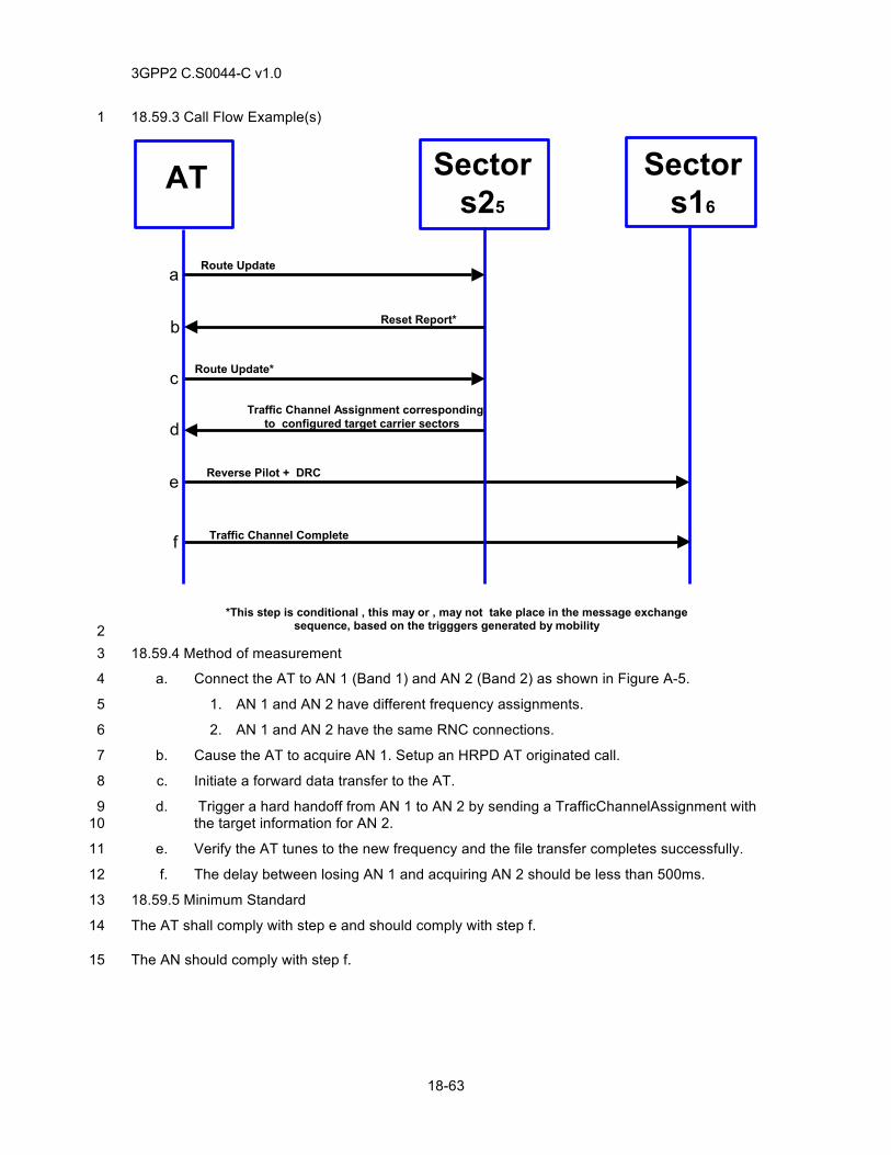
3GPP2 C.S0044-C v1.0
18-63
18.59.3 Call Flow Example(s) 1
SectorAT
Reverse Pilot + DRC
Traffic Channel Complete
Traffic Channel Assignment correspondingto configured target carrier sectors
a Route Update
c
d
e
Sectors25
Sectors16
Reset Report*b
Route Update*
*This step is conditional , this may or , may not take place in the message exchangesequence, based on the trigggers generated by mobility
f
2 18.59.4 Method of measurement 3
a. Connect the AT to AN 1 (Band 1) and AN 2 (Band 2) as shown in Figure A-5. 4
1. AN 1 and AN 2 have different frequency assignments. 5
2. AN 1 and AN 2 have the same RNC connections. 6
b. Cause the AT to acquire AN 1. Setup an HRPD AT originated call. 7
c. Initiate a forward data transfer to the AT. 8
d. Trigger a hard handoff from AN 1 to AN 2 by sending a TrafficChannelAssignment with 9 the target information for AN 2. 10
e. Verify the AT tunes to the new frequency and the file transfer completes successfully. 11
f. The delay between losing AN 1 and acquiring AN 2 should be less than 500ms. 12
18.59.5 Minimum Standard 13
The AT shall comply with step e and should comply with step f. 14
The AN should comply with step f. 15
3GPP2 C.S0044-C v1.0
18-64
18.60 RLP Activation 1
18.60.1 Definition 2
This test verifies the ability of the AN to activate RLP flows during session negotiation and later 3 associate these active RLP flows to requested QoS. In the test, it is assumed that the AN will be 4 able to accept the reservation requests generated by the AT. Note that each of the reservation 5 requests may have multiple ProfileIDs and it is possible for the AN to accept any one or none of 6 these Profiles. Typically, the AN should accept AT’s most preferred profile, unless it is not able to 7 support this profile due to resource constraints or other reasons. 8
This test requires the ability to generate QoS requests from the AT, allocate QoS resources at the 9 AN and install traffic filtering at the PDSN. The application that causes the AT to generate QoS 10 requests could either reside at the AT or the TE. Further, it should be ensured that the application 11 is able to connect with the server/peer and receive and transmit data. This may require password 12 authentication when using commercial applications residing on the AT. 13
18.60.2 Traceability 14
(see [24]) 15
Chapter 4 Multiflow Packet Application 16
(see [12]) 17
Chapters 2 and 3 18
18.60.3 Call Flow Example(s) 19
None 20
18.60.4 Method of measurement 21
a. Connect the AT to the AN as shown in Figure A-3. 22
b. Cause the AT to acquire the AN. 23
c. Configure the AT to negotiate the use of Multi-Flow Packet Application or Enhanced 24 Multi-Flow Packet Application or Multi-Link Multi-Flow Packet Application bound to the 25 service network, Physical layer subtype 2 and Subtype 3 RTC MAC. 26
d. Configure the AN to activate MaxActivatedRLPFlowsFwd Forward Link Flows and 27 MaxActivatedRLPFlowsRev Reverse Link Flows during session configuration. 28
e. If the AT has an established session with the AN, cause the AN to close the session by 29 transmitting a SessionClose message. 30
f. Power cycle the AT. 31
g. Ensure that the AT establishes a session with the AN and acquires the HRPD system. 32
h. Verify that the AN activates MaxActivatedRLPFlowsFwd Forward Link Flows and 33 MaxActivatedRLPFlowsRev Reverse Link Flows during session configuration. 34
i. Cause the AT to establish a data call with the AN. 35
j. Allow the AT to go idle. 36
k. Trigger a QoS request by starting any application that requires reservation for at least 37 one forward and one reverse link flow. An example of such an application would be 38 video telephony. 39
l. Verify that during the subsequent signaling the AN does not transmit 40 AttributeUpdateRequest messages containing 41 FlowNNIdentificationFwd/FlowNNIdentificationRev attributes for any flow. 42
3GPP2 C.S0044-C v1.0
18-65
m. Verify that if the AN did not negotiate FlowNNReservationFwd and 1 FlowNNReservationRev attributes during session negotiation, then the AN transmits 2 AttributeUpdateRequest messages(s) containing FlowNNReservationFwd attributes 3 binding ReservationLabel(s) to Forward Link RLP flow(s) NN and 4 FlowNNReservationRev attributes binding ReservationLabel(s) to Reverse Link flow(s). 5
n. Verify that if the AN transmits AttributeUpdateRequest messages(s) containing 6 FlowNNReservationFwd and FlowNNReservationRev attributes, then the AT transmits 7 AttributeUpdateAccept message to the AN accepting the FlowNNReservationFwd and 8 FlowNNReservationRev attributes. 9
o. Verify that if the AN did not negotiate AssociatedFlowNN attribute during session 10 negotiation, then the AN transmits AttributeUpdateRequest message containing 11 AssociatedFlowNN attribute binding the RLP flow(s) to the RTCMAC flow(s). 12
p. Verify that if the AN transmits AttributeUpdateRequest messages(s) containing 13 AssociatedFlowNN attribute, then the AT transmits AttributeUpdateAccept message(s) 14 to the AN accepting the binding sent by the AN in AssociatedFlowsNN attribute. 15
q. Start data transfer for each of the forward and reverse link higher layer flows that are 16 bound to an RLP flow through FlowNNReservationFwd and FlowNNReservationRev 17 attributes. 18
r. Verify that the AT uses Flow NN to transmit data for higher layer flow with 19 ReservationLabel KK if the ReservationLabel KK was mapped to Flow NN through 20 FlowNNReservationRev attribute. 21
s. Verify that the AN uses Flow NN to transmit data for higher layer flow with 22 ReservationLabel KK if the ReservationLabel KK was mapped to Flow NN through 23 FlowNNReservationFwd attribute. 24
18.60.5 Minimum Standard 25
The AT shall comply with steps n, p and r. 26
The AN shall comply with steps h, l, m, o and s. 27
18.61 QoS Set Up 28
18.61.1 Definition 29
This test verifies the ability of the AN and the AT to set-up and use QoS for any application. The 30 application may reside at the AT or the TE (Terminal Equipment). Specifically, for setting up the 31 QoS for the application, this test verifies that the QoS request and response, reservation to RLP 32 binding, RLP to RTCMAC flow binding on the reverse link, RLP and RTCMAC flow activation, and 33 opening the reservations. This test also verifies the GAUP messages needed to update various 34 attributes and parameters. Note for this test each of the reservation requests may have multiple 35 ProfileIDs and it is possible for the AN to accept any one or none of the Profiles. Typically, the AN 36 should accept AT’s most preferred profile, unless it is not able to support this profile due to 37 resource constraints or other reasons. Unless otherwise specified, this test assumes that the AN 38 will be able to accept any of the proposed profiles. 39
It is assumed that the application needs one or more higher layer flows that are identified by their 40 ReservationLabels. Each higher layer flow is bound to an RLP. More than one flow may be bound 41 to an RLP. On the reverse link, the RLP ids are in turn bound to 1 or more MAC Flows. For 42 example a Video Telephony application may require three separate higher layer flows 43 (reservations) for audio, video and SIP signaling. The application may be designed to map audio 44 and video higher layer flows to separate RLPs (due to different abort timer requirements for audio 45 and video, for example), but transmit SIP flows’ data through the default RLP that is typically used 46 for best effort traffic. On the reverse link RLP ids used by audio and video may be mapped to 47 different MAC flows that are configured to provide different latencies, for example. 48
3GPP2 C.S0044-C v1.0
18-66
18.61.2 Traceability 1
(see [24]) 2
Chapter 4 Multi-Flow Packet Application 3
(see [12]) 4
Chapters 2 and 3 5
(see [10]) 6
18.61.3 Call Flow Example(s) 7
None 8
18.61.4 Method of measurement 9
a. Connect the AT to the AN as shown in Figure A-3. If the application resides on the TE 10 connect the TE to the AT. 11
b. Cause the AT to acquire the AN. 12
c. Configure the AT to negotiate the use of Multi-Flow Packet Application or Enhanced 13 Multi-Flow Packet Application or Multi-Link Multi-Flow Packet Application bound to the 14 service network, Physical layer subtype 2 and Subtype 3 RTC MAC. 15
d. Configure the AN to activate only the default RLP flow during session configuration. 16 This can be done by setting the active parameter of the FlowNNIdentificationFwd and 17 FlowNNIdentificationRev attribute to 0 for all RLP flows with NN ≠ 0. 18
e. Ensure that the AN activates only the default RLP flow during session configuration. 19
f. If the AT has an established session with the AN, cause either the AT or the AN to 20 close the session by transmitting a SessionClose message. 21
g. Cause the AT to negotiate a new session with the AN. 22
h. Cause the AT to establish a data call with the AN and allow the AT to go idle. 23
i. Cause the AT to start the application that needs to be tested. The application will 24 generate QoS requests for all forward and reverse link flow(s). 25
j. Verify that the AT transmits GAUP message(s) with ReservationKKQoSReqFwd with 26 R_QoS_SUB_BLOB containing the specified Profile ID for forward flow(s) and 27 ReservationKKQoSReqRev with R_QoS_SUB_BLOB containing the specified Profile ID 28 for reverse flow(s). 29
k. Verify that the AT constructs a Traffic Flow Template (TFT) with the desired packet 30 filters and sends an RSVP Resv [Create new TFT] message. 31
l. Verify that the AN transmits AttributeUpdateAccept message(s) accepting the QoS 32 ReservationKKQoSRequestFwd/ ReservationKKQoSRequestRev attributes from the 33 AT. 34
m. The AN should GAUP the ReservationKKQoSResponseFwd with G_QoS_BLOB 35 containing the set ID for primary Profile ID for all the higher layer flow(s) of the 36 application. 37
n. Verify that the PDSN installs the desired packet filters and sends an RSVP ResvConf 38 message. 39
o. Verify that the AT transmits AttributeUpdate message(s) to the AN accepting the AN’s 40 ReservationKKQosResponseFwd and ReservationKKQosResponseRev for the 41 ReservationLabel(s). 42
3GPP2 C.S0044-C v1.0
18-67
p. Verify that the AN transmits a GAUP message for FlowNNIdentificationFwd and 1 FlowNNIdentificationRev in order to activate the forward and reverse link flow(s). 2
q. Verify that the AT transmits AttributeUpdateAccept message(s) accepting 3 FlowNNIdentificationFwd and FlowNNIdentificationRev attributes. 4
r. Verify that the AN transmits a GAUP message for FlowNNReservationFwd and 5 FlowNNReservationRev for binding the reservations to RLP flow(s). 6
s. Verify that the AT transmits AttributeUpdateAccept message(s) accepting 7 FlowNNReservationFwd and FlowNNReservationRev values. 8
t. The AN will determine the number of Forward and Reverse Link RLP flows and 9 RTCMAC flows needed to support the accepted QoS requests. The AN may need to 10 transmit AttributeUpdateRequest message(s) negotiating the parameters for Forward 11 and Reverse link and RLP flows and RTCMAC flows. 12
u. If the AN transmits Attribute Update Request for the Forward and Reverse Link RLP 13 Flows and/or RTCMAC flows, verify that the AT transmits AttributeUpdateAccept 14 message(s) accepting RLP and RTCMAC parameters. 15
v. Verify that the AN transmits AttributeUpdateRequest message containing 16 AssociatedFlowNN with substream field set to 1 to bind the RLP flow(s) to the RTCMAC 17 flow(s). 18
w. Verify that the AT transmits AttributeUpdateAccept message(s) to the AN accepting the 19 binding sent by the AN in AssociatedFlowsNN attribute. 20
x. The AN should GAUP RTCMAC BucketLevelMaxNN with a nonzero value to activate 21 the RTCMAC flow(s). 22
y. Verify that the AT transmits AttributeUpdateAccept message to the AN accepting the 23 BucketLevelMaxNN value sent by the AN. 24
z. Verify that the AT sends ReservationOnRequest for both the forward and reverse 25 ReservationLabel(s) using single ReservationOnRequest message. 26
aa. Verify that AN sends ReservationAccept for both forward and reverse reservations. 27
bb. Verify that both the forward and reverse RLP flows are activated and all the 28 reservations are in Open state. 29
cc. Once the application starts data transfer, verify that data is being sent on the 30 appropriate RLP IDs on the forward link and on the appropriate RLP and MAC Flows on 31 the reverse link. 32
dd. Ensure that the PDSN is sending data via the intended filter. 33
18.61.5 Minimum Standard 34
The AT shall comply with steps j, k, o, q, s, u, w, y, z, bb, and cc. 35
The AN shall comply with steps l, p, r, v, aa, bb, and cc. 36
The AN should comply with steps m and x. 37
The PDSN should comply with steps n and dd. 38
18.62 Successful negotiation of Enhanced Idle State Protocol 39
18.62.1 Definition 40
This test verifies negotiation and successful setup of the Enhanced Idle State Protocol. 41
3GPP2 C.S0044-C v1.0
18-68
18.62.2 Traceability 1
(see [24]) 2
8.4.7 Configuration Attributes 3
8.5 Enhanced Idle State Protocol 4
8.5.7.1 Simple Attributes 5
18.62.3 Call Flow Example(s) 6
None 7
18.62.4 Method of measurement 8
a. Connect the AT to the AN as shown in Figure A-3. Ensure that the AT does not have a 9 previously assigned UATI from the AN. 10
b. Configure the AN and AT to support Enhanced Idle State Protocol. 11
c. Power on the AT. 12
d. During HRPD session negotiation, verify the AT sends a ConfigurationRequest 13 message that includes the following values: 14
Field Value
Protocol Type
0x0c
(Idle State Protocol)
Protocol Subtype 0x0001
(Enhanced Idle State)
e. Ensure the AN responds with a ConfigurationResponse message including the 15 following: 16
Field Value
Protocol Type
0x0c
(Idle State Protocol)
Protocol Subtype 0x0001
(Enhanced Idle State)
f. If the AT supports hybrid mode operation and hybrid mode is enabled, verify the AT 17 sends a second ConfigurationRequest that includes the following: 18
Field Value
AttributeID 0x00 (PreferredControlChannelCycle)
PreferredControlChannelCycleEnabled 0x1
PreferredControlChannelCycle Value
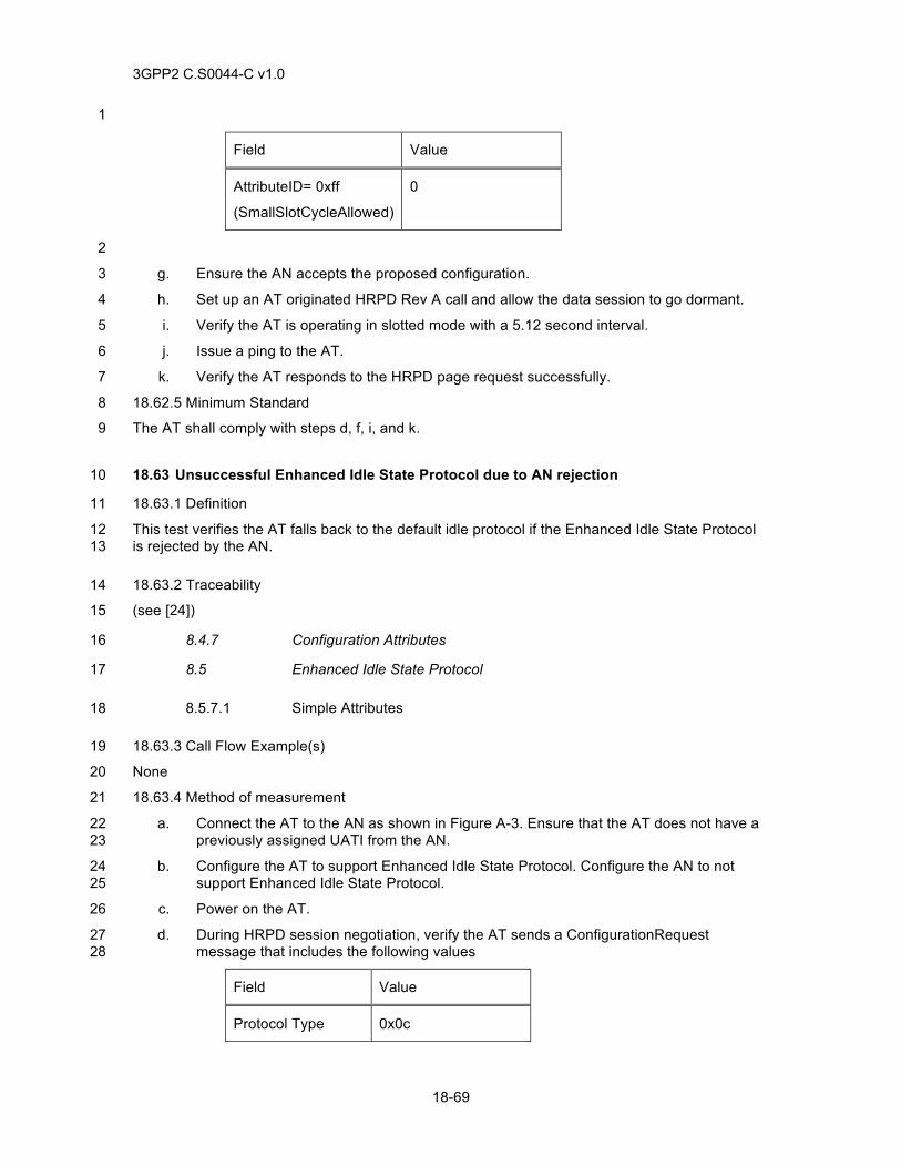
3GPP2 C.S0044-C v1.0
18-69
1
Field Value
AttributeID= 0xff
(SmallSlotCycleAllowed)
0
2
g. Ensure the AN accepts the proposed configuration. 3
h. Set up an AT originated HRPD Rev A call and allow the data session to go dormant. 4
i. Verify the AT is operating in slotted mode with a 5.12 second interval. 5
j. Issue a ping to the AT. 6
k. Verify the AT responds to the HRPD page request successfully. 7
18.62.5 Minimum Standard 8
The AT shall comply with steps d, f, i, and k. 9
18.63 Unsuccessful Enhanced Idle State Protocol due to AN rejection 10
18.63.1 Definition 11
This test verifies the AT falls back to the default idle protocol if the Enhanced Idle State Protocol 12 is rejected by the AN. 13
18.63.2 Traceability 14
(see [24]) 15
8.4.7 Configuration Attributes 16
8.5 Enhanced Idle State Protocol 17
8.5.7.1 Simple Attributes 18
18.63.3 Call Flow Example(s) 19
None 20
18.63.4 Method of measurement 21
a. Connect the AT to the AN as shown in Figure A-3. Ensure that the AT does not have a 22 previously assigned UATI from the AN. 23
b. Configure the AT to support Enhanced Idle State Protocol. Configure the AN to not 24 support Enhanced Idle State Protocol. 25
c. Power on the AT. 26
d. During HRPD session negotiation, verify the AT sends a ConfigurationRequest 27 message that includes the following values 28
Field Value
Protocol Type 0x0c
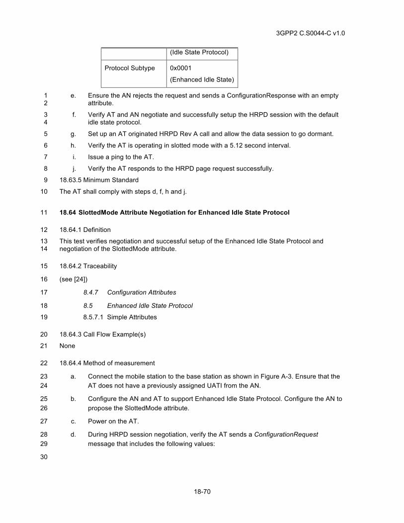
3GPP2 C.S0044-C v1.0
18-70
(Idle State Protocol)
Protocol Subtype 0x0001
(Enhanced Idle State)
e. Ensure the AN rejects the request and sends a ConfigurationResponse with an empty 1 attribute. 2
f. Verify AT and AN negotiate and successfully setup the HRPD session with the default 3 idle state protocol. 4
g. Set up an AT originated HRPD Rev A call and allow the data session to go dormant. 5
h. Verify the AT is operating in slotted mode with a 5.12 second interval. 6
i. Issue a ping to the AT. 7
j. Verify the AT responds to the HRPD page request successfully. 8
18.63.5 Minimum Standard 9
The AT shall comply with steps d, f, h and j. 10
18.64 SlottedMode Attribute Negotiation for Enhanced Idle State Protocol 11
18.64.1 Definition 12
This test verifies negotiation and successful setup of the Enhanced Idle State Protocol and 13 negotiation of the SlottedMode attribute. 14
18.64.2 Traceability 15
(see [24]) 16
8.4.7 Configuration Attributes 17
8.5 Enhanced Idle State Protocol 18
8.5.7.1 Simple Attributes 19
18.64.3 Call Flow Example(s) 20
None 21
18.64.4 Method of measurement 22
a. Connect the mobile station to the base station as shown in Figure A-3. Ensure that the 23 AT does not have a previously assigned UATI from the AN. 24
b. Configure the AN and AT to support Enhanced Idle State Protocol. Configure the AN to 25 propose the SlottedMode attribute. 26
c. Power on the AT. 27
d. During HRPD session negotiation, verify the AT sends a ConfigurationRequest 28 message that includes the following values: 29
30
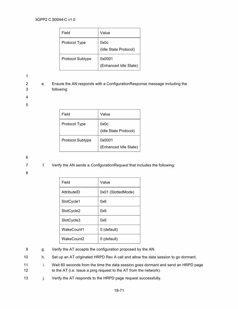
3GPP2 C.S0044-C v1.0
18-71
Field Value
Protocol Type
0x0c
(Idle State Protocol)
Protocol Subtype 0x0001
(Enhanced Idle State)
1
e. Ensure the AN responds with a ConfigurationResponse message including the 2 following: 3
4
5
Field Value
Protocol Type
0x0c
(Idle State Protocol)
Protocol Subtype 0x0001
(Enhanced Idle State)
6
f. Verify the AN sends a ConfigurationRequest that includes the following: 7
8
Field Value
AttributeID 0x01 (SlottedMode)
SlotCycle1 0x6
SlotCycle2 0x6
SlotCycle3 0x6
WakeCount1 0 (default)
WakeCount2 0 (default)
g. Verify the AT accepts the configuration proposed by the AN. 9
h. Set up an AT originated HRPD Rev A call and allow the data session to go dormant. 10
i. Wait 60 seconds from the time the data session goes dormant and send an HRPD page 11 to the AT (i.e. Issue a ping request to the AT from the network). 12
j. Verify the AT responds to the HRPD page request successfully. 13
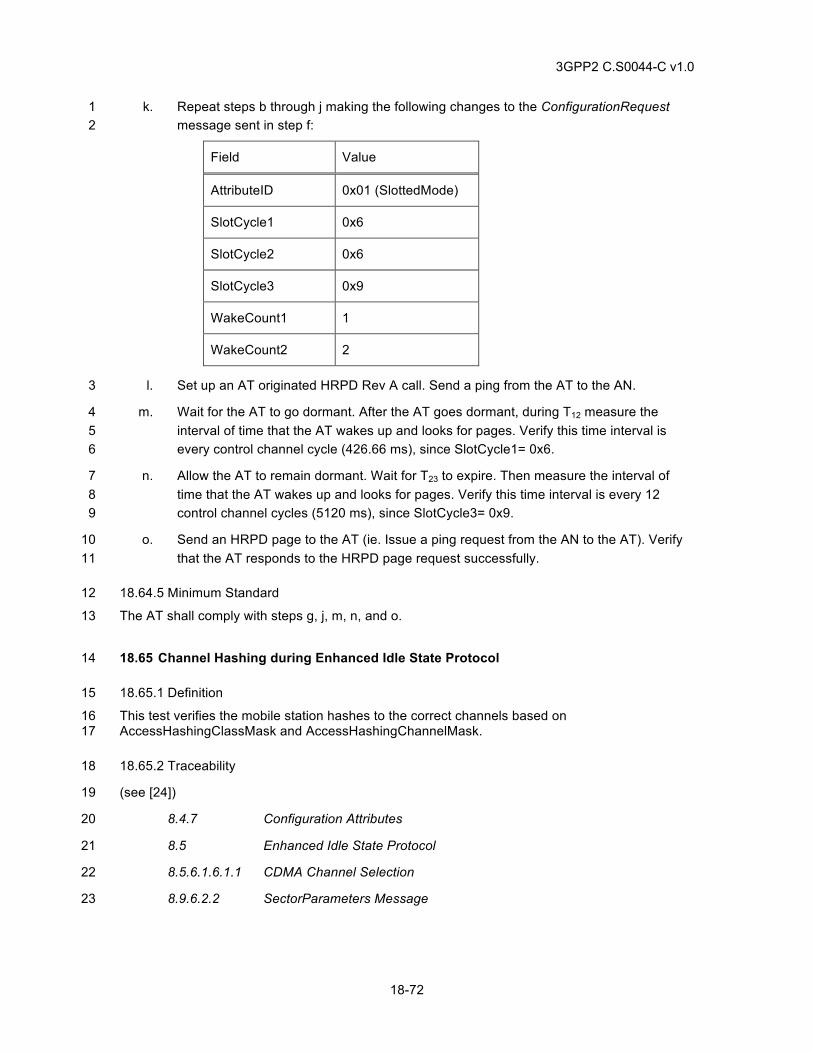
3GPP2 C.S0044-C v1.0
18-72
k. Repeat steps b through j making the following changes to the ConfigurationRequest 1 message sent in step f: 2
Field Value
AttributeID 0x01 (SlottedMode)
SlotCycle1 0x6
SlotCycle2 0x6
SlotCycle3 0x9
WakeCount1 1
WakeCount2 2
l. Set up an AT originated HRPD Rev A call. Send a ping from the AT to the AN. 3
m. Wait for the AT to go dormant. After the AT goes dormant, during T12 measure the 4 interval of time that the AT wakes up and looks for pages. Verify this time interval is 5 every control channel cycle (426.66 ms), since SlotCycle1= 0x6. 6
n. Allow the AT to remain dormant. Wait for T23 to expire. Then measure the interval of 7 time that the AT wakes up and looks for pages. Verify this time interval is every 12 8 control channel cycles (5120 ms), since SlotCycle3= 0x9. 9
o. Send an HRPD page to the AT (ie. Issue a ping request from the AN to the AT). Verify 10 that the AT responds to the HRPD page request successfully. 11
18.64.5 Minimum Standard 12
The AT shall comply with steps g, j, m, n, and o. 13
18.65 Channel Hashing during Enhanced Idle State Protocol 14
18.65.1 Definition 15
This test verifies the mobile station hashes to the correct channels based on 16 AccessHashingClassMask and AccessHashingChannelMask. 17
18.65.2 Traceability 18
(see [24]) 19
8.4.7 Configuration Attributes 20
8.5 Enhanced Idle State Protocol 21
8.5.6.1.6.1.1 CDMA Channel Selection 22
8.9.6.2.2 SectorParameters Message 23
3GPP2 C.S0044-C v1.0
18-73
18.65.3 Call Flow Example(s) 1
None 2
18.65.4 Method of measurement 3
a. Connect the AT to the AN as shown in Figure A-5. AN 1 and AN 2 are AT supported 4 CDMA Channels operating in the same band class and have same PN offset. 5
b. Ensure that the AT does not have a previously assigned UATI from the AN. 6
c. Configure the AT and each AN to support Enhanced Idle State Protocol. 7
d. Configure each AN to send a SectorParameters Message with 8 AccessHashingMaskLength=0xf and to negotiate a value of 0x0 for 9 AccessHashingClassMask attribute during session negotiation. 10
e. Configure both AN 1 and AN 2 to include in the SectorParameters Message a Channel 11 List with the channel information for AN 1 with AccessHashingChannelMask=0xffff. 12
f. Configure both AN 1 and AN 2 to include in the SectorParameters Message an 13 Extended Channel List with the channel information for AN 2 with 14 AccessHashingChannelMask=0xffff. 15
g. Power on the AT and set up an HRPD data call. 16
h. Allow the call to go dormant and ping the AT. 17
i. Verify the AT responds to the page successfully. 18
j. End the call and terminate the HRPD session. 19
k. Repeat steps g through j a maximum of 20 times. 20
l. Verify the mobile station hashes on AN 1 and AN 2 at least once. 21
18.65.5 Minimum Standard 22
The AT shall comply with steps i and l. 23
18.66 Channel Hashing during Enhanced Idle State Protocol - Hashing to AN 2 Only 24
18.66.1 Definition 25
This test verifies the mobile station hashes to the correct channels based on 26 AccessHashingClassMask and AccessHashingChannelMask. In this test, the AT will only hash to 27 AN 2 based on settings for AccessHashingClassMask and AccessHashingChannelMask. 28
18.66.2 Traceability 29
(see [24]) 30
8.4.7 Configuration Attributes 31
8.5 Enhanced Idle State Protocol 32
8.5.6.1.6.1.1 CDMA Channel Selection 33
3GPP2 C.S0044-C v1.0
18-74
8.9.6.2.2 SectorParameters Message 1
18.66.3 Call Flow Example(s) 2
None 3
18.66.4 Method of measurement 4
a. Connect the AT to the AN as shown in Figure A-5. AN 1 and AN 2 are AT supported 5 CDMA Channels operating in the same band class and have the same PN offset. 6
b. Ensure that the AT does not have a previously assigned UATI from the AN. 7
c. Configure the AT and each AN to support Enhanced Idle State Protocol. 8
d. Configure each AN to send a SectorParameters Message with 9 AccessHashingMaskLength=0x1 and to negotiate a value of 0x2 for 10 AccessHashingClassMask attribute during session negotiation. 11
e. Configure both AN 1 and AN 2 to include in the SectorParameters Message a Channel 12 List with the channel information for AN 1 with AccessHashingChannelMask=0x1. 13
f. Configure both AN 1 and AN 2 to include in the SectorParameters Message an 14 Extended Channel List with the channel information for AN 2 with 15 AccessHashingChannelMask=0x2. 16
g. Power on the AT and set up an HRPD data call. 17
h. Allow the call to go dormant and ping the AT. 18
i. Verify the AT responds to the page successfully. 19
j. End the call and terminate the HRPD session. 20
k. Repeat steps g through j 3 times. 21
l. Verify the mobile station hashes to only AN 2. Verify the mobile station does not hash to 22 AN 1 after the EISP has been negotiated. (The AT may initially acquire AN 1, but shall 23 not hash to AN 1 after receiving the AccessHashingClassMask and 24 AccessHashingMaskLength.) 25
18.66.5 Minimum Standard 26
The AT shall comply with steps i and l. 27
18.67 QoS Signaling upon PPP resynchronization 28
18.67.1 Definition 29
This test verifies that upon PPP resynchronization the AT transmits a new RSVP RESV message 30 and that the PDSN installs the new filter based on the new RESV message 31
18.67.2 Traceability 32
(see [24]) 33
Chapter 4 Multi-Flow Packet Application 34
3GPP2 C.S0044-C v1.0
18-75
(see [12]) 1
Chapters 2 and 3 2
(see [10]) 3
18.67.3 Call Flow Example(s) 4
None 5
18.67.4 Method of measurement 6
a. Connect the AT to the AN as shown in Figure A-3. 7
b. Cause the AT to acquire the AN. 8
c. Configure the AT to negotiate the use of Multi-Flow Packet Application or Enhanced 9 Multi-Flow Packet Application or Multi-Link Multi-Flow Packet Application bound to the 10 service network, Physical layer subtype 2 and Subtype 3 RTC MAC. 11
d. Configure the AN to grant the QoS request from the AT. 12
e. If the AT has an established session with the AN, cause the AN to close the session by 13 transmitting a SessionClose message. 14
f. Cause the AT to negotiate a new session with the AN. 15
g. Ensure that the AN activates only the default RLP flow during session configuration. 16
h. Cause the AT to establish a data call with the AN and allow the AT to go idle. 17
i. Cause the AT to generate QoS requests for two forward and two reverse link flows. 18 Wait for the AN to transmit a ReservationAccept message for all the reservations. 19
j. Start data transfer and verify that all reservations are in open state and that the data is 20 being transmitted using appropriate RLP flow IDs. 21
k. Cause the PDSN to initiate a PPP resynchronization. This can be achieved for example 22 by an inter-PDSN handoff. Ensure that the PDSN provides the same IP Address as 23 received in step h. 24
l. Verify that the AT resynchronizes the PPP. 25
m. Verify that the AT transmits a RSVP RESV message with all the higher layer flows to 26 the PDSN after PPP resynchronization is complete. 27
n. Ensure that the PDSN sends a RSVP ResvConf message. 28
18.67.5 Minimum Standard 29
The AT shall comply with step l and m. 30
The PDSN should comply with step n. 31
18.68 AT behavior upon Rejection of Reservation Request by AN 32
18.68.1 Definition 33
The default flow in HRPD is always in active state. When the AN rejects a QoS request, the data 34 for the QoS flow should be sent through the default RLP flow on the forward and reverse link and 35 will receive best-effort treatment. 36
Under normal circumstances, the AN will accept a reservation request from the AT. However, the 37 AN may deny the reservation request for many reasons, for example if the request is invalid or if 38 the given admission control policy at the AN determines that the request cannot be fulfilled. 39
3GPP2 C.S0044-C v1.0
18-76
Specifying a configuration where the AN denies the QoS request is beyond the scope of the 1 document and is left to the tester. 2
18.68.2 Traceability 3
(see [24]) 4
Chapter 4 Multi-Flow Packet Application 5
(see [12]) 6
Chapters 2 and 3 7
18.68.3 Call Flow Example(s) 8
None. 9
18.68.4 Method of measurement 10
a. Connect the AT to the AN as shown in Figure A-3. 11
b. Cause the AT to acquire the AN. 12
c. Configure the AT to negotiate the use of Multi-Flow Packet Application or Enhanced 13 Multi-Flow Packet Application or Multi-Link Multi-Flow Packet Application bound to the 14 service network, Physical layer subtype 2 and Subtype 3 RTC MAC. 15
d. If the AT has an established session with the AN, cause the AN to close the session by 16 transmitting a SessionClose message. 17
e. Cause the AT to negotiate a new session with the AN. 18
f. Ensure that the AN activates only the default RLP flow during session configuration. 19
g. Cause the AT to establish a data call with the AN. 20
h. Cause the AT to generate QoS request for one forward and reverse link flow. 21
i. Cause the AN to reject GAUP AttributeUpdateRequest message for 22 ReservationKKQoSRequestFwd and ReservationKKQoSRequestRev. 23
j. Start bi-directional data transfer with parameters that match the specification of the QoS 24 request. 25
k. Verify that the data can be sent and received on the default RLP flow and receives 26 best-effort treatment. 27
18.68.5 Minimum Standard 28
The AT shall comply with step k. 29
The AN shall comply with step k. 30
18.69 AT behavior upon Receiving ProfileType set to NULL 31
18.69.1 Definition 32
When the AN accepts a QoS request but sends a QoS response with ProfileType field set to 33 NULL, the data for the QoS flow should be sent through the default RLP flow on the forward and 34 reverse link and will receive best-effort treatment. 35
18.69.2 Traceability 36
(see [24]) 37
3GPP2 C.S0044-C v1.0
18-77
Chapter 4 Multi-Flow Packet Application 1
(see [12]) 2
Chapters 2 and 3 3
18.69.3 Call Flow Example(s) 4
None 5
18.69.4 Method of measurement 6
a. Connect the AT to the AN as shown in Figure A-3. 7
b. Cause the AT to acquire the AN. 8
c. Configure the AT to negotiate the use of Multi-Flow Packet Application or Enhanced 9 Multi-Flow Packet Application or Multi-Link Multi-Flow Packet Application bound to the 10 service network, Physical layer subtype 2, Enhanced FTCMAC and Subtype 3 RTC 11 MAC. 12
d. If the AT has an established session with the AN, cause the AN to close the session by 13 transmitting a SessionClose message. 14
e. Cause the AT to negotiate a new session with the AN. 15
f. Ensure that the AN activates only the default RLP flow during session configuration. 16
g. Cause the AT to establish a data call with the AN. 17
h. While the AT has a connection with the AN, cause the AT to generate QoS request for 18 one forward and one reverse link flow. 19
i. Cause the AN to accept the GAUP AttributeUpdateRequest message for 20 ReservationKKQoSRequestFwd and ReservationKKQoSRequestRev. 21
j. Cause the AN to transmit a ReservationKKQoSResponse with ProfileType set to 0x00 22 for both the forward and reverse link flows. 23
k. Start bi-directional data transfer with parameters that match the specification of the QoS 24 request. 25
l. Verify that the data is sent and received on the default RLP flow and receives best-26 effort treatment. 27
18.69.5 Minimum Standard 28
The AT shall comply with step k. 29
The AN shall comply with step k. 30
18.70 ReservationKKIdleStateFwd and ReservationKKIdleStateRev set to 0 31
18.70.1 Definition 32
The state of a reservation can change when the AT goes dormant. The change in a reservation’s 33 state is determined by the value of ReservationKKIdleStateFwd / ReservationKKIdleStateRev 34 where KK (=0xij) is the 2 digit hexadecimal ReservationLabel (0xij ≠ 0xff) that identifies the 35 reservation in use. A Reservation is bound to an RLP flow NN by setting the ReservationLabel 36 parameter of the FlowNNReservationFwd / FlowNNReservationRev attribute to the reservation’s 37 label (KK = 0xij). When the ReservationKKIdleStateFwd / ReservationKKIdleStateRev (KK = 0xij) 38 attribute is set to 0, the state of the reservation (with ReservationLabel KK = 0xij) will not change 39 upon closing or opening of the connection. In the test procedure, application refers to an 40 application that generates data for flow with ReservationLabel (KK = 0xij). Starting this application 41 will cause the AT to transmit forward and reverse QoS ReservationOn request(s) for 42
3GPP2 C.S0044-C v1.0
18-78
ReservationLabel (KK = 0xij) if the reservation is in closed state. Any higher layer flow with 1 ReservationLabel 0xij (0xij ≠ 0xff) that generates forward and reverse reservation requests can be 2 used. This test verifies that the reservation state does not change when ReservationKKIdleState 3 is set to 0 and that the initial state of a reservation is closed (0xij ≠ 0xff). The test procedure 4 transitions the state of the (connection state, reservation state) pair from (close, close), to (open, 5 close), to (open, open), to (close, open) and finally to (open, open) again. 6
18.70.2 Traceability 7
(see [24]) 8
Chapter 4 Multi-Flow Packet Application 9
(see [12]) 10
Chapters 2 and 3 11
18.70.3 Call Flow Example(s) 12
None 13
18.70.4 Method of measurement 14
a. Connect the AT to the AN as shown in Figure A-3. 15
b. Cause the AT to acquire the AN. 16
c. Configure the AT to negotiate the use of Multi-Flow Packet Application or Enhanced 17 Multi-Flow Packet Application or Multi-Link Multi-Flow Packet Application bound to the 18 service network, Physical layer subtype 2, Enhanced FTCMAC, and Subtype 3 RTC 19 MAC. 20
d. Configure the AN to grant the QoS request from the AT and to set 21 ReservationKKIdleStateFwd and ReservationKKIdleStateRev to 0x0 for 22 ReservationLabel KK (= 0xij ≠ 0xff). 23
e. If the AT has an established session with the AN, cause the AN to close the session by 24 transmitting a SessionClose message. 25
f. Cause the AT to negotiate a new session with the AN. 26
g. Cause the AT to establish a data call with the AN by transmitting data for higher layer 27 flow with ReservationLabel 0xff (Note. This will open the connection by transmitting 28 data on the default flow). 29
h. While the AT has a connection with the AN, start the application that generates data for 30 higher layer flow with ReservationLabel KK (= 0xij ≠ 0xff). 31
i. Verify that the reservation is in closed state and the AT transmits forward and reverse 32 ReservationOn request for the higher layer flows with ReservationLabel KK (= 0xij ≠ 33 0xff). Wait for the AN to transmit ReservationAccept message for all the reservations. 34
j. Once the data transfer starts from the application, ensure that the reservation is in open 35 state and that the data is being transmitted using appropriate (non-default) RLP flow ID. 36
k. Cause the AT to loose the connection with the AN. Ensure that the AT does not 37 transmit ReservationOff request for the ReservationLabel KK (= 0xij ≠ 0xff) to the AN. 38
l. Cause the AT to reestablish a data call with the AN. 39
m. Start bi-directional data transfer for the higher layer flow with ReservationLabel KK (= 40 0xij ≠ 0xff). 41
n. Verify that the reservation is in open state and that during or after reestablishing the 42 data call, the AT does not need to transmit the ReservationOn request for 43
3GPP2 C.S0044-C v1.0
18-79
ReservationLabel KK (= 0xij ≠ 0xff) and that the AN does not transmit 1 FwdReservationOn and/or RevReservationOn message(s). 2
o. Verify that the AN and the AT transmit the data through RLP with appropriate (non-3 default) flow id. 4
p. Stop the application and cause the AT to transmit a ReservationOff message for the 5 forward and/or reverse higher layer flows with ReservationLabel KK (= 0xij ≠ 0xff). 6
q. Allow the AT to go dormant. 7
r. Cause the AT to establish a data call with the AN by transmitting data for higher layer 8 flow with ReservationLabel 0xff. 9
s. Start the application. 10
t. Verify that the reservation is in closed state and the AT transmits the ReservationOn 11 request for opening the reservation for forward and reverse link flow with 12 ReservationLabel KK (= 0xij ≠ 0xff). Note, the AT may send a combined ReservationOn 13 request for the forward link and reverse link reservations. Wait for the AN to accept the 14 reservation(s). 15
u. Verify that the AN and the AT transmit the data through RLP with appropriate (non-16 default) flow id 17
18.70.5 Minimum Standard 18
The AT shall comply with step i, n, o, t and u. 19
The AN shall comply with steps n, o and u. 20
18.71 ReservationKKIdleState set to 1 21
18.71.1 Definition 22
The state of a reservation can change when the AT goes dormant. The change in a reservation’s 23 state is determined by the value of ReservationKKIdleStateFwd / ReservationKKIdleStateRev 24 where KK (=0xij) is the 2 digit hexadecimal ReservationLabel (0xij ≠ 0xff) that identifies the 25 reservation in use. A Reservation is bound to an RLP flow NN by setting the ReservationLabel 26 parameter of the FlowNNReservationFwd / FlowNNReservationRev attribute to the reservation’s 27 label (KK = 0xij). When the ReservationKKIdleStateFwd / ReservationKKIdleStateRev (KK = 0xij) 28 attribute is set to 0x1, the reservation will close when the HRPD connection is closed. This test 29 verifies the change in a reservation’s state when ReservationKKIdleState is set to 1. In the test 30 procedure, application refers to an application that generates data for higher layer flow with 31 ReservationLabel KK (= 0xij ≠ 0xff). Starting this application will cause the AT to transmit forward 32 and reverse QoS reservation requests for ReservationLabel KK (= 0xij ≠ 0xff) if the reservation is 33 in closed state. Any ReservationLabel KK other that 0xff that generates forward and reverse 34 reservation requests can be used. 35
18.71.2 Traceability 36
(see [24]) 37
Chapter 4 Multi-Flow Packet Application 38
(see [12]) 39
Chapters 2 and 3 40
18.71.3 Call Flow Example(s) 41
None 42
3GPP2 C.S0044-C v1.0
18-80
18.71.4 Method of measurement 1
a. Connect the AT to the AN as shown in Figure A-3. 2
b. Cause the AT to acquire the AN. 3
c. Configure the AT to negotiate the use of Multi-Flow Packet Application or Enhanced 4 Multi-Flow Packet Application or Multi-Link Multi-Flow Packet Application bound to the 5 service network, Physical layer subtype 2, Enhanced FTCMAC and Subtype 3 RTC 6 MAC. 7
d. Configure the AN to grant the QoS request from the AT and to set 8 ReservationKKIdleStateFwd and ReservationKKIdleStateRev to 0x01 for 9 ReservationLabel KK (= 0xij ≠ 0xff). 10
e. If the AT has an established session with the AN, cause the AN to close the session by 11 transmitting a SessionClose message. 12
f. Cause the AT to negotiate a new session with the AN. 13
g. Cause the AT to establish a data call with the AN by transmitting data for higher layer 14 flow with ReservationLabel 0xff. 15
h. Start the application and verify that the AT transmits reservation requests for forward 16 and reverse link higher layer flows with ReservationLabel KK (= 0xij ≠ 0xff). Wait for the 17 AN to transmit ReservationAccept message for all the reservations. 18
i. Start the application and ensure that the reservation is in open state and that the data is 19 being transmitted using appropriate (non-default) RLP flow ID. 20
j. Cause the AT to loose the connection with the AN. Ensure that the AT does not 21 transmit ReservationOff requests (forward or reverse) for ReservationLabel KK (= 0xij ≠ 22 0xff) to the AN. 23
k. Cause the AT to reestablish a data call with the AN. 24
l. Ensure that the application generates data for the higher layer flow with 25 ReservationLabel KK (= 0xij ≠ 0xff). 26
m. Verify that the reservation is in closed state and the AT transmits the ReservationOn 27 request for the higher layer flows with ReservationLabel KK (= 0xij ≠ 0xff) for forward 28 and reverse link flows. Wait for the AN to accept the reservation. 29
n. Verify that the AN and the AT transmit the data through RLP with appropriate (non-30 default) flow id. 31
18.71.5 Minimum Standard 32
The AT shall comply with steps h, m and n. 33
The AN shall comply with step n. 34
18.72 ReservationKKIdleState set to 2 35
18.72.1 Definition 36
The state of a reservation can change when the AT goes dormant. The change in a reservation’s 37 state is determined by the value of ReservationKKIdleStateFwd / ReservationKKIdleStateRev 38 where KK (=0xij) is the 2 digit hexadecimal ReservationLabel (0xij ≠ 0xff) that identifies the 39 reservation in use. A Reservation is bound to an RLP flow NN by setting the ReservationLabel 40 parameter of the FlowNNReservationFwd / FlowNNReservationRev attribute to the reservation’s 41 label (KK = 0xij). When the ReservationKKIdleStateFwd / ReservationKKIdleStateRev (KK = 0xij) 42 attribute is set to 0x2, the reservation will open when the HRPD connection is opened and close 43 when the HRPD connection is closed. This test verifies the change in state of the reservation 44
3GPP2 C.S0044-C v1.0
18-81
(with ReservationLabel KK = 0xij ≠ 0xff) with opening and closing of connection when 1 ReservationKKIdleState is set to 0x2. In the test procedure, application refers to an application 2 that generates data for higher layer flow with ReservationLabel KK (= 0xij ≠ 0xff). Starting this 3 application will cause the AT to transmit forward and reverse QoS ReservationOn requests for 4 ReservationLabel KK (= 0xij ≠ 0xff) if the reservation is in closed state. Any ReservationLabel KK 5 other that 0xff that requires forward and reverse reservations can be used 6
18.72.2 Traceability 7
(see [24]) 8
Chapter 4 Multi-Flow Packet Application 9
(see [12]) 10
Chapters 2 and 3 11
18.72.3 Call Flow Example(s) 12
None 13
18.72.4 Method of measurement 14
a. Connect the AT to the AN as shown in Figure A-3. 15
b. Cause the AT to acquire the AN. 16
c. Configure the AT to negotiate the use of Multi-Flow Packet Application or Enhanced 17 Multi-Flow Packet Application or Multi-Link Multi-Flow Packet Application bound to the 18 service network, Physical layer subtype 2 Enhanced FTCMAC and Subtype 3 RTC 19 MAC. 20
d. Configure the AN to grant the QoS request from the AT and to set 21 ReservationKKIdleStateFwd and ReservationKKIdleStateRev to 0x0 for 22 ReservationLabel KK (= 0xij ≠ 0xff) and FlowNNDataOverSignalingAllowedRev and 23 FlowNNDataOverSignalingAllowedFwd set to 1 for the RLP flow NN to which 24 ReservationLabel KK (= 0xij ≠ 0xff) will be bound. 25
e. Configure the AN to activate MaxActivatedRLPFlowsFwd and 26 MaxActivatedRLPFlowsRev during session configuration. 27
f. If the AT has an established session with the AN, cause the AN to close the session by 28 transmitting a SessionClose message. 29
g. Cause the AT to negotiate a new session with the AN. 30
h. Cause the AT to establish a data call with the AN. 31
i. Start the application and ensure that the AT transmits reservation requests for forward 32 and reverse link higher layer flows with ReservationLabel KK (= 0xij ≠ 0xff). Wait for the 33 AN to transmit ReservationAccept message for all the reservations. 34
j. Start data transfer and verify that the reservation is in open state and that the data is 35 being transmitted using appropriate (non-default) RLP flow ID. 36
k. Stop the data transfer and allow the AT to become dormant and ensure that the AT 37 does not transmit ReservationOffRequest messages for the ReservationLabel KK (= 38 0xij ≠ 0xff). 39
l. Cause the AT to generate a DataOverSignaling message for the higher layer flow with 40 ReservationLabel KK (= 0xij ≠ 0xff). Ensure that the AT does not open the connection 41 with the AN. 42
3GPP2 C.S0044-C v1.0
18-82
m. Ensure that the reservation is in open state and the AT does not need to transmit the 1 ReservationOn request for the reservation and that the AN does not transmit 2 FwdReservationOn and/or RevReservationOn message(s). 3
n. Ensure that the AT transmits the DataOverSignaling message. 4
o. Transmit a DataOverSignaling message from the AN to the AT for the higher layer flow 5 with ReservationLabel KK (= 0xij ≠ 0xff). Ensure that the AT does not open the 6 connection with the AN. 7
p. Ensure that the reservation is in open state and the AT does not need to transmit the 8 ReservationOn request for the reservation and that the AN does not transmit 9 FwdReservationOn and/or RevReservationOn message(s). 10
q. Ensure that the AN transmits the DataOverSignaling message. 11
r. Repeat steps d to h with the exception that in step d, configure the AN to set 12 ReservationKKIdleStateFwd and ReservationKKIdleStateRev to 0x2. 13
s. Cause the AT to establish a data call with the AN by transmitting data for higher layer 14 flow with ReservationLabel 0xff. 15
t. Generate data from the application. 16
u. Verify that the AT does not need to transmit the ReservationOn request for the 17 reservation and that the AN does not transmit FwdReservationOn and/or 18 RevReservationOn message(s) and that the AN and the AT transmit application’s data 19 through appropriate (non-default) RLP. 20
v. Force the AT to become idle. 21
w. Cause the AT to generate a DataOverSignaling message for the higher layer flow with 22 ReservationLabel KK (= 0xij ≠ 0xff). 23
x. Verify that the AT does not transmit DataOverSignaling message. 24
y. Cause the AN to generate a DataOverSignaling message for the higher layer flow with 25 ReservationLabel KK (= 0xij ≠ 0xff). 26
z. Verify that the AN does not transmit DataOverSignaling message. 27
18.72.5 Minimum Standard 28
The AT shall comply with step u and x. 29
The AN shall comply with steps u and z. 30
18.73 DRC Supervision Failure 31
18.73.1 Definition 32
The AT performs DRC supervision in order to ensure call quality. This test verifies that the AT 33 behavior for DRC supervision. Specifically, it verifies that if the AT transmits NULL DRC for 34 DRCSupervisionTimer*10 + 240 ms. continuously without receiving any packets (either FTC or 35 CC MAC packets) from the AN then it shall disable the Reverse Traffic Channel. Subsequently, 36 the AT starts a timer for TFTCMPRestartTx (5.12 seconds). If during this period, a packet (either FTC or 37 CC MAC packets) is received from the AN or if the AT transmits a non-NULL tentative DRC, then 38 the AT disables the timer. Otherwise it declares a DRC supervision failure and tears down the 39 connection. 40
18.73.2 Traceability 41
(see [24]) 42
3GPP2 C.S0044-C v1.0
18-83
Section 10.7.6.1.10.1 1
(see [12]) 2
Chapters 2 and 3 3
18.73.3 Call Flow Example(s) 4
None 5
18.73.4 Method of measurement 6
a. Connect the AT to the AN as shown in Figure A-1. 7
b. Cause the AT to acquire the AN. 8
c. Configure the AT to negotiate the use of Multi-Flow Packet Application or Enhanced 9 Multi-Flow Packet Application or Multi-Link Multi-Flow Packet Application bound to the 10 service network, Physical layer subtype 2, Enhanced CCMAC Enhanced FTCMAC and 11 Subtype 3 RTC MAC. 12
d. Configure the AN to use a transmission rate of 38.4 kbps for the control channel. 13
e. During SCP or using GAUP, negotiate the value of MultiUserPacketsEnabled to be 14 0x00. This will disallow the AN from transmitting data to the AT, when the AT is 15 transmitting NULL rate DRC. 16
f. Cause the AT to establish a connection with the AN. 17
g. Start bi-directional data transfer and ensure that data is going through continuously in 18 both directions. 19
h. Reduce Îor such that the AT starts transmitting NULL rate tentative DRC and is unable 20 to receive the control channel. 21
i. Verify that the AT disables the Reverse Traffic Channel after transmitting null rate 22 tentative DRC for DRCSupervisionTimer*10 + 240 ms period continuously. Ensure that 23 the AN does not transmit any packets on the forward traffic channel to the AT and the 24 AT does not receive any control channel packet during this time interval. 25
j. Within TFTCMPRestartTx (5.12 seconds) of disabling reverse traffic channel transmitter in the 26 last step, increase Îor such that the AT start transmitting a non-null tentative DRC to the 27 AN. Ensure that the AN does not transmit any packets on the forward traffic channel to 28 the AT and the AT does not receive any control channel packet before AT has 29 transmitted non-null DRC for NFTCMPRestartTx slots continuously. 30
k. Verify that the AT enables the reverse traffic channel and bi-directional transfer occurs 31 after AT has transmitted non-null DRC for NFTCMPRestartTx slots continuously. 32
l. Reduce Îor such that the AT starts transmitting NULL rate tentative DRC’s and is unable 33 to receive the control channel. 34
m. Verify that the AT returns a DRC supervision failure indication and tears down the 35 connection at the expiration of TFTCMPRestartTx. Note, the AT will transmit a null rate 36 tentative DRC for a period of DRCSupervisionTimer*10 + 240 ms before starting the 37 TFTCMPRestartTx timer. 38
18.73.5 Minimum Standard 39
The AT shall comply with steps i, k, m. 40
The AN shall comply with steps k. 41
3GPP2 C.S0044-C v1.0
18-84
18.74 Soft Handoff during DRC Supervision Timeout State 1
18.74.1 Definition 2
This test verifies the soft handoff during DRC supervision timeout state. 3
18.74.2 Traceability 4
(see [24]) 5
Section 10.7.6.1.10.1 6
(see [12]) 7
Chapters 2 and 3 8
18.74.3 Call Flow Example(s) 9
None 10
18.74.4 Method of measurement 11
a. Connect the AT to the AN as shown in Figure A-10. 12
b. Cause the AT to acquire the AN 1. 13
c. Configure the AT to negotiate the use of Multi-Flow Packet Application or Enhanced 14 Multi-Flow Packet Application or Multi-Link Multi-Flow Packet Application bound to the 15 service network, Physical layer subtype 2, Enhanced CCMAC, Enhanced FTCMAC and 16 Subtype 3 RTC MAC. 17
d. During SCP or using GAUP, negotiate the value of MultiUserPacketsEnabled to be 18 0x00. This will disallow the AN from transmitting data to the AT, when the AT is 19 transmitting NULL rate DRC. 20
e. Cause the AT to establish a connection with the AN 1. 21
f. Start bi-directional data transfer and ensure that data is going through continuously in 22 both directions. 23
g. Reduce Îor for the pilot from AN 1 such that the AT starts transmitting NULL rate 24 tentative DRC and is unable to receive the control channel from AN 1. 25
h. Ensure that the AT disables the Reverse Traffic Channel after transmitting null rate 26 tentative DRC for DRCSupervisionTimer*10 + 240 ms period continuously. 27
i. Within TFTCMPRestartTx (5.12 seconds) of disabling reverse traffic channel transmitter in the 28 last step, increase the Ior of sector 1 of AN 2 or increase Îor such that the AT transmits 29 non-null tentative DRC for NFTCMPRestartTx slots continuously to AN 2. 30
j. Verify that the AT successfully acquires AN 2, enables the reverse traffic channel and 31 that the bi-directional transfer resumes from the AT and AN 2. 32
18.74.5 Minimum Standard 33
The AT shall comply with step j 34
The AN shall comply with step j. 35
3GPP2 C.S0044-C v1.0
18-85
18.75 DRC Supervision with MultiUserPacketsEnabled 1
18.75.1 Definition 2
This test verifies the AN and AT behavior when the value of MultiUserPacketsEnabled is set to 3 0x01. This test requires that the AN transmit data to an AT even when the AT transmits a NULL 4 DRC. This will happen for Flows that require QoS, such as a VOIP flow if the 5 MultiUserPacketsEnabled is set 0x01. It is assumed that such a flow is used in this test. 6
18.75.2 Traceability 7
(see [24]) 8
Section 10.7.6.1.10.1 and 9
Section 10.6.7.1 10
(see [12]) 11
Chapters 2 and 3 12
18.75.3 Call Flow Example(s) 13
None 14
18.75.4 Method of measurement 15
a. Connect the AT to the AN as shown in Figure A-1. 16
b. Cause the AT to acquire the AN 1. 17
c. Configure the AT to negotiate the use of Multi-Flow Packet Application or Enhanced 18 Multi-Flow Packet Application or Multi-Link Multi-Flow Packet Application bound to the 19 service network, Physical layer subtype 2 Enhanced FTCMAC and Subtype 3 RTC 20 MAC. 21
d. During SCP or using GAUP, negotiate the value of DRCSupervisionTimer to 0x00 and 22 the value of MultiUserPacketsEnabled to be 0x01. This will allow the AN to transmit 23 data to the AT, when the AT is transmitting NULL rate DRC. 24
e. Cause the AT to establish a connection with the AN. 25
f. Start bi-directional data transfer and ensure that data is going through continuously in 26 both directions. 27
g. Reduce Îor such that the AT starts transmitting NULL rate tentative DRC. 28
h. Verify that the AN continues to transmit data to the AT at DRC 1 rate. 29
i. Verify that the AT does not disable the Reverse Traffic Channel after transmitting null 30 rate tentative DRC for DRCSupervisionTimer*10 + 240 ms period continuously if it 31 receives either a forward traffic channel or control channel packet. 32
j. If the AT does not receive any forward traffic channel or control channel packet in the 33 last step, the repeat the test by increasing the Îor. 34
18.75.5 Minimum Standard 35
The AT shall comply with step i 36
The AN shall comply with step h. 37
3GPP2 C.S0044-C v1.0
18-86
18.76 DRCTranslationOffset Verification 1
18.76.1 Definition 2
This test verifies DRCTranslationOffset attribute negotiation between the AT and the AN. 3
18.76.2 Traceability 4
(see [24]) 5
Section 10.7.6.1.10.1 6
18.76.3 Call Flow Example(s) 7
None 8
18.76.4 Method of measurement. 9
a. Connect the AT to the AN as shown in Figure A-3. 10
b. Cause the AT to acquire the AN. 11
c. Configure the AT to negotiate the use of Physical layer subtype 2 and Enhanced 12 FTCMAC. 13
d. During SCP or using GAUP, negotiate the value of DRCTranslationOffset attribute with 14 a value 0 for DRCOffsetN for all N. 15
e. Cause the AT to establish a connection with the AN. 16
f. Cause the AT to request a tentative DRC value of 0x8. This can either be done by fixing 17 the DRC requested by the AT or by changing the Îor. 18
g. Ensure that the AT is transmitting a DRC value 0x08 most of the time. 19
h. GAUP the value of DRCTranslationOffset attribute with a value of 5 for DRCOffset8 and 20 0 for all other DRCOffsetN. 21
i. Start bi-directional data transfer and ensure that data is going through continuously in 22 both directions. 23
j. Verify that the AT requests a DRC of 3, when its tentative DRC is 0x8 24
18.76.5 Minimum Standard 25
The AT shall comply with step j. 26
18.77 DSC and DRC compliance during Soft handoff 27
18.77.1 Definition 28
The purpose of this test is to verify that the AT follows the DSC channel and DRC channel 29 timeline in transmitting the DSC and DRC values while performing a soft handoff with DRCGating 30 disabled. Further, it is tested that the AN does not skip transmission of any octets from the RLP 31 sequence space during soft handoff. In the test procedure, both AN 1 and AN 2 support HRPD 32 Rev A and are connected to the same RNC. It is intended that this test be executed with the 33 default hybrid mode operation, if supported by the AT. 34
18.77.2 Traceability 35
(see [24]) 36
3GPP2 C.S0044-C v1.0
18-87
Section 10.7.6.1.5 and 1
Section 10.7.6.1.8.1 2
(see [12]) 3
Chapters 2 and 3 4
18.77.3 Call Flow Example(s) 5
None 6
18.77.4 Method of measurement 7
a. Connect the AT to AN 1 and AN 2 as shown in Figure A-5. 8
1. AN 1 and AN 2 support HRPD Rev A and have same frequency assignments. 9
2. AN 1 and AN 2 are connected to the same RNC, but are located at separate 10 base stations. 11
b. Cause the AT to acquire the AN 1. 12
c. Configure the AT to negotiate the use of Multi-Flow Packet Application or Enhanced 13 Multi-Flow Packet Application or Multi-Link Multi-Flow Packet Application bound to the 14 service network, Physical layer subtype 2, Enhanced CCMAC, Enhanced ACMAC, 15 Enhanced FTCMAC, Enhanced Idle State Protocol and Subtype 3 RTC MAC. 16
d. During SCP negotiate the value of DSCLength to 8 (64 slots), SoftHandoffDelay to 8 17 (64 slots) and DRCGating to 0x00 (continuous transmission). 18
e. Cause the AT to establish a connection with the AN 1. 19
f. Initiate a forward data transfer using the maximum supported data rate to the AT (i.e. 20 use the FTP “get” command from the AT). Choose a file large enough to sustain data 21 for entire test duration. 22
g. Force the AT to handoff from AN 1 to AN 2. 23
h. Force the AT to handoff from AN 2 to AN 1. 24
i. Verify that the AT does not change its sector cover such that there is overlap in 25 transmission of packets from 2 sectors. 26
j. Verify that after a handoff occurs from AN 1 to AN 2, the RLP sequence number of the 27 first byte transmitted by AN 2 is less than or equal to the 1+ RLP sequence of the last 28 byte transmitted by the AN 1. Similarly, verify contiguous RLP sequence numbers for 29 handoff from AN 2 to AN 1. 30
k. Verify that the call is maintained across the handoff and that the file transfer is 31 completed. 32
18.77.5 Minimum Standard 33
The AT shall comply with steps i and k. 34
The AN shall comply with the steps j and k. 35
18.78 DRC Compliance During Softer Handoff 36
18.78.1 Definition 37
The purpose of this test is to verify that the AN and the AT behavior during softer handoff. It is 38 verified that the AT transmits the correct value of DRC and the AN transmits the data correctly. In 39 the test procedure, both AN 1 and AN 2 support HRPD Rev A and are adjacent sectors located at 40
3GPP2 C.S0044-C v1.0
18-88
the same base station. It is intended that this test be executed with the default hybrid mode 1 operation, if supported by the AT. 2
18.78.2 Traceability 3
(see [24]) 4
Section 10.7.6.1.10.1 5
(see [12]) 6
Chapters 2 and 3 7
18.78.3 Call Flow Example(s) 8
None 9
18.78.4 Method of measurement 10
a. Connect the AT to AN 1 and AN 2 as shown in Figure A-5. 11
1. AN 1 and AN 2 support HRPD Rev A and have the same frequency 12 assignments. 13
2. AN 1 and AN 2 are connected to the same RNC, and are located at the same 14 base stations but have different PN offsets. 15
b. Cause the AT to acquire the AN 1. 16
c. Configure the AT to negotiate the use of Multi-Flow Packet Application or Enhanced 17 Multi-Flow Packet Application or Multi-Link Multi-Flow Packet Application bound to the 18 service network, Physical layer subtype 2, Enhanced CCMAC, Enhanced ACMAC, 19 Enhanced FTCMAC, Enhanced Idle State Protocol and Subtype 3 RTC MAC. 20
d. During SCP negotiate the value of DRCLength to 8 slots, SofterHandoffDelay to 8 slots 21 and DRCGating to 0x00 (continuous transmission). 22
e. Cause the AT to establish a connection with the AN 1. 23
f. Initiate a forward data transfer using the maximum supported data rate to the AT (i.e. 24 use the FTP “get” command from the AT). Choose a file large enough to sustain data 25 for entire test duration. 26
g. Force the AT to handoff from AN 1 to AN 2. 27
h. Force the AT to handoff from AN 2 to AN 1. 28
i. Verify that the AT does not change its sector cover such that there is overlap in 29 transmission of packets from the 2 sectors. 30
j. Verify that after a handoff occurs from AN 1 to AN 2, the AN transmits contiguous RLP 31 sequence, i.e. the RLP sequence number of the first byte transmitted by AN 2 is one 32 more than the RLP sequence of the last byte transmitted by the AN 1. Similarly, verify 33 contiguous RLP sequence numbers for handoff from AN 2 to AN 1. 34
k. Verify that the call is maintained across handoff and that the file transfer is completed. 35
18.78.5 Minimum Standard 36
The AT shall comply with steps i and k. 37
The AN shall comply with steps j and k. 38
3GPP2 C.S0044-C v1.0
18-89
18.79 MUP and Non Canonical SUP decoding by AT 1
18.79.1 Definition 2
The purpose of this test is to verify that the AT can decode multi-user packets (MUP) and non-3 canonical single user packet (SUP) that the AN transmits. 4
18.79.2 Traceability 5
(see [24]) 6
Section 10.7.6.1.5 7
(see [12]) 8
Chapters 2 and 3 9
18.79.3 Call Flow Example(s) 10
None 11
18.79.4 Method of measurement 12
a. Connect the AT to the AN as shown in Figure A-3. 13
b. Cause the AT to acquire the AN. 14
c. Configure the AT to negotiate the use of Multi-Flow Packet Application or Enhanced 15 Multi-Flow Packet Application or Multi-Link Multi-Flow Packet Application bound to the 16 service network, Physical layer subtype 2, Enhanced CCMAC, Enhanced FTCMAC and 17 Subtype 3 RTC MAC. 18
d. During session configuration or using GAUP negotiate the value of 19 ShortPacketsEnabledThresh to 0x03, and MultiUserPacketsEnabled to 0x00. 20
e. Cause the AT to establish a connection with the AN. 21
f. Vary the channel conditions such that the AT transmits a close to peak rate DRC value 22 of 0xe. 23
g. Instruct the AN to GAUP DRCTranslationOffset attribute with parameter DRCOffsetE 24 set to 0xa, DRCOffsetd set to 0xa, DRCOffsetc set to 0xa, DRCOffsetb set to 0xa, 25 DRCOffseta set to 0xa and DRCOffseti for all other DRC i, set to 0. 26
h. Ensure that the AT starts transmitting DRC values in the range 0x0 to 0x4. 27
i. Cause the AN to transmit one or more single user packets to the AT in any format other 28 than the canonical format. The transmission packet format used by the AN is 29 implementation dependent. Canonical format for a DRC is the largest packet size. If the 30 payload of a transmission can fit in a smaller size packet allowed for the DRC, the AN 31 may transmit a smaller (non-canonical) format. For example, if a ping packet with 10 32 bytes of payload is transmitted to the AT, it will be transmitted using a (512, 2, 128) 33 format if the transmitted DRC is 0x4, or (512, 4, 256) format if the transmitted DRC is 34 0x3. This assumes that the ping packet will not fit in a 256 bit packet but will fit in a 512 35 bit physical layer packet. 36
j. Verify that the AT successfully decodes all single user packets transmitted by the AN. 37
k. Repeat step i for all DRC in the range 0x0 to 0x4. Note the DRC transmitted by the AT 38 can be varied either by varying Îor or by increasing the DRCOffsetE parameter of the 39 DRCTranslationOffset by using GAUP. 40
l. Using GAUP negotiate the value of ShortPacketsEnabledThresh to 0x00, and 41 MultiUserPacketsEnabled to 0x01. 42
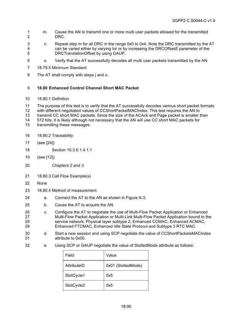
3GPP2 C.S0044-C v1.0
18-90
m. Cause the AN to transmit one or more multi user packets allowed for the transmitted 1 DRC. 2
n. Repeat step m for all DRC in the range 0x0 to 0x4. Note the DRC transmitted by the AT 3 can be varied either by varying Ior or by increasing the DRCOffsetE parameter of the 4 DRCTranslationOffset by using GAUP. 5
o. Verify that the AT successfully decodes all multi user packets transmitted by the AN. 6
18.79.5 Minimum Standard 7
The AT shall comply with steps j and o. 8
18.80 Enhanced Control Channel Short MAC Packet 9
18.80.1 Definition 10
The purpose of this test is to verify that the AT successfully decodes various short packet formats 11 with different negotiated values of CCShortPacketMACIndex. This test requires the AN to 12 transmit CC short MAC packets. Since the size of the ACAck and Page packet is smaller than 13 512 bits, it is likely although not necessary that the AN will use CC short MAC packets for 14 transmitting these messages. 15
18.80.2 Traceability 16
(see [24]) 17
Section 10.3.6.1.4.1.1 18
(see [12]) 19
Chapters 2 and 3 20
18.80.3 Call Flow Example(s) 21
None 22
18.80.4 Method of measurement 23
a. Connect the AT to the AN as shown in Figure A-3. 24
b. Cause the AT to acquire the AN. 25
c. Configure the AT to negotiate the use of Multi-Flow Packet Application or Enhanced 26 Multi-Flow Packet Application or Multi-Link Multi-Flow Packet Application bound to the 27 service network, Physical layer subtype 2, Enhanced CCMAC, Enhanced ACMAC, 28 Enhanced FTCMAC, Enhanced Idle State Protocol and Subtype 3 RTC MAC. 29
d. Start a new session and using SCP negotiate the value of CCShortPacketsMACIndex 30 attribute to 0x00. 31
e. Using SCP or GAUP negotiate the value of SlottedMode attribute as follows: 32
Field Value
AttributeID 0x01 (SlottedMode)
SlotCycle1 0x5
SlotCycle2 0x5
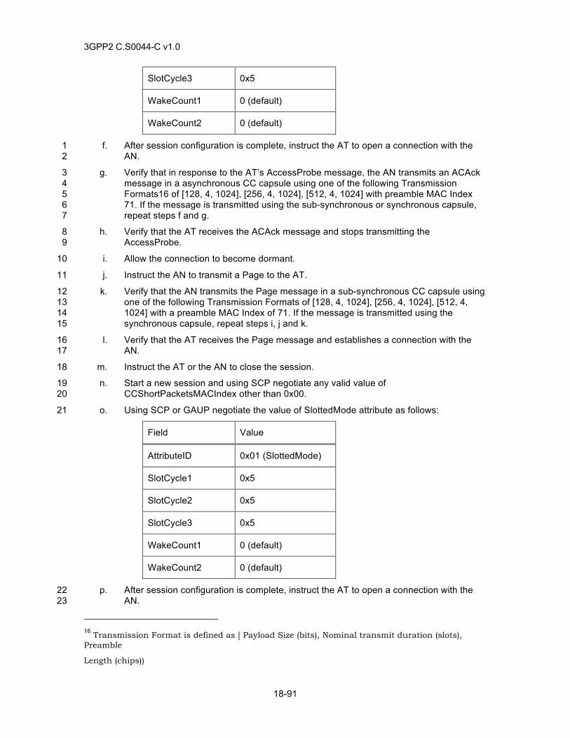
3GPP2 C.S0044-C v1.0
18-91
SlotCycle3 0x5
WakeCount1 0 (default)
WakeCount2 0 (default)
f. After session configuration is complete, instruct the AT to open a connection with the 1 AN. 2
g. Verify that in response to the AT’s AccessProbe message, the AN transmits an ACAck 3 message in a asynchronous CC capsule using one of the following Transmission 4 Formats16 of [128, 4, 1024], [256, 4, 1024], [512, 4, 1024] with preamble MAC Index 5 71. If the message is transmitted using the sub-synchronous or synchronous capsule, 6 repeat steps f and g. 7
h. Verify that the AT receives the ACAck message and stops transmitting the 8 AccessProbe. 9
i. Allow the connection to become dormant. 10
j. Instruct the AN to transmit a Page to the AT. 11
k. Verify that the AN transmits the Page message in a sub-synchronous CC capsule using 12 one of the following Transmission Formats of [128, 4, 1024], [256, 4, 1024], [512, 4, 13 1024] with a preamble MAC Index of 71. If the message is transmitted using the 14 synchronous capsule, repeat steps i, j and k. 15
l. Verify that the AT receives the Page message and establishes a connection with the 16 AN. 17
m. Instruct the AT or the AN to close the session. 18
n. Start a new session and using SCP negotiate any valid value of 19 CCShortPacketsMACIndex other than 0x00. 20
o. Using SCP or GAUP negotiate the value of SlottedMode attribute as follows: 21
Field Value
AttributeID 0x01 (SlottedMode)
SlotCycle1 0x5
SlotCycle2 0x5
SlotCycle3 0x5
WakeCount1 0 (default)
WakeCount2 0 (default)
p. After session configuration is complete, instruct the AT to open a connection with the 22 AN. 23
16 Transmission Format is defined as [ Payload Size (bits), Nominal transmit duration (slots), Preamble
Length (chips))
3GPP2 C.S0044-C v1.0
18-92
q. Verify that in response to the AT’s AccessProbe message, the AN transmits an ACAck 1 message in a asynchronous CC capsule using one of the following Transmission 2 Formats of [128, 4, 1024], [256, 4, 1024], [512, 4, 1024] with preamble MAC Index 3 negotiated in step n or 71. If the message is transmitted using the sub-synchronous or 4 synchronous capsule, repeat steps o and p. 5
r. Verify that the AT receives the ACAck message and stops transmitting the 6 AccessProbe. 7
s. Allow the connection to become dormant. 8
t. Instruct the AN to transmit a Page to the AT. 9
u. Verify that the AN transmits the Page message in a sub-synchronous CC capsule using 10 one of the following Transmission Formats of [128, 4, 1024], [256, 4, 1024], [512, 4, 11 1024] with a preamble MAC Index negotiated in step n or 71. If the message is 12 transmitted using the synchronous capsule, repeat steps i, j and k. 13
v. Verify that the AT receives the Page message and establishes a connection with the 14 AN 15
18.80.5 Minimum Standard 16
The AT shall comply with steps h, l, r, and v. 17
The AN shall comply with steps g, k, q and u. 18
18.81 Enhanced Access Channel Probe Transmission 19
18.81.1 Definition 20
The purpose of this test is to verify that the AN and the AT successfully negotiate the 21 PreambleLengthSlots, AccessOffset, SectorMaxRate and CapsuleLengthMax attributes of the 22 EACMAC protocol and that using these parameters the AT transmits the access probe at 23 appropriate time and rate and that the AN successfully receives the probe. This test uses Data 24 Over Signaling protocol to generate payload for the Access Channel Capsule. 25
18.81.2 Traceability 26
(see [24]) 27
Section 10.5.6.1.4.1.2 (Probe Transmission) 28
Section 10.5.6.2.6 (Access Parameters message) 29
(see [12]) 30
Chapters 2 and 3 31
18.81.3 Call Flow Example(s) 32
None 33
18.81.4 Method of measurement 34
a. Connect the AT to the AN as shown in Figure A-3. 35
b. Cause the AT to acquire the AN. 36
c. Configure the AT to negotiate the use of Multi-Flow Packet Application or Enhanced 37 Multi-Flow Packet Application or Multi-Link Multi-Flow Packet Application bound to the 38
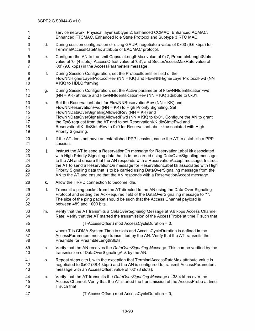
3GPP2 C.S0044-C v1.0
18-93
service network, Physical layer subtype 2, Enhanced CCMAC, Enhanced ACMAC, 1 Enhanced FTCMAC, Enhanced Idle State Protocol and Subtype 3 RTC MAC. 2
d. During session configuration or using GAUP, negotiate a value of 0x00 (9.6 kbps) for 3 TerminalAccessRateMax attribute of EACMAC protocol. 4
e. Configure the AN to transmit CapsuleLengthMax value of 0x7, PreambleLenghtSlots 5 value of ‘0’ (4 slots), AccessOffset value of ‘03’, and SectorAccessMaxRate value of 6 ‘00’ (9.6 kbps) in the AccessParameters message. 7
f. During Session Configuration, set the ProtocolIdentifier field of the 8 FlowNNHigherLayerProtocolRev (NN = KK) and FlowNNHigherLayerProtocolFwd (NN 9 = KK) to HDLC framing. 10
g. During Session Configuration, set the Active parameter of FlowNNIdentificationFwd 11 (NN = KK) attribute and FlowNNIdentificationRev (NN = KK) attribute to 0x01. 12
h. Set the ReservationLabel for FlowNNReservationRev (NN = KK) and 13 FlowNNReservationFwd (NN = KK) to High Priority Signaling. Set 14 FlowNNDataOverSignalingAllowedRev (NN = KK) and 15 FlowNNDataOverSignalingAllowedFwd (NN = KK) to 0x01. Configure the AN to grant 16 the QoS request from the AT and to set ReservationKKIdleStateFwd and 17 ReservationKKIdleStateRev to 0x0 for ReservationLabel kk associated with High 18 Priority Signaling. 19
i. If the AT does not have an established PPP session, cause the AT to establish a PPP 20 session. 21
j. Instruct the AT to send a ReservationOn message for ReservationLabel kk associated 22 with High Priority Signaling data that is to be carried using DataOverSignaling message 23 to the AN and ensure that the AN responds with a ReservationAccept message. Instruct 24 the AT to send a ReservationOn message for ReservationLabel kk associated with High 25 Priority Signaling data that is to be carried using DataOverSignaling message from the 26 AN to the AT and ensure that the AN responds with a ReservationAccept message. 27
k. Allow the HRPD connection to become idle. 28
l. Transmit a ping packet from the AT directed to the AN using the Data Over Signaling 29 Protocol and setting the AckRequired field of the DataOverSignaling message to ‘1’. 30 The size of the ping packet should be such that the Access Channel payload is 31 between 489 and 1000 bits. 32
m. Verify that the AT transmits a DataOverSignaling Message at 9.6 kbps Access Channel 33 Rate. Verify that the AT started the transmission of the AccessProbe at time T such that 34
(T-AccessOffset) mod AccessCycleDuration = 0, 35
where T is CDMA System Time in slots and AccessCycleDuration is defined in the 36 AccessParameters message transmitted by the AN. Verify that the AT transmits the 37 Preamble for PreambleLengthSlots. 38
n. Verify that the AN receives the DataOverSignaling Message. This can be verified by the 39 transmission of DataOverSignalingAck by the AN. 40
o. Repeat steps c to l, with the exception that TerminalAccessRateMax attribute value is 41 negotiated to 0x02 (38.4 kbps) and the AN is configured to transmit AccessParameters 42 message with an AccessOffset value of ‘02’ (8 slots). 43
p. Verify that the AT transmits the DataOverSignaling Message at 38.4 kbps over the 44 Access Channel. Verify that the AT started the transmission of the AccessProbe at time 45 T such that 46
(T-AccessOffset) mod AccessCycleDuration = 0, 47
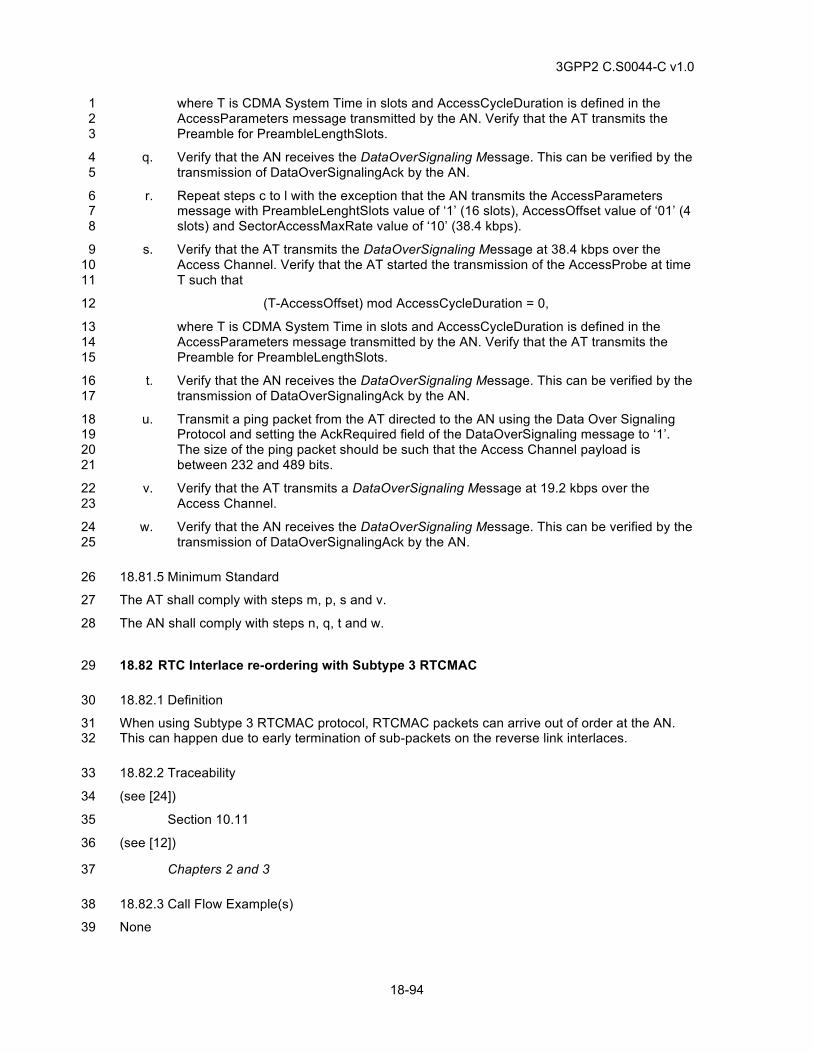
3GPP2 C.S0044-C v1.0
18-94
where T is CDMA System Time in slots and AccessCycleDuration is defined in the 1 AccessParameters message transmitted by the AN. Verify that the AT transmits the 2 Preamble for PreambleLengthSlots. 3
q. Verify that the AN receives the DataOverSignaling Message. This can be verified by the 4 transmission of DataOverSignalingAck by the AN. 5
r. Repeat steps c to l with the exception that the AN transmits the AccessParameters 6 message with PreambleLenghtSlots value of ‘1’ (16 slots), AccessOffset value of ‘01’ (4 7 slots) and SectorAccessMaxRate value of ‘10’ (38.4 kbps). 8
s. Verify that the AT transmits the DataOverSignaling Message at 38.4 kbps over the 9 Access Channel. Verify that the AT started the transmission of the AccessProbe at time 10 T such that 11
(T-AccessOffset) mod AccessCycleDuration = 0, 12
where T is CDMA System Time in slots and AccessCycleDuration is defined in the 13 AccessParameters message transmitted by the AN. Verify that the AT transmits the 14 Preamble for PreambleLengthSlots. 15
t. Verify that the AN receives the DataOverSignaling Message. This can be verified by the 16 transmission of DataOverSignalingAck by the AN. 17
u. Transmit a ping packet from the AT directed to the AN using the Data Over Signaling 18 Protocol and setting the AckRequired field of the DataOverSignaling message to ‘1’. 19 The size of the ping packet should be such that the Access Channel payload is 20 between 232 and 489 bits. 21
v. Verify that the AT transmits a DataOverSignaling Message at 19.2 kbps over the 22 Access Channel. 23
w. Verify that the AN receives the DataOverSignaling Message. This can be verified by the 24 transmission of DataOverSignalingAck by the AN. 25
18.81.5 Minimum Standard 26
The AT shall comply with steps m, p, s and v. 27
The AN shall comply with steps n, q, t and w. 28
18.82 RTC Interlace re-ordering with Subtype 3 RTCMAC 29
18.82.1 Definition 30
When using Subtype 3 RTCMAC protocol, RTCMAC packets can arrive out of order at the AN. 31 This can happen due to early termination of sub-packets on the reverse link interlaces. 32
18.82.2 Traceability 33
(see [24]) 34
Section 10.11 35
(see [12]) 36
Chapters 2 and 3 37
18.82.3 Call Flow Example(s) 38
None 39
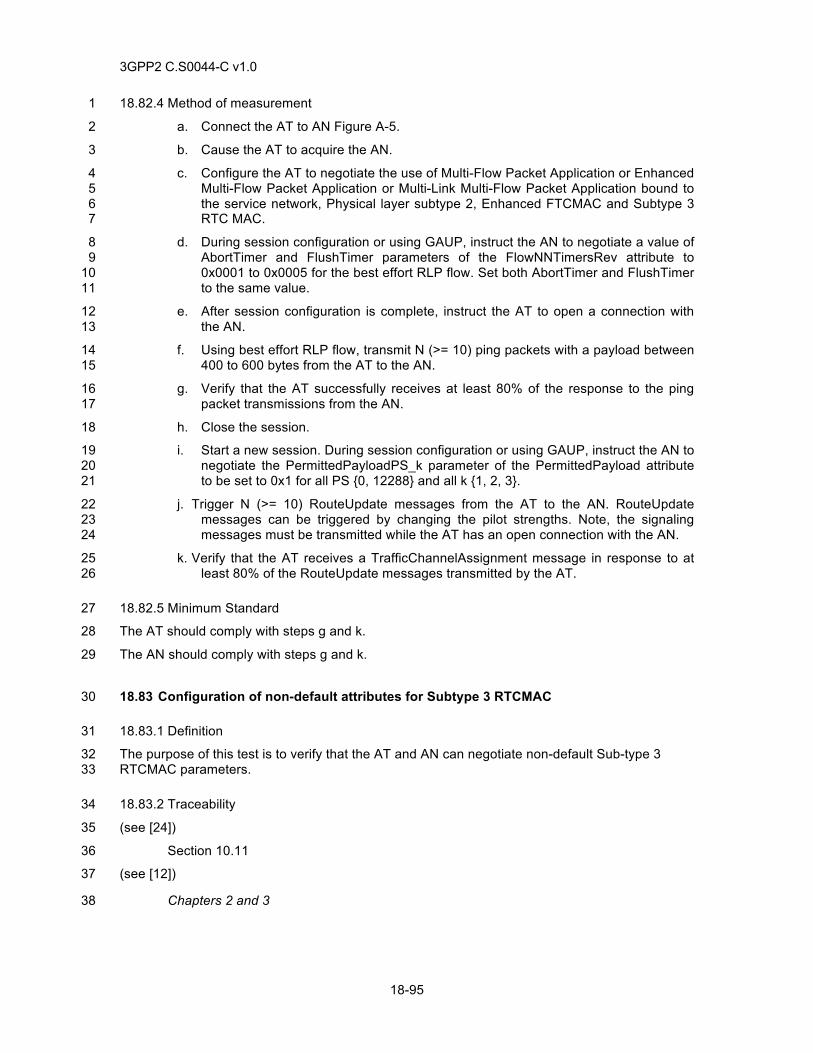
3GPP2 C.S0044-C v1.0
18-95
18.82.4 Method of measurement 1
a. Connect the AT to AN Figure A-5. 2
b. Cause the AT to acquire the AN. 3
c. Configure the AT to negotiate the use of Multi-Flow Packet Application or Enhanced 4 Multi-Flow Packet Application or Multi-Link Multi-Flow Packet Application bound to 5 the service network, Physical layer subtype 2, Enhanced FTCMAC and Subtype 3 6 RTC MAC. 7
d. During session configuration or using GAUP, instruct the AN to negotiate a value of 8 AbortTimer and FlushTimer parameters of the FlowNNTimersRev attribute to 9 0x0001 to 0x0005 for the best effort RLP flow. Set both AbortTimer and FlushTimer 10 to the same value. 11
e. After session configuration is complete, instruct the AT to open a connection with 12 the AN. 13
f. Using best effort RLP flow, transmit N (>= 10) ping packets with a payload between 14 400 to 600 bytes from the AT to the AN. 15
g. Verify that the AT successfully receives at least 80% of the response to the ping 16 packet transmissions from the AN. 17
h. Close the session. 18
i. Start a new session. During session configuration or using GAUP, instruct the AN to 19 negotiate the PermittedPayloadPS_k parameter of the PermittedPayload attribute 20 to be set to 0x1 for all PS {0, 12288} and all k {1, 2, 3}. 21
j. Trigger N (>= 10) RouteUpdate messages from the AT to the AN. RouteUpdate 22 messages can be triggered by changing the pilot strengths. Note, the signaling 23 messages must be transmitted while the AT has an open connection with the AN. 24
k. Verify that the AT receives a TrafficChannelAssignment message in response to at 25 least 80% of the RouteUpdate messages transmitted by the AT. 26
18.82.5 Minimum Standard 27
The AT should comply with steps g and k. 28
The AN should comply with steps g and k. 29
18.83 Configuration of non-default attributes for Subtype 3 RTCMAC 30
18.83.1 Definition 31
The purpose of this test is to verify that the AT and AN can negotiate non-default Sub-type 3 32 RTCMAC parameters. 33
18.83.2 Traceability 34
(see [24]) 35
Section 10.11 36
(see [12]) 37
Chapters 2 and 3 38
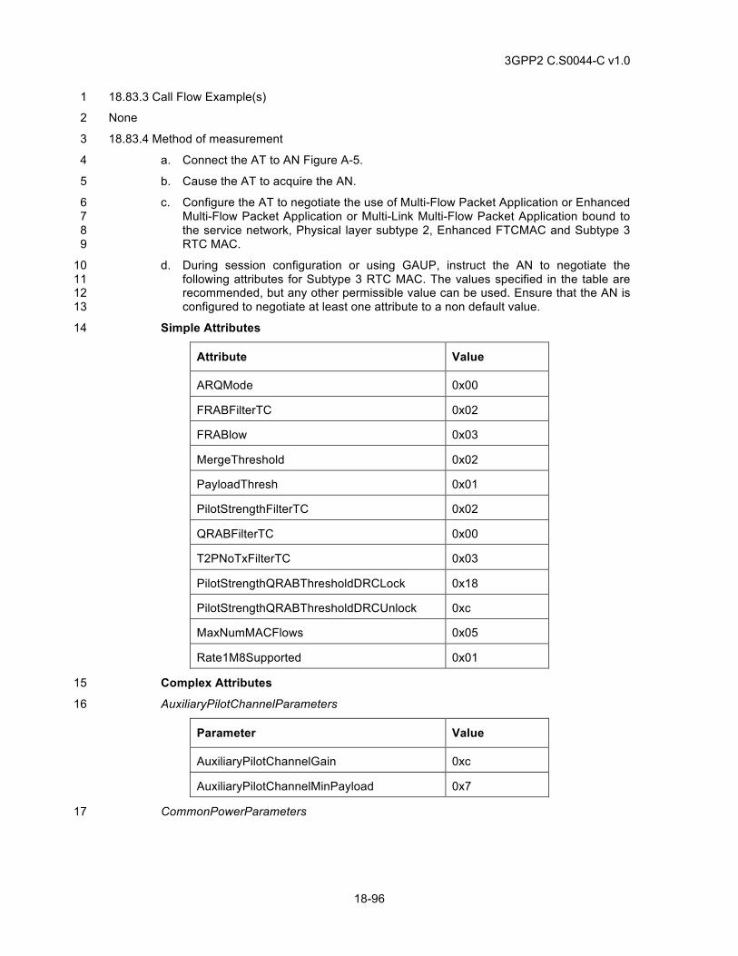
3GPP2 C.S0044-C v1.0
18-96
18.83.3 Call Flow Example(s) 1
None 2
18.83.4 Method of measurement 3
a. Connect the AT to AN Figure A-5. 4
b. Cause the AT to acquire the AN. 5
c. Configure the AT to negotiate the use of Multi-Flow Packet Application or Enhanced 6 Multi-Flow Packet Application or Multi-Link Multi-Flow Packet Application bound to 7 the service network, Physical layer subtype 2, Enhanced FTCMAC and Subtype 3 8 RTC MAC. 9
d. During session configuration or using GAUP, instruct the AN to negotiate the 10 following attributes for Subtype 3 RTC MAC. The values specified in the table are 11 recommended, but any other permissible value can be used. Ensure that the AN is 12 configured to negotiate at least one attribute to a non default value. 13
Simple Attributes 14
Attribute Value
ARQMode 0x00
FRABFilterTC 0x02
FRABlow 0x03
MergeThreshold 0x02
PayloadThresh 0x01
PilotStrengthFilterTC 0x02
QRABFilterTC 0x00
T2PNoTxFilterTC 0x03
PilotStrengthQRABThresholdDRCLock 0x18
PilotStrengthQRABThresholdDRCUnlock 0xc
MaxNumMACFlows 0x05
Rate1M8Supported 0x01
Complex Attributes 15
AuxiliaryPilotChannelParameters 16
Parameter Value
AuxiliaryPilotChannelGain 0xc
AuxiliaryPilotChannelMinPayload 0x7
CommonPowerParameters 17
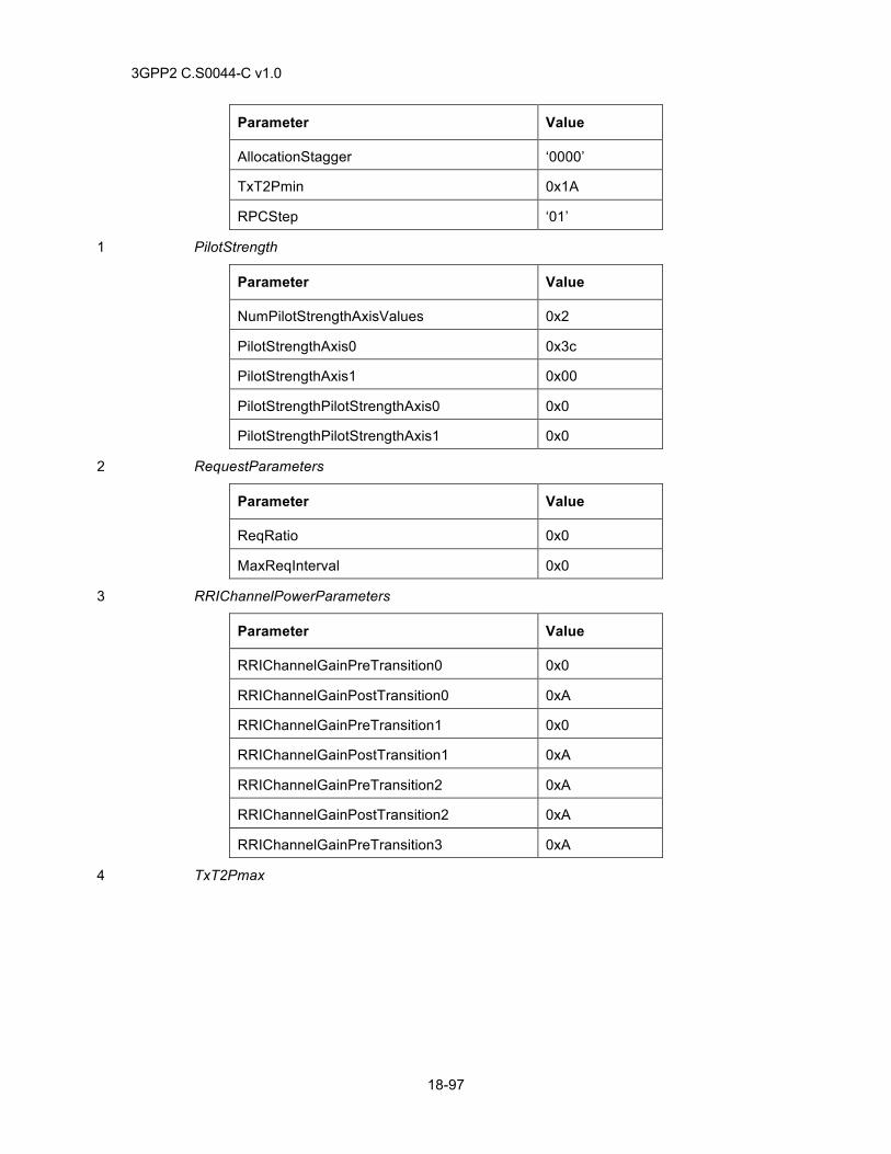
3GPP2 C.S0044-C v1.0
18-97
Parameter Value
AllocationStagger ‘0000’
TxT2Pmin 0x1A
RPCStep ‘01’
PilotStrength 1
Parameter Value
NumPilotStrengthAxisValues 0x2
PilotStrengthAxis0 0x3c
PilotStrengthAxis1 0x00
PilotStrengthPilotStrengthAxis0 0x0
PilotStrengthPilotStrengthAxis1 0x0
RequestParameters 2
Parameter Value
ReqRatio 0x0
MaxReqInterval 0x0
RRIChannelPowerParameters 3
Parameter Value
RRIChannelGainPreTransition0 0x0
RRIChannelGainPostTransition0 0xA
RRIChannelGainPreTransition1 0x0
RRIChannelGainPostTransition1 0xA
RRIChannelGainPreTransition2 0xA
RRIChannelGainPostTransition2 0xA
RRIChannelGainPreTransition3 0xA
TxT2Pmax 4
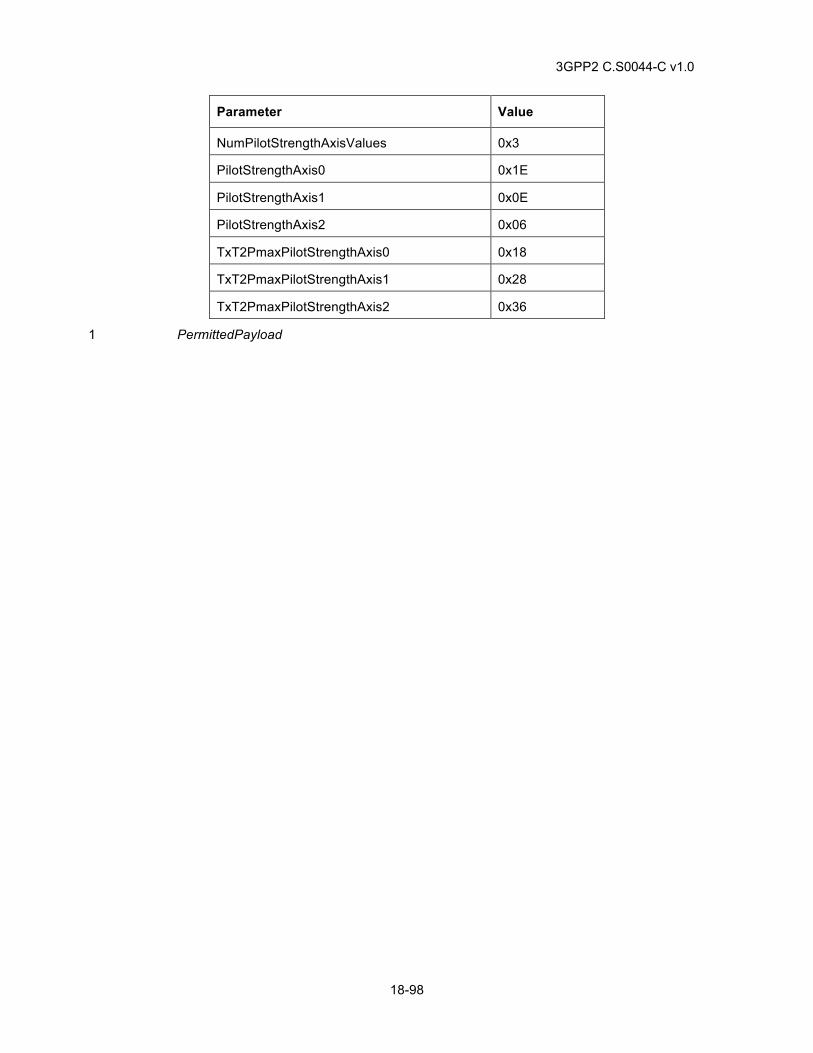
3GPP2 C.S0044-C v1.0
18-98
Parameter Value
NumPilotStrengthAxisValues 0x3
PilotStrengthAxis0 0x1E
PilotStrengthAxis1 0x0E
PilotStrengthAxis2 0x06
TxT2PmaxPilotStrengthAxis0 0x18
TxT2PmaxPilotStrengthAxis1 0x28
TxT2PmaxPilotStrengthAxis2 0x36
PermittedPayload 1
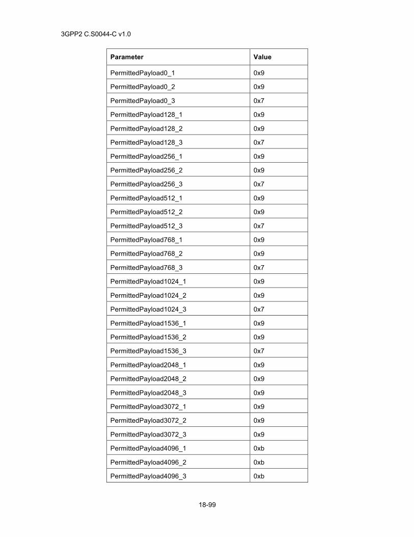
3GPP2 C.S0044-C v1.0
18-99
Parameter Value
PermittedPayload0_1 0x9
PermittedPayload0_2 0x9
PermittedPayload0_3 0x7
PermittedPayload128_1 0x9
PermittedPayload128_2 0x9
PermittedPayload128_3 0x7
PermittedPayload256_1 0x9
PermittedPayload256_2 0x9
PermittedPayload256_3 0x7
PermittedPayload512_1 0x9
PermittedPayload512_2 0x9
PermittedPayload512_3 0x7
PermittedPayload768_1 0x9
PermittedPayload768_2 0x9
PermittedPayload768_3 0x7
PermittedPayload1024_1 0x9
PermittedPayload1024_2 0x9
PermittedPayload1024_3 0x7
PermittedPayload1536_1 0x9
PermittedPayload1536_2 0x9
PermittedPayload1536_3 0x7
PermittedPayload2048_1 0x9
PermittedPayload2048_2 0x9
PermittedPayload2048_3 0x9
PermittedPayload3072_1 0x9
PermittedPayload3072_2 0x9
PermittedPayload3072_3 0x9
PermittedPayload4096_1 0xb
PermittedPayload4096_2 0xb
PermittedPayload4096_3 0xb
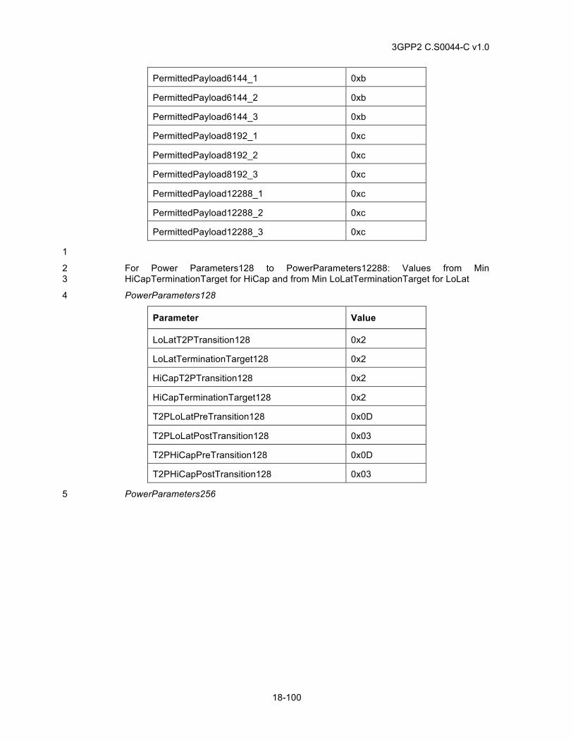
3GPP2 C.S0044-C v1.0
18-100
PermittedPayload6144_1 0xb
PermittedPayload6144_2 0xb
PermittedPayload6144_3 0xb
PermittedPayload8192_1 0xc
PermittedPayload8192_2 0xc
PermittedPayload8192_3 0xc
PermittedPayload12288_1 0xc
PermittedPayload12288_2 0xc
PermittedPayload12288_3 0xc
1
For Power Parameters128 to PowerParameters12288: Values from Min 2 HiCapTerminationTarget for HiCap and from Min LoLatTerminationTarget for LoLat 3
PowerParameters128 4
Parameter Value
LoLatT2PTransition128 0x2
LoLatTerminationTarget128 0x2
HiCapT2PTransition128 0x2
HiCapTerminationTarget128 0x2
T2PLoLatPreTransition128 0x0D
T2PLoLatPostTransition128 0x03
T2PHiCapPreTransition128 0x0D
T2PHiCapPostTransition128 0x03
PowerParameters256 5
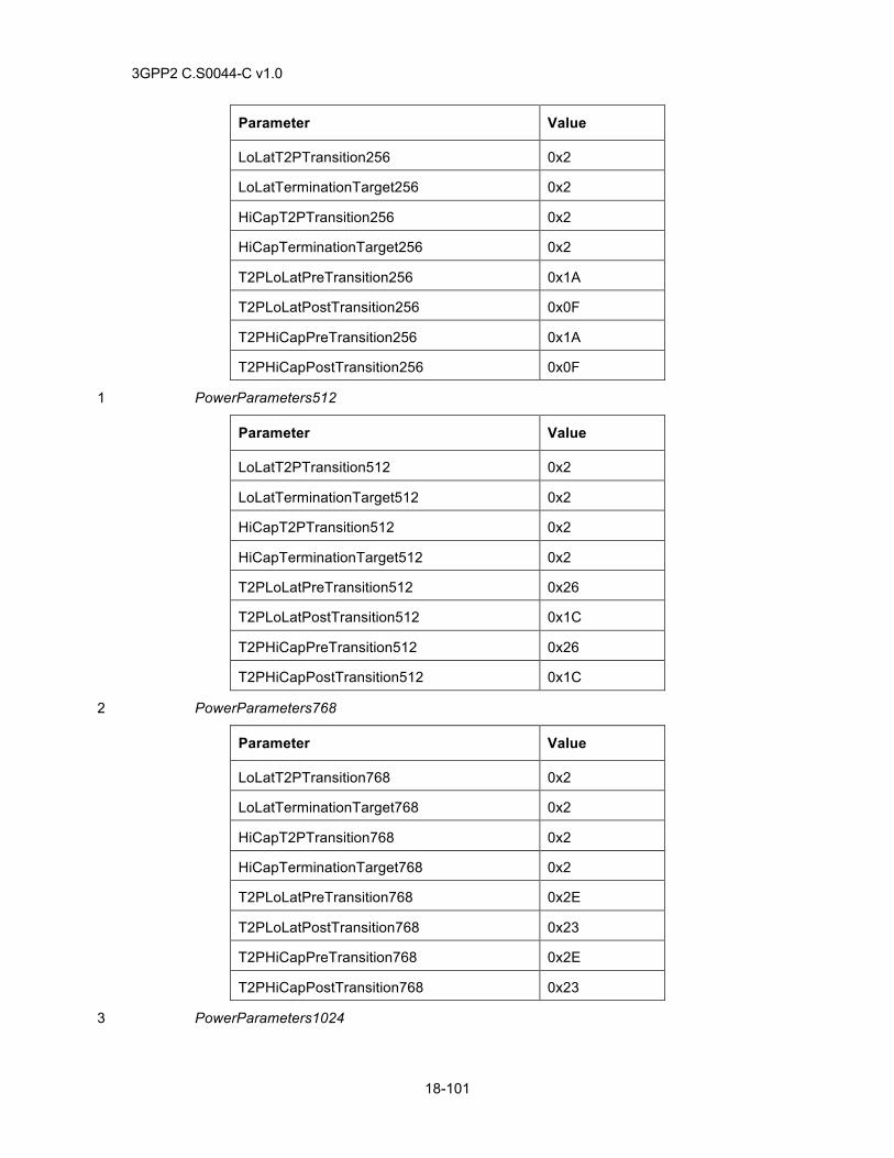
3GPP2 C.S0044-C v1.0
18-101
Parameter Value
LoLatT2PTransition256 0x2
LoLatTerminationTarget256 0x2
HiCapT2PTransition256 0x2
HiCapTerminationTarget256 0x2
T2PLoLatPreTransition256 0x1A
T2PLoLatPostTransition256 0x0F
T2PHiCapPreTransition256 0x1A
T2PHiCapPostTransition256 0x0F
PowerParameters512 1
Parameter Value
LoLatT2PTransition512 0x2
LoLatTerminationTarget512 0x2
HiCapT2PTransition512 0x2
HiCapTerminationTarget512 0x2
T2PLoLatPreTransition512 0x26
T2PLoLatPostTransition512 0x1C
T2PHiCapPreTransition512 0x26
T2PHiCapPostTransition512 0x1C
PowerParameters768 2
Parameter Value
LoLatT2PTransition768 0x2
LoLatTerminationTarget768 0x2
HiCapT2PTransition768 0x2
HiCapTerminationTarget768 0x2
T2PLoLatPreTransition768 0x2E
T2PLoLatPostTransition768 0x23
T2PHiCapPreTransition768 0x2E
T2PHiCapPostTransition768 0x23
PowerParameters1024 3
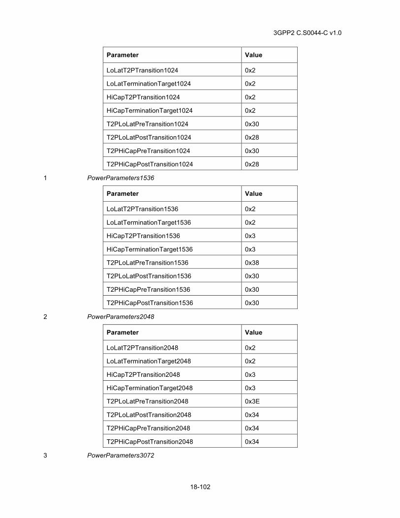
3GPP2 C.S0044-C v1.0
18-102
Parameter Value
LoLatT2PTransition1024 0x2
LoLatTerminationTarget1024 0x2
HiCapT2PTransition1024 0x2
HiCapTerminationTarget1024 0x2
T2PLoLatPreTransition1024 0x30
T2PLoLatPostTransition1024 0x28
T2PHiCapPreTransition1024 0x30
T2PHiCapPostTransition1024 0x28
PowerParameters1536 1
Parameter Value
LoLatT2PTransition1536 0x2
LoLatTerminationTarget1536 0x2
HiCapT2PTransition1536 0x3
HiCapTerminationTarget1536 0x3
T2PLoLatPreTransition1536 0x38
T2PLoLatPostTransition1536 0x30
T2PHiCapPreTransition1536 0x30
T2PHiCapPostTransition1536 0x30
PowerParameters2048 2
Parameter Value
LoLatT2PTransition2048 0x2
LoLatTerminationTarget2048 0x2
HiCapT2PTransition2048 0x3
HiCapTerminationTarget2048 0x3
T2PLoLatPreTransition2048 0x3E
T2PLoLatPostTransition2048 0x34
T2PHiCapPreTransition2048 0x34
T2PHiCapPostTransition2048 0x34
PowerParameters3072 3
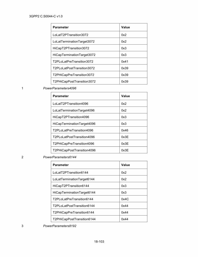
3GPP2 C.S0044-C v1.0
18-103
Parameter Value
LoLatT2PTransition3072 0x2
LoLatTerminationTarget3072 0x2
HiCapT2PTransition3072 0x3
HiCapTerminationTarget3072 0x3
T2PLoLatPreTransition3072 0x41
T2PLoLatPostTransition3072 0x39
T2PHiCapPreTransition3072 0x39
T2PHiCapPostTransition3072 0x39
PowerParameters4096 1
Parameter Value
LoLatT2PTransition4096 0x2
LoLatTerminationTarget4096 0x2
HiCapT2PTransition4096 0x3
HiCapTerminationTarget4096 0x3
T2PLoLatPreTransition4096 0x46
T2PLoLatPostTransition4096 0x3E
T2PHiCapPreTransition4096 0x3E
T2PHiCapPostTransition4096 0x3E
PowerParameters6144 2
Parameter Value
LoLatT2PTransition6144 0x2
LoLatTerminationTarget6144 0x2
HiCapT2PTransition6144 0x3
HiCapTerminationTarget6144 0x3
T2PLoLatPreTransition6144 0x4C
T2PLoLatPostTransition6144 0x44
T2PHiCapPreTransition6144 0x44
T2PHiCapPostTransition6144 0x44
PowerParameters8192 3
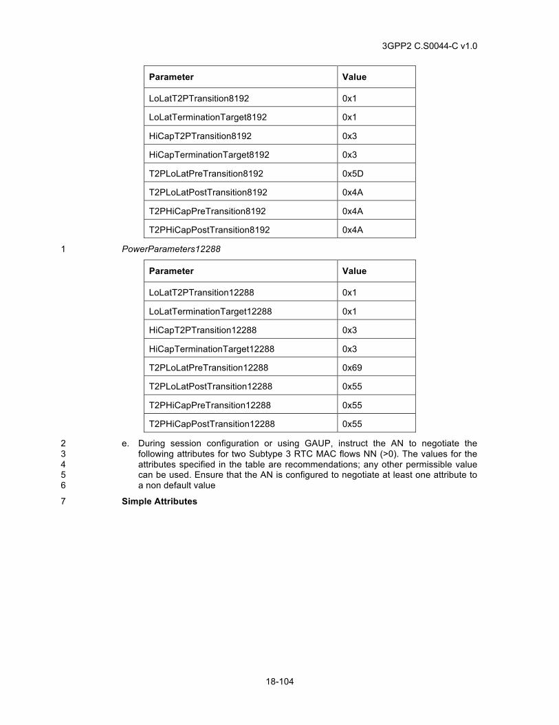
3GPP2 C.S0044-C v1.0
18-104
Parameter Value
LoLatT2PTransition8192 0x1
LoLatTerminationTarget8192 0x1
HiCapT2PTransition8192 0x3
HiCapTerminationTarget8192 0x3
T2PLoLatPreTransition8192 0x5D
T2PLoLatPostTransition8192 0x4A
T2PHiCapPreTransition8192 0x4A
T2PHiCapPostTransition8192 0x4A
PowerParameters12288 1
Parameter Value
LoLatT2PTransition12288 0x1
LoLatTerminationTarget12288 0x1
HiCapT2PTransition12288 0x3
HiCapTerminationTarget12288 0x3
T2PLoLatPreTransition12288 0x69
T2PLoLatPostTransition12288 0x55
T2PHiCapPreTransition12288 0x55
T2PHiCapPostTransition12288 0x55
e. During session configuration or using GAUP, instruct the AN to negotiate the 2 following attributes for two Subtype 3 RTC MAC flows NN (>0). The values for the 3 attributes specified in the table are recommendations; any other permissible value 4 can be used. Ensure that the AN is configured to negotiate at least one attribute to 5 a non default value 6
Simple Attributes 7
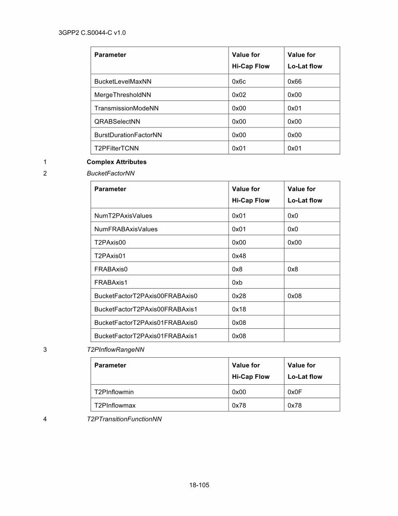
3GPP2 C.S0044-C v1.0
18-105
Parameter Value for
Hi-Cap Flow
Value for
Lo-Lat flow
BucketLevelMaxNN 0x6c 0x66
MergeThresholdNN 0x02 0x00
TransmissionModeNN 0x00 0x01
QRABSelectNN 0x00 0x00
BurstDurationFactorNN 0x00 0x00
T2PFilterTCNN 0x01 0x01
Complex Attributes 1
BucketFactorNN 2
Parameter Value for
Hi-Cap Flow
Value for
Lo-Lat flow
NumT2PAxisValues 0x01 0x0
NumFRABAxisValues 0x01 0x0
T2PAxis00 0x00 0x00
T2PAxis01 0x48
FRABAxis0 0x8 0x8
FRABAxis1 0xb
BucketFactorT2PAxis00FRABAxis0 0x28 0x08
BucketFactorT2PAxis00FRABAxis1 0x18
BucketFactorT2PAxis01FRABAxis0 0x08
BucketFactorT2PAxis01FRABAxis1 0x08
T2PInflowRangeNN 3
Parameter Value for
Hi-Cap Flow
Value for
Lo-Lat flow
T2PInflowmin 0x00 0x0F
T2PInflowmax 0x78 0x78
T2PTransitionFunctionNN 4
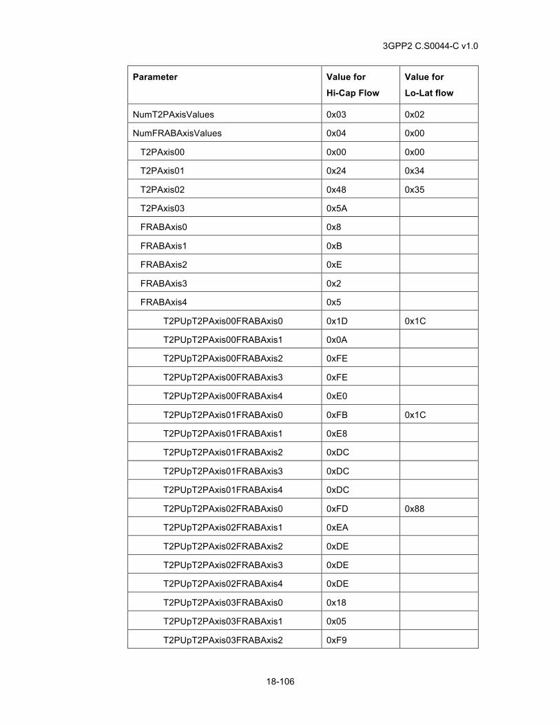
3GPP2 C.S0044-C v1.0
18-106
Parameter Value for
Hi-Cap Flow
Value for
Lo-Lat flow
NumT2PAxisValues 0x03 0x02
NumFRABAxisValues 0x04 0x00
T2PAxis00 0x00 0x00
T2PAxis01 0x24 0x34
T2PAxis02 0x48 0x35
T2PAxis03 0x5A
FRABAxis0 0x8
FRABAxis1 0xB
FRABAxis2 0xE
FRABAxis3 0x2
FRABAxis4 0x5
T2PUpT2PAxis00FRABAxis0 0x1D 0x1C
T2PUpT2PAxis00FRABAxis1 0x0A
T2PUpT2PAxis00FRABAxis2 0xFE
T2PUpT2PAxis00FRABAxis3 0xFE
T2PUpT2PAxis00FRABAxis4 0xE0
T2PUpT2PAxis01FRABAxis0 0xFB 0x1C
T2PUpT2PAxis01FRABAxis1 0xE8
T2PUpT2PAxis01FRABAxis2 0xDC
T2PUpT2PAxis01FRABAxis3 0xDC
T2PUpT2PAxis01FRABAxis4 0xDC
T2PUpT2PAxis02FRABAxis0 0xFD 0x88
T2PUpT2PAxis02FRABAxis1 0xEA
T2PUpT2PAxis02FRABAxis2 0xDE
T2PUpT2PAxis02FRABAxis3 0xDE
T2PUpT2PAxis02FRABAxis4 0xDE
T2PUpT2PAxis03FRABAxis0 0x18
T2PUpT2PAxis03FRABAxis1 0x05
T2PUpT2PAxis03FRABAxis2 0xF9
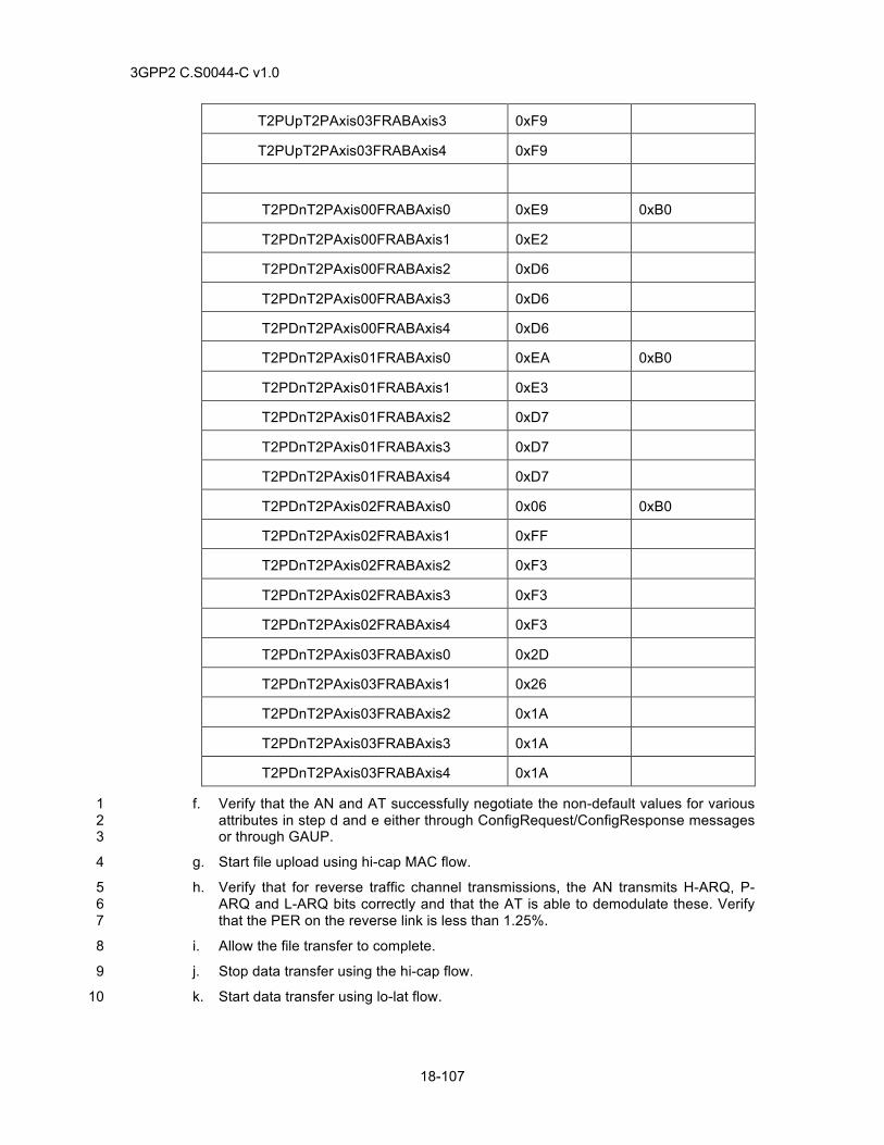
3GPP2 C.S0044-C v1.0
18-107
T2PUpT2PAxis03FRABAxis3 0xF9
T2PUpT2PAxis03FRABAxis4 0xF9
T2PDnT2PAxis00FRABAxis0 0xE9 0xB0
T2PDnT2PAxis00FRABAxis1 0xE2
T2PDnT2PAxis00FRABAxis2 0xD6
T2PDnT2PAxis00FRABAxis3 0xD6
T2PDnT2PAxis00FRABAxis4 0xD6
T2PDnT2PAxis01FRABAxis0 0xEA 0xB0
T2PDnT2PAxis01FRABAxis1 0xE3
T2PDnT2PAxis01FRABAxis2 0xD7
T2PDnT2PAxis01FRABAxis3 0xD7
T2PDnT2PAxis01FRABAxis4 0xD7
T2PDnT2PAxis02FRABAxis0 0x06 0xB0
T2PDnT2PAxis02FRABAxis1 0xFF
T2PDnT2PAxis02FRABAxis2 0xF3
T2PDnT2PAxis02FRABAxis3 0xF3
T2PDnT2PAxis02FRABAxis4 0xF3
T2PDnT2PAxis03FRABAxis0 0x2D
T2PDnT2PAxis03FRABAxis1 0x26
T2PDnT2PAxis03FRABAxis2 0x1A
T2PDnT2PAxis03FRABAxis3 0x1A
T2PDnT2PAxis03FRABAxis4 0x1A
f. Verify that the AN and AT successfully negotiate the non-default values for various 1 attributes in step d and e either through ConfigRequest/ConfigResponse messages 2 or through GAUP. 3
g. Start file upload using hi-cap MAC flow. 4
h. Verify that for reverse traffic channel transmissions, the AN transmits H-ARQ, P-5 ARQ and L-ARQ bits correctly and that the AT is able to demodulate these. Verify 6 that the PER on the reverse link is less than 1.25%. 7
i. Allow the file transfer to complete. 8
j. Stop data transfer using the hi-cap flow. 9
k. Start data transfer using lo-lat flow. 10
3GPP2 C.S0044-C v1.0
18-108
l. Verify that the PER for the reverse link is less than 1.25% and that 99% of the 1 packets terminate within LoLatTerminationTargetPS + 1 sub-packet transmissions 2 for packet size PS. 3
18.83.5 Minimum Standard 4
The AN and AT shall comply with step f. 5
The AN and AT should comply with steps h, and l. 6
18.84 MultiATPage message 7
18.84.1 Definition 8
This test verifies that AT can be paged using MultiATPage message. 9
18.84.2 Traceability 10
(see [24] part 400) 11
1.5.6.1.7.1 Access Terminal Requirements 12
1.5.6.2.4 MultiATPage 13
MultiATPageMessageSupported attribute in 1.5.7.1 Simple Attributes 14
1.6.6.1.7.1 Access Terminal Requirements 15
1.6.6.2.5 MultiATPage 16
MultiATPageMessageSupported attribute in 1.6.7.1 Simple Attributes 17
18.84.3 Call Flow Example(s) 18
None 19
18.84.4 Method of measurement 20
a. Power up the AT. 21
b. Configure the AN to negotiate Enhanced Idle State Protocol or Quick Idle State 22 Protocol. 23
c. Ensure that the MultiATPageMessageSupported attribute is set to 0x01 indicating that 24 the AT supports the MultiATPage message. 25
d. Cause the AN to page the AT under test using the MultiATPage message. 26
e. Verify that the AT responds by sending a ConnectionRequest message, and connection 27 setup is successful. 28
18.84.5 Minimum Standard 29
The AT shall comply with e. 30
31
3GPP2 C.S0044-C v1.0
18-109
18.85 LoadInformation message 1
18.85.1 Definition 2
This test verifies that the AT uses LoadInformation message to select forward link server. 3
18.85.2 Traceability 4
(see [24] part 300) 5
1.7.6.2.6 LoadInformation 6
LoadInformationSupported attribute in 1.7.7.1 Simple Attributes 7
1.8.6.2.6 LoadInformation 8
LoadInformationSupported attribute in 1.8.7.1 Simple Attributes 9
1.9.6.2.6 LoadInformation 10
LoadInformationSupported attribute in 1.9.7.1 Simple Attributes 11
18.85.3 Call Flow Example(s) 12
None 13
18.85.4 Method of Measurement 14
a. Power up the AT. 15
b. Configure the AN to negotiate Enhanced Forward Traffic Channel MAC Protocol 16 (subtype 1), Subtype 2 Forward Traffic Channel MAC Protocol, or Subtype 3 Forward 17 Traffic Channel MAC Protocol 18
c. Setup a connection such that sector α and sector ß are in active set. Maintain the 19 connection during this test. 20
d. Ensure that AN is not transmitting the LoadInformation message. 21
e. Adjust the attenuation on the sectors such that sector α has slightly higher Forward Link 22 Power Ior than sector ß. 23
f. Ensure that AT is consistently pointing its DRC to sector α. 24
g. Cause the AN to transmit LoadInformation message with LoadingAdjust for sector α 25 considerably higher than sector ß. 26
h. Verify that the AT is consistently pointing its DRC to sector ß. 27
i. Cause the AN to transmit LoadInformation message with same value of LoadingAdjust 28 for sector α and sector ß. 29
j. Verify that the AT is consistently pointing its DRC to sector α. 30
18.85.5 Minimum Standard 31
The AT shall comply with h and j. 32
33
3GPP2 C.S0044-C v1.0
18-110
18.86 Single Carrier Multi-Link 1
18.86.1 Definition 2
This test verifies that the AT can operate with connection assigned in single carrier multi-link 3 (SCML) mode. 4
18.86.2 Traceability 5
(see [24] part 200) 6
Chapter 3 Subtype 3 Physical Layer 7
Chapter 4 Subtype 4 Physical Layer 8
Chapter 5 Subtype 5 Physical Layer 9
(see [24] part 400) 10
1.9 Subtype 1 Route Update Protocol 11
1.9.6.2.2 TrafficChannelAssignment 12
13
18.86.3 Call Flow Example(s) 14
None 15
18.86.4 Method of measurement 16
a. Power up the AT. 17
b. Configure the AN to negotiate Subtype 3 Physical Layer protocol and Subtype 1 Route 18 Update Protocol. 19
c. Ensure that the SingleCarrierMultiLinkCapability attribute is set to value other than 20 0x00. 21
d. Adjust the attenuation on the sectors such sector α and sector ß have same Forward 22 Link Power Ior . 23
e. Setup a connection. 24
f. Cause AN to send TrafficChannelAssignment with SCML assignment. The 25 TrafficChannelAssignment message should have 2 identical sub-Active sets (both with 26 sector α and sector ß on same frequency), FeedbackMultiplexingEnabled Set to ‘1’, and 27 FeedbackMultiplexingIndex set to a feedback multiplexing method supported by the AT. 28
g. Transfer FL data to the AT. 29
h. Verify that the data is sent over the 2 links assigned to the AT. 30
i. Verify that the data transfer is successful. 31
18.86.5 Minimum Standard 32
The AT shall comply with steps h and i. 33
3GPP2 C.S0044-C v1.0
19-1
19 XHRPD 1
For xHRPD test cases described in chapter 19, the terms mobile station and base station 2 represent the access terminal (AT) and access network (AN) respectively. 3
For all tests in Chapter 19, Session Security should be enabled if supported. 4
19.1 xHRPD Acquisition and Idle Mode Operation 5
Same as 18.1. 6
19.2 xHRPD Session Establishment 7
Same as 18.2. 8
19.2.1 Traceability 9
see [33] 10
1 MAC Layer, 3 Connection Layer, 4 Session Layer 11
19.3 xHRPD Session Configuration and Management with Subnet change 12
Same as 18.3. 13
19.3.1 Traceability 14
see [33] 15
4 Session Layer 16
19.4 AT Color Code and UATI24 17
Same as 18.4. 18
19.4.1 Traceability 19
see [33] 20
1 MAC Layer, 3 Connection Layer, 4 Session Layer 21
19.5 xHRPD Connection Setup 22
Same as 18.5. 23
19.5.1 Traceability 24
see [33] 25
1 MAC Layer, 3 Connection Layer, 4 Session Layer 26
19.6 AN Packet Data Inactivity Timer 27
Same as 18.6. 28
19.6.1 Traceability 29
see [33] 30
3GPP2 C.S0044-C v1.0
19-2
1 MAC Layer, 2 Security Layer, 3 Connection Layer, 4 Session Layer 1
19.7 Reserved 2
19.8 Reserved 3
19.9 Reserved 4
19.10 RLP Operation in Severely Degraded Channel 5
19.10.1 Definition 6
This test verifies RLP Operation in Severely Degraded Channel when in active xHRPD mode. 7
19.10.2 Traceability: 8
see [33] 9
1 MAC Layer, 3 Connection Layer, 4 Session Layer 10
see [26] 11
3 HRPD IOS Call Flows 12
see [12] 13
Chapters 2 and 3 14
19.10.3 Call Flow Example(s) 15
None 16
19.10.4 Method of Measurement 17
a. Connect the AT to the AN as shown in Figure A-1. 18
b. Set the channel simulator to one Ray 100 km/hr Rayleigh fading on the forward link. 19
c. Configure the AT to negotiate the use of Default Packet Application bound to the 20 Service Network. 21
d. Cause the AT to acquire the AN. 22
e. Initiate a xHRPD packet data call from the AT. 23
a. Issue a “ping” from AT. 24
f. Verify the AT receives “ping” response from AN. 25
g. End the xHRPD packet data call. 26
h. Configure the AT to negotiate the use of Enhanced Multi-Flow Packet Application 27 bound to the Service Network. 28
i. Repeat steps d to g. 29
19.10.5 Minimum Standard 30
The AT shall comply with step f. 31
3GPP2 C.S0044-C v1.0
19-3
19.11 Reserved 1
19.12 xHRPD Control Channel Monitoring and Overhead Message Updates 2
Same as 18.12. 3
19.12.1 Traceability: 4
see [33] 5
3.4 xHRPD Subtype 0 Idle State Protocol 6
3.5 xHRPD Subtype 1 Idle State Protocol 7
19.13 Control Channel Rate 8
Same as 18.13. 9
19.14 xHRPD ConnectionDeny 10
Same as 18.14. 11
19.14.1 Traceability: 12
see [33] 13
3.4 xHRPD Subtype 0 Idle State Protocol 14
3.4.6.1.6.1 AT Requirements 15
3.4.6.1.6.2 AN Requirements 16
3.4.6.2.3 ConnectionDeny 17
3.5 xHRPD Subtype 1 Idle State Protocol 18
19.15 xHRPD Keep Alive Mechanism 19
Same as 18.15. 20
19.16 Reserved 21
19.17 Reserved 22
19.18 Intra-band xHRPD-xHRPD System Re-selection (Idle State) 23
Same as 18.18. 24
19.18.1 Traceability 25
see [24] 26
8.2 Default Air Link Management Protocol 27
8.2.6.1.2 Initialization State 28
8.6 Default Connected State Protocol 29
3GPP2 C.S0044-C v1.0
19-4
See [33] 1
3.4 xHRPD Subtype 0 Idle State Protocol 2
3.4.6.1.6 Connection Setup State 3
3.5 xHRPD Subtype 1 Idle State Protocol 4
(see [26]) 5
3.7.1 PCF-PCF Dormant Handoff with Successful Retrieval of HRPD Session 6 Information 7
19.19 Inter-band xHRPD-xHRPD System Re-selection (Idle State) 8
Same as 18.19. 9
19.19.1 Traceability 10
see [24] 11
8.2 Default Air Link Management Protocol 12
8.2.6.1.2 Initialization State 13
8.6 Default Connected State Protocol 14
See [33] 15
3.4 xHRPD Subtype 0 Idle State Protocol 16
3.4.6.1.6 Connection Setup State 17
3.5 xHRPD Subtype 1 Idle State Protocol 18
(see [26]) 19
3.7.1 PCF-PCF Dormant Handoff with Successful Retrieval of HRPD Session 20 Information 21
19.20 xHRPD Terminal Authentication 22
Same as 18.20. 23
19.21 PPP Session in Adverse Conditions - Disconnect cable between AT and PC. 24
Same as 18.21. 25
19.22 Reserved 26
19.23 Reserved 27
19.24 Idle State Channel Hashing 28
19.24.1 Definition 29
This test can be performed only if the AN supports more than one xHRPD channels. 30
3GPP2 C.S0044-C v1.0
19-5
If multiple channels are advertised in the sector parameter message, AT uses hash function (as 1 specified in (See [24])) to select one of the advertised channels for idle state operation. The 2 primary purpose of channel hashing is to equally distribute the AN load on all available channels. 3
19.24.2 Traceability 4
see [33] 5
3.4.6.1.5.1.1 CDMA Channel Selection 6
19.24.3 Call Flow Example(s) 7
None 8
19.24.4 Method of measurement 9
a. Configure the AT roaming list with the primary channel. Configure the AT to negotiate 10 xHRPD subtype 1 idle state protocol. 11
b. Power up the AT. 12
c. Place AT where it can receive good xHRPD signal. 13
d. If the AT has an open session with the AN, cause the AN to close the session. Cause 14 the AT to establish a new session with the AN. 15
e. Ensure that AT correctly acquires the primary channel listed in the roaming list. 16
f. After receiving the sector parameter messages with multiple channels, AT will try to 17 hash to a channel listed in SectorParameter message (it could be the same channel in 18 some cases). 19
g. Verify that if there are “n” channels listed in the sector parameter message and if this 20 test is repeated “m” number of times, AT will hash to each channel approximately “m/n” 21 times. In a subnet where SectorParameter message contains multiple channels, AT will 22 try to hash to a new channel every time a new session is opened. 23
h. Repeat steps d through g approximately 3n times. 24
i. Setup a xHRPD data connection after channel hashing is complete to verify that AT can 25 setup a connection on the hashed channel. Let the call connection go idle. 26
j. Send a data page from the AN (on the hashed channel) and verify that AT can receive 27 a page on the hashed channel. 28
19.24.5 Minimum Standard 29
The AT shall comply with steps g, i and j. 30
19.25 Reserved 31
19.26 Typical xHRPD Session Configuration 32
19.26.1 Definition 33
This test verifies the ability of AT and AN to use typical xHRPD configuration. The use of EMFPA 34 bound to the service network, xHRPD subtype 1 FTCMAC, xHRPD subtype 0 RTCMAC, default 35 CCMAC, xHRPD subtype 0 ACMAC and xHRPD subtype 0 Physical layer is verified. 36
19.26.2 Traceability 37
see [32] and [33] 38
3GPP2 C.S0044-C v1.0
19-6
8 Enhanced Multi-Flow Packet Application 1
3.5 xHRPD subtype 1 Idle State Protocol 2
1.2 Default Control Channel MAC Protocol 3
1.4 xHRPD subtype 0 Access Channel MAC Protocol 4
1.6 xHRPD subtype 1 Forward Traffic Channel MAC Protocol 5
1.7 xHRPD subtype 0 Reverse Traffic Channel MAC Protocol 6
[32] xHRPD subtype 0 Physical Layer 7
19.26.3 Call Flow Example(s) 8
None 9
19.26.4 Method of measurement 10
a. Connect the AT to the AN as shown in Figure A-3. 11
b. Cause the AT to acquire the AN. 12
c. Configure the AT to negotiate the use of Enhanced Multi-Flow Packet Application 13 bound to the service network, xHRPD subtype 0 Physical layer, Default CCMAC, 14 xHRPD subtype 0 ACMAC, xHRPD subtype 1 FTCMAC, xHRPD subtype 1 Idle State 15 Protocol and xHRPD subtype 0 RTC MAC. 16
d. If the AT has an established session with the AN, cause the AN to close the session by 17 transmitting a SessionClose message. 18
e. Power cycle the AT. 19
f. Verify that the AT establishes a session with the AN and acquires the xHRPD system. 20
g. Cause the AT to initiate a data call with the AN. 21
h. Verify that the AT and the AN have successfully negotiated the use of Enhanced Multi-22 Flow Packet Application bound to the AN, xHRPD subtype 0 Physical layer, Default 23 CCMAC, xHRPD subtype 0 ACMAC, xHRPD subtype 1 FTCMAC, xHRPD subtype 1 24 Idle State Protocol and xHRPD subtype 0 RTC MAC. 25
i. Cause the AT to transmit data to the AN. 26
j. Verify that the data is transmitted using the default RLP flow of the EMFPA. 27
19.26.5 Minimum Standard 28
The AT shall comply with steps f, h and j. 29
The AN shall comply with step h. 30
19.27 Multiple Reservations bound to one RLP 31
19.27.1 Definition 32
In xHRPD multiple higher layer flows can be bound to a single RLP flow. This is done by mapping 33 the ReservationLabel associated with the higher layer flow in FlowNNReservationFwd and 34 FlowNNReservationRev attribute of the RLP Flow NN. This test verifies the ability of the AN and 35 the AT to successfully bind multiple reservations to a single RLP flow. 36
This test requires the ability to generate QoS requests from the AT, allocate QoS resources at the 37 AN and install traffic filtering at the PDSN. The application that causes the AT to generate QoS 38
3GPP2 C.S0044-C v1.0
19-7
requests could either reside at the AT or the TE. Further, it should be ensured that the application 1 is able to connect with the server/peer and receive and transmit data. This may require password 2 authentication when using commercial applications residing on the AT. 3
The following behavior is assumed for the application using the QoS. Starting the application will 4 cause ReservationKKQoSRequestFwd/Rev to be sent containing the requested Profile ID. Unless 5 otherwise specified, the Profile should be accepted by the AN. Closing the application will cause 6 the AT to transmit a ReservationKKQoSRequestFwd/Rev with ProfileType set to NULL. If 7 application is paused or restarted, it should turn the reservation to on state if the reservation is in 8 closed state. This application behavior is assumed for all QoS related tests in this chapter. 9
19.27.2 Traceability 10
(see [24]) 11
4.4.4 Procedures and Messages for the InUse Instance of the RLP 12
4.4.8 Complex Attributes of Multi-Flow Packet Application 13
(see 17]) 14 11.4 QoS ProfileType and ProfileValue Assignment 15 (see [10]) 16 (see [12]) 17 Chapters 2 and 3. 18
19.27.3 Call Flow Example(s) 19
None 20
19.27.4 Method of measurement 21
a. Connect the AT to the AN as shown in Figure A-3. 22
b. Cause the AT to acquire the AN. 23
c. Configure the AT to negotiate the use of Enhanced Multi-Flow Packet Application 24 bound to the service network, xHRPD subtype 0 Physical layer, xHRPD subtype 1 25 FTCMAC and xHRPD subtype 0 RTC MAC. 26
d. Configure the AN to activate only the default RLP flow during session configuration. 27
e. Configure the AN to use a value of 2 for MaxActivatedRLPFlowsFwd and 28 MaxActivatedRLPFlowRev. 29
f. If the AT has an established session with the AN, cause the AN to close the session by 30 transmitting a SessionClose message. 31
g. Cause the AT to negotiate a new session with the AN. 32
h. Cause the AT to establish a data call with the AN and allow the AT to go idle. 33
i. Cause the AT to generate a QoS request for one forward and one reverse link higher 34 layer flow. 35
j. Ensure that the AT transmits GAUP message(s) with ReservationKKQoSRequestFwd 36 with R_QoS_SUB_BLOB containing the specified Profile ID for forward higher layer 37 flows and ReservationKKQoSRequestRev with R_QoS_SUB_BLOB containing the 38 specified Profile ID for reverse higher layer flows. 39
k. Ensure that the AT constructs a Traffic Flow Template (TFT) with the desired packet 40 filters and sends an RSVP Resv [Create new TFT] message. 41
3GPP2 C.S0044-C v1.0
19-8
l. Ensure that the AN transmits AttributeUpdateAccept message(s) accepting the QoS 1 ReservationKKQoSRequestFwd / ReservationKKQoSRequestRev attributes from the 2 AT. 3
m. The AN should GAUP the ReservationKKQoSResponseFwd with G_QoS_BLOB 4 containing the set ID for primary Profile ID. 5
n. The AN should GAUP the ReservationKKQoSResponseRev with G_QoS_BLOB 6 containing the set ID for primary Profile ID. 7
o. The PDSN should install the desired packet filters and sends an RSVP ResvConf 8 message. 9
p. Ensure that the AT transmits AttributeUpdate message(s) to the AN accepting the AN’s 10 ReservationKKQosResponseFwd and ReservationKKQosResponseRev for the various 11 Reservarion Labels. 12
q. Ensure that the AN transmits a GAUP message for FlowNNIdentificationFwd (NN = 1) 13 and FlowNNIdentificationRev (NN = 1) in order to activate the forward and reverse link 14 flows. 15
r. Ensure that the AT transmits AttributeUpdateAccept message(s) accepting 16 FlowNNIdentificationFwd and FlowNNIdentificationRev arrtibutes. 17
s. The AN may need to transmit AttributeUpdateRequest message(s) negotiating the 18 FlowNNTimersFwd and FlowNNTimersRev for the Forward and Reverse link RLP flows 19 and various parameters of the RTCMAC flow. 20
t. If the AN transmits Attribute Update Request for the Forward and Reverse Link RLP 21 Flows and/or RTCMAC flows, the AT should transmit AttributeUpdateAccept 22 message(s) accepting RLP and RTCMAC parameters. 23
u. Ensure that the AN transmits a FlowNNReservationFwd to bind the reservation to 24 forward to RLP flow (NN = 0x01). 25
v. Ensure that the AN transmits a FlowNNReservationRev to bind the reservation to 26 reservation to RLP flow (NN = 0x01). 27
w. Ensure that the AT transmits an AttributeUpdateAccept message accepting the 28 FlowNNReservationFwd and FlowNNReservationRev values. 29
x. Ensure that the AN transmits AttributeUpdateReqest message containing 30 AssociatedFlowNN with substream field set to 1 to bind the RLP FlowNN (NN = 1) to an 31 RTCMAC flow. 32
y. Ensure that the AT transmits AttributeUpdateAccept message(s) to the AN accepting 33 the binding sent by the AN in AssociatedFlowsNN attribute. 34
z. Ensure that the AN transmits a GAUP message to set RTCMAC BucketLevelMaxNN 35 with a nonzero value in order to activate the RTCMAC flow. 36
aa. Ensure that the AT transmits AttributeUpdateAccept message to the AN accepting the 37 BucketLevelMaxNN value sent by the AN. 38
bb. Ensure that the AT sends ReservationOnRequest for both the forward and reverse 39 ReservationLabels using single ReservationOnRequest message. 40
cc. Ensure that AN sends ReservationAccept for both forward and reverse reservations. 41
dd. Repeat steps i to cc for 2 other QoS requests. 42
ee. Verify that both the forward and reverse RLP flows (NN = 1) are activated and the 43 reservation for all the higher layer flows are in the Open state. 44
3GPP2 C.S0044-C v1.0
19-9
ff. Start bidirectional data transfer for different higher layer flows and verify that data is 1 being sent/received on the correct RLP IDs. 2
gg. Ensure that the PDSN is sending data via the intended filter. 3
19.27.5 Minimum Standard 4
The AT shall comply with steps ee and ff. 5
The AN shall comply with steps ee and ff. 6
The PDSN should comply with steps o and gg. 7
19.28 Maximum Open Reservations, Activated RLP and MAC flows 8
19.28.1 Definition 9
The Maximum number of reservations that can be in open state in xHRPD is governed by 10 MaxNumOpenReservationsFwd and MaxNumOpenReservationsRev (default value of 16). The 11 maximum number of open RLP flows is governed by MaxActivatedRLPFlowsFwd and 12 MaxActivatedRLPFlowsRev. The maximum number of active MAC flows is governed by 13
MaxNumActiveMACFlows This test verifies that AT and the AN can support up to 16 open 14 reservations, mapped to 8 RLP flows that are in turn mapped to 4 MAC flows. This test implicitly 15 verifies the ability of the AN and the AT to allow many to one binding from reservation labels to 16 RLP flows and RLP flows to MAC Flows. It also verifies the ability of the PDSN to create multiple 17 filters for the AT. 18
19.28.2 Traceability 19
(see [24]) 20
4.4.4 Procedures and Messages for the InUse Instance of the RLP 21
4.4.8 Complex Attributes of Multi-Flow Packet Application 22
(see [10]) 23
(see [12]) 24
Chapters 2 and 3 25
19.28.3 Call Flow Example(s) 26
None 27
19.28.4 Method of measurement 28
a. Connect the AT to the AN as shown in Figure A-3. 29
b. Cause the AT to acquire the AN. 30
c. Configure the AT to negotiate the use of Enhanced Multi-Flow Packet Application 31 bound to the service network, xHRPD subtype 0 Physical layer, xHRPD subtype 1 32 FTCMAC and xHRPD subtype 0 RTC MAC. 33
d. Configure the AN to activate only the default RLP flow during session configuration. 34
e. Configure the AN to use a value of 8 for MaxActivatedRLPFlowsFwd, 35 MaxActivatedRLPFlowRev, MaxNumRLPFlowsFwd and MaxNumRLPFlowsRev. 36
f. Configure the AN to set the MaxNumOpenReservationsFwd and 37 MaxNumOpenReservationsRev parameters of MaxReservations attribute to 16. 38
3GPP2 C.S0044-C v1.0
19-10
g. Configure the AN to grant the QoS request from the AT and to bind 2 QoS reservations 1 to one RLP flow for both the forward and reverse link flows, and to bind 2 RLP flows to 2 each RTCMAC Flow. 3
h. If the AT has an established session with the AN, cause the AN to close the session by 4 transmitting a SessionClose message. 5
i. Cause the AT to negotiate a new session with the AN. 6
j. Ensure that the AN activates only the default RLP flow during session configuration. 7
k. Cause the AT to establish a data call with the AN and allow the AT to go idle. 8
l. Using multiple applications, cause the AT to generate QoS requests for 16 forward and 9 reverse link flows. Wait for the AN to transmit ReservationAccept message for all the 10 reservations. 11
m. Verify that all 8 forward and reverse RLP flows are activated and all 16 reservations are 12 in Open state. 13
n. Start bidirectional data transfer for different higher layer flows and verify that data is 14 being sent/received on the correct RLP and MAC flows. 15
o. Ensure that the PDSN is sending data for each higher layer flow via the intended filter. 16
19.28.5 Minimum Standard 17
The AT shall comply with steps m and n. 18
The AN shall comply with steps m and n. 19
The PDSN should comply with step o. 20
19.29 QoS Release upon PDSN initiated LCP termination 21
19.29.1 Definition 22
When the PDSN terminates a PPP connection by transmitting an LCP termination message, the 23 AT and the AN should release all the resources allocated to the current QoS Reservations. The 24 PDSN should delete the TFT associated with the AT. 25
19.29.2 Traceability 26
(see [24]) 27
Chapter 4. Multi-Flow Packet Application 28
(see [12]) 29
Chapter 2 Enhanced Mult-Flow Packet Application 30
Chapter 3 Multi-Link Multi-Flow Packet Application 31
(see [10]) 32
(see [28]) 33
3.2.1 PPP Session 34
19.29.3 Call Flow Example(s) 35
None 36
19.29.4 Method of measurement 37
a. Connect the AT to the AN as shown in Figure A-3. 38
3GPP2 C.S0044-C v1.0
19-11
b. Cause the AT to acquire the AN. 1
c. Configure the AT to negotiate the use of Enhanced Multi-Flow Packet Application 2 bound to the service network, xHRPD subtype 0 Physical layer, xHRPD subtype 1 3 FTCMAC and xHRPD subtype 0 RTCMAC. 4
d. Configure the AN to grant the QoS request from the AT and to use a value of 0x00 5 for ReservationKKIdleStateFwd and ReservationKKIdleStateRev attributes. 6
e. If the AT has an established session with the AN, cause the AN to close the session 7 by transmitting a SessionClose message. 8
f. Cause the AT to negotiate a new session with the AN. 9
g. Cause the AT to establish a data call with the AN and allow the AT to go idle. 10
h. Cause the AT to generate QoS requests for one forward and reverse link flow with 11 ReservationKKIdleStateFwd and ReservationKKIdleStateRev set to 0x00. Wait for the 12 AN to transmit ReservationAccept message for all the reservations. 13
i. Start data transfer and ensure that all reservations are in open state and that the 14 data is being transmitted using appropriate RLP flow IDs. 15
j. Cause the PDSN to transmit an LCP termination to the AT. 16
k. Verify that the AT terminated the PPP. 17
l. Ensure that the AN and AT release all QoS resources by verifying that the AT 18 transmits ReservationKKQoSRequest(s) with ProfileType set to NULL and 19 ReservationOffRequest message(s) for all the open reservation(s) and that the AN 20 responds with a ReservationAccept message(s). 21
m. The PDSN should delete all filters associated with the AT. 22
19.29.5 Minimum Standard 23
The AT shall comply with step k and l. 24
The AN shall comply with steps l. 25
The PDSN should comply with step m. 26
19.30 QoS Release upon AT Initiated PPP Termination 27
19.30.1 Definition 28
When the AT terminates the PPP session, the AT and the AN should release all QoS and the 29 PDSN should delete TFT related to the AT. 30
19.30.2 Traceability 31
(see [24]) 32
Chapter 4. 33
(see [10]) 34
(see [12]) 35
Chapters 2 and 3 36
19.30.3 Call Flow Example(s) 37
None 38
3GPP2 C.S0044-C v1.0
19-12
19.30.4 Method of measurement 1
a. Connect the AT to the AN as shown in Figure A-3. 2
b. Cause the AT to acquire the AN. 3
c. Configure the AT to negotiate the use of Enhanced Multi-Flow Packet Application 4 bound to the service network, xHRPD subtype 0 Physical layer, xHRPD subtype 1 5 FTCMAC and xHRPD subtype 0 RTC MAC. 6
d. Configure the AN to grant the QoS request from the AT and to use a value of 0x00 for 7 ReservationKKIdleStateFwd and ReservationKKIdleStateRev attributes. 8
e. If the AT has an established session with the AN, cause the AN to close the session by 9 transmitting a SessionClose message. 10
f. Cause the AT to negotiate a new session with the AN. 11
g. Cause the AT to establish a data call with the AN and allow the AT to go idle. 12
h. Cause the AT to generate Qos requests for one forward and reverse link flow. Wait for 13 the AN to transmit ReservationAccept message for all the reservations. 14
i. Start data transfer and verify that all reservations are in open state and that the data is 15 being transmitted using appropriate RLP flow IDs. 16
j. Cause the AT to terminate the PPP session. 17
k. Ensure that the AN and AT release all QoS resources by verifying that the AT transmits 18 ReservationKKQoSRequest(s) with ProfileType set to NULL and 19 ReservationOffRequest message(s) for all the open reservation(s) and that the AN 20 responds with a ReservationAccept message(s). 21
l. The PDSN should delete all filters associated with the AT. 22
19.30.5 Minimum Standard 23
The AT shall comply with step k. 24
The AN shall comply with steps k. 25
The PDSN should comply with step l. 26
19.31 Reserved 27
19.32 AT Data Over Signaling Message Transmission 28
19.32.1 Definition 29
This test verifies that the AT can send a packet over the Access Channel to the AN. This is 30 accomplished by using the Data Over Signaling (DoS) Protocol. The size of the data packet that 31 the AT sends must be smaller than the Access Channel capsule size. Specifically, this test 32 validates that the delivery of higher layer packet using a DataOverSignaling Message transmitted 33 by the AT to the AN, and the MessageSequence increment for the DataOverSignaling Messages. 34 This test also validates the ability of the AN to acknowledge the DataOverSignaling Message with 35 a DataOverSignalingAck with appropriate AckSequence field when the AckRequired field in the 36 DataOverSignaling Message is set to 1. 37
19.32.2 Traceability 38
(see [12]) 39
Chapters 2 and 3 40
3GPP2 C.S0044-C v1.0
19-13
19.32.3 Call Flow Example(s) 1
None 2
19.32.4 Method of measurement 3
a. Connect the AT to the AN as shown in Figure A-3. 4
b. Cause the AT to acquire the AN. 5
c. Configure the AT to negotiate the use of Enhanced Multi-Flow Packet Application 6 bound to the service network, xHRPD subtype 0 Physical layer, Enhanced CCMAC, 7 xHRPD subtype 0 ACMAC, xHRPD subtype 0 RTC MAC. 8
d. During Session Configuration, set the ProtocolIdentifier field of the 9 FlowNNHigherLayerProtocolRev (NN = 0xij) and FlowNNHigherLayerProtocolFwd (NN 10 = 0xij) to HDLC framing. 11
e. During Session Configuration, set the Active parameter of FlowNNIdentificationFwd 12 (NN = 0xij) attribute and FlowNNIdentificationRev (NN = 0xij attribute to 0x01. 13
f. Set the ReservationLabel for FlowNNReservationRev (NN = 0xij and 14 FlowNNReservationFwd (NN = 0xij) to High Priority Signaling. Set 15 FlowNNDataOverSignalingAllowedRev (NN = 0xij) to 0x01. Configure the AN to grant 16 the QoS request from the AT and to set ReservationKKIdleStateFwd and 17 ReservationKKIdleStateRev to 0x0 for ReservationLabel kk associated with High 18 Priority Signaling. 19
g. If the AT does not have an established PPP session, cause the AT to establish a PPP 20 session. 21
h. Instruct the AT to send a ReservationOn message for ReservationLabel kk associated 22 with High Priority Signaling data that is to be carried using DataOverSignaling message 23 to the AN and ensure that the AN responds with a ReservationAccept message. Instruct 24 the AT to send a ReservationOn message for ReservationLabel kk associated with High 25 Priority Signaling data that is to be carried using DataOverSignaling message from the 26 AN to the AT and ensure that the AN responds with a ReservationAccept message. 27
i. Allow the HRPD connection to become idle. 28
j. Transmit a packet from the AT directed to the AN using the DataOverSignaling 29 message and setting the AckRequired field of the DataOverSignaling message to ‘1’. 30 Ensure that the DataOverSignaling message is smaller than the maximum Access 31 Channel capsule size. 32
k. Verify that the AT transmits a DataOverSignaling Message with MessageID field set to 33 0x14, AckRequired field set to 1, Reset field set to 0, MessageSequence field set to 0, 34 and the HigherLayerPacket field set to entire higher layer packet. 35
l. Verify that if the AN received the DataOverSignaling Message, it transmits a 36 DataOverSignalingAck with MessageID set to 0x15 and AckSequence field set to zero 37 and the higher layer packet carried in the DataOverSignaling message is delivered to 38 the higher layer protocol. 39
m. Transmit a packet from the AT directed to the AN using the DataOverSignaling 40 message and setting the AckRequired field of the DataOverSignaling message to ‘1’. 41 Ensure that the DataOverSignaling message size is smaller than the maximum Access 42 Channel capsule size. 43
n. Verify that the AT transmits a DataOverSignaling Message with MessageSequence 44 field set to 1. 45
3GPP2 C.S0044-C v1.0
19-14
o. Verify that if the AN received the DataOverSignaling Message, it transmits a 1 DataOverSignalingAck with the AckSequence field set to one and the packet is 2 delivered to the higher layer protocol. 3
19.32.5 Minimum Standard 4
The AT shall comply with steps k and n. 5
The AN shall comply with steps l and o. 6
19.33 AN Data Over Signaling Message Transmission 7
19.33.1 Definition 8
This test verifies that the AN can send a packet over the Control Channel to the AT. This is 9 accomplished by using the Data Over Signaling (DoS) Protocol. Specifically, this test validates 10 the delivery of higher layer packet using of a DataOverSignaling Message transmitted by the AN 11 to the AT, and the MessageSequence increment for the DataOverSignaling Messages. This test 12 also validates the ability of the AT to acknowledge the DataOverSignaling Message with a 13 DataOverSignalingAck with appropriate AckSequence field when the AckRequired field in the 14 DataOverSignaling Message is set to 1. 15
19.33.2 Traceability 16
(see [12]) 17
Chapters 2 and 3 18
19.33.3 Call Flow Example(s) 19
None 20
19.33.4 Method of measurement 21
a. Connect the AT to the AN as shown in Figure A-3. 22
b. Cause the AT to acquire the AN. 23
c. Configure the AT to negotiate the use of Enhanced Multi-Flow Packet Application 24 bound to the service network, xHRPD subtype 0 Physical layer, Enhanced CCMAC, 25 xHRPD subtype 0 ACMAC, xHRPD subtype 0 RTC MAC. 26
d. During Session Configuration, set the ProtocolIdentifier field of the 27 FlowNNHigherLayerProtocolRev (NN = 0xij) and FlowNNHigherLayerProtocolFwd (NN 28 = 0xij) to HDLC framing. 29
e. During Session Configuration, set the Active parameter of FlowNNIdentificationFwd 30 (NN = 0xij) attribute and FlowNNIdentificationRev (NN = 0xij) attribute to 0x01. 31
f. Set the ReservationLabel for FlowNNReservationRev (NN = 0xij) and 32 FlowNNReservationFwd (NN = 0xij) to High Priority Signaling. Set 33 FlowNNDataOverSignalingAllowedRev (NN = 0xij) to 0x01. Configure the AN to grant 34 the QoS request from the AT and to set ReservationKKIdleStateFwd and 35 ReservationKKIdleStateRev to 0x0 for ReservationLabel kk associated with High 36 Priority Signaling. 37
g. If the AT does not have an established PPP session, cause the AT to establish a PPP 38 session. 39
h. Instruct the AT to send a ReservationOn message for ReservationLabel kk associated 40 with High Priority Signaling data that is to be carried using DataOverSignaling message 41 to the AN and ensure that the AN responds with a ReservationAccept message. 42
3GPP2 C.S0044-C v1.0
19-15
i. Allow the xHRPD connection to become idle. 1
j. Cause the AN to transmit a packet directed to the AT using the DataOverSignaling 2 message and setting the AckRequired field of the DataOverSignaling message to ‘1’. 3 Ensure that the DataOverSignaling Message size is less than the ControlChannel 4 capsule size (600 bytes). 5
k. Verify that the AN transmits a DataOverSignaling Message with MessageID field set to 6 0x14, AckRequired field set to 1, Reset field set to 0, MessageSequence field set to 0, 7 and the HigherLayerPacket field set to entire higher layer packet. 8
l. Verify that if the AT received the DataOverSignaling Message, it transmits a 9 DataOverSignalingAck with MessageID field set to 0x15 and AckSequence field set to 10 zero and the packet carried in the DataOverSignaling message is delivered to the 11 higher layer protocol. 12
m. Cause the AN to transmit a packet directed to the AT using the DataOverSignaling 13 message and setting the AckRequired field of the DataOverSignaling message to ‘1’. 14 Ensure that the DataOverSignaling message size is smaller than the Control Channel 15 capsule size (600 bytes). 16
n. Verify that the AN transmits a DataOverSignaling Message with MessageSequence 17 field set to 1. 18
o. Verify that if the AT received the DataOverSignaling Message, it transmits a 19 DataOverSignalingAck with the AckSequence field set to one and the packet carried in 20 the DataOverSignaling message is delivered to the higher layer protocol. 21
19.33.5 Minimum Standard 22
The AT shall comply with steps l and o. 23
The AN shall comply with steps k and n. 24
19.34 Voice Origination in xHRPD Idle Mode 25
19.34.1 Definition 26
This test verifies a voice origination call when in idle xHRPD mode. 27
19.34.2 Traceability 28
(see [29]) 29
(see [30]) 30
(see [33]) 31
Chapter 4 Session Layer 32
Chapter 3 Connection Layer 33
Chapter 1 MAC Layer 34
(see [26]) 35
Chapter 3 HRPD IOS Call Flows 36
(see [4]) 37
2.2.6.2.5 Mobile Station Origination Operation 38
2.6.3 System Access State 39
2.6.3.5 Mobile Station Origination Attempt Substate 40
3GPP2 C.S0044-C v1.0
19-16
2.6.4 Mobile Station Control on the Traffic Channel State 1
2.7.1.3.2.4 Origination Message 2
2.7.2.3.2.15 Service Option Control Message 3
2.7.3 Orders 4
3.6.3.5 Response to Origination Message 5
3.6.4 Traffic Channel Processing 6
3.7.2.3.2.21 Extended Channel Assignment Message 7
3.7.3.3.2.3 Alert With Information Message 8
3.7.3.3.2.20 Service Connect Message 9
3.7.4 Orders 10
3.7.5.5 Signal 11
19.34.3 Call Flow Example(s) 12
None. 13
19.34.4 Method of measurement 14
a. Connect the AT to the AN as shown in Figure A-1. 15
b. Initiate a voice call from the AT. 16
c. Verify the call completes,uses xHRPD header compression and verify user data in both 17 directions. 18
d. End the call. 19
19.34.5 Minimum Standard 20
The AT and AN shall comply with step c. 21
19.35 Voice Termination in xHRPD Idle Mode 22
19.35.1 Definition 23
This test verifies a voice termination call when in idle xHRPD mode. 24
19.35.2 Traceability 25
(see [29]) 26
(see [30]) 27
(see [33]) 28
Chapter 4 Session Layer 29
Chapter 3 Connection Layer 30
Chapter 1 MAC Layer 31
(see [26]) 32
Chapter 3 HRPD IOS Call Flows 33
(see [4]) 34
2.2.6.2.5 Mobile Station Origination Operation 35
3GPP2 C.S0044-C v1.0
19-17
2.6.3 System Access State 1
2.6.3.5 Mobile Station Origination Attempt Substate 2
2.6.4 Mobile Station Control on the Traffic Channel State 3
2.7.1.3.2.4 Origination Message 4
2.7.2.3.2.15 Service Option Control Message 5
2.7.3 Orders 6
3.6.3.5 Response to Origination Message 7
3.6.4 Traffic Channel Processing 8
3.7.2.3.2.21 Extended Channel Assignment Message 9
3.7.3.3.2.3 Alert With Information Message 10
3.7.3.3.2.20 Service Connect Message 11
3.7.4 Orders 12
3.7.5.5 Signal 13
19.35.3 Call Flow Example(s) 14
None 15
19.35.4 Method of measurement 16
a. Connect the AT to the AN as shown in Figure A-1. 17
b. Initiate a voice call to the AT. 18
c. Verify the call completes,uses xHRPD header compression and verify user data in both 19 directions. 20
d. End the call. 21
19.35.5 Minimum Standard 22
The AT and AN shall comply with step c. 23
19.36 Reserve 24
19.37 Reserve 25
19.38 Voice Origination in xHRPD Active Mode 26
19.38.1 Definition 27
This test verifies a voice origination call when in active xHRPD mode. 28
19.38.2 Traceability 29
(see [29]) 30
(see [30]) 31
(see [33]) 32
Chapter 4 Session Layer 33
Chapter 3 Connection Layer 34
3GPP2 C.S0044-C v1.0
19-18
Chapter 1 MAC Layer 1
(see [26]) 2
Chapter 3 HRPD IOS Call Flows 3
(see [4]) 4
2.2.6.2.5 Mobile Station Origination Operation 5
2.6.3 System Access State 6
2.6.3.5 Mobile Station Origination Attempt Substate 7
2.6.4 Mobile Station Control on the Traffic Channel State 8
2.7.1.3.2.4 Origination Message 9
2.7.2.3.2.15 Service Option Control Message 10
2.7.3 Orders 11
3.6.3.5 Response to Origination Message 12
3.6.4 Traffic Channel Processing 13
3.7.2.3.2.21 Extended Channel Assignment Message 14
3.7.3.3.2.3 Alert With Information Message 15
3.7.3.3.2.20 Service Connect Message 16
3.7.4 Orders 17
3.7.5.5 Signal 18
19.38.3 Call Flow Example(s) 19
None 20
19.38.4 Method of measurement 21
a. Connect the AT to the AN as shown in Figure A-1. 22
b. Initiate a xHRPD packet data call from the AT. 23
c. Issue a continuous “ping” command from the AT to a remote host. 24
d. Initiate a voice call from the AT. 25
e. Verify the call completes and pings continue through the voice call. 26
f. End the voice call. 27
g. After voice call is released, verify that pings are continuous on same ppp session. 28
h. End the xHRPD packet data call. 29
19.38.5 Minimum Standard 30
The AT shall comply with steps e and g 31
19.39 Voice Termination in xHRPD Active Mode 32
19.39.1 Definition 33
This test verifies a voice termination call when in active xHRPD mode. 34
3GPP2 C.S0044-C v1.0
19-19
19.39.2 Traceability 1
(see [29]) 2
(see [30]) 3
(see [24]) 4
Chapter 4 Session Layer 5
Chapter 3 Connection Layer 6
Chapter 1 MAC Layer 7
(see [26]) 8
Chapter 3 HRPD IOS Call Flows 9
(see [4]) 10
2.2.6.2.5 Mobile Station Origination Operation 11
2.6.3 System Access State 12
2.6.3.5 Mobile Station Origination Attempt Substate 13
2.6.4 Mobile Station Control on the Traffic Channel State 14
2.7.1.3.2.4 Origination Message 15
2.7.2.3.2.15 Service Option Control Message 16
2.7.3 Orders 17
3.6.3.5 Response to Origination Message 18
3.6.4 Traffic Channel Processing 19
3.7.2.3.2.21 Extended Channel Assignment Message 20
3.7.3.3.2.3 Alert With Information Message 21
3.7.3.3.2.20 Service Connect Message 22
3.7.4 Orders 23
3.7.5.5 Signal 24
19.39.3 Call Flow Example(s) 25
None 26
19.39.4 Method of measurement 27
a. Connect the AT to the AN as shown in Figure A-1. 28
b. Initiate a xHRPD packet data call from the AT. 29
c. Issue a continuous “ping” command from the AT to a remote host. 30
d. Initiate a voice call to the AT. 31
e. Verify the call completes and pings continue through the voice call. 32
f. End the voice call. 33
g. After voice call is released, verify that pings are continuous on same ppp session. 34
h. End the xHRPD packet data call. 35
3GPP2 C.S0044-C v1.0
19-20
19.39.5 Minimum Standard 1
The AT shall comply with steps e and g 2
19.40 Reserved 3
19.41 Reserved 4
19.42 Reserved 5
19.43 Reserved 6
19.44 Reserved 7
19.45 Reserved 8
19.46 Reserved 9
19.47 Reserved 10
19.48 Reserved 11
19.49 Reserved 12
19.50 Reserved 13
19.51 Reserved 14
19.52 Reserved 15
19.53 Inter RNC Dormant Hand-off (xHRPD to xHRPD) 16
19.53.1 Definition 17
This test verifies the Inter-RNC dormant handoff is successful. AN 1 and AN 2 have a different 18 RNC. Both AN 1 and AN 2 support xHRPD. RNC 1 and RNC 2 have an A13 link established. 19
19.53.2 Traceability 20
(see [33]) 21
3.2 Default Air Link Management Protocol 22
3.5 xHRPD Subtype 1 Idle State Protocol 23
3.5.6.1.7 Connection Setup State 24
3.6 Default Connected State Protocol 25
3GPP2 C.S0044-C v1.0
19-21
(see [26]) 1
3.7.1 PCF-PCF Dormant Handoff with Successful Retrieval of xHRPD Session 2 Information 3
19.53.3 Call Flow Example(s) 4
None 5
19.53.4 Method of measurement 6
b. Connect the AT to AN 1 and AN 2 as shown in Figure A-5. 7
1. AN 1 and AN 2 have different frequency assignments. 8
2. AN 1 and AN 2 have different RNC connections. Each RNC is broadcasting a 9 different subnet. There is an A13 link between each RNC. 10
c. Cause the AT to acquire AN 1. Setup an xHRPD AT originated call. 11
d. Ensure that the AT connection is idle and the PPP session is dormant. 12
e. Force the AT to handoff from AN 1 to AN 2. 13
f. After the AT has successfully acquired AN 2, issue a “ping” from AT. 14
g. Verify the AT successfully establishes an xHRPD connection and call on AN 2, RNC 2. 15
19.53.5 Minimum Standard 16
The AT shall comply with step f. 17
19.54 Reserved 18
19.55 Reserved 19
19.56 Reserved 20
19.57 Reserved 21
19.58 Reserved 22
19.59 Reserved 23
19.60 RLP Activation 24
19.60.1 Definition 25
This test verifies the ability of the AN to activate RLP flows during session negotiation and later 26 associate these active RLP flows to requested QoS. In the test, it is assumed that the AN will be 27 able to accept the reservation requests generated by the AT. Note that each of the reservation 28 requests may have multiple ProfileIDs and it is possible for the AN to accept any one or none of 29 these Profiles. Typically, the AN should accept AT’s most preferred profile, unless it is not able to 30 support this profile due to resource constraints or other reasons. 31
This test requires the ability to generate QoS requests from the AT, allocate QoS resources at the 32 AN and install traffic filtering at the PDSN. The application that causes the AT to generate QoS 33 requests could either reside at the AT or the TE. Further, it should be ensured that the application 34
3GPP2 C.S0044-C v1.0
19-22
is able to connect with the server/peer and receive and transmit data. This may require password 1 authentication when using commercial applications residing on the AT. 2
19.60.2 Traceability 3
(see [12]) 4
Chapters 2 and 3 5
19.60.3 Call Flow Example(s) 6
None 7
19.60.4 Method of measurement 8
a. Connect the AT to the AN as shown in Figure A-3. 9
b. Cause the AT to acquire the AN. 10
c. Configure the AT to negotiate the use of Enhanced Multi-Flow Packet Application 11 bound to the service network, xHRPD subtype 0 Physical layer and xHRPD subtype 0 12 RTC MAC. 13
d. Configure the AN to activate MaxActivatedRLPFlowsFwd Forward Link Flows and 14 MaxActivatedRLPFlowsRev Reverse Link Flows during session configuration. 15
e. If the AT has an established session with the AN, cause the AN to close the session by 16 transmitting a SessionClose message. 17
f. Power cycle the AT. 18
g. Ensure that the AT establishes a session with the AN and acquires the xHRPD system. 19
h. Verify that the AN activates MaxActivatedRLPFlowsFwd Forward Link Flows and 20 MaxActivatedRLPFlowsRev Reverse Link Flows during session configuration. 21
i. Cause the AT to establish a data call with the AN. 22
j. Allow the AT to go idle. 23
k. Trigger a QoS request by starting any application that requires reservation for at least 24 one forward and one reverse link flow. An example of such an application would be 25 video telephony. 26
l. Verify that during the subsequent signaling the AN does not transmit 27 AttributeUpdateRequest messages containing 28 FlowNNIdentificationFwd/FlowNNIdentificationRev attributes for any flow. 29
m. Verify that if the AN did not negotiate FlowNNReservationFwd and 30 FlowNNReservationRev attributes during session negotiation, then the AN transmits 31 AttributeUpdateRequest messages(s) containing FlowNNReservationFwd attributes 32 binding ReservationLabel(s) to Forward Link RLP flow(s) NN and 33 FlowNNReservationRev attributes binding ReservationLabel(s) to Reverse Link flow(s). 34
n. Verify that if the AN transmits AttributeUpdateRequest messages(s) containing 35 FlowNNReservationFwd and FlowNNReservationRev attributes, then the AT transmits 36 AttributeUpdateAccept message to the AN accepting the FlowNNReservationFwd and 37 FlowNNReservationRev attributes. 38
o. Verify that if the AN did not negotiate AssociatedFlowNN attribute during session 39 negotiation, then the AN transmits AttributeUpdateRequest message containing 40 AssociatedFlowNN attribute binding the RLP flow(s) to the RTCMAC flow(s). 41
3GPP2 C.S0044-C v1.0
19-23
p. Verify that if the AN transmits AttributeUpdateRequest messages(s) containing 1 AssociatedFlowNN attribute, then the AT transmits AttributeUpdateAccept message(s) 2 to the AN accepting the binding sent by the AN in AssociatedFlowsNN attribute. 3
q. Start data transfer for each of the forward and reverse link higher layer flows that are 4 bound to an RLP flow through FlowNNReservationFwd and FlowNNReservationRev 5 attributes. 6
r. Verify that the AT uses Flow NN to transmit data for higher layer flow with 7 ReservationLabel KK if the ReservationLabel KK was mapped to Flow NN through 8 FlowNNReservationRev attribute. 9
s. Verify that the AN uses Flow NN to transmit data for higher layer flow with 10 ReservationLabel KK if the ReservationLabel KK was mapped to Flow NN through 11 FlowNNReservationFwd attribute. 12
19.60.5 Minimum Standard 13
The AT shall comply with steps n, p and r. 14
The AN shall comply with steps h, l, m, o and s. 15
19.61 QoS Set Up 16
19.61.1 Definition 17
This test verifies the ability of the AN and the AT to set-up and use QoS for any application. The 18 application may reside at the AT or the TE (Terminal Equipment). Specifically, for setting up the 19 QoS for the application, this test verifies that the QoS request and response, reservation to RLP 20 binding, RLP to RTCMAC flow binding on the reverse link, RLP and RTCMAC flow activation, and 21 opening the reservations. This test also verifies the GAUP messages needed to update various 22 attributes and parameters. Note for this test each of the reservation requests may have multiple 23 ProfileIDs and it is possible for the AN to accept any one or none of the Profiles. Typically, the AN 24 should accept AT’s most preferred profile, unless it is not able to support this profile due to 25 resource constraints or other reasons. Unless otherwise specified, this test assumes that the AN 26 will be able to accept any of the proposed profiles. 27
It is assumed that the application needs one or more higher layer flows that are identified by their 28 ReservationLabels. Each higher layer flow is bound to an RLP. More than one flow may be bound 29 to an RLP. On the reverse link, the RLP ids are in turn bound to 1 or more MAC Flows. For 30 example a Video Telephony application may require three separate higher layer flows 31 (reservations) for audio, video and SIP signaling. The application may be designed to map audio 32 and video higher layer flows to separate RLPs (due to different abort timer requirements for audio 33 and video, for example), but transmit SIP flows’ data through the default RLP that is typically used 34 for best effort traffic. On the reverse link RLP ids used by audio and video may be mapped to 35 different MAC flows that are configured to provide different latencies, for example. 36
19.61.2 Traceability 37
(see [12]) 38
Chapters 2 and 3 39
(see [10]) 40
19.61.3 Call Flow Example(s) 41
None 42
3GPP2 C.S0044-C v1.0
19-24
19.61.4 Method of measurement 1
a. Connect the AT to the AN as shown in Figure A-3. If the application resides on the TE 2 connect the TE to the AT. 3
b. Cause the AT to acquire the AN. 4
c. Configure the AT to negotiate the use of Enhanced Multi-Flow Packet Application 5 bound to the service network, xHRPD subtype 0 Physical layer and xHRPD subtype 0 6 RTC MAC. 7
d. Configure the AN to activate only the default RLP flow during session configuration. 8 This can be done by setting the active parameter of the FlowNNIdentificationFwd and 9 FlowNNIdentificationRev attribute to 0 for all RLP flows with NN ≠ 0. 10
e. Ensure that the AN activates only the default RLP flow during session configuration. 11
f. If the AT has an established session with the AN, cause either the AT or the AN to 12 close the session by transmitting a SessionClose message. 13
g. Cause the AT to negotiate a new session with the AN. 14
h. Cause the AT to establish a data call with the AN and allow the AT to go idle. 15
i. Cause the AT to start the application that needs to be tested. The application will 16 generate QoS requests for all forward and reverse link flow(s). 17
j. Verify that the AT transmits GAUP message(s) with ReservationKKQoSReqFwd with 18 R_QoS_SUB_BLOB containing the specified Profile ID for forward flow(s) and 19 ReservationKKQoSReqRev with R_QoS_SUB_BLOB containing the specified Profile ID 20 for reverse flow(s). 21
k. Verify that the AT constructs a Traffic Flow Template (TFT) with the desired packet 22 filters and sends an RSVP Resv [Create new TFT] message. 23
l. Verify that the AN transmits AttributeUpdateAccept message(s) accepting the QoS 24 ReservationKKQoSRequestFwd/ ReservationKKQoSRequestRev attributes from the 25 AT. 26
m. The AN should GAUP the ReservationKKQoSResponseFwd with G_QoS_BLOB 27 containing the set ID for primary Profile ID for all the higher layer flow(s) of the 28 application. 29
n. Verify that the PDSN installs the desired packet filters and sends an RSVP ResvConf 30 message. 31
o. Verify that the AT transmits AttributeUpdate message(s) to the AN accepting the AN’s 32 ReservationKKQosResponseFwd and ReservationKKQosResponseRev for the 33 ReservationLabel(s). 34
p. Verify that the AN transmits a GAUP message for FlowNNIdentificationFwd and 35 FlowNNIdentificationRev in order to activate the forward and reverse link flow(s). 36
q. Verify that the AT transmits AttributeUpdateAccept message(s) accepting 37 FlowNNIdentificationFwd and FlowNNIdentificationRev attributes. 38
r. Verify that the AN transmits a GAUP message for FlowNNReservationFwd and 39 FlowNNReservationRev for binding the reservations to RLP flow(s). 40
s. Verify that the AT transmits AttributeUpdateAccept message(s) accepting 41 FlowNNReservationFwd and FlowNNReservationRev values. 42
t. The AN will determine the number of Forward and Reverse Link RLP flows and 43 RTCMAC flows needed to support the accepted QoS requests. The AN may need to 44
3GPP2 C.S0044-C v1.0
19-25
transmit AttributeUpdateRequest message(s) negotiating the parameters for Forward 1 and Reverse link and RLP flows and RTCMAC flows. 2
u. If the AN transmits Attribute Update Request for the Forward and Reverse Link RLP 3 Flows and/or RTCMAC flows, verify that the AT transmits AttributeUpdateAccept 4 message(s) accepting RLP and RTCMAC parameters. 5
v. Verify that the AN transmits AttributeUpdateRequest message containing 6 AssociatedFlowNN with substream field set to 1 to bind the RLP flow(s) to the RTCMAC 7 flow(s). 8
w. Verify that the AT transmits AttributeUpdateAccept message(s) to the AN accepting the 9 binding sent by the AN in AssociatedFlowsNN attribute. 10
x. The AN should GAUP RTCMAC BucketLevelMaxNN with a nonzero value to activate 11 the RTCMAC flow(s). 12
y. Verify that the AT transmits AttributeUpdateAccept message to the AN accepting the 13 BucketLevelMaxNN value sent by the AN. 14
z. Verify that the AT sends ReservationOnRequest for both the forward and reverse 15 ReservationLabel(s) using single ReservationOnRequest message. 16
aa. Verify that AN sends ReservationAccept for both forward and reverse reservations. 17
bb. Verify that both the forward and reverse RLP flows are activated and all the 18 reservations are in Open state. 19
cc. Once the application starts data transfer, verify that data is being sent on the 20 appropriate RLP IDs on the forward link and on the appropriate RLP and MAC Flows on 21 the reverse link. 22
dd. Ensure that the PDSN is sending data via the intended filter. 23
19.61.5 Minimum Standard 24
The AT shall comply with steps j, k, o, q, s, u, w, y, z, bb, and cc. 25
The AN shall comply with steps l, p, r, v, aa, bb, and cc. 26
The AN should comply with steps m and x. 27
The PDSN should comply with steps n and dd. 28
3GPP2 C.S0044-C v1.0
19-26
19.62 Reserved 1
19.63 Reserved 2
19.64 Reserved 3
19.65 Reserved 4
19.66 Reserved 5
19.67 QoS Signaling upon PPP resynchronization 6
19.67.1 Definition 7
This test verifies that upon PPP resynchronization the AT transmits a new RSVP RESV message 8 and that the PDSN installs the new filter based on the new RESV message 9
19.67.2 Traceability 10
(see [12]) 11
Chapters 2 and 3 12
(see [10]) 13
19.67.3 Call Flow Example(s) 14
None 15
19.67.4 Method of measurement 16
a. Connect the AT to the AN as shown in Figure A-3. 17
b. Cause the AT to acquire the AN. 18
c. Configure the AT to negotiate the use of Enhanced Multi-Flow Packet Application 19 bound to the service network, xHRPD subtype 0 Physical layer and xHRPD subtype 0 20 RTC MAC. 21
d. Configure the AN to grant the QoS request from the AT. 22
e. If the AT has an established session with the AN, cause the AN to close the session by 23 transmitting a SessionClose message. 24
f. Cause the AT to negotiate a new session with the AN. 25
g. Ensure that the AN activates only the default RLP flow during session configuration. 26
h. Cause the AT to establish a data call with the AN and allow the AT to go idle. 27
i. Cause the AT to generate QoS requests for two forward and two reverse link flows. 28 Wait for the AN to transmit a ReservationAccept message for all the reservations. 29
j. Start data transfer and verify that all reservations are in open state and that the data is 30 being transmitted using appropriate RLP flow IDs. 31
k. Cause the PDSN to initiate a PPP resynchronization. This can be achieved for example 32 by an inter-PDSN handoff. Ensure that the PDSN provides the same IP Address as 33 received in step h. 34
3GPP2 C.S0044-C v1.0
19-27
l. Verify that the AT resynchronizes the PPP. 1
m. Verify that the AT transmits a RSVP RESV message with all the higher layer flows to 2 the PDSN after PPP resynchronization is complete. 3
n. Ensure that the PDSN sends a RSVP ResvConf message. 4
19.67.5 Minimum Standard 5
The AT shall comply with step l and m. 6
The PDSN should comply with step n. 7
19.68 AT behavior upon Rejection of Reservation Request by AN 8
19.68.1 Definition 9
The default flow in xHRPD is always in active state. When the AN rejects a QoS request, the data 10 for the QoS flow should be sent through the default RLP flow on the forward and reverse link and 11 will receive best-effort treatment. 12
Under normal circumstances, the AN will accept a reservation request from the AT. However, the 13 AN may deny the reservation request for many reasons, for example if the request is invalid or if 14 the given admission control policy at the AN determines that the request cannot be fulfilled. 15 Specifying a configuration where the AN denies the QoS request is beyond the scope of the 16 document and is left to the tester. 17
19.68.2 Traceability 18
(see [12]) 19
Chapters 2 and 3 20
19.68.3 Call Flow Example(s) 21
None. 22
19.68.4 Method of measurement 23
a. Connect the AT to the AN as shown in Figure A-3. 24
b. Cause the AT to acquire the AN. 25
c. Configure the AT to negotiate the use of Enhanced Multi-Flow Packet Application 26 bound to the service network, xHRPD subtype 0 Physical layer and xHRPD subtype 0 27 RTC MAC. 28
d. If the AT has an established session with the AN, cause the AN to close the session by 29 transmitting a SessionClose message. 30
e. Cause the AT to negotiate a new session with the AN. 31
f. Ensure that the AN activates only the default RLP flow during session configuration. 32
g. Cause the AT to establish a data call with the AN. 33
h. Cause the AT to generate QoS request for one forward and reverse link flow. 34
i. Cause the AN to reject GAUP AttributeUpdateRequest message for 35 ReservationKKQoSRequestFwd and ReservationKKQoSRequestRev. 36
j. Start bi-directional data transfer with parameters that match the specification of the QoS 37 request. 38
3GPP2 C.S0044-C v1.0
19-28
k. Verify that the data can be sent and received on the default RLP flow and receives 1 best-effort treatment. 2
19.68.5 Minimum Standard 3
The AT shall comply with step k. 4
The AN shall comply with step k. 5
19.69 AT behavior upon Receiving ProfileType set to NULL 6
19.69.1 Definition 7
When the AN accepts a QoS request but sends a QoS response with ProfileType field set to 8 NULL, the data for the QoS flow should be sent through the default RLP flow on the forward and 9 reverse link and will receive best-effort treatment. 10
19.69.2 Traceability 11
(see [12]) 12
Chapters 2 and 3 13
19.69.3 Call Flow Example(s) 14
None 15
19.69.4 Method of measurement 16
a. Connect the AT to the AN as shown in Figure A-3. 17
b. Cause the AT to acquire the AN. 18
c. Configure the AT to negotiate the use of Enhanced Multi-Flow Packet Application 19 bound to the service network, xHRPD subtype 0 Physical layer, xHRPD subtype 1 20 FTCMAC and xHRPD subtype 0 RTC MAC. 21
d. If the AT has an established session with the AN, cause the AN to close the session by 22 transmitting a SessionClose message. 23
e. Cause the AT to negotiate a new session with the AN. 24
f. Ensure that the AN activates only the default RLP flow during session configuration. 25
g. Cause the AT to establish a data call with the AN. 26
h. While the AT has a connection with the AN, cause the AT to generate QoS request for 27 one forward and one reverse link flow. 28
i. Cause the AN to accept the GAUP AttributeUpdateRequest message for 29 ReservationKKQoSRequestFwd and ReservationKKQoSRequestRev. 30
j. Cause the AN to transmit a ReservationKKQoSResponse with ProfileType set to 0x00 31 for both the forward and reverse link flows. 32
k. Start bi-directional data transfer with parameters that match the specification of the QoS 33 request. 34
l. Verify that the data is sent and received on the default RLP flow and receives best-35 effort treatment. 36
19.69.5 Minimum Standard 37
The AT shall comply with step k. 38
The AN shall comply with step k. 39
3GPP2 C.S0044-C v1.0
19-29
19.70 ReservationKKIdleStateFwd and ReservationKKIdleStateRev set to 0 1
19.70.1 Definition 2
The state of a reservation can change when the AT goes dormant. The change in a reservation’s 3 state is determined by the value of ReservationKKIdleStateFwd / ReservationKKIdleStateRev 4 where KK (=0xij) is the 2 digit hexadecimal ReservationLabel (0xij ≠ 0xff) that identifies the 5 reservation in use. A Reservation is bound to an RLP flow NN by setting the ReservationLabel 6 parameter of the FlowNNReservationFwd / FlowNNReservationRev attribute to the reservation’s 7 label (KK = 0xij). When the ReservationKKIdleStateFwd / ReservationKKIdleStateRev (KK = 0xij) 8 attribute is set to 0, the state of the reservation (with ReservationLabel KK = 0xij) will not change 9 upon closing or opening of the connection. In the test procedure, application refers to an 10 application that generates data for flow with ReservationLabel (KK = 0xij). Starting this application 11 will cause the AT to transmit forward and reverse QoS ReservationOn request(s) for 12 ReservationLabel (KK = 0xij) if the reservation is in closed state. Any higher layer flow with 13 ReservationLabel 0xij (0xij ≠ 0xff) that generates forward and reverse reservation requests can be 14 used. This test verifies that the reservation state does not change when ReservationKKIdleState 15 is set to 0 and that the initial state of a reservation is closed (0xij ≠ 0xff). The test procedure 16 transitions the state of the (connection state, reservation state) pair from (close, close), to (open, 17 close), to (open, open), to (close, open) and finally to (open, open) again. 18
19.70.2 Traceability 19
(see [12]) 20
Chapters 2 and 3 21
19.70.3 Call Flow Example(s) 22
None 23
19.70.4 Method of measurement 24
a. Connect the AT to the AN as shown in Figure A-3. 25
b. Cause the AT to acquire the AN. 26
c. Configure the AT to negotiate the use of Enhanced Multi-Flow Packet Application 27 bound to the service network, xHRPD subtype 0 Physical layer, xHRPD subtype 1 28 FTCMAC, and xHRPD subtype 0 RTC MAC. 29
d. Configure the AN to grant the QoS request from the AT and to set 30 ReservationKKIdleStateFwd and ReservationKKIdleStateRev to 0x0 for 31 ReservationLabel KK (= 0xij ≠ 0xff). 32
e. If the AT has an established session with the AN, cause the AN to close the session by 33 transmitting a SessionClose message. 34
f. Cause the AT to negotiate a new session with the AN. 35
g. Cause the AT to establish a data call with the AN by transmitting data for higher layer 36 flow with ReservationLabel 0xff (Note. This will open the connection by transmitting 37 data on the default flow). 38
h. While the AT has a connection with the AN, start the application that generates data for 39 higher layer flow with ReservationLabel KK (= 0xij ≠ 0xff). 40
i. Verify that the reservation is in closed state and the AT transmits forward and reverse 41 ReservationOn request for the higher layer flows with ReservationLabel KK (= 0xij ≠ 42 0xff). Wait for the AN to transmit ReservationAccept message for all the reservations. 43
j. Once the data transfer starts from the application, ensure that the reservation is in open 44 state and that the data is being transmitted using appropriate (non-default) RLP flow ID. 45
3GPP2 C.S0044-C v1.0
19-30
k. Cause the AT to loose the connection with the AN. Ensure that the AT does not 1 transmit ReservationOff request for the ReservationLabel KK (= 0xij ≠ 0xff) to the AN. 2
l. Cause the AT to reestablish a data call with the AN. 3
m. Start bi-directional data transfer for the higher layer flow with ReservationLabel KK (= 4 0xij ≠ 0xff). 5
n. Verify that the reservation is in open state and that during or after reestablishing the 6 data call, the AT does not need to transmit the ReservationOn request for 7 ReservationLabel KK (= 0xij ≠ 0xff) and that the AN does not transmit 8 FwdReservationOn and/or RevReservationOn message(s). 9
o. Verify that the AN and the AT transmit the data through RLP with appropriate (non-10 default) flow id. 11
p. Stop the application and cause the AT to transmit a ReservationOff message for the 12 forward and/or reverse higher layer flows with ReservationLabel KK (= 0xij ≠ 0xff). 13
q. Allow the AT to go dormant. 14
r. Cause the AT to establish a data call with the AN by transmitting data for higher layer 15 flow with ReservationLabel 0xff. 16
s. Start the application. 17
t. Verify that the reservation is in closed state and the AT transmits the ReservationOn 18 request for opening the reservation for forward and reverse link flow with 19 ReservationLabel KK (= 0xij ≠ 0xff). Note, the AT may send a combined ReservationOn 20 request for the forward link and reverse link reservations. Wait for the AN to accept the 21 reservation(s). 22
u. Verify that the AN and the AT transmit the data through RLP with appropriate (non-23 default) flow id 24
19.70.5 Minimum Standard 25
The AT shall comply with step i, n, o, t and u. 26
The AN shall comply with steps n, o and u. 27
19.71 ReservationKKIdleState set to 1 28
19.71.1 Definition 29
The state of a reservation can change when the AT goes dormant. The change in a reservation’s 30 state is determined by the value of ReservationKKIdleStateFwd / ReservationKKIdleStateRev 31 where KK (=0xij) is the 2 digit hexadecimal ReservationLabel (0xij ≠ 0xff) that identifies the 32 reservation in use. A Reservation is bound to an RLP flow NN by setting the ReservationLabel 33 parameter of the FlowNNReservationFwd / FlowNNReservationRev attribute to the reservation’s 34 label (KK = 0xij). When the ReservationKKIdleStateFwd / ReservationKKIdleStateRev (KK = 0xij) 35 attribute is set to 0x1, the reservation will close when the HRPD connection is closed. This test 36 verifies the change in a reservation’s state when ReservationKKIdleState is set to 1. In the test 37 procedure, application refers to an application that generates data for higher layer flow with 38 ReservationLabel KK (= 0xij ≠ 0xff). Starting this application will cause the AT to transmit forward 39 and reverse QoS reservation requests for ReservationLabel KK (= 0xij ≠ 0xff) if the reservation is 40 in closed state. Any ReservationLabel KK other that 0xff that generates forward and reverse 41 reservation requests can be used. 42
19.71.2 Traceability 43
(see [12]) 44
3GPP2 C.S0044-C v1.0
19-31
Chapters 2 and 3 1
19.71.3 Call Flow Example(s) 2
None 3
19.71.4 Method of measurement 4
a. Connect the AT to the AN as shown in Figure A-3. 5
b. Cause the AT to acquire the AN. 6
c. Configure the AT to negotiate the use of Enhanced Multi-Flow Packet Application 7 bound to the service network, xHRPD subtype 0 Physical layer, xHRPD subtype 1 8 FTCMAC and xHRPD subtype 0 RTC MAC. 9
d. Configure the AN to grant the QoS request from the AT and to set 10 ReservationKKIdleStateFwd and ReservationKKIdleStateRev to 0x01 for 11 ReservationLabel KK (= 0xij ≠ 0xff). 12
e. If the AT has an established session with the AN, cause the AN to close the session by 13 transmitting a SessionClose message. 14
f. Cause the AT to negotiate a new session with the AN. 15
g. Cause the AT to establish a data call with the AN by transmitting data for higher layer 16 flow with ReservationLabel 0xff. 17
h. Start the application and verify that the AT transmits reservation requests for forward 18 and reverse link higher layer flows with ReservationLabel KK (= 0xij ≠ 0xff). Wait for the 19 AN to transmit ReservationAccept message for all the reservations. 20
i. Start the application and ensure that the reservation is in open state and that the data is 21 being transmitted using appropriate (non-default) RLP flow ID. 22
j. Cause the AT to loose the connection with the AN. Ensure that the AT does not 23 transmit ReservationOff requests (forward or reverse) for ReservationLabel KK (= 0xij ≠ 24 0xff) to the AN. 25
k. Cause the AT to reestablish a data call with the AN. 26
l. Ensure that the application generates data for the higher layer flow with 27 ReservationLabel KK (= 0xij ≠ 0xff). 28
m. Verify that the reservation is in closed state and the AT transmits the ReservationOn 29 request for the higher layer flows with ReservationLabel KK (= 0xij ≠ 0xff) for forward 30 and reverse link flows. Wait for the AN to accept the reservation. 31
n. Verify that the AN and the AT transmit the data through RLP with appropriate (non-32 default) flow id. 33
19.71.5 Minimum Standard 34
The AT shall comply with steps h, m and n. 35
The AN shall comply with step n. 36
19.72 ReservationKKIdleState set to 2 37
19.72.1 Definition 38
The state of a reservation can change when the AT goes dormant. The change in a reservation’s 39 state is determined by the value of ReservationKKIdleStateFwd / ReservationKKIdleStateRev 40 where KK (=0xij) is the 2 digit hexadecimal ReservationLabel (0xij ≠ 0xff) that identifies the 41 reservation in use. A Reservation is bound to an RLP flow NN by setting the ReservationLabel 42
3GPP2 C.S0044-C v1.0
19-32
parameter of the FlowNNReservationFwd / FlowNNReservationRev attribute to the reservation’s 1 label (KK = 0xij). When the ReservationKKIdleStateFwd / ReservationKKIdleStateRev (KK = 0xij) 2 attribute is set to 0x2, the reservation will open when the HRPD connection is opened and close 3 when the HRPD connection is closed. This test verifies the change in state of the reservation 4 (with ReservationLabel KK = 0xij ≠ 0xff) with opening and closing of connection when 5 ReservationKKIdleState is set to 0x2. In the test procedure, application refers to an application 6 that generates data for higher layer flow with ReservationLabel KK (= 0xij ≠ 0xff). Starting this 7 application will cause the AT to transmit forward and reverse QoS ReservationOn requests for 8 ReservationLabel KK (= 0xij ≠ 0xff) if the reservation is in closed state. Any ReservationLabel KK 9 other that 0xff that requires forward and reverse reservations can be used 10
19.72.2 Traceability 11
(see [12]) 12
Chapters 2 and 3 13
19.72.3 Call Flow Example(s) 14
None 15
19.72.4 Method of measurement 16
a. Connect the AT to the AN as shown in Figure A-3. 17
b. Cause the AT to acquire the AN. 18
c. Configure the AT to negotiate the use of Enhanced Multi-Flow Packet Application 19 bound to the service network, xHRPD subtype 0 Physical layer, xHRPD subtype 1 20 FTCMAC and xHRPD subtype 0 RTC MAC. 21
d. Configure the AN to grant the QoS request from the AT and to set 22 ReservationKKIdleStateFwd and ReservationKKIdleStateRev to 0x0 for 23 ReservationLabel KK (= 0xij ≠ 0xff) and FlowNNDataOverSignalingAllowedRev and 24 FlowNNDataOverSignalingAllowedFwd set to 1 for the RLP flow NN to which 25 ReservationLabel KK (= 0xij ≠ 0xff) will be bound. 26
e. Configure the AN to activate MaxActivatedRLPFlowsFwd and 27 MaxActivatedRLPFlowsRev during session configuration. 28
f. If the AT has an established session with the AN, cause the AN to close the session by 29 transmitting a SessionClose message. 30
g. Cause the AT to negotiate a new session with the AN. 31
h. Cause the AT to establish a data call with the AN. 32
i. Start the application and ensure that the AT transmits reservation requests for forward 33 and reverse link higher layer flows with ReservationLabel KK (= 0xij ≠ 0xff). Wait for the 34 AN to transmit ReservationAccept message for all the reservations. 35
j. Start data transfer and verify that the reservation is in open state and that the data is 36 being transmitted using appropriate (non-default) RLP flow ID. 37
k. Stop the data transfer and allow the AT to become dormant and ensure that the AT 38 does not transmit ReservationOffRequest messages for the ReservationLabel KK (= 39 0xij ≠ 0xff). 40
l. Cause the AT to generate a DataOverSignaling message for the higher layer flow with 41 ReservationLabel KK (= 0xij ≠ 0xff). Ensure that the AT does not open the connection 42 with the AN. 43
3GPP2 C.S0044-C v1.0
19-33
m. Ensure that the reservation is in open state and the AT does not need to transmit the 1 ReservationOn request for the reservation and that the AN does not transmit 2 FwdReservationOn and/or RevReservationOn message(s). 3
n. Ensure that the AT transmits the DataOverSignaling message. 4
o. Transmit a DataOverSignaling message from the AN to the AT for the higher layer flow 5 with ReservationLabel KK (= 0xij ≠ 0xff). Ensure that the AT does not open the 6 connection with the AN. 7
p. Ensure that the reservation is in open state and the AT does not need to transmit the 8 ReservationOn request for the reservation and that the AN does not transmit 9 FwdReservationOn and/or RevReservationOn message(s). 10
q. Ensure that the AN transmits the DataOverSignaling message. 11
r. Repeat steps d to h with the exception that in step d, configure the AN to set 12 ReservationKKIdleStateFwd and ReservationKKIdleStateRev to 0x2. 13
s. Cause the AT to establish a data call with the AN by transmitting data for higher layer 14 flow with ReservationLabel 0xff. 15
t. Generate data from the application. 16
u. Verify that the AT does not need to transmit the ReservationOn request for the 17 reservation and that the AN does not transmit FwdReservationOn and/or 18 RevReservationOn message(s) and that the AN and the AT transmit application’s data 19 through appropriate (non-default) RLP. 20
v. Force the AT to become idle. 21
w. Cause the AT to generate a DataOverSignaling message for the higher layer flow with 22 ReservationLabel KK (= 0xij ≠ 0xff). 23
x. Verify that the AT does not transmit DataOverSignaling message. 24
y. Cause the AN to generate a DataOverSignaling message for the higher layer flow with 25 ReservationLabel KK (= 0xij ≠ 0xff). 26
z. Verify that the AN does not transmit DataOverSignaling message. 27
19.72.5 Minimum Standard 28
The AT shall comply with step u and x. 29
The AN shall comply with steps u and z. 30
19.73 CQI Supervision Failure 31
19.73.1 Definition 32
The AT performs CQI supervision in order to ensure call quality. This test verifies that the AT 33 behavior for CQI supervision. Specifically, it verifies that if the AT transmits NULL CQI for 34 CQISupervisionTimer*10 + 240 ms. continuously without receiving any packets (either FTC or CC 35 MAC packets) from the AN then it shall disable the Reverse Traffic Channel. Subsequently, the 36 AT starts a timer for TFTCMPRestartTx (5.12 seconds). If during this period, a packet (either FTC or CC 37 MAC packets) is received from the AN or if the AT transmits a non-NULL tentative CQI, then the 38 AT disables the timer. Otherwise it declares a CQI supervision failure and tears down the 39 connection. 40
19.73.2 Traceability 41
(see [24]) 42
3GPP2 C.S0044-C v1.0
19-34
Section 1.6.6.1.9.1 1
(see [12]) 2
Chapters 2 and 3 3
19.73.3 Call Flow Example(s) 4
None 5
19.73.4 Method of measurement 6
a. Connect the AT to the AN as shown in Figure A-1. 7
b. Cause the AT to acquire the AN. 8
c. Configure the AT to negotiate the use of Enhanced Multi-Flow Packet Application 9 bound to the service network, xHRPD subtype 0 Physical layer, Enhanced CCMAC, 10 xHRPD subtype 1 FTCMAC and , xHRPD subtype 0 RTC MAC. 11
d. Configure the AN to use a transmission rate of 38.4 kbps for the control channel. 12
e. During SCP or using GAUP, negotiate the value of MultiUserPacketsEnabled to be 13 0x00. This will disallow the AN from transmitting data to the AT, when the AT is 14 transmitting NULL rate CQI. 15
f. Cause the AT to establish a connection with the AN. 16
g. Start bi-directional data transfer and ensure that data is going through continuously in 17 both directions. 18
h. Reduce Îor such that the AT starts transmitting NULL rate tentative CQI and is unable to 19 receive the control channel. 20
i. Verify that the AT disables the Reverse Traffic Channel after transmitting null rate 21 tentative CQI for CQISupervisionTimer*10 + 240 ms period continuously. Ensure that 22 the AN does not transmit any packets on the forward traffic channel to the AT and the 23 AT does not receive any control channel packet during this time interval. 24
j. Within TFTCMPRestartTx (5.12 seconds) of disabling reverse traffic channel transmitter in the 25 last step, increase Îor such that the AT start transmitting a non-null tentative CQI to the 26 AN. Ensure that the AN does not transmit any packets on the forward traffic channel to 27 the AT and the AT does not receive any control channel packet before AT has 28 transmitted non-null CQI for NFTCMPRestartTx slots continuously. 29
k. Verify that the AT enables the reverse traffic channel and bi-directional transfer occurs 30 after AT has transmitted non-null CQI for NFTCMPRestartTx slots continuously. 31
l. Reduce Îor such that the AT starts transmitting NULL rate tentative CQI’s and is unable 32 to receive the control channel. 33
m. Verify that the AT returns a CQI supervision failure indication and tears down the 34 connection at the expiration of TFTCMPRestartTx. Note, the AT will transmit a null rate 35 tentative CQI for a period of CQISupervisionTimer*10 + 240 ms before starting the 36 TFTCMPRestartTx timer. 37
19.73.5 Minimum Standard 38
The AT shall comply with steps i, k, m. 39
The AN shall comply with steps k. 40
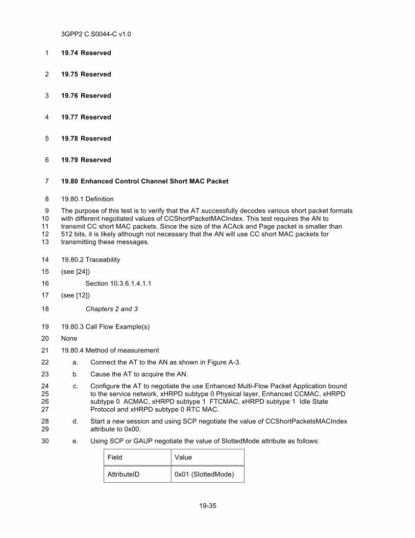
3GPP2 C.S0044-C v1.0
19-35
19.74 Reserved 1
19.75 Reserved 2
19.76 Reserved 3
19.77 Reserved 4
19.78 Reserved 5
19.79 Reserved 6
19.80 Enhanced Control Channel Short MAC Packet 7
19.80.1 Definition 8
The purpose of this test is to verify that the AT successfully decodes various short packet formats 9 with different negotiated values of CCShortPacketMACIndex. This test requires the AN to 10 transmit CC short MAC packets. Since the size of the ACAck and Page packet is smaller than 11 512 bits, it is likely although not necessary that the AN will use CC short MAC packets for 12 transmitting these messages. 13
19.80.2 Traceability 14
(see [24]) 15
Section 10.3.6.1.4.1.1 16
(see [12]) 17
Chapters 2 and 3 18
19.80.3 Call Flow Example(s) 19
None 20
19.80.4 Method of measurement 21
a. Connect the AT to the AN as shown in Figure A-3. 22
b. Cause the AT to acquire the AN. 23
c. Configure the AT to negotiate the use Enhanced Multi-Flow Packet Application bound 24 to the service network, xHRPD subtype 0 Physical layer, Enhanced CCMAC, xHRPD 25 subtype 0 ACMAC, xHRPD subtype 1 FTCMAC, xHRPD subtype 1 Idle State 26 Protocol and xHRPD subtype 0 RTC MAC. 27
d. Start a new session and using SCP negotiate the value of CCShortPacketsMACIndex 28 attribute to 0x00. 29
e. Using SCP or GAUP negotiate the value of SlottedMode attribute as follows: 30
Field Value
AttributeID 0x01 (SlottedMode)
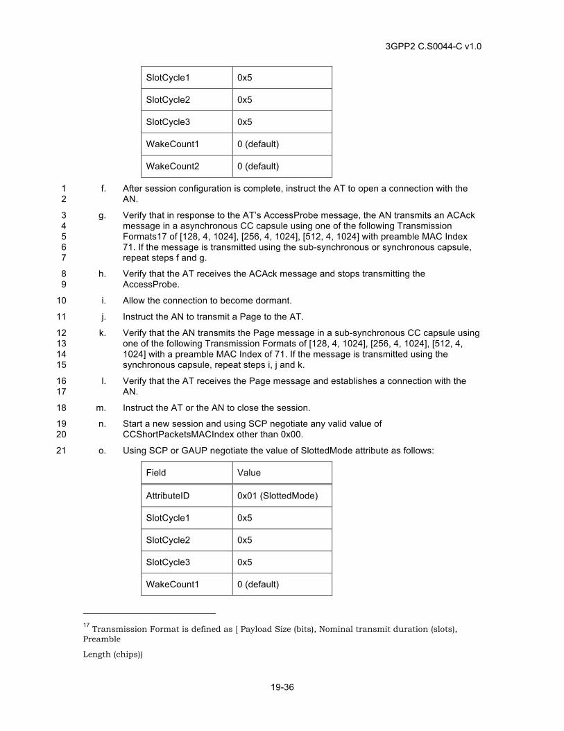
3GPP2 C.S0044-C v1.0
19-36
SlotCycle1 0x5
SlotCycle2 0x5
SlotCycle3 0x5
WakeCount1 0 (default)
WakeCount2 0 (default)
f. After session configuration is complete, instruct the AT to open a connection with the 1 AN. 2
g. Verify that in response to the AT’s AccessProbe message, the AN transmits an ACAck 3 message in a asynchronous CC capsule using one of the following Transmission 4 Formats17 of [128, 4, 1024], [256, 4, 1024], [512, 4, 1024] with preamble MAC Index 5 71. If the message is transmitted using the sub-synchronous or synchronous capsule, 6 repeat steps f and g. 7
h. Verify that the AT receives the ACAck message and stops transmitting the 8 AccessProbe. 9
i. Allow the connection to become dormant. 10
j. Instruct the AN to transmit a Page to the AT. 11
k. Verify that the AN transmits the Page message in a sub-synchronous CC capsule using 12 one of the following Transmission Formats of [128, 4, 1024], [256, 4, 1024], [512, 4, 13 1024] with a preamble MAC Index of 71. If the message is transmitted using the 14 synchronous capsule, repeat steps i, j and k. 15
l. Verify that the AT receives the Page message and establishes a connection with the 16 AN. 17
m. Instruct the AT or the AN to close the session. 18
n. Start a new session and using SCP negotiate any valid value of 19 CCShortPacketsMACIndex other than 0x00. 20
o. Using SCP or GAUP negotiate the value of SlottedMode attribute as follows: 21
Field Value
AttributeID 0x01 (SlottedMode)
SlotCycle1 0x5
SlotCycle2 0x5
SlotCycle3 0x5
WakeCount1 0 (default)
17 Transmission Format is defined as [ Payload Size (bits), Nominal transmit duration (slots), Preamble
Length (chips))
3GPP2 C.S0044-C v1.0
19-37
WakeCount2 0 (default)
p. After session configuration is complete, instruct the AT to open a connection with the 1 AN. 2
q. Verify that in response to the AT’s AccessProbe message, the AN transmits an ACAck 3 message in a asynchronous CC capsule using one of the following Transmission 4 Formats of [128, 4, 1024], [256, 4, 1024], [512, 4, 1024] with preamble MAC Index 5 negotiated in step n or 71. If the message is transmitted using the sub-synchronous or 6 synchronous capsule, repeat steps o and p. 7
r. Verify that the AT receives the ACAck message and stops transmitting the 8 AccessProbe. 9
s. Allow the connection to become dormant. 10
t. Instruct the AN to transmit a Page to the AT. 11
u. Verify that the AN transmits the Page message in a sub-synchronous CC capsule using 12 one of the following Transmission Formats of [128, 4, 1024], [256, 4, 1024], [512, 4, 13 1024] with a preamble MAC Index negotiated in step n or 71. If the message is 14 transmitted using the synchronous capsule, repeat steps i, j and k. 15
v. Verify that the AT receives the Page message and establishes a connection with the 16 AN 17
19.80.5 Minimum Standard 18
The AT shall comply with steps h, l, r, and v. 19
The AN shall comply with steps g, k, q and u. 20
19.81 Access Channel Probe Transmission 21
19.81.1 Definition 22
The purpose of this test is to verify that the AN and the AT successfully negotiate the 23 PreambleLength, AccessChannelOffset and CapsuleLengthMax attributes of the xHRPD subtype 24 0 ACMAC protocol and that using these parameters the AT transmits the access probe at 25 appropriate time and that the AN successfully receives the probe. This test uses Data Over 26 Signaling protocol to generate payload for the Access Channel Capsule. 27
19.81.2 Traceability 28
(see [33]) 29
Section 1.4.6.1.4.1.1 (Probe Transmission) 30
Section 1.4.6.2.6 (Access Parameters message) 31
(see [12]) 32
Chapters 2 and 3 33
19.81.3 Call Flow Example(s) 34
None 35
19.81.4 Method of measurement 36
a. Connect the AT to the AN as shown in Figure A-3. 37
3GPP2 C.S0044-C v1.0
19-38
b. Cause the AT to acquire the AN. 1
c. Configure the AT to negotiate the use of Enhanced Multi-Flow Packet Application 2 bound to the service network, xHRPD subtype 0 Physical layer, Enhanced CCMAC, 3 xHRPD subtype 0 ACMAC, xHRPD subtype 1 FTCMAC, xHRPD subtype 1 Idle State 4 Protocol and xHRPD subtype 0 RTC MAC. 5
d. Configure the AN to transmit CapsuleLengthMax value of 0x7, PreambleLenght value of 6 ‘0’ (4 slots), AccessChannelOffset value of ‘03’ in the AccessParameters message. 7
e. During Session Configuration, set the ProtocolIdentifier field of the 8 FlowNNHigherLayerProtocolRev (NN = KK) and FlowNNHigherLayerProtocolFwd (NN 9 = KK) to HDLC framing. 10
f. During Session Configuration, set the Active parameter of FlowNNIdentificationFwd 11 (NN = KK) attribute and FlowNNIdentificationRev (NN = KK) attribute to 0x01. 12
g. Set the ReservationLabel for FlowNNReservationRev (NN = KK) and 13 FlowNNReservationFwd (NN = KK) to High Priority Signaling. Set 14 FlowNNDataOverSignalingAllowedRev (NN = KK) and 15 FlowNNDataOverSignalingAllowedFwd (NN = KK) to 0x01. Configure the AN to grant 16 the QoS request from the AT and to set ReservationKKIdleStateFwd and 17 ReservationKKIdleStateRev to 0x0 for ReservationLabel kk associated with High 18 Priority Signaling. 19
h. If the AT does not have an established PPP session, cause the AT to establish a PPP 20 session. 21
i. Instruct the AT to send a ReservationOn message for ReservationLabel kk associated 22 with High Priority Signaling data that is to be carried using DataOverSignaling message 23 to the AN and ensure that the AN responds with a ReservationAccept message. Instruct 24 the AT to send a ReservationOn message for ReservationLabel kk associated with High 25 Priority Signaling data that is to be carried using DataOverSignaling message from the 26 AN to the AT and ensure that the AN responds with a ReservationAccept message. 27
j. Allow the xHRPD connection to become idle. 28
k. Transmit a ping packet from the AT directed to the AN using the Data Over Signaling 29 Protocol and setting the AckRequired field of the DataOverSignaling message to ‘1’. 30
l. Verify that the AT transmits a DataOverSignaling Message over the Access Channel. 31 Verify that the AT started the transmission of the AccessProbe at time T such that 32
(T-12*AccessChannelOffset) mod AccessCycleDuration = 0, 33
where T is CDMA System Time in slots and AccessCycleDuration is defined in the 34 AccessParameters message transmitted by the AN. Verify that the AT transmits the 35 Preamble for PreambleLength. 36
m. Verify that the AN receives the DataOverSignaling Message. This can be verified by the 37 transmission of DataOverSignalingAck by the AN. 38
19.81.5 Minimum Standard 39
The AT shall comply with step l. 40
The AN shall comply with step m. 41
3GPP2 C.S0044-C v1.0
19-39
19.82 Reserved 1
19.83 Reserved 2
19.84 Reserved 3
19.85 Reserved 4
19.86 Reserved 5
19.87 Inter Technology Switching in Idle Mode – xHRPD to LTE 6
19.87.1 Definition 7
This test verifies idle mode inter-technology switching from xHRPD to LTE. This test only applies 8 to AT that are capable of switching from xHRPD to LTE while the AT is idle. The algorithm for 9 switching is AT dependent and should be known before test case execution. 10
19.87.2 Traceability 11
(see [29]) 12
(see [30]) 13
(see [33]) 14
Chapter 4 Session Layer 15
Chapter 3 Connection Layer 16
Chapter 1 MAC Layer 17
(see [26]) 18
Chapter 3 HRPD IOS Call Flows 19
(see [4]) 20
2.2.6.2.5 Mobile Station Origination Operation 21
2.6.3 System Access State 22
2.6.3.5 Mobile Station Origination Attempt Substate 23
2.6.4 Mobile Station Control on the Traffic Channel State 24
2.7.1.3.2.4 Origination Message 25
2.7.2.3.2.15 Service Option Control Message 26
2.7.3 Orders 27
3.6.3.5 Response to Origination Message 28
3.6.4 Traffic Channel Processing 29
3.7.2.3.2.21 Extended Channel Assignment Message 30
3.7.3.3.2.3 Alert With Information Message 31
3.7.3.3.2.20 Service Connect Message 32
3.7.4 Orders 33
3GPP2 C.S0044-C v1.0
19-40
3.7.5.5 Signal 1
19.87.3 Call Flow Example(s) 2
None 3
19.87.4 Method of measurement 4
a. Connect the AT to the AN as shown in Figure A-5 with AN 1 configured as xHRPD and 5 AN 2 configured as LTE. 6
b. Cause the AT to acquire AN 1 configured as xHRPD. 7
c. Initiate a xHRPD packet data call from the AT. 8
d. Wait for AT to go idle. 9
e. Cause the AT terminal to switch from AN 1, configured as xHRPD to AN 2 configured 10 as LTE. 11
f. Verify AT is idle for data on AN 2 configured as LTE. 12
g. Open a data session with AN 2. 13
h. Issue a “ping” command from the remote host to the AT. 14
i. Verify the AT is active for data on AN 2 configured for LTE, and verify the remote host 15 receives a “ping” response from the AT. 16
j. End the call. 17
19.87.5 Minimum Standard 18
The AT shall comply with step i. 19
19.88 Inter Technology Switching in Idle Mode – xHRPD to HRPD 20
19.88.1 Definition 21
This test verifies idle mode inter-technology switching from xHRPD to HRPD. This test only 22 applies to AT that are capable of switching from xHRPD to HRPD while the AT is idle. The 23 algorithm for switching is AT dependent and should be known before test case execution. 24
19.88.2 Traceability 25
(see [29]) 26
(see [30]) 27
(see [33]) 28
Chapter 4 Session Layer 29
Chapter 3 Connection Layer 30
Chapter 1 MAC Layer 31
(see [26]) 32
Chapter 3 HRPD IOS Call Flows 33
(see [4]) 34
2.2.6.2.5 Mobile Station Origination Operation 35
2.6.3 System Access State 36
2.6.3.5 Mobile Station Origination Attempt Substate 37
3GPP2 C.S0044-C v1.0
19-41
2.6.4 Mobile Station Control on the Traffic Channel State 1
2.7.1.3.2.4 Origination Message 2
2.7.2.3.2.15 Service Option Control Message 3
2.7.3 Orders 4
3.6.3.5 Response to Origination Message 5
3.6.4 Traffic Channel Processing 6
3.7.2.3.2.21 Extended Channel Assignment Message 7
3.7.3.3.2.3 Alert With Information Message 8
3.7.3.3.2.20 Service Connect Message 9
3.7.4 Orders 10
3.7.5.5 Signal 11
19.88.3 Call Flow Example(s) 12
None 13
19.88.4 Method of measurement 14
a. Connect the AT to the AN as shown in Figure A-5 with AN 1 configured as xHRPD and 15 AN 2 configured as HRPD. 16
b. Cause the AT to acquire AN 1 configured as xHRPD. 17
c. Initiate a xHRPD packet data call from the AT. 18
d. Wait for AT to go idle. 19
e. Cause the AT terminal to switch from AN 1, configured as xHRPD to AN 2 configured 20 as HRPD. 21
f. Verify AT is idle for data on AN 2 configured as HRPD. 22
g. Open a data session with AN 2. 23
h. Issue a “ping” command from the remote host to the AT. 24
i. Verify the AT is active for data on AN 2 configured for HRPD, and verify the remote host 25 receives a “ping” response from the AT. 26
j. End the call. 27
19.88.5 Minimum Standard 28
The AT shall comply with steps i. 29
19.89 Concurrent Voice and Data Service 30
19.89.1 Definition 31
This test verifies that xHRPD terminal supports concurrent voice and data services. 32
19.89.2 Traceability 33
(see [29]) 34
(see [30]) 35
(see [33]) 36
3GPP2 C.S0044-C v1.0
19-42
Chapter 4 Session Layer 1
Chapter 3 Connection Layer 2
Chapter 1 MAC Layer 3
(see [26]) 4
Chapter 3 HRPD IOS Call Flows 5
(see [4]) 6
2.2.6.2.5 Mobile Station Origination Operation 7
2.6.3 System Access State 8
2.6.3.5 Mobile Station Origination Attempt Substate 9
2.6.4 Mobile Station Control on the Traffic Channel State 10
2.7.1.3.2.4 Origination Message 11
2.7.2.3.2.15 Service Option Control Message 12
2.7.3 Orders 13
3.6.3.5 Response to Origination Message 14
3.6.4 Traffic Channel Processing 15
3.7.2.3.2.21 Extended Channel Assignment Message 16
3.7.3.3.2.3 Alert With Information Message 17
3.7.3.3.2.20 Service Connect Message 18
3.7.4 Orders 19
3.7.5.5 Signal 20
19.89.3 Call Flow Example(s) 21
None 22
19.89.4 Method of measurement 23
a. Connect the AT to the AN as shown in Figure A-1. 24
b. Initiate a xHRPD packet data call from the AT. 25
c. Issue a continuous “ping” command from the AT to a remote host. 26
d. Initiate a voice call from the AT. 27
e. Verify that the voice call is successful and the pings continue during the voice call. 28
f. End the voice call. 29
g. After voice call is released, verify that pings are continuous on same ppp session. 30
h. End the xHRPD packet data call. 31
19.89.5 Minimum Standard 32
The AT shall comply with steps e and g. 33
3GPP2 C.S0044-C v1.0
19-43
19.90 CALEA Requirement in Idle State 1
19.90.1 Definition 2
This test verifies that xHRPD terminal complies to CALEA requirement in Idle state. 3
19.90.2 Traceability 4
(see [33]) 5
3.7.6.2.1 Route Update Message 6
19.90.3 Call Flow Example(s) 7
None 8
19.90.4 Method of measurement 9
a. Connect the AT to the AN as shown in Figure A-1. 10
b. Inform the AT of change in country code. 11
c. Verify that the upon encountering change of country code, AT, if in Idle state, generates 12 a route update message to AN with ‘GMSALocationPresent‘ and ‘GMSALocation’ fields 13 set to appropriate values. 14
19.90.5 Minimum Standard 15
The AT shall comply with step c. 16
17
18
19

3GPP2 C.S0044-C v1.0
19-44
This page intentionally left blank.1
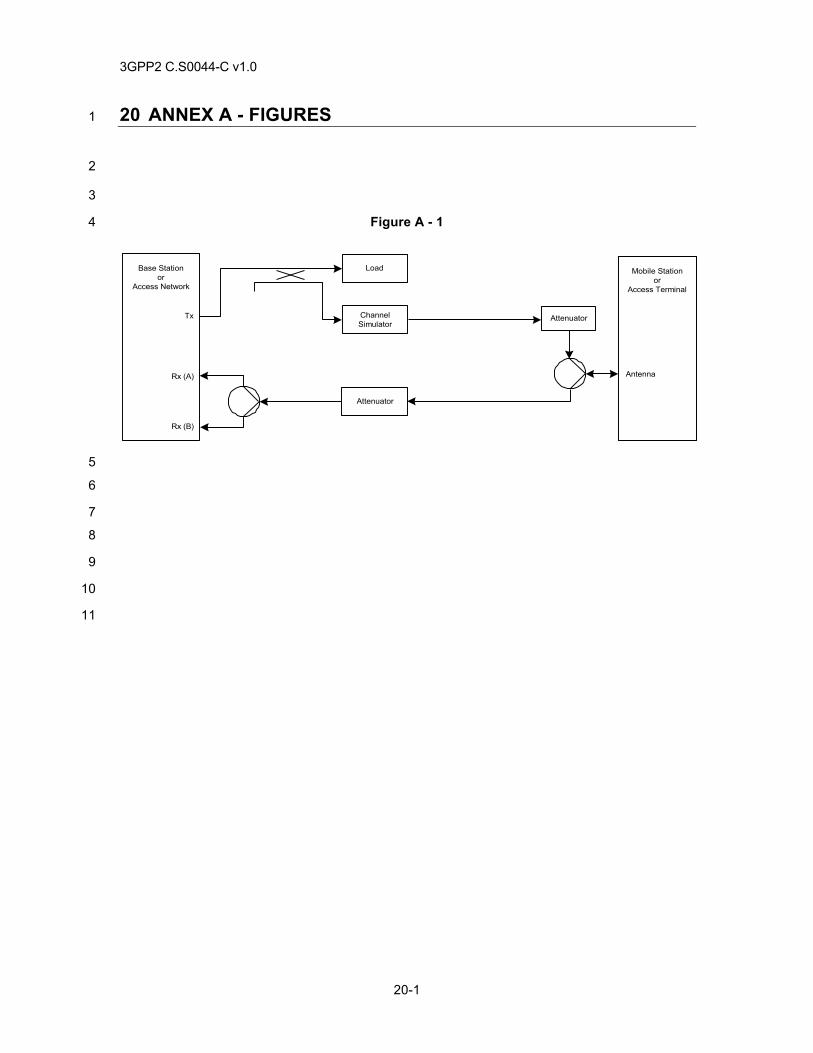
3GPP2 C.S0044-C v1.0
20-1
20 ANNEX A - FIGURES 1
2
3
Figure A - 1 4
5
6
7
8
9
10
11
Tx
Rx (A)
Rx (B)
Base Stationor
Access Network
Mobile Stationor
Access Terminal
Antenna
Attenuator
Load
ChannelSimulator
Attenuator
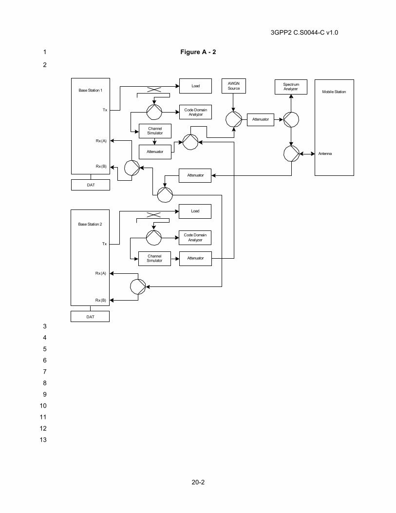
3GPP2 C.S0044-C v1.0
20-2
Figure A - 2 1
2
3
4
5
6
7
8
9
10
11
12
13
Base Station 1
Tx
Rx (A)
Rx (B)
Base Station 2
Tx
Rx (A)
Rx (B)
Mobile Station
Antenna
DAT
Code DomainAnalyzer
AWGNSource
Attenuator
Attenuator
SpectrumAnalyzer
Attenuator
DAT
Load
ChannelSimulator
Code DomainAnalyzer
Load
ChannelSimulator Attenuator
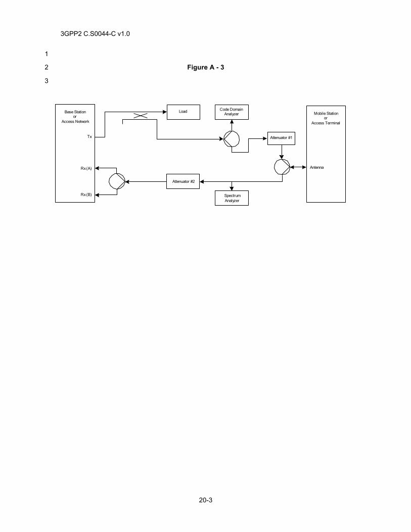
3GPP2 C.S0044-C v1.0
20-3
1
Figure A - 3 2
3
Tx
Rx (A)
Rx (B)
Base Stationor
Access Network
Mobile Stationor
Access Terminal
Antenna
Attenuator #2
Load
Attenuator #1
SpectrumAnalyzer
Code DomainAnalyzer
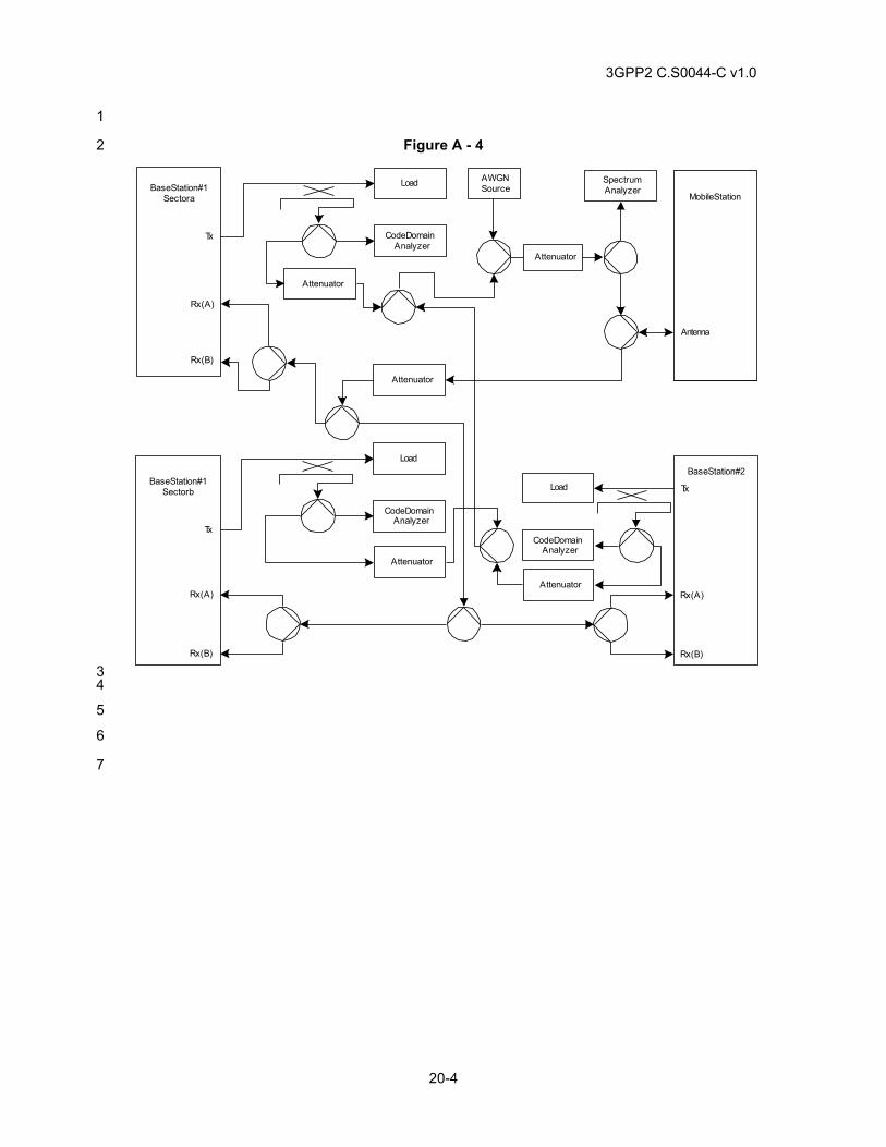
3GPP2 C.S0044-C v1.0
20-4
1
Figure A - 4 2
Base Station #1Sector a
Tx
Rx (A)
Rx (B)
Base Station #1Sector b
Tx
Rx (A)
Rx (B)
Mobile Station
Antenna
Code DomainAnalyzer
AWGNSource
Attenuator
Attenuator
SpectrumAnalyzer
Attenuator
Load
Code DomainAnalyzer
Load
Attenuator
Base Station #2
Tx
Rx (A)
Rx (B)
Code DomainAnalyzer
Load
Attenuator
3 4
5
6
7
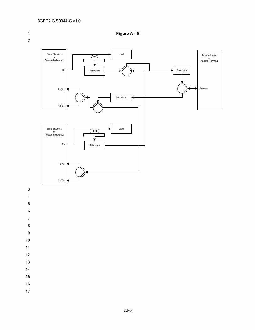
3GPP2 C.S0044-C v1.0
20-5
Figure A - 5 1
2
3
4
5
6
7
8
9
10
11
12
13
14
15
16
17
Tx
Rx (A)
Rx (B)
Base Station 1or
Access Network 1
Mobile Stationor
Access Terminal
Antenna
Attenuator
Load
AttenuatorAttenuator
Tx
Rx (A)
Rx (B)
Base Station 2or
Access Network 2
Load
Attenuator
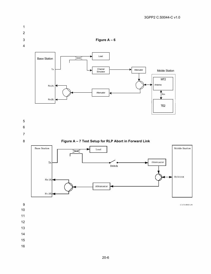
3GPP2 C.S0044-C v1.0
20-6
1
2
Figure A – 6 3
4
5
6
7
Figure A – 7 Test Setup for RLP Abort in Forward Link 8
9 10
11
12
13
14
15
16
Rm
Tx
Rx (A)
Rx (B)
Base Station
Mobile Station
Antenna
Attenuator
Load
ChannelSimulator
Attenuator
MT2
TE2
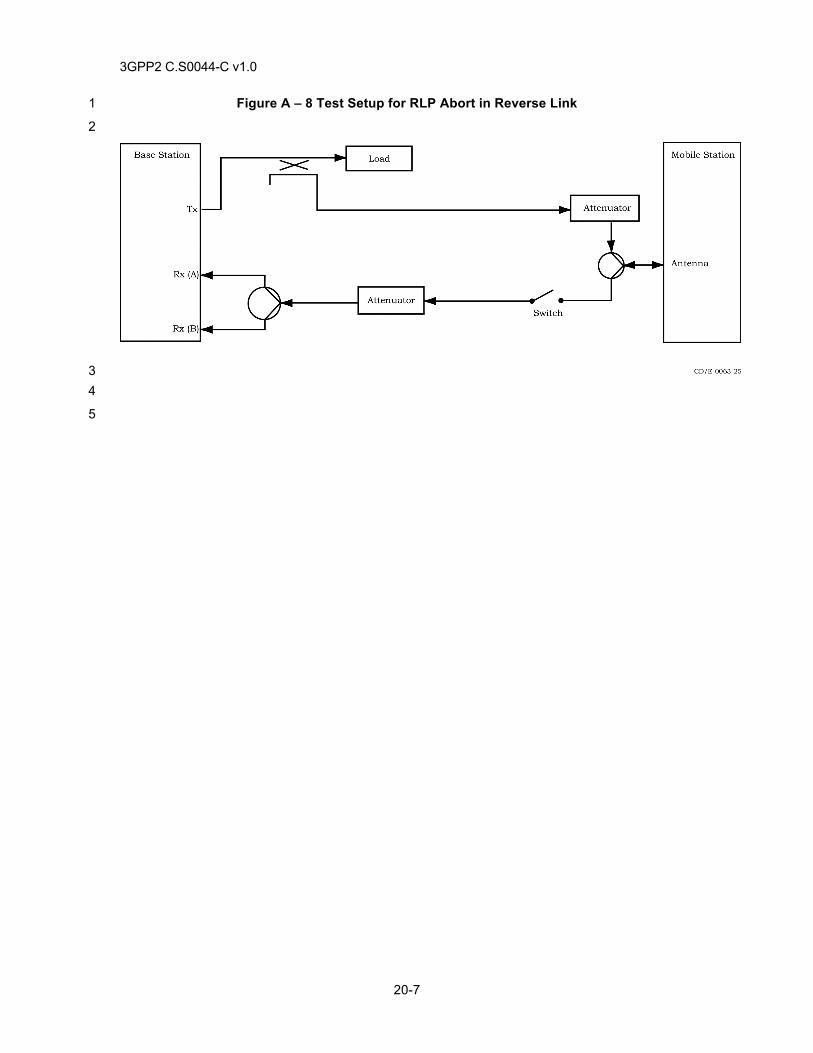
3GPP2 C.S0044-C v1.0
20-7
Figure A – 8 Test Setup for RLP Abort in Reverse Link 1
2
3 4
5
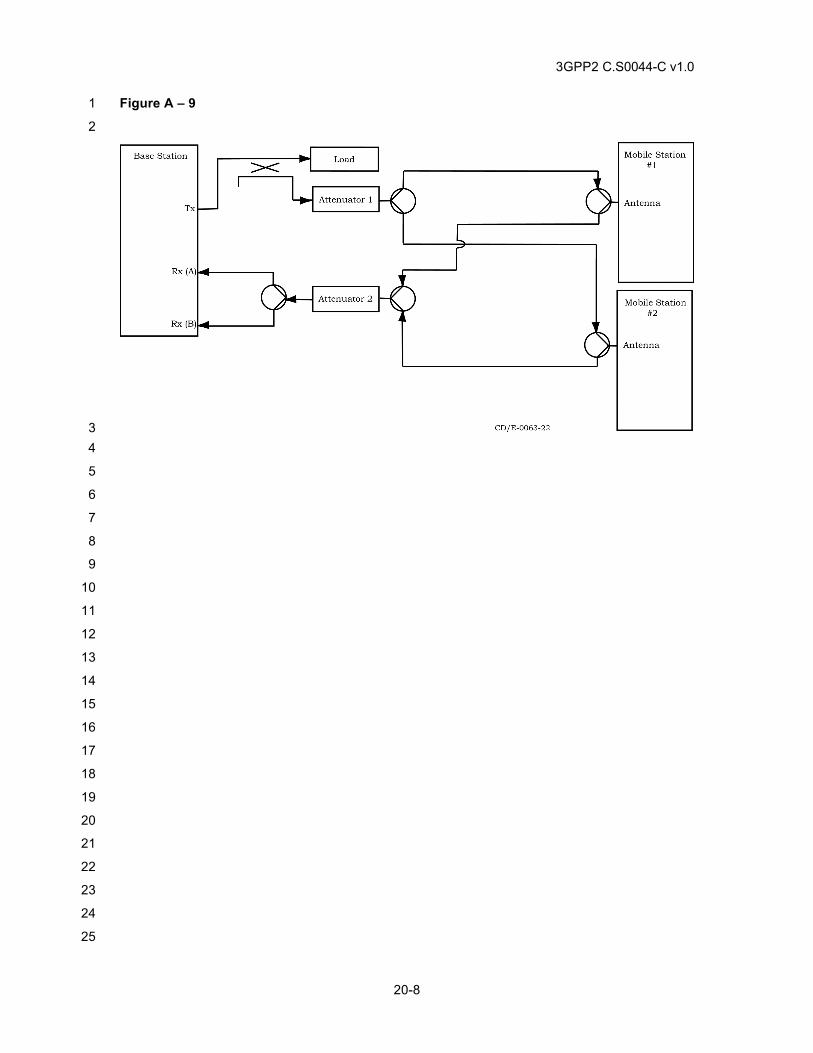
3GPP2 C.S0044-C v1.0
20-8
Figure A – 9 1
2
3 4
5
6
7
8
9
10
11
12
13
14
15
16
17
18
19
20
21
22
23
24
25
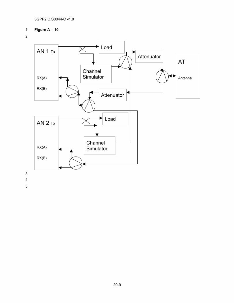
3GPP2 C.S0044-C v1.0
20-9
Figure A – 10 1
2
3 4
5
AN 1 Tx
RX(A)
RX(B)
Load
Channel Simulator
AT Antenna
Attenuator
Attenuator
AN 2 Tx
RX(A)
RX(B)
Load
Channel Simulator

3GPP2 C.S0044-C v1.0
20-10
This page intentionally left blank.1
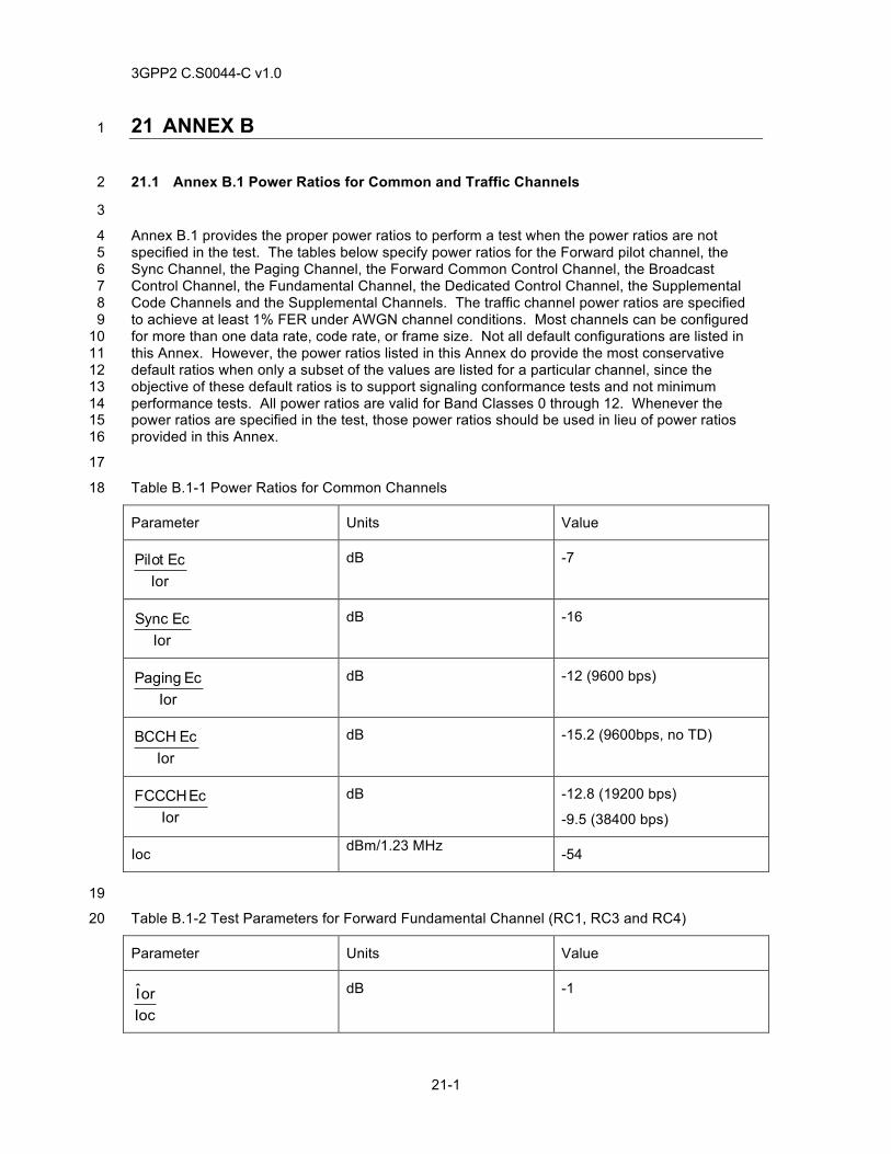
3GPP2 C.S0044-C v1.0
21-1
21 ANNEX B 1
21.1 Annex B.1 Power Ratios for Common and Traffic Channels 2
3
Annex B.1 provides the proper power ratios to perform a test when the power ratios are not 4 specified in the test. The tables below specify power ratios for the Forward pilot channel, the 5 Sync Channel, the Paging Channel, the Forward Common Control Channel, the Broadcast 6 Control Channel, the Fundamental Channel, the Dedicated Control Channel, the Supplemental 7 Code Channels and the Supplemental Channels. The traffic channel power ratios are specified 8 to achieve at least 1% FER under AWGN channel conditions. Most channels can be configured 9 for more than one data rate, code rate, or frame size. Not all default configurations are listed in 10 this Annex. However, the power ratios listed in this Annex do provide the most conservative 11 default ratios when only a subset of the values are listed for a particular channel, since the 12 objective of these default ratios is to support signaling conformance tests and not minimum 13 performance tests. All power ratios are valid for Band Classes 0 through 12. Whenever the 14 power ratios are specified in the test, those power ratios should be used in lieu of power ratios 15 provided in this Annex. 16
17
Table B.1-1 Power Ratios for Common Channels 18
Parameter Units Value
IorEcPilot
dB -7
IorEcSync
dB -16
IorEcPaging
dB -12 (9600 bps)
IorEcBCCH
dB -15.2 (9600bps, no TD)
IorEcFCCCH
dB -12.8 (19200 bps)
-9.5 (38400 bps)
Ioc dBm/1.23 MHz -54
19
Table B.1-2 Test Parameters for Forward Fundamental Channel (RC1, RC3 and RC4) 20
Parameter Units Value
IocorI
dB -1
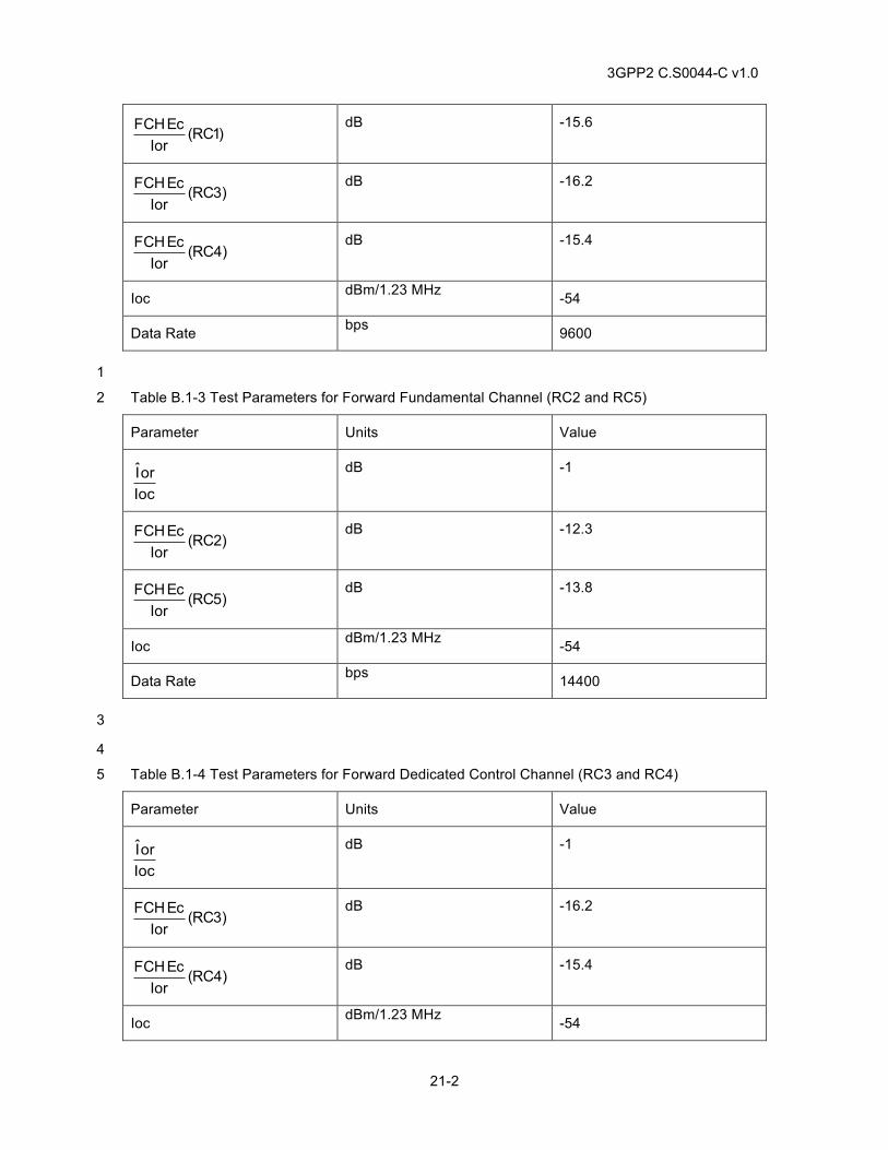
3GPP2 C.S0044-C v1.0
21-2
)1RC(IorEcFCH
dB -15.6
)3RC(IorEcFCH
dB -16.2
)4RC(IorEcFCH
dB -15.4
Ioc dBm/1.23 MHz -54
Data Rate bps 9600
1
Table B.1-3 Test Parameters for Forward Fundamental Channel (RC2 and RC5) 2
Parameter Units Value
IocorI
dB -1
)2RC(IorEcFCH
dB -12.3
)5RC(IorEcFCH
dB -13.8
Ioc dBm/1.23 MHz -54
Data Rate bps 14400
3
4
Table B.1-4 Test Parameters for Forward Dedicated Control Channel (RC3 and RC4) 5
Parameter Units Value
IocorI
dB -1
)3RC(IorEcFCH
dB -16.2
)4RC(IorEcFCH
dB -15.4
Ioc dBm/1.23 MHz -54
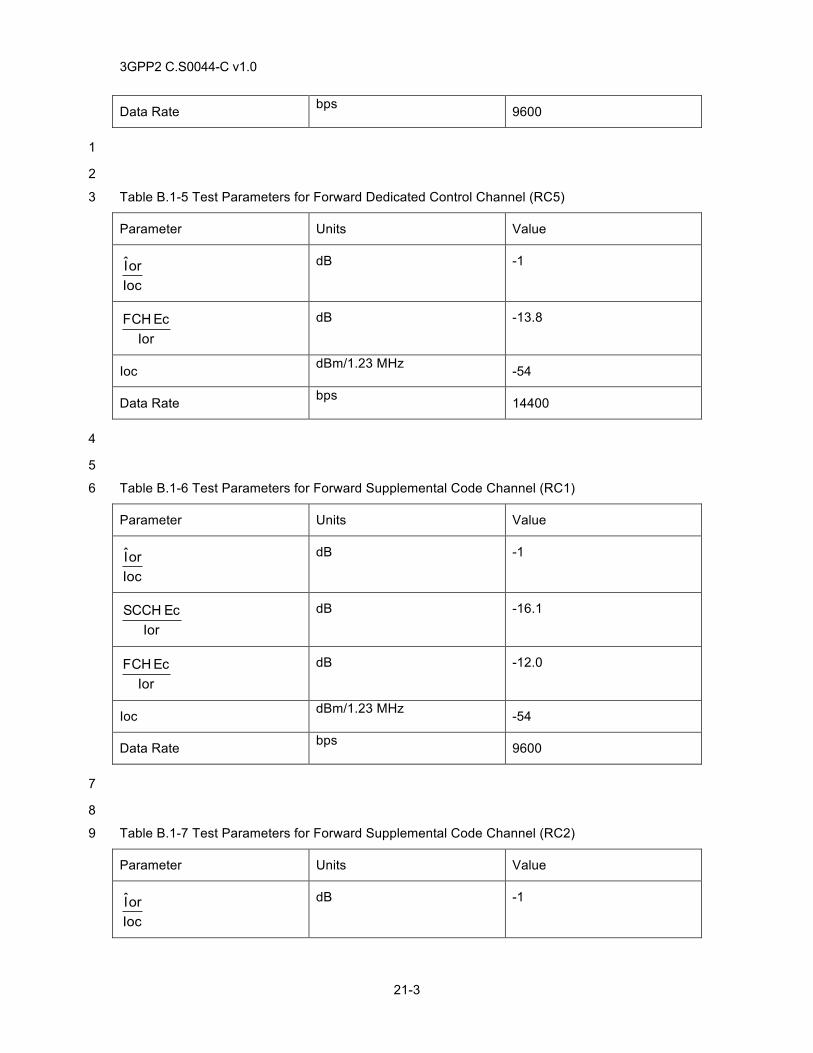
3GPP2 C.S0044-C v1.0
21-3
Data Rate bps 9600
1
2
Table B.1-5 Test Parameters for Forward Dedicated Control Channel (RC5) 3
Parameter Units Value
IocorI
dB -1
IorEcFCH
dB -13.8
Ioc dBm/1.23 MHz -54
Data Rate bps 14400
4
5
Table B.1-6 Test Parameters for Forward Supplemental Code Channel (RC1) 6
Parameter Units Value
IocorI
dB -1
IorEcSCCH
dB -16.1
IorEcFCH
dB -12.0
Ioc dBm/1.23 MHz -54
Data Rate bps 9600
7
8
Table B.1-7 Test Parameters for Forward Supplemental Code Channel (RC2) 9
Parameter Units Value
IocorI
dB -1
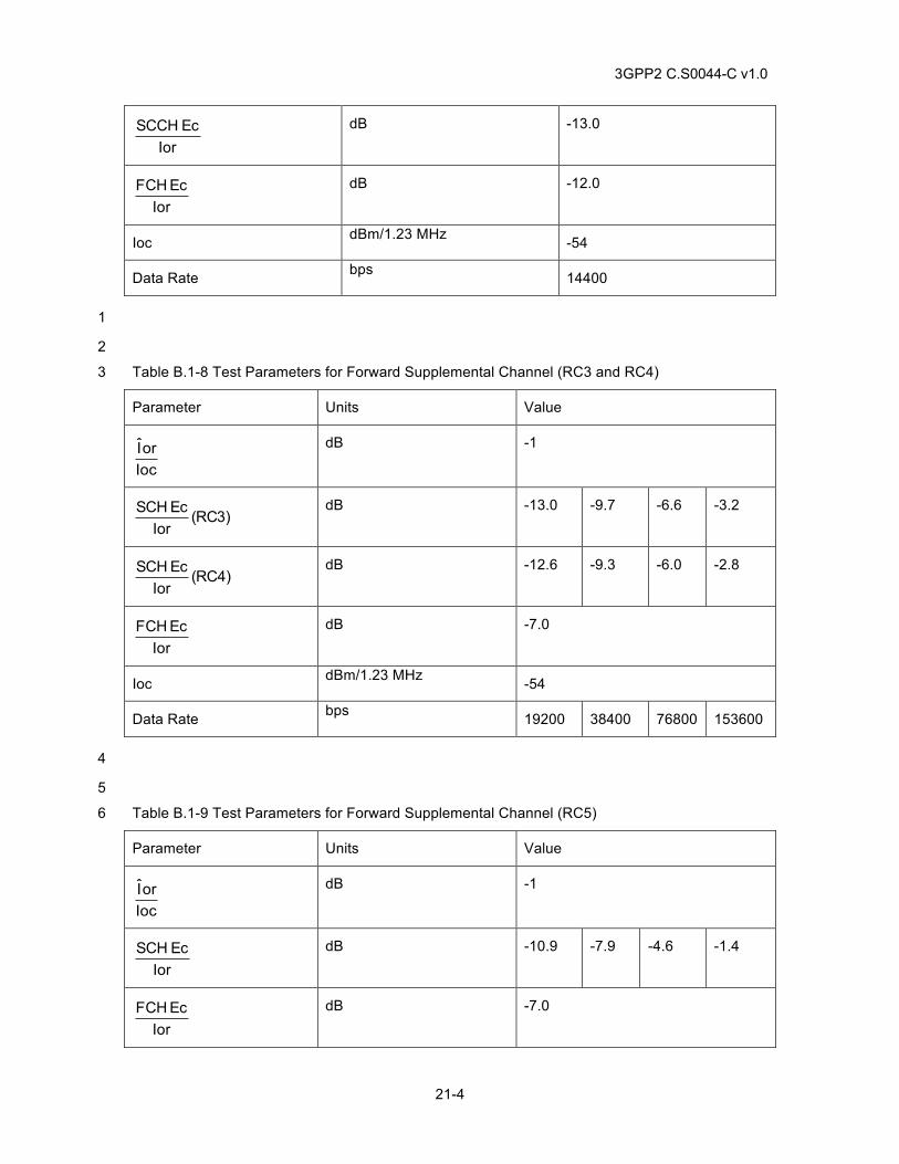
3GPP2 C.S0044-C v1.0
21-4
IorEcSCCH
dB -13.0
IorEcFCH
dB -12.0
Ioc dBm/1.23 MHz -54
Data Rate bps 14400
1
2
Table B.1-8 Test Parameters for Forward Supplemental Channel (RC3 and RC4) 3
Parameter Units Value
IocorI
dB -1
)3RC(IorEcSCH
dB -13.0 -9.7 -6.6 -3.2
)4RC(IorEcSCH
dB -12.6 -9.3 -6.0 -2.8
IorEcFCH
dB -7.0
Ioc dBm/1.23 MHz -54
Data Rate bps 19200 38400 76800 153600
4
5
Table B.1-9 Test Parameters for Forward Supplemental Channel (RC5) 6
Parameter Units Value
IocorI
dB -1
IorEcSCH
dB -10.9 -7.9 -4.6 -1.4
IorEcFCH
dB -7.0
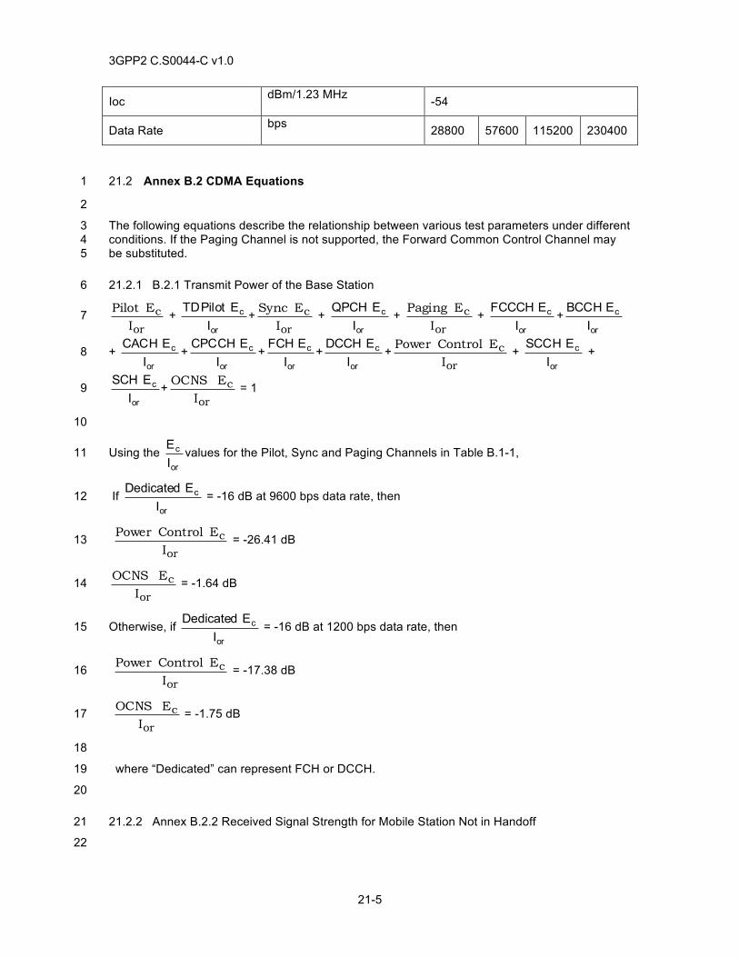
3GPP2 C.S0044-C v1.0
21-5
Ioc dBm/1.23 MHz -54
Data Rate bps 28800 57600 115200 230400
21.2 Annex B.2 CDMA Equations 1
2
The following equations describe the relationship between various test parameters under different 3 conditions. If the Paging Channel is not supported, the Forward Common Control Channel may 4 be substituted. 5
21.2.1 B.2.1 Transmit Power of the Base Station 6
or
cI
EPilot + or
c
IE Pilot TD
+or
cI
E Sync + or
c
IE QPCH
+ or
cI
EPaging + or
c
IE FCCCH
+or
c
IE BCCH
7
+ or
c
IE CACH
+or
c
IE CPCCH
+or
c
IE FCH
+or
c
IE DCCH
+or
cI
E ControlPower + or
c
IE SCCH
+ 8
or
c
IE SCH
+or
cI
E OCNS = 1 9
10
Using the or
c
IE
values for the Pilot, Sync and Paging Channels in Table B.1-1, 11
If or
c
IE Dedicated
= -16 dB at 9600 bps data rate, then 12
or
cI
E ControlPower = -26.41 dB 13
or
cI
E OCNS = -1.64 dB 14
Otherwise, if or
c
IE Dedicated
= -16 dB at 1200 bps data rate, then 15
or
cI
E ControlPower = -17.38 dB 16
or
cI
E OCNS = -1.75 dB 17
18
where “Dedicated” can represent FCH or DCCH. 19
20
21.2.2 Annex B.2.2 Received Signal Strength for Mobile Station Not in Handoff 21
22
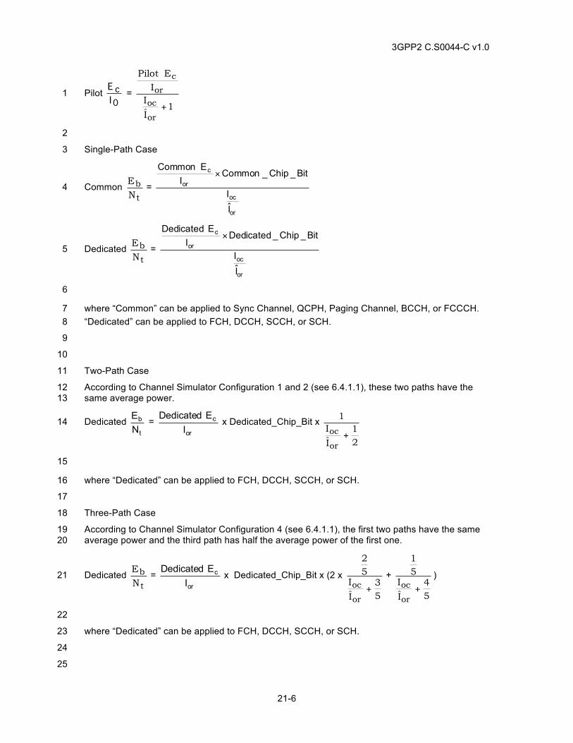
3GPP2 C.S0044-C v1.0
21-6
Pilot 0c
IE
= 1
I
II
EPilot
or
oc
or
c
+
1
2
Single-Path Case 3
Common t
bN
E =
or
oc
or
c
II
Bit_Chip_CommonI
E Common×
4
Dedicated t
bN
E =
or
oc
or
c
II
Bit_Chip_DedicatedI
E Dedicated×
5
6
where “Common” can be applied to Sync Channel, QCPH, Paging Channel, BCCH, or FCCCH. 7 “Dedicated” can be applied to FCH, DCCH, SCCH, or SCH. 8
9
10
Two-Path Case 11
According to Channel Simulator Configuration 1 and 2 (see 6.4.1.1), these two paths have the 12 same average power. 13
Dedicated t
b
NE =
or
c
IE Dedicated
x Dedicated_Chip_Bit x
21
I
I1
or
oc + 14
15
where “Dedicated” can be applied to FCH, DCCH, SCCH, or SCH. 16
17
Three-Path Case 18
According to Channel Simulator Configuration 4 (see 6.4.1.1), the first two paths have the same 19 average power and the third path has half the average power of the first one. 20
Dedicated t
bN
E = or
c
IE Dedicated
x Dedicated_Chip_Bit x (2 x
53
I
I52
or
oc +
+
54
I
I51
or
oc +
) 21
22
where “Dedicated” can be applied to FCH, DCCH, SCCH, or SCH. 23
24
25
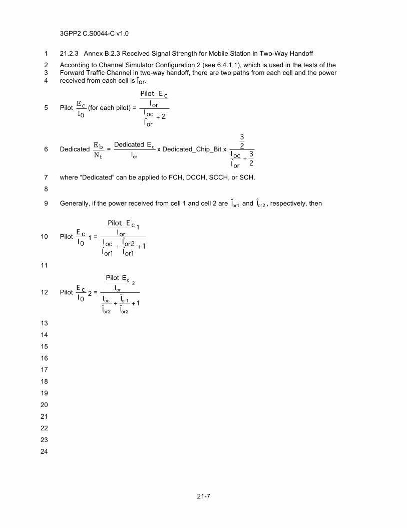
3GPP2 C.S0044-C v1.0
21-7
21.2.3 Annex B.2.3 Received Signal Strength for Mobile Station in Two-Way Handoff 1
According to Channel Simulator Configuration 2 (see 6.4.1.1), which is used in the tests of the 2 Forward Traffic Channel in two-way handoff, there are two paths from each cell and the power 3 received from each cell is Îor. 4
Pilot 0
cI
E (for each pilot) = 2
II
IEPilot
oroc
orc
+ 5
Dedicated t
bN
E = or
c
IE Dedicated
x Dedicated_Chip_Bit x
23
II
23
oroc +
6
where “Dedicated” can be applied to FCH, DCCH, SCCH, or SCH. 7
8
Generally, if the power received from cell 1 and cell 2 are 1orI and 2orI , respectively, then 9
Pilot 0c
IE
1 = 1
II
II
IEPilot
1or2or
1oroc
1or
c
++
10
11
Pilot 0c
IE
2 = 1
I
I
I
I
IE Pilot
2or
1or
2or
oc
2or
c
++
12
13
14
15
16
17
18
19
20
21
22
23
24
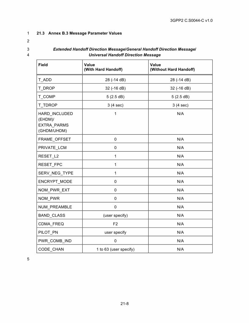
3GPP2 C.S0044-C v1.0
21-8
21.3 Annex B.3 Message Parameter Values 1
2
Extended Handoff Direction Message/General Handoff Direction Message/ 3 Universal Handoff Direction Message 4
Field Value (With Hard Handoff)
Value (Without Hard Handoff)
T_ADD 28 (-14 dB) 28 (-14 dB)
T_DROP 32 (-16 dB) 32 (-16 dB)
T_COMP 5 (2.5 dB) 5 (2.5 dB)
T_TDROP 3 (4 sec) 3 (4 sec)
HARD_INCLUDED (EHDM)/ EXTRA_PARMS (GHDM/UHDM)
1 N/A
FRAME_OFFSET 0 N/A
PRIVATE_LCM 0 N/A
RESET_L2 1 N/A
RESET_FPC 1 N/A
SERV_NEG_TYPE 1 N/A
ENCRYPT_MODE 0 N/A
NOM_PWR_EXT 0 N/A
NOM_PWR 0 N/A
NUM_PREAMBLE 0 N/A
BAND_CLASS (user specify) N/A
CDMA_FREQ F2 N/A
PILOT_PN user specify N/A
PWR_COMB_IND 0 N/A
CODE_CHAN 1 to 63 (user specify) N/A
5
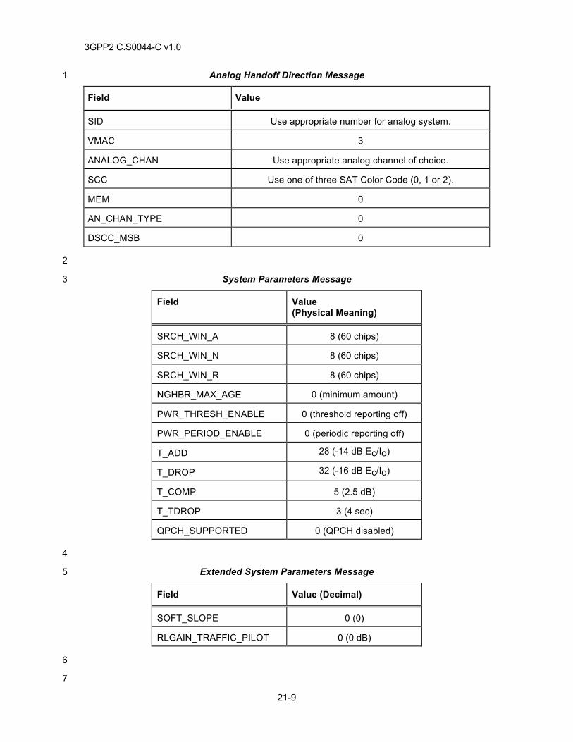
3GPP2 C.S0044-C v1.0
21-9
Analog Handoff Direction Message 1
Field Value
SID Use appropriate number for analog system.
VMAC 3
ANALOG_CHAN Use appropriate analog channel of choice.
SCC Use one of three SAT Color Code (0, 1 or 2).
MEM 0
AN_CHAN_TYPE 0
DSCC_MSB 0
2
System Parameters Message 3
Field Value (Physical Meaning)
SRCH_WIN_A 8 (60 chips)
SRCH_WIN_N 8 (60 chips)
SRCH_WIN_R 8 (60 chips)
NGHBR_MAX_AGE 0 (minimum amount)
PWR_THRESH_ENABLE 0 (threshold reporting off)
PWR_PERIOD_ENABLE 0 (periodic reporting off)
T_ADD 28 (-14 dB Ec/Io)
T_DROP 32 (-16 dB Ec/Io)
T_COMP 5 (2.5 dB)
T_TDROP 3 (4 sec)
QPCH_SUPPORTED 0 (QPCH disabled)
4
Extended System Parameters Message 5
Field Value (Decimal)
SOFT_SLOPE 0 (0)
RLGAIN_TRAFFIC_PILOT 0 (0 dB)
6
7
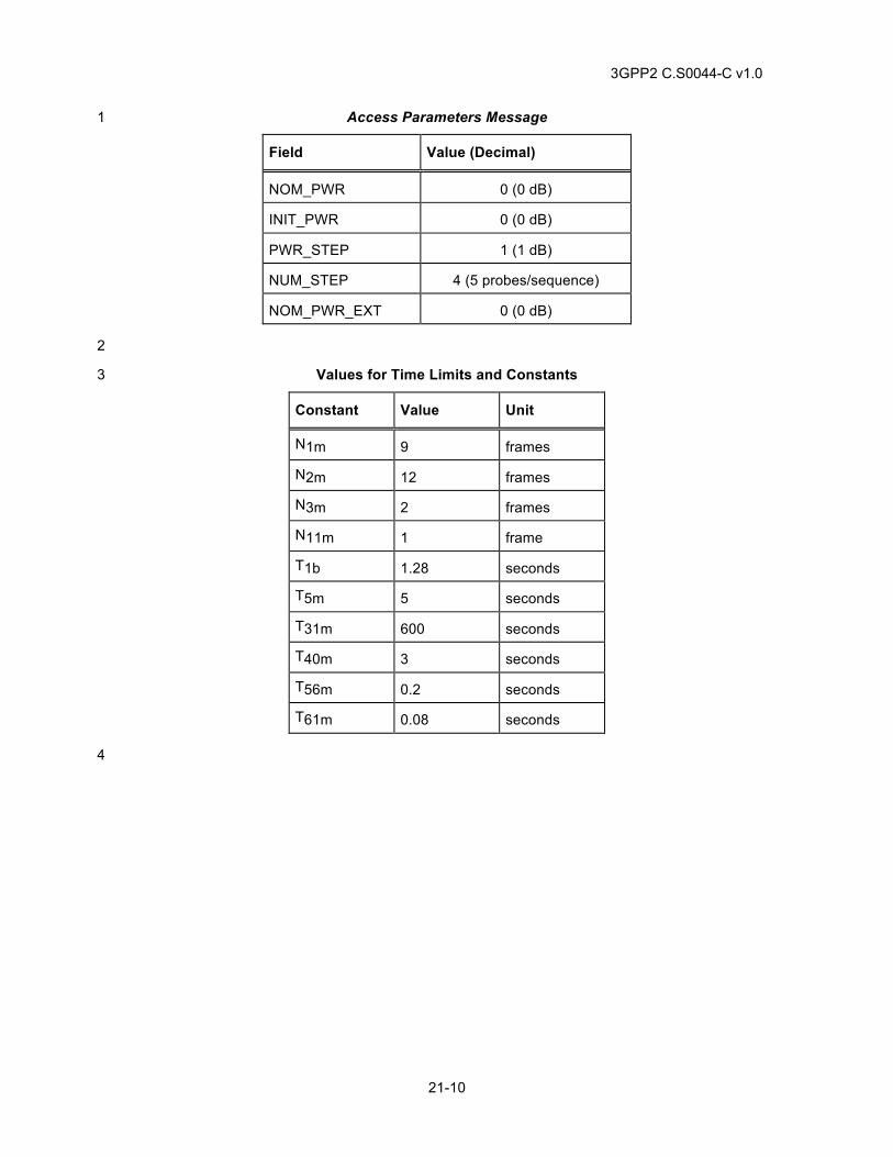
3GPP2 C.S0044-C v1.0
21-10
Access Parameters Message 1
Field Value (Decimal)
NOM_PWR 0 (0 dB)
INIT_PWR 0 (0 dB)
PWR_STEP 1 (1 dB)
NUM_STEP 4 (5 probes/sequence)
NOM_PWR_EXT 0 (0 dB)
2
Values for Time Limits and Constants 3
Constant Value Unit
N1m 9 frames
N2m 12 frames
N3m 2 frames
N11m 1 frame
T1b 1.28 seconds
T5m 5 seconds
T31m 600 seconds
T40m 3 seconds
T56m 0.2 seconds
T61m 0.08 seconds
4
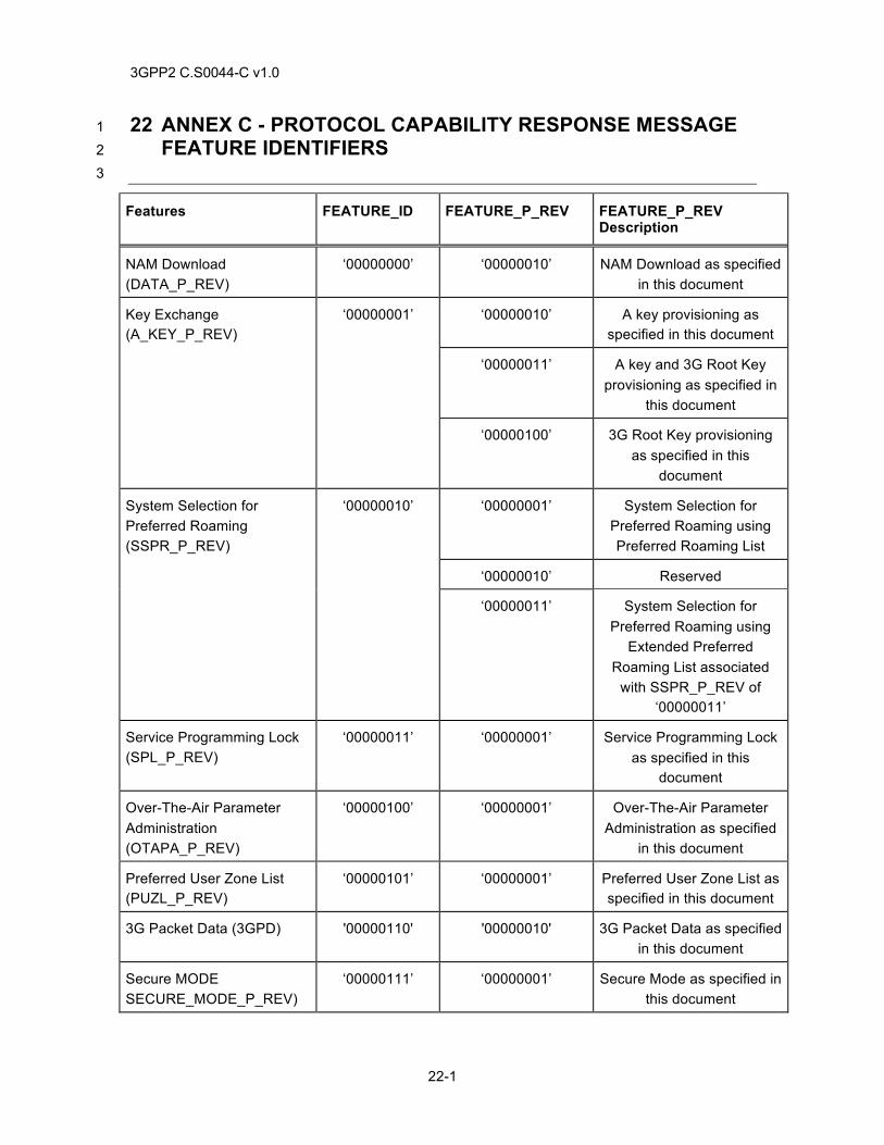
3GPP2 C.S0044-C v1.0
22-1
22 ANNEX C - PROTOCOL CAPABILITY RESPONSE MESSAGE 1 FEATURE IDENTIFIERS 2 3
Features FEATURE_ID FEATURE_P_REV FEATURE_P_REV Description
NAM Download (DATA_P_REV)
‘00000000’ ‘00000010’ NAM Download as specified in this document
Key Exchange (A_KEY_P_REV)
‘00000001’ ‘00000010’ A key provisioning as specified in this document
‘00000011’ A key and 3G Root Key provisioning as specified in
this document
‘00000100’ 3G Root Key provisioning as specified in this
document
System Selection for Preferred Roaming (SSPR_P_REV)
‘00000010’ ‘00000001’ System Selection for Preferred Roaming using Preferred Roaming List
‘00000010’ Reserved
‘00000011’ System Selection for Preferred Roaming using
Extended Preferred Roaming List associated
with SSPR_P_REV of ‘00000011’
Service Programming Lock (SPL_P_REV)
‘00000011’ ‘00000001’ Service Programming Lock as specified in this
document
Over-The-Air Parameter Administration (OTAPA_P_REV)
‘00000100’ ‘00000001’ Over-The-Air Parameter Administration as specified
in this document
Preferred User Zone List (PUZL_P_REV)
‘00000101’ ‘00000001’ Preferred User Zone List as specified in this document
3G Packet Data (3GPD) '00000110' '00000010' 3G Packet Data as specified in this document
Secure MODE SECURE_MODE_P_REV)
‘00000111’ ‘00000001’ Secure Mode as specified in this document
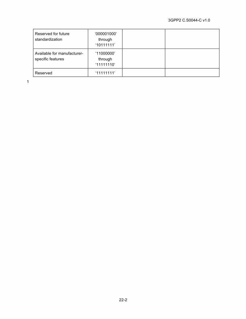
3GPP2 C.S0044-C v1.0
22-2
Reserved for future standardization
‘000001000’ through
‘10111111’
Available for manufacturer-specific features
‘11000000’ through
‘11111110’
Reserved ‘11111111’
1
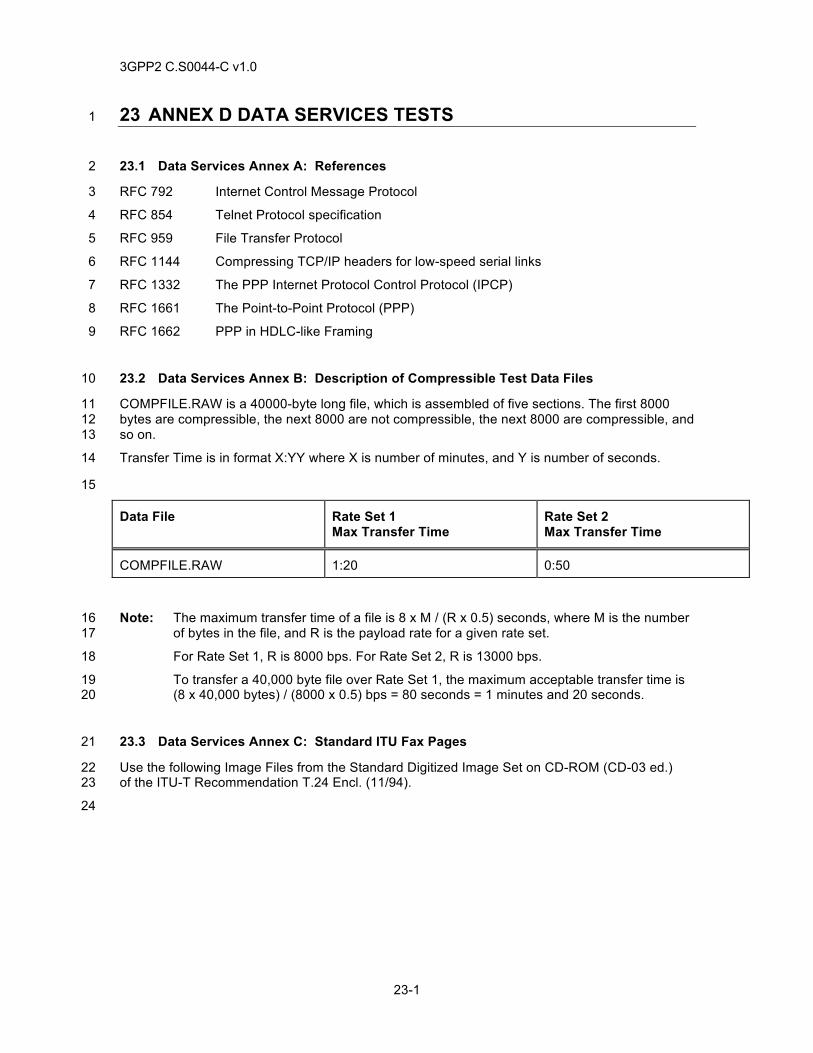
3GPP2 C.S0044-C v1.0
23-1
23 ANNEX D DATA SERVICES TESTS 1
23.1 Data Services Annex A: References 2
RFC 792 Internet Control Message Protocol 3
RFC 854 Telnet Protocol specification 4
RFC 959 File Transfer Protocol 5
RFC 1144 Compressing TCP/IP headers for low-speed serial links 6
RFC 1332 The PPP Internet Protocol Control Protocol (IPCP) 7
RFC 1661 The Point-to-Point Protocol (PPP) 8
RFC 1662 PPP in HDLC-like Framing 9
23.2 Data Services Annex B: Description of Compressible Test Data Files 10
COMPFILE.RAW is a 40000-byte long file, which is assembled of five sections. The first 8000 11 bytes are compressible, the next 8000 are not compressible, the next 8000 are compressible, and 12 so on. 13
Transfer Time is in format X:YY where X is number of minutes, and Y is number of seconds. 14
15
Data File Rate Set 1 Max Transfer Time
Rate Set 2 Max Transfer Time
COMPFILE.RAW 1:20 0:50
Note: The maximum transfer time of a file is 8 x M / (R x 0.5) seconds, where M is the number 16 of bytes in the file, and R is the payload rate for a given rate set. 17
For Rate Set 1, R is 8000 bps. For Rate Set 2, R is 13000 bps. 18
To transfer a 40,000 byte file over Rate Set 1, the maximum acceptable transfer time is 19 (8 x 40,000 bytes) / (8000 x 0.5) bps = 80 seconds = 1 minutes and 20 seconds. 20
23.3 Data Services Annex C: Standard ITU Fax Pages 21
Use the following Image Files from the Standard Digitized Image Set on CD-ROM (CD-03 ed.) 22 of the ITU-T Recommendation T.24 Encl. (11/94). 23
24
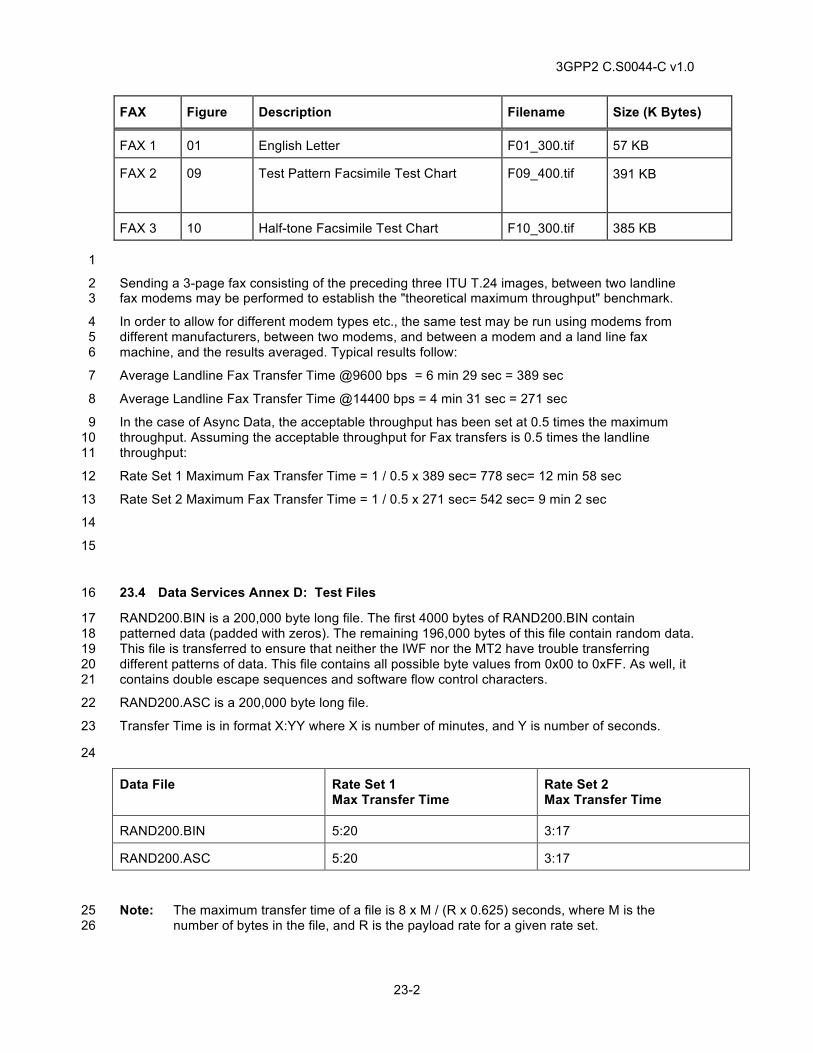
3GPP2 C.S0044-C v1.0
23-2
FAX Figure Description Filename Size (K Bytes)
FAX 1 01 English Letter F01_300.tif 57 KB
FAX 2 09 Test Pattern Facsimile Test Chart F09_400.tif 391 KB
FAX 3 10 Half-tone Facsimile Test Chart F10_300.tif 385 KB
1
Sending a 3-page fax consisting of the preceding three ITU T.24 images, between two landline 2 fax modems may be performed to establish the "theoretical maximum throughput" benchmark. 3
In order to allow for different modem types etc., the same test may be run using modems from 4 different manufacturers, between two modems, and between a modem and a land line fax 5 machine, and the results averaged. Typical results follow: 6
Average Landline Fax Transfer Time @9600 bps = 6 min 29 sec = 389 sec 7
Average Landline Fax Transfer Time @14400 bps = 4 min 31 sec = 271 sec 8
In the case of Async Data, the acceptable throughput has been set at 0.5 times the maximum 9 throughput. Assuming the acceptable throughput for Fax transfers is 0.5 times the landline 10 throughput: 11
Rate Set 1 Maximum Fax Transfer Time = 1 / 0.5 x 389 sec= 778 sec= 12 min 58 sec 12
Rate Set 2 Maximum Fax Transfer Time = 1 / 0.5 x 271 sec= 542 sec= 9 min 2 sec 13
14
15
23.4 Data Services Annex D: Test Files 16
RAND200.BIN is a 200,000 byte long file. The first 4000 bytes of RAND200.BIN contain 17 patterned data (padded with zeros). The remaining 196,000 bytes of this file contain random data. 18 This file is transferred to ensure that neither the IWF nor the MT2 have trouble transferring 19 different patterns of data. This file contains all possible byte values from 0x00 to 0xFF. As well, it 20 contains double escape sequences and software flow control characters. 21
RAND200.ASC is a 200,000 byte long file. 22
Transfer Time is in format X:YY where X is number of minutes, and Y is number of seconds. 23
24
Data File Rate Set 1 Max Transfer Time
Rate Set 2 Max Transfer Time
RAND200.BIN 5:20 3:17
RAND200.ASC 5:20 3:17
Note: The maximum transfer time of a file is 8 x M / (R x 0.625) seconds, where M is the 25 number of bytes in the file, and R is the payload rate for a given rate set. 26
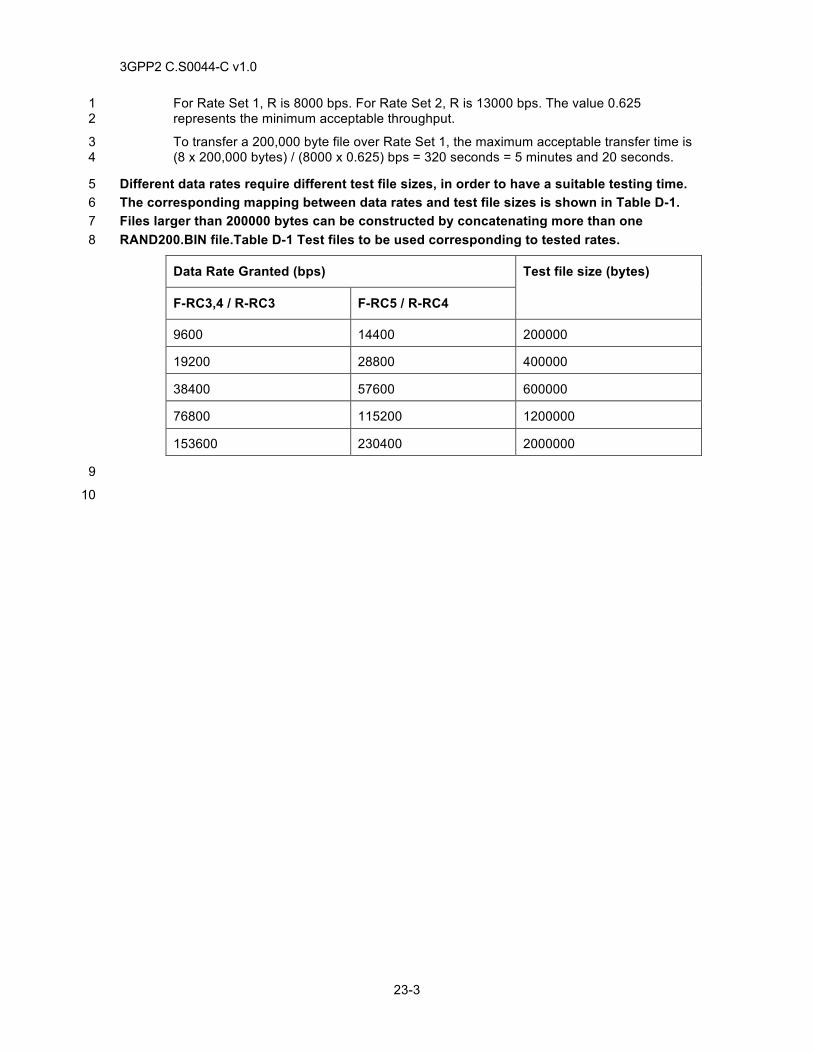
3GPP2 C.S0044-C v1.0
23-3
For Rate Set 1, R is 8000 bps. For Rate Set 2, R is 13000 bps. The value 0.625 1 represents the minimum acceptable throughput. 2
To transfer a 200,000 byte file over Rate Set 1, the maximum acceptable transfer time is 3 (8 x 200,000 bytes) / (8000 x 0.625) bps = 320 seconds = 5 minutes and 20 seconds. 4
Different data rates require different test file sizes, in order to have a suitable testing time. 5 The corresponding mapping between data rates and test file sizes is shown in Table D-1. 6 Files larger than 200000 bytes can be constructed by concatenating more than one 7 RAND200.BIN file.Table D-1 Test files to be used corresponding to tested rates. 8
Data Rate Granted (bps) Test file size (bytes)
F-RC3,4 / R-RC3 F-RC5 / R-RC4
9600 14400 200000
19200 28800 400000
38400 57600 600000
76800 115200 1200000
153600 230400 2000000
9
10

3GPP2 C.S0044-C v1.0
23-4
This page intentionally left blank.1
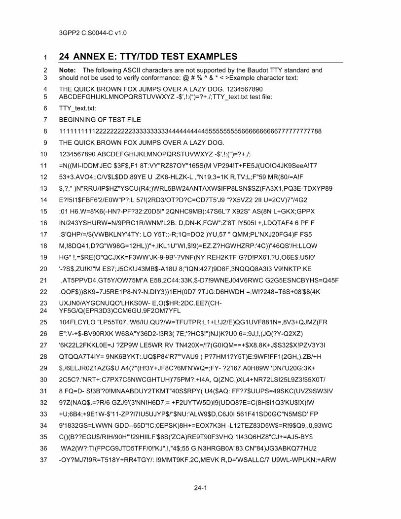
3GPP2 C.S0044-C v1.0
24-1
24 ANNEX E: TTY/TDD TEST EXAMPLES 1
Note: The following ASCII characters are not supported by the Baudot TTY standard and 2 should not be used to verify conformance: @ # % ^ & * < >Example character text: 3
THE QUICK BROWN FOX JUMPS OVER A LAZY DOG. 1234567890 4 ABCDEFGHIJKLMNOPQRSTUVWXYZ -$’,!:(“)=?+./;TTY_text.txt test file: 5
TTY_text.txt: 6
BEGINNING OF TEST FILE 7
111111111122222222223333333333444444444455555555556666666666777777777788 8
THE QUICK BROWN FOX JUMPS OVER A LAZY DOG. 9
1234567890 ABCDEFGHIJKLMNOPQRSTUVWXYZ -$',!:(")=?+./; 10
=N((MI-IDDM'JEC $3F$,F1 8T:VY"RZ87OY"165S(M VP294!T+FE5J(UOIO4JK9SeeA!T7 11
53+3.AVO4;;C/V$L$DD.89YE U .ZK6-HLZK-L ,"N19,3=1K R,TV;L;F"59 MR(80/=A!F 12
$,?," )N"RRU/IP$HZ"YSCU(R4;)WRL5BW24ANTAXW$IFP8LSN$SZ(FA3X1,PQ3E-TDXYP89 13
E?!5I1$FBF6'2/E0W"P?;L 57!(2RD3/OT?D?C=CD7T5'J9 "?X5VZ2 2II U=2CV)7"/4G2 14
;01 H6.W=8'K6(-HN?-PF?32:Z0D5I" 2QNHC9MB(:47S6L'7 X92S" AS(8N L+GKX;GPPX 15
IN/243YSHURW=N/9PRC1R/WNM'L2B. D,DN-K,FGW":Z'8T IY505I +,LDQTAF4 6 PF F 16
.S'QHP/=/$(VWBKLNY'4TY: LO Y5T::-R;1Q=DO2 )YU,57 " QMM;PL'NXJ20FG4)F FS5 17
M,!8DQ41,D?G"W98G=12HL))"+,IKL1U"WI,$!9)=EZ.Z?HGWHZRP:'4C))"46QS'/H:LLQW 18
HG" !,=$RE(O"QCJXK=F3WW'JK-9-9B'-?VNF(NY REH2KTF G?D!PX6'I.?U,O6E$.U5I0' 19
'-?S$,ZU!K!"M ES7;J5CK!J43MB$-A18U 8;"IQN:427)9D8F,3NQQQ8A3I3 V9!NKTP:KE 20
,AT5PPVD4.GT5Y/OW75M"A E58,2C44:33K,$-D7!9WNEJ04V6RWC G2G5ESNCBYHS=Q45F 21
.QOF$))SK9=7J5RE1P8-N?-N.DIY3))1EH(0D7 ?TJG:D6HWDH =:W!?248=T6S+08'$8(4K 22
UXJN0/AYGCNUQO'LHKS0W- E,O($HR:2DC.EE7(CH-23 YF5G/Q(EPR3D3)CCM6GU.9F2OM7YFL 24
104FLCYLO "LP55T07.:W6/IU.QU?/W=TFUTPR:L1+L!J2/E)QG1UVF881N=,8V3+QJMZ(FR 25
E":V-+$-BV90RXK W6SA"Y36D2-!3R3( 7E;'?HC$!")NJ)K?U0 6=:9J,!,(JQ(?Y-Q2XZ) 26
'6K22L2FKKL0E=J ?ZP9W LE5WR RV TN420X=/!7(G0IQM==+$X8.8K+J$S32$X!PZV3Y3I 27
QTQQA7T4IY= 9NK6BYKT:.UQ$P84'R7'"VAU9 ( P?7HM1?Y5T)E:9WF!FF1(2GH,).ZB/+H 28
$,/6ELJR0Z1AZG$U A4(7"(H!3Y+JF8C?6M'N'WQ=;FY- ?2167.A0H89W 'DN/'U20G:3K+ 29
2C5C?.'NRT+:C7PX7C5NWCGHTUH)'75PM?:+I4A, Q(ZNC,)XL4+NR72LSI25L9Z3!$5X0T/ 30
8 FQ=D- S!3B'?0!MNAABDUY2TKMT"40S$RPY( U4($AQ: FF?7$UUPS=49SKC(UVZ9SW3IV 31
9?Z(NAQ$.=?R/6 GZJ9'(3'NNIH6D7:= +F2UYTW5D)I9(UDQ8?E=C(8H$I1Q3'KU$!X)!W 32
+U;6B4;+9E1W-$'11-ZP?I7IU5UJYP$/"$NU:'ALW9$D,C6J0I 561F41SD0GC"N5MSD' FP 33
9'1832GS=LWWN GDD--65D"!C;0EPSK)8H+=EOX7K3H -L12TEZ83D5W$=R!9$Q9,.0,93WC 34
C()(B??EGU$/RIH/90H'"!29HIILF'$6S('ZCA)RE9T90F3VHQ 1I43Q6HZ8"CJ+=AJ5-BY$ 35
WA2(W?:TI(FPCG9JTD5TFF/0!'KJ",I,"4$;55 G.N3HRGB0A"83.CN"84)JG3ABKQ77HU2 36
-OY?MJ7!9R=T518Y+RR4TGY/: I9MMT9KF.2C,MEVK R,D='WSALLC/7 U9WL-WPLKN:+ARW 37
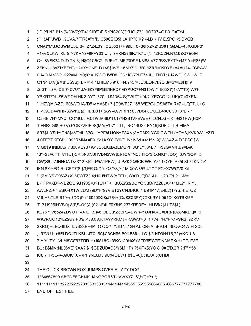
24-2
):D!(:'H:I?H'1N(6-80V7;XB4"KJD'T)EI$ :PIS203(?KUG(Z7/ J9OZ9Z--C1W:C=TY4 1
: "+3AF"JWB+,9UVA,7F)R6A"Y"I!,IC596G!O5! JAHP?0,X?K-LB'KHV E.$P0:K5'QVGB 2
CNA)'/MSJOSWMU5U 3=I 27Z-E0YTOS5031+P99LIT0=86K-2V21JS61(G/!AE=46!OJDP0" 3
+4V6CLKW' KL-S,Y?KHA8+6F+Y0$!U=;=8VXH26!8K."'K7!J'(N="ZKCZH:N'C:9BG7E0IH 4
C+L8VSK24 DJD:TNI6; N$Q1C5C2 IP(!E=TJMF?3D9E1/M88,V7C/FSVEYTY+MZ Y=R88)W 5
ZZKKJJ 39ZIYEZH") +?=YYGKF1D1X$$IWR;+6MYSO;"!R) 9ZRR="KDYF1A4AU?4- "GRAW 6
6;A-O.N.VW? .2??=MHY0;X1=H9WEHWD8;:C6 :JO/7?!.EZ4JL/ !FNXL;AJAWB; CWUWLF 7
O1N4 U;V(9M8"O$S6)FER=14I4I,HIEM5'916:FN.Y?5"=LC0EQN7I,?D;3(=2'/=L8H(!I9 8
:2.ST 1.2A:,DE;745VU7UA-$Z?F8PGE'INKD7 G?PUQ79N610W:Y;E63X7)4-.V?T0))W7H 9
YBKRT/DL-S5WZ'OH;HK21'/Y7 ,8Z0 1UMD64-S;7WIZT="'4/2''XE7CQ.:2LUK)C"=0XEN 10
" :HZV(M'/4ZQ16$6WO1A-'D5)VMA3E+? $D0WF271)68 WE?GJ OSA8T=!R=7 -UQT7JU+G 11
FI-?.9DD44'IH!=$$WKE)2:,!ID:DJ !+.(AW=O/V!RPR 85?D04'6L"UZE43O8O0T6 'ERP 12
O:58B.7HYM?QTCO"3U; 5+.0TWJA3ID"T!,1)?H2S1VFBW/E 6 LCN,.GH:KI:99$1RW(H0P 13
1)+H83 G8! H0 V).6'QK7VFIE-/S)MA(+'D7" TTI.,-'NO46Q32.NY19,KDFD!TLB-FIMA 14
6R7$L Y$H=:TN8$4VD4L,8?QL "=PF8UJQN=E8XM;AAOMXLYG9-CWEH (YOYS,KVK0WU=Z'R 15
4/0FFBT 2FG!!!J 093RMNA=EX.:6:1AK08KY0(DJN:JV6:L=4:J5N:9)"WW4Z,4:DCPSO$W 16
V!G8$9 INIB!.U/;? J00VEY0+)G"0S5LK6!A3EMUPF,JQ"LY',34E?TK$2G=M4 J/9=!AKT 17
"S"=23A6TT4VTK:1)CP.8NJ7.UHVDN5VW)EI/1CA "NCJ FIQ"$KXN!G73DO),!0JY"$OPH5 18
CW(S6=I7JNNOA DZX" 2-3(0;TP5A1PEW(=J:PZKGQ6CK.WFJYZ1J OY69P?5I SL2T0N CZ 19
IKN,8X:+FG-R=CEY7(8 $3;ER Q(D0. O3/Y8,Y,1M;X0W85!!.4"!OT FC+X7WGV$:K/L: 20
"I;(ZA'.Y$)E9"AZ),XJM)WTZ(I'4;N6H'NTW(AEEI+, C80B ,F(D8KH; H;Q0-Z1 2H6M= 21
LI('F P=XD?-NDZOO!9J !?0S=J?1L4+F+HBUX6S:9DOYC 38O(YZZ8LAP+10IL?" :R YJ 22
AWLNZ/+ "!BSK-4X1W:2UM!(9U?F"97V.BT3YCNJDIG6I4 6)!4M17,E4L2(T-Y$,H:E ;QZ 23
V,6-H8,TLEIB19+('$DD)P-(46920DX$(J754+(G:/SZC3FY)7ZKI;RY1)954O''XOTBK!5F 24
'P ?J1906IHVS'0(.8(I',S-Q9(A )0?J-E4LF0X!H9 23?KR$DFYLHLB5(?)/U)T3$I.)I; 25
KLY6?')V65Z4ZDVOYF4X:G. 3))46!OEG(KZ8BP24L'W"(-Y)JJHAXG=DR!-)UZ8MKDQ=!"6 26
WK?R/;IO42?LZ2U9 H0'E.K88,0S,KTA?YRKMJH-C$WJ?(0=4 /"A(; "H."H"OPSR2=9ZRV 27
3XRG)HLEQ6IDX TJ7$23EF4M=O QQ?- /N6J7:L13HPJ: CR6A--/F9J,4=3LQVC4W-H-2CL 28
; (5?VU:L,+6ELDO4TLKBU JTC=$9$C3CN$6 P0'4E35-: .LO $'5.HD3N41$;72)+KOU.3 29
7(A Y, TY .-VLM8Y3'?I7FRR-H+I5818G4"8KC.:29HQ"Y8FR'5!"GTE)NAMEK(H4RPJE3E 30
BU: B$MM:NL36VE)'9AA?I$+$GDZUD=D3/Y6M 1P) ?5XFK$(YO!8'(9=E'D.2R ?:F'"Y58 31
!C8,7TR5E-K-J9UK" X -"/PF9NL0DL,9C94OEWT 8$C-A(05)0X=.5(CHDF 32
33
THE QUICK BROWN FOX JUMPS OVER A LAZY DOG. 34
1234567890 ABCDEFGHIJKLMNOPQRSTUVWXYZ -$',!:(")=?+./; 35
111111111122222222223333333333444444444455555555556666666666777777777788 36
END OF TEST FILE 37


