Embed Size (px)
Citation preview
Finite Element Modelling Results of
High-Rise Timber BuildingsDynamic Modal Analysis
Ida Edskär


Finite Element Modelling Results of
High-Rise Timber Buildings
Dynamic Modal Analysis
Ida Edskär
Luleå University of TechnologyDepartment of Civil, Environmental and Natural Resources Engineering
Division of Industrialized and sustainable construction

ISSN 1402-1536ISBN 978-91-7790-519-6 (pdf)
Luleå 2019
www.ltu.se

I
Abstract Tall timber buildings are built around the world and the development is moving forward. Tall timber buildings are sensitive to wind-induced vibration and can cause discomfort for humans. In this report is the results from a dynamic analysis preformed on a cross-laminated buildings system presented. Size and placement of openings and floor plans have been investigated using finite element analysis and dynamic modal analyses. The results show that asymmetric placement of openings and asymmetric floor plans may affect the dynamic behaviour of tall timber buildings. Asymmetry can cause modes with a tendency to rotate and even diagonal modes. Timber buildings may have problem to fulfil the comfort criteria already at a slenderness of 1.5-2.1.


III
Contents
Abstract ....................................................................................................................................... I
Introduction ................................................................................................................................ 1
Theory ........................................................................................................................................ 1
Method ....................................................................................................................................... 2
Part A ...................................................................................................................................... 3
Part B ...................................................................................................................................... 3
FE-model and material properties .......................................................................................... 4
Results – Part A .......................................................................................................................... 5
Case O .................................................................................................................................... 6
Case 1X .................................................................................................................................. 7
Case 2X .................................................................................................................................. 8
Case 1X1Y ............................................................................................................................. 9
Case 1X2Y ........................................................................................................................... 10
Case 2X2Y ........................................................................................................................... 11
Result – Part B .......................................................................................................................... 14
Timber .................................................................................................................................. 15
Hybrid I ................................................................................................................................ 16
Hybrid II ............................................................................................................................... 17
Concrete ............................................................................................................................... 18
Summary .................................................................................................................................. 23
References ................................................................................................................................ 25
Appendix A1 ........................................................................................................................ A1.1
Appendix A2 ........................................................................................................................ A2.1
Appendix B.1 ....................................................................................................................... B1.1

1
Introduction Taller timber buildings are sensitive to wind-induced vibrations, which can cause discomfort for humans. Tall timber building can be stabilised by cross-laminated timber panels (CLT) and the placement of stabilising elements are generally not symmetric in plane. Several walls may have large openings for windows and doors. The geometry of the floor plan is different in buildings, where mid- and high-rise buildings often are organised around the elevator shaft. The shaft can be a part of the stabilising system and can be placed in the central core or at the exterior part of the building. Placement of the shaft and openings may affect the dynamic behaviour of the building. The aim of this report is to present the results from a modal analysis of a CLT building where asymmetrical floor plans and openings have been studied.
Theory The theory of vibrations of a uniform cantilever beam, fixed to the foundation can be used to model a tall building. Since tall buildings can be very complex and consist of several elements, finite element (FE) software is useful to solve the multiple degree of freedom problem. In FE software the modal analysis is used to solve the free-vibration equation of motion (Chopra, 2012):
Mü + Ku = 0 (1)
Where M and K are the 𝑁𝑁 × 𝑁𝑁 matrices of mass and stiffness and u denotes the generalised displacement. Further derivation of the equation is referred to Chopra (2012). The dynamic properties such as the natural freqency, mode shape and modal mass can be determined by modal analaysis. For each resonance mode there is an associated modal mass and a modal stiffness (Jeary, 1997). The squared natural frequencies are related to the modal mass and modal stiffness by (Chopra, 2012):
𝜔𝜔𝑛𝑛2 = 𝐾𝐾𝑛𝑛�
𝑀𝑀𝑛𝑛� (2)
Where 𝐾𝐾𝑛𝑛� is the modal stiffness and 𝑀𝑀𝑛𝑛� is the modal mass. From the squared natural frequencies, the natural frequencies can be written as:
𝑓𝑓𝑛𝑛 = 𝜔𝜔𝑛𝑛2𝜋𝜋
(3)
Since the modal mass is generated from the modal analysis the modal stiffness can be calculated by using Eq.(2) and (3). For a continuous system the modal mass is defined by (Jeary, 1997):
𝑀𝑀𝑛𝑛� = ∫ 𝑚𝑚(𝑧𝑧)𝜙𝜙𝑛𝑛2𝑑𝑑𝑧𝑧ℎ0 (4)

2
Eq.(4) assume that the dimensions in the X- and Y-directions are constant and do not vary along the building, figure 1. Irregularities in X- and Y-directions need to be considered. The equation of modal mass for a 3D-system is by definition a volume integral, (Jeary, 1997).
The three fist modes for a building are normally two orthogonal translation modes and one torsional mode given that the building is symmetric. Asymmetry in the building can yield other mode combinations (Jeary, 1997).
To evaluate the comfort criteria, the acceleration level needs to be calculated. In the Swedish national annex, EKS 10 (2015) the following equation is stated for estimating the standard deviation of acceleration:
𝜎𝜎𝑥𝑥(𝑧𝑧) = 3∙𝐼𝐼𝑣𝑣(ℎ)∙𝑅𝑅∙𝑞𝑞𝑚𝑚(ℎ)∙𝑏𝑏∙𝑐𝑐𝑓𝑓∙𝜙𝜙1,𝑥𝑥(𝑧𝑧)𝑚𝑚𝑒𝑒
(5)
𝐼𝐼𝑣𝑣(ℎ) is the turbulence intensity at height ℎ, 𝑅𝑅 is the square root of the resonant response, 𝑞𝑞𝑚𝑚(ℎ) is the mean pressure at height ℎ, 𝑏𝑏 is the width of the structure, 𝑐𝑐𝑓𝑓 is the force coefficient, 𝜙𝜙1,𝑥𝑥(𝑧𝑧) is the mode shape value at height 𝑧𝑧, 𝑚𝑚𝑒𝑒 is the equivalent mass per unit length, 𝑧𝑧 is the height above the ground, and ℎ is the height of the structure. According to Eurocode 1-4 (2005) the equivalent mass per unit length is given by:
𝑚𝑚𝑒𝑒 = ∫ 𝑚𝑚(𝑧𝑧)∙𝜙𝜙12(𝑧𝑧)𝑑𝑑𝑧𝑧ℎ0
∫ 𝜙𝜙12(𝑧𝑧)𝑑𝑑𝑧𝑧ℎ0
(6)
The equivalent mass is the modal mass presented per unit length and has the unit kg/m. The numerator is the modal mass and the denominator is the integral of the mode shape over the height of the building for a given mode. The equivalent mass can be approximate by average value of the mass of the upper third of the structure or the total mass of the building divided by the total height (Eurocode 1-4, 2005):
𝑚𝑚𝑒𝑒,𝑎𝑎𝑎𝑎𝑎𝑎 = 𝑚𝑚𝑡𝑡𝑡𝑡𝑡𝑡ℎ
(7)
From a modal analysis which is performed on a 3D model, the mode shape is visually presented in 3D. The sum of modal masses in X- Y- and Z-directions represent the total mass for the associated vibration modes:
𝑀𝑀𝑛𝑛� = 𝑚𝑚𝑋𝑋� + 𝑚𝑚𝑌𝑌� + 𝑚𝑚𝑍𝑍� (8)
Where 𝑚𝑚𝑋𝑋� , 𝑚𝑚𝑌𝑌,� 𝑚𝑚𝑍𝑍� are the modal mass in each direction X- Y- and Z-direction for the current mode (Autodesk Inc., 2015)
Method This study is divided in two parts, Part A and Part B. In part A, the effects of openings have been studied and in part B different floor plans and hybrid solutions have been studied. The

3
study is based on same fictitious building as presented in Edskär & Lidelöw (2017). The building represents a common floor plan and building type for mid- and high-rise timber buildings. The building footprint is 20x20m2 and the structure consists of cross-laminated timber, stabilised through diaphragm action. The slenderness of the building, h/d where h is the height and d is the depth of the building, has been varied between 1.5 to 4.5 with a step of 0.6. To evaluate a very high building h/d = 9.0 was added.
Eq.(6) was used to calculate the equivalent mass from the generated modal mass and mode shape. Eq.(7) was used to calculated the approximate equivalent mass. From Eq.(2) and (3) the modal stiffness was calculated by using the natural frequency and the associated modal mass for each case.
Part A The inner walls are neglected in Part A and only the outer walls and the floors were considered. Opening sizes of (height x width) 1.5x1.0m2 and 1.5x2.5 m2 have been studied with 4 openings in each wall. 6 different configurations of opening placement have been studied, figure 1:
- In case O no openings are added,
- Case 1X has openings on one wall in the X-direction
- Case 2X has openings on both walls in the X-direction
- Case 1X1Y has openings on one wall in X-direction and one wall in Y-direction
- Case 1X2Y has openings on one wall in X-direction and on both walls in Y-direction
- Case 2X2Y have openings on all walls.
Figure 1 Placement of openings, Z-direction is out-of-plane
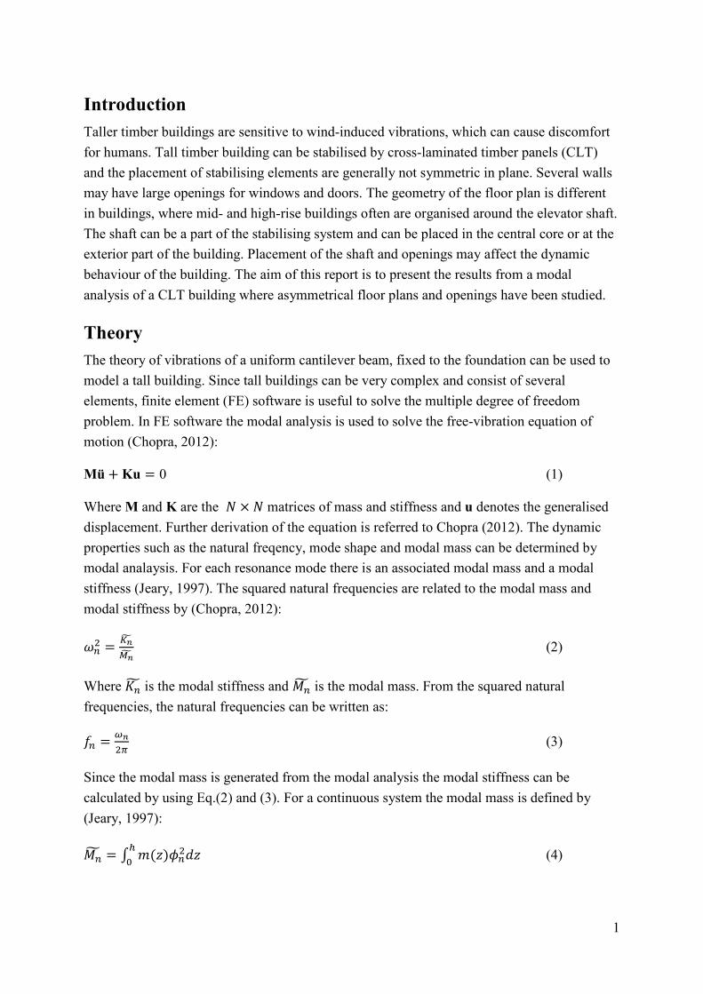
Part B In Part B openings for windows have been removed, but door openings are left. Four cases have been studied with different placement of the elevator shaft, figure 2. The placements of the shaft are denoted I, II and III, with an additional case III – Hybrid with the same floor plan
O 1X 2X 1X1Y 1X2Y 2X2Y
X
Y
4
but an extra wall added opposite to the shaft. Different building system are analysed for each case:
- Timber, all structural elements are in CLT - Concrete, all structural elements are in concrete - Hybrid I, all structural elements are in CLT except for the shaft which is in concrete - Hybrid II, the shaft is in concrete and a 7 m long concrete wall on the opposite side
while the rest of the structural elements are CLT
Hybrid II has only been studied for floor plan III.
I II
III III - Hybrid
Figure 2 Placement of the shaft, floor layout
FE-model and material properties From a modal analysis, dynamic properties such as the natural frequencies, the mode shape, and the modal mass can be generated. To perform the modal analysis a commercial FE-software (Autodesk ® RobotTM Structural Analysis) was used. The CLT walls are 200 mm thick and the floors are 280 mm. The wall element consist of five layers and the floor element consist of seven layer. Graded C24 are used for all layers with a E-modulus of 11,000 MPa, a G-modulus of 690 MPa, and a density taken as 400 kg/m3. Only dead-load was considered in the model. The element stiffness has been calculated from CLT handbook and manually

5
defined in the FE software so the orthotropic properties are handled properly (Svenskt Trä, 2017). Four-node quadrilateral shell elements were used for all panels. The mass in Z-direction was ignored to avoid local vibrations of floor elements. Only X- and Y-directions (transversal vibration) were set to be active in the analysis, figure 1.
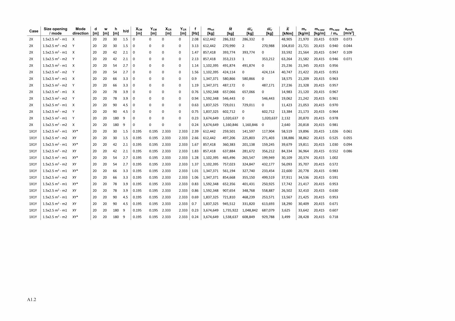
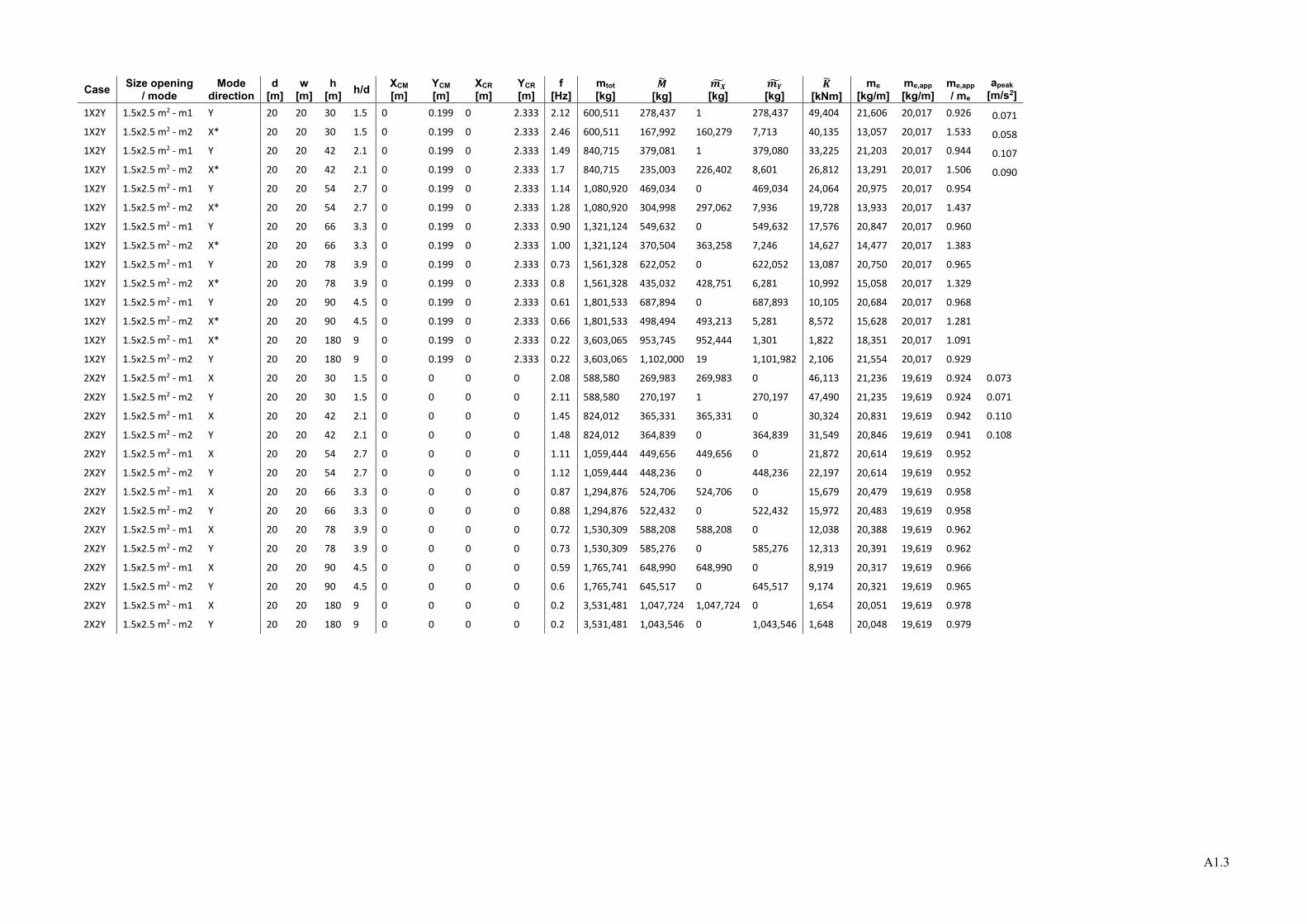
Results – Part A In appendix A1 and A2 all results from Part A are presented. In appendix A1 the results from opening sizes of 1.5x2.5 m2 are presented and in appendix A2 the results from opening sizes of 1.5x1.0m2 . In the following figure 3 to 8, the modal mass, modal stiffness, and natural frequency are presented for the two first modes for each case with size opening 1.5x2.5m2. The two first modes represent the two first transversal modes. Some of the modes show a tendency to rotate and even diagonal modes occur, see appendix A1 and A2. The peak acceleration for selected cases are presented in the appendix A1 and A2. The peak acceleration for cases with opening size of 1.5x2.5 m2 and natural frequency are presented in figure 9 and 10 in relation to the comfort standard ISO 10137 (ISO 10137, 2008) for selected slenderness, h/d.

6
Case O
a b
c d
e f
Figure 3 Case O – size opening 1.5x2.5 m2 a) slenderness vs natural frequency mode 1 b) slenderness vs natural frequency mode 2 c) slenderness vs modal mass mode 1 d) slenderness vs modal mass mode 2 e) slenderness vs modal stiffness mode 1 f) slenderness vs modal stiffness mode 2

7
Case 1X
a b
c d
e f
Figure 4 Case 1X - size opening 1.5x2.5 m2 a) slenderness vs natural frequency mode 1 b) slenderness vs natural frequency mode 2 c) slenderness vs modal mass mode 1 d) slenderness vs modal mass mode 2 e) slenderness vs modal stiffness mode 1 f) slenderness vs modal stiffness mode 2

8
Case 2X
a b
c d
e f
Figure 5 Case 2X - size opening 1.5x2.5 m2 a) slenderness vs natural frequency mode 1 b) slenderness vs natural frequency mode 2 c) slenderness vs modal mass mode 1 d) slenderness vs modal mass mode 2 e) slenderness vs modal stiffness mode 1 f) slenderness vs modal stiffness mode 2
9
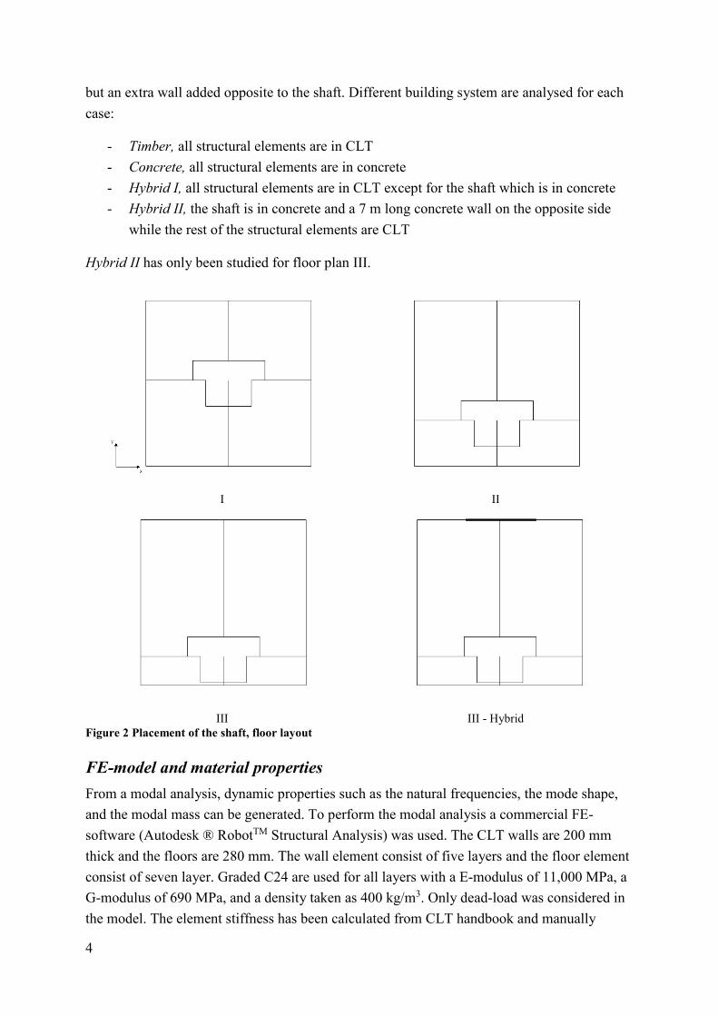
Case 1X1Y
a b
c d
e f
Figure 6 Case 1X1Y - size opening 1.5x2.5 m2 a) slenderness vs natural frequency mode 1 b) slenderness vs natural frequency mode 2 c) slenderness vs modal mass mode 1 d) slenderness vs modal mass mode 2 e) slenderness vs modal stiffness mode 1 f) slenderness vs modal stiffness mode 2
10
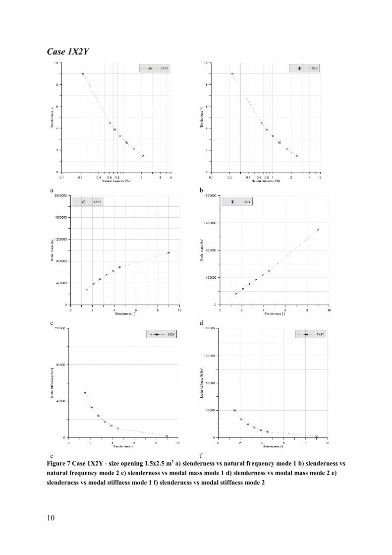
Case 1X2Y
a b
c d
e f
Figure 7 Case 1X2Y - size opening 1.5x2.5 m2 a) slenderness vs natural frequency mode 1 b) slenderness vs natural frequency mode 2 c) slenderness vs modal mass mode 1 d) slenderness vs modal mass mode 2 e) slenderness vs modal stiffness mode 1 f) slenderness vs modal stiffness mode 2

11
Case 2X2Y
a b
c d
e f
Figure 8 Case 2X2Y - size opening 1.5x2.5 m2 a) slenderness vs natural frequency mode 1 b) slenderness vs natural frequency mode 2 c) slenderness vs modal mass mode 1 d) slenderness vs modal mass mode 2 e) slenderness vs modal stiffness mode 1 f) slenderness vs modal stiffness mode 2

12
Acceleration
a
b c
d e
Figure 9 ISO 10137 with peak acceleration and natural frequency for a) Case O – mode 1 and 2 b) Case 1X – mode 1 c) Case 1X – mode 2 d) Case 2X – mode 1 e) Case 2X – mode 2

13
a b
c d
e Figure 10 ISO 10137 with peak acceleration and natural frequency for a) Case 1X1Y – mode 1 b) Case 1X1Y – mode 2 c) Case 1X2Y – mode 1 d) Case 1X2Y – mode 2 e) Case 2X2Y – mode 1 and 2
14
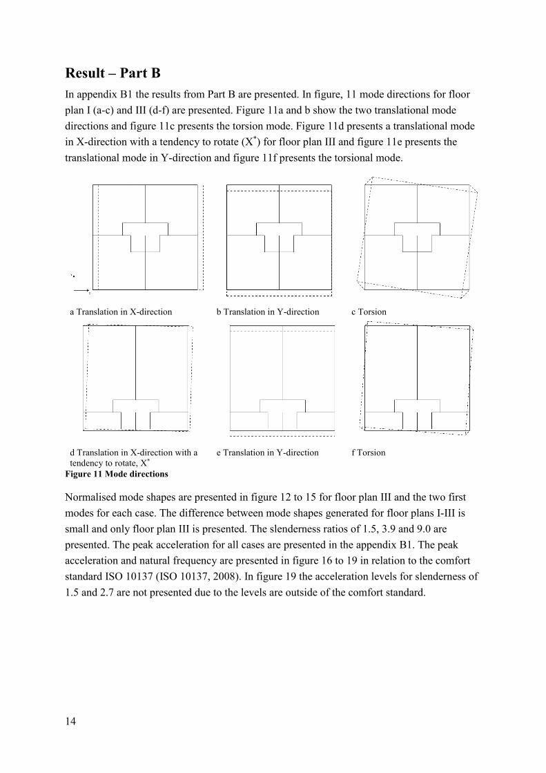
Result – Part B In appendix B1 the results from Part B are presented. In figure, 11 mode directions for floor plan I (a-c) and III (d-f) are presented. Figure 11a and b show the two translational mode directions and figure 11c presents the torsion mode. Figure 11d presents a translational mode in X-direction with a tendency to rotate (X*) for floor plan III and figure 11e presents the translational mode in Y-direction and figure 11f presents the torsional mode.
a Translation in X-direction b Translation in Y-direction c Torsion
d Translation in X-direction with a tendency to rotate, X*
e Translation in Y-direction f Torsion
Figure 11 Mode directions
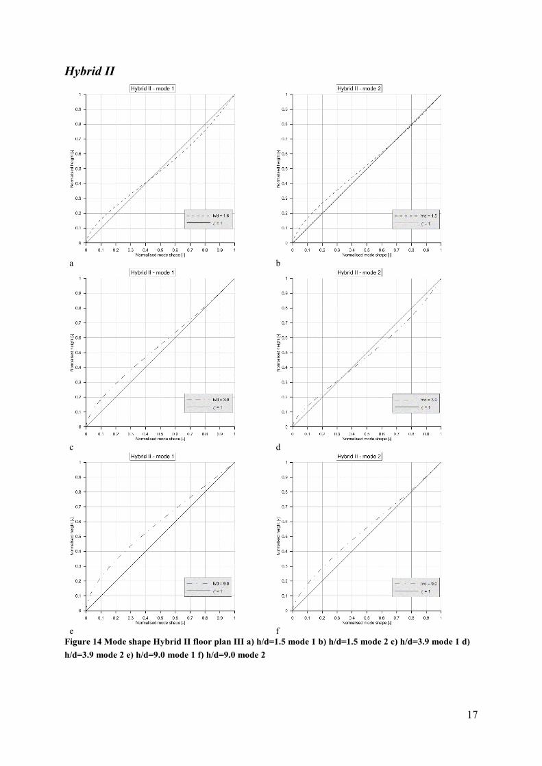
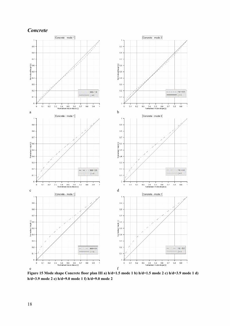
Normalised mode shapes are presented in figure 12 to 15 for floor plan III and the two first modes for each case. The difference between mode shapes generated for floor plans I-III is small and only floor plan III is presented. The slenderness ratios of 1.5, 3.9 and 9.0 are presented. The peak acceleration for all cases are presented in the appendix B1. The peak acceleration and natural frequency are presented in figure 16 to 19 in relation to the comfort standard ISO 10137 (ISO 10137, 2008). In figure 19 the acceleration levels for slenderness of 1.5 and 2.7 are not presented due to the levels are outside of the comfort standard.

15
Timber
a b
c d
e f
Figure 12 Mode shape Timber floor plan III a) h/d=1.5 mode 1 b) h/d=1.5 mode 2 c) h/d=3.9 mode 1 d) h/d=3.9 mode 2 e) h/d=9.0 mode 1 f) h/d=9.0 mode 2

16
Hybrid I
a b
c d
e f
Figure 13 Mode shape Hybrid I floor plan III a) h/d=1.5 mode 1 b) h/d=1.5 mode 2 c) h/d=3.9 mode 1 d) h/d=3.9 mode 2 e) h/d=9.0 mode 1 f) h/d=9.0 mode 2
17
Hybrid II
a b
c d
e f
Figure 14 Mode shape Hybrid II floor plan III a) h/d=1.5 mode 1 b) h/d=1.5 mode 2 c) h/d=3.9 mode 1 d) h/d=3.9 mode 2 e) h/d=9.0 mode 1 f) h/d=9.0 mode 2
18
Concrete
a b
c d
e f
Figure 15 Mode shape Concrete floor plan III a) h/d=1.5 mode 1 b) h/d=1.5 mode 2 c) h/d=3.9 mode 1 d) h/d=3.9 mode 2 e) h/d=9.0 mode 1 f) h/d=9.0 mode 2

19
Acceleration
a b
c
d Figure 16 ISO 10137 with peak acceleration and natural frequency for Timber a) floor plan I – mode 1 b) floor plan I-III – mode 2 c) floor plan II mode 1 d) floor plan III mode 1

20
a b
c d
e f
Figure 17 ISO 10137 with peak acceleration and natural frequency for Hybrid I a) floor plan I – mode 1 b) floor plan I – mode 2 c) floor plan II – mode 1 d) floor plan II - mode 2 e) floor plan III – mode 1 f) floor plan III – mode 2
21
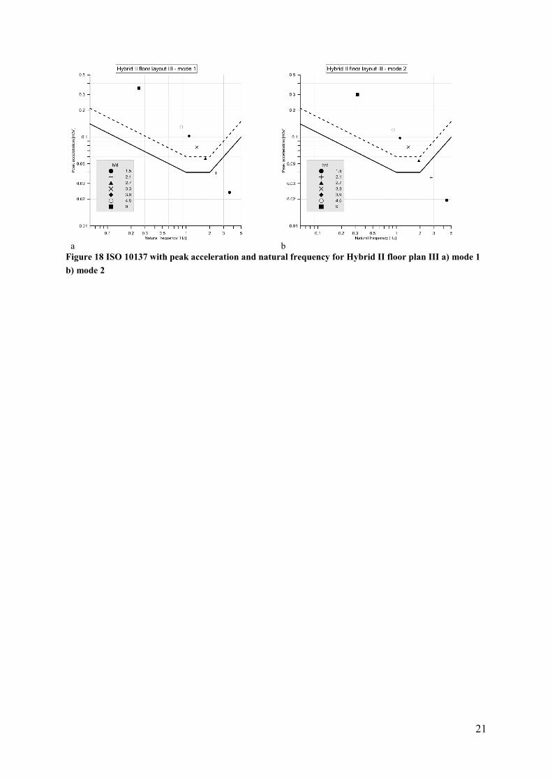
a b
Figure 18 ISO 10137 with peak acceleration and natural frequency for Hybrid II floor plan III a) mode 1 b) mode 2
22
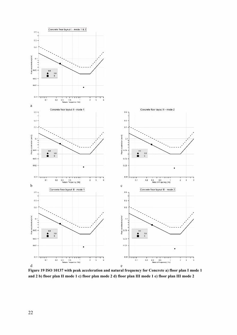
a
b c
d e
Figure 19 ISO 10137 with peak acceleration and natural frequency for Concrete a) floor plan I mode 1 and 2 b) floor plan II mode 1 c) floor plan mode 2 d) floor plan III mode 1 e) floor plan III mode 2

23
Summary In this report, size and placement of openings have been studied. Three different floor plans have been studied for four different cases with varying structural material: 1) cross-laminated timber, 2) a timber-concrete hybrid solution where the shaft is in concrete 3) a concrete shaft and a 7m long concrete wall, and 4) all structural elements in concrete. The slenderness has been varied between 1.5 to 4.5 with a step of 0.6 and an additional slenderness of 9.0. Asymmetry in both placement of openings and floor plan affect the dynamic properties. The asymmetry create eccentricities between centre of mass and centre of rigidity resulting in some of the modes tends to rotate or even be diagonal. Depending on the floor plan, timber buildings with a slenderness of 1.5-2.1 may have problem to fulfil the comfort criteria. Additional mass from non-structural elements has not been included, which may affect the acceleration level.

25
References Autodesk Inc. (2015). Technical Documentation for Calculating the Modal Mass.
BFS 2015:6 EKS 10. (2015). Boverkets föreskrifter om ändring i verkets föreskrifter och allmänna råd (2011:10) om tillämpning av europeiska konstruktionsstandarder (eurokoder). Boverket. Karlskrona: In Swedish.
Chopra, A. K. (2012). Dynamics of structures : theory and applications to earthquake engineering (4th ed. ed.). Upper Saddle River, N.J.: Prentice Hall.
Edskär, I., & Lidelöw, H. (2017). Wind-induced vibrations in timber buildings-parameter study of cross-laminated timber residential structures. Structural Engineering International, 27(2), 205-216. doi:10.2749/101686617X14881932435619
Eurocode 1-4 SS-EN 1991-1-4. (2005). Actions on structures - Part1-4: General actions - Wind actions. Stockholm: SIS Förlag AB.
ISO 10137. (2008). Bases for design of structures - Serviceability of buildings and walkways againts vibration. Stockholm: SIS Förlag AB.
Jeary, A. (1997). Designer´s guide to the dynamic response of structures. Hong Kong: E & FN Spon.
Svenskt Trä. (2017). KL-trähandbok (CLT handbook). (E. Borgström, & J. Fröbel, Eds.) Stockholm: Skogsindutrierna, Svenskt Trä (In Swedish).

A1.1
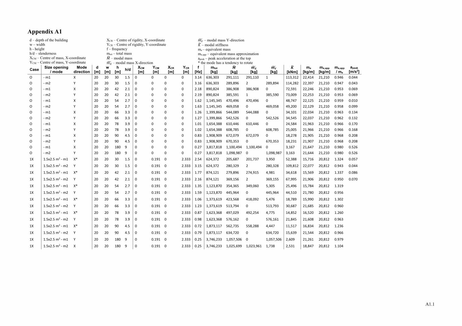
Appendix A1 d – depth of the building w – width h - height h/d – slenderness XCM – Centre of mass, X-coordinate YCM – Centre of mass, Y-coordinate
XCR – Centre of rigdity, X-coordinate YCR – Centre of rigidity, Y-coordinate f – frequency mtot – total mass 𝑀𝑀� – modal mass 𝑚𝑚𝑋𝑋� – modal mass X-direction
𝑚𝑚𝑌𝑌� – modal mass Y-direction 𝐾𝐾� – modal stiffness me – equivalent mass me,app – equivalent mass approximation apeak – peak acceleration at the top * the mode has a tendency to rotate
Case Size opening / mode
Mode direction
d [m]
w [m]
h [m] h/d XCM
[m] YCM [m]
XCR [m]
YCR [m]
f [Hz]
mtot [kg]
𝑴𝑴� [kg]
𝒎𝒎𝑿𝑿� [kg]
𝒎𝒎𝒀𝒀� [kg]
𝑲𝑲� [kNm]
me [kg/m]
me,app [kg/m]
me,app / me
apeak [m/s2]
O - m1 X 20 20 30 1.5 0 0 0 0 3.14 636,303 291,111 291,110 1 113,312 22,414 21,210 0.946 0.044 O - m2 Y 20 20 30 1.5 0 0 0 0 3.16 636,303 289,896 2 289,894 114,282 22,397 21,210 0.947 0.043 O - m1 X 20 20 42 2.1 0 0 0 0 2.18 890,824 386,908 386,908 0 72,591 22,246 21,210 0.953 0.069 O - m2 Y 20 20 42 2.1 0 0 0 0 2.19 890,824 385,591 1 385,590 73,009 22,253 21,210 0.953 0.069 O - m1 X 20 20 54 2.7 0 0 0 0 1.62 1,145,345 470,496 470,496 0 48,747 22,125 21,210 0.959 0.010 O - m2 Y 20 20 54 2.7 0 0 0 0 1.63 1,145,345 469,058 0 469,058 49,200 22,129 21,210 0.958 0.099 O - m1 X 20 20 66 3.3 0 0 0 0 1.26 1,399,866 544,089 544,088 0 34,101 22,034 21,210 0.963 0.134 O - m2 Y 20 20 66 3.3 0 0 0 0 1.27 1,399,866 542,526 0 542,526 34,545 22,037 21,210 0.962 0.132 O - m1 X 20 20 78 3.9 0 0 0 0 1.01 1,654,388 610,446 610,446 0 24,584 21,963 21,210 0.966 0.170 O - m2 Y 20 20 78 3.9 0 0 0 0 1.02 1,654,388 608,785 0 608,785 25,005 21,966 21,210 0.966 0.168 O - m1 X 20 20 90 4.5 0 0 0 0 0.83 1,908,909 672,079 672,079 0 18,278 21,905 21,210 0.968 0.208 O - m2 Y 20 20 90 4.5 0 0 0 0 0.83 1,908,909 670,353 0 670,353 18,231 21,907 21,210 0.968 0.208 O - m1 X 20 20 180 9 0 0 0 0 0.27 3,817,818 1,100,494 1,100,494 0 3,167 21,647 21,210 0.980 0.526 O - m2 Y 20 20 180 9 0 0 0 0 0.27 3,817,818 1,098,987 0 1,098,987 3,163 21,644 21,210 0.980 0.526
1X 1.5x2.5 m2 - m1 X* 20 20 30 1.5 0 0.191 0 2.333 2.54 624,372 205,687 201,737 3,950 52,388 15,716 20,812 1.324 0.057
1X 1.5x2.5 m2 - m2 Y 20 20 30 1.5 0 0.191 0 2.333 3.15 624,372 280,329 2 280,328 109,812 22,077 20,812 0.943 0.044
1X 1.5x2.5 m2 - m1 X* 20 20 42 2.1 0 0.191 0 2.333 1.77 874,121 279,896 274,915 4,981 34,618 15,569 20,812 1.337 0.086
1X 1.5x2.5 m2 - m2 Y 20 20 42 2.1 0 0.191 0 2.333 2.16 874,121 369,156 2 369,155 67,995 21,906 20,812 0.950 0.070
1X 1.5x2.5 m2 - m1 X* 20 20 54 2.7 0 0.191 0 2.333 1.35 1,123,870 354,365 349,060 5,305 25,496 15,784 20,812 1.319
1X 1.5x2.5 m2 - m2 Y 20 20 54 2.7 0 0.191 0 2.333 1.59 1,123,870 445,964 0 445,964 44,510 21,780 20,812 0.956
1X 1.5x2.5 m2 - m1 X* 20 20 66 3.3 0 0.191 0 2.333 1.06 1,373,619 423,568 418,092 5,476 18,789 15,990 20,812 1.302
1X 1.5x2.5 m2 - m2 Y 20 20 66 3.3 0 0.191 0 2.333 1.23 1,373,619 513,794 0 513,793 30,687 21,685 20,812 0.960
1X 1.5x2.5 m2 - m1 X* 20 20 78 3.9 0 0.191 0 2.333 0.87 1,623,368 497,029 492,254 4,775 14,852 16,520 20,812 1.260
1X 1.5x2.5 m2 - m2 Y 20 20 78 3.9 0 0.191 0 2.333 0.98 1,623,368 576,162 0 576,161 21,845 21,608 20,812 0.963
1X 1.5x2.5 m2 - m1 X* 20 20 90 4.5 0 0.191 0 2.333 0.72 1,873,117 562,735 558,288 4,447 11,517 16,834 20,812 1.236
1X 1.5x2.5 m2 - m2 Y 20 20 90 4.5 0 0.191 0 2.333 0.79 1,873,117 634,720 0 634,720 15,639 21,544 20,812 0.966
1X 1.5x2.5 m2 - m1 Y 20 20 180 9 0 0.191 0 2.333 0.25 3,746,233 1,057,506 0 1,057,506 2,609 21,261 20,812 0.979
1X 1.5x2.5 m2 - m2 X 20 20 180 9 0 0.191 0 2.333 0.25 3,746,233 1,025,699 1,023,961 1,738 2,531 18,847 20,812 1.104
A1.2
Case Size opening / mode
Mode direction
d [m]
w [m]
h [m] h/d XCM
[m] YCM [m]
XCR [m]
YCR [m]
f [Hz]
mtot [kg]
𝑴𝑴� [kg]
𝒎𝒎𝑿𝑿� [kg]
𝒎𝒎𝒀𝒀� [kg]
𝑲𝑲� [kNm]
me [kg/m]
me,app [kg/m]
me,app / me
apeak [m/s2]
2X 1.5x2.5 m2 - m1 X 20 20 30 1.5 0 0 0 0 2.08 612,442 286,332 286,332 0 48,905 21,970 20,415 0.929 0.073
2X 1.5x2.5 m2 - m2 Y 20 20 30 1.5 0 0 0 0 3.13 612,442 270,990 2 270,988 104,810 21,721 20,415 0.940 0.044
2X 1.5x2.5 m2 - m1 X 20 20 42 2.1 0 0 0 0 1.47 857,418 393,774 393,774 0 33,592 21,564 20,415 0.947 0.109
2X 1.5x2.5 m2 - m2 Y 20 20 42 2.1 0 0 0 0 2.13 857,418 353,213 1 353,212 63,264 21,582 20,415 0.946 0.071
2X 1.5x2.5 m2 - m1 X 20 20 54 2.7 0 0 0 0 1.14 1,102,395 491,874 491,874 0 25,236 21,345 20,415 0.956
2X 1.5x2.5 m2 - m2 Y 20 20 54 2.7 0 0 0 0 1.56 1,102,395 424,114 0 424,114 40,747 21,422 20,415 0.953
2X 1.5x2.5 m2 - m1 X 20 20 66 3.3 0 0 0 0 0.9 1,347,371 580,866 580,866 0 18,575 21,209 20,415 0.963
2X 1.5x2.5 m2 - m2 Y 20 20 66 3.3 0 0 0 0 1.19 1,347,371 487,172 0 487,171 27,236 21,328 20,415 0.957
2X 1.5x2.5 m2 - m1 X 20 20 78 3.9 0 0 0 0 0.76 1,592,348 657,066 657,066 0 14,983 21,120 20,415 0.967
2X 1.5x2.5 m2 - m2 Y 20 20 78 3.9 0 0 0 0 0.94 1,592,348 546,443 0 546,443 19,062 21,242 20,415 0.961
2X 1.5x2.5 m2 - m1 X 20 20 90 4.5 0 0 0 0 0.63 1,837,325 729,011 729,011 0 11,423 21,053 20,415 0.970
2X 1.5x2.5 m2 - m2 Y 20 20 90 4.5 0 0 0 0 0.75 1,837,325 602,712 0 602,712 13,384 21,173 20,415 0.964
2X 1.5x2.5 m2 - m1 Y 20 20 180 9 0 0 0 0 0.23 3,674,649 1,020,637 0 1,020,637 2,132 20,870 20,415 0.978
2X 1.5x2.5 m2 - m2 X 20 20 180 9 0 0 0 0 0.24 3,674,649 1,160,846 1,160,846 0 2,640 20,818 20,415 0.981
1X1Y 1.5x2.5 m2 - m1 XY* 20 20 30 1.5 0.195 0.195 2.333 2.333 2.39 612,442 259,501 141,597 117,904 58,519 19,896 20,415 1.026 0.061
1X1Y 1.5x2.5 m2 - m2 XY 20 20 30 1.5 0.195 0.195 2.333 2.333 2.66 612,442 497,206 225,803 271,403 138,886 38,862 20,415 0.525 0.055
1X1Y 1.5x2.5 m2 - m1 XY* 20 20 42 2.1 0.195 0.195 2.333 2.333 1.67 857,418 360,383 201,138 159,245 39,679 19,811 20,415 1.030 0.094
1X1Y 1.5x2.5 m2 - m2 XY 20 20 42 2.1 0.195 0.195 2.333 2.333 1.83 857,418 637,884 281,672 356,212 84,334 36,964 20,415 0.552 0.086
1X1Y 1.5x2.5 m2 - m1 XY* 20 20 54 2.7 0.195 0.195 2.333 2.333 1.28 1,102,395 465,496 265,547 199,949 30,109 20,374 20,415 1.002
1X1Y 1.5x2.5 m2 - m2 XY 20 20 54 2.7 0.195 0.195 2.333 2.333 1.37 1,102,395 757,023 324,847 432,177 56,093 35,707 20,415 0.572
1X1Y 1.5x2.5 m2 - m1 XY* 20 20 66 3.3 0.195 0.195 2.333 2.333 1.01 1,347,371 561,194 327,740 233,454 22,600 20,778 20,415 0.983
1X1Y 1.5x2.5 m2 - m2 XY 20 20 66 3.3 0.195 0.195 2.333 2.333 1.06 1,347,371 854,668 355,150 499,519 37,911 34,536 20,415 0.591
1X1Y 1.5x2.5 m2 - m1 XY* 20 20 78 3.9 0.195 0.195 2.333 2.333 0.83 1,592,348 652,356 401,431 250,925 17,742 21,417 20,415 0.953
1X1Y 1.5x2.5 m2 - m2 XY 20 20 78 3.9 0.195 0.195 2.333 2.333 0.86 1,592,348 907,654 348,768 558,887 26,502 32,410 20,415 0.630
1X1Y 1.5x2.5 m2 - m1 XY* 20 20 90 4.5 0.195 0.195 2.333 2.333 0.69 1,837,325 721,810 468,239 253,571 13,567 21,425 20,415 0.953
1X1Y 1.5x2.5 m2 - m2 XY 20 20 90 4.5 0.195 0.195 2.333 2.333 0.7 1,837,325 945,512 331,820 613,693 18,290 30,409 20,415 0.671
1X1Y 1.5x2.5 m2 - m1 XY 20 20 180 9 0.195 0.195 2.333 2.333 0.23 3,674,649 1,735,922 1,048,842 687,079 3,625 33,642 20,415 0.607
1X1Y 1.5x2.5 m2 - m2 XY* 20 20 180 9 0.195 0.195 2.333 2.333 0.24 3,674,649 1,538,637 608,849 929,788 3,499 28,428 20,415 0.718
A1.3
Case Size opening / mode
Mode direction
d [m]
w [m]
h [m] h/d XCM
[m] YCM [m]
XCR [m]
YCR [m]
f [Hz]
mtot [kg]
𝑴𝑴� [kg]
𝒎𝒎𝑿𝑿� [kg]
𝒎𝒎𝒀𝒀� [kg]
𝑲𝑲� [kNm]
me [kg/m]
me,app [kg/m]
me,app / me
apeak [m/s2]
1X2Y 1.5x2.5 m2 - m1 Y 20 20 30 1.5 0 0.199 0 2.333 2.12 600,511 278,437 1 278,437 49,404 21,606 20,017 0.926 0.071 1X2Y 1.5x2.5 m2 - m2 X* 20 20 30 1.5 0 0.199 0 2.333 2.46 600,511 167,992 160,279 7,713 40,135 13,057 20,017 1.533 0.058 1X2Y 1.5x2.5 m2 - m1 Y 20 20 42 2.1 0 0.199 0 2.333 1.49 840,715 379,081 1 379,080 33,225 21,203 20,017 0.944 0.107 1X2Y 1.5x2.5 m2 - m2 X* 20 20 42 2.1 0 0.199 0 2.333 1.7 840,715 235,003 226,402 8,601 26,812 13,291 20,017 1.506 0.090 1X2Y 1.5x2.5 m2 - m1 Y 20 20 54 2.7 0 0.199 0 2.333 1.14 1,080,920 469,034 0 469,034 24,064 20,975 20,017 0.954
1X2Y 1.5x2.5 m2 - m2 X* 20 20 54 2.7 0 0.199 0 2.333 1.28 1,080,920 304,998 297,062 7,936 19,728 13,933 20,017 1.437
1X2Y 1.5x2.5 m2 - m1 Y 20 20 66 3.3 0 0.199 0 2.333 0.90 1,321,124 549,632 0 549,632 17,576 20,847 20,017 0.960
1X2Y 1.5x2.5 m2 - m2 X* 20 20 66 3.3 0 0.199 0 2.333 1.00 1,321,124 370,504 363,258 7,246 14,627 14,477 20,017 1.383
1X2Y 1.5x2.5 m2 - m1 Y 20 20 78 3.9 0 0.199 0 2.333 0.73 1,561,328 622,052 0 622,052 13,087 20,750 20,017 0.965
1X2Y 1.5x2.5 m2 - m2 X* 20 20 78 3.9 0 0.199 0 2.333 0.8 1,561,328 435,032 428,751 6,281 10,992 15,058 20,017 1.329
1X2Y 1.5x2.5 m2 - m1 Y 20 20 90 4.5 0 0.199 0 2.333 0.61 1,801,533 687,894 0 687,893 10,105 20,684 20,017 0.968
1X2Y 1.5x2.5 m2 - m2 X* 20 20 90 4.5 0 0.199 0 2.333 0.66 1,801,533 498,494 493,213 5,281 8,572 15,628 20,017 1.281
1X2Y 1.5x2.5 m2 - m1 X* 20 20 180 9 0 0.199 0 2.333 0.22 3,603,065 953,745 952,444 1,301 1,822 18,351 20,017 1.091
1X2Y 1.5x2.5 m2 - m2 Y 20 20 180 9 0 0.199 0 2.333 0.22 3,603,065 1,102,000 19 1,101,982 2,106 21,554 20,017 0.929
2X2Y 1.5x2.5 m2 - m1 X 20 20 30 1.5 0 0 0 0 2.08 588,580 269,983 269,983 0 46,113 21,236 19,619 0.924 0.073
2X2Y 1.5x2.5 m2 - m2 Y 20 20 30 1.5 0 0 0 0 2.11 588,580 270,197 1 270,197 47,490 21,235 19,619 0.924 0.071
2X2Y 1.5x2.5 m2 - m1 X 20 20 42 2.1 0 0 0 0 1.45 824,012 365,331 365,331 0 30,324 20,831 19,619 0.942 0.110
2X2Y 1.5x2.5 m2 - m2 Y 20 20 42 2.1 0 0 0 0 1.48 824,012 364,839 0 364,839 31,549 20,846 19,619 0.941 0.108
2X2Y 1.5x2.5 m2 - m1 X 20 20 54 2.7 0 0 0 0 1.11 1,059,444 449,656 449,656 0 21,872 20,614 19,619 0.952
2X2Y 1.5x2.5 m2 - m2 Y 20 20 54 2.7 0 0 0 0 1.12 1,059,444 448,236 0 448,236 22,197 20,614 19,619 0.952
2X2Y 1.5x2.5 m2 - m1 X 20 20 66 3.3 0 0 0 0 0.87 1,294,876 524,706 524,706 0 15,679 20,479 19,619 0.958
2X2Y 1.5x2.5 m2 - m2 Y 20 20 66 3.3 0 0 0 0 0.88 1,294,876 522,432 0 522,432 15,972 20,483 19,619 0.958
2X2Y 1.5x2.5 m2 - m1 X 20 20 78 3.9 0 0 0 0 0.72 1,530,309 588,208 588,208 0 12,038 20,388 19,619 0.962
2X2Y 1.5x2.5 m2 - m2 Y 20 20 78 3.9 0 0 0 0 0.73 1,530,309 585,276 0 585,276 12,313 20,391 19,619 0.962
2X2Y 1.5x2.5 m2 - m1 X 20 20 90 4.5 0 0 0 0 0.59 1,765,741 648,990 648,990 0 8,919 20,317 19,619 0.966
2X2Y 1.5x2.5 m2 - m2 Y 20 20 90 4.5 0 0 0 0 0.6 1,765,741 645,517 0 645,517 9,174 20,321 19,619 0.965
2X2Y 1.5x2.5 m2 - m1 X 20 20 180 9 0 0 0 0 0.2 3,531,481 1,047,724 1,047,724 0 1,654 20,051 19,619 0.978
2X2Y 1.5x2.5 m2 - m2 Y 20 20 180 9 0 0 0 0 0.2 3,531,481 1,043,546 0 1,043,546 1,648 20,048 19,619 0.979


A2.1
Appendix A2 d – depth of the building w – width h - height h/d – slenderness XCM – Centre of mass, X-coordinate YCM – Centre of mass, Y-coordinate
XCR – Centre of rigdity, X-coordinate YCR – Centre of rigidity, Y-coordinate f – frequency mtot – total mass 𝑀𝑀� – modal mass 𝑚𝑚𝑋𝑋� – modal mass X-direction
𝑚𝑚𝑌𝑌� – modal mass Y-direction 𝐾𝐾� – modal stiffness me – equivalent mass me,app – equivalent mass approximation apeak – peak acceleration at the top * the mode has a tendency to rotate
Case Size opening / mode
Mode direction
d [m]
w [m]
h [m] h/d XCM
[m] YCM [m]
XCR [m]
YCR [m]
f [Hz]
mtot [kg]
𝑴𝑴� [kg]
𝒎𝒎𝑿𝑿� [kg]
𝒎𝒎𝒀𝒀� [kg]
𝑲𝑲� [kNm]
me [kg/m]
me,app [kg/m]
me,app / me
1X 1.5x1 m2 - m1 X* 20 20 30 1.5 0 0.076 - - 2.94 631,531 258,579 257,798 780 88,236 19,774 21,051 1.065 1X 1.5x1 m2 - m2 Y 20 20 30 1.5 0 0.076 - - 3.16 631,531 286,512 2 286,510 112,947 22,272 21,051 0.945 1X 1.5x1 m2 - m1 X* 20 20 42 2.1 0 0.076 - - 2.05 884,143 347,129 346,312 817 57,592 19,551 21,051 1.077 1X 1.5x1 m2 - m2 Y 20 20 42 2.1 0 0.076 - - 2.18 884,143 379,870 1 379,869 71,270 22,106 21,051 0.952 1X 1.5x1 m2 - m1 X* 20 20 54 2.7 0 0.076 - - 1.54 1,136,755 429,629 428,895 734 40,225 19,669 21,051 1.070 1X 1.5x1 m2 - m2 Y 20 20 54 2.7 0 0.076 - - 1.62 1,136,755 461,048 0 461,048 47,768 21,981 21,051 0.958 1X 1.5x1 m2 - m1 X* 20 20 66 3.3 0 0.076 - - 1.2 1,389,367 503,189 502,510 679 28,606 19,758 21,051 1.065 1X 1.5x1 m2 - m2 Y 20 20 66 3.3 0 0.076 - - 1.26 1,389,367 532,445 0 532,445 33,371 21,890 21,051 0.962 2X 1.5x1 m2 - m1 X 20 20 30 1.5 0 0 - - 2.76 626,758 289,843 289,843 0 87,165 22,242 20,892 0.939 2X 1.5x1 m2 - m2 Y 20 20 30 1.5 0 0 - - 3.16 626,758 283,159 2 283,157 111,626 22,123 20,892 0.944 2X 1.5x1 m2 - m1 X 20 20 42 2.1 0 0 - - 1.94 877,462 390,022 390,022 0 57,950 21,927 20,892 0.953 2X 1.5x1 m2 - m2 Y 20 20 42 2.1 0 0 - - 2.18 877,462 374,216 1 374,215 70,209 21,960 20,892 0.951 2X 1.5x1 m2 - m1 X 20 20 54 2.7 0 0 - - 1.46 1,128,165 477,938 477,938 0 40,220 21,813 20,892 0.958 2X 1.5x1 m2 - m2 Y 20 20 54 2.7 0 0 - - 1.61 1,128,165 453,185 0 453,184 46,375 21,836 20,892 0.957 2X 1.5x1 m2 - m1 X 20 20 66 3.3 0 0 - - 1.15 1,378,868 555,852 555,852 0 29,021 21,706 20,892 0.962 2X 1.5x1 m2 - m2 Y 20 20 66 3.3 0 0 - - 1.25 1,378,868 522,614 0 522,613 32,237 21,744 20,892 0.961 1X1Y 1.5x1 m2 - m1 XY* 20 20 30 1.5 0.076 0.076 - - 2.93 626,758 305,260 228,031 77,229 103,458 23,546 20,892 0.887 1X1Y 1.5x1 m2 - m2 XY 20 20 30 1.5 0.076 0.076 - - 2.97 626,758 368,555 93,230 275,325 128,344 28,528 20,892 0.732 1X1Y 1.5x1 m2 - m1 XY* 20 20 42 2.1 0.076 0.076 - - 2.04 877,462 394,769 316,088 78,681 64,858 22,377 20,892 0.934 1X1Y 1.5x1 m2 - m2 XY 20 20 42 2.1 0.076 0.076 - - 2.06 877,462 451,848 90,031 361,817 75,698 25,847 20,892 0.808 1X1Y 1.5x1 m2 - m1 XY* 20 20 54 2.7 0.076 0.076 - - 1.53 1,128,165 467,577 401,340 66,237 43,211 21,537 20,892 0.970 1X1Y 1.5x1 m2 - m2 XY 20 20 54 2.7 0.076 0.076 - - 1.54 1,128,165 511,316 72,401 438,915 47,873 23,815 20,892 0.877 1X1Y 1.5x1 m2 - m1 XY* 20 20 66 3.3 0.076 0.076 - - 1.19 1,378,868 534,775 476,110 58,665 29,897 21,145 20,892 0.988 1X1Y 1.5x1 m2 - m2 XY 20 20 66 3.3 0.076 0.076 - - 1.2 1,378,868 571,015 62,608 508,407 32,462 22,844 20,892 0.915 1X2Y 1.5x1 m2 - m1 Y 20 20 30 1.5 0 0.077 - - 2.78 621,986 285,863 1 285,861 87,218 22,096 20,733 0.938 1X2Y 1.5x1 m2 - m2 X* 20 20 30 1.5 0 0.077 - - 2.94 621,986 246,100 245,059 1,041 83,978 18,991 20,733 1.092 1X2Y 1.5x1 m2 - m1 Y 20 20 42 2.1 0 0.077 - - 1.95 870,781 383,394 1 383,393 57,554 21,831 20,733 0.950 1X2Y 1.5x1 m2 - m2 X* 20 20 42 2.1 0 0.077 - - 2.04 870,781 331,739 330,732 1,007 54,503 18,936 20,733 1.095 1X2Y 1.5x1 m2 - m1 Y 20 20 54 2.7 0 0.077 - - 1.47 1,119,575 468,504 0 468,504 39,968 21,669 20,733 0.957 1X2Y 1.5x1 m2 - m2 X* 20 20 54 2.7 0 0.077 - - 1.53 1,119,575 411,730 410,890 840 38,050 19,186 20,733 1.081 1X2Y 1.5x1 m2 - m1 Y 20 20 66 3.3 0 0.077 - - 1.15 1,368,369 543,739 0 543,739 28,389 21,559 20,733 0.962 1X2Y 1.5x1 m2 - m2 X* 20 20 66 3.3 0 0.077 - - 1.19 1,368,369 482,600 481,864 736 26,980 19,352 20,733 1.071

A2.2
Case Size opening / mode
Mode direction
d [m]
w [m]
h [m] h/d XCM
[m] YCM [m]
XCR [m]
YCR [m]
f [Hz]
mtot [kg]
𝑴𝑴� [kg]
𝒎𝒎𝑿𝑿� [kg]
𝒎𝒎𝒀𝒀� [kg]
𝑲𝑲� [kNm]
me [kg/m]
me,app [kg/m]
me,app / me
2X2Y 1.5x1 m2 - m1 X 20 20 30 1.5 0 0 - - 2.76 617,214 283,383 283,382 1 85,222 21,942 20,574 0.938 2X2Y 1.5x1 m2 - m2 Y 20 20 30 1.5 0 0 - - 2.78 617,214 282,618 1 282,617 86,228 21,947 20,574 0.937 2X2Y 1.5x1 m2 - m1 X 20 20 42 2.1 0 0 - - 1.93 864,099 378,992 378,992 0 55,732 21,680 20,574 0.949 2X2Y 1.5x1 m2 - m2 Y 20 20 42 2.1 0 0 - - 1.95 864,099 377,881 1 377,880 56,726 21,684 20,574 0.949 2X2Y 1.5x1 m2 - m1 X 20 20 54 2.7 0 0 - - 1.45 1,110,985 462,224 462,224 0 38,366 21,520 20,574 0.956 2X2Y 1.5x1 m2 - m2 Y 20 20 54 2.7 0 0 - - 1.46 1,110,985 460,693 0 460,692 38,768 21,522 20,574 0.956 2X2Y 1.5x1 m2 - m1 X 20 20 66 3.3 0 0 - - 1.13 1,357,870 535,682 535,682 0 27,004 21,412 20,574 0.961 2X2Y 1.5x1 m2 - m2 Y 20 20 66 3.3 0 0 - - 1.14 1,357,870 533,776 0 533,776 27,386 21,415 20,574 0.961

B1.1
Appendix B.1 d – depth of the building w – width h - height h/d – slenderness XCM – Centre of mass, X-coordinate YCM – Centre of mass, Y-coordinate
XCR – Centre of rigdity, X-coordinate YCR – Centre of rigidity, Y-coordinate f – frequency mtot – total mass 𝑀𝑀� – modal mass 𝑚𝑚𝑋𝑋� – modal mass X-direction
𝑚𝑚𝑌𝑌� – modal mass Y-direction 𝐾𝐾� – modal stiffness me – equivalent mass me,app – equivalent mass approximation apeak – peak acceleration at the top * the mode has a tendency to rotate
Case Floor plan Mode Mode
direction d [m] w [m]
h [m] h/d XCM
[m] YCM [m]
XCR [m]
YCR [m]
f [Hz]
mtot [kg]
𝑴𝑴� [kg]
𝒎𝒎𝑿𝑿� [kg]
𝒎𝒎𝒀𝒀� [kg]
𝑲𝑲� [kNm]
me [kg/m]
me,app [kg/m]
me,app / me
apeak [m/s2]
Timber I m1 X 20 20 30 1.5 0 0.016 0 0.054 3.6 746,698 317,600 317,599 1 162,497 25,062 24,890 0.993 0.033
Timber I m2 Y 20 20 30 1.5 0 0.016 0 0.054 3.64 746,698 328,099 2 328,097 171,620 26,570 24,890 0.937 0.031
Timber I m1 X 20 20 42 2.1 0 0.016 0 0.054 2.46 1,045,376 430,978 430,977 1 102,964 25,513 24,890 0.976 0.052
Timber I m2 Y 20 20 42 2.1 0 0.016 0 0.054 2.47 1,045,376 433,324 1 433,323 104,368 26,140 24,890 0.952 0.051
Timber I m1 X 20 20 54 2.7 0 0.016 0 0.054 1.81 1,344,055 524,883 524,882 1 67,886 25,585 24,890 0.973 0.076
Timber I m2 Y 20 20 54 2.7 0 0.016 0 0.054 1.81 1,344,055 523,741 1 523,739 67,738 25,925 24,890 0.960 0.075
Timber I m1 X 20 20 66 3.3 0 0.016 0 0.054 1.39 1,642,734 605,709 605,694 15 46,201 25,593 24,890 0.973 0.103
Timber I m2 Y 20 20 66 3.3 0 0.016 0 0.054 1.39 1,642,734 603,352 15 603,336 46,021 25,791 24,890 0.965 0.102
Timber I m1 Y 20 20 78 3.9 0 0.016 0 0.054 1.1 1,941,413 676,273 8 676,265 32,305 25,696 24,890 0.969 0.133
Timber I m2 X 20 20 78 3.9 0 0.016 0 0.054 1.1 1,941,413 678,828 678,820 7 32,427 25,572 24,890 0.973 0.134
Timber I m1 Y 20 20 90 4.5 0 0.016 0 0.054 0.89 2,240,092 745,364 0 745,364 23,308 25,621 24,890 0.971 0.167
Timber I m2 X 20 20 90 4.5 0 0.016 0 0.054 0.89 2,240,092 747,534 747,534 0 23,376 25,544 24,890 0.974 0.168
Timber I m1 Y 20 20 180 9 0 0.016 0 0.054 0.28 4,480,185 1,251,344 0 1,251,344 3,873 25,324 24,890 0.983 0.448
Timber I m2 X 20 20 180 9 0 0.016 0 0.054 0.28 4,480,185 1,251,194 1,251,194 0 3,873 25,316 24,890 0.983 0.448
Timber II m1 X* 20 20 30 1.5 0 -0.404 0 -0.287 3.54 746,698 271,596 269,593 2,003 134,366 20,941 24,890 1.189 0.041
Timber II m2 Y 20 20 30 1.5 0 -0.404 0 -0.287 3.64 746,698 323,275 2 323,273 169,096 26,447 24,890 0.941 0.031
Timber II m1 X* 20 20 42 2.1 0 -0.404 0 -0.287 2.42 1,045,376 367,950 366,079 1,871 85,071 21,279 24,890 1.170 0.064
Timber II m2 Y 20 20 42 2.1 0 -0.404 0 -0.287 2.48 1,045,376 432,128 1 432,126 104,924 26,063 24,890 0.955 0.051
Timber II m1 X* 20 20 54 2.7 0 -0.404 0 -0.287 1.79 1,344,055 457,456 455,871 1,585 57,865 21,788 24,890 1.142 0.090
Timber II m2 Y 20 20 54 2.7 0 -0.404 0 -0.287 1.83 1,344,055 526,961 15 526,945 69,669 25,871 24,890 0.962 0.074
Timber II m1 X* 20 20 66 3.3 0 -0.404 0 -0.287 1.37 1,642,734 540,753 539,505 1,248 40,068 22,320 24,890 1.115 0.120
Timber II m2 Y 20 20 66 3.3 0 -0.404 0 -0.287 1.41 1,642,734 610,469 15 610,454 47,914 25,749 24,890 0.967 0.101
Timber II m1 X* 20 20 78 3.9 0 -0.404 0 -0.287 1.09 1,941,413 619,355 618,418 937 29,050 22,806 24,890 1.091 0.152
Timber II m2 Y 20 20 78 3.9 0 -0.404 0 -0.287 1.12 1,941,413 686,542 1 686,541 33,999 25,663 24,890 0.970 0.131
Timber II m1 X* 20 20 90 4.5 0 -0.404 0 -0.287 0.88 2,240,092 693,896 693,181 716 21,214 23,195 24,890 1.073 0.187
Timber II m2 Y 20 20 90 4.5 0 -0.404 0 -0.287 0.91 2,240,092 757,775 1 757,775 24,773 25,596 24,890 0.972 0.164
Timber II m1 X* 20 20 180 9 0 -0.404 0 -0.287 0.28 4,480,185 1,224,298 1,224,168 129 3,789 24,510 24,890 1.015 0.463
Timber II m2 Y 20 20 180 9 0 -0.404 0 -0.287 0.29 4,480,185 1,264,896 0 1,264,896 4,200 25,318 24,890 0.983 0.438
Timber III m1 X* 20 20 30 1.5 0 -0.542 0 -0.330 3.51 746,698 257,922 255,046 2,876 125,448 19,864 24,890 1.253 0.043
Timber III m2 Y 20 20 30 1.5 0 -0.542 0 -0.330 3.66 746,698 318,994 2 318,991 168,696 26,137 24,890 0.952 0.031
Timber III m1 X* 20 20 42 2.1 0 -0.542 0 -0.330 2.4 1,045,376 351,228 348,447 2,781 79,868 20,249 24,890 1.229 0.068
Timber III m2 Y 20 20 42 2.1 0 -0.542 0 -0.330 2.5 1,045,376 432,882 1 432,881 106,809 25,911 24,890 0.961 0.051
Timber III m1 X* 20 20 54 2.7 0 -0.542 0 -0.330 1.77 1,344,055 439,499 437,093 2,405 54,358 20,834 24,890 1.195 0.096
Timber III m2 Y 20 20 54 2.7 0 -0.542 0 -0.330 1.85 1,344,055 531,599 1 531,599 71,827 25,786 24,890 0.965 0.073

B1.2
Case Floor plan Mode Mode
direction d [m] w [m]
h [m] h/d XCM
[m] YCM [m]
XCR [m]
YCR [m]
f [Hz]
mtot [kg]
𝑴𝑴� [kg]
𝒎𝒎𝑿𝑿� [kg]
𝒎𝒎𝒀𝒀� [kg]
𝑲𝑲� [kNm]
me [kg/m]
me,app [kg/m]
me,app / me
apeak [m/s2]
Timber III m1 X* 20 20 66 3.3 0 -0.542 0 -0.330 1.36 1,642,734 523,262 521,332 1,930 38,208 21,467 24,890 1.159 0.126
Timber III m2 Y 20 20 66 3.3 0 -0.542 0 -0.330 1.43 1,642,734 617,273 0 617,272 49,832 25,695 24,890 0.969 0.099
Timber III m1 X* 20 20 78 3.9 0 -0.542 0 -0.330 1.08 1,941,413 602,121 600,605 1,516 27,726 22,029 24,890 1.130 0.158
Timber III m2 Y 20 20 78 3.9 0 -0.542 0 -0.330 1.14 1,941,413 694,522 0 694,522 35,633 25,643 24,890 0.971 0.128
Timber III m1 X* 20 20 90 4.5 0 -0.542 0 -0.330 0.88 2,240,092 678,040 676,869 1,171 20,729 22,518 24,890 1.105 0.192
Timber III m2 Y 20 20 90 4.5 0 -0.542 0 -0.330 0.93 2,240,092 766,400 0 766,400 26,169 25,580 24,890 0.973 0.160
Timber III m1 X* 20 20 180 9 0 -0.542 0 -0.330 0.28 4,480,185 1,216,039 1,215,820 219 3,764 24,256 24,890 1.026 0.468
Timber III m2 Y 20 20 180 9 0 -0.542 0 -0.330 0.3 4,480,185 1,272,079 0 1,272,079 4,520 25,315 24,890 0.983 0.429
Hybrid I I m1 Y 20 20 30 1.5 0 -0.422 0 0.054 3.68 935,397 351,117 3 351,114 187,719 33,064 31,180 0.943 0.025
Hybrid I I m2 c 20 20 30 1.5 0 -0.422 0 0.054 3.94 935,397 278,053 273,646 4,408 170,404 22,831 31,180 1.366 0.033
Hybrid I I m1 Y 20 20 42 2.1 0 -0.422 0 0.054 2.42 1,309,556 490,564 2 490,562 113,419 32,490 31,180 0.960 0.042
Hybrid I I m2 X* 20 20 42 2.1 0 -0.422 0 0.054 2.58 1,309,556 415,147 413,011 2,137 109,094 26,071 31,180 1.196 0.048
Hybrid I I m1 Y 20 20 54 2.7 0 -0.422 0 0.054 1.74 1,683,715 610,838 1 610,837 73,010 32,242 31,180 0.967 0.063
Hybrid I I m2 X* 20 20 54 2.7 0 -0.422 0 0.054 1.84 1,683,715 541,424 540,355 1,069 72,366 28,052 31,180 1.112 0.068
Hybrid I I m1 Y 20 20 66 3.3 0 -0.422 0 0.054 1.32 2,057,874 716,401 1 716,401 49,279 32,097 31,180 0.971 0.087
Hybrid I I m2 X* 20 20 66 3.3 0 -0.422 0 0.054 1.38 2,057,874 656,306 655,765 541 49,343 29,319 31,180 1.063 0.091
Hybrid I I m1 Y 20 20 78 3.9 0 -0.422 0 0.054 1.03 2,432,032 812,557 0 812,557 34,032 31,996 31,180 0.974 0.115
Hybrid I I m2 X* 20 20 78 3.9 0 -0.422 0 0.054 1.08 2,432,032 760,694 760,408 287 35,028 30,102 31,180 1.036 0.116
Hybrid I I m1 Y 20 20 90 4.5 0 -0.422 0 0.054 0.83 2,806,191 903,197 0 903,197 24,564 31,919 31,180 0.977 0.144
Hybrid I I m2 X* 20 20 90 4.5 0 -0.422 0 0.054 0.86 2,806,191 858,203 858,043 160 25,058 30,584 31,180 1.019 0.145
Hybrid I I m1 Y 20 20 180 9 0 -0.422 0 0.054 0.26 5,612,383 1,552,454 0 1,552,454 4,143 31,616 31,180 0.986 0.375
Hybrid I I m2 X* 20 20 180 9 0 -0.422 0 0.054 0.26 5,612,383 1,529,983 1,529,976 7 4,083 31,410 31,180 0.993 0.378
Hybrid I II m1 Y 20 20 30 1.5 0 -1.766 0 -0.287 3.67 935,397 343,470 3 343,466 182,633 32,904 31,180 0.948 0.025
Hybrid I II m2 X* 20 20 30 1.5 0 -1.766 0 -0.287 3.74 935,397 225,713 215,805 9,908 124,640 17,546 31,180 1.777 0.045
Hybrid I II m1 Y 20 20 42 2.1 0 -1.766 0 -0.287 2.43 1,309,556 488,182 2 488,180 113,803 32,381 31,180 0.963 0.042
Hybrid I II m2 X* 20 20 42 2.1 0 -1.766 0 -0.287 2.5 1,309,556 342,304 335,119 7,185 84,460 20,243 31,180 1.540 0.065
Hybrid I II m1 Y 20 20 54 2.7 0 -1.766 0 -0.287 1.76 1,683,715 617,125 12 617,112 75,467 32,152 31,180 0.970 0.062
Hybrid I II m2 X* 20 20 54 2.7 0 -1.766 0 -0.287 1.8 1,683,715 464,250 459,566 4,684 59,382 22,808 31,180 1.367 0.086
Hybrid I II m1 Y 20 20 66 3.3 0 -1.766 0 -0.287 1.34 2,057,874 732,612 57 732,555 51,933 32,022 31,180 0.974 0.086
Hybrid I II m2 X* 20 20 66 3.3 0 -1.766 0 -0.287 1.36 2,057,874 582,974 580,001 2,973 42,568 24,915 31,180 1.251 0.109
Hybrid I II m1 X 20 20 78 3.9 0 -1.766 0 -0.287 1.06 2,432,032 695,980 694,158 1,823 30,872 26,546 31,180 1.175 0.134
Hybrid I II m2 Y 20 20 78 3.9 0 -1.766 0 -0.287 1.06 2,432,032 838,196 9 838,187 37,181 31,934 31,180 0.976 0.111
Hybrid I II m1 X 20 20 90 4.5 0 -1.766 0 -0.287 0.85 2,806,191 801,215 800,042 1,173 22,853 27,696 31,180 1.126 0.162
Hybrid I II m2 Y 20 20 90 4.5 0 -1.766 0 -0.287 0.86 2,806,191 936,321 1 936,321 27,339 31,865 31,180 0.978 0.139
Hybrid I II m1 X 20 20 180 9 0 -1.766 0 -0.287 0.26 5,612,383 1,505,736 1,505,629 107 4,018 30,610 31,180 1.019 0.388
Hybrid I II m2 Y 20 20 180 9 0 -1.766 0 -0.287 0.28 5,612,383 1,599,034 0 1,599,034 4,949 31,598 31,180 0.987 0.359
Hybrid I III m1 Y 20 20 30 1.5 0 -2.209 0 -0.330 3.67 935,397 340,735 16 340,719 181,179 32,747 31,180 0.952 0.025
Hybrid I III m2 X* 20 20 30 1.5 0 -2.209 0 -0.330 3.69 935,397 216,083 205,106 10,977 116,154 16,639 31,180 1.874 0.049
Hybrid I III m1 Y 20 20 42 2.1 0 -2.209 0 -0.330 2.44 1,309,556 492,772 2 492,770 115,821 32,266 31,180 0.966 0.042
Hybrid I III m2 X* 20 20 42 2.1 0 -2.209 0 -0.330 2.48 1,309,556 323,245 314,409 8,835 78,486 18,861 31,180 1.653 0.070
Hybrid I III m1 Y 20 20 54 2.7 0 -2.209 0 -0.330 1.78 1,683,715 628,925 373 628,552 78,668 31,528 31,180 0.989 0.063
Hybrid I III m2 X* 20 20 54 2.7 0 -2.209 0 -0.330 1.79 1,683,715 438,134 431,582 6,552 55,421 21,234 31,180 1.468 0.093

B1.3
Case Floor plan Mode Mode
direction d [m] w [m]
h [m] h/d XCM
[m] YCM [m]
XCR [m]
YCR [m]
f [Hz]
mtot [kg]
𝑴𝑴� [kg]
𝒎𝒎𝑿𝑿� [kg]
𝒎𝒎𝒀𝒀� [kg]
𝑲𝑲� [kNm]
me [kg/m]
me,app [kg/m]
me,app / me
apeak [m/s2]
Hybrid I III m1 X* 20 20 66 3.3 0 -2.209 0 -0.330 1.36 2,057,874 553,574 549,269 4,305 40,422 23,366 31,180 1.334 0.116
Hybrid I III m2 Y 20 20 66 3.3 0 -2.209 0 -0.330 1.37 2,057,874 749,824 125 749,700 55,560 31,964 31,180 0.975 0.084
Hybrid I III m1 X* 20 20 78 3.9 0 -2.209 0 -0.330 1.06 2,432,032 665,061 662,263 2,798 29,501 25,097 31,180 1.242 0.142
Hybrid I III m2 Y 20 20 78 3.9 0 -2.209 0 -0.330 1.09 2,432,032 859,778 1 859,777 40,327 31,881 31,180 0.978 0.108
Hybrid I III m1 X* 20 20 90 4.5 0 -2.209 0 -0.330 0.85 2,806,191 771,287 769,398 1,889 22,000 26,423 31,180 1.180 0.170
Hybrid I III m2 Y 20 20 90 4.5 0 -2.209 0 -0.330 0.89 2,806,191 960,074 0 960,074 30,022 31,824 31,180 0.980 0.135
Hybrid I III m1 X* 20 20 180 9 0 -2.209 0 -0.330 0.26 5,612,383 1,488,012 1,487,806 206 3,971 30,162 31,180 1.034 0.394
Hybrid I III m2 Y 20 20 180 9 0 -2.209 0 -0.330 0.29 5,612,383 1,620,233 0 1,620,233 5,379 31,587 31,180 0.987 0.351
Hybrid II III m1 Y 20 20 30 1.5 0 -1.155 0 -7.718 3.56 1,023,751 376,111 3 376,108 188,181 35,679 34,125 0.956 0.024
Hybrid II III m2 X* 20 20 30 1.5 0 -1.155 0 -7.718 4.37 1,023,751 327,037 326,713 325 246,559 33,753 34,125 1.011 0.019
Hybrid II III m1 Y 20 20 42 2.1 0 -1.155 0 -7.718 2.39 1,433,252 551,005 2 551,003 124,254 35,185 34,125 0.970 0.039
Hybrid II III m2 X 20 20 42 2.1 0 -1.155 0 -7.718 2.77 1,433,252 449,097 448,825 272 136,038 33,039 34,125 1.033 0.035
Hybrid II III m1 Y 20 20 54 2.7 0 -1.155 0 -7.718 1.76 1,842,753 710,328 3 710,325 86,865 34,959 34,125 0.976 0.057
Hybrid II III m2 X 20 20 54 2.7 0 -1.155 0 -7.718 1.93 1,842,753 569,094 568,880 215 83,687 33,078 34,125 1.032 0.054
Hybrid II III m1 Y 20 20 66 3.3 0 -1.155 0 -7.718 1.37 2,252,253 855,746 9 855,737 63,408 34,847 34,125 0.979 0.077
Hybrid II III m2 X 20 20 66 3.3 0 -1.155 0 -7.718 1.42 2,252,253 685,081 684,930 151 54,535 33,378 34,125 1.022 0.077
Hybrid II III m1 X 20 20 78 3.9 0 -1.155 0 -7.718 1.09 2,661,754 795,210 795,112 98 37,299 33,652 34,125 1.014 0.103
Hybrid II III m2 Y 20 20 78 3.9 0 -1.155 0 -7.718 1.11 2,661,754 988,917 4 988,913 48,102 34,769 34,125 0.981 0.097
Hybrid II III m1 X 20 20 90 4.5 0 -1.155 0 -7.718 0.87 3,071,254 900,202 900,136 67 26,899 33,831 34,125 1.009 0.130
Hybrid II III m2 Y 20 20 90 4.5 0 -1.155 0 -7.718 0.91 3,071,254 1,109,662 1 1,109,661 36,277 34,715 34,125 0.983 0.121
Hybrid II III m1 X 20 20 180 9 0 -1.155 0 -7.718 0.25 6,142,509 1,644,927 1,644,918 9 4,059 34,262 34,125 0.996 0.355
Hybrid II III m2 Y 20 20 180 9 0 -1.155 0 -7.718 0.32 6,142,509 1,855,830 0 1,855,830 7,502 34,508 34,125 0.989 0.301
Concrete I m1 Y 20 20 30 1.5 0 0.016 0 0.054 5.85 4,696,536 1,719,251 79 1,719,172 2,322,794 168,693 156,551 0.928 0.003
Concrete I m2 X 20 20 30 1.5 0 0.016 0 0.054 5.86 4,696,536 1,702,758 1,702,694 64 2,308,383 162,471 156,551 0.964 0.003
Concrete I m1 Y 20 20 54 2.7 0 0.016 0 0.054 2.41 8,453,764 2,617,416 244 2,617,172 600,159 164,901 156,551 0.949 0.008
Concrete I m2 X 20 20 54 2.7 0 0.016 0 0.054 2.42 8,453,764 2,616,176 2,615,935 242 604,864 163,854 156,551 0.955 0.008
Concrete I m1 Y 20 20 78 3.9 0 0.016 0 0.054 1.28 12,210,993 3,482,252 16 3,482,236 225,237 162,847 156,551 0.961 0.018
Concrete I m2 X 20 20 78 3.9 0 0.016 0 0.054 1.28 12,210,993 3,479,275 3,479,260 15 225,045 162,577 156,551 0.963 0.018
Concrete I m1 Y 20 20 180 9 0 0.016 0 0.054 0.26 28,179,215 7,320,902 10 7,320,892 19,538 159,500 156,551 0.982 0.074
Concrete I m2 X 20 20 180 9 0 0.016 0 0.054 0.26 28,179,215 7,316,527 7,316,518 10 19,526 159,457 156,551 0.982 0.074
Concrete II m1 X* 20 20 30 1.5 0 -0.404 0 -0.287 5.79 4,696,536 1,635,141 1,632,865 2,276 2,164,074 154,191 156,551 1.015 0.003
Concrete II m2 Y 20 20 30 1.5 0 -0.404 0 -0.287 5.95 4,696,536 1,709,839 62 1,709,777 2,389,730 166,368 156,551 0.941 0.003
Concrete II m1 X 20 20 54 2.7 0 -0.404 0 -0.287 2.41 8,453,764 2,537,970 2,537,234 737 581,943 157,240 156,551 0.996 0.009
Concrete II m2 Y 20 20 54 2.7 0 -0.404 0 -0.287 2.49 8,453,764 2,645,825 18 2,645,807 647,619 164,247 156,551 0.953 0.008
Concrete II m1 X 20 20 78 3.9 0 -0.404 0 -0.287 1.28 12,210,993 3,419,968 3,419,688 280 221,208 158,633 156,551 0.987 0.018
Concrete II m2 Y 20 20 78 3.9 0 -0.404 0 -0.287 1.33 12,210,993 3,512,866 8 3,512,857 245,315 162,610 156,551 0.963 0.017
Concrete II m1 X 20 20 180 9 0 -0.404 0 -0.287 0.26 28,179,215 7,289,373 7,289,347 26 19,453 158,602 156,551 0.987 0.075
Concrete II m2 Y 20 20 180 9 0 -0.404 0 -0.287 0.28 28,179,215 7,338,882 1 7,338,881 22,715 159,477 156,551 0.982 0.071
Concrete III m1 X* 20 20 30 1.5 0 -0.542 0 -0.330 5.75 4,696,536 1,593,946 1,590,366 3,580 2,080,506 149,526 156,551 1.047 0.003
Concrete III m2 Y 20 20 30 1.5 0 -0.542 0 -0.330 6.05 4,696,536 1,691,204 67 1,691,136 2,443,804 163,041 156,551 0.960 0.003
Concrete III m1 X 20 20 54 2.7 0 -0.542 0 -0.330 2.4 8,453,764 2,508,590 2,507,368 1,222 570,442 154,646 156,551 1.012 0.009
Concrete III m2 Y 20 20 54 2.7 0 -0.542 0 -0.330 2.55 8,453,764 2,659,061 16 2,659,045 682,603 163,540 156,551 0.957 0.008

B1.4
Case Floor plan Mode Mode
direction d [m] w [m]
h [m] h/d XCM
[m] YCM [m]
XCR [m]
YCR [m]
f [Hz]
mtot [kg]
𝑴𝑴� [kg]
𝒎𝒎𝑿𝑿� [kg]
𝒎𝒎𝒀𝒀� [kg]
𝑲𝑲� [kNm]
me [kg/m]
me,app [kg/m]
me,app / me
apeak [m/s2]
Concrete III m1 X 20 20 78 3.9 0 -0.542 0 -0.330 1.28 12,210,993 3,395,057 3,394,567 490 219,597 157,047 156,551 0.997 0.018
Concrete III m2 Y 20 20 78 3.9 0 -0.542 0 -0.330 1.37 12,210,993 3,526,351 7 3,526,344 261,292 162,338 156,551 0.964 0.017
Concrete III m1 X 20 20 180 9 0 -0.542 0 -0.330 0.26 28,179,215 7,278,644 7,278,599 45 19,425 158,268 156,551 0.989 0.075
Concrete III m2 Y 20 20 180 9 0 -0.542 0 -0.330 0.29 28,179,215 7,345,786 1 7,345,785 24,389 159,441 156,551 0.982 0.070


