Embed Size (px)
Citation preview
Conference Paper, Published Version
Turner, Katrin; Schlicke, Dirk; Tue, Nguyen VietFinite Element Analysis of Thermal Restraint at EarlyConcrete Ages, Exemplified by a Cooling Tower ShellStructure
Verfügbar unter/Available at: https://hdl.handle.net/20.500.11970/100840
Vorgeschlagene Zitierweise/Suggested citation:Turner, Katrin; Schlicke, Dirk; Tue, Nguyen Viet (2012): Finite Element Analysis of ThermalRestraint at Early Concrete Ages, Exemplified by a Cooling Tower Shell Structure. In:Abstracts - SSCS 2012 - Numerical Modeling Strategies for Sustainable Concrete Structures,May 29-June 1, 2012, Aix-en-Provence, France for Sustainable Concrete Structures. Paris:AFGC. S. 145-146.
Standardnutzungsbedingungen/Terms of Use:
Die Dokumente in HENRY stehen unter der Creative Commons Lizenz CC BY 4.0, sofern keine abweichendenNutzungsbedingungen getroffen wurden. Damit ist sowohl die kommerzielle Nutzung als auch das Teilen, dieWeiterbearbeitung und Speicherung erlaubt. Das Verwenden und das Bearbeiten stehen unter der Bedingung derNamensnennung. Im Einzelfall kann eine restriktivere Lizenz gelten; dann gelten abweichend von den obigenNutzungsbedingungen die in der dort genannten Lizenz gewährten Nutzungsrechte.
Documents in HENRY are made available under the Creative Commons License CC BY 4.0, if no other license isapplicable. Under CC BY 4.0 commercial use and sharing, remixing, transforming, and building upon the materialof the work is permitted. In some cases a different, more restrictive license may apply; if applicable the terms ofthe restrictive license will be binding.
a-iii
Numerical Modelingstrategies for Sustainable Concrete Structures
International C
A C„___..„
onference
Numerical Modeling Strategies forSustainable Concrete Structures
Chairmen: Pierre Rossi and Jean-Louis Tailhan(|FS`|`|`AR, former LCPC)
www.sscs2012.com
FINAL PROGRAM AND ABSTRACTS
åıI.._.ıı.
.la
Q' ll
May 29 - June 1, 2012Aix-en-Provence, France
Sri
MI .
u-iii
Numerical Modeling §1--'i"“ ` ustrategies for Sustainable Concrete Structures
International Conference
Numerical Modeling Strategies forSustainable Concrete Structures
Chairmen: Pierre Rossi and Jean-Louis Tailhan(lFS`l'l'AR, former LCPC)
www.sscs2012.com
FINAL PROGRAM AND ABSTRACTS
May 29 - .lune 1, 2012Aix-en-Provence, France
II
..-,. .ll
S
Numerical Modeling S‘Shainqlts I01 Su.sla\|\ah\n llnnclziz Strucillrts
international Conference
Numerical Modeling Strategies forSustainable Concrete Structures
Chairmen: Pierre Ross! and Jean—Louls Tallhen(IFSTFAR. fflrmer LCFC)
www.sscs2012.com
FINAL PROGRAM AND ABSTRACTS
May 29 - June 1, 2012Aix-an-Provence, France
5-‘_A Ii
AQ
,_ . _, _,_, \__ı „'\.` í ı K;
lf ._ 'lt 1Numertcal Modeling |Strategies for Sustainable Concrete Structures
Aix-en-Provence, FranceMay 29-June ZL, 2012
Final Program W
1
Numerical Modeling§\,m.=¢w>\,,.r.r.\= m/mm: smmumAixerrProven0e, France
May zemne 1, 2012
Final Program
l
\
V
F
|

Invıtatıon from the AFGC President
The French Association of Cıvıl Engineering (AFGC) the International Federatıon of concrete (fıb) the RILEMand the AUGC are pleased to ınvıte you to the international conference on Numerical Modeling Strategies forSustainable Concrete Structures in Aıx-en-Provence from, the 29th of May to the lst of June 2012
The French Association of Cıvıl Engıneenng (AFGC) includes all actors in the field of cıvıl engineering, whetherthey are owners, designers, developers or researchers The association links the world of materials to the world ofstructures, the world of education and research to the world of design and construction
Through close con acts wıth the IABSE (lnternat1onalAssoc1atıon for Bridges and Structural Engıneermg) RILEM(Internatıonal Unıo Laboratories and Experts in Constructıon Materials Systems and Structures), fıb(Internatıonal Federatıon for Structural Concrete) and the ACI (American Concrete Institute), the AFGC provıdesınvaluable links between French cıvıl-engineering research and practıce and the international scientific communityThe Association ıs a network through which French engıneers and researchers working abroad can keep up wıthFrench know-how
Th International Conferenc SSCS 2012 will ro d n o oıtunıt for all t s as desı n r t t rs toe e p vıea pp y acor, gesorconsruco ,promote their work and share about the use of computer modelıng and present their contribution wıth respect tosustainable development issues.
On behalf of the four associations and the organising committee, we are looking forward to seeing you in Aix andparticipating in the dynamic field of Civil Engineering.
Jean-Marc TanisPresident of the AFGC
Invitation from the Organisers
Q 5_ _ _ _ “ _ _ __ „_ _
\\eL ,7
Cement is the more used building material constituent, and will continue to be largely used in the years to come.Its production generates CO2 emissions.
It is, thus, of primary importance to optimize the use of this cement in the concrete structures, while checking thatthese structures have lifespan compatible with the stakes of the sustainable development. To take up this challenge,it is essential to use adapted tools of quantification making it possible to justify, in a rigorous and reliable way, thestrategic and technical choices adopted_
The numerical methods (finite elements, finite volumes, finite differences. _ _) constitute a relevant response to thischallenge. They potentially allow, due to a best taken into account of the rheological, physico-chernical, andmechanical concrete properties, and of therıno-hydro-mechanics and environmental boundary conditions on thestructures, to optimize these structures (optimization with respect to time, money, safety, energy, CO2 emissions,and, more generally, life cycle), in a way more reliable than the codes and analytical approaches currently used.
The control of the concretes placing in the formworks, their durability, their cracking, their shrinkages, and theirCreeps, with respect to the sustainable development (evaluation of CO2 emissions, for example) constitute,therefore, the principal topics of this international conference.
The objective is to join together researchers, engineers, architects, urbanists, industrials and owners, to exchangeand reflect on the use of these numerical tools and their contribution with respect to the current stakes ofSustainable development.
Pierre Rossi and Jean-Louis TailhanChairmen of the Conference
3
L
*7
I Invitation from the AFGC President I— I 2
The French Association of Civil Engineering (AFGC), the International Federation of concrete (fib), the RELEMand the AUGC are pleased to invite you to the international conference on “Numerical Modeling Strategies forSustainable Concrete Structures" in Aix-en-Provence from, the 29th of May to the lst of June 2012.
The French Association of Civil Engineering (AFGC) includes all actors in the field of civil engineering, whetherthey are owners, designers, developers or researchers. The association links the world of materials to the world ofstructures, the world of education and research to the world of design and construction.
Through close contfiis with the IABSE (International Association for Bridges and Structural Engineering), RTLEM(International Unio o£,Laboratories and Experts in Construction Materials, Systems and Structures), fib(International Federation for Structural Concrete) and the AC1 (American Concrete Institute), the AFGC providesinvaluable links between French civil-engineering research and practice and the intemational scientific community.The Association is a network through which French engineers and researchers working abroad can keep up withFrench know»how.
The International Conference SSCS’2()l 2 will provide an opportunity for all actors. as designers or constructors, topromote their work and share about the use of computer modeling and present their contribution with respect tosustainable development issues.
On behalf of the four associations and the organising committee, we are looking forward to seeing you in Aix andparticipating in the dynamic field of Civil Engineering.
Jean-Marc Tan isPresident of the AFGC
I Invitation from the Organisers I
Cement is the more used building material constituent, and will continue to be largely used in the years to come.Its production generates CO1 emissions.
It is, thus, of primary importance to optimize the use of this cement in the concrete structures, while checking thatthese stnictures have lifespan compatible with the stakes of the sustainable development. To take up this challenge,it is essential to use adapted tools of quantification making it possible to justify, in a rigorous and reliable way, thestrategic and technical choices adopted.
The numerical methods (finite elernents, finite volumes, finite differences...) constitute a relevant response to thischallenge. They potentially allow, due to a best taken into account of the rheological, physicochemical, andmechanical concrete properties, and of then-no-hydro-mechanics and environmental boundary conditions on thestructures, to optimize these structures (optimization with respect to time, money, safety, energy, CO; emissions,and, more generally, life cycle), in a way more reliable than the codes and analytical approaches currently used.
The control of the concretes placing in the formworks, their durability, their cracking, their shrinkages, and theirCreeps, with respect to the sustainable development (evaluation of CO1 emissions, for example) constitute,therefore, the principal topics of this international conference.
The objective is to join together researchers, engineers, architects, urbanists, industrials and owners, to exchangeand reflect on the use of these numerical tools and their contribution with respect to the current stakes ofsustainable development.
Pierre Rossi and Jean—Louis TailhanChainnen of the Conference
3
L
I Presentation of the parEers_ I
Established in 1981, the AUGC aims developing and promoting the academic teaching (initialformation, continuing formation, PhD studies) and researches in the civil engineering field in
_. the universities and high schools depending on the French Education Ministry.The association initiates links with other French associations which act in developing civilengineering and its specialities_ It supports the intemational cooperation, identifies graduatesjob opportunities and encourages contacts between its members.
Every year, the AUGC organizes the academic symposium of civil engineering which includes several events:
0 A scientific meeting which themes are open-ended allowing the researchers community to present their work
0 The "René HOUPERT" young researchers' price which offers to PhD students the possibility to expose theirworks to all the researchers and professional communities of civil engineering. By the way, it contributes in thediffusion of a part of their laboratory activities. This price is organized in connection with the Doctoral Networkof Civil Engineering.
0 Several workshops relating to civil engineering training.
These three events render the AUGC objectives: to collectively contribute to the continuing education ol' uııiyferfsityteachers to increase the quality of our students' training, to participate to the PhD students training and to thedissemination of our research results. The AUGC organizes also scientific events in collaboration with other' associafionsor groups. These events cover more precise topics than that on which focuses the annual general meeting. The AUGCrepresents the academic community at the different partners of civil engineering field.
¬' The International Federation for Structural Concrete (fib - fédération internationale duI beton) is a non-profit organisation created in 1998 from the merger of the Euro-
Irıternational Concrete Committee (CEB - Comité Euro-International du Béton) and the*I 555313 Intemational Federation for Prestressing (FIP - Fédération Internationale de la
Précontrainte). The parent organisations CEB and FIP existed independently since 1952.The objectives of fib as given in the statutes are to develop at an intemational level the study of scientific and practicalmatters capable of advancing the technical, economic, aesthetic and environmental performance of concreteconstruction. These objectives shall be achieved by the stimulation of research, the synthesis of findings from researchand practice, the dissemination of the results by way of publications, guidance documents and the organisation ofintemational congresses and symposia, the production of recormnendations for the design and construction of concretestructures, the information of members on the latest developments. The objectives shall be pursued in conjunction withthe existing intemational technical associations and regional standardisation organisations.
RILEM, The International Union of Laboratories and Experts in Construction Materials,Systems and Structures, is a non profit-making, non-governmental scientific associationfounded in France in 1947, whose vocation is to contribute to progress in the constructionsciences, techniques and industries. RILEM members include the leading building researchand testing laboratories around the world with interests in industrial research,
I“ manufacturing and contracting, as well as a significant number of individual membersfrom universities and industry.
RILEM's focus is on construction materials and their use in building and civil engineering structures, covering allphases of the building process from manufacture to use and recycling of materials. RILEM meets these objectivesthrough the work of its technical committees. Symposia, workshops and seminars are organised to facilitate theexchange of information and dissemination of knowledge.
RILEM publishes the journal Materials and Structures, the flagship of the association, which is a uniqueinternational and interdisciplinary forum for new research findings on the performance of construction materials.The journal is dedicated to the publication of high quality reviewed papers examining the fundamental properties ofbuilding materials, their characterization and processing techniques, modeling, standardization of test methods, andthe application of research results in building and civil engineering.
Many other publications, in the form of reports and proceedings, are produced and published on the websitewww .rilem.net for free.
4
I Presentation of the partners l
I-ktablished in 1981, the AUGC aims developing and promoting the academic teaching (initialfonnation, continuing fomiation, PhD studies) and researches in the civil engineering field inthe universities and high schools depending on the French Education Ministry.
~ The association initiates links with other French associations which act in developing civilengineering and its specialities. lt suppons the international cooperation, identifies graduatesjob opportunities and encourages contacts between its members.
Every year, the AUGC organizes the academic symposium of civil engineering which includes several events:
0 A scientific meeting which themes are opcnended allowing the researchers community to present their work
I The "Rene HOUPERT“ young researchers’ price which offers to PhD students the possibility to expose theirworks to all the researchers and professional communities of civil engineering. By the way, it contributes in thediffusion of a part of their laboratory activities. This price is organized in connection with the Doctoral Networkof Civil Engineering.
0 Several workshops relating to civil engineering training.These three events render the AUGC objectives: to collectively contribute to the continuing education of universityteachers to increase the quality of our students’ training, to participate to the PhD students training and to thedissemination of our research results. The AUGC organizes also scientific events in collaboration with other associahonsor groups. These events cover more prccise topics than that on which focuses the annual general meeting. The AUGCrcprcscnts the academic community at the different partners of civil engineering ficld.
‘ The International Federation for Structural Concrete (fib — federation internationale du. béton) is a non-profit organisation created in 1998 from the merger of the Euro»
international Concrete Committee (CEB - Comité Euro-International du Béton) and the‘T395773 lnternational Federation for Prestrcssing (FEP — Fédération Intemationale de la
Précontrainte). The parent organisations CEB and Flt’ existed independently since 1952.The objectives of fib as given in the statutes are to develop at an international level the study of scientific and practicalmatters capable of advancing the technical, economic, aesthetic and environmental performance of concreteconstruction. These objectives shall be achieved by the stimulation of research, the synthesis of findings from researchand practice, the dissemination of the results by way of publications, guidance documents and the organisation ofinternational congresses and symposia, the production of recommendations for the design and construction of concretestructures, the infomtation of members on the latest developments. The objectives shall be pursued in conjunction withthe existing intemational technical associations and regional standardisation organisations.
RILEM, The International Union of Laboratories and Experts in Constnietion Materials,Systems and Structures, is a non profivmaking, nongovernmental scientific associationfounded in France in 1947, whose vocation is to contribute to progress in the constructionsciences, techniques and industries. RILEM members include the leading building researchand testing laboratories around the world with interests in industrial research,
M manufacturing and contracting, as well as a significant number of individual membersfrom universities and industry.
RlLEM's focus is on construction materials and their use in building and civil engineering structures, covering allphases of the building process frorn manufacture to use and recycling of materials. RLLEM meets these objectivesthrough the work of its technical committees. Symposia, Workshops and seminars are organised to facilitate theexchange of information and dissemination of knowledge.
RTLEM publishes the journal Materials and Structures, the flagship of the association, which is a uniqueinternational and interdisciplinary forum for new research findings on the performance of construction materials.The journal is dedicated to the publication of high quality reviewed papers examining the fundamental properties ofbuilding materials, their characterization and processing techniques, modeling, standardization of test methods, andthe application of research results in building and civil engineering.
Many other publications, in the form of repons and proceedings, are produced and published on the websitewww.rilem.net for free.
4
]
è _
1Chairman: P. Rossi (IFSTTAR) - FRANCEMembers:F. Barré, P. Bisch, B. Capra, X. Cespédes, S. Dal Pont, S. Erlicher, J. Mazars, A. Millard, A. Sellier, JL. Tailhan - FRANCEM. Di Prisco, M. Fremond, B. Schrefler - ITALYD. Gawin - POLANDI. Carol, J. Planas - SPAINR. de Borst, J. Rots, E. Schlangen - THE NETHERLANDSJ _ Barros - PORTUGALJ Ozbolt - GERMANYH Stang - DENMARKJ.E_ Bolander, V. Saouma, F. Ulm - USAP. Léger, B. Massicotte, M. Veilleux - CANADAE. Fairbairn, F. Ribeiro - BRAZILK. Maekawa, N. Nakamura - JAPAN
Scientific Committee Secretariat: [email protected] or [email protected]
Organisation Committee
Chairman: S. Dal Pont (IFSTTAR) - FranceMembers:N. Berrahou - AFGCP. Ducomet - RILEMF. Gatuingt - AUGCP. Guiraud - CIMBETONJ _ Jacob - AFGCM. Moussard - ARCADISC. Raulet - DLADESJ _ Resplendino - SETEC TPIN. Richet - ASCO-TPP. Schumacher - fibJ .L. Tailhan - IFSTTAR
Organising Committee Secretariat: [email protected]
Sponsors
The International Conference “Numerical Modeling Strategies for Sustainable Concrete Structures” is orgarıizedwıth the financial support of the following companies:
ııtrotiır/lrcn.iur=3~ıL›~.§ 'iii
4
1é 7
I Scientific Committee I
Chairman: P. Rossi (H<‘STTAR) - FRANCEMembers:F. Ban'é,P. Bisch,B. Capm,X. Cespédes,S. Dal Pom, S.Erlicher,J. Mazars,A. Millard,A. Sellier,J.L.Tailhan - FRANCEM. Di Prisco, M. Fremond, B. Schrefler - ITALYD. Gawin - POLANDI. Carol, J. Planas - SPAINR. de Burst, J . Rots, E. Schlangen - THE NETHERLANDSJ . Barres — PORTUGALJ . Ozbolt - GERMANYH. Stang - DENMARKJ.E.B01ander, V. Saouma, F. Ulm — USAP. Léger, B. Massicotte, M. Veilleux — CANADAE. Fairbairn, F. Ribeiro - BRAZILK. Maekawa, N. Nakamura - JAPAN
Scientific Committee Secretarial: [email protected] or [email protected]
Erganisation Committee U— _
Chairman: S. Dal Pont (IFSTFAR) - FranceMembers:N. Berrahou - AFGCP. Ducornet - RILEMF. Gatuingt - AUGCP. Guiraud - CIMBETONJ . Jacob - AFGCM. Moussard — ARCADISC. Raulet e DIADESJ. Resplendino - SETEC TPIN. Richer » ASCO—TPP. Schumacher - fibJ.L. Tailhan — [FSTTAR
Organising Committee Secretariat: [email protected]
| Sponsors lI _ —
Tlie International Conference “Numerical Modeling Strategies for Sustainable Concrete Structures" is organizedwith Lhe financial support of the following companies:
-, 1
‘lib em’
M
Practical Information
Venue of the Conference
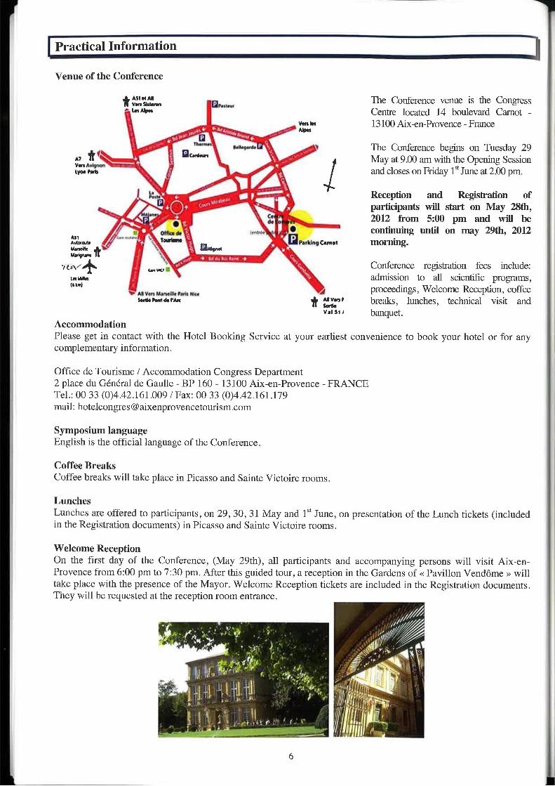
uııuu 'tm 'MW The Conference Venue is the Congress* I-mw« Centre located 14 boulevard Carnot -
vum 13100 Aix-en-Provence - France_ı_,_..„ı› H-›„.,„___ _ ' Nun
rw" P "'" „_'_ P `-._ _ Y The Conference begins on Tuesday 29
May at 9.00 am with the Opening Sessionmw l and closes on Friday 1“ June at 2.00 pm.
_ gm __ Reception aııd Registration ofg kr .Ol participants wiıı starr on May zstiı,
_' . ? 2012 from 5:00 pm and will be/ „Mg Wa. .` _ continuing until on may 29th, 2012
3:3 *` *- ¬'~ mıııı vıfıiwami morning.
1 'OM'›"""' `5\_, „- 4 ı4›:~,ı±.ı.<~ '-LJ _ _ _-,b\./ab uw“ -› =.I_`^ Conference registration fees include.
„..„., - admission to all scientific programs,""'° nmmwmmm 1 proceedings, Welcome Reception, coffee
muımıırm wk 2:6' breaks, lunches, technical visit andVI' SI 1 banquet.
§a
Ҥ1
„MH ~".5,«I//f:\ııt`
\I
1”*furE0'
AcconımodationPlease get in contact with the Hotel Booking Service at your earliest convenience to book your hotel or for anycomplementary information.
Office de Tourisme / Accommodation Congress Department2 place du Général de Gaulle - BP 160 - 13100 Aix-en-Provence - FRANCETel.: 00 33 (0)4.42.161.009 / Fax: 00 33 (0)4.42.161.179mail: [email protected]
Symposium languageEnglish is the official language of the Conference.
Coffee BreaksCoffee breaks will take place in Picasso and Sainte Victoire rooms.
LunchesLunches are offered to participants, on 29, 30, 31 May and 1“ June, on presentation of the Lunch tickets (includedin the Registration documents) in Picasso and Sainte Victoire rooms.
Welcome ReceptionOn the first day of the Conference, (May 29th), all participants and accompanying persons will visit Aix-en-Provence from 6:00 pm to 7:30 pm. After this guided tour, a reception in the Gardens of « Pavillon Vendôme ›› willtake place with the presence of the Mayor. Welcome Reception tickets are included in the Registration documents.They will be requested at the reception room entrance.
6
YEracfical Information N
I _
Venue of the Conference
*"'“' The Conference venue is the Congress‘h...e...... ,,..,_, ‘'InNvII Centre located 14 boulevard (earnot —
v-v-In l 3 I00 Aix-en-Provence — FranceAnnW vi W >~....,______m ‘ ‘__ 0 P ‘~_ v The Conference begins on Tuesday 29
to I" + I“""' '\. May at 9.00 am with the Opening Session1'."..¢L'°“ and closes on Friday l“June at 2.00 pm.
_ bk g Reception and Registration of% participants will start on May 28th,
2012from5:00pmandwillbe_ . AIPVIVOI ‘ _ continuing until on may 29th, 2012
Ex. _,/“""" E _ x Hlnllnnhlndt morning."F" R ni...-..~ ‘L, _ _ _
~,¢,\./4; hm; Z‘ Conference registration fees include:mm, "-= admission to all scientific programs,(IIII - - --4 proceedings, Welcome Reception, coftee
v:-;"~nI-rA-in“ jv 3'" breaks, lunches, technical visit andV" 5" banquet.
4%..,Q Q=\ +\.
AccommodationPlease get in contact with the Hotel Booking Service at your earliest convenience to book your hotel or for anycomplementary information.
Office de Tourisme / Accommodation Congress DepartmentZ place du General de Gaulle - BP 160 - 13100 Aix-en-Provence - FRANCETel.: 00 33 (0)4442>161s009 / Fax: 00 33 (0)4.42.161.179mail: [email protected]
Symposium languageEnglish is the official language of the Conference.
Coffee BreaksCoffee breaks will take place in Picasso and Sainte Vietoire rooms.
LunchesLunches are offered to participants, on 29, 30, 31 May and 1“ June, on presentation of the Lunch tickets (includedin the Registration documents) in Picasso and Sainte Victoire rooms.
Welcome ReceptionOn the first day of the Conference, (May 29th), all participants and accompanying persons Will visit Aix—en-Provence from 6:00 pm to 7:30 pm. After this guided tour, a reception in the Gardens of << Pavillon Vendome » willtake place with the presence of the Mayor. Welcome Reception tickets are included in the Registration documents.They will be requested at the reception room entrance.
6 r
_ SSCSj May 29-June 1, 2012
I
ı
1....
Numerical ModelingSırntnalos lnr Suııiilnrıblıı llnnmle Structures
Aix-en-Provence, France
l
Abstracts
I
1?-
]-__i. C-SSENumerical Modelingsimwuws t|!Sus|»\nn|nn Ennurli Sililillflrs
Aix—en—Pr0\/erice, FianceMay 29—J\me 1. 2012
Abstracts

1*" *_*
SSCSNumerical ModelingSlmln gms für Suulnııı nhlc Corınrnte ¦itnn:1urı::
Aix-en-Provence, FranceMay 29-June 1, 2012
Invited papers
A multiphase concrete model with application to high temperature, structural repair, leaching and Alkali-Silica reactionBA. Schrefler
Multilevel numerical modeling for durability of RC structuresV. Baroghel-Boimy
Cracking of concrete structures: interest and advantages of the probabilistic discrete approachesP. Rossi, J.L. Tailhan
Implementation of a Validation procedure for using numerical models in concrete structure design andassessmentB. Massicotte, M. Ben Ftima, A. Nour, E. Yiliz, D. Conciari
Special Session
A new mock-up for evaluation of the mechanical and leak-tightness behaviour of NPP containmentbuildingE. Galenne, B. Masson
17
1?’ ¢
SSENumerical Modelingsrmriq-i». In Stlllrlllvtlllo Cwirmte Simcvum
Aiken-Provence, FranceMay zeirms 1, 2012
Invited papers
A multiphase concrete model with application to high temperature, structural repair, leaching and Alkali-Silica reactionBA. Schrefler
Multilevel numerical modeling for durability of RC structuresV. Bar0ghel—Buuny
Cracking of concrete structures: interest and advantages of the probabilistic discrete approachesP. Rnsri, J .L. Tailhan
Implementation of a validation procedure for using numerical models in concrete structure design andassessmentB. Masxicotte, M. Ben Ftima, A. Nour, E. Yiliz, D. Conciari
Special Session
A neW mock-up for evaluation of the mechanical and leak-tightness behaviour of NPP containmentbuildingE. Galerme, B. Masson
M
1*
L
A multiphase concrete model withapplication to high temperature, structuralrepair, leaching and Alkali-Silica reaction it-'5-ii-‘$75317-'-W»?-'3'-'§7i'='i3
Aix'en—Pro\/ence. FranceMay 29June 1, 2012
lB.A. Schrefler, F. Pesavento, G. Sciumc, 2D. Gawin
IDip. or Ingegnzria Civile, Edilz,Ambien1ale - Universi/fl) di Padavzi, Italy2DepI. Offluilding Physic: and Building Material: _ mt. University 0/"Lodz. Poland
Abstract
We present a general multi—physics model for concrete, with applications to concrete at hightemperatures, concrete at early age and structural repair work, leaching in concrete and alkali—aggregate reactions, [1—4j. The model includes most of the processes taking place in the pores of themix and their interaction with the solid phase in the above mentioned situations. The mathematicalmodel has been developed by Writing the relevant balance equations for the constituents at the porescale and by upscaling these equations to the macroscopic scale, taking into account thermodynamicconstraints. The final model after introduction of the constitutive equations, consists of a mass balanceequation for dry air, a mass balance equation for the fluid phases (Water and vapour), a mass balanceequation for the solid phase. an energy balance and a linear momentum balance equation for themixture fluids plus solid phase and, when needed, a rnass balance equation for the calcium ions, [1 ~4].The numerical solution of this problem has been greatly enhanced by a new multifrontal parallelsolver. The spccdups obtained will be shown. Also several other aspects will be addressed as shown inthe following.
In the case of concrete at early ages for industrial applications such as stnictural repair work, not allthe aspects included in the reference model are of importance. We present hence also a simplifiedmodel with applications to repair of damaged concrete. In general, examples for all mentioned aspectswill be shown including a fully integrated analysis for fire in tunnel, [4].
References
[I] Modelling of hygro-thermal behaviour of concrete at high temperature with thermochemical andmechanical material degradation, D. Gawin. F. Pesavento, BA. Schrefler. Comput. Methods Appl. Mech.Engrg., l92(13-14), 1731-1771, 2003.
[2] Modelling creep and shrinkage of concrete by means of effective stress, D. Gawin. F. Pesavento, B.A.Schrcflcr, Materials & Structures, 40, 579591, 2007.
/3] Modeling deterioration of cementitious materials exposed to calcium leaching in non-isothermal conditions,D. Gawin, F. Pcsavcnto, B. A. Schreflcr, Comput. Methods Appl. Mech. Engrg., 198, 3051-3083, 2009.
/4] Modelling alkali—silica reaction under non—isothcrmal conditions in partially saturated cementitiousmaterials, B.A. Schrefler, F. Pesavcnto, L. Simoni, D. Gawin, M. Wyr/.ykowski, Mechanics and Physics ofPorous Solids (MPPSZO1l- A tribute to Prof. O. Coussy), 371389, 20] l .
19
Z 1 L J Z i
l Qllng- Multi-level concept and various coupled problems - st...........§........i.A\x—en—PmVenC€, FranceMay 29June 1, 2012
Numerical modelling of RC structure
V. Baroghel-Bonny - M. Thiery — P. Danglal’m'i.\--Est Univmiiy e IFSTTAR - Paris e France
Numerical modelling in the field of durability of RC structures is presented through a multi-level concept.The scope is restricted to the problem of chloride- and carbonation-induced reinforcement corrosion (onlythe initiation phase is considered) and to isothermal conditions. First the needs and purposes in this fieldare reminded. Then, the various levels of sophistication of the physically-based models developed for theprediction of chloride transport or carbonation of cementitious materials are described. Typical examplesof application of the various tools, numerically implemented in the l—D case, are given in the presentation.The numerical results obtained are compared to experimental data, in order to test the reliability and theefficiency of the models.
The IFSTTAR modelling platfonn for chloride transport offers currently three levels of sophistication insaturated conditions and one level in non—saturated conditions: level 1 is a simple chloride diffusionmodel. level 2 is a multi-species transport model, level 3 involves transport-chemistry coupling, whereaslevel 4 is a coupled moisture-ion transport model. In the level-2 model, the ionic transport processinvolves the species Cl', OH, Na‘ and K’, which are the main ions present in the pore solution, and isdescribed by thc Nernsr-Planck equation (electro—difl'usion of ions). The level4 model accounts inaddition for ionic transport by advection of the liquid phase. In this model, moisture transport includesFickian water-vapour relative diffusion and Darcian liquid-phase movement. The ion effect onliquid/vapour Water equilibrium is taken into account by including the chemical activity of liquid waterinto the chemical potential formula. The variations of the transport properties vr. the degree of saturationare described by integral functions or analytical formulas. A Freundlich 's type description can be assumedfor chloride binding at equilibrium as usually done by researchers. While a kinetic equation is addcd inorder to account for the delayed binding of chlorides when their velocity is high with respect to the rate ofthe binding process (case of high-rate advcctive transport).
The selection of the proper level is done in particular according to the purpose of the prediction and to thedegree of complexity acceptable (based in particular on the availability of the input data, etc.) and ofcourse of the actual environmental conditions of the stnicture. Thus, level 2 can be used for the assessmentof some of the required input data, such as effective chloride diffusion coefficient and bindingisothermparameters, by numerical invcrse analysis, or for concentration profile and SL prediction of realstructures, as illustrated in the presentation. Level 4 is rather appropriate for understanding and predictionof complex processes, and in particular for the validation of some assumptions/mechanisms. As anillustration, level-4 simulations of wick action tests and of wetting tests by a salt solution after drying inlab are discussed.
With regard to carbonation, level I corresponds to analytical physical-chemical models, while thecoupling of such simple models with a numerical moisture transport model is included in level 2. Level 3corresponds to numerical physicabchemical models (reactive transport). ln particular, the level-3IFSTTAR model includes CaCO; formation by both Ca(OH)1 and C-S-H, the influence of the kinetics
20
1?
g
related to Ca(OH)2 dissolution, an (ideal) solid solution approach for the progressive C-S-Hdecalcification, and the associated porosity changes. The chemical reactions (which involve the solidcompounds Ca(OH);, C-S-H and CaCO3) are coupled with the transport equations associated withmoisture movement (which occur during drying andlor wetting), gaseous CO; and ionic diffusion.
Examples of application of probabilistic analytical or semi-analytical carbonation models (levels l and 2)are presented for the assessment of the time-dependent reliability index and for SL prediction, as well asfor the selection of the appropriate concrete cover for given target SL and reliability index. One of themain advantages of these probabilistic tools is that uncertainties and variability of the parameters (e.g.material properties and boundary conditions) can properly be taken into account. Moreover, thecapabilities of the level—3 IFSTTAR model are illustrated in the case of accelerated carbonation thoughsimulations of phase mineral assemblages, as well as of profiles of pH, Ca(OH); content and liquid watersaturation profiles.
The further developments needed, in order to improve the prediction of long-term durability, are alsosummarized.
References:[1] Baroghel-Bouny V., Nguyen T.Q., Dangla P., Assessment and Prediction of RC Structure Service Life by Meansof Durability Indicators and Physical/chemical Models, Cem. Cone. Comp., vol. 31 , n” 8, Z009. PP 522-534.[Z] Baroghel-Bouny V., Thiery M., Wang X., Modelling of isothermal coupled moistuleiou transport incementitious materials, Cem. C.0nc. Res, vol. 41, n° 8, 2011, pp 828-841.[3] Thiery M.. Cremona c., Baroghel-Bouny v., Application of the reliability theory to thc assessment ofcarbonation-induced corrosion risk of rebars, Euro. Joumal of Env. 8:. Civil Eng., vol. 16, n° 3-4, 2012, pp 273-287.[4] Morandeau A., Thiéry M., Dangla P., Baroghel-Bouny V., Incorporating an ideal solid solution model for the C-S—H decalcification in a reactive transport modelling of carbonation, in Proc. of Int. Symp. on Concrete Modelling(CONMOD 2010), 23-25 june 2010, Lausanne, Switzerland.[5] Thiery M., Baroghel-Bouny V., Boumeton N., Villain G., Stefani C., Modelling of drying of concrete - Analysisof the different moisture transport modes (in French), Rev. Euro. Gen. Civ. vol. ll, n° 5, 2007, pp 541-577.[6] Baroghel-Bonny V., Mzringuy M., Lassahatere T.. Coussy 0., Characterization and identification of equilibriumand transfer moisture properties for ordinary and highperformance cementitious materials, Cem. C.onc. Res., vol.29,n° s,1999,pp 1225-123:1.
2l
Cracking of concrete structures: interestand advantages of the probabilistic discreteapprgaches !:.iiii::§i§fli,r'i'i3.§i§i.'.'¢i§
Atxen-Provence. FranceMal! 29-June 1. 2012
P. Rossi, J.-L. Tailhan
Uruvrrsité Paris-E.\'t, IFSTTAR, MAT. P375732, Park, France
In the Iield of numerical modelling of cracking of concrete structures, almost all of the approachesadopted and used nationally and internationally fall into two main families of models:
— Models that address explicitly the propagation of one or several (s) crack (s) within the structure,- Models that treat cracks as distributed damage and do not take them into account explicitly.Almost all of these numerical models arc detenninistic and consider concrete as a homogeneous material.Since I985 (the first paper in an international journal was published in 1987), LCPC (newly TFSTTAR)develops another philosophy of modelling for concrete cracking: a probabilistic discrete crackingapproach‘The numerical modellings developed in this frame are based on three innovations:
- Concrete is considered as heterogeneous through a random spatial distribution of mechanical propertiesconsidered as dominant in the cracking process, namely the Young's modulus and the tensile strength;- Scale effects on concrete cracking (experimentally proved) constitutive modelling are proposed: themechanical properties of material depend on the size of the mesh elements adopted for the finite elementanalysis.- Cracking is treated explicitly, through the creation of random kinematic discontinuities, which providesaccess to quantitative information on the state of cracking (cracks number, opening and spacing). Thisknowledge is essential for reliable prediction of the durability of structures and therefore their life span.This is one of the key issues of sustainable development related to this problematic.
In the frame of the modelling strategy developed by Tailhan and Rossi, two scales of analyze of thestructure are taken into account: the global scale that means the scale of the whole structure and the localscale for which only a small part of the structure is concerned.The fact that the developed modellings are related to the discrete cracking implies that they are both ableto provide explicit information about cracks, this at the two scales of analysis concerned.The fact that one calculation corresponds to one random spatial distribution of mechanical properties leadsto the necessity of, for a given problem (given geometry of structure and boundary conditions ...),realizing a great number of calculations in the frame of a Monte Carlo approach.In consequence. the modelling strategy does not provide a deterministic result, but an average oneassociated with a standard deviation which allows a relevant analysis of the structure safety.One of the main social and technical repercussions of this development of physically based numericaltools conccrns the optimization of the concrete quantity used in the structure (and thus to minimize CO2related to cement industry) and the operational safety of these structures (cycle of life analysis).This paper summarizes different applications of the proposed modelling strategy which is related todifferent scales of problems:
- Macrocrack propagation with explicit information on its process zone,- Cracking process around an rebar loaded in tension,~ Cracking in a reinforced concrete structure.
22
¥
IImplementation of a validation procedurefor usin numerical models in concretegstructure design and assessment
Aixer\—Prover\ce, FranceMay 29-June 1, 2012
B. Massicotte, M. Ben Ftima, A, Nour, E. Yildiz, D. Conciatori
Ecole Palytechniquc de Montréal, Montréal, Canada
Abstract
For decades engineering processes have used numerical models for developing new industrialproducts. Increasing computational capabilities and confidence gained through years of experiencehave allowed remarkable innovations while maintaining or increasing reliability and performance.Such an approach is not common in the field of structural engineering. Several reasons can explain. oreven justify, this reality. The uniqueness of many constructions often cannot justify optimising thedesign using sophisticated models. Moreover design codes limit or even prohibit initiatives towardinnovation, justified with the noble principle of protecting public safety. Current practice is generallybased on simplified design methods and specifications derived from laboratory tests carried on simplestructural elements, often of small scale compared to the actual stnicture. They are supported byreasonable, though conservative. assumptions, and validated by years of satisfactory performance.Moreover, numerical models and computational capabilities have not been accessible for concretestructures until recently. Nonlinear finite element modelling has been limited to the academic world orfor the design of exceptional and rare structures.
Since approximately the Year 2000, the availability of commercial software with sophisticatedconcrete models has given new opportunities. Nonlinear finite clement analysis (NLFEA) is nowaccessible for determining concrete structures behaviour beyond the linear condition. Although mostdesign and structural assessments will be carried out using traditional approaches, it is most likely thatthe availability of refined and powerful models, combined with the training acquired by engineers intheir graduate degrees, will make more attractive the use of NLI-‘EA. However, there is little if anyguidance for using NLFEA in structural calculations. There is also a need for providing proceduresaimed at guiding engineers for validating, and correctly using NLFEA software.
The paper presents a validation procedure that can be adopted for the safe use of NLFEA in thecontext of structural design and strength assessment. The objective of the paper is to propose aphilosophy that could he adopted by agencies or large structure owners, and be eventually introducedin design codes. The aspects of quality control and benchmark test selections are discussed. The paperconcludes with an invitation to die expens in the field of structural modelling to join their effort in acollaborative project aimed at setting up the scientific background for developing a validationprocedure for using numerical models in concrete structure design and assessment.
Kcywordr: nonlinear analysis, finite element, reinforced concrete, benchmark tests, validationProcedures.
23
I j i M M
A new mock-up for evaluation of themechanical and leak-tightness behaviour ofNPP containment building
Aixen-Provence, FranceMay 29-June 1, 2012
E. Galenne, B. Masson
EDF R&D, Clumnrt, France / EDF SEPTEN, Lyon, Frrmce
The passive leak-tightness function of the French I300~I450 MWe NPP reactors is provided by areinforced and pre—stress concrete inner wall without steel liner, an outer reinforced wall assuring theprotection against extemal effects. The leak through the intemal wall is collected in the annular spacebeing permanently maintained slightly below atmospheric pressure.The technical objective, in term of leak-tightness, is to maintain the rate of gas escape under a legalcriterion. The compliance with the rule is evaluated by measuring the quantity of air leak, obtainedduring a periodical pressure test at ambient temperature.
Numerical models are up to now not sufficiently mature and accurate to predict the evolution of theleakage rate during these pressure tests, nor during standard design-basis accidents. ln the frame of thecontinuous effort on safety and in the perspective of NPP life extension, the project of building areduced scale containment mock-up is then studied by EDF. The main ambitions are the following:
- to demonstrate in an indisputable way the good behaviour of inner wall in situation ofsevere accident (high pressure and high temperature during two weeks);
> to have a better comprehension of the leakage and its evolution with the ageing of thestructure. The ageing of the mock-up will be accelerated by the scale effects (reducedthickness, faster drying, faster shrinkage) ;
~ to collect experimental data necessary for the development and validation of numericalmodels.
This project is complementary to other experiments conducted or funded by EDF these last years :cylindral concrete specimens under damaging compression loading ll], cracked wall [2] (3 x 2 x l mreinforced concrete wall), MAEVA mock—up [3] (containment cylinder at 1:3 scale),At the difference of this last case , we planned to integrate in the new mock-up all complexities of thecontainment stmcture : base raft, gusset, penetrations, access hatch, dome, grouted prestressingtendons, The scale will probably be 1:3.The conception phase of the mock-up has just began, the construction being planed in 2013. The mainconception choices will be presented and discussed during the conference.
References[I] Damaged concrete wall and leak rate under simulated conditions, A. Lagcha. G. Debicki, B. Masson,
SMiRTl8.200S[2] Nonlinear tluid—stn|eture interaction calculation of the leakage behaviour of cracked concrete walls, C.
Niklasch, N. I-lerrmann, Nuclear Engineering and Design 239 (2009) l628—l640[3I Mechanical and leaktightness behaviour of a containment mock-up under severe accident, L. Granger, P.
Labbé. SMiRTl4, 1997
24
f
o
FIE:B| MHll-WM! L'nn3e$=?i{::'¥vencfi, Franceune 1. 2012
s
:_d by amg theF Space
I legal
""'"=d Sessions I:‘f thef the"8
\ of
‘heed
al
1
¥
Numerical lvlodollngSlvnlegws llviuxuwahle mm 5\mLIm:5Aix—errProvence. France
May 2£Hune 1, 2012
Q Theoretical and Numerical Models
1*
SSENumerical ModelingSlvalzrnn |IfSlA!\I\r\ahl! Eflflflli! §\NC'lliE\
A\X—en—P|0ver\Ce, FranceMay 29—June 1, 2012
Session I-1:Fl0wing and CastingExperimental and Numerical Techniques to Characterize Structural Prnpenies of Fresh ConcreteTony Di CarloUniversity UfSU!lfh€77| Callfflrllia, Daniel]. E])Sll?i!l Deparlrrwnt iifiiidimiiiii and Syxtz/mx zinginwiiig
Optimizing lhe casting of High Performance Concrete structural elements via Compulaflonal Fluid DynamicsModelling of fresh concrete behaviourLiberate Ferrara, Massimiliano Cremonesi and Alessio CavemanDeparzment ofStructural Engineering, Polilecnico di Milano, Italy
A numerical approach to analyze the particulate flow in concrete pumping circuitChoi, Myoung Sung *, Kim, Young Jin. Jeon, Se Iin, Kim, Yong JicCivil Engineering Research Team, Daewofl lrlslilule 0fCon.\'truczi/m Technology, South Korea
Application of the fluid dynamics mode] to the field of fibre reinforced self-compaciing concrete0. Svec‘, H. slang‘, J. F. Olesen' , L. N. Thrunez' Technizral Uni!/er.\'l'ty 0fI)EVlm(1!/C, Deparlmerlt nfClvilEhgineer1'ng, Z Danish Téfhrll/'ltIgiL‘fll Inxlilult
p 27
é
j i Z
Experimental and Numerical Techniques tocharacterize Structural Properties of Freshconcrete
Alx-en-Provence, FranceMB)’ 29~June 1, 2012
Tony Di Carlo, PhD candidatez/iiivmiry 17fSfIl4Ih¢I‘Vt ciittfamiiiDaniel J . Epstein Department of Industrial and Systems Engineering
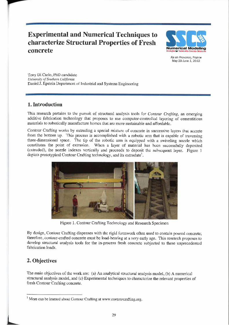
1. IntroductionThis research pertains to the pursuit of structural analysis tools for Contour Crafiing, an emergingadditive fabrication technology that proposes to use computercontrolled layering of cementitiousmaterials to mbotically manufacture homes that are more sustainable and affordable,
Contour Crafting works by extruding a special mixture of concrete in successive layers that accretcfrom the bottom up. This process is accomplished with a robotic arm that is capable of traversingthree—dimensiona.l space. The tip of the robotic arm is equipped with a swiveling nozzle whichconstitutes the point of extnision. When a layer of material has been successfully deposited(extruded), the nozzle indexes vertically and proceeds to deposit the subsequent laycr. Figure ldepicts prototypical Contour Crafting technology, and its extmdatel.
Figure l. Contour Crafting Technology and Research Specimen
By design, Contour Crafting dispenses with the rigid formwork oft/en used to contain poured concrete;therefore, contourcrafted concrete must be load-bearing at a very early age. This research proposes todevelop structural analysis tools for the in-process fresh concrete subjected to these unprecedentedfabrication loads.
2. Objectives
The main objectives of the work are: (a) An analytical structural analysis model, (b) A numericalstmctural analysis model, and (c) Experimental techniques to characterize the relevant properties offresh Contour Crafting concrete.
' More can be learned about Contour Crafting at www.c0ntourcrafting.org.
29
2.1. Analytical Model
The analytical model will couple geometry, density, green strength, and strength—gain relations torelate material stress to material strength, i.n the fresh extmdate, and thus ascertain the conditionsnecessary for safe Contour Crafting concreting of simple monolithic stnictures.
2.2. Numerical Model
The numerical (finite element) model will be developed to evaluate and compare alternativefabrication strategies. This numerical model can be easily implemented with commercially availablefinite element analysis (FEA) programs, like ABAQUS, using Drucker—Prager (DP) plasticity, whichFamiglietti (Famiglietti, et. al. 1994) and others have demonstrated to be adequate in a constitutivemodel for fresh concrete. This numerical structural analysis model can be useful before constructionbegins, to evaluate and compare alternative fabrication strategies, and during construction, as amaterial health monitoring system. As a material health monitoring system the numerical model runsin real time (synchronously) accounting for non~isothermal curing and material strength development(maturity).
2.3. Experimental Techniques
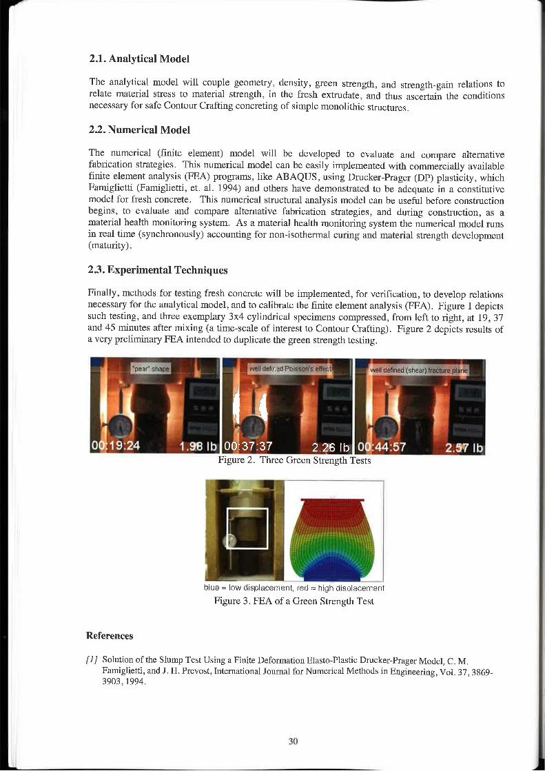
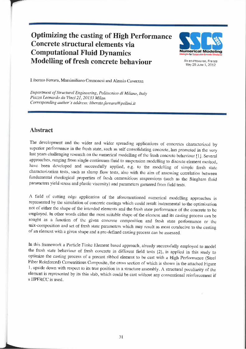
Finally, methods for testing fresh concrete will be implemented, for verification, to develop relationsnecessary for the analytical model, and to calibrate the finite element analysis (PEA). Figure 1 depictssuch testing, and three exemplary 3x4 cylindrical specimens compressed, from left to right, at 19, 37and 45 minutes after mixing (a timc—scale of interest to Contour Crafting). Figure 2 depicts results ofa very preliminary FEA intended to duplicate the green strength testing.
blue = low displacement, red = high displacementFigure 3. PEA of a Green Strength Test
References
[I] Solution of the Slump Test Using a Finite Deformation Elast0—Plastic Drucker-Pmger Model, C. M.Fainiglietti, and J. H. Prevost, International Journal for Numerical Methods in Engineering, Vol. 37. 3869-3903 , 1994.
30
Optimizing the casting of High PerformanceConcrete structural elements viaComputational Fluid DynamicsModelling of fresh concrete behaviour "l;1j,*,"§,§fjL‘;".°‘§jZ',§‘f;‘*
Liberato Ferrara, Massimiliano Cremoncsi and Alessio Caverzan
Depflrtmenf ofStructural Engineering, Politecnica di Milano, ItalyPiazza Leonardo da Vinci 21, 20133 MilanCorresponding author ’,r address: libemmferrum@p0limr'.it
Abstract
The development and the wider and wider spreading applications of concretes characterized bysuperior performance in the fresh statc, such as self consolidating concrete, has promoted in the vcrylast years challenging research on the numerical modelling of the fresh concrete behaviour [1]. Severalapproaches, ranging from single continuum fluid to suspension modelling to discrete element method,have been developed and successfully applied, e.g. to the modelling of simple fresh Statecharacterization tests, such as slump flow tests, also with the aim of assessing correlation betweenfundamental rheological properties of fresh cementitious suspensions (such as the Bingham fluidparameters yield stress and plastic viscosity) and parameters garnered from field tests.
A field of cutting edge application of the aforementioned numerical modelling approaches isrepresented by the simulation of concrete castings which could result instrumental to the optimiuitionnot of either the shape of the intended elements and the fresh state performance of the concrete to beemployed. ln other words either the most suitable shape of the element and its casting process can besought as a function of the given concrete composition and fresh state performance or themix-composition and set of fresh state parameters which may result as most conducive to the castingof an element with a given shape and a predefined casting process can be assessed.
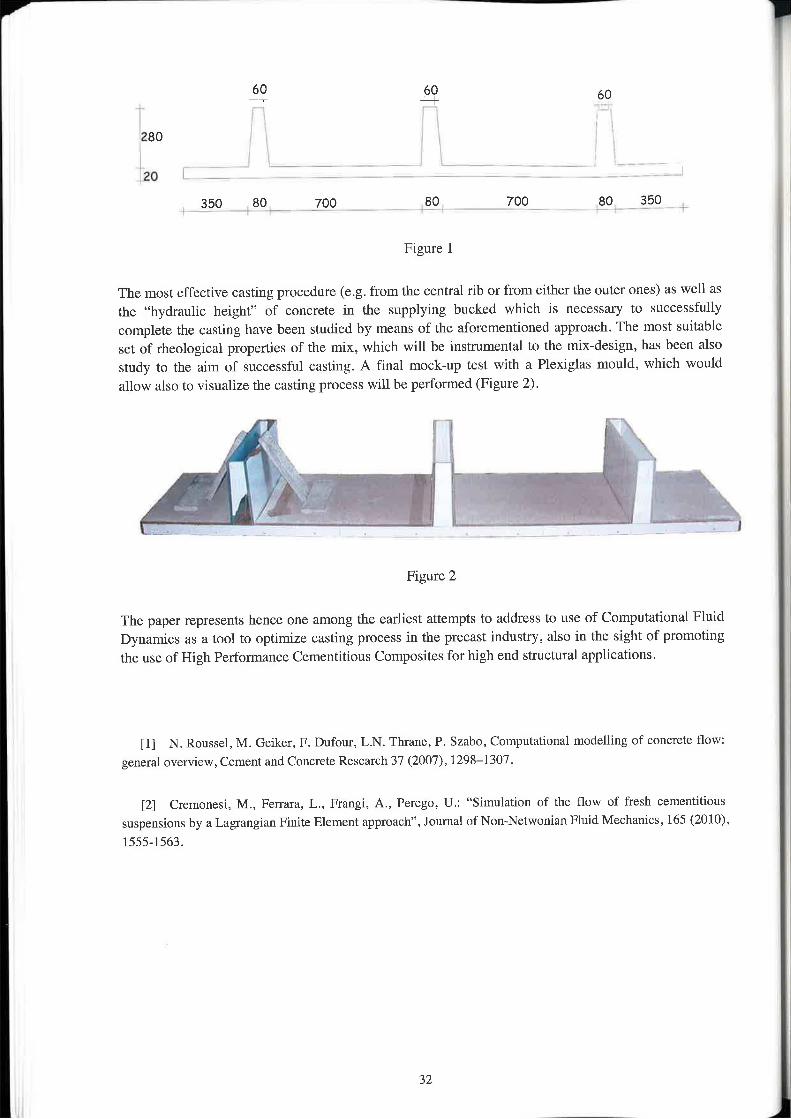
In this framework a Particle Finite Element based approach, already successfully employed to modelthe fresh state behaviour of fresh concrete in different field tests [2], is applied in this study tooptimize the casting process of a precast ribbed element to be cast with a High Performance (SteelFiber Reinforced) Cementitious Composite, the cross section of which is shown in the attached Figure1, upside down with respect to its true position in a structure assembly. A structural peculiarity of theelement is represented by its thin slab, which could be cast without any conventional reinforcement ifa HPFRCC is used.
3l
M
_ $3 jg} so
280 ‘ t .
.20 l 7 7 7 7 7 7 7 7 7 _ _ __
Q50 W507 _7OO _ i ‘Q0 J00i §0_ii§5Q i__
Figmre l
The most effective casting procedure (e.g. from the central rib or from either the outer ones) as well asthe “hydraulic height” of concrete in the supplying bucked which is necessary to successfullycomplete the casting have been studied by means of the aforementioned approach. The most suitableset of rheological properties of the mix, which will be instrumental to the mix-design, has been alsostudy to the aim of successful casting. A final mock-up test with a Plexiglas mould, which wouldallow also to visualize the casting process will be performed (Figure 2).
t F .1;” *. >
V "1 ‘;\ —. v 1 tL, Vt}_<—_- _
Figure 2
The paper represents hence one among the earliest attempts to address to use of Computational FluidDynamics as st tool to optimize casting process in the precast industry, also in the sight of promotingthe use of High Perfomrance Cementitious Composites for high end Structural applications.
[l] N4 Rousscl, M. Geiker, F. Dufour, LN. Thrane. P. Szahn, Computational modelling of concrete flow:general overview, Cement and Concrete Research 37 (2007). 1298-1307.
[2] Cremonesi. M4, Ferrara, L._ Frangi, A., Perego, U.: “Simulation of the flow of fresh cementitioussuspensions by a Lagrangian Finite Element approach", Journal of Non~Netwonian Fluid Mechanics, 165 (2010)1555-1563.
32
Q
A numerical approach to analyze theparticulate flow in concrete pumping circuit
Numerical ModelingSblllrglal m stnmni L'flHLVu\E §t|||Llm(§
Aix'en—Provence. FranceMay 29—Jtme 1, 2012
Choi, Myoung Sung*, Kim, Young Jin, Jeon, Se Jin. Kim, Yong Jic
Civil Engineering Research Team, Daewoo Institute 0fC0nstrMI:!i0n Technology, South Karen
Abstract
Pumping is a commonly used method to cast concrete, especially to build high rise building and highrise pylon structures without the use of any bucket or conveying belt system. To come up with thistendency, a large number of experimental studies about the concrete flow using pumping circuit havebeen published. But most experimental studies up to date only aimed to evaluate the pumpingperformance of the finally derived mixing design, S0 even though it cost a tremendous amount, thetest results were only used as a one-time experimental data before really casting to build structures.
So as a part of the establishing the standardized test methods of pumping circuit, a 170 m~longexperimental pumping circuit was designed and installed. Before the actual experiments, I simulatedvarious parameters such as the concrete flow characteristics under concrete rheology, aggregatevolume fraction and pumping pressure using computational fluid dynamics (CFD) simulation method.
Among them, in this paper we would like to discuss the pumping concrctc flow performance regardingthe aggregate volume fraction and the resulting characteristics of the formation of lubricatingboundary layer. Through the CFD analysis results, depending on the aggregate volume fractionformation of lubricating boundary layer is determined and directly affecting the pumping concreteflow characteristics.
For the validation of analysis results, l also compared with experimental rcsults.
33
Application of the fluid dynamics model tothe field of fibre reinforced self-compactingconcrete §i‘.ffS$TI$filt.“§.fifi3.'§.'J%
Aix-en—Pr0veneei FranceMay 29—June 1, 2012
0. Svcc', n. Stang',.|. F. Olesenl,L. N. Thranez1 Technical University‘ 0fD2rtm11Yk, Department of Civil Engineering, {0I.rv, hs, j}'0)@byg.d.'u at2 Danish Technological Institute, lmh@teI<n0Iogisk.dk
Abstract
Ability to properly simulate a form filling process of the fibre reinforced self-compacting concrete is achallenging task. Such simulations may clarify an evolution of fibre orientation and distribution which inturn significantly influences final mechanical properties of the casted elements. Such a codc has bccndeveloped and is shortly introduced in the presented paper. An implicit representation of aggregates issuggested to speed up the computational time. The main focus of the paper is towards validation of theability of the code to properly mimic the fibre reinforced self-compacting concrete. In order to do that,several experimental parametric studies were carried on. One of them was a parametric study of differentslump tests. The resulting “spread versus time” curves were afterwards compared to the curves comingfrom the simulation, which helped to validate the computational code.
34
F
l
I1
t!Q5'."'Fh§:l=n>
é
L
SSlI§Numerical Modelingsmttata srtlmrtt lluncvzlcilluuluvrsA|x—en—Provence, FranceMay 29—June 1, 2012
Session I-2:Early age behavioursNumerical Modcl for Quantifying Degree of Hydration in Concrete Mixes with Rcduccd CO; FootprintA. Attari, C. McNally, M. RichardsonSchrml 0fArchilecture, Land rcapc and Civil Engineering, University College, Dublin, Ireland
Use of original percolation approach in homogenization methods for the prediction of concrete hydromechanicalbehavior at early ageL. Buffo-Lacarriere, A. Sellier, P, SouyrisUniversité de Toulouse; UPS, INSA; LMDC, Toulouse, France
Monitoring of the creep and the relaxation behavior of concrete since setting tilne. part 1: compressionClaude Boulay', Michela Crespini', Stephanie Staquetz, Brice Delsautez, Jerome Carette*2' IFSTTAR, Paris, France ,~ 1 Ur1iVBl’.rl'l€ Libre die Bruxeller, BelgiumMonitoring of the creep and the relaxation behavior of concrete since setting timc, part 2: tensionBrice Dclsaute‘. Jerome Carettel, Stéphanic Staquet'. Claude Boulayi, Michcla Crespinil' Univerrilé Libra at Brwrelles, Belgium," 2 IFSTI‘/ilt’, Paris, FranceUsing GGBFS to reduce concrete crack control rcinforcement under early-age thermal actionKangkang Tang‘ ,Steve Millard‘ . and Greg BcatticlIDepartment qfC|'vt'l Engineering, Xi'an Ji(ll1t(1ng—LiVerp(I0l Universilyliangxu, China, 2/irup, Liverpool, UK
Load Calculation Modcl during Construction of Mult.i—story Concrete StructuresToshihiko YamamotoProfessor, Department ofArchiteciure - Daido University, Nagoya, Aichi, Japan
“Time—dependent Deformation" of RC Strut in Retaining ExcavationYang, Yaoning', Yuan, Yong‘ , Zhu, Yiminz1Dcp|1rtmenI of Geotechnical Engineering, Tongji University, Shanghai, China {Shanghai No.1 ConstmctioC0,,Lld, Shanghai, China
35
n
Numerical Model for Quantifying Degree ofHydration in Concrete Mixes with ReducedC02 Footprint
Aix-en-Provence. FranceMay 29-June 1. 2011
A. Attari, C. McNally, M. Richardson
School 0fArchirec!ure, Land scape and Civil Engineering.University College Dublin, Ireland
Abstract
The cement industry is estimated to be responsible for about 7% of the carbon dioxidegenerated globally. As such, reducing the amount of CO2 emitted during cement production isa key issue if the construction industry is to participate in sustainable development. Under thetemis of the Kyoto Protocol Emissions Trading Scheme it is also potentially profitable forcement companies to reduce their CO; emissions. By using blended cement instead ofordinary Portland cement, it is possible to lower the share of clinker in cement, resulting inreduced CO; and energy emissions. In Ireland, CEM II now accounts for over 80% of theIrish cement production portfolio.
GGBS is a by-product of steel industry and a common replacement for cement. Whencompared to Portland cement it has a reduced CO2 footprint and concretes containing GGBSare less prone to deterioration due to aggressive chemical attacks. Its use has the potential toproduce more durable concrete with increased service life, lower maintenance costs and alower carbon footprint, increasing the sustainability of concrete construction.
The widespread application of altemative materials raises the need for more comprehensiveinvestigation of the resulting concrete properties. Early age behaviour is a major factor to beaddressed, and tools are required for quantifying the hydration state of concrete members,particularly at early-ages. Numerical models can potentially be used in mass concreteconstruction to predict and prevent possible thermal crack formation. They also provide anindirect means for characterizing development of the hydration reaction in concrete. The lattercan then be utilised in modelling and predicting secondary concrete properties, such asdiffusion coefficient.
The aim of the current study is to use this approach to quantify the development of heat ofhydration when mixtures of CEM II and GGBS are utilised. Experiments were conductedwhere the temperature profiles in 4 different mixes of concrete (CEM II with 0%, 30%. 50%and 70% GGBS) are recorded. This Was achieved by casting 6 identical concrete samplesfrom each mix, with thermocouples embedded to record the intemal temperature of the mix atregular time steps. Temperature changes of the mix are then used to quantify the heat evolved,based on the principles of heat transfer. To account for the combined effect of time and
3'7

temperature on hydration development, activation energy of the mix is used, 31011.‘; with lheequivalent age maturity method. Total heat of hydration is determined based on thecomposition and amount of cementitious materials.
It has long been accepted that the liberated heat of hydration, divided by the total availableheat of hydration is a good measure of H16 degree of hydration. The experimental datadescribing hydration development with equivalent age are then used to calibrate theexponential formulation presenting the S—shaped hydration curve. Values of [3, ‘II. and rL.. (thehydration parameters) are obtained for each mix, from the results of multivariate non-linearregression analysis. Comments on the use of this method in quantifying concrete hydrationare then made.
38
f
Use of original percolation approach inhomogenization methods for the predictionof concrete hydro-mechanical behavior at
I MK-en»Provence, Franceea!‘ Y age May 29-June 1, 2012
L. Buffolacarricre, A. Sellier, P. Souyris
L/nivzniilé de Tuulnuse; UPS, INSA; uwoc (laimraloire Marérinux er Dumbiliti 11e.\' L'urt\'trm:Iirin:),' 135, avenue 11¢ RM!LgML'ii,'51 077 Toirlr/use Cedex 04; Front‘?
Thanks to recent progress in experimental setups. micromechanical elastic properties of cementcomponents can be estimate by nanoindentation. Moreover, hydration models are able to predict theevolution of volume fractions of different phases during cement hydration. So, the use ofhomogenisation methods may predict the evolution of properties of cement materials in the early agehydration. As seen in previous works ([1,2]), the use of these methods for concrete is usually dividedin three successive steps. First, the paste properties are predicted using a seltlconsistent scheme whichis more adapted to overlapped microstructure of numerous hydrates. Then the Mori-Tanaka issuccessively used to predict the mortar ones, using the calculated paste properties and experimentalsand properties, and so on for concrete.These methods well reproduce the elastic properties of mature concrete, but at early age, theprogressive passage from viscous material to solid (percolation threshold) cannot be reproduced for allconcrete compositions and especially for paste with W/C ratio lower than 0.5. Indeed, as selfconsistent scheme implies a percolation threshold as soon as solid fraction is begins greater than 50%of the REV, it can not correctly represent the material behaviour at the early age. In fact, this methodforecasts an excessive stiffness at early age. The main objective of the present work is to solve thisproblem by proposing a relation giving the fraction of percolated hydrates from the composition of thecement material without using percolation algorithms, and Without neglecting the bulk modulusexistence for the non percolated part of the material. contrary to the approach proposed in ([3, 4]).Inthis study, we use a relation based on basic probability considerations to find the percolation fractionof the cement paste. Furthermore, we don’t ignore the uirpcrcolated phases but replace it by one withan insignificant shear modulus. This method enables to calculate a realistic bulk modulus at the earlyage, and this bulk modulus can be then used to estimate the Biot coefficient in the paste, even duringthe first hours after casting.The results of the model are compared with experimental data from literature for cement paste and anoriginal experimental campaign. This campaign allows to confront each level of homogenisation withexperimental results; On purpose, cement paste, mortar and concrete were casted with a same W/Cratio, the mortar have the same fraction of paste and sand as the concrete fraction without largeaggregate. Concerning the hydro-mechanical behaviour of concrete at early age, model predictions arecompared with the experimental measures obtained in an autogeneous shrinkage test performed fromcasting to l month.
Referencesii] Bernard O, Ulm F»I, Lemarchand E, A multiscale micromechanics-hydration model for the early—age elasticproperties of cement»bascd materials, Cement and Concrete Research 33 (2003) 12934 309.
[2] I-lacckcr C—I, Garboczi EJ. Bullarda IW, Bohn RB, Sun Z, Shah SP. et al., Modeling the linear elasticproperties of Fenland cement paste, Cement and Concrete Research 35 (Z005) I948-1960.
[3] Tnrrcnti JM, Beuboudjema F, Mechanical threshold of cementitious materials at early age, Materials andStructures 38 (2005)
[4] Stefan L, Benboudjema F, Torrenti JM, Bissonncttc B, Prediction of elastic properties of cement pastes atearly ages. Compumtional Materials Science 47 (2010) 7'/5—784.
39
Monitoring of the creep and the relaxationbehavior of concrete since settin time
. . g , Numerical Modelingpart 1, c0mpfQ§§|Qn_ §s,t.,,..»¢§t§t.,mr=t,.,=t.Wii,..A|x’en—Pmvence, France
May 29—June 1. 2012
Claude Boulayi, Michela Crcspini' , Stéphanic Staquctz, Brice Dclsaute2,Jerome Carctt0*21 Inslitut Fran/yais tier Sciences el Technologies ties Trnrupor/r, 42 l'Arrt<‘nctgemen! Pl dc: Rsireawc, DépartementMatériuux, 58 rm Lefébvre, 75732, Paris Cedex 15, France, e~mail: Ctttudz.b‘[email protected] Université Libre de Eruxzllzs (ULB), B/lTir Department, CP194/4, A. Buy! Avenue 87, I050 Hmxelles, Belgiume-mail.‘ [email protected] be, brice.del.mute@ulb A6178, :stuquet@uIb1zc,bc
Abstract
Early age deformations of concrete are involved in cracking which can lead to service life reduction. Inparticular, the development of the concrete shrinkage under restrained conditions often leads to durabilityproblems in concrete structures.
This study (part l& 2) presents an experimental methodology using two different test rigs enabling amonitoring of the stiffness, the creep or the relaxation of a concrete sample at early age. Tension testsrealized on the Tempemture Stress Testing Machine [1] (TSTM) are presented in a second part whilecompressive tests, realized on another test rig called BTIASPE [2], are presented in the first one. ln eachpart, models are used for the description of the experimental set of data. Results in compression and intension are compared in the second part.Since, in case of restrained conditions, the concrete is mainly submitted to tensions at early age, thepurpose of this study is to answer to the question of the equivalence between the early age creep andrelaxation behavior of concrete in tension and in compression for a typical reference ordinary concrete.
BTJASPE is a test rig which enable early age compressive test on cylinders. Samples are cast inside astainless steel mold (sealed conditions) around which a flow of water allows the control of the sampletemperature. The Young‘s modulus, the creep or the relaxation of the sample can be monitored at earlyage. Cyclic loadings arc applied at regular intervals. ln each cycle, a loading, controlled in displacement isapplied, then the stress or the strain are kept constant during a short period and the sample is unloaded to azero stress until the next cycle,
Rheological functions are used to model the observations performed in compression. Results areexpressed, after the setting time, in function of the maturity. This time is determined both with ultrasonicmeasurements and the monitoring of the stiffness with the cyclic loading protocol. Parameters of the creepmodel are used as input for relaxation model Whose response is compared to experimental results.
References:[1]. Darquennes Aveline, Slaquct Stephanie, Delplancke-Oglctrcc Ma|'ic—Pau|c, Espion Bernard, Effect ofautogeuous deformation on the cracking risk of slag cement coucrctcs, Ccmcnt and Concrctc Composites,Volume 33, Issue 3, March 201 I , Pages 368-379.[2]. Boulay C., Merliot E., Staquct S., Marzouk 0., Monitoring of the concrete setting with an automatic method,13th International Conference Stnictural Faults & Repair — 2010, Edinburgh, 15-17/6/2010, Proceedings CDROM (M. FORDE, editor), Engineering Technics Press, Edinburgh, U.K., I 1 ppi, ISBN O—947644—67-9. (Bookof Abstracts: ISBN O-947644-664); p.98),
40
?
Monitoring of the creep and the relaxationbehavior of concrete since setting time,part 2: tension.
Aixen—Provenee, FranceMay 29-June 1, 2012
I1». i, \ 2Brice Delsaute ,Jerome Carette , Stephanie Staquet , Claude Boulay ,Michela CrespinizI Universiti Libra dc Bruxcllcnr (ULB), BAH! Department, CP194/4, A. Buy] Avenue 87, 1050 Hruxr/lIe.\, Belgium6-mL'lil.‘j€[email protected]¢‘,b£, bric‘[email protected], s:[email protected] Ins-titm Franpais des Sciences at Technologies des Transports, de l‘./tvrlénagement er der Remit», DépartementMatériaux, 58 Ed Lefébvre, 75732. Pm: Cedzx 15. France, 2-mail: Claude.Boulay@if:rtarfr
Abstract
In the first part of this paper (see abstract part l), the compressive behavior (stiffness and creep orrelaxation) of a sample is observed and modeled. In the second part of the paper, an experimentalmethodology using a test rig (Temperature Stress Testing Machine) specifically designed to measure theevolution of several parameters, such as the elastic deformation, the creep and the relaxation of concrete ispresented [1]. In the framework of this study, the TSTM equipment was associated with a mould and athermal regulation and displacement measurement without contact systems. The TSTM consists of anelectromechanical testing setup, where one end of the specimen is restrained by a steel anchorage and thedisplacement of the other end is controlled by a motor moving the other steel anchorage.
First, the setting time t0 is detemtined through ultrasonic measurements with P and S waves. Then,automatic loadings or displacements are applied at regular intervals on the studied sample in tension andin compression. The evolution of the elastic modulus is detennined. The TSTM device finally allows thevery accurate monitoring of the early age deformations and stresses Within a concrete sample, in order todetermine its creep and relaxation behavior. Traction and compression tests are compared, as well asrestrained shrinkage experiments in sealed conditions. This second part of this study presents acomparison of two methods used for modeling basic creep and relaxation coefficient of concrete at veryearly age (since setting time) in tension and compression. Maxwell Chain (relaxation) or Kelvin—Voigt(Creep) are used for this purpose, All results are expressed, as proposed by De Schutter [2], in function ofthe degree of hydration.
This field of research has already been investigated for the creep, especially in compression and severalmodels have already been proposed [2]. For the behavior of concrete at early age in tension, especially incase of relaxation, it is completely different. The purpose of this study is to answer to the question of therelevance of using the same modeling approach or not for all these phenomena occurring at early age(creep/relaxation in tension and in compression). Indeed, in case of a full restraint shrinkage test, all thesephenomena have to be modeled accurately.
References:il]. Darquennes Aveline, Staquct Stephanie, Dclplanckc—Ogletree Marie-Paule, Espion Bernard, Effect offlutogenous deformation on the cracking risk of slag ccmcnt concretes, Cement and Concrete Composites.Volume 33,l5s\1e 3, March 20] l , Pages 368379.[2]. De Schutter, Geert. Applicability of degree of hydration concept and maturity method for thermoviscoelasticbehaviour at early age concrete. Cement and Concrete Composites. Volume 26, Issue S, July 2004, pages437-443.
41
I
i
Using GGBFS to reduce concrete crackcontrol reinforcement under early-agethermal acfign §\..'.'.f;'il§§'.§l§-§.‘.’.l=.'¥l.3$§l.'1'.ll.*.'.
Aix-en—Prover\ce, FranceMay 29-June 1. 2012
Kangkang Tang’ ", Steve Millard" h and Greg Beattiem
'DepmtmenI of Civil Engineering, Xi'an Jiaotong-Liverpool University, 111 Ken Ai Road, om“ lake Higher Education Town,Suzhou Irudmtrial Park, Suzhou, Jiangsu 215122, China2 Amp, 12m Floor, the Plaza, 100 01-1 111111 Streex, Liverpool, Li ‘IQJ ux"hang/wVlg.Iarlg@Xj!lu .3411 .m, ”[email protected].¢n, ‘ M-,q,n1»~1/r1'<'v,1,1,,,..-ml
l _ — — — - —
Abstract
()ver 160 million tonnes of blast furnace slag is generated in China annually, of which only 55% is recycled.Blast fumace slag, ground to an appropriate fineness, can he used as a cementitious material in concrete.However. most ground granulated blast furnace slag (GGBFS) in China ends up in low-grade applications,including ‘Low heat’ cementitious material used in low-grade bulk concrete and cementitious material inmortar.
A recently started project at XJTLU aims to contribute to the application of GGBFS in long-span concretestructures in China by avoiding/reducing the use of more expensive crack control reinforcement. This paperreports on the methodology which will be adopted to carry out this project. Special considerations are paid onissues associated with concrete early~age thermal contractions. Modelling of a case study commercial buildingin Shanghai is used to compare the cost effectiveness of conventional crack control steel reinforcement withthe mitigation of thermal crack stresses using GGBFS. This includes the use of finite element modelling toinvestigate the development of heat during the cement hydration process and the resulting thermal strainsproduced in the concrete.
Keywords: Thermal Cracking, blast furnace slag, cement hydration, crack control steel.
42
Load calculation model during constructionof multi-story concrete Structures
Atx-en-Provence, FranceMay 29-June 1, 2012
Toshihiko Yamamoto
P/-ofmw, Department 0/Architecture, Dtlidu Urtivcrsity, Nagoya, Aichi, Jajmrt
Abstract
Field researches on the construction loads on supporting floors have been performed in recent decadeswith results indicating that the constniction loads may exceed the design loads before reaching theirspecific concrete strength. Therefore, it is important to prevent the structural damage such as cracking,excessive deflection and yielding of stnietural members caused by the construction loads. This damageremains after construction and affects the building’s lifetime serviceability. To prevent the initialdamage of concrete during construction, it is necessary to properly calculate the loads duringconstruction. Most of the conventional load calculation models during construction, because they arelinear elastic, cannot handle the nonlinearity of concrete such as creep, shrinkage and temperatureeffects. This paper presents a nonlinear load calculation model during construction of multi-storyconcrete structures. In the current fomiwork for multi-story reinforced concrete buildings, a freshlyplaced floor is shored by several of the previously cast floors below. The proposed model takes intoaccount the following effects, creep, shrinkage and temperature. The calculated results of the loadsduring construction indicate that the construction loads are inevitably heavy and the creepdeformations arc not negligible. The strength and Young’s modulus of the concrete and the rigidity ofshores affect the load distributions, and temperature changes directly affect the construction loads.Comparison with the measured data, the proposed model is found to express very well the actualsituation of construction loads. lt is possible to calculate the details of each construction phase of thcconstruction load by this model. Monte Carlo simulations were also conducted to evaluate thecoefficient of variation of load and deformation using this model. The coefficients of variation are lessthan 10% for construction loads and about 20% for creep deflections during constniction.
43
“Time-dependent Deformation” of RC Strutin Retaining Excavation
Numerical Modelingsmtm llr Suilairlahle Cullurlz swim
Atx—en—Provent:e. FianceMay 29June 1, 2012
Yang, Yaoningm, Yuan, Yongm, Zhl1,Yiminm
l,D€pm'!m1:nt of Gem.-mm: Engineering, Twtgji University, Shanghai, China2.Yhmighai No.1 Construction C0.,Llti, Shanghai, China
Abstract
A conventional task when constructing deep foundation is to constitute retaining system. Whenexcavating in soft ground interior stnits are necessary to support diaphragm wall. From local practicereinforced concrete (RC) strut cast-in-place is applied widely for it can provide sound withstand tolimit ground deformation. Questions arise when RC strut applied to retain large—scale excavation forits rigidity for the shrinkage of concrete might be of significance. As cast—in—place concrete materialproperties will develop with its maturity while forces applied on stnit varies with excavation.Performance of RC long—strut would vary with ages. To make a clear understanding thetimedependent behavior of RC long—strut, this paper deals with the ways to form RC long-strut andthe difference in controlling ground movement. To achieve this purpose, time-dependent behavior ofreinforced concrete was investigated with typical experiment and knowledge on the study of early ageproperties of concrete. Computing models given to several cases to cast RC long-stmt. Comparisonand analysis between computing and in»site measurement were presented for the reference of decisionof the way to construct RC long—strut.
Keywords: concrete long—strut, retaining deep excavation, time-dependent, early age
44
17 e
SSENumerical ItllodollngStvatvuws M Surlamsm: Bunmlr Sllnmmun
Aixren-Provence. FranceMay 29~June 1, 2012
Session I-3:D1-ying, Shrinkages and CreepsUse of FEM to assess shrinkage cracking in restrained concrete structuresL. Leit50*, M. AZenha**, CF. S0usa*, R. Faria*manssr, Laborumryfnr the Concrete Technology and Structural Behaviour, University r,_'fPvrto, Perm, Portugal**ISlSE, Institutefor Sustainability and Innuvatirm in Structural Engineering, Universily 0fMinh0, Guimarfies, Purrugal
The simulation of time dependent behaviour of cement bound materials with a micro—mechanicul modelR. Davics, AJ. JeffersonC!H'dl'jYSCh0U1 ofEngineering, Cardijf University, Cardifi’, Wales, UK
Hydration Based Model to predict Creep and Shrinkage in Concrete.D.l-larinadha Reddy, Ananth RamaswamyDepartment ofCivil Engineering, IISC. Bangalore, India
Analysis of cracking in a massive concrete structure at early ageA. Hilair-e', F4 Benboudjema', A. Darquennes', Y. Berthaudz, op Nahas3' LMT, ENS Cachan, France, 2 Université Paris 6, Paris, France,3 IRSN, Fontenay-aux-Roses, France
Mesh»less diffusion and elastic numerical lromogenizatiun of concrete micrustructuiesF. Lavergnc "2. J, Sanahuja Z. C. Toulemonde Z'ENPC, Chmr1ps»sur-Marne, France. 2 EDF R&D. MMC Department, Mnret sur Laing, France
Approach for Consideration of Viscoelasticity in Time Step Restraint FEM Analyses of Hardening ConcreteDiplr-Wirtsch.-lng. Dirk Schlicke and Prof. Dr.—lng. habil. Nguyen Viet TueGmz University vf Technology, Insli/fme_fnr Srruc/um! Concrete, Austria
Nonlinear basic creep and drying creep modelingA.Sellier‘, L.B uffo-Lacarriere‘, S4 Mullonl, avian‘, x. Bourbon?' Université de Toulouse ,' UPS, INSA ,' LMDC, Toulouse, France ~ 2Andra, Chatenay-Malabry, France
Simulation of the restrained ring test applied to cement-based materials incorporating rubber aggregates and fibrereinforcementFzrrouk TaziLllboratuire Malériaux er Dumbilité ties Conslructiuns,Tnu1u14se, Frunce
45
Use of FEM to assess shrinkage cracking inrestrained concrete structures
Aix—err—Provence. FranceMay 29'Jurre 1, 2012
t. r.=na<r', M. Azcrrha“, c.r=. Sousa’, R. Faria‘’LAEIZ.\"l‘, Laborrllvryfi/r mt» (,'0nm'ete Technology am! Structural BehaviourUniversity cfF‘0rt0, Porto, Portugal"ISISE, lnstitutefbr Sustainability and Innovation in Structural EngineeringUniversity ofMinh0, Guimrrrfies, Portugal
Abstract
Consideration of the effects of shrinkage for quantification of the minimum reinforcement for crackingcontrol is usually made through a simplified approach, according to general building codes such as theEurocode 2 (Part l). This approach usually consists of considering concrete elements as tensile tiesunder total restraint to deformation, which is quite conservative in view of the actual restraint todeformation that real structures endure. To overcome this simplification, some regulations devoted toreservoirs (such as the Part 3 of Eurocodc 2) are currently taking into account the concept of degree ofrestraint for a more realistic prediction of actual crack width in concrete structures. However, thenumber of restraint situations that these regulations can tackle is limited.
The present research has been motivated by this limitation of design codes, and mainly concerns theimplementation of numerical simulation strategies with recourse to the finite element method, in orderto obtain realistic cracking pattems and crack widths for laminar concrete structures under restraineddeformation. As the proposed methodology is intended for practical purposes, it was decided todisregard the non—uniform distribution of shrinkage across the thickness of laminar elements, whichwould significantly increase the complexity of the problem, requiring the use of hygrrrmechanicalmodels. The modelling strategy to be adopted in the paper is devoted to laminar elements modelled inplane stress conditions, with reinforcement being explicitly considered with bar elements, and withconsideration of the transient character of the problem, namely in vicw of concrete creep andshrinkage. Tension stiffening effects associated to cracking are ta.kcn into account through the use ofappropriate strcss—strain relationships for concrete that surrounds the reinforcement.
Validation of the adopted approach is made through comparison of the model predictions with resultsObtained experimentally in a concrete tie subjected to a direct tension test. The modelling approach isthen applied to a set of retaining walls for which crack patterns and openings are available in theliterature. Coherence between the in-situ observed behaviour of the retaining walls and the FEMresults is thoroughly discussed, together with the description of parametric analyses for assessment ofthe relative importance of the input variables for the simulation. The paper ends with a criticaldiscussion of the possibility of adopting this kind of numerical approach for computation of minimumreinforcement for concrete structures, with emphasis on the cost-efficiency that can be achieved.
47
The simulation of time dependent behaviourof cement bound materials with a
- . Numerical Modelingn-ncroqngchanlcal model mt-,1-avi-=r.».t.t.t><-ta-<..|.stmn.,.Aix'en—Provence. France
May 29—June 1. 2012
R. Davies, A.J. Ieffersun
CurJrfl'Sch0nl nfEngt'nezring, cmu/7 University, cm./7, Wales, I/K
Abstract
An approach is described for simulating the behaviour of concrete, and other cementitious compositesmaterials, using micro mechanics. The basic mechanical material model is that presented by Mihai andJefferson‘ which employs micromechanical solutions of a two-phase composite comprising a matrixphase, spherical inclusions, circular microcracks distributed in the matrix and combines these with arough crack Contact component.
The primary focus of the paper is on the enhancement of the model to include time dependentbehaviour. This is accomplished by adding visco—elastic rheological units to govern the mechanicalbehaviour of the cement paste phase of the material. Early age behaviour is dealt with by using anadapted solidification theoryl. The effects of moisture content and changing moisture content areconsidered in a model in which groups of rheological units, each comprising three Maxwell elements,are added. to represent the behaviour of the material over different time scales. The recentobservations aimed at understanding the fundamental nature of creep by Jennings & Bullarda andVandamme & Ulm er al4 have been used to guide the development of the functions that govern therelative sizes of the three units and their properties.
Validations are presented using data from a range from drying and creep tests on cementitiousmaterials at different ages.
References
[1] A material model for cementitious composite materials with an exterior point Bshelby microcrack initiationcriterion. l.C. Mihai and A.D. Jefferson. Int. J. Solids Struct, 2011, doi:10.1016/j.ijsolstr.20l1.08.001
[2] Temperature Effect on Concrete Modelled by Micropresstress-Solidication Theory. Z.P. Bazant, G. Cusatis,and L. Cedolin. Iournal Engineering Mechanics, ASCE, 691-699, 2004
[3] From electrons to infrastructure: Engineering concrete from the bottom up. H. M. Jennings and J . W.Bullard. Cement and Concrete Research 41 ,727—735, 2011
[4] Nanogranular packing of C-S-l-I at substochiometric conditions, M. Vandamme, F.—J. Ulm and P. Fonollosa.Cement and Concrete Research 40(1): p. I4-26, 2009
48
Y
1*
Hydration Based Model to predict Creepand Shrinkage in Concrete
!!.l§ll<‘3§i!€:’.l.t.'!§.‘.’.21§.'.'.'.IEAir-en-Provence, France
May 29—June 1, 2012
D.Harinadha Reddy, Ananth Ramaswamy
Department of Civil Engineering, "SE, Bangalore, hnliu
AbstractProbably the most uncertain and difficult aspect of the design of reinforced and prcstressed concretestructures is the prediction of time-dependent behavior. However, realistic prediction of concrete creepand shrinkage is of crucial impor1ancc for durability and long-time serviceability of concretestructures. For some stnicturcs, for the long-term performance from the safety view point, predictionof time dependent deformations are critical. Creep and shrinkage cause increases in deflection andcurvature, cracking of concrete, loss of prestress, redistribution of stresses and leakages. The presentstudy comprises of an experimental and analytical program to asscss the levels of creep and shrinkagein normal, self compacted and heavy density concrete. The experimental program includes tests oncreep using standard cylinder specimen, while shrinkage studies have been conducted using prismspecimen, both under controlled environmental conditions. The experimental results suggest that creepand shrinkage strains are higher in heavy density concrete than in normal and self compacted concrete.This may be attributed to the relatively smaller pore structure of heavy density concrete that results inlarger availability of free water and a relatively slower hydration process in comparison to normalconcrete. While there is some scatter in the results, creep strains decrease with age of loading and bothcreep and shrinkage strains are smaller when the relative humidity is higher. The analytical work iscarried out based on the degree of hydraion in the concrete. The mechanical properties of concretesuch as Young’s modulus, compressive strength, etc. are caliculated with age based on the degree ofhydration[45]. The Hydration based microprestress solidification theory[l,2,4,6,7] prediction modelis able to predict the test results of creep satisfactorily.
References
[1] Bazant, Z. P., and Prasannan, S., 1989a, Solidification theory for concrete creep. I: Formulation.” J . Eng.Mech., 115, 1691-1703.
[2] Bazant, Z. P., and Prasannan, S., l989b,“Solidification theory for concrete creep. II: Verification andapplication.“ J. Eng. Mech., 115, 1704-1725.
[3] Bazant, Z. P., and Chern, J.-C., 1985b, “Concrete creep at variable humidity: Constitutive law andmechanism.” Mater. Stn1ct., 18, 1-20.
[4] Dariusz Gawin, Francesco Pesavento ans Bemhard A. Schrefler, 2006, "1-lygro-thermo-mechanicalmodelling of concrete at early ages and beyond. Part l : Hydration and hygro-thermal phenomena” IJNME671299331 .
[5] Darius; Gawin. Francesco Pesavento ans Bernhard A. Schrefler, 2006, "Hygro—thermo-mechanicalmodelling of concrete at early ages and beyond. Part ll : Shrinkage and creep of concrete” IJNME 67:332-363.
[6] Majorana C.E., Salomoni V., Schrefler B.A., I998. Hygro»thermal and Mechanical Model of Concrete atHigh Tcmpcraturc, Materials and Structures, Vol. 31, July 1998. pp378»386.
l7l Bazant 7..l’., 1972, Prediction of Concrete Creep Effects using Age-Adjusted Effective Modulus
L ..
Ziii i i—
Analysis of cracking in a massive concretestructure at early age
§.E';!!3f!§ifl!.,"$f3fl??.'!lEAmen-Provence, France
May 29—June 1. 2012
A, Hilairel, F. Benboudjema' . A. Darquennes' , Y. Bfiflhfllldz, G. Nahasx' cm, ENS cat-um, Frame, {hiln£re,benbam1jema)@lmr.ens-cocharqr2 Universiré Paris 6, France, (ber‘thand}@ lnitens-cachan fr’ IRSN, Fontenayawr-Roses. France, {g20rges.m1ha.r)@irsnfr
Massive structures like concrete containment in nuclear power plants, LNG tanks, dams or tunnels involvemaking important investments and are designed to have a long lifespan (from several decades to morethan one century). At early age, cracks may occur which can reduce the service ability of these structuresat long term (improving penetration of aggressive agents like CO2 which lead to corrosion, reduction ofthe tightness...).lndeed, during the casting process, the cement hydration reactions release large amountsof heat and large variations of temperature are observed in the core of concrete. A thermal stress state iscreated due to boundary conditions (i.e. restraint by previous lift after restart of concrete pouring) andtemperature gradient. Besides, the hydration reaction occurs also with a reduction of volume, leading toautogeneous shrinkage. For most of the case, compressive stresses are firstly generated during the self-heating phase, followed by tensile stresses during cooling, which may lead to cracks.In order to predict accurately the risk of cracking, compressive and tensile creep must be taken into ac»count since it induces relaxation of stresses. However, most used numerical simulations are based on dataobtained on compressive tests even if some experimental results show a difference between tensile andcompressive creep. Besides, to the author's knowledge, no concrete creep model in the literature is able totake into account different creep in tension and compression. ln this contribution, a simplified creepmodel, which integrates the ability to differentiate creep in tension/compression is proposed. It consists ina rheological model with only 4 material parameters and is ahle to predict also partial recovery of creepstrains during unloading, effect of hydration, temperature and long-tenn aging. Besides, the numericalresolution is carried out using analytical equations, and requires no local iteration (in contrary to modelbased on generalized Maxwell rheological chains).
An identitication proocss has been carried out thanks to several previous experimental studies, it allows toidentify the material parameters and to validate the model (especially ability to distinguish compressionand tension). A first study of a 1D embedded concrete element, representative of a massive wall cast on arigid raft foundation, which is submitted to temperature variation highlights that :
- Tensile creep is beneficial, since it induces relaxation and reduces tensile stresses; ' Asymetry of creepin tension/compression is important to consider (see Figure l(b)), it induces a
- Variation of about 1Mpa on the predicted tensile stresses in some cases.
This model is currently extended to 3D and implemented into Cast3m finite element code, in order tnassess risks of cracking in concrete containment of nuclear power plants. However, the scientificexplanation of asymetry of creep in tension/compression is still not known. Besides, the effects oftemperature on tensile creep at early-age have not been yet studied. These aspects are also currently underinvestigation.
SO
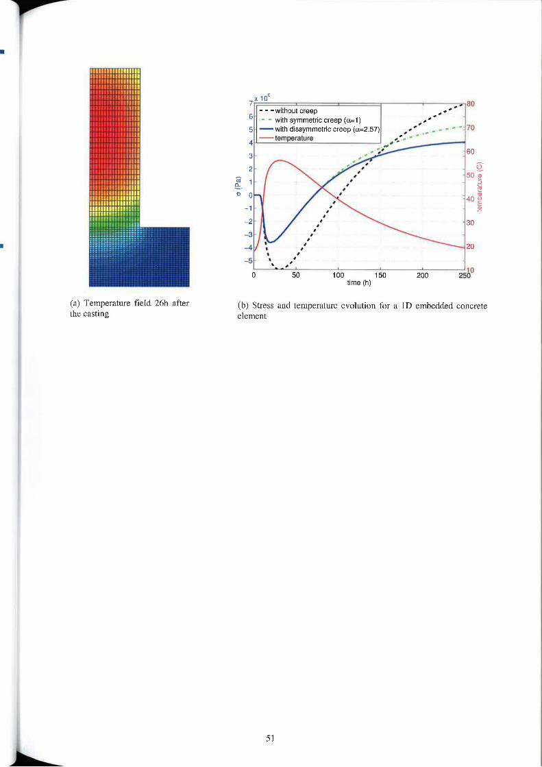
Itlllllllllll lllllll---mmllrrll vttlllllllMlllllHtvtlllial. . ,
(a) Temperature field 26h afterthe casting
7“ we so- - -without creep
6 - - with symmetric creep ((I§l) _5 —wim dissymmetvlc creep(t1=2.57) /04 — temperature3 so
_, /,~2 3 so>3 I,
4 I 2“,
<s(Pa) Q_.N ~ euiOU
_5 t‘ ; m.m
O 50 IOU t 50 200 2550time (h)
(b) Stress and temperature evolution for a 1D embedded concreteelement
5 1
Z;re
temperat
Mesh-less diffusion and elastic numericalhomogenization of concrete microstructures
Air-en—Provence, FranceMay 2EHur\e 1, 2012
F. Lavergne 1,2, J. Sanahuja 2, C. Toulemonde 21 ENPC, C/|14Y!l]7.\'—S!4!—1‘/IlIr‘!I4?, Franrc,fmrtL'[email protected]¢‘fi2 EDF R&D. MMC department, Morel SW’ Loing, France, {julienslmahujzz.chaIle:J0uIem0nde)@ed_flfr
Abstract
EDP operates numerous large facilities and thus, is to warrant their safety and serviccability. Lifeextension and life-cycle management are key objectives of operators of Nuclear Power Plants (NPP).Continuous safe operation of commercial NPP is economically desirable for operators and necessary tosatisfy the needs of the general public, Decade-old industrial plants face aging induced by theenvironment, the plant operation itself or unexpected pathologies. ln addition, in the prospect of buildingnew facilities, the responsibility of the future owner is to prescribe the exposure class and the requiredproperties of a set ofconcretes depending on their location inside the plant. ln both cases, the assessmentof the structural integrity requires precise knowledge and anticipation of concrete behaviour.
Concrete is a genuinely complex multi-scale and multi-physics material made up of local materials.
Thus, considering the impossibility to experimentally assess the behaviour of every concrete found infacilities, modelling is the only viable option to properly estimate the long-tenn behaviour of a large set ofconcretes, especially regarding creep. The multi—scale nature of the material makes homogenizationapproaches appealing. The effective behaviour of a given concrete does not only depend on theelementary behaviour of its components (aggregates, air voids, cement paste), but also on itsmicrostructure, that is how these components are spatially arranged. Unfortunately, as far as realisticmicrostructures of concrete are concerned, the most common numerical homogenization approaches fail.Considering finite elements for example, the mesh creation proves to be an extremely tedious task as, bynature, the aggregates have complex shapes, are densely packed, and follow a very large particle sizedistribution.Mesh—less approaches can overcome previously mentioned issues. A revival of finite volumes ordifferences is proposed here, to allow responsive computations without heavy memory requirements.More precisely, the degrees of freedom are arranged along a cartesian grid, so no mesh is to be stored. The3D conduction problem is solved by means of finite volumes. Centered finite differences on staggeredgrids are used to handle 3D elasticity in heterogeneous materials. Algorithmic improvements and carefulimplementation allow to reach unprecedented performances: an elastic problem with 400 millionunknowns can now be routinely solved within one minute on EDP clusters.
Various numerical tests have been perfonned and are presented so as to ensure the reliability of suchmethods. The influence of the resolution, of the chosen boundary conditions and of the size of theelementary volume are studied. The local fields are displayed and the macroscopic results are calculated.Most of the computations were performed on a synthetic microstructure made of 2024 polydispersespherical inclusions. The contrast of the behaviours of the elementary phases is choosen to be very high tochallenge the numerical approach and anticipate the needs of viscoelastic computations.
52
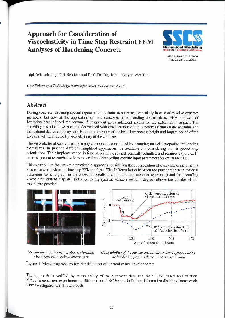
Y’
Approach for Consideration ofViscoelasticity in Time Step Restraint FEMAnalyses of Hardening Concrete
Anr—en—P|t|venoe, FranceMay 29—June 1, 2012
Dip].-Wirtsch.-l.ng. Dirk Schlicke and Prof. Dr.—l.ng. habil. Nguyen Viet Tue
Gruz. Univerriry 0; Teciuwlvgy. lYI.s'!i/nlefor Srrmtural Conrre1e,Auslria
AbstractDuring concrete hardening special regard to the restraint is necessary, especially in case of massive concretemembers, but also at the application of new concretes at outstanding constructions. FEM analyses ofhydration heat induced temperature development gives sufficient results for the deformation impact. Theaccording restraint stresses can be determined With consideration of the concrete's rising elastic modulus andthe restraint degree of the system. But due to duration of the heat flow process height and impact period of thcrestraint will be affected by viscoelastieity of the concrete.
The viseoelastie effects consist of many components constituted by changing material properties influencingthemselvm. In practice different simplified approaches are available for considering this in global stepcalculations. Their implementation in time step analyses is not generally admitted and requires expertise. Incontrast present research develops material models needing specific input parameters for every use ease.
This contribution focuses on a practicable approach considering the superposition of every stress ineren1ent’sviscoelastic behaviour in time step FEM analysis. The Differentiation between the pure viscoelastic materialbehaviour (as it is given in the codes for idealistic oonclitions like creep or relaxation) and the accordingviscoelastic system response (addicted to the systems variable restraint degree) allows the transfer of thismodel into practice.
_ —l I11 1 with ('orr.sirlcr";ttiurr of(|1m¢;_ visr-oolzr~:t.i(' r~,ttt~ct.~'
' “ °‘ rrretrslrrvrrrrtrrt
A H StressnN/mm\ 7-
r'1 \.
'\ t _ . "K \vitlro\rt (‘I_1|].si&l\'l’t\l.i\Jll~'-l»-—~» -» ll ‘ of vi.~¢('uel:t;~"tic cfl'r~(-t,>=; t -2t , res 3110 r-04 072
l \ Atqc of (1nr(<r'etr~ in hours
Measurement instruments, above: vibrating Compatibility of the measurements, stress development duringwire rlrain gage, below: .rlre.r.rmeter the hardening prncess determined 0» ‘strain data
Figure 1 . Measuring system for identification of thermal restraint of concrete
The approach is verified by compatibility of measurement data and their FEM based recalculation.Fllfthemwore cunent experiments of different cured RC beams, built in a deformation disabling frame work,were investigated with this approach.
L 53
Nonlinear basic creep and drying creepmodellin
Numerical Modeling§»=t.nan|nnmn, Eflfllrlll Sfllrzlmes
Atxerwrovence. FranceMay 29»Jun2 1. 2012
A.Sellicr(l), L.Buffo-Iacarriere( l), S. Multon( 1 ). T.Vidal (l),X. Bourhon(2)
( 1) Univcrri/:5 dc Toulouse ,' UPS, INSA ,' LMDC (Luboratoire Matériaux 21 Drrrabililé rlea C'orm'tructiunr) ; I35, avenue dzRangueil I F—3I 077 Toulome Cedex 04. Franc?»(Z) Andra, Direction Scienrrflquc/Service Cali: — Matériauac, Pare de la Craix Blanche, 1-7 me Jean Manner,92298 Chatenay-Malflbry
AbstractThe conventional splitting of delayed strain of concrete in autogenous shrinkage, drying shrinkage,basic creep and drying creep assumes a decoupling of underlying phenomena. Even if this splitting isusually used to interpret creep test results, it is not full—compatible with physical phenomenaunderstood by the creep poro»mechanics modelling community. lndeed in the framework of poro—mechanics, drying shrinkage and basic creep can be modelled thanks to a single poro-mechanicsscheme in which capillary pressure acts on a concrete skeleton. In this type of model based on the Biottheory. shrinkage is the consequence of capillary pressure acting on the visco—elastic solid. lt assumesimplicitly a coupling between shrinkage and creep. But, even if this approach is more physie than thetraditional ones, it remains unable to explain the additional strain obtained on creep test in dryingconditions (Pickett effect), which is usually modelled by an additional module for drying creep. Thisobservation points out a gap in physical phenomena comprehension and consequently in the poro»mechanic fon-nulation.
Moreover, modelling of tertiary creep needs a coupling With the damage theory. lndeed, die increaseof basic creep rate observed in this ease of loading, can be explained by the stress concentrationinduced by micro-cracking which takes place at a micro-stnrctural level. If a modelling of this firstfamily of micro cracks is used, the model will be able to simulate non-linear dependency of creepstrain toward applied stresses. Nevertheless, it remains unable to explain drying creep.
In the proposed work, a second family of micro—cracl<s is postulated to explain drying creep. Thesemicrocracks are due to the paste shrinkage that is restrained by aggregates and anhydrous phases ofcement paste. This second family of cracks is modelled thanks to the anisotropic damage theory. Thestress field heterogeneity induced by capillary pressure at the microstructure-level is explicitly takeninto account in the damage criterion. The damage is then used in the poro-mechanics framework tomodify the influence of capillary pressure on solid skeleton (Biot tensor), explaining most of thedrying creep strains.
This physical modelling considers explicitly the stress field heterogeneity consequences. lt offers away to link shrinkage effect to Weibull scale effect Without using an explicit mesh of elasticheterogeneities as it is often the case in mesoscopic numerical models.
Finally, the proposed modelling allows considering meso-scale random effects through a probabilisticmethod directly included in the damage criterion. Drying creep and Weibull scale effects, which areinterpreted as mesoscopic heterogeneity consequences, can then be considered for the stnrctural levelanalysis but without resorting to a mesoscopic modelling or an additive module in the poro—mechanicformulation.
54
Simulation of the restrained ring testlied 0 cement-based materialsapp t
incorporating rubber aggregates and fibreAixerwrovence, Fiancereinforcement May 2e1ime 1, 2012
F. Tazi“laborntoirc Matériaux at Dmubilité 42: Cortxtrucnons. 115, av de Rangtieil, 31077 rmizam. Cedex 04. France
Abstract
The assessment of the durability of constructions is a major concern today. Cement-based materials, themost widely used manmade construction materials, suffer from some imperfections and thus highlysusceptible to cracking. They particularly suffer from shrin.kage cracking, especially when the shrinkage isrestrained. Nowadays, Steel bar or fibre reinforcement is an imperfect solution, which does not preventconcrete cracking but restrains the crack opening. However, a better solution to limit brittleness andprevent shrinkage cracking is to design a cimentitious composite exhibiting a high level of deformationbefore macro/micro cracks appear. For this reason, it was assumed that incorporation of rubber aggregatesobtained from shredded non-reusable tyres with low elastic modulus could be a solution. Thus alsohelping to meet the demand for a clean environment.
Several experimental researchers have recently investigated the influence of material composition on theage of cracking and a significant body of research is being developed to illustrate the influence of mixturecomposition on the age of cracking. The restrained ring test is becoming widely used as a test method toassess the potential for early-age cracking in the cement composites. Such considerations led us topropose a new numerical approach to reduce the propensity of concrete to crack. In this regard, ourinvestigation aims at developing a numerical model as a direct solution, based on the finite elementanalysis, to predict the age of cracking for cimentitious composite having a high strain capacity beforemacro/micro cracking localisation. This paper describes a numerical study of restrained ring specimenstested, using different composite specimen ratios of rubber aggregates and fibre reinforcement, in order tocompare with experimental results that have been published recently.
The results for this numerical method estimate the residual stress and strain developing according to time,and consequently quantify the materials potential for cracking. This numerical program is presented toillustrate the favourable correlation that exists between the predicted behaviour of cimentitious compositesmodel and the experimental results.
Keywords: Rubber aggregates, Fibre reinforcement, Drying shrinkage, Shrinkage cracking, restrainedPlug test, Finite element analysis, Environment.
55
SSENumerical Modelingmay rilqfiuilimzihll Enncvzlz StmclumrA|xen—Provence, France
May 29~J\me 1. 2012
Session I-4:Cracking behaviours (static, fatigue, dynamic)Discrete Element Simulation of Concrete Fracture and Crack EvolutionB. Beclcrnan, K. Sehicktanz, M. CurbachInstitute ufConcrcte Structures, TU Drcrdcn, Germany
Crack Elimination in Concrete Floors and FoundationsR. Cajka at al.VSB — Technical University Ortrava, Czech Republic
Effects of the concrete damage due to corrosion of steel bars on the static and dynamic response of PRC/RC beamsR. CapozuccaArr. ProfofStruct. Eng., Universiu) Politecnica Marche, Ancuna, Italy
Effects of carbonation on the lifetime of concrete structures and updating by Bayesain networksB. Capra‘, A. SelLier2, F. Debyz, P. Rougeaus’ ox/mo S_A.,‘ 2 Université 11¢ Tvulouse ,- UPS, ms/4 ,~ LMDC; ‘camsNumerical Modelling of reinforced concrete beam short and long term response to cyclic loadingA. Castel' _ R.l. Gilbert’. s.1. Fosteiz'Pr0fe.rr0r, University 0//vim, Nice, France 7 2Prr1fe.\'.\'0r, University UfN€W South Wales, Sydney, NSW, AustraliaModelling of the reinforcing bars and prestressing tendons for containment buildingsM. David” . E. Lorentz‘, s. Michel—Ponnclle', 1.71. Marigof‘ LaMSlD, EDF R&D, Clamart, 1 LMS, Ecolc Polyteehnique, PalaiseauNumerical study on load distribution in I-IC floorsP. Bemardi, R. Cerioni, N. Garutti, E. MicheliniDepartment ofCivil and Environmental Engineering and Architecture,Universiry of Parma, Italy
Detemiination of the dynamic tensile response and dissipated fiacture energy of concrete with a cohesive element modelF. Gatuingt‘, L. Snozziz, J.F. MolinariJ LMT-Cachan (ENS Cachan/CNRS/Universite’ Paris 6/PRES Unit/erSud Paris), 2 LSMS, School of Architecture.Civil and Envimnmental Engineering (ENAC), Ecole Pnlymchniquz Fédérule dc lauxunnc (EPFLJ, Switzerland
Three dimensional constitutive law for concreteR1}-larnmoud*, A. Yahia**, R. Boul<hili**Ec0le Polytechnique dz Mnntréal, M0/1/réal, Québec — **Univer.\‘1'te' dc Sherbmvke, Sherbruaka, Québec
Numerical modeling of the behaviour of UHPFRCA.P_ Lampropoulus and M.N. SoutsosDepartment 0fCivll Engineering, Univerxiry rgfLi\/erpr/ol, Liverpool, UK
57
Using 3D Microstructnral Imaging I0 Produce Physically—Based Numerical Models for Concrete. Part I: MicromechanicalExperimentsE.N. Landis‘. J.E. Bolanderzl University ofMaine, Omno, Maine, 2 University of California, Davis, Calfiurnia,
Using 3D Microstrucluml Imaging to Produce Physically-Based Numerical Models for Concrete: lattice simulations1.12. Bolanderz, E.N. Landis'1 Ur|iversit\'0fMair1e, OVOHO, Maine, 2 University qf California, Davis, Califarnia.
Inverse analysis procedure for the Characterisation of softening diagrams fur FRC beams and panelsAli Noni“, Bruno Massic0tle\, Renaud De Munmignac‘ , .lean~I’hi|ippc Chaminl‘ Elm Pulylecnnique de Muntréal, Munlréal, Quebec, 2Hydr0 Quéhen, Mnntréal, Q!4e'bec,Can:1daNumerical Modelling of Reinforced Concrete Beams Repaired with Polymer»Modified MortarL.M Mauludin, G. Guidi. F. Da PortoPoliteknik Negeri Bandung-Indonesia, University afPadova, Italy
Cracking Propagation Simulation of Concrete due to Rebar CorrosionH. Nakamura, T.K. Khoa, N. Ueda, M. KuniedaNag0yaUniversiry, Japan
Statistical analysis of crack Widths by virtual modeling of rcinl'0i'ced concrete beamsD. Nnvak, L. FeketeInstitute ufStmc‘luri1l Meclianics, Fin-my of Civil Engineering, Brno University of Technulugy, Emu, Czech RepublicModeling of the behaviour of RC tie-beams reinforced by [lat steel rebars: A comparison between 2|) and 3|)numerical simulations of the stccl/concrete interfaceT.S. Phan, ].—L. Tailhan, P. Rossi, .l.Foullia1'0nIFSTTAR Paris, France
Continuum damage mechanics based model for quasi-brittle materials subjected to cyclic loadings: application to concreteB. Richard, F. Ragueneau. A. Delaplace. C. OliverLMT/ENS Cachan, CNRS/Univerxiré. Paris 6/ PRES UniverSud, France
Numerical modeling of cracking in fiber reinforced concretesP. Rossi, T.S. Phan, J.-L. TailhanIFSTTAR Paris, France
Multiscale Modeling of Shear Failure in RC Slabs with Spatial VariabilityA.B. Suma, l-LG. Burggraaf, AJ. Bigaj-van Vliet.A.H.J.M.Vervuui1TNO, Delft. The Nelhcrlamir
Probabilistic modelling of crack creation and propagation in concrete structures: some nurncrical and mechanicalconsiderations.J.—L. Tailhan, P. Rossi, T.S. Phan, J. FoulliaronIFSTTAR Paris, Franc!
A RC fibre beam element for full modelling of the bending-shear response by dual section approachP. Tortolini, E. Spacone, M. PetrangeliDepartment Civil Engineering of the "G. D’Annunzio" University , Pescara, Italy
Numerical methods for collapse analysis of RC framed structures with physical and geometrical nonlinearityM. Ucci‘. M. V. Sivaselvani. E. Spacone‘' Dept. Of Structural Engineering, University 0f Chieri-Pescara "0. d'Armnnzi0”, Imly, 1 Dept. of Civil,Environmental and Architectural Engineering, University of Colaradn at Boulder, co, USA
58
f
nical
ans
'ic
3D
iical
ivil,
Discrete Element Simulation of ConcreteFracture and Crack Evolution SSlI§
NUIIIBPIOBI ModelingSiruiigwsflllinilaliiahlz llonriele Simcinrzs
AlX'QU~Pi0V8l'lC€v FranceMay 29-June 1, 2012
B. Beckmann, K. Schicktanz, M. CurbachInsriruze 0fConcreze Structures, TU Dresden, Germany,{BiVgit.Beckrm1nYl,Kai.Schick!l1rIz,Mn1n/5241 .Curbach)@lu—dresden1ie
A two-dimensional simulation of concrete behaviour using Discrete Element Method (DEM) is presentedin this work. The main aim of this work is the modelling of the failure process and crack initiation. Thefailure process of a concrete specimen during a standard compression test is simulated with regard to highstrain rates as they occur due to impact load. Crack patterns resulting from the simulation are shown andcompared to laboratory experiments. lt is shown, that the calculated peak load is independent from theparticle number used in thc simulation. The Poisson‘s ratio of the concrete specimen during loadapplication is an inherent result of thc simulation and is compared to experimental results.

V
Crack Elimination in Concrete Floorsand Foundations SSE
Numerical Modeling‘ilIalcgln§IM5nS(IlMI>l! Cflflflllfl §|WI.‘luH 3
Aix-en-Provence. FranceMay 29»Jurie 1. 2012
R. Cajka at al.
VSB - Technical Univenity Oalrava, Czech Republic
AbstractUsing the rheological sliding joint is effective method to decrease the friction between deformingstnicture and subsoil. Convenient material for sliding joint is bitumen asphalt belt, widely availableand reasonably priced material. Sliding joints were applied successfully on several buildings in CzechRepublic in the undermined region Where the subsoil has been deformed. But the application of slidejoint is concededly much wider, e.g. pre-stressed foundations, creep and shrinkage, thermal strain andothers. Original experiments of shear resistance of bitumen slide joint as a function of time dates fromthe 80"‘ of last century. Material characteristic of bitumen belt has been changed significantly sincethat time and this fact demanded new experiments. At VSB — Technical University of Ostrava uniqueequipment was designed for shear resistance measuring. Renewed experiments for different types ofbitumen belts passed in 2008. One of the important factor which affect the shear resistance is thetemperature and that is way the experiments continues with measuring the shear resistance of slidejoint as a function of temperature in air-conditioned room. In the paper first experiment results oftemperature dependant shear resistance will be presented. Test results are used for analysis ofstress/strain relation between concrete floor or foundation structure and subsoil.
Coauthors: Ph.D. students from Department of Building Structures, Faculty of Civil Engineering, VSBTU Ostrava
60
Effects of the Concrete Damage due toCorrosion of Steel Bars on the Static andDynamic Response of PRC/RC Beams
A|X—en—Provence, FianceMay 29'June 1. 2012
R. Capozucca
Asst Profof Strucr. Eng., Universirfi Politecnica Marche, Anczma, Italy r.m/mmtuttrlitmiv rm.t!
Abstract
Accidental actions and environmental conditions may cause damage to concrete structural elements,The analysis of concrete beams affected by damage due to corrosion of steel bars represents aconvenient approach to evaluate the degree of safe and the sustainable methods of rehabilitation. Thepresent paper reports on experimentally investigation through dynamic and static tests on prestressedreinforced concrete (PRC) beams and reinforced concrete (RC) beams damaged by corrosion of steelbars‘ Testing has been carried out in order to verify damage degree correlated to microcrncking ofcompressive concrete. The experimental program foresaw that PRC/RC beams were subjected toartificial reinforcement corrosion and successively to static loading with increasing applied loads toproduce bending cracking. Dynamic investigation was developed both on undamaged and damagedPRC/RC beams measuring natural frequencies and evaluating vibration mode shapes. The analysis ofexperimental results compared with theoretical data, are shown and discussed.
6l
Effects of carbonation on the lifetime of Cconcrete structures and updating byBayesain networks
Aix-en-Provence, FranceMay 2&Jt|V\e 1, 2012
B.Capra (1), A. Sellier (2), F. Dcby (2), P.Rougeau (3)(I) OXAND SA; 49 avenue F. Roosevelt; 77210 Avon, France(2) Université dc Toulouse ; UPS, INSA ,' LII/1DC(LaboYa10ire Matériaux er Durabilité des Constructions) ; 135, avenue deR:1ngue|'l;F—31 O77 Toulouse Cedex O4, France,(3) CERIB; Rue des Longs Réages; BP 30059; 28231 Eperrwn Cedex
AbstractConcrete cover carbonation and chloride ingress are the main causes for concrete reinforcementcorrosion. So, design of concrete cover has to be perfonncd in such a way that the probability for thecritical chloride concentration or for the carbonation front to reach the reinforcement for the expectedservice life remains lesser than an accepted value.ln current standards rules, this objective should be implicitly verified using concrete cover proposedBut the empiric methods used in these codes does not take into account accurately the variousvariability of environmental and material durability indicators involved in the depassivation processes(local carbon dioxide high concentration, excellent durability indicator for some new concretes, moreor less quality control for other ones. . .).To consider properly durability indicators. environmental parameters, and their respective variability,an empirical method is not sufficient. A probabilistic method using explicitly the parameters randomdistribution is more convenient.To use such a method, three conditions are needed: A realistic physical modelling of the depassivationprocesses (carbonation or chloride ingress models); A statistical measure of the model unavoidableinaccuracy; A target probability level, and a realistic random distribution for other random parameterinvolves in the physical phenomena.The target probability level can be chosen in accordance with previous probability of depassivationlevel calculable for conventional ooncrete respecting previous standard design rules in a “normalenvironment".The models have to be as realistic as possible to minimize their own random inaccuracy, but not toomuch complex to be used in a standard code. On purpose two models are proposed, one forcarbonation, another one for chloride ingress. Their parameters fitting need durability indicator tests,and their physical meaning allows using them in various environments and for different concretes. Forexample the carbonation model is able to take into account accelerated carbonation tests results topredict natural carbonation kinetic; chloride model is able to consider the bending isotherm variationwith the cement type and the chloride diffusion coefficient dependence on the concrete formulation.These models are based on numerous parameters whose Values are not certain. In a design phase, it ispossible to postulate a priori values and distribution laws [or these variables. Vlfhen experimental dataare available for a given concrete formulation, carbonation tests or chloride diffusion tests allowfollowing with time the evolution of certain parameters. The use of Bayesian techniques allow toupdate the distribution law parameters according to the observed data, their likelihood and the a prioridata. When few data are available, Bayesian approaches are a mcan to update the models according tothe available information. ln this article, this approach is used to update the evolution of the concrctccover design with regards to available experimental data.
62
_ — — _ _
Numerical modelling of reinforced concretebeam response to repeated loading, - - Numerical Modelingincluding steel-concrete interface damage
l\ix—en—Pr0vence, FranceMay 29—lune 1, 2012
A. Casteli. RJ. Gilbert2, SJ. Fostcrz
1. Professor, University 0/"Nice, Nice. France.2. Professor, Univerxiry ofN2w Xouth Wales, Sydney, tvsw, Australia.
Abstract
In reinforced concrete constructions, deflcction control of is an important performance criterion fortheir serviceability and sustainability. Excessive concrete cracking resulting from excessivedeformation is one of the most common causes of damage and results in huge annual cost to theconstniction industry,
The Finite~Elcment modeling proposed in this paper is dedicated to the calculation of beam deflectionafter cracking. By implementing a new constitutive law for concrete in tension, firstly, the cumulateddeflection under pennanent loading resulting from both concrete bending cracking and long termeffects is predicted. Secondly, the elastic response of the already cracked beam under cyclic loading iscalculated including tension stiffening effect.
Calculation are performed at serviceability stage only analyzing the coupled effects of the permanentloading and the live loading of structural members under normal operating conditions. Finite Elementresults are validated on several large size reinforced concrete beams under different permanent loadingvalues and maximum live loading values during cycles.
Keywords: reinforce concrete, Finite Element modelling, tension stiffening, long term effccts
63
Modelling of the reinforcing bars andprestressing tendons for containmentbuildings
Amen-Provence, FranceMay 2&JuV\e 1. 2012
SSEM. David”, E. Lorcntz1,S. Miehel—Ponnelle' . J.-I. Marigoz
ILHMSID, EDFR&D, Clamnrt, Franco:ZLMS, Ecole Polytechnique, Palaiseau, France
The containment concrete vessel is a major element in the safety assessment of a nuclear power plant:in accidental cases, it constitutes the third barrier preventing the escape of radioactive products in theenvironment. Since the containment building cannot be replaced, the prediction of its mechanicalstrength is a major concern for the energy producer. To answer this question, numerical simulationsprovide an important analysis tool which gives quantitative estimations of the stress states and crackOpenings.The containment vessels are cylinder shaped, 50 meters high, about l meter thick, and arc made ofprestressed reinforced concrete. They are designed so that the concrete always stays in compression,hence preventing potential cracks from opening. However, in accidental ultimate loading stages, if theinternal pressure becomes too large, cracks may open. ln this case, the reinforcing bars andprestressing tendons play a crucial role in the containment efficiency of the structure, by limiting thecrack opening. This effect is also strongly influenced by the behaviour of the steel-concrete interface.The proper modelling of the bars and tendons and of the steel-concrete bond is therefore veryimportant to estimate the containment efficiency of the structure.The method generally used to model bars and tendons relies on bar elements, i.e. lD elements whichonly have elongation stiffness, This approach is not completely satisfactory, because it results in an ill»posed mathematical problem: the interaction between a 3D medium and a lD element has no meaningin the framework of variational continuum mechanics [1]. In practice, this kind of model fosters highstress concentrations near Lhc bar elements, and a slight mesh dependency.Generally, for large concrete structures, the reinforcements take the form of 2D lattices. To describesuch kinds of reinforcements, we propose a different approach: the reinforcements arc modelled bymembrane elements, While Lhc degradation of the steel—conercte bond is described by cohesiveelements. This simple model can be rigorously derived by using the method of separation of scales [2].lt is able to describe both the steel reinforcements and the prestressing tendons, depending on the lcvelof details required by the analysis. Compared to detailed 3D computations, this model results in amuch lower computational cost.The model is implemented in the finite element code C0de_Arler [3]. It is validated by extensivecomparisons with 3D computations. We show that it can be used to accurately model the behaviour ofreinforced concrete structures, and to estimate crack openings.
References[1] Ill—pr1.\'ed boundary com1l'li:m.r encnu/tiered in 3D and plate finite element simulilrions, E, Lorentz, Finite
Elements in Analysis and Design, 41 (2005)[2] The efleclive behavior 0/ elastic bodies containing /nicmcruL‘k.\' or micmholes localized on a xurfa1:e,].-
J.Marigo, C.Pideri, International Journal of Damage Mechanics, Special issue of ESMCZUOQ (to bepublished)
[3] (,'ru1e_Aster, EDF R&D, http://WWW.code-astcr.0|'g
64
Numerical study on load distribution in HCfloors
Numerical Modeling.w.t.a,,t.=-mrtmtttt “mt. SlruulurrsAix-en—Provence. France
May 29<June 1, 2012
P. Bcmardi, R. Cerioni, N 4 Garutti, E. Michclini
Department of cm: and Envirormwrtlal Engineering W1 Architecture,University 0fPat'ma, Italy
AbstractPrecast prestressed hollow core units are widely used for ground and suspended floors in several types ofbuilding constnrction, representing an economic and flexible solution. Actually, these structures perfort'n verywell despite their limited weight, allowing to cover long spans and offering several advantages over traditionalmethods, such as cast in situ concrete, steel—concrete composite and timber floors.
Hollow core units are usually designed as simply supported elements subjected to bending and they are inpractice connected to each other with cast—in-situ concrete joints, so to form a shear key without transmissionof bending moment. These longitudinal joints play at timdamental role in transversal load distribution amongpanels, especially in presence of line loads acting parallel to floor span or concentrated point loads. The lateralload distribution relies on the shear key especially when HC floors are realized without a cast»in-situ concretetopping, as still occurs in many European countries. As a consequence, the design of the entire floor slabrequires the knowledge of the load fraction supported by each panel, which is usually evaluated on the basisof simplified curves provided by design standards [1]. Actually, several former studies [2,3] have indicatedthat load distribution depends not only on span length and on load position over floor span, but also on theflexural and torsional stiffness of HC units. lt has also been pointed out that the distribution of deflection,bending moment and shear force may differ greatly. As a consequence, no reliable methods are available fordesigners and numerical approach can represent a usefirl tool to afford the problem, taking into account all theinvolved variables,
ln this paper, hollow core slabs with in—situ RC joints under concentrated and litre loads are analyzed byadopting the finite element method. To this scope, different modeling techniques applied to complete lloorsare discussed and compared to standard distribution curves, as well as to eitperimental results. Particularattention has also been paid to longitudinal joint modeling, by considering different sehernatizations able toreproduce the hypothesized hinge behavior,
At the beginning, a simplified global FE model of the complete floors has been considered in order to focusOn joint behavior and also to limit Computational efforts. Subsequently, the model has been progressivelyrefined so to introduce some additional variables, influencing the lateral load distribution among panels. Theso obtained results have been compared to previous ones, so to evaluate the level of detail necessary toachieve reasonable degree of accuracy in HC floor design. Finally, NLFE analyses have also been carried outin order to simulate some significant experimenml tests available in technical literature [4], focusing on theConsidered topic. Both the tests and the analyses describe the HC floor behavior undcr serviceability andultimate conditions, up to failure. ln numerical analyses, the nonlinear behavior of the reinforced concrete hasbeen described through 2D—PARC constitutive model [5], whose cfficiency has already been proved forseveral concrete structures.
65

W
L
References
[I] UNI EN 1168:2005, Precast concrete products - Hollow core slabs./2] K. Lundgren. H. Bron. B. Engslrém. Analyses of hollow core flnors subjected Lo shear and torsion.
Slruct, Ccncr. 2004, 5(4): 161-I72.[3] J. Stanton, Response of hollow core slab floors for concentrated loads, PCl J. 1992, 37(4):98»1 13./4] M. Pajari, Shear-torsion tests on 400 mm hulluw core floor, Espuu 2.004, VTT Tiedotteita-Research
Notes Z274, 30 p. + app. 82 p4[5] R. Cericni. l. lori, E. Michelini. P. Bernnrdi, Multi-direclinnal modeling of crack pattern in 2D R/C
members, Eng Fracl Mach Z008, 75: 61$-628.
66
Determination of the dynamic tensileresponse and dissipated fracture energy ofconcrete with a cohesive element model
Alx-en-Provence, FranceMay 29—June 1, 2012
F. Gatuingtl. L. Snozzi1,J.l~'. Molinariz' LMT—C.'lt‘hnrt (ENS Cuchun/CNRS/Ultiversité Purtlr 6/PRES Unit/erSud l’uri.r), Frant?/ill)rir‘c .gr|Mingl@£'t|.t-writ‘/lztnfr7 LSMS, School 0fArchiteclul'e, Civil and Ertvirortmenlal Engineering (ENAC), ECOLE POLYl'I:'CHNIQUI;' FEIFIZIMLEDEMUSANNE (EPFL), Switzeilnmi
The macroscopic modeling of the tensile response of concrete in dynamic has considerably evolved andthe current constitutive laws are able to represent more and more complex phenomena. Nevertheless, inthese approaches the different scales present in the structure of the material are not represented despitetheir strong influence on the macroscopic behaviour. For example it is usual to introduce in these models adynamic increase factor directly in the macroscopic behaviour to represent the experimental data forloading strain rates exceeding l /s. This has to be done with care as it is not clear how important thcdissipation at the structural level is. Indeed, the increase of the fracture energy with the strain rate may becaused, in the experiments, by a structural effect (at the concrete sample level) instead of a material one’s.In the high dynamic regime, multiple cracking and micro-inertia effects in the fracture process zone arethought as the main factors for the rate dependency of concrete. However, the influence of the intemalmicrostructure of concrete and the mechanisms that lead to different crack patterns when varying theloading rate, remain open questions. In order to give some answers to these questions, concrete has to beconsidered as a heterogeneous material where the nature of the heterogeneity depends essentially on thescale of observation.
In this Work the influence of the heterogeneous mesoestructure of concrete on the dynamic tensileresponse is analyzed. For this purpose a 2D geometrical model of concrete consisting of aggregates,interfacial transition zones and a matrix is modeled. We use a finite element framework with cohesiveelements to explicitly represent the crack nucleation and growth. The debonding process in the cohesiveelements is controlled by a traction separation law based on the popular linear extrinsic irreversible lawproposed by Camacho and Ortiz [1]. This numerical approach has proved its efficiency on brittle materiallike ceramics [2] without an explicit meso—structure representation.
We validate our model by simulating a direct dynamic tension test of a concrete specimen. The role of themesostructure and the influence of the loading rate are then analyzed. We especially focus on theevolution of the stress peak and the energy dissipated. We can observe that with a traction separation lawindependent of the strain rate We are not able to reproduce the macroscopic rate effect experimentallyobserved while the global dissipated energy is correctly simulated. We will also show the respectiveinfluences of the meso-structure and the loading rate on the variability of the stress peak in tension.
References:
ll] Computational modeling 0/7 impact damage in brittle materials‘, or Camacho, M. Orliz,Intt:rnati0n1t| Journal<1fSolids and Structure, 33. 2299-2938, 1996.I21 Dynamic fmgmertmtinn 0/7 ceramics, Signature cg" defects and scaling 0/ffiagntd/tl sizes, S.Levy, I.F Molinari,Juurnal of the Mechanics and Physics of Solids, ss, 12.26. 20l0.
67
V
‘_
Three dimensional constitutive law forconcrete
Numerlcal Modelingsmttttia stmawmm Dnnnvztz SllullulcAtx—en'Provenee, Ftaflfle
May 29June 1, 2012
R. l-lamm0ud*, A. Yahia**_ R. Boukhili*
*Ec0le Polytechnique dz Montréal, Montrézil, Québec, Canada“Universilé de Sherbrookz, Sherbrovke, Québec, Canada
Abstract
Concrete has been widely used in various structural applications because of its high performance andgood durability. Although concrete can be considered a continuum material on the macro—scale, it is aheterogeneous and anisotropic material on the micro—scale. Because of this heterogeneity andanisotropic behaviour, strength, stiffness, and ductility are strongly dependent upon the load path.Various finite element analyses have been carried out to evaluate thrce—dimensional behaviour ofconcrete. To ensure reliable analysis, realistic models describing the behaviour of concrete andefficient computational procedures are required. The objective of this study was to develop aconstitutive law with hardening and softening parameters that can better describe the behaviour ofnormal concrete. Equivalent plastic strain serves as hardening variable and itself is a function of meanpressure, which can accurately assess the magnitude of permanent strain under various loads.
Strain softening causes the dissipation of plastic energy that is eventually transformed into fractureenergy when major crack develop. These inelastic phenomena are described by plastic flow which itsdirection is determined by the gradient of the plastic potential, and which controls inelastic dilatancyin terms of the inelastic deformation behaviour of material. A new plastic potential is introduced andexperimentally fitted to ensure better estimate of load direction. By overlaying the plastic potential onthe Etse and Willani’s yielding surface, both defined on the I-laigh»Westergaa|'d coordinate, it ispossible to establish that, at the same strength parameter, the two curves do not undergo through thesame stress states. For the evaluation of normal vectors, it is necessary that each surface goes throughthe current stress state to ensure adequate evaluation of normal vectors. Keeping the loading surfaceunchanged, the calculation related to the plastic potential need to be modify. The proposed constitutivemodel is validated through numerical experiments.
Keywords: Constitutive law, Failure, Elastic-plastic material.
68
' Numerical modeling of the behaviour ofUHPFRC
Numerical Ivlodallngllmlqlu M s...|.i»-I». mm. SlmclulliAnt-en-Provence, France
May 29—lune 1, 2012
AP. Lampropoulos and M.N. Soutsos
l)epnr/men! qf Civil Engineering, U/m/-my Qfljvcrpflol, Liverpool, m9 JGQ, we
L
AbstractUltra High Performance Fibre Reinforced Concrete (UHPFRC) is a relatively new material withsignificant enhanced strength in both compression and tension and significant higher energyabsorption in the post crack region. its mix composition is not much dissimilar from that of normalstrength concrete. The main difference is that the only aggregate that is used is silica sand. Highdosage of steel fibres, up to 2% by volume, makes it a ductile material.
Finite Element Method, for simulating the behaviour of UHPFRC, required a constitutive law in bothcompression and tension that included both the strain-hardening and softening behaviour of thematerial. Cylinders were tested to determine the stress-strain relationship in compression. Directtensile tests were also needed. The behaviour of the material in tension is of significant importance forthe simulation of the behaviour of UHPFRC, as it is shows significant post crack energy absorption,and the existing procedures proposed in literature, that are based on load — deflection results frombending tests, cannot be used as they assume a linear stress distribution in the cross section.
The uniaxial stress — strain relationship in tension was found to be consisting of several linear parts,which included strain hardening, a subsequent plateau , and a significant post crack energy absorptionsoftening branch, To validate the accuracy of the proposed material constitutive relationship and toinvestigate the ‘size effect’ of the specimens tested, a series of three point bending tests wereperformed on beams with different section depths. The beams were notched in the middle whereLVDTs (Linear Variable Displacement Transducers) were placed to measure the crack mouth openingdimension (CMOD) in addition to the load - deflection relationship. These results were used tocalibrate the numerical model so that is able to reliably predict the response of any size of specimen(i.e. to take into account size effects).
The ultimate aim of this work is to predict accurately the response of UHPFRC plates. The strainhardening behaviour of UHPFRC means that cracking occurs before the ultimate load is obtained. TheCracked section has a reduced depth and this increases the risk of punching shear occurring. TheProposed material model was used for the numerical simulation of thesc plates and the results wereCompared to plates of different thicknesses that were tested in thc laboratory.
69
Using 3D Mierostructural Imaging to .,Produce Physically-Based Numerical “jrNurnaflcatmmndallngM0d€lS f0l‘ C0l1Cl‘€t6. ‘"";;i;'fe'f;;§{/"éné§'g;§r§gg'~1rPart I: Micromechanleal Experiments Ma’ ”"“"° 11°”
an. Landis‘ , J.E. Bolanderz' Univzmily 0; Maine, Drona, Maine. USA, !andt:@muin2.edu2 University ofCali/"ornia, Davix. California, us/t, j¢ba!ander@uc:lav[s.edu
The complex microstructure of concrete has traditionally led us to modeling approaches where modelconstants are based on either simple measurements or empirical curve fitting with experimental data.While this approach is certainly sound, and powerful tools have evolved, We seek here to make moredirect links between measurable micromechanical properties and the computational models we use forperfonnance prediction. The work described here represents progress towards this direct mic1"ostructure—model link.
In the micromechanical experiments we employ synchroLron—based x—ray microtomography, a 3D imagingtechnique that allows us to identify and measure different microstructural phases. Using a custom builtload frame, we were able to make high resolution 3D images of small specimens subjected to splitcylinder fracture. Through multiple scans of t.he same specimen with progressively higher levels ofdamage, We were able to measure internal cracking and damage evolution while simultaneouslymonitoring bulk l0ad—deformation relationships. Using 3D image processing techniques, phasedistributions. the porosity and pore structure are all measured, along with the complex network of cracks,the degree of fragmentation, and the 3D deformation fields. This paper focuses on the differentmicrostructural measurements that can be made, and what we might infer about mieroniechanicalproperties.
As a first step toward linking these measurements with computational models, specimens were prc— paredwith idealized aggregates consisting of spherical glass beads of two different surface properties. Upon 3Dimaging, these aggregate particles were isolated and located in such a way that 3D lattice models could bemeshed with aggregates in the same locations as in the real specimens. As discussed in the companionpaper, comparisons between simulations can be made where both bul.k—dei'ormation response is matched,but also fmcture and damage patterns. Further simulations predicted a relationship between strength andaggregate fraction that was confirmed by further experiments. We view this work as an important step in amovement towards more physical-based modeling.
70 ‘

r
\V<~—H|_4—U“4
Z1
l)
I
Il
Using 3D Microstruetural Imaging toProduce Physically-Based NumericalModels of Concrete: Lattice Simulations
SSIENumerical Modelingsmut» = lI.\i|~iaHMLi! Euicrele SlmcluvisAix-en-Provence, France
May zwtme 1, 2012
1.15. Bolanderl, E.N. Landis21 University 0fCaIi/brnin, Davis. California, um, jebulnn1ler@u£davi.r.eriu2 University 0fM:Iine, Drona, Maine, USA, landi:@maine.edu
Abstract
This paper describes the combined use of thrcedimensional lattice models and tomographic imagingtechniques to study pre-critical cracking in concrete materials. Model results are compared with 3-D mapsof internal damage and crack growth provided by in situ load testing of split-cylinder microconcretespecimens within the tomographic setup. Microtomography provides high—resolution 3—D pictures ofmaterial structure and cracking at distinct stages of the loading history. Although the coarse domaindiscretizations considered in this study do not resolve such I'ine—scale features. the models provide acontinuous event~by-event description of the 3—D fracture process and thus insight into the cause-and»effect relationships that Cletermine material performance and failure.
As one example covered in the paper, lattice models are used simulate multiple, nominally identicalspecimens differing only in aggregate content and positioning. These simulations, which are analogous tothe testing of replicate specimens in the laboratory, provide insight into the origins of strength variabilityof the composite material/structure. The model indicates that the arrangement of inclusions affects peakload, although additional factors (e.g. inegularities of specimen geometry) appear to be more influential incausing the scatter observed in the experimental results.
The lattice approach is also capable of modelling the scalar fields associated with potential flow. Inprevious work, the nodes used to represent the structural problem (i .e. displacements) arc coincident withthe nodes used to represent flow related quantities (e.g. moisture content and temperature). This sharing ofnodes amongst the different element types is effective prior to cracking. Upon crack formation. however,the flow elements are oriented perpendicular to the simulated crack path, which complicates the modellingOf crack-assisted flow and its dependence on crack opening. By defining the flow network on a duallattice, the flow elements are aligned with potential cracks so that both pre- and post-cracking flow can beeffectively simulated. This approach to modeling crack-assisted flow is presented, along with discussionof its use toward investigating the durability of concrete materials.
L 7.
V
Inverse analysis procedure for thecharacterisation of softening diagrams for
Numerical lvlndellnFRC beams and panels
htx-en-Provence, FranceMay 29—June 1, 2o12
Ali Nour"2, Bnrno Massicotlcl , Renaud De Montaignac‘, Iean—Philippe Charronl
r at-01¢ Polylevltniqun at Murrlréal, Morméul, Québer, H3C _w, rzmrar2 Hyzlm Qnébec, Momréal. Québec, HZL/4P5, Canada
Abstract
The flexural performance of fibre reinforced concrete (FRC) materials is directly related to the stress—crack opening diagram (rr»w). This diagram is needed for structural design applications since itrepresents the energy change in the fracture process zone at the material level. Thus, the o—w diagramis considered the characteristic material property of FRC materials. In practice, the simplest testmethod is to perform a direct tension test. Unfortunately, such test is complicated to perform since it isdifficult to prepare the specimen, and to impose unambiguous boundary conditions in the setup. Thealternative that is currently being studied exhaustively is the use of the experimentally obtained load-displacement bending response of some structural elements to determine the o-w curve of thecorresponding material through inverse analysis. Most investigators have focused on the behaviour ofa notched beam under a three point bending load, whereas an inverse analysis with FRC panels is veryscarce in the literature. In this paper, a novel inverse analysis procedure for the characterisation of theo-w diagrams for FRC beams and panels is presented and validated. This procedure is based on a datafitting algorithm, for which the shape of the cs-w diagram is, a priori, free to vary. An analyticalformulation that uses the <r—w curve as the input and provides the analytical load—displacementresponse for the beam or the panel is needed to match with the experimental results. For the ease ofFRC beams, an analytic formulation in the literature that provides, with satisfactory accuracy, theloadalispl-acement response, for an arbitrary inputted o—w diagram, is adopted. Since for FRC panels,to the authors’ knowledge, such an analytic formulation is either scarce or does not exist, the authorsdeveloped recently a simple analytic formulation to investigate the post-crack behaviour of FRCpanels using an arbitrary oiw diagram as the input. The proposed post-crack behaviour of FRC panelsis studied using the yield line theory, where the load deflection response is predicted based on thecrack length parameter-normalized deflection relationship. It is worthy to nrention that this procedureis being intensively used in the frame of sustainable development projects dealing with FRC and ultraperformance fibre concrete (UPFC) materials. Application to the prediction of fibre reinforcedconcrete beam behaviour, with crack width prediction in service condition to ultimate concludes thepaper,
72
Numerical Modelling of ReinforcedConcrete Beams Repaired withPolymer-Modified Mortar
Alx-en-Provence. FranceMay 29June 1, 2012
L_M Mauludin, G. Guidi, F. Da Porto
Pulizeknik Negeri Raruiung-Irirlzumsiu, I/niver.\'ify ufI"adr|vu—l!u]y, Univr'r.\'ity offmrlovn, Italy
Abstract
This paper presents the results of finite element analyses on flexural behaviour of rcinforccd concretebeams repaired with polyrncr—rnodified mortar. The numerical models were calibrated on flexural testscarried out on eight concrete beams.
The main aim of the analyses was extending the study to different concrete and repair mortarproperties and simulating the behaviour of repaired beams when subjected to cyclic loadingParametric study was can-ied out to evaluate effectiveness and behaviour of repaired beams built andrepaired with different materials, with different thickness of mortar repair and under static and cyclicflexural loading.
The numerical results showed that the repairing layer properties influence significantly the ultimatecapacity of beams. The repair mortar is effective when its mechanical properties are similar or overthose of the parent concrete. Thick repairs including the longitudinal reinforcement are the mosteffective repair method when beams are subjected to both static and fatigue loading. l.n general, theload bearing capacity of repaired beams is significantly reduced in case of cyclic loading compared tostatic loading.
73
Cracking Propagation Simulation ofConcrete due to Rebar Corrosion
Numerical MndellngSllvllt t, , .r."s.t.W,r lg C1tvrr:l: itruelurnz
A\x—en—Prm/ence, FranceMay 29—Jur\e 1, 2012
H. Nakarnura, T.K. Khoa, N. Ueda, M. Kunieda
Nug0yaUniver.riry, Japan
Abstract
Cracking of concrete due to rebar corrosion is a major source of deterioration of concrete stnictures.Such cracking typically accelerates the corrosion and deterioration processes, and can involve spallingof the concrete cover. lt is necessary to assess intemal damage from observable surface conditionsduring maintenance procedures. Therefore, it is desirable to establish a prediction method that canquantitatively evaluate internal crack propagation behavior and the rebar corrosion amount fromobserving surface cracks. it gives us maintenance strategy to achieve sustainable concrete structures.
Internal crack pattems due to rebar corrosion have mainly been investigated experimentally. Crackpattern have been also simulated numerically in which Finite Element Mthod is usually performed.Since the numerical tools give us useful information considering several conditions during life ofstructures, it is required to develop advanced numerical modeling for realistic evaluation of corrosioncrack.
In this study, the simulation method developed by the authors is applied to evaluate intemal andsurface corrosion crack propagation under many conditions. The developed method is based onRigid-BOCly—Spt'lng Method (RBSM) with three-dimensional Voronoi particles. In the method, athree—phase material model including concrete, steel reinforcement, and corrosion products layer isproposed. For the corrosion products layer, internal expansion pressure due to corrosion expansion ismodeled as an initial strain problem. Moreover, the effects of penetration of corrosion products intocracks, local corrosion and local penetration of corrosion products into cracks during the corrosionprocess can be considered.
The applicability of the model is shown by comparison with the experimental resultsThen, the crack propagation is simulated several conditions such as rebar diameter,cover thickness, corrosion length, corrosion velocity, space of rebar for multi corrosion.
74
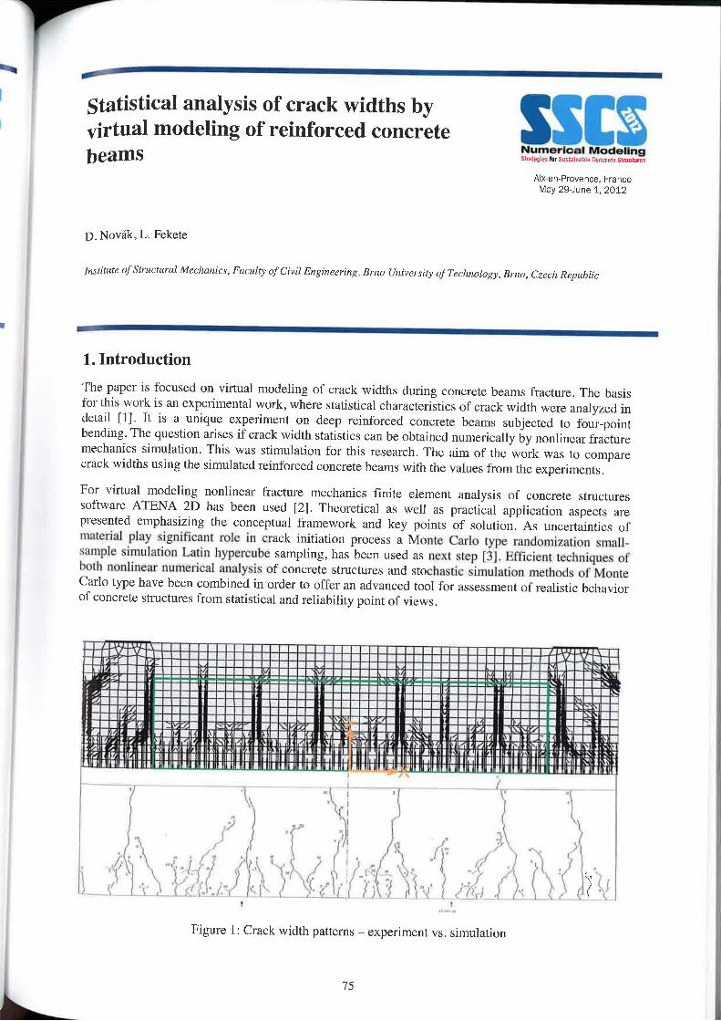
statistical analysis of crack Widths by‘ virtual modeling of reinforced concrete
Numerical Modelingstvalzuw In Suxtauvilriv rnnevm stmtttim
AlX—er\»Pr0ver\ee, FranceMay 29-June 1. 2012
D. Novék, L. Fekete
Iuslitulfl ufslrllcluml Mechanics, Fauulry of Civil Engirwering, Hrrw I/nivcrsity 0; Tethnlliogy, mm-, Czech Republic
1. IntroductionThe paper is focused on virtual modeling of crack widths during concrete beams fracture. The basisfor this work is an experimental Work, where statistical characteristics of crack width were analyzed indetail [1]. It is a unique experiment on deep reinforced concrete beams subjected to four—pointbending. The question arises if crack width statistics can be obtained numerically by nonlinear fracturemechanics simulation. This was stimulation for this research. The aim of the work was to comparecrack widths using the simulated reinforced concrete beams with the values from the experiments.
For virtual modeling nonlinear fracture mechanics finite element analysis of concrete structuressoftware ATENA 2D has been used [214 Theoretical as well as practical application aspects arepresented emphasizing the conceptual framework and key points of solution. As uncertainties ofmaterial play significant role in crack initiation process a Monte Carlo type randomization small»sample simulation Latin hypercube sampling, has been used as ncxt step [3]. Efficient techniques ofboth nonlinear numerical analysis of concrete structures and stochastic simulation methods of MonteCarlo type have been combined in order to offer an advanced tool for assessment of realistic behaviorof concrete structures from statistical and reliability point of views.
!...._..._.___.__-Iirseailllao 5:-i§I_IIIlI.oIL :§5§§!!IlII‘.5
....=_aI|nllu:
-%—-<::-ls§§IIIIIl!!
7*2::.lII!!!!Ii
_-.,__..._._.<<.\<-P
/ _!!zgIIIIIIIinll
:::!lIIIIIlIII
_~giéggv-RGIIIIIIIIII
5;-IalulllliIIII
'~gigIlIIII__IIIA 2::_4__........I] —\Q5;-4§IIIIIIllII
Agg.IIIIIlIIIII5!_gIIIIIIIII
IA rgg-anIIIIIIIII ¢/~-2;‘IIII_IIII
---
/‘"'5iiiiinII: -gggIIIIIIIIIM _5:-____g|IIllIII 7»,_~\_2E2:-*\rIIIIIIIIII
;!i__ԤIIIIIlIIIlI
gig-<5lIIIII_III<-_
‘*iiiiii.5:.—\_<,,5/‘5-5IIIIIII_=;%;____-- _IIIIIII
\,__-_IIIIIIII _::__!IIllIIII ‘ rgiiifiillill‘>.___!!~*sIIIII1~“'22;-4_i!_IIIII\II
E-!§_4éIIIlI|III g._!r_:IIIIIIIIII
\;-;_._IIIIQIIIIIII/_\...:\!=::._._......-<___In
_!!g!5iIIIIIIII ;:5§__IIIIlIIII =2-—IIIIIIIIll
\-sgag!EIIIIIIIII\gg-$§IIIII.lII
"“’==-'2iiiii':::/L--9...r_
gggggaillunIIIII g!>g:-.::£4_IIIIIllIlII
,__‘ggsqnlllllIII‘/4-I~\!lIIIIIIllll‘
I'f"!lIIIIV)//‘1(<I\2:“-‘;::=§::,!
\\*'“‘ ..!IIIIIllI
T”
.
-5.-..||-pal:
II////QII'/:III
IVF! . !I U. . ,I‘JV: !__!.’”- __E!!‘!! P\Y!!!!!!:!!'¥.!. El!‘ E!!!) E--3' ~
'1 III lII I'I :\§!‘I lswllI II on _ i\!IIit ' .~' 1 oar II 104 Ip’ III I_‘YA lvnltll I lul » §\Y1I I IQI 1: v??L7.'.l‘ll 'z. $1 rm.-u1I:|Ii I1 .l#\WIl1l “It M |..ll1\1\ min 1:i|..z.:|~.:r in 1|» i rm no is:Ii ‘IIII I lli rliilxulnIt ‘I‘lli‘I‘.Il\ll‘
'\~<;\. ,4_
%~l E.. *1. x/--\ /~\A Y- \ V“\) ‘E1 l l(‘)<’ - \
Figure l: Crack width patterns — experiment vs. simulation
75
pm
Crack widths were studied at nine cuts and statistical characteristics were calculated — mean crackwidth, maximum crack width and coeffieierrt of variation. Experimental results versus numericalsimulation were compared. good agreement was obtained. The paper discuss the differences bctweerrthe behaviour of different material models (Sbeta model and fractur'e~plastic model Non-linearcementitious). crack models (fixed and rotated cracks) and between simulations with and without deadweight. Comparison with design specification is performed in the form of probability that allowablecrack width (according to standard) will be exceeded.
References
/II Bt'aam.C, R..Contt'ol ofcrack width in deep reinforced concrete beams. HERON. Vol.35. No.4. 1990.[2] Cervenkn. V.. Jendele. L.. cervenka. 1.. 'ATENA Program Document. — Part l: Theory’. Cervenka
Consulting. Prague, (2007) htlp://wwwcervenkaicz .I3] Novék, D., Vofechovsky, M., Rusina, R., ’FReE'l‘ - program doeuinentation. User's and Theory Guides’,
Brno/Cervenka Consulting. Prague. (2010) http://www.freet.cz.
ll
76 l
Modeling of the behaviour of RC tie-beamsreinforced by flat steel rebars:A comparison between 2D and 3D numerical
AIX err Provence Francesimulations of the steel/concrete interface M-ay ignne 1'. 2012
T.S Phan“ , .l.»L. Tailhan*, P. Rossi", Ph. Brcssolette’, . Mezghanii,J, Foulliar0n'
"French Institute 0/ Science and 'l'r'chn0logyfor Trartsport, Developmzrtl (Hid Natworkr ursrmx) Paris Elli! University, France1 Ciermortl University. Blaise Pascal University LaMI, E./U867, BP Z06, 63000 Clermont, France f MATIEREU - Cortstructionmmptlny, Franceemail .» [email protected], jean-louisxzrilhun@$rtmrfr, pierre.r0:[email protected]
The simulation of the behaviour of the steel-concrete interface is of primary importance for an accuratedescription of cracking processes in reinforced concrete structures and an improved prediction of theirdurability. in this paper, the methodology used to identify the mechanical behaviour of a steel-concreteinterface in the case of a particular steel reinforcement is first mentioned. The methodology consists insimulating the statistical mechanical behaviour of RC tie-beams (170 x 10 x l0 cm), subjected to tension,using a probabilistic approach for the mechanical behaviour of the concrete and a deterministic model forthe steel—concrete interface. The tie—beams are reinforced by a flat steel rebar which cross section isrectangular (22.5 x 5 mm).
In this work, the model simulating the concrete behaviour takes into account the inherent heterogeneity ofthe material and the consecutive scale effects on its mechanical properties (tensile strength f. and Young'smodulus Ec) via appropriate size effect laws and random distributions [1]. The steel-concrete interface isrepresented by contact elements which behaviour is modelled by a damage model taking into account theprincipal mechanical behaviour of physical phenomena of the interface: the cohesion and the slip. Theobtained numerical results are compared with experiments [2]. The comparison is made in terms of globalresponse (load-relative displacement curves), as well as local response (cracks opening, cracks spacingand number of cracks). And as far as the developed approach remains probabilistic, they are examined in astatistical way and the results seem to be relevant [3] [4]. In this Work, a 3D numerical simulation of theseRC tie-beams and its results will also be presented, and a comparison between the two approaches isperformed. Finally, a discussion on the efficiency of both approaches (ZD and 3D) is also proposed.
Keywords: Reinforced concrete, flat steel rebar, steel—concrete interface, cracking.
References:[l] Probabilistic model for material behavior analysis and appraisement of concrete structures, Rossi P. and Wu X.,Mag.Conc.Res., 44 (l6l):27l-280, 1992.
[Z] Internal report of experimental results on RC tie-beams tests, MATIERE. 2010.[3] Numerical Probabilistic Simulation of Cracking Processes in RC Tie—beams Subjected to Tension and Rein—forced by Flat Steel Rcbats. Phan T.S., Rossi P. and Tailhan J.—L., Proceeding of International Conference onComputational Modeling of Fracture and Failure of Materials and stnrctures (CFRAC 2011), Barcelona, Spain,20]].
l4] Numerical modeling of the rebar/concrete interface: case of thc flat stecl rebars, Phan T.S., Rossi P., Tailhan J .-L-. Bressolctte l’h. and Mezghani F., Mag.Mat.Stn1c. (In review 201 l)
77
Continuum damage mechanics based model , plfor quasi-brittle materials subjected to ')cyclic loadings: application to concrete
Aix-en-Provence, FranceMay 29—June 1. 2012
B. Richard, F. Raguencau, A. Delaplace, C. OliverLMT/ENS Cttchnn, CNRS/Univ. Paris 6/ PRES Uri/'verSud,61 Avenue du President Wilson, Caclmn, France, {Benjamin Rich:lVd}@Imr.en.r—caL‘hanfr
Abstract
The events occurred in the World have shown the necessity to build constitutive models capable ofpredicting thc response of a structure when subjected to cyclic - or seismic — loadings, particularly in thefield of nuclear engineering. In civil engineering, concrete and steel are the most used materials. Materialnonlinearities are mainly due to cracking.
The aim of that study is to propose an original concrete constitutive model allowing a refined descriptionof mechanisms involved in the case of cyclic loadings. The formulation is based on a thermodynamicalcoupling between elasticity, damage, internal sliding and inelasticity. A full and progressive unilateraleffect is also considered. Although further works is needed to validate this model, first applications showthat the formulation is able to represent closed-loop bending tests not only in a quantitative way(load/displacement) but also in a qualitative way (damage pattern). The proposed model has also beenapplied to large-scale reinforced concrete structures subjected to synthetic accelerograms and the resultsclearly eniphasive the power of such an approach.
Keywords: Unilateral effect, continuum damage mechanics, concrete, thermodynamics
78
Numerical modelling of cracking in fibrereinforced concretes
Numerical ModelingSt1.\\=§\r-shryiuslumah E Cnvmrlv smt.w-.Alx-en-Provence, Fiance
May 29—June 1, 2012
P.Rossi,J.-L.Tailh21nUnlvzrsilé rum-,1;'n, ll-‘STTAR, MAT, F-75732. Paris, Francz
Fibre reinforced concretes are more and more used in structural applications. One of the principal reasonsof this statement is related to the existence of national (French, Japanese, Italian, German...) andinternational (Rilem, Fib...) recommendations concerning the design of stnictures using this type ofmaterial.
These recommendations are efficient for designing simple isostatic structures (beams and slabs) loaded inbending. But, for more complex hyperstatic structures or for others types of loading as shear and pushing,these recommendations are not enough physically based to propose relevant solutions. As a matter of fact,they are often too conservative and lead to an over consumption of matter. That is not good, especially ifthe problem of sustainable development is concerned.
In these eases, the best approach for designing structures in the respect of both safety and sustainabledevelopment is to use finite element analysis.LCPC (newly IFSTTAR) develops a probabilistic discrete cracking model since 1985 (first paper in aninternational journal in 1987). This numerical modelling firstly developed for analyzing cracking ofconcrete structures has been then (1992) enriched to take into account cracking of fibre reinforcedconcrete structures.
[n the present paper, an improvement of this probabilistic discrete cracking model devoted to the analysisof fibre reinforced concretes cracking is proposcd.In this new model:- Cracks creation and propagation in the concrete arc taken into account by using special interfaceelements which open when the normal tensile stress at its gravity centre reaches a critical value. Theprobabilistic aspect of the cracking process is then given by the fact that the critical value of the tensilestress is randomly distributed through the mesh.~ Just after the cracks creation, the fibres acting is taken into account by considering a linear decrease ofthe tensile stress in function of the crack opening. This post-cracking behaviour is modelled by using adamage model approach. I-Iere. the probabilistic aspect consists in randomly distributing the post—crackingenergy.
In the paper, the above numerical modelling is used to analywe the shear behaviour of a beam made with asteel fibre reinforced concrete. The simulations are compared with experimental results in terms of globalbehaviour of thc beam and in terms of cracking process (cracks number, spacing and opening).
79
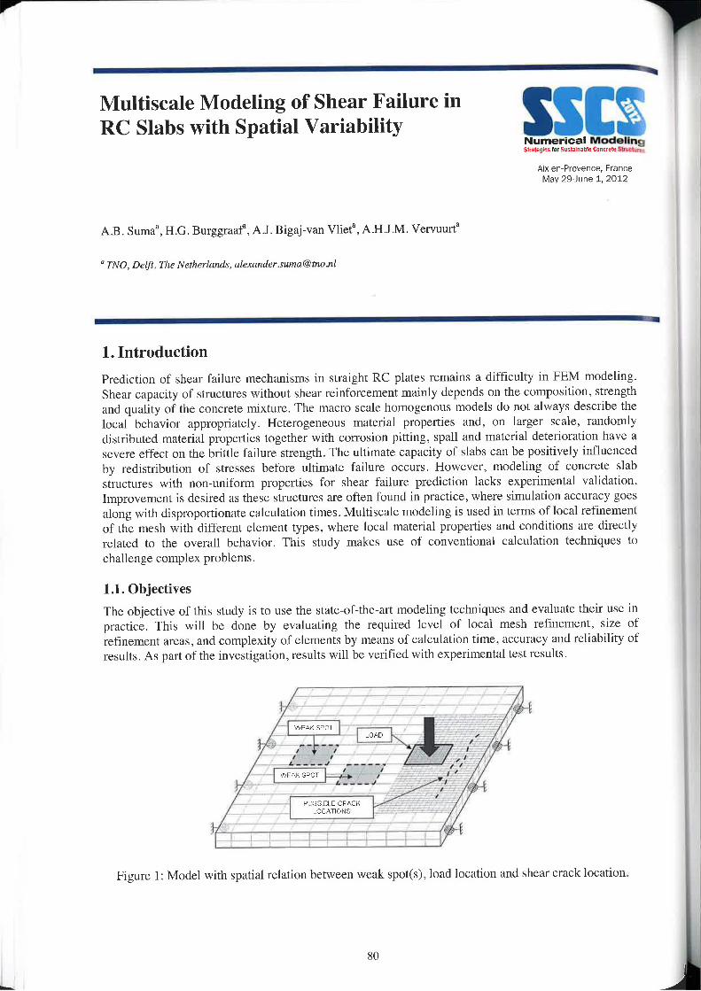
V
_
Multiscale Modeling of Shear Failure inRC Slabs with Spatial Variability SSW
Numerical ModelingStrategies lflliuslmuahl/1 Dontvuluilllliltms
Aix-en—Prover\ce, FranceMay 29Jur\e 1. 2012
AB. Suma', H.G. Burggraaf“, A_l. Bigaj-van Vliet“, A.HJ.M. Vervuurta
M T/V0, Delfl, Th8 Nethzrlrunla, (4l€'X41!lA16r.rm'[email protected]
1. IntroductionPrediction of shear failure mechanisms in straight RC plates remains a difficulty in FEM modeling.Shear capacity of structures without shear reinforcement mainly depends on the composition, strengthand quality of the concrete mixture. The macro scale homogenous models do not always describe thelocal behavior appropriately. Heterogeneous material properties and, on larger scale, randomlydistributed material properties together with corrosion pitting, spall and material deterioration have asevere effect on the brittle failure strength. The ultimate capacity of slabs can be positively influencedby redistribution of stresses before ultimate failure occurs. However, modeling of concrete slabstructures with n0n—\lnlfOrm properties for shear failure prediction lacks experimental validation.Improvement is desired as these stmctures are often found in practice, where simulation accuracy goesalong with disproportionate calculation times. Multiscale modeling is used in terms of local refinementof the mesh with different element types. where local material properties and conditions are directlyrelated to the overall behavior. This study makes use of conventional calculation techniques tochallenge complex problems.
1.1. ObjectivesThe objective of this study is to use the state—of»the»art modeling techniques and evaluate their use inpractice. This will be done by evaluating the required level of local mesh refinement, size ofrefinement areas, and complexity of elements by means of calculation time, accuracy and reliability ofresults. As part of the investigation, results will be verified with experimental test results.
WEN/»$FOT/
W |-— --- I 1,?
l ' ' 'ii’, '' 1'.-.... I, .9, __j/A p
i ‘ ‘ ' l
“s \\\
Figure l: Model with spatial relation between weak spot(s), load location and shear crack location.
80
1,2. Subject of studyThe subject of study is a RC slab without shear reinforcement with a concentrated load (Fig. 1). Inwlflflnn to practice. the slab study is focused on brittle shear failure, Where life time expectation needsto be estimated by means of FEM models. With more knowledge of mesh refinement and influence ofmeal deficiencies, time Consuming calculations of tunnel walls, bridge decks, building Walls and floorsslabs will be reduced. From this context. most relevant configurations for spatial variability aredefined in terms of load location, cycling and magnitudes, weak spot location(s) and grade, andprobable crack initiation location.
1.3. MethodologyThe study case will be approached by making use of ATENA software. This package is Wellestablished for concrete modeling with shear failure mechanisms and cracking patterns. ln addition,ATENA employs advanced constitutive models for concrete (incl. post-peak behavior for specificfailure mechanism), based on damage mechanics, nonlinear fracture mechanics and plasticity theorieswith smeared crack approach, specific for computer simulation of reinforced structures (e.g. crackingof concrete is governed by the nonlinear fracture mechanics).
1.4. Research programInvestigations will start by modeling with relatively large elements to explore spatial relations andbehavior in order to select most interesting cases. This is followed by modeling a more defined areaaround the probable cracks, Weak spnt(s), and load plane with a finc mosh consisting of solidelements. ln a second phase, areas with linear and nonlinear behavior are selected, and replaccd byshell elements and a refined mesh of solid element respectively. Iteratively, the sizc of the localizedarea and thc lcvel of refinement will be tested for optimized calculation time and level of accuracy.
References
[1] Title, A. B. Authl , B. C. Auth2, RILEM, 2012.
81
Probabilistic modelling of crack creation .7and propagation in concrete structures: “lsome numerical and mechanicalconsiderations. “l3§y"§$31i1°i'. @538
J.L. Tailhan, P. Rossi, T. S. Phan, _l. Foulliaron
I"ari.r—Eua/ University, F/‘such Institute 0/ Science and Tzechnulogyfm Tmn.\[7l/rt, Duvclupnierll a/niNe1w0rl<s, 58 rm lmbvre,75732 Paris crldex 15.
The numerical modelling of concrete cracking is a challenging issue in Civil Engineering. Thedevelopment of models providing information on Lhc characteristics of concrete cracks, for a givenenvironment, loading and limit conditions set, is actually very popular. Cracks openings, lengths,orientations and spatial distributions are essential factors. Their impact on the long-term structuralperformance maintenance must he taken into account for an accurate prediction of structures life span.
Since the 90's, the French “Laboratoire des Ponts et Chaussécs" (now named IIFSTTAR) has developed adiscrete probabilistic model [l] for an accurate description of the cracking processes in concretestructures. The model, which has been recently reworked, takes into consideration the inherentheterogeneity of the material and the consecutive scale effects on its mechanical properties viaappropriate, and experimentally validated, size effect laws and random distributions. Since the model usescontact elements for the description of the kinematic discontinuities of the displacement field when cracksappear, the model can provide local information on both micro and macro cracks and it is well suited formodelling cracking patterns. In this framework of modelling of crack creation and propagation, theefficiency and the relevance of the approach, for a given scale of modelling, directly depends on thejudicious choice of the couple of type of model/type of numerical support. This paper illustrates thatapproximating the description of crack propagation by the progressive creation of coalescent multiplecrack planes by using a local elastic brittle behaviour necessarily induces the use of a quadratic element(for very fine refinements of meshes), and at the opposite, the use of an enriched model can allow the useof linear elements at a larger scale (i.e. for larger elements). The choice between these two strategies hasan important and obvious impact on the richness of the local information obtained for cracking processes(micro and macro cracking). An illustration is proposed through the modelling of crack propagation iflplane concrete structures and numerical results are compared to experimental results of tests performed fllIfsttar (concrete beams in bending and double cantilever beams).
References:[1] Rossi, P. and Wu, X., Probabilistic model for material behaviour analysis and appraisement of concretestructures, Mag.Conc.Res., 44 (l6l):27l-280, [992
82
‘ ‘ A RC fibre beam element for full modelling lof the bendin shear res onse b dualg‘ P Y
. tlumerlcal ModelingSectlon apprgach Sliilfiqln hISu§l.tlriIhl: Clltllllil §i.iti....<Aix—en—Pro\/ence, FranceMay 2elime 1, 2011
P. Tortolini, E. Spaeoue, M. Petrangeli
Department Civil lingineering (If!/IE "0. D'Anrumzi0" University , l’e.\'l.'uru, hilly
AbstractThe paper describe a fibre element with axial, bending and shear interaction for the static and dynamicanalysis of reinforced concrete beams and columns. The element accuracy and numerical robustnessmake it a very useful tool in the seismic analysis of RC structures.
The element response is calculated by integrating a full 2D behaviour of the concrete fibres and the bi-axial arrangement of the longitudinal and transverse steel. The beam model is an evolution of thePetrangeli's element, [10], as they share the same solution strategies and overall element architectureand similar steel and concrete constitutive models. Both elements use an equilibrium based iterativeapproach to integrate the element stress»strain fields. The concrete constitutive model is an evolutionof the microplane approach, modified to account for material heterogeneity. The model uses the planesections rernain plane hypothesis.
The major improvement of the new model relay on a static approach for the solution of the sectionshear field (fibre shear strains). The latter is obtained by imposing equilibrium, fibre by fibre, withadjoining sections following the Dual Section approach as proposed by Vecchio and Collins, [16].Although this approach requires nesting of section iterations within the element solution, it isconsidered a substantial improvement With respect to the previous one that used predefined sectionshear functions (cinematic approach). This new approach ensures equilibrium and compatibility atboth section and fibre level with improved capability of depicting the actual localization of axial andshear deformation within the reinforced concrete element.
The model is validated with two case studies based on experimental tests carried out at UNI San Diegoon column specimens exhibiting a flexural and a shear failure under cyclic loading. Qualitative andquantitative agreement between model response and tests are quite impressive demonstrating theelement capability to correctly depict the actual behaviour of R.C. members and their failuremechanisms under combined axial, bending and shear forces.
References
[11 Baiant, '/..P., Prat, l>.c., wss. Microplane m(!LlC| for brittle plastic material. I: Tl'teOt‘y”, J. of EngineeringMechanics, ASCH. ll4(lO), i672-I688.
[21 cm-sir P.. Pertini L., Pll1l1O R., 2007. FlCX|.\l‘C—Sl\LEi1T fiber Beam—column element mi modelling framestructures under seismic loading - Slate of An. J. of Earthquake Engineering 11,46-88.
[3] Ceresa PA, Pelrini l.., Pinho R., R. Sousa., 2009. A fibre flexure—shear model for seislnic analysis of RC—framed structures. Earthquake Engineering and Structural Dynamics, 38(5), 537586.
l4] Gregori .l.N., Sosa P.M.. Prada M.A.F., Filippou F.C., 2007. 3D frame element for the analysis of reinforcedand prcstrcssed concrete structures subjected to shear and torsion loads. Engineering Structures, 29(12),34043419.
83
[5] Gucdes, 1.. Pinto, A... I997. A numerical model for shear dominated bridge piers. Proc. of the secondltsrlian-Japan Workshop on seismic design and retrofit of bridges, Roma,
I6] Menegotto, M.. Pinto E.. i973. Method of analysis for cyclically loaded reinforced concrete plane frar-rmincluding changes in geometry and non-elastic behaviour of elements under combined normal force andbending. Proc. IABSE Symposium. Lisbon. Portugal .
[7] Mander..l.B., Priestley. M.J.N.. Park, R. l988,Thcoretic:tl stress-strain model for confined concrete. JournnlofEngineer'ing Meelianics, ASCE, ll4(8). 1804-1826.
|8] Petrangeli M.. Ciampi V.. I997. Equilibtitmr based iterative solutions for the nonlinear beam problem.International] J. oi‘ Numerical Methods in Engirrecr'ing. 40. 423-437.
[0] Petrangeli, M.. Pinto. l".E.. Cianrpi. V., 1999. Fibre element for cyclic bending and shear of RC structures. l;Theory. .l. of Engineering Mechanics, ASCE, l25(9). 994-100].
[I0] Peuangeli, M.. I999, “Fibre element for cyclic bending and shear of RC structures. II: Verification. Journalof En-gineering Mechanics. ASCE. 125(9), 1002-I009.
{ll]Ranzo. G.. Petrnngeli, M.. 1998. A llhre linile beam element with section shear modeling for seismicnnrrlysis of RC struettltes. J. of Earthquake Engineering, 2(3). 443-473.
[l2lR:rnzo, G.. 2000. Experimental and Numerical Studies on the Seismic Perlornnmee of Beam-Column RCStruc-tural Members Subject to High Shear. PhD Dissertn-tion. Facolta di lngengeria, Univcrsita “LrrSapienza". Roma.
[l3]Spaeone. E., Ciarnpi. V.. Filippou. F.C., 1996. Mixed forrnrrlrrtitnr ol‘ nonlinear beam finite element.Comprlters KL Structures, 58(1). 7 I-83.
ll4]TortoIini. P., l’cu'nngeli. M.. Spzrcone. 2009. Un modello nricroplane motlilicato per la rispostn dc]ealccstnizzo nel piano. Atti Xlll Congrcsso ANIDIS. Bologna, 28 giugno - 2 Luglio (Italian)
llS]Tortolini. P.. 2011. Uelcrnento di trave non iineare con interzrzione M~N-V. PhD Dissertation. Facolta diArchitettura, Universita "G.D'Anl\unzio" Clrieti-Pcscara (Italian).
[16] Vecchio. F.J.. Collins, M.P., I988. Predicting the response of reinforced concrete beams subjected to shearusing Modified Compression Field Theory. ACI Structural Journal. 85, 258-268.
[ I 7]Xiao Y.. I993. Steel jacket retrofit for enhancing shear strength of short rectangular reinforced concretecolumns. Report No. SSRP-92/O7, University of Cnlilorrria, San Diego.
l 84
Numerical methods for collapse analysis ofRC framed structures with physical andgeometrical nonlinearity.
Aix—en-Provence. FranceMay 2&Jur\e 1, 2012
M. Ucci' . M. V. Sivaselvanz. E. Spacone‘1 De/J1. ufS!ruc!urulErrgint'ermg, Univ4'r.\ir‘y afChiuli—I-’e.\'cum “G.d'Ann.1mzi0”, Imly{m,ucci, e:pacone)@1miEh.iI2 Dept. 0_/"Civil, Environmental and Architectural Engineering, University of Colorado at swan. C0, [email protected]
i
Abstract
The use of numerical methods for nonlinear time—histor'y analysis of reinforced concrete structures up tothe ultimate and collapse limit states should consider second order effects. Structures subjected to seismicloading show a rapid growth of early cracking which can determine sudden loss of bearing capacity and,eventually, element failure. Although local collapse can be recognized as a significant cvcnt in theanalysis, in order to track structural collapse at a global level, capacity design must be simulated. Theprogressive level of damage, along with element failures, affects dynamic behavior so that the structuralscheme should be updated in U-“I64 Moreover, kinematic mechanisms can take place, even in case ofhighly redundant structures, due to the fonnation of plastic hinges. Such conditions likely imply largedisplacements and rotations of joints in space. According to spatial kinematics [1], the latter should betreated with particular attention, since they can produce numerical instabilities. In fact, somerepresentations of finite rotations may lead to singularities and energetic inconsistencies, threateningadherence of the solution to the related physical problem. This fact depends on the non-Euclidean natureof the configiration space of rigid bodics in space. Therefore, a preliminary study has been conducted todetermine the most suitable representation system for rigid body motion. Numerical results for anelastically restrained body have been carried out and compared. ln a second phase, a physically nonlinearforce-based element based on Spacone et al.[2] and complying with the chosen representation system hasbeen formulated. A computational framework for testing the element has also been developed. Structure-preserving solution algorithms have been adopted, in order to ensure conservation of hamiltonian andother important first integrals characterizing the problem [3]. Numerical results show optimal convcrgcnccand energetic consistency throughout the solution.
Keywords: Geometrical nonlineaiity, Frame analysis, Nonlinear dynamic analysis, Seismic analysis
References:[l] Space kinematics and Lie groups, A. Karger, J . Novrik, Gordon and Breach Science Publishers, New York,1985.[Z] Fiber Beam»ColumnM0del for Nonlinear Analysis of R/C Frames. I: Fonnulation., E. Spacone, F.C. Filippou,FF. Taucer, Earthquake Engineering and Structural Dynamics, Vol. 25, N. 7., pp. 71 l-725, 1996.[3] Geometric numerical integration: structure-preserving algorithms for ordinary differential equations, E.l-lairer.C‘ Lubich, G. Wanner, Springer, 2006.
85
I
l
L
SSENumerical ModelingSlvllrglrslntiuslimihlr mm stints,‘
Aixen—Provence, FranceMay 29—Jurie 1, 2012
Session I-5:Chemical aging (chemical reactions and transfers)Lattice discrete particle modeling of alkali-silicareaction effects to concrete structuresGiovanni or Lu1io‘,Mohammed Alnaggarz, Gianluca Cusatiss'Assis!ant Professor, Department ofstructural Engineering (ms), Politccnico at Milunu, ItalyZkeseurch /r.r.ri.rtr1nt, Department 0fClvil and Environmental Engineering, Northwestern University, Evanston, USA‘A.r.\'0ciaIe Professor, Department nfCivil and Environmental Engineering, Narthwcstern University, Evansmn, USA
Thc Alkali—Silica Reaction in Concrete: Structural Modeling and Numerical SimulationR. Esposito, M.A4N. HendriksDel/i‘ University of Technology, The Netherlands
Bayesian reliability of reinforced concrete structure coupled with corrosion sensorsG. bebon, C. Poisson, R, Devaux. V. LamourCementys, Choiry-le-Roi, France
Concrete resistivity on small scale high performance concrete samplesI . Lizarazo-Marriaga, C. A. CortésFacultad dc Ingcnieriu, Universirlazl Naci/mal dc Cnlombia
Simulation of the concrete chloride NT Builtl49Zrnigra(itJtl testJ. Lizarazo-Marriaga‘ , J. Gonzalez' , P. crime’' Universidad Nacionul dc Colombia - 2 Cnventry Univcr.rity— ux
A mllltiscale approach to diffusion phenomena in concreteF. Nilcnius ‘-1, F. Larssonz. K. Lundgrenl , K. Runessoni[Dcpnflment ofCivil and Environmental Engineering, Chalmers University 0fTecnn0logy, 2 Department of AppliedMechanics, Chalmers University ofTechnology, Sweden
Contact elements, creep and anisotropy for the numerical modelling of concrete structures affected by internalswelling reaction0. Omikrine»Metalssi1,J.—F. Seignol' . s. Rigobert', F. Toutlemondel and r..»r. BoldeazlUniversité Paris-Est, IFSTTAR, Paris, France — 2 Stucky, Lausanne, Switzerland
Assessment of service life and environmental impacts of chloride exposed concrete structures with repairs by coverreplacement iA. PetcherdchttoKing Mnngkufs University of Technology North Bangkok, Thailand
87

"l
4
Prediction of Chloride lngress into Concrete in a Marine EnvironmentIan N. RobertsonUm'ver.\'i1y ufHawuii, Depar/men! ofCivil Engineering. USA
Lattice model as a tool for modelling transpnrl phenomena in cement based cumpusitesB. §nvija, J. Pacheco. RB. Folder, E. SchlangcnMicrnlab. Delfl l/niverrily of Technology. Delfl. The NerherImul_\'
Numerical lnol for durability assessment of concrete structures subjected to aggressive environmentJ4 Mni~Nhu', A. Sellierz, P. Rougeau', F. Duprat2I CERIB (Sludy and Research Cenlre for the I"r'em:h Concrete Inzl|4.\"l1'y), 2 Univer's|'1é de Toulouse, UPS, INS4LMDC (Lulu/raruil-e Mulériuux al Duralzililé des C0n.\‘Ir!lrIim1.!')
Modelling of the moisture transfer under wetting-drying cycles in cementitious materialZ. Zhang. M. Thiéry. V.Bar0ghcl BonnyIFSTTAR Pzl/‘is, Pram-e
88
Lattice discrete particle modelling ofalkali-silica- reaction effects to concrete
Numerical ModelingStructuresAix-en-Provence, France
May 29—June 1, 2012
Giovanni Di Luziol , Mohammed Alnaggar2, Gianluca Cusatis3’ As.\ist1mr Prr)fL'.\'.\'1lr, Department 0/Struclurril bngincering (ms). Politecnico di Milan:/, Itrily [email protected] Research Assistant. Department. of Civil and Environmental Engineering, Northwestern University, Evimrron usaMo/1ammemilnaggar20I2@unorrhwesterrueduI Associate Pro/error, Department. 0fCivil and Environmental Engineering, Northwestern University, Evrznswn USAgialllu£[email protected]
Abstract
A largc number of structures especially in high humidity environments are endangered by Al.kali—Silica Reaction (ASR). ASR is characterized by two proccsscs: the first is gel formation resulting fromcontact between alkali and reactive silica in aggregates; the second is watcr imbibition into this formedbasic gel which is the one responsible of the progressive swelling behavior. The swelling causesdeterioration of concrete internal structure by cracking of reactive aggregate, mortar matrix and mortaraggregate contact surface, leading to loss of concrete strength and stiffness, Many research effortswere directed towards the evaluation, modelling and treatment of these phenomena but acomprehensive computational model is still lacking.
In this paper, the ASR effect is implemented within thc framework of a mesoscale formulation thatsimulates concrete heterogeneity and ASR thermochemo-mechanical characteristics. The mesoscalcmodel adopted is the Lattice Discrete Particle Model (LDPM), which simulates the mechanical interactionof coarse aggregate pieces through a system of three-dimensional polyhedral particles connected throughlattice struts. LDPM has been calibrated and validated extensively with comparison to experimental dataand it has shown superior capabilities in modelling concrete cracking and fracture.
The ASR expansion behavior is assumed to be totally zt result of water imbibition into the formed ASRbasic gel. For caeh aggregate, the two processes are simulated assuming that the aggregate paniclcs arespheres and the permeability of the ASR gel is based on Fick's law. The gel formation ratc, which directlydepends on water supply to the reaction front, is calculated by a radial diffusion law. The rate of waterimbibition is calculated using the thermodynamic equilibrium of watcr imbibition process. For a singleaggregate, the model predicts the volume increase of the aggicgatc due to water imbibition.The single aggregate model is then amalgamated within the LDPM framework by calculating thc rateof change of each LDPM simulated aggregate radius assuming uniform aggregate volume change. TheChange in LDPM tetrahedron edge lengths are then calculated and applied to the facets along theseedges as nonnal strains. Also the state of stress inside the LDPM meso-structure is used to redirect theapplied normal strains to simulate expansion transfer reported in many experimental data.Since LDPM simulates the heterogeneity and randomness characteristics of concrete. this formulationallows for precise and unique modelling of ASR effect including non-uniform expansions, expansionlrnnsfer and heterogeneous cracking. Thc model can replicate ASR cracking behavior even in freeElipansion tests. This is a capability that cannot be obtained within classical homogeneous and isotropicContinuum based models. In addition, it reproduces reactive aggregate size and distribution effects on thcASR expansion considering temperature and stress state effects. The prcscnt model was validated based onthe simulation of experiments for free and laterally passively restrained specimens under free expansion asWell as subjccted to axial load. The results showed good agreement with the experimental data.
89
7
Q
The Alkali-Silica Reaction in Concrete:Structural Modeling and NumericalSimulation NllIIl8l'lOB| Mfldflllnsfilmlviullrsistiv.<hl:Ulm.reY:S\|lmI: ..
A|x—en—Pr0vence. FranceMay 29—June 1, 2012
R. Esposito, M.A.N. Hendriks
Delft University of Technology, The Netherlands
During their service life, concrete structures can be affected by chemical degradation processes. One ofthe most harmful processes is given by Alkali—Silica Reaction. which produces a hydrophilic andexpansive gel. This reaction. Which begins at mierostructural level, may cause serious damage withconsequent loss of structural capacity; the designer must be able to assess the safety at macrostructurallevel.The gel formation and swelling is influenced by the environmental condition, as temperature andmoisture. In a structural model these aspects can be taken in account through a kinetic law: one of themost known and used law was performed by Larive [1]. In an ASR-affected concrete stmcture also theinteraction between gel and cement matrix is a relevant aspect. Experimental tests show that gel expansioninto the concrete is influenced by the concrete porosity and the boundary condition (Larive [1], Multonand Toutlemonde [2]).In the last SO years various structural models have been developed and implemented in finite elementcodes. In early proposals the gel expansion is taken in account with a thermal equivalent approach. Moreadvanced models have been developed by Ulm et al. [2], Bangert et al. [3], Saouma and Perrotti [4] andComi et al. [5]. They are dzunage models in which the coupling between the chemical and mechanicalaspects is considered.The choice of mechanical properties and environmental parameters, on the basis of a literature review, forfinite element analyses regarding ASR—affeeted concrete is discussed in this paper. The concepts areunderlined by some examples.
References:[I] Larive. C., I998. Apports combines de |'eXpét'imeuIation et dc la modélisalion Ia comprehension de l'alculi-reaction et de ses effets mécaniques. Ph.D. Thesis, LCPC.
[2] Multon, S., Toutlemonde, F.. 2006. Effect of applied stresses on alkali-silica reaction-induced expansions.Cement and Concrete Research 36. 9l2—920.
[3] Ulm, F.J.. Coussy. 0.. Kefei, L., Larive, C.. 2000. Thermo-chemo-mechanics of ASR expansion in concretestructures. ASCE Journal of Engineering Mechanics 126 (3), 233-242.
[4] Bangert. F.D.K., Meschken, G., 2004. Chemo-I-lygro-Mechanical Modeling and Numerical Simulation OfConcrete Deterioration Caused by Alkali Silica Reaction, International Journal of Numerical Analytical Methods andGeoniechanics, 28, 689714.
[5] Saouma, V., Perotti, I... 2006, Constitutive model for a]kali—aggregate reaction. ACI Material Journal I03, 194*202.
[6] Comi, C.. Fedele, R , Pcrego, U., 2009, A chemo-thermo—damagc mode] for the analysis of concrete tlamSaffected by alkali—silica reaction. Mechanics of Materials 41 , 2l0—230.
90
Bayesian reliability of reinforced concrete‘ structure coupled with corrosion sensors
Numerical ModelingSt-raleqln Ill! Suililuahlli Enricrete SIWZIIAYI:
Aixen-Provence. FranceMay 2SLJtme 1, 2012
(;_ Lebon, C. Poisson, R. Devaux, V. Lamour
Cr*!iiL'!|l_\'.9 Slls. 29 avenue ta la Républiquc, 94000 Choisy 12 rm. Frzlricz,.w.».t-.-mt-tin-.\< mm (gregorylebonyincenllamour}@t‘emenrys.com
Reinforced concrete is Widely used for durable construction in civil engineering. But the sustainabilityof reinforced concrete structure depends mainly of the corrosion of steel reinforcement. Thedegradation is induced by environmental actions and by the use of the structure (de-icing salt,atmospheric CO1 or leaching). The corrosion affects severely the integrity of the stnicture and thevisible consequences appear when the state of the stnicture is critical. To optimize the reparation orprevention costs, it is necessary to predict the risk of corrosion before that visual degradations appear.
Our first approach to assess such a risk is based on a simple diffusion model of chloride identified byinsitu corrosion sensors. Fick’s second law gives the chloride concentration along the concrete coverat considered time. The parameters of the law are the initial chloride concentration in the concrete, thechloride concentration of the environment, and the diffusion parameter of the concrete. A threshold onthe chloride concentration gives the begiruring of the corrosion of the reinforce steel. The lack ofknowledge about these parameters makes more difficult the prognosis of a structure. Probabilisticmodelling is necessary to evaluate the risk of corrosion. To enhance the accuracy of the diffusionmodel is necessary to decrease the uncertainty of model parameters as diffusion coefficient, criticalconcentration of chloride or the boundary conditions.
Anode ladder Corrosion sensors (Coi'roVolta) located in the concrete cover detect the progress of thechloride fi'oiit at different depths (typically every centimetres). Eventually, this data will update theprobability variables of the model by a Bayesian method. At a matter of fact, a Bayesian network isdefined between selected parameters of the diffusive model. ln our example, the diffusion parameterand the critical chloride coiicentratiou are chosen as unknowns. Discrete normal laws represent theinitial repartition of unknown parameters. The detection of the initialisation of corrosion withCoiroVolta sensors feeds the Bayesian tictualisation of the variables. The update of these parametersgives a new prognosis of risk corrosion of the structure. The model is updated each time the corrosioninitiation is detected by the sensor at known cover depth.
The proposed sensor assisted prediction model allows to estimate accurately the concrete coveraffected by corrosion. Furthermore. reinforcement location is not known accurately: constructionvariability adds uncertainty about several millimetres upon concrete cover. Reliability computationtakes into account this additional uncertainty to evaluate corrosion risk.
References
[I I The kinetics of chloride ions penetration in concrete. M. Collepardi. A. Marcialis and R. Turriziani, llCemerilo. I970, 67II57-I64.
I2] When did Bayesian inference become “Bayesian”?. S. E. Fienberg, Bayeriun A/i1iIy.w'.v.2()O5, l:l-40./3] Réreaux Ba_vé.s'ien, P. Naiin. P. H. Wuillemin, P. Leray ,0. Fourrcl and A. Becker, Eyrolles./4] Apprache prububili'.s'Ve rle in dumbilite’ der bérnns en erivirmiriunienl mririn. F. Deby, PhD Thesis. Lnsa
Toulouse. 2003.
..
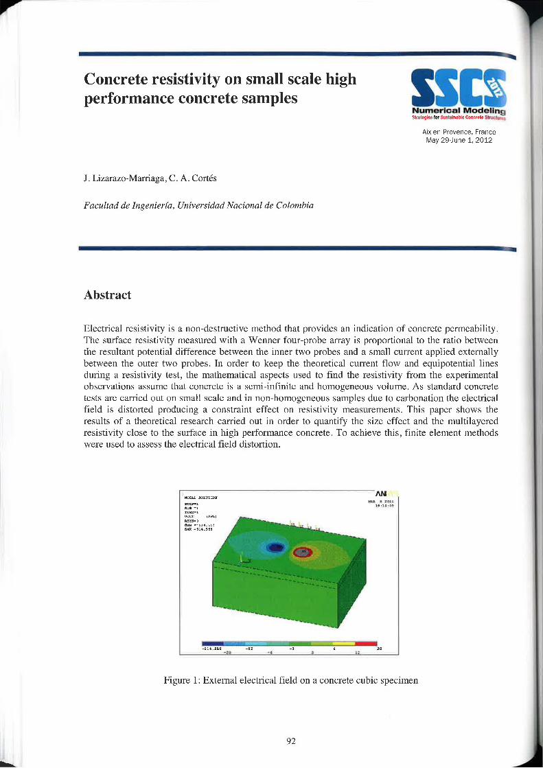
L
Concrete resistivity on small scale highperformance concrete samples SSlI§
Numerical NIDHBIIHQilratlglrs |.,stm.m= Dnncrelz shlllllllri
Aix-en-Provence. FranceMay 29—Jur\e 1. 2012
J . Lizarazo»Marriaga, C. A. Cortés
Facultad de Ingenieria. Universidad Naciomzl de Colombia
Abstract
Electrical resistivity is a non—dcstructive method that provides an indication of concrete permeability.The surface resistivity measured with a Wenner four-probe array is proportional to the ratio betweenthe resultant potential difference between the inner two probcs and a small currcnt applicd cxtcrnallybetween the outer two probes. In order to keep the theoretical current flow and equipotential linesduring a resistivity test, the mathematical aspects used to find the resistivity from the experimentalobservations assume that concrete is a semi-infinite and homogeneous volume. As standard concretetests are carried out on small scale and in non-homogeneous samples due to carbonation the electricalfield is distorted producing a constraint effect on resistivity measurements. This paper shows theresults of a theoretical research carried out in order to quantify the size effect and the multilayeredresistivity close to the surface in high performance concrete. To achieve this, finite element methodswere used to assess the electrical field distortion.
‘All
_m.m -1: -1 K XI
Figure l: External electrical field on a concrete cubic specimen
92
Simulation of the concrete chloride NTbuild-492 migration test
Alx-en-Provence, FranceMay 29June 1, 2012
]. Li2arazo—Marriaga1,]. Gonzalezl, P. Claissel,
1 Urliversidud National de Colombia1 Coventry Um'versity- ur
— — —
Abstract
Corrosion of steel reinforcement is the major cause of deterioration in concrete structures, wherecarbon dioxide and especially chlorides are the main causes of damage. The rate at which chlorideions diffuse through concrete is a major determinant of the durability of structures. The classicalapproach of ion transport in solutions states that if there is a difference in the concentration of ions indifferent regions this gradient produces a flow of ions, this movement is called diffusion. In the sameway, if there is a difference of electric potential, this difference is called migration, electromigration orconduction.
The principle of eleetromigration tests is to apply a constant potential difference across a fullysaturated sample. Usually they are performed in two chamber cells with the concrete in the middle andeach cell full of a defined salt solution. As the chloride is the ion of interest and the pore solution ofconcrete contains sodium. potassium and hydroxyls. these species are the most used to till the cells.The size of the concrete sample is usually a cylinder of 100 mm diameter and length about l5 to 50mm. One of the most used migration test is the NORDTEST METHOD NT 492 approved as astandard in Finland in 1999.
The standard NT492 is extensively used around the world to determine the chloride diffusioncoefficient. lt assumes the chloride inns as isolated particles without any ionic interaction with otherspecies. However, as chloride ions are charged particles, they interact Willi other species which affectthe ionic flux. In order to investigate numerically the chloride penetration during a standard NT-4923X]Tcrirnent, in this paper simulations of the test has been carried out. For this, two differentapproaches have been used. First, the equations of the standard based on a mono-ion condition. Andsecondly, a finite difference coupled numerical multi-species model accounting for a binding isothermand the ionic interaction caused by the species penetration the sample or contained in the poresolution.
93
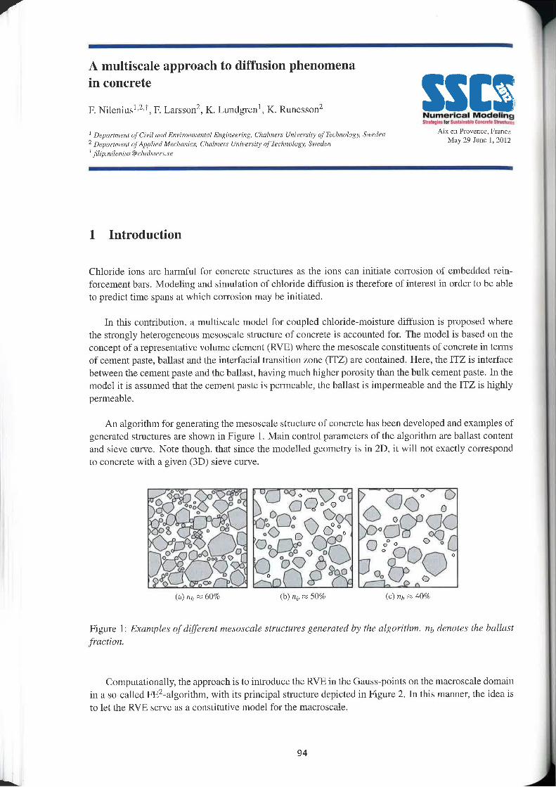
V
L
A multiscale approach to diffusion phenomenain concrete
F. Nileniuslizri, F. Larssonz, K. Lundgrenl, K. Runessonz m‘s"§|gd 'w.a,t..M...t.n.r»=m.\. swat...
' mpm-immr afC1viI /ma Envimivmznlnl Engiiiecring, Clmlmerx Univev-wiry qr'rrt»l|mn~;.-y. Swcdmt A“ °“ P""’°““°‘ 1’“‘““°1 Dzpullmznl n]App1lt"d MFL‘/mnirt, Chttlmrir 1/nivmny 0/ Technology, Sweden M“ 29'1"“ ‘- 2°”t fil|p.n|lr"|tlL|[email protected]:
1 Introduction
Chloride ions are harmful for concrete structures as the ions can initiate corrosion of embedded r"ein—foreement bars. Modeling and simulation of chloride diffusion is therefore of interest in order to be ableto predict time spans at which corrosion may be initiated.
ln this contribution, a multiscale model for coupled chlorideemoisture diffusion is proposed wherethe strongly heterogeneous mesoscale structure of concrete is accounted for. The model is based on theconcept of a representative volume element (RVE) where the rnesoseale constituents of concrete in termsof cement paste, ballast and the interfacial transition zone (ITZ) are contained. Here, the ITZ is interfacebetween the cement paste and the ballast, having much higher porosity than the bulk cement paste. In themodel it is assumed that the cement paste is permeable, the ballast is impermeable and the ITZ is highlypermeable.
An algorithm for generating the mesoscale structure of concrete has been developed and examples ofgenerated structures are shown in Figure l. Main control parameters of the algorithm are ballast contentand sieve curve. Note though, that since the modelled geometry is in 2D, it will not exactly correspondto concrete with a given (3D) sieve curve.
@> . <5 . °°<“\> O r " oO“ O OQ"<§At .03 19 (>69O O o<>".,73‘% QQQW Q00
O "ob oo 0 °° O “Q$39 00 e5 O 9<%°Cj. .<=-m». ° $3 °
(a) nb ~ 60% (b) 11,, z 50% (c) »,, ~ 40%
Figure 1: Examples ofdiflzrenz mexorcale structures generated by the algorithm. nb denotes the ballast
Q%;..QQ,.§ A~‘3@O<><??O8;“Qo,Qms
fraction.
Computationally, the approach is to introduce the RVE in the Gauss—points on the macroscale domainin a so~called FEZ-algorithm, with its principal structure depicted in Figure 2. ln this manner, the idea isto let the RVE serve as a constitutive model for the macroscale.
94
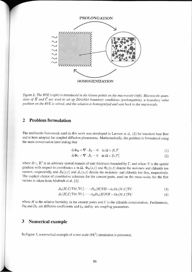
PROLONG-ATION
_LLLL/
§fiB°!.'-9 * - -.1
_ . 1""-'!p.‘Eff’; I
TYTYYTTYYYTQY
HOMOGENIZATION
iiiiifii
Figlre 2: The RVE (right) is introduced in the Gauss-points on the macroscnle (left). Macroscale quan-tities of H and C are used to set up Dirichlet boundary conditions (prolongation), a boundary valueproblem on the RVE is solved, and the r0l!4ti0n is homogenized and rent back to the macroscale.
2 Problem formulation
The multiscale framework used in this work was developed in Larsson et al. [l] for transient heat flowand is here adopted for coupled diffusion phenomena. Mathematically, the problem is fonnulated usingthe mass conservation laws stating that
B,¢'H+V-JHIO inQ><[O,T] (I)8,415+ V"-IQIO inQ><[(),T] (2)
where Q C R3 is an arbitrary spatial domain of unit thickness bounded by F, and where V is the spatialgradient with respect to coordinates x in Q. <I>1.1(x,t) and fil>¢(x, t) denote the moisture and chloride ioncontent, respectively, and JH(x,t) and JC(x,t) denote thc moisture- and chloride ion flux, respectively.The explicit choice of constitutive relations for the cement paste, used on the mcso—scale, for the fluxvectors is taken from Abahneh et al. I2]:
JH(H,C;VH,VC) :—D|.|(H)VH—€gDg(H,C)VC (3)]C(H,C;VH,VC): —SHDH(H)VH—DC(H,C)VC (4)
where H is the relative humidity in the cement pores and C is the chloride concentration. Furthermore,DH and Dc are diffusive coefficients and EH and cc are coupling parameters,
3 Numerical example
In Figure 3, a numerical example of a two scale (FE2) simulation is presented.
95
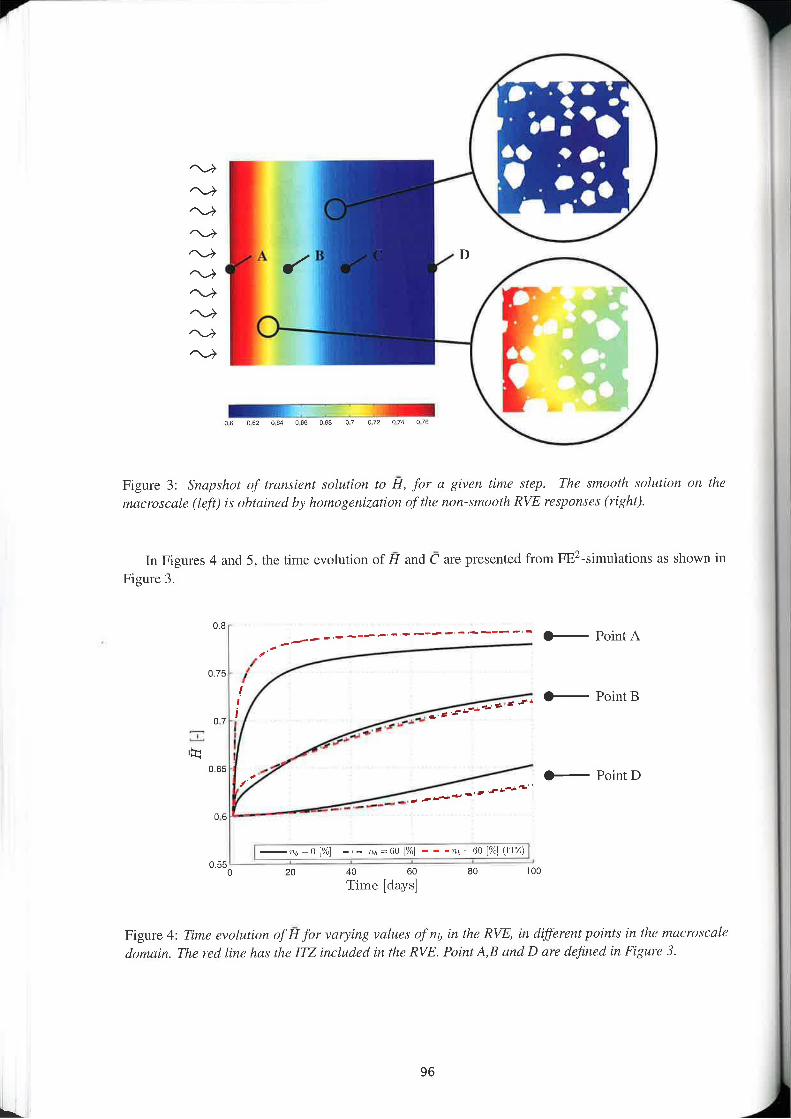
L
£i5££i££€£
as m DB4 use use 01 in on on
Figure 3: Srmpshul Of Irnnxient solution tn Fl, for a given time step. The smooth solulizm on themacrosmle (left) is obtained by homogenization of the n!m—sm00th RVE rexprznxex (right).
In Figures 4 and 5, the time evolution of Fl and 5 are presented from FE2»simulali0ns us shown inFigure 3.
0.8 ‘_,_ --- ——--~- -—-- -‘"'"" "' 0—— PointA’_-/
0.75 I’I .i ‘ _,_,-. Q——' P0mtB, _I__H___‘.,,
.r*“'7. ‘.1 Ii_ _,_,-I‘E
u.ss ./1 ' Q—i Pn|nlD-,.-.. -i-""""""H
o.s ..,_‘__-
= \A
fill, :0 [%1-_-_~- 1», =60 1%] - - -",5 :60 [%] (1%0550 10 4'0 an an 100
Time [days]
Figure 4: Time evolution off! for varying values of nh in lhe RVE, in different point: in the macruxral€domain. The red /inc hay the ITZ included in the RVE. Point A,B and D are defined in Figure 3.
96
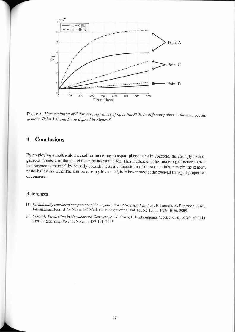
X10‘1 —Tt,=o[%16 \-‘-m,=40[%] ‘_‘_‘_._.- ------ --
5 ’ 1 I Point A1l 1
4 1_ I.5 l
3 ,' _.. - ' > PuintC1 --"
2 _1 _-"I _.'
, ‘_41 _; __,,-—" ‘__ _____ __._‘-~-~- " Oilioimlj
_i_4-ii _.__._ mt. _ino 100 znn zoo 4uu soo son 100 800
Time [days]
Figure 5: Time evolution ofC for varying valuer of nb in the RVE, in different points in the macmscaledomain. P0intA,C and D are defined in Figure 3.
4 Conclusions
By employing a multiscale method for modeling transport phenomena in concrete, the strongly hetcro—geneous structure of the material can be accounted for. This method enables modeling of concrete as aheterogeneous material by actually consider it as a composition of three materials, namely the cementpaste, ballast and ITZ. The aim here, using this model, is to better predict the over-all transport propertiesof concrete.
References
[ll Wzriationally cnnrislent computational hnmugenizatian oftransient heal/low, F. Larsson, K. Runesson, F. Su,lnwmational Icumal for Numerical Methods in Engineering, Vol. Bl, N0 13. pp 1659—1686, 2009.
[2] Chloride Penetration in Nanraturared Concrete, A. Ababneh, F. Benboudjerna, Y. Xi, Journal of Materials inCivil Engineering, Vol. 15, N0 2‘ PP 1 33»191_ 2003.
97
Contact elements, creep and anisotropy for _the numerical modelling of concretestructures affected by internal swellingreaction "l3'§y"§Z§3iil°i1Z'$l5e
O. Omikrine—MetaIssi‘, J.—F. Scignol' , S. Rigobcrt', F. ToutIemondc',L714 Buldeaz'Université Paris-Est, IFSTTAR, Paris, FranceZ Stucliy, Lausanne, Switzerland
i
Abstractlnternal swelling reactions (lSR) which mainly consists in alkali-aggregate reaction (AAR) and/ordelayed ettringite formation (DEF) are autogenous reactions that may affect the long term durability ofconcrete structures. They produce concrctc expansion and generate cracking within structures anddegradation of their mechanical behaviour. This phenomenon is worrying for affected structureowners as it deals with people safety and structure serviceability. Moreover, there is no practical wayto stop reaction and only palliative actions can bc proposed, Hence, prediction of concrete expansion,structural degradation and assessment of efficiency and schedule of repair works are crucial issues.The modelling of these phenomena in CESAR-LCPC F.E. code was based on a sub program called“ALKA“, for AAR, and presently relies on its newly developed extension called "RGIB" that allowsmodelling the behaviour of a structure affected by AAR or DEF. This program takes into accountseveral coupled phenomena: influence of thermo-hygral conditions, effects of the early age thermalhistory, anisotropy of the imposed expansion related to the direction of concrete casting, damageresulting from cracking of the material, drying shrinkage and coupling between the expansion and thestate of stresses. The developed sub program is applied by following two steps for each time step:firstly, RGLB calculates the reaction extent increment from the fields of temperature and humidity, andchemical parameters of the material, . Then, this reaction cxtcnt is introduced into the chemo—mechanical model, bascd on thc assumption of prescribed chemical strains superimposed tomechanical deformations. In the case of DEF, this chemical strain is also affected by thc early agethermal history, which can be assessed by a preliminary FE computation.Many case studies have shown that it is necessary to model displacement discontinuities in theconcrete, mainly to take into account two phenomena: firstly thc modelling of the major cracksopening that rcsult from interactions between pathology and mechanical behaviour of the structure.and secondly, the evaluation ol the potential efficiency of stress release (e.g. sawing of dams), theprocedure which consists in the creation of cutting lines in the structure for release of excessivecompressive stresses (the possible re-closing of tl1e cutting lines have to be ensured by allowing aresidual stress in the surrounding concrete).Furthermore, taking into account these phenomena and couplings in ISR modelling appears to beinsufficient for the analysis of some types of structures, especially those subject to significantpermanent loads, such as dams or large pre~stressed concrete structures. In this context, creep and itsinteraction with the development of ISR, particularly alkalraggrcgate reaction, shall be accounted for.This paper describes the algorithm development aimed to possibly combine contact elements and non»linear coupled models related to ISR modelling. It presents some illustrative cases to validate thismodel development. Moreover, the effect of stress on the anisotropy of expansion is highlighted.Finally, some validation cases of basic crcep integration will be discussed.
Keywords: internal swelling reactions (ISR), creep, cracks, numerical analysis, concrete dams, strcssaclcase,anisotropy.
98
'"""I
Assessment of service life and'1-onmental im acts of chloride ex osed
envl p P Numerical Modsllnconcrete structures with repairs by covert Alx en Provence Francerepl3¢6I11BI1 M-ay ‘mm 1; 2012
A, Petcherdchoo
Kmg Mr/ng/t741'.r I/nivrzrxiry 0] Technology North Bung/wk, Thailand.
ii i
Abstract
This paper aims at assessing service life and environmental impacts of repaired concrete structureunder chloride attack using the finite difference method. The quantitative prediction of chloridediffusion in concrete stnictures can mathematically be described using the Fick’s second law, but thcprediction of repaired concrete structures after repair by concrete cover replacement using the Fiek’ssecond law is restricted due to the complexity in solving the partial differential equations. Hence. aCrank—Nicolson based finite difference formulation is proposed to predict the remaining service life ofrepaired concrete structures. Furthermore, the environmental impacts, in terms of energy use andglobal warming categories, which can be used to indicate the sustainability of the stmctures. are alsoestimated based on the relationship between the application time of repair and the environmentalimpacts per repair action. Finally, a numerical example is presented.
99
Prediction of Chloride Ingress into vConcrete in a Marine Environment ‘
Numerical Modell
Alx-en-Provence. FranceMay 29-June 1, 2012
Ian N. Robertson
University ufHuwuii, Department of Civil Engineering, 2540 Dole Street, Honolulu, Hawaii 96822, US/Aemail: [email protected]
Abstract
Corrosion of reinforcing steel is a major contributor to early deterioration of concrete structures in acoastal environment. This paper presents results of a six year field monitoring study involving 25reinforced concrete panels exposed to a marine environment. Seven different corrosion inhibitingadmixtures were used in the study to compare their effectiveness at preventing or delaying onset ofcorrosion.
Chloride concentrations were measured at various depths below the concrete surface to obtain a chlorideconcentration profile approximately annually during the field exposure. LlFE—365, a numerical model topredict chloride ingress into concrete, was used to predict the chloride concentration profile for eachspecimen at each monitoring interval. Comparison of predicted and measured profiles indicatediscrepancies which could lead to inappropriate design if Ll'FE~365 is applied using the default settings,Modifications to LE1-3365 are suggested to improve the prediction of chloride concentrations for theconcrete mixtures considered in this test program.
This study was funded by the Hawaii Department of Transportation, Harbors Division‘ in order toevaluate commercially available corrosion inhibiting admixtures when used in concretes made with basaltaggregates common to Hawaii and other Pacific Islands. The corrosion—inhibiting admixtures included inthis project were categorized into two types. Type l admixtures attempt to reduce the concretepermeability » Xypex Admix C-2000, latex modifier, Kryton KIM, fly ash, and silica fume were used inthis study. Type 2 admixtures attempt to raise the chloride concentration threshold at which corrosion ofthe reinforcing steel is initiated — Darcx Corrosion Inhibitor (DCI), Rheocrete CNI, Rheocrete 222+, andFerroGard 90l were used in this study.
100
' Lattice model as a tool for modellingtransport phenomena in cement based
. Numerical Modelingcolnposltes §s=t=a.rn|ntatm.t. swat 5|-law,
Aix-en—Provence, FranceMay 2eJune 1, 2012
B. §avija, 1. Pacheco, R.B. Polder, E. Schlangen
Micmlab, Delfi I/rtivemry ufTechn0logy, Delft, The Netherlands
AbstractReinforced concrete is a construction material of choice for structures exposed to severeenvironmental conditions. Due to relatively good durability characteristics and low price, its use isonly going to increase in the future. However, due to different deterioration mechanisms (e.g. chlorideor carbonation induced corrosion, sulphate or frost attack, etc.), it is inevitable that it deteriorates intime. There is an increasing need for reliable models which would enable reliable prediction ofconcrete durability.
A majority of these processes, if not all of them, involve transport of some agent (moisture, ions, heat,electrical current, ete.). Kinetics of these degradation mechanisms is controlled by different concretemix properties, exposure conditions, curing, and so on. Analytical or numerical tools are thereforeneeded in order to optimize concrete mix proportions and construction practice, all in order to achievethe desired service life.
Lattice models have long been successfully used in modelling fracture processes in cement basedmaterials [1]. In the model, specimens are modelled as a set of beam or truss elements. Realistic crackpattems and fracture properties can be casily obtained using these models. Also, composite nature ofthe material (concrete as mix of coarse aggregate, ITZ, and mortar) can be simulated with the latticemodel [2]. Computer generated microstructure or microstructure obtained by scanning a real materialcan be used.
Recently, development of the lattice model as a tool for modelling transport processes in cement basedmateria.ls has commenced. A two or three dimensional random (irregular) triangular lattice is used. Lnthis ease, the material is modelled as a set of one dimensional “pipes”, through which the transporttakes place. This makes it possible to model a two or three dimensional process using only onedimensional linear element. Cross sections of these elements are determined employing the Voronoiscaling method, previously proposed in the literature [3]. Since all the elements are one dimensional,computational effort needed to solve the system of resulting equations can be chiefly reduced. As withthe fracture lattice model, it is possible to model the material on both the macro (homogeneous) andthe meso scale (heterogeneous). In the paper, basic characteristics of the model- spatial discretizationprocedure, governing equations» are laid out. Examples for time independent (i.e. steady-state flow)problems at both the macro and the meso scale are presented and compared. Simulation results arethen compared to the analytical solutions, and error estimates are given. Finally, conclusions on themodel efficiency and the future prospective are given.
It is envisioned that this model will, in the future, be coupled with the fracture lattice model, whichWould enable taking cracking into account when modelling the transport of different species in cementbased materials. This should enable more rcalistic estimates of the effect of cracking on durability ofconcrete exposed to different aggressive environments, ensuring that the influence of cracking is notover or underestimated.
101

rfi
L.
References
[1] Experimental and numerical analysis of fracture processes in concrete, E. Schlaugen, PhD thesis. DelflUniversity of Technology, 1993
[2] 3D lattice fracture model: theury and computer implementation. Z. Qian, E. Schlangen, G. Ye, K. vanBreugel, Key Engineering Materials 452-453: 69-72
[3] Automated modeling of three-dimensional structural components using irregular lattices, M, Yip, J. Mohle_IE4 Bolander. Computer-Aided Civil and Infrastructure Engineering 20: 393-407, 2005
102
Numerical tool for durability assessmentof concrete structures subjected toaggl‘€SSiV€ environment
Aix-en—Provence. FranceMay 29—June 1, 2012
J. Mai—Nhu'. A. Sellierz, P. Rougeau' , F. Dupratz
' CERIB (Study and Research Cenlrcfor ma French Contreie lndusiry), Research and Innovation Department, MaterialsSeclizm, BP 30059, 28231 Epemon, FRANCE‘1 Univzrsité 11¢ Toulouse, UPS, nvsa, moc (labormoire Matérbux er Durabilize’ dc: Comlruclionr), 135 Avenue dz Rangueil,[<13] 077 Toulouse Cedex 04, FRANCE.
Abstract
Mastering and optimising the durability of prefabricated products, whether they are structural,architectural or intended for sewerage, is without a doubt a major challenge for the entire profession.
Previous works carried out at CERIB and LMDC have already resulted in the creation of a predictivemodel for assessing the lifetime of reinforced concrete structures subjected to the phenomenon ofcarbonation.
In this research work, additional parameters of corrosion are being introduced such as the migration ofchlorides in a saturated and unsaturated phase or the combination of this migration with themechanism of carbonation and the corrosion of reinforcing bars according to wetting-drying cycles. Anew experimental setup was developed to simulate wetting-drying cycles in controlled environmentalconditions and to monitor the corrosion initiation for several types of concretes with differentwater/binder ratios and different types of binders.
In the same way, a model able to predict the performance of concretes in relation to the carbonationphenomenon in unsaturated phase was developed with a finite element analysis and m\llliphySiCssimulation.
The final goal is to come up with a comprehensive and more accurate model which takes into accountall the most important coupled phenomena.
103
iii
it‘
Modelling of the moisture transfer underwetting-drying cycles in cementitious
Numnrloal Mcdellnmaterial St|aI:qtonler!I|llaInlB||Eun=n1nStM|< 9,Aix-en-Provence, Fiance
May 29-June 1. 2012
Zhidong Zhang, Mickael Thiéiy, Veronique Baroghel—Bouny
P!Il'1'.t»E.si Umvel'.\'ifv, Prim-; Mritrririli Depttrlrlielll, IFSTTAR. Paris, Fmm»
Abstract
In a realistic environment, cementitious materials are subjected to cyclic changes of relative humidity,such as from low level (40%-50%) to near water saturation The description, quantification and studyof moisture transport leads to the consideration of the hydraulic properties of unsaturated cementitiousmaterials. This involves the relationship between the water content and the relative humidity, calledthe Water vapour sorption isotherms (WVSls). This function exhibits hysteresis, depending on whetherthe material is wetting (adsorption) or drying (desorption). Experimental results indicate cycles(scanning loops) remaining inside the area delimited by the boundary of the main desorption andadsorption curves obtained in the whole range of relative humidity.
The aim of this paper is to incorporate the hysteretic behaviour of WVSls in a multiphase modelsimulating liquid water ~ water vapour ~ dry air flow in cementitious materials. There are two methodsproposed. One We call ‘direct shifting’ method. The power functions developed by van Genuchten areused for least square fitting of experimental data of the main desorption and adsorption curves. Thecyclic wetting and drying phenomena is described by direct shifting between desorption curve andadsorption curve. The numerical result shows this method suit for specimen undergoing high RHwetting progress (nearly saturated). The other method combines with an incremental relationshipdeveloped by Pedroso, which takes place of ‘direct shifting’ to describe the cyclic wetting and dryingphenomena. ln addition to the watcr sorption characteristics, the modelling of moisture transferrequires transport coefficients, as relative gas and liquid permeabilities, are derived from theknowledge of the WVSls according to analytical models developed in the literature.
The mass loss (kinetics) and moisture profiles data, gained from experiments using gamma-rayattenuation measurements during the first wetting and drying cycle which were carried on thehardened cement pastes made of OPC (W/c 0.45 and 0.6) cylinderical specimens, are used to determinethe intrinsic permeabilities and to validate the above model. The hysteretic behaviour of the materialscan be investigated accoding the data gained from experiments and the main drying-wetting curves arefitted. Further more, a mass loss evolution under several drying-Wetting cucles will be predicted. Atthe last, this paper describes and analyses phnomenon of tl1e moisture transfer under the multi—cycles.
Keyword: Wettll\g—drying cycles, moisture transfer, cementitious material
104
SSENumerical Modelingsvmtw luv smmm Cnrlcllll Structurzs
Alx-en-Provence, FranceMay 29-June 1. 2012
Session I-6:Coupling ProblemsInvestigation of the hygro-thermo-chemical modelling of concrete in unsaturated state conditions subjected tomoderate temperaturesA.S. Chilez, A.J. JeffersonCardlfl‘Schnul ufEngineering, Cardiff University, Cardifl, Wales, UK
A Thermo-chemo-mechanical numerical model applied to the design of sustainable structuresEduardo M. R. Fairbairn, Fernando L. B. Ribeiro, Romildn D. Toledo Filho, Marcos M. Silvoso, luri A. Ferrein,Guilherme C. CordelmUFRJ
Numerical Modelling for Corrosion Evaluation in RC Structures due to Climate Change ImpactsM. Gharib', s.J. Fosterz, A. CaslelaI PhD Candidate, University ofNew South Wales, Australia - 2 Professor, University of New South Wales, Australia3 Professor, Universite’ de Nice, France
Experimental and numerical analysis of salt transport and crystalli7ati0n in non-isothemial partly and fully saturatedporous building materialsM. Koniorezyk, D. GawinDepartment of Building Physics and Building Materials, Technical University nfL0dz, Lodz, Poland
Prediction of strength of cunerete in long-lived concrete memberI. Maruyama, G. IgnrashiNagoya University, Graduate schaal of environmental studies, Japan
Modelling of Corrosion of Steel Reinforcement in Concrete _ Fully Coupled an we ModelI. ozbow. 0. Balabaniéz, M. Ku§t€l} and F, or§an1e'~’’lWB. University Ofsmttgm, Stuttgart, Germany - ‘G1-" Rijeku, University afRijeka, Rijelaz, Croatia » ’cF Zagreb,University ofZagreb, Croatia
Then-no-hydro—mecha.nical modelling and simulation of fire induced spalling in concreteMT. Phan, S. Dal Pont. F. Meilah, S. Rigoberl, P4 Autuori, L. D‘AloiaMSME, Univzrsité Paris Est, Frunce
Modeling of fluid transfers in cracking concrete: experimental constitutive laws and numerical probabilisticstrategiesG-Rastiello, P. Rossi, J.—L. Tailhan. S. Dal Pont, C. BoulayIFSTTAR Paris, France
I05

Numcrieal modelling of fluid transfer in cracked reinforced concrete structuresG.Rusticllo, .I.-L. Tailhan, P. Rossi, C,Desmett.re,.l-P.Cl1an'on,S, Dal PuntII"S7'l'AR Paris. Frrmce
Mesn-mechanical study of high-temperature cracking in mortar and concrete specimens using fracturmbusedzero-thickness interfacesM, Rodriguez, C.M. Lopez. I. CarolETSECCPB (Schaal ofCivil Engineering), UPC (Technical Univ<'I‘t'iI_v 0fCl1tal0n|'n), Bareelmia, Spain
Chem0»Mechanit:al Micro Model for Alkali~Sillca ReactionVictor Saoumti. Wiwnt PuntatsananonDept. ofCivil Errgineering, Universily nfCvl0ra1lu
Role of Numerical Modelling ol"Rcint"o1-ceinenl Corrosion for Susuiinalalc Concrete StructuresHenrik smug‘, Michael 0. Lcpechz and Mette Gelkerm' Teclwiral Ultiwrsiry 0fDz'I1mar/t.2SIanfi1|'zI Unive:-.viry, " Norwegian Universi/y nf.S'c/‘arise rmzl Technology
1 06
t_ll
Investigation of the hygro-thermo-chemicalmodelling of concrete in unsaturated stateconditions subjected to moderate ii-'~5i'1~'3555-3?-5\='i~'~i°»='i?~'~'=5~'i‘:temperatures ‘i§'§y"§Z§Z"$nl°‘i1Z'5'i§e
A5, Chitez, AJ. Jefferson
L‘an1ifi‘ School 0/ Engineering, Curdtfi University, Cardifl, Wales, UK
i — — — —
Abstract
Ln this study a finite element numerical model is described which is used to investigate the moisturetransfer in unsaturated concrete subjected to moderate temperatures through both phenomenologicaland mechanistic approaches. The numerical results are validated with experimental findings availablein the literature. The approaches differ in the complexity of the constitutive equations used to describemoisture transport mechanisms. This elaborateness is responsible for a higher degree of non—linearityof the system and for the difficulty of choosing the input material parameters. The phenomenologicalapproachmj gives a relatively simplified description of the diffusion model since it encompasses in asingle flux term all the existing means of fluid transport within concrete. The moisture diffusionanalysis has one primary variable: the relative humidity (I-I) or the moisture content (w). To couple thediermal effect a heat transfer equation is introduced adding temperature T as supplementary variable.The mechanistic approach uses separate mass balance equations for each individual phase (dry air.water vapour, liquid water) to which an enthalpy balance equation is attached for the thermal effect”.In the current study simplified assumptions are made based on previous research results” and thesystem is reduced to two sets of equations with capillary pressure (pg)/degree of saturation (SW) andtemperature (T) as independent variables. In both approaches the switch between the first possiblevariables is made by means of sorption isothenn and capillary curve respectively.
The numerical investigation is intended to highlight the issues raised by the diversity of constitutivelaws found in literature describing the material characteristics related especially to moisture transfer inconcrete. Attention is focused particularly upon the expression of the permeability function of thewater phase and the effective diffusivity of vapour within air. The numerical findings are comparedwith relative humidity versus time experimental curves at different concrete depths for specimens withvarious water-cement ratios. These expressions are highly non-linear and the predicted response showsconsiderable sensitivity to their values and controlling parameters. In addition the hygro-thermalmodel appears to be responsive to the moisture and heat transfer coefficients responsible for theboundary convection fluxes. '
Also in this investigation due to the inconsistencies between the numerical and experimental values ofrelative humidity at the end of self»desiceation a comparison of two hydration models was performed.One model considers the hydration rate dependent on the chemical affinity and relative humidity“while in the other the hydration rate is obtained considering the hydration degree as an exponentialfunction of an equivalent time derived from maturity method”. In this Way the chemical coupling wasadded to the model.
107
q
References
Nonlinear water diffusion in non-saturated concrete, Z. P. Bazant.. L. J. Najjar, Materials and Structures, 5,3-20, 1972.Mathematical Modeling ol'Creep and Shrinkage of Concrete, Z. P. Bazant, Wiley: Cltichestcr, 1988CEB-FIP Model code I990. Comite Euro-International du Belon, I993Characterization and identification of equilibrium and transfer moisture properties for ordinary and high-pcrformance cementitious materials, V. Baroghel-Bouny. M. Mainguy. T. Lassabatere. 0. Coussy. Cementand Concrete Res.. 29(8), 1225-1238, 1999The Finite Eleuieiit Method in tltc Static and Dynamic Deformation and Consolidation of Porous Media,R.W. Lewis, B. A. Schrcfler, John Wiley 84 Sons, Chicliester. 1998l-Iygro-thermo-chemo-mechanical modelling of concrete at early ages and beyond. Part I: Hydration andhygro-thermal phenomena, D. Crawin. F. Pesavento _B. A. Sehrcfler, Int. J. Numvr. Methods Et|grg., 67(3),299-331. Z006An experimental. numerical and analytical investigation of gas flow characteristics in concrete. D. R.Gardner, A. D. Jefferson. R. J . Lark. Cement and Concrete Research. 38(3). 360-367. 2008A coupled t.hermo-hydro-mechanicabdamage model for concrete subjected to moderate temperatures, B.Bary, G. Ranc, S. Durand. O. Carpenticr, lntemational Jonmal of Heat and Mass Transfer-, 51, 2847-2862,2008Heat of hydration models for cementitious materials A. K. Schindlen. l(.J. Folliard, AC1 Material Journal.lO2(l), 24-33. 2005
I08
A Thermo-chemo-mechanical numericalmodel applied to the design of sustainablestructures
SSlI§Numerical ModelingShltuuiwl In Stlllnlnlhll Lanunlr SlruuttmxAix-en—PIOVenl:e, FranceMay 29~June 1, 2012
Eduardo M. R. Fairbairnl , Fernando L. B. Ribeiro', Marcos M. Silvosoz,Romildo D. Toledo Filhol'COPPE/UFRJ. 2!-‘Al//UFRJ
Abstract
Ln this paper we present a parallel finite element implementation of a thermo-chemo-mechanical modeldedicated to the analysis of massive structures. The code is developed for distributed memory parallelarchitectures and simulates the layered construction of hydropower plants. The optimized code permits theconsideration of complex geometries with a fine discretization of power houses and spillways. We presenttwo applications of thc model: the first one is the analysis of the construction phase of a spillway gate pierof the Tokoma hydrnpower plant, which is being constructed in Venezuela, and the second one simulatesthe construction of a general spillway considering two different materials, a conventional concrete and aconcrete made with the partial substitution of cement by a blend of sugar cane bagasse ash and rice ruskash, which can reduce CO2 emissions‘
109
§
Numerical Modelling for Corrosion _,Evaluation in RC Structures due to TClimate Change Impacts
Aix-en-Provence. FranceMay 29—Jurie 1. 2012
M. Gharib', S.J. Foster], A. Castel3
1- l’I1D Crmdirlnlr‘. Urtivnsiry ufNz'w South Wales, /lilsllulia.2- Professor, University ofNew Smith Wafer, Atmmlizi.3- Professor, Universite’ dz Nice, France.
Abstract
For sustainable development, perl'ormance—basecl durability analysis of reinforced concrete (RC)structures is needed to ascertain serviceability, and strength, perfonnance over time as a result ofdeterioration processes. Performance based durability design is not only needed at the initial designstage but also, based on updated state data, at subsequent in—service stages. This allow for continuedupdating and assessment throughout the life of the structure to implement optimal maintenanceschedules. In this regard, corrosion due to chloride ingress and carbonation are generally the moreconcerning processes indicating susceptibility to deterioration.
In this paper, a model is proposed for coupling chloride ingress and carbonation in concrete. Themodel is capable of predicting onset of corrosion, focusing on the initiation phase. It is assembled bysimulation of chloride ion, carbon dioxide, moisture and oxygen concentrations via multi-mechanistictransport into concrete with diffusion and conviction mechanisms. A numerical solution is employedthrough finite element modelling to solve the coupled system using governing mass conservation andheat tmnsfer equations. The developed model is compared with existing models and is verified byexperimental results.
The model proposed may be utilised to assess the impacts of climate change in the presence ofsustained mechanical loading, for changes in atmospheric CO; concentration, temperature and relativehumidity. Some examples are given.
Keywords: Durability, reinforced concrete, corrosion, carbonation, diffusion
I10
Experimental and numerical analysis of salttransport and crystallization innon-isothermal partly and fully saturatedporous building materials ‘l§,'§,"'2";fjf,,",°i1§'§f;°
M. Kortiorczyk, D. Gawin
l)epur1ment0fBuilrlirtg Physics and Building Materials, '1'echnic'al UrtivL'r.s'rry ufL0rIz, Lodz, Poland
Abstract
Water and salt are wildly recognized as a major factor of porous materials damage, therefore a lot ofexperimental and theoretical studies are devoted to them. One of the most adverse phenomenon whichis related to the salt and moisture presence in the pore system of building materials is saltcrystallization. lt might be responsible for two kinds of building material damage. One is efflorescenceof salt on the surfaces and the other is the additional pressure, which is produced during thecrystallization. The maximum value of the pressure, which is generated during salt crystallization isdescribed by the equation [l]:
Ap = ‘1:—lln[%jW1
where a is ion activity product, K is the equilibrium constant, T is absolute temperature, R is gasconstant.The mathematical model of salt, moisture and energy transport was derived and based on it thecomputer code was developed [2]. The salt phase change kinetics is taken into account whilemodeling. Crystals grow in pores when the solution is supersaturated. Solution supersaturation ratio isthe function of the ion activity product, which is calculated based on the Pitzer ion interaction model.The mercury intrusion porosimetry tests were performed in order to study the inflrrencc of saltcrystallization on the internal structure of porous medium e.g. porosity, permeability, pore sizedistribution. To get additional information about the shape of pores two intrusion-extrusion cycleswere carried out.To solve the set of governing, differential equations the finite element and finite difference methodsare used. The numerical validation of the developed software for various density of finite elements andtime intervals, was curried out. Three different rate laws are assumed for the modeling the salt phasechange kinetics. The drying and cooling~warming of cement mortar containing salt solution, have beenSimulated using the developed software. The changes of salt concentration in the pore solution and theamount of precipitated salt due to variation of boundary conditions are analyzed. The crystallizing saltgenerates the additional tensile stress in the surface layer, What might be responsible for its splitting.
References
ll] Crystallization in pores, G.W. Scherer, Cement and Concrete Research (i999) Z2:l 3474358.l2] Numerical Modeling of Salt Transport and Precipitation in Nomlsothermal Partially Saturated Porous Media
Considering Kinetics of Salt Phase Changes, M. Koniorezyk, D. Gawin, Transport in Porous Media (201 I)87:57-76.
lll
Prediction of strength of concrete inlong-lived concrete member
Numerical |WDdO||h§...t....,..i..t............,.........,AiXer\—Prover\ee. France
May 29—J\me 1. 2012
I. Maruyama, G. Igarashi
Nagoya University, Graduate school ofenvirunmenml studies, Japan
Abstract
Distribution and time dependent behaviour of concrete strength and related properties of concrete arepredicted in aged—concretc structural member which suffers from relatively high temperature anddrying condition. This condition is assuming the member in nuclear power plant.
For the prediction or evaluation of this, hydration—model-based numerical evaluation tool is proposed.This system is composed of models of rate of hydration, phase composition, heat production, specificheat. compressive strength and Young‘s modulus, vapor desorption isotherm, coupled heat andmoisture transfer.
Each model parameters are determined through experimental data. This system is aiming for thestructural member which can not be accessed or can not be evaluated by the core sampling test. Usingnondestructive data or quality control sample's data, this system might illustrate the distribution anddevelopment of concrete strength in structural member properly.
in this paper, a samples calculation results for concrete members exposed to high temperaturecondition (65 "C) and room temperature condition is discussed.
During construction period, water in concrete is evaporates from the both surfaces and then watercontent on the surface become low and become relatively high in internal pan. Assuming that themember is attached to high temperature facilities and there is no water movement on the surface afterl year from the casting and the facilities begin to run at the same time, re-distribution of Water contentis observed. Due to the temperature distribution in specimen, Water in the centre is moved to bothsurfaces, and strength development on the high temperature side is produced. Finally the weakeststrength is found on the surface of room temperature side.
On the contrary, concrete member which is not attached to high temperature facilities, strong drying isobserved on the high temperature side. And resultantly, the Weakest part is found on the hightemperature side.
As a result, strength development as well as distribution is quite sensitive to the boundary condition,and this concludes that the evaluation of structural member under such special condition needs preciseboundary conditions.
l12
Modelling of Corrosion of SteelReinforcement in Concrete — Fully Coupled3D FE Model 5.'.l1.'.!.‘3€.'.‘3.‘.’.l.'!.F.‘.‘..‘.!?.'.'.$‘.:
Alx—en—Pmvence. FranceMay 2$June 1, 2012
J_ Oiboltm, G. Balabartiéz, M. Kline? and F. Orsaniéu
’lWE, University ufStu1tgart, Stuttgart. GcrrrulnyZGF Rijeka. University o/'Rijeka, Rijcka. CroatiatarZagreb, University 0fZagrel1, Zagreb, Croatia
AbstractReinforced concrete structures, which are exposed to aggressive environmental conditions, such asstructures close to the sea or highway bridges and garages exposed to de-icing salts, often exhibitdamage due to corrosion. Damage is usually manifested in the fon'n of cracking and spalling ofconcrete cover caused by expansion of corrosion products around reinforcement. The reparation ofcorroded structure is related with relatively high direct and indirect costs. Therefore, it is of greatimportance to have a model, which is able to realistically predict influence of corrosion on the safetyand durability of RC structures.
To estimate reduction of the cross-section of reinforcement and to predict the increase of the volumeof corrosion product it is necessary to know the corrosion rate e.g. corrosion current density in thecorrosion unit. The calculation of corrosion current density and its consequence for concrete structuresrequires modelling of the following physical and electrochemical processes: (1) transport of capillarywater, oxygen and chloride through the concrete cover; (2) irrunobilization of chloride in the concrete;(3) transport of OH' ions through electrolyte in concrete pores, (4) cathodic and anodie polarization,(5) calculation of corrosion rate and (6) transport of corrosion products. These processes are coupledwith the mechanical properties of concrete (damage), which have significant influence on transportprocesses and consequently on the corrosion rate. Moreover, the corrosion products have two to seventime large volume than the steel. This generates stresses and can cause cracking of concrete cover.
In the present contribution a 3D chemo—hygro-thermo—mechanical model for concrete is presented[1,2]. In the model the interaction between non-mechanical properties (distribution of temperature,humidity, oxygen, chloride and rust) and mechanical properties of concrete (damage), is accountedfor. The mechanical part of the model is based on the microplane model. The strong and weakformulations and implementation into a 3D finite element code are discussed. The application of themodel is illustrated on numerical examples in which the transient 3D finite element analysisof RC specimens is carried out. First example includes only initiation phase of corrosion andShows the influence of damage of concrete on depassivation time of reinforcement. Toinvestigate the influence of environment conditions and concrete properties on corrosion rateof reinforcement, in the second example are simulated processes before and afterdepassivation of reinforcement. Comparison between numerical and experimentally observedcorrosion rates shows that the model is able to realistically predict corrosion of reinforcement.References[1] Modelling the effect of damage on transport processes in concrete, J. Oibolt, G. Balabanic and M. Kuster,
Construction & Building Materials. 24, 16384 648, 2010.[Z] 3D Numerical modelling of steel corrosion in concrete structures, J. Oiboll, G. Balabanic and M. Kustcr,
Submitted for possible publication, Corrosion Science, 20l l .
113
Thermo-hydro-mechanical modelling andsimulation of fire induced spalling incongretg gfififififiiifiiimfigiipfi
AiX—en—Pmven£:e, FranceMay 29—June 3. 2012
M.T. Phan', s. Dal Pm“, F. Meflahz, s. Rignbcrtz, P. Autuori4,L. D’Aloia—Schwartzenu'uber51 MSME, Universiré Puris—E:t Mame-la-Vallée, France, Minh»Tuyen .phan@univ-Paris-estfr2 LMMGC, Universite’ Cergy»Pon10ise, Neuville»:ur—0i.re, France, Fekrijl/Iq?ah@u-cergyf!3 IFFSTAR-LCPC, 53 boulevard Lefebvre 75732 Paris, Fflmfe, {dalp0nt,rig0berz}@lcpcfr4 Bouygues TI’, Challenger -1 avenue Eugene Freyssinel, 78061 Saint~Qucntin-cn-Yvelines, France,P.autunri@bnuygues—L‘0n.r1rur:lizm.L‘0m5 CETU, 25 llvenua l"rnrl§!!i.\‘ Mitterrund, 69674 Bran, Frmce, Iattiti/A111110111@d2vzlappEm£rl!—du|1lblE.gDuvfl
Abstract
This paper presents a coupled Ihenno-hydro-mechanical (THM) model enriched with a bucklingtypecriterion for progressive spalling. In the first part of the paper, a general fully coupled multi-phase Tl-[Mmodel describing the behaviour of concrete at moderate and high temperatures is presented. Then thespalling criterion and its numerical implementation in the framework of the finite element method arepresented. Finally, a simple lD numerical example will illustrate the effectiveness of the implementednumerical approach.
114
-\
llflg - - - . -JEYMV
1
P°Mheread
L
Modelling of fluid transfer in concrete:experimental constitutive laws and SSE
Numarlcnl Modallngnumerical probabilistic strategiesAixen-PFDVGHOB, France
May 29—Jtme 1, 2012
G, Rastiello' J.-L. Tailhan‘, P. Rossil, s. Dal Punt‘ , c. Boula '. Y'IFS1TAR, PE!‘il*EM.\'! University, France, fgiuicppelasticllrl, rosxi, tuillnzn, dalpiml, b-mlay}@;fmar¢r
The aim of this paper is to present a three-dimensional finite element fully coupled thei'mo-hydro-mechanical probabilistic strategy to model fluid transfer in cracking concrctc. The concrete is consideredas a partially saturated porous medium and, as common in the multi—phase theory, it is treated as a three-phase system composed by the voids of the skeleton filled with liquid water and gas (two misciblespecies: dry air and water vapour).
Although in conventional analyses a homogeneity assumption is commonly adopted for solid skeletonproperties and transfer properties, an appropriate approach for thermo—hydro—mechanica] modelling ofconcrete should not ignore a proper description of its heterogeneous nature. Such a heterogeneity makesinevitable the presence of micro/macro cracks and, as Well known in the literature, it is strictly related toscale effects in concrete mechanical response.
In the model, herein presented, material heterogeneities are taken into account through a probabilisticapproach considering some mechanical characteristics as randomly distributed fields.
Concrete mechanical cracking is modelled by means of the probabilistic model first proposed by [6] andmore recently by [7 ,8]. This approach allows describing the growth of a preexisting flaw as well as topredict the genesis and formation of cracks in an initially flaw—frec structure subjected to tension. Themacroscopic model for tensile cracking is capable at thc same time of providing information on the localresponse (i.e., cracks), taking into account scale effects as well as the heterogeneous nature of concrete viaappropriate, experimentally validated, size effect laws and via a statistical distribution of mechanicalproperties.
The coupling with the thermo—hydraulic model is assured by the use of experimental constitutive lawsallowing to relate, when cracking occurs, crack geometry (orientation, opening, ) to a local variation ofhydraulic properties. These constitutive laws has been obtained by means of the experimental protocol forreal-time measurements of the transfer properties evolution of a concrete sample under tensile loading(Brazilian test) first presented by [1] for electric resistivity and more recently by [5] for hydraulicconductivity and permeability.
The model is implemented in a new finite element code for multi-physics numerical analysis. It is basedon a staggered solution procedure [2,3,4], which allows to split thc overall model into four small sub—models, one for each type of problem (mechanical, thermal and hydraulic), and to solve subsequently theCorresponding block of equations for the correspondent set of field variables, while the other variables ofthe problem are temporarily frozen at predicted values. Interaction effects between blocks arc treated asadditional external forces. The full coupling of the problem is prcscrved by means of a suitable multi~leveliterative scheme.After validation of the code by means of some case study examples, some capabilities of the numericalmodel and of the proposed probabilistic approach in modelling of cracking of concrete structures arefinally illustrated and discussed.
115 lt
References:ll] Real-time evolution of electric resistivity in cracking concretc. C. Boulay. S. Dal Punt, P. Belin, Cement nut]Concrete Research 39: B25 :83l .2009.
[2] A multiphase thernio-hydro-mechanical model for concrete at high temperatures Y finite clement implentflntatinuand validation under LOCA load, Dal Font S, Durand S, Sclueflcr BA, Int. J. Nuclear Eng. and Design. 237/21);2137-2150,2007.[3] Staggered finite volume modelling of trzutsport phenomena in porous materials with convective bound“,-yconditions. F. Meftah, S. Dal Pout,Transport in Porous Media. 82: 175-1982010.I4] A tltree~dimensional staggered finite element approach for random paratnetric modeling of lhermo-]1yg|-;|_|coupled phenomena in porous mediu. F. Meftah, S. Dnl Pont, B.A. Schreflcr. International Journal for Numerical andAnalytical Methods in Geomechauies. 201 l . D01: l0.l 002/nag.l 017.[5] Real-time evolution of water perineability in cracking concrete, G. Rasticllo. C. Boulay. S. Dal Pnnt. J.L. TailhanS. Ramnniclt, RILEM lutcrnationul Conference in Advances in Construction Muterials through Science (||\(lEngineering, Hung-Kong, 201 I .
I61 Scale effects of concrete in tension. P» Rossi, X. Wu X, F. Le Maou. A. Bellue. Mater. & Struct., 27: 437-444_I994.
I7] Macroscopic probabilistic modelling of cracking processes in concrete structures. J.-L. Tailhan. P. Rossi, S. DalPout. WCCM~ECCOMAS. Venice. Italy. 2008.
I8] From local to global probabilistic modeling of concrete cracking,.l .-L. Tailhan, S. Dal Pout. P. Rossi. Annals ofSolid und Structural Mechanics, l/2: I03-105.2010. DO]: 10.1007/s12356-010-00081.
ll6
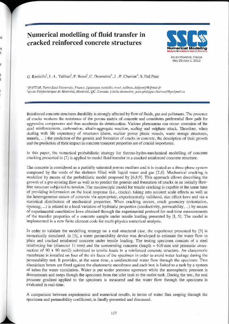
Numerical modelling of fluid transfer incracked reinforced concrete structures
Numerical ModelingStzatzgrzs Miuslitnlhll Enamel: SttuclutrsAt><-enrrovenee, France
May 29—Jtme 1, 2012
G. Rastiello', J .—L. Tailhan', P. Rossi', c. Destnettrez, J .-P. Charronz, s. Dal Pont
'rrsr1"/oz, Part'.r—Easl University, Fmnce, {gittxeppe.ra.\r‘iL'll0, r0.\.\i, tailh1ur,dulponr}@ifi\'r!nrfr2Ec0le Fnlytechniqtre at Monzrénl, Montréal, QC. Canada, {clelia desmertre, jeamphilippe.charmn)@p0lymt!.L‘a
Reinforced concrete structures durability is strongly affected by flow of fluids, gas and pollutants. The presenceof cracks weakens the resistance of the porotts matrix of concrete and constitutes preferential flow path foraggressive components and thus accelerate its deterioration. Various phenomena can occur: corrosion of thesteel reinforcements, carbonation, alkalis-aggregate reaction, scaling and sulphate attack. Therefore, whendealing with life expectancy of structures (dams, nuclear power plants vessels, waste storage stnrctures,tunnels, ) the prediction of the genesis and fonnation of cracks in concrete, the description of their growthand the prediction of their impact in concrete transport properties are of crucial importance.
ln this paper, the numerical probabilistic strategy for thermo—hydro-mechanical modelling of concretecracking presented in [7] is applied to model fluid transfer in a cracked reinforced concrete structure.
The concrete is considered as a partially saturated porous medium and it is treated as a three-phase systemcomposed by the voids of the skeleton filled with liquid Water and gas [2,4]. Mechanical cracking ismodelled by means of the probabilistic model proposed by [6,8 ,9]. This approach allows describing thegrowth of a pre-existing flaw as Well as to predict the genesis and formation of cracks in an initially flaw—frec structure subjected to tension. The macroscopic model for tensile cracking is capable at the same timeof providing information on the local response (i.e., cracks), taking into account scale effects as well asthe heterogeneous nature of concrete via appropriate, experimentally validated, size effect laws and via astatistical distribution of mechanical properties. When cracking occurs, crack geometry (orientation,opening, ...) is related to a local variation of hydraulic properties (conductivity, permeability, ...) by meansof experimental constitutive laws obtained through the experimental protocol for real—time measurementsof the transfer properties of a concrete sample under tensile loading presented by [l, 5]. The model isimplemented in a new finite element code for multi-physics numerical analysis.
In order to validate the modelling strategy on a real structural case, the experience presented by [3] isnumerically simulated. In [3], a water permeability device was developed to estimate the water flow inplain and cracked reinforced concrete under tensile loading. The testing specimen consists of a steelreinforcing bar (diameter ll mm) and the surrounding concrete (length = 610 mm and prismatic cross‘section of 90 x 90 mm2) submitted to tensile loads in a reinforced concrete structure. An elastomericmembrane is installed on four of the six faces of the specimen in order to avoid Water leakage during thepermeability test. lt provides, at the same time, a unidirectional water flow through thc specimen. Twoaluminium boxes are fixed against the elastomeric membrane and each box is linked to a tank by a systemof tubes for water circulation, Water is put under prcssion upstream while the atmospheric pressure isdownstream and seeps though the specimen from the inlet tank to the outlet tank. During the test, the realpressure gradient applied to the specimen is measured and the water flow through the specimen isevaluated in real-time.
A comparison between experimental and numerical results, in terms of water ilux seeping through theSpecimen and permeability coefficient, is finally presented and discussed.
117
‘ i
References:[1] Real-time evolution of electric resistivity in cracking concrete, C. Boulay, S. Dal Punt, P. Belin, Cement andConcrete Research 39: 825:83l,2009.
[2] A multiphase thernioehydrwmechanical model for concrete at high temperatures » finite element ilflplemfifllflliqnand validation under LOCA load. Dal Pont S, Durand S, Sehrefler BA. lnt. J . Nuclear Eng. and Design. 237/20;2l37—2l50,2007.[3] Novel water permeability device for reinforced concrete specimens under loads, C. Desmettre, J .-P. Charm“)Materials and Stnictures, 2011. DOl: lO.I6l'7/sl l527~Ol P9729-6.
[4] A three-dimensional staggered finite element approach for random parametric modeling of thermohygmlcoupled phenomena in porous media, F. Meftah, S. Dai Pont, B .A. Schrefler_ international Journal for Numerical andAnalytical Methods in Geomechanies,20l1. DOl: lO.l002/nag.l0l7.
[5] Real~tjme evolution of water permeability in cracking concrete, G. Rastiello, C. Boulay, S. Dal Pent. J.L. TailhanS. Ramanich_ RILEM Intemational Conference in Advances in Construction Materials through Science andEngineering, Hrmg—Kong, 2011.[6] Scale effects of concrete in tension. P— Rossi, X. Wu X, F. Le Maou. A. Belloc, Mater. & Struet.. 27: 437-444‘1994.
[7] Numerical modelling of fluid transfer in concrete: experimental constitutive laws and numerical probabilisticstrategies, G. Rzistiello, P. Rossi, J .—L. Tailhan, S. Dai Pont, C. Boulay. SSCS-2012, 2012.
[8] Macroscopic pmbahilistie modelling of cracking processes in concrete structures. J .-L. Tailhan, P. Rossi, S. DalPnnt, WCCMJECCOM AS, Venice, Italy, 2008.
[9] From local to global probabilistic modeling of concrete cracking. J.-L. Tailhan, S. Dal Pont, P. Rossi, Annals ofSolid and Structural Mechanics, 1/2: 103-105 2010. DOI: 10.1007/s12356-010-0008-y.
118
Meso-mechanical study of high-temperature Scracking in mortar and concrete specimensusing fracture-based zero-thickness 5975335373-3i~'i5?¢»5?~'»'=753interfaces ‘i;§r";"r'f11?:iLZ't§i§*
M. Rodriguez, C.M. Lopez, I. Carol
Ersrccrrr (School ufCivil Engineering), r/re (Technical University 0/ Camlarda) Camptu Nord UPC, EdifD2, 03034Barcelona, spam
AbstractMultiscale, and in particular, meso—meehanical analysis of heterogeneous and quasi-brittle materialssuch as concrete or rock has emerged as a powerful tool for thc modeling of the fracture processesunder different loading situations. The group of Mechanics of Materials at UPC (Barcelona, Spain) hasbeen developing such tools with the distinctive feature of the way of representing a key ingredient ofconcrete behavior: cracking. All lines in the FE mesh are considered as potential crack lines, viasystematic use of zero-thickness interface elements, and equipped with traction-separation constitutivemodels based on principles of non—l.inear fracture mechanics. ln the simplest scenario, the matrix phaseis considered elastic or linear viscoelastic, and both the continuum and the interfaces may or may notincorporate the variation of their parameters with time (aging effect). This approach has beenimplemented in the context of a general 2D/3D FEM code with features such asconstniction/excavation. coupled THMC analysis, etc. The polygonal geometry of the particles (largeraggregates) is generated numerically using Voronoi‘/ Delaunay theory. This meso-mechanical modelhas proven to yield very realistic results, such as distributed microcrack, coalescence, localization andaverage stress~strain curves for concrete specimens. Applications developed focus primarily onconcrete mechanics and durability (drying shrinkage, external sulfate attack), but also expand tosandstone rock and even biological materials (trabecular bone) [1 ,2,3].ln this paper, attention is focused on the on—going extension of the model to the analysis of thermalmismatch effects in mortar and concrete subject to high temperatures up to 800 C. As a first approachto this scenario, the material is considered as a two—phase composite, with different thennal expansionlaws for matrix and particles, whereby the mismatch generates cracks which are captured by theinterface elements. The computational results are verified with the experimental observations reportedin thc literature [4,5] for uniform temperature distribution. and is then extended to the non-uniformtemperature distribution to the prediction of thermal spalling under heating using differenttemperature-time evolution,References
[1] Micromechanical analysis of quasi—britt.le materials using fracture-based interface elements, 1. Carol, CM. Lopez. 0.Roa, Int. 1. Meth. Engng., 52:l93-215.2001.
[21 A meso-level approach to the an numerical analysis of cracking and fracture of Concrete materials, A. Caballero, C.M.Lopez, I, Carol, Fracture and Fatigue of Engineering Materials and Structures, 29,919-9912006.
[31 Chemo-mechanical analysis of concrete cracking rind degradation due to external sulphate attack! a meso-scale mode. A.Idiart, CM. Lopez, rcnrei, Cement at Concrete Composites. In press-online version DOI10.1016/j,cemconcomp.2010.l2.00l.
/4] Thermal expansion of Portland cement paste, nrerter and concrete at high tenrperettrre. C.R. Cruz, M. Guillen, Fire andMaterials, 4 n°Z,l980.
[5] Stress and defomrzition characteristic of concrete ill high temperature, Y. Anderbcrg, J. Theliindersson. TechnicalReport, Lund Institute of Technology. Lund, Sweden, 1976.
119
Chemo-Mechanical Micro Model forAlkali-Silica Reaction SSIE
Numerical MndfillhgBnleglu In snwmt Ennulll mam,
Alx-en-Provence, FranceMay 29-June 1. 2012
Victur Saouma, Wiwal Pnatatsananon,
University 0fCOI0m110, Boulder USA & Ubon Rntchathani University, Thailand
Abstract
We present a twwstage numerical model for ASR/stress analysis in concrete. A finite differencemodel is used to simulate l.he coupled diffusion of alkali into concrete and then thc subsequent ASRgel into pores surrounding the aggregates, finally a finite element one is subsequently used to performa nonlinear analysis. This model is invoked from the master finitc difference one resulting in a coupledchemo-mechanical simulation of ASR affected concrete with aggregates of different shapes and sines.Throughout this analysis, we keep track of the vertical and lateral expansion of the concrete with time,which in turn are transfonned into equivalent anisotropic coefficients of ASR expansion.
Finally, accuracy of the model is assessed through comparison with simulated laboratory tests.
120
""1Role of Numerical Modelling ofReinforcement Corrosion for SustainableConcrete Structures Numerical ModelingSlnfeqlns lor sttnttmtt wmtr Sllunturn
A|>t—eVl—Pr0\/once, FranceMay 29—Jurle 1. 2012
Henrik song‘ . Michael 1). Lepechz and Mctte Gcikerm
' Techrticnl I/rtiwraity 0jDL'lmuIr!<7 Stanford Univerrily3 Norwegian University 0fScience and Technology ‘
Abstract
With a focus on numerical modeling of reinforcement corrosion and the associated structuraldeterioration, this paper connects numerical models in order to operationalize design and maintenancefor sustainability. A framework was established consisting of two types of models: (i) probabilisticdeterioration models combining one or several deterioration mechanisms with a suite of limit statesand (ii) probabilistic life cycle assessment (LCA) models for measuring the impact of a given repair.rehabilitation, or strengthening. As such, numerical deterioration models of reinforced concretecomprise a major component of this design approach‘
Numerical modelling of reinforced concrete deterioration is used to stochastically estimate the time tothe first repair (from the time of initial construction) and — given the structural condition after a repair~ the time to any subsequent repair. Novel numerical models of initiation and propagation ofreinforcement corrosion are discussed.
These deterioration models are coupled with impact models of a given repair, rehabilitation, orstrengthening activity based on a process—hased LCA of individual repair activities. lmpacts can beenvironmental, social, and economic in nature. Both types of models (material deterioration or LCA)are formulated stochastieally so that the time to repair and total sustainability impact are described bya probability density function. This leads to a fully probabilistic calculation of accrued cumulativeimpacts (which can be annualized) throughout the service life of a structure from the time of initialconstruction up to the time of functional obsolescence (end of life). Results facilitate rationaldecision—making by infrastructure stakeholders when designing to meet sustainability targets.
The paper is prepared in connection with the Nordic Innovation Center (N'lCe) project 08190 SR.
I 121
Y t
SSIENumerical ModelingMrullgizsflifinslamabln lnmjtlt stmttm
Aix—en-Provence, FmneeMay 29-June 1. 2U12
Session I-7:Other ProblemsRelationship between cement alkalis and ASR-based expansionMohammad s lqlam“ and Nader Ghafnorih""'Civil t1IldEnvi!‘0rLmenlalEngirltcring Department, University 0/Nevada Lax Vegas, Lax Vsgax, USA
Piecliction of aggregate reactivity based on a modified polynomial modelMohammad s Islam“ and Nader Ghafnnrih“Civil and Env|'r0m1zmm/ Engineering Deparmzent, University ofNevada Lus Vegas, Las Vegas, USA
Modeling the engineering pcrfornlance of self-compacting concrete to produce precast pilesMohammed Sonebil, Richard M0rlun2. Su Taylor''Sc/um! 0/ Plarming, Arcllilectwe and Civil Engineering Quzra/1'.\" Univcr.\'iry Belfast, Belfast, UK 7 2Bullivm1tTuranm Ltd. Precasl Company, Tnlzdmgee, UK
Bond behavior of plain bars subjected to uniaxial lateral tensionB.H. Xu, X. Zhang, Z.M. WuSlate Key la}/oratory of Coaxial and 0/mm Engineering, Dalian Univer.\'it_y of Technolvgy, China
Characteristics and Pnzdicljon of Autngenous Shrinkage in Concrete Made with Low-Heat Cement and GGBSs. Y0shida', T. Nawaz, F. Taguchi' , T. ogm’‘civil Engineering Resmrch lnslilutefor Cold Regiun, ZHukkaid0 um/wiry, ’1\/mm Cenlent c/1.1.14. Japan
123
Relationship between Cement Alkalis andASR-based Expansion
Numerical ModelingSllllmllslurwrllllllitrllCmuill!lIwlu1u
Aix—en—Provence, FranceMay 29—June 1, 2012
Mohammad S Islam, Nader GhafooriCivil and Environmental Engineering Department, University 0/ N8!/H1111 La: Vegas, L118 Vegas, USACnrrespondilig Blllhur: Nader Ghafnori, Pmfessor, Dtpaflmcnt of Civil and Environmental Engineering, University of NevadaLas Vegas. l'li.tLlCl' gliafoon@unlv cdu
Abstract
The main objective of this study was to examine the influence of three dosages of cement alkalis,namely, 0.42%, 0.84% and 1.26% Na20eq, on the expansion of mortar bars made with five differentaggregate sources due to alkali—silica reactivity (ASR) at the immersion ages of 14, 28 and 56 days.The previously suggested Kolmogorov-Avrami-Mehl—Johnson (K-A-M-J) model was utilizcd tointerpret the ASR classifications of the investigated aggregates. Additionally, an improved K-A-M-Jmodel was developed to better predict thc degree of reactivity of the trial aggregates. The studyrevealed that the ASR—induced expansion increased with an incrcase in cement alkalis, and the percentincrease in expansion due to elevated cement alkalis was more at the early immersion age than thatexperienced at the extended immersion ages. When compared to the original K-A-M-J model, theproposed statistical model showed a better correlation with the findings of the experimental methodand the reactivity suspected based on aggregate mineralogy.Key words: alkali-silica reactivity; cement alkali; ASR expansion; mortar bars; immersion age; modified K-A—M—J model
125
'_
L
Prediction of Aggregate Reactivity based ona Modified Polynomial Model
Numerical Modeling§§1JlH|tIiE§u!luvml>l! lw|uIlB$llI-Klllu
Aix-en—Prm/enoe. FranceMay 29'June 1. 2012
Mohammad S Islam, Nader GhafooriCivil um! E/t\H'/'u!lInL*I|Iu/ E!lgitwn|‘!!Xg Dzqmrfmem‘, i/niwiiny Qrzi/mt/4 Lai Vegas, on Vegas, USACflfluflpulldiflg author: Nader Glulfonri, Professor, Department of Civil and Environmental Engineering, University of NevadaLns Vegas. I nat-i. 'li:|i'0nri(I1‘||!l|v.\3(lH
Abstract
This paper explored the alkali-silica reactivity (ASR) of thirteen aggregate sources by using theexpansion limits of ASTM C 1260. Based on the previous research findings, the ASR-inducedexpansions over the immersion age of 14 days were fitted in a polynomial equation of second degreewith three terms having three distinct regression variables of A2 (the leading coefficient), A1 (thesecond coefficient), and A() (constant). The A1 cuefficients were plotted against the A2 coefficients toevaluate the degree of alkali—siliea reactivity of the trial aggregates based on the trend of the curvegenerated by these aggregate groups. Additionally, A0, A1 and A2 coefficients were correlated withthe l4»day ASR~induced expansions. A modified polynomial model, based on the values of A2parameter, was proposed to better interpret ASTM C I260 results. The output of the study showedthat the existing polynomial model was nearly unable to confirm the actual results of ASTM C 1260.However, the proposed polynomial model showed a better prediction of ASTM C 1260 results on thedegree of alkali-silica reactivity of the trial aggregate sources.
Keywnrrlx: alkali-silica reactivity, mortar bar, ASR—indueed expansion, aggregate mineralogy, polynomialmodel.
126
"9lures
Q l 1 I
. Modeling the engineering performance of‘ self-compacting concrete to produce precast
Numerical Modelingpiles alrillqlviQlihmlaumllvllinrvrlealvvtilvttiAix-en-Ptuvence, France
May 29—June 1. 2012
Mohammed Sonebil, Richard Mortonz, Su Taylor'(1) Slihvtri r1fl’limning, AIL‘/liI2(.’l14l'L' inul Civil Eng., Queen’: University Bfllfdsl, Bfllfllii, UK(2) Eullivimt Tarzmw Lid, Precast Company, Tandragee, UK
Abstract
This investigation aims to model the engineering performance of selfreompaeting concrete (SCC) toproduce precast piles With grade C40/50. A factorial design was carried out to model the influence of mixparameters on the fresh and hardened properties such as filling ability, passing ability, segregation, andcompressive strength that are important for the successful development of SCC. The parametersconsidered in the study were the content of binder, the type of binder, water-to-binder ratio (W/B), andsanil—to-aggregate ratio (S/A). Twelve mixes were prepared to derive the statistical models. The modelsof fresh properties and compressive strengths were established. The influences of W/B, binder content,type of binder and the S/A were characterised and analysed using polynomial regression which canidentify the primary factors and their interactions on the measured properties. The results of themodelling and surface responses of the engineering performance were discussed in this paper.
lJ
4
l
ll
‘ 127 \
F
Bond behavior of plain bars subjected to S , _uniaxial lateral tension Numerical Modelln
Aix-en'Provence. FranceMay 29-June 1. 2012
EH. Xu, X. Zhang, Z.M, Wu
State Key Lubflflllvry 0/ CUGSUII and 017;/inn; Engineering, Dalian University Hf Technology, Chum
Abstract
This paper presents the results of an experimental study undertaken to evaluate the characteristics ofthe local bond Stl'8SS—Sli]J response of plain bars embedded in concrete under uniaxial lateral tension. Atotal of 87 (150 x 150 x 150 mm) specimens were tested, which are divided into several seriesaccording to the different compressive strength and plain bar diameter. The tension is uniformlyimposed on steel plates bonded on parallel surfaces of cube pull-out specimens. The maximum lateraltension applied in thc test is equal to 80% of the uniaxial tensile strength (fi) of concrete, lt was foundthat the ultimate bond strength monotonously decreases by 46% when the lateral tension reaches 0.8 _fl.The slip corresponding to the ultimate bond strength increases with the increase of lateral tension.Based on the experimental results of this study, a model for the local bond stress-slip response of plainbars embedded in concrete is proposed, and constitutive relationships that describe its characteristicbehavior were developed.
Key words: bond strength; plain bars; lateral tension; bond stress-slip
128
Characteristics and Prediction ofAutogenous Shrinkage in Concrete Madewith Low-Heat Cement and GGBS
Aix—en—PIoVen\>e, FranceMay 2&June 1, 2012
s. Yoshida‘, T. Nawaz, F. Taguchi', T. ogura‘
‘cm! Engilturing Reaearch Instilutefur Cold Region. 1110/(tam University, ’Nmt»¢; Cement Co.Ltd Japan
Abstract
Recently, investment in tl1e development of new infrastructure has decreased because of highermaintenance and replacement costs related to the increase of old social capital stock in Japan.Against this background, there is a strong need to promote more efficient infrastructure developmentthrough measures such as ensuring the long-term durability of structures to extend their service life.The key to ensuring the long-term durability of concrete structures is to make the concrete used forthem more durable, and for this reason it is important to study concrete with a low watercement ratiorange. However, such concrete has a variety of inherent problems, including an increased likelihoodof thermal and shrinkage cracking and the need to secure workability.
The authors previously conducted studies on enhancing the performance of concrete by modifyingcement and using mineral admixtures. The results indicated that the use of ground granulatedblast-fumace slag (GGBS) as a substitute for part of highly pulverized belite~based cement (low»heatcement) improved strength, heat generation characteristics, frost resistance, chloride penetrationresistance and other properties as well as the dutability of the concrete, thereby enabling enhancedconcrete performance. As concrete made using binders with such properties is expected to exhibitlow—heat generation properties and long-term strength development in addition to long—term durability,it is regarded as very useful for application to relatively large structures such as piers and abutments oflong bridges and retaining walls constructed under severe environments where frost and salt damagemay occur. With the use of such binders, the amount of CO2 generated in the cement productionprocess can be reduced, In this regard, a reduction in the environmental burden related to theconstruction industry can be expected.
However, it should be noted that concrete with a low water-binder ratio range undergoes significantautogenous shrinkage, and that the use of fitter GGBS results in greater autogenous shrinkage. Theoccurrence of initial cracking leads to crucial issues in securing lor|g~terrn durability. Accordingly,this study sought to investigate and p|'cdict autogenous shrinkage in concrete made with highlypulverized bclite-based cement and GGBS with a low water-binder ratio.
The results indicated that the degree of autogcnous shrinkage depended on the binder type and thewater-binder ratio. It was also found that autogenous shrinkage was reduced when higher volumes ofSO; were addcd to GGBS, and this was true even when thc fineness of the slag was increased. Inaddition, a prediction equation for estimating autogenous shrinkage of concretc made withbelite—based cement and GGBS was proposed in consideration of the effects of various factors on suchshrinkage.
129
Y
Numgrlcal Modelings atstutnqbs Suflitnlhll Dzlmrell t =l\/in
Alxen-Provence. FranceMay 29—June 1, 2012
Sessions II:
Structural applications and Sustainability
131
SSENumerical ModelingSlnmnlns In! Suslltnillle st-mt. Slmclurls
Aix-en-Provence. FrflnceMay ZQJLIVIG 1. 2012
Session II-1:BridgesNumerical Modeling of the Mechanical behavior of bridge Decks with Precast PampetsM. Namy, J.—P. Charron, and B. MassicotteEcole Polytechnique dz Montreal, Montreal, Canada
Usc of nonlinear finite clement models for stmctural evaluation of concrete box girder bridgesE.Yildiz', B.Massicotte2’ CIMA+ smeté Mingénierie, Muntréal, Canada, Z Emile Polytechnique dz Mr/ntréal, Montréal, Camldfl
Predicting the Shear Behaviour Of Solid Slab Bridges using Nonlinear Finite ElementsD. Conciatori, B. MassicotteEcole Palytechnique tie Montréal, Montréal, Canada
Cracking analysis of concrete structure elements reinforced by flat steel rebarsT.S. Phan. J.~L. Tailhan, P. Rossi, I. FoulliaronIFSTTAR Paris, France
CO;—Optimization of PC precast bridges by hybrid heuristicsJ.V, Marti, V. Yopes, F. Cvon2;ilez—Vidosa, J. AlcaléICITECH, Urtiversitat Politécnica dc Valencia, Spain
133
“H
Q
Numerical modeling of the mechanicalbehaviour of bridge decks with precastparapgts §.'§::-'§';i§fii|.':..?§§:i'.'§2
Aixerwrovence, FranceMay 29'June 1, 2012
AM. Namy, J .l’. Charron P) and B. MassicotteEcole Pulylechnique dc Mmmw, Department (If Civil, Geological and Mining Engineering1+0. at»; 6079, Slutizm cm":-vi/re, Montreal (Quebec) Cmuldfl, use am"' Cvrrexpomiing author: jean-philippe.charmn@p0lym-!l.ca
Abstract
l.n the framework of a 4-years industrial project, new designs of precast bridge parapets made with fibrereinforced concretes (FRC) and novel anchorage methods to connect the parapet to thc underneath slabwere developed. In order to study the mechanical performance of a btidgc deck with precast parapets incomparison to cast in place parapets, an experimental program of quasi-static tests was carried out on 3full-scale specimens of 6—m lcngth including the extemal girder, slab and parapets. A tridimensicnal non-linear finite elements model was developed in thc project to reproduce the stiffness, ultimate strength,crack pattem and failure mode of thc bridge deck with precast and cast in place parapets. The paper willfirst focus on the comparison of finite element calculations and experimental results. Then the results of anumerical parametric study conducted on various configurations of bndge deck will be discussed.
135
Use of nonlinear finite element models forstructural evaluation of concrete box girder
N | M $8bridges s~..iL'i:ii?,'§'i§?=rti iigttrsiiiiiig
Aixen'P|over\ce. FranceMay 29-June 1, 2012
E.Yildizl, B.Massicotte2
1 _ C[MA+ smété d'ingéuierie,Mantre’al, Cllflllfffl2 - Ecole Polylechniquz av Montrézil, Monzréal, Canada
i
AbstractMost of the bridges in Canada are built before 1980s. The type of concrete and the reinforcementdetailing prescribed in codes at that timc are such that structures need major investments formaintenance and rehabilitation. In this process many structural evaluations are carried out based onwellknown structural analysis and strength calculation methods. The methods prescribed in codes aremainly oriented for designing new structures. Although they have generally proven to be safe, theymaybe sometime inappropriate when used in bridge evaluation. In some case they fail in identifyingthe appropriate failure mode and lead to inadequate strengthening whereas in other cases they canunderestimate the actual strength and lead unnecessary repairs.
The paper is based on a typical 1960's multi-cellular reinforced concrete bridge showing typicaldefects such as extended cracking and insufficient reinforcement. Two main issues are considered: thestrength of pier caps that are deep and massive elements, and the strength of the box girder webs thatare considered as slender members in which shear and bending interact.
Nonlinear finite elements were used to study these issues. The first study presented in this paper dealswith the strength and behaviour of the pier caps. The failure modes before and after strengthening arestudied. The emphasis will be put on the contribution of nonlinear analysis in identifying theinadequate behaviour of the existing structure and the proper strengthening technique adopted.
The second portion of the paper considers the importance of the flexural—shcar cracking over thespans. The finite element models used allows to observe the progression of the shear cracks versus theapplied load amount and the associated failure modes.
The paper emphasis will be on how nonlinear finite element models can be used to properly identifythe failure modes and to optimise the strengthening solutions in order to limit the costs and maximizethe structural reliability.
136
Predicting the Shear Behaviour of SolidSlab Bridges using Nonlinear FiniteElements
SSIENumerical Modelingsumqt-, mo.t.mt,»t Cnrtcvntr Stmctuvrs
A|x—en—Provence, FranceMay 29—Jur\e 1. 2012
D. Conciatori, B. Massicottc
Ecole Polyrech/tique de Mflnlréfll, Montréal, Canada
Abstract
Catastrophic collapse of Concorde Bridge in 2006 near Montreal raised the issue shear stressconcentration in straight and skewed concrete concrete slab bridges. These bridge have beentraditionally designed without shear reinforcement. Questions were raised concerning the reliability ofexisting bridges and also on the design guidelines of new bridges.
Straight and skewed solid concrete slab bridges are modeled using linear and nonlinear finite elementmodels to highlight shear forces that develop in slab bridges, particularly at the corners. Various typesof loads are applied in order to understand the elastic and plastic behavior of the corner force inservice conditions and near ultimate. A parametric study is carried out on several configurations ofsimply supported slabs with geometries covering one to four lane bridges of 3 to 20 m spans and withskew angles ranging from 0° to 60°. The analyses show that comer forces develop locally and theactual design of straight and skew concrete slab bridges is not influenced by the comer forces. Aredistribution of corner forces is observed near ultimate limit states with apparition of shear crackbringing ductility at this failure mode. The analyses indicate that these corner forces appear along thefree edge with depth about a half-thickness of the concrete slab. This justifies reinforcing the free edgeby stirrup, when the design propose a reinforcement.
For existing bridges, the analyses show that strength obtained using a beam type behavior is tooconservative for estimating the actual shear strength of slab bridges where wheel loads allows a betterredistribution than assumed using elastic analysis.
‘__A,A
Cracking analysis of concrete structureelements reinforced by flat steel rebars
Numorloal lvludellnSllsllqtzs tovsurtatnantt Bnnuet: Sum lug
Aix—en—P|'0\/ence. FranceMay 29-lune 1, 2012
T.S Phan"', J.»L. Tailhan”, P. Rossi“, Phi Bressolette‘, F. Me4ghani',J . Foulliaron“‘French Institute 0fScience and Technologyfor Transport, Development and Networks (IFSTTAR) Pm; East University, Frame1’ Clermont University, Blaise Pascal University LaMI, EA3867, BP 206, 63000 Clermonl, Frrrnce 1 MATIEREU - Corulructioncompany, Franceemail .- thanh-sung,phan@¢rlmrfr,jean-l0uis,tailhan@ysrmrfr, pierrz.r0s:i@1fil!arfi
This paper presents a cracking analysis of a new reinforcement method based on the use of flat steel rebarsinstead of classical circular high adhesion. The objective of this method of reinforcement is to optimive the useof materials and to better distribute the cracking processes in the concrete elements. The analysis is performedin the case of the beam—slabs subjected to four point bending. The results are analysed in terms of crackingprocesses of thc concrete as well as at the level of the steelconcrete interface. The dimensions of the ooncreteprismatic speci.mens are 330 X 15 x 80 cm. The reinforcement is made of flat steel which cross section isrectangilar (22.5 x 5 mm).
The behaviour of the concrete is represented by an explicit probabilistic cracking model ([1], [4]) taking intoaccount two major characteristics of the concrete: heterogeneity, on the one hand, and its sensitivity to scaleeffects, on the other hand. The mechanical properties (tensile strength f, and Y0ung’s modulus Ee) arerandomly distributed and dependent on the volume of material stressed (size effect laws). The behaviour of theflat steel rebars remains elastic as far as only the service limit state is here considered. The steel-concreteinterface is represented by contact elements which behaviour is modelled by a detenninisric damage modeltaking into account cohesion and slip at the level of the interface. To identify the parameters of this interfacemodel, a methodology based on an inverse analysis approach is used. This methodology has been made bysimulating the statistical mechanical behaviour of RC tie—beams (170 X l0 x l0 cm) subjected to tension andmade of the same concrete and reinforced by the same flat steel rebars. The results have been compared withexperiment [2] and are relevant ([5], [6]).
The obtained numerical results of the beam—slabs are also compared with experiments [3]. The comparison ismade in tenns of global response (load~relative displacement curves), as Well as cracking process (eratrksopening, cracks spacing and number of cracks).
Keywords: Reinforced concrete, flat steel rebar, steel-concrete interface, cracking.
References:[1] Probabilistic model for material behavior analysis and appraisement of concrete structures, Rossi P. and W" X--Mag.C0l1C.Res., 44 (I6 l):27 L230, 1992.[2] Internal report of experimental results on RC tie-beams tests, MATIERE, 2010.[3] Experimental results of RC beam-slabs tests, MATTEREU ,20l l.[4] Scale effects on concrete in tension, Rossi P., Wu X., Le Mziou F.. Belloc A., Journal Materials and Structures,27 (172): 437444, I994[5] Numerical Probabilistic Simulation of Cracking Processes in RC Tie-beams Subjected to Tension and Rein— forced bl’Flat Steel Rebars, Phan TISA’ Rossi P. and Tailhan J.—L.. Proceeding of International Conference on ComputatioflfllModeling of Fracture and Failure of Materials and stnictures (CFRAC 20] l), Barcelona, Spain, 20] I .[6] Numerical modeling of thc rebar/concrete interface; case of the tlat steel rebars, Phan T.S., Rossi P., Tailhan 1-‘L., Bressolette Ph. and Mczghaui P., MagMat.Struc. (in review 20] 1)
133
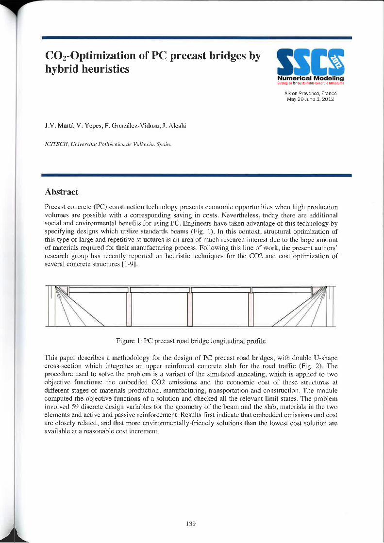
CO2-Optimization 0f PC‘ precast bridges byhybrid heuristics
Numerical Modelingsmug I-tlllliutlilmhll Dnntul: Slmtluvzs
Aix-en-Provence, FranceMay 29-June 1. 2012
J.V. Marti, V. Yepes, F. Gonzalez-Vidosa, J . Alcalé
ICITECH, Ultivcrsilnl Pvlilécnicu dc Vulénciu. Spain.
Abstract
Precast concrete (PC) construction technology presents economic opportunities when high productionvolumes are possible with a corresponding saving in costs. Nevertheless, today thcre are additionalsocial and environmental benefits for using PC. Engineers have taken advantage of this technology byspecifying designs which utilize standards bcams (Fig. 1). ln this context, structural optimization ofthis type of large and repetitive structures is an area of much research interest due to the large amountof materials required for their manufacturing process. Following this line of work, the present authors’research group has recently reported on heuristic techniques for the CO2 and cost optimization ofseveral concrete structures [l -9].
\ /,. /
// /Figure I: PC precast road bridge longitudinal profile
This paper describes a methodology for the design of PC precast road bridges, with double U—shapecross—section which integrates an upper reinforced concrete slab for the road traffic (Fig. 2). Theprocedure used to solve the problem is a variant of the simulated annealing, which is applied to twoobjective functions: the embedded CO2 emissions and the economic cost of these structures atdifferent stages of materials production, manufacturing, transportation and construction The modulecomputed the objective functions of a solution and checked all the relevant limit states. The probleminvolved 59 discrete design variables for the geometry of the beam and the slab, materials in the twoelements and active and passive reinforcement. Results first indicate that embedded emissions and costare closely related, and that more environmentally-friendly solutions than the lowest cost solution areavailable at a reasonable cost increment
139
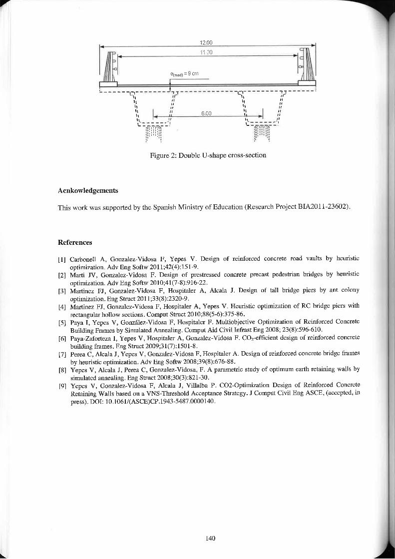
: 1200 I
_ _ . _ _ . _ _ _ . . _ .._J ________..-__-...._._-__ .......:W‘, Yr‘ '-1', “.3‘\ If ‘\‘-‘. 1: ‘-‘.., son‘¢-____.-’,' ‘\\:_____.,
Figure 2: Double U-shape cross-section
Aenkowledgements
This work was supported by the Spanish Ministry of Education (Research Project BIA20l 1-23602)
References
[I] Carbonell A, Gonzalez—Vidosa F, Yepes V. Design of reinforced concrete road vaults by heuristicoptimization. Adv Eng Softw 201 1;42(4): l Sl-9.
[2] Marti IV. Gonzalez-Vidosa F. Design of prestressed concrete precast pedestrian bridges by heuristicoptimization. Adv Eng Soflw 20l0;4l(7-8):9l&22.
[3] Martinez Fl, Gonzalez-Vidosa F, Hospitaler A, Alcala J. Design of tall bridge piers by ant colonyoptimization. Eng Strtlct 201 1 ;33(8):2320-9.
[4] Martinez FJ, Gonzalez-Vidosa F, Hospitaler A, Yepes V. Heuristic optimization of RC bridge piers withrectangular hollow sections. Comput Stnict 20l0;88(5-6):37S-86.
[5] Paya I, Yepes V, Gonzalez»Videsa F. Hospitaler F. Multiobjective Optimization of Reinforced ConcreteBuilding Frames by Simulated Annealing. Comput Aid Civil lnfrast Eng 2008; 23(8):S96-610.
[6] Payalaforteza I. Yepes V, I-lospitaler A. Gonzalez»Vidosa F. C01-efficient design of reinforced concretebuilding frames. Eng Stniet 2009;3l(7): 1501-8 .
[7] Perea C, Alcala J , Yepes V, Gnnzalez»Vidosa F. Hospitaler A. Design of reinforced concrete bridge framesby heuristic optimization. Adv Eng Softw 2008;39(8):676-88.
[8] Yepes V, Alcala I, Perea C, Gonzalez—Vidosa, F. A parametric study of optimum earth retaining Walls bysimulated annealing. Eng Struct 2008;30(3):821»30.
[9] Yepes V, Gonzalez-Vidosa F, Alcala J, Villalba P. CO2-Optimization Design of Reinforced ConcreteRetaining Walls based on a VNS-Threshold Acceptance Strategy. I Comput Civil Eng ASCE, (accepted ll'lpress). DOI: 10.1061/(ASCE)CP.1943—5487.0000l40.
140
SSCSNunerloal Modeling§hI\lQlWIht‘5t|l|l|n|hl1Ea||c|ulnSln||rtu|\i
Aix-en-Provence. FranceMay 29-June 1. 2012
Session II-2:BuildingsNumcricnl Modelling of Deconstructable Composite Beams with Bolted Shear ConnectorsM.A. Bradford & Y.—L. PiCentre for Infiastructure Engineering & Safety, University ufN/aw Snuth Wales. UNSW Sydney, Australia
Experimental and numerical analysis of advanced cementitious composites for sustainable roof clcmcntsM. Di Prisco, G. ZaniI’0litccnicu di Milarw, Italy
Optimized and Sustainable Earthquake Resistant Engineered Cemenlitious Composites BuildingsBora Gencturk' and Amr Elnashaiz' Research Associate (currenibl assistant prvfierror, University of Houston) — 2 Bill and Elaine Hall Endowed Professor,Department Head - Department of Civil and Environmental Engineering, University af Illinois at Urbaruz-Champaign.USA
Advanced Construction Stage Analysis of High—rise Building Considering Creep and Shrinkage of ConcreteTachun l-in, Sungho LccDaewzm E&C, Suwan, Gye0nggi—110,Sz/uth Korea
Usc of HPFRC for Sustainable Seismic Hazard Mitigationc..c. Hung‘, s. El—Ta\vil2” Dkpartrnkrtl 0 ‘Civil Engineering, Naliunal Central Unlversil , Taiwan 7 Z’ De arlnuznl 0 Civil and Environmentaly PEngineering, University nfMichigan, Ann Arbor. Ml. USA.
Numerical modelling of UHPC structural members reinforced with fibers and rebarsP. LussouLafarge centre de recherches. France
Numerical Assessment of the Thet'mal Performance of Structural Precast PanelsJ. Keenahan. K. Concannon, D. Hajializadeh, C. McNallyUniversity College Dublin, Ireland
Modeling of Progressive Collapse in Reinforced Concrete StructureA.R. Rahai, M. Banazadcli, M.R. Seify AsghshahrDeparlnmnt 0fCivil Engineering, /lmirlmlrir University r/fTzchn0l0gy(Tehran Polytechnic), Iran
Numerical Modeling of FRP— Confined Square RC Columns under Axial load and Biaxial BendingA.R. Rahal‘ , 1-1. Akbarpouiz"2 Department afCivil and Environmental Engineering. Amirkabir University nflcchnnlogy, Iran
141
Reliability of Ancient RC Structuies by Means of Numerical ModelingS. Talloni. FiStochinoDISIG Univerxily nfflagliari. Italy
Seismic Performance Evaluation of Reinforced Concrete Building with Static Pushover AnalysisK. Tounsi' , H. Aknouche"*Superiur Naiinrml School of Public Wnrlei, ENSTP, Algiem - ** National Cen/re of Applied Research in EurlhqunkeEngineering, CGS. Algiers. Algeria
Decreases to the Carbon Dioxide Irnpcrmeabilily of Polyurethane Waterproof Membranes Caused by Weatheringand Concrete Substrate CrackingM. Tsukagoshi‘, T. Ueda*. K. Tanakn"University of Tnkuxhinia, Japan‘, Tokyo I/lxlimle of Technalngy. Jap¢m*"
Mechanical Analysis and Simplified Mozicls of Concrete Block Infill Walls under Out-of-Plane ActionWei-qiu zmmg‘. Ming-shu Gang'. Xian-hui cal’' Faculty of Infrastructure Engineering. Dalian Univeri-iry Q/' Teclmology, Linaning - 2 Dzparrmznl of EngineeringMechanicr, Fnculry of Vehicle Engineering and Mechnnicx, Dalian Univeri-ily nfT£Chm1ll)gy, Liannlng, Cliinn
I42
it
Numerical Modelling of DeconstructableComposite Beams with Bolted ShearConnectors
A|X—en—Pro\/ence, FranceMay 29—Jurte 1. 2012
MA. Bradford & Y,-L. Pi
cam/1» Infmstrlwlurc Engineering at Safety, University z/fNe'w Saulh Wales, unswswim, zvsw 2052, Australia
Abstract
Composite beams of steel and concrete are commonplace in engineering structures, taking advantageof the favourable compressive strength of the concrete slab and the favourable tensile strength of thesteel girder in a symbiotic fashion. Mechanical shear connection between these two components isessential to realise the increased strength and stiffness of composite beams above those of the slab andsteel girder alone. Because of this, headed mechanical stud shear connectors have found close touniversal acceptance in contemporary buildings and bridges in providing robust shear connectionbetween the slab and girder, being installed very economically by rapid welding procedures.
Paradigms related to sustainability and full life-cycle assessment in building construction and usageare being introduced in many nations, and unfortunately composite beams with headed stud connectorsare not able to be decommissioned easily and efficiently during deconstruction or buildingmodification. One means of circumventing this drawback is to use high strength bolts to provide theshear connection in lieu of headed connectors welded to the steel girder‘s top flange, which can beunbolted to deconstruct the building or to alter part of it stmcturally. Surprisingly, this form of shearconnection has received little attention in published comprehensive research outcomes, despite itsattractiveness for deconsuuction as well as structural retrofit.
This paper describes an efficient finite element method of analysis of composite beams with structuralsteel joists and ordinary Portland cement concrete slabs which are joined by high strength bolted shearconnectors. It incorporates material nun~lincarity in these three elements of the beam, drawing onempirical representations of the shear connection response that may be obtained from standard pushtesting. By making recourse to comprehensive experimental investigations undertaken in the UnitedStates some forty years ago, the numerical model is shown to agree well with test results for full-scalebeams.
Since the carbon footprint of a building transcends the materials of its original construction because offull life—cycle performance which includes its deconstruction, the use of bolted shear connectors withordinary Portland cement slabs reduces the carbon footprint of a building that uses welded headed studconnectors with ordinary Portland cement slabs for which deconstruction is problematic. Thenumerical technique developed in the paper provides an efficacious tool of analysis for compositebeams with welded headed stud connectors.
143 |
L l
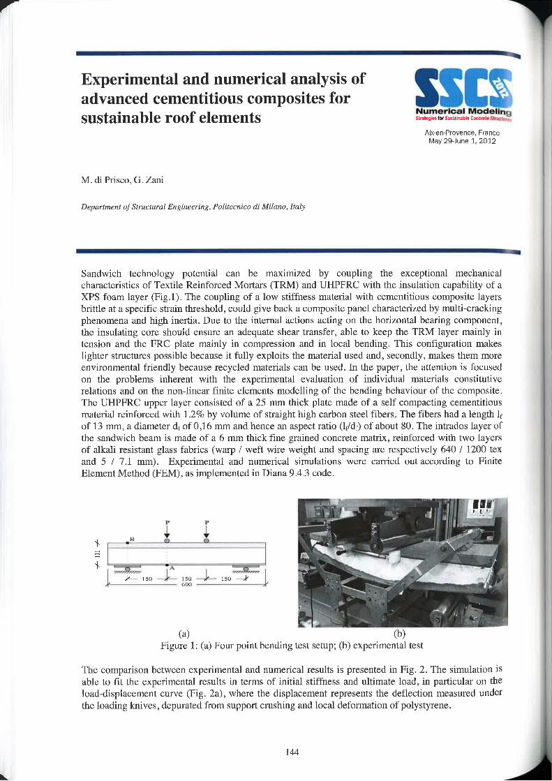
Experimental and numerical analysis of I,advanced cementitious composites for ‘ ')sustainable roof elements
Aix—en—Provence, FranceMay 29<June 1. 2012
M. di Prisco, G. Zani
Department ofSrmcn4ml Engineering, Politecnico dz‘ Milzmo, Italy
Sandwich technology potential can be maximized by coupling the exceptional mechanicalcharacteristics of Textile Reinforced Mortars (TRM) a.nd UHPFRC with the insulation capability of aXPS foam layer (Fig.1). The coupling of a low stiffness material With ccmcntitious composite layersbrittle at a specific strain threshold, could give back a composite panel characterized by multi—crackingphenomena and high inertia. Due to the internal actions acting on the horizontal bearing component,thc insulating core should ensure an adequate shear transfer, able to kccp thc TRM layer mainly intension and thc FRC plate mainly in compression and in local bending. This configuration makeslighter structures possible because it fully exploits the material used and, secondly, makes them moreenvironmental friendly because recycled materials can be used. In the paper, the attention is focusedon the problems inherent with the experimental evaluation of individual materials constitutiverelations and on the non-linear finite elements modelling of the bending behaviour of the composite.The UHPFRC upper layer consisted of at 25 mm thick plate made of a self compacting cementitiousmaterial reinforced with 1.2% by volume of straight high carbon steel fibers. The fibers had a length 1;of l3 mm, a diameter df of 0,16 mm and hence an aspect ratio (I;/df) of about 80. The intrados layer ofthe sandwich beam is made of a 6 mm thick fine grained concrete matrix, reinforced with two layersof alkali resistant glass fabrics (warp / weft wire Weight and spacing are respectively 640 / I200 tcxand 5 / 7.1 mm), Experimental and numerical simulations wcrc carried out according to FiniteElement Method (FEM), as implemented in Diana 9.4.3 code.
i I+ m—_%;l
(B) (b)Figure 1: (a) Four point bending test setup; (b) experimental test
The comparison between experimental and numerical results is prcscntcd in Fig. 2. Thc simulation isable to fit the experimental results in terms of initial stiffness and ultimate load. in particular on theload—displaccment curve (Fig, 2a), where the displacement represents the deflection mcasurcd underthe loading knives, depurated from support crushing a.nd local deformation of polystyrene.
144
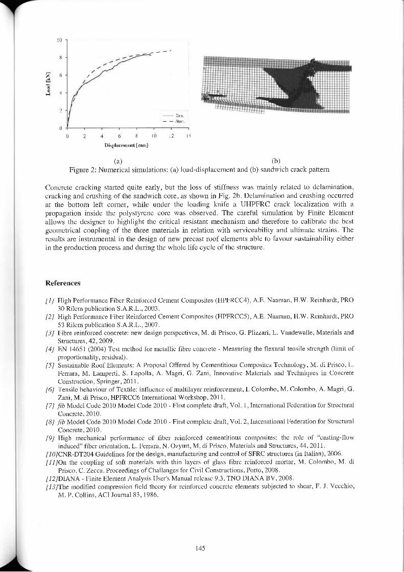
10
8 ,"'- :.iii::::- _ j :::.: . . .:::;,. ____ __ -
I 6 a4 ,4' 1 “ é2 / ,t.t,o§i,LoadkN
_.---..if§5
...— Exp l
l7 7 NrrmU
U 2 4 6 E 10 12 14
Displacement [mm]
' <a> <1»)Figure 2: Numerical simulations: (a) load-displacement and (b) sandwich crack pattern
Concrete cracking started quite early, but the loss of stiffness was mainly related to clelamination,cracking and crushing of the sandwich core, as shown in Fig. Zb. Delamination and crushing occurredat the bottom left corner, while under the loading knife a UHPFRC crack localization with apropagation inside the polystyrene core was observed. The careful simulation by Finite Elementallows thc dcsigncr to highlight the critical resistant mechanism and therefore to calibrate the bestgeometrical coupling of thc three materials in relation with serviceability and ultimate strains. Thercsults are instrumental in the design 01' new prccast roof elements able to favour sustainability eithcrin the production process and during the whole life cycle of thc structure.
References
[I] High Performance Fiber Reinforced Cement Composites (HPFRCC4), A.E. Naaman, H.W. Reinhardt. PRO30 Rilem publication S.A.R.L., 2003.
[2] High Performance Fiber Reinforced Cement Composites (HPFRCCS), A.E. Naaman, H.W. Reinhardt, PRO53 Rilem publication S,A.R.L.. 2007.
[3] Fibre reinforocd concrete: new design perspectives, M. di Prisco, G. Plizz-.\r'i, L. Vandewalle, Materials andStructures, 42, Z009.
[4] EN 14651 (2004) Test method for metallic fibrc concrctc — Measuring the flexurzrl tensile strcngth (limit 01‘proportionality, residual).
[5] Sustainable Roof Elcmcnts: A Proposal Offered by Cernentitious Composites Technology. M. (ll Frisco, 1..Ferrzna, M. Lampcrti, S. Lapolla, A. Magri, G. Zani, lnnovativc Materials and Techniques lll ConcreteConstruction, Springer, Z011.
[6] Tensile behaviour of Textile: influcncc of multilayer’ reinforcement, l. Colombo, M. Colombo, A. Magri, G.Zani, M. di Priscu, l-IPFRCC6 International Workshop. Z011.
[7] fib Model Code 2010 Model Code 2010 — First complete draft, Vol. 1, International Federation for StructuralConcrete, 2010.
[8] fib Model Code 2010 Model Code 2010 » First complete draft, Vol. 2, International Federation for StructuralConcrete, 2010.
[9] High mechanical performance of fiber reinforced cementitious composites: the role of “casting-flowinduced" fiber orientation, L. Ferrara, N. Ozyurt, M. di Prisco, Materials and Structures, 44, 2011.
[1l7]CN'R»DT2U4 Guidelines for the design, manufacturing and control of SFRC structures (in Italian), 2006.[I1]On the coupling of soft materials with thin layers of glass lllJ\'C reinforced mortar, M. Colombo, M. or
Prisco. C. Zecca, Prococdings of Challanges for Civil Constructions, Porto, 2008.[IZ]DlANA — Finitc Elcmcnt Analysis User's Manual release 9.3, TNO DIANA BV. 2008.[I3]The modified compression field theory for reinforcctl concrctc elements subjected to slrcar, F. J. Vecchio,
M. P. Collins, AC1 Journal 83, 1986.
145
Optimized and Sustainable Earthquake ,IResistant Engineered Cementitious SComposites Buildings !3“'5i'»33533T355~'?~5~‘=i?1§‘\»'-7“%=.
"l3§y"§$Zli1°i'. Z555‘
Bora Gencturk(1) and Amr Elnashai(2)
(1) Research Associate (currently assistant prvfzsxur, University o/Houston, USA)(2) Bill ll-M11 Elaine 1-1,111 Endowed Professor, Department HeadDepartment Dfcrv-'1 and Envirorunemul Engineering Department, University 0/111mm at Urbana-Champaign, um
I — — —
Abstract
Lifecycle Cost Analysis provides a powerful tool to balance initial design and construction cost,maintenance and operation. Engineered cementitious composites (ECC) are high performance concretemixes that are significantly more expensive than reinforced concrete (RC). In this paper, constitutiverelationships that capture the difference in behavior between the two materials, ECC and RC aredeveloped and applied to earthquake design in an optimization framework. A Whole lifecycle cost modelis developed and used to assess the results from analytical simulation of the two types of structure whensubjected to severe earthquake motion. It is concluded that ECC buildings are indeed a most viable andoften superior solution, in spite of their higher initial cost.
146
Advanced Construction Stage Analysis ofHigh-rise Building Considering Creep andShrinkage of Concrete
A1><~en-Provence, FranceMay 2&June 1, 2012
T. Ha, S. LeeDucwoo E&C, Sim/on, cyemggzau, South Korea
Constniction stage analysis for reinforced concrete structures is usually applied to bridges, of which thestructural stability during constmction is as much important as for the finished structure. This requirementis equally applicable to high-rise reinforced concrete buildings. Long—tenned construction period of hig,h—rise building may induce axial shortening of the structure over several hundred millimetres at higher levelsof the building during construction. For buildings with mass eccentricity or irregularity, the differentialshortening combined with applied moment could also make the building move laterally duc to themechanism similar to bimetallic strip. The amount of axial or lateral movement can be ignored forordinary buildings but is very important to high—risc buildings, since they cause adverse effects to theconstruction and perfonnance of elevators and facade, and also develop locked-in forces in outriggcrs orbelt trusses which are vital to the lateral resistance of the high-rise buildings.In this research, a constntction stage analysis program was developed and used to predict and to solve theproblems during the construction of the KLCC Tower, a 58-story reinforced concrete building (refer toFigure 1). The program can create or import 3-dimensional structural model of a building for analysis.The user defines the time-dependent material properties like modulus of elasticity, creep, and shrinkage ofconcrete according to ACI 209, 318, and 363. Other creep and shrinkage models such as CEB MC90-9‘),B3, and GL2000 are currently being incorporated into the program for a possibility of better prediction ofbuilding movement. The amount of reinforcement is also input to consider the effect of load redistributionbetween steel and thc surrounding concrete for RC and SRC members. The construction sequence of abuilding is modelled by assigning birth date or extinction date to each element of the structural model forself—weight and to other additional loading stages. In the process of analysis, the model is analysed at eachconstruction stage for member forces and deformation, and the intennediate results are stored and used asdatum values for the next construction stage analysis. As a result, the building is simulated for itsmovement and forces for all stages of construction best possible. In the case of the KLCC Tower,developed program was used (1) to set the preset amount at each level for axial shortening, (2) to reducethe supporting duration of the temporary prop under a massive transfer girder, and (3) to predict thebuilding verticality at the time of elevator construction and the remaining lateral movement until targettime. Material testing for the modulus of elasticity, specific creep, and ultimate shrinkage of concrete wasperformed to update the accuracy of the prediction. Three types of field monitoring for actual movementof the building was also performed: strain measurement of column deformation using vibrating wiregauge, optical survey for lateral movement, and 3-dimensional laser scanning of as—built shape of thebuilding for axial and lateral movement (refer to Figure 2). The results of field monitoring confirmed thepredicted value of the building movement.
I47
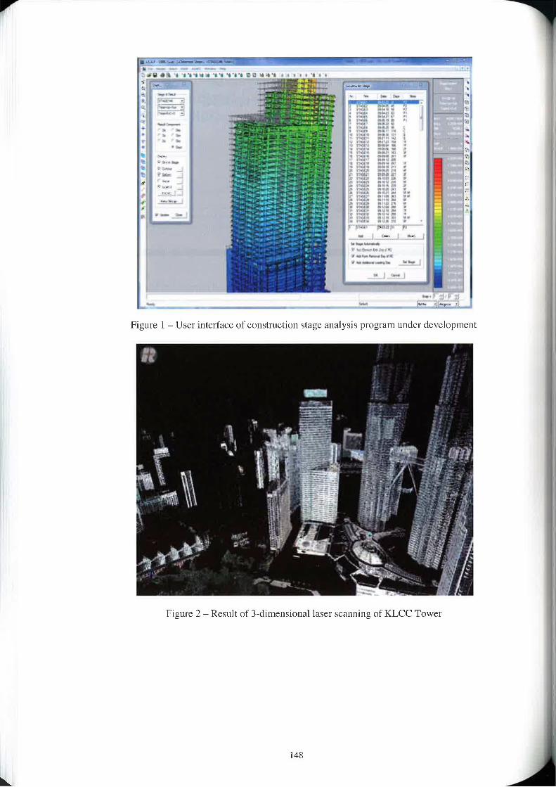
._.. -_ t.:_.-Ya-ta- ,!,,i,._.,__.L.L............. .
1 ..-W i .,
‘ 1
lM
_ F4
_ .. 04' ...,.. .
Figure I i User interface of construction stage analysis program under development
Figure 2 - Result of 3-dimensional laser scanning of KLCC Tower
148
Use of HPFRC for Sustainable SeismicHazard Mitigation
Numerical ModelingSrlirlqlzs IMStflIJtHIbl: Dnnbrntz stit..t.m
Aix-en-Provence. Francemay 29-June 1. 2012
c.-c. Hung”, s. El-Tawil”
1; Department ¢fCivil Engineering, Nlliiflfllll Central University, Taiwan2; Dtpllrtmenl of Civil and Environmental Engineering, University ofMichigan, Ann Arbor, MI, USA.
Abstract
High performance fiber reinforced concrete (H'PF'RC) is a type of cementitious material that exhibitstensile strain hardening behavior accompanied by the development of multiple hair-line cracks.HPFRC has many advantages over conventional concrete materials including enhanced ductility. shearresistance, crack control, and damage tolerance. The study hcrcin investigates using HPFRC forsustainable seismic hazard mitigation. The premise is that the use of HPFRC instead of regularconcrete will result in substantial reduction in damage due to a design earthquake, reducing the needfor repair andlor replacement after the event. To this end, detailed finite element models are used toassess the seismic performance of a HPFRC coupled wall system. The performance is discussedthrough various performance indicators, including system response parameters, crack pattems, andenergy absorbing capacity. The ability of using HPFRC for reducing perrnanent damage in structuresand its use for sustainable hazard mitigation is also discussed.
149
I
Numerical modelling of UHPC structuralmembers reinforced with fibres and rebars
Aixenrruvence. FranceMay 29-tune 1. 2012
PA Lussou
Lafargz Czntre de Recherche, Frmtce
The current reference document for t.he design of UT-l'PC structural members is the “interimrecommendations” of AFGOSETRA. As this document doesn’t consider the possibility of mixing fibersand reinforcing bars, there is not yet a generally admitted way of modelling this kind of compositestructures. The objective of this study is to compare several computation strategies for structural membersmade of Ul-l.PC with several types of reinforcement. Two types of structural members are considered;beams and plates; each of them is reinforced by a combination of fibers (steel, PVA or glass) and rebars(steel or composite) or glass fiber mesh.
In order to support this benchmark, a set of seven beams has been tested in the laboratory of theUniversity of Lyon. Strain gages were placed on the steel bar and on concrete in the middle section of thebeam. Image-based measurement of concrete strain was also carried out in order to evaluate crack width‘These beams were made of UHPC and were reinforced with PVA fibers and a steel bar. Conceming,plates, in order to calibrate the robustness of the computation methods, several geometries and reinforcingsolutions have been considered (plate with stiffening ribs reinforced with steel bars, fiber glass mesh etc).
For each computation, the stnictural member is described by using either structural finite elements (fiberbeams or multilayer plates) or full 3D description. The paper will present in details the technical choicesconcerning the Finite Elements Method.The simulations results are shown in terms of force»displacemenlcurves compared to test results. A special focus is put on the serviceability and safety criteria.
150
Ntunerical Assessment of the ThermalPerformance of Structural Precast Panels SSE
Numerical Modelingstarts»: M Svllulnavn Cwtntcln Slmttwus
Aixen—Provence, FranceMil! 29-June 1. 2012
J. Keenahan, K. Concannon, D. Hajializadeh, C. McNally
Urii|'t'rxi!y Colluge uubzm, Mimi
AbstractWith thc increasing cost of cncrgy thc necd to providc cncrgy efficient buildings continues to grow. In2003 the EU introduced the Energy Performance of Buildings Directive and this was enforced by allmember states by 2006. The need to continually improve thermal performance has lead to memberstatcs implcmcnting thcir own national initiatives, and from next year thc National StandardsAuthority of Ireland will specify that all certified sandwich panel products comply with the incomingbuilding regulations. The incoming building regulations stipulate that all sandwich panels achieve a U-Value of ().l S W/mZK, a reduction from the current value of 0.25 W/mZl(. This is a significantchallenge and requires that there be no significant heat loss through the panel.
This paper presents the results of a collaborative project with a sandwich panel manufacturer wherebythe thennal performance of a number of concrete panels was assessed. Each sandwich panel containedan inner concrete wythe of 150mm thickness, a 120mm layer of phenolic foam insulation and a 90mmthick outer layer of concrete. For structural reasons it is necessary to use connectors between the innerand outer concrete wythes, but these connectors have the potential to allow heat loss. In this study 2connector types were used: l manufactured using FRP, the other with stainless steel. A control (non~stnictural) panel was manufactured containing no connectors. The thermal performance of each panelwas assessed through experimental hot—box testing to determine U-values. This was complemented bya series of images taken using a thermal camera to show areas of heat loss. In addition the U—valucswere also determined using a theoretical numerical approach and a thermal finite element analysis(using MSC Patran) was conducted to determine the heat flux through the panel.
The rcsults showcd that thc connector typc has a significant influence on the thermal performance ofthe sandwich panels, and that those containing steel connectors were not capable of providing therequired U—value. The relative performance of the various panel types was consistent between analysismethods, as the finite element, the numerical and experimental approaches were in agreement. Inaddition, the heat losses observed through the thermal imaging camera were consistent with the heatlosses predicted by the finite element analysis. It is proposed then that the use of numerical and finiteelement approaches has a valuable role in the design of thermally efficient sandwich panels. Theexperimental testing required is time consuming and requires significant effort. The analysis approachdescribed above will make the design process more efficient and facilitate the construction of energyefficient buildings.
l5l
ml
t
Modeling of Progressive Collapse inReinforced Concrete Structure
Numerical Modelingsunqu |IIISI!1l1IhlI or-an-st.rn..n.Atx-en—PruvertBe, France
May 29—June 1, 2012
A.R. Ram‘ . M. Banazadeh' , M.R. Seify Asghshahrl
' Department of Civil Engineering, Amirkabir University ofTechn0I0gy (Tehran Polytechnic‘), Iran .{rahai,mbanazudeh,m_se#y}@ aut.ac.ir
Abstract
Progressive collapse is the complete failure of the structure or of a major part of it when one or severalload—bearing elements fail suddenly. One of the scenarios that guidelines such as GSA (GeneralService Administration) and DOD (Department of Defense) propose for progressive collapse analysisof structures is the instantaneous removal of a column in different locations; this kind of analysis isassumed to be independent of the cause of damage. Bombing, explosion and sudden extemal impactscan be the cause of damage. Behaviour of stmcture after column removal can be investigated throughstatic and dynamic analysis.Model of 5-story RC structure developed using OpenSees software and designed based on currentconcrete codes. The modelling method was verified using the experimental and analytical studies donein Northeastern University and Amirkabir University of Technology, respectively. In addition tomaterial nonlinearity, geometric nonlinearity is considered in analysis because large deformationsoccur in structure after column removal. The nonlinear force based elements are used for accuratemodelling of the structure. Service loads for progressive collapse analysis of structure are calculatedbased on GSA guideline.In this research after removing the column from the model, at first redistribution of the forces to otherelements is investigated through a linear static and nonlinear dynamic analysis. Response of stnicturein linear static analysis is evaluated by demand to capacity ratios (DCR). Then plastic deformations inelements during the nonlinear dynamic analysis are evaluated. Finally the effects of the duration ofelement removing as well as the location of the removed elements are discussed.
Keywords
Progressive Collapse, Reinforced Concrete Structure, Nonlinear Dynamic Analysis, InstantaneousRemoval, OpenSees Software
152
Numerical Modeling of FRP- ConfinedSquare RC Columns under Axial load andBiaxial Bending ml-iii:3:i§:::t.':§g?.i.|='.i§
Atx—en—Provence, FranceMay 29June 1, 2012
AR. Rahai' , l-I. Akbarpourz
"Z mp. nf Civil am! Environmental Engineering. Amirkabzr University nf Technology, Iran, [rahtlijinklmrpt/m')@uut44t'.ir
Abstract
Rehabilitation of RC buildings after a lot of destructive earthquakes becomes a considerable point instructural engineering. Application of fiber-reinforced polymer (FRP) sheets for strengthening of theRC elements such as those columns which are commonly under biaxial eccentric loading is known asa more effective technique. This paper presents the results of a numerical modeling of square RCcolumns using of both the finite element analysis (FEA) and the fiber method modeling (FMM). Thisiterative procedure predicts the location of the natural axis at every step and updates the stiffnessmatrix of elements produced with thc principle virtual work. For this reason, the cross—section isdivided into a number of small fibers and a step-by—step loading is applied. Strains of all fibers arecalculated and the elemental stiffness matrix as a function of strain distribution states as well as thestress-strain relation of each material has been regenerated. Finally, interaction diagrams of a bi-direction eccentric loaded square column are plotted. The results compare with the experimental studyhas conducted by El Sayed and El Maaddawy at United Arab Emirates University. It shows that theresults of the numerical model are in a good agreement with experimental results.
Keywords: Biaxial Bending, Square RC Columns, Interaction Diagram, fiber—reinforcedpolymer
153
‘ t
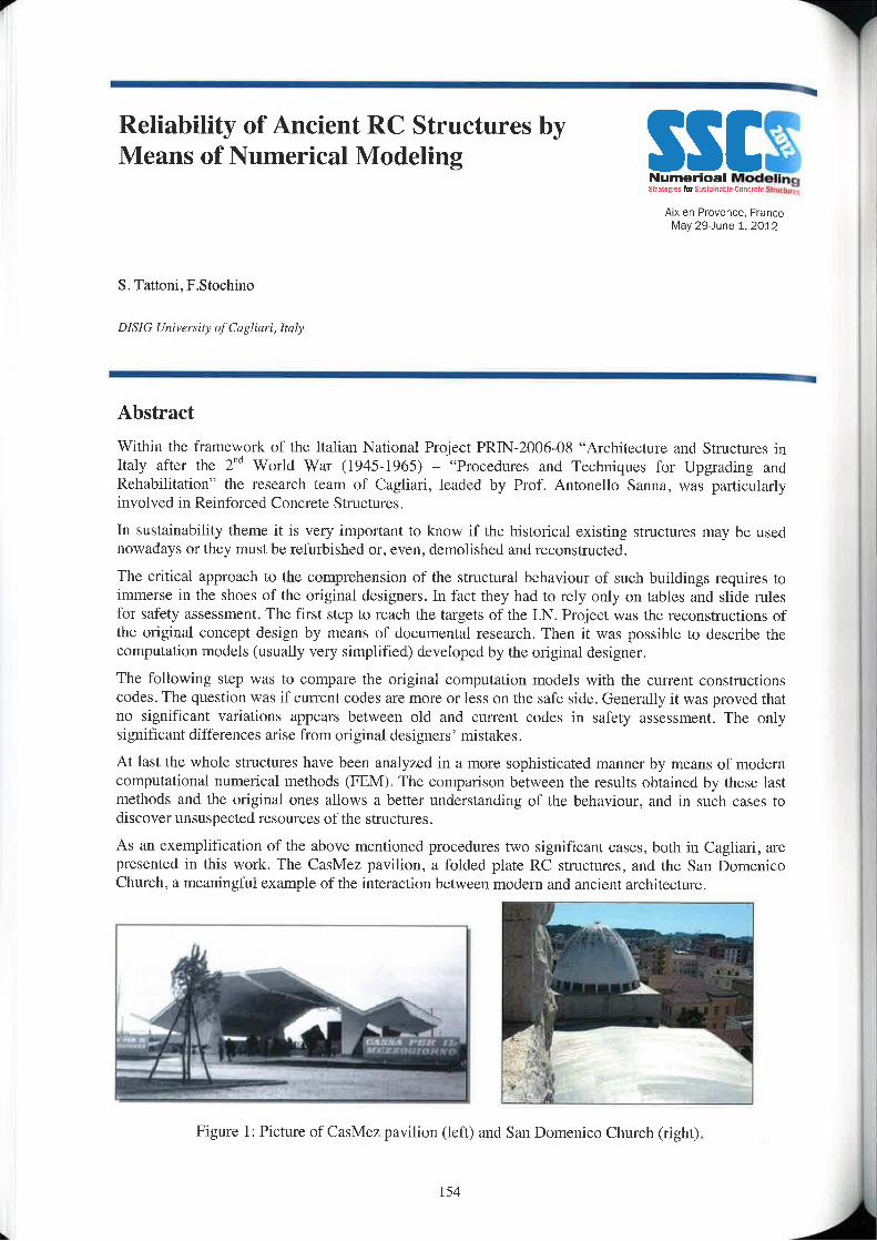
Reliability of Ancient RC Structures by ._,Means of Numerical Modeling ‘ “
Aixen—Prover\ee, FranceMay 29—June 1, 2012
S. Tattoni, F.Stoehino
DISIG Uriivcraily uftlaglrar 1, Italy
AbstractWithin the framework of the Italian National Project PRTN-2006—08 “Architecture and Structures inltaly after the 2"“ World War (l945»l965) — “Procedures and Techniques for Upgrading andRehabilitation” the research team of Cagliari, leadcd by Profr Antonello Sanna, was particularlyinvolved in Reinforced Concrete Stnrctures.
In sustainability theme it is very important to know if the historical existing structures may be usednowadays or they must be refurbished or, even, demolished and reconstructed.
The critical approach to the comprehension of the structural behaviour of such buildings requires toimmerse in the shoes of the original designers. In fact they had to rely only on tables and slide rulesfor safety assessment. The first step to reach the targets of the I.N. Project was the reconstructions ofthe original concept design by means of documental research. Then it was possible to describe thecomputation models (usually very simplified) developed by the original designer.
The following step was to compare the original computation models with the current constructionscodes. The question was if current codes are more or less on the safe side. Generally it Was proved thatno significant variations appears between old and current codes in safety assessment. The onlysignificant differences arise from original designers‘ mistakes.At last the whole structures have been analyzed in a more sophisticated manner by means of modemcomputational numerical methods (FEM) The comparison between the results obtained by these lastmethods and the original ones allows a better understanding of the behaviour, and in such cases todiscover unsuspected resources of the structures.As an exemplification of the above mentioned procedures two significant cases, both in Cagliari. arepresented in this work. The CasMez pavilion, a folded plate RC structures, and the San DomenicoChurch, a meanin ful exam le of the interaction between modem and ancient architecture.V..
__ JFigure 1: Picture of CasMez pavilion (left) and San Domenico Church (right).
154
Seismic Performance Evaluation ofReinforced Concrete Building with StaticPushovef Analysis
Arxen—Provence. FranceMay 29)urre 1, 2012
K‘ Tounsi' , H. Aknouche"
* Superior National School of Public WUI/(J, ervsrr, Algiers, Algeriu* * National Centre ofzipplied Research in Earthquake Engineering, cos. Algiers, Algeria
Abstract
The aim of this presentation is to investigate the nonlinear perfonrianee of reinforced concrete framedbuilding which is taken as a representative structure of the mid-rise RC buildings currently designed inAlgeria under the new seismic Code RPA99/2003.
The global and the local frames behaviour are studied under several earthquake ground motions.Nonlinear Static ”Push0ver” Analysis using various lateral load patterns was also perfonned.
The seismic performance of the structure is determined on the basis of its damage state underan earthquake ground motion. For this purpose. inelastic dynamic and nonlinear static analysesare used to calculate the damage state "inter-storey drifts”.
Damage Index from the nonlinear time history analysis is compared with those obtained by PushoverAnalysis procedure.
Keywords
Seismic perfurmunca, Nun linear analysis, Purhover, RPA99/2003, Damage state.
155
Decreases to the Carbon DioxideImpermeability of PolyurethaneWaterproof Membranes Caused byWeathering and Concrete SubstrateCrackingM. Tsukagoshi*, T. Ueda*, K. Tanaka**
SSIZSNumerical ModelingSrvatzgrnlmSnsurrrantrtnnuztz Slrunruyy
Aixen—Pr0vence. FranceMay 29Jtme 1. 2012
Urtiversity ofllzkushinia. Japrm*, Tokyo Institute 0/'Tcchm1lrI2;Y. Japan”
AbstractConcrete structures, to a certain extent, are intrinsically durable. However, in recent years they havebeen being required to resist carbonation to meet the demand for extended service lives of buildings.For this reason, waterproofing membranes having CO2—shielding performance are employed as ameans to prevent carbonation of concrete substrates.
However, little attention has currently been paid to the problem of cracking under such membranes,which is difficult to completely eliminate in reinforced concrete buildings. It’s often the case thatwaterproofing membranes are adhered to concrete substrates.
Therefore, cracking occurring in concrete substrate which has been coated with such a membrane is aconcem because the membrane on the crack elongates and decreases the shielding effect. In addition,almost all waterproofing membranes are composed of organic materials, which gradually aredeteriorated by ultra violet radiation, heat and rain. This deterioration further elongates and thins thewaterproofing membranes across the cracks making them more permeable to CO2, and therebyaccelerating carbonation.
The purpose of this study is to investigate the carbonation resistance of waterproofing membranesapplied to the concrete surface, particularly the changes to the membrane’s shielding effectivenesscaused by substrate cracking and deterioration due to weathering.
The study examines test specimens of concrete beams coated with membranes of various thickness,stressed to produce a l.0rrurr wide crack, and exposed to the outdoors for five years in Yokohama,Japan. In particular, carbonation around the cracked zones of the specimens is examined. The studyfinds that the thickness of waterproofing membranes is significant. Membranes with a thickness of0.5mm allow carbonation to proceed along the cracks. Within the parameters of this study, amembrane with a thickness of 1.0mm or more appears to resist carbonation of concrete around crack.
The changes in the CO2 pemreability of deteriorated waterproofing membranes are also investigated.On the basis of these observations, a numerical simulation method is developed in order to predict theinfluence on carbonation caused by the degradation of the membranes. Note that, carbon dioxide gas isassumed to permeate in the following three stages : (I) CO7. gas diffuses and permeates through awaterproofing membrane; (2) CO2 gas and air mutually diffuse in the space in the cnrck; and (3) CO2gas diffuses into concrete. It is the stage (1) process which is the focus of the consideration of thechanges caused by the deterioration of the membrane.
Carbonation was simulated using a simple model incorporating the extension of a waterproofingmembrane across cracking, and the results were compared with test results. The numerical modelingappears useful and capable of evaluating the carbonation phenomenon in cracked substrate concrete.
I56
Mechanical Analysis and Simplified Modelsof Concrete Block Infill Walls underOut-of-Plane Action
Aix-en-Provence, FranceMay 29—June 1. 2012
Wei—qiu Zhong‘ _ Ming—shu Gang', Xian-hui Caiz
1 Faculty 0/Infra:/rucmre Eltgilwering, Dalian University 0fT4’ChIl0l0gy, Dalian 116023, Liaoning, China2 Department 0fEngine2ring Mechanics, Fmiuy Of Vehicle Engineering (Md Mechanics, Dalian University 0/ Technology.Dali:mI16023, Liaonirlg, China
Abstract
in big earthquakes, the whole collapse of iutlll Walls often happened. It is essential to analyzemechanical performance of infill walls under out—of—plane action and to study out-of-plane capacity ofinfill walls for the serious damage results. Furthermore, another problem should be penetrated into:what kinds of simplified models are appropriate to calculate out-of-plane capacity of infill walls. In thepresent paper, the concrete block infill walls were analyzed by ANSYS software and the deformationin plane was ignored. Hence the issue of out-of-plane action was transformed to the issue of planestrain. Two kinds of concrctc block infill Walls wcrc numcrica.Lly simulated in nonlincar way andanalyzed. One kind was rigidly connected to top beams, and the other was connected to top beamswith steel bar. Under uniformly distributed load and displacement between floors, the infill wallcracked. In the process of cracking, the stress changed and failure modes were inspected. The archingeffect of rigidly connected walls was obviously represented in the late cracking period. However, thearching action did not exist for the infill walls connected with steel bar, and the capacity of this kindwas obviously smaller than rigid connection one. Based on this, different simplified models for fourcircumstances were proposed: the infill walls rigidly connected on top can be considered with archmodel of three hinges under uniformly rlistributerl load, and can be considered with arch model of twohinges under displacement between floors. The walls separated from top beams and connected by steelbar can be simplified by hinge joints on thc top and consolidation on thc bottom modcl for two kindsof action.
157
SSlI§Numarlcql Modeling§Lr:|t!qi::|ny5u:\:|wat1\u Ennuztz SlvurlmasA|x—en—Pm\/enoe, France
May 29—June 1, 2012
Session II-3:Nuclear structures and storagesCracks distance and opening in reinforced concrete mcmbranes: codes predictions vs. experimental measurementsP. Bisch, S. ErlicherEgir lndustrie.\', Moritreuil, France
A new Creep model for NPP containment behaviour predictionA.FoucaultEDF R&D, Clamarl, France, I41MSID,UMR EDF/CNRS 2832, Clamarl, France
Dunkerque LNG Terminal : tanks designMaryline Verbauwhede, Louis MarracciBouyguer Travuux Publics, Saint-Quentin en Yveliner, France
Modelling of leak tightness degradation of reinforced containment vessels due to aging and cracking mechanismsMahsa Mozyan—Kharazi
Finite Element Analysis of Thermal Restraint at Early Concrete Ages, Exemplificd by Cooling Tower Shell StructureDipl.-lng. K. Turner, Dipl.—Wir1.sch.-lng. D. Schlickc and Prof. Dr.-lng. habil. N. v. TueGraz University of Technology, Inrlimtejor Sxmcmml Concrele, Austria
159
Cracks distance and opening in reinforcedconcrete membranes: codes predictions vs.experimental measurements
Alx-en-Provence, FranceMay 29—June 1, 2012
M. Rachidi, P. Bisch, S. Erlicher
EGIS Industries, 4 rue Dolores lburrurl, [SA 50012, 93188 Munlreuil crdcx, Fmrrrra
Abstract
An important aspect of reinforced concrete structure analysis for design purposes is thc cvaluation ofcrack distances and openings [l -5]. This kind of infonnation is required for checking the structure againstthe serviceability limit state. In the practical applications, in particular for walls in nuclear buildings, thecvaluation of crack openings should be based on an accurate and robust procedure.
In this paper, we use a proccdurc of crack assessment articulated in two phases: (i) evaluation of stressesand strains by a finite element (FE) model where reinforced concrete walls and slabs arc rcprcsentcd byshell elements with a suitable macroscopic nonlinear constitutive rule; (ii) computation of crack distancesand openings from stresses computed at the previous step, by using a procedure inspired to Eurocode 2formulas [6] and to the cracked membrane theory of Kaufmann [1]. The choice of decoupling these twocoupled aspects of the crack analysis is motivated by the need of a numerically not too expensiveprocedure for industrial applications.
Observe that phase (ii) is not carried out by merely using the fonnulas of Eurocode 2, because, by theauthors’ knowledge, they mainly concern the case of cracks in rcinforced concrete beams and not the caseof mcmbrancs. Hcnce, in the case of membranes a comparison is needed between Eurocode predictionsand experimental results. The experimental results used here come from thc cxpcrimcntal campaigncarried out in the framework of the National French Project CEOS.FR [7-9] on a reinforced concrete wallsubjected to shcar load.
161
A new Creep model for NPPcontainment behaviour prediction
Numerical Modeling>.'r.<lw] -5 llritirlmiztle Carmel: 5tmcl.v:§
Ai>t'er\'Provenee. FranceMay 29—June 1, 2012
AFoucault
EDF R&D, Clnmart, FRANCEb1MSID,UMR EDF/CNRS 2832, Clamarl. FRANCE
Abstract
Eleetricité de Francc (EDF) — the French main electricity production and distribution company —manages 59 nuclear power plants (NPP) in France. Some of these NPP are based on thc concept ofPressurized Water Reactor (PWR), where the radioactive protection is ensured by a double concretecontainments vessel.
In order to deal with the security and durability of these concrete structures, engineers requirenumerical tools to predict delayed strains. Indeed, creep and shrinkage cause cracking, losses of pre-stress and redistribution of stresses in the structures.The numerical simulations of delayed strains are actually performed on the FE software Code_Ast/er[4] with the constitutive model BETON_UMLV__FP, developed by Benboudjema[2]. This paper willonly deal with the creep part of the hydro~mechanical model [2], which includes the description ofdrying. shrinkage, creep and cracking phenomena.It is assumed that the creep process can be split into a spherical and a deviatoric pan as assumed by[1 ,2,6,7]. This concept has been motivated by experimental results [3], which havc shown aproportional link between stress and strain according to this decomposition in two parts.
The feedback on using the creep part of this constitutive model and also some recent experimentalresults [4] highlight theoritical points to review its formulation. The experimental results of Brooks[4jon uniaxial creep tcsts show a slower creep rate over the 30—years of records. ln contrast, theBETON_UMLV_FP model assumes on the deviatoric part a constant creep ratc long-term. Moreover,the lack of interaction between spherical and deviatoric parts of creep strains leads to a non—controlledevolution of the apparent Poisson’s ratio.
The proposed improvements on BETON_UMLV__FP model are based on the works of Sellier andBuffo-Laeaniere [6]. The deviatoric and spherical pans of creep strains are modelled by Burger‘schains with a non~linear term introduced on the Maxwell level. The viscosity depends on creep strain.However, our approach considers the effects of the tensor of creep strain and not only the sphericalone.
This model is integrated through an implicit scheme into the Finite Element software Code_Aster. Theanalysis of the long-term behaviour of concrete samples has been done. The result of thc comparisonbetween numerical results and measured deformations on French NPP containment will be discussed.
References
[I] Acker P., Ulm F.—J., Z001. Creep and shrinkage of concrete: physical origins and practical measurements.Nuclear Engineering and Design 203(2), 143458.
162

_ _
[2] Benboudjema F., 2002. Modélisatiou des deformations différées du béton sous solicitations bi-axiales.Application aux enceintes de confinement des bfitiruents réacteurs des eentrals nucléaires, PhD thesis.
[3] Benboucljema F., Meftah F., Torrenti JM,. 2005, Interaction between drying, shrinkage, creep and crackingphenomena in concrete. Engineering Structures, 27, 239»250.
t [4] Brooks I.]., 2005. 30-Year creep and shrinkage of concrete. Magazine of Concrete Research, 57(9), 545-556.
[5] Code_Aster. Open Source FE Software, www.code-asterorg./6] Sellier A,_ Buffo-Lacarriere L., 2009.Vers une modélisatinn simple et unififée du flnage proper, du retrait et
du fluage en dessication du béton. EJECE, l3(l0), 1161-1182.[7] Ulm J.F.. l-leukamp F.H., Germaine J,T.. 2002. Residual design strength of cement-based materials for
nuclear waste storage systems. Nuclear Engineering and Design 2| 1(1), 51760.
163A
Dunkerque LNG Terminal: tanks design
Numarlcnl ModelingSlulzmrslllriusllmsh = Enucrzlr stator“Aix»er\-Provence. France
May 29-June 1. 2012
M. Verbauwhcdc U), L. Matracci ‘Z1
Eutlygues Travaux Publicx. ' ” lngénierie new Fmnre, '1’ Bureau d’Etudes
Abstract
The consortium composed of Entrepose Projets and Bouygmes Tiavaux Publics has won a tender held byDunkerquc LNG, subsidiary of EDF, to design and build the three cryogenic LNG (liquefied natural gas)storage tanks of methane terminal of Dunkerque (Dunkirk) in Northern France. Each of the tanks has aworking capacity of I90 .000 m3. Their main dimensions are 91 m in diameter and 50 m hcight. They areamong the largest “full containment tanks“ built in the world, composed of an internal 9% Nickel steelinner tank which will contain the LNG at a temperature of —l63°C, thanks to an insulation systemcomposed of perlite, foamglas, fiberglass, etc..., and of an outer concrete structure (prestressed wall,reinforced dome and raft). Bouygues Travaux Publics will build the concrete structures and carty out thesoil improvement. Construction should start at the beginning of 2012.
This paper will present numerical methods used during the design phase, both for structural design andconcrete design.
The stnictural design had to cope with soft soil with significant settlements and important design seismicaccelerations (0.30 g pga).
The following numerical models were used for structural design:I Static models :
I Axi-symmetrical modelI Full 3D model for non axi-symmetrical loadsI Gcotechnical non linear model, which analyses construction phases and different service
configurations (tests, tank drainage, consolidation), enables the soil improvement designand evaluates soil settlement
v Dynamic models for seismic analysis, which consider both full and empty tanks:Q 3D non linear model for soil structure interaction and impedance matrix determinationQ Global seismic model which determines global response of the structure, taking into
account soil structure interaction and liquid structure interactionQ Detailed model for detennination of seismic forces in the raftI Detailed model fnr determination of seismic forces in the dome and the top platform
0 Tliermo-mechanical model: this model copes with a major leakage of LNG across the steel innfil’tank which results in the progressive filling of the concrete outer tank. This configuration isstudied via a non linear coupled thermo-mechanical model in which reinforcement rebars HY‘?modeled taking into account concrete mechanical and thermal properties variation again-sltemperature, concrete non linear behavior and cracking.
164

I Specific tl1er|'|1(7dyl'l£u'|1iO and structural analysis for overfilling scenario for which it has to bedemonstrated that the damage of the roof under the corresponding over pressure will occur in thefirst place enabling the over pressure to be dissipated and the containment of LNG still beingensured by the outer concrete wall and raft.
1 Thermal models for fire and LNG leakage on roof studies
Concrete mix study in design phase will use a tl1ermo—mechanica_l finite element model to assess earlythermal behavior of concrete. The purpose is to optimize the concrete formula and concretingmethodology. CO2 emissions will be reduced by using equivalent cement content method in ordcr toreduce cement content.
Durability will also be integrated in this approach by incorporation of pulverized fuel ash.Model results will be compared with measurements on full scale mock ups of relevant parts of tanks andwith in-situ measurements in the fmal structure itself.
lll
l
165
7Z Z i i ii L
Modelling of leak tightness degradation ofreinforced containment vessels due to aging -and cracking mechanisms §iT7~'-333§!?3r1i»'i9~‘l'75i?r'~'-595!
Aix-en-Provence. FranceMay 2&June 1, 2012
M.Mozyan»Khara/.i
— — _ — — —|
Abstract
One of the main functions of a pressure containment vessel is its capacity to provide sufficient leakagetightness. This is obtained either by placing a liner covering the entire surface of the vessel, or by a thickerreinforced concrete wall. Periodically, the tightness of containments vessels is verified by means of tests,by injecting pressurized air into the vessel. The test is considered successful if thc measured leakage isbellow licencing limit.in most cases, test results are positive (bellow limits). But leakage measures indicate that some vesselsmaintain a steady ratc cven over several decades, while for others the leakage rate increases with timc.The reasons behind these increases are more or less well known.The purpose of this paper is to present a set of numerical models accompanied by a study methodology tohelp experts understand those mechanisms most responsible for leakage tightness degradation ofprestressed reinforced concrete pressure containment vessels without liner.An important feature of this work is that the solution proposed is adapted to the study of full size reactorbuildings. Most research work dealing with this matter offers sophisticated modelling techniques, but theircomplexity and cost make it that they are only suitable for local studies. In our opinion it is essential tosimultaneously encounter all phenomena behind tightness decay, in order to be able to comparesimulation results with test mcasurcs. This is mandatory to demonstrate the efficiency of the technique, inorder to provide reliable engineering analysis tools that can be used to improve design codes for futureconstructions, or develop retrofitting solutions to improve or maintain leakage tightness of existing reactorbuildings.In this methodology, the gas flow across a concrete wall is classified in three parts: flow due to thc naturalporosity of material; accelerated flsow through microcracks, and macroctacks. In the last case, both openand rcclosed cracks are accounted for. In this approach, it is considered that the gas phase consists only ofdry air. Transport through the unsaturated sound and microcracked concrete is calculated by Darcy's law -In case of discrete cracks, it is with Poiseuille-flow equation that leakage is estimated. In unsaturatedsound concrete, permeability is defined by both intrinsic porosity and hydric state of concrete (degree ofsaturation). In unsaturated damaged concrete. permeability also depends on the mechanical state. That iswhy, prior to permeability and leakage calculations, thermo~hydric and mechanical analyses areperformed to determine saturation degrees and damage states. These analyses use thermo»hydro-mechanical models which include moisture and heat transfer, creep, shrinkage. damage and cracking illconcrete.
Simulations are performed by coupling the finite elements program Code_Aster®, and the fluidmechanics program ECREVISSE, both developed by EDI‘.Different experimental elementary tests are studied to check the validity of mechanical, thermal, hydricand hydraulic models individually and when coupled. Finally a large scale structural application is studiedin order to assess the model's ability to simulate a complex case.
166
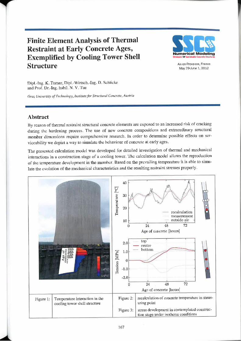
Finite Element Analysis of ThermalRestraint at Early Concrete Ages,Exemplified by Cooling Tower ShellStructure
SSl.'I§Numerical ModelingShallgtes ltisusmnuhle nmn Structures
A1><—en-Provence, FranceMay 29-June 1, 2012
Dipl.—].ng. K. Turner, Dipl.-Wiri_sch.—lng. D. Schlickeand Prof. Dr.-Ing. habil. N. V. Tue
Graz University of Technology, Institutefor Structural Concrete, Austria
AbstractBy reason of thennal restraint structural concrete elements are exposed to an increased risk of crackingduring the hardening process. The use of new concrete compositions and extraordinary structuralmember dimensions require comprehensive research. In order to determine possible effects on ser—viceability we depict a way to simulate the behaviour of concrete at early ages.
The presented calculation model was developed for detailed investigation of thermal and mechanicalinteractions in a construction stage of a cooling tower. The calculation model allows the reproductionof the temperature development in the member. Based on the prevailing temperature it is able to simu-late the evolution of the mechanical characteristics and the resulting restraint stresses properly.
to - J. --v lll. .1 .-‘--.30 _ ;")_-'
.L.;Y / ‘\ ‘--.1’-" _ii20 \L‘“‘/ \.‘/' \v -
0rectrlculatiou 'mea.s\u'ement
rature"C
Tempe10 - j outside mt‘ -
O 24 48 72Age of concrete [hours]
vi2.0 V ‘°P ~— centre
._ 1.0- butt
OT '
0TensionMPa
.1} . .
_2_() - .
Age of eoncret/c [hours]
Figure 1: Temperature interaction in the Figure Z: recalculation of concrete temperature in meas-cooling tower shell structure uring point
Figure 3: stress development in contemplated construc-tion stage under isotherm conditions
167
I

It is useful to link heat dissipation and the development of the concrctc’s strength properties to thehydration degree. Performed material analyses provided corresponding knowledge of the hardeningprocess. Temperature ineasurements in the structure were executed additionally. Furthermore thermalboundary conditions, assembly situation and construction progress were taken into consideration.
The contribution is focused on the implementation of the material behaviour in the calculation modeland their adjusting to the obtained measurement data for achieving conclusive results.
168
Y
1l
Session H-4:TunnelsAnalysis of cracking due to shrinkage restraint in a concrete tunnelM. Briffaut, A. Bonnet, B. Bahrami, F. Benboudjema, L. D‘AloiaLMT, ENS CACHAN, France / CETU, Bron, Fnmne
The may of interaction between sprayed concrete and steel support in a mck—TBM tunnelling using 3D—Fl~lM model ‘G.D. Kang, Y.S. Kwak, I.M. LeeDuclim Industrial Company, Kurea Univzrxify, Karea
169
NIIIIIQPIQII IIOJOIIIIQav-aw by sm11|nm» Duncrll: amm-
Aix~en'Provence. FranceMay 29June 1. 2012
1
\
2 — —
Analysis of cracking due to shrinkagerestraint in a concrete tunnel
Ai><en‘Provence, FranceMay 29—lune 1. 2012
M. Briffaut, A. Bonnet, B. Bahrami, F. Benboudjema, L. D'Aloia
LMT, ENS CACHAN, Fmncel CETU, Bron, France
Abstract
Cracking in concrete structures can reduce drastically its serviceability, since it increases thepermeability and diffusivity. Therefore, it leads to a faster penetration of liquid/gas (which isprejudicial if the tightness must be guaranteed like in water resewoir or dams, nuclear and gascontainment, tunnel etc ...) and aggressive agents (chloride, CO2 leading to corrosion, in bridges,beams, column etc ...). Cracking may be due to the (self or extemal) restraint of autogeneous, dryingand thermal shrinkage.
This study concerns the prediction of cracking due to restraint of shrinkage in a concrete tunnel. Theobjective is twofold. First, the effect of fibres (two types of organic fibres and one type of steel fibre)has been studied (via experience and numerical simulations) and compared to a solution using anti-crack mesh. Secondly, an analysis has been perfonned in order to investigate the effect ofautogeneous, thermal and drying shrinkage.
Since several phenomena are involved (hydration, them1al, drying, shrinkage, creep, cracking), animportant experimental program has been carried out. lt consists to measure “classical” thermo-mechanical parameters (hydration heat, autogeneous shrinkage, dilatation coefficient, Young’smodulus ...), which are needed for the numerical simulations as input data. Ring tests have been alsoperformed: a concrete ring is cast around a brass one. Therefore, the shrinkage of concrete is restrainedby the metallic ring, which is representative on an external restraint. The time of cracking (Whichallows for quantifying the potential of cracking) and evolution of strains in the inner brass ring (Whichallows for identifying creep parameters) are mcasurcd. At this timc, drying shrinkage has not beentaken into account (it is currently under investigation). These experimental results show (for thestudied mix designs), that the solution using steel fibres cracks the latest, with the smallest crackopening. Splitting tests show also that its tensile strength is the most important. Besides, the presenceof fibres does not seem to modify the creep of concrete.
A numerical model has been developed to predict early age cracking, All major phenomena have beenmodelled (hydration, drying, heat, evolution of mechanical parameters, thermal and autogeneousshrinkage, basic creep ...). For the prediction of cracking, a simple elastic damage model is used.Numerical simulations have been performed in order to predict thc behaviour of a concrete tunnellining (50 em width) for 2 different concrete mixes and different types of fibres (polypropylene, steel).The results highlight that:
I A cracking pattern, close to the one observed usually on tunnel lining, has been obtained (seeFigure l)
I Crack opening depends upon the type of fibers;
l7l
m;
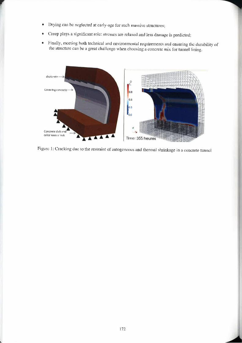
Drying
Creep pl
v Finally,
can be neglected at early—age for such massive structures;
ays a significant role: stresses are relaxed and less damage is predicted;
d vironmental requirements and ensuring the durability ofmeeting both technical an enl all c when choosing ll concrete mix for tunnel lining.the structure can be a great c 1 eng
cov@nngcorwrere%
Cunuecalrere
Figure
lirr
l: Cracking due to the restraint of autogcneous and thermal shrinkage in a concrete tunnel
172
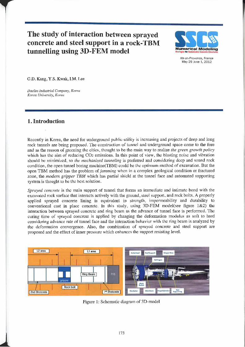
1 — — 3 Z i
The study of interaction between sprayedconcrete and steel support in a rock-TBMtunnelling using 3D-FEM model 53-l5t71“37l1-‘Zfll-'!'»»€7$‘-’~'~'-'~!~‘E
Aix—en—P1ovenee, FranceMay 29—June 1. 2012
GD. Kang, Y.S. Kwak, I.M. Lee
Daelim Industrial Company, KoreaKorea Universixy, Korea
1 . Introduction
Recently in Korea, the need for underground public utility is increasing and projects of deep and longrock tunnels are being proposed. The construction of tunnel and underground space come to the foreand as the reason of greening the cities, thought to be the main way to realize the green growth policywhich has the aim of reducing CO2 emissions. In this point of view. the blasting noise and vibrationshould be min.i.mized, so the mechanized tunneling is preferred and considering deep and sound rockcondition, the open tunnel boring machine(TBM) could be the optimum method of excavation. But theopen TBM method has the problem of jamming when in a complex geological condition or fracturedzone, the modern gripper TBM which has partial shield at the tunnel face and automated supportingsystem is thought to be the best solution.
Sprayed concrete is the main support of tunnel that forms an immediate and intimate bond with theexcavated rock surface that interacts actively with the ground, steel support, and rock bolts. A properlyapplied sprayed concrete lining is equivalent in strength, impermeability and durability toconventional cast in place concrete. In this study, using 3D—FEM model(see figure l&2) theinteraction between sprayed concrete and ring beam as the advance of tunnel face is performed. Thecuring time of sprayed concrete is applied by changing the deformation modulus as soft to hardconsidering advance ratc of tunnel face and the interaction behavior with the ring beam is analyzed bythe deformation convergence. Also, the combination of sprayed concrete and steel support areproposed and the effect of inner pressure which enhances the support resisting level.
Figure l: Schematic diagram of 3D»model
173
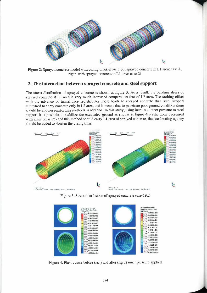
7&1 i_\\ "T; r :2"t
=\ it4, . ./ ‘- .,_'- '»\ ‘ s ‘
Figure 2: Sprayed concrete model with curing time(left-without sprayed concrete in L1 area: case—l ,right- with sprayed concrete in Ll area: case-2)
2. The interaction between sprayed concrete and steel support
The stress distribution of sprayed concrete is shown at figure 3. As a result, the bending stress ofsprayed concrete at L1 area is very much increased compared to that of L2 area. The arching effectwith the advance of tunnel face redistributes more loads to sprayed concrete than steel supportcompared to spray concrete only in L2 area, and it means that to penetrate poor ground condition thereshould be another reinforcing methods in addition. In this study, using increased inner pressure to steelsupport it is possible to stabilize the excavated ground as shown at figure 4(plasLic zone decreasedwith inner pressure) and this method should carry Ll area of sprayed concrete, the accelerating agencyshould be added to shorten the curing time.
»—<=a—~:r :1-aw, _.=,-.=
lWWl»:4 tr i4 [mq'|‘4 ,Vltirnil t»;@\I\4e§X><r@>r c.‘Figure 3: Stress distribution of sprayed concrete case-1&2
/./~\ :::|.zuB<rsr'|n<c seer...-rm,\ uwmwuiM .m¢>uM uluwumH I‘ .mm»a»
>‘r/ M .r.m».4w..,.......;§;.. ..a....,.W ....a,..=.N‘~tmu~m4. avancu/M ;§;.,.m..,.r M......,....n“~5fiI—nml_ m_....,....,..,,_.,,...W\_ ., m-uwmw~_ _ I M..r.W..-nmm--aw
Figure 4: Plastic zone before (left) and after (right) inner pressure applied
/V’ tf
nniullsmm5-rm-....=.t.-mm--10 N .- mmW ~--mmM -lum-miM -IwuevmaH-—3;~v|v1vs»w1.m=rM»| rt!»
\ M12313r I2‘I I; -6214754114P M ulrubml\H T N /.1 mm»-I H‘ -zzsmwvW an -uvnwu
nu" "““’"‘“"“_.| st-muU “Amara:
enmam
‘T
SSlI§Numerical Modelingsimian: In Snstliniblu Cnnlvllll Klmclunrz
Aix—en—Provence, FranceMay Qeitme 1, 2012
Session II-5: Other applicationsConstruction phasing of a dam spillway: thcrmo-mechanical simulationM. Azenha, R.M. Lameiras, J. Barres, A, CostaISISE, Institute for Sustainability and Innovation in Structural Engineering, University 0fMinh0, Guirnarfiex, Portugal
Fatigue life of fire damaged concrete cylinders repaired with carbon fibre reinforced polymer subjected to cyclicloading in compressionY.K Gunrprasad, Ananth RamaswamyDepartment ofCivil Engineering, Indian Institute of Science. Bangalore, India
Design of UHPC Wind TurbinesFXt Jammes, FJ . Ulm, X. Cespedes, J .ResplendinoSetec TPI, Paris, France
Numerical modelling strategies for safety assessment and rehabilitation of concrete damsPierre Leger, Ph.l), Eng, Lucian Stefan, M.Sc.A., Martin Leclcrc, M.Eng, Eng.Department of Civil, Gwlngical llrul Mining Engineering, 15¢-01¢ Palytechnique at» Mann-énl, Canada
Explicit Nonlinear Finite Elements for the Design of Concrete Structures: Application to Hydraulic StnicturesM. Ben Ftima, B. MassicotteEmu Palytechnique 11¢ Montréal, Muntréal, Canada
Experimental and numerical studies on the behaviour of concrete sandwich panelsG. Metelli. N. Bettini, G. PlizzariDICATA, University uflirescia, Italy
Comparison of Deterministic and Probabilistic Design (environmental aspects)P. §tépé.nek, 1. Lanfkova. P. simmerFaculty ofCivil Engineering, Brno University of Technology, Brno, Czech Republic
175
A
adj
ll
Construction phasing of a dam spillway:thermo-mechanical simulation SSIENumerical Modelingsta-qt.‘ lqsurutnatstr r.,»=..t. Stmclmn
Aix'en—Provence, FranceMay 2&June 1, 2012
M. Azenha, RM. Lameiras, J. Barres, A. Costa
ISISE, Institutefor Sustainability and Innovation in Structural EngineeringUrtiverrity 0/"Minho, Gttimzmies, Portugal
Abstract
The construction phasing of massive concrete elements is an issue that frequently raises doubts topractitioner engineers in regard to the risks of thermal cracking. A sustained estimation of temperatureand self-induced stress development that occurs at early ages can only be achieved by numericalsimulation with thermo-mechanical models, through which scenarios of constructionphasing/scheduling can be compared.
The recourse to such approach consists on the initial computation of the temperature field, andsubsequent evaluation of the corresponding stresses. The them1al field is calculated considering thevariable environmental temperature, the exothermal and thermally activated nature of cementhydration reactions, as well as the adequate modelling of boundary conditions. The stress field isdetermined for each time step considering the corresponding temperature variation and the thermaldilation coeffieient of concrete. The evolution of E—modulus and the creep behaviour at early ages areof particularly importance, and are also carefully estimated.
Tis paper deals with the assessment of the temperature and stress development in the construction of a27.5m long wall integrated dam spillway, with a thickness that attains a maximum of 2.8m. This Wallhas a total height of 15m, and is constructed by stages. Particular attention is devoted to a segment ofthe constmction, in Which a 2.5m tall concreting was performed, and intemal cooling of concrete wasmade with recourse to prestrcss sheaths into which air was blown by industrial fans. Parts of thiscasting phase were monitored by temperature sensors (thermocouples and thermistors) and vibratingwire strain gages.
The paper encompasses an initial description of the studied structure, along with the correspondingenvironmental conditions and a brief description of the monitored temperatures and snains. Asummary discussion of laboratory characterization tests is also made, and the overall properties of thestudied concrete are provided. The main focus of the paper is then centred in the description ofmodelling strategies and their discussion in view of the available laboratory testing and the in-situconditions of the spillway wall.
177 t
L t
i
Fatigue life of fire damaged concretecylinders repaired with carbon fibrereinforced polymer subjected to cyclicloading in compression
SSlI§Numerical ModelingSlrltrqtrshviuslrnrahlr En M. ll §lWt.lu'»\
Aixen—Provence, FranceMay 29»June 1, 2012
Y.K Guruprasad, Ananth Ramaswamy
Department of Civil Engineering, Indian Instilme ofSt‘ien<‘e, Bangalore, India
Abstract
This study looks at concrete cylinders of 25MPa cylinder compressive strength, l5()mm in diameterand 300mm in height, exposed to temperatures of 715 dcgress Celcius for a duration of 4 hours and 2hours respectively , 550 degress Celcius for a duration of 4 hours, cooled and thereafter repaired withCFRP wrap was subjected to cyclic loading in compression to assess the fatigue life of these cylinderswith fire damage.The concrete cylinders which were subjected to tire damage at different temperatures and duration asindicated above were wrapped with CFRP. It was observed that the concrete cylinders subjected tofire damage at temperatures of 715 degress Celcius for 4 and 2 hours and 550 degress Celcius for4 hours had cracked extensively and had very low compressive strength of the order of about20 to 50 % of the corresponding control cylinders in compression. When these fire damaged cylinderswere wrapped with CFRP and subjected to cyclic loading in compression, these cylinders failed atsignificantly large number of cycles close to the number of cycles at which the cylinders which werenot subjected to fire damage and without CFRP wrap(control cylinders) had failed under cyclicloading in compression.
This indicated that the tire damaged concrete when well confined by the CFRP can result in asubstantially improved fatigue life.
A finite element model has been developed for predicting the behaviour of fire damaged unrcpairedand repaired cylinders with CFRP under cyclic compression loading.
References
[1] Behaviour of Plain Concrete under cyclic compressive loading, Ying Yee Lam, MS Thesis, MassachusettsInstitute of Technology, 1980.
[2] CFRP confined reinforced concrete elements subjected to cyclic compressive loading, .ltA.O. Barros,l).R.S.M. Ferreira, and R.K. Varma, American Concrete l.||st.itule(SP—258), ppr 85-104, 2008.
[3I Concrete at High Temperatures — A General Review, Ulrich Schncidcr, Fire Safety Joumal(Vol.l3),pp. 55 — 68.1988.
[4] Effect of fiber orientation on the structural behavior of FRP wrapped concrete cylinders, Guoqiang Li,Dinesh Marie-herla, Kumar Si.ngh, Su-Seng Pang, Manu John, loumal of Composite Stmctures(Vol.74),pp 475483, 2006.
[5] Propenies of Concrete after High Temperature Heating and Cooling, Jaesung Lee, Yunping Xi, and KasparWillam, Joumal of ACI Materials (Vol.lU5. No.4), pp.334 — 34] , Z008.
178 A
Design of UHPC Wind TurbinesNumerical ModelingSlvilzqizs lISl.stam:|h': Concrete simm,
Aixen—Prover\ve, FranceMay ZQJUHB 1, 2012
FX. Jarnmes, X. Cespcdcs, J. Resplendino. FJ . Ulm
Setec tpi. 42/52. quai dz la Rzipée, 75 583 Paris cedex 12, France
AbstractUltra-High Performance Concrete (UHPC) has proven an asset for bridge design as it significantlyreduces the quantities of material used. Howevcr. UHPC has not been applied yct to wind turbinetechnology. Wind turbine design is mostly based on the use of steel, which is not proven to be themost effective material in terms of cost and durability. ln recent years. some authoritative studies haveshown the advantages of building reinforced concrete towers and a number of companics have adoptedthis solution [1]. The purpose of this paper is to go even further by considering UHPC as the best steelsubstitute available. The project is mainly adapted from a Master's thesis achieved by FX. Iammes in2009 and supervised by Professor Ulm at the Massachusetts Institute of Technology [2].J , Resplendino, an intemational expert of UHPC. played a key role in the relevancy of the research aswell as X. Cespedes who helped to develop the most innovative FE models.
First, the unique characteristics of UHPC in terms of fatigue are highlighted. For current offshoreprojects where the tower height is of primary concern, fatigue represents an important limit for a steeldesign. Therefore, the superiority of UHPC ovcr stccl in this field definitely makes it a moreappropriate material,
Then a design of the mast using UHPC in the case of onshore conditions is suggested. The designloads are adapted from the literature and their values wcrc validated by experts from the mostspecialized design organisations [3]. The accuracy of the design is validated through two main finiteelement models. Hence, the structure is globally checked by being modelled as a cantilever beamaccording to the beam theory. Local verifications have bccn can-icd out through a very innovativefinite element model based on the shell theory. These models were developed in close collaborationwith the Setec tpi R&D department led by X. Cespedes.
Finally, a revolutionary construction sequence is proposed in order to reveal the easiness of theerection process and to justify that UHPC could be directly applied by construction companies. Theprefabrication, the jacking-up, and the fastening of the elements are more particularly considered.
The ultimate objective is to demonstrate that UHPC is an attractive substitute to steel for the erectionof wind turbine masts.
References
[I] Enercon GmBH, Precast concrete tawzr, in Technology & Service brochure.[2] Design of Wind Turbines with Ultra-High Performance Concrete, Fmngois-Xavier ./fl7I|In2.\'. Muster of
Engineering Thesis at the Massachusetts Institute of Technology, Z009.[3] National Renewable Energy Laboratory. De: Nnmke Veritas.
179
Numerical modelling strategies for safetyassessment and rehabilitation of concrete
r1 ||v| tr ||dams ff.'§I:Z>-i§fint=...3a.§,.§i§Ai><—en-Provence. France
May 29—June 1. 2012
Pierre Légeri, PhD, Eng, Lucian Stefan, M.Sc.A., Martin Leclerc, M.Eng, Eng.DL'[/u!!!nt'nt of Civil, Get/lugitril “nu Mining Izrlgirrecring, £1111.» Pulyrechnique at Muntréul, Mnnwnl University Campus, 110.Box 5079, Station cv, Montrzal, PQ H3C 3A7' Phone: (514) 340.4711 (ext. 3712), Fax .1514) 340.5881, E—mm'l: [email protected]» Léger CORRESPONDING AUTHOR
Concrete dams are major strategic infrastructures to produce renewable energy and control floods. Indeveloped countries constniction of new dams is limited. The challenge has been put in extending theservice life of existing dams. Figure l shows the increase in service lives of existing dams that could bebrought by implementing effective remedial actions, repair strategies, and protection systems. However,innovative and economic rcmcdial work must be based on (i) an effective diagnostic and prognostic ofpast, present and expected structural behaviours, (ii) advanced knowledge of damaged, repair, andcomposite materials. (iii) suitable decision models based on eost—bcnefit analysis of different remedialactions, and (iv) appropriate construction methods and quality control procedures (Fig. 2).This paper first presents the difference in CO1 foot print of new dams (where it is possible to minimizecement consumption) and existing dams. The benefit of extending the service life of existing stmctures isdiscussed. The emphasis is then put on typical concrete hydraulic structures such as spillways for whichinnovative numerical modeling strategies have been developed. They were furthermore implemented indedicated computer program CADAM-3D and complementary module GM-Dam to assess the structuralstability of existing and repaired stnictures (Fig.3). Spillways are complex three-dimensional concretestructures often being unreinforced or with limited reinforcement. Multiple cracking directions candevelop in spillways due to tbreedimensional loading patterns (water and uplift pressures, ice impact,earthquake, ...). There is a lack of simplified computational methods to asses the safety of lightlyreinforced hydraulic structures. The safety factors, widely used by the profession, were developed basedon beam theory and global equilibrium. However, there is no direct way to include thc effect of nonprestrcsscd reinforcement in the evaluation of these factors. The finite element analyses (FEA) can beused but in a progressive safety evaluation strategy simplified tools based on beam theory are initiallyprefeired by practical engineers. FEA arc particularly difficult to converge when water penetration andcracking occurs. The paper presents innovative robust methodologies for sectional analyses and safetyfactors computation of arbitrary cracked sections of spillway piers accounting for concrete cracking, thepresence of passive reinforcements and uplift pressures.
A three-dimensional extension of the gravity method is developed accounting for biaxial momentinteractions (PrMt’My), presence of passive reinforcements, in~plane concrete cracking and 3D updatingstrategy for uplift pressures. The kemel of arbitrary cross sections is computed for a planar bi-dimensionalextension of the so called "middle third" criterion extensively used for the location of the resultant whereno»tension could he developed. The structural shear strength is evaluated by summing the shear resistanceof concrete (friction and cohesion) and the shear resistance of reinforcements working as anchors.Cracked sectional analyses of reinforced spillway piers are shown as application examples.
There is a wide interest to develop efficient and robust tools for computation of safety indicators andstrength evaluation of lightly reinforced hydraulic structures. The proposed methodology is very useful forpractical engineers as it offers an accessible approach for thc rational consideration of reinforcement barsin existing/repaired or new hydraulic structures. A decision can be made based on safety factors computed
I80
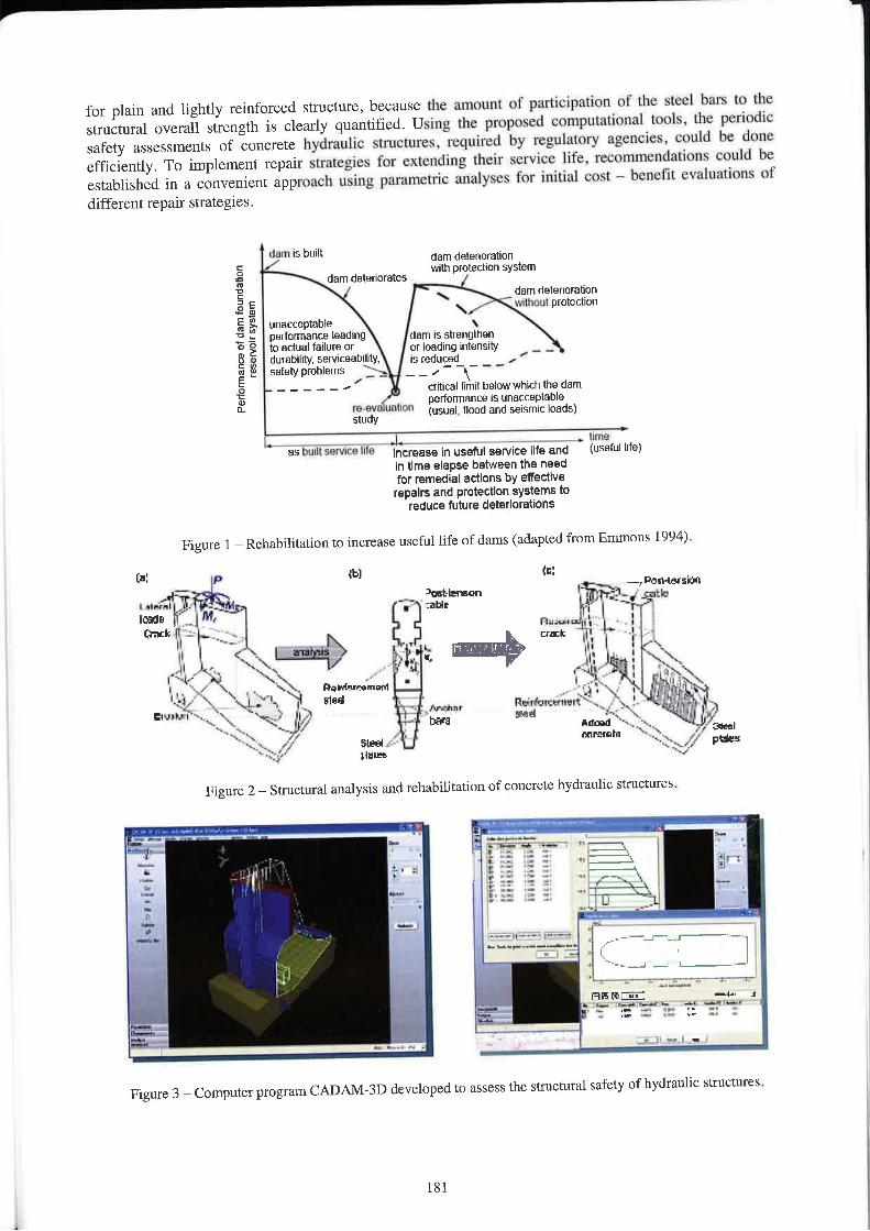
i
for plain and lightly reinforced structure, because the amount of participation of the steel bats to thestructural overall strength is clearly quantified. Using the proposed cnmputatinnal tnuls, the periodicsafety assessments of concrete hydraulic structures, required by regulatory agencies, could be doneefficiently. To implement repair strategies for extending their service life. reconimendations could beestablished in a convenient approach using parametric analyses for initial cost ~ benefit t!Vflltl2\ll0llS ofdifferent repair strategies.
"""‘ '5 "“'“ dam deterturatitmVlflh pmteumn system
Performancenfdarnfoundation
resesystemI | I I I \ \
//
darn delenurates_ dam delermralim
\v|tneu| protecllbnunacceptable \performance laadrntl dam ls strenglttenIn with falure or H or loading intensity _ _durabtlily, serviceability, is Mum , »safetyprutllems >: _ _ ,— -\- — —
critical limit new wmn the dam
rvor
pertorrrtance is unacceptable2;-3“ "!'"°" (usuatr mm and seisrnlc loads)
___ ._ .___ .,_ ,7} __.umei “S "W" 5““"C° ‘"9 lincrease ln useful servlce life and (\I§9l"| Mel
In time elapse between the needfor remedlal actions by eflectlverepair! and protection systems to
reduce future dsterloratinns
Figure 1 — Rehabilitation to increase useful life of dams (adapted 1t'0m Emmons I994).
_ -,l*on-lersianI rwiirx ’"‘"=""" P‘ ?Y\'5:¢' §:‘“\'-‘low. J nu: nmm“]%i3| -.
I",
‘ii
‘_"T.,tn13-1,/I .// \ g2sr‘
;T ._g‘___‘___J/. 2/’
I: 1 -.0" F ix an ‘lipll < r l_I'alL!l.=1\./ \ ., Dnlrrlrrmbmcm
E t \\-it--V '17\|'.‘ ""' |'l:~’rlr.rrcerr|_tm‘:'!' .wt \ ~ .. | 1 =.;'»§\\_\ ‘*-7'16,” an mun 1
'?.;-.__,f}’ 5tml.»-- "“"°“"“ '-T. If, pun'~.y lllllb ~~,'
nijl*2 if i in
'~w \
Figure 2 — Structural analysis and rehabilitation of concrete hydraulic structures.
Z___g_ éw-_ \_ _
_,.. ,... ..~_.,cfgis22‘in l
.l...t-
Figure 3 — Computer program CADAM—3D developed to assess the structural safety of hydraulic structures.
181
Explicit Nonlinear Finite Elements for theDesign of Concrete Structures: Applicationto Hydraulic Structures
Alx-en-Provence, FranceMay 29~June 1, 2012
M. Ben Ftima, B. Massicotte
Ecol: Polyzechniquc 11¢ Mzmlléal, Monlréul, Curtltdu
AbstractNonlinear finite elements for concrete structures have seen a remarkable advancement in the last halfcentury with more emphasis on constitutive modelling of reinforced and non—reinforced concrete.Applications were restricted to the analysis of simple structures (beams, columns, slabs ...etc.),comparisons to experimental tests, and rarely extended to the design of complex structures.
Many reasons lie behind this fact. Thc first is the difficulty to implement such analyses for complexstmctures; large computation time with respect to conventional linear analyses, and convergenceproblems generally related to concrete softening. The second important reason is the complexity of theconcrete material and the existence of a multitude of models and theories in the literature. Finally,there is a lack in the literature and international codes concerning the reliability framework and thelimit state design using nonlinear analyses. The current work presents solutions to these issues. Toaddress the first problem, the quasi-static explicit solver algorithm is presented in this paper, as analtemative to the conventional static implicit solver. Effectiveness of the explicit solver algorithmcompared to the standard implicit one is demonstrated. It is shown tl'u'0ugh validations that, analysis ofcomplex models with highly nonlinear behaviour is posSible without the need for iterations. Toaddress the second and third problems, a methodology that uses nonlinear finite elements analysis fordetermining a global resistance factor for the design of reinforced concrete structures is suggested. Anew reliability approach is introduced, which takes into account the uncertainties of the materialproperties and the performance of the concrete model used in the calculations. In the proposedapproach, the global resistance factor is computed following a procedure in which the coefficient ofvariation of the calculated resistance is estimated using Rosenblueth’s point estimate method.
Finally, the application of nonlinear finite elements is presented for the case of large hydraulicstructures. The structure of draft tube, typical component of a powerhouse, is chosen as candidate forthis application. It is a large concrete structure with low reinforcement ratios, complex geometry andhighly nonlinear behaviour due to thermal loads and concrete-rock interaction. Analyses and designverification were conducted on a model with more than one million degrees of freedom. Comparisonsare made with an existing powerhouse at service load, and showed good correlation for the crackingpattern, mainly due to then-nal effects. It is shown that thermal effects could lead to a decrease in thestructural resistance with a premature shear failure. Effect of shear reinforcement, a practice which isuncommon for this type of structures, is illustrated. It showed an interesting increase in the structuralresistance with the use of minimal shear reinforcement.
Keyvimrdr: nonlinear analysis, finite element, reinforced concrete, explicit algorithm, global safetyfactor, limit state design, hydraulic structures, size effect.
l82
Experimental and numerical studies on thebehaviour of concrete sandwich panels
Aix’en—Provence, FranceMay 2Q—June 1. 2012
G. Melelli, N. Bettini, G, Plizzari
DICATA,Univzr.vity 0fBrescia, Italy
Abstract
Precast concrete panels are often used for the facades of modern warehouses and commercial malls.During the last two decades, they have generally been made of two concrete layers with interposedthermal insulating polystyrene boards. Traditionally, perimeter concrete ribs allow the weight of thcexternal concrete layer to be transferred to the internal thus causing unavoidable thermal bridgeswhich reduce the energy performance of the building. In the sandwich cladding panel, the twoconcrete layers can be linked by lowconductivity shear connectors crossing through the insulationlayer, thus ensuring the overall thermal efficiency of the building.
The research study presented in the paper aims to better understand the behaviour of a concretesandwich panels [CSP) realized by the use of pultmded glass fibre connectors. A wide numericalresearch program is presented, focusing on the stresses and deformations caused by dead load, thermalgradient and differential concrete shrinkage through the panel thickness.
Matcria.l properties and local shear behaviour of the connector wcrc experimentally studied withpreliminary tests.
The preliminary experimental campaign on the mechanical behavior of FRI’ connector shows a tensilestrength ranging from 130 MPa to 160 MPa, depending on the fibers orientation. The tensile strengthis weakly affected by the temperature with a decrease by 25% when temperature rises up to 100°Cfrom 23°C. The shear strength is greater than 6.0 kN.
A 3D finite element analyses show the remarkable role of the position of the panel constraints (to thestructure) on the shear action distribution among the connectors: when only the dead load is present,the outermost connectors are stressed by greatest shear force (that is reduced in the inner ones), thusconfirming that the typical uniform distribution of the dead load among the connectors cannot beadopted for design purposes.
Results of several numerical analyses carried out with a f.h6l'n'12\l heating equal to 45°C or a thermalcooling of -25°C after a drying shrinkage actions ranging from 15 days to 1 year time, show that ayoung CSP could suffer from external wythe heating while an older one from cooling, The verticalshear action on the outennost connectors reaches a value close to 73% of the maximum shear strengthunder the effects of dead load, l5 days shrinkage and +45“C heating of external concrete wythe.
As the thermal gradient and drying shrinkage act like eigcn—strains applied to the concrete wythes, anincrease of the connector number at the outer panel ends does not markedly reduce the stress in theconnectors. Furthermore, the presented 3D numerical model shows that the differential dryingshrinkage (within the wythe thickness) due to the different humidity between the environment and theconcrete—to—insulation interface, is responsible of out of plane imperfection of the CSP.
183
Comparison of Deterministic andProbabilistic Design (environmentalaspects)
SSIENumerical Modelingstnt-gleslustrmmanu Eonnml smnm
Aix-en-Provence. FranceMay 29—June 1, 2012
P, stepanek, 1. Lanikova, P. §im\'mek,
Faculty of cm! lzngineering, um” I/rtiverxity 0; Technology. Brno, Czech Republic
Abstract
1. Introduction
The building industry is one of the largest consumers of material and energy resources and ranksamong the largest producers of waste and harmful emissions. Therefore, it is useful to design astructure so that its environmental impact is minimal. To find the best possible design for a suucture ormember without a negative effect on the reliability system as a whole it is necessary to use a suitableoptimisation method. The reliability of a stnicture can be expressed in accordance with the standard[l] via the commonly used partial reliability factor method, and also via the use of fully probabilisticmethods in connection with that same standard and the standard [2].
The impact of stnicture on t.he environment should be assessed from the viewpoint of lifecycle of thisones. The methodology of life cycle assessment is defined in standards ISO 14040-14049. Thismethodology includes the following stages for a particular structure: the construction process,utilisation and the end of its life cycle.
The optimisation problem of the concrete stmcture may be, e.g. according to [3], defined by the targetfunction
{f({/40)} =f(mi" Eton min Cm, max Stu), (1)where Em, is the gross environmental impact, C,,,, is the gross cost and Stot is the gross socio—culturalquality. ln a case when the Life Cycle Assessment of a structure is taken into account, it is possible toexpress
E... = + Euper + Edemv <2>ct, = Cmnslr + ct," + ctr. <3)
where E,,,,,., , E0," ,E,,,,,, are the environmental impacts for the constniction, operation and demolitionphases respectively; C¢,,,,,,, , C,,,,,, , C,,,,,, are the costs for the construction, operation and demolitionphases respectively.
2. Case study - a prestressed concrete poleA prestrcsscd pole made from spun concrete was designed. The geometry of the pole is displayed inFigure l.
The target function criteria involve economic, ecological and stnlctural aspects (according to eq. (2))in terms of life cycle of pole. The gross socio-cultural quality Slot was neglected. The target functiondescribes thc costs of tl1e execution of l pole, the environmental impact being expressed in terms of
184
. Y
A
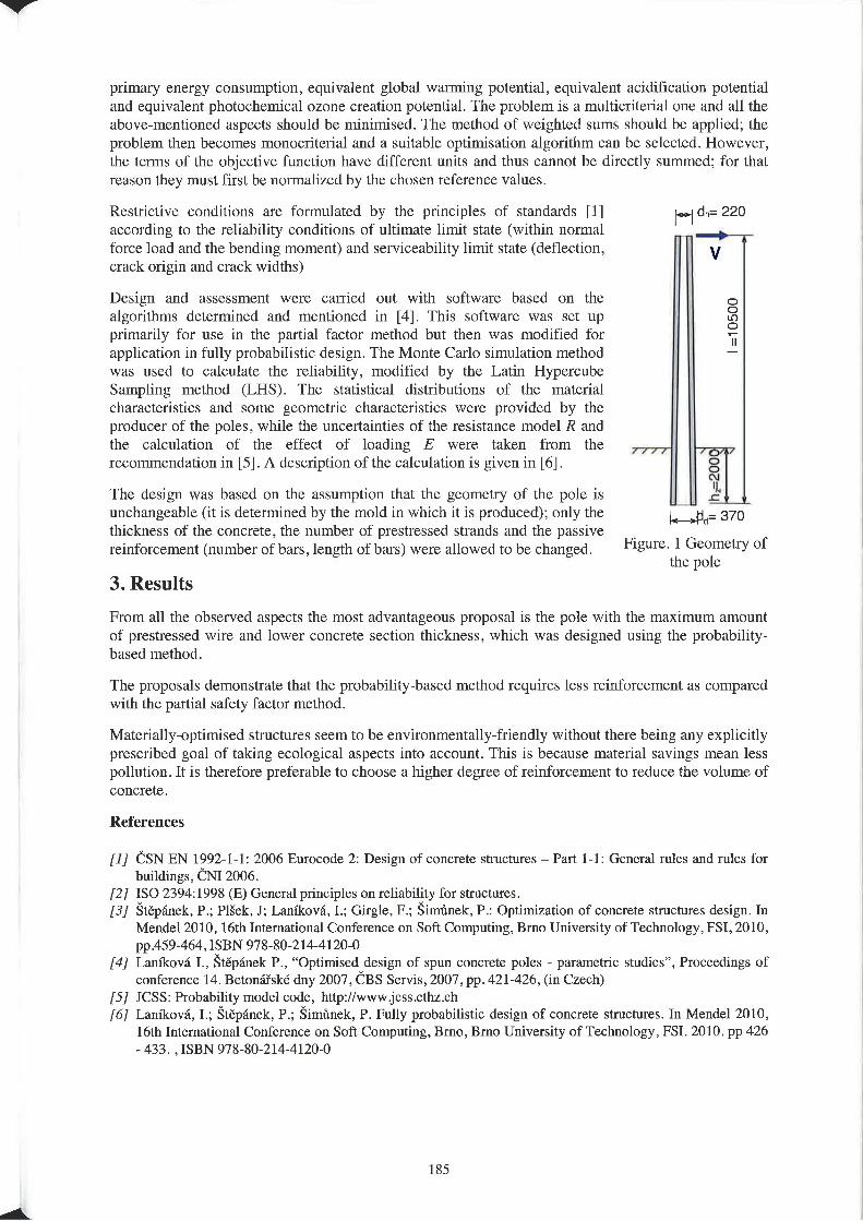
7
4
primary energy consumption, equivalent global wamting potential, equivalent acidification potentialand equivalent photochemical ozone creation potential. The problem is a multicriterial one and all t.heabove-mentioned aspects should be minimised. The method of weighted sums should be applied; theproblem then becomes monocriterial and a suitable optimisation algorithm can be selected. However,the tenns of the objective function have different units and thus cannot be directly summed; for thatreason they must first be normalized by the chosen reference values.
Restrictive conditions are formulated by the principles of standards fl]according to the reliability conditions of ultimate limit state (within normalforce load and the bending moment) and serviceability lirrrit state (deflection, Vcrack origin and crack widths)
|.>1 d>t= 220
Design and assessment were carried out with software based on thealgorithms determined and mentioned in [4]. This software was set upprimarily for use in the partial factor method but then was modified forapplication in fully probabilistic design. The Monte Carlo simulation method —was used to calculate thc reliability, modified by the Latin HypercubeSampling method (LHS). The statistical distributions of the materialcharacteristics and some geometric characteristics were provided by theproducer of the poles, while the uncertainties of the resistance model R andthe calculation of the effect of loading E were taken from therecommendation in [5]. A description of the calculation is given in [6].
The design was based on the assumption that the geometry of the pole isunchangeable (it is determined by the mold in which it is produced); ordy thethickness of the concrete, the number of prestrcsscd strands and the passivereinforcement (number of bars, length of bars) were allowed to be changed.
3. Results
hF200
=10500
_ ,l,id= 370
Figure. l Geometry ofthe pole
From all the observed aspects the most advantageous proposal is the pole with the maximum amountof prestressed wire and lower concrete section thickness, which was designed using the probability-based method.
The proposals demonstrate that the probability»hased method requires less reinforcement as comparedwith the partial safety factor method.
Materiallyoptimised structures seem to be environmentally—friendly without there being any explicitlyprescribed goal of taking ecological aspects into account. This is because material savings mean lesspollution. It is therefore preferable to choose a higher degree of reinforcement to reduce the volume ofconcrete.
References
[I] CSN EN 1992-l-1: 2006 Eurocode 2: Design of concrete structures - Part l—1: General nrles and rules forbuildings. cur 2006.
[2] ISO 2394:1998 (E) General principles on reliability for stnlctures.[3] srepnier, P.; Plsek, J; Lanfkovti, 1.; Girgle, F.; simmer. P.: Optimization of concrete structures design. Iii
Mendel 2010, 16th International Conference on Soft Computing. Bmo University of Technology. FSI, 2010,pp.459-464, ISBN 978-80-2144120-0
[4] Lanfltova I., fitepének P., “Optimised design of spun concrete poles - parametric studies", Proceedings ofconference l4. Betonzitské dny 2007, CBS Servis, 2007, pp. 42l—426. (in Czech)
[5] JCSS: Probability model code, http://www.jessethzch[6] Ianikova, I.; §tepa.nek, P.; §im\'rnek, P, Fully probabilistic design of concrete structures. In Mendel 2010,
l6th International Conference on Soft Computing, Bmo, Bmo University of Technology, FSI. 2010. pp 426- 433. .ISBN 978-80-214-4120-0
185
SSC%Numerical ModelingStrategies for Sustainable Concrete Structures
Conference Secretariat
Mrs Nadget BERRAHOU-DAOUDTe|.+Z-33144582429-Fax +33144582479
e-mail : [email protected]
www.sscs2012.com
_ ‘_',|. _\-._H_,_)_ \;_ _",-1' - -L '- " M ' '-


