Embed Size (px)
Citation preview
Materials
www.elsevier.com/locate/matdes
Materials and Design 26 (2005) 549–554
&Design
Short Communication
Finite element analysis of bending occurring whilecutting with high speed steel lathe cutting tools
Abdullah Duran *, Muammer Nalbant
Gazi University, Mechanical Engineering Department, Technical Education Faculty, Bes�evler, Ankara 06500, TeknikokuIIar, Turkey
Received 4 February 2004; accepted 26 July 2004
Available online 6 October 2004
Abstract
The bending which occurs on a cutting tool during machining on a lathe affects tool life, surface roughness and dimension cor-
rectness. In this research, the bending which has been calculated by Castigliano theorem has been compared with the bending
obtained by finite element method. Under the constant cutting conditions, material C1060 has been machined with high speed steel
(HSS) lathe cutting tools having 60�, 75� and 90� of cutting edge angle. It was determined by using ANSYS finite elements program
that the bending of the cutting tool generated by the forces, which varied between 1360 N and 1325 N and occurred during cutting,
varied between 0.039958 and 0.04373 mm. According to the results, it has been observed that the bending that was calculated by
Castigliano theorem and that varied between 0.03542 and 0.034505 mm was almost the same with the bending determined by finite
elements method. In other words, it was seen that the calculated values approach to the analysed results up to 0.4% .
� 2004 Elsevier Ltd. All rights reserved.
Keywords: Finite elements method; Bending; Cutting forces
1. Introduction
Various machine tools and cutting tools are used in
metal cutting. Cutting tools for turning can generally
be divided into two groups: high speed steels and cemen-
ted carbides. High speed steel (HSS) cutting tools can be
subdivided into three groups according to their manu-facture: single, brazed and indexable inserts [1,2].
Cutting tool geometry, chip geometry, cutting speed,
cutting tool and workpiece material, cutting speed and
cutting fluid are the main factors affecting the metal cut-
ting process [3,4].
Tool geometry, one of the most important factor
affecting metal cutting process, is determined by rake an-
gle, side clearance angle, side cutting edge angle andback rake angle. Tool geometry is an important factor
0261-3069/$ - see front matter � 2004 Elsevier Ltd. All rights reserved.
doi:10.1016/j.matdes.2004.07.028
* Corresponding author.
E-mail address: [email protected] (A. Duran).
having influence on cutting forces and tool life. For an
optimum turning operation, correct selection of cutting
parameters as well as the length of tool holder extending
from its post are essential [5]. That is because, incorrect
selection of cutting parameters leads to rapid tool wear,
breakage and plastic deformation. This increases ma-
chine tool idle time due to the changing of damaged cut-ting tools and causes some other problems such as poor
surface quality and wrong workpiece dimensions. This,
in turn, increases the overall cost [6].
Determination of cutting parameters through con-
ventional methods is mostly not possible. Therefore,
the use of high capacity computers is also gaining
importance as it is possible to find appropriate solutions
for metal cutting operation. Approximate solutionmethods giving very close results to those obtained by
the experimental work are appealing as they are easy
to use and there is no necessity to carry out costly exper-
imental work [7]. Parallel to the development in the
computer technology, finite element analysis (FEM)
550 A. Duran, M. Nalbant / Materials and Design 26 (2005) 549–554
method, one of the approximate solution methods, has
been increasingly used. Finite element method gives very
close results to the real values and, therefore, it is now a
well accepted numerical method [8–11].
In this study, deflection of HSS cutting tool during
turning was investigated using ANSYS version 5.4 pro-
gram based on the tool length extending through the
tool post. The deflection of the tool was also calculatedusing Castigliano theory and the results were compared
to those obtained using ANSYS program.
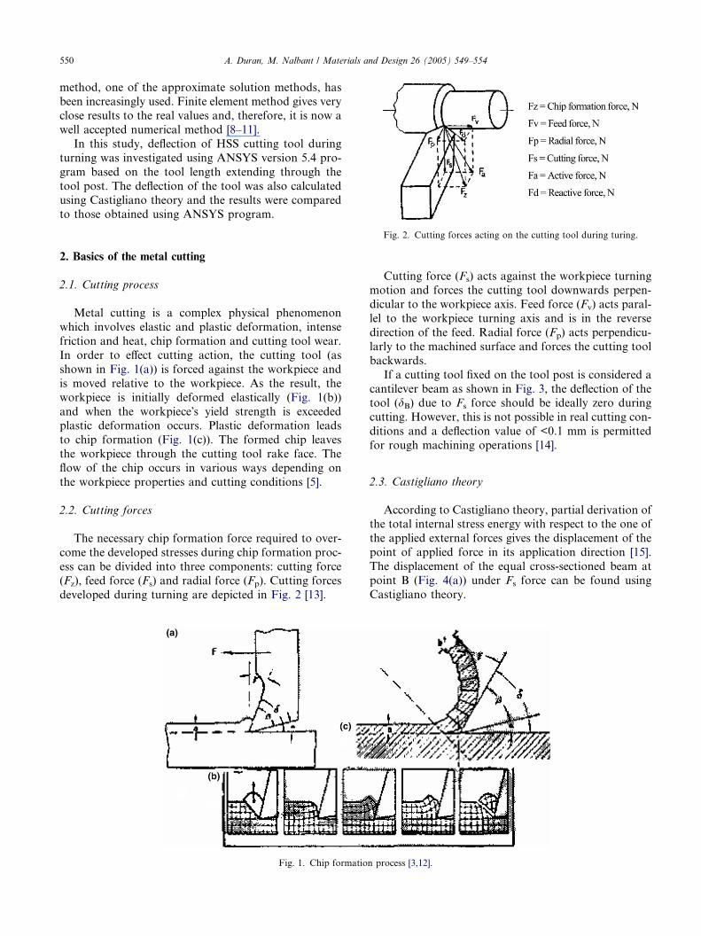
Fig. 2. Cutting forces acting on the cutting tool during turing.
2. Basics of the metal cutting
2.1. Cutting process
Metal cutting is a complex physical phenomenon
which involves elastic and plastic deformation, intense
friction and heat, chip formation and cutting tool wear.
In order to effect cutting action, the cutting tool (as
shown in Fig. 1(a)) is forced against the workpiece and
is moved relative to the workpiece. As the result, the
workpiece is initially deformed elastically (Fig. 1(b))
and when the workpiece�s yield strength is exceededplastic deformation occurs. Plastic deformation leads
to chip formation (Fig. 1(c)). The formed chip leaves
the workpiece through the cutting tool rake face. The
flow of the chip occurs in various ways depending on
the workpiece properties and cutting conditions [5].
2.2. Cutting forces
The necessary chip formation force required to over-
come the developed stresses during chip formation proc-
ess can be divided into three components: cutting force
(Fz), feed force (Fs) and radial force (Fp). Cutting forces
developed during turning are depicted in Fig. 2 [13].
Fig. 1. Chip formatio
Cutting force (Fs) acts against the workpiece turningmotion and forces the cutting tool downwards perpen-
dicular to the workpiece axis. Feed force (Fv) acts paral-
lel to the workpiece turning axis and is in the reverse
direction of the feed. Radial force (Fp) acts perpendicu-
larly to the machined surface and forces the cutting tool
backwards.
If a cutting tool fixed on the tool post is considered a
cantilever beam as shown in Fig. 3, the deflection of thetool (dB) due to Fs force should be ideally zero during
cutting. However, this is not possible in real cutting con-
ditions and a deflection value of <0.1 mm is permitted
for rough machining operations [14].
2.3. Castigliano theory
According to Castigliano theory, partial derivation ofthe total internal stress energy with respect to the one of
the applied external forces gives the displacement of the
point of applied force in its application direction [15].
The displacement of the equal cross-sectioned beam at
point B (Fig. 4(a)) under Fs force can be found using
Castigliano theory.
n process [3,12].
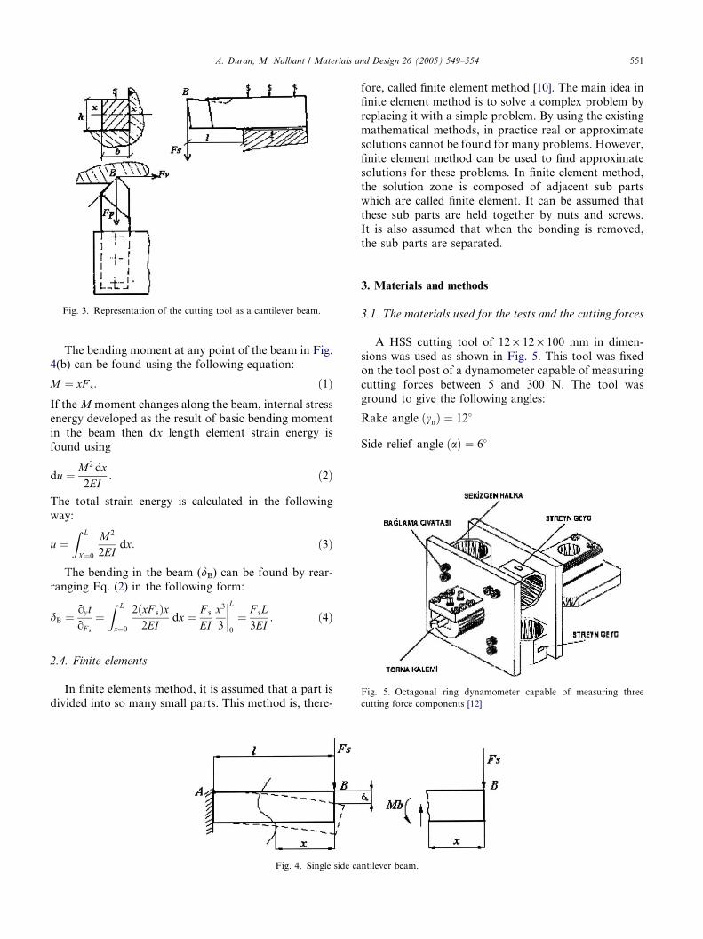
Fig. 3. Representation of the cutting tool as a cantilever beam.
A. Duran, M. Nalbant / Materials and Design 26 (2005) 549–554 551
The bending moment at any point of the beam in Fig.4(b) can be found using the following equation:
M ¼ xF s: ð1ÞIf theMmoment changes along the beam, internal stress
energy developed as the result of basic bending moment
in the beam then dx length element strain energy isfound using
du ¼ M2 dx2EI
: ð2Þ
The total strain energy is calculated in the following
way:
u ¼Z L
X¼0
M2
2EIdx: ð3Þ
The bending in the beam (dB) can be found by rear-
ranging Eq. (2) in the following form:
dB ¼ oy toF s
¼Z L
x¼0
2ðxF sÞx2EI
dx ¼ F s
EIx3
3
����L
0
¼ F sL3EI
: ð4Þ
Fig. 5. Octagonal ring dynamometer capable of measuring three
cutting force components [12].
2.4. Finite elements
In finite elements method, it is assumed that a part is
divided into so many small parts. This method is, there-
Fig. 4. Single side ca
fore, called finite element method [10]. The main idea in
finite element method is to solve a complex problem by
replacing it with a simple problem. By using the existing
mathematical methods, in practice real or approximate
solutions cannot be found for many problems. However,
finite element method can be used to find approximate
solutions for these problems. In finite element method,
the solution zone is composed of adjacent sub partswhich are called finite element. It can be assumed that
these sub parts are held together by nuts and screws.
It is also assumed that when the bonding is removed,
the sub parts are separated.
3. Materials and methods
3.1. The materials used for the tests and the cutting forces
A HSS cutting tool of 12 · 12 · 100 mm in dimen-
sions was used as shown in Fig. 5. This tool was fixed
on the tool post of a dynamometer capable of measuring
cutting forces between 5 and 300 N. The tool was
ground to give the following angles:
Rake angle ðcnÞ ¼ 12�
Side relief angle ðaÞ ¼ 6�
ntilever beam.
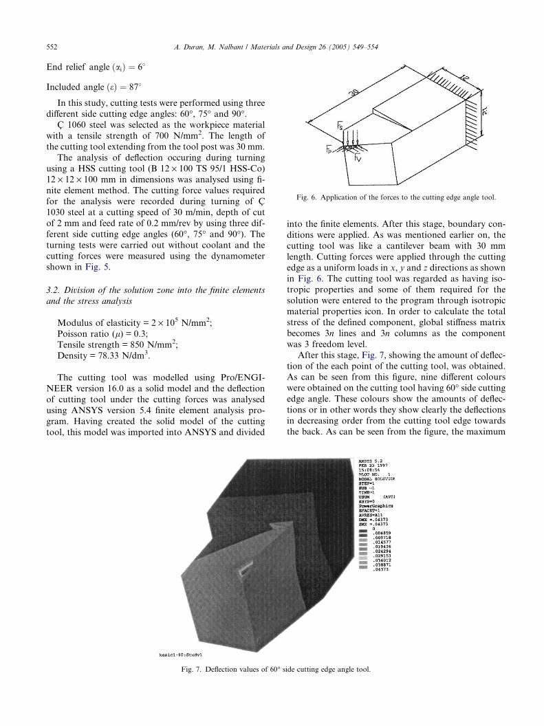
Fig. 6. Application of the forces to the cutting edge angle tool.
552 A. Duran, M. Nalbant / Materials and Design 26 (2005) 549–554
End relief angle ðaiÞ ¼ 6�
Included angle ðeÞ ¼ 87�
In this study, cutting tests were performed using three
different side cutting edge angles: 60�, 75� and 90�.C 1060 steel was selected as the workpiece material
with a tensile strength of 700 N/mm2. The length of
the cutting tool extending from the tool post was 30 mm.
The analysis of deflection occuring during turning
using a HSS cutting tool (B 12 · 100 TS 95/1 HSS-Co)12 · 12 · 100 mm in dimensions was analysed using fi-
nite element method. The cutting force values required
for the analysis were recorded during turning of C
1030 steel at a cutting speed of 30 m/min, depth of cut
of 2 mm and feed rate of 0.2 mm/rev by using three dif-
ferent side cutting edge angles (60�, 75� and 90�). Theturning tests were carried out without coolant and the
cutting forces were measured using the dynamometershown in Fig. 5.
3.2. Division of the solution zone into the finite elements
and the stress analysis
Modulus of elasticity = 2 · 105 N/mm2;
Poisson ratio (l) = 0.3;
Tensile strength = 850 N/mm2;Density = 78.33 N/dm3.
The cutting tool was modelled using Pro/ENGI-
NEER version 16.0 as a solid model and the deflection
of cutting tool under the cutting forces was analysed
using ANSYS version 5.4 finite element analysis pro-
gram. Having created the solid model of the cutting
tool, this model was imported into ANSYS and divided
Fig. 7. Deflection values of 60� s
into the finite elements. After this stage, boundary con-
ditions were applied. As was mentioned earlier on, the
cutting tool was like a cantilever beam with 30 mm
length. Cutting forces were applied through the cutting
edge as a uniform loads in x, y and z directions as shown
in Fig. 6. The cutting tool was regarded as having iso-tropic properties and some of them required for the
solution were entered to the program through isotropic
material properties icon. In order to calculate the total
stress of the defined component, global stiffness matrix
becomes 3n lines and 3n columns as the component
was 3 freedom level.
After this stage, Fig. 7, showing the amount of deflec-
tion of the each point of the cutting tool, was obtained.As can be seen from this figure, nine different colours
were obtained on the cutting tool having 60� side cuttingedge angle. These colours show the amounts of deflec-
tions or in other words they show clearly the deflections
in decreasing order from the cutting tool edge towards
the back. As can be seen from the figure, the maximum
ide cutting edge angle tool.
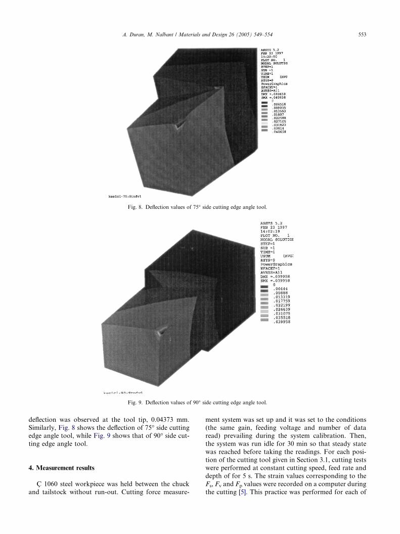
Fig. 8. Deflection values of 75� side cutting edge angle tool.
Fig. 9. Deflection values of 90� side cutting edge angle tool.
A. Duran, M. Nalbant / Materials and Design 26 (2005) 549–554 553
deflection was observed at the tool tip, 0.04373 mm.
Similarly, Fig. 8 shows the deflection of 75� side cuttingedge angle tool, while Fig. 9 shows that of 90� side cut-
ting edge angle tool.
4. Measurement results
C 1060 steel workpiece was held between the chuck
and tailstock without run-out. Cutting force measure-
ment system was set up and it was set to the conditions
(the same gain, feeding voltage and number of dataread) prevailing during the system calibration. Then,
the system was run idle for 30 min so that steady state
was reached before taking the readings. For each posi-
tion of the cutting tool given in Section 3.1, cutting tests
were performed at constant cutting speed, feed rate and
depth of for 5 s. The strain values corresponding to the
Fs, Fv and Fp values were recorded on a computer during
the cutting [5]. This practice was performed for each of
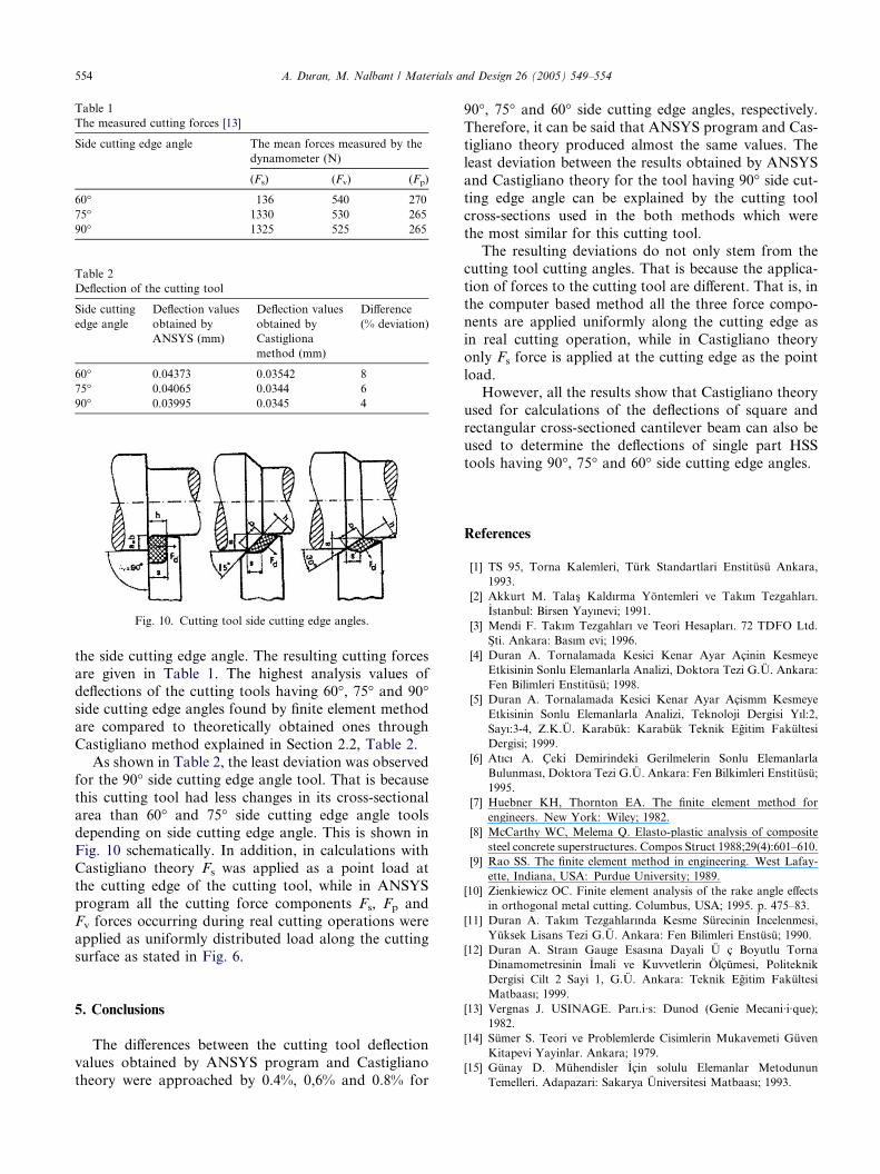
Table 1
The measured cutting forces [13]
Side cutting edge angle The mean forces measured by the
dynamometer (N)
(Fs) (Fv) (Fp)
60� 136 540 270
75� 1330 530 265
90� 1325 525 265
Table 2
Deflection of the cutting tool
Side cutting
edge angle
Deflection values
obtained by
ANSYS (mm)
Deflection values
obtained by
Castigliona
method (mm)
Difference
(% deviation)
60� 0.04373 0.03542 8
75� 0.04065 0.0344 6
90� 0.03995 0.0345 4
Fig. 10. Cutting tool side cutting edge angles.
554 A. Duran, M. Nalbant / Materials and Design 26 (2005) 549–554
the side cutting edge angle. The resulting cutting forces
are given in Table 1. The highest analysis values ofdeflections of the cutting tools having 60�, 75� and 90�side cutting edge angles found by finite element method
are compared to theoretically obtained ones through
Castigliano method explained in Section 2.2, Table 2.
As shown in Table 2, the least deviation was observed
for the 90� side cutting edge angle tool. That is because
this cutting tool had less changes in its cross-sectional
area than 60� and 75� side cutting edge angle toolsdepending on side cutting edge angle. This is shown in
Fig. 10 schematically. In addition, in calculations with
Castigliano theory Fs was applied as a point load at
the cutting edge of the cutting tool, while in ANSYS
program all the cutting force components Fs, Fp and
Fv forces occurring during real cutting operations were
applied as uniformly distributed load along the cutting
surface as stated in Fig. 6.
5. Conclusions
The differences between the cutting tool deflection
values obtained by ANSYS program and Castigliano
theory were approached by 0.4%, 0,6% and 0.8% for
90�, 75� and 60� side cutting edge angles, respectively.
Therefore, it can be said that ANSYS program and Cas-
tigliano theory produced almost the same values. The
least deviation between the results obtained by ANSYS
and Castigliano theory for the tool having 90� side cut-
ting edge angle can be explained by the cutting tool
cross-sections used in the both methods which were
the most similar for this cutting tool.The resulting deviations do not only stem from the
cutting tool cutting angles. That is because the applica-
tion of forces to the cutting tool are different. That is, in
the computer based method all the three force compo-
nents are applied uniformly along the cutting edge as
in real cutting operation, while in Castigliano theory
only Fs force is applied at the cutting edge as the point
load.However, all the results show that Castigliano theory
used for calculations of the deflections of square and
rectangular cross-sectioned cantilever beam can also be
used to determine the deflections of single part HSS
tools having 90�, 75� and 60� side cutting edge angles.
References
[1] TS 95, Torna Kalemleri, Turk Standartlari Enstitusu Ankara,
1993.
[2] Akkurt M. Talas� Kaldırma Yontemleri ve Takım Tezgahları._Istanbul: Birsen Yayınevi; 1991.
[3] Mendi F. Takım Tezgahları ve Teori Hesapları. 72 TDFO Ltd.
S�ti. Ankara: Basım evi; 1996.
[4] Duran A. Tornalamada Kesici Kenar Ayar Acinin Kesmeye
Etkisinin Sonlu Elemanlarla Analizi, Doktora Tezi G.U. Ankara:
Fen Bilimleri Enstitusu; 1998.
[5] Duran A. Tornalamada Kesici Kenar Ayar Acismm Kesmeye
Etkisinin Sonlu Elemanlarla Analizi, Teknoloji Dergisi Yıl:2,
Sayı:3-4, Z.K.U. Karabuk: Karabuk Teknik Egitim Fakultesi
Dergisi; 1999.
[6] Atıcı A. Ceki Demirindeki Gerilmelerin Sonlu Elemanlarla
Bulunması, Doktora Tezi G.U. Ankara: Fen Bilkimleri Enstitusu;
1995.
[7] Huebner KH, Thornton EA. The finite element method for
engineers. New York: Wiley; 1982.
[8] McCarthy WC, Melema Q. Elasto-plastic analysis of composite
steel concrete superstructures. Compos Struct 1988;29(4):601–610.
[9] Rao SS. The finite element method in engineering. West Lafay-
ette, Indiana, USA: Purdue University; 1989.
[10] Zienkiewicz OC. Finite element analysis of the rake angle effects
in orthogonal metal cutting. Columbus, USA; 1995. p. 475–83.
[11] Duran A. Takım Tezgahlarında Kesme Surecinin _Incelenmesi,
Yuksek Lisans Tezi G.U. Ankara: Fen Bilimleri Enstusu; 1990.
[12] Duran A. Straın Gauge Esasına Dayali U c Boyutlu Torna
Dinamometresinin _Imali ve Kuvvetlerin Olcumesi, Politeknik
Dergisi Cilt 2 Sayi 1, G.U. Ankara: Teknik Egitim Fakultesi
Matbaası; 1999.
[13] Vergnas J. USINAGE. Parı.i·s: Dunod (Genie Mecani·i·que);
1982.
[14] Sumer S. Teori ve Problemlerde Cisimlerin Mukavemeti Guven
Kitapevi Yayinlar. Ankara; 1979.
[15] Gunay D. Muhendisler _Icin solulu Elemanlar Metodunun
Temelleri. Adapazari: Sakarya Universitesi Matbaası; 1993.


