Embed Size (px)
Citation preview
1
METERING MANUAL
As on
31.10.2021
NORTH EASRTERN REGIONAL
LOAD DESPATCH CENTRE

2
3
Table of Contents
FOREWORD……................................................................................………....................................... 4
Section-1: Special Energy Meter, DCD and Technical Specifications
1.1 Special Energy Meter (SEM)............................................................................................... 6-8
1.1.1 Abou SEM.......................................................................................................................... 6
1.1.2 General Description of SEM............................................................................................. 6-7
1.1.3 Data Recording Format ................................................................................................... 7
1.1.4 Measurement Principle .................................................................................................. 7
1.1.5 Operating Section of the Meter...................................................................................... 8 1.1.6 Display Parameters.......................................................................................................... 8 1.1.7 Meter parts and overall dimension of the meter......................................................... 8
1.2 Data Collecting Device (DCD)............................................................................................... 9
1.2.1 About DCD...................................................................................................................... 9 Section-2: Regulatory Provisions and Standards
2.1 Metering Philosopy of CEA............................................................................................... 11-12 2.1.1 Types of Meters................................................................................................................ 11
2.1.2 Meter Standards.............................................................................................................. 11
2.1.3 Accuracy Class of Meters…............................................................................................ 11
2.1.4 Testing of Meters............................................................................................................... 12
2.1.5 Location of Meters............................................................................................................ 12
2.2 Philosophy for Installation of SEMs in NER............................................................. 13
2.3 Utility wise Meters in NER............................................................................................... 14-15
2.3.1 Breakup of meters in Powergrid sub-stations in NER............................................. 15
2.4 Constituent wise Metering Arrangement........................................................................ 16-36 2.4.1 Arunachal Pradesh............................................................................................................ 16-17
2.4.2 Assam................................................................................................................................. 18-20
2.4.3 Manipur............................................................................................................................. 20-21
2.4.4 Meghalaya......................................................................................................................... 22-23
2.4.5 Mizoram.......................................................................................................................... 23
2.4.6 Nagaland........................................................................................................................... 24-25
2.4.7 Tripura............................................................................................................................... 25-26
2.4.8 ER-NER............................................................................................................................. 26-27
2.4.9 Doyang.............................................................................................................................. 27-28
2.4.10 Khandong & Kopili-2...................................................................................................... 28-29
2.4.11 Kopili................................................................................................................................. 29-30
2.4.12 Kathalguri......................................................................................................................... 30-31
2.4.13 Loktak................................................................................................................................ 31-32
4
Table of Contents
2.4.14 AGTCCPP...................................................................................................................... 32
2.4.15 Ranganadi...................................................................................................................... 33
2.4.16 Palatana........................................................................................................................... 34
2.4.17 BGTPP.............................................................................................................................. 35
2.4.18 Pare.................................................................................................................................... 36
2.4.19 Kameng........................................................................................................................... 37
2.5 Master Database of SEMs in NER...................................................................................... 38-51
Section-3: Processing and Computation of data
3.1 Data collection from Meters................................................................................................. 53-68 3.1.1 Data collection from SEM through DCD....................................................................... 53
3.1.1.1 Data tapping from Meter to DCD............................................................................. 54-55
3.1.1.2 Data dumping from DCD to PC by Vincom software for L&T Meters............... 55-58
3.1.1.3 Data dumping from DCD to PC by Vinplus software for L&T Meters............... 58-65
3.1.1.4 Data dumping from DCD to PC by Smartgrid software for SML Meters.......... 65-68
3.1.1.5 Sending data from metering location to RLDC........................................................... 68
3.2 Data collection from SEM hrough RS-485 Scheme......................................................... 68-70
3.2.1 Data collection through RS-485....................................................................................... 69-70
3.3 Automating Meter data collection/ Transmission....................................................... 71
3.3.1 Automatic Data collection.................................................................................................. 71
3.3.2 Automatic Data transmission.............................................................................................. 71
3.4 Receipt of SEM data at RLDC............................................................................................. 72 3.5 Softwares for data viewing/ conversion to TEXT file................................................... 72-91 3.6 Structure of NPC file.......................................................................................................... 92-93
Annexure-1…..................................................................................................................... 94-99
Annexure-2.......................................................................................................................... 100-101

5
Foreword Special Energy Meter (SEM) with Data Collection device (DCD) was conceptualized and designed by POWERGRID in the beginning of 1990s to take care of metering requirements of bulk power tariff structure (post rationalization) in India in line with ECC recommendations which paved way for ABT (Availability Based Tariff) implementation in India. SEM/DCD was, therefore, a special metering package, aimed at fulfilling metering needs of ABT era. North-Eastern Region has the distinction of being the first region in the country to get SEMs installed during 1994-95, followed by Southern and Eastern Regions in the same year. As per IEGC provisions, CTU (POWERGRID) is responsible for installation as well as maintenance/testing of SEMs in ISTS. RLDCs validate and process the meter readings received from various locations for computation of REA. In case of any discrepancy/problem related to meter/accessories, RLDCs take up with respective RTS for rectification. In nutshell, metering activities are very streamlined and carried out in a specific time frame.
(a) Meter/DCD Commissioning, Maintenance, Testing – CTU (b) Weekly Data Collection / Transmittal to RLDC – Metering Locations (CTU, State, SLDC, ISGS) (c) Data Processing, Validation, Computation, Accounting, Metering Philosophy, Identification of Metering Locations – RLDC
The manual unfolds with detailed description of SEM/DCD in Section-1 followed by the regulatory requirements with details of meter location in the region in Section-2. Section-3 covers in great length, data collection from meters and transmittal to RLDC with special emphasis on future road map to automate the system. Finally, data checking, data validation, computation, and data archival, which are exclusive functions of RLDC, have been detailed in Section-4. Data Processing, Validation, Computation, Accounting, Metering Philosophy, Identification of Metering Locations have not been included to restrict the volume of the present manual.
6
SECTION 1:
SPECIAL ENERGY METER, DCD AND
TECHNICAL SPECIFICAIONS
7
1.1.1 About SEM
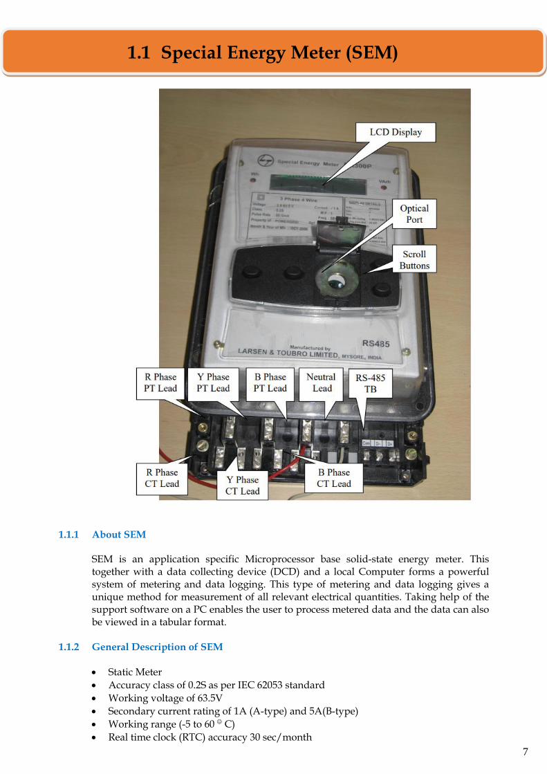
SEM is an application specific Microprocessor base solid-state energy meter. This together with a data collecting device (DCD) and a local Computer forms a powerful system of metering and data logging. This type of metering and data logging gives a unique method for measurement of all relevant electrical quantities. Taking help of the support software on a PC enables the user to process metered data and the data can also be viewed in a tabular format.
1.1.2 General Description of SEM
• Static Meter
• Accuracy class of 0.2S as per IEC 62053 standard
• Working voltage of 63.5V
• Secondary current rating of 1A (A-type) and 5A(B-type)
• Working range (-5 to 60 C)
• Real time clock (RTC) accuracy 30 sec/month
1.1 Special Energy Meter (SEM)
8
• Extended temperature LCD for display
• Rechargeable Ni-Cd battery with a push button on front panel to operate during power failure
• Offline data collection possible for 6-7 hrs during power off condition
• Surface mounted, light in weight (<2.5kg)
• Mounting can be done on a flat surface, one hole on top and two holes at the bottom 1.1.3 Data Recording Format
Data recorded by the meters are normally not Windows readable. Therefore, data downloaded from the meters must be first converted to Windows readable form, usually a text file, for computation and analysis. This is explained in details in Section-4. Conversion software is required for this purpose which is proprietary to the meter supplier. All data of last 10 full days plus the most recent complete 15 min block data up to the time of collection is available. Last ten (10) full day’s data remain in non-volatile memory of meter and is available on collection of data.
1.1.4 Measurement Principle
a) Wh Measurement
The active energy (Wh) measurements are carried out on 3-phase, 4-wire principle with an accuracy as per class 0.2S of IEC-687/IEC-62053-22. The meter computes the net active energy (Wh) in each successive 15-minutes block and stores it in its non-volatile memory along with plus/ minus sign. The 15-minute Wh shall have a +ve sign when there is a net Wh export and a –ve sign when there is a net Wh import. Cumulative Wh reading at each midnight shall be stored in the meter’s memory along with plus/ minus sign. The meter shall store all data in its memories for a period of ten (10) days. The data older than ten (10) days shall get erased automatically.
b) VARh Measurement The meter shall also compute the reactive power (VAR) on a 3-phase 4-wire principle with an accuracy as per class 0.2S of IEC-687/IEC-62053-23. There shall be two reactive energy registers, one for the period when average RMS voltage is above 103% and the other for the period the voltage is below 97%. The registers will move forward when there is VARh export and will move backward when there is VARh import.
c) Average Frequency The meter shall count the number of cycles in VT output during each successive 15-minute block and divide the same by 900 (15*60=900) to arrive at the average frequency. The average frequency is stored in meter’s memory in 2-digit code neglecting decimals. In case the average frequency is less than 49.5 Hz, it is recorded as 00 and in case it is 50.5 Hz or higher it is recorded as 99. The actual frequency corresponding to two consecutive codes differ by 0.01Hz.
9
1.1.5 Operating Section of the Meter a) Analog Section: High precision Current transformer and voltage transformer step down
input currents and voltages which are fed to an Analog to Digital converter. b) Digital Section: A powerful microprocessor controls the Analog and Digital sections.
Analog to Digital converters are fed from high precision instrument transformers. The Digital samples from Analog to Digital converter are used to process the metering data. The sampling rate is 3000 samples per second which gives the meter an exceptional accuracy and results.
c) Power supply Section: A switch mode power supply (SMPs) unit supplies power to the
meter’s internal circuit.
1.1.6 Display Parameters Special Energy Meters have the facility to display the following parameters: Display Parameter: Indication Display format 1. Meter identification code A NP1234A 2. Date (day, date, month, year) d dd-mm-yy 3. Time (hour, min, sec) t hh:mm:ss 4. Cumulative Wh reading c xxxx.x Wh 5. Reactive Power Pr xxx:x VAr 6. Average freq. of previous block F xx:xx 7. Net Wh transmittal-previous block E xx:xx 8. Average % voltage U xx:xx 9. Voltage high VArh register reading H xxxx:x VArh 10. Voltage low VArh register reading L xxxx:x VArh 11. Real time indication rtC Fit 12. Low battery indication Low Bat
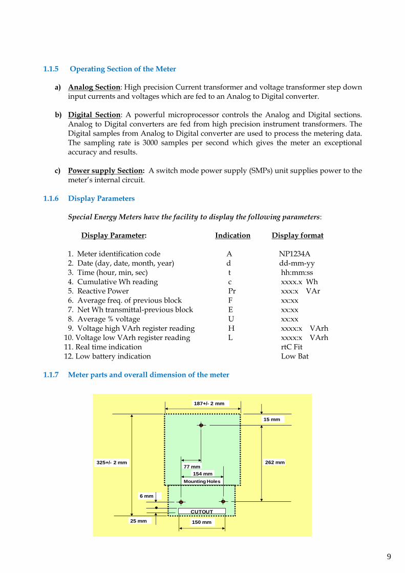
1.1.7 Meter parts and overall dimension of the meter
CUTOUT
154 mm
150 mm
6 mm
25 mm
15 mm
262 mm
Mounting Holes
187+/- 2 mm
325+/- 2 mm77 mm
10
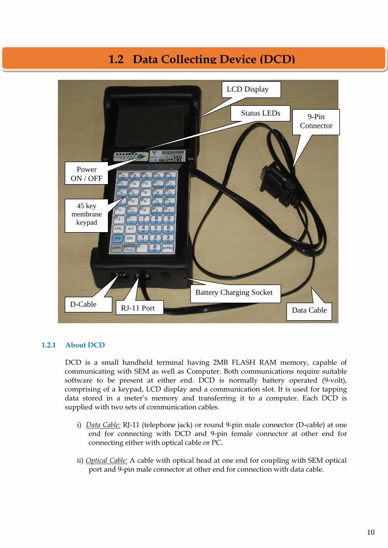
1.2.1 About DCD
DCD is a small handheld terminal having 2MB FLASH RAM memory, capable of communicating with SEM as well as Computer. Both communications require suitable software to be present at either end. DCD is normally battery operated (9-volt), comprising of a keypad, LCD display and a communication slot. It is used for tapping data stored in a meter’s memory and transferring it to a computer. Each DCD is supplied with two sets of communication cables.
i) Data Cable: RJ-11 (telephone jack) or round 9-pin male connector (D-cable) at one
end for connecting with DCD and 9-pin female connector at other end for connecting either with optical cable or PC.
ii) Optical Cable: A cable with optical head at one end for coupling with SEM optical
port and 9-pin male connector at other end for connection with data cable.
LCD Display
9-Pin
Connector
Power
ON / OFF
switch
Status LEDs
RJ-11 Port
45 key
membrane
keypad
Battery Charging Socket
Data Cable D-Cable
Port
1.2 Data Collecting Device (DCD)

11
SECTION-2:
REGULATORY PROVISIONS &
STANDARDS

12
2.1.1 Types of Meters a) Interface Meter: Interface Meter means a Meter, connected at the point of interconnection with inter-State Transmission system (ISTS) for the purpose of electricity accounting and billing. Meter shall be owned by CTU.
b) Consumer meter: Consumer Meter means a Meter used for accounting and billing of electricity supplied to the consumer. Meter shall be owned by licensee.
c) Energy accounting meter: Energy Accounting and Audit Meter means Meter used for accounting of electricity to various segments of electrical system. Meter shall be owned by Generating Company or licensee
All interface meters, consumer meters and energy accounting and audit meter shall be of static type.
Note: Our focus is on SEMs which are interface meters. 2.1.2 Meter Standards
All interface meter, consumer meters, energy accounting and audit meters shall:
Comply with the relevant standards of Bureau of Indian Standards (BIS). If BIS Standards are not available for an equipment or material, the relevant British Standards (BS), International Electro-technical Commission (IEC) Standards, or any other equivalent Standards shall be followed.
Provided that whenever an International Standard or IEC Standard is followed, necessary corrections of modifications shall be made for nominal system frequency, nominal system voltage, ambient temperature, humidity, and other conditions prevailing in India before actual adaption of the said Standard.
2.1.3 Accuracy Class of Meters
Every meter shall meet the following requirements of accuracy class as specified in the standards.
Interface Meter …………………………………….…. 0.2S Consumer meters
Upto 650 Volts ……………………….….…. 1.0S Above 650 Volts & upto 33kV ……………. 0.5S Above 33kV …………………………….….. 0.2S
2.1 Metering Philosophy of CEA (vide notification dated 17.03.06 and amendments thereof)
13
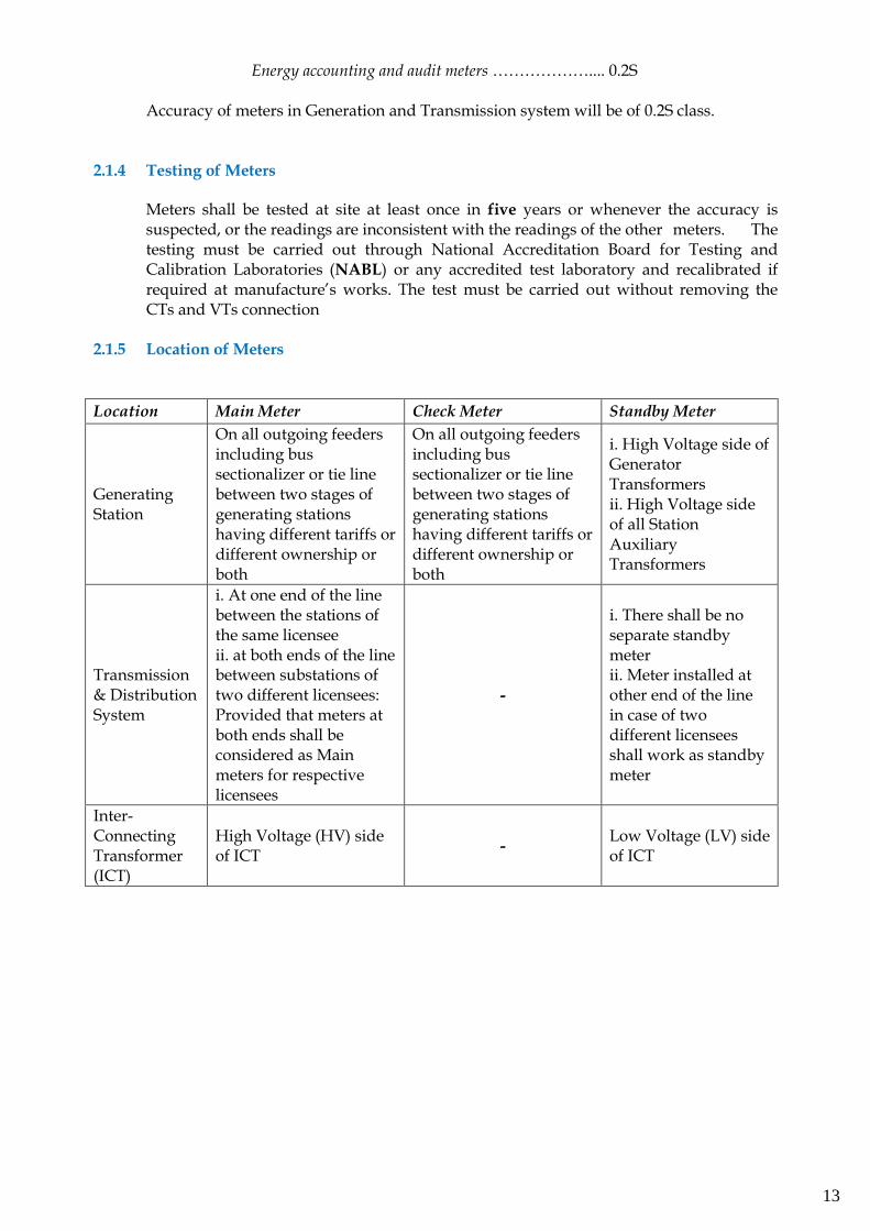
Energy accounting and audit meters ……………….... 0.2S Accuracy of meters in Generation and Transmission system will be of 0.2S class. 2.1.4 Testing of Meters
Meters shall be tested at site at least once in five years or whenever the accuracy is suspected, or the readings are inconsistent with the readings of the other meters. The testing must be carried out through National Accreditation Board for Testing and Calibration Laboratories (NABL) or any accredited test laboratory and recalibrated if required at manufacture’s works. The test must be carried out without removing the CTs and VTs connection
2.1.5 Location of Meters
Location Main Meter Check Meter Standby Meter
Generating Station
On all outgoing feeders including bus sectionalizer or tie line between two stages of generating stations having different tariffs or different ownership or both
On all outgoing feeders including bus sectionalizer or tie line between two stages of generating stations having different tariffs or different ownership or both
i. High Voltage side of Generator Transformers ii. High Voltage side of all Station Auxiliary Transformers
Transmission & Distribution System
i. At one end of the line between the stations of the same licensee ii. at both ends of the line between substations of two different licensees: Provided that meters at both ends shall be considered as Main meters for respective licensees
-
i. There shall be no separate standby meter ii. Meter installed at other end of the line in case of two different licensees shall work as standby meter
Inter-Connecting Transformer (ICT)
High Voltage (HV) side of ICT
- Low Voltage (LV) side of ICT
14
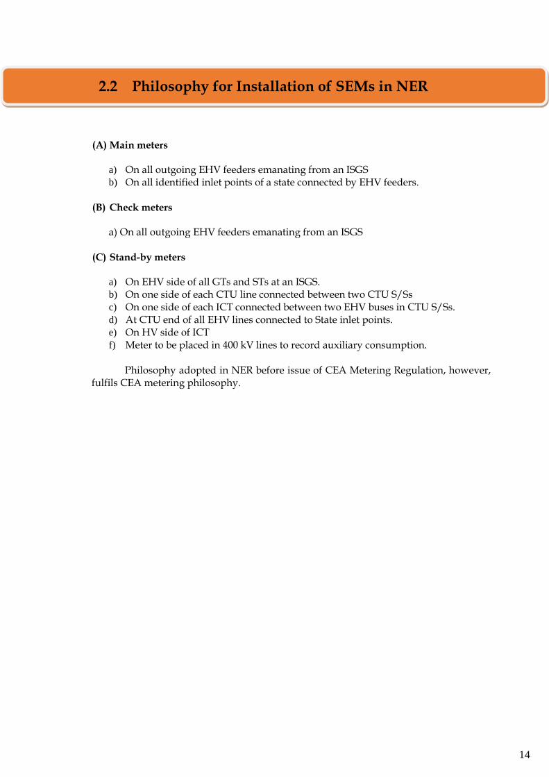
(A) Main meters
a) On all outgoing EHV feeders emanating from an ISGS b) On all identified inlet points of a state connected by EHV feeders.
(B) Check meters
a) On all outgoing EHV feeders emanating from an ISGS
(C) Stand-by meters
a) On EHV side of all GTs and STs at an ISGS. b) On one side of each CTU line connected between two CTU S/Ss c) On one side of each ICT connected between two EHV buses in CTU S/Ss. d) At CTU end of all EHV lines connected to State inlet points. e) On HV side of ICT f) Meter to be placed in 400 kV lines to record auxiliary consumption.
Philosophy adopted in NER before issue of CEA Metering Regulation, however,
fulfils CEA metering philosophy.
2.2 Philosophy for Installation of SEMs in NER
15
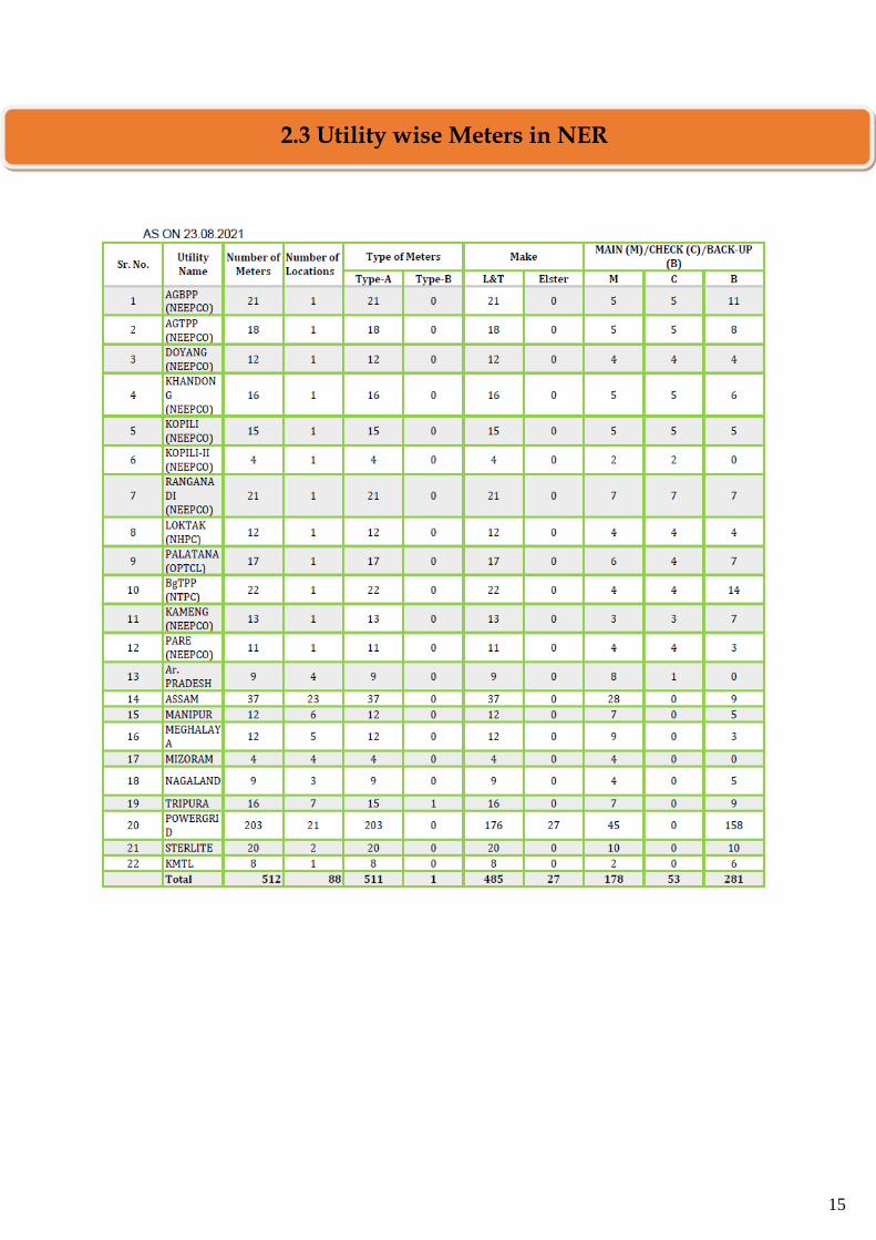
2.3 Utility wise Meters in NER
16
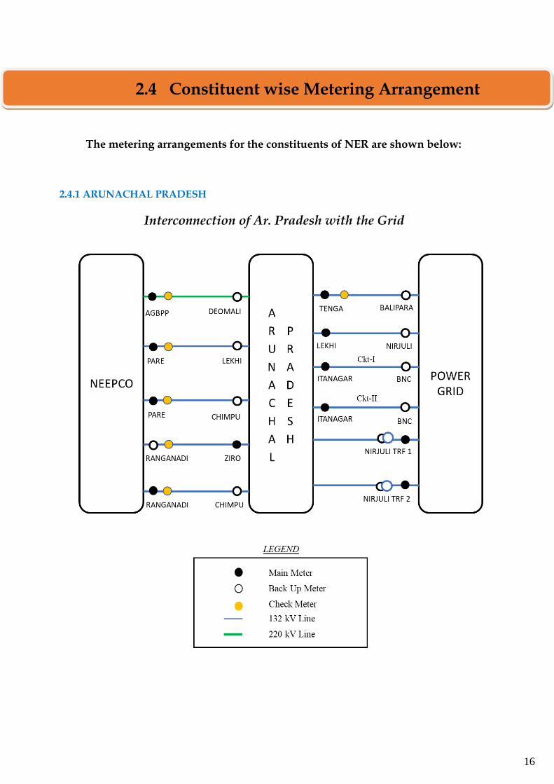
The metering arrangements for the constituents of NER are shown below: 2.4.1 ARUNACHAL PRADESH
Interconnection of Ar. Pradesh with the Grid
2.4 Constituent wise Metering Arrangement
17
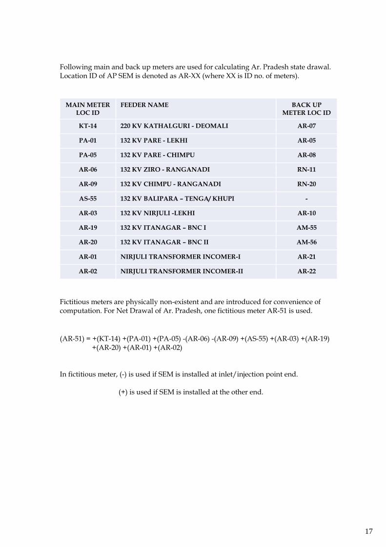
Following main and back up meters are used for calculating Ar. Pradesh state drawal. Location ID of AP SEM is denoted as AR-XX (where XX is ID no. of meters).
MAIN METER LOC ID
FEEDER NAME BACK UP METER LOC ID
KT-14 220 KV KATHALGURI - DEOMALI AR-07
PA-01 132 KV PARE - LEKHI AR-05
PA-05 132 KV PARE - CHIMPU AR-08
AR-06 132 KV ZIRO - RANGANADI RN-11
AR-09 132 KV CHIMPU - RANGANADI RN-20
AS-55 132 KV BALIPARA – TENGA/ KHUPI -
AR-03 132 KV NIRJULI -LEKHI AR-10
AR-19 132 KV ITANAGAR – BNC I AM-55
AR-20 132 KV ITANAGAR – BNC II AM-56
AR-01 NIRJULI TRANSFORMER INCOMER-I AR-21
AR-02 NIRJULI TRANSFORMER INCOMER-II AR-22
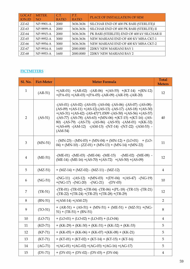
Fictitious meters are physically non-existent and are introduced for convenience of computation. For Net Drawal of Ar. Pradesh, one fictitious meter AR-51 is used.
(AR-51) = +(KT-14) +(PA-01) +(PA-05) -(AR-06) -(AR-09) +(AS-55) +(AR-03) +(AR-19) +(AR-20) +(AR-01) +(AR-02)
In fictitious meter, (-) is used if SEM is installed at inlet/injection point end. (+) is used if SEM is installed at the other end.
18
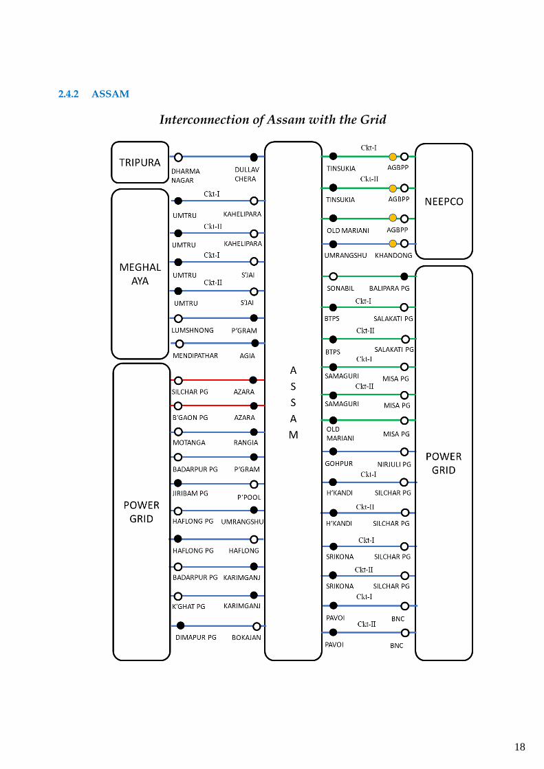
2.4.2 ASSAM
Interconnection of Assam with the Grid
19
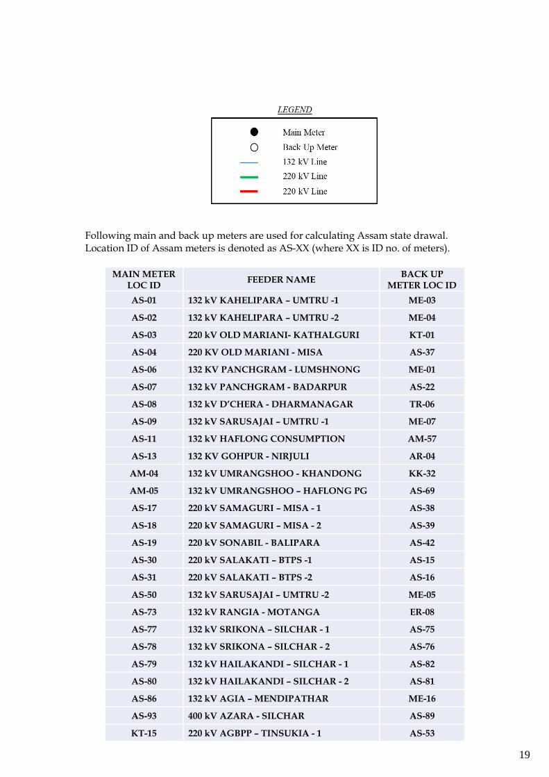
Following main and back up meters are used for calculating Assam state drawal. Location ID of Assam meters is denoted as AS-XX (where XX is ID no. of meters).
MAIN METER LOC ID
FEEDER NAME BACK UP
METER LOC ID
AS-01 132 kV KAHELIPARA – UMTRU -1 ME-03
AS-02 132 kV KAHELIPARA – UMTRU -2 ME-04
AS-03 220 kV OLD MARIANI- KATHALGURI KT-01
AS-04 220 KV OLD MARIANI - MISA AS-37
AS-06 132 KV PANCHGRAM - LUMSHNONG ME-01
AS-07 132 kV PANCHGRAM - BADARPUR AS-22
AS-08 132 kV D’CHERA - DHARMANAGAR TR-06
AS-09 132 kV SARUSAJAI – UMTRU -1 ME-07
AS-11 132 kV HAFLONG CONSUMPTION AM-57
AS-13 132 KV GOHPUR - NIRJULI AR-04
AM-04 132 kV UMRANGSHOO - KHANDONG KK-32
AM-05 132 kV UMRANGSHOO – HAFLONG PG AS-69
AS-17 220 kV SAMAGURI – MISA - 1 AS-38
AS-18 220 kV SAMAGURI – MISA - 2 AS-39
AS-19 220 kV SONABIL - BALIPARA AS-42
AS-30 220 kV SALAKATI – BTPS -1 AS-15
AS-31 220 kV SALAKATI – BTPS -2 AS-16
AS-50 132 kV SARUSAJAI – UMTRU -2 ME-05
AS-73 132 kV RANGIA - MOTANGA ER-08
AS-77 132 kV SRIKONA – SILCHAR - 1 AS-75
AS-78 132 kV SRIKONA – SILCHAR - 2 AS-76
AS-79 132 kV HAILAKANDI – SILCHAR - 1 AS-82
AS-80 132 kV HAILAKANDI – SILCHAR - 2 AS-81
AS-86 132 kV AGIA – MENDIPATHAR ME-16
AS-93 400 kV AZARA - SILCHAR AS-89
KT-15 220 kV AGBPP – TINSUKIA - 1 AS-53
20
KT-16 220 kV AGBPP – TINSUKIA - 2 AS-74
MN-06 132 kV JIRIBAM - PAILAPOOL AS-10
NG-08 132 kV DIMAPUR - BOKAJAN AS-63
AM-01 400 kV AZARA - BONGAIGAON AM-02
AM-10 132 kV BNC – PAVOI - 1 AM-12
AM-11 132 kV BNC – PAVOI - 2 AM-13
AM-53 132 kV KARINGANJ - BADARPUR ZZ-35
AM-54 132 kV KARIMGANJ - KUMARGHAT TR-10
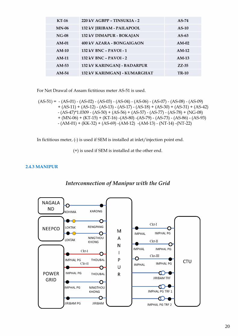
For Net Drawal of Assam fictitious meter AS-51 is used.
(AS-51) = - (AS-01) - (AS-02) - (AS-03) - (AS-04) - (AS-06) - (AS-07) - (AS-08) - (AS-09) + (AS-11) + (AS-12) - (AS-13) - (AS-17) - (AS-18) + (AS-30) + (AS-31) + (AS-42) - (AS-47)*1.0309 - (AS-50) + (AS-56) + (AS-57) - (AS-77) - (AS-78) + (NG-08) + (MN-06) + (KT-15) + (KT-16) -(AS-80) -(AS-79) - (AS-73) - (AS-86) - (AS-93) - (AM-01) + (KK-32) + (AS-69) -(AM-12) -(AM-13) - (NT-14) -(NT-22) In fictitious meter, (-) is used if SEM is installed at inlet/injection point end. (+) is used if SEM is installed at the other end.
2.4.3 MANIPUR
Interconnection of Manipur with the Grid
21
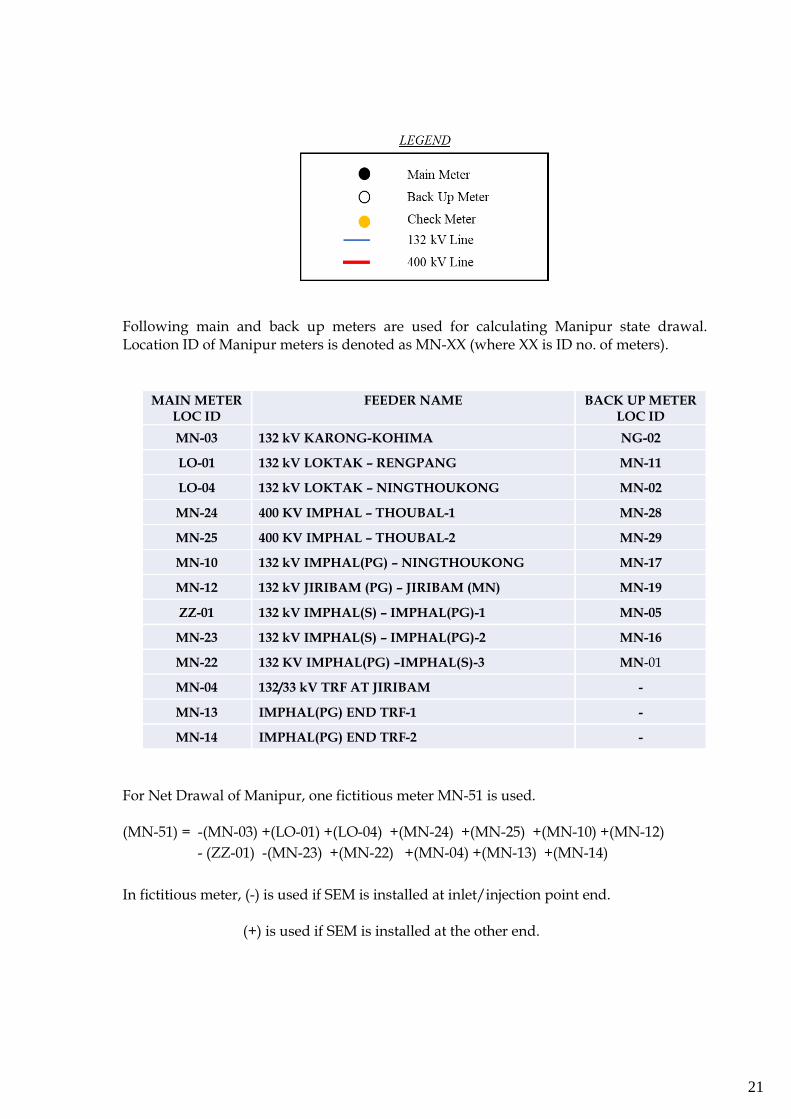
Following main and back up meters are used for calculating Manipur state drawal. Location ID of Manipur meters is denoted as MN-XX (where XX is ID no. of meters).
MAIN METER LOC ID
FEEDER NAME BACK UP METER LOC ID
MN-03 132 kV KARONG-KOHIMA NG-02
LO-01 132 kV LOKTAK – RENGPANG MN-11
LO-04 132 kV LOKTAK – NINGTHOUKONG MN-02
MN-24 400 KV IMPHAL – THOUBAL-1 MN-28
MN-25 400 KV IMPHAL – THOUBAL-2 MN-29
MN-10 132 kV IMPHAL(PG) – NINGTHOUKONG MN-17
MN-12 132 kV JIRIBAM (PG) – JIRIBAM (MN) MN-19
ZZ-01 132 kV IMPHAL(S) – IMPHAL(PG)-1 MN-05
MN-23 132 kV IMPHAL(S) – IMPHAL(PG)-2 MN-16
MN-22 132 KV IMPHAL(PG) –IMPHAL(S)-3 MN-01
MN-04 132/33 kV TRF AT JIRIBAM -
MN-13 IMPHAL(PG) END TRF-1 -
MN-14 IMPHAL(PG) END TRF-2 -
For Net Drawal of Manipur, one fictitious meter MN-51 is used.
(MN-51) = -(MN-03) +(LO-01) +(LO-04) +(MN-24) +(MN-25) +(MN-10) +(MN-12)
- (ZZ-01) -(MN-23) +(MN-22) +(MN-04) +(MN-13) +(MN-14)
In fictitious meter, (-) is used if SEM is installed at inlet/injection point end. (+) is used if SEM is installed at the other end.
22
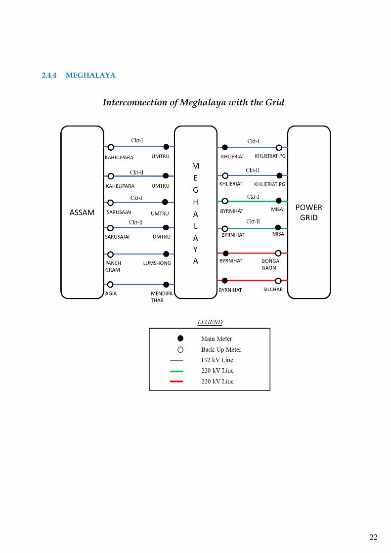
2.4.4 MEGHALAYA
Interconnection of Meghalaya with the Grid
23
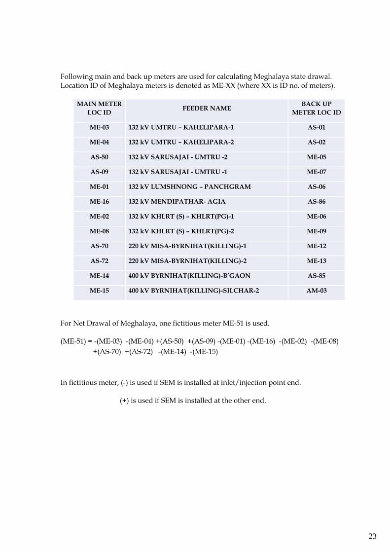
Following main and back up meters are used for calculating Meghalaya state drawal. Location ID of Meghalaya meters is denoted as ME-XX (where XX is ID no. of meters).
MAIN METER
LOC ID FEEDER NAME
BACK UP
METER LOC ID
ME-03 132 kV UMTRU – KAHELIPARA-1 AS-01
ME-04 132 kV UMTRU – KAHELIPARA-2 AS-02
AS-50 132 kV SARUSAJAI - UMTRU -2 ME-05
AS-09 132 kV SARUSAJAI - UMTRU -1 ME-07
ME-01 132 kV LUMSHNONG – PANCHGRAM AS-06
ME-16 132 kV MENDIPATHAR- AGIA AS-86
ME-02 132 kV KHLRT (S) – KHLRT(PG)-1 ME-06
ME-08 132 kV KHLRT (S) – KHLRT(PG)-2 ME-09
AS-70 220 kV MISA-BYRNIHAT(KILLING)-1 ME-12
AS-72 220 kV MISA-BYRNIHAT(KILLING)-2 ME-13
ME-14 400 kV BYRNIHAT(KILLING)-B’GAON AS-85
ME-15 400 kV BYRNIHAT(KILLING)-SILCHAR-2 AM-03
For Net Drawal of Meghalaya, one fictitious meter ME-51 is used. (ME-51) = -(ME-03) -(ME-04) +(AS-50) +(AS-09) -(ME-01) -(ME-16) -(ME-02) -(ME-08)
+(AS-70) +(AS-72) -(ME-14) -(ME-15)
In fictitious meter, (-) is used if SEM is installed at inlet/injection point end. (+) is used if SEM is installed at the other end.
24
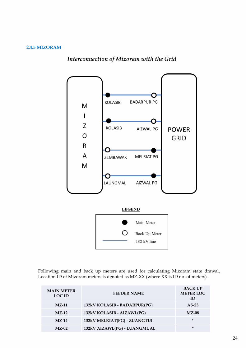
2.4.5 MIZORAM
Interconnection of Mizoram with the Grid
Following main and back up meters are used for calculating Mizoram state drawal. Location ID of Mizoram meters is denoted as MZ-XX (where XX is ID no. of meters).
MAIN METER LOC ID
FEEDER NAME BACK UP
METER LOC ID
MZ-11 132kV KOLASIB - BADARPUR(PG) AS-23
MZ-12 132kV KOLASIB - AIZAWL(PG) MZ-08
MZ-14 132kV MELRIAT(PG) - ZUANGTUI *
MZ-02 132kV AIZAWL(PG) - LUANGMUAL *
25
For Net Drawal of of Mizoram, one fictitious meter MZ-51 is used. (MZ-51) = - (MZ-11) - (MZ-12) + (MZ-14) + (MZ-02) In fictitious meter, (-) is used if SEM is installed at inlet/injection point end. (+) is used if SEM is installed at the other end.
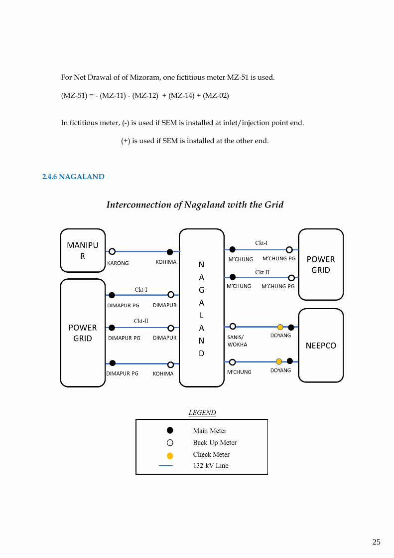
2.4.6 NAGALAND
Interconnection of Nagaland with the Grid
26
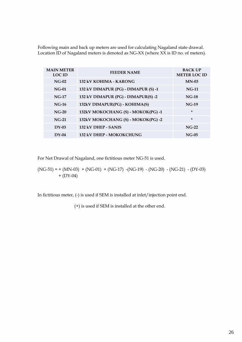
Following main and back up meters are used for calculating Nagaland state drawal. Location ID of Nagaland meters is denoted as NG-XX (where XX is ID no. of meters).
MAIN METER LOC ID
FEEDER NAME BACK UP
METER LOC ID
NG-02 132 kV KOHIMA - KARONG MN-03
NG-01 132 kV DIMAPUR (PG) - DIMAPUR (S) -1 NG-11
NG-17 132 kV DIMAPUR (PG) - DIMAPUR(S) -2 NG-18
NG-16 132kV DIMAPUR(PG) - KOHIMA(S) NG-19
NG-20 132kV MOKOCHANG (S) - MOKOK(PG) -1 *
NG-21 132kV MOKOCHANG (S) - MOKOK(PG) -2 *
DY-03 132 kV DHEP - SANIS NG-22
DY-04 132 kV DHEP - MOKOKCHUNG NG-05
For Net Drawal of Nagaland, one fictitious meter NG-51 is used.
(NG-51) = + (MN-03) + (NG-01) + (NG-17) -(NG-19) - (NG-20) - (NG-21) - (DY-03)
+ (DY-04)
In fictitious meter, (-) is used if SEM is installed at inlet/injection point end. (+) is used if SEM is installed at the other end.
27
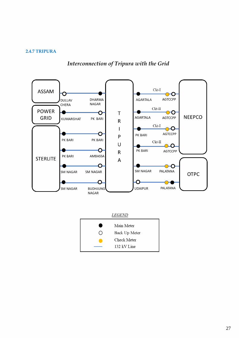
2.4.7 TRIPURA
Interconnection of Tripura with the Grid
28
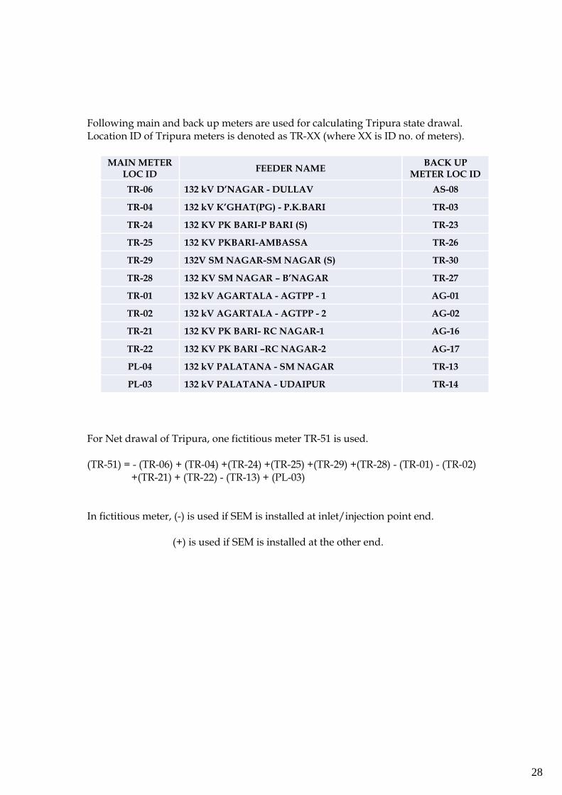
Following main and back up meters are used for calculating Tripura state drawal. Location ID of Tripura meters is denoted as TR-XX (where XX is ID no. of meters).
MAIN METER LOC ID
FEEDER NAME BACK UP
METER LOC ID
TR-06 132 kV D’NAGAR - DULLAV AS-08
TR-04 132 kV K’GHAT(PG) - P.K.BARI TR-03
TR-24 132 KV PK BARI-P BARI (S) TR-23
TR-25 132 KV PKBARI-AMBASSA TR-26
TR-29 132V SM NAGAR-SM NAGAR (S) TR-30
TR-28 132 KV SM NAGAR – B’NAGAR TR-27
TR-01 132 kV AGARTALA - AGTPP - 1 AG-01
TR-02 132 kV AGARTALA - AGTPP - 2 AG-02
TR-21 132 KV PK BARI- RC NAGAR-1 AG-16
TR-22 132 KV PK BARI –RC NAGAR-2 AG-17
PL-04 132 kV PALATANA - SM NAGAR TR-13
PL-03 132 kV PALATANA - UDAIPUR TR-14
For Net drawal of Tripura, one fictitious meter TR-51 is used. (TR-51) = - (TR-06) + (TR-04) +(TR-24) +(TR-25) +(TR-29) +(TR-28) - (TR-01) - (TR-02) +(TR-21) + (TR-22) - (TR-13) + (PL-03) In fictitious meter, (-) is used if SEM is installed at inlet/injection point end. (+) is used if SEM is installed at the other end.
29
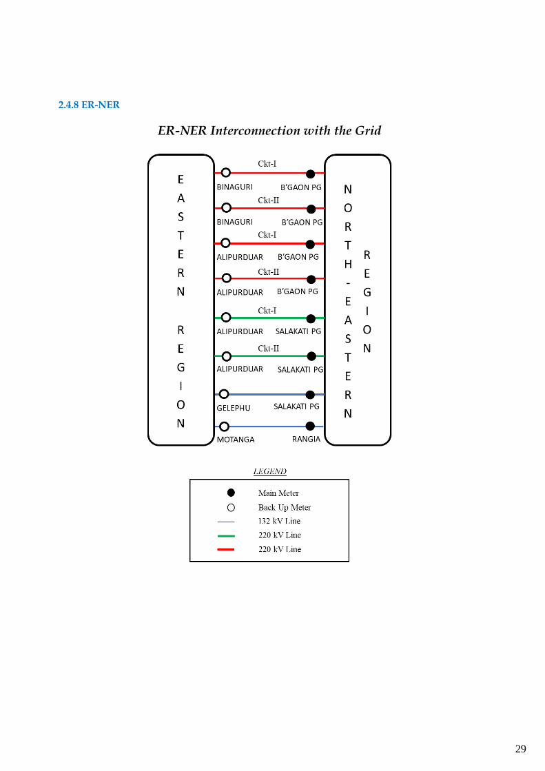
2.4.8 ER-NER
ER-NER Interconnection with the Grid
30
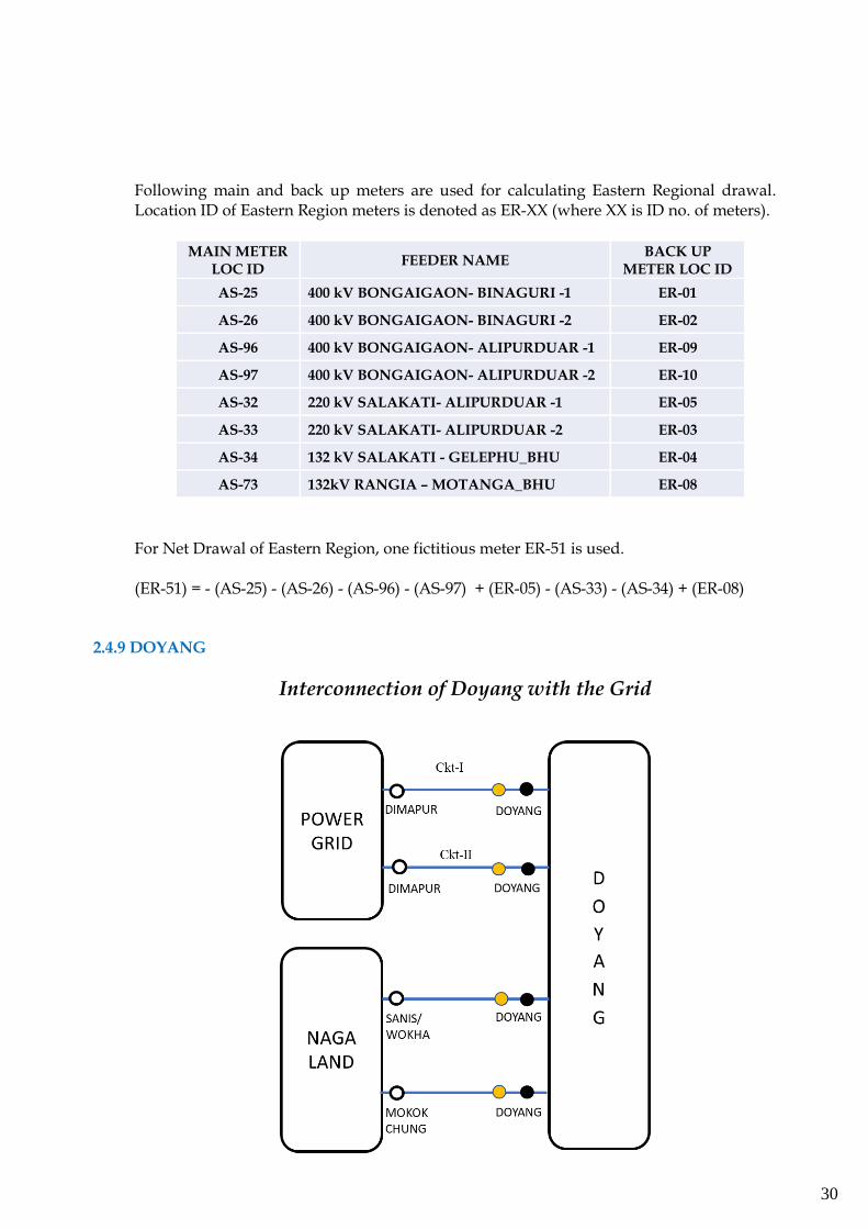
Following main and back up meters are used for calculating Eastern Regional drawal. Location ID of Eastern Region meters is denoted as ER-XX (where XX is ID no. of meters).
MAIN METER LOC ID
FEEDER NAME BACK UP
METER LOC ID
AS-25 400 kV BONGAIGAON- BINAGURI -1 ER-01
AS-26 400 kV BONGAIGAON- BINAGURI -2 ER-02
AS-96 400 kV BONGAIGAON- ALIPURDUAR -1 ER-09
AS-97 400 kV BONGAIGAON- ALIPURDUAR -2 ER-10
AS-32 220 kV SALAKATI- ALIPURDUAR -1 ER-05
AS-33 220 kV SALAKATI- ALIPURDUAR -2 ER-03
AS-34 132 kV SALAKATI - GELEPHU_BHU ER-04
AS-73 132kV RANGIA – MOTANGA_BHU ER-08
For Net Drawal of Eastern Region, one fictitious meter ER-51 is used. (ER-51) = - (AS-25) - (AS-26) - (AS-96) - (AS-97) + (ER-05) - (AS-33) - (AS-34) + (ER-08)
2.4.9 DOYANG
Interconnection of Doyang with the Grid
31
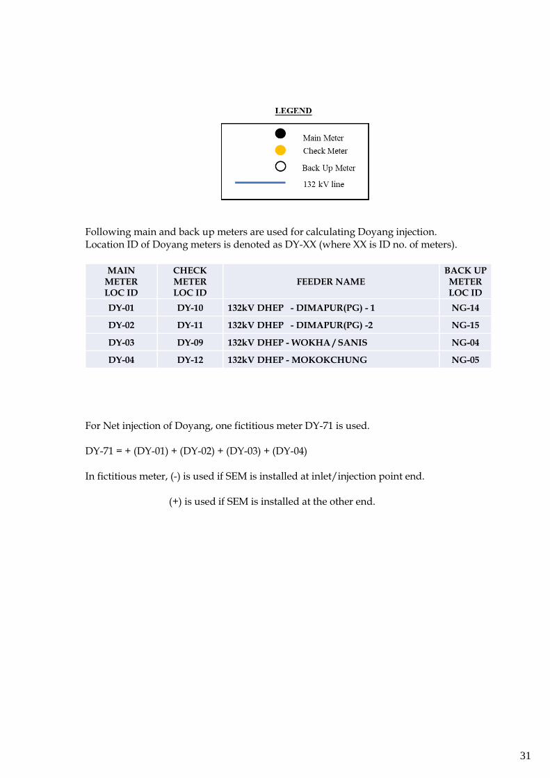
Following main and back up meters are used for calculating Doyang injection. Location ID of Doyang meters is denoted as DY-XX (where XX is ID no. of meters).
MAIN METER LOC ID
CHECK METER LOC ID
FEEDER NAME BACK UP METER LOC ID
DY-01 DY-10 132kV DHEP - DIMAPUR(PG) - 1 NG-14
DY-02 DY-11 132kV DHEP - DIMAPUR(PG) -2 NG-15
DY-03 DY-09 132kV DHEP - WOKHA / SANIS NG-04
DY-04 DY-12 132kV DHEP - MOKOKCHUNG NG-05
For Net injection of Doyang, one fictitious meter DY-71 is used. DY-71 = + (DY-01) + (DY-02) + (DY-03) + (DY-04) In fictitious meter, (-) is used if SEM is installed at inlet/injection point end. (+) is used if SEM is installed at the other end.
32
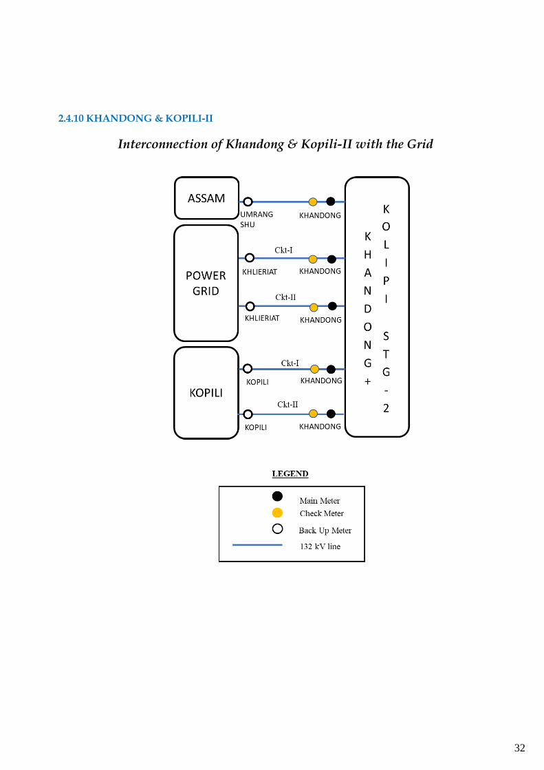
2.4.10 KHANDONG & KOPILI-II
Interconnection of Khandong & Kopili-II with the Grid
33
Following main and back up meters are used for calculating Khandong and Kopili-II injection. Location ID of Khandong and Kopili-II meters is denoted as KD-XX (where XX is ID no. of meters).
MAIN METER LOC ID
CHECK METER LOC ID
FEEDER NAME STAND-
BY METER LOC ID
KK-01 KK-32 132kV KHANDONG - UMRANGSHU
KK-02 KK-31 132kV KHANDONG - KHLRT - 1 ME-10
KK-03 KK-30 132kV KHANDONG - KHLRT - 2 ME-11
KK-04 KK-33 132kV KHANDONG - KOPILI -1 KK-08
KK-22 KK-29 132kV KHANDONG - KOPILI-2 KK-21
KK-17 KK-34 KOPILI GT OF STG-2
KK-19 KK-35 KOPILI STG-2 33 kV STN TRF
For Net injection of Khandong, one fictitious meter KD-71 is used. (KD-71) = + (KK-29) + (KK-30) + (KK-31) + (KK-32) + (KK-33) Net injection of Kopili-II is the summation of (KK-34) & (KK-35). Kopili-2 injection = + (KK-34) - (KK-35) In fictitious meter, (-) is used if SEM is installed at inlet/injection point end. (+) is used if SEM is installed at the other end.
34
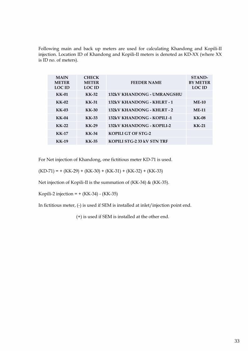
2.4.11 KOPILI
Interconnection of Kopili with the Grid
Following main and back up meters are used for calculating Kopili injection. Location ID of Kopili meters is denoted as KK-XX (where XX is ID no. of meters).
MAIN
METER
LOC ID
CHECK
METER
LOC ID
FEEDER NAME
BACK UP
METER
LOC ID
KK-05 KK-24 220 kV KOPILI-MISA-1 AS-66
KK-06 KK-25 220 kV KOPILI-MISA-2 AS-67
KK-07 KK-26 220 kV KOPILI-MISA-3 AS-68
KK-08 KK-27 220 kV KOPILI-KHANDONG-1 KK-04
35
KK-21 KK-28 220 kV KOPILI-KHANDONG-2 KK-22
For Net injection of Kopili, one fictitious meter KP-71 is used. (KP-71) = + (KK-05) + (KK-06) + (KK-07) + (KK-08) + (KK-21) In fictitious meter, (-) is used if SEM is installed at inlet/injection point end. (+) is used if SEM is installed at the other end.
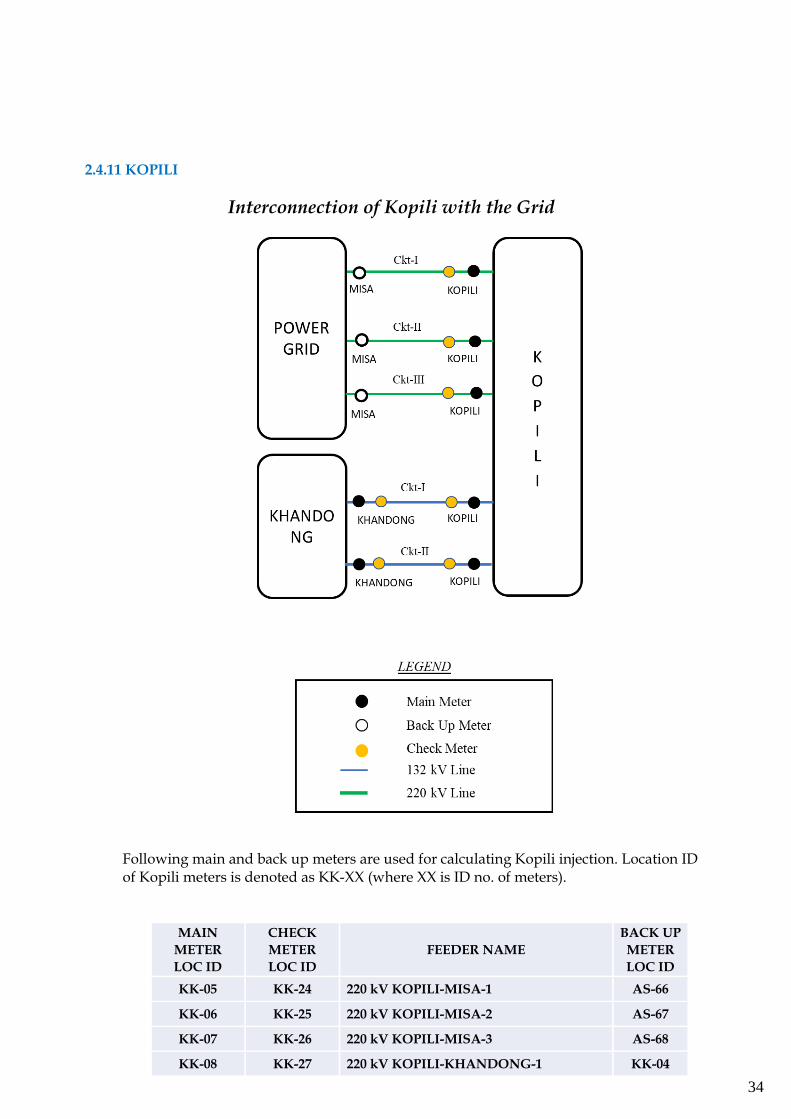
2.4.12 AGBPP (KATHALGURI)
Interconnection of AGBPP (Kathalguri) with the Grid
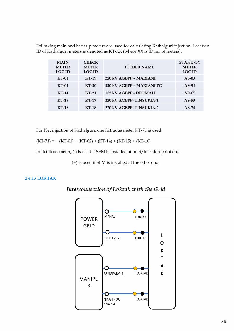
36
Following main and back up meters are used for calculating Kathalguri injection. Location ID of Kathalguri meters is denoted as KT-XX (where XX is ID no. of meters).
MAIN METER LOC ID
CHECK METER LOC ID
FEEDER NAME STAND-BY
METER LOC ID
KT-01 KT-19 220 kV AGBPP – MARIANI AS-03
KT-02 KT-20 220 kV AGBPP – MARIANI PG AS-94
KT-14 KT-21 132 kV AGBPP - DEOMALI AR-07
KT-15 KT-17 220 kV AGBPP- TINSUKIA-1 AS-53
KT-16 KT-18 220 kV AGBPP- TINSUKIA-2 AS-74
For Net injection of Kathalguri, one fictitious meter KT-71 is used. (KT-71) = + (KT-01) + (KT-02) + (KT-14) + (KT-15) + (KT-16) In fictitious meter, (-) is used if SEM is installed at inlet/injection point end. (+) is used if SEM is installed at the other end.
2.4.13 LOKTAK
Interconnection of Loktak with the Grid
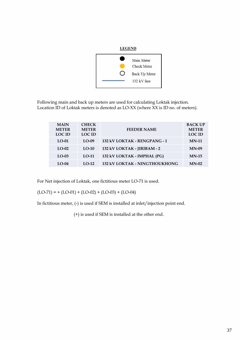
37
Following main and back up meters are used for calculating Loktak injection. Location ID of Loktak meters is denoted as LO-XX (where XX is ID no. of meters).
MAIN METER LOC ID
CHECK METER LOC ID
FEEDER NAME BACK UP METER LOC ID
LO-01 LO-09 132 kV LOKTAK - RENGPANG - 1 MN-11
LO-02 LO-10 132 kV LOKTAK - JIRIBAM - 2 MN-09
LO-03 LO-11 132 kV LOKTAK - IMPHAL (PG) MN-15
LO-04 LO-12 132 kV LOKTAK - NINGTHOUKHONG MN-02
For Net injection of Loktak, one fictitious meter LO-71 is used. (LO-71) = + (LO-01) + (LO-02) + (LO-03) + (LO-04) In fictitious meter, (-) is used if SEM is installed at inlet/injection point end. (+) is used if SEM is installed at the other end.
38
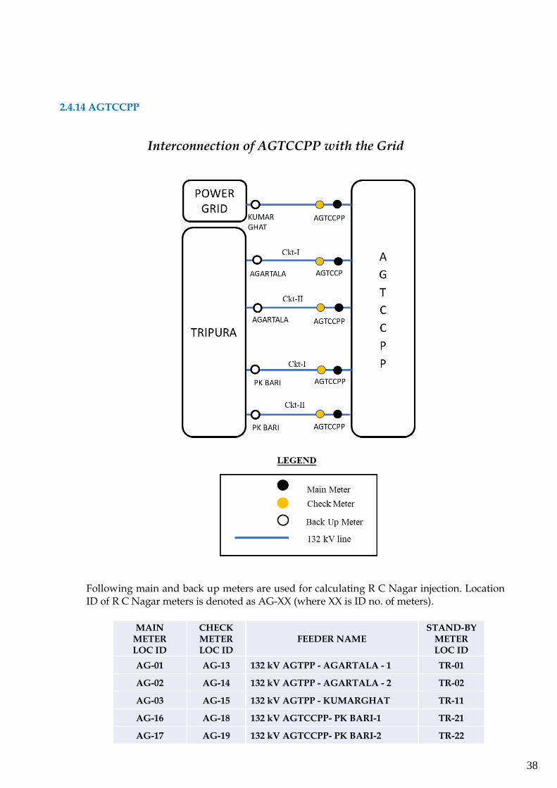
2.4.14 AGTCCPP
Interconnection of AGTCCPP with the Grid
Following main and back up meters are used for calculating R C Nagar injection. Location ID of R C Nagar meters is denoted as AG-XX (where XX is ID no. of meters).
MAIN METER LOC ID
CHECK METER LOC ID
FEEDER NAME STAND-BY
METER LOC ID
AG-01 AG-13 132 kV AGTPP - AGARTALA - 1 TR-01
AG-02 AG-14 132 kV AGTPP - AGARTALA - 2 TR-02
AG-03 AG-15 132 kV AGTPP - KUMARGHAT TR-11
AG-16 AG-18 132 kV AGTCCPP- PK BARI-1 TR-21
AG-17 AG-19 132 kV AGTCCPP- PK BARI-2 TR-22
39
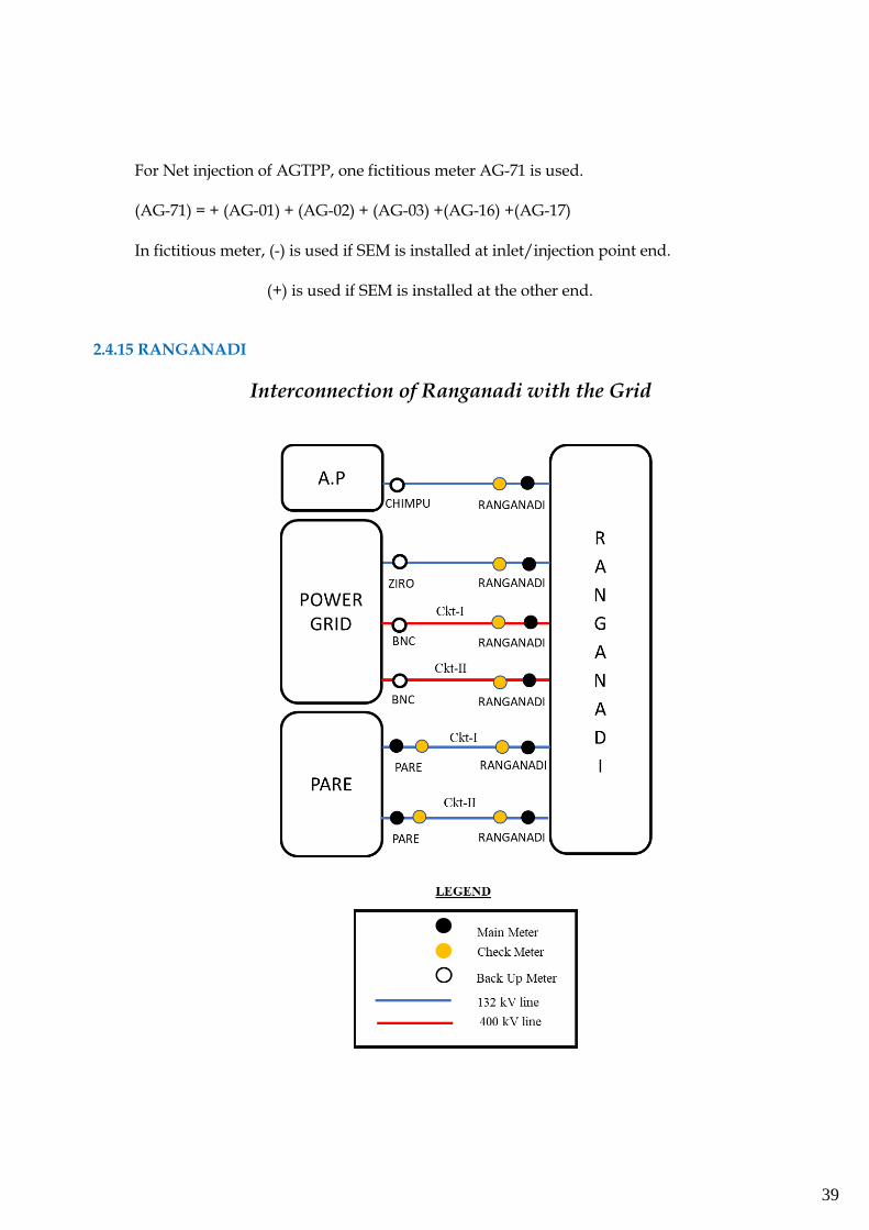
For Net injection of AGTPP, one fictitious meter AG-71 is used. (AG-71) = + (AG-01) + (AG-02) + (AG-03) +(AG-16) +(AG-17) In fictitious meter, (-) is used if SEM is installed at inlet/injection point end. (+) is used if SEM is installed at the other end.
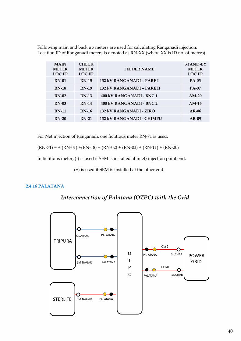
2.4.15 RANGANADI
Interconnection of Ranganadi with the Grid
40
Following main and back up meters are used for calculating Ranganadi injection. Location ID of Ranganadi meters is denoted as RN-XX (where XX is ID no. of meters).
MAIN METER LOC ID
CHECK METER LOC ID
FEEDER NAME STAND-BY
METER LOC ID
RN-01 RN-15 132 kV RANGANADI – PARE I PA-03
RN-18 RN-19 132 kV RANGANADI – PARE II PA-07
RN-02 RN-13 400 kV RANGANADI - BNC 1 AM-20
RN-03 RN-14 400 kV RANGANADI - BNC 2 AM-16
RN-11 RN-16 132 kV RANGANADI - ZIRO AR-06
RN-20 RN-21 132 kV RANGANADI - CHIMPU AR-09
For Net injection of Ranganadi, one fictitious meter RN-71 is used.
(RN-71) = + (RN-01) +(RN-18) + (RN-02) + (RN-03) + (RN-11) + (RN-20) In fictitious meter, (-) is used if SEM is installed at inlet/injection point end. (+) is used if SEM is installed at the other end.
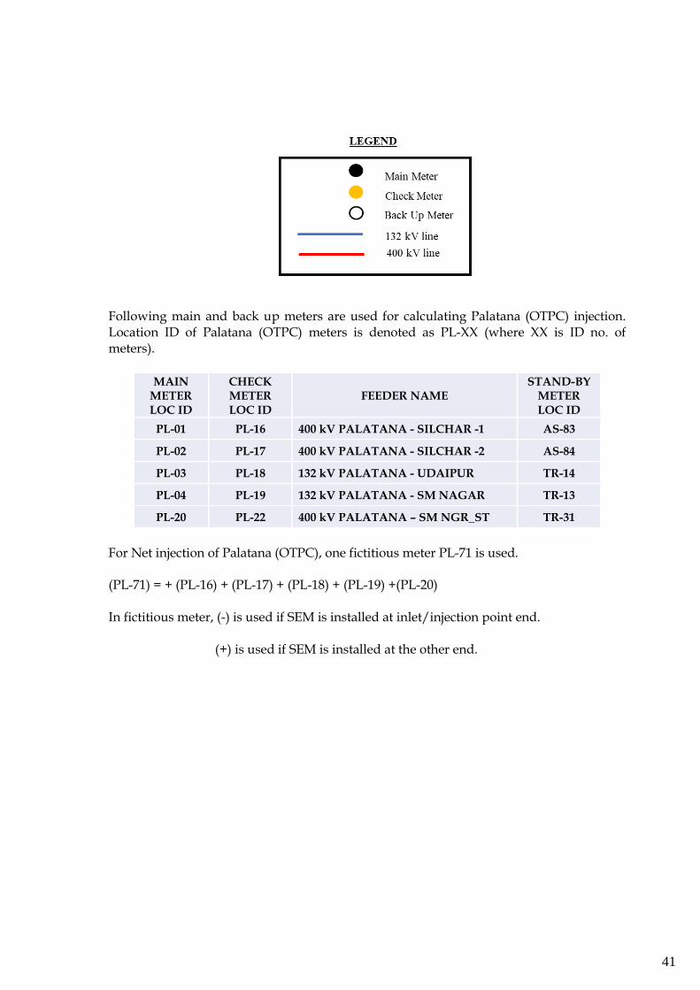
2.4.16 PALATANA
Interconnection of Palatana (OTPC) with the Grid
41
Following main and back up meters are used for calculating Palatana (OTPC) injection. Location ID of Palatana (OTPC) meters is denoted as PL-XX (where XX is ID no. of meters).
MAIN METER LOC ID
CHECK METER LOC ID
FEEDER NAME STAND-BY
METER LOC ID
PL-01 PL-16 400 kV PALATANA - SILCHAR -1 AS-83
PL-02 PL-17 400 kV PALATANA - SILCHAR -2 AS-84
PL-03 PL-18 132 kV PALATANA - UDAIPUR TR-14
PL-04 PL-19 132 kV PALATANA - SM NAGAR TR-13
PL-20 PL-22 400 kV PALATANA – SM NGR_ST TR-31
For Net injection of Palatana (OTPC), one fictitious meter PL-71 is used. (PL-71) = + (PL-16) + (PL-17) + (PL-18) + (PL-19) +(PL-20) In fictitious meter, (-) is used if SEM is installed at inlet/injection point end. (+) is used if SEM is installed at the other end.
42
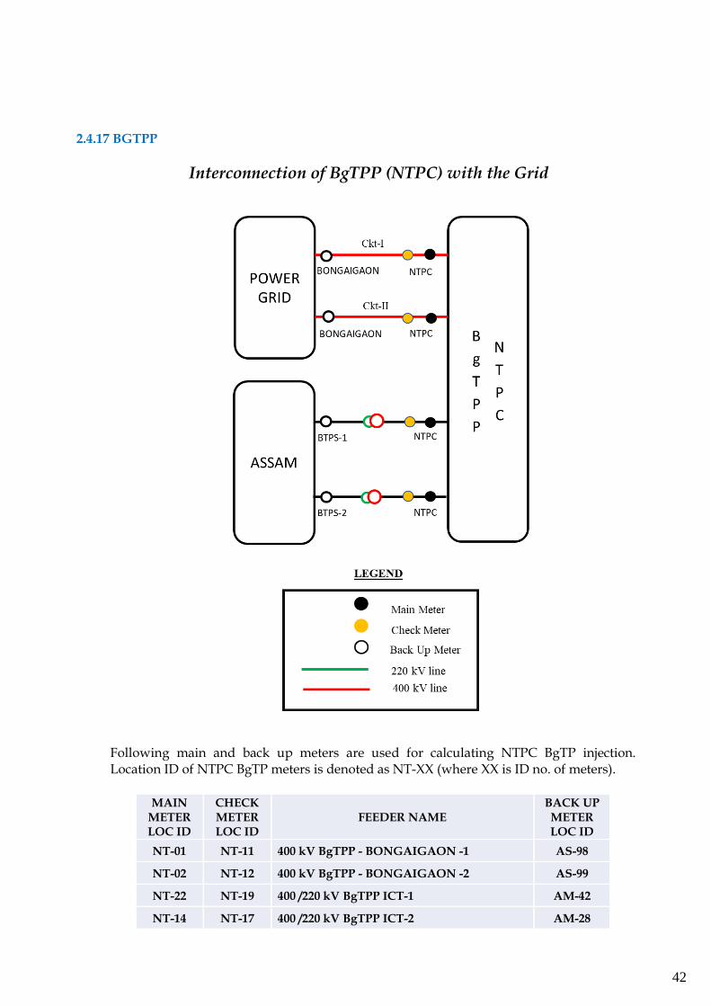
2.4.17 BGTPP
Interconnection of BgTPP (NTPC) with the Grid
Following main and back up meters are used for calculating NTPC BgTP injection. Location ID of NTPC BgTP meters is denoted as NT-XX (where XX is ID no. of meters).
MAIN METER LOC ID
CHECK METER LOC ID
FEEDER NAME BACK UP METER LOC ID
NT-01 NT-11 400 kV BgTPP - BONGAIGAON -1 AS-98
NT-02 NT-12 400 kV BgTPP - BONGAIGAON -2 AS-99
NT-22 NT-19 400 /220 kV BgTPP ICT-1 AM-42
NT-14 NT-17 400 /220 kV BgTPP ICT-2 AM-28
43
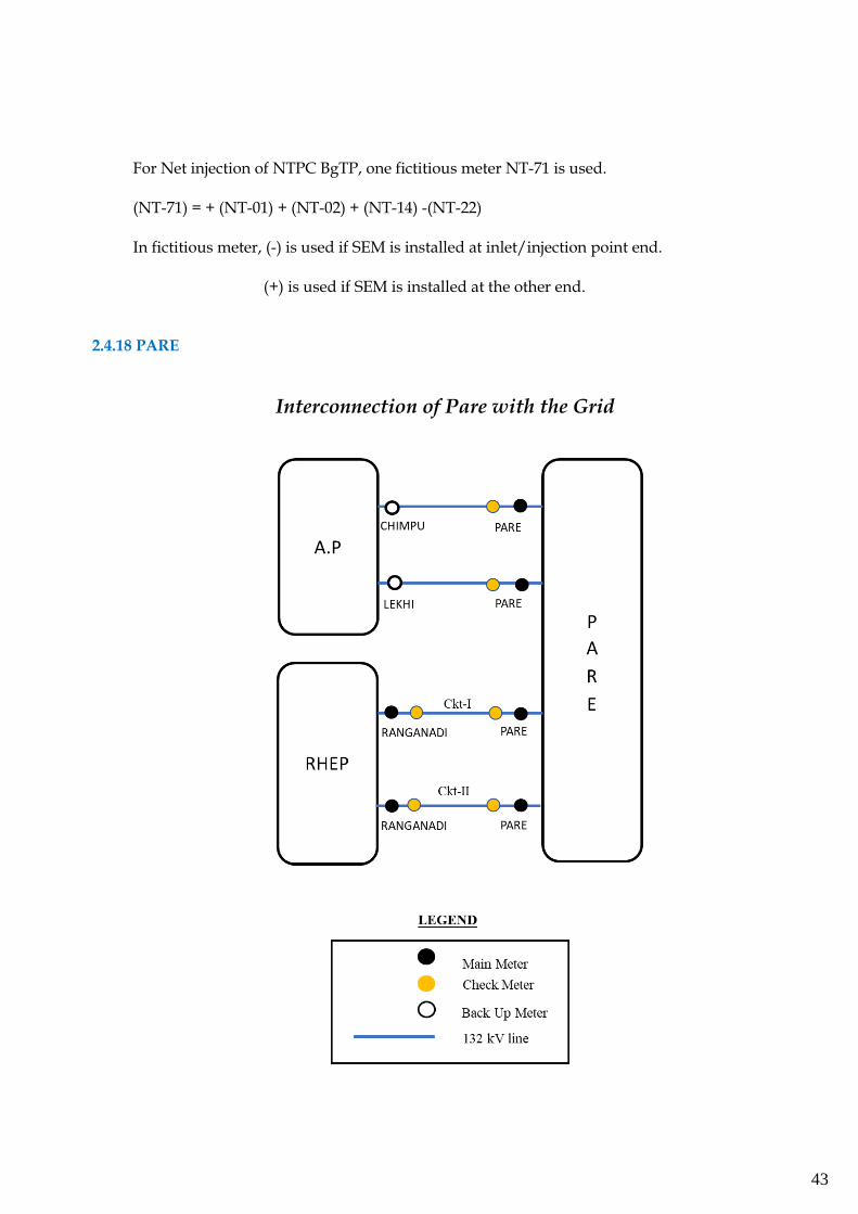
For Net injection of NTPC BgTP, one fictitious meter NT-71 is used. (NT-71) = + (NT-01) + (NT-02) + (NT-14) -(NT-22) In fictitious meter, (-) is used if SEM is installed at inlet/injection point end. (+) is used if SEM is installed at the other end.
2.4.18 PARE
Interconnection of Pare with the Grid

44
Following main and stand-by meters are used for calculating Pare injection. Location ID of Pare meters is denoted as PA-XX (where XX is ID no. of meters).
MAIN METER LOC ID
CHECK METER LOC ID
FEEDER NAME STAND-
BY METER LOC ID
PA-01 PA-02 132 kV PARE - LEKHI AR-05
PA-05 PA-06 132 kV PARE - CHIMPHU AR-08
PA-03 PA-04 132 kV PARE – RANGANADI-1 RN-01
PA-07 PA-08 132 kV PARE – RANGANADI-2 RN-18
For Net injection of Pare, one fictitious meter PA-71 is used. (PA-71) = + (PA-01) + (PA-03) + (PA-05) + (PA-07) In fictitious meter, (-) is used if SEM is installed at inlet/injection point end. (+) is used if SEM is installed at the other end.
2.4.19 KAMENG
Interconnection of Kameng with the Grid
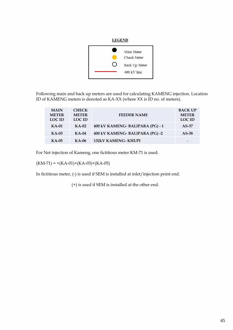
45
Following main and back up meters are used for calculating KAMENG injection. Location ID of KAMENG meters is denoted as KA-XX (where XX is ID no. of meters).
MAIN METER LOC ID
CHECK METER LOC ID
FEEDER NAME BACK UP METER LOC ID
KA-01 KA-02 400 kV KAMENG- BALIPARA (PG) - 1 AS-37
KA-03 KA-04 400 kV KAMENG- BALIPARA (PG) -2 AS-38
KA-05 KA-06 132kV KAMENG- KHUPI -
For Net injection of Kameng, one fictitious meter KM-71 is used.
(KM-71) = +(KA-01)+(KA-03)+(KA-05) In fictitious meter, (-) is used if SEM is installed at inlet/injection point end. (+) is used if SEM is installed at the other end.
46
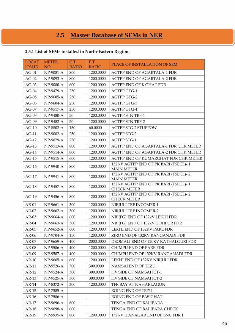
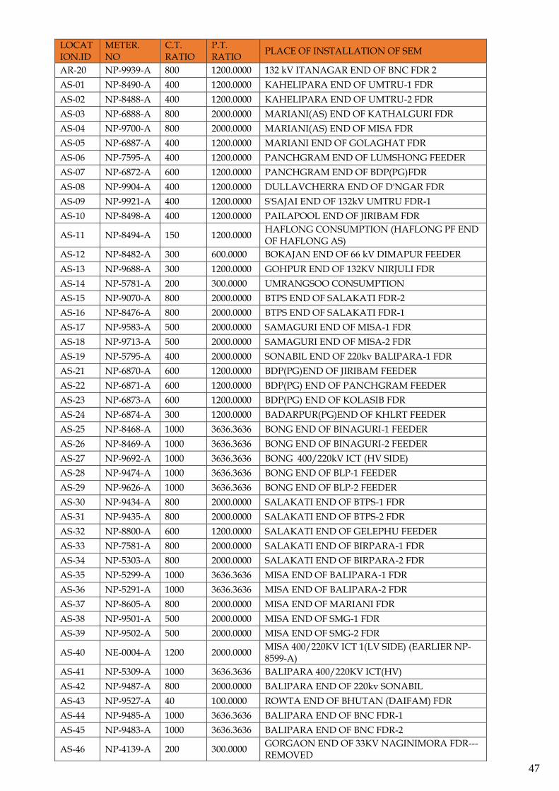
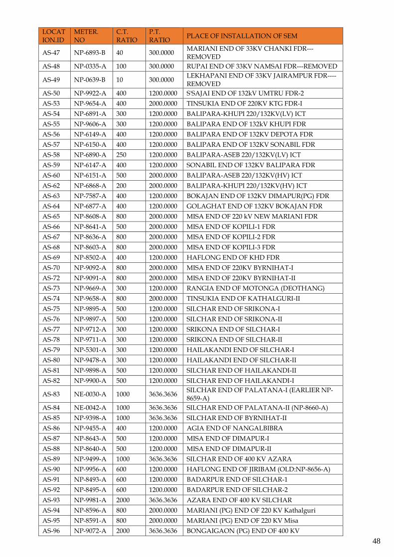
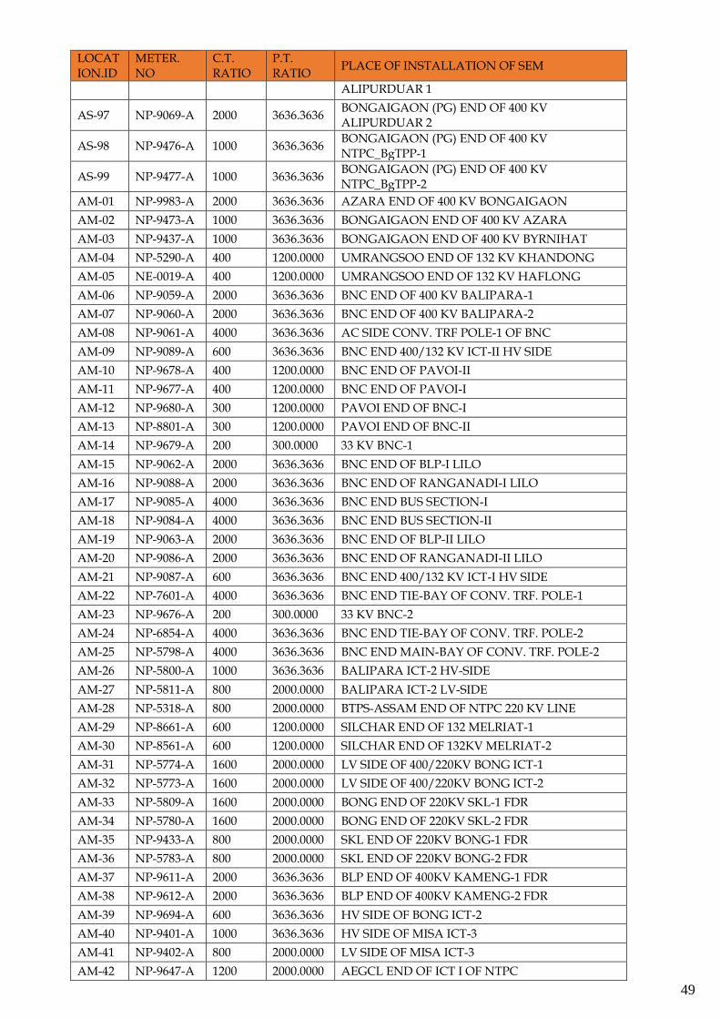
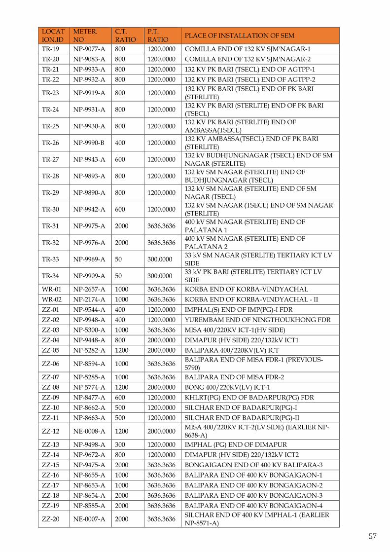
2.5.1 List of SEMs installed in North-Eastern Region: LOCATION.ID
METER. NO
C.T. RATIO
P.T. RATIO
PLACE OF INSTALLATION OF SEM
AG-01 NP-9081-A 800 1200.0000 AGTPP END OF AGARTALA-1 FDR
AG-02 NP-9093-A 800 1200.0000 AGTPP END OF AGARTALA-2 FDR
AG-03 NP-9080-A 600 1200.0000 AGTPP END OF K'GHAT FDR
AG-04 NP-9479-A 250 1200.0000 AGTPP GTG-1
AG-05 NP-9605-A 250 1200.0000 AGTPP GTG-2
AG-06 NP-9604-A 250 1200.0000 AGTPP GTG-3
AG-07 NP-9517-A 250 1200.0000 AGTPP GTG-4
AG-08 NP-9480-A 50 1200.0000 AGTPP STN TRF-1
AG-09 NP-9482-A 50 1200.0000 AGTPP STN TRF-2
AG-10 NP-8802-A 150 60.0000 AGTPP STG-2 STUPPOW
AG-11 NP-9082-A 250 1200.0000 AGTPP STG-2
AG-12 NP-9079-A 250 1200.0000 AGTPP STG-1
AG-13 NP-9513-A 800 1200.0000 AGTPP END OF AGARTALA-1 FDR CHK METER
AG-14 NP-9514-A 800 1200.0000 AGTPP END OF AGARTALA-2 FDR CHK METER
AG-15 NP-9515-A 600 1200.0000 AGTPP END OF KUMARGHAT FDR CHK METER
AG-16 NP-9940-A 800 1200.0000 132 kV AGTPP END OF PK BARI (TSECL)- 1 MAIN METER
AG-17 NP-9941-A 800 1200.0000 132 kV AGTPP END OF PK BARI (TSECL)- 2 MAIN METER
AG-18 NP-9457-A 800 1200.0000 132 kV AGTPP END OF PK BARI (TSECL)- 1 CHECK METER
AG-19 NP-9456-A 800 1200.0000 132 kV AGTPP END OF PK BARI (TSECL)- 2 CHECK METER
AR-01 NP-9661-A 300 1200.0000 NIRJULI TRF INCOMER-1
AR-02 NP-9662-A 300 1200.0000 NIRJULI TRF INCOMER-2
AR-03 NP-9664-A 600 1200.0000 NRJ(PG) END OF 132kV LEKHI FDR
AR-04 NP-9663-A 300 1200.0000 NRJ(PG) END OF 132kV GOHPUR FDR
AR-05 NP-9652-A 600 1200.0000 LEKHI END OF 132KV PARE FDR
AR-06 NP-9704-A 150 1200.0000 ZIRO END OF 132KV RANGANADI FDR
AR-07 NP-9659-A 400 2000.0000 DEOMALI END OF 220KV KATHALGURI FDR
AR-08 NP-9586-A 400 1200.0000 CHIMPU END OF PARE FDR
AR-09 NP-9587-A 400 1200.0000 CHIMPU END OF 132KV RANGANADI FDR
AR-10 NP-9665-A 600 1200.0000 LEKHI END OF 132KV NIRJULI FDR
AR-11 NP-9526-A 300 300.0000 NAMSAI END OF TEZU
AR-12 NP-9524-A 300 300.0000 HV SIDE OF NAMSAI ICT-1
AR-13 NP-9525-A 300 300.0000 HV SIDE OF NAMSAI ICT-2
AR-14 NP-8372-A 300 1200.0000 TFR BAY AT NAHARLAGUN
AR-15 NP-7585-A ROING END OF TEZU
AR-16 NP-7586-A ROING END OF PASIGHAT
AR-17 NP-9696-A 600 TENGA END OF BALIPARA
AR-18 NP-9698-A 600 TENGA END OF BALIPARA CHECK
AR-19 NP-9935-A 800 1200.0000 132 kV ITANAGAR END OF BNC FDR 1
2.5 Master Database of SEMs in NER
47
LOCATION.ID
METER. NO
C.T. RATIO
P.T. RATIO
PLACE OF INSTALLATION OF SEM
AR-20 NP-9939-A 800 1200.0000 132 kV ITANAGAR END OF BNC FDR 2
AS-01 NP-8490-A 400 1200.0000 KAHELIPARA END OF UMTRU-1 FDR
AS-02 NP-8488-A 400 1200.0000 KAHELIPARA END OF UMTRU-2 FDR
AS-03 NP-6888-A 800 2000.0000 MARIANI(AS) END OF KATHALGURI FDR
AS-04 NP-9700-A 800 2000.0000 MARIANI(AS) END OF MISA FDR
AS-05 NP-6887-A 400 1200.0000 MARIANI END OF GOLAGHAT FDR
AS-06 NP-7595-A 400 1200.0000 PANCHGRAM END OF LUMSHONG FEEDER
AS-07 NP-6872-A 600 1200.0000 PANCHGRAM END OF BDP(PG)FDR
AS-08 NP-9904-A 400 1200.0000 DULLAVCHERRA END OF D'NGAR FDR
AS-09 NP-9921-A 400 1200.0000 S'SAJAI END OF 132kV UMTRU FDR-1
AS-10 NP-8498-A 400 1200.0000 PAILAPOOL END OF JIRIBAM FDR
AS-11 NP-8494-A 150 1200.0000 HAFLONG CONSUMPTION (HAFLONG PF END OF HAFLONG AS)
AS-12 NP-8482-A 300 600.0000 BOKAJAN END OF 66 kV DIMAPUR FEEDER
AS-13 NP-9688-A 300 1200.0000 GOHPUR END OF 132KV NIRJULI FDR
AS-14 NP-5781-A 200 300.0000 UMRANGSOO CONSUMPTION
AS-15 NP-9070-A 800 2000.0000 BTPS END OF SALAKATI FDR-2
AS-16 NP-8476-A 800 2000.0000 BTPS END OF SALAKATI FDR-1
AS-17 NP-9583-A 500 2000.0000 SAMAGURI END OF MISA-1 FDR
AS-18 NP-9713-A 500 2000.0000 SAMAGURI END OF MISA-2 FDR
AS-19 NP-5795-A 400 2000.0000 SONABIL END OF 220kv BALIPARA-1 FDR
AS-21 NP-6870-A 600 1200.0000 BDP(PG)END OF JIRIBAM FEEDER
AS-22 NP-6871-A 600 1200.0000 BDP(PG) END OF PANCHGRAM FEEDER
AS-23 NP-6873-A 600 1200.0000 BDP(PG) END OF KOLASIB FDR
AS-24 NP-6874-A 300 1200.0000 BADARPUR(PG)END OF KHLRT FEEDER
AS-25 NP-8468-A 1000 3636.3636 BONG END OF BINAGURI-1 FEEDER
AS-26 NP-8469-A 1000 3636.3636 BONG END OF BINAGURI-2 FEEDER
AS-27 NP-9692-A 1000 3636.3636 BONG 400/220kV ICT (HV SIDE)
AS-28 NP-9474-A 1000 3636.3636 BONG END OF BLP-1 FEEDER
AS-29 NP-9626-A 1000 3636.3636 BONG END OF BLP-2 FEEDER
AS-30 NP-9434-A 800 2000.0000 SALAKATI END OF BTPS-1 FDR
AS-31 NP-9435-A 800 2000.0000 SALAKATI END OF BTPS-2 FDR
AS-32 NP-8800-A 600 1200.0000 SALAKATI END OF GELEPHU FEEDER
AS-33 NP-7581-A 800 2000.0000 SALAKATI END OF BIRPARA-1 FDR
AS-34 NP-5303-A 800 2000.0000 SALAKATI END OF BIRPARA-2 FDR
AS-35 NP-5299-A 1000 3636.3636 MISA END OF BALIPARA-1 FDR
AS-36 NP-5291-A 1000 3636.3636 MISA END OF BALIPARA-2 FDR
AS-37 NP-8605-A 800 2000.0000 MISA END OF MARIANI FDR
AS-38 NP-9501-A 500 2000.0000 MISA END OF SMG-1 FDR
AS-39 NP-9502-A 500 2000.0000 MISA END OF SMG-2 FDR
AS-40 NE-0004-A 1200 2000.0000 MISA 400/220KV ICT 1(LV SIDE) (EARLIER NP-8599-A)
AS-41 NP-5309-A 1000 3636.3636 BALIPARA 400/220KV ICT(HV)
AS-42 NP-9487-A 800 2000.0000 BALIPARA END OF 220kv SONABIL
AS-43 NP-9527-A 40 100.0000 ROWTA END OF BHUTAN (DAIFAM) FDR
AS-44 NP-9485-A 1000 3636.3636 BALIPARA END OF BNC FDR-1
AS-45 NP-9483-A 1000 3636.3636 BALIPARA END OF BNC FDR-2
AS-46 NP-4139-A 200 300.0000 GORGAON END OF 33KV NAGINIMORA FDR---REMOVED
48
LOCATION.ID
METER. NO
C.T. RATIO
P.T. RATIO
PLACE OF INSTALLATION OF SEM
AS-47 NP-6893-B 40 300.0000 MARIANI END OF 33KV CHANKI FDR---REMOVED
AS-48 NP-0335-A 100 300.0000 RUPAI END OF 33KV NAMSAI FDR---REMOVED
AS-49 NP-0639-B 10 300.0000 LEKHAPANI END OF 33KV JAIRAMPUR FDR----REMOVED
AS-50 NP-9922-A 400 1200.0000 S'SAJAI END OF 132kV UMTRU FDR-2
AS-53 NP-9654-A 400 2000.0000 TINSUKIA END OF 220KV KTG FDR-I
AS-54 NP-6891-A 300 1200.0000 BALIPARA-KHUPI 220/132KV(LV) ICT
AS-55 NP-9606-A 300 1200.0000 BALIPARA END OF 132kV KHUPI FDR
AS-56 NP-6149-A 400 1200.0000 BALIPARA END OF 132KV DEPOTA FDR
AS-57 NP-6150-A 400 1200.0000 BALIPARA END OF 132KV SONABIL FDR
AS-58 NP-6890-A 250 1200.0000 BALIPARA-ASEB 220/132KV(LV) ICT
AS-59 NP-6147-A 400 1200.0000 SONABIL END OF 132KV BALIPARA FDR
AS-60 NP-6151-A 500 2000.0000 BALIPARA-ASEB 220/132KV(HV) ICT
AS-62 NP-6868-A 200 2000.0000 BALIPARA-KHUPI 220/132KV(HV) ICT
AS-63 NP-7587-A 400 1200.0000 BOKAJAN END OF 132KV DIMAPUR(PG) FDR
AS-64 NP-6877-A 400 1200.0000 GOLAGHAT END OF 132KV BOKAJAN FDR
AS-65 NP-8608-A 800 2000.0000 MISA END OF 220 kV NEW MARIANI FDR
AS-66 NP-8641-A 500 2000.0000 MISA END OF KOPILI-1 FDR
AS-67 NP-8636-A 800 2000.0000 MISA END OF KOPILI-2 FDR
AS-68 NP-8603-A 800 2000.0000 MISA END OF KOPILI-3 FDR
AS-69 NP-8502-A 400 1200.0000 HAFLONG END OF KHD FDR
AS-70 NP-9092-A 800 2000.0000 MISA END OF 220KV BYRNIHAT-I
AS-72 NP-9091-A 800 2000.0000 MISA END OF 220KV BYRNIHAT-II
AS-73 NP-9669-A 300 1200.0000 RANGIA END OF MOTONGA (DEOTHANG)
AS-74 NP-9658-A 800 2000.0000 TINSUKIA END OF KATHALGURI-II
AS-75 NP-9895-A 500 1200.0000 SILCHAR END OF SRIKONA-I
AS-76 NP-9897-A 500 1200.0000 SILCHAR END OF SRIKONA-II
AS-77 NP-9712-A 300 1200.0000 SRIKONA END OF SILCHAR-I
AS-78 NP-9711-A 300 1200.0000 SRIKONA END OF SILCHAR-II
AS-79 NP-5301-A 300 1200.0000 HAILAKANDI END OF SILCHAR-I
AS-80 NP-9478-A 300 1200.0000 HAILAKANDI END OF SILCHAR-II
AS-81 NP-9898-A 500 1200.0000 SILCHAR END OF HAILAKANDI-II
AS-82 NP-9900-A 500 1200.0000 SILCHAR END OF HAILAKANDI-I
AS-83 NE-0030-A 1000 3636.3636 SILCHAR END OF PALATANA-I (EARLIER NP-8659-A)
AS-84 NE-0042-A 1000 3636.3636 SILCHAR END OF PALATANA-II (NP-8660-A)
AS-85 NP-9398-A 1000 3636.3636 SILCHAR END OF BYRNIHAT-II
AS-86 NP-9455-A 400 1200.0000 AGIA END OF NANGALBIBRA
AS-87 NP-8643-A 500 1200.0000 MISA END OF DIMAPUR-I
AS-88 NP-8640-A 500 1200.0000 MISA END OF DIMAPUR-II
AS-89 NP-9499-A 1000 3636.3636 SILCHAR END OF 400 KV AZARA
AS-90 NP-9956-A 600 1200.0000 HAFLONG END OF JIRIBAM (OLD:NP-8656-A)
AS-91 NP-8493-A 600 1200.0000 BADARPUR END OF SILCHAR-1
AS-92 NP-8495-A 600 1200.0000 BADARPUR END OF SILCHAR-2
AS-93 NP-9981-A 2000 3636.3636 AZARA END OF 400 KV SILCHAR
AS-94 NP-8596-A 800 2000.0000 MARIANI (PG) END OF 220 KV Kathalguri
AS-95 NP-8591-A 800 2000.0000 MARIANI (PG) END OF 220 KV Misa
AS-96 NP-9072-A 2000 3636.3636 BONGAIGAON (PG) END OF 400 KV
49
LOCATION.ID
METER. NO
C.T. RATIO
P.T. RATIO
PLACE OF INSTALLATION OF SEM
ALIPURDUAR 1
AS-97 NP-9069-A 2000 3636.3636 BONGAIGAON (PG) END OF 400 KV ALIPURDUAR 2
AS-98 NP-9476-A 1000 3636.3636 BONGAIGAON (PG) END OF 400 KV NTPC_BgTPP-1
AS-99 NP-9477-A 1000 3636.3636 BONGAIGAON (PG) END OF 400 KV NTPC_BgTPP-2
AM-01 NP-9983-A 2000 3636.3636 AZARA END OF 400 KV BONGAIGAON
AM-02 NP-9473-A 1000 3636.3636 BONGAIGAON END OF 400 KV AZARA
AM-03 NP-9437-A 1000 3636.3636 BONGAIGAON END OF 400 KV BYRNIHAT
AM-04 NP-5290-A 400 1200.0000 UMRANGSOO END OF 132 KV KHANDONG
AM-05 NE-0019-A 400 1200.0000 UMRANGSOO END OF 132 KV HAFLONG
AM-06 NP-9059-A 2000 3636.3636 BNC END OF 400 KV BALIPARA-1
AM-07 NP-9060-A 2000 3636.3636 BNC END OF 400 KV BALIPARA-2
AM-08 NP-9061-A 4000 3636.3636 AC SIDE CONV. TRF POLE-1 OF BNC
AM-09 NP-9089-A 600 3636.3636 BNC END 400/132 KV ICT-II HV SIDE
AM-10 NP-9678-A 400 1200.0000 BNC END OF PAVOI-II
AM-11 NP-9677-A 400 1200.0000 BNC END OF PAVOI-I
AM-12 NP-9680-A 300 1200.0000 PAVOI END OF BNC-I
AM-13 NP-8801-A 300 1200.0000 PAVOI END OF BNC-II
AM-14 NP-9679-A 200 300.0000 33 KV BNC-1
AM-15 NP-9062-A 2000 3636.3636 BNC END OF BLP-I LILO
AM-16 NP-9088-A 2000 3636.3636 BNC END OF RANGANADI-I LILO
AM-17 NP-9085-A 4000 3636.3636 BNC END BUS SECTION-I
AM-18 NP-9084-A 4000 3636.3636 BNC END BUS SECTION-II
AM-19 NP-9063-A 2000 3636.3636 BNC END OF BLP-II LILO
AM-20 NP-9086-A 2000 3636.3636 BNC END OF RANGANADI-II LILO
AM-21 NP-9087-A 600 3636.3636 BNC END 400/132 KV ICT-I HV SIDE
AM-22 NP-7601-A 4000 3636.3636 BNC END TIE-BAY OF CONV. TRF. POLE-1
AM-23 NP-9676-A 200 300.0000 33 KV BNC-2
AM-24 NP-6854-A 4000 3636.3636 BNC END TIE-BAY OF CONV. TRF. POLE-2
AM-25 NP-5798-A 4000 3636.3636 BNC END MAIN-BAY OF CONV. TRF. POLE-2
AM-26 NP-5800-A 1000 3636.3636 BALIPARA ICT-2 HV-SIDE
AM-27 NP-5811-A 800 2000.0000 BALIPARA ICT-2 LV-SIDE
AM-28 NP-5318-A 800 2000.0000 BTPS-ASSAM END OF NTPC 220 KV LINE
AM-29 NP-8661-A 600 1200.0000 SILCHAR END OF 132 MELRIAT-1
AM-30 NP-8561-A 600 1200.0000 SILCHAR END OF 132KV MELRIAT-2
AM-31 NP-5774-A 1600 2000.0000 LV SIDE OF 400/220KV BONG ICT-1
AM-32 NP-5773-A 1600 2000.0000 LV SIDE OF 400/220KV BONG ICT-2
AM-33 NP-5809-A 1600 2000.0000 BONG END OF 220KV SKL-1 FDR
AM-34 NP-5780-A 1600 2000.0000 BONG END OF 220KV SKL-2 FDR
AM-35 NP-9433-A 800 2000.0000 SKL END OF 220KV BONG-1 FDR
AM-36 NP-5783-A 800 2000.0000 SKL END OF 220KV BONG-2 FDR
AM-37 NP-9611-A 2000 3636.3636 BLP END OF 400KV KAMENG-1 FDR
AM-38 NP-9612-A 2000 3636.3636 BLP END OF 400KV KAMENG-2 FDR
AM-39 NP-9694-A 600 3636.3636 HV SIDE OF BONG ICT-2
AM-40 NP-9401-A 1000 3636.3636 HV SIDE OF MISA ICT-3
AM-41 NP-9402-A 800 2000.0000 LV SIDE OF MISA ICT-3
AM-42 NP-9647-A 1200 2000.0000 AEGCL END OF ICT I OF NTPC
50
LOCATION.ID
METER. NO
C.T. RATIO
P.T. RATIO
PLACE OF INSTALLATION OF SEM
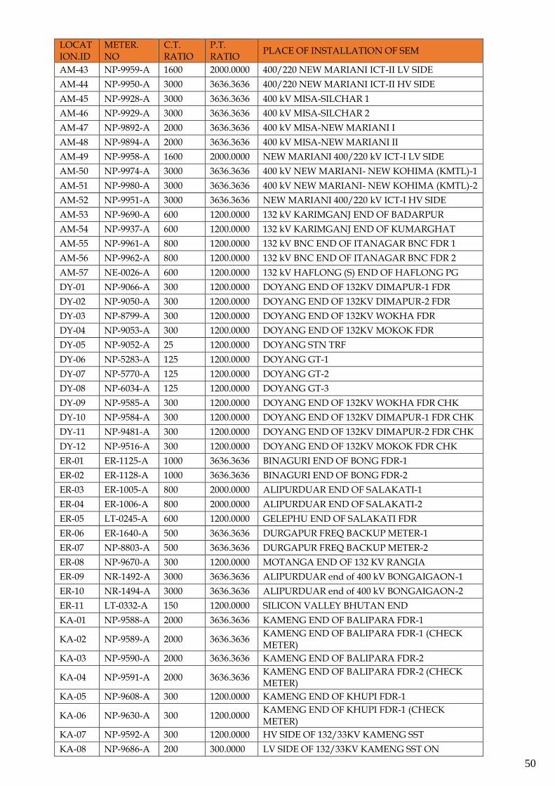
AM-43 NP-9959-A 1600 2000.0000 400/220 NEW MARIANI ICT-II LV SIDE
AM-44 NP-9950-A 3000 3636.3636 400/220 NEW MARIANI ICT-II HV SIDE
AM-45 NP-9928-A 3000 3636.3636 400 kV MISA-SILCHAR 1
AM-46 NP-9929-A 3000 3636.3636 400 kV MISA-SILCHAR 2
AM-47 NP-9892-A 2000 3636.3636 400 kV MISA-NEW MARIANI I
AM-48 NP-9894-A 2000 3636.3636 400 kV MISA-NEW MARIANI II
AM-49 NP-9958-A 1600 2000.0000 NEW MARIANI 400/220 kV ICT-I LV SIDE
AM-50 NP-9974-A 3000 3636.3636 400 kV NEW MARIANI- NEW KOHIMA (KMTL)-1
AM-51 NP-9980-A 3000 3636.3636 400 kV NEW MARIANI- NEW KOHIMA (KMTL)-2
AM-52 NP-9951-A 3000 3636.3636 NEW MARIANI 400/220 kV ICT-I HV SIDE
AM-53 NP-9690-A 600 1200.0000 132 kV KARIMGANJ END OF BADARPUR
AM-54 NP-9937-A 600 1200.0000 132 kV KARIMGANJ END OF KUMARGHAT
AM-55 NP-9961-A 800 1200.0000 132 kV BNC END OF ITANAGAR BNC FDR 1
AM-56 NP-9962-A 800 1200.0000 132 kV BNC END OF ITANAGAR BNC FDR 2
AM-57 NE-0026-A 600 1200.0000 132 kV HAFLONG (S) END OF HAFLONG PG
DY-01 NP-9066-A 300 1200.0000 DOYANG END OF 132KV DIMAPUR-1 FDR
DY-02 NP-9050-A 300 1200.0000 DOYANG END OF 132KV DIMAPUR-2 FDR
DY-03 NP-8799-A 300 1200.0000 DOYANG END OF 132KV WOKHA FDR
DY-04 NP-9053-A 300 1200.0000 DOYANG END OF 132KV MOKOK FDR
DY-05 NP-9052-A 25 1200.0000 DOYANG STN TRF
DY-06 NP-5283-A 125 1200.0000 DOYANG GT-1
DY-07 NP-5770-A 125 1200.0000 DOYANG GT-2
DY-08 NP-6034-A 125 1200.0000 DOYANG GT-3
DY-09 NP-9585-A 300 1200.0000 DOYANG END OF 132KV WOKHA FDR CHK
DY-10 NP-9584-A 300 1200.0000 DOYANG END OF 132KV DIMAPUR-1 FDR CHK
DY-11 NP-9481-A 300 1200.0000 DOYANG END OF 132KV DIMAPUR-2 FDR CHK
DY-12 NP-9516-A 300 1200.0000 DOYANG END OF 132KV MOKOK FDR CHK
ER-01 ER-1125-A 1000 3636.3636 BINAGURI END OF BONG FDR-1
ER-02 ER-1128-A 1000 3636.3636 BINAGURI END OF BONG FDR-2
ER-03 ER-1005-A 800 2000.0000 ALIPURDUAR END OF SALAKATI-1
ER-04 ER-1006-A 800 2000.0000 ALIPURDUAR END OF SALAKATI-2
ER-05 LT-0245-A 600 1200.0000 GELEPHU END OF SALAKATI FDR
ER-06 ER-1640-A 500 3636.3636 DURGAPUR FREQ BACKUP METER-1
ER-07 NP-8803-A 500 3636.3636 DURGAPUR FREQ BACKUP METER-2
ER-08 NP-9670-A 300 1200.0000 MOTANGA END OF 132 KV RANGIA
ER-09 NR-1492-A 3000 3636.3636 ALIPURDUAR end of 400 kV BONGAIGAON-1
ER-10 NR-1494-A 3000 3636.3636 ALIPURDUAR end of 400 kV BONGAIGAON-2
ER-11 LT-0332-A 150 1200.0000 SILICON VALLEY BHUTAN END
KA-01 NP-9588-A 2000 3636.3636 KAMENG END OF BALIPARA FDR-1
KA-02 NP-9589-A 2000 3636.3636 KAMENG END OF BALIPARA FDR-1 (CHECK METER)
KA-03 NP-9590-A 2000 3636.3636 KAMENG END OF BALIPARA FDR-2
KA-04 NP-9591-A 2000 3636.3636 KAMENG END OF BALIPARA FDR-2 (CHECK METER)
KA-05 NP-9608-A 300 1200.0000 KAMENG END OF KHUPI FDR-1
KA-06 NP-9630-A 300 1200.0000 KAMENG END OF KHUPI FDR-1 (CHECK METER)
KA-07 NP-9592-A 300 1200.0000 HV SIDE OF 132/33KV KAMENG SST
KA-08 NP-9686-A 200 300.0000 LV SIDE OF 132/33KV KAMENG SST ON
51
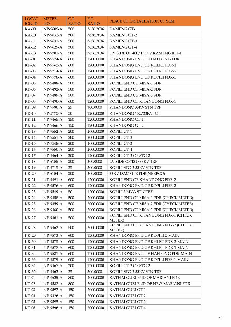
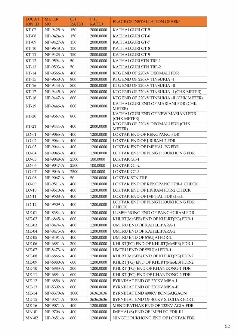
LOCATION.ID
METER. NO
C.T. RATIO
P.T. RATIO
PLACE OF INSTALLATION OF SEM
KA-09 NP-9609-A 500 3636.3636 KAMENG GT-1
KA-10 NP-9632-A 500 3636.3636 KAMENG GT-2
KA-11 NP-9631-A 500 3636.3636 KAMENG GT-3
KA-12 NP-9629-A 500 3636.3636 KAMENG GT-4
KA-13 NP-9701-A 500 3636.3636 HV SIDE OF 400/132KV KAMENG ICT-1
KK-01 NP-9574-A 600 1200.0000 KHANDONG END OF HAFLONG FDR
KK-02 NP-9562-A 600 1200.0000 KHANDONG END OF KHLRT FDR-1
KK-03 NP-9714-A 600 1200.0000 KHANDONG END OF KHLRT FDR-2
KK-04 NP-9578-A 600 1200.0000 KHANDONG END OF KOPILI FDR-1
KK-05 NP-9488-A 500 2000.0000 KOPILI END OF MISA-1 FDR
KK-06 NP-9492-A 500 2000.0000 KOPILI END OF MISA-2 FDR
KK-07 NP-9489-A 500 2000.0000 KOPILI END OF MISA-3 FDR
KK-08 NP-9490-A 600 1200.0000 KOPILI END OF KHANDONG FDR-1
KK-09 NP-9580-A 25 300.0000 KHANDONG 33KV STN TRF
KK-10 NP-5775-A 50 1200.0000 KHANDONG 132/33KV ICT
KK-11 NP-9465-A 150 1200.0000 KHANDONG GT-1
KK-12 NP-9466-A 150 1200.0000 KHANDONG GT-2
KK-13 NP-9552-A 200 2000.0000 KOPILI GT-1
KK-14 NP-9551-A 200 2000.0000 KOPILI GT-2
KK-15 NP-9548-A 200 2000.0000 KOPILI GT-3
KK-16 NP-9550-A 200 2000.0000 KOPILI GT-4
KK-17 NP-9464-A 200 1200.0000 KOPILI GT-2 OF STG-2
KK-18 NP-6155-A 200 300.0000 LV SIDE OF 132/33KV TRF
KK-19 NP-9715-A 25 300.0000 KOPILI STG-2 33KV STN TRF
KK-20 NP-6154-A 200 300.0000 33KV DAMSITE FDR(NEEPCO)
KK-21 NP-9491-A 600 1200.0000 KOPILI END OF KHANDONG FDR-2
KK-22 NP-9576-A 600 1200.0000 KHANDONG END OF KOPILI FDR-2
KK-23 NP-9549-A 50 1200.0000 KOPILI 5 MVA STN TRF
KK-24 NP-9458-A 500 2000.0000 KOPILI END OF MISA-1 FDR (CHECK METER)
KK-25 NP-9459-A 500 2000.0000 KOPILI END OF MISA-2 FDR (CHECK METER)
KK-26 NP-9460-A 500 2000.0000 KOPILI END OF MISA-3 FDR (CHECK METER)
KK-27 NP-9461-A 500 2000.0000 KOPILI END OF KHANDONG FDR-1 (CHECK METER)
KK-28 NP-9462-A 500 2000.0000 KOPILI END OF KHANDONG FDR-2 (CHECK METER)
KK-29 NP-9573-A 600 1200.0000 KHANDONG END OF KOPILI 2-MAIN
KK-30 NP-9575-A 600 1200.0000 KHANDONG END OF KHLRT FDR-2-MAIN
KK-31 NP-9577-A 600 1200.0000 KHANDONG END OF KHLRT FDR-1-MAIN
KK-32 NP-9581-A 600 1200.0000 KHANDONG END OF HAFLONG FDR-MAIN
KK-33 NP-9579-A 600 1200.0000 KHANDONG END OF KOPILI FDR-1-MAIN
KK-34 NP-9467-A 200 1200.0000 KOPILI GT-2 OF STG-2
KK-35 NP-9463-A 25 300.0000 KOPILI STG-2 33KV STN TRF
KT-01 NP-9625-A 800 2000.0000 KATHALGURI END OF MARIANI FDR
KT-02 NP-9582-A 800 2000.0000 KATHALGURI END OF NEW MARIANI FDR
KT-03 NP-9597-A 150 2000.0000 KATHALGURI GT-1
KT-04 NP-9426-A 150 2000.0000 KATHALGURI GT-2
KT-05 NP-9595-A 150 2000.0000 KATHALGURI GT-3
KT-06 NP-9596-A 150 2000.0000 KATHALGURI GT-4
52
LOCATION.ID
METER. NO
C.T. RATIO
P.T. RATIO
PLACE OF INSTALLATION OF SEM
KT-07 NP-9425-A 150 2000.0000 KATHALGURI GT-5
KT-08 NP-9424-A 150 2000.0000 KATHALGURI GT-6
KT-09 NP-9427-A 150 2000.0000 KATHALGURI GT-7
KT-10 NP-9648-A 150 2000.0000 KATHALGURI GT-8
KT-11 NP-9423-A 150 2000.0000 KATHALGURI GT-9
KT-12 NP-9594-A 50 2000.0000 KATHALGURI STN TRF-1
KT-13 NP-9593-A 50 2000.0000 KATHALGURI STN TRF-2
KT-14 NP-9566-A 400 2000.0000 KTG END OF 220kV DEOMALI FDR
KT-15 NP-9650-A 800 2000.0000 KTG END OF 220kV TINSUKIA -I
KT-16 NP-9443-A 800 2000.0000 KTG END OF 220kV TINSUKIA -II
KT-17 NP-9445-A 800 2000.0000 KTG END OF 220kV TINSUKIA -I (CHK METER)
KT-18 NP-9447-A 800 2000.0000 KTG END OF 220kV TINSUKIA -II (CHK METER)
KT-19 NP-9446-A 800 2000.0000 KATHALGURI END OF MARIANI FDR (CHK METER)
KT-20 NP-9567-A 800 2000.0000 KATHALGURI END OF NEW MARIANI FDR (CHK METER)
KT-21 NP-9444-A 400 2000.0000 KTG END OF 220kV DEOMALI FDR (CHK METER)
LO-01 NP-9065-A 400 1200.0000 LOKTAK END OF RENGPANG FDR
LO-02 NP-9064-A 400 1200.0000 LOKTAK END OF JIRIBAM-2 FDR
LO-03 NP-9044-A 400 1200.0000 LOKTAK END OF IMPHAL PG FDR
LO-04 NP-9045-A 400 1200.0000 LOKTAK END OF NINGTHOUKHONG FDR
LO-05 NP-9048-A 2500 100.0000 LOKTAK GT-1
LO-06 NP-9047-A 2500 100.0000 LOKTAK GT-2
LO-07 NP-9046-A 2500 100.0000 LOKTAK GT-3
LO-08 NP-9067-A 50 1200.0000 LOKTAK STN TRF
LO-09 NP-9511-A 400 1200.0000 LOKTAK END OF RENGPANG FDR-1 CHECK
LO-10 NP-9510-A 400 1200.0000 LOKTAK END OF JIRIBAM FDR-2 CHECK
LO-11 NP-9508-A 400 1200.0000 LOKTAK END OF IMPHAL FDR check
LO-12 NP-9509-A 400 1200.0000 LOKTAK END OF NINGTHOUKHONG FDR CHECK
ME-01 NP-8384-A 400 1200.0000 LUMSHNONG END OF PANCHGRAM FDR
ME-02 NP-6865-A 600 1200.0000 KHLRT(MeSEB) END OF KHLRT(PG) FDR-1
ME-03 NP-8474-A 400 1200.0000 UMTRU END OF KAHELIPARA-1
ME-04 NP-8475-A 400 1200.0000 UMTRU END OF KAHELIPARA-2
ME-05 NP-8491-A 400 1200.0000 UMTRU END OF S'SUJAI FDR-2
ME-06 NP-6881-A 300 1200.0000 KHLRT(PG) END OF KHLRT(MeSEB) FDR-1
ME-07 NP-8473-A 400 1200.0000 UMTRU END OF S'SUJAI FDR-1
ME-08 NP-6866-A 400 1200.0000 KHLRT(MeSEB) END OF KHLRT(PG) FDR-2
ME-09 NP-6880-A 600 1200.0000 KHLRT(PG) END OF KHLRT(MeSEB) FDR-2
ME-10 NP-6883-A 300 1200.0000 KHLRT (PG) END OF KHANDONG-1 FDR
ME-11 NP-6884-A 600 1200.0000 KHLRT (PG) END OF KHANDONG-2 FDR
ME-12 NP-6856-A 800 2000.0000 BYRNIHAT END OF 220KV MISA-I
ME-13 NP-5302-A 800 2000.0000 BYRNIHAT END OF 220KV MISA-II
ME-14 NP-8370-A 1000 3636.3636 BYRNIHAT END 400KV BONGAIGAON
ME-15 NP-8371-A 1000 3636.3636 BYRNIHAT END OF 400KV SILCHAR FDR II
ME-16 NP-9071-A 400 1200.0000 MENDIPATHAR END OF 132KV AGIA FDR
MN-01 NP-9706-A 400 1200.0000 IMPHAL(S) END OF IMPH PG FDR-III
MN-02 NP-9651-A 600 1200.0000 NINGTHOUKHONG END OF LOKTAK FDR
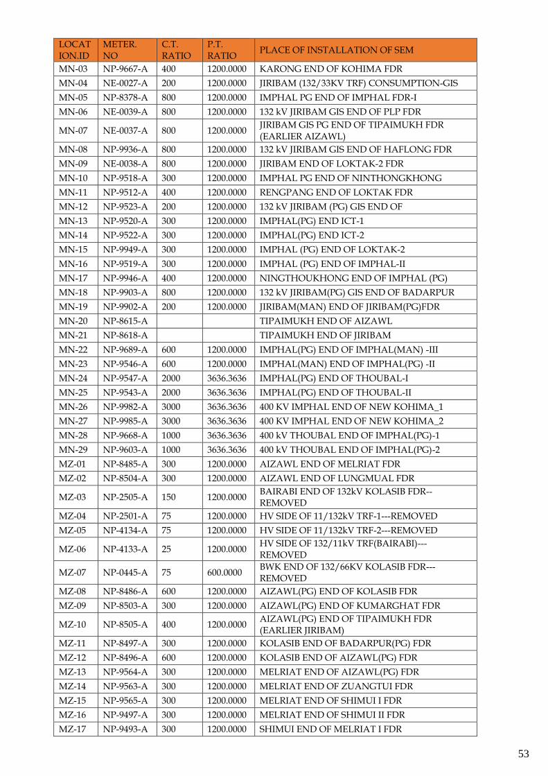
53
LOCATION.ID
METER. NO
C.T. RATIO
P.T. RATIO
PLACE OF INSTALLATION OF SEM
MN-03 NP-9667-A 400 1200.0000 KARONG END OF KOHIMA FDR
MN-04 NE-0027-A 200 1200.0000 JIRIBAM (132/33KV TRF) CONSUMPTION-GIS
MN-05 NP-8378-A 800 1200.0000 IMPHAL PG END OF IMPHAL FDR-I
MN-06 NE-0039-A 800 1200.0000 132 kV JIRIBAM GIS END OF PLP FDR
MN-07 NE-0037-A 800 1200.0000 JIRIBAM GIS PG END OF TIPAIMUKH FDR (EARLIER AIZAWL)
MN-08 NP-9936-A 800 1200.0000 132 kV JIRIBAM GIS END OF HAFLONG FDR
MN-09 NE-0038-A 800 1200.0000 JIRIBAM END OF LOKTAK-2 FDR
MN-10 NP-9518-A 300 1200.0000 IMPHAL PG END OF NINTHONGKHONG
MN-11 NP-9512-A 400 1200.0000 RENGPANG END OF LOKTAK FDR
MN-12 NP-9523-A 200 1200.0000 132 kV JIRIBAM (PG) GIS END OF
MN-13 NP-9520-A 300 1200.0000 IMPHAL(PG) END ICT-1
MN-14 NP-9522-A 300 1200.0000 IMPHAL(PG) END ICT-2
MN-15 NP-9949-A 300 1200.0000 IMPHAL (PG) END OF LOKTAK-2
MN-16 NP-9519-A 300 1200.0000 IMPHAL (PG) END OF IMPHAL-II
MN-17 NP-9946-A 400 1200.0000 NINGTHOUKHONG END OF IMPHAL (PG)
MN-18 NP-9903-A 800 1200.0000 132 kV JIRIBAM(PG) GIS END OF BADARPUR
MN-19 NP-9902-A 200 1200.0000 JIRIBAM(MAN) END OF JIRIBAM(PG)FDR
MN-20 NP-8615-A TIPAIMUKH END OF AIZAWL
MN-21 NP-8618-A TIPAIMUKH END OF JIRIBAM
MN-22 NP-9689-A 600 1200.0000 IMPHAL(PG) END OF IMPHAL(MAN) -III
MN-23 NP-9546-A 600 1200.0000 IMPHAL(MAN) END OF IMPHAL(PG) -II
MN-24 NP-9547-A 2000 3636.3636 IMPHAL(PG) END OF THOUBAL-I
MN-25 NP-9543-A 2000 3636.3636 IMPHAL(PG) END OF THOUBAL-II
MN-26 NP-9982-A 3000 3636.3636 400 KV IMPHAL END OF NEW KOHIMA_1
MN-27 NP-9985-A 3000 3636.3636 400 KV IMPHAL END OF NEW KOHIMA_2
MN-28 NP-9668-A 1000 3636.3636 400 kV THOUBAL END OF IMPHAL(PG)-1
MN-29 NP-9603-A 1000 3636.3636 400 kV THOUBAL END OF IMPHAL(PG)-2
MZ-01 NP-8485-A 300 1200.0000 AIZAWL END OF MELRIAT FDR
MZ-02 NP-8504-A 300 1200.0000 AIZAWL END OF LUNGMUAL FDR
MZ-03 NP-2505-A 150 1200.0000 BAIRABI END OF 132kV KOLASIB FDR--REMOVED
MZ-04 NP-2501-A 75 1200.0000 HV SIDE OF 11/132kV TRF-1---REMOVED
MZ-05 NP-4134-A 75 1200.0000 HV SIDE OF 11/132kV TRF-2---REMOVED
MZ-06 NP-4133-A 25 1200.0000 HV SIDE OF 132/11kV TRF(BAIRABI)---REMOVED
MZ-07 NP-0445-A 75 600.0000 BWK END OF 132/66KV KOLASIB FDR---REMOVED
MZ-08 NP-8486-A 600 1200.0000 AIZAWL(PG) END OF KOLASIB FDR
MZ-09 NP-8503-A 300 1200.0000 AIZAWL(PG) END OF KUMARGHAT FDR
MZ-10 NP-8505-A 400 1200.0000 AIZAWL(PG) END OF TIPAIMUKH FDR (EARLIER JIRIBAM)
MZ-11 NP-8497-A 300 1200.0000 KOLASIB END OF BADARPUR(PG) FDR
MZ-12 NP-8496-A 600 1200.0000 KOLASIB END OF AIZAWL(PG) FDR
MZ-13 NP-9564-A 300 1200.0000 MELRIAT END OF AIZAWL(PG) FDR
MZ-14 NP-9563-A 300 1200.0000 MELRIAT END OF ZUANGTUI FDR
MZ-15 NP-9565-A 300 1200.0000 MELRIAT END OF SHIMUI I FDR
MZ-16 NP-9497-A 300 1200.0000 MELRIAT END OF SHIMUI II FDR
MZ-17 NP-9493-A 300 1200.0000 SHIMUI END OF MELRIAT I FDR
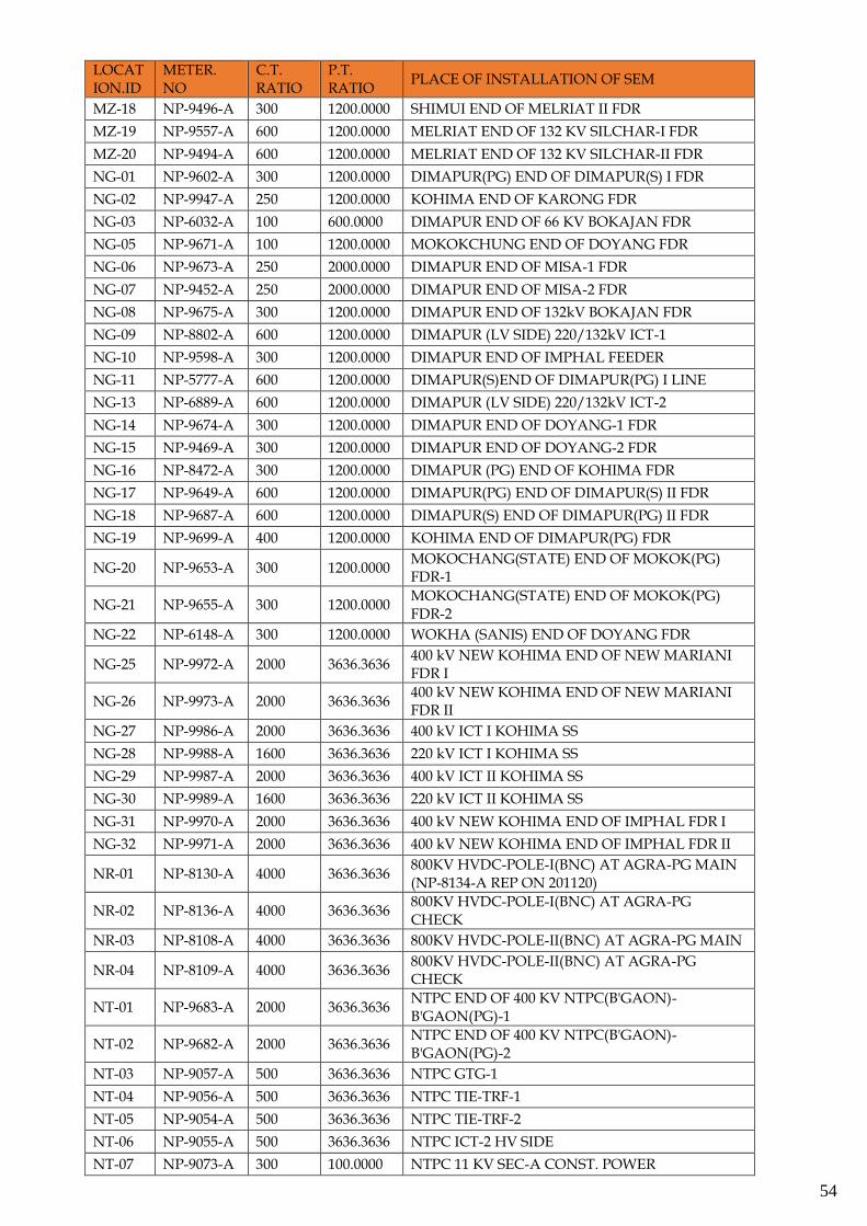
54
LOCATION.ID
METER. NO
C.T. RATIO
P.T. RATIO
PLACE OF INSTALLATION OF SEM
MZ-18 NP-9496-A 300 1200.0000 SHIMUI END OF MELRIAT II FDR
MZ-19 NP-9557-A 600 1200.0000 MELRIAT END OF 132 KV SILCHAR-I FDR
MZ-20 NP-9494-A 600 1200.0000 MELRIAT END OF 132 KV SILCHAR-II FDR
NG-01 NP-9602-A 300 1200.0000 DIMAPUR(PG) END OF DIMAPUR(S) I FDR
NG-02 NP-9947-A 250 1200.0000 KOHIMA END OF KARONG FDR
NG-03 NP-6032-A 100 600.0000 DIMAPUR END OF 66 KV BOKAJAN FDR
NG-05 NP-9671-A 100 1200.0000 MOKOKCHUNG END OF DOYANG FDR
NG-06 NP-9673-A 250 2000.0000 DIMAPUR END OF MISA-1 FDR
NG-07 NP-9452-A 250 2000.0000 DIMAPUR END OF MISA-2 FDR
NG-08 NP-9675-A 300 1200.0000 DIMAPUR END OF 132kV BOKAJAN FDR
NG-09 NP-8802-A 600 1200.0000 DIMAPUR (LV SIDE) 220/132kV ICT-1
NG-10 NP-9598-A 300 1200.0000 DIMAPUR END OF IMPHAL FEEDER
NG-11 NP-5777-A 600 1200.0000 DIMAPUR(S)END OF DIMAPUR(PG) I LINE
NG-13 NP-6889-A 600 1200.0000 DIMAPUR (LV SIDE) 220/132kV ICT-2
NG-14 NP-9674-A 300 1200.0000 DIMAPUR END OF DOYANG-1 FDR
NG-15 NP-9469-A 300 1200.0000 DIMAPUR END OF DOYANG-2 FDR
NG-16 NP-8472-A 300 1200.0000 DIMAPUR (PG) END OF KOHIMA FDR
NG-17 NP-9649-A 600 1200.0000 DIMAPUR(PG) END OF DIMAPUR(S) II FDR
NG-18 NP-9687-A 600 1200.0000 DIMAPUR(S) END OF DIMAPUR(PG) II FDR
NG-19 NP-9699-A 400 1200.0000 KOHIMA END OF DIMAPUR(PG) FDR
NG-20 NP-9653-A 300 1200.0000 MOKOCHANG(STATE) END OF MOKOK(PG) FDR-1
NG-21 NP-9655-A 300 1200.0000 MOKOCHANG(STATE) END OF MOKOK(PG) FDR-2
NG-22 NP-6148-A 300 1200.0000 WOKHA (SANIS) END OF DOYANG FDR
NG-25 NP-9972-A 2000 3636.3636 400 kV NEW KOHIMA END OF NEW MARIANI FDR I
NG-26 NP-9973-A 2000 3636.3636 400 kV NEW KOHIMA END OF NEW MARIANI FDR II
NG-27 NP-9986-A 2000 3636.3636 400 kV ICT I KOHIMA SS
NG-28 NP-9988-A 1600 3636.3636 220 kV ICT I KOHIMA SS
NG-29 NP-9987-A 2000 3636.3636 400 kV ICT II KOHIMA SS
NG-30 NP-9989-A 1600 3636.3636 220 kV ICT II KOHIMA SS
NG-31 NP-9970-A 2000 3636.3636 400 kV NEW KOHIMA END OF IMPHAL FDR I
NG-32 NP-9971-A 2000 3636.3636 400 kV NEW KOHIMA END OF IMPHAL FDR II
NR-01 NP-8130-A 4000 3636.3636 800KV HVDC-POLE-I(BNC) AT AGRA-PG MAIN (NP-8134-A REP ON 201120)
NR-02 NP-8136-A 4000 3636.3636 800KV HVDC-POLE-I(BNC) AT AGRA-PG CHECK
NR-03 NP-8108-A 4000 3636.3636 800KV HVDC-POLE-II(BNC) AT AGRA-PG MAIN
NR-04 NP-8109-A 4000 3636.3636 800KV HVDC-POLE-II(BNC) AT AGRA-PG CHECK
NT-01 NP-9683-A 2000 3636.3636 NTPC END OF 400 KV NTPC(B'GAON)-B'GAON(PG)-1
NT-02 NP-9682-A 2000 3636.3636 NTPC END OF 400 KV NTPC(B'GAON)-B'GAON(PG)-2
NT-03 NP-9057-A 500 3636.3636 NTPC GTG-1
NT-04 NP-9056-A 500 3636.3636 NTPC TIE-TRF-1
NT-05 NP-9054-A 500 3636.3636 NTPC TIE-TRF-2
NT-06 NP-9055-A 500 3636.3636 NTPC ICT-2 HV SIDE
NT-07 NP-9073-A 300 100.0000 NTPC 11 KV SEC-A CONST. POWER
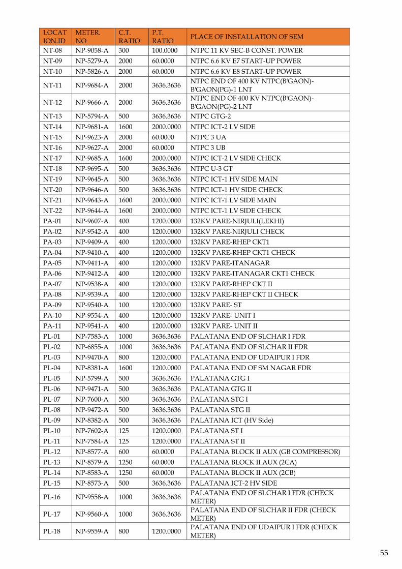
55
LOCATION.ID
METER. NO
C.T. RATIO
P.T. RATIO
PLACE OF INSTALLATION OF SEM
NT-08 NP-9058-A 300 100.0000 NTPC 11 KV SEC-B CONST. POWER
NT-09 NP-5279-A 2000 60.0000 NTPC 6.6 KV E7 START-UP POWER
NT-10 NP-5826-A 2000 60.0000 NTPC 6.6 KV E8 START-UP POWER
NT-11 NP-9684-A 2000 3636.3636 NTPC END OF 400 KV NTPC(B'GAON)-B'GAON(PG)-1 LNT
NT-12 NP-9666-A 2000 3636.3636 NTPC END OF 400 KV NTPC(B'GAON)-B'GAON(PG)-2 LNT
NT-13 NP-5794-A 500 3636.3636 NTPC GTG-2
NT-14 NP-9681-A 1600 2000.0000 NTPC ICT-2 LV SIDE
NT-15 NP-9623-A 2000 60.0000 NTPC 3 UA
NT-16 NP-9627-A 2000 60.0000 NTPC 3 UB
NT-17 NP-9685-A 1600 2000.0000 NTPC ICT-2 LV SIDE CHECK
NT-18 NP-9695-A 500 3636.3636 NTPC U-3 GT
NT-19 NP-9645-A 500 3636.3636 NTPC ICT-1 HV SIDE MAIN
NT-20 NP-9646-A 500 3636.3636 NTPC ICT-1 HV SIDE CHECK
NT-21 NP-9643-A 1600 2000.0000 NTPC ICT-1 LV SIDE MAIN
NT-22 NP-9644-A 1600 2000.0000 NTPC ICT-1 LV SIDE CHECK
PA-01 NP-9607-A 400 1200.0000 132KV PARE-NIRJULI(LEKHI)
PA-02 NP-9542-A 400 1200.0000 132KV PARE-NIRJULI CHECK
PA-03 NP-9409-A 400 1200.0000 132KV PARE-RHEP CKT1
PA-04 NP-9410-A 400 1200.0000 132KV PARE-RHEP CKT1 CHECK
PA-05 NP-9411-A 400 1200.0000 132KV PARE-ITANAGAR
PA-06 NP-9412-A 400 1200.0000 132KV PARE-ITANAGAR CKT1 CHECK
PA-07 NP-9538-A 400 1200.0000 132KV PARE-RHEP CKT II
PA-08 NP-9539-A 400 1200.0000 132KV PARE-RHEP CKT II CHECK
PA-09 NP-9540-A 100 1200.0000 132KV PARE- ST
PA-10 NP-9554-A 400 1200.0000 132KV PARE- UNIT I
PA-11 NP-9541-A 400 1200.0000 132KV PARE- UNIT II
PL-01 NP-7583-A 1000 3636.3636 PALATANA END OF SLCHAR I FDR
PL-02 NP-6855-A 1000 3636.3636 PALATANA END OF SLCHAR II FDR
PL-03 NP-9470-A 800 1200.0000 PALATANA END OF UDAIPUR I FDR
PL-04 NP-8381-A 1600 1200.0000 PALATANA END OF SM NAGAR FDR
PL-05 NP-5799-A 500 3636.3636 PALATANA GTG I
PL-06 NP-9471-A 500 3636.3636 PALATANA GTG II
PL-07 NP-7600-A 500 3636.3636 PALATANA STG I
PL-08 NP-9472-A 500 3636.3636 PALATANA STG II
PL-09 NP-8382-A 500 3636.3636 PALATANA ICT (HV Side)
PL-10 NP-7602-A 125 1200.0000 PALATANA ST I
PL-11 NP-7584-A 125 1200.0000 PALATANA ST II
PL-12 NP-8577-A 600 60.0000 PALATANA BLOCK II AUX (GB COMPRESSOR)
PL-13 NP-8579-A 1250 60.0000 PALATANA BLOCK II AUX (2CA)
PL-14 NP-8583-A 1250 60.0000 PALATANA BLOCK II AUX (2CB)
PL-15 NP-8573-A 500 3636.3636 PALATANA ICT-2 HV SIDE
PL-16 NP-9558-A 1000 3636.3636 PALATANA END OF SLCHAR I FDR (CHECK METER)
PL-17 NP-9560-A 1000 3636.3636 PALATANA END OF SLCHAR II FDR (CHECK METER)
PL-18 NP-9559-A 800 1200.0000 PALATANA END OF UDAIPUR I FDR (CHECK METER)
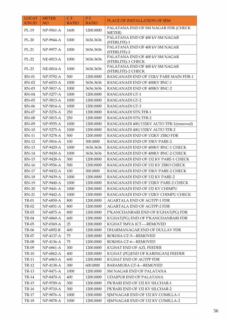
56
LOCATION.ID
METER. NO
C.T. RATIO
P.T. RATIO
PLACE OF INSTALLATION OF SEM
PL-19 NP-9561-A 1600 1200.0000 PALATANA END OF SM NAGAR FDR (CHECK METER)
PL-20 NP-9944-A 1000 3636.3636 PALATANA END OF 400 kV SM NAGAR (STERLITE)-1
PL-21 NP-9977-A 1000 3636.3636 PALATANA END OF 400 kV SM NAGAR (STERLITE)-2
PL-22 NE-0013-A 1000 3636.3636 PALATANA END OF 400 kV SM NAGAR (STERLITE)-1 CHECK
PL-23 NE-0014-A 1000 3636.3636 PALATANA END OF 400 kV SM NAGAR (STERLITE)-2 CHECK
RN-01 NP-5792-A 500 1200.0000 RANGANADI END OF 132kV PARE MAIN FDR-1
RN-02 NP-6033-A 1000 3636.3636 RANGANADI END OF 400KV BNC-1
RN-03 NP-5817-A 1000 3636.3636 RANGANADI END OF 400KV BNC-2
RN-04 NP-5277-A 1000 1200.0000 RANGANADI GT-1
RN-05 NP-5813-A 1000 1200.0000 RANGANADI GT-2
RN-06 NP-5814-A 1000 1200.0000 RANGANADI GT-3
RN-07 NP-5276-A 250 1200.0000 RANGANADI STN.TFR-1
RN-08 NP-5815-A 250 1200.0000 RANGANADI STN.TFR-2
RN-09 NP-9555-A 1000 1200.0000 RANGANADI 400/132KV AUTO TFR-1(removed)
RN-10 NP-5275-A 1000 1200.0000 RANGANADI 400/132KV AUTO TFR-2
RN-11 NP-5278-A 500 1200.0000 RANGANADI END OF 132KV ZIRO FDR
RN-12 NP-5816-A 100 300.0000 RANGANADI END OF 33KV PARE-2
RN-13 NP-9429-A 1000 3636.3636 RANGANADI END OF 400KV BNC-1 CHECK
RN-14 NP-9430-A 1000 3636.3636 RANGANADI END OF 400KV BNC-2 CHECK
RN-15 NP-9428-A 500 1200.0000 RANGANADI END OF 132 KV PARE-1 CHECK
RN-16 NP-9556-A 500 1200.0000 RANGANADI END OF 132 KV ZIRO CHECK
RN-17 NP-9432-A 100 300.0000 RANGANADI END OF 33KV PARE-2 CHECK
RN-18 NP-9439-A 1000 1200.0000 RANGANADI END OF 132 KV PARE-2
RN-19 NP-9440-A 1000 1200.0000 RANGANADI END OF 132KV PARE-2 CHECK
RN-20 NP-9441-A 1000 1200.0000 RANGANADI END OF 132 KV CHIMPU
RN-21 NP-9442-A 1000 1200.0000 RANGANADI END OF 132KV CHIMPU CHECK
TR-01 NP-6850-A 800 1200.0000 AGARTALA END OF AGTPP-1 FDR
TR-02 NP-6851-A 800 1200.0000 AGARTALA END OF AGTPP-2 FDR
TR-03 NP-6875-A 800 1200.0000 P'KANCHANBARI END OF K'GHAT(PG) FDR
TR-04 NP-6860-A 600 1200.0000 K'GHAT(PG) END OF P'KANCHANBARI FDR
TR-05 NP-0369-A 25 1200.0000 K'GHAT 5MVA ICT----REMOVED
TR-06 NP-6892-B 400 1200.0000 DHARMANAGAR END OF DULLAV FDR
TR-07 NP-4137-A 75 1200.0000 ROKHIA GT-5---REMOVED
TR-08 NP-4136-A 75 1200.0000 ROKHIA GT-6---REMOVED
TR-09 NP-6861-A 300 1200.0000 K'GHAT END OF AZL FEEDER
TR-10 NP-6862-A 400 1200.0000 K'GHAT (PG)END OF KARINGANJ FEEDER
TR-11 NP-6863-A 600 1200.0000 K'GHAT END OF AGTPP FDR
TR-12 NP-4138-A 300 600.0000 BARAMURA GT-4---REMOVED
TR-13 NP-8471-A 1000 1200.0000 SM NAGAR END OF PALATANA
TR-14 NP-8470-A 400 1200.0000 UDAIPUR END OF PALATANA
TR-15 NP-9709-A 300 1200.0000 PK'BARI END OF 132 KV SILCHAR-1
TR-16 NP-9710-A 300 1200.0000 PK'BARI END OF 132 KV SILCHAR-2
TR-17 NP-9076-A 1000 1200.0000 SJM'NAGAR END OF 132 KV COMILLA-1
TR-18 NP-9078-A 1000 1200.0000 SJM'NAGAR END OF 132 KV COMILLA-2
57
LOCATION.ID
METER. NO
C.T. RATIO
P.T. RATIO
PLACE OF INSTALLATION OF SEM
TR-19 NP-9077-A 800 1200.0000 COMILLA END OF 132 KV SJM'NAGAR-1
TR-20 NP-9083-A 800 1200.0000 COMILLA END OF 132 KV SJM'NAGAR-2
TR-21 NP-9933-A 800 1200.0000 132 KV PK BARI (TSECL) END OF AGTPP-1
TR-22 NP-9932-A 800 1200.0000 132 KV PK BARI (TSECL) END OF AGTPP-2
TR-23 NP-9919-A 800 1200.0000 132 KV PK BARI (TSECL) END OF PK BARI (STERLITE)
TR-24 NP-9931-A 800 1200.0000 132 KV PK BARI (STERLITE) END OF PK BARI (TSECL)
TR-25 NP-9930-A 800 1200.0000 132 KV PK BARI (STERLITE) END OF AMBASSA(TSECL)
TR-26 NP-9990-B 400 1200.0000 132 KV AMBASSA(TSECL) END OF PK BARI (STERLITE)
TR-27 NP-9943-A 600 1200.0000 132 kV BUDHJUNGNAGAR (TSECL) END OF SM NAGAR (STERLITE)
TR-28 NP-9893-A 800 1200.0000 132 kV SM NAGAR (STERLITE) END OF BUDHJUNGNAGAR (TSECL)
TR-29 NP-9890-A 800 1200.0000 132 kV SM NAGAR (STERLITE) END OF SM NAGAR (TSECL)
TR-30 NP-9942-A 600 1200.0000 132 kV SM NAGAR (TSECL) END OF SM NAGAR (STERLITE)
TR-31 NP-9975-A 2000 3636.3636 400 kV SM NAGAR (STERLITE) END OF PALATANA 1
TR-32 NP-9976-A 2000 3636.3636 400 kV SM NAGAR (STERLITE) END OF PALATANA 2
TR-33 NP-9969-A 50 300.0000 33 kV SM NAGAR (STERLITE) TERTIARY ICT LV SIDE
TR-34 NP-9909-A 50 300.0000 33 kV PK BARI (STERLITE) TERTIARY ICT LV SIDE
WR-01 NP-2657-A 1000 3636.3636 KORBA END OF KORBA-VINDYACHAL
WR-02 NP-2174-A 1000 3636.3636 KORBA END OF KORBA-VINDYACHAL - II
ZZ-01 NP-9544-A 400 1200.0000 IMPHAL(S) END OF IMP(PG)-I FDR
ZZ-02 NP-9948-A 400 1200.0000 YUREMBAM END OF NINGTHOUKHONG FDR
ZZ-03 NP-5300-A 1000 3636.3636 MISA 400/220KV ICT-1(HV SIDE)
ZZ-04 NP-9448-A 800 2000.0000 DIMAPUR (HV SIDE) 220/132kV ICT1
ZZ-05 NP-5282-A 1200 2000.0000 BALIPARA 400/220KV(LV) ICT
ZZ-06 NP-8594-A 1000 3636.3636 BALIPARA END OF MISA FDR-1 (PREVIOUS-5790)
ZZ-07 NP-5285-A 1000 3636.3636 BALIPARA END OF MISA FDR-2
ZZ-08 NP-5774-A 1200 2000.0000 BONG 400/220KV(LV) ICT-1
ZZ-09 NP-8477-A 600 1200.0000 KHLRT(PG) END OF BADARPUR(PG) FDR
ZZ-10 NP-8662-A 500 1200.0000 SILCHAR END OF BADARPUR(PG)-I
ZZ-11 NP-8663-A 500 1200.0000 SILCHAR END OF BADARPUR(PG)-II
ZZ-12 NE-0008-A 1200 2000.0000 MISA 400/220KV ICT-2(LV SIDE) (EARLIER NP-8638-A)
ZZ-13 NP-9498-A 300 1200.0000 IMPHAL (PG) END OF DIMAPUR
ZZ-14 NP-9672-A 800 1200.0000 DIMAPUR (HV SIDE) 220/132kV ICT2
ZZ-15 NP-9475-A 2000 3636.3636 BONGAIGAON END OF 400 KV BALIPARA-3
ZZ-16 NP-8655-A 1000 3636.3636 BALIPARA END OF 400 KV BONGAIGAON-1
ZZ-17 NP-8653-A 1000 3636.3636 BALIPARA END OF 400 KV BONGAIGAON-2
ZZ-18 NP-8654-A 2000 3636.3636 BALIPARA END OF 400 KV BONGAIGAON-3
ZZ-19 NP-8585-A 2000 3636.3636 BALIPARA END OF 400 KV BONGAIGAON-4
ZZ-20 NE-0007-A 2000 3636.3636 SILCHAR END OF 400 KV IMPHAL-1 (EARLIER NP-8571-A)
58
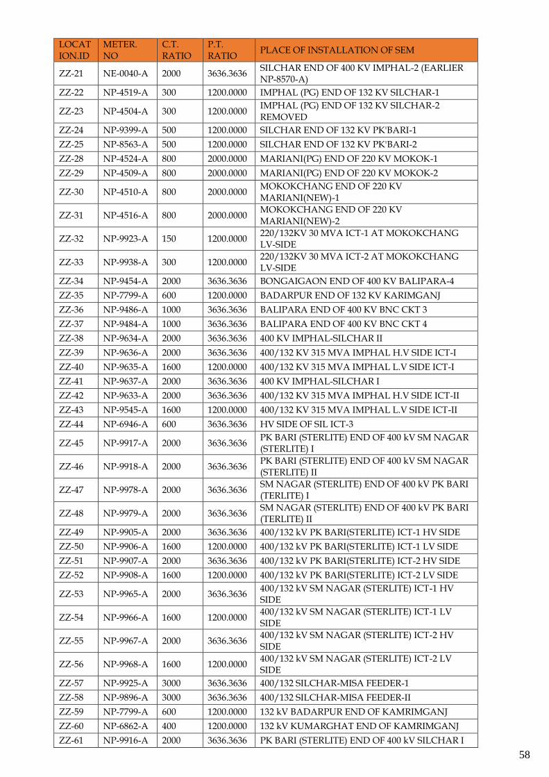
LOCATION.ID
METER. NO
C.T. RATIO
P.T. RATIO
PLACE OF INSTALLATION OF SEM
ZZ-21 NE-0040-A 2000 3636.3636 SILCHAR END OF 400 KV IMPHAL-2 (EARLIER NP-8570-A)
ZZ-22 NP-4519-A 300 1200.0000 IMPHAL (PG) END OF 132 KV SILCHAR-1
ZZ-23 NP-4504-A 300 1200.0000 IMPHAL (PG) END OF 132 KV SILCHAR-2 REMOVED
ZZ-24 NP-9399-A 500 1200.0000 SILCHAR END OF 132 KV PK'BARI-1
ZZ-25 NP-8563-A 500 1200.0000 SILCHAR END OF 132 KV PK'BARI-2
ZZ-28 NP-4524-A 800 2000.0000 MARIANI(PG) END OF 220 KV MOKOK-1
ZZ-29 NP-4509-A 800 2000.0000 MARIANI(PG) END OF 220 KV MOKOK-2
ZZ-30 NP-4510-A 800 2000.0000 MOKOKCHANG END OF 220 KV MARIANI(NEW)-1
ZZ-31 NP-4516-A 800 2000.0000 MOKOKCHANG END OF 220 KV MARIANI(NEW)-2
ZZ-32 NP-9923-A 150 1200.0000 220/132KV 30 MVA ICT-1 AT MOKOKCHANG LV-SIDE
ZZ-33 NP-9938-A 300 1200.0000 220/132KV 30 MVA ICT-2 AT MOKOKCHANG LV-SIDE
ZZ-34 NP-9454-A 2000 3636.3636 BONGAIGAON END OF 400 KV BALIPARA-4
ZZ-35 NP-7799-A 600 1200.0000 BADARPUR END OF 132 KV KARIMGANJ
ZZ-36 NP-9486-A 1000 3636.3636 BALIPARA END OF 400 KV BNC CKT 3
ZZ-37 NP-9484-A 1000 3636.3636 BALIPARA END OF 400 KV BNC CKT 4
ZZ-38 NP-9634-A 2000 3636.3636 400 KV IMPHAL-SILCHAR II
ZZ-39 NP-9636-A 2000 3636.3636 400/132 KV 315 MVA IMPHAL H.V SIDE ICT-I
ZZ-40 NP-9635-A 1600 1200.0000 400/132 KV 315 MVA IMPHAL L.V SIDE ICT-I
ZZ-41 NP-9637-A 2000 3636.3636 400 KV IMPHAL-SILCHAR I
ZZ-42 NP-9633-A 2000 3636.3636 400/132 KV 315 MVA IMPHAL H.V SIDE ICT-II
ZZ-43 NP-9545-A 1600 1200.0000 400/132 KV 315 MVA IMPHAL L.V SIDE ICT-II
ZZ-44 NP-6946-A 600 3636.3636 HV SIDE OF SIL ICT-3
ZZ-45 NP-9917-A 2000 3636.3636 PK BARI (STERLITE) END OF 400 kV SM NAGAR (STERLITE) I
ZZ-46 NP-9918-A 2000 3636.3636 PK BARI (STERLITE) END OF 400 kV SM NAGAR (STERLITE) II
ZZ-47 NP-9978-A 2000 3636.3636 SM NAGAR (STERLITE) END OF 400 kV PK BARI (TERLITE) I
ZZ-48 NP-9979-A 2000 3636.3636 SM NAGAR (STERLITE) END OF 400 kV PK BARI (TERLITE) II
ZZ-49 NP-9905-A 2000 3636.3636 400/132 kV PK BARI(STERLITE) ICT-1 HV SIDE
ZZ-50 NP-9906-A 1600 1200.0000 400/132 kV PK BARI(STERLITE) ICT-1 LV SIDE
ZZ-51 NP-9907-A 2000 3636.3636 400/132 kV PK BARI(STERLITE) ICT-2 HV SIDE
ZZ-52 NP-9908-A 1600 1200.0000 400/132 kV PK BARI(STERLITE) ICT-2 LV SIDE
ZZ-53 NP-9965-A 2000 3636.3636 400/132 kV SM NAGAR (STERLITE) ICT-1 HV SIDE
ZZ-54 NP-9966-A 1600 1200.0000 400/132 kV SM NAGAR (STERLITE) ICT-1 LV SIDE
ZZ-55 NP-9967-A 2000 3636.3636 400/132 kV SM NAGAR (STERLITE) ICT-2 HV SIDE
ZZ-56 NP-9968-A 1600 1200.0000 400/132 kV SM NAGAR (STERLITE) ICT-2 LV SIDE
ZZ-57 NP-9925-A 3000 3636.3636 400/132 SILCHAR-MISA FEEDER-1
ZZ-58 NP-9896-A 3000 3636.3636 400/132 SILCHAR-MISA FEEDER-II
ZZ-59 NP-7799-A 600 1200.0000 132 kV BADARPUR END OF KAMRIMGANJ
ZZ-60 NP-6862-A 400 1200.0000 132 kV KUMARGHAT END OF KAMRIMGANJ
ZZ-61 NP-9916-A 2000 3636.3636 PK BARI (STERLITE) END OF 400 kV SILCHAR I
59
LOCATION.ID
METER. NO
C.T. RATIO
P.T. RATIO
PLACE OF INSTALLATION OF SEM
ZZ-62 NP-9901-A 2000 3636.3636 SILCHAR END OF 400 PK BARI (STERLITE)I
ZZ-63 NP-9899-A 2000 3636.3636 SILCHAR END OF 400 PK BARI (STERLITE) II
ZZ-64 NP-9915-A 2000 3636.3636 PK BARI (STERLITE) END OF 400 kV SILCHAR II
ZZ-65 NP-9952-A 3000 3636.3636 NEW MARIANI END OF 400 KV MISA CKT-1
ZZ-66 NP-9954-A 3000 3636.3636 NEW MARIANI END OF 400 KV MISA CKT-2
ZZ-67 NP-9914-A 1600 2000.0000 220KV NEW MARIANI BAY 1
ZZ-68 NP-9953-A 1600 2000.0000 220KV NEW MARIANI BAY 2
FICTMETERS
Sl. No. Fict-Meter Meter Formula Total
Meters
1
(AR-51) +(AR-01) +(AR-02) -(AR-06) +(AS-55) +(KT-14) +(RN-12) +(PA-01) +(AR-03) +(PA-05) -(AR-09) -(AR-19) -(AR-20)
12
2 (AS-51)
-(AS-01) -(AS-02) -(AS-03) -(AS-04) -(AS-06) -(AS-07) -(AS-08)-(AS-09) +(AS-11) +(AS-12)-(AS-13) -(AS-17) -(AS-18) +(AS-30) +(AS-31) +(AS-42) -(AS-47)*1.0309 -(AS-50) +(AS-56) +(AS-57) -(AS-77) -(AS-78) -(AS-63) +(MN-06) +(KT-15) +(KT-16) -(AS-80) -(AS-79) -(AS-73) -(AS-86) -(AS-93) -(AM-01) +(KK-32) +(AS-69) -(AM-12) -(AM-13) -(NT-14) -(NT-22) -(AM-53) -(AM-54)
40
3 (MN-51) - (MN-23) - (MN-03) + (MN-04) + (MN-12) + (LO-01) + (LO-04) + (MN-10) - (ZZ-01) + (MN-13) + (MN-14) +(MN-22)
11
4 (ME-51) -(ME-01) -(ME-03) -(ME-04) -(ME-15) -(ME-02) -(ME-08) -(ME-14) -(ME-16) +(AS-70) +(AS-72) +(AS-50) +(AS-09)
12
5 (MZ-51) + (MZ-14) + (MZ-02) - (MZ-11) - (MZ-12) 4
6 (NG-51) -(NG-11) -(AS-12) +(MN-03) +(DY-04) +(AS-47) -(NG-19) +(NG-17) -(NG-20) -(NG-21) -(DY-03)
10
7 (TR-51) -(TR-01) -(TR-02) +(TR-04) -(TR-06) +(PL-18) -(TR-13) -(TR-21) -(TR-22) +(TR-24) +(TR-25) +(TR-28) +(TR-29)
12
8 (BN-51) +(AM-14) +(AM-23) 2
9 (TO-51) + (AR-51) + (AS-51) + (MN-51) + (ME-51) + (MZ-51) +(NG-51) + (TR-51) + (BN-51)
8
10 (LO-71) + (LO-01) + (LO-02) + (LO-03) + (LO-04) 4
11 (KD-71) + (KK-29) + (KK-30) + (KK-31) + (KK-32) + (KK-33) 5
12 (KP-71) + (KK-05) + (KK-06) + (KK-07) +(KK-08) + (KK-21) 5
13 (KT-71) + (KT-01) + (KT-02) + (KT-14) + (KT-15) + (KT-16) 5
14 (AG-71) +(AG-01) +(AG-02) +(AG-03) +(AG-16) +(AG-17) 5
15 (DY-71) + (DY-01) + (DY-02) - (DY-03) + (DY-04) 4
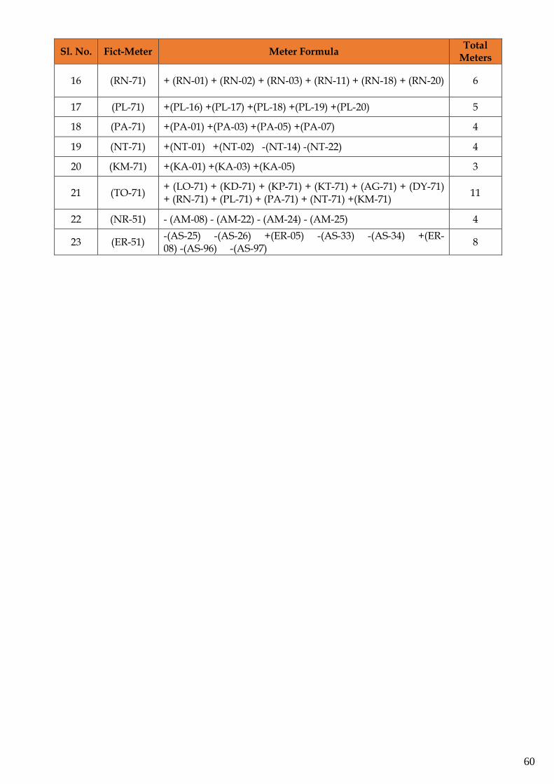
60
Sl. No. Fict-Meter Meter Formula Total
Meters
16 (RN-71) + (RN-01) + (RN-02) + (RN-03) + (RN-11) + (RN-18) + (RN-20) 6
17 (PL-71) +(PL-16) +(PL-17) +(PL-18) +(PL-19) +(PL-20) 5
18 (PA-71) +(PA-01) +(PA-03) +(PA-05) +(PA-07) 4
19 (NT-71) +(NT-01) +(NT-02) -(NT-14) -(NT-22) 4
20 (KM-71) +(KA-01) +(KA-03) +(KA-05) 3
21 (TO-71) + (LO-71) + (KD-71) + (KP-71) + (KT-71) + (AG-71) + (DY-71) + (RN-71) + (PL-71) + (PA-71) + (NT-71) +(KM-71)
11
22 (NR-51) - (AM-08) - (AM-22) - (AM-24) - (AM-25) 4
23 (ER-51) -(AS-25) -(AS-26) +(ER-05) -(AS-33) -(AS-34) +(ER-08) -(AS-96) -(AS-97)
8
61
SECTION-3:
PROCESSING AND COMPUTATION OF
DATA
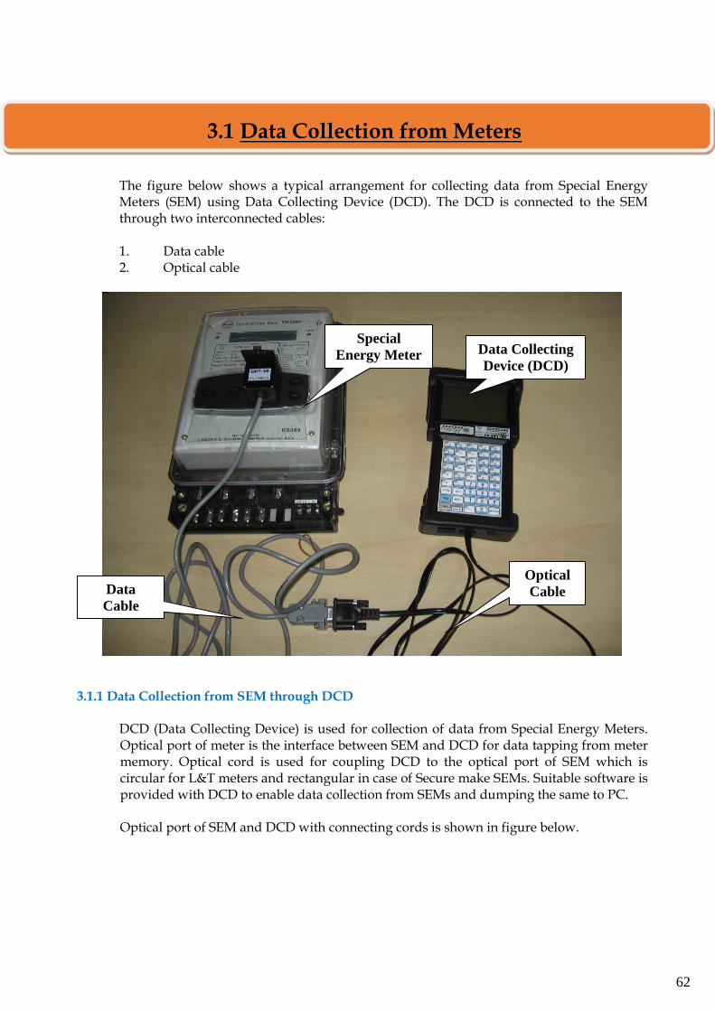
62
The figure below shows a typical arrangement for collecting data from Special Energy Meters (SEM) using Data Collecting Device (DCD). The DCD is connected to the SEM through two interconnected cables: 1. Data cable 2. Optical cable
3.1.1 Data Collection from SEM through DCD
DCD (Data Collecting Device) is used for collection of data from Special Energy Meters. Optical port of meter is the interface between SEM and DCD for data tapping from meter memory. Optical cord is used for coupling DCD to the optical port of SEM which is circular for L&T meters and rectangular in case of Secure make SEMs. Suitable software is provided with DCD to enable data collection from SEMs and dumping the same to PC.
Optical port of SEM and DCD with connecting cords is shown in figure below.
Special
Energy Meter
Optical
Cable Data
Cable
Data Collecting
Device (DCD)
3.1 Data Collection from Meters
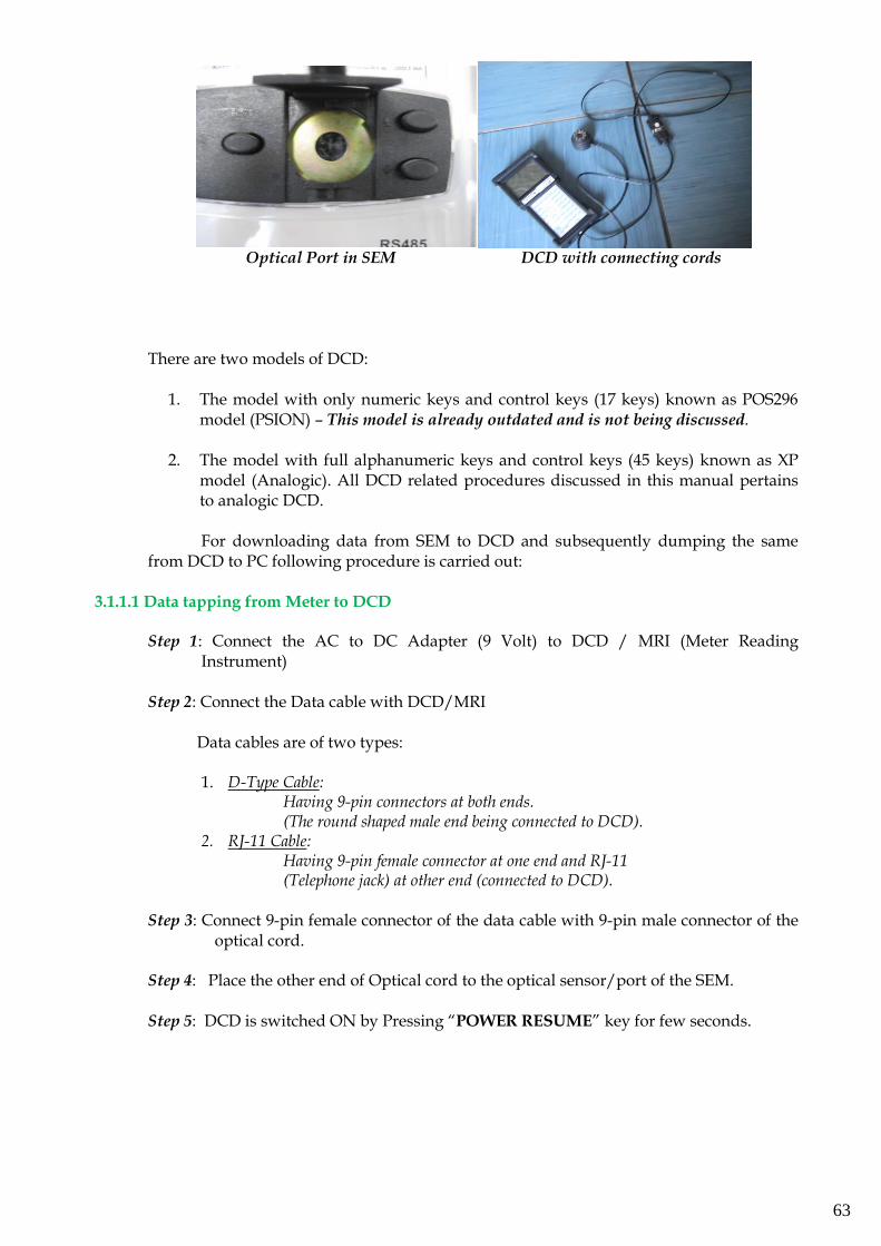
63
Optical Port in SEM DCD with connecting cords There are two models of DCD:
1. The model with only numeric keys and control keys (17 keys) known as POS296
model (PSION) – This model is already outdated and is not being discussed. 2. The model with full alphanumeric keys and control keys (45 keys) known as XP
model (Analogic). All DCD related procedures discussed in this manual pertains to analogic DCD. For downloading data from SEM to DCD and subsequently dumping the same
from DCD to PC following procedure is carried out: 3.1.1.1 Data tapping from Meter to DCD
Step 1: Connect the AC to DC Adapter (9 Volt) to DCD / MRI (Meter Reading Instrument)
Step 2: Connect the Data cable with DCD/MRI
Data cables are of two types:
1. D-Type Cable:
Having 9-pin connectors at both ends. (The round shaped male end being connected to DCD).
2. RJ-11 Cable: Having 9-pin female connector at one end and RJ-11 (Telephone jack) at other end (connected to DCD).
Step 3: Connect 9-pin female connector of the data cable with 9-pin male connector of the
optical cord.
Step 4: Place the other end of Optical cord to the optical sensor/port of the SEM.
Step 5: DCD is switched ON by Pressing “POWER RESUME” key for few seconds.
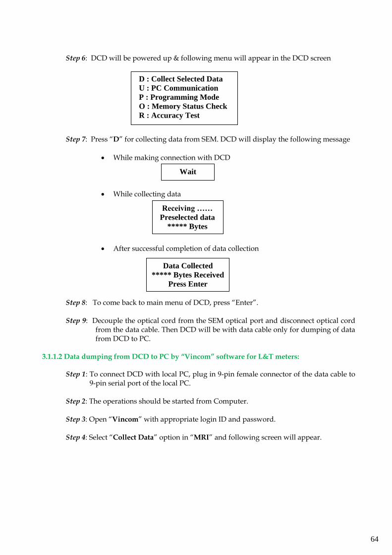
64
Step 6: DCD will be powered up & following menu will appear in the DCD screen
Step 7: Press “D” for collecting data from SEM. DCD will display the following message
• While making connection with DCD
• While collecting data
• After successful completion of data collection
Step 8: To come back to main menu of DCD, press “Enter”.
Step 9: Decouple the optical cord from the SEM optical port and disconnect optical cord
from the data cable. Then DCD will be with data cable only for dumping of data from DCD to PC.
3.1.1.2 Data dumping from DCD to PC by “Vincom” software for L&T meters:
Step 1: To connect DCD with local PC, plug in 9-pin female connector of the data cable to 9-pin serial port of the local PC.
Step 2: The operations should be started from Computer.
Step 3: Open “Vincom” with appropriate login ID and password.
Step 4: Select “Collect Data” option in “MRI” and following screen will appear.
Wait
Data Collected
***** Bytes Received
Press Enter
D : Collect Selected Data
U : PC Communication
P : Programming Mode
O : Memory Status Check
R : Accuracy Test
Receiving ……
Preselected data
***** Bytes
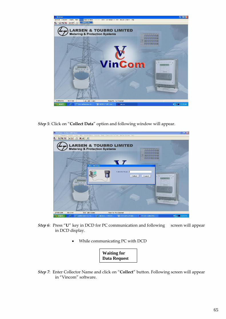
65
Step 5: Click on “Collect Data” option and following window will appear.
Step 6: Press “U” key in DCD for PC communication and following screen will appear in DCD display.
• While communicating PC with DCD
Step 7: Enter Collector Name and click on “Collect” button. Following screen will appear in “Vincom” software.
Waiting for
Data Request
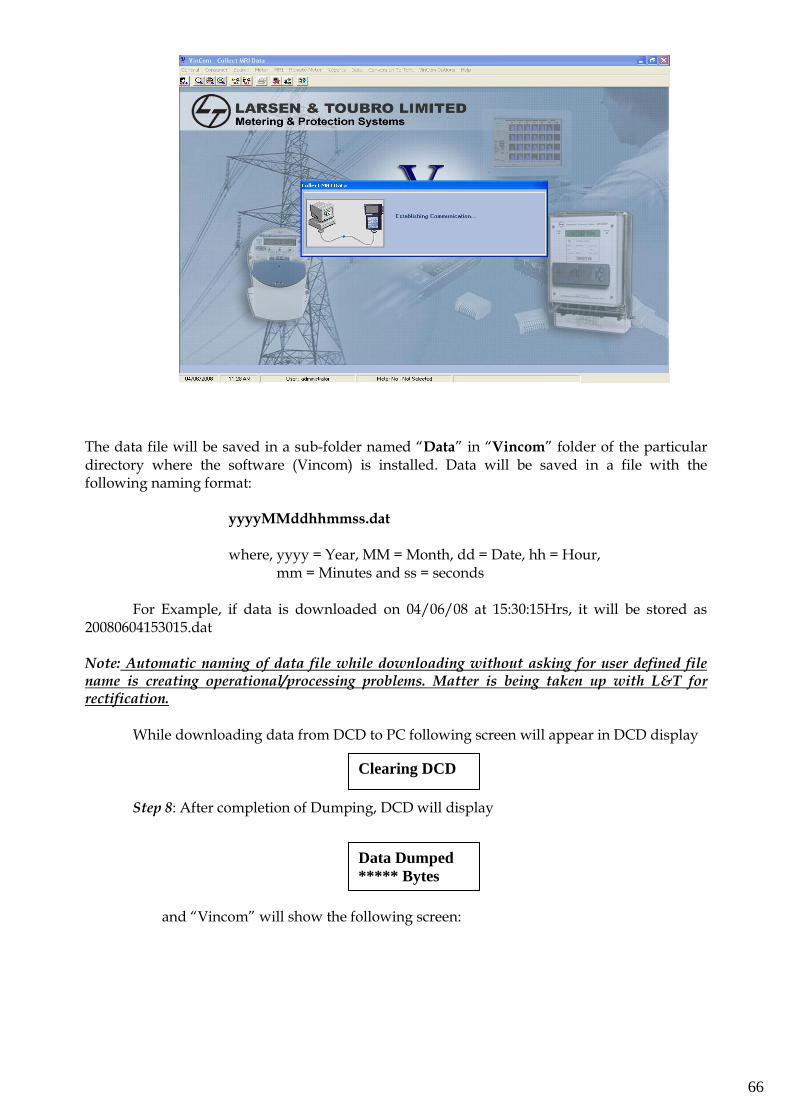
66
The data file will be saved in a sub-folder named “Data” in “Vincom” folder of the particular directory where the software (Vincom) is installed. Data will be saved in a file with the following naming format:
yyyyMMddhhmmss.dat
where, yyyy = Year, MM = Month, dd = Date, hh = Hour,
mm = Minutes and ss = seconds
For Example, if data is downloaded on 04/06/08 at 15:30:15Hrs, it will be stored as 20080604153015.dat Note: Automatic naming of data file while downloading without asking for user defined file name is creating operational/processing problems. Matter is being taken up with L&T for rectification.
While downloading data from DCD to PC following screen will appear in DCD display
Step 8: After completion of Dumping, DCD will display
and “Vincom” will show the following screen:
Data Dumped
***** Bytes
Clearing DCD
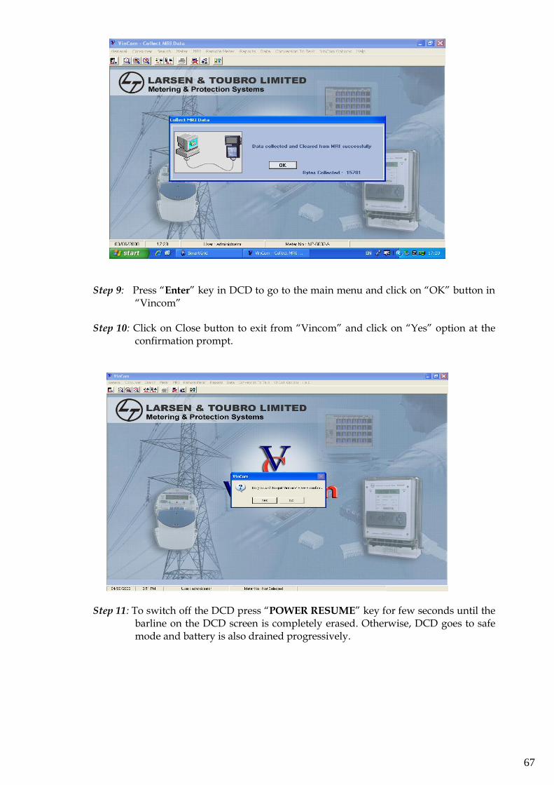
67
Step 9: Press “Enter” key in DCD to go to the main menu and click on “OK” button in
“Vincom” Step 10: Click on Close button to exit from “Vincom” and click on “Yes” option at the
confirmation prompt.
Step 11: To switch off the DCD press “POWER RESUME” key for few seconds until the barline on the DCD screen is completely erased. Otherwise, DCD goes to safe mode and battery is also drained progressively.
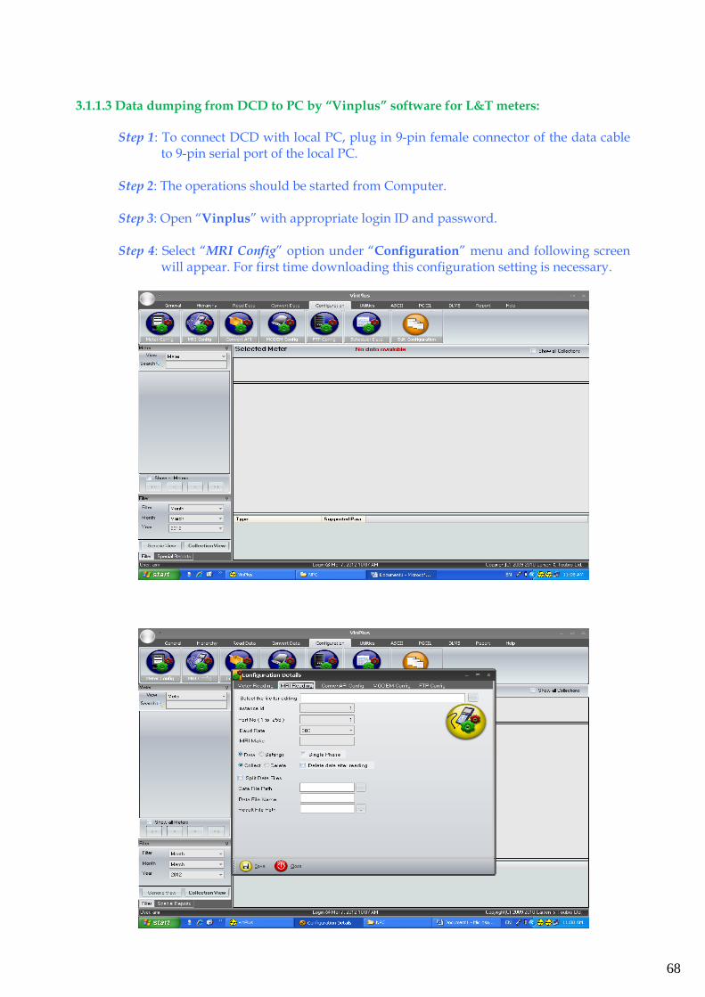
68
3.1.1.3 Data dumping from DCD to PC by “Vinplus” software for L&T meters:
Step 1: To connect DCD with local PC, plug in 9-pin female connector of the data cable to 9-pin serial port of the local PC.
Step 2: The operations should be started from Computer.
Step 3: Open “Vinplus” with appropriate login ID and password.
Step 4: Select “MRI Config” option under “Configuration” menu and following screen
will appear. For first time downloading this configuration setting is necessary.
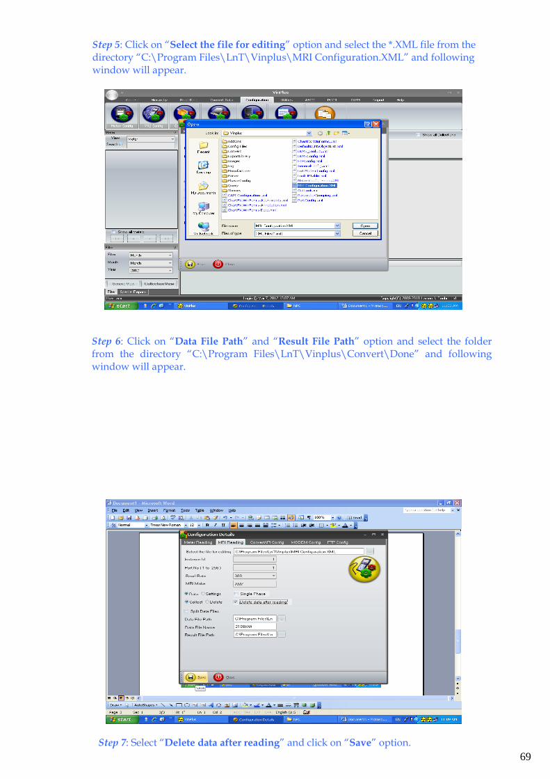
69
Step 5: Click on “Select the file for editing” option and select the *.XML file from the directory “C:\Program Files\LnT\Vinplus\MRI Configuration.XML” and following window will appear.
Step 6: Click on “Data File Path” and “Result File Path” option and select the folder from the directory “C:\Program Files\LnT\Vinplus\Convert\Done” and following window will appear.
Step 7: Select “Delete data after reading” and click on “Save” option.
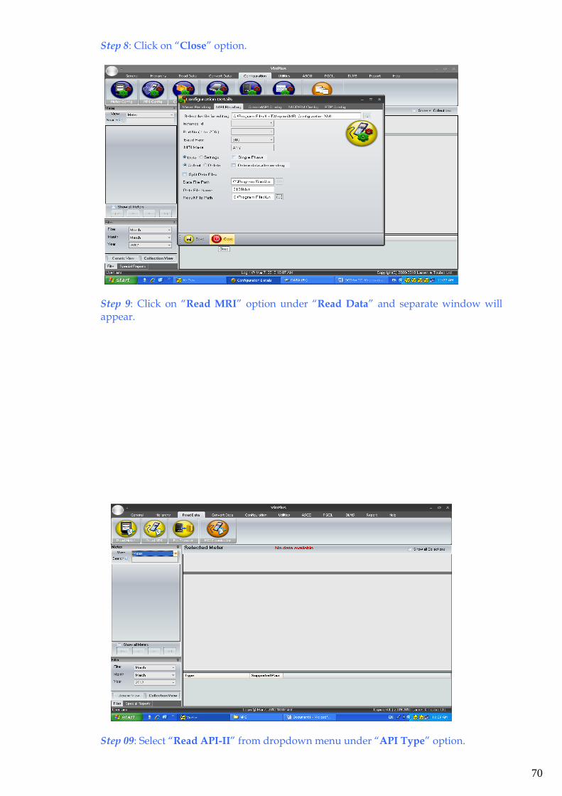
70
Step 8: Click on “Close” option.
Step 9: Click on “Read MRI” option under “Read Data” and separate window will appear.
Step 09: Select “Read API-II” from dropdown menu under “API Type” option.
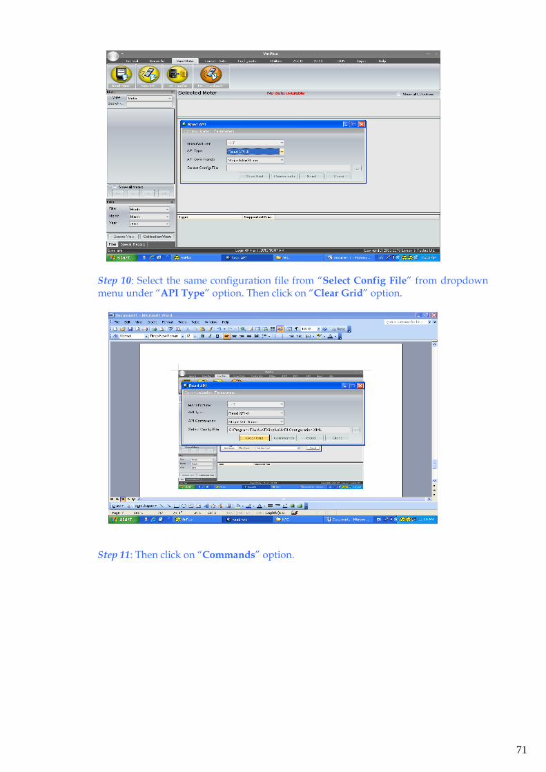
71
Step 10: Select the same configuration file from “Select Config File” from dropdown menu under “API Type” option. Then click on “Clear Grid” option.
Step 11: Then click on “Commands” option.
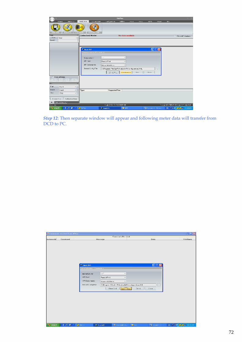
72
Step 12: Then separate window will appear and following meter data will transfer from DCD to PC.
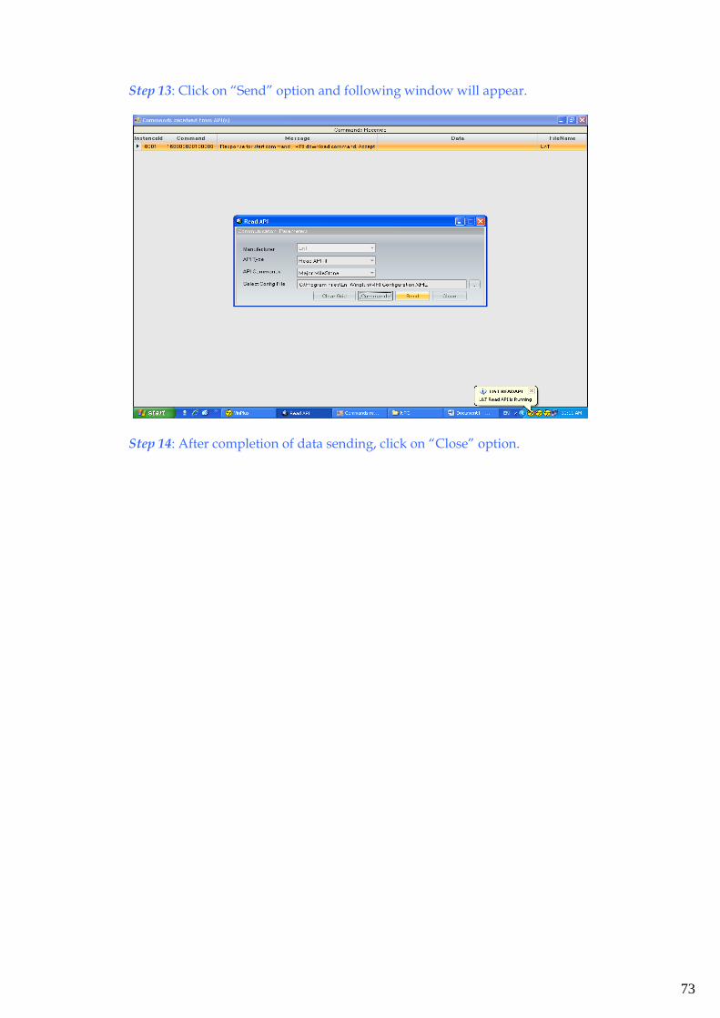
73
Step 13: Click on “Send” option and following window will appear.
Step 14: After completion of data sending, click on “Close” option.
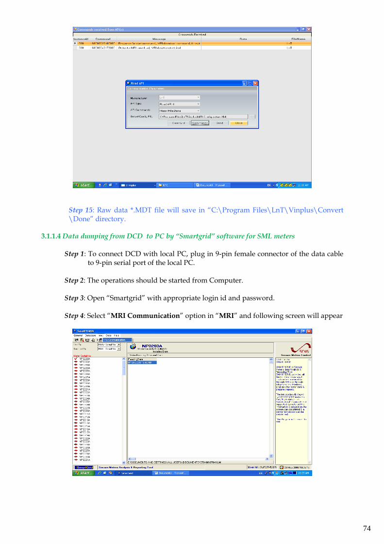
74
Step 15: Raw data *.MDT file will save in “C:\Program Files\LnT\Vinplus\Convert \Done” directory.
3.1.1.4 Data dumping from DCD to PC by “Smartgrid” software for SML meters
Step 1: To connect DCD with local PC, plug in 9-pin female connector of the data cable to 9-pin serial port of the local PC.
Step 2: The operations should be started from Computer.
Step 3: Open “Smartgrid” with appropriate login id and password.
Step 4: Select “MRI Communication” option in “MRI” and following screen will appear
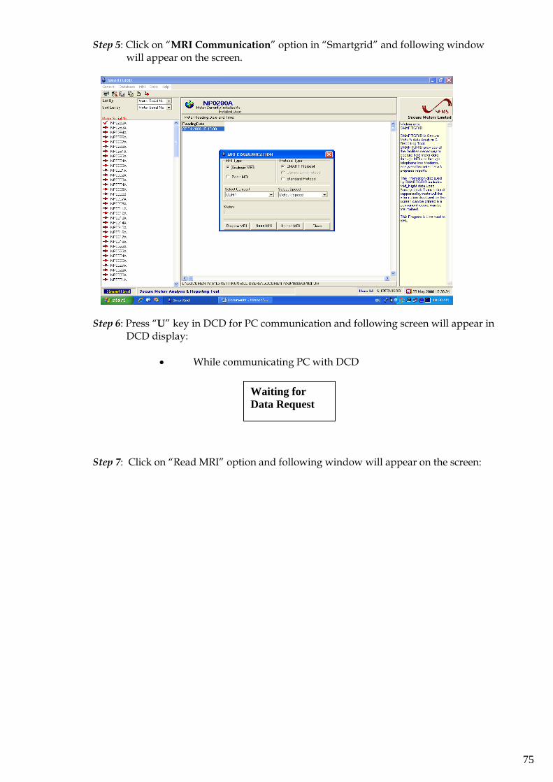
75
Step 5: Click on “MRI Communication” option in “Smartgrid” and following window will appear on the screen.
Step 6: Press “U” key in DCD for PC communication and following screen will appear in
DCD display:
• While communicating PC with DCD
Step 7: Click on “Read MRI” option and following window will appear on the screen:
Waiting for
Data Request
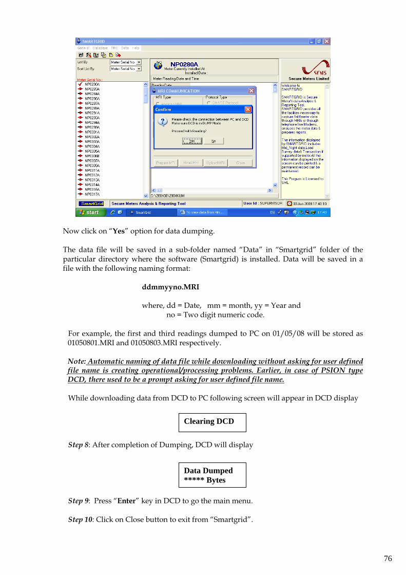
76
Now click on “Yes” option for data dumping.
The data file will be saved in a sub-folder named “Data” in “Smartgrid” folder of the particular directory where the software (Smartgrid) is installed. Data will be saved in a file with the following naming format:
ddmmyyno.MRI
where, dd = Date, mm = month, yy = Year and
no = Two digit numeric code.
For example, the first and third readings dumped to PC on 01/05/08 will be stored as 01050801.MRI and 01050803.MRI respectively. Note: Automatic naming of data file while downloading without asking for user defined file name is creating operational/processing problems. Earlier, in case of PSION type DCD, there used to be a prompt asking for user defined file name. While downloading data from DCD to PC following screen will appear in DCD display
Step 8: After completion of Dumping, DCD will display
Step 9: Press “Enter” key in DCD to go the main menu.
Step 10: Click on Close button to exit from “Smartgrid”.
Data Dumped
***** Bytes
Clearing DCD
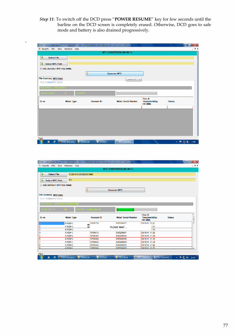
77
Step 11: To switch off the DCD press “POWER RESUME” key for few seconds until the barline on the DCD screen is completely erased. Otherwise, DCD goes to safe mode and battery is also drained progressively.
.
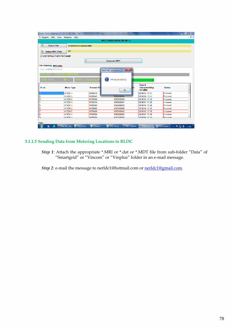
78
3.1.1.5 Sending Data from Metering Locations to RLDC
Step 1: Attach the appropriate *.MRI or *.dat or *.MDT file from sub-folder “Data” of “Smartgrid” or “Vincom” or “Vinplus” folder in an e-mail message.
Step 2: e-mail the message to [email protected] or [email protected].
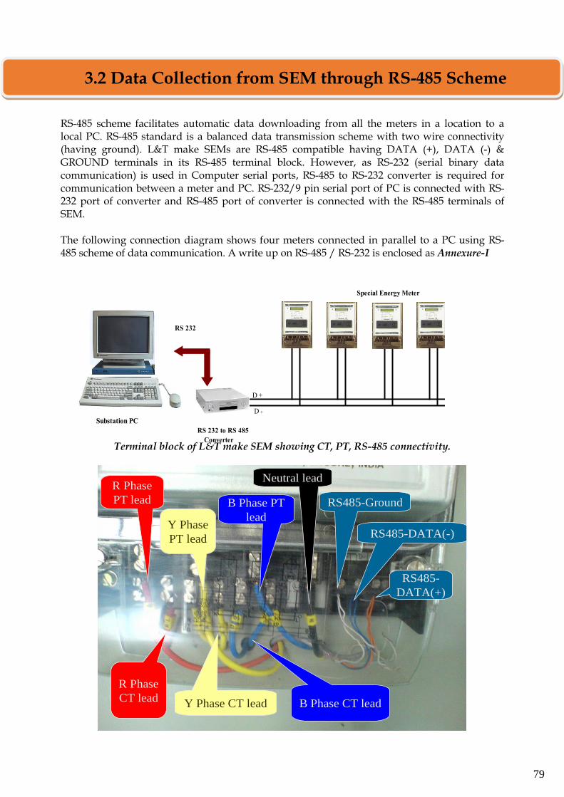
79
RS-485 scheme facilitates automatic data downloading from all the meters in a location to a local PC. RS-485 standard is a balanced data transmission scheme with two wire connectivity (having ground). L&T make SEMs are RS-485 compatible having DATA (+), DATA (-) & GROUND terminals in its RS-485 terminal block. However, as RS-232 (serial binary data communication) is used in Computer serial ports, RS-485 to RS-232 converter is required for communication between a meter and PC. RS-232/9 pin serial port of PC is connected with RS-232 port of converter and RS-485 port of converter is connected with the RS-485 terminals of SEM. The following connection diagram shows four meters connected in parallel to a PC using RS-485 scheme of data communication. A write up on RS-485 / RS-232 is enclosed as Annexure-I
Terminal block of L&T make SEM showing CT, PT, RS-485 connectivity.
R Phase
PT lead
B Phase CT leadY Phase CT lead
R Phase
CT lead
Y Phase
PT lead
B Phase PT
lead
Neutral lead
RS485-Ground
RS485-DATA(-)
RS485-
DATA(+)
RS 232
D +
D -
RS 232 to RS 485
Converter
Substation PC
Special Energy Meter
3.2 Data Collection from SEM through RS-485 Scheme
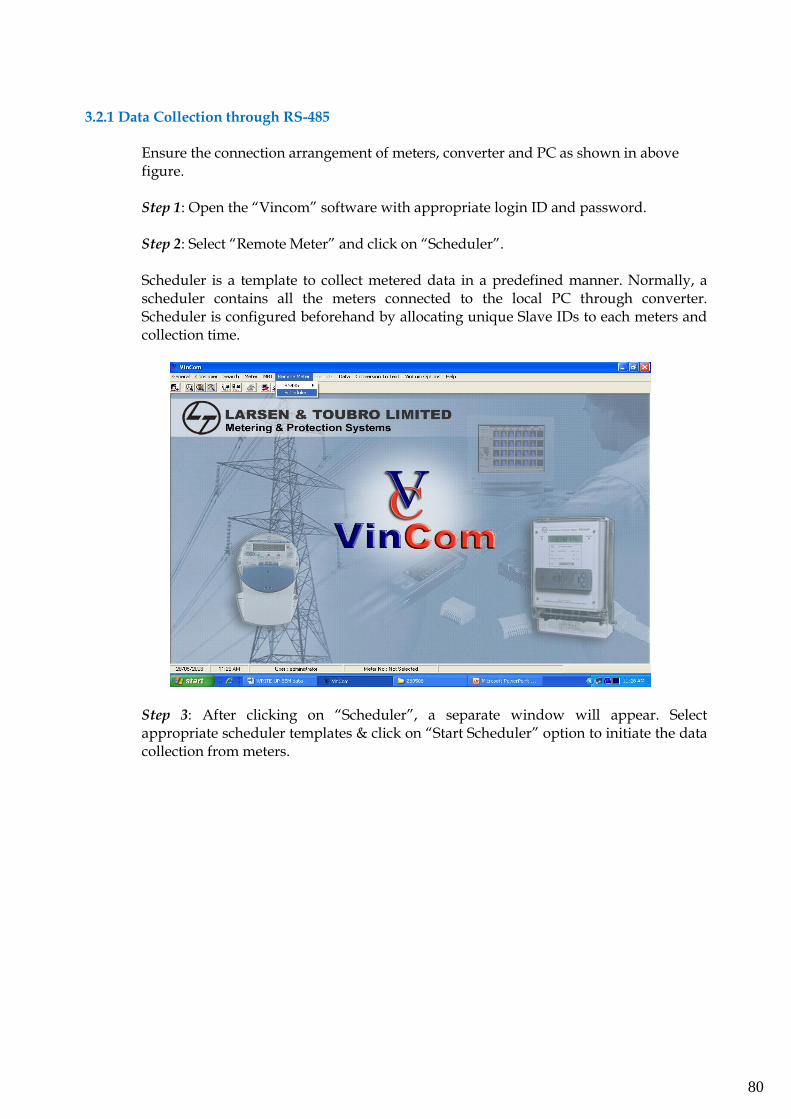
80
3.2.1 Data Collection through RS-485
Ensure the connection arrangement of meters, converter and PC as shown in above figure. Step 1: Open the “Vincom” software with appropriate login ID and password. Step 2: Select “Remote Meter” and click on “Scheduler”. Scheduler is a template to collect metered data in a predefined manner. Normally, a scheduler contains all the meters connected to the local PC through converter. Scheduler is configured beforehand by allocating unique Slave IDs to each meters and collection time.
Step 3: After clicking on “Scheduler”, a separate window will appear. Select appropriate scheduler templates & click on “Start Scheduler” option to initiate the data collection from meters.
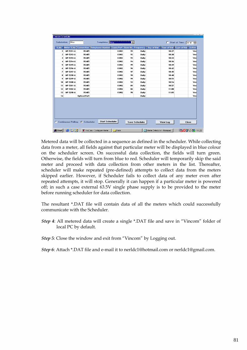
81
Metered data will be collected in a sequence as defined in the scheduler. While collecting data from a meter, all fields against that particular meter will be displayed in blue colour on the scheduler screen. On successful data collection, the fields will turn green. Otherwise, the fields will turn from blue to red. Scheduler will temporarily skip the said meter and proceed with data collection from other meters in the list. Thereafter, scheduler will make repeated (pre-defined) attempts to collect data from the meters skipped earlier. However, if Scheduler fails to collect data of any meter even after repeated attempts, it will stop. Generally it can happen if a particular meter is powered off; in such a case external 63.5V single phase supply is to be provided to the meter before running scheduler for data collection. The resultant *.DAT file will contain data of all the meters which could successfully communicate with the Scheduler.
Step 4: All metered data will create a single *.DAT file and save in “Vincom” folder of
local PC by default.
Step 5: Close the window and exit from “Vincom” by Logging out.
Step 6: Attach *.DAT file and e-mail it to [email protected] or [email protected].
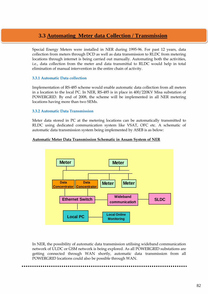
82
Special Energy Meters were installed in NER during 1995-96. For past 12 years, data collection from meters through DCD as well as data transmission to RLDC from metering locations through internet is being carried out manually. Automating both the activities, i.e., data collection from the meter and data transmittal to RLDC would help in total elimination of manual intervention in the entire chain of activity. 3.3.1 Automatic Data collection Implementation of RS-485 scheme would enable automatic data collection from all meters in a location to the local PC. In NER, RS-485 is in place in 400/220KV Misa substation of POWERGRID. By end of 2008, the scheme will be implemented in all NER metering locations having more than two SEMs.
3.3.2 Automatic Data Transmission Meter data stored in PC at the metering locations can be automatically transmitted to RLDC using dedicated communication system like VSAT, OFC etc. A schematic of automatic data transmission system being implemented by ASEB is as below:
Automatic Meter Data Transmission Schematic in Assam System of NER
In NER, the possibility of automatic data transmission utilising wideband communication network of ULDC or GSM network is being explored. As all POWERGRID substations are getting connected through WAN shortly, automatic data transmission from all POWERGRID locations could also be possible through WAN.
Metering architecture of ASEB for Intra-State ABT
Meter
Data
Concentrator
Data
ConcentratorMeter Meter
Ethernet Switch
Local PCLocal Online
Monitoring
Meter
Wideband
communicationSLDC
3.3 Automating Meter data Collection / Transmission
83
In this section all activities have been discussed in details, sequentially, starting with receipt of SEM data at NERLDC till sending processed meter data to NERPC for computation and issuance of weekly Unscheduled Interchange (UI) Account as well as Reactive Energy Account.
Further, in the concluding part of this section, a brief on post processing activities and data archival has also been covered.
Meter data (*.mri, *.RM3*.dat and *.MDT files) downloaded at various locations of NER are electronically sent to NERLDC through e-mail. First activity pertaining to meter data begins after receipt of these data at NERLDC preferably by Tuesday of every week. The data are viewed and checked to ensure that data of every meter under the jurisdiction of a particular location have been collected as per stipulated time frame. Initially, received meter data in binary format (*.mri in case of Secure Meters and *.dat or *.MDT in case of L&T Meters) is temporarily stored in a directory for viewing / checking. Following naming format is used in case of binary files:
ddmmXXX.mri ddmmXXX.dat ddmmXXX.mdt ddmmXXX.RM3
where, ddmm is date and month of collecting data
XXX is three letter code for the location
For example, data collected at Jiribam on 05-05-2008 (Monday) is named as 0505JBM.mri. As data is to be collected on every MONDAY, ddmm naming corresponding to Monday is done even if data is collected on Tuesday for some reason. All locations are naming the files accordingly before sending. In case of aberration, proper naming is given at NERLDC on receipt.
3.4 Receipt of SEM Data at RLDC
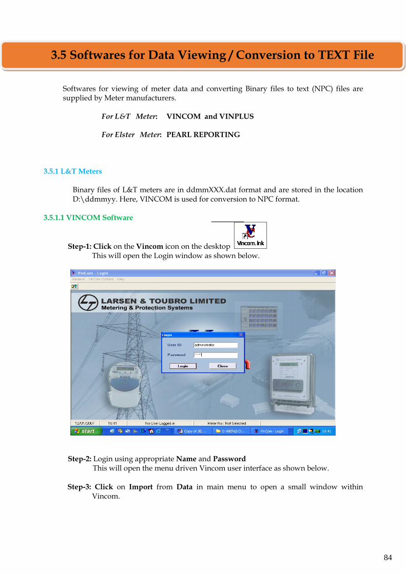
84
Softwares for viewing of meter data and converting Binary files to text (NPC) files are supplied by Meter manufacturers.
For L&T Meter: VINCOM and VINPLUS For Elster Meter: PEARL REPORTING
3.5.1 L&T Meters
Binary files of L&T meters are in ddmmXXX.dat format and are stored in the location D:\ddmmyy. Here, VINCOM is used for conversion to NPC format.
3.5.1.1 VINCOM Software
Step-1: Click on the Vincom icon on the desktop This will open the Login window as shown below.
Step-2: Login using appropriate Name and Password This will open the menu driven Vincom user interface as shown below.
Step-3: Click on Import from Data in main menu to open a small window within
Vincom.
3.5 Softwares for Data Viewing / Conversion to TEXT File
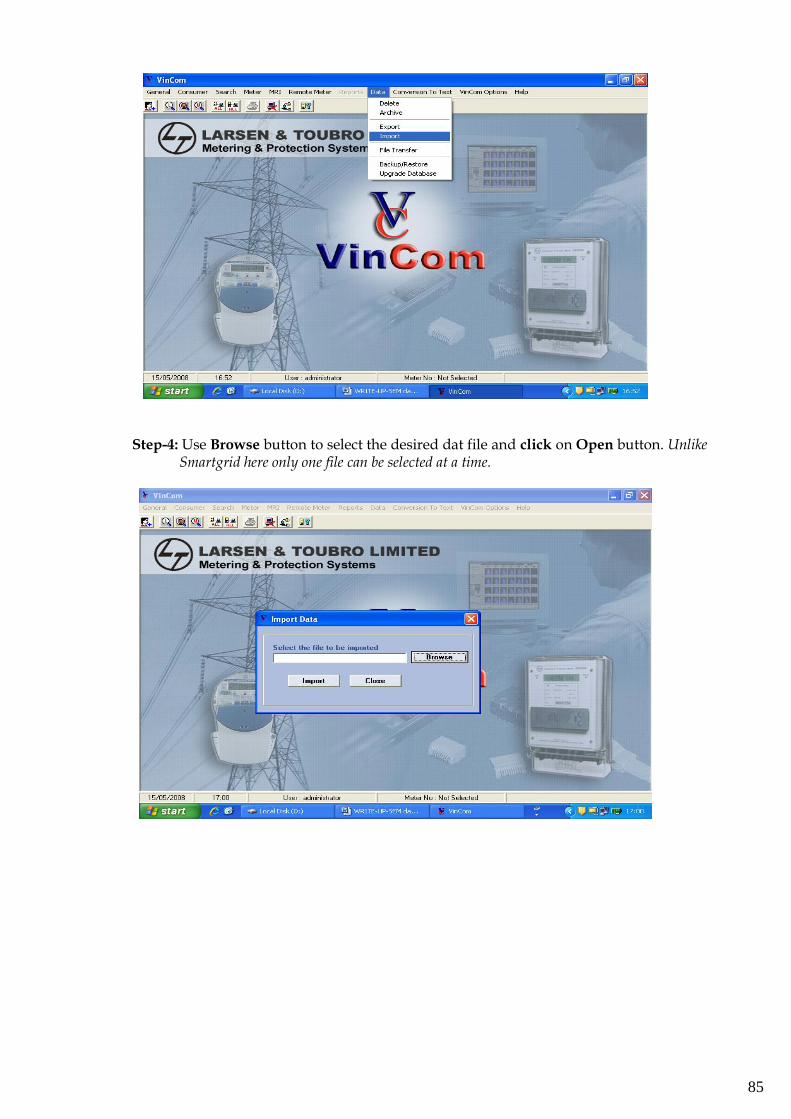
85
Step-4: Use Browse button to select the desired dat file and click on Open button. Unlike
Smartgrid here only one file can be selected at a time.
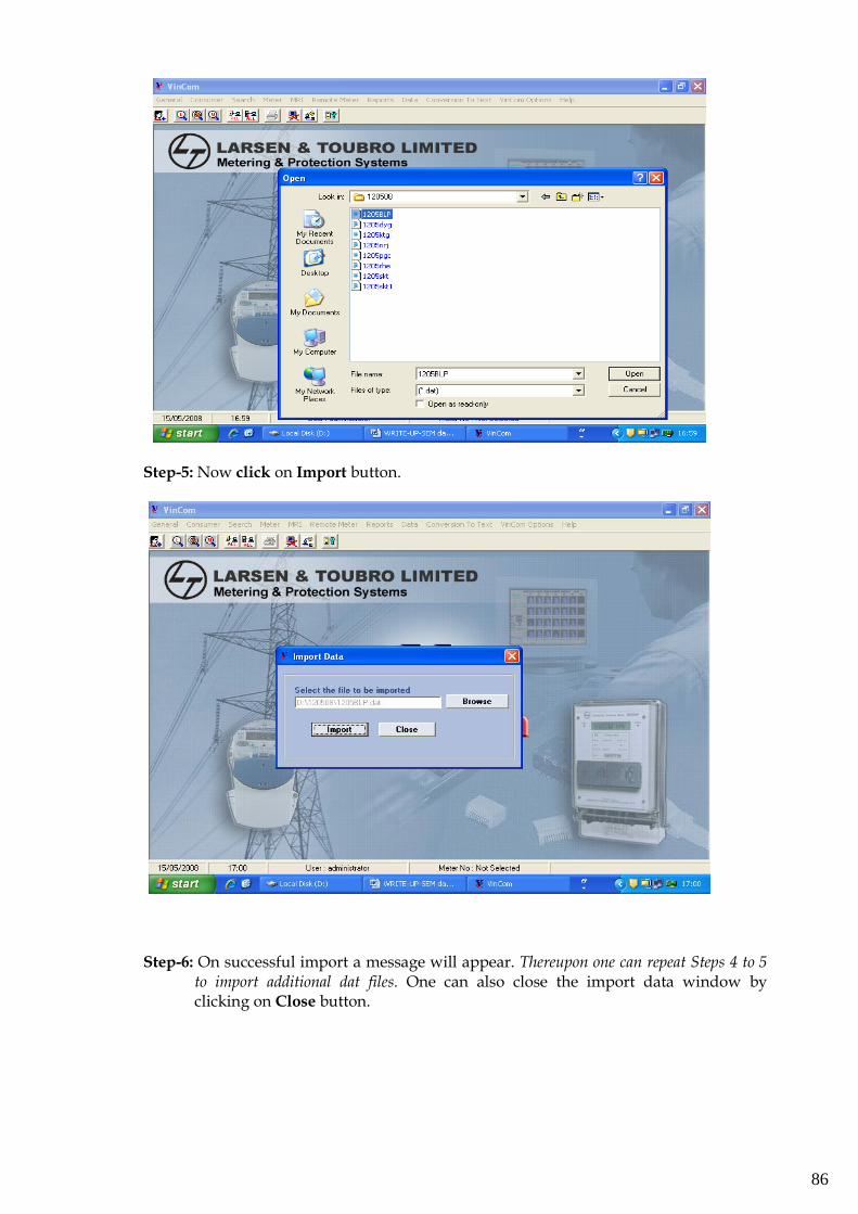
86
Step-5: Now click on Import button.
Step-6: On successful import a message will appear. Thereupon one can repeat Steps 4 to 5 to import additional dat files. One can also close the import data window by clicking on Close button.
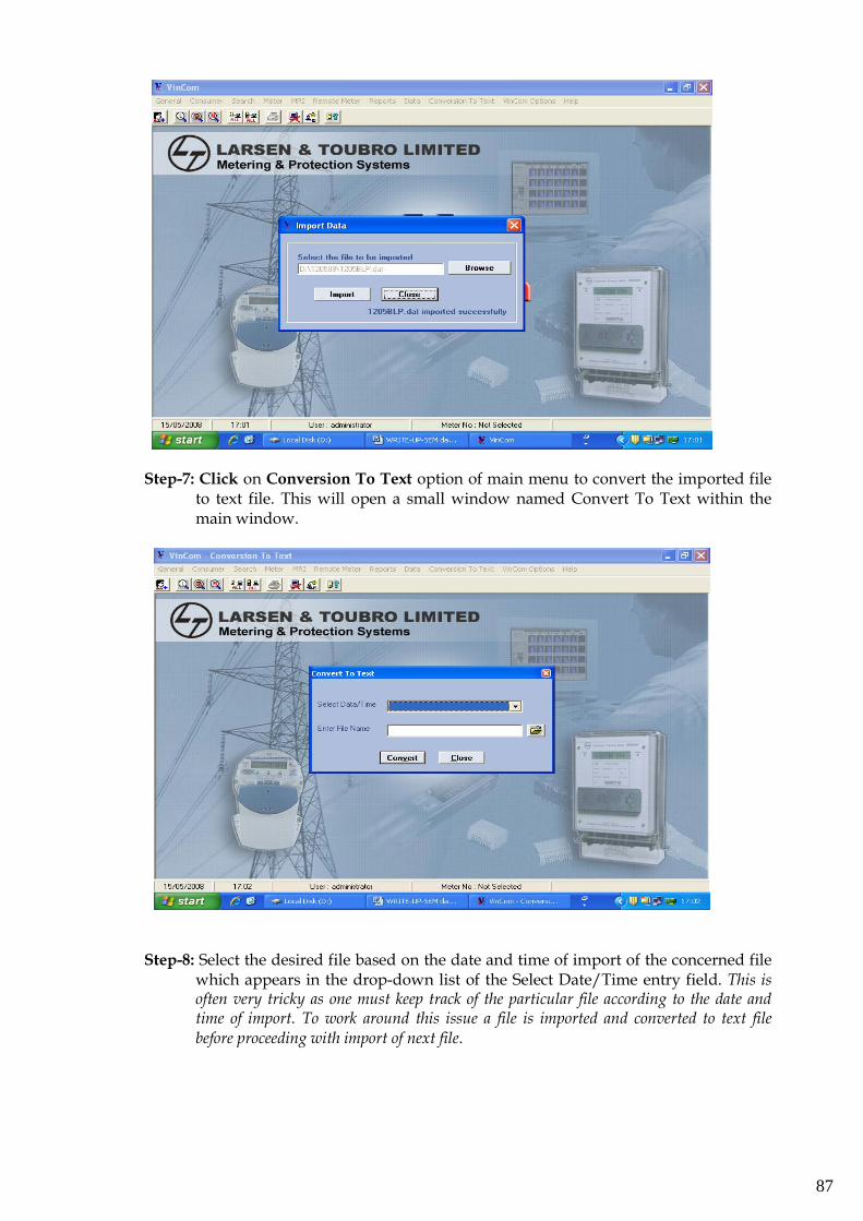
87
Step-7: Click on Conversion To Text option of main menu to convert the imported file to text file. This will open a small window named Convert To Text within the main window.
Step-8: Select the desired file based on the date and time of import of the concerned file which appears in the drop-down list of the Select Date/Time entry field. This is often very tricky as one must keep track of the particular file according to the date and time of import. To work around this issue a file is imported and converted to text file before proceeding with import of next file.
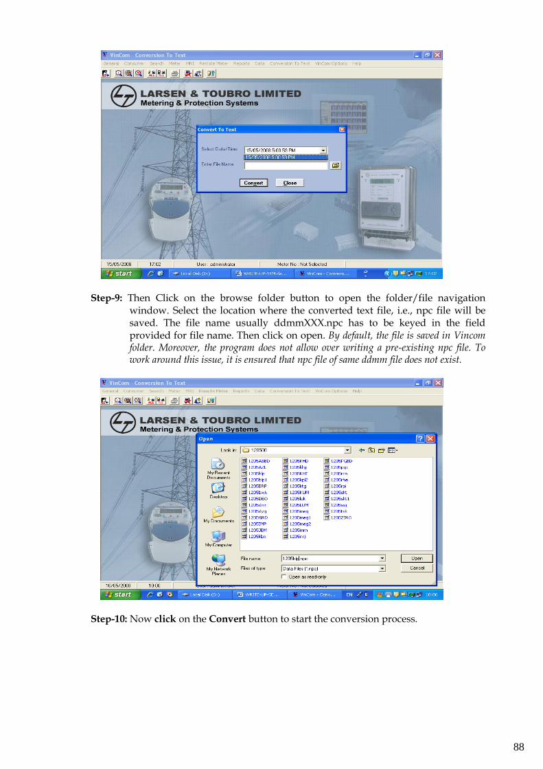
88
Step-9: Then Click on the browse folder button to open the folder/file navigation window. Select the location where the converted text file, i.e., npc file will be saved. The file name usually ddmmXXX.npc has to be keyed in the field provided for file name. Then click on open. By default, the file is saved in Vincom folder. Moreover, the program does not allow over writing a pre-existing npc file. To work around this issue, it is ensured that npc file of same ddmm file does not exist.
Step-10: Now click on the Convert button to start the conversion process.
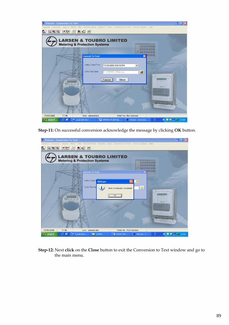
89
Step-11: On successful conversion acknowledge the message by clicking OK button.
Step-12: Next click on the Close button to exit the Conversion to Text window and go to the main menu.
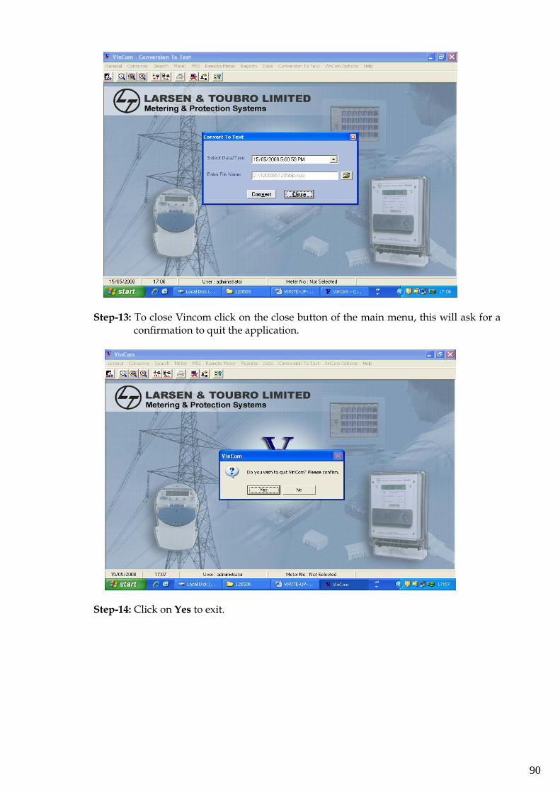
90
Step-13: To close Vincom click on the close button of the main menu, this will ask for a confirmation to quit the application.
Step-14: Click on Yes to exit.

91
3.5.2.2 VINPLUS Software
Step-1: Click on the Vinplus icon on the desktop. This will open the Login window as shown below.
Step-2: Login using appropriate Name and Password This will open the menu driven Vinplus user interface as shown below. Step-3: Click on “Ascii Convert” from “ASCII” in main menu to open a small window
within Vinplus.
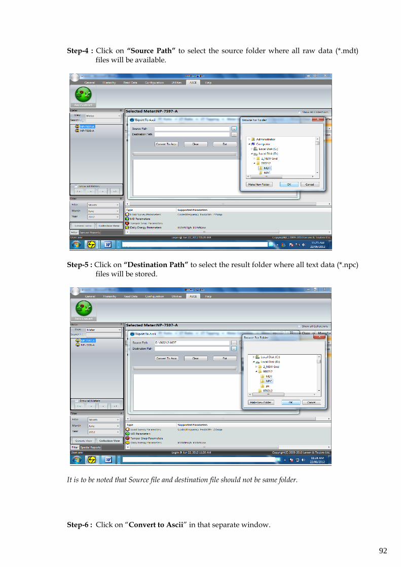
92
Step-4 : Click on “Source Path” to select the source folder where all raw data (*.mdt) files will be available.
Step-5 : Click on “Destination Path” to select the result folder where all text data (*.npc) files will be stored.
It is to be noted that Source file and destination file should not be same folder.
Step-6 : Click on “Convert to Ascii” in that separate window.
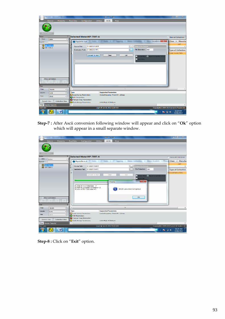
93
Step-7 : After Ascii conversion following window will appear and click on “Ok” option which will appear in a small separate window.
Step-8 : Click on “Exit” option.
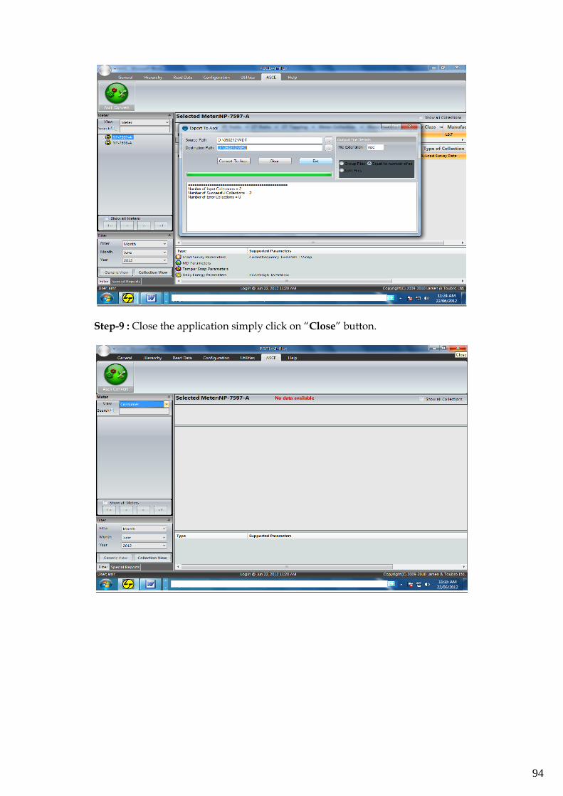
94
Step-9 : Close the application simply click on “Close” button.
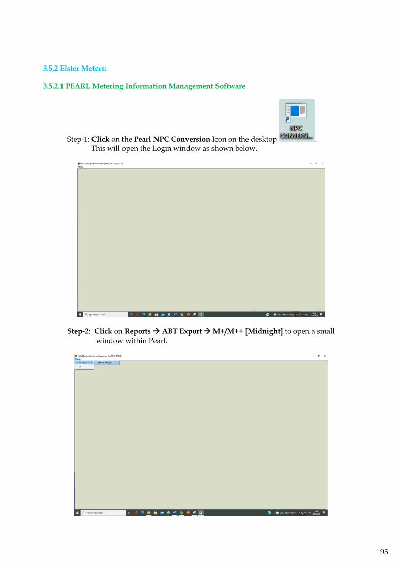
95
3.5.2 Elster Meters: 3.5.2.1 PEARL Metering Information Management Software
Step-1: Click on the Pearl NPC Conversion Icon on the desktop . This will open the Login window as shown below.
Step-2: Click on Reports → ABT Export → M+/M++ [Midnight] to open a small window within Pearl.
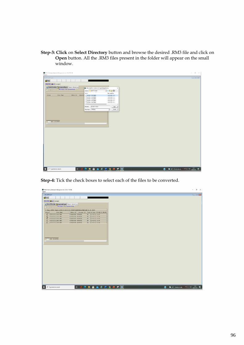
96
Step-3: Click on Select Directory button and browse the desired .RM3 file and click on
Open button. All the .RM3 files present in the folder will appear on the small window.
Step-4: Tick the check boxes to select each of the files to be converted.
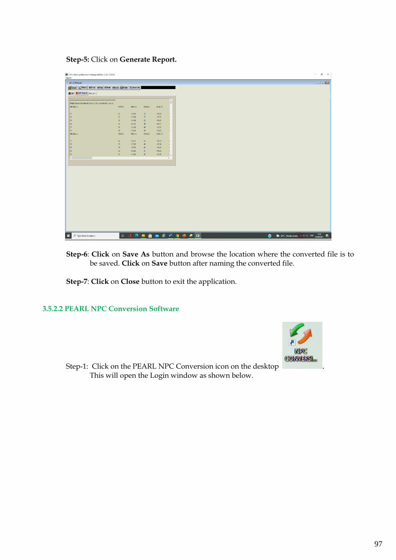
97
Step-5: Click on Generate Report.
Step-6: Click on Save As button and browse the location where the converted file is to be saved. Click on Save button after naming the converted file.
Step-7: Click on Close button to exit the application.
3.5.2.2 PEARL NPC Conversion Software
Step-1: Click on the PEARL NPC Conversion icon on the desktop .
This will open the Login window as shown below.
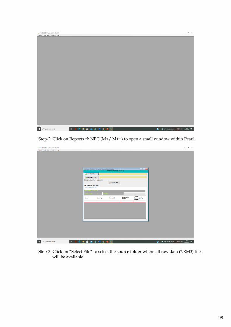
98
Step-2: Click on Reports → NPC (M+/ M++) to open a small window within Pearl.
Step-3: Click on “Select File” to select the source folder where all raw data (*.RM3) files will be available.
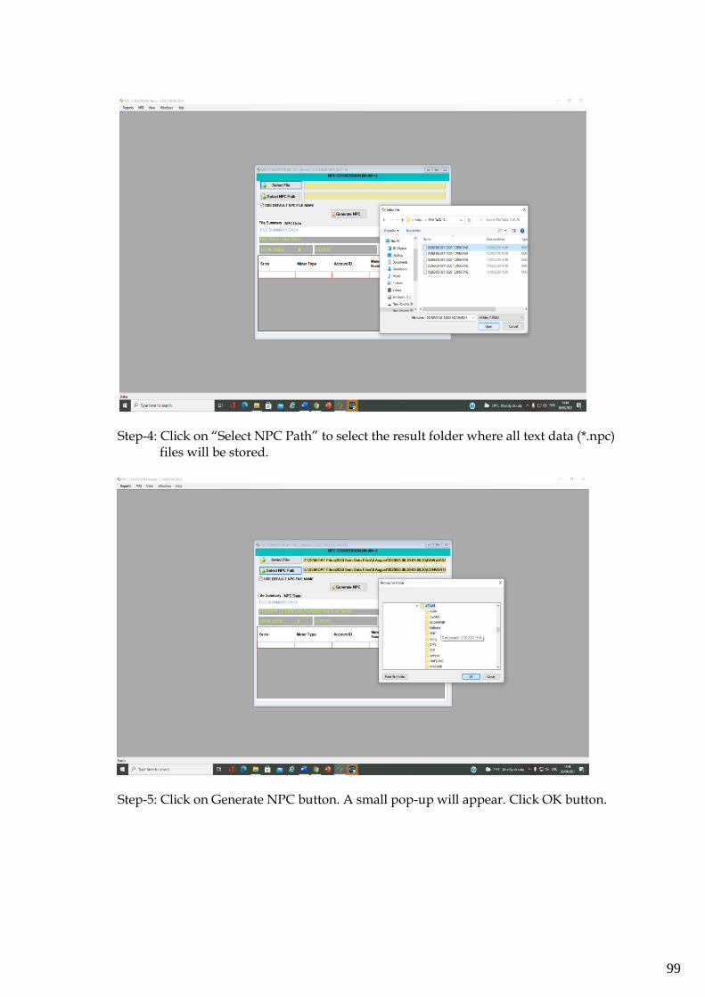
99
Step-4: Click on “Select NPC Path” to select the result folder where all text data (*.npc) files will be stored.
Step-5: Click on Generate NPC button. A small pop-up will appear. Click OK button.
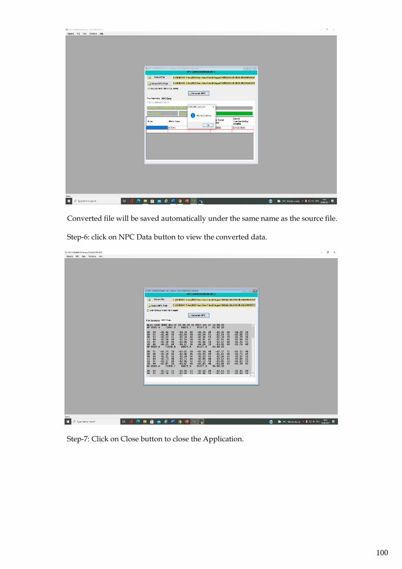
100
Converted file will be saved automatically under the same name as the source file.
Step-6: click on NPC Data button to view the converted data.
Step-7: Click on Close button to close the Application.
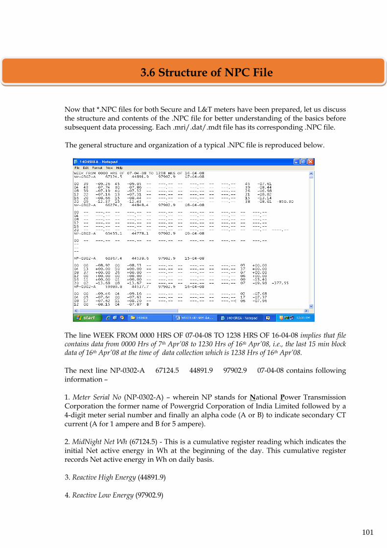
101
Now that *.NPC files for both Secure and L&T meters have been prepared, let us discuss the structure and contents of the .NPC file for better understanding of the basics before subsequent data processing. Each .mri/.dat/.mdt file has its corresponding .NPC file. The general structure and organization of a typical .NPC file is reproduced below.
The line WEEK FROM 0000 HRS OF 07-04-08 TO 1238 HRS OF 16-04-08 implies that file contains data from 0000 Hrs of 7th Apr’08 to 1230 Hrs of 16th Apr’08, i.e., the last 15 min block data of 16th Apr’08 at the time of data collection which is 1238 Hrs of 16th Apr’08. The next line NP-0302-A 67124.5 44891.9 97902.9 07-04-08 contains following information – 1. Meter Serial No (NP-0302-A) – wherein NP stands for National Power Transmission Corporation the former name of Powergrid Corporation of India Limited followed by a 4-digit meter serial number and finally an alpha code (A or B) to indicate secondary CT current (A for 1 ampere and B for 5 ampere).
2. MidNight Net Wh (67124.5) - This is a cumulative register reading which indicates the initial Net active energy in Wh at the beginning of the day. This cumulative register records Net active energy in Wh on daily basis.
3. Reactive High Energy (44891.9) 4. Reactive Low Energy (97902.9)
3.6 Structure of NPC File
102
There are two cumulative registers which record the reactive energy (VARh) exchange on daily basis under high and low voltage conditions, i.e., when RMS voltage is >=103%Vn and when RMS volage is <97%Vn but >70%Vn
Cumulative net Wh, net VARh for voltage high and voltage low condition at each midnight is recorded in 5 main digits and 1 decimal digit. These figures are always positive and cycles from 0 to 99999.9 in forward or backward direction depending on energy export or import. 5. Date (07-04-08) – This indicates that the 6 Rows X 16 Columns arrangement of data pertains to this date.
Next is the blockwise data arranged as 16 block data in each row and total 6 rows for complete 24 hours (96 time blocks of 15 min each) data with the following format:
StartingHour AvgFreq StatusIndication NetEnergy AvgFreq StatusIndication NetEnergy....
StartingHour indicates the time in hour at the beginning of each of the 6 rows.
AvgFreq (average frequency) is recorded for every 15 min block as a 2-digit code ( 0 to 99) and is computed based on the no. of voltage cycles in one 15 min block divided by (15*60=900). Computation of average frequency is done only for the period during which the VT supply was available in the 15 min block under consideration. The frequency data is available for each successive 15 min block in encoded form as (Average frequency – 49.5)*100 and neglecting decimals. When frequency is <=49.5 it is recorded as 0 and when the frequency is >=50.5 it is recorded as 99. The actual frequency corresponding to two consecutive codes differ by 0.01Hz.
StatusIndication may be either ‘*’ to indicate supply down or supply failure which might be momentary or might have lasted for several blocks Or ‘rr’ to indicate time retardation undergone Or ‘aa’ to indicate time advance undergone. Finally sum of net energies (96 blocks) is given at the end of last row of the day having complete 24 hours data.
Advance/Retard RTC command : Using these commands, 6 consecutive 15 min time blocks are contracted/elongated by 10 seconds each (with the first 15 min block being the closest 15 min block from the time of keying in the RTC command). Moreover once advance/retard RTC command is given, a lock-out of seven days sets in which implies that the next RTC command can be given only after seven days of the earlier RTC command. This implies that only 1 min time correction can be executed over a week. There is ‘aa’ or ‘rr’ indication stamped against the corresponding 15 min time blocks for which advance or retard RTC was executed. A ‘*’ indication implies power failure in the corresponding 15 min block or RMS voltage in any or all phases was <70%Vn for at least 3 secs. NetEnergy (active energy) is recorded by the meters in Wh for every 15 min based on the average active energy exchange for the time block considered. Net Wh data is available for each successive 15 min time block up to second decimal with plus/minus sign corresponding to energy export/import.
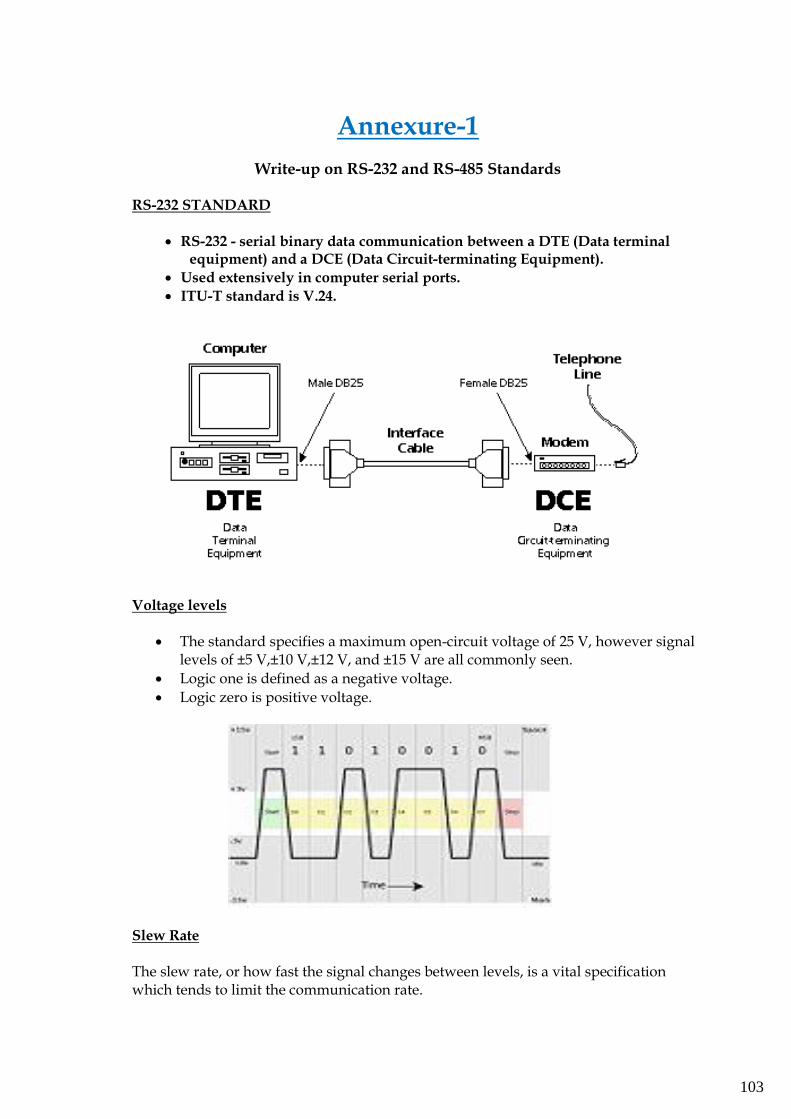
103
Annexure-1
Write-up on RS-232 and RS-485 Standards
RS-232 STANDARD
• RS-232 - serial binary data communication between a DTE (Data terminal equipment) and a DCE (Data Circuit-terminating Equipment).
• Used extensively in computer serial ports.
• ITU-T standard is V.24.
Voltage levels
• The standard specifies a maximum open-circuit voltage of 25 V, however signal levels of ±5 V,±10 V,±12 V, and ±15 V are all commonly seen.
• Logic one is defined as a negative voltage.
• Logic zero is positive voltage.
Slew Rate
The slew rate, or how fast the signal changes between levels, is a vital specification which tends to limit the communication rate.
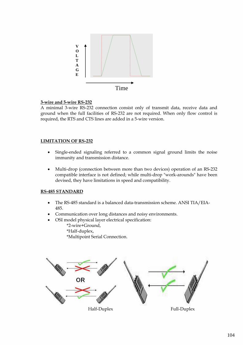
104
3-wire and 5-wire RS-232 A minimal 3-wire RS-232 connection consist only of transmit data, receive data and ground when the full facilities of RS-232 are not required. When only flow control is required, the RTS and CTS lines are added in a 5-wire version.
LIMITATION OF RS-232
• Single-ended signaling referred to a common signal ground limits the noise immunity and transmission distance.
• Multi-drop (connection between more than two devices) operation of an RS-232 compatible interface is not defined; while multi-drop "work-arounds" have been devised, they have limitations in speed and compatibility.
RS-485 STANDARD
• The RS-485 standard is a balanced data-transmission scheme. ANSI TIA/EIA-485.
• Communication over long distances and noisy environments.
• OSI model physical layer electrical specification: *2-wire+Ground, *Half-duplex, *Multipoint Serial Connection.
Half-Duplex Full-Duplex
Time
V
O
L
T
A
G
E
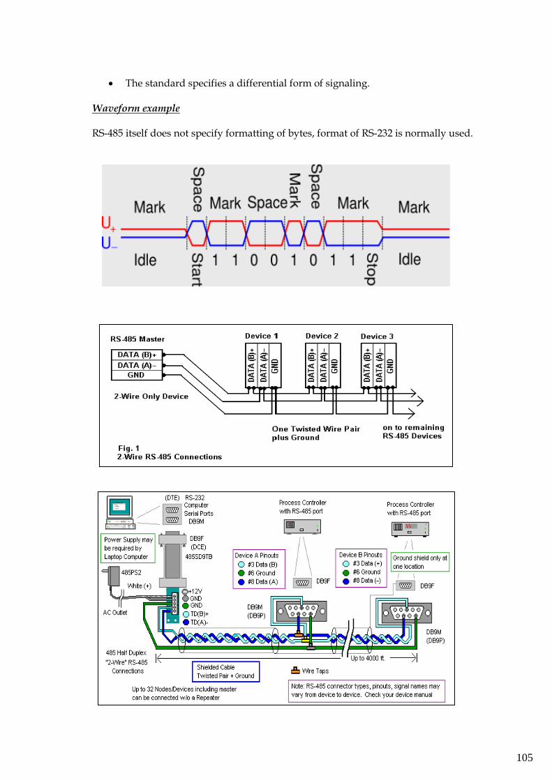
105
• The standard specifies a differential form of signaling.
Waveform example RS-485 itself does not specify formatting of bytes, format of RS-232 is normally used.
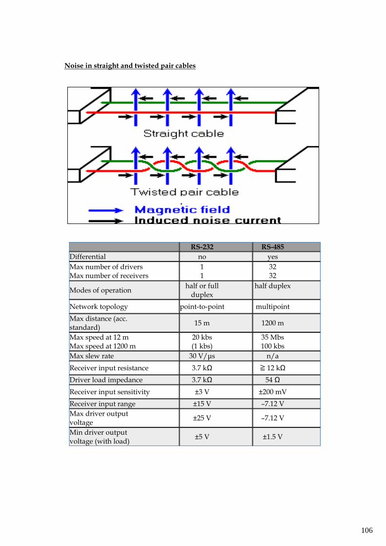
106
Noise in straight and twisted pair cables
RS-232 RS-485
Differential no yes
Max number of drivers Max number of receivers
1 1
32 32
Modes of operation half or full
duplex half duplex
Network topology point-to-point multipoint
Max distance (acc. standard)
15 m 1200 m
Max speed at 12 m Max speed at 1200 m
20 kbs (1 kbs)
35 Mbs 100 kbs
Max slew rate 30 V/μs n/a
Receiver input resistance 3.7 kΩ ≧ 12 kΩ
Driver load impedance 3.7 kΩ 54 Ω
Receiver input sensitivity ±3 V ±200 mV
Receiver input range ±15 V –7.12 V
Max driver output voltage
±25 V –7.12 V
Min driver output voltage (with load)
±5 V ±1.5 V
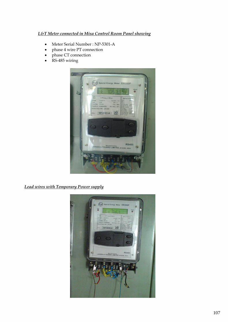
107
L&T Meter connected in Misa Control Room Panel showing
• Meter Serial Number : NP-5301-A
• phase 4 wire PT connection
• phase CT connection
• RS-485 wiring
Lead wires with Temporary Power supply
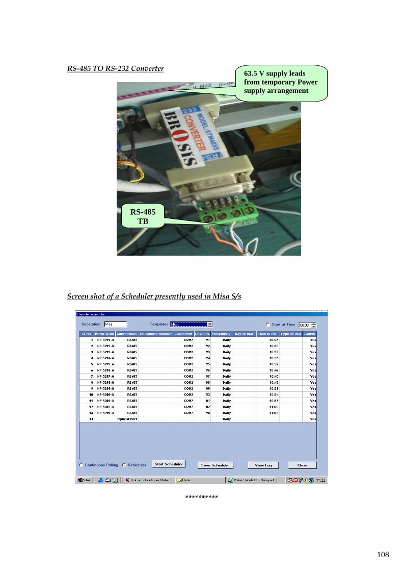
108
RS-485 TO RS-232 Converter
Screen shot of a Scheduler presently used in Misa S/s
**********
63.5 V supply leads
from temporary Power
supply arrangement
RS-485
TB
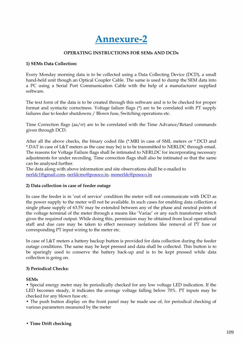
109
Annexure-2
OPERATING INSTRUCTIONS FOR SEMs AND DCDs
1) SEMs Data Collection: Every Monday morning data is to be collected using a Data Collecting Device (DCD), a small hand-held unit though an Optical Coupler Cable. The same is used to dump the SEM data into a PC using a Serial Port Communication Cable with the help of a manufacturer supplied software. The text form of the data is to be created through this software and is to be checked for proper format and syntactic correctness. Voltage failure flags (*) are to be correlated with PT supply failures due to feeder shutdowns / Blown fuse, Switching operations etc. Time Correction flags (aa/rr) are to be correlated with the Time Advance/Retard commands given through DCD. After all the above checks, the binary coded file (*.MRI in case of SML meters or *.DCD and *.DAT in case of L&T meters as the case may be) is to be transmitted to NERLDC through email. The reasons for Voltage Failure flags shall be intimated to NERLDC for incorporating necessary adjustments for under recording. Time correction flags shall also be intimated so that the same can be analysed further. The data along with above information and site observations shall be e-mailed to [email protected], [email protected], [email protected] 2) Data collection in case of feeder outage In case the feeder is in ‘out of service’ condition the meter will not communicate with DCD as the power supply to the meter will not be available. In such cases for enabling data collection a single phase supply of 63.5V may be extended between any of the phase and neutral points of the voltage terminal of the meter through a means like ‘Variac’ or any such transformer which gives the required output. While doing this, permission may be obtained from local operational staff and due care may be taken to effect necessary isolations like removal of PT fuse or corresponding PT input wiring to the meter etc. In case of L&T meters a battery backup button is provided for data collection during the feeder outage conditions. The same may be kept pressed and data shall be collected. This button is to be sparingly used to conserve the battery back-up and is to be kept pressed while data collection is going on. 3) Periodical Checks: SEMs • Special energy meter may be periodically checked for any low voltage LED indication. If the LED becomes steady, it indicates the average voltage falling below 70%. PT inputs may be checked for any blown fuse etc. • The push button display on the front panel may be made use of, for periodical checking of various parameters measured by the meter • Time Drift checking
110
Since the data recorded by SEM is time stamped (15 min. block data), it is very important to maintain the time of the meter, as it is prone to drift due to inherent variation of parameters like temperature, humidity etc. The time of the meter (Real Time Clock) as shown on the display panel of the SEM may be periodically checked for its correctness with respect to GPS/AIR time. When the time drift is more than 1 minute, necessary correction through the DCD may be carried out. It may be noted that time correction through DCD can be done by only 1 minute in a week and if the drift is more than 2 minutes, correction may be carried out in successive weeks. Due care may be taken regarding the type of correction i.e. ADVANCE or RETARD depending on whether the meter is SLOW or FAST. All the sites have to send weekly reports on the time drift of the SEMs and also the details of Time corrections carried out. DCDs • Manual for DCD shall be thoroughly studied to ensure proper operation of DCD. • DCD may be carefully handled and preserved in a suitable cover, when not in use. • Healthiness of Data Collecting Device (DCD) and associated cables, accessories like charger, battery etc. shall be maintained to avoid last minute emergencies. • It is preferred to use a fully charged battery with the DCD before data collection. • In case of Analogic DCDs, the DCD may be kept in charged condition for at least 24 hours before data collection. 4) Special precautions SEMs i) Never keep the SEM in De-energised condition for long durations, to avoid drain on the internal battery. In case of spare meters, the SEM may be kept in charged condition by extending the supply to the voltage terminals. ii) Never leave the optical window uncovered. Otherwise entry of dust particles on the window glass may result in problems in data collection because of improper communication of DCD with the meter. iii) Never remove the optical cable from the meter while data collection is in progress. Doing so may result in hanging of the internal processor because the same would be in handshaking mode with the DCD till the data collection process is completed. iv) Never subject the meter to extreme climatic conditions. It may be suitably guarded in a safe panel free from dust and water ingression. DCDs i) Never use a non-chargeable/disposable Battery cell in the DCD as it is prone to improper drain characteristics. ii) Never fold the optical cable used for data collection or data dumping cable as this may result in cutting of the internal strands or opening of the soldered joints. iii) Never leave the Analogic DCDs (supplied with L&T and SML new meters) in uncharged condition for a long time as it may result in corruption of the internal software.
**************