Embed Size (px)
Citation preview
1
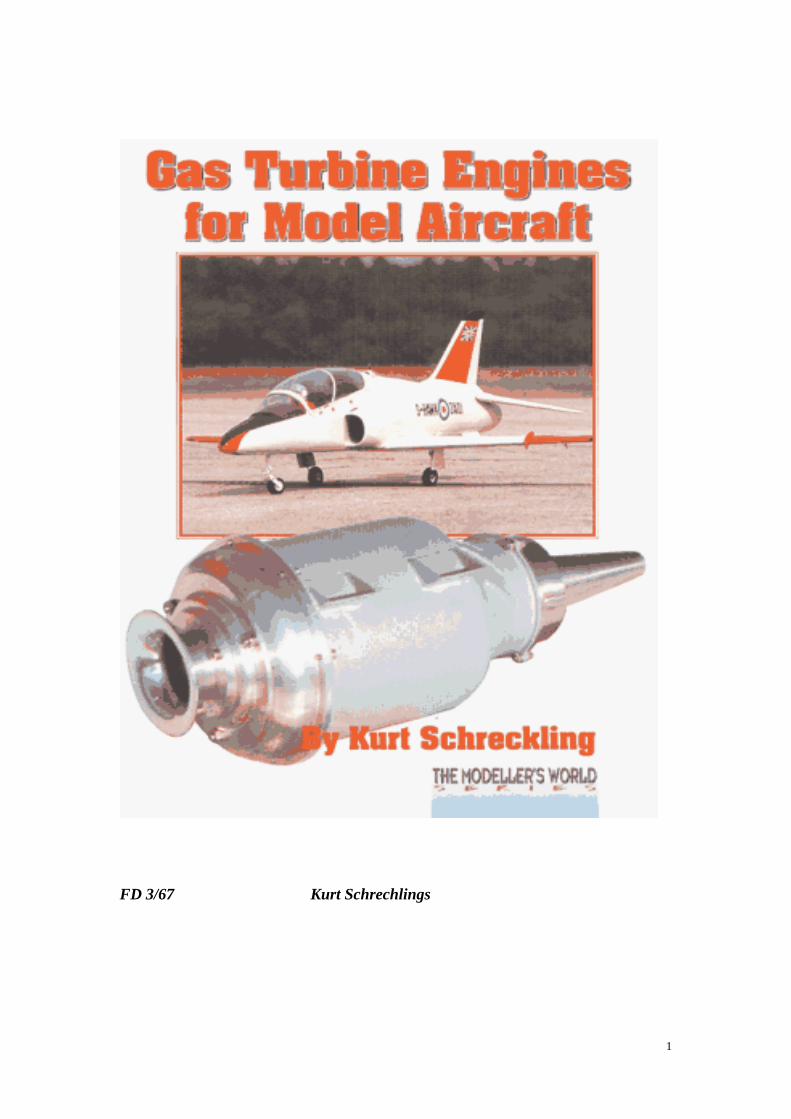
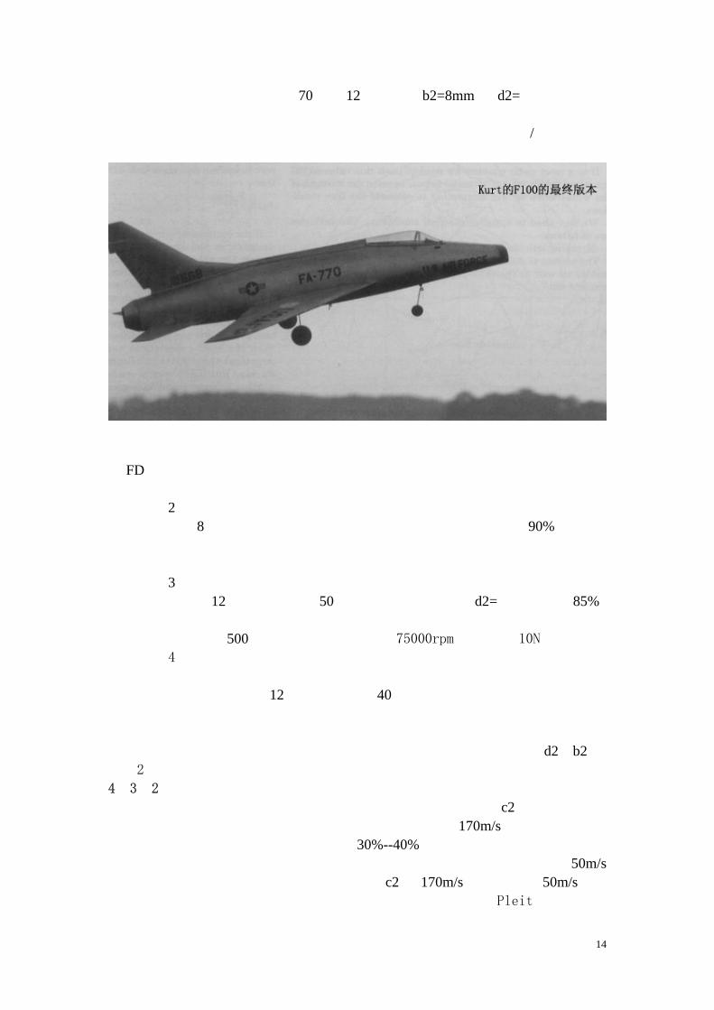
FD 3/67喷气涡轮发动机是 Kurt Schrechlings开发最后一款发动机,而且它的装配不需要特别的工具。
2
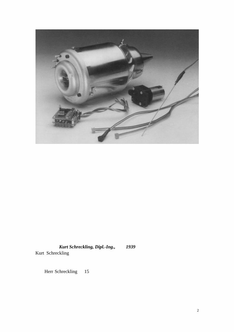
关于作者:Kurt Schreckling, Dipl.-Ing.,生于 1939年 Kurt Schreckling 早期受到过基础技术教育,后来又修完了重点在应用物理学方面的工程课程。之后又在一家大型的化工公司从事工程控制和系统控制方面的工
作。 Herr Schreckling在 15岁之前已经有了飞行模型的经验,那是他第一次把一
套飞机模型套件组装起来后的事。几年之后他开始学习制造模型飞机和无线电控
制设备。他特别钟情于模型的动力系统,但那时还没有重大的进展。因此他投入
了相当多的时在电动飞行器方面的开发:可调螺距的推进系统和计算机优化的电
动飞行系统。接下来他的首次成功尝试是用他自己制作的一套电动直升机,随后

3
是他为Wolfgang Kueppers设计了电动系统,并创造了竞速模型的速度记录。再随后的五年中他把他的全部业余时间投入了喷气发动机的开发,并且抽出时间写
出他在这方面的成功经验。 因此,如决定要开发专业级的模型喷气发动机的话,Herr Schreckling是最适
合的合作人选。 虽然 Herr Schreckling并不是非常好的模型飞行员,但是他具有独创的见解,
并且在一个领域有独创,并把他自己做的发动机装到了模型中并且飞了起来,因
此他必定是我们这个时代最多才多艺最有经验的模型制造者。 编 设计涡轮机 我将从尾部开始,也就是涡轮机的喷口。这是经过深思熟虑的,既然涡轮喷
气发动机最重要的部分是废气的喷射速度也就是推力,这第一个问题是:如何设
计涡轮机产生所需的推力,产生最高的温度和外围速度。压缩机的设计计算方法
也同样适用于涡轮机的设计。最大可能的节约,也就是尽量低的燃料消耗,但在
短时间的模型飞行中这一点并不是要优先考虑的。 我们限制讨论轴向的涡轮机。轴向的涡轮机的工作气流沿轴向流进桨叶然后又以
相同的方向喷出。有一个特性就是相对与涡轮的直径来说,桨叶的长度很短。这
样我们需要使用平均速度 dm来研究桨叶的速度。草图显示了涡轮桨片的桨叶分布平面图,以及相应的扩散系统。两个剖面分别清晰的显示轴向方向的速度。 在轴向区域外围的速度 u与涡轮桨叶的入口和出口速度相同,都是在平均直
径 dm处测量。 我们将考虑从出口那边气流的流动与机械部件移动的关系,也就是涡轮桨叶
的后面。尽管我们关心的是最后的结果,也就是喷气推力。这被箭头 c2 表示。如果箭头 c2 直接指向涡轮轴线方向,那么我们就确定它是推力矢量。这个定义是设计过程的开始。c2 和涡轮桨叶的外围速度 u 组成一个一定角度的三角。这个三角的第三边就是喷气速度 w2,它在涡轮桨叶的出口被测量。以上全部被称为出口三角。如果涡轮的桨叶靠得很近,那么废气就会沿着桨叶的拱形流动,那
么实际上速度 w2 与 u 之间的角 ß2 就和涡轮桨叶出口末端的速度一样。用公式表示:c2=u*tan ß2 现在我们能够定义从 c2到 u的比率使用桨叶角 ß2,同时 w2到 u也可以同
样的表示出来,其中的任何一个值都是理论上可能的。结果是我们从中可以看出
4
实践中可能出现的范围。 当然,我们必须确保这些所有的情况都是物体本身能够达到的。 为了让你知道如何用理论解决实践中的问题,我们将要精确的评估 FD3/64
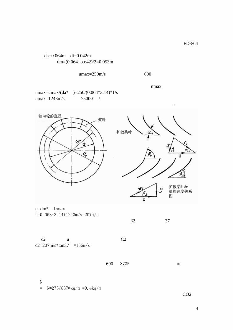
的推力。为了简化问题,我们将忽略喷口的影响。以下是已知的值: da=0.064m di=0.042m 结果 dm=(0.064+o.o42)/2=0.053m。 正像已经在第而章中讨论过的哪样,镍铬合金钢(涡轮的基本材料)能承
受的最大外围速度是 umax=250m/s,和最高桨叶温度 600℃,假如我们能够把涡轮盘的温度保持在极限之下。正如我们所了解的,这是可能的。
我们已经定义的数据使我们能够确定最大旋转速度 nmax: nmax=umax/(da*π)=250/(0.064*3.14)*1/s nmax=1243m/s或接近 75000转/分钟。 为了将来的计算我们需要涡轮出口的三角关系和平均外围速度 u。
u=dm*π*nmax
u=0.053*3.14*1243m/s=207m/s
目前我们还没有一个值来表示出口桨叶角 ß2,它的角度是 37℃。这个临界值已经被理论和实践确定下来,并且以后将要详细论述。现在我们可以画出出口
的三角关系。我们将假设一个直的(也就不是螺旋形)的气流。意思是:出口速
度 c2是垂直于 u,因而平行于转动轴线。C2也能够简单的计算: c2=207m/s*tan37˙=156m/s
显然出口的速度比任何螺旋桨模型高得多。因此我们有必要安装一个喷口来
提高速度。靠这样稍微提高发动机的推力是可能的,以后的方法能提高得更多。 正如预料到的,气体的温度是 600℃=873K。我们也需要吸气质量 m,也就是
经过发动机的气流的质量。既然排放的气体要被解压到周围的空气中,它的密度
就很容易计算了:
ρN
ρ=ρN*273/837*kg/m3=0.4kg/m3
氧气仅占空气的一小部分,而在任何燃烧过程中只有氧气被转化成 CO2 和
5
水,因此废气的密度与普通新鲜空气密度的差别是无关紧要的,因此能够被忽略。
同样我们也能够忽略燃料气流的质量,它必然比空气流的质量小得多。从出口截
面面积 A,和出口速度 c2,我们能够计算出下面的结果: m˙=A*c2*ρ A=(da2-di2)*π/4 A=((0.0642-0.0422)*3.14/4)m2 A=0.oo183m2
m˙=0.4*.000183*156kg/s=0.115kg/s
我们还能够计算推力 F:
F=m˙*c2=0.114*156kg*m/s2=17.8kg*m/s2=17.8N
显而易见,如果 d3和 dm增高,而 c2和 u保持不变,推力将会以相同速率增高这归功与大面积的喷口截面。如果外围速度 u 能被看成是恒定的,那么 ß2也就保持不变,但是转速在减小,如果是按以上公式计算的话就会是那样。这会
提醒你注意这样一个事实:只说明转速是没用的除非我们知道转子的直径! 现在我们假设我们能够单独的改变排气的温度和桨叶的角度 ß2。这将有助
于我们了解这些因素对推力的影响范围,如果保持别的条件不变。我假设排气温
度是低于 100℃。排放的气体的温度决定于系数:837/737=1.14。 气流的动量 m˙,也就是推力 F,被同一个系数增加。结果如下:
F=17.8N*1.14=20.3N 降低排气温度要求我们降低系统的总损失,或者,改进整个发动机的效率。 现在让我们增加浆叶角 ß2。我们假设不加考虑的增加到 40°,其它的条件
也不变。使用熟悉的方程,出口的速度 c2 增加到 173.7m/s。动量也增加到0.127kg/s。推力能被类似的公式计算: F=0,127*173.7N=22N。 你能够看出桨叶角是推力计算中非常重要的决定因素,而且能够猜出它不能够无
穷增大。正像我们看到的,当桨叶角 ß2 增大时出口的速度增加结果喷射气流的动能也增加。但是能量必须要有一个来源,在我们的系统中是燃料燃烧的热能。
必须要有更高的排气温度,而结果涡轮的运行温度随之升高当 ß2 角增大时。结果我们需要提高材料的极限温度。 精确的描述能量的转化与在涡轮机和增压涡轮机里的气流的关系是可能的。
我们回到速度三角关系图上并解释涡轮机的扭矩是如何产生的。为了简化计算我
们将假设气体的密度不变当它流过涡轮时。这是允许的,因为涡轮机工作在比较
低的压力之下。为了产生扭矩当气体流过涡轮时必须有力作用在涡轮的外围方向
上。这个力是当气流偏转涡轮叶片的时候产生的。气流被扩散体叶片输送以便能
够以一定的角度 ß1 和一定的相对速度 w1 流动。偏斜是独立的,在这种情况下是丛角度 ß1到角度 ß2,这时会在桨叶上产一个力,就像机翼一样。这个力在叶片所在的管道中被气流的加速度从 w1 加速到 w2。当我们考虑发动机的功率时我们仅需计算涡轮外围方向上的力变化了多少。根据物理规则这个力的大小正比
于外围方向上的动量流,用 clu来表示。因此我们能够计算涡轮发动机的功率利用下边的公式: Pw=m˙*clu*u 让我们看速度 c2,它由扩散桨叶决定,对涡轮机的功率起着很大的作用。 很久以前模型涡轮发动机已经被开发出来,理论和实践都表明气流的损失都
归功于叶片和管道的摩擦力和紊乱气流,这样能量被吸收也就是压力和温度下
6
降,扩散系统和涡轮都有同样的现象。因此完美设计的扩散系统和涡轮之间的管
道应该是一样的,但是具有方向相反的弓形。在这种情况下 B1大概是 90°,而它们的速度三角关系在涡轮的进口和出口上的方向是相同的但方向相反(镜像对
称)。Clu=u涡轮机的轴功率是:
Pw=m˙*u2(这个情况下ɑ1=ß2) 而涡轮机总共转化的能量更高,当然,另外一种表示是用输入的能量 PE转
化成有用的能量的效率 nT。公式如下: Pw=ηT*PE 有用功包括轴动力,像以上描述的,以及喷气动力,我们能用下面方法表示:
PE=(m˙*u2+m˙*(c22/2))/ηT=m˙*(u2+c22/2)/ηT
L利用我们已经描述过的速度三角关系图,得出下列公式: C2=u*tanβ2 这个表达式能够代入上面的公式中得出下面的输入功率的公式:
PE=(m˙*u2*(1+tanβ2))/ηT 这个公式显示 B2的增大会导致涡轮机的输入功率迅速增加到无法想象的地
步。 我们仍然没有讨论过压力和温度与涡轮机输入功率之间的精确数学关系。这
要包括两个计算过程。我们能够从已知的气流动量和轴功率计算出增压涡轮的压
缩率同时我们能够得出增压涡轮的效率。使用下面的公式: Pw*ηv=m˙*cp*T1[π*((x-1)/x)-1] 在公式里各个变量的含义是: ηv=增压涡轮的效率 Pw=涡轮机的轴动力 m˙=流过增压涡轮和涡轮机的气体动量 cp=空气的热容,这个值大概为 1000J/kg*K T1=入口空气的绝对温度,单位为 K,20摄氏度,就是(272+20)K Pi=压缩率。就是进口的空气压力与增压涡轮后边的空气压力的比值。 x=cp/cv空气的常数,大概为 1.4。 既然我们能够用公式 Pw=m˙* u2, m˙就能够被消掉:
u2*ηv=cp*T1*[π*((x-1)/x)-1]
公式能够根据 pi的值算出。 指数(x-1)/x有这样的值:
(1.4-1)/1.4=0.285 (ηv*μ2)/(cp*T1)+1=π的 0.285次方
π=((ηv*μ2)/(cp*T1)) 的 0.285次方
现在我们能够计算出涡轮机前边的空气压缩率。我们将使用我们的原始评估
u=207m/s,在进气口周围空气温度为 T1=293K时效率 nv=70%。这个效率是基于我们对压缩机的测量。 π=(((0.7*2072)/(1000*293))+1) 的 0.285次方
π=1.408 这个时候我们不必关心对于我们设计的增压涡轮它是如何算出来的这些问
题。你要做的就是相信它大概就是 70%。如果涡轮前边的空气压强为 1帕,我们就能够算出经压缩涡轮处理后压强为 1.408帕,或增加了 0.408帕. 为了描述涡轮的处理过程我们锁定温度 T3,任务是:计算涡轮机中的温度
7
T3根据给定的压缩率和输入功率。我们使用下面的公式,它的作用是要得出 T3: PE=cp*T3(1-1/(π的 0.285次方))*m˙
对于 Pe我们使用
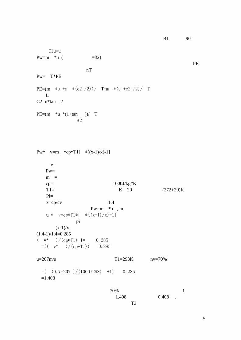
已知的公式(1)和 pi的公式(2);我们就可以得出 T3: T3=u2(1+tanβ22)/2/(ηT*cp*(1-1/((ηv*u2)/(cp*T1)+1))) 这是一个近似公式,但是已经足够让我们看出当涡轮叶片角增大时涡轮前边
的温度会升高。注意,公式仅适用反作用力因数为 0.5的涡轮机,也就是能量在增压涡轮和涡轮机上的能量转化相等的情况。图片清楚的显示了在不同的效率下
温度和桨叶角的关系。外围的最大允许速度是 207m/s,这我们已经讨论过。入口温度是 15℃,或是 288K。使用我们的设备是不可能精确的测量增压涡轮和涡轮机的效率的。我们的测量显示这两个部件的效率都为 0.7,因此图表画出效率从 0.75到 0.65之间时的影响。对于我们的目的不管最后得出增压涡轮的效率为0.72而涡轮机的效率为 0.68,还是反过来,这都无足轻重。但如果是其中一个的值很特别的低,那么就表明公式错了。 理论是很有用的,这在“FD”系列的开发过程中已经能清楚的得出这个结
论。我已经制造了几个桨叶角分别是 30°,37°和 43°的,然测量结果和效率
为 0.7的线精确的吻合了。如果我把温度提高到 873K也就是 600℃,达到最大允
许温度,这时 40°的角度仍是可行的。43°的在达到最高温度时运转几分钟后
发生了变形。图上这时的桨叶温度为 940K=667℃。为了安全,FD3/64 的桨叶角
被定在 37°。测量结果的点与理论计算的推力与旋转速度的吻合再一次证明了
理论的正确和有用,虽然它很可能比较简单,在实际设计中,温度与转速的关系
也是很重要的。然而,在温度/转速图中显示温度对于转速的影响小于推力对它
的影响。推论增加转速的最好方法是增加涡轮的直径,使转速提高。但是转速的
增加要求使用特别耐高温的高强度材料来制作涡轮。对于业余爱好者这个技术问
题难以解决。推力和转速关系图显示,安装一个锥形的喷口(锥形的角度靠实验
确定)可以只在稍微提高温度的情况下明显的增大推力。从计算的曲线可以假设
大约可以克服 10%的压力损失。
8
如果你想制作一个更好的喷气发动机使用简单的工具和避免技术上的问题,
那么最好的办法就是制作更大的涡轮。如果你保持温度、外围速度、桨叶角不超
出上限,那么出口的最大速度就不变。然而截面积由于大直径的涡轮而被增大,
空气的流量也就跟着被增大一样的倍率。因而推力就以同样的倍率增加。很简单,
发动机的推力会由于裸露的直径增加而增大。维持外围速度不变意思就是相映要
降低涡轮的旋转速度。例如如果我们制作了一个 80 毫米直径的涡轮,那么它与64毫米直径的涡轮相比旋转速度 n80降低: n80=n64*(64/80) z.B.n80=75000*(64/80)U/min=60000U/min 另一方面,推力增加: z.B.F80=20N*(80/64)2=31.3N 如果再加上使用喷管推力就有可能再增加 20%,最后静态推力变成 37N。自
然,发动机的质量也会变得更大,实际上所有的部件都要跟着涡轮一起增大,但
是你能够发现扩大之后内部的效率会稍微提高。 最后,在理论上还有一个方法可以增加推力那就是增加涡轮的直径、温度和
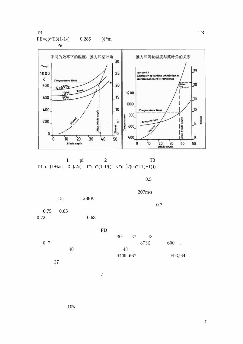
外围速度,这要靠构造一个能够产生更大偏向力的涡轮。图 A—D显示了可能的结构。请注意,用图 C—D的形式构造涡轮要花费更大的努力。而且也不知道它们在普通模型的尺寸下的效率如何因为没有实际实验过这种类型的涡轮(据我所
知),一般我们可以说图中从 A--D 的任何形状的涡轮形状都可以一试,而我也不能预测出它们的运行特性和计算方法的变化。不用说,每一个配置都需要专门
的设计一种类型的增压涡轮机。错误的匹配会改变发动机的强烈依靠于增压涡轮
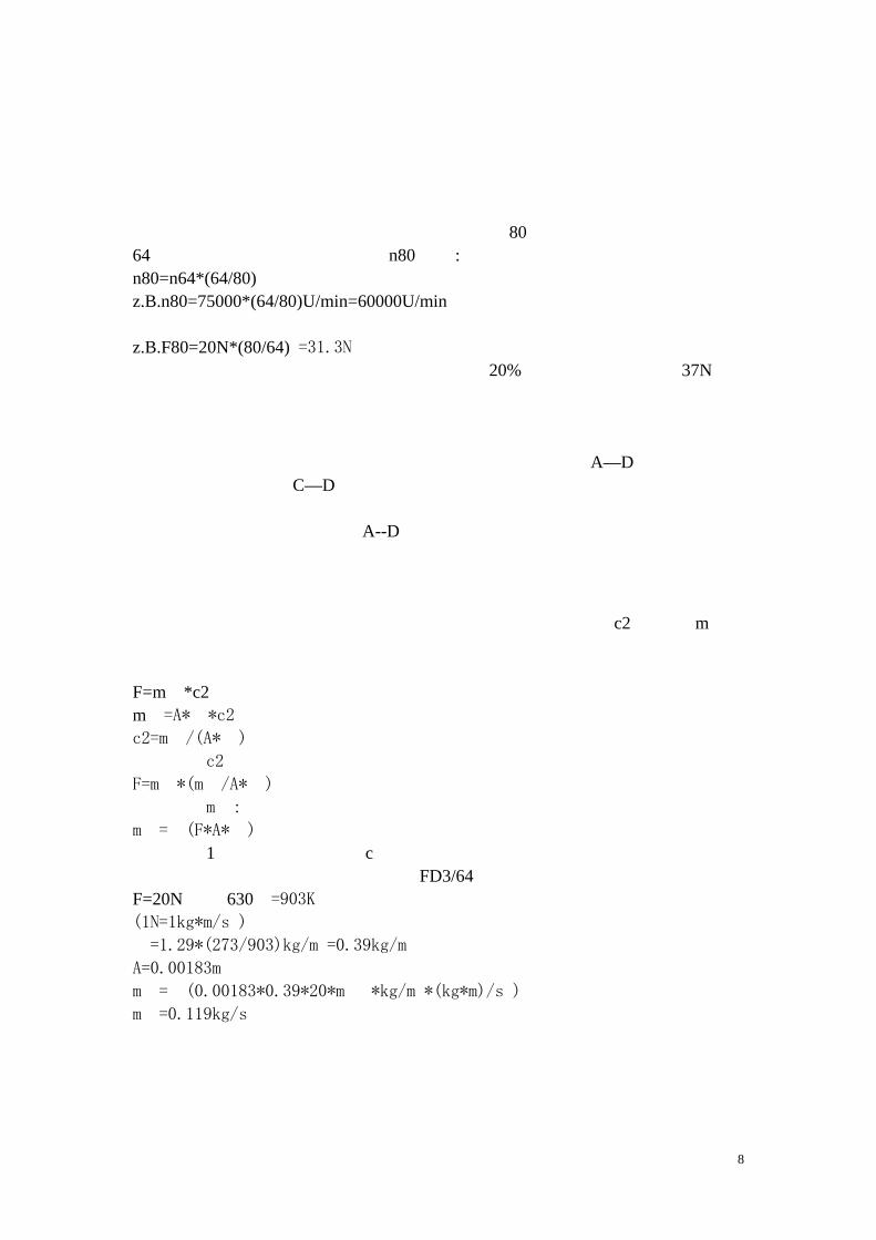
的操作特性。 作为一种检验发动机的方法,我们需要一种计算出口速度 c2 和动量 m˙的
方法。对此需要测量静态推力、温度值以及涡轮之后的出口的截面积。排放的废
气的密度能从温度计算出来。利用下面的两个公式: F=m˙*c2 m˙=A*ρ*c2
c2=m˙/(A*ρ)
这个 c2的表达式能够代入第一个公式:
F=m˙*(m˙/A*ρ)2
得出 m˙:
m˙=√(F*A*ρ)
就像 1一样我们能够得出 c。 作为一个实践的例子,我们使用 FD3/64 来做实验。假设推力和温度的值是
F=20N以及 630℃=903K。
(1N=1kg*m/s2)
ρ=1.29*(273/903)kg/m3=0.39kg/m3
A=0.00183m2
m˙=√(0.00183*0.39*20*m˙2*kg/m3*(kg*m)/s2)
m˙=0.119kg/s
9
m˙的值能够代入在第一个公式里计算出 c2: c2=F/m˙=20/0.119=168m/s
如果同时我们测量旋转速度,我们就有了一个极好的办法来检验计算结果的
数据。使用这种计算方法实际上是靠使用一些经验常数。这种方法同样适用于计
算函道风扇发动机的出口速度和动量。我们也能够测量静态的喷气功率使用下面
的公式: Pstrahl=(m˙/2)*c2
旋转的值能够被用来计算系统的效率相对于马达的轴向功率。最后一点:涡
轮喷气发动机设计过程中的计算,包括一些与发动机在飞行中的行为的数据(在
第 3章中有描述)与带螺旋桨的活塞发动机以及函道发动机的简单的多。 涡轮喷气发动机设计过程中的最后一步是热膨胀的评估。使用在发动机中的
热气部分的每一种材料的热膨胀系数如下:普通钢 12*10-6/K 和镍铬合金钢16*10-6。这些值是很精确的,但对于我们的目的并不是很重要。 如果我们假设在加热,长度的改变量可以用下面的公式计算:
△ l=l*△T*α l 是部件在标准情况下的长度,以及直径。△T 是温度的变化量。在所有金
属和合金中热膨胀发生在各个方向上。在涡轮机中我们关心的就只有直径。在
FD3/64中涡轮的直径是 64毫米。我们假设在最坏的情况下轮子的温度是 600℃。
结果△T=580℃而直径的改变量是:
△ Ф=64*580*0.000016
△ Ф=0.59mm 这几乎相当于直径改变 1%,也就是涡轮叶片和机壳间的缝隙必须比必须的
再 0.3mm如果轮子是正确的处于中心的话,并且我们忽略重力。实际上,轮子的中心温度比 600℃低得多,另一方面在离心加速度的作用下,涡轮机叶片某些部分的温度会更高。以上的计算值实际上只是计算直径膨胀的最大值。实际上机壳
的膨胀使问题简化很多。涡轮机周围的机壳的温度大概 400℃,如果它的直径是66毫米,使用普通钢材制作将产生的直径变化是:
10
△ Ф=66*380*0.000012
△ Ф=0.3mm 在稳定的情况下,也就是当发动机的温度已经固定下来,我们就可以假设一
个平均的涡轮温度约为 500℃相应的直径的变化是 0.49mm。在稳定的情况下涡轮
的直径比机壳的直径多膨胀 0.3mm。因此它们间还留有 0.15mm 的间隙。实际中
缝隙在常温下大概是 0.4毫米,以避免出现问题。
4.3增压涡轮机的设计
4.3.1在考虑空气流的情况下设计赠压涡轮
我们在涉及到涡轮机的设计中已经把最大转速设定了,用动量 m˙和轴功率Pw,我们就能够实际合适的压缩涡轮,这是一个很多专业书刊能帮助我们的领域,
比如,Willi Bohi的书“通风机”(“风扇”)。在技术和物理放面风扇和旋转的压缩涡轮没有明显的区别。一般的情况下风扇被看作低压气流设备,与之相比,
压缩机能工作在高压状况下。 设计的第一部是为我们的应用选择最合适的压缩涡轮,开始我们要计算运行时的
基于涡轮机设计时的数据的因素。所有的风扇专家都熟悉 Cordier图,从里边最优的轮形里我们能得到基本的数据,基本类型的轮子的功能就是偏转经过的气
流,有一种放射型的轮子是在真空吸尘器中用的。Cordier 的另一个极端就是轴向风扇,常用的螺旋桨就是一个很好的例子。在我们找到的推进叶轮中,也就是
轴向压缩机的多桨叶风轮和大型涡轮风扇的叶片,没有特别明显的区别。Bohi总结了 Cordier图的结果,把优化的轮子类型分类,在下面的表中: 运行参数 轮子类型 0.06-0.8 放射式轮 0.25-1.0 对角式轮 0.6-3 轴向轮 0.35-5 鼓形轮 这些优化的轮子都能在一定的条件下提供最高的效率。正如表中显示的那
样,分类间有一部分重叠,当运行参数为 0.5时九有可能一个放射轮或对角轮它们的效率几乎相等。在最后一行的鼓形轮我们对它不感兴趣因为它的形状。 第一步我们要用下面的公式计算运行参数:
δ*(2*n*√(V*π))/(3*(2*Yt)/4) n=在 S-1的旋转速度 Yt=总比流供给 [“流补给”]功单位 J/K 对于我们的应用,我们能够利用下边的表达式从我们的涡轮计算中确定比流
供给功: Pw/m˙=u2
V˙=流过压缩涡轮的气体流量以 m3/s 记。这很容易通过温度和压缩机旁的压力
以及动量 m˙计算出来。这儿有一个快速提示:动量等于穿过压缩机和涡轮机的
气流的动量。相比之下,气流的容积决定于温度和压力。Pi=3.14
这个数据来源于我们讨论涡轮机的时候: u=207m/s m=0.121kg/s n=1250/s或 75000rpm 使用 Yt=42800J/kg 我们可以假设涡轮增压机一边的空气密度是 1.23kg/m3,因此 V=0.097m3/s,

11
现在我们能够像下面一样计算:
δ=(2.1250*√(0.097*3.14))/((2*42800*3)/4) δ=0.285
从运行参数很清楚要选择放射形的压缩涡轮,甚至在以上的计算中得出一些
不确定的值时我们也可以确定我们能够制造一个稳定可靠的增压涡轮机使用放
射结构轮。 然而,我们都知道,全尺寸的涡轮喷气发动机都是采用多级的轴向压缩机,因此
我们需要讨论 为什么这种结构对于我们的目的不适合。一个原因很明显:多级压缩机的制作难度太大。为达到我们模型中的 1.4的压缩率这种类型的压缩机至少需要 3级。我自己使用了一个适当尺寸单级的轴向压缩机进行了实验,显示其最大效率约为 60%。类似于函道风扇发动机的效率,它也是使用轴向的轮子。不可能拿模型的效率与全尺寸发动机的效率相比因为模型发动机的很低的雷诺系
数。相比之下,放射涡轮压缩机的测量效率至少 70%。这个发现确定了轴向压缩机只适合与尺寸比较大的发动机。在全尺寸喷气发动机的设计中轴向压缩机的比
较小的直径是非常重要的优点,而这个因素在超音速飞行中是非常重要的。模型
的速度,在另一方面并不完全适合。对于是不是有可能制作一个模型涡轮发动机
使用小尺寸的多级轴向压缩机我们并不抱任何希望,但有一个是确定的:我们绝
对不会使用鼓形造型和方法。
阐明和解释不同类型的压缩涡轮机将会要使用几章的内容,因此我们只讨论
放射式压缩机。最重要的增加压力的方法就是设法开发当空气从小直径的入口进
入大直径的出口时的离心力的作用潜能。同时这种放射涡轮的出口的空气速度与
涡轮的外围速度差不多。然后这些高动能的空气的能量能被转化成压力能量。这
种转化发生在与增压涡轮机一样结构的固定不动的扩散体的突出部位上。 这时让我们仔细的看看放射轮。很多类型的放射轮能够被制作:比如,前向
曲线桨叶,放射尖端桨叶,或是没有桨叶盘的。其中具有反向曲线的桨叶的轮盘
轮的效率最高。这就是最好的选择。放射尖端的桨叶能够产生最大的压力增量在
小的直径下,但是效率不高,但有可能通过高明的扩散体设计来弥补这个缺点。
这是专业发动机的首选方案,比如,APUS(能量补给单元)。一定数量的模型涡轮发动机手册也是使用这种形式的增压涡轮机结构。我们的计算和实验,考虑发
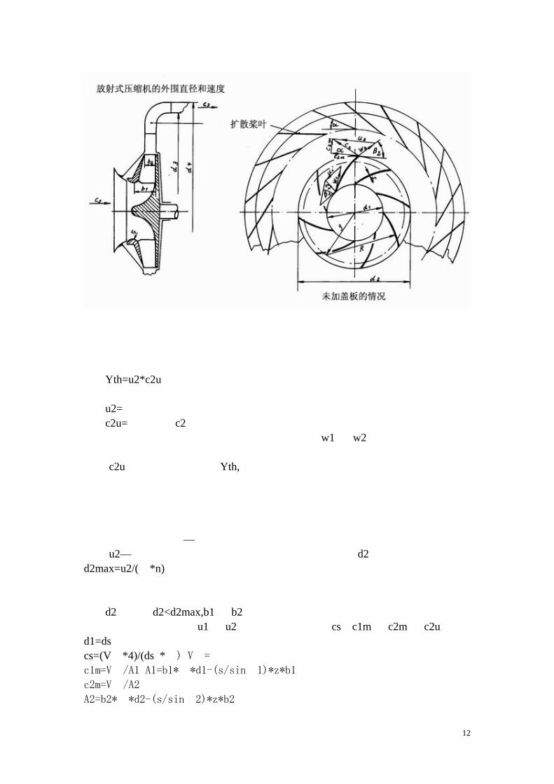
动机实际使用的要求,这都显示反向曲线桨叶最适合于我们的应用。 下边的图显示了那样的一个发动机的主体尺寸,以及桨叶进口和出口的速度
关系图,以及相应的角度。主体尺寸对于制作那样的一个单元是非常重要的。 ds=入口直径,实际中是指入口末端的 d1的直径。 d2=外部直径 b1=桨叶通道进口的宽度 b2=桨叶通道出口的宽度 R=桨叶拱形的半径 P=半径 R的几何中心 rs=轮盘入口的半径 s=桨叶厚度 这些具体的数字在制作指导中将有详细描述。
12
既然能量转化是压缩机的主要功能,我们必须考虑整个增压涡轮机的速度和
气流情况。在我们钻研复杂的速度平面图之前,我们要先找问题:多少流动能量
被转化在零流量损失的情况下?换句话说:多少轴动力被增压涡轮转化成空气的
压力和动能?使用下列公式: Yth=u2*c2u 这里: u2=外围直径的速度 c2u=出口速度 c2的切线方向分量 这很可能让人惊讶,因为进口速度以及速度 w1 和 w2 的关系完全没有出现
在公式中。这个简单公式的推论如下:对于一个给定的外围速度功的转化使达到
速度 c2u但是绝对不会超过 Yth,而不管空怎样供给空气。就像已经解释过的,这些转化的功由空气流的压力能量和动能组成。不幸的是在扩散系统中,气流的动
能转化成压力能量的损失相当高。所以设计压缩涡轮的本质是尽量减少这些损
失。如果采用反向曲线桨叶,那么动能所占的比例就比较小,这就是为什么第一
种类型比较高效。 较少的本质因数—流量、轴功率和旋转速度,都起源于压缩涡轮的最大外围
速度 u2—这点已经知道了。从这些信息我们能得出计算 d2最大值的公式: d2max=u2/(π*n) 我们是否要把这个值推向极限这一点无关紧要。以我的观点看,要铭记在心
的就是当你企图优化气流的条件时要特别注意涡轮的强度。 d2,考虑 d2<d2max,b1和 b2。 处理过程需要定义 u1和 u2以及空气吞吐速度 cs,c1m和 c2m和 c2u。
d1=ds cs=(V˙*4)/(ds2*π) V˙=空气流量
c1m=V˙/A1 A1=b1*π*d1-(s/sinβ1)*z*b1
c2m=V˙/A2
A2=b2*π*d2-(s/sinβ2)*z*b2
13
因为压缩率比较低,在压缩涡轮的进口和出口 V˙能被假设是一个常数。
C2u=Pw/(u2*m˙)=Yw/u2
对于专家—你们中的想要详细的了接气流的行为—可能会对这个公式不满意。我们已经知道不可避免的损失意思是波长不能被更改。结果 Yw的正确表达是 Yw*ηv。我们还不得不忍受后来的一些现象,如果涡轮的其中几个桨叶的桨叶角拱形曲线不正确,因此在叶片之间就会产生双倍的循环流。结果角度为β2桨叶的 w2的方向就会有很低的效率。一些特别的著作中会特别的论述 u的减小的影响。正确的公式是: c2u=(Yw*ηv)/(u2*μ) 如果压缩轮设计得很好,ηv和 u就近似相等,并且证明我的简化是正确的。
被减少的因素稍微的提高当桨叶的数量增加的时候。现在我们来优化桨叶 z的数量。这是一连最有实践和理论经验的理论家都不能断定的事情。但不必担心—8到 12 片的桨叶对于我们的压缩涡轮都是足够的。据我的经验桨叶的数量从来不会危及我们的目的。 与轮的直径和桨叶宽度这些使用公式,表格和图表[1]有关的优化参数是不可
能使用精确的数学方法来解决的。这些优化的值可能对效率有比较好的影响,但
是要注意只能稍微的偏离材料的最佳强度条件,这是为了能够抵挡很高的旋转速
度产生的离心力。如果我们要从理论上提高高速旋转下的最大可能强度值,我们
可以通过采用无盖子的放射尖端式的涡轮或是稍微有一些反向曲线的桨叶。如果
我们使用公式来表示上边的情况,就是 cu2=u2。意思就是与反向曲线桨叶轮相比做同样的功,空气流的动能占了相更高的比例。这样我们就需要一个复杂的大
直径的扩散系统去把动能有效的转化成压力能量。根据这个认识,优化的涡轮发
动机形状应该是高度低的,像扁平的饼,带有宽的面向流动的气流。那看上去好
像不太对劲。 我做了好多实验去修改轮,结果压缩涡轮的结构就像制作指导里描述的一
样。下面的表显示了根据[1]计算的数据和使用制作指导建造的轮子比较的相对和绝对值。 尺寸 根据[1]计算的 FD3/64 相对尺寸 d2 70 66 最大尺寸 d1 33 33 0.5*d2 b1 16 13 0.2*d2 b2 8.5 7.5 0.11*d2 β1 29° 34° 34°
β2 39° 45° 45°
R 37.3 42.3 根据公式 ρ 24.2 30.1 根据公式 z 9 11 8 bis 12 s 1.1mm 0.88mm 0.07*b2 R=(d22-d12)/4*(d2*cosβ2-d1*cosβ1)
ρ√(R2+d12/4-R*d1*cosβ1)
那些很有经验的模型家会非常惊讶于那些数据那么的靠近临界值。换句话
说:如果主要数据都使用表中的值那么会发生什么呢?为了回答这个问题,这里
有一些开发 FD系列发动机的例子。 例子一
14
增压涡轮使用出口角度为 70°的 12片桨叶,b2=8mm 而 d2=涡轮机轮的直径,结果:涡轮喷气发动机在启动的时候有速度有波动的倾向,而从待机速度加
速到工作速度非常的慢。这种波动效果是由于气流在涡轮压缩机和/或者压缩区域发生突变引起的,它的表现是发出低沉的轰隆声,
和一般的喷气声音很不一样。当同一个轮子被用稍微小桨叶角作为扩散装置安装
在 FD系列发动机中的时候,发动机将不能运行。从这个现象我们可以断定如果压缩轮的尺寸超限的话,系统会崩溃。 例子 2 压缩轮装 8片放射尖桨,但是外围最大直径相应为涡轮机轮的 90%。结果:
发动机能够运行,但是涡轮机过热。因而飞行时不可能让发动机运行在最大转速
下。 例子 3 压缩轮安装 12片出口角度为 50°的反向曲线叶片,但 d2=涡轮机轮的 85%。
这是所有的实验中最小的轮径。结果:启动性能和加速到最大转速的性能非常的
好。而排气温度在 500℃以下,但是在转速为 75000rpm时推力仅 10N。
例子 4
压缩轮被做成有盖子的像底座一样的平的形式,也就是,桨叶的进口和出口
是一样的。桨叶的数量是 12片,桨叶角是 40°而其它使用标准数据。结果:使用这样的压缩轮,发动机能勉强飞行,但是推力减小,而涡轮腔内的温度明显的
很高。 总结:这些问题仅发生在压缩轮的尺寸超限的时候。可能是由于 d2、b2 或
者β2超限太多。
4.3.2设计扩散系统
空气从压缩涡轮的旋转平面流出,它具有很高的绝对速度 c2 甚至是使用反向曲线桨叶的时候。使用我们的标准压缩轮这个速度是 170m/s 在满载的时候。空气流中动能约占压缩涡轮的轴动力的 30%--40%。然而我们的目的是让空气以相当低的速度流进燃烧室。合理的目标是使流入燃烧室的气流的速度为 50m/s左右,因此我们应该设法把出口的气流速度 c2从 170m/s降低到大约 50m/s,这样能获得尽可能高的压力增长。理论上可能获得的压力增量△Pleit为:
15
△ Pleit=ρm*(c22-c32*m)*ηleit/2
η是扩散系统的效率,估计大概是 70%。
Ρm是扩散系统中的空气的平均密度。它大概比周围的空气的密度高 10% 。
因此实际压力增量大概为 12000帕,相当于 0.12个大气压(1pa=1N/m)。 气流速度因为截面积 A2增加到 A3而从 c2减小到 c3。A2是压缩涡轮出口
的横截面积。 A2=d2*b2*π
A3是环形的横截面积,根据公式:
A3=π*(d42-d32)/4
因此得到下边的公式: A3/A2=c2/c3 在压缩涡轮的出口和环形裂隙的偏斜区域之间的空间起到了一个扩散体的
作用。C2的成分比 c3m高的多。包含所有的螺旋运动,这在扩散盘内是不会被降低的。扩散桨叶的作就是要降螺旋运动的速度。这些桨叶的进口角度可以使用
以下公式计算: tanɑ=c2m/c2u 一个大概 2°必须被加进去,这是为了避免厚的桨叶片收缩的影响。在我们
的扩散体系统中正确的角度大概是 24°。
桨叶和扩散体盘的入口的间距需要有一个补偿,如果桨叶的角度不很正确。如果
我们更仔细的考虑口气流的行为,特别是在发动机加速器期间,我们能发现在轮
子的出口气流的方向会发生不可避免的改变,气流的速度也一样。在实际中气流
会在桨叶后边发生一些扭曲运动,也就是在扩散系统到燃烧室之间的空间,则不
会引起任何问题。 我以已经不在进行系统的实验来优化扩散系统桨叶的片数,但有一点是清楚
的:根据几何学一个扩散系统是不可能在没有引导叶片的情况下工作的,因为螺
旋运动的影响。引导桨叶的安装位置可以在 d3与 d4之间的位置。在这种情况下,入口角度也应该先前面介绍过的一样,被弯曲以便出口的点的方向与轴线方向相
同。我的最初能够飞行的发动机(FD2和 FD3/62)就是使用这种方法制作的。但是这种方法稍微有些难,并且没有实际经验的优势。由于这一点,在 FD3/64中使用了技术上更简单的解决方法。 一种螺旋形的空腔带有一个固定风扇常被用做扩散系统,它没有引导桨叶。
但是这种螺旋形几何形状的部件占用太大的空间对于我们的模型飞行起来说。我
的第一个实验性的发动机使用了一个有四个螺旋管道的压缩机。这种结构被用在
第一台涡轮喷气发动机中并能够在涡轮机和增压涡轮的作用下自动运行。 4.3.3压缩涡轮的强度 发动机高速旋转的部件强迫我们更仔细的研究它上边的离心荷载。这个问题
的详细描述能在 Bohi[1]里看到。当我们考虑压缩涡轮的时候我们注意到反向曲线的桨叶受到一个弯曲荷载,我们能够计算这些弯曲力。如果两边都安装了桨叶,
那么下面的公式能用来计算桨叶入口末端的弯曲力: δ=(ρ*u12*b12*cosβ12)/d1*s δ=弯矩单位 N/m2
u1=进口部分桨叶的外围速度 b1=桨叶宽 s=桨叶厚
16
d1=桨叶进口直径 我们现在就可以计算压缩涡轮进口点的弯矩,就像制作指导中的描述一样。
d1=33mm=0.033m p=1mm u1=0.033*3.14*1250m/s=129.6m/s B1=34° δ=700kg/m3 δ=(700*129.63*0.0132*cos34°)/(0.033*0.001)*kg*m3*m2/m2*s2=50N/mm2
各种密度在 0.7g/cm3各种木材的抗弯强度范围从 70 到 110N/mm2。我已经用一个木制的轮子在超过 90000rpm 下短暂的运行,而轮子没发生任何损坏。使
用不同的轮子装上更大宽度的桨叶b1=16mm和d1=35mm结果部分桨叶在转速达到
76000mpr 时在进口边沿发生破裂,虽然把桨叶固定在转盘上的方法不完全和制
作指导中描述的一样。因此在计算时我们不得不允许一定程度的不确定性。
现在让我们看桨叶出口末端的弯矩,也就是在宽度 b2 处。我们可以又一次
使用同样的公式,但这一次使用适合于 b2的数据:
d2=66mm,U2=259.2,b2=7.5mm,β2=45°
δ2=((700*259.23*0.00752*cos45°)/(0.066*0.001))*Pa=28.4N/mm2
从这个结果我们能看得出桨叶上的弯矩在入口的值比在出口的值大的多。在
实验中我做了很多损坏分析同时开发出了一个强度相当满意的轮子这证明这些
计算方法能在处理过程中给我们一个好的开端。 计算压缩轮的所有方面的强度,特别是桨叶与轮盘的连接点,这将是更为复
杂的一个问题。在任何情况下这些结果可能并不比靠实验得到的结果精确。 然而,评估轮盘的强度是有可能的。对于一个厚度一样并且中央带有一个小
孔的轮盘它的最大抗弯强度是 amax=0.83*ρ*u2。 使用密度为 700kg/m3的木材并且外围最大速度为 260m/s(我们的压缩涡轮
的最大外围速度),弯矩大概在 39Mpa=39N/mm2。最大弯矩发生在中心孔的边缘,而不是在轮盘的边缘尽管你可能那样认为。木材完全能够应付理论水平的弯
矩。
但是,在我们的案例中轮盘强度被插入其中桨叶削弱。如果桨叶和轮盘通过
连接柄连接,也就是盘上没有开槽,那么轮子依然能够经受 50000rpm的转速,相应的外围速度为 170m/s。正如所预测的桨叶和无槽轮盘的胶合点是部件上的薄弱环节。另一方面,全木制结构能承受的最大外围速度离我们的发动机的最大
转速的要求并不远,因此加强木制结构强度是一个不错的选择。这并不是最早产
生的主意—很老的运输车采用木头轮子和铁制轮胎还有木头的桶使用铁制的箍才是最早的。 发生在旋转的环里的张力可以很容易的使用下边的公式计算:
δRing=ρ*u2 比如,如果我们假设使用密度为 7850kg/m3钢材并且最大外围速度为
260m/s,由加强环的质量引起的张力为 531Mpa,或是 530N/mm2。现在我们将使用碳素纤维作为加强材料重复计算,也就是用碳纤维包裹木制轮的外围。碳纤
维的密度大概是 1500kg/m2,算出的张力仅为 101N/mm2,而碳纤维可以承受的张
力却高达 1000N/mm2。很明显这种材料是加固压缩涡轮的最好选择。结果得到的
组件就是制作指导中描述的那样。
对强度有要求的不仅是这个,然而,我们也要考虑由于离心力的影响而产生
17
的弹性扭曲变形。对于环形这很容易计算,直径的改变是: Δd=d*δRing*E
E是弹性系数。对于钢材这个系数的值为 2.1*10ˉ11N/mm2,碳纤维材料的值也一样。我们已经使用以上的公式计算了这些力的作用效果,最后得出对于钢
制环直径改变 0.17mm 而碳纤维的只改变 0.03mm。因为碳纤维有很高的抗张力强度,很明显它能够提供比其它加强材料更高的加强强度的效果。材料的外形稳
定性在别的条件下的决定性因素是常数 p/E。这个值越小材料的尺寸改变在给定的尺度和外围速度下就会约小。这方面碳纤维材料的表现比别的材料要好的多。
Aramid 碳纤维(凯夫拉尔),也是考虑过的高强度材料,但是它完全不适合用来加固压缩涡轮。这种材料的优点是使之适合应用于需要高强度和高弹性的场
合,比如,受震动荷载的部件。 最后一个简短的注释是关于压缩涡轮机在温度升高的时候强度减小的问题。
在我们压缩率为 1.4的情况下温度升高大约为 300℃。以下的公式能给出近似的一个值: T2=T1*π的 0.285次方 这里 m表示压缩机的压缩率。问题确实在高压缩率的全尺寸发动机被发现,
在压缩机的最后一级,温度会抬升到 400℃,但是这不会在我们的应用里发生。 4.4燃料消耗量 4.4.1计算 FD3/64的燃料消耗量 一旦我们确定了与温度和空气流量的运行数据,就很容易计算发动机的最小
燃料消耗率。我们假设在低压缩率的热力发动机中热空气热能的主要作用是用来
加热工作媒介。输出的热能从热空气比热,流量和温度差异从公式得到: Q˙=c1*m˙*△T c1=热空气的比热 △T是进气口和喷气口的空气温度差。使用我们的涡轮喷气发动机的数据,
我们发现: Q˙=0.115*600*1050=72.450W热能输出! 当碳氢化合物燃料比如柴油,汽油和类似的燃料燃烧的时候,每克发出大概
4000 焦耳的热能。因此我们就能够计算出每秒的最小燃料消耗量73.450/40=1.81g/s。如果燃料的密度为 0.85g/ml 那么相应的燃料流量是1.81/0.85ml/s=2.13ml/s。 使用这种基于空气流量和排气温度的方法能够精确的评估整个转速范围内
的燃料最小消耗率。实际测量的结果比计算结果稍微高一些(请看图表,在 5.7章节)。 在燃料消耗率的计算中燃料的热值是唯一的一个决定性因素。
4.4.2最优燃料消耗率下的运行参数 如果我们假设我们的模型飞行器在速度为 50m/s 左右飞行—一个比较合理
的值—我们能够预测推力实际与静态推力相同。我们现在需要考虑是否可以优化这个静态推力下的燃料消耗率。就像我们的计算显示的那样,桨叶角的选择范围
相当大,而这个因素影响涡轮机的轴向能量的转化率。但是在一定的流量下能够
获得尽可能高的压缩率。众所周知,内燃机的热效率主要依赖于压缩率和内部能
量的转化效率。不幸的是这样的基本要求就是使用一个具有大角度偏斜的涡轮,
但是这不可能使用简单的工艺和技术达到。
18
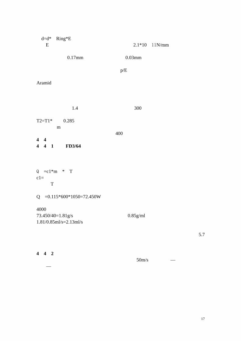
FD3 系列发动机的启动装备是很简单的。一个吹头 发的吹风机或是12伏特的真空吸尘器可以用来使发动机进入最小转速,而用一个小的喷雾器的罐子装丙烷/丁烷体燃料来预热发动机的燃烧室。如果没装内部点火系统的话,最后还需要一盒火柴或打火机。
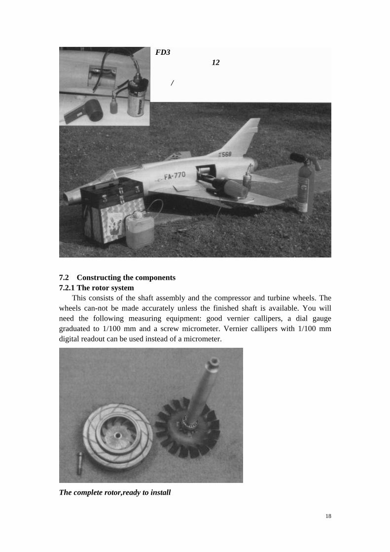
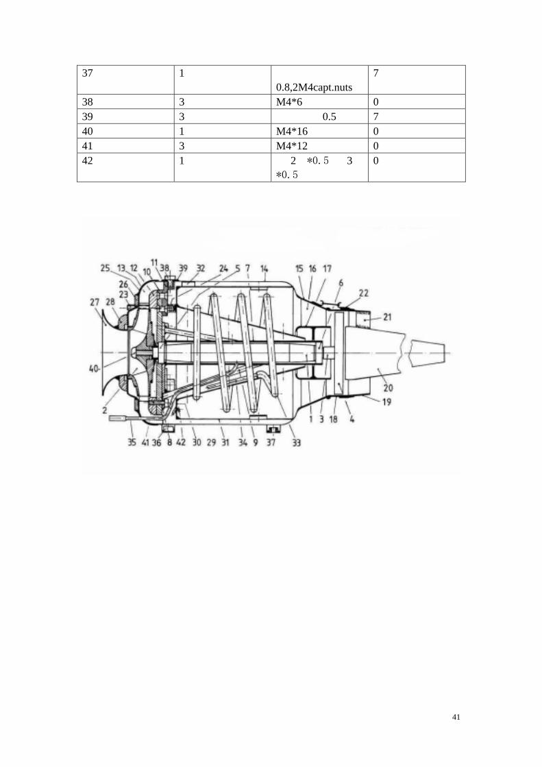
7.2 Constructing the components 7.2.1 The rotor system
This consists of the shaft assembly and the compressor and turbine wheels. The wheels can-not be made accurately unless the finished shaft is available. You will need the following measuring equipment: good vernier callipers, a dial gauge graduated to 1/100 mm and a screw micrometer. Vernier callipers with 1/100 mm digital readout can be used instead of a micrometer.
The complete rotor,ready to install
19
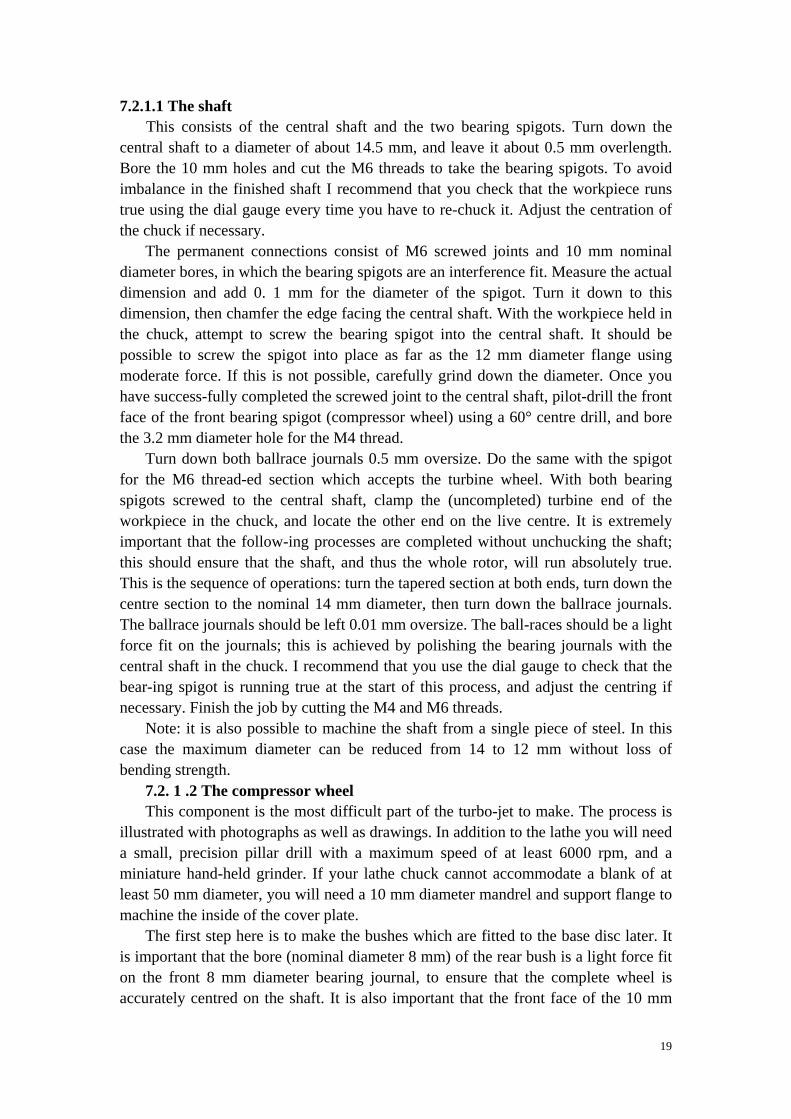
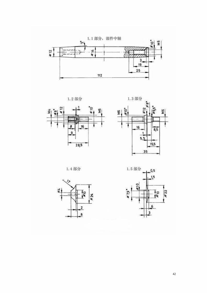
7.2.1.1 The shaft This consists of the central shaft and the two bearing spigots. Turn down the
central shaft to a diameter of about 14.5 mm, and leave it about 0.5 mm overlength. Bore the 10 mm holes and cut the M6 threads to take the bearing spigots. To avoid imbalance in the finished shaft I recommend that you check that the workpiece runs true using the dial gauge every time you have to re-chuck it. Adjust the centration of the chuck if necessary.
The permanent connections consist of M6 screwed joints and 10 mm nominal diameter bores, in which the bearing spigots are an interference fit. Measure the actual dimension and add 0. 1 mm for the diameter of the spigot. Turn it down to this dimension, then chamfer the edge facing the central shaft. With the workpiece held in the chuck, attempt to screw the bearing spigot into the central shaft. It should be possible to screw the spigot into place as far as the 12 mm diameter flange using moderate force. If this is not possible, carefully grind down the diameter. Once you have success-fully completed the screwed joint to the central shaft, pilot-drill the front face of the front bearing spigot (compressor wheel) using a 60° centre drill, and bore the 3.2 mm diameter hole for the M4 thread.
Turn down both ballrace journals 0.5 mm oversize. Do the same with the spigot for the M6 thread-ed section which accepts the turbine wheel. With both bearing spigots screwed to the central shaft, clamp the (uncompleted) turbine end of the workpiece in the chuck, and locate the other end on the live centre. It is extremely important that the follow-ing processes are completed without unchucking the shaft; this should ensure that the shaft, and thus the whole rotor, will run absolutely true. This is the sequence of operations: turn the tapered section at both ends, turn down the centre section to the nominal 14 mm diameter, then turn down the ballrace journals. The ballrace journals should be left 0.01 mm oversize. The ball-races should be a light force fit on the journals; this is achieved by polishing the bearing journals with the central shaft in the chuck. I recommend that you use the dial gauge to check that the bear-ing spigot is running true at the start of this process, and adjust the centring if necessary. Finish the job by cutting the M4 and M6 threads.
Note: it is also possible to machine the shaft from a single piece of steel. In this case the maximum diameter can be reduced from 14 to 12 mm without loss of bending strength.
7.2. 1 .2 The compressor wheel This component is the most difficult part of the turbo-jet to make. The process is
illustrated with photographs as well as drawings. In addition to the lathe you will need a small, precision pillar drill with a maximum speed of at least 6000 rpm, and a miniature hand-held grinder. If your lathe chuck cannot accommodate a blank of at least 50 mm diameter, you will need a 10 mm diameter mandrel and support flange to machine the inside of the cover plate.
The first step here is to make the bushes which are fitted to the base disc later. It is important that the bore (nominal diameter 8 mm) of the rear bush is a light force fit on the front 8 mm diameter bearing journal, to ensure that the complete wheel is accurately centred on the shaft. It is also important that the front face of the 10 mm
20
diameter flange, which rests against the inner ring of the ballrace, is exactly perpendicular to the bore. The front bush is not machined to final shape until both bushes have been glued to the base disc.
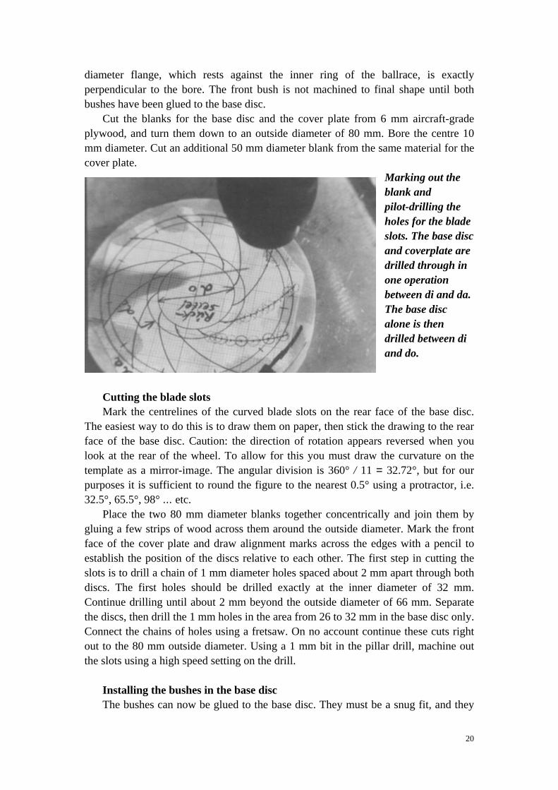
Cut the blanks for the base disc and the cover plate from 6 mm aircraft-grade plywood, and turn them down to an outside diameter of 80 mm. Bore the centre 10 mm diameter. Cut an additional 50 mm diameter blank from the same material for the cover plate.
Marking out the blank and pilot-drilling the holes for the blade slots. The base disc and coverplate are drilled through in one operation between di and da. The base disc alone is then drilled between di and do.
Cutting the blade slots Mark the centrelines of the curved blade slots on the rear face of the base disc.
The easiest way to do this is to draw them on paper, then stick the drawing to the rear face of the base disc. Caution: the direction of rotation appears reversed when you look at the rear of the wheel. To allow for this you must draw the curvature on the template as a mirror-image. The angular division is 360° / 11 = 32.72°, but for our purposes it is sufficient to round the figure to the nearest 0.5° using a protractor, i.e. 32.5°, 65.5°, 98° ... etc.
Place the two 80 mm diameter blanks together concentrically and join them by gluing a few strips of wood across them around the outside diameter. Mark the front face of the cover plate and draw alignment marks across the edges with a pencil to establish the position of the discs relative to each other. The first step in cutting the slots is to drill a chain of 1 mm diameter holes spaced about 2 mm apart through both discs. The first holes should be drilled exactly at the inner diameter of 32 mm. Continue drilling until about 2 mm beyond the outside diameter of 66 mm. Separate the discs, then drill the 1 mm holes in the area from 26 to 32 mm in the base disc only. Connect the chains of holes using a fretsaw. On no account continue these cuts right out to the 80 mm outside diameter. Using a 1 mm bit in the pillar drill, machine out the slots using a high speed setting on the drill.
Installing the bushes in the base disc The bushes can now be glued to the base disc. They must be a snug fit, and they
21
should be fixed in place using heat-curable epoxy, e.g. UHU endfest 300. It should go without saying that the joint surfaces should be cleaned and keyed (roughened) before you apply the resin. Be careful not to apply excess glue. Fit a machine screw through both bushes and tighten a nut on the other side to hold the parts together under light pressure. Cure the epoxy at a temperature of 120℃, then let the assembly cool down. Fit the blank on the shaft with the ballrace in place, clamp it in the lathe chuck, centred on the ballrace journal, and tighten the retaining screw. You can now machine the bush to final shape, and machine out the stepped section to an internal diameter of 64 mm on the front face of the base disc. Machine out the curved face of the bush in small stages at first, then smooth it to a radius of about 17 mm using a mini-grinding disc. The actual radius is not crucial to the correct working of the compressor wheel. The only important point is that there should be a smooth, flowing transition from metal to wood, and that the worked surfaces should exhibit no wobble. It is essential to main-tam the outer step as shown in the drawing, as it locates the car-bon fibre reinforcement. It is sanded away when the compressor wheel is finished. Mark the position of the disc relative to the shaft, and always screw the parts together in the same position during the later stages of construction, and when you assemble the engine before running it. Leave the disc 80 mm in outside diameter for the present. Glue the 50 mm diameter blank con-centrically to the front face of the cover plate blank using cyanoacrylate adhesive. The grain direction at the joint surfaces should cross at right-angles. Before applying the glue check on
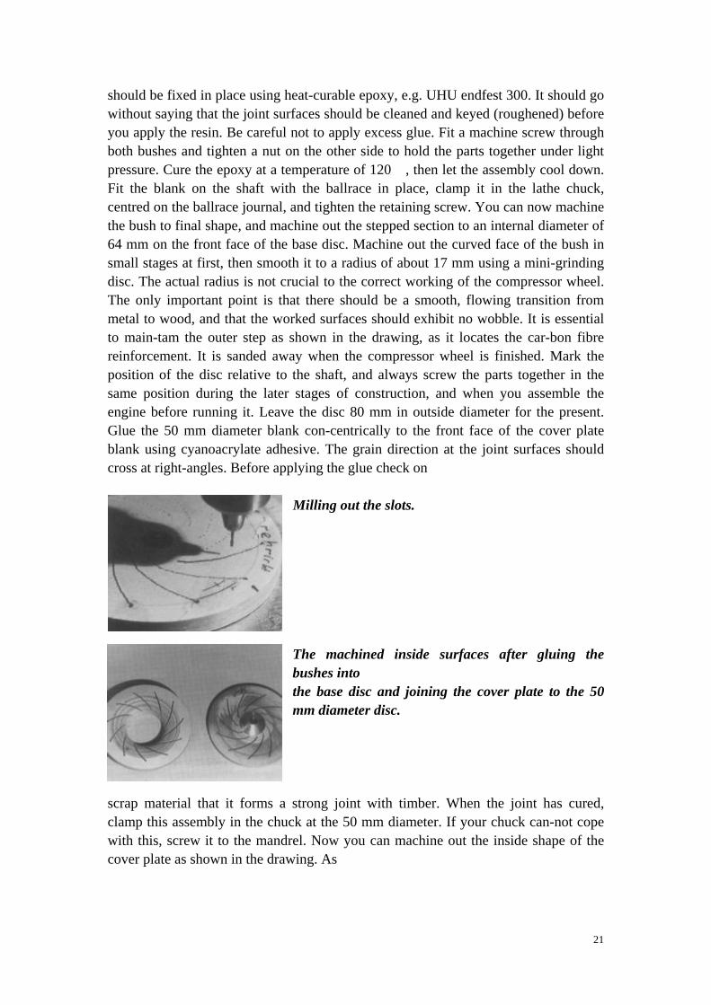
Milling out the slots. The machined inside surfaces after gluing the bushes into the base disc and joining the cover plate to the 50 mm diameter disc.
scrap material that it forms a strong joint with timber. When the joint has cured, clamp this assembly in the chuck at the 50 mm diameter. If your chuck can-not cope with this, screw it to the mandrel. Now you can machine out the inside shape of the cover plate as shown in the drawing. As
22
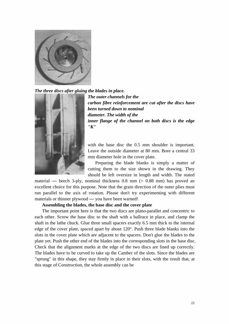
The three discs after gluing the blades in place.
The outer channels for the carbon fibre reinforcement are cut after the discs have been turned down to nominal diameter. The width of the inner flange of the channel on both discs is the edge "K" with the base disc the 0.5 mm shoulder is important. Leave the outside diameter at 80 mm. Bore a central 33 mm diameter hole in the cover plate.
Preparing the blade blanks is simply a matter of cutting them to the size shown in the drawing. They should be left oversize in length and width. The stated
material — beech 3-ply, nominal thickness 0.8 mm (= 0.88 mm) has proved an excellent choice for this purpose. Note that the grain direction of the outer plies must run parallel to the axis of rotation. Please don't try experimenting with different materials or thinner plywood — you have been warned!
Assembling the blades, the base disc and the cover plate The important point here is that the two discs are plano-parallet and concentric to
each other. Screw the base disc to the shaft with a ballrace in place, and clamp the shaft in the lathe chuck. Glue three small spacers exactly 6.5 mm thick to the internal edge of the cover plate, spaced apart by about 120°. Push three blade blanks into the slots in the cover plate which are adjacent to the spacers. Don't glue the blades to the plate yet. Push the other end of the blades into the corresponding slots in the base disc. Check that the alignment marks at the edge of the two discs are lined up correctly. The blades have to be curved to take up the Camber of the slots. Since the blades are "sprung" in this shape, they stay firmly in place in their slots, with the result that, at this stage of Construction, the whole assembly can be
23
plugged together "dry" and dismantled at any time. Gently press the cover plate onto the assembly using the tailstock and a soft buffer, and check that both discs make contact with all three spacers. You are now in a position to adjust the concentricity of the cover plate relative to the base disc. Take your time, and be as accurate as you can. An eccentricity of 0. 1 mm is satisfactory. Once you are confident that alignment is correct, glue the blades into the slots using cyano-acrylate adhesive. It is very important here to use a type of cyano which is expressly recommended for wood. Alternatively a slow-setting epoxy resin can be used. Once you have decided on the type of glue, keep to it when fitting the remaining blades. Once the joints have set
hard, release the workpiece from the shaft and fit the remaining blades, working from the rear face of the base disc. Push them through until they rest against the 50 mm diameter disc on the front face of the cover plate. Glue them in place as described above.
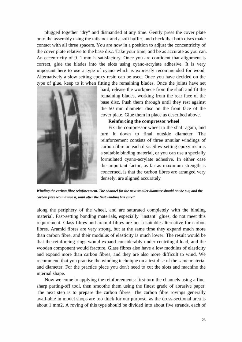
Reinforcing the compressor wheel Fix the compressor wheel to the shaft again, and
turn it down to final outside diameter. The reinforcement consists of three annular windings of carbon fibre on each disc. Slow-setting epoxy resin is a suitable binding material, or you can use a specially formulated cyano-acrylate adhesive. In either case the important factor, as far as maximum strength is concerned, is that the carbon fibres are arranged very densely, are aligned accurately
Winding the carbon fibre reinforcement. The channel for the next smaller diameter should not be cut, and the
carbon fibre wound into it, until after the first winding has cured.
along the periphery of the wheel, and are saturated completely with the binding material. Fast-setting bonding materials, especially "instant" glues, do not meet this requirement. Glass fibres and aramid fibres are not a suitable alternative for carbon fibres. Aramid fibres are very strong, but at the same time they expand much more than carbon fibre, and their modulus of elasticity is much lower. The result would be that the reinforcing rings would expand considerably under centrifugal load, and the wooden component would fracture. Glass fibres also have a low modulus of elasticity and expand more than carbon fibres, and they are also more difficult to wind. We recommend that you practise the winding technique on a test disc of the same material and diameter. For the practice piece you don't need to cut the slots and machine the internal shape.
Now we come to applying the reinforcements: first turn the channels using a fine, sharp parting-off tool, then smoothe them using the finest grade of abrasive paper. The next step is to prepare the carbon fibres. The carbon fibre rovings generally avail-able in model shops are too thick for our purpose, as the cross-sectional area is about 1 mm2. A roving of this type should be divided into about five strands, each of
24
approximately the same thickness. If possible they should all be longer than 1 m. Splice the start and finish of each strand using a sharp balsa knife. This ensures that the individual fibres of each strand do not end at the same point. All strands must be free of knots and tangles.
Clamp the workpiece in the lathe chuck and wind the fibres onto the wheel by manually rotating the chuck, holding the car-bon fibre strand taut, and guiding it by hand. Check that the start of the strand rests snugly in the bottom of the channel. You can achieve this by smoothing it down with a narrow strip of soft balsa. When the start of the strand is correctly positioned, apply a drop of adhesive. Apply glue successively at approximately each quarter-rotation. Smooth the end of the strand into the channel in the same way, and start winding the next strand at a point offset by around 180p from the end. Continue this process until the channel is completely filled with carbon fibres. Leave the bonding agent to cure for several hours before starting on the next stage, even if you are using cyano-acrylate adhesive. The next step is to cut the channels for the rings of the next smaller diameter. Once you have completed the test piece, let the bonding agent cure then separate the carbon fibre ring from the wood on the lathe. You can now test the quality of the winding by carrying out a fracture test. Study the fracture point with a powerful magnifier, and you will clearly be able to see whether the fibres are fully saturated with binding agent as described above. If fair-ly large areas seem to be unsaturated, the adhesive or epoxy is not suitable. In my experience, UHU Endfest 300 and Simprop Blitzkleber "extra duenn" (ultra-low viscosity cyano) have proved outstandingly good. Although the Simprop adhesive is termed "Blitzkleber" (instant glue) it is sufficiently slow in response when applied to the carbon fibre windings using the method stat-ed above, and permeates the fibres very well. I always recom-mend making an experimental winding in any case if you are
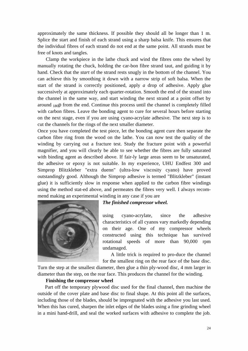
The finished compressor wheel. using cyano-acrylate, since the adhesive characteristics of all cyanos vary markedly depending on their age. One of my compressor wheels constructed using this technique has survived rotational speeds of more than 90,000 rpm undamaged.
A little trick is required to pro-duce the channel for the smallest ring on the rear face of the base disc.
Turn the step at the smallest diameter, then glue a thin ply-wood disc, 4 mm larger in diameter than the step, on the rear face. This produces the channel for the winding.
Finishing the compressor wheel Part off the temporary plywood disc used for the final channel, then machine the
outside of the cover plate and base disc to final shape. At this point all the surfaces, including those of the blades, should be impregnated with the adhesive you last used. When this has cured, sharpen the inlet edges of the blades using a fine grinding wheel in a mini hand-drill, and seal the worked surfaces with adhesive to complete the job.
25
The transition areas where the blades meet the discs must be left unworked. Cut away the plywood at the outside diameter on the internal face of both discs, taking greater care to avoid damaging the blades and the carhon fibre windings. Ideally a thin layer of wood should remain between the carbon winding and inside face. Smoothe the worked edges using a fine emery board.
The final process on the lathe is to machine out and round off the inlet throat. The internal shape has to match the outside diameter of the inlet nozzle, and this cannot be done until the nozzle has been made. For this reason it makes sense to leave this stage until all the internal components and the cover have been completed. The actual process is completed in two stages: first bore out the inlet to the point where the inlet nozzle is a tight fit in it. Once the rotor and all the other parts have been installed, and the housing trimmed to fit, it is possible to centre the nozzle, the cover and the compressor wheel very accurately (see section 7.2.8). Once the parts have been centred, you can increase the diameter and depth of the opening by 0.2 mm. The worked surfaces must be impregnated with adhesive in the usual way.
Balancing the compressor wheel This is best left until all the processes described above have been completed in
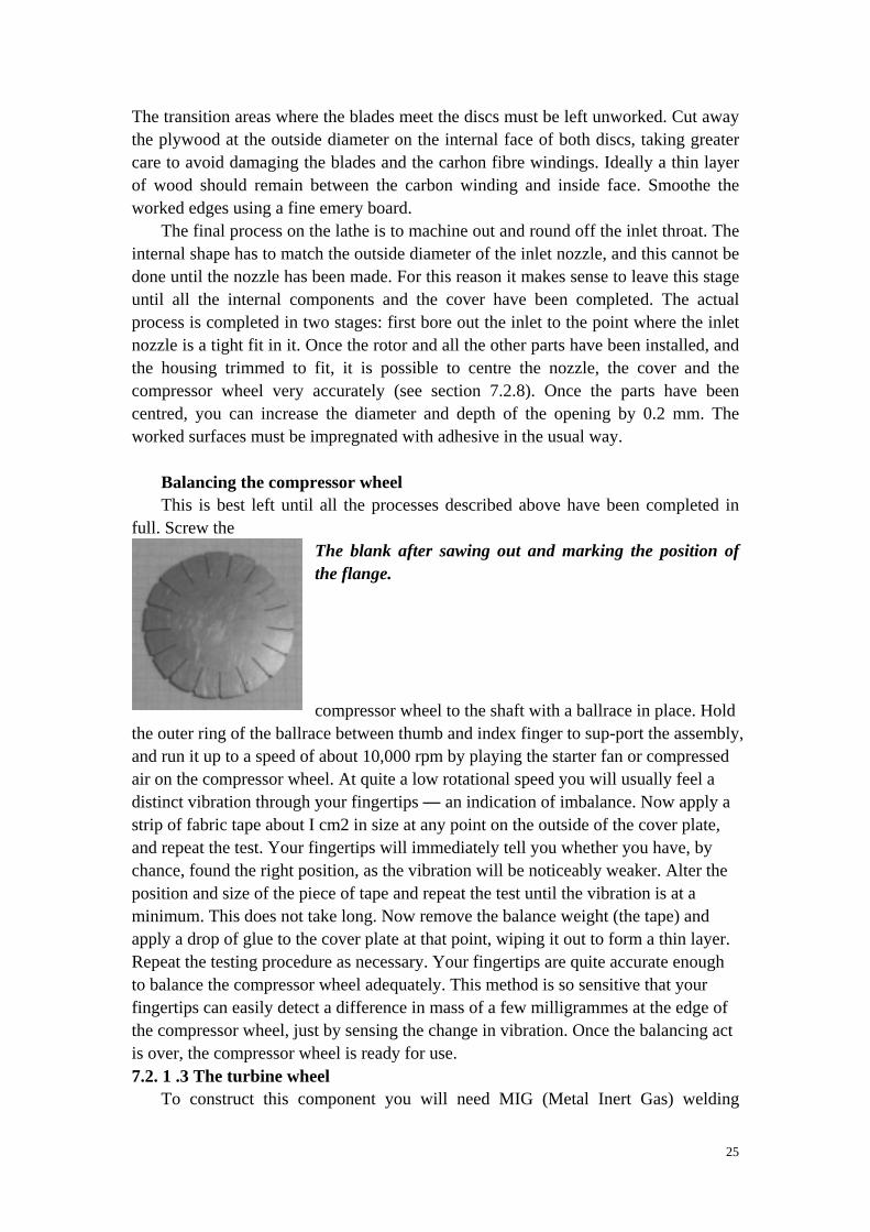
full. Screw the The blank after sawing out and marking the position of the flange. compressor wheel to the shaft with a ballrace in place. Hold
the outer ring of the ballrace between thumb and index finger to sup-port the assembly, and run it up to a speed of about 10,000 rpm by playing the starter fan or compressed air on the compressor wheel. At quite a low rotational speed you will usually feel a distinct vibration through your fingertips — an indication of imbalance. Now apply a strip of fabric tape about I cm2 in size at any point on the outside of the cover plate, and repeat the test. Your fingertips will immediately tell you whether you have, by chance, found the right position, as the vibration will be noticeably weaker. Alter the position and size of the piece of tape and repeat the test until the vibration is at a minimum. This does not take long. Now remove the balance weight (the tape) and apply a drop of glue to the cover plate at that point, wiping it out to form a thin layer. Repeat the testing procedure as necessary. Your fingertips are quite accurate enough to balance the compressor wheel adequately. This method is so sensitive that your fingertips can easily detect a difference in mass of a few milligrammes at the edge of the compressor wheel, just by sensing the change in vibration. Once the balancing act is over, the compressor wheel is ready for use. 7.2. 1 .3 The turbine wheel
To construct this component you will need MIG (Metal Inert Gas) welding
26
apparatus and a small, robust, high-speed hand-held grinder in addition to the lathe. Mark out the blade division on drafting paper using a root diameter of 41.5 mm and an outside diameter of 65 mm, and glue the template to the blank (2.5 mm thick stainless steel sheet). Mark the diameter of the mounting flange on the template. The stated outside diameter is about 1.5 mm larger than the diameter of the finished turbine wheel.
Mark both ends of the blade division slots on the metal at the inside and outside diameters using a centre punch. Mark the points on the outside diameter deeply, but those at the root diameter very delicately. Punch four points lightly around the hub flange diameter, spaced out at 90° to each other. Remove the paper template and mark the blade divisions from each punched point at the root diameter out to the corresponding point on the outside diameter, using a scriber. Don’t scribe lines right across the disc, as this produces a serrated effect. Making the blank
Drill 2.5 mm diameter holes at the outside point of each division. You will need to use a HSS drill in conjunction with a lubricant designed for stainless steel. In an emergency lubricating oil forms an adequate lubricant. Remove rough edges from the drilled holes. You can now cut out the prepared blank from the sheet material. Using a good hacksaw this takes about 30 minutes. Guide the saw blade from the centre of one hole to the centre of its neighbour, leaving half of each hole visible on the blank. Cut along the dividing lines between the blades, again using the fretsaw. Start from the half-holes and cut along the scribed line to the punched point at the root diameter. Twisting the blades
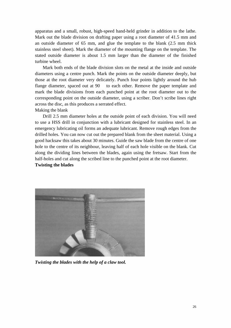
Twisting the blades with the help of a claw tool.
27
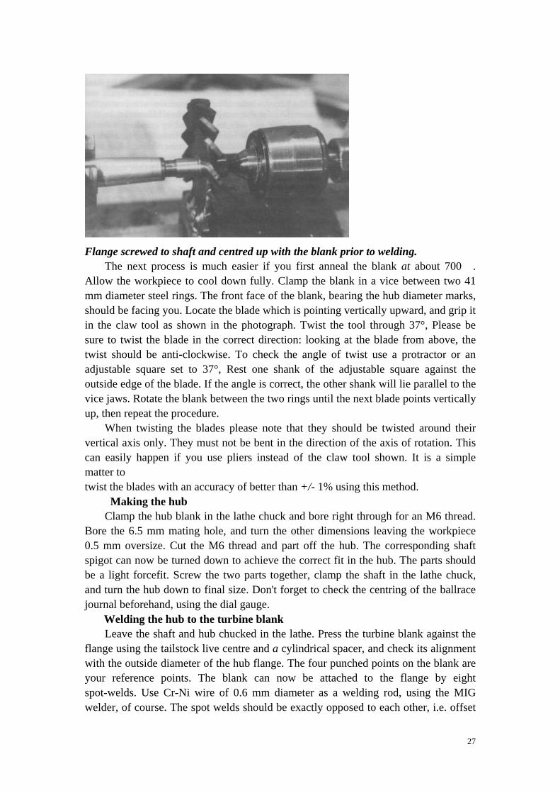
Flange screwed to shaft and centred up with the blank prior to welding.
The next process is much easier if you first anneal the blank at about 700℃. Allow the workpiece to cool down fully. Clamp the blank in a vice between two 41 mm diameter steel rings. The front face of the blank, bearing the hub diameter marks, should be facing you. Locate the blade which is pointing vertically upward, and grip it in the claw tool as shown in the photograph. Twist the tool through 37°, Please be sure to twist the blade in the correct direction: looking at the blade from above, the twist should be anti-clockwise. To check the angle of twist use a protractor or an adjustable square set to 37°, Rest one shank of the adjustable square against the outside edge of the blade. If the angle is correct, the other shank will lie parallel to the vice jaws. Rotate the blank between the two rings until the next blade points vertically up, then repeat the procedure.
When twisting the blades please note that they should be twisted around their vertical axis only. They must not be bent in the direction of the axis of rotation. This can easily happen if you use pliers instead of the claw tool shown. It is a simple matter to twist the blades with an accuracy of better than +/- 1% using this method.
Making the hub Clamp the hub blank in the lathe chuck and bore right through for an M6 thread.
Bore the 6.5 mm mating hole, and turn the other dimensions leaving the workpiece 0.5 mm oversize. Cut the M6 thread and part off the hub. The corresponding shaft spigot can now be turned down to achieve the correct fit in the hub. The parts should be a light forcefit. Screw the two parts together, clamp the shaft in the lathe chuck, and turn the hub down to final size. Don't forget to check the centring of the ballrace journal beforehand, using the dial gauge.
Welding the hub to the turbine blank Leave the shaft and hub chucked in the lathe. Press the turbine blank against the
flange using the tailstock live centre and a cylindrical spacer, and check its alignment with the outside diameter of the hub flange. The four punched points on the blank are your reference points. The blank can now be attached to the flange by eight spot-welds. Use Cr-Ni wire of 0.6 mm diameter as a welding rod, using the MIG welder, of course. The spot welds should be exactly opposed to each other, i.e. offset
28
by 180°. Cover the lathe under the joint area with metal sheet to avoid blobs of hot welding rod burning the machine. Turn down the blank to within 0.5 mm of its final outside diameter.
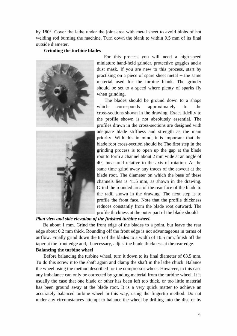
Grinding the turbine blades For this process you will need a high-speed
miniature hand-held grinder, protective goggles and a dust mask. If you are new to this process, start by practising on a piece of spare sheet metal -- the same material used for the turbine blank. The grinder should be set to a speed where plenty of sparks fly when grinding.
The blades should be ground down to a shape which corresponds approximately to the cross-sections shown in the drawing. Exact fidelity to the profile shown is not absolutely essential. The profiles drawn in the cross-sections are designed with adequate blade stiffness and strength as the main priority. With this in mind, it is important that the blade root cross-section should be The first step in the grinding process is to open up the gap at the blade root to form a channel about 2 mm wide at an angle of 40', measured relative to the axis of rotation. At the same time grind away any traces of the sawcut at the blade root. The diameter on which the base of these channels lies is 41.5 mm, as shown in the drawing. Grind the rounded area of the rear face of the blade to the radii shown in the drawing. The next step is to profile the front face. Note that the profile thickness reduces constantly from the blade root outward. The profile thickness at the outer part of the blade should
Plan view and side elevation of the finished turbine wheel. Be about 1 mm. Grind the front edge of the blades to a point, but leave the rear
edge about 0.2 mm thick. Rounding off the front edge is not advantageous in terms of airflow. Finally grind down the tip of the blades to a width of 10.5 mm, finish off the taper at the front edge and, if necessary, adjust the blade thickness at the rear edge. Balancing the turbine wheel
Before balancing the turbine wheel, turn it down to its final diameter of 63.5 mm. To do this screw it to the shaft again and clamp the shaft in the lathe chuck. Balance the wheel using the method described for the compressor wheel. However, in this case any imbalance can only be corrected by grinding material from the turbine wheel. It is usually the case that one blade or other has been left too thick, or too little material has been ground away at the blade root. It is a very quick matter to achieve an accurately balanced turbine wheel in this way, using the fingertip method. Do not under any circumstances attempt to balance the wheel by drilling into the disc or by
29
grinding material away from the turbine disc itself. A turbine wheel with a hole in it, even if the hole is only part-way through, is completely unsuitable for high rotational speeds, and will certainly fail in use. 7.2.2 Jigs
Jigs are required to centre the housing component 14 relative to parts 15 — 18, and to the internal structure, parts 7 — 13. The first jig is a flanged disc similar to the turbine wheel, with the same diameter as the internal diameter of part 18 (jig A). You will also need two discs with the same diameter as the internal diameter of the housing, and a central bore matching the shaft diameter. Link these two discs together using three studs, spaced about 70 mm apart. You can turn the discs from 4 — 5 mm thick plywood. The two large discs with the studs form jig B. Jig C is used to align parts 15, 16 and 18. 7.2.3 The internal structure
The internal structure consists of parts 7 to 13. It’s purpose is to locate and centre the rotor bearings in the housing, and it simultaneously forms the diffusor system for the compressor wheel at the front end. We will begin with the shaft sleeve, part 7, which includes the bearing sockets at either end. The rear bearing socket is an easy sliding fit. The front bearing socket forms a fixed bearing, and provides the axial location of the rotor, in conjunction with the base plate, part 10. The bearing centres up parts 7 and 10 relative to each other.
The easiest method of making the bearing sockets is to turn them from bar stock initially, fit them in the tubular shaft sleeve, and hard-solder the parts together. Turn the shaft sleeve to length, then attach the front mounting flange to it using about 6 spot welds. The struts between flange and shaft sleeve can now be welded in place. Clamp the workpiece in the lathe chuck, true up the front face of the flange perfectly flat, and turn the front bearing sleeve as shown in the drawing. The position of the vent hole on the periphery of the shaft sleeve is not crucial, but it must be the correct distance from the front face, and the inlet point for the oil pipe, part 35, should be offset to the hole by 180'. Hard-solder part 35 to part 7, and attach it to one of the struts by wrapping with wire. Hard solder the joint.
Cut out the base plate, part 10, oversize. Don’t use thinner material to save weight — that would be a false economy! The base plate forms a very rigid assembly in conjunction with the shaft sleeve, the housing and the link pieces, part 11. This rigidity is a fundamental necessity if the engine is to function correct- ly.
First drill through the centre bore in the plate and turn the ballrace seating. If your lathe does not allow you to chuck the base plate directly, screw it to a simple flat-faced flange for machining. The screw holes can be sealed later with countersunk aluminium rivets.
Make the link pieces, part 11, leaving them overlength, so that they can be cut down to suit the exact diameter of the housing. The threaded holes for the retaining screws, part 8, should not be drilled until the internal structure has been completed, and is ready for fitting in the housing. Rivet the link pieces to the base plate, using countersunk rivets on the front face of the base plate.
30
Saw out the compressor diffusor blade holder, part 12, to approximate size, and slot it to take the diffusor blades, part 13. Use the template method to mark out the slots, as described in chapter 7.2. 1. Glue parts 10 and 12 together at this stage using heat-curable epoxy, e.g. UHU Endfest 300, and cure the joint at 120℃. Offer up this assembly to the assembly consisting of parts 7, 8 and 9, using a ballrace to aid location. The screw holes can now be drilled in the following sequence:
Drill the 2.5 mm through holes in the positions shown. Drill out these holes in part 8 to 3. 1 mm diameter. Tap an M3 thread in parts 10 and 12. Harden the threaded holes in part 12 by applying cyano-acrylate glue. This produces a self-locking thread which holds quite well. For the next stage the two sub-assemhues need to be screwed together. Clamp the shaft sleeve in the lathe chuck, and centre up the other end on the ballrace using the live centre. This ballrace should only be used for the following machining process. Don't use it when running the rotor. Turn the diameter of parts 10 and 12 to final size. Machine the radiused edge and turn the front face of part 12 to size.
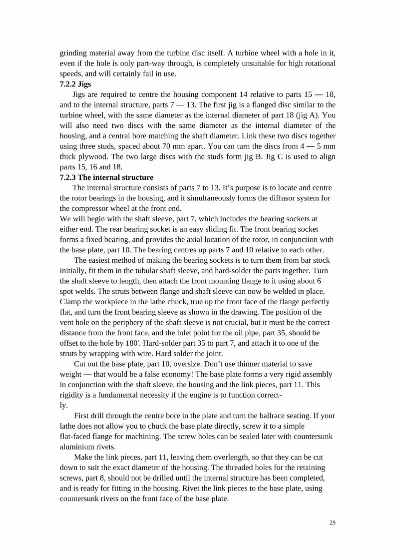
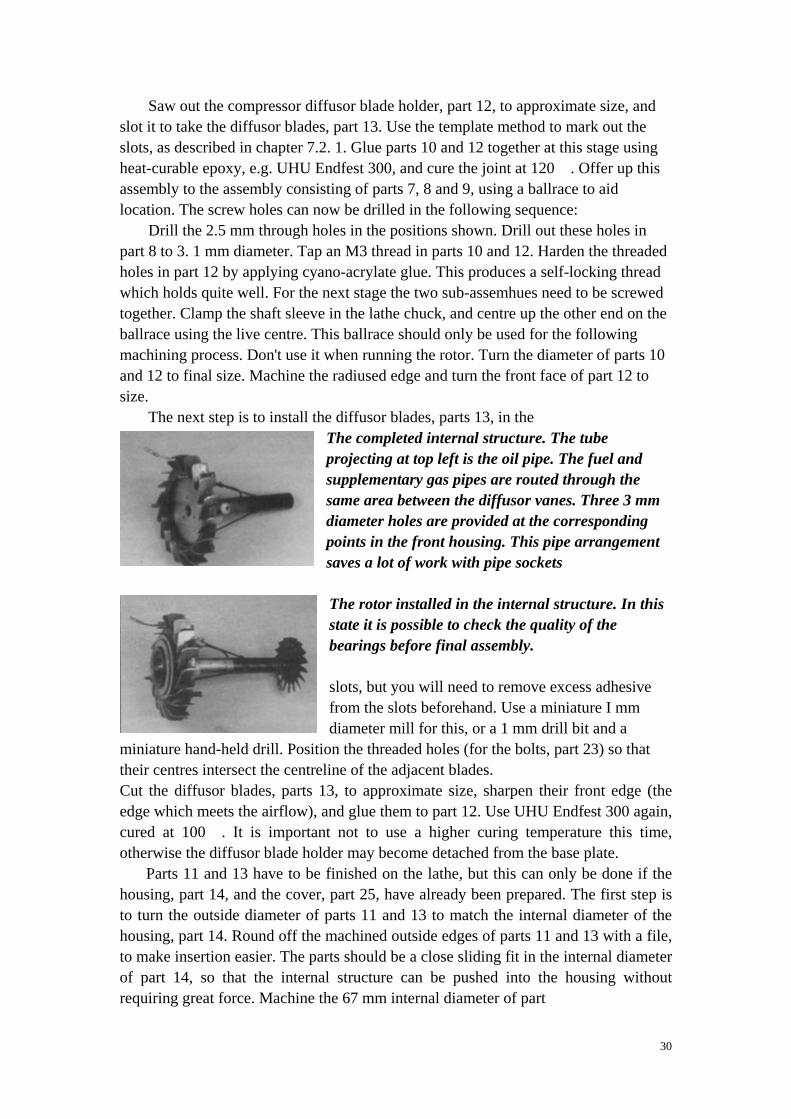
The next step is to install the diffusor blades, parts 13, in the The completed internal structure. The tube projecting at top left is the oil pipe. The fuel and supplementary gas pipes are routed through the same area between the diffusor vanes. Three 3 mm diameter holes are provided at the corresponding points in the front housing. This pipe arrangement saves a lot of work with pipe sockets
The rotor installed in the internal structure. In this state it is possible to check the quality of the bearings before final assembly. slots, but you will need to remove excess adhesive from the slots beforehand. Use a miniature I mm diameter mill for this, or a 1 mm drill bit and a
miniature hand-held drill. Position the threaded holes (for the bolts, part 23) so that their centres intersect the centreline of the adjacent blades. Cut the diffusor blades, parts 13, to approximate size, sharpen their front edge (the edge which meets the airflow), and glue them to part 12. Use UHU Endfest 300 again, cured at 100℃. It is important not to use a higher curing temperature this time, otherwise the diffusor blade holder may become detached from the base plate.
Parts 11 and 13 have to be finished on the lathe, but this can only be done if the housing, part 14, and the cover, part 25, have already been prepared. The first step is to turn the outside diameter of parts 11 and 13 to match the internal diameter of the housing, part 14. Round off the machined outside edges of parts 11 and 13 with a file, to make insertion easier. The parts should be a close sliding fit in the internal diameter of part 14, so that the internal structure can be pushed into the housing without requiring great force. Machine the 67 mm internal diameter of part
31
12, and chamfer the edges. Impregnate all the worked surfaces of the wooden component with fuel-proof lacquer. Machine the outside shape of the diffusor blades 13 to match the shape of the cover. Machining the blades is easier if you set up the lathe to rotate in the direction opposite to normal, and clamp the turning tool with the cutting edge at the bottom. 7.2.4 The housing
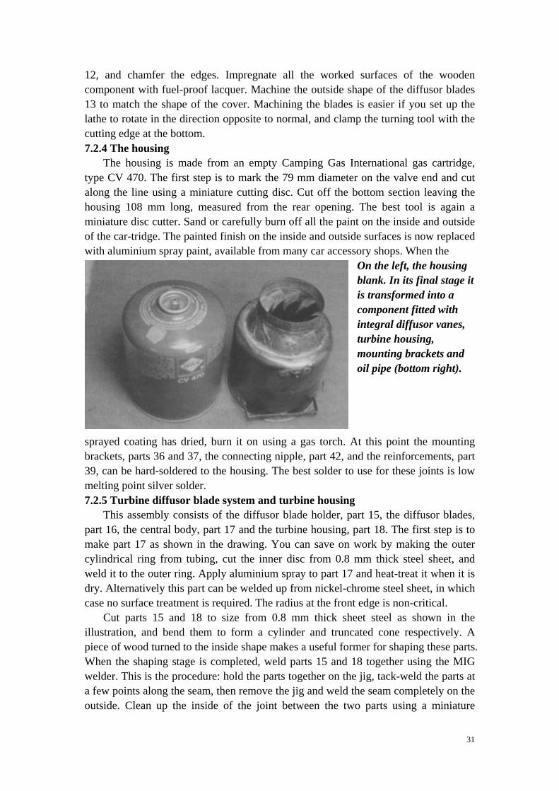
The housing is made from an empty Camping Gas International gas cartridge, type CV 470. The first step is to mark the 79 mm diameter on the valve end and cut along the line using a miniature cutting disc. Cut off the bottom section leaving the housing 108 mm long, measured from the rear opening. The best tool is again a miniature disc cutter. Sand or carefully burn off all the paint on the inside and outside of the car-tridge. The painted finish on the inside and outside surfaces is now replaced with aluminium spray paint, available from many car accessory shops. When the
On the left, the housing blank. In its final stage it is transformed into a component fitted with integral diffusor vanes, turbine housing, mounting brackets and oil pipe (bottom right).
sprayed coating has dried, burn it on using a gas torch. At this point the mounting brackets, parts 36 and 37, the connecting nipple, part 42, and the reinforcements, part 39, can be hard-soldered to the housing. The best solder to use for these joints is low melting point silver solder. 7.2.5 Turbine diffusor blade system and turbine housing
This assembly consists of the diffusor blade holder, part 15, the diffusor blades, part 16, the central body, part 17 and the turbine housing, part 18. The first step is to make part 17 as shown in the drawing. You can save on work by making the outer cylindrical ring from tubing, cut the inner disc from 0.8 mm thick steel sheet, and weld it to the outer ring. Apply aluminium spray to part 17 and heat-treat it when it is dry. Alternatively this part can be welded up from nickel-chrome steel sheet, in which case no surface treatment is required. The radius at the front edge is non-critical.
Cut parts 15 and 18 to size from 0.8 mm thick sheet steel as shown in the illustration, and bend them to form a cylinder and truncated cone respectively. A piece of wood turned to the inside shape makes a useful former for shaping these parts. When the shaping stage is completed, weld parts 15 and 18 together using the MIG welder. This is the procedure: hold the parts together on the jig, tack-weld the parts at a few points along the seam, then remove the jig and weld the seam completely on the outside. Clean up the inside of the joint between the two parts using a miniature
32
hand-held grinder. Apply the usual surface treatment to this component: aluminium spray fixed by burning on.
Cut the diffusor blade slots in part 15 working from the out-side, using a miniature disc cutter and hand-held drill. Mark the slot positions using the paper template method. Glue the paper template in place securely and cut the slots using a grinder or drill, cutting along the marked centrelines. Make the wooden jig C as shown in the sketch before installing the blades. It is important that the 64 mm diameter of the jig is a press-fit in part 18. The jig forms a stop for the inside edge of the diffusor blades, part 16. The diameter of the stop should be approximately 1 mm smaller than the outside diameter of part 17 at this point. The result is a pre-defined excess at the inside edge of the diffusor blades, ready for final working.
The first step in making the diffusor blades is to cut a pattern from 0.5 mm sheet brass. This blade should fit as accurately as possible against the cylindrical part of the jig, and project by about 2 mm beyond the outside edge of part 15. The curvature of the outside edge of the blade is dictated by the shape of the slots in part 15. The radius of the curve should become steadily smaller towards the cylindrical part of the jig, although exact adherence to the stated radii is not a pre-requisite for the correct functioning of the system. Once this template is completed, you can make the actual diffusor blades using it as a pattern. The blades are installed as follows: fit the blade through the slot and tack in place on the outside using the welder, then adjust it if necessary. The blades should be radially symmetrical when viewed from the front and rear, but aligning them by eye is quite accurate enough. When you are satisfied, weld the blades to part 15 along the length of the joints, using the MIG welder. Use 0.6 mm diameter steel wire as welding rod.
Press out the jig, and clamp the diameter of part 18 in the lathe. The inside length of the diffusor blades can now be ground down to final size using the miniature grinder. Part 17 should fit inside the diffusor blades with about 0.2 mm clearance. 7.2.6 Attaching the diffusor blade system to the housing
Push jig B into the housing. Screw jig A to the shaft instead of the turbine. Place the sub-assembly consisting of parts 15 to 18 on the rear face of part 14, and slide the shaft in from the rear using jig A to centre up the parts. The sub-assembly can now be hard-soldered to part 14. Alternatively, if you are confident of your ability to weld very thin sheet metal you can weld the joint instead. Remove the jigs and clean up the hard soldered or weld-ed seam on the inside of the joint. Use brass-based hard solder for this joint. 7.2.7 Centring the internal structure
Fit the front bearing in the internal structure by pushing it into the housing from the front. Fit a ballrace on the turbine end of the shaft, then screw jig A in place again. Slide this assembly into the shaft sleeve from the rear. This process accurately centres the shaft sleeve relative to the turbine housing. Measure the dimensions carefully, and drill the retaining screw holes through part 14 and the link pieces, part 11. Drill 3.2 mm pilot holes for the M4 thread first, then remove the internal structure from the housing. Drill out the holes in the housing to 4 mm diameter, and tap an M4 thread in the holes in parts 11.
33
7.2.8 Making the front section This consists of the cover, part 25, the reinforcing ring, part 26, the connecting
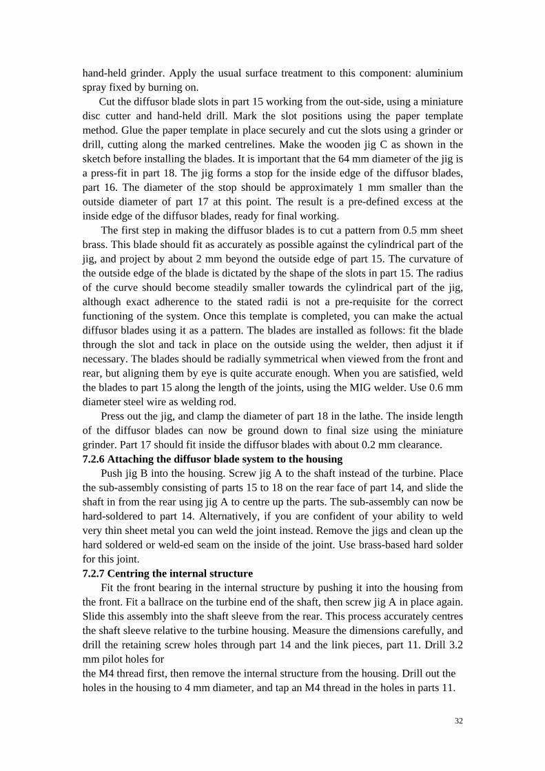
ring, part 28, and the inlet nozzle, part 27. Parts 25 and 27 are pressed out of I mm thick pure aluminium sheet. This technique is very easy to learn. I suggest that you start with the simpler component: part 27. You will need a hardwood former turned to shape; alternatively you could assemble the former from a stack of plywood discs. The out-side shape of the former should be the same shape as the inside of the component to be pressed, but should be slightly longer, as shown in the drawing. Clamp the former in the lathe chuck. The workpiece blank is now pressed over the flat front face of the for-men The live centre is used for this, in conjunction with a pressing disc whose diameter is slightly smaller than the front face of the former. The blank is a flat disc of sheet metal with the diameter stated in the drawing. It must be annealed at around 300' C before being shaped. Instead of a turning tool, a pressure tool is used for the next step. For our purposes this consists of a length of hardwood about 10 x 10 mm in cross-section, with the front face rounded off. For this simple type of pressing a lubricant is needed, e.g. grease. The principle of the process is this: the former rotates, and the sheet metal, in its soft state, is pressed against the former using the pressure tool. The first step is to guide the pressing tool as if you wanted to create a shape half-way between the final form and the flat plate. You then continue pressing with the pressure tool, until finally the formed metal rests against the former. This process does demand a little prac tice. If the material becomes too brittle
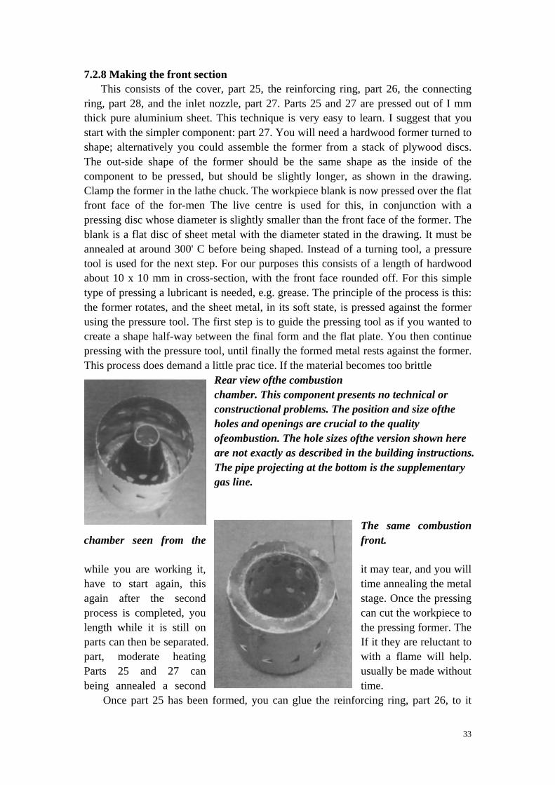
Rear view ofthe combustion chamber. This component presents no technical or constructional problems. The position and size ofthe holes and openings are crucial to the quality ofeombustion. The hole sizes ofthe version shown here are not exactly as described in the building instructions. The pipe projecting at the bottom is the supplementary gas line.
The same combustion chamber seen from the front. while you are working it, it may tear, and you will have to start again, this time annealing the metal again after the second stage. Once the pressing process is completed, you can cut the workpiece to length while it is still on the pressing former. The parts can then be separated. If it they are reluctant to part, moderate heating with a flame will help. Parts 25 and 27 can usually be made without being annealed a second time.
Once part 25 has been formed, you can glue the reinforcing ring, part 26, to it
34
using UHU Endfest 300. Cure the epoxy with heat. When the glued joint is hard, saw out the central hole to accommodate part 27. It does not matter if this opening is not exactly central. Drill holes in parts 25 and 26 for the retaining screws, part 41, in line with the holes in the internal structure. You can now screw the cover, the internal structure and the housing together, and centre up parts 27, 28 and 25 using the compressor wheel itself. The machined curve in the compressor wheel cover plate serves to locate part 27 accurately. Parts 25, 28 and 27 can now be glued together in a single operation, with part 27 engaging in the opening in the compressor wheel. For once fast-setting epoxy is adequate for the job, although the metal joint surfaces should still be cleaned carefully and keyed with coarse abrasive paper. Take care that no resin gets between part 27 and the compressor wheel. When the resin has cured, separate the parts again (in so far as you have not glued them together). The opening in the compressor wheel can now be turned down on the lathe to produce 0.3 mm clearance between the nozzle and the cover plate both axially and radially. Apply sealing lacquer to the machined opening. It is a good idea to re-check the balance of the compressor wheel after completing this stage. 7.2.9 The combustion chamber
The combustion chamber consists of the inner cone, part 29, the front section 30 and the outer jacket 31. Mark out these parts as shown in the drawing, and drill the holes in part 29. Place a sheet of hardwood under the thin sheet metal before applying the drill. It is important to use the right type of drill with this material. HSS drill bits, in conjunction with stainless steel cutting paste, have proved excellent. Remove rough edges from the holes using a miniature hand-held grinder.
All the sheet metal parts can be cut accurately from the sheet material, without distorting the panels, using a miniature hand-held grinder and fine cutting discs. Part 29 can then be bent to the correct conical shape. One method is to machine a conical wooden former and bend the metal round it. Alternatively, with a little skill it is possible to do the job using a length of dowel about 15 mm in diameter as a former. Clamp the dowel in the vice, and bend the part round it segment by segment, until you achieve the correct conical shape. Weld the seam using the MIG welder and 0.6 mm diameter nickel-chrome wire. Weld part 29 to the front section, part 30, as just described, then weld part 30 to part 31. It is a good idea to make a plywood locating ring to help centre up part 29 relative to part 31 at the rear end. Cut out the air inlet flaps in part 31 using the miniature disc cutter, and bend them inward as shown in the drawing. It is important that the flaps are cut so that they point in the direction of rotation. Cut the cooling air slots as shown in the drawing, using a 1 mm thick grinding disc. The last part of the combustion chamber is the spacers, which are tack-welded in place using the MIG welder, and the supplementary gas inlet tube, part 43, which should be fixed to part 30. The tube can be soldered in place using high melting point silver solder. The inlet tube should only just project into the combustion chamber, otherwise there is a risk that it will melt when the engine is running.
If you wish to install an internal ignition system, fit a threaded glowplug sleeve on the front face, offset by about 60' relative to the inlet pipe, and hard-solder it in place. If you fit the sleeve, remember to check at the final assembly stage that the projecting
35
glowplug head does not foul any of the internal structure components. A cable duct must also be provided for the glowplug cable. The duct can be fitted at any point in the housing in the area between parts 10 and 30. Thick-walled silicone tubing has proved an ideal insulating material for the cable. Make a spring clip from brass sheet for the glowplug con-tact. Bend the spacer 32 so that it presses lightly against the inner wall when the combustion chamber is fitted into the housing, part 14. 7.2.10 The vaporiser
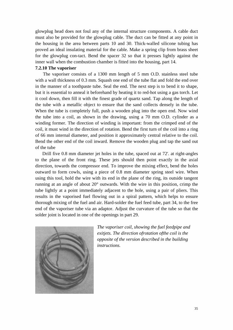
The vaporiser consists of a 1300 mm length of 5 mm O.D. stainless steel tube with a wall thickness of 0.3 mm. Squash one end of the tube flat and fold the end over in the manner of a toothpaste tube. Seal the end. The next step is to bend it to shape, but it is essential to anneal it beforehand by heating it to red-hot using a gas torch. Let it cool down, then fill it with the finest grade of quartz sand. Tap along the length of the tube with a metallic object to ensure that the sand collects densely in the tube. When the tube is completely full, push a wooden plug into the open end. Now wind the tube into a coil, as shown in the drawing, using a 70 mm O.D. cylinder as a winding former. The direction of winding is important: from the crimped end of the coil, it must wind in the direction of rotation. Bend the first turn of the coil into a ring of 66 mm internal diameter, and position it approximately central relative to the coil. Bend the other end of the coil inward. Remove the wooden plug and tap the sand out of the tube
Drill five 0.8 mm diameter jet holes in the tube, spaced out at 72'. at right-angles to the plane of the front ring. These jets should then point exactly in the axial direction, towards the compressor end. To improve the mixing effect, bend the holes outward to form cowls, using a piece of 0.8 mm diameter spring steel wire. When using this tool, hold the wire with its end in the plane of the ring, its outside tangent running at an angle of about 20° outwards. With the wire in this position, crimp the tube lightly at a point immediately adjacent to the hole, using a pair of pliers. This results in the vaporised fuel flowing out in a spiral pattern, which helps to ensure thorough mixing of the fuel and air. Hard-solder the fuel feed tube, part 34, to the free end of the vaporiser tube via an adaptor. Adjust the curvature of the tube so that the solder joint is located in one of the openings in part 29.
The vaporiser coil, showing the fuel feedpipe and exitjets. The direction ofrotation ofthe coil is the opposite of the version described in the building instructions.
36
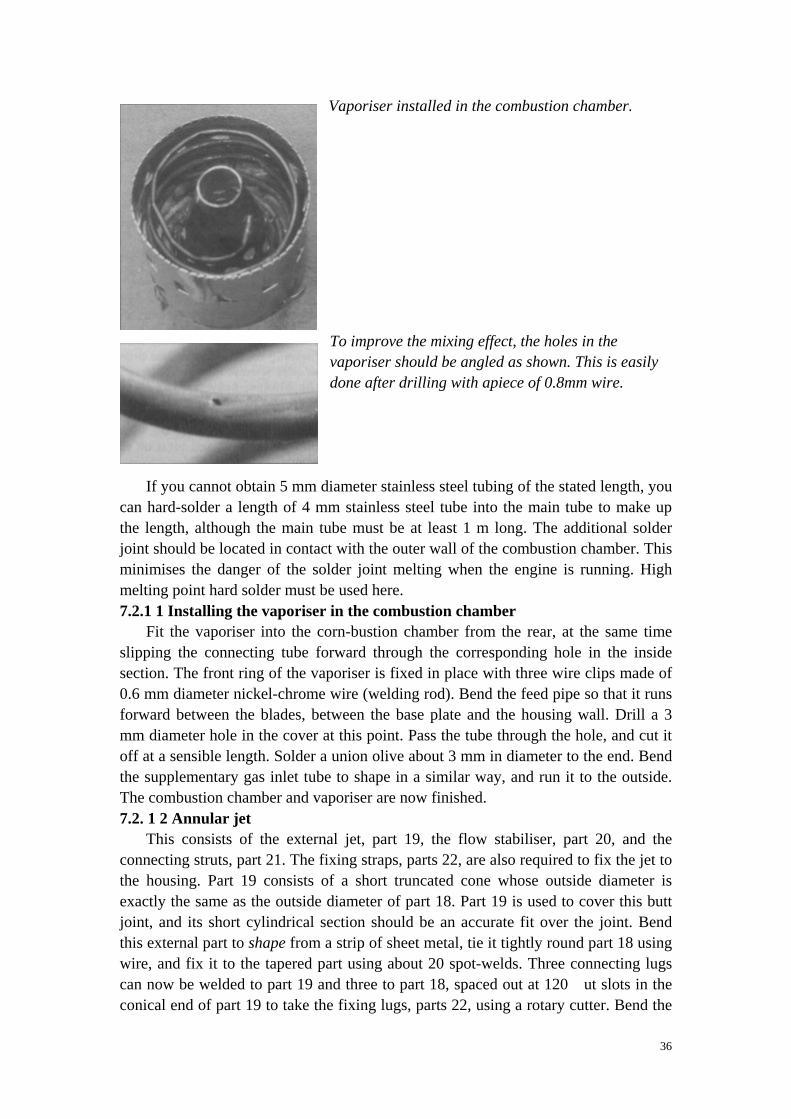
Vaporiser installed in the combustion chamber.
To improve the mixing effect, the holes in the vaporiser should be angled as shown. This is easily done after drilling with apiece of 0.8mm wire.
If you cannot obtain 5 mm diameter stainless steel tubing of the stated length, you can hard-solder a length of 4 mm stainless steel tube into the main tube to make up the length, although the main tube must be at least 1 m long. The additional solder joint should be located in contact with the outer wall of the combustion chamber. This minimises the danger of the solder joint melting when the engine is running. High melting point hard solder must be used here. 7.2.1 1 Installing the vaporiser in the combustion chamber
Fit the vaporiser into the corn-bustion chamber from the rear, at the same time slipping the connecting tube forward through the corresponding hole in the inside section. The front ring of the vaporiser is fixed in place with three wire clips made of 0.6 mm diameter nickel-chrome wire (welding rod). Bend the feed pipe so that it runs forward between the blades, between the base plate and the housing wall. Drill a 3 mm diameter hole in the cover at this point. Pass the tube through the hole, and cut it off at a sensible length. Solder a union olive about 3 mm in diameter to the end. Bend the supplementary gas inlet tube to shape in a similar way, and run it to the outside. The combustion chamber and vaporiser are now finished. 7.2. 1 2 Annular jet
This consists of the external jet, part 19, the flow stabiliser, part 20, and the connecting struts, part 21. The fixing straps, parts 22, are also required to fix the jet to the housing. Part 19 consists of a short truncated cone whose outside diameter is exactly the same as the outside diameter of part 18. Part 19 is used to cover this butt joint, and its short cylindrical section should be an accurate fit over the joint. Bend this external part to shape from a strip of sheet metal, tie it tightly round part 18 using wire, and fix it to the tapered part using about 20 spot-welds. Three connecting lugs can now be welded to part 19 and three to part 18, spaced out at 120℃ut slots in the conical end of part 19 to take the fixing lugs, parts 22, using a rotary cutter. Bend the
37
deflector cone to approximate shape round a length of 12 mm diameter dowel prior to welding the joint. Clean up the weld seam inside and out using the miniature grinder. Make a hardwood cone with a slightly rounded base, and drive the truncated metal cone onto it. If the wooden cone is now clamped in the lathe using a suitable mandrel, you can press the deflector cone to final shape and clean it up. Parts 20, 19 and 21 are assembled as follows: place part 19 on part 18, and wrap nickel-chrome wire round the lugs. With the turbine wheel in position, place part 20 on the turbine disc, using a locating ring and a spacer disc. The struts, part 21, can now be fitted, and parts 19 and 20 joined by means of a few spot welds. Remove the spacer disc and the locating ring, and the annular jet is ready to use. You may find that the fatter end of the deflector cone distorts into a slightly triangular shape, but this has no effect on the annular jet's effectiveness.
The turbo-jet engine has been thoroughly tested with the annular jet held in place by the fixing lugs and wire clips shown, and the system is completely reliable. A gastight joint between jet and housing is not necessary. 7.3 Final assembly
Screw three studs in the M4 threaded holes in the central structure, and fit locknuts on the rear face to secure them4 Flatten the studs slightly in the air duct area on the front face, using the disc grinder. Fit the springs which press against the combustion chamber onto the end of the bolts which project on the rear side. You can bend the springs slightly so that they do not slip off the bolts by themselves. There must be at least 1 mm clearance between the projecting end of the studs facing the combustion chamber, and the front face of the combustion chamber itself, to avoid serious stress or distortion occurring when heat causes the combustion chamber to expand.
The front end of the studs is used to secure the cover. Three M4 nuts are sufficient for this. Alternatively you can use two of the studs as a method of mounting the turbo-jet: in this case replace two of the M4 nuts with 7 mm diameter pillars with an internal M4 thread. Fit these pillars through a former at the tail end of the fuselage, and the engine only then requires to be screwed to a suitable support at the rear, by means of the rear front mounting bracket, part 37. If you select this method of mounting, the mounting bracket, part 36, is not required.
Before finally assembling the motor prior to running it, check that all the pipework is unobstructed, and mark each pipe to identify it. Remove any traces of dust and swarf from all the engine's components. Install the front and rear ballraces, and fix the central structure in place using three M3 screws. Clamp the shaft in the lathe chuck and screw the turbine wheel into place by hand, using a cloth to avoid injury. Screw the wheel in place as far as it will go, without using force. Further assembly is completed in the following sequence:
Push part 17 in as far as it will go. Slide the combustion chamher into place and rotate it until the three pipes line up with the holes in the cover. Fit the central structure and line up the threaded holes in parts 11 with the corresponding holes in part 14. Fit the retaining screws but do not tighten them fully. Slide the shaft and turbine wheel into the shaft sleeve from the rear, as far as it will go. The clearance
38
between the turbine wheel and part 18 should now be adjusted by placing three strips of metal 0,3 mm thick between the turbine wheel and part 18, spaced out at 120°. Lightly tighten the retaining screws, part 38. Withdraw the metal strips and check that the turbine wheel rotates freely. I recommend using a feeler gauge, 0.2 to 0.3 mm thick. If the blade can be slipped into place equally easily at all points, then the turbine wheel is correctly centred. Otherwise you will need to make a slight further adjustment, as follows: undo the retaining screw which is closest to the area with the tightest clearance —two of the screws, if necessary — and fit a 0.4 mm feeler gauge at the point with least clearance. Tighten all the screws and with-draw the feeler gauge. If you find it impossible to centre the turbine in this way you will have to make a careful adjustment to the holes in part 14.
Once you have successfully carried out this adjustment, you can fit the compressor wheel and screw it to the shaft using the retaining screw, part 40. Check again that the rotor spins freely. The bearings should be so free that a light puff on the compressor wheel sets it spinning. If the system passes this test satisfactorily, the front section can be fitted and screwed in place. Now repeat the freewheel test again, and re-check the centration of the turbine, as under certain circumstances the housing may change shape when the cover is screwed to it. This may occur if the cover is pressed too tightly against the edge of the housing. If this is the case, grind back the cover slightly where it makes con-tact with the housing. With the front section screwed in place and the turbine centred perfectly, blow on the rotor with the electric fan, then switch the fan off and hold the engine with the inlet opening facing down. Listen carefully, and you should hear no sounds of rubbing at all. The rotor should slow down gradually not abruptly. Assuming that any fouling is not due to dirt or excess glue at the edge of the inlet nozzle, the machined opening in the compressor wheel cover plate will need further adjustment.
For the first test runs seal the gap between parts 15 and 14 with a double layer of narrow textile tape, wrapped tightly round over the gap. Temporarily seal the openings between the feed pipes and the cover with thin hose. The engine is now ready for its first run. Don't install the annular jet at this stage.
Carry out test runs of the engine as described in sections 9.3 and 9.4. When you are satisfied that everything works correctly, seal the cover and the feed pipe openings with silicone sealant, using this procedure: remove all traces of oil from the inside of the cover and the edge of the housing. Place . cover on the engine and tighten the retaining nuts lightly, so that the components are in their final position. Now loosen the three retaining nuts by one complete turn, and push the cover forward as far as the nuts allow. Apply a thin line of silicone sealant around the annular gap, and tighten the retaining nuts fully. Seal the pipe openings in the cover with silicone sealant.
39
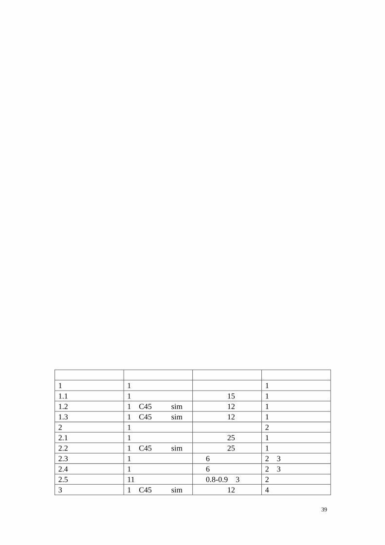
配件编号 材料 直径 图号 1 轴 1 构造群 1 1.1 中轴 1 轻金属合金 圆柱形,15Ф 1 1.2 前部轴承套 1 C45钢或 sim 圆柱形,12Ф 1 1.3 后部轴承套 1 C45钢或 sim 圆柱形,12Ф 1 2 压缩轮 1 构造群 2 2.1 前部衬套 1 轻金属合金 圆柱形,25Ф 1 2.2 后部衬套 1 C45钢或 sim 圆柱形,25Ф 1 2.3 底盘 1 夹板 厚 6,碳纤维加固 2,3 2.4 盖板 1 夹板 厚 6,碳纤维加固 2,3 2.5 压缩轮桨叶 11 夹板 厚 0.8-0.9,3层 2 3 毂 1 C45钢或 sim 圆柱形,12Ф 4
40
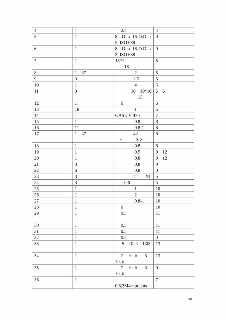
4 涡轮 1 镍铬钢 厚 2.5 4 5 前部滚珠轴承 1 铬钢 8 I.D. x 16 O.D. x
5, ISO 688 0
6 后部滚珠轴承 1 铬钢 8 I.D. x 16 O.D. x 5, ISO 688
0
7 轴袖 1 钢 18*1 管子,圆柱形,18Ф
5
8 法兰盘 1 37号钢 薄片,厚 2 5 9 支撑 3 钢 焊接杆,2.5Ф 5 10 底盘 1 轻金属合金 薄片,厚 4 6 11 连接件 3 轻金属合金 薄片厚 10,10*10
或圆柱形,15Ф 5,6
12 压缩轮桨叶架 1 夹板 厚 6,山毛或白桦 6 13 压缩轮桨叶 18 轻金属合金 薄片,厚 1 5 14 机壳 1 钢 GAS CV 470弹壳 7 15 涡轮桨叶架 1 钢 薄片,厚 0.8 8 16 涡轮桨叶 11 镍铬钢 薄片,厚 0.8-1 8 17 中央部件 1 37号钢 圆柱形,42Ф或圆
管+薄片,0.8 8
18 涡轮机室 1 钢 薄片,厚 0.8 8 19 环形喷管 1 镍铬钢 薄片,厚 0.5 9,12 20 扩散锥 1 镍铬钢 薄片,厚 0.8 9,12 21 支架 3 镍铬钢 薄片,厚 0.8 9 22 环 6 镍铬钢 薄片,厚 0.8 0 23 螺栓 3 钢 圆柱形,4Ф或 M4 5 24 压缩机弹簧 3 弹簧钢 线,0.6Ф或类似 5 25 盖子 1 铝 薄片,厚 1 10 26 加固环 1 轻金属合金 薄片,厚 2 10 27 吸气口 1 铝 薄片,厚 0.8-1 10 28 连接环 1 夹板 厚 6 10 29 内部蜂窝燃烧室
1 镍铬钢 厚 0.5 11
30 燃烧室前部 1 镍铬钢 厚 0.5 11 31 燃烧室外部 1 镍铬钢 厚 0.5 11 32 间隔 1 镍铬钢 厚 0.5 0 33 喷雾器 1 镍铬钢 管 5Ф*0.3,1300
长 13
34 燃料管 1 黄铜 管 2Ф*0.5 和 3Ф*0.5
13
35 油管 1 黄铜 管 2Ф*0.5 和 3Ф*0.5
0
36 前部装备支架 1 钢 薄 片 , 厚
0.8,2M4capt.nuts 7
41
37 后部装备支架 1 钢 薄 片 , 厚
0.8,2M4capt.nuts 7
38 螺丝 3 钢 M4*6槽头螺丝 0 39 加固 3 钢 薄片,厚 0.5 7 40 保持螺丝 1 钢 M4*16槽头螺丝 0 41 螺丝 3 钢 M4*12槽头螺丝 0 42 辅助气体管道 1 黄铜 管 2Ф*0.5 和 3Ф
*0.5 0
42
43
44
45
46
47
48
49
50
51
52
53


![[12] 发明专利申请公布说明书](https://img.dokumen.tips/doc/110x75/631bfac6c2fddc481907c882/12--1674952393.jpg)


