Embed Size (px)
Citation preview
Fault Analysis
Prof. M VENKATESWARA RAO
Dept. of EEE,
JNTUA College of Engineering, Kalikiri
Chittoor District, A P, India
Prof. M Venkateswara Rao, Dept. of EEE, JNTUA College of Engineering, Kalikiri, Chittoor District, A P, India
Outline of Presentation
Prof. M Venkateswara Rao, Dept. of EEE, JNTUA College of Engineering, Kalikiri, Chittoor District, A P, India
❖ Introduction
❖ Types of Faults
❖ Symmetrical Fault Analysis
❖ Sequence components
❖ Sequence Networks
❖ Zero sequence Impedance of Transformers
❖ Unsymmetrical Fault Analysis
❖ Previous years GATE questions
Introduction
❖ A fault in a power system or circuit is a failure which interferes
with the normal flow of current
❖The faults are associated with abnormal change in current,
voltage and frequency of the power system
❖In general faults occur in power system networks due to
insulation failure of equipments, flashover of lines initiated by a
lightning stroke, or due to accidental faulty operation
Prof. M Venkateswara Rao, Dept. of EEE, JNTUA College of Engineering, Kalikiri, Chittoor District, A P, India
Need for fault calculation
Prof. M Venkateswara Rao, Dept. of EEE, JNTUA College of Engineering, Kalikiri, Chittoor District, A P, India
❖ When the fault occur in a part of power system, heavy current flows in
that part of circuit which may cause permanent damage to the
equipments
❖ The selection of the circuit breaker depends on the current flowing
immediately after the fault occurs
❖ The estimation of these currents for various types of faults at various
locations in the system is called fault calculation
❖ The data obtained from fault calculations are also used to determine the
settings of the relay which control the circuit breakers
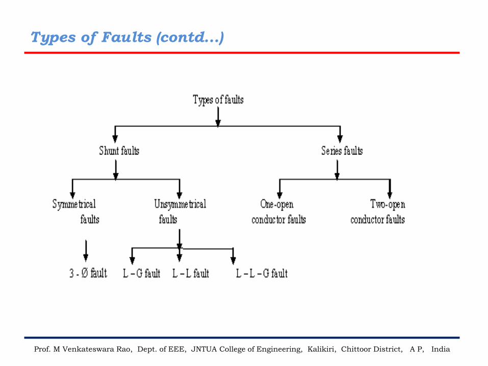
Types of Faults
Prof. M Venkateswara Rao, Dept. of EEE, JNTUA College of Engineering, Kalikiri, Chittoor District, A P, India
❖ The faults can be broadly classified into
a) Shunt faults (short circuit)
b) Series faults (open conductors)
❖ The shunt type of faults involves short circuit between conductor
and ground or short circuit between two or more conductors. The
shunt faults are characterized by increase in current and fall in
voltage and frequency
❖ The series faults may occur with one or two broken conductors
which creates open circuits. The series faults are characterized by
increase in voltage and frequency and fall in current in the faulty
phase
Types of Faults (contd...)
Prof. M Venkateswara Rao, Dept. of EEE, JNTUA College of Engineering, Kalikiri, Chittoor District, A P, India
Types of Faults (contd...)
Prof. M Venkateswara Rao, Dept. of EEE, JNTUA College of Engineering, Kalikiri, Chittoor District, A P, India
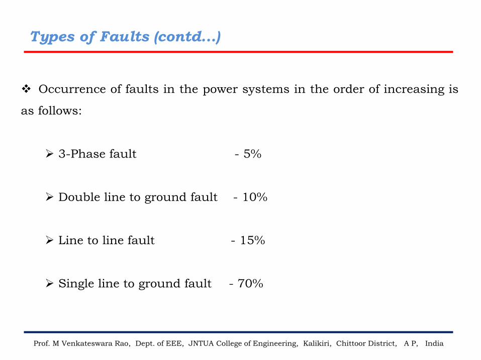
❖ Occurrence of faults in the power systems in the order of increasing is
as follows:
➢ 3-Phase fault - 5%
➢ Double line to ground fault - 10%
➢ Line to line fault - 15%
➢ Single line to ground fault - 70%
Types of Faults (contd...)
Prof. M Venkateswara Rao, Dept. of EEE, JNTUA College of Engineering, Kalikiri, Chittoor District, A P, India
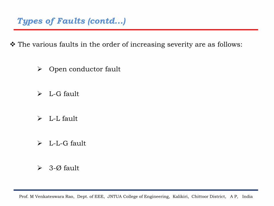
❖ The various faults in the order of increasing severity are as follows:
➢ Open conductor fault
➢ L-G fault
➢ L-L fault
➢ L-L-G fault
➢ 3-Ø fault
Symmetrical Fault Analysis
Prof. M Venkateswara Rao, Dept. of EEE, JNTUA College of Engineering, Kalikiri, Chittoor District, A P, India
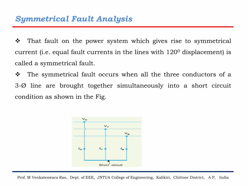
❖ That fault on the power system which gives rise to symmetrical
current (i.e. equal fault currents in the lines with 1200 displacement) is
called a symmetrical fault.
❖ The symmetrical fault occurs when all the three conductors of a
3-Ø line are brought together simultaneously into a short circuit
condition as shown in the Fig.
Symmetrical Fault Analysis (contd...)
Prof. M Venkateswara Rao, Dept. of EEE, JNTUA College of Engineering, Kalikiri, Chittoor District, A P, India
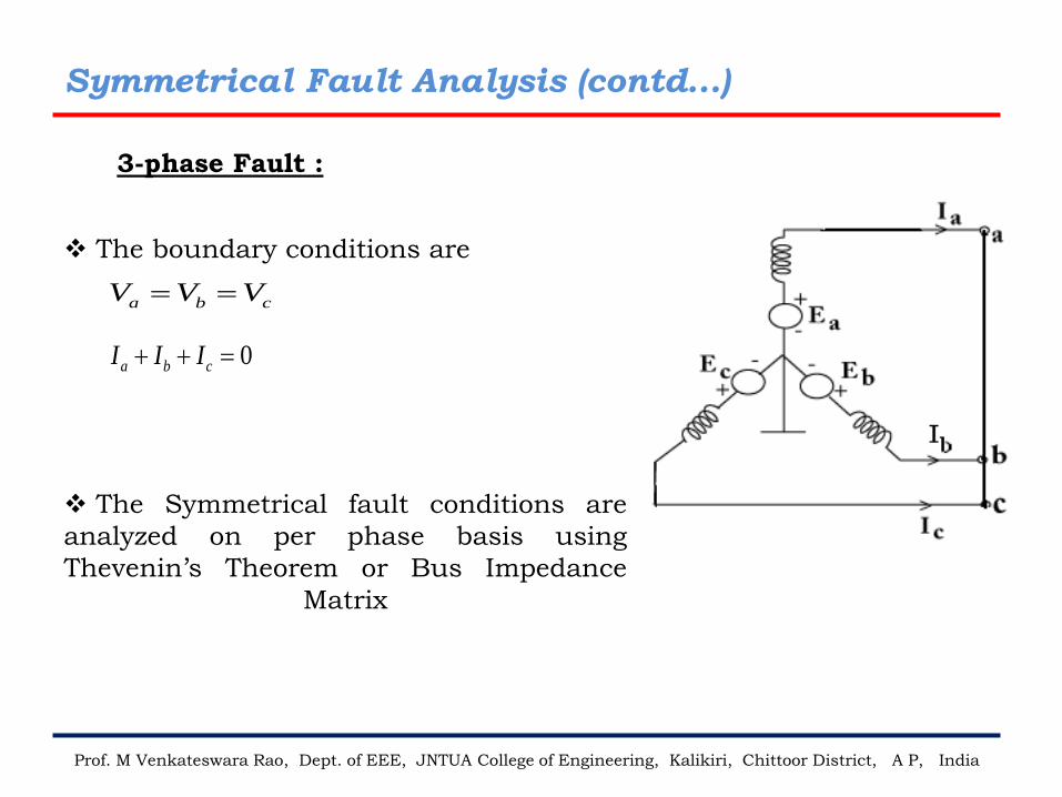
0a b cI I I+ + =
a b cV V V= =
3-phase Fault :
❖ The boundary conditions are
❖ The Symmetrical fault conditions are
analyzed on per phase basis using
Thevenin’s Theorem or Bus Impedance
Matrix
Sequence Components
Prof. M Venkateswara Rao, Dept. of EEE, JNTUA College of Engineering, Kalikiri, Chittoor District, A P, India
❖ An unbalanced system of ‘n’ related vectors can be resolved into ‘n’
system of balanced vectors called Symmetrical components of original
vectors
❖ In a Three phase system, the three unbalanced vectors either Va, Vb, Vc
or Ia, Ib, Ic can be resolved into three balanced system of vectors. The
vectors of the balanced system are called Symmetrical components of the
original system
❖ The symmetrical components of Three Phase system are as follows:
Positive Sequence Components
Negative Sequence Components
Zero Sequence Components
Sequence Components (contd…)
Prof. M Venkateswara Rao, Dept. of EEE, JNTUA College of Engineering, Kalikiri, Chittoor District, A P, India
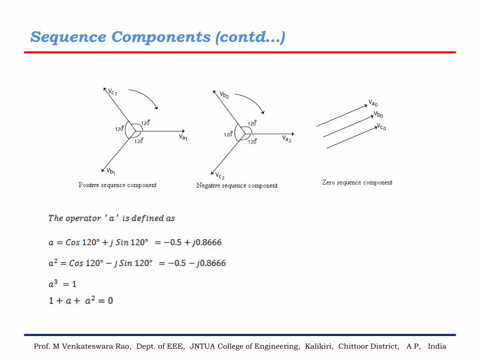
1. Positive sequence components:
✓ Equal in magnitude
✓ 120 degrees phase angle exists with same phase sequence of original vectors
✓ occurs before and after fault
Importance: Relay and circuit breaker operates on positive sequence
components
2. Negative sequence components:
✓ Equal in magnitude
✓ 120 degrees phase angle exists with opposite phase sequence of original
vectors
✓ Occurs only during fault
Importance: Synchronous Generator is protected from
unbalanced condition by using negative sequence relay
Sequence Components (contd…)
Prof. M Venkateswara Rao, Dept. of EEE, JNTUA College of Engineering, Kalikiri, Chittoor District, A P, India
3. Zero sequence components:
✓ Equal in magnitude, No phase difference
✓ Occurs only when neutral is grounded and fault occurred with
grounded
Importance:
zero sequence components are used in the calculation of leakage Flux.
Sequence Components (contd…)
Prof. M Venkateswara Rao, Dept. of EEE, JNTUA College of Engineering, Kalikiri, Chittoor District, A P, India
Sequence Components (contd…)
Prof. M Venkateswara Rao, Dept. of EEE, JNTUA College of Engineering, Kalikiri, Chittoor District, A P, India
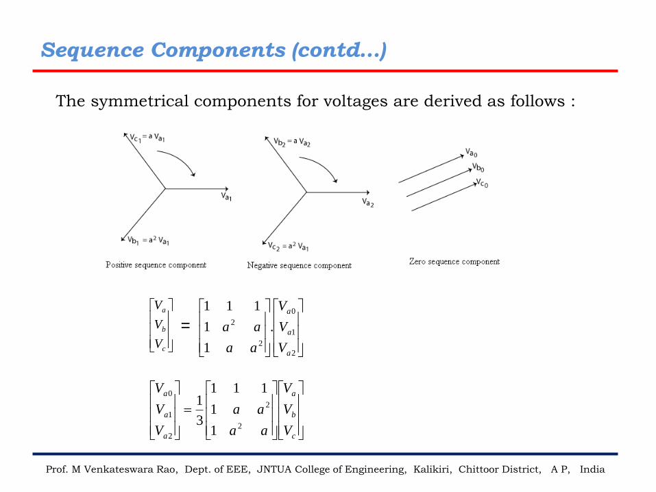
The symmetrical components for voltages are derived as follows :
c
b
a
V
V
V
2
1
0
2
2 .
1
1
111
a
a
a
V
V
V
aa
aa=
=
c
b
a
a
a
a
V
V
V
aa
aa
V
V
V
2
2
2
1
0
1
1
111
3
1
Sequence Components (contd…)
Prof. M Venkateswara Rao, Dept. of EEE, JNTUA College of Engineering, Kalikiri, Chittoor District, A P, India
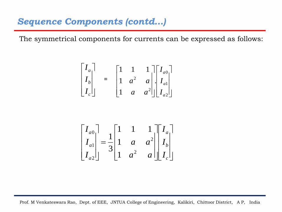
The symmetrical components for currents can be expressed as follows:
c
b
a
I
I
I
=
2
1
0
2
2 .
1
1
111
a
a
a
I
I
I
aa
aa
=
c
b
a
a
a
a
I
I
I
aa
aa
I
I
I
2
2
2
1
0
1
1
111
3
1
Prof. M Venkateswara Rao, Dept. of EEE, JNTUA College of Engineering, Kalikiri, Chittor District, A P, India
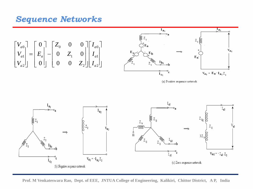
Sequence Networks
0 0 0
1 1 1
2 2 2
0 0 0
0 0
0 0 0
a a
a a a
a a
V Z I
V E Z I
V Z I
= −
Prof. M Venkateswara Rao, Dept. of EEE, JNTUA College of Engineering, Kalikiri, Chittor District, A P, India
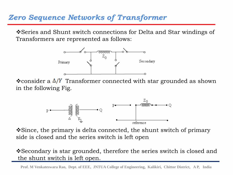
Zero Sequence Networks of Transformer
❖Series and Shunt switch connections for Delta and Star windings of
Transformers are represented as follows:
❖consider a Transformer connected with star grounded as shown
in the following Fig.
❖Since, the primary is delta connected, the shunt switch of primary
side is closed and the series switch is left open
❖Secondary is star grounded, therefore the series switch is closed and
the shunt switch is left open.
Prof. M Venkateswara Rao, Dept. of EEE, JNTUA College of Engineering, Kalikiri, Chittor District, A P, India
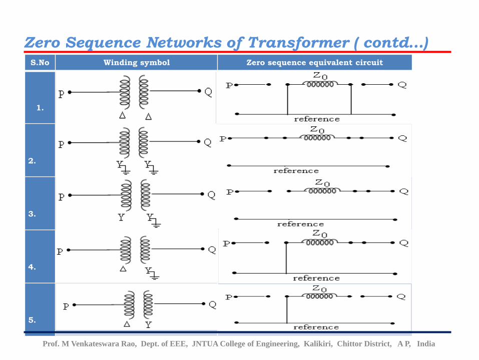
S.No Winding symbol Zero sequence equivalent circuit
1.
2.
3.
4.
5.
Zero Sequence Networks of Transformer ( contd…)
Unsymmetrical Fault Analysis
Prof. M Venkateswara Rao, Dept. of EEE, JNTUA College of Engineering, Kalikiri, Chittoor District, A P, India
❖ The faults on the power system which give rise to unsymmetrical
fault currents (i.e. unequal fault currents in the lines with unequal
phase displacement) are known as unsymmetrical faults.
❖On the occurrence of an unsymmetrical fault, the currents in the
three lines become unequal and so there is a phase displacement
among them.
❖ There are three ways in which unsymmetrical faults may occur in a
power system
➢Single line-to-ground fault (L-G)
➢Line-to-line fault (L-L)
➢Double line-to-ground fault (L-L-G)
Unsymmetrical Fault Analysis (contd.)
Prof. M Venkateswara Rao, Dept. of EEE, JNTUA College of Engineering, Kalikiri, Chittoor District, A P, India
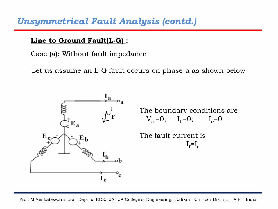
Case (a): Without fault impedance
Let us assume an L-G fault occurs on phase-a as shown below
The boundary conditions are
Va =0; Ib=0; Ic=0
The fault current is
If=Ia
Line to Ground Fault(L-G) :
Unsymmetrical Fault Analysis (contd…)
Prof. M Venkateswara Rao, Dept. of EEE, JNTUA College of Engineering, Kalikiri, Chittoor District, A P, India
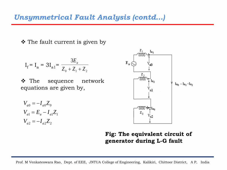
❖ The fault current is given by
If = Ia = 3Ia1=210
3
ZZZ
Ea
++
❖ The sequence network
equations are given by,
222
111
000
ZIV
ZIEV
ZIV
aa
aaa
aa
−=
−=
−=
Fig: The equivalent circuit of
generator during L-G fault
Prof. M Venkateswara Rao, Dept. of EEE, JNTUA College of Engineering, Kalikiri, Chittoor District, A P, India
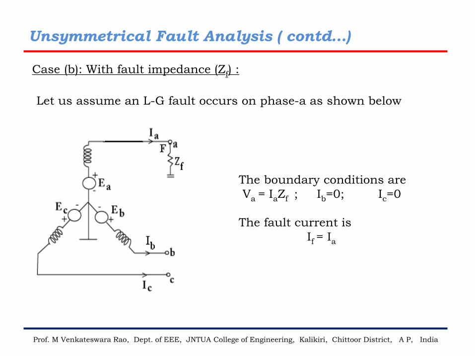
Case (b): With fault impedance (Zf) :
The boundary conditions are
Va = IaZf ; Ib=0; Ic=0
The fault current is
If = Ia
Let us assume an L-G fault occurs on phase-a as shown below
Unsymmetrical Fault Analysis ( contd…)
Prof. M Venkateswara Rao, Dept. of EEE, JNTUA College of Engineering, Kalikiri, Chittoor District, A P, India
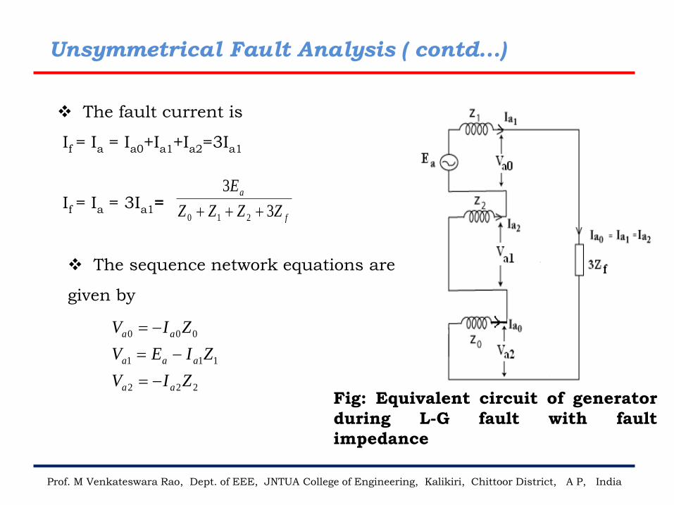
❖ The fault current is
If = Ia = Ia0+Ia1+Ia2=3Ia1
If = Ia = 3Ia1=f
a
ZZZZ
E
3
3
210 +++
222
111
000
ZIV
ZIEV
ZIV
aa
aaa
aa
−=
−=
−=
❖ The sequence network equations are
given by
Fig: Equivalent circuit of generator
during L-G fault with fault
impedance
Unsymmetrical Fault Analysis ( contd...)
Prof. M Venkateswara Rao, Dept. of EEE, JNTUA College of Engineering, Kalikiri, Chittoor District, A P, India
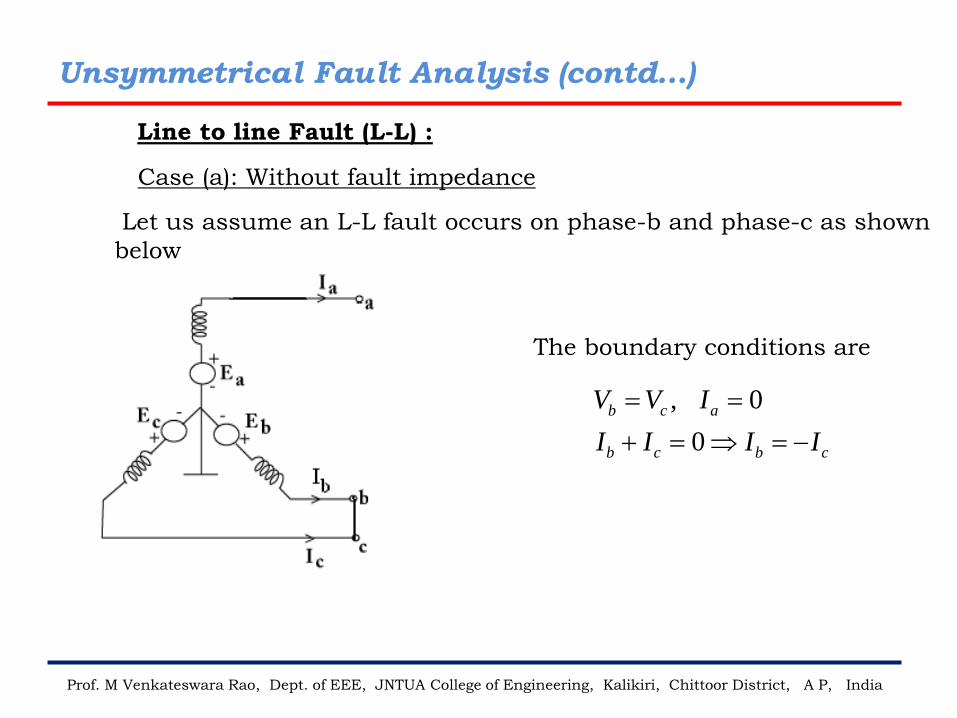
, 0
0
b c a
b c b c
V V I
I I I I
= =
+ = = −
Case (a): Without fault impedance
The boundary conditions are
Line to line Fault (L-L) :
Let us assume an L-L fault occurs on phase-b and phase-c as shown
below
Unsymmetrical Fault Analysis (contd…)
Unsymmetrical Fault Analysis (contd…)
Prof. M Venkateswara Rao, Dept. of EEE, JNTUA College of Engineering, Kalikiri, Chittoor District, A P, India
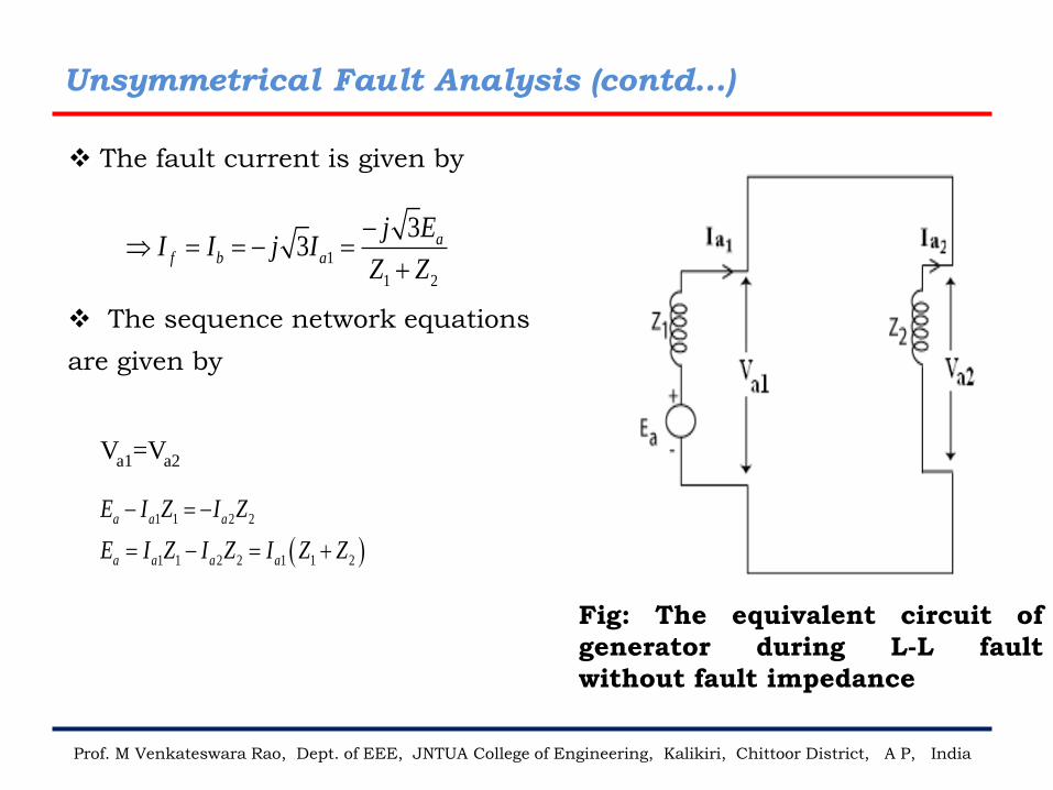
❖ The fault current is given by
1
1 2
33 a
f b a
j EI I j I
Z Z
− = = − =
+
Va1=Va2
( )1 1 2 2
1 1 2 2 1 1 2
a a a
a a a a
E I Z I Z
E I Z I Z I Z Z
− = −
= − = +
❖ The sequence network equations
are given by
Fig: The equivalent circuit of
generator during L-L fault
without fault impedance
Prof. M Venkateswara Rao, Dept. of EEE, JNTUA College of Engineering, Kalikiri, Chittoor District, A P, India
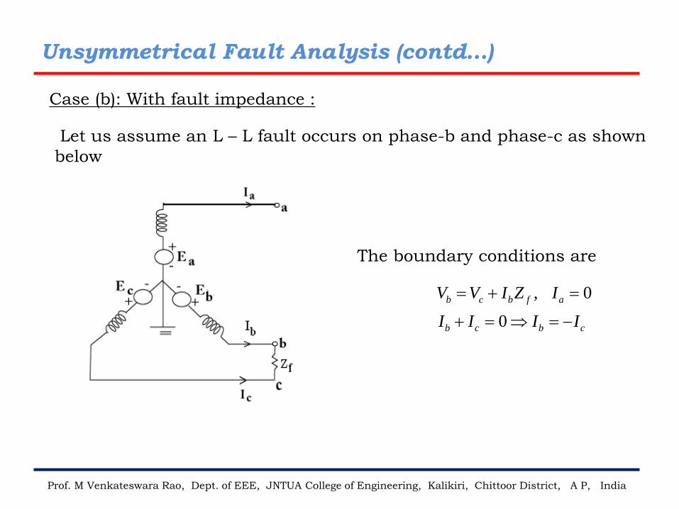
, 0
0
b c b f a
b c b c
V V I Z I
I I I I
= + =
+ = = −
Case (b): With fault impedance :
The boundary conditions are
Let us assume an L – L fault occurs on phase-b and phase-c as shown
below
Unsymmetrical Fault Analysis (contd…)
Prof. M Venkateswara Rao, Dept. of EEE, JNTUA College of Engineering, Kalikiri, Chittoor District, A P, India
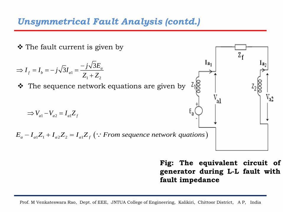
❖ The fault current is given by
1
1 2
33 a
f b a
j EI I j I
Z Z
− = = − =
+
1 2 1a a a fV V I Z − =
( )1 1 2 2 1a a a a fE I Z I Z I Z From sequence network quations− + =
Fig: The equivalent circuit of
generator during L-L fault with
fault impedance
❖ The sequence network equations are given by
Unsymmetrical Fault Analysis (contd.)
Prof. M Venkateswara Rao, Dept. of EEE, JNTUA College of Engineering, Kalikiri, Chittoor District, A P, India
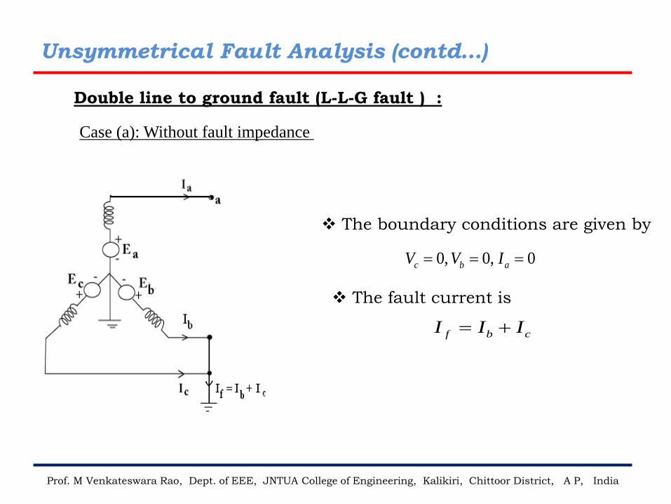
0, 0, 0c b aV V I= = =
f b cI I I= +
Case (a): Without fault impedance
❖ The boundary conditions are given by
❖ The fault current is
Double line to ground fault (L-L-G fault ) :
Unsymmetrical Fault Analysis (contd…)
Prof. M Venkateswara Rao, Dept. of EEE, JNTUA College of Engineering, Kalikiri, Chittoor District, A P, India
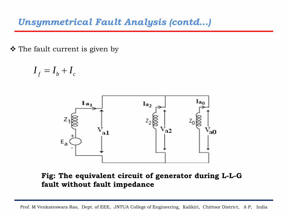
❖ The fault current is given by
f b cI I I= +
Fig: The equivalent circuit of generator during L-L-G
fault without fault impedance
Unsymmetrical Fault Analysis (contd…)
Prof. M Venkateswara Rao, Dept. of EEE, JNTUA College of Engineering, Kalikiri, Chittoor District, A P, India
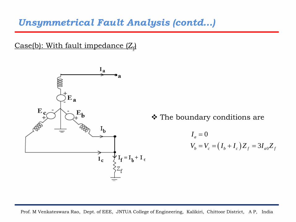
( ) 0
0
3
a
b c b c f a f
I
V V I I Z I Z
=
= = + =
Case(b): With fault impedance (Zf)
❖ The boundary conditions are
Unsymmetrical Fault Analysis (contd…)
Prof. M Venkateswara Rao, Dept. of EEE, JNTUA College of Engineering, Kalikiri, Chittoor District, A P, India
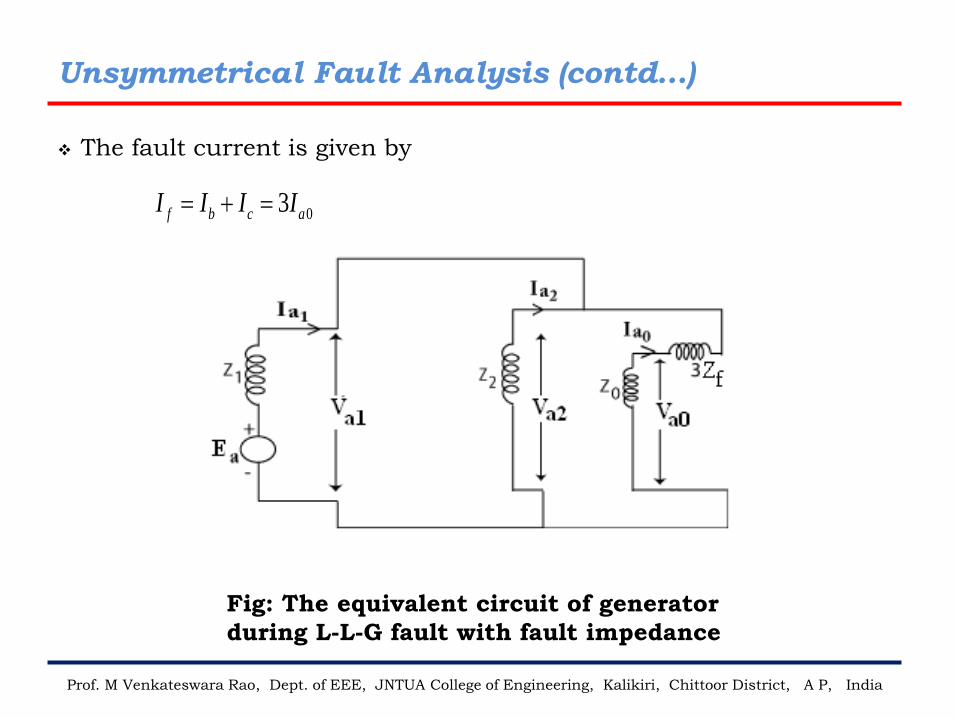
❖ The fault current is given by
03f b c aI I I I= + =
Fig: The equivalent circuit of generator
during L-L-G fault with fault impedance
Unsymmetrical Fault Analysis (contd…)
Prof. M Venkateswara Rao, Dept. of EEE, JNTUA College of Engineering, Kalikiri, Chittor District, A P, India
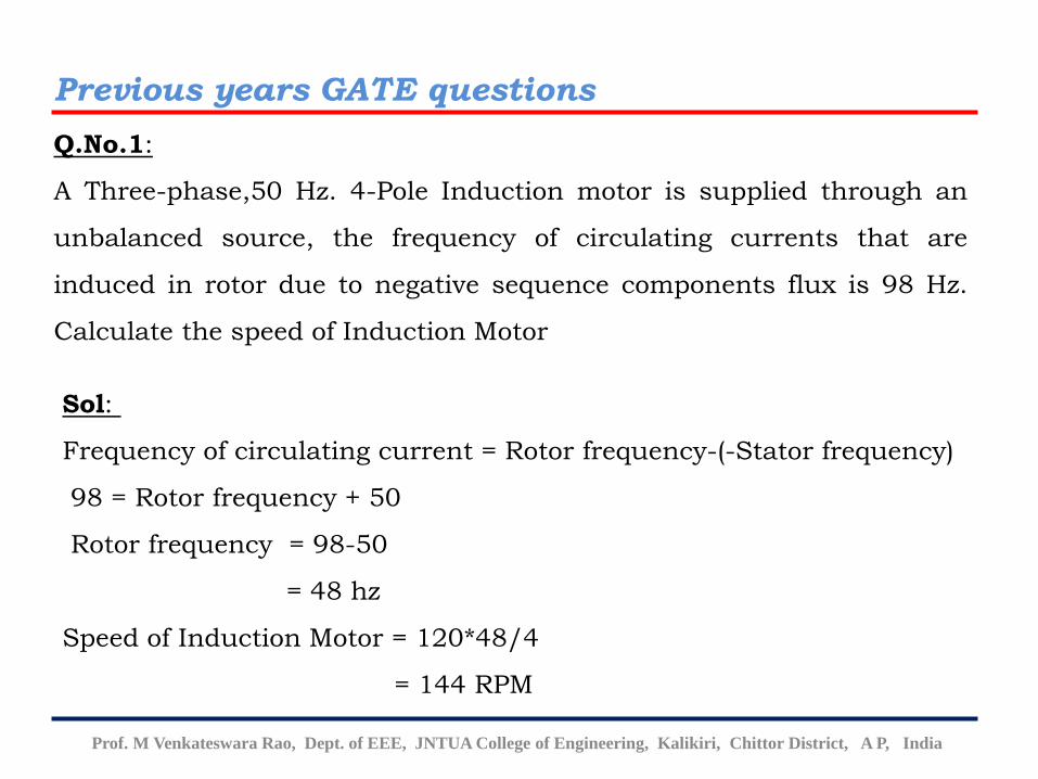
Q.No.1:
A Three-phase,50 Hz. 4-Pole Induction motor is supplied through an
unbalanced source, the frequency of circulating currents that are
induced in rotor due to negative sequence components flux is 98 Hz.
Calculate the speed of Induction Motor
Sol:
Frequency of circulating current = Rotor frequency-(-Stator frequency)
98 = Rotor frequency + 50
Rotor frequency = 98-50
= 48 hz
Speed of Induction Motor = 120*48/4
= 144 RPM
Previous years GATE questions
Prof. M Venkateswara Rao, Dept. of EEE, JNTUA College of Engineering, Kalikiri, Chittor District, A P, India
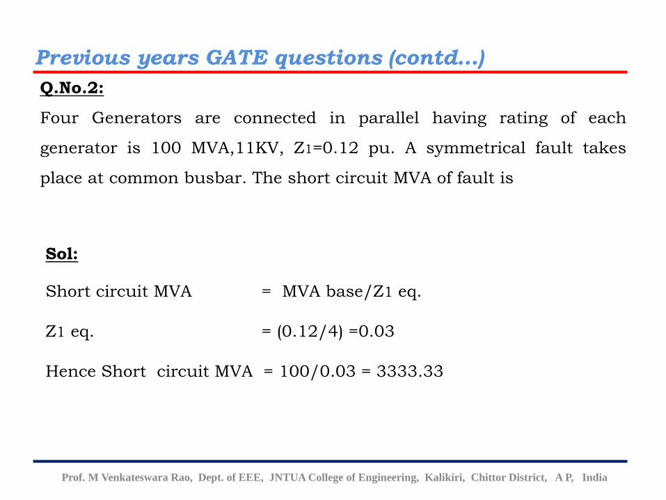
Q.No.2:
Four Generators are connected in parallel having rating of each
generator is 100 MVA,11KV, Z1=0.12 pu. A symmetrical fault takes
place at common busbar. The short circuit MVA of fault is
Sol:
Short circuit MVA = MVA base/Z1 eq.
Z1 eq. = (0.12/4) =0.03
Hence Short circuit MVA = 100/0.03 = 3333.33
Previous years GATE questions (contd…)
Prof. M Venkateswara Rao, Dept. of EEE, JNTUA College of Engineering, Kalikiri, Chittor District, A P, India
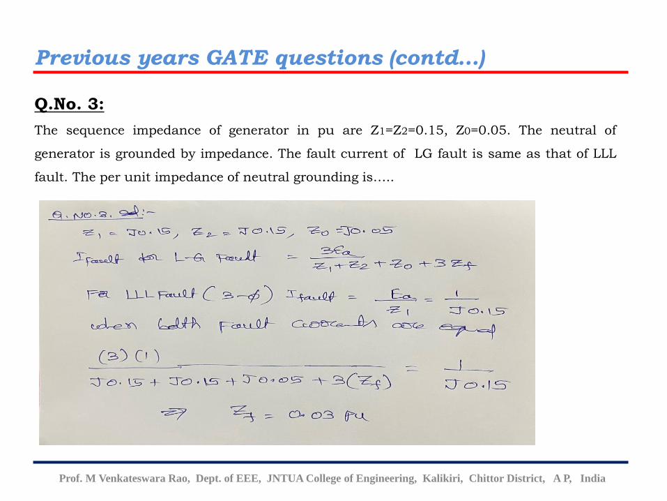
Q.No. 3:
The sequence impedance of generator in pu are Z1=Z2=0.15, Z0=0.05. The neutral of
generator is grounded by impedance. The fault current of LG fault is same as that of LLL
fault. The per unit impedance of neutral grounding is…..
Previous years GATE questions (contd…)
Prof. M Venkateswara Rao, Dept. of EEE, JNTUA College of Engineering, Kalikiri, Chittor District, A P, India
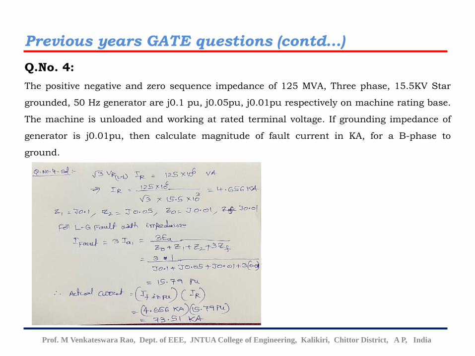
Q.No. 4:
The positive negative and zero sequence impedance of 125 MVA, Three phase, 15.5KV Star
grounded, 50 Hz generator are j0.1 pu, j0.05pu, j0.01pu respectively on machine rating base.
The machine is unloaded and working at rated terminal voltage. If grounding impedance of
generator is j0.01pu, then calculate magnitude of fault current in KA, for a B-phase to
ground.
Previous years GATE questions (contd…)
Prof. M Venkateswara Rao, Dept. of EEE, JNTUA College of Engineering, Kalikiri, Chittor District, A P, India
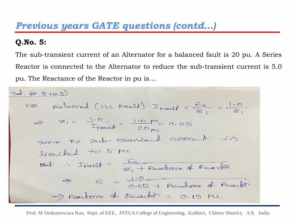
Q.No. 5:
The sub-transient current of an Alternator for a balanced fault is 20 pu. A Series
Reactor is connected to the Alternator to reduce the sub-transient current is 5.0
pu. The Reactance of the Reactor in pu is…
Previous years GATE questions (contd…)
Prof. M Venkateswara Rao, Dept. of EEE, JNTUA College of Engineering, Kalikiri, Chittor District, A P, India
Queries ???
Prof. M Venkateswara Rao, Dept. of EEE, JNTUA College of Engineering, Kalikiri, Chittor District, A P, India
Thank You


