Embed Size (px)
Citation preview

Journal of Constructional Steel Research 112 (2015) 93–107
Contents lists available at ScienceDirect
Journal of Constructional Steel Research
Fatigue life enhancement of welded stiffened S355 steel plates withnoncircular openings
Galya Duncheva a,⁎, Jordan Maximov b, Nikolaj Ganev c, Marieta Ivanova a
a Department of Machine Еlements, Technical University of Gabrovo, 5300 Gabrovo, Bulgariab Department of Applied Mechanics, Technical University of Gabrovo, 5300 Gabrovo, Bulgariac Department of Solid State Engineering, Czech Technical University in Prague, 115 19 Prague 1, Czech Republic
⁎ Corresponding author. Tel.: +359 66827312.E-mail address: [email protected] (G. Duncheva).
http://dx.doi.org/10.1016/j.jcsr.2015.04.0180143-974X/© 2015 Elsevier Ltd. All rights reserved.
a b s t r a c t
a r t i c l e i n f oArticle history:Received 22 August 2014Accepted 26 April 2015Available online xxxx
Keywords:Stiffened plateT-shape girderNon-circular openingsFatigue lifeResidual stress
The paper is devoted to fatigue life enhancement of S355 steel welded stiffened plate containing T-shaped stiff-eners and girders with non-circular openings. Its rounded corners are natural stress concentrators and potentialplaces for initiation and growth of first-mode fatigue cracks. To slow down this process, beneficial residual com-pressive stresses are introduced around the non-circular opening corners throughmandrel cold working of pre-liminarily drilled round holes in the corners' zone. The creation through cutting of the non-circular openings andsubsequentwelding of the T-shaped girders generates residual stress redistribution. The latter is studied both ex-perimentally and numerically. X-ray diffractionmethod has been employed for residual stress analysis. Theman-drel coldworking process and subsequent cutting to form the non-circular opening have been simulated througha nonlinear finite element method (FEM) analysis. In order to simulate the residual stress redistribution due towelding of the T-shaped girders with non-circular openings, a sequentially coupled thermal-stress FEM analysishas been carried out. In order to identify the optimal value of the mandrel cold working interference fit (the dif-ference between the mandrel diameter and the initial hole diameter) and welding sequence, a multi-objectiveoptimization task is set and solved. The optimization has been based on a planned numerical experiment. Theoptimal value of the interference fit and the welding sequence have been found, which ensure high intensityand homogeneity of the residual compressive field around the opening roundings.
© 2015 Elsevier Ltd. All rights reserved.
1. Introduction
The structures containing a plate reinforced by stiffeners are widelyused in shipbuilding, the aircraft industry, bridges, offshore structuresand other. They are particularly preferred in airframes, fuselages andwinds of aircrafts, in structural components as ship decks and hulls fortheir high strength-to-weight ratio. This type of structure is subjectedto intensive dynamic stresses, which provokes initiation and growthof fatigue cracks.
For strength and stiffness enhancement of the components as awhole, two types of structures are used: a plate, stabilized throughwelded to it stiffeners parallel to each other [1–4]; a plate, reinforced bywelded longitudinal girders and transverse stiffeners [5–7]. T-shapedgirders and stiffeners are used or such with other cross-sections. In thecase of T-shaped girders and stiffeners, the structure could be made intwo variants:
• The transversally placed stiffeners are welded bilaterally (or arenot welded) to the T-shaped girders webs, so that their length isdetermined by the distance between the girders [5–8];
• In the webs of the T-shaped girders, non-circular openings are cutwith a certain step, in whose openings the stiffeners are located [9].
Obviously, the structures comprising longitudinally situated Т-shapedgirders and transversely to them Т-shaped stiffeners, provide high stabil-ity under bending in the two planes of inertia.
However, the use of non-circular openings provides the followingadvantages of the structure in comparison with the first embodiment:
• The bending stiffness of the structure is continuous in both principalplanes of inertia as the high stability is provided mainly by the webof the T-shaped girders and the stiffeners.
• It is not necessary to weld the stiffeners ends to the web ofthe T-shaped girders. Thus, the structure assembly is achievedonly by bilateral angular welds of the girders and stiffeners to theplate.
In order to correctly assess the load caring capacity and the fatiguebehaviour of the corresponding structure it is necessary to take intoaccount the following important factors:
• The influence of the imported after welding residual stresses;• Stress concentration around fastener holes, openings, notches, slots,radii cut-outs etc.

94 G. Duncheva et al. / Journal of Constructional Steel Research 112 (2015) 93–107
To adequately assess the structure fatigue life, reinforced throughstiffeners, the experimental study based on fatigue tests is most appro-priate. However, the implementation of this approach requires expen-sive specialized equipment and considerable resources of time andmoney. On the other hand, only certain components, containing stiff-eners [2,3] or flat samples [10], may be subjected to fatigue tests.
The fatigue behaviour of the individual components with stiffenersis studied in two directions: the fatigue test type corresponds to the na-ture of the individual components loading [2]; thepurpose of the fatiguetests is to study the development of pre-localized fatigue cracks in theplate [3]. When the fatigue tests are applied to flat samples, the empha-sis is on the fatigue characteristics of a concrete steel, not on the fatiguebehaviour of the corresponding structural component [10]. Obviously,this approach can not be applied to a single structure, containing a platewith T-shaped girders and stiffeners. From this viewpoint, an alternativeapproach to assess the fatigue behaviour of the structural components isknowing in a qualitative and quantitative aspect the residual stresses inpotentially critical areas in the corresponding structure.
When the structures are made of aluminum alloys, alternative as-sembly methods are used—riveted or adhesive bonded stiffeners [3].As a whole, these methods are used mostly in the aircraft industry.In case of stiffened steel plates, often found in ship structures, off-shore structures etc., complex residual stresses are imparted, whichare caused by the heating and cooling effect of the welding process.For their study, two main approaches are applied—an experimentalone, based on neutron diffraction strain-scanning technique, X-raydiffraction or hole drilling measurement [3,4,11] and a finite elementmethod (FEM) [3,4,9,12–14]. A number of studies of weld steel struc-tures with stiffeners confirm that near the welds, tensile residualstresses are generated, caused by intense local heating, followed bycooling due to the heat transfer to the environment [3,11–13]. Inthis aspect, the welding of the stiffeners to the web of the T-shapedgirders will cause pronounced local effect areas with tensile residualstresses in the web of the girders. If these welds are eliminated, thestructure stiffness will be discontinuous, which will significantly re-duce its load carrying capacity. As it is known, tensile residual stressfields are potential sites for initiation and growth of first-modecracks, when the maximum working stresses are tensile and viceversa—the fatigue crack growing process is significantly slowedwhen the residual stresses are compressive [2,3,9,12–14]. From theviewpoint of the fatigue life and safety during operation, a disadvan-tage of the structure containing T-shaped girders with noncircularopenings are the rounded places because they are natural stress con-centrators (Fig. 1).
According to [9], the stress concentration at the edge of a cut-outmay be limited to about four times the nominal stress in the region.Therefore, taking into account a considerable stress-concentration,
Fig. 1. Stiffened structure with non-circular openings.
the rounded corners are potential places for initiation and growth offirst-mode cracks. As it is well-known the fatigue life ofmetal structurescan be increased by generating compressive normal stresses around thestress concentrators. These beneficial residual stresses significantlyreduce the maximum values of the operating tensile stresses arisingat the critical points of the members and in such manner, impede theformation of the first-mode fatigue cracks.
A common approach to impart beneficial residual stresses is thecold working process, having a temperature lower than the recrystalli-zation temperature of the respective metal. When the stress concentra-tor is a circular hole, fastener or other, the cold working can be carriedout through various methods: ball or solid mandrel expansion [16],ring coining [17], pre-stressing of fastener holes by tapered pin andtapered sleeve [18], pad coining [19], split sleeve cold expansion [20],cold working by seamless tubular member [21], split mandrel coldworking [22], stresswave [23], coldwork of holes by rotationalmandreland tubular seamless sleeve made of shape memory alloy [24] andothers.
For cold working of noncircular openings, an initial mechanicalsurface treatment such as ball and roller burnishing, shot peening,stress coining and others, has been employed. For instance, in the casewith a transverse web-frame (Fig. 1), after welding of the web-frameto the plate, stress coining has been employed in order to introducebeneficial compressive stresses around the cut-out corners [9]. In thecase of aluminum alloy, experimentally and through FEM analysis, ithas demonstrated the beneficial effect of stress coining on the structurefatigue life.
Taking into account the nature of the ball and roller burnishing,shot peening and stress coining, they are characterized by a commondisadvantage—relatively shallow zones of residual stresses impartedaround the openings. From this point of view these methods are mosteffective for aluminum alloys. Considering the wide application ofsteel, obviously, in the case of structure with noncircular openings(Fig. 1), another solution is necessary, in order to generate more inten-sive and deeper zone with compressive residual stresses. A suitablematerial for building the depicted in Fig. 1 structure is constructionallow-alloy steel S355 EN 10025-1:2005.
Using the advantages of the cold hole expansion method, Landyand Easterbrook [25,26] developed methods for fatigue life enhance-ment of noncircular openings: bymeans of cold expansion of circularholes, preliminarily drilled at appropriate places and next cutting ofthe unneeded metal to obtain a noncircular opening [25]; by meansof cold expansion of the noncircular opening using appropriate in-sert [26]. A main disadvantage of the method [26] is the need of acomplicated tool, composed of parts with external (covering) con-tour, corresponding to that of the non-circular opening. On theother hand, technologically, there are various possibilities for imple-mentation of the process of cold working of the pre-drilled holes inthe rounded areas in accordance with the basic idea of the method[25]: solid mandrel expansion [16]; split mandrel cold working[25]; direct mandrel cold working etc. These methods have a com-mon disadvantage—significant and nonsymmetrical, with respectto the middle plane of the plate, gradient of the generated residualstresses due to axial force flow passing through the mandrel-plate-support system [27,28]. On the other hand, because of the relativelyclose location of the pre-drilled holes, an effect of interference be-tween the plastic and elastic waves, generated due to the cold work-ing of the two holes, is observed [29]. Taking into account theaforementioned features, it is necessary to find the optimal interfer-ence fit and the working scheme for the implementation of the man-drel cold working process of the pre-drilled holes.
The main objective of this study is to estimate the beneficial effectfrom implementation of cold working on S355 steel of preliminarilydrilled holes in corner zones of noncircular opening and next cuttingto obtain a noncircular opening in accordance with the configurationshown in Fig. 1.

95G. Duncheva et al. / Journal of Constructional Steel Research 112 (2015) 93–107
The following major problems have been solved to achieve theobjective:
1). Assessing the effect of redistribution of created by mandrel coldworking residual compressive stresses due to cutting the outlineof non-circular openings and the temperature effect of welding;
2). Selection of an appropriate working scheme for implementation ofthe mandrel cold working of the pre-drilled holes in the roundedareas, taking into account the effect of cutting the contour of thenon-circular opening and the temperature effect of welding;
3). Finding the optimal value of the interference fit of the mandrel coldworking process and the sequence ofwelding, using 3D FEMmodel-ing of the full technological cycle “mandrel cold working–cutting–welding”, referred to the structure containing T-shaped girderwith noncircular opening.
Given the specificity of the research problem, both experimental andFEM simulation are used to solve these tasks.
2. Residual stresses around noncircular openings—experimentalstudy
2.1. Nature of the experimental study
The aim is to obtain a database of the residual hoop normal stressesaround the rounding. The obtained database chronologically corre-sponds to the stages of the studied approach to enhancement of fatiguelife of structural components with non-circular openings. The informa-tion on the distribution and redistribution of the residual stresses allowsevaluating the beneficial effects from applying the full technologicalcycle as awhole and the individual stages from it:mandrel coldworkingof pre-drilled holes, cutting the contour of the non-circular opening andwelding of the T-shaped girder with a noncircular opening to the plate(Fig. 1). The nondestructive X-raydiffractionmethod is used for residualstress measurement.
2.2. Experimental specimens
2.2.1. Material and geometry of the specimensThe specimens are made of steel S355 ЕN 10025-1:2005. The
geometrical parameters of the experimental samples are adaptedto the structure shown in Fig. 1 and are consistent with the possibilityof implementing an X-ray diffraction measurement. The specimengeometry is depicted in Fig. 2.
By technological considerations in the experimental study, itis accepted that the mandrel cold working process is implemented
Fig. 2. Specimen geometry.
sequentially for the two openings. From this perspective, two alterna-tive working patterns are possible: one-sided scheme and two-sidedscheme. For a comparison between the two schemes, two samples aremanufactured according to Fig. 2. The specimen subjected to one-waycold working is marked with number 1, and the one, subjected totwo-way CP—with number 2.
2.2.2. Technology of the specimen productionThe samplesweremade in the following sequence:milling the plate;
drilling and reaming the two holes up to diameter do = 9.8±0.01 mm;grinding the front surfaces. The latter operation allows a measurementof the residual stresses in direction of the lines, designated as “A” and“B” in Fig. 2 on both sides of the plate. These lines are oriented at anangle of 45°, i.e., object of the study is the areas of maximum stressconcentration.
2.3. Implementation of mandrel cold working
The mandrel cold working method generates a zone with useful re-sidual hoop compressive stresses around the openings at a relativelylarge depth (a few millimeters), which like a brace closes the existingcracks and impedes the formation of new ones. The essence of themethod is the following: a tool with a diameter greater than the diam-eter of the preliminarily drilled hole passes through it from end toend; after ceasing the action of the tool on the hole, the plasticallydeformed layer of metal around the hole appears to be pressed at theexpense of the reversible deformations of the elastically deformedlayers around it.
The mandrel cold working of the holes is carried out in laboratoryTesting of Metals at the Technical University of Gabrovo. The mandrelgeometry is depicted in Fig. 3a, and the process of implementation ona testing machine—in Fig. 3b.
The process was carried out with interference fit:
i ¼ dt � do ¼ 0;392 mm; ð1Þ
where dt= 10,192 mm is the major diameter of the mandrel; do is thediameter of the preliminarily drilled hole (Fig. 3a). The indicated valueof the interference fit corresponds to a linear hoop strain at a hole sur-face point:
εt;0 ¼ dt � dodo
� 100¼4%: ð2Þ
2.4. Flow-chart of the experimental study
The experimental study was conducted in five steps in a chronolog-ical order corresponding to the actual technological cycle. A flow-chartof the study is shown in Fig. 4. In the fourth step, after welding the spec-imens to a base plate, the samples are separated from it by a cutting disc.This operation is required for the third step in which the residual hoopstresses are measured.
The holes are numbered according to the implementation of themandrel cold working process.
The following indications were adopted:
• The specimens front surfaces—side “a” is the side of the tool entry;side “b” is the side of the tool exit with respect to the cold workingof the first hole;
• The lines, along which the residual hoop stresses are measured:around the first hole—line A; around the second hole—line B.
2.5. X-ray diffraction stress analysis—results and discussion
The residual stress measurement is performed in the X-ray diffrac-tion laboratory in Czech Technical University in Prague in three stages
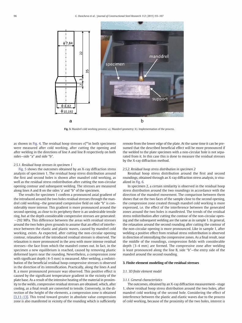
Fig. 3.Mandrel cold working process: a). Mandrel geometry; b). Implementation of the process.
96 G. Duncheva et al. / Journal of Constructional Steel Research 112 (2015) 93–107
as shown in Fig. 4. The residual hoop stresses σtresin both specimens
were measured after cold working, after cutting the opening andafter welding in the directions of line A and line B respectively on bothsides—side “a” and side “b”.
2.5.1. Residual hoop stresses in specimen 1Fig. 5 shows the outcomes obtained by an X-ray diffraction stress
analysis of specimen 1. The residual hoop stress distribution aroundthe first and second holes is shown after mandrel cold working, aswell as the residual stress redistribution after cutting the non-circularopening contour and subsequent welding. The stresses are measuredalong lines A and B on the sides ‘a’ and “b” of the specimen.
The results for specimen 1 confirm a pronounced axial gradient ofthe introduced around the two holes residual stresses through theman-drel cold working—the generated compressive field on side “b” is con-siderably more intense. This gradient is more pronounced around thesecond opening, as close to its periphery there is an undesirable tensilering, but at the depth considerable compressive stresses are generated:−292 MPa. This difference between the areas with residual stressesaround the two holes gives grounds to assume that an effect of interfer-ence between the elastic and plastic waves, caused by mandrel coldworking, exists. As expected, after cutting the non-circular openingcontour, relaxation of the introduced residual stresses is observed. Therelaxation is more pronounced in the area with more intense residualstresses—the face from which the mandrel comes out. In fact, in thespecimen a new equilibrium is reached, caused by removing plasticdeformed layers near the rounding. Nevertheless, a compression zonewith significant depth (4–5 mm) is measured. After welding, a redistri-bution of the beneficial residual hoop compressive stresses is observedin the direction of its intensification. Practically, along the lines A andB, a more pronounced pressure was observed. This positive effect iscaused by the significant temperature gradient in the vicinity of theplate base. As a result of the intensive heating of thematerial in proxim-ity to thewelds, compressive residual stresses are obtained,which, aftercooling, as a final result are converted to tensile. Conversely, in the di-rection of the height of the elements, a compression zone is obtained[3,11–13]. This trend toward greater in absolute value compressionzone is also manifested in vicinity of the rounding which is sufficiently
remote from the lower edge of the plate. At the same time it can be pre-sumed that the described beneficial effect will be more pronounced ifthe welded to the plate specimen with a non-circular hole is not sepa-rated from it. In this case this is done to measure the residual stressesby the X-ray diffraction method.
2.5.2. Residual hoop stress distribution in specimen 2Residual hoop stress distribution around the first and second
roundings, obtained through an X-ray diffraction stress analysis, is visu-alized in Fig. 6.
In specimen 2, a certain similarity is observed in the residual hoopstress distribution around the two roundings in accordance with thedirection of the mandrel movement. The comparison between themshows that on the two faces of the sample close to the second opening,the compression zone created through mandrel cold working is moreexpressed, i.e. the effect of the interference between the generatedzones around the two holes is manifested. The trends of the residualstress redistribution after cutting the contour of the non-circular open-ing and the subsequent welding are the same as in sample 1. In general,the relaxation around the second rounding after cutting the contour ofthe non-circular opening is more pronounced. Like in sample 1, afterwelding a positive effect from residual stress redistribution is observedin direction of intensifying the compressive zones. As a final result, nearthe middle of the roundings, compression fields with considerabledepth (3–4 mm) are formed. The compressive zone after weldingis least pronounced along the line B, side “b”—the entry side of themandrel around the second rounding.
3. Finite element modeling of the residual stresses
3.1. 3D finite element model
3.1.1. General characteristicsThe outcomes, obtained by an X-ray diffractionmeasurement—stage
1, show residual hoop stress distribution around the two holes, aftermandrel cold working of the second hole. Considering the effect ofinterference between the plastic and elastic waves due to the processof cold working, because of the proximity of the two holes, interest is
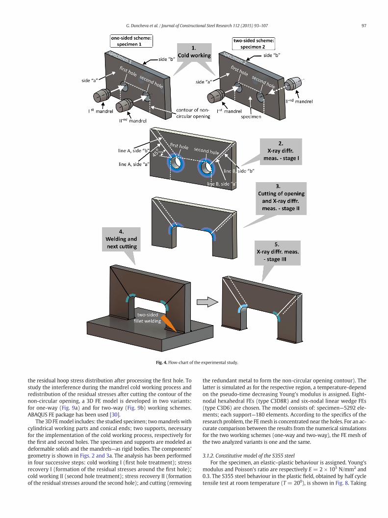
Fig. 4. Flow-chart of the experimental study.
97G. Duncheva et al. / Journal of Constructional Steel Research 112 (2015) 93–107
the residual hoop stress distribution after processing the first hole. Tostudy the interference during the mandrel cold working process andredistribution of the residual stresses after cutting the contour of thenon-circular opening, a 3D FE model is developed in two variants:for one-way (Fig. 9a) and for two-way (Fig. 9b) working schemes.ABAQUS FE package has been used [30].
The 3DFEmodel includes: the studied specimen; twomandrelswithcylindrical working parts and conical ends; two supports, necessaryfor the implementation of the cold working process, respectively forthe first and second holes. The specimen and supports are modeled asdeformable solids and the mandrels—as rigid bodies. The components'geometry is shown in Figs. 2 and 3a. The analysis has been performedin four successive steps: cold working I (first hole treatment); stressrecovery I (formation of the residual stresses around the first hole);cold working II (second hole treatment); stress recovery II (formationof the residual stresses around the second hole); and cutting (removing
the redundant metal to form the non-circular opening contour). Thelatter is simulated as for the respective region, a temperature-dependon the pseudo-time decreasing Young's modulus is assigned. Eight-nodal hexahedral FEs (type C3D8R) and six-nodal linear wedge FEs(type C3D6) are chosen. The model consists of: specimen—5292 ele-ments; each support—180 elements. According to the specifics of theresearch problem, the FEmesh is concentrated near the holes. For an ac-curate comparison between the results from the numerical simulationsfor the two working schemes (one-way and two-way), the FE mesh ofthe two analyzed variants is one and the same.
3.1.2. Constitutive model of the S355 steelFor the specimen, an elastic–plastic behaviour is assigned. Young's
modulus and Poisson's ratio are respectively E = 2 × 10⁵ N/mm2 and0.3. The S355 steel behaviour in the plastic field, obtained by half cycletensile test at room temperature (T = 200), is shown in Fig. 8. Taking

Fig. 5. X-ray diffraction measurement of specimen 1.
98 G. Duncheva et al. / Journal of Constructional Steel Research 112 (2015) 93–107
into account the specificity of themandrel coldworkingprocess, nonlin-ear kinematic strain hardening behaviour has been chosen, according tothe conclusion made in [27].
3.1.3. Interactions and boundary conditionsThe cold working process of the holes is simulated through assigned
axial displacements in Z direction of the reference points of themandrels (Fig. 7). Tabulated functions, synchronized in the generalpseudo-time of the analysis, have been used. The interactions betweenthe model's components correspond to the physical nature of the stud-ied process. A normal and tangential contact with friction coefficientof 0.08 (in view of the presence of lubricating liquid) between themandrels and specimen has been defined. Between the specimen andsupports such contact is also assigned, but with friction coefficient of0.15 (Fig. 7).
The boundary conditions are consistent with the physics of theman-drel cold working process and the sequence of the processing holes.
Fig. 6. X-ray diffraction meas
Zero displacements on the free frontal surfaces of the supports areassigned. In the starting position, the tapered ends of the two mandrelsare aimed in the holes, thus the corresponding interactions are defined.Due to the influence of the plastic waves from the processing of the firsthole on the second hole, the self adjustment of the second mandrel onthe second hole is simulated.
3.2. Finite element outcomes and comments
3.2.1. One-sided schemeThe outcomes of the one-sided working scheme, obtained by a FE
simulation of the mandrel cold working and removing the unnecessarymetal, are generalized in Fig. 9. In view of a possibility for comparison,additional graphs are shown, visualizing the results of an X-ray diffrac-tion analysis for sample 1—respectively, after cold working of the sec-ond hole and cutting a non-circular opening.
urement of specimen 2.

Fig. 7. 3D FE model of mandrel cold working and next cutting: a). One-sided scheme; b). Two-sided scheme.
99G. Duncheva et al. / Journal of Constructional Steel Research 112 (2015) 93–107
On the base of the outcomes shown in Fig. 9, the following com-ments can be made:
• FE results confirm the effect of overlapping of the deforming wavesobtained due to cold working of the two holes. As a result, a partial re-sidual stress redistribution is obtained: the cold working process ofthe first hole provokes tensile stresses in the vicinity of the secondhole, which are higher on the side “b” and vice versa—the cold work-ing of the second hole leads to partial relaxation of the compressionzone on side “b” around the first hole. From this point of view, the im-plementation of the mandrel cold working of adjacent holes with thesame value of the interference fit can not lead to one and the sameresidual stress distribution, even in the presence of a plane of symme-try in a structural components. As a whole, the interference (due toplastic waves around the two holes) slightly affects on the residualstress distribution after mandrel cold working;
• FE results and X-ray stress analysis outcomes confirm the presence ofa field with beneficial residual compressive stresses in the locationswith pronounced stress concentration. The compressive field ischaracterized by a considerable depth: according to the FE results, itreaches more than 6 mm, and the experimental outcomes show adepth of about 4–5 mm.
• As a whole, the X-ray diffraction graphical dependences haveno expressed character and are smaller in absolute value. Regard-less of the difference in the distribution and redistribution of
Fig. 8. Stress–strain diagram in the plastic field of S355 steel.
the residual stresses obtained by FE and experimental results, oneand the same trends are observed. A less pronounced compressivezone, obtained by an X-ray diffraction analysis can be explained bythe initial mechanical stress in the specimens that are not taken intoaccount in the KE model. To correctly evaluate the effectiveness ofthe studied approach in real conditions, the experimental sampleswere not subjected to annealing to remove the introduced residualstresses during their preparation. It is known that mechanical work-ing by cutting usually causes tensile residual stresses [31].
• The results, obtained by the X-ray stress analysis, show a greater re-laxation of the residual stresses after the removal of the unnecessarymetal to form the non-circular opening as compared to the FE results.This effect can be explained as follows: on the one hand, a new equi-librium is reached due to the removal of the plastic deformed layers,on the other hand, in the samples, additional deformations wereimparted due to milling of the non-circular opening. These additionaldeformations can not be accounted correctly in the FE model. In linewith this, the relaxation is more pronounced on the side with themore intense compressive zone after cold working, i.e. the exit sideof themandrels. The results, obtained by an X-ray diffraction analysis,show a more pronounced gradient of the residual stresses along thehole axis, compared to the FE results—the compressive zone is moreintense on the side “b”, i.e. exit side of the mandrels.
3.2.2. Two-sided schemeThe FE results for the residual hoop stresses in specimen 2 and the
experimental outcomes, obtained in the first two steps of the X-ray dif-fraction analysis, are visualized in Fig. 10.
The obtained results can be commented in the following way:
• The effect of interference between the generated through mandrelcold working areas with residual stresses around the two holes isless pronounced compared to the one-way scheme;
• As with sample 1, the results obtained by an X-ray diffraction analysisshow a more pronounced axial gradient in the residual stress distribu-tion after mandrel cold working, compared to the FE results. Neverthe-less, the same trends are observed in distribution and redistribution ofresidual stresses after the respective stages;
• FE and experimental results show that after cutting the contour ofthe non-circular opening the compressive zone is least around the sec-ond rounding of the non-circular opening from the inlet side of themandrel—along line B, side “b”. From this perspective, there is an

Fig. 9. FE results for the one-sided scheme.
100 G. Duncheva et al. / Journal of Constructional Steel Research 112 (2015) 93–107
analogy with the one-way scheme for the implementation of the man-drel cold working—close to the rounding, a tensile ring exists, and thecompressive zone is least pronounced on the entrance side of theman-drel for the second hole—line B side “a”. At the same time, quantitative-ly, the compressive zone near the second rounding is more intense inthe one-way scheme—according to the X-ray diffraction, a residualhoop stress of −144 MPa was measured. The comparative analysisbetween the two work schemes of the mandrel cold working processshows that the two-way scheme does not provide a more intense andmore homogeneous zone with residual compressive hoop stress. Onthis basis, it can be assumed that for technological purposes the one-way scheme is more appropriate.
Fig. 10. FE results for the
4. Finite element modeling of the production sequence taking intoaccount residual stresses due to welding
To correctly assess the effectiveness of the studied approach, itis necessary to know in the qualitative and quantitative aspect the resid-ual hoop stresses around the roundings of the non-circular openings,taking into account the following factors:
• The effect of the redistribution of the created residual stressesafter the formation of the non-circular opening contour due tothe temperature effect of welding of the T-shaped girder to theplate;
two-sided scheme.

101G. Duncheva et al. / Journal of Constructional Steel Research 112 (2015) 93–107
• The influence of the geometrical form and the absolute sizes of themain components in the studied structure;
• Building a realistic constitutivematerialmodel of the S355 steel in theelastic and plastic fields in terms of the influence of the temperatureon the mechanical characteristics;
• The interference fit influence on the mandrel cold working process;• Influence of the sequence of welding of the T-shaped girder to theplate in relation to the mandrel cold working scheme.
To find the optimal value of the interference fit and consistency ofwelding, a multipurpose optimization task is set and solved. For thispurpose, FE simulations were conducted on the basis of a developedgeneralized 3D FE model.
4.1. Generalized 3D finite element model
Considering the above-mentioned factors, for simulating the fulloperating cycle, a generalized 3D FE model was developed. The modelcontains a T-shaped girder with non-circular opening, plate, mandreland support. The emphasis of the study is placed on the redistributionof pre-entered by mandrel cold working residual stresses around not-circular opening rounding, resulting from the welding. Therefore, inorder to eliminate the interaction between the plate and the T-shapedgirder, they are modeled as a single object. In order to reduce the com-putational time, the non-circular opening symmetry is used. Thus, in thenumerical simulations, the effect of interference of the mandrel coldworking process of the two openings is ignored. However, as it wasestablished in Section 3.2, this effect is not strongly expressed. A gener-alized 3D FE model with geometrical parameters of the structure to bestudied is shown in Fig. 3. The model contains 2682 linear hexahedralFEs type C3D8R and 174 linear wedge FEs type C3D6.
The analysis has been carried out in three steps in accordance withthe completed technological cycle: cold working, cutting and welding.The location of welds is shown in Fig. 11.
4.2. Interactions and boundary conditions
The interactions “mandrel—T-shaped girder” and “T-shapedgirder—support” are similar to those specified in Section 3.1.3. The im-posed structural restrictions are consistent with the physical natureof the different steps in the analysis. The middle plane of the studied
Fig. 11. Generalized 3D fi
structure is restricted to moving along Z axis, the bottom surface ofthe plate—along Y axis. In steps “cutting” and “welding” the structureis restricted as a rigid body. In step “cold working” the free frontalface of the support is restricted to moving along X, Y and Z axes. Insteps “cutting” and “welding” these limitations are applied to the entiresupport.
4.3. Formulation of the welding study
A number of authors have studied various aspects of welding thegirders or stiffeners to the plate: determining the residual stress distri-bution due to the temperature effect of intense local heating and cooling[3,4,7]; studying the element deformations (distortions) [11,14]; influ-ence of the welding sequence on the residual stresses and deformations[12]; statistics of imperfections induced in welds and effect of weldingresidual stresses on the fatigue behaviour of the components [2,9,13,15,28]; influence of the residual stresses on the load carrying capacityof the structure [1,5,6]. Themodern experimental studies of the residualstresses are based on the methods hole drilling, neutron and X-ray dif-fraction. Unlike hole drilling, the neutron and X-ray diffractionmethodsare non-destructive, but it takes expensive equipment and requiressignificant resources of time to process the results [3,4]. In this regard,an alternative is the numerical simulation, which allows to obtain asignificant volume of useful information, when it is based on the mostrealistic FE model.
Given the physical nature of welding, the FE procedure is based onsequentially coupled thermal-stress FEM analysis comprising sequen-tially performed heat transfer analysis and nonlinear static analysis.The temperature distribution during the heating and cooling of theanalyzed structure, obtained from the heat transfer analysis is appliedas thermal loading in the subsequent nonlinear static analysis.
Obviously, the adequate constitutive model of the material is essen-tial to the reliability of the numerical results. To build such a model ofthe studied steel S355, an experimental study of itsmechanical behaviordepending on the temperature was conducted. On the other hand, tak-ing into account the axial gradient in the residual stress distribution duetomandrel coldworking, interest is the sequence ofwelding, dependingon the working scheme of the mandrel cold working. In the presentstudy two variants of the sequence of welding are analyzed (Fig. 12).To ensure a correct comparison between the two variants, the FEmesh in the generalized FE model is symmetrical with respect to themiddle plane of the T-shaped girder (Fig. 11).
nite element model.
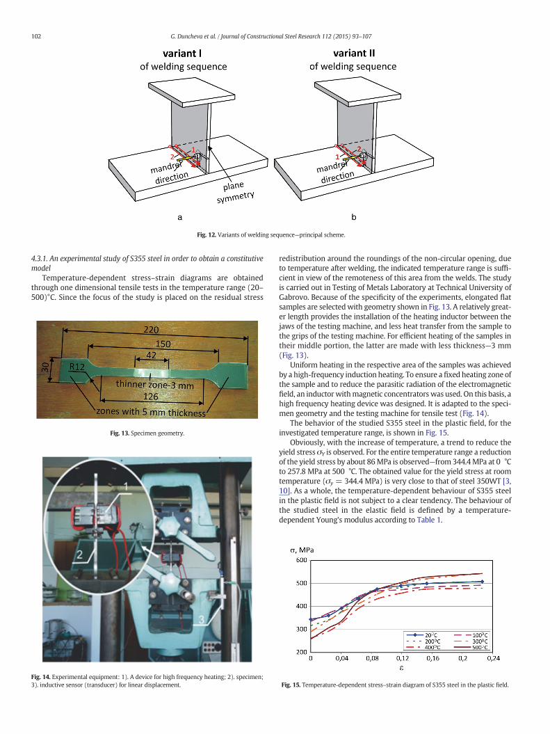
Fig. 12. Variants of welding sequence—principal scheme.
102 G. Duncheva et al. / Journal of Constructional Steel Research 112 (2015) 93–107
4.3.1. An experimental study of S355 steel in order to obtain a constitutivemodel
Temperature-dependent stress–strain diagrams are obtainedthrough one dimensional tensile tests in the temperature range (20–500)°C. Since the focus of the study is placed on the residual stress
Fig. 14. Experimental equipment: 1). A device for high frequency heating; 2). specimen;3). inductive sensor (transducer) for linear displacement.
Fig. 13. Specimen geometry.
redistribution around the roundings of the non-circular opening, dueto temperature after welding, the indicated temperature range is suffi-cient in view of the remoteness of this area from the welds. The studyis carried out in Testing of Metals Laboratory at Technical University ofGabrovo. Because of the specificity of the experiments, elongated flatsamples are selectedwith geometry shown in Fig. 13. A relatively great-er length provides the installation of the heating inductor between thejaws of the testing machine, and less heat transfer from the sample tothe grips of the testing machine. For efficient heating of the samples intheir middle portion, the latter are made with less thickness—3 mm(Fig. 13).
Uniform heating in the respective area of the samples was achievedby a high-frequency induction heating. To ensure a fixed heating zone ofthe sample and to reduce the parasitic radiation of the electromagneticfield, an inductor withmagnetic concentrators was used. On this basis, ahigh frequency heating device was designed. It is adapted to the speci-men geometry and the testing machine for tensile test (Fig. 14).
The behavior of the studied S355 steel in the plastic field, for theinvestigated temperature range, is shown in Fig. 15.
Obviously, with the increase of temperature, a trend to reduce theyield stress σY is observed. For the entire temperature range a reductionof the yield stress by about 86MPa is observed—from 344.4MPa at 0 °Cto 257.8 MPa at 500 °C. The obtained value for the yield stress at roomtemperature (σy = 344.4 MPa) is very close to that of steel 350WT [3,10]. As a whole, the temperature-dependent behaviour of S355 steelin the plastic field is not subject to a clear tendency. The behaviour ofthe studied steel in the elastic field is defined by a temperature-dependent Young's modulus according to Table 1.
Fig. 15. Temperature-dependent stress–strain diagram of S355 steel in the plastic field.

Table 2Thermal properties of the generalized FE model.
Thermalconductivity,k (W/m2 °C)
Temp., °C 0 800 3000 - -
Value 54 27.3 27.3 – –
Mass density,ρ (kg/m3)
Temp., °C 0 2000 – – –
Value 7850 6892 – – –
Coefficient of thermalexpansion, α(1/°C)
Temp., °C 0 1000 3000 – –
Value 1.2 × 10⁻⁵ 1.6 × 10⁻⁵ 1.6 × 10⁻⁵ – –
Specific heat,c(J/kg °C)
Temp., °C 0 600 735 900 2000Value 425 760 1400 650 650
Table 1Temperature-dependent Young's modulus.
Temperature °C 0 20 100 200 300 400 500 600
Young's modulus× 10−11, Pa
2.1 2 1.966 1.91 1.825 1.76 1.66 1.56
103G. Duncheva et al. / Journal of Constructional Steel Research 112 (2015) 93–107
4.3.2. Heat transfer analysis—simulation of weldingThe heat transfer analysis is directed to obtain the temperature dis-
tribution generated from the heating and cooling effect of welding. Twobasic approaches for simulation of heating are commonly used—by atraveling heat source [11,12,14] and by applying a specific nodal tem-perature at the root of the weld [3]. In the first approach the transientanalysis is based on a double ellipsoid heat sourcemodel [11], volumet-ric heat source with uniform density and surface heat source withGaussian distribution [11,12]. In the second approach it is assumed,that in the weld, temperature increases to a maximum from 20 °C pro-portionally to the time required for welding. Obviously, the approachfor welding simulation by a traveling heat source is more realistic and,therefore, it is assumed in the generalized FE model. As a heat source,a heat flux with constant density is used, applied at the correspondingnodes. The heat flux is specified at nodes by tabular function in realtime as shown in Fig. 16. Through this law of overlapping in the timeof the heat flow, it is simulated a heat source with a constant densityq = 2000 W/m2, uniformly moving in the direction of the two welds.This density corresponds to temperature of welding in the respectivenodes in the range 1100 ‐ 1600 °C[3].
An object of the heat transfer analysis are the plate and the T-shapedgirder, respectively, the support andmandrel are excluded from the gen-eralized FEmodel shown in Fig. 11. One and the same approachwas usedto build the FEmesh to ensure full compliance of themodel of the studiedstructurewith this in the generalized FEmodel. The analysis is carried outin two steps: first weld and second weld. For each weld, in accordancewith the welding speed (Fig. 16), a time of 26 s is assigned. Temperaturefield in the structure is formed over a period of 5944 s after finalization ofthe secondweld in the absence of convection and radiation on the bound-aries. Thus, a less favorable picture is obtainedwith regard to the residualstress redistribution created by the mandrel cold working.
Two groups of temperature-dependent thermal properties of thestudied structure are defined: for the material, corresponding to thecutout forming a non-circular opening; for the rest of the structure.For the material being cut, for the entire temperature range (Т =0–3000 °C), the following are defined: thermal conductivity k =1 × 10¹⁰ W/m2 °C, specific heat c = 1 × 10¹⁰ J/kg °C, mass densityρ = 1 kg/m3 and coefficient of thermal expansion α = 0 (/°C). Thethermal properties for the studied structure are assigned dependingon the temperature in accordance with Table 2.
4.4. Finite element optimization
4.4.1. Basic stagesThis part of the study includes the following key stages: 1). A
planned numerical experiment for the two welding variants in
Fig. 16. Time-dependent curve of the heat flow density.
accordance with Fig. 12; 2). A multi-objective optimization to deter-mine the optimal amount of interference fit (i, mm) and a choice ofthe more favorable variant of welding. Optimal is this combination,for which around the rounding of the non-circular opening the resid-ual hoop compressive stresses are the most intense and homoge-neous and have a minimum gradient in the thickness of the T-shapedgirder.
4.4.2. Details of the planned numerical experimentThe governing factor is the interference fit i, mm. The factor levels
are shown in Table 3.For each value of i, mm, and for each variant of welding, on the basis
of the results obtained from the non-linear static analysis, the followingobjective functions are accounted and calculated:
• σA,nres—divided by yield limit σY mean-arithmetic value of the residual
hoop stresses in five consecutive nodes from the hole entrance face,starting from its periphery. The stresses are accounted in the radialdirection along a line oriented at 45° in the middle of the rounding(see Fig. 11);
• σB,nres—divided by yield limit σY mean-arithmetic value of the residual
hoop stresses in five consecutive nodes from the hole exit face,starting from its periphery;
• AVA—mean-arithmetic value of the residual hoop stresses in the nodesfrom the rounding edge on the entrance face. These nodes belongs toan arc of 90° (see Fig. 11);
• AVB—mean-arithmetic value of the residual hoop stresses in the nodesfrom the rounding edge on the exit face.
• AVA,norm—divided by yield limit σY value of AVA;• AVB,norm—divided by yield limit σY value of AVB;• DeltaAVA—absolute value of the difference between AVA and themaximum residual stress σtA,max
res from the rounding periphery onthe entrance face, accounted as an algebraic number: DeltaAVA =|AVA ‐ σtA,max
res |• DeltaAVB,—absolute value of the difference between AVB and themax-imum residual stress σtB,max
res from the rounding periphery on the exitface, accounted as an algebraic number:
DeltaAVB ¼ AVB � σ restB;max
���
���
• DeltaAVA,norm—divided by yield limit σY value of DeltaAVA,norm;• DeltaAVB,norm—divided by yield limit σY value of DeltaAVB,norm;
It is assumed σY =344.4 MPa—yield limit obtained by a tensile testat room temperature.
Table 3Levels of governing factor.
Interference fit Factor levels
Codded values, x −1 −0.5 0 +0.5 +1Natural values, i, mm (~x) 0.1 0.2 0.3 0.4 0.5Hoop linear strain in the pointsfrom hole surface εt,0, %
1 2 3 4 5

104 G. Duncheva et al. / Journal of Constructional Steel Research 112 (2015) 93–107
4.4.3. Formulation of the optimization taskIn order to determine the optimal interference fit i, mm and the
appropriate welding variant, a multi-objective optimization task is setand solved. For the two welding variants (see Fig. 12) the followingregressional models of the objective functions are obtained usingQStatLab statistical package [32]:
• FA,n is the model of σA,nres:
FA;n I¼�0:8407þ0:08637x�0:0495x2�0:2147x3þ0:3716x4; ð3Þ
FA;n II¼�0:8965þ0:2937x�0:4882x2�0:4405x3þ0:7432x4; ð4Þ
where the indices I and II correspond to the two welding variants;• FB,n is the model of σB,n
res:
FB;n I¼�1:31�0:09965xþ0:1725x2�0:1322x3þ0:1702x4; ð5Þ
FB;n II¼�1:378�0:01883xþ0:2811x2�0:2671x3; ð6Þ
• FAV,n_A is the model of AVA,norm:
FAV ;n A I¼�0:8039�0:1657xþ0:177x2; ð7Þ
FAV ;n A II¼�0:8731�0:1906xþ0:1119x2; ð8Þ
• FAV,n_B is the model of AVB,norm:
FAV ;n B I¼�1:407�0:06423xþ0:2648x2�0:1467x3þ0:1031x4; ð9Þ
FAV ;n B II¼�1:419�0:01723xþ0:1189x2�0:2351x3þ0:1596x4; ð10Þ
• FΔAV,n_A is the model of DeltaAVA,norm:
FΔAV ;n A I¼0:1858þ0:00155xþ0:08755x2�0:0738x3�0:015x4; ð11Þ
FΔAV ;n A II¼�0:8731�0:1906xþ0:1119x2; ð12Þ
• FΔAV,n_B is the model of DeltaAVB,norm:
FΔAV ;n B I¼0:0452�0:02067xþ0:1375x2�0:1005x3þ0:0276x4; ð13Þ
FΔAV ;n B II¼0:0348þ0:07315xþ0:07655x2�0:1454x3þ0:0746x4: ð14Þ
The optimization was carried out under the following conditions:
1). Close to the rounding on the entrance face, the residual hoopstresses are maximum in absolute value in radial direction orientedat 45°:
FA;n I→min; FA;n II→min; ð15Þ
2). Close to the rounding on the exit face, the residual hoop stresses aremaximum in absolute value in radial direction oriented at 45°:
FB;n I→min; FB;n II→min; ð16Þ
Table 4Results from optimization.
Variant of welding sequence Optimal value FA,n FB,n
Coddedx
Naturali, mm
I variant −0.3223 0.235 −0.8625 −1II variant −0.5292 0.194 1.0651 −1
3). Achieving maximum average intensity of the compressive fieldaround the rounding on the entrance face:
FAV ;n A I→min; FAV ;n A II→min; ð17Þ
4). Achieving maximum average intensity of the compressive fieldaround the rounding on the exit face:
FAV ;n B I→min; FAV ;n B II→min; ð18Þ
5). Minimum gradient along the hole axis of the residual hoop stressesin the rounding middle (in radial direction oriented at 45°) afterwelding:
GI ¼ FA;n I � FB;n I��
��→min; GII ¼ FA;n II � FB;n II
��
��→min; ð19Þ
6). Maximum homogeneity of the residual hoop stresses around therounding in hoop direction on the entrance face:
FΔAV ;n A I→min; FΔAV ;n A II→min; ð20Þ
7). Maximum homogeneity of the residual hoop stresses around therounding in hoop direction on the exit face:
FΔAV ;n B I→min; FΔAV ;n B II→min: ð21Þ
The optimization task consists of determining the interference fit xfor each of the two welding variants, so that conditions (15)–(21) tobe satisfied. For each variant of welding, the optimization is performedas the objective functions are entered in QstatLab in order of their prior-ity in the following order:
FA;n; FB;n; G; FAV ;n A; FAV ;n B; FΔAV ;n A; FΔAV ;n B�
This sequence of the objective functions ensures that the emphasisis on the compressive field intensity on both faces (entrance and exit)of the T-shaped girder web in the roundingmiddle, as well as providinga smaller axial gradient between these fields. This variant of weldingis selected, for which a smaller value of interference fit provides a small-er value of the objective functions. Thus, with less energy consumption,a residual compressive stress field around the roundings withmaximum intensity and homogeneity, and minimal axial gradient,will be generated.
4.4.4. Outcomes from the optimizationThe optimization task is solved through the genetic algorithm [32].
The obtained optimal values of the governing factor, as well as thecorresponding optimal values of the objective functions for the twowelding variants, are shown in Table 4.
The second welding variant, carried out in sequence “entrance-exit”in termsof the direction of themandrelmovement, provides a compres-sive zone with greater intensity and homogeneity, both in axial and incircumferential directions. Another advantage of this variant is thesmaller value of the interference fit i. This allows the cold working tobe implemented with a smaller axial force, respectively, with a lowerenergy cost. The obtained optimal solution shows that in terms of
G FAV,n_A FAV,n_B FΔAV,n_A FΔAV,n_B
.2536 0.3862 −0.7321 −1.3529 0.1967 0.0698
.2494 0.2609 −0.7409 −1.3287 0.1638 0.0449

Fig. 17. Distribution of residual hoop stresses for i = 0.2 mm and using the second variant of welding sequence.
105G. Duncheva et al. / Journal of Constructional Steel Research 112 (2015) 93–107
redistribution of the residual stresses imported through mandrel coldworking, higher values of i are ineffective. Fig. 17 shows the residualhoop stress around the rounding, obtained through interference fit ofi = 0.2 mm and using the second welding variant. Obviously, aroundthe entire rounding on both sides of the T-shaped girder, a compressionzone with significant intensity is observed.
In order to clarify the trends on residual hoop stress redistributionafter cutting the contour of a non-circular opening and followingwelding of the T-shaped girder to the plate, for the same case thesestresses are shown on entrance and exit faces of the web (Fig. 18). Forcomparison, the residual hoop normal stress after welding are shownfor the case “withoutmandrel coldworking”. Due to the temperature ef-fect in the critical zone tensile residual stresses are generated such asthe tensile zone is more intensive at the side of the second weld—upto 124 MPa. The residual hoop stresses are accounted in the middle ofthe rounding for each analysis step in radial direction by 45° using acylindrical coordinate system.
From the comparison between Fig. 18a and b it is evident that on theentrance face it is observed a more pronounced redistribution of theresidual stresses introduced by mandrel cold working. Partial intensifi-cation of the compressive zone is observed after forming the non-circular opening contour and significantly intensifying after the simulat-ed welding process. The effect of partial intensifying after step “cutting”is opposite to the effect of residual stress relaxation established by theX-ray diffraction analysis (see Section 2.5). This resultmay be explainedby the significant difference in the geometrical shape and the absolutesize of the modeled T-shaped girder and the experimental samples, aswell as with the non-free bottom surface of the T-shaped girder web,which in FE model is modeled connected to the plate. On the otherhand, the simulation of the welding process using variable nodal
Fig. 18. Residual hoop stress redistrib
constraints would extremely complicate the calculation procedurein the generalized FE model. On this basis it can be concluded thatthe temperature load, due to welding, is essential for the residual stressredistribution. The numerical simulations show that, after welding inthe base of the T-shaped girderweb, in vicinity of thewelds, the residualnormal stresses are tensile (at some point exceed 250 MPa) and up-wards they are gradually transformed into compressive ones with aminor magnitude (−20–−30 MPa). In fact, the center of the non-circular opening rounding is located at a distance of 30 mm from thetop surface of the plate, within the zone, in which the beneficial effectis obtained by overlaying the previously entered and generateddue to welding stresses. The obtained residual stress distribution inthe T-shaped girder web confirms the findings of the effect of weldingmade in [3,11–13]. As a whole, the intensification of the pre-enteredbymandrel coldworking residual stresses andminimizing the axial gra-dient of these stresses are obtained.
Analogously, the redistribution of residual stresses around the con-tour of the rounding (arc defined by angle of 90°) in accordance withthe production sequence is depicted in Fig. 19. The same figure showsthedistributionof the imported only bywelding tensile stresses, respec-tively without applying mandrel cold working.
The results for each analysis step are calculated as amean-arithmeticvalue of the residual hoop stresses, corresponding to the first threenodes from the rounding contour, orientated in a radial direction. In ac-cordance with the FE model, the distance in radial direction betweenthe first nodes (belonging to the rounding contour) and the thirdnodes is constant—1.054 mm. Fig. 19 confirms the effect of a morepronounced redistribution of previously entered residual stresses onthe entrance face. It can be concluded that the effect of applying a tem-perature load with significant gradient is more strongly expressed
ution in the stress concentrator.

Fig. 19. Residual hoop stress redistribution around the rounding.
106 G. Duncheva et al. / Journal of Constructional Steel Research 112 (2015) 93–107
in regions with previously entered, smaller in absolute value, residualstresses. The result is a smaller axial gradient of the residual stressesand more intense compressive zones around the roundings on bothsides—entrance and exit—of the T-shaped girder web. On this basis itcan be concluded that the welding of a T-shaped girder to the baseplate is reflected in the homogenization and intensification of previous-ly entered residual stresses around the non-circular opening roundings.This compressive zone will counteract the initiation and growth of thefirst-mode fatigue cracks, respectively the fatigue life of the studiedstructure will be significantly increased.
5. Conclusions
• The beneficial effect from an approach for increasing the fatigue life ofa dynamically loaded structure, having noncircular openings, hasbeen proved. The approach is based on mandrel cold working of thepre-drilled holes in the places with roundings and subsequent cuttingof the contour of the non-circular opening. The beneficial effect isexpressed in creation of an intensive and relatively homogeneousfield with useful residual hoop compressive stresses in the places withstress concentration. The comparison between the two cases—withandwithout coldworking, conclusively proves thebenefit from thepro-posed approach.
• Residual hoop stress redistribution around the non-circular openingroundings of specimens, due to the completed production sequencehas been studied through an X-ray diffraction stress analysis. An objectof a comparative analysis is the two mandrel cold working schemeswith respect to the holes—one-way and two-way schemes. In order toinvestigate the interference between the two holes, these workingschemes are studied by a developed 3D FE model. Regardless of the ef-fects of relaxation, FE results and those obtained from X-ray diffractionanalysis, confirm the presence of a field with useful residual hoopcompressive stresses in the places with stress concentration. Due tothe slight difference in the residual stress distribution, from techno-logical considerations, the one-way scheme is recommended for themandrel cold working implementation.
• A generalized 3D FE model is developed to simulate the completedproduction sequence taking into account the temperature effect ofwelding and the influence of the shape and dimensions of the studiedcomponents. A realistic constitutivemodel of the studied S355 steel isbuilt. For this purpose, an experimental study of itsmechanical behav-ior, depending on the temperature, is carried out.
• In order to define the optimum value of the mandrel cold workinginterference fit and the sequence of welding of the T-shaped girderto the plate, a multi-objective optimization task is set and solved bya series of sequentially coupled thermal-stress FEM analyses. Theoptimal interference fit of i=0.194 mm has been obtained. A secondwelding variant has been chosen, for which the welding of the
T-shaped girder to the plate is in sequence “entrance face–exit face”with respect to the mandrel movement direction.
Acknowledgment
This work was supported by the Bulgarian Ministry of Educationand Science and the technical University of Gabrovo under contractno. M-1110/2012. The authors express their special thanks to Dr AngelAnchev for his contribution with the mechanical tests.
References
[1] Grondin GY, Elwi AE, Cheng JJ. Buckling of stiffened steel plates—a parametric study.J Constr Steel Res 2002;58:1–81-1102.
[2] Dexter RJ, Pilarski PJ. Crack propagation inwelded stiffened panels. J Constr Steel Res2002;58 [1-81-1102].
[3] Yuen BKC, Taheri F, Gharghouri M. Fatigue life prediction of welded stiffened 350WT steel plates. Mar Struct 2006;19:241–70.
[4] O'Down Noel P, Nikbin Kamran M, Lee Nyeong Y, Wimpory Robert C, Biglari Farid R.Stress intensity factor due to residual stresses in T-plate welds. J Press VesselTechnol November 2004;126:432–7.
[5] Sheikh IA, Grondin GY, Elwi AE. Stiffened steel plates under uniaxial compression.J Constr Steel Res 2002;58:1061–80.
[6] Sheikh IA, Elwi AE, Grondin GY. Stiffened steel plates under combined compressionand bending. J Constr Steel Res 2003;58:911–30.
[7] Kee Paik Jeom, Andrieu Celine, Paul Cojeen H. Mechanical collapse testing onaluminium stiffened plate structures for marine applications. 10th InternationalSymposium on Practical Design of Ships and Other Floating Structures. Houston,Texas: American Bureau of Shipping; 2007.
[8] Chacon R, Mirambell E, Real E. Transversally stiffened plate girders subjected topatch loading. Part 1. Preliminary study. J Constr Steel Res 2013;80:483–91.
[9] Ogeman RT, Josefson BL. Residual stresses at a longitudinal stiffener-web frameintersection and their effects on crack growth. Mar Struct 1995;8:603–16.
[10] Taheri F, Track D, Pegg N. Experimental and analytical investigation of tatiguecharacteristics of 350WT steel under constant and variable amplitude loadings.Mar Struct 2003;16:69–91.
[11] Michaleris By P, Sun X. Finite element analysis of thermal tensioning techniquemitigating weld buckling distortion. Weld Res Suppl November 1997:451–7.
[12] Gannon Liam, Liu Yi, Pegg Neli, Smith Malcolm. Effect of welding sequenceon residual stress and distorsion in flat-bar stiffened plates. Mar Struct 2010;23:385–404.
[13] Dexter Robert J, Pilarski Paul J, MahmoudHussamN. Analysis of crack propagation instiffened panels. Int J Fatigue 2003;25:1169–74.
[14] Deng Dean, LiangWei, Murakawa Hidekazu. Determination of welding deformationin fillet-welded joint by means of numerical simulations and comparison withexperimental measurements. J Mater Process Technol 2007;183:219–25.
[15] Park Eung-Joon, Kim Eung-Joon, Yoo Seung-Hyun. Prediction of the crack openingbehaviour for fatigue crack propagation in welding residual stress field. Key EngMater 2004;270–273:96–101. http://dx.doi.org/10.4028/www.scientific.net/KEM.270-273.96.
[16] Focke A. E., Mize G. G. Chain. USA Patent 2424087, Patented July 15, 1947.[17] Philips A. Coining structural parts. USA Patent 3110086, Patented Nov. 12, 1963.[18] Salter L., Estates P. V., Briles F. S. Method of prestressed fastening of materials. USA
Patent 3270410, Patented Sept. 6, 1966.[19] Speakman E. R. Stress coining. USA Patent 3434327, Patented Mar. 25, 1969.[20] Champoux L. A. Coldworking Method and Apparatus. USA Patent 3566662, Patented
March 2, 1971.[21] King J. O. Apparatus and method for enlarging holes. USA Patent 3805578, Patented
Apr. 23, 1974.

107G. Duncheva et al. / Journal of Constructional Steel Research 112 (2015) 93–107
[22] Hogenhout F. Method and apparatus for hole coldworking. USA Patent 4665732,Patented May 19, 1987.
[23] Easterbrook E. T. Method and apparatus for producing beneficial stresses around ap-ertures by use of focused stress waves. USA Patent 6230537, PatentedMay 15, 2001.
[24] Kuo A. S. Coldwork holes with rotating mandrel and method. USA Patent 7302746,Patented Dec. 4, 2007.
[25] Landy M. A. Fatigue life enhancement of dovetail connector slots and noncircularopenings. USA Patent 4885829, Patented Dec. 12, 1989.
[26] Easterbrook E. T., LandyM. A. Fatigue life enhancement of noncircular openings. USAPatent 4934170, Patented Jun. 19, 1990.
[27] Maximov JT, Duncheva GV, Kuzmanov TV. Modelling of hardening behaviour of coldexpanded holes in medium carbon steel. J Constr Steel Res 2008;64(3):261–7.
[28] Maximov JT, Duncheva GV, Ganev N. Enhancement of fatigue life of net section infitted bolt connections. J Constr Steel Res 2012;74:37–48.
[29] Duncheva GV. Homogenization zone with residual stresses around cold expandedadjacent holes. International scientific conference UNITECH'11, November 19–20,Gabrovo. in Bulgarian: University Publishing House "V. Aprilov" - Gabrovo; 2011.p. II-118–25.
[30] Hibbit Karlsson, Sirensen Inc.. ABAQUS/CAE Theory Manual, Version 6.5.1, ABAQUSInc. Rising Sun Mills, 166 Valley Street Providence, RI 02909-2499; 2004.
[31] El-Axir MH. A method of modeling residual stress distribution in turning for differ-ent materials. Int J Mach Tool Manuf 2002;42(9):1055–63.
[32] Vuchkov IN, Vuchkov II. QStatLab Professional, v. 5.5—Statistical Quality ControlSoftware. User's Manual, Sofia; 2009.


