Embed Size (px)
Citation preview
This Information is based on our best knowledge, but POLYGUARD cannot guarantee the results to be obtained.
POLYGUARD PRODUCTS, INC • ENNIS, TEXAS 75120-0755 PH: 214-515-5000 • 800-541-4994 • FAX: 972-875-9425
Web Site: www.polyguardproducts.com
Polyguard has been ISO 9000 certified since 1996. Current certifications are: - American Natl. Standards Institute - Dutch Council for Certification - Deutscher Akkreditierungs Rat
FAIL/SAFE COATINGS Polyguard Products believes that everyone concerned with the selection, specification, installation, and use of corrosion control coatings on underground pipelines should understand “fail/safe” coatings.
Most people know that underground pipelines use cathodic protection systems (CP) as part of the corrosion prevention package. In almost all cases, the CP system is designed to act as a backup corrosion protection system. The coating system is the primary corrosion control system, and the CP system is designed to begin work whenever and wherever there is a failure or defect in the coating system.
What many do not understand is that most coatings used around the world today have properties of electrical resistance which, when coating adhesion is lost and water penetrates, can block cathodic protection currents. In other words, if the coating fails, the pipeline is not safe, because the cathodic protection system has effectively been disabled.
It follows that a “fail/safe” coating is one that, in the event there is a defect or failure area where water has penetrated between the pipe and coating, will allow the passage of protective electrical currents, and therefore will permit the CP system to keep the pipeline safe.
This section, which is a printout of materials found on the Polyguard Products pipeline coatings website, explains the fail/safe concept in more detail. Included are:
• Background information
• NACE definition of shielding
• NACE Standard Recommended Practice (RP0169) concerning shielding
• NACE training course which covers shielding
• Shielding behavior of corrosion control coating materials:
a. FBE
b. Shrink Sleeves
c. Polyguard RD 6
d. 2 and 3 layer Systems
e. Liquid Coatings
f. Polyethylene Backed Tapes
If you read this information and need more detail, further information can be found on the website. w.xlp.FailSafe Coatings 01297
FAIL / SAFE CORROSION CONTROL COATINGS FOR UNDERGROUND PIPE

This Information is based on our best knowledge, but POLYGUARD cannot guarantee the results to be obtained.
POLYGUARD PRODUCTS, INC • ENNIS, TEXAS 75120-0755 PH: 214-515-5000 • 800-541-4994 • FAX: 972-875-9425
Web Site: www.polyguardproducts.com
Polyguard has been ISO 9000 certified since 1996. Current certifications are: - American Natl. Standards Institute - Dutch Council for Certification - Deutscher Akkreditierungs Rat
U.S. PATENT NOS. 4,983,449 AND 5,120,381 AND FOREIGN PATENTS
DESCRIPTION:
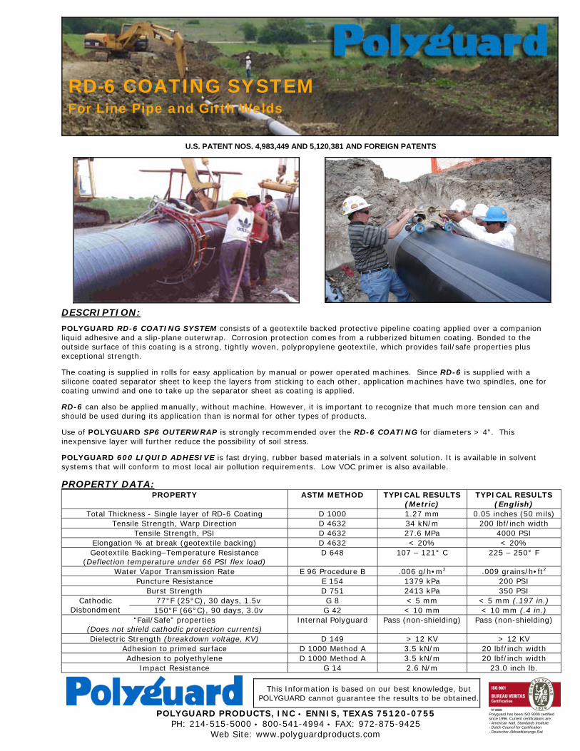
POLYGUARD RD-6 COATING SYSTEM consists of a geotextile backed protective pipeline coating applied over a companion liquid adhesive and a slip-plane outerwrap. Corrosion protection comes from a rubberized bitumen coating. Bonded to the outside surface of this coating is a strong, tightly woven, polypropylene geotextile, which provides fail/safe properties plus exceptional strength.
The coating is supplied in rolls for easy application by manual or power operated machines. Since RD-6 is supplied with a silicone coated separator sheet to keep the layers from sticking to each other, application machines have two spindles, one for coating unwind and one to take up the separator sheet as coating is applied.
RD-6 can also be applied manually, without machine. However, it is important to recognize that much more tension can and should be used during its application than is normal for other types of products.
Use of POLYGUARD SP6 OUTERWRAP is strongly recommended over the RD-6 COATING for diameters > 4”. This inexpensive layer will further reduce the possibility of soil stress.
POLYGUARD 600 LIQUID ADHESIVE is fast drying, rubber based materials in a solvent solution. It is available in solvent systems that will conform to most local air pollution requirements. Low VOC primer is also available.
PROPERTY DATA: PROPERTY ASTM METHOD TYPICAL RESULTS
(Metric) TYPICAL RESULTS
(English) Total Thickness - Single layer of RD-6 Coating D 1000 1.27 mm 0.05 inches (50 mils)
Tensile Strength, Warp Direction D 4632 34 kN/m 200 lbf/inch width Tensile Strength, PSI D 4632 27.6 MPa 4000 PSI
Elongation % at break (geotextile backing) D 4632 < 20% < 20% Geotextile Backing–Temperature Resistance
(Deflection temperature under 66 PSI flex load) D 648
107 – 121° C 225 – 250° F
Water Vapor Transmission Rate E 96 Procedure B .006 g/h•m2 .009 grains/h•ft2 Puncture Resistance E 154 1379 kPa 200 PSI
Burst Strength D 751 2413 kPa 350 PSI 77°F (25°C), 30 days, 1.5v G 8 < 5 mm < 5 mm (.197 in.) Cathodic
Disbondment 150°F (66°C), 90 days, 3.0v G 42 < 10 mm < 10 mm (.4 in.) “Fail/Safe” properties
(Does not shield cathodic protection currents) Internal Polyguard
Pass (non-shielding) Pass (non-shielding)
Dielectric Strength (breakdown voltage, KV) D 149 > 12 KV > 12 KV Adhesion to primed surface D 1000 Method A 3.5 kN/m 20 lbf/inch width Adhesion to polyethylene D 1000 Method A 3.5 kN/m 20 lbf/inch width
Impact Resistance G 14 2.6 N/m 23.0 inch lb.
RD-6 COATING SYSTEM For Line Pipe and Girth Welds
ADVANTAGES:
• RD-6 is a “fail/safe” coating. This means that if the coating disbonds, cathodic protection currents will not be shielded, and will be able to reach water underneath the coating.
• Has excellent resistance to cathodic disbondment, even if surface preparation is below standard, as often happens in field application.
• Geotextile backing properties of high strength, low “stretchability” (elongation), and high temperature resistance all contribute to resistance of soil stress.
• Fast and easy to apply, and can be backfilled immediately after coating. • Woven construction of geotextile backing permits bitumen to bitumen contact at the overlaps. • Has excellent resistance to water or vapor transmission. • Is not subject to deterioration due to exposure to below ground acids and alkalis that are encountered in
normal soil. • Provides uniform factory controlled thickness, compared to field applied liquid coatings. • Elastomeric properties to accommodate normal expansion and contraction of the substrate.
PRECAUTIONS: The liquid adhesive is an industrial coating and would be harmful or fatal if swallowed. It is marked as red label from the standpoint of flash point. Prohibit flames, sparks, welding and smoking during application. Solvents could be irritating to the eyes. In case of contact with eyes, flush with water and contact physician. Avoid prolonged contact with skin and breathing of vapor or spray mist from liquid adhesive. In confined areas, use adequate forced ventilation, fresh air masks, explosion proof equipment, and clean clothing. This material is sold by Polyguard Products, Inc. only for the purposes described in this literature. Any other use of the products is the responsibility of the purchaser and Polyguard Products does not warrant nor will be responsible for any misuse of these products. Polyguard Products will replace material not meeting our published specifications within one year from date of sale. MATERIAL SAFETY DATA: All Polyguard Products Material Safety Data Sheets (MSDS) and precautionary labels should be read and understood by all user supervisory personnel and employees before using. Purchaser is responsible for complying with all applicable federal, state or local laws and regulations covering use, health, safety, and disposal of the product. MAINTENANCE: None required. Technical Service: Polyguard Products Inc. Ennis, Texas 75120-0755 PH: 214.515.5000 FAX: 972.875.9425 www.polyguardproducts.com
Share/lit/pipeline/rd6data 1/11/08
This Information is based on our best knowledge, but POLYGUARD cannot guarantee the results to be obtained.
POLYGUARD PRODUCTS, INC • ENNIS, TEXAS 75120-0755 PH: 214-515-5000 • 800-541-4994 • FAX: 972-875-9425
Web Site: www.polyguardproducts.com
RD-6 APPLICATION SPECIFICATION
Manual Operated or Power Machine Application
Polyguard has been ISO 9000 certified since 1996. Current certifications are: - American Natl. Standards Institute - Dutch Council for Certification - Deutscher Akkreditierungs Rat
U.S. PATENT NOS. 4,983,449 and 5,120,381. FOREIGN PATENTS
SPECIFICATION FOR HANDLING AND MACHINE APPLICATION OF POLYGUARD RD-6 COATING FOR BELOW GROUND PIPING
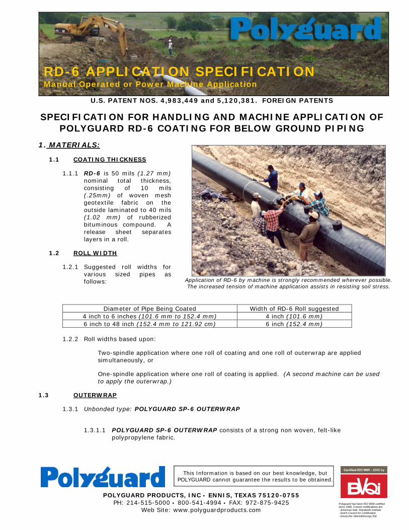
1. MATERIALS: 1.1 COATING THICKNESS 1.1.1 RD-6 is 50 mils (1.27 mm)
nominal total thickness, consisting of 10 mils (.25mm) of woven mesh geotextile fabric on the outside laminated to 40 mils (1.02 mm) of rubberized bituminous compound. A release sheet separates layers in a roll.
1.2 ROLL WIDTH 1.2.1 Suggested roll widths for
various sized pipes as follows:
Diameter of Pipe Being Coated Width of RD-6 Roll suggested 4 inch to 6 inches (101.6 mm to 152.4 mm) 4 inch (101.6 mm) 6 inch to 48 inch (152.4 mm to 121.92 cm) 6 inch (152.4 mm)
1.2.2 Roll widths based upon:
Two-spindle application where one roll of coating and one roll of outerwrap are applied simultaneously, or
One-spindle application where one roll of coating is applied. (A second machine can be used to apply the outerwrap.)
1.3 OUTERWRAP 1.3.1 Unbonded type: POLYGUARD SP-6 OUTERWRAP 1.3.1.1 POLYGUARD SP-6 OUTERWRAP consists of a strong non woven, felt-like
polypropylene fabric.
Application of RD-6 by machine is strongly recommended wherever possible. The increased tension of machine application assists in resisting soil stress.
1.4 LONGITUDINAL MILL WELD SEAM STRIPPING MATERIAL (where required on DSAW pipe) 1.4.1 Polyguard RD-6 or 1.4.2 POLYGUARD 606 - A 60 mil (1.52 mm) thick, reinforced coating consisting of a rubberized
bituminous compound. It has no backing on either side of the compound. Release sheets separate layers in a roll.
2. HANDLING OF COATING MATERIALS: 2.1 Coating and wrapping materials shall be hauled and stored in such a manner as to prevent injury
to packages. No packages shall be dropped from trucks or handled with hooks. 2.2 All coating and wrapping materials shall be protected from the elements. Wrapping materials shall
be transported only as needed during application of the coating, conveyed in a covered vehicle and moved directly from the vehicle to the coating or wrapping machines as required.
2.3 Coating and liquid adhesive shall be maintained at a temperature of 45 deg. F. (7 deg. C) or higher
at time of application.
3. COATING APPLICATION: 3.1 PIPE 3.1.1 Surface Preparation Surface preparation of the pipe shall include: A. Removal of all visible oil and grease, by swabbing with a safety solvent that does not leave
residue. B. Removal of splatter and slag from welds and pipe surface by filing, wire brushing or other
methods satisfactory to Company representative. C. Minimum requirements: Pipe shall be cleaned to be free of all mill scale, loose rust, knurls,
frost, dust, moisture and other deleterious matter. If power brushes are used in the cleaning process, a polished surface shall be avoided.
D. Blast Cleaning (if specified): It is required to obtain a commercial finish (minimum), as
described by NACE No. 3. E. Cleaning to the satisfaction of Company representative. Bare pipe shall be considered clean
when all foreign matter has been removed, and a surface cleaned to the parent metal is immediately available to the coating operation.
F. Protection of the cleaned pipe such that it will remain free from contamination and be
suitable for immediate coating application. In the event of surface contamination prior to coating application, pipe shall be reprocessed through the necessary cleaning steps outlined above.
3.1.2 Liquid Adhesive Application
All pipe shall be covered with POLYGUARD 600 LIQUID ADHESIVE after cleaning and before coating application. LIQUID ADHESIVE shall be applied with a clean brush or roller brush or other acceptable mechanical means to obtain uniform and complete coverage of the pipe surface. Liquid Adhesive shall be applied at a rate of approximately 400 square feet (10.0m2/Liter) per gallon and shall be dry or tacky/dry to touch prior to coating application.
3.1.3 Weld Stripping Material (where required)
Where DSAW pipe is involved, the longitudinal mill weld seam shall be stripped with POLYGUARD RD-6 preferably or POLYGUARD 606 - 6" wide stripping material after the liquid adhesive has been applied to the pipe and before application of the coating. In applying the stripping material, position the material over the weld so that when the roll is unwound, half the width will rest on both sides of the weld. As the material is applied to the weld, remove the inner separator sheet next to the weld. When completed, manually press
the stripping material into the weld crevices. When the 606 material is used, slowly remove the outer separator sheet from the compound while pressing the material with a piece of the release paper, to conform to the weld and pipe surface.
3.1.4 Coating (by machine) A. The primary coating shall be spirally wrapped by an approved machine on pipe suitably cleaned,
and with liquid adhesive applied. B. The machine used shall be equipped with take-up spindles to remove and wind the separator
sheet as the coating roll is applied to the pipe. The machine used shall be capable of applying the primary coating with uniform tension across the width of the roll equal to 15 lbs. (6.8 Kgs/25.4 mm) per inch minimum width (dead weight). The machine shall be equipped with a constant tension brake system to assure equalization of tension across the roll width and through out the complete unwind of the roll, regardless of the roll size.
C. Operators shall make all necessary manual or machine adjustments to accomplish a uniform,
tightly adhered coating having a lap of at least 1" (25.44 mm) over the preceding spirals. Care shall be taken that no wrinkles, puckers, voids, or breaks are left in the coating as a result of a deficiency in application.
D. An unbonded outerwrap (if specified by the Company) shall be spirally applied. Operators shall
make necessary adjustments to achieve a uniform, outerwrap having a lap of at least 1" (25.44 mm) over preceding spirals.
E. Coated pipe shall be handled at all times with wide non-abrasive slings, belts or other equipment
designed and maintained to prevent damage to the coating. All skid supports shall be padded to protect the coating. Equipment which the Company representative deems to be injurious to the coating shall not be permitted. Walking on the coated pipe shall not be permitted.
4. INSPECTION AND REPAIR: 4.1 Where the coated pipe is above ground, the coated pipe shall be holiday detected and lowered into
the ditch with care. Coated pipe shall not be lowered into the ditch until it has been inspected and approved by the Company representative.
4.2 The coating system shall be holiday detected with an adjustable electronic detector as follows:
The thickness of the RD-6 compound is 40 mils with a 10 mil mesh backing that will allow the current from the holiday detector to easily penetrate if the compound is damaged. In a single layer of RD-6 set the detector at 4500 volts. Do not exceed 5500 volts. Excessive voltage can stress the coating and cause burn through. If POLYGUARD OUTERWRAP is to be included with the coating in the detection process, please consult the manufacturer for recommended voltage.
4.3 All holidays and defects shall be repaired by the Contractor to the satisfaction of the Company
representative. If any coated pipe is damaged upon lowering into the ditch, it shall be repaired in the position deemed most practical by the Company representative.
4.4 All holidays and all damaged or defective coating shall be repaired immediately. A. Small or pinhole type holidays can be repaired in the RD-6 by applying liquid adhesive over the
holiday area and when dry to touch, starting with RD-6, at the 2:00 o’clock position on the coated pipe surface and while covering the repair area, a minimum of 1 inch (25.4 mm) on all sides of the repair, make a complete wrap of 1-1/3 revolutions around the coated pipe surface, ending at the 10 o’clock position. This will make sure the tape laps on both sides are in a downward direction. If outerwrap is being used apply a layer of unbonded outerwrap over the repair area and attach with fiber reinforced strapping tape.
B. For larger holidays or where coating is damaged that exposes pipe, remove damaged coating and
smooth edges before repair is made. If a hole or large void area occurs, fill in the area with a patch of RD-6 or 606 Filler tape to make sure bridging of the void does not occur. Finish repair as in A. above. If the damaged area is large enough that it requires a material patch larger than 6" (152.4 mm) x 12" (304.8 mm), then spiral wrap the pipe with RD-6, to include the damaged area. Over this, apply an outerwrap as in A. above.
C. If an unbonded outerwrap was used, remove outerwrap and make repair as in A. or B. above.
4.5 All coating repairs shall be reinspected as outlined above.
5.0 PRECAUTIONS:
5.1 The liquid adhesive is an industrial coating and would be harmful or fatal if swallowed. It is marked as red label from the standpoint of flash point. Prohibit flames, sparks, welding and smoking during application. Solvents could be irritating to the eyes. In case of contact with eyes, flush with water and contact physician.
5.2 Avoid prolonged contact with skin and breathing of vapor or spray mist from liquid adhesive. In
confined areas, use adequate forced ventilation, fresh air masks, explosion proof equipment, and clean clothing.
5.3 This material is sold by Polyguard Products, Inc. only for the purposes described in this literature.
Any other use of the products is the responsibility of the purchaser and Polyguard Products does not warrant nor will be responsible for any misuse of these products. Polyguard Products will replace material not meeting our published specifications within one year from date of sale.
6.0 MATERIAL SAFETY DATA:
6.1 All Polyguard Products Material Safety Data Sheets (MSDS) and precautionary labels should be read and understood by all user supervisory personnel and employees before using. Purchaser is responsible for complying with all applicable federal, state or local laws and regulations covering use, health, safety, and disposal of the product.
MAINTENANCE: None required.
Technical Service: Polyguard Products Inc. Ennis, Texas 75120-0755 PH: 214.515.5000 FAX: 972.875.9425 www.polyguardproducts.com
x.xl.RD6 Spec Mach Applic R.2-15-07
This Information is based on our best knowledge, but POLYGUARD cannot guarantee the results to be obtained.
POLYGUARD PRODUCTS, INC • ENNIS, TEXAS 75120-0755 PH: 214-515-5000 • 800-541-4994 • FAX: 972-875-9425
Web Site: www.polyguardproducts.com
Polyguard has been ISO 9000 certified since 1996. Current certifications are: - American Natl. Standards Institute - Dutch Council for Certification - Deutscher Akkreditierungs Rat
U.S. PATENT No. 4,983,449, U.S. PATENT No. 5,120,381 and FOREIGN PATENTS
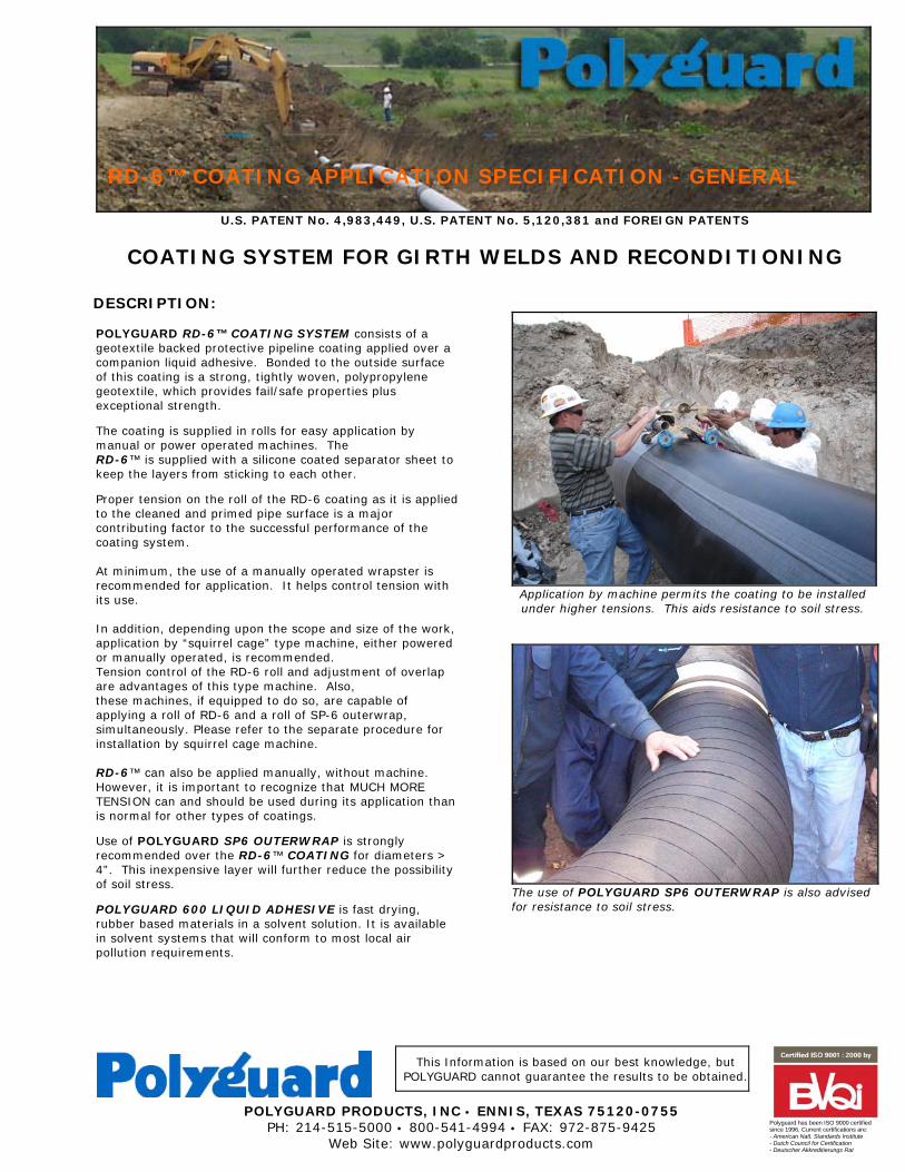
COATING SYSTEM FOR GIRTH WELDS AND RECONDITIONING DESCRIPTION: POLYGUARD RD-6™ COATING SYSTEM consists of a geotextile backed protective pipeline coating applied over a companion liquid adhesive. Bonded to the outside surface of this coating is a strong, tightly woven, polypropylene geotextile, which provides fail/safe properties plus exceptional strength.
The coating is supplied in rolls for easy application by manual or power operated machines. The
RD-6™ is supplied with a silicone coated separator sheet to keep the layers from sticking to each other.
Proper tension on the roll of the RD-6 coating as it is applied to the cleaned and primed pipe surface is a major contributing factor to the successful performance of the coating system. At minimum, the use of a manually operated wrapster is recommended for application. It helps control tension with its use. In addition, depending upon the scope and size of the work, application by “squirrel cage” type machine, either powered or manually operated, is recommended. Tension control of the RD-6 roll and adjustment of overlap are advantages of this type machine. Also, these machines, if equipped to do so, are capable of applying a roll of RD-6 and a roll of SP-6 outerwrap, simultaneously. Please refer to the separate procedure for installation by squirrel cage machine. RD-6™ can also be applied manually, without machine. However, it is important to recognize that MUCH MORE TENSION can and should be used during its application than is normal for other types of coatings.
Use of POLYGUARD SP6 OUTERWRAP is strongly recommended over the RD-6™ COATING for diameters > 4”. This inexpensive layer will further reduce the possibility of soil stress.
POLYGUARD 600 LIQUID ADHESIVE is fast drying, rubber based materials in a solvent solution. It is available in solvent systems that will conform to most local air pollution requirements.
Application by machine permits the coating to be installed under higher tensions. This aids resistance to soil stress.
The use of POLYGUARD SP6 OUTERWRAP is also advised for resistance to soil stress.
RD-6™ COATING APPLICATION SPECIFICATION - GENERAL
APPLICATION SPECIFICATIONS: HANDLING MATERIALS: RD-6™ COATING and LIQUID ADHESIVE should be hauled and stored in such a manner as to prevent injury to the packages. No packages should be dropped or thrown from trucks. Packages shall not be handled with hooks. Containers and rolls should be stored in a dry place, kept from contact with earth, and protected from weather at all times. It is recommended that the coating and liquid adhesive be transported in warmed vehicles and stored in heated buildings in cold weather. Although the coating can be applied at lower temperatures, to maximize the quality, it is recommended that the coating and liquid adhesives be maintained at a temperature of 45 deg. F (7 deg. C) or higher at time of application. SURFACE PREPARATION: At the minimum, the pipe shall be cleaned of all paints, oil and grease, mill scale, loose rust, welding residue, knurls, frost, dust, moisture, weeds, and other foreign matter. Where feasible and practical, the surface can be blast cleaned to a commercial finish, such as described in NACE No. 3. Where mill coated pipe is involved, the LIQUID ADHESIVE and coating should be applied to the girth weld, starting on top of the mill coating, at least 2" back from the edges of the mill coating. The liquid adhesive should extend 1” out from the RD-6 Coating. Neither liquid adhesive nor coating should be applied to pipe surfaces where there is the presence of visual moisture. POLYGUARD RD-6™ COATING SYSTEMS will not properly adhere to pipes with moisture. Condensation happens on a metal surface when the temperature of the pipe is at or below the dew point temperature. Relative humidity is the measure of how much moisture is in the air. Dew point is the combination of temperature and relative humidity where moisture condensates on a surface. The ASTM E 337, AStandard Method for Measuring Humidity with Psychrometer: is the recommended method for measuring dew point temperature. When condensation is a problem, the pipe surfaces should be heated to at least 5°F above the dew point temperature before the coating is applied. Condensation is usually not a problem unless the relative humidity is 85% or more. LIQUID ADHESIVE APPLICATION: POLYGUARD 600 LIQUID ADHESIVE should be applied at an average rate of 400 ft2 / gallon (10.0m2/liter). Stir before using. Apply liquid adhesive with brush or roller to clean and dry substrate. Do not thin liquid adhesive. APPLICATION: POLYGUARD RD-6™ can be spirally wrapped by hand or power operated machine. Coating is spirally wrapped with bitumen side next to the dry or tacky/dry liquid adhesive. As coating is unwound from its spindle, the separator sheet is rewound simultaneously onto the other spindle and discarded after roll is completely applied. Enough brake tension should be used to obtain good overlap confirmation and a smooth, tight, air pocket free condition on pipe surface. Coating overlap should be minimum 1" (25.4mm) unless otherwise specified. Where DSAW pipe is being coated, prior to coating, 6” (152.4mm) wide RD-6™ material must be used for stripping purposes over the mill weld. The material is applied over the LIQUID ADHESIVE surface before the RD-6™ coating is applied. Centering the middle of the product over the weld, the roll is unwound normally, removing the separator sheet as it is unwound. If the coated pipe in hot weather remains in either an open ditch or on skids for an extended period, overwrap coating with kraft paper or other suitable temporary material. Use of POLYGUARD SP6 OUTERWRAP is strongly recommended over the RD-6™ for diameters > 4”. This inexpensive layer will further assist RD-6 and provide a major contribution to the mitigation of soil stress forces. LOWERING IN: The coated pipe should be inspected before lowering-in with a holiday detector. The thickness of the RD-6™ compound is nominal 40 mils with a nominal 10 mil mesh backing that will allow the current from the holiday detector to easily penetrate if the compound is damaged. For this reason Polyguard recommends setting the holiday detector at maximum of 4000 volts. Significant testing has proven that when the compound is not damaged, the voltage could be set at higher voltages, but doing so can penetrate thin spots that may be perfectly good coating otherwise. BACKFILLING: Care shall be taken in backfilling to avoid sharp rocks or other material in the backfill which would damage and penetrate the coating. In areas of rough backfill, suitable rock shield shall be provided to protect the coating from backfill damage. PRECAUTIONS: The liquid adhesive is an industrial coating and would be harmful or fatal if swallowed. It is marked as red label from the standpoint of flash point. Prohibit flames, sparks, welding and smoking during application. Solvents could be irritating to the eyes. In case of contact with eyes, flush with water and contact physician. Avoid prolonged contact with skin and breathing of vapor or spray mist from liquid adhesive. In confined areas, use adequate forced ventilation, fresh air masks, explosion proof equipment, and clean clothing. This material is sold by Polyguard Products, Inc. only for the purposes described in this literature. Any other use of the products is the responsibility of the purchaser and Polyguard Products does not warrant nor will be responsible for any misuse of these products. Polyguard Products will replace material not meeting our published specifications within one year from date of sale. MATERIAL SAFETY DATA: All Polyguard Products Material Safety Data Sheets (MSDS) and precautionary labels should be read and understood by all user supervisory personnel and employees before using. Purchaser is responsible for complying with all applicable federal, state or local laws and regulations covering use, health, safety, and disposal of the product. MAINTENANCE: None required. Technical Service: Polyguard Products Inc. Ennis, Texas 75120-0755 PH: 214.515-5000 FAX: 972.875.9425 www.polyguardproducts.com x.lit/pipeline/rd6 application spec genl R 11-15-07
This Information is based on our best knowledge, but POLYGUARD cannot guarantee the results to be obtained.
POLYGUARD PRODUCTS, INC • ENNIS, TEXAS 75120-0755 PH: 214-515-5000 • 800-541-4994 • FAX: 972-875-9425
Web Site: www.polyguardproducts.com
Polyguard has been ISO 9000 certified since 1996. Current certifications are: - American Natl. Standards Institute - Dutch Council for Certification - Deutscher Akkreditierungs Rat
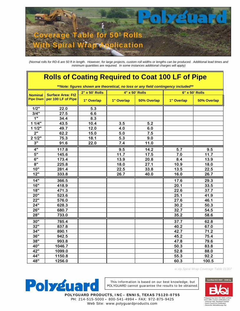
(Normal rolls for RD-6 are 50 ft in length. However, for large projects, custom roll widths or lengths can be produced. Additional lead times and
minimum quantities are required. In some instances additional charges will apply)
Rolls of Coating Required to Coat 100 LF of Pipe
**Note: figures shown are theoretical, no loss or any field contingency included** 2" x 50’ Rolls 4" x 50’ Rolls 6" x 50’ Rolls
Nominal Pipe Diam
Surface Area: Ft2 per 100 LF of Pipe 1" Overlap 1" Overlap 50% Overlap 1" Overlap 50% Overlap
1/2" 22.0 5.3 3/4" 27.5 6.6 1" 34.4 8.3
1 1/4" 43.5 10.4 3.5 5.2 1 1/2" 49.7 12.0 4.0 6.0
2" 62.2 15.0 5.0 7.5 2 1/2" 75.3 18.1 5.3 9.0
3" 91.6 22.0 7.4 11.0
4" 117.8 9.5 14.2 5.7 9.5 5" 145.6 11.7 17.5 7.0 11.7 6" 173.4 13.9 20.8 8.4 13.9 8" 225.8 18.0 27.1 10.9 18.0
10" 281.4 22.5 33.8 13.5 22.5 12" 333.8 26.7 40.0 16.0 26.7
14" 366.5 17.6 29.3 16" 418.9 20.1 33.5 18" 471.3 22.6 37.7 20" 523.6 25.1 41.9 22" 576.0 27.6 46.1 24" 628.3 30.2 50.3 26" 680.7 32.7 54.5 28" 733.0 35.2 58.6
30" 785.4 37.7 62.8 32" 837.8 40.2 67.0 34" 890.1 42.7 71.2 36" 942.5 45.2 75.4 38" 993.8 47.8 79.6 40" 1046.7 50.3 83.8 42" 1099.0 52.8 88.0 44" 1150.8 55.3 92.2 48" 1256.0 60.3 100.5
w.xlp.Spiral Wrap Coverage Table 01307
Coverage Table for 50’ Rolls With Spiral Wrap Application

This Information is based on our best knowledge, but POLYGUARD cannot guarantee the results to be obtained.
POLYGUARD PRODUCTS, INC • ENNIS, TEXAS 75120-0755 PH: 214-515-5000 • 800-541-4994 • FAX: 972-875-9425
Web Site: www.polyguardproducts.com
Polyguard has been ISO 9000 certified since 1996. Current certifications are: - American Natl. Standards Institute - Dutch Council for Certification - Deutscher Akkreditierungs Rat
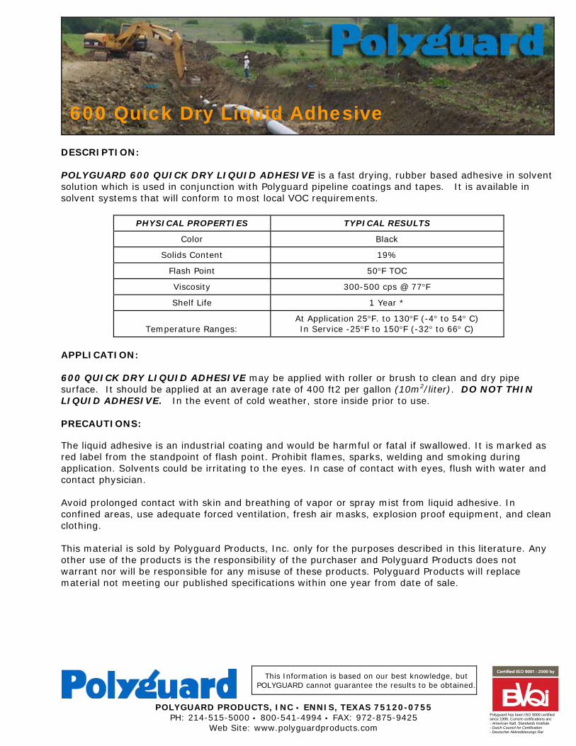
DESCRIPTION: POLYGUARD 600 QUICK DRY LIQUID ADHESIVE is a fast drying, rubber based adhesive in solvent solution which is used in conjunction with Polyguard pipeline coatings and tapes. It is available in solvent systems that will conform to most local VOC requirements.
PHYSICAL PROPERTIES
TYPICAL RESULTS
Color
Black
Solids Content
19%
Flash Point
50°F TOC
Viscosity
300-500 cps @ 77°F
Shelf Life
1 Year *
Temperature Ranges:
At Application 25°F. to 130°F (-4° to 54° C) In Service -25°F to 150°F (-32° to 66° C)
APPLICATION: 600 QUICK DRY LIQUID ADHESIVE may be applied with roller or brush to clean and dry pipe surface. It should be applied at an average rate of 400 ft2 per gallon (10m2/liter). DO NOT THIN LIQUID ADHESIVE. In the event of cold weather, store inside prior to use. PRECAUTIONS: The liquid adhesive is an industrial coating and would be harmful or fatal if swallowed. It is marked as red label from the standpoint of flash point. Prohibit flames, sparks, welding and smoking during application. Solvents could be irritating to the eyes. In case of contact with eyes, flush with water and contact physician. Avoid prolonged contact with skin and breathing of vapor or spray mist from liquid adhesive. In confined areas, use adequate forced ventilation, fresh air masks, explosion proof equipment, and clean clothing. This material is sold by Polyguard Products, Inc. only for the purposes described in this literature. Any other use of the products is the responsibility of the purchaser and Polyguard Products does not warrant nor will be responsible for any misuse of these products. Polyguard Products will replace material not meeting our published specifications within one year from date of sale.
600 Quick Dry Liquid Adhesive
MATERIAL SAFETY DATA: All Polyguard Products Material Safety Data Sheets (MSDS) and precautionary labels should be read and understood by all user supervisory personnel and employees before using. Purchaser is responsible for complying with all applicable federal, state or local laws and regulations covering use, health, safety, and disposal of the product. MAINTENANCE: None required. Technical Service: Polyguard Products Inc. Ennis, Texas 75120-0755 PH: 214.515-5000 FAX: 972.875.9425 www.polyguardproducts.com w.xlp.600 Quick Dry Primer 3-1-07

This Information is based on our best knowledge, but POLYGUARD cannot guarantee the results to be obtained.
POLYGUARD PRODUCTS, INC • ENNIS, TEXAS 75120-0755 PH: 214-515-5000 • 800-541-4994 • FAX: 972-875-9425
Web Site: www.polyguardproducts.com
Polyguard has been ISO 9000 certified since 1996. Current certifications are: - American Natl. Standards Institute - Dutch Council for Certification - Deutscher Akkreditierungs Rat
DESCRIPTION: POLYGUARD 606 FILLER TAPE is a cold applied protective coating. Within the rubberized bitumen coating is a continuous filament thermoplastic fiber for reinforcement. The fiber adds tensile strength and provides resistance to tear. The continuous filament fiber used to reinforce the coating is randomly arranged and highly dispersed within the compound. The fiber can be stretched within its break level so as not to restrict conformability and to assure exceptionally good molding characteristics. The coat-ing is supplied in rolls and utilizes both paper and plastic film release sheets which are removed prior to application. 606 FILLER TAPE is formulated for use with POLYGUARD RD-6 and 600 SERIES COATINGS. It also is applied over a companion 600 LIQUID ADHESIVE. USES: 606 FILLER TAPE is designed for hand application. It is primarily designed for use over weld seams, but also finds use as a filler material under the coating and wrapping of station piping, irregular shapes such as valve bodies, flange bolts, and compression fittings. ADVANTAGES: Following are the advantages of 606 FILLER TAPE. ! Easily applied and provides excellent conformation and molding properties. ! Has excellent resistance to water or vapor transmission. ! Not subject to deterioration from below ground acids and alkalis that are encountered in normal soil. ! Has excellent ability to resist infiltration of moisture. ! Has elastomeric properties to accommodate normal expansion and contraction of the substrate. ! Includes as the basic corrosion coating a polymer modified bitumen.
PROPERTY ASTM Test English
Metric Color Black
Black
Thickness D 1000 0.06”
1.5 mm
Moisture Absorption D 570 0.2%
0.2 %
606 FILLER TAPE FABRIC REINFORCED COATING FOR MOLDING IRREGULAR SURFACES
606 Filler Tape can fill irregular transition areas, thus avoiding
gaps and voids under the coating.
This photo illustrates how the corrosion control coating
used in 606 Filler Tape conforms and fills voids.
GUIDE SPECIFICATION: Handling Materials: 606 FILLER TAPE and LIQUID ADHESIVE should be hauled and stored in such a manner as to prevent injury to the packages. All packages and rolls of wrapping materials should be transported in warmed vehicles and stored in a warm dry place and kept from contact with earth and protected from weather at all times. Although the filler tape can be utilized at lower temperatures, to maximize the quality application characteristics of the tape, it is recommended that the tape and liquid adhesive be maintained at a temperature of 60EF (16EC) or higher at all times. Surface Preparation: The pipe shall be cleaned of all paint, oil, grease, mill scale, loose rust, welding residue, knurls, frost, dust, moisture, weeds and other foreign matter. Applying Liquid Adhesive: Polyguard Liquid Adhesive should be applied at an average rate of 400 sq. ft. per gallon (10.0m2/liter). Stir before using. Apply with brush or roller to clean and dry substrate. DO NOT THIN POLYGUARD LIQUID ADHESIVES. Wrapping: 606 FILLER TAPE can be applied by spiral wrapping or by cigarette wrapping. The release sheet is to be removed immediately prior to the time of application. Remove the paper release liner and apply coating to the substrate. Remove the remaining plastic film liner and press filler coating into all voids, using a piece of release paper to do this. The coating should be applied with enough tension to eliminate any air pockets and to conform to the surface area. Lowering-in and Backfilling: Normally, filler material is used under coating systems such as RD-6 and the 600 Series Systems. In these circumstances, the recommendations made for lowering-in, inspection and backfilling for these specific coating systems should be followed. Where filler material is to be used alone or in combination with materials other than mentioned above, please consult POLYGUARD. PRECAUTIONS: The liquid adhesive is an industrial coating and would be harmful or fatal if swallowed. It is marked as red label from the standpoint of flash point. Prohibit flames, sparks, welding and smoking during application. Solvents could be irritating to the eyes. In case of contact with eyes, flush with water and contact physician. Avoid prolonged contact with skin and breathing of vapor or spray mist from liquid adhesive. In confined areas, use adequate forced ventilation, fresh air masks, explosion proof equipment, and clean clothing. This material is sold by Polyguard Products, Inc. only for the purposes described in this literature. Any other use of the products is the responsibility of the purchaser and Polyguard Products does not warrant nor will be responsible for any misuse of these products. Polyguard Products will replace material not meeting our published specifications within one year from date of sale. MATERIAL SAFETY DATA: All Polyguard Products Material Safety Data Sheets (MSDS) and precautionary labels should be read and understood by all user supervisory personnel and employees before using. Purchaser is responsible for complying with all applicable federal, state or local laws and regulations covering use, health, safety, and disposal of the product. MAINTENANCE: None required. Technical Service: Polyguard Products Inc. Ennis, Texas 75120-0755 PH: 214.515.5000 FAX: 972.875.9425 www.polyguardproducts.com w.xlp.606 Filler Tape R. 11-15-07
This Information is based on our best knowledge, but POLYGUARD cannot guarantee the results to be obtained.
POLYGUARD PRODUCTS, INC • ENNIS, TEXAS 75120-0755 PH: 214-515-5000 • 800-541-4994 • FAX: 972-875-9425
Web Site: www.polyguardproducts.com
Polyguard has been ISO 9000 certified since 1996. Current certifications are: - American Natl. Standards Institute - Dutch Council for Certification - Deutscher Akkreditierungs Rat
DESCRIPTION:
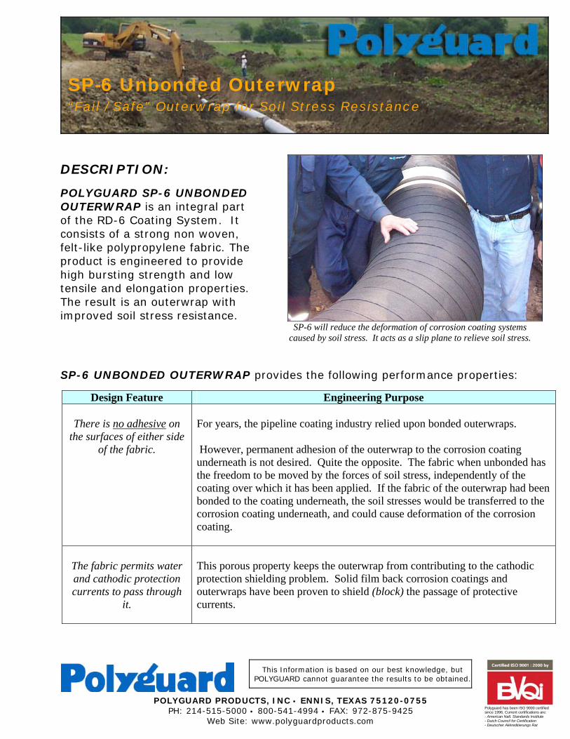
POLYGUARD SP-6 UNBONDED OUTERWRAP is an integral part of the RD-6 Coating System. It consists of a strong non woven, felt-like polypropylene fabric. The product is engineered to provide high bursting strength and low tensile and elongation properties. The result is an outerwrap with improved soil stress resistance.
SP-6 UNBONDED OUTERWRAP provides the following performance properties:
Design Feature Engineering Purpose
There is no adhesive on the surfaces of either side
of the fabric.
For years, the pipeline coating industry relied upon bonded outerwraps. However, permanent adhesion of the outerwrap to the corrosion coating underneath is not desired. Quite the opposite. The fabric when unbonded has the freedom to be moved by the forces of soil stress, independently of the coating over which it has been applied. If the fabric of the outerwrap had been bonded to the coating underneath, the soil stresses would be transferred to the corrosion coating underneath, and could cause deformation of the corrosion coating.
The fabric permits water and cathodic protection currents to pass through
it.
This porous property keeps the outerwrap from contributing to the cathodic protection shielding problem. Solid film back corrosion coatings and outerwraps have been proven to shield (block) the passage of protective currents.
SP-6 Unbonded Outerwrap “Fail / Safe” Outerwrap for Soil Stress Resistance
SP-6 will reduce the deformation of corrosion coating systems
caused by soil stress. It acts as a slip plane to relieve soil stress.
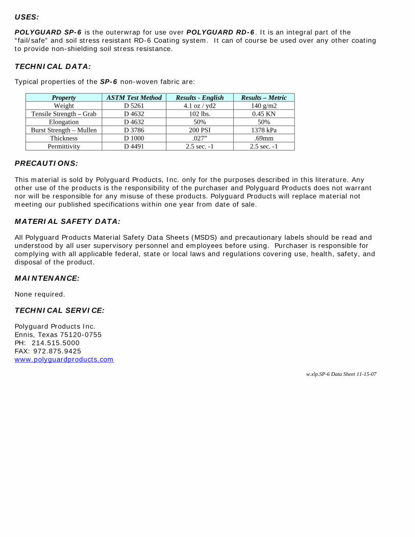
USES: POLYGUARD SP-6 is the outerwrap for use over POLYGUARD RD-6. It is an integral part of the “fail/safe” and soil stress resistant RD-6 Coating system. It can of course be used over any other coating to provide non-shielding soil stress resistance. TECHNICAL DATA: Typical properties of the SP-6 non-woven fabric are:
Property ASTM Test Method Results - English Results – Metric Weight D 5261 4.1 oz / yd2 140 g/m2
Tensile Strength – Grab D 4632 102 lbs. 0.45 KN Elongation D 4632 50% 50%
Burst Strength – Mullen D 3786 200 PSI 1378 kPa Thickness D 1000 .027” .69mm
Permittivity D 4491 2.5 sec. -1 2.5 sec. -1 PRECAUTIONS: This material is sold by Polyguard Products, Inc. only for the purposes described in this literature. Any other use of the products is the responsibility of the purchaser and Polyguard Products does not warrant nor will be responsible for any misuse of these products. Polyguard Products will replace material not meeting our published specifications within one year from date of sale. MATERIAL SAFETY DATA: All Polyguard Products Material Safety Data Sheets (MSDS) and precautionary labels should be read and understood by all user supervisory personnel and employees before using. Purchaser is responsible for complying with all applicable federal, state or local laws and regulations covering use, health, safety, and disposal of the product. MAINTENANCE: None required. TECHNICAL SERVICE: Polyguard Products Inc. Ennis, Texas 75120-0755 PH: 214.515.5000 FAX: 972.875.9425 www.polyguardproducts.com
w.xlp.SP-6 Data Sheet 11-15-07
Web Site:www.polyguardproducts.com/failsafecoating.htm PH: 214-515-5000
Polyguard Products' has been certified to these quality systems requirements: - American Natl. Standards Institute - Dutch Council for Certification - Deutscher Akkreditierungs Rat
Polyguard RD-6 Pipeline Coating System
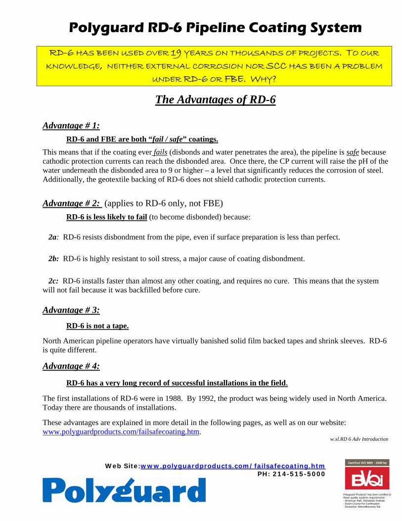
RD-6 HAS BEEN USED OVER 19 YEARS ON THOUSANDS OF PROJECTS. TO OUR
KNOWLEDGE, NEITHER EXTERNAL CORROSION NOR SCC HAS BEEN A PROBLEM
UNDER RD-6 OR FBE. WHY?
The Advantages of RD-6
Advantage # 1: RD-6 and FBE are both “fail / safe” coatings. This means that if the coating ever fails (disbonds and water penetrates the area), the pipeline is safe because cathodic protection currents can reach the disbonded area. Once there, the CP current will raise the pH of the water underneath the disbonded area to 9 or higher – a level that significantly reduces the corrosion of steel. Additionally, the geotextile backing of RD-6 does not shield cathodic protection currents.
Advantage # 2: (applies to RD-6 only, not FBE) RD-6 is less likely to fail (to become disbonded) because:
2a: RD-6 resists disbondment from the pipe, even if surface preparation is less than perfect. 2b: RD-6 is highly resistant to soil stress, a major cause of coating disbondment.
2c: RD-6 installs faster than almost any other coating, and requires no cure. This means that the system will not fail because it was backfilled before cure.
Advantage # 3:
RD-6 is not a tape.
North American pipeline operators have virtually banished solid film backed tapes and shrink sleeves. RD-6 is quite different.
Advantage # 4:
RD-6 has a very long record of successful installations in the field. The first installations of RD-6 were in 1988. By 1992, the product was being widely used in North America. Today there are thousands of installations. These advantages are explained in more detail in the following pages, as well as on our website: www.polyguardproducts.com/failsafecoating.htm.
w.xl.RD 6 Adv Introduction
Web Site:www.polyguardproducts.com/failsafecoating.htm PH: 214-515-5000
Polyguard Products' has been certified to these quality systems requirements: - American Natl. Standards Institute - Dutch Council for Certification - Deutscher Akkreditierungs Rat
Polyguard RD-6TM Pipeline Coating System
Advantage #1 RD-6 is a ‘Fail/Safe’ coating system
‘Fail/Safe’ coatings are coatings which do not shield (block) cathodic protection currents.
The subject of shielding is a complex and technical one, which not many understand in detail. However, as it relates to the subject of underground exterior pipeline corrosion coatings, some general concepts can be explained which do not require detailed training.
It is important for anyone with pipeline responsibilities to understand cathodic shielding. That is because the latest NACE standard, as well as government regulations (CFR §192.461 and §195.559) require that external corrosion coating materials have non-shielding properties.
Here is the NACE definition of shielding:
“Shielding: Preventing or diverting the cathodic protection current from its intended path.” NACE Standard RPO169-2002, Control of External Corrosion on Underground or Submerged Metallic Piping Systems, page 3
Here is what the NACE standard says about corrosion coatings which shield:
“Materials and construction practices that create electrical shielding should not be used on the pipeline.”
NACE Standard RPO169-2002, Control of External Corrosion on Underground or Submerged Metallic Piping Systems
Here is what CFR §192.461 says about allowable corrosion coatings:
“(a) Each external protective coating, whether conductive or insulating, applied for the purposes of external corrosion control must--...............(5) Have properties compatible
with any supplemental cathodic protection.” 49 CFR Part 192-Transportation of Natural and Other Gas by Pipeline: Minimum Federal Safety Standards, Subpart I – Requirements for Corrosion Control
Coatings with solid film backing have been proven to shield. Solid film backings have a property of high resistivity, which is not compatible with supplemental cathodic protection. This is why shrink sleeves and solid film backed tapes have lost favor with North American pipeline operators. The high resistivity property of these film backings resists the passage of electricity; thus these coatings can “hide” areas of corrosion from cathodic protection currents.
As early as the late 1980’s, the Pipeline Research Council reported(1) that both corrosion and SCC were; “..enhanced by cathodic shielding at the disbonded areas..” by solid polyethylene film backed tapes installed on natural gas pipelines. In the mid 1990’s,

Canada’s National Energy Board concluded that solid film back tapes contributed to an outbreak of SCC failures because of shielding.
Although usage of solid film back tapes and shrink sleeves has greatly declined in North America, both types of products continue to be broadly used in other areas of the world. In addition, 2 layer and 3 layer systems using solid film coatings of polyethylene or polypropylene are in wide use. All of these coatings have proven shielding characteristics.
The graphic below gives some idea how “fail / safe” coatings differ from shielding coatings.
FBE and Polyguard RD-6 are both “fail / safe” coatings. This means that they have been proven to allow passage of protective currents to disbonded areas with corrosion potential. Once the protective current has penetrated underneath the coating, the current raises the pH of the water to 9 or more, a level which significantly reduces corrosion.
We don’t have space here to show you the evidence, but we invite you to our website to review both external and internal testing. On the website is also a PowerPoint presentation which illustrates the concept more fully.
(1) A Review of Gas Industry Pipeline Coating Practices, July 1988, Corrosion Supervisory Committee, Pipeline Research Committee, Catalog L51586, Technical Toolboxes, Inc, Houston, TX 77098
w.xlp.RD6 Adv Fail Safe R. 2-26-07
pH check indicates a high pH (9 to 10) in water under this improperly applied
RD-6. High pH confirms “Fail/Safe” properties.
Web Site: www.polyguardproducts.com/failsafecoating.htm PH: 214-515-5000
Polyguard Products' has been certified to these quality systems requirements: - American Natl. Standards Institute - Dutch Council for Certification - Deutscher Akkreditierungs Rat
Polyguard RD-6 Pipeline Coating System
Advantage #2a: RD-6 resists disbondment,
whether surface preparation quality is minimal, medium, or high
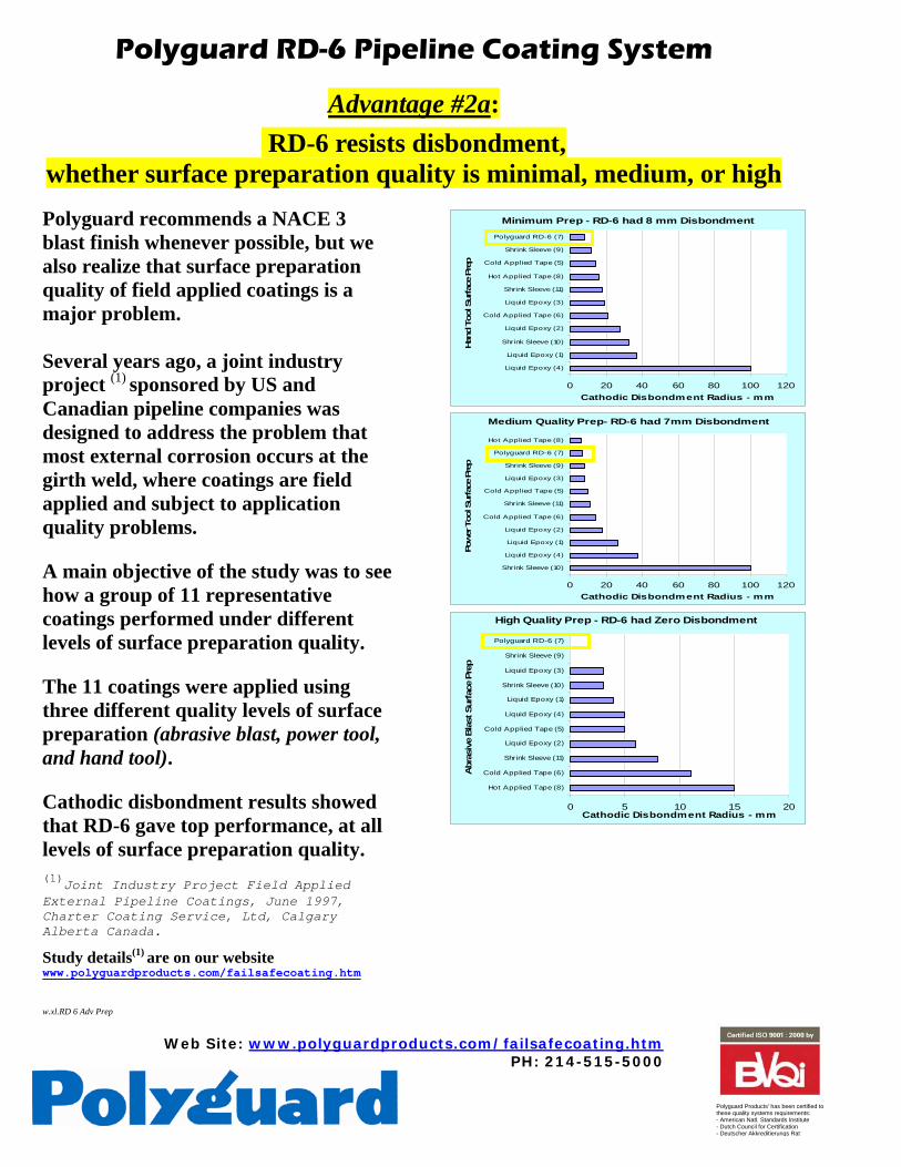
Polyguard recommends a NACE 3 blast finish whenever possible, but we also realize that surface preparation quality of field applied coatings is a major problem. Several years ago, a joint industry project (1) sponsored by US and Canadian pipeline companies was designed to address the problem that most external corrosion occurs at the girth weld, where coatings are field applied and subject to application quality problems. A main objective of the study was to see how a group of 11 representative coatings performed under different levels of surface preparation quality. The 11 coatings were applied using three different quality levels of surface preparation (abrasive blast, power tool, and hand tool). Cathodic disbondment results showed that RD-6 gave top performance, at all levels of surface preparation quality.
(1)Joint Industry Project Field Applied External Pipeline Coatings, June 1997, Charter Coating Service, Ltd, Calgary Alberta Canada.
Study details(1) are on our website www.polyguardproducts.com/failsafecoating.htm w.xl.RD 6 Adv Prep
Minimum Prep - RD-6 had 8 mm Disbondment
0 20 40 60 80 100 120
Liquid Epoxy (4)
Liquid Epoxy (1)
Shrink Sleeve (10)
Liquid Epoxy (2)
Cold Applied Tape (6)
Liquid Epoxy (3)
Shrink Sleeve (11)
Hot Applied Tape (8)
Cold Applied Tape (5)
Shrink Sleeve (9)
Polyguard RD-6 (7)
Han
d To
ol S
urfa
ce P
rep
Cathodic Disbondment Radius - mm Medium Quality Prep- RD-6 had 7mm Disbondment
0 20 40 60 80 100 120
Shrink Sleeve (10)
Liquid Epoxy (4)
Liquid Epoxy (1)
Liquid Epoxy (2)
Cold Applied Tape (6)
Shrink Sleeve (11)
Cold Applied Tape (5)
Liquid Epoxy (3)
Shrink Sleeve (9)
Polyguard RD-6 (7)
Hot Applied Tape (8)
Pow
er T
ool S
urfa
ce P
rep
Cathodic Disbondment Radius - mm
High Quality Prep - RD-6 had Zero Disbondment
0 5 10 15 20
Hot Applied Tape (8)
Cold Applied Tape (6)
Shrink Sleeve (11)
Liquid Epoxy (2)
Cold Applied Tape (5)
Liquid Epoxy (4)
Liquid Epoxy (1)
Shrink Sleeve (10)
Liquid Epoxy (3)
Shrink Sleeve (9)
Polyguard RD-6 (7)
Abr
asiv
e B
last
Sur
face
Pre
p
Cathodic Disbondment Radius - mm
Web Site:www.polyguardproducts.com/failsafecoating.htm PH: 214-515-5000
Polyguard Products' has been certified to these quality systems requirements: - American Natl. Standards Institute - Dutch Council for Certification - Deutscher Akkreditierungs Rat
Polyguard RD-6 Pipeline Coating System
Advantage #2b RD-6 has very high resistance to soil stress
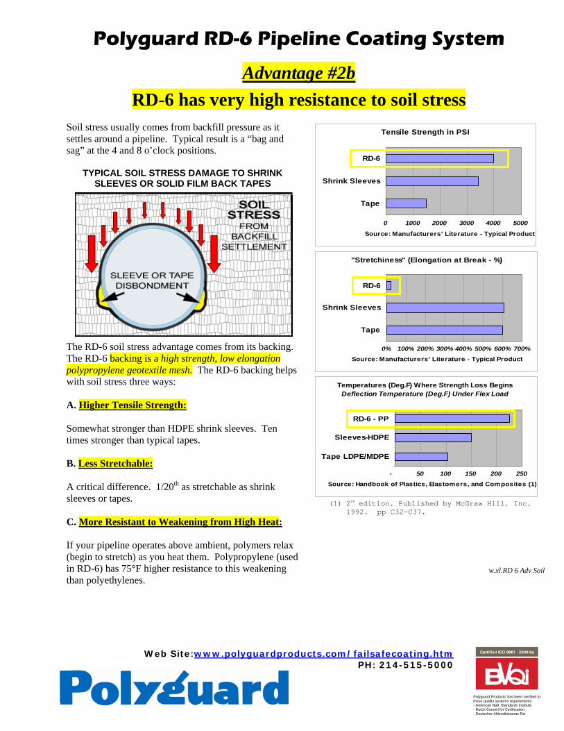
Soil stress usually comes from backfill pressure as it settles around a pipeline. Typical result is a “bag and sag” at the 4 and 8 o’clock positions.
TYPICAL SOIL STRESS DAMAGE TO SHRINK SLEEVES OR SOLID FILM BACK TAPES
The RD-6 soil stress advantage comes from its backing. The RD-6 backing is a high strength, low elongation polypropylene geotextile mesh. The RD-6 backing helps with soil stress three ways: A. Higher Tensile Strength: Somewhat stronger than HDPE shrink sleeves. Ten times stronger than typical tapes. B. Less Stretchable: A critical difference. 1/20th as stretchable as shrink sleeves or tapes. C. More Resistant to Weakening from High Heat: If your pipeline operates above ambient, polymers relax (begin to stretch) as you heat them. Polypropylene (used in RD-6) has 75°F higher resistance to this weakening than polyethylenes.
Tensile Strength in PSI
0 1000 2000 3000 4000 5000
Tape
Shrink Sleeves
RD-6
Source: Manufacturers' Literature - Typical Product
"Stretchiness" (Elongation at Break - %)
0% 100% 200% 300% 400% 500% 600% 700%
Tape
Shrink Sleeves
RD-6
Source: Manufacturers' Literature - Typical Product
Temperatures (Deg.F) Where Strength Loss Begins Deflection Temperature (Deg.F) Under Flex Load
- 50 100 150 200 250
Tape LDPE/MDPE
Sleeves-HDPE
RD-6 - PP
Source: Handbook of Plastics, Elastomers, and Composites (1)
(1) 2ND edition. Published by McGraw Hill, Inc.
1992. pp C32-C37.
w.xl.RD 6 Adv Soil
Web Site: www.polyguardproducts.com/failsafecoating.htm PH: 214-515-5000
Polyguard Products' has been certified to these quality systems requirements: - American Natl. Standards Institute - Dutch Council for Certification - Deutscher Akkreditierungs Rat
Polyguard RD-6 Pipeline Coating System
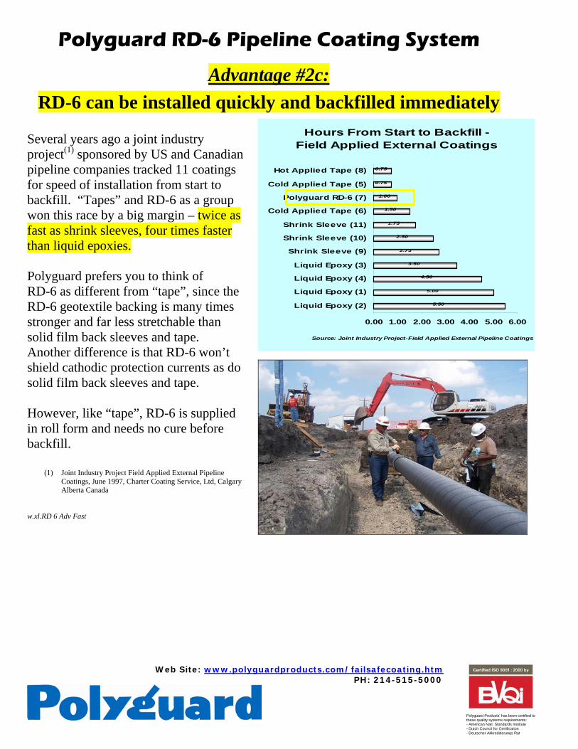
Advantage #2c: RD-6 can be installed quickly and backfilled immediately
Several years ago a joint industry project(1) sponsored by US and Canadian pipeline companies tracked 11 coatings for speed of installation from start to backfill. “Tapes” and RD-6 as a group won this race by a big margin – twice as fast as shrink sleeves, four times faster than liquid epoxies. Polyguard prefers you to think of RD-6 as different from “tape”, since the RD-6 geotextile backing is many times stronger and far less stretchable than solid film back sleeves and tape. Another difference is that RD-6 won’t shield cathodic protection currents as do solid film back sleeves and tape. However, like “tape”, RD-6 is supplied in roll form and needs no cure before backfill.
(1) Joint Industry Project Field Applied External Pipeline Coatings, June 1997, Charter Coating Service, Ltd, Calgary Alberta Canada
w.xl.RD 6 Adv Fast
Hours From Start to Backfill - Field Applied External Coatings
5.50
5.00
4.50
3.50
2.75
2.50
1.75
1.50
1.00
0.75
0.75
0.00 1.00 2.00 3.00 4.00 5.00 6.00
Liquid Epoxy (2)
Liquid Epoxy (1)
Liquid Epoxy (4)
Liquid Epoxy (3)
Shrink Sleeve (9)
Shrink Sleeve (10)
Shrink Sleeve (11)
Cold Applied Tape (6)
Polyguard RD-6 (7)
Cold Applied Tape (5)
Hot Applied Tape (8)
Source: Joint Industry Project-Field Applied External Pipeline Coatings
Web Site:www.polyguardproducts.com/failsafecoating.htm PH: 214-515-5000
Polyguard Products' has been certified to these quality systems requirements: - American Natl. Standards Institute - Dutch Council for Certification - Deutscher Akkreditierungs Rat
Polyguard RD-6 Pipeline Coating System
Advantage #3 RD-6 Is Not a Tape. (Or is it?)
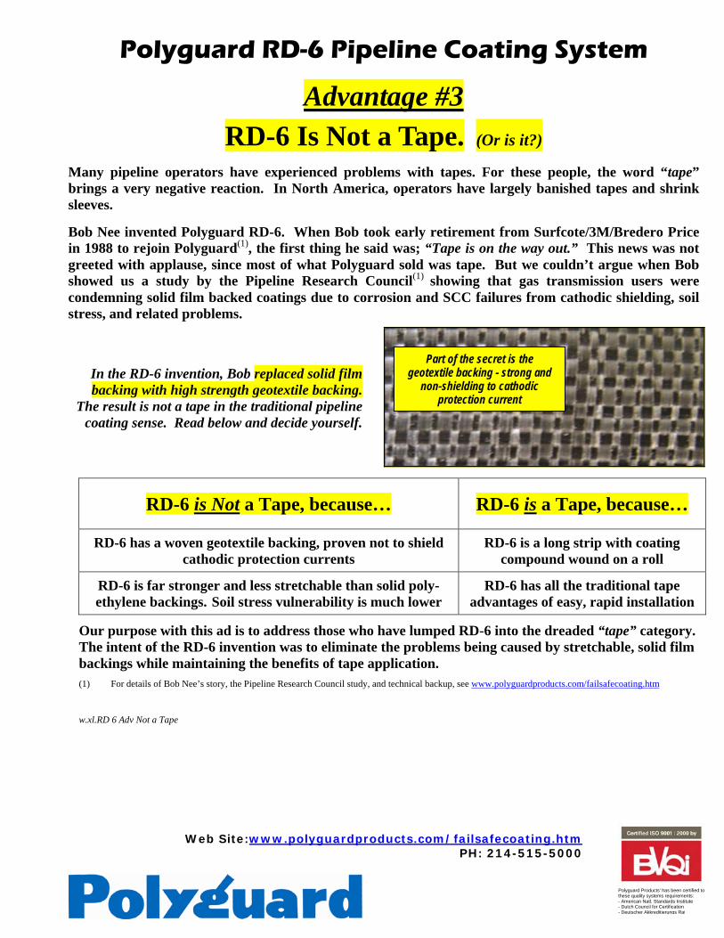
Many pipeline operators have experienced problems with tapes. For these people, the word “tape” brings a very negative reaction. In North America, operators have largely banished tapes and shrink sleeves. Bob Nee invented Polyguard RD-6. When Bob took early retirement from Surfcote/3M/Bredero Price in 1988 to rejoin Polyguard(1), the first thing he said was; “Tape is on the way out.” This news was not greeted with applause, since most of what Polyguard sold was tape. But we couldn’t argue when Bob showed us a study by the Pipeline Research Council(1) showing that gas transmission users were condemning solid film backed coatings due to corrosion and SCC failures from cathodic shielding, soil stress, and related problems.
In the RD-6 invention, Bob replaced solid film backing with high strength geotextile backing.
The result is not a tape in the traditional pipeline coating sense. Read below and decide yourself.
RD-6 is Not a Tape, because… RD-6 is a Tape, because…
RD-6 has a woven geotextile backing, proven not to shield cathodic protection currents
RD-6 is a long strip with coating compound wound on a roll
RD-6 is far stronger and less stretchable than solid poly-ethylene backings. Soil stress vulnerability is much lower
RD-6 has all the traditional tape advantages of easy, rapid installation
Our purpose with this ad is to address those who have lumped RD-6 into the dreaded “tape” category. The intent of the RD-6 invention was to eliminate the problems being caused by stretchable, solid film backings while maintaining the benefits of tape application. (1) For details of Bob Nee’s story, the Pipeline Research Council study, and technical backup, see www.polyguardproducts.com/failsafecoating.htm
w.xl.RD 6 Adv Not a Tape
Part of the secret is the geotextile backing - strong and
non-shielding to cathodic protection current
Web Site: www.polyguardproducts.com/failsafecoating.htm PH: 214-515-5000
Polyguard Products' has been certified to these quality systems requirements: - American Natl. Standards Institute - Dutch Council for Certification - Deutscher Akkreditierungs Rat
Polyguard RD-6 Pipeline Coating System Advantage #4:
RD-6 has a very long record of successful installations in the field
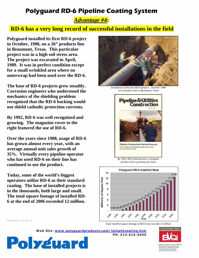
Polyguard installed its first RD-6 project in October, 1988, on a 26” products line in Beaumont, Texas. This particular project was in a high soil stress area. The project was excavated in April, 1989. It was in perfect condition except for a small wrinkled area where no outerwrap had been used over the RD-6. The base of RD-6 projects grew steadily. Corrosion engineers who understood the mechanics of the shielding problem recognized that the RD-6 backing would not shield cathodic protection currents. By 1992, RD-6 was well recognized and growing. The magazine cover to the right featured the use of RD-6. Over the years since 1988, usage of RD-6 has grown almost every year, with an average annual unit sales growth of 35%. Virtually every pipeline operator who has used RD-6 on their line has continued to use the product. Today, some of the world’s biggest operators utilize RD-6 as their standard coating. The base of installed projects is in the thousands, both large and small. The total square footage of installed RD-6 at the end of 2006 exceeded 12 million. RD6 Adv #4 - Long Track rcd
Installation of the first RD-6 project – October 1988
on a products line in Beaumont, Texas
By 1992, RD-6 had become a recognize
product with a growing user base.
Polyguard RD-6 Installed Base
0.010.020.050.500.971.441.952.503.10
3.754.48
5.276.15
7.057.97
9.049.91
11.1512.46
-
2
4
6
8
10
12
14
1988
1990
1992
1994
1996
1998
2000
2002
2004
2006
Year
Mill
ions
of S
quar
e Fe
et
Total installed square footage of RD-6 now exceeds 12 million
62 Pipeline & Gas Journal / October 2006 / www.pgjonline.com
hen selecting a pipeline coating, the “Fail Safe” characteristics
may be more important than other issues that are normally considered.
A “Fail Safe” coating system is defined as one that will allow cathodic protection (CP) current to pass through it to protect the substrate - not shield it - should the coating bond fail and ade-quate CP is available (Norsworthy, June 2004). Therefore, “Fail Safe” coatings will reduce or eliminate corrosion, including stress corrosion cracking (SCC), on the pipe under the coating if a bond failure occurs, water penetrates and cathodic protection is adequate.
Fusion bonded epoxy (FBE) coatings are known to be “Fail Safe.” Polyguard RD-6 is a pipeline coating system that provides “Fail Safe” properties incorporated with reduced soil stress problems and shielding problems. It has been used for more than 15 years, but the “Fail Safe” technology is just now being understood by many in the pipeline industry.
Why Fail Safe Coatings?Several corrosion technical papers refer to
this characteristic which may be called “Fail Safe,” “CP Compatible,” or “CP Friendly.” When these CP-compatible coatings degrade or groundwater contacts the pipe, the surface is still protected from corrosion and SCC because the CP current can pass through the permeable coating (King et al., 2004). It is believed that the high permeability of FBE coating to water is the reason for the appar-ently “transparent” nature of FBE coating to the cathodic protection (Ruschau, 2006). SCC has been studied extensively and has never been observed on FBE-coated pipelines in over 30 years (Neal, 2000).
What happens if the coating is not “Fail Safe”? Soil stress, poor surface preparation,
poor application techniques and selection of the wrong coating are why pipeline coatings disbond during service. When a coating system fails, the question one must ask is, will the coat-ing shield CP if the bond fails (Moore, 2000)?
Typically, if the bond (adhesion to pipe) is good, there is no water buildup between the coating and the pipe, therefore neither corro-sion nor SCC is usually a problem. Even when water permeable coatings absorb water or allow water to penetrate by other methods, the water does not present a problem as long as the coat-ing is well bonded to the pipe surface. The type of coating chosen can lead to potential pipe-line corrosion and failure if water penetrates between the coating and the pipe and the coat-ing does not have “Fail Safe” characteristics.
One “Fail Safe” CoatingThe advantages of selecting a “Fail Safe”
coating system are many. Here are the advan-tages for the woven geo-textile mesh-backed wrap system:
1. When adequate CP is present, corrosion, including SCC, is significantly reduced or elim-inated if water penetrates under the coating.
2. Field- and lab-proven “Fail Safe” proper-ties similar to FBE (Norsworthy 2004). There typically is a change in the pH to between 10 and 13 under the disbondment proving that the pipe is getting adequate CP.
3. This coating system provides an excel-lent choice for rehabilitation, girth welds and repairing pipeline coatings to provide improved pipeline integrity and safety.
4. The woven geo-textile mesh backing
is resistant to soil stress effects, especially when the complete system includes the use of unbonded (slip plane type) outer wrap.
5. Less stringent surface preparation, ease of application, easy cleanup, mixing or off ratio concerns and no cure time (no sophisti-cated equipment needed).
6. No heat required for application which is much safer for applicators and removes the problems with over- or under-heating.
7. The compound is compatible with most other pipeline coatings.
8. Because current can penetrate at the areas of disbondment, these areas can be located by the use of Direct Current Voltage Gradient (DCVG) surveys.
9. Since the coating is “Fail Safe,” the end user does not have to be as concerned about replacing the coating immediately.
10. Compatible with CP (over 15 years of test data and in-service life).
11. Resistant to microbiological attack.12. There are no known failures after over
15 years of service when proper surface prepa-ration and application were used.
13. The two occasions water has been found under this coating (once was an application problem and the other was the intentional application to a wet pipe) the pH was 10 to 11, indicating adequate CP for protection is being achieved under the disbonded area.
Is Your Pipeline Coating ‘Fail Safe’?By Richard Norsworthy, Polyguard Products, Inc.
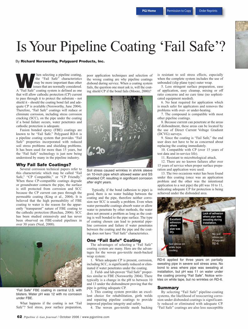
“Fail Safe” FBE coating in central U.S. with blisters. Water pH was 12 with no corrosion under FBE.
Soil stress caused wrinkles in shrink sleeve on 10-inch pipe which allowed water and SS shielded CP, resulting in significant corrosion after eight years.
RD-6 applied for three years on partially sweating pipe in severe soil stress area. No bond to area where pipe was sweating at installation, but pH was 11 on water under the coating proving “Fail Safe”. Notice wrin-kles on white tape, but no wrinkles on RD-6.
SummaryBy selecting “Fail Safe” pipeline-coating
systems, the likelihood of reoccurring corro-sion under disbonded coatings is significant-ly reduced or eliminated with adequate CP. “Fail Safe” coatings are also less susceptible
PGJ Home Permission to Copy Order Reprints
Pipeline & Gas Journal / October 2006 / www.pgjonline.com 63
f
f
t
t
d t
f
r
d
?
to SCC. Most of the intergranular failures have been on pipes coated with a coal tar primer and coal tar enamel reinforced with felt or fiber glass, although some failures have occurred with asphalt or tape-coated systems, but none with thin film (FBE) coat-ings (Parkins, 1996).
There have been other documented cases of corrosion under solid film-backed tape, shrink sleeves and other very high dielec-tric strength coatings (Ruschau, 2006, Norsworthy, 1997, Koch, 1994, Beavers & Thompson, 1997). The ability of coatings such as FBE or the geo-textile mesh strands of the RD-6 to permit CP current to penetrate to the pipe surface if disbondment occurs accounts for the higher potential and subse-quent change in pH of any water that may be
present. Therefore, the chance of significant corrosion or SCC is less likely.
Since FBE is not easily applied in the field except to girth welds, it is not con-sidered a rehabilitation coating. The alter-native is to use another coating that has been proven to be “Fail Safe” through field observations and laboratory testing. The “Fail Safe” choices are limited. At this time, few pipeline coatings have actu-ally been tested for these characteristics. Therefore the question to ask the coating vendor should be: “Has your pipeline coat-ing been proven to be Fail Safe?” P&GJ
Author: Richard Norsworthy graduated from Stephen F. Austin State University, Nacogdoches, TX with a degree in Mathematics. In 1980, he started working for Tennessee Gas Pipeline as a corrosion technician. From 1984-88 he taught the Corrosion Technology program at Kilgore College, Kilgore, TX, then worked as a Corrosion Specialist for Amoco Pipeline Co. from 1988-90. He was with Mobil Pipeline as Corrosion Control Manager from 1991-95. From 1995-2005 he was an independent corrosion consultant and then a Corrosion Specialist for Tepsco. On June 1, 2006, he started in technical sales for Polyguard Products, Inc. He is a member of several
NACE committees and is a NACE instructor for CP, Basic Corrosion and Coatings Used with Cathodic Protection.
LITERATURE: J. Beaver and N.G. Thompson, “Corrosion Beneath
Disbonded Pipeline Coatings,” Materials Performance,
April 1997, Pg.. 13.
T. Fore, K. Varughese, “First Generation of Fusion
Bonded Epoxy Coatings Performance After 30 Years
of Service--A Case Study,” CORROSION 2006, Paper
06045, pg. 3.
F. King, T. Jack, M. Kolar, and R. Worthingham,
“A Permeable Coating Model for Predicting the
Environment at the Pipe Surface Under CP-Compatible
Coatings,” CORROSION 2004, Paper 04158, pg. 1.
G. Koch, “A Test of Stress,” Oil Week, Oct. 17, 1994,
Pg. 16.
D. P. Moore, “Cathodic Shielding Can Be A Major
Problem After a Coatings Fails,” MP39, 4, 2000,
Pg. 44.
D. Neal, “Pipeline Coatings Failure – Not Always
What You Think It Is,” CORROSION 2000, Paper
00755, Pg. 5.
R. Norsworthy, “Fail Safe Tape System Used in
Conjunction with Cathodic Protection,” Materials
Performance, June 2004, Pg. 34.
R. Norsworthy, “Select Effective Pipeline Coatings,”
Hart’s Pipeline Digest, Feb. 1997, Pg. 17.
R. N. Parkins, “Stress Corrosion Cracking of
Pipelines- Its Control or Prevention,” CCORROSION
96, Paper 249.
G. R. Ruschau, “Determining the CP Shielding
Behavior of Pipeline Coatings in the Laboratory,”
CORROSION 2006, Paper 06043, pg.2.
ACKNOWLEDGMENT:Based on a presentation at NACE CORROSION 2006.
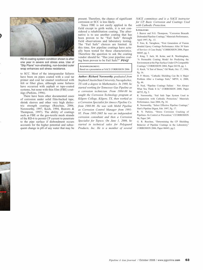
RD-6 coating system condition shown is after one year in severe soil stress area. Use of “Slip Plane” non-shielding, non-bonded outer wrap enhances soil stress resistance.


This Information is based on our best knowledge, but POLYGUARD cannot guarantee the results to be obtained.
POLYGUARD PRODUCTS, INC • ENNIS, TEXAS 75120-0755 PH: 214-515-5000 • 800-541-4994 • FAX: 972-875-9425
Web Site: www.polyguardproducts.com
Polyguard has been ISO 9000 certified since 1996. Current certifications are: - American Natl. Standards Institute - Dutch Council for Certification - Deutscher Akkreditierungs Rat
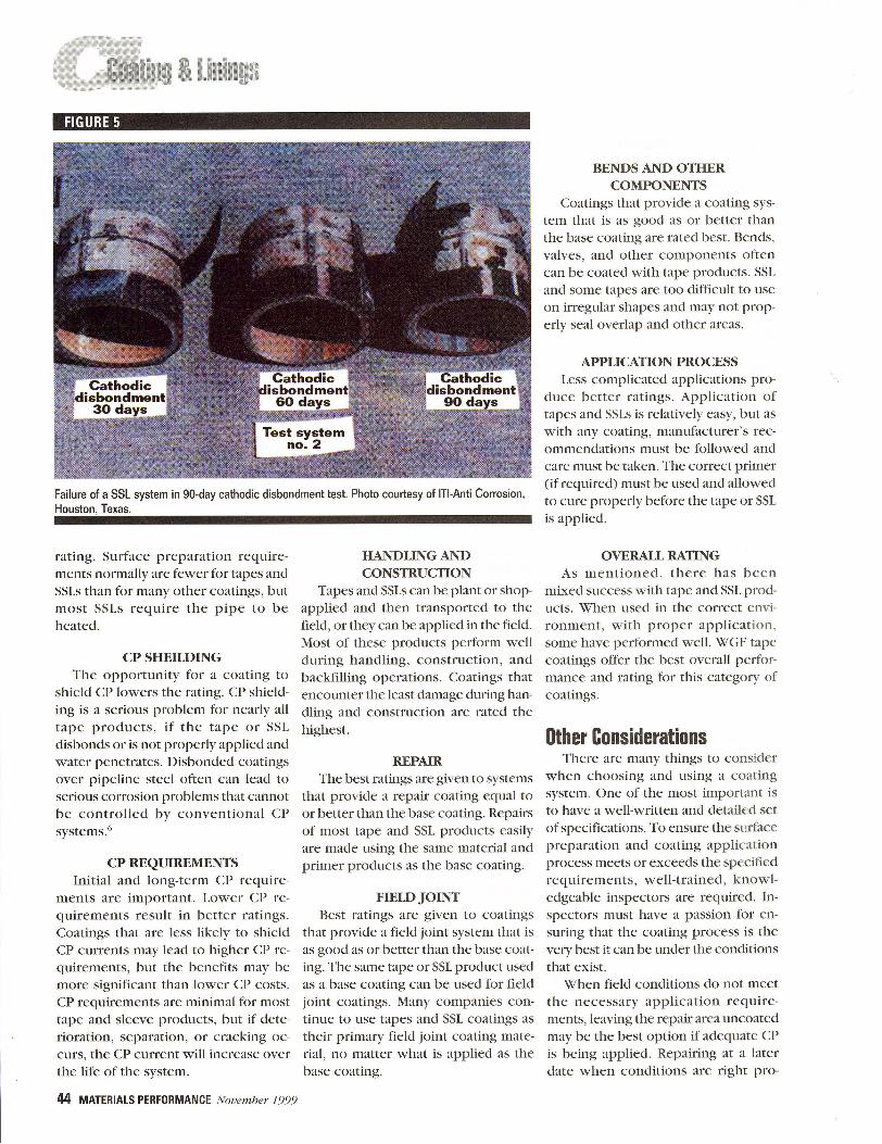
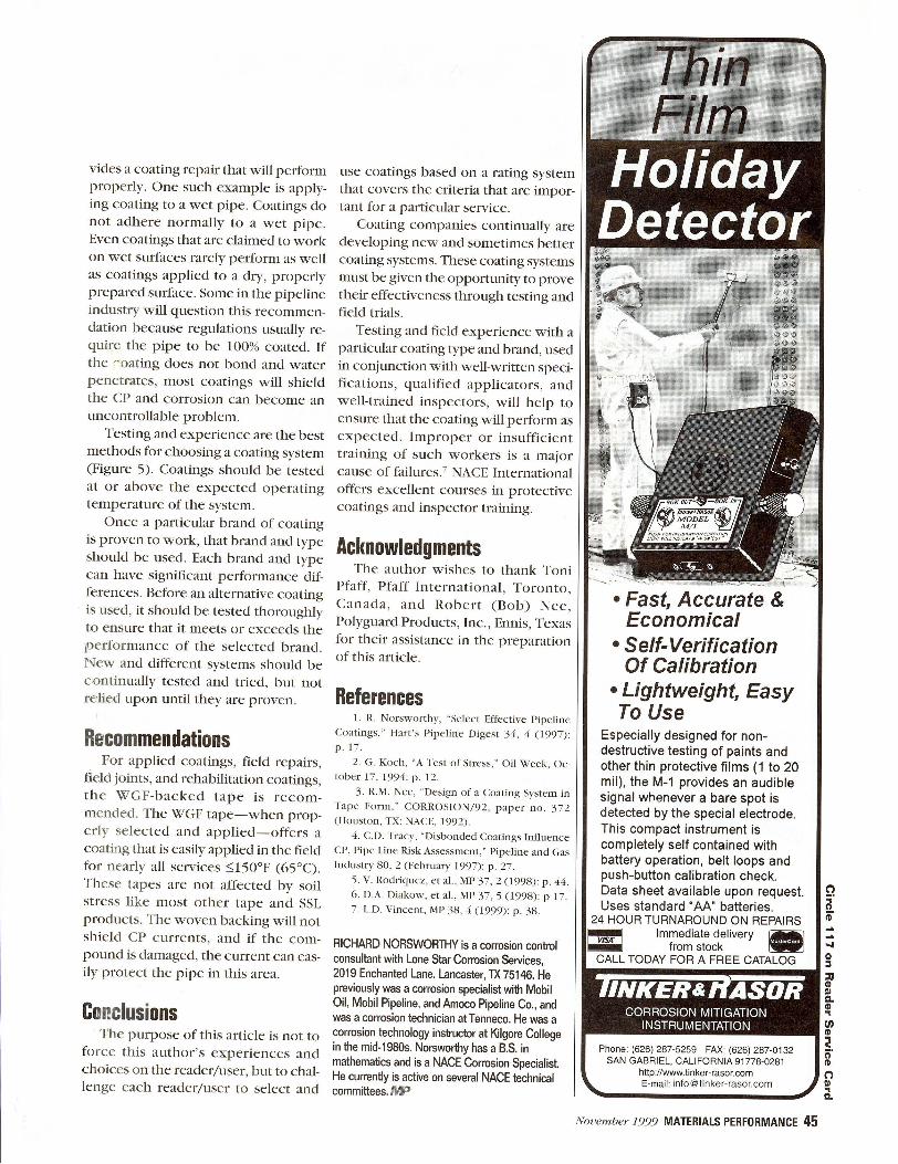
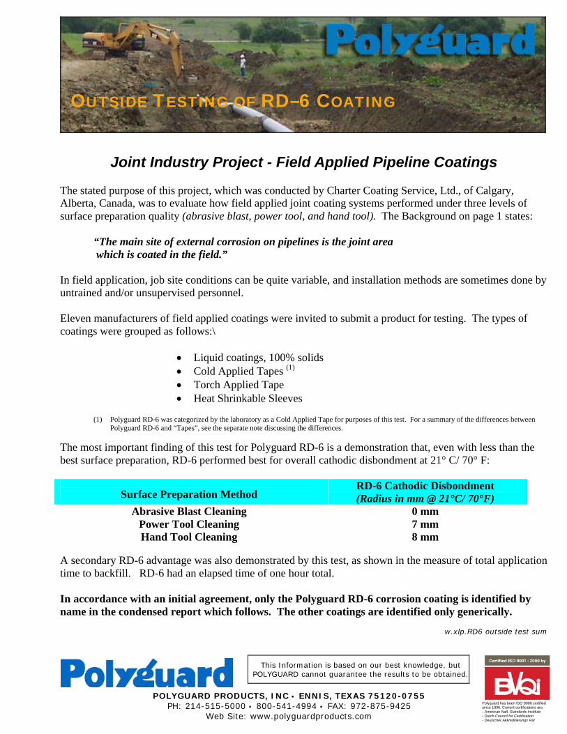
Joint Industry Project - Field Applied Pipeline Coatings The stated purpose of this project, which was conducted by Charter Coating Service, Ltd., of Calgary, Alberta, Canada, was to evaluate how field applied joint coating systems performed under three levels of surface preparation quality (abrasive blast, power tool, and hand tool). The Background on page 1 states:
“The main site of external corrosion on pipelines is the joint area which is coated in the field.”
In field application, job site conditions can be quite variable, and installation methods are sometimes done by untrained and/or unsupervised personnel. Eleven manufacturers of field applied coatings were invited to submit a product for testing. The types of coatings were grouped as follows:\
• Liquid coatings, 100% solids • Cold Applied Tapes (1) • Torch Applied Tape • Heat Shrinkable Sleeves
(1) Polyguard RD-6 was categorized by the laboratory as a Cold Applied Tape for purposes of this test. For a summary of the differences between
Polyguard RD-6 and “Tapes”, see the separate note discussing the differences.
The most important finding of this test for Polyguard RD-6 is a demonstration that, even with less than the best surface preparation, RD-6 performed best for overall cathodic disbondment at 21° C/ 70° F:
Surface Preparation Method
RD-6 Cathodic Disbondment (Radius in mm @ 21°C/ 70°F)
Abrasive Blast Cleaning 0 mm Power Tool Cleaning 7 mm Hand Tool Cleaning 8 mm
A secondary RD-6 advantage was also demonstrated by this test, as shown in the measure of total application time to backfill. RD-6 had an elapsed time of one hour total. In accordance with an initial agreement, only the Polyguard RD-6 corrosion coating is identified by name in the condensed report which follows. The other coatings are identified only generically.
w.xlp.RD6 outside test sum
OUTSIDE TESTING OF RD–6 COATING

FI
EL
D A
PPL
IED
PIP
EL
INE
CO
AT
ING
S - S
UM
MA
RY
OF
TE
ST R
ESU
LT
SC
oatin
g N
o./
C
oatin
g N
ame
Cat
hodi
c D
isbo
ndm
ent (
radi
us in
mm
)Im
pact
Res
ista
nce
(in-lb
s)H
ot W
ater
Soa
k(a
dhes
ion
ratin
g,1=
best
, 5=w
orst
21°C
/ 70
°FH
ot1 (°
C)
Bla
stPo
wer
tool
Han
dto
olB
last
Pow
erTo
ol21
°C
70°F
0°
C32
°F
-30°
C -2
2°F
Bla
stPo
wer
tool
Han
d to
ol
LIQ
UID
S
1/ L
iqui
d Ep
oxy
100%
Sol
ids
427
3733
9027
4843
402
55
2/ L
iqui
d Ep
oxy
100%
Sol
ids
618
2822
6515
4879
581
25
3/ L
iqui
d Ep
oxy
100%
Sol
ids
38
1923
90To
tal
3538
202
35
4/ L
iqui
d Ep
oxy
100%
Sol
ids
538
Tota
l45
90To
tal
2718
164
55
Coa
ting
Man
ufac
ture
rs
Coa
ting
No.
, Man
ufac
ture
r
1Li
quid
Epo
xy2
Liqu
id E
poxy
3Li
quid
Epo
xy4
Liqu
id E
poxy
5Ta
pe C
old
App
lied
6Ta
pe C
old
App
lied
7Po
lygu
ard
Prod
ucts
8Ta
pe T
orch
App
lied
9Sh
rink
Slee
ve10
Shrin
k Sl
eeve
11Sh
rink
Slee
ve
Coa
ting
No.
/
Coa
ting
Nam
eC
atho
dic
Dis
bond
men
t (ra
dius
in m
m)
Impa
ct R
esis
tanc
e (in
-lbs)
Shea
r R
esis
tanc
e(h
rs. t
o fa
il)Pe
el R
ate
at 2
kg
wei
ght
(mm
/min
)21
°C /
70°F
Hot
1 (°C
)
Bla
stPo
wer
tool
Han
dto
olB
last
Pow
erTo
ol21
°C
70°F
0°
C32
°F
-30°
C -2
2°F
21°C
70
°F
Hot
1 (°C
)21
°C
70°F
H
ot1 (°
C)
YJI
FBE
TA
PES
(Col
d A
pplie
d)
5/ T
ape
with
Prim
er5
1014
Mas
tic F
low
6012
313
715
80.
1in
stan
t 60
2.9
3
60 6
03.
12.
1
6/ T
ape
with
Prim
er11
1421
Mas
tic F
low
7517
116
613
92.
7in
stan
t 75
2.1
inst
ant
755.
94.
5
7/ P
olyg
uard
RD
-6 T
ape
with
Pri
mer
07
8M
astic
Flo
w65
9213
013
422
.1in
stan
t 66
<1
64
66<1
<1
TA
PES
(Hot
App
lied)
8/ T
ape
with
Prim
er15
616
3343
3448
4340
>50
0.
443
<1
30
43<1
<1
SHR
INK
SL
EE
VE
S
9/ S
leev
e w
ith P
rimer
08
1232
6560
%2
>180
>180
116
>50
2.
365
<1
53
65<1
<1
10/ S
leev
e w
ith P
rimer
340
%2
3318
80To
tal
>180
>180
>180
>50
>50
80<1
1
180
<1<1
11/ S
leev
e8
1118
1680
85%
212
414
3 8
136
.25
inst
ant
802.
2
87
802.
72.
41 “
Hot
tem
pera
ture
s are
show
n in
shad
ed a
reas
for e
ach
test
.2 P
ropo
rtion
of t
est a
rea
disb
onde
d, th
ese
area
s wer
e ex
tens
ive.
ii
FIELD APPLIED PIPELINE COATINGS - EXECUTIVE SUMMARY
A joint industry project was conducted by Charter Coating Service to examine the performance of a series ofexternal pipeline coatings that can be applied under field conditions. The eleven participants in this projectincluded both end user companies and coating suppliers. Eleven pipeline coatings were selected including:four liquid coatings; three cold applied tapes; one hot applied tape; and three shrink sleeves. Coatings wereexamined for application characteristics and for performance in a number of tests that simulate stressesimposed on pipeline coatings in service. The coatings were examined over different substrates includingdifferent standards of steel cleanliness and different main line coatings.
Application Characteristics:All the coatings were applied with simple equipment that could be readily transported and used in the field.A notable difference between the coatings is the requirement for preheat of the pipe in the application of theshrink sleeves. Pre-heating is not typically possible on pipelines that are in service and so this requirementrestricts the use of shrink sleeves in rehabilitation work.
The liquid coatings were the fastest to apply but required the longest time to set-up to a point where the linecould be backfilled. This set-up time can be reduced by preheat of the pipe. The liquid coatings were the easiestto examine for quality of application.
Application of the cold applied tapes was faster and easier using a wrapster. The hot applied tape requiredcareful use of a torch but was more simple to apply than the shrink sleeves. The shrink sleeves required themost skill to apply well.
Performance Characteristics:The coatings tested and their performance are shown in the table on the following page. The coatings wereexamined for resistance to: cathodic disbondment; impact damage; adhesive failure of liquid applied coatings(hot water soak, pull-off adhesion); and soil stress damage of tapes and sleeves (shear and peel resistance).Tests were conducted at varying temperatures to simulate the effects of application and service under differentambient and pipeline service conditions. Pull-off adhesion data has not been included in the Table because thepreponderance of failures were between the coatings and the pull-off load fixtures. Failures of this type do notgive true adhesion value and can be misleading.
The following notes summarize the main differences noted in the performance of the coatings in this study.
C Performance was improved by better substrate preparation in the order: abrasive blasted better than powertool cleaned better than hand tool cleaned.
C The coatings that had the least tolerance for poorer surface preparation were those that included a two-component epoxy (the liquid coatings plus). These coatings would not typically be suited for applicationwhere the substrate can only be power tool cleaned.
C Higher temperatures worsened performance characteristics of all coatings. Performance in these testsindicates that most of the coatings would not be expected to give long term protection to pipelines runningcontinuously at or near their maximum rated temperature. In selecting a coating for high temperatureservice it is important to examine the performance characteristics of the candidate coatings at the servicetemperature.
C The tapes and sleeves had higher impact resistance than the liquid coatings which would be expected sincetapes and sleeves have a deformable outer wrap. Most coatings had lower resistance to impact under coldconditions.
C Adhesion of the test products to main line coatings varied. Coatings selection should include considerationof the compatibility of the candidate coatings with the existing coatings on the pipeline.
Charter Coating Service Ltd.0300-96-01-T(Main) i
BACKGROUND
The failure of pipelines by external corrosion has caused both financial and environmentalconsequences and is also a safety hazard. Corrosion protection of pipelines is accomplished by acombination of cathodic protection and protective coatings. The coatings provide a barrier to theenvironment and the cathodic protection protects holiday or damage sites in the he coating.
The main site of external corrosion on pipelines is the joint area which is coated in the field. The steelat the junction between different pipe sections is more susceptible to corrosion because of the heataffected zone near the weld or because of the complexity of the joint system. Nevertheless, the jointarea has historically received the least amount of attention when it comes to coating application. Corrosion can occur at the joint area despite the cathodic protection because the pipe may be shieldedfrom flow of current between the coating failure and the anode. Cathodic shielding, as it is called, ismost commonly attributed to the electrical insulating properties of disbonded coating.
A problem often associated with external corrosion is stress corrosion cracking (SCC). A December1996 report by the National Energy Board (NEB) of Canada has reviewed the SCC on Canada’spipelines. The NEB report recommends a comprehensive approach to the SCC problem including theimplementation by each pipeline company of an SCC management program. The report notes thatmost of the 22 SCC related pipeline failures occurred on pipelines that were coated with polyethylenetape, a common joint coating.
Interviews with a number of companies identified a desire for a test program to evaluate field appliedexternal pipeline coatings. This study was designed to bring in a number of industry participants, bothend users and coating suppliers, in a cooperative venture. Based on a test plan developed by CharterCoating, a number of interested companies met to discuss the details of the project. Further to thismeeting a final test plan was developed. Companies that elected to participate in this project allcontributed the same amount to the project and were considered equal participants in all respects.
The test plan that was developed for this project examines characteristics of the coatings that have abearing on their long term performance in service. These characteristics include both performance andapplication characteristics since poor performance is often a result of improper application procedures. The performance tests were selected to simulate stresses encountered on buried pipelines. Tests wereconducted at both 21°C/70°F to represent cold and ambient running lines and at the maximum ratedtemperature of the selected coating systems to determine changes in performance as a result oftemperature and to evaluate the acceptability of the suppliers temperature ratings on buried lines.
The joint industry project that was developed included one coating per participant. Coatings wereselected by the participants as detailed in the Coating Selection section of this report. All tests and testconditions were specified at the introductory meeting. Products and product information were suppliedfree of charge by the coating suppliers. This study was limited to application and testing of the selectedcoating systems.
Charter Coating Service Ltd.0300-96-01-T(Main) 1
TEST PROGRAM OBJECTIVES
C Select and source a representative range of field applied external pipeline coatings.C Identify substrates commonly encountered in pipeline joint and rehabilitation coating.C Evaluate the application characteristics of the selected coating systems.C Record the different temperature requirements for application of the coatings.C Compare performance of coatings applied to different surface preparations of steel pipe.C Determine performance of the coatings at both 21°C/70°F and at the maximum rated
temperatures for the coatings.C Measure impact resistance of the coatings at varying temperatures.C Examine and compare adhesion of the coatings to the different substrates.C Evaluate shear resistance of tape and sleeve coatings.
COATING SELECTION
Coating selection was based on discussion between the participants that were present at the introductorymeeting so as to result in the desired mix of coating systems. Each participant selected one coating forthe study. The final decision as to the coatings used was at the discretion of the participant thatsponsored the selected product. The coatings selected represent a broad range of tried and tested orrecently introduced products from a number of generic coating types.
Charter Coating Service Ltd.0300-96-01-T(Main) 3
SUMMARY OF TEST PROGRAM
Application Characteristics
The different generic types of coating were compared to determine the strengths of each of the systems.Application characteristics of the coating systems were evaluated for:
- ease of application- equipment requirements- required temperatures- speed of application- speed of set-up (time to backfill)- safety aspects of the applications- ease of inspection (can defects be easily detected?)- tendency of tent over welds- likelihood of channelling within the coating
The components within each coating system are noted together with any preheating that was used. Allcoatings were applied either by or in the presence of representatives of the coating suppliers.
The coatings were applied to a variety of substrates. These substrates included prepared pipe and mainline coatings to simulate the environments at joints, tie-ins, risors and repair areas. Surface preparationmethods included hand tool, power tool, and abrasive blasting.
Details of application characteristics are in the Application Section of this report.
Charter Coating Service Ltd.0300-96-01-T(Main) 4
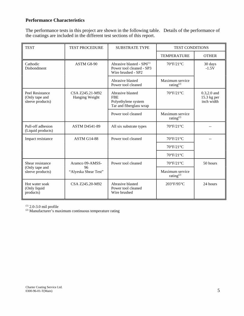
Performance Characteristics
The performance tests in this project are shown in the following table. Details of the performance ofthe coatings are included in the different test sections of this report.
TEST TEST PROCEDURE SUBSTRATE TYPE TEST CONDITIONS
TEMPERATURE OTHER
CathodicDisbondment
ASTM G8-90 Abrasive blasted - SP6(1)
Power tool cleaned - SP3Wire brushed - SP2
70°F/21°C 30 days-1.5V
Abrasive blastedPower tool cleaned
Maximum servicerating(2)
Peel Resistance(Only tape andsleeve products)
CSA Z245.21-M92Hanging Weight
Abrasive blastedFBEPolyethylene systemTar and fiberglass wrap
70°F/21°C 0.3,2.0 and15.3 kg perinch width
Power tool cleaned Maximum servicerating(2)
Pull-off adhesion(Liquid products)
ASTM D4541-89 All six substrate types 70°F/21°C --
Impact resistance ASTM G14-88 Power tool cleaned 70°F/21°C --
70°F/21°C
70°F/21°C
Shear resistance(Only tape andsleeve products)
Aramco 09-AMSS-96
“Alyeska Shear Test”
Power tool cleaned 70°F/21°C 50 hours
Maximum servicerating(2)
Hot water soak(Only liquidproducts)
CSA Z245.20-M92 Abrasive blastedPower tool cleanedWire brushed
203°F/95°C 24 hours
(1) 2.0-3.0 mil profile(2) Manufacturer’s maximum continuous temperature rating
Charter Coating Service Ltd.0300-96-01-T(Main) 5
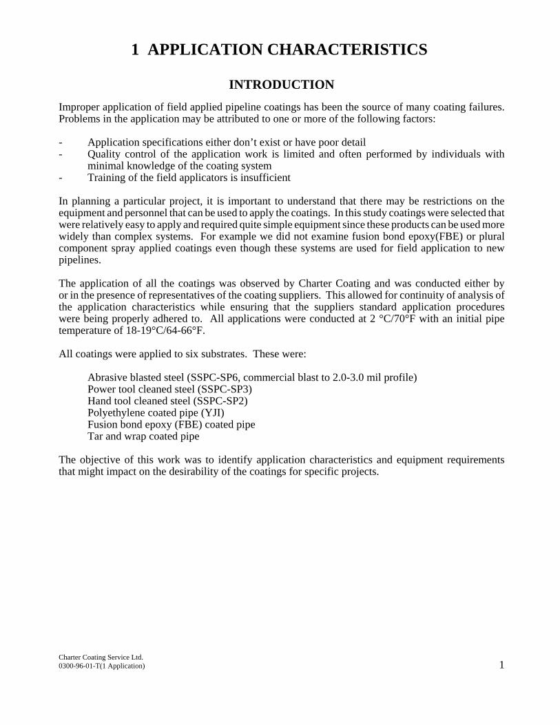
1 APPLICATION CHARACTERISTICS
INTRODUCTION
Improper application of field applied pipeline coatings has been the source of many coating failures.Problems in the application may be attributed to one or more of the following factors:
- Application specifications either don’t exist or have poor detail- Quality control of the application work is limited and often performed by individuals with
minimal knowledge of the coating system- Training of the field applicators is insufficient
In planning a particular project, it is important to understand that there may be restrictions on theequipment and personnel that can be used to apply the coatings. In this study coatings were selected thatwere relatively easy to apply and required quite simple equipment since these products can be used morewidely than complex systems. For example we did not examine fusion bond epoxy(FBE) or pluralcomponent spray applied coatings even though these systems are used for field application to newpipelines.
The application of all the coatings was observed by Charter Coating and was conducted either byor in the presence of representatives of the coating suppliers. This allowed for continuity of analysis ofthe application characteristics while ensuring that the suppliers standard application procedureswere being properly adhered to. All applications were conducted at 2 °C/70°F with an initial pipetemperature of 18-19°C/64-66°F.
All coatings were applied to six substrates. These were:
Abrasive blasted steel (SSPC-SP6, commercial blast to 2.0-3.0 mil profile)Power tool cleaned steel (SSPC-SP3)Hand tool cleaned steel (SSPC-SP2)Polyethylene coated pipe (YJI)Fusion bond epoxy (FBE) coated pipeTar and wrap coated pipe
The objective of this work was to identify application characteristics and equipment requirementsthat might impact on the desirability of the coatings for specific projects.
Charter Coating Service Ltd.0300-96-01-T(1 Application) 1
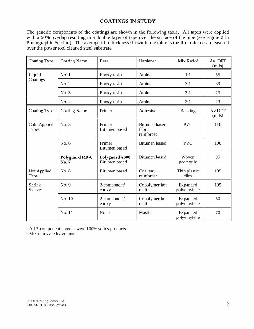
COATINGS IN STUDY
The generic components of the coatings are shown in the following table. All tapes were appliedwith a 50% overlap resulting in a double layer of tape over the surface of the pipe (see Figure 2 inPhotographic Section). The average film thickness shown in the table is the film thickness measuredover the power tool cleaned steel substrate.
Coating Type Coating Name Base Hardener Mix Ratio2 Av. DFT(mils)
Liquid Coatings
No. 1 Epoxy resin Amine 1:1 55
No. 2 Epoxy resin Amine 3:1 39
No. 3 Epoxy resin Amine 3:1 23
No. 4 Epoxy resin Amine 3:1 23
Coating Type Coating Name Primer Adhesive Backing Av.DFT(mils)
Cold AppliedTapes
No. 5 Primer Bitumen based
Bitumen based,fabricreinforced
PVC 110
No. 6 PrimerBitumen based
Bitumen based PVC 100
Polyguard RD-6No. 7
Polyguard #600Bitumen based
Bitumen based Wovengeotextile
95
Hot AppliedTape
No. 8 Bitumen based Coal tar, reinforced
Thin plasticfilm
105
ShrinkSleeves
No. 9 2-component1 epoxy
Copolymer hotmelt
Expandedpolyethylene
105
No. 10 2-component1
epoxyCopolymer hotmelt
Expandedpolyethylene
60
No. 11 None Mastic Expandedpolyethylene
70
1 All 2-component epoxies were 100% solids products2 Mix ratios are by volume
Charter Coating Service Ltd.0300-96-01-T(1 Application) 2
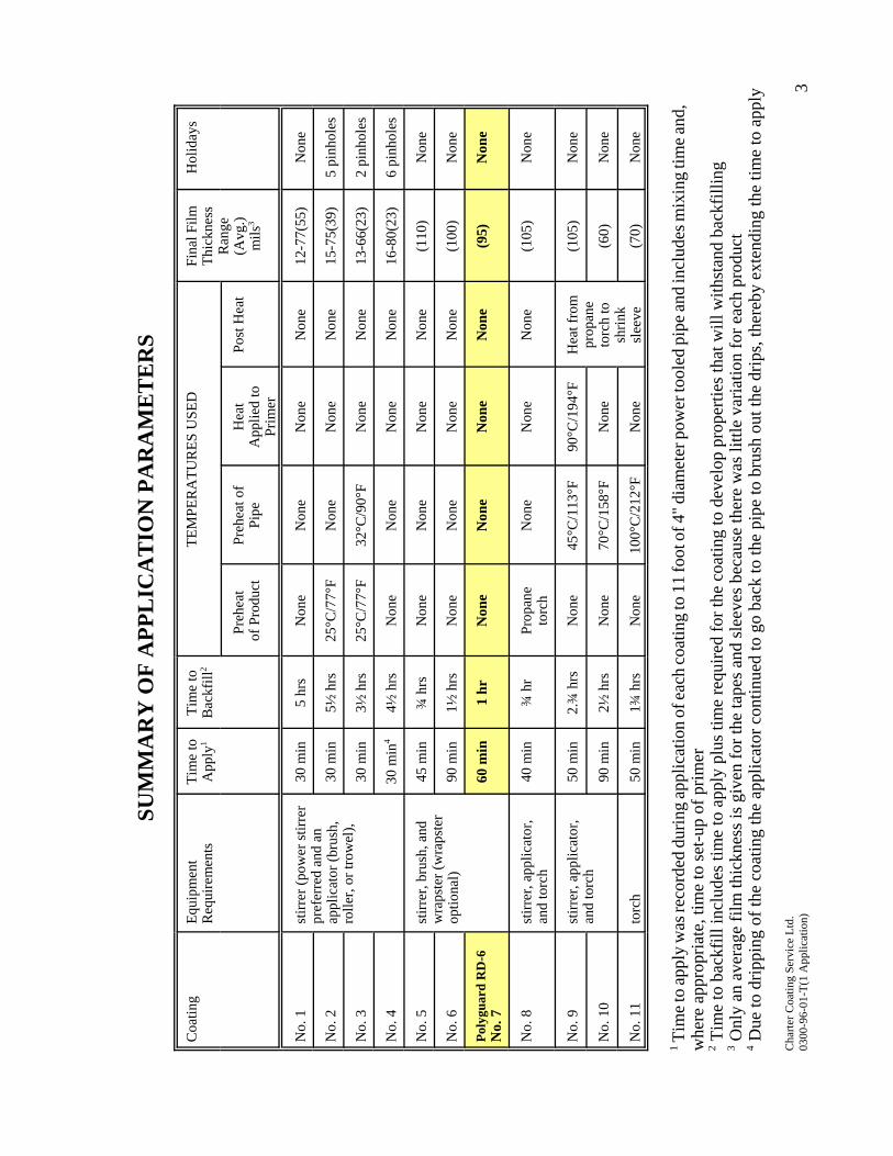
SUM
MA
RY
OF
APP
LIC
AT
ION
PA
RA
ME
TE
RS
Coa
ting
Equi
pmen
tR
equi
rem
ents
Tim
e to
App
ly1
Tim
e to
Bac
kfill
2TE
MPE
RA
TUR
ES U
SED
Fina
l Film
Thic
knes
sR
ange
(Avg
.)m
ils3
Hol
iday
s
Preh
eat
of P
rodu
ctPr
ehea
t of
Pipe
Hea
tA
pplie
d to
Prim
er
Post
Hea
t
No.
1st
irrer
(pow
er st
irrer
pref
erre
d an
d an
appl
icat
or (b
rush
,ro
ller,
or tr
owel
),
30 m
in5
hrs
Non
eN
one
Non
eN
one
12-7
7(55
)N
one
No.
230
min
5½ h
rs25
°C/7
7°F
Non
eN
one
Non
e15
-75(
39)
5 pi
nhol
es
No.
330
min
3½ h
rs25
°C/7
7°F
32°C
/90°
FN
one
Non
e13
-66(
23)
2 pi
nhol
es
No.
430
min
44½
hrs
Non
eN
one
Non
eN
one
16-8
0(23
)6
pinh
oles
No.
5st
irrer
, bru
sh, a
ndw
raps
ter (
wra
pste
rop
tiona
l)
45 m
in¾
hrs
Non
eN
one
Non
eN
one
(110
)N
one
No.
690
min
1½ h
rsN
one
Non
eN
one
Non
e(1
00)
Non
e
Poly
guar
d R
D-6
No.
760
min
1 hr
Non
eN
one
Non
eN
one
(95)
Non
e
No.
8st
irrer
, app
licat
or,
and
torc
h40
min
¾ h
rPr
opan
eto
rch
Non
eN
one
Non
e(1
05)
Non
e
No.
9st
irrer
, app
licat
or,
and
torc
h50
min
2.¾
hrs
Non
e45
°C/1
13°F
90°C
/194
°FH
eat f
rom
prop
ane
torc
h to
shrin
ksl
eeve
(105
)N
one
No.
10
90 m
in2½
hrs
Non
e70
°C/1
58°F
Non
e(6
0)N
one
No.
11
torc
h50
min
1¾ h
rsN
one
100°
C/2
12°F
Non
e(7
0)N
one
1 Tim
e to
appl
y w
as re
cord
ed d
urin
g ap
plic
atio
n of
each
coat
ing
to 1
1 fo
ot o
f 4" d
iam
eter
pow
er to
oled
pip
e and
incl
udes
mix
ing
time a
nd,
whe
re a
ppro
pria
te, t
ime
to se
t-up
of p
rimer
2 Tim
e to
bac
kfill
incl
udes
tim
e to
app
ly p
lus t
ime
requ
ired
for t
he c
oatin
g to
dev
elop
pro
perti
es th
at w
ill w
ithst
and
back
fillin
g3 O
nly
an a
vera
ge fi
lm th
ickn
ess i
s giv
en fo
r the
tape
s and
slee
ves b
ecau
se th
ere
was
littl
e va
riatio
n fo
r eac
h pr
oduc
t4 D
ue to
drip
ping
of t
he c
oatin
g th
e ap
plic
ator
con
tinue
d to
go
back
to th
e pi
pe to
bru
sh o
ut th
e dr
ips,
ther
eby
exte
ndin
g th
e tim
e to
app
ly
Cha
rter C
oatin
g Se
rvic
e Lt
d.03
00-9
6-01
-T(1
App
licat
ion)
3

THIS REPORT HAS BEEN REPRODUCED, IN ITS ENTIRETY, (WORD FOR WORD) FOR THE PURPOSE OFHIGHLIGHTING. ORIGINAL COPIES ARE AVAILABLE.
Testing of Pipeline Maintenance and RehabilitationCoatings
by R. Norsworthy
Mobil Asset Services, Dallas, Texas
The International Pipeline Monitoring & Rehabilitation Seminar
Twenty-Nine (29) different pipeline coat-ings were tested, evaluated and thenranked, based upon the results.
Tapes, shrink sleeves and brushable coat-ings were included. All Known manufac-turers were invited to submit the coating’sof their choice.
Highlighted here is what we considerpertinent information. However, readingthe complete paper provides interestingand unbiased information for those in-volved in Coating Selection.
The Polyguard RD-6 Coating Systemwas ranked number one.
The Doubletree Hotel/Post OakHouston, Texas
February 6-9, 1995
Organized by
Systems Integrityand
Pipeline & Gas Journal
128
TESTING OF PIPELINE MAINTENANCEAND REHABILITATION COATINGS
By Richard Norsworthy
February 1995
In an effort to provide information needed to determine which coatings are best suited for use in repairing orreplacing pipeline coatings during normal maintenance or rehabilitation, a test program was developed andimplemented. This testing program was designed to give specific information that isimportant for determining the best coating in the different categories tested as well as thebest types to be used in different conditions.
Many of the tests are adaptations of standard tests. Changes in these test procedureswere usually made by changing the length of the test, voltages and temperatures. Whenthere was not a suitable standard to test for parameters that were important, new testswere developed. Most of these tests were developed by using the expertise of PaulPartridge (Technical Inspection Services, Inc.) and Gary Cox (ITI Anti-Corrosion, Inc.).Paul and Gary helped to take the needs and ideas for different test parameters andadapt these into a very good test program.
One of the new cathodic disbondment (CD) test parameters involved determining how the coating performs atlongitudinal and girth welds. Each sample had a longitudinal weld and one girth weld. Asseen in some of the results, many of the failures did occur at the weld areas. Threeeights (3/8) inch holidays (larger than usual) were intentionally placed at the intersectionof the longitudinal and girth welds. Some of the tape and shrink sleeve coatings allowed waterpenetration along the weld seams. Some of the brushable coatings developed problems along the welds andnot in other areas.
Another test was developed to determine the peel resistance a coating may have when compared to othercoatings of the same type. This test could only be performed on the tape and shrink sleevecoatings. The particular test involves determining the differences of peel strength atcathodic disbondment and impact areas to find out what kind of peel strength is lost (ifany) at areas of damage. Many tape and shrink sleeve manufacturers make claims thattheir products “self heal” when minor damage occurs, but is the integrity of the coatingbond in these areas as good as before the damage? This condition will be referred toas the “weakened bond radius” and will be determined by comparison to the averagepeel strength on the original coating. The average “weakened bond radius” wasconsidered to be cathodic disbondment or water permeation.

129
Pull off tests were performed on all the brushable coatings to determine the extent ofadhesion. Most results were good with one or two being exceptional. The cathodicdisbondment area was easier to identify with these coatings. A problem did develop onsome of the mor brittle coatings that kept chipping past the CD ring. However sincethere was good adhesion, no metal corrosion or water penetration in these areas, thiswas not considered to be further failure.
The tensile and tear properties of the tapes and shrink sleeves were compared before and after approximately3000 hours in the prohesion exposure equipment. This test was to determine what changes are seen in thesecoatings after they have been exposed to burial conditions. The break strength and percentelongation at break were also used to determine what coatings would perform best in soil stresssituations. The best ratings were given to those coatings that had a high break strength and the least amountof elongation. Some coatings actually showed an improvement in these properties after theprohesion exposure.
The attached information will give the basic information for the test program and anexample of how the results were distributed. All participating company names have beendeleted and generic descriptions used for each coating type. Of course for Mobil’s use,this information was included.
Plans are to continue this test program on an annual basis or at least at times when thereare enough new or different coatings to test. By reusing the same testing labs and testparameters, a continual updating process will exist. This gives the opportunity to lookat existing coating technology as well as new coating systems that are being developed.After comparing the results, pipeline repair and rehabilitation coatings can be selectedon a basis of tests and performance, not just cost or popularity.
I would like to thank each participating company, both testing labs and each of you forsupport and help during this program.
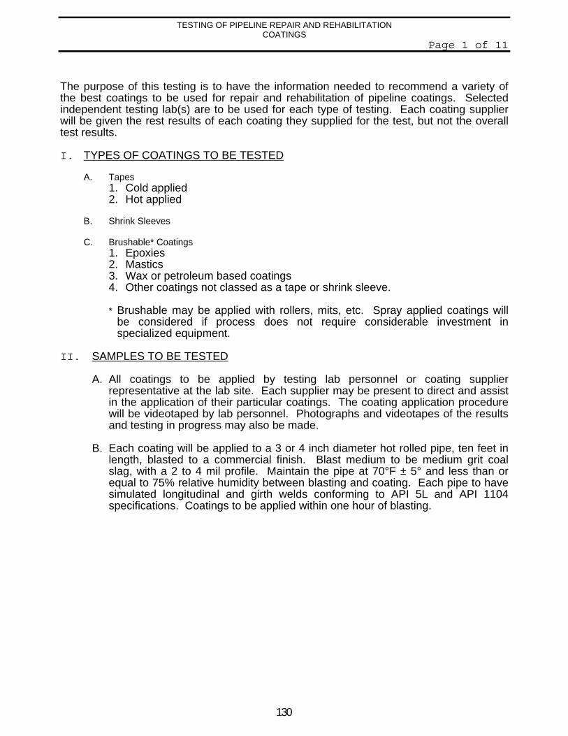
130
TESTING OF PIPELINE REPAIR AND REHABILITATIONCOATINGS
Page 1 of 11
The purpose of this testing is to have the information needed to recommend a variety ofthe best coatings to be used for repair and rehabilitation of pipeline coatings. Selectedindependent testing lab(s) are to be used for each type of testing. Each coating supplierwill be given the rest results of each coating they supplied for the test, but not the overalltest results.
I. TYPES OF COATINGS TO BE TESTED
A. Tapes1. Cold applied2. Hot applied
B. Shrink Sleeves
C. Brushable* Coatings1. Epoxies2. Mastics3. Wax or petroleum based coatings4. Other coatings not classed as a tape or shrink sleeve.
* Brushable may be applied with rollers, mits, etc. Spray applied coatings willbe considered if process does not require considerable investment inspecialized equipment.
II. SAMPLES TO BE TESTED
A. All coatings to be applied by testing lab personnel or coating supplierrepresentative at the lab site. Each supplier may be present to direct and assistin the application of their particular coatings. The coating application procedurewill be videotaped by lab personnel. Photographs and videotapes of the resultsand testing in progress may also be made.
B. Each coating will be applied to a 3 or 4 inch diameter hot rolled pipe, ten feet inlength, blasted to a commercial finish. Blast medium to be medium grit coalslag, with a 2 to 4 mil profile. Maintain the pipe at 70°F ± 5° and less than orequal to 75% relative humidity between blasting and coating. Each pipe to havesimulated longitudinal and girth welds conforming to API 5L and API 1104specifications. Coatings to be applied within one hour of blasting.
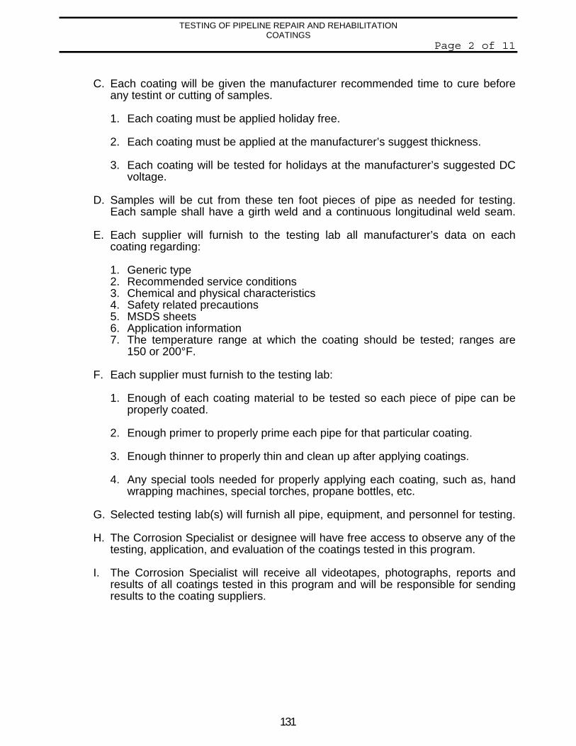
131
TESTING OF PIPELINE REPAIR AND REHABILITATIONCOATINGS
Page 2 of 11
C. Each coating will be given the manufacturer recommended time to cure beforeany testint or cutting of samples.
1. Each coating must be applied holiday free.
2. Each coating must be applied at the manufacturer’s suggest thickness.
3. Each coating will be tested for holidays at the manufacturer’s suggested DCvoltage.
D. Samples will be cut from these ten foot pieces of pipe as needed for testing.Each sample shall have a girth weld and a continuous longitudinal weld seam.
E. Each supplier will furnish to the testing lab all manufacturer’s data on eachcoating regarding:
1. Generic type2. Recommended service conditions3. Chemical and physical characteristics4. Safety related precautions5. MSDS sheets6. Application information7. The temperature range at which the coating should be tested; ranges are
150 or 200°F.
F. Each supplier must furnish to the testing lab:
1. Enough of each coating material to be tested so each piece of pipe can beproperly coated.
2. Enough primer to properly prime each pipe for that particular coating.
3. Enough thinner to properly thin and clean up after applying coatings.
4. Any special tools needed for properly applying each coating, such as, handwrapping machines, special torches, propane bottles, etc.
G. Selected testing lab(s) will furnish all pipe, equipment, and personnel for testing.
H. The Corrosion Specialist or designee will have free access to observe any of thetesting, application, and evaluation of the coatings tested in this program.
I. The Corrosion Specialist will receive all videotapes, photographs, reports andresults of all coatings tested in this program and will be responsible for sendingresults to the coating suppliers.
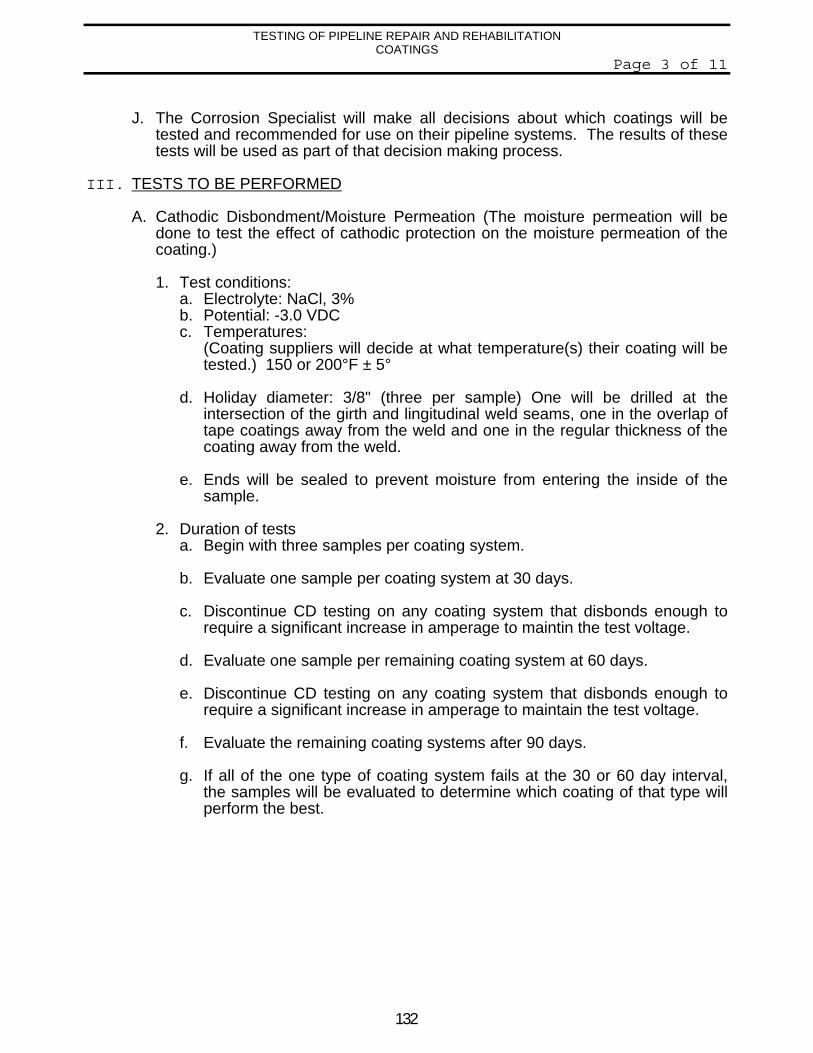
132
TESTING OF PIPELINE REPAIR AND REHABILITATIONCOATINGS
Page 3 of 11
J. The Corrosion Specialist will make all decisions about which coatings will betested and recommended for use on their pipeline systems. The results of thesetests will be used as part of that decision making process.
III. TESTS TO BE PERFORMED
A. Cathodic Disbondment/Moisture Permeation (The moisture permeation will bedone to test the effect of cathodic protection on the moisture permeation of thecoating.)
1. Test conditions:a. Electrolyte: NaCl, 3%b. Potential: -3.0 VDCc. Temperatures:
(Coating suppliers will decide at what temperature(s) their coating will betested.) 150 or 200°F ± 5°
d. Holiday diameter: 3/8" (three per sample) One will be drilled at theintersection of the girth and lingitudinal weld seams, one in the overlap oftape coatings away from the weld and one in the regular thickness of thecoating away from the weld.
e. Ends will be sealed to prevent moisture from entering the inside of thesample.
2. Duration of testsa. Begin with three samples per coating system.
b. Evaluate one sample per coating system at 30 days.
c. Discontinue CD testing on any coating system that disbonds enough torequire a significant increase in amperage to maintin the test voltage.
d. Evaluate one sample per remaining coating system at 60 days.
e. Discontinue CD testing on any coating system that disbonds enough torequire a significant increase in amperage to maintain the test voltage.
f. Evaluate the remaining coating systems after 90 days.
g. If all of the one type of coating system fails at the 30 or 60 day interval,the samples will be evaluated to determine which coating of that type willperform the best.
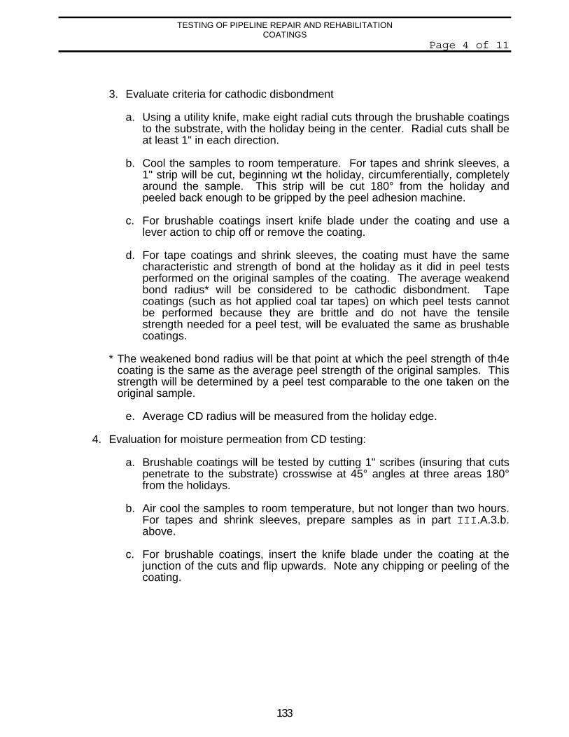
133
TESTING OF PIPELINE REPAIR AND REHABILITATIONCOATINGS
Page 4 of 11
3. Evaluate criteria for cathodic disbondment
a. Using a utility knife, make eight radial cuts through the brushable coatingsto the substrate, with the holiday being in the center. Radial cuts shall beat least 1" in each direction.
b. Cool the samples to room temperature. For tapes and shrink sleeves, a1" strip will be cut, beginning wt the holiday, circumferentially, completelyaround the sample. This strip will be cut 180° from the holiday andpeeled back enough to be gripped by the peel adhesion machine.
c. For brushable coatings insert knife blade under the coating and use alever action to chip off or remove the coating.
d. For tape coatings and shrink sleeves, the coating must have the samecharacteristic and strength of bond at the holiday as it did in peel testsperformed on the original samples of the coating. The average weakendbond radius* will be considered to be cathodic disbondment. Tapecoatings (such as hot applied coal tar tapes) on which peel tests cannotbe performed because they are brittle and do not have the tensilestrength needed for a peel test, will be evaluated the same as brushablecoatings.
* The weakened bond radius will be that point at which the peel strength of th4ecoating is the same as the average peel strength of the original samples. Thisstrength will be determined by a peel test comparable to the one taken on theoriginal sample.
e. Average CD radius will be measured from the holiday edge.
4. Evaluation for moisture permeation from CD testing:
a. Brushable coatings will be tested by cutting 1" scribes (insuring that cutspenetrate to the substrate) crosswise at 45° angles at three areas 180°from the holidays.
b. Air cool the samples to room temperature, but not longer than two hours.For tapes and shrink sleeves, prepare samples as in part III.A.3.b.above.
c. For brushable coatings, insert the knife blade under the coating at thejunction of the cuts and flip upwards. Note any chipping or peeling of thecoating.
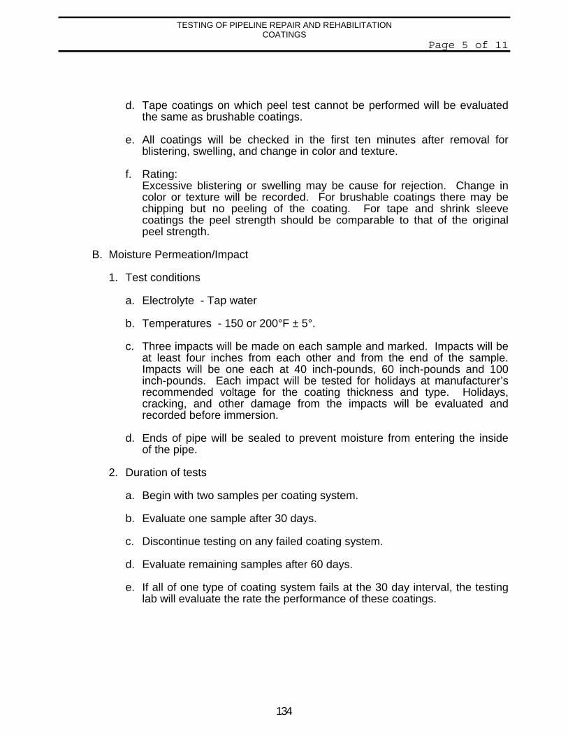
134
TESTING OF PIPELINE REPAIR AND REHABILITATIONCOATINGS
Page 5 of 11
d. Tape coatings on which peel test cannot be performed will be evaluatedthe same as brushable coatings.
e. All coatings will be checked in the first ten minutes after removal forblistering, swelling, and change in color and texture.
f. Rating:Excessive blistering or swelling may be cause for rejection. Change incolor or texture will be recorded. For brushable coatings there may bechipping but no peeling of the coating. For tape and shrink sleevecoatings the peel strength should be comparable to that of the originalpeel strength.
B. Moisture Permeation/Impact
1. Test conditions
a. Electrolyte - Tap water
b. Temperatures - 150 or 200°F ± 5°.
c. Three impacts will be made on each sample and marked. Impacts will beat least four inches from each other and from the end of the sample.Impacts will be one each at 40 inch-pounds, 60 inch-pounds and 100inch-pounds. Each impact will be tested for holidays at manufacturer’srecommended voltage for the coating thickness and type. Holidays,cracking, and other damage from the impacts will be evaluated andrecorded before immersion.
d. Ends of pipe will be sealed to prevent moisture from entering the insideof the pipe.
2. Duration of tests
a. Begin with two samples per coating system.
b. Evaluate one sample after 30 days.
c. Discontinue testing on any failed coating system.
d. Evaluate remaining samples after 60 days.
e. If all of one type of coating system fails at the 30 day interval, the testinglab will evaluate the rate the performance of these coatings.
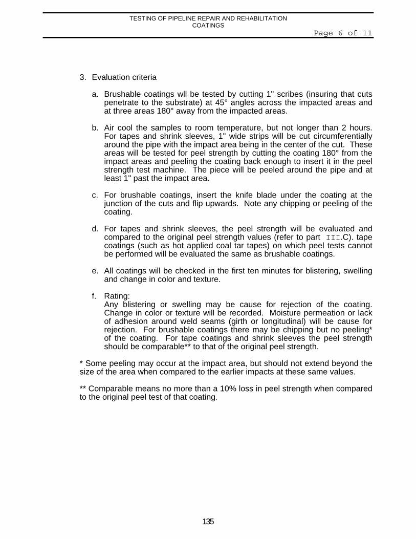
135
TESTING OF PIPELINE REPAIR AND REHABILITATIONCOATINGS
Page 6 of 11
3. Evaluation criteria
a. Brushable coatings wll be tested by cutting 1" scribes (insuring that cutspenetrate to the substrate) at 45° angles across the impacted areas andat three areas 180° away from the impacted areas.
b. Air cool the samples to room temperature, but not longer than 2 hours.For tapes and shrink sleeves, 1" wide strips will be cut circumferentiallyaround the pipe with the impact area being in the center of the cut. Theseareas will be tested for peel strength by cutting the coating 180° from theimpact areas and peeling the coating back enough to insert it in the peelstrength test machine. The piece will be peeled around the pipe and atleast 1" past the impact area.
c. For brushable coatings, insert the knife blade under the coating at thejunction of the cuts and flip upwards. Note any chipping or peeling of thecoating.
d. For tapes and shrink sleeves, the peel strength will be evaluated andcompared to the original peel strength values (refer to part III.C). tapecoatings (such as hot applied coal tar tapes) on which peel tests cannotbe performed will be evaluated the same as brushable coatings.
e. All coatings will be checked in the first ten minutes for blistering, swellingand change in color and texture.
f. Rating:Any blistering or swelling may be cause for rejection of the coating.Change in color or texture will be recorded. Moisture permeation or lackof adhesion around weld seams (girth or longitudinal) will be cause forrejection. For brushable coatings there may be chipping but no peeling*of the coating. For tape coatings and shrink sleeves the peel strengthshould be comparable** to that of the original peel strength.
* Some peeling may occur at the impact area, but should not extend beyond thesize of the area when compared to the earlier impacts at these same values.
** Comparable means no more than a 10% loss in peel strength when comparedto the original peel test of that coating.
136
TESTING OF PIPELINE REPAIR AND REHABILITATIONCOATINGS
Page 7 of 11
C. Peel Test - Tape Coatings and Shrink Sleeves
1. Test conditions
a. Cured coatings
b. Temperature of sample - all samples tested at ambient (roomtemperature).
c. The 200°F test samples will also be peel tested at a substratetemperature of no less than 170°F.
d. Same apparatus to be used for all peel tests including CD and moisturepermeation tests.
2. Test procedure
a. Cut two 1" wide strips circumferentially around the pipe.
b. Cut the strip and peel the coating back enough to attach it to the peel testapparatus.
c. Attach peel test apparatus.
d. The strips will all be pulled at the same rate of inches per minute (to bedetermined by the testing lab).
3. Rating/Evaluation
a. These test results will be used for comparison values for the CD andmoisture permeation tests.
b. The results will be given in a value that can be used for ranking eachcoating according to peel strength.
D. Impact Testing
1. Test conditions
a. Cured coatings
b. Temperature of sample - all samples tested at ambient (roomtemperature).
137
TESTING OF PIPELINE REPAIR AND REHABILITATIONCOATINGS
Page 8 of 11
c. The 200°F test samples will also be impact tested at a substratetemperature of no less than 170°F.
d. Same apparatus used for moisture permeation/impact testing.
2. Test procedure
a. Perform impact tests beginning at 20 inch-pounds and increasing by 10inch-pounds per test on each sample until the impact causes the area tofail a holiday detection test. Each impact will be performed on the coatingat an area at least one inch from previous impacts and from the end of thesample.
b. Perform impact tests of 40, 60 and 100 inch-pounds on each sample,whether failure occurs or not. These three impacts will be evaluated foruse on the moisture permeation/impact testing results.
3. Rating/Evaluation
a. Record the impact value in inch-pounds at which each sample failsholiday detection.
b. Evaluate each sample at 40, 60, and 100 inch-pounds of impact todetermine the amount and type of damage done to the coating (such asdisbonding, cracking, etc.)
c. Record results.
E. Tensile Properties of Tapes and Shrink Sleeves
1. Test conditions
a. Tapes and shrink sleeves only
b. Performed on each coating in applied form (This may require shrinksleeves to be heated, tapes to be stretched, etc.)
c. To be performed on original coating before exposure.
d. To be performed after 3,000 hours of prohesion exposure.
2. Test procedurea. Evaluate break strength and percent elongation at break.
b. Evaluate tear strength.
c. Tape to tape peel strength (adhesion at overlaps).
138
TESTING OF PIPELINE REPAIR AND REHABILITATIONCOATINGS
Page 9 of 11
2. Rating/Evaluation
a. Each coating will be rated as to break strength and percent elongation.
b. Each coating will be rated as to tear strength.
c. Each coating will be rated as to peel strength or adhesion strength atoverlaps.
F. Pull-off Test for Brushable Coatings
1. Test conditions
a. Roughen surface of coating with 60-grit sandpaper or approved method.
b. Roughen surface of an Elcometer adhesion dolly.
c. Mix and apply adhesive in thin film to both the pipe surface and dollysurface.
d. Sprinkle #4 sand on the epoxy on both surfaces.
e. Apply dolly to coating and press firmly, avoid trapping air.
f. Allow to cure 12 hours at 100°F to 150°F.
g. Cool to room temperature (approx. 72°F).
h. Attach to tensile machine and pull off at a rate of one inch per minute.
3. Rating/Evaluation
a. Record maximum load at failure.
b. Note type and location of failure.
c. Rate each coating as to pull-off strength.
*** For 200°F coatings, an attempt will be made to perform the adhesion testwhen the substrate is no less than 170°F.
Any changes or deviations in this testing program shall be approved by the CorrosionSpecialist shown below. In some cases, equpment or procedures may have to bechanged or may not be available as described in the above specifications. Any changesor deviations shall be made before testing begins.
139
TESTING OF PIPELINE REPAIR AND REHABILITATIONCOATINGS
Page 10 of 11
The testing lab must furnish an evaluation report for each coating that includes, but is notlimited to the following:
1. Comments on eacse of application.2. Procedure followed for each application.3. Procedure for surface preparation.4. Manufacturer’s datea for each coating.5. List of materials supplied by each coating supplier.6. Results and procedure of each test performed.7. Additional comments about each coating and test parameters that may help with
future testing programs or proper use of the coating.8. All results shall be sent to the Corrosion Specialist listed below by an agreed
upon date.
All reports, additional information or questions should be directed to:
(Corrosion Specialist Name and address)
TESTING LABS AND COSTS
As indicated by the previous test procedures, this testing may be more stringent thansome testing that has been done in the past. Please review these procedures, costs andrequirements before submitting any coating for testing. This information will be used toselect field applied repair and rehabilitation pipeline coatings for the future.
The following indepedent testing lab has been chosen for testing all tape coatngs (hotand cold applied) and all shrink sleeves:
ITI Anti-Corrosion, Inc.10175 HarwinSuite 110Houston, TX. 77036Telephone (713) 771-0688Fax: (713) 776-9634
140
TESTING OF PIPELINE REPAIR AND REHABILITATIONCOATINGS
Page 11 of 11
The following indepedent testing lab has been chosen for testing all brushable coatings,wax type coatings and coatings that can not be tested as described for tapes and shrinkssleeves:
TECHNICAL INSPECTION SERVICES, INC.5202 South ShaverHouston, TX. 77034Telephone (713) 947-6630Fax: (713) 947-7796
Please contact “Corrosion Specialist - Phone Number” if your company wants toparticipate in this program.
END
141
TEST RESULTS OF PIPE LINE REPAIR & REHABILITATION COATINGSDecember, 1994AUTHOR: R. Norsworthy Page 1 of 9
TEST RESULTS OF PIPE LINE REPAIR & REHABILITATION COATINGS
INTRODUCTION
The purpose of this testing was to have the information needed to recommend a variety of the bestcoatings to be used for repairs and rehabilitation of pipeline coatings. These coatings are for normaltemperature (-20 to 150°F) underground or submersed pipelines, must be compatible with cathodicprotection, be simple to apply and withstand the environment in which they are used.
A variety of pipeline coatings have been used by industry in the past. Some of these coatings havebeen successful, others have not. A testing program evaluates the coatings that are available andeliminates those that do not meet the company standards for coatings of this type.
Twenty-nine coatings were tested as shown in the following report. A discussion about the ranking and test results of eachcoating will be latter in this report.
Since this will be an ongoing test program in which the vendors of the products pay for the cost ofthe testing, the recommended coatings should be used for repair or replacement of coatings on allburied or submerged pipelines in the organization. Other coatings that are being used should betested for comparisons to the tested coatings. Any company that promotes a coating should beencouraged to participate in future testing programs. The purpose of the continuing program is toevaluate coatings that come on the market or existing coatings that have not been tested or used.The recommended list will change and be updated after each set of tests are completed.
All referrals for testing should be made through the Corrosion Specialist. The Corrosion Specialistwill oversee the testing programs and make recommendations from the results of the tests,comparisons with other coatings that have been tested and past experiences with particular coatingsytems. Field input and experiences with particular coatings systems will be very valuableinformation in determining the recommended coatings for the future.
The generic types of coatings tested were cold and hot applied tapes, shrink sleeves, brushable(liquid) types and petrolatum tape systems.
RANKING
(Ranking - Number 1 represents the best product from the group and will be highly recommended for use in the areas indicatedin the discussion. The larger the number the lower the ranking. Those not ranked should not be used for any reason.)
COLD AND HOT APPLIED TAPES
RANKING TEST # DESCRIPTION
1 12 Primer/Outer Wrap
2 13 Primer/Weld Seam Tape
3 1 Primer/Weld Seam Tape/Inner Wrap/Outer Wrap
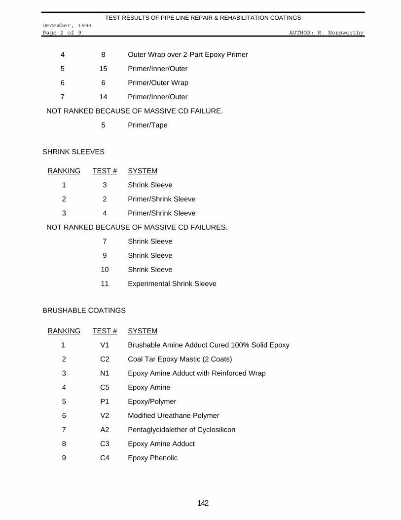
142
TEST RESULTS OF PIPE LINE REPAIR & REHABILITATION COATINGSDecember, 1994Page 2 of 9 AUTHOR: R. Norsworthy
4 8 Outer Wrap over 2-Part Epoxy Primer
5 15 Primer/Inner/Outer
6 6 Primer/Outer Wrap
7 14 Primer/Inner/Outer
NOT RANKED BECAUSE OF MASSIVE CD FAILURE.
5 Primer/Tape
SHRINK SLEEVES
RANKING TEST # SYSTEM
1 3 Shrink Sleeve
2 2 Primer/Shrink Sleeve
3 4 Primer/Shrink Sleeve
NOT RANKED BECAUSE OF MASSIVE CD FAILURES.
7 Shrink Sleeve
9 Shrink Sleeve
10 Shrink Sleeve
11 Experimental Shrink Sleeve
BRUSHABLE COATINGS
RANKING TEST # SYSTEM
1 V1 Brushable Amine Adduct Cured 100% Solid Epoxy
2 C2 Coal Tar Epoxy Mastic (2 Coats)
3 N1 Epoxy Amine Adduct with Reinforced Wrap
4 C5 Epoxy Amine
5 P1 Epoxy/Polymer
6 V2 Modified Ureathane Polymer
7 A2 Pentaglycidalether of Cyclosilicon
8 C3 Epoxy Amine Adduct
9 C4 Epoxy Phenolic
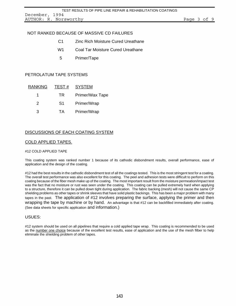
143
TEST RESULTS OF PIPE LINE REPAIR & REHABILITATION COATINGSDecember, 1994AUTHOR: R. Norsworthy Page 3 of 9
NOT RANKED BECAUSE OF MASSIVE CD FAILURES
C1 Zinc Rich Moisture Cured Ureathane
W1 Coal Tar Moisture Cured Ureathane
5 Primer/Tape
PETROLATUM TAPE SYSTEMS
RANKING TEST # SYSTEM
1 TR Primer/Wax Tape
2 S1 Primer/Wrap
3 TA Primer/Wrap
DISCUSSIONS OF EACH COATING SYSTEM
COLD APPLIED TAPES.
#12 COLD APPLIED TAPE
This coating system was ranked number 1 because of its cathodic disbondment results, overall performance, ease ofapplication and the design of the coating.
#12 had the best results in the cathodic disbondment test of all the coatings tested. This is the most stringent test for a coating.The overall test performance was also excellent for this coating. The peel and adhesion tests were difficult to perform on thiscoating because of the fiber mesh make up of the coating. The most important result from the moisture permeation/impact testwas the fact that no moisture or rust was seen under the coating. This coating can be pulled extremely hard when applyingto a structure, therefore it can be pulled down tight during application. The fabric backing (mesh) will not cause the same CPshielding problems as other tapes or shrink sleeves that have solid plastic backings. This has been a major problem with manytapes in the past. The application of #12 involves preparing the surface, applying the primer and thenwrapping the tape by machine or by hand. An advantage is that #12 can be backfilled immediately after coating.(See data sheets for specific application and information.)
USUES:
#12 system should be used on all pipelines that require a cold applied tape wrap. This coating is recommended to be usedas the number one choice because of the excellent test results, ease of application and the use of the mesh filber to helpeliminate the shielding problem of other tapes.
144
TEST RESULTS OF PIPE LINE REPAIR & REHABILITATION COATINGSDecember, 1994Page 4 of 9 AUTHOR: R. Norsworthy
#13 - PRIMER/WELD TAPE/INNER/OUTER
This coating had very good results in the cathodic disbondment tests and good overall results onthe other tests. The major disadvantage is the application because of the requirements of the seqmtape and double wrapping.
The #13 coating did very good in the CD testing. #13 also did very good in the moisturepermeation/impact testing with no moisture or rust detected under the tape. The use of the weldseam tape probably helped to prevent water penetration around the weld seams. The doublewrapping also helps from an impact standpoint. The coating can be backfilled immediately afterapplication. The coating can be applied by hand or machine, but machine would be recommendedfor large areas. The tested system involved using a primer, weld seam tape, an inner and outerwrap which could be labor intensive and provide more opportunity for error of application. The timerequired and the amount of coating used could also be more expensive.
USES:
This #13 system will be an excellent choice for areas that may have severe environmental stressand require the use of a tape wrap. This #13 system should be considered as a second choice andis recommended for use on all underground or submerged systems. This system requires use ofa primer, seam tape, and inner and outer wraps and amy be more expensive and time consumingto install.
#1 - PRIMER/WELD SEAM TAPE/INNER WRAP/OUTER WRAP
This coating system had good results on the cathodic disbondment test and good overall results onthe other tests. The major disadvantage is the application because of the requirements for seamtape and double wrapping.
The #1 tape did good in the CD test, but not as good others. The moisture permeation/impactresults were also good. The peel strength results actually improved over the 90 days, which mayindicate an improvement in peel strength with ageing. Once again the use of the weld seam tapemay have helped with the water penetration at the welds. The coating can be backfilled immediatelyafter coating. The coating can be applied by hand or machine. The tested system consisted ofusing a primer, weld seam tape, an inner wrap and an outer wrap which could be labor intensive andprovide more opportunity for error of application. The time required and the amount of coating usedcould also cause the coating to be more expensive.
USES:
This #1 system would be an alternative to the #13 system, but the test results were not as goodoverall, therefore it is not recommended to use except when the #12 or #13 systems are notavailable. Once again it requires the use of four different steps and products to complete the coatingsystem.
#8-PRIMER/OUTER WRAP
This coating had very good results on the cathodic disbondment test and good overall results on theother tests. The major disadvantage of this coating is the use of the primer which requires
145
TEST RESULTS OF PIPE LINE REPAIR & REHABILITATION COATINGSDecember, 1994AUTHOR: R. Norsworthy Page 5 of 9
considerable curing time, especially on cool damp days or cold pipe.
This #8 system did very good in the CD test and very good in the moisture permeation/impactwith no water penetration. This is a two coat system that is fairly simple to apply. The primer isbrushed on and the tape can be applied by hand or machine. The major problem with thiscoating is the cure time of the primer. During a demonstration in January, the day was rainy andcool. The primer took between one to two hours to cure enough the #8 Representatives couldapply the tape. If there is plenty of tie for curing the primer this could be a second choice to the#12.
USES:
This #8 system is recommended to be used only when there is sufficient time to allow the primerto cure properly. The application is similar to the #12 (two coats), but the test resultsd were notas good and the primer takes a long time to cure (especially on cold days or cold pipe).
THE FOLLOWING COATINGS WILL NOT BE RECOMMENDED FOR USE UNDER ANYCIRCUMSTANCES. THESE COATINGS ALL HAD POOR RESULTS ON THE CATHODICDISBONDMENT TESTS AND OVERALL LOWER RATINGS ON THE OTHER TESTS.
#15 - PRIMER/INNER WRAP/OUTER WRAP
#06 - PRIMER/OUTER WRAP
#14 - PRIMER/INNER WRAP/OUTER WRAP
THE FOLLOWING COATINGS HAD MASSIVE FAILURE IN THE CD TESTING AND WOULD NOTBE RECOMMENDED FOR ANY PURPOSE.
#5 - PRIMER/TAPE
SHRINK SLEEVES -
#3 - SHRINK SLEEVE - NO PRIMER
This shrink sleeve had excellent results on the cathodic disbondment tests and very good overallresults on the other tests. This sleeve does not require a primer and is fairly easy to apply.
The #3 shrink sleeve had excellent CD results and very good results on the other tests. Themoisture/impact results were very good with no moisture penetration or rust. Shrink sleeves areapplied with an open flame torch, require training and use of the proper equipment. The sleeveneeds to cool a few minutes before backfilling. The open flame torch can be a safety problemand requires training and use of the proper torch. Shrink sleeves may not bond well to coldpipes or inservice pipes that have cold (under 50°F) product.
146
TEST RESULTS OF PIPE LINE REPAIR & REHABILITATION COATINGSDecember, 1994Page 6 of 9 AUTHOR: R. Norsworthy
USES:
The #3 sleeve will be excellent to use on out of service or new construction pipe when the propersurface preparation and preheat can be applied to the pipe steel. The test results were excellent and thiscould be an overall second choice to the #12 tape wrap coating and may be first choice on new or out-of-service pipes. This will depend on cost and application cocnerns.
THE FOLLOWING SHRINK SLEEVES ARE NOT RECOMMENDED FOR USE BECAUSE OFMOISTURE PERMEATION PROBLEMS AND POOR CD RESULTS.
#2 - Primer/Shrink Sleeve
#4 - Primer/Shrink Sleeve
THE FOLLOWING SHRINK SLEEVES ARE NOT RECOMMENDED FOR USE UNDER ANYCIRCUMSTANCES BECAUSE OF MASSIVE CD FAILURES.
#7 - Shrink Sleeve
#9 - Shrink Sleeve
#10 - Shrink Sleeve
#11 - EXPERIMENTAL Shrink Sleeve
BRUSHABLE COATINGS -
V1 - BRUSHABLE AMINE ADDUCT CURED 100% SOLIDS EPOXY
This two part epoxy coating has very good cathodic disbondment results, overall perforamnceand is easy to apply. This coating has been used for field joints and patching on FBE andFBE/polyolefin coated pipelines for approximately two years with good results.
The CD results for this coating may be hard to evaluate because of the formulation used in thetest tended to chip easily from the steel. This may have lead the testing lab to assume thischipping was caused from CD. As the photo indicates, the CD discoloration rings are muchsmaller than those indicated in the test results. The supplier has also reformulated slightly todecrease the chipping. Moisture permeation/impact testing results were very good with nomoisture or rust under the coating. This coating had the best adhesive test results of any of thecoatings. This coating is a two part epoxy that is mixed in correct proportions and applieddirectly to the pipe steel after surface preparation. The supplier can supply this coating indifferent size containers that will eliminate the need for measuring and waste. Curing has to takeplace before backfilling. Curing time is dependent on the temperature of the pipe and air. Anadvantage of this coating over tape coating is the fact that it will not have the same shieldingcharacteristics as tapes or shrink sleeves, can be applied to irregular shapes and is erycompatible with FBE coatings.
147
TEST RESULTS OF PIPE LINE REPAIR & REHABILITATION COATINGSDecember, 1994AUTHOR: R. Norsworthy Page 7 of 9
USES:
The V1 Brushable Epoxy should be first choice for repairs, field joints and rehabilitation of FBEor FBE/polyolefin coated pipelines. This product is easy to apply and requires only one coatwithout a primer. The coating must cure before backfilling, but there are some ways to possiblyspeed up the cure or protect the uncured coating during backfilling. The time for curing will bedetermined by the pipe temperature and the air temperature. This coating could also be used forvalves and irregular shapes, especially if mostly coated ahead of time in the shop.
C2-COAL TAR EPOXY MASTIC
This coating had good results in the cathodic disbondment test and performed good in most ofthe other test. The test coating was applied in a two coat system, but could be applied in a onecoat if given enough time to cure priperly.
The results were good on the CD tests. Moisture permeation/impact test were very good with noblisters or holidays. The adhesion test results were good and impact resistance only fair. Thecuring time will be a factor in the field, but using one coat will speed up the time to backfill. Thiscoating is simple to apply in either a one coat or two coat system.
USES:
The C-2 Black Mastic will be a very good coating for use on valves and other irregular shapedcomponents. This coating should be very compatible with coal tar and asphalt coatings. Thiscoating will not cause shielding like many tape coatings. The C-2 would be a second choice tothe V1 Brushable Epoxy coating.
N1 - EPOXY AMINE ADDUCT WITH REINFORCED WRAP
N1 had very good results in nearly all the testing and might be the number one coatingrecommended if it were not for the application problems. The application is basically a threestep operation.
This coating had very good CD results and very good moisture permeation/impact results. TheN1 is a very thick coating and has the potential for causing shielding problems similar to heavytape coatings. Impact resistance is excellent because of the thickness. Adhesion is also verygood. This coating is very labor intensive and messy to apply.
USES:
N1 has potential for very agreesive environments where other coatings may have difficulties. Ifthe application problems with this coating are not a concern for a particular application this is avery good coating. When conditions allow for proper application and cure times N1 would berecommended.
C5 - EPOXY AMINE
The C5 had good results in all the tests. This system requires a primer and top coat system.
148
TEST RESULTS OF PIPE LINE REPAIR & REHABILITATION COATINGSDecember, 1994Page 8 of 9 AUTHOR: R. Norsworthy
The results of this system were similar to the V1 Brushable Epoxy. It had good CD and moisturepermeation/impact results and very good adhesion results. The major difference in the twocoatings is that the C5 requires a primer that must cure before the top coat is applied. If theapplication allowed for time to cure the primer and the top coat before backfilling this coatingcould possibly be used in the place of the V1 Brushable Epoxy.
USES:
C5 does not have the past experience with Mobil that the V1 Brushable Epoxy has at this time,therefore it will not be recommended for use except when the V1 Brushable Epoxy is notavailable.
P1 - EPOXY POLYMER
P1 IS STILL AN EXPERIMENTAL COATING, BUT HAS PROMISE FOR THE FUTURE. AT THISTIME P1 IS NOT RECOMMENDED FOR USE AS A PIPELINE COATING.
THE FOLLOWING COATINGS ARE NOT RECOMMENDED FOR USE A A PIPELINE COATINGBECAUSE OF THEIR POOR TEST RESULTS.
V2 - MODIFIED UREATHANE POLYMER
A2 - PENTAGLYCIDALETHER OF CYCLOSILICON
C3 - EPOXY AMINE ADDUCT
C4 - EPOXY PHENOLIC
C1 - ZINC RICH MOISTURE CURED UREATHANE
W1 - COAL TAR MOISTURE CURED UREATHANE
PETROLATUM TAPE SYSTEMS.
TR - WAX TAPE
TR had very good results in most of the tests. As with all petrolatum based coatings, the impactresistance was poor. The petrolatum coatings were tested at lower temperatures (75°F) than theother coatings (150°F).
TR did very good in the cathodic disbondment and mositure permeation/impact testing with nowater penetration to the pipe steel. This coating is very easy to apply and will conform wellaround irregular shapes. The prime coat of TR primer is very effective in stopping water after itis top coated with the wax tape. These type coatings do not handle heat or impacts very well. Petrolatum coatings are more forgiving than most coatings to a poor surface preparation.
USES:
TR coating is recommended for use in special cases where other coatings may not work be-cause of pipe or weather conditions (cold, wet, etc.). The wax tape can be used to coat valvesand other irregular shaped components. This coating is very easy to apply. Limitations
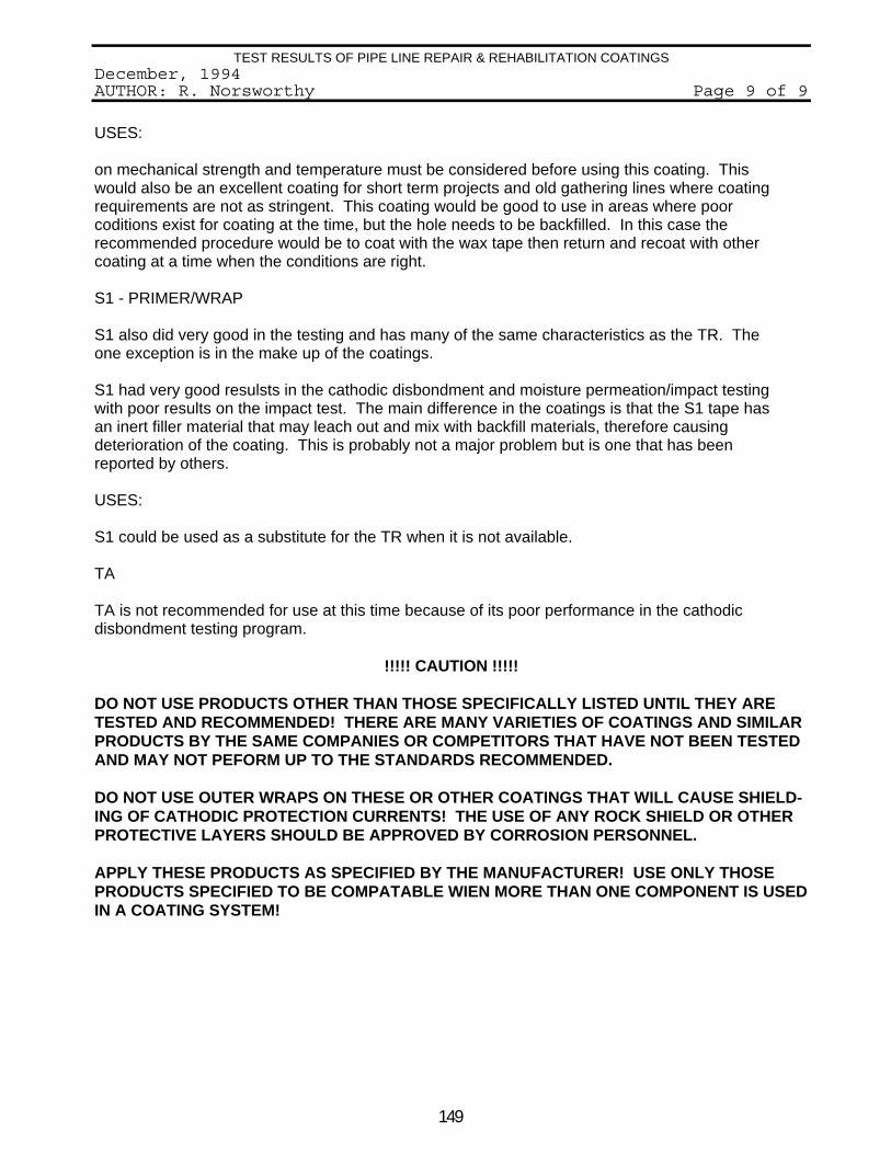
149
TEST RESULTS OF PIPE LINE REPAIR & REHABILITATION COATINGSDecember, 1994AUTHOR: R. Norsworthy Page 9 of 9
USES:
on mechanical strength and temperature must be considered before using this coating. Thiswould also be an excellent coating for short term projects and old gathering lines where coatingrequirements are not as stringent. This coating would be good to use in areas where poorcoditions exist for coating at the time, but the hole needs to be backfilled. In this case therecommended procedure would be to coat with the wax tape then return and recoat with othercoating at a time when the conditions are right.
S1 - PRIMER/WRAP
S1 also did very good in the testing and has many of the same characteristics as the TR. Theone exception is in the make up of the coatings.
S1 had very good resulsts in the cathodic disbondment and moisture permeation/impact testingwith poor results on the impact test. The main difference in the coatings is that the S1 tape hasan inert filler material that may leach out and mix with backfill materials, therefore causingdeterioration of the coating. This is probably not a major problem but is one that has beenreported by others.
USES:
S1 could be used as a substitute for the TR when it is not available.
TA
TA is not recommended for use at this time because of its poor performance in the cathodicdisbondment testing program.
!!!!! CAUTION !!!!!
DO NOT USE PRODUCTS OTHER THAN THOSE SPECIFICALLY LISTED UNTIL THEY ARETESTED AND RECOMMENDED! THERE ARE MANY VARIETIES OF COATINGS AND SIMILARPRODUCTS BY THE SAME COMPANIES OR COMPETITORS THAT HAVE NOT BEEN TESTEDAND MAY NOT PEFORM UP TO THE STANDARDS RECOMMENDED.
DO NOT USE OUTER WRAPS ON THESE OR OTHER COATINGS THAT WILL CAUSE SHIELD-ING OF CATHODIC PROTECTION CURRENTS! THE USE OF ANY ROCK SHIELD OR OTHERPROTECTIVE LAYERS SHOULD BE APPROVED BY CORROSION PERSONNEL.
APPLY THESE PRODUCTS AS SPECIFIED BY THE MANUFACTURER! USE ONLY THOSEPRODUCTS SPECIFIED TO BE COMPATABLE WIEN MORE THAN ONE COMPONENT IS USEDIN A COATING SYSTEM!

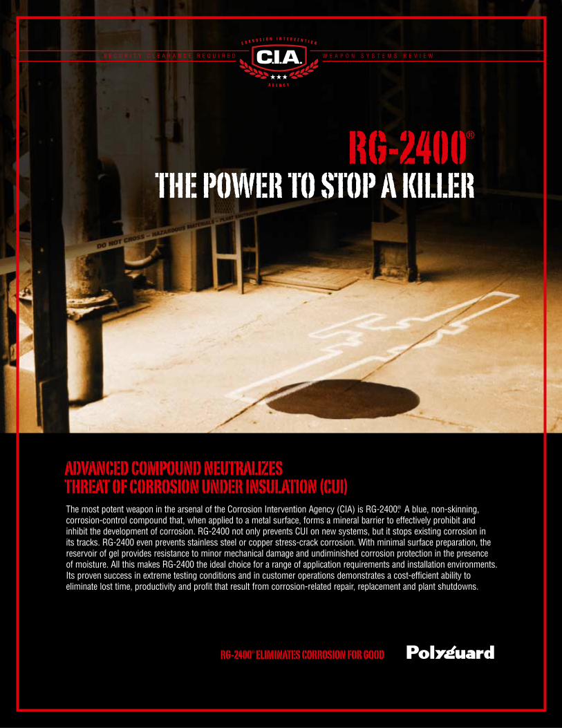
S E C U R I T Y C L E A R A N C E R E Q U I R E D W E A P O N S Y S T E M S R E V I E W
RG-2400®
THE POWER TO STOP A KILLER
RG-2400®ELIMINATES CORROSION FOR GOOD
The most potent weapon in the arsenal of the Corrosion Intervention Agency (CIA) is RG-2400®. A blue, non-skinning, corrosion-control compound that, when applied to a metal surface, forms a mineral barrier to effectively prohibit and inhibit the development of corrosion. RG-2400 not only prevents CUI on new systems, but it stops existing corrosion inits tracks. RG-2400 even prevents stainless steel or copper stress-crack corrosion. With minimal surface preparation, thereservoir of gel provides resistance to minor mechanical damage and undiminished corrosion protection in the presence of moisture. All this makes RG-2400 the ideal choice for a range of application requirements and installation environments.Its proven success in extreme testing conditions and in customer operations demonstrates a cost-efficient ability to eliminate lost time, productivity and profit that result from corrosion-related repair, replacement and plant shutdowns.
ADVANCED COMPOUND NEUTRALIZES THREAT OF CORROSION UNDER INSULATION (CUI)
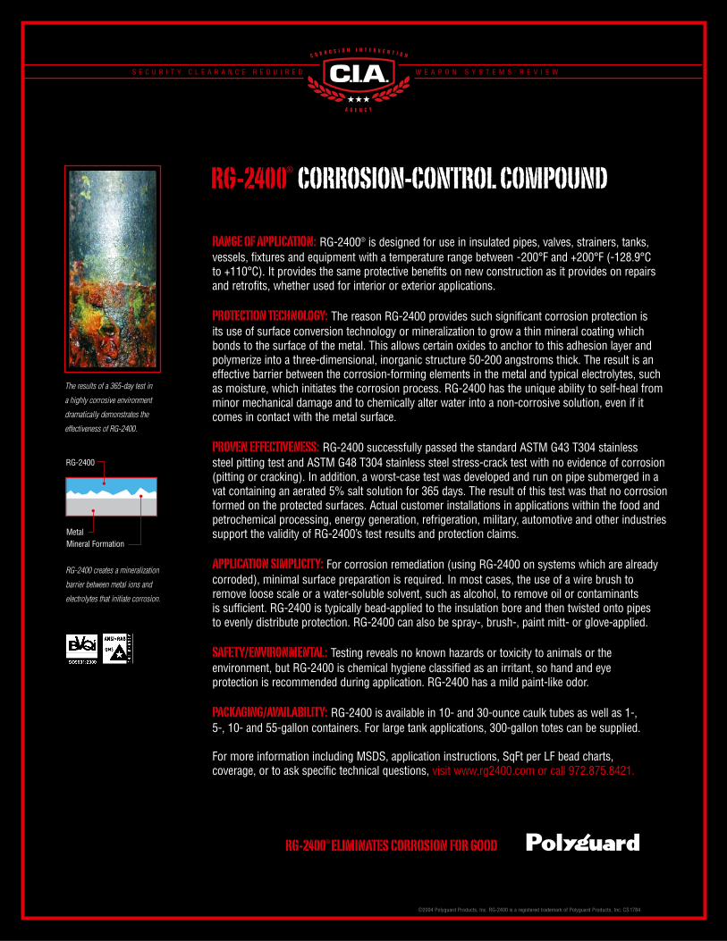
The results of a 365-day test in
a highly corrosive environment
dramatically demonstrates the
effectiveness of RG-2400.
RG-2400 creates a mineralization
barrier between metal ions and
electrolytes that initiate corrosion.
RANGE OF APPLICATION: RG-2400® is designed for use in insulated pipes, valves, strainers, tanks,vessels, fixtures and equipment with a temperature range between -200°F and +200°F (-128.9°C to +110°C). It provides the same protective benefits on new construction as it provides on repairsand retrofits, whether used for interior or exterior applications.
PROTECTION TECHNOLOGY: The reason RG-2400 provides such significant corrosion protection is its use of surface conversion technology or mineralization to grow a thin mineral coating whichbonds to the surface of the metal. This allows certain oxides to anchor to this adhesion layer andpolymerize into a three-dimensional, inorganic structure 50-200 angstroms thick. The result is aneffective barrier between the corrosion-forming elements in the metal and typical electrolytes, suchas moisture, which initiates the corrosion process. RG-2400 has the unique ability to self-heal fromminor mechanical damage and to chemically alter water into a non-corrosive solution, even if itcomes in contact with the metal surface.
PROVEN EFFECTIVENESS: RG-2400 successfully passed the standard ASTM G43 T304 stainless steel pitting test and ASTM G48 T304 stainless steel stress-crack test with no evidence of corrosion(pitting or cracking). In addition, a worst-case test was developed and run on pipe submerged in avat containing an aerated 5% salt solution for 365 days. The result of this test was that no corrosionformed on the protected surfaces. Actual customer installations in applications within the food andpetrochemical processing, energy generation, refrigeration, military, automotive and other industriessupport the validity of RG-2400’s test results and protection claims.
APPLICATION SIMPLICITY: For corrosion remediation (using RG-2400 on systems which are alreadycorroded), minimal surface preparation is required. In most cases, the use of a wire brush toremove loose scale or a water-soluble solvent, such as alcohol, to remove oil or contaminants is sufficient. RG-2400 is typically bead-applied to the insulation bore and then twisted onto pipes to evenly distribute protection. RG-2400 can also be spray-, brush-, paint mitt- or glove-applied.
SAFETY/ENVIRONMENTAL: Testing reveals no known hazards or toxicity to animals or the environment, but RG-2400 is chemical hygiene classified as an irritant, so hand and eye protection is recommended during application. RG-2400 has a mild paint-like odor.
PACKAGING/AVAILABILITY: RG-2400 is available in 10- and 30-ounce caulk tubes as well as 1-, 5-, 10- and 55-gallon containers. For large tank applications, 300-gallon totes can be supplied.
For more information including MSDS, application instructions, SqFt per LF bead charts, coverage, or to ask specific technical questions, visit www.rg2400.com or call 972.875.8421.
RG-2400®ELIMINATES CORROSION FOR GOOD
RG-2400® CORROSION-CONTROL COMPOUND
S E C U R I T Y C L E A R A N C E R E Q U I R E D W E A P O N S Y S T E M S R E V I E W
RG-2400
©2004 Polyguard Products, Inc. RG-2400 is a registered trademark of Polyguard Products, Inc. CS1784
MetalMineral Formation
POLYGUARD PRODUCTS, INC. SELF ADHESIVE PROTECTIVE COATINGS FOR ENGINEERING AND CONSTRUCTION
ENNIS, TEXAS 75120-0755 PH: 214-515-5000 • 800-541-4994 • FAX: 972-875-9425 E-Mail: [email protected] Web Site: www.polyguardproducts.com
Additional Technical Papers and Tests
96 Hour Salt Water Toxicity Test ASTM G43 T-304 Stainless Steel Pitting ASTM G48 T-304 Stainless Steel Stress Crack Corrosion Closed Bottle Test for Salt Water Wildlife Toxicity Long Term Salt Fog Exposure Measurement of CUI Long Term Salt Water Immersion Exposure (1 year)

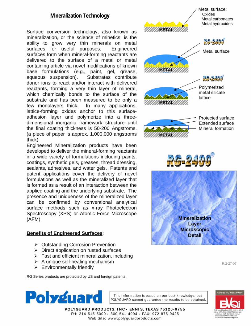
This Information is based on our best knowledge, but POLYGUARD cannot guarantee the results to be obtained.
POLYGUARD PRODUCTS, INC • ENNIS, TEXAS 75120-0755 PH: 214-515-5000 • 800-541-4994 • FAX: 972-875-9425
Web Site: www.polyguardproducts.com
Polyguard has been ISO 9000 certified since 1996. Current certifications are: - American Natl. Standards Institute - Dutch Council for Certification - Deutscher Akkreditierungs Rat
Mineralization Technology
Surface conversion technology, also known as mineralization, or the science of minetics, is the ability to grow very thin minerals on metal surfaces for useful purposes. Engineered surfaces form when mineral-forming reactants are delivered to the surface of a metal or metal containing article via novel modifications of known base formulations (e.g., paint, gel, grease, aqueous suspension). Substrates contribute donor ions to react and/or interact with delivered reactants, forming a very thin layer of mineral, which chemically bonds to the surface of the substrate and has been measured to be only a few monolayers thick. In many applications, lattice-forming oxides anchor to this surface-adhesion layer and polymerize into a three-dimensional inorganic framework structure until the final coating thickness is 50-200 Angstroms. (a piece of paper is approx. 1,000,000 angstroms thick) Engineered Mineralization products have been developed to deliver the mineral-forming reactants in a wide variety of formulations including paints, coatings, synthetic gels, greases, thread dressing, sealants, adhesives, and water gels. Patents and patent applications cover the delivery of novel formulations as well as the mineralized layer that is formed as a result of an interaction between the applied coating and the underlying substrate. The presence and uniqueness of the mineralized layer can be confirmed by conventional analytical surface methods such as x-ray Photoelectron Spectroscopy (XPS) or Atomic Force Microscope (AFM)
Benefits of Engineered Surfaces:
Outstanding Corrosion Prevention Direct application on rusted surfaces Fast and efficient mineralization, including A unique self-healing mechanism Environmentally friendly
RG Series products are protected by US and foreign patents.
R.2-27-07
Metal surface: Oxides Metal carbonates Metal hydroxides
Polymerized metal silicate lattice
METAL
Metal surface
METAL
Protected surface Extended surface Mineral formation
Mineralization Layer
Microscopic Detail
METAL
METAL

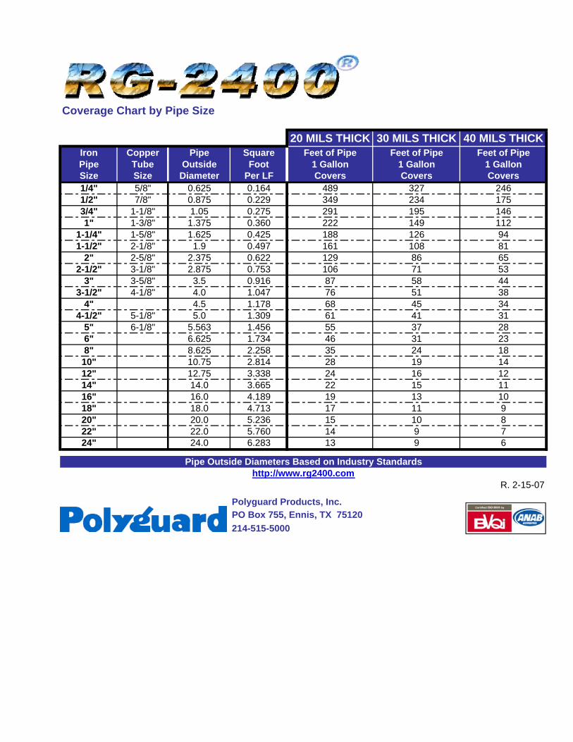
Coverage Chart by Pipe Size
20 MILS THICK 30 MILS THICK 40 MILS THICKIron Copper Pipe Square Feet of Pipe Feet of Pipe Feet of PipePipe Tube Outside Foot 1 Gallon 1 Gallon 1 GallonSize Size Diameter Per LF Covers Covers Covers1/4" 5/8" 0.625 0.164 489 327 2461/2" 7/8" 0.875 0.229 349 234 1753/4" 1-1/8" 1.05 0.275 291 195 1461" 1-3/8" 1.375 0.360 222 149 112
1-1/4" 1-5/8" 1.625 0.425 188 126 941-1/2" 2-1/8" 1.9 0.497 161 108 81
2" 2-5/8" 2.375 0.622 129 86 652-1/2" 3-1/8" 2.875 0.753 106 71 53
3" 3-5/8" 3.5 0.916 87 58 443-1/2" 4-1/8" 4.0 1.047 76 51 38
4" 4.5 1.178 68 45 344-1/2" 5-1/8" 5.0 1.309 61 41 31
5" 6-1/8" 5.563 1.456 55 37 286" 6.625 1.734 46 31 238" 8.625 2.258 35 24 1810" 10.75 2.814 28 19 1412" 12.75 3.338 24 16 1214" 14.0 3.665 22 15 1116" 16.0 4.189 19 13 1018" 18.0 4.713 17 11 920" 20.0 5.236 15 10 822" 22.0 5.760 14 9 724" 24.0 6.283 13 9 6
R. 2-15-07
Polyguard Products, Inc.PO Box 755, Ennis, TX 75120214-515-5000
Pipe Outside Diameters Based on Industry Standardshttp://www.rg2400.com

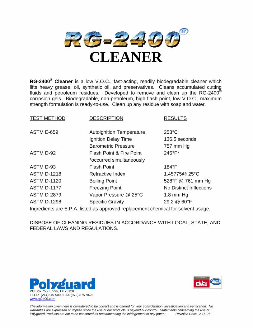
PO Box 755, Ennis, TX 75120 TELE: (214)515-5000 FAX (972) 875-9425 www.rg2400.com The information given here is considered to be correct and is offered for your consideration, investigation and verification. No warranties are expressed or implied since the use of our products is beyond our control. Statements concerning the use of Polyguard Products are not to be construed as recommending the infringement of any patent Revision Date: 2-15-07
CLEANER
RG-2400® Cleaner is a low V.O.C., fast-acting, readily biodegradable cleaner which lifts heavy grease, oil, synthetic oil, and preservatives. Cleans accumulated cutting fluids and petroleum residues. Developed to remove and clean up the RG-2400® corrosion gels. Biodegradable, non-petroleum, high flash point, low V.O.C., maximum strength formulation is ready-to-use. Clean up any residue with soap and water. TEST METHOD DESCRIPTION RESULTS ASTM E-659 Autoignition Temperature 253°C Ignition Delay Time 136.5 seconds Barometric Pressure 757 mm Hg ASTM D-92 Flash Point & Fire Point 245°F* *occurred simultaneously ASTM D-93 Flash Point 184°F ASTM D-1218 Refractive Index 1.45775@ 25°C ASTM D-1120 Boiling Point 528°F @ 761 mm Hg ASTM D-1177 Freezing Point No Distinct Inflections ASTM D-2879 Vapor Pressure @ 25°C 1.8 mm Hg ASTM D-1298 Specific Gravity 29.2 @ 60°F Ingredients are E.P.A. listed as approved replacement chemical for solvent usage. DISPOSE OF CLEANING RESIDUES IN ACCORDANCE WITH LOCAL, STATE, AND FEDERAL LAWS AND REGULATIONS.


This Information is based on our best knowledge, but POLYGUARD cannot guarantee the results to be obtained.
POLYGUARD PRODUCTS, INC • ENNIS, TEXAS 75120-0755 PH: 214-515-5000 • 800-541-4994 • FAX: 972-875-9425
Web Site: www.polyguardproducts.com
Polyguard has been ISO 9000 certified since 1996. Current certifications are: - American Natl. Standards Institute - Dutch Council for Certification - Deutscher Akkreditierungs Rat
DESCRIPTION: POLYGUARD 600 SERIES COATING SYSTEMS are laminated protective coatings. The primary corrosion coating material is a rubberized bitumen coating, bonded to a white polyethylene film. For products that conform easily, Polyguard coatings have exceptional adhesion and mechanical strength. The coatings are supplied in rolls for easy application on all sizes of pipe. POLYGUARD 600 LIQUID ADHESIVE is a fast drying, rubber based materials in a solvent solution. It is available in solvent systems that will conform to most local VOC requirements. USES: POLYGUARD 600 SERIES COATING SYSTEMS are for hand application for coating and wrapping of station piping, field joints, repairs on mill coated pipe, gas distri-bution, and for reconditioning of older lines.
ADVANTAGES: ! Excellent cathodic disbondment resistance. ! Uniform factory controlled thickness. ! Damaged coating areas can be repaired quickly and easily. ! Excellent resistance to water or vapor transmission. ! Resistant to deterioration from acids and alkalis encountered in normal soil. ! Excellent ability at the lap to resist infiltration of moisture. ! Elastomeric properties to accommodate normal expansion and contraction of the substrate. ! Easy to apply. ! Excellent peel adhesion.
PROPERTY TEST METHODS
600/634P COATINGS
610/CP50P COATINGS
Nominal Coating Thickness
ASTM D 1000
35 mils (.89 mm)
50 mils (1.27mm)
Nominal Film Thickness
ASTM D 1000
10 mils (.25mm)
10 mils (.25mm)
Tensile Strength
ASTM D 882-B
22.5 lb./in/width (4.0 kg./cm.width)
22.5 lb./in/width (4.0 kg./cm.width)
Elongation at Break
ASTM D 882-B
400%
400%
Dielectric Strength
ASTM D 149
>12 KV
>12 KV
Low Temperature Flex at 0EF. (-17.8EC)
ASTM D 146
No Cracking
No Cracking
Adhesion to Primed Steel
ASTM D 1000
17.0 lb./in. width (3.0 kg./cm. width)
17.0 lb./in.width (3.0 kg./cm. width)
Adhesion to Overlap
ASTM D 1000
14.0 lb./in. width (2.4 kg./cm. width)
14.0 lb./in. width (2.4 kg./cm. width)
Cathodic Disbondment
ASTM G 8
< 5.0 mm avg.
< 5.0 mm avg.
Water Vapor Transmission Rate
ASTM E 96
.032 grains/hr/ft2 (.036 g/h-m2)
.032 grains/hr/ft2 (.036 g/h-m2)
Water Absorption
ASTM D 570
<.1%
<.1%
Temperature Ranges: ! At Application 25EF. to 110EF (-4E to 43E C)
! In Service -25EF. to 130EF (-32E to 54E C)
600 Series Coating Systems Cold Applied Pipeline Coating for Hand Application
600 Series Coating applied on a rehabilitation project.
GUIDE SPECIFICATION: Handling Materials: Polyguard coatings and liquid adhesives should be hauled and stored in such a manner as to prevent injury to the packages. All packages and rolls should be stored in a dry place, kept from contact with earth and protected from weather. It is recommended that the tape and liquid adhesive be transported in warmed vehicles and stored in heated buildings during cold weather. Although the coating can be utilized at lower temperatures, to maximize the quality application characteristics of the coating system, coating and liquid adhesives should be maintained at a tem-perature of 45EF (7EC) or higher at times of application. Surface Preparation: The pipe shall be cleaned of all paint, oil and grease, mill scale, loose rust, welding residue, knurls, frost, dust, moisture, weeds, and other foreign matter. Where feasible and practical, the surface can be blast cleaned to a NACE No. 3 finish. Where mill coated pipe is involved, the liquid adhesive and coating should be applied to the girth weld, starting on top of the mill coating, at least 1" back from the edges of the mill coating. Liquid Adhesive Application: Polyguard liquid adhesive should be applied at an average rate of 400 sq. ft. per gallon (10m2/liter). Stir liquid adhesive before using. Apply with brush or roller to clean and dry pipe surface. DO NOT THIN POLYGUARD LIQUID ADHESIVE. In cold weather, store inside prior to use. Wrapping: Polyguard coating systems can be applied by spiral wrapping. The release sheet is to be removed immediately prior to the application. The bitumen surface of the coating shall be applied to the dry liquid adhesive. In spiral wrapping, a minimum of 1" (25.44 mm) lap shall be maintained. In areas designated by the owner as critical, overlap may be increased to 50%. Critical areas are determined by pipe diameter, weight of the pipe, type of backfill soil and the severity of soil stress conditions. Where larger diameter pipe is involved or where soil stress conditions exist, it is advisable to over wrap the applied coating systems with Polyguard SP6 Outerwrap or other suitable outerwrap material. Polyguard 600 Series Coatings should be applied with enough tension to eliminate any air pockets and also to conform to the weld bead area and beveled cut back. DO NOT STRETCH EXCESSIVELY. Coating Repairs: The pipe and mill coating surface shall be clean and dry. Remove all loose or damaged coating around the holiday with a draw knife or other sharp hand tool. Feather edge the mill coating. Prime the pipe and adjacent coating area 2" wider than the repair coating. Either cigarette wrap or spiral wrap the repair coating to cover the entire holiday area, plus at least 2" of mill coating on either side of the damage area. Small pinholes may be patched by a single cigarette wrap over the coated pipe surface. The end laps should be at least 4". A postage stamp patch may be substituted for the complete cigarette wrap around the pipe when dry sandy or loam soil is used as backfill material. Patches are not recommended when backfill consists of large wet or dry dirt clods that could dislodge the patch from the pipe surface as the backfill settles. Lowering-in: The pipe should be inspected immediately before lowering in. Polyguard 600 Series Coating Systems shall be holiday detected with an adjustable electronic detector at a maximum voltage in accord with the following formula:
V = /T x 1250, where V = Voltage, and T = Coating thickness, in mils Excess voltage will break down the dielectric strength of the coating. Care should be taken to use the minimum voltage setting to locate defects in the coating system. Follow instructions of holiday equipment manufacturer. Backfilling: Take care in backfilling to avoid sharp rocks or other material in backfill that would damage and penetrate the coating. In areas of rough backfill, suitable rock shielding shall be provided to protect the coating from backfill damage. PRECAUTIONS: The liquid adhesive is an industrial coating and would be harmful or fatal if swallowed. It is marked as red label from the standpoint of flash point. Prohibit flames, sparks, welding and smoking during application. Solvents could be irritating to the eyes. In case of contact with eyes, flush with water and contact physician. Avoid prolonged contact with skin and breathing of vapor or spray mist from liquid adhesive. In confined areas, use adequate forced ventilation, fresh air masks, explosion proof equipment, and clean clothing. This material is sold by Polyguard Products, Inc. only for the purposes described in this literature. Any other use of the products is the responsibility of the purchaser and Polyguard Products does not warrant nor will be responsible for any misuse of these products. Polyguard Products will replace material not meeting our published specifications within one year from date of sale. MATERIAL SAFETY DATA: All Polyguard Products Material Safety Data Sheets (MSDS) and precautionary labels should be read and understood by all user supervisory personnel and employees before using. Purchaser is responsible for complying with all applicable federal, state or local laws and regulations covering use, health, safety, and disposal of the product. MAINTENANCE: None required. Technical Service: Polyguard Products Inc. Ennis, Texas 75120-0755 PH: 214.515.5000 FAX: 972.875.9425 www.polyguardproducts.com x.xl.pipeline.600 Series Data R. 1-10-08

This Information is based on our best knowledge, but POLYGUARD cannot guarantee the results to be obtained.
POLYGUARD PRODUCTS, INC • ENNIS, TEXAS 75120-0755 PH: 214-515-5000 • 800-541-4994 • FAX: 972-875-9425
Web Site: www.polyguardproducts.com
Polyguard has been ISO 9000 certified since 1996. Current certifications are: - American Natl. Standards Institute - Dutch Council for Certification - Deutscher Akkreditierungs Rat
DESCRIPTION
POLYGUARD 600 UV 350 COATING SYSTEM is a laminated protective coating which is applied over its companion liquid adhesive. The primary corrosion coating material is a rubberized bitumen coating, bonded to an organic ethylene polymer film, which provides UV resistance. For a product that conforms easily, 600 UV 350 has exceptional adhesion. The coating is supplied in rolls for easy application on all sizes of pipe. 600 UV 350 is manufactured with a disposable release sheet. POLYGUARD 600 LIQUID ADHESIVE is a fast drying, rubber based material in a solvent solution. It will conform to most local air pollution requirements. USES: 600 UV 350 COATING is used as a hand applied coating and wrapping for steel pipe that is exposed above and below ground whenever resistance to ultra violet is a consideration. No other use of these materials is to be made without prior approval of Polyguard Products as to ser-vice and method of application. ADVANTAGES: Following are the advantages of 600 UV 350: ! The organic ethylene polymer film backing is more resistant to UV rays than most other types of films. ! The film backing is resistant to a variety of chemical environments, including acids, salts, and bases, without
significant property loss. Consult Polyguard for more information on these properties. ! Provides uniform coating thickness. ! Has excellent ability at the lap to resist infiltration of moisture. ! Has elastomeric properties to accommodate normal expansion and contraction of the substrate. ! Included as the corrosion coating element is a rubberized bitumen coating.
600 UV 350 Corrosion Coating – Typical Properties Property ASTM Method English Metric
Color Black Black Coating Thickness D 1000 .050” 1.19 mm
Film Weatherability @ 300 hours exposure (Test results reported by manufacturer of film)
D 3361 No cracking or delamination
No cracking or delamination
Tensile Strength D 1000 400 PSI 2.8 N/mm Cathodic Disbondment G 8 < 5.0 mm avg. < 5.0 mm avg.
Dielectric Strength D 149 > 12 KV > 12 KV Bacterial Resistance G 22 Excellent Excellent Elongation at Break D 1000 250% 250%
Water Vapor Transmission E 96 .039 grains/hr/ft2 .026 grains/hr/m2 Peel Adhesion D 1000 20 lb./inch width 3.5 N/mm
GUIDE SPECIFICATION: Handling Materials: Polyguard coatings and liquid adhesives should be hauled and stored in such a manner as to prevent injury to the packages. No packages should be dropped or thrown from trucks. All packages and rolls of wrapping materials should be stored in a dry place, kept from contact with earth, and protected from weather. Materials may be applied between 0 F (-18 C) and 120 F (49 C). It is recommended that the tape and liquid adhesive be transported in warmed vehicles and stored in
600 UV 350 Corrosion Coating System Weather Resistant 50 mil Pipeline Coating for Hand Application
heated buildings during cold weather. Although the coating can be utilized at lower temperatures, to maximize the quality application characteristics of the coating system, it is recommended that the coating and liquid adhesive be maintained at a temperature of 45EF (7EC) or higher at times of application. Surface Preparation: As a minimum, pipe should be cleaned of all paint, oil and grease, mill scale, loose rust, welding residue, knurls, frost, dust, moisture, weeds, and other deleterious matter. Where feasible and practical, the surface can be blast cleaned to a commercial finish, as described in NACE No. 3. In cold weather, where safety regulations permit, pipe surface may be warmed to 100EF. (38EC) approximately, prior to application of liquid adhesive to accelerate adhesion. Priming: Polyguard liquid adhesive should be applied at an average rate of 400 sq. ft. per gallon (10m2/liter). Stir before each use. Apply with brush or roller to clean and dry pipe surface. Do not thin the liquid adhesive. Wrapping: 600 UV 350 can be applied by spiral wrapping. The release sheet is to be removed immediately prior to the time of application. The bitumen surface of the coating shall be applied to the dry liquid adhesive. In spiral wrapping, a minimum of 1" (25.4 mm) lap should be maintained. In areas designated by the owner as critical, the overlap may be increased to 50%. Critical areas would be determined by the severity of conditions in a particular area. 600 UV 350 should be applied with just enough tension to eliminate any air pockets, to conform to the shape of the object being coated and to make complete contact with the covered pipe surface. If 600 UV 350 is required to tie into a coating below ground, clean surface of below ground coating of any deleterious contamination before overlapping. Overlap existing coating a minimum of 2" (50.8 mm). If any questions of compatibility of coatings should occur, contact Polyguard Products. When applied on risers, the coating system should be applied starting at grade or below grade level and continue upward to provide a shingle effect at the overlap area. PRECAUTIONS: The liquid adhesive is an industrial coating and would be harmful or fatal if swallowed. It is marked as red label from the standpoint of flash point. Prohibit flames, sparks, welding and smoking during application. Solvents could be irritating to the eyes. In case of contact with eyes, flush with water and contact physician. Avoid prolonged contact with skin and breathing of vapor or spray mist from liquid adhesive. In confined areas, use adequate forced ventilation, fresh air masks, explosion proof equipment, and clean clothing. This material is sold by Polyguard Products, Inc. only for the purposes described in this literature. Any other use of the products is the responsibility of the purchaser and Polyguard Products does not warrant nor will be responsible for any misuse of these products. Polyguard Products will replace material not meeting our published specifications within one year from date of sale. MATERIAL SAFETY DATA: All Polyguard Products Material Safety Data Sheets (MSDS) and precautionary labels should be read and understood by all user supervisory personnel and employees before using. Purchaser is responsible for complying with all applicable federal, state or local laws and regulations covering use, health, safety, and disposal of the product. MAINTENANCE: None required. Technical Service: Polyguard Products Inc. Ennis, Texas 75120-0755 PH: 214.515.5000 FAX: 972.875.9425 www.polyguardproducts.com
x.xl.pipeline600 UV 350 Data R.11-15-07
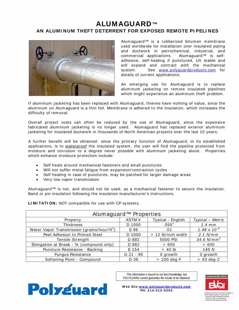
This information is based on our best knowledge, but POLYGUARD cannot guarantee the results to be obtained.
Web Site:www.polyguardproducts.com
PH: 214-515-5000
Polyguard Products' has been certified to these quality systems requirements: - American Natl. Standards Institute - Dutch Council for Certification - Deutscher Akkreditierungs Rat
ALUMAGUARD™ AN ALUMINUM THEFT DETERRENT FOR EXPOSED REMOTE PIPELINES
Alumaguard™ is a rubberized bitumen membrane used worldwide for installation over insulated piping and ductwork in petrochemical, industrial, and commercial applications. Alumaguard™ is self-adhesive, self-healing if punctured, UV stable and will expand and contract with the mechanical system. See www.polyguardproducts.com for details of current applications. An emerging use for Alumaguard is to replace aluminum jacketing on remote insulated pipelines which might experience an aluminum theft problem.
If aluminum jacketing has been replaced with Alumaguard, thieves have nothing of value, since the aluminum on Alumaguard is a thin foil. Membrane is adhered to the insulation, which increases the difficulty of removal. Overall project costs can often be reduced by the use of Alumaguard, since the expensive fabricated aluminum jacketing is no longer used. Alumaguard has replaced exterior aluminum jacketing for insulated ductwork in thousands of North American projects over the last 10 years. A further benefit will be obtained: since the primary function of Alumaguard, in its established applications, is to waterproof the insulated system, the user will find the pipeline protected from moisture and corrosion to a degree never possible with aluminum jacketing alone. Properties which enhance moisture protection include:
• Self heals around mechanical fasteners and small punctures • Will not suffer metal fatigue from expansion/contraction cycles • Self healing in case of punctures, may be patched for larger damage areas • Very low vapor transmission
Alumaguard™ is not, and should not be used, as a mechanical fastener to secure the insulation. Band or pin insulation following the insulation manufacturer’s instructions. LIMITATION: NOT compatible for use with CP systems.
Alumaguard™ Properties Property ASTM # Typical - English Typical – Metric Thickness D 1000 .055” 1.4 mm
Water Vapor Transmission (grains/hour/ft2) E 96 .01 1.48 x 10⁻⁹
Peel Adhesion to Primed Steel D 1000 > 12 lb/inch width 2.1 N/mm Tensile Strength D 882 5000 PSI 34.6 N/mm2
Elongation at Break - % (compound only) D 882 > 600 > 600 Puncture Resistance - Backing E 154 > 40 lb 145 N
Fungus Resistance G 21 - 90 0 growth 0 growth Softening Point - Compound D 36 > 200 deg F > 93 deg C
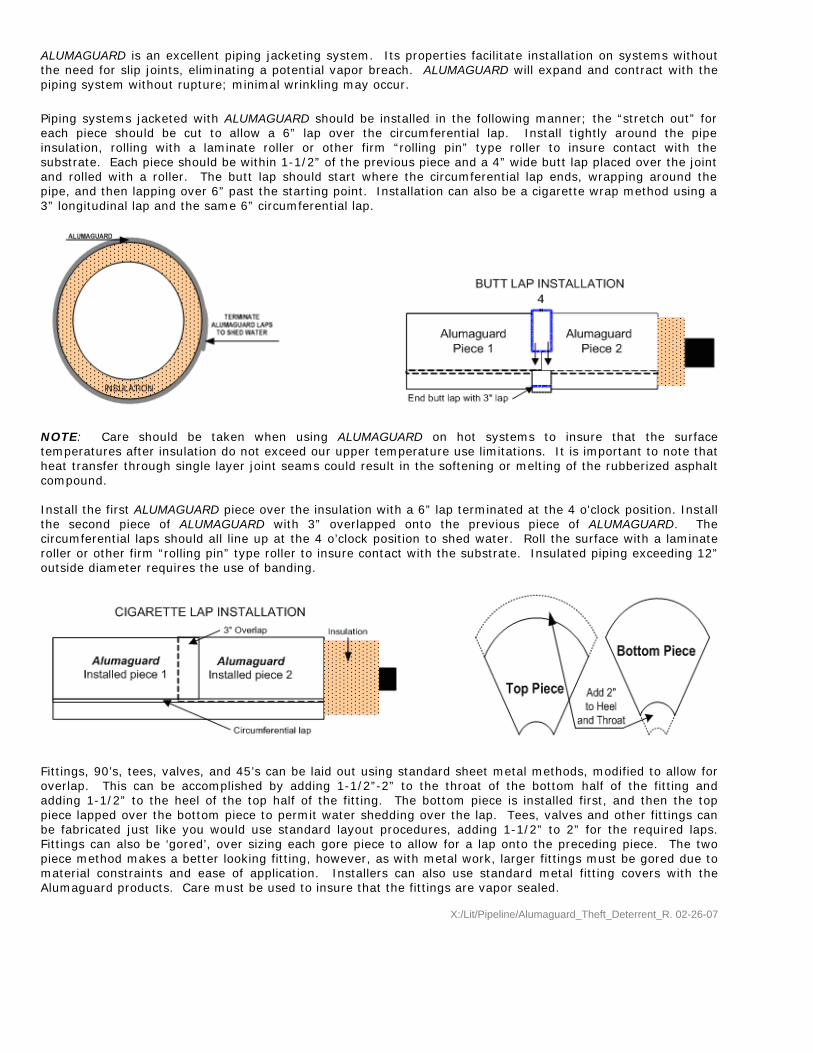
ALUMAGUARD is an excellent piping jacketing system. Its properties facilitate installation on systems without the need for slip joints, eliminating a potential vapor breach. ALUMAGUARD will expand and contract with the piping system without rupture; minimal wrinkling may occur.
Piping systems jacketed with ALUMAGUARD should be installed in the following manner; the “stretch out” for each piece should be cut to allow a 6” lap over the circumferential lap. Install tightly around the pipe insulation, rolling with a laminate roller or other firm “rolling pin” type roller to insure contact with the substrate. Each piece should be within 1-1/2” of the previous piece and a 4” wide butt lap placed over the joint and rolled with a roller. The butt lap should start where the circumferential lap ends, wrapping around the pipe, and then lapping over 6” past the starting point. Installation can also be a cigarette wrap method using a 3” longitudinal lap and the same 6” circumferential lap.
NOTE: Care should be taken when using ALUMAGUARD on hot systems to insure that the surface temperatures after insulation do not exceed our upper temperature use limitations. It is important to note that heat transfer through single layer joint seams could result in the softening or melting of the rubberized asphalt compound. Install the first ALUMAGUARD piece over the insulation with a 6” lap terminated at the 4 o'clock position. Install the second piece of ALUMAGUARD with 3” overlapped onto the previous piece of ALUMAGUARD. The circumferential laps should all line up at the 4 o’clock position to shed water. Roll the surface with a laminate roller or other firm “rolling pin” type roller to insure contact with the substrate. Insulated piping exceeding 12” outside diameter requires the use of banding.
Fittings, 90’s, tees, valves, and 45’s can be laid out using standard sheet metal methods, modified to allow for overlap. This can be accomplished by adding 1-1/2”-2” to the throat of the bottom half of the fitting and adding 1-1/2” to the heel of the top half of the fitting. The bottom piece is installed first, and then the top piece lapped over the bottom piece to permit water shedding over the lap. Tees, valves and other fittings can be fabricated just like you would use standard layout procedures, adding 1-1/2” to 2” for the required laps. Fittings can also be ‘gored’, over sizing each gore piece to allow for a lap onto the preceding piece. The two piece method makes a better looking fitting, however, as with metal work, larger fittings must be gored due to material constraints and ease of application. Installers can also use standard metal fitting covers with the Alumaguard products. Care must be used to insure that the fittings are vapor sealed.
X:/Lit/Pipeline/Alumaguard_Theft_Deterrent_R. 02-26-07
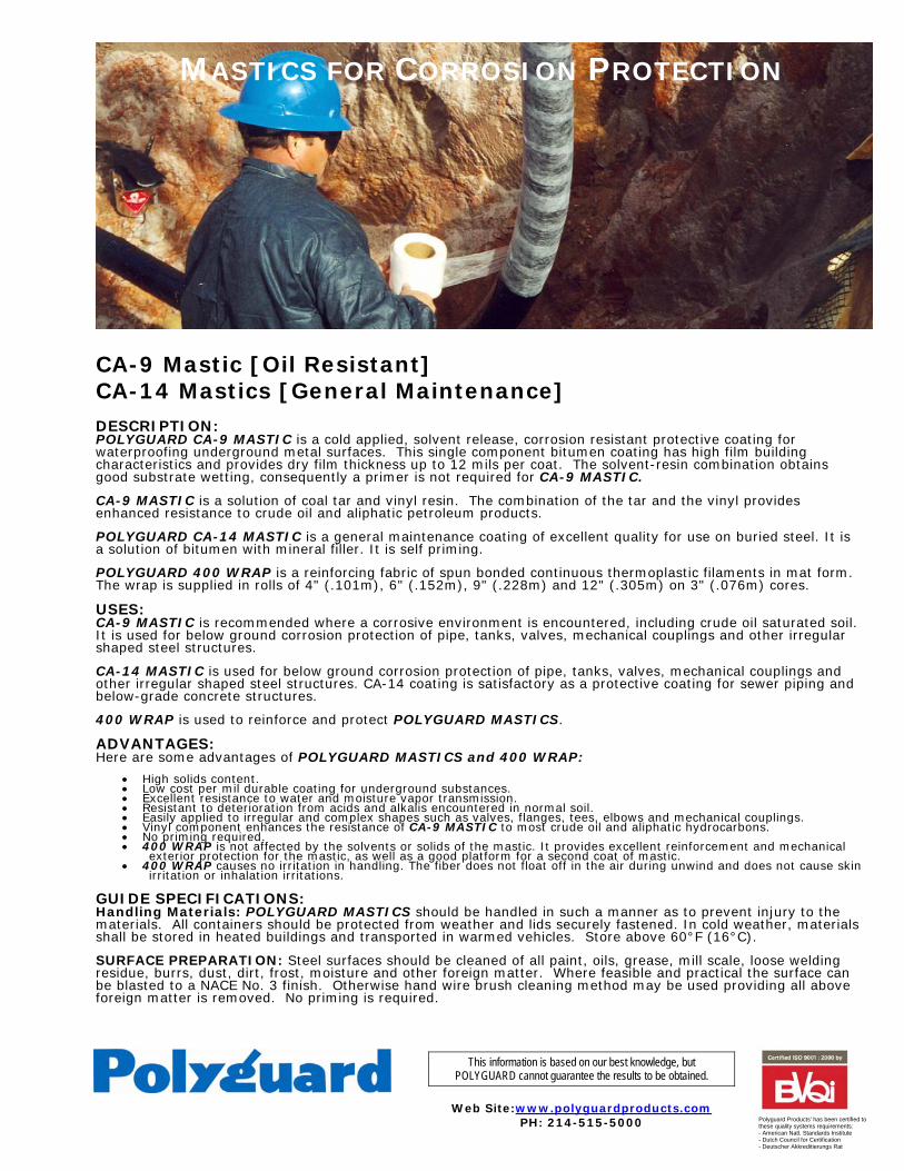
This information is based on our best knowledge, but POLYGUARD cannot guarantee the results to be obtained.
Web Site:www.polyguardproducts.com
PH: 214-515-5000
Polyguard Products' has been certified to these quality systems requirements: - American Natl. Standards Institute - Dutch Council for Certification - Deutscher Akkreditierungs Rat
CA-9 Mastic [Oil Resistant] CA-14 Mastics [General Maintenance] DESCRIPTION: POLYGUARD CA-9 MASTIC is a cold applied, solvent release, corrosion resistant protective coating for waterproofing underground metal surfaces. This single component bitumen coating has high film building characteristics and provides dry film thickness up to 12 mils per coat. The solvent-resin combination obtains good substrate wetting, consequently a primer is not required for CA-9 MASTIC. CA-9 MASTIC is a solution of coal tar and vinyl resin. The combination of the tar and the vinyl provides enhanced resistance to crude oil and aliphatic petroleum products. POLYGUARD CA-14 MASTIC is a general maintenance coating of excellent quality for use on buried steel. It is a solution of bitumen with mineral filler. It is self priming. POLYGUARD 400 WRAP is a reinforcing fabric of spun bonded continuous thermoplastic filaments in mat form. The wrap is supplied in rolls of 4" (.101m), 6" (.152m), 9" (.228m) and 12" (.305m) on 3" (.076m) cores. USES: CA-9 MASTIC is recommended where a corrosive environment is encountered, including crude oil saturated soil. It is used for below ground corrosion protection of pipe, tanks, valves, mechanical couplings and other irregular shaped steel structures. CA-14 MASTIC is used for below ground corrosion protection of pipe, tanks, valves, mechanical couplings and other irregular shaped steel structures. CA-14 coating is satisfactory as a protective coating for sewer piping and below-grade concrete structures. 400 WRAP is used to reinforce and protect POLYGUARD MASTICS. ADVANTAGES: Here are some advantages of POLYGUARD MASTICS and 400 WRAP:
• High solids content. • Low cost per mil durable coating for underground substances. • Excellent resistance to water and moisture vapor transmission. • Resistant to deterioration from acids and alkalis encountered in normal soil. • Easily applied to irregular and complex shapes such as valves, flanges, tees, elbows and mechanical couplings. • Vinyl component enhances the resistance of CA-9 MASTIC to most crude oil and aliphatic hydrocarbons. • No priming required. • 400 WRAP is not affected by the solvents or solids of the mastic. It provides excellent reinforcement and mechanical
exterior protection for the mastic, as well as a good platform for a second coat of mastic. • 400 WRAP causes no irritation in handling. The fiber does not float off in the air during unwind and does not cause skin
irritation or inhalation irritations. GUIDE SPECIFICATIONS: Handling Materials: POLYGUARD MASTICS should be handled in such a manner as to prevent injury to the materials. All containers should be protected from weather and lids securely fastened. In cold weather, materials shall be stored in heated buildings and transported in warmed vehicles. Store above 60°F (16°C). SURFACE PREPARATION: Steel surfaces should be cleaned of all paint, oils, grease, mill scale, loose welding residue, burrs, dust, dirt, frost, moisture and other foreign matter. Where feasible and practical the surface can be blasted to a NACE No. 3 finish. Otherwise hand wire brush cleaning method may be used providing all above foreign matter is removed. No priming is required.
MASTICS FOR CORROSION PROTECTION
APPLICATION: POLYGUARD MASTICS should be brush applied for best adhesion to the substrate. They are normally applied in a two coat system. The first coat should be dry before the second coat is applied. Drying time is dependent upon atmospheric and surface temperature. Coating should be done in areas free of dust and moisture. COVERAGE RATE: POLYGUARD CA-9 MASTIC covers approximately 60 square feet per gallon (1.48m2liter) on smooth surfaces. The dry film thickness will be approximately 12 mils with a wet film thickness of 20 mils to obtain this coverage. Two coats are recommended. POLYGUARD CA-14 MASTIC will cover approximately 75-80 square feet per gallon (1.96M2/Liter), on smooth surfaces. The dry film thickness will be approximately 12 mils with a wet film thickness of 20 mils to obtain this coverage. Two coats are recommended. It is suggested that an application of POLYGUARD 400 WRAP be applied over the first mastic coating. The second mastic coat shall be applied on top of the 400 WRAP which acts as a reinforcement in the coating. It will also form a platform for the second coat. After the second coat is applied, another layer of 400 WRAP shall be applied to the exterior surface of the mastic. Caution should be taken to lay the wrap into the outside surface of the mastic and not to pull #400 wrap through mastic onto pipe surface. Use minimum tension during application. BACKFILLING: Mastics are subject to displacement or damage from backfill. It is therefore good practice to let each coat of mastic dry prior to backfilling to minimize this occurrence. If quick backfilling is desired (before the mastic is set) the area may be overwrapped with Polyguard SP6 Outerwrap. This will provide protection against displacement of the mastic. TESTING: The applied coating shall be checked visually for bare areas. Recoat these areas with POLYGUARD MASTIC to the required mil thickness.
TECHNICAL DATA:
NOMINAL PROPERTIES: 400 MAT Weight/Yd.2
0.3 oz.
Average Thickness ASTM D 1777
2.3 mils Machine Direction
3.4 lbs.
LBS Tear Strength ASTM
D 2263-68
Transverse Direction
2.4 lbs. Air Permeability (CMF/ft2) ASTM D 737-69
13.00
PRECAUTIONS: The mastics are industrial coatings and would be harmful or fatal if swallowed. They are marked as red label from the standpoint of flash point. Prohibit flames, sparks, welding and smoking during application. Refer to product label for handling, use and storage precautions. Solvents, including thinner, could be irritating to the eyes. In case of contact with eyes, flush with water and contact physician. Avoid prolonged contact with skin and breathing of vapor or spray mist from mastic. In confined areas, use adequate forced ventilation, fresh air masks, explosion proof equipment, and clean clothing. Close container after each use. This material contains MEK and toluol as a solvent. It may not be acceptable for use under some fire and air pollution regulations. Consult local regulations. Material has a storage life of one year in unopened containers, from shipment date, when storage conditions as prescribed by manufacturer are followed. Minimum storage temperature is 60°F (16°C). Review precautions carefully in respect to flash point and other special handling procedures. This material is sold by Polyguard Products, Inc. only for the purposes described in this literature. Any other use of the products is the responsibility of the purchaser and Polyguard Products does not warrant nor will be responsible for any misuse of these products. Polyguard Products will replace material not meeting our published specifications within one year from date of sale. MATERIAL SAFETY DATA: All Polyguard Products Material Safety Data Sheets (MSDS) and precautionary labels should be read and understood by all user supervisory personnel and employees before using. Purchaser is responsible for complying with all applicable federal, state or local laws and regulations covering use, health, safety, and disposal of the product. MAINTENANCE: None required. Technical Service: Polyguard Products Inc. Ennis, Texas 75120-0755 PH: 214.515.5000 FAX: 972.875.9425 www.polyguardproducts.com
x:/lit/Pipeline/Mastics Product Data.doc R.3-20-07
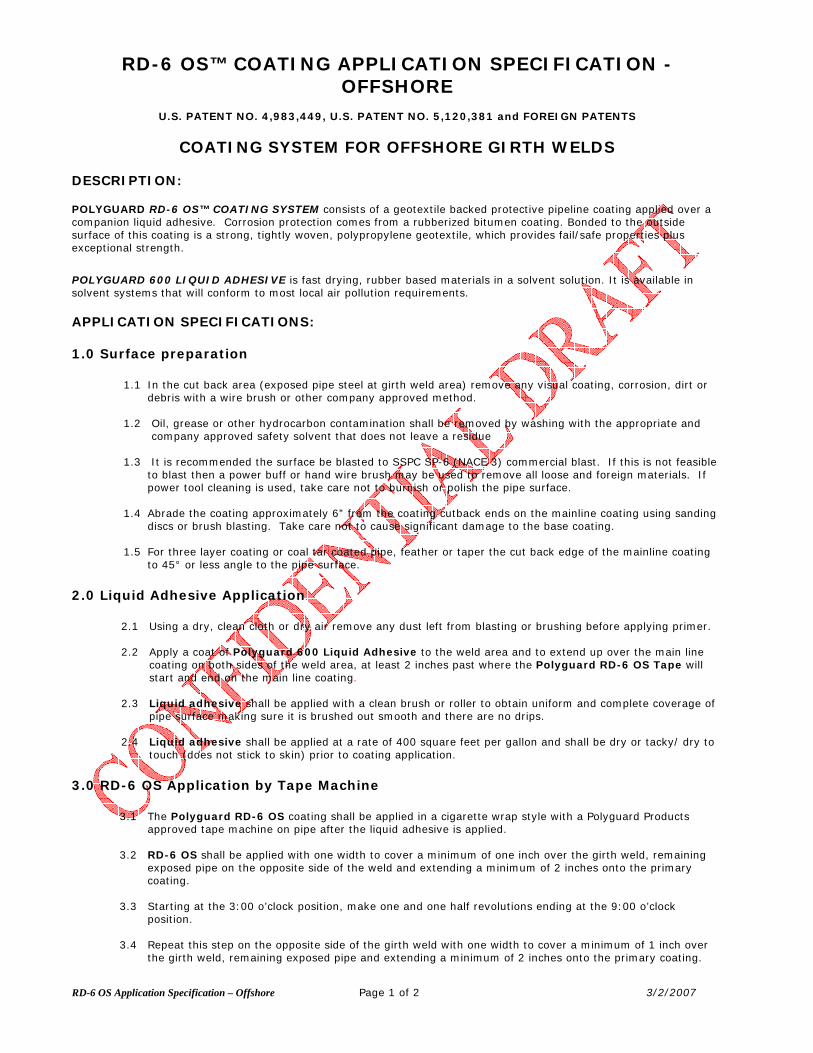
RD-6 OS Application Specification – Offshore Page 1 of 2 3/2/2007
RD-6 OS™ COATING APPLICATION SPECIFICATION - OFFSHORE
U.S. PATENT NO. 4,983,449, U.S. PATENT NO. 5,120,381 and FOREIGN PATENTS
COATING SYSTEM FOR OFFSHORE GIRTH WELDS
DESCRIPTION: POLYGUARD RD-6 OS™ COATING SYSTEM consists of a geotextile backed protective pipeline coating applied over a companion liquid adhesive. Corrosion protection comes from a rubberized bitumen coating. Bonded to the outside surface of this coating is a strong, tightly woven, polypropylene geotextile, which provides fail/safe properties plus exceptional strength.
POLYGUARD 600 LIQUID ADHESIVE is fast drying, rubber based materials in a solvent solution. It is available in solvent systems that will conform to most local air pollution requirements. APPLICATION SPECIFICATIONS:
1.0 Surface preparation
1.1 In the cut back area (exposed pipe steel at girth weld area) remove any visual coating, corrosion, dirt or debris with a wire brush or other company approved method.
1.2 Oil, grease or other hydrocarbon contamination shall be removed by washing with the appropriate and
company approved safety solvent that does not leave a residue
1.3 It is recommended the surface be blasted to SSPC SP-6 (NACE 3) commercial blast. If this is not feasible to blast then a power buff or hand wire brush may be used to remove all loose and foreign materials. If power tool cleaning is used, take care not to burnish or polish the pipe surface.
1.4 Abrade the coating approximately 6” from the coating cutback ends on the mainline coating using sanding
discs or brush blasting. Take care not to cause significant damage to the base coating. 1.5 For three layer coating or coal tar coated pipe, feather or taper the cut back edge of the mainline coating
to 45° or less angle to the pipe surface.
2.0 Liquid Adhesive Application
2.1 Using a dry, clean cloth or dry air remove any dust left from blasting or brushing before applying primer.
2.2 Apply a coat of Polyguard 600 Liquid Adhesive to the weld area and to extend up over the main line coating on both sides of the weld area, at least 2 inches past where the Polyguard RD-6 OS Tape will start and end on the main line coating.
2.3 Liquid adhesive shall be applied with a clean brush or roller to obtain uniform and complete coverage of
pipe surface making sure it is brushed out smooth and there are no drips.
2.4 Liquid adhesive shall be applied at a rate of 400 square feet per gallon and shall be dry or tacky/ dry to touch (does not stick to skin) prior to coating application.
3.0 RD-6 OS Application by Tape Machine
3.1 The Polyguard RD-6 OS coating shall be applied in a cigarette wrap style with a Polyguard Products approved tape machine on pipe after the liquid adhesive is applied.
3.2 RD-6 OS shall be applied with one width to cover a minimum of one inch over the girth weld, remaining
exposed pipe on the opposite side of the weld and extending a minimum of 2 inches onto the primary coating.
3.3 Starting at the 3:00 o’clock position, make one and one half revolutions ending at the 9:00 o’clock position.
3.4 Repeat this step on the opposite side of the girth weld with one width to cover a minimum of 1 inch over
the girth weld, remaining exposed pipe and extending a minimum of 2 inches onto the primary coating.
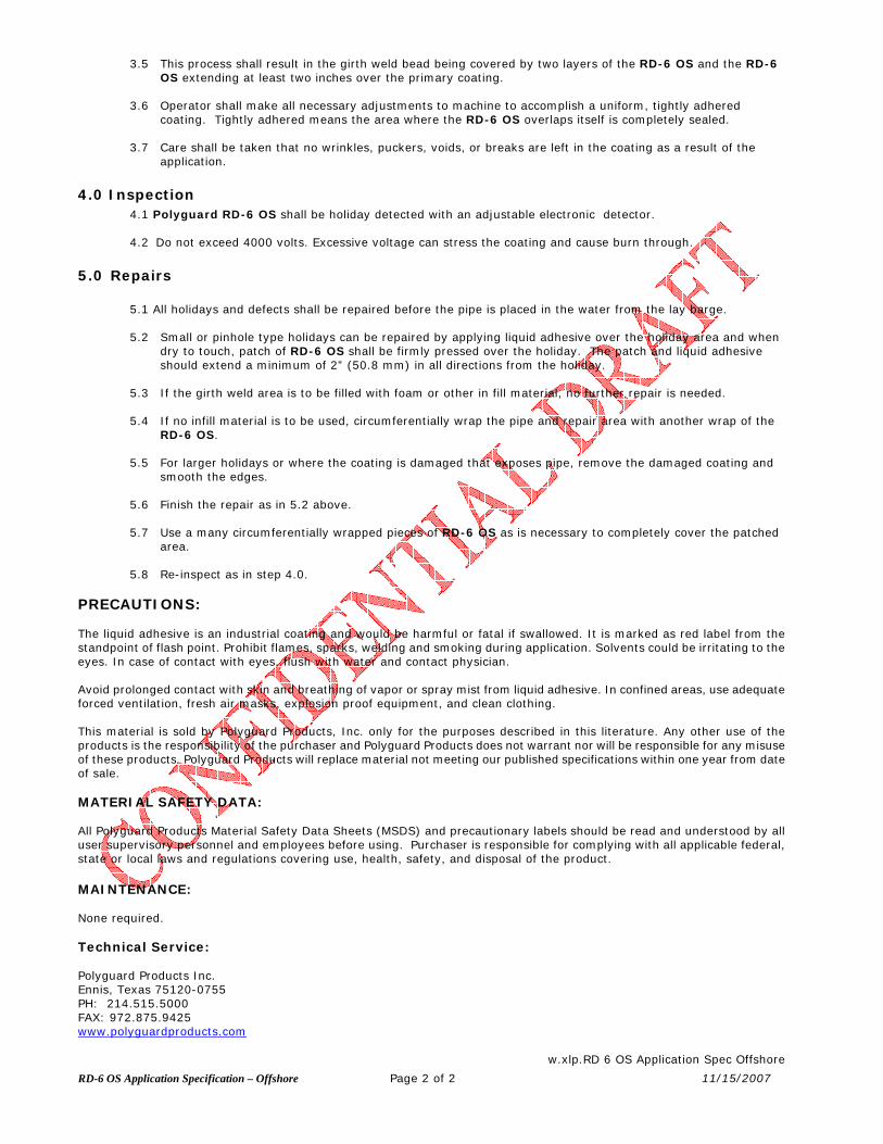
RD-6 OS Application Specification – Offshore Page 2 of 2 11/15/2007
3.5 This process shall result in the girth weld bead being covered by two layers of the RD-6 OS and the RD-6 OS extending at least two inches over the primary coating.
3.6 Operator shall make all necessary adjustments to machine to accomplish a uniform, tightly adhered
coating. Tightly adhered means the area where the RD-6 OS overlaps itself is completely sealed.
3.7 Care shall be taken that no wrinkles, puckers, voids, or breaks are left in the coating as a result of the application.
4.0 Inspection 4.1 Polyguard RD-6 OS shall be holiday detected with an adjustable electronic detector.
4.2 Do not exceed 4000 volts. Excessive voltage can stress the coating and cause burn through.
5.0 Repairs
5.1 All holidays and defects shall be repaired before the pipe is placed in the water from the lay barge. 5.2 Small or pinhole type holidays can be repaired by applying liquid adhesive over the holiday area and when
dry to touch, patch of RD-6 OS shall be firmly pressed over the holiday. The patch and liquid adhesive should extend a minimum of 2” (50.8 mm) in all directions from the holiday.
5.3 If the girth weld area is to be filled with foam or other in fill material, no further repair is needed.
5.4 If no infill material is to be used, circumferentially wrap the pipe and repair area with another wrap of the
RD-6 OS.
5.5 For larger holidays or where the coating is damaged that exposes pipe, remove the damaged coating and smooth the edges.
5.6 Finish the repair as in 5.2 above.
5.7 Use a many circumferentially wrapped pieces of RD-6 OS as is necessary to completely cover the patched
area.
5.8 Re-inspect as in step 4.0. PRECAUTIONS: The liquid adhesive is an industrial coating and would be harmful or fatal if swallowed. It is marked as red label from the standpoint of flash point. Prohibit flames, sparks, welding and smoking during application. Solvents could be irritating to the eyes. In case of contact with eyes, flush with water and contact physician. Avoid prolonged contact with skin and breathing of vapor or spray mist from liquid adhesive. In confined areas, use adequate forced ventilation, fresh air masks, explosion proof equipment, and clean clothing. This material is sold by Polyguard Products, Inc. only for the purposes described in this literature. Any other use of the products is the responsibility of the purchaser and Polyguard Products does not warrant nor will be responsible for any misuse of these products. Polyguard Products will replace material not meeting our published specifications within one year from date of sale. MATERIAL SAFETY DATA: All Polyguard Products Material Safety Data Sheets (MSDS) and precautionary labels should be read and understood by all user supervisory personnel and employees before using. Purchaser is responsible for complying with all applicable federal, state or local laws and regulations covering use, health, safety, and disposal of the product. MAINTENANCE: None required. Technical Service: Polyguard Products Inc. Ennis, Texas 75120-0755 PH: 214.515.5000 FAX: 972.875.9425 www.polyguardproducts.com
w.xlp.RD 6 OS Application Spec Offshore


