Embed Size (px)
Citation preview

Delivered by Publishing Technology to: Waheed AlmasryIP: 212.57.215.203 On: Mon, 02 Feb 2015 08:53:48
Copyright: American Scientific Publishers
ARTICLE
Copyright © 2015 by American Scientific Publishers
All rights reserved.
Printed in the United States of America
Science of Advanced MaterialsVol. 7, pp. 309–318, 2015(www.aspbs.com/sam)
Fabrication of the Diethylenetriamine GraftedPolyacrylonitrile Electrospun Nanofibers Membranefor the Aqueous Removal of Cationic DyesSajjad Haider1�∗, Faez F. Binagag1, Adnan Haider2, Asif Mahmood1, Waheed A. Al Masry1,Mansour Alhoshan1, and Salah Ud-Din Khan3
1Department of Chemical Engineering, College of Engineering, King Saud University, P.O. BOX 800,Riyadh 11421, Saudi Arabia2Department of Polymer Science, Kyungpook National University, #1370 Sankyuk-dong, Buk-gu,Daegu 702-701 South Korea3Sustainable Energy Technologies Center, King Saud University, P.O. BOX 800,Riyadh 11421, Saudi Arabia
ABSTRACT
Diethylenetriamine (DETA) grafted polyacrylonitrile ((PAN) DETA-g-PAN) nanofibers (NFs) membrane was pre-pared by using electrospinning and chemical grafting techniques. Grafting of DETA to PAN was confirmed byFourier Transform Infrared (FT-IR) spectroscopy. Adsorption kinetics of methylene blue (MB), rhodamine B (RB),and safranin T (ST) dyes onto PAN and DETA-g-PAN NFs membranes showed that adsorption leveled off at∼60 min. The kinetics data showed good fitting to pseudo second-order model. No change in the intra-particlediffusion pattern was observed for DETA-g-PAN membrane. The equilibrium adsorption data fitted well to Lang-muir and Freundlich equations. The correlation coefficient (r2) varied from 0.940–0.995 for Langmuir and 0.941to 0.999 for Freundlich equation. The maximum adsorption capacities (qmax� of dyes increased in the order:MB (42.66 mg/g for PAN and 184.84 mg/g for DETA-g-PAN) < ST (72.46 mg/g for PAN and 195.7 mg/g forDETA-g-PAN)< RB (99.31 mg/g for PAN and 367.65 mg/g for DETA-g-PAN). These values are far higher thanthe values reported in literature.
KEYWORDS: Electrospinning, Nanofiber, Grafting, Dyes, Adsorption, Mechanism.
1. INTRODUCTIONThe industrial revolution by the end of 20th century has ledto the installation of many industrial unites (such as electri-cal, electronic, textile, paper, food, cosmetic, plastics, etc.).These industrial unites have not only used a substantialvolume of water during manufacturing, but also consumedchemicals of both inorganic (e.g., (gold (Au), palladium(Pd), and platinum (Pt) copper (Cu), lead (Pb), iron (Fe),etc.) and organic origin (e.g., dye stuff, pigments, etc.).As a result, these industries generated a sizeable amountof wastewaters containing metal ions and dyes and pig-ments. The wastewaters containing metal ions, when takenin, causes various diseases such as ailments, dehydration,stomach ache, nausea, dizziness and/or lack of coordina-tion in muscles, destroying nervous systems of young chil-dren, lung irritation, eye irritation, skin rashes, vomiting,
∗Author to whom correspondence should be addressed.Email: [email protected]: 3 February 2014Accepted: 15 May 2014
abdominal pain, lung insufficiency, and liver damage, etc.Dyes and pigments, on the other hand, are mostly consid-ered non-toxic, even though some are not entirely risk-free.Interest in the environmental behavior of dyes is promptedprimarily due to the concern that dyes may significantlyaffect the aquatic life by reducing photosynthetic activityin the receiving waters (due to the presence of aromat-ics and chlorides, etc.1), cause aesthetic problems and arealso carcinogenic. Furthermore, many dyes are designedfor their chemical stability and do not undergo biochemicalor photo-degradation.2 Hence, a number of conventionalwater treatment methods/processes such as coagulation,3
ultra filtration,4 oxidization,5 electrochemical,6 photocat-alytic degradation,7 and adsorption8 have been studied forthe removal of dyes from wastewaters. However, most ofthese are not affective, expensive, complex, and time con-suming. Adsorption is considered a simple, attractive, andfavorable alternative for the removal of dyes and manyother chemicals from wastewaters. In the last decade,a wide variety of conventional adsorbent materials such
Sci. Adv. Mater. 2015, Vol. 7, No. 2 1947-2935/2015/7/309/010 doi:10.1166/sam.2015.2023 309

Delivered by Publishing Technology to: Waheed AlmasryIP: 212.57.215.203 On: Mon, 02 Feb 2015 08:53:48
Copyright: American Scientific Publishers
Fabrication of the DETA Grafted PAN Electrospun Nanofibers Membrane for the Aqueous Removal of Cationic Dyes SajjadHaider et al.ARTICLE
as a fly ash,9 natural phosphate,10 bentonite,11 activatedcarbon,12 chitosan,13 cyclodextrine,14 and few novel poly-meric materials15 have been used for the removal of var-ious dyes. However, their adsorption capacities were notlarge enough to be considered for industrial applications.To overcome this problem, researchers started focusingon more advanced adsorbent technologies. ElectrospunNFs with fiber diameter in the range of 10 to 500 nm,large surface to volume ratio, high inter-fiber porosity andsmall inter-fiber pore size; is one such example, whichhas changed the whole scenario of wastewaters treatment.Moreover, functionalization of polymers NFs16 with appro-priate functional groups has also enhanced their potentialfor use in advance applications such as filtration, multi-functional membranes,17 composite reinforcement,18 tissueengineering scaffolds,19 wound dressings,20 drug delivery,21
artificial organs,22 and vascular grafts, etc.23 Most of theresearch in the recent past was focused on the utilization ofthe functionalization NFs for biomedical applications. Veryfew instances show the environmental applications of thefunctionalized NFs for the removal of multi-metal ions24
and dyes. In our previous work, we have also successfullyused PAN NFs functionalized with oxime group for theremoval of Cu (II) and Pb (II)ions.16
In the present work, we have combined electrospinningtechnique with chemical grafting. PAN was electrospunto produce NFs (with an average diameter of 225 nm)membrane. The NFs were then surface grafted with DETAin a simple chemical reaction. Finally, the grafted NFsmembrane was applied to the removal of dyes and theirmechanism of adsorption was evaluated. Rare work hasbeen reported on the grafting of PAN NFs for the removalof dyes from wastewaters.
2. EXPERIMENTAL DETAILS2.1. MaterialsPAN (average molecular weight (Mw) 150,000), N ,N -dimethylformamide (DMF (C3H7NO)), DETA(C4H13N3�,MB (C16H18CIN3S · 3H2O),RB (C28H31ClN2O3�, and ST(C20H19ClN4� were purchased from sigma-aldrich. Sodiumcarbonate anhydrous (Na2CO3� was purchased fromPaneac Quimica S.A.U. All the chemicals were of ana-lytical grade and were used without further purification.Distilled water was used for the preparation of the dyessolutions.
2.2. Methods2.2.1. Electrospinning of SolutionFor electrospinning, the solution was added to 5 mL plas-tic syringe of 10 mm diameter with stainless steel needleof 0.8 mm diameter. The syringe was placed in syringepump and the needle was connected with a high volt-age supply, which could generate a high voltage of up to30 kV. The NANON electrospinning setup (Model MECC,
Table I. Optimal electrospinning parameters for the present system.
Parameter Optimization value
Concentration PAN Solution 10 wt%Flow rate 0.8 ml/hApplied voltage 20 kVNeedle diameter 0.8 mmDistance between needle and collector 150 mmViscosity 387 mpa.sConductivity 109.9 �s/cmFiber diameter 225 nmCollector rotation speed 100 rpm
NANON-01A) was used in this study. The optimal solu-tion concentration and electrospinning parameters for thepreparation of PAN NFs membrane are given in Table I.After electrospinning the solution for 1 week (∼6 h daily),the NFs membranes were removed from the aluminumfoil, dried in the vacuum oven (Model DP63, Yamata Sci-entific Co. Ltd.) at 50 �C and −0.1 MPa for 24 h andstored for characterizations and surface grafting.
2.2.2. Morphology Study of the NFsThe morphology of PAN NFs, produced at optimal elec-trospinning parameters, was studied by using a FE-SEM(JSM-7600F). To study the surface morphology of theelectrospun NFs through FE-SEM, NFs samples werefixed onto a holder with aid of a carbon tape and thenplaced in the sputtering machine for platinum coating toincrease their electrical conductivity. After platinum coat-ing the electrospun NFs were examined with FE-SEMunder high vacuum.
2.2.3. Measurement of Viscosity and ConductivityThe viscosities and conductivities of the above mentionedsolutions were measured at room temperature and atmo-spheric pressure using vibro-viscometer (Model SV-10/SV-100) and conductivity meter (CDH-280).
2.2.4. Measurement of the NFs DiameterIn order to measure the NFs diameters, 100 fibers wererandomly selected from the FE-SEM micrographs of eachsample. The diameters were measured using adobe pho-toshop software program 7.0. The measured values werechanged to real values using the scale bar of the FE-SEMmicrograph and the histograms were plotted.
2.2.5. DETA Grafting to PAN NFsDETA-g-PAN NFs were prepared by immersing PAN NFsin a mixture solution of DETA (2.3 M) and sodium car-bonate (0.83 g) in a sealed 500 mL beaker. The mixturewas heated on a water bath at 90 �C with gentle stirring fordifferent time durations (1, 2, 3, 4, and 5 h respectively).After the reaction (Fig. 1), NFs membranes were washedseveral times with distilled water and dried at 60 �C in
310 Sci. Adv. Mater., 7, 309–318, 2015

Delivered by Publishing Technology to: Waheed AlmasryIP: 212.57.215.203 On: Mon, 02 Feb 2015 08:53:48
Copyright: American Scientific Publishers
SajjadHaider et al. Fabrication of the DETA Grafted PAN Electrospun Nanofibers Membrane for the Aqueous Removal of Cationic Dyes
ARTICLE
Fig. 1. Schematic of DETA grafting to PAN.
an oven and stored for characterization. The % grafting ofPAN to DETA-g-PAN was calculated using Eq. (1).
Cn =W1−W0
W0
M0
M1
×100 (1)
Where Cn is % grafting of PAN to DETA-g-PAN, W0 isthe weight of the PAN NFs membrane before reaction, W1
is the weight of the PAN NFs membrane after reaction,M1 and M0 are the Mw of DETA (103.17 g/moL), and ANrepeating unit (53.06 g/moL), respectively.25
2.2.6. FT-IR StudyThe changes occurred in chemical structure of PAN werestudied by taking infrared spectra of the PAN and DETA-g-PAN NFs membranes using FTIR spectrometer (BrukerVertex 70). For the FTIR characterization, potassium bro-mide (KBr) discs of the samples were prepared by mixingand grounding the membranes samples with KBr powderin mortar with a pestle. The mixture was then shaped intodiscs using hydraulic press. The samples discs were thenput into FTIR and spectral measurements were recorded inthe wave number range of 400–4000 cm−1. The data wereprocessed by OPUS 6.0 software (Bruker). The baselinewas corrected by rubber band method, excluding CO2 andH2O bands.
2.2.7. Adsorption StudiesDried samples of PAN and DETA-g-PAN membranes wereadded separately to 10 mL synthetic solutions of dyes(400 ppm) and shaked (in a shaker bath) by batch tech-nique at 25 �C as a function of time until 240 min.Equilibrium time of ∼60 min was determined from thesaturation point of the adsorption kinetics data. Adsorptionequilibrium isotherm was also studied at 25 �C as a func-tion of the dyes concentration. The concentrations of dyesin solution after adsorption experiment were determinedwith UV/VIS Spectrometer (Perkin Elmer, Lambda 35).The amount adsorbed was calculated using the followingEq. (2);
q = �C0−Cf �V
M(2)
Where q is the amount adsorbed (mg ·g−1�, C0 and Cf arethe initial and final concentrations (mg ·L−1� of the dyes,respectively. V is the solution volume (L) and M is theamount of adsorbent (g) used.
3. RESULTS AND DISCUSSION3.1. DETA Grafting to PAN NFsTable II shows the data for the grafting of DETA to PAN.As can be observed, grafting reaction increases as the timeof the reaction was increased. The increase in DETA graft-ing might be attributed to the increased molecular diffusionof DETA from solution into the NFs. During the reaction,the color of the NFs membrane changes from white tolight yellow and then to pale orange. At the end of thereaction (5 h), the color of the membrane was white withslight contracted size. The % grafting of the DETA to thenitrile group of the PAN (calculated from Eq. (1)) was92.74% (the present value is more than the values reportedin the literature25). The change in color might be attributedto the degradation of nitrile (C N) group in PAN. As faras the contraction in size is concerned, since NFs duringthe electrospinning process are under severe drawing ten-sion (stretching force) and in the wet heating reaction arein high-energy meta-stable state, hence contraction in sizemight be attributed to the relaxation of the drawing tensionand decrease in the energy of the meta-stable state.25
3.2. Morphology of the DETA-g-PAN NFsFigures 2(a–f) shows the FE-SEM micrographs, digi-tal images and histograms of the diameters of PANNFs and DETA-g-PAN NFs membranes. The micro-graphs of the DETA-g-PAN NFs membranes exhibitedalmost similar morphology to that of the PAN NFs mem-brane. No serious cracks or degradation of the NFs wasobserved (Figs. 2(a–b)); however, the average fiber diam-eter increased from 225–232 (Figs. 2(e)–(f)). The increasein the average diameter of the fiber in case of DETA-g-PAN membrane might be attributed to the DETA graftingto PAN. The digital image of the DETA-g-PAN NFs mem-brane showed that the membrane had flexible physical tex-ture (Figs. 2(c)–(d)). This consistent physical texture ofthe membrane after grafting complements our argumentsin favor of the undamaged/smooth morphology of DETA-g-PAN NFs (Figs. 2(a)–(b)). The BET (Micromeritics,Gemini MODEL 2390 t) measured interfibers pore vol-ume, pore size and specific surface area of the PAN were
Table II. DETA grafting to PAN NFs membrane.
Exp. No. Time (h) Temp. (�C) Conv. % Coloure Softness
1 1 0.814907 light yellow Soft2 2 36.90374 Pall Orange Soft3 3 85–90 55.88692 Light yellow Soft4 4 81.20476 White soft5 5 92.73977 White Soft
Sci. Adv. Mater., 7, 309–318, 2015 311

Delivered by Publishing Technology to: Waheed AlmasryIP: 212.57.215.203 On: Mon, 02 Feb 2015 08:53:48
Copyright: American Scientific Publishers
Fabrication of the DETA Grafted PAN Electrospun Nanofibers Membrane for the Aqueous Removal of Cationic Dyes SajjadHaider et al.ARTICLE
Fig. 2. FE-SEM micrographs of the surface of the NFs membranes;(a) PAN, (b) DETA-g-PAN, (c–d) digital images of the DETA-g-PAN(Fig. (d) shows that the sample is soft) and (e–f) histogram of the averagediameter; (e) PAN and (f) DETA-g-PAN.
0.0052 cm3/g, 12.25 Å and 16.90 m2/g, respectively. Sim-ilarly, the pore volume, pore size and specific surface areafor DETA-g-PAN NFs were observed as 0.0055 cm3/g,13.00 A� and 16.94 m2/g, respectively. The results showedthat not only the pore size, pore volume but also the spe-cific surface area of the DETA-g-PAN NFs has increased.
3.3. FTIR StudyFigure 3 shows the FTIR spectra of the PAN NFs andDETA-g-PAN NFs membranes. PAN exhibited the absorp-tion bands in region of 1700 cm−1 (C O stretching),1000–1300 cm−1 (C O stretching) at 2938 cm−1(CHstretching), 1453 cm−1(CH2 bending), and 2241 cm1
(C N stretching vibration), which suggests that PAN isa copolymer of acrylonitrile and methylacrylate. Duringthe grafting reactions, the sharp band at 2241 cm−1 con-tineouly decreased in intensity and disappeared until 5 h(the conversion was 92.7397% (Table II)). Whereas theintensities of the newly appeared broad band at 3395 cm−1
(N H group stretching), and medium bands at 1571 cm−1
(N H bending vibration) and 1644 cm−1 (amide C Ostretching vibration) continuously increased as the reactiontime was increased.25–27 The decrease in the intensity ofthe band at 2241 cm−1 with increase in the reaction time
Fig. 3. FT-IR spectra of the (a) PAN NFs and DETA-g-PAN NFs mem-branes at different reaction time: (b) 1 h, (c) 2 h, (d) 3 h, (e) 4 h and(f) 5 h.
clearly shows that C N is the reaction site where DETAgrafting has occurred (Fig. 1).
3.4. Adsorption of Dyes3.4.1. Adsorption KineticsFigures 4(a–b) shows the adsorption of MB, RB, and STfrom 400 ppm synthetic solution onto the PAN and DETA-g-PAN NFs membranes as a function of time. The shapeof the kinetic curves indicates that the adsorption of thedyes to active sites on the adsorbents increased sharplyupto ∼30 min and the surface become homogeneouslysaturated at ∼60 min. At this time there is equilibriumbetween adsorption and desorption of dyes. The effect ofgrafting on the adsorption capacity of the PAN NFs mem-branes was also studied. The adsorption capacity of PANand DETA-g-PAN NFs membranes for dyes was found toincrease in the order PAN < DETA. This increase in thedyes adsorption with grafting could be attributed to theincrease in the number of active sites and exposed sur-face of the membranes. Furthermore, RB showed enhancedadsorption/affinity when all the three dyes were adsorbedonto same membrane. The order of the adsorption for dyeswas MB< ST< RB.To get a further insight into the phenomena of dyes
adsorption onto PAN NFs and DETA-g-PAN NFs mem-branes, the data obtained from kinetic study were furtheranalyzed by using pseudo-first-order (Eq. (3)) and pseudo-second-order kinetic (Eq. (4)) models. The pseudo-first-order kinetic model is based on the approximation thatthe adsorption rate relates to the number of the unoccu-pied adsorptive sites (i.e., one adsorbate is adsorbed ontoone adsorption site on the surface). Whereas, the pseudo-second-order kinetic model is based on the notion that theadsorption should relate to the squared product of the dif-ference between the number of the equilibrium adsorptivesites available on an adsorbent and that of the occupiedsites (one adsorbate is adsorbed onto two sorption sites onthe surface).
312 Sci. Adv. Mater., 7, 309–318, 2015

Delivered by Publishing Technology to: Waheed AlmasryIP: 212.57.215.203 On: Mon, 02 Feb 2015 08:53:48
Copyright: American Scientific Publishers
SajjadHaider et al. Fabrication of the DETA Grafted PAN Electrospun Nanofibers Membrane for the Aqueous Removal of Cationic Dyes
ARTICLE
Fig. 4. Adsorption kinetics of NFs membranes; (a) PAN and (b) DETA-g-PAN.
log�q1e−qt�= log�q1e�−K1
2�303t (3)
q1e and K1 can be obtained by the intercept and slope ofthe plot of log �q1e−qt� versus t.
t
qt= 1
K2q22e
+ 1
q2et (4)
q2e and K2 can be obtained by the slope and intercept ofplot of t/qt versus t�28
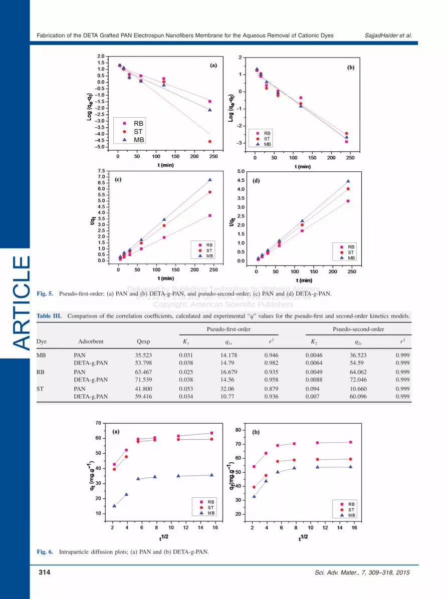
Figures 5(a–d) and Table III shows the correlation andcorrelation coefficients of the adsorption data to pseudo-first-order and pseudo-second-order kinetic. The best fitmodel was determined from the linear correlation coef-ficient values. Good fitting of the data was observedwith the pseudo second-order kinetic model compare topseudo-first-order kinetic model. Furthermore, the q2e val-ues obtained from the pseudo-second-order kinetic modelfor MB, RB, and ST were much closer to the experi-mental qexp values (Table III). The results suggest thatthe adsorption of MB, RB, and ST follow pseudo-secondorder kinetic model, which further suggests that the dyemolecule is adsorbed onto two sorption sites on the sur-face.
Pseudo-first and pseudo-second order kinetic modelscannot identify the influence of mass transfer (solute trans-fer)on sorption. Sorption process is controlled by foursteps;(i) transport in the bulk of solution,(ii) film diffusion,(iii) intra particle diffusion and(iv) adsorption and desorption in the particle and on theouter surface.
Since mixing in the solution is fast, hence steps (i) and(iv) are negligible. Therefore, the possibility of intra-fiberdiffusion was explored by using the intra-particle diffu-sion model. The intra-particle diffusion model (Eq. (5))presumesthat film diffusion or boundary layer diffusion isnegligible, and that intra-particle diffusion is the only ratecontrolling step.29
qt = Kdt1/2 (5)
Where kd is the diffusion coefficient value, t1/2 the time,and qt is the amount of dye adsorbed.The plot of qt versus t1/2 should be linear if intra-
particle diffusion is involved in the adsorption system andintraparticle diffusion is the rate-controlling step, if thelines pass through the origin.30 When the plots do not passthrough the origin, this is an indication of some degreeof boundary layer control and this further indicates thatintraparticle diffusion is not the only rate-limiting step, butother kinetic models may also control the rate of adsorp-tion, all of which may be operating simultaneously.Figure 6 shows that the adsorption plots of dyes are not
linear over the whole range and can be separated into athree linear regions. The first sharp part in the line showsboundary layer diffusion and surface adsorption. The sec-ond part is a more advanced adsorption section and dif-fusion may be the rate-controlling grade here. The thirdpart is the equilibrium section, where intra-fiber diffusionstarts to slow down due to saturation.31 Diffusion in thesecond and third part could be explained by the fact thatNFs are long fibers and deposit randomly in layered form.Hence, diffusion might occur between these layers andthe pores between the fibers. Both PAN and DETA-g-PANNFs membranes showed similar intra-fiber diffusion pat-terns. The three linear regions show that both film diffu-sion and pore diffusion are controlling the adsorption.32
Based on the above explanation, it could be concluded thatgrafting did not affect the intra-fiber diffusion property ofthe membranes.
3.4.2. Equilibrium AdsorptionFigures 7(a)–(b) shows the equilibrium adsorption of MB,RB, and ST onto the PAN and DETA-g-PAN NFs mem-branes as a function of equilibrium concentration (Ce).Initially the adsorption of the dyes increased rapidly; how-ever, as the dyes concentrations were increased, adsorptionwas gradually reduced. To understand the phenomenon ofthe adsorption onto the PAN and DETA-g-PAN NFs mem-branes two isotherm equations were used.Figures 8(a)–(d) shows that the adsorption data fitted
to both Langmuir (Figs. 8(a) and (b)) and Freundlich(Figs. 8(c) and (d)) equations. Langmuir theory suggest
Sci. Adv. Mater., 7, 309–318, 2015 313
Delivered by Publishing Technology to: Waheed AlmasryIP: 212.57.215.203 On: Mon, 02 Feb 2015 08:53:48
Copyright: American Scientific Publishers
Fabrication of the DETA Grafted PAN Electrospun Nanofibers Membrane for the Aqueous Removal of Cationic Dyes SajjadHaider et al.ARTICLE
Fig. 5. Pseudo-first-order; (a) PAN and (b) DETA-g-PAN, and pseudo-second-order; (c) PAN and (d) DETA-g-PAN.
Table III. Comparison of the correlation coefficients, calculated and experimental “q” values for the pseudo-first and second-order kinetics models.
Pseudo-first-order Psuedo-second-order
Dye Adsorbent Qexp K1 q1e r 2 K2 q2e r 2
MB PAN 35�523 0�031 14�178 0�946 0�0046 36�523 0�999DETA-g.PAN 53�798 0�038 14�79 0�982 0�0064 54�59 0�999
RB PAN 63�467 0�025 16�679 0�935 0�0049 64�062 0�999DETA-g.PAN 71�539 0�038 14�56 0�958 0�0088 72�046 0�999
ST PAN 41�800 0�053 32�06 0�879 0�094 10�660 0�999DETA-g.PAN 59�416 0�034 10�77 0�936 0�007 60�096 0�999
Fig. 6. Intraparticle diffusion plots; (a) PAN and (b) DETA-g-PAN.
314 Sci. Adv. Mater., 7, 309–318, 2015

Delivered by Publishing Technology to: Waheed AlmasryIP: 212.57.215.203 On: Mon, 02 Feb 2015 08:53:48
Copyright: American Scientific Publishers
SajjadHaider et al. Fabrication of the DETA Grafted PAN Electrospun Nanofibers Membrane for the Aqueous Removal of Cationic Dyes
ARTICLE
Fig. 7. Adsorption isotherm of organic dyes on to; (a) PAN and (b) DETA-g-PAN NFs membranes.
that adsorption takes place at specific homogeneous siteswithin the adsorbent and once a dye occupied a reac-tion site, then no further adsorption occurred at that loca-tion (chemical adsorption).33 Whereas, Freundlich theorysuggests that there occurs some non-chemical adsorptionor condensation (physical adsorption), which forms morethan one layer. The value of correlation coefficient (r2) forLangmuir varied from 0.940 to 0.995 and for Freundlichfrom 0.941 to 0.999. The increased values of the corre-lation coefficient in case of Freundlich suggest that eventhough monolayer adsorption has occurred but multilayeradsorption is more prominent. Table IV shows the val-ues of qm and K (Langmuir), and n and Kf (Freundlich),which were calculated from the slope and intercept of theplots. The values of n is between 1 and 10, which suggestthat (1<n> 10 represent favorable adsorption) adsorptionis favorable for all the dyes.34
Moreover, the favorability of adsorption in case ofLangmuir is also determined in term of dimensionlessseparation factor or equilibrium parameter RL, which iscalculated with Eq. (6).
RL =1
�1+KLC0�(6)
Where C0 is the highest initial concentration of adsor-bate (mg · L−1�, and KL (L · mg−1� is Langmuirconstant.
RL indicates the shape of the isotherm to be either unfa-vorable (RL>1), linear (RL = 1), favorable (0<RL < 1), orirreversible (RL = 0). The obtained values of RL (Table V)are in the range of 0< RL < 1, which shows that adsorp-tion is favorable.
The qm values calculated from the slope of the Langmuirplots for the adsorption of RB, ST and MB onto DETA-g-PAN NFs membranes were found higher as compare tomost of the values reported for these dyes on conventionaladsorbents (Table VI). These increased values suggestedthat our grafted membrane could find potential industrialapplication.
Table IV. Langmuir and Freundlich isotherms constants for the adsorp-tion of dyes onto PAN and DETA-g-PAN NFs membranes.
PAN
Dye qmax K r 2
Langmuir
MB 42�662 1�163 0�989ST 72�465 0�926 0�995RB 99�305 2�309 0�967
Dye Kr n r 2
Freundlich
MB 3�293 2�011 0�941ST 5�979 1�522 0�988RB 5�609 1�775 0�990
DETA-g-PAN
Dye qmax K r 2
Langmuir
MB 184�8429 104�9142 098�739ST 195�6947 117�8203 097�14RB 367�6471 147�0696 099�66
Dye Kr n r 2
Freundlich
MB 156�6715 121�0214 099�46ST 176�8968 121�6737 099�49RB 189�7842 113�0224 099�861
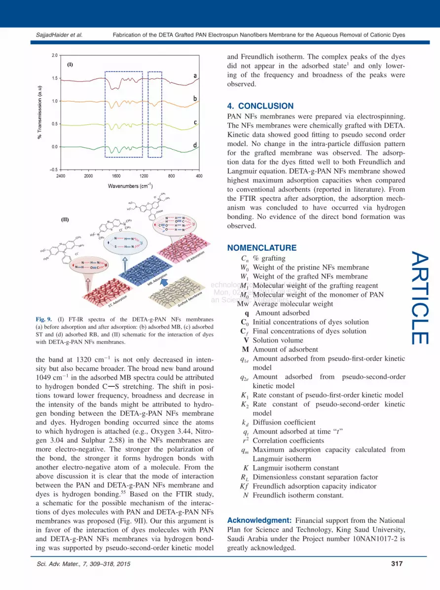
3.4.3. FTIR After AdsorptionFigures 9I(a)–(d) shows the FTIR spectra of DETA-g-PAN before and after adsorption of dyes. The bands
Table V. Showing the RL values for the adsorption of dyes onto PANand DETA-g-PAN NFs membranes.
RL
Membrane MB RB ST
PAN 0�21 0�24 0�36DETA-g-PAN 0�56 0�64 0�54
Sci. Adv. Mater., 7, 309–318, 2015 315

Delivered by Publishing Technology to: Waheed AlmasryIP: 212.57.215.203 On: Mon, 02 Feb 2015 08:53:48
Copyright: American Scientific Publishers
Fabrication of the DETA Grafted PAN Electrospun Nanofibers Membrane for the Aqueous Removal of Cationic Dyes SajjadHaider et al.ARTICLE
Fig. 8. Isotherms models for dyes adsorption; Langmuir (a) PAN, (b) DETA-g-PAN NFs and Freundlich (c) PAN (d) DETA-g-PAN NFs.
at 1571, 1644, 1483, and 1320 cm−1 in DETA-g-PANspectra before adsorption are assigned to the bendingvibration of N H, stretching vibration of C O, stretch-ing vibration of C O, and C N, respectively. After the
Table VI. Adsorption of MB, RB and ST onto various conventional adsorbent reported in the literature.
Methylene blue Rhodamine B Safranin T
Eq. time qmax Eq. time qmax Eq. time qmax
Adsorbent (min) (mg/g) Ref. Adsorbent (min) (mg/g) Ref. Adsorbent (min) (mg/g) Ref.
Peanut hull ∼720 68�03 [35] Fruit waste ∼120 34�48 [40] NaOH treated 45 37�70 [49]rice husk
Banana pee ∼120 20�80 [36] Sodium ∼400 42�19 [41] Magnetic 90 20�00 [50]montmorillonite charcoalclay
Rice husk ∼200 40�59 [37] Coal ash ∼ 4320 2�86 [42] Magnetic 90 46�00 [51]brewer’s yeast
Egg shells ∼120 0�80 [38] Anaerobic ∼70 19�52 [43] PET 2880 29�00 [52]sludge depolymerization
productsWalnut shells ∼1440 3�53 [39) Unburneal ∼3000 9�68 [44] Starch-g-acrylic 1440 116�50 [53]
activated carbon carbon acid copolymer 1Poly — 13�80 [47] Australian ∼3000 2�12 [45] Starch-g-acrylic 1440 204�00 [53]
(vinyl alcohol) natural acid copolymer 2zeolite
CNTs 119�71 [48] Kaolinite ∼80 46�08 [46] Coal 50 12�5 [54]PAN 60 42�66 Present PAN 60 99�31 Present PAN 60 72�465 PresentDETA–g-PAN - 60 184�84 Present DETA–g-PAN - 60 367�65 Present DETA–g-PAN 60 195�70 Present
dyes adsorption, the band at 1571 cm−1 is shifted to1565 (RB), 1562 (MB), and 1564 (ST). Whereas, the bandat 1483 cm−1 (C O stretching) is shifted to 1450 (RB),1451 (MB), and 1451 (ST) cm−1, respectively. Similarly,
316 Sci. Adv. Mater., 7, 309–318, 2015
Delivered by Publishing Technology to: Waheed AlmasryIP: 212.57.215.203 On: Mon, 02 Feb 2015 08:53:48
Copyright: American Scientific Publishers
SajjadHaider et al. Fabrication of the DETA Grafted PAN Electrospun Nanofibers Membrane for the Aqueous Removal of Cationic Dyes
ARTICLEFig. 9. (I) FT-IR spectra of the DETA-g-PAN NFs membranes
(a) before adsorption and after adsorption: (b) adsorbed MB, (c) adsorbedST and (d) adsorbed RB, and (II) schematic for the interaction of dyeswith DETA-g-PAN NFs membranes.
the band at 1320 cm−1 is not only decreased in inten-sity but also became broader. The broad new band around1049 cm−1 in the adsorbed MB spectra could be attributedto hydrogen bonded C S stretching. The shift in posi-tions toward lower frequency, broadness and decrease inthe intensity of the bands might be attributed to hydro-gen bonding between the DETA-g-PAN NFs membraneand dyes. Hydrogen bonding occurred since the atomsto which hydrogen is attached (e.g., Oxygen 3.44, Nitro-gen 3.04 and Sulphur 2.58) in the NFs membranes aremore electro-negative. The stronger the polarization ofthe bond, the stronger it forms hydrogen bonds withanother electro-negative atom of a molecule. From theabove discussion it is clear that the mode of interactionbetween the PAN and DETA-g-PAN NFs membrane anddyes is hydrogen bonding.55 Based on the FTIR study,a schematic for the possible mechanism of the interac-tions of dyes molecules with PAN and DETA-g-PAN NFsmembranes was proposed (Fig. 9II). Our this argument isin favor of the interaction of dyes molecules with PANand DETA-g-PAN NFs membranes via hydrogen bond-ing was supported by pseudo-second-order kinetic model
and Freundlich isotherm. The complex peaks of the dyesdid not appear in the adsorbed state1 and only lower-ing of the frequency and broadness of the peaks wereobserved.
4. CONCLUSIONPAN NFs membranes were prepared via electrospinning.The NFs membranes were chemically grafted with DETA.Kinetic data showed good fitting to pseudo second ordermodel. No change in the intra-particle diffusion patternfor the grafted membrane was observed. The adsorp-tion data for the dyes fitted well to both Freundlich andLangmuir equation. DETA-g-PAN NFs membrane showedhighest maximum adsorption capacities when comparedto conventional adsorbents (reported in literature). Fromthe FTIR spectra after adsorption, the adsorption mech-anism was concluded to have occurred via hydrogenbonding. No evidence of the direct bond formation wasobserved.
NOMENCLATURECn % graftingW0 Weight of the pristine NFs membraneW1 Weight of the grafted NFs membraneM1 Molecular weight of the grafting reagentM0 Molecular weight of the monomer of PANMw Average molecular weight
q Amount adsorbedC0 Initial concentrations of dyes solutionCf Final concentrations of dyes solutionV Solution volumeM Amount of adsorbentq1e Amount adsorbed from pseudo-first-order kinetic
modelq2e Amount adsorbed from pseudo-second-order
kinetic modelK1 Rate constant of pseudo-first-order kinetic modelK2 Rate constant of pseudo-second-order kinetic
modelkd Diffusion coefficientqt Amount adsorbed at time “t”r2 Correlation coefficientsqm Maximum adsorption capacity calculated from
Langmuir isothermK Langmuir isotherm constantRL Dimensionless constant separation factorKf Freundlich adsorption capacity indicatorN Freundlich isotherm constant.
Acknowledgment: Financial support from the NationalPlan for Science and Technology, King Saud University,Saudi Arabia under the Project number 10NAN1017-2 isgreatly acknowledged.
Sci. Adv. Mater., 7, 309–318, 2015 317
Delivered by Publishing Technology to: Waheed AlmasryIP: 212.57.215.203 On: Mon, 02 Feb 2015 08:53:48
Copyright: American Scientific Publishers
Fabrication of the DETA Grafted PAN Electrospun Nanofibers Membrane for the Aqueous Removal of Cationic Dyes SajjadHaider et al.ARTICLE
References and Notes1. S. Kaur, S. Rani, and R. K. Mahajan, J. Chem. 2013, 1 (2013).2. R. Jain, V. K. Gupta, and S. Sikarwar, J. Hazard. Mater. 182, 749
(2010).3. J. W. Lee, S. P. Choi, R. Thiruvenkatachari, W. G. Shim, and
H. Moon, Water Res. 40, 435 (2006).4. K. Majewska-Nowak, T. Winnicki, and J. Wisniewski, Desalination
71, 127 (1989).5. I. A. Salem and M. El-maazawi, Chemosphere 41, 1173 (2000).6. S. Song, J. Fan, Z. He, L. Zhan, Z. Lin, J. Chen, and X. Xu,
Electrochim. Acta 55, 3606 (2010).7. F. Xia, E. Ou, L. Wang, and J. Wang, Dyes Pigm. 76, 76 (2008).8. D. Sun, X. Zhang, Y. Wu, and X. Liu, J. Hazard Mater. 181, 335
(2010).9. I. D. Mall, V. C. Srivastava, and N. K. Agarwal, Dyes Pigm. 69, 210
(2006).10. N. Barka, A. Assabbane, A. Nounah, L. Laanab, and Y. A. Ichou,
Desalination 235, 264 (2009).11. B. Benguella and A. Yacouta-Nour, Desalination 235, 276 (2009).12. V. Gomez, M. S. Larrechi, and M. P. Callao, Chemosphere 69, 1151
(2007).13. A. R. Cestari, E. F. S. Vierira, A. M. G. Tavares, and R. E. Bruns,
J. Hazard Mater. 153, 566 (2008).14. G. Erini, Dyes Pigm. 77, 415 (2008).15. R. Dhodapkar, N. N. Rao, S. P. Pande, and S. N. Kaul, Bioresour.
Technol. 97, 877 (2006).16. K. Saeed, S. Haider, T. J. Oh, and S. Y. Park, J. Membr. Sci. 322,
400 (2008).17. Z. Ma, M. Kotaki, and S. Ramakrishna, J. Membr. Sci. 265, 115
(2005).18. G. M. Kim, G. H. Michler, and P. Potschke, Polymer 46, 7346
(2005).19. Z. Ma, M. Kotaki, and R. Inai, Tissue Eng. 11, 101 (2005).20. H. Ueno, T. Mori, and T. Fujinaga, Adv. Drug. Deliv. Rev. 52, 105
(2001).21. D. S. Katti, K. W. Robinson, and F. K. Ko, J. Biomed. Mater. Res.
Part B 70, 286 (2004).22. Z. M. Huang, Y. Z. Zhang, M. Kotaki, and S. Ramakrishna, Compos.
Sci. Technol. 63, 2223 (2003).23. J. Stitzel, L. Liu, M. Komura, J. Berry, S. Soker, G. Lim, M. Van
Dyke, R. Czerw, J. J. Yoo, and A. Atala, Biomaterials 27, 1088(2006).
24. S. J. Park, J. S. Shin, J. W. Shin, and S. K. Ryu, J. Coll. InterfaceSci. 275, 342 (2004).
25. P. K. Neghlani, M. Rafizadeh, and F. A. Taromi, J. Hazar. Mater.186, 182 (2011).
26. R. T. Morrison and R. K. Boyd, Organic Chemistry, Prentice-Hall,Englewood Cliffs, NJ (1992).
27. S. Deng and R. Bai, Environ. Sci. Technol. 37, 5799 (2003).28. P. S. Kumar and R. Gayathri, J. Engin. Sci. Technol. 4, 381 (2009).29. W. J. Weber and J. C. Morris, J. Sanit. Eng. Div. Am. Soc. Civ. Eng.
89, 31 (1963).30. J. P. Chen, S. Wu, and K. H. Chong, Carbon 41, 1979 (2003).31. I. D. Mall, V. C. Srivastava, N. K. Agarwal, and I. M. Mishra,
Chemosphere 61, 492 (2005).32. M. N. Sahmoune and N. Ouazene, Environ. Prog. Sustainable Energ.
31, 597 (2012).33. I. D. Mall, V. C. Srivatava, and N. K. Agarwal, Dyes Pigm. 69, 210
(2006).34. K. Kairvelu and C. Namasivayam, Environm. Techn. 21, 1091
(2000).35. R. Gong, M. Li, C. Yang, Y. Sun, and J. Chen, J. Hazard Mater.
121, 247 (2005).36. G. Annadurai, R. S. Juang, and D. J. Lee, J. Hazard Mater. 92, 263
(2002).37. V. Vadivelan and K. V. Kumar, J. Colloid Interface Sci. 286, 90
(2005).38. W. T. Tsai, J. M. Yang, C. W. Lai, Y. H. Cheng, C. C. Lin, and
C. W. Yeh, Bioresour. Technol. 97, 488 (2006).39. A. Aygun, S. Yenisoy-Karakas, and I. Duman, Microporous Meso-
porous Mater. 66, 189 (2003).40. P. Parimaladevi and V. Venkateswaran, J. Appl. Tech. Environm. San-
itation 1, 285 (2011).41. P. P. Selvam, S. Preethi, P. Basakaralingam, N. Thinakaran,
A. Sivasamy, and S. Sivanesan, J. Hazard Mater. 155, 39 (2008).42. S. Wang, M. Soudi, and L. Li, J. Hazard Mater. 133, 243 (2006).43. Y. Wang, Y. Mu, and Q. B. Zhao, Sep. Purif. Technol. 50, 1 (2006).44. S. Wang and H. Li, J. Hazard Mater. 126, 71 (2005).45. S. Wang and Z. H. Zhu, J. Hazard Mater. 136, 946 (2006).46. T. A. Khan, S. Dahiya, and I. Ali, Appl. Clay Sci. 69, 58 (2012).47. S. A. Umoren, U. J. Etim, and A. U. Israel, J. Mater. Environ. Sci.
4, 75 (2013).48. Z. Shahryari, A. S. Goharrizi, and M. Azadi, Int. J. Water Res. Env-
iron. Eng. 2, 16 (2010).49. S. Chowdhury, R. Mishra, P. Kushwaha, and P. Saha, Asia-Pac. J.
Chem. Eng. 7, 236 (2012).50. I. Safark, K. Nymburska, and M. Safarkova, J. Chem. Tech. Biotech-
nol. 69, 1 (1997).51. M. Safarikova, L. Ptackova, I. Kibrikova, and I. Safarik, Chemo-
sphere 59, 831 (2005).52. I. Acar, A. Bal, and G. Guclu, Clean-Soil Air Water 40, 325 (2012).53. G. Guclu and S. Keles, J. Appl. Polym. Sci. 106, 2422 (2007).54. D. P. Spitzer, Prepr. Pap. Am. Chem. Soc. Div. Fuel Chem. 33, 789
(1988).55. S. Haider, N. Bukhari, S. Y. Park, Y. Iqbal, and W. A. Al-Masry,
Chem. Eng. Res. Des. 89, 23 (2011).
318 Sci. Adv. Mater., 7, 309–318, 2015


