Embed Size (px)
Citation preview

www.rsc.org/materialsRegistered Charity Number 207890
Showcasing research from the lab of Bio-Materials and
Technology, Prof. Xiuzhi Susan Sun in the Department
of Grain Science and Industry at Kansas State
University, U.S.A.
Title: Chemical pathways of epoxidized and hydroxylated fatty
acid methyl esters and triglycerides with phosphoric acid
Chemical pathways of epoxidized and hydroxylated triglycerides
with phosphoric acid (H3PO4) were revealed using fatty acid methyl
esters model system. Besides catalyst function, H3PO4 facilitates
phosphate ester linkages. Novel transparent tapes were developed
based on this chemistry.
As featured in:
See Byung-Jun Kollbe Ahn, Stefan Kraft
and Xiuzhi Susan Sun, J. Mater. Chem.,
2011, 21, 9498.
0959-9428(2011)21:26;1-H
ISSN 0959-9428
www.rsc.org/materials Volume 21 | Number 26 | 14 July 2011 | Pages 9381–9792
Vo
lum
e 2
1
| N
um
be
r 26
|
20
11
Jo
urn
al of M
aterials C
hem
istry
P
ag
es
93
81
–9
79
2
FEATURE ARTICLED. W. Hutmacher et al.Design, fabrication and characterization of PCL electrospun scaff olds—a review

Dynamic Article LinksC<Journal ofMaterials Chemistry
Cite this: J. Mater. Chem., 2011, 21, 9419
www.rsc.org/materials FEATURE ARTICLE
Design, fabrication and characterization of PCL electrospunscaffolds—a review
A. Cipitria,ab A. Skelton,a T. R. Dargaville,a P. D. Daltonac and D. W. Hutmacher*ad
Received 23rd December 2010, Accepted 16th March 2011
DOI: 10.1039/c0jm04502k
The expanding interest in electrospinning fibers for bioengineering includes a significant use of
polyesters, including poly(3-caprolactone) (PCL). This review summarizes literature on PCL and
selected blends, and provides extensive descriptions of the broad range of parameters used in
manufacturing such electrospun fibers. Furthermore the chemical, physical and biological approaches
for characterizing the electrospun material are described and opinions offered on important
information to include in future publications with this electrospun material.
1 Introduction
The origins of the electrospinning process can be traced to the
first half of the 20th century through various patents by Cooley,1
Morton2 (both 1902), Norton3 (1936) and by Formhals in the
1930s and 1940s.4–7 The technique was not commercially adopted
due to competition with mechanical drawing processes to form
polymeric fibers, and electrospinning remained an obscure
method of making fibers until the mid-1990s. At this time,
Reneker and colleagues demonstrated its potential for nano-
technology research, since the polymeric material produced was
both sub-micron in diameter and inexpensive to prepare.8
Additionally, electrospinning could be used with a variety of
diverse polymeric materials and readily accommodated within
a research laboratory.
Electrospun fibers are produced by applying a potential
difference (high voltage) between a polymeric liquid and a col-
lecting target. A polymeric fluid with sufficient macromolecular
entanglements is typically pumped to the tip of a capillary, or
spinneret. When electrical charges overcome the surface tension
of the fluid, a polymeric fluid jet is ejected from the spinneret.
Due to the macromolecular entanglements, the ejected liquid jet
does not undergo Rayleigh instabilities (breaking up of the liquid
jet into droplets), but is coherently drawn directly towards the
collector. Since the surface charge density increases with prox-
imity to the collector, the charges become sufficiently high to
cause a second transformation, where the jet is twisted and
aInstitute of Health and Biomedical Innovation, Queensland University ofTechnology, 60 Musk Avenue, Kelvin Grove, Brisbane, QLD, 4059,Australia. E-mail: [email protected] Wolff Institute and Center for Musculoskeletal Surgery, Berlin-Brandenburg Center for Regenerative Therapies, Charit�e-Universit€atsmedizin, Berlin, GermanycMed-X Research Institute, Shanghai Jiao Tong University, Huashan Lu1954, Shanghai, 200030, ChinadGeorgeW.Woodruff School of Mechanical Engineering, Georgia Instituteof Technology, Atlanta, USA
This journal is ª The Royal Society of Chemistry 2011
drawn. This phenomenon of fiber drawing is often termed
‘‘bending instabilities’’ and stretches the fibers resulting in the
formation of nano-scale fiber materials. When a single collector
is used, the fibers are non-woven and the collected material is
often called ‘‘meshes’’. Further details of the physical phenomena
governing the electrospinning process can be found in numerous
articles.9–22
About 6 years after the usefulness of electrospinning was
demonstrated by Reneker, researchers including the Ko and
Bowlin laboratories showed that electrospun fibers are relevant
for tissue engineering (TE) research.23,24 In one respect this is due
to electrospun fibers attaining diameters similar to fibrous
extracellular matrix (ECM) in the body, in particular collagen. In
the subsequent decade, electrospun fiber meshes have attracted
increasing attention within TE, including as wound dressing and
in skin TE, blood vessel TE, neural TE, bone and cartilage TE or
controlled drug release, as described in various reviews.25–28 The
rapid rise in the use of electrospun material for TE can be put
down to a number of factors. Firstly, as previously stated, the
nanofiber mesh architecture can mimic the hierarchical orga-
nized fibrous structure found in the ECM. Secondly, the high
surface area of the electrospun meshes is favorable for cell
attachment and drug loading. Furthermore, the fibrous porosity
facilitates nutrient and waste exchange. There are advantages of
electrospinning over other nanofiber mesh fabrication methods
such as phase separation or self-assembly. They include the
simplicity and low cost of constructing a laboratory device, its
versatility—a wide range of possible polymer solutions can be
employed, changing the composition in the core/shell of the
fibers using coaxial electrospinning and control over fibers
diameter and alignment—and reproducibility. While we are not
yet at the stage of generating complex electrospun TE structures,
the potential and huge interest generated after less than 10 years
of research in this area indicates that the process is here to stay
and be one of the more important TE scaffold fabrication tech-
niques in the first half of the 21st century. While there is definitely
J. Mater. Chem., 2011, 21, 9419–9453 | 9419

Fig. 1 Publications using PCL electrospun meshes during the last 10
years, until March 2011. Sourced from ISI Web of Knowledge.
Fig. 2 Chemical structures and selected physical properties of common
linear polyesters.
room for excitement within the TE electrospinning community, it
is important to take stock of where we are and what has been
achieved, recognizing the challenges that the technique is yet to
overcome.
While electrospinning can be used with different synthetic as
well as natural origin polymers,25,29 this review will focus
electrospun materials based on a widely used material, poly-
(3-caprolactone) (PCL). The use of PCL for scaffold fabrica-
tion is increasing generally within the TE community, and is
one of the more significant polymers electrospun during the
past decade (Fig. 1).30 This review is focused on electrospinning
of PCL, synthetic–natural copolymers PCL–collagen or PCL–
gelatin and mixtures of PCL with ceramic Ca–P nanoparticles
than have reportedly been used for biological applications.
Together they make up a small yet significant number of
electrospinning articles, and by collating their use within this
review, it is anticipated that this forges a clearer path for
electrospinning researchers over the next decade of electro-
spinning research.
2 State of the art of PCL for TE applications
There has been a gradual increase in the use of PCL for
biomaterials and TE.30 PCL is an aliphatic linear polyester, with
a glass transition temperature of �62 �C and a melting point of
55–60 �C, (Fig. 2) depending on the degree of crystallinity, which
in turn is dictated by the molecular weight (normally 3000–
100 000 g mol�1) and, to some extent, by the scaffold fabrication
process.31–33 It is biocompatible, bioresorbable and a low-cost
synthetic polymer. Due to its semi-crystalline and hydrophobic
nature, it exhibits a very slow degradation rate (2–4 years
depending on the starting molecular weight) and has mechanical
properties suitable for a variety of applications.31–33 It is a Food
and Drug Administration (FDA) approved material and has
been clinically used as a slow release drug delivery device and
suture material since the 1980s (i.e. Capronor�, SynBiosys�,
Monocryl� suture).
9420 | J. Mater. Chem., 2011, 21, 9419–9453
Compared to other aliphatic linear polyesters such as poly-
glycolic acid (PGA), polylactic acid (PLA) and the diverse
number of copolymer syntheses, PCL has some distinct differ-
ences in physical properties that attract researchers. Firstly, PCL
does not have isomers in the manner that PLA has. With PLA
there are different forms: PDLA, PLLA, and combinations to
form PDLLA. Correspondingly the biological degradation and
melting points of PLA variants are distinct. The melting point of
PCL is substantially lower than PLA, PGA and all of the variant
combinations which is most likely a reflection of the greater
polarity and potential for hydrogen bonding of PGA and PLA
compared with PCL. PCL also has some rheological and visco-
elastic properties that allow it to be formed from a wide range
of scaffold fabrication technologies. The ease unto which
a polymeric material is accommodated into different scaffold
fabrication technologies is a property that should not be
underestimated. PCL and its copolymers have demonstrated this
utility by being successfully used in electrospinning, gravity
spinning,34 phase separation, solid freeform fabrication35,36 and
microparticles,37,38 in part due to the low melting temperature,
very good blend-compatibility, FDA approval and low cost.30
Other combinations with PCL have been electrospun, such as
PCL–PLA39–43 and PCL–PEG44 to induce different properties,
however, for clarity and conciseness, we will only describe PCL
within this review.
One disadvantage of PCL, however, is its hydrophobic
nature, resulting in poor wettability, lack of cell attachment and
uncontrolled biological interactions with the material.45
Surfaces with moderate hydrophilicity are able to absorb
adequate amount of proteins, while preserving their natural
conformation, unlike hydrophobic or very hydrophilic surfaces,
which have poor cell attachment.46–51 In order to rectify this
issue, surface modification techniques can alter the chemical
and/or physical properties of the surface, by modifying the
existing surface or by coating it with a different material. The
optimal degree of surface hydrophilicity, however, depends on
the cell type and on the specific surface modification method
applied.52 Four main surface modification approaches for PCL
include:
� Plasma treatment, which improves the hydrophilicity by
forming oxygen-containing groups at the surface.
� Chemical treatment of PCL with a reagent such as sodium
hydroxide (NaOH).
� Coating or adsorbing natural ECM proteins, which intro-
duce cell recognition sites for improved cell–biomaterial
interaction.
This journal is ª The Royal Society of Chemistry 2011

� Blending in biologically active components to provide signals
to cellular material.
These approaches towards modifying the surface of PCL
elsewhere have all been applied towards electrospun PCL
material. Each approach has its strengths and weaknesses, since
the various surface modification approaches provide new
requirements on the electrospinning process. Electrospun
materials can be difficult to handle, especially if their thickness
is low, and therefore the surface modification processes can
influence the morphology of the structure. This is particularly
important for approaches where post-processing is required, in
particular when the surface modification requires that the
electrospun material is immersed and removed from liquids.
The interfacial energies that separate air and liquid can easily
damage the morphology and structure of an electrospun
material.
2.1 Plasma treatment of electrospun PCL meshes
One approach that avoids immersing electrospun materials into
a liquid is the plasma modification process. The main effects of
this gaseous route to post-processing are: surface cleaning and
etching, which induces changes in topography, and surface
reaction between the plasma and surface molecules, which alters
the surface charge, surface energy and chemistry, without
modifying the bulk properties.53,54Using different feed gases such
as air, O2, NH3, SO2, CO2 or other organic compounds, polar-
ized groups such as hydroxyl, carboxyl, amino and sulfate groups
can be introduced on PCL surfaces.46 Plasma treatment using
oxygen is commonly used in the biomedical field to increase
hydrophilicity of polymers, by increasing the amount of oxygen-
containing groups on the surface, mainly hydroxyl (–OH) and
carbonyl (–C]O) functionalities.53–57
Practically, plasma treatment of electrospun meshes alters the
cell–material interactions as observed in vitro. Prabhakaran et al.
showed that Schwann cells exhibited higher proliferation on
plasma-treated PCL electrospun meshes than PCL and PCL–
collagen meshes, while maintaining their phenotype.58 Fujihara
et al. air plasma treated composite PCL–CaCO3 nanofiber
meshes before culturing with osteoblasts.59 Martins et al.
provided the first systematic study of different plasma treatment
conditions (type of gas—Ar or O2, power—20 or 30 W, exposure
time—5 or 10 min) for modification of PCL electrospun nano-
fiber meshes and influence on the adhesion and proliferation of
fibroblasts, chondrocytes and osteoblasts.55 Undoubtedly more
studies on the plasma modification of PCL electrospun scaffolds
will follow.
2.2 Chemical treatment of electrospun PCL meshes
Immersing the electrospun meshes into a solution which modifies
the surface chemistry has been used for other, non-electrospun,
PCL scaffolds.60 The most common method of chemical treat-
ment is with an aqueous solution of sodium hydroxide (NaOH).
This approach introduces hydroxyl groups and side chain
modification to the PCL by introduction of carboxylate
(–COOH) groups, improving the wettability of the material. The
presence of hydroxyl and carboxylate groups decreases the
hydrophobicity of the polymer surface due to the slightly
This journal is ª The Royal Society of Chemistry 2011
electronegative effects of the carbonyl and hydroxyl functional-
ities which is also less sterically hindered.
There are tribology effects with NaOH treatment with small
pits along the fiber surface. This alters the surface area and
changes the interfacial energy as shown by contact angle values.
Papers that discuss NaOH treatment papers61–63 show morpho-
logical changes to the fibers as well as surface changes chemically
with good characterization data. NaOH treatment has also
been used as an intermediate step to produce apatite-covered
PCL nanofibers. After immersion in aqueous CaCl2 and
K2HPO4$3H2O, apatite nanocrystals deposited on the NaOH
treated surface containing carboxylate groups. The mineralized
PCL nanofiber surface was more hydrophilic and stimulated
osteogenic differentiation.64,65
2.3 Coating of electrospun PCL meshes
Protein adsorption is an important process that dictates the
cellular interaction with a material.66 Therefore PCL meshes are
altered by coating processes—either by physical absorption or
covalent surface bonding.67 Some excellent reviews cover the
general subject of protein adsorption onto biomaterials surfaces.
Such proteins include laminin, gelatin, collagen vitronectin and
fibronectin.46 These proteins interact with the cell, providing
signaling cues and adhesion ligands for cell function. For
example, laminin has been adsorbed onto the surface of elec-
trospun PCL for promoting neurite outgrowth.68 While it is also
well known that growth factors can also be adsorbed onto
surfaces,69 this has not yet been performed with PCL electrospun
fibers.
However to immobilize entities such as growth factors or
peptides with biological activity (e.g. RGDS peptide from
fibronectin), some form of chemical binding needs to be per-
formed. The grafting of hydrophilic polymers onto surfaces has
been performed for various biomaterial surfaces, to provide
both hydrophilicity and reactive functionalities to conjugate
the peptide or protein of interest. Ma et al. grafted gelatin on
PCL nanofiber meshes to improve endothelial cell spreading
and proliferation, and to control cell orientation.70 They
treated the PCL electrospun meshes with air plasma to intro-
duce –COOH groups on the surface and to aid covalent gelatin
grafting, using water-soluble carbodiimide as the coupling
agent.
2.4 Blending biologically active materials with PCL prior to
electrospinning
Since pure electrospun PCL limits cell adhesion, and biological
polymers have problems with fiber formation and mechanical
integrity in biological media, some researchers have blended
both biological polymers and PCL together. For example,
despite the cell affinity to natural collagen, electrospun collagen
meshes have the disadvantages of poor mechanical strength and
that they dissolve in a water-based medium, thus the need for
chemical cross-linking, with the consequent possible cytotox-
icity problems and mesh morphology changes.71 Therefore,
hybrid PCL–collagen brings together the advantages of
synthetic PCL and natural origin collagen. Since collagen
denatures to gelatin72—also with biological properties—there
J. Mater. Chem., 2011, 21, 9419–9453 | 9421

have been investigations with gelatin–PCL electrospun mate-
rial.70,71,73–76 Finally mixtures of PCL with Ca–P compounds are
being investigated for bone TE, owing to the improved
mechanical properties and bioactivity, as the Ca–P compounds
mimic the mineral crystals present in the natural tissue. PCL-
bioactive glass nanofibers have also been investigated.77,78 The
most widely used blends with PCL have been PCL–collagen,
PCL–gelatin and PCL–Ca–P electrospun meshes, although
there have been others blended with biological molecules
including PCL–PLA–gelatin–HA,79 PCL–PLA–collagen,80
PCL–chitosan,81 and PCL–natural human ECM proteins.82 One
important note on blending polymers is that the method does
not require post-processing so delicate structures are not
affected by liquid immersion, and the samples are rapidly ready
for use.
2.5 Factors involved in electrospun meshes for TE studies
A comparative study on recent articles that use PCL or hybrid
PCL–collagen, PCL–gelatin and PCL–Ca–P electrospun meshes,
for in vitro and in vivo studies, is presented in Tables 1–7. Only
articles with a focus on the different biological assays to monitor
cell viability, morphology, adhesion, proliferation, differentia-
tion and infiltration in the mesh were selected for these tables.
It is known that these cellular processes are influenced by the
surface geometry83–87 and curvature,88,89 by the surface chem-
istry90–92 and by the mechanical properties of the substrate.86,93–96
In the context of cell–nanofiber interaction, factors that play an
important role in cellular processes are: fiber diameter,97–99 fiber
alignment,69,70,76,97,99–101 elasticity,102,103 pore size distribution and
porosity,16 surface topography,104 surface chemistry modification
by coating or adsorbing natural ECM proteins,68–70 which
introduce cell recognition sites for improved cell–biomaterial
interaction, or by plasma treatment,55,58,59,70 which improves the
hydrophilicity by forming oxygen-containing groups at the
surface.
Since cellular processes are influenced by mesh physical and
chemical characteristics, in order to compare biological tests
reported on different articles, first the relevant fabrication
process parameters (Table 1) and the physical (Table 2) and
chemical (Table 3) characterization of the meshes are summa-
rized. The different cell seeding and mesh handling techniques
are summarized (Table 4), while in vitro (Table 5) and in vivo
(Table 6) assays are shown.
As it can be seen with the empty entries in Tables 1–7, many of
the articles reviewed in this paper do not provide complete
information regarding systematic mesh characterization, nor
references to previous work, with detailed information of the
mesh fabrication process and physical and chemical character-
istics of the mesh. Moreover, the fact that different culture
medium and cell seeding procedures for the same type of cells are
being used, or different assays are performed to measure one
same phenomenon—i.e. metabolic assays vs. DNA content
quantification using fluorophores to measure cell prolifera-
tion105—does not facilitate the comparison of biological tests
reported on different articles. It is the purpose of this review to
list and discuss the requirements for comprehensive character-
ization of electrospun meshes and in vitro cell culture studies, to
enable comparison of results across different laboratories.
9422 | J. Mater. Chem., 2011, 21, 9419–9453
3 Requirement for comprehensive characterizationof electrospun meshes
In this review we aim to correlate various information compiled
on electrospun PCL materials and blends with collagen, gelatin
and CaP, from the large number of publications depicted in
Fig. 1 (see Tables 1–7). Section 3.1 lists the information required
for complete description of the fabrication process, which is
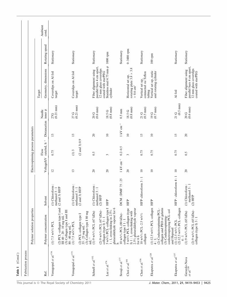
necessary for repeatability purposes. Table 1 summarizes the
fabrication process parameters employed in the cited publica-
tions and reveals gaps in reported data. The physical/chemical
characteristics of electrospun meshes and the most suitable
characterization techniques are described in Section 3.2. Tables 2
and 3 list corresponding reported data and prove an even
stronger evidence of the lack of systematic characterization of the
mesh morphology, topography, mechanical properties and
chemistry, which play an important role to make the adequate
conclusions in in vitro studies. In Section 3.3 we discuss issues
related to cell and mesh handling and sterilization (Table 4) that
are often vaguely described, but are important for replication or
to compare results of in vitro assays (Table 5) between different
groups. Finally, the assessment of electrospun PCL meshes
within in vivo assays is summarized in Section 3.4 and Table 6.
3.1 Fabrication process
Electrospinning is governed by polymer solution properties,
process parameters and ambient conditions and these parameters
and effects on the morphology are widely recognized within the
electrospinning literature.16,27,106
3.1.1 Polymer solution properties. Themain polymer solution
properties are the polymer type and its molecular weight, solvent
type and concentration. Additional properties such as viscosity,
surface tension, conductivity and dielectric strength can be useful
to relate the electrospinning process parameters (see Section 3.1.2)
to the finalmorphology attained (see Section 3.2.1).Many of these
property-relationships are already widespread within the litera-
ture; however there are two aspects of polymeric solutions that
require attention and also inclusionwithin electrospinning papers.
The PCL chosen by the vast majority of researchers is sourced
from Sigma-Aldrich, with a molecular weight of 80 kDa. Recent
discussions with Sigma-Aldrich have revealed that the 80 kDa
PCL is currently out of stock, almost worldwide, and replaced
with another PCL, this time with a broad molecular weight of 70
to 90 kDa.Thereforewhile the use of a specific PCL is excellent for
standardization and comparative research between groups, the
community as a whole is subject to the continued, reproducible,
manufacture of PCL. Unfortunately accurately reproducing PCL
in such large quantities is technically difficult, and the PCL elec-
trospinning community likely to undergo ‘‘readjustment’’ exper-
iments periodically, and thework published a decade before could
become very difficult to precisely reproduce.
Studies with solvents used for electrospinning other polymers
show that different solvent conductivities affect the electrospun
mesh morphology.107,108 One particular study was performed for
solutions of polystyrene dissolved in dimethyl formamide
(DMF).109 They showed a considerable variability in conduc-
tivity, and therefore the morphology of resulting electrospun
This journal is ª The Royal Society of Chemistry 2011

Table
1Fabricationprocess
parameters:polymer
solutionproperties,electrospinningprocess
parametersandambientconditions
Fabricationprocess
Ref.
Polymer
solutionproperties
Electrospinningprocess
parameters
Ambient
cond.
Polymer
concentration
Solvent
Voltage/kV
Flow
rate/m
Lh�1
Distance/cm
Needle
inner
f
Target
Geometry,dim
ensions
Rotatingspeed
PCL
Yoshim
oto
etal.153
10w/v%
PCL(80kDa)
Chloroform
13
61mm
Verticalsetup
Stationary
Liet
al.154
14w/v%
PCL(80kDa)
Dim
ethylform
amide
(DMF)/
tetrahydrofuran
(THF)1:1
12
0.4
20
18G
(0.8
mm)
Verticalsetup,Alfoil
coveringCuplate
Stationary
Shin
etal.155
10w/v%
PCL(80kDa)
Chloroform
13
61mm
Stationary
Shin
etal.156
10w/v%
PCL(80kDa)
Chloroform
:methanol1:1
12
630
1mm
Verticalsetup,nickel-
chromewirering,15mm
ringdiam,0.08mm
wire
diam
Stationary
Ishiiet
al.157
10w/v%
PCL(80kDa)
Chloroform
:methanol1:1
12
6Verticalsetup,static
nickel-chromewirering,
15mm
ringdiam,0.08
mm
wirediam
Stationary
Liet
al.148
14w/v%
PCL(80kDa)
DMF/THF1:1
12
0.4
20
18G
(0.8
mm)
Verticalsetup,Alfoil
coveringCuplate
Stationary
Liet
al.158
14w/v%
PCL(80kDa)
DMF/THF1:1
12
0.4
20
18G
(0.8
mm)
Verticalsetup,Alfoil
coveringCuplate
Stationary
Pham
etal.16
8–15w/v%
PCL(80kDa)
Chloroform
:methanol
5:1to
7:1
19–27
3.5–18
18–33
16–22G
(1.2–0.4
mm)
Horizontalsetup
Moves
back
and
forthfor
uniform
coating
Liet
al.100
14w/v%
PCL(80kDa)
DMF/THF1:1
15
20
18G
(0.8
mm)
Verticalsetup,1inch
Al
cylinder
0–7000rpm
¼0–9.3
ms�
1
Kolambkar1
59
13wt/v%
PCL(80kDa)
andcoatingwith
GFOGER
20mgmL
�1
1hroom
T
Dichloromethane
(DCM)/DMF40:60
14
0.75
15
22G
(0.4
mm)
Metalcylinder
Stationary
and
rotating
Prabhakaran
etal.58
(1)12w/v%
PCL(80kDa)
(1)Chloroform
:methanol1:3
12
112
0.4
mm
15mm
fcoverslipson
Alfoiltarget
Stationary
(2)8w/v%
PCL–collagen
(2)HFIP
(3)Plasm
atreatedp-PCL
(vacuum,30W,1min)
Nottelet
etal.160
5–15w/v%
PCL(80kDa),
implant:15w/v%
(Acetone),
(chloroform
/acetone7:3),
chloroform
/ethanol7:3
15–25,
implant:
20
12–24,
implant:
12
15–25,
implant:
20
21G
(0.5
mm)
Stainless
steelmandrel
with2or4mm
f,
stainless
steelplate
as
asecondnegativepole
Rotating4500rpm
andtranslating200
moves
min
�1,4cm
amplitude
Pektoket
al.147
15w/v%
PCL(80kDa)
Chloroform
:ethanol7:3
20
12
20
Stationary
Nisbet
etal.161
10w/v%
PCL,aninolysedin
0.05M
ethylenediamine,
in2-isopropanol
Chloroform
:methanol3:1
20
0.397
15
21G
(0.5
mm)
10�
10�
2cm
3Al
container
filled
with20
mLPBS
Stationary
Martinset
al.55
17w/v%
PCL,plasm
atreatm
ent:O
2orAr,20or
30W,5or10min,0.2
mbar
Chloroform
:DMF7:3
9–10
120
Alfoil
Stationary
This journal is ª The Royal Society of Chemistry 2011 J. Mater. Chem., 2011, 21, 9419–9453 | 9423

Table
1(C
ontd.)
Fabricationprocess
Ref.
Polymer
solutionproperties
Electrospinningprocess
parameters
Ambient
cond.
Polymer
concentration
Solvent
Voltage/kV
Flow
rate/m
Lh�1
Distance/cm
Needle
inner
f
Target
Geometry,dim
ensions
Rotatingspeed
Liet
al.162
14w/v%
PCL(80kDa)
DMF/THF1:1
12
20
18G
(0.8
mm)
Verticalsetup,Alfoil
coveringCuplate
Stationary
Piskin
etal.163
40w/v%
PCL([
Mw84kDa:
YM
w14kDa20:80)
Chloroform
:DMF1:1
15
10
Alfoil
Stationary
Sim
vastatinloading:
(1)Embeddingdrop20mm
per
scaffold
(2)Dispersingin
PCL
before
electrospinning,20
mm
per
scaffold
Chen
etal.164
10–20w/v%
PCL(80kDa)
Acetone
10–25
37.5–25
0.8
mm
Stationary
Nisbet
etal.165
13w/v%
PCL
Chloroform
:methanol75:25
15
0.6
12
18G
(0.8
mm)
Alrotatingmandrel5
cmf
200–4000rpm
Wiseet
al.166
10w/v%
PCL(80kDa)
Methylenechloride/
DMF75:25
1kV
cm�1
10.1
mm
Rotatingdisc
10ms�
125
� C,
40%
Loweryet
al.124
PCL(80kDa)
Chloroform
,methanol
andDMF
13–37
0.05–0.1
32–48
Stationary
PCL–PEO
(1�
105and2�
106gmol�
1)andpost-H
2O
treatm
ent
Ruckhet
al.167
12w/v%
PCL(80kDa)
Choroform
:methanol
4:1
21
2.8
10
20G
(0.6
mm)
Alfoilonto
Cuplate
Stationary
Wuet
al.168
10w/v%
PCL(80kDa)
Chloroform
:DMF
10:1
18–(�
2)
0.4
15
0.8
mm
3.2,4.5,7.6
mm
diameter
cylinder
300rpm
(circumf
orientation)50rpm
(axialorientation)
Zhuet
al.169
10–25%
PCL(80kDa)
Chloroform
:DMF2:1
15–20
110
0.7
mm
Stainless
steelplane
standorrotating
400–3000rpm
Coatedwithfibrin
Caoet
al.170
(1)14%
PCL(65kDa)
(1)TFE:dH
2O
5:1
(1)16–18
(1)1.5
(1)13–14
22G
(0.4
mm)
PCLfilm
(1)200–250
20–23
� C,
51–56%
(2)9.5%
PCL(65kDa)
(2)DCM
:methanol
3:2
(2)13–15
(2)1.5
(2)8–9
(2)2600–2700
Jhaet
al.171
50–275mgmL
�1PCL(65
kDa)
TFE
22–(�
4or�1
6)
2–20
10–30
18G
(0.8
mm)
Twopole
airgap
Stationary
68
� F,
40%
Yeet
al.172
(1)16%
heparin–PCL(83
kDa)
CH
2Cl 2
20
520
Tubularscaffold
Rotatingmetallic
mandrel
(2)14%
heparin–PCL
conjugate
withorwithout
FGF2loading
PCL–collagen
Venugopalet
al.173
(1)7.5
w/v%
PCL(80kDa)
(1)Chloroform
:methanol3:1
13
113
27G
(0.21mm)
CoverslipsonAlfoil
target
Stationary
(2)PCLcoatedwith10mg
mL
�1collagen
(2and3)
Hexafluoropropanol
(HFP)
(3)7.5
w/v%
collagen
(typeI)
9424 | J. Mater. Chem., 2011, 21, 9419–9453 This journal is ª The Royal Society of Chemistry 2011
Table
1(C
ontd.)
Fabricationprocess
Ref.
Polymer
solutionproperties
Electrospinningprocess
parameters
Ambient
cond.
Polymer
concentration
Solvent
Voltage/kV
Flow
rate/m
Lh�1
Distance/cm
Needle
inner
f
Target
Geometry,dim
ensions
Rotatingspeed
Venugopalet
al.174
(1)7.5
w/v%
PCL
(1)Chloroform
:methanol3:1
12
0.75
13
27G
(0.21mm)
CoverslipsonAlfoil
target
Stationary
(2)PCL–collagen
typeIand
III40:20:10mgmL
�1
(2and3)HFP
(3)Collagen
typeIandIII
80:40mgmL
�1
Venugopalet
al.175
(1)7.5
w/v%
PCL
(1)Chloroform
:methanol3:1
13
(1)3
13
27G
(0.21mm)
CoverslipsonAlfoil
target
Stationary
(2)PCL–collagen
typeI
55:25mgmL
�1
(2and3)HFP
(2and3)0.9
(3)Collagen
typeI80mg
mL
�1
Schnellet
al.152
(1)9w/v%
PCL(67kDa)
(1)Chloroform
:methanol3:1
20
0.5
20
20G
(0.6
mm)
Fiber
alignmentusing
parallel
bars
4cm
apart,
12mm
glass
coverslips
coatedwithstarPEG
Stationary
(2)9w/v%
PCL(67kDa)–
collagen
(typeI)
3:1
(2)HFP
Lee
etal.176
5w/v%
PCL–collagen
typeI
1:1,cross-linkingin
2.5%
glutaraldehydevapourfor6
h
HFP
20
310
18.5
G(0.8
mm)
Stainless
steel4.75mm
fcylinder
1000rpm
Sroujiet
al.177
10w/v%
PCL(80kDa)–
collagen
typeI1:1
DCM
:DMF75:25
1kV
cm�1
0.2–0.5
1kV
cm�1
0.5
mm
Stationary
Choiet
al.101
5w/v%
PCL–collagen
(type
I)1:1,cross-linkingwith
2.5%
glutaraldehydevapour
for6h
HFP
20
310
18.5
G(0.8
mm)
Horizontalsetup,
rotatingplate
3.8
�3.8
�0.6
cm3
0–3480rpm
Chen
etal.136
10w/v%
PCL–2.5
w/v%
collagen
HFP–chloroform
3:1
10
0.75
15
21G
(0.5
mm)
Verticalsetup,
connectedviaTeflon
tubing
Stationary
Ekaputraet
al.128
(1)12.5
w/v%
PCL–collagen
4:1;
HFP
10
0.75
10
19G
(0.7
mm)
Verticalsetup,static
androtatingcylinder
100rpm
(2)CoelectrospinningPCL–
collagen
andPEO
orgelatin
(3)Coelectrospinning–
coelectrosprayingPCL–col
andHeprasil
Ekaputraet
al.137
(1)12.5
w/v%
PCL
HFP:chloroform
4:1
10
0.75
15
21G (0.5
mm)
Alfoil
Stationary
(2)12.5
w/v%
PCL–collagen
4:1
Gerardo-N
ava
etal.150
(1)9w/v%
PCL(65kDa)
(1)Chloroform
:methanol3:1
20
0.5
20
20G
(0.6
mm)
Fiber
alignmentusing
parallel
bars
4cm
apart,
12mm
glass
coverslips
coatedwithstarPEG
Stationary
(2)9w/v%
PCL(65kDa)–
collagen
(typeI)
3:1
(2)HFP
This journal is ª The Royal Society of Chemistry 2011 J. Mater. Chem., 2011, 21, 9419–9453 | 94
25
Table
1(C
ontd.)
Fabricationprocess
Ref.
Polymer
solutionproperties
Electrospinningprocess
parameters
Ambient
cond.
Polymer
concentration
Solvent
Voltage/kV
Flow
rate/m
Lh�1
Distance/cm
Needle
inner
f
Target
Geometry,dim
ensions
Rotatingspeed
Yanget
al.178
8w/v%
PCL(80kDa)–
collagen
(typeI)
3:1
HFP
10
0.6
10
0.9
mm
CoverslipsorAlfoil;cell
seedingonmesh,drain
DMEM,place
3cm
ring,
electrospin
onto
cells
Stationary
PowellandBoyce
149
10w/v%
polymer
HFP
25–30
8.5
cm2groundingplate
Stationary
(1)100%
collagen
(2)1–99%
PCL–col
(3)3–97%
PCL–col
(4)10–90%
PCL–col
(5)30–70%
PCL–col
(6)100%
PCL
PCL(40kDa)
Chem
icalcross-linking
Tillm
anet
al.179
PCL–collagen
typeI1:1,
cross-linkingin
2.5%
glutaraldehydevapourfor6
h
HFP
20
310
18.5G
(0.8
mm)
Stainless
steel4.75mm
fcylinder
1000rpm
Juet
al.180
5–15w/v%
PCL–collagen
typeI1:1,cross-linkingin
2.5%
glutaraldehydevapour
for6h
HFP
5–25
1–10
10–20
18G
(0.8
mm)
Stainless
steel4.75mm
fcylinder
1000rpm
Szotet
al.181
5–15w/v%
PCL–collagen
typeI1:1
HFP
12–(�
8)
310
18G
(0.8
mm)
15mm
diameter
samples
1500rpm
PCL–gelatin
Zhanget
al.73
10w/v%
PCL(80kDa)–
gelatin(typeA)1:1
TFE
1mm
Verticalsetup,30cm
Teflontubing,metal
rack
withAlfoil
Moves
back
and
forthfor
uniform
coating
Maet
al.70
(1)10w/v%
PCL(80kDa)
Chloroform
–DMF
70:30
15
0.5
15
0.21mm
Verticalsetup,15mm
coverslipsonstaticand
rotatingAlcylinder
1000rpm
(2)p-PCL(air,30W,5min)
(3)p-PCLandgelatin
grafting
Chonget
al.75
10w/v%
PCL(80kDa)–
gelatin(typeA)1:1
TFE
10.5
0.7
0.4
mm
Verticalsetupwith
Teflontubing,static15
�15cm
collector
Stationary
Heydarkhan-
Hagvallet
al.71
10w/v%
PCL(10–20kDa)–
gelatin(typeB)1:1
HFP
25
15
22G
(0.4
mm)
Verticalsetup,Alfoil
coatedwithPEG
tofacilitate
removalof
mesh
Stationary
Ghasemi-
Mobarakeh
etal.74
6w/v%
PCL(80kDa)–
gelatin(typeA)50:50and
70:30
HFP
12
10.4
mm
15mm
coverslipson
arotatingdiscorAl
plate
Stationary
and1000rpm
9426 | J. Mater. Chem., 2011, 21, 9419–9453 This journal is ª The Royal Society of Chemistry 2011

Table
1(C
ontd.)
Fabricationprocess
Ref.
Polymer
solutionproperties
Electrospinningprocess
parameters
Ambient
cond.
Polymer
concentration
Solvent
Voltage/kV
Flow
rate/m
Lh�1
Distance/cm
Needle
inner
f
Target
Geometry,dim
ensions
Rotatingspeed
Gupta
etal.76
10w/v%
PCL(80kDa)–
gelatin(typeA)1:1
TFE
17.5
1.5
13
27G
(0.21mm)
15mm
coverslipson
staticandrotating
cylinder
4000rpm
Lim
etal.182
6.7
w/v%
PCL(65kDa)–
gelatin(typeA)1:1
HFP
�26
15
20
20G
(0.6
mm)
7.6
cm�
7.6
cm�
0.2
mm
sheetonto
glass
coatedwithindium–tin
oxide
18mm
coverslips
at1000rpm
Tigliet
al.183
(1)12w/v%
PCL(80kDa)
(1)DCM/D
MF
50:50
(1)25
(1)12
35
0.9
mm
15mm
diameter,20mm
thickmeshes
Stationary
(2)5.4
w/v%
PCL–gelatin
typeA
(50:50)withand
withoutcovalent
immobilizationof10mg
mL
�1epidermalgrowth
factor
(2)HFP
(2)12
(2)1.8
PCL–CaPcompound
Fujihara
etal.59
3–7.5
wt/v%
PCL(80kDa)–
CaCO
3nanoparticles(40
nm
cubictype)
3:1and
1:3,plasm
atreatm
ent
(vacuum,30W,10min)
Chloroform
:methanol3:1
20
113
0.21mm
Verticalsetup,13mm
coverslipsongrounded
plate
Stationary
Room
T,
30–40%
humidity
Venugopalet
al.133
(1)7.5
w/w%
PCL
(1)Chloroform
:methanol3:1
13
113
CoverslipsonAlfoil
Stationary
23
� C,60%
humidity
(2)Collagen
typeI80mg
mL
�1
(2)HFP
(3)PCL/nHA
(51nm)/col
60:90:30mgmL
�1
(3)HFP
Wutticharoenmongkol
etal.184
12w/v%
PCL
(80kDa)
DCM/D
MF
21
110
20G
(0.6
mm)
Alfoilwrapped
15cm
fcylinder
50rpm
PCL—1w/v%
HA
(234�
68nm)
Erisken
etal.185
12w/v%
PCL(80kDa)–0to
15%
bTCP(50nm–2.5
mm)
DCM
50.6
7.5
0.6
mm
Hybridtw
in–screw–
extrusion/
electrospinning
Stationary
Liet
al.138
20w/v%
PCL(42.5
kDa)–
gelatincoatingbylayer-by-
layer
self-assem
bly-C
aP
coatingbyim
mersionin
10�
concentratedSBF
DCM/D
MF80:20
15
0.5
15
24G
(0.311mm)
Alfoil
Stationary
Yuet
al.65
10w/v%
PCL(80kDa),
surface
mineralizedwith
apatite
byseries
ofsolution
treatm
ents
DCM
:ethanol4:1
10
0.5
10
Stationary
This journal is ª The Royal Society of Chemistry 2011 J. Mater. Chem., 2011, 21, 9419–9453 | 9427
Table
1(C
ontd.)
Fabricationprocess
Ref.
Polymer
solutionproperties
Electrospinningprocess
parameters
Ambient
cond.
Polymer
concentration
Solvent
Voltage/kV
Flow
rate/m
Lh�1
Distance/cm
Needle
inner
f
Target
Geometry,dim
ensions
Rotatingspeed
Yanget
al.132
12w/v%
PCL(80kDa)–
nHA
1:4,1:2
80%
TFEin
deionized
H2O
orin
PBS
18–22
212
0.5
mm
Verticalsetup,Teflon
tubing
Stationary
Yanget
al.186
12w/v%
PCL(80kDa)–
gelatintypeA
1:1,
polymer
:nHA
5:1
TFE
20
28
0.5
mm
Alfoil
Stationary
9428 | J. Mater. Chem., 2011, 21, 9419–9453
meshes, between different grades of solvent. Although they inves-
tigated onlyDMF (which is also used inmaking PCL solutions for
electrospinning), the lessons are equally applicable to other
solvents used regularly for PCL, namely chloroform, methanol,
hexafluoroisopropanol (HFIP), THF, and dichloromethane. The
quality and reproducibility of both the polymeric and solvent
constituents for electrospinning PCL are a cause for concern and
for best results, the brand, grade and preferably lot number of the
PCL/solvent should be provided within all publications.
3.1.2 Electrospinning instrument parameters. The potential
permutations for the electrospinning instrument parameters are
endless and for an electrospun mesh to be reproduced, the
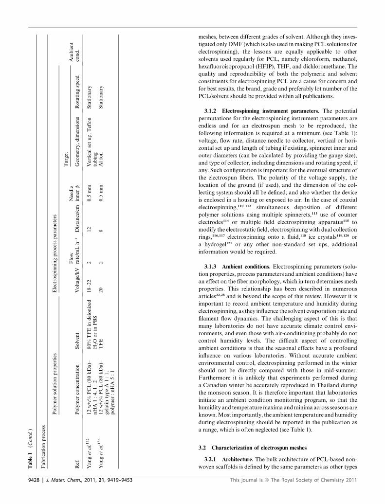
following information is required at a minimum (see Table 1):
voltage, flow rate, distance needle to collector, vertical or hori-
zontal set up and length of tubing if existing, spinneret inner and
outer diameters (can be calculated by providing the gauge size),
and type of collector, including dimensions and rotating speed, if
any. Such configuration is important for the eventual structure of
the electrospun fibers. The polarity of the voltage supply, the
location of the ground (if used), and the dimension of the col-
lecting system should all be defined, and also whether the device
is enclosed in a housing or exposed to air. In the case of coaxial
electrospinning,110–112 simultaneous deposition of different
polymer solutions using multiple spinnerets,113 use of counter
electrodes114 or multiple field electrospinning apparatus115 to
modify the electrostatic field, electrospinning with dual collection
rings,116,117 electrospinning onto a fluid,118 ice crystals119,120 or
a hydrogel121 or any other non-standard set ups, additional
information would be required.
3.1.3 Ambient conditions. Electrospinning parameters (solu-
tion properties, process parameters and ambient conditions) have
an effect on the fiber morphology, which in turn determines mesh
properties. This relationship has been described in numerous
articles22,28 and is beyond the scope of this review. However it is
important to record ambient temperature and humidity during
electrospinning, as they influence the solvent evaporation rate and
filament flow dynamics. The challenging aspect of this is that
many laboratories do not have accurate climate control envi-
ronments, and even those with air-conditioning probably do not
control humidity levels. The difficult aspect of controlling
ambient conditions is that the seasonal effects have a profound
influence on various laboratories. Without accurate ambient
environmental control, electrospinning performed in the winter
should not be directly compared with those in mid-summer.
Furthermore it is unlikely that experiments performed during
a Canadian winter be accurately reproduced in Thailand during
the monsoon season. It is therefore important that laboratories
initiate an ambient condition monitoring program, so that the
humidity and temperaturemaximaandminima across seasons are
known.Most importantly, the ambient temperature andhumidity
during electrospinning should be reported in the publication as
a range, which is often neglected (see Table 1).
3.2 Characterization of electrospun meshes
3.2.1 Architecture. The bulk architecture of PCL-based non-
woven scaffolds is defined by the same parameters as other types
This journal is ª The Royal Society of Chemistry 2011

Fig. 3 SEM micrographs of a freeze-fracture cross-section of 10 w/v%
PCL–gelatin electrospun mesh (unpublished data), showing the mesh
thickness (a) and higher magnification detail (b).
of scaffolds,107 namely, the fiber diameter, fiber alignment/
anisotropy, porosity, pore size, surface area to volume ratio,
interconnectivity and tortuosity. The techniques for measuring
these parameters are vast and include simple manual or auto-
mated image analysis (from SEM, bright field microscopy and
TEM), mercury porosimetry, gravimetry, liquid intrusion,16 gas
pycnometry, gas adsorption, and capillary flow porosimetry. The
merits of these techniques have been reviewed elsewhere.122,123
Other than the fiber diameter, many of the other influential
architectural parameters of PCL fibers are commonly over-
looked (Table 2) possibly due to the lack of access to appropriate
instrumentation which may not be present in all trans-disci-
plinary laboratories. Pham et al. have offered part of a solution
to this problem.16 In a very comprehensive study in which the
PCL fiber diameter and porosity were altered, they found an
excellent agreement between the measured pore size using
mercury porosimetry and the theoretical values from the fiber
diameter (SEM) and the porosity from either gravimetry or
liquid intrusion, both of which can be done with simply an
analytical balance and can generate statistically similar porosity
values between the two methods.16 They were also able to esti-
mate the pore size from samples with fibers too narrow to
withstand the high pressures of mercury porosimetry using this
theoretical method. For fibers 4–10 mm in diameter the pore size
was 20–45 mm based on mercury porosimetry and theoretical
calculations and for 2–3 mm fibers the pore size was approxi-
mately 10–15 mm based on only theoretical calculations. The
total porosity for all samples was between 83 and 89%. A word of
caution is required, however, that when Pham et al. measured
their fiber diameter using SEM, to their credit they used five
different polymer sheets with five samples taken from each and
three measurements made at three different magnifications for
a total of 75 measurements per condition. If the fiber diameter is
going to be carried through to other theoretical estimates, it
needs to be accurate.
Compliant fibrous meshes are, however, susceptible to
undergo mechanical deformation under the pressures attained in
a mercury porosimetry experiment. Lowery et al. used PCL
blended with PEO in order to create fibrous mats with a similar
fiber diameter, but different pore diameter, after PEO removal,
with the aim of isolating the effect of fiber diameter and pore size
on cell growth.124 The pore size distribution was determined
using mercury porosimetry and the results were corrected for the
mechanical deformation of the pore size using the algorithm
described by Rutledge et al.125
In addition to the porosity between fibers, nano-porosity can
also manifest itself on the surfaces of PCL fibers produced by co-
electrospinning with gelatin or PEO followed by a leaching
step.104,124,126–128 Zhang et al. confirmed additional porosity on
PCL fibers after leaching of gelatin using high resolution SEM
then measured the increase in porosity using the BET nitrogen
gas adsorption method.104 They observed an increase in BET
surface area from 6.56 m2 g�1 to 15.84 m2 g�1 after leaching. This
compares with the theoretical surface area of unleached fibers of
3.93 m2 g�1 using the fiber diameter and distribution derived from
the SEM using Image J software.
Computerized tomography (CT) is a potential non-destructive
method for obtaining the fiber diameter and alignment, porosity,
pore size and interconnectivity all from one measurement.122
This journal is ª The Royal Society of Chemistry 2011
Micro-CT has been used to determine the architecture of PCL/
PEG/PLA scaffolds printed using rapid prototyping with 0.5 mm
nozzle diameter and for PLGA meshes with 160 mm thick fila-
ments.122 In each case the porosity, surface area to volume ratio
and interconnectivity were calculated from the micro-CT anal-
ysis. The resolution of micro-CT is typically down to 6 mm which
is too large to be useful for fibers less than approximately 200–
1000 nm, however, it is possible that with the recent availability
of nano-CT this technique will be used for these types of
scaffolds.129
3.2.2 Mechanical properties. Accurate measurement of
mechanical properties of electrospun meshes for biomedical
applications is essential, to guarantee they can withstand the
forces during surgical operation and those exerted by physio-
logical activities and/or by tissue growth.
Uniaxial tensile testing gives information about the Young’s
Modulus or stiffness (E) in tension (slope of the initial linear s–3
curve), yield strength/strain (sy � 3y) (end of linear elastic
region, beginning of non-linear plastic region), fracture stress/
deformation (sf � 3f), and fracture energy per volume (area
under s–3 curve) of the nanofiber mesh or single nanofibers.
Other techniques such as AFM-based nanoindentation or
bending tests have also been reported to measure the local
stiffness, hardness and flexural properties. The description of
the limitations of these techniques is beyond the scope of this
review.
For a tensile test to be accurate and repeatable it is important
to report macroscopic dimensions (gauge length and cross-
sectional area), the strain rate, the applied load, as well as
whether they have been performed at room temperature or under
physiological conditions (at 37 �C, in PBS or culture media).
Most articles that report mechanical properties of a electrospun
mesh measure the cross-sectional area of a highly porous
membrane of the order of tens to hundred of microns, using
a micrometre with a precision of tens of microns. The error
induced by doing so could be one explanation for the large
scatter observed in reported mechanical properties of similar
composition polymer meshes (Table 2). One alternative could be
to take a representative sample of the mesh and to freeze-fracture
in liquid nitrogen as depicted in Fig. 3, and to measure the cross-
sectional area by image analysis.
J. Mater. Chem., 2011, 21, 9419–9453 | 9429

Table
2Physicalcharacterizationofelectrospunmeshes
Ref.
Averagefiber
f/nm
Degreeoffiber
alignment
Porosity
(and
technique)/%
Pore
size
distribution(and
technique)/mm
Mechanicaltesting
Area/m
m2
Thickness/mm
Strain
rate/m
mmin
�1
F/N
E/s_max/3_max[M
Pa]/
[MPa]/[%
]
PCL
Yoshim
oto
etal.153
400�
200
1000
Liet
al.154
700
10�
10
Approx1000
Shin
etal.155
5�
51000
Shin
etal.156
250
10
Ishiiet
al.157
100–5000,average250
10
Liet
al.148
500–900
10�
10
Approx,1000
Liet
al.158
700
10�
10
Approx,1000
Pham
etal.16
Alternatingmicro-and
nanofiber
layers
83–89(by
mercury
porosimetry,
liquid
intrusion
andgravim
etry)
20–45(bymercury
porosimetry
0.6–50psi)
Liet
al.100
0ms�
1:438�
156,9.3
ms�
1:519�
127
0ms�
1:33%,4.0
ms�
1:71.9%,
9.3
ms�
1:94%
40�
5700–1000
2.4
44
E0ms�
1:2.1
isotrop,E4
ms�
1:7.2
(k),<1(t
),E8
ms�
1:11.6
(k),<1(t
)Kolambkar1
59
591�
199
Prabhakaranet
al.58
PCL:350�
83,PCL–
col:245�
80
60–70
10
PCL:s_max¼
3.89,3_max¼
101,p-PCL:s_max¼
1.75,
3_max¼
97,PCL–col:s_max
¼2,3_max¼
24
Nottelet
etal.160
200to
1800,im
plant:
1900
1or3cm
length
10
0.5
<s_max<4.2,100<
3_max<600,im
plant:s4.8
MPa,3600%
Pektoket
al.147
1900
s_max¼
4.8,3_max¼
600
Nisbet
etal.161
750�
100
200
Martinset
al.55
Liet
al.162
8mm
f2000
Piskin
etal.163
600–800
�80
Chen
etal.164
400–1100
56(400nm
f),69
(1100nm
f)(by
SEM)
50
Nisbet
etal.165
Rand:350�
125,alig:
450�
100
200rpm:22%,
4000rpm:47%
Wiseet
al.166
Alig:492�
120,alig:
2796�
845
Loweryet
al.124
730�
90to
10530�
5170
66–87(by
mercury
porosimetry)
2.91–38.5
(by
mercury
porosimetry)
500
Ruckhet
al.167
372�
179
Wuet
al.168
300–500
Circumferencialand
axialalignment
measuredwith
FTT
5�
10
0.4
0.25
Zhuet
al.169
1–2mm,some100nm
Caoet
al.170
(1)313�
5(1)80.9
(2)506�
24
(2)82.6
(by
gravim
etry)
9430 | J. Mater. Chem., 2011, 21, 9419–9453 This journal is ª The Royal Society of Chemistry 2011

Table
2(C
ontd.)
Ref.
Averagefiber
f/nm
Degreeoffiber
alignment
Porosity
(and
technique)/%
Pore
size
distribution(and
technique)/mm
Mechanicaltesting
Area/m
m2
Thickness/mm
Strain
rate/m
mmin
�1
F/N
E/s_max/3_max[M
Pa]/
[MPa]/[%
]
Jhaet
al.171
400–1500
Highly
aligned
fibers
parallel
tocylinder
axismeasuredby
2D
FTT
58–95(liquid
intrusionmethod
ofPham
16)
2.67�
0.295
10
s_max¼
2–4.25MPa
Yeet
al.172
(1)PCL:<1mm
(1)PCL:94
Burstpressure:
(1)PCL:207�
1kPa
(2)Heparin–PCL:3.5
mm
(2)Heparin–
PCL:83(m
ercury
porosimetry)
(2)PCL–heparin:208�
2kPa
PCL–collagen
Venugopalet
al.173
PCL:661–700,collagen:
300–375
20
Venugopalet
al.174
PCL–collagen:210–225
�0.035
EPCL–collagen:18
Venugopalet
al.175
(1)250�
25
(1)2.3
(1)53.5
(2)170�
75
(2)2.2
(2)47.3
(3)275�
56
(3)2.0
(3)45.2
Schnellet
al.152
PCL:559�
300,PCL–
collagen:541�
164
n/a
individual
fiberson
asubstrate
Lee
etal.176
PCL:580�
17,PCL–
col:520�
14
PCL:26.9
mm
2,
PCL–col:22.7
mm
2
(bySEM)
4.75mm
f,12mm
length
300
3,after
having
immersed
samplesin
PSBat
RTfor12h,(*)
alsomeasured
suture
retention
strength,burst
pressure
strength,
compliance
and
maintenance
of
tensile
prop.in
bioreactorafter
4weeks
PCL:E¼
7.7,s_max¼
5.1,
3_max¼
417,PCL–col(w
et):
E¼
2.7,s_max¼
4,3_max¼
140,PCL–col(dry):E¼
3.8,
s_max¼
8.3,3_max¼
62
Sroujiet
al.177
100–120
Choiet
al.101
Rand:334�
125,alig:
296�
97
Histogramsoffiber
angle
asafunction
ofrotationspeed
30�
10
300
30,samplesin
PBS@
RTfor12
hbefore
test
E_rand:4.07(t
)–4.33(k)
,E_alig:2.93(t
)–4.43(k)
,s_maxrand:3.86(t
)–4.01
(k),s_maxalig:3.06(t
)–4.88
(k),3_maxrand:56.67(t
)–53
(k),3_maxalig:91.67(t
)–42.33(k)
Chen
etal.136
PCL:564�
267;PCL–
col:513�
83with
secondary
much
finer
fibers
35�
10
10,samplesin
PBS@
37
� Cduringtesting
PCL:E¼
12.35,s_max¼
4.14,3_max¼
147.15,PCL–
col:E¼
4.5,s_max¼
1.93,
3_max¼
187.11
Ekaputraet
al.128
129�
110
This journal is ª The Royal Society of Chemistry 2011 J. Mater. Chem., 2011, 21, 9419–9453 | 9431

Table
2(C
ontd.)
Ref.
Averagefiber
f/nm
Degreeoffiber
alignment
Porosity
(and
technique)/%
Pore
size
distribution(and
technique)/mm
Mechanicaltesting
Area/m
m2
Thickness/mm
Strain
rate/m
mmin
�1
F/N
E/s_max/3_max[M
Pa]/
[MPa]/[%
]
Ekaputraet
al.137
(1)564�
267
Tube6
mm
f2
mm
long
1–2mm
wall
thickness
2,wet
withPBS
225
(1)Meshonly,seeChen
136
(2)513�
83
(2)Radialdirection-
compressiontest
PCL–col:E
¼1,PCL–col&
cellsheet:E¼
21.4,axialdirection-
indentationPCL–col:E¼
0.61,PCL–col&
cellsheet:E¼
2.4
Gerardo-N
ava
etal.150
PCL:564.4
�208,
PCL–collagen:601.4
�151
Yanget
al.178
455�
85
(a)Dermal¼
10
layersof
fibroblasts,(b)
bilayer
skin
¼18layersof
fibroblast,2of
keratinocytes
PowellandBoyce
149
(1)760�
60
20�
42
5(1)E¼
6.7
�10�3N
mm
�1,
s_max¼
0.118,3_max¼
113.7
(2)890�
100
(2)E¼
8.4
�10�3N
mm
�1,
s_max¼
0.179,3_max¼
106.4
(3)630�
40
(3)E¼
8�
10�3N
mm
�1,
s_max¼
0.198,3_max¼
58.9
(4)630�
85
(4)E¼
1.1
�10�2N
mm
�1,
s_max¼
0.326,3_max¼
50.7
(5)690�
30
(5)E¼
2.3
�10�2N
mm
�1,
s_max¼
0.418,3_max¼
70.8
(6)200
(6)E¼
6�
10�2N
mm
�1,
s_max¼
0.974,3_max¼
102.1
Tillm
anet
al.179
8�
55
1000
Juet
al.180
(1)270�
90
(1)1.76�
1.11mm
2Tube4.75
mm
f12
mm
long
30,samplesin
PBS@
RTfor12
hbefore
test
(1)26
(1)E¼
2.03,s_max¼
3.13,
3_max¼
90
(2)1000�
150
(2)55.7
�34.2
mm
2(2)23
(2)E¼
0.58,s_max¼
2.03,
3_max¼
142
(3)2390�
690
(3)143.5
�80.7
mm
2(3)8
(3)E¼
0.45,s_max¼
0.71,
3_max¼
211
(4)4450�
810
(4)1199.6
�851.2
mm
2
(4)9
(4)E¼
0.26,s_max¼
0.75,
3_max¼
734
Szotet
al.181
(1)424�
60
(2)1156�
184
(3)1613�
213
(4)2236�
282
9432 | J. Mater. Chem., 2011, 21, 9419–9453 This journal is ª The Royal Society of Chemistry 2011

Table
2(C
ontd.)
Ref.
Averagefiber
f/nm
Degreeoffiber
alignment
Porosity
(and
technique)/%
Pore
size
distribution(and
technique)/mm
Mechanicaltesting
Area/m
m2
Thickness/mm
Strain
rate/m
mmin
�1
F/N
E/s_max/3_max[M
Pa]/
[MPa]/[%
]
PCL–gelatin
Zhanget
al.73
50�
10
10
10
PCL:E¼
4.98,s_max¼
2.7,
3_max¼
126,gel:E¼
105,
s_max¼
2.5,3_max¼
64,
PCL–gel:E¼
30.8,s_max¼
1.29,3_max¼
138
Maet
al.70
200–1000
25–100
Chonget
al.75
470�
120
62–75(by
gravim
etry)
28
Heydarkhan-H
agvall
etal.71
880
Average¼
39.25�
7.24(bySEM
image
analysis)
6100–200
1E¼
138,s_max¼
11.17
Ghasemi-Mobarakeh
etal.74
PCL:431�
118,PCL–
gelatin70:30:189�
56,PCL–gelatin50:50:
113�
33
PCL:1.7
�0.39,
PCL–gelatin70:30:
1�
0.35,PCL–
gelatin50:50:0.8
�0.2
(bycapillary
flow
optometry)
50�
10
10
10
PCL–gel
70:30higher
%elongationbutlower
strength
thanPCL
Gupta
etal.76
PCLrand471�
218;
PCLal200�
100;
PCL–gel
rand232�
194;PCL–gel
al160�
86
PCL86,PCL–gel
90(bycapillary
flowporosimeter)
PCL:1.5,PCL–gel:
1.1–1.25
20–30
510
PCLrand:E¼
2.5,s_max¼
1.64,3_max¼
80.45,PCL–gel
rand:E¼
6,s_max¼
1.41,
3_max¼
76.51
Lim
etal.182
(1)As-spun:570
(1)As-spun:6.35
(2)FSlaser-ablated:660
(2)FSlaser-ablated:
7.45
Tigliet
al.183
(1)488�
114
(1)79
(2)663�
107
(2)68(by
gravim
etry)
PCL–CaPcompound
Fujihara
etal.59
PCL:600�
230,PCL–
CaCO
31:3:900�
450,
PCL–CaCO
33:1:760
�190
60�
10
10
s_maxPCLonly:4.8;s_max
PCLwith10%
CaCO
3:2.8
Venugopalet
al.133
From
189�
0.026to
579�
272
(1)PCL:72.3
(1)PCL:2–15
30�
610@
25
� Cand
74%
humidity
10
s_max:
(1)PCL:2.72
(2)PCL/nHA:
78.2
(2)PCL/nHA:3–22
(2)PCL/nHA:1.25
(3)PCL/nHA/
col:85.6
(3)PCL/nHA/col:
2–35
(3)PCL/nHA/col:1.73
(4)Col:89.7
(by
gravim
etry)
(4)Col:3–50(by
bubble
point
pressure)
(4)Col:1.28
Wutticharoenmongkol
etal.184
PCL:950,PCL–HA:
1260
130
This journal is ª The Royal Society of Chemistry 2011 J. Mater. Chem., 2011, 21, 9419–9453 | 9433

Table
2(C
ontd.)
Ref.
Averagefiber
f/nm
Degreeoffiber
alignment
Porosity
(and
technique)/%
Pore
size
distribution(and
technique)/mm
Mechanicaltesting
Area/m
m2
Thickness/mm
Strain
rate/m
mmin
�1
F/N
E/s_max/3_max[M
Pa]/
[MPa]/[%
]
Erisken
etal.185
200–2000withbTCP
varying0–15%
5–50(bySEM
imageanalysis)
8.6
mm
discs
350–400
(1)Tensile
testing:0.01mm
min
�1@
25
� C
(1)Tensile
testing,E;PCL:
0.0185;PCL–6%
bTCP:
0.0195;PCL–12%
bTCP:
0.0275
(2)Compression
testing:0.1
mm
min
�1with
samplesin
PBS@
37
� Cduring
testing
(2)Compressiontestingof
PCL–15%
bTCP,E;
unseeded:0.055;seeded
1week:0.065;seeded
4weeks:
0.110
Liet
al.138
1200
15mm
discs
Yuet
al.65
792�
345
10�
10
200–300
Yanget
al.132
PCL:320,PCL–nHA
1:4390,PCL–nHA
1:2:430
PCL:1.14�
0.51,
PCL–nHA
1:4:
0.92�
0.46,PCL–
nHA
1:2:1.61�
0.69
50�
10
10
250
PCL:E¼
6.77,3_max¼
121,
PCL–nHA
1:4:E¼
19.5,
3_max¼
196,PCL–nHA
1:2:E¼
13.5,3_max¼
161
Yanget
al.186
(1)PCL–gelatin:161
nm
(2)PCL–gelatin–nHA:
281nm
9434 | J. Mater. Chem., 2011, 21, 9419–9453 This journal is ª The Royal Society of Chemistry 2011
3.2.3 Crystallinity. Processing parameters are known to affect
the polymer crystallinity. When processing PCL using solution
electrospinning the extremely rapid removal of solvent may be
expected to result in little opportunity for crystal nucleation
and hence poor crystal structure. Competing with this will be
the simultaneous drawing of the fibers in the whipping region
of the jet to enhance the crystallinity via orientation of the
polymer chains. The crystallinity of PCL fibers has been
studied using several techniques including wide angle X-ray
diffraction (WAXD),130,131 differential scanning calorimetry
(DSC)124,131 and atomic force microscopy (AFM).131 Electro-
spinning from dilute solutions results in thinner fibers with
higher crystallinity attributed to lower viscosity allowing for
better mobility for molecular orientation.131 The study of
a range of fiber diameters found that changes in crystallinity
increased linearly from approx. 42% crystallinity for 900 nm
PCL fibers to 50% for 250 nm fibers. Likewise, crystallinity
further increased when these fibers where stretched after elec-
trospinning.130 The surface morphology of PCL fibers observed
using AFM showed thinner fibers had aligned lamellae within
fibrillar structures, whereas the thicker fibers had more mis-
aligned lamellae with respect to the fiber axis suggesting the
higher degree of crystallinity in the thinner fibers is a result of
orientation.131
The effects of enhanced crystallinity of PCL fibers are
mainly related to mechanical properties. Increased tensile
strength has been reported for PCL fibers below 700 nm
which correlates with improved crystallinity and molecular
orientation.130
3.2.4 Infrared spectroscopy. Fourier Transform Infrared
Spectroscopy (FTIR) is a useful and convenient tool for
determining the chemical composition of PCL composite
fibers. When used with a total internal reflectance (ATR)
accessory it provides a quick, semi-quantitative method for
confirming the presence of additives to PCL fibers including
nano-hydroxyapatite (nHA)132 and gelatin.74 The ATR method
is normally considered non-destructive, however, good contact
between the sample and ATR crystal requires applying
significant pressure which will damage delicate scaffold
morphologies. The technique is generally considered as being
a surface analysis tool as sample depths are typically 0.5–2
mm, however, since most electrospun fibers have diameters in
the nanometre to micrometre scales, the spectra obtained will
be indicative of the whole fibers, not just the surface. Non-
contact reflectance mode is also possible and has been used
to identify the individual components of osteoinductive
PCL/nHA/collagen fibrous scaffolds including detection of
interactions of the nHA with the collagen based on a shift in
the collagen carboxyl group from interaction with calcium of
the nHA.133 FTIR is also useful for determining the protein
conformation in PCL–gelatin/collagen composites based on
characteristic shifts of amide groups indicative of hydrogen
bonding.74,76,133
Other vibrational spectroscopy techniques such as Raman
spectroscopy are also useful in the analysis of nano and micro-
fibrous scaffolds including detection of fiber alignment134 but to
date this technique has not been exploited in the analysis of PCL
based fibers.
This journal is ª The Royal Society of Chemistry 2011
3.2.5 Surface properties. A change in the contact angle of
PCL-based meshes can be a useful indicator of successful surface
modification or blending, however, the contact angle is also
dependent on the surface roughness and porosity. When
a droplet of water is placed on a fibrous mesh only a fraction of
the water comes into contact with the fibers which decreases the
liquid–solid interactions and increases the liquid–air interactions
leading to typically higher contact angles than for smooth
surfaces. Tang et al.135 listed contact angles for PCL films, with
105� being the highest values, while Chen et al.136 and Ekaputra
et al.137 both reported values of 129� for PCL nanofiber mesh
contact angle. In addition, when measuring contact angles of
meshes it is often difficult to extrapolate the circular part of the
drop profile with the surface when it is irregular. For these
reasons the water contact angle of PCL meshes can vary greatly.
Table 3 lists reported angles which range from 109� and 134�.The other point to note in Table 3 is that when PCL is modified
with collagen,136,137 gelatin70,73,74,76,138 or plasma59 the contact
angle reduces to zero meaning it often only serves as a qualitative
guide to the success of a modification process when used in this
way, although Martins et al.55 have demonstrated how change in
contact angle with plasma exposure time can be used to monitor
the exposure required.
The simple elemental composition of PCL (C, H and O only)
makes it a good substrate for X-ray photoelectron spectroscopy
(XPS) which is a highly sensitive surface analysis technique with
a small sampling depth relative to fiber diameters. XPS measures
the binding energy shifts of inner shell electrons and is commonly
used to detect C1s, O1s and N1s shifts. Similarly to contact angle
analysis, XPS has been used only relatively qualitatively to
identify new chemical species for surface modified PCL including
increased oxygen presence after air plasma,58 increased nitrogen
after inclusion of collagen,58 –OH and –C]O after argon or
oxygen plasma.55
3.2.6 Degradation properties. Surprisingly, despite the
increase in the number of publication describing the use of PCL
in electrospinning, very few of them describe the degradation
mechanisms and resorption kinetics in vitro and/or in vivo of
PCL electrospun meshes. PCL degradation mainly occurs by
hydrolytic cleavage of ester groups,139,140 which can proceed via
surface or bulk degradation pathways.61,62 After an initial linear
relationship of ln Mn and time, the second stage begins, which
involves loss of mechanical strength and weight.141 At later
stages of in vivo degradation, when PCL has broken down into
fragments of low molecular weight (Mn < 3000) and high
crystallinity, intracellular degradation can take place by
phagocytosis.142 The degradation rate of bulk PCL is rather
slow: 2–3 years.33 Sun et al. traced the distribution, absorption
and excretion of PCL using radioactive labeling after 3 years in
rats.143
The degradation mechanisms and kinetics of PCL nanofiber
meshes differ from those of bulk PCL, owing to the larger surface
area-to-volume ratio, as well as changes in hydrophobicity and
crystallinity induced by the electrospinning process.144 B€olgen et
al. reported faster degradation kinetics for nanofiber meshes with
thinner fibers in vitro.145 PCL nanofiber meshes with an average
diameter of 196 nm saw its elongation at break reduced from 82
to 5.7%, the ultimate tensile strength from 17.4 to 5.02 MPa and
J. Mater. Chem., 2011, 21, 9419–9453 | 9435
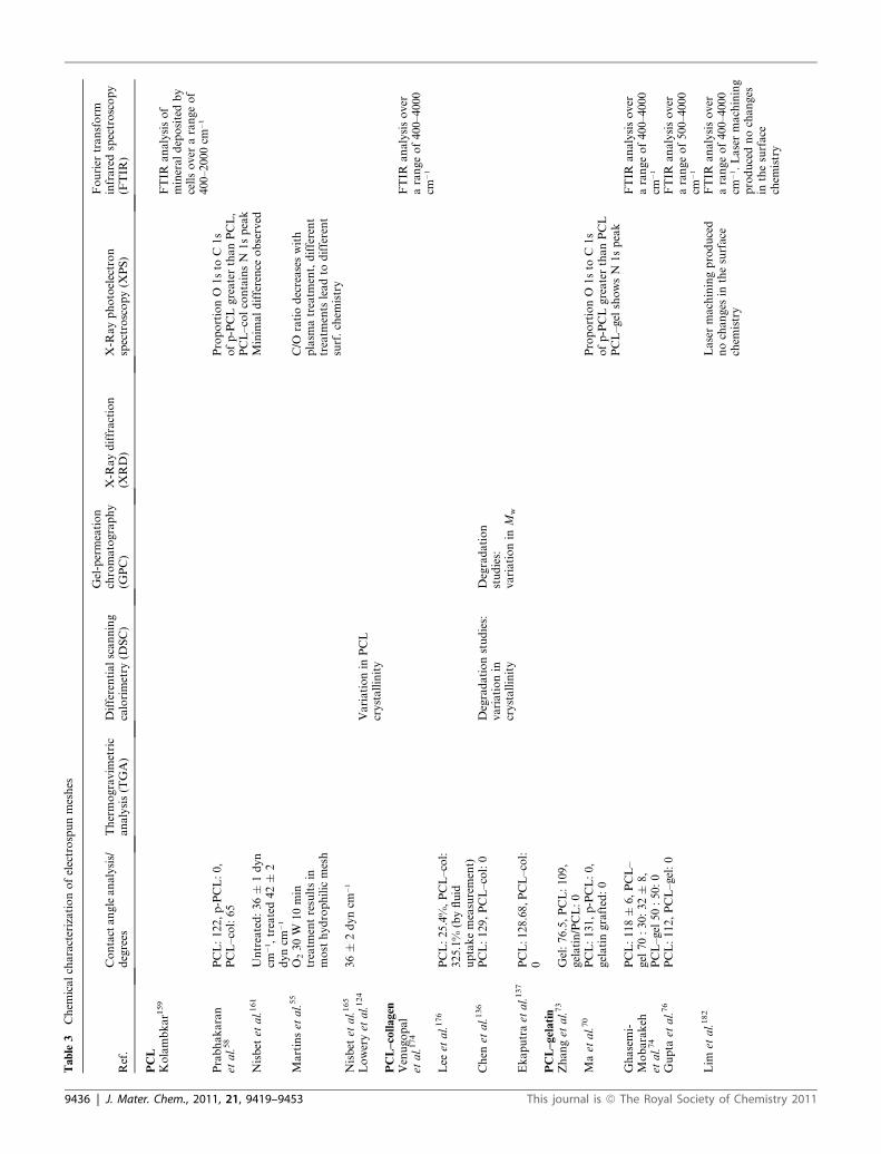
Table
3Chem
icalcharacterizationofelectrospunmeshes
Ref.
Contactangleanalysis/
degrees
Thermogravim
etric
analysis(TGA)
Differentialscanning
calorimetry
(DSC)
Gel-permeation
chromatography
(GPC)
X-R
aydiffraction
(XRD)
X-R
ayphotoelectron
spectroscopy(X
PS)
Fourier
transform
infraredspectroscopy
(FTIR
)
PCL
Kolambkar1
59
FTIR
analysisof
mineraldepositedby
cellsover
arangeof
400–2000cm
�1
Prabhakaran
etal.58
PCL:122,p-PCL:0,
PCL–col:65
ProportionO
1sto
C1s
ofp-PCLgreaterthanPCL,
PCL–colcontainsN
1speak
Nisbet
etal.161
Untreated:36�
1dyn
cm�1,treated42�
2dyncm
�1
Minim
aldifference
observed
Martinset
al.55
O230W
10min
treatm
entresultsin
most
hydrophilic
mesh
C/O
ratiodecreaseswith
plasm
atreatm
ent,different
treatm
ents
leadto
different
surf.chem
istry
Nisbet
etal.165
36�
2dyncm
�1
Loweryet
al.124
Variationin
PCL
crystallinity
PCL–collagen
Venugopal
etal.174
FTIR
analysisover
arangeof400–4000
cm�1
Lee
etal.176
PCL:25.4%,PCL–col:
325.1%
(byfluid
uptakemeasurement)
Chen
etal.136
PCL:129,PCL–col:0
Degradationstudies:
variationin
crystallinity
Degradation
studies:
variationin
Mw
Ekaputraet
al.137
PCL:128.68,PCL–col:
0PCL–gelatin
Zhanget
al.73
Gel:76.5,PCL:109,
gelatin/PCL:0
Maet
al.70
PCL:131,p-PCL:0,
gelatingrafted:0
ProportionO
1sto
C1s
ofp-PCLgreaterthanPCL
PCL–gel
showsN
1speak
Ghasemi-
Mobarakeh
etal.74
PCL:118�
6,PCL–
gel
70:30:32�
8,
PCL–gel
50:50:0
FTIR
analysisover
arangeof400–4000
cm�1
Gupta
etal.76
PCL:112,PCL–gel:0
FTIR
analysisover
arangeof500–4000
cm�1
Lim
etal.182
Lasermachiningproduced
nochanges
inthesurface
chem
istry
FTIR
analysisover
arangeof400–4000
cm�1.Lasermachining
producednochanges
inthesurface
chem
istry
9436 | J. Mater. Chem., 2011, 21, 9419–9453 This journal is ª The Royal Society of Chemistry 2011

Table
3(C
ontd.)
Ref.
Contactangleanalysis/
degrees
Thermogravim
etric
analysis(TGA)
Differentialscanning
calorimetry
(DSC)
Gel-permeation
chromatography
(GPC)
X-R
aydiffraction
(XRD)
X-R
ayphotoelectron
spectroscopy(X
PS)
Fourier
transform
infraredspectroscopy
(FTIR
)
Tigliet
al.183
PCL:133,PCL–gel:
125,PCL–EGF:0,
PCL–gel–EGF:0
FTIR
analysisover
arangeof525–4000
cm�1.EGF
successfully
immobilized
on
nanofiber
surface
PCL–CaPcompound
Fujihara
etal.59
PCL:134,1:3PCL-
CaCO
3:139,after
plasm
atreatm
ent:
0forboth
Venugopal
etal.133
Analysisof
crystallographic
structure
ofPCL,
PCL/nHA
andPCL/
nHA/Col
FTIR
analysisover
arangeof400–4000
cm�1
Erisken
etal.185
PCL:133,PCL—15%
bTCP:127
Determinethetrue
contentofbTCPin
themem
brane
Liet
al.138
PCL:117,PCL–gel:0
Depositedmineral
phase
mixture
of
dicalcium
phosphate
dehydrate
andapatite
Yanget
al.132
Determinethetrue
contentofnHA
inthemem
brane
Analysisof
crystallographic
structure
ofthe
particles
Analysisofchem
ical
structure
ofthe
particlesandof
depositedCaPafter
4daysim
mersedin
SBF
This journal is ª The Royal Society of Chemistry 2011 J. Mater. Chem., 2011, 21, 9419–9453 | 9437

the Young’s modulus from 3.5 to 1.0 MPa, after 6 months in
Ringer solution, at 37 �C and pH 7.4. Fiber with an average
diameter of 689 nm on the other hand exhibited a drop from
150 to 122.2% in the elongation at break, from 48.94 to 31.9
MPa in the ultimate strength and from 4.2 to 2.7 MPa in the
Young’s modulus. Although they observed a slower decrease of
Mw compared to solvent-cast PCL film, a 5% decrease vs. 29%
after 2 months in vitro, indicating that the degradation mech-
anism of PCL nanofibers might shift from bulk degradation to
surface degradation. This was also suggested by Kim et al.:146
the diffusion length for the degraded by-products is shorter in
small diameter nanofibers, hence the soluble hydrolytic prod-
ucts can easily diffuse into the medium, reducing the risk of
autocatalysis in PLA-based electrospun membranes. A shift
from the bulk to surface degradation for PCL nanofiber
meshes might also explain why B€olgen et al. measured a 27%
drop in Mw after 90 days in vivo compared to a 4% drop
in vitro,145 despite similar hydrolytic degradation rates in vitro
(water at 40 �C) and in vivo (rabbits and rats) had been
reported for PCL capsules and films after 144 days, concluding
that the first stage of degradation was non-enzymatic.139 The
surface-to-volume ratio of the PCL capsules (2 cm length,
varying wall thickness) and films (2 � 1 � 0.01 cm3), however,
differed only by ten-fold. Johnson et al. monitored changes in
mechanical properties of PCL electrospun meshes after 7 and
28 days in vitro in six different solutions: sodium bicarbonate,
sterile saline, pasteurized whole cow milk, bovine urine, bovine
plasma and de-ionized water.103 They observed that material
degradation, as well as biological deposition, were responsible
for the changes in mechanical properties. Pektok et al. inves-
tigated the degradation and healing characteristics of 2 mm
internal diameter electrospun grafts in rat abdominal aorta.147
Despite a molecular weight loss of 20% after 24 weeks of
implantation, the grafts kept their strength, prevented any
aneurysm formation, promoted faster endothelization and
premature structural deformation due to degradation seemed
not to be a problem.
3.3 Cell and mesh handling prior to in vitro assays
It is beyond the scope of the review to discuss all the in vitro
studies on PCL meshes summarized in Table 5; yet we like to
discuss some practical points in this section. Irrespective of the
ultimate purpose for the in vitro investigations (cell viability,
proliferation, differentiation or migration), cell and mesh
handling should be thoroughly described for repeatability
purposes. While the cell type and origin, type of culture medium
and passage number are often included in most articles reporting
biological assays, crucial details that allow reproduction of
experiments are often omitted. Often this is a result of the
researcher not considering the many effects that a protocol could
have on their material. One such example is the method of PCL
mesh sterilization.
The mesh sterilization methods vary greatly between different
laboratories: ethylene oxide, UV radiation or soaking in ethanol.
Ethylene oxide is known to soften and plasticize polymers. To
the author’s knowledge, there are no systematic studies of the
UV radiation dose effect on polymer molecular weight and its
consequent changes in mechanical and degradation properties.
9438 | J. Mater. Chem., 2011, 21, 9419–9453
Regarding the use of ethanol, sterilization is independent of the
time immersed in ethanol, and long immersion period is not an
optimal sterilization practice.
Furthermore, it has been observed in our group (Fig. 4)
that sterilization with ethanol can dramatically change the
morphology of PCL–gelatin electrospun meshes. Very few of
the referred articles in this review148,149 analyze the mesh
morphology after sterilization and incubation in the culture
medium. They do not observe any significant structural
degradation on the PCL mesh, after sterilization with UV
irradiation only (no ethanol) and 21 days incubation time.
Although analysis of mesh morphology changes due to ster-
ilization is most relevant for PCL–collagen or PCL–gelatin
meshes. In general, despite the exponential growth of publi-
cations describing the use of PCL in tissue engineering, few
groups have included a study of the degradation and resorp-
tion kinetics.30 Puppi et al. commented that the maintenance
of scaffold structure in physiological buffer and the support
of cell proliferation/differentiation may be more promising
for the engineering of more structurally stable connective
tissues.78
Regarding cell seeding, although the initial cell seeding
density is often reported, the seeding method, that is, the
initial seeding volume and whether this is followed by an
incubation time for cell attachment before adding the rest of
the culture medium, is not always mentioned (see Table 4 and
Fig. 5).
Finally, the in vitro handling of electrospun meshes is not
technically trivial and hence need to be discussed. PCL has
a density of 1.13–1.15 g mL�1 and readily sinks, however,
nanofibers of this material can be lifted off surfaces from fluid
flow. Probably the most destructive aspect of in vitro culture to
electrospun meshes is the frequent media changes. Removing
a liquid entirely, then replacing with another one has strong
mechanical effects on the electrospun material, and care is
needed in the withdrawal of the fluid so that the sample does
not get drawn into the pipette. However the parameters
involved in culture are more complicated than this. The mesh
could be freely floating in the culture medium, or somehow
immobilized onto a surface. The way that an immobilized mesh
is achieved, whether it is in direct contact with a substrate
underneath or it is suspended between two rings, all has an
effect on the results and they are confounded by media
changes. Unlike other cell culture protocols, such as protein
coating of substrates, cell culture media used and passaging of
cells, there are no widely used approach to placing electrospun
substrates into a culture well. This is also unlikely to change, as
it is one area where researchers are looking at different ways to
culture and observe cellular interactions with electrospun
fibers.
To demonstrate how the approach of placing electrospun
material into a culture well is becoming specialized, a function-
ally reactive starPEG has been used to pre-treat glass cover slips
so that a very low number of fibers can be adhered to a substrate
without floating off. In a series of four papers using this
approach,150–152 the reactive PEG macromer adheres the fiber
and continues to react with water so that the exposed PEG
substrate is non-adhesive to proteins or cells. Fig. 6 shows elec-
trospun PCL/collagen blends collected using a dual beam
This journal is ª The Royal Society of Chemistry 2011

Table
4Cellandmeshhandlingpriorto
invitroassays
Ref.
Celltype
Culture
medium
Seedingdensity/cells
per
cm2
Meshhandling
Sterilization
PCL
Yoshim
oto
etal.153
RatMSCs
Osteogenic
medium,2daysstatic
culture,then
dynamic
conditions
Meshpressed
onto
cellpelletwith
4�
106cells
Cutin
10�
10mm
270%
ethanolfor3h,soaked
inpurified
collagen
solutionovernight
Liet
al.154
Fetalbovine
chondrocytes,P2–6
Seedingin
20mLdrops,after
4hin
an
incubator,add
(1)1�
104
Cutin
10�
10mm
2,24-w
ell
plates
UV
irradiation30min,soaked
withHanks’
BalancedSaltSolution(H
BSS)for24hat37�
-Serum-freechondrogenic
medium
(2)4�
105
-Serum-containingchondrogenic
medium
Shin
etal.155
NeonatalLew
isratbone
marrow-derived
MSCs
Osteogenic
medium,2daysstatic
culture,then
rotatingbioreactor
Meshpressed
onto
cellpelletwith
4�
106cells
Cutin
5�
5mm
270%
ethanolfor24h,soaked
inpurified
collagen
solutionovernight
Shin
etal.156
NeonatalLew
israt
cardiomyocytes
40%
M–199,54%
Earle’sBalancedSalt
Solution,6%
FBS
2.5
�106
Meshsuspended
across
anickel-chrome15mm
fring(w
ire0.08mm
f)
70%
ethanolovernight,coatingwithpurified
typeI
collagen
solution
Ishiiet
al.157
NeonatalLew
israt
cardiomyocytes
40%
M–199,54%
Earle’sBalancedSalt
Solution,6%
FBS,supplementedwith
100U
mL
�1penicillinandstreptomycin
2.5
�106
Meshsuspended
across
anickel-chrome15mm
fring(w
ire0.08mm
f),after
days5–7,upto
5meshes
overlaid
in3D
cardiacgrafts
Liet
al.148
Humanbonemarrow
derived
MSCs,P1–3
Seedingin
20mLdrops,after
4hin
an
incubator,addchondrogenic
medium,
supplementedwithTGF-b1
4�
105
Cutin
10�
10mm
2,24-w
ell
plates
UV
irradiation30min,soaked
withHanks’
BalancedSaltSolution(H
BSS)for24hat37�
Liet
al.158
Humanbonemarrow
derived
MSCs
(1)Chondrogenic
medium
(1)4�
105
Cutin
10�
10mm
2,24-w
ell
plates
UV
irradiation30min,soaked
withHanks’
BalancedSaltSolution(H
BSS)for24hat37�
(2)Osteogenic
medium
(2and3)2�
105
(3)Adipogenic
medium
Pham
etal.16
RatMSCs
Osteogenic
medium
5�
105
8mm
discs
cutwithpunch,
press
fitinto
cassettesand
placedin
6-w
ellplates
Ethyleneoxidegas14h,70%
ethanolovernight,
rinse
withPBS3�,
soakwithculture
themedium
inanincubatorovernight
Liet
al.100
HumanMSCs,P2
Seedingin
20mLdrops,after
4hin
an
incubator,addDMEM,10%
FBS,1%
penicillin/streptomycin/fungizone
250�
103
UV
irradiation,prewet
withFCSfor30min
Kolambkar1
59
HumanMSCsand
amnioticfluid
derived
SCs
a-M
EM,16.7%
FBSandantibiotics,
osteogenic
medium
4daysafter
seeding
2�
104
Cutin
14�
14mm
2
Prabhakaranet
al.58
Schwanncells,P2
DMEM,10%
FBS,1%
penicillin/
streptomycin/amphotericin-B
1�
104
24-w
ellplate
Nottelet
etal.160
Cylinder
with2or4cm
length
and2or4mm
inner
diameter
gRadiation25kGy
Pektoket
al.147
2mm
internaldiameter,13
mm
length
gRadiation25kGy
Nisbet
etal.161
Ratbrain
derived
neural
stem
cells
(1)10%
FBS
5�
105cellsper
mL
Cutin
5�
5mm
2Aninolysedin
0.05M
ethylenediamine,
in2-
isopropanol,allowed
toreact
at20
� Cfor10–40
min,washed
3�
inicewater,soaked
for1hin
distilled
wateronice,
dried
overnightin
avacuum
oven,disinfected
with70%
ethanol
(2)Mitogens
This journal is ª The Royal Society of Chemistry 2011 J. Mater. Chem., 2011, 21, 9419–9453 | 9439

Table
4(C
ontd.)
Ref.
Celltype
Culture
medium
Seedingdensity/cells
per
cm2
Meshhandling
Sterilization
Martinset
al.55
(1)Mouse
lung
fibroblasts
(1and2)DMEM,10%
FBS,1%
antibiotic/antimycotic
1�
105
24-w
ellplate
Ethyleneoxidegas
(2)Humanprimary
osteosarcomacellline
(3)DMEM–F12,10%
FBS,2nM
L-
glutamine
(3)Mouse
chondrocyte
teratocarcinoma-derived
cellline
Liet
al.162
Allogenic
chondrocytes
orxenogenic
human
MSCs
Seedingin
0.1
mLdrops,20mLof
DMEM,10%
FBSmedium
added
every
30min,after
2hseedingontheother
side
8�
105oneach
side
Cutin
8mm
discs,24-w
ell
plate
UV
irradiation30min,soaked
in70%
ethanol30
min,rehydratedwithsequential30min
rinsesof
50%,25%,dH
2O
andHBSS
Chen
etal.164
Mouse
fibroblasts
Seedingin
1mLdrops,then
subjected
tovacuum
pressure
of2.5,8or20in
Hg.
AddDMEM,10%
FCS,1%
penicillin/
streptomycin
3�
105
Cutin
10�
10mm
2Sprayed
withalcohol,rinsedtw
icewithPBS,
soaked
withtheculture
medium
overnight
Nisbet
etal.165
5mm
square
scaffolds,
rolled
into
atube,
inserted
into
a21G
needle
70%
ethanol
Wiseet
al.166
HumanMSCs,P3
(1)Growth
media:DMEM,15%
FBS,2
mM
L-glutamine,
1%
antibiotics/
antimycotics
6�
104
2cm
270%
ethanolfor1h,vacuum
chamber
for3days,
UV
irradiationfor6honeach
side
(2)Chondrogenic
differentiationmedia
Loweryet
al.124
Humandermal
fibroblasts
DMEM,10%
FBS,1%
penicillin/
streptomycin
(1)Dropletcell
seeding:5�
105cells
per
mL
2.2
cmdiameter
(2)Perfusioncell
seeding
Ruckhet
al.167
RatMSCs
DMEM,10%
FBS,1%
penicillin/
streptomycin.Onday7,osteogenic
differentiationmedia
1�
106
0.7
cm2discs
UV
irradiationfor60min,followed
bysoakingin
70%
ethanolfor60min,washed
2�
withwarm
PBS,followed
byculture
media
Wuet
al.168
BAEC
cells
5�
104cellsper
well
1.5
�1.5
cm2,meshes
held
withmetalrings
UV
radiationfor45min
Zhuet
al.169
(1)Humanumbilical
arterysm
ooth
muscle
cells,P7
(1)Smooth
muscle
cellbasalmedium
supplementedwithhumanepidermal
growth
factor(hEGF),insulin,human
fibroblastic
growth
factor-basic(hFGF-
B),fetalbovineserum
(FBS),andGA-
1000
(1)6�
104
Smalldiscs
70%
ethanol,rinsedwithPBS
(2)Humanumbilical
veinendothelialcells,P7
(2)Endothelialbasalmedium
supplementedwithhydrocortisone,
hEGF,FBS,andgentanicin
amphotericinB
(2)10�
104
Caoet
al.170
Humanprimary
monocytes
10%
autologousserum
andmacrophage-
serum
free
media
5�
105cellsonto
each
scaffold
Discs
of1cm
diameter
in24-w
ellplates
70%
ethanolfor30min,washed
3�
withPBS,UV
irradiation30min
Jhaet
al.171
Dorsalrootganglion
(DRG)explants
from
embryonic
day15rats
Media
supplementedwith0.1
mgmL
�1
NGF
Single
DRG
inserted
inthecavity
25G
needleusedto
produce
acavityinto
thedorsal
surface
ofatubularscaffold
100%
ethanolovernight,rinsedin
70%
ethanol,
rinsed3�
insterilePBS
Yeet
al.172
Endothelialcells
DMEM,10%
FBS,1%
penicillin/
streptomycin
(1)1�
103cellsmL
�1
0.5
cm2in
24-w
ellplates
(2)1�
105cellsmL
�1
100mLinto
each
well
9440 | J. Mater. Chem., 2011, 21, 9419–9453 This journal is ª The Royal Society of Chemistry 2011
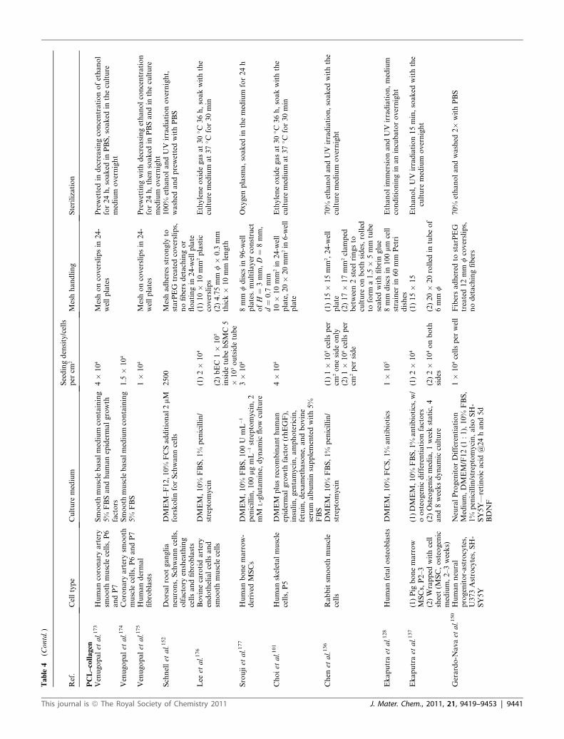
Table
4(C
ontd.)
Ref.
Celltype
Culture
medium
Seedingdensity/cells
per
cm2
Meshhandling
Sterilization
PCL–collagen
Venugopalet
al.173
Humancoronary
artery
smooth
muscle
cells,P6
andP7
Smooth
musclebasalmedium
containing
5%
FBSandhumanepidermalgrowth
factors
4�
104
Meshoncoverslipsin
24-
wellplates
Prewettedin
decreasingconcentrationofethanol
for24h,soaked
inPBS,soaked
intheculture
medium
overnight
Venugopalet
al.174
Coronary
arterysm
ooth
muscle
cells,P6andP7
Smooth
musclebasalmedium
containing
5%
FBS
1.5
�104
Venugopalet
al.175
Humandermal
fibroblasts
1�
104
Meshoncoverslipsin
24-
wellplates
Prewettingwithdecreasingethanolconcentration
for24h,then
soaked
inPBSandin
theculture
medium
overnight
Schnellet
al.152
Dorsalrootganglia
neurons,Schwanncells,
olfactory
ensheathing
cellsandfibroblasts
DMEM–F12,10%
FCSadditional2mM
forskolinforSchwanncells
2500
Meshadheres
strongly
tostarPEG
treatedcoverslips,
nofibersdetachingor
floatingin
24-w
ellplate
100%
ethanolandUV
irradiationovernight,
washed
andprewettedwithPBS
Lee
etal.176
Bovinecarotidartery
endothelialcellsand
smooth
muscle
cells
DMEM,10%
FBS,1%
penicillin/
streptomycin
(1)2�
104
(1)10�
10mm
2plastic
coverslips
Ethyleneoxidegasat30
� C36h,soakwiththe
culture
medium
at37
� Cfor30min
(2)bEC
1�
105
insidetubebSMC
5�
105outsidetube
(2)4.75mm
f�
0.3
mm
thick�
10mm
length
Sroujiet
al.177
Humanbonemarrow-
derived
MSCs
DMEM,10%
FBS,100U
mL
�1
penicillin,100mgmL
�1streptomycin,2
mM
L-glutamine,
dynamic
flow
culture
3�
104
8mm
fdiscs
in96-w
ell
plates.multilayer
construct
ofH
¼3mm,D
¼8mm,
d¼
0.7
mm
Oxygen
plasm
a,soaked
inthemedium
for24h
Choiet
al.101
Humanskeletalmuscle
cells,P5
DMEM
plusrecombinanthuman
epidermalgrowth
factor(rhEGF),
insulin,gentamycin,amphotericin,
fetuin,dexamethasone,
andbovine
serum
albumin
supplementedwith5%
FBS
4�
104
10�
10mm
2in
24-w
ell
plate,20�
20mm
2in
6-w
ell
plate
Ethyleneoxidegasat30
� C36h,soakwiththe
culture
medium
at37
� Cfor30min
Chen
etal.136
Rabbitsm
ooth
muscle
cells
DMEM,10%
FBS,1%
penicillin/
streptomycin
(1)1�
105cellsper
cm2onesideonly
(1)15�
15mm
2,24-w
ell
plate
70%
ethanolandUV
irradiation,soaked
withthe
culture
medium
overnight
(2)1�
106cellsper
cm2per
side
(2)17�
17mm
2clamped
between2steelringsto
culture
onboth
sides,rolled
toform
a1.5
�5mm
tube
sealedwithfibringlue
Ekaputraet
al.128
Humanfetalosteoblasts
DMEM,10%
FCS,1%
antibiotics
1�
105
8mm
discs
in100mm
cell
strainer
in60mm
Petri
dishes
Ethanolim
mersionandUV
irradiation,medium
conditioningin
anincubatorovernight
Ekaputraet
al.137
(1)Pig
bonemarrow
MSCs,P2–3
(1)DMEM,10%
FBS,1%
antibiotics,w/
oosteogenic
differentiationfactors
(1)2�
104
(1)15�
15
Ethanol,UV
irradiation15min,soaked
withthe
culture
medium
overnight
(2)Wrapped
withcell
sheet(M
SC,osteogenic
medium,2–3weeks)
(2)Osteogenic
media,1weekstatic,
4and8weeksdynamic
culture
(2)2�
104onboth
sides
(2)20�
20rolled
intubeof
6mm
f
Gerardo-N
avaet
al.150
Humanneural
progenitor-astrocytes,
U373Astrocytes,SH-
SY5Y
NeuralProgenitorDifferentiation
Medium,DMEM/F12(1
:1),10%
FBS,
1%
penicillin/streptomycin,alsoSH-
SY5Y—
retinoic
acid@24hand5d
BDNF
1�
104cellsper
well
Fibersadhered
tostarPEG
treated12mm
fcoverslips,
nodetachingfibers
70%
ethanolandwashed
2�
withPBS
This journal is ª The Royal Society of Chemistry 2011 J. Mater. Chem., 2011, 21, 9419–9453 | 9441
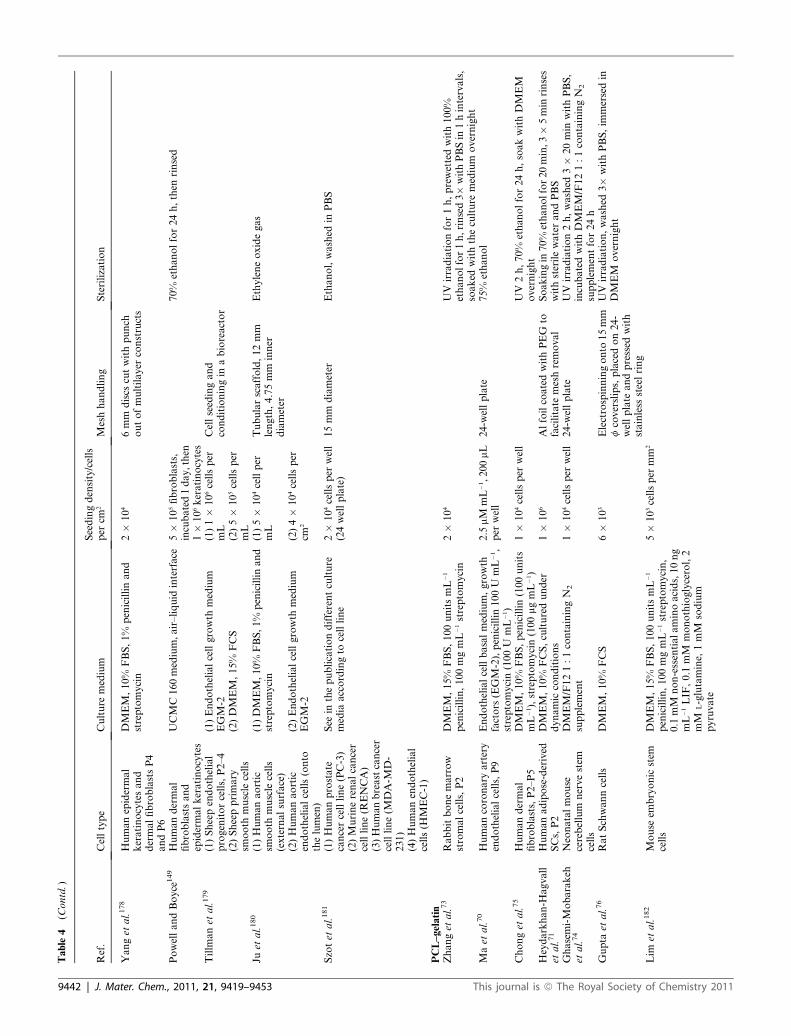
Table
4(C
ontd.)
Ref.
Celltype
Culture
medium
Seedingdensity/cells
per
cm2
Meshhandling
Sterilization
Yanget
al.178
Humanepidermal
keratinocytesand
dermalfibroblastsP4
andP6
DMEM,10%
FBS,1%
penicillinand
streptomycin
2�
104
6mm
discs
cutwithpunch
outofmultilayer
constructs
PowellandBoyce
149
Humandermal
fibroblastsand
epidermalkeratinocytes
UCMC160medium,air–liquid
interface
5�
105fibroblasts,
incubated1day,then
1�
106keratinocytes
70%
ethanolfor24h,then
rinsed
Tillm
anet
al.179
(1)Sheependothelial
progenitorcells,P2–4
(1)Endothelialcellgrowth
medium
EGM-2
(1)1�
106cellsper
mL
Cellseedingand
conditioningin
abioreactor
(2)Sheepprimary
smooth
muscle
cells
(2)DMEM,15%
FCS
(2)5�
105cellsper
mL
Juet
al.180
(1)Humanaortic
smooth
muscle
cells
(externalsurface)
(1)DMEM,10%
FBS,1%
penicillinand
streptomycin
(1)5�
104cellper
mL
Tubularscaffold,12mm
length,4.75mm
inner
diameter
Ethyleneoxidegas
(2)Humanaortic
endothelialcells(onto
thelumen)
(2)Endothelialcellgrowth
medium
EGM-2
(2)4�
104cellsper
cm2
Szotet
al.181
(1)Humanprostate
cancercellline(PC-3)
See
inthepublicationdifferentculture
media
accordingto
cellline
2�
104cellsper
well
(24wellplate)
15mm
diameter
Ethanol,washed
inPBS
(2)Murinerenalcancer
cellline(R
ENCA)
(3)Humanbreastcancer
cellline(M
DA-M
D-
231)
(4)Humanendothelial
cells(H
MEC-1)
PCL–gelatin
Zhanget
al.73
Rabbitbonemarrow
stromalcells,P2
DMEM,15%
FBS,100unitsmL
�1
penicillin,100mgmL
�1streptomycin
2�
104
UV
irradiationfor1h,prewettedwith100%
ethanolfor1h,rinsed3�
withPBSin
1hintervals,
soaked
withtheculture
medium
overnight
Maet
al.70
Humancoronary
artery
endothelialcells,P9
Endothelialcellbasalmedium,growth
factors
(EGM-2),penicillin100U
mL
�1,
streptomycin(100U
mL
�1)
2.5
mM
mL
�1,200mL
per
well
24-w
ellplate
75%
ethanol
Chonget
al.75
Humandermal
fibroblasts,P2–P5
DMEM,10%
FBS,penicillin(100units
mL
�1),streptomycin(100mgmL
�1)
1�
104cellsper
well
UV
2h,70%
ethanolfor24h,soakwithDMEM
overnight
Heydarkhan-H
agvall
etal.71
Humanadipose-derived
SCs,P2
DMEM,10%
FCS,culturedunder
dynamic
conditions
1�
106
AlfoilcoatedwithPEG
tofacilitate
meshremoval
Soakingin
70%
ethanolfor20min,3�5min
rinses
withsterilewaterandPBS
Ghasemi-Mobarakeh
etal.74
Neonatalmouse
cerebellum
nervestem
cells
DMEM/F121:1containingN
2
supplement
1�
104cellsper
well
24-w
ellplate
UV
irradiation2h,washed
3�
20min
withPBS,
incubatedwithDMEM/F121:1containingN
2
supplementfor24h
Gupta
etal.76
RatSchwanncells
DMEM,10%
FCS
6�
103
Electrospinningonto
15mm
fcoverslips,placedon24-
wellplate
andpressed
with
stainless
steelring
UV
irradiation,washed
3�
withPBS,im
mersedin
DMEM
overnight
Lim
etal.182
Mouse
embryonic
stem
cells
DMEM,15%
FBS,100unitsmL
�1
penicillin,100mgmL
�1streptomycin,
0.1
mM
non-essentialaminoacids,10ng
mL
�1LIF
,0.1
mM
monothioglycerol,2
mM
L-glutamine,
1mM
sodium
pyruvate
5�
103cellsper
mm
2
9442 | J. Mater. Chem., 2011, 21, 9419–9453 This journal is ª The Royal Society of Chemistry 2011

Table
4(C
ontd.)
Ref.
Celltype
Culture
medium
Seedingdensity/cells
per
cm2
Meshhandling
Sterilization
Tigliet
al.183
L929mouse
fibroblast
DMEM,10%
FBS
1�
105cellsper
well
24-w
ellplate
15mm
diameter,20mm
thick
meshes
70%
ethanol,dried
overnight,wettedwithPBS
PCL–CaPcompound
Fujihara
etal.59
Humanosteoblasts
DMEM,10%
FBS,1%
penicillin–
streptomycin
2.5
�104
24-w
ellplate
70%
ethanol60min
under
UV,rinsed3�
withPBS
Venugopalet
al.133
Humanfetalosteoblasts,
P4–5
DMEM/F12(1
:1),10%
FBS
2�
104
24-w
ellplate
Wutticharoenmongkol
etal.184
Mouse
calvaria-derived
pre-osteoblastic
cells
MEM,10%
FBS,1%
L-glutamine,
1%
penicillin–streptomycin,forsome
studies,after
5days,osteogenic
media
added
3.6
�104
15mm
discs,24-w
ellplate,
12mm
fmetalringplaced
ontop
70%
ethanolfor60min,washed
withdH
2O,soaked
inthemedium
overnight
Erisken
etal.185
Mouse
preosteoblast
Minim
um
essentialmedium,alpha1�,
FBS/penicillin/streptomycin(1/0.1/0.01
volratio).After
3days,MEM
aMedium,FBS/penicillin/streptomycin
(1/0.1/0.01volratio)andNaHCO
3(2.2
gL
�1)
2�
104
24-w
ellplate
Multiple
immersionsinto
70%
ethanolandPBS
solution,soaked
withtheculture
medium
Liet
al.138
Mouse
preosteoblast
a-M
inim
um
essentialm
edium,10%
FBS,
1%
penicillinandstreptomycin,
osteogenic
medium
forcellculture
on
meshes
5.7
�104
24-w
ellplate
70%
ethanolovernight,rinsed3�
withPBS
Yuet
al.65
Murine-derived
osteoblastic
cells
a-M
odified
minim
um
essentialmedium,
10%
FCS,100U
mL
�1penicillinG
sodium,100mgmL
�1streptomycin
sulfate,0.25mgmL
�1amphotericinB,
plusosteogenic
supplements
2�
104
24-w
ellplate,sterilized
glass
ring-typeholder
toprevent
specim
ensfrom
floating
70%
ethanol,dryingovernight
Yanget
al.132
Ratbonemarrow
cells,
P1
a-M
EM,0.5
mgmL
�1gentamycin,3mg
mL
�1fungizone
2�
104
24-w
ellplate
70%
ethanolfor2h,w
ashed
withPBS2�,
soaked
inthemedium
overnight
Yanget
al.186
Ratdentalpulp
stem
cells
a-M
EM
supplementedwith10%
FCS,
10mM
sodium
b-glycerophosphate,
1028M
dexamethasone,
L-ascorbic
acid
(50mgmL
�1),andgentamycin(50mg
mL
�1)
5�
106cellsper
mL
1mLfor6scaffolds
rotatingat6rpm
for
3h
15mm
discs,0.3
mm
thickness
70%
ethanol,rinsedwithPBS,soaked
inthe
medium
overnight
This journal is ª The Royal Society of Chemistry 2011 J. Mater. Chem., 2011, 21, 9419–9453 | 9443
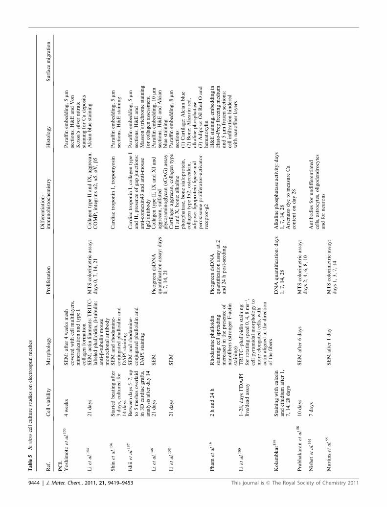
Table
5In
vitrocellculture
studiesonelectrospunmeshes
Ref.
Cellviability
Morphology
Proliferation
Differentiation-
immunohistochem
istry
Histology
Surface
migration
PCL
Yoshim
oto
etal.153
4weeks
SEM:after
4weeksmesh
covered
withcellmultilayers,
mineralizationandtypeI
collagen
form
ation
Paraffinem
bedding,5mm
sections,H&EandVon
Kossa’ssilver
nitrate
stainingforCadeposits
Liet
al.154
21days
SEM,actin
filaments:TRIT
C-
labeled
phalloidin,b-tubulin:
anti-b-tubulinmouse
monoclonalantibody
MTScolorimetricassay:
days0,7,14,21
Collagen
typeII
andIX
,aggrecan,
COMP,integrinsa2,a5,aV,b5
Alcianbluestaining
Shin
etal.156
Started
beatingafter
3days,culturedfor
14days
SEM
andrhodamine-
conjugatedphalloidin
and
DAPIstaining
Cardiactroponin
I,tropomyosin
Paraffinem
bedding,5mm
sections,H&Estaining
Ishiiet
al.157
Betweendays5–7,u
pto
5meshes
overlaid
in3D
cardiacgrafts,
analysisafter
day14
SEM
andrhodamine-
conjugatedphalloidin
and
DAPIstaining
Cardiactroponin
I,collagen
typeI
andII,presence
ofgapjunctions:
anti-connexin43andanti-m
ouse
IgG
antibody
Paraffinem
bedding,5mm
sections,H&Eand
Masson’strichromestaining
forcollagen
assessm
ent
Liet
al.148
21days
SEM
Picogreen
dsD
NA
quantificationassay:days
0,7,14,21
Collagen
typeII,IX
andXIand
aggrecan,sulfated
glycosaminoglycan(sGAG)assay
Paraffinem
bedding,10mm
sections,H&EandAlcian
bluestaining
Liet
al.158
21days
SEM
Cartilage:
aggrecan,collagen
type
IIandX,bone:alkaline
phosphatase,bonesialoprotein,
collagen
typeIa2,osteocalcin,
adipose:lipoprotein
lipase
and
peroxisomeproliferator-activator
receptor-g2
Paraffinem
bedding,8mm
sections:
(1)Cartilage:
Alcianblue
(2)Bone:
Alizarinred,
alkalinephosphatase
(3)Adipose:OilRed
Oand
hem
atoxylin
Pham
etal.16
2hand24h
Rhodaminephalloidin
staining:cellspreading
increasedin
thepresence
of
nanofibers(stronger
F-actin
staining)
Picogreen
dsD
NA
quantificationassayat2
and24hpost-seeding
H&Estaining,embeddingin
Histo-Prepfreezingmedium
and5mm
frozensections:
cellinfiltrationhindered
withnanofiber
layers
Liet
al.100
1–28,daysFDA/PI
live/deadassay
TRIT
C–phalloidin
staining:
forrotatingspeed0,4,8ms�
1,
cellpyramidalmorphologyto
more
elongatedcells,with
actin
aligned
inthedirection
ofthefibers
Kolambkar1
59
Stainingwithcalcein
andethidium
after
1,
7,14,28days
DNA
quantification:days
1,7,14,28
Alkalinephosphatase
activity:d
ays
1,7,14,28
Arsenazo
dyeto
measure
Ca
contentonday28
Prabhakaranet
al.58
10days
SEM
after
6days
MTScolorimetricassay:
days2,4,6,8,10
Nisbet
etal.161
7days
Antibodiesforundifferentiated
cells,astrocytes,oligodendrocytes
andforneurons
Martinset
al.55
SEM
after
1day
MTScolorimetricassay:
days1,3,7,14
9444 | J. Mater. Chem., 2011, 21, 9419–9453 This journal is ª The Royal Society of Chemistry 2011

Table
5(C
ontd.)
Ref.
Cellviability
Morphology
Proliferation
Differentiation-
immunohistochem
istry
Histology
Surface
migration
Chen
etal.164
1,3,5days
SEM
andSYTOX
green
fluorescentdye
Detach
cellswithtrypsin–
EDTA,countingwith
hem
ocytometer
Paraffinem
bedding,10mm
sections,H&Estain
Wiseet
al.166
4,7,21,35days,live/
deadassay
DNA
quantificationkit
Collagen
typeII,aggrecan
Loweryet
al.124
Live/deadassayafter
day14
SEM
after
days1,7,14and
21,DAPIstain
tomeasure
surface
celldensity
andspread
ofcellsacross
themesh,after
14days
Picogreen
dsD
NA
quantificationassay:after
days1,7,14and21
Ruckhet
al.167
Days1and4:MTT
assaykit
SEM
after
1,4,7days,livecell
adhesionusingcalcein-A
MCellproliferationupto
7days
After
3weeks:alkaline
phosphatase
activity,calcium
and
phosphate
deposition(EDS),
osteopontin,osteocalcin
Calcium
content(A
lizarin
red&
vonKossa)
Wuet
al.168
4days
Livecelladhesionusing
calcein-A
MZhuet
al.169
huSMC
viabilityby
mitochondrial
function
measurement,huECs
viabilitybylive/dead
assay
SEM,FIT
C-cellactin,DAPI-
cellnuclei
Smooth
muscle
a-actin
(a-SMA)
vonWillebrandfactor(vWF)
Caoet
al.170
Days0,3,7,10
SEM
Jhaet
al.171
7–10days
DAPIstain
torevealnuclei
Neuronspecificmarker
TubulinJ1,
counterstained
withgoatanti-
mouse
antibodyconjugatedwith
Texasred(1
:200)
Yeet
al.172
7days
SEM
ELISA
forFGF2loading
efficiency,MTT
colorimetricassayafter
3,5
and7days
PCL–collagen
Venugopalet
al.173
3days
SEM
MTScolorimetricassay:
days1,2,3
a-A
ctin
cytoskeletalprotein
Venugopalet
al.174
7days
SEM
after
7days
MTScolorimetricassay:
days2,4,6
Venugopalet
al.175
6days
SEM
after
6days
MTScolorimetricassay:
days2,4,6
Schnellet
al.152
1–7days,live/dead
assay
SEM
CountingDAPIstained
nuclei:1–7days
-S100im
munoreactivityfor
Schwanncells
MigrationofDAPI
stained
nuclei
within
200mm
radiating
from
explantsurface
-NeurofilamentNF200forOEC
-Mouse
monoclonalantibody
N0142forneuronsandaxons
-S100-negativecellsforfibroblasts
Lee
etal.176
7days
SEM
andDAPIafter
2days
MTScolorimetricassay:
days1,3,7
H&Safter
2days
Sroujiet
al.177
SEM
andconfocalmic
(CellTrace
FarRed
DDAO-
SEandPI)after
24h,6weeks
under
dynamic
flow
culture
This journal is ª The Royal Society of Chemistry 2011 J. Mater. Chem., 2011, 21, 9419–9453 | 9445

Table
5(C
ontd.)
Ref.
Cellviability
Morphology
Proliferation
Differentiation-
immunohistochem
istry
Histology
Surface
migration
Choiet
al.101
7days
SEM
andrhodamine-
conjugatedphalloidin
staining:aligned
myotubes
withsimilarfbutmore
than
twicethelength
thanthose
inrandom
mesh
MTScolorimetricassay:
days1,3,7.Nodifference
betweencontrol,random
or
aligned
mesh
Desmin,myoD,andmyosinheavy
chain
(MHC)
Chen
etal.136
(1)5weeks
Picogreen
dsD
NA
quantificationassay:weeks
1–5
10mm
cryo-cross-sections,
H&EandMasson’s
trichromestaining
(2)4weeks
Ekaputraet
al.128
3and10days,FDA/
PIlive/deadassay
SEM
10mm
cryo-cross-sections,
H&Estaining
Ekaputraet
al.137
(1)28days
SEM
after
7days
Picogreen
dsD
NA
quantificationassay:weeks
1,7,14,21,28
(1)Collagen
typeI,osteopontin,
osteocalcin
(1)10mm
cryo-cross-
sections,H&E,Alizarinred
S(2)4and8weeks
(2)Collagen
typeIandII,
osteocalcin
(2)10mm
cryo-cross-
sections,H&E
Gerardo-N
avaet
al.150
1,4and7days
SEM
andIH
CCountingDAPIstained
nuclei
1,4and7days
-GFAPandvim
entinforhNPac
andU373cells
Measurementof
distance
from
pellet
offurthers10%
of
DAPIstained
cells
-NeurofilamentNF200forSH-
SY5Y
Yanget
al.178
1day,MTT
cytotoxicityandlive/
deadassay
TRIT
C-conjugatedphalloidin
andDAPI
CyQuant:days3,7,14
7–10mm
cryo-cross-
sections,H&EandDAPI
staining
PowellandBoyce
149
MTTcolorimetricassay:
days6,10,14;d
ay10,B
rdU
todetermineactive
proliferatingcells
Day10cryosections,human
invulocrin,humancollagen
typeIV
andcellularDNA
Cryosectionsatdays6,10,
14,H&E
Tillm
anet
al.179
9days
SEM,measurementofplatelet
adhesion
Paraffinem
bedding,5mm
sections,H&Estain
Juet
al.180
(1)28days
Cellmigrationandinfiltration
withDAPI,actin
cytoskeleton
andfocaladhesionstainingkit
Day7,anti-PECAM-1
(CD31),
anti-vonWillebrandfactor(vWF)
andanti-vascularendothelial(V
E)-
cadherin
antibody
(2)1,12,24,48and
72h
Szotet
al.181
1,3,5,7days
SEM
andphalloidin–DAPI
after
4–7days
PCL–gelatin
Zhanget
al.73
1week
SEM
114mm
penetration,
measuredbyconfocal
microscopy
Maet
al.70
4days
SEM
andphalloidin–
tetramethylrhodamineB
isothiocyanate
staining
MTScolorimetricassay:
days1,2,4
Platelet–endothelialcelladhesion
molecule
1[PECAM-1
orCD31],
vascularcelladhesionmolecule
1[VCAM-1
orCD106],intercellular
adhesionmolecule
1[ICAM-1
or
CD54]
Chonget
al.75
(1)Only
oneside7
days
SEM
MTScolorimetricassay:
days1,3,5,7,14
(2)Both
sides,7
days-flip-7
days
Heydarkhan-H
agvall
etal.71
2weeks
SEM
andDAPIstaining
CountingDAPIstained
nuclei:2weeks
Paraffinem
bedding,5mm
sections,H&Estaining
9446 | J. Mater. Chem., 2011, 21, 9419–9453 This journal is ª The Royal Society of Chemistry 2011
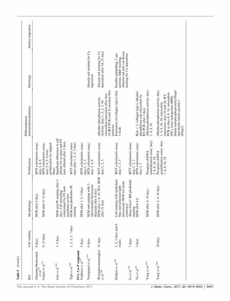
Table
5(C
ontd.)
Ref.
Cellviability
Morphology
Proliferation
Differentiation-
immunohistochem
istry
Histology
Surface
migration
Ghasemi-Mobarakeh
etal.74
6days
SEM
after
6days
MTScolorimetricassay:
days2,4,6
Gupta
etal.76
9,12days
SEM
after
9,12days
MTScolorimetricassay:
days3,6,9.Lower
proliferationforaligned
fibers
Lim
etal.182
1–3days
SEM
andPIstainingafter
3days.Cellspreading
constrained
byFSlaser
machined
cavities
Significantdifference
incell
density
foras-spunandFS
laserablatedafter
3days
Tigliet
al.183
1,2,3,5,7days
SEM
andphalloidin–PI
staining
MTTcolorimetricassay:
daysafter
1,2,3,5days
PCL–Ca–Pcompound
Fujihara
etal.59
5days
SEM
after
1,3,5days
MTScolorimetricassay:
days1,3,5
Venugopalet
al.133
6days
SEM
andstainingwith5-
chloromethylfluorescein
diacetate
after
6days
MTScolorimetricassay:
days2,4,6
AlizarinredstainingforCa
deposition
Wutticharoenmongkol
etal.184
21days
SEM
after
1,4,16,48h,SEM
after
21days
MTTcolorimetricassay:
days1,2,3
Alkalinephosphatase
activity.
Activity:days1,2,3,5,10,
osteocalcin
expressionafter
days
14(R
T-PCR)and21(w
estern
blot
analysis)
AlizarinredstainingforCa
depositionafter
14,21days
Erisken
etal.185
1,3,5daysand4
weeks
Cellstainingwithmethylene
blueandpolarizedlight
microscopySEM
fortissue
constructs
MTTcolorimetricassay:
days1,3,5
Expressionofcollagen
type-Iafter
1week
Paraffinem
bedding,5mm
sections,H&Estaining,
AlizarinredandvonKossa
stainingforCadeposition
Liet
al.138
7days
AlexaFluor1
488phalloidin
staining
MTTcolorimetricassay:
days1,3,7
Yuet
al.65
3days
SEM
after
8h
MTScolorimetricassay:
days1,3
Run�
2,collagen
typeI,alkaline
phosphatase
andosteocalcin
by
RT-PCR
after
3days
Yanget
al.132
SEM
after
4,16days
Picogreen
dsD
NA
quantificationassay:days
1,4,8,16,24
Alkalinephosphatase
activity:d
ays
1,4,8,16
Yanget
al.186
24days
SEM
after
1,4,16days
Picogreen
dsD
NA
quantificationassay:days
1,4,8,16,24
Alkalinephosphatase
activity:d
ays
1,4,8,16,24,osteocalcin
expression:days16and24,RT-
PCR
atdays4,8,16:osteocalcin
(OC),bonesialoprotein
(BSP),
dentinsialophosphoprotein
(Dspp)
anddentinmatrix
protein
1(D
mp1)
This journal is ª The Royal Society of Chemistry 2011 J. Mater. Chem., 2011, 21, 9419–9453 | 9447

Fig. 4 SEM micrographs of a random aligned 10 w/v% PCL–gelatin electrospun mesh (unpublished data), before sterilization (a) and same
magnification (b) and higher magnification images (c) of the changes in the morphology after sterilization, by soaking with ethanol followed by
evaporation.
Fig. 5 Scratch test adapted to electrospun meshes for cell migration studies along its surface. Bottom view of a mesh in a 13 mm well plate with a 13
� 3 � 3 mm3 stainless steel strip (a). Osteoblasts were seeded on a random aligned 10 w/v% PCL–gelatin electrospun mesh with a cell seeding density
40 000 cells per cm2, in a seeding volume of 50 mL per well, followed by the addition of 250 mL culture medium per well after 1 h incubation time.
Live–dead FDA/PI fluorescent micrograph showing a region with high cell density and a 3 mm wide cell free gap, one day after cell seeding, when
the metal strip was removed (b), cells migrating into the gap after 3 days (c) and after 7 days (d). SEM image of a cell on a mesh. Fluorescent
micrograph (f) and confocal image (g) of phalloidin–DAPI staining of osteoblasts migrating on the edge of the gap after 3 and 7 days respectively
(unpublished data).
collector, deposited onto a chemically reactive PEG substrate at
a density of 57 � 7 fibers per mm, resulting in an inter-fiber
distance of 17.4 mm. The approach is a highly specialized one and
difficult to replicate in other laboratories unless there is access to
the starPEG reactive chemical. This macromer is synthesized
locally in the laboratory, and there is currently no commercial
equivalent available.
Furthermore, there is an increasing interest with depositing
electrospun fibers into matrices to perform three-dimensional
in vitro culture. The choice of matrices, cells, protocols
and electrospun fiber properties are likely to be so specific
that the experiments performed in such studies will have an
even greater array of complexity over current approaches
discussed.
9448 | J. Mater. Chem., 2011, 21, 9419–9453
3.4 Assessment of electrospun PCL meshes within in vivo
assays
Considering the extensive use of PCL meshes for in vitro studies,
there is a surprising lack of literature concerning the in vivo
implantation of these materials. The studies found are listed in
Table 6. One interesting aspect of electrospun PCL material is
their (in)compatibility with processes for immunohistochemistry.
Paraffin embedding of tissues requires a series of washes within
xylene and/or histoclear, which are solvents for PCL. Conse-
quently the preparation of tissues containing electrospun PCL
meshes are typically frozen, which removes the need for organic
solvents in their preparation. Also important to mention is the
methods used to ensure that the mesh has the solvent removed
from the material, such as vacuum degassing, so that the solvent
This journal is ª The Royal Society of Chemistry 2011

Fig. 6 A pellet of astrocyte driven neural progenitor cells upon
a substrate of oriented PLC/collagen electrospun fibers (a). On the same
substrates U373 astrocyte cell lines (right) are observed at 4DIV (b) and 7
DIV (c). Adapted from Nanomedicine (2009), 4(1), 11-30 with permission
of Future Medicine Ltd
Table 6 In vivo experiments with electrospun meshes
PCLShin et al.155 Implantation in the omenta of rats. After 4 weeks of in vitro culture and 4 weeks of implantation: histology (H&S and von Kossa
staining), immunohistochemistry (type I collagen) and SEM (multilayers of cells and ECM)Nottelet et al.160 Implantation in the abdominal aorta of rats. After 3, 6, and 12 weeks: digital subtraction angiography, to evaluate patency and
structural integrity, and histology (H&S stain)Pektok et al.147 Implantation in the abdominal aorta of rats. After 3, 6, 12, 18 and 24 weeks: digital subtraction angiography, to evaluate patency
and structural integrity, and computed histomorphometry (H&S), to measure endothelial coverage, neointima formation andtransmural cellular ingrowth. In vivo degradation analysis by changes in molecular weight (Mn and Mw) using size exclusionchromatography
Li et al.162 In vivo iatrogenic, 7 mm f full thickness, articular cartilage repair on femoral condyles in Lee-Sung mini-pigs. After 21 days of invitro culture and 6 months of implantation: mechanical testing (compressive stress relaxation by indentation) and histology(H&E stain)
Piskin et al.163 Implantation of spiral-wound scaffold, 8 mm f, 2 mm height, in 8 mm f mouse cranial (critical size) defect. After 1, 3 and 6months implantation (no cell seeding on the mesh): micro-CT and histology (H&S, Goldner’s Masson trichrome stain)
Nisbet et al.165 Implantation in the caudate putamen of rats. Neurite infiltration and inflammation assessed. Immunocytochemistry at days: 1, 37, 14, 21, 28 and 60. Inflammation peaked at day 4 (microglia) and day 7 (astrocytes) and subsided to homeostatic levels by day60. No evidence of microglial encapsulation. Neurites could penetrate randomly orientated meshes but could not penetratepartially aligned meshes. Neurites grew perpendicular to the direction of fiber alignment at the implant–tissue interface
Cao et al.170 Subcutaneous implantation in rats to test biocompatibility and host response at weeks 1, 2 and 4. Histology: the thickness of thefibrous capsule around nanofiber meshes is significantly thinner than that around PCL films. Cell infiltration observed in alignednanofiber meshes; fibrous capsule boundaries found on the surface of random nanofiber meshes and PCL films
Jha et al.171 Implantation in 10 mm lesions in rodent sciatic nerve (200 mg mL�1 PCL, 1 mm diameter fibers, coated with electrosprayedPGA : PLA (50 : 50) to reduce inflammatory cell infiltration). Seven weeks post-implantation revealed dense, parallel arrays omyelinated and non-myelinated axons and functional blood vessels
PCL–collagenSrouji et al.177 Subcutaneous implantation in mice. After 6 weeks implantation: SEM and histology (H&S, Masson’s trichrome or Toluidine
blue stain)Chen et al.136 In vivo critical size corpus cavernosa defect in male New Zealand white rabbits. Tubular constructs by rolling up double-sided
seeded meshes. After 1 and 3 months, histology (H&E stain and Masson’s trichrome stain)Tillman et al.179 Rabbit aortoiliac bypass model. Mechanical testing of pre-implant graft material and 1 month post-surgery. After 1 month o
implantation, CT scanning with intravenous contrast agent and histology (H&E stain)PCL–Ca–P compoundYang et al.186 Subcutaneous implantation into immunocompromised nude mice, 4 and 8 weeks. Histology: scaffolds surrounded by thin fibrou
capsule without adverse effects. Cell/scaffold composites showed in vivo hard tissue formation. RT-PCR: the combination ofnHA in the nanofiber meshes upregulated the expression of specific odontogenic genes
Table 7 Parameters to consider in performing and reporting electrospunPCL fibers
Polymeric parametersMolecular weightSource; batch/lot numberSolution properties: source, conductivityPolymer solution/melt viscosity; surface tensionInstrument parametersVoltageCollector–spinneret distanceSpinneret flow rateElectrospinning configuration; vertical or horizontalCollector type; dimensions; rotation speed (if applicable)Temperature and humiditySurface treatment methodologiesMethod used; plasma/chemical treatment/adsorbing/blendingConcentrations of solutions usedTimes for each stage of surface modificationMesh characterizationPorosityMorphology/architecture (OM/SEM/CT)Fiber diameterMechanical propertiesContact angleIn vitro parametersCell type; passage numberMedia usedSterilization method; times for each stepAssay usedMesh anchoring approachIn vivo parametersPreparation of samples; method of solvent removalHistological fixation method
This journal is ª The Royal Society of Chemistry 2011 J. Mater. Chem., 2011, 21, 9419–9453 | 9449
,
f
f
s

toxicity does not influence the in vivo results. The time between
manufacture and implantation should be reported.
4 Conclusions
PCL electrospun nanofiber meshes—and its copolymers with
collagen or gelatin or mixtures with Ca–P compounds—are
currently being investigated in the context of different fields of
TE and a broad spectrum of cell types is used for in vitro cell
cultures studies. The main focus of the articles reviewed in Tables
1–6 is the biological assays. It is, nevertheless, known that the
mesh morphology, topography, chemistry and mechanical
properties play an important role in cellular processes. It is
difficult to compare the results of biological assays reported in
different papers, if the information regarding physical and
chemical characteristics of the cell environment is incomplete.
Physical and chemical characterization of electrospun meshes is
not trivial; however, even when the focus of an article is bio-
logical, the importance of adequate mesh characterization
cannot be underestimated, if we are to compare results reported
by different groups. Table 7 summarizes the elements a compre-
hensive investigation of PCL should include and report. With
improved consideration and thorough reporting of such
parameters and properties, it will be possible to better compare
studies from different laboratories in the future.
Acknowledgements
The authorswould like to acknowledge the financial support from
the AO Foundation, the Australian Research Council, CEIT
(CEIT, Manuel de Lardiz�abal 15, 20018 San Sebasti�an, Spain)
and Berlin-Brandenburg Center for Regenerative Medicine
(BCRT) for A. Cipitria and the Queensland State Government,
Tissue Therapies Ltd and QUT for T. Dargaville’s fellowship.
References
1 J. F. Cooley, Apparatus for Electrically Dispersing Fluids, U. P.Office, 1902.
2 W. J. Morton, Method of Dispersing Fluids, U. P. Office, 1902.3 C. L. Norton, Method of and Apparatus for Producing Fibrous orFilamentary Material, U. S. P. Office, 1936.
4 A. Formhals, Process and apparatus for preparing artificial threads,US Pat. 1975504, 1934.
5 A. Formhals, Method and apparatus for spinning, US Pat. 2160962,1939.
6 A. Formhals,Artificial thread and method of producing same,US Pat.2187306, 1940.
7 A. Formhals, Method and Apparatus for Spinning, U. S. P. Office,1944.
8 D. H. Reneker and I. Chun, Nanometre diameter fibers of polymer,produced by electrospinning, Nanotechnology, 1996, 7(3), 216–223.
9 G. Taylor, Electrically driven jets, Proc. Natl. Acad. Sci. U. S. A.,1969, A313(1515), 453–475.
10 D. H. Reneker, et al., Bending instability of electrically chargedliquid jets of polymer solutions in electrospinning, J. Appl. Phys.,2000, 87(9), 4531–4547.
11 A. E. Spivak, Y. A. Dzcnis and D. H. Reneker, A model of steadystate jet in the electrospinning process, Mech. Res. Commun., 2000,27(1), 37–42.
12 J. M. Deitzel, et al., The effect of processing variables on themorphology of electrospun nanofibers and textiles, Polymer, 2001,42, 261–272.
13 D. Li and Y. Xia, Electrospinning of nanofibers: reinventing thewheel?, Adv. Mater., 2004, 16(14), 1151–1170.
9450 | J. Mater. Chem., 2011, 21, 9419–9453
14 S. A. Theron, E. Zussman and A. L. Yarin, Experimentalinvestigation of the governing parameters in the electrospinning ofpolymer solutions, Polymer, 2004, 45, 2017–2030.
15 W. Teo and S. Ramakrishna, A review on electrospinning design andnanofiber assemblies, Nanotechnology, 2006, 17, R89–R106.
16 Q. P. Pham, U. Sharma and A. G. Mikos, Electrospun poly(3-caprolactone) microfiber and multilayer nanofiber/microfiberscaffolds: characterization of scaffolds and measurement ofcellular infiltration, Biomacromolecules, 2006, 7, 2796–2805.
17 C. J. Thompson, et al., Effects of parameters on nanofiber diameterdetermined from electrospinning model, Polymer, 2007, 48, 6913–6922.
18 T. Han, D. H. Reneker and A. L. Yarin, Buckling of jets inelectrospinning, Polymer, 2007, 48, 6064–6076.
19 T. Han, A. L. Yarin and D. H. Reneker, Viscoelastic electrospunjets: initial stresses and elongational rheometry, Polymer, 2008, 49,1651–1658.
20 T. Han, D. H. Reneker and A. L. Yarin, Pendulum-like motion ofstraight electrified jets, Polymer, 2008, 49, 2160–2169.
21 D. H. Reneker and A. L. Yarin, Electrospinning jets and polymernanofibers, Polymer, 2008, 49, 2387–2425.
22 T. J. Sill and H. A. V. Recum, Electrospinning: applications in drugdelivery and tissue engineering, Biomaterials, 2008, 29, 1989–2006.
23 J. A. Matthews, et al., Electrospinning of collagen nanofibers,Biomacromolecules, 2002, 3(2), 232–238.
24 W. J. Li, et al., Electrospun nanofibrous structure: a novel scaffoldfor tissue engineering, J. Biomed. Mater. Res., 2002, 60(4), 613–621.
25 J. Venugopal, et al., Interaction of cells and nanofiber scaffolds intissue engineering, J. Biomed. Mater. Res., Part B, 2008, 84(1), 34–48.
26 S. G. Kumbar, et al., Electrospun nanofiber scaffolds: engineeringsoft tissues, Biomed. Mater., 2008, 3, 034002, (1–15pp).
27 C. Burger, B. S. Hsiao and A. B. Chu, Nanofibrous materials andtheir applications, Annu. Rev. Mater. Res., 2006, 36, 333–368.
28 N. Bhardwaj and S. C. Kundu, Electrospinning: a fascinating fiberfabrication technique, Biotechnol. Adv., 2010, 28(3), 325–347.
29 Z.-M. Huang, et al., A review on polymer nanofibers byelectrospinning and their applications in nanocomposites, Compos.Sci. Technol., 2003, 63, 2223–2253.
30 M. Woodruff and D. Hutmacher, The return of a forgottenpolymer—polycaprolactone in the 21st century, Prog. Polym. Sci.,2010, 35(10), 1217–1256.
31 I. Engelberg and J. Kohn, Physico-mechanical properties ofdegradable polymers used in medical applications: a comparativestudy, Biomaterials, 1991, 12, 292–304.
32 J. C. Middleton and A. J. Tipton, Synthetic biodegradable polymersas orthopedic devices, Biomaterials, 2000, 21(23), 2335–2346.
33 L. S. Nair and C. T. Laurencin, Biodegradable polymers asbiomaterials, Prog. Polym. Sci., 2007, 32, 762–798.
34 M. R. Williamson and A. G. A. Coombes, Gravity spinning ofpolycaprolactone fibers for applications in tissue engineering,Biomaterials, 2004, 25(3), 459–465.
35 D. W. Hutmacher and S. Cool, Concepts of scaffold-based tissueengineering—the rationale to use solid free-form fabricationtechniques, J. Cell. Mol. Med., 2007, 11(4), 654–669.
36 D. W. Hutmacher, M. Sittinger and M. V. Risbud, Scaffold-basedtissue engineering: rationale for computer-aided design and solidfree-form fabrication systems, Trends Biotechnol., 2004, 22(7), 354–362.
37 V. Coccoli, et al., Engineering of poly(3-caprolactone) microcarriersto modulate protein encapsulation capability and release kinetic, J.Mater. Sci.: Mater. Med., 2008, 19(4), 1703–1711.
38 A. Luciani, et al., PCL microspheres based functional scaffolds bybottom-up approach with predefined microstructural propertiesand release profiles, Biomaterials, 2008, 29(36), 4800–4807.
39 I. K. Kwon, S. Kidoaki and T. Matsuda, Electrospun nano- tomicrofiber fabrics made of biodegradable copolyesters: structuralcharacteristics, mechanical properties and cell adhesion potential,Biomaterials, 2005, 26, 3929–3939.
40 C. M. Vaz, et al., Design of scaffolds for blood vessel tissueengineering using a multi-layering electrospinning technique, ActaBiomater., 2005, 1, 575–582.
41 X. M. Mo, et al., Electrospun P(LLA-CL) nanofiber: a biomimeticextracellular matrix for smooth muscle cell and endothelial cellproliferation, Biomaterials, 2004, 25, 1883–1890.
This journal is ª The Royal Society of Chemistry 2011
42 C. Y. Xu, et al., Aligned biodegradable nanofibrous structure:a potential scaffold for blood vessel engineering, Biomaterials,2004, 25, 877–886.
43 C. Xu, et al., Electrospun nanofiber fabrication as syntheticextracellular matrix and its potential for vascular tissueengineering, Tissue Eng., 2004, 10(7/8), 1160–1168.
44 D. Grafahrend, et al., Biofunctionalized poly(ethylene glycol)-block-poly(3-caprolactone) nanofibers for tissue engineering, J. Mater.Sci.: Mater. Med., 2008, 19, 1479–1484.
45 E. S. Place, et al., Synthetic polymer scaffolds for tissue engineering,Chem. Soc. Rev., 2009, 38, 1139–1151.
46 Z. Ma, Z. Mao and C. Gao, Surface modification and propertyanalysis of biomedical polymers used for tissue engineering,Colloids Surf., B, 2007, 60(2), 137–157.
47 P. B. van Wachem, et al., Interaction of cultured human endothelialcells with polymeric surfaces of different wettabilities, Biomaterials,1985, 6(6), 403–408.
48 P. B. van Wachem, et al., Adhesion of cultured human endothelialcells onto methacrylate polymers with varying surface wettabilityand charge, Biomaterials, 1987, 8(5), 323–328.
49 J. H. Lee, et al., Interaction of different types of cells on polymersurfaces with wettability gradient, J. Colloid Interface Sci., 1998,205(2), 323–330.
50 J. H. Lee, et al., Interaction of fibroblasts on polycarbonatemembrane surfaces with different micropore sizes andhydrophilicity, J. Biomater. Sci., Polym. Ed., 1999, 10(3), 283–294.
51 E. Tziampazis, J. Kohn and P. V. Moghe, PEG-variant biomaterialsas selectively adhesive protein templates: model surfaces forcontrolled cell adhesion and migration, Biomaterials, 2000, 21(5),511–520.
52 X. Liu and P. X. Ma, Polymeric scaffolds for bone tissueengineering, Ann. Biomed. Eng., 2004, 32(3), 477–486.
53 C. M. Chan, T. M. Ko and H. Hiraoka, Polymer surfacemodification by plasmas and photons, Surf. Sci. Rep., 1996, 24(1–2), 3–54.
54 P. K. Chu, et al., Plasma-surface modification of biomaterials,Mater. Sci. Eng., R, 2002, 36(5–6), 143–206.
55 A. Martins, et al., Surface modification of electrospunpolycaprolactone nanofiber meshes by plasma treatment toenhance biological performance, Small, 2009, 5(10), 1195–1206.
56 J. N. Lai, et al., Study on hydrophilicity of polymer surfacesimproved by plasma treatment, Appl. Surf. Sci., 2006, 252(10),3375–3379.
57 J. M. Grace and L. J. Gerenser, Plasma treatment of polymers, J.Dispersion Sci. Technol., 2003, 24(3–4), 305–341.
58 M. P. Prabhakaran, et al., Surface modified electrospun nanofibrousscaffolds for nerve tissue engineering, Nanotechnology, 2008, 19,455102, (8pp).
59 K. Fujihara, M. Kotaki and S. Ramakrishna, Guided boneregeneration membrane made of polycaprolactone/calciumcarbonate composite nano-fibers, Biomaterials, 2005, 26, 4139–4147.
60 M. C. Serrano, et al., Nitric oxide production by endothelial cellsderived from blood progenitors cultured on NaOH-treatedpolycaprolactone films: a biofunctionality study, Acta Biomater.,2009, 5(6), 2045–2053.
61 C. X. F. Lam, et al., Dynamics of in vitro polymer degradation ofpolycaprolactone-based scaffolds: accelerated versus simulatedphysiological conditions, Biomed. Mater., 2008, 3, 034108, (15pp).
62 C. X. F. Lam, et al., Evaluation of polycaprolactone scaffolddegradation for 6 months in vitro and in vivo, J. Biomed. Mater.Res., Part A, 2008, 906–919.
63 C. X. Lam, S. H. Teoh and D. W. Hutmacher, Comparison of thedegradation of polycaprolactone and polycaprolactone–(b-tricalcium phosphate) scaffolds in alkaline medium, Polym. Int.,2007, 56, 718–728.
64 A. Oyane, et al., Simple surface modification of poly(3-caprolactone)for apatite deposition from simulated body fluid, Biomaterials, 2005,26(15), 2407–2413.
65 H.-S. Yu, et al., Apatite-mineralized polycaprolactone nanofibrousweb as a bone tissue regeneration substrate, J. Biomed. Mater.Res., Part A, 2009, 88(3), 747–754.
66 J. Goddard and J. Hotchkiss, Polymer surface modification for theattachment of bioactive compounds, Prog. Polym. Sci., 2007, 32,698–725.
This journal is ª The Royal Society of Chemistry 2011
67 V. Beachley and X. Wen, Polymer nanofibrous structures:fabrication, biofunctionalization, and cell interactions, Prog.Polym. Sci., 2010, 35(7), 868–892.
68 H. S. Koh, et al., Enhancement of neurite outgrowth using nano-structured scaffolds coupled with laminin, Biomaterials, 2008, 29,3574–3582.
69 S. Patel, et al., Bioactive nanofibers: synergistic effects ofnanotopography and chemical signaling on cell guidance, NanoLett., 2007, 7(7), 2122–2128.
70 Z. Ma, et al., Grafting of gelatin on electrospun poly(caprolactone)nanofibers to improve endothelial cell spreading and proliferationand to control cell orientation, Tissue Eng., 2005, 11(7/8), 1149–1158.
71 S. Heydarkhan-Hagvall, et al., Three-dimensional electrospunECM-based hybrid scaffolds for cardiovascular tissue engineering,Biomaterials, 2008, 29, 2907–2914.
72 D. I. Zeugolis, et al., Electro-spinning of pure collagen nano-fibers—just an expensive way to make gelatin?, Biomaterials, 2008, 29, 2293–2305.
73 Y. Zhang, et al., Electrospinning of gelatin fibers and gelatin/PCLcomposite fibrous scaffolds, J. Biomed. Mater. Res., 2005, 72(1),156–165.
74 L. Ghasemi-Mobarakeh, et al., Electrospun poly(3-caprolactone)/gelatin nanofibrous scaffolds for nerve tissue engineering,Biomaterials, 2008, 29, 4532–4539.
75 E. J. Chong, et al., Evaluation of electrospun PCL/gelatinnanofibrous scaffold for wound healing and layered dermalreconstitution, Acta Biomater., 2007, 3, 321–330.
76 D. Gupta, et al., Aligned and random nanofibrous substrate for thein vitro culture of Schwann cells for neural tissue engineering, ActaBiomater., 2009, 5(7), 2560–2569.
77 J.-H. Jo, et al., In vitro/in vivo biocompatibility and mechanicalproperties of bioactive glass nanofiber and poly(3-caprolactone)composite materials, J. Biomed. Mater. Res., Part B, 2009, 91(1),213–220.
78 D. Puppi, et al., Polymeric materials for bone and cartilage repair,Prog. Polym. Sci., 2010, 35, 403–440.
79 D. Gupta, et al., Nanostructured biocomposite substrates byelectrospinning and electrospraying for the mineralization ofosteoblasts, Biomaterials, 2009, 30, 2085–2094.
80 W. He, et al., Fabrication of collagen-coated biodegradable polymernanofiber mesh and its potential for endothelial cells growth,Biomaterials, 2005, 26, 7606–7615.
81 M. P. Prabhakaran, et al., Electrospun biocomposite nanofibrousscaffolds for neural tissue engineering, Tissue Eng. A, 2008, 14(11),1787–1797.
82 K. Schenke-Layland, et al., The use of three-dimensionalnanostructures to instruct cells to produce extracellular matrix forregenerative medicine strategies, Biomaterials, 2009, 30(27), 4665–4675.
83 C. S. Chen, et al., Geometric control of cell life and death, Science,1997, 276, 1425–1428.
84 A. S. G. Curtis and C. D. W. Wilkinson, Reactions of cells totopography, J. Biomater. Sci., Polym. Ed., 1998, 9(2), 1313–1329.
85 R. McBeath, et al., Cell shape, cytoskeletal tension, and RhoAregulate stem cell lineage commitment, Dev. Cell, 2004, 6, 483–495.
86 V. Vogel and M. Sheetz, Local force and geometry sensing regulatecell functions, Nat. Rev. Mol. Cell Biol., 2006, 7, 265–275.
87 R. K. Assoian and E. A. Klein, Growth control by intracellulartension and extracellular stiffness, Trends Cell Biol., 2008, 18(7),347–352.
88 G. A. Dunn and J. P. Heath, A new hypothesis of contact guidancein tissue cells, Exp. Cell Res., 1976, 101, 1–14.
89 M. Rumpler, et al., The effect of geometry on three-dimensionaltissue growth, J. R. Soc. Interface, 2008, 5, 1173–1180.
90 J. Folkman and A. Moscona, Role of cell shape in growth control,Nature, 1978, 273(5661), 345–349.
91 A. Ben-Ze’ev, S. R. Farmer and S. Penman, Protein synthesisrequires cell–surface contact while nuclear events respond to cellshape in anchorage-dependent fibroblasts, Cell, 1980, 21(2), 365–372.
92 B. D. Boyan, et al., Role of material surfaces in regulating bone andcartilage cell response, Biomaterials, 1996, 17(2), 137–146.
93 R. J. Pelham and Y.-L. Wang, Cell locomotion and focal adhesionsare regulated by substrate flexibility, Proc. Natl. Acad. Sci. U. S. A.,1997, 94, 13661–13665.
J. Mater. Chem., 2011, 21, 9419–9453 | 9451

94 D. E. Discher, P. Janmey and Y.-l. Wang, Tissue cells feel andrespond to the stiffness of their substrate, Science, 2005, 310,1139–1143.
95 T. Yeung, et al., Effects of substrate stiffness on cell morphology,cytoskeletal structure, and adhesion, Cell Motil. Cytoskeleton,2005, 60, 24–34.
96 A. J. Engler, et al., Matrix elasticity directs stem cell lineagespecification, Cell, 2006, 126, 677–689.
97 F. Yang, et al., Electrospinning of nano/microscale poly(L-lacticacid) aligned fibers and their potential in neural tissue engineering,Biomaterials, 2005, 26, 2603–2610.
98 A. S. Badami, et al., Effect of fiber diameter on spreading,proliferation, and differentiation of osteoblastic cells onelectrospun poly(lactic acid) substrates, Biomaterials, 2006, 27,596–606.
99 Y. Liu, et al., Effects of fiber orientation and diameter on thebehavior of human dermal fibroblasts on electrospun PMMAscaffolds, J. Biomed. Mater. Res., Part A, 2009, 90(4), 1092–1106.
100 W.-J. Li, et al., Engineering controllable anisotropy in electrospunbiodegradable nanofibrous scaffolds for musculoskeletal tissueengineering, J. Biomech., 2007, 40, 1686–1693.
101 J. S. Choi, et al., The influence of electrospun aligned poly(3-caprolactone)/collagen nanofiber meshes on the formation of self-aligned skeletal muscle myotubes, Biomaterials, 2008, 2899–2906.
102 J. Lee, et al., The effect of gelatin incorporation into electrospunpoly(L-lactide-co-epsilon-caprolactone) fibers on mechanicalproperties and cytocompatibility, Biomaterials, 2008, 29(12), 1872–1879.
103 J. Johnson, et al., Electrospun PCL in vitro: a microstructural basisfor mechanical property changes, J. Biomater. Sci., Polym. Ed.,2009, 20(4), 467–481.
104 Y. Z. Zhang, et al., Fabrication of porous electrospun nanofibers,Nanotechnology, 2006, 17, 901–908.
105 V. M. Quent, et al., Discrepancies between metabolic activity andDNA content as tool to assess cell proliferation in cancer research,J. Cell. Mol. Med., 2010, 14(4), 1003–1013.
106 A.Martins, R. L. Reis and N.M. Neves, Electrospinning: processingtechnique for tissue engineering scaffolding, Int. Mater. Rev., 2008,53(5), 257–274.
107 T. Lin, et al., The charge effect of cationic surfactants on theelimination of fiber beads in the electrospinning of polystyrene,Nanotechnology, 2004, 15(9), 1375–1381.
108 J. F. Zheng, et al., Studies on the controlled morphology andwettability of polystyrene surfaces by electrospinning orelectrospraying, Polymer, 2006, 47(20), 7095–7102.
109 T. Uyar and F. Besenbacher, Electrospinning of uniform polystyrenefibers: the effect of solvent conductivity, Polymer, 2008, 49(24),5336–5343.
110 Y. Lu, et al., Mild immobilization of diverse macromolecularbioactive agents onto multifunctional fibrous membranes preparedby coaxial electrospinning, Acta Biomater., 2009, 5(5), 1562–1574.
111 Y. Z. Zhang, et al., Characterization of the surface biocompatibilityof the electrospun PCL–collagen nanofibers using fibroblasts,Biomacromolecules, 2005, 6(5), 2583–2589.
112 P. Zhao, et al., Biodegradable fibrous scaffolds composed of gelatincoated poly(3-caprolactone) prepared by coaxial electrospinning, J.Biomed. Mater. Res., Part A, 2007, 83(2), 372–382.
113 S. Kidoaki, I. K. Kwon and T. Matsuda, Mesoscopic spatial designsof nano- and microfiber meshes for tissue-engineering matrix andscaffold based on newly devised multilayering and mixingelectrospinning techniques, Biomaterials, 2005, 26(1), 37–46.
114 L. S. Carnell, et al., Aligned mats from electrospun single fibers,Macromolecules, 2008, 41, 5345–5349.
115 J. M. Deitzel, et al., Controlled deposition of electrospun poly(ethylene oxide) fibers, Polymer, 2001, 42, 8163–8170.
116 P. D. Dalton, D. Klee and M. M€oller, Electrospinning with dualcollection rings, Polymer, 2005, 46, 611–614.
117 M. Acharya, G. K. Arumugam and P. A. Heiden, Dual electric fieldinduced alignment of electrospun nanofibers, Macromol. Mater.Eng., 2008, 293, 666–674.
118 R. Tzezana, E. Zussman and S. Levenberg, A layered ultra-porousscaffold for tissue engineering, created via a hydrospinningmethod, Tissue Eng., Part C, 2008, 14(4), 281–288.
119 O. D. Schneider, et al., Cotton wool-like nanocompositebiomaterials prepared by electrospinning: in vitro bioactivity and
9452 | J. Mater. Chem., 2011, 21, 9419–9453
osteogenic differentiation of human mesenchymal stem cells, J.Biomed. Mater. Res., Part B, 2008, 84(2), 350–362.
120 M. Simonet, et al., Ultraporous 3D polymer meshes by low-temperature electrospinning: use of ice crystals as a removablevoid template, Polym. Eng. Sci., 2007, 47(12), 2020–2026.
121 K. D. Anderson, et al., Hydrogel microstructures combined withelectrospun fibers and photopatterning for shape and moduluscontrol, Polymer, 2008, 49, 5284–5293.
122 S. T. Ho and D. W. Hutmacher, A comparison of micro-CT withother techniques used in the characterization of scaffolds,Biomaterials, 2006, 27, 1362–1376.
123 D. R. Nisbet, et al., Surface and bulk characterization of electrospunmembranes: problems and improvements, Colloids Surf., B, 2009, 71(1), 1–12.
124 J. L. Lowery, N. Datta and G. C. Rutledge, Effect of fiber diameter,pore size and seeding method on growth of human dermalfibroblasts in electrospun poly(3-caprolactone) fibrous mats,Biomaterials, 2010, 31(3), 491–504.
125 G. C. Rutledge, J. L. Lowery and C. L. Pai, Characterization bymercury porosimetry of non-woven fiber media with deformation,J. Eng. Fibers Fabr., 2009, 4(3), 1–13.
126 B. M. Baker, et al., The potential to improve cell infiltration incomposite fiber-aligned electrospun scaffolds by the selectiveremoval of sacrificial fibers, Biomaterials, 2008, 29(15), 2348–2358.
127 B. M. Baker, et al., Fabrication and modeling of dynamicmultipolymer nanofibrous scaffolds, J. Biomech. Eng., 2009, 131(10), 101012.
128 A. K. Ekaputra, et al., Combining electrospun scaffolds withelectrosprayed hydrogels leads to three-dimensional cellularizationof hybrid constructs, Biomacromolecules, 2008, 9, 2097–2103.
129 B. Marelli, et al., Compliant electrospun silk fibroin tubes for smallvessel bypass grafting, Acta Biomater., 2010, 6(10), 4019–4026.
130 S. C. Wong, A. Baji and S. W. Leng, Effect of fiber diameter ontensile properties of electrospun poly(3-caprolactone), Polymer,2008, 49(21), 4713–4722.
131 C. T. Lim, E. P. S. Tan and S. Y. Ng, Effects of crystallinemorphology on the tensile properties of electrospun polymernanofibers, Appl. Phys. Lett., 2008, 92(14), 141908.
132 F. Yang, et al., Development of an electrospun nano-apatite/PCLcomposite membrane for GTR/GBR application, Acta Biomater.,2009, 5(9), 3295–3304.
133 J. Venugopal, et al., Biocomposite nanofibers and osteoblasts forbone tissue engineering, Nanotechnology, 2007, 18, 055101, (8pp).
134 M. Lisunova, et al., Nanofibers of CA/PAN with high amount ofcarbon nanotubes by core–shell electrospinning, Compos. Sci.Technol., 2010, 70(11), 1584–1588.
135 Z. G. Tang, et al., Surface properties and biocompatibility ofsolvent-cast poly(3-caprolactone) films, Biomaterials, 2004, 25(19),4741–4748.
136 Z. C. C. Chen, et al., In vitro and in vivo analysis of co-electrospunscaffolds made of medical grade poly(3-caprolactone) and porcinecollagen, J. Biomater. Sci., Polym. Ed., 2008, 19(5), 693–707.
137 A. K. Ekaputra, et al., Composite electrospun scaffolds forengineering tubular bone grafts, Tissue Eng. A, 2009, 15(12), 3779–3788.
138 X. Li, et al., Coating electrospun poly(3-caprolactone) fibers withgelatin and calcium phosphate and their use as biomimetic scaffoldsfor bone tissue engineering, Langmuir, 2008, 24, 14145–14150.
139 C. G. Pitt, et al., Aliphatic polyesters. 1. The degradation of poly(3-caprolactone) in vivo, J. Appl. Polym. Sci., 1981, 26(11), 3779–3787.
140 S. A. Ali, et al., Mechanisms of polymer degradation in implantabledevices. I. Poly(caprolactone), Biomaterials, 1993, 14(9), 648–656.
141 C. G. Pitt, et al., Aliphatic polyesters. 2. The degradation of poly(D,L-lactide), poly(3-caprolactone), and their copolymers in vivo,Biomaterials, 1981, 2(4), 215–220.
142 S. C. Woodward, et al., The intracellular degradation of poly(3-caprolactone), J. Biomed. Mater. Res., 1985, 19(4), 437–444.
143 H. Sun, et al., The in vivo degradation, absorption and excretion ofPCL-based implant, Biomaterials, 2006, 27(9), 1735–1740.
144 Y. Dong, et al., Degradation behaviors of electrospun resorbablepolyester nanofibers, Tissue Eng., Part B: Rev., 2009, 15(3), 333–351.
145 N. B€olgen, et al., In vitro and in vivo degradation of non-wovenmaterials made of poly(3-caprolactone) nanofibers prepared byelectrospinning under different conditions, J. Biomater. Sci.,Polym. Ed., 2005, 16(12), 1537–1555.
This journal is ª The Royal Society of Chemistry 2011

146 K. Kim, et al., Control of degradation rate and hydrophilicity inelectrospun non-woven poly(D,L-lactide) nanofiber scaffolds forbiomedical applications, Biomaterials, 2003, 24(27), 4977–4985.
147 E. Pektok, et al., Degradation and healing characteristics of small-diameter poly(3-caprolactone) vascular grafts in the rat systemicarterial circulation, Circulation, 2008, 118(24), 2563–2570.
148 W.-J. Li, et al., A three-dimensional nanofibrous scaffold forcartilage tissue engineering using human mesenchymal stem cells,Biomaterials, 2005, 26, 599–609.
149 H. M. Powell and S. T. Boyce, Engineered human skin fabricatedusing electrospun collagen–PCL blends: morphogenesis andmechanical properties, Tissue Eng. A, 2009, 15(8), 2177–2187.
150 J. Gerardo-Nava, et al., Human neural cell interactions withorientated electrospun nanofibers in vitro, Nanomedicine, 2009, 4(1), 11–30.
151 K. Klinkhammer, et al., Deposition of electrospun fibers on reactivesubstrates for in vitro investigations, Tissue Eng., Part C, 2009, 15(1),77–85.
152 E. Schnell, et al., Guidance of glial cell migration and axonal growthon electrospun nanofibers of poly-3-caprolactone and a collagen/poly-3-caprolactone blend, Biomaterials, 2007, 28, 3012–3025.
153 H. Yoshimoto, et al., A biodegradable nanofiber scaffold byelectrospinning and its potential for bone tissue engineering,Biomaterials, 2003, 24, 2077–2082.
154 W.-J. Li, et al., Biological response of chondrocytes cultured in threedimensional nanofibrous poly(3-caprolactone) scaffolds, J. Biomed.Mater. Res., 2003, 67(4), 1105–1114.
155 M. Shin, H. Yoshimoto and J. P. Vacanti, In vivo bone tissueengineering using mesenchymal stem cells on a novel electrospunnanofibrous scaffold, Tissue Eng., 2004, 10(1/2), 33–41.
156 M. Shin, et al., Contractile cardiac grafts using a novel nanofibrousmesh, Biomaterials, 2004, 25, 3717–3723.
157 O. Ishii, et al., In vitro tissue engineering of a cardiac graft usinga degradable scaffold with an extracellular matrix-like topography,J. Thorac. Cardiovasc. Surg., 2005, 130(5), 1358–1363.
158 W.-J. Li, et al., Multilineage differentiation of human mesenchymalstem cells in a three-dimensional nanofibrous scaffold, Biomaterials,2005, 26, 5158–5166.
159 Y. M. Kolambkar, Electrospun nanofiber meshes for the repair oflarge bone defects, PhD thesis proposal, Department ofBiomedical Engineering, Georgia Institute of Technology, 2007.
160 B. Nottelet, et al., Factorial design optimization and in vivofeasibility of poly(3-caprolactone)-micro- and nanofiber-basedsmall diameter vascular grafts, J. Biomed. Mater. Res., Part A,2009, 89(4), 865–875.
161 D. R. Nisbet, et al., Characterization of neural stem cells onelectrospun poly(3-caprolactone) submicron scaffolds: evaluatingtheir potential in neural tissue engineering, J. Biomater. Sci.,Polym. Ed., 2008, 19(5), 623–634.
162 W.-J. Li, et al., Evaluation of articular cartilage repair usingbiodegradable nanofibrous scaffolds in a swine model: a pilotstudy, J. Tissue Eng. Regener. Med., 2009, 3, 1–10.
163 E. Piskin, et al., In vivo performance of simvastatin-loadedelectrospun spiral-wound polycaprolactone scaffolds inreconstruction of cranial bone defects in the rat model, J. Biomed.Mater. Res., Part A, 2009, 90(4), 1137–1151.
164 M. Chen, H. Michaud and S. Bhowmick, Controlled vacuumseeding as a means of generating uniform cellular distribution inelectrospun polycaprolactone (PCL) scaffolds, J. Biomech. Eng.,2009, 131(7), 074521.
165 D. R. Nisbet, et al., Neurite infiltration and cellular response toelectrospun polycaprolactone scaffolds implanted into the brain,Biomaterials, 2009, 30(27), 4573–4580.
166 J. K. Wise, et al., Chondrogenic differentiation of humanmesenchymal stem cells on oriented nanofibrous scaffolds:
This journal is ª The Royal Society of Chemistry 2011
engineering the superficial zone of articular cartilage, Tissue Eng.A, 2009, 15(4), 913–921.
167 T. T. Ruckh, et al., Osteogenic differentiation of bone marrowstromal cells on poly(3-caprolactone) nanofiber scaffolds, ActaBiomater., 2010, 6(8), 2949–2959.
168 H. Wu, et al., Electrospinning of small diameter 3-D nanofibroustubular scaffolds with controllable nanofiber orientations forvascular grafts, J. Mater. Sci.: Mater. Med., 2010, 21(12), 3207–3215.
169 Y. B. Zhu, et al., Macro-alignment of electrospun fibers for vasculartissue engineering, J. Biomed. Mater. Res., Part B, 2010, 92(2), 508–516.
170 H. Q. Cao, et al., The topographical effect of electrospunnanofibrous scaffolds on the in vivo and in vitro foreign bodyreaction, J. Biomed. Mater. Res., Part A, 2010, 93(3), 1151–1159.
171 B. S. Jha, et al., Two pole air gap electrospinning: fabrication ofhighly aligned, three-dimensional scaffolds for nervereconstruction, Acta Biomater., 2011, 7(1), 203–215.
172 L. Ye, et al., Heparin-conjugated PCL scaffolds fabricated byelectrospinning and loaded with fibroblast growth factor 2, J.Biomater. Sci., Polym. Ed., 2011, 22(1–3), 389–406.
173 J. Venugopal, T. Y. L. L. Ma and S. Ramakrishna, In vitro study ofsmooth muscle cells on polycaprolactone and collagen nanofibrousmatrices, Cell Biol. Int., 2005, 29, 861–867.
174 J. Venugopal, Y. Zhang and S. Ramakrishna, Fabrication ofmodified and functionalized polycaprolactone nanofiber scaffoldsfor vascular tissue engineering, Nanotechnology, 2005, 16, 2138–2142.
175 J. R. Venugopal, Y. Zhang and S. Ramakrishna, In vitro culture ofhuman dermal fibroblasts on electrospun polycaprolactone collagennanofibrous membrane, Artif. Organs, 2006, 30(6), 440–446.
176 S. J. Lee, et al., Development of a composite vascular scaffoldingsystem that withstands physiological vascular conditions,Biomaterials, 2008, 29, 2891–2898.
177 S. Srouji, et al., 3-D Nanofibrous electrospun multilayered constructis an alternative ECM mimicking scaffold, J. Mater. Sci.: Mater.Med., 2008, 19, 1249–1255.
178 X. Yang, J. D. Shah and H. Wang, Nanofiber enabled layer-by-layerapproach toward three-dimensional tissue formation, Tissue Eng. A,2009, 15(4), 945–956.
179 B. W. Tillman, et al., The in vivo stability of electrospunpolycaprolactone–collagen scaffolds in vascular reconstruction,Biomaterials, 2009, 30(4), 583–588.
180 Y. M. Ju, et al., Bilayered scaffold for engineering cellularized bloodvessels, Biomaterials, 2010, 31(15), 4313–4321.
181 C. S. Szot, et al., Investigation of cancer cell behavior on nanofibrousscaffolds, Mater. Sci. Eng., C, 2011, 31(1), 37–42.
182 Y. C. Lim, et al., Micropatterning and characterization ofelectrospun poly(3-caprolactone)/gelatin nanofiber tissue scaffoldsby femtosecond laser ablation for tissue engineering applications,Biotechnol. Bioeng., 2011, 108(1), 116–126.
183 R. S. Tigli, et al., Cellular behavior on epidermal growth factor(EGF)-immobilized PCL/gelatin nanofibrous scaffolds, J.Biomater. Sci., Polym. Ed., 2011, 22(1–3), 207–223.
184 P. Wutticharoenmongkol, P. Pavasant and P. Supaphol,Osteoblastic phenotype expression of MC3T3-E1 cultured onelectrospun polycaprolactone fiber mats filled with hydroxyapatitenanoparticles, Biomacromolecules, 2007, 8, 2602–2610.
185 C. Erisken, D. M. Kalyon and H. Wang, Functionally gradedelectrospun polycaprolactone and b-tricalcium phosphatenanocomposites for tissue engineering applications, Biomaterials,2008, 29, 4065–4073.
186 X. C. Yang, et al., The performance of dental PCL/gelatin/nHAscaffolds pulp stem cells on nanofibrous, J. Biomed. Mater. Res.,Part A, 2010, 93(1), 247–257.
J. Mater. Chem., 2011, 21, 9419–9453 | 9453


