Embed Size (px)
Citation preview
Magazine of Concrete Research
http://dx.doi.org/10.1680/macr.14.00065
Paper 1400065
Received 28/02/2014; revised 01/05/2014; accepted 12/05/2014
ICE Publishing: All rights reserved
Magazine of Concrete Research
Experimental tests on SSTT-confined HSCcolumnsMa, Awang, Omar and Maybelle
Experimental tests onSSTT-confined HSC columnsChau-Khun MaPhD Candidate, Faculty of Civil Engineering, Universiti Teknologi Malaysia,Johor Bahru, Malaysia
Abdullah Zawawi AwangSenior Lecturer, Faculty of Civil Engineering, Universiti Teknologi Malaysia,Johor Bahru, Malaysia
Wahid OmarProfessor, Faculty of Civil Engineering, Universiti Teknologi Malaysia, JohorBahru, Malaysia
Liang MaybellePhD Candidate, Faculty of Civil Engineering, Universiti Teknologi Malaysia,Johor Bahru, Malaysia
The steel-strapping tensioning technique (SSTT) has been widely accepted as an effective method for enhancing the
performance of high-strength concrete (HSC) columns. Previous experimental tests showed that SSTT can increase the
ductility of HSC by up to twice that of unconfined HSC. However, most of the tests performed on SSTT-confined HSC
columns have focused on concentrically loaded short specimens. In reality, however, columns with a length/diameter
ratio greater than three and subjected to eccentric loading are very common. Against this background, experiments
were carried out to investigate the slenderness effect of SSTT-confined HSC columns subjected to eccentric loads. It
was found that SSTT increases both the strength and deformability of slender HSC columns, although the confining
effects are reduced proportionally with an increase in slenderness ratio. The effects of the eccentricities and the
eccentricity ratio are also presented in this paper.
NotationAs column cross-sectional area
e eccentricity
ei /es eccentricity ratio
fc column strength
fy yield strength of steel straps
L total length of the column
r gross radius of gyration of the column cross-section
Vc volume of concrete being confined
Vs volume of steel straps used
�MID lateral mid-height deflection
º slenderness ratio (¼ L/r)
r longitudinal reinforcement ratio
rv SSTT confinement ratio
IntroductionHigh-strength concrete (HSC) has become popular in recent years
due to its high strength and dense microstructure. However, the
application of HSC in the construction industry is still rather
stagnant. Over the past 20 years, the construction of multi-storey
buildings in Malaysia has been very limited. The construction of
Petronas Twin Towers can be considered the most significant
breakthrough of the use of HSC in Malaysia, which used concrete
of grade 90 MPa for the basement storey. The limited use of
higher grade concrete in Malaysia, despite the rapid development
of concrete that can be commercially produced up to 300 MPa
strength, provides evidence of a lack of confidence in the use of
HSC. In view of the many positive findings elsewhere, the main
barrier to wider application of HSC in Malaysia may be ascribed
to the brittleness of the material: HSC, although offering higher
strength and durability, is very brittle compared with normal-
strength concrete (NSC). Indeed, it has been reported that the
ductility of HSC structures reduces almost linearly with an
increase in concrete strength and the failure of HSC can be
sudden and explosive.
A recent research study conducted at Universiti Teknologi
Malaysia on confined HSC showed that the use of low-cost steel
straps as confining material can significantly increase the strength
and ductility of HSC (Awang, 2013). The provision, by the steel
straps, of a lateral pre-tensioned force was found to be very
effective in restricting the lateral dilation of HSC and conse-
quently improved the cracking strain of extreme concrete fibres in
loaded HSC. The stress–strain curve of HSC confined with steel
straps showed strain softening and the inherently low deform-
ability of HSC was observed to increase with confinement ratio.
However, research studies on HSC columns confined with steel
straps have mainly focused on concentrically loaded short speci-
mens. Although some research studies have been carried out to
study the behaviour of eccentrically loaded columns confined
with steel straps (Hadi, 2011; Lei, 2012; Song, 2012), the effects
of slenderness and eccentricity of confined HSC are still poorly
understood.
In this work, tests were performed to
j evaluate the effectiveness of the steel-strapping tensioning
technique (SSTT) for medium-scale circular HSC columns of
increasing slenderness by comparison with identical
unconfined columns
1
j study the effectiveness of hoop-style SSTT-confinement in
reducing the susceptibility of slender HSC columns to
slenderness effects.
Experimental method
Details of column specimens
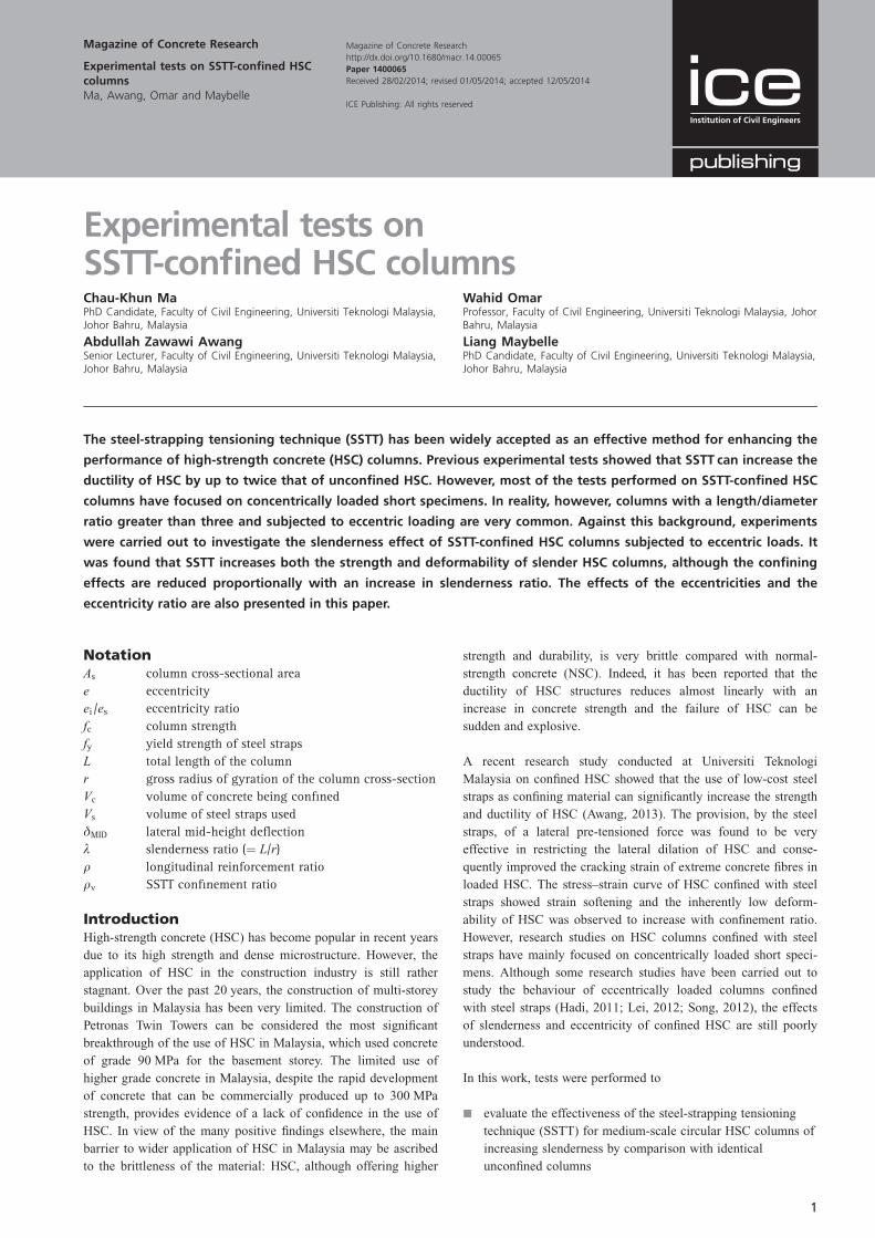
A total of 18 circular columns were prepared for testing. All the
columns were 150 mm in diameter and were 600, 900 or
1200 mm in length. The cross-sectional dimensions and reinforce-
ment details of the columns are shown in Figure 1. The long-
itudinal reinforcement consisted of four 10 mm diameter
deformed bars that were equally distributed around the column.
The selected target ratios of longitudinal reinforcement were
0.7% for the columns. The lateral reinforcement of the columns
consisted of 6 mm diameter deformed bars with a spacing of
300 mm. The internal reinforcements were chosen for construc-
tive purposes only according to EN 1992-1-1 (CEN, 1992). The
column dimensions and reinforcement details were limited to the
capacity and vertical dimensions of the loading frame used, and
also by the minimum sizes of available deformed steel bars.
Although the columns were slightly smaller than realistic
columns, studies have found no discernible size effect for circular
fibre-reinforced polymer (FRP) wrapped reinforced concrete
columns (Rocca et al., 2006).
The column details are summarised in Table 1. The clear
spacings of the steel straps were selected to be 20 mm and
40 mm, with one or two steel strap layers. The measured concrete
compressive strength, based on standard 100 mm 3 100 mm 3
100 mm cube tests, was in the range 60–70 MPa. Confinement
was provided up to the ends of the columns to avoid premature
failure in the end regions of the columns. The concrete cover was
kept constant at 20 mm to the face of the longitudinal reinforce-
ment. The longitudinal reinforcements were cut to match the
column height and were flush with the ends of the columns. The
circular columns were prepared for vertical casting using poly-
vinyl chloride (PVC) tubes. The PVC tubes were secured by
fitting them in plywood formworks (internal dimensions of
152 mm 3 152 mm) to avoid buckling of the tubes during
casting.
Specimen identification
Column specimens were labelled according to slenderness ratio
(i.e. different lengths of 600, 900 and 1200 mm), eccentricity of
applied load, eccentricity ratio and SSTT confinement ratio. For
example, specimen C600-E25-R1-S0.076 is a circular column of
600 mm length, subjected to eccentricities of 25 mm, with an
eccentric ratio of 1 and confined with a SSTT confinement ratio
(rv) of 0.076. The SSTT confinement ratio is calculated based on
Vsfy /VcAs, where Vs and Vc are the volume of steel straps used
and the volume of concrete being confined respectively, fy is the
yield strength of the steel straps and As is the column’s cross-
sectional area.
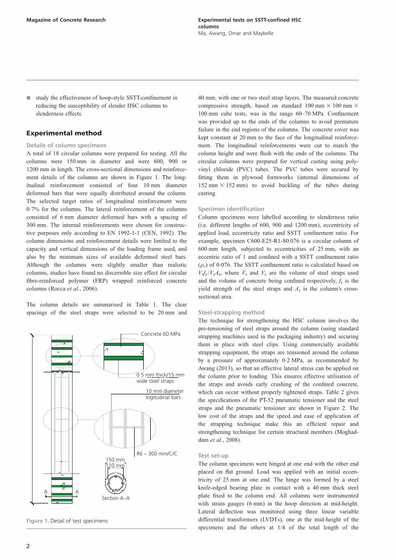
Steel-strapping method
The technique for strengthening the HSC column involves the
pre-tensioning of steel straps around the column (using standard
strapping machines used in the packaging industry) and securing
them in place with steel clips. Using commercially available
strapping equipment, the straps are tensioned around the column
by a pressure of approximately 0.2 MPa, as recommended by
Awang (2013), so that an effective lateral stress can be applied on
the column prior to loading. This ensures effective utilisation of
the straps and avoids early crushing of the confined concrete,
which can occur without properly tightened straps. Table 2 gives
the specifications of the PT-52 pneumatic tensioner and the steel
straps and the pneumatic tensioner are shown in Figure 2. The
low cost of the straps and the speed and ease of application of
the strapping technique make this an efficient repair and
strengthening technique for certain structural members (Moghad-
dam et al., 2008).
Test set-up
The column specimens were hinged at one end with the other end
placed on flat ground. Load was applied with an initial eccen-
tricity of 25 mm at one end. The hinge was formed by a steel
knife-edged bearing plate in contact with a 40 mm thick steel
plate fixed to the column end. All columns were instrumented
with strain gauges (6 mm) in the hoop direction at mid-height.
Lateral deflection was monitored using three linear variable
differential transformers (LVDTs), one at the mid-height of the
specimens and the others at 1/4 of the total length of the
A ASection A–A
110 mm150 mm
R6 – 300 mm/C/C
Concrete 60 MPa
0·5 mm thick/15 mmwide steel straps
10 mm diameterlogitudinal bars
Figure 1. Detail of test specimens
2
Magazine of Concrete Research Experimental tests on SSTT-confined HSCcolumnsMa, Awang, Omar and Maybelle
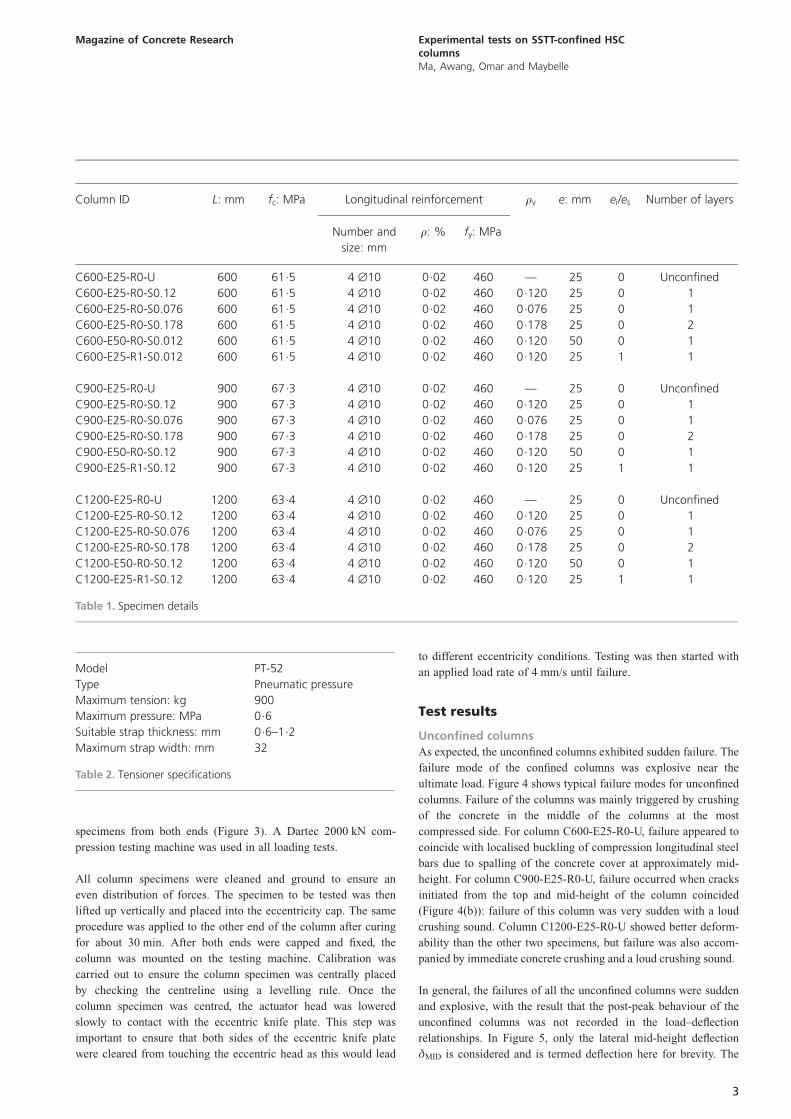
specimens from both ends (Figure 3). A Dartec 2000 kN com-
pression testing machine was used in all loading tests.
All column specimens were cleaned and ground to ensure an
even distribution of forces. The specimen to be tested was then
lifted up vertically and placed into the eccentricity cap. The same
procedure was applied to the other end of the column after curing
for about 30 min. After both ends were capped and fixed, the
column was mounted on the testing machine. Calibration was
carried out to ensure the column specimen was centrally placed
by checking the centreline using a levelling rule. Once the
column specimen was centred, the actuator head was lowered
slowly to contact with the eccentric knife plate. This step was
important to ensure that both sides of the eccentric knife plate
were cleared from touching the eccentric head as this would lead
to different eccentricity conditions. Testing was then started with
an applied load rate of 4 mm/s until failure.
Test results
Unconfined columns
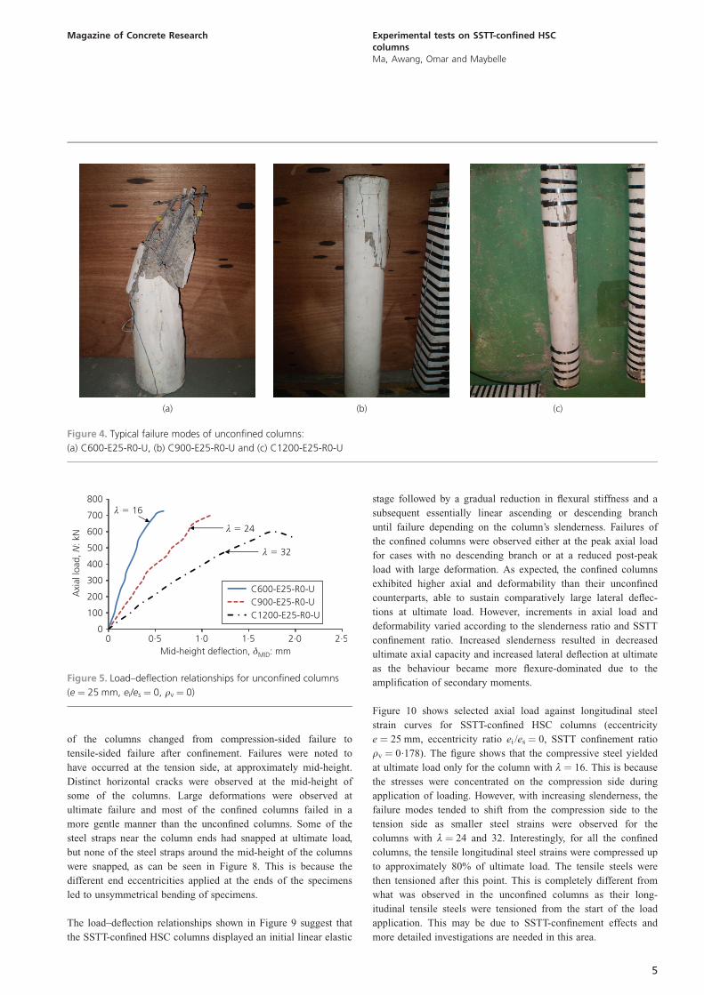
As expected, the unconfined columns exhibited sudden failure. The
failure mode of the confined columns was explosive near the
ultimate load. Figure 4 shows typical failure modes for unconfined
columns. Failure of the columns was mainly triggered by crushing
of the concrete in the middle of the columns at the most
compressed side. For column C600-E25-R0-U, failure appeared to
coincide with localised buckling of compression longitudinal steel
bars due to spalling of the concrete cover at approximately mid-
height. For column C900-E25-R0-U, failure occurred when cracks
initiated from the top and mid-height of the column coincided
(Figure 4(b)): failure of this column was very sudden with a loud
crushing sound. Column C1200-E25-R0-U showed better deform-
ability than the other two specimens, but failure was also accom-
panied by immediate concrete crushing and a loud crushing sound.
In general, the failures of all the unconfined columns were sudden
and explosive, with the result that the post-peak behaviour of the
unconfined columns was not recorded in the load–deflection
relationships. In Figure 5, only the lateral mid-height deflection
�MID is considered and is termed deflection here for brevity. The
Model PT-52
Type Pneumatic pressure
Maximum tension: kg 900
Maximum pressure: MPa 0.6
Suitable strap thickness: mm 0.6–1.2
Maximum strap width: mm 32
Table 2. Tensioner specifications
Column ID L: mm fc: MPa Longitudinal reinforcement rv e: mm ei/es Number of layers
Number and
size: mm
r: % fy: MPa
C600-E25-R0-U 600 61.5 4 ˘10 0.02 460 — 25 0 Unconfined
C600-E25-R0-S0.12 600 61.5 4 ˘10 0.02 460 0.120 25 0 1
C600-E25-R0-S0.076 600 61.5 4 ˘10 0.02 460 0.076 25 0 1
C600-E25-R0-S0.178 600 61.5 4 ˘10 0.02 460 0.178 25 0 2
C600-E50-R0-S0.012 600 61.5 4 ˘10 0.02 460 0.120 50 0 1
C600-E25-R1-S0.012 600 61.5 4 ˘10 0.02 460 0.120 25 1 1
C900-E25-R0-U 900 67.3 4 ˘10 0.02 460 — 25 0 Unconfined
C900-E25-R0-S0.12 900 67.3 4 ˘10 0.02 460 0.120 25 0 1
C900-E25-R0-S0.076 900 67.3 4 ˘10 0.02 460 0.076 25 0 1
C900-E25-R0-S0.178 900 67.3 4 ˘10 0.02 460 0.178 25 0 2
C900-E50-R0-S0.12 900 67.3 4 ˘10 0.02 460 0.120 50 0 1
C900-E25-R1-S0.12 900 67.3 4 ˘10 0.02 460 0.120 25 1 1
C1200-E25-R0-U 1200 63.4 4 ˘10 0.02 460 — 25 0 Unconfined
C1200-E25-R0-S0.12 1200 63.4 4 ˘10 0.02 460 0.120 25 0 1
C1200-E25-R0-S0.076 1200 63.4 4 ˘10 0.02 460 0.076 25 0 1
C1200-E25-R0-S0.178 1200 63.4 4 ˘10 0.02 460 0.178 25 0 2
C1200-E50-R0-S0.12 1200 63.4 4 ˘10 0.02 460 0.120 50 0 1
C1200-E25-R1-S0.12 1200 63.4 4 ˘10 0.02 460 0.120 25 1 1
Table 1. Specimen details
3
Magazine of Concrete Research Experimental tests on SSTT-confined HSCcolumnsMa, Awang, Omar and Maybelle
load–deflection relationships of unconfined columns with various
slenderness ratios (º ¼ 16, 24 and 32) are shown in Figure 5. The
slenderness ratio is taken as L/r, where L is the total length of the
column and r is the gross radius of gyration of the column cross-
section. It was found that an increase in slenderness resulted in
decreased ultimate load-carrying capacity but an increase in
deflection. This indicates that the failure mode shifted from
axially dominated material failure to flexural dominated instabil-
ity failure. Figure 6 suggests that no yielding of the longitudinal
bars occurred prior to failure and therefore the ultimate deflec-
tions of all the unconfined columns were relatively small.
Examination of the relationships of load against concrete axial
strain (Figure 7) reveals that both tensile concrete strain and
compressive concrete strains presented almost similar patterns for
columns with various slenderness ratios when subjected to
eccentric loads. The variation of axial strain with increasing
slenderness for unconfined HSC columns is counterintuitive as no
significant increments were observed for axial concrete strains
with increasing flexural effects. This can be explained by noting
that failure of the unconfined slender HSC columns was initiated
slightly above the mid-height of the specimens, where the strain
gauges were placed. This led to inaccuracy as the maximum
strain was not captured at the exact location of failure in most
cases (which is at mid-height of the column).
Confined columns
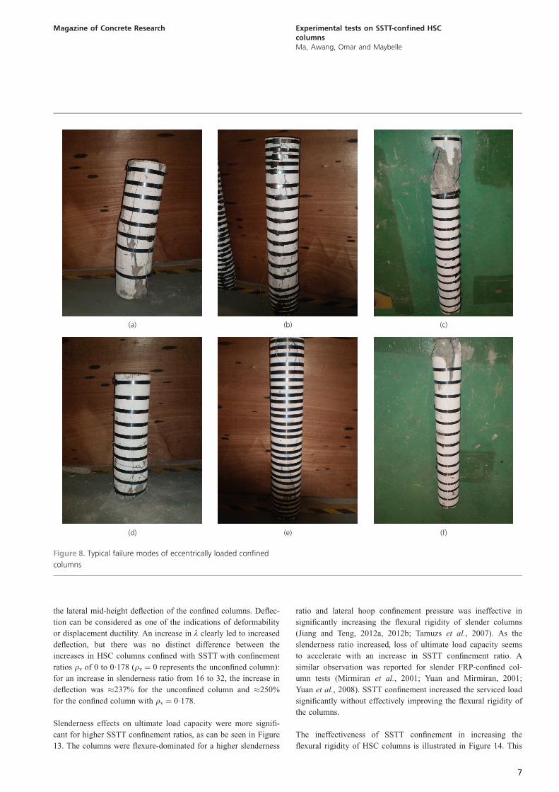
Figure 8 shows typical failure modes of the eccentrically loaded
SSTT-confined slender HSC columns. It can be seen that failure
Load actuator
Load cell
LVDT 50 mm
LVDT 50 mm
LVDT 50 mm
L /4
L /4
Pi gauges
Strain gauges
Figure 3. Schematic illustration of test set-up and selected
instrumentation (A ‘pi gauge’, also known as an omega strain
gauge, is a non-destructive gauge used to measure a material’s
strain. Its shape resembles the Greek character pi/omega – hence
its name.)
(a)
(b)
Figure 2. Steel straps (a) and tensioner (b) used to confine the
columns
4
Magazine of Concrete Research Experimental tests on SSTT-confined HSCcolumnsMa, Awang, Omar and Maybelle
of the columns changed from compression-sided failure to
tensile-sided failure after confinement. Failures were noted to
have occurred at the tension side, at approximately mid-height.
Distinct horizontal cracks were observed at the mid-height of
some of the columns. Large deformations were observed at
ultimate failure and most of the confined columns failed in a
more gentle manner than the unconfined columns. Some of the
steel straps near the column ends had snapped at ultimate load,
but none of the steel straps around the mid-height of the columns
were snapped, as can be seen in Figure 8. This is because the
different end eccentricities applied at the ends of the specimens
led to unsymmetrical bending of specimens.
The load–deflection relationships shown in Figure 9 suggest that
the SSTT-confined HSC columns displayed an initial linear elastic
stage followed by a gradual reduction in flexural stiffness and a
subsequent essentially linear ascending or descending branch
until failure depending on the column’s slenderness. Failures of
the confined columns were observed either at the peak axial load
for cases with no descending branch or at a reduced post-peak
load with large deformation. As expected, the confined columns
exhibited higher axial and deformability than their unconfined
counterparts, able to sustain comparatively large lateral deflec-
tions at ultimate load. However, increments in axial load and
deformability varied according to the slenderness ratio and SSTT
confinement ratio. Increased slenderness resulted in decreased
ultimate axial capacity and increased lateral deflection at ultimate
as the behaviour became more flexure-dominated due to the
amplification of secondary moments.
Figure 10 shows selected axial load against longitudinal steel
strain curves for SSTT-confined HSC columns (eccentricity
e ¼ 25 mm, eccentricity ratio ei /es ¼ 0, SSTT confinement ratio
rv ¼ 0.178). The figure shows that the compressive steel yielded
at ultimate load only for the column with º ¼ 16. This is because
the stresses were concentrated on the compression side during
application of loading. However, with increasing slenderness, the
failure modes tended to shift from the compression side to the
tension side as smaller steel strains were observed for the
columns with º ¼ 24 and 32. Interestingly, for all the confined
columns, the tensile longitudinal steel strains were compressed up
to approximately 80% of ultimate load. The tensile steels were
then tensioned after this point. This is completely different from
what was observed in the unconfined columns as their long-
itudinal tensile steels were tensioned from the start of the load
application. This may be due to SSTT-confinement effects and
more detailed investigations are needed in this area.
(a) (b) (c)
Figure 4. Typical failure modes of unconfined columns:
(a) C600-E25-R0-U, (b) C900-E25-R0-U and (c) C1200-E25-R0-U
2·52·01·51·00·50
100
200
300
400
500
600
700
800
0
Axi
al lo
ad,
: kN
N
Mid-height deflection, : mmδMID
C600-E25-R0-UC900-E25-R0-UC1200-E25-R0-U
λ � 32
λ � 24
λ 16�
Figure 5. Load–deflection relationships for unconfined columns
(e ¼ 25 mm, ei/es ¼ 0, rv ¼ 0)
5
Magazine of Concrete Research Experimental tests on SSTT-confined HSCcolumnsMa, Awang, Omar and Maybelle
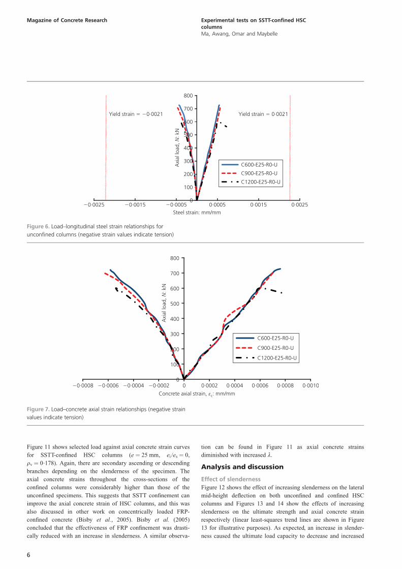
Figure 11 shows selected load against axial concrete strain curves
for SSTT-confined HSC columns (e ¼ 25 mm, ei /es ¼ 0,
rv ¼ 0.178). Again, there are secondary ascending or descending
branches depending on the slenderness of the specimen. The
axial concrete strains throughout the cross-sections of the
confined columns were considerably higher than those of the
unconfined specimens. This suggests that SSTT confinement can
improve the axial concrete strain of HSC columns, and this was
also discussed in other work on concentrically loaded FRP-
confined concrete (Bisby et al., 2005). Bisby et al. (2005)
concluded that the effectiveness of FRP confinement was drasti-
cally reduced with an increase in slenderness. A similar observa-
tion can be found in Figure 11 as axial concrete strains
diminished with increased º.
Analysis and discussion
Effect of slenderness
Figure 12 shows the effect of increasing slenderness on the lateral
mid-height deflection on both unconfined and confined HSC
columns and Figures 13 and 14 show the effects of increasing
slenderness on the ultimate strength and axial concrete strain
respectively (linear least-squares trend lines are shown in Figure
13 for illustrative purposes). As expected, an increase in slender-
ness caused the ultimate load capacity to decrease and increased
Axi
al lo
ad,
: kN
N
Yield strain 0·0021�
0·00250·00150·0005�0·0005�0·00150
100
200
300
400
500
600
700
800
�0·0025Steel strain: mm/mm
C600-E25-R0-U
C900-E25-R0-U
C1200-E25-R0-U
Yield strain 0·0021� �
Figure 6. Load–longitudinal steel strain relationships for
unconfined columns (negative strain values indicate tension)
0·00100·00080·00060·00040·00020�0·0002�0·0004�0·00060
100
200
300
400
500
600
700
800
�0·0008
Axi
al lo
ad,
: kN
N
Concrete axial strain, : mm/mmεc
C600-E25-R0-U
C900-E25-R0-U
C1200-E25-R0-U
Figure 7. Load–concrete axial strain relationships (negative strain
values indicate tension)
6
Magazine of Concrete Research Experimental tests on SSTT-confined HSCcolumnsMa, Awang, Omar and Maybelle
the lateral mid-height deflection of the confined columns. Deflec-
tion can be considered as one of the indications of deformability
or displacement ductility. An increase in º clearly led to increased
deflection, but there was no distinct difference between the
increases in HSC columns confined with SSTT with confinement
ratios rv of 0 to 0.178 (rv ¼ 0 represents the unconfined column):
for an increase in slenderness ratio from 16 to 32, the increase in
deflection was �237% for the unconfined column and �250%
for the confined column with rv ¼ 0.178.
Slenderness effects on ultimate load capacity were more signifi-
cant for higher SSTT confinement ratios, as can be seen in Figure
13. The columns were flexure-dominated for a higher slenderness
ratio and lateral hoop confinement pressure was ineffective in
significantly increasing the flexural rigidity of slender columns
(Jiang and Teng, 2012a, 2012b; Tamuzs et al., 2007). As the
slenderness ratio increased, loss of ultimate load capacity seems
to accelerate with an increase in SSTT confinement ratio. A
similar observation was reported for slender FRP-confined col-
umn tests (Mirmiran et al., 2001; Yuan and Mirmiran, 2001;
Yuan et al., 2008). SSTT confinement increased the serviced load
significantly without effectively improving the flexural rigidity of
the columns.
The ineffectiveness of SSTT confinement in increasing the
flexural rigidity of HSC columns is illustrated in Figure 14. This
(a) (b) (c)
(d) (e) (f)
Figure 8. Typical failure modes of eccentrically loaded confined
columns
7
Magazine of Concrete Research Experimental tests on SSTT-confined HSCcolumnsMa, Awang, Omar and Maybelle
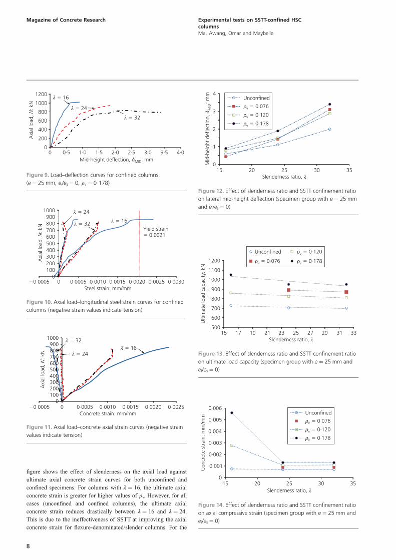
figure shows the effect of slenderness on the axial load against
ultimate axial concrete strain curves for both unconfined and
confined specimens. For columns with º ¼ 16, the ultimate axial
concrete strain is greater for higher values of rv. However, for all
cases (unconfined and confined columns), the ultimate axial
concrete strain reduces drastically between º ¼ 16 and º ¼ 24.
This is due to the ineffectiveness of SSTT at improving the axial
concrete strain for flexure-denominated/slender columns. For the
4·03·53·02·52·01·51·00·50
200
400
600
800
1000
1200
0
Axi
al lo
ad,
: kN
N
Mid-height deflection, : mmδMID
λ 16�
λ � 24
λ � 32
Figure 9. Load–deflection curves for confined columns
(e ¼ 25 mm, ei/es ¼ 0, rv ¼ 0.178)
0·00300·00250·00200·00150·00100·00050
Axi
al lo
ad,
: kN
N
Yield strain0·0021�
0100200300400500600700800900
1000
�0·0005Steel strain: mm/mm
λ 16�
λ � 24
λ � 32
Figure 10. Axial load–longitudinal steel strain curves for confined
columns (negative strain values indicate tension)
0·00250·00200·00150·00100·000500
100200300400500600700800900
1000
�0·0005
Axi
al lo
ad,
: kN
N
Concrete strain: mm/mm
λ � 16λ � 24
λ 32�
Figure 11. Axial load–concrete axial strain curves (negative strain
values indicate tension)
Mid
-hei
ght
defle
ctio
n,: m
mδ M
ID
353025200
1
2
3
4
15Slenderness ratio, λ
Unconfined
ρv 0·076�
ρv � 0·120
ρv � 0·178
Figure 12. Effect of slenderness ratio and SSTT confinement ratio
on lateral mid-height deflection (specimen group with e ¼ 25 mm
and ei/es ¼ 0)
333129272523211917500
600
700
800
900
1000
1100
1200
15
Ulti
mat
e lo
ad c
apac
ity: k
N
Slenderness ratio, λ
Unconfined
ρv � 0·076
ρv 0·120�
ρv � 0·178
Figure 13. Effect of slenderness ratio and SSTT confinement ratio
on ultimate load capacity (specimen group with e ¼ 25 mm and
ei/es ¼ 0)
353025200
0·001
0·002
0·003
0·004
0·005
0·006
15
Con
cret
e st
rain
: mm
/mm
Slenderness ratio, λ
Unconfined
ρv 0·076�
ρv � 0·120
ρv � 0·178
Figure 14. Effect of slenderness ratio and SSTT confinement ratio
on axial compressive strain (specimen group with e ¼ 25 mm and
ei/es ¼ 0)
8
Magazine of Concrete Research Experimental tests on SSTT-confined HSCcolumnsMa, Awang, Omar and Maybelle
case of rv ¼ 0.178, there is an approximately 77% drop in
ultimate axial concrete strain for º increasing from 16 to 24. The
ultimate concrete axial strains for all confined and unconfined
specimens beyond º ¼ 24 were very similar. This clearly explains
the flexure-dominated behaviour and under-utilisation of SSTT
confinement in slender columns.
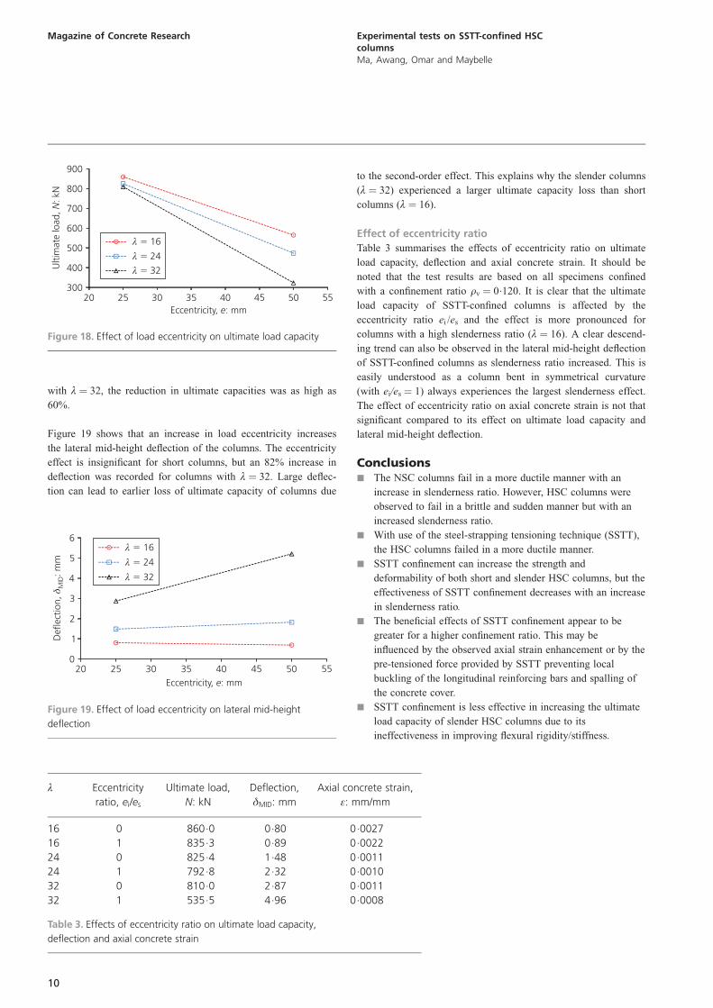
Effect of SSTT confinement ratio
Figure 15 shows the effect of increasing SSTT confinement ratio
(rv ¼ 0, 0.076, 0.120, 0.178) on the load–deflection curves
behaviour of both short and slender columns (rv ¼ 0 represents
an unconfined column). Increasing rv increased the strength and
deformability for both short and slender columns under eccentric
axial load, but the increase in axial load is more pronounced for
the short columns. The increments in axial load were approxi-
mately 30% and 80% for columns with rv ¼ 0.076 and 0.120
respectively. It is probable that the pre-tensioned force provided
by SSTT confinement improves the concrete’s strength and
deformability mainly by preventing or delaying local bar buckling
for a higher SSTT confinement level. The enhanced axial con-
crete strain, although not significant, may also play a role.
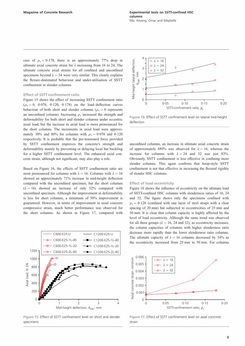
Based on Figure 16, the effects of SSTT confinement ratio are
most pronounced for columns with º ¼ 16. Columns with º ¼ 16
showed an approximately 71% increase in mid-height deflection
compared with the unconfined specimen, but the short columns
(º ¼ 16) showed an increase of only 52% compared with
unconfined specimen. Although the improvement in deformability
is less for short columns, a minimum of 50% improvement is
guaranteed. However, in terms of improvement in axial concrete
compressive strain, much better performance was observed for
the short columns. As shown in Figure 17, compared with
unconfined columns, an increase in ultimate axial concrete strain
of approximately 689% was observed for º ¼ 16, whereas the
increase for columns with º ¼ 24 and 32 was just 83%.
Obviously, SSTT confinement is less effective in confining more
slender columns. This again confirms that hoop-style SSTT
confinement is not that effective in increasing the flexural rigidity
of slender HSC columns.
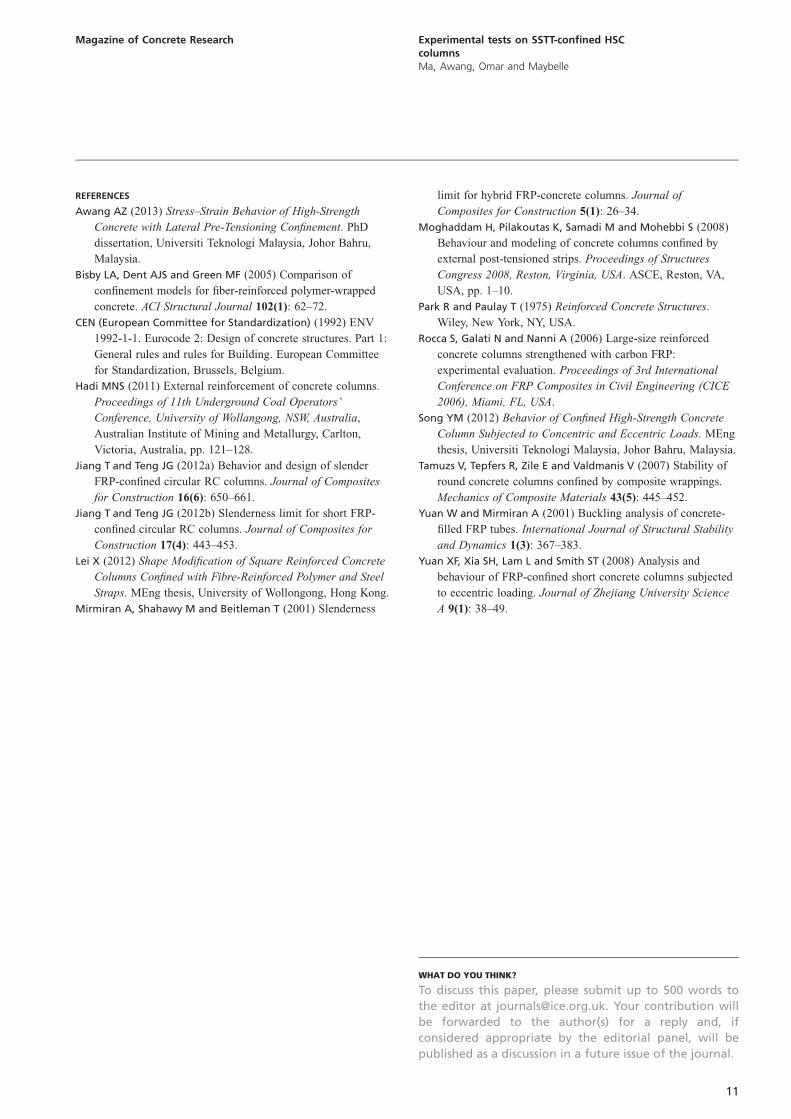
Effect of load eccentricity
Figure 18 shows the influence of eccentricity on the ultimate load
of SSTT-confined HSC columns with slenderness ratios of 16, 24
and 32. The figure shows only the specimens confined with
rv ¼ 0.120 (confined with one layer of steel straps with a clear
spacing of 20 mm) but subjected to eccentricities of 25 mm and
50 mm. It is clear that column capacity is highly affected by the
level of load eccentricity. Although the same trend was observed
for all three groups (º ¼ 16, 24 and 32), as eccentricity increases,
the column capacities of columns with higher slenderness ratio
decrease more rapidly than the lower slenderness ratio columns.
The ultimate capacity of º ¼ 16 columns decreased by 34% as
the eccentricity increased from 25 mm to 50 mm. For columns
Axi
al lo
ad,
: kN
N
43210
200
400
600
800
1000
1200
0Mid-height deflection, : mmδMID
C600-E25-U
C600-E25-1L 40-
C600-E25 1L 20- -
C600-E25 2L 40- -
C1200-E25-U
C1200-E25 1L 40- -
C1200-E25 1L 20- -
C1200-E25 2L 40- -
Figure 15. Effect of SSTT confinement level on short and slender
specimens
0·200·150·100·050
1
2
3
4
0
Mid
-hei
ght
late
ral d
efle
ctio
n,: m
mδ M
ID
SSTT-confinement ratio, ρv
λ 16�
λ � 24λ � 32
Figure 16. Effect of SSTT confinement level on lateral mid-height
deflection
0·200·150·100·050
0·001
0·002
0·003
0·004
0·005
0·006
0
Axi
al c
oncr
ete
stra
in: m
m/m
m
SSTT-confinement ratio, ρv
λ 16�
λ � 24
λ � 32
Figure 17. Effect of SSTT confinement level on axial concrete
strain
9
Magazine of Concrete Research Experimental tests on SSTT-confined HSCcolumnsMa, Awang, Omar and Maybelle
with º ¼ 32, the reduction in ultimate capacities was as high as
60%.
Figure 19 shows that an increase in load eccentricity increases
the lateral mid-height deflection of the columns. The eccentricity
effect is insignificant for short columns, but an 82% increase in
deflection was recorded for columns with º ¼ 32. Large deflec-
tion can lead to earlier loss of ultimate capacity of columns due
to the second-order effect. This explains why the slender columns
(º ¼ 32) experienced a larger ultimate capacity loss than short
columns (º ¼ 16).
Effect of eccentricity ratio
Table 3 summarises the effects of eccentricity ratio on ultimate
load capacity, deflection and axial concrete strain. It should be
noted that the test results are based on all specimens confined
with a confinement ratio rv ¼ 0.120. It is clear that the ultimate
load capacity of SSTT-confined columns is affected by the
eccentricity ratio ei /es and the effect is more pronounced for
columns with a high slenderness ratio (º ¼ 16). A clear descend-
ing trend can also be observed in the lateral mid-height deflection
of SSTT-confined columns as slenderness ratio increased. This is
easily understood as a column bent in symmetrical curvature
(with ei/es ¼ 1) always experiences the largest slenderness effect.
The effect of eccentricity ratio on axial concrete strain is not that
significant compared to its effect on ultimate load capacity and
lateral mid-height deflection.
Conclusionsj The NSC columns fail in a more ductile manner with an
increase in slenderness ratio. However, HSC columns were
observed to fail in a brittle and sudden manner but with an
increased slenderness ratio.
j With use of the steel-strapping tensioning technique (SSTT),
the HSC columns failed in a more ductile manner.
j SSTT confinement can increase the strength and
deformability of both short and slender HSC columns, but the
effectiveness of SSTT confinement decreases with an increase
in slenderness ratio.
j The beneficial effects of SSTT confinement appear to be
greater for a higher confinement ratio. This may be
influenced by the observed axial strain enhancement or by the
pre-tensioned force provided by SSTT preventing local
buckling of the longitudinal reinforcing bars and spalling of
the concrete cover.
j SSTT confinement is less effective in increasing the ultimate
load capacity of slender HSC columns due to its
ineffectiveness in improving flexural rigidity/stiffness.
55504540353025Eccentricity, : mme
300
400
500
600
700
800
900
20
Ulti
mat
e lo
ad,
: kN
N
λ 16�
λ � 24
λ � 32
Figure 18. Effect of load eccentricity on ultimate load capacity
Eccentricity, : mme55504540353025
0
1
2
3
4
5
6
20
Def
lect
ion,
: mm
δ MID
λ 16�
λ � 24
λ � 32
Figure 19. Effect of load eccentricity on lateral mid-height
deflection
º Eccentricity
ratio, ei/es
Ultimate load,
N: kN
Deflection,
�MID: mm
Axial concrete strain,
�: mm/mm
16 0 860.0 0.80 0.0027
16 1 835.3 0.89 0.0022
24 0 825.4 1.48 0.0011
24 1 792.8 2.32 0.0010
32 0 810.0 2.87 0.0011
32 1 535.5 4.96 0.0008
Table 3. Effects of eccentricity ratio on ultimate load capacity,
deflection and axial concrete strain
10
Magazine of Concrete Research Experimental tests on SSTT-confined HSCcolumnsMa, Awang, Omar and Maybelle
REFERENCES
Awang AZ (2013) Stress–Strain Behavior of High-Strength
Concrete with Lateral Pre-Tensioning Confinement. PhD
dissertation, Universiti Teknologi Malaysia, Johor Bahru,
Malaysia.
Bisby LA, Dent AJS and Green MF (2005) Comparison of
confinement models for fiber-reinforced polymer-wrapped
concrete. ACI Structural Journal 102(1): 62–72.
CEN (European Committee for Standardization) (1992) ENV
1992-1-1. Eurocode 2: Design of concrete structures. Part 1:
General rules and rules for Building. European Committee
for Standardization, Brussels, Belgium.
Hadi MNS (2011) External reinforcement of concrete columns.
Proceedings of 11th Underground Coal Operators’
Conference, University of Wollangong, NSW, Australia,
Australian Institute of Mining and Metallurgy, Carlton,
Victoria, Australia, pp. 121–128.
Jiang T and Teng JG (2012a) Behavior and design of slender
FRP-confined circular RC columns. Journal of Composites
for Construction 16(6): 650–661.
Jiang T and Teng JG (2012b) Slenderness limit for short FRP-
confined circular RC columns. Journal of Composites for
Construction 17(4): 443–453.
Lei X (2012) Shape Modification of Square Reinforced Concrete
Columns Confined with Fibre-Reinforced Polymer and Steel
Straps. MEng thesis, University of Wollongong, Hong Kong.
Mirmiran A, Shahawy M and Beitleman T (2001) Slenderness
limit for hybrid FRP-concrete columns. Journal of
Composites for Construction 5(1): 26–34.
Moghaddam H, Pilakoutas K, Samadi M and Mohebbi S (2008)
Behaviour and modeling of concrete columns confined by
external post-tensioned strips. Proceedings of Structures
Congress 2008, Reston, Virginia, USA. ASCE, Reston, VA,
USA, pp. 1–10.
Park R and Paulay T (1975) Reinforced Concrete Structures.
Wiley, New York, NY, USA.
Rocca S, Galati N and Nanni A (2006) Large-size reinforced
concrete columns strengthened with carbon FRP:
experimental evaluation. Proceedings of 3rd International
Conference on FRP Composites in Civil Engineering (CICE
2006), Miami, FL, USA.
Song YM (2012) Behavior of Confined High-Strength Concrete
Column Subjected to Concentric and Eccentric Loads. MEng
thesis, Universiti Teknologi Malaysia, Johor Bahru, Malaysia.
Tamuzs V, Tepfers R, Zile E and Valdmanis V (2007) Stability of
round concrete columns confined by composite wrappings.
Mechanics of Composite Materials 43(5): 445–452.
Yuan W and Mirmiran A (2001) Buckling analysis of concrete-
filled FRP tubes. International Journal of Structural Stability
and Dynamics 1(3): 367–383.
Yuan XF, Xia SH, Lam L and Smith ST (2008) Analysis and
behaviour of FRP-confined short concrete columns subjected
to eccentric loading. Journal of Zhejiang University Science
A 9(1): 38–49.
WHAT DO YOU THINK?
To discuss this paper, please submit up to 500 words to
the editor at [email protected]. Your contribution will
be forwarded to the author(s) for a reply and, if
considered appropriate by the editorial panel, will be
published as a discussion in a future issue of the journal.
11
Magazine of Concrete Research Experimental tests on SSTT-confined HSCcolumnsMa, Awang, Omar and Maybelle


