Embed Size (px)
Citation preview
Engineering Geology 157 (2013) 1–7
Contents lists available at SciVerse ScienceDirect
Engineering Geology
j ourna l homepage: www.e lsev ie r .com/ locate /enggeo
Experimental modeling of abandoned shallow oil wells convergence
P. Bujok a, M. Porzer a, K. Labus b,⁎, M. Klempa a, J. Pavluš a
a Institute of Geological Engineering, VŠB-Technical University of Ostrava, 17. listopadu 15, 708 33 Ostrava, Czech Republicb Institute for Applied Geology, Silesian University of Technology, 2 Akademicka St., 44-100 Gliwice, Poland
⁎ Corresponding author.E-mail addresses: [email protected], klabus@o
0013-7952/$ – see front matter © 2013 Elsevier B.V. Allhttp://dx.doi.org/10.1016/j.enggeo.2013.02.004
a b s t r a c t
a r t i c l e i n f oArticle history:Received 20 June 2012Received in revised form 1 February 2013Accepted 2 February 2013Available online 20 February 2013
Keywords:Well convergencePhysical modelShallow oil wellsWell abandonment
The paper discusses issues related to inappropriately abandoned production wells in depleted oil field nearHodonín (South Moravia, Czech Republic). The characteristic effects of the well deformation, depending onwhether there was a possibility of fluid displacement from the well space were defined on the basis ofmodel experiments. It was proven that in the analyzed conditions, convergence of abandoned wells is notequivalent to their proper liquidation, because the communication of media is still possible, creating a riskof pollution of groundwater and land surface.
© 2013 Elsevier B.V. All rights reserved.
1. Introduction
The Hodonín oil field under consideration is located in the north-ern part of the Lower Moravian depression (northern part of theVienna Basin) along the right bank of the Morava River, about5.5 km south-west from the town of Hodonín. The oilfield consistsof several elevated structures, with related accumulations of hydro-carbons. They can be treated as separate deposits, which are part ofthe so-called Hodonín-Gbel play. The productive series is representedby Sarmatian sandy marls with inserts sand oil horizons, as well assandstone and lignite beds. Below lie the sandy marls classified asupper Badenian. The overburden consists of sandy marls, claysand sands of Sarmatian age, covered by Quaternary clayey-sandysediments of fluvial terraces of the Morava River — Fig. 1.
The first oil wells in this area were drilled in 1919. They werelocalized on the basis of the observed leakage of gas and oil in the oldriverbed of Moravia. Signs of oil were found at a depth of 218 mbelow the surface. Since the start of operation in the twenties of XXcentury, hundreds of production wells have been drilled in theHodonín region. These wells, gradually excluded from the operation,were systematically plugged, although often after a long time sincethe abandonment. The plugging technology was often very primitive(removal of casing, filling with clay or soil), or incorrectly performed.Many of the wells were left without plugging. In some oil fields,particularly where the reservoir water have extensive coverage, a grad-ual pressure buildup may occur (MND Group, archival data). Thisprocess can lead to restoration of spontaneous connections betweenthe shallow productive layer (situated 100 to 180 m below the surface)
2.pl (K. Labus).
rights reserved.
and the overburden (surface), through the space of poorly pluggedwell. Example effects of improper well abandonment are shown inFig. 2.
In order to study the phenomena responsible for the passage offluids through abandoned wells and mechanisms of well space defor-mation in Sarmatian sediments, a program of simple model experi-ments was designed. The purpose of these models was to providethe view of underground processes occurring after the casing removalin order to abandon oil well in terms of exceeding the rock failurecriterion after the thereby induced stress deviation. It should beunderlined, that time dependent effects such as creep were beyondthe study extent and model resolution.
2. Shallow well convergence and its effects
Interactions between rock mass and the space within the abandonedborehole can be considered in two possible scenarios:
A) cemented or partly cemented sections of casing were left in theborehole,
B) the borehole is open and filled with mud or reservoir fluid.
According to the scenario A the destruction of casing due to externalpressure is unlikely at least to a depth of several hundred meters (Barreeand Mukherjee, 1996; Shuling et al., 2010, 2012). Already at the stage ofwell design calculations are carried out to prevent the casing destructiondue to external or internal pressure. Casing shall be conducted on thebasis of these calculations and empirical experience as well. Improperlyliquidated production well however, may enable communication be-tween the collector and the surface or zones of lower reservoir pressures.Communication can take place inside the well, or outside the casing, in
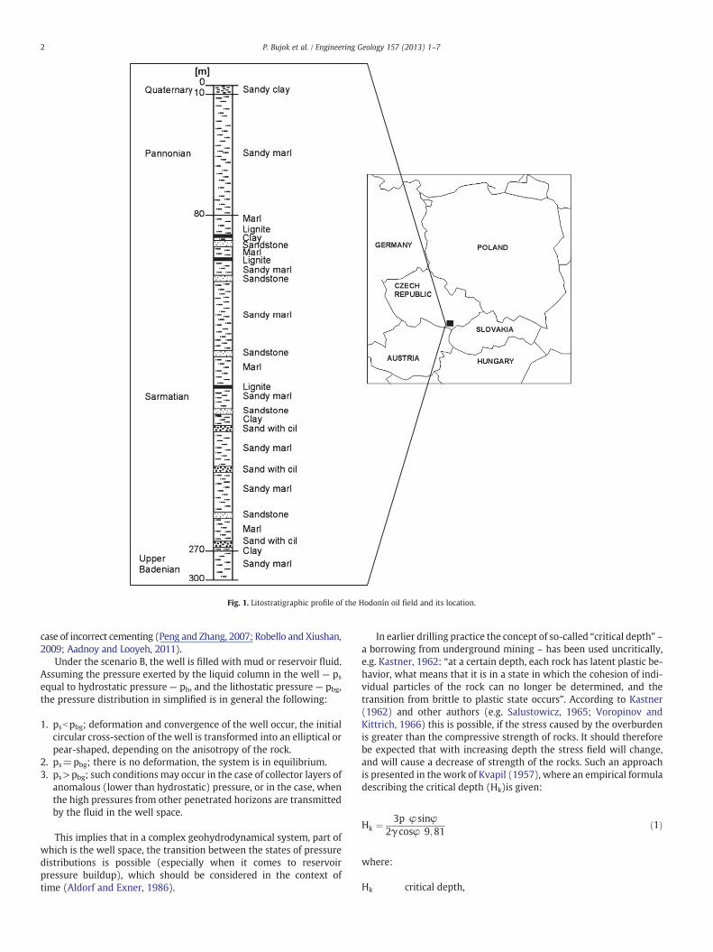
Fig. 1. Litostratigraphic profile of the Hodonín oil field and its location.
2 P. Bujok et al. / Engineering Geology 157 (2013) 1–7
case of incorrect cementing (Peng and Zhang, 2007; Robello and Xiushan,2009; Aadnoy and Looyeh, 2011).
Under the scenario B, the well is filled with mud or reservoir fluid.Assuming the pressure exerted by the liquid column in the well — psequal to hydrostatic pressure — ph, and the lithostatic pressure — pbg,the pressure distribution in simplified is in general the following:
1. psbpbg; deformation and convergence of the well occur, the initialcircular cross-section of the well is transformed into an elliptical orpear-shaped, depending on the anisotropy of the rock.
2. ps=pbg; there is no deformation, the system is in equilibrium.3. ps>pbg; such conditions may occur in the case of collector layers of
anomalous (lower than hydrostatic) pressure, or in the case, whenthe high pressures from other penetrated horizons are transmittedby the fluid in the well space.
This implies that in a complex geohydrodynamical system, part ofwhich is the well space, the transition between the states of pressuredistributions is possible (especially when it comes to reservoirpressure buildup), which should be considered in the context oftime (Aldorf and Exner, 1986).
In earlier drilling practice the concept of so-called “critical depth” –a borrowing from underground mining – has been used uncritically,e.g. Kastner, 1962: “at a certain depth, each rock has latent plastic be-havior, what means that it is in a state in which the cohesion of indi-vidual particles of the rock can no longer be determined, and thetransition from brittle to plastic state occurs”. According to Kastner(1962) and other authors (e.g. Salustowicz, 1965; Voropinov andKittrich, 1966) this is possible, if the stress caused by the overburdenis greater than the compressive strength of rocks. It should thereforebe expected that with increasing depth the stress field will change,and will cause a decrease of strength of the rocks. Such an approachis presented in the work of Kvapil (1957), where an empirical formuladescribing the critical depth (Hk)is given:
Hk ¼ 3p φ sinφ2γ cosφ 9;81
ð1Þ
where:
Hk critical depth,
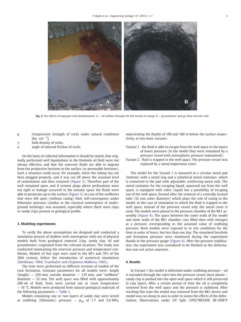
Fig. 2. The effects of improper well abandonment: A — oil outflow through the left section of casing; B — groundwater and gas flow into the well.
3P. Bujok et al. / Engineering Geology 157 (2013) 1–7
p Compressive strength of rocks under natural conditions[kp·cm−2],
γ bulk density of rocks,φ angle of internal friction of rocks.
On the basis of collected information it should be stated, that orig-inally performed well liquidations in the Hodonín oil field were notalways effective, and that the reservoir fluids are able to migratefrom the productive horizons to the surface (or permeable horizons).Such a situation could occur, for example, when the tubing has notbeen plugged properly, and it was cut off above the assumed levelof cementation and then removed (Figure 3). Therefore part of thewell remained open, and if cement plugs above perforations werenot tight or leakage occurred in the annular space the fluids wereable to penetrate up to the surface (Figure 3). In case of the wellboresthat were left open (without casing) their self-convergence underlithostatic pressure (similar to the classical convergence of under-ground workings) was assumed, especially where there were claysor sandy clays present in geological profile.
3. Modeling experiments
To verify the above assumptions we designed and conducted asimulation process of shallow well convergence with use of physicalmodels built from geological material (clay, sandy clay, oil andgroundwater) originated from the relevant locations. The study wasconducted maintaining the reservoir pressure and temperature con-ditions. Models of this type were used in the 60's and 70's of the20th century, before the introduction of numerical simulations(Denkhaus, 1964; Trumbačev and Chajmova-Malkova, 1965).
The tests were performed on different versions of models of therock formation. Constant parameters for all models were: height(length) — 250 mm, outside diameter — 135 mm, and “wellbore”diameter — 32 mm. The well space was filled with approximately200 ml of fluid. Tests were carried out at room temperature— 18 °C. Models were produced from natural geological materials ofthe following parameters — Table 1.
Models containing one or two layers of sandy clay were testedat confining (lithostatic) pressure — pbg of 1.7 and 3.6 MPa,
representing the depths of 100 and 180 m below the surface respec-tively, in two basic variants:
Variant 1 the fluid is able to escape from the well space to the layersof lower pressure (in the model they were simulated by apressure vessel with atmospheric pressure maintained);
Variant 2 fluid is trapped in the well space. The pressure vessel wasreplaced by a metal impervious cover.
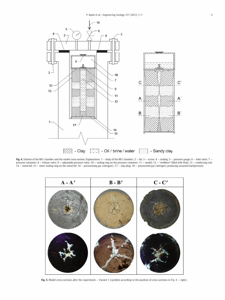
The model for the Variant 1 is mounted to a circular metal pad(bottom) with a metal ring and a cylindrical metal container, whichis connected to the pad with adjustable, reinforcing metal rods. Themetal container for the escaping liquid, squeezed out from the wellspace, is equipped with valve. Liquid has a possibility of escapingout of the well space, formed after the removal of a centrally locatedtube (32 mm outer diameter) which plays the role of casing in themodel. In the case of simulation in which the fluid is trapped in thewell space, instead of the pressure vessel only the metal cover isused. The models were placed in the pressure chamber of the RK1 as-sembly (Figure 4). The space between the outer walls of the modeland inner walls of the RK1 chamber, was filled then with nitrogenat a pressure corresponding to the assumed value of confiningpressure. Rock models were exposed to in situ conditions for thetime in order of hours, but less than one day. The simulated boreholeand formation pressure were monitored during the experimentthanks to the pressure gauge (Figure 4). After the pressure stabiliza-tion, the experiment was considered to be finished as the deforma-tion was not active anymore.
4. Results
In Variant 1 the model is deformed under confining pressure – oilis extruded through the valve into the pressure vessel, more plastic –sandy clay is pushed into the open well space which is still preservedin clay layers. After a certain period of time the oil is completelyremoved from the well space and the pressure is stabilized. Afterreaching this state the model was removed from the RK1 device andmodel was cut along its axis in order to assess the effects of the defor-mation. Observations under UV light (SPECTROLINE SB-100P/F
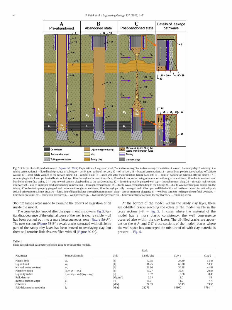
Fig. 3. Scheme of an old productionwell (Bujok et al., 2012). Explanations: 1— ground level; 2— surface casing; 3— surface casing cementation; 4—mud; 5— sandy clay; 6— tubing; 7—
tubing cementation; 8— liquid in the production tubing; 9— perforation at the oil horizon; 10— oil horizon; 11— bottom cementation; 12— ground completion above backed-off surfacecasing; 13 — steel hatch, welded to the surface casing; 14— cement plug; 15 — open well after the production tubing back-off; 16 — point of backing-off (cutting-off) the casing; 17 —
cement plug in the lower perforated horizon; leakage: 18— through rock-cement interface; 19— due to improper casing cementation— through cement stone; 20— due toweak cementbond onto the surface casing; 21— due toweak cement plug bonding to the surface casing; 22— due to improperly plugged well top— through cement plug; 23— through rock-cementinterface; 24— due to improper production tubing cementation— through cement stone; 25— due to weak cement bonding to the tubing; 26— due to weak cement plug bonding in thetubing; 27— due to improperly plugged well bottom— through cement stone; 28— through partially convergedwell; 29— openwell filledwithmud residuumor/and formation liquids(oil, oil-brinemixture, brine, etc.); 30— formation of liquid leakage through bottom cement plug— case of improper plugging; 31—wellbore contents leaking to the surficial layers; pg—lithostatic pressure; pv — formation pressure; ps — well pressure; ph — hydrostatic pressure; sh — horizontal stresses around the wellbore; σh — confining stress.
4 P. Bujok et al. / Engineering Geology 157 (2013) 1–7
365 nm lamp) were made to examine the effects of migration of oilinside the model.
The cross-section model after the experiment is shown in Fig. 5. Par-tial disappearance of the original space of the well is clearly visible— oilhas been pushed out into a more heterogeneous zone (Figure 5A-A′).The next section (Figure 5B-B′) reveals cracks saturated with oil. Somepart of the sandy clay layer has been moved to overlaying clay, butthere still remains little fissures filled with oil (Figure 5C-C′).
Table 1Basic geotechnical parameters of rocks used to produce the models.
Parameter Symbol/formula Uni
Plastic limit wP [%]Liquid Limit wL [%]Natural water content wn [%]Plasticity index (IP=wL−wP) [%]Liquidity index IL=(wn−wP)/(wL−wP) [–]Bulk density ρ [MgInternal friction angle φ [°]Cohesion c [kPaSoil deformation modulus E0 [kPa
At the bottom of the model, within the sandy clay layer, thereare oil-filled cracks reaching the edges of the model, visible in thecross section B-B′ — Fig. 5. In cases where the material of themodel has a more plastic consistency, the well convergenceoccurred also within the clay layers. The oil-filled cracks are appar-ent on the A-A′ and C-C′ cross-sections of the model; places wherethe well space has converged the mixture of oil with clay material ispresent — Fig. 5.
Rock
t Sandy clay Clay 1 Clay 2
17.98 27.49 33.4831.25 60.20 54.3622.24 30.18 41.8913.27 32.71 20.880.32 0.08 0.40
/m3] 2.05 2.0 1.816.0 11.9 7.7
] 27.33 55.43 39.55] 21273 18160 8791
17
18
Fig. 4. Scheme of the RK1 chamber and the model cross-section. Explanations: 1 — body of the RK1 chamber; 2 — lid; 3 — screw; 4 — sealing; 5 — pressure gauge; 6 — inlet valve; 7 —
pressure container; 8 — release valve; 9 — adjustable pressure valve; 10 — sealing ring on the pressure container; 11 — model; 12 — “wellbore” filled with fluid; 13 — reinforcing rod;14 — metal lid; 15 — inner sealing ring on the metal lid; 16 — pressurizing gas (nitrogen); 17 — clay plug; 18 — pressurized gas (nitrogen) producing assumed backpressure.
Fig. 5. Model cross-sections after the experiment — Variant 1 (symbols according to the position of cross-sections in Fig. 4 — right).
5P. Bujok et al. / Engineering Geology 157 (2013) 1–7
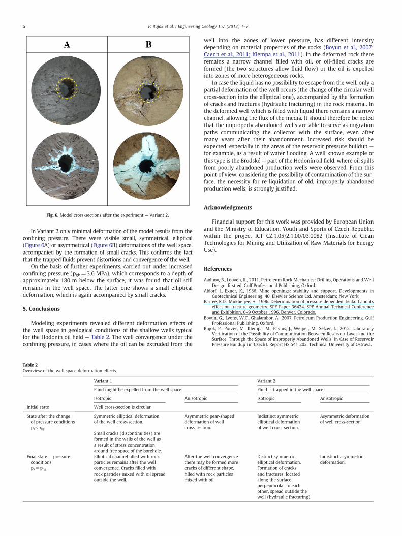
Fig. 6. Model cross-sections after the experiment — Variant 2.
6 P. Bujok et al. / Engineering Geology 157 (2013) 1–7
In Variant 2 only minimal deformation of the model results from theconfining pressure. There were visible small, symmetrical, elliptical(Figure 6A) or asymmetrical (Figure 6B) deformations of the well space,accompanied by the formation of small cracks. This confirms the factthat the trapped fluids prevent distortions and convergence of the well.
On the basis of further experiments, carried out under increasedconfining pressure (pgb=3.6 MPa), which corresponds to a depth ofapproximately 180 m below the surface, it was found that oil stillremains in the well space. The latter one shows a small ellipticaldeformation, which is again accompanied by small cracks.
5. Conclusions
Modeling experiments revealed different deformation effects ofthe well space in geological conditions of the shallow wells typicalfor the Hodonín oil field — Table 2. The well convergence under theconfining pressure, in cases where the oil can be extruded from the
Table 2Overview of the well space deformation effects.
Variant 1
Fluid might be expelled from the well space
Isotropic Anisotrop
Initial state Well cross-section is circular
State after the changeof pressure conditionspsbpbg
Symmetric elliptical deformationof the well cross-section.
Asymmetdeformatcross-sec
Small cracks (discontinuities) areformed in the walls of the well asa result of stress concentrationaround free space of the borehole.
Final state — pressureconditionsps=pbg
Elliptical channel filled with rockparticles remains after the wellconvergence. Cracks filled withrock particles mixed with oil spreadoutside the well.
After thethere macracks offilled witmixed wi
well into the zones of lower pressure, has different intensitydepending on material properties of the rocks (Boyun et al., 2007;Caenn et al., 2011; Klempa et al., 2011). In the deformed rock thereremains a narrow channel filled with oil, or oil-filled cracks areformed (the two structures allow fluid flow) or the oil is expelledinto zones of more heterogeneous rocks.
In case the liquid has no possibility to escape from the well, only apartial deformation of the well occurs (the change of the circular wellcross-section into the elliptical one), accompanied by the formationof cracks and fractures (hydraulic fracturing) in the rock material. Inthe deformed well which is filled with liquid there remains a narrowchannel, allowing the flux of the media. It should therefore be notedthat the improperly abandoned wells are able to serve as migrationpaths communicating the collector with the surface, even aftermany years after their abandonment. Increased risk should beexpected, especially in the areas of the reservoir pressure buildup —
for example, as a result of water flooding. A well known example ofthis type is the Brodské— part of the Hodonín oil field, where oil spillsfrom poorly abandoned production wells were observed. From thispoint of view, considering the possibility of contamination of the sur-face, the necessity for re-liquidation of old, improperly abandonedproduction wells, is strongly justified.
Acknowledgments
Financial support for this work was provided by European Unionand the Ministry of Education, Youth and Sports of Czech Republic,within the project ICT CZ.1.05/2.1.00/03.0082 (Institute of CleanTechnologies for Mining and Utilization of Raw Materials for EnergyUse).
References
Aadnoy, B., Looyeh, R., 2011. Petroleum Rock Mechanics: Drilling Operations and WellDesign, first ed. Gulf Professional Publishing, Oxford.
Aldorf, J., Exner, K., 1986. Mine openings: stability and support. Developments inGeotechnical Engineering, 40. Elsevier Science Ltd, Amsterdam; New York.
Barree, R.D., Mukherjee, H., 1996. Determination of pressure dependent leakoff and itseffect on fracture geometry. SPE Paper 36424. SPE Annual Technical Conferenceand Exhibition, 6–9 October 1996, Denver, Colorado.
Boyun, G., Lyons, W.C., Ghalambor, A., 2007. Petroleum Production Engineering. GulfProfessional Publishing, Oxford.
Bujok, P., Porzer, M., Klempa, M., Pavluš, J., Weiper, M., Selzer, L., 2012. LaboratoryVerification of the Possibility of Communication Between Reservoir Layer and theSurface, Through the Space of Improperly Abandoned Wells, in Case of ReservoirPressure Buildup (in Czech). Report HS 541 202. Technical University of Ostrava.
Variant 2
Fluid is trapped in the well space
ic Isotropic Anisotropic
ric pear-shapedion of welltion.
Indistinct symmetricelliptical deformationof well cross-section.
Asymmetric deformationof well cross-section.
well convergencey be formed moredifferent shape,h rock particlesth oil.
Distinct symmetricelliptical deformation.
Indistinct asymmetricdeformation.
Formation of cracksand fractures, locatedalong the surfaceperpendicular to eachother, spread outside thewell (hydraulic fracturing).

7P. Bujok et al. / Engineering Geology 157 (2013) 1–7
Caenn, R., Darley, H.C.H., Gray, George R., 2011. Composition and Properties of Drillingand Completion Fluids, sixth ed. Gulf Professional Publishing, Oxford.
Denkhaus, H.G., 1964. Critical review of strata movements and their application topractical problems. Journal of the South Africa Institute of Mining Metallurgy 64,310–332.
Kastner, H., 1962. Statik des Tunnel- und Stollenbaues. Springer-Verlag, Berlin.Klempa, M., Zeman, V., Bujok, P., Struna, J., Pinká, J., 2011. Techniques and Technology of
Drilling (in Czech). Projekt FRVŠ č. 960/2011. http://geologie.vsb.cz/TECHHLDOB/index.htm.
Kvapil, R., 1957. Nové názory v teorii horských tlaků a důlních otřesů. SNTL, Praha.Peng, S., Zhang, J., 2007. Engineering Geology for Underground Rocks, first ed.
Springer-Verlag, Berlin.
Robello, S.G., Xiushan, L., 2009. Advanced Drilling Engineering — Principles and Design.Gulf Publishing Company, Houston, Texas.
Salustowicz, A., 1965. Zarys mechaniki górotworu, first ed. Śląsk, Katowice.Shuling, L., Jeff, G., Cary, P., 2010. Maximum horizontal stress and wellbore stability
while drilling: modeling and case study. Paper SPE 139280 Presented at the SPELatin America and Caribbean Petroleum Engineering Conference, 1–3 December2010,Lima, Peru.
Shuling, L., Jeff, G., Cary, P., 2012. Pore-pressure and wellbore-stability predict toincrease drilling efficiency. Journal of Petroleum Technology 64 (2), 98–101.
Trumbačev, V.F., Chajmova-Malkova, T., 1965. Vliv koeficientu bočního odporu (tlaku)na stabilitu přípravných důlních děl. UHLÍ, 1. SNTL, Praha.
Voropinov, J., Kittrich, R., 1966. Mechanika I. Vysokoškolská učebnice. SNTL/SVTL, Praha.


