Embed Size (px)
Citation preview

Experimental Correlation of Mechanical Properties of Joints and Transverse Vibrations in PMMA Beams
S. KAMLE,' S. R. UPRETI,' V. K. AWASTHI,' M. P. SINGH,' N. G. R. IYENGAR,' and A. KUMARZ,*
'Department of Aerospace Engineering and 2Department of Chemical Engineering, Indian Institute of Technology, Kanpur-208 016, India
SYNOPSIS
An ultrathin joint in a poly(methy1 methacrylate) (PMMA) beam was introduced by joining the two pieces using 1,2-dichloroethane. The viscoelastic property of the interfacial region was varied using dioctylphthalate (DOP) plasticizer and flexural waves in the beam were generated by impacting the beam with a small steel ball as well as with a calibrated ex- perimental impact hammer. The acceleration vs. time data of a given point on a beam were used to optimally separate the wave emanating from the joint and were shown to correlate with the mechanical strength of the joint. 0 1996 John Wiley & Sons, Inc.
INTRODUCTION
The use of adhesive bonds in primary structures is restricted due to the limited growth of methodologies for predicting their life. In spite of this limitation, it is preferred because of the distinct advantages that they offer such as uniform stress distribution, sealing against corrosion, damage tolerance, and stealthi- ness. It is desired to characterize the properties of adhesive bonds and to establish quantitative rela- tions between the material's structures and its me- chanical perf~rmance.'-~ Among the existing tech- niques, the most commonly used are pulse echo, through transmission, and resonance spectroscopy.
An important characteristic of adhesive joints is that there is a definite limit to the bond strength developed between specified adherends for a par- ticular adhesive.6-10 When an adhesive joint fails, failure occurs either because of the failure of ad- hesive or that of the interfaces between the ad- hesive and the adherends."-'l Normally, a joint fails from a combination of both of these. The former is called cohesion failure, while the latter, adhesion failure.
To characterize the properties of these joints, various theoretical models have been p r ~ p o s e d . ~ ~ - ~ ~
* To whom correspondence should be addressed. Journal of Applied Polymer Science, Vol. 60, 343-352 (1996) 0 1996 John Wiley & Sons, Inc. CCC 0021-8995/96/030343-10
They can be classified into a complete bond thick- ness model and an interface weakness model. The former analyses the propagation of waves, such as plate waves, leaky waves, and interface waves, through the adhesive layer and the adherends. The signals received across are found to be affected both by the interface as well as by the cohesive weakness. The interface weakness model evaluates the inter- face weakness by examining the transmission factors of the interface between the adhesive and the ad- herends.
The properties of adhesive joints also depend upon the nature of the interface, the adhesive, the materials to be joined, and the age. In the present work, flexural waves, generated through controlled impacting, are employed to characterize the joint interface. Experiments are conducted on a uniform rectangular poly(methy1 methacrylate) (PMMA) beam because it is easy to change the property of its joints. It is well known that the flexural wave at any location is a superposition of a forward wave, a wave bearing information of the joint, and a wave due to echoes from the ends of the beam. Using a suitable search and optimization tech- nique, the composite flexural wave has been re- solved into its components. The wave correspond- ing to the joint is found to be sensitive to the vari- ation in the viscoelastic property of the joint, and the experiments conducted demonstrate a corre- lation between them.
343
344 KAMLE E T AL.
% kl A
ACCELEROMETER
/ LOCATION OF IMPACT JOINT
(AT THE CENTRE )
RIGID SUPPORT
0 THREAD
PMMA BEAM
( c )
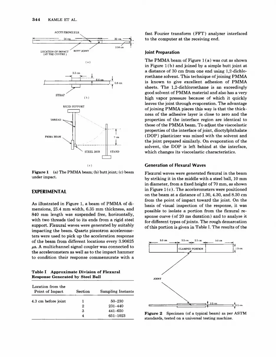
Figure 1 under impact.
(a) The PMMA beam; (b) butt joint; (c) beam
EXPERIMENTAL
As illustrated in Figure 1, a beam of PMMA of di- mensions, 25.4 mm width, 6.35 mm thickness, and 840 mm length was suspended free, horizontally, with two threads tied to its ends from a rigid steel support. Flexural waves were generated by suitably impacting the beam. Quartz piezotron accelerome- ters were used to pick up the acceleration response of the beam from different locations every 3.90625 ps. A multichannel signal coupler was connected to the accelerometers as well as to the impact hammer to condition their response commensurate with a
Table I Response Generated by Steel Ball
Approximate Division of Flexural
Location from the Point of Impact Section Sampling Instants
4.3 cm before joint 1 50-230 2 231-440 3 441-650 4 651-1023
fast Fourier transform ( FFT ) analyzer interfaced to the computer at the receiving end.
Joint Preparation
The PMMA beam of Figure 1 ( a ) was cut as shown in Figure 1 ( b ) and joined by a simple butt joint at a distance of 30 cm from one end using 1,Z-dichlo- roethane solvent. This technique of joining PMMA is known to give excellent adhesion of PMMA sheets. The 1,2-dichloroethane is an exceedingly good solvent of PMMA material and also has a very high vapor pressure because of which it quickly leaves the joint through evaporation. The advantage of joining PMMA pieces this way is that the thick- ness of the adhesive layer is close to zero and the properties of the interface region are identical to those of the PMMA beam. To adjust the viscoelastic properties of the interface of joint, dioctylphthalate (DOP) plasticizer was mixed with the solvent and the joint prepared similarly. On evaporation of the solvent, the DOP is left behind at the interface, which changes its viscoelastic characteristics.
Generation of Flexural Waves
Flexural waves were generated flexural in the beam by striking it in the middle with a steel ball, 10 mm in diameter, from a fixed height of 70 mm, as shown in Figure 1 (c ) . The accelerometers were positioned on the beam at a distance of 1.30,4.30, and 8.30 cm from the point of impact toward the joint. On the basis of visual inspection of the response, it was possible to isolate a portion from the flexural re- sponse curve (of 20 ms duration) and to analyze it for different types of joints. The rough demarcation of this portion is given in Table I. The results of the
_I 50cm 2 5 c m 2 5 c m 5 O c m cc- -I, -9kr -
fl CLAMPED PORTION
.+
/// JOINT
\) 0 5 e m 5 cm
Figure 2 standards, tested on a universal testing machine.
Specimen (of a typical beam) as per ASTM

CORRELATION OF VIBRATIONS IN PMMA BEAMS 345
0 3 10 15 20
% DOP
Figure 3 Ultimate strength of the joint (in kgf) vs. % DOP as determined from the universal testing machine.
analysis show the existence of a significant param- eter sensitive to the joint property. Further exper- imentations were performed with a calibrated impact hammer.
Flexural Wave Generation using Calibrated Impact Hammer
A calibrated impact hammer was hung free from the frame and was used to apply a controlled force to
15 c -I
-I5 t 1 -23 1 I
0 2W 400 600 ail 1000
smplmg Instant
Figure 4 Acceleration vs. sampling instant (1024 sam- ples in 20 ms), at a point on the beam 4.30 cm before the joint, due to impact with a steel ball (one acceleration unit = 421.03 m/sz)).
0 5 lo l i 20
% DOP
Figure 5 weight.
Amplitude of second peak vs. % DOP by
generate flexural waves in the beam. A slotted angle on a support was used to guide the impact hammer from a given height and distance from the beam. The relative motion between the thread and the beam and that between the iron frame was elimi- nated by properly gluing their points of contacts. This obviates any friction which might interfere with the propagation of flexural waves in the beam. Flex- ural responses were recorded for a period of 4 ms, during which the hammer impacted only once. A small PMMA point of negligible mass was attached on the point of impact at the center of the beam in
450 before p n t -
after ,01111 c
250 *"In or sq"ared ermn
m
150
IW
0 5 10 15 20 25 30 31 40 4 5 50
Iteration number
Figure 6 the optimization code for a typical beam.
Sum of squared errors vs. iteration number of

346 KAMLE ET AL
Table I1 (for Different Beams) Located 5 cm Before the Joint
Initial and Optimal Values of Complex Coefficients of Flexural Response at a Typical Point
2.5 Initial
5.0 Initial
7.5 Initial
10.0 Initial
12.5 Initial
15.0 Initial
Optimal
Optimal
Optimal
Optimal
Optimal
Optimal
(b) k = 1 or w = 750a rad/s
1195.752 1207.710 1195.752 1422.945 1195.752 1231.625 1195.752 1195.752 1195.752 1195.752 1195.752 1219.667
-200.267 -202.270 - 1001.460 -1191.740
-200.084 -206.087
-91.847 -91.847 -72.767 -72.767
74.9537 280.4529
0.0 0.0 0.0 0.0 0.0 0.0 0.0 0.0 0.0 0.0 0.0 0.0
0.0 0.0 0.0 0.0 0.0 0.0 0.0 0.0 0.0 0.0 0.0 0.0
2.5 Initial
5.0 Initial
7.5 Initial
10.0 Initial
12.5 Initial
15.0 Initial
Optimal
Optimal
Optimal
Optimal
Optimal
Optimal
89.14785
89.14785
89.14785
89.14785
89.14785
89.14785
166.7064
177.404 1
181.8615
185.4274
141.745
142.6364
53.11034 99.31632
331.1812 659.0504
-201.513 -411.087
-23.0354 -47.9136 -17.2859 -27.4846
-225.317 -360.507
-863.594 -1911.14
-863.594 -1665.01
-863.594 -1870.55
-863.594 -1870.55
-863.594 -1763.46 -863.594
-1952.59
1421.146 3183.371 1589.432 3321.915
1796.494 1418.352 3148.74 1393.765 2996.595
2013.366
809.2318
886.9459
order to spatially localize the impact force. Restric- tion of the peak value of the impulse force within ?5% of a specified value was found to give the best reproducible results.
THEORETICAL DEVELOPMENT
It may be recalled that any signal g ( t ) satisfying Dirichlet’s conditions for finite duration can be ex- pressed with the help of a Fourier integral48 as
where G ( w ) is defined by the Fourier transform
For the problem of one-dimensional transverse wave propagation in a PMMA beam, it is assumed that at any given location on a beam the flexural response is a superposition of three types of waves: ( a ) for- ward wave, gf( t ) , arising from the impacting of the beam: ( b ) echo, g,( t ) , from the joint, and (c ) echo, g, ( t ) , from the ends of the beam. This implies that
( 3 )
In terms of its Fourier transform, this equation can be written as
+ Ge(w)]exp(j2awt)dw (4)
It is desired to separate the waveform corresponding to the joint because it is expected that it should carry some information concerning the nature of the joint.

CORRELATION OF VIBRATIONS IN PMMA BEAMS 347
Table I11 the Joint on a Beam with Different Initial Populations
Optimal Values of Complex Coefficients of Flexural Response at a Point Located 5 cm Before
0.382
0.563
0.108 71.082 1 0 1 2 3 4 5 6 7 8 9
69.8793 0 1 2 3 4 5 6 7 8 9
72.0807 0 1 2 3 4 5 6 7 8 9
1207.71
-1219.26 191.6678
-235.138 -28.439 -20.2839 146.6164 73.11405 40.22677 54.80875
1207.71 184.536
-256.281 - 1217.06
-34.6214 -19.1463 146.8709 88.68462 43.57167 59.9754
1207.71
-1204.42 -245.71
195.2337
- 29.9847 -24.3988 160.1071 103.5782 22.84211 60.45883
-202.27 114.1872 685.8073 385.143 186.6327 194.2424
-61.4362 -82.9547 -57.0925
32.65966
-202.27 109.9384 685.8073 393.7496 227.2052 175.044 43.54621
-74.5199 -91.8746 -43.1423
-202.27 116.3115 676.6223 389.4464 196.7758 238.2857
-87.0347 -45.9373 -56.5758
25.85556
0.0 -1911.14
38.63196 686.3358 472.2038
89.14599
67.94595 -8.25962
-26.2645
- 13.6086
0.0 -1911.14
37.87075 715.3951 447.2476 130.2366 -35.1557
76.84083 -6.43971
-10.5444
0.0 -1861.91
38.63196 697.0418 629.5117
81.485 15.25271 80.56336 -6.25306 - 13.4798
0.0 3183.371 874.1748 -59.2043
-364.363 -137.176
44.34067 36.74568 8.42146
65.62904
0.0 3183.371 856.9497 -61.2636
-328.35 -200.406
59.12091 40.69683
6.56589 49.59297
0.0 3140.737 874.1748 -60.2339
-446.98 -125.388
35.10303 20.34841 6.37557
65.0351 1
a To randomize initial population of variables.
To do so, eq. ( 4 ) is discretized as follows treating Gf( kF,), G,( kF,), and Ge( kF,) as complex variables, to be optimally determined later:
+Ge(kFs)]exp j - k n G 1 L < N , n = 0 , 1 , . . . , L - 1
(5)
Above, g( nT,) represents a finite sequence of N samples of the flexural response separated in time space by T, instants where 1 / T, is greater than or equal to twice the highest frequency component of the signal. The coefficients Gf ( k F s ) , Gj( kF,) , and
Ge(kF,) are complex finite sequences of L samples separated in the spectral space by F, Hz.
The Optimization Problem
The optimal complex coefficients, G, (kF,) , G,( kF,) , and Ge (kF,) , are determined so that the response g( t ) in eq. (3) minimizes the sum of the squares of difference between ( a ) the response reconstructed from these three coefficients and ( b ) the actual re- sponse in time space. The optimization problem is, thus, mathematically stated as

348 KAMLE ET AL.
M srnplilude
ratio 16
I 0
5
1 , 6 I I 0 I ? 1s 9i DOP
Figure 7 Amplitude ratio of optimal coefficients (cor- responding to k = 0, 1) after and before the joint vs. % DOP.
where the objective function I is the sum of the square error and g ( n T, ) is the experimental accel- eration value of a given point on the beam.
In the absence of a joint, the acceleration at any point, g, ( t ) , is the superposition of only gf ( t ) and g , ( t ) as
If in the beam with a joint the superposition of gf( t ) and g, ( t ) is gz ( t 1, then eq. ( 3 ) can be rewritten as
Since gz ( t ) is expected to be close to g,, suitable guess values for G z ( k F , ) and G,( kF,) were chosen in order to initiate the optimization process. The guess value for G$ ( kF,) was based upon the spectral coefficient of the flexural response of an identical point on a beam without the joint. The difference of the corresponding spectral coefficients of the flexural responses of identical points on the beam with and without the joint was used to provide the guess value for Gj( kF,) . The choice of initial con- ditions in this manner is observed to preserve the pattern of the original flexural waveform.
To reduce the number of independent variables, L is taken to be 10, associated with the first 10 spec- tral points with N = 1024 in time space. For this, the problem consists of optimization in a 40 variable (both real and imaginary) search space. With flex- ural wave data collected so far, this value of L has been observed to be a good compromise between the desirable accuracy of result and the computer time.
RESULTS AND DISCUSSION
The joints were prepared using a solution of 1,2- dichloroethane (DCE) and dioctylphthalate (DOP) plasticizer. The latter has very low vapor pressure and is expected to stay near the joint after DCE is evaporated. This way led to the variation of me- chanical properties of the joint and the ultimate joint strengths of the PMMA beams were determined us- ing an universal testing machine (UTM). The specimens were made as per ASTM standards as shown in Figure 2. The load was applied at the rate of 0.2 mm/min until failure. For specimens made the same way as the beams tested earlier, the failure strength is found to be a strong monotonically de- creasing function of DOP percentage as seen in Fig- ure 3. The fall in the ultimate strength is expected because the DOP stays in the joint, making it vis- coelastic. It is desired to predict this property using a single-point measurement of the beam’s acceler- ation vs. time under a transverse impact. To do so, a PMMA beam with a joint was suspended freely as shown in Figure 1 and impacted with a steel ball. A typical acceleration response of the beam with a joint is shown in Figure 4. On superposition of different time responses (of beams with different joint prop- erties) for a particular point on a beam, it is observed that some specific portion of this curve is affected by a fraction of DOP content in the joining solution. By visual inspection, such a portion as section 3 in Figure 4 is marked out (also refer to Table I) . In fact, three more sections are also marked out as given in Table I. A computer program is written to rep- resent each section by 128 equispaced acceleration
4 5 cm before p i i t 0
5 crn after JOlllt +
+ 0
0
Rat Acceleration 2 -
0 2 I 6 8 LO I2 I4
ADOP
Figure 8 Peak values of joint waves vs. % DOP.
CORRELATION OF VIBRATIONS IN PMMA BEAMS 349
values. Fast Fourier transforms of the time re- sponses, of different beams, of all sections are ob- tained. A careful observation of the amplitude vs. frequency shows that the second peak is significant. In Figure 5, the peak amplitude vs. % DOP in the joining solution is shown. The “0% DOP” stands for an identical beam without a joint. It is found that the peak amplitude of the third section is a monotonically increasing function of % DOP. For 20% DOP, an increase of about 425% in the peak amplitude is observed. Such sensitivity is not found for other sections and it appears that the informa- tion concerning the properties of the joint is em- bodied in the third section of Table I.
One disadvantage of the experimentation with a steel ball is that the frequencies of the flexural wave generated upon impacting are very large, whereas sensitivity to the joint properties is higher for lower frequencies. In addition to this, multiple impacts may also occur. In an effort to understand the pro- cess of impacting, a calibrated impact hammer was employed. In this study, butt joints were made with- out the straps. Upon measuring the impact force as a function of time, at least three impacts over the period of 20 ms are found. The second and third impacts are of smaller magnitudes but cannot be ignored or eliminated. Hence, acceleration mea- surement only up to 4 ms, during which only one impact occurs, is considered. Since the impact force can be measured as a function of time, the force applied can be controlled more carefully. The peak value of the force has been restricted to within f 5 % of a specified value and the experimental accelera- tion vs. time data are recorded.
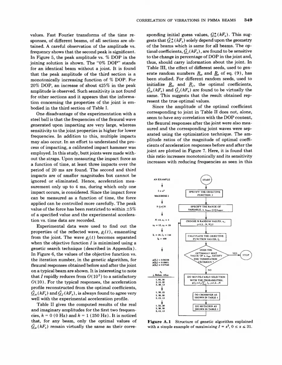
Experimental data were used to find out the properties of the reflected wave, gj( t ) , emanating from the joint. The wave gj( t ) becomes separated when the objective function I is minimized using a genetic search technique (described in Appendix). In Figure 6 , the values of the objective function vs. the iteration number, in the genetic algorithm, for flexural responses obtained before and after the joint on a typical beam are shown. It is interesting to note that I rapidly reduces from O ( 10’) to a satisfactory O( 10). For the typical responses, the acceleration profile reconstructed from the optimal coefficients, G, ( kF,) and Gf ( kFs) , is always found to agree very well with the experimental acceleration profile.
Table I1 gives the computed results of the real and imaginary amplitudes for the first two frequen- cies, k = 0 ( 0 Hz) and k = l ( 2 5 0 Hz). It is noticed that, for any beam, only the optimal values of Gw ( kF,) remain virtually the same as their corre-
sponding initial guess values, G z (kF,) . This sug- gests that & ( kF,) solely depend upon the geometry of the beams which is same for all beams. The op- timal coefficients, G.( kF,) , are found to be sensitive to the change in percentage of DOP in the joint and, thus, should carry information about the joint. In Table 111, the effect of different seeds, used to gen- erate random numbers R, and Re of eq. (9) , has been studied. For different random seeds, used to initialize R, and &, the optimal coefficients, &( kF,) and Gj( kF,) are found to be virtually the same. This suggests that the result obtained rep- resent the true optimal values.
Since the amplitude of the optimal coefficient corresponding to joint in Table I1 does not, alone, seem to have any correlation with the DOP content, the flexural responses after the joint were also mea- sured and the corresponding joint waves were sep- arated using the optimization technique. The am- plitude ratios of the magnitude of optimal coeffi- cients of acceleration responses before and after the joint are plotted in Figure 7. Here, it is found that this ratio increases monotonically and its sensitivity increases with reducing frequencies as seen in this
p(lr) = 0.04’209 p(l2) = 0.2%51 p(b) = 0 . 6 m o
> j. &lore, Afler
1.05. m 2. 13. 20 3.10. 13
c
c I . m. 21 2.m. 20 3, 13. 13
1 , n . 28 2. m. 20 3, 13. 13
START 0 t SPECIFY THE OBJECTIVE
FUNCTION. I
SPECIFY THE RANGE OF VARIABLE, I. ~ - . , S x < x ~ ~ p . ~
I
CALCULATE THE OBJECTIVE
OPTIMALLY BEST
RITERION I
I NO I DO Y O S T E C A R L O SELECTION I
WITH THE PROBABILITIES,
SHOWN IN TABLE I
Figure A . l Structure of genetic algorithm explained with a simple example of maximizing I = x2, 0 5 x 5 31.

350 KAMLE E T AL.
Table A. I The Process of Crossover and Mutation in Figure 2
Crossover or recombination of strings
A string is defined as a number encoded in binary digit system. For example, x = 20 can be written as 1 0 1 0 0 in binary, which is a string. In the process of crossover, we randomly pick two strings at a time, say x = 13 and x = 20, from a population of variables and recombine them as follows:
1=400 1=484 - - ( x = 20) or 101 : 00 + 101 1 0 or x = 22
(x = 13) or 001 : 10 00100 or x = 04 I= 169 I=16 - -
The vertical dots, above, represent a randomly chosen crossover site, the bits right to which are swapped.
Mutation of strings
A string from the population of variables is picked up. With a very small probability, each bit is changed, i.e., if i t is 1, then it is made 0, and if it is 0, then it is made 1, applying the Monte Carlo method. The process is repeated for all strings in the population. For example, with the strings x = 22, x = 20, and x = 13, the following mutations may happen:
I=& I=784 - - ( x = 22) or 01110
( x = 20) or 10100 + 10100 or x = 20
11100 or x = 28 1=400 1=400 - - 1=169 I=64 - -
(x = 13) or 01101 01000 or x = 08
Optimally better string, x = 28, is substituted in place of x = 22, while the optimally inferior string, x = 8, is rejected.
figure. For flexural wave measurements at locations 5 cm before the joint, the optimal coefficients cor- responding to the joint, G.( kF9), are used to recon- struct the joint waves in time domain. In Figure 8, the peak values of the separated joint waves (before and after the joint) are plotted and are found to decrease with increase in the DOP content of the joint. Thus, it appears that one can predict the me- chanical strength of the joint using the transverse wave technique.
CONCLUSIONS
A beam of PMMA of a uniform cross section was prepared and an ultrathin joint was introduced at the desired location using 1,2-dichloroethane. The property of the joint was varied using a dioctyl- phthalate plasticizer. Transverse flexural waves were generated by striking it with a small steel ball of 1 cm diameter at its center and the acceleration as a function of time was measured at various locations. The flexural wave, so generated, at any given loca- tion appears to have a region where the information (i.e., % DOP content) concerning the nature of the
joint is coded. It is shown that the FFT of this por- tion (section 3 of Fig. 4 ) is linearly correlated with the % DOP for smaller frequencies. To carry out more controlled experiments, studies were made us- ing a calibrated impact hammer and it was found that striking is a multiple impact process. However, in a short time ( - 4 ms) , there is always only one impact for which the acceleration vs. time data a t a given location on the beam was collected. Using an optimal search technique employing genetic algo- rithms, the flexural wave corresponding to the joint was separated. It is shown that the waves reflected and transmitted through the joint are related to the content of plasticizer in it. The ultimate joint strength of the PMMA beams was also determined using a universal testing machine as per ASTM standards and the failure strength is found to de- crease monotonically with the amount of DOP in the joint. This suggests that the transverse wave measurements developed in this work may be used for nondestructive testing of joints.
This work was financially supported by the Aeronautical Research and Development Board, New DeIhi, India. We acknowledge the helpful discussion with Prof. V. P.

CORRELATION OF VIBRATIONS IN PMMA BEAMS 351
Sinha, Department of Electrical Engineering, IIT Kanpur.
APPENDIX
Genetic Algorithm
Genetic algorithms (GAS) are robust and versatile optimization technique^*^*^^ which do not require the objective function to be continuous and/or differ- entiable. The basic structure of GAS is shown in Figure A.l and its working is demonstrated with a simple example on the same diagram. As shown in the flow chart, the guesses leading to higher values of objective functions are favored with the help of a Monte-Carlo selection technique. For the example in Figure A.1, the Monte Carlo selection gives the guesses for the next stage to be x = 13, 20, and 20. In Table A.1 the crossover and mutation processes have been defined which are done by writing these numbers into binary strings. These operations pro- duce the new values of guesses which are far better than the original ones. For the example discussed, there is a local maximum at x = 31 and the crossover and mutation operations lead to the new guess values of xi = 28, 20, and 13, which are closer to the opti- mum value. The experience of working with this al- gorithm shows a fast convergence toward the opti- mal solution, and it is particularly true for the pres- ent problem where other standard search techniques do not work well enough.
The present problem consists of finding the op- timal real and imaginary values of Gw(lzfs) and G(tzF,). This means that if L is chosen in eq. (5) to be 10, it would mean that there would be 40 in- dependent variables to optimize. A single string (defined in Table A.1) is formed in which all these variables are represented as shown in Figure A.2. Each slot in the string has a fixed number of binary bits. Experience in working with this has shown that randomizing the initial population on the basis of guess values leads to a faster convergence. To do so, the random population is related to the guess values, &i,o and G,i,o, in the following way:
i = 0 , 1 , . . . , 9 (9)
Here, and &,i are the complex random numbers. The purpose of this formulation is to provide the inequality constraints
i = 0, 1, . . . , 9 (10)
if Rw,i 2 0 and Z?j,i 2 0. Otherwise,
i = 0 , 1 , . . . , 9 (11)
if Rw,i I 0 and Rj,i I 0. This ensures variation of the 40 variable search space by varying the order of & , i and R,,i in the vicinity of the guess values where the optimal coordinates (Q,,o, &,I, . . . , &,9, Q j , o ,
. . . , &) are expected. Since the sum of squares of the error has to be minimized, the objective func- tion value in the algorithm should be 1 / I i , i = 0, 1, . . - 9.Ithasbeentakentobe(l/Ii)*,i=O,l, - . . 9, because using the square of the objective function
Figure A.2 in optimization.
Layout of a multivariable binary string used

352 KAMLE ET AL.
value has been shown to lead to faster convergence of GAS faster.51
REFERENCES
1.
2.
3.
4.
5.
6. 7.
8.
9.
10.
11.
R. B. Thompson and D. 0. Thompson, J . Adhes. Sci. Technol., 5, 583 (1991). D. Jiao and L. Rose, J . Adhes. Sci. Technol., 5, 631, (1991). S. E. Hannemann and V. K. Kinra, Exp. Mech., 32, 323 (1992). S. E. Hannemann, V. K. Kinra, and C. Zhu, Exp. Mech., 32,332 (1992). A. Tiwari, E. G. Henneke 11, and J. C. Duke, J . Adhes., 3 4 , l (1991). H. L. Groth, Znt. J. Adhes. Adhes., 6 , 3 1 (1990). A. Pilaraski and J. L. Rose, J . App. Phys., 63, 2 ( 1988). H. Ishikawa, R. Yuuki, N. Y. Chung, and S. Nakano, Conference on Mixed Mode Fracture and Fatigue, July 15-19, 1988, Vienna, Austria. L. J. Hart-Smith, Adhesive-Bonded Double-Lap Joints, Technical Report NASA CR 112235, Langley Research Center, Hampton, Virginia, 1973. M. D. Rao and M. J. Crocker, J . Vib. Acoust., 112, 444 (1990). S. A. Hashim, M. J. Cowling, and T. E. Winkle, Znt. - J . Adhes. Adhes., 10, 139 (1991).
Adhes., 1 0 , 3 1 ( 1990).
Adhes., 10, 167 (1990).
( 1988).
12. A. D. Bigwood and D. A. Crocombe, Znt. J . Adhes.
13. A. D. Bigwood and D. A. Crocombe, Int. J . Adhes.
14. H. L. Groth and J. Brottare, J . Test. Eval., 16, 291
15. A. Needleman, Appl. Mech. Rev., 43, 5274 (1990). 16. Z. Suo, Appl. Mech. Rev., 43, S276 (1990). 17. S. Krenk, Eng. Fract. Mech., 43, 549 (1992). 18. T. Sawa, H. Ishikawa, and K . Muto, ZSME Znt. J .
19. S. Yadagiri, C. P. Reddy, and T. S. Reddy, Comput.
20. J. P. Jeandrau, Znt. J. Adhes. Adhes., 6 , 229 (1986). 21. R. D. Adams, Znt. J . Adhes. Adhes., 3 7 , 4 7 (1986). 22. A. A. Khalil and M. R. Bayoumi, Znt. J . Adhes. Adhes.,
23. F. Edde and Y. Verreman, Int. J . Adhes. Adhes., 12,
24. T. Hattori, S. Sakate, and G. Murakami, J . Elect.
25. R. Davis and A. A. Khalil, Znt. J . Adhes. Adhes., 10,
Ser., 3 5 , 3 8 (1992).
Struct. 27 ,445 (1987).
1 1 , 2 5 (1991).
43 (1993).
Pack., 111, 243 (1989).
25 (1990).
26.
27.
28. 29.
30. 31. 32.
33.
34.
35.
36. 37.
38.
39.
40.
41.
42.
43. 44. 45.
46.
47. 48.
49.
50.
51.
T. S. Ramamurthy and A. K. Rao, J . Aero. SOC. India, 36, 29 (1983). D. Chen and S. Cheng, J . Appl. Mech., 105, 109 (1983). J. P. Jeandrau, Znt. J . Adhes. Adhes., 1 1 , 7 1 (1991). G. Fernlund and J. K. Spelt, Eng. Fract. Mech., 40, 119 (1991). X. Mu and H. Hu, Comput. Struct., 30,953 (1988). H. L. Groth, Znt. J . Adhes. Adhes., 6, 31 (1986). Y. Yamada, N. Yosnimura, and T. Sakurai, Znt. J . Adhes. Adhes., 10,343 (1968). S. Mall and G. Ramamurthy, Znt. J . Adhes. Adhes., 9, 33 (1989). Y. R. Nagaraja and R. S. Alwar, Comput. Struct. 11, 621 (1980). J. N. Reddy and S. Roy, Znt. J . Non-Linear Mech., 2 3 , 9 7 ( 1988). W. S. Johnson, J . Test. Eval. TTEVA, 15,302 (1987). T. Sawa, K. Temma, and Y. Isunoda, Int. J . Adhes. Adhes., 9 , 161 (1989). K. Temma, T. Sawa, and A. Iwata, Int. J. Adhes. Adhes., 9, 285 (1990). P. Czarnocki and K. Piekarski, Znt. J . Adhes. Adhes., 6,157 (1986). K. Temma, T. Sawa, and Y. Tsunoda, Znt. J. Adhes. Adhes., 7 , 294 (1990). H. L. Groth and P. Nordlund, Znt. J . Adhes. Adhes., 11, 204 (1991). S. Marcolefas, V. Kostopoulos, and S. A. Paipetis, Znt. J . Mech. Sci., 33, 961 (1991). J. P. Jeandrau, Znt. J . Adhes. Adhes., 11, 71 (1991). T. Hattori, J S M E Znt. J., 34,326 (1991 ) . Y. Liu and K. Chen, Comput. Struct., 29,161, 1033 ( 1988). F. Edde and Y. Verreman, Znt. J . Adhes. Adhes., 12, 43 (1992). D. Chen and S. Cheng, J. Appl. Mech., 5 7 , 7 8 (1990). E. C. Titchmarsh, Introduction to the Theory of Fourier Integrals, 2nd ed., Oxford University Press, London ( 1948). J. H. Holland, Adaptation in Natural and Artificial Systems, University of Michigan Press, Ann Arbor, 1975. D. E. Goldberg, Genetic Algorithms in Search, Opti- mization, and Machine Learning, Addison-Wesley, Reading, MA, 1989. D. E. Goldberg and K. Deb, in Foundations of Genetic Algorithms, G. Rawlins, Ed., Morgan Kaufman, San Mateo, CA, 1991, pp. 69-93.
Received June 15, 1995 Accepted September 19, 1995


