Embed Size (px)
Citation preview

FCC COMPLIANCE STATEMENTFOR AMERICAN USERS
This equipment generates and uses radio frequency energy and if not installed and used properly, that is, in strict accordance with the manufacturer’s instructions, may cause interference toradio and television reception. It has been type tested and found to comply with the limits for aClass B computing device in accordance with the specifications in Subpart J of part 15 of FCCRules, which are designed to provide reasonable protection against such interference in a resi-dential installation, However, there is no guarantee that interference will not occur in a particu-lar installation. If this equipment does cause interference to radio or television reception, whichcan be determined by turning the equipment off and on, the user is encouraged to try to correctthe interference by one or more of the following measures:
- Reorient the receiving antenna- Relocate the printer with respect to the receiver- Plug the printer into a different outlet so that the printer and receiver are on different
branch circuits.
If necessary the user should consult the deafer or an experienced radio/television technicianfor additional suggestions. The user may find the following booklet prepared by the FederalCommunications Commission helpful:
“How to Identify and Resolve Radio-TV interference Problems.”
This booklet is available from the U.S. Government Printing Office, Washington, DC 20402.Stock No. 004-000-00345-4.
WARNINGThe connection of a non-shielded printer interface cable to this printer will invalidate the FCCCertification of this device and may cause interference levels which exceed the limits established by the FCC for this equipment. If this equipment has more than one interface connector,do not leave cables connected to unused interfaces.
All rights reserved. No part of this publication may be reproduced, stored in a retrieval system, ortransmitted, in any form or by any means, mechanical, photocopying, recording or otherwise, with-out the prior written permission of Seiko Epson Corporation. No patent liability is assumed withrespect to the use of the information contained herein. While every precaution has been taken in thepreparation of this book, Seiko Epson Corporation assumes no responsibility for errors or omissions.Neither is any liability assumed for damages resulting from the use of the information containedherein.
Graphics created with UniPaint by Unison World Inc. and EPSON 3D-Graph.
Apple is a registered trademark of Apple Computer, Inc.Centronics is a registered trademark of Centronics Data Computer Corporation.Epson is a registered trademark of Seiko Epson Corporation.IBM is a registered trademark of International Business Machines Corporation.Microsoft is a trademark of Microsoft Corporation.ESC/P is a trademark of Seiko Epson Corporation.
Copyright © 1986 by Seiko Epson CorporationNagano, Japan Y446991030
ii

IMPORTANT SAFETY INSTRUCTIONS1. Read all of these instructions and save them for later reference.
2. Follow all warnings and instructions marked on the product.
3. Unplug this product from the wall outlet before cleaning. Do not useliquid cleaners or aerosol cleaners. Use a damp cloth for cleaning.
4. Do not use this product near water.
5. Do not place this product on an unstable cart, stand, or table. Theproduct may fall, causing serious damage to the product.
6. Slots and openings in the cabinet and the back or bottom areprovided for ventilation; to ensure reliable operation of the productand to protect it from overheating, these openings must not beblocked or covered. The openings should never be blocked byplacing the product on a bed, sofa, rug, or other similar surface. Thisproduct should never be placed near or over a radiator or heatregister. This product should not be placed in a built-in installationunless proper ventilation is provided.
7. This product should be operated from the type of power sourceindicated on the marking label. If you are not sure of the type ofpower available, consult your dealer or local power company
8. This product is equipped with a S-wire grounding type plug, a plughaving a third (grounding) pin. This plug will only fit into agrounding-type power outlet. This is a safety feature. If you areunable to insert the plug into the outlet, contact your electrician toreplace your obsolete outlet. Do not defeat the purpose of thegrounding-type plug.
9. Do not locate this product where the cord will be walked on.
10. If an extension cord is used with this product, make sure that thetotal of the ampere ratings on the products plugged into theextension cord do not exceed the extension cord ampere rating.Also, make sure that the total of all products plugged into the walloutlet does not exceed 15 amperes.
11. Never push objects of any kind into this product through cabinetslots as they may touch dangerous voltage points or short out partsthat could result in a risk of fire or electric shock. Never spill liquidof any kind on the product.
12. Except as specifically explained in the Users Manual, do not attemptto service this product yourself. Opening or removing those coversthat are marked “Do Not Remove” may expose you to dangerousvoltage points or other risks. Refer all servicing in thosecompartments to service personnel.
13. Unplug this product from the wall outlet and refer servicing toqualified service personnel under the following conditions:
A. When the power cord or plug is damaged or frayed.
B. If liquid has been spilled into the product.
C. If the product has been exposed to rain or water.
D. If the product does not operate normally when the operatinginstructions are followed. Adjust only those controls that arecovered by the operating instructions since improper adjustmentof other controls may result in damage and will often requireextensive work by a qualified technician to restore the product tonormal operation.
E. If the product has been dropped or the cabinet has beendamaged.
F. If the product exhibits a distinct change in performance, indicatinga need for service.
PQ277
Contents
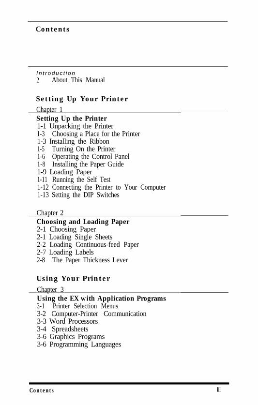
I n t r oduc t i on2 About This Manual
Setting Up Your PrinterChapter 1Setting Up the Printer1-1 Unpacking the Printer1-3 Choosing a Place for the Printer1-3 Installing the Ribbon1-5 Turning On the Printer1-6 Operating the Control Panel1-8 Installing the Paper Guide1-9 Loading Paper1-11 Running the Self Test1-12 Connecting the Printer to Your Computer1-13 Setting the DIP Switches
Chapter 2Choosing and Loading Paper2-1 Choosing Paper2-1 Loading Single Sheets2-2 Loading Continuous-feed Paper2-7 Loading Labels2-8 The Paper Thickness Lever
Using Your PrinterChapter 3Using the EX with Application Programs3-1 Printer Selection Menus3-2 Computer-Printer Communication3-3 Word Processors3-4 Spreadsheets3-6 Graphics Programs3-6 Programming Languages
Contents.III
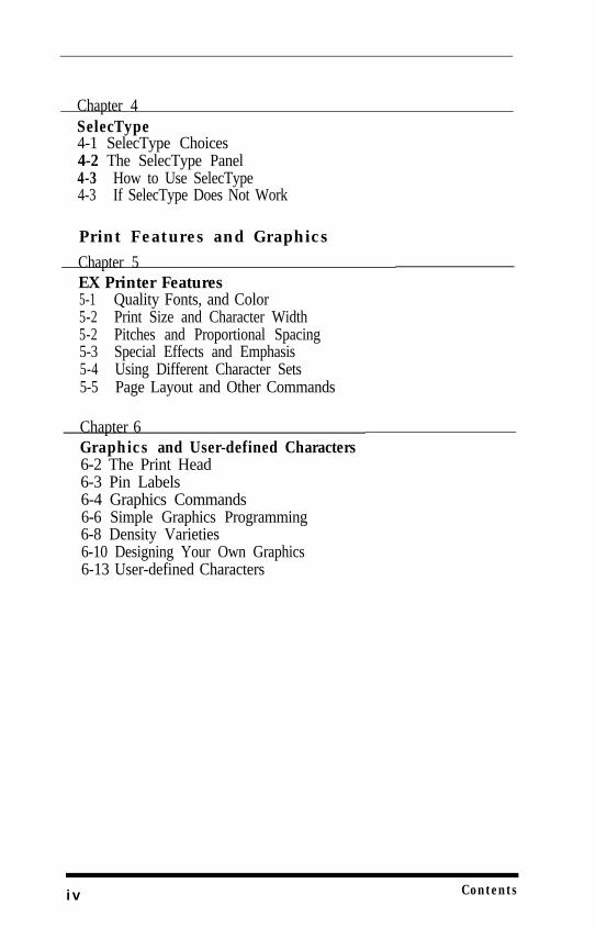
Chapter 4SelecType4-1 SelecType Choices4-2 The SelecType Panel4-3 How to Use SelecType4-3 If SelecType Does Not Work
Print Features and Graphics
Chapter 5EX Printer Features5-1 Quality Fonts, and Color5-2 Print Size and Character Width5-2 Pitches and Proportional Spacing5-3 Special Effects and Emphasis5-4 Using Different Character Sets5-5 Page Layout and Other Commands
Chapter 6Graphics and User-defined Characters6-2 The Print Head6-3 Pin Labels6-4 Graphics Commands6-6 Simple Graphics Programming6-8 Density Varieties6-10 Designing Your Own Graphics6-13 User-defined Characters
i v Contents
Command SummaryAppendix ACommand SummaryA-4 Commands in Numerical OrderA-7 Epson (ESC/P) CommandsA-37 IBM Printer Emulation Mode Commands
ReferenceAppendix BCharacter TablesB-l Epson ModeB-9 Epson International Character SetsB-11 IBM Printer Emulation Mode
Appendix CThe Serial InterfaceC-l The DIP SwitchesC-3 Troubleshooting for Serial InterfacesC-3 Serial Interface Specifications
Appendix DProblem Solving and MaintenanceD-1 General TroubleshootingD-3 Troubleshooting Graphics ProblemsD-4 Data Dump ModeD-5 Solutions for IBM and CompatiblesD-5 IBM PC BASIC SolutionsD-6 Maintaining Your PrinterD-7 Transporting the Printer
Contents v
Appendix EDefaults and DIP SwitchesE-l Default and Initialization SettingsE-2 DIP Switch SettingsE-4 International Character SetsE-5 Interface Selection
Appendix FChoosing and Setting Up Optional InterfacesF-1 Compatible InterfacesF-2 Choosing an InterfaceF-4 Installing an InterfaceF-6 Inserting the Interface BoardF-7 Serial Interface Settings
Appendix GTechnical SpecificationsG-1 PrintingG-2 PaperG-2 MechanicalG3 ElectricalG3 EnvironmentG4 Parallel InterfaceG6 Data Transfer Sequence
Index
v i Contents
Introduction
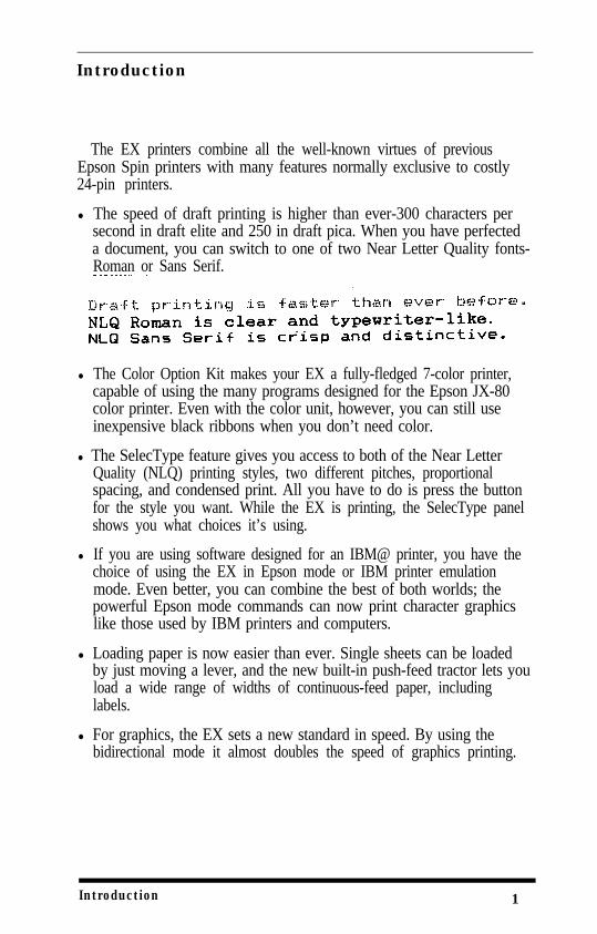
The EX printers combine all the well-known virtues of previousEpson Spin printers with many features normally exclusive to costly24-pin printers.
l The speed of draft printing is higher than ever-300 characters persecond in draft elite and 250 in draft pica. When you have perfecteda document, you can switch to one of two Near Letter Quality fonts-Roman or Sans Serif.
l The Color Option Kit makes your EX a fully-fledged 7-color printer,capable of using the many programs designed for the Epson JX-80color printer. Even with the color unit, however, you can still useinexpensive black ribbons when you don’t need color.
l The SelecType feature gives you access to both of the Near LetterQuality (NLQ) printing styles, two different pitches, proportionalspacing, and condensed print. All you have to do is press the buttonfor the style you want. While the EX is printing, the SelecType panelshows you what choices it’s using.
l If you are using software designed for an IBM@ printer, you have thechoice of using the EX in Epson mode or IBM printer emulationmode. Even better, you can combine the best of both worlds; thepowerful Epson mode commands can now print character graphicslike those used by IBM printers and computers.
l Loading paper is now easier than ever. Single sheets can be loadedby just moving a lever, and the new built-in push-feed tractor lets youload a wide range of widths of continuous-feed paper, includinglabels.
l For graphics, the EX sets a new standard in speed. By using thebidirectional mode it almost doubles the speed of graphics printing.
Introduction 1
About this Manual
To make it easier to set up your new EX-800 or EX-1000, this manualincludes a 10-step guide. This guide, which is printed on the inside ofthe back flap, summarizes the first chapter’s setting up instructions.
The blue-edged divider pages are another aid to using the manual.They make it easy to find the section of the manual you need. Inaddition to Setting Up Your printer, there are four other sections.
Using Your Printer covers the basic functions, Print Features andGraphics describes more advanced functions, and the last two sectionscontain reference information, including all the details you need to useany of the printer’s commands, and some advice on solving problems.
Finally, there is a glossary and a comprehensive index, and inside theback of the manual is a pullout quick reference card containing theinformation you need most.
2 Introduction

Chapter 1Setting Up the Printer
Setting up your EX printer is easy Simply follow the steps in thischapter.
NoteAlthough this manual covers both the EX-800 and the EX-1000, theillustrations show only one printer (the EX-800) because the onlydifference between the two is that the EX-1000 can use wider paper.
1 Unpacking the Printer
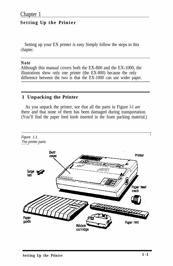
As you unpack the printer, see that all the parts in Figure l-l arethere and that none of them has been damaged during transportation.(You’ll find the paper feed knob inserted in the foam packing material.)
Figure 1-1.The printer parts
Setting Up the Printer 1-1
CautionDo not plug in the power cord yet. You should perform the first threesteps before you plug in the printer and turn on the power,
Remove the tape that holds the dust cover in place during shippingand take the cover off the printer. Simply tilt the dust cover up and lift itoff.
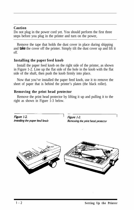
Installing the paper feed knobInstall the paper feed knob on the right side of the printer, as shown
in Figure 1-2. Line up the flat side of the hole in the knob with the flatside of the shaft, then push the knob firmly into place.
Now that you’ve installed the paper feed knob, use it to remove thesheet of paper that is behind the printer’s platen (the black roller).
Removing the print head protectorRemove the print head protector by lifting it up and pulling it to the
right as shown in Figure 1-3 below.
1 - 2 Setting Up the Printer
When you are finished unpacking, put the packaging materials andthe head protector in the box and keep them in case you need totransport the printer. Full details on transporting the printer are inAppendix D.
2 Choosing a Place for the Printer
The printer must be close enough to the computer for the cable toreach. Also keep the following tips in mind:
l Place the printer on a flat, stable surface-never on a chair or anyother unstable support.
l Choose a place that is clean and free from excessive heat (includingdirect sunlight), moisture, and dust.
l Use a grounded outlet-one that has three holes to match the powerplug on the printer. Don’t use an adapter plug.
l Avoid sockets on the same circuit with large motors or otherappliances that might disturb the power supply
l Keep your entire computer system away from potential sources ofinterference such as the base units of cordless telephones.
3 Installing the Ribbon
The EX uses a simple cartridge ribbon designed for convenient andtrouble-free installation. With the color option kit, you can use a colorribbon whenever you need one and a normal black ribbon for day-to-day printing. You install both types of ribbon in-the same way
1. Remove the dust cover.
2. If the printer is plugged in, see that it is turned off.
Setting Up the Printer 1 - 3
WARNINGThe power must be OFF when you move the print head. Otherwise,you may damage the printer mechanism. Also, if you’ve been using theprinter just before changing the ribbon cartridge, be careful not to touchthe print head because it becomes hot during use.
3.
4.
5.
6.
7.
Move the print head carriage to about 25 on the ruler on the paperbail.
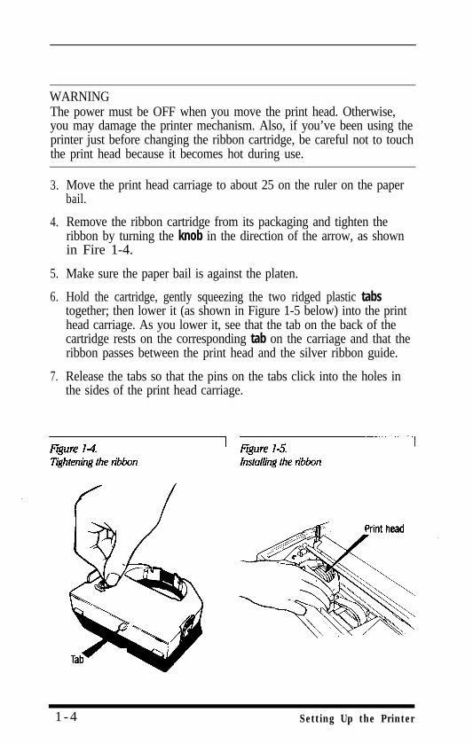
Remove the ribbon cartridge from its packaging and tighten theribbon by turning the knob in the direction of the arrow, as shownin Fire 1-4.
Make sure the paper bail is against the platen.
Hold the cartridge, gently squeezing the two ridged plastic tabstogether; then lower it (as shown in Figure 1-5 below) into the printhead carriage. As you lower it, see that the tab on the back of thecartridge rests on the corresponding tab on the carriage and that theribbon passes between the print head and the silver ribbon guide.
Release the tabs so that the pins on the tabs click into the holes inthe sides of the print head carriage.
1 - 4 Setting Up the Printer
8. Turn the ribbon tightening knob again to see that the ribbon movesfreely
Replacing the ribbon . . .The EX-800 uses a continuous-loop, inked fabric ribbon. When
your printing becomes too light, replace the whole ribbon cartridge.
Always use replacement ribbons designed specifically for Epson EXprinters. It is not possible to use ribbons for any other series ofprinter, and you should never try to re-ink the ribbon.
To remove the old ribbon, simply grip the cartridge by the twoplastic tabs and lift it up and out of the printer. You can then install anew cartridge as described above.
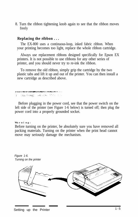
Before plugging in the power cord, see that the power switch on theleft side of the printer (see Figure 1-6 below) is turned off; then plug thepower cord into a properly grounded socket.
W a r n i n g :
Before turning on the printer, be absolutely sure you have removed allpacking materials. Turning on the printer when the print head cannotmove may seriously damage the mechanism.
Figure 1-6.Turning on the printer
Setting up the Printer 1 - 5
Now, turn the power ON with the switch on the left side of theprinter. When you turn on the printer, several important things happen:
l The print head moves back and forth and stops at the left side of theprinter; this is the home position.
l The ribbon carriage moves up and down to set the ribbon at thecorrect level for printing.
l The printer is initialized and set to certain default settings (which arefully described in Appendix E).
l The green power light on the control panel comes on.
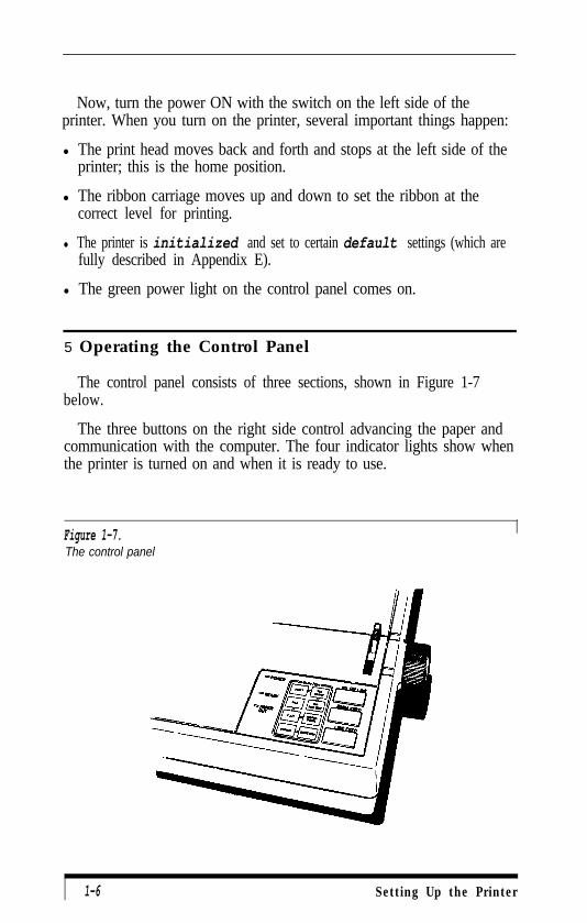
5 Operating the Control Panel
The control panel consists of three sections, shown in Figure 1-7below.
The three buttons on the right side control advancing the paper andcommunication with the computer. The four indicator lights show whenthe printer is turned on and when it is ready to use.
Figure 1-7.The control panel
1-6 Setting Up the Printer
The buttons
There are three buttons on the right side of the control panel.
ON LINE The green light next to this button indicates that theprinter is able to receive and print data from thecomputer. When the light is off, the printer is off line andcannot receive any data. Press the button to change fromon line to off line or from off line to on line. The printerautomatically goes off line when you try to print withoutpaper in the printer. Pressing the ON LINE button then hasno effect until you load paper.
The other two buttons work only when the printer is off line.
FORM FEED This button ejects a single sheet of paper or advancescontinuous paper to the next top of form.
LINE FEED This button advances the paper one line each time youpress it or continuously if you hold it down. When theprinter is turned on, use this button to advance paper.
Remember not to use the paper feed knob while the printer is turnedon. You can damage the printer mechanism.
The indicator lights
In addition to the ON LINE light, the printer has three other lights.
POWER This comes on to show that the printer is connected tothe power and is turned on.
READY This comes on when the printer is on line and ready toprint. It normally flickers during printing.
PAPER OUT This comes on when the printer is out of paper.
The remain f the control panel is made up of eight touchswitches that let you choose the print style and size. This is a specialfeature called SelecType, which is fully described in Chapter 4.
Setting Up the Printer 1 - 7
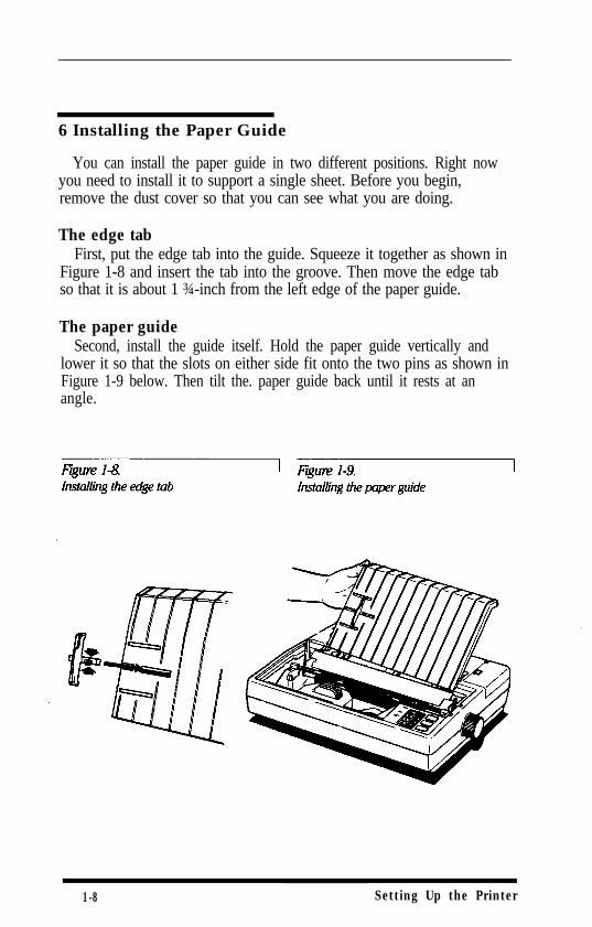
6 Installing the Paper Guide
You can install the paper guide in two different positions. Right nowyou need to install it to support a single sheet. Before you begin,remove the dust cover so that you can see what you are doing.
The edge tabFirst, put the edge tab into the guide. Squeeze it together as shown in
Figure 1-8 and insert the tab into the groove. Then move the edge tabso that it is about 1 ¾-inch from the left edge of the paper guide.
The paper guideSecond, install the guide itself. Hold the paper guide vertically and
lower it so that the slots on either side fit onto the two pins as shown inFigure 1-9 below. Then tilt the. paper guide back until it rests at anangle.
1-8 Setting Up the Printer
7 Loading Paper
Even if you normally use continuous paper, it is simpler to test theprinter using a single sheet of paper. If you have an EX-1000, be sure touse 14-inch-wide paper so that none of the self test prints on the platen.
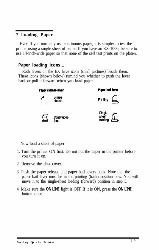
Paper loading icons...Roth levers on the EX have icons (small pictures) beside them.
These icons (shown below) remind you whether to push the leverback or pull it forward when you load paper.
Now load a sheet of paper:
1. Turn the printer ON first. Do not put the paper in the printer beforeyou turn it on.
2. Remove the dust cover
3. Push the paper release and paper bail levers back. Note that thepaper bail lever must be in the printing (back) position now. You willmove it to the single-sheet loading (forward) position in step 5.
4. Make sure the ON LINE light is OFF If it is ON, press the ON LINEbutton once.
Setting Up the Printer 1-9
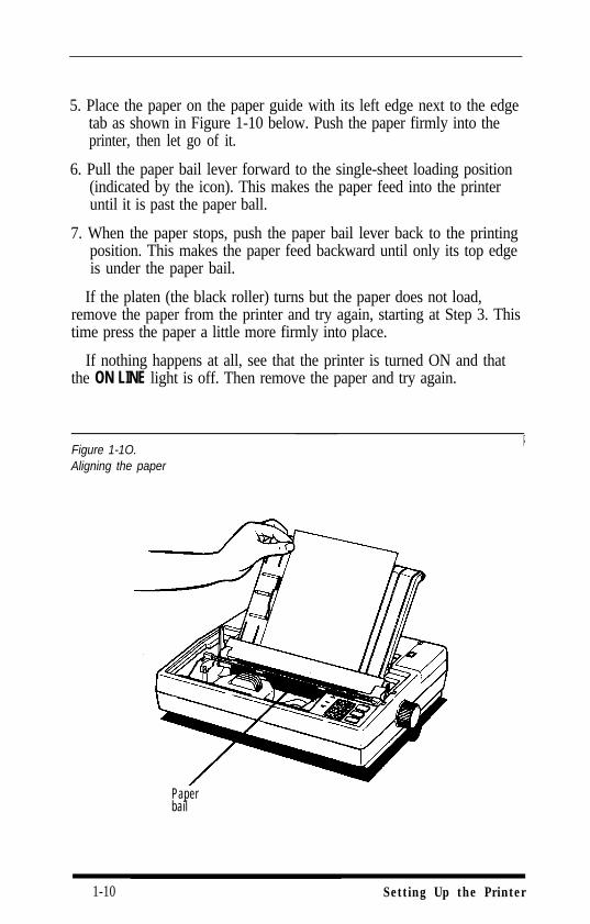
5. Place the paper on the paper guide with its left edge next to the edgetab as shown in Figure 1-10 below. Push the paper firmly into theprinter, then let go of it.
6. Pull the paper bail lever forward to the single-sheet loading position(indicated by the icon). This makes the paper feed into the printeruntil it is past the paper ball.
7. When the paper stops, push the paper bail lever back to the printingposition. This makes the paper feed backward until only its top edgeis under the paper bail.
If the platen (the black roller) turns but the paper does not load,remove the paper from the printer and try again, starting at Step 3. Thistime press the paper a little more firmly into place.
If nothing happens at all, see that the printer is turned ON and thatthe ON LINE light is off. Then remove the paper and try again.
Figure 1-1O.Aligning the paper
Paperbail
1-10 Setting Up the Printer
8 Running the Self Test
The EX has a built-in self test that prints out the characters in itsmemory so that you can see that the printer is working properly
The self test also prints the settings of the printer’s DIP switches. Thispart of the printout will be useful in the next section of this manual.
Before running the self test, make sure that paper is loaded in theprinter and that the power is OFF
To run the self test in the Near Letter Quality (NLQ) mode, hold downthe FORM FEED button while you turn the printer on. When theprinting starts, release the FORM FEED button.
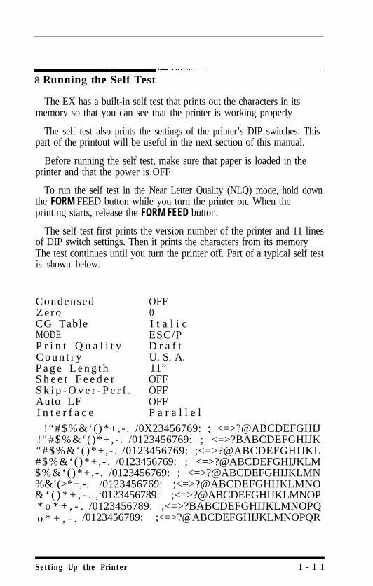
The self test first prints the version number of the printer and 11 linesof DIP switch settings. Then it prints the characters from its memoryThe test continues until you turn the printer off. Part of a typical self testis shown below.
Condensed OFFZero 0CG Table I t a l i cMODE ESC/PP r i n t Q u a l i t y D r a f tC o u n t r y U. S. A.P a g e L e n g t h 11”S h e e t F e e d e r OFFS k i p - O v e r - P e r f . OFFAuto LF OFFI n t e r f a c e P a r a l l e l
!“#$%&‘( )*+ , - . /0X23456769: ; <=>?@ABCDEFGHIJ!“#$%&‘( )*+ , - . /0123456769: ; <=>?BABCDEFGHIJK“#$%&‘( )*+ , - . /0123456769: ;<=>?@ABCDEFGHIJKL#$%&‘( )*+ , - . /0123456769: ; <=>?@ABCDEFGHIJKLM$%&‘( )*+ , - . /0123456769: ; <=>?@ABCDEFGHIJKLMN%&‘(>*+,-. /0123456769: ;<=>?@ABCDEFGHIJKLMNO& ‘ ( ) * + , - . ,‘0123456789: ;<=>?@ABCDEFGHIJKLMNOP* o * + , - . /0123456789: ;<=>?BABCDEFGHIJKLMNOPQo * + , - . /0123456789: ;<=>?@ABCDEFGHIJKLMNOPQR
Setting Up the Printer 1 - 1 1
To run the same test in the draft mode, hold down the LINE FEEDbutton instead of the FORM FEED button while you turn the printer on.The EX cannot print a draft self test, however, if the NLQ DIP switch ison. Therefore, if the Print Quality line of the self test printout says ‘PrintQuality NLQ,” you cannot print a draft test without changing a DIPswitch. (DIP switches are explained in Appendix E.)
9 Connecting the Printer to Your Computer
Your EX printer has two separate interface connections. Therefore,you must be sure to use the one that your computer requires.
The two interfaces are a Centronics® compatible parallel interface andan RS-232C compatible serial interface. If you have a suitable cable, youcan connect most computers immediately
The few computers that require other interfaces can usually use oneof the optional interface boards described in Appendix F Check yourcomputer’s manual if don’t know which interface to use.
The parallel interfaceMore connecting a parallel interface cable, see that both the printer
and computer are turned off. Then plug the connector into the printeras shown in Fire 1-11. Next squeeze the clips gently and click theminto place.
Some parallel cables have a ground wire. Connect this wire to theground screw on the printer to protect data from interference. Thenplug the other end of the cable into the computer and connect theground wire on the computer end of the cable if it has one.
Parallel interfaces require no further adjustment.
1-12 Setting Up the Printer
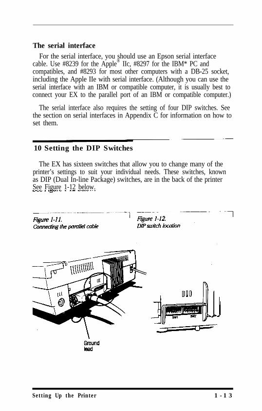
The serial interfaceFor the serial interface, you should use an Epson serial interface
cable. Use #8239 for the Apple® IIc, #8297 for the IBM* PC andcompatibles, and #8293 for most other computers with a DB-25 socket,including the Apple IIe with serial interface. (Although you can use theserial interface with an IBM or compatible computer, it is usually best toconnect your EX to the parallel port of an IBM or compatible computer.)
The serial interface also requires the setting of four DIP switches. Seethe section on serial interfaces in Appendix C for information on how toset them.
10 Setting the DIP Switches
The EX has sixteen switches that allow you to change many of theprinter’s settings to suit your individual needs. These switches, knownas DIP (Dual In-line Package) switches, are in the back of the printerSee Figure 1-12 below.
Setting Up the Printer 1 - 1 3
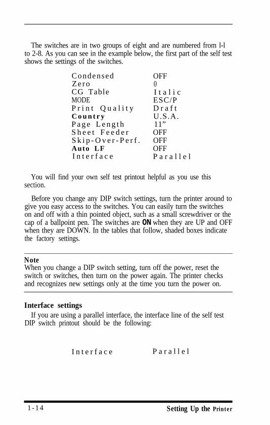
The switches are in two groups of eight and are numbered from l-lto 2-8. As you can see in the example below, the first part of the self testshows the settings of the switches.
Condensed OFFZero 0CG Table I t a l i cMODE ESC/PP r i n t Q u a l i t y D r a f tC o u n t r y U.S.A.P a g e L e n g t h 11”S h e e t F e e d e r OFFS k i p - O v e r - P e r f . OFFAuto LF OFFI n t e r f a c e P a r a l l e l
You will find your own self test printout helpful as you use thissection.
Before you change any DIP switch settings, turn the printer around togive you easy access to the switches. You can easily turn the switcheson and off with a thin pointed object, such as a small screwdriver or thecap of a ballpoint pen. The switches are ON when they are UP and OFFwhen they are DOWN. In the tables that follow, shaded boxes indicatethe factory settings.
NoteWhen you change a DIP switch setting, turn off the power, reset theswitch or switches, then turn on the power again. The printer checksand recognizes new settings only at the time you turn the power on.
Interface settingsIf you are using a parallel interface, the interface line of the self test
DIP switch printout should be the following:
I n t e r f a c e P a r a l l e l
1 -14 Setting Up the Printer
If the interface line does not say Parallel, turn switches 2-5 and 2-6OFF
If you are using a serial interface, turn to Appendix C, which givesfull information on serial interfaces.
The operating modeThe EX has two operating modes, ESC/P™ and IBM printer emulation
mode. ESC/P stands for Epson Standard Code for Printers, a powerfulset of commands developed by Epson and supported by almost allapplication software for personal computers. This is the mode that youshould find the most useful and valuable for your printing. The rest ofthis manual refers to the ESC/P mode simply as the Epson mode.
The IBM printer emulation mode is for software that is designed onlyfor IBM printers. It is not necessary to use this mode for your EX to becompatible with IBM computers. As you can see from the list of Epsonand IBM printer emulation mode commands in Appendix A, the Epsonmode has more commands and many more capabilities.
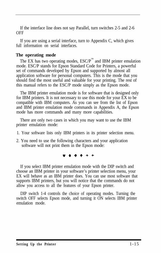
There are only two cases in which you may want to use the IBMprinter emulation mode:
1. Your software lists only IBM printers in its printer selection menu.
2. You need to use the following characters and your applicationsoftware will not print them in the Epson mode:
If you select IBM printer emulation mode with the DIP switch andchoose an IBM printer in your software’s printer selection menu, yourEX will behave as an IBM printer does. You can use most software thatsupports IBM printers, but you will notice that the commands do notallow you access to all the features of your Epson printer.
DIP switch 1-4 controls the choice of operating modes. Turning theswitch OFF selects Epson mode, and turning it ON selects IBM printeremulation mode.
Setting Up the Printer 1-15
The Epson character graphics setHalf of the characters used by IBM PCs and compatibles are special
character graphics and international characters. On most previousEpson printers, these characters printed as italics. With the EX,however, you can print the character graphics without losing italics orany of the power of the Epson commands.
DIP switch 1-3 controls the choice between the italic character andgraphic character tables (called CG table in the DIP switch printout).Turning the switch ON selects the character graphic table, and turning itOFF selects the italic table. Remember that italics are still available evenif you select the character graphic table.
Because only Epson mode has italics, DIP switch 1-3 has a differentfunction in the IBM printer emulation mode; In that mode the EX addsa carriage return to each line feed if DIP switch 1-3 is OFF For mostIBM printer emulation mode applications, you should not have tochange the setting of this switch.
Making the choiceThe decision you make about the operating mode and the character
graphics set depends upon the software you use. For most applications,choose the Epson mode and the Character Graphics set (DIP switch 1-4OFF and DIP switch 1-3 ON). That way you can set up your software foran Epson printer and have the full power of the Epson commands.
If you have trouble printing italics, change DIP switch 1-3 to OFF tochoose italics instead of character graphics. On the other hand, if youhave trouble printing character graphics, change the printer to IBMprinter emulation mode by setting DIP switch 1-4 ON and set yoursoftware to match.
You must always be careful to set up your printer and software tomatch. Although the IBM commands are based on some of the Epsoncommands, important differences affect much software. Thesedifferences can cause erratic printing. In particular, line spacing andpage layout are likely to be wrong, and extra characters may appear
1-16 Setting up the Printer

Other DIP switch settingsAppendix E summarizes all the DIP switch settings in a group of
tables. See that appendix for reference or further information.
Setting Up the Printer 1 - 1 7

1 -18 Setting Up the Printer
Chapter 2Choosing and Loading Paper
The EX printer can accommodate many different sizes and types ofpaper, using either its automatic singlesheet loading feature or its built-in adjustable tractor.
The tractor is easy to use and can handle a wide range of paperwidths. The automatic singlesheet loading feature handles individualsheets quickly and easily, and for greater efficiency you can add anoptional automatic sheet feeder.
Choosing Paper
Without installing any accessories, you can use single-sheet paperfrom 7¼ to 8½ inches wide and continuous paper from 4 to 10 incheswide (including the perforated edge strips).
You can also add an optional roll paper holder, which uses paper 8½inches wide. You load roll paper the same way you load single sheets,except that you do not use the paper guide.
Carbon copies
If you use multi-part forms or carbon copies in the EX, use no morethan three sheets or parts at a time, with a total thickness of no morethan 0.16 mm. Also change the paper thickness setting as described atthe end of this chapter.
Loading Single Sheets
You have already loaded singlesheet paper using the automatic sheetloading feature in Step 7 of the setup chapter This feature gives youshort printing times by combining fast loading with fast printing.
If you print large amounts on single sheets of paper, however, youmay find it more convenient to use an automatic sheet feeder. This isan optional device that holds a stack of paper and inserts a new sheet
Choosing and Loading Paper 2 - 1
whenever required, making single sheets as easy and convenient to useas continuous paper. The automatic sheet feeder has its own user’smanual.
Reloading during printingWhen you print a document more than one page long using single
sheets of paper, there are two different ways your software can allowyou to load a new sheet at the end of a page.
l If your software sends characters in a continuous stream, the printerstops printing when it reaches the bottom of the paper and soundsthe beeper. When this happens, the ON LINE light goes offautomatically
l If your software handles printing page by page, it probably stopssending characters at the end of a page and prompts you to insertmore paper. In this case the ON LINE light probably remains on, andthe first thing you should do is press the ON LINE button once to turnit off.
Once the ON LINE light is off, remove the sheet that has just beenprinted and load a new sheet in the same way as before.
Loading Continuous-feed Paper
The new push-feed tractor built into the EX has several majoradvantages over other types. It combines the ability to handle a widerange of paper widths with an extremely low profile, and it is easy toload.
The push-feed tractor must be loaded in a slightly different way thanthe pin-feed system on Epson FX printers and the usual pull-throughtractors. If you are used to using other systems, follow these instructionscarefully
Begin by seeing that the printer is turned off. If you have been usingthe printer with single sheets, remove the paper guide. You will install itin a different way
2-2 Choosing and Loading Paper
Clear enough space around the printer so that the paper has anunobstructed path in and out of the printer. There are three commonmethods of arranging a printer and continuous paper:
l Using a printer stand with the paper stacked underneath it.
l Using a desk or table as a stand, with the printer near the rear edgeand the paper on the floor or on a shelf.
l Putting the printer on a desk or table and stacking the paper behindthe printer.
Now follow these steps to load continuous paper in your EX.
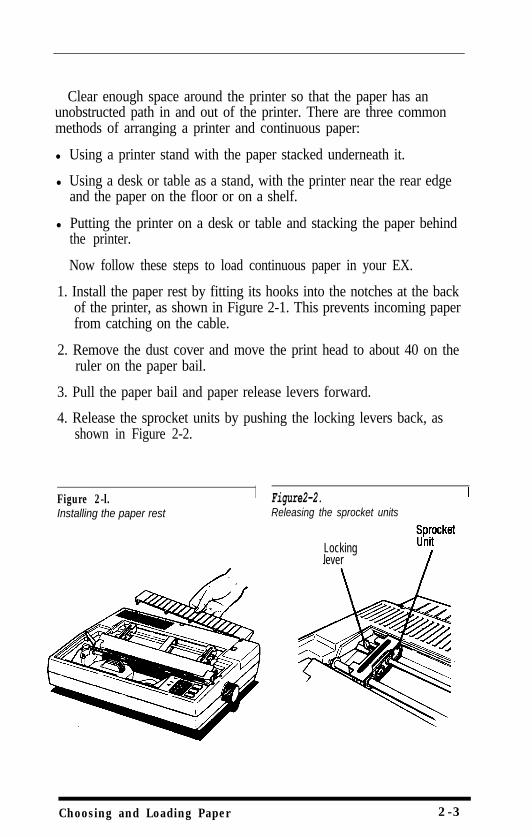
1. Install the paper rest by fitting its hooks into the notches at the backof the printer, as shown in Figure 2-1. This prevents incoming paperfrom catching on the cable.
2. Remove the dust cover and move the print head to about 40 on theruler on the paper bail.
3. Pull the paper bail and paper release levers forward.
4. Release the sprocket units by pushing the locking levers back, asshown in Figure 2-2.
Figure 2-l. Figure2-2.Installing the paper rest Releasing the sprocket units
Lockinglever
Choosing and Loading Paper 2-3
5. Move the left sprocket unit all the way to the left and pull thelocking lever forward to hold it in position.
NoteWith the sprocket unit in this position, you always have a margin at theleft side. If you want to print without a left margin or if your softwarecreates a margin, move the left sprocket unit about 3/4 inch from theleft side, so that the perforated edge of the paper fines up with thenumber 1 on the ruler on the paper bail. Check the exact positionwhen you finish loading.
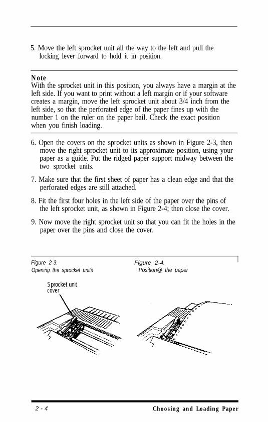
6. Open the covers on the sprocket units as shown in Figure 2-3, thenmove the right sprocket unit to its approximate position, using yourpaper as a guide. Put the ridged paper support midway between thetwo sprocket units.
7. Make sure that the first sheet of paper has a clean edge and that theperforated edges are still attached.
8. Fit the first four holes in the left side of the paper over the pins ofthe left sprocket unit, as shown in Figure 2-4; then close the cover.
9. Now move the right sprocket unit so that you can fit the holes in thepaper over the pins and close the cover.
Figure 2-3. Figure 2-4.Opening the sprocket units Position@ the paper
Sprocket unitcover
2 - 4 Choosing and Loading Paper
10. If the paper is straight and has no wrinkles, lock the right sprocketunit in place.
11. Turn the paper feed knob slowly to feed the paper under the metalplate in front of the tractor. (The diagram on the metal plate showshow the paper should go through.) See that the paper does notwrinkle after it reaches the platen.
12. Turn the knob until the paper is past the paper bail. Then pushback the paper bail lever (the lever on the right side). The paperbail lever must be back at all times when you are printing withcontinuous paper.
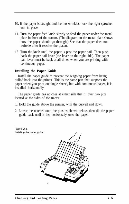
Installing the Paper GuideInstall the paper guide to prevent the outgoing paper from being
pulled back into the printer. This is the same part that supports thepaper when you print on single sheets, but with continuous paper, it isinstalled horizontally
The paper guide has notches at either side that fit over two pinslocated at the sides of the tractor.
1. Hold the guide above the printer, with the curved end down.
2. Lower the notches onto the pins as shown below, then tilt the paperguide back until it lies horizontally over the paper.
Figure 2-5.Installing the paper guide
Choosing and Loading Paper 2-5
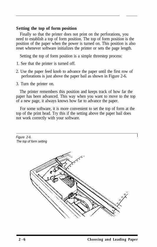
Setting the top of form positionFinally so that the printer does not print on the perforations, you
need to establish a top of form position. The top of form position is theposition of the paper when the power is turned on. This position is alsoreset whenever software initializes the printer or sets the page length.
Setting the top of form position is a simple threestep process:
1. See that the printer is turned off.
2. Use the paper feed knob to advance the paper until the first row ofperforations is just above the paper bail as shown in Figure 2-6.
3. Turn the printer on.
The printer remembers this position and keeps track of how far thepaper has been advanced. This way when you want to move to the topof a new page, it always knows how far to advance the paper.
For some software, it is more convenient to set the top of form at thetop of the print head. Try this if the setting above the paper bail doesnot work correctly with your software.
Figure 2-6.The top of form setting
2-6 Choosing and Loading Paper
Remember that you should never advance the paper using the paperfeed knob while the power is turned on. You can damage themechanism of the printer, and the printer will lose track of the top ofform position.
Loading Labels
If you want to use labels on a continuous backing, always choose thetype that are mounted on a perforated backing sheet for use with thetractor. Labels on a shiny backing sheet will almost always slip a little iffed by friction alone. Also remember that the minimum width of labelthat can be used is 4 inches, including the full width of the backingpaper.
The procedure for loading labels with the tractor is the same as forloading continuous paper, except for two points. Labels on a backingsheet are thicker than normal paper. Therefore, you must adjust thepaper thickness lever, which is described at the end of this chapter.Also, if you don’t want a left margin on the labels, move the leftsprocket unit about 3/4 inch from the left side before locking it inposition.
WARNINGNever turn labels backward with the paper feed knob or with reverseline feed commands. Labels can peel off the backing and jam theprinter If a label does become stuck in the printer, see your authorizedEpson dealer. Do not attempt to remove the labels yourself.
When you are through printing on labels, tear them off at aperforation behind the platen; then feed the remainder through. It isbetter to waste a few labels than to risk damaging the printer
It is also possible to buy labels on a matte backing in single sheets.There are normally no gaps between individual labels on the sheet, sothat the labels are less likely to catch on the platen. You can load thesewith the automatic single-sheet loading feature.
Choosing and Loading Paper 2 - 7
The Paper Thickness Lever
You can adjust the EX to accommodate different thicknesses of paper.You need to do this when you print labels or carbon copies.
Before moving the paper thickness lever, always turn off the power,open the dust cover, and move the print head to the middle of theprinter,
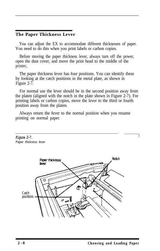
The paper thickness lever has four positions. You can identify theseby looking at the catch positions in the metal plate, as shown inFigure 2-7.
For normal use the lever should be in the second position away fromthe platen (aligned with the notch in the plate shown in Figure 2-7). Forprinting labels or carbon copies, move the lever to the third or fourthposition away from the platen.
Always return the fever to the normal position when you resumeprinting on normal paper.
Figure 2-7.Paper thickness lever
Catchpositions
2-8 Choosing and Loading Paper
Chapter 3Using the EX with Application Programs
Now that you’ve set up and tested the printer, you need to start usingit with your application programs.
Printer Selection Menus
Most application programs let you specify the type of printer you’reusing so that the program can take full advantage of the printer’sfeatures. Many programs provide an installation or setup procedure thatpresents a list of printers to choose from. If your application programhas a printer selection menu, use the instructions below.
For further information on selecting a printer or sending commandsfrom your application program, read the rest of this chapter, whichcovers word processors, spreadsheets, graphics programs, andprogramming languages.
Menu selectionsIf your software has a printer selection menu, simply choose EX-800
or EX-1000. If the menu does not list any EX printers, choose one of thefollowing. They are listed in order of preference.
EX-800FX-85FX-80 +FX-80FXLXEpson printerDraft printer
EX-1000FX-286FX-185FX-100+FX-100FXL xEpson printerDraft printer
If you plan to use the IBM printer emulation mode, choose IBMProprinter, IBM Graphics printer, or IBM printer, in that order ofpreference.
If you have installed the color option kit, choose EX or Epson JX-80color printer. Do not select an IBM printer, because the IBM printeremulation mode cannot use the color option kit.
Using the EX with Application Programs 3 - 1
NoteIf your application program does not list the EX printers, you may wantto contact the manufacturer to find whether an update is available.
A quick testAfter setting up your application program, print a sample document
to be sure the program and the EX are communicating properly If thedocument doesn’t print correctly recheck the program’s printer selectionand installation procedure. If you’re still having trouble printing, consultthe troubleshooting section in Appendix D.
Computer-Printer Communication
Computers and printers communicate by using codes to representcharacters and commands. To be sure the two devices use the samecodes, almost all manufacturers of computers, printers, and software usethe American Standard Code for Information Interchange, which isusually referred to by its abbreviation, ASCII.
The ASCII standard includes codes for printable characters (letters,punctuation marks, numerals, and mathematical symbols) and 33 othercodes called control codes: The control codes are for such functions assounding the beeper and performing carriage returns. Because the 33control codes are not enough to control all possible printer functions,most printer commands are actually a sequence of two or more codes.
One of the 33 control codes, the escape code, signals the beginning ofa sequence of codes. Therefore, most printer commands are sequencesof codes, the first of which is the escape code. This manual uses theASCII abbreviation EX for this code.
When using control codes to select printer functions for anapplication program or programming language, check the manual forthe program or language to find the appropriate method of inserting thecode into the program. Further details on the methods to use are in therest of this chapter.
3-2 Using the EX with Application Programs
Naming and using commandsIn order to use printer commands, you should know how they are
recognized by your software program. The most common way ofnaming codes or commands is with one of two numbering systems,decimal or hexadecimal.
The decimal system is the standard numbering system based on unitsof ten, using the numerals 0-9.
The hexadecimal, or hex, system is based on units of 16, and is oftenused by programmers. Instead of using only the numerals 0 through 9,the hex system also uses the letters A through F. For example, thedecimal numbers 9, 10, 11, and 12 are 09, OA, OB, and OC in hex.
Since the most frequently used hexadecimal numbers are between 0and FF hex (0 to 255 in decimal), it’s common to write hexadecimalnumbers that are less than 16 with a zero in front, as shown above.
In this book, hex numbers are distinguished from decimal numbersby the word hex after them (for example, 1B hex). Other common waysof denoting a hexadecimal number are the following:
1BH $lB &lB &H1B <lB>H
The Command Summary and the Quick Reference Card give boththe decimal and hex numbers for each command.
Word Processors
In many ways, word processors demand the most from your printerWhen you create and print a document, you may use many print stylesand fonts, reformat pages, add headers and footers, and use bold, italic,and other effects.
Once you have installed your word processor by using the lists onpage 3-1, you can ordinarily use a fixed set of printer features by using aword processor command to place markers around the text to bealtered. When the document is printed, the markers are recognized andtranslated into suitable commands for your printer. On your screensome programs show the markers in a distinctive way while othersdisplay the text as it will appear-for example, in bold or italics.
Using the EX with Application Programs 3-3
This method is normally restricted to features that can be found onalmost all printers, such as bold and underlining.
Some programs also provide a way of placing complete printercommands in the text. These commands may or may not be visible onyour screen. This method has the advantage of allowing you to use anyprinter command, not just a limited set. To make use of it, however, youneed to understand how to use the printers commands.
Check the manual for your word processor to see if you can placeprinter commands in your text. If this is possible, use the CommandSummary in this manual to find the command, and use the manual foryour word processor to find how to assign the command.
If your EX is not printing correctly check both the EX and your wordprocessor and review this checklist:
Make sure you’ve selected the correct printer.
Carefully read the printer setup and installation information in yourword processor’s manual.
Check the printer options that may be part of the installation orsetup section (line feeds, interface, etc.).
Make sure your word processor is capable of sending the propercommands to your printer.
If you’re still having difficulty printing, check the troubleshootingsection in your word processor’s manual and Appendix D of thismanual.
Spreadsheets
Although spreadsheets seldom use as many printing styles as wordprocessors, they do have some very specific requirements.
Installation and column widthIf your spreadsheet program provides a list of printers, use the list on
page 3-1 to find the proper selection. If your spreadsheet doesn’t have aprinter setup routine, carefully read the program’s manual forinformation on printing.
3-4 Using the EX with Application Programs
A major concern for printing spreadsheets is the width of the printer.The EX-800 is an 80 column printer, and the EX-1000 is a 136 columnprinter, but by using condensed elite (explained in Chapters 4 and 5)you can print up to 160 columns on the EX-800 and 272 on theEX-1000. Therefore, if your spreadsheet asks the number of columnsyour printer can print, you can specify 160 or 272.
Printer commandsUnlike word processors, spreadsheet programs don’t usually let you
change printer commands within a spreadsheet. Instead, one style ormode of printing is used for the whole spreadsheet. With the EX, thereare two main ways of sending commands to control the printing of aspreadsheet.
First, almost all spreadsheets have the capability of sendingcommands to a printer. Look in the manual for your spreadsheet to findout how to send printer commands. Then look in the CommandSummary in this manual to find the proper codes to send.
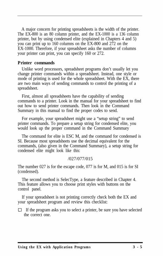
For example, your spreadsheet might use a “setup string” to sendprinter commands. To prepare a setup string for condensed elite, youwould look up the proper command in the Command Summary
The command for elite is ESC M, and the command for condensed isSI. Because most spreadsheets use the decimal equivalent for thecommands, (also given in the Command Summary), a setup string forcondensed elite might look like this:
/027/077/015
The number 027 is for the escape code, 077 is for M, and 015 is for SI(condensed).
The second method is SelecType, a feature described in Chapter 4.This feature allows you to choose print styles with buttons on thecontrol panel.
If your spreadsheet is not printing correctly check both the EX andyour spreadsheet program and review this checklist:
If the program asks you to select a printer, be sure you have selectedthe correct one.
Using the EX with Application Programs 3 - 5
If you’re using the program’s print facility recheck the EX’sCommand Summary to make sure you’re sending the correctcommands.
q If you’re still having difficulty printing, check the troubleshootingsection in your spreadsheet program’s manual or Appendix D of thismanual.
Graphics Programs
The EX is capable of producing finely detailed graphic images inblack or in color (with the optional color kit). Chapter 6 gives specificinformation on the graphics commands, but the easiest way to takeadvantage of the EX’s capabilities is with one of the many graphicsprograms available.
When buying graphics software, always. make sure it has a suitableoption to allow printouts on an EX printer. Any program with an optionfor an EX or FX printer should give excellent results in black and white,using different dot densities to produce a realistic scale of grays. If youhave installed a color option kit, look for software that has an option forthe EX or for the Epson JX-80 color printer.
Most graphics programs have a printer selection procedure, in whichcase you should check the lists on page 3-1 to find the proper selection.
Most users rely on application programs to send commands to theprinter. An awareness of programming languages, however, can behelpful in exploring a printer’s potential or troubleshooting a printingproblem.
For example, if you want to set up your application program to senda command for italic printing, you can use a programming language,such as BASIC or Pascal, to do a quick printout before setting up theprogram.
3-6 Using the EX with Application Programs
If, on the other hand, you’ve set up a program to send a certaincommand to the printer, but it’s not printing correctly you could sendthe same command with a programming language to find whether theproblem lies with your application program, the command, or theprinter.
Sending printer commands with BASICYou can send printer commands with any programming language.
The examples in this manual are written in BASIC, because BASIC isincluded with most computer systems.
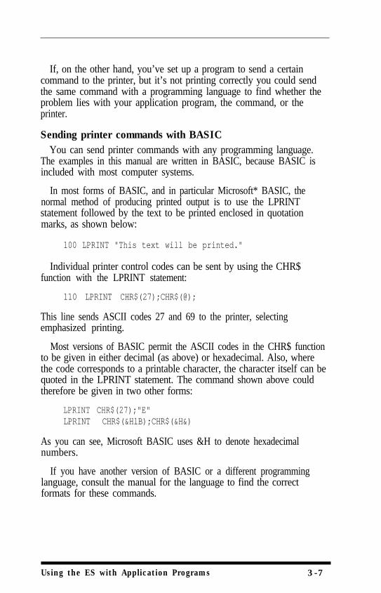
In most forms of BASIC, and in particular Microsoft* BASIC, thenormal method of producing printed output is to use the LPRINTstatement followed by the text to be printed enclosed in quotationmarks, as shown below:
100 LPRINT "This text will be printed."
Individual printer control codes can be sent by using the CHR$function with the LPRINT statement:
110 LPRINT CHR$(27);CHR$(@);
This line sends ASCII codes 27 and 69 to the printer, selectingemphasized printing.
Most versions of BASIC permit the ASCII codes in the CHR$ functionto be given in either decimal (as above) or hexadecimal. Also, wherethe code corresponds to a printable character, the character itself can bequoted in the LPRINT statement. The command shown above couldtherefore be given in two other forms:
LPRINT CHR$(27);"E"LPRINT CHR$(&HlB);CHR$(&H&)
As you can see, Microsoft BASIC uses &H to denote hexadecimalnumbers.
If you have another version of BASIC or a different programminglanguage, consult the manual for the language to find the correctformats for these commands.
Using the ES with Application Programs 3-7

3-8 Using the EX with Application Programs
Chapter 4SelecType
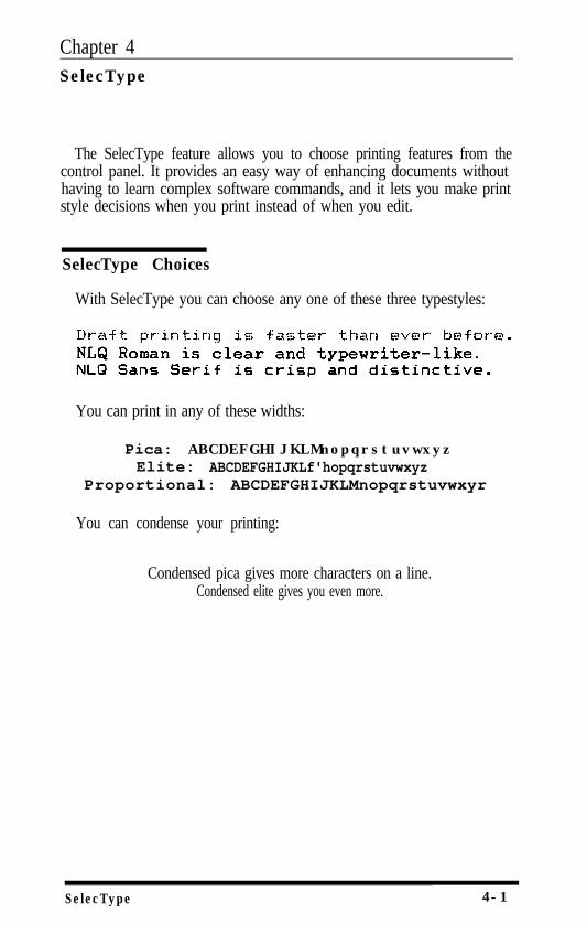
The SelecType feature allows you to choose printing features from thecontrol panel. It provides an easy way of enhancing documents withouthaving to learn complex software commands, and it lets you make printstyle decisions when you print instead of when you edit.
SelecType Choices
With SelecType you can choose any one of these three typestyles:
You can print in any of these widths:
Pica: ABCDEFGHIJKLMnopqrstuvwxyzElite: ABCDEFGHIJKLf'hopqrstuvwxyz
Proportional: ABCDEFGHIJKLMnopqrstuvwxyr
You can condense your printing:
Condensed pica gives more characters on a line.Condensed elite gives you even more.
SelecType 4-1
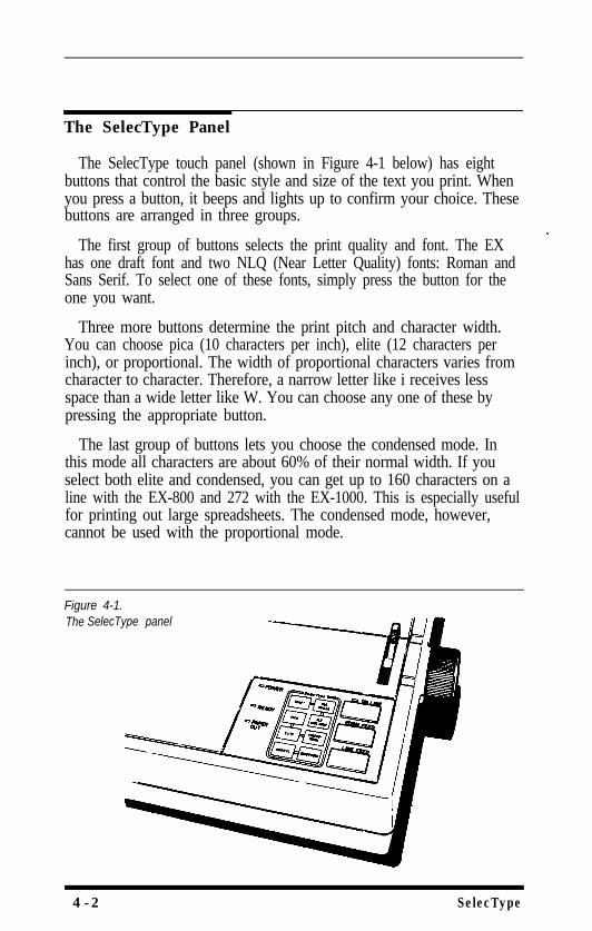
The SelecType Panel
The SelecType touch panel (shown in Figure 4-1 below) has eightbuttons that control the basic style and size of the text you print. Whenyou press a button, it beeps and lights up to confirm your choice. Thesebuttons are arranged in three groups.
The first group of buttons selects the print quality and font. The EXhas one draft font and two NLQ (Near Letter Quality) fonts: Roman andSans Serif. To select one of these fonts, simply press the button for theone you want.
Three more buttons determine the print pitch and character width.You can choose pica (10 characters per inch), elite (12 characters perinch), or proportional. The width of proportional characters varies fromcharacter to character. Therefore, a narrow letter like i receives lessspace than a wide letter like W. You can choose any one of these bypressing the appropriate button.
The last group of buttons lets you choose the condensed mode. Inthis mode all characters are about 60% of their normal width. If youselect both elite and condensed, you can get up to 160 characters on aline with the EX-800 and 272 with the EX-1000. This is especially usefulfor printing out large spreadsheets. The condensed mode, however,cannot be used with the proportional mode.
Figure 4-1.The SelecType panel
4-2 SelecType
If you try to combine proportional with condensed, proportional willoverride condensed, no matter which you choose first. When you haveselected condensed and then press the proportional button, it beepsthree times to tell you that it is overriding condensed. (The condensedbutton light goes off also.)
If you have selected proportional and then press the condensedbutton, it beeps three times to tell you that you cannot select condensedwithout changing to pica or elite first.
How to Use SelecType
Now you can try the various SelecType possibilities by printing ashort sample document created with an application program. Create asample and then perform the following two steps.
1. Press the button or buttons for the print styles that you want to use.Each button will confirm your selection by beeping and lighting up.
2. Print the document using your application program’s printcommand.
If you print a short sample two or three times using differentSelecType settings, you will quickly see how easy it is to use SelecTypebecause the lighted buttons tell you what mode the printer is using atany time.
lf SelecType Does Not Work
Some application programs are designed to control all typestylefunctions. Before each printing operation, these programs cancel allprevious typestyle settings by sending a signal (INIT) or by sendingspecific control codes to cancel certain typestyles. These signals orcontrol codes may cancel your SelecType settings.
One reset signal, however, does not affect your SelecType settings.This is the ESC @ command.
You can see whether your program is changing your settings bywatching the buttons when printing starts. If the lights change, theprogram is controlling the typestyles.
SelecType 4-3
If your application program changes your SelecType settings, youhave two choices:
1. Use the program’s setup procedure (which could be called byanother name, such as install) to remove the codes that interferewith your SelecType settings.
2. Use the print control codes for your application program instead ofSelecType to control your printing. The manual for your programtells you how to change the printing style. Most programs that cancelSelecType settings also have sophisticated print control commandsthat give the same results that SelecType does.
NoteAlso remember that any control codes in your document will overrulethe SelecType settings. Therefore, if you have a code for NLQ Roman inyour document and you press the DRAFT SelecType button, yourprinting will still be in NLQ Roman.
Two of the most frequent uses for SelecType are printing spreadsheetsin condensed and changing between NLQ and draft printing. WithSelecType you can use the draft mode to quickly print your first copiesof a document and then switch to NLQ when you have perfected thedocument and are ready to print the finished product.
Because the use of SelecType with the IBM printer emulation modecan produce unexpected results, it is recommended that you should notuse SelecType with that mode.
4-4 SelecType

Chapter 5EX Printer Features
You can obtain many different printing effects with the EX printer,from arranging the printout on the paper to using color or giving extraemphasis to particular words and phrases. This chapter shows you thefeatures you may want to select with your software. Once you haveread about the features, you can find their commands in the CommandSummary
SelecType, as you know, controls the printing style of a wholedocument. Software commands, on the other hand, can changeanything from a single character to the entire document.
Quality, Fonts, and Color
The most fundamental changes you can make to printing on the EXare in the print quality NLQ font, and color.
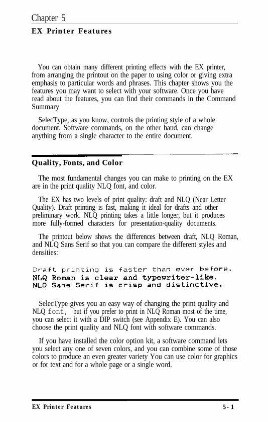
The EX has two levels of print quality: draft and NLQ (Near LetterQuality). Draft printing is fast, making it ideal for drafts and otherpreliminary work. NLQ printing takes a little longer, but it producesmore fully-formed characters for presentation-quality documents.
The printout below shows the differences between draft, NLQ Roman,and NLQ Sans Serif so that you can compare the different styles anddensities:
SelecType gives you an easy way of changing the print quality andNLQ font, but if you prefer to print in NLQ Roman most of the time,you can select it with a DIP switch (see Appendix E). You can alsochoose the print quality and NLQ font with software commands.
If you have installed the color option kit, a software command letsyou select any one of seven colors, and you can combine some of thosecolors to produce an even greater variety You can use color for graphicsor for text and for a whole page or a single word.
EX Printer Features 5-1
Print Size and Character Width
To add greater variety to your documents, the EX has two pitches aswell as proportional spacing and condensed printing. All four can beselected either with SelecType or a software command, and softwarecommands also offer one other option: doublewidth printing.
Pitches and Proportional Spacing
The two pitches are pica and elite. Pica is 10 characters per inch (cpi)and elite is 12 cpi. The printout below shows the difference between thetW0.
Pica: ABCDEFGHIJKLMnopqrstuvwxyzElite: ABCDEFGHIJKLhopqrstuvwxyz
Another mode is proportional. In this mode the width of thecharacters varies. Therefore, a narrow letter like i receives less spacethan a wide letter like W, as you can see in the printout below:
Pica: ABCDEFGHIJKLMnopqrstuvwxyzProportional: ABCDEFGHIJKLMnopqrstuvwxyz
The character tables in Appendix B list the widths of all proportionalcharacters.
Double-width and condensedIn addition to the basic pitches and the proportional mode, the EX
offers two other modes that change the size of your printing. Thesemodes are double-width and condensed.
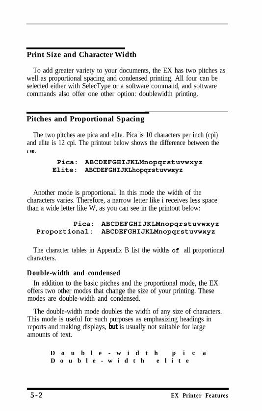
The double-width mode doubles the width of any size of characters.This mode is useful for such purposes as emphasizing headings inreports and making displays, but is usually not suitable for largeamounts of text.
D o u b l e - w i d t h p i c aD o u b l e - w i d t h e l i t e
5 - 2 EX Printer Features
Pica and elite can be reduced to about 60% of their normal widthwith the condensed mode. This mode is particularly useful for printingwide spreadsheets because condensed elite allows you up to 160characters on an 8-inch line and 272 on a 13½-inch line.
Condensed can be selected with SelecType, by setting a DIP switch(see Appendix E), or with a software command. Even if you turncondensed on with the DIP switch, you can still turn it off withSelecType or the software command.
Condensed pica gives more characters on a line.Condensed elite gives you even more.
Widening or narrowing the characters also widens or narrows thespaces between words and letters. Because word processors usuallycreate a left margin by printing spaces, you may need to change thenumber of characters on a line to keep the margins correct if youchange widths. For example, a left margin of five pica characters is thesame as one of six elite characters.
Special Effects and Emphasis
The EX offers two ways of emphasizing parts of your text and alsoallows you to use underlining, superscripts, and subscripts. Thesefeatures can be controlled only by software commands, but manyapplication programs can produce them if they are properly installed.
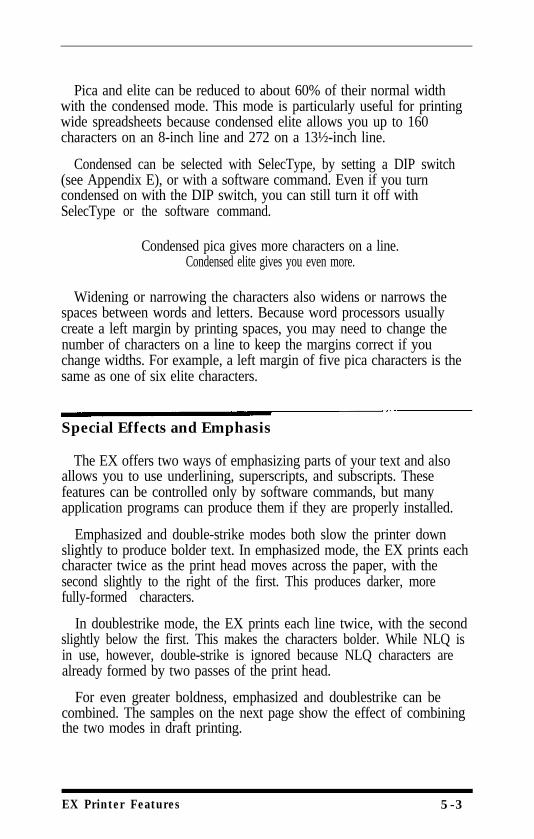
Emphasized and double-strike modes both slow the printer downslightly to produce bolder text. In emphasized mode, the EX prints eachcharacter twice as the print head moves across the paper, with thesecond slightly to the right of the first. This produces darker, morefully-formed characters.
In doublestrike mode, the EX prints each line twice, with the secondslightly below the first. This makes the characters bolder. While NLQ isin use, however, double-strike is ignored because NLQ characters arealready formed by two passes of the print head.
For even greater boldness, emphasized and doublestrike can becombined. The samples on the next page show the effect of combiningthe two modes in draft printing.
EX Printer Features 5-3
Superscripts and subscripts are valuable for such purposes as printingfootnote numbers or parts of mathematical formulas, and the underlinemode provides an automatic way of underlining fully any piece of text.It underlines spaces, subscripts, and superscripts without a break.
The example below shows underlining with text and combined withsuperscripts and subscripts in a mathematical formula.
Using Different Character Sets
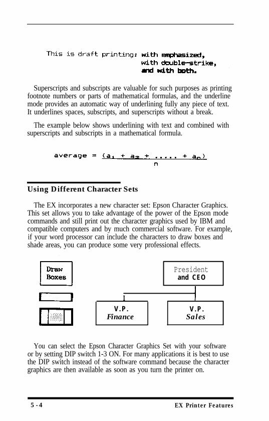
The EX incorporates a new character set: Epson Character Graphics.This set allows you to take advantage of the power of the Epson modecommands and still print out the character graphics used by IBM andcompatible computers and by much commercial software. For example,if your word processor can include the characters to draw boxes andshade areas, you can produce some very professional effects.
IV . P .
Finance
Presidentand CEO
V . P .Sales
You can select the Epson Character Graphics Set with your softwareor by setting DIP switch 1-3 ON. For many applications it is best to usethe DIP switch instead of the software command because the charactergraphics are then available as soon as you turn the printer on.
5-4 EX Printer Features
The other important change you can make to the standard characterset is to change some characters for ones commonly used in otherlanguages-chiefly European and Scandinavian-such as accentedcharacters and symbols. In Epson mode, eight international charactersets can be selected by setting DIP switches 1-6 to 1-8: USA, French,German, UK, Danish, Swedish, Italian, and Spanish. See Appendix E forthe DIP switch settings.
In Epson mode, these eight, and five more, can also be selected by asoftware command. The additional character sets are the following:Norwegian, a second Danish set, Japanese, a second Spanish set, andLatin American. A complete list of these characters is in Appendix B.
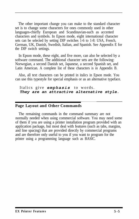
Also, all text characters can be printed in italics in Epson mode. Youcan use this typestyle for special emphasis or as an alternative typeface.
I t a l i c s g ive emphasis t o words .They are an attractive alternative style.
Page Layout and Other Commands
The remaining commands in the command summary are notnormally needed when using commercial software. You may need someof them if you are using a printer installation program provided with anapplication package, but most deal with features (such as tabs, margins,and line spacing) that are provided directly by commercial programsand are therefore only useful to you if you want to program for theprinter using a programming language such as BASIC.
EX Printer Features 5-5

5-6 EX Printer Features
Chapter 6Graphics and User-defined Characters
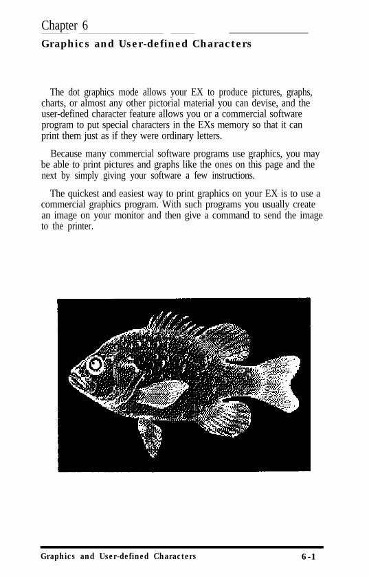
The dot graphics mode allows your EX to produce pictures, graphs,charts, or almost any other pictorial material you can devise, and theuser-defined character feature allows you or a commercial softwareprogram to put special characters in the EXs memory so that it canprint them just as if they were ordinary letters.
Because many commercial software programs use graphics, you maybe able to print pictures and graphs like the ones on this page and thenext by simply giving your software a few instructions.
The quickest and easiest way to print graphics on your EX is to use acommercial graphics program. With such programs you usually createan image on your monitor and then give a command to send the imageto the printer.
Graphics and User-defined Characters 6-1
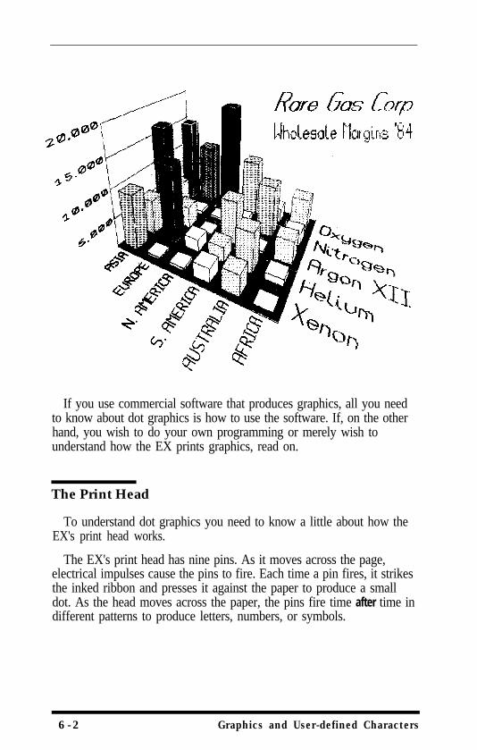
If you use commercial software that produces graphics, all you needto know about dot graphics is how to use the software. If, on the otherhand, you wish to do your own programming or merely wish tounderstand how the EX prints graphics, read on.
The Print Head
To understand dot graphics you need to know a little about how theEX's print head works.
The EX's print head has nine pins. As it moves across the page,electrical impulses cause the pins to fire. Each time a pin fires, it strikesthe inked ribbon and presses it against the paper to produce a smalldot. As the head moves across the paper, the pins fire time after time indifferent patterns to produce letters, numbers, or symbols.
6-2 Graphics and User-defined Characters
Dot patterns
The EXs print head is able to print graphics in addition to textbecause graphic images are formed on the EX about the same way thatpictures in newspapers and magazines are printed.
If you look closely at a newspaper photograph, you can see that it ismade up of many small dots. The EX also forms its images withpatterns of dots, as many as 240 dot positions per inch horizontally and72 dots vertically The images printed by the EX can, therefore, be asfinely detailed as the one on the first page of this chapter.
In its main graphics mode the EX prints one column of dots for eachcode it receives, and it uses only the top eight of the nine pins.Therefore, your graphics program must send codes for dot patterns, onenumber for each column in a line. For each of those columns the printhead prints the pattern of dots you have specified.
To print figures taller than eight dots, the print head makes more thanone pass. The printer prints one line, then advances the paper andprints another, just as it does with text.
To keep the print head from leaving gaps between the graphics linesas it does between the text lines, the line spacing must be changed toeliminate the space between lines. With a change in line spacing, theEX can print finely detailed graphic images that give no indication thatthey are made up of separate lines, each no more than 8/72nds of aninch tall.
Each pass of the print head prints one piece of the total pattern,which can be as tall or short and as wide or narrow as you desire. Youdon’t have to fill the whole page or even an entire line with yourgraphics figures. In fact, you can use as little or as much space as youlike for a figure and put it anywhere on the page.
Pin Labels
The graphics mode requires a method to tell the printer which pins tofire in each column. Since there are 256 possible combinations of eightpins, you need a numbering system that allows you to use a singlenumber to specify which of the 256 possible patterns you want. Thisnumbering system is shown in Figure 6-1 on the next page.
Graphics and Userdefined Characters 6-3
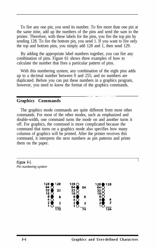
To fire any one pin, you send its number. To fire more than one pin atthe same time, add up the numbers of the pins and send the sum to theprinter. Therefore, with these labels for the pins, you fire the top pin bysending 128. To fire the bottom pin, you send 1. If you want to fire onlythe top and bottom pins, you simply add 128 and 1, then send 129.
By adding the appropriate label numbers together, you can fire anycombination of pins. Figure 61 shows three examples of how tocalculate the number that fires a particular pattern of pins.
With this numbering system, any combination of the eight pins addsup to a decimal number between 0 and 255, and no numbers areduplicated. Before you can put these numbers in a graphics program,however, you need to know the format of the graphics commands.
Graphics Commands
The graphics mode commands are quite different from most othercommands. For most of the other modes, such as emphasized anddouble-width, one command turns the mode on and another turns itoff. For graphics, the command is more complicated because thecommand that turns on a graphics mode also specifies how manycolumns of graphics will be printed. After the printer receives thiscommand, it interprets the next numbers as pin patterns and printsthem on the paper.
Figure 6-1.Pin numbering system
6-4 Graphics and User-defined Characters
The graphics command formatThere are several different graphics commands giving different
horizontal dot densities and printing speeds. Because the format isalmost the same for all the commands, however, the example herekeeps things simple by using only the singledensity graphicscommand, ESC K. In single-density graphics, there are 60 dots per inchhorizontally
The command to enter singledensity graphics mode is ESC K nl n2.In BASIC the command is given in this format:
ESC K specifies single-density graphics, and the next two numbers (nland n2) specify the number of columns reserved for graphics.
Column reservation numbersEven in single-density graphics mode, one 8-inch line can
accommodate 480 columns of graphics; in quadruple-density, almost2000 columns can fit on the same 8-inch line. Since the printer doesnot use decimal numbers larger than 255, the graphics commands usetwo numbers for reserving columns.
Because the commands are set up for two numbers, you must supplytwo even if you need only one. When you need fewer than 256columns, it is easy to determine nl and n2: nl is the number ofcolumns you are reserving and n2 is zero. For example, to send data for200 columns of graphics, nl is 200 and n2 is 0.
For more than 256 columns of graphics data, n2 is the number ofcomplete groups of 256 columns, and nl is the number of columns tocomplete the line. For example, to send 1632 columns of graphic data,nl is 96 and n2 is 6 because 96 + (6 x 256) = 1632.
You can calculate both nl and n2 by dividing the total number ofcolumns by 256. The quotient is n2 and the remainder is nl. If you areusing a programming language with MOD (modulus) and INT (integer)functions, you can use the following formulas, in which n is the totalnumber of columns.
nl = n MOD 256n2 = INT (n/256)
Graphics and User-defined Characters 6-5
Graphics dataAfter receiving a graphics command such as ESC K nl n2, the printer
prints the number of codes specified by nl and n2 as graphics data, nomatter what codes they are. This means that you must be sure tosupply exactly the right amount of graphics data. If you supply too little,the printer will stop and wait for more data and will seem to be locked.The next data sent will then be printed as graphics, even if it is reallytext. On the other hand, if you supply too much graphics data, theexcess will be printed as regular text.
Simple Graphics Programming
The first example in this section shows how a graphics command,column reservation numbers, and data can be used to print a single lineof graphics. The example is a BASIC program. If you prefer anotherprogramming language, the principles are exactly the same. Therefore,you can easily adapt the program to the language you prefer.
The first line of the program specifies single-density graphics for 40columns:
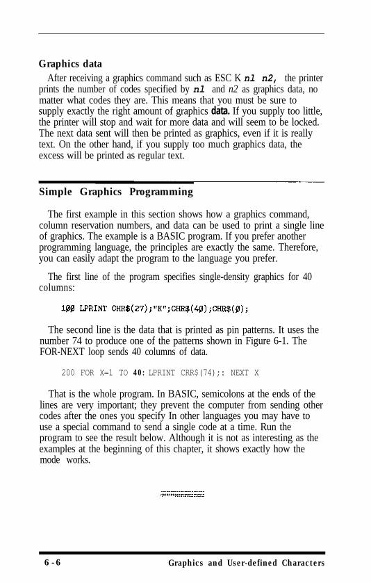
The second line is the data that is printed as pin patterns. It uses thenumber 74 to produce one of the patterns shown in Figure 6-1. TheFOR-NEXT loop sends 40 columns of data.
200 FOR X=1 TO 40: LPRINT CRR$(74);: NEXT X
That is the whole program. In BASIC, semicolons at the ends of thelines are very important; they prevent the computer from sending othercodes after the ones you specify In other languages you may have touse a special command to send a single code at a time. Run theprogram to see the result below. Although it is not as interesting as theexamples at the beginning of this chapter, it shows exactly how themode works.
6-6 Graphics and User-defined Characters
WIDTH statementsSome software (including most versions of BASIC) automatically
inserts carriage return and line feed codes after every 80 or 130characters. This is usually no problem with text, but it can spoil yourgraphics. Two extra columns of graphics are printed in the middle of theones you send, and are left over and printed as text.
In some versions of BASIC you can prevent unwanted control codesin graphics by putting a WIDTH statement at the beginning of allgraphics programs. The format in many forms of BASIC is eitherWIDTH “LPTI:“, 255 or WIDTH LPRINT 255. Check your softwaremanual for the proper format.
Printing taller patternsThe next example shows how several lines of graphics can be formed
into a figure taller than eight dots. It uses programming techniques forproducing textured or repetitive patterns.
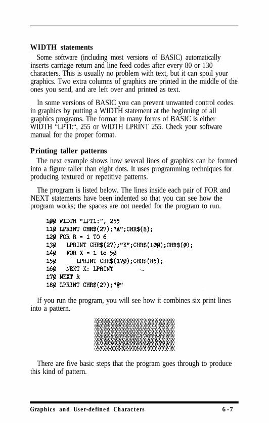
The program is listed below. The lines inside each pair of FOR andNEXT statements have been indented so that you can see how theprogram works; the spaces are not needed for the program to run.
If you run the program, you will see how it combines six print linesinto a pattern.
There are five basic steps that the program goes through to producethis kind of pattern.
Graphics and User-defined Characters 6-7
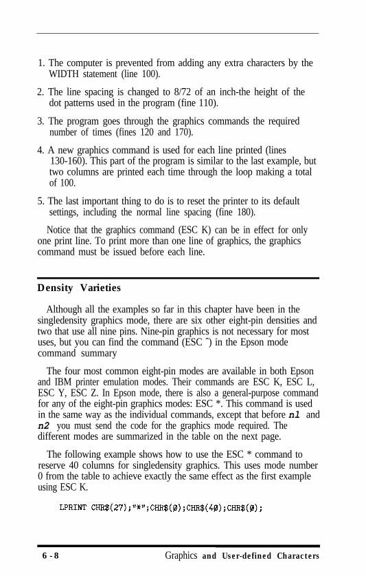
1. The computer is prevented from adding any extra characters by theWIDTH statement (line 100).
2. The line spacing is changed to 8/72 of an inch-the height of thedot patterns used in the program (fine 110).
3. The program goes through the graphics commands the requirednumber of times (fines 120 and 170).
4. A new graphics command is used for each line printed (lines130-160). This part of the program is similar to the last example, buttwo columns are printed each time through the loop making a totalof 100.
5. The last important thing to do is to reset the printer to its defaultsettings, including the normal line spacing (fine 180).
Notice that the graphics command (ESC K) can be in effect for onlyone print line. To print more than one line of graphics, the graphicscommand must be issued before each line.
Density Varieties
Although all the examples so far in this chapter have been in thesingledensity graphics mode, there are six other eight-pin densities andtwo that use all nine pins. Nine-pin graphics is not necessary for mostuses, but you can find the command (ESC ˆ) in the Epson modecommand summary
The four most common eight-pin modes are available in both Epsonand IBM printer emulation modes. Their commands are ESC K, ESC L,ESC Y, ESC Z. In Epson mode, there is also a general-purpose commandfor any of the eight-pin graphics modes: ESC *. This command is usedin the same way as the individual commands, except that before nl andn2 you must send the code for the graphics mode required. Thedifferent modes are summarized in the table on the next page.
The following example shows how to use the ESC * command toreserve 40 columns for singledensity graphics. This uses mode number0 from the table to achieve exactly the same effect as the first exampleusing ESC K.
6 -8 Graphics and User-defined Characters
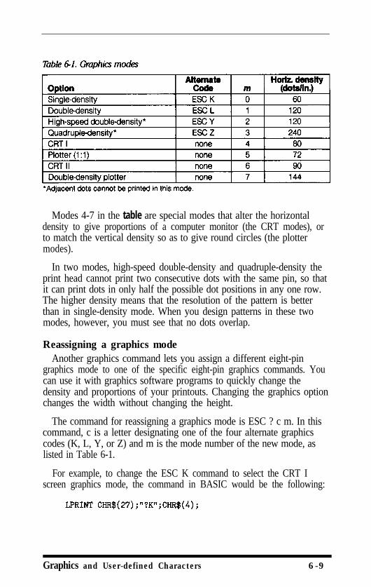
Modes 4-7 in the table are special modes that alter the horizontaldensity to give proportions of a computer monitor (the CRT modes), orto match the vertical density so as to give round circles (the plottermodes).
In two modes, high-speed double-density and quadruple-density theprint head cannot print two consecutive dots with the same pin, so thatit can print dots in only half the possible dot positions in any one row.The higher density means that the resolution of the pattern is betterthan in single-density mode. When you design patterns in these twomodes, however, you must see that no dots overlap.
Reassigning a graphics modeAnother graphics command lets you assign a different eight-pin
graphics mode to one of the specific eight-pin graphics commands. Youcan use it with graphics software programs to quickly change thedensity and proportions of your printouts. Changing the graphics optionchanges the width without changing the height.
The command for reassigning a graphics mode is ESC ? c m. In thiscommand, c is a letter designating one of the four alternate graphicscodes (K, L, Y, or Z) and m is the mode number of the new mode, aslisted in Table 6-1.
For example, to change the ESC K command to select the CRT Iscreen graphics mode, the command in BASIC would be the following:
Graphics and User-defined Characters 6-9
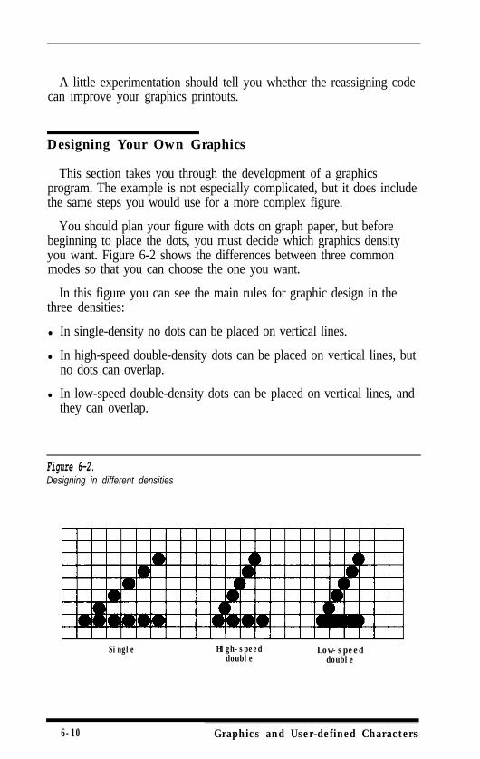
A little experimentation should tell you whether the reassigning codecan improve your graphics printouts.
Designing Your Own Graphics
This section takes you through the development of a graphicsprogram. The example is not especially complicated, but it does includethe same steps you would use for a more complex figure.
You should plan your figure with dots on graph paper, but beforebeginning to place the dots, you must decide which graphics densityyou want. Figure 6-2 shows the differences between three commonmodes so that you can choose the one you want.
In this figure you can see the main rules for graphic design in thethree densities:
l In single-density no dots can be placed on vertical lines.
l In high-speed double-density dots can be placed on vertical lines, butno dots can overlap.
l In low-speed double-density dots can be placed on vertical lines, andthey can overlap.
Figure 6-2.Designing in different densities
SingleI
High-speeddouble
Low-speeddouble
6-10 Graphics and User-defined Characters

Now look at Figure 6-3, a design for a high-speed doubledensitydesign. It should point you in the right direction for your own designs.
After plotting the dots on a grid, you calculate the numbers for eachpin pattern by dividing the design grid into separate print lines. For thearrow design, the grid was divided into two lines, each seven dots high.Then each column was examined to calculate the graphics data. Theresults for the first line are shown in figure 6-4. The pin values are onthe left and the sums at the bottom of each column.
Graphics and User-defined Characters 6-11
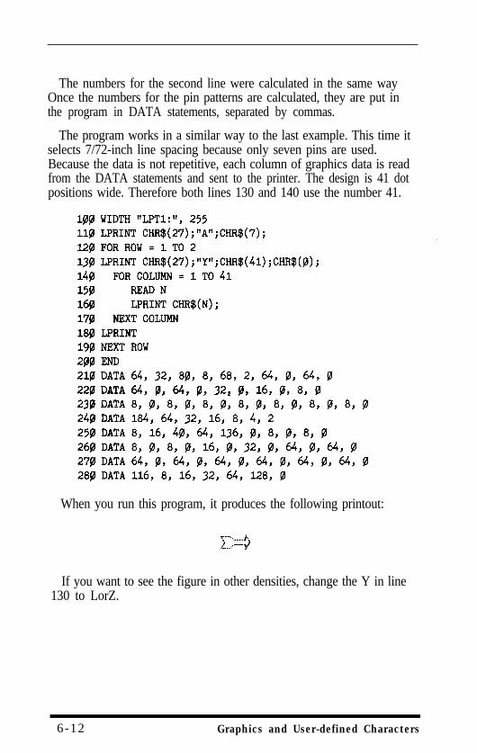
The numbers for the second line were calculated in the same wayOnce the numbers for the pin patterns are calculated, they are put inthe program in DATA statements, separated by commas.
The program works in a similar way to the last example. This time itselects 7/72-inch line spacing because only seven pins are used.Because the data is not repetitive, each column of graphics data is readfrom the DATA statements and sent to the printer. The design is 41 dotpositions wide. Therefore both lines 130 and 140 use the number 41.
When you run this program, it produces the following printout:
If you want to see the figure in other densities, change the Y in line130 to LorZ.
6-12 Graphics and User-defined Characters
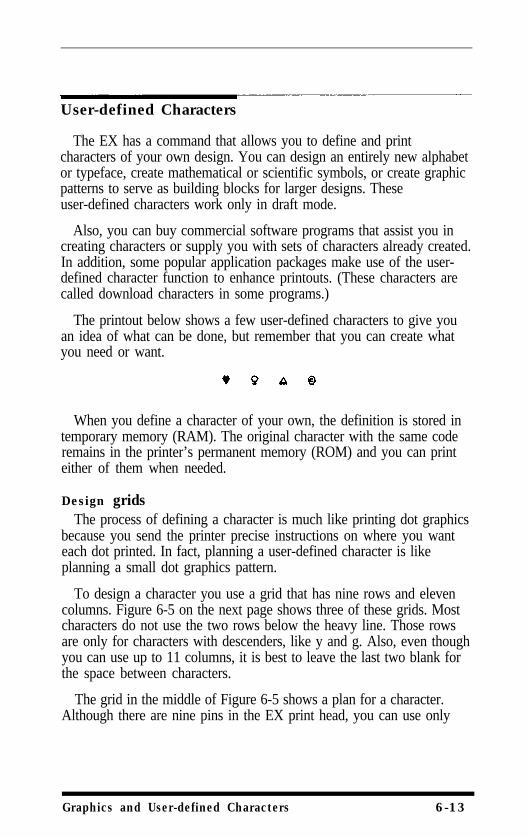
User-defined Characters
The EX has a command that allows you to define and printcharacters of your own design. You can design an entirely new alphabetor typeface, create mathematical or scientific symbols, or create graphicpatterns to serve as building blocks for larger designs. Theseuser-defined characters work only in draft mode.
Also, you can buy commercial software programs that assist you increating characters or supply you with sets of characters already created.In addition, some popular application packages make use of the user-defined character function to enhance printouts. (These characters arecalled download characters in some programs.)
The printout below shows a few user-defined characters to give youan idea of what can be done, but remember that you can create whatyou need or want.
When you define a character of your own, the definition is stored intemporary memory (RAM). The original character with the same coderemains in the printer’s permanent memory (ROM) and you can printeither of them when needed.
Design gridsThe process of defining a character is much like printing dot graphics
because you send the printer precise instructions on where you wanteach dot printed. In fact, planning a user-defined character is likeplanning a small dot graphics pattern.
To design a character you use a grid that has nine rows and elevencolumns. Figure 6-5 on the next page shows three of these grids. Mostcharacters do not use the two rows below the heavy line. Those rowsare only for characters with descenders, like y and g. Also, even thoughyou can use up to 11 columns, it is best to leave the last two blank forthe space between characters.
The grid in the middle of Figure 6-5 shows a plan for a character.Although there are nine pins in the EX print head, you can use only
Graphics and User-defined Characters 6-13
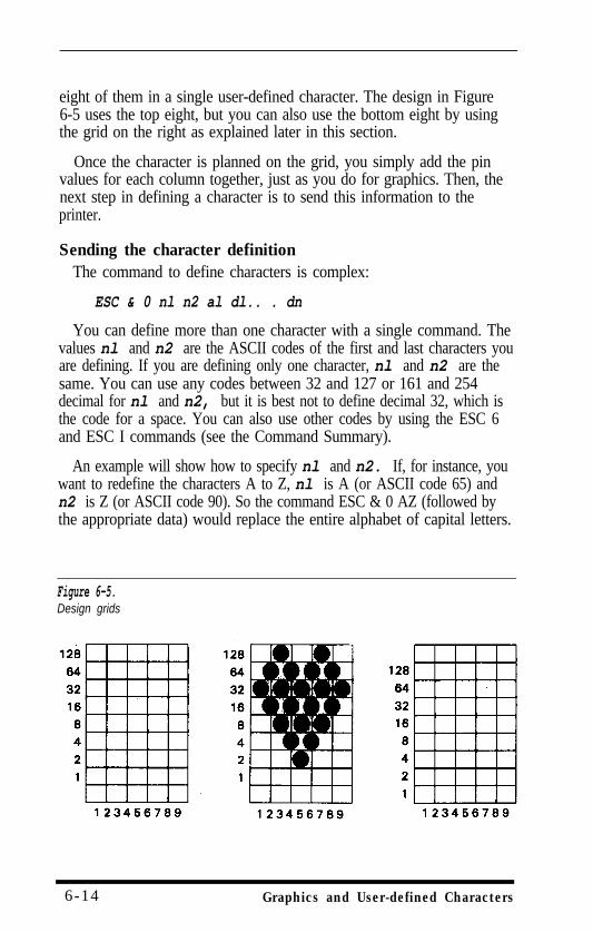
eight of them in a single user-defined character. The design in Figure6-5 uses the top eight, but you can also use the bottom eight by usingthe grid on the right as explained later in this section.
Once the character is planned on the grid, you simply add the pinvalues for each column together, just as you do for graphics. Then, thenext step in defining a character is to send this information to theprinter.
Sending the character definitionThe command to define characters is complex:
ESC & 0 nl n2 al dl.. . dn
You can define more than one character with a single command. Thevalues nl and n2 are the ASCII codes of the first and last characters youare defining. If you are defining only one character, nl and n2 are thesame. You can use any codes between 32 and 127 or 161 and 254decimal for nl and n2, but it is best not to define decimal 32, which isthe code for a space. You can also use other codes by using the ESC 6and ESC I commands (see the Command Summary).
An example will show how to specify nl and n2. If, for instance, youwant to redefine the characters A to Z, nl is A (or ASCII code 65) andn2 is Z (or ASCII code 90). So the command ESC & 0 AZ (followed bythe appropriate data) would replace the entire alphabet of capital letters.
Figure 6-5.Design grids
6-14 Graphics and User-defined Characters
Following the specification of the range of characters to be defined inthis command is one number (al) that specifies the width of thecharacter and whether it uses the top eight pins or the bottom eight pins.
The last part of the character definition is the actual data that definesthe dot patterns for each column of each character. Since a charactercan use up to eleven columns, you must supply eleven data numbersfor each character even if some of the columns are blank.
An example character definition program should make the processclear:
In line 100, the ESC x 0 command selects draft style printing. Theactual character definition starts in line 110. The two at signs (@) in line120 are nl and n2, the range of characters being defined (in this case, arange of one). Line 130 contains al.
The information about the character design (which is contained in thedata statements at the end of the program) is sent to the printer in theloop between lines 140 and 160.
This example program defines a heart and places it in the area ofRAM reserved for ASCII code 64, which corresponds to the at sign inthe characters in the ROM. The next part of the program (lines 170-210)prints out a threeline sample. The first and third lines contain at signs;the second line contains the heart that was defined.
Graphics and User-defined Characters 6-15
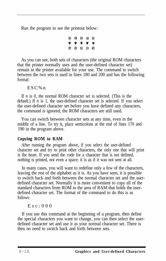
Run the program to see the printout below:
As you can see, both sets of characters (the original ROM charactersthat the printer normally uses and the user-defined character set)remain in the printer available for your use. The command to switchbetween the two sets is used in lines 180 and 200 and has the followingformat:
E S C % n
If n is 0, the normal ROM character set is selected. (This is thedefault.) If n is 1, the user-defined character set is selected. If you selectthe user-defined character set before you have defined any characters,the command is ignored; the ROM characters are still used.
You can switch between character sets at any time, even in themiddle of a line. To try it, place semicolons at the end of lines 170 and190 in the program above.
Copying ROM to RAMAfter running the program above, if you select the user-defined
character set and try to print other characters, the only one that will printis the heart. If you send the code for a character that is not defined,nothing is printed, not even a space; it is as if it was not sent at all.
In many cases, you will want to redefine only a few of the characters,leaving the rest of the alphabet as it is. As you have seen, it is possibleto switch back and forth between the normal character set and the user-defined character set. Normally it is more convenient to copy all of thestandard characters from ROM to the area of RAM that holds the user-defined character set. The format of the command to do this is asfollows:
E s c : 0 0 0
If you use this command at the beginning of a program, then definethe special characters you want to change, you can then select the user-defined character set and use it as your normal character set. There isthen no need to switch back and forth between sets.
6-16 Graphics and User-defined Characters
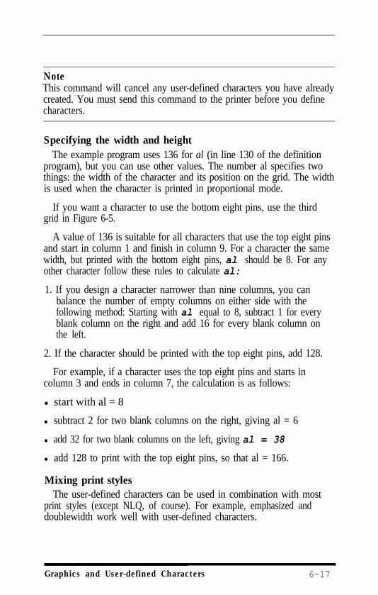
NoteThis command will cancel any user-defined characters you have alreadycreated. You must send this command to the printer before you definecharacters.
Specifying the width and heightThe example program uses 136 for al (in line 130 of the definition
program), but you can use other values. The number al specifies twothings: the width of the character and its position on the grid. The widthis used when the character is printed in proportional mode.
If you want a character to use the bottom eight pins, use the thirdgrid in Figure 6-5.
A value of 136 is suitable for all characters that use the top eight pinsand start in column 1 and finish in column 9. For a character the samewidth, but printed with the bottom eight pins, al should be 8. For anyother character follow these rules to calculate al:
1. If you design a character narrower than nine columns, you canbalance the number of empty columns on either side with thefollowing method: Starting with al equal to 8, subtract 1 for everyblank column on the right and add 16 for every blank column onthe left.
2. If the character should be printed with the top eight pins, add 128.
For example, if a character uses the top eight pins and starts incolumn 3 and ends in column 7, the calculation is as follows:
l start with al = 8
l subtract 2 for two blank columns on the right, giving al = 6
l add 32 for two blank columns on the left, giving al = 38
l add 128 to print with the top eight pins, so that al = 166.
Mixing print stylesThe user-defined characters can be used in combination with most
print styles (except NLQ, of course). For example, emphasized anddoublewidth work well with user-defined characters.
Graphics and User-defined Characters 6-17
The sample below shows the heart character printed in various styles.
Other considerationsKeep in mind that user-defined characters are stored in RAM, which
is not permanent. Whenever the printer power is turned off or yourcomputer sends an initialization (INIT) signal, all of the user-definedcharacters are lost. For example, some computers send an INIT signaleach time BASIC is loaded or when certain application programs startup, and most computers do it if you have to reset them. If the programresets the printer with the ESC @ command, the ROM set is selected,but the user-defined characters are not lost.
The IBM printer emulation mode has a different method of definingcharacters. See page A-44 in the Command Summary if you areinterested.
6-18 Graphics and User-defined Characters
Appendix ACommand Summary
This appendix lists and describes all the commands, both Epson(ESC/P) mode and IBM printer emulation mode, available on the EX.This summary is in two parts. The first part lists each command innumerical order and gives the page number where it is fully describedin the second part of this appendix.
If you know which command you are looking for, consult thenumerical list to find the page number where it is described. The QuickReference Card at the end of the book also contains a list of thecommands divided by topic, with page number references that directyou to full explanations of the commands. The numerical list and theQuick Reference Card also show the differences between the Epsonmode and the IBM printer emulation mode.
The second part of this appendix lists and describes Epson modecommands and IBM printer emulation mode commands separately andthe commands are divided into the following subjects:
Printer OperationData ControlVertical MotionHorizontal MotionOverall Printing StylePrint Size
Print EnhancementWord ProcessingCharacter SetsUser-defined CharactersGraphics
Each command has a format section and a comment section. Theformat section gives the ASCII, decimal, and hexadecimal values for thecommand; the comment section describes the effect of the commandand gives any additional information necessary for using it.
All three formats are equivalent, and it should be easy to pick the onemost suited to your purpose.
Command Summary A - l
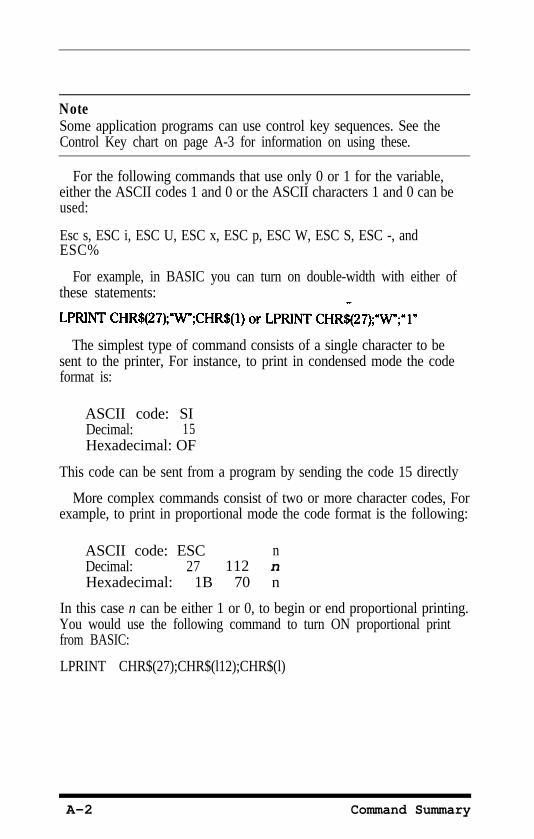
NoteSome application programs can use control key sequences. See theControl Key chart on page A-3 for information on using these.
For the following commands that use only 0 or 1 for the variable,either the ASCII codes 1 and 0 or the ASCII characters 1 and 0 can beused:
Esc s, ESC i, ESC U, ESC x, ESC p, ESC W, ESC S, ESC -, andESC%
For example, in BASIC you can turn on double-width with either ofthese statements:
The simplest type of command consists of a single character to besent to the printer, For instance, to print in condensed mode the codeformat is:
ASCII code: SIDecimal: 15Hexadecimal: OF
This code can be sent from a program by sending the code 15 directly
More complex commands consist of two or more character codes, Forexample, to print in proportional mode the code format is the following:
ASCII code: ESC nDecimal: 27 112 nHexadecimal: 1B 70 n
In this case n can be either 1 or 0, to begin or end proportional printing.You would use the following command to turn ON proportional printfrom BASIC:
LPRINT CHR$(27);CHR$(l12);CHR$(l)
A-2 Command Summary
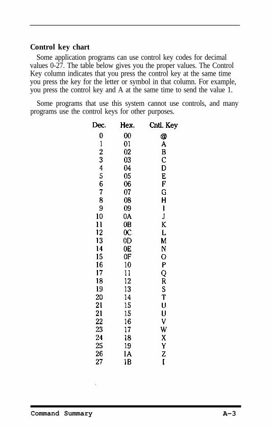
Control key chartSome application programs can use control key codes for decimal
values 0-27. The table below gives you the proper values. The ControlKey column indicates that you press the control key at the same timeyou press the key for the letter or symbol in that column. For example,you press the control key and A at the same time to send the value 1.
Some programs that use this system cannot use controls, and manyprograms use the control keys for other purposes.
Command Summary A-3
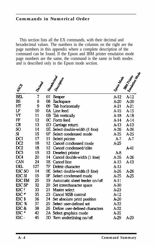
Commands in Numerical Order
This section lists all the EX commands, with their decimal andhexadecimal values. The numbers in the columns on the right are thepage numbers in this appendix where a complete description of thecommand can be found. If the Epson and IBM printer emulation modepage numbers are the same, the command is the same in both modesand is described only in the Epson mode section.
A -4 Command Summary
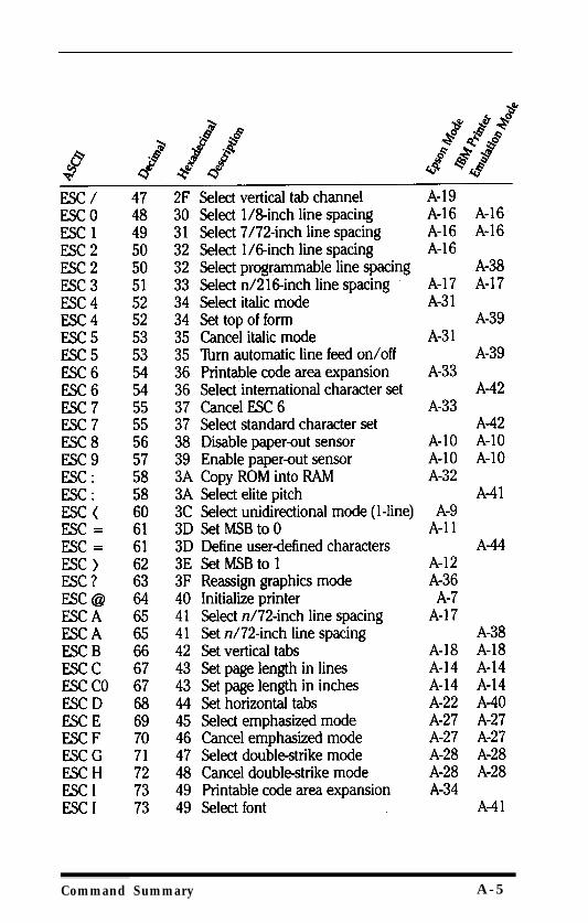
Command Summary A-5
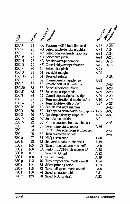
A-6 Command Summary
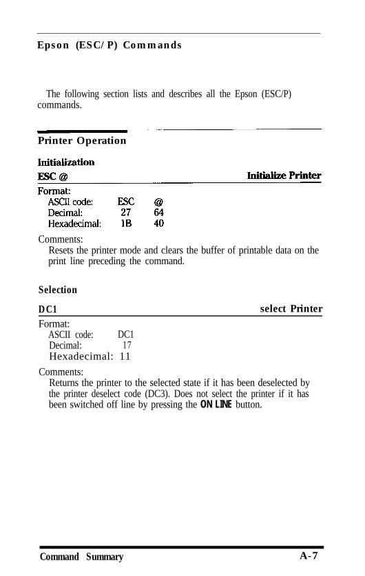
Epson (ESC/P) Commands
The following section lists and describes all the Epson (ESC/P)commands.
Printer Operation
Comments:Resets the printer mode and clears the buffer of printable data on theprint line preceding the command.
Selection
DC1 select PrinterFormat:
ASCII code: DC1Decimal: 17Hexadecimal: 11
Comments:Returns the printer to the selected state if it has been deselected bythe printer deselect code (DC3). Does not select the printer if it hasbeen switched off line by pressing the ON LINE button.
Command Summary A-7
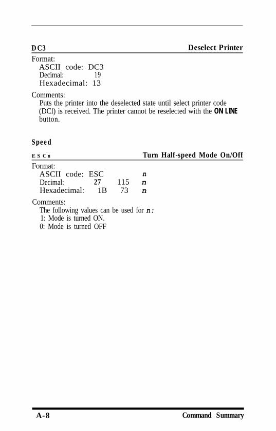
DC3Format:
ASCII code: DC3Decimal: 19Hexadecimal: 13
Deselect Printer
Comments:Puts the printer into the deselected state until select printer code(DCl) is received. The printer cannot be reselected with the ON LINEbutton.
Speed
E S C 8
Format:Turn Half-speed Mode On/Off
ASCII code: ESC nDecimal: 27 115 nHexadecimal: 1B 73 n
Comments:The following values can be used for n:1: Mode is turned ON.0: Mode is turned OFF
A-8 Command Summary
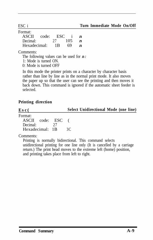
ESC i Turn Immediate Mode On/OffFormat:
ASCII code: ESC i nDecimal: 27 105 nHexadecimal: 1B 69 n
Comments:The following values can be used for n:1: Mode is turned ON.0: Mode is turned OFFIn this mode the printer prints on a character by character basisrather than line by line as in the normal print mode. It also movesthe paper up so that the user can see the printing and then moves itback down. This command is ignored if the automatic sheet feeder isselected.
Printing direction
E s c (Format:
Select Unidirectional Mode (one line)
ASCII code: ESC (Decimal: 27Hexadecimal: 1B 3C
Comments:Printing is normally bidirectional. This command selectsunidirectional printing for one line only (It is cancelled by a carriagereturn.) The print head moves to the extreme left (home) position,and printing takes place from left to right.
Command Summary A-9
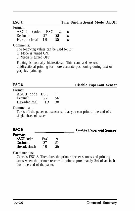
ESC U Turn Unidirectional Mode On/OffFormat:
ASCII code: ESC U nDecimal: 27Hexadecimal: 1B
Comments:The following values can be used for n:1: Mode is turned ON.0: Mode is turned OFFPrinting is normally bidirectional. This command selectsunidirectional printing for more accurate positioning during text orgraphics printing.
ESC 8Format:
ASCII code: ESC 8Decimal: 27 56Hexadecimal: 1B 38
Disable Paper-out Sensor
Comments:Turns off the paper-out sensor so that you can print to the end of asingle sheet of paper.
Comments :Cancels ESC 8. Therefore, the printer beeper sounds and printingstops when the printer reaches a point approximately 3/4 of an inchfrom the end of the paper,
A-10 Command Summary
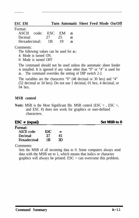
ESC EM Turn Automatic Sheet Feed Mode On/OffFormat:
ASCII code: ESC EM nDecimal: 27 25 nHexadecimal: 1B 19 n
Comments:The following values can be used for n:4: Mode is turned ON.0: Mode is turned OFFThe command should not be used unless the automatic sheet feederis installed. It is ignored if any value other than “0” or “4” is used forn. The command overrides the setting of DIP switch 2-2.The variables are the characrers “0” (48 decimal or 30 hex) and “4”(52 decimal or 34 hex). Do not use 1 decimal, 01 hex, 4 decimal, or04 hex.
MSB control
Note: MSB is the Most Significant Bit. MSB control (ESC = , ESC >,and ESC #) does not work for graphics or user-definedcharacters.
Comments:Sets the MSB of all incoming data to 0. Some computers always senddata with the MSB set to 1, which means that italics or charactergraphics will always be printed. ESC = can overcome this problem.
Command Summary A-11
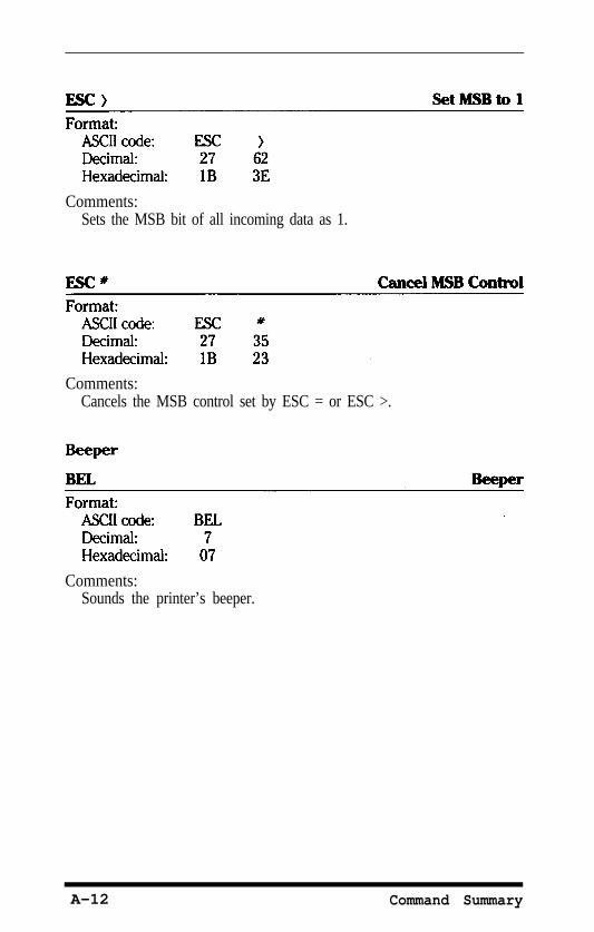
Comments:Sets the MSB bit of all incoming data as 1.
Comments:Cancels the MSB control set by ESC = or ESC >.
Comments:Sounds the printer’s beeper.
A-12 Command Summary
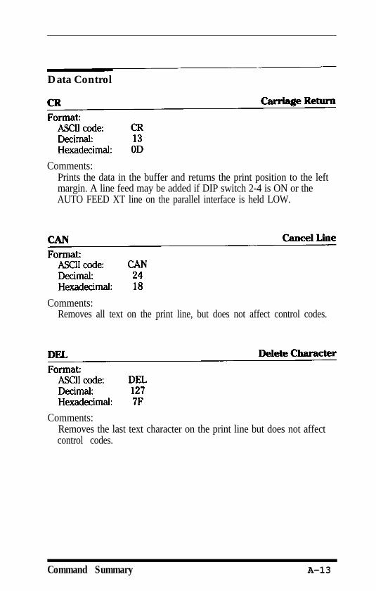
Data Control
Comments:Prints the data in the buffer and returns the print position to the leftmargin. A line feed may be added if DIP switch 2-4 is ON or theAUTO FEED XT line on the parallel interface is held LOW.
Comments:Removes all text on the print line, but does not affect control codes.
Comments:Removes the last text character on the print line but does not affectcontrol codes.
Command Summary A-13
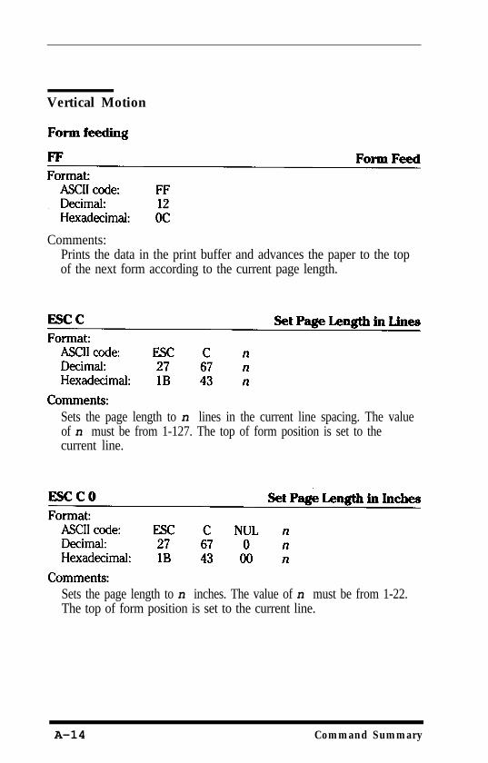
Vertical Motion
Comments:Prints the data in the print buffer and advances the paper to the topof the next form according to the current page length.
Sets the page length to n lines in the current line spacing. The valueof n must be from 1-127. The top of form position is set to thecurrent line.
Sets the page length to n inches. The value of n must be from 1-22.The top of form position is set to the current line.
A-14 Command Summary
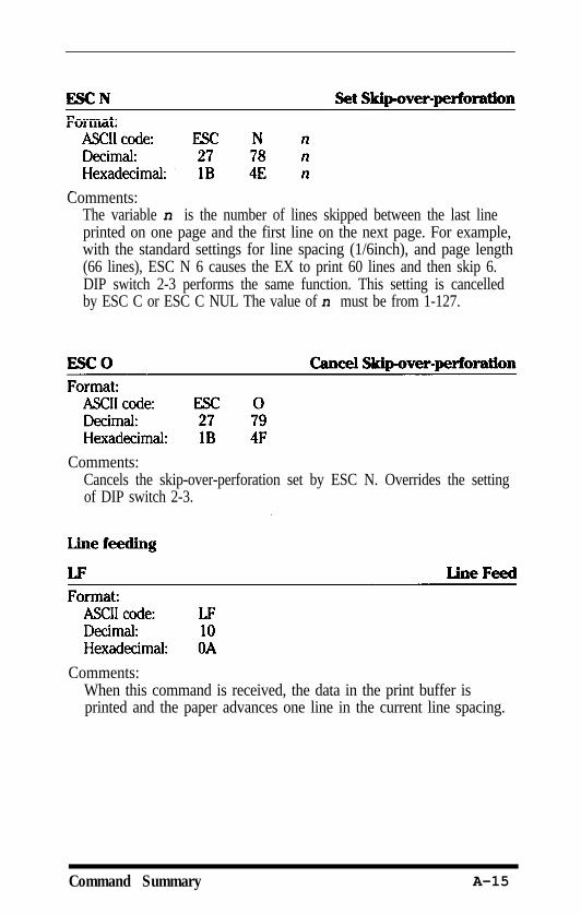
Comments:The variable n is the number of lines skipped between the last lineprinted on one page and the first line on the next page. For example,with the standard settings for line spacing (1/6inch), and page length(66 lines), ESC N 6 causes the EX to print 60 lines and then skip 6.DIP switch 2-3 performs the same function. This setting is cancelledby ESC C or ESC C NUL The value of n must be from 1-127.
Comments:Cancels the skip-over-perforation set by ESC N. Overrides the settingof DIP switch 2-3.
Comments:When this command is received, the data in the print buffer isprinted and the paper advances one line in the current line spacing.
Command Summary A-15
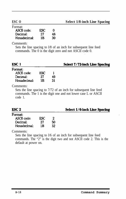
ESC OFormat:
Select 1/8-inch Line Spacing
Comments:Sets the line spacing to l/8 of an inch for subsequent line feedcommands. The 0 is the digit zero and not ASCII code 0.
Comments:Sets the line spacing to 7/72 of an inch for subsequent line feedcommands. The 1 is the digit one and not lower case L or ASCIIcode 1.
Comments:Sets the line spacing to l/6 of an inch for subsequent line feedcommands. The “2” is the digit two and not ASCII code 2. This is thedefault at power on.
A-16 Command Summary
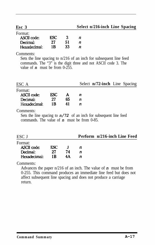
Esc 3Format:
Select n/216-inch Line Spacing
Comments:Sets the line spacing to n/216 of an inch for subsequent line feedcommands. The “3” is the digit three and not ASCII code 3. Thevalue of n must be from 0-255.
ESC AFormat:
Select n/72-inch Line Spacing
Comments:Sets the line spacing to n/72 of an inch for subsequent line feedcommands. The value of n must be from 0-85.
ESC JFormat:
Perform n/216-inch Line Feed
Comments:Advances the paper n/216 of an inch. The value of n must be from0-255. This command produces an immediate line feed but does notaffect subsequent line spacing and does not produce a carriagereturn.
Command Summary A-17
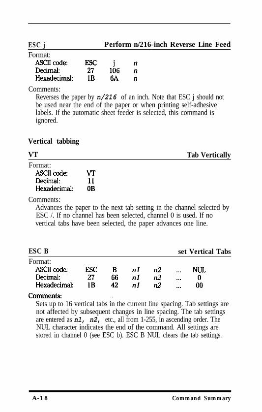
ESC j Perform n/216-inch Reverse Line FeedFormat:
Comments:Reverses the paper by n/216 of an inch. Note that ESC j should notbe used near the end of the paper or when printing self-adhesivelabels. If the automatic sheet feeder is selected, this command isignored.
Vertical tabbing
VT Tab VerticallyFormat:
Comments:Advances the paper to the next tab setting in the channel selected byESC /. If no channel has been selected, channel 0 is used. If novertical tabs have been selected, the paper advances one line.
ESC BFormat:
set Vertical Tabs
Sets up to 16 vertical tabs in the current line spacing. Tab settings arenot affected by subsequent changes in line spacing. The tab settingsare entered as nl, n2, etc., all from 1-255, in ascending order. TheNUL character indicates the end of the command. All settings arestored in channel 0 (see ESC b). ESC B NUL clears the tab settings.
A-18 Command Summary
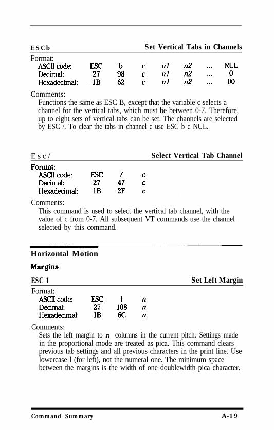
ESCb Set Vertical Tabs in ChannelsFormat:
Comments:Functions the same as ESC B, except that the variable c selects achannel for the vertical tabs, which must be between 0-7. Therefore,up to eight sets of vertical tabs can be set. The channels are selectedby ESC /. To clear the tabs in channel c use ESC b c NUL.
E s c / Select Vertical Tab Channel
Comments:This command is used to select the vertical tab channel, with thevalue of c from 0-7. All subsequent VT commands use the channelselected by this command.
Horizontal Motion
ESC 1Format:
Set Left Margin
Comments:Sets the left margin to n columns in the current pitch. Settings madein the proportional mode are treated as pica. This command clearsprevious tab settings and all previous characters in the print line. Uselowercase l (for left), not the numeral one. The minimum spacebetween the margins is the width of one doublewidth pica character.
Command Summary A-19
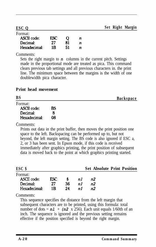
ESC QFormat:
Set Right Margin
Comments:Sets the right margin to n columns in the current pitch. Settingsmade in the proportional mode are treated as pica. This commandclears previous tab settings and all previous characters in. the printline. The minimum space between the margins is the width of onedoublewidth pica character.
Print head movement
BSFormat:
Backspace
Comments:Prints out data in the print buffer, then moves the print position onespace to the left. Backspacing can be performed up to, but notbeyond, the left margin setting. The BS code is also ignored if ESC a,2, or 3 has been sent. In Epson mode, if this code is receivedimmediately after graphics printing, the print position of subsequentdata is moved back to the point at which graphics printing started.
ESC $ Set Absolute Print PositionFormat:
Comments:This sequence specifies the distance from the left margin thatsubsequent characters are to be printed, using this formula: totalnumber of dots = nl + (n2 x 256). Each unit equals 1/60th of aninch. The sequence is ignored and the previous setting remainseffective if the position specified is beyond the right margin.
A-20 Command Summary
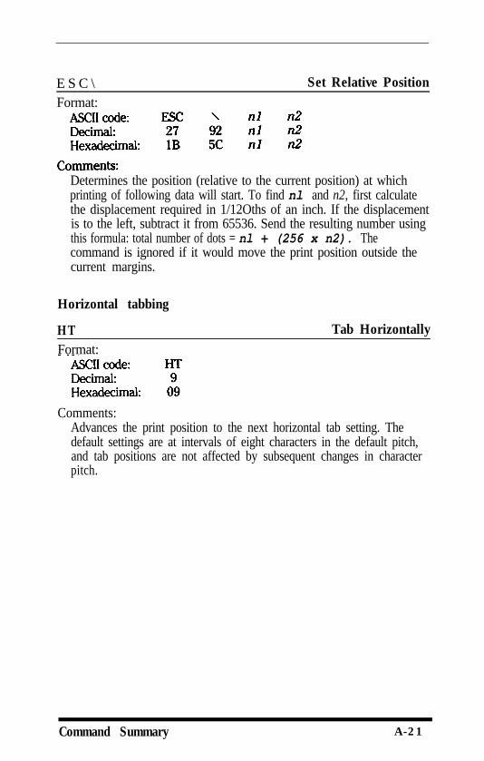
E S C \Format:
Set Relative Position
Determines the position (relative to the current position) at whichprinting of following data will start. To find nl and n2, first calculatethe displacement required in 1/12Oths of an inch. If the displacementis to the left, subtract it from 65536. Send the resulting number usingthis formula: total number of dots = nl + (256 x n2). Thecommand is ignored if it would move the print position outside thecurrent margins.
Horizontal tabbing
HTFormat:
Tab Horizontally
Comments:Advances the print position to the next horizontal tab setting. Thedefault settings are at intervals of eight characters in the default pitch,and tab positions are not affected by subsequent changes in characterpitch.
Command Summary A-21
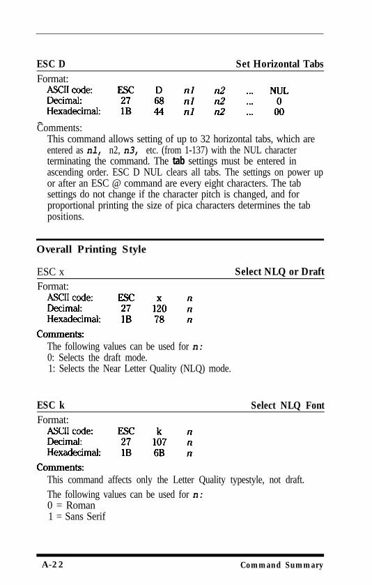
ESC D Set Horizontal TabsFormat:
Comments:This command allows setting of up to 32 horizontal tabs, which areentered as nl, n2, n3, etc. (from 1-137) with the NUL characterterminating the command. The tab settings must be entered inascending order. ESC D NUL clears all tabs. The settings on power upor after an ESC @ command are every eight characters. The tabsettings do not change if the character pitch is changed, and forproportional printing the size of pica characters determines the tabpositions.
Overall Printing Style
ESC xFormat:
Select NLQ or Draft
The following values can be used for n:0: Selects the draft mode.1: Selects the Near Letter Quality (NLQ) mode.
ESC kFormat:
Select NLQ Font
This command affects only the Letter Quality typestyle, not draft.The following values can be used for n:0 = Roman1 = Sans Serif
A-22 Command Summary
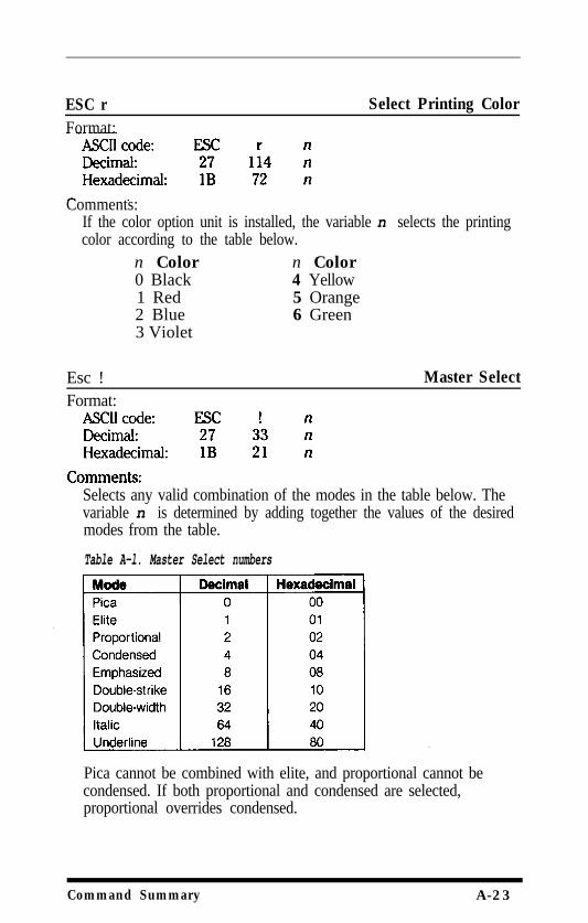
ESC rFormat:
Select Printing Color
Comments:If the color option unit is installed, the variable n selects the printingcolor according to the table below.
n Color n Color0 Black 4 Yellow1 Red 5 Orange2 Blue 6 Green3 Violet
Esc !Format:
Master Select
Selects any valid combination of the modes in the table below. Thevariable n is determined by adding together the values of the desiredmodes from the table.
Table A-l. Master Select numbers
Pica cannot be combined with elite, and proportional cannot becondensed. If both proportional and condensed are selected,proportional overrides condensed.
Command Summary A-23
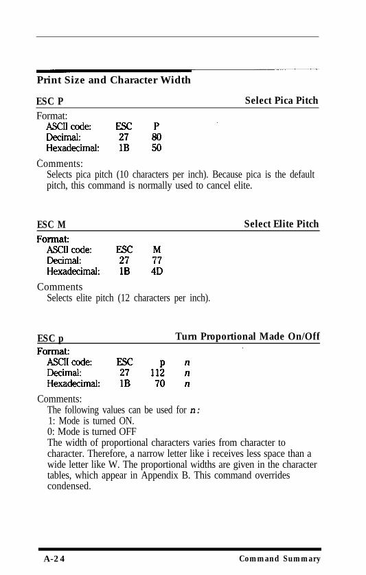
Print Size and Character Width
ESC P Select Pica PitchFormat:
Comments:Selects pica pitch (10 characters per inch). Because pica is the defaultpitch, this command is normally used to cancel elite.
ESC M Select Elite Pitch
CommentsSelects elite pitch (12 characters per inch).
ESC p Turn Proportional Made On/Off
Comments:The following values can be used for n:1: Mode is turned ON.0: Mode is turned OFFThe width of proportional characters varies from character tocharacter. Therefore, a narrow letter like i receives less space than awide letter like W. The proportional widths are given in the charactertables, which appear in Appendix B. This command overridescondensed.
A-24 Command Summary
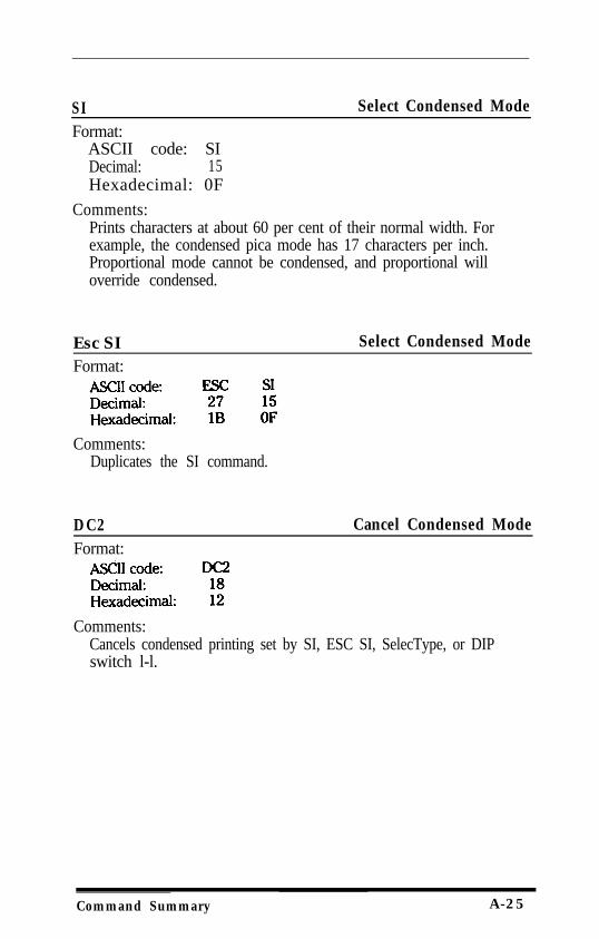
SI Select Condensed ModeFormat:
ASCII code: SIDecimal: 15Hexadecimal: 0F
Comments:Prints characters at about 60 per cent of their normal width. Forexample, the condensed pica mode has 17 characters per inch.Proportional mode cannot be condensed, and proportional willoverride condensed.
Esc SIFormat:
Select Condensed Mode
Comments:Duplicates the SI command.
DC2Format:
Cancel Condensed Mode
Comments:Cancels condensed printing set by SI, ESC SI, SelecType, or DIPswitch l-l.
Command Summary A-25
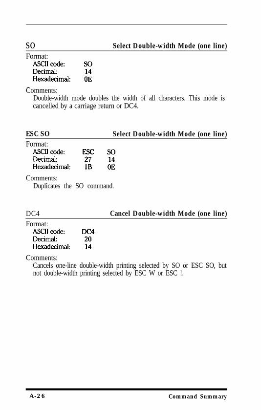
so Select Double-width Mode (one line)Format:
Comments:Double-width mode doubles the width of all characters. This mode iscancelled by a carriage return or DC4.
ESC SO Select Double-width Mode (one line)Format:
Comments:Duplicates the SO command.
DC4Format:
Cancel Double-width Mode (one line)
Comments:Cancels one-line double-width printing selected by SO or ESC SO, butnot double-width printing selected by ESC W or ESC !.
A-26 Command Summary
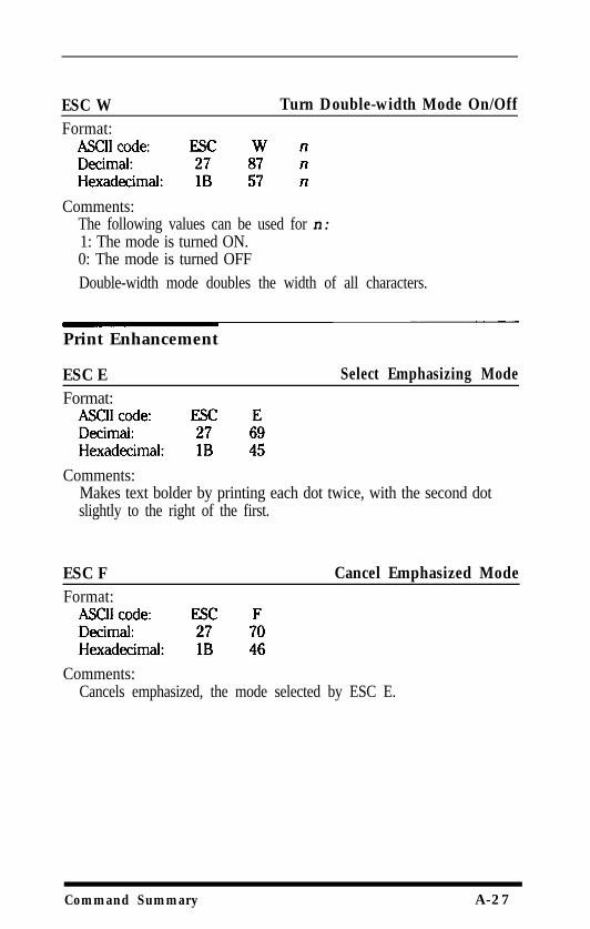
ESC WFormat:
Turn Double-width Mode On/Off
Comments:The following values can be used for n:1: The mode is turned ON.0: The mode is turned OFFDouble-width mode doubles the width of all characters.
Print Enhancement
ESC EFormat:
Select Emphasizing Mode
Comments:Makes text bolder by printing each dot twice, with the second dotslightly to the right of the first.
ESC FFormat:
Cancel Emphasized Mode
Comments:Cancels emphasized, the mode selected by ESC E.
Command Summary A-27
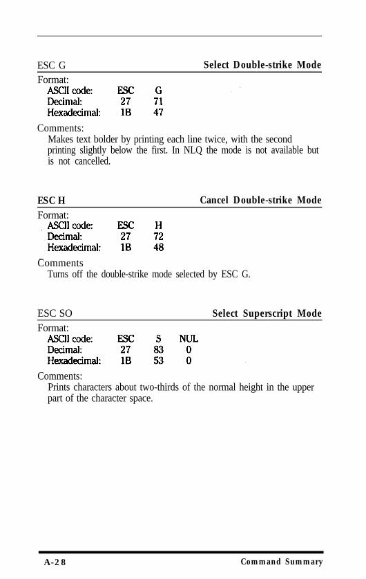
ESC G Select Double-strike ModeFormat:
Comments:Makes text bolder by printing each line twice, with the secondprinting slightly below the first. In NLQ the mode is not available butis not cancelled.
ESC H Cancel Double-strike ModeFormat:
CommentsTurns off the double-strike mode selected by ESC G.
ESC SO Select Superscript ModeFormat:
Comments:Prints characters about two-thirds of the normal height in the upperpart of the character space.
A-28 Command Summary
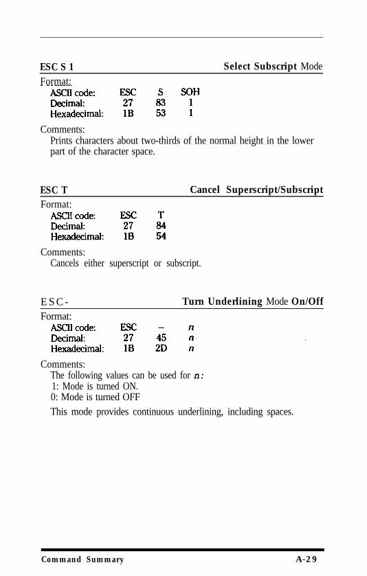
ESC S 1Format:
Select Subscript Mode
Comments:Prints characters about two-thirds of the normal height in the lowerpart of the character space.
ESC T Cancel Superscript/SubscriptFormat:
Comments:Cancels either superscript or subscript.
E S C -Format:
Turn Underlining Mode On/Off
Comments:The following values can be used for n:1: Mode is turned ON.0: Mode is turned OFFThis mode provides continuous underlining, including spaces.
Command Summary A-29
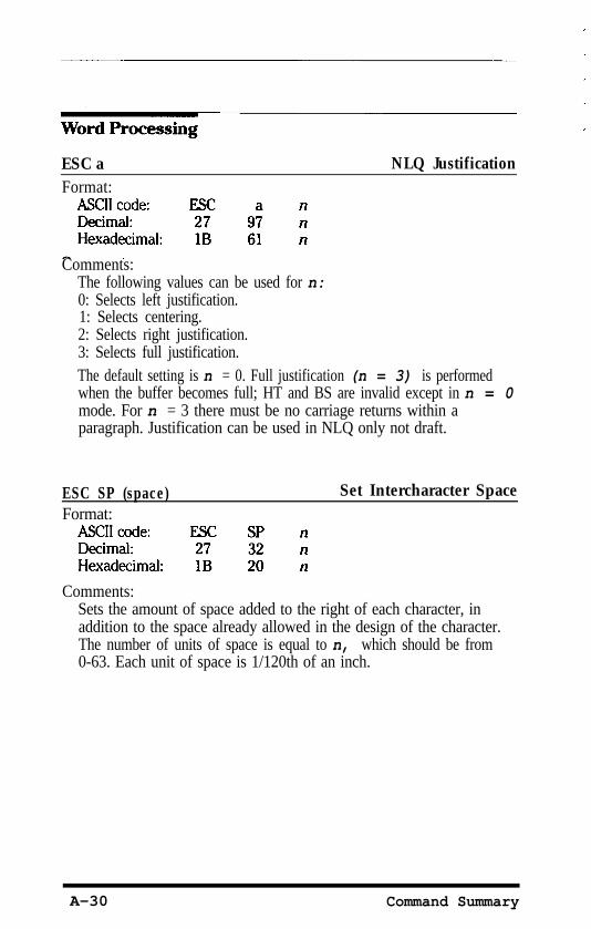
ESC a NLQ JustificationFormat:
Comments:The following values can be used for n:0: Selects left justification.1: Selects centering.2: Selects right justification.3: Selects full justification.The default setting is n = 0. Full justification (n = 3) is performedwhen the buffer becomes full; HT and BS are invalid except in n = 0mode. For n = 3 there must be no carriage returns within aparagraph. Justification can be used in NLQ only not draft.
ESC SP (space)Format:
Set Intercharacter Space
Comments:Sets the amount of space added to the right of each character, inaddition to the space already allowed in the design of the character.The number of units of space is equal to n, which should be from0-63. Each unit of space is 1/120th of an inch.
A-30 Command Summary
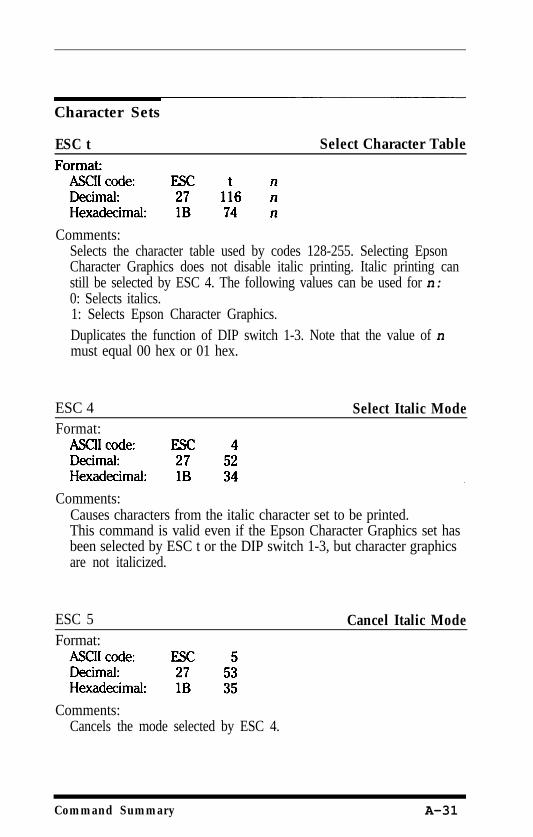
Character Sets
ESC t Select Character Table
Comments:Selects the character table used by codes 128-255. Selecting EpsonCharacter Graphics does not disable italic printing. Italic printing canstill be selected by ESC 4. The following values can be used for n:0: Selects italics.1: Selects Epson Character Graphics.Duplicates the function of DIP switch 1-3. Note that the value of nmust equal 00 hex or 01 hex.
ESC 4Format:
Select Italic Mode
Comments:Causes characters from the italic character set to be printed.This command is valid even if the Epson Character Graphics set hasbeen selected by ESC t or the DIP switch 1-3, but character graphicsare not italicized.
ESC 5Format:
Comments:Cancels the mode selected by ESC 4.
Cancel Italic Mode
Command Summary A-31
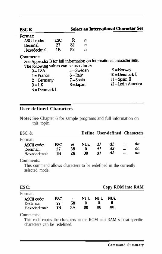
User-defined Characters
Note: See Chapter 6 for sample programs and full information onthis topic.
ESC &Format:
Define User-defined Characters
Comments:This command allows characters to be redefined in the currentlyselected mode.
ESC:Format:
Copy ROM into RAM
Comments:This code copies the characters in the ROM into RAM so that specificcharacters can be redefined.
Command Summary
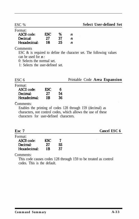
ESC % Select User-defined SetFormat:
CommentsESC & is required to define the character set. The following valuescan be used for n:0: Selects the normal set.1: Selects the user-defined set.
ESC 6 Printable Code Area ExpansionFormat:
Comments:Enables the printing of codes 128 through 159 (decimal) ascharacters, not control codes, which allows the use of thesecharacters for user-defined characters.
Esc 7 Cancel ESC 6 Format:
Comments:This code causes codes 128 through 159 to be treated as controlcodes. This is the default.
Command Summary A-33
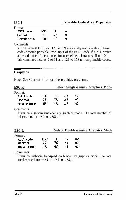
ESC I Printable Code Area ExpansionFormat:
Comments:ASCII codes 0 to 31 and 128 to 159 are usually not printable. Thesecodes become printable upon input of the ESC I code if n = 1, whichallows the use of these codes for userdefined characters. If n = 0,this command returns 0 to 31 and 128 to 159 to non-printable codes.
Graphics
Note: See Chapter 6 for sample graphics programs.
ESC K Select Single-density Graphics ModeFormat:
Comments:Turns on eight-pin singledensity graphics mode. The total number ofcolumns = nl + (n2 x 256).
ESC L Select Double-density Graphics ModeFormat:
Comments:Turns on eight-pin low-speed double-density graphics mode. The totalnumber of columns = nl + (n2 x 256).
A-34 Command Summary
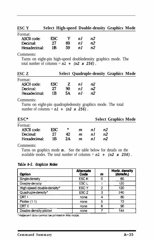
ESC YFormat:
Select High-speed Double-density Graphics Mode
Comments:Turns on eight-pin high-speed doubledensity graphics mode. Thetotal number of columns = nl + (n2 x 256).
ESC ZFormat:
Select Quadruple-density Graphics Mode
Comments:Turns on eight-pin quadrupledensity graphics mode. The totalnumber of columns = nl + (n2 x 256).
ESC*Format:
Select Graphics Mode
Comments:Turns on graphics mode m. See the table below for details on theavailable modes. The total number of columns = nl + (n2 x 256).
Table A-2. Graphics ModesTable A-2. Graphics Modes
Command Summary A-35
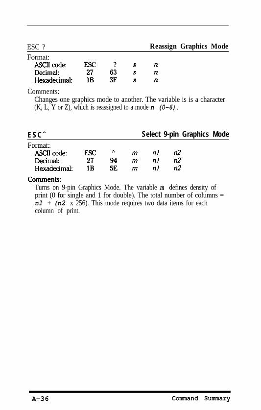
ESC ?Format:
Reassign Graphics Mode
Comments:Changes one graphics mode to another. The variable is is a character(K, L, Y or Z), which is reassigned to a mode n (0-6).
ESCˆFormat:
Select 9-pin Graphics Mode
Turns on 9-pin Graphics Mode. The variable m defines density ofprint (0 for single and 1 for double). The total number of columns =nl + (n2 x 256). This mode requires two data items for eachcolumn of print.
A-36 Command Summary
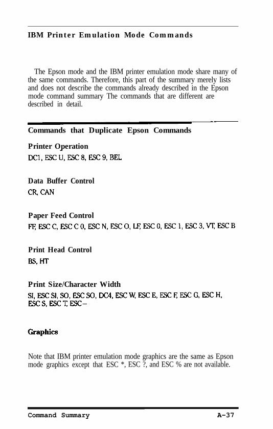
IBM Printer Emulation Mode Commands
The Epson mode and the IBM printer emulation mode share many ofthe same commands. Therefore, this part of the summary merely listsand does not describe the commands already described in the Epsonmode command summary The commands that are different aredescribed in detail.
Commands that Duplicate Epson Commands
Printer Operation
Data Buffer Control
Paper Feed Control
Print Head Control
Print Size/Character Width
Note that IBM printer emulation mode graphics are the same as Epsonmode graphics except that ESC *, ESC ?, and ESC % are not available.
Command Summary A-37
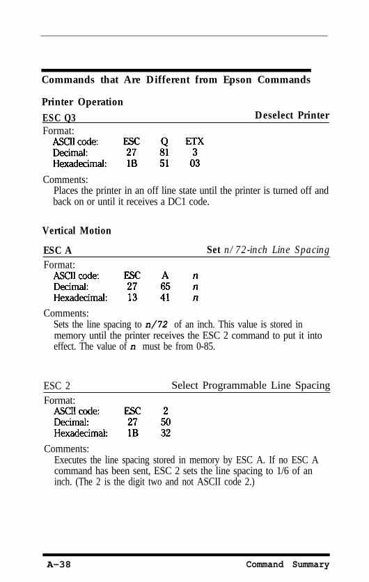
Commands that Are Different from Epson Commands
Printer OperationESC Q3Format:
Deselect Printer
Comments:Places the printer in an off line state until the printer is turned off andback on or until it receives a DC1 code.
Vertical Motion
ESC A Set n/72-inch Line SpacingFormat:
Comments:Sets the line spacing to n/72 of an inch. This value is stored inmemory until the printer receives the ESC 2 command to put it intoeffect. The value of n must be from 0-85.
ESC 2Format:
Select Programmable Line Spacing
Comments:Executes the line spacing stored in memory by ESC A. If no ESC Acommand has been sent, ESC 2 sets the line spacing to 1/6 of aninch. (The 2 is the digit two and not ASCII code 2.)
A-38 Command Summary
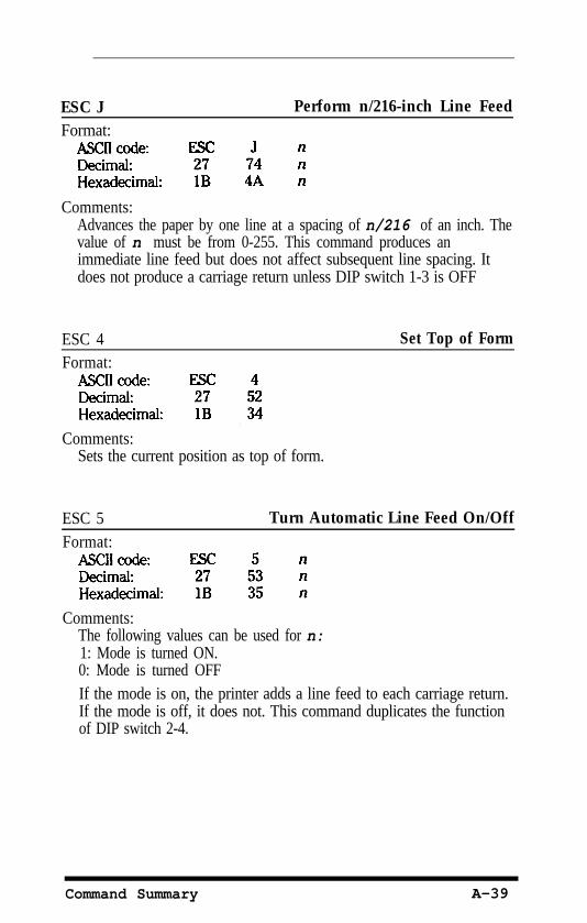
ESC JFormat:
Perform n/216-inch Line Feed
Comments:Advances the paper by one line at a spacing of n/216 of an inch. Thevalue of n must be from 0-255. This command produces animmediate line feed but does not affect subsequent line spacing. Itdoes not produce a carriage return unless DIP switch 1-3 is OFF
ESC 4Format:
Set Top of Form
Comments:Sets the current position as top of form.
ESC 5Format:
Turn Automatic Line Feed On/Off
Comments:The following values can be used for n:1: Mode is turned ON.0: Mode is turned OFFIf the mode is on, the printer adds a line feed to each carriage return.If the mode is off, it does not. This command duplicates the functionof DIP switch 2-4.
Command Summary A-39
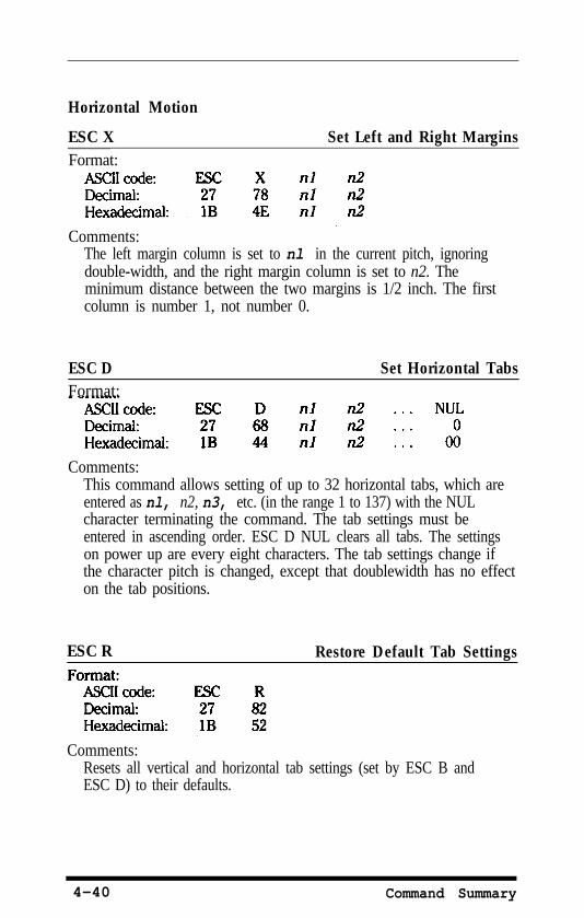
Horizontal Motion
ESC X Set Left and Right MarginsFormat:
Comments:The left margin column is set to nl in the current pitch, ignoringdouble-width, and the right margin column is set to n2. Theminimum distance between the two margins is 1/2 inch. The firstcolumn is number 1, not number 0.
ESC DFormat:
Set Horizontal Tabs
Comments:This command allows setting of up to 32 horizontal tabs, which areentered as nl, n2, n3, etc. (in the range 1 to 137) with the NULcharacter terminating the command. The tab settings must beentered in ascending order. ESC D NUL clears all tabs. The settingson power up are every eight characters. The tab settings change ifthe character pitch is changed, except that doublewidth has no effecton the tab positions.
ESC R Restore Default Tab Settings
Comments:Resets all vertical and horizontal tab settings (set by ESC B andESC D) to their defaults.
4-40 Command Summary
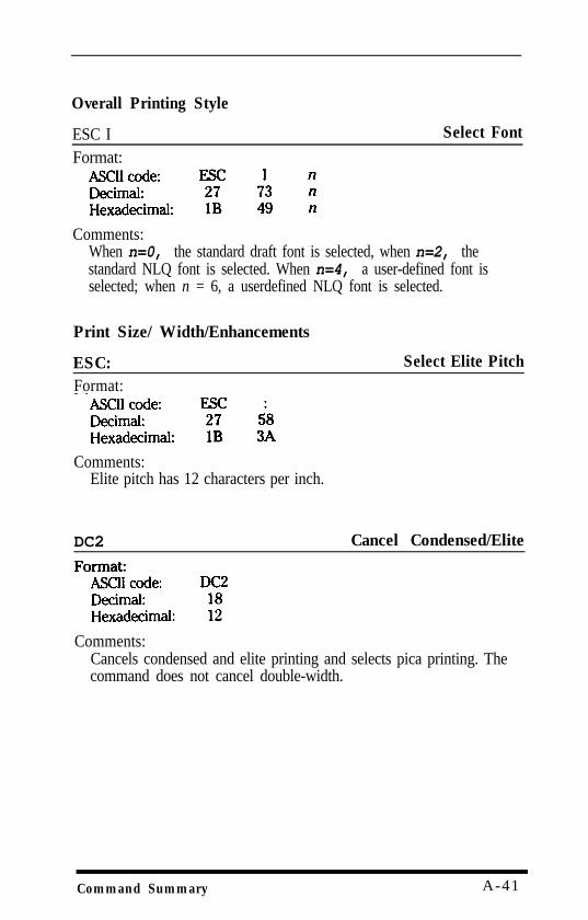
Overall Printing Style
ESC IFormat:
Select Font
Comments:When n=0, the standard draft font is selected, when n=2, thestandard NLQ font is selected. When n=4, a user-defined font isselected; when n = 6, a userdefined NLQ font is selected.
Print Size/ Width/Enhancements
ESC:Format:
Select Elite Pitch
Comments:Elite pitch has 12 characters per inch.
DC2 Cancel Condensed/Elite
Comments:Cancels condensed and elite printing and selects pica printing. Thecommand does not cancel double-width.
Command Summary A-41
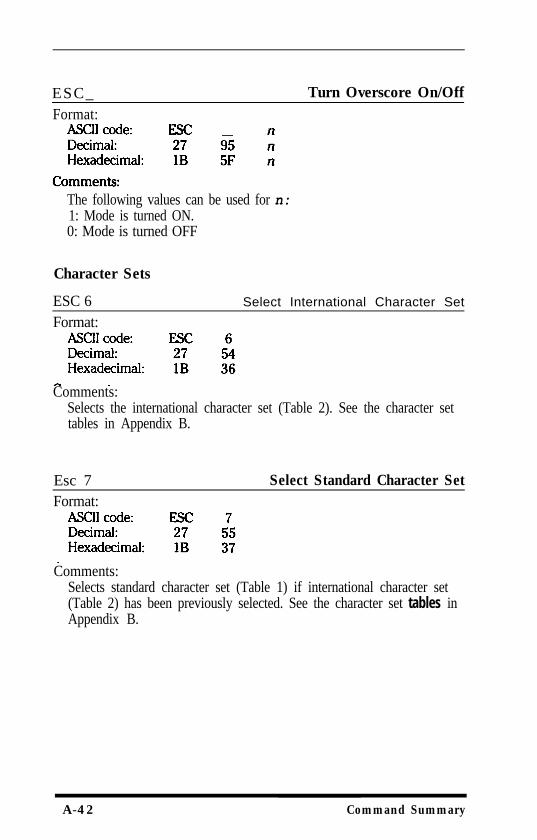
ESC_ Turn Overscore On/OffFormat:
The following values can be used for n:1: Mode is turned ON.0: Mode is turned OFF
Character Sets
ESC 6 Select International Character Set
Format:
Comments:Selects the international character set (Table 2). See the character settables in Appendix B.
Esc 7 Select Standard Character SetFormat:
Comments:Selects standard character set (Table 1) if international character set(Table 2) has been previously selected. See the character set tables inAppendix B.
A-42 Command Summary
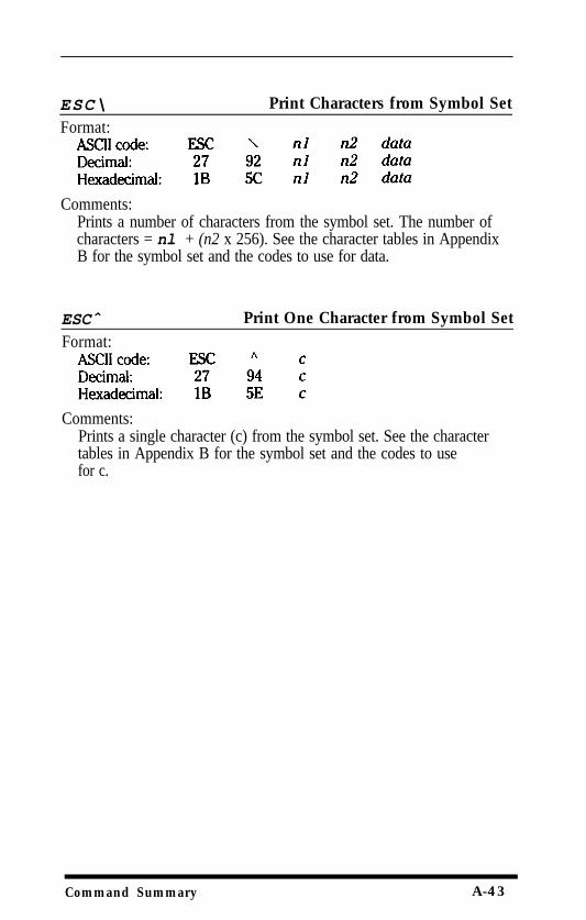
ESC\
Format:
Print Characters from Symbol Set
Comments:Prints a number of characters from the symbol set. The number ofcharacters = nl + (n2 x 256). See the character tables in AppendixB for the symbol set and the codes to use for data.
ESCˆ
Format:Print One Character from Symbol Set
Comments:Prints a single character (c) from the symbol set. See the charactertables in Appendix B for the symbol set and the codes to usefor c.
Command Summary A-43
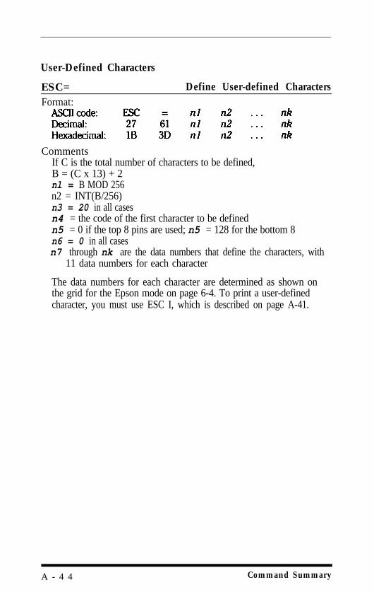
User-Defined Characters
ESC= Define User-defined CharactersFormat:
CommentsIf C is the total number of characters to be defined,B = (C x 13) + 2nl = B MOD 256n2 = INT(B/256)n3 = 20 in all casesn4 = the code of the first character to be definedn5 = 0 if the top 8 pins are used; n5 = 128 for the bottom 8n6 = 0 in all casesn7 through nk are the data numbers that define the characters, with
11 data numbers for each character
The data numbers for each character are determined as shown onthe grid for the Epson mode on page 6-4. To print a user-definedcharacter, you must use ESC I, which is described on page A-41.
A - 4 4 Command Summary

Appendix BCharacter Tables
This appendix contains tables of the complete Epson mode characterset, including the extra characters for the 13 Epson internationalcharacter sets, and the IBM printer emulation mode character sets. Thetables give a printout of each character, the codes in decimal andhexadecimal, and the proportional width of each character.
Epson Mode
The first half of the Epson mode table covers the standard ASCIIcharacter codes from 0 to 127. The remainder of the table shows twocharacters for each code: one from the standard italic character tableand one from the Epson character graphics table. The Epson charactergraphics are selected by ESC t or DIP switch 1-3. Where appropriate,two proportional widths are shown, one for the normal character andone for the italic form.
Character Tables B - l
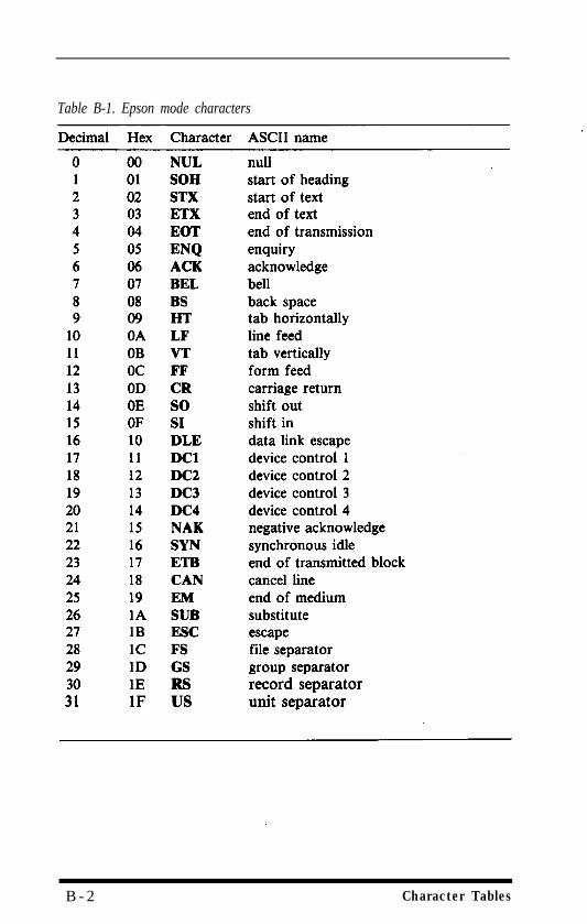
Table B-1. Epson mode characters
B - 2 Character Tables
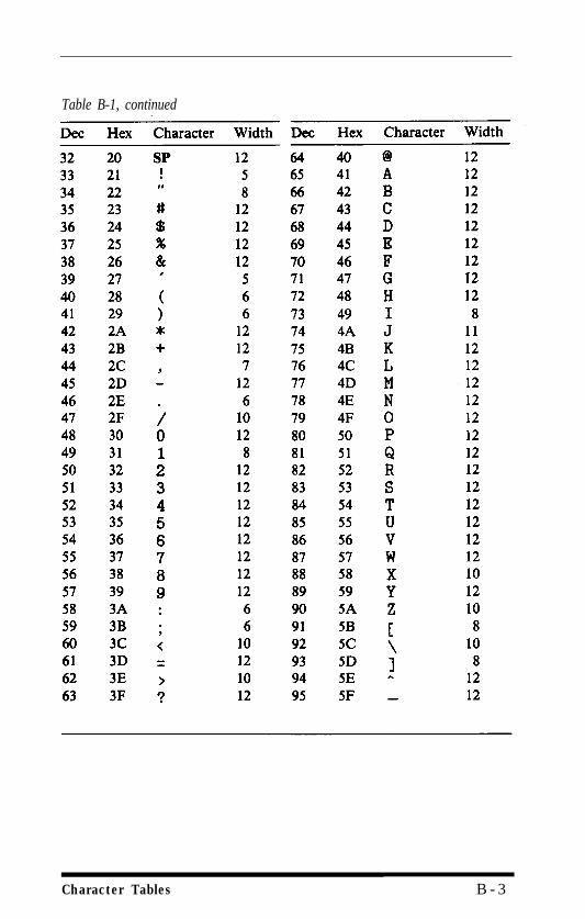
Table B-1, continued
Character Tables B - 3
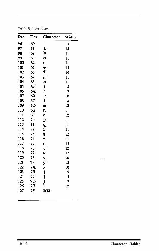
Table B-1, continued
B - 4 Character Tables
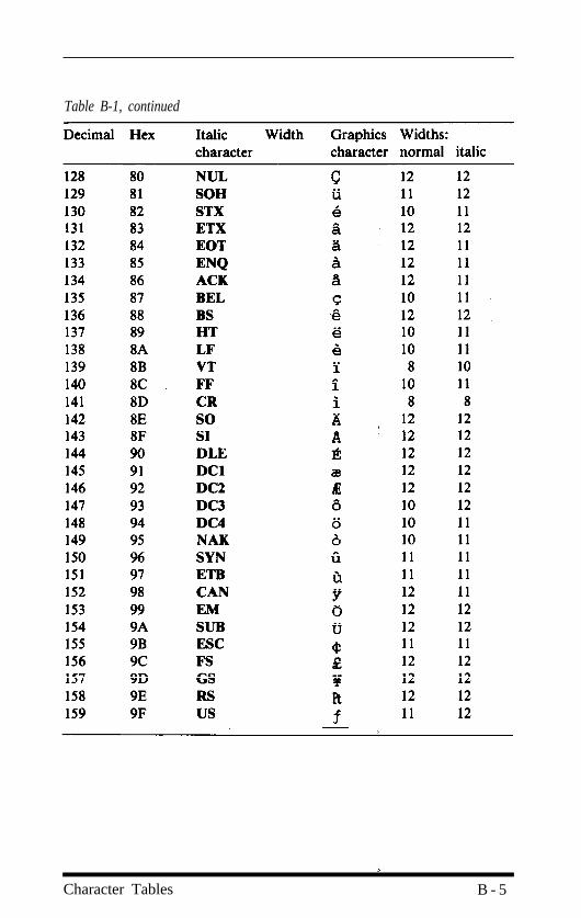
Table B-1, continued
Character Tables B - 5
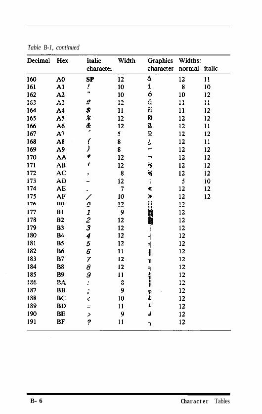
Table B-1, continued
B-6 Character Tables
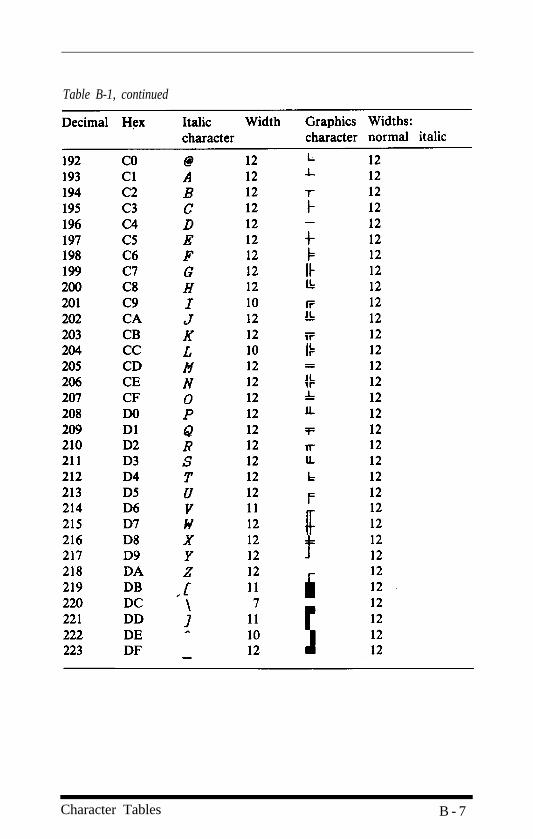
Table B-1, continued
Character Tables B - 7
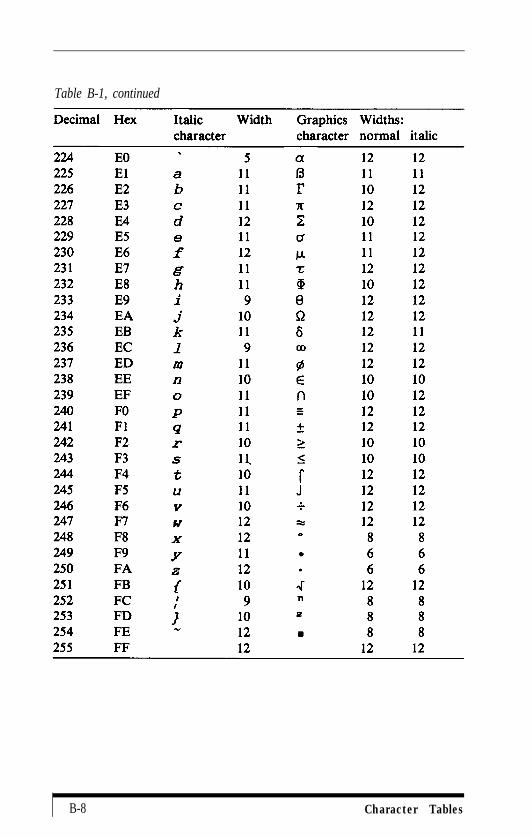
Table B-1, continued
B-8 Character Tables
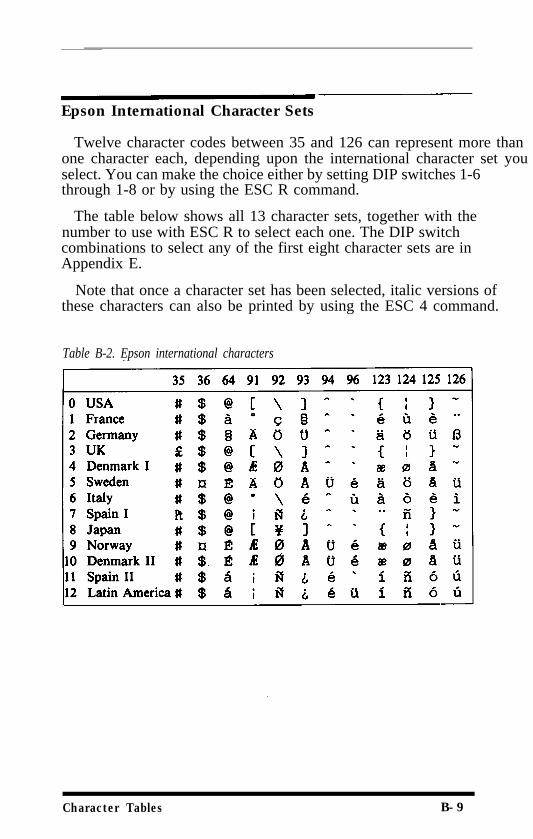
Epson International Character Sets
Twelve character codes between 35 and 126 can represent more thanone character each, depending upon the international character set youselect. You can make the choice either by setting DIP switches 1-6through 1-8 or by using the ESC R command.
The table below shows all 13 character sets, together with thenumber to use with ESC R to select each one. The DIP switchcombinations to select any of the first eight character sets are inAppendix E.
Note that once a character set has been selected, italic versions ofthese characters can also be printed by using the ESC 4 command.
Table B-2. Epson international characters
Character Tables B-9
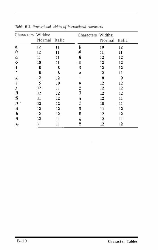
Table B-3. Proportional widths of international characters
Characters Widths: Characters Widths:Normal Italic Normal Italic
B-10 Character Tables
IBM Printer Emulation Mode
This section shows the characters available in IBM printer emulationmode.
There are two main character tables: standard (CG Table 1) andinternational (CG Table 2). The standard table is selected when DIPswitches 1-6 to 143 are all UP; the international table is selected by anyother setting of these three switches. You can also switch between thetwo tables using the ESC 6 and ESC 7 commands.
To print characters from the symbol set use either the ESC ˆcommand or ESC \. For example, to print the symbol 1 in BASIC thecommand is as follows:
If you use ESC ˆ or ESC\ to send a non-printable code, a blank isprinted.
All three tables are the same for codes from 32 to 127, and thesymbol table is identical to the international table from 128 to 255.
Character Tables B-11
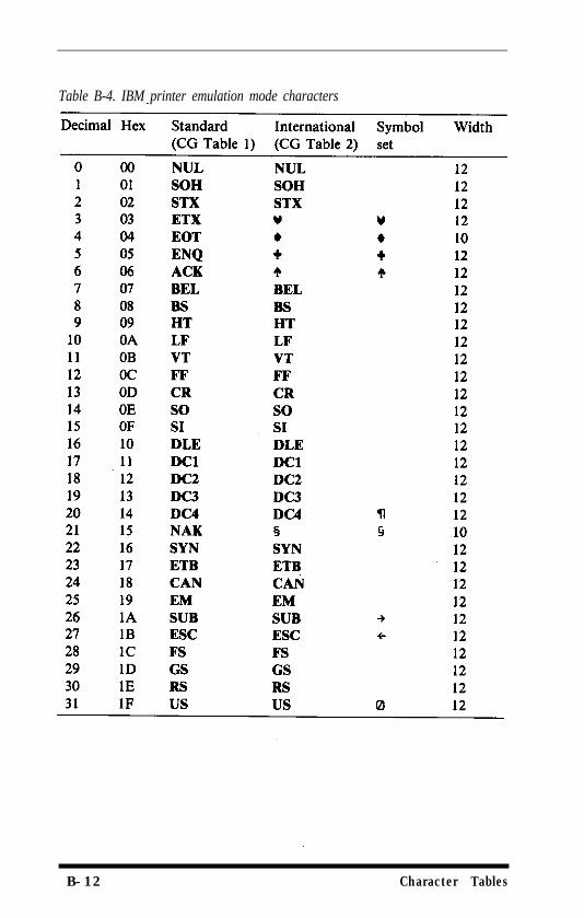
Table B-4. IBM printer emulation mode characters
B-12 Character Tables
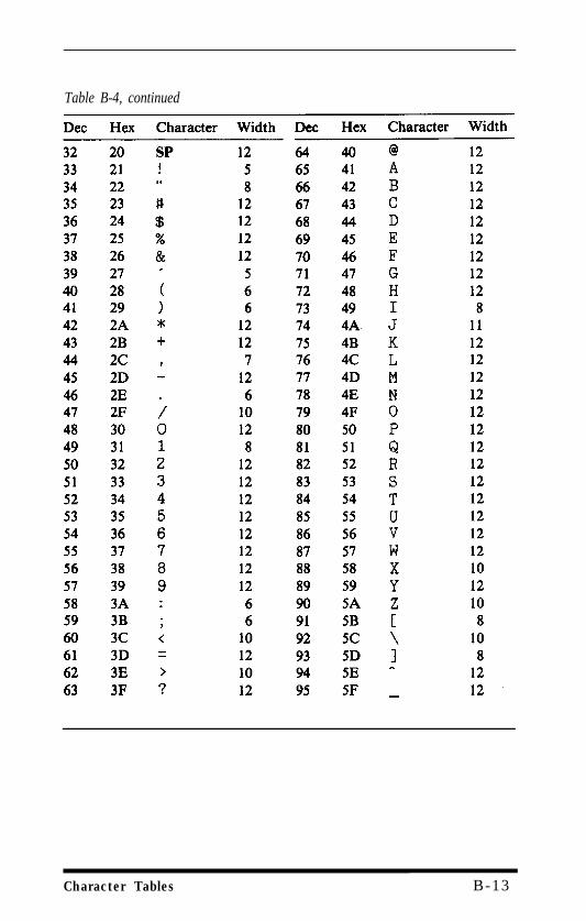
Table B-4, continued
Character Tables B-13
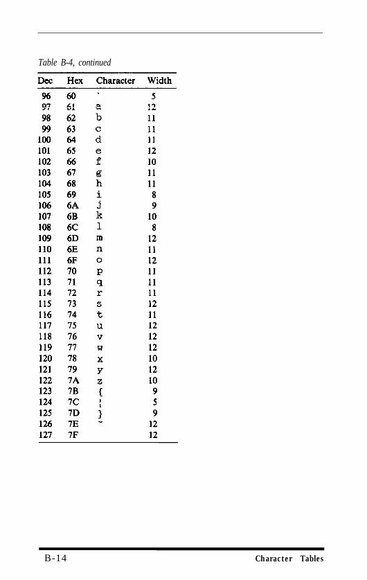
Table B-4, continued
B-14 Character Tables
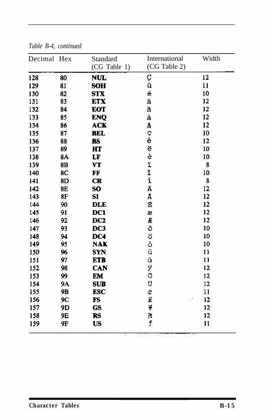
Table B-4, continued
Decimal Hex Standard International Width(CG Table 1) (CG Table 2)
Character Tables B-15
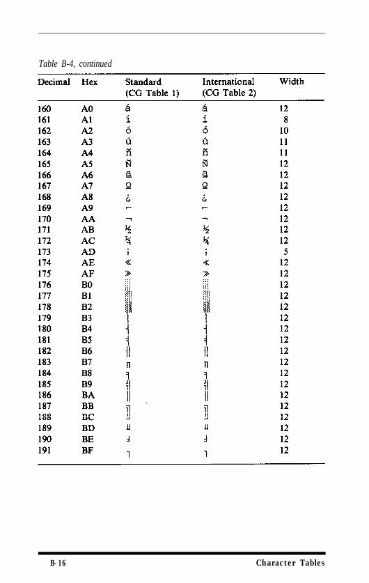
Table B-4, continued
B-16 Character Tables
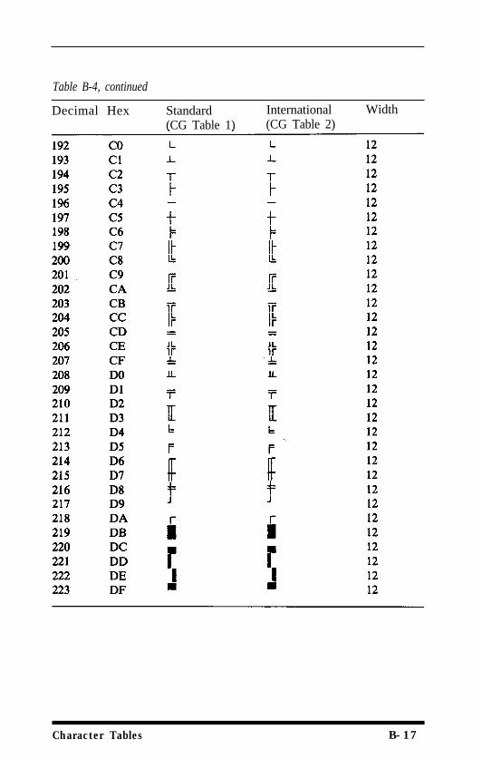
Table B-4, continued
Decimal Hex Standard International Width(CG Table 1) (CG Table 2)
Character Tables B-17
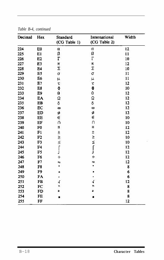
Table B-4, continued
B-18 Character Tables
Appendix CThe Serial Interface
This appendix has the information you need to use the EX's built-inserial interface. It includes DIP switch settings, problem solving, andtechnical specifications. The information on the built-in parallelinterface is in Chapter 1 and Appendix G, and the information onoptional interfaces is in Appendix E
WARNINGTwo interface cables should not be plugged into the printer at the sametime. This may damage your printer.
The most important thing to keep in mind about using a serialinterface is that the serial settings on the printer, computer, and softwaremust all be the same for your EX to print properly Therefore, whenyou change the setting on one, you must be sure that it matches thesettings on the others.
The DIP Switches
After you have connected your computer to the built-in serialinterface of the EX, the first thing you need to do is change or check thesettings of several DIP switches. Four of the 16 DIP switches on the EXcontrol the built-in serial interface.
Serial communication has four characteristics. Two of these cannot bechanged in the EX serial interface and must be set on the computer andsoftware. The number of start bits is fixed at one, and the computermust match this setting. The number of stop bits can be one or more-you should normally choose one.
The remaining two characteristics can be set on the printer. They arebaud rate and parity
The baud rate (which is the speed that data can be received by theprinter) is set for 9600 at the factory Do not change that setting unlessyour computer or software manuals suggest another setting or unlessyour printing is not reliable at that setting. Always remember to set thesame speed on the computer and the printer
The Serial Interface C - 1
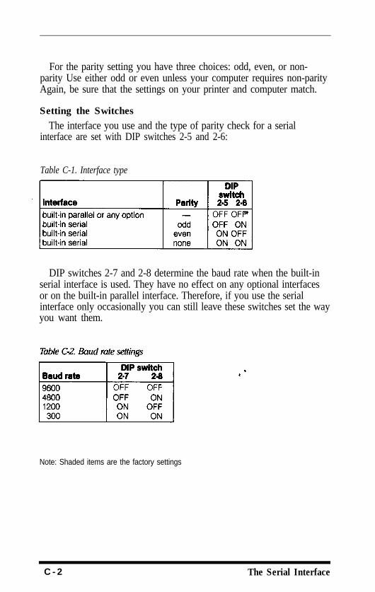
For the parity setting you have three choices: odd, even, or non-parity Use either odd or even unless your computer requires non-parityAgain, be sure that the settings on your printer and computer match.
Setting the SwitchesThe interface you use and the type of parity check for a serial
interface are set with DIP switches 2-5 and 2-6:
Table C-1. Interface type
DIP switches 2-7 and 2-8 determine the baud rate when the built-inserial interface is used. They have no effect on any optional interfacesor on the built-in parallel interface. Therefore, if you use the serialinterface only occasionally you can still leave these switches set the wayyou want them.
Note: Shaded items are the factory settings
C - 2 The Serial Interface
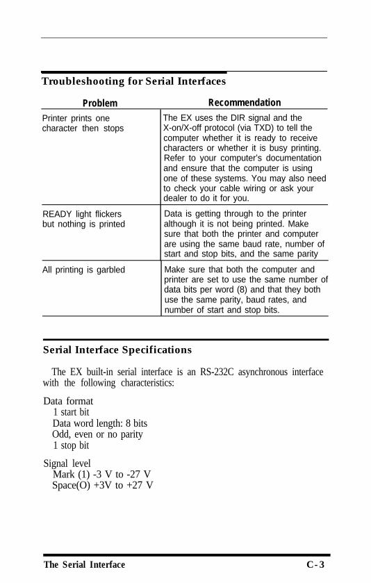
Troubleshooting for Serial Interfaces
ProblemPrinter prints onecharacter then stops
RecommendationThe EX uses the DIR signal and theX-on/X-off protocol (via TXD) to tell thecomputer whether it is ready to receivecharacters or whether it is busy printing.Refer to your computer’s documentationand ensure that the computer is usingone of these systems. You may also needto check your cable wiring or ask yourdealer to do it for you.
READY light flickersbut nothing is printed
Data is getting through to the printeralthough it is not being printed. Makesure that both the printer and computerare using the same baud rate, number ofstart and stop bits, and the same parity
All printing is garbled Make sure that both the computer andprinter are set to use the same number ofdata bits per word (8) and that they bothuse the same parity, baud rates, andnumber of start and stop bits.
Serial Interface Specifications
The EX built-in serial interface is an RS-232C asynchronous interfacewith the following characteristics:
Data format1 start bitData word length: 8 bitsOdd, even or no parity1 stop bit
Signal levelMark (1) -3 V to -27 VSpace(O) +3V to +27 V
The Serial Interface C-3
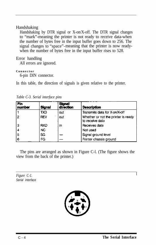
HandshakingHandshaking by DTR signal or X-on/X-off. The DTR signal changesto “mark”-meaning the printer is not ready to receive data-whenthe number of bytes free in the input buffer goes down to 256. Thesignal changes to “space”-meaning that the printer is now ready-when the number of bytes free in the input buffer rises to 528.
Error handlingAll errors are ignored.
Connector6-pin DIN connector.
In this table, the direction of signals is given relative to the printer.
Table C-3. Serial interface pins
The pins are arranged as shown in Figure C-l. (The figure shows theview from the back of the printer.)
Figure C-1.Serial interface
C - 4 The Serial Interface
Appendix DProblem Solving and Maintenance
This appendix presents solutions for possible problems, explanationsof the EX's advanced features, and tips on maintaining and transportingyour printer.
General Troubleshooting
ProblemPrinter does not print
RecommendationMake sure that the printer is turned onand is on line. Both the POWER and ONLINE lights should be on.
Make sure that the printer and computerare connected. Be certain you are usingthe correct cable.
Make sure the printer is connected toonly one interface.
If the program you are using allows youto choose between screen output andprinter output, see that you have selectedprinter output.
If the printer still does not print, try theself test procedure (see Chapter 1). If the
self test works correctly, the printer is allright, and the problem lies elsewhere. Ifthe self test doesn’t work, contact yourdealer.
Problem Solving and Maintenance D - 1
Printing is patchy, faint,uneven, or intermittent
All the text is printedon the same line ortext is printed with anextra blank line between
Some of the charactersprinted do not matchthose in the file
Paper feeding problems
Regular gaps appearin printouts
RecommendationCheck that the ribbon is seated correctlyand that the pins at either side arelocated properly in the holes in the ribboncarriage.
Check that the ribbon moves freely in thecartridge.
If you have been using the ribbon for along time or for a large amount ofprinting, it may need replacing.
It is also possible for the print head towear out if the printer is used frequentlyand for long periods at a time. Contactyour dealer for a replacement print head.Never attempt to replace it yourselfbecause other parts of the printer shouldbe checked at the same time.
If you have removed the color option kit,consult the user’s guide to check that theribbon carriage is set correctly
This can usually be corrected bychanging the setting of DIP switch 2-4. Ifthat does not solve the problem, you mayneed a different cable.
If they are international characters,check the settings of DIP switches 1-6 to1-8. If they are graphics characters, seethat your software is correctly installedand that you have correctly set DIPswitches 1-3 and 1-4.
See Chapter 2 for specific instructions onloading paper
Check the settings of DIP switches 2-1and 2-3 to ensure that you’ve selectedthe correct paper size and that skip-over-perforation is OFF:
D - 2 Problem Solving and Maintenance
Problem RecommendationSelf test patternis garbled
If the test pattern did not print as shownin Chapter 1, the printer is faulty Referthe problem to your dealer. If the patternis printed but is patchy or faint, checkthat the ribbon is installed correctly
Beeper sounds andprinter stops
If the READY light is off and the ON LINElight is flashing, the EX has stopped toallow the head to cool. Printing will soonresume; you do not have to do anythingto restart it. If the ON LINE light is notflashing, turn the printer off and see thatit is not out of paper and that the paper isloaded correctly Then turn the printerback on and try again. If the printerbeeps and does not print again, take it toa qualified service Person.
Troubleshooting Graphics Problems
ProblemStrange dot patternsappear in graphicsprintouts
RecommendationMany computers have problems sendingone or more of the codes between 0 and13. Try to avoid these characters ifpossible.
Be sure that no other commands orcarriage returns come between thegraphics command and its data.
Printer freezes whenprinting graphics
Text appears as randomgraphics characters
If the printer freezes in graphics mode,you have sent too few columns of data.
If you interrupt the computer while it isprinting in graphics mode, for exampleduring a screen dump, it may not resetthe printer to text mode. If not, the nexttext printed will be interpreted by theprinter as graphics data. Turn off theprinter and turn it back on again to resetit.
Problem Solving and Maintenance D - 3
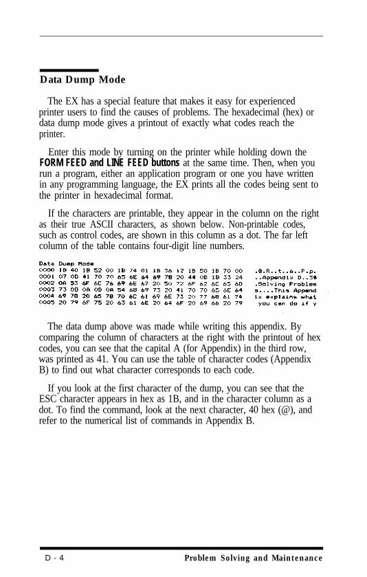
Data Dump Mode
The EX has a special feature that makes it easy for experiencedprinter users to find the causes of problems. The hexadecimal (hex) ordata dump mode gives a printout of exactly what codes reach theprinter.
Enter this mode by turning on the printer while holding down theFORM FEED and LINE FEED buttons at the same time. Then, when yourun a program, either an application program or one you have writtenin any programming language, the EX prints all the codes being sent tothe printer in hexadecimal format.
If the characters are printable, they appear in the column on the rightas their true ASCII characters, as shown below. Non-printable codes,such as control codes, are shown in this column as a dot. The far leftcolumn of the table contains four-digit line numbers.
The data dump above was made while writing this appendix. Bycomparing the column of characters at the right with the printout of hexcodes, you can see that the capital A (for Appendix) in the third row,was printed as 41. You can use the table of character codes (AppendixB) to find out what character corresponds to each code.
If you look at the first character of the dump, you can see that theESC character appears in hex as 1B, and in the character column as adot. To find the command, look at the next character, 40 hex (@), andrefer to the numerical list of commands in Appendix B.
D - 4 Problem Solving and Maintenance
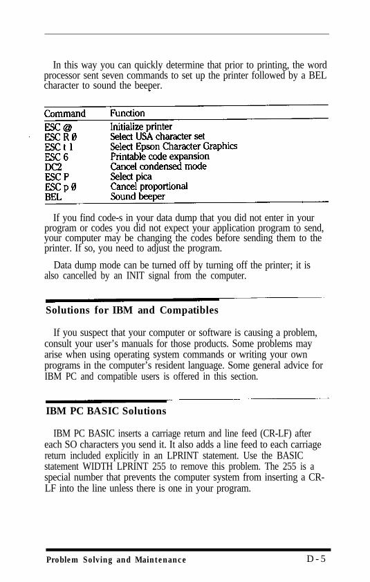
In this way you can quickly determine that prior to printing, the wordprocessor sent seven commands to set up the printer followed by a BELcharacter to sound the beeper.
If you find code-s in your data dump that you did not enter in yourprogram or codes you did not expect your application program to send,your computer may be changing the codes before sending them to theprinter. If so, you need to adjust the program.
Data dump mode can be turned off by turning off the printer; it isalso cancelled by an INIT signal from the computer.
Solutions for IBM and Compatibles
If you suspect that your computer or software is causing a problem,consult your user’s manuals for those products. Some problems mayarise when using operating system commands or writing your ownprograms in the computer’s resident language. Some general advice forIBM PC and compatible users is offered in this section.
IBM PC BASIC Solutions
IBM PC BASIC inserts a carriage return and line feed (CR-LF) aftereach SO characters you send it. It also adds a line feed to each carriagereturn included explicitly in an LPRINT statement. Use the BASICstatement WIDTH LPRINT 255 to remove this problem. The 255 is aspecial number that prevents the computer system from inserting a CR-LF into the line unless there is one in your program.
Problem Solving and Maintenance D - 5
The extra line feed character is usually no problem, unless you wantto send ASCII code 13 on its own as part of a graphics statement or acharacter definition. To do this, use the OPEN statement to assign a filenumber to the printer (LPTl:) and use the PRINT# statement in place ofLPRINT You also need to use a slightly different WIDTH statement. Toprepare the printer in this way use a line like this:
A third problem exists with IBM PC BASIC release 2.0. This versioncannot send ASCII code 26 (1A hex) either with LPRINT or withPRINT #. Try to avoid including this code in your programs.
Maintaining Your Printer
Always keep the printer in a clean and safe place. Keep it away fromdust, grease, moisture and any source of heat, including direct sunlight.A safe temperature range is 40°F to 95°F (5 C to 35 C).
If the outer case is dirty clean it with a soft, clean cloth dampenedwith mild detergent dissolved in water. Keep the dust cover in place toprevent any water from getting inside the printer. Do not use a hardbrush or cloth, and never use alcohol or a thinner to clean the printerbecause it could damage the print head and the case.
Do not spray the inside of the printer with oil: unsuitable oils candamage the mechanism. If lubrication is needed, contact your Epsondealer
The print headBe particularly careful with the print head. Never move it when the
printer is turned on. When the printer is printing, the print headbecomes hot. If you need to change the ribbon or load continuouspaper, turn the printer off and wait for a few minutes while the printhead cools down.
The print head should last for about 100 million characters (assumingan average of 14 dots per character). When it fails, one or more of thepins may fire erratically or stop firing completely making the printout
D - 6 Problem Solving and Maintenance
patchy If this happens suddenly or long before the expected lifetime isover, the problem is almost certainly connected with anothercomponent of the printer.
As soon as the print head fails, stop using the printer and contactyour Epson deafer for a replacement head. Do not attempt to replacethe head yourself because the printer should also be tested to makesure that no other parts are damaged.
Transporting the Printer
There are several precautions you should take when packing theprinter for transportation:
l Remove the ribbon.
l Move the print head to the left and replace the print head protector
l Remove the paper rest and paper guide and pack them separately
l Fix the dust cover in place with tape.
l Remove the paper feed knob.
l Pack the printer in the original foam packing supports and box.
l If the color option kit is installed, remove it, using the instructions inits user’s guide.
Problem Solving and Maintenance D-7

D-8 Problem Solving and Maintenance
Appendix EDefaults and DIP Switches
This appendix lists all of the default settings and lists and explains thesettings of all the DIP switches.
Default and Initialization Settings
The EX can be initialized (returned to a fixed set of conditions) inthree different ways: when it is turned on, when it receives an INITsignal at the parallel interface (pin 31 becomes LOW), and when itreceives the ESC @ command.
The following conditions are always reset:
l The print head returns to the home position.
l If the color option kit is installed, the ribbon carriage is reset to printin black.
l Interface signals are reset, and the printer is put on line.
l The current print line is cleared.
l Margins and vertical tab settings are cleared, line spacing is set to1/6-inch, horizontal tabs are set at every eighth position and verticaltab channel 0 is selected.
l The page length and skip-over-perforation are set according to DIPswitches 2-1 and 2-3, and the top of form position is set to the currentline.
l The ROM characters are selected, and the Epson mode charactertable and international character set are reset according to DIPswitches 1-3 and 1-6 to 1-8.
In addition, when the printer is initialized by turning on the power orby an INIT signal, the data buffer is cleared of all text.
ESC @ resets the typestyle to the current SelecType settings, but theother two methods reset the typestyle according to the DIP switches.Also, ESC @ does not check whether any DIP switches have beenaltered since the printer was turned on; instead it uses the old settings.
Defaults and DIP Switches E - 1
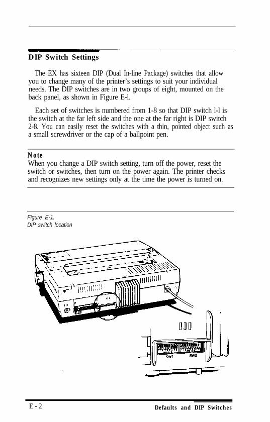
DIP Switch Settings
The EX has sixteen DIP (Dual In-line Package) switches that allowyou to change many of the printer’s settings to suit your individualneeds. The DIP switches are in two groups of eight, mounted on theback panel, as shown in Figure E-l.
Each set of switches is numbered from 1-8 so that DIP switch l-l isthe switch at the far left side and the one at the far right is DIP switch2-8. You can easily reset the switches with a thin, pointed object such asa small screwdriver or the cap of a ballpoint pen.
NoteWhen you change a DIP switch setting, turn off the power, reset theswitch or switches, then turn on the power again. The printer checksand recognizes new settings only at the time the power is turned on.
Figure E-1.DIP switch location
E - 2 Defaults and DIP Switches
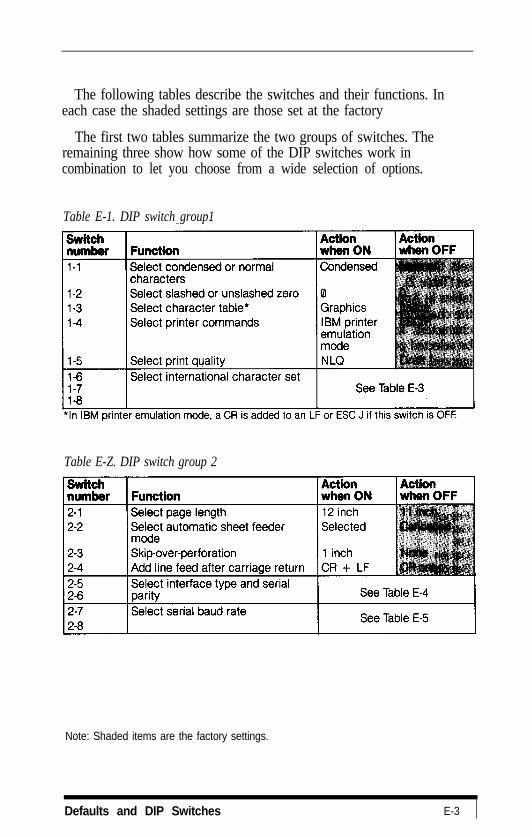
The following tables describe the switches and their functions. Ineach case the shaded settings are those set at the factory
The first two tables summarize the two groups of switches. Theremaining three show how some of the DIP switches work incombination to let you choose from a wide selection of options.
Table E-1. DIP switch group1
Table E-Z. DIP switch group 2
Note: Shaded items are the factory settings.
Defaults and DIP Switches E-3
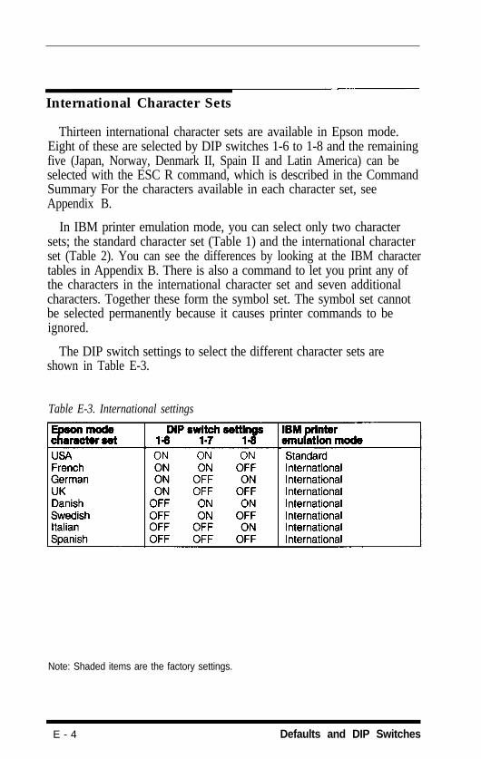
International Character Sets
Thirteen international character sets are available in Epson mode.Eight of these are selected by DIP switches 1-6 to 1-8 and the remainingfive (Japan, Norway, Denmark II, Spain II and Latin America) can beselected with the ESC R command, which is described in the CommandSummary For the characters available in each character set, seeAppendix B.
In IBM printer emulation mode, you can select only two charactersets; the standard character set (Table 1) and the international characterset (Table 2). You can see the differences by looking at the IBM charactertables in Appendix B. There is also a command to let you print any ofthe characters in the international character set and seven additionalcharacters. Together these form the symbol set. The symbol set cannotbe selected permanently because it causes printer commands to beignored.
The DIP switch settings to select the different character sets areshown in Table E-3.
Table E-3. International settings
Note: Shaded items are the factory settings.
E - 4 Defaults and DIP Switches
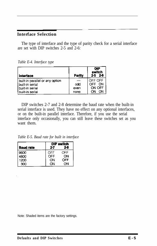
Interface Selection
The type of interface and the type of parity check for a serial interfaceare set with DIP switches 2-5 and 2-6:
Table E-4. Interface type
DIP switches 2-7 and 2-8 determine the baud rate when the built-inserial interface is used. They have no effect on any optional interfaces,or on the built-in parallel interface. Therefore, if you use the serialinterface only occasionally, you can still leave these switches set as youwant them.
Table E-5. Baud rate for built in interface
Note: Shaded items are the factory settings.
Defaults and DIP Switches E - 5

E - 6 Defaults and DIP Switches
Appendix FChoosing and Setting Up Optional Interfaces
This appendix contains information on Epson interfaces compatiblewith EX printers, instructions on choosing the right interface for aparticular job, and instructions for installing internally mountedinterface boards.
Compatible Interfaces
You can use a number of optional interfaces that supplement the EX'sbuilt-in parallel and serial interfaces and the standard 8K data buffer.These fall into three main categories:
l IEEE-488 and other special interfaces, which allow connection tocomputers with other interface requirements (the Apple interface isinstalled in the computer rather than the printer)
l Buffer interfaces, which provide a larger data buffer to release thecomputer for other tasks when printing large amounts of text
l Serial interfaces providing a wide range of baud rates and otheradditional features not available with the standard interface.
The following Epson interfaces are compatible with EX printers. Notethat some of these are no longer available, and that others are notavailable in all countries.
#8131#8143
#8145#8148#8149#8149M#8161#8165#8172#8172M
Apple II parallel interfaceSerial interface with baud rate selectable between
75 and 9600RS-232C/current loop interface type 2Intelligent serial interface32K buffer serial interface128K buffer serial interfaceIEEE-488 interfaceIntelligent IEEE-488 interface32K buffer parallel interface128K buffer parallel interface
If you are using an optional internal interface, set DIP switches 2-5and 2-6 OFF and do not connect anything to the parallel interface.
Choosing and Setting Up Optional Interfaces F - l
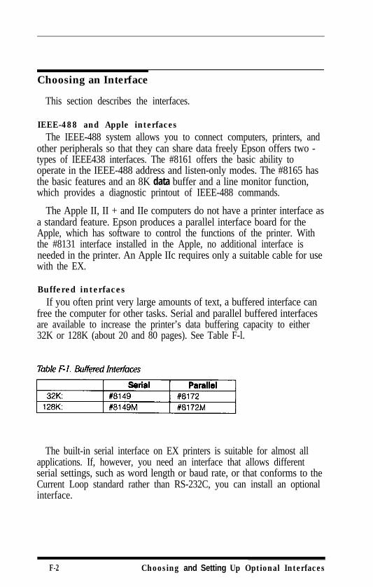
Choosing an Interface
This section describes the interfaces.
IEEE-488 and Apple interfacesThe IEEE-488 system allows you to connect computers, printers, and
other peripherals so that they can share data freely Epson offers two -types of IEEE438 interfaces. The #8161 offers the basic ability tooperate in the IEEE-488 address and listen-only modes. The #8165 hasthe basic features and an 8K data buffer and a line monitor function,which provides a diagnostic printout of IEEE-488 commands.
The Apple II, II + and IIe computers do not have a printer interface asa standard feature. Epson produces a parallel interface board for theApple, which has software to control the functions of the printer. Withthe #8131 interface installed in the Apple, no additional interface isneeded in the printer. An Apple IIc requires only a suitable cable for usewith the EX.
Buffered interfacesIf you often print very large amounts of text, a buffered interface can
free the computer for other tasks. Serial and parallel buffered interfacesare available to increase the printer’s data buffering capacity to either32K or 128K (about 20 and 80 pages). See Table F-l.
The built-in serial interface on EX printers is suitable for almost allapplications. If, however, you need an interface that allows differentserial settings, such as word length or baud rate, or that conforms to theCurrent Loop standard rather than RS-232C, you can install an optionalinterface.
F-2 Choosing and Setting Up Optional Interfaces
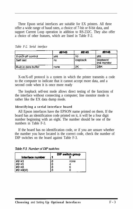
Three Epson serial interfaces are suitable for EX printers. All threeoffer a wide range of baud rates, a choice of 7-bit or 8-bit data, andsupport Current Loop operation in addition to RS-232C. They also offera choice of other features, which are listed in Table F-2.
Table F-2. Serial interface
X-on/X-off protocol is a system in which the printer transmits a codeto the computer to indicate that it cannot accept more data, and asecond code when it is once more ready
The loopback self-test mode allows direct testing of the functions ofthe interface without connecting a computer; line monitor mode israther like the EX data dump mode.
Identifying a serial interface board
All Epson interfaces have the EPSON name printed on them. If theboard has an identification code printed on it, it will be a four digitnumber beginning with an eight. The number should be one of thenumbers in Table F-3.
If the board has no identification code, or if you are unsure whetherthe number you have located is the correct code, check the number ofDIP switches on the board against Table F-3.
Choosing and Setting Up Optional Interfaces F - 3
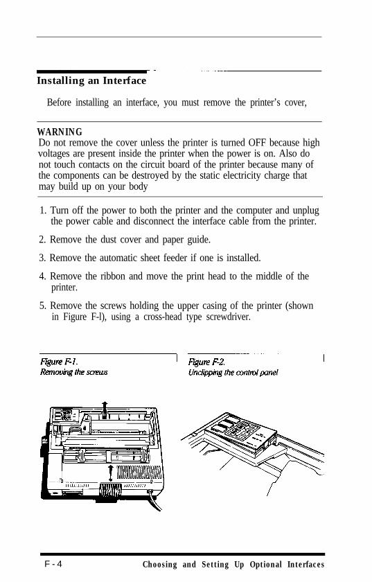
Installing an Interface
Before installing an interface, you must remove the printer’s cover,
WARNINGDo not remove the cover unless the printer is turned OFF because highvoltages are present inside the printer when the power is on. Also donot touch contacts on the circuit board of the printer because many ofthe components can be destroyed by the static electricity charge thatmay build up on your body
1. Turn off the power to both the printer and the computer and unplugthe power cable and disconnect the interface cable from the printer.
2. Remove the dust cover and paper guide.
3. Remove the automatic sheet feeder if one is installed.
4. Remove the ribbon and move the print head to the middle of theprinter.
5. Remove the screws holding the upper casing of the printer (shownin Figure F-l), using a cross-head type screwdriver.
F - 4 Choosing and Setting Up Optional Interfaces
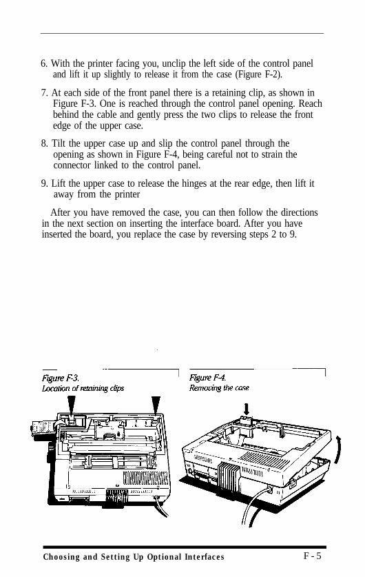
6. With the printer facing you, unclip the left side of the control paneland lift it up slightly to release it from the case (Figure F-2).
7. At each side of the front panel there is a retaining clip, as shown inFigure F-3. One is reached through the control panel opening. Reachbehind the cable and gently press the two clips to release the frontedge of the upper case.
8. Tilt the upper case up and slip the control panel through theopening as shown in Figure F-4, being careful not to strain theconnector linked to the control panel.
9. Lift the upper case to release the hinges at the rear edge, then lift itaway from the printer
After you have removed the case, you can then follow the directionsin the next section on inserting the interface board. After you haveinserted the board, you replace the case by reversing steps 2 to 9.
Choosing and Setting Up Optional Interfaces F - 5
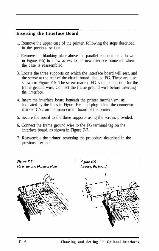
Inserting the Interface Board
1. Remove the upper case of the printer, following the steps describedin the previous section.
2. Remove the blanking plate above the parallel connector (as shownin Figure F-5) to allow access to the new interface connector whenthe case is reassembled.
3. Locate the three supports on which the interface board will rest, andthe screw at the rear of the circuit board labelled FG. These are alsoshown in Figure F-5. The screw marked FG is the connection for theframe ground wire. Connect the frame ground wire before insertingthe interface.
4. Insert the interface board beneath the printer mechanism, asindicated by the lines in Figure F-6, and plug it into the connectormarked CN2 on the main circuit board of the printer.
5. Secure the board to the three supports using the screws provided.
6. Connect the frame ground wire to the FG terminal tag on theinterface board, as shown in Figure F-7.
7. Reassemble the printer, reversing the procedure described in theprevious section.
F - 6 Choosing and Setting Up Optional Interfaces
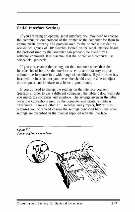
Serial Interface Settings
If you are using an optional serial interface, you may need to changethe communications protocol of the printer or the computer for them tocommunicate properly The protocol used by the printer is decided byone or two groups of DIP switches located on the serial interface board;the protocol used by the computer can probably be altered by asoftware command. It is essential that the printer and computer usecompatible protocols.
If you can, change the settings on the computer rather than theinterface board because the interface is set up at the factory to giveoptimum performance in a wide range of conditions. If your dealer hasinstalled the interface for you, he or she should also be able to adjustthe computer and interface to achieve a good match.
If you do need to change the settings on the interface yourself,(perhaps in order to use a different computer), the tables below will helpyou match the computer and interface. The settings given in the tablecover the conventions used by the computer and printer as data istransferred. There are other DIP switches and jumpers, but for mostpurposes you only need change the settings described here. The othersettings are described in the manual supplied with the interface.
Choosing and Setting Up Optional Interfaces F-7
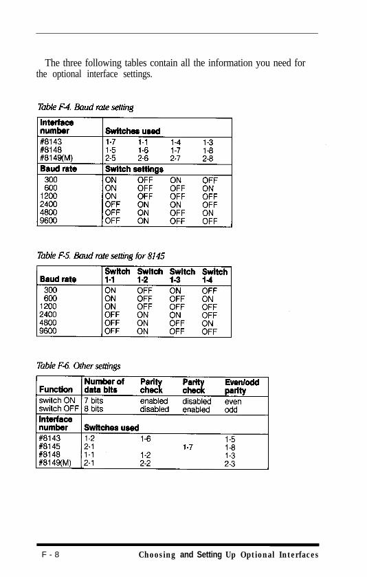
The three following tables contain all the information you need forthe optional interface settings.
F - 8 Choosing and Setting Up Optional Interfaces
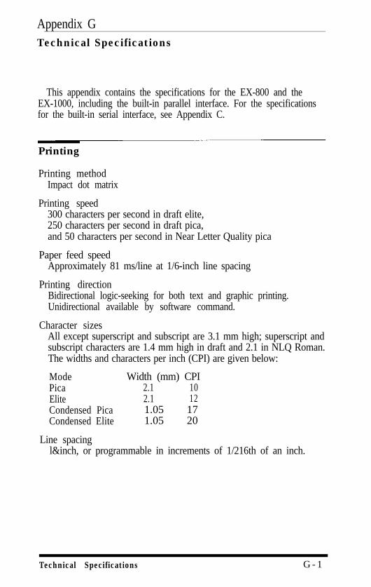
Appendix GTechnical Specifications
This appendix contains the specifications for the EX-800 and theEX-1000, including the built-in parallel interface. For the specificationsfor the built-in serial interface, see Appendix C.
Printing
Printing methodImpact dot matrix
Printing speed300 characters per second in draft elite,250 characters per second in draft pica,and 50 characters per second in Near Letter Quality pica
Paper feed speedApproximately 81 ms/line at 1/6-inch line spacing
Printing directionBidirectional logic-seeking for both text and graphic printing.Unidirectional available by software command.
Character sizesAll except superscript and subscript are 3.1 mm high; superscript andsubscript characters are 1.4 mm high in draft and 2.1 in NLQ Roman.The widths and characters per inch (CPI) are given below:
Mode Width (mm) CPIPica 2.1 10Elite 2.1 12Condensed Pica 1.05 17Condensed Elite 1.05 20
Line spacingl&inch, or programmable in increments of 1/216th of an inch.
Technical Specifications G - 1
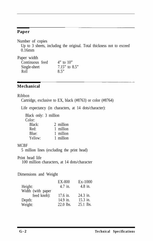
Paper
Number of copiesUp to 3 sheets, including the original. Total thickness not to exceed0.16mm
Paper widthContinuous feedSingle-sheetRoll
4” to 10”7.15” to 8.5”8.5”
Mechanical
RibbonCartridge, exclusive to EX, black (#8763) or color (#8764)
Life expectancy (in characters, at 14 dots/character):
Black only: 3 millionColor:
Black: 2 millionRed: 1 millionBlue: 1 millionYellow: 1 million
MCBF5 million lines (excluding the print head)
Print head life100 million characters, at 14 dots/character
Dimensions and Weight
EX-800 Ex-1000Height: 4.7 in. 4.8 in.Width (with paper
feed knob): 17.6 in. 24.3 in.Depth: 14.9 in. 15.3 in.Weight: 22.0 lbs. 25.1 Ibs.
G-2 Technical Specifications
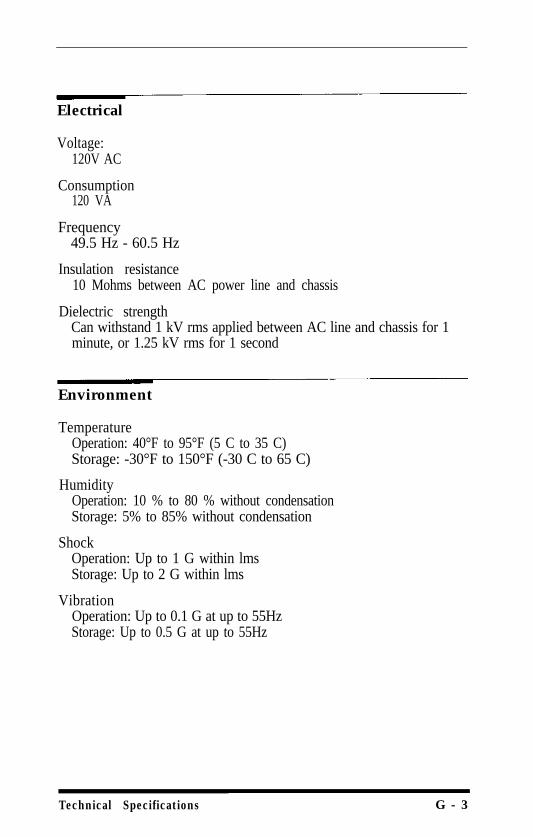
Electrical
Voltage:120V AC
Consumption120 VA
Frequency49.5 Hz - 60.5 Hz
Insulation resistance10 Mohms between AC power line and chassis
Dielectric strengthCan withstand 1 kV rms applied between AC line and chassis for 1minute, or 1.25 kV rms for 1 second
Environment
TemperatureOperation: 40°F to 95°F (5 C to 35 C)Storage: -30°F to 150°F (-30 C to 65 C)
HumidityOperation: 10 % to 80 % without condensationStorage: 5% to 85% without condensation
ShockOperation: Up to 1 G within lmsStorage: Up to 2 G within lms
VibrationOperation: Up to 0.1 G at up to 55HzStorage: Up to 0.5 G at up to 55Hz
Technical Specifications G - 3
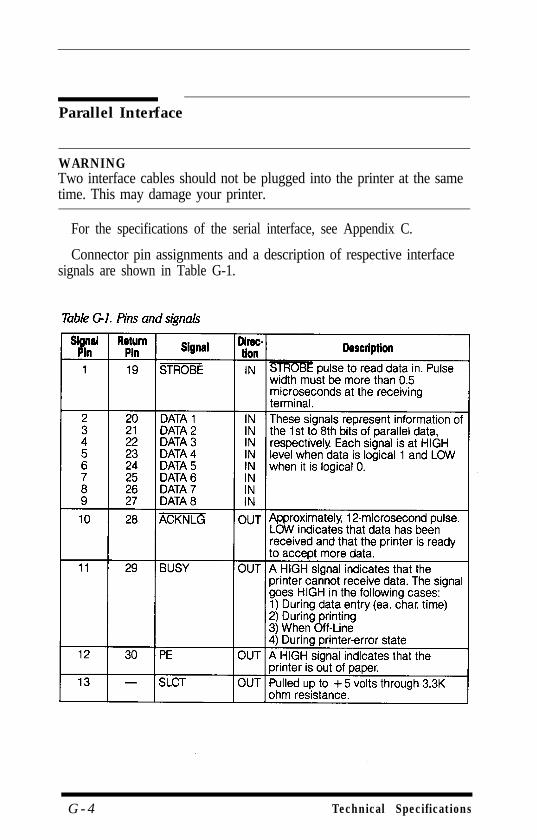
Parallel Interface
WARNINGTwo interface cables should not be plugged into the printer at the sametime. This may damage your printer.
For the specifications of the serial interface, see Appendix C.
Connector pin assignments and a description of respective interfacesignals are shown in Table G-1.
G - 4 Technical Specifications
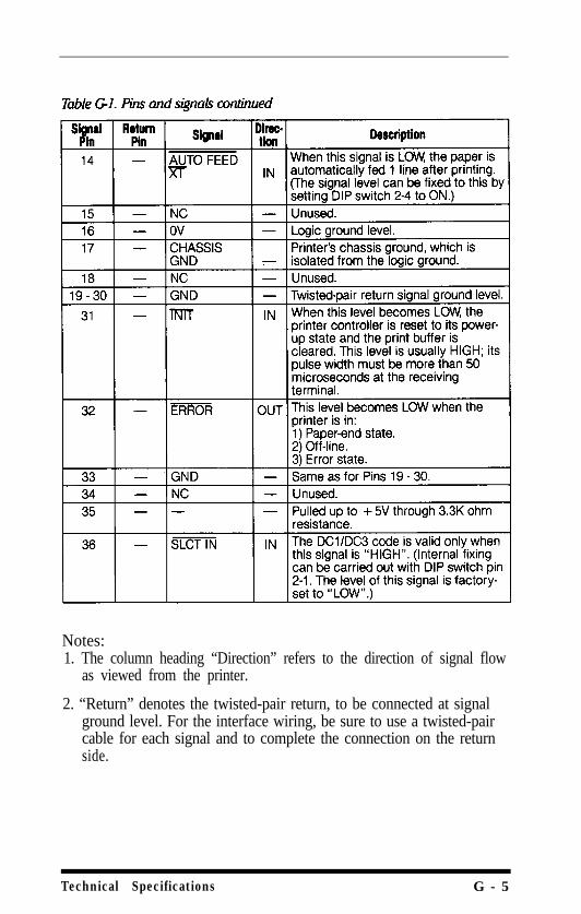
Notes:1. The column heading “Direction” refers to the direction of signal flow
as viewed from the printer.
2. “Return” denotes the twisted-pair return, to be connected at signalground level. For the interface wiring, be sure to use a twisted-paircable for each signal and to complete the connection on the returnside.
Technical Specifications G - 5
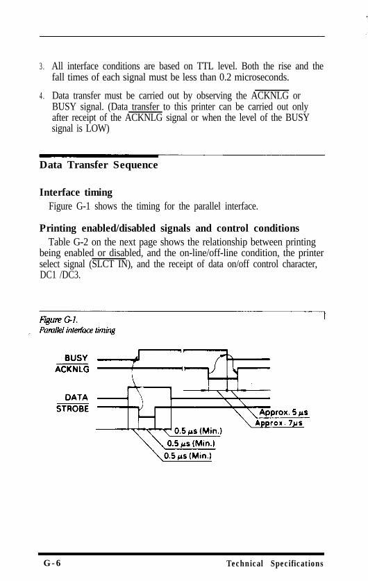
3.
4.
All interface conditions are based on TTL level. Both the rise and thefall times of each signal must be less than 0.2 microseconds.
Data transfer must be carried out by observing the ACKNLG orBUSY signal. (Data transfer to this printer can be carried out onlyafter receipt of the ACKNLG signal or when the level of the BUSYsignal is LOW)
Data Transfer Sequence
Interface timingFigure G-1 shows the timing for the parallel interface.
Printing enabled/disabled signals and control conditionsTable G-2 on the next page shows the relationship between printing
being enabled or disabled, and the on-line/off-line condition, the printerselect signal (SLCT IN), and the receipt of data on/off control character,DC1 /DC3.
G-6 Technical Specifications
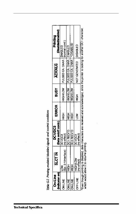

G -8 Technical Specifications
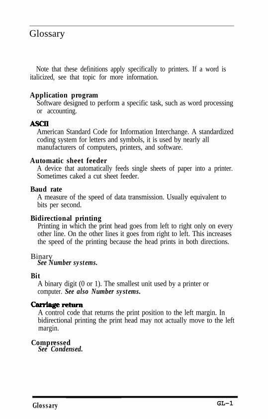
Glossary
Note that these definitions apply specifically to printers. If a word isitalicized, see that topic for more information.
Application programSoftware designed to perform a specific task, such as word processingor accounting.
American Standard Code for Information Interchange. A standardizedcoding system for letters and symbols, it is used by nearly allmanufacturers of computers, printers, and software.
Automatic sheet feederA device that automatically feeds single sheets of paper into a printer.Sometimes caked a cut sheet feeder.
Baud rateA measure of the speed of data transmission. Usually equivalent tobits per second.
Bidirectional printingPrinting in which the print head goes from left to right only on everyother line. On the other lines it goes from right to left. This increasesthe speed of the printing because the head prints in both directions.
BinarySee Number systems.
BitA binary digit (0 or 1). The smallest unit used by a printer orcomputer. See also Number systems.
A control code that returns the print position to the left margin. Inbidirectional printing the print head may not actually move to the leftmargin.
CompressedSee Condensed.
Glossary GL-1
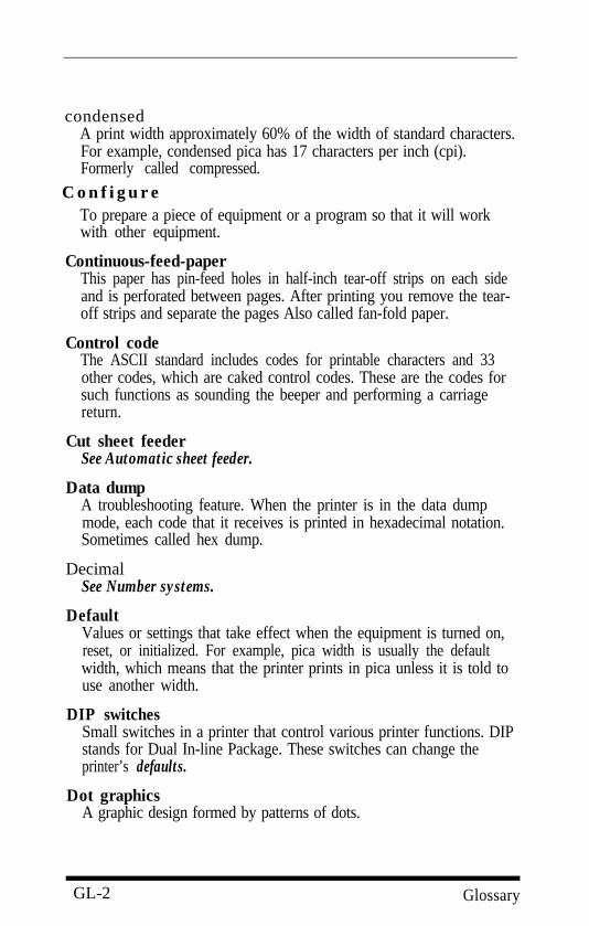
condensedA print width approximately 60% of the width of standard characters.For example, condensed pica has 17 characters per inch (cpi).Formerly called compressed.
C o n f i g u r eTo prepare a piece of equipment or a program so that it will workwith other equipment.
Continuous-feed-paperThis paper has pin-feed holes in half-inch tear-off strips on each sideand is perforated between pages. After printing you remove the tear-off strips and separate the pages Also called fan-fold paper.
Control codeThe ASCII standard includes codes for printable characters and 33other codes, which are caked control codes. These are the codes forsuch functions as sounding the beeper and performing a carriagereturn.
Cut sheet feederSee Automatic sheet feeder.
Data dumpA troubleshooting feature. When the printer is in the data dumpmode, each code that it receives is printed in hexadecimal notation.Sometimes called hex dump.
DecimalSee Number systems.
DefaultValues or settings that take effect when the equipment is turned on,reset, or initialized. For example, pica width is usually the defaultwidth, which means that the printer prints in pica unless it is told touse another width.
DIP switchesSmall switches in a printer that control various printer functions. DIPstands for Dual In-line Package. These switches can change theprinter’s defaults.
Dot graphicsA graphic design formed by patterns of dots.
GL-2 Glossary
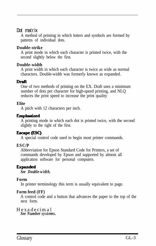
Dot matrixA method of printing in which letters and symbols are formed bypatterns of individual dots.
Double-strikeA print mode in which each character is printed twice, with thesecond slightly below the first.
Double-widthA print width in which each character is twice as wide as normalcharacters. Double-width was formerly known as expanded.
One of two methods of printing on the EX. Draft uses a minimumnumber of dots per character for high-speed printing, and NLQreduces the print speed to increase the print quality
EliteA pitch with 12 characters per inch.
A printing mode in which each dot is printed twice, with the secondslightly to the right of the first.
A special control code used to begin most printer commands.
ESC/PAbbreviation for Epson Standard Code for Printers, a set ofcommands developed by Epson and supported by almost allapplication software for personal computers.
See Double-width.
FormIn printer terminology this term is usually equivalent to page.
Form feed (FF)A control code and a button that advances the paper to the top of thenext form.
HexadecimalSee Number systems.
Glossary GL-3
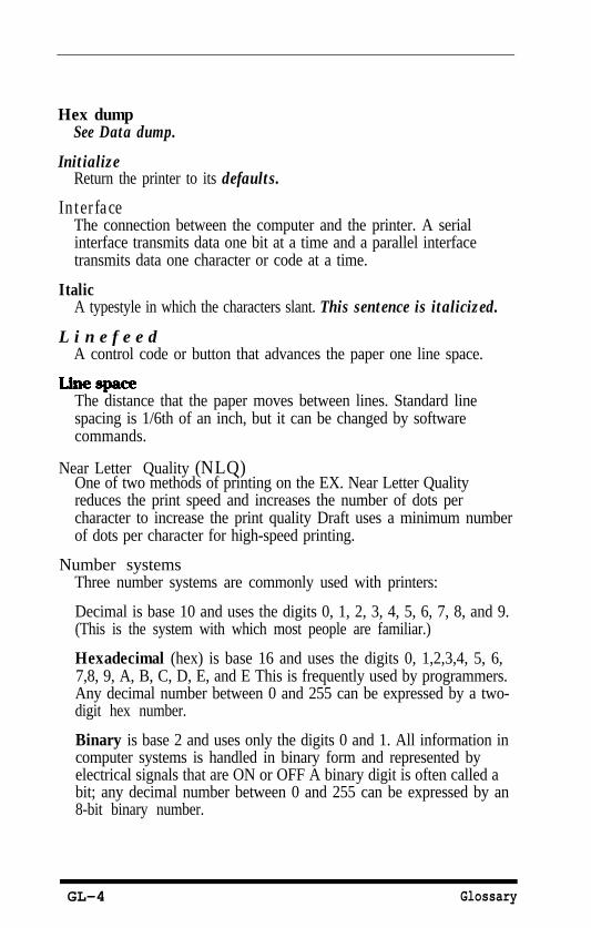
Hex dumpSee Data dump.
InitializeReturn the printer to its defaults.
InterfaceThe connection between the computer and the printer. A serialinterface transmits data one bit at a time and a parallel interfacetransmits data one character or code at a time.
ItalicA typestyle in which the characters slant. This sentence is italicized.
L i n e f e e dA control code or button that advances the paper one line space.
The distance that the paper moves between lines. Standard linespacing is 1/6th of an inch, but it can be changed by softwarecommands.
Near Letter Quality (NLQ)One of two methods of printing on the EX. Near Letter Qualityreduces the print speed and increases the number of dots percharacter to increase the print quality Draft uses a minimum numberof dots per character for high-speed printing.
Number systemsThree number systems are commonly used with printers:
Decimal is base 10 and uses the digits 0, 1, 2, 3, 4, 5, 6, 7, 8, and 9.(This is the system with which most people are familiar.)
Hexadecimal (hex) is base 16 and uses the digits 0, 1,2,3,4, 5, 6,7,8, 9, A, B, C, D, E, and E This is frequently used by programmers.Any decimal number between 0 and 255 can be expressed by a two-digit hex number.
Binary is base 2 and uses only the digits 0 and 1. All information incomputer systems is handled in binary form and represented byelectrical signals that are ON or OFF A binary digit is often called abit; any decimal number between 0 and 255 can be expressed by an8-bit binary number.
GL-4 Glossary
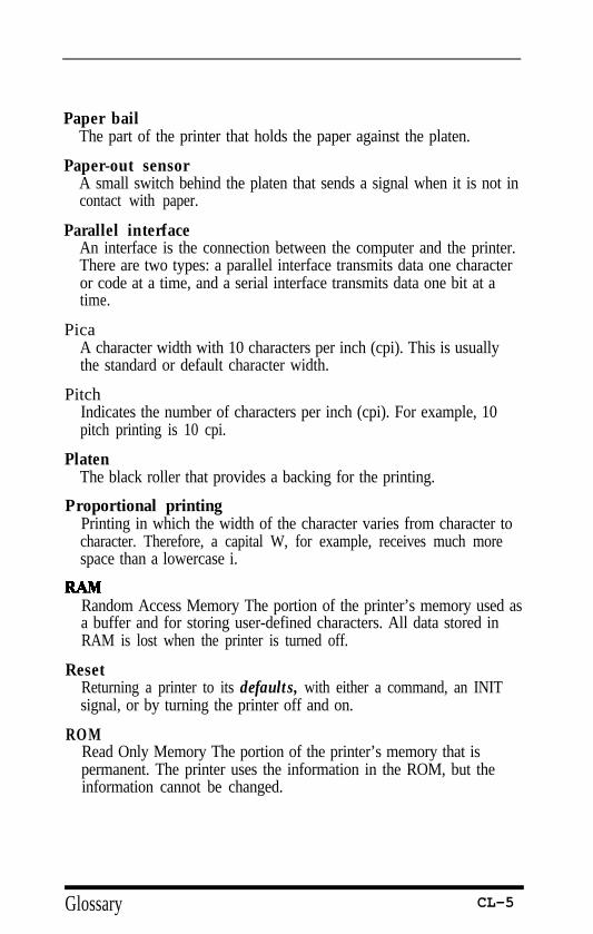
Paper bailThe part of the printer that holds the paper against the platen.
Paper-out sensorA small switch behind the platen that sends a signal when it is not incontact with paper.
Parallel interfaceAn interface is the connection between the computer and the printer.There are two types: a parallel interface transmits data one characteror code at a time, and a serial interface transmits data one bit at atime.
PicaA character width with 10 characters per inch (cpi). This is usuallythe standard or default character width.
PitchIndicates the number of characters per inch (cpi). For example, 10pitch printing is 10 cpi.
PlatenThe black roller that provides a backing for the printing.
Proportional printingPrinting in which the width of the character varies from character tocharacter. Therefore, a capital W, for example, receives much morespace than a lowercase i.
Random Access Memory The portion of the printer’s memory used asa buffer and for storing user-defined characters. All data stored inRAM is lost when the printer is turned off.
ResetReturning a printer to its defaults, with either a command, an INITsignal, or by turning the printer off and on.
ROMRead Only Memory The portion of the printer’s memory that ispermanent. The printer uses the information in the ROM, but theinformation cannot be changed.
Glossary CL-5
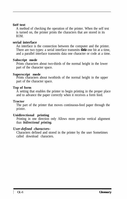
Self testA method of checking the operation of the printer. When the self testis turned on, the printer prints the characters that are stored in itsROM.
serial interfaceAn interface is the connection between the computer and the printer.There are two types: a serial interface transmits data one bit at a time,and a parallel interface transmits data one character or code at a time.
Subscript modePrints characters about two-thirds of the normal height in the lowerpart of the character space.
Superscript modePrints characters about twothirds of the normal height in the upperpart of the character space.
Top of formA setting that enables the printer to begin printing in the proper placeand to advance the paper correctly when it receives a form feed.
TractorThe part of the printer that moves continuous-feed paper through theprinter.
Unidirectional printingPrinting in one direction only Allows more precise vertical alignmentthan bidirectional printing.
User-defined characters-Characters defined and stored in the printer by the user Sometimescalled download characters.
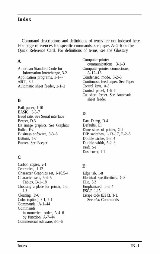
Index
Command descriptions and definitions of terms are not indexed here.For page references for specific commands, see pages A-4–6 or theQuick Reference Card. For definitions of terms, see the Glossary
A
American Standard Code forInformation Interchange, 3-2
Application programs, 3-1–7ASCII, 3-2Automatic sheet feeder, 2-1–2
B
Bail, paper, 1-10BASIC, 3-6–7Baud rate. See Serial interfaceBeeper, D-3Bit image graphics. See GraphicsBuffer, F-2Business software, 3-3–6Buttons, 1-7Buzzer. See Beeper
C
Carbon copies, 2-1Centronics, 1-12Character Graphics set, 1-16,5-4Character sets, 5-4–5
Tables, B-1–18Choosing a place for printer, 1-3,
2-3Cleaning, D-6Color (option), 3-1, 5-1Commands, A-1–44Commands
in numerical order, A-4–6by function, A-7–44
Commericial software, 3-1–6
Computer-printercommunications, 3-1–3
Computer-printer connections,A-12–13
Condensed mode, 5-2–3Continuous feed paper. See PaperControl keys, A-3Control panel, 1-6–7Cut sheet feeder. See Automatic
sheet feeder
D
Data Dump, D-4Defaults, ElDimensions of printer, G-2DIP switches, 1-13–17, E-2–5Double strike, 5-3–4Double-width, 5-2–3Draft, 5-1Dust cover, 1-1
E
Edge tab, 1-8Electrical specifications, G-3Elite, 5-2Emphasized, 5-3–4ESC/P 1-15Escape code (ESC), 3-2.
See also Commands
Index IN-1
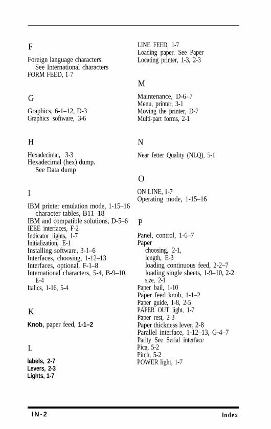
FForeign language characters.
See International charactersFORM FEED, 1-7
GGraphics, 6-1–12, D-3Graphics software, 3-6
HHexadecimal, 3-3Hexadecimal (hex) dump.
See Data dump
IIBM printer emulation mode, 1-15–16
character tables, B11–18IBM and compatible solutions, D-5–6IEEE interfaces, F-2Indicator lights, 1-7Initialization, E-1Installing software, 3-1–6Interfaces, choosing, 1-12–13Interfaces, optional, F-1–8International characters, 5-4, B-9–10,
E-4Italics, 1-16, 5-4
KKnob, paper feed, 1-1–2
Llabels, 2-7Levers, 2-3Lights, 1-7
LINE FEED, 1-7Loading paper. See PaperLocating printer, 1-3, 2-3
MMaintenance, D-6–7Menu, printer, 3-1Moving the printer, D-7Multi-part forms, 2-1
NNear fetter Quality (NLQ), 5-1
OON LINE, 1-7Operating mode, 1-15–16
PPanel, control, 1-6–7Paper
choosing, 2-1,length, E-3loading continuous feed, 2-2–7loading single sheets, 1-9–10, 2-2size, 2-1
Paper bail, 1-10Paper feed knob, 1-1–2Paper guide, 1-8, 2-5PAPER OUT light, 1-7Paper rest, 2-3Paper thickness lever, 2-8Parallel interface, 1-12–13, G-4–7Parity See Serial interfacePica, 5-2Pitch, 5-2POWER light, 1-7
I N - 2 Index
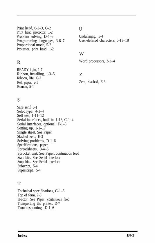
Print head, 6-2–3, G-2Print head protector, 1-2Problem solving, D-1–6Programming languages, 3-6–7Proportional mode, 5-2
UUnderlining, 5-4User-defined characters, 6-13–18
Protector, print head, 1-2W
RREADY light, 1-7
Word processors, 3-3–4
Ribbon, installing, 1-3–5Ribbon, life, G-2Roll paper, 2-1Roman, 5-1
ZZero, slashed, E-3
SSans serif, 5-1SelecType, 4-1–4Self test, 1-11–12Serial interfaces, built in, 1-13, C-1–4Serial interfaces, optional, F-1–8Setting up, 1-1–17Single sheet. See PaperSlashed zero, E-3Solving problems, D-1–6Specifications, paperSpreadsheets, 3-4–6Sprocket unit. See Paper, continuous feedStart bits. See Serial interfaceStop bits. See Serial interfaceSubscript, 5-4Superscript, 5-4
TTechnical specifications, G-1–6Top of form, 2-6II-actor. See Paper, continuous feedTransporting the printer, D-7Troubleshooting, D-1–6
Index IN-3

I N - 4 Index
Quick Reference
Commands by Function
The following list of commands is in the order used in the commandsummary (Appendix A). To find details of the command you want to use, referto the page number in the column for your operating mode-Epson or IBMprinter emulation mode.
Note that for commands consisting of two or more codes, the decimal andhexadecimal columns show only the second code.
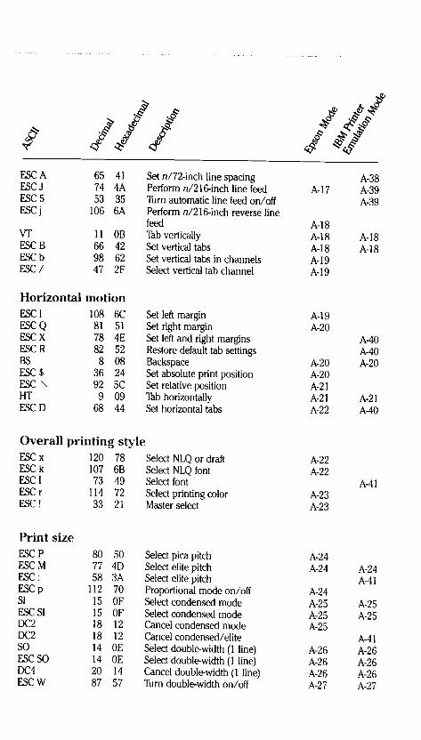
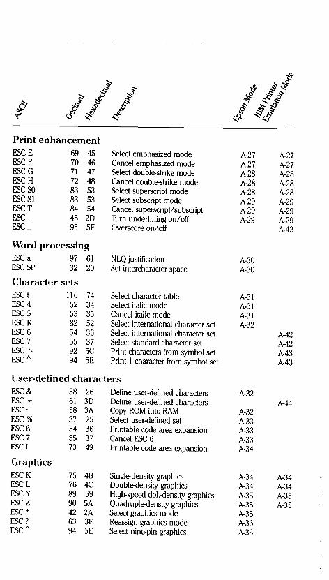
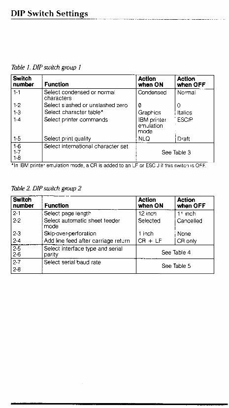
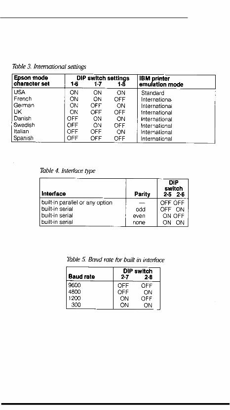
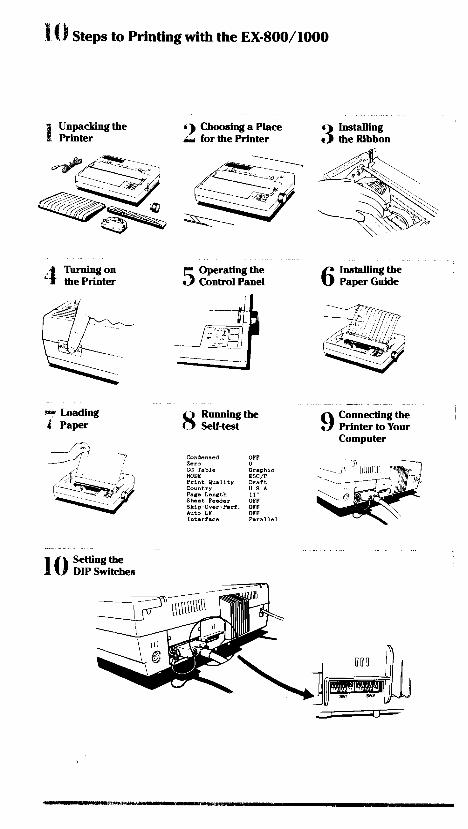
I EPSON OVERSEAS MARKETING LOCATIONS
EPSON AMERICA, INC.2780 Lomita Blvd.,Torrance, Calif. 90505, U.S.A.
Phone: (2 13) 539-9140Telex: 182412
EPSON DEUTSCHLAND GmbHZülpicher Strasse 6, 4000 Düsseldorf 11F.R. GermanyPhone: (02 11) 56030Telex: 8584786
EPSON UK LTD.Campus 100, Maylands Avenue,Hemel Hempstead, Hertfordshire,HP2 7EZ. U.K.Phone: (44) 442-61144Telex: 5182467
EPSON FRANCE S. A.68 bis, rue Marjolin 92300,Levallois-Perret, FrancePhone: (1) 47-373333Telex: 610657
EPSON AUSTRALIA PTY. LTD. EPSON SINGAPORE PTE. LTD.Unit 3, 17 Rodborough Road, No. 1 Raffles Place #26-00Frenchs Forest, NSW 2086, Australia Oub Centre, Singapore 0104Phone: 61 (2) 4520666 Phone: 5330477Telex: 75052 Telex: 39536
EPSON ELECTRONICS TRADING LTD. EPSON ELECTRONICS TRADING LTD.25/F, Harbour Centre. (TAIWAN BRANCH)25 Harbour Road, Wanchai, 10F. No. 287 Nanking E. Road Sec. 3,Hong Kong Taipei, Taiwan, R.O.C.Phone: 5-8314600 Phone: (02) 717-7360Telex: 65542 Telex: 24444
EPSON ITALIA S.p.A.V, le F, Ili Casiraghi. 427 20099
SESTO S, GIOVANNI Ml, ItalyPhone: 39-2-262331
EPSON-STl S.A.Paris, 152, 08036 Barcelona, SpainPhone: 410-3400Telex: 50129 STTK
SEIKO EPSON CORPORATION(Hirooka Office)80 Harashinden, HirookaShiojiri-shi, Nagano-ken399-07 JapanPhone: (0263) 52-2552Telex: 3342-214
1989 Jan.
Featuring:Setting Up
Choosing and Loading PaperTypestyle Selection with SelecType
GraphicsUser-defined CharactersCommand Summary
EPSON AMERICA, INC. 2780 Lomita Boulevard, Torrance, California 90505
Printed in Japan 89.02-6


