Embed Size (px)
Citation preview
Evolutionary structural optimization for stress minimizationproblems by discrete thickness design
Qing Li a, Grant P. Steven a,*, Y.M. Xie b
a Department of Aeronautical Engineering, University of Sydney, Sydney, NSW 2006, Australiab Faculty of Engineering and Science, Victoria University of Technology, P.O. Box 14428, Melbourne City MC, Vic. 8001, Australia
Received 20 April 1999; accepted 18 February 2000
Abstract
Stress minimization is a major aspect of structural optimization in a wide range of engineering designs. This paper
presents a new evolutionary criterion for the problems of variable thickness design whilst minimizing the maximum
stress in a structure. On the basis of ®nite element analysis, a stress sensitivity number is derived to estimate the stress
change in an element due to varying the thickness of other elements. Following the evolutionary optimization proce-
dure, an optimal design with a minimum maximum stress is achieved by gradually removing material from those el-
ements, which have the lowest stress sensitivity number or adding material onto those elements, which have the highest
stress sensitivity number. The numerical examples presented in this paper demonstrate the capacity of the proposed
method for solving stress minimization problems. The results based on the stress criterion are compared with traditional
ones based on a sti�ness criterion, and an optimization scheme based on the combination of both the stress minimi-
zation and the sti�ness maximization criteria is presented. Ó 2000 Elsevier Science Ltd. All rights reserved.
Keywords: Finite element analysis; Stress minimization; Sensitivity analysis; Evolutionary structural optimization; Discrete thickness
design
1. Introduction
The focus of many engineering design analyses is to
®nd the maximum stress present in a given structure
under all loading conditions. Usually, this maximum
provides the basis of a design limit and is thus employed
to determine the structural material and its weight. For
this reason, stress minimization has always been a major
concern of design engineers. This classic problem has
attracted wide attention for many years, but previous
work has mainly been limited to the reduction of stress
concentration for such structural elements as ®llets and
holes by locally re-shaping the initial design [1,2].
In recent years, structural optimization with sti�ness
considerations has been exhaustively studied, as in Refs.
[3±10]. In these publications, the mean compliance is
usually formulated as the objective function while the
weight or volume of the structure is posed as a con-
straint. However, such a design process cannot always
warrant higher reliability and durability, if stress itself is
not considered in the design process [11]. Usually, stress
is presented in a form of constraints rather than an
objective in the optimization processes [12±20]. Al-
though this may guarantee the stress within a prescribed
constraint, it cannot always make the stress minimum.
As pointed out by Yang and Chen [11], when using the
conventional ®nite element and mathematical pro-
gramming based approaches, two major di�culties are
encountered in the treatment of the stress localization
and its high non-linearity with respect to the design
variables. For these reasons, various continuous stress
Computers and Structures 78 (2000) 769±780
www.elsevier.com/locate/compstruc
* Corresponding author.
E-mail address: [email protected] (G.P. Steven).
0045-7949/00/$ - see front matter Ó 2000 Elsevier Science Ltd. All rights reserved.
PII: S0 04 5 -7 94 9 (00 )0 0 05 7 -2
functions, such as the well-known Kreisselmeier±Stein-
hauser function [11], need to be employed to construct
an objective or pose a constraint. In addition, to deal
with the singularity in mathematical programming pro-
cedures of the stress based problems, appropriate re-
laxation techniques have to be used [14,19,20].
To avoid the adoption of the arti®cial stress functions
and use of non-linear programming algorithms, in this
study, the rule based evolutionary structural optimiza-
tion (ESO) algorithm [6,21] is employed to solve such
stress-based problems. The ESO method has been pro-
posed and developed to simplify traditional structural
optimization procedure. It is based on a simple concept
that by systematically removing the material from the
least e�cient regions or adding the material onto the
most e�cient regions, the resulting structure evolves
towards an optimum. Originally, the ESO method takes
elemental stress level as the optimality criterion [21], in
which the lowly (highly) stressed material is regarded as
less (more) e�cient or under (over) utilized from a
standpoint of iso-strength design. As the material is re-
distributed, the stress levels in the remaining structure
become more uniform or the e�ciencies of material us-
age get more even. Recent studies by Mckeown [22] and
the authors [23] have shown that such a fully stressed
design, in fact, is equivalent to a sti�est design. In other
words, although the optimization results in each part of
structure to carry near the same levels of stress, it cannot
always minimize the highest stress in the structure.
To achieve a design of stress minimization, it is es-
sential to estimate the stress change in a speci®ed ele-
ment due to the variation of material allocation of the
other elements. For this purpose, a stress sensitivity
number is introduced in this paper. In the presented
evolutionary optimization process, discrete thickness of
elements is considered as design variables. In terms of
the stress sensitivity number, the thicknesses of candi-
date elements are progressively redistributed so that the
maximum stress is gradually minimized.
It should be pointed out that the proposed stress
minimization criterion di�ers from the conventional
sti�ness maximization one. In these two criteria, the
maximum stress is considered as an objective function
for the former and could be treated as a constraint for
the latter. Note that, in most of the typical sti�ness de-
signs, increases in maximum stress can be relatively
small, and usually, do not violate the stress constraint [6].
Therefore, the sti�ness maximization criterion is most
commonly used, in which the strength requirement is
re¯ected by means of the fully stressed or iso-strength
concept [21,23,24]. It is believed that an ideal optimiza-
tion should comply with both the stress minimization and
the sti�ness maximization. Under most circumstances,
however, this is very di�cult and an appropriate trade-
o� is usually required. For this reason, the paper also
develops a weighting factor scheme to address this issue.
2. Sensitivity analysis
In variable thickness design, one of the common
approaches of changing the material distribution of a
structure is to reduce or increase thickness of some ele-
ments [6,8,25,26]. This can be done by simply assigning
the element thickness to the next available one from a
given set of discrete values. It is a desirable technical
goal that such a process of material morphing leads to
the reduction of the maximum stress in a structure. For
this purpose, it is necessary to evaluate the contribution
of elemental thickness variation to the reduction of the
maximum stress, prior to the material redistribution.
2.1. Displacement sensitivity number
Suppose the ith element is to be re-sized to the next
available lower thickness. This results in the change in
the global sti�ness matrix by DK̂i � K ÿ Knewi . The
change in displacements can be determined by consid-
ering the equilibrium conditions before the change [6±
10], i.e.
Ku � p �1�and after the change, i.e.
�K ÿ DK̂i� � �u� Du� � p; �2�where K denotes the global sti�ness matrix of the old
system, u the global nodal displacement vector, p the
nodal load vector and Du the change of the displacement
vector u. No change in the nodal load vector is assumed
[7±10]. By subtracting Eq. (1) from Eq. (2) and ignoring
the higher order term [10], the change in the displace-
ment vector can be found as
Du � Kÿ1 � DK̂i � u: �3�To ®nd the change in a speci®ed jth displacement
component uj, a virtual unit load vector f j, in which the
jth component is equal to unity and all the others are
equal to zero, is introduced. Multiplying Eq. (3) by f j,
the change Duj in the speci®ed jth displacement com-
ponent due to the thickness change in the ith element, is
determined by
Duj � f Tj � Du � f T
j Kÿ1 DK̂iu � uTj DK̂iu; �4�
where uj represents the solution of Eq. (1) under the
virtual load f j (i.e. K � uj � f j). The displacement
change Duj can be simply calculated at one element level
as [6±10,27±30]
Duj � uTij DK iui � uT
ij � �K i�t� ÿ K i�t ÿ Dt�� � ui; �5�
where DK i is the change of the ith elementÕs sti�ness
matrix due to the variation from the old thickness t to
the next lower thickness �t ÿ Dt�, ui and uij denote the
770 Q. Li et al. / Computers and Structures 78 (2000) 769±780
displacement vectors of the ith element under the real
load p and the virtual unit load f j, respectively. The
value,
aij � uTij DK iui �6�
is de®ned as the displacement sensitivity number of the ith
element, which is used to estimate the displacement
change of the jth degree of freedom due to the thickness
change of element i.
Under typical sti�ness based criteria, structures are
required to be sti� enough to carry the given loads. In
structural design, strain energy is commonly considered
as an inverse measure for the overall sti�ness of a
structure. It is well known that maximizing the overall
sti�ness is equivalent to minimizing the strain energy. In
general, the reduction of element's thickness leads to the
increase in strain energy and decrease in the sti�ness. To
evaluate the e�ect of the element thickness reduction on
the overall strain energy of the structure, a sti�ness
sensitivity number can be further de®ned [7,8], similar to
Eq. (6), as
as;i � 12pTDu � 1
2pTKÿ1 DK̂iu
� 12uT
i �K i�t� ÿ K i�t ÿ Dt��ui � 12uT
i DK iui: �7�
2.2. Stress sensitivity number
In stress minimization, stress is taken into account as
a design objective. Therefore, it is necessary to evaluate
the stress change of an element due to the thickness
variation in other elements. Without losing any gener-
ality, 2D plane stress problems are considered for sim-
plicity. The derivation can be easily extended to other
cases.
In ®nite element analysis, the kth element stress
vector r � frxx; ryy ; rxygTk can be calculated on the basis
of its nodal displacement vector uk � fu1; u2; . . . ;uj; . . . ; ungT
k by
r � DBuk �8�
where n is the total number of degrees of freedom for
element k, D and B stress denote the conventional elastic
and strain matrices respectively [27±29]. The change of
the kth element stress vector due to the variation in the
ith elementÕs thickness can be expressed as
Dr � fDrxx;Dryy ;DrxygTk � DB Duk ; �9�
where vector Duk � fDu1;Du2; . . . ;Duj; . . . ;DungTk de-
notes the nodal displacement change of the kth element.
From the previous discussion, the change Duj�j � 1; 2;. . . ; n� of the displacement component uj can be calcu-
lated by the displacement sensitivity number as de®ned in
Eq. (5) or Eq. (6), thereby Eq. (9) can be expressed as
Dr � DBfai1; ai2; . . . ; aij; . . . ; aingTk � DBa; �10�
where a � fai1; ai2; . . . ; aij; . . . ; aingTk is hereafter referred
to as the displacement sensitivity vector of the ith ele-
ment, which indicates the displacement changes of all
nodal components of the kth element due to the thick-
ness variation of the ith element. Using Eq. (10), the
change of the kth element stress can be calculated on the
basis of the variations of its displacement components.
In engineering design, the stress level at each element
may be measured by some sort of aggregate of all the
stress components. For isotropic material, the von Mises
stress is frequently used in this capacity. In a plane stress
problem, the von Mises stress rvm at the kth element is
expressed as [23]
rvm � g�rxx; ryy ; rxy� � �rTTr�1=2k ; �11�
where
T �1 ÿ0:5 0ÿ0:5 1 0
0 0 3
24 35is the coe�cient matrix of von Mises quadratic form.
The change in elementÕs von Mises stress can be found
by
Drvm � ogorxx� Drxx � og
oryy� Dryy � og
orxy� Drxy
� rgT �DBa � c � a; �12�where
rg � ogorxx
;og
oryy;
ogorxy
� �T
k
is the gradient vector of von Mises stress function and
c � rgTDB � fc1; c2; . . . ; cj; . . . ; cngTk represents the co-
e�cients of the element displacement sensitivity vector a.
It has been previously shown, how to ®nd the dis-
placement change of the jth degree of freedom in ele-
ment k by using a virtual unit load corresponding to this
degree of freedom. Adopting this idea, to ®nd the stress
change of the kth element, there would need to be n
virtual unit loads imposed to deal with each degree of
freedom from Eqs. (10) and (12). In other words, the
number of virtual systems depends on the total number
of degrees of freedom per element. Thus, the computa-
tional cost will be considerably higher than that for a
sti�ness sensitivity analysis as Eq. (7). It would be ben-
e®cial to reduce the number of virtual systems and
thereby improve the computational e�ciency. Accord-
ing to the de®nition of the displacement sensitivity
number in Eq. (6), Eq. (12) can be re-written as [9,30].
Drvm �Xn
j�1
�cjuTij DK iui� �
Xn
j�1
cjuTij
!� DK i � ui: �13�
Q. Li et al. / Computers and Structures 78 (2000) 769±780 771
Note that uTij�j � 1; 2; . . . ; n� is the solution of the jth
virtual system of
Kuij � f j: �14�
Multiplying Eq. (14) by the coe�cient cj yields
Kcjuij � cjf j: �15�
Adding all the n virtual equilibrium equations given in
Eq. (15), we have
KXn
j�1
cjuij
!�Xn
j�1
cjf j or K~uik � ~f ; �16�
where ~uik �Pn
j�1 cjuij represents one virtual displace-
ment vector and ~f �Pnj�1 cjf j denotes one virtual load.
In a certain extent, the approach is similar to the tra-
ditional adjoint sensitivity analysis as in Refs. [27±29].
Eq. (16) introduces a new virtual system, where n
non-zero components of the virtual load vector ~f are the
corresponding coe�cients cj instead of the unit value
used in the previous displacement sensitivity analysis.
The solution ~uik of this new virtual system (Eq. (16))
provides the result, which is required in Eq. (13). Con-
sequently, Eq. (13) can be re-written as
Drvm � ~uTik � DK i � ui: �17�
Thus, by introducing only one virtual load ~f , the change
of the von Mises stress at the kth element can be eval-
uated. The above processing signi®cantly improves the
computing e�ciency. Therefore, we de®ne
ar;i � ~uTik � DK i � ui �18�
as the ith elementÕs stress sensitivity number, whose for-
mulation is quite similar to those of the displacement
sensitivity number in Eq. (6) and the sti�ness sensitivity
number in Eq. (7).
It is worth noting that the stress sensitivity number
ar;i can be positive or negative, which implies that the
stress of element k may increase or decrease, when there
is a change in the thickness of element i. This provides a
means of controlling the stress at a speci®ed element by
appropriate thickness design in other regions of a
structure. The principle can be extended to any kind of
structural modi®cation.
It should also be pointed out that the above deriva-
tion is not restricted to the von Mises stress. Indeed, any
form of stress function ~r � f �rxx; ryy ; rxy� (for instance,
principle stresses or Tresca stress) can have a corre-
sponding stress sensitivity number, which can then be
employed to evaluate the change of the relevant stress
function due to thickness variations of other elements.
Hence, di�erent design requirements can be met.
As stated previously, the maximum stress in a
structure plays a crucial role in an engineering design. It
is often the major objective of a designer to minimize the
maximum stress in a structure. One of the most impor-
tant advantages of establishing the stress sensitivity
number is that it identi®es the location at which the
structure should be modi®ed, so that the maximum
stress can be most e�ciently reduced.
3. Evolutionary optimization procedure and implementa-
tion
There are two approaches to the design of thickness
distribution of a structure. One is to set the initial design
thickness at the maximum possible value, then gradu-
ally remove the redundant/ine�cient material from the
structure by progressive thickness reduction in terms of
the stress sensitivity number. Another is to set the ini-
tial design thickness at a medium value, then gradually
shift the material from the over-designed location to the
under-designed location. These two di�erent approaches
are described separately in the following sections.
3.1. Morphing evolutionary structural optimization via
material removal
The previous derivations have shown the possibility
of minimizing the highest stress in a structure by ap-
propriate thickness design. In a morphing ESO proce-
dure, the initial design thickness is ®rst set at the
maximum possible value. Then by using the stress sen-
sitivity number, redundant/ine�cient material is re-
moved from the structure by thickness reduction. This is
performed in a discrete and progressive manner, i.e.
from the old thickness t downwards to the next lower
thickness t ÿ Dt at each iterative step. The change in
sti�ness matrix is
DK i � K i�t� ÿ K i�t ÿ Dt�; �19�
where K i�t� and K i�t ÿ Dt� denote the elemental sti�ness
matrices of the ith element for the old thickness t and the
new thickness �t ÿ Dt�, respectively. In practice, a set of
allowable discrete values for element thicknesses is given
in a decreasing order as
ts � ft1; t2; . . . ; tr; tr�1; . . . ; tmgT; �20�
where tr > tr�1�r � 1; 2; . . . ;mÿ 1� is the available de-
sign thickness and m is the number of discrete thickness;
t � t1 and t � tm are referred to as the upper bound and
lower bound of the design variables, respectively. When
the thickness of an element has reached the lower bound
t � tm, it will no longer change. In accordance with dif-
ferent design requirements, the step sizes of Dt (i.e.
tr ÿ tr�1) may be constant or variable.
In the evolutionary procedure, the number of ele-
ments subjected to the thickness reduction should be
appropriately small to ensure a smooth change between
772 Q. Li et al. / Computers and Structures 78 (2000) 769±780
two iterations [6±10]. This is because the displacement
sensitivity number is formulated by ignoring a high or-
der term, and is valid only when the changes in the
sti�ness matrix and the displacement vector are small. In
the ESO method, the number of elements with thickness
reduction can be determined by the step size Dt and a
prescribed material removal ratio (MRR), which is de-
®ned as the amount of removed material (volume) at
each iteration over the total material (volume) of the
initial design domain. A typical value for MRR is
around 0.1±1%. This is the range that has been used to
solve the example problems below.
The evolutionary iteration procedure for thickness
reduction is given as follows:
Step 1: discretize the structure using a dense ®nite
element mesh;
Step 2: de®ne a variable thickness set ts and the ESO
driving parameters MRR;
Step 3: carry out a FEA for the real system as de®ned
in Eq. (1);
Step 4: ®nd element k with the maximum stress, then
apply a virtual load ~f as given in Eq. (16) onto this
element;
Step 5: perform another FEA for the virtual system
as de®ned in Eq. (16);
Step 6: calculate stress sensitivity number ar;i using
Eq. (18);
Step 7: reduce the thicknesses of a number of ele-
ments with the most negative ar;i;
Step 8: repeat Steps 3±7 until a minimized maximum
stress is found.
3.2. Morphing evolutionary structural optimization via
material shifting
In the previous section, the optimization process is
carried out by progressively removing material from the
structure. Therefore, the total weight or the volume of
the structure is gradually reduced with the evolutionary
process. Sometimes, a designer may wish to improve the
performance or reliability of a structure while keeping its
weight (or volume) constant. This can be achieved by
shifting material from the ÔstrongestÕ to the ÔweakestÕlocation. The concept of strength or weakness originated
from the conventional fully stressed criterion [6,21,31],
in which the material is gradually shifted from the least
e�cient (under-utilized) location to the most e�cient
(over-utilized) location. In stress minimization prob-
lems, the concept of ÔstrengthÕ and ÔweaknessÕ needs to be
distinguished between the case of thickness reduction
from that of thickness increase [6]. The e�ect of the
thickness variation of the ith element on the stress of the
kth element is estimated by Eq. (17). In the case of
thickness increase, we have
DK i � DK�i � K i�t� ÿ K i�t � Dt� �21�
and in the case of thickness reduction, we have
DK i � DKÿi � K i�t� ÿ K i�t ÿ Dt�: �22�Therefore, two sensitivity numbers need to be calculated
for each element, one for thickness increase
a�r;i � ~uTik � DK�i � ui �23�
and another for thickness reduction
aÿr;i � ~uTik � DKÿi � ui: �24�
To minimize the maximum stress, the most e�ective way
is to remove the material from the elements with the
most negative aÿr;i and then add it to the elements with
the most negative a�r;i. When the evolving process has
progressed to a certain degree, the lowest aÿr;i may be
come positive. Then, the increase or reduction of the
stress will depend on the deviation between the lowest
a�r;i and the lowest aÿr;i. Usually, a tolerance s needs to be
prescribed for the convergence check on the target stress
�rmax�. If the relative change in the target stress in two
successive iterations is less than the given tolerance s, i.e.
rnewmax ÿ rold
max
rnewmax
���� ����6 s; �25�
then, a convergent state for the target stress is reached
and the evolutionary procedure may be terminated. To
continue the iterations beyond such a convergent state
will yield little or no improvement in the target stress.
In general, the variations in element sti�ness matrix
DK�i and DKÿi due to the thickness change may be dif-
ferent. Therefore, they need to be calculated at the end
of each ®nite element analysis. For the simplest plane
stress problems, however, jDK�i j is equal to jDKÿi j.Under this condition, the calculation of the stress sen-
sitivity number may be carried out just once.
The number of elements subjected to material shift is
also determined by the step size Dt and the prescribed
material shift ratio (MSR) [6,8], de®ned as the amount of
material to be shifted at each iteration over the total
material (volume) of the designed structure. Typical
values for MSR are 0.1±1%, which have been used to
solve the following examples.
In the evolution process, the thickness of original
design is often set at a value between the upper bound tand lower bound t of the thickness set ts. When the
thickness reaches its upper bound (i.e. t � t) or lower
bound (i.e. t � t), respectively, they cannot change up-
wards or downwards any further, but may reverse di-
rection if subsequent calculation of sensitivity numbers
requires this. The evolutionary iteration procedure for
minimizing the maximum stress while keeping the
weight constant is organized as follows:
Step 1: discretize the structure using a dense ®nite
element mesh;
Q. Li et al. / Computers and Structures 78 (2000) 769±780 773
Step 2: de®ne a thickness set ts and the ESO driving
parameter MSR;
Step 3: perform a FEA for the real system as de®ned
in Eq. (1);
Step 4: ®nd the element k with the maximum stress,
then add virtual load ~f as given in Eq. (16) onto this
element;
Step 5: perform another FEA for the virtual system
as de®ned in Eq. (16);
Step 6: calculate stress sensitivity numbers a�r;i and
aÿr;i using Eqs. (23) and (24);
Step 7: reduce the thickness of a number of elements
with the lowest aÿr;i and increase the thickness of a
number of elements with the lowest a�r;i while keeping
the volume constant;
Step 8: repeat Steps 3±7 until the objective has
reached to a convergent state as de®ned by Eq. (25).
4. Examples and discussion
Based on the proposed stress minimization criterion,
three examples are presented to demonstrate the capa-
bility of the ESO method. The ®rst two examples have
their volume progressively decreased by removing ma-
terial, the third one maintains constant volumes by
shifting material. All the examples are assumed to be
under plane stress conditions and aimed at minimizing
the maximum von Mises stress. To compare the pro-
posed stress based designs with the more traditional
sti�ness based ones, each example is also solved in terms
of the sti�ness sensitivity numbers as de®ned in Eq. (7).
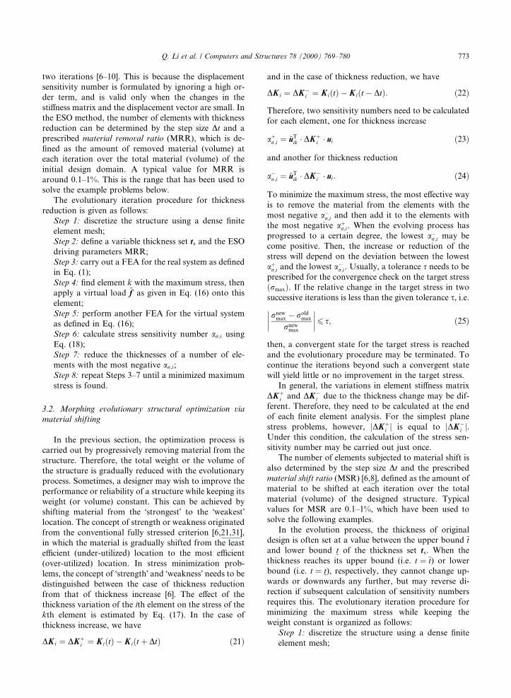
4.1. Example 1
A rectangular plate with the dimensions of 40 mm �20 mm is clamped along two sides of the top edge and
loaded by a uniform stress r � 10 MPa along the middle
region of the bottom edge as shown in Fig. 1. The re-
gions of clamped and loaded elements are considered as
the non-design domains. The Young modulus E and the
Poisson ratio m are set at 210 GPa and 0.3, respectively.
Due to the symmetry, only half of the region is analyzed
with 20� 20 four node plane stress elements. Upon
completion of the evolutionary process, the symmetric
half region is mirrored up to clarify the whole structure.
In this example, the design vector is set in equal in-
tervals of Dt � 0:1 from 1.0 to 0.5 mm, i.e. ts � f1:0; 0:9;0:8; 0:7; 0:6; 0:5gT
. Initially, all elements are assigned the
upper bound of the variable vector, i.e. t � 1:0 mm. In
the evolution process, a material removal ratio of
MMR � 16� 0:1=190 � 0:84% (i.e. 16 elements for
each iteration) is adopted.
To minimize the maximum von Mises stress and to
maximize the overall sti�ness of the structure, the stress
and sti�ness based criterion are used in terms of the
corresponding sensitivity numbers as de®ned in Eqs.
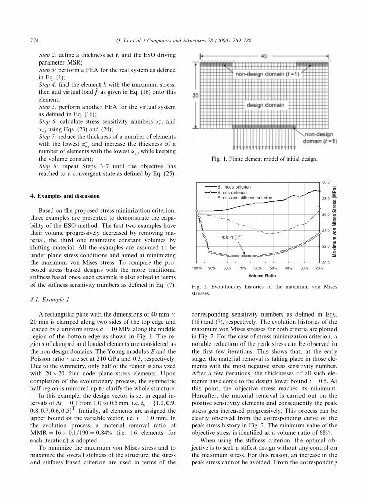
(18) and (7), respectively. The evolution histories of the
maximum von Mises stresses for both criteria are plotted
in Fig. 2. For the case of stress minimization criterion, a
notable reduction of the peak stress can be observed in
the ®rst few iterations. This shows that, at the early
stage, the material removal is taking place in those ele-
ments with the most negative stress sensitivity number.
After a few iterations, the thicknesses of all such ele-
ments have come to the design lower bound t � 0:5. At
this point, the objective stress reaches its minimum.
Hereafter, the material removal is carried out on the
positive sensitivity elements and consequently the peak
stress gets increased progressively. This process can be
clearly observed from the corresponding curve of the
peak stress history in Fig. 2. The minimum value of the
objective stress is identi®ed at a volume ratio of 68%.
When using the sti�ness criterion, the optimal ob-
jective is to seek a sti�est design without any control on
the maximum stress. For this reason, an increase in the
peak stress cannot be avoided. From the corresponding
Fig. 1. Finite element model of initial design.
Fig. 2. Evolutionary histories of the maximum von Mises
stresses.
774 Q. Li et al. / Computers and Structures 78 (2000) 769±780

stress evolution curve in Fig. 2, it can be seen that the
maximum stress increases in some iteration steps and
decreases at others. This implies that the elements with
the least strain energy might not be those with negative
stress sensitivity, or vice versa. In this sense, the sti�ness
criterion may not comply with the strength criterion,
in other words, the Ôsti�est designÕ may not be the
Ôstrongest designÕ.Fig. 3 shows the di�erence in the sti�ness evolution
histories for both criteria. As mentioned before, for a
®xed load, the strain energy is the inverse measure of the
overall sti�ness of a structure. A structure is sti�er when
its strain energy is lower. From the plotted evolutionary
histories of the strain energy, one can see the strain en-
ergy of the Ôsti�est designÕ (sti�ness maximization) is
considerably lower than that of the Ôstrongest designÕ(stress minimization). In the ®rst few iterations, the
strain energy is almost unchanged for the sti�ness design
but clearly increases for the strength design. This reveals
the converse statement to the one above: the Ôstrongest
designÕ may not be the Ôsti�est designÕ.In view of the di�erence between the stress criterion
and the sti�ness criterion, a weighting factor scheme is
employed to produce a design, which is a compromise
between these two criteria. In the ESO procedure, the
sequence of material removal of an element is deter-
mined by that of its sensitivity number. In other words,
the sequences of element sensitivity numbers are re-
garded as their relative contribution levels to design
objectives. As a result, the elementÕs overall contribution
to both stress and sti�ness criteria can be measured by
adding the sequences of these two sensitivity numbers
with weight factors as
Si � wr � S�ai;r� � ws � S�ai;s�; �26�where wr and ws represent the weight factors for stress
criterion and sti�ness criterion, respectively, and usually:
wr � ws � 1. The weight factors can be used to empha-
size the satisfaction of the di�erent design criteria. In
this example, considering that stress minimization is a
major concern, it is assigned a larger weight factor as
wr � 0:7;ws � 0:3.
Fig. 4(a) and (b) shows the optimal designs for the
stress minimization and the sti�ness maximization, re-
spectively. From a strength point of view, it is worth
noting that the maximum von Mises stress is reduced by
Fig. 3. Evolutionary histories of the strain energy.
Fig. 4. Optimized designs based on di�erent criteria
�V =V0 � 68%� (a) Design for the stress minimization (material
removed by 32%, rmaxvm reduced by 21% and strain energy in-
creased by 17%). (b) Design for the sti�ness maximization
(material removed by 32%, rmaxvm increased by 3% and strain
energy increased by 2%). (c) Design for stress minimization and
sti�ness maximization (wr � 0:7;ws � 0:3;rmaxvm reduced by 7%
and strain energy increased by 6%).
Q. Li et al. / Computers and Structures 78 (2000) 769±780 775
21% and the structure volume reduced by 32% for the
stress criterion design. Compared to the sti�ness based
design with the same volume ratio of 68%, the stress
reduction is remarkable and meaningful. This shows the
most signi®cant advantages of the proposed criterion
over the conventional sti�ness design, in which material
volume and the maximum stress are simultaneously re-
duced. From the sti�ness standpoint, however, the in-
crease in the strain energy based on stress criterion
reaches 17%, while that based on sti�ness criterion is just
2%. Thus, there exists a notable sti�ness di�erence be-
tween these two designs. Fig. 4(c) shows a trade o� de-
sign between the stress minimization and the sti�ness
maximization, where the peak stress reduces by 7% and
the strain energy increases by only 6% at the same vol-
ume ratio of 68%.
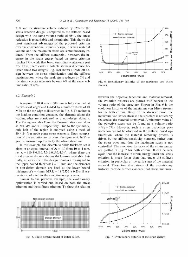
4.2. Example 2
A region of 1000 mm� 300 mm is fully clamped at
its two short edges and loaded by a uniform stress of 10
MPa on the top edge as illustrated in Fig. 5. To maintain
the loading condition constant, the elements along the
loading edge are considered as a non-design domain.
The Young modulus E and the Poisson ratio m are taken
as 210 GPa and 0.3, respectively. Due to the symmetry,
only half of the region is analyzed using a mesh of
40� 24 four node plane stress elements. Upon comple-
tion of the evolutionary process, the symmetric half re-
gion is mirrored up to clarify the whole structure.
In this example, the discrete variable thickness set is
given in an equal interval of Dt � 1:0 from 10 to 4 mm,
i.e. ts � f10; 9:0; 8:0; 7:0; 6:0; 5:0; 4:0gT, where there are
totally seven discrete design thicknesses available. Ini-
tially, all elements in the design domain are assigned to
the upper bound thickness t � 10 mm and the elements
in non-design domain are ®xed at the lower bound
thickness of t � 4 mm. MRR � 18=5520 � 0:2% (18 ele-
ments) is adopted in the evolutionary processes.
Similar to the previous example, the evolutionary
optimization is carried out, based on both the stress
criterion and the sti�ness criterion. To show the relation
between the objective functions and material removal,
the evolution histories are plotted with respect to the
volume ratio of the structure. Shown in Fig. 6 is the
evolution histories of the maximum von Mises stresses
for the both criteria. Based on the stress criterion, the
maximum von Mises stress in the structure is noticeably
reduced as the material is removed. A minimum value of
the objective stress can be found at a volume ratio
V =V0 � 77%. However, such a stress reduction phe-
nomenon cannot be observed in the sti�ness based op-
timization, where the material removing process is
driven by the sti�ness sensitivity numbers, rather than
the stress ones and thus the maximum stress is not
controlled. The evolution histories of the strain energy
are plotted in Fig. 7 for both criteria. It can be seen
again that the increase in strain energy under the stress
criterion is much faster than that under the sti�ness
criterion, in particular at the early stage of the material
removal. These two illustrations of the evolutionary
histories provide further evidence that stress minimiza-
Fig. 5. Finite element model of initial design.
Fig. 6. Evolutionary histories of the maximum von Mises
stresses.
Fig. 7. Evolutionary histories of the strain energy.
776 Q. Li et al. / Computers and Structures 78 (2000) 769±780
tion and sti�ness maximization cannot be satis®ed si-
multaneously.
To partially achieve both objectives, the weight fac-
tor scheme is again used in this example. In general, the
e�ects of weighting factor wr and ws on stress and
sti�ness objectives are not linear. This implies that a
50%±50% allocation of weights may not re¯ect an equal
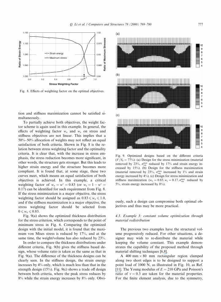
satisfaction of both criteria. Shown in Fig. 8 is the re-
lation between stress weighting factor and the optimality
criteria. It is clear that, with the increase in stress em-
phasis, the stress reduction becomes more signi®cant, in
other words, the structure gets stronger. But this leads to
higher strain energy and the structure becomes more
compliant. It is found that, at some stage, these two
curves meet, which means an equal satisfaction of both
objectives is achieved. In this example, a critical
weighting factor of wr � w� � 0:83 (or ws � 1ÿ w� �0:17) can be identi®ed for such requirement from Fig. 8.
If the stress minimization is a major objective, the stress
weighting factor should be assigned as 0:836wr6 1:0,
and if the sti�ness maximization is a major objective, the
stress weighting factor should be selected from
06wr6 0:83.
Fig. 9(a) shows the optimized thickness distribution
for the stress criterion, which corresponds to the point of
minimum stress in Fig. 6. Comparing the optimized
design with the initial model, it is found that the maxi-
mum von Mises stress is reduced by 17%, and at the
same time, the weight/volume has also reduced by 23%.
In order to compare the thickness distributions under
di�erent criteria, Fig. 9(b) gives the sti�ness based de-
sign, whose volume ratio is taken as the same as that in
Fig. 9(a). The di�erence of the thickness designs can be
clearly seen. In the sti�ness design, the strain energy
increases by 4% only, which is much less than that in the
strength design (15%). Fig. 9(c) shows a trade o� design
between both criteria, where the peak stress reduces by
8% while the strain energy increases by 8% only. Obvi-
ously, such a design can compromise both optimal ob-
jectives and thus may be more practical.
4.3. Example 3: constant volume optimization through
material redistribution
The previous two examples have the structural vol-
ume progressively reduced. For other situations, a de-
signer may wish to re-distribute the material while
keeping the volume constant. This example demon-
strates the capability of the proposed method through
material shifting techniques [6,8].
A 400 mm� 80 mm rectangular region clamped
along two short edges is to be designed to support a
point load of 1000 N, as illustrated in Fig. 10, as Ref.
[11]. The Young modulus of E � 210 GPa and PoissonÕsratio of m � 0:3 are taken for the material properties.
For the ®nite element analysis, due to the symmetry,
Fig. 8. E�ects of weighting factor on the optimal objectives.
Fig. 9. Optimized designs based on the di�erent criteria
(V =V0 � 77%): (a) Design for the stress minimization (material
removed by 23%, rmaxvm reduced by 17% and strain energy in-
creased by 15%). (b) Design for the sti�ness maximization
(material removed by 23%, rmaxvm increased by 1% and strain
energy increased by 4%). (c) Design for stress minimization and
sti�ness maximization (wr � 0:83;ws � 0:17;rmaxvm reduced by
5%, strain energy increased by 8%).
Q. Li et al. / Computers and Structures 78 (2000) 769±780 777
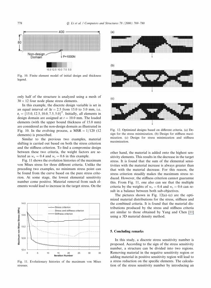
only half of the structure is analyzed using a mesh of
30� 12 four node plane stress elements.
In this example, the discrete design variable is set in
an equal interval of Dt � 2:5 from 15.0 to 5.0 mm, i.e.
ts � f15:0; 12:5; 10:0; 7:5; 5:0gT. Initially, all elements in
design domain are assigned at t � 10:0 mm. The loaded
elements (with the upper bound thickness of 15.0 mm)
are considered as the non-design domain as illustrated in
Fig. 10. In the evolving process, a MSR � 1=120 (12
elements) is prescribed.
Similar to the previous two examples, material
shifting is carried out based on both the stress criterion
and the sti�ness criterion. To ®nd a compromise design
between these two criteria, the weight factors are se-
lected as wr � 0:4 and ws � 0:6 in this example.
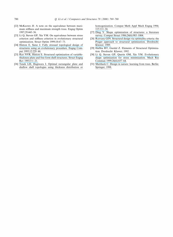
Fig. 11 shows the evolution histories of the maximum
von Mises stress for three di�erent criteria. Unlike the
preceding two examples, no minimum stress point can
be found from the curve based on the pure stress crite-
rion. At some stage, the lowest elemental sensitivity
number come positive. Material removal from such el-
ements would lead to increase in the target stress. On the
other hand, the material is added onto the highest sen-
sitivity elements. This results in the decrease in the target
stress. It is found that the sum of the elemental sensi-
tivities with the material increase is always greater than
that with the material decrease. For this reason, the
stress criterion steadily makes the maximum stress re-
duced. However, the sti�ness criterion cannot guarantee
this. From Fig. 11, one also can see that the multiple
criteria by the weights of wr � 0:4 and ws � 0:6 can re-
sult in a balance between both sub-objectives.
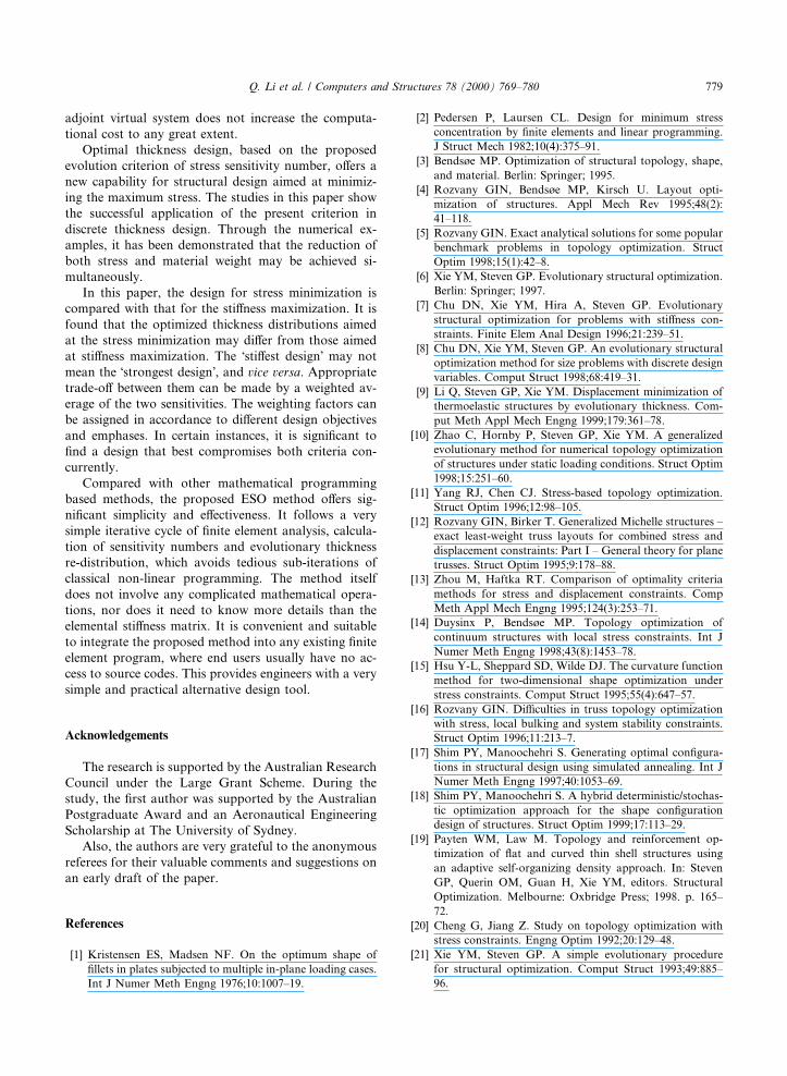
The pictures shown in Fig. 12(a)±(c) are the opti-
mized material distributions for the stress, sti�ness and
the combined criteria. It is found that the material dis-
tributions produced by the stress and sti�ness criteria
are similar to those obtained by Yang and Chen [11]
using a 3D material density method.
5. Concluding remarks
In this study, a discrete stress sensitivity number is
proposed. According to the sign of the stress sensitivity
number, a structure can be divided into two regions.
Removing material in the negative sensitivity region or
adding material in positive sensitivity region will lead to
a stress reduction on the speci®c elements. The calcula-
tion of the stress sensitivity number by introducing an
Fig. 10. Finite element model of initial design and thickness
legend.
Fig. 11. Evolutionary histories of the maximum von Mises
stresses.
Fig. 12. Optimized designs based on di�erent criteria. (a) De-
sign for the stress minimization. (b) Design for sti�ness maxi-
mization. (c) Design for stress minimization and sti�ness
maximization.
778 Q. Li et al. / Computers and Structures 78 (2000) 769±780
adjoint virtual system does not increase the computa-
tional cost to any great extent.
Optimal thickness design, based on the proposed
evolution criterion of stress sensitivity number, o�ers a
new capability for structural design aimed at minimiz-
ing the maximum stress. The studies in this paper show
the successful application of the present criterion in
discrete thickness design. Through the numerical ex-
amples, it has been demonstrated that the reduction of
both stress and material weight may be achieved si-
multaneously.
In this paper, the design for stress minimization is
compared with that for the sti�ness maximization. It is
found that the optimized thickness distributions aimed
at the stress minimization may di�er from those aimed
at sti�ness maximization. The Ôsti�est designÕ may not
mean the Ôstrongest designÕ, and vice versa. Appropriate
trade-o� between them can be made by a weighted av-
erage of the two sensitivities. The weighting factors can
be assigned in accordance to di�erent design objectives
and emphases. In certain instances, it is signi®cant to
®nd a design that best compromises both criteria con-
currently.
Compared with other mathematical programming
based methods, the proposed ESO method o�ers sig-
ni®cant simplicity and e�ectiveness. It follows a very
simple iterative cycle of ®nite element analysis, calcula-
tion of sensitivity numbers and evolutionary thickness
re-distribution, which avoids tedious sub-iterations of
classical non-linear programming. The method itself
does not involve any complicated mathematical opera-
tions, nor does it need to know more details than the
elemental sti�ness matrix. It is convenient and suitable
to integrate the proposed method into any existing ®nite
element program, where end users usually have no ac-
cess to source codes. This provides engineers with a very
simple and practical alternative design tool.
Acknowledgements
The research is supported by the Australian Research
Council under the Large Grant Scheme. During the
study, the ®rst author was supported by the Australian
Postgraduate Award and an Aeronautical Engineering
Scholarship at The University of Sydney.
Also, the authors are very grateful to the anonymous
referees for their valuable comments and suggestions on
an early draft of the paper.
References
[1] Kristensen ES, Madsen NF. On the optimum shape of
®llets in plates subjected to multiple in-plane loading cases.
Int J Numer Meth Engng 1976;10:1007±19.
[2] Pedersen P, Laursen CL. Design for minimum stress
concentration by ®nite elements and linear programming.
J Struct Mech 1982;10(4):375±91.
[3] Bendsùe MP. Optimization of structural topology, shape,
and material. Berlin: Springer; 1995.
[4] Rozvany GIN, Bendsùe MP, Kirsch U. Layout opti-
mization of structures. Appl Mech Rev 1995;48(2):
41±118.
[5] Rozvany GIN. Exact analytical solutions for some popular
benchmark problems in topology optimization. Struct
Optim 1998;15(1):42±8.
[6] Xie YM, Steven GP. Evolutionary structural optimization.
Berlin: Springer; 1997.
[7] Chu DN, Xie YM, Hira A, Steven GP. Evolutionary
structural optimization for problems with sti�ness con-
straints. Finite Elem Anal Design 1996;21:239±51.
[8] Chu DN, Xie YM, Steven GP. An evolutionary structural
optimization method for size problems with discrete design
variables. Comput Struct 1998;68:419±31.
[9] Li Q, Steven GP, Xie YM. Displacement minimization of
thermoelastic structures by evolutionary thickness. Com-
put Meth Appl Mech Engng 1999;179:361±78.
[10] Zhao C, Hornby P, Steven GP, Xie YM. A generalized
evolutionary method for numerical topology optimization
of structures under static loading conditions. Struct Optim
1998;15:251±60.
[11] Yang RJ, Chen CJ. Stress-based topology optimization.
Struct Optim 1996;12:98±105.
[12] Rozvany GIN, Birker T. Generalized Michelle structures ±
exact least-weight truss layouts for combined stress and
displacement constraints: Part I ± General theory for plane
trusses. Struct Optim 1995;9:178±88.
[13] Zhou M, Haftka RT. Comparison of optimality criteria
methods for stress and displacement constraints. Comp
Meth Appl Mech Engng 1995;124(3):253±71.
[14] Duysinx P, Bendsùe MP. Topology optimization of
continuum structures with local stress constraints. Int J
Numer Meth Engng 1998;43(8):1453±78.
[15] Hsu Y-L, Sheppard SD, Wilde DJ. The curvature function
method for two-dimensional shape optimization under
stress constraints. Comput Struct 1995;55(4):647±57.
[16] Rozvany GIN. Di�culties in truss topology optimization
with stress, local bulking and system stability constraints.
Struct Optim 1996;11:213±7.
[17] Shim PY, Manoochehri S. Generating optimal con®gura-
tions in structural design using simulated annealing. Int J
Numer Meth Engng 1997;40:1053±69.
[18] Shim PY, Manoochehri S. A hybrid deterministic/stochas-
tic optimization approach for the shape con®guration
design of structures. Struct Optim 1999;17:113±29.
[19] Payten WM, Law M. Topology and reinforcement op-
timization of ¯at and curved thin shell structures using
an adaptive self-organizing density approach. In: Steven
GP, Querin OM, Guan H, Xie YM, editors. Structural
Optimization. Melbourne: Oxbridge Press; 1998. p. 165±
72.
[20] Cheng G, Jiang Z. Study on topology optimization with
stress constraints. Engng Optim 1992;20:129±48.
[21] Xie YM, Steven GP. A simple evolutionary procedure
for structural optimization. Comput Struct 1993;49:885±
96.
Q. Li et al. / Computers and Structures 78 (2000) 769±780 779
[22] McKeown JJ. A note on the equivalence between maxi-
mum sti�ness and maximum strength truss. Engng Optim
1997;29:443±56.
[23] Li Q, Steven GP, Xie YM. On equivalence between stress
criterion and sti�ness criterion in evolutionary structural
optimization. Struct Optim 1999;18:67±73.
[24] Hinton E, Sienz J. Fully stressed topological design of
structures using an evolutionary procedure. Engng Com-
put 1995;12:229±44.
[25] Rao NVR, Hinton E. Structural optimization of variable-
thickness plate and free form shell structures. Struct Engng
Rev 1993;5:1±21.
[26] Tenek LH, Hagiwara I. Optimal rectangular plate and
shallow shell topologies using thickness distribution or
homogenization. Comput Meth Appl Mech Engng 1994;
115:111±24.
[27] Ding Y. Shape optimization of structures: a literature
survey. Comput Struct 1986;24(6):985±1004.
[28] Rozvany GIN. Structural design via optimality criteria: the
Prager approach to structural optimization. Dordrecht:
Kluwer; 1989.
[29] Haftka RT, Gurdal Z. Elements of Structural Optimiza-
tion. Dordrecht: Kluwer; 1992.
[30] Li Q, Steven GP, Querin OM, Xie YM. Evolutionary
shape optimization for stress minimization. Mech Res
Commun 1999;26(6):657±64.
[31] Mattheck C. Design in nature: learning from trees. Berlin:
Springer; 1998.
780 Q. Li et al. / Computers and Structures 78 (2000) 769±780


