Embed Size (px)
Citation preview
Network Architectures and Services
Ethernet Circuit FailureDetection over AggregatedTrunks
Sulabh Deshmukh
Mas
tero
fScie
nce
Thes
is
PVM 2016-084

Faculty of Electrical Engineering, Mathematics and Computer ScienceNetwork Architectures and Services Group
Ethernet Circuit FailureDetection over Aggregated
Trunks
Sulabh Deshmukh4407466
Committee members:Supervisor: Dr. Ir. F.A. KuipersMentor: Ir. Ronald van der PolMember: Dr. R. Venkatesha PrasadMember: Ir. N.L.M. van Adrichem
June 6, 2016M.Sc. Thesis No: PVM 2016-084

The work in this thesis was supported by SURFnet. Theircooperation is hereby gratefully acknowledged.
Copyright c© 2016 by Sulabh DeshmukhAll rights reserved. No part of the material protected by this copyright may be reproducedor utilized in any form or by any means, electronic or mechanical, including photocopying,recording or by any information storage and retrieval system, without the permission fromthe author and Delft University of Technology.
Abstract
With the increase in data-intensive research in recent years, the Ethernet circuit, which isa high speed point-to-point connection, can be used for transmitting large amounts of databetween sites. Customers use the trunk port to connect to the operator network. It allowsmultiple Ethernet circuits to share the same trunk port by using the trunk and results inthe efficient utilization of the bandwidth of the port. It distinguishes each (VLAN) serviceon the basis of VLAN identifiers. When redundancy needs to be offered in the networkusing two trunk ports, detecting an individual Ethernet-circuit failure over the trunk andload balancing per-flow traffic between active trunks is not possible because the existingtechnique, namely link aggregation, has limitations. Link aggregation does not support per-VLAN failure detection and must only be setup between directly connected network elements.Hence, it cannot be used for end-to-end failure detection when intermediate network elementsare involved.
In this thesis, alternative Layer 2 technologies are identified for detecting per-Ethernet cir-cuit failure over trunk and per-flow traffic load balancing. Both traditional networking-basedas well as software-defined networking (SDN)-based approaches are investigated to solve theaforementioned problems, and the findings are summarized. An SDN-based design to solveboth failure detection and load balancing problems is proposed. Furthermore, the proposedsolution is validated using proof of concept (POC) implementation. Finally, the performanceof the POC implementation is evaluated and the findings are summarized along with recom-mendations for future work.
Our findings reveal that existing Layer 2 technologies lack support in successfully detectingper-Ethernet circuit failure over trunk and per-flow traffic load balancing between activetrunks. However, an SDN-based approach can successfully be deployed to solve both theproblems.
Master of Science Thesis Sulabh Deshmukh

ii
Sulabh Deshmukh Master of Science Thesis
Table of Contents
Acknowledgments ix
1 Introduction 11-1 Motivation . . . . . . . . . . . . . . . . . . . . . . . . . . . . . . . . . . . . . . 11-2 Problem Description . . . . . . . . . . . . . . . . . . . . . . . . . . . . . . . . . 21-3 Thesis Objectives . . . . . . . . . . . . . . . . . . . . . . . . . . . . . . . . . . 101-4 Thesis Outline . . . . . . . . . . . . . . . . . . . . . . . . . . . . . . . . . . . . 10
2 Overview of Relevant Concepts 132-1 Existing Protocol-Based Design Considerations . . . . . . . . . . . . . . . . . . 13
2-1-1 Overview of Existing Layer 2 Technologies for Failure Detection . . . . . 132-1-2 Overview of Existing Layer 2 Technology for Load Balancing . . . . . . . 212-1-3 Existing Protocol-based Design Summary and Conclusion . . . . . . . . . 21
2-2 Software-Defined Networking . . . . . . . . . . . . . . . . . . . . . . . . . . . . 222-2-1 Overview . . . . . . . . . . . . . . . . . . . . . . . . . . . . . . . . . . . 222-2-2 OpenFlow Protocol . . . . . . . . . . . . . . . . . . . . . . . . . . . . . 242-2-3 SDN Controllers and Switches . . . . . . . . . . . . . . . . . . . . . . . 262-2-4 Overview of Layer 2 Failure Detection Support in SDN . . . . . . . . . . 282-2-5 Overview of Layer 2 Load balancing in SDN . . . . . . . . . . . . . . . . 282-2-6 Summary and Conclusion on SDN . . . . . . . . . . . . . . . . . . . . . 29
3 Proposed System Design 313-1 Design Considerations . . . . . . . . . . . . . . . . . . . . . . . . . . . . . . . . 31
3-1-1 Failure Detection and Failover Considerations . . . . . . . . . . . . . . . 313-1-2 Per-flow Load Balancing Considerations . . . . . . . . . . . . . . . . . . 32
3-2 Design Proposal . . . . . . . . . . . . . . . . . . . . . . . . . . . . . . . . . . . 32
Master of Science Thesis Sulabh Deshmukh
iv Table of Contents
4 Design Simulation and Testbed Setup 354-1 Testbed Setup for Load Balancing . . . . . . . . . . . . . . . . . . . . . . . . . 364-2 Testbed Setup for Failure Detection and Failover . . . . . . . . . . . . . . . . . 374-3 Prototype Software of Proposed Design . . . . . . . . . . . . . . . . . . . . . . 42
5 Testing and Evaluation 455-1 Results for Fast Failover . . . . . . . . . . . . . . . . . . . . . . . . . . . . . . . 45
5-1-1 Experiment Procedure . . . . . . . . . . . . . . . . . . . . . . . . . . . . 455-1-2 Results . . . . . . . . . . . . . . . . . . . . . . . . . . . . . . . . . . . . 475-1-3 Result Analysis . . . . . . . . . . . . . . . . . . . . . . . . . . . . . . . 47
5-2 Experimental Results: Controller Initiated Failover . . . . . . . . . . . . . . . . . 495-2-1 Experimental Procedure . . . . . . . . . . . . . . . . . . . . . . . . . . . 495-2-2 Results . . . . . . . . . . . . . . . . . . . . . . . . . . . . . . . . . . . . 505-2-3 Experiment Analysis . . . . . . . . . . . . . . . . . . . . . . . . . . . . . 51
5-3 Results for per-VLAN Failover Over Trunk . . . . . . . . . . . . . . . . . . . . . 525-3-1 Experiment Procedure . . . . . . . . . . . . . . . . . . . . . . . . . . . . 525-3-2 Results . . . . . . . . . . . . . . . . . . . . . . . . . . . . . . . . . . . . 525-3-3 Result Analysis . . . . . . . . . . . . . . . . . . . . . . . . . . . . . . . 54
5-4 Results for Load Balancing . . . . . . . . . . . . . . . . . . . . . . . . . . . . . 54
6 Conclusions and Future Work 556-1 Conclusion . . . . . . . . . . . . . . . . . . . . . . . . . . . . . . . . . . . . . . 556-2 Recommendations for Future Work . . . . . . . . . . . . . . . . . . . . . . . . 57
A Test Plan 59A-1 Test Plan for Failure Detection and Failover Mechanism . . . . . . . . . . . . . . 59
A-1-1 Test Cases . . . . . . . . . . . . . . . . . . . . . . . . . . . . . . . . . . 59A-2 Test Plan for Load Balancing and Overall System Connectivity . . . . . . . . . . 61A-3 Resources Used for Testing . . . . . . . . . . . . . . . . . . . . . . . . . . . . . 61
B Procedure to Test Fast Failover in Pica8 Switches 63B-1 Procedure to Test Fast failover in Pica8 Switches . . . . . . . . . . . . . . . . . 63B-2 Procedure to configure CFM in Pica8 Switches . . . . . . . . . . . . . . . . . . 63B-3 OpenFlow Commands Executed on Each Switch . . . . . . . . . . . . . . . . . . 65
C Testbed Configuration 67
D Pktgen Packet Generator Script 71
Sulabh Deshmukh Master of Science Thesis
List of Figures
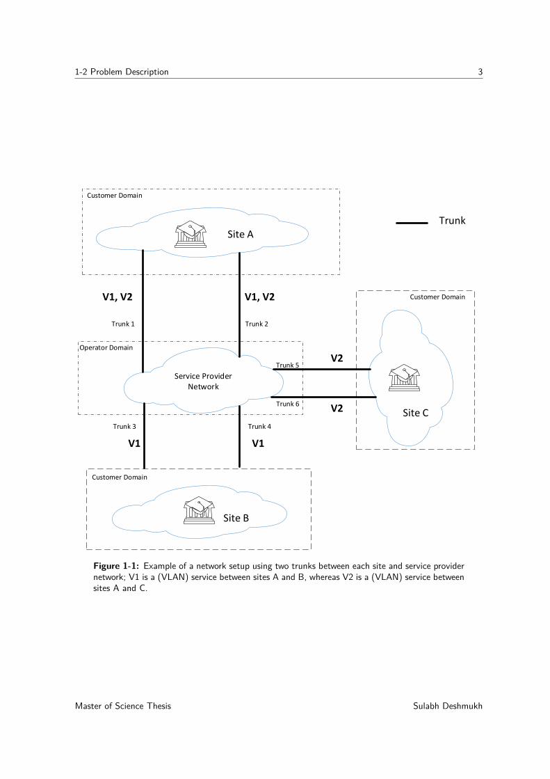
1-1 Example of a network setup using two trunks between each site and service providernetwork; V1 is a (VLAN) service between sites A and B, whereas V2 is a (VLAN)service between sites A and C. . . . . . . . . . . . . . . . . . . . . . . . . . . . 3
1-2 Various trunk connection scenarios between one or more customer edge Ethernetswitches and one or more provider edge Ethernet switches. . . . . . . . . . . . . 4
1-3 Failure of Trunk 4 between service provider network and site B . . . . . . . . . . 61-4 To offer redundancy, failover connection between switch 1 and switch 2 of both
site A and site B results in loop in the network. . . . . . . . . . . . . . . . . . . 71-5 Formation of loop when single customer edge Ethernet switch is used. . . . . . . 71-6 An attempt to load balance traffic between customer network Ethernet switch and
customer edge Ethernet switches results in loop. . . . . . . . . . . . . . . . . . . 81-7 Formation of one-sided LAG at customer network Ethernet switch for load balancing. 91-8 Trunk connection scenario B and C of Figure 1-2. In scenario B, a loop is formed.
In scenario C, a one-sided LAG at the customer edge Ethernet switch is createdfor load balancing. . . . . . . . . . . . . . . . . . . . . . . . . . . . . . . . . . . 9
2-1 LAG formation between two adjacent network elements. . . . . . . . . . . . . . . 142-2 BFD State Machine; Source [1]. . . . . . . . . . . . . . . . . . . . . . . . . . . 162-3 IEEE 802.1ag: Maintenance Domain (MD); Adopted from [2]. . . . . . . . . . . 182-4 IEEE 802.1ag: Maintenance Association (MA), Maintenance Association End
Points (MEPs) and Maintenance Domain Intermediate Points (MIP); Adoptedfrom [2]. . . . . . . . . . . . . . . . . . . . . . . . . . . . . . . . . . . . . . . 19
2-5 SDN Architecture; Source [3]. . . . . . . . . . . . . . . . . . . . . . . . . . . . 232-6 Flow Table Entry Fields; Source [4]. . . . . . . . . . . . . . . . . . . . . . . . . 252-7 PicOS Generic Architecture; Source [5]. . . . . . . . . . . . . . . . . . . . . . . 27
3-1 Proposed SDN-based Architecture. . . . . . . . . . . . . . . . . . . . . . . . . . 333-2 Connections between customer edge Ethernet circuit and OpenFlow switch when
one OpenFlow switch is used in the proposed architecture. . . . . . . . . . . . . 34
Master of Science Thesis Sulabh Deshmukh
vi List of Figures
4-1 SURFnet SDN testbed. . . . . . . . . . . . . . . . . . . . . . . . . . . . . . . . 354-2 Testbed setup for load balancing. . . . . . . . . . . . . . . . . . . . . . . . . . . 364-3 Physical testbed setup for failure detection and failover mechanism . . . . . . . . 384-4 Example of CCM exchange per-VLAN between switch and controller . . . . . . . 394-5 CFM application design overview. . . . . . . . . . . . . . . . . . . . . . . . . . . 43
5-1 Wireshark capture of generated Pktgen Traffic. . . . . . . . . . . . . . . . . . . 465-2 Fast Failover Time for single VLAN in Pica8 P 5101 series switches. CCM rate of
100 ms was configured for this setup. . . . . . . . . . . . . . . . . . . . . . . . . 475-3 Statistical parameter calculations for fast failover time measurements with CCM
Rate=100 ms. . . . . . . . . . . . . . . . . . . . . . . . . . . . . . . . . . . . . 485-4 Boundary cases for CCM arrival and failure initiation for fast failover measurements. 495-5 Wireshark capture of CCM messages for failure monitoring over trunk. . . . . . . 505-6 Failover time measurement for developed CFM implementation when single VLAN
traffic is present over a trunk. . . . . . . . . . . . . . . . . . . . . . . . . . . . . 515-7 per-VLAN Failover Time Measurements for CCM Interval=100 ms. . . . . . . . 535-8 Statistical parameter calculation for per-VLAN failover time measurements with
CCM Interval=100 ms. . . . . . . . . . . . . . . . . . . . . . . . . . . . . . . . 53
B-1 Sample Topology Used to Setup Fast Failover using CFM . . . . . . . . . . . . . 64B-2 OpenFlow Rules Configured on Switch 00T for Fast Failover . . . . . . . . . . . 65B-3 OpenFlow Rules Configured on Switch 01T for Fast Failover . . . . . . . . . . . 65B-4 OpenFlow Rules Configured on Switch 32T for Fast Failover . . . . . . . . . . . 65B-5 OpenFlow Rules Configured on Switch 96T for Fast Failover . . . . . . . . . . . 66
C-1 OpenStack summary on created VMs. . . . . . . . . . . . . . . . . . . . . . . . 67C-2 Successful connection of Ryu SDN controller with Pica8 switch . . . . . . . . . . 68C-3 Example of OpenFlow messages exchanged between Ryu controller and Pica8
switch during initial connection setup. . . . . . . . . . . . . . . . . . . . . . . . 69C-4 Link Aggregation setup on Cisco switch interfaces. . . . . . . . . . . . . . . . . 70C-5 Mac address-based load balancing configuration on Cisco switch . . . . . . . . . 70
Sulabh Deshmukh Master of Science Thesis
List of Tables
2-1 Summary on Existing Layer 2 Technologies . . . . . . . . . . . . . . . . . . . . . 21
Master of Science Thesis Sulabh Deshmukh

viii List of Tables
Sulabh Deshmukh Master of Science Thesis
Acknowledgments
I would like to take this opportunity to thank all the people who have been instrumental inshaping this thesis work during the last nine months.
The work in this thesis was supported by SURFnet. Their cooperation is gratefully acknowl-edged. Most importantly, I would like to thank my daily supervisor at SURFnet, Ir. Ronaldvan der Pol, for his constant support, encouragement and advice on my work. I sincerelyappreciate his enthusiasm and the time he devoted to discussing all my doubts even outsideregular working hours and on weekends. I would also like to thank my colleague at SURFnet,Dr. Ir. Marijke Kaat, for her invaluable inputs that helped shape the initial draft of thisthesis.
I would like to express my gratitude to my supervisor at TU Delft, Dr. Ir. F.A. Kuipers,for his guidance, encouragement and critical feedback throughout this graduation project. Iwould also like to acknowledge his feedback and attention to detail that helped me shapethe final version of this thesis. I would also like to thank all my colleagues at the NetworkArchitectures and Services (NAS) research group, TU Delft for their support during thiswork, specially to Ir. N.L.M. van Adrichem for providing unconditional help throughout theassignment.
Furthermore, I would like to thank my colleagues at SURFnet, Dr. Ir. Richa Malhotra,Ir. Wouter Huisman, and Ir. Niels den Otter for their willingness to collaborate and shareknowledge during this thesis work.
Finally, I am grateful to my family for their selfless love, constant encouragement, and financialsupport.
Master of Science Thesis Sulabh Deshmukh

x Acknowledgments
Sulabh Deshmukh Master of Science Thesis
Chapter 1
Introduction
1-1 Motivation
With the advancement in cloud computing and big data processing technologies, large data-intensive research has been conducted within the scientific community. Many scientific in-stitutes conduct large data-intensive studies in collaboration with other institutes across theglobe. Most big data research applications require high data bandwidth, and carry data thatis often too large for conventional IP networks and could potentially disrupt other traffic.Ethernet circuit [6] can be used to carry such high volume data. Ethernet circuit providesa direct, high-speed Ethernet connection with bandwidth up to 100 Gb/s between two endpoints by bypassing the regular internet connection [6] [7].
Trunk port [8] is used by network operators to facilitate (VLANs) services to their network. Itis used by customers to connect to the operator network and enable private (VLANs) servicesbetween geographically separated locations and provide dedicated connections to data centersand cloud providers [9]. All (VLANs) services from the customer network can be carried overthis single trunk port.
Trunk ports offer multiple benefits when used with Ethernet circuits. Port bandwidth can beshared between circuits and can potentially results in efficient port bandwidth utilization [10].Trunk ports eliminate the need for additional hardware installation as new Ethernet circuitconnections can use the same trunk port if port bandwidth is available [10]. To carry trafficfor multiple Ethernet circuits, trunk ports are configured on customer edge Ethernet switchesand provider edge Ethernet switches. Multiple Ethernet circuits carrying different (VLANs)services use a common trunk to carry traffic from the trunk port of customer edge Ethernetswitch to the trunk port of provider edge Ethernet switch. Hence, this common trunk act asa (multi-VLAN) multiservice trunk carrying traffic for multiple VLANs.
As an Ethernet circuit is a point-to-point connection between two sites, redundancy is animportant aspect, and customers use second circuit connected to a trunk port over additionalprovider edge Ethernet switch to evade the disturbances due to failure. Per-flow load bal-ancing that preserves the frame order is preferred by customers between the active circuits
Master of Science Thesis Sulabh Deshmukh
2 Introduction
because frame reordering can impact the throughput [11]. When traffic for multiple (VLANs)services arrives at the trunk port of provider edge switch, the provider edge switch directs thetraffic for these (VLANs) services toward their destinations based on VLAN identifiers [10].Failure detection of a single Ethernet circuit is crucial because different Ethernet circuits usea common trunk and each Ethernet circuit can fail irrespective of the others.
IEEE 802.1ax link aggregation [12] is the de-facto standard at Layer 2 that offers per-flowload balancing and a resilience mechanism. Link aggregation combines multiple physicallinks in parallel to form a link aggregation group (LAG). LAG provides automatic failoverwhen one of the links in the aggregation bundle fails. LAG also load balance per-flow trafficacross all links in the LAG. However, IEEE 802.1ax does not support VLAN-tagged controlmessages [12]. Hence, challenges arise in identifying an individual Ethernet circuit failurewhen multiple Ethernet circuits are carried over a trunk and simultaneously load balance theper-flow traffic over all active trunks. Therefore, alternative technologies need to be identifiedor a new solution needs to be designed to identify the per-Ethernet circuit failure detectionand per-flow traffic load balancing.
In traditional networking, both the control and data planes exist directly on the networkdevice [13]. If the operator needs to introduce a new feature in to their network, the operatorneeds to request for changes from the network equipment vendor [14]. Introduction of newfeatures into the Multivendor networks is even more challenging as feature support shouldbe requested of all the vendors and a feature cannot be introduced into the network tillsupport is available from all the vendors. Rather than each time requesting for changes tonetwork equipment vendors and being dependent on them for introduction of new features,a technology that offers more flexibility to the operators is required for faster introduction offeatures, independent of the vendor.
Software-defined networking (SDN) is an emerging technology that aims to make a networkprogrammable. This paradigm allows separation of the data and control planes [15]. InSDN, the data plane resides in the switching hardware and behaves as a data-forwardingdevice. The control plane resides in a centralized intelligent entity called a controller, whichcontrols and manages the switches through a programmable interface. OpenFlow [4] is oneof the popular SDN protocol that is widely adopted by the networking industry. It wasintroduced by Stanford University in 2008 and is currently developed and maintained by theOpen Networking Foundations [16]. It is a network protocol for traffic management amongstrouters and switches. A programmable control plane allows the operators to easily introducenew network features and customize the network behavior according to their requirement.
1-2 Problem Description
To make efficient use of the trunk port when more than one port is used for achieving redun-dancy, two problems must be solved. The first issue to be resolved is per-Ethernet circuitfailure detection over the trunk and per-Ethernet circuit failover, and the second issue isper-flow traffic load balancing over active trunks. In this section, we describe these problemsin detail with the help of an example.
Requirements:
Sulabh Deshmukh Master of Science Thesis
1-2 Problem Description 3
Site A
Site B
Site C
Trunk
Service Provider Network
Customer Domain
Customer Domain
Customer Domain
Operator Domain
V1, V2 V1, V2
V1 V1
V2
V2
Trunk 1 Trunk 2
Trunk 3 Trunk 4
Trunk 6
Trunk 5
Figure 1-1: Example of a network setup using two trunks between each site and service providernetwork; V1 is a (VLAN) service between sites A and B, whereas V2 is a (VLAN) service betweensites A and C.
Master of Science Thesis Sulabh Deshmukh
4 Introduction
Trunk Port
Trunk
Customer Edge Ethernet Switch
Trunk ports on single customer edge Ethernet switch and two separate provider edge switches.
Trunk ports on separate customer edge Ethernet
switches and single provider edge Ethernet
switch.
Trunk ports on single customer edge Ethernet
switch and single provider edge Ethernet
switch.
(A) (B) (C)
Provider Edge Ethernet Switch
(D)Trunk ports on separate customer edge Ethernet switches and separate provider edge Ethernet
switches.
Figure 1-2: Various trunk connection scenarios between one or more customer edge Ethernetswitches and one or more provider edge Ethernet switches.
Sulabh Deshmukh Master of Science Thesis
1-2 Problem Description 5
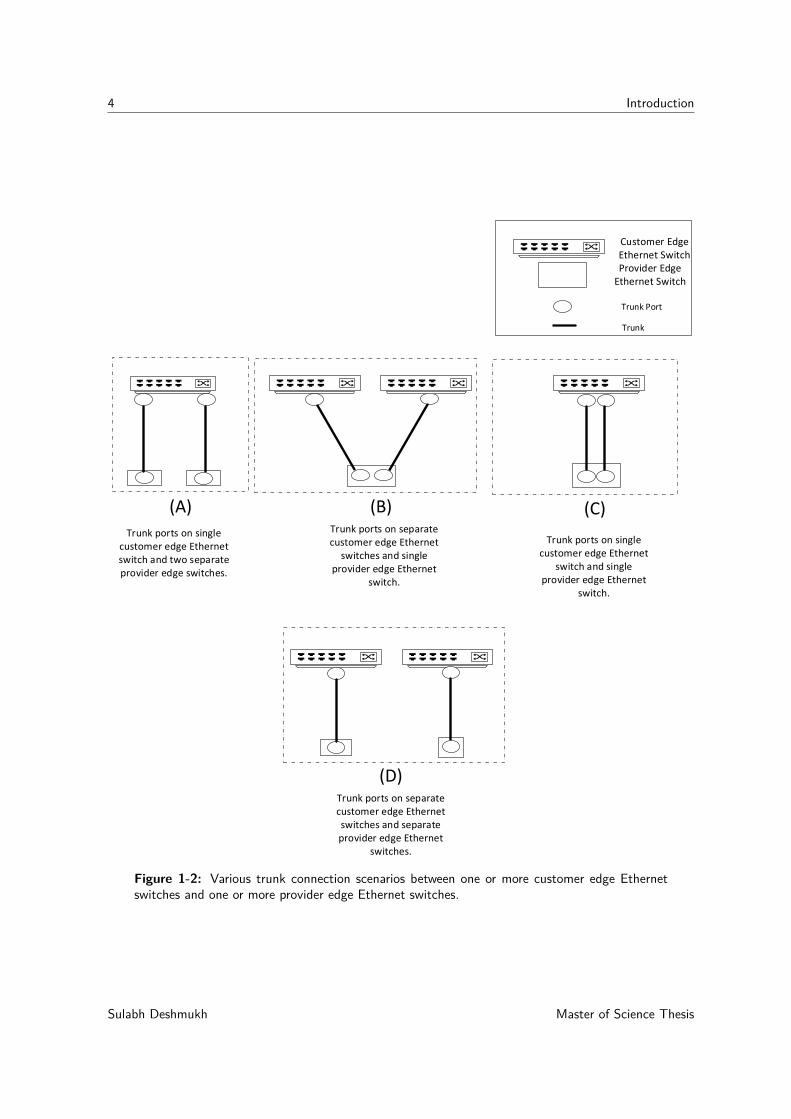
Figure 1-1 shows an example network setup to make efficient use of the trunk ports whentwo trunk ports are used to provide redundancy. In Figure 1-1, V1 is a (VLAN) servicebetween sites A and B, whereas, V2 is a (VLAN) service between sites A and C. Two trunksare setup between each site and the service provider network to achieve redundancy. Twotrunks between each site and service provider network are connected to one or more customeredge Ethernet switches and one or more provider edge Ethernet switches by using trunkports. Various trunk connection combinations used by customers are depicted in Figure 1-2.The availability of two trunk ports on two separate provider edge Ethernet switches providesredundancy for the connection to the operator network. Scenarios B and C of Figure 1-2 donot offer redundancy for the connection to the operator network in case of the failure of theprovider edge Ethernet switch.
In the network setup described in Figure 1-1, the traffic for (VLAN) service V1 is carriedbetween site A and site B by using two point-to-point Ethernet circuits (not shown in Figure1-1). To provide redundancy, both Ethernet circuits should not use the same trunk to carrytraffic from each site to the service provider network. At site A, the traffic for these Ethernetcircuits is carried over Trunk 1 and Trunk 2 separately. Similarly, the traffic for (VLAN)service V2 is carried between site A and site C by using two point-to-point Ethernet circuits.At site A, the traffic for these Ethernet circuits is also carried over Trunk 1 and Trunk 2separately. The traffic for both (VLANs) services, V1 and V2, is carried using two trunksbetween site A and the service provider as depicted in Figure 1-1. Because two trunks areavailable between site A and the service provider network, balancing the per-flow traffic forV1 and V2 on Trunk 1 and Trunk 2 is preferred. At site A, when the Ethernet circuit carryingtraffic for the (VLAN) service, V1 or V2, over any one of the two trunks fails, traffic for that(VLAN) service must be forwarded using another available Ethernet circuit between sites Aand B. Assuming that the Ethernet circuit carrying traffic for V1 over Trunk 2 fails, andthe Ethernet circuit carrying traffic for V2 over Trunk 2 is still active, the traffic for V1must be carried by other available Ethernet circuits between site A and site B over Trunk1. The Ethernet circuit carrying traffic for V2 over Trunk 2 can still use Trunk 2. Hence,per-Ethernet circuit failure detection over trunk and failover mechanism is required at site A.Similarly, per-flow load balancing and per-Ethernet failure-detection functionality must alsobe present at site B and site C.
Several problems occur while trying to achieve the expected aforementioned behavior. Theseproblems are explained below:
The Failure Detection Problem:
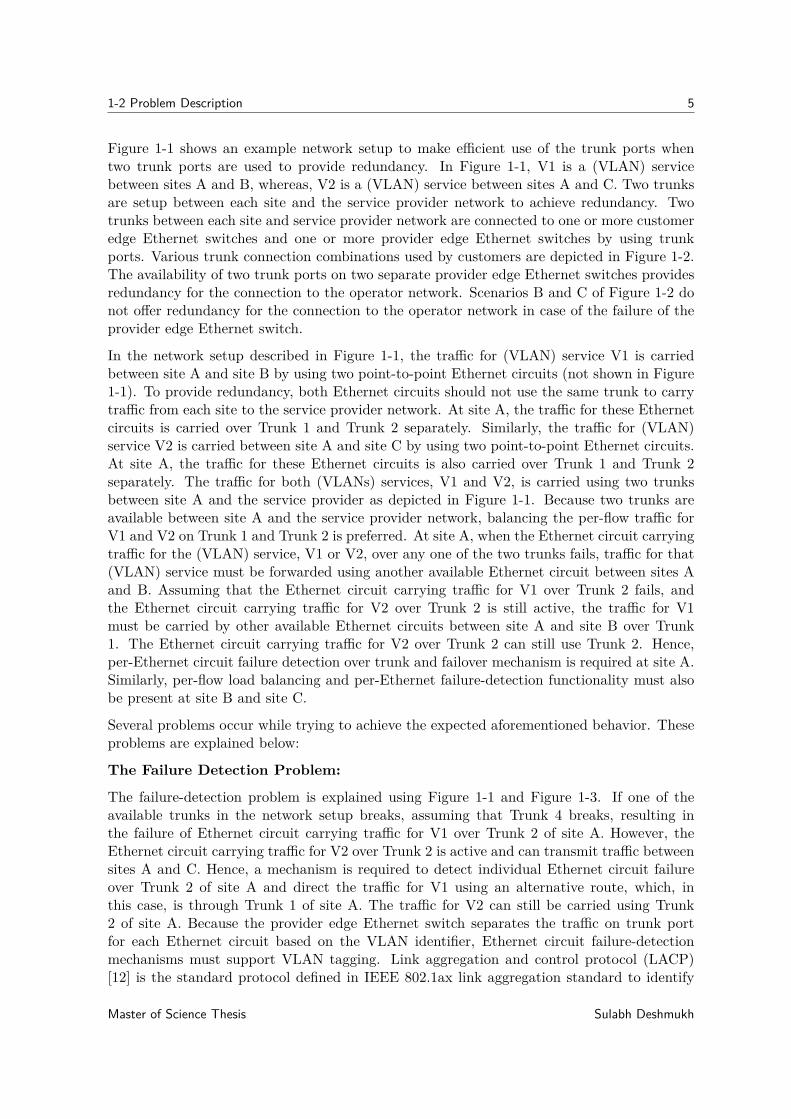
The failure-detection problem is explained using Figure 1-1 and Figure 1-3. If one of theavailable trunks in the network setup breaks, assuming that Trunk 4 breaks, resulting inthe failure of Ethernet circuit carrying traffic for V1 over Trunk 2 of site A. However, theEthernet circuit carrying traffic for V2 over Trunk 2 is active and can transmit traffic betweensites A and C. Hence, a mechanism is required to detect individual Ethernet circuit failureover Trunk 2 of site A and direct the traffic for V1 using an alternative route, which, inthis case, is through Trunk 1 of site A. The traffic for V2 can still be carried using Trunk2 of site A. Because the provider edge Ethernet switch separates the traffic on trunk portfor each Ethernet circuit based on the VLAN identifier, Ethernet circuit failure-detectionmechanisms must support VLAN tagging. Link aggregation and control protocol (LACP)[12] is the standard protocol defined in IEEE 802.1ax link aggregation standard to identify
Master of Science Thesis Sulabh Deshmukh
6 Introduction
Site A
Site B
Site C
Trunk
Service Provider Network
Customer Domain
Customer Domain
Customer Domain
Operator Domain
V1, V2 V1, V2
V1 V1
V2
V2
Trunk 1 Trunk 2
Trunk 3 Trunk 4
Trunk 6
Trunk 5
X
Figure 1-3: Failure of Trunk 4 between service provider network and site B
a link failure. However, LACP messages cannot be VLAN tagged, and the IEEE 802.1axstandard allows only one LACP message per trunk [12]. Hence, LACP cannot be used foridentifying an individual Ethernet circuit failure over a trunk, when the trunk carries trafficfor multiple Ethernet circuits. In addition, link aggregation can only be used to identify thefailure of links between directly connected network elements [12]. Therefore, the failure ofTrunk 4 cannot be identified at site A by using LACP.
The Failover Problem:
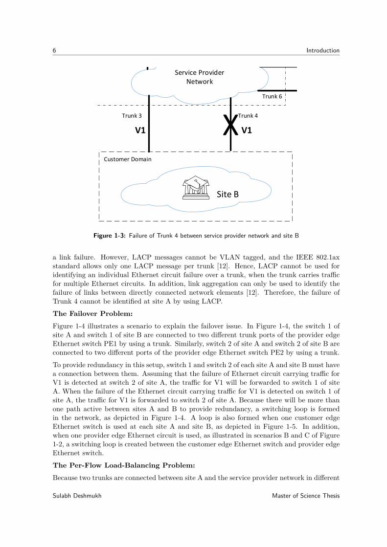
Figure 1-4 illustrates a scenario to explain the failover issue. In Figure 1-4, the switch 1 ofsite A and switch 1 of site B are connected to two different trunk ports of the provider edgeEthernet switch PE1 by using a trunk. Similarly, switch 2 of site A and switch 2 of site B areconnected to two different ports of the provider edge Ethernet switch PE2 by using a trunk.
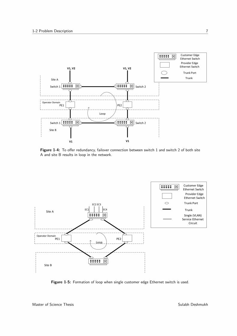
To provide redundancy in this setup, switch 1 and switch 2 of each site A and site B must havea connection between them. Assuming that the failure of Ethernet circuit carrying traffic forV1 is detected at switch 2 of site A, the traffic for V1 will be forwarded to switch 1 of siteA. When the failure of the Ethernet circuit carrying traffic for V1 is detected on switch 1 ofsite A, the traffic for V1 is forwarded to switch 2 of site A. Because there will be more thanone path active between sites A and B to provide redundancy, a switching loop is formedin the network, as depicted in Figure 1-4. A loop is also formed when one customer edgeEthernet switch is used at each site A and site B, as depicted in Figure 1-5. In addition,when one provider edge Ethernet circuit is used, as illustrated in scenarios B and C of Figure1-2, a switching loop is created between the customer edge Ethernet switch and provider edgeEthernet switch.
The Per-Flow Load-Balancing Problem:
Because two trunks are connected between site A and the service provider network in different
Sulabh Deshmukh Master of Science Thesis
1-2 Problem Description 7
Switch 1 Switch 2
Switch 1 Switch 2
Site A
Site B
PE1 PE2Operator Domain
Trunk Port
Trunk
Provider Edge Ethernet Switch
Customer Edge Ethernet Switch
Loop
V1, V2 V1, V2
V1 V1
Figure 1-4: To offer redundancy, failover connection between switch 1 and switch 2 of both siteA and site B results in loop in the network.
Site A
Site B
PE1 PE2Operator Domain
Trunk
Provider Edge Ethernet Switch
Customer Edge Ethernet Switch
Trunk Port
Single (VLAN) Service Ethernet
Circuit
EC1
EC2 EC3
EC4
Loop
Figure 1-5: Formation of loop when single customer edge Ethernet switch is used.
Master of Science Thesis Sulabh Deshmukh
8 Introduction
scenarios, as depicted in Figure 1-2, different approaches are used to load balance the per-flowtraffic between these two trunks. When the single Ethernet switch is used at the customeredge, per-flow load balancing using a Layer 2 technique should be provided by the sameswitch; however, when two customer edge Ethernet switches are present as illustrated inscenarios B and D of Figure 1-2, a network device in the customer network that distributesthe Ethernet traffic to these 2 switches should provide the per-flow load balancing by using aLayer 2 technique.
The challenges involved in successfully addressing the per-flow load balancing requirement ofFigure 1-1 are explained below:
Switch 1 Switch 2
Site A
PE1 PE2Operator Domain
Trunk Port
Trunk
Provider Edge Ethernet Switch
Customer Edge Ethernet Switch
Customer Network Ethernet Switch
Ethernet Circuit
V1
V2 V1
V2
Loop
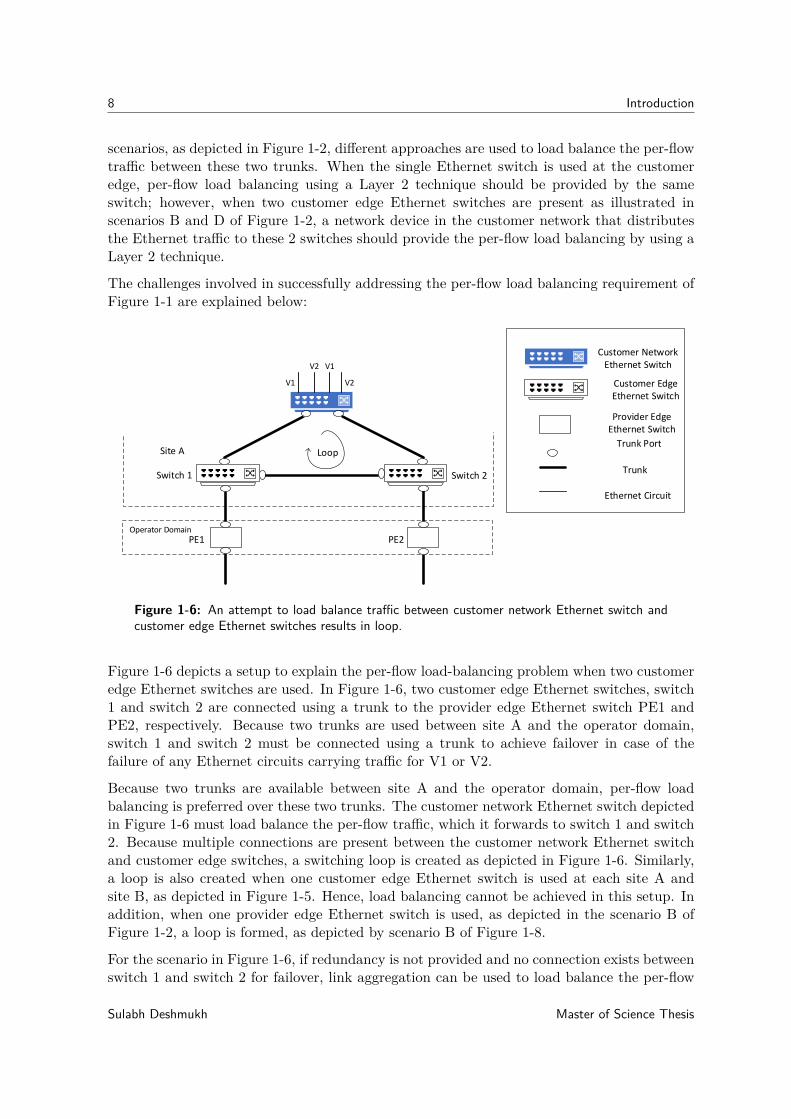
Figure 1-6: An attempt to load balance traffic between customer network Ethernet switch andcustomer edge Ethernet switches results in loop.
Figure 1-6 depicts a setup to explain the per-flow load-balancing problem when two customeredge Ethernet switches are used. In Figure 1-6, two customer edge Ethernet switches, switch1 and switch 2 are connected using a trunk to the provider edge Ethernet switch PE1 andPE2, respectively. Because two trunks are used between site A and the operator domain,switch 1 and switch 2 must be connected using a trunk to achieve failover in case of thefailure of any Ethernet circuits carrying traffic for V1 or V2.
Because two trunks are available between site A and the operator domain, per-flow loadbalancing is preferred over these two trunks. The customer network Ethernet switch depictedin Figure 1-6 must load balance the per-flow traffic, which it forwards to switch 1 and switch2. Because multiple connections are present between the customer network Ethernet switchand customer edge switches, a switching loop is created as depicted in Figure 1-6. Similarly,a loop is also created when one customer edge Ethernet switch is used at each site A andsite B, as depicted in Figure 1-5. Hence, load balancing cannot be achieved in this setup. Inaddition, when one provider edge Ethernet switch is used, as depicted in the scenario B ofFigure 1-2, a loop is formed, as depicted by scenario B of Figure 1-8.
For the scenario in Figure 1-6, if redundancy is not provided and no connection exists betweenswitch 1 and switch 2 for failover, link aggregation can be used to load balance the per-flow
Sulabh Deshmukh Master of Science Thesis
1-2 Problem Description 9
Switch 1 Switch 2
Site A
PE1 PE2Operator Domain
Trunk Port
Trunk
Provider Edge Ethernet Switch
Customer Edge Ethernet Switch
Customer Network Ethernet Switch
Ethernet Circuit
V1
V2 V1
V2
LAG
Site BSwitch 1 Switch 2
V1 V1
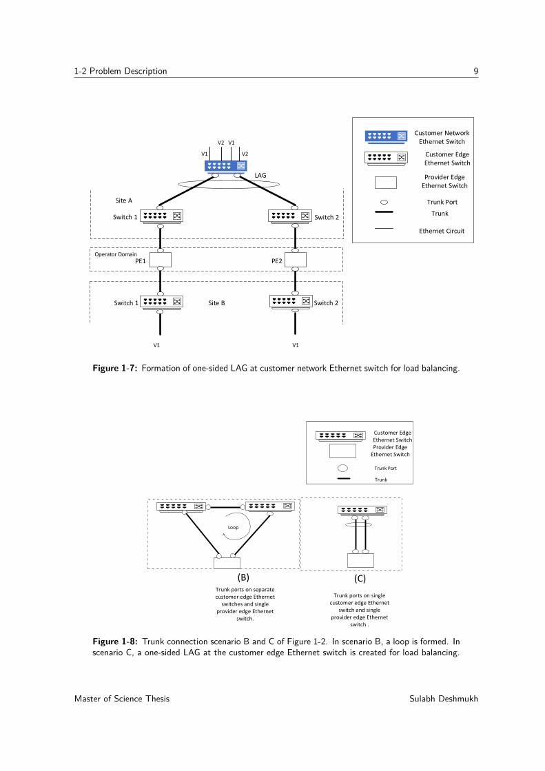
Figure 1-7: Formation of one-sided LAG at customer network Ethernet switch for load balancing.
Trunk Port
Trunk
Customer Edge Ethernet Switch
Trunk ports on separate customer edge Ethernet
switches and single provider edge Ethernet
switch.
Trunk ports on single customer edge Ethernet
switch and single provider edge Ethernet
switch .
(B) (C)
Provider Edge Ethernet Switch
Loop
Figure 1-8: Trunk connection scenario B and C of Figure 1-2. In scenario B, a loop is formed. Inscenario C, a one-sided LAG at the customer edge Ethernet switch is created for load balancing.
Master of Science Thesis Sulabh Deshmukh

10 Introduction
traffic from a customer network Ethernet switch to the customer edge switches, switch 1 andswitch 2 [12]. One-sided LAG can be created at the customer network Ethernet switch, asdepicted in Figure 1-7. However, in this scenario, if any Ethernet circuit carrying traffic forV1 and V1 fails, assuming that the Ethernet circuit carrying traffic for V1 fails between PE2and switch 2 of site B, the LAG created on the customer network Ethernet switch at site Awill not detect this Ethernet circuit failure and will continue to send traffic for V1 to switch2 of site A, resulting in frame loss. Similar issues are present when scenario A or C of Figure1-2 is used and a one-sided LAG is created at the customer edge switch. Hence, the per-flowload balancing and redundancy cannot be achieved for the scenario depicted in Figure 1-6 byusing link aggregation.
1-3 Thesis Objectives
The objectives of this thesis are as follows:
1. To detect per-Ethernet circuit failure over a (multi-VLAN) multiservice trunk andachieve per-Ethernet circuit failover.
2. Load balance the per-flow traffic over (multi-VLAN) multiservice trunks.
This thesis contributes to the objectives as follows:
1. Identify whether both the objectives can be achieved using existing technologies thatare alternative to link aggregation. Identify the pros and cons of using the discussedexisting alternative technologies.
2. Perform careful literature review of SDN and its current state for achieving the keyobjectives. Propose an SDN-based solution and evaluate its performance. Identify ifthe emerging networking paradigms, such as SDN, are better alternatives.
Thesis Scope: This thesis focuses only on standard Layer 2 technologies.
1-4 Thesis Outline
This thesis addresses the key objectives described in the previous section in a systematicmanner. This work is categorized into five main chapters:
In chapter 2, we identify existing Layer 2 technologies for failure detection and load balancing.Moreover, we evaluate their suitability to meet our objectives and elaborate on their advan-tages and disadvantages. In this chapter, we review the literature on relevant SDN concepts.Furthermore, we evaluate the current state of SDN in meeting our objectives.
In chapter 3, we propose a system design based on SDN to meet our objectives.
Chapter 4 describes the design simulations and testbed configuration details.
Sulabh Deshmukh Master of Science Thesis

1-4 Thesis Outline 11
In chapter 5, we describe the test scenarios and the results obtained from them. Moreover,we evaluate the performance of a newly proposed SDN-based solution for different scenarios.
Chapter 6 provides the final remarks and conclusions for the presented work and futurerecommendations.
Master of Science Thesis Sulabh Deshmukh

12 Introduction
Sulabh Deshmukh Master of Science Thesis
Chapter 2
Overview of Relevant Concepts
This chapter provides an overview of the relevant concepts of this thesis. In section 2-1,existing protocol-based design options are discussed, the potential Layer 2 technologies areidentified, and their advantages and disadvantages are discussed. In section 2-2, some relevantSDN concepts are discussed. We also provide an overview of Layer 2 failure-detection supportin SDN and describe the load-balancing techniques used in it. At the end of this chapter,we summarized our findings and concluded on the potential of SDN to achieve our principleobjectives.
2-1 Existing Protocol-Based Design Considerations
In this section, existing technologies for failure detection and load balancing are identifiedand compared on the basis of the following criteria:
1. The possibility of usage at Layer 2.
2. The possibility to achieve both the key objectives at the same time using same technol-ogy.
3. The possibility of combining with another technology if only one of the objectives issatisfied.
2-1-1 Overview of Existing Layer 2 Technologies for Failure Detection
Several Layer 2 technologies are available for failure detection. Technologies for detectingLayer 2 failure include link aggregation control protocol [12], bidirectional forwarding detec-tion [1], and IEEE 802.1ag: connectivity fault management [17]. In this chapter, we introducethese technologies, describe the situations in which they are useful and discuss their advan-tages and limitations.
Master of Science Thesis Sulabh Deshmukh
14 Overview of Relevant Concepts
Link Aggregation
Overview
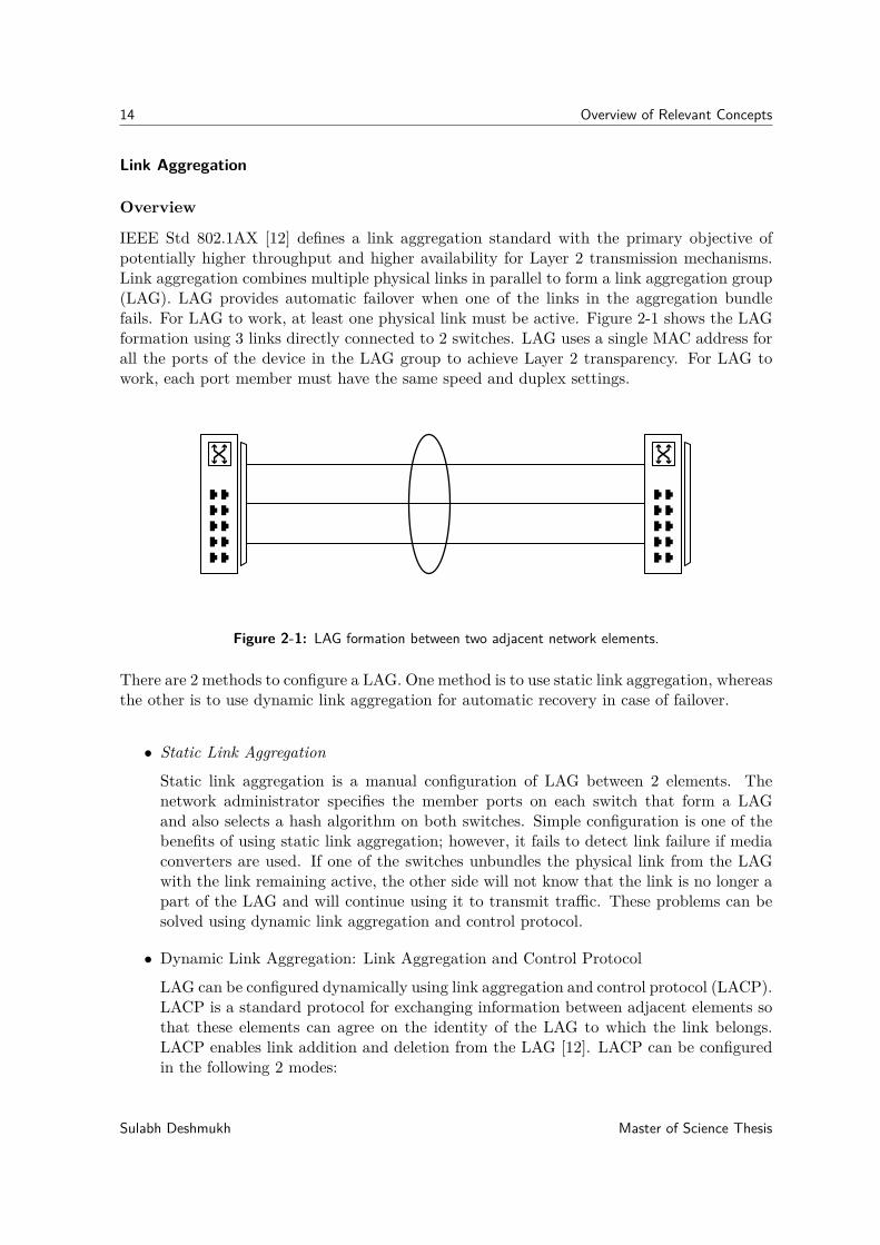
IEEE Std 802.1AX [12] defines a link aggregation standard with the primary objective ofpotentially higher throughput and higher availability for Layer 2 transmission mechanisms.Link aggregation combines multiple physical links in parallel to form a link aggregation group(LAG). LAG provides automatic failover when one of the links in the aggregation bundlefails. For LAG to work, at least one physical link must be active. Figure 2-1 shows the LAGformation using 3 links directly connected to 2 switches. LAG uses a single MAC address forall the ports of the device in the LAG group to achieve Layer 2 transparency. For LAG towork, each port member must have the same speed and duplex settings.
Figure 2-1: LAG formation between two adjacent network elements.
There are 2 methods to configure a LAG. One method is to use static link aggregation, whereasthe other is to use dynamic link aggregation for automatic recovery in case of failover.
• Static Link Aggregation
Static link aggregation is a manual configuration of LAG between 2 elements. Thenetwork administrator specifies the member ports on each switch that form a LAGand also selects a hash algorithm on both switches. Simple configuration is one of thebenefits of using static link aggregation; however, it fails to detect link failure if mediaconverters are used. If one of the switches unbundles the physical link from the LAGwith the link remaining active, the other side will not know that the link is no longer apart of the LAG and will continue using it to transmit traffic. These problems can besolved using dynamic link aggregation and control protocol.
• Dynamic Link Aggregation: Link Aggregation and Control Protocol
LAG can be configured dynamically using link aggregation and control protocol (LACP).LACP is a standard protocol for exchanging information between adjacent elements sothat these elements can agree on the identity of the LAG to which the link belongs.LACP enables link addition and deletion from the LAG [12]. LACP can be configuredin the following 2 modes:
Sulabh Deshmukh Master of Science Thesis

2-1 Existing Protocol-Based Design Considerations 15
1. Active Mode: In active mode, a device immediately sends LACP messages known asLACPDUs when a port comes up.
2. Passive Mode: In passive mode, a device does not initiate negotiation by itself. Itonly responds to the LACPDUs initiated by the active-mode devices.
When both devices are configured in the active mode, a LAG is formed by exchanging variousparameter details in LACPDUs. If one of the devices is set in the passive mode, LAG canstill can be established because the passive device can respond to the LACPDU received fromthe active device. If both the devices are in passive mode, a LAG cannot be created, and itsconfiguration details cannot be negotiated. Therefore, to form a LAG using LACP, one ofthe devices must be in the active mode.
In LAG, LACP messages are transmitted for each link in the LAG in 1 seconds or 10 secondsinterval patterns. If LACP messages are not received from the other side of the LAG on eachlink, failover is initiated for that link. The default failover initiation time is 30 s. LACP canbe combined with fast-failover mechanisms such as bidirectional forwarding detection [18].Moreover, we found some proprietary implementations that have a failover time ranging from250 ms to 2 s [19].
We summarize some advantages and disadvantages of this technology, which are relevant tothis work, from the standard specification [12], as follows:
Advantages
1. Link aggregation is a dedicated Layer 2 technology that offers both failure detectionand load balancing.
2. It offers automatic failover mechanisms by removing the failed links from the LAG.
Disadvantages
1. LAG can only be setup between directly connected network elements and is not forend-to-end failure detection when intermediate network elements are involved.
2. It must be setup on untagged interfaces.
3. All links in link aggregation must belong to the same VLAN when used as an accesslink.
4. When configured for a trunk, only one LACP message per trunk is exchanged between2 network elements. Hence, cannot be used for per-VLAN failure detection over trunk.
Conclusion
In this section, we reviewed link aggregation technology and listed some of its advantagesand disadvantages. This standard lacks the support for sending control messages for each(VLAN) service over a trunk. No combination of configurations allows sending per-VLANcontrol messages. Therefore, link aggregation fails to achieve our objective of per-Ethernetcircuit failure detection.
Master of Science Thesis Sulabh Deshmukh
16 Overview of Relevant Concepts
BFD Protocol
OverviewBidirectional forwarding detection (BFD) is a protocol to detect faults in the bidirectionalpath between 2 adjacent forwarding engines [1]. It is simple, has low latency, is protocol-independent, and is used with various data protocols across different OSI layers. Many of theavailable liveliness detection protocols are slow protocols and require a failure detection timein seconds range, which might not be suitable for an application that deals with data at gigabitrate. BFD is an alternative for such applications that provides faster failure detection. It wasfor example used by Van Adrichem et al. in [20] to speed up failover times in software-definednetworks. BFD is suitable for detecting failure of physical path, virtual circuits, tunnels,multi-hop route paths, and unidirectional paths.
BFD sends control packets between 2 nodes for failure detection. These control packets aresent as an encapsulation of other protocols at different OSI layers. Each packet containsinformation, such as interval of control packet transmission and minimum interval betweenBFD packets supported.
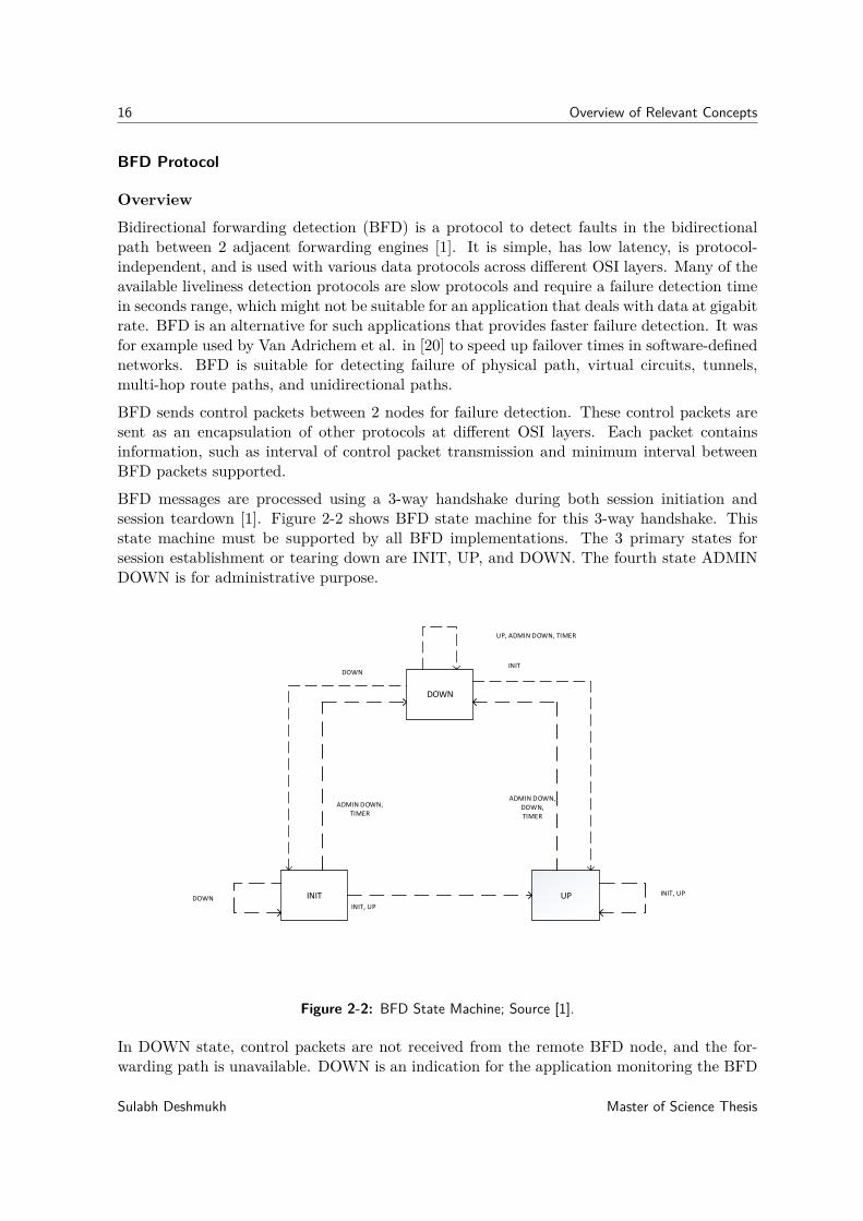
BFD messages are processed using a 3-way handshake during both session initiation andsession teardown [1]. Figure 2-2 shows BFD state machine for this 3-way handshake. Thisstate machine must be supported by all BFD implementations. The 3 primary states forsession establishment or tearing down are INIT, UP, and DOWN. The fourth state ADMINDOWN is for administrative purpose.
DOWN
INIT UPDOWNINIT, UP
INIT, UP
DOWNINIT
UP, ADMIN DOWN, TIMER
ADMIN DOWN,TIMER
ADMIN DOWN,DOWN,TIMER
Figure 2-2: BFD State Machine; Source [1].
In DOWN state, control packets are not received from the remote BFD node, and the for-warding path is unavailable. DOWN is an indication for the application monitoring the BFD
Sulabh Deshmukh Master of Science Thesis
2-1 Existing Protocol-Based Design Considerations 17
sessions to take further action.The INIT state suggests readiness for communication with the remote system. When BFDcontrol packets signaling INIT or UP are received from the remote system, the local systemchanges the session state to the UP state. When no control packets are received in theconfigured detection time, the session moves back to the DOWN state.The UP state signals the remote system that the local system can successfully receive thecontrol packets from it. The system remains in this state until there is a failure on the connec-tion between local and remote systems or the session has been taken down administratively.The system also moves in the DOWN state when it does not receive packets from the remoteend within the configurable time interval.The ADMIN DOWN state suggests that the BFD session has been administratively changedto DOWN. This local system state change causes a change in the remote system state toDOWN state and remains in that state till local system is in ADMIN DOWN state.We summarize some advantages and disadvantages of this protocol, which are relevant to thiswork, as follows:Advantages
1. BFD is a low-overhead protocol and provides rapid failure detection times in millisecondrange between directly connected networking elements.
2. It is transport-aware and service-agnostic [21].
3. It offers faster failure detection compared with LACP when configured over LAG [18].
Disadvantages
1. BFD protocol supports VLAN tagging and can be used over LAG along with LACP [18].It also supports setting up micro-BFD sessions to identify per-link failures in the LAG.However, when used over a LAG, packets should be sent untagged or with a VLANtag of zero [18]. Therefore, BFD configured over LAG cannot be used for per-Ethernetcircuit failure detection objective of this work.
2. Although BFD can be configured on VLAN interface per-VLAN, such setups cannot beused in combination with Layer 2 load-balancing techniques such as LAG. At Layer 2,load balancing is only performed on untagged ports.
3. Some leading switch vendors allow the configuration of BFD at Layer 2 on VLANinterfaces only when Layer 3 adjacency information is available [22] [23]. Cisco imple-mentation of BFD supports only Layer 3 clients, and VLAN interfaces are defined asLayer 3 to enable routing between VLAN interfaces [24] [25]. BFD support on Layer 2VLAN interface is a highly vendor-specific implementation.
ConclusionIn this section, we reviewed the BFD protocol for failure detection and discussed advantagesand disadvantages of it in relevance to the main objectives of this work. BFD fails in achievingfailure detection per-VLAN when configured over LAG. It can be setup over VLAN interfacesfor per-Ethernet circuit failure detection. However, support should be requested from theswitching vendors for appropriate forwarding mechanism between Layer 2 VLAN interfaces.
Master of Science Thesis Sulabh Deshmukh
18 Overview of Relevant Concepts
IEEE 802.1ag: Connectivity Fault Management (CFM)
OverviewIEEE 802.1ag standard is a set of protocols for connectivity fault management (CFM). CFM isused to discover, detect, verify, report, and recover Ethernet connectivity faults [17]. Followingare some key concepts of CFM.
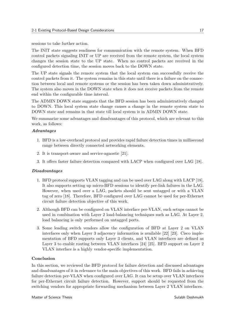
• Maintenance DomainMaintenance domain (MD) is a part of single operator/customer network and is used tosupport network connectivity between the domain service access points [17]. Eight MDlevels in the range 0-7 differentiate between the domains. MD level and domain nameare used to define the hierarchical relationship between various domains. In general, theoperator has the lowest domain level, and the customer has the highest domain level.Intermediate service providers may use an MD level in between these extreme values.CFM message exchange is only possible within MD. Figure 2-3 shows the possible MDs.
Customer Domain
Operator DomainOperator Domain
Service Domain
Customer Customer
Figure 2-3: IEEE 802.1ag: Maintenance Domain (MD); Adopted from [2].
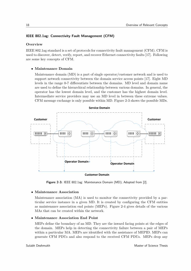
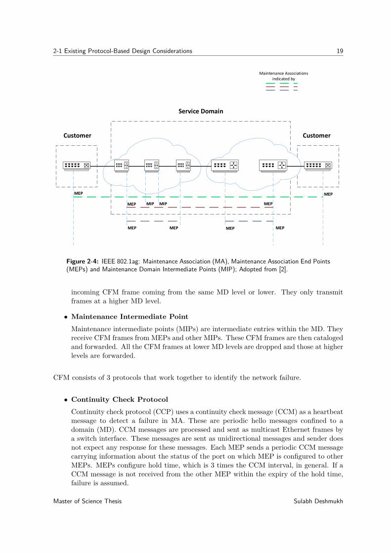
• Maintenance AssociationMaintenance association (MA) is used to monitor the connectivity provided by a par-ticular service instance in a given MD. It is created by configuring the CFM entitiesas maintenance association end points (MEPs). Figure 2-4 gives details of the variousMAs that can be created within the network.
• Maintenance Association End PointMEPs define the boundary of an MD. They are the inward facing points at the edges ofthe domain. MEPs help in detecting the connectivity failure between a pair of MEPswithin a particular MA. MEPs are identified with the assistance of MEPID. MEPs cangenerate CFM PDUs and also respond to the received CFM PDUs. MEPs drop any
Sulabh Deshmukh Master of Science Thesis
2-1 Existing Protocol-Based Design Considerations 19
Service Domain
Customer Customer
MEP
MEP
MEP MEP MEP MEP
MEP
MEPMIP MIP
Maintenance Associations indicated by
Figure 2-4: IEEE 802.1ag: Maintenance Association (MA), Maintenance Association End Points(MEPs) and Maintenance Domain Intermediate Points (MIP); Adopted from [2].
incoming CFM frame coming from the same MD level or lower. They only transmitframes at a higher MD level.
• Maintenance Intermediate PointMaintenance intermediate points (MIPs) are intermediate entries within the MD. Theyreceive CFM frames from MEPs and other MIPs. These CFM frames are then catalogedand forwarded. All the CFM frames at lower MD levels are dropped and those at higherlevels are forwarded.
CFM consists of 3 protocols that work together to identify the network failure.
• Continuity Check ProtocolContinuity check protocol (CCP) uses a continuity check message (CCM) as a heartbeatmessage to detect a failure in MA. These are periodic hello messages confined to adomain (MD). CCM messages are processed and sent as multicast Ethernet frames bya switch interface. These messages are sent as unidirectional messages and sender doesnot expect any response for these messages. Each MEP sends a periodic CCM messagecarrying information about the status of the port on which MEP is configured to otherMEPs. MEPs configure hold time, which is 3 times the CCM interval, in general. If aCCM message is not received from the other MEP within the expiry of the hold time,failure is assumed.
Master of Science Thesis Sulabh Deshmukh
20 Overview of Relevant Concepts
• Link TraceLink trace messages (LTMs) are also known as MAC traceroute. These are sent asmulticast frames to other MEPs to acquire the path information. LTMs are used forfault discovery and path isolation. Each receiving MEP then sends back a trace routereply directly to the originating MEP as a unicast message. LTM is similar to IPtraceroute but at Layer 2.
• Loop-backLoop-back messages are known as MAC ping messages. MEPs transmit these messagesas unicast messages for fault verification to other MEPs or MIPs in the same MA. Theyare used to ping MAC addresses. This feature is similar to IP ping but at Layer 2.
From the standard specification [17], we have summarized some advantages and disadvantagesof CFM as follows:
Advantages
1. CFM is a strict Layer 2 standard that only uses Ethernet MAC addresses.
2. CFM offers end-to-end service level operation and maintenance. It has an extensive setof mechanisms for connectivity monitoring, fault verification, and fault isolation.
3. It can auto discover MEPs and monitor the connections between multiple MEPs usinga single multicast CFM message. This is not possible with other failure monitoringtechniques such as BFD and LACP. In case of BFD and LACP, failure monitoring islimited to two directly connected network elements.
Disadvantages
1. CFM has no support for setting up multiple MEPs over a trunk port.
2. CFM has similar issues to those in BFD. It can be setup on VLAN interfaces foreach VLAN. However, switches rely on Layer 3 mechanism for routing between VLANinterfaces [26]. CFM setup on Layer 2 VLAN interface is highly dependent on vendorimplementation. Leading switch vendors do not allow setting up CFM setup on Layer 2VLAN interfaces [27]. Moreover, when MEPs are setup per-VLAN on VLAN interfaces,they cannot be used with Layer 2 load balancer for the same reason explained for BFD.
3. Moreover, CFM introduces the risk of looping in multipath environment.
ConclusionIn this section, we reviewed CFM technology for failure detection and discussed advantagesand disadvantages of it in relevance to the main objectives of this work. In CFM, multipleMEPs cannot be setup over untagged interfaces for per-Ethernet circuit failure detection.Although CFM as a technology can be used over a VLAN interface for per-VLAN failuredetection, lack of appropriate frame forwarding mechanism between a Layer 2 VLAN inter-faces remain a concern. Most vendor implementations use Layer 3 routing techniques tocommunicate between Layer 2 VLAN interfaces.
Sulabh Deshmukh Master of Science Thesis
2-1 Existing Protocol-Based Design Considerations 21
2-1-2 Overview of Existing Layer 2 Technology for Load Balancing
In this section, we describe the existing load-balancing techniques. Our literature reviewrevealed that there are not many choices available for load balancing at Layer 2. Loadbalancing can be achieved by configuring LAG. This technique is explained in the followingtext:
Overview
LAG allows per-flow load balancing of traffic across all links in the LAG. Because link aggre-gation reflects a set of physical ports as a single logical port channel, a port is selected fromthe set by using a distribution algorithm. The selection of the algorithm is implementation-dependent, and the standard does not recommend a specific algorithm. When an algorithmselects an outgoing physical port to transmit a frame, all similar frames are transmittedthrough it. Hash-based port selection and dynamic port selection, where the physical port inthe LAG changes for a given set of conversations, are some algorithms used to achieve loadbalancing at Layer 2. These techniques are explained in detail in [12].
Conclusion
Static LAG configuration can be used to achieve our objective of load balancing. It supportsper-flow load balancing over a trunk. LAG can be setup over multiple trunk links, and itshashing techniques can be used to achieve per-flow load balancing.
2-1-3 Existing Protocol-based Design Summary and Conclusion
In this section, we reviewed the potential Layer 2 failure-detection protocols and standards.Moreover, we evaluated the load-balancing technique used for Layer 2 technologies. All thediscussed Layer 2 technologies failed to fulfill the failure-detection objective of this thesis.Although BFD and CFM offer possibilities to be used over VLAN interfaces, no leadingvendor currently offers such solutions with appropriate forwarding mechanisms between Layer2 VLAN interfaces. Network operators cannot modify the switch behaviors and have to relyon the solutions provided by switch vendors. The only available Layer 2 load-balancingtechnique LAG, which can be used to load balance per-flow multi-service traffic over trunks,has the potential to achieve our load-balancing objective.
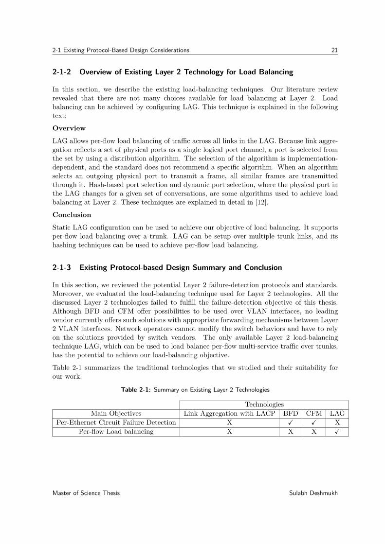
Table 2-1 summarizes the traditional technologies that we studied and their suitability forour work.
Table 2-1: Summary on Existing Layer 2 Technologies
TechnologiesMain Objectives Link Aggregation with LACP BFD CFM LAG
Per-Ethernet Circuit Failure Detection X X X XPer-flow Load balancing X X X X
Master of Science Thesis Sulabh Deshmukh
22 Overview of Relevant Concepts
2-2 Software-Defined Networking
In this section, we provide an overview of SDN and also introduce some relevant concepts.
2-2-1 Overview
Software-defined networking (SDN) is an emerging trend in the field of networking. SDN isbased on the following principles, as defined in [3]:
• Decoupling of data and control planes: According to this principle, the data and con-trol planes should be separable. However, it was concluded that some control planeresponsibilities should remain in the data plane system. The interface between SDNcontroller and the network element is defined in a manner that allows the controllerto delegate some of its responsibilities to the network element. However, the controllershould be completely aware of the networking element state. The criteria for delegationare described in [3].
• Logically Centralized Controller: The centralized controller can provide a broad per-spective of the total network resources and result in better decision capabilities fornetwork deployment.
• Exposure of abstract network resources and state to external applications: Applicationsmay be created at any level of abstraction or granularity. Further northbound theapplication, the more abstract view of the network the application has. No clear sep-aration exists between the control and application, because the interface that exposesthe network state and attributes northbound remains a controller interface.
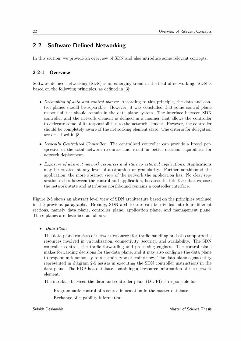
Figure 2-5 shows an abstract level view of SDN architecture based on the principles outlinedin the previous paragraphs. Broadly, SDN architecture can be divided into four differentsections, namely data plane, controller plane, application plane, and management plane.These planes are described as follows:
• Data PlaneThe data plane consists of network resources for traffic handling and also supports theresources involved in virtualization, connectivity, security, and availability. The SDNcontroller controls the traffic forwarding and processing engines. The control planemakes forwarding decisions for the data plane, and it may also configure the data planeto respond autonomously to a certain type of traffic flow. The data plane agent entityrepresented in diagram 2-5 assists in executing the SDN controller instructions in thedata plane. The RDB is a database containing all resource information of the networkelement.The interface between the data and controller plane (D-CPI) is responsible for
– Programmatic control of resource information in the master database.– Exchange of capability information
Sulabh Deshmukh Master of Science Thesis
2-2 Software-Defined Networking 23
Coordinator
Master RDB
Agent
SDN Control Logic
SDN Application
SDN Application
Management Plane
Application Plane
Control Plane
Agent
Data Plane
Coordinator
Network Resources
Master RDB
Agent
Figure 2-5: SDN Architecture; Source [3].
Master of Science Thesis Sulabh Deshmukh
24 Overview of Relevant Concepts
– Event notification
• Controller planeThe Controller plane is also known as the control plane. However, the controller planemay consist of more than one SDN controller. The control plane is separated from dataplane and is centrally located in the controller. The control plane is responsible forconfiguring the data plane with packet forwarding rules. It is also responsible for policyenforcement at each network element. A centralized control plane is fully aware of thenetwork state; therefore, the controller can provide optimized routing path comparedto traditional networking where control plane is distributed in each switch. It is easyto alter the network behavior in real time and deploy applications in a short timespan. As shown in figure 2-5, the controller plane primarily consists of SDN controllogic. The SDN control logic has a data plane control function (DPCF) to manage thenetwork resources as directed by the management plane. Multiple agents at the controlplane provide the abstract level view of the network resources to a different applicationthrough a northbound application programming interface (API). Coordinator functionof the control plane manages the coordination between various SDN controllers.
• Application PlaneIn SDN, based on the business requirement and policy enforcement, external applica-tions can specify the resources and request the required behavior from the network.Applications may use external services and multiple SDN controllers to achieve the ob-jective. The operator can write applications to dynamically control the service qualityof the network by obtaining the real-time information about network parameters suchas delay and throughput.
• Management PlaneManagement provides an infrastructure support task that is not to be performed byother SDN entities. The manager may install the policy enforcement software. It mayprovide the Operations support system (OSS) interface to other SDN planes.
2-2-2 OpenFlow Protocol
OpenFlow [4] is one of the key drivers of SDN innovation. This protocol is used to exchangea set of instructions between the controller and OpenFlow-compliant switches over D-CPI.In this section, we will summarize the basic working details of OpenFlow protocol that arerelevant to this thesis.
The OpenFlow protocol defines a set of flow manipulation messages. A flow can be installedin a proactive or reactive manner. In the proactive method, flows are configured in advance,and there is no flow table lookup. In reactive method, unmatched packets from the flow tablelookup are forwarded to the controller by a PacketIn message where the controller calculatesthe new forwarding rule based on the current state of the network and installs these rulesinto the flow table by a FlowMod message. The controller instructs the switch to send thepacket out of a specified port of a switch by sending a PacketOut message.
Moreover, a hybrid approach is possible for flow instantiation, and it provides granular trafficcontrol for some of the customer traffic and preserves the low-latency forwarding for the other.
Sulabh Deshmukh Master of Science Thesis
2-2 Software-Defined Networking 25
The latest standard 1.5 for OpenFlow switch specification is defined in [4] and consists of thefollowing major modules:
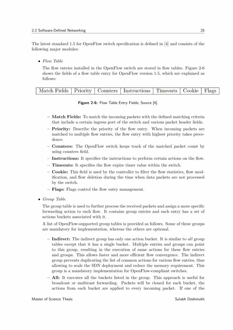
• Flow TableThe flow entries installed in the OpenFlow switch are stored in flow tables. Figure 2-6shows the fields of a flow table entry for OpenFlow version 1.5, which are explained asfollows:
Figure 2-6: Flow Table Entry Fields; Source [4].
– Match Fields: To match the incoming packets with the defined matching criteriathat include a certain ingress port of the switch and various packet header fields.
– Priority: Describe the priority of the flow entry. When incoming packets arematched to multiple flow entries, the flow entry with highest priority takes prece-dence.
– Counters: The OpenFlow switch keeps track of the matched packet count byusing counters field.
– Instructions: It specifies the instructions to perform certain actions on the flow.– Timeouts: It specifies the flow expire timer value within the switch.– Cookie: This field is used by the controller to filter the flow statistics, flow mod-
ification, and flow deletion during the time when data packets are not processedby the switch.
– Flags: Flags control the flow entry management.
• Group TableThe group table is used to further process the received packets and assign a more specificforwarding action to each flow. It contains group entries and each entry has a set ofactions buckets associated with it.A list of OpenFlow-supported group tables is provided as follows. Some of these groupsare mandatory for implementation, whereas the others are optional.
– Indirect: The indirect group has only one action bucket. It is similar to all grouptables except that it has a single bucket. Multiple entries and groups can pointto this group, resulting in the execution of same actions for these flow entriesand groups. This allows faster and more efficient flow convergence. The indirectgroup prevents duplicating the list of common actions for various flow entries, thusallowing to scale the SDN deployment and reduce the memory requirement. Thisgroup is a mandatory implementation for OpenFlow-compliant switches.
– All: It executes all the buckets listed in the group. This approach is useful forbroadcast or multicast forwarding. Packets will be cloned for each bucket, theactions from each bucket are applied to every incoming packet. If one of the
Master of Science Thesis Sulabh Deshmukh
26 Overview of Relevant Concepts
buckets forwards the packets on the ingress port, its clone packets are dropped byother buckets. This group is mandatory for OpenFlow-compliant switches.
– Select: The select group is used to achieve load balancing. A single bucket willprocess the packets in the group, and each bucket has an assigned weight. Thebucket selection algorithm is the choice of the switch vendor. However, weightedround-robin is the most common algorithm used by various switch providers. Thisgroup is an optional implementation for OpenFlow-compliant switches.
– Fast-failover: This group is used to achieve failover mechanism in case of portfailure. Each action bucket is associated with a port, which is continuously checkedfor its liveliness. In case of port failure, actions from the next live bucket areexecuted. Buckets are evaluated in the same order in which they are defined in thegroup.
• Meter Table
Meter table is used to perform various quality of service (QOS) operations using Open-Flow switches. Various QOS operations include rate limiting, per-port queuing, andDiffServ. Meters are attached to flow entries and can measure the rate with which thepackets are assigned to flow entries. It can control and limit this rate to achieve variousthroughputs.
2-2-3 SDN Controllers and Switches
The controller is the brain of SDN networks. It acts as a network OS connecting the toplevel application and devices to the network. Because of network abstraction, the controllerprovides centralized control over the complete network, making it possible to apply the SDNparadigm across heterogeneous networks, such as wireless, wired, and optical networks [28].Various OpenFlow-based controllers are commercially available and are compatible with pro-gramming languages such as Java and Python. Some popular controllers are POX [29], Ryu[30], ONOS [31], Floodlight [32], and OpenDaylight [33]. All of these controllers are compli-ant with the OpenFlow protocol standards and implement the core control plane behaviorin line with the SDN standards highlighted in the overview section. All these controllers areenterprise-class [34] controllers, except POX.
Open vSwitch (OVS) is a production quality multilayer virtual switch [35]. It is a open sourcesoftware, and is widely used as a backend switch for OpenStack [36] networking. OVS is not adedicated OpenFlow switch and supports traditional management interfaces, such as LACP,802.1ag, SPAN, RSPAN, CLI, NetFlow, and sFlow. The programmability of OVS makes itpossible for operators to perform large-scale network automation. It allows applications toprogram switch behavior using the OpenFlow protocol. Moreover, it can be controlled by anexternal controller or through a built-in control interface via a command line. OVS is mostwidely used in virtualized platforms, such as KVM [37], Xen [38], Docker [39], and VirtualBox[40]. Hardware-based switches, such as Pica8 [41] and NoviFlow [42], offer OVS support.
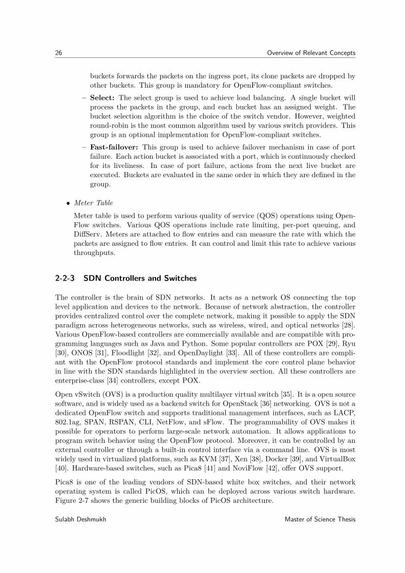
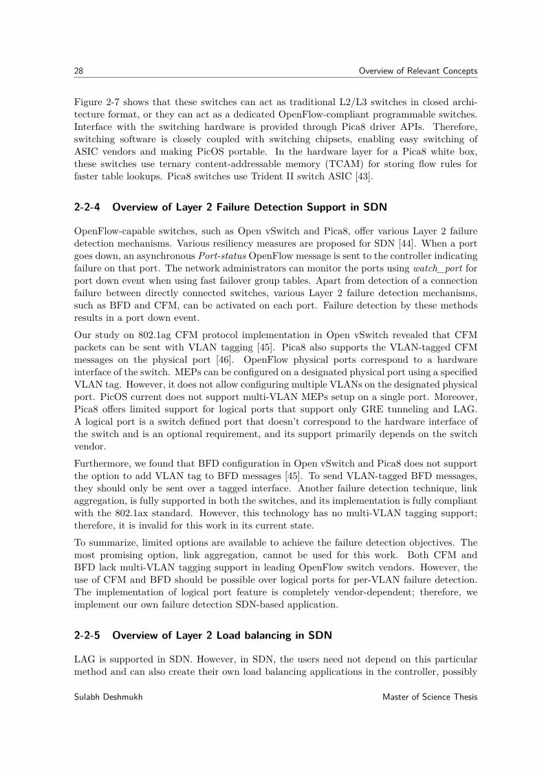
Pica8 is one of the leading vendors of SDN-based white box switches, and their networkoperating system is called PicOS, which can be deployed across various switch hardware.Figure 2-7 shows the generic building blocks of PicOS architecture.
Sulabh Deshmukh Master of Science Thesis
2-2 Software-Defined Networking 27
Hardware
ASICs TCAMCPU
PICA8 API
LINUX
Layer 2 / Layer 3 OVS
OpenFlow Interface
Figure 2-7: PicOS Generic Architecture; Source [5].
Master of Science Thesis Sulabh Deshmukh
28 Overview of Relevant Concepts
Figure 2-7 shows that these switches can act as traditional L2/L3 switches in closed archi-tecture format, or they can act as a dedicated OpenFlow-compliant programmable switches.Interface with the switching hardware is provided through Pica8 driver APIs. Therefore,switching software is closely coupled with switching chipsets, enabling easy switching ofASIC vendors and making PicOS portable. In the hardware layer for a Pica8 white box,these switches use ternary content-addressable memory (TCAM) for storing flow rules forfaster table lookups. Pica8 switches use Trident II switch ASIC [43].
2-2-4 Overview of Layer 2 Failure Detection Support in SDN
OpenFlow-capable switches, such as Open vSwitch and Pica8, offer various Layer 2 failuredetection mechanisms. Various resiliency measures are proposed for SDN [44]. When a portgoes down, an asynchronous Port-status OpenFlow message is sent to the controller indicatingfailure on that port. The network administrators can monitor the ports using watch_port forport down event when using fast failover group tables. Apart from detection of a connectionfailure between directly connected switches, various Layer 2 failure detection mechanisms,such as BFD and CFM, can be activated on each port. Failure detection by these methodsresults in a port down event.Our study on 802.1ag CFM protocol implementation in Open vSwitch revealed that CFMpackets can be sent with VLAN tagging [45]. Pica8 also supports the VLAN-tagged CFMmessages on the physical port [46]. OpenFlow physical ports correspond to a hardwareinterface of the switch. MEPs can be configured on a designated physical port using a specifiedVLAN tag. However, it does not allow configuring multiple VLANs on the designated physicalport. PicOS current does not support multi-VLAN MEPs setup on a single port. Moreover,Pica8 offers limited support for logical ports that support only GRE tunneling and LAG.A logical port is a switch defined port that doesn’t correspond to the hardware interface ofthe switch and is an optional requirement, and its support primarily depends on the switchvendor.Furthermore, we found that BFD configuration in Open vSwitch and Pica8 does not supportthe option to add VLAN tag to BFD messages [45]. To send VLAN-tagged BFD messages,they should only be sent over a tagged interface. Another failure detection technique, linkaggregation, is fully supported in both the switches, and its implementation is fully compliantwith the 802.1ax standard. However, this technology has no multi-VLAN tagging support;therefore, it is invalid for this work in its current state.To summarize, limited options are available to achieve the failure detection objectives. Themost promising option, link aggregation, cannot be used for this work. Both CFM andBFD lack multi-VLAN tagging support in leading OpenFlow switch vendors. However, theuse of CFM and BFD should be possible over logical ports for per-VLAN failure detection.The implementation of logical port feature is completely vendor-dependent; therefore, weimplement our own failure detection SDN-based application.
2-2-5 Overview of Layer 2 Load balancing in SDN
LAG is supported in SDN. However, in SDN, the users need not depend on this particularmethod and can also create their own load balancing applications in the controller, possibly
Sulabh Deshmukh Master of Science Thesis
2-2 Software-Defined Networking 29
by using information from network monitoring applications, like OpenNetMon [47]. Thisapproach has advantages over the LAG. Operators can create their own customized loadbalancing algorithms that suit their network requirements. New algorithms that remove thelimitations of the current technology can be created. It is easy to create and introduce newdesign algorithms without depending on the switch vendors.
In [48], a flow-based load balancing application that eliminates the requirement of a spanningtree protocol and resides in SDN controller was introduced. The application selects differentoutgoing paths for different incoming flows based on various load-balancing algorithms. Intraditional LAG, only hash-based algorithms were supported. However, this work implementsother load-balancing techniques that might be suitable for the current network workload.Some other supported load-balancing techniques are as follows:
• Random path selection: This algorithm assigns new flow to an outgoing interface of aswitch randomly.
• Round-Robin path selection: In this approach, new flow is assigned to the next availableoutgoing interface of a switch in a round-robin fashion.
• Flow-based path selection: This algorithm considers the number of flows already mappedto any particular outgoing interface of a switch before allocating new incoming flow.
• Application-aware path selection: This method considers the data transferred by eachapplication. However, for this algorithm, applications require the sharing of the datatransfer information with the controller.
In summary, SDN offers flexibility and more Layer 2 load-balancing choices for network op-erators to traffic engineer their network than traditional technology.
2-2-6 Summary and Conclusion on SDN
In this section, we reviewed SDN and discussed some of its concepts relevant to this work. Wealso provided an overview of the current state of Layer 2 failure-detection and load-balancingtechniques. Although the main objectives of this thesis cannot be achieved using the currentSDN-based implementations because of a lack of direct support for detecting per-VLANfailures, SDN offers several advantages over traditional technology, allowing the operators tocreate their own applications to overcome vendor lock-in and protocol limitations.
Master of Science Thesis Sulabh Deshmukh

30 Overview of Relevant Concepts
Sulabh Deshmukh Master of Science Thesis
Chapter 3
Proposed System Design
In this chapter, we propose a system design to meet the primary objectives of this thesis.Section 3-1 discusses the design considerations for solving the problems. The details of theproposed design are discussed in section 3-2.
3-1 Design Considerations
As discussed in Chapter 2, no combination of standard (IEEE) protocols can be used tomeet our objectives. Therefore, we considered an SDN-based design approach. SDN is arelatively new technology that has not been widely deployed in production networks. Thus,a pure SDN-based solution can cause extensive changes in the existing infrastructure andincrease the cost. Moreover, SDN has its own set of challenges, including robustness andscalability [49]. Therefore, we considered a hybrid SDN-based design. Our design approachensures minimal effect and changes in the customer network. This thesis focusses on two sub-problems, namely failure detection and failover and load balancing, the design considerationsfor which are explained separately.
3-1-1 Failure Detection and Failover Considerations
Because multiple Ethernet circuits use the same trunk, per-Ethernet circuit failure detectionis required over a trunk. As summarized in section 2-1-3, at Layer 2, only BFD and CFMallow per-VLAN failure detection. Applying these failure detection techniques on Ethernetswitches along with Layer 2 load balancing mechanism results in loops because of a multipathenvironment. Loop avoidance techniques, such as spanning tree protocol (STP) [8], cannotbe used in Layer 2 networks when multiple paths need to be active.
OpenFlow-capable switches offer flexibility and allow customized flow rule installation toavoid loops in a multipath environment. However, our study on these switches, described insection 2-2-4, revealed their disadvantages. In OpenFlow-capable switches, failover is possible
Master of Science Thesis Sulabh Deshmukh
32 Proposed System Design
in 2 ways, fast and slow failover. In fast failover, failover is initiated from the switch. Inslow failover, failover is initiated from the SDN controller. Because per-VLAN fast failoverdetection is not currently implemented, a failure detection application requires to be designed.This means that the failover will be slow, managed using the SDN controller.
3-1-2 Per-flow Load Balancing Considerations
For Layer 2 Ethernet networks, the only available existing standard technology that offers loadbalancing support is IEEE 802.1AX link aggregation group (LAG). However, in SDN alongwith LAG support, network administrators can design their own customized load balancingapplications. An SDN-based load balancer implies that network service provider’s customerswill have to replace their existing edge equipment with OpenFlow-capable switches. Our pri-mary objective is to minimize the effect on end customers; therefore, we decided to use theexisting LAG-based load balancing technique on the existing Ethernet-based customer edgeswitch. One of the early challenges with this approach was that the feasibility of combiningthis setup with OpenFlow-capable switches was not confirmed. Experiments were performedto confirm it. More details about these experiments are given in appendix A. Experimen-tal results showed that LAG-based load balancing setup can be successfully combined withOpenFlow-capable switches.
3-2 Design Proposal
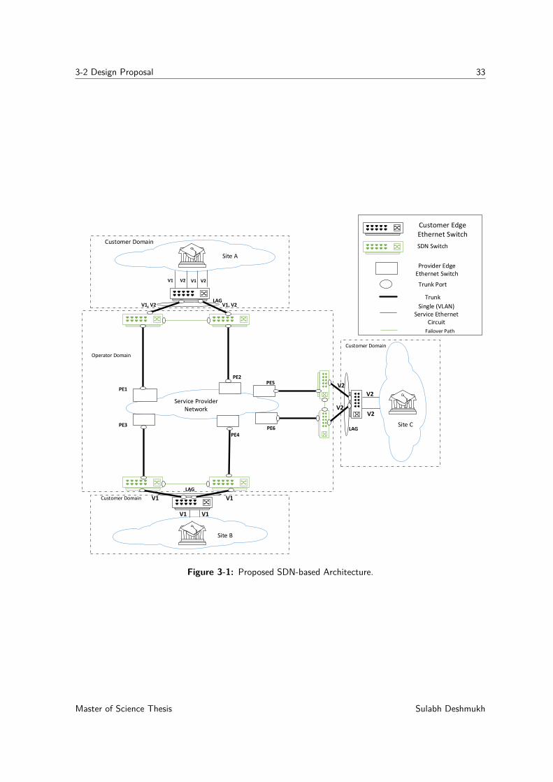
Figure 3-1 illustrates the proposed architecture. In our design, we ensured minimal effect onthe customers. The hybrid design approach will allow customers to continue using existingEthernet switches, and all the extra complexity will be managed by the network operator byusing OpenFlow switches, which provide support for trunk ports. Customers will not have tomake infrastructural changes in their network. Figure 3-1 shows an example design with twoactive trunk ports over two separate provider edge switches. However, the proposed designcan scale up to multiple trunk port connections for multi-site collaboration. Operators canalso use one OpenFlow switch instead of the proposed two, as shown in figure 3-2. Choice ofnumber of OpenFlow switches to introduce is dependent on the network resilience requirementof the customer.
In our design, we introduced hardware-based OpenFlow switches between the Ethernet-basedcustomer edge switch and provider edge Ethernet switches. These switches are placed at thecustomer premises, however, they are controlled by the network operator. This OpenFlowswitch placement approach is similar to the Customer-premises equipment [50]. Hardware-based switches were particularly selected because of the high-speed requirement of an end-to-end Ethernet connection. The speed requirement for such Ethernet connection is within therange of 10G to 100G. Open vSwitch has a performance bottleneck in its current state [51][52]; therefore, we cannot use a virtual switch for our design. A centralized controller willcontrol all OpenFlow-capable switches. Operators can select any enterprise-class controller.A list of such controllers is presented in section 2-2-3.
Ethernet-based customer-edge switch enables per-flow traffic load sharing for two trunks usedbetween OpenFlow switches and provider edge Ethernet switches by using static LAG. One-
Sulabh Deshmukh Master of Science Thesis
3-2 Design Proposal 33
Site A
Site B
Site C
Customer Edge Ethernet Switch
Trunk Port
Trunk
Single (VLAN) Service Ethernet
Circuit
Service Provider Network
Customer Domain
Customer Domain
Customer Domain
Operator Domain
V1, V2 V1, V2
V1 V1
Failover Path
LAG
LAG
LAG
SDN Switch
Provider Edge Ethernet Switch
PE1
PE3
PE4
PE2PE5
PE6
V2
V2
V1 V2 V1 V2
V1 V1
V2
V2
Figure 3-1: Proposed SDN-based Architecture.
Master of Science Thesis Sulabh Deshmukh
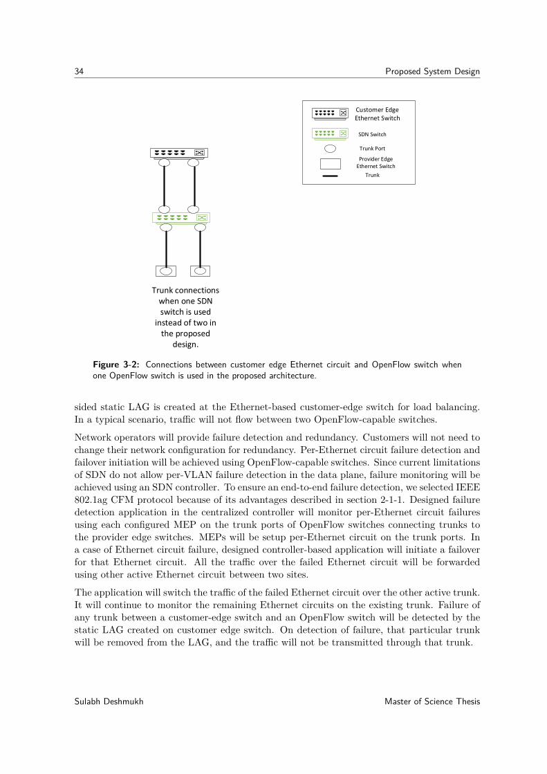
34 Proposed System Design
Trunk Port
Trunk
SDN Switch
Customer Edge Ethernet Switch
Trunk connections when one SDN switch is used
instead of two in the proposed
design.
Provider Edge Ethernet Switch
Figure 3-2: Connections between customer edge Ethernet circuit and OpenFlow switch whenone OpenFlow switch is used in the proposed architecture.
sided static LAG is created at the Ethernet-based customer-edge switch for load balancing.In a typical scenario, traffic will not flow between two OpenFlow-capable switches.
Network operators will provide failure detection and redundancy. Customers will not need tochange their network configuration for redundancy. Per-Ethernet circuit failure detection andfailover initiation will be achieved using OpenFlow-capable switches. Since current limitationsof SDN do not allow per-VLAN failure detection in the data plane, failure monitoring will beachieved using an SDN controller. To ensure an end-to-end failure detection, we selected IEEE802.1ag CFM protocol because of its advantages described in section 2-1-1. Designed failuredetection application in the centralized controller will monitor per-Ethernet circuit failuresusing each configured MEP on the trunk ports of OpenFlow switches connecting trunks tothe provider edge switches. MEPs will be setup per-Ethernet circuit on the trunk ports. Ina case of Ethernet circuit failure, designed controller-based application will initiate a failoverfor that Ethernet circuit. All the traffic over the failed Ethernet circuit will be forwardedusing other active Ethernet circuit between two sites.
The application will switch the traffic of the failed Ethernet circuit over the other active trunk.It will continue to monitor the remaining Ethernet circuits on the existing trunk. Failure ofany trunk between a customer-edge switch and an OpenFlow switch will be detected by thestatic LAG created on customer edge switch. On detection of failure, that particular trunkwill be removed from the LAG, and the traffic will not be transmitted through that trunk.
Sulabh Deshmukh Master of Science Thesis
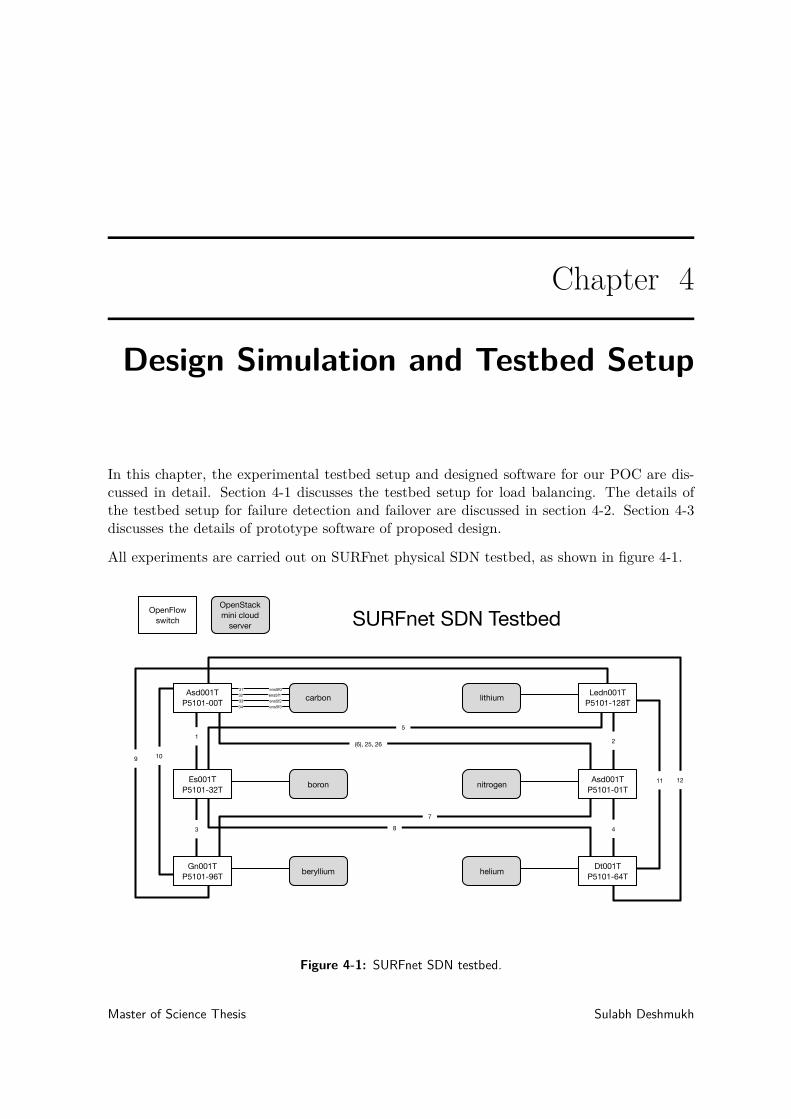
Chapter 4
Design Simulation and Testbed Setup
In this chapter, the experimental testbed setup and designed software for our POC are dis-cussed in detail. Section 4-1 discusses the testbed setup for load balancing. The details ofthe testbed setup for failure detection and failover are discussed in section 4-2. Section 4-3discusses the details of prototype software of proposed design.
All experiments are carried out on SURFnet physical SDN testbed, as shown in figure 4-1.
Gn001TP5101-96T
Es001TP5101-32T
Asd001TP5101-00T carbon
boron
beryllium helium
nitrogen
lithium Ledn001TP5101-128T
Asd001TP5101-01T
Dt001TP5101-64T
OpenStackmini cloud
server
OpenFlowswitch SURFnet SDN Testbed
ens5f031
ens5f2ens5f1
ens5f3
323334
1
109
12
2
3 4
5
(6), 25, 26
7
8
11
Figure 4-1: SURFnet SDN testbed.
Master of Science Thesis Sulabh Deshmukh
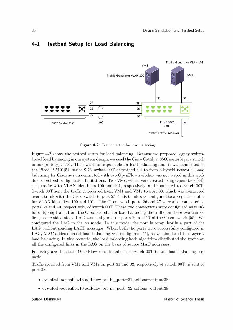
36 Design Simulation and Testbed Setup
4-1 Testbed Setup for Load Balancing
25
26
27
38
40
39
Toward Traffic Receiver
Traffic Generator VLAN 100
Traffic Generator VLAN 101
31 32
25LAG Pica8 510100T
CISCO Catalyst 3560
VM1
VM2
Figure 4-2: Testbed setup for load balancing.
Figure 4-2 shows the testbed setup for load balancing. Because we proposed legacy switch-based load balancing in our system design, we used the Cisco Catalyst 3560 series legacy switchin our prototype [53]. This switch is responsible for load balancing and, it was connected tothe Pica8 P-5101[54] series SDN switch 00T of testbed 4-1 to form a hybrid network. Loadbalancing for Cisco switch connected with two OpenFlow switches was not tested in this workdue to testbed configuration limitations. Two VMs, which were created using OpenStack [44],sent traffic with VLAN identifiers 100 and 101, respectively, and connected to switch 00T.Switch 00T sent the traffic it received from VM1 and VM2 to port 38, which was connectedover a trunk with the Cisco switch to port 25. This trunk was configured to accept the trafficfor VLAN identifiers 100 and 101 . The Cisco switch ports 26 and 27 were also connected toports 39 and 40, respectively, of switch 00T. These two connections were configured as trunkfor outgoing traffic from the Cisco switch. For load balancing the traffic on these two trunks,first, a one-sided static LAG was configured on ports 26 and 27 of the Cisco switch [55]. Weconfigured the LAG in the on mode. In this mode, the port is compulsorily a part of theLAG without sending LACP messages. When both the ports were successfully configured inLAG, MAC-address-based load balancing was configured [55], as we simulated the Layer 2load balancing. In this scenario, the load balancing hash algorithm distributed the traffic onall the configured links in the LAG on the basis of source MAC addresses.Following are the static OpenFlow rules installed on switch 00T to test load balancing sce-nario:Traffic received from VM1 and VM2 on port 31 and 32, respectively of switch 00T, is sent toport 38.
• ovs-ofctl -oopenflow13 add-flow br0 in_port=31 actions=output:38
• ovs-ofctl -oopenflow13 add-flow br0 in_port=32 actions=output:38
Sulabh Deshmukh Master of Science Thesis
4-2 Testbed Setup for Failure Detection and Failover 37
Traffic received on port 39 and 40 of switch 00T is sent to port 25.
• ovs-ofctl -oopenflow13 add-flow br0 in_port=39 actions=output:25
• ovs-ofctl -oopenflow13 add-flow br0 in_port=40 actions=output:25
4-2 Testbed Setup for Failure Detection and Failover
Figure 4-3 shows the testbed topology setup for failure detection and failover mechanism.Using this topology, we demonstrated failure detection on a per-VLAN basis over a trunk inOpenFlow-based networks. For this experiment, we used the SURFnet physical testbed, asshown in figure 4-1, and created a topology consisting of 5 Pica8 P-5101 series switches. Asshown in figure 4-3, we used multiple VMs running Ubuntu 14.4 LTS. VM1 and VM2 sendtraffic with VLAN identifiers 100 and 101, respectively. On the receiver side, traffic fromVM1 and VM2 was captured on a bare metal switch (Beryllium). The OpenFlow controllerwas installed on a separate, dedicated VM. This controller had connection to all the switchesin the topology. However, in our prototype, the controller was only connected to the switches00T and 96T. We used Ryu SDN controller for our experiments.
VM1 and VM2 were connected to ports 31 and 32, respectively of switch 00T. Beryllium wasconnected to two ports, namely port 31 and port 32 of switch 96T. The traffic from VM1and VM2 was received on dedicated interfaces by the traffic receiver beryllium to analyze thereceived traffic separately. Traffic for VLAN 100 was received on port 31, whereas that forVLAN 101 was received on port 32 of beryllium. Traffic can follow two paths in this testsetup, the primary path and the backup path. Typically, traffic follows the primary path.The backup path is only used when failure is detected on the primary path. Traffic for VLANidentifiers 100 and 101 from switch 00T was sent over the same path on port 25 to switch01T. At switch 01T, the traffic for these VLANs was separated and followed the separatepaths. We configured a path between switch 00T and switch 01T as a trunk. At switch 96T,the traffic for VLAN 100 and 101 was sent over dedicated ports to the receiver as shown infigure 4-3.
We used our software implementation of 802.1ag connectivity fault management (CFM) fordetecting failure. Maintenance end points (MEPs) were setup on switch 00T and switch 96Tto detect end-to-end connectivity failure for individual VLANs over a trunk between switch00T and switch 01T. Because our setup was within the same domain, the MD level was thesame for each protocol message transmitted between MEPs. The MD level was set to 0. Weprovided a unique maintenance association (MA) name for each VLAN.
MEPs generate CCMs for each VLAN on a trunk port, at regular intervals. Figure 4-4 depictsthe manner in which CCM per-VLAN can be sent and received using OpenFlow controller.Unique MA id is used to track CCMs from all the MEPs for a particular VLAN. Figure 4-4is a sample configuration on switch 00T. The controller creates and sends CCMs per-VLANwith different MA id on the outgoing trunk port 25 of switch 00T. It installs a rule to receiveall the CCM replies for each VLAN back to the controller.
The following section discusses traffic processing by each switch, relevant static configuration,and OpenFlow rules for the setup.
Master of Science Thesis Sulabh Deshmukh
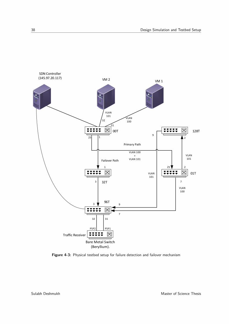
38 Design Simulation and Testbed Setup
31
VLAN 100
VLAN 101
VLAN 100 +
VLAN 101
VLAN 100
VLAN 101
VLAN 101
00T 128T
01T
96T
32T
Failover Path
SDN Controller (145.97.20.117)
32
25 1
73
9
Traffic Receiver
2
VM 1VM 2
Primary Path
3132
9
7
21
3
P5P2 P5P1
Bare Metal Switch (Beryllium).
25
Figure 4-3: Physical testbed setup for failure detection and failover mechanism
Sulabh Deshmukh Master of Science Thesis
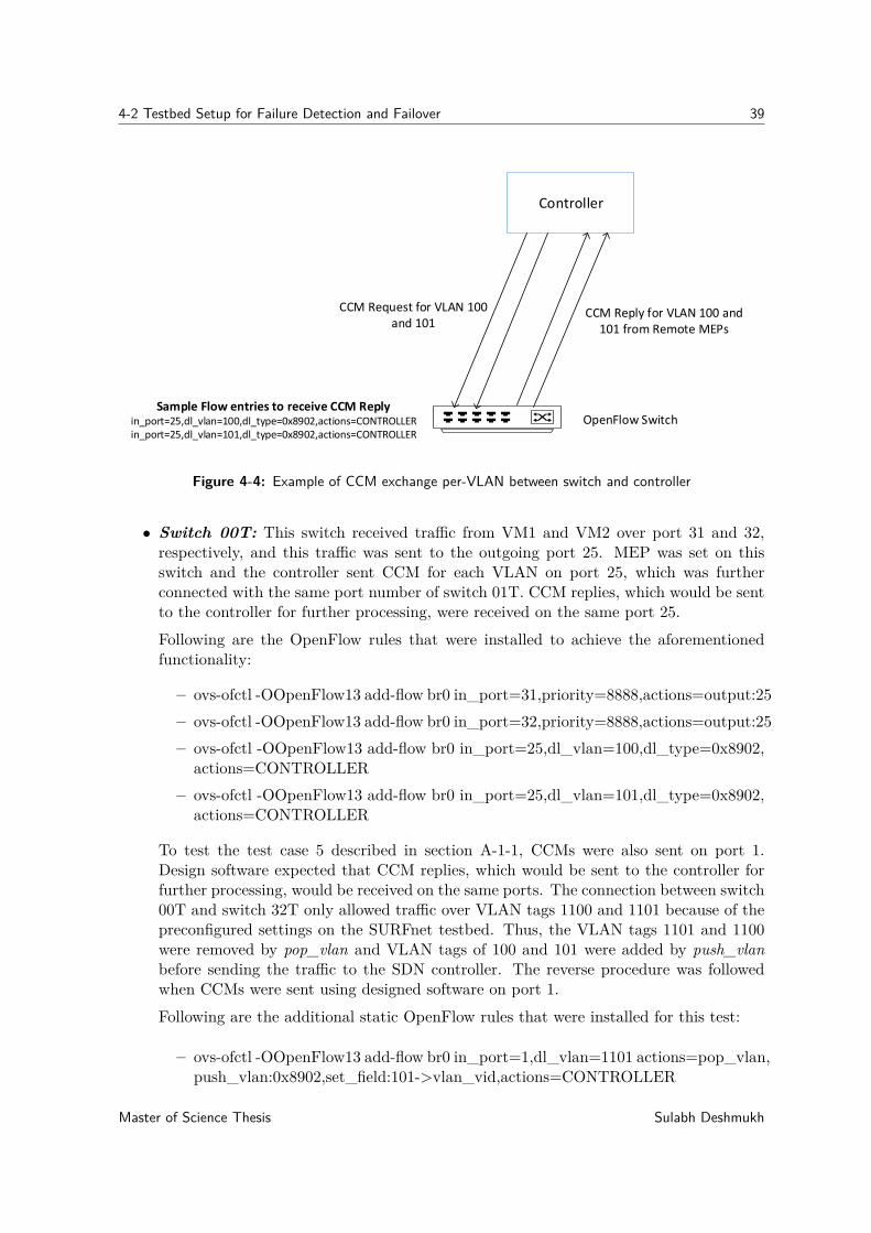
4-2 Testbed Setup for Failure Detection and Failover 39
Controller
OpenFlow Switch
CCM Request for VLAN 100 and 101
CCM Reply for VLAN 100 and 101 from Remote MEPs
Sample Flow entries to receive CCM Replyin_port=25,dl_vlan=100,dl_type=0x8902,actions=CONTROLLERin_port=25,dl_vlan=101,dl_type=0x8902,actions=CONTROLLER
Figure 4-4: Example of CCM exchange per-VLAN between switch and controller
• Switch 00T: This switch received traffic from VM1 and VM2 over port 31 and 32,respectively, and this traffic was sent to the outgoing port 25. MEP was set on thisswitch and the controller sent CCM for each VLAN on port 25, which was furtherconnected with the same port number of switch 01T. CCM replies, which would be sentto the controller for further processing, were received on the same port 25.
Following are the OpenFlow rules that were installed to achieve the aforementionedfunctionality:
– ovs-ofctl -OOpenFlow13 add-flow br0 in_port=31,priority=8888,actions=output:25– ovs-ofctl -OOpenFlow13 add-flow br0 in_port=32,priority=8888,actions=output:25– ovs-ofctl -OOpenFlow13 add-flow br0 in_port=25,dl_vlan=100,dl_type=0x8902,
actions=CONTROLLER– ovs-ofctl -OOpenFlow13 add-flow br0 in_port=25,dl_vlan=101,dl_type=0x8902,
actions=CONTROLLER
To test the test case 5 described in section A-1-1, CCMs were also sent on port 1.Design software expected that CCM replies, which would be sent to the controller forfurther processing, would be received on the same ports. The connection between switch00T and switch 32T only allowed traffic over VLAN tags 1100 and 1101 because of thepreconfigured settings on the SURFnet testbed. Thus, the VLAN tags 1101 and 1100were removed by pop_vlan and VLAN tags of 100 and 101 were added by push_vlanbefore sending the traffic to the SDN controller. The reverse procedure was followedwhen CCMs were sent using designed software on port 1.
Following are the additional static OpenFlow rules that were installed for this test:
– ovs-ofctl -OOpenFlow13 add-flow br0 in_port=1,dl_vlan=1101 actions=pop_vlan,push_vlan:0x8902,set_field:101->vlan_vid,actions=CONTROLLER
Master of Science Thesis Sulabh Deshmukh
40 Design Simulation and Testbed Setup
– ovs-ofctl -OOpenFlow13 add-flow br0 in_port=1,dl_vlan=1100 actions=pop_vlan,push_vlan:0x8902,set_field:100->vlan_vid,actions=CONTROLLER
• Switch 01T: When frames arrived at switch 01T over the trunk port 25, traffic foreach VLAN was separated. Frames for VLAN 100 were sent to port 7 and framesfor VLAN 101 were forwarded to port 2. Moreover, designed software expected toreceive CCM replies for each VLAN on the same port, where traffic was sent for theseVLANs. Therefore, traffic received on port 2 and port 7 was forwarded to port 25. Theconnection between switch 01T and switch 128T only allowed traffic over VLAN tags2100 and 2101 because of the preconfigured settings on the SURFnet testbed. Thus, theVLAN tag 101 was removed and either of the VLAN tags, 2100 or 2101, was added tosend the traffic further. The reverse procedure was followed when traffic was receivedon port 2.Following are the OpenFlow rules that were installed to achieve the aforementionedfunctionality:
– ovs-ofctl -OOpenFlow13 add-flow br0 in_port=25,dl_vlan=101 actions=pop_vlan,push_vlan:0x8100,set_field:2101->vlan_vid,output:2
– ovs-ofctl -OOpenFlow13 add-flow br0 in_port=25,dl_vlan=100,actions=output:7– ovs-ofctl -OOpenFlow13 add-flow br0 in_port=2,dl_vlan=2101 actions=pop_vlan,
push_vlan:0x8100,set_field:101->vlan_vid,output:25– ovs-ofctl -OOpenFlow13 add-flow br0 in_port=7,actions=output:25
• Switch 128T:At this switch, the traffic for VLAN 101 was received on port 2. Thistraffic was routed to port 9. In addition, we expected a CCM reply in the reversedirection, that is, traffic on port 9 would be sent to port 2. This switch merely actedas an intermediate switch for VLAN 101 traffic. The connection between switch 01Tand switch 128T only allowed traffic over VLAN tags 2100 and 2101 because of thepreconfigured settings on the SURFnet testbed. Thus, the VLAN tag 101 was removedby pop_vlan and either of the VLAN tags, 2100 or 2101, was added by push_vlan tosend the traffic on port 2 of switch 128T. These tages were removed before sendingtraffic further on port 9 as these VLAN tags were not supported on other paths. Thereverse procedure was followed when traffic was received on port 9 before forwarding itto port 2.Following are the OpenFlow rules that were installed to achieve the aforementionedfunctionality:
– ovs-ofctl -OOpenFlow13 add-flow br0 in_port=2,dl_vlan=2101,actions=pop_vlan,push_vlan:0x8100,set_field:101->vlan_vid,output:9
– ovs-ofctl -OOpenFlow13 add-flow br0 in_port=9,dl_vlan=101,actions=pop_vlan,push_vlan:0x8100,set_field:2101->vlan_vid,output:2
• Switch 32T: This switch is only used when the redundant path is used. The connectionbetween switch 00T and switch 32T only allowed the VLAN tags 1100 and 1101 becauseof intermediate traditional switches (not shown) in our testbed. Therefore, we removedthe VLAN tags 1100 and 1101 and added the tags 100 and 101 to send the traffic on
Sulabh Deshmukh Master of Science Thesis
4-2 Testbed Setup for Failure Detection and Failover 41
port 3 of switch 32T. The reverse procedure was followed when frames were sent onport 1 of switch 32T.
Following are the OpenFlow rules that were installed to achieve the aforementionedfunctionality:
– ovs-ofctl -OOpenFlow13 add-flow br0 in_port=1,dl_vlan=1101 actions=pop_vlan,push_vlan:0x8100,set_field:101->vlan_vid,output:3
– ovs-ofctl -OOpenFlow13 add-flow br0 in_port=1,dl_vlan=1100 actions=pop_vlan,push_vlan:0x8100,set_field:100->vlan_vid,output:3
– ovs-ofctl -OOpenFlow13 add-flow br0 in_port=3,dl_vlan=101 actions=pop_vlan,push_vlan:0x8100,set_field:1101->vlan_vid,output:1
– ovs-ofctl -OOpenFlow13 add-flow br0 in_port=3,dl_vlan=100 actions=pop_vlan,push_vlan:0x8100,set_field:1100->vlan_vid,output:1
• Switch 96T: We set up an MEP at switch 96T. The CCMs were sent per-VLAN. TheMEP operation and procedure was in accordance with that of switch 00T. The onlydifference being that CCM for VLAN 100 were sent to port 7, whereas those for VLAN101 were forwarded to port 9. The traffic for VLAN 100, which was received on port 7,was further routed to port 31. Traffic for VLAN 101 was received on port 9 which wassent to port 32. Traffic received on port 3 of the failover path was sent over to eitherport 31 or 32 based on the VLAN identifiers.
Following are the OpenFlow rules that were installed to achieve the functionality men-tioned above:
– ovs-ofctl -OOpenFlow13 add-flow br0 in_port=9,dl_vlan=101,actions=output:32– ovs-ofctl -OOpenFlow13 add-flow br0 in_port=7,dl_vlan=100,actions=output:31– ovs-ofctl -OOpenFlow13 add-flow br0 in_port=3,dl_vlan=100 actions=output:31– ovs-ofctl -OOpenFlow13 add-flow br0 in_port=3,dl_vlan=101 actions=output:32– ovs-ofctl -OOpenFlow13 add-flow br0 in_port=7,dl_vlan=100,dl_type=0x8902,
actions=CONTROLLER– ovs-ofctl -OOpenFlow13 add-flow br0 in_port=9,dl_vlan=101,dl_type=0x8902,
actions=CONTROLLER
To test the test case 5 described in section A-1-1, MEPs were also configured to sendCCMs per-VLAN on port 3 for failover path monitoring with unique maintenance as-sociation (MA).
Following are the additional OpenFlow rules that were installed for this test:
– ovs-ofctl -OOpenFlow13 add-flow br0 in_port=3,dl_vlan=100,dl_type=0x8902,actions=CONTROLLER
– ovs-ofctl -OOpenFlow13 add-flow br0 in_port=3,dl_vlan=101,dl_type=0x8902,actions=CONTROLLER
Master of Science Thesis Sulabh Deshmukh
42 Design Simulation and Testbed Setup
Failure detection and failover experiments were performed separately and in combinationwith load balancing features to test the overall connectivity of the prototype. Therefore, thetestbed setup mentioned in the section 4-1 was combined with that mentioned in this section.A list of tests performed is provided in appendix A. When both the testbed setups werecombined, changes were required only at switch 00T. Instead of sending the traffic receivedfrom VM1 and VM2 directly on port 25, it was sent over to the Cisco switch and the incomingtraffic from the Cisco switch was sent over to port 25. In this scenario, the OpenFlow rulesinstalled were similar to those explained in section 4-1. In the available testbed, it waspossible to send traffic for only two VLANs. Hence, multi-VLAN failure detection was nottested simultaneously on both primary and failover path as shown in figure 3-1. Multi-VLANfailure detection was evaluated using either primary or failover path.
4-3 Prototype Software of Proposed Design
As discussed in chapter 3, an application needs to be designed in SDN controller for detectingper-VLAN failure over a trunk. For prototype simulation, we designed and developed anapplication in Ryu. Figure 4-5 shows an overview of the designed software components.Implementation is categorized into 3 main components: main application, failover, and CCM.
CFM Implementation is the primary module, and only a single instance of it is active in thewhole network. All configuration details, such as switches and ports on which MEPs should besetup and failover path details should be provided in this module. This module is responsiblefor creating MEPs and initiating failovers. Failure monitoring and communication betweenall configured MEPs is performed in this module.
CCM library implements IEEE 802.1ag standards for detecting per-VLAN liveliness. A stan-dard state machine for sending and receiving CCM is implemented in this module. A failoverlibrary is responsible for failover initiation. When a failover is triggered after the timeout ofa failure detection timer, the appropriate failover path OpenFlow rules are installed on theswitches.
Sulabh Deshmukh Master of Science Thesis
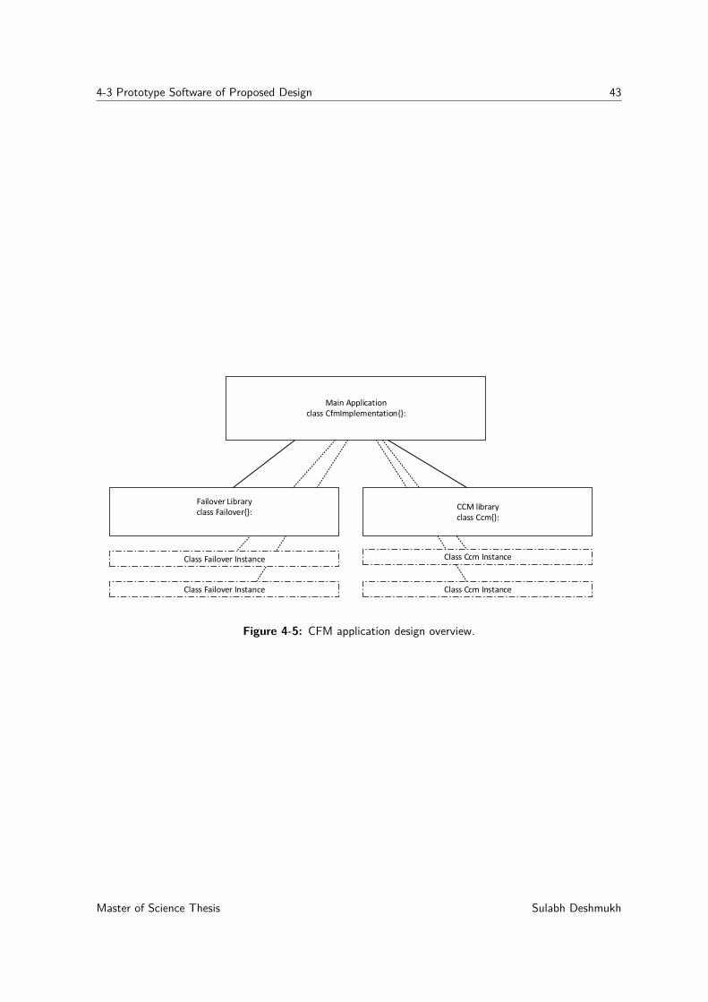
4-3 Prototype Software of Proposed Design 43
Main Application class CfmImplementation{}:
Class Failover Instance Class Ccm Instance
Failover Libraryclass Failover{}:
CCM library class Ccm{}:
Class Ccm InstanceClass Failover Instance
Figure 4-5: CFM application design overview.
Master of Science Thesis Sulabh Deshmukh

44 Design Simulation and Testbed Setup
Sulabh Deshmukh Master of Science Thesis
Chapter 5
Testing and Evaluation
This chapter discusses the results of the experiments conducted using the POC implementa-tion explained in chapter 4. To evaluate the proposed design and the developed software, atest plan was created, which is described in detail in Appendix A. The outcomes of the testsperformed are discussed in this section.
5-1 Results for Fast Failover
Although we concluded in chapter 2 that currently fast failover group tables cannot be usedwith CFM failure detection mechanism to solve multi-VLAN failure detection and failoverproblems, it is crucial to investigate and understand how effective the failover could be if itwas initiated from the data plane of SDN switches. This experiment provided an insight intothe current state of OpenFlow switches in achieving fast failover with CFM.
5-1-1 Experiment Procedure
This experiment can be broadly categorized into 3 major sections: traffic generation, fastfailover using CFM-based failure monitoring, and failover time calculations, which are ex-plained as follows:
Traffic Generation:
To simulate the network traffic of our experiments, we used pktgen [56], which is a Linux-basedhigh-speed packet generator that operates in kernel space. Pktgen allows sending fixed-sizedpackets at regular intervals. The generated packets are numbered sequentially. Pktgen allowsthe configuration of various parameters, such as packet size, source and destination IP andMAC addresses, packet interval, and the number of packets to be sent. In addition, it allowsVLAN tagging for the packets it generates.
Packets of size of 64 bytes were sent at fixed intervals of 0.05 ms. For each iteration of thisexperiment, we sent nearly 1 million of these packets from sender to receiver host. A script
Master of Science Thesis Sulabh Deshmukh
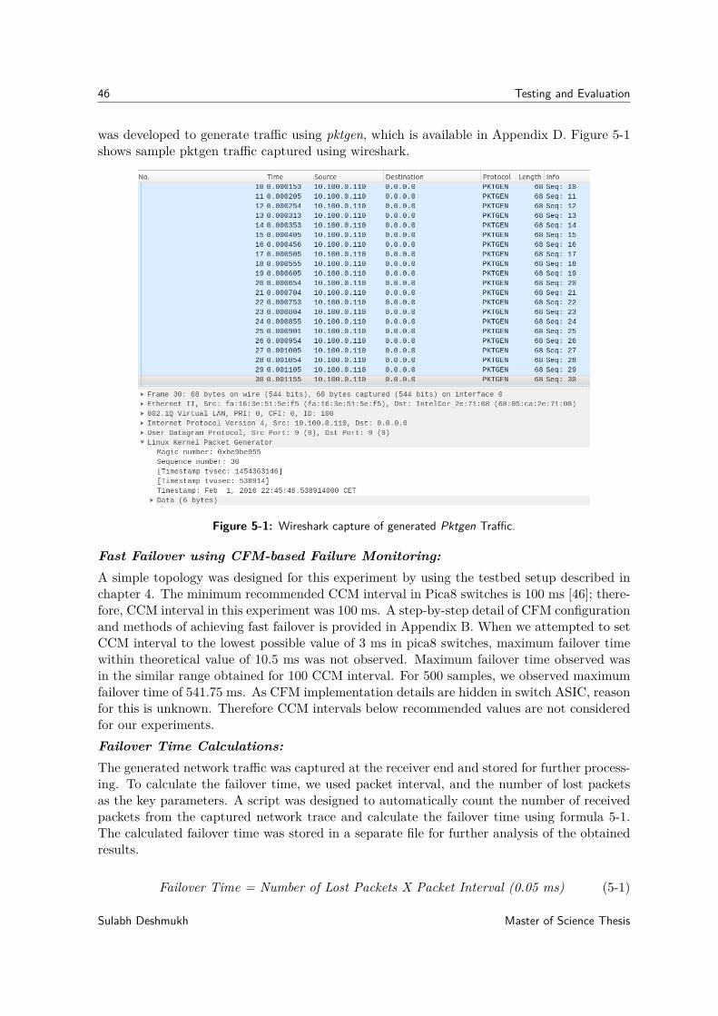
46 Testing and Evaluation
was developed to generate traffic using pktgen, which is available in Appendix D. Figure 5-1shows sample pktgen traffic captured using wireshark.
Figure 5-1: Wireshark capture of generated Pktgen Traffic.
Fast Failover using CFM-based Failure Monitoring:A simple topology was designed for this experiment by using the testbed setup described inchapter 4. The minimum recommended CCM interval in Pica8 switches is 100 ms [46]; there-fore, CCM interval in this experiment was 100 ms. A step-by-step detail of CFM configurationand methods of achieving fast failover is provided in Appendix B. When we attempted to setCCM interval to the lowest possible value of 3 ms in pica8 switches, maximum failover timewithin theoretical value of 10.5 ms was not observed. Maximum failover time observed wasin the similar range obtained for 100 CCM interval. For 500 samples, we observed maximumfailover time of 541.75 ms. As CFM implementation details are hidden in switch ASIC, reasonfor this is unknown. Therefore CCM intervals below recommended values are not consideredfor our experiments.Failover Time Calculations:The generated network traffic was captured at the receiver end and stored for further process-ing. To calculate the failover time, we used packet interval, and the number of lost packetsas the key parameters. A script was designed to automatically count the number of receivedpackets from the captured network trace and calculate the failover time using formula 5-1.The calculated failover time was stored in a separate file for further analysis of the obtainedresults.
Failover Time = Number of Lost Packets X Packet Interval (0.05 ms) (5-1)
Sulabh Deshmukh Master of Science Thesis
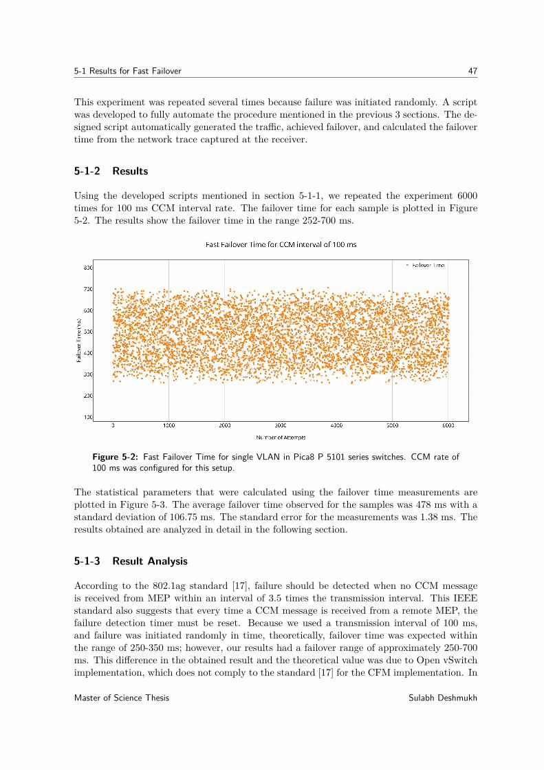
5-1 Results for Fast Failover 47
This experiment was repeated several times because failure was initiated randomly. A scriptwas developed to fully automate the procedure mentioned in the previous 3 sections. The de-signed script automatically generated the traffic, achieved failover, and calculated the failovertime from the network trace captured at the receiver.
5-1-2 Results
Using the developed scripts mentioned in section 5-1-1, we repeated the experiment 6000times for 100 ms CCM interval rate. The failover time for each sample is plotted in Figure5-2. The results show the failover time in the range 252-700 ms.
Figure 5-2: Fast Failover Time for single VLAN in Pica8 P 5101 series switches. CCM rate of100 ms was configured for this setup.
The statistical parameters that were calculated using the failover time measurements areplotted in Figure 5-3. The average failover time observed for the samples was 478 ms with astandard deviation of 106.75 ms. The standard error for the measurements was 1.38 ms. Theresults obtained are analyzed in detail in the following section.
5-1-3 Result Analysis
According to the 802.1ag standard [17], failure should be detected when no CCM messageis received from MEP within an interval of 3.5 times the transmission interval. This IEEEstandard also suggests that every time a CCM message is received from a remote MEP, thefailure detection timer must be reset. Because we used a transmission interval of 100 ms,and failure was initiated randomly in time, theoretically, failover time was expected withinthe range of 250-350 ms; however, our results had a failover range of approximately 250-700ms. This difference in the obtained result and the theoretical value was due to Open vSwitchimplementation, which does not comply to the standard [17] for the CFM implementation. In
Master of Science Thesis Sulabh Deshmukh
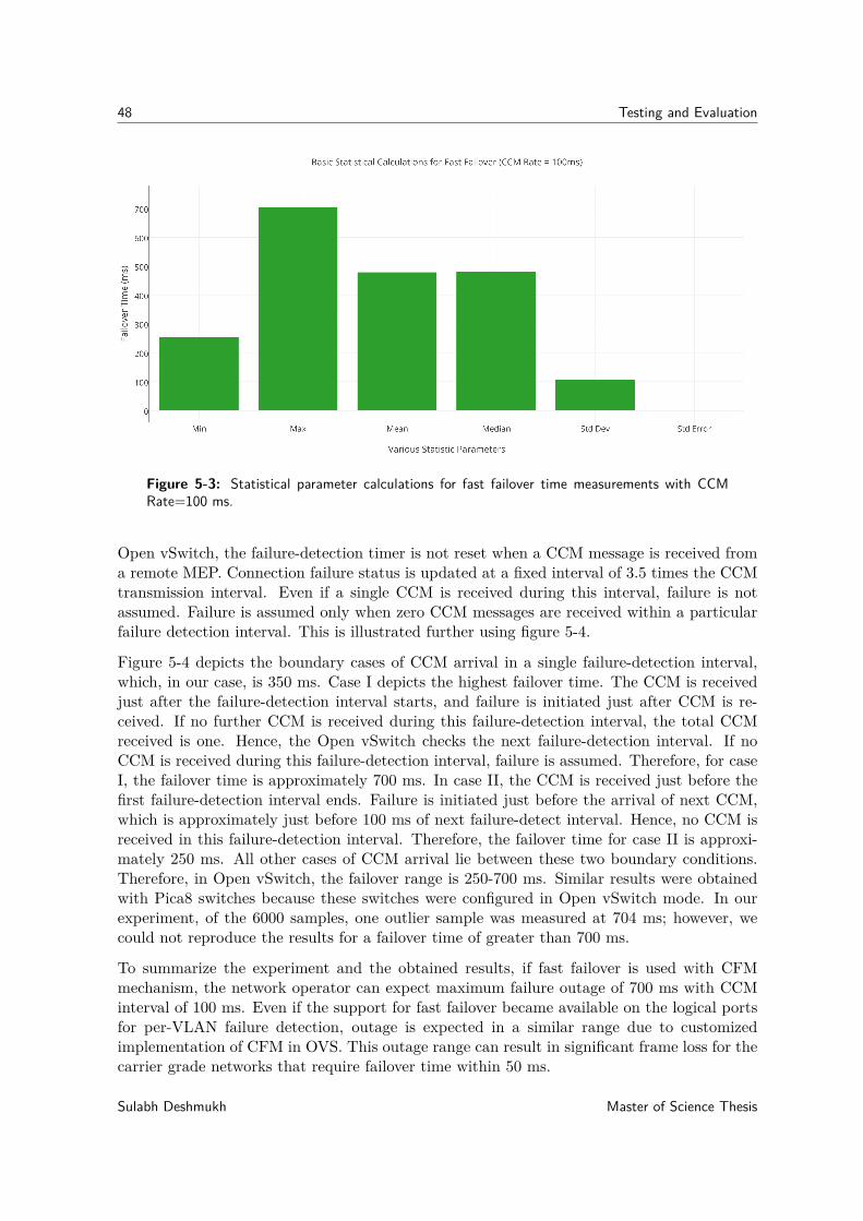
48 Testing and Evaluation
Figure 5-3: Statistical parameter calculations for fast failover time measurements with CCMRate=100 ms.
Open vSwitch, the failure-detection timer is not reset when a CCM message is received froma remote MEP. Connection failure status is updated at a fixed interval of 3.5 times the CCMtransmission interval. Even if a single CCM is received during this interval, failure is notassumed. Failure is assumed only when zero CCM messages are received within a particularfailure detection interval. This is illustrated further using figure 5-4.
Figure 5-4 depicts the boundary cases of CCM arrival in a single failure-detection interval,which, in our case, is 350 ms. Case I depicts the highest failover time. The CCM is receivedjust after the failure-detection interval starts, and failure is initiated just after CCM is re-ceived. If no further CCM is received during this failure-detection interval, the total CCMreceived is one. Hence, the Open vSwitch checks the next failure-detection interval. If noCCM is received during this failure-detection interval, failure is assumed. Therefore, for caseI, the failover time is approximately 700 ms. In case II, the CCM is received just before thefirst failure-detection interval ends. Failure is initiated just before the arrival of next CCM,which is approximately just before 100 ms of next failure-detect interval. Hence, no CCM isreceived in this failure-detection interval. Therefore, the failover time for case II is approxi-mately 250 ms. All other cases of CCM arrival lie between these two boundary conditions.Therefore, in Open vSwitch, the failover range is 250-700 ms. Similar results were obtainedwith Pica8 switches because these switches were configured in Open vSwitch mode. In ourexperiment, of the 6000 samples, one outlier sample was measured at 704 ms; however, wecould not reproduce the results for a failover time of greater than 700 ms.
To summarize the experiment and the obtained results, if fast failover is used with CFMmechanism, the network operator can expect maximum failure outage of 700 ms with CCMinterval of 100 ms. Even if the support for fast failover became available on the logical portsfor per-VLAN failure detection, outage is expected in a similar range due to customizedimplementation of CFM in OVS. This outage range can result in significant frame loss for thecarrier grade networks that require failover time within 50 ms.
Sulabh Deshmukh Master of Science Thesis
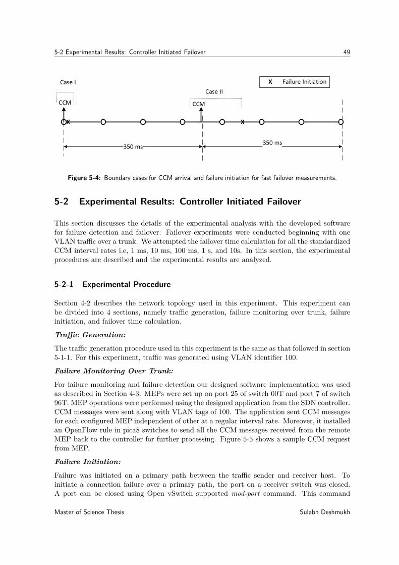
5-2 Experimental Results: Controller Initiated Failover 49
350 ms350 ms
X X
CCM CCM
X Failure InitiationCase I
Case II
Figure 5-4: Boundary cases for CCM arrival and failure initiation for fast failover measurements.
5-2 Experimental Results: Controller Initiated Failover
This section discusses the details of the experimental analysis with the developed softwarefor failure detection and failover. Failover experiments were conducted beginning with oneVLAN traffic over a trunk. We attempted the failover time calculation for all the standardizedCCM interval rates i.e, 1 ms, 10 ms, 100 ms, 1 s, and 10s. In this section, the experimentalprocedures are described and the experimental results are analyzed.
5-2-1 Experimental Procedure
Section 4-2 describes the network topology used in this experiment. This experiment canbe divided into 4 sections, namely traffic generation, failure monitoring over trunk, failureinitiation, and failover time calculation.
Traffic Generation:
The traffic generation procedure used in this experiment is the same as that followed in section5-1-1. For this experiment, traffic was generated using VLAN identifier 100.
Failure Monitoring Over Trunk:
For failure monitoring and failure detection our designed software implementation was usedas described in Section 4-3. MEPs were set up on port 25 of switch 00T and port 7 of switch96T. MEP operations were performed using the designed application from the SDN controller.CCM messages were sent along with VLAN tags of 100. The application sent CCM messagesfor each configured MEP independent of other at a regular interval rate. Moreover, it installedan OpenFlow rule in pica8 switches to send all the CCM messages received from the remoteMEP back to the controller for further processing. Figure 5-5 shows a sample CCM requestfrom MEP.
Failure Initiation:
Failure was initiated on a primary path between the traffic sender and receiver host. Toinitiate a connection failure over a primary path, the port on a receiver switch was closed.A port can be closed using Open vSwitch supported mod-port command. This command
Master of Science Thesis Sulabh Deshmukh
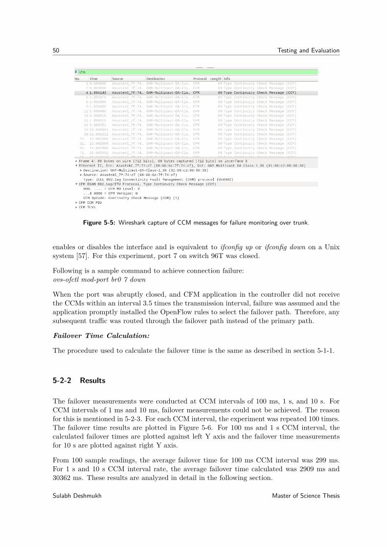
50 Testing and Evaluation
Figure 5-5: Wireshark capture of CCM messages for failure monitoring over trunk.
enables or disables the interface and is equivalent to ifconfig up or ifconfig down on a Unixsystem [57]. For this experiment, port 7 on switch 96T was closed.
Following is a sample command to achieve connection failure:ovs-ofctl mod-port br0 7 down
When the port was abruptly closed, and CFM application in the controller did not receivethe CCMs within an interval 3.5 times the transmission interval, failure was assumed and theapplication promptly installed the OpenFlow rules to select the failover path. Therefore, anysubsequent traffic was routed through the failover path instead of the primary path.
Failover Time Calculation:
The procedure used to calculate the failover time is the same as described in section 5-1-1.
5-2-2 Results
The failover measurements were conducted at CCM intervals of 100 ms, 1 s, and 10 s. ForCCM intervals of 1 ms and 10 ms, failover measurements could not be achieved. The reasonfor this is mentioned in 5-2-3. For each CCM interval, the experiment was repeated 100 times.The failover time results are plotted in Figure 5-6. For 100 ms and 1 s CCM interval, thecalculated failover times are plotted against left Y axis and the failover time measurementsfor 10 s are plotted against right Y axis.
From 100 sample readings, the average failover time for 100 ms CCM interval was 299 ms.For 1 s and 10 s CCM interval rate, the average failover time calculated was 2909 ms and30362 ms. These results are analyzed in detail in the following section.
Sulabh Deshmukh Master of Science Thesis
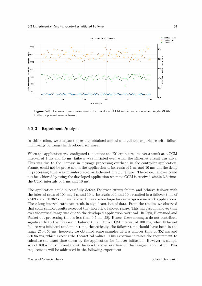
5-2 Experimental Results: Controller Initiated Failover 51
Figure 5-6: Failover time measurement for developed CFM implementation when single VLANtraffic is present over a trunk.
5-2-3 Experiment Analysis
In this section, we analyze the results obtained and also detail the experience with failuremonitoring by using the developed software.
When the application was configured to monitor the Ethernet circuits over a trunk at a CCMinterval of 1 ms and 10 ms, failover was initiated even when the Ethernet circuit was alive.This was due to the increase in message processing overhead in the controller application.Frames could not be processed in the application at intervals of 1 ms and 10 ms and the delayin processing time was misinterpreted as Ethernet circuit failure. Therefore, failover couldnot be achieved by using the developed application when no CCM is received within 3.5 timesthe CCM intervals of 1 ms and 10 ms.
The application could successfully detect Ethernet circuit failure and achieve failover withthe interval rates of 100 ms, 1 s, and 10 s. Intervals of 1 and 10 s resulted in a failover time of2.909 s and 30.362 s. These failover times are too large for carrier-grade network applications.These long interval rates can result in significant loss of data. From the results, we observedthat some sample results exceeded the theoretical failover range. This increase in failover timeover theoretical range was due to the developed application overhead. In Ryu, Flow-mod andPacket-out processing time is less than 0.5 ms [58]. Hence, these messages do not contributesignificantly to the increase in failover time. For a CCM interval of 100 ms, when Ethernetfailure was initiated random in time, theoretically, the failover time should have been in therange 250-350 ms, however, we obtained some samples with a failover time of 352 ms and350.85 ms, which exceeds the theoretical values. This experiment raises the requirement tocalculate the exact time taken by the application for failover initiation. However, a samplesize of 100 is not sufficient to get the exact failover overhead of the designed application. Thisrequirement will be addressed in the following experiment.
Master of Science Thesis Sulabh Deshmukh
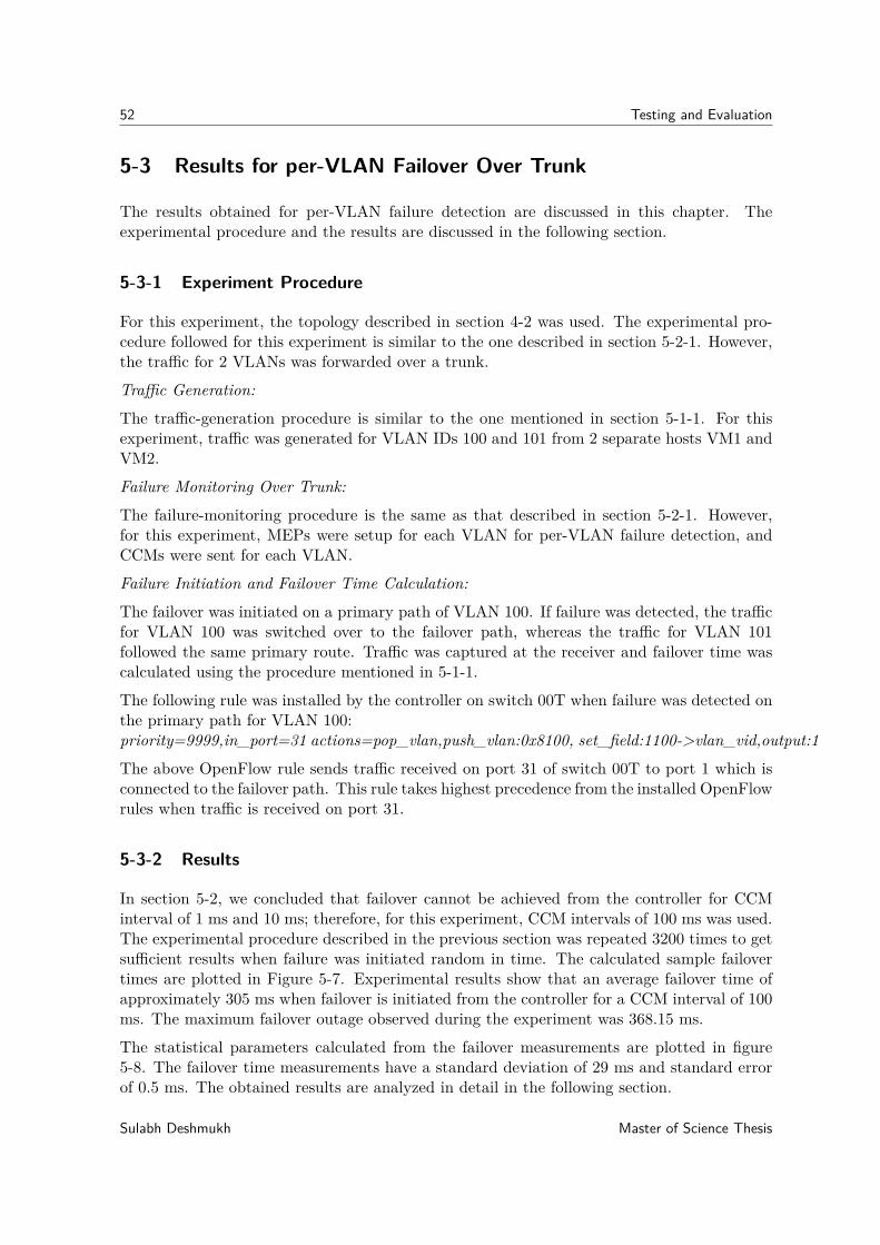
52 Testing and Evaluation
5-3 Results for per-VLAN Failover Over Trunk
The results obtained for per-VLAN failure detection are discussed in this chapter. Theexperimental procedure and the results are discussed in the following section.
5-3-1 Experiment Procedure
For this experiment, the topology described in section 4-2 was used. The experimental pro-cedure followed for this experiment is similar to the one described in section 5-2-1. However,the traffic for 2 VLANs was forwarded over a trunk.
Traffic Generation:
The traffic-generation procedure is similar to the one mentioned in section 5-1-1. For thisexperiment, traffic was generated for VLAN IDs 100 and 101 from 2 separate hosts VM1 andVM2.
Failure Monitoring Over Trunk:
The failure-monitoring procedure is the same as that described in section 5-2-1. However,for this experiment, MEPs were setup for each VLAN for per-VLAN failure detection, andCCMs were sent for each VLAN.
Failure Initiation and Failover Time Calculation:
The failover was initiated on a primary path of VLAN 100. If failure was detected, the trafficfor VLAN 100 was switched over to the failover path, whereas the traffic for VLAN 101followed the same primary route. Traffic was captured at the receiver and failover time wascalculated using the procedure mentioned in 5-1-1.
The following rule was installed by the controller on switch 00T when failure was detected onthe primary path for VLAN 100:priority=9999,in_port=31 actions=pop_vlan,push_vlan:0x8100, set_field:1100->vlan_vid,output:1
The above OpenFlow rule sends traffic received on port 31 of switch 00T to port 1 which isconnected to the failover path. This rule takes highest precedence from the installed OpenFlowrules when traffic is received on port 31.
5-3-2 Results
In section 5-2, we concluded that failover cannot be achieved from the controller for CCMinterval of 1 ms and 10 ms; therefore, for this experiment, CCM intervals of 100 ms was used.The experimental procedure described in the previous section was repeated 3200 times to getsufficient results when failure was initiated random in time. The calculated sample failovertimes are plotted in Figure 5-7. Experimental results show that an average failover time ofapproximately 305 ms when failover is initiated from the controller for a CCM interval of 100ms. The maximum failover outage observed during the experiment was 368.15 ms.
The statistical parameters calculated from the failover measurements are plotted in figure5-8. The failover time measurements have a standard deviation of 29 ms and standard errorof 0.5 ms. The obtained results are analyzed in detail in the following section.
Sulabh Deshmukh Master of Science Thesis
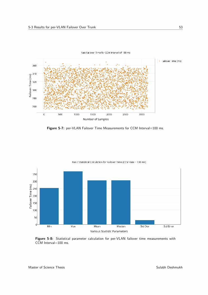
5-3 Results for per-VLAN Failover Over Trunk 53
Figure 5-7: per-VLAN Failover Time Measurements for CCM Interval=100 ms.
Figure 5-8: Statistical parameter calculation for per-VLAN failover time measurements withCCM Interval=100 ms.
Master of Science Thesis Sulabh Deshmukh
54 Testing and Evaluation
5-3-3 Result Analysis
As discussed in our earlier experiments, for a CCM transmission interval of 100 ms, whenper-VLAN failure is initiated randomly at any time, theoretically, the failover time shouldbe within the range of 250-350 ms; however, the obtained samples had a failover time ofapproximately 252-368 ms. The maximum failover overhead of 18 ms was observed. Duringthe experiment, 2 outlier values were observed at 384.85 ms and 379.2 ms; however, theresults were not reproducible. We suspected this to be a race condition [59] in the designedmulti-threaded software implementation due to sharing of failure monitoring event updatevariables between Ccm and failover instances threads. The 2 outlier results were excludedfrom the graph. The mean calculated for the sample was approximately 305 ms, which is 5 msmore than the possible theoretical mean value. This 5 ms overhead in mean value representsthe time between failure detection by the application and failover OpenFlow rule installation.Several studies have been conducted to benchmark the Ryu controller and OpenFlow messageprocessing time of the Ryu controller [58] [60] [61]. The average PacketOut time and FlowModprocessing time in Ryu were 0.2 ms and 0.4 ms, respectively. Therefore, we concluded thatthe extra overhead is the processing time of the failover module in the designed application.This module was invoked when the failure detection timer expired when no CCM was receivedwithin an interval of 3.5 times the transmission interval time.
Our controller-based software implementation outperformed fast failover using CFM in Pica8hardware switches due to the customized implementation of CFM in these switches. Althoughstandardized support is available for CFM in Pica8 hardware switches, fast failover featurewill not have significant advantage over the implemented software for a CCM interval of 100ms because the implemented software showed a maximum overhead of approximately 18 msfrom the theoretical value. However, fast failover can be instrumental for a CCM interval of1 ms and 10 ms because these failure detection intervals cannot be supported currently byusing a controller based software implementation.
5-4 Results for Load Balancing
In LAG-based load-balancing, the choice of load balancing algorithm is vendor-specific. Ciscoproprietary hash-based algorithms were used because we used a Cisco switch. The config-uration of LAG is described in section 4-1, and tests were performed to ensure successfulload balancing across all the links in the LAG using the test plan defined in Appendix A-2.Load balancing was successfully verified using the performed tests. Our objective was not totest the performance of these well-defined algorithms but to ensure that failure detection ispossible over all the links, and traffic flows within the system in case of link failure when tra-ditional technology-based load balancing is combined with the OpenFlow switch-based failuredetection mechanism. The test plan for connectivity test is described in Appendix A.
Sulabh Deshmukh Master of Science Thesis
Chapter 6
Conclusions and Future Work
This chapter contains the conclusions of the work presented in the thesis and recommendationsfor further work. The objectives of the thesis and results are described followed by conclusionsand recommendations for future work.
6-1 Conclusion
The trunk port is used by customers to connect to the service provider network and offersmultiple benefits. Multiple Ethernet circuits can be carried over this trunk port using trunk,which distinguishes each (VLAN) service on the basis of VLAN identifiers. When redun-dancy needs to be offered in the network using two trunk ports over two separate provideredge Ethernet switches, challenges arise in detecting a single Ethernet circuit failure overtrunk and balancing the per-flow traffic load over active trunks. Solving both these problemsby identifying Layer 2 technologies for detecting per-Ethernet circuit failure and load balanc-ing were the primary objectives of the thesis. We investigated traditional networking, andsoftware-defined networking (SDN)-based approaches to solve these problems.
To address the challenges of detecting per-Ethernet circuit failure and traffic load balancingat Layer 2, several existing technologies were identified and evaluated. No existing stan-dard technology, in its current state, offered a solution to both the aforementioned problems.At Layer 2, failure detection can be provided by LACP [12], BFD [1], and CFM [17]. Wefound that none of these standard protocols supported per-VLAN failure detection on theuntagged interfaces of the switch. Although BFD and CFM can potentially be used overVLAN interfaces to detect a per-Ethernet circuit failure over a trunk, the lack of an appropri-ate forwarding mechanism between the VLAN interfaces at Layer 2 prevents the use of theseprotocols. A Layer 2 solution should be designed by switch vendors to provide flexibility andappropriate control for forwarding Ethernet frames between these Layer 2 VLAN interfacesfor detecting per-Ethernet circuit failure. We also found that even if such VLAN interface-based solution becomes available for detecting failure, it cannot be used in combination with
Master of Science Thesis Sulabh Deshmukh
56 Conclusions and Future Work
the existing Layer 2 load balancing technique, namely LAG, because LAG requires to besetup on untagged interfaces.In this thesis, we also investigated SDN-based approach to solve the problem. We discoveredthat no direct support was available to solve both the aforementioned problems in SDN.However, SDN offers flexibility to the network operators, allows them to design their ownsolutions, and eliminates vendor dependence. In this thesis, we proposed a hybrid SDN-based system design approach to solve both the problems. The per-flow load balancing wasprovided by an Ethernet-based customer edge switch using LAG, whereas OpenFlow-capable[4] switches ensured SDN-controller initiated per-Ethernet circuit failure detection and failoverusing developed software. CFM was used for detecting Ethernet circuit failure. The proposedarchitecture offered an advantage over a purely SDN-based solution because it eliminatedthe need for any changes in the customer network infrastructure. All the proposed designmodification will be managed by the network operator. This allows faster adaptation of thesolution and often results in cost benefits to the customers because no infrastructure changesare required in the customer network.We validated the proposed system design using POC implementation over the physical SDNtestbed. Experimental results revealed that the SDN-based approach could be successfullyused to solve both the previously mentioned problems. Experimental results also revealedseveral challenges associated with the current state of SDN. We demonstrated that becauseof the high latency requirement of the SDN controller, achieving per-Ethernet circuit failoverwithin the carrier grade recovery time (<50 ms) [62] is currently not possible from the SDNcontroller. For the standardized CFM failure monitoring interval of 100 ms, the maximalobserved failover time for per-Ethernet circuit failure was 368 ms. We also demonstrated thesuccessful integration of LAG-based load balancing with the SDN-based per-Ethernet circuitfailure detection mechanism. In this work, we also investigated the Fast Failover Group Tablesupport in OpenFlow switches. This mechanism is used in the data plane and monitorsthe outgoing port for connection failure. It supports the CFM and BFD failure monitoringmechanism and forwards the traffic to the first active port in the group. Our experimentsrevealed that when CFM failure monitoring interval of 100 ms was used with the fast failovermechanism, the maximum failover time was 700 ms which is double that of the maximumpossible theoretical failover time of 350 ms because of switch vendor specific implementationof CFM. Although fast failover mechanism currently does not support per-VLAN failuredetection over trunk and only supports single VLAN at the time of writing this thesis, itallows aggressive failure monitoring intervals below 10 ms, which we could not use from thecontroller-initiated failover mechanism because of its high latency requirement. With theappropriate support for per-VLAN failure detection and standardized CFM implementation,a fast failover approach could potentially be used to achieve failover within carrier grade limit.SDN is still in its early stage of development. The service deployment flexibility and vendorneutrality make SDN an attractive technology for the network operator. However, SDNstill has many challenges to overcome. The latency requirement for communication betweenthe data plane and control plane is still higher than 50 ms [61]. Network operators arestill dependent on switch vendors for data plane changes. To visualize the future of fullyprogrammable networks that transfer the control to the network operators along with controlplane programmability, research toward a fully programmable data plane is required, allowingscalability and efficiency to support carrier grade networks. Nevertheless, this thesis was thefirst attempt to achieve the primary objectives using SDN, and it demonstrated the manner in
Sulabh Deshmukh Master of Science Thesis
6-2 Recommendations for Future Work 57
which network operators can leverage the SDN benefits and introduce new innovative featureswithout dependence on the switch vendors.
In conclusion, we investigated the existing standard Layer 2 technologies for per-Ethernetcircuit failure detection and load balancing and listed the advantages and challenges associatedwith them in this thesis. We also provided a state-of-the-art literature summary of SDNtechnology and the current state of Layer 2 failure detection and load balancing supportin SDN. We proposed the SDN-based design to achieve both the objectives of this workand implemented the software for per-Ethernet circuit failure detection and failover. Withthe help of the POC implementation, we validated the proposed design and evaluated itsperformance. We showcased how SDN can be successfully used to solve both the objectivesof this work. We also identified several issues with the popular OpenFlow-capable switchesand summarized our findings.
6-2 Recommendations for Future Work
Because SDN is a relatively new technology, during validation of the proposed system, severalissues were observed with the current OpenFlow implementations. Given below is a list ofrecommendations for future work required to implement the proposed design in the productionnetwork on a large scale.
• Current per-Ethernet circuit failover detection software was validated in the prototypeenvironment. The correlation between failover overhead and the number of Ethernetcircuits monitored should be studied when a large number of Ethernet circuits need tobe monitored.
• To reduce the failover time within the carrier grade range, we recommend the per-Ethernet circuit failover initiation from the data plane of the switch due to the highlatency requirement of the current SDN controllers. Support should be requested forper-VLAN failure detection from the OpenFlow switch vendors.
• It was observed that the current implementation of CFM in OVS-supported Pica8switches currently do not fully comply with the standard CFM implementation. Forfailover time within the carrier grade requirement, standard CFM implementation wouldbe required. To implement the proposed design in production network, standard CFMsupport should be requested from Pica8 switch vendor.
• The proposed system design uses existing Ethernet switch-based load balancing mecha-nism. In the future, to leverage the complete SDN benefits, existing Ethernet switchesshould be replaced with OpenFlow-capable switches and SDN controller-based loadbalancing should be used. Hence, the performance and effectiveness of controller-basedload balancing techniques should be investigated
Master of Science Thesis Sulabh Deshmukh

58 Conclusions and Future Work
Sulabh Deshmukh Master of Science Thesis
Appendix A
Test Plan
To assess POC implementation, several tests were performed. Along with the test cases thatwere intended to test the developed software, a test plan was created to assess the performanceof the proposed system as well. The test plan for the proposed system is categorized into twomain sections:
• Test plan for failure detection and failover mechanism
• Test plan for load balancing and overall system connectivity
A-1 Test Plan for Failure Detection and Failover Mechanism
The testbed used for these tests is shown in fig 4-3. When the testbed is configured as shownin fig 4-3, perform the basic connectivity test using the ping command. The ping request fromVM1 should be successfully received at port 31 of the Beryllium switch. The ping requestfrom VM2 should be successfully received on port 32 of the Beryllium switch. Repeat thistest to check both primary and backup path connectivity.
Several tests are performed to assess failure detection and the failover mechanism. Theprimary objective of these tests is to verify the designed software on the testbed to achievethe first objective of this thesis.
Given below is the list of test cases designed using the behavior driven development [63]technique. This technique allows software development based on expected system behavior.The test cases are developed before the development of the software. The software code iswritten to successfully pass these tests.
A-1-1 Test Cases
Test Case 1
Master of Science Thesis Sulabh Deshmukh
60 Test Plan
• Given: Configured switches and the controller in the defined topology.
• When: CFM application is initiated from the controller.
• Then: CCMs will be sent for each configured VLAN at regular interval of 1 ms/10ms/100 ms.
Test Case 2
• Given: Configured switches and the controller in the defined topology.
• When: CFM application is initiated from the controller.
• Then: CCMs will be sent as per 802.1ag standard CCM format.
Test Case 3
• Given: Configured switches and the controller in the defined topology.
• When: Port 7 is closed on switch 96T for VLAN 100 tagged traffic to initiate a connec-tion failure between switch 96T and 01T.
• Then: MEP on switch 00T detects the failure and traffic for VLAN 100 is transferredto failover path on port 1.
Test Case 4
• Given: Configured switches and the controller in the defined topology.
• When: Port 9 is closed on switch 96T for VLAN 101 tagged traffic to initiate a connec-tion failure between switch 96T and 128T.
• Then: MEP on switch 00T detects the failure and traffic for VLAN 101 is transferredto failover path on port 1.
Test Case 5
• Given: Configured switches and the controller in the defined topology.
• When: Traffic for VLAN tag 100 is sent over primary path and traffic for VLAN tag101 is sent over failover path.
• Then: When failure is initiated on any of the path, traffic from that path is switchedto the active path.
Test Case 6
• Given: Configured switches and the controller in the defined topology.
• When: Port 7 is closed on switch 96T random in time for VLAN 100 tagged traffic.
• Then: Calculate failover time for VLAN 100 traffic.
Sulabh Deshmukh Master of Science Thesis
A-2 Test Plan for Load Balancing and Overall System Connectivity 61
A-2 Test Plan for Load Balancing and Overall System Connectivity
This section explains the tests performed for assessing load balancing. In addition, the testscarried out to examine the overall connectivity of the prototype design are described. Thedetection of any path failure using the proposed SDN-based solution is an important aspectof system connectivity tests.
Per-flow Load Balancing
Configure LAG on the Cisco switch of figure 4-2 such that the hashing algorithm sends thetraffic for VLAN 100 and VLAN 101 separately on port 26 and port 27, respectively. Checkthe packet counters on port 39 and port 40 of the switch 00T using OVS dump-ports commandto confirm the per-flow load balancing test. The packet counters on both ports should increasewhen the traffic for VLAN 100 and VLAN 101 is sent separately over port 39 and 40. Becausethe per-flow load balancing hashing algorithms are well standardized, the performance testof those algorithms is not a part of this study.
Overall System Connectivity Test
As the final part of this work, the load balancing and failure detection solution were combinedas a complete system. Experiments were performed on the combined system to ensure thatwhen any path in the system fails, the failure is detected and traffic flows uninterrupted. Thefollowing tests are designed for this purpose.
• A Cisco switch is connected to a Pica8 switch 00T; therefore, perform tests to check theconnectivity between these two switches. Close port 39 on the Pica8 switch administra-tively using the OVS mod-port command to verify that the LAG configured on Ciscocan detect the link failure and switch all traffic using the remaining links in the LAG.Perform a similar test for port 40 of switch 00T.
• Test the system connectivity by initiating a failure on paths between intermediateswitches between traffic sender VM1 and VM2 to traffic receiver Beryllium. For theseexperiments, initiate a failure on the paths between switch pairs 01T-128T, 01T-00T,01T-96T, and 128T-96T. Perform tests to initiate failure on a single path or two pathsbetween any pair of these switches. When failure is initiated, traffic from VM1 andVM2 is expected to continue flowing and to be successfully received at the Berylliumswitch.
A-3 Resources Used for Testing
• Pica8 P5101 OpenFlow switches (PicOS version 2.6)
• Cisco Catalyst 3560 Release 12.2(55)SE
• Ryu SDN controller
• Ubuntu 14.4 LTS
• Pktgen
Master of Science Thesis Sulabh Deshmukh

62 Test Plan
• Wireshark version 2.0.1
• OpenStack
• Python 3.4
• numpy 1.8.2 (for random number generation)
Sulabh Deshmukh Master of Science Thesis

Appendix B
Procedure to Test Fast Failover inPica8 Switches
B-1 Procedure to Test Fast failover in Pica8 Switches
The following procedure was followed to achieve failover with the topology described in figureB-1.
• Forwarding rules were configured for both the paths mentioned in the figure B-1. Eachswitch has an appropriate rule set to forward the traffic.
• On switch 00T, traffic coming in on port 31 was forwarded for handling to group 1.
• Group 1 is a failover table that watches on port 25 and port 1. The first bucket isalways chosen from the list of buckets to forward the traffic. Hence, it is important tospecify the primary path as a first bucket.
• OpenFlow ovs-ofctl mod-port command was used to close the port 7 on switch 96T.As group table watches for port failure event, once failure is detected next active portbucket from the failover group table is selected.
B-2 Procedure to configure CFM in Pica8 Switches
CFM was configured on port 25 of switch 00T and port 7 of switch 96T. Other setup remainsthe same as defined in the previous section.
CFM was configured as follows and the same procedure was repeated on both the switcheswith different mpid for the respective ports. MEPs are uniquely identified in the domainusing mpid.
Master of Science Thesis Sulabh Deshmukh
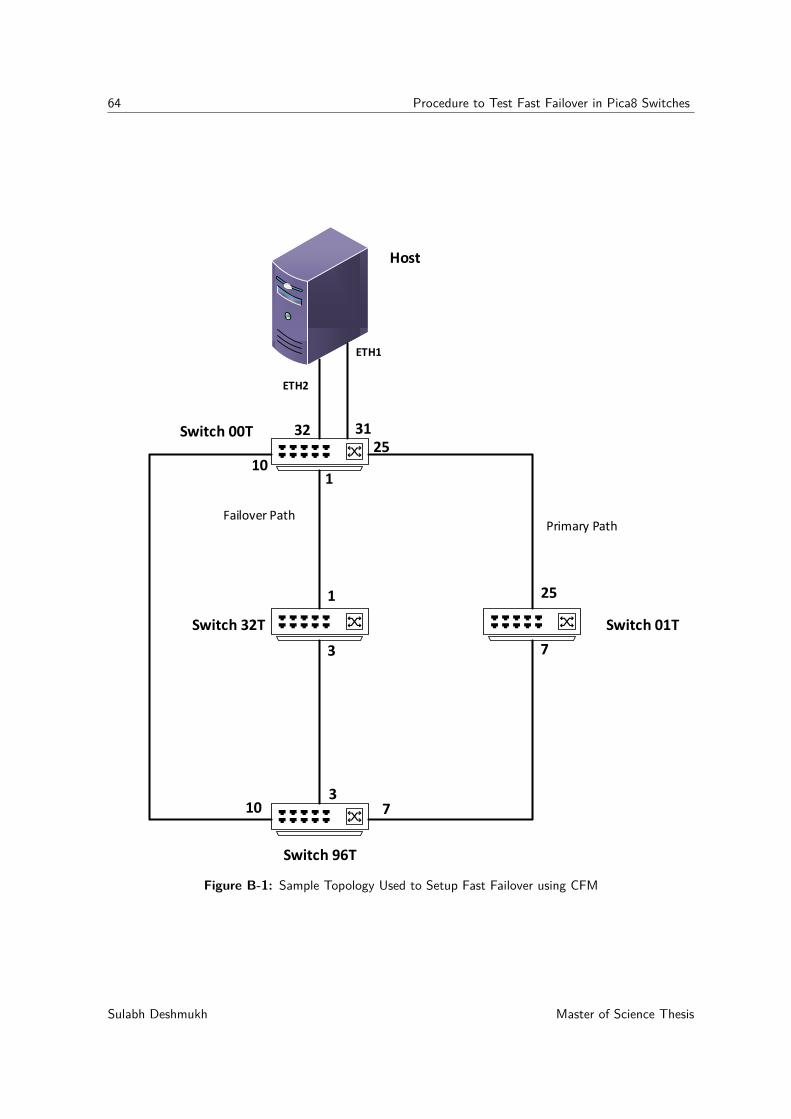
64 Procedure to Test Fast Failover in Pica8 Switches
Host
Switch 01T
Switch 00T
Switch 32T
Switch 96T
ETH1
ETH2
25
7
101
3
Primary PathFailover Path
3132
1
3710
25
Figure B-1: Sample Topology Used to Setup Fast Failover using CFM
Sulabh Deshmukh Master of Science Thesis
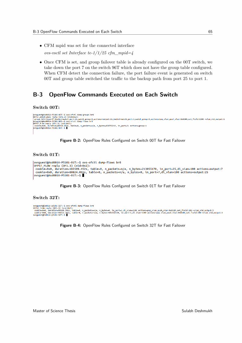
B-3 OpenFlow Commands Executed on Each Switch 65
• CFM mpid was set for the connected interfaceovs-vsctl set Interface te-1/1/25 cfm_mpid=4
• Once CFM is set, and group failover table is already configured on the 00T switch, wetake down the port 7 on the switch 96T which does not have the group table configured.When CFM detect the connection failure, the port failure event is generated on switch00T and group table switched the traffic to the backup path from port 25 to port 1.
B-3 OpenFlow Commands Executed on Each Switch
Switch 00T:
Figure B-2: OpenFlow Rules Configured on Switch 00T for Fast Failover
Switch 01T:
Figure B-3: OpenFlow Rules Configured on Switch 01T for Fast Failover
Switch 32T:
Figure B-4: OpenFlow Rules Configured on Switch 32T for Fast Failover
Master of Science Thesis Sulabh Deshmukh

66 Procedure to Test Fast Failover in Pica8 Switches
Switch 96T
Figure B-5: OpenFlow Rules Configured on Switch 96T for Fast Failover
Sulabh Deshmukh Master of Science Thesis
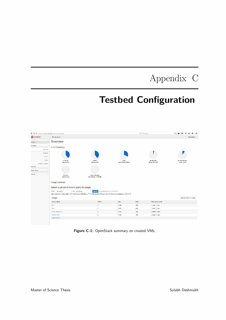
Appendix C
Testbed Configuration
Figure C-1: OpenStack summary on created VMs.
Master of Science Thesis Sulabh Deshmukh
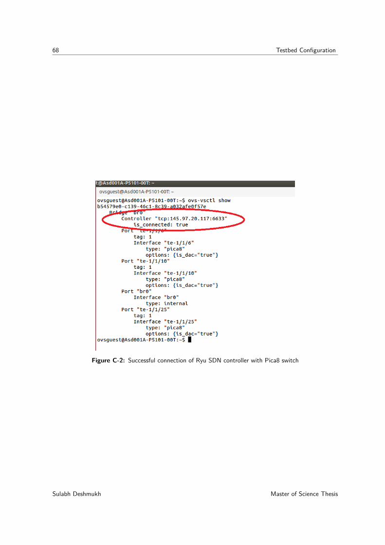
68 Testbed Configuration
Figure C-2: Successful connection of Ryu SDN controller with Pica8 switch
Sulabh Deshmukh Master of Science Thesis
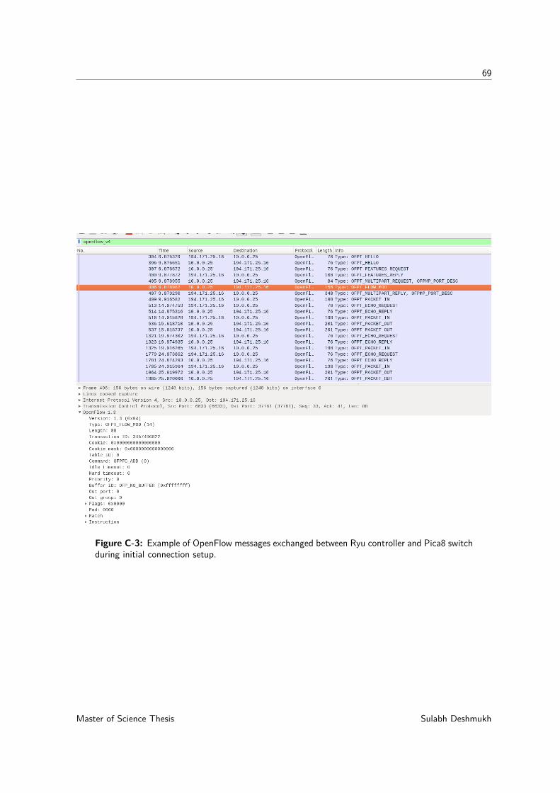
69
Figure C-3: Example of OpenFlow messages exchanged between Ryu controller and Pica8 switchduring initial connection setup.
Master of Science Thesis Sulabh Deshmukh
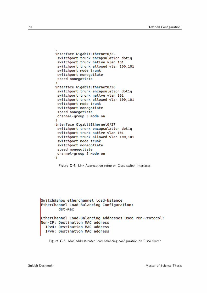
70 Testbed Configuration
Figure C-4: Link Aggregation setup on Cisco switch interfaces.
Figure C-5: Mac address-based load balancing configuration on Cisco switch
Sulabh Deshmukh Master of Science Thesis
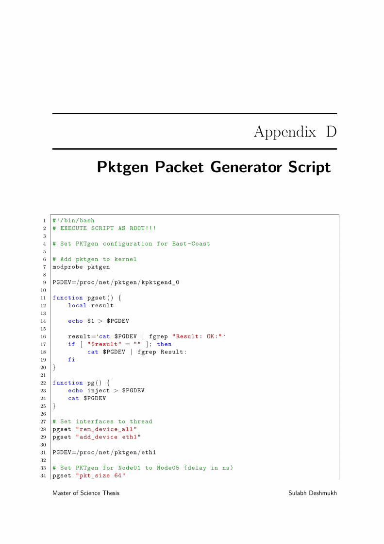
Appendix D
Pktgen Packet Generator Script
1 #!/bin/bash2 # EXECUTE SCRIPT AS ROOT!!!34 # Set PKTgen configuration for East-Coast56 # Add pktgen to kernel7 modprobe pktgen89 PGDEV=/proc/net/pktgen/kpktgend_0
1011 function pgset ( ) {12 local result1314 echo $1 > $PGDEV1516 result=‘cat $PGDEV | fgrep "Result: OK:" ‘17 if [ "$result" = "" ] ; then18 cat $PGDEV | fgrep Result :19 fi20 }2122 function pg ( ) {23 echo inject > $PGDEV24 cat $PGDEV25 }2627 # Set interfaces to thread28 pgset "rem_device_all"29 pgset "add_device eth1"3031 PGDEV=/proc/net/pktgen/eth13233 # Set PKTgen for Node01 to Node05 (delay in ns)34 pgset "pkt_size 64"
Master of Science Thesis Sulabh Deshmukh
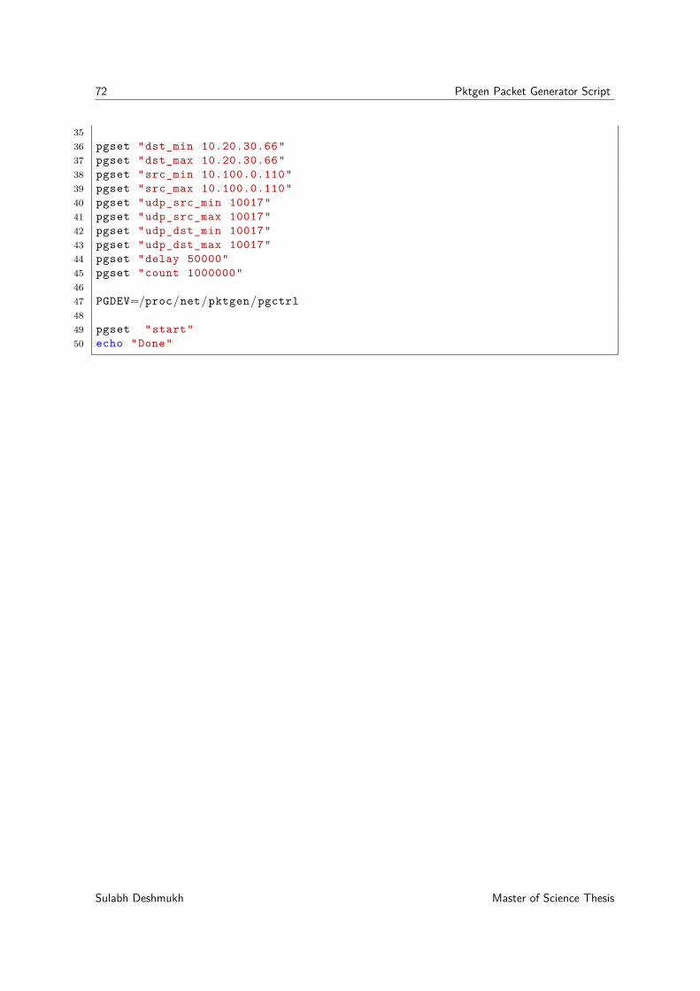
72 Pktgen Packet Generator Script
3536 pgset "dst_min 10.20.30.66"37 pgset "dst_max 10.20.30.66"38 pgset "src_min 10.100.0.110"39 pgset "src_max 10.100.0.110"40 pgset "udp_src_min 10017"41 pgset "udp_src_max 10017"42 pgset "udp_dst_min 10017"43 pgset "udp_dst_max 10017"44 pgset "delay 50000"45 pgset "count 1000000"4647 PGDEV=/proc/net/pktgen/pgctrl4849 pgset "start"50 echo "Done"
Sulabh Deshmukh Master of Science Thesis

Bibliography
[1] Bidirectional forwarding detection (bfd). [Online]. Available: https://tools.ietf.org/html/rfc5880
[2] Cfm concepts. [Online]. Available: http://www.cisco.com/c/en/us/support/docs/asynchronous-transfer-mode-atm/operation-administration-maintenance-oam/117457-technote-cfm-00.html
[3] Sdn architecture (issue 1). [Online]. Available: https://www.opennetworking.org/images/stories/downloads/sdn-resources/technical-reports/TR_SDN_ARCH_1.0_06062014.pdf
[4] Openflow switch specification version 1.5.0 ( protocol version 0x06 ). [Online].Available: https://www.opennetworking.org/images/stories/downloads/sdn-resources/onf-specifications/openflow/openflow-switch-v1.5.0.noipr.pdf
[5] Picos overview. [Online]. Available: http://www.pica8.com/wp-content/uploads/2015/08/pica8-whitepaper-picos-overview.pdf
[6] Metro ethernet services - a technical overview. [Online]. Available: https://www.mef.net/Assets/White_Papers/Metro-Ethernet-Services.pdf
[7] 100 gb/s ethernet standard. [Online]. Available: http://www.ieee802.org/3/ba/
[8] “Ieee standard for local and metropolitan area networks–bridges and bridged networks,”IEEE Std 802.1Q-2014 (Revision of IEEE Std 802.1Q-2011), pp. 1–1832, Dec 2014.
[9] Aarnet layer 2 point-to-point and multipoint virtual private networks. [Online].Available: http://news.aarnet.edu.au/aarnet-4-update-rolling-out-network/
[10] Surfnet multiservice point. [Online]. Available: https://www.surf.nl/diensten-en-producten/multi-service-port/index.html
[11] Y. Wang, G. Lu, and X. Li, “A study of internet packet reordering,” in InformationNetworking. Networking Technologies for Broadband and Mobile Networks. Springer,2004, pp. 350–359.
Master of Science Thesis Sulabh Deshmukh
74 Bibliography
[12] “Ieee standard for local and metropolitan area networks – link aggregation,” IEEE Std802.1AX-2014 (Revision of IEEE Std 802.1AX-2008), pp. 1–344, Dec 2014.
[13] Traditional networking vs software-defined networking. [Online]. Available: https://globalconfig.net/software-defined-networking-vs-traditional/
[14] N. McKeown, T. Anderson, H. Balakrishnan, G. Parulkar, L. Peterson, J. Rexford,S. Shenker, and J. Turner, “Openflow: enabling innovation in campus networks,” ACMSIGCOMM Computer Communication Review, vol. 38, no. 2, pp. 69–74, 2008.
[15] Sdn definition. [Online]. Available: https://www.opennetworking.org/sdn-resources/sdn-definition
[16] Open networking foundation. [Online]. Available: https://www.opennetworking.org/index.php
[17] “Ieee standard for local and metropolitan area networks - virtual bridged local areanetworks amendment 5: Connectivity fault management,” IEEE Std 802.1ag - 2007(Amendment to IEEE Std 802.1Q - 2005 as amended by IEEE Std 802.1ad - 2005 andIEEE Std 802.1ak - 2007), pp. 1–260, 2007.
[18] Bidirectional forwarding detection (bfd) on link aggregation group (lag) interfaces.[Online]. Available: https://tools.ietf.org/html/rfc7130
[19] Lacp failover time cisco propritory. [Online]. Available: http://www.cisco.com/c/en/us/td/docs/ios/cether/configuration/guide/ce_lnkbndl.html
[20] N. L. van Adrichem, B. J. Van Asten, and F. A. Kuipers, “Fast recovery in software-defined networks,” in Software Defined Networks (EWSDN), 2014 Third European Work-shop on. IEEE, 2014, pp. 61–66.
[21] Ethernet oam: Bidirectional forwarding detection (bfd). [Online]. Available:http://www.tecnologika.co.uk/wp-content/uploads/2000364-en.pdf
[22] Configuring bidirectional forwarding detection. [Online]. Avail-able: http://www.cisco.com/c/en/us/td/docs/switches/datacenter/sw/5_x/nx-os/interfaces/configuration/guide/if_cli/if_bfd.html#12420
[23] Configuring bidirectional forwarding and detection over switched virtual interface.[Online]. Available: http://www.cisco.com/c/en/us/td/docs/routers/7600/ios/15S/configuration/guide/7600_15_0s_book/bfdsvi.html
[24] Cisco switches overview of layer 2. [Online]. Available: http://www.cisco.com/c/en/us/td/docs/switches/datacenter/sw/5_x/dcnm/layer2/configuration/guide/b_Cisco_DCNM_Layer_2_Switching_Configuration_Guide__Release_5-x/Cisco_DCNM_Layer_2_Switching_Configuration_Guide__Release_5-x_chapter2.html
[25] Cisco bidirectional forwarding detection (bfd) implementation. [Online]. Avail-able: http://www.cisco.com/c/en/us/td/docs/switches/lan/catalyst3750x_3560x/software/release/15-2_1_e/configuration/guide/scg3750x/swbfd.html
Sulabh Deshmukh Master of Science Thesis
75
[26] Juniper cfm and oam configuration on bridge connections. [On-line]. Available: http://www.juniper.net/techpubs/en_US/junos15.1/topics/example/layer-2-802-1ag-ethernet-oam-cfm-example-over-bridge-connections-mx-solutions.html
[27] Cisco cfm and oam configuration. [Online]. Avail-able: http://www.cisco.com/c/en/us/td/docs/switches/lan/catalyst4500/12-2/46sg/configuration/guide/Wrapper-46SG/E_OAM.html
[28] K. Govindarajan, K. C. Meng, and H. Ong, “A literature review on software-definednetworking (sdn) research topics, challenges and solutions,” in Advanced Computing(ICoAC), 2013 Fifth International Conference on. IEEE, 2013, pp. 293–299.
[29] Pox sdn controller. [Online]. Available: http://www.noxrepo.org/pox/about-pox/
[30] Ryu. [Online]. Available: http://http://osrg.github.io/ryu/
[31] Onos sdn controller. [Online]. Available: http://onosproject.org/
[32] Floodlight sdn controller. [Online]. Available: http://www.projectfloodlight.org/floodlight/
[33] Opendaylight sdn controller. [Online]. Available: https://www.opendaylight.org/
[34] Enterprise-class definition. [Online]. Available: https://www.techopedia.com/definition/27853/enterprise-class
[35] Open vswitch official website. [Online]. Available: http://openvswitch.org/
[36] Openstack official website. [Online]. Available: https://www.openstack.org/
[37] Linux kvm official website. [Online]. Available: http://www.linux-kvm.org/page/Main_Page
[38] Xenserver virtualization platform official website. [Online]. Available: http://xenserver.org/
[39] Docker official website. [Online]. Available: https://www.docker.com/
[40] Virtualbox official website. [Online]. Available: https://www.virtualbox.org/
[41] Pica8 sdn switch official website. [Online]. Available: http://www.pica8.com/
[42] Noviflow sdn switch official website. [Online]. Available: www.noviflow.com
[43] Broadcom asic for pica8 switch. [Online]. Available: http://www.broadcom.nl/products/Switching/Data-Center/BCM56850-Series
[44] B. J. van Asten, N. L. van Adrichem, and F. A. Kuipers, “Scalability and resilience ofsoftware-defined networking: An overview,” arXiv preprint arXiv:1408.6760, 2014.
[45] Open vswitch database configuration. [Online]. Available: http://openvswitch.org/ovs-vswitchd.conf.db.5.pdf
Master of Science Thesis Sulabh Deshmukh
76 Bibliography
[46] Picos 2.6 configuration guide. [Online]. Available: http://www.pica8.com/wp-content/uploads/2015/09/ovs-configuration-guide-1.pdf
[47] N. L. Van Adrichem, C. Doerr, and F. A. Kuipers, “Opennetmon: Network monitoringin openflow software-defined networks,” in Network Operations and Management Sym-posium (NOMS), 2014 IEEE. IEEE, 2014, pp. 1–8.
[48] M. Bredel, Z. Bozakov, A. Barczyk, and H. Newman, “Flow-based load balancing inmultipathed layer-2 networks using openflow and multipath-tcp,” in Proceedings of thethird workshop on Hot topics in software defined networking. ACM, 2014, pp. 213–214.
[49] S. Vissicchio, L. Vanbever, and O. Bonaventure, “Opportunities and research challengesof hybrid software defined networks,” ACM SIGCOMM Computer Communication Re-view, vol. 44, no. 2, pp. 70–75, 2014.
[50] Customer-premises equipment. [Online]. Available: https://en.wikipedia.org/wiki/Customer-premises_equipment
[51] Open vswitch performance measurement. [Online]. Available: http://goo.gl/dGX92D
[52] P. Emmerich, D. Raumer, F. Wohlfart, and G. Carle, “Performance characteristics ofvirtual switching,” in Cloud Networking (CloudNet), 2014 IEEE 3rd International Con-ference on. IEEE, 2014, pp. 120–125.
[53] Cisco catalyst 3560 series switches. [Online]. Available: http://www.cisco.com/c/en/us/products/switches/catalyst-3560-series-switches/index.html
[54] Pica8 p5101 series switches. [Online]. Available: http://www.pica8.com/documents/pica8-datasheet-72x10gbe-p5101.pdf
[55] Cisco catalyst 3560 etherchannels configurations. [Online]. Avail-able: http://www.cisco.com/c/en/us/td/docs/switches/lan/catalyst3560/software/release/12-2_55_se/configuration/guide/3560_scg/swethchl.html#wp1275918
[56] R. Olsson, “Pktgen the linux packet generator,” in Proceedings of the Linux Symposium,Ottawa, Canada, vol. 2, 2005, pp. 11–24.
[57] Picos open vswitch command reference. [Online]. Available: http://www.pica8.com/wp-content/uploads/2015/09/ovs-commands-reference-1.pdf
[58] C. Metter, S. Gebert, S. Lange, T. Zinner, P. Tran-Gia, and M. Jarschel, “Investigatingthe impact of network topology on the processing times of sdn controllers,” in IntegratedNetwork Management (IM), 2015 IFIP/IEEE International Symposium on. IEEE, 2015,pp. 1214–1219.
[59] Race condition. [Online]. Available: https://en.wikipedia.org/wiki/Race_condition
[60] C. Rotsos, N. Sarrar, S. Uhlig, R. Sherwood, and A. W. Moore, “Oflops: An open frame-work for openflow switch evaluation,” in Passive and Active Measurement. Springer,2012, pp. 85–95.
Sulabh Deshmukh Master of Science Thesis

77
[61] A. Shalimov, D. Zuikov, D. Zimarina, V. Pashkov, and R. Smeliansky, “Advanced studyof sdn/openflow controllers,” in Proceedings of the 9th Central & Eastern European Soft-ware Engineering Conference in Russia. ACM, 2013, p. 1.
[62] carrier grade network recovery time. [Online]. Available: http://www.hjp.at/doc/rfc/rfc5654.html
[63] Behavior driven development. [Online]. Available: https://en.wikipedia.org/wiki/Behavior-driven_development
Master of Science Thesis Sulabh Deshmukh

78 Bibliography
Sulabh Deshmukh Master of Science Thesis


