Embed Size (px)
Citation preview
Citation: Jiang, T.; Yan, B.; Jiang, M.;
Xu, B.; Xu, Y.; Yu, Y.; Ma, T.; Wang, H.
Enhanced Adhesion—Efficient
Demolding Integration DLP 3D
Printing Device. Appl. Sci. 2022, 12,
7373. https://doi.org/10.3390/
app12157373
Academic Editor: Radu Godina
Received: 17 June 2022
Accepted: 19 July 2022
Published: 22 July 2022
Publisher’s Note: MDPI stays neutral
with regard to jurisdictional claims in
published maps and institutional affil-
iations.
Copyright: © 2022 by the authors.
Licensee MDPI, Basel, Switzerland.
This article is an open access article
distributed under the terms and
conditions of the Creative Commons
Attribution (CC BY) license (https://
creativecommons.org/licenses/by/
4.0/).
applied sciences
Article
Enhanced Adhesion—Efficient Demolding Integration DLP 3DPrinting DeviceTing Jiang 1,2 , Bo Yan 1, Minzheng Jiang 1,*, Buguang Xu 2,*, Yi Xu 2, Yueqiang Yu 1,3 , Tingang Ma 1
and Hao Wang 1
1 College of Mechanical Science and Engineering, Northeast Petroleum University, Daqing 163318, China;[email protected] (T.J.); [email protected] (B.Y.); [email protected] (Y.Y.);[email protected] (T.M.); [email protected] (H.W.)
2 Ningbo Runyes Medical Instrument Co., Ltd., Ningbo 315300, China; [email protected] Research and Development Center of 3D Printing Material and Technology, Northeast Forestry University,
Harbin 150040, China* Correspondence: [email protected] (M.J.); [email protected] (B.X.)
Abstract: A novel forming method of enhanced adhesion-efficient demolding integration is proposedto solve the problems of weak adhesion between the initial forming layer and the printing platformas well as the excessive stripping force at the bottom of the liquid tank when the printing platformrises. Therefore, a digital light processing (DLP) 3D printing forming device equipped with a porousreplaceable printing platform and a swing mechanism for the liquid tank is manufactured and verifiedby experiments. The experimental results show that the porous printing platform can enhance theadhesion between the initial forming layer and the printing platform and improve the demoldingefficiency of the forming device. In addition, the pull-out design of the printing platform plate reducesthe maintenance cost of the forming device. Therefore, the device has a good application prospect.
Keywords: 3D printing; stereolithography; DLP technology; forming device; printing platform
1. Introduction
Three-dimensional printing, also known as additive manufacturing (AM), is a process-ing method for creating three-dimensional objects by printing powder layer by layer [1].Compared with the subtractive manufacturing methods, additive manufacturing technol-ogy is a “bottom-up” material accumulation method [2]; its unique processing method hasprominent advantages in mass customization and being lightweight. Combined with thedata and Internet integration of industry 4.0, it will have higher efficiency, more utility andmore eco-friendly production potential [3]. Its principle is the process of slicing the 3Dmodel to obtain the 3D coordinates of the model contour by software and then stacking theslicing layer by layer into the real object [4]. Its molding process can be divided into: StereoLithography Apparatus (SLA) [5], Selective Laser Sintering (SLS) [6], Laminated ObjectManufacturing (LOM) [7], Fused Deposition Modeling (FDM) [8] and other technologies.Digital light processing (DLP) 3D printing technology belongs to the subdivision of SLAtechnology [9]. Because DLP 3D printing technology uses a surface light source, comparedwith other 3D printing technologies, DLP 3D printing technology has the advantages ofhigh efficiency [10], high precision and individualization. Therefore, it is widely used indentistry [11], jewelry [12] and other precision fields.
DLP 3D printing technology first obtains two-dimensional slice images from a three-dimensional model, and then the projection system is controlled to realize the projectionof the images, the mechanical structure is driven to complete printing layer by layer andthe model is finally manufactured [13]. Although DLP photocuring formed equipmenthas been well applied, there are still problems such as weak adhesion of the forming layerand excessive separation force when the printing platform rises [14]. This separation force
Appl. Sci. 2022, 12, 7373. https://doi.org/10.3390/app12157373 https://www.mdpi.com/journal/applsci

Appl. Sci. 2022, 12, 7373 2 of 14
mainly comes from the adhesion of the cured resin and the vacuum suction caused bythe topical negative pressure when the resin is not filled in time as the printing platformrises [15]. In order to reduce the separation force, Huang et al. [16] proposed enhancingthe adhesion by means of over-curing, but this would reduce the accuracy and printingspeed of the model. The dual-channel method proposed by Pan et al. [17] can also reducethe separation force through the lateral movement of the liquid tank, but it will greatlyincrease the printing time. A new technology, continuous liquid interface production, wasproposed by researchers at the University of North Carolina in 2015 [18]. The techniqueutilized oxygen polymerization to create a tiny “dead zone” between the solidified layerand the bottom of the tank, significantly reducing the separation force. However, the Teflonfilm is expensive, limiting the development of the technology. The above methods solvedthe problems by reducing the separation force; this paper aims to improve the adhesionbetween the model and the printing platform by changing the mechanical structure andimproving the demolding efficiency and success rate of the printing model by combiningthe structure with the demolding device.
In this work, through the design of the key components of the mechanical movementsystem, hardware and control system, a DLP 3D printing forming device equipped witha porous printing platform that is easy to be replaced and a swing mechanism for theliquid tank is manufactured. The equipment uses Z-axis slide rail and limit switch as amechanical motion system, Raspberry PI as the control core, an LED UV light machine asthe light source and the expansion board for driving the movement of the stepping motorto achieve the movement and control of DLP 3D printing equipment. The design of theporous printing platform and the swing mechanism can not only enhance the adhesionbetween the initial forming layer and the printing platform and make forming layer easierto separate from the liquid resin but also can improve the demolding efficiency of theforming device, and reduce the cost of equipment consumption. The stability and printingeffect of the device were verified by experiments with tooth models.
2. DLP 3D Printing Forming Principle
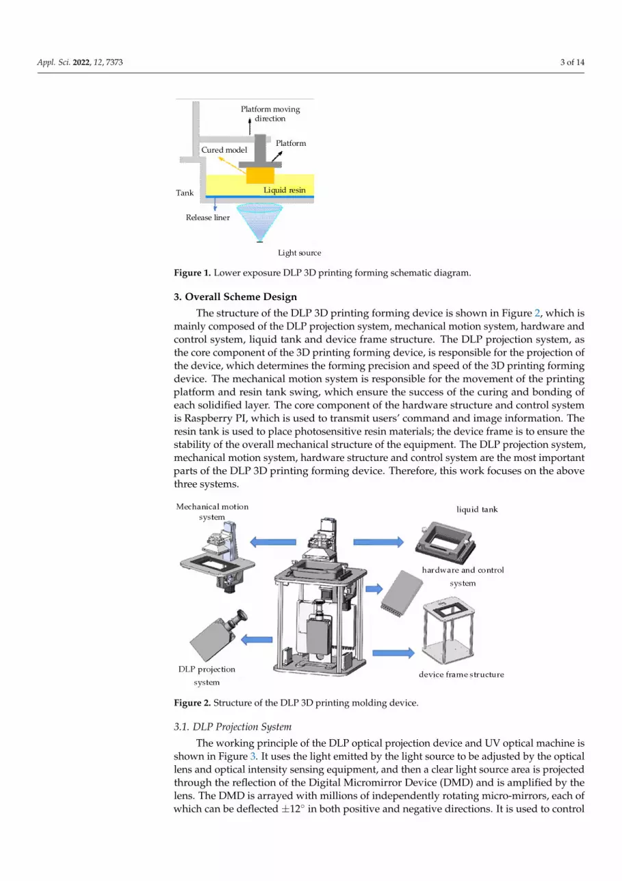
The core component of the DLP 3D printing forming device is the DLP projectionsystem, which can be divided into the upper exposure 3D printing forming device andthe lower exposure 3D printing forming device [19] according to the relative position ofthe projection equipment and the liquid tank. The DLP 3D printing molding device wedesigned in this work adopts the form of the lower exposure device. Compared with theupper exposure 3D printing forming device, its advantages are that the demand for thephotosensitive resin is smaller, the liquid level does not need to maintain a calm level,the scraping mechanism is not required to assist, and the printing rate is faster [20]. Theforming principle of DLP 3D printing with a lower exposure type is shown in Figure 1. Theliquid photosensitive resin is poured inside the tank, the initial position of the printingplatform is only one forming layer away from the bottom of the tank, and the cross-sectionalbitmap of the 3D model of the layer is projected onto the transparent window at the bottomof the liquid tank so that the irradiated part of the photosensitive resin is polymerized toform a solid thin layer of the cross-sectional bitmap of the corresponding layer. Then theprinting platform moves upward, and the distance between the solid layer and the bottomof the tank is a forming layer that is prepared for the solidification of the next layer. In orderto reduce the adhesion between the solidified layer and the bottom of the liquid tank, arelease liner is attached to the bottom of the liquid tank. As the next layer starts to print, the3D model will finally be printed at the bottom of the printing platform layer by layer [21].
Appl. Sci. 2022, 12, 7373 3 of 14Appl. Sci. 2022, 12, x FOR PEER REVIEW 3 of 14
Platform moving direction
PlatformCured model
Release liner
Tank
Light source
Liquid resin
Figure 1. Lower exposure DLP 3D printing forming schematic diagram.
3. Overall Scheme Design The structure of the DLP 3D printing forming device is shown in Figure 2, which is
mainly composed of the DLP projection system, mechanical motion system, hardware and control system, liquid tank and device frame structure. The DLP projection system, as the core component of the 3D printing forming device, is responsible for the projection of the device, which determines the forming precision and speed of the 3D printing forming device. The mechanical motion system is responsible for the movement of the printing platform and resin tank swing, which ensure the success of the curing and bonding of each solidified layer. The core component of the hardware structure and control system is Raspberry PI, which is used to transmit users’ command and image information. The resin tank is used to place photosensitive resin materials; the device frame is to ensure the sta-bility of the overall mechanical structure of the equipment. The DLP projection system, mechanical motion system, hardware structure and control system are the most important parts of the DLP 3D printing forming device. Therefore, this work focuses on the above three systems.
Figure 2. Structure of the DLP 3D printing molding device.
3.1. DLP Projection System The working principle of the DLP optical projection device and UV optical machine
is shown in Figure 3. It uses the light emitted by the light source to be adjusted by the optical lens and optical intensity sensing equipment, and then a clear light source area is projected through the reflection of the Digital Micromirror Device (DMD) and is amplified
Figure 1. Lower exposure DLP 3D printing forming schematic diagram.
3. Overall Scheme Design
The structure of the DLP 3D printing forming device is shown in Figure 2, which ismainly composed of the DLP projection system, mechanical motion system, hardware andcontrol system, liquid tank and device frame structure. The DLP projection system, asthe core component of the 3D printing forming device, is responsible for the projection ofthe device, which determines the forming precision and speed of the 3D printing formingdevice. The mechanical motion system is responsible for the movement of the printingplatform and resin tank swing, which ensure the success of the curing and bonding ofeach solidified layer. The core component of the hardware structure and control systemis Raspberry PI, which is used to transmit users’ command and image information. Theresin tank is used to place photosensitive resin materials; the device frame is to ensure thestability of the overall mechanical structure of the equipment. The DLP projection system,mechanical motion system, hardware structure and control system are the most importantparts of the DLP 3D printing forming device. Therefore, this work focuses on the abovethree systems.
Appl. Sci. 2022, 12, x FOR PEER REVIEW 3 of 14
Platform moving direction
PlatformCured model
Release liner
Tank
Light source
Liquid resin
Figure 1. Lower exposure DLP 3D printing forming schematic diagram.
3. Overall Scheme Design The structure of the DLP 3D printing forming device is shown in Figure 2, which is
mainly composed of the DLP projection system, mechanical motion system, hardware and control system, liquid tank and device frame structure. The DLP projection system, as the core component of the 3D printing forming device, is responsible for the projection of the device, which determines the forming precision and speed of the 3D printing forming device. The mechanical motion system is responsible for the movement of the printing platform and resin tank swing, which ensure the success of the curing and bonding of each solidified layer. The core component of the hardware structure and control system is Raspberry PI, which is used to transmit users’ command and image information. The resin tank is used to place photosensitive resin materials; the device frame is to ensure the sta-bility of the overall mechanical structure of the equipment. The DLP projection system, mechanical motion system, hardware structure and control system are the most important parts of the DLP 3D printing forming device. Therefore, this work focuses on the above three systems.
Figure 2. Structure of the DLP 3D printing molding device.
3.1. DLP Projection System The working principle of the DLP optical projection device and UV optical machine
is shown in Figure 3. It uses the light emitted by the light source to be adjusted by the optical lens and optical intensity sensing equipment, and then a clear light source area is projected through the reflection of the Digital Micromirror Device (DMD) and is amplified
Figure 2. Structure of the DLP 3D printing molding device.
3.1. DLP Projection System
The working principle of the DLP optical projection device and UV optical machine isshown in Figure 3. It uses the light emitted by the light source to be adjusted by the opticallens and optical intensity sensing equipment, and then a clear light source area is projectedthrough the reflection of the Digital Micromirror Device (DMD) and is amplified by thelens. The DMD is arrayed with millions of independently rotating micro-mirrors, each ofwhich can be deflected ±12◦ in both positive and negative directions. It is used to control
Appl. Sci. 2022, 12, 7373 4 of 14
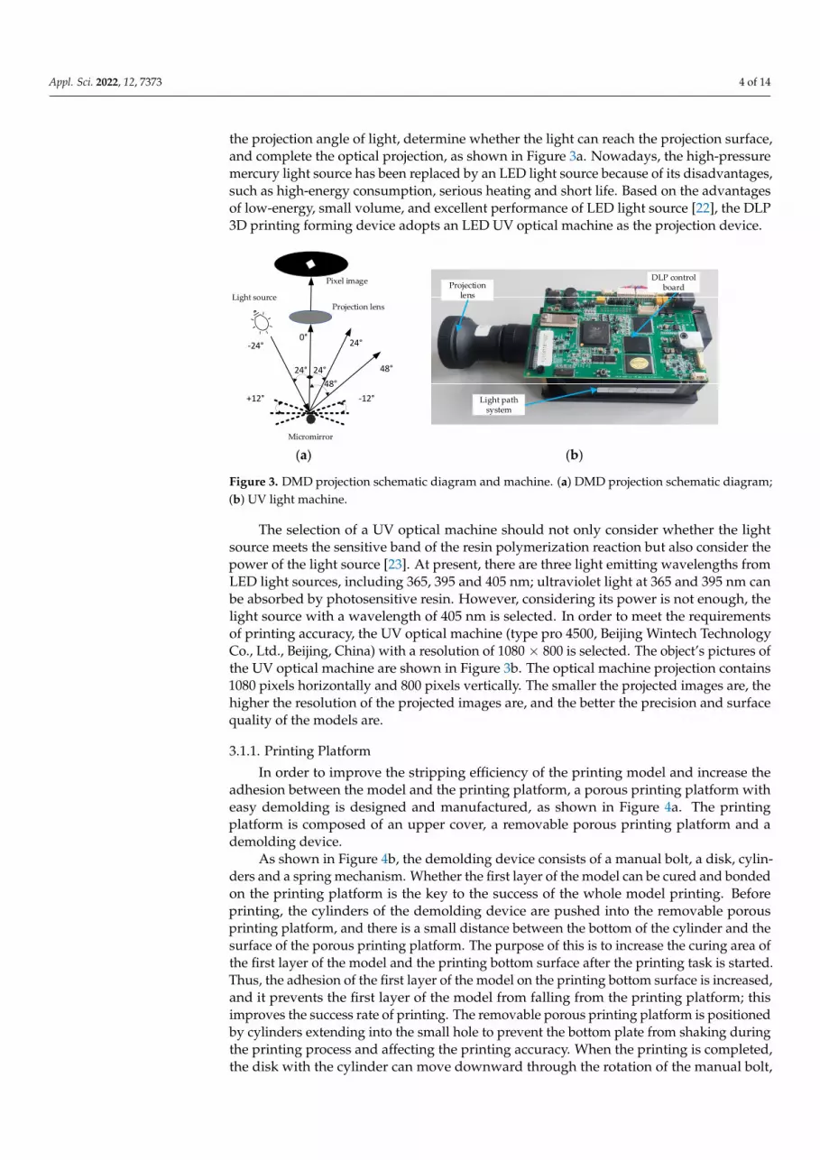
the projection angle of light, determine whether the light can reach the projection surface,and complete the optical projection, as shown in Figure 3a. Nowadays, the high-pressuremercury light source has been replaced by an LED light source because of its disadvantages,such as high-energy consumption, serious heating and short life. Based on the advantagesof low-energy, small volume, and excellent performance of LED light source [22], the DLP3D printing forming device adopts an LED UV optical machine as the projection device.
Appl. Sci. 2022, 12, x FOR PEER REVIEW 4 of 14
by the lens. The DMD is arrayed with millions of independently rotating micro-mirrors, each of which can be deflected ±12° in both positive and negative directions. It is used to control the projection angle of light, determine whether the light can reach the projection surface, and complete the optical projection, as shown in Figure 3a. Nowadays, the high-pressure mercury light source has been replaced by an LED light source because of its disadvantages, such as high-energy consumption, serious heating and short life. Based on the advantages of low-energy, small volume, and excellent performance of LED light source [22], the DLP 3D printing forming device adopts an LED UV optical machine as the projection device.
The selection of a UV optical machine should not only consider whether the light source meets the sensitive band of the resin polymerization reaction but also consider the power of the light source [23]. At present, there are three light emitting wavelengths from LED light sources, including 365, 395 and 405 nm; ultraviolet light at 365 and 395 nm can be absorbed by photosensitive resin. However, considering its power is not enough, the light source with a wavelength of 405 nm is selected. In order to meet the requirements of printing accuracy, the UV optical machine (type pro 4500, Beijing Wintech Technology Co., Ltd., Beijing, China) with a resolution of 1080 × 800 is selected. The object’s pictures of the UV optical machine are shown in Figure 3b. The optical machine projection contains 1080 pixels horizontally and 800 pixels vertically. The smaller the projected images are, the higher the resolution of the projected images are, and the better the precision and sur-face quality of the models are.
Light source
Pixel image
Projection lens
Micromirror
+12° -12°
-24°0° 24°
48°24° 24°48°
Projection lens
DLP control board
Light path system
(a) (b)
Figure 3. DMD projection schematic diagram and machine. (a) DMD projection schematic diagram; (b) UV light machine.
3.1.1. Printing Platform In order to improve the stripping efficiency of the printing model and increase the
adhesion between the model and the printing platform, a porous printing platform with easy demolding is designed and manufactured, as shown in Figure 4a. The printing plat-form is composed of an upper cover, a removable porous printing platform and a demold-ing device.
As shown in Figure 4b, the demolding device consists of a manual bolt, a disk, cylin-ders and a spring mechanism. Whether the first layer of the model can be cured and bonded on the printing platform is the key to the success of the whole model printing. Before printing, the cylinders of the demolding device are pushed into the removable po-rous printing platform, and there is a small distance between the bottom of the cylinder and the surface of the porous printing platform. The purpose of this is to increase the curing area of the first layer of the model and the printing bottom surface after the printing task is started. Thus, the adhesion of the first layer of the model on the printing bottom surface is increased, and it prevents the first layer of the model from falling from the print-ing platform; this improves the success rate of printing. The removable porous printing
Figure 3. DMD projection schematic diagram and machine. (a) DMD projection schematic diagram;(b) UV light machine.
The selection of a UV optical machine should not only consider whether the lightsource meets the sensitive band of the resin polymerization reaction but also consider thepower of the light source [23]. At present, there are three light emitting wavelengths fromLED light sources, including 365, 395 and 405 nm; ultraviolet light at 365 and 395 nm canbe absorbed by photosensitive resin. However, considering its power is not enough, thelight source with a wavelength of 405 nm is selected. In order to meet the requirementsof printing accuracy, the UV optical machine (type pro 4500, Beijing Wintech TechnologyCo., Ltd., Beijing, China) with a resolution of 1080 × 800 is selected. The object’s pictures ofthe UV optical machine are shown in Figure 3b. The optical machine projection contains1080 pixels horizontally and 800 pixels vertically. The smaller the projected images are, thehigher the resolution of the projected images are, and the better the precision and surfacequality of the models are.
3.1.1. Printing Platform
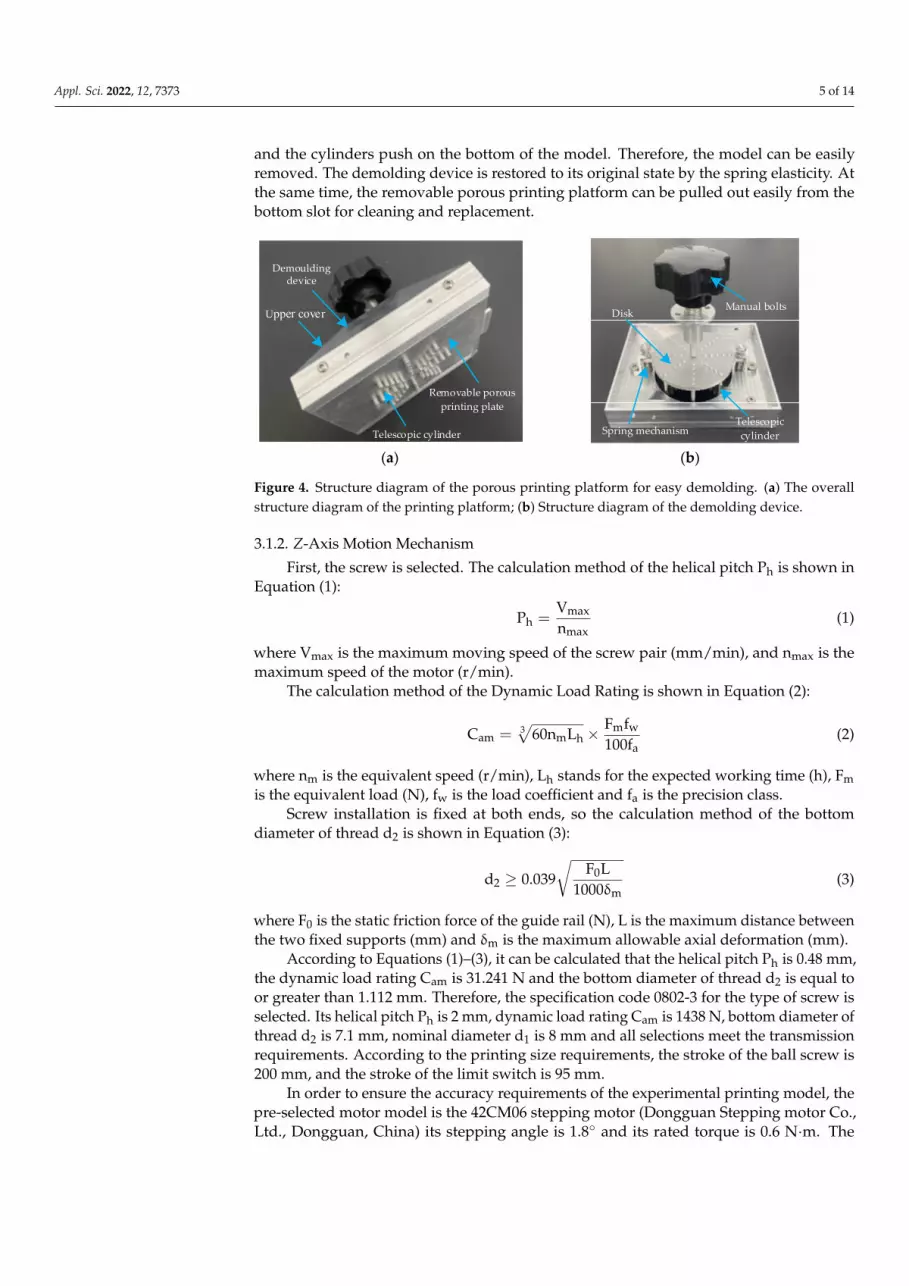
In order to improve the stripping efficiency of the printing model and increase theadhesion between the model and the printing platform, a porous printing platform witheasy demolding is designed and manufactured, as shown in Figure 4a. The printingplatform is composed of an upper cover, a removable porous printing platform and ademolding device.
As shown in Figure 4b, the demolding device consists of a manual bolt, a disk, cylin-ders and a spring mechanism. Whether the first layer of the model can be cured and bondedon the printing platform is the key to the success of the whole model printing. Beforeprinting, the cylinders of the demolding device are pushed into the removable porousprinting platform, and there is a small distance between the bottom of the cylinder and thesurface of the porous printing platform. The purpose of this is to increase the curing area ofthe first layer of the model and the printing bottom surface after the printing task is started.Thus, the adhesion of the first layer of the model on the printing bottom surface is increased,and it prevents the first layer of the model from falling from the printing platform; thisimproves the success rate of printing. The removable porous printing platform is positionedby cylinders extending into the small hole to prevent the bottom plate from shaking duringthe printing process and affecting the printing accuracy. When the printing is completed,the disk with the cylinder can move downward through the rotation of the manual bolt,
Appl. Sci. 2022, 12, 7373 5 of 14
and the cylinders push on the bottom of the model. Therefore, the model can be easilyremoved. The demolding device is restored to its original state by the spring elasticity. Atthe same time, the removable porous printing platform can be pulled out easily from thebottom slot for cleaning and replacement.
Appl. Sci. 2022, 12, x FOR PEER REVIEW 5 of 14
platform is positioned by cylinders extending into the small hole to prevent the bottom plate from shaking during the printing process and affecting the printing accuracy. When the printing is completed, the disk with the cylinder can move downward through the rotation of the manual bolt, and the cylinders push on the bottom of the model. Therefore, the model can be easily removed. The demolding device is restored to its original state by the spring elasticity. At the same time, the removable porous printing platform can be pulled out easily from the bottom slot for cleaning and replacement.
Demoulding device
Upper cover
Removable porous printing plate
Telescopic cylinder
Manual boltsDisk
Telescopic cylinderSpring mechanism
(a) (b)
Figure 4. Structure diagram of the porous printing platform for easy demolding. (a) The overall structure diagram of the printing platform; (b) Structure diagram of the demolding device.
3.1.2. Z-Axis Motion Mechanism First, the screw is selected. The calculation method of the helical pitch Ph is shown in
Equation (1):
maxh
max
VP =
n (1)
where Vmax is the maximum moving speed of the screw pair (mm/min), and nmax is the maximum speed of the motor (r/min).
The calculation method of the Dynamic Load Rating is shown in Equation (2):
= × m w3am m h
a
F fC 60n L
100f (2)
where nm is the equivalent speed (r/min), Lh stands for the expected working time (h), Fm is the equivalent load (N), fw is the load coefficient and fa is the precision class.
Screw installation is fixed at both ends, so the calculation method of the bottom di-ameter of thread d2 is shown in Equation (3):
02
m
F Ld 0.039
1000≥
δ (3)
where F0 is the static friction force of the guide rail (N), L is the maximum distance be-tween the two fixed supports (mm) and δm is the maximum allowable axial deformation (mm).
According to Equations (1)–(3), it can be calculated that the helical pitch Ph is 0.48 mm, the dynamic load rating Cam is 31.241 N and the bottom diameter of thread d2 is equal to or greater than 1.112 mm. Therefore, the specification code 0802-3 for the type of screw is selected. Its helical pitch Ph is 2 mm, dynamic load rating Cam is 1438 N, bottom diameter of thread d2 is 7.1 mm, nominal diameter d1 is 8 mm and all selections meet the transmis-sion requirements. According to the printing size requirements, the stroke of the ball screw is 200 mm, and the stroke of the limit switch is 95 mm.
In order to ensure the accuracy requirements of the experimental printing model, the pre-selected motor model is the 42CM06 stepping motor (Dongguan Stepping motor Co.,
Figure 4. Structure diagram of the porous printing platform for easy demolding. (a) The overallstructure diagram of the printing platform; (b) Structure diagram of the demolding device.
3.1.2. Z-Axis Motion Mechanism
First, the screw is selected. The calculation method of the helical pitch Ph is shown inEquation (1):
Ph =Vmax
nmax(1)
where Vmax is the maximum moving speed of the screw pair (mm/min), and nmax is themaximum speed of the motor (r/min).
The calculation method of the Dynamic Load Rating is shown in Equation (2):
Cam = 3√
60nmLh × Fmfw
100fa(2)
where nm is the equivalent speed (r/min), Lh stands for the expected working time (h), Fmis the equivalent load (N), fw is the load coefficient and fa is the precision class.
Screw installation is fixed at both ends, so the calculation method of the bottomdiameter of thread d2 is shown in Equation (3):
d2 ≥ 0.039√
F0L1000δm
(3)
where F0 is the static friction force of the guide rail (N), L is the maximum distance betweenthe two fixed supports (mm) and δm is the maximum allowable axial deformation (mm).
According to Equations (1)–(3), it can be calculated that the helical pitch Ph is 0.48 mm,the dynamic load rating Cam is 31.241 N and the bottom diameter of thread d2 is equal toor greater than 1.112 mm. Therefore, the specification code 0802-3 for the type of screw isselected. Its helical pitch Ph is 2 mm, dynamic load rating Cam is 1438 N, bottom diameter ofthread d2 is 7.1 mm, nominal diameter d1 is 8 mm and all selections meet the transmissionrequirements. According to the printing size requirements, the stroke of the ball screw is200 mm, and the stroke of the limit switch is 95 mm.
In order to ensure the accuracy requirements of the experimental printing model, thepre-selected motor model is the 42CM06 stepping motor (Dongguan Stepping motor Co.,Ltd., Dongguan, China) its stepping angle is 1.8◦ and its rated torque is 0.6 N·m. The
Appl. Sci. 2022, 12, 7373 6 of 14
calculation methods of maximum acceleration torque at no load Teq1 and the maximumworking load torque Teq2 of the stepping motor are shown in Equations (4) and (5):
Teq1 =2πJeqnm
60taη(4)
Teq2 =FPh2πηi
(5)
where Jeq denotes the total moment of inertia of the stepping motor (kg·m2), Nm is rotationalspeed (r/min), Ta is acceleration time of stepping motor (s), F is the maximum workingload on the workbench (N), Ph is the stroke of the screw (m), η is transmission efficiencyand i is total transmission ratio.
According to the above calculations, the maximum load torque Teq on the loadingstepping motor shaft should be:
Teq = Teq1 + Teq2 (6)
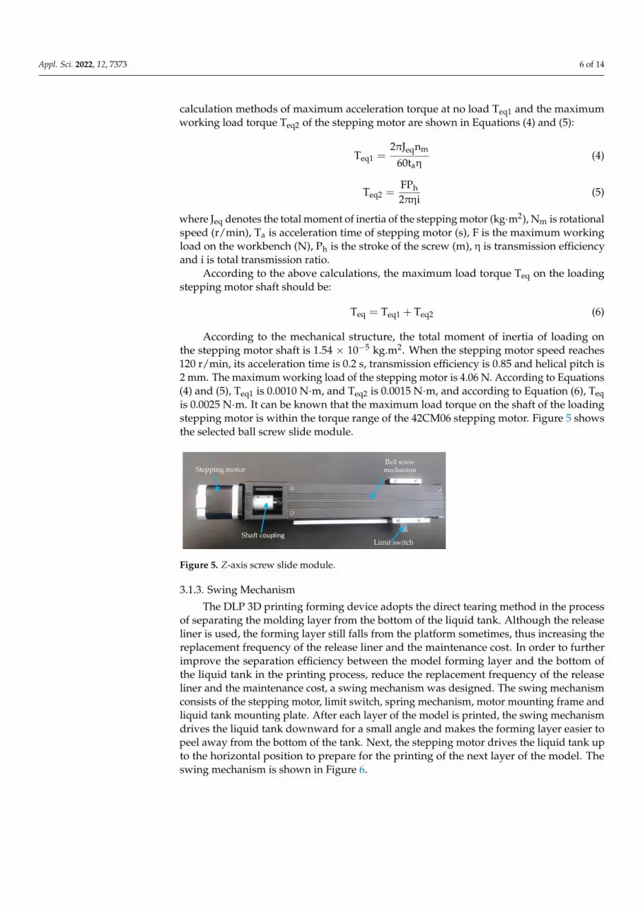
According to the mechanical structure, the total moment of inertia of loading onthe stepping motor shaft is 1.54 × 10⁻⁵ kg.m2. When the stepping motor speed reaches120 r/min, its acceleration time is 0.2 s, transmission efficiency is 0.85 and helical pitch is2 mm. The maximum working load of the stepping motor is 4.06 N. According to Equations(4) and (5), Teq1 is 0.0010 N·m, and Teq2 is 0.0015 N·m, and according to Equation (6), Teqis 0.0025 N·m. It can be known that the maximum load torque on the shaft of the loadingstepping motor is within the torque range of the 42CM06 stepping motor. Figure 5 showsthe selected ball screw slide module.
Appl. Sci. 2022, 12, x FOR PEER REVIEW 6 of 14
Ltd., Dongguan, China) its stepping angle is 1.8° and its rated torque is 0.6 N·m. The cal-culation methods of maximum acceleration torque at no load Teq1 and the maximum work-ing load torque Teq2 of the stepping motor are shown in Equations (4) and (5):
eq meq1
a
2 J nT
60tπ
=η
(4)
heq2
FPT
2 i=
πη (5)
where Jeq denotes the total moment of inertia of the stepping motor (kg·m2), Nm is rota-tional speed (r/min), Ta is acceleration time of stepping motor (s), F is the maximum work-ing load on the workbench (N), Ph is the stroke of the screw (m), η is transmission effi-ciency and i is total transmission ratio.
According to the above calculations, the maximum load torque Teq on the loading stepping motor shaft should be:
eq eq1 eq2T T T= + (6)
According to the mechanical structure, the total moment of inertia of loading on the stepping motor shaft is 1.54 × 10⁻⁵ kg.m2. When the stepping motor speed reaches 120 r/min, its acceleration time is 0.2 s, transmission efficiency is 0.85 and helical pitch is 2 mm. The maximum working load of the stepping motor is 4.06 N. According to Equations (4) and (5), Teq1 is 0.0010 N·m, and Teq2 is 0.0015 N·m, and according to Equation (6), Teq is 0.0025 N·m. It can be known that the maximum load torque on the shaft of the loading stepping motor is within the torque range of the 42CM06 stepping motor. Figure 5 shows the selected ball screw slide module.
Stepping motor
Shaft coupling
Ball screw mechanism
Limit switch Figure 5. Z-axis screw slide module.
3.1.3. Swing Mechanism The DLP 3D printing forming device adopts the direct tearing method in the process
of separating the molding layer from the bottom of the liquid tank. Although the release liner is used, the forming layer still falls from the platform sometimes, thus increasing the replacement frequency of the release liner and the maintenance cost. In order to further improve the separation efficiency between the model forming layer and the bottom of the liquid tank in the printing process, reduce the replacement frequency of the release liner and the maintenance cost, a swing mechanism was designed. The swing mechanism con-sists of the stepping motor, limit switch, spring mechanism, motor mounting frame and liquid tank mounting plate. After each layer of the model is printed, the swing mechanism drives the liquid tank downward for a small angle and makes the forming layer easier to peel away from the bottom of the tank. Next, the stepping motor drives the liquid tank up to the horizontal position to prepare for the printing of the next layer of the model. The swing mechanism is shown in Figure 6.
Figure 5. Z-axis screw slide module.
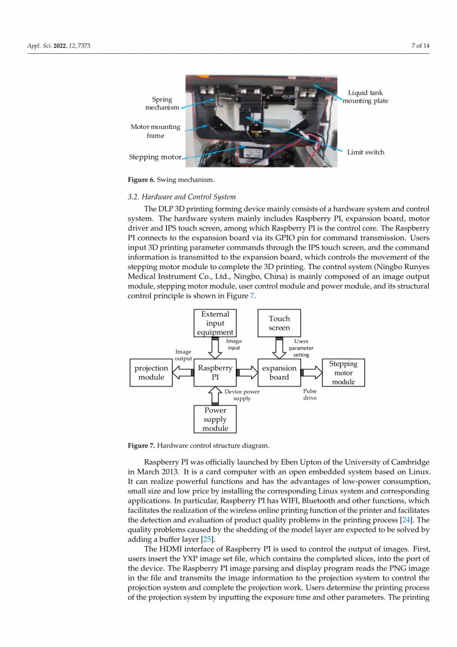
3.1.3. Swing Mechanism
The DLP 3D printing forming device adopts the direct tearing method in the processof separating the molding layer from the bottom of the liquid tank. Although the releaseliner is used, the forming layer still falls from the platform sometimes, thus increasing thereplacement frequency of the release liner and the maintenance cost. In order to furtherimprove the separation efficiency between the model forming layer and the bottom ofthe liquid tank in the printing process, reduce the replacement frequency of the releaseliner and the maintenance cost, a swing mechanism was designed. The swing mechanismconsists of the stepping motor, limit switch, spring mechanism, motor mounting frame andliquid tank mounting plate. After each layer of the model is printed, the swing mechanismdrives the liquid tank downward for a small angle and makes the forming layer easier topeel away from the bottom of the tank. Next, the stepping motor drives the liquid tank upto the horizontal position to prepare for the printing of the next layer of the model. Theswing mechanism is shown in Figure 6.
Appl. Sci. 2022, 12, 7373 7 of 14Appl. Sci. 2022, 12, x FOR PEER REVIEW 7 of 14
Stepping motor Limit switch
Spring mechanism
Liquid tank mounting plate
Motor mounting frame
Figure 6. Swing mechanism.
3.2. Hardware and Control System The DLP 3D printing forming device mainly consists of a hardware system and con-
trol system. The hardware system mainly includes Raspberry PI, expansion board, motor driver and IPS touch screen, among which Raspberry PI is the control core. The Raspberry PI connects to the expansion board via its GPIO pin for command transmission. Users input 3D printing parameter commands through the IPS touch screen, and the command information is transmitted to the expansion board, which controls the movement of the stepping motor module to complete the 3D printing. The control system (Ningbo Runyes Medical Instrument Co., Ltd., Ningbo, China) is mainly composed of an image output module, stepping motor module, user control module and power module, and its struc-tural control principle is shown in Figure 7.
Raspberry PI was officially launched by Eben Upton of the University of Cambridge in March 2013. It is a card computer with an open embedded system based on Linux. It can realize powerful functions and has the advantages of low-power consumption, small size and low price by installing the corresponding Linux system and corresponding ap-plications. In particular, Raspberry PI has WIFI, Bluetooth and other functions, which fa-cilitates the realization of the wireless online printing function of the printer and facilitates the detection and evaluation of product quality problems in the printing process [24]. The quality problems caused by the shedding of the model layer are expected to be solved by adding a buffer layer [25].
The HDMI interface of Raspberry PI is used to control the output of images. First, users insert the YXP image set file, which contains the completed slices, into the port of the device. The Raspberry PI image parsing and display program reads the PNG image in the file and transmits the image information to the projection system to control the pro-jection system and complete the projection work. Users determine the printing process of the projection system by inputting the exposure time and other parameters. The printing device will feed back the current printing progress to the user’s control interface. When the projection system receives pause or stop command information from users, the image parsing projection program immediately executes the current command and enters the empty loop. The program flow is shown in Figure 8.
Raspberry PI
projection module
Touch screen
expansion board
External input
equipment
Stepping motor
module
Image input
Image output
Users parameter
setting
Power supply module
Device power supply
Pulse drive
Figure 7. Hardware control structure diagram.
Figure 6. Swing mechanism.
3.2. Hardware and Control System
The DLP 3D printing forming device mainly consists of a hardware system and controlsystem. The hardware system mainly includes Raspberry PI, expansion board, motordriver and IPS touch screen, among which Raspberry PI is the control core. The RaspberryPI connects to the expansion board via its GPIO pin for command transmission. Usersinput 3D printing parameter commands through the IPS touch screen, and the commandinformation is transmitted to the expansion board, which controls the movement of thestepping motor module to complete the 3D printing. The control system (Ningbo RunyesMedical Instrument Co., Ltd., Ningbo, China) is mainly composed of an image outputmodule, stepping motor module, user control module and power module, and its structuralcontrol principle is shown in Figure 7.
Appl. Sci. 2022, 12, x FOR PEER REVIEW 7 of 14
Stepping motor Limit switch
Spring mechanism
Liquid tank mounting plate
Motor mounting frame
Figure 6. Swing mechanism.
3.2. Hardware and Control System The DLP 3D printing forming device mainly consists of a hardware system and con-
trol system. The hardware system mainly includes Raspberry PI, expansion board, motor driver and IPS touch screen, among which Raspberry PI is the control core. The Raspberry PI connects to the expansion board via its GPIO pin for command transmission. Users input 3D printing parameter commands through the IPS touch screen, and the command information is transmitted to the expansion board, which controls the movement of the stepping motor module to complete the 3D printing. The control system (Ningbo Runyes Medical Instrument Co., Ltd., Ningbo, China) is mainly composed of an image output module, stepping motor module, user control module and power module, and its struc-tural control principle is shown in Figure 7.
Raspberry PI was officially launched by Eben Upton of the University of Cambridge in March 2013. It is a card computer with an open embedded system based on Linux. It can realize powerful functions and has the advantages of low-power consumption, small size and low price by installing the corresponding Linux system and corresponding ap-plications. In particular, Raspberry PI has WIFI, Bluetooth and other functions, which fa-cilitates the realization of the wireless online printing function of the printer and facilitates the detection and evaluation of product quality problems in the printing process [24]. The quality problems caused by the shedding of the model layer are expected to be solved by adding a buffer layer [25].
The HDMI interface of Raspberry PI is used to control the output of images. First, users insert the YXP image set file, which contains the completed slices, into the port of the device. The Raspberry PI image parsing and display program reads the PNG image in the file and transmits the image information to the projection system to control the pro-jection system and complete the projection work. Users determine the printing process of the projection system by inputting the exposure time and other parameters. The printing device will feed back the current printing progress to the user’s control interface. When the projection system receives pause or stop command information from users, the image parsing projection program immediately executes the current command and enters the empty loop. The program flow is shown in Figure 8.
Raspberry PI
projection module
Touch screen
expansion board
External input
equipment
Stepping motor
module
Image input
Image output
Users parameter
setting
Power supply module
Device power supply
Pulse drive
Figure 7. Hardware control structure diagram. Figure 7. Hardware control structure diagram.
Raspberry PI was officially launched by Eben Upton of the University of Cambridgein March 2013. It is a card computer with an open embedded system based on Linux.It can realize powerful functions and has the advantages of low-power consumption,small size and low price by installing the corresponding Linux system and correspondingapplications. In particular, Raspberry PI has WIFI, Bluetooth and other functions, whichfacilitates the realization of the wireless online printing function of the printer and facilitatesthe detection and evaluation of product quality problems in the printing process [24]. Thequality problems caused by the shedding of the model layer are expected to be solved byadding a buffer layer [25].
The HDMI interface of Raspberry PI is used to control the output of images. First,users insert the YXP image set file, which contains the completed slices, into the port ofthe device. The Raspberry PI image parsing and display program reads the PNG imagein the file and transmits the image information to the projection system to control theprojection system and complete the projection work. Users determine the printing processof the projection system by inputting the exposure time and other parameters. The printing

Appl. Sci. 2022, 12, 7373 8 of 14
device will feed back the current printing progress to the user’s control interface. Whenthe projection system receives pause or stop command information from users, the imageparsing projection program immediately executes the current command and enters theempty loop. The program flow is shown in Figure 8.
Appl. Sci. 2022, 12, x FOR PEER REVIEW 8 of 14
Images file path
Format correct?
Analyze images
Specify image position
Project images and time delay
End the layer projection
Is it the last layer image?
End
Stop?
Feedback current layer number
display to users control module
Read imagesNo
Yes
No
Yes
Yes
Figure 8. Flow chart of projection program for image analysis.
The stepping motor control module is the core of the control system, which directly determines the accuracy of the 3D printing model. The Z-axis motion control and position limit of the 3D printing device are realized by using a digital actuator and a U-slot photo-electric limit switch. The expansion board realizes the driving function of the motor, pho-toelectric limit switch, touch screen driver and other components. Its interface is simple, and data transmission is convenient. The DM422C stepping motor driver (Shenzhen Ley-sai Intelligent Control Co., Ltd., Shenzhen, China), with the function of over-voltage and short circuit protection, adopts the connection method of a common anode. The PUL in-terface transmits the pulse signal, and the stepping motor rotates at an angle into a pulse signal. The DIR interface transmits the direction signal, and it is used to control the motor steering. The OPTO interface is connected to a 5 V power supply, and the ENA interface transmits the enable control signal. The DM422C and 42 stepping motor wiring diagram is shown in Figure 9a. The number and frequency of pulses transmitted by the stepping motor to the driver through the expansion board can accurately control the speed and position of Z-axis movement. The specific control process is shown in Figure 9b. The LRS-150-12 switching power supply is adopted for the device, which can convert the alternat-ing current of the home into 5 and 12 V of direct current to supply power to each module of the device and ensure the normal operation of the DLP 3D printing forming device and completion of the printing work.
Figure 8. Flow chart of projection program for image analysis.
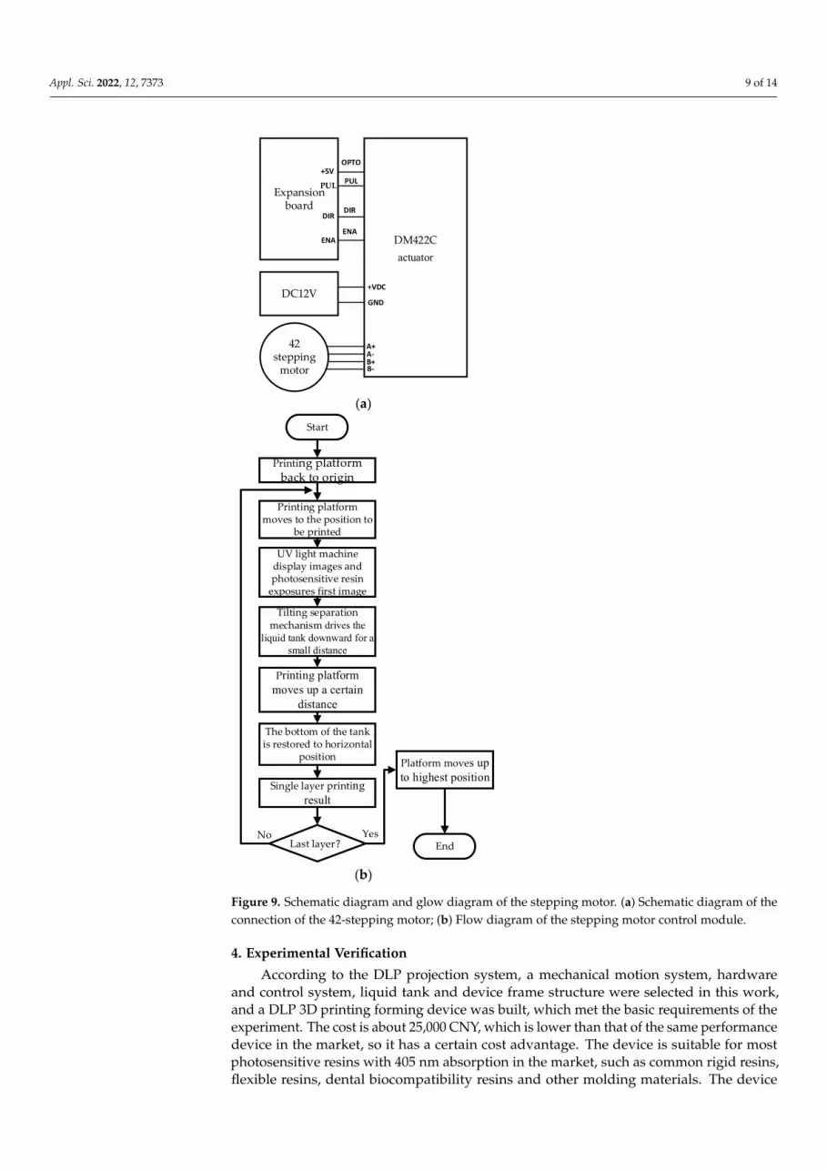
The stepping motor control module is the core of the control system, which directlydetermines the accuracy of the 3D printing model. The Z-axis motion control and posi-tion limit of the 3D printing device are realized by using a digital actuator and a U-slotphotoelectric limit switch. The expansion board realizes the driving function of the motor,photoelectric limit switch, touch screen driver and other components. Its interface is simple,and data transmission is convenient. The DM422C stepping motor driver (Shenzhen LeysaiIntelligent Control Co., Ltd., Shenzhen, China), with the function of over-voltage and shortcircuit protection, adopts the connection method of a common anode. The PUL interfacetransmits the pulse signal, and the stepping motor rotates at an angle into a pulse signal.The DIR interface transmits the direction signal, and it is used to control the motor steering.The OPTO interface is connected to a 5 V power supply, and the ENA interface transmitsthe enable control signal. The DM422C and 42 stepping motor wiring diagram is shown inFigure 9a. The number and frequency of pulses transmitted by the stepping motor to thedriver through the expansion board can accurately control the speed and position of Z-axismovement. The specific control process is shown in Figure 9b. The LRS-150-12 switchingpower supply is adopted for the device, which can convert the alternating current of thehome into 5 and 12 V of direct current to supply power to each module of the device andensure the normal operation of the DLP 3D printing forming device and completion of theprinting work.
Appl. Sci. 2022, 12, 7373 9 of 14Appl. Sci. 2022, 12, x FOR PEER REVIEW 9 of 14
Expansion board
DC12V
actuator
42 stepping
motor
DM422C
OPTO
PUL
DIR
ENA
+VDC
GND
A+A-
B-B+
+5V
PUL
DIR
ENA
(a)
Start
Printing platform back to origin
Printing platform moves to the position to
be printed
UV light machine display images and photosensitive resin
exposures first image
Printing platform moves up a certain
distance
Tilting separation mechanism drives the
liquid tank downward for a small distance
Last layer?
Platform moves up to highest position
End
Single layer printing result
YesNo
The bottom of the tank is restored to horizontal
position
(b)
Figure 9. Schematic diagram and glow diagram of the stepping motor. (a) Schematic diagram of the connection of the 42-stepping motor; (b) Flow diagram of the stepping motor control module.
4. Experimental Verification According to the DLP projection system, a mechanical motion system, hardware and
control system, liquid tank and device frame structure were selected in this work, and a DLP 3D printing forming device was built, which met the basic requirements of the ex-periment. The cost is about 25,000 CNY, which is lower than that of the same performance device in the market, so it has a certain cost advantage. The device is suitable for most photosensitive resins with 405 nm absorption in the market, such as common rigid resins, flexible resins, dental biocompatibility resins and other molding materials. The device is
Figure 9. Schematic diagram and glow diagram of the stepping motor. (a) Schematic diagram of theconnection of the 42-stepping motor; (b) Flow diagram of the stepping motor control module.
4. Experimental Verification
According to the DLP projection system, a mechanical motion system, hardwareand control system, liquid tank and device frame structure were selected in this work,and a DLP 3D printing forming device was built, which met the basic requirements of theexperiment. The cost is about 25,000 CNY, which is lower than that of the same performancedevice in the market, so it has a certain cost advantage. The device is suitable for mostphotosensitive resins with 405 nm absorption in the market, such as common rigid resins,flexible resins, dental biocompatibility resins and other molding materials. The device

Appl. Sci. 2022, 12, 7373 10 of 14
is shown in Figure 10, and the device parameters are shown in Table 1. Figure 11 is theadhesion test figure of the DLP 3D printing platform. Blocks with length, width andheight of 40 × 40 × 10 mm are printed by this device. The CMT5105 universal testingmachine is used to carry out a tensile test at a speed of 1 mm/min. The maximum force ofseparation from the traditional printing platform is 195.2 N. However, the maximum forceof separation from the porous printing platform is 220.7 N, which verifies that the devicehas enhanced adhesion.
Appl. Sci. 2022, 12, x FOR PEER REVIEW 10 of 14
shown in Figure 10, and the device parameters are shown in Table 1. Figure 11 is the ad-hesion test figure of the DLP 3D printing platform. Blocks with length, width and height of 40 × 40× 10 mm are printed by this device. The CMT5105 universal testing machine is used to carry out a tensile test at a speed of 1 mm/min. The maximum force of separation from the traditional printing platform is 195.2 N. However, the maximum force of sepa-ration from the porous printing platform is 220.7 N, which verifies that the device has enhanced adhesion.
Figure 10. DLP 3D printing forming device.
Figure 11. Adhesion test figure of printing platform.
Table 1. Parameters of DLP 3D printing device.
Device Parameters Value Printer size 320 × 300 × 585 mm
Input parameters AC 220 V/50 HZ Printing accuracy ±0.05 mm
Recommended printing thickness 0.1 mm Printing speed 40 mm/h
Maximum printing size 89.6 × 56 × 95 mm Power 65 W
Figure 10. DLP 3D printing forming device.
Table 1. Parameters of DLP 3D printing device.
Device Parameters Value
Printer size 320 × 300 × 585 mmInput parameters AC 220 V/50 HZPrinting accuracy ±0.05 mm
Recommended printing thickness 0.1 mmPrinting speed 40 mm/h
Maximum printing size 89.6 × 56 × 95 mmPower 65 W
Net weight 20 Kg
Appl. Sci. 2022, 12, x FOR PEER REVIEW 10 of 14
shown in Figure 10, and the device parameters are shown in Table 1. Figure 11 is the ad-hesion test figure of the DLP 3D printing platform. Blocks with length, width and height of 40 × 40× 10 mm are printed by this device. The CMT5105 universal testing machine is used to carry out a tensile test at a speed of 1 mm/min. The maximum force of separation from the traditional printing platform is 195.2 N. However, the maximum force of sepa-ration from the porous printing platform is 220.7 N, which verifies that the device has enhanced adhesion.
Figure 10. DLP 3D printing forming device.
Figure 11. Adhesion test figure of printing platform.
Table 1. Parameters of DLP 3D printing device.
Device Parameters Value Printer size 320 × 300 × 585 mm
Input parameters AC 220 V/50 HZ Printing accuracy ±0.05 mm
Recommended printing thickness 0.1 mm Printing speed 40 mm/h
Maximum printing size 89.6 × 56 × 95 mm Power 65 W
Figure 11. Adhesion test figure of printing platform.

Appl. Sci. 2022, 12, 7373 11 of 14
The DLP 3D printing technology is a suitable 3D printing technology for dentalapplications because the dental models printed by the DLP 3D printing technology havehigh accuracy, surface hardness and bending strength [26]. Many dental applications canbe effectively printed using DLP 3D printing technology, including dental models, dentalcrowns, custom trays, etc. [27]. In this experiment, the adult tooth model was selected forthe comparative printing experiment, and the same adult tooth model was printed andcompared by the traditional printing device and the printing device that was designedin this paper. First, a 3D model of an adult tooth was established and sliced, and theslicing file was imported into the device port. Then, the printing platform was leveled,and liquid resin was poured into the liquid tank before printing. After the printing workwas completed, the tooth model was removed and cured secondly. The specific process isshown in Figure 12.
Appl. Sci. 2022, 12, x FOR PEER REVIEW 11 of 14
Net weight 20 Kg
The DLP 3D printing technology is a suitable 3D printing technology for dental ap-plications because the dental models printed by the DLP 3D printing technology have high accuracy, surface hardness and bending strength [26]. Many dental applications can be effectively printed using DLP 3D printing technology, including dental models, dental crowns, custom trays, etc. [27]. In this experiment, the adult tooth model was selected for the comparative printing experiment, and the same adult tooth model was printed and compared by the traditional printing device and the printing device that was designed in this paper. First, a 3D model of an adult tooth was established and sliced, and the slicing file was imported into the device port. Then, the printing platform was leveled, and liquid resin was poured into the liquid tank before printing. After the printing work was com-pleted, the tooth model was removed and cured secondly. The specific process is shown in Figure 12.
Tooth model Model slicing Manual leveling Pour into resin
Printing processPrinting resultModel effectSecondary curing Figure 12. Operation flow diagram of DLP 3D printing forming device.
Figure 13 is the printing result of the adult tooth model, in which Figure 13a,c,e are the printing results from traditional equipment, and Figure 13b,d,f are the printing results from the equipment studied in this paper. It can be seen that the 3D printed tooth model studied in this paper maintains good surface quality and printing accuracy. As shown in Figure 13f, small protrusions with uniform distribution are distributed at the bottom of the tooth model, indicating that the curing area at the bottom of the printing platform and the bottom of the model has increased. As shown in Figure 13g,h, due to the longer expo-sure time of the bottom layer, the resin solidifies in the groove of the printing platform and forms a riveted structure. The adhesion area between the bottom resin layer and the printing platform increases. According to the adhesion mechanical connection theory, the adhesion between the resin coating and the printing platform increases to a certain extent. The traditional printing platform needs to scrape the tooth model with a scraper. The printing platform designed by this device only needs to push out the model with a manual bolt, which has high stripping efficiency. At the same time, the design of a detachable printing platform is convenient for cleaning and replacement and reduces the mainte-nance cost of the traditional printing platform in the later period.
Figure 12. Operation flow diagram of DLP 3D printing forming device.
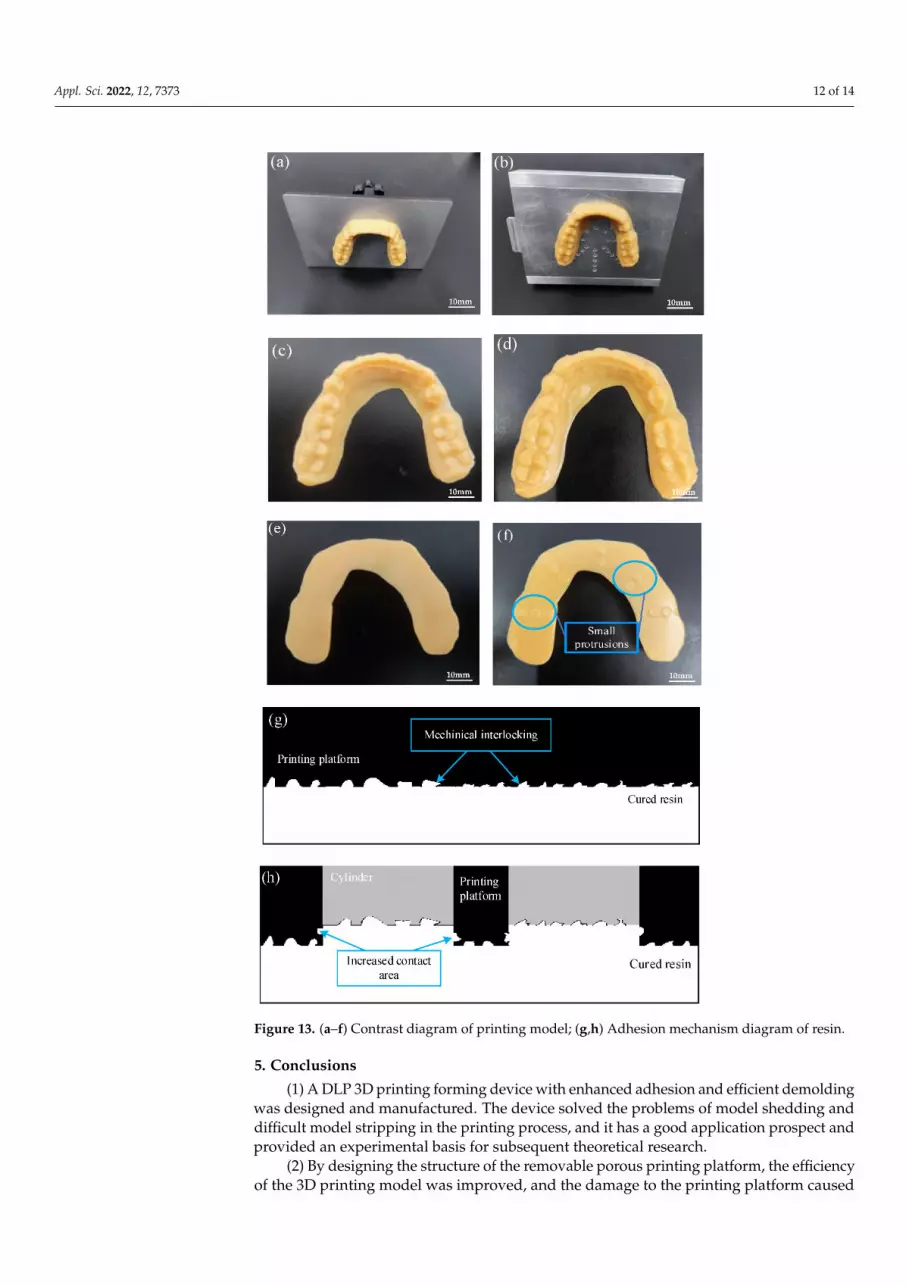
Figure 13 is the printing result of the adult tooth model, in which Figure 13a,c,e arethe printing results from traditional equipment, and Figure 13b,d,f are the printing resultsfrom the equipment studied in this paper. It can be seen that the 3D printed tooth modelstudied in this paper maintains good surface quality and printing accuracy. As shownin Figure 13f, small protrusions with uniform distribution are distributed at the bottomof the tooth model, indicating that the curing area at the bottom of the printing platformand the bottom of the model has increased. As shown in Figure 13g,h, due to the longerexposure time of the bottom layer, the resin solidifies in the groove of the printing platformand forms a riveted structure. The adhesion area between the bottom resin layer and theprinting platform increases. According to the adhesion mechanical connection theory, theadhesion between the resin coating and the printing platform increases to a certain extent.The traditional printing platform needs to scrape the tooth model with a scraper. Theprinting platform designed by this device only needs to push out the model with a manualbolt, which has high stripping efficiency. At the same time, the design of a detachableprinting platform is convenient for cleaning and replacement and reduces the maintenancecost of the traditional printing platform in the later period.
Appl. Sci. 2022, 12, 7373 12 of 14Appl. Sci. 2022, 12, x FOR PEER REVIEW 12 of 14
Figure 13. (a–f) Contrast diagram of printing model; (g,h) Adhesion mechanism diagram of resin.
5. Conclusions (1) A DLP 3D printing forming device with enhanced adhesion and efficient demold-
ing was designed and manufactured. The device solved the problems of model shedding and difficult model stripping in the printing process, and it has a good application pro-spect and provided an experimental basis for subsequent theoretical research.
(2) By designing the structure of the removable porous printing platform, the effi-ciency of the 3D printing model was improved, and the damage to the printing platform
Figure 13. (a–f) Contrast diagram of printing model; (g,h) Adhesion mechanism diagram of resin.
5. Conclusions
(1) A DLP 3D printing forming device with enhanced adhesion and efficient demoldingwas designed and manufactured. The device solved the problems of model shedding anddifficult model stripping in the printing process, and it has a good application prospect andprovided an experimental basis for subsequent theoretical research.
(2) By designing the structure of the removable porous printing platform, the efficiencyof the 3D printing model was improved, and the damage to the printing platform caused
Appl. Sci. 2022, 12, 7373 13 of 14
by the traditional demolding method was reduced. In the process of printing the model,the porous structure was used to increase the curing area between the first layer of themodel and the printing platform so that the model was easier to adhere to the printingplatform and improve the success rate of printing.
(3) Through the design of the swing mechanism, after the printing of each model layer,the stepping motor and limit switch device was used to make the bottom side of the liquidtank tilt down at a small angle, reducing the lifting force of the printing platform, andmaking the model more easily attached to the bottom of the printing platform.
(4) The designed printing device with Raspberry PI as the control core had the ad-vantages of simple structure, convenient operation, stable operation of each module of thecontrol system, high precision and high speed.
Author Contributions: Data curation, Y.X.; Formal analysis, T.M. and H.W.; Funding acquisition, M.J.and B.X.; Methodology, T.J., Y.Y. and Y.X.; Writing—original draft, T.J. and B.Y.; Writing—review andediting, M.J. and B.X. All authors have read and agreed to the published version of the manuscript.
Funding: Supported by the Guiding Innovation Fund Project of Northeast Petroleum University(2021YDL-13 and 2022YDL-06), Daqing City guiding science and technology project (zd-2021-41),the Scientific Research Start-up Fund Project of Northeast Petroleum University (2021KQ09 and2019KQ67), National Natural Science Foundation of China (52075090), and Supported by the NationalKey R&D Program of China (2017YFD0601004).
Institutional Review Board Statement: Not applicable.
Informed Consent Statement: Not applicable.
Data Availability Statement: Not applicable.
Conflicts of Interest: The authors declare no conflict of interest. The funders had no role in the designof the study; in the collection, analyses, or interpretation of data; in the writing of the manuscript, orin the decision to publish the results.
References1. Bahnini, I.; Rivette, M.; Rechia, A.; Siadat, A.; Elmesbahi, A. Additive manufacturing technology: The status, applications, and
prospects. Int. J. Adv. Manuf. Technol. 2018, 97, 147–161. [CrossRef]2. Lu, B.; Li, D. Development of the Additive Manufacturing (3D printing) Technology. Mach. Build. Autom. 2013, 42, 1–4.3. Khorasani, M.; Loy, J.; Ghasemi, A.H.; Sharabian, E.; Leary, M.; Mirafzal, H.; Cochrane, P.; Rolfe, B.; Gibson, I. A review of
Industry 4.0 and additive manufacturing synery. Rapid Prototyp. J. 2022. Ahead-of-print. [CrossRef]4. Zhao, Y.; Liu, C.; Congbo, X.; Wenqiu, L. Development Status of 3D Printing Technology and Equipment. Mech. Res. Appl. 2021,
34, 224–227.5. Li, Y.; Li, D.; Li, B. Introduction to stereolithography and application. J. Appl. Opt. 1999, 3, 35–37.6. Bourell, D.L. Sintering in Laser Sintering. JOM 2016, 68, 885–889. [CrossRef]7. Mueller, B.; Kochan, D. Laminated object manufacturing for rapid tooling and patternmaking in foundry industry. Comput. Ind.
1999, 39, 47–53. [CrossRef]8. Daminabo, S.; Goel, S.; Grammatikos, S.; Nezhad, H.Y.; Thakur, V.K. FDM-based Additive Manufacturing (3D Printing):
Techniques for Polymer Material Systems. Mater. Today 2020, 16, 100248. [CrossRef]9. Pagac, M.; Hajnys, J.; Ma, Q.P.; Jancar, L.; Jansa, J.; Stefek, P.; Mesicek, J. A Review of Vat Photopolymerization Technology:
Materials, Applications, Challenges, and Future Trends of 3D Printing. Polymers 2021, 13, 598. [CrossRef] [PubMed]10. Anunmana, C.; Ueawitthayasuporn, C.; Kiattavorncharoen, S.; Thanasrisuebwong, P. In Vitro Comparison of Surgical Implant
Placement Accuracy Using Guides Fabricated by Three Different Additive Technologies. Appl. Sci. 2020, 10, 7791. [CrossRef]11. Reich, S.; Berndt, S.; Kühne, C.; Herstell, H. Accuracy of 3D-Printed Occlusal Devices of Different Volumes Using a Digital Light
Processing Printer. Appl. Sci. 2022, 12, 1576. [CrossRef]12. Zarek, M.; Layani, M.; Eliazar, S.; Mansour, N.; Cooperstein, I.; Shukrun, E.; Szlar, A. 4D printing shape memory polymers for
dynamic jewellery and fashionwear. Virtual Phys. Prototyp. 2016, 11, 263–270. [CrossRef]13. Mu, Q.; Wang, L.; Dunn, C.K.; Kuang, X.; Duan, F.; Zhang, Z.; Qi, H.J.; Wang, T. Digital light processing 3D printing of conductive
complex structures. Addit. Manuf. 2017, 18, 74–83. [CrossRef]14. Zhao, G.; Liu, Z.; Li, Y. Stereolithography: Principle, Technologies, Applications and Novel Developments. Mech. Electr. Eng.
Technol. 2020, 49, 7.15. Wang, Q.; Yang, X.; Hui, Z.; Zhao, R.; Yang, Z.; Guo, M.; Li, Y. Influence of Micro-texture Characteristics of Substrate on Separation
Force in Constrained-surface Projection Based Stereolithography. J. Mech. Eng. 2021, 57, 196–206.

Appl. Sci. 2022, 12, 7373 14 of 14
16. Huang, Y.M.; Jiang, C. On-line force monitoring of platform ascending rapid prototyping system. J. Mater. Processing Technol.2005, 159, 257–264. [CrossRef]
17. Pan, Y.; Zhou, C.; Chen, Y. A fast mask projection stereolithography process for fabricating digital models in minutes. J. Manuf.Sci. Eng. 2012, 134, 051011. [CrossRef]
18. Tumbleston, J.R.; Shirvanyants, D.; Ermoshkin, N.; Janusziewicz, R.; Johnson, A.R.; Kelly, D.; Chen, K.; Pinschmidt, R.; Rolland,J.P.; Rrmoshkin, A.; et al. Continuous liquid interface production of 3D objects. Science 2015, 347, 1349–1352. [CrossRef]
19. Fang, H.; Chen, J. 3D Printing Based on Digital Light Processing Technology. J. Beijing Univ. Technol. 2015, 41, 1775–1782.20. Quan, H.; Zhang, T.; Xu, H.; Luo, S.; Nie, J.; Zhu, X. Photo-curing 3D printing technique and its challenges. Bioact. Mater. 2020,
5, 6. [CrossRef]21. Barone, S.; Neri, P.; Paoli, A.; Razionale, A.; Tamburrino, F. Development of a DLP 3D printer for orthodontic applications.
Procedia Manuf. 2019, 38, 1017–1025. [CrossRef]22. Zhou, X.; Wang, Z. Design and realization of 3D printer based on the principle of DLP. Manuf. Technol. Mach. Tool 2018, 4, 4.23. Liao, Z.; Deng, J. Technical Analysis of DLP Light Curing Rapid Prototyping Equipment. Mech. Electr. Eng. Technol. 2018,
47, 66–69.24. Wu, L.; Liu, Z.; Guan, Y.; Cui, K.; Jian, M.; Qin, Y.; Li, Y.; Yang, F.; Yang, T. Visual presentation for monitoring layer-wise curing
quality in DLP 3D printing. Rapid Prototyp. J. 2021, 27, 1776–1790. [CrossRef]25. Dave, H.K.; Karumuri, R.T.; Prajapati, A.R.; Rajpurohit, S.R. Specific energy absorption during compression testing of ABS and
FPU parts fabricated using LCD-SLA based 3D printer. Rapid Prototyp. J. 2022. Ahead-of-print. [CrossRef]26. Kim, H.J.; Lim, S.W.; Lee, M.K.; Ju, S.W.; Park, S.H.; Ahn, J.S.; Hwang, K.G. Which Three-Dimensional Printing Technology Can
Replace Conventional Manual Method of Manufacturing Oral Appliance? A Preliminary Comparative Study of Physical andMechanical Properties. Appl. Sci. 2022, 12, 130. [CrossRef]
27. Alageel, O. Three-dimensional printing technologies for dental prosthesis: A review. Rapid Prototyp. J. 2022. Ahead-of-print.[CrossRef]


