Embed Size (px)
Citation preview
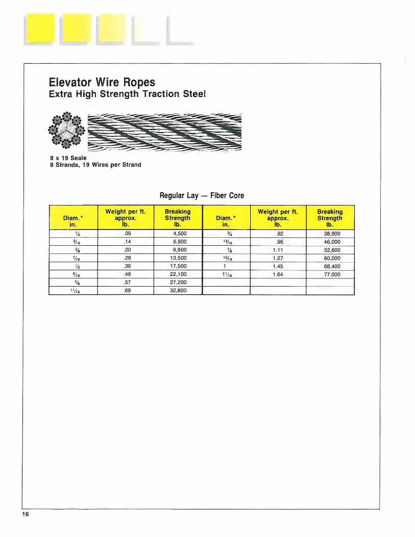
Elevator Wire Ropes Extra High Strength Traction Steel
8 x 19 Seale 8 Strands, 19 Wires per Strand
Regular Lay - Fiber Core
Weight per ft. Breaking Weight per ft . Breaking Diam.• approx. Strength Diam.• approx. Strength
in. lb. lb. in. lb. lb.
'14 .09 4,500 % .82 38,900 5lts .1 4 6,900 1alt6 .96 46,000
% .20 9 ,900 7/s 1.11 52 ,600
71ts .28 13,500 1SJt6 1.27 60,000
% .36 17,500 1 1.45 68,400
91t6 .46 22 ,100 11/ts 1.64 77,000
% .57 27,200
111t6 .69 32,800
16

Elevator Wire Ropes Extra High Strength Traction Steel
6 x 25 filler wire Type W 6 Strands, 25 Wires per Strand
Regular Lay - Fiber Core
Weight per ft. Breaking Weight per ft. Breaking Diam. • approx. Strength Diam.* approx. Strength
in. lb. lb. in. lb. lb.
1f4 .10 5 ,200 % .90 45,200
SJ\s 16 8 ,100 13;\6 1.06 52,900
% .23 11,600 1fa 1.23 61 ,200 7/16 .31 15,700 15;\6 1.41 70,000
% .40 20,400 1 1.60 79,500
9j,6 .51 25,700 1Y1s 1.81 89,400
% .63 31,600
11;\6 .76 38,200
17
Wire Rope Suggestions for Elevator Service
Shown on the following pages are diagrams illustrating different types of elevators and the Bethlehem Elevator Rope suggestions for each type. Where WWW suggests several rope constructions, the preferred construction is shown first. The following section discusses certain conditions under which a different construction or grade is recommended .
Hoist Ropes. With the advent of high rise elevators and increased car speeds, elevator designers and manufacturers frequently select a higher strength hoist rope. The extra wearing properties of extra high strength traction steel provide r~sistance to the surface wear and abrasion caused by the continual movement of the rope in the sheave grooves (called creep). For a basement traction elevator, an 8 x 21 filler wire Type U traction steel hoist rope provides the extra flexibility needed.
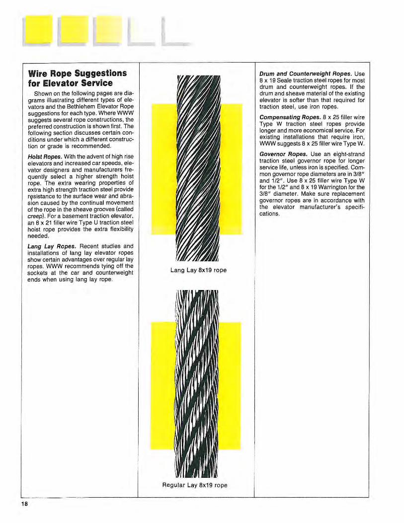
Lang Lay Ropes. Recent studies and installations of lang lay elevator ropes show certain advantages over regular lay ropes. WWW recommends tying off the sockets at the car and counterweight ends when using lang lay rope.
18
Lang Lay 8x19 rope
Regular Lay 8x19 rope
Drum and Counterweight Ropes. Use 8 x 19 Seale traction steel ropes for most drum and counterweight ropes. If the drum and sheave material of the existing elevator is softer than that required for traction steel, use iron ropes.
Compensating Ropes. 8 x 25 filler wire Type W traction steel ropes provide longer and more economical service. For existing installations that require iron, WWW suggests 8 x 25 filler wire Type W.
Governor Ropes. Use an eight-strand traction steel governor rope for longer service life, unless iron is specified. Common governor rope diameters are in 3/8" and 1/2" . Use 8 x 25 filler wire Type W for the 1/2" and 8 x 19 Warrington tor the 3/8 " diameter. Make sure replacement governor ropes are in accordance with the elevator manufacturer's specifications.

Single-Wrap Traction Overhead-Type Elevator
Hoisting Ropes 8 x 19 Seale 6 X 25 Type W
Compensating Ropes 8 x 25 Type W, Traction Steel 8 x 25 Type W, Iron
Governor Ropes *8 x 25 Type W, Traction Steel *8 x 25 Type W, Iron 6 x 25 Type W, Iron
•a x 19 Warrington for 7f1 6- and :Y8-inch diameter ropes.
Compensating Ropes -----i~l
Governor '--Rope
19

20
1:1 Double-Wrap Traction Overhead-Type Elevator
Hoisting Ropes 8 x 19 Seale 6 X 25 Type W
Compensating Ropes 8 x 25 Type W, Traction Steel 8 x 25 Type W, Iron
Governor Ropes (Car and Counterweight)
*8 x 25 Type W, Traction Steel *8 x 25 Type W, Iron 6 x 25 Type W, Iron
·s x 19 Warrington for 7!1s· and %-inch diameter ropes.
Compensating Ropes-----~
Hoist ~----Ropes
Governor -4---Rope

2:1 Double-Wrap Traction Overhead-Type Elevator
Hoisting Ropes 8 x 19 Seale 6 X 25 Type W
Governor Ropes *8 x 25 Type W, Traction Steel *8 x 25 Type W, Iron 6 x 25 Type W, Iron
Hoist Ropes --+H..,._I
Compensating Ropes (When Used) 8 x 25 Type W, Traction Steel 8 x 25 Type W, Iron
• 8 x 19 Warrington for 7;\8 - and 3fa-inch diameter ropes.
Governor Rope----+++-~~1
Compensating Ropes---_.
21

22
Single-Wrap Traction Basement-Type Elevator
Hoisting Ropes 8 x 19 Seale 8 X 21 Type U
Governor Ropes *8 x 25 Type W, Traction Steel * 8 x 25 Type W, Iron 6 x 25 Type W, Iron
•a x 19 Warrington for 7!1 1- and %-inch diameter ropes.
Hoist Ropes
Governor l~.f--- Rope

Basement Drum-Type Elevator
Hoisting Ropes *8 x 19 Seale
Drum and Car Counterweight Ropes
*8 x 19 Seale, Traction Steel
Governor Ropes t8 x 25 Type W, Traction Steel t8 x 25 Type W, Iron 6 x 25 Type W, Iron
Control Ropes 8 x 19 Warrington, Iron
•For certain drum and sheave materials, the 6 x 25 Iron rope may be preferable.
tB x 19 Warrington for 7ft 1 - and %-inch diameter ropes.
Back Drum Counterweight
Ropes---..,.
Car Counterweight
~--1+++---- Ropes
Hoist 11...,..11--.fH+-- Ropes
Governor ~---+1+1--- Rope
23

24
Overhead Drum-Type Elevator
Hoisting Ropes *8 x 19 Seale, Traction Steel
Drum and Car Counterweight Ropes
* 8 x 19 Seale, Traction Steel
Governor Ropes ta x 25 Type W, Traction Steel t8 x 25 Type _W, Iron 6 x 25 Type W, Iron
Control Ropes 8 x 19 Warrington, Iron
·For certain drum and sheave materials, the 6 x 25 Iron rope may be preferable.
Hoist Ropes~!--+-~
tB x 19 Warrington for 1j,6- and %-inch diameter ropes.
Governor Rope---~
Back Drum Counterweight ~Ropes

Hydraulic Elevator, Direct Plunger Type
Car Counterweight Ropes *8 x 19 Seale, Traction Steel
Control Ropes 8 x 19 Warrington, Iron
•For certain drum and sheave materials, the 6 x 25 Iron rope may be prererable.
Control Rope--~~
]
Car Counterweight
1..,-Ropes
25

26
Hydraulic Elevator, Horizontal Plunger Type
Hoisting Ropes *8 x 19 Seale, Traction Steel
Car Counterweight Ropes * 8 x 19 Seale, Traction Steel
Governor Ropes t8 x 25 Type W, Traction Steel t8 x 25 Type W, Iron 6 x 25 Type W, Iron
Control Ropes 8 x 19 Warrington , Iron
*For certain drum and sheave materials, the 6 x 25 Iron rope may be preferable.
tax 19 Warrington for 7Ae- and %-inch diameter ropes.
Hoist Ropes ----1~
Governor Rope )It
Control Rope----+-"'*"!
Car Counterweight
-4---Ropes

Bethlehem Elevator Rope Service Centers
California - Long Beach and Oakland
Colorado - Denver
Florida - Tampa
Georgia - Atlanta
Illinois - Chicago
Louisiana - New Orleans
Missouri - St. Louis
New Hampshire - Exeter
Oklahoma- Oklahoma City
Pennsylvania - Williamsport
Texas - Houston
Washington - Longview
27

WILLIAMSPORT WIREROPE WORKS Standard Product List
The following is a partial list of Bethlehem Wire Rope, Strand and Williamsport High Carbon Wire products manufactured by Williamsport Wirerope Works, Inc. If you require another product which is not shown below, please call our Customer Service Department at 1-800-541-7673 for assistance.
Bethlehem Wire Rope
6x19 Class General Purpose 6x37 Class General Purpose 6x25 Flex Seale 6x43 Special Tensile Rotation Resistant 4x39, 8x19 Class, 19x7,
19x19 and 35x7 Drill line Tubing line Sand line Torpedo line Well measuring line (wire) Well servicing line 1x16 and 1x19 Logging rope Roepac Roepac-T Crane Hoist Teleroepac Hammerline Herringbone Galvanized rope
Bethlehem Elevator Rope
6x19 Class 8x19 Class Iron Grade Traction Grade Xtrac Grade
Bethlehem Structural Strand & Strand Products
A-Coat Galvanized Strand B-Coat Galvanized Strand C-Coat Galvanized Strand Structural Strand Assemblies Guy Strand Lock Coil Track Strand Half-Lock Coil Track Strand Round Wire Track Strand Stone-sawing Strand Bethco Drawn Stone-sawing Strand Hose Reinforcing Strand
Bethlehem Mining Rope
6x19 Class 6x37 Class 6x61 Class 8x19 Class 8x37 Class Excavator Grade Excavator-AR Grade En-core Bethpac Bethex Maxicore Structural Strand pendants Flattened Strand Rope
Williamsport High Carbon Wire
Bright Wire .018"-.250" Rope Wire .018"-.250" Mechanical Spring Wire .018"-.200" Music Spring Wire 8ga-%" Pipewrapping Wire 8ga-%" Tankwrapping Wire
Patented Wire .032"-.200" for redraw .032"-.200" for flatrolling .032"-.200" for brushwire
Hot Dipped Galvanized .066"-.250" Structural Strand Wire .066"-.250" ACSR Wire


Technical Bulletin
one E I eva tor R o p e
This bulletin is the first in a series of technical papers intended to help our customers understand elevator wire rope . Along with the Bethlehem Elevator Rope Catalog, these bulletins will discuss, in f urther detail, those items and questions in which our customers are most interested. The first bulletin is intended to help in the basic terminology of the product. This information will also be useful in discussing future bulletins.
Diameter
The easiest rope parameter to understand is diameter. However, do not assume rope diameters. Measure the diameter of the set of ropes before installation to insure the material meets the design requirements for the equipment on which it is to be used.
If the rope is undersize, the rope breaking strength will be lower; therefore, stresses are higher. The outer wires are smaller, adding to shorter abrasion life. The rope also tends to cut into the sheave since the area of rope support is less on a smaller diameter rope.
An oversize rope will be pinched in the grooves, causing a concentrated pattern of stress and eventual wire breakage along the planes of groove support. Some customers actually choose to go to a larger diameter rope in an effort to increase traction. However, the trade-off is shortened rope life.
The actual rope diameter is measured as the diameter of the circumscribed circle (largest crosssectional dimension). Figure 1 illustrates this method for measuring 6- or a-strand rope.
Table 1 illustrates the diameter tolerances for Bethlehem Elevator Ropes. Statistical Process Control methods insure diameter consistencies within each production run .
Nomenc a t u r e
__ Figure 1 Calipering Elevator Rope
Figure A Right Way Figure B Wrong Way
To properly measure the diameter of elevator rope, caliper from the top of one strand to the top of the opposite strand, as shown in Figure A. Do not caliper across two strands as shown in Figure B.
Table 1 Diameter Tolerances
Rope Loaded Unloaded Out of Round Diameter Rope• Rope Tolerance (inches) (inches) (Inches) (inches)
% .375/.390 .382/ .397 .008
112 .500/.515 .510/.525 .008
5fs .625/.643 .637/.654 .009
11f1s .687/.708 .701 /.722 .011
% .750/.772 .765/.787 .011
1¥,6 .812/.836 .828/.852 .012
% .875/.901 .892/.918 .013
1 1.000/1.030 1.020/1.050 .015
11.As 1.062/1.094 1.083/1.115 .016
"Loaded rope equals 10% of breaking s trength.

Ele vator A o p e
Construction
Ropes are classified by the number of strands as well as by the number of wires in each strand. For example, an 8 x 19 Seale rope has 8 outer strands, with each strand containing 19 wires each. The term Seale refers to the position of wires in the outer strands. Figure 2 illustrates various constructions commonly used on elevator applicatons, along with highlighting the components of the rope .
Ropes are also identified by nominal classification t hat may not reflect their actual construction. For example, an 8 x 19 Seale, 8 x 21 Type U and 8 x 25 Type Ware all classif ied as 8 x 19 class ropes . This is very important to know when a job requires a particular rope construction but only specifies the class reference. To avoid potential misunderstanding, order specific constructions.
Generally speaking, an 8 x 19 Warrington is more flexible than an 8 x 19 Seale. However, the Seale rope has larger outside wires making it more abrasion resistant. Similarly, the 8 x 25 Type W is more flexible , yet less abrasion resistant than an 8 x 21 Type U. Contact Williamsport Wirerope Works' (WWW) Sales and Engineering Departments for help in determining your specific needs.
Figure 2 Constructions
-~~'· . ···~· . ····'·•·•!'•····'· •••••••••••••••• •'•!'• ·'··· ••• • •• ··~·. ' .•!'• ·1·•· ···:·~ ·-~~·.,::.•%·~·
·~··· . ··-=·· 6 x 25 Filler Wire Type W
..... ~. ········::······ ····~·~·- ~-·:·· .!t ••• ~. • ••••• ::·· ··~ .. •••••• ••••• ·1·~· ·•·:.· ··--~ ,. .... • ~.-.~. • 1.·~·:· •!t/.~ •• ~.········· ······~· .. ······ ··:··
8 x 25 Filler Wire Type W
•:• • •••••• •• • .. ~.··•!'•· ·· ·· •····•• • ···=·· •::• •;.• •••• ••••• ••• • ••••• ....... ·'!·~. ••••• •• • • • •• ··~·-· . ·:.··· ·····~'·······!t· • ••• ~·=·· ••
·~· 8 x 21 Filler Wire Type U
.·.-.: . ••••••••••••• ............... ,...... • ·:=·: ..:• . ·.:··· ••••• •••• ••••• •••• ··:if ··:·· • • • ••• ··=·· .•.....• ·:··········\· ···-.·.·.·~ ··· •••
8 x 19 Warrington
Vegetable Ftber Core
STRAND 8 refers to the number of strands tn the rope
Commonly Used Constructions of Elevator Rope
Nomencl at ur e
Lay Direction and Type of Lay
Lay is sometimes a confusing wire rope term but its meaning is important to know. Essentially, the term derives from the way in which the rope is put together. Contrary to its appearance, wire rope is not strands of wire twisted together. Rather, the strands are laid into position. Great care is taken in the manufacture of wire rope to insure that no unwanted twist is imparted to the wires or strands.
The term lay is used in two ways: (1) describing the appearance or construction of the wire rope in regard to the direction of its spiral , and (2) measuring the length of the helix (spiral) of the rope.
When used in the first context, the terms right and left refer to the direction in which the strands rotate around the rope. The terms regular lay and Lang lay refer to the way the wires rotate around the strands in relation to the direction of the strands in the rope.
Figure 3
Regular Lay 8 x 19 Rope Lang Lay 8 x 19 Rope
In right lay, strands rotate around the rope in a clockwise direction, as the threads do in a righthanded bolt. Regular lay means the wires in a strand rotate in a direction opposite to the direction in which the strand rotates around the rope. The net result of regular lay is that the visible wires run roughly parallel to the core of the rope. Lang lay is the reverse of regular. Wires in a Lang lay rope rotate in the same direction as the strands and appear to spiral diagonally around the rope. Figure 3 illustrates right regular lay and right Lang lay. If direction and type of lay are omitted f rom the rope description, it is presumed to be right regular lay.
Lang lay ropes offer greater fatigue resistance and abrasion resistance than regular lay ropes. In-house fatigue testing by Williamsport Wirerope Works confirms 1/2" 8 x 19 Lang lay ropes show increased fatigue life over similar regular lay ropes when subjected to bend-over sheave testing.

Elevator R o p e
Figure 4
Supporting Inner Wire
Regular ~ ' J k "? 'l
The Worn Crown of the Regular Lay has a Shorter Exposed Length.
The superior fatigue life of Lang lay ropes is attributed to the longer, exposed length of the outer wires. Since the individual wires in a Lang lay rope run in the same direction as the strands, the valley-tovalley length is much greater than on a regular lay rope. Bending the exposed wire over a greater length results in lower axial bending stresses of the outer wires and greater torsional flexure . In addition , the wear pattern on a Lang lay rope is extended, allowing greater distribution of contact stresses. The worn crown of a regular lay rope, combined with its shorter exposed length, causes the wire to spring away from the supporting inner wires as illustrated in Figure 4. This results in higher bending stresses and shorter fatigue life.
Because the wires of a regular lay rope are wound counterlaid to the strands, the individual wires in t his type of rope run almost parallel to the rope , making a regular lay rope more torque resistant than a Lang lay. A Lang lay rope also has more stretch than a similar regular lay rope.
As a unit of measure, rope lay means the lengthwise distance a single strand covers in making one complete turn around the rope. Lay length is measured in a straight line parallel to the center line of the rope , not by following the strand as it spirals around the rope. It is necessary to know the lay length because it provides a convenient basis for rope inspection. For example, a rope may be removed from service after a certain number of wires break in one rope lay.
Figure 5 Lay as a Unit of Measure
One Rope Lay.
Showing how " One-Rope Lay" is the Lengthwise Distance in which a Strand Makes One Complete Turn Around the Rope.
Nomen c latur e
Preforming
Form-set, Bethlehem's preformed rope , reduces internal torsional stresses and thereby increases fatigue resistance of the wires. This results in a stable, better balanced rope. Form-set elevator ropes run smoother over sheaves and drums. When wire breaks do occur, the broken wires are less likely to protrude from the rope surface. This results in less damage to adjacent wires and may increase fatigue life.
Preforming occurs in the rope closing operation in which the component wires and strands are permanently formed into the helical position occupied in the finished rope .
Form-set ropes are easy to handle and, normally, cut ends do not need to be seized to prevent unwinding. Preforming makes installation easier and more cost-efficient.
Preforming may increase rope stretch by approximately 50% over non-preformed rope, as illustrated in Table 2.
Grade of Rope
In the early days, most elevator hoist ropes were made of iron. After the invention of the traction elevator, iron hoist ropes became obsolete due to their inadequate strengths and abilities to withstand abrasion. Instead, a special grade of steel , suitably named traction steel , was developed to meet the service conditions of traction machines.
The tensile strength of traction steel is between 160,000 and 208,000 lbs. per square inch. Characterized by an excellent combination of strength, toughness, ductility and fatigue-resistance, traction steel ropes are designed primarily for hoist ropes for modern, traction-drive passenger and freight elevators. Traction steel elevator ropes provide the qualities of traction and hardness needed for satisfactory elevator service. In hoist rope applications, traction steel is more durable and reliable than iron.
Iron ropes are relatively low in tensile strength (approximately 110,000 to 172,000 lbs. per square inch), and are soft and extremely ductile. Because of this combination, their use for elevator service is mainly limited to governor and compensating ropes.
High rise and high speed elevators often require high strength hoist ropes to meet the required safety factor. Bethlehem's extra high strength traction steel provides the extra margin needed.

Elevator R o p e
Coatings
The most common finish for elevator rope is "bright" or uncoated. Galvanized (zinc-coated) rope may be specified where corrosion may be a serious problem. Galvanized rope is not a stock item and a special production run is required.
Type of Core
The core of elevator rope is usually made of vegetable fiber, such as sisal or manila, and is lubricated to WWW specifications.
During core manufacturing, lubricant penetrates all fibers of the core. This lubricant eventually breaks down as the elevator rope operates and should be replenished by proper field maintenance. Field lubrication will be addressed in future Bethlehem Elevator Rope technical bulletins.
The core contributes elasticity to the elevator rope. It allows for the constructional adjustments needed to equalize stresses when the elevator rope is bent or loaded.
The core's most important job is providing support for the strands. Valley breakage is directly related to the support provided by the core. Lack of proper lubrication is the most common cause of core failure.
Some synthetic fiber cores may give excellent support to outer strands and are not as susceptible to drying-out as the sisal cores. Synthetic cores have better diameter and density consistencies than natural cores. Reverse-bend testing has shown synthetic core ropes may yield better fatigue values than do sisal core ropes. However, synthetic cores have greater elasticities which result in greater stretch and may require additional take-ups and cutoffs.
Prestretching
Since wire rope is an elastic member, it stretches under any applied load. The stretch is derived through (1) initial or constructional stretch, and (2) secondary or elastic stretch. The amount of constructional stretch relates to the rope design but is typically 3A% to 1% for 8 x 19 class and V2% to 3A o/o for 6 x 19 class elevator ropes.
Usually constructional stretch ceases at an early stage in rope life. However, elevator ropes , which are lightly loaded, may lose the constructional stretch over a long period of time.
Nomenclature
When installing Bethlehem Elevator Ropes, make the following allowances for constructional stretch:
Table 2
Class Allowance for Stretch (inches per 100 feet)
6 x 19 non-preformed 6
6 x 19 preformed 9
8 x 19 non-preformed 8
8 x 19 preformed 12
Prestretching elevator rope during production eliminates constructional stretch. This allows for fewer take-ups since the overall stretch is considerably reduced. The following limits of stretch (after installation of prestretched elevator hoist ropes) are derived from medium and high rise installations.
Table3
Construction Stretch (inches per 100 teet)
minimum maximum
6 x 19 Class (preformed 1.5 2.5 and non-preformed)
8 x 19 Class (preformed 2.0 3.5 and non-preformed)
Wire rope products will break if abused, misused or overused. Regular inspection and maintenance are necessary. Consult indust ry recommendation and ANSI Standards before using.
WW-1008 1/92
~FHLEBE~
\\lim ROP~ \1 illiamsport 1\ ire rope 1\ or ~1. Inc.
100 Maynard Street
P 0 Box3188
W 1ll1amspor t . PA 17701
Te l 717-326 - 5146
F ax 717-327 - 4274

Technical Bulletin
w E e v a t o r R o p e
Lubrication is necessary for the proper maintenance of any machine. As a machine, an operating wire rope must also have a lubrication maintenance program to insure it is functioning properly.
Every wire rope application requires a different lubricant. Applied during manufacturing, lubricants are selected on the basis of rope service requirements. For example, ropes for heavy-duty stripping shovels have a relatively short service life and need a lubricant suitable to the abrasive conditions under which the wire ropes operate. Elevator hoist ropes , on the other hand, have a relatively long service life and need a lubricant that: (1) retains its chemical and physical properties for a period of several years, and (2) does not materially affect the traction design relationship.
Lubrication During Manufacturing
In the manufacturing of Bethlehem Elevator Rope, the lubricant is applied to individual wires during the stranding operation. The lubricant amount is then regulated on the finished strand by a special wiping process. This process determines the lubricant content of the strand.
The quality of the lubricant in a wire rope is just as important as the quality of other rope components (wire and core). This is especially true of elevator ropes because of their relatively long service lives. When an elevator hoist rope is in operation, each wire is in contact (over its entire length) with other wires, sheaves and drums. The strands also move with respect to each other and with the core. The need for a lubricating film between all of these components is necessary to minimize wear between the wires, strands and the fiber core.
Some believe that the fiber core 's major role is to continuously provide lubrication to the elevator rope. In fact, the core 's most important functions are to provide support to the strands and contribute
L u b r c a t o n
elasticity to the rope. During core manufacturing, lubricant penetrates all fibers of the core , but eventually the lubricant breaks down. Since the factoryapplied lubricant is gradually dispersed during the operating life of the hoist rope , and understanding that the fiber core is not a lubricant reservoir, elevator hoist ropes need to be field lubricated during their service life.
Field Lubrication
Field lubrication is necessary to :
• minimize wear between ropes and sheaves. • reduce friction between the wires. • minimize corrosion due to atmospheric and/or
operating conditions. • help reduce bending fatigue by allowing
movement between the wires and strands.
The proper field lubricant must be used so the traction relationship between the hoist ropes and the drive drums is not adversely affected. The lubricant should also be compatible with the strand and core lubricants, and have good rope penetrating properties.
A lubricant meeting these requirements is a light viscosity Spindle oil. It should have a Saybolt Seconds Universal (SSU) viscosity of 34 to 38 sec. at 210°F. This lubricant is readily available and inexpensive. Spindle oil not only lubricates, but also assists in keeping the hoist ropes clean. Spindle oil is best applied with a felt pad, wick-type lubricator. This device can be mounted on the bedplate and is easily moved from one machine to another. The Spindle oil can also be sparingly applied with a brush, if necessary.
Hoist rope slippage during acceleration or deceleration may be an indication of excessive lubrication. To determine if the lubricant is reducing the trac-

E l e vator R o p e
tion and causing slippage, watch the hoist ropes as they pass around the driving sheave during operation. Some rope creepage is normal; slippage is not.
WWW does not recommend the use of solvent cut-back lubricants. Solvent cut-backs tend to dilute the strand and core lubricants, which result in lubricant throw-off and ultimate dryness of the hoist rope.
Do not lubricate governor ropes after installation. The lubricant may interfere with the governor jaw 's ability to stop the governor rope and apply the safety. Lubrication may also reduce the traction between the governor rope and sheave, and prevent proper functioning of the speed governor.
Lubrication Frequency
The amount of lubricant used and the frequency of field lubrication should be determined by maintenance personnel. The amount and frequency of lubrication depends on such factors as atmospheric and climatic conditions, rope speed and the type of elevator service.
A good rule of thumb to follow is to check for a film of lubricant in the drive sheave grooves. With the machine out of service, carefully wipe the groove with your finger. If the groove is dry, field lubrication is required .
Rope Cleaning
WWW does not recommend the use of a solvent to clean elevator hoist ropes. Solvents dilute the lubricant within the strands of the elevator hoist rope. The diluted lubricant bleeds from the elevator hoist rope and is thrown off during operation . Not only does the solvent counteract the lubricant, the throw-off results in a dirty machine room and may harm the rotor or other electrical components.
We do recommend a regular cleaning program. Elevator hoist ropes need to be cleaned because of the build-up of dirt, lint, etc., picked up in the atmosphere of the shaft. If cleaned on a regular basis, the hoist ropes will not require the harsh processes needed to remove the dirt and lint which have accumulated over the months. This also eliminates the need for disposal of controlled or
L ubrication
hazardous waste cleaning materials.
Instead, continuous light cleaning can be done. Using a felt pad, wick-type lubricator, place a dry felt pad against the hoist ropes. As the elevator operates, the hoist ropes are cleaned . Another method is to attach a section of natural fiber carpeting at the top of the machine so the hoist ropes are wiped as they operate.
In the event a hoist rope is overlubricated, the methods discussed above may be used to remove the excess lubricant.
The frequency of rope cleaning , like lubrication, should also be determined by maintenance personnel.
For further information on lubrication, please contact WWW's Sales or Engineering Departments.
Wire rope products will break if abused , misused or overused. Consult industry recommendations and appropriate safety stan· dards before using.
WW-1015 7/92
Williamsport Wirerope works, Inc. P.O. sox 3188 • 100 Maynard Street
Wt lltamsport. PA 17701
Phone: 1717) 326·5146 Fax. !717l 327-4274
Order Entry (800) 541-7673

Technical Bulletin
Elevate r R o p e R o u g n g
Rouge (or red rouge) is a fine, red iron oxide which forms on the rope, giving it a " rusty" appearance and suggesting that advanced deterioration is taking place. Rouging is caused by fretting , a special type of abrasion which occurs when two solid surfaces bear against one another, while under a heavy load and subjected to small amplitude vibrations. The small amplitude vibrations are due to load vibrations which occur during loading and unloading, and starting and stopping of the elevator. The pressures from the heavy load and vibrations work out any lubrication that may have been present, and result in very small metal particles that have become abraded or torn out of the metal surface. These particles spontaneously oxidize in the air to form the red ferric oxide dust that is characteristic of rouging .
Rouge is different from what we commonly refer to as rust. Rust forms when moisture is introduced to a metal surface. When combined with this moisture, the metal surface, itself, rusts. Rouge does not indicate that a wire rope is beginning to rust . Rouging, instead, means that abrasion is occurring between the wire rope components and that only the small metal particles, now separate from the wire rope, are rusting.
In elevator rope, rouging begins with a lack of core support. This is usually due to a lack of proper field lubrication. The fiber core dries up and cannot provide the strands with the necessary support . Another possibility is that a solvent or solvent-based lubricant was used, which diluted the existing lubricant and dried out the core and wires within the strands. Rouging occurs where the strands contact the f iber core, and also at the areas of contact between adjacent strands.
Field lubrication does not counteract the effects of rouging or restore the rope to its proper operating condition; the damage has already been done. Field lubrication may appear to stop the rouging , when it actually only temporarily cleans and retards the evidence of the rouge. The evidence of rouge should
Figure 1 Cross-section of rope where rouging occurred.
The inner wires of the strands in contact with the vegetable (hemp) fiber core are worn considerably. Wear is also quite severe where adjacent strands come in contact with one another.

E levato r Rope R oug ng
not, by itself, be construed as an immediate cause for removal. For inspection guidance on the condition of rouging , refer to ANSI/ASME 17.21nspectors' Manual for Elevators and Escalators, Item 103.4. Please. note that this code reduces the number of allowable wire breaks (all types) by 50% once rouging occurs. It should also be noted that when the core no longer supports the strands, a reduction in diameter is common. Therefore, in addition to checking the criteria for allowable wire breaks, please refer to A17.2 criteria for removal due to diameter reduction. WWW suggests an increase in the frequency of rope inspection, with an intent to schedule rope replacement once rouging is evident.
Figure 2 An unlaid section of wire rope which exhibited severe rouging
The individual strands show nicked areas caused by abrasion at points of contact between strands. Between the nicked areas is an abraded area which resulted from wear between the strands and fiber core.
For further information on rouging , please contact WWW's Sales or Engineering Department.
Wire rope products will break if abused, misused or overused. Consult industry recommendations and appropriate safety standards before using.
WW-1017 7/92
Williamsport Wirerope works, Inc. p o sox 3188 • 100 Maynard street
Williamsport. PA 17701
Pho ne 1717! 326·5146 Fa x 171 7! 327·4274
Order Entry (800) 541-7673

Technical Bulletin I
E e v a t o r R o p e s p p a g e
For proper operation, the modern mid- and high-rise traction elevators in service today depend on the friction between the hoist ropes and the drive sheave. The cars of these traction elevators are raised and lowered by hoist ropes attached to the car head frame. These ropes wind around the secondary and drive sheaves one or more times, then move down to the counterweight. The elevator cab, with its load, is suspended from one end of the hoist ropes, with the counterweight on the other end. The driving force required to raise and lower the car is soley dependent upon the traction between the ropes and drive sheave.
There are basically four factors which determine and control the driving force of traction elevators: (1) traction ratio, (2) area of contact of hoist ropes on the drive sheave, (3) coefficient of friction between the hoist ropes and drive sheave, and (4) rate of acceleration/deceleration. The designer determines these factors for the specific application, and the manufacturer checks them to ensure proper operation of the installed machine.
Improper operating practices are most often the cause of rope slippage. Following are some of the causes of slippage.
Excessive Counterweights
The general rule is that the counterweights equal the weight of the car and attachments, plus 40% of the rated capacity. In some cases, to economize, a designer will use a motor which is too light for the service. Extra counterweights are then used to compensate for the light motor. It is easy to see what will happen when an empty car with an overloaded counterweight is driven downward - slippage.
Hard Braking
Hard braking may cause the car to jolt, and in turn may result in rope slippage. In this case, adjust the braking to provide for a smooth or " soft" stop.
Overloading
Exceeding the rated capacity is particularly serious on traction-type elevators. Overloading results in an increased traction ratio, and the traction of the ropes on the drive sheave may be insufficient to lift and control the loaded car. Most cars have the rated capacities noted and those capacities should not be exceeded.
Increasing Acceleration
In some cases, the acceleration rate is increased beyond the designed figure to increase the number of trips an elevator makes. This also causes slippage.
Fit Factor
The fit of the hoist ropes in the grooves of the drive sheave is very important. If the rope does not fit with sufficient clearance to seat properly, the area of contact between the rope and groove decreases below the design value and slippage may, and probably will, occur.
Unequal Tensions
Unequal tensions of the hoist ropes are another cause of rope slippage. Most elevator systems are

E I e v a t o r
roped with four to eleven ropes operating in parallel and driven by a multi-groove sheave. Having improperly tensioned ropes, and/or nonuniform tensioning within a set of ropes affects operating rope diameters, sheave groove wear and rope stretch, and will , over time, cause rope slippage and an array of other problems. It is of the utmost importance that ropes are properly tensioned during installation.
Lubrication
Excessive lubrication on hoist ropes reduces the coefficient of friction between the ropes and the drive sheave, and is another cause of slippage. This is more often the case on U-grooved sheaves, where traction is dependent upon the friction of the rope in the bottom of the groove. V-grooved machines are not as easily affected since traction is increased by the pinching action of the sides of the groove.
Insufficient Counterweights
If the counterweight is insufficient for the designed load, slippage occurs. An inadequate counterweight increases the traction ratio beyond the value for which the elevator is designed.
S I p p a g e
One method for determining rope slippage is to run the car for one cycle, then mark the ropes and drive sheave with chalk while the car is at one of the terminal landings. Have the car make two complete trips, ending at the original starting point. Compare the chalk mark on the ropes with that on the sheave. If the differential is 1" to 2", this is normal and can be considered creepage. Anything over should be treated as slippage.
Rope slippage on traction elevators may be due to a number of causes. When slippage is detected, it should be traced to its source and corrected. If left uncorrected, rope slippage can become expensive since it causes excessive wear of the ropes and sheave grooves. Re-roping and re-grooving is costly. In addition, slippage can result in unsafe operation of the elevator.
WW-1019 9/93
Williamsport Wirerope works, Inc. P.O. Box 3188 • 100 Maynard Street
Williamsport, PA 17701
Phone: !717l 326-5146 Fax: !717) 327-4274
1-800-541-7673

I
I
I
I
I
I
I
I
I I
I
I
BETHLEHEM • ELEVATOR • ROP
Technical •
E e v a t 0 r R
One of the inherent properties of all wire rope is stretch. Wire rope is essentially an elastic member, stretching or elongating when under load. This elongation is the result of two separate factors: constructional stretch and elastic stretch.
Constructional Stretch
When a load is applied to a wire rope, the helically-laid wires and strands react in a constricting manner, compressing the core and bringing all of the elements of the rope into closer contact. The result is a slight reduction in diameter and an accompanying lengthening of the rope.
Figure 1 shows the diameter range of Bethlehem Elevator Rope as manufactured. Usually constructional stretch will cease at an early stage in the rope's life. However, some fiber core ropes, when lightly loaded, may continue to display a degree of constructional stretch over a considerable portion of its life.
As might be expected, ropes with strand cores or independent wire rope cores (IWRC's) have less constructional stretch than those with fiber cores. Steel cores do not compress as much as fiber cores, and the stretch characteristics of steel versus sisal (fiber) are significatly different.
A finite value for constructional stretch cannot be defined since it is influenced by the : • type of core • grade(s) of steel • construction of the rope • degree of preforming • length of the helixes
Because of these conditions, along with individual operating conditions such as car weights, rope speed, roping configuration, breaking and acceleration speeds, shaft height and rope lengths, and sheave conditions, it is difficult to determine the actual rate of constructional stretch for various elevator ropes .
As shown in Figure 2, there is a difference in constructional stretch between preformed and non-preformed elevator ropes. Preforming is the process where the
'll, . .
~ .·. ~ WJ'
0
Bulletin
p e s t r e t c h
Figure 1- Diameter Range for Bethlehem Elevator Rope, as Manufactured
Diameter Loaded Rope Unloaded Rope (inches) (inches) (inches)
3/8 .375/.390 .382/.397
1/2 .500/ .515 .510/.525
5/8 .625/.643 .637/.654
11 /16 .687/.708 .701/.722
3/4 .750/ .772 .765/.787
13/16 .812/.836 .828/.852
718 .875/.901 .892/.918
1 1.000/1 .030 1.020/1.050
1-1/16 1.062/1 .094 1 . 083/1 . 11 5
Loaded weight is approximately 10% of published breaking strength
Figure 2- Constructional Stretch Allowance for Non-Prestretched Ropes
Class Allowance for Stretch (inches/1 00 feet)
6 x 19 non-preformed 6
6 x 19 preformed 9
8 x 19 non-preformed 8
8 x 19 preformed 12
Figure 3 - Limits of Constructional Stretch
Construction
6x19Ciass
8 x 19 Class
Stretch (inches/1 00 feet)
minimum
1.5
2.0
maximum
2.5
3.5
~ W)'

strands are permanently formed into a helix prior to closing around the core. This process adds to the constructional stretch as indicated. However, preformed ropes are more flexible and easier to install. This flexibility adds to the fatigue life of the rope, making preformed ropes the preferred product for most elevator applications. 8-strand ropes show greater constructional stretch than 6-strand ropes. This is due to the fiber core's being larger in an 8-strand rope, allowing the rope to stretch and compact more.
Other factors in rope design may influence rope stretch. Tests have shown that Lang lay ropes have a slightly higher stretch value than regular lay ropes. This is the result of wire helix and lay lengths. Extra High Strength (EHS) Traction ropes have a slightly higher stretch value as well, due to the higher loads applied to EHS ropes.
Synthetic cores have different stretch characteristics than normal sisal cores. Although synthetic core ropes normally have greater stretch, various manufacturing and design techniques are available which may reduce the stretch values to more conventional parameters.
Tensioning of Ropes
To this point, this technical bulletin assumes that all ropes within a set are from the same manufactu rer and are all of the same material, grade, construction and diameter. The A 17.2 code recommends, but does not restrict, the rope to be from the same production run. With consistencies in the product, variations between reels are minimal.
Greater concern should be placed on the consistency of the rope tensions. If the ropes are not tensioned equally, each rope will stretch in relationship to the load placed upon it. Unequal tensioning causes: • a change in safety factors • vibration • unequal sheave wear • short rope life • slippage
Tensioning of ropes by pulling on them by hand is not recommended by Williamsport Wirerope Works (WWW) nor is it recommended by the elevator OEM'S. Speciallydesigned tools and procedures have been established to eliminate the guesswork in tensioning cables.
Proper inspection of the sheaves prior tore-roping, along with equal tensioning and good field lubrication practices are the three most important factors for extending rope service life.
WW-1024 6/95
~ WJ'
Prestretching
Constructional stretch of hoist ropes may require frequent rope adjustments. In high rise buildings and structures where p it clearance is shallow and overhead run by is limited, WWW recommends prestretched rope. Prestretched ropes reduce or eliminate the number of shortenings required by removing the majority of constructional stretch and therefore may be very cost effective.
The limits of constructional stretch (after installation of prestretched elevator hoist ropes) shown in Figure 3 are derived from data obtained through WWW's in-house testing and actual field measurements. The values shown represent rope prestretched by a method called continuous prestretching, a separate process used by WWW to prestretch Bethlehem Elevator Rope. If a manufacturer uses in-line prestretching, double the number shown in appropriate column for an approximate value of constructional stretch .
Elastic Stretch
Elastic stretch results from the recoverable elongation of the steel wires and strands. Elastic properties for wire ropes are well documented and enable computations to be made in determining the elastic stretch in the rope. The following equation can provide a reasonable determination to calculate this increase in rope length due to a change in load.
Changes in Length (ft) Change in Loads (lbs) x Length
of One Rope (ft)
Area of One Rope (in' ) x Modulus of
Elasticity (psi)
The modulus for 6-strand, fiber core ropes is 10,800,000 psi , and 8,100,000 psi for 8-strand, fiber core ropes. Rope areas can be provided by your wire.rope supplier.
Hoist ropes will stretch while in service, primarily as a result of constructional stretch. Once constructional stretch occurs, it will not return to the rope. The time required to remove the constructional stretch in a rope varies w ith each application. Prestretching greatly reduces the contructional stretch after rope installation. As the load is changed on each rope, that rope will stretch elastically. Excessive stretch may therefore indicate excessive loading or unusual operating conditions which may result in significant rope diameter reduction and premature removal.

BETHLEHEM • ELEVATOR • ROPE
Technical
L u b r c a n t
Lubricant build-up on elevator rope is a condition which for years has frustrated maintenance personnel and inspectors. In recent years build-up has become more prevalent; today it is not uncommon for a wire rope to resemble a black rubber hose (see Figure 1, rope 1), or an undercut U- or V-groove to be mistaken for a U-groove because of the amount of buildup in the groove.
To answer the growing concern over lubricant build-up, Williamsport Wirerope Works, Inc. (WWW) actively investigated lubricant build-up, a condition occurring on all manufacturers equipment and with all brands of wire rope. Over a period of years WWW collected and analyzed many samples from various buildings, geographical areas, speeds, weights, groove configurations and from a cross-section of manufacturers of equipment and ropes. The following are WWW's findings.
Content Analysis
The contents of the lubricant build-up fall into two major categories: solids, or metal fines (shavings) from sheaves and ropes; and non-solids, excess lubricant filled with contaminants. Solids were found in all samples analyzed. In some instances solids comprised 90% of the total content of the lubricant build-up. No sample analyzed contained less than 20% solid content. Site contaminants comprised the remaining portion. It is also important to note that a few samples contained nearly 2% water.
Contributing Factors
Sheaves The relationship of rope diameter to sheave diameter has changed dramatically. Years ago ropes ran on large sheaves; today the trend is moving towards the allowable minimum of 40 to 1 (i.e. 1/2" diameter ropes on 20" sheaves). Undercut U- and V-grooves compensate for the loss of contact area, resulting in increased abrasion of the ropes and sheave. In these cases WWW discovered the solid content to be very high. Samples collected from older equipment using large U-groove sheaves (where the sheave had not been regrooved) also contained a high metal fines content. Wire rope reduces in diameter throughout its life. As it reduces in diameter, the rope continually machines the sheave groove to fit it's diameter, producing metal fines. With each new set
Bulletin
B u d u p
of ropes the process begins again. When the sheave is not regrooved, the groove profile will be considerably smaller than the diameter of the new rope, increasing the amount of metal fines and forcing lubrication out of the rope, thus accelerating lubricant build-up. In years past metal shavings at the base of the machine, with which many mechanics and superintendents are familiar, indicated that the sheave was wearing. Today this condition is masked as part of lubricant build-up, or metal fines and other contaminants mixing with the lubricant.
Over Lubrication In many cases over lubricating wire rope is the major cause of lubricant build-up and contamination. Suppliers of automatic lubricators state that the electrostatic process of lubricating wire rope results in the rope's taking "only what it needs." This is incorrect. The fact is the electrostatic process will continually feed lubricant to the rope well beyond its absorption point. The excess lubricant is thrown off and/or exudes from the rope and combines with site contaminants to create the "black rubber hose" effect. There are economic advantages to using automatic lubricators. However. service technicians must realize the limits and subseguent

effects of these lubricators when not used properly. Likewise, pouring a gallon of lubricant over the ropes is just as detrimental. Excess lubricant attracts si te contaminants and may cause slippage. Refer to Bethlehem Elevator Rope Technical Bulletin No. Two on Lubrication for further information.
Carbon Dust Dust from carbon brushes has been a major problem as a contaminant not only for wire rope but other components of the elevator system. WWW's analyses revealed carbon dust as another component of the build-up.
Air Conditioned Control Rooms WWW observed during multiple inspections that cars nearest the air conditioner exhaust vents have a much greater potential for lubricant build-up. In this case, as also was the case in high humidity conditions, the sample water content was as high as 2%. Due to the warm, humid conditions of the shaft, air conditioned control rooms will cause condensation on the ropes when the ropes cycle into the control room even for a short period of time. The condensation mixes with contaminants trapped in the lubricant and causes a high moisture content in the build-up.
Incompatible Field Dressings For some reason gear oil, motor oil and hydraulic fluid are sometimes used as wire rope lubricants. WWW recommends only a light viscosity spindle oil. Any lubricant with detergents or solvents is incompatible with the manufacturing lubricant.
Airborne Contaminants WWW inspected an elevator in an older building and found lubricant build-up in the mid-rise, with no build-up in the highrise. Further, the inspection revealed the following:
The large U-groove sheaves were regrooved to specilication. No automatic lubricator was used. The ropes were not lubricated in the field. The ropes were only one year old.
The bui ld-up was comprised primarily of non-metall ic solids. Further examination led to a discovery: renovation activity in the mid-rise area. Several factors were involved here which would not have been present in the past. Dusty, inexpensive sheet rock was used in lieu of plaster, the carpets were synthetic fiber and the air circulated through the elevator/ventilation shaft, bringing dust and fibers into contact with the elevator ropes. Contaminants will adhere to any surface with a greasy or sticky film. Often it has been observed that a build-up of lint surrounds the ropes above the shackles where the ropes do not pass over the sheaves. The electrostatic charge in the ropes acts as a magnet to airborne particles.
Rope Brakes These safety devices use friction pads to stop the car in emergency situations. In many cases the pads need to be grooved to fit the number, size and spacing of the ropes. Typically the ropes are used to groove the friction pads, creating particles that ultimately mix with the manufacturer's lubricant.
I
Rope Cleaning Methods
Due to the wide variety of causes of lubricant build-up, at this time the key to controlling lubricantbuild-up rests solely on maintenance personnel. Inspectors will issue a violation if they cannot inspect the crowns or valleys of the ropes. Therefore, rope cleaning is imperative. Build-up may cause severe abrasion on the ropes and sheaves if the solid content is high. The lubricant and metallic fines combine to act as a cutting or polishing media between the ropes and sheave. Conversely, a high non-solid content may cause slippage. Additional lubrication is useless under these conditions since it will not penetrate to the core.
Solvent The use of a solvent will not only break down the exterior lubricant build-up, it will also break down the lubrication in the core, resulting in a dry rope and subsequent rouge. Solvents are unacceptable.
Carpeting In the past carpeting mounted in the rope guards was commonly used with success. Most carpets then were made from natural fiber. Today most carpets are synthetic, not biodegradable, and add to the problem of contamination. In addition, the use of carpeting may be in violation of fire codes. Therefore the use of carpeting is unacceptable as a means of cleaning wire rope.
Wire Brush Manual labor with a wire brush is costly in terms of labor, but remains an acceptable method of cleaning the ropes.
Automatic Rope Cleaner A proven automatic rope cleaner is available and being sold commercially to clean ropes without expensive manual labor. Patented and licensed to Parts Specialists, Inc. (PSI) of Posen, Illinois, the rope cleaner cleans hoist ropes as they cycle in everyday operation. The only labor involved is in the initial installation and periodic removal of build-up from the cleaner's surrounding areas. It should be noted that car tops need to be protected from falling lubricant build-up. Once the ropes are clean a very light field dressing should be applied. For further information contact PSI at 800-598-2444.
~ J1nnpt kKlt.IIC.
I 00 Maynard Street P.O. Box 3 188 W~amsport. PA 1770 I
Tel: 717-326·5 146 Fax: 717-327-~274
WW-1036 3197

8 E T J-1 l E H E M • E L E V A T R • E·
•
•
Technical Bulletin
T r a c t o n S h e a v e H a r d n e s s
There is a direct relationship between ropes and traction sheaves, yet this relationship is sometimes misunderstood. Many times a problem occurs which appears to be rope related, such as wear or vibration, and the natural assumption of the cause is a manufacturing defect in the wire rope. More often than not, the actual cause of the problem is the sheave. Poor rope performance is the first indication of a sheave problem because a sheave problem is always conveyed to the ropes.
Sheave and Wire Rope Brinell Hardness
Manufactured in a foundry, a traction sheave's Brinell hardness depends on the material composition used when it is cast. For example, a Class #40 traction sheave (a very common grade specifying 40,000 psi tensile strength) typically provides a Brine II hardness of 180/210. However, today most OEM's require a minimum sheave hardness of 220 Brinell, while some OEM's work with a Brine II as high as 260. Therefore, to obtain the sp~cified hardness, foundries utilize two methods.
Heat treating, most commonly used due to its lower cost considerations, is a process whereby the casting (sheave) is heated and cooled at controlled temperatures to increase the hardness of the outer shell or skin of the casting. Heat treating, however, has little to no effect on the casting's core hardness. Sheaves which have obtained their hardness through heat treating will gradually become "soft" after multiple rope replacements. Another method is alloying in which the composition of the casting, and thus the hardness, is altered by specifying different alloys in the composition of the steel used in the casting. Alloying provides uniform (homogeneous) hardness throughout the casting. Figure 1 shows a range of 220 to 260 for current generation traction sheaves.
Traction grade elevator wire is approximately 165% harder than
FIGURE 1: Approximate Brinell Hardness of Wire Rope and Sheaves
BRINEl L HAAONfSS
ROPEGAAOE
I'<>RE TRACTION SHEAVE WINDING DRUM
&ua t-ton ' S(l500 Strt i"Qih Ttae~.cl\
Tra6en 36$1'10 2201260 160•200
~"" 240'365
FIGURE 2: Progession of Sheave Wear
the sheaves; extra high strength traction wires are approximately 200% harder than the sheaves. Wire rope is harder than the sheave on which It operates. Therefore a sheave will continually wear throughout its life. Figure 2 shows the progression of sheave wear. As the rope operates, it seats itself into the groove, causing a diameter reduction in the sheave as the sheave is worn to match the diameter of the rope due to the greater hardness of the rope. The resultant worn groove now adversely affects the performance of each new rope.
Sheave Wear
The rate of sheave wear is determined by several factors including the specific hardness of the sheaves, the diameter of the sheave (arc of contact), the type of groove (pressure on groove and rope) . speed of the car, lubrication (refer to Bethlehem Elevator Rope Technical Bulletin No. Two) and tensioning.
Sheave Hardness Soft Sheaves . A soft sheave condition, seen usually in
heated-treated sheaves, can be detected by rope imprinting (sheave corrugation) or metal shavings around the drive sheave. A soft sheave condition is most likely to occur after multiple rope replacements. As the rope seats itself into the groove and wears away the hardened outer shell as discussed previously, the softer steel beneath will eventually be exposed and the groove will have a hardness unacceptable for any elevator rope grade. Under these circumstances regrooving is useless as the required Brine II hardness cannot be achieved.
Hard Sheaves. Sheaves with a Brinell hardness of 220+ will last longer than sheaves in the 21 0 range. However, harder sheaves will in time also wear smaller in diameter due to the hardness of the ropes. Eventually the groove will become tight and pinch the rope, resu lting in abrasion and a flattening of the outer wire crowns. A hard, tight sheave may deteriorate the wire rope in as little as two years . Prior to regrooving,
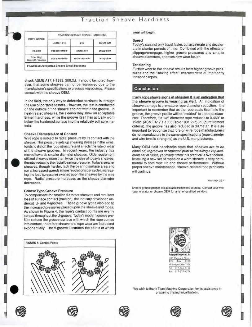
TRACTION SHEAVE BRINELL HARDNESS ROPE GRADE
UNDER 210 210 OVER220
Tfacllon not acceptable acceplabln acceptob4e
Extra High nol acceplable nol acceplable acceplable Strength Traclion
FIGURE 3: Acceptable Sheave Brinell Hardness
check ASME A 17.1-1 993, 208.2d. It should be noted, however, that some sheaves cannot be regrooved due to the manufacturer's specifications or previous regroovings. Please consult with the sheave OEM.
In the field, the only way to determine hardness is through the use of portable testers. However, the test is conducted on the outside of the sheave and not within the groove. In heal-treated sheaves, the exterior may show an acceptable Brinell hardness, while the groove itself has actually worn below the hardened surface into the relatively soft core material.
Sheave Diameter/Arc of Contact Wire rope is subject to radial pressure by its contact with the sheave. This pressure sets up shearing stresses in the wires, tends to distort the rope structure and affects the rate of wear of the sheave grooves. In recent years, the industry has moved towards smaller diameter sheaves. Older equipment utilized sheaves more than twice the size of today's sheaves, thereby reducing the radial bearing pressure. Today's smaller sheaves, though harder, lack the bearing surface area and run at increased speeds (more revolutions per cycle), increasing the load (pressure) exerted upon the sheaves by the wire rope. Radial pressure Increases as the sheave diameter decreases.
Groove Type/Groove Pressure To compensate for smaller diameter sheaves and resultant loss of surface contact (traction), the industry developed undercut U- and V-grooves. These groove types also add to the increased pressures placed upon the sheave and ropes. As shown in Figure 4, the rope's contact points are evenly spread throughout the U-groove. Today's modern groove profiles reduce the groove surface with which the rope comes into contact, therefore sheave and rope wear are increased exponentially. The V-groove illustrates the points at which
FIGURE 4: Contact Points
wear will begin.
Speed Today's cars not only travel faster, but accelerate and decelerate in shorter periods of time. Combined with the effects of slippage/creepage, higher groove pressures and smaller sheave diameters, sheaves now wear faster.
Tensioning Further wear to the sheave results from higher groove pressures and the "sawing effect" characteristic of improperly tensioned ropes.
Conclusion
If any rope shows signs of abrasion It is an indication that the sheave groove is wearing as wel l. An indication of sheave damage is premature rope diameter reduction. It is important to remember that as the rope seats itself into the groove, the groove profile will be "molded" to the rope diameter. Therefore, if a 1/2" diameter rope reduces to 0 .469" or 15/32" (ASME A17. 1-1 993Table 1001.2 (c)(29)(c) retirement criteria), the groove has also reduced in diameter. It is also important to recognize that foreign wire rope manufacturers do not manufacture to the same specifications (rope diameter and wire tensile strengths) as the U.S. manufacturers.
Many OEM field handbooks state that sheaves are to be checked, regrooved or replaced prior to installing a replacement set of ropes, yet many times this practice is overlooked. Installing a new set of ropes on a worn sheave is very detrimental to both rope life and sheave performance. Without proper sheave maintenance, sheave-related rope problems will continue.
WW-1034 3197
Sheave groove gauges are available from many sources. Contact your wire rope, elevator or sheave OEM for a list of qualified vendors.
ll~llim!JI\111.\Io-.
I 00 M.tyn.mi Street P.O Bo• 3188 Wll.lrrnpon. PA 1770 I Tel 717- 126 - ~1·16
fax 717-327-H74
We wish to thank Titan Machine Corporation lor its assistance in preparing this technical bulletin.

Technical
T e n s
Tensioning of ropes is the single most important maintenance factor in extending rope and sheave life, improving the quality of ride, meeting ASME A 17.1-1993 safety factors (refer to ASME A 17.1-1993 Table 212.3) and increasing cost savings.
When ropes are installed, they must be adjusted so that each rope takes its equal share of the total load. If ropes in a set operate under varying degrees of tension, optimum service life will not be obtained since, obviously, some ropes are performing more work than others. Ropes under the greater load will usually deteriorate first due to the load/fatigue ratio. However, due to the differential action and slippage that occurs during operation, eventually the ropes under the lighter load will wear more rapidly.
Improper tensioning not only induces short service life, but also creates uneven wear in the sheaves. Unequal tensioning causes some grooves to wear deeper than the others, creating a condition that
FIGURE 1: Differential Tensioning
Bulletin
0 n n g
cannot be remedied without regrooving or replacing the equipment. If this condition is not corrected immediately, the damage to subsequent sets of ropes will become progressively worse.
It is also important to note that before new ropes are installed, it should be made certain the condition of the grooves meets specifications (for the reasons cited above and those outlined in Bethlehem Elevator Rope Technical Bulletin No. 7 on sheave hardness), otherwise rope and sheave life will continue to deteriorate and costs will escalate.
I
Effects of Improper Tensioning
Figure 1 shows the varying effects on six ropes under differential tensioning.
Ropes 2, 4 and 6 show similar torque measurements and loads. Ropes 1 and 5 have the greatest torque and loads. Rope 3 has the least torque and load.
ROPE TORQUE TIME IN SECONDS LOAD % OF TOTAL LOAD
NO. (ft./lb.) (10 cycles) (lbs.)
1 96 12 2,070 20.8%
2 80 14 1,473 14.9%
3 76 15 1,276 12.9%
4 80 14 1,473 14.9%
5 100 11 2,142 21.6%
6 80 14 1.473 .H.9%
9,907 100.0%

Compare the extremes : ropes 3 and 5. Rope 3 holds 1 ,276 lbs. or approximately 13% of the total load. Rope 5 holds 2,142 lbs or almost 22% of the load. The difference in load is dramatic. This type · of unequal tensioning may cause:
unequal groove wear unequal rope wear slippage vibration slapping short rope and sheave life a change in safety factors
Unequal Groove Wear and Slippage
Each rope must take its equal share of the total load. Improper tensioning not only induces short service life, but also creates uneven wear in the sheave grooves, resulting in differential groove depths. This causes the ropes to operate at different speeds to compensate for the varying groove depths.
Figure 2 shows the effect of uneven tensioning on the sheave. A tight rope condition causes ropes to quickly reduce in diameter, placing excessive pressure on the sheave. If this situation is not corrected immediately, the loose ropes will slip across the groove in an attempt to adjust to the ropes that are carrying the load, resulting in extreme abrasion or a sawing effect as the loose ropes slide over the groove, as shown in Figure 3. This sliding also negatively impacts the sheave groove. In Figure 1, ropes 1 and 5 hold approximately 42% of the load, as compared with 33% for properly adjusted ropes. In time, the loose ropes will actually pass more of the load
FIGURE 2: Uneven Sheave Wear Caused by Differential Tensioning
FIGURE 3: Rope Wear Caused by Improper Tensioning
to the two carrying the greater load, due to the continued slippage and increased groove depth.
Vibration and Slapping
Due to the rope's excessive load and diameter reduction, rope and sheave wear initially occurs in the heavily-loaded ropes. The loose ropes will not reduce in diameter at the same rate, and at this time will remain closer to nominal. This is due to the difference in constructional stretch between the heavily- and lightly-loaded ropes; remember, each :ope stretches in relationship to the load placed upon 1t (refer to Bethlehem Elevator Rope Technical Bulletin No. 5 on Stretch). In this stage the heavily loaded ropes will seat themselves more deeply into the groove, causing slight abrasion. Tight ropes will eventually adjust to their "condition" and operate comfortably in conjunction with their grooves, and the rate of deterioration will slow down. At this critical juncture, proper tensioning will still resolve any future problems.
After this adjustment period, however, the loose ropes will begin to slip across the grooves in an eff~rt to equalize themselves with the tight ropes. In t1me, due to the sawing effect, the grooves will wear deeper than those of the heavily-loaded ropes, causing excessive abrasion on the loose ropes. Eventually the damage in the form of rope abrasion and diameter reduction will surpass that of the tight ropes. The ropes will become progressively loose, increasing the potential for slapping and further rope and groove damage. This situation cannot be corrected with tensioning.
If the sheave is not regrooved or replaced prior to installation of a new set of ropes, excessive vibra-
)

,f! '~ .•
Tensioning
tion will occur due to the larger diameter ropes' being installed onto a sheave with differential groove depths and differently-seated grooves. Improperly tensioned ropes create differential groove depths and differential groove profiles.
Short Rope Life
Ropes passing over a sheave with various groove depths and profiles can never be tensioned properly. The new or replacement ropes will only last a fraction of their expected service life. Each set of ropes will have progressively shorter life due to the differential grooving. Figure 3 shows four ropes that were removed after one year of service. The damage to the ropes was actually caused by poor tensioning on prior ropes; the new ropes could not be tensioned due to differential grooving. The two ropes showing extreme wear and wire breaks were loose. If new ropes are installed on a differentiallyworn sheave, the ropes will continue to saw into the grooves and a significantly shorter rope life may result.
ASME Specification
ASME A17.1-1993 1001 .2(c)(29)(a)(4) states, "if in the judgement of the inspector, any unfavorable condition, such as fretting corrosion (red dust or rouge), excessive wear of individual wires in the strands, unequal tension, poor sheave grooves etc., the criteria for broken wires will be reduced by 50% of the values indicated in Table 1001.2(c}(29}(a)." Refer to 1 001 .2(c)(29)(a) for the code in its entirety.
Excessive wear of the individual wire in the strand, unequal tension and poor sheave grooves will reduce the number of allowable broken wires by 50%, causing premature rope removal (see Figure 4).
When to Tension Ropes
Ropes must be tensioned immediately after installation; adjusted at six weeks and six months after
FIGURE 4: ASME A17.1 -1993 Table 1001.2(c)(29)(a)
CONSTRUCTION A
6x19 Class 24-30
8x19 Class 32-40
The upper limils may be used when inspections are made at least monthly by a competenl person.
installation, and checked annually. Tensioning is especially important during the rope's initial constructional stretch period (refer to Bethlehem Elevator Rope Technical Bulletin No. 5) and during the adjustment periods when problems can still be corrected. It is also important that the necessary adjustments are made by shortening the loose ropes, and not by twisting or unwinding the end of the rope, thus causing a change of the rope lay. A rope can be damaged easily in this manner, and many causes of short service have been traced to this type of misuse.
How to Tension Ropes
Prior to the removal of existing ropes and installation of new ropes, check for differential groove depths. Place a straight edge across the ropes. If the straight edge wobbles, the ropes in the middle are higher in the groove than those at the ends. If the straight edge sits across the ropes without movement, look for gaps between the ropes and the straight edge. A flashlight held behind the straight edge will aid in detecting any gaps.
The use of a small level as a straight edge is recommended. The bubble will show if the ropes are level , seated evenly and if the sheave is plumb. If the level shows that the ropes are even but not level, the sheave is on an angle. This will have the same effect on the ropes and grooves as unequally tensioned ropes. Again, in this instance, the ropes are not traveling the same distance and will try to equalize with one another.
There are only two types of tensioning methods recommended by Williamsport Wirerope Works, Inc. (WWW).
Torque Wrenches Some of the OEM's have designed torque wrenches and pressure gauges that are available to their branches . Commercially-marketed torque wrenches are also available from many suppliers.
B c 8-12 12-20
10·16 16-24

Any of these tools are acceptable and will provide accurate readings of the tension on each rope. Needed adjustments can then be made. Unfortunately, even with the availability of these inexpensive tools, many service technicians and inspectors are not aware of their existence.
Tuning Method This method of tensioning ropes without tools is accurate and has been documented mathematically. Place the car at the bottom. Remove any dampening devices from the ropes. From the top of the car, starting from either side, pull one rope back by hand in a manner which will not allow the rope to hit the adjoining rope(s). Release the rope. Using a watch's second hand, time how long it takes for the oscillation created by pulling and releasing the rope to travel up to the drive sheave and back down. Placing your thumb lightly on the rope will allow you to feel when the oscillation returns.
In buildings under 30 stories, time ten complete oscillations. Record the number of seconds it takes the oscillation to travel up and down ten times. Repeat the procedure for all ropes. The lower the number of seconds, the tighter the rope; the higher the number, the looser the rope. On a high rise above 30 stories, time five oscillations per rope.
In 2:1 double wraps, each rope must be timed in two segments. Time ten oscillations on (1) the rope before it enters the sheave on top of the car, then again on (2) the rope after it exits the sheave. Add the numbers from both segments to get the rope's actual time. Repeat for adjoining ropes.
It should be noted that the variance in the strength used to tune the ropes does not change the result. When ropes are pulled and released, an oscillation is created. These oscillations, regardless of strength variance, travel through the ropes at the same speed. It is the frequency (speed) that is being timed, not the oscillation itself. For a practical example, the same key on a piano struck at different strengths will vary the loudness (oscillation), but the tone (frequency) will not change.
Feel Method The feel method of pushing and pulling on each rope is an unacceptable and inaccurate method of tensioning for the majority of the industry. Tensioning by feel requires a skill which can only be likened to
that of a piano tuner who can expertly adjust the piano strings merely by listening to the tones produced by striking the keys. This is not a practice which can be learned; it is an innate talent.
WARNING: If a set of ropes is not properly tensioned early in its life, tensioning will become increasingly difficult and time-consuming. Multiple adjustments may be required to properly adjust a set of poorly-tensioned ropes having undergone their initial constructional stretch period.
llh iiJ .. rt )llftnJ!t'hr\s. llr
I 00 Maynard Street PO. Box 3188 Wloamsport. PA 17701
Tel 7 17-326-S I46 Fax 7 17-327-4274
WW-1035 3197
)
Technical
n F a t
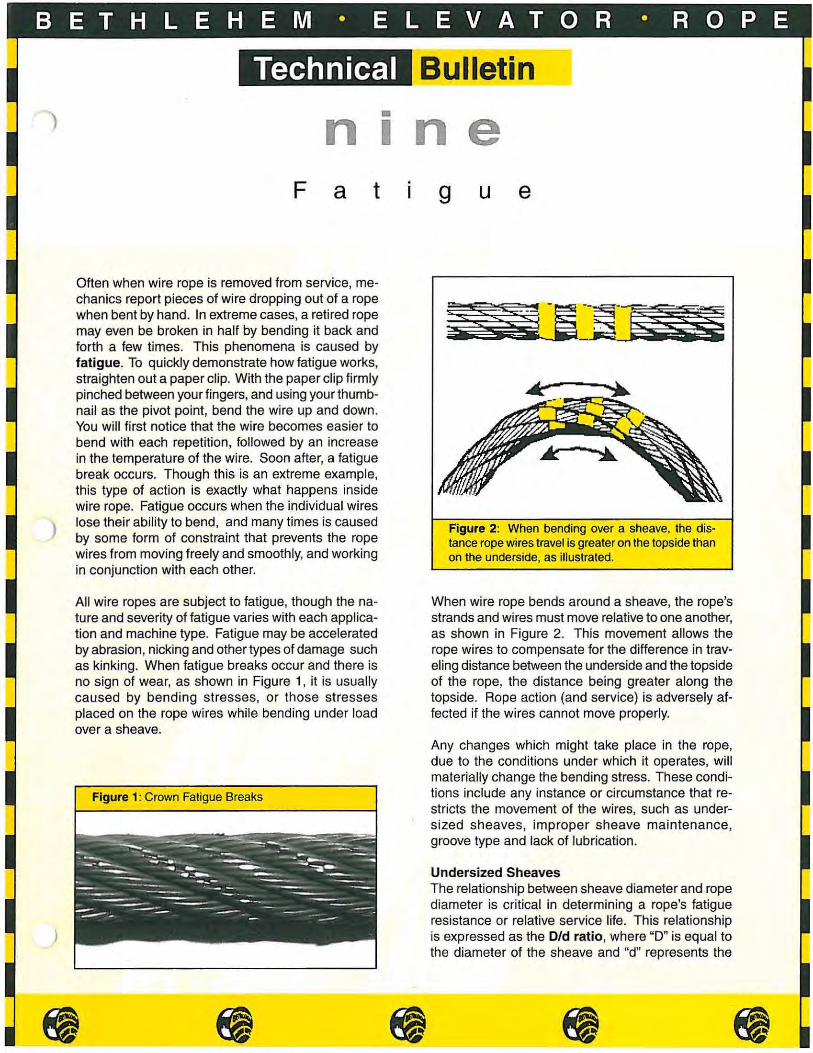
Often when wire rope is removed from service, mechanics report pieces of wire dropping out of a rope when bent by hand. In extreme cases, a retired rope may even be broken in half by bending it back and forth a few times. This phenomena is caused by fatigue. To quickly demonstrate how fatigue works, straighten out a paper clip. With the paper clip firmly pinched between your fingers, and using your thumbnail as the pivot point, bend the wire up and down. You will first notice that the wire becomes easier to bend with each repetition, followed by an increase in the temperature of the wire. Soon after, a fatigue break occurs. Though this is an extreme example, this type of action is exactly what happens inside wire rope. Fatigue occurs when the individual wires lose their ability to bend, and many times is caused by some form of constraint that prevents the rope wires from moving freely and smoothly, and working in conjunction with each other.
All wire ropes are subject to fatigue, though the nature and severity of fatigue varies with each application and machine type. Fatigue may be accelerated by abrasion, nicking and other types of damage such as kinking. When fatigue breaks occur and there is no sign of wear, as shown in Figure 1, it is usually caused by bending stresses, or those stresses placed on the rope wires while bending under load over a sheave.
Figure 1: Crown Fatigue Breaks
• I ne
g u e
Figure 2: When bending over a sheave, the distance rope wires travel is greater on the topside than on the underside, as illustrated.
When wire rope bends around a sheave, the rope's strands and wires must move relative to one another, as shown in Figure 2. This movement allows the rope wires to compensate for the difference in traveling distance between the underside and the topside of the rope, the distance being greater along the topside. Rope action (and service) is adversely affected if the wires cannot move properly.
Any changes which might take place in the rope, due to the conditions under which it operates, will materially change the bending stress. These conditions include any instance or circumstance that restricts the movement of the wires, such as undersized sheaves, improper sheave maintenance, groove type and lack of lubrication.
Undersized Sheaves The relationship between sheave diameter and rope diameter is critical in determining a rope's fatigue resistance or relative service life. This relationship is expressed as the 0/d ratio, where "D" is equal to the diameter of the sheave and "d" represents the
• • ------- ~------ -------•

Fatigue
100 l I ' I J
1---- lf-90
80 -- -- ·- ·-- - .-/ 70
Q)
5 60 Q) 0
- ~ 50 Q) (/)
~ 40
~ 30 a: 20
10
f-- ··-t--f--!--
'--- ----+---- -----
---·1--·· 17 f-- --1- 1--(---. V-t-·-f--- -b~ >----;--1---- ·t l f--~ I
10 20 30
Did Ratio
Figure 3: Service Life Curve
/! --/I
·--/ --+---~
~----1--~- -~
7 ~- --!--- -
;_
+:=~ ~ -
+-·-I-
' L-i 40 50 60
diameter of the rope. A minimum D/d ratio has a negative effect on the rope wires' ability to adjust to their ever-changing environment. The smaller the radius over which a rope passes, the greater the fatigue. ASME A 17.1 Section 208.2b Minimum Pitch Diameter references a 40:1 minimum ratio for elevator drive sheaves (suspension ropes) , and 32:1 for compensation ropes. This means, in the case of a drive sheave, the sheave diameter must, at a minimum, be 40 times the rope's diameter. Refer to Tables 1 and 2 for various D/d ratios and multipliers for hoist, compensation and governor ropes. To properly illustrate the effects of sheave diameter on wire rope performance, the wire rope industry developed the Service Life Curve (Figure 3). Following ASME specifications, a W' diameter rope working with a D/ d ratio of 40:1 (20" sheave) has a relative service life of 40 units. If the same rope works over a sheave with a D/d ratio of 55:1 (27%" sheave), its service life increases to 76.5 units. In short, the rope's service life can be increased from 40 to 76.5 units -a 91% increase - by operating on a sheave that is only 7112'' larger in diameter. Note the change in service life if an improper D/d ratio is used. With a ratio of 30:1 (15" sheave), relative service life units drop to 25. Users can anticipate a 37.5% reduction in
Table 1: Minimum Sheave Diameters
Application 3/8"
Rope Diameter
1/2" 5/8" 11/16"
Suspension Ropes 15 20 25 27.5 (40:1 D/d ratio)
Compensation Ropes 12 16 20 22 (32:1 D/d ratio)
~ ------
service life than would have been experienced had ASME specifications been followed.
Improper Sheave Maintenance Just as critical as using a proper D/d ratio is maintaining the sheaves over which a rope operates. Conditions such as tight or loose grooves, out of round sheaves, misaligned sheaves, and the like all contribute to shortened service life. In each of these examples, sheave conditions interfere with a rope's ability to adjust to its working environment. In combination with normal bending stresses, these conditions accelerate fatigue.
Groove Type To increase rope traction, the elevator industry designed a series of new groove types, i. e. V-grooves, undercut U-grooves and progressive grooves. Improved traction is a result of increased rope pressure. These designs created a trade off - increased traction for decreased service life. The pinching action of these grooves creates excessive stress on the rope wires as the pinching restrains the rope wires from properly moving. A rope operating in such a groove will have a higher occurrence of fatigue breaks than a rope operating in a U-groove, where all other conditions remain constant.
Lack Of Lubrication It stands to reason that a properly lubricated rope has greater fatigue resistance than a dry rope -properly lubricated rope wires move against and with each other with great ease as the rope passes over a sheave. An improperly lubricated rope, however, will suffer internally, particularly in the area of the core. As the core dries out, becomes hard and no longer supports the strands, the rope strands and wires begin to abrade not only against the core, but against each other as well. Both abrasion and nicking accelerate fatigue. Refer to Bethlehem Elevator Rope Technical Bulletins Two and Three for further information.
Modern elevator systems in and of themselves also cause shortened service life. Unlike some of the
Table2: ASME A17.1 Table 206.7 Multiplier For Determining Governor Sheave Pitch Diameter
Rated Speed No. Rope Strands Multiplier• (feet/minute)
6 42 200' or less
8 30
6 46 Over 200'
8 32
"multiply by the diameter of the rope
~ ~ ------- ------
)
)

)
Fatigue
aforementioned conditions, these designs e.g. multiple sheave and reverse bend configurations, cannot be avoided.
Multiple Sheave Configurations The greater the bending cycles, the greater the likelihood of fatigue breaks. Therefore, logic dictates that ropes installed on a double wrap configuration will exhibit greater fatigue than those on a single wrap. A 2:1 double wrap utilizes four sheaves, placing greater bending stresses on the rope, thus greater fatigue.
Reverse Bends From a wire rope manufacturer's point of view, reverse bends should be avoided, yet they do exist. Because of architectural designs e.g. limited space, elevator OEM's must adapt their elevator systems, usually resulting in machines that are offset from the hoistway. Any reeving arrangement that involves reverse bends (especially where sheaves, or sheaves and drum are spaced closely) causes the rope to operate at a disadvantage and results in greatly reduced rope life. A reverse bend develops when the rope bends over a sheave in one direction, then under another in the opposite direction within a short distance, as shown in Figure 6. This bending of the rope in reverse directions results in fatigue and the premature breaking of wires. In Figure 6, the rope passes over Sheave A. The topside, required to travel a greater distance around the sheave, pulls down while the underside opens up (reference Figure 2). The rope then passes under Sheave B, bending in a reverse direction. The topside rope wires, still trying to compensate for the first sheave, are now positioned on the underside and must quickly readjust again- in the opposite direction. This action places extreme pressure upon the rope wires. Actual experience and research shows that the service life of ropes subjected to reverse bends over sheaves is only about one-half of that of ropes bent
Figure 4: This 6-strand rope, showing extreme fatigue, operated in a reverse bend configuration. Note the number of crown and valley breaks.
-------•
Figure 5: Valley Fatigue Break
over a single sheave in one direction.
Multiple sheave and reverse bend configurations have an immediate, negative impact upon the service life of wire ropes. In response, WWW developed a hoist rope called Liftpac ™. Littpac is designed for difficult applications such as those found with 2:1 double wraps and reverse bend configurations, and provides a 200%+ increase in service life in these applications.
Fatigue breaks can occur both on the crown (that which contacts the sheave) and in the valleys (reference Figures 5, 7 and 9). Crown fatigue breaks typically occur as a result of abrasive wear against the sheave. l.n most instances, under normal operating conditions, users will first see appreciable surface wear, followed by crown fatigue breakage. Though
Figure 6: In a reverse bend configuration, a rope operates in an "S" pattern either horizontally or vertically.
( B

Fatigue
--Crown
Figure 7: Crown and Valley Wires
the industry considers these to be true abrasion breaks, they are not. When examined under amicroscope, it is clearly evident they are actually fatigue breaks resulting from abrasion, as shown in Figure 8. In the event breaks occur on the crown, and little to no surface wear is present, these breaks are true fatigue breaks and are most common in ropes operating in reverse bend configurations or on sheaves equipped with sheave liners.
Internal wires are not subjected to the same external forces, but may be subjected to internal forces. These internal forces may be in the form of interstrand contact due to a reduction in core support over the life of the rope. Fatigue breaks will occur at these contact points and are identified as valley breaks.
Figure 8: Both photos illustrate fatigue breaks. The fatigue break on the left is caused by abrasion, and is normally found on crown wires. To the right is a true fatigue break typically found to be the cause of valley breaks.
Figure 9: A valley break is highlighted above. The break originates in the valley.
A valley break is defined as a wire break in between two adjoining strands. If a valley break is found, it is almost always due to fatigue and is a strong indication internal rope wires are fatiguing as well. ASME A 17.1 Section 1 001 .2(c)(29)(a)(5) states 'if there is more than one valley break per rope lay the ropes must be removed.' If two or more valley breaks exist, the rope is fatiguing internally. Valley breaks are difficult to detect because of their location, poor lighting in the shaft and lubricant on the ropes. While wire breaks protrude in non-preformed ropes, in preformed ropes wire breaks may either lie flat or be slightly raised. With a pocket screwdriver or knife, try to lift the broken wire. If it can be lifted out of place and the break originates in the valley of the strands as shown in Figure 9, this is considered a valley break.
WW-1 041 9/98
~ilb111.ptrt lfirmpe Wuh. ltr.
I 00 Maynard Street PO Box 3 188 Williamsport, PA I 770 I
Tel: 717-326-51 46
Fax: 717-327 -4274
-------• )

Technical Bulletin
Sheaves and Grooves
Over the past few decades, elevator system equipment has become more compact in the quest for decreased power consumption, reduced equipment costs and increased space util ization. The key to this downsizing is the drive sheave, which must be manufactured in smaller diameters to accommodate this trend. Technical Bulletin No. Ten shows how this downsizing has adversely affected wire rope and sheave life through changes to the sheaves, and ad· dresses the superin1endent who says , hey don't make ropes like they used to; and "I've never EVER had to regroove a sheave:
Rope Performance
Groove Types
The U-g100Ve Sheave The U-groove sheave, found predominantly in older inst~llations, is the sheave of choice for optimum rope life. Its large size (when compared with the drive sheave diameters in newer installations) in combination with its supportive grooves minimizes abrasion and fatigue.
Rgure 1 illustrates the support given to the rope by the groove. Note the large groove area with which the rope comes into contact (A to B). The groove cradles the rope, resulting in low groove pressures that allow the wires and strands to move about freely while the rope is operating. Also paramount to the U-groove's sucoess in achieving excellent rope life is the relative diameter of the sheave required to maintain traction. The larger Did ratio makes bending easier, provides a large arc of contaCt between rope and sheave, reduces operating stresses, and generally optimizes rope life. Refer to Bethlehem 8evator Rope Technical Bulletin No. Nine on Fatigue for further information on D/d ratios.
Unfortunately, the U·grooved sheave with its large diameter also provides the least amount of traction. Hence, the U·grooved sheave, the favorite among wire
Rgure 1 The U-grooved sheave provides full support to the rope with its large aro of contact.
• Figure 2 In the Undercut Ugrooved sheave, note the decrease coming in contact with the sheave.
Figure 3 • When the size of the
undercut is increased. bearing pressure grows as the rope-to· sheave contact declines.
Figure 4 V-grooved sheaves provide the greatest amount of bearing pressures and rope wear.
PAGE 5

Quick Review rope manufacturers. has lost popularity in favor of other types of grooved sheaves that can increase traction and be downsized at the same time.
In general, the modern grooves -Undercut U and Progressive V -increase traction by increasing groove pressures. The beauty of these groove types is that the diameter of the sheave utilizing this modern groove design can be reduced. ·why? With an increase in rope-to-sheave contact pressure, created by the gripping action (or rope pinching) of the groove, a large arc of contact is not needed to sustain traction.
The Undercut U-groove Sheave IJIJith the reduction in sheave diameter comes a loss of contact area between rope and sheave. To compensate for this loss of contact, and traction, an undercut is placed in the grocJV<:? (Rgure 2). \,Nhen com-
Wire ropes are harder then the sheaves on which they operate. As the ropes operate. they decrease in diameter and machine themselves into the grooves, thus decreasing the diameter of the grooves. When the next set of ropes is installed, the new set of ropes with its new nominal + 2~~% -0% diameter, is forced to operate in grooves •machined" by the previous set of ropes. The second set of ropes will not perform as well as the first, and each subsequent set will perform more poorly than the last. It is not uncommon to hear that the first set of ropes lasted 18 years. while the last set had to be retired after only a few years. Refer to Bethlehem Elevator Rope Technical Bulletin No. Seven on Sheave Hardness for fur-
of pressure on the ropes and sheave grooves, resulting in the greatest amount of traction. but also the greatest amount of rope abrasion. V-grooves increase the bearing pressure on the rope. resulting in shorter rope service life. Because of the increased groove pressures. it is imperative to use a rope that is designed to maintain its roundness.
Undercut u- and V-grooved sheaves adversely affect rope performance. But because these grooves Increase traction and therefore do not require a large diameter sheave, these groove types are more attractive to elevator system designers.
Position of the Secondary Sheave
ther information.
pared •Nith the U-groove in Figure 1, the surface area of the rope making contact with the Undercut U-groove decreases (A to B and C to D). Note the undercut where the rope no longer makes contact with the groove (8 to C). Groove pressure is increased as the rope is ~gripped" to provide the traction required for effective operation. These increased stresses lead to accelerated wear of the vvires and sheave at the points of contact and increased wire fatigue breakage in these areas.
Note the size of undercut in Rgure 3. Its larger size further reduces the area of contact between rope and groove. As undercuts become larger, groove pressures mount, traction increases, and unfortunately, rope and sheave wear and rope fatigue accelerates.
The V- or Progressive V-groove Sheave The V-groove is the ultimate groove for traction. The angle of the groove affects rope traction and performance. Generally, the angle of a V-groove is between 32° and 40°. This measurement is the included angle of both sides of the groove. Traction increases with the decreasing groove angle.
f\lote in Figure 4 (A to 8 and C to D) how little of the rope makes contact with the Sllliace of the sheave groove. This type of groove places the greatest amount
-.... \. __ -..
Compact elevator system designs have created some rather unique reeving configurations, the effects
of which are covered in Bethlehem Elevator Rope Technical Bulletin No. Nir1e on Fatigue. For the purpose of this bulletin, we will focus on one aspect of the nev.• configurations - the position of the secondary sheave.
The proximity of the secondary or deflection sheave to the drive sheave is critical for two reasons: (1; bending cycles. and (2) fle<3t angle.
Bending cycles 'v'Jire rope is actually a machine with a multitude of moving parts. For example, an 8x19 Seale has 152 moving parts (8 strands. 19 wires per strand) that must be work in conjunction with not only each other. but also with external forces. such as sheaves. The rope's 152 wire and strand components continually adjust and readjust as the rope moves over a sheave and then straightens. When a wire rope operates over multiple sheaves, more work is required of the rope's components as the wires and strands adjust to the additional bending cycles. For example. ropes installed on a 2:1 Double Wrap system have a greater number of bending cyclas than ropes on a Single Wrap system. To achievo? optimum ro~ life. it is advisable to have at least three to four rope lay lengths between sheaves to allow the wires and strands the necessary recovery distance between bends. Nevertheless.
.......
PAGE 6
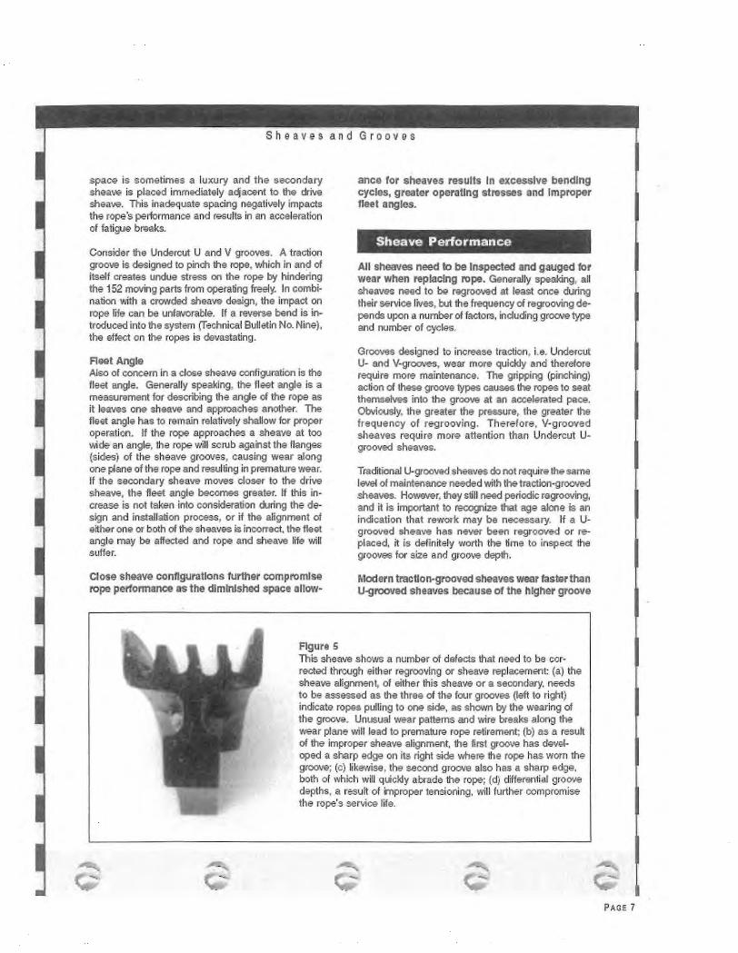
space is sometimes a luxury and the secondary sheave is placed immediately adjacent to the drive sheave. This inadequate spacing negatively impacts the rope's performance and results in an acceleration of fatigue breaks.
Consider the Undercut U and V grooves. A traction groove is designed to pinch the rope, which in and of itself creates undue stress on the rope by hindering the 152 moving parts from operating freely. In combination with a crowded sheave design, the impact on rope life can be unfavorable. If a reverse bend is in~ troduced into the system (fechnical Bulletin No. Nine), the effect on the ropes is devastating.
Fleet Angle Also of concern in a close sheave configuration is the fleet angle. Generally speaking, the fleet angle is a measurement for describing the angle of the rope as it leaves one sheave and approaches another. The fleet angle has to remain relatively shallow for proper operation. If the rope approaches a sheave at too wide an angle, the rope will scrub against the flanges (sides) of the sheave grooves, causing wear along one plane of the rope and resulting in premature wear. If the secondary sheave moves closer to the drive sheave, the fleet angle becomes greater. If this increase is not taken into consideration during the design and installation process, or if the alignment of either one or both of the sheaves is incorrect , the fleet angle may be affected and rope and sheave life will suffer.
Close sheave configurations further compromise rope performance as the diminished space allow-
Figures
ance for sheaves results In excessive bending cycles, greater operaUng stresses and Improper fleet angles.
Sheave Performance
All sheaves need to be Inspected and gauged for wear when replacing rope. Generally speaking, all sheaves need to be regrooved at least once during !heir service lives, but the frequency of regrooving depends upon a number of factors, including groove type and number of cycles.
Grooves designed to increase traction, i.e. Undercut U- and V-grooves, wear more quickly and therefore require more maintenance. The gripping (pinching) action of these groove types causes the ropes to seat themselves into the groove at an accelerated pace. Obviously, the greater the pressure, the greater the frequency of regrooving . Therefore, V·grooved sheaves require more attention than Undercut Ugrooved sheaves.
Traditional U-grooved sheaves do not require the same level of maintenance needed with the traction-grooved sheaves. However, they still need periodic regrooving, and it is important to recognize that age alone is an indication that rework may be necessary. If a Ugrooved sheave has never been regrooved or replaced, it is definitely worth the time to inspect the grooves for size and groove depth.
Modern traction-grooved sheaves wear raster than U-grooved sheaves because of the higher groove
This sheave shows a number of defects that need to be corrected through either regrooving or sheave replacement (a) the sheave alignment, of either this sheave or a secondary. needs to be assessed as the three of the four grooves {left to right) indicate ropes pulling to one side. as shown by the wearing of the groove. Unusual wear patterns and wire breaks along the wear plane will lead to premature rope retirement; (b) as a result of the improper sheave alignment, the first groove has developed a sharp edge on its right side where the rope has worn the groove; (c) likewise, the second groove also has a sharp edge, both of which w ill quickly abrade the rope; (d) differential groove depths, a result of improper tensioning, will further compromise the rope's service life.
........ .... -
PAGE 7

pressures placed on the ropes.
Conclusion
In the good ol' days, servicing the large, expansive ·elevator systems with their U-grooved sheaves was relatively predictable. Initially. the systems were costly, but ropes and sheaves lasted "forever." Today, the downsizing trend in new constr.uction and modernization is effectively holding down costs on the front end, but this push towards smaller systems is adversely affecting wire rope and sheave life, and can be costly on the back end lf these changes go unrecognized.
Service superintendents must acknowledge (a) elevator systems are changing, and (b) existing equipment is aging, and remember that there is a direct relationship between sheave and rope. These new challenges to the service industry mean that cfose attdntion must be paid to the reeving configuration, size and groove type of the drive sheave, the age of the equipment, past maintenance records, and the effect all of this has on wire rope life. Especially when bidding for a new service contract, more consideration needs to be given to the condition of the sheaves. It could mean tha difference between profit and loss.
Wlllamsport Wllerope Works, Inc. manufacturer or Betr.Jehem Wire Rope.r.
T 00 Maynard Street Williamsport f'emsytvania 17701 USA
telephone. 570-326-5146 facsirnile 570-326-4274
h t rp://'WV•W.V,W\Mop€ .COm
~ -·-Wlre rq>?pt:<lreb '61lltfoalrllabuoe<l,ml!lllleda"''&ruee<l. ClJMUtlndlWJISOOrmlenc»~mooSHAotanaer(bblltfi?u.IJ'9. Wllla11'6J.'<f!Wlr~W>J1Cs. lnc ... -an;;nl!laii BQtrj;lli)J'OWI'o Rq~~Ar>:l SIJaro Pr«<udrl. ltloN>'Or, anrwanenlj', "'P"'....,"''I!If.ll;d•• toquauy. pe<I«J!W"O?a l11rF.<ia "'...,., •• uer'!>" ltsJoiaraPremlw.l c<>11>9 <>:n111tmlllat tllaput:Ar.ha1 "'''"""9 stlln(ltro •Prly <XI'/ IDnn, uJIU5<(! J'Of'>. mttne rnect<lllltol~upmont.:n,.·nrcn .,Cilf<odU<lsara U<F.G Ia prowry ~nod mo mBin1arnoo. matou:nprodUotl are Ff<p;!ti !oiOJ€<1, nanare<l. 1e<1 ana mtln\91J>!d. and f"9"il' lf"6P'CE<l on a 011Jll1r bOSI!i rumg lle porlld oru .... Mtnubo111r«ohall noU» llotlo> 1« COO<OqE<ll!alor lnel-tal ~•or ...xmsry en.~ IJ>dU<If'6 t<Jtn<t IIITIIMI<l I""I!M•rlnjurt raDe<ooot&. a looool~ro~l"'--<llmQWtll11 1119 uaeotuldp<oducl&c.r nomam:J JI•:dlcts tet>glrmrpua'"dlnor boc<!mlnga o:mp<nentclall)' Ffe<luct Qell~;Mmwre A ore. lle e.ltiohOOl \l\1r,;. Ropo""" bgO. ollltne www r.~o ""' "'J!!tl!te<lll<lden>ul'.s ofl'lllromsp:>rtl'.1101~f'<' l '<bll<O.Ino. Belhli>l'em g "''"" Ripe ore W'INI ~aO>marls.
WIIL9m>p<nwter<9&Yiooo. rro.c ~co
-... ....... --.
. - .... .......
PAGE 8

-'
-.
Technical Bulletin
el n Vibration
Vibration, or rope chatter, is a leading cause of early rope wear and deterioratinn. Most complaints regard· ing •noisy ropes" occur very quickly after the ropes have been installed, and can be found in all types of equipment, reeving and groove configurations. Rope chatter may intensify at various speeds, and will be emitted throughout the elevator system. There may not be any complaints from riders, but complaints can be expected from the building manager.
Sheave-related Causes
Rope-to-Groove Mismatch The most common reason for vibration is a size differ~
entia! between rope and groove. New ropes are manu· factored to a defined oversize diameter tolerance. For example, Bethlehem Wire Rope• on-tension diameter readings for new rope range between 00/o and 3% oversize. Unforttmatety, the grooves in which new ropes operate may not have been checked and regrooved prior to rope installation. lf the previous set of rope was retired for minimum diameter readings, the grooves1 now wom to the rope's diameter; can be up to 8% below nominal. This creates a substantial mismatch in rope-to-groove size. As the drive rotates, operating pressures force the rope into the groove, causing the snapping or chattering sound. Not only does this prematurely wear the rope, it also -reworks• the groove. The result, along with noise, is shorter rope and sheave life, and the telltale metallic dust bui[dup on the ropes, grooves and machine room floor.
To inspect for this problem, use a groove gauge to measure all the grooves, including the secondary if applicable. Based on the actual rope diameters, it may be necessary to rework or possibly replace the sheaves. Where chatter is present but not excessive, a light application of field dressing may allow the rope to •fit• more quickly into the groove. This is not to say, however, that new ropes need an applicatron of field dressing. In tl'lis example, field dressing is lightly a~ pned only to quiet the rope in question. Contact the wire rope manufacturer before applying any lubricant
.....
on newly installed ropes. It should be noted that an Sx19 construC'I[on rope is less likely than a 6x25 rope to chatter because it has more of a tendency (due to less metallic area) to squeeze into the worn groove.
Differential Groove Depths Another cause of vibration can be attributed to differ· entlal groove depths. When a groove is wom, the rope in that particular groove travels over a slightly smaller radius than it would if the groove were closer to nominal. Naturally, the greater 1he groove wear, the smaOer the radius as the rope wears closer to the center of the sheave. This becomes an issue when ropes, fixed at both ends, are used in a set. When one rope in a set operates over a slightly smaller ra· dius in a wom groove, the other ropes must travel a greater distance to 'catch-up• to the first rope. The "catch·up" is what causes snapping, popping. chat· taring and/or vibration. Even .a small difference in groove depths will create this condition. Consider this - one groove is worn only 1116" below the other grooves. A deviation of 1/16" on a24" diameter sheave calct.llates to a difference in rope travel of 3116 .. for each rotation, or 0.26% between ropes. If the length of the ropes is 500 feet, the variation in travel between ropes is 15.6 inches. Imagine the chaos if aft of the grooves are machined to varying depths. The ropes may eventually balance out, however, where and how they balance out may be reflected in unusual rope movement at the end of the hoist cycle, and certainty seen in shortened service life.
The best way to check for differential groove depths is with a straight-edge placed on top of the rope sur~ faces at the drive sheave. If the straight-edge does not contact all of the ropes, unequal groove depth is indicated. Where ropes are seated into the grooves so that using a straight-edge is impractical, a depth gauge or some other similar device can be used. The intent is to determine not only if differential groove depths exist, but to what degree.
Most of the elevator OEM's dictate the amount of groove depth allowed per type of groove and system .
PAGE 5

In addition, ASME A17.1 states under rule 208.2d, .. sheaves and drums shall be permenentJy and legibly marked to state the minimum groove bottom diameter permissible for regrooving and required to maintan structural integrity." The concern with regrooving too often is the potential to machine away the hardened steel, exposing the softer steel beneath the surface. As the rope wears into the sheave, the remaining hardness of the groove may vary, causing accelerated wear and deterioration of both rope and sheave. Further information on this is addressed in Bethlehem Elevator Rope Technical Bulletin No. 7 on Traction Sheave Hardness.
Harmonics In some cases, vibration is the result of the rope's natural harmonics as it operates between the drive sheave and the secondary. A change in distance between the sheaves. if possible, alters the frequency and amplitude and can quite possibly reduce or eliminate the vibration.
Other Causes
Rope Stretch On high rise, high speed equipment , vibration can come from another source. As discussed ·in the Bethlehem Wire Ropel1j Elevator Catalog, wire rope is an elastic member and is subjected to various elements of stretch - constructional, elastic, and dynamic. Constructional and elastic stretch values are well documented. Stretch due to dynamic load changes, however, is not as readily defined or understood. When a high speed car accelerates and decelerates, the changes in the dynamic loading can be quite significant. The acceleration stress is influenced by the suspended weight, rope weight, car acceleration, maxi· mum speed and period of acceleration. Not only will
this phenomenon be seen in the rope stretch, but also exhibited by the snapping and chatter between ropes and grooves.
Mechanical Issues There are also many installation and mechanical issues in the elevator system which can cause the ropes to vibrate. Several of these include sheave misalignment, unequal rope tensioning, and bad sheave bear· ings. There may be misalignment in the rail guides which causes a ~bump~ every t ime the rollers pass over this area. Electrical or motor issues may also be contributing to an inconsistent motion that will be transferred to the hoist ropes.
Conclusion
When vibration occurs, the culprit is always perceived to be the ropes. There have been many cases in which new ropes were replaced, only to discover the prob-lem still existed. Vibration is rarely caused by wire rope; rope chatter is merely a symptom of a larger issue. The majority of vibration complaints occur as a result of some type of problem with the sheaves.
WW'W cannot stress enough the importance of checking the sheaves before raroping a car. An expressfon frequently used in business is "pay me now, or pay me later." But where sheaves are concerned, it is not an equal trade-off. If bad sheaves are present, an inordinate amount of time and money will be spent investigating the problem, handling complaints, replacing parts, and the like. And nothing gets the building tenants' attention faster than rope chatter! Service contracts cannot be profitable it sheaves are not properly maintained. A simple check of the sheaves before installation may make the difference!
Williamsport Wlrerope Works, Inc. manufacturer of Bethlehem Wlre Ro_oe·•
I oo Maynaro Str~t Wd:lamsport Pernsjlvania I 770 I USA
international. 570-326-51 <16 inslce tl':-e U.S.: 800-541-7673
facsimile 570-326-4274 h rrp 1/IM'WV.W'MMopc. com
PAGE 6


