Embed Size (px)
Citation preview
OCTOBER 1983
ELECTRONICS WITHOUT TEARS HOME STUDY COURSE-TEACH-IN 84
TARTS THIS MONTH
40 20 10
SHORT WAVE RADIO Australia $1.60 Now Zsalared 81.80 Malaysia 84.98 16 £1.30 tine VAT.)

el tro tze AUTO -ELECTRONIC PRODUCTS KITS OR READY BtInT
TOTAL ENERGY DISCHARGE ELECTRONIC IGNITION
Thelon ratStriATICA
'
IS
YOUR CAR
AS GOOD AS IT COULD BE? Is it EASY TO START in the cold and the damp? Total Energy Discharge will give the most powerful spark and maintain full output even with a near flat battery.
* Is it ECONOMICAL or does it "go off" between servic rs the ignition performance deteriorates? Total Energy Discharge gives much more output and maintains it from service to service.
* Has it PEAK PERFORMANCE or is it flat at tech and low revs. where the ignition output is marginal? Total Energy Discharge gives a more powerful spark from idle to the engines maximum (even with 8 cylinders).
Is the PERFORMANCE SMOOTH. The more powerful spark of Total Energy Discharge eliminates the "near misfires" whilst an electronic filter smoothes out the effects of contact bounce etc.
Do the PLUGS and POINTS .always need changing to bring the engine back to its best?. Total pitiogg y Discharge eliminates contact arcing and erosion by removing the heavy electrical load. The timing stays "s "4,ancf the contact condition doesn't affect the performan er. Larger plug gaps can be used, even wet or badly fouled plugs can be fired with this system.
TOTAL ENERGY DISCHARGE is a unique system and the most powerful on the market - 31/2 times the power of inductive systems - 3/a times the energy and 3 times the duration of ordinary capacitive systems. These are the facts: Performance at only 6 volts.(max. supply 16 volts) SPARK PO WER — 140 W, SPARK ENERGY — 36mJ SPARK DURATION — 5001,jS, STORED ENERGY — 135mJ LOADED OUTPUT VOLTAGE
50pF load — 38kV , 50pF + 500k — 26kV
We challenge any manufacturer to publish better performance figures. Before you buy any other make, ask for the facts, its probably only an inductive system. But if an inductive system is what you really want, we'll still give you a good deal.
* All ELECTRONIZE electronic ignitions feature: EASY FITTING, STANDARDIELECTRONIC CHANGEOVER SWITCH, STATIC TIMING LIGHT and DESIGNED IN RELIABILITY (14 years experience and a 3 year guarantee).
IN KIT FORM it provides a top performance system at less than half the price of comparable ready built units.The kit includes: pre-drilled fibreglass PCB, pre-wound and varnished ferrite transformer, high quality 21iF discharge capacitor, case, easy to follow instructions, solder and everything needed to build and fit to your car. All you heed is a soldering iron and a few basic tools.
Most NE W CARS already have electronic ignition. Update YOUR CAR
fill in the coupon and send to:
PROTECT YOUR CAR WITH AN EtECTRONIZE
ELECTRONIC ALARM
2000 COMBINATIONS provided by an electronic key - a miniature jack plug containing components which must match
each individual alarm system. (Not limited to a few hundred keys or a four bit code).
60 SECOND ALARM PERIOD flashes headlights and sounds horn, then resets ready to operate again if needed.
10 SECOND ENTRY DELAY allows owner to dis-arm the system, by inserting the key plug into a dashboard mounted socket, before the alarm sounds. (No holes in external bodywork, fiddly code systems or hidden switches). Re-closing the door will not cancel the alarm, before or after it sounds, the key plug must be used.
INSTANT ALARM OPERATION triggered by accessories or bonnet/boot opening.
30 SECOND DELAY when system is armed allows owner to lock doors etc.
DISABLES IGNITION SYSTEM when alarm is armed.
IN KIT FORM it provides a high level of protection at a really low cost. The kit includes everything needed, the case, fibreglass PCB, CMOS IC's, random selection resistors to set the combination, in fact everything down to the last nut and washer plus easy to follow instructions.
FITS ALL 12 VOLT NEGATIVE EARTH VEHICLES. SUPPLIED COMPLETE WITH ALL NECESSARY LEADS AND CONNECTORS PLUS TWO KEY PLUGS
Don't Wait Until Its too Late - Fit one NO W!
ELECTRONIZE DESIGN Dept C Magnus Rd • Wilnecote • Ta m worth B77 5BY • te( 0827 281000
TOTAL ENERGY DISCHARGE (6 or 12 volt negative earth)
O Asse mbled ready to fit £2.100 £19.95
F7 D.I.Y. parts kit £1,5 40 £14.95
TWIN OUTPUT for cars and motor cycles with dual ignition
n Twin, Asse mbled ready to fit £3545 £29.95
n Twin, D.I.Y. parts kit £24:55 £22.95
PLEASE SEND MORE INFORMATION
CAR ALAR M
I Asse mbled ready to fit £3795
D.I.Y. parts kit £24.95
I enclose cheque/postal order OR debit my Access/Visa card
VISA 11111 11111_1111'!I Name
Address
Goods normally despatched within 7 days.
Prices Include VAT. P+P £1-00 (UK) Code
EVERYDAY
ELECTRONICS and computer PROJECTS
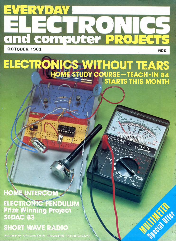
VOL. 12 NO. 10 OCTOBER 1983
PROJECTS . . . THEORY. . . NE WS . . . COMMENT... POPULAR FEATURES...
C IPC Magazines Limited 1983. Copyright in all drawings, photographs and articles published in EVERYDAY ELECTRONICS is fully protected, and reproduction or imitations in whole or in part are expressly forbidden.
PROJECTS HO ME INTERCO M by R. A. Penfold 626 Two-station room-to-room communication
IM MERSION HEATER TELL-TALE by T. R. de Vaux Balbirnie 630 Monitors level of hot water in cylinder
MODEL CAR "PETROL TANK" by A. P. Donleavey 640 Added realism for two-car slot racing
TE MPERATURE TRANSDUCER AMPLIFIER by A. A. Chanerley 646 For use with analogue meter or computer via an ADC
SHORT W AVE RADIO by R. A. Penfold 664 Simple t.r.f. receiver covering 1.5MHz to 30MHz
ELECTRONIC PENDULU M by M. Cragg 670 Determines the acceleration due to gravity
DIGITAL TO ANALOGUE BOARD by J. Adams & G. M. Feather 652 HIGH PO WER DAC DRIVER BOARD by J. Adams & G. M. Feather 655
SERIES TEACH-IN 84 by G. Hylton 634 Part 1: AC., D.C., and Signals
MICROCO MPUTER INTERFACING TECHNIQUES by J. Adams & G. M. Feather 650 Part 4: Digital-to-Analogue Conversion
CO MPUTER AIDED EXPERI MENTS by A. A. Chanerley 674 Part 2: Naphthalene cooling characteristic
FEATURES EDITORIAL Without Tears; Wider Scope For Schools SHOP TALK by Dave Barrington Product news and component buying
COUNTER INTELLIGENCE by Paul Young A retailer comments
PLEASE TAKE NOTE Car Intruder Alarm
SEDAC 1984 BOOK REVIE WS A selection of recent releases
FOR YOUR ENTERTAIN MENT by Barry Fox Technology; Digital War
SPECIAL OFFER Eagle KEW 7S multimeter
RADIO W ORLD by Pat Hawker G3VA All Change; Merriman Report; Signals From Space
EVERYDAY NE WS What's happening in the world of electronics
READERS' LETTERS Your news and views
CIRCUIT EXCHANGE A forum for readers' ideas SQUARE ONE Beginners' Page: Switches
NE W PRODUCTS Facts and photos of instruments, equipments and tools
625
629
633
644
645
648
649
657
659
660
662
663,678
668
676
Our November 1983 issue will be published on Friday, October 21. See page 658 for details. Readers' Services • Editorial and Advertisement Departments 625
Everyday Electronics, October 1983 617
TWO FABULOUS OFFERS FROM
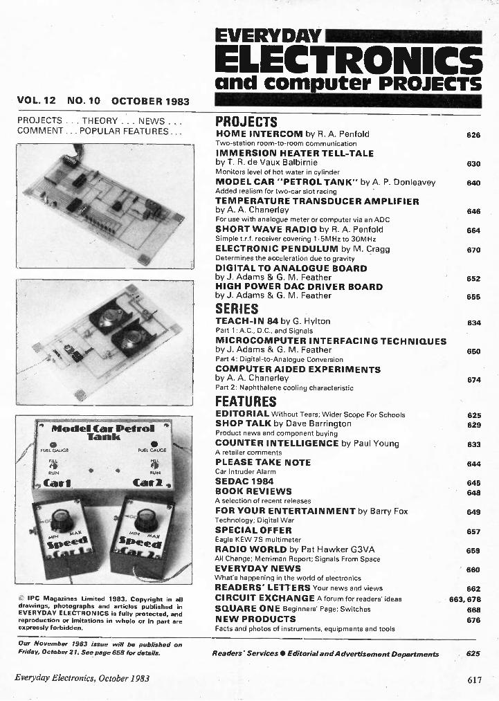
SUPER 20 201d2TV a.c. & d.c.
A SUPER PROTECTED UNIVERSAL MULTIMETER
Undestructible, with auto-matic protection on all ranges but 10A.
ONLY £33.50 inc. VAT, P&P, complete with carrying case, leads and instructions.
This special offers is a wonderful opportunity to acquire an essential piece of test gear with a saving of nearly £20.00.
Accuracy: d.c. ranges and fl, 2% a.c. 3% (of f.s.d.) 39 ranges: d.c. V 100mV, 1 OV, 3 OV, 10V, 30V, 100V, 300V, 1000V.
d.c. I 50i.LA, 100p.A, 300µA, 1.0µmA,3mA, 10mA, 30mA, 100mA, 1A, 10A a.c. V 10V, 30V, 100V, 300V, 1000V. a.c. I 3mA, 10mA, 30mA, 100mA, 1.0A, 10A. SI 0-5.0)(11, 0-50I a 0-500k1, dB from -10 to +61 in 5 ranges.
Dimensions: 105 x 130 x 40mm.
M• 20 Super
• miseic
TESTER 50 39 ranges 501d1 V a.c. and d.c. With protective diodes and quick-acting 1.25A fuse. THE PROFESSIONAL SOLUTION TO GENERAL MEASUREMENT PROBLEMS
ONLY £36.30 incl. VAT, P&P, complete with
carrying case, leads and instructions. Goods normally by return of post.
The best instrument for the workshop, school, toolbox, TV shop and anywhere accurate measurement is needed quickly and simply. Accuracy: d.c. ranges and 2% a.c. 3% (off.s.d) 39 ranges: d.c. V 150mV, 1V, 3V, by, 30V, 100V, 300V, 1000V;
d.c. I 20p.A, 100µA,300µA, 1.0mA, 3mA, 10mA, 30mA, 100mA, 1A, 3A. a.c. V by, 30V, 100V, 300V, 1000V; a.c. I 3mA, 10mA, 30mA, 100mA, 1A, 3A. Ohms 5kf0, 50kO, 500kf0, 5M11, 50MCl. dB from -10 to +61 in 5 ranges.
Dimensions: 105 x 130 x 40mm.
For details of these and the many other instruments in the Alcon range, including multimeters, components measuring, automotive and elec-tronic instruments, please write or telephone:
Instru ments Ltd.
19 MULBERRY WALK LONDON SW3 6DZ TEL: 01-352 1897 TELEX: 918867
M E V Er.ii
I E ili . LIP ... : nl EF-xsi .i1.1, El E .1_, "1 • '
.F. , ....
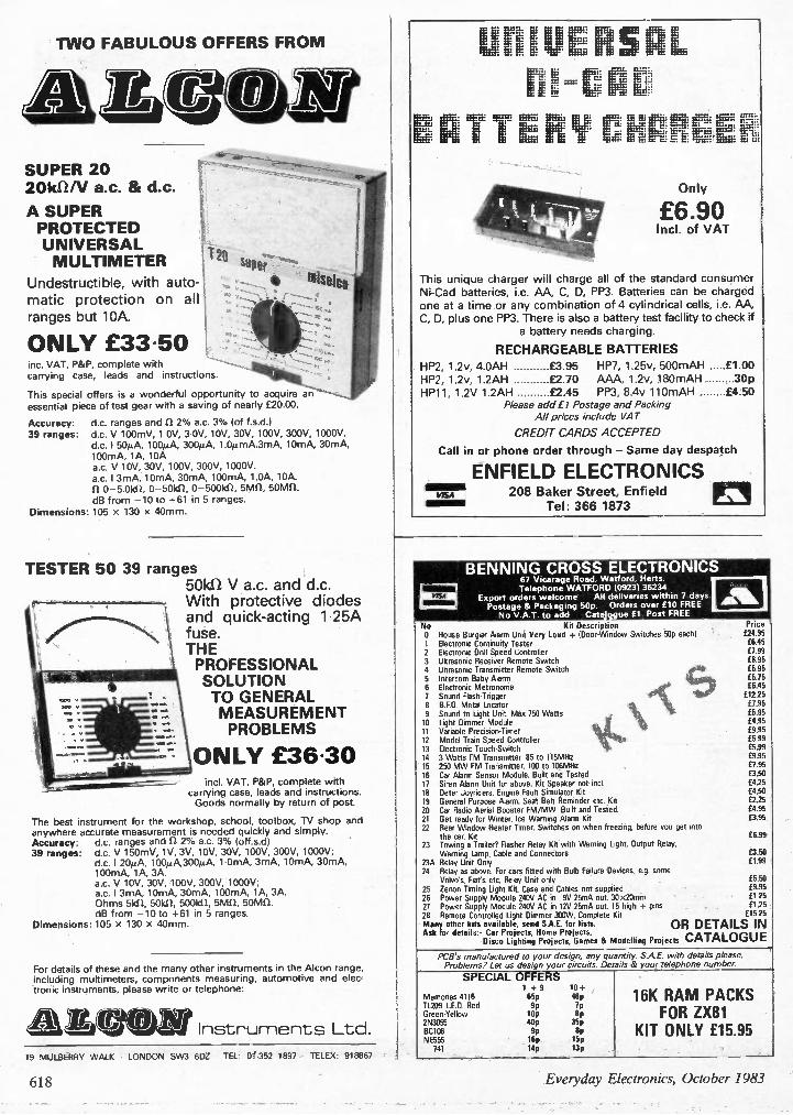
This unique charger will charge all
Ni-Cad batteries, i.e. AA, C, D, PP3. one at a time or any combination
C, D, plus one PP3. There is also a battery a battery needs
RECHARGEABLE
HP2, 1.2v, 4.0AH £3.95 HP7,
HP2, 1.2v, 1.2AH £2.70 AAA, HP11, 1.2V 1.2AH £2.45 PP3,
Please add fl Postage AH prices include
CREDIT CARDS ACCEPTED
Call in or phone order through
ENFIELD ELECTRONICS
. . E Iii fj,..:. . Eff....: 4.:_-=:.
Only
£6.90 Incl. of VAT
of the standard consumer Batteries can be charged
of 4 cylindrical cells, i.e. AA, test facility to check if
charging.
BATTERIES
1.25v, 500mAH £1.00
1.2v, 180mAH 30p 8.4v 110mAH £4.50
and Packing VAT
- Same day despatch
Enfield VISA 208 Baker Street,
Tel: 366 1873
• BENNING CROSS ELECTRONICS 67 Vicarage Road, Watford, Herts.
, Telephone WATFORD 109231 36234 Export orders welcome All deliveries within 7 deys.
FREE Postage & Packaging 50p. Orders over £10 No V.A.T. to add Catalogue Et. Post FREE
No Kit Description Price 0 House Burglar Alarm Unit Very Loud + (Door-Window Switches 50p each) £24.95 1 Electronic Continuity Tester £6.45 2 Electronic Drill Speed Controller £7.99 3 Ultrasonic Receiver Remote Switch £8.95 4 Ultrasonic Transmitter Remote Switch £6.95 5 Intercom Baby Alarm 6 Electronic Metronome £6.45
4°I c 1111 1
7 Sound Rash-Trigger £12.25 8 B.F.O. Metal Locator £7.95 9 Sound to Light Unit Max 750 Watts £6.95 10 Light Dimmer Module \ £4.95 11 Variable Precision-Timer f9.95 12 Model Train Speed Controller £5.99 13 Electronic Touch-Switch £5.99 14 3 Watts FM Transmitter. 85 to 115MHz £9.95 15 250 MW FM Transmitter. 100 to 106MHz £7.95 16 Car Alarm Sensor Module. Built and Tested £3.50 17 Siren Alarm Unit for above. Kit Speaker not incl. £4.25 18 Deter Joyriders. Engine Fault Simulator Kit £4.50 19 General Purpose Alarm. Seat Belt Reminder etc. Kit £2.25 20 Car Radio Aerial Booster FM/MW. Built and Tested. £4.95 21 Get ready for Winter. Ice Warning Alarm Kit £3.95 22 Rear Window Heater Timer. Switches on when freezing, before you get into
the car. Kit £6.99 23 Towing a Trailer? Flasher Relay Kit with Waming Light. Output Relay,
Warning Lamp, Cable and Connectors £3.50 23A Relay Unit Only £1.99 24 Relay as above. For cars fitted with Bulb Failure Devices, e.g. some
Volvo's, Fiats etc. Relay Unit only £5.50 25 Zenon liming Light Kit. Case and Cables not supplied f9.95 26 Power Supply Module 24W AC in 9V 25mA out 30 x2Omm £125 27 Power Supply Module 240V AC in 12V 25mA out 15 high + pins f125 • 28 Remote Controlled Light Dimmer W. Complete Kit f1525 Many other kits available, send S.A.E. for lists. OR DETAILS IN Ask for details:- Car Projects, Home Projects,
Disco Lighting Projects, Games 8 Modelling Projects CATALOGUE
PCB's manufactured to your design, any quantity. S.A.E. with details please. Problems? Let us design your circuits. Details & your telephone number.
SPECIAL OFFERS 1 + 9 10+
Memories 4116 65p 48p TL209 LE.D. Red 9p 7p Green-Yellow 10p 8p 2N3055 44 35p BC108 9p Op NE555 16p 15p 741 14p 13p
16K RAM PACKS FOR ZX81
KIT ONLY £15.95
618 Everyday Electronics, October 1983
TRapid Electronics
LINEAR
555CMOS 80 556CM0S 150 709 25 11)741 14 748 35 9400CJ 350 AY.3-1270 720 AY-3-8910 370 AY•3-8912 540 CA3046 60 PCA3080 65 CA3089 190 CA3090AQ 375 CA3130E 85 I.CA3140E 36 CA3I61 E 100 CA3189 290 PCA3240E 110
ICL7106 790 ICL7611 96 ICL7621 180 ICL7622 180 ICL8038 296 ICL82114 200 IC 80224 785 ICM7555 80 PLF351 45 LF353 85 LF3S8 90 LMIO 360 LM301A 25 LM311 70 LM318 120 LM324 40 LM3342 100 LM3352 125
TRANSISTORS
AC125 35 ACI28 25 AC127 25 1. AC128 20 AC176 25 AC187 22 ACI88 22 40142 120 40149 80 40161 40 40162 40 AF124 60 AF126 60 AF139 40 AF186 70 AF239 75 BC107 10 EIC1078 12 PBC108 10 BC1086 12 BC108C 12 PBC109 10 BC109C 12 BC114 18 BC115 22 BC117 18 BC119 35 8C137 40 EIC139 40 BC140 28 8C141 -30 8C142 25 13C143 25 BC147 8 BC148 8
LM339 45 LAA348 60 LM358 50 LM377 170 PLM380 65 PLM381 120 LM382 120 LM384 130 LM386 65 LM387 120 LM393 100 LM709 26 LM711 60 LM725 350 LM733 75 LM741 14 LM747 60 LM1458 40 LM2917 200 LM3900 45 PLM3909 70
LM3911 120 LM3914 175 LM39I 5 195 LM13600 105 MCI496 68 MC3340 135 ▪ MFIOCN 350 ML922 400 ML924 195 ML925 210 ML926 140 ML927 140 ML928 140 ML929 140 MM5387A 465 NE529 225 NE531 150 5E544 205 le NE555 1,6 ▪ N E556 45 NE565 110
NE586 140 TL0134 96 PNE567 100 TL071 30 1.148570 370 1L072 50 NE571 370 TL074 1.RC4136 55 1.1-L081 8C4558 60 TL082
SL480 170 TL084 95 SL490 250 1L170 50 SL76018 150 UA2240 120 11111476477 383 ULN2003 SP8629 250 ULN2004 TBA1205 70 XR2205 TBA800 75 Z14414 TBA8I0 96 ZN423 TBA820 70 ZN424 TBA950 220 ZN425E TDA1008 320 014426E 1.T0A1022 490 ZN427E T0A1024 125 Z14428E TL061 40 ZN459 TL062 60 2N1034E
es 90 290 100 135 135 350 330 650 480 285 200
13C517 8C547 BC548
BC149 9 8C549 5C157 8 8C558 8C158 10 BCY70 8C159 8 BCY71 BC160 45 BCY72 8C168C 10 B0I15 BC169C 10 1313131 8C170 8 1313132 6C171 10 80133 8C172 8 80135 8C177 18 80136 30 8C178 18 80137 30 5C179 18 80138 30
10 1.130139 35 1.BC182L 8 1.1313140 36 5C183 10 813204 110 BC183L 10 B0206 110 BCI84 10 80222 85 13C1841- 7
8C212 10 BF182 8C212L 10 BF184 5C213 10 BF185 13C2131. 10 8E194 5C214 10 BFI95 1.BC214L 8 BF196 5C237 8 BF197 5C238 14 BF198 5C308 12 BF199 5C327 14 BF200 8C328 14 1.BF24413 22 EIC337 14 BF245 30 5C338 14 BF2568 45 5C477 30 BF257 32 8C478 30 BF258 25 8C479 30 9E259 35
MIN. 13 CONNECTORS
40 BF337 40 7 BFR40 23 10 BF R80 23 10 11.13FR81 20 10 BFX29 25 18 BFX84 25 18 BFX85 25 18 5FX86 28 55 BF X87 25 35 5FX88 25 35 BFY50 23 50 BFY51 20 40 BFY52 23
BFY53 32 BFY55 32 BFY56 32 BRY39 40 BSX20 20 BSX29 35 BSY95A 25 BU205 160 13U206 180
35 5U208 170 25 MJ2955 99 25 MJE340 50 12 MJE520 65 12 MJE521 95 12 MJE3056 70 12 MPF102 40 10 MPFI04 40 18 MPSA05 22 30 MPSAC6 25
MPSA12 30 MPSA55 30 MPSA56 30 MPSUO5 56 MPSUO6 55 MPSU55 60
TIP31C TIP32A TIP32C TIP33A TIP33C TIP34A TIP34C T1P35A TIP35C TIP36A TIP36C TIP41A TIP42A TIP120 TIP121 TIP122 TIP141 T1P142 T1P147
MPSU56 130 TIP29A 30 TIP298 55 TIP29C 37 TIP304 35 TIP3OB '50 TIP30C 37
35 37 35 37 50 75 60 85 105 125 125 135 45 45 90 90
98 110
TIP2955 60 TIP3055 55 71543 40 TIS44 45 TIS90 30 TIS91 30 VN1OKM 45 VN46AF 75 VN664F 85 VN88AF 95 ITX107 8
ZT0108 8 2N3055 50 ZTX109 12 253142 12 ZTX300 14 1.2143702 ZTX301 16 2143703 ZTX302 15 1.2N3704 2TX304 17 2N3705 21X341 30 2N3706 ZTX500 15 2N3707 1 ZTX501 16 2143708 I ZTX502 15 2143709 1 ZTX503 18 2N3772 17 ZTX504 25 I.2N3773 19 2N697 20 1.2N3819 1 214698 40 2143820 2N706A 20 2N3823 6 214708 20 2N3866 90 25918 35 2143903 1 251132 22 2143904 1 251613 30 2143905 2142218A 45 2143906 2N2219A 25 2N4037 2142221A 25 2N4058 21922228 20 2N4060
00 2142368 25 2144061 98 2142369 16 2144062
2142484 25 2N5457 2142646 45 2145458 3 292904 20 2145459 2142904A 20 2145485 2142905 22 2N5777 4 21429058 22 2N6027 3 2142906 25 40360 4 2142906A 25 40361 50 252907 25 40362 2N29078 25 40408 2N2926 9 *253053 23 253054 55
50 70
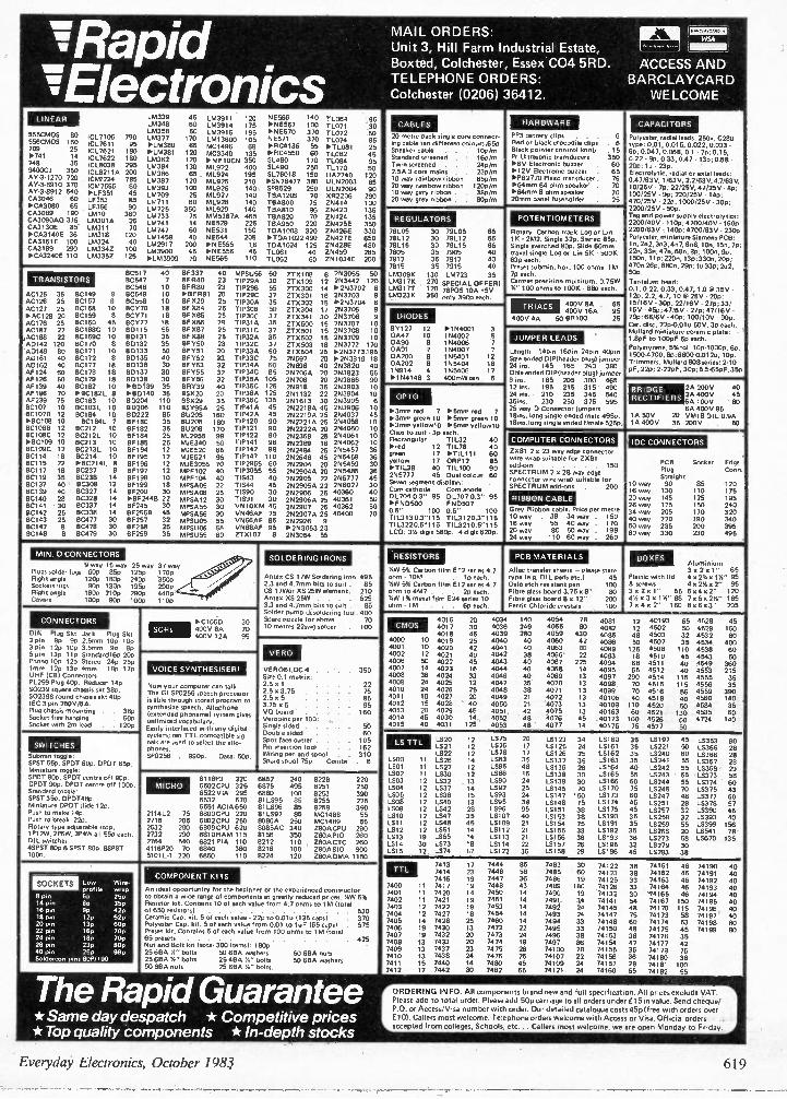
MAIL ORDERS: Unit 3, Hill Farm Industrial Estate, Boxted, Colchester, Essex C04 5RD. TELEPHONE ORDERS: Colchester (0206) 36412.
CABLES
20 metre pack single core connect-ing cable ten different colours.65P Speaker cable . . . 100/m Standard screened . . 16p/m Twin screened . . . 24p/m 2.5A 3 core mains . 23p/m Sway rainbow ribbon 65p/m 20 way rainbow ribbon 120p/rn Sway gery ribbon . . 38p/m 20 way grey ribbon . . 80p/m
REGULATORS
78L05 30 79L05 65 78L12 30 79L12 65 78L15 30 79L15 65
7788°125 35 7905 40 35 7912 40 7815 35 7915 eo LM309K 130 LM723 35
LM31 7K 2" SPECIAL OFFER! LM317T 120 78P05 10A w5V LM3231( 350 only 390p eac h.
HARDWARE
PP3 battery clips . . . Red or black crocodile clips Black pointer control knob Pr Ultrasonic transducers 1.6V Electronic buzzer 1.12V Electronic buzzer *P82720 Pie.° transducer 1.64rnm 64 ohm speaker 1.134mm 8 ohm speaker 20mrn panel fuseholder
POTENTIOMETERS
CZ = vim
1 ACCESS AND
BARCLAYCARD WELCOME
6 . 6 . 15 350 80 65 75 70 70 25
Rotary. Carbon track Log or Lin 1K • 2M2. Single 320. Stereo 850. Single switched 1300. Slide 60mm travel single Log or Lin 5K. 500K 63p each. Preset subrnin. hor. 100 ohms -1M 7p each. Cermet precision multiturn, 0.75W Y." 100 ohms to 100K - El8p each.
DIODES
BY127 12 0447 10 0490 8 0A91 7 08200 8 0A202 8 15914 4 *154148 3
*1N4001 154002 154006 7 154007 7 1145401 12 155404 16 155406 17 400mWzen 6
9 way 15 way 25 way 37 way Plugs solder logs 60p 85p 1250 1700 Right angle 120p 180p 24 50 350P Sockets lugs 90p 130p 1950 290P Right angle 16 50 2100 2900 440P Covers 100p 900 100p 110p
CONNECTORS
DIN Plug Skt Jack Plug Skt 2 pin 9p 9p 2.5mm 10p 100 3 pin 120 10p 3.5mm 90 90 5 pin 130 Ilp Standard16p 200 Phono 10p 12p Stereo 24p 25p 1mm 12p 13p Omm 18p 17p UHF (CB) Connectors: PL259 Plug 400. Reducer 14p. S0239 square chassis skt 38P. S0239S round chassis skt 40p. IEC 3 pin 250V/6A. Plug chassis mounting . 38p Socket free hanging . . . 600 Socket with 2m lead . . 1250
SWITCHES
SCRs IsC106D 30 400V 80 70 400V 124 95
SOLDERING IRONS
Antes CS 17W Soldering iron 495 2.3 and 4.7mm bits to suit . 85 CS 17Wor XS 25W element. 210 Antex XS 25W . . . 525 3.3 and 4.7mm bits to suit . 85 Solder pump desoldaring 1001. 480 Spare nozzle for above . 70 10 metres 22svvg solder . 100
OPTO
e3rnrn red 7 lx 5mm red 7 *3min green 10 1.5inm green 10 0.3mm yellow10 1.5n5m yellow10 Clips to salt. 30 each. Rectangular TIL32 40 red 12 TIL78 40
green 17 1.TIL111 60 yellow 17 ORP12 85 PT1L38 40 TIL100 90 255777 05 Dual colour 60 Seven segment displays: Cow cathode Corn anode 0L7040.3" 95 DL707 0.3" 95 1.FN0500 FNI3507 0.5 100 0.5" 100 TIL313 0.3'115 T1L3120.3"115 TiL3220.5115 T1L3210.5115 LCD: 30 digit 58 50. 4 digit 6200.
RESISTORS
TRIACS
400v 40
400V 8A 400V 168
50 8R100
JUMPER LEADS
65 95 25
Length 14pin 16pi0 24pin 40pin Sole ended DIP(header plug) jumper 24 ins. 146 165 240 380 Dble ended DIP1header plug) jumper 6 ins. 185 205 300 465 12 ins. 195 216 315 490 24 ins.. 210 235 345 540 36in5. 230 250 375 595 25 way 0 Connector jumpers 18ins. long single ended male 49 50. 18ins.long single ended f /male 525p
COMPUTER CONNECTORS
ZX81 2n 23 way edge connector wire wrap suitable for ZX81 add-ons . . . . . 150 SPECTRUM 2 x 28 way edge connector wire-wrap suitable for SPECTRUM add-ons . 200
RIBBON CABLE
Grey Ribbon cable. Price per metre 10 way . 38 34 way . 150 16 way 55 40 way . 170 20 way 80 50 way . 198 24 way 110 60 way . 260
CAPACITORS
Polyester, radial leads. 2500. C280 type: 0.01, 0.015, 0.022, 0.033 - BP; 0.047,0.068,0.1 - 7p; 0.15, 0.22 - 9p:0.33, 0.47 - 13p; 0.68 • 250; 1u -230. Electrolytic, radial or axial leads, 0.47/63V, 1/63V, 2.2/63V,4.7/63V, 10/25V -70; 22/25V, 47/25V - 8p; 100(25V • 9p; 220/25V. 14p; 470/25V - 22p; 1000/25V -30p; 2200/25V 'Sop Tag end power supply electrolyticr 2200/40V. 11 50; 4700/40V -160p 2200/63V. 14 50; 4700/63V - 230P Polyester, miniature Siemens PCB: In, 2n2,3n3,4n7,6n8, 10n, 15n, 7p, 22n,33n,47n,68n, 8p; 10011,9p; 150n, 110; 220n,139; 330n, 20P; 470n 26P: 680n, 250; 10 330; 2u2, 50o.
Tantalum bead: 0.1, 0.22, 0.33,0.47, 1.0 6135V • 130. 2.2,4.7, 106 25V- 250; 15/I6V -3 50; 22/16V - 27p; 33/ 16V -45p; 47/6V - 27p; 47/16V. 70P;138/6V - 40p; 100/10V • 90P. Car, disc 22p-0 01u 50V, 300.05. Mallard miniature ceramic plate: 1.50F to 100PF 81/ each. Polystyrene, 5% WI: lOp-1000g, 64. 15004700, 8p;13800 0,012u, 10P. Trimmers. Mullard 808 series: 2.10 pF, 22P; 2-22pF, 300; 5.5-1350F,35p
BRIDGE RECTIFIERS
28200V 40 24 400V 45 6A 100V BO 6A 400 95
1A 50V 20 VM18 DI L 0.9A 1A 400V 35 200V 50
IDC CONNECTORS
PCB Socket Edge Plug Conn Straight
10 way 90 85 120 16 way 130 110 175 20 way 145 125 195 26 way 175 150 240 34 way 205 170 320 40 way 220 190 340 50 way 236 200 395 60 way 330 230 495
SW 5% Carbon film E12 series 4.7 ohm • 10M . . 10 each. XVV 5% Carbon film E12 series 4.7 ohm to 4M7 . . 2p each. XW 1% metal film E24 series 10 ohm - 1M 6p each.
PCB MATERIALS
Altac transfer sheets - Please slate type (e.g. DI L pads etc.) 45 Delo etch resistant pen 100 Fibre glass board 3.75 x 8" 80 Fibre glass board 8o 12" 200 Ferric Chloride crystals 100
BOXES Aluminium 30201" 65
Plastic with lid 4 x 2% x 1W' 95 & screws 442042" 95 30201" 55 60402" 120 40,030114- 88 70502/S" 165 70402" 160 80603" 205
Submin toggle. SPST 550. SPOT 60p. DPDT 65P. Miniature toggle; SPOT 80p. SPOT centre off 90p. DPDT 90p. DPDT centre off 100p. Standard toggle: SPST 35p. DPDT48p Miniature DPDT slide 12p. Push to make 140. Push to break 221p. Rotary type adjustable stop. 1P1 2W, 2P6W,3P415 all 55p each OIL switches: 4SPST 800 6 SPST 80p. &SPST 1000
VOICE SYNTHESISER ,
Now your computer can talk. The GI SP0256 speech processor is able through stored program to synthesize speech. Allophone (extended phoneme) system gives unlimited vocabulary. Easily interfaced with any digital system: ten TTL compatible sig-nals are used to select the allo-phones. SP0256 . 99 50. Data: 50P.
VERO
VEROBLOC 1 . Sin 0.1 matrix' 2.50 1 2.5 03.75 2.50 5 3.75 x 5 VO board Veropins per 1130: Single sided Double sided . Spot face cutter . Pin insertion tool . Wiring pen and spool Spare spool 75p Combs
350
22 75 85 95 160
50 60 105 162 310 . 6
CMOS
4000 4001 4002 4006 4007 4008 4009 4010 4011 4012 4013 4014 4015
4016 4017 4018 4019
10 4020 12 4021 50 4022 14 4023 36 4024 24 4025 24 4026 10 4027 15 4028 20 4029 45 4030 40 4031
20 4034 30 4036 45 4039 25 4040 42 4041 40 4042 45 4043 16 4044 33 4048 12 4047 75 4048 20 4049 40 4050 45 4051 14 4052 125 4053
140 4054 249 4055 280 4059 40 4060 40 4083 38 4066 40 4067 40 4068 40 4069 35 4070 38 4071 21 4072 21 '4073 42 4075 48 4076 48 4077
78 8o 430 42 80 22 225 14 13 13 13 13 13 13 45 14
4081 4082 4085 4086 4089 4093 4094 4095 4097 4098 4099 40106 40109 40163 40173 40175
12 40193 12 4502 48 4503 50 4507 125 4508 18 4510 68 4511 65 4512 290 4514 70 4515 70 4516 40 4518 110 4520 60 4521 100 4526 75 4527
130 60 50
65 4528 60 4529 32 4532 35 4534 110 4538 45 4543
4549 40 4553 115 4555 115 4556 55 4559 40 4560 50 4584
4585 4724
45 150 60 400 60 50 360 215 35 35 390 140 35 60 140
SOCKETS Low Wire. profile wrap
Spin 6p 250 14 pin 8p 35p 16 pin 50 42p 18 pin 12p 520 20 pin 13p 60p 22 pin 16p 70p 24 pin 18p 70p 28 pin 230 80p 40 pin 25p 980 Soldercon pins 60P/100
MICRO
2114L2 2716 2532 2732 2764 4116P20 5101L-1
75 205 290 290 540 70 220
95 25 45
5116P3 320 6852 240 8228 220 8502CPU 325 6875 495 8251 250 6522 VIA 295 6880 100 8253 390 6532 570 81L595 85 8255 225 6551 ACIA 650 81LS96 85 8259 390 6800CPU 220 811.S97 85 MC1488 55 13802CPU 250 80808 250 MC1489 55 6809 CPU 620 8085AC 340 ZEIOACPU 290 6810 RAM 115 8156 350 280APIO 260 6821 PIA 110 8212 110 ZBOACTC 260 6840 360 8216 100 280ASIO 900 6850 110 8224 120 2130A DMA 1150
COMPONENT KITS
3
10
LS TTL
LSOO LS01 LSO2 LSO3 LSO4 LSO5 LSO8 LSO9 LS10 LS11 LS12 LS13 L514 LS15
11 11 11 12 12 12 12 12 12 12 12 19 30 12
LS20 LS21 1.022 LS26 LS27 LS30 LS32 1.537 LS38 LS40 LS42 LS47 1.548 LS51 LS55 1.573 L574
12 12 12 14 12 12 13 14 15 13 28 35 45 14 14 18 17
LS75 LS76 LS78 LS83 LS85 LS86 LS90 LS92 LS93 1.395 LS96 LS107 L5109 1.5112 1.5113 LS114 LS122
20 LS123 34 17 L5125 24 17 LSI 26 25 35 1.5132 35 48 L5136 26 16 L5I38 30 24 LS139 30 25 LS145 70 24 1.8147 150 38 L0148 75 95 L5151 38 40 1.5153 38 21 LS154 75 21 1.8155 33 21 LS156 36 22 L5157 26 35 1.5158 29
40
L5160 35 13197 45 LS161 35 13221 50 1.S162 35 L5240 60 LS163 35 L5241 55 LS164 40 1.5242 55 LS165 55 LS243 55 L5166 60 13244 55 L5170 75 1.S245 70 L5173 60 LS247 48 L5174 45 L5251 28 LS175 45 1.0257 32 L5190 35 L5258 32 1.5191 35 LS259 55 1.5192 35 L5266 20 L5193 36 13273 58 L5195 32 13279 30 1.61961 45 13283 38
LS353 60 LS365 28 LS366 28 LS367 28 LS368 29 LS373 58 LS374 60 LS375 43 1.5377 60 LS378 57 LS390 45 LS393 40 1.5399 156 LS541 78 LS670 135
An ideal opportunity for the beginner or the experienced constructor to obtain a wide range of components at greatly reduced prices. '415 5% Resistor kit. Contains 10 of each value from 4.7 ohms to 1M (total 01 680 resistors) . . . . . . . . . . . . . 530 Ceramic Cap. kit. 5 of each value -2 26 to 0.01u1135 caps) . 370 Polyester Cap. kit. 501 each value from 0.01 to luF 165 caps) . 576 Preset kit. Contains 501 each value frorn 100 ohms to 1M (total 65 presets 415 Nut and Bolt kit (total 300 items): 1813p 25 SSA Yv" bolts 50 SSA washers 50688 nuts 25 68A 0" bolts 25 4BA X" bolts 50 68A washers 5060A nuts 25 684 '4" bolts
The Rapid Guarantee * Same day despatch * Competitive prices * Top quality components * In-depth stocks
7400 11 7401 11 7402 11 7403 12 7404 12 7405 14 7406 19 7407 19 7408 13 7409 13 7410 13 7411 15 7412 17
7413 7414 7418 7417 7420 7421 7422 7427 7428 7430 7432 7433 7437 7438 7440 7442
17 7444 23 7446 19 7447 19 7448 14 7450 19 7451 19 7453 18 7454 25 7460 13 7472 20 7473 20 7474 23 7475
7476 7480 7482
24 14 30
85 58 36 43 14 14 14 14 14 22 24 19 26 25 45 65
7483 7485 7486 7489 7490 7491 7492 7493 7494 7495 7496 7497 74100 74107 74109 74121
30 60 19 180 19 34 24 24 33 33 38 86 78 22 24 24
74122 74123 74125 ,74126 74132 74141 74145 74147 74148 74150 74153 74154 74155 74156 74157 74160
38 38 33 33 30 se 48 75 60 48 38 47 36 36 28 55
74161 74162 74183 74164 74165 74167 74170 74173 74174 74175 74176 74177 74179 74180 74181 74182
ea 46 46 46 46 150 115 58 53 45 35 42 75 38 100 55
74190 40 74191 40 74192 40 74193 40 74194 40 74195 40 74196 40 74197 40 74198 80 74199 80
ORDERING INFO. All components brand new and full specification. All prices exclude VAT.
Please add to total order. Please add 50p carriage to all orders under £15 in value. Send cheque/ P.O. or Access/Visa number with order. Our detailed catalogue costs 45p (free with orders over £10). Callers most welcome. Telephone orders welcome with Access or Visa. Official orders .
accepted from colleges, Schools, etc... Callers most welcome, we are open Monday to Friday.
Everyday Electronics, October 1983 619
• HEC1RY'S (AUDIO ELECTROINCe ml COMPUTERS • COMMUNICATIONS • TEST EQUIPMENT • COMPONENTS I"
VISIT OR PHONE • OPEN 6 DAYS A WEEK • ALL PRICES INC VAT
THERMAL MATRIX & LINE PRINTER
COMPLETE WITH FULL 4E129 INC HANDBOOK 310115 PAPER .95 VAT
£113.00 VAT 11.11( post etc El 051 IList envoy £I87 I 150 to IBOLPM• Full 96CH ASCII* 40 CP1.• 2110 Dots P/L • Auto- underline • 50 Grephic Symbols • Back Space Sell Test • VU/HOR TABS • 7 x 10 Matrix • 4.4" Wide Paper • Bidirectional • 220/2409 AC • Size Approx 9 8 x 2B As P7'
'CHERRY'ADD-ON KEYPAD A compact 16 button keypad suitable for use with cherry keyboard to extend its functions. Supplied brand new with data. A 49 4 non.enceded single mode keyboard. £5.Unm (inc. 0.0,111
a UK C/P Free
RECHARGEABLE BATTERIES AA or HP7 size batteries 4 tor £3.00 IUK C/P 3081 Charger takes up to 4 any size 1 V rechargeables also. 1 x PP3 size £6.95 {UK Cif' 6501
DIGITAL MULTIMETERS •with case rotary switches' +Side button - case £2.95 KD 25CI 3 range 1,23 DC 2 meg ohm £23.50 K030511 16 range 10A DC 2 meg ohm £26.95 K11130C • 26 range IA AC/DC 20 meg ohm £29.50
K 055C • 28 range 10A AC/DC 20 meg ohm £32.50 Metex 3000 30 range 10A AC/DC 20 meg ohm £33.24 6010 28 range 10A AC/DC 20 meg ohm £34.40 70304• AS6010 high ace 0 basic £41.30 KD615 • 16 range 10A DC 2 meg plus Hle tester £39.95 SI AM 2200121 range 29 AC/ BC 20 meg £39.95 Bench Models TM355 29 range LED 10A AC/SC 20 meg Thandar £86.25 TM356 26 range LCD 10A AC/SC 20 meg Thandar £97.75 TM351 29 range LCD 10A AC/DC 20 meg Thandar £120.75 SIFAM 250024 rangeLCO 20 AC/SC 29 meg £99.95 ALSO IN STOCK Thuriby. Metrix and Beckman Professional series incl. True Rms. etc.
SPEAKERS, TWEETERS AND CROSSOVERS
HIF2OESM 8 ohm 30/50 watt Bass/Mtd range 8 £5.95 HIF2OESM 4 ohm version 0
eV !UK C/PC1 001 £4.95
T 2, 8 ohm 15 watt tweeter
Ore) 11IF87 BSM 4 8 ohm 30/50 watt mid range
0 P11303 8 ohm thwart tweeter
HT315F 5 a3, 8 ohm 30 watt tweeter
CN38 3 way 8 ohm 15 watt
SM300 40 wan version
!UK C/P 65p per 1103 ilems1
Pair £3.50
£495
Pair £3.50
Pair £5.50
Pair £2.00
Pair £3.00
MULTIMETERS ILIN C/P 6501 HMI 021111 20K/V 10A DC 22 range 8 cont. buzzer £13.50 ETC5000 21 ranges. 50K/V Range doubler 10A DC E18.95 TMK500 23 ranges 30K/V. 120 DC plus cont. buzzer £23.95 141456R 20K/V. 22 range pocket ETU102 16 range 2K/V pocket 830 20 range 30K/V. 10A AC/DC overload protection. etc. 36018 23 range 100K/V. Large scale IOA AC/SC plus Hie 812100 31 range 100K/V deluxe I2A AC/DC AT 1020 18 range 2131(/ V. Deluxe plus Hfe tester TN360TR 19 range 20K/V plus Ale tester
£10.95 £6.50
£23.95
E39.95
£33.50
£18.95 £15.95
IN STOCK Large range of semi-conductors, tools, components. accessories, cordless and electronic telephones. CA. equipment. etc.
SIGNAL GENERATORS 1220/2400 ACI FUNCTION All sine square triangle /TTL. etc TG100 1 HZ 100 KH/ £90.00 TG10202 HZ 2 MHZ £166.75 PULSE TG105 Various latilities 5 HZ -5 MHZ £97.75 AUDIO Mulliband Sine iSquare
18627 10 Hz tot MHz £90.85 A6202A 20 Hz to 200 KHz (List £94 501 £83.50 RF S6402 100 KHz to 30 MHz Hist E79 501 LSG17 100 KHz to 150 MHz £79.35
£69.50
LPIO IOMHZ £211.50 LOGIC PROBES 01P50 50 MHZ with carry case and accessories £52.33
HIGH VOLTAGE METER Direct reading 0/40 CV
1011: doll £23.00 10K C/P 6501
DIGITAL CAPACITANCE METER VI pl to 2000 mid LCD 8 ranges DM6013 £52.75
TRANSISTOR TESTER Direct reading PAP NPN. etc. IC 1 £21.95 .0 • IVK C/P 6591
OSCILLOSCOPES Full specification any moont on request SAE by post MM Series Series HAMEG: 'SG' INANDAR: 'CS* TRIO: '3' CROTECH 'DT' Salgan SINGLE TRACE UK C/P £300 3030 15 MHZ 5intil 95mm tube plus component tester C C300 £177.10 SC I ICIA• Miniature 10 MHZ battery portable Post Are £171.00 IIM103 15 MHZ 2ing 6 x 7 display plus component tester C P C300 £ .70 •Dptional carry case C6 84 AC adaptor E61 8691 Nicads £12 58 DUAL TRACE (UK C/P E4.001 01 520 Dual 20 MHZ £241.50 HM203/4 Dual 20 MHZ plus component tester £303.60 CSI562A Dual IA MHz Kist £321 001 £269.50 3131 Dual 15 MHZ • component tester £276.00 CSI 56611 Dual 20 MHZ All facilities 'List I:401 351
M204 Dual 20 MHZ plus component tester E349.5° sweep delay £419.75 OPTIONAL PROBE KITS At £7.95 X1 x10 £10.50 X10 £9.45
VARIABLE POWER SUPPLIES IUK C/P f1.001 PP241 0/12/240. 0/1A £35.00 P P243 3 amp version £59.95 PS1307S 8/15V tamp twin meter £24.95
HENRY'S
FREQUENCY COUNTERS PFM200A 200 MHZ hand held pocket 8 digit LED £77.60 ME11008 digital) benth2 ranges 100 MHZ £102.35 MET6008 digit LH bench3 ranges 600 MHZ £132.25 MET1000 A digit LEO 3 ranges 1 GHZ £182.85 1F0408 Vigil LCD 40 MHZ Thandar £126.50 20200 3 Moit LCD 200 MHZ Thandar £166.75
Cubegate Limited
404-406 Edgware Road, London. W2 1E0 Computer. 01-402 6822. Component: 01-723 1008 Test Equipment & Communications: 01-724 0323
AUDIO ELECTR01110 301 Edgware Road. London, W2 1811 01-724 3564 (All mail to this address)
JUST A SELECTION OF OUR STOCK. CALL IN AND SEE FOR YOURSELF.
FREE CATALOGUES - SEND LARGE S.A.E. (20p UK) ORDER BY POST OR PHONE.
.1111 . 01$ VISA
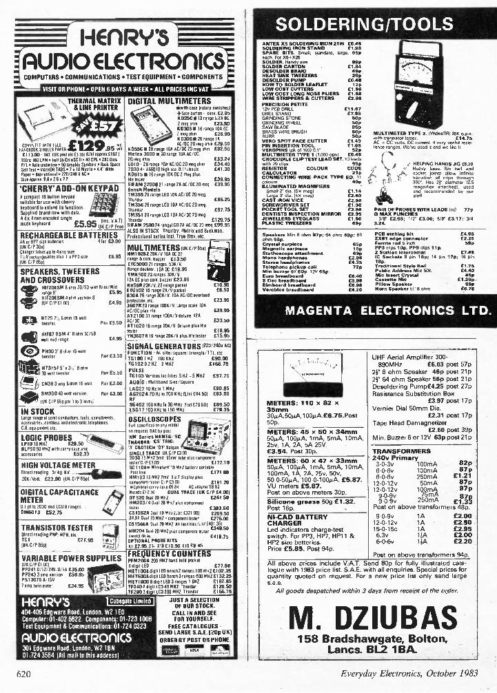
SOLDERING/TOOLS ANTEX X5 SOLDERING IRON 25W £5.48 SOLDERING IRON STAND £1.98 SPARE BITS. Small, standard, large, 65p each For X5-X25 SOLDER. Handy size 99p SOLDER CARTON £1.84 DESOLDER BRAID 69p HEAT SINK TWEEZERS 29p DESOLDER PUMP £6.48 HOW TO SOLDER LEAFLET 12p LOW COST CUTTERS £1.69 LOW COST LONG NOSE PLIERS £1.68 WIRE STRIPPERS & CUTTERS £2.69 PRECISION PETITE 12V PCB DRILL £11.67 DRILL STAND £7.98 GRINDING STONE 50p GRINDING WHEEL 50p SAW BLADE 85p BRASS WIRE BRUSH 50p BURR 50p VERO SPOT FACE CUTTER £1.49 PIN INSERTION TOOL £1.98 VEROPINS (pk of 100) 0.1' 52p MULTIMETER TYPE 1 (1,000 opv) £5.48 CROCODILE CLIP TEST LEAD SET. 10 leads with 20 clips 99p RESISTOR COLOUR CODE CALCULATOR 21p CONNECTING WIRE PACK TYPE ED. 11 colours 40p ILLUMINATED MAGNIFIERS Small 2" dia. (5. meg) £1.14 Large 3" dia. (4 x meg/ £2.40
CAST IRON VICE £2.98 SCREWDRIVER SET £1.98 POCKET TOOL SET £3.98 DENTISTS INSPECTION MIRROR £2.95 JEWELLERS EYEGLASS £1.50 PLASTIC TWEEZERS 69p
MULTIMETER TYPE 2. IYN360TRI 200 o.p.v. with transistor tester. £14.75 AC c DC volts. DC current. 4 very useful resis-tance ranges. We've used it and we like it.
HELPING HANDS JIG £6.30 Heavy base. Six ball and socket joints allow infinite
/, variation of clips through ' 360°. Has 21 diameter 12.5
magnifier attached), used and recommended by our staff.
PAIR OF PROBES WITH LEADS lccl 77p CI MAX PUNCHES 3/8" £2.98; 1/2' £3.06; 5/8' £3.17; 3/4
3.24.
Speakers Min 8 ohm 87p; 64 ohm 89p; 80 ohr, 98p. Crystal earpiece Magnetic earpiece Stethoscope attachment Mono headphones Stereo headphones Telephone pickup coil Min buxzer 6V 50p. 12V 65p. Euro breadboard 5 Dec breadboard Binnboard breadboard Verobloc breadboard
65p 15p 69p
£2.98 £4.35 72p
£6.40 £3.98 £6.98 £4.20
PCB etching kit £4.98 2X81 edge connector £2.25 Ferrite rod 5 inch 59p PP3 clips 10p. PP9 clips lip. 2 Station intercomm £7.48 IC Sockets 8 pin 16p; 14 pin 17p; 16 pin 18p. Traditional Style Bell Public Address Mic 50K Mic Insert Crystal Cauette Mic Pillow Speaker Horn Speaker 51" 8 ohm
£1.75 £4.40 45p
£1.29p 98p
£6.75
MAGENTA ELECTRONICS LTD.
METERS: 110 x 82 x 35mm 30µA,50µA,100µA.16.75.Post 50p.
METERS: 45 X 50 X 34mm 50µA, 100µA, 1mA, 5mA, 10mA, 25v, 1A, 2A, 5A 25V. £3.54. Post 30p.
METERS: 60 x 47 x 33mm 5014A, 100µA, 1mA, 5mA, 10mA, 100mA, 1A, 2A, 25v, 50v, 50-0-50µA, 100-0-100µA. £5.87. VU meters £5.87. Post on above meters 30p.
Silicone grease 50g £1.32. Post 16p.
NI-CAD BATTERY CHARGER Led indicators charge-test switch. For PP3, HP7, HP11 & HP2 size betteries. Price £5.85. Post 94p.
UHF Aerial Amplifier 300-890MHz £6.03 post 57p 2? 8 ohm Speaker 46p post 21p 2? 64 ohm Speaker 56p post 21p Desoldering Pump£4.25 post 27p Resistance Substitution Box
0.97 post 17p Vernier Dial 50mm Dia.
£2.31 post 17p Tape Head Demagnetizer
£2.60 post 39p Min. Buzzer 6 or 12V 63p post 21p
TRANSFORMERS 240v Primary 3-0-3v 100mA 6-0-6v 100mA 6-0-6v 250mA 12-0-12v 50mA 12-0-12v 100mA 9-0-9v 75mA
250mA £18.37 0- g Post on above transformers 48p
9-0-9v 12-0-12v 15-0-15c 6.3v 6-0-6v
82p 87p
£1.21 87p 97p
1A £2.00 1A £2.50 1A £2.95 10, £2.00
£2.20
Post on above transformers 94p.
All above prices include VAT. Send 80p for fully illustrated cata-logue with 1983 price list. S.A.E. with all enquiries. Special prices for quantity quoted on request. For a new price list only send large s.a.e.
All goods despatched within 3 days from receipt of the order.
M. DZIUBAS 158 Bradshawgate, Bolton,
Lancs. BL2 IBA.
620 Everyday Electronics, October 1983
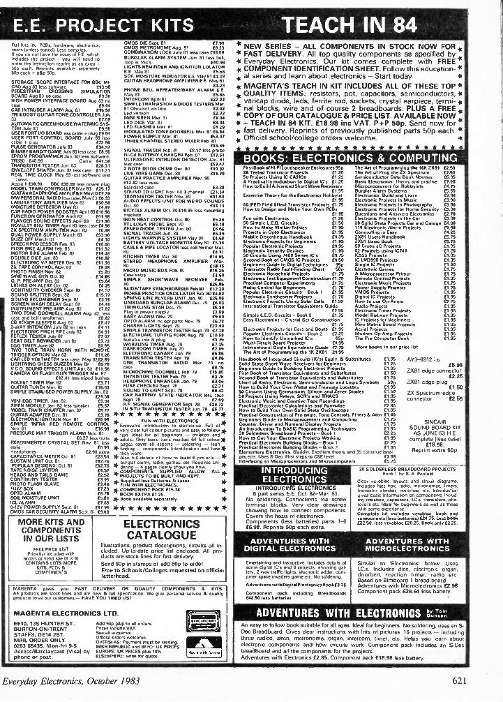
E.E. PROJECT KITS TEACH IN 84 Full Kits inc. PCBs, hardware, electronics, cases (unless stated). Less batteries. If you do not have the issue of E.E. which includes the project - you will need to order the instruction reprint as an extra - 50p each. Reprints available separately 50p each 4- p&p 50p.
STORAGE 'SCOPE INTERFACE FOR BBC MI-CRO Aug 83 less software £13.98 PEDESTRIAN CROSSING SIMULATION BOARD Aug 83 no case £9.36 HIGH POWER INTERFACE BOARD Aug 83 no case £9.44 CAR INTRUDER ALARM Aug 83 £15.52 TIII BOOST GUITAR TONE CONTROLLER July 83 £7.59 AUTOMATIC GREENHOUSE WATERING SYS-TEM July 83 £9.98 USER PORT I/O BOARD less cable -0- plug £3.54 USER PORT CONTROL BOARD July 83 less cable + plug £22.86 PULSE GENERATOR July 83 134.97 BINARY BANDIT GAME July 83 less case £8.98 EPROM PROGRAMMER Jun. 83 less software. TRS80 £40.99 Genie £41.58 TRANSISTOR TESTER Jun. 83 £26.31 ENVELOPE SHAPER Jun. 83 less case £11.21 REAL TIME CLOCK May 83 less software and
Apple 0 £30.98 BBC £35.99 less power plug MODEL TRAIN CONTROLLER May 83 f25.17 GUITAR HEADPHONE AMPLIFIER May83E7.20 MW PERSONAL RADIO less case, May 83 £6.93 LABORATORY AMPLIFIER May 83 £30.98 MOISTURE DETECTOR May 83 £4.97 CAR RADIO POWER BOOSTER April 83E10.98 FUNCTION GENERATOR April 83 £41.98 FLANGER SOUND EFFECTS April 83 £21.98 NOVELTY EGG TIMER April 83 less case £4.98 ZX SPECTRUM AMPLIFIER April 83 DUAL POWER SUPPLY March 83 £53.98 BUZZ OFF March 83 £4.10 SPEECH PROCESSOR Feb. 83 £10.66 PUSH BIKE ALARM Feb. 83 £11.32 MOTOR BIKE ALARM Feb 83 £14.46 DOUBLE DICE Jan. 83 £10.82 ELECTRONIC V/I METER D.. 82 £11.38 ZX TAPE CONTROL Nov. 82 £6.48 PHOTO FINISH Nov. 82 0.89 SINE WAVE GEN Oct. 82 £14.65 G. P. PRE-AMP Oct. 82 £5.64 LIGHTS ON ALERT Oct. 82 £4.25 CONTINUITY CHECKER Sept. 82 £4.97 SOUND SPLITTER Sept. 82 £15.77 SOUND RECOMBINER Sept. 82 £3.70 SCREEN WASH DELAY Sept. 82 £4.48 INSTRUMENT PRE AMP Aug. 82 £7.82 TWO TONE DOORBELL ALARM Aug 82. less case and bell transformer £8.82 CB ROGER BLEEPER Aug. 82 £8.47 2-WAY INTERCOM July 82 no case £4.11 ELECTRONIC PITCH PIPE July 82 £4.91 REFLEX TESTER July 82 £7.07 SEAT BELT REMINDER Jun 82 1E3.73 EGG TIMER June 82 £4.95 TWO TONE TRAIN HORN WITH REMOTE TRIGGER OPTION May 82 £11.26 CAR LED VOLTMETER less case. May 82 52.89 LIGHTNING CHESS BUZZER May 82 £6.20 V.C.O. SOUND EFFECTS UNIT Apr. 82 01.56 CAMERA OR FLASH GUN TRIGGER Mar. 82
£12.41 less tripod bushes POCKET TIMER Mar. 82 E3.71 GUITAR TUNER Mar. 82 £15.63 SIMPLE STABILISED POWER SUPPLY Jan. 82
£24.58
MINI EGG SIREN MODULE TIMER. 82 less speaker £5.57
Jan. 82.
MODEL TRAIN CHUFFER Jan. 82 £8.27 GUITAR ADAPTER Dec. 81 £3.76 ELECTRONIC IGN MON Nov. 81 £25.98 SIMPLE INFRA RED REMOTE CONTROL Nov. 81 £16.98 PRESSURE MAT TRIGGER ALARM Nov. 81
£6.27 less mats EXPERIMENTER CRYSTAL SET Nov. 81 less aerial £5.99 Headphones £2.98 extra CAPACITANCE METER Oct. 81 £7.3.51 SUSTAIN UNIT Oct. 81 £12.76 'POPULAR DESIGNS Oct. 81 £12.76
£4.57 £2.52 E3.95 0.46 £7.29 £6.78 £5.81 £7.89
0-12V POWER SUPPLY Sept. 81 £17.98 CMOS CAR SECURITY ALARM Sent 81 £9.08
TAPE NOISE LIMITOR HEADS AND TAILS GAME CONTINUITY TESTER PHOTO FLASH SLAVE FUZZ BOX OPTO ALARM SOIL MOISTURE UNIT ICE ALARM
CMOS DIE Sept 81 £7.99 CMOS METRONOME Aug. 81 £8.23 COMBINATION LOCK July 81 less case £19.58 BURGLAR ALARM SYSTEM Jun. 81 less bell, loop & Mic's £40.98 LIGHTS REMINDER AND IGNITION LOCATOR E.E. May 81 £5.66 SOIL MOISTURE INDICATOR E.E. May 81 £4.09 GUITAR HEADPHONE AMPLIFIER E.E. May 81
PHONE BELL REPEATER/BABY ALARME4E2.E3. May 81 £5.66 INTERCOM April 81 £22.23 SIMPLE TRANSISTOR & DIODE TESTERS Mar. 81 Ohmeter version £2.02 Led version f2.73 MINI SIREN Mar. 81 £8.04 LED DICE Mar. 81 £8.44 LED FLASHER Mar. 81 £4.29 MODULATED TONE DOORBELL Mar. 81 £6.64 POWER SUPPLY Mar. 81 £53.47 THREE CHANNEL STEREO MIXER Feb. 81
£18.69 SIGNAL TRACER Feb. 81 £8.17 less probe Ni-Cd BATTERY CHARGER Feb. 81 £13.61 ULTRASONIC INTRUDER DETECTOR Jan. 81 less case £53.47 2 NOTE DOOR CHIME Dec. 80 £10.32 LIVE WIRE GAME Dec. 80 £11.70 GUITAR PRACTICE AMPLIFIER Nov. 93 £12.82 less case. Standard case £3 88 SOUND TO LIGHT Nov. 803 channel £2134 TRANSISTOR TESTER Nov. 80 £11.63 AUDIO EFFECTS UNIT FOR WEIRD SOUNDS Oct 80 £13.11 BICYCLE ALARM Oct. 89 E10.35 less mounting brackets IRON HEAT CONTROL Oct. 80 £ TTL LOGIC PROBE Sept. 80 E55136
..18
ZENER DIODE TESTER Jun. 80 £6.66 SIGNAL TRACER Jun. 80 £639 LIGHTS WARNING SYSTEM May 80 £4.68 BATTERY VOLTAGE MONITOR May 80 £5.16 CABLE 8, PIPE LOCATOR less coil former Mar. 80 £4.11 KITCHEN TIMER Mar. 80 £14.65 STEREO HEADPHONE AMPLIFIER Ma,. 80 08.15 MICRO MUSIC BOX Feb. 80 £16.26 Case extra £3.60 SIMPLE SHORT WAVE RECEIVER Feb. 80 £25.86 SUDE/TAPE SYNCHRONISER Feb 80 £12.30 MORSE PRACTICE OSCILLATOR Feb. 80 £4.62 SPRING LINE REVERS UNIT Jan. 80 £25.86 UNIBOARD BURGLAR ALARM Dec. 79 £6.03 TWINKLING STAR Dec. 79 £6.39 Plug in power supply £3.89 BABY ALARM Nov. 79 £9.60 OPTO ALARM inc opt parts Nov. 79 £6.78 CHASER LIGHTS Sept. 79 £23.40 SIMPLE TRANSISTOR TESTER Sept. 79 £7.30 ELECTRONIC TUNING FORK Aug. 79 miss Suitable mic & plug £1.79 WARBLING TIMER Aug. 79 £7.35 DARKROOM TIMER July 79 £2.89 ELECTRONIC CANARY Jun. 79 £5.86 TRANSISTOR TESTER Apr. 79 £4.86 ONE TRANSISTOR RADIO Mar. 79 no case £8.15 MICROCHIME DOORBELL Feb. 79 £15.85 THYRISTOR TESTER Feb. 79 £3.78 HEADPHONE ENHANCER Jan. 79 03.78
06
FUSE CHECKER Sept. 78 £2.31 SOUND TO LIGHT Sept. 78 £8.42 CAR BATTERY STATE INDICATOR less case Sept. 78 R.F. SIGNAL GENERATOR Sept. 78 £26.72 IN SITU TRANSISTOR TESTER Jun. 78 £6.77
* * * * * * * * * * * * * *
* Enjoyab WI Thle F iUntNroductionE LlEoC eleOctNroiCnIs. Full of * * very clear full colour pictures and easy to follow * text. Ideal for all beginners - children and
* adults. Only basic tools needed. 64 full colour * * pages c_ovecor ansepnetscttde-nt- cld; soldering n-d fault
work).
*2gIVIUTLI MOZic8rs" * COMPONENT PACK £15.78 BOOK EXTRA £1.25.
* Book available sep 1y.
* * * * * * * * * * * * *
MORE KITS AND COMPONENTS IN OUR LISTS
FREE PRICE LIST Price list included with
orders or send sae 19 x 4) CONTAINS LOTS MORE
KITS, PCDs & COMPONENTS
ELECTRONICS CATALOGUE
Illustrations, product descriptions, circuits all in-cluded. Up-to-date price list enclosed. All pro-ducts are stock lines for fast delivery. Send 80p in sta mps or add 80p to order.
Free to Schools/Colleges requested on official letterhead.
MAGENTA gives you FAST DELIVERY OR QUALITY COMPONENTS & KITS. All products are stock lines and are new & full specification. We give personal service & quality products to all our customers - HAVE YOU TRIED US?
MAGENTA ELECTRONICS LTD.
EE10, 135 HUNTER ST., BURTON-ON-TRENT STAFFS, DE14 2ST. MAIL ORDER ONLY. 0283 65435, Mon-Fri 9-5. Access/Barclaycard (Visa) by phone or post.
Add 50p p&p to all orders. Prices include VAT. Sae all enquiries. Official orders welcome. OVERSEAS: Payment must be sterling. IRISH REPUBUC and BFPO: UK PRICES. EUROPE: UK PRICES plus 10%. ELSEWHERE write for quote.
11.11CI .C .0 01
i g =1 *
4
NEW SERIES - ALL COMPONENTS IN STOCK NOW FOR, * FAST DELIVERY. All top quality components as specified by 4, * Everyday Electronics. Our kit comes complete with FREE COMPONENT IDENTIFICATION SHEET. Follow this education- * al series and learn about electronics- Start today.
* MAGENTA'S TEACH IN KIT INCLUDES ALL OF THESE TOP * QUALITY ITEMS: resistors, pot, capacitors, semiconductors, .0 varicap diode, leds, ferrite rod, sockets, crystal earpiece, termi-
'4 nal blocks, wire and of course 2 breadboards. PLUS A FREE .4 * COPY OF OUR CATALOGUE & PRICE LIST. AVAILABLE NOW - TEACH IN 84 KIT, £18.98 inc VAT. P+P 50p. Send now for
* fast delivery. Reprints of previously published parts 50p each. 4(
Official school/college orders welcome.
* * * * * * * * * * * * *
BOOKS: ELECTRONICS & COMPUTING First Book of Hi-Fl Loudspeaker Enclosures 95p 28 Tested Transistor Projects £1.25 50 Projects Using IC CA3130 £1.25 A Practical Introduction to Digital IC's £1.25 How to Build Advanced Short Wave Receivers
. £1.95 Essential Theory for the Electronics Hobbyist
£1.95 50 (FET) Field Effect Transistor Projects £1.75 How to Design and Make Your Own PCBs
£1.95 Fun with Electronics £1.25 50 Simple LED. Circuits £1.50 How to Make Welkie-Talkies £1.95 Projects in Opto-Electronics £1.95 Mobile Discotheque Handbook £135 Electronic Projects for Beginners £1.95 Popular Electronic Projects £1.95 Electronic Security Devices £1.95 50 Circuits Using 7400 Series IC's £1.75 Second Book of CMOS IC Projects £1.50 Beginners Guide to Digital Techniques 95p Transistor Radio Fault-Finding Chart 50 Electronic Household Projects £1.75 Electronic Test Equipment Construction £1.75 Practical Computer Experiments £1.75 Radio Control for Beginners £1.75 Popular Electronic Circuits - Book 1 £11.95 Electronic Synthesiser Projects £1.75 Electronic Projects Using Solar Cells £1.95 International Transistor Equivalents Guide
£2.95 Simple L.E.D. Circuits - Book 2 £1.35 Easy Electronics - Crystal Set Construction
£1.75 Electronic Projects for Cars and Boats £1.95 Popular Electronic Circuits - Book 2 £2.25 How to Identify Unmarked IC's 65p Multi-Circuit Board Projects £1.95 International Diode Equivalents Guide £2.25 The Art of Programming the 1K 2%81 £1 as
Handbook of Integrated Circuits (IC's) Equiv. & Substitutes £1.95 Solid State Short Wave Receivers for Beginners £1.25 Beginners Guide to Building Electronic Projects £1.95 First Book of Transistor Equivalents and Substitutes £1.50 Second Book of Transistor Equivalents and Substitutes £1.75 Chart of Radio, Electronic, Semi-conductor and Logic Symbols 50p How to Build Your Own Metal and Treasure Locators £1.95 50 Circuits Using Germanium, Silicon and Zener Diodes £1.50 50 Projects Using Relays, SCR's and TRIACS £1.95 Electronic Music and Creative Tape Recordings £1 95 Practical Electronics Calculations and Formulae £2.95 How to Build Your Own Solid State Oscilloscope £1.95 Practical Construction of Pre-amps, Tone Controls, Filters 88 Attn. £1.45 Beginners Guide to Microprocessors and Computing £1.75 Counter, Driver and Numeral Display Projects £1.75 An Introduction To BASIC Programming Techniques £1.95 30 Solderless Breadboard Projects - Book 1 £2.25 How to Get Your Electronic Projects Working £1.95 Practical Electronic Building Bloeks - Book 1 12.25 Practical Electronic Building Blocks - Book 2 £1.95 Elementary Electronics. Sladdin. Excellent theory a d 35 constructional projects Uses S-Dec. First steps to CSE level. £3.98 Interfacing to Microprocessors and Microcomputers £5.75
INTRODUCING ELECTRONICS
INTRODUCING ELECTRONICS 6 part series E.E. Oct. 82-Mar. 83.
No soldering. Connections via screw terminal blocks. Very clear drawings showing how to connect co mponents. Covers the basis of electronics. Co mponents (less batteries) parts 1-6 £6.98. Reprints 50p each extra.
ADVENTURES WITH DIGITAL ELECTRONICS
Entertaining and instructive. Includes details of some digital IC's and 8 projects: shooting gal-lery, 2 way traffic lights, electronic adder, com-puter space invaders game etc. No soldering.
Adventures with Digital Electronics Book £3.25
Component pack including Breadboards £42.50 less batteries
The Art of Programming the 16K ZX81 £2.50 The Art of Prog the ZX Spectrum £2.50 Semiconductor Data Book Newnes £6.95 Basic Electronics. Theory and practice £7.98 Microprocessors for Hobbyists £4.75 Burglar Alarm Systems £5.55 Electronics, Build and Learn £3.90 Electronic Projects in Music £3.90 Electronic Projects in Photography £3.90 Electronic Projects for Home Security £3.90 Questions and Answers Electronics £2.70 Electronic Projects in the Car 0.90 20 Solid State Projects Car and Garage £4.80 110 Electronic Alarm Projects £5.98 Computing is Easy £4.25 ZX81 Users Handbook £5.75 2X81 Basic Book £5.75 50 Cmos JC Projects £1.35 52 Projects using IC741 £1.25 IC555 Projects £1.95 IC LM3900 Projects £1.35 Single IC Projects £1.50 Electronic Games £1.75 A Microprocessor Primer £1.75 Remote Control Projects £1.95 Electronic Music Projects £1.75 Power Supply Projects £1.75 VMOS Projects f1.95 Digital IC Projects £1.95 How to use Op-Amps £2.25 Audio Projects £1.95 Electronic Tinter Projects £1.95 Model Railway Projects £1.95 IC Projects for Beginners £1.95 Mini Matrix Board Projects £1.95 Aerial Projects £1.95 Modern Op-Amp Projects £1.95 The Pre-Computer Book £1.95
More books in our price list
AY3-8912 i.c. £5.98
ZX81 edge connector £2.25
ZX81 edge plug £1.50
ZX Spectru m edge connector £2.55
SINCAIR SOUND BOARD KIT AS JUNE 83 H.E complete (less case)
£18.98. Reprint extra 50p
30 SOLDERLESS BREADBOARD PROJECTS Book 1 by R. A Penfold
Clear verobloc layouts and circuit diagrams Includes fuzz box, radio, metronomes, timers. transistor checker, switches, etc. Introduction gives basic information on components includ-ing resistors. capacitors, I.C.s, transistors, pho-tocells etc. Ideal for beginners as well as those with some experience. Complete kit includes verobloc, book and components (less batteries) £24.75. Less book £22.50, less verobloc £20.25. Book only £2.25.
ADVENTURES WITH MICROELECTRONICS
Si milar to 'Electronics' below. Uses (Cs. Includes dice, electronic organ, doorbell, reaction timer, radio etc. Based on Bi mboard 1 bread board. Adventures with Microelectronics 0.98 Co mponent pack £29.64 less battery.
ADVENTURES WITH ELECTRONICS !VT-An easy to follow book suitable for all ages. Ideal for beginners. No soldering, uses an S-
Dec Breadboard. Gives clear instructions with lots of pictures. 16 projects - including
three radios, siren, metrono me, organ, interco m, timer, etc. Helps you learn about electronic components and 'how circuits work. Component pack includes an S-Dec
breadboard and all the co mponents for the projects.
Adventures with Electronics £2.85. Component pack £18.98 less battery.
they * Iso full details of how to build 6 projects - * * burglar arm, radii?, griamr, etc. Requires sol-dering * COI ONENTSpag es SUPPLIED AouLLOoWs' ALL 4.
* PROJECTS TO BE BUILT AND KEPT. -•

Al!!1! Fki • APSPIKI M 7 AEI
YOUR CAREER . YOUR FUTURE ..YOUR OWN BUSINESS „YOUR HOBBY
THIS IS THE AGE — OF ELECTRONICS! the worldt fastest glytta industry ..
There is a world wide demand for designers/engineers and for men to service and maintain all the electronic equipment on the market today — industrial — commercial and domestic. No unemployment in this walk of life!
Also — the most exciting of all hobbies — especially if you know the basic essentials of the subject.... A few hours a week for less than a year — and the knowledge will be yours....
We have had over 40 years of experience in training men and women successfully in this subject.
•
Our new style course will enable anyone to have a real understanding of electronics by a modern, practical and visual method. No previous knowledge is required, no maths, and an absolute minumum of theory.
You learn by the practical way in easy steps, mastering all the essentials of your hobby or to start, or further, a career in electronics or as a self-employed servicing engineer.
All the training can be carried out in the comfort of your own home and at your own pace. A tutor is available to whom you can write personally at any time, for advice or help during your work. A Certificate is given at the end of every course.
You will do the following: • Build a modern oscilloscope • Recognise and handle current electronic components
• Read, draw and understand circuit diagrams • Carry out 40 experiments on basic electronic circuits used in modern equipment using the oscilloscope
• Build and use digital electronic circuits and current solid state 'chips'
• Learn how to test and service every type of electronic device used in industry and commerce today. Servicing of radio, TV., Hi-Fi, VCR and microprocessor/computer equipment.
rc*c1 British National Badio nlectronics School Reading,Berks.RGHBR
r FREE! COLOUR BROCHURE
Please send your brochure without any obligation to
NAME
ADDRESS
BLOCK CAPS PLEASE
I am interested in:
COURSE IN ELECTRONICS as described above
I POST NOW TO TELEX 22758 EE/10/841 CACC 24 HR SERVICE)
LitritishNationallladio8cE1ectro1ics School Reading,Berks.RG1 1B11
OR TELEPHONE US
0734 51515 OR rrEPLISPO LCI
•
RADIO AMATEUR LICENCE
MICROPROCESSORS
OTHER SUBJECTS please state below
622 Everyday Electronics, October 1983
III SIS 1 ORS
CARSON FILM 5% HESTAR LOW NOISE 07770 101411 ".01 624 2p SW E14 20/3 1W E 12 5p 2W E12 129
METAL FILM ULTRA STABLE 0.4 W EXTRA
22 11p 100 22 350 309 33 25 100 33 40 lip 33 63 12p 4.7 16 69 4 7 25 917 4'7 40 lip 47 63 12p 47 100 14p 10 25 Op to 40 12p 10 63 14p 10 100 16p
Single sided 100 • 160 115 100 • 220 110 203 • 110 1,16 133 • 220 3.99 Double sided 100 . 160 1.16 100 t 220 215 203 ̀ 114 2.21 233 • 220 4.55 Developer for abov. (do not use Sruburn Hydro,, de11500m1 250
292905 260 2929054 29p 252906 2Sp 2529064 30p 252907 25p 1929074 269 252920 8.50 252923 250 292924 15 P 292925 150 252976 10p 253053 27p 153054 56p 253055 60p 2530550 120p
. 40411 286 40412 909 40673 830 40822 1.80 40871 79p 40872 790 4C125 49. 4C126 321' AC 127 32 P 4C128 35p 4C137 680 AC 141 K 28p 4C1420 28p AC151 51p 0C152 459 AC153
002,474 100 005478 14p 00548 120 8C5484 130 BC54813 14p BC548C . 150 8C549 IM 13C5490 14P 00549C -my 6C550 15, BC550C 251, BC557 005574 160 B[55713 160 8C558 lop
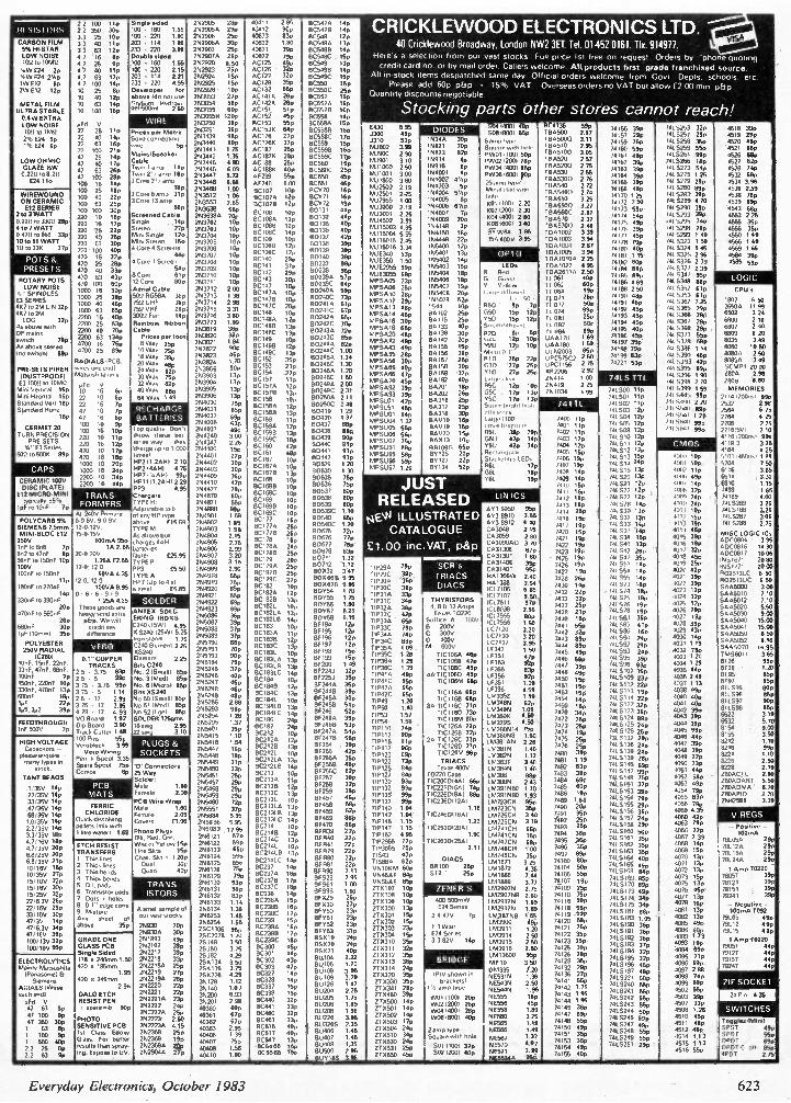
RICKLE WOOD 40 Cricldewood
Here's a selection
credit card
All in-stock ite ms
Please add
Quantity discounts
Stocking
ELECTRONICS Broadway, London NW2
horn our vast stocks Full
no. or by mail order. Callers welco me.
despatched sa me day. Official
60p p&p . 15 °,,-, VAT.
negotiable.
parts Other
3Ef. Tel. 01-452 price list free
All products
orders welco me
Overseas orders
stores
LTD. 0161. TN. 914977. on request Orders by 'phone
first grade franchised
fro m Govt Depts. schools.
no VAT but allow £2 00 min.
'
cannot reach!
quoting
source. .
etc •
p&p
. LOW NOISE 1012 tp 11.117
9Fd V 11 25 11 17
293253 36p 253251 36p 253439 980
5517 AC1536 54p 41/176 27P
3C5584 159 13C55813 16p 00558C 17P
1-431) 5 95 33130 48p
004 74007 405 DIODE 1-, 508 78007 55p " 736 55 P
1134500 2 97 74156 399 7415253 32p 74157 290 7415257 299
4518 399 4519 29p Pnces per Metre
2% E24 Sp 22 40 14P So101connectinq 263440 80p 4C1765 37p 8C559 1SP
3310 53. 19344 30P 6 anm tyPe TBA5000 311 7015258 35p 4520 489 1% E24 Sp
LOW OHMIC GLAZE KW 0 2211 to 8 211 E24 lip
22 63 18 17 22 100 21p 47 25 14p 47 40 17p 47 63 26p 47 100 28p 100 16 14p
wire sp m ...p._...
P .F Cable
T.I° I ,4097 1417 Twin 2 , anm 169 3 Core 2', arno
153441 125 253442 1 35 253445 180 293446 6.09 253447 15.72 2133448 158
AC187 2Sp AC 187K 28p AC1813 25p AC1880 40p AF239 58311 AF240 1.0D
BC55913 16p BC559C 17p FIC560 150 8C560C 2Sp BC650 45P BC651 4614
w on 3.55 Ni no, 290 Ni mi . 3 to Knopp 2.50 ka.,1001 3.00
15821 7017 15823 92p 15914 4p 19916 Op 154001 Op 614002 Cap 1154033
5,1114.1 wall lakle pw0, ,r00 , 50 .
PW0212001 7110 PW00 (4001 115p pw06 ,600 , 00p
25.. ''°:°.“°•"'
TBASIO 296 T1345100 306 M14520 2 67 1045200 2 75 T B A530 259 11345300 2 76
74161 Illo 77,744441:16,L: 57S933595;
/4164 390 74165 39p
1415259 55p 7415261 99p 7415266 lap 7415773 54p 741 5775 125 741 5279 29P
4521 88P 4526 Mb 4527 621, 4528 74p 4537 690 4534 3 96
103 25 16p 100 40 22p mi3 63 25p too too 301'
220 10 llip 220 16 17p 220 25 22p 220 40 25p 220 53 30p no ,, ,oi, 470 16 22p
1SP 3 Core 6 amp 3111 3 Cote 13 00,0
5611 Screened QIN. Single lop 5,0, e. 1711 Mir,, Single 12p Mint Stereo 15p 4 Core 4 Screens
44p
253468 110 253512 1.08 293553 265 253638 66p 2536384 7%, 293102 10p 253703 10p 253704 10P 253705 1017 2613706 100 263707 10P
BC107 109 13C107A 121, 0C10713 1213 BE wo top BC 1084 12p
EIC 108E1 12p 8C 108C 14p EIC109 159 BCI098 12p BC109C 12p
BCY70 16p OCT 71 16P BC Y 72 19P 80131 44p 130132 44p BDI35 40p K0616001 00136 40p B0I37 42p 00138 390 B0139 39p 130140 39p
m1° 3'215008® 2164 66)2501 2 25 5,2955 ISO
MJ3000 2 19 MJ3001 2 15 MJ4502 359
MJ15003 4.85 Nu15004 5 ,
MJ15015 245 mMJJ,15034016 35334p
194004 S hbPp ,
154005 6p 154006 130 p 7415210 .„„, ,... 15. .. "1. 754 009 208 154148 30 194150 18p 154448 270
171365454M01 1123pP
,:zi;;';':,.."":":__:'
K021100, 2 30 60414001 280
140 -
Er21564 195 3544000 3.96
OP T (1
11110,540 272
1T:40545500(0/ 3272 74 3 25
TBA560C 2 87 1134570 237
1 BAS700 2 . - - - — TDA1002 3 39 11341003 1 94 10.41004 287 11341005 3 94
74166 48P 74170 1 25 14117 250 74173 59P 74174 54p 74175 49p 74176 39p 14111 45e 74178 79p 74180 000 74181 115
7415280 890 7415783 330 7415289 470
390 /415793 39P 141 5795 74p /415298 79p /015299 109 741 5323 199 7415324 146 1415375 256
4536 259 4538 78o 4539 89p 4543 68p 4553 225 4555 35p 4556 35p 4560 1 4 9
4566 149 4569 1 65 4580 39P
WIRE WOUND ON CERAMIC 512 SERIES
210 3 WATT 022/i to 3300 2817 4 to 7 WATT „_ 0 4712 to 6k8 40P 10 to II WATT 19 to 336 37p
I '1(1 51 I I-•
420 25 25p
070 40 33p
4 Core 1 Screen 54p
253708 100 293709 10p
BC140 29p 6, 5, 37p 1313137 98P
80238 Wp
m.,E350 , 50 643E2855 ggp
1015402 14p 155403 15p LEDs
11341010A 225 7041017 456
7144 71.87 8809pp /415376 235 14/ S377 239
4585 HP
470 63 43p 8 CO, 61p 12 Core 80p
253710 10p 10p
0C142 25 . 'I' EIC143 300 130239A 570
MJE3055 650
510
155404 180
17,1155:94545454:040
13 Red
1601
T0416114 250 11 061 40p 7418h 89p 74/ 514/ 950
7415348 615p 1 061(I ROTARY POTS
LOW NOISE I. SPINDLES E3 SERIES 467 972.11532p 41(7 to 2M LOG 32a
As above mth DP mains switch •,....
As above stereo wi ,_ 100 SWilChl Iv.
PRESETS FINER IDUSTPROOF1 E3 100S/10 10MS/ Min, Vemcal Ise Mmi firontal 151, Standard 500 18p
470 100 60P 1000 16 30p 1000 25 30, r000 40 46p
1000 63 65p 2200 16 40p 2200 25 63p 2200 40 70p 2200 63 134p 4700 16 75p 4100 25 89p
RADIALS I PCB w1res one en,11 PA811188 •1 .81 pFd V 10 16 6p 22 10 Op 22 16 7p
Aerial Cable 501100584 36p 759 UHF 36p 750 VHF 28p 30011 Fiat 14p Rainbow Ribbon Cable Prices per foot 8 Way 25P 10 Wav 25p 16 Way 39p 20 pup, 4 5 p
24 Wav 62p 30 Way 75p 32 Way 82p 40 WKS' sso 64 Wa, 1 49
263711 253712 2.00 253713 1.38 1143714 2.95 253715 131 253716 3.80 253773 1/9 253819 36p 253820 3811, 2013821 1.84 2N3822 90P
u.n 26/3823 8- ' 253824 1.70 253866 90P 253903 13p 253904 13p 253905 13p 253906 13p 294030 750
BC 147 10p 8C147A 10p BCI4713 10p 8C 147C 20p BC 148 10p 8C1484 12p 0C1480 130 513CC,14485C 1303pp
BC149B 12P 01/1491/ 130 BC152 3Sp BC153 23p BC 154 27p EIC157 lip EIC 1574 12p 01/ 1578 13p BC158 10p
1313139C 600 1302404 59p 130240C 73p 13132410 61p 0D141C 67P 131324217 65P 80247C 70p 00243A 72p BD243C 85p 1302444 82p BE/244C 1 00 131)2454 110 1313245C 1.30 1302464 1.20 00246C 1 50 130249A 2 00 80209C 231 002504 2 11 00250C 240
MM" PPP SSS AAA '6° 2228%3PP
MUI PPSSAAIll 4785PP MPS414 46- MPSA16 30Pp MPS418 65p MPSA20 49, MPSA42 45n MPSA43 4-59 MPSA55 28p MPS456 30p MPS466 40p MPS/166 47p MPSA70 458 MPSA92 39P MPS493 39P MPSLOI 420
80207 92 ( 1:402 °P; BA102 250 BA115 25p 134133 4017 60138 30P 84142 2017 BA155 ISP 04156 38p 04157 25p
30p BA159 32p 04I82 40, 84201 lop 134101 26p BA316 250
I'0.55: 000" ' VC: : : ' ' ''' ',1'''''Lp: 5011222 'ppp
Soma tiiffieuel
R20 SP OP 0111 12p 10p 5,57?olko. 0 71.2p 100
0113 25p 22p G M 27p 25p 010 27p 25p Ono. t1,9 05C 12p tOp ,G55cC ;77: 1.3.3p
5,101 4 t111 0,011 .7117
:771 I: 174' sr:001;4-7: prii5,00P:: -:.
17 082 it 0 89p
04 UAA I 70 1 69 UL N43501803 1856,9
. 50 0PC575C7 F UPC 1156 1 75 8117206 2 92 /5414 ISO 29419 2 25 /510734 1 55
1 1 1 L
7,717/1:44444,7,177:9!327 42441g;
74195 40p 74196 45p 74„, ,. . 7., 1..: .1.54p0
74199 83P 74221 53p
741 S T I I_
7704LL IT 1, 411
741 SO? 11P
7475157 61,7 /4t 5351 61p /415367 7 25 Mi 536S 29p 7415366 29p /415357 29p 701 S3611 29p rai S3/3 5 5 P /41 S3/11 68p 141 5386 1 14 /41 S390 46P /415193 42o 141%395 89p PH 53113 1 90 -. - 141 5396 2 70
an 5399 1 59 fat S445 990 PP 54•10 220
CPU's
1807 6 SO 26504 11 99 6501 3 24 6600 2 10 6802 2 40
u p°80,9p 620 , o .1.4 ' ,,,,. -.... 0,,p8°6 2 '",,..,.7. 8"88° '̀ '.'" 80854 345
sCm P' 2000 2804 286 4,0. 800 r - MEMORIES
71741700,1 998 7537 285
RECHARGE Standard Hon/ 47 10 7p 254031 650 BC 158A 120 13C1588 13p 130419 125
MPS151 48, 84317 25p 1'8', ',"',',
741503 12p '41 ,S48 89P 7564 025 15P 47 16 80
100 10 69 BATTERIES 254032 e - R-F 254036 59 BC159 I 1p 0042 ° 1 3',
880 80437 MPSUO5
MPSUOt 8414ap MPSUO4 132
1343 18 30o 1341/10 1614 14111 , 1100
f"u188" '
14 110 00 7401 lip
741504 12p 741505 130
Mi "41 1 20 Ill 6947 / 990
2764 4 25 7708 225
CERMET 20 TURNPRECISION
POE-SETS 01" E3 Seri.
100 16 10p no 10 lip 220 16 12p 470 10 17p
Top quality Don't throw the. bat tunes way they charge up lo 1.000
254037 44..° y•r, 294240 300 264347 278 254400 15P
BC1594 12p 13C1598 13p BC159C 180 BC160 42p 01/161
1313438 WA 013439 900 130440 91p E10441 91p
55p MPSUO6 66 MPSUO7 75PP MPSUS1 813p
849 19 15 P 84020 15P 84013 - 10, 8E11090 65p
8".', 05U 38p 29P 050 42P 3417 7510 42p 340 R.00•717 0771,9
7402 lip 7403 12p 7004 12p 7405 15o
14/SOB 12p 741510 12p 14/511 12p 741512 12p
7415 "i 99p
- ) ' L.. M ( !-,
27161501 210 4116720071st 990 4118 3 3 25 4164 • 25
5012 to 5006 13911 470 16 180 1000 70 20p 1000 16 24p
101.5' HP211.11H1 2.10 HP214AH/ 4.75
254401 27p 254402 30P 254403 30p
40, BC167 111p 01/1674 lop 861620 1 3 p
130442 93 p 130529 120 00530 130
MPSU55 58p MPSU56 59p MPSU57 120
87126 20p 80127 22p 87134 52p
Star Kiilles LEDs 061 77 p G6L tap
7406 19p 7407 190 1408 14p
741513 150 741514 24p
74 515 13P
4000 10p 4001 10o. 4007 rip '
5101 i45Ons I 185 5204 750
6116 385 1./1,1'S 2200 10 34p 2200 16 440
HP7114431) 99p HP1111.24141 2.29 254409 36C,
294410 42p Etc tee top .0,0!_,35 7!8 29 9
VOL 19p JUST 7409 14p 74/520 130 741621 125
4m0, 49p 400/ 14p
0574 33° 6810 115 CERAMIC 100V
DISC IPLATEI PP3 4.95 154427 79p BC 1680 oa 104,
. ..4.
00537 88 °
7410 15p 7417 lop 741522 12p 41044 371/ n89 165
TRANS 512 MICRO.MINI
N°,04"6 ±5% 1pF 70 1007 7p
Chargers TYPE H- Arkustable In 6
754870 80p 254871 55p 294888 990
8C 168C - BC 169 1 13C16913 10poP
00538 BOP B0539 800 80539C 110
RELEASED ITN ICS AY 1 5050 95P
7417 18P 1413 18P M. 15p
,- 741527 12p /41 S28 14p 141530 13p
re m 24p 411111 24p 4017 70p
74189 000 7415289 325 7415188 2 25
FOR MERS
All 240V Phrna, 6-0-6V, 9 0 9V.
of any HP type above (15.59
254901 1 69 2144907
8 °C16°C 1° ' BCI77 m8 I3D540 85P 14E..44 ILLUSTRATED 403 0910 3.56
424080 1416 15 , 141 532 13P 4012 15p 7415287 305
7415288 POLYCARB 5% SIEMENS 7.5mm MINI-BLOC 012 2501/ lnf to 608 78
12-0-12V, 151150
100mA 95P 142. 66
TYPE M As above but charges 44H barrenes
1 85 254903 198 294904 2 .15 254905 275
013CC 11777784 22 5- 6- pp' BC178 160 BC178A 24p
08 00654750C 13220p
60676 77p 80677 78p
cr1:3308953 12
CATALOGUE CA3048 2 15
£1.00 i n c. VAT, p&p 3 7°
1520 1 , p
:452,1, :90:
4 19 7 22 P
741 533 149 741537 14p 141538 1Sp 141540 13p
4013 19p 4010 46o 4015 390 41116 19p
225
M1SC LOGIC ICs ADC0930 395 ADC0816 1450
8n2 to47/F Op 20.0.200 faster E25.95 225940909'67 212099 01/1788 25p BD678 83p 1/431306 970 870 CA3130 1 so 7423 11P 141547 281, 9717 32p
4018 45p ADC0817 1000 560F to 150nF 10p 10012 1013oF to 150nF
11p 180nF to 270nF
14p 330nF to 390nF
20p 470nF to 560nF
68D0F 32::
1.25A E2.65 121: 121
SOVA 4.35 12-0 120
IO WA 8.95 0 • 6 • 6 • 9 • 9
1.26160,25 These goods are heatLy send mora pH,' we w „, - cr-589 bps ,
TYPE P PP3 (5.50 TYPE A HP7 (Up 974 at a time/ E5.85
254908 3.15 154909 290 254918 65p 254919 75o 254920 13SP 294921 55p 254922 69p 254923 9.3p
295086 36P 255087 39p
BC179 20p BC179A 25p 13C19713 25p 0C179C 27p 51/ 192 10p 13C1824 120 01/ 1028 13p 8C1821. 10p BC1821A 130 EIC182LB 14p EIC18.3 10p
B0711 1 32 00712 112 131)032 3.47 000 6613 5 95 EIDX 676 5 95 130054 1.70 BDY55 1,75 ....‘, 180 FIR ' '''. 00057 5_ 25._ 130058 5 16 EIF 194 12p
110294 no TIP29C 389 TIP30A 350 101430C 369 TIP31A 33p TIP31C 34p TIP32A 38P TIP32C 42p TIP 33A 33A 65p TIP33C 780
SCR's,
TRIACS
DIACS
THYRISTORS 4, 811 12 Amps Texas 10220
Suffice A 1000 pp,
CA31406 39p C431401 95p 041366W 2 40 HA 1388 254 IC17106 6 85 1C17107 9 50 ICL7611 97p 10.8038 255 1C17555 80p la 7556 1 50
. 7475 190 7426 19P 7477 19P 7419 26P 7430 14p 7031 22p 7433 22o 7437 25o 7438 21p 7440 15p
1441 55p
14/ 541 35t7 141651 14p 741554 10p 141 SS, 14p 141613 189 mt S m ltip 141 S16 10p 141571, 19p 741578 I9P /41 SH3 36p /41 085 41P
4019 25o 9120 42p 41121 39p 4022 390 4023 12p 9174 32p 41126 12p 9176 79p 4077 19p 4018 39p
/951671 20 00 INS1771 20 00 8025131C 600 0025130C 650 SAA5000 300 5445010 710 S465012 110 SAA5020 550 5445030 9 EC SAA5040 15 00 SAA5041 15.00
50101 10
ANTEX SOLO
ERING IRONS C240 115W1 cm
19F 110rnml 350 difference 05240115W) 825
1r19 ̀.8n° 11°
255088 37p 2550,50 32p BC183A Ilp
13C1830 12p
8E195 12p 137196 12p
TIP344 74p TIP34C
C 3000 D 4000
LC7120 3 20 LC7130 3 20
7442 32P 7443 ggp
141886 16p /41 590 740
4079 43p 4030 14p 5045050 8.50
SAA5052 8 50 POLYESTER 250V RADIAL
1C2801 10nF, 15n9 12nF, 33nF. 47nF , 6/3nF. 100nF 7P
v , it ( ,
01" COPPER TRACKS
2.5 • 3 75 83P 99P
C240 Element 2.25 05740 Element 2. .,p Bits C240 — No. 2 ISrnalll 1159 No. 3
255190 68p 255191 70p 255193 90p 255194 79p 295245 37p 165246 411p
81/ 1031/ 13P 13C1831 101' BC 183LA 13p BC18318 13p BC183LC 14p
13E197 120 BF 198 150
8" 158 13E200 1 49 1372243 32p 8F2253 35p
TIP354 119 TIP3SC 1.28 TIP364 128 TIP36C 139 1IP414 49p
M 6006
TIC1061 45 P mime 47P
106 4484 44111/1060TIC
LC7137 396
LL FF 334571 14 7S'p L F353 92p LL ;33.55 :;pp
1444 090
;4'1 54205P SAA
7447 39p :95;
741592 29P 741593 24P 741 595 39 p 8116 /41596 93p 741 5107 35p 7415109 23p
613, 179
4037 79p -1033 120 403,1 129 .1035 44p 4036 2 49
5070 16.95 7MS6011 365
95f3 8116 ' 120 8155 85p
150nF, 220770 10p 4700F ..1.3p
25 • 5 3,75 • 3 75 99p
IMed) 85p NO. 6 Micro) EtSp 755147 4Sp
255248 46p
BC 184 10p BC18413 125 I3F244.4 35p
TIP41C 55P TIP42A 55p
TIC106M BM LF 357 1 09 LE 398
7744485p
7451 15p /415112 22P 4037 113 8197 85p 811.595 80p 330nF.
6130nF 175 • 5 1 14 Bits XS240
asp 255249 481, BC184C 13p ElF24413 39P 072454 30p 11P42C 650 TI1/1160 66P 4 59
1513352 1 19 7453 15 7415113 19P
141 S114
4038 00p
.1040 40P 811596 85p 1.._.
19F 4._ 1,5, 21,2 330
2.5 v 17 299 3.75 • 17 3.85 4.79 x 17 4.93 VO Board 1/2 Dip Board 190
1.413
No 501Sn-tall/ No 51 Med/ EISP 50.521Lgel 85P SOLDER 1259m4 18 swg 2.95
155266 2.88 2N5293 987, 255294 1.28 255295 117 255401 35p
BC1841 10p BC19418 13p BC1841C 14p BCI86 24p 0C187 259
8E24513 51p 13E246 520 0F2464 39p ElF24613 SIP 872474
TIP49 1.20 TIPSO 1.40 TIP53 1.57 TIP54• 1.58 TIP110 74p
TIC11613 68P 8A TIC116C 71p
TIC116D 739 TIC 116M 800 1IC1264 72p
1043485 62p 1M3495 1 09 16,..443501( 4.60 3795 0 50
LOA3806,114 75p
7454 14Pp
748° ‘5P 7470 34p 7472 25p
" 73 26 0
22p 7415122 32, 7415123 36p 74L 5124 89p 7015125 24p 7415126
9741 40p 4002 390
0043 39p 4044 39p .7045 99p
811597 90P 811598 85 9 6512 3 19 6532 5 70 8154 9.00
FEEDTHROUGH InF 500V 7p Track Cutter
100 Pins 55p Veroblock 199 Voro Wiring
Pen , Spool 3.35 Spare Spool 750 Combs Op
22 swq 3.10
PLUGS _ Lk
SOCKETS
'13" Connectors 25 Way Solder: Male 180
255415 1.10 65
255418 i'"' 255447 16p 255448 19p 255449 21p 255450 23o 2015451 259 • 255457 29p 255458 29p
BC212 10p BC212A 12p BC212B 130 BC2121 10p BC212LA 130 13C212113 lop BC213 10p SC2134 Ilp BC2138 12P
54, BF247E1 55p FIF254 39p 87255 42p EIF2564 35o 8F256B 48p BF256C 62p 13E257 30p EIF258 32p
rim i, 90p
T10115 81p TIP117 96P TIP120 69p TIP122 73p TIP125 84p TIP127 849 TIP130 93p If 93p
TICI2613 72p 2A TIC126C 73p
1I1/1260 77p TIC126M 96p
TRIACS Texas 400V
TO220 Case TIC2060144,1 66p TIC22501630 74p
1M380148 1 50 LM38145 2 26 ,A38 ,, 1 40
1M3825 1 12 LM3B3T 3 40 1043845 1 40 LM386 88p LM3885 2.43 1M391560 1.70
7474 19p 7475 250 7476 2Sp
14„r ,39,8, 7981 . 4' 7482 'I. ' 7403 38P 7484 690 7485 607
2ep 7315132 29p 7415136 24p 141 S1 13 14c, 741 S139 2131,1 7415145 69P 7415147 ggr, 7415148 75p 745151 310
4046 44p 4047 39p 4048 39p 4049 220 4050 23p 4051 440 4052 S8P 0053 09p
8155 3.50 8212 1 10 8216 99p 8224 1.10 8226 2/0 8228 2.19 280ACTC 260 /8040/ART 5.50 180ADMA 6.70
HIGH VOLTAGE Capacitors -
818858 88888 8 - manV PIP.. stock.
TANT BEADS
1 35V 14p 1'). I)
22 35V 149 M A 1 S .„,...
'091414 4.9 . 255459 BC213C 13P 6E259 35p 1-111135 99p TIC2261)11341 889 1M391580 1.93 7486 198
7415153 3gp 4054 no 280API0 270 33 35V 14p PCB Wire Wrap
29p 255460 729 BC2131 10p
FIC21314
46 F4 7 0 13E458 58P TIP137 99p TIC2361311241 LM723CH 950 7089 1 68
2017
7415154 79p 74LSI55 29P
4055 83p 4056 79p 25415E8 130
FERRIC 47 350101, 68 35V 140 CHLORIDE
Quick dissolving
Mole 1.60 Female 2.09
255551 37P 195884 595
13p 0C213L8 13p 13E459 62p
137469 86P
TIP140 1.04 TIP102 1.04
1.16 TIC24613t16A1
LM723C14 3Sp LM725CH 140
7490 2481 35 P
7415156 36p 7415157 24c,
4059 4.36 4060 42o V REGS
10 35V 14p 22355 149 33 350 18P 4 7 16V 18p 07/350 2017 6.8/26V 20P 6.8/35V 21p 10/16V Illp 10/35V 27p ,p,,,, Zip ign i;,' 3-F.
15/25V 32p 2216.311 21117
pellets (mix with
1 18re 8.8"" 149
Covers E1.00
Phono Plugs 01k, Fled. 0 r0, Wht or Yellow 15p Line Skts 15p Chas. Skt • 1 20p Dual 30c 'Mad 40p
155886 595 256083 77 95
' 256121 57P 256122 59p 256123 65p 256124 59p 196125 65P 256126 758
— 79p 256130 93p 2616131 513g7 256132 83P
BC2131-C 14p 0C214 10p EIC21413 12P BC214C 13P 8C2 141 100 61,214LB 13, - ' - 8C214L1/ lop 01/237 BC237A 16P BC2378 17p 01/2371/ 1130 6C238 14p 01/2384 15p
BF470 SOP 0ER39 22p BER40 220
BER41 22 p 13E1379 22P BFR80 22 .,
'' BF881 22p 13E090 2.11 13E528 295 BFS61 1.00 8E598 1.10 BF X29 26 p
-
0I0145 1.15 1I0147 1.15 TIP162 4.95 1,2955 770 1103,5 20p TIS43 40p TIS884 619 VN1OKM 60p VN46A 84P f VN56AF 85P Z10107 10p 210108 10p
10p
1.22 TIC25313I20A1
1.90 TIC2631312641
211
D1ACS 1313100 25P ST2 ' 25p
ZFNER S
400.50077 W
1M725CN 119 1M70106 gfip 1M741CN 15p 1M747C5 69p LM748CH 1.00
LM748CN 35P LM1871 3 25 LM1872 4.311 LM1886 7,44 1.1889 3.77 15429075 275 1M2907148 260
7492 250 7493 25P 7494 36p 7495 36P 7496 35p 7497 1190 74100 800 74104 50P 74105 551, 74107 19p 7;7)09 25p 74110 35P 74116 50P
7415158 29p 7418160 SOP 7415161 35p 74 15 162 35P 7415163 IS 7415164 400 7415165 AO
--P 741_5168 134p 7415169 85P 7015170 69p 7415173 49p 7415174 34p
4063 190 4066 22p 4067 2.39
4068 10 p 4069 15p 4070 13p 4071 13p 4072 13p 4073 15p 4075 13P 4076 4So 4077 '3P
- Positive - 100mA
781054 290 781126 29p 78115/77 29p 781244 29p
1 Amp TO120 713051 39p 7817T 39p 7816 T 39p 78241 39p
ETCH RESIST TRANSFERS I. Thin lines 2. Thick Ion. 3 Thin bends 4. Thick bends 5. DIL pads 6. Transistor pads 7. Dots 0 holes
TRANS
IS T DR S
22/ 16V 21to 33/100 309
0- 0'r ed ge '̀'-"' 9 Mixture ' , 80 ' .5 1 41 °'
A small sample of OUf vast siocks
256133 114 26/6134 110 256253 145
8C2388 16p 13C23130 17p
BFX30 27p BEY50 23p BFY51 23p
ZTX109 ZTX300 13p ZTX301 15p
624 Senes
2 4-470 7p
1M291714 119 L1029175 1,09
LM387618 195 74118 550 74119 500
7415175 34p 7415181 880 7415183 1.05
4078 15p 4081 13p 4082 13P
- Negative - 100mA 7092
79105 490 47/3V 14P 47/6.3V 34P 47/160 39P 100/13V 32p 100 ,10 p 55,,
above lop 25930 20p 259304 30p
256254 155 25C1306 251/2078 11,5 25349 350 25350 175 25387 4.29 251(134 150 250135 3.75 250226 4.29 35128 1.12 3N .0 1,07 35200 6.93 35201 218 40360 60, 40361 67p 40362 67p 50363 /55 40406 1,35
0C239 15p BC239A 150 BC23913 17p 0C239C 180 EIC300 45p 01/301 44p BC302 43p BC303 47p 0C327 14p 01/328 lop 01/337 15p 8C338 15p 51/440 32p 13C441 33P BC460 32p BC461 33p BC516 401, BC517 40p
BFY52 23p pc ,,3 33p •-•" — .- 135/09 24p BSX20 140 05021 458 131A104 22? 811105 170 - ' BU108 196 BU109 3.29 5U126 1.47 BU204 2.25 8U205 1.75 8U206 1 89 BU208 1.98 9U226 195 0U3265 235 13U406 1 45 130407 1 45
ZTX302 15p 210303 23p 210304 15p ZTX310 35p ZTX311 32 Z10311 35p Z1X313 36p 210314 24p ZTX320 3Sp Z10330 35p ZTX341 28p 210450 39p 210500 14p ZTX501 14 P ZTX502 14P 270503 lip ZTX504 24p ZTX510 34p
1.3 Watt E24 Series 33820 14 0
11.4.39D0 49p 1M3911 1.20 LM3914 2.50 LM3915 1.9) LM3916 2.50 19413600 95i, 54E10 3 50
0.335 f.2a 5053115 1.36 NE5435 2.50 NE54401 1.96
- NE555 16p 5E566 4Sp NE558 1.89 NE560 125 5E565 1 18 NE566 1 49 NE ,, 1.37
74120 59P 74121 25p 74122 3Sp 74123 35P 74125 30p 74126 29p 74128 35p 74132 2 _9p 74136 27p 74141 SSp 74142 1.75 70143 1.95 74144 1.96 74145 38o
- ' 74147 89p 74148 55p 74150 49p 74151 35p
7415190 36p 7415191 36p 7415192 36p 7415193 37p 7415194 32p 741.5/ 95 32p 7415196 45P 7415197 48p 7415221 50p 7415240 55p 7415241 56p 7415242 55p 7415243 55P 7415244 50p 7415245 69p 7415247 45, 7415248 550 7415249 SSp
4085 49p 4086 60p 4089 121 4093 19p 0094 69p 4095 71p 4096 69p 4097 288 4098 lop 4099 89p 4502 55p 4503 39p 4507 33p 4508 1.26 0510 45p 4511 48p 4512 48P 4514 113
791_12 190 79115 499
1 Amp 10220 79051 44p 79127 44, 79157 44p 79241 44p
GRADE ONE GLASS PCB Single Sided
251893 49p 292102 39p 252217 39p 252218 33p 2522184 259 2142219 2717 2522194 280 2012220 22p
228 2522214 230 292222 24p 2522224 2Sp 252223' 2.10 2142223A 115 252368 25p 2612369
BRIDGE ELECTROLY11CS Mainly Matsushita I Panasontc/ Et 5.5r.p.„5
ANIALS Mires each end) uFd V 47 63 99
47 KV 9P 47 350 30P 1 63 Sp 1 108 ip
178 x 240nun 1.50
420 1 195 .91 1.95
420, 245011n 2.95
DALO ETCH RESIST PEN • spare nib 90p
PHOTO SENSITIVE PCB 15t Class Ep-oxy Glass. For better
. IPIV shown In brackets,
S mP 1 a haat
0/01 0001 20p W02(2001 2611 W0414001 2Sp w05 03001 40p
2 fl,p N, Pe Square with hole
ZIF SOCKET
24 Pin 135
S WITCHES
Toggles IMinil SPST 49p SPOT 66p
1 500 40p 2 2 75 80 02 63 99
results than spray ong Expose to UV
26123694, 2529044 2 p
; 40407 75E, 63405 1.56 50470 191
01/547 13p 81/54 08 15p 81/5560 150
0°4°6 1'35 130500 296 0u ,105 3,05
210530 245 27/(531 2Sp ZTX650 460
S011100/ 37p 50212001 40p
0 4 07 5E57 _ _ NE571 3.95 NE5534A 15,9
74153 35p 70154 49P 7„ , 5p _ ' ' ''''' '''.'"
7415251 29P 0515 1.1 1 4516 559
M DT 59p DPDT C off 1Sp 4001 215
Everyday Electronics, October 1983 623
.17 Step-tnl-ste p fully illustrated assembly and Atting instructions sre included together
with circuit descriptions. Highest quality components are used throughout.
%1 .0...1! AT-80
AT-80 Electronic Car Security System
• Arms doors, boot, bonnet and has security loop to protect fog/spot lamps. radio/tape. CB equipment
• Programmable personal code entry system • Armed and disarmed from outside vehicle using a special magnetic key fob against a windscreen sensor pad adhered to the inside of the screen • Fits all 12V neg earth vehicles
• Over 250 components to assemble
1'
BRANDLEADING ELECTRONICS
NO W AVAILABLE IN KIT FORM VOYAGER Car Drive Computer
S X 1000 Electronic Ignition
• Inductive Discharge • Extended coil energy storage circuit
• Contact breaker driven • Three position changeover switch • Over 65 components to assemble • Patented clip-to-coil fitting • Fits all 12v neg earth vehicles
SX2000 Electronic Ignition
• The brandleading system on the market today
• Unique Reactive Discharge • Combined Inductive and Capacitive Discharge
• Contact breaker driven • Three position changeover switch • Over 130 components to assemble • Patented clip-to-coil fitting • Fits all 12v neg earth vehicles
SPECIAL OFFER "FREE" MAGIDICE KIT WITH ALL ORDERS OVER £45.00
- - .4 4.4a\ 4k, INN
SPARKRITE 82 Bath Street, Walsall, West Midlands, WS1 3DE England
NAME
•A most sophisticated accessory • Utilises a single chip mask programmed microprocessor incorporating a unique programme designed by EDA Sparkrite Ltd • Affords 12 functions centred on Fuel, Speed, Distance and Time • Visual and Audible alarms warning of Excess Speed, Frost/Ice, Lights-left-on • Facility to operate LOG and TRIP functions independently or synchronously • Large 10mm high 400ft-L fluorescent display with auto intensity • Unique speed and fuel transducers giving a programmed accuracy of + or — 1% • Large LOG & TRIP memories. 2,000 miles 180 gallons 100 hours • Full Imperial and Metric calibrations • Over 300 components to assemble A real challenge for the electronics enthusiast'
TX 1002 Electronic Ignition
• Contactless or contact triggered • Extended coil energy storage circuit • Inductive Discharge • Three position changeover switch • Distributor triggerhead adaptors included • Die cast weatherproof case • Clip-to-coil or remote mounting facility • Fits majority of 4 Et 6 cyl. 12V. neg. earth vehicles • Over 145 components to assemble.
TX2002 Electronic Ignition
• The ultimate system • Switchable contactless • Three position switch with
Auxiliary back-up inductive circuit • Reactive Discharge Combined capacitive
and inductive • Extended coil energy storage circuit • Magnetic contactless distributor trigger-head • Distributor triggerhead adaptors included
• Can also be triggered by existing contact breakers • Die cast waterproof case with clip-to-coil fitting • Fits
majority of 4 and 6 cylinder 12v neg earth vehicles • Over 150 components to assemble
Al , SPARK RiTE products and designs are imP5 covered by one or rnore W orld Patents
SELF ASSE MBLY
KIT
SX 1000 £12.95 SX 2000 £19.95 TX 1002 £22.95 TX 2002 £32.95 AT 80 £32.95
MAGIDICE Electronic Dice
• Not an auto tern but great fun for the family
• Total random selectoon • Troggered by waving of hand over dice
• Bleeps and flashes during a 4 second tumble sequence
• Throw displayed for 10 seconds • Auto display of last throw 1 second on 5 • Mutong and Off switch on base • Hours of contonuous use from PP7 battery • Over 100 components to assemble
Sparkrite,82 Bath Street, Walsall, West Midlands.
A N M N I = N M M E N E
Tel: (0922) 614791 Al/ow 28 days for delivery
EE/10/83 ADDRESS
I ENCLOSE CHEQUE(S)/POSTAL ORDERS FOR
KIT REF
CHEQUE NO VOYAGER £64.95 MAGIDICE £9:95
PHONE YOURORDER WITH PRICES INC VAT POSTAGE & PACKI N G
11111111 3 1 .1 . M . M I = I IN N E n 1 . . N MI . 1111 M I M E . 111
SEND ONLY SAE IF BROCHURE IS REQUIRED
BARCLAYCARD
CUT OUT THE COUPON NOW!
EVERYDAY
ELECTRONICS and computer PROJECTS
VOL. 12 NO.10 OCTOBER 1983
Editor F. E. BENNETT
Assistant Editor B. W. TERRELL B Sc.
Production and News Editor D. G. BARRINGTON
Projects Editor G. P. HODGSON
Technical Sub-Editor R. A. HOOPER
Art Editor R. F. PALMER
Assistant Art Editor P. A. LOATES
Technical Ill or D. J. GOODING Tech. (CEO
Secretary JACQUELINE DOIDGE
Editorial Offices KING'S REACH TOWER STAMFORD STREET LONDON SE1 9LS Phone: 01-261 6873
Advertisement Manager R. SMITH Phone: 01-261 6671
Representative R. WILLETT Phone: 01-261 6865
Classified Supervisor B. BLAKE Phone: 01-261 5897
Make-Up and Copy Department Phone: 01-261 6615
Advertisement Offices KING'S REACH TOWER STAMFORD STREET LONDON SE1 9LS
WITHOUT TEARS A UTUMN is in some respects an even more auspicious time for new resolu-tions than the new year. It is certainly true that the approach of the Sep-
tember equinox turns thoughts of many of us towards ways to occupy the longer evenings that lie ahead. Personal needs and fancies vary widely. There are those who prefer a casual, maybe inconsequential, kind of pastime. And there are those who wish to make a commitment to serious study over several months. In the latter case the choice of subject may be hard to resolve. So to the undecided may we put in a word or two in favour of electronics as an appropriate and interesting subject for home study. The basic principles that govern all electronic circuits are not difficult to
learn and can be readily proved by uncomplicated experiments carried out on any table top. With batteries as the source of power and the use of a circuit block for assembling components without any recourse to a soldering iron, the introduction to electronic circuits couldn't be easier. All this applies to our new twelve-part series Teach-In 84. We commend
this home study course to all who would like to understand what makes elec-tronics tick. No previous knowledge of electronic or electrical theory is needed. Anyone of any age should be able to follow these articles and rapidly become accustomed to handling components through the experiments. Furthermore all components needed for the twelve parts of Teach-In 84 can be purchased as a complete kit from a number of our advertisers. All of which goes to reinforce our claim to present "Electronics Without Tears".
WIDER SCOPE FOR SCHOOLS Talent for designing and building electronic equipment abounds amongst
our kcondary school students. This has been amply demonstrated over the past two years through the Schools Electronic Design Award Competition (SEDAC). The projects submitted have been impressive, covering an in-teresting range of applications within the limitations imposed by the rules which restricted the designs to those having a useful function in a school's science laboratory. Electronic technology is versatile, and perhaps such limitations ought to be
eased in future so that the scope for designs could be extended. This at any rate is the feeling of both sponsors, Mullard and Everyday Electronics. Therefore, the rules have been amended to permit entry of any electronic design having some specific use within a school's premises, or at any external event, indoors or outdoors, in which the school participates. We confidently expect a large entry of designs and models representative
of all aspects of applied electronics, in this coming third year of SEDAC. Scholars and teachers should note the_ particulars regarding SEDAC 1984 given elsewhere in this issue. Requests for registration forms should be sent in without delay.
Readers' Enquiries We cannot undertake to answer readers' letters requesting modifications,
designs or information on commercial equipment or subjects not published by us. All letters requiring a personal reply should be accompanied by a stamped self-addressed envelope. We cannot undertake to engage in discussions on the telephone.
Component Supplies Readers should note that we do not supply electronic components for
building the projects featured in EVERYDAY ELECTRONICS, but these requirements can be met by our advertisers.
All reasonable precautions are taken to ensure that the advice and data given to readers are reliable. We cannot, however, guarantee it and we cannot accept legal responsibility for it. Prices quoted are those current as we go to press.
Back Issues Certain back issues of EVERYDAY ELECTRONICS are available
worldwide price £1.00 inclusive of postage and packing per copy. Enquiries with remittance should be sent to Post Sales Department, IPC Magazines Ltd., Lavington House, 25 Lavington Street, London SE1 OPF. In the event of non-availability remittances will be returned.
Binders Binders to hold one volume 112 issues) are available from the above
address for £4.60 inclusive of postage and packing worldwide. Please state which Volume.
Subscriptions Annual subscription for delivery direct to any address in the UK: £12.00.
Overseas: £13.00. Cheques should be made payable to IPC Magazines Ltd., and sent to Room 2613, King's Reach Tower, Stamford Street, London SE1 9LS.
Everyday Electronics, October 1983 625
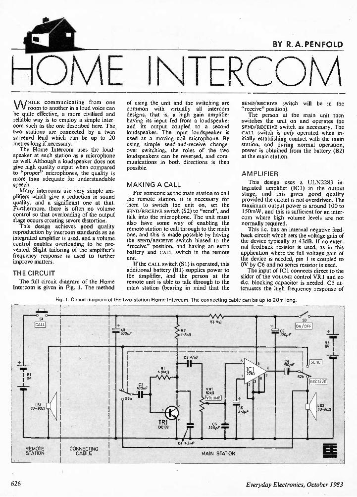
BY R. A. PENFOLD
HOME I\TERCOM W HILE communicating from one
room to another in a loud voice can be quite effective, a more civilised and reliable way is to employ a simple inter-com such as the one described here. The two stations are connected by a twin screened lead which can be up to 20 metres long if necessary. The Home Intercom uses the loud-
speaker at each station as a microphone as well. Although a loudspeaker does not give high quality output when compared to "proper" microphones, the quality is more than adequate for understandable speech. Many intercoms use very simple am-
plifiers which give a reduction in sound quality, and a significant one at that. Furthermore, there is often no volume control so that overloading of the output stage occurs creating severe distortion. This design achieves good quality
reproduction by intercom standards as an integrated amplifier is used, and a volume control enables overloading to be pre-vented. Slight tailoring of the amplifier's frequency response is used to further improve matters.
THE CIRCUIT The full circuit diagram of the Home
Intercom is given in Fig. 1. The method
SI
CALL
LS1 40—son
of using the unit and the switching are common with virtually all intercom designs, that is, a high gain amplifier having its input fed from a loudspeaker and its output coupled to a second loudspeaker. The input loudspeaker is used as a moving coil microphone. By using simple send-and-receive change-over switching, the roles of the two loudspeakers can be reversed, and com-munications in both directions is then possible.
MAKING A CALL For someone at the main station to call
the remote station, it is necessary for them to switch the unit on, set the SEND/RECEIVE Switch (S2) to "send", and talk into the microphone. The unit must also have some way of enabling the remote station to call through to the main one, and this is made possible by having the SEND/RECEIVE SWItCh biased to the "receive" position, and having an extra battery and CALL switch in the remote unit. If the CALL switch (Si) is operated, this
additional battery (B1) supplies power to the amplifier, and the person at the remote unit is able to talk through to the main station (bearing in mind that the
SEND/RECEIVE Mitch will be in the "receive" position). The person at the main unit then
switches the unit on and operates the SEND/RECEIVE switch as necessary. The CALL switch is only operated when in-itially establishing contact with the main station, and during normal operation, power is obtained from the battery (B2) at the main station.
AMPLIFIER
This design uses a ULN2283 in-tegrated amplifier (IC1) in the output stage, and this gives good quality provided the circuit is not overdriven. The maximum output power is around 100 to 150mW, and this is sufficient for an inter-com where high volume levels are not normally required. This i.c. has an internal negative feed-
back circuit which sets the voltage gain of the device typically at 43dB. If no exter-nal feedback resistor is used, as in this application where the full voltage gain of the device is needed, pin 1 is coupled to OV by C6 and no series resistor is used. The input of IC1 connects direct to the
slider of the VOLUME control VRI and no d.c. blocking capacitor is needed. C5 at-tenuates the high frequency response of
Fig. 1. Circuit diagram of the two-station Home Intercom. The connecting cable can be up to 20m long. 1
REMOTE STATION
CONNECTING CABLE
M AI 83 /Ai/
8
Id 228
2 VR1 10511
rv-o
C 330pF
3
5
4
C7
53
ON/OFF
LS2 40-80f1
C4 3,3n F
MAIN STATION EE
626 Everyday Electronics, October 1983
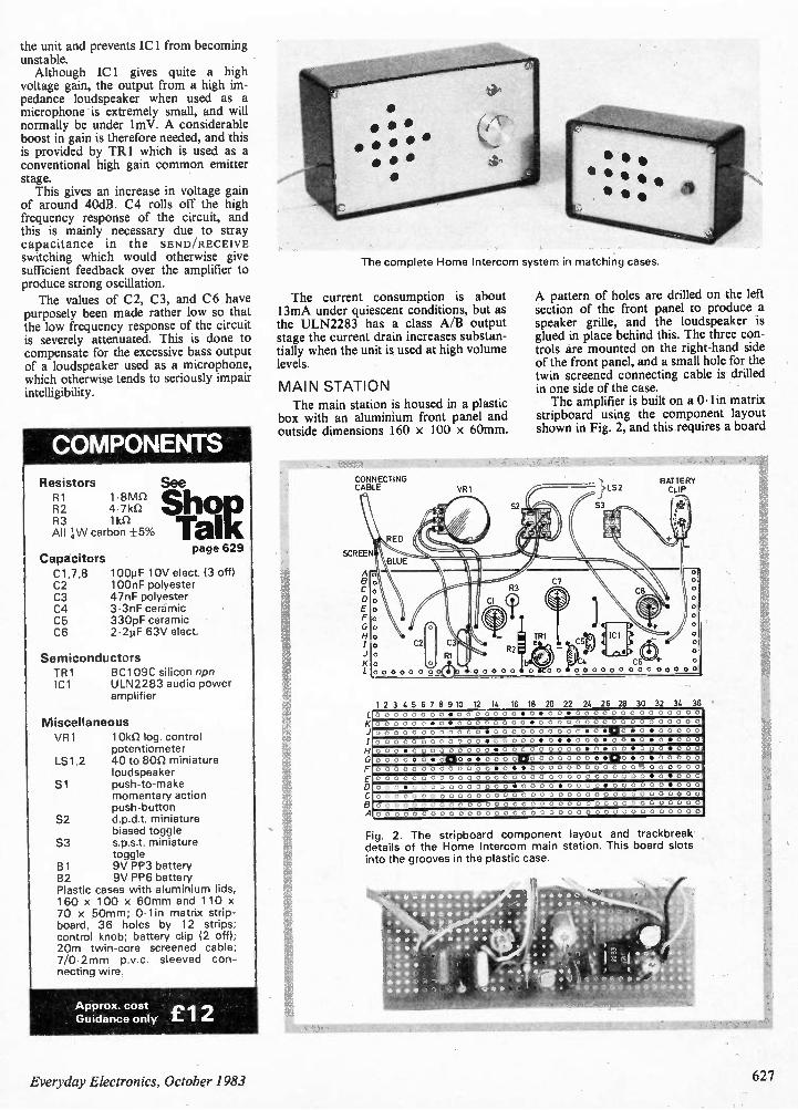
the unit and prevents IC! from becoming unstable. Although IC 1 gives quite a high
voltage gain, the output from a high im-pedance loudspeaker when used as a microphone is extremely small, and will normally be under 1 mV. A considerable boost in gain is therefore needed, and this is provided by TR I which is used as a conventional high gain common emitter stage. This gives an increase in voltage gain
of around 40dB. C4 rolls off the high frequency response of the circuit, and this is mainly necessary due to stray capacitance in the SEND/RECEIVE switching which would otherwise give sufficient feedback over the amplifier to produce strong oscillation. The values of C2, C3, and C6 have
purposely been made rather low so that the low frequency response of the circuit is severely attenuated. This is done to compensate for the excessive bass output of a loudspeaker used as a microphone, which otherwise tends to seriously impair intelligibility.
COMPONENTS
Resistors R1 1•8M1 R2 4.7kS2 R3 1k0 All 4-W carbon +5%
Capacitors
C1,7,8 C2 C3 C4 C5 C6
See
page 629
1001iF 10V elect. (3 off) 100nF polyester 47nF polyester 3.3nF ceramic 330pF ceramic 2.2µF 63V elect.
Semiconductors TR1 IC1
BC109C silicon npn ULN2283 audio power amplifier
Miscellaneous VR1 lokn log, control
potentiometer LS1,2 40 to 80f2 miniature
loudspeaker Si push-to-make
momentary action push-button
S2 d.p.d.t. miniature biased toggle
S3 s.p.s.t. miniature toggle
B1 9V PP3 battery B2 9V PP6 battery Plastic cases with aluminium lids, 160 x 100 x 60mm and 110 x 70 x 50mm; Olin matrix strip-board, 36 holes by 12 strips; control knob; battery clip (2 off); 20m twin-core screened cable; 7/0.2mm p.v.c. sleeved con-necting wire.
Approx. cost £1 2 Guidance only
The complete Home Intercom system in matching cases.
The current consumption is about 13mA under quiescent conditions, but as the ULN2283 has a class A/B output stage the current drain increases substan-tially when the unit is used at high volume levels.
M AIN STATI ON
The main station is housed in a plastic box with an aluminium front panel and outside dimensions 160 x 100 x 60mm.
CONNECTING CABLE
SCREEN
A B
RED
BLUE
VR1
52
A pattern of holes are drilled on the left section of the front panel to produce a speaker grille, and the loudspeaker is glued in place behind this. The three con-trols are mounted on the right-hand side of the front panel, and a small hole for the twin screened connecting cable is drilled in one side of the case. The amplifier is built on a 0- lin matrix
stripboard using the component layout shown in Fig. 2, and this requires a board
}L52
53
BATTERY CLIP
2
0 0 0 0 0 0 0
RI
C7 Cs
4 C6 000000 000 00000
0
0
0
0
0
0
0
0
6
A
1 2 3 4 5 6 7 8 9 10 12 14 16 18 20 22 24 26 28 30 32 34 36 0 0 0 0 , 0 0 • 0 0 0 0 0 0 0 • 0 • 0 0 • 0 0 0 0 0 0 0 0 0 0 0 0 0 0
0 0 0 0 0 0 • 0 • 0 0 0 0 0 0 0 0 • 0 0 0 0 0 0 0 0 0 0 0 0 0 0 0 0 0 0
0 0 0 0 0 0 0 0 0 0 0 0 • 0 0 0 0 0 0 0 0 0 0 • 0 • C . 0 • 0 • 0 0 0 0 0
0 0 0 0 0 0 0 0 0 0 0 0 . 0 0 0 0 0 . 0 . . 0 0 0 . 0 0 . 0 . 0 . 0 0 0
oo o m oo oo o o•O o oo o 000•o•oo•oo o•000 000 o•o• 0120 • •oo o o no 0 00000• • no • o • 0 0 o o 0 0 0 0 0 0 0 0 0 0 0 0 0 • 0 • • 0 0 0 0 0 0 0 0 0 0 0 0 0 0 0 0 0 0 0
0 0 0 0 0 0 0 0 0 0 0 0 0 0 0 0 0 0 0 0 0 0 0 0 0 0 0 0 0 0 • 0 • 0 0 0
0 0 0 • 0 0 0 0 0 0 0 0 0 0 0 • 0 0 0 0 • 0 0 0 0 • 0 0 0 0 0 0 • 0 0 0
0 0 0 0 0 0 0 0 0 0 0 0 0 0 0 0 0 0 0 0 0 0 0 0 0 0 0 0 0 0 0 0 0 0 0 0
0 0 0 0 0 0 0 0 0 0 0 0 0 0 0 0 0 0 0 0 0 0 0 0 0 0 0 0 0 0 0 0 0 0 0 0
0 0 0 0 0 0 0 0 0 0 0 0 0 0 0 0 0 0 0 0 0 0 0 0 0 0 0 0 0 0 0 0 0 0 0 0
Fg. 2. The stripboard component layout and trackbreak details of the Home Intercom main station. This board slots into the grooves in the plastic case.
• • •
• * & • • • • 1r
• • * o. • ;et •• • • • •
• • * • • •
• • •
• r 4 • •
• ft • •
• • •
• • •
• • • •
Everyday Electronics, October 1983 627
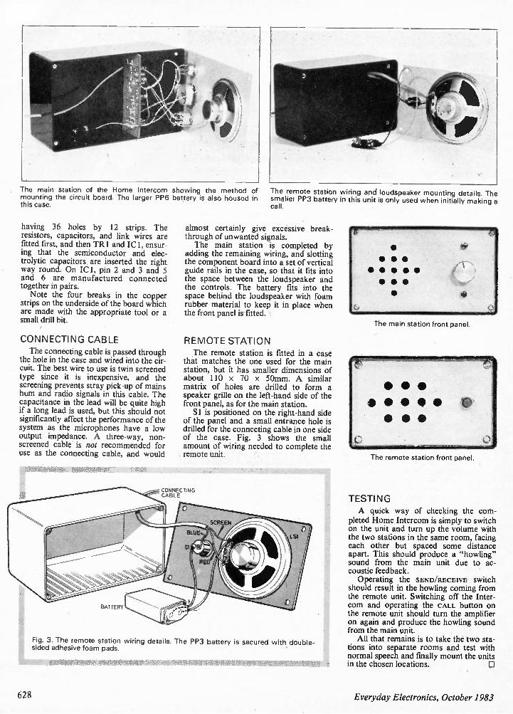
The main station of the Home Intercom showing the method of mounting the circuit board. The larger PP6 battery is also housed in this case.
having 36 holes by 12 strips. The resistors, capacitors, and link wires are fitted first, and then TR I and ICI, ensur-ing that the semiconductor and elec-trolytic capacitors are inserted the right way round. On IC 1, pin 2 and 3 and 5 and 6 are manufactured connected together in pairs. Note the four breaks in the copper
strips on the underside of the board which are made with the appropriate tool or a small drill bit.
CONNECTING CABLE The connecting cable is passed through
the hole in the case and wired into the cir-cuit. The best wire to use is twin screened type since it is inexpensive, and the screening prevents stray pick-up of mains hum and radio signals in this cable. The capacitance in the lead will be quite high if a long lead is used, but this should not significantly affect the performance of the system as the microphones have a low output impedance. A three-way, non-screened cable is not recommended for use as the connecting cable, and would
The remote station wiring and loudspeaker mounting details. The smaller PP3 battery in this unit is only used when initially making a call.
almost certainly give excessive break-through of unwanted signals. The main station is completed by
adding the remaining wiring, and slotting the component board into a set of vertical guide rails in the case, so that it fits into the space between the loudspeaker and the controls. The battery fits into the space behind the loudspeaker with foam rubber material to keep it in place when the front panel is fitted.
REMOTE STATION The remote station is fitted in a case
that matches the one used for the main station, but it has smaller dimensions of about 110 x 70 x 50mm. A similar matrix of holes are drilled to form a speaker grille on the left-hand side of the front panel, as for the main station. S 1 is positioned on the right-hand side
of the panel and a small entrance hole is drilled for the connecting cable in one side of the case. Fig. 3 shows the small amount of wiring needed to complete the remote unit.
CONNECTING CABLE
Fig. 3. The remote station wiring details. The PP3 battery is secured with double-sided adhesive foam pads.
The main station front panel.
The remote station front panel.
TESTING A quick way of checking the com-
pleted Home Intercom is simply to switch on the unit and turn up the volume with the two stations in the same room, facing each other but spaced some distance apart. This should produce a "howling" sound from the main unit due to ac-coustic feedback. Operating the SEND/RECEIVE Switch
should result in the howling coming from the remote unit. Switching off the Inter-com and operating the CALL button on the remote unit should turn the amplifier on again and produce the howling sound from the main unit. All that remains is to take the two sta-
tions into separate rooms and test with normal speech and finally mount the units in the chosen locations. 0
628 Everyday Electronics, October 1983
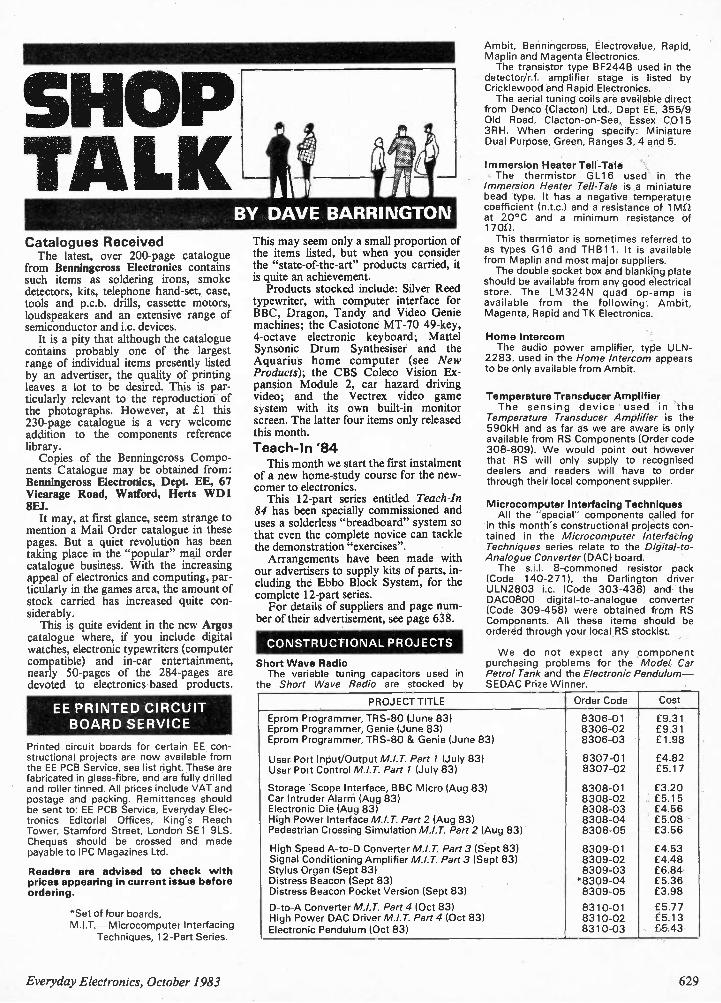
Catalogues Received The latest, over 200-page catalogue
from Benningcross Electronics contains such items as soldering irons, smoke detectors, kits, telephone hand-set, case, tools and p.c.b. drills, cassette motors, loudspeakers and an extensive range of semiconductor and i.c. devices. It is a pity that although the catalogue
contains probably one of the largest range of individual items presently listed by an advertiser, the quality of printing leaves a lot to be desired. This is par-ticularly relevant to the reproduction of the photographs. However, at 1 this 230-page catalogue is a very welcome addition to the components reference library. Copies of the Benningcross Compo-
nents Catalogue may be obtained from: Benningcross Electronics, Dept. EE, 67 Vicarage Road, Watford, Herts WD1 8EJ. It may, at first glance, seem strange to
mention a Mail Order catalogue in these pages. But a quiet revolution has been taking place in the "popular" mail order catalogue business. With the increasing appeal of electronics and computing, par-ticularly in the games area, the amount of stock carried has increased quite con-siderably. This is quite evident in the new Argos
catalogue where, if you include digital watches, electronic typewriters (computer compatible) and in-car entertainment, nearly 50-pages of the 284-pages are devoted to electronics-based products.
EE PRINTED CIRCUIT BOARD SERVICE
Printed circuit boards for certain EE con-structional projects are now available from the EE PCB Service, see list right. These are fabricated in glass-fibre, and are fully drilled and roller tinned. All prices include VAT and postage and packing. Remittances should be sent to: EE PCB Service, Everyday Elec-tronics Editorial Offices, King's Reach Tower, Stamford Street, London SE1 9LS. Cheques should be crossed and made payable to IPC Magazines Ltd.
Readers are advised to check with prices appearing in current issue before ordering.
*Set of four boards. M.I.T. —Microcomputer Interfacing
Techniques, 12-Part Series.
BY DAVE BARRINGTON
This may seem only a small proportion of the items listed, but when you consider the "state-of-the-art" products carried, it is quite an achievement. Products stocked include: Silver Reed
typewriter, with computer interface for BBC, Dragon, Tandy and Video Genie machines; the Casiotone MT-70 49-key, 4-octave electronic keyboard; Mattel Synsonic Drum Synthesiser and the Aquarius home computer (see New Products); the CBS Coleco Vision Ex-pansion Module 2, car hazard driving video; and the Vectrex video game system with its own built-in monitor screen. The latter four items only released this month.
Teach-In '84 This month we start the first instalment
of a new home-study course for the new-comer to electronics. This 12-part series entitled Teach-In
84 has been specially commissioned and uses a solderless "breadboard" system so that even the complete novice can tackle the demonstration "exercises". Arrangements have been made with
our advertisers to supply kits of parts, in-cluding the Ebbo Block System, for the complete 12-part series. For details of suppliers and page num-
ber of their advertisement, see page 638.
CONSTRUCTIONAL PROJECTS
Short Wave Radio The variable tuning capacitors used in
the Short Wave Radio are stocked by
Ambit, Benningcross, Electrovalue, Rapid, Maplin and Magenta Electronics. The transistor type BF244B used in the
detector/r.f. amplifier stage is listed by Cricklewood and Rapid Electronics. The aerial tuning coils are available direct
from Denco (Clacton) Ltd., Dept EE, 355/9 Old Road, Clacton-on-Sea, Essex C015 3RH. When ordering specify: Miniature Dual Purpose, Green, Ranges 3, 4 and 5.
Immersion Heater Tell-Tale The thermistor GL16 used in the
Immersion Heater Tell-Tale is a miniature bead type. It has a negative temperature coefficient (n.t.c.) and a resistance of 1 vin at 20°C and a minimum resistance of 1700. This thermistor is sometimes referred to
as types G16 and THB11. It is available from Maplin and most major suppliers. The double socket box and blanking plate
should be available from any good electrical store. The LM324N quad op-amp is available from the following: Ambit, Magenta, Rapid and TK Electronics.
Home Intercom The audio power amplifier, type ULN-
2283, used in the Home Intercom appears to be only available from Ambit.
Temperature Transducer Amplifier The sensing device used in the
Temperature Transducer Amplifier is the 590kH and as far as we are aware is only available from RS Components (Order code 308-809). We would point out however that RS will only supply to recognised dealers and readers will have to order through their local component supplier.
Microcomputer Interfacing Techniques All the "special" components called for
in this month's constructional projects con-tained in the Microcomputer Interfacing Techniques series relate to the Digital-to-Analogue Converter (DAC) board. The sit. 8-commoned resistor pack
(Code 140-271), the Darlington driver ULN2803 i.c. (Code 303-438) and the DAC0800 digital-to-analogue converter (Code 309-458) were obtained from RS Components. All these items should be ordered through your local RS stockist.
We do not expect any component purchasing problems for the Model Car Petrol Tank and the Electronic Pendulum — SEDAC Prize Winner.
PROJECT TITLE Order Code Cost
Eprom Programmer, TRS-80 (June 83) 8306-01 £9.31 Eprom Programmer, Genie (June 83) 8306-02 £9.31 Eprom Programmer, TRS-80 & Genie (June 83) 8306-03 £1.98
User Port Input/Output M.I.T. Part 1 (July 83) 8307-01 £4.82 User Port Control M.I.T. Part 1 (July 831 8307-02 £5.17
Storage 'Scope Interface, BBC Micro (Aug 83) 8308-01 £3.20 Car Intruder Alarm (Aug 83) 8308-02 £5.15 Electronic Die (Aug 83) 8308-03 £4.56 High Power Interface M.I.T. Part 2 (Aug 83) 8308-04 £5.08 Pedestrian Crossing Simulation M.I.T. Part 2 (Aug 83) 8308-05 £3.56
High Speed A-to-D Converter M.I.T. Part 3 (Sept 83) 8309-01 £4.53 Signal Conditioning Amplifier M.I.T. Part 3 (Sept 83) 8309-02 £4.48 Stylus Organ (Sept 83) 8309-03 £6.84 Distress Beacon (Sept 83) *8309-04 £5.36 Distress Beacon Pocket Version (Sept 83) 8309-05 £3.98
D-to-A Converter M.I.T. Part 4 (Oct 83) 8310-01 £5.77 High Power DAC Driver M.I.T. Part 4 (Oct 83) 8310-02 £5.13 Electronic Pendulum (Oct 83) 8310-03 £5.43
Everyday Electronics, October 1983 629
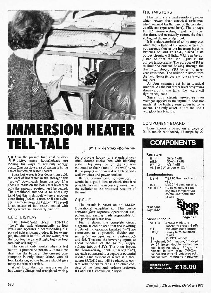
IMMERSION HEATER TELL-TALE BY T. R.de Vaux-Balbirnie
W 1TH the present high cost of elec-tricity, many householders are
looking for ways of reducing energy costs. One possible area of saving is in the use of immersion water heaters. Since hot water is less dense than cold,
the level of hot water in the storage tank "grows" downwards from the top. If a check is made on the hot-water level then only the amount required need be heated. The traditional method is to check by hand but this is difficult where a modern close-fitting jacket is used or if the cylin-der is remote from the kitchen. The result is an excess of hot water; heated with energy which will be dearly paid for.
L.E.D. DISPLAY The Immersion Heater Tell-Tale
"feels" the tank electronically at four levels and operates a corresponding dis-play of light emitting diodes. If, for exam-ple, the tank is half full of hot water, then the top two 1.e.d.s will light but the bot-tom pair will stay off. The circuit only works when a test
button is pressed so normally there is no drain on the battery. The current con-sumption is only about 20mA with all four I.e.d.s on, so the battery should give many months of service. Apart from the four sensors on the
hot-water cylinder and associated wiring,
the project is housed in a standard elec-trical double socket box with blanking plate. This may be of the surface-mounted or flush (sunk in the wall) type. If the project is on view it will blend with wall switches and power sockets. Before commencing construction, it
would be a good idea to check that it is possible to run the necessary wires from the cylinder to the proposed position of the unit.
CIRCUIT The circuit is based on an LM324
Operational Amplifier i.e. This device contains four separate operational am-plifiers and each is made responsible for one particular water level. Fig. 1 shows the complete circuit
diagram. It can be seen that the inverting inputs of the op-amps (marked "—") are connected to a potential divider con-sisting of two equal value resistors, R5 and R6. This sets the inverting inputs to about one-half of the battery supply voltage (about 4.5V). The other inputs, the non-inverting inputs (marked "+"), are each connected to a separate potential divider. One element of which is a ther-mistor (RTH1) and will be placed in con-tact with the water tank. The other con-sists of the fixed and variable resistors, R1 and VR1, connected in series.
THERMISTORS Thermistors are heat-sensitive devices
which reduce their electricai resistance when warmed (in the case of the negative co-efficient type used here). The voltage at the non-inverting input will rise, therefore, and eventually exceed the fixed voltage at the inverting input. It is a characteristic of an op-amp that
when the voltage at the non-inverting in-put exceeds that at the inverting input, it switches on and an I.e.d., placed in its output circuit, will light. VR1 can be ad-justed so that the 1.e.d. lights at the correct temperature. The purpose of R I is to limit the current flowing through the thermistor should VR1 be set to near-zero resistance. The resistor in series with the I.e.d. limits its current to a safe work-ing level. All four channels act in an identical
manner. As the hot-water level progresses downwards in the tank, the I.e.d.s will light in sequence. Since this circuit compares two
voltages applied to the inputs, it does not matter if the battery runs down to some extent. The only effect is that the 1.e.d.s will glow less brightly.
COMPONENT BOARD Construction is based on a piece of
0.1in matrix stripboard, 17 strips by 27
COMPONENTS
Resistors R1-4 10k(l (4 off) R5,6 1001d2 (2 off) R7-10 1kSZ (4 off) All or carbon +10%
Semiconductors D1-4
IC1 * RTH1-4
*see note page 632
TIL220 5mm red led. (4 off) LM324N quad op-amp GL16 miniature bead, negative temperature coefficient thermistor (4 off)
See
Miscellaneous page 629
VR1-4 470k1) miniature horizontal preset (4 off)
Si miniature push-button TB1,2 5-way terminal block
(2 off) B1 9V PP3 battery Stripboard, 0.1 in matrix, 17 strips by 27 holes; double socket box and blanking plate; 14-pin i.e. holder; battery clip; 7/0.2mm connecting wire (5 colours); solid copper wire; mounting hardware.
Approx cost. £118 00 Guidance only .
630 Everyday Electronics, October 1983
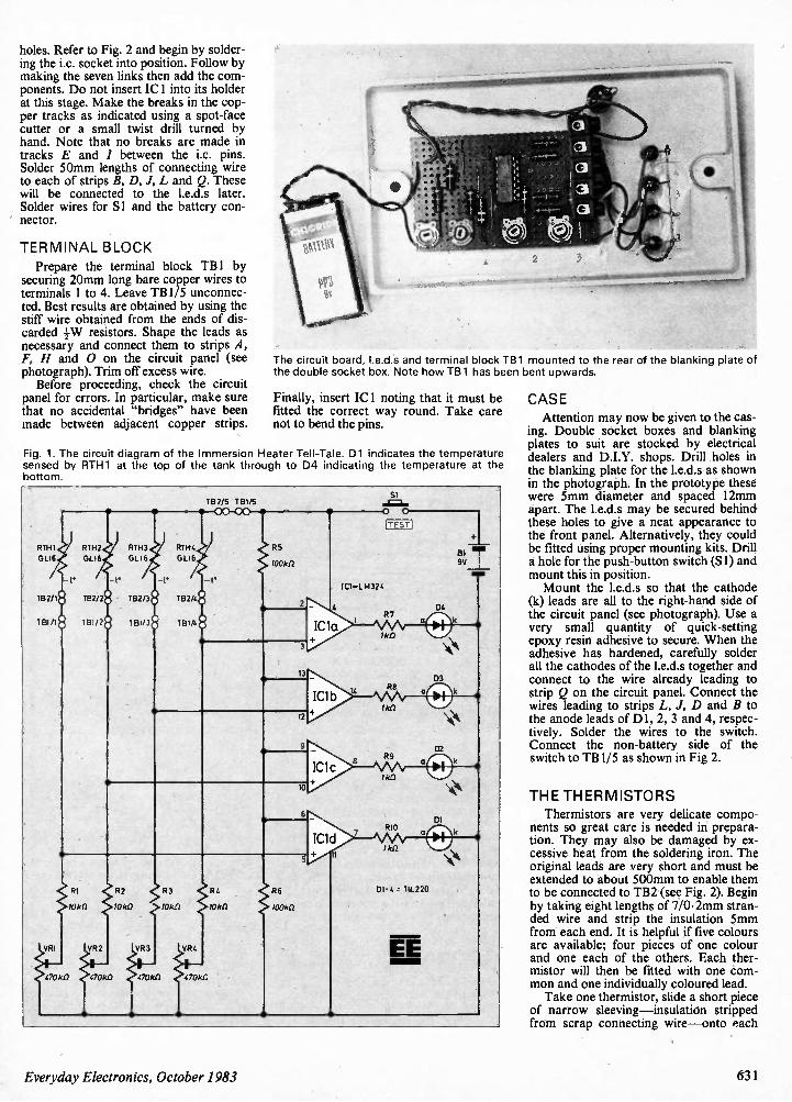
100k ft
R6
100k11
Si siN GIN.
4
11
a 04
03
a k
k
iTEST I
IC1=L M324
R7
lk1)
R8
R9
I kfl
DI - 4 . TIL2 20
EE
02
DI
holes. Refer to Fig. 2 and begin by solder-ing the i.c. socket into position. Follow by making the seven links then add the com-ponents. Do not insert ICI into its holder at this stage. Make the breaks in the cop-per tracks as indicated using a spot-face cutter or a small twist drill turned by hand. Note that no breaks are made in tracks E and I between the i.c. pins. Solder 50mm lengths of connecting wire to each of strips B, D, J, L and Q. These will be connected to the 1.e.d.s later. Solder wires for Si and the battery con-nector.
TERMINAL BLOCK Prepare the terminal block TB I by
securing 20mm long bare copper wires to terminals 1 to 4. Leave TB 1/5 unconnec-ted. Best results are obtained by using the stiff wire obtained from the ends of dis-carded INV resistors. Shape the leads as necessary and connect them to strips A, F, H and 0 on the circuit panel (see photograph). Trim off excess wire. Before proceeding, check the circuit
panel for errors. In particular, make sure that no accidental "bridges" have been made between adjacent copper strips.
The circuit board, I.e.d.s and terminal block TB1 mounted to the rear of the blanking plate of the double socket box. Note how TB1 has been bent upwards.
Finally, insert IC1 noting that it must be fitted the correct way round. Take care not to bend the pins.
Fig. 1. The circuit diagram of the Immersion Heater Tell-Tale. D1 indicates the temperature sensed by RTH1 at the top of the tank through to 04 indicating the temperature at the bottom.
RTH I
GLI6
TB 2/1
T B I / I
T82/5 TB1/5
RTH2 RTH3 R1H4 GU 6 GL16 G LI 6
-I' -t° -I' --V
TB2/2 TB2/3 TB2/4
RI
1050
VRI
R2 R3 R4
lokn >lokfl >10512
470k12 470k0 4701(12 4 70k11
CASE Attention may now be given to the cas-
ing. Double socket boxes and blanking plates to suit are stocked by electrical dealers and D.I.Y. shops. Drill holes in the blanking plate for the 1.e.d.s as shown in the photograph. In the prototype these were 5mm diameter and spaced 12mm apart. The 1.e.d.s may be secured behind these holes to give a neat appearance to the front panel. Alternatively, they could be fitted using proper mounting kits. Drill a hole for the push-button switch (Si) and mount this in position. Mount the 1.e.d.s so that the cathode
(k) leads are all to the right-hand side of the circuit panel (see photograph). Use a very small quantity of quick-setting epoxy resin adhesive to secure. When the adhesive has hardened, carefully solder all the cathodes of the 1.e.d.s together and connect to the wire already leading to strip Q on the circuit panel. Connect the wires leading to strips L, J, D and B to the anode leads of Di, 2, 3 and 4, respec-tively. Solder the wires to the switch. Connect the non-battery side of the switch to TB 1/5 as shown in Fig 2.
THE THERMISTORS Thermistors are very delicate compo-
nents so great care is needed in prepara-tion. They may also be damaged by ex-cessive heat from the soldering iron. The original leads are very short and must be extended to about 500mm to enable them to be connected to TB2 (see Fig. 2). Begin by taking eight lengths of 7/0-2mm stran-ded wire and strip the insulation 5mm from each end. It is helpful if five colours are available; four pieces of one colour and one each of the others. Each ther-mistor will then be fitted with one com-mon and one individually coloured lead. Take one thermistor, slide a short piece
of narrow sleeving —insulation stripped from scrap connecting wire —onto each
Everyday Electronics, October 1983 631
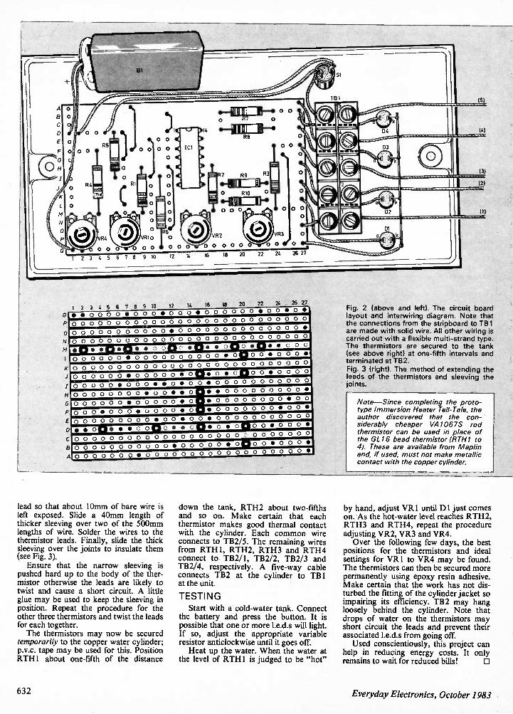
0
IA 20 24 26 27 1 2 3 4 5 b / 0 iu sz ,.. •., • • 0 0 0 0 • 0 0 0 • 0 0 0 • 0 0 0 0 0 0 • 0 0 • 0 •
0 0 0 0 0 0 0 0 0 0 0 0 0 0 0 0 0 0 0 0 0 0 0 0 0 0 0
0 0 0 0 0 0 0 0 0 0 0 • 0 0 0 0 0 0 0 0 0 0 0 0 0 0 •
0 0 0 0 0 0 0 0 0 0 0 0 0 0 0 0 0 0 0 0 0 0 0 0 0 0 0
•0. •ci•o• • o oClo •CD• • ol W egl• •000 0 0 0 0 0 0 • 0 0 0 0 0 0 0 0 0 0 • O M 0 0 • 0 0 0 •
0 0 0 0 0 0 0 0 0 0 0 0 0 0 0 0 0 0 0 0 0 0 0 0 0 0 0
00 000 0•0 0000•0 0 woClo0•o 00 0 0 0000 •000• •o •o o• 0 0 0 00 000 00 0 00 0 0 0 0 0 0 0 0 0 • 0 0 0 0 0 0 0 0 0 0 •
0 0 0 0 0 0 • 0 0 0 0 0 • 0 • 0 0 0 0 0 0 0 0 • 0 0
I
. 0 0 0 • 0 0 0 • 0 0 0 0 • 0 • 0 0 0 0 0 0 0 • 0 0 •
0 0 0 0 0 0 0 0 0 • 0 0 • 0 0 • 0 0 0 0 0 0 .0 0 0 0 0
) • • O CI • • • o o 0 o • • c o, o • opo o • o o o • :00 000 0 00 0 000 00 0 00 0 000000 000 300000 00 0o 0 o• 0o 0 00 • 0 00 0500 05 4 0 0 0 0 0 0 0 • 0 0 0 0 0 0 0 0 0 0 0 0 0 0 0 0 0 0 •
Fig. 2 (above and left). The circuit board layout and interwiring diagram. Note that the connections from the stripboard to TB 1 are made with solid wire. All other wiring is carried out with a flexible multi-strand type. The thermistors are secured to the tank (see above right) at one-fifth intervals and terminated at T82. Fig. 3 (right). The method of extending the leads of the thermistors and sleeving the joints.
Note—Since completing the proto-type Immersion Heater Tell-Tale, the author discovered that the con-siderably cheaper VA1 067S rod thermistor can be used in place of the GL 16 bead thermistor (RTH1 to 4). These are available from Maplin and, if used, must not make metallic contact with the copper cylinder.
lead so that about 10mm of bare wire is left exposed. Slide a 40mm length of thicker sleeving over two of the 500mm lengths of wire. Solder the wires to the thermistor leads. Finally, slide the thick sleeving over the joints to insulate them (see Fig. 3). Ensure that the narrow sleeving is
pushed hard up to the body of the ther-mistor otherwise the leads are likely to twist and cause a short circuit. A little glue may be used to keep the sleeving in position. Repeat the procedure for the other three thermistors and twist the leads for each together. The thermistors may now be secured
temporarily to the copper water cylinder; p.v.c. tape may be used for this. Position RTH1 about one-fifth of the distance
down the tank, RTH2 about two-fifths and so on. Make certain that each thermistor makes good thermal contact with the cylinder. Each common wire connects to TB2/5. The remaining wires from RTH1, RTH2, RTH3 and RTH4 connect to TB2/1, TB2/2, TB2/3 and TB2/4, respectively. A five-way cable connects TB2 at the cylinder to TBI at the unit.
TESTING
Start with a cold-water tank. Connect the battery and press the button. It is possible that one or more I.e.d.s will light. If so, adjust the appropriate variable resistor anticlockwise until it goes off. Heat up the water. When the water at
the level of RTHI is judged to be "hot"
by hand, adjust VR I until Dl just comes on. As the hot-water level reaches RTH2, RTH3 and RTH4, repeat the procedure adjusting VR2, VR3 and VR4. Over the following few days, the best
positions for the thermistors and ideal settings for VR1 to VR4 may be found. The thermistors can then be secured more permanently using epoxy resin adhesive. Make certain that the work has not dis-turbed the fitting of the cylinder jacket so impairing its efficiency. TB2 may hang loosely behind the cylinder. Note that drops of water on the thermistors may short circuit the leads and prevent their associated I.e.d.s from going off. Used conscientiously, this project can
help in reducing energy costs. It only remains to wait for reduced bills! 0
632 Everyday Electronics, October 1983
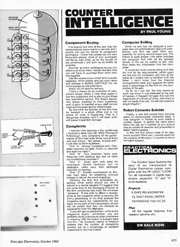
HOrNAT ER CYLINDER
BOND THERMISTORS TO CYLINDER
11)
IS)
LEADS 500mm —
LONG
LARGE BORE SLEEVING
TB2
THERMISTOR
k\ S Z:Ze
V 50,5 7 07 0 0 0
SMALL BORE SLEEVING
Hot Water
0 Level
to
0
INTELLIGENCECOUNTER
Component Buying It is around this time of the year that the
constructional scene starts in earnest, and I usually trot out my advice to component purchasers. I know that unless you are very favourably placed, most of your purchases will be by mail order, so for the benefit of the uninitiated I will sum up as briefly as possible: Send for as many catalogues as you can
afford and study them. Accept the fact that you will have to purchase from more than one supplier. Use the retailer's own order form (usually
supplied). Write clearly and put your name and address in BLOCK CAPITALS. Do not write queries on the order form. Allow 10-14 days for delivery. I have a theory on the evolution of com-
ponent shops. When a new shop opens it has few customers and is able to give these few superlative service. The shop's reputa-tion grows resulting in more customers until a point is reached where staff cannot cope and the good service deteriorates. By this time the founder of the firm may
be isolated in a plush office and is not aware of what is happening. This is a dangerous situation and if not dealt with, will cause irreparable damage.
Complaints I mention this, because a few weeks ago
I received a letter from Mr. Mills-Thomas of Pulborough, who complains of the perfor-mance of four mail order firms, two of them very well known, "No names, no pack drill", I will refer to them by letters: Firm "A". Wrong Transistors sent. Tran-
sistor returned, no reply. Faulty Lc. returned and again no reply!! Firm "B". Two incorrect items sent.
Returned with packing slip, but no reply, nor to additional reminder!! Firm "C". Order sent with extra for
catalogue. Goods received, but no catalogue. Letter sent, then catalogue received, no apology. Firm "D". Grossly overcharged on Bar-
clay Card debit, on protesting received cheque in refund. No word of apology. Certainly the first two complaints are
serious. What action should you take if placed in a similar situation? I suggest that you write first to the Managing Director of the firm concerned and mark the envelope "personal". If this fails to effect a remedy, write to the magazine which is carrying the firm's advertising. In the final analysis the magazine bears the responsibility for any lapse on the part of their advertisers, so you can be certain that they will demand an explanation from the offenders. If you still get no satisfaction, write to the
magazine again; remember you are probably doing a service to other customers in ensuring that the culprit is brought back into line. I do, however, hasten to reassure readers that the number of complaints worked out as a percentage of satisfied customers is very low indeed.
BY PAUL YOUNG
Computer Selling While no one has yet designed a com-
puter that will automatically deal with com-plaints, one firm has used them suc-cessfully for selling second-hand cars. The theory is quite simple —the seller provides the computer firm with all the relevant details of the car he wishes to sell, who then ,feeds the information into the com-puter. A would-be buyer comes along and tells
the firm all his requirements, which again are fed into the computer, and then at the press of a button one is matched with the other. I don't know how the financial arrangements work, but I suppose the seller pays a percentage to the firm on the com-pletion of the sale. As far as I can tell, the idea seems to
work, but when it was extended to the sale of houses, it flopped! At least, this was the experience of a friend of mine, who tried to sell his house this way. He did not receive a single enquiry!!
Robot Commits Suicide Finally, a tale that comes from America
about an electronically controlled robot. It was designed in Florida to work inside a nuclear reactor. It seems the robot didn't fancy the job, so it worked its arm around into an unnatural position and proceeded to batter itself to pieces. Is this the first known case of an elec-
tronic suicide? Mind you, I cannot vouch for the veracity of the story —it seems to me to be highly suspect.
R ACTICAL LECTRDNICS
The October issue features the
start of our Introduction to Digital Electronics course, com-
plete with the PE LOGIC TUTOR. For all interested in digital elec-
tronics, especially "0" and "A" level students.
Projects
A SAFE RELAXOMETER
4+ DIGIT PANEL METER
EXPANDING THE VIC 20
Plus All the regular features, free
readers' adverts, etc.
ON SALE NO W
Everyday Electronics, October 1983 633
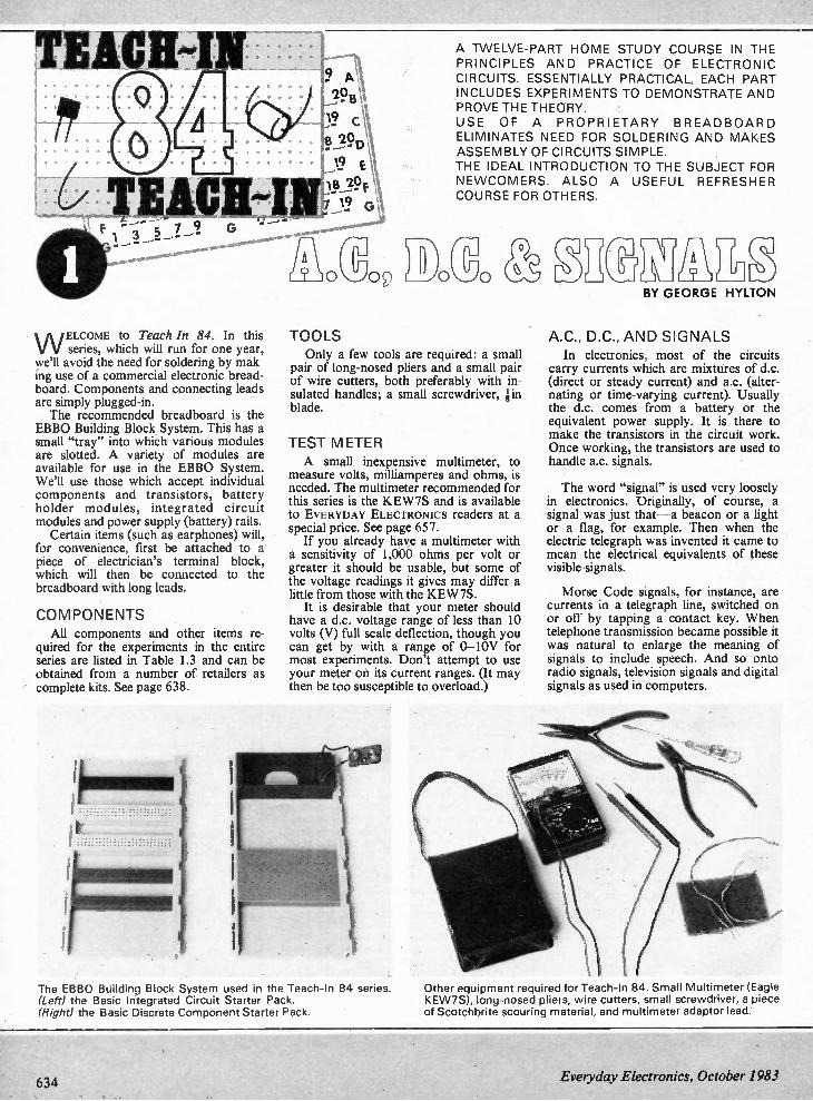
W ELCOME to Teach-In 84. In this series, which will run for one year,
we'll avoid the need for soldering by mak-ing use of a commercial electronic bread-board. Components and connecting leads are simply plugged-in. The recommended breadboard is the
EBBO Building Block System. This has a small "tray" into which various modules are slotted. A variety of modules are available for use in the EBBO System. We'll use those which accept individual components and transistors, battery holder modules, integrated circuit modules and power supply (battery) rails. Certain items (such as earphones) will,
for convenience, first be attached to a piece of electrician's terminal block, which will then be connected to the breadboard with long leads.
COMPONENTS All components and other items re-
quired for the experiments in the entire series are listed in Table 1.3 and can be obtained from a number of retailers as complete kits. See page 638.
A TWELVE-PART HOME STUDY COURSE IN THE PRINCIPLES AND PRACTICE OF ELECTRONIC CIRCUITS. ESSENTIALLY PRACTICAL, EACH PART INCLUDES EXPERIMENTS TO DEMONSTRATE AND PROVE THE THEORY. USE OF A PROPRIETARY BREADBOARD ELIMINATES NEED FOR SOLDERING AND MAKES ASSEMBLY OF CIRCUITS SIMPLE. THE IDEAL INTRODUCTION TO THE SUBJECT FOR NEWCOMERS. ALSO A USEFUL REFRESHER COURSE FOR OTHERS.
TOOLS Only a few tools are required: a small
pair of long-nosed pliers and a small pair of wire cutters, both preferably with in-sulated handles; a small screwdriver, in blade.
TEST METER A small inexpensive multimeter, to
measure volts, milliamperes and ohms, is needed. The multimeter recommended for this series is the KEW7S and is available to EVERYDAY ELECTRONICS readers at a special price. See page 657. If you already have a multimeter with
a sensitivity of 1,000 ohms per volt or greater it should be usable, but some of the voltage readings it gives may differ a little from those with the KEW7S. It is desirable that your meter should
have a d.c. voltage range of less than 10 volts (V) full scale deflection, though you can get by with a range of 0-10V for most experiments. Don't attempt to use your meter on its current ranges. (It may then be too susceptible to overload.)
The EBBO Building Block System used in the Teach-In 84 series. (Left) the Basic Integrated Circuit Starter Pack. (Right) the Basic Discrete Component Starter Pack.
BY GEORGE HYLTON
A.C., D.C., AND SIGNALS In electronics, most of the circuits
carry currents which are mixtures of d.c. (direct or steady current) and a.c. (alter-nating or time-varying current). Usually the d.c. comes from a battery or the equivalent power supply. It is there to make the transistors in the circuit work. Once working, the transistors are used to handle a.c. signals.
The word "signal" is used very loosely in electronics. Originally, of course, a signal was just that —a beacon or a light or a flag, for example. Then when the electric telegraph was invented it came to mean the electrical equivalents of these visible signals.
Morse Code signals, for instance, are currents in a telegraph line, switched on or off by tapping a contact key. When telephone transmission became possible it was natural to enlarge the meaning of signals to include speech. And so onto radio signals, television signals and digital signals as used in computers.
Other equipment required for Teach-In 84. Small Multimeter (Eagle KEW7S), long-nosed pliers, wire cutters, small screwdriver, a piece of Scotchbrite scouring material, and multimeter adaptor lead.
634 Everyday Electronics, October 1983
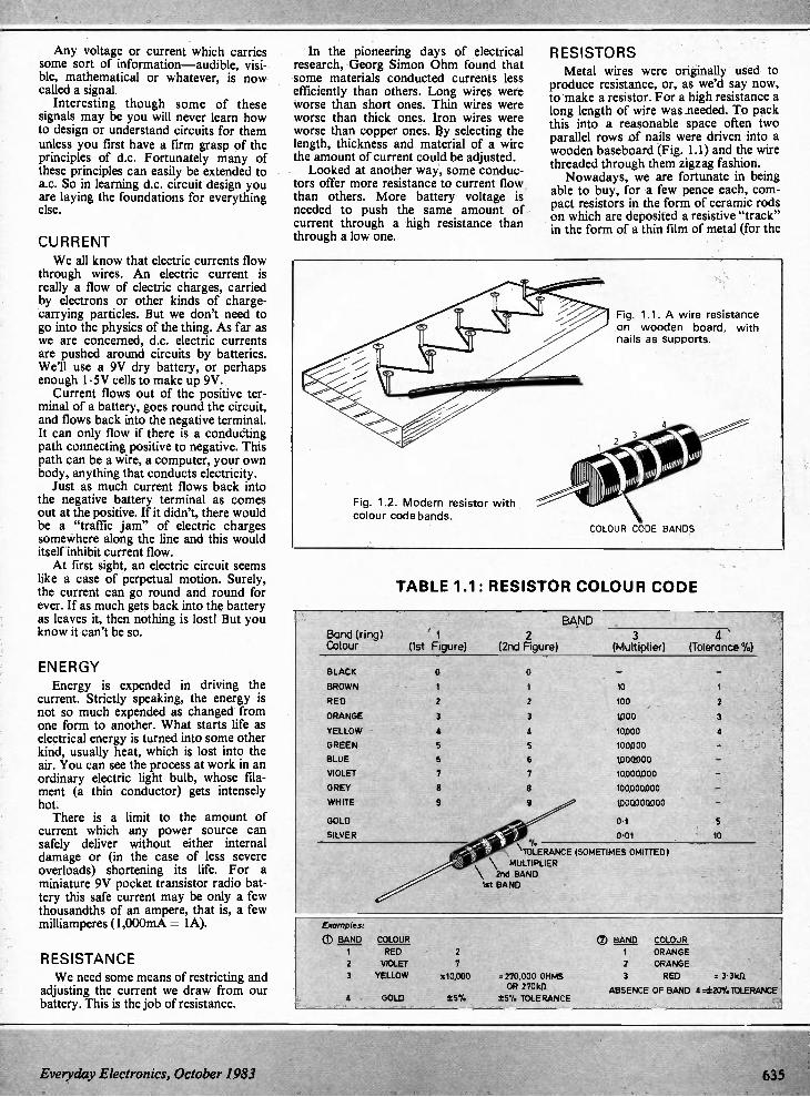
Any voltage or current which carries some sort of information —audible, visi-ble, mathematical or whatever, is now called a signal. Interesting though some of these
signals may be you will never learn how to design or understand circuits for them unless you first have a firm grasp of the principles of d.c. Fortunately many of these principles can easily be extended to a.c. So in learning d.c. circuit design you are laying the foundations for everything else.
CURRENT We all know that electric currents flow
through wires. An electric current is really a flow of electric charges, carried by electrons or other kinds of charge-carrying particles. But we don't need to go into the physics of the thing. As far as we are concerned, d.c. electric currents are pushed around circuits by batteries. We'll use a 9V dry battery, or perhaps enough 1.5V cells to make up 9V. Current flows out of the positive ter-
minal of a battery, goes round the circuit, and flows back into the negative terminal. It can only flow if there is a conducting path connecting positive to negative. This path can be a wire, a computer, your own body, anything that conducts electricity. Just as much current flows back into
the negative battery terminal as comes out at the positive. If it didn't, there would be a "traffic jam" of electric charges somewhere along the line and this would itself inhibit current flow. At first sight, an electric circuit seems
like a case of perpetual motion. Surely, the current can go round and round for ever. If as much gets back into the battery as leaves it, then nothing is lost! But you know it can't be so.
ENERGY Energy is expended in driving the
current. Strictly speaking, the energy is not so much expended as changed from one form to another. What starts life as electrical energy is turned into some other kind, usually heat, which is lost into the air. You can see the process at work in an ordinary electric light bulb, whose fila-ment (a thin conductor) gets intensely hot. There is a limit to the amount of
current which any power source can safely deliver without either internal damage or (in the case of less severe overloads) shortening its life. For a miniature 9V pocket transistor radio bat-tery this safe current may be only a few thousandths of an ampere, that is, a few milliamperes (1,000mA = 1A).
RESISTANCE We need some means of restricting and
adjusting the current we draw from our battery. This is the job of resistance.
In the pioneering days of electrical research, Georg Simon Ohm found that some materials conducted currents less efficiently than others. Long wires were worse than short ones. Thin wires were worse than thick ones. Iron wires were worse than copper ones. By selecting the length, thickness and material of a wire the amount of current could be adjusted. Looked at another way, some conduc-
tors offer more resistance to current flow than others. More battery voltage is needed to push the same amount of current through a high resistance than through a low one.
RESISTORS Metal wires were originally used to
produce resistance, or, as we'd say now, to make a resistor. For a high resistance a long length of wire was needed. To pack this into a reasonable space often two parallel rows of nails were driven into a wooden baseboard (Fig. 1.1) and the wire threaded through them zigzag fashion. Nowadays, we are fortunate in being
able to buy, for a few pence each, com-pact resistors in the form of ceramic rods on which are deposited a resistive "track" in the form of a thin film of metal (for the
Fig. 1.2. Modern resistor with colour code bands.
Fig. 1.1. A wire resistance on wooden board, with nails as supports.
COLOUR CODE BANDS
TABLE 1.1: RESISTOR COLOUR CODE
Band (ring) Colour (1st Figure)
BLACK 0
BROWN 1
RED 2
ORANGE 3
YELLOW
GREEN 5
BLUE 6
VIOLET
GREY 8
WHITE
GOLD
SILVER
Examples:
(D BAND COLOUR
RED
2 VIOLET 3 YELLOW
4 GOLD
2 (2nd Figure)
0
1
2
3
6
7
% \ TOLERANCE (SOMETIMES OMITTED) MULTIPLIER
2nd BAND 1st BAND
BAND 3
(Multiplier)
to 100
WOO
10000
100,000
1,000,000
10000000
100000,000
W00000000
0.1
0.01
4 \ (Tolerance la)
1
2
3
10
7
x10,000 =270,000 OHMS OR 2701t0
*5% 1'5% TOLERANCE
(D BAND COLOUR 1 ORANGE 2 ORANGE 3 RED 3-31d1
ABSENCE OF BAND 4.ct20%1OLERAICE
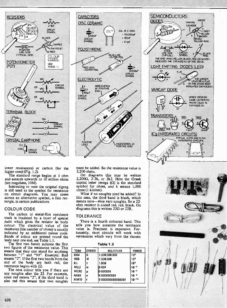
FRESISTORS
RESISTOR LIFE-SIZE
( TYPICAL 1/LW)
POTENTIOMETER (POT)
TERM:NAL BLOCK
RI
..-1 \ A Ar"" 2- 7kf1
CIRCUIT SYMBOL
3rd RED
),..k'ka2nd VIOLET
1st RED
COLOUR CODES SEE TABLE LI
CIRCUIT SYMBOL
T 81
cc CIRCUIT 2 SYMBOL
I CRYSTAL EARPHONE TL1 [tri
XTAL CIRCUIT SYMBOL
cc 3
lower resistances) or carbon (for the higher ones) (Fig. 1.2). The standard range begins at 1 ohm
and extends upwards to 10 million ohms (ten megohms, 10M). Interesting to note the original zigzag
is still used as the symbol for resistance on circuit diagrams. You may come across an alternative symbol, a thin rec-tangle, in certain publications.
COLOUR CODE
The carbon or metal-film resistance track is insulated by a layer of special paint which gives the resistor its body colour. The electrical value of the resistance (the number of ohms) is usually indicated by an additional colour code. Bands of colour are printed round the body near one end, see Table 1.1. The first two bands indicate the first
two figures of the resistance value. This means that they can stand for anything between "1" and "99". Example: Red means "2". If the first two bands from the end of the body are both red, the resistance begins with 22. The next colour tells you if there are
any noughts after the 22. For example, since red means "2", if the third band is also red this means that two noughts
CAPACITORS
DISC CERAMIC
CI
100nF
CIRCUIT SYMBOL
POLYSTYRENE
tRED DISC =OUTER FOIL
ELECTROLYTIC
=1—+ CI
I 100pF
CIRCUIT SYMBOL
POSITIVE LEAD
BLUE LINE =OUTER FOIL
C„
104=10 + 0000
= 100,000 pF
= 100nF
0.1pF
INDENTATION Al POSITIVE END
NIL
I 1000pF CIRCUIT SYMBOL
must be added. So the resistance value is 2,200 ohms. On diagrams this may be written
2,2000, 2.2k, or 2k2. Here the Greek capital letter omega (0) is the standard symbol for ohms, and k means 1,000 ohms (1 kilohm). What if no noughts need be added? In
this case, the third band is black, which means zero —thus zero noughts. So a 22-ohm resistor is coded red, red, black. On diagrams this is written 220 or 22R.
TOLERANCE
There is a fourth coloured band. This tells you how accurate the resistance value is. Precision is expensive. For-tunately, most circuits will work with resistances which vary from the chosen
Table 1.2
TERM SYMBOL MULTIPLIER POWER GIGA G 1,000,000,000 109 MEG M 1,000,000 106 KIL k 1,000 103 MILLI m 0-001 10-3 MICRO 11 0-000001 10-6 NANO n 0-000000001 10-9 FEMTO f 0-000000000000001 10-16
14
SEMICONDUCTORS: DIODE ANODE
(IN4148) g
CATHODE
a GREY
V , YELLOW k I BROWN BROAD YELLOW RING
.1 1 =1.. 1.4
DIODE LIFE-SIZE CIRCUIT k BLACK (TYPICAL) SYMBOL RING
THE END RING (YELLOW. BLACK, RED OR WHITE) INDICATES THE CATHODE tk) OF THE DIODE.
LIGHT EMITTING DIODES (LED) DI FLAT
VARICAP DIODE
THE LONGER LEAD OR A FLAT
a ON THE DIODE BODY INDICATES CATHODElk)
WHEN VIEWING CASE LETTERING, RIGHT LEAD IS CATHODE I k)
TRANSISTORS ,b TR1 TR2 e c
e TAB (npn)
IC's (INTEGRATED CIRCUITS) TYPICAL 14 PIN AND 8 PIN INTEGRATED CIRCUITS
( pnp)
8
7 5
636
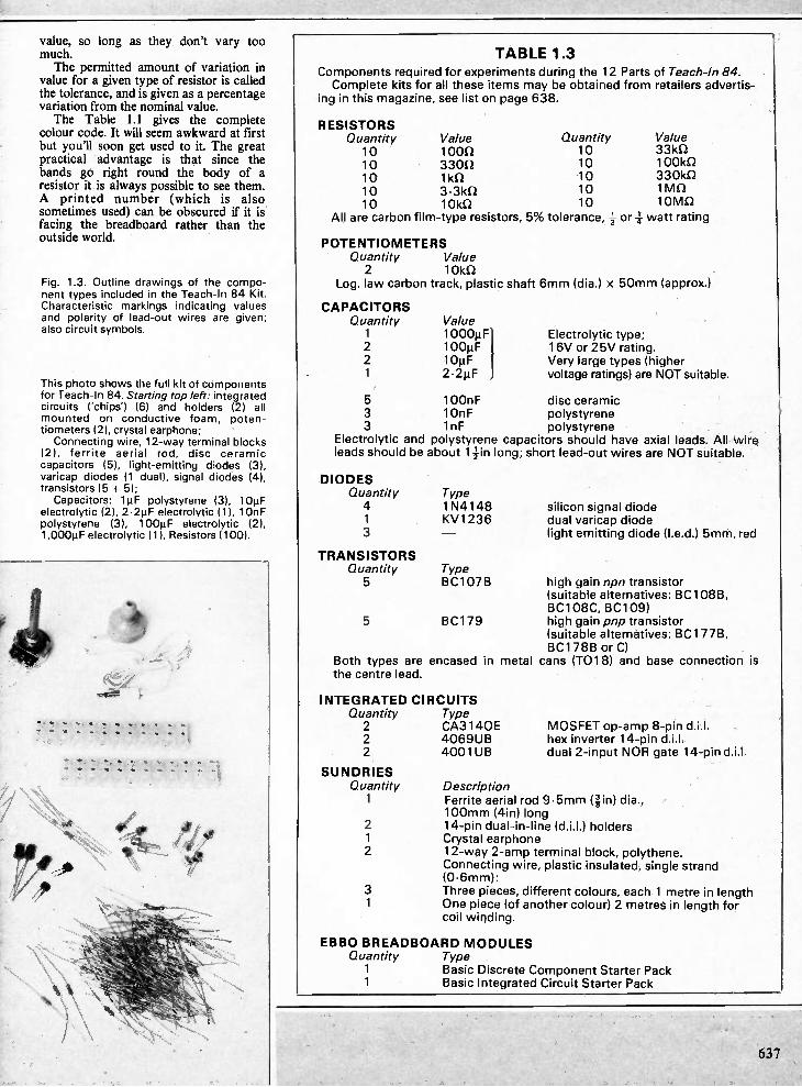
value, so long as they don't vary too much. The permitted amount of variation in
value for a given type of resistor is called the tolerance, and is given as a percentage variation from the nominal value. The Table 1.1 gives the complete
colour code. It will seem awkward at first but you'll soon get used to it. The great practical advantage is that since the bands go right round the body of a resistor it is always possible to see them. A printed number (which is also sometimes used) can be obscured if it is facing the breadboard rather than the outside world.
Fig. 1.3. Outline drawings of the compo-nent types included in the Teach-In 84 Kit. Characteristic markings indicating values and polarity of lead-out wires are given; also circuit symbols.
This photo shows the full kit of components for Teach-In 84. Starting top left: integrated circuits ('chips') (6) and holders (2) all mounted on conductive foam, poten-tiometers (2), crystal earphone; Connecting wire, 12-way terminal blocks
(2), ferrite aerial rod, disc ceramic capacitors (5), light-emitting diodes (3), varicap diodes (1 dual), signal diodes (4), transistors 15 + 61; Capacitors: 14F polystyrene (3), 10µF
electrolytic (2), 2•21.IF electrolytic (1), 10nF polystyrene (3), 100µF electrolytic (2), 1,000µF electrolytic (1), Resistors (100).
TABLE 1.3 Components required for experiments during the 12 Parts of Teach-In 84. Complete kits for all these items may be obtained from retailers advertis-
ing in this magazine, see list on page 638.
RESISTORS Quantity 10 10 10 10 10
All are carbon
Value Quantity Value 1000 10 331(12 33012 10 100162 1k0 10 330k1 3.3k11 10 1MS2 10kf2 10 10M0
film-type resistors, 5% tolerance, 4_ or 4- watt rating
POTENTIOMETERS Quantity Value 2 10162
Log. law carbon track, plastic shaft 6mm (dia.) x 50mm (approx.)
CAPACITORS Quantity 1 2 2 1
Value 1000µF1 100µF 10µF 2.2µF
Electrolytic type; 16V or 25V rating. Very large types (higher voltage ratings) are NOT suitable.
5 100nF disc ceramic 3 10nF polystyrene 3 1nF polystyrene
Electrolytic and polystyrene capacitors should have axial leads. All wire leads should be about 14-in long; short lead-out wires are NOT suitable.
DIODES Quantity 4 1 3
TRANSISTORS Quantity 5
5
Type 1N4148 KV1236
Type BC107B
BC179
Both types are encased in metal the centre lead.
INTEGRATED CIRCUITS Quantity Type 2 CA3140E 2 4069UB 2 4001UB
SUNDRIES Quantity 1
2 1 2
3 1
silicon signal diode dual varicap diode light emitting diode (I.e.d.) 5mm, red
high gain npn transistor (suitable alternatives: BC108B, BC108C, BC109) high gain pnp transistor (suitable alternatives: BC1778, BC178B or C) cans (T018) and base connection is
MOSFET op-amp 8-pin di.). hex inverter 14-pin d.i.l. dual 2-input NOR gate 14-pin d.i.l.
Description Ferrite aerial rod 9.5mm (gin) dia., 100mm (4in) long 14-pin dual-in-line (d.i.1.) holders Crystal earphone 12-way 2-amp terminal block, polythene. Connecting wire, plastic insulated, single strand (0.6mm): Three pieces, different colours, each 1 metre in length One piece (of another colour) 2 metres in length for coil winding.
EBBO BREADBOARD MODULES Quantity Type 1 Basic Discrete Component Starter Pack 1 Basic Integrated Circuit Starter Pack
637
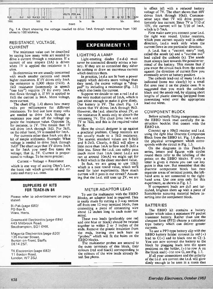
0 1v
100R
02 03 0 4 0 5
500
0.7
lk
you's ,PER,mdl:
5k OHMS
10 20 30 40 50 70
Fig. 1.4. Chart showing the voltage needed to drive ohms to 100 kilohms.
RESISTANCE, VOLTAGE, CURRENT The resistance value can be described
by saying how many volts are needed to drive a current through a resistance. If a current of one ampere (IA) is driven when IV is applied the resistance is 1 ohm. In electronics we are usually concerned
with much smaller currents and much higher resistances. If IV drives only lmA the resistance is 1,000 ohms (1k0). A 1 !al resistance (commonly in speech "one kay") requires IV for every lmA that flows through it. If 9V is applied to lkn the current is 9mA. More voltage, more current. The chart (Fig. 1.4) shows how many
volts per milliampere for different resistances. To find out how many volts are needed to drive 1mA through a resistance you read off the voltage op-posite the resistance value. Opposite 1k, for instance, is IV. This means that 1V will drive lmA through 1k1. For 5k12, on the other hand, 5V is needed for lmA. For currents other than lmA you do a
bit of simple arithmetic. Example: What voltage is needed to drive 5mA through 11(0? The chart says that 1V drives lmA so for 5mA you need five times the voltage; that is, 5V. Current is propor-tional to voltage. To be more precise:
Current = Voltage ± Resistance
which is one way of stating Ohm's Law, the basic rule which governs all d.c. cir-cuits and many a.c. ones.
SUPPLIERS OF KITS FOR TEACH-IN 84
Please refer to advertisement on page stated.
Bi-Pak (page 680) PO Box 6, Ware, Herts.
G reenweld Electronics (page 684) 443 Millbrook Road, Southampton, S01 OHX.
Magenta Electronics (page 620) 135 Hunter Street, Burton-on-Trent, Staffs DE14 2ST.
TK Electronics (page 682) 11 Boston Road, London, W7 3SJ.
105 50k
boy
10050
1mA through resistances from 100
EXPERI MENT 1.1
LIGHTING A LAMP Light-emitting diodes (1.e.d.$) must
never be connected directly across a bat-tery. If they are so connected they either do nothing or draw an enormous current which destroys them. In practice, 1.e.d.s are lit from a power
supply which delivers more voltage than they need; the excess voltage is "drop-ped" by including a resistance (Fig. 1.5) which also limits the current. Suppose we decide to run a red 1.e.d at
the very modest current of 1mA, which is just about enough to make it glow dimly. Our battery is 9V. The chart Fig. 1.4 shows that 9V drives lmA through 9k12. However, the 1.e.d. absorbs about 2V, so the resistance R needs only to absorb the remaining 7V. The chart links lmA and 7V to 7k0, and this is the required value for R. Here the circuit designer is up against
a practical problem. Cheap resistors are not usually made to a 7kS2 resistance. The nearest standard values are 6.8k0 and 8.2ka Clearly, 6.8kSI will allow a little more than lmA to flow and 8.2k0 a little less. Since the 1.e.d. can safely pass much more than lmA (most I.e.d.s are run at around 10mA) we might opt for 6. 8kn which is the closer standard value. In fact, we are going to use 101(0
which is a nice round value, which we'll need for later experiments. How much current will it pass in our circuit? Assum-ing that the 1.e.d. still uses up 2V, we are
METER ADAPTOR LEAD To use the multimeter with the EBBO
Blocks, an adaptor lead is required. This is easily made by cutting a 3-way section off from one 12-way terminal block, then connecting a piece of connecting wire about 12 inches long to each outer ter-minal. These two leads (preferably one red
and one blue or black) should be twisted together to within 2 or 3 inches of the ends. Remove the plastic insulation from the ends, leaving one inch bare as "probes" which will fit the holes on the EBBO blocks. The multimeter probes are secured to
the outer terminals of this block, their colours (red and black) corresponding to the colours of the wire leads already fit-ted. See photo.
in effect left with a reduced battery voltage of 7V. The chart shows that 10V drives lmA through 10k12. Common-sense says that 7V will drive propor-tionately less current. Since 7V is 7/10 of 10V, the current will be 7/10 of ImA, which is 0.7mA. First make sure you connect your 1.e.d.
the right way round. Unlike resistors, which pass current equally well in either direction, 1.e.d.s work only when the current flows in one particular direction. A 1.e.d. has a "current entry" lead,
called the anode (a) and a "current exit" lead called the cathode (k). The anode must always face towards the positive ter-minal of the battery. This means that if you trace the circuit back from the anode against the direction of current flow you eventually arrive at battery positive. The cathode lead-out of many I.e.d.s is
indicated (none too clearly) by a small flat area near it on the plastic case. It is suggested that you mark the cathode black and the anode red, by slipping short lengths of plastic sleeving (stripped from connecting wire) over the appropriate lead-out wires.
COMPONENT BLOCK Before actually fitting components into
the EBBO block read carefully the in-struction booklet that comes with the EBBO kit. Connect up a 101(0 resistor and 1.e.d.
using the light blue Discrete Component Block from the EBBO kit. Fig. 1.6 shows the physical arrangement which corre-sponds with the circuit in Fig. 1.5. On the diagrams in this Teach-In
series, letters and figures with circles round them refer to the labelling of the points on the EBBO blocks. If only a letter is given it means you can use any point in that row. But remember that the discrete component block has two separate areas of terminal points, the left-hand area is not connected to the right-hand area. Use one area only for this experiment, as shown in Fig. 1.7. If component leads are dull and tar-
nished, brighten them up with a piece of Scotchbrite scouring material before in-serting into the component block.
BATTERIES The EBBO kit contains a battery
holder which takes a miniature 9V pocket transistor battery. Rather than use the cheapest form (PP3) choose a calculator type battery which can deliver greater currents. To use a PP3-type battery clip with the
EBBO battery holder connect its red (+) lead to C(+) and its black one to C(—). You can now connect the battery to the block by plugging leads into the spare positions on the holder, (+) to row A on the block and (—) to row G, see Fig. 1.7. If all your connections and the polarity
of the 1.e.d. are correct the 1.e.d. will glow dimly enough to be seen in a room that
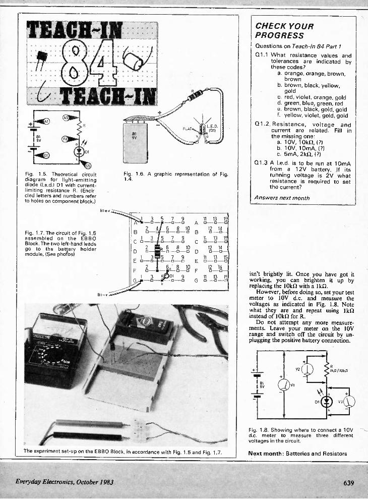
Fig. 1.5. Theoretical circuit diagram for light-emitting diode (led.) Dl with current-limiting resistance R. (Encir-cled letters and numbers refer to holes on component block.)
Fig. 1.7. The circuit of Fig. 1.5 assembled on the EBBO Block. The two left-hand leads go to the battery holder module. (See photos)
A
Bl+v
B1-v
Fig. 1.6. A graphic representation of Fig. 1.4.
3 5 7 9 - 0---- - 0 -0
2 4 6 8 10 o— 0-0 -0
1 3 5 7 9 0-0 0-0 -0
2 R6 8 10 0-0 -0
1 3 5 7 9 0 - 0 o o o 2 6 8 10 0-
1 3 5 DI 9 G
11 13 15 0 -o ---o
12 14 o—o-
11 13 15 o—o —o 12 14 0-0-
11 13 15 0—D —O 12 14 0-0—
(1 13 1 0 -0 -0
The experiment set-upon the EBBO Block, in accordance with Fig. 1.5 and Fig. 1.7.
CHECK YOUR PROGRESS Questions on Teach-1n 84 Part 1
Q1.1 What resistance values and tolerances are indicated by these codes? a. orange, orange, brown, brown
b. brown, black, yellow, gold
c. red, violet, orange, gold d. green, blue, green, red e. brown, black, gold, gold f. yellow, violet, gold, gold
Q1.2. Resistance, voltage and current are related. Fill in the missing one: a. 10V, 10k11, (?) b. 10V, 10mA, (?) c. 5mA, 2k12, (?)
Q1.3 A I.e.d. is to be run at 10mA from a 12V battery. If its running voltage is 2V what resistance is required to set the current?
Answers next month
isn't brightly lit. Once you have got it working, you can brighten it up by replacing the 10k1/ with a 1k a However, before doing so, set your test
meter to by d.c. and measure the voltages as indicated in Fig. 1.8. Note what they are and repeat using lkf/ instead of 10kQ for R. Do not attempt any more measure-
ments. Leave your meter on the 10V range and switch off the circuit by un-plugging the positive battery connection.
Fig. 1.8. Showing where to connect a 10V d.c. meter to measure three different voltages in the circuit.
Next month: Batteries and Resistors
Everyday Electronics, October 1983 639
MODEL CAR 'PETRO TANK'
BY A.P. DONLEAVY
T0 ADD another hurdle to the com-petitive aspect of model car racing,
each car can be given a petrol tank which is emptied at a rate depending on the speed of the car. With an empty tank, the car comes to a stop until the tank is refilled, which takes a certain amount of time. A "petrol gauge" gives the state of the
tank and the "tank" is in fact, a capacitor. The fuel gauge consists of a I.e.d. which changes colour from green to red as the tank empties.
CIRCUIT DESCRIPTION The circuit diagram is shown in Fig. 1.
There is an identical circuit for each track so only the circuit for one track is drawn. The numbers in brackets next to IC2 in-puts give the corresponding i.c. pin con-
nections for the other channel and all duplicated component references are prefixed by 100. The "tank" is represented by Cl,
which is full when the capacitor is dis-charged. The charging up of this capacitor through R3 and IC!, an ad-justable current source, represents the emptying of the tank. The current to charge the capacitor is governed by IC1, which in turn depends on the series resistance of R2 and VR I. For a given value of R2 and VR1, the current remains constant even though the voltage across the terminals of IC1 changes as the capacitor charges. The current flowing to C 1 causes a
volt drop across R3. This voltage is applied to the non-inverting (+ve) input of IC2a (Pin 3). IC2 consists of four operational amplifiers, all of which are used in this project.
The prototype Model Car Petrol Tank for a two-car race track.
INIodlell Car Petrol Tank
FUEL GAUGE
F1.LL et RUN
0 FUEL GAUGE
RUN
Carl Car 2
640
The output (Pin 1) of op-amp IC2a is connected directly to the inverting input. This gives it unity gain, that is the output voltage follows the input voltage at the non-inverting terminal. The output of this op-amp is connected
via R4 to the base of TR1, the emitter of which is connected to the base of TR2. It is the collector TR2 which provides the drive current for the racing car. The available current to drive the car from TR2 will depend on the output voltage at Pin I of IC2a and the value of R4. The speed of the car depends on the current supplied by TR2.
OPERATION The operation of the unit is then as
follows: the capacitor Cl, initially dis-charged, is charged up by the current which is adjusted by the setting of VRI. R2 limits the maximum current. The higher the current, the higher the voltage drop across R3, thus the higher the voltage at the output of IC2a, and the higher the current from TR2, hence the faster the car travels. The voltage at the v+ terminal of IC!
continually falls as Cl charges until it comes to a point where the voltage at the v+ terminal is insufficient to allow the correct functioning of ICI (about IV). At this point the current starts dropping, and also the voltage across R3. This in turn leads to a reducing current from TR I and TR2. Another limiting factor is that unless
the voltage at Pin 1 IC2a is at least equal to the two base-emitter voltage drops of TR I and TR2 (about 1.4V), these transistors will not be turned on. Hence even though IC! is functioning at 1.4V, the output transistors would cease to pass any current, thus stopping the racing car.
Everyday Electronics, October 1983
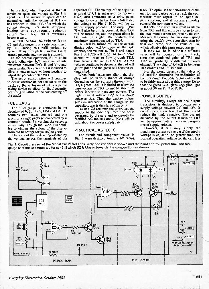
In practice, what happens is that at maximum speed the voltage at Pin 3 is about 3V. This maximum speed can be maintained until the voltage at IC! v+ has dropped to about 4V, after which the current through R3 starts dropping, leading to a continuously reducing current from TR2, until it eventually becomes zero. To refill the tank, S2 switches R 1 to
Cl and discharges it at a rate determined by RI. During this refill period, no current flows through R3, so Pin 3 is at ground potential and the car is stopped. In the normal operation, S I must be
closed, otherwise ICI sees an infinite resistance between Pin's R and V—, and passes negligible current. Si is included to allow a sudden stop without needing to adjust the potentiometer VR1. The petrol consumption will continue
to occur whether or not the car is on the track, so the inclusion of Si is a petrol saving device to allow for the frequently occurring situation of the cars coming off the tracks.
FUEL GAUGE The "fuel gauge" is contained in the
circuitry of IC2b, TR3, TR4 and Dl. D1 contains two 1.e.d.s, one red and one green in a single package, connected by a common anode. By varying the currents individually through the 1.e.d.s it is possi-ble to change the colour of the display from red to orange (or yellow) to green. The state of the tank is represented by
the voltage across the terminals of the
capacitor Cl. The voltage of the negative terminal of C I is measured by op-amp IC2b, also connected as a unity gains voltage follower. In the tank's full state, the voltage at Pin 5 IC2b will be at almost supply potential. The output (Pin 7) will also be at this potential, thus TR4 will be turned on, and the green diode in Dl will be alight. R6 controls the maximum current passed by TR4. TR3 will be turned off, so the overall
display colour will be green. As the tank empties, the voltage at Pin 5 and hence Pin 7 of IC2b will drop. At some point current will start to flow through TR3, thus turning the red half of DI. As the voltage continues to decrease, the red will get brighter and the green will become ex-tinguished. When both 1.e.d.s are alight, the dis-
play will be various shades of orange depending on the currents through each. D2, a green 1.e.d. is included to allow the base voltage of TR4 to rise to about 3V before it starts to pass any current. The high forward voltage drop of the diode achieves this. Thus the display colour gives an indication of the charge on the capacitor, that is the state of the tank. D3 and C2 are intended to protect the
supply to the circuitry from the noise generated by the cars and to smooth the rectified AC mains supply. More will be said about the power supply later.
PRACTICAL ASPECTS The circuit and component values in
Fig. I were designed round a 6V racing
track. To optimise the performance of the unit for any particular racetrack the con-structor must expect to do some ex-perimentation, and if necessary modify some of the component values. R4 sets the maximum current available
from TR2 and this must be chosen to suit the maximum current required by the car. Measure the current for maximum speed using the track's own controller, then by trial and error, find the value of R4, which will give this same output current. It may well be found that a different
value will be required for each track, since the combined gains of TR 1 and TR2 will probably be different for each channel. The value of R4 will be between 100 kilohms and 330 kilohms. For the gauge circuitry, the values of
R5 and R6 determine the calibration of the fuel gauge. For constructors who wish to be fairly exact about this, choose R6 so that the green 1.e.d. gives negligible light at about 3V on Pin 7 of IC2b.
PO WER SUPPLY The circuitry, except for the output
transistors, is designed to operate on a supply voltage between 9V and 12V. It could operate on less, but this would reduce the tank capacity. The current delivered by the output transistor TR2 will be approximately the same irrespec-tive of supply voltage. However, it will only supply the
maximum current to the car if the supply voltage is equal to, or greater than, the normal operating voltage for the car. It is
Fig. 1. Circuit diagram of the Model Car Petrol Tank. Only one channel is shown and the hand control, petrol tank and fuel gauge sections are repeated for car 2. Switch S2 is biased towards the RUN position as shown.
EE
Si
VRI 4.7k0
SPEED
S2
RI 2.2k0
FILL
RUN
IC2 PIN 4
+V
R2 2.2k.0
IC1 LM334Z
ILI_AND CONTROL _1 R3 /00k/1
1C2 LM324
1C2 PIN 11
PETROL TANK
RED DI a
FUEL GAUGE
GREEN • ® •
03 IN4001
r==:' C2
+I2V SKI V
POWER IN
SK2
SK3 —C SKIO2
TO TRIO2 CO LECTOR (OTHER CHANNEL)
CAR I
CAR 2
OV
Everyday Electronics, October 1983 641
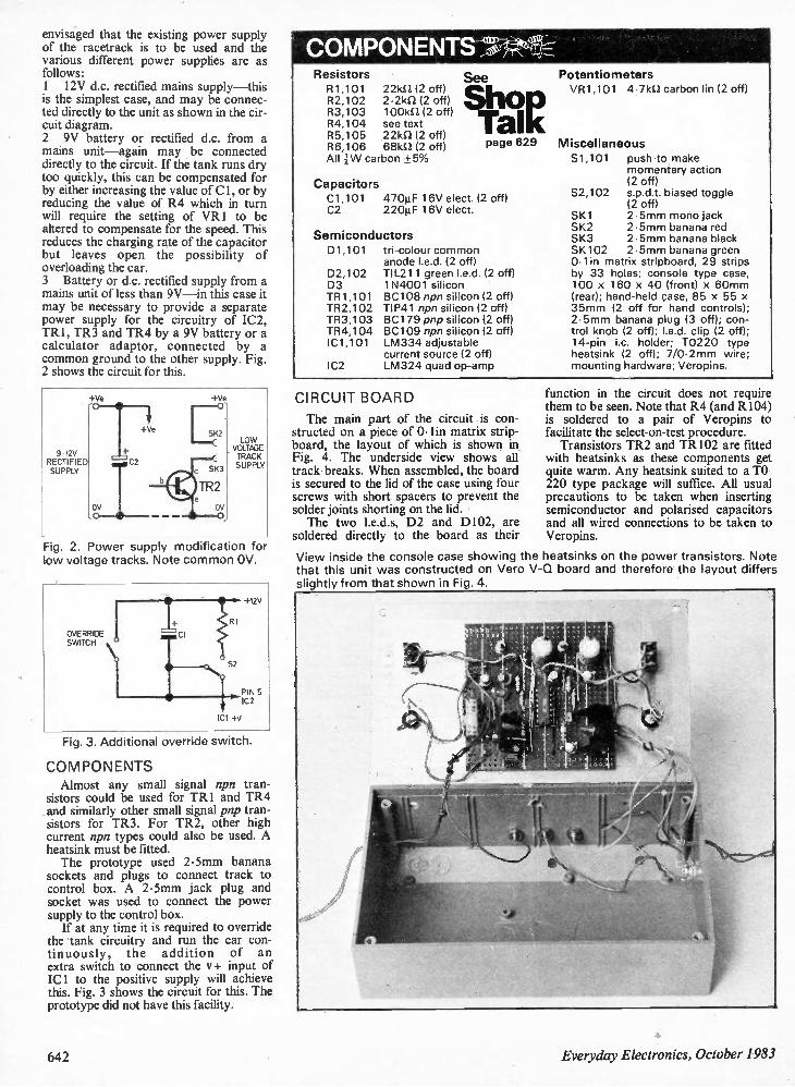
envisaged that the existing power supply of the racetrack is to be used and the various different power supplies are as follows: 1 12V d.c. rectified mains supply —this is the simplest case, and may be connec-ted directly to the unit as shown in the cir-cuit diagram. 2 9V battery or rectified d.c. from a mains unit —again may be connected directly to the circuit. If the tank runs dry too quickly, this can be compensated for by either increasing the value of Cl, or by reducing the value of R4 which in turn will require the setting of VR1 to be altered to compensate for the speed. This reduces the charging rate of the capacitor but leaves open the possibility of overloading the car. 3 Battery or d.c. rectified supply from a mains unit of less than 9V —in this case it may be necessary to provide a separate power supply for the circuitry of IC2, TR1, TR3 and TR4 by a 9V battery or a calculator adaptor, connected by a common ground to the other supply. Fig. 2 shows the circuit for this.
+Ve
9-12V RECTIFIE SUPPLY
+Ve
LOW VOLTAGE TRACK SUPPLY
Fig. 2. Power supply modification for low voltage tracks. Note common OV.
OVERRIDE SWITCH
IC1 +V
Fig. 3. Additional override switch.
COMPONENTS Almost any small signal npn tran-
sistors could be used for TR1 and TR4 and similarly other small signal pnp tran-sistors for TR3. For TR2, other high current npn types could also be used. A heatsink must be fitted. The prototype used 2.5mm banana
sockets and plugs to connect track to control box. A 2.5mm jack plug and socket was used to connect the power supply to the control box. If at any time it is required to override
the tank circuitry and run the car con-tinuously, the addition of an extra switch to connect the v+ input of IC1 to the positive supply will achieve this. Fig. 3 shows the circuit for this. The prototype did not have this facility.
COMPONENTS ' Resistors R1,101 22kfl (2 off) R2,102 2.2kS2 (2 off) R3,103 1001M (2 off) R4,104 see text R5,105 22k1(2 off) R6,106 68k1(2 off) All 1-1N carbon +5%
Capacitors C1,101 C2 220µF 16V elect.
See
Shop Tali( page 629
470µF 16V elect. (2 off)
Semiconductors 01,101 tri-colour common
anode led. (2 off) 02,102 TIL211 green led. (2 off) 03 1N4001 silicon TR1,101 BC108 npn silicon (2 off) TR2,102 TIP41 npn silicon (2 off) TR3,103 BC179 pnp silicon (2 off) TR4,104 BC109 npn silicon (2 off) IC1,101 LM334 adjustable
current source (2 off) IC2 LM324 quad op-amp
CIRCUIT BOARD
The main part of the circuit is con-structed on a piece of 0.1in matrix strip-board, the layout of which is shown in Fig. 4. The underside view shows all track-breaks. When assembled, the board is secured to the lid of the case using four screws with short spacers to prevent the solder joints shorting on the lid. The two 1.e.d.s, D2 and D102, are
soldered directly to the board as their
Potentiometers VR1,101 4.7kS2 carbon lin (2 off)
Miscellaneous S1,101 push-to-make
momentary action (2 off)
S2,102 s.p.d.t. biased toggle (2 off)
SK1 2.5mm mono jack SK2 2.5mm banana red SK3 2.5mm banana black SK102 2.5mm banana green Olin matrix stripboard, 29 strips by 33 holes; console type case, 100 x 160 x 40 (front) x 60mm (rear); hand-held case, 85 x 55 x 35mm (2 off for hand controls); 2.5mm banana plug (3 off); con-trol knob (2 off); I.e.d. clip (2 off); 14-pin i.c. holder; T0220 type heatsink (2 off); 7/0.2mm wire; mounting hardware; Veropins.
function in the circuit does not require them to be seen. Note that R4 (and R104) is soldered to a pair of Veropins to facilitate the select-on-test procedure. Transistors TR2 and TR102 are fitted
with heatsinks as these components get quite warm. Any heatsink suited to a TO-220 type package will suffice. All usual precautions to be taken when inserting semiconductor and polarised capacitors and all wired connections to be taken to Veropins.
View inside the console case showing the heatsinks on the power transistors. Note that this unit was constructed on Vero V-Q board and therefore the layout differs slightly from that shown in Fig. 4.
642 Everyday Electronics, October 1983
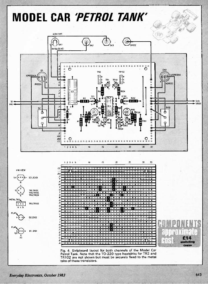
Si
VR1
MODEL CAR 'PETROL TANK'
V+
+I2V (TIP)
SKI
0V (SLEEVE)
SK2 SK3 SK102
01
(GREEN)
(RED) k a
1
,4 00 0 0 00 00 0 00 0 0 00 0 o o o o 00 00 0 00 0 00
0 0 • 0 C o O o
ICI R2 V+
TR2
77: C TR I TRIO1
TRIO2
•-•
R104
IC101 V+ R102
R106
o D2 a D102TR103
AA BB CC
TR104
o 0 O 0 0 0 0 0 0 0 0 0 0 0 0 0 0 0 0 0 0 0 0 0 0 0 0 0 0 0 0 0 0 0 0
0 °
I
0
O 0
1 2 3 4 5 10 15 20 25 30 33
•
•
0101
k (GREEN )
k(RED)
5102
0
PIN VIEW
METAL TAG
FLAT
FLAT
V- IC1,1C101
ec b
TRI,TRI01, TR3,TRIO3 TR4,TRIO4
TR2,TR102
a 02,0102
a (gn) D1,0101
(r)
CC BB
AA
X
V
5
0
A
1 2 3 5 10 15 20 25 30 33
0 0 0 0 0 0 0 0 0 0 0 0 0 0 0 0 0 0 0 0 0 0 0 0 0 0 0 0 0 0 0 0 0
0 0 0 0 0 0 0 0 0 0 0 0 0 0 0 0 0 0 0 0 0 0 0 0 0 0 0 0 0 0 0
0 0 0 0 0 0 0 0 0 0 0 0 0 0 0 0 0 0 0 0 0 0 0 0 0 0 0 0 0 0 0 0 0
0 0 0 0 0 0 0 0 0 0 0 0 0 0 0 0 0 0 0 0 0 0 0 0 0 0 0 0 0 0 0 0 0
• 0 0 0 0 O • 0 0 0 0 0 0 0 0 0 0 0 0 0 0 0 0 0 0 0 0 • 0 0 0 •
• 0 0 0 0 0 0 0 0 0 0 0 0 0 0 0 0 • • 0 0 0 0 0 0 0 0 0 0 0 0 •
0 0 0 0 0 0 0 0 • 0 0 0 0 0 • 0 0 0 0 0 • 0 0 0 0 • 0 0 0 0 0 0
I
• • 0 1 2 0 0 0 0 0 • 0 0 • TI • • 0 0 o• ••D• o • 0 0 0 0 0 0 0 •0 0 0 0 0 0 0 0 0 0 • o po o • • •o • Do • 0 0 0 0 0 0 0 • 00 0 0 0 0 0 0 0 0 0 0 • o • • 0 0 0 • • • o • 0 0 0 0 0 0 0 0 0 00 0 0 0 0 • • 0 0 0 •42• 0 • 0 •o • Clo • 0 0 0 0 • o • o o 00 0 0 0 0 0 0 • • 0 0 0 • o • o• o • 0 0 0 0 • • 0 0 0 0 0 0 •0 0 0 0 0 0 0 0 0 0 • 0 0 0 5 o• 0 0 0 0 • 0 0 0 0 0 0 0 0 • 0 • 0 • 0 0 0 • 0 0 0 0 • 0 0 • 0 • 0 0 • 0 0 0 0 0 0 0 • 0 0 0
• 0 0 0 0 0 0 0 0 0 0 • 0 O • • 0 • • 0 O • 0 0 0 0 0 0 0 0 O •
• 0 0 0 0 • 0 0 1 3 0 • • €1 • 0 • O • • og• • o po o • 0 0 0 • 500 0 0 0 0 0 •n• • • 0 • • •o• 0 0 0 0 0 0 0 0 0 •
0 0 0 0 0 0 ,.) 0 0 0 0 . 0 . 0 0 0 0 0 0 0. 0 . 0 . 0 0 0 0 0 0 0 0 0 0 0 0 0 0 0 0 0 0 0 0 0 0 0 0 0 0 0 0 0 0 0 0 0 0 0 0 0 0 0 0
0 0 0 0 0 0 0 0 0 0 0 0 0 0 0 0 0 0 0 0 0 0 0 0 0 0 0 0 0 0 0 0 0
• 0 0 0 0 0 0 0 0 0 0 O • 0 0 0 • 0 O • 0 0 0 O C 0 0 0 0 0 • O •
0 0 0 0 0 0 0 0 0 0 0 0 0 O • • 0 5 0 • 0 0 0 0 0 0 0 0 0 0 0 0 ,
0 0 0 0 0 0 0 0 0 0 0 0 0 • 0 0 • 0 • 0 5 0 0 0 0 0 0 0 0 0 0 0
I
• 0 0 0 0 0 0 0 0 0 0 0 0 • 0 0 0 0 0 0 • 0 0 0 0 0 0 0 0 0 0 0
• 0 0 5 0 0 0 0 0 0 0 0 O • 0 0 0 0 0 0 0 • 0 0 0 0 0 0 0 • 0 0 •
0 0 0 0 0 0 0 0 0 0 0 0 0 0 0 0 0 0 0 0 0 0 0 0 0 0 0 0 0 0 0 0 0
0 0 0 0 0 0 0 0 0 0 0 0 0 0 0 0 0 0 0 0 0 0 0 0 0 0 0 0 0 0 0 0 0
0 0 ( ) 0 0 0 0 0 0 0 0 0 0 0 0 0 0 0 0 0 0 0 0 0 0 0 0 0 0 0 ( ) 0 0
0 0 0 0 0 0 0 0 0 0 0 0 0 0 0 0 0 0 0 0 0 0 0 0 0 0 0 0 0 0 0 0 0
Fig. 4. Stripboard layout for both channels of the Model Car Petrol Tank. Note that the TO-220 type heatsinks for TR2 and TR102 are not shown but must be securely fixed to the metal tabs of these transistors.
S101 ir VR101
Everyday Electronics, October 1983 643
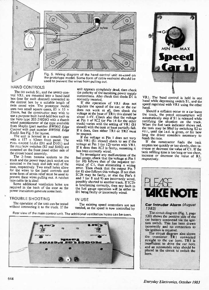
„.„O
wiffi
ireb O
VR1/ VR101
Fig. 5. Wiring diagram of the hand control unit as.used on the prototype model. Some form of cable restraint should be used to prevent the wires from pulling out.
HAND CONTROLS
The GO switch Si, and the SPEED con-trol VR1, are mounted into a hand-held box (one for each channel) connected to the control box by a suitable length of twin cored wire. The prototype model uses two small square cases, 85 x 55 x 35mm, but the constructor may wish to use a purpose built hand-held box such as the Vero type 202-21026G with a thumb wheel potentiometer of the type available from Maplin (part number B WO6G Edge Control with part number B WO9K Edge Knob). See Fig. 5 for layout. The unit is housed in a console case
with a 157 x 92mm front panel. The FUEL GAUGE 1.e.d.s (DI and D101) and the FILL/RUN switches (S2 and S102) are mounted on the front panel either side of the circuit board assembly. The 2.5mm banana sockets to the
track and the power input jack socket are mounted in the back and side wall of the case, respectively. Two small holes allow for the wires to the hand controls and some form of strain relief must be used to prevent these wires pulling out. A ratchet type cable tie is ideal. Some additional ventilation holes are
required in the back of the case as the power transistors generate some heat.
TROUBLE SHOOTING
The operation of the unit can be tested without connecting it to the track. If the
unit appears completely dead, then check the polarity of the incoming power supply connections. Also check that diode DI is correctly inserted. If the operation of VRI does not
regulate the speed of the car, or the car does not work at all, then check the voltage at the base of TR I; this should be about 1.4V. Check also that the voltage at Pin 1 of IC2 (or Pin 14 for the other track) varies with the setting of VR I (Si closed) with the tank at least partially full. If it does, then either TRI or TR2 must be suspect. If the voltage at Pin 1 does not vary
with VR1 (Si closed) check to see if the voltage at Pin 3 (or 12) varies with VR1. If it does then IC2 is faulty, assuming it has been correctly wired. To investigate any malfunctions of the
fuel gauge, check that the voltage at Pin 5 (or 10) follows that of the negative ter-minal of Cl, thus eliminating a wiring error. Then check that the output Pin 7 (or 8) also follows this voltage. If not then IC2b may be faulty, or else the Pin's 6 and 7 (or 8 and 9) are incorrectly wired, possibly shorted to another track. If IC2b is functioning correctly, then any fault in the fuel gauge operation will lie either in DI being faulty or incorrectly wired.
IN USE
The existing speed controllers are not needed, as the speed is now controlled by
Rear view of the main control unit. The additional ventilation holes can be seen.
'71
2111110
via OLS6E.11 SA 6F.1.-66 It alb 1111DA ICIA MASA
VR1. The hand control is held in one hand while depressing switch S 1, and the speed regulated with VR1 using the other hand. Should a collision occur or a car leave
the track, the petrol consumption will automatically stop if Si is released while rectifying the situation on the track. When the fuel tank indicator shows red, the tank may be filled by switching S2 to FILL, until the 1.e.d. is green, or for how long the driver considers necessary to finish the race. If the constructor finds the tank
empties too quickly or too slowly, then in-crease or decrease the value of Cl. If the tank refilling time is too long or too short, increase or decrease the value of RI, respectively.
PLEAT TAKE NOTE Car Intruder Alarm (August 1983)
The circuit diagram (Fig. 1, page 520) shows the positive side of the car battery connected via the igni-tion switch. This has been drawn incorrectly and no connection to the ignition is required. The circuit diagram also shows
the transistor TR I connected straight to the car horn. TR1 is insufficient to drive the car horn and an automobile relay should be placed in the circuit to switch the horn.
644 Everyday Electronics, October 1983

1984 SCHOOLS Electronic Design Award COMPETITION Buiti 6(A tke Fame mut Reap Lite &math
SEDAC TROPHY
CASH SPRIZES 12 Months 2 DAY TRIP subscription TO LONDON to EE expenses paid
FULL PAYMENT FOR PROJECTS PUBLISHED CERTIFICATES
TARCEL of OMPONEN 200 WORT
THE TVVELVE FINALISTS WILL SHARE OVER £3000 AND PARTICIPATE IN AN ALL-EXPENSES-PAID TWO-DAY VISIT TO LONDON DURING JUNE 1984
For the third year running Mullard Ltd. —the largest electronic components company in the UK —and Everyday Electronics join forces to present a rewarding challenge to Secondary Schools within the United Kingdom.
As distinct from the two previous contests, this year the conditions have been somewhat broadened so that entries can relate to electronic equipment having practical use anywhere within the school, or at any external event in which the school participates.
FIRST PRIZE
SECOND PRIZE £200
THIRD PRIZE £100
The Sedac Trophy and £300 Plus a selection of components valued at £200
NINE RUNNERS-UP. A selection of components valued at £100.
In addition, all twelve finalists will receive a certificate and one year's subscription to EVERYDAY ELECTRONICS— and will enjoy an all-expenses-paid two-day visit to London during June 1984.
Science teachers of Secondary Schools are invited to apply for a Registration Form which contains full details of this competition.
Write to: SEDAC Schools Competition, Room 2130, King's Reach Tower, Stamford Street, London SE1 9LS.
Secondary School Pupils —make sure your school accepts this challenge and enters this contest. So bring this announcement to the attention of your science teacher or the head of your school.
Closing date for Registration: 15 November 1983 •
Closing date for submission of Papers: 31 January 1984
tn SCHOOLS ELECTRONIC DESIGN AWARD COMPETITION (SEDAC) EE SPONSORED BY MULLARD LTD AND EVERYDAY ELECTRONICS
Everyday Electronics, October 1983 645
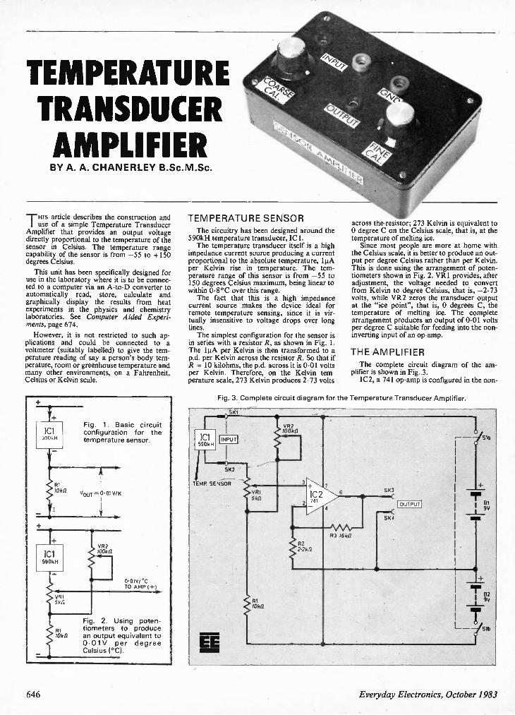
TEMPERATURE TRANSDUCER AMPLIFIER BY A. A. CHANERLEY B.Sc.M.Sc.
THis article describes the construction and use of a simple Temperature Transducer
Amplifier that provides an output voltage directly proportional to the temperature of the sensor in Celsius. The temperature range capability of the sensor is from —55 to +150 degrees Celsius.
This unit has been specifically designed for use in the laboratory where it is to be connec-ted to a computer via an A-to-D converter to automatically read, store, calculate and graphically display the results from heat experiments in the physics and chemistry laboratories. See Computer Aided Experi-ments, page 674.
However, it is not restricted to such ap-plications and could be connected to a voltmeter (suitably labelled) to give the tem-perature reading of say a person's body tem-perature, room or greenhouse temperature and many other environments, on a Fahrenheit, Celsius or Kelvin scale.
Id1 590kH
Fig. 1. Basic circuit configuration for the temperature sensor.
100k12
0.01V/ °C TO AMP (+
Fig. 2. Using poten-R1 tiometers to produce 10k12 an output equivalent to
0.01V per degree Celsius (°C).
TEMPERATURE SENSOR The circuitry has been designed around the
590kH temperature transducer, ICI. The temperature transducer itself is a high
impedance current source producing a current proportional to the absolute temperature, 1µA per Kelvin rise in temperature. The tem-perature range of this sensor is from —55 to 150 degrees Celsius maximum, being linear to within 0.8°C over this range. The fact that this is a high impedance
current source makes the device ideal for remote temperature sensing, since it is vir-tually insensitive to voltage drops over long lines. The simplest configuration for the sensor is
in series with a resistor R, as shown in Fig. 1. The 1µA per Kelvin is then transformed to a p.d. per Kelvin across the resistor R. So that if R = 10 kilohms, the p.d. across it is 0.01 volts per Kelvin. Therefore, on the Kelvin tem-perature scale, 273 Kelvin produces 2.73 volts
across the resistor; 273 Kelvin is equivalent to 0 degree C on the Celsius scale, that is, at the temperature of melting ice. Since most people are more at home with
the Celsius scale, it is better to produce an out-put per degree Celsius rather than per Kelvin. This is done using the arrangement of poten-tiometers shown in Fig. 2. VR1 provides, after adjustment, the voltage needed to convert from Kelvin to degree Celsius, that is, —2.73 volts, while VR2 zeros the transducer output at the "ice point", that is, 0 degrees C, the temperature of melting ice. The complete arrangement produces an output of 0.01 volts per degree C suitable for feeding into the non-inverting input of an op-amp.
THE AMPLIFIER The complete circuit diagram of the am-
plifier is shown in Fig. 3. IC2, a 741 op-amp is configured in the non-
Fig. 3. Complete circuit diagram for the Temperature Transducer Amplifier.
Ski
'Cl 590kH
INPUT
1L ) SK2
TEMP SENSOR
EE
VR2 700412
VR1 Sk/2
/Oka
IC 2 741
7
4
R2 2.2k.12
SK3
R3 16kf2
SK4
OUTPUT
SIa
646 Everyday Electronics, October 1983
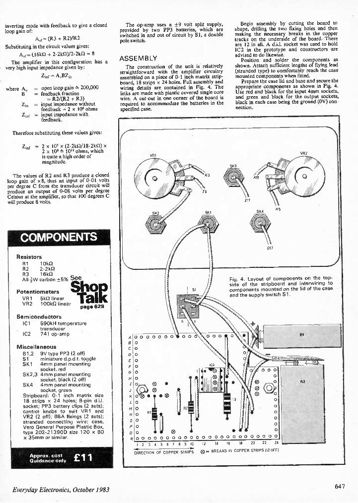
inverting mode with feedback to give a closed loop gain of:
Avf= (R3 + R2)/R2
Substituting in the circuit values gives:
Ayr= (16kn + 2.21(1/)/2.2k11 = 8
The amplifier in this configuration has a very high input impedance given by:
where A„
zin
Zinf
Zinf =
= open loop gain 200,000 = feedback fraction
= R2/(R2 + R3) = input impedance without feedback = 2 x 10⁶ ohms
= input impedance with feedback.
Therefore substituting these values gives:
Z m f = 2 x 105 x (2.2k12/18•2k0) x 2 x 106 10" ohms, which is quite a high order of magnitude.
The values of R2 and R3 produce a closed loop gain of x8, thus an input of 0.01 volts per degree C from the transducer circuit will produce an output of 0.08 volts per degree Celsius at the amplifier, so that 100 degrees C will produce 8 volts.
COMPONENTS
Resistors R1 10k12 R2 2.2k0 R3 16k5/ All iNA/ carbon +5% See
S h o o
Talk Potentiometers VR1 5kil linear VR2 1001(12 linear page 629
Semiconductors ICI 590kH temperature
transducer IC2 741 op-amp
Miscellaneous B1,2 9V type PP3 (2 off) Si miniature d.p.d.t. toggle SK1 4mm panel mounting
socket, red SK2,3 4mm panel mounting
socket, black (2 off) SK4 4mm panel mounting
socket, green Stripboard: 0.1 inch matrix size 18 strips x 24 holes; 8-pin d.i.l. socket; PP3 battery clips (2 sets); control knobs to suit VR1 and VR2 (2 off); 6BA fixings (2 sets); stranded connecting wire; case, Vero General Purpose Plastic Box, type 202-213900 size 120 x 80 x 35mm or similar.
Approx. cost Guidance only £1 1
The op-amp uses a +9 volt split supply, provided by two PP3 batteries, which are switched in and out of circuit by SI, a double pole switch.
ASSEMBLY The construction of the unit is relatively
straightforward with the amplifier circuitry assembled on a piece of 0.1 inch matrix strip-board, 18 strips x 24 holes. Full assembly and wiring details are contained in Fig. 4. The links are made with plastic covered single core wire. A cut-out in one corner of the board is required to accommodate the batteries in the specified case.
A
0
VR1
0 0 0 0 0 0 0
0
0
0
0
0
0
0
•
® 0 0 • • ®
0
0 0 RI
0
0
0
0 0 0 0 0
I6
SKI
Begin assembly by cutting the board to shape, drilling the two fixing holes and then making the necessary breaks in the copper tracks on the underside of the board. There are 12 in all. A d.i.l. socket was used to hold IC2 in the prototype and constructors are advised to do likewise. Position and solder the components as
shown. Attach sufficient lengths of flying lead (stranded type) to comfortably reach the case mounted components when fitted. Prepare the case lid and base and secure the
appropriate components as shown in Fig. 4. Use red and black for the input 4mm sockets, and green and black for the output sockets, black in each case being the ground (OV) con-nection.
SK3
/17
K5
017
VR2
Fig. 4. Layout of components on the top-side of the stripboard and interwiring to components mounted on the lid of the case and the supply switch Si.
• 0 0 0 0 0 0 0 0 0 0 0 0 0 0 0 0 0 0 0
I 2 3 4 5 6 7 8 9 10 12 14 16 18 20 22 24
DIRECTION OF COPPER STRIPS 0 = BREAKS IN COPPER STRIPS 112 OFF/
B2
Everyday Electronics, October 1983 647
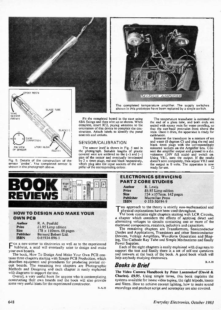
TEMP SENSOR (S90 kH)
EPDXY RESIN
CASE CONNECTION
PIN VIEW OF SENSOR
GLASS TUBE
EPDXY RESIN
BLACK(-)
RED 1+1
Fig. 5. sensor shown
Details of the construction of the "probe". The completed sensor is in the photograph above.
fE t-4 SC)R A MPLIFIER
The completed temperature amplifier. The supply switches shown in this prototype have been replaced by a single switch.
Fit the completed board in the case using 6BA fixings and then wire up as shown. When complete, insert IC2, paying attention to the orientation of this device to complete the con-struction. Attach labels to identify the panel controls and sockets.
SENSOR/CALIBRATION
The sensor itself is shown in Fig. 5 and in the photograph. Suitable lengths of plastic covered wire are soldered to the (+) and (—) pins of the sensor and eventually terminated by 2 x 4mm plugs, red and black respectively, which plug into the input sockets of the am-plifier of the corresponding colour.
The temperature transducer is mounted on the end of a glass tube, and both ends are sealed with epoxy resin for water-proofmg, so that the can-head protrudes from above the resin. Once it dries, the apparatus is ready for calibration. Immerse the transducer in a mixture of ice
and water (0 degrees C) and plug the red and black 4mm plugs with the correspondingly coloured sockets on the Amplifier box. Con-nect the amplifier output and ground to a d.c. voltmeter (10V full scale) and switch on. Using VR1, zero the output. If the needle doesn't zero completely, then adjust VR2 until the output is 0 volts. The apparatus is now ready for use.
BOOK REVIEWS
HO W TO DESIGN AND M AKE YOUR
O WN PCB
Author R. A. Penfold Price £1.95 Limp edition Size 178 x 110mm. 66 pages Publisher Bernard Babani Ltd. ISBN 0-85934-096-1
FOR a new-comer to electronics as well as to the experienced hobbyist, a need will eventually arise to design and make your own boards. The book, How To Design And Make Your Own PCB con-
tains three chapters starting with Simple PCB Production, Which describes equipment and procedures for producing printed cir-cuit boards. The remaining two chapters are Photographic Methods and Designing and each chapter is easily explained with diagrams to support the text. Overall, a very useful book for anyone who is contemplating
constructing their own boards and the book will also provide some very useful hints for the experienced constructor.
R.A.H
ELECTRONICS SERVICING PART 2 CORE STUDIES
Author Price Size Publisher ISBN
R. Lewis £6.95 Limp edition 234 x 157mm. 142 pages Macmillan Press 0-333-30594-9
THE approach to the theory is strictly non-mathematical and physical explanations have been used throughout. The book contains eight chapters starting with LCR Circuits,
a chapter which considers the effects of applying direct and alternating voltages to circuits containing one or more of the electronic components, resistors, inductors and capacitors. The remaining chapters are Transformers, Semiconductor
Diodes and Applications, Transistors and other Semiconductor Devices, Voltage Amplifiers, Waveform Generation and Shap-ing, The Cathode Ray Tube and Simple Mechanisms and finally Power Supplies. Each of the eight chapters is easily explained with diagrams to
support the text and finally there is a set of self-test questions and answers at the back of the book. A good book which will help anybody studying electronics.
Books in Brief The Video Camera Handbook by Peter Lanzendorf (David & Charles). £9.95. Using simple terms, this book explains the systems available for home video taping, the right tripods, lenses and filters. How to achieve correct lighting, how to make sound recordings and produce script and screenplay are also covered.
R.A.H
648 Everyday Electronics, October 1983
rea RITAINMENT BY BARRY FOX
Development News Through my post at home I get literally
dozens of press releases a day, covering audio, electronics and video. My last postman had to retire with a bad back. Obviously it's impossible to write about
everything I receive. So I read it all, make background phone calls for more informa-tion if something looks especially interest-ing, and then file it away for the future using a Sinclair Spectrum to cross reference related items. For instance, by making a note of what
new integrated circuits are becoming available for designers you can get a clear indication of what new gadgetry is likely to come on the market in a year or so's time. But if you think that being a journalist is just about re-writing press releases, think again. Last week, Mullard, the British company
owned by Philips of Eindhoven, sent me a press release on a new i.c. that integrates the entire circuitry for an f.m. radio receiver, from aerial input to audio output. This, said the press release, will let designers build an f.m. radio into a pencil, wristwatch or key-ring. It uses a non-standard intermediate fre-
quency. Usually the i.f, for an f.m. radio is 10.7MHz, but in the Mullard chip it is 70kHz. Curiosity aroused, I phoned Mullard to ask how they had overcome distortion problems, and how a low i.f, helps them make the chips smaller. A week, and several phone calls later, I
am still no nearer an answer. Believe it or not, there's no one in Mullard UK who can explain what's written in the company's press release. I've now been promised a call from an expert in Eindhoven who may or may not be able to help.
Tele News Another release is a clear pointer to a
new generation of low-cost gadgetry that couples to your telephone and is triggered by an incoming ring. Texas Instruments are now selling chips that are powered by the incoming ring signal to produce a regulated 5-volt output which connects the phone line to a microprocessor or system that handles voice or data signals. The chip is ideal for a telephone answer-
ing machine, a data modem or facsimile machine. Cost, if you buy in hundreds, is just £1.40 each. Talking of telephones, I've just received
news from British Telecom, who proudly announce that they have created 300 new jobs. How? By setting up three Telcare centres. Telcare stands for Telecom Customer Attitude Research, and the centre's sole job is to phone up Telecom subscribers and ask what they think of British Telecom. Personally, I would have thought that,
with so many people already telling BT what they think for free, in letters to the press and to BT, that Telcare is an expen-sive luxury that BT subscribers can ill afford. Finally, my favourite press release of the
week; a blank sheet of paper with just the PR company's name and address and the words "Press Release" printed at the top.
Perhaps they've just got nothing to say this week.
Technology Cabaret You don't normally associate nightclubs
with high technology, especially a Parisian nightclub. But I found out differently when I ended up at the Lido, probably the most famous of all Paris nightclubs. Please understand, I wasn't paying the
bill! With drinks at around £10 a time on top of the meal, I'm not recommending that anybody else spends their hard-earned money that way either. The technology at the Lido helps explain
the high cost and raises an interesting point on the future of live entertainment. In addi-tion to a fifty strong dance group, and a string of conjurers, jugglers and balancing acts, there's a full orchestra and singers out of sight in the gallery. They keep in touch with the stage through closed circuit tele-vision and headphones. Perhaps inevitably the opening routine
show relies on lasers, with several raw beams split into fantail arrays by diffraction gratings. The whole cabaret floor either rises up as a stage, or drops down and slides away to reveal an enormous pit. Up from this pit, with a throbbing of
hydraulics, rises either a swimming pool or a genuine ice-skating rink in a refrigerated tank. At the back of the stage they unveil a miniature Niagara Falls, that pumps real water by the thousands of gallons. In one dance routine, jungle witch-
doctors with scuba gear hidden under their masks, carry flaming torches into the swim-ming pool. They then stay underwater for the rest of the act with the flaming torches held aloft out of the water. Other fireworks are lit underwater. Don't forget that a firework doesn't need oxygen to burn, it's provided by the chlorate or nitrate in the firework mix. The star comedian is obviously an ex
pick-pocket, whose act involves stealing watches, wallets, socks, ties and braces from the audience without their knowing.
miDigital War The hi fi world is now in the throes of a civil
war over digital audio. One faction says that Compact Disc (the laser-read digital audio disc developed by Philips with the subsequent help of Sony), is the best thing to happen to audio since the microgroove LP and stereo. The more level headed among them admit
that the system is suffering from teething problems. Players and discs aren't yet perfect. But who expects any new technology to be perfect from the day it is launched? The other faction vehemently argues that
Compact Disc is inherently imperfect because the coding standards adopted can't ever produce a sound as good as you get from an analogue disc. Even when the players and the discs are working perfectly, and recordings are tailor-made to the new medium, it will still be inadequate. For the record, if you will pardon the unin-
tentional pun, I firmly believe that the system
His star trick was to sit a dozen or so members of the audience on chairs on the stage, and then give each of them a mild electric shock through the chair seat —I'm still trying to work out how that was done.
Bad Taste High-spot of the evening and pinnacle of
bad taste was a re-enactment of the Hin-denburg disaster. Half the stage was turned into a mock-up of life on board the airship, with back projected film of the trans-Atlantic flight from Germany to America. Then there's a switch to Lakehurst, New
Jersey, where the ground crew try to hold the dirigible down by ropes. True to history, it bursts into real flames. Four Lido perfor-mers, clad in protective clothing, and drenched in burning paraffin, leap out of the Hindenberg cabin and writhe around on stage, burning to death in distressingly realistic fashion. We the public have now grown so used
to seeing dramatic stunts and spectacles on film and on television, that the only way a live show can compete is to mount spec-tacles of this kind. But the cost of mounting such a show, with all the necessary technology and as many technicians back-stage as performers on stage, is so high that most of us can't afford to go and watch it!
. . . Post Script I finally obtained some technical infor-
mation on the new Mullard chip, by talking to Philips in Eindhoven. It's a clever design. Normally the i.f, for f.m. radio is 10.7MHz, and at that frequency you can't possibly in-tegrate the necessary coils and capacitors in a chip. But at the low if. frequency of 70kHz you can use RC filters. Unfortunately, the low i.f, makes it im-
possible to achieve the +75kHz deviation normal for f.m. so the designer, a Mr. Kasperkovitz, devised a feedback circuit to keep distortion down to acceptable limits even at an if. deviation of only +15kHz.
isn't yet right, but it is potentially better than anything an analogue disc can deliver. The best argument I can muster in favour of this, other than gut feeling, is a comparison with the digital audio systems used by the BBC for at least ten years to transmit f.m. stereo radio sound around the country, between v.h.f. transmitters. Whereas Compact Disc audio is sampled at
44•1kHz, and coded into 16-bit words, the BBC has for ten years been sampling at 32kHz and coding into 13-bit words. So for ten years almost every f.m. stereo radio programme has been piped through a digital chain that is far inferior to Compact Disc. I wonder why the people who are now com-
plaining about what they call the nasty digital sound of Compact Disc, haven't been com-plaining over the last ten years about what should be the even more nasty digital sound of BBC v.h.f. radio? —Any comments to the Ed.
Everyday Electronics, October 1983 649
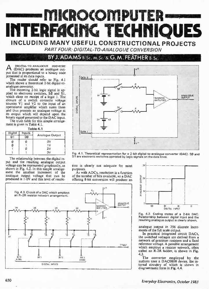
MICROCOMPUTER IrITERRICIMG TECHNIQUES INCLUDING MANY USEFUL CONSTRUCTIONAL PROJECTS
PART FOUR: DIGITAL-TO-ANALOGUE CONVERSION
BY J. ADAMS B Sc, M.Sc. & G. M . FEATHER B.Sc.
A DIGITAL-TO-ANALOGUE converter (DAC) produces an analogue out-
put that is proportional to a binary code presented at its data inputs. The reader should refer to Fig. 4.1
which shows a theoretical 2-bit digital-to-analogue converter. The incoming 2-bit logic signal is ap-
plied to electronic switches, SO and S I, which close on receipt of a logic 1. The closure of a switch connects voltage sources Vi and V2 to the input of an operational amplifier which sums them and thus presents an analogue voltage at its output which will depend upon the binary signal presented to the DAC input. The truth table for this simple arrange-
ment is given in Table 4.1.
Table 4.1 Digital Inputs
Analogue Output D1 DO
0 0 OV 0 1 1V 1 0 2V 1 1 3V
The relationship between the digital in put and the resulting analogue output voltage can be represented graphically, as shown in Fig. 4.2. In this simple arrange-ment the smallest increment of the analogue output voltage that can be produced is 1.0V and this level of resolu-
Fig. 4.3. Circuit of a DAC which employs an R-2R resistor network arrangement.
TV
ANALOGUE OUTPUT
Fig. 4.1. Theoretical representation for a 2-bit digital-to-analogue converter (DAC). SO and Si are electronic switches operated by logic signals on the data lines.
tion is clearly not adequate for most purposes. As with ADCs, resolution is a function
of the number of bits available, so a DAC offering 8-bit conversion will produce an
BITS BIT I BIT 2 BIT 3 ILSB) • IMSB)
DIGITAL INPUTS
ANALOGUE OUTPUT
3V
00 01 10 DIGITAL INPUT
11
Fig. 4.2. Coding states of a 2-bit DAC. Relationship between digital input and the resulting analogue output is clearly shown.
analogue output in 256 discrete incre-ments of the full scale output. In practical integrated circuit DACs,
the switched voltages are derived from a network of precision resistors and a fixed reference voltage. A possible arrangement which employs a resistor network, often called an R-2R ladder, is shown in Fig. 4.3. The converter employed by the
authors uses a DAC0800 device, the in-ternal circuitry of which is shown in diagrammatic form in Fig. 4.4.
650 Everyday Electronics, October 1983
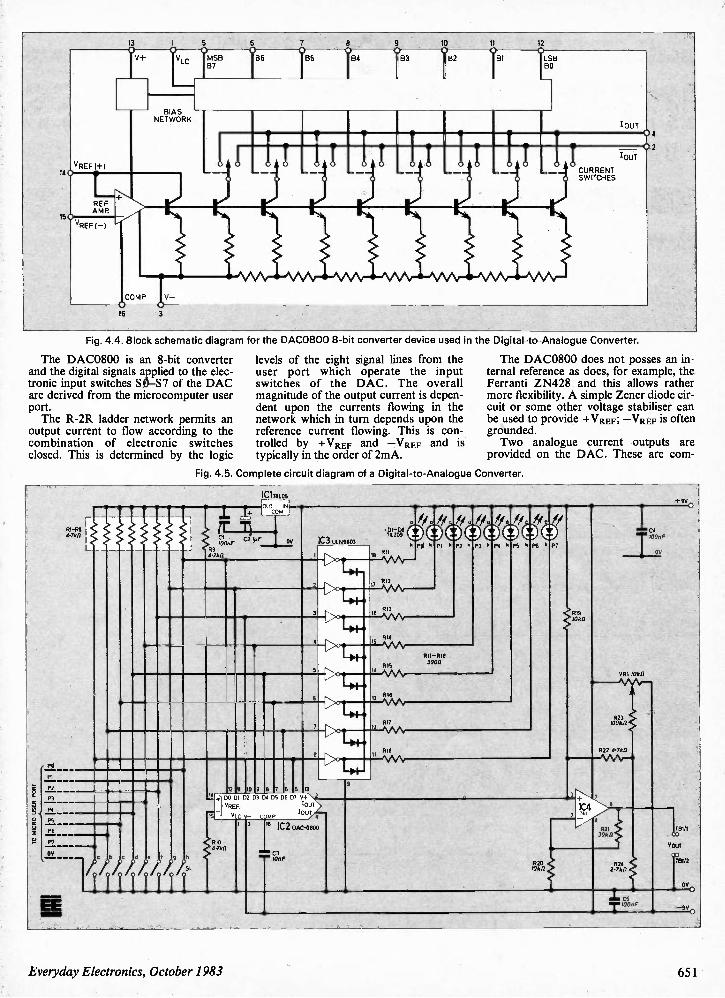
13 I 5 6 7 a 9 10 11 12 0 V+ 0 VLC 0 • IMSB B7 B6 B5 84 • 83 B2 W ILSB BO
BIAS NETWORK TOUT 0 4
14 VREF (+1 I I I
0
CURRENT 'OUT 2
REF +
SWITCHES
150 AMR VREF(_) ,
COMP - 0 16 3
Fig. 4.4. Block schematic diagram for the DAC0800 8-bit converter device used in the Digital-to-Analogue Converter.
The DAC0800 is an 8-bit converter and the digital signals applied to the elec-tronic input switches S 0—S7 of the DAC are derived from the microcomputer user port. The R-2R ladder network permits an
output current to flow according to the combination of electronic switches closed. This is determined by the logic
levels of the eight signal lines from the user port which operate the input switches of the DAC. The overall magnitude of the output current is depen-dent upon the currents flowing in the network which in turn depends upon the reference current flowing. This is con-trolled by +VREF and —VREF and is typically in the order of 2mA.
The DAC0800 does not posses an in-ternal reference as does, for example, the Ferranti ZN428 and this allows rather more flexibility. A simple Zener diode cir-cuit or some other voltage stabiliser can be used to provide +VREF ; —VREF is often grounded. Two analogue current outputs are
provided on the DAC. These are corn-
Fig. 4.5. Complete circuit diagram of a Digital-to-Analogue Converter.
TO MICRO USER PORT
69 4.7{d7
IC1781.05
OUT IN CO
1C3 1.1LN2803
RIO
3
2 11 0 a 7 6 5
00 01 02 D3 D4 05 D6 10+'.
VREF. OUT
V C V- MP IOU1.
. 44.7k0
2
• 231-08 TIL209
1116
7
RIB
PE 9 PI k P2 k P3 k P4 k PS k P6
1711-618 3900
P7
919 •000
ce 100,7F
1123 10000
1122 4.7011
3
3 16 1C2 DAC-01100
CUE R20 1000
1C4 2
7
4
1121 3000
•
820 2.700
I . CS
TI"'F .
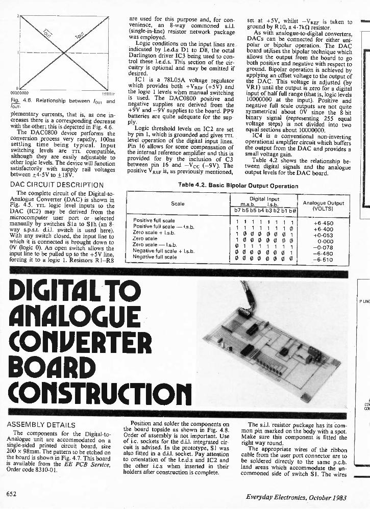
00000000 11111111 Fig. 4.6. Relationship between /OUT and /our.
plementary currents, that is, as one in-creases there is a corresponding decrease with the other; this is depicted in Fig. 4.6. The DAC0800 device performs the
conversion process very rapidly, 100ns settling time being typical. Input switching levels are Tu. compatible, although they are easily adjustable to other logic levels. The device will function satisfactorily with supply rail voltages between ±45V to + 18V.
DAC CIRCUIT DESCRIPTION
The complete circuit of the Digital-to-Analogue Converter (DAC) is shown in Fig. 4.5. TTL logic level inputs to the DAC (IC2) may be derived from the microcomputer user port or selected manually by switches S la to S 1 h (an 8-way s.p.s.t. d.i.l. switch is used here). With any switch closed, the input line to which it is connected is brought down to OV (logic 0). An open switch allows the input line to be pulled up to the +5V line, forcing it to a logic 1. Resistors R1—R8
are used for this purpose and, for con-venience, an 8-way commoned (single-in-line) resistor network package was employed. Logic conditions on the input lines are
indicated by 1.e.d.s D1 to D8, the octal Darlington driver IC3 being used to con-trol these 1.e.d.s. This section of the cir-cuitry is optional and may be omitted if desired. IC! is a 78L05A voltage regulator
which provides both +VREF (+5V) and the logic 1 levels when manual switching is used. The DAC0800 positive and negative supplies are derived from the +9V and —9V supplies to the board. PP9 batteries are quite adequate for the sup-ply. Logic threshold levels on IC2 are set
by pin 1, which is grounded and gives rrL level operation of the digital input lines. Pin 16 allows for some compensation of the internal reference amplifier and this is provided for by the inclusion of C3 between pin 16 and —Vcc (-9V). The positive VREF is, as previously mentioned,
set at +5V, whilst —VREF is taken to ground by R10, a 4.7kil resistor. As with analogue-to-digital converters,
DACs can be connected for either uni-polar or bipolar operation. The DAC board utilises the bipolar technique which allows the output from the board to go both positive and negative with respect to ground. Bipolar operation is achieved by applying an offset voltage to the output of the DAC. This voltage is adjusted (by VR1) until the output is zero for a digital input of half full range (that is, logic levels 10000000 at the input). Positive and negative full scale outputs are not quite symmetrical about OV since the 8-bit binary signal (representing 255 equal voltage steps) is not divided into two equal sections about 10000000. IC4 is a conventional non-inverting
operational amplifier circuit which buffers the output from the DAC and provides a small voltage gain. Table 4.2 shows the relationship be-
tween digital signals and the analogue output levels for the DAC board.
Table 4.2. Basic Bipolar Output Operation
Scale Digital Input
m.s.b. I.s.b. Analogue Output (VOLTS) b7 b6 b5 b4 b3 b2 b1 b0
Positive full scale 1 1 1 1 1 1 1 1 +6.450 Positive full scale — I.s.b. 1 1 1 1 1 1 1 0 +6.400 Zero scale + I.s.b. 1 0 0 0 0 0 0 1 +0.053 Zero scale 1 0 0 0 0 0 0 0 0.000 Zero scale — I.s.b. 0 1 1 1 1 1 1 1 —0.078 Negative full scale + I.s.b. 0 0 0 0 0 0 0 1 —6.460 Negative full scale 0 0 0 0 0 0 0 0 —6.510
DIGITAL TO ariaoGuE COMPERTER BOMID COMSTRUCTIOM ASSEMBLY DETAILS
The components for the Digital-to-Analogue unit are accommodated on a single-sided printed circuit board, size 200 x 98mm. The pattern to be etched on the board is shown in Fig. 4.7. This board is available from the EE PCB Service, Order code 8310-01.
Position and solder the components on the board topside as shown in Fig. 4.8. Order of assembly is not important. Use of i.c. sockets for the d.i.l. integrated cir-cuit is advised. In the prototype, Si was also fitted in a d.i.l. socket. Pay attention to orientation of the 1.e.d.s and IC2 and the other i.c.s when inserted in their holders after construction is complete.
The s.i.l. resistor package has its com-mon pin marked on the body with a spot. Make sure this component is fitted the right way round. The appropriate wires of the ribbon
cable from the user port connector are to be soldered directly to the same p.c.b. land areas which accommodate the un-commoned side of switch SI. The wires
PUNE
CON CON
‘1111 1
652 Everyday Electronics, October 1983
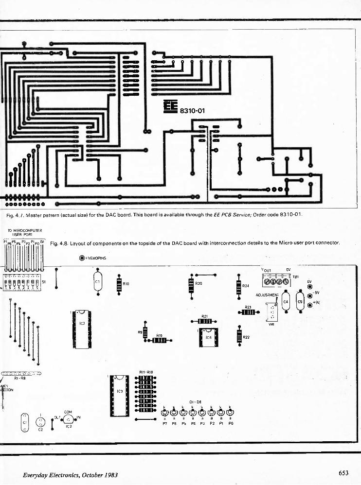
0 0 0 0 0 0 0 0 • co o 00000 0
00
Fig. 4.7. Master pattern (actual size) for the DAC board. This board is available through the EE PCB Service; Order code 8310-01.
TO M I ROCOMPUTER USER PORT P7P6P5 P4 P3P2 P1 0OV
l il il il li ll il U
7.6 5 6 3 0 1
Fig. 4.8. Layout of components on the topside of the DAC board with interconnection details to the Micro user port connector.
0 VEROPINS
SI 1
CO M OU T I N IC2
RIO
R 9 RIG 441111-•
R20
R2I 0- 41 O1 F.
. 111
R11 R18 041111:10 O H M. * M E N
•4111 1114 *41TR le * W M* DI - D8 .111 w k kl< 4 k 4 4 k .41111.
© 1 9 1 9 a a a a a a a
P7 P6 PS P4 P3 P2 PI PO
R24
V OUT OV - tf -11-11-
0
ADJUSTMENT
R23 OTI E B.
R22
VRI
TB1
A 04 CS
DV 0-9V 0+9V
Everyday Electronics, October 1983 653
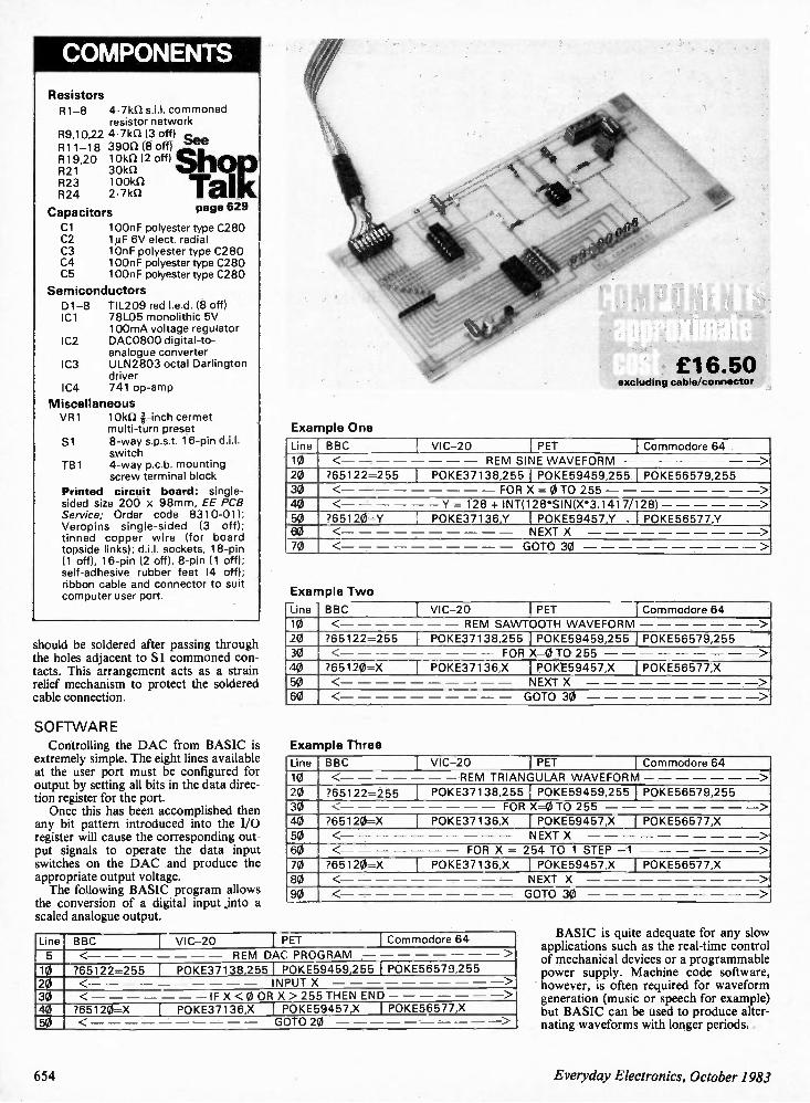
COMPONENTS
Resistors
R1-8 4.7k0 commoned resistor network
R9,10,22 4.7kil (3 off) see R11-18 3900 (8 off) R19,20 10kS2 (2 off) R21 301d1 R23 100kS2 R24 2.7kn
Capacitors page 629
Cl 100n F polyester type C280 C2 11.LF 6V elect. radial C3 10nF polyester type C280 C4 100nF polyester type C280 C5 100nF polyester type C280
Semiconductors 01-8 TIL209 red I.e.d. (8 off) IC I 78L05 monolithic 5V
100mA voltage regulator IC2 DAC0800 digital-to-
analogue converter IC3 ULN2803 octal Darlington
driver IC4 741 op-amp
Miscellaneous VR1 10kni-inch cermet
multi-turn preset Si 8-way s.p.s.t. 16-pin d.i.l.
switch TB1 4-way p.c.b. mounting
screw terminal block
Printed circuit board: single-sided size 200 x 98mm, EE PCB Service; Order code 8310-01); Veropins single-sided (3 off); tinned copper wire (for board topside links); d.i.l. sockets, 18-pin (1 off), 16-pin (2 off), 8-pin (1 off); self-adhesive rubber feet (4 off); ribbon cable and connector to suit computer user port.
should be soldered after passing through the holes adjacent to Si commoned con-tacts. This arrangement acts as a strain relief mechanism to protect the soldered cable connection.
SOFTVVARE
Controlling the DAC from BASIC is extremely simple. The eight lines available at the user port must be configured for output by setting all bits in the data direc-tion register for the port. Once this has been accomplished then
any bit pattern introduced into the I/O register will cause the corresponding out-put signals to operate the data input switches on the DAC and produce the appropriate output voltage. The following BASIC program allows
the conversion of a digital input jnto a scaled analogue output.
£16.50 excluding cable/connector
Example One
Line BBC VIC-20 PET I Commodore 64 10 < REM SINE WAVEFORM > 20 ?65122=255 I P0KE37138,255 I P0KE59459,255 P0KE56579,255
30 < FOR X = 0 TO 255 >
40 < — Y = 128 + INT(128*SINIX•3.1417/1281 — > 50 ?65120=Y POKE37136,Y I P0KE59457,Y , I P0KE56577,Y 60 < NEXT X 5
70 < GOTO 30 -- >
Exa mple Two
Line BBC VIC-20 PET _ Commodore 64 10 < REM SAWTOOTH WAVEFORM > 20 ?65122=255 P0KE37138,255 I P0KE59459,255 P0KE56579,255
,
30 < FOR X=0 TO 255 > 40 ?65120=X P0KE37136,X I P0KE59457,X I P0KE56577,X
50 < NEXT X >, 60 < GOTO 30 >
Exa mple Three
Line BBC VIC-20 I PET Commodore 64
10 < — REM TRIANGULAR WAVEFORM — >
20 765122=255 P0KE37138,255 P0KE59459,255 P0KE56579,255
30 < FOR X=0 TO 255 > 40 ?65120=X P0KE37136,X P0KE59457,X I P0KE56577,X
50 < NEXT X >
60 < FOR X = 254 TO 1 STEP —1 >
70 ?65120=X P0KE37136,X I P0KE59457,X I P0KE56577,X
80 < N EXT X >
90 < GOTO 30 >
Line BBC I- VIC-20 I PET I Commodore 64
5 < REM DAC: PROGRAM >
10 ?65122=255 I POKE37138,255 I POKE59459,255 P0KE56579,255
20 < INPUT X >
30 < IF X < 0 OR X> 255 THEN END — >
40 ?65120=X I P0KE37136,X I P0KE59457,X I P0KE56577,X
50 < G OTO 20 ->
BASIC is quite adequate for any slow applications such as the real-time control of mechanical devices or a programmable power supply. Machine code software, however, is often required for waveform generation (music or speech for example) but BASIC can be used to produce alter-nating waveforms with longer periods.
654 Everyday Electronics, October 1983
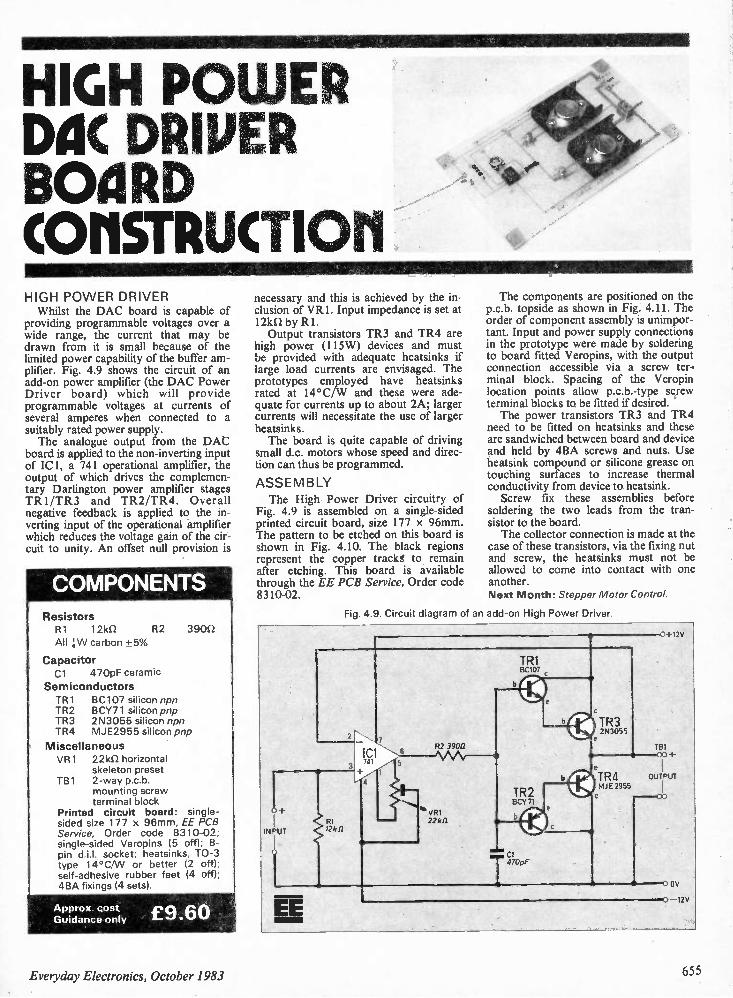
HIGH POWER Da DIMMER BOARD COMSTRUCTIOM HIGH PO WER DRIVER Whilst the DAC board is capable of
providing programmable voltages over a wide range, the current that may be drawn from it is small because of the limited power capability of the buffer am-plifier. Fig. 4.9 shows the circuit of an add-on power amplifier (the DAC Power Driver board) which will provide programmable voltages at currents of several amperes when connected to a suitably rated power supply. The analogue output from the DAC
board is applied to the non-inverting input of IC1, a 741 operational amplifier, the output of which drives the complemen-tary Darlington power amplifier stages TR1/TR3 and TR2/TR4. Overall negative feedback is applied to the in-verting input of the operational amplifier which reduces the voltage gain of the cir-cuit to unity. An offset null provision is
COMPONENTS Resistors R1 12k12 R2 3900 All 1-\A/ carbon +5%
Capacitor Cl 470pF ceramic
Semiconductors TR1 BC107 silicon npn TR2 BCY71 silicon pnp TR3 2N3055 silicon npn TR4 MJE2955 silicon pnp
Miscellaneous VR1 221(0 horizontal
skeleton preset TB1 2-way p.c.b.
mounting screw terminal block
Printed circuit board: single-sided size 177 x 96mm, EE PCB Service, Order code 8310-02; single-sided Veropins (5 off); 8-pin d.j.]. socket; heatsinks, TO-3 type 14°C/VV or better (2 off); self-adhesive rubber feet (4 off); 4BA fixings (4 sets).
Approx. cost Guidance only £9.60
necessary and this is achieved by the in-clusion of VR1. Input impedance is set at 12k0 by Rl. Output transistors TR3 and TR4 are
high power (115W) devices and must be provided with adequate heatsinks if large load currents are envisaged. The prototypes employed have heatsinks rated at 14°C/W and these were ade-quate for currents up to about 2A; larger currents will necessitate the use of larger heatsinks. The board is quite capable of driving
small d.c. motors whose speed and direc-tion can thus be programmed.
ASSE MBLY
The High Power Driver circuitry of Fig. 4.9 is assembled on a single-sided printed circuit board, size 177 x 96mm. The pattern to be etched on this board is shown in Fig. 4.10. The black regions represent the copper tracks to remain after etching. This board is available through the EE PCB Service, Order code 8310-02.
The components are positioned on the p.c.b. topside as shown in Fig. 4.11. The order of component assembly is unimpor-tant. Input and power supply connections in the prototype were made by soldering to board fitted Veropins, with the output connection accessible via a screw ter-minal block. Spacing of the Veropin location points allow p.c.b.-type screw terminal blocks to be fitted if desired. The power transistors TR3 and TR4
need to be fitted on heatsinks and these are sandwiched between board and device and held by 4BA screws and nuts. Use heatsink compound or silicone grease on touching surfaces to increase thermal conductivity from device to heatsink. Screw fix these assemblies before
soldering the two leads from the tran-sistor to the board. The collector connection is made at the
case of these transistors, via the fixing nut and screw, the heatsinks must not be allowed to come into contact with one another. Next Month: Stepper Motor Control.
Fig. 4.9. Circuit diagram of an add-on High Power Driver.
INPUT
- 7 l '' - 52 39012 39011 6
741 5
4
51 2k
vR1 22k[2
TR1 BC107
TR2 BOY 71
bf
470pF
TR3 2N3055
0+12V
TB1 • oo +
b © TR4 OUTPUT MJE 2955
EE 0 OV
o 12V
Everyday Electronics, October 1983 655
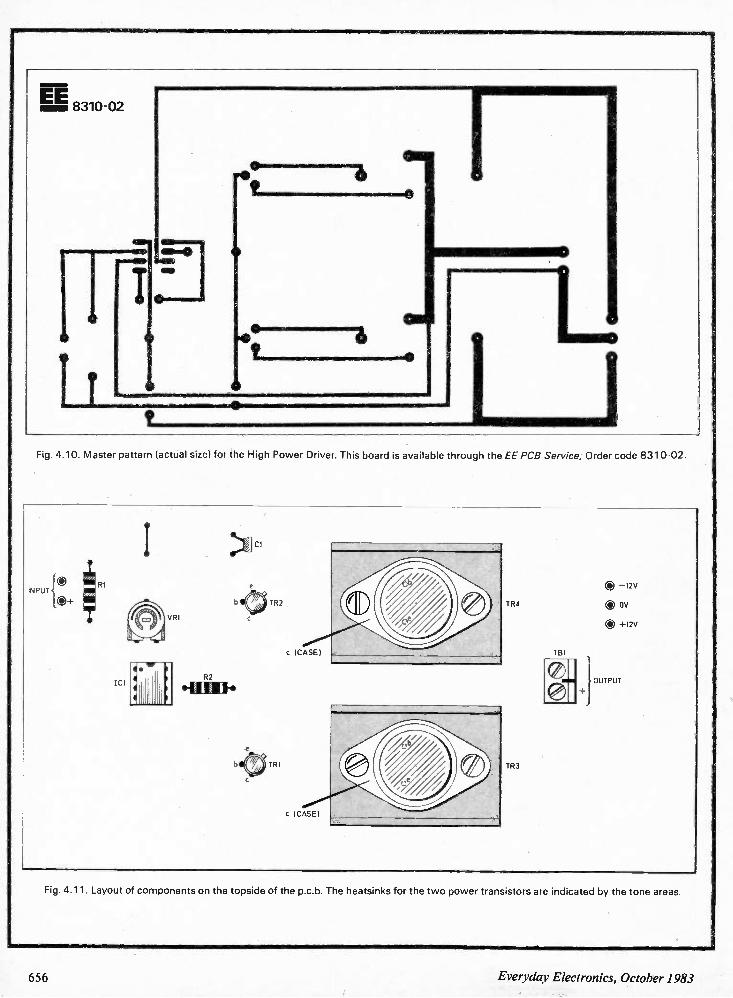
EE 8310-02
v o o min men massu mismo maii
•
Fig. 4.10. Master pattern (actual size) for the High Power Driver. This board is available through the EE PCB Service; Order code 8310-02.
RI
ICI
VR1
4 • R2
TR 2
TRI
d
TR 3
TB1
0 —12V
OV
0 +I2V
1 OUTPUT
+
Fig. 4.11. Layout of components on the topside of the p.c.b. The heatsinks for the two power transistors are indicated by the tone areas.
656 Everyday Electronics, October 1983
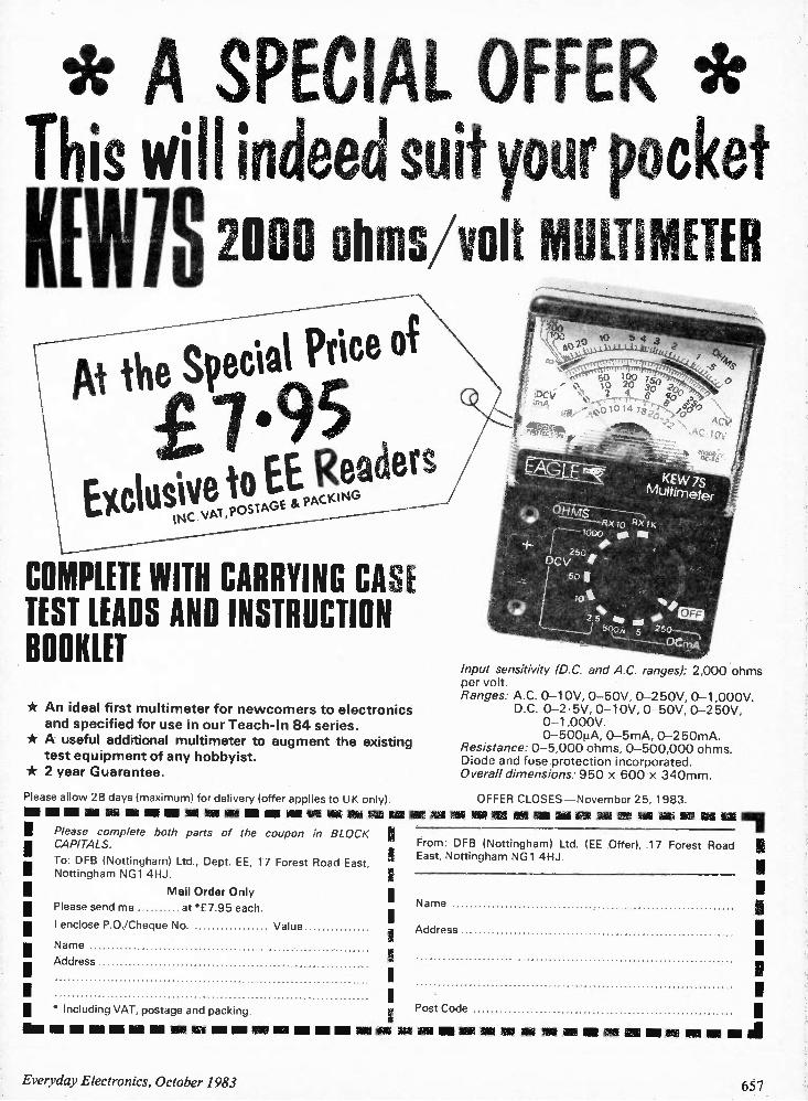
* A SPECIAL OFFER * This will indeed suit your pocket KEWIS 2000 ohms/volt MULTIMETER
COMPLETE WITH CARRYING CASE TEST LEADS AND INSTRUCTION BOOKLET * An ideal first multimeter for newcomers to electronics and specified for use in our Teach-In 84 series.
* A useful additional multimeter to augment the existing test equipment of any hobbyist.
* 2 year Guarantee.
Please allow 28 days (maximum) for delivery (offer applies to UK only)
Please complete both parts of the coupon in BLOCK CAPITALS.
To: DFB (Nottingham) Ltd., Dept. EE, 17 Forest Road East, Nottingham NG1 4HJ.
Mail Order Only Please send me at "f 7.95 each.
I enclose P.O./Cheque No. Value
Name
Address
• Including VAT, postage and packing.
Input sensitivity (D.C. and A.C. ranges): 2,000 ohms per volt. Ranges: A.C. 0-10V, 0-50V, 0-250V, 0-1,000V.
D.C. 0-2-5V, 0-10y, 0-50V, 0-250V, 0-1,000V. 0-5001iA, 0-5mA, 0-250mA.
Resistance: 0-5,000 ohms, 0-500,000 ohms. Diode and fuse protection incorporated. Overall dimensions: 950 x 600 x 340mm.
OFFER CLOSES —November 25, 1983.
III Ell MI MI MI MI MI NI IN IIIII
From: DFB (Nottingham) Ltd. (EE Offer), 17 Forest Road I East, Nottingham NG1 4HJ.
Name
Address
Post Code
Om me No NE on um am ow mu No um mu
Everyday Electronics, October 1983
- - - - - 11111 MN Nil MN IM IN III
657
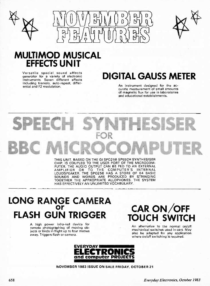
r OW% v1) TRAM3 Nr
MULTIMOD MUSICAL EFFECTS UNIT
Versatile special sound effects generator for a variety of electronic instruments. Seven different effects including tremolo, auto-repeat, differ-ential and F2 modulation.
DIGITAL GAUSS METER An instrument designed for the ac-curate measurement of small amounts of magnetic flux for use in laboratories and educational establishments.
SPEECH SLI HESISER
BBC MICROCOMPUTER THIS UNIT, BASED ON THE GI SP0256 SPEECH SYNTHESISER CHIP, IS COUPLED TO THE USER PORT OF THE MICROCOM-PUTER. THE AUDlO OUTPUT CAN BE FED TO AN EXTERNAL AMPLIFIER OR TO THE COMPUTER'S INTERNAL LOUDSPEAKER. THE SP0256 HAS A STORE OF 64 BASIC SOUNDS AND WORDS ARE PRODUCED BY STRINGING TOGETHER THE APPROPRIATE ALLOPHONES. THE SYSTEM HAS EFFECTIVELY AN UNLIMITED VOCABULARY.
LONG RANGE CAMERA or CAR ON/OFF
FLASH GUN TRIGGER TOUCH SWITCH A high power infra-red device for remote photographing of moving ob-jects or birds in flight up to four metres away. Triggers flash or camera.
EVERYDAY
An alternative to the normal on/off mechanical switches used in cars. May also be adapted for any application where on/off switching is required.
ELECTRONICS and co mputer PROJECTS
NOVEMBER 1983 ISSUE ON SALE FRIDAY, OCTOBER 21
658 Everyday Electronics, October 1983
RADIO WORLD All Change Changes in the regulation of amateur
radio licences in the UK have been coming thick and fast. First, following the General Election, the entire Radio Regulatory Department in Waterloo Bridge Road was transferred lock, stock and barrel, from the responsibility of the Home Secretary to the Secretary of State for Trade and Industry. Then, on 27 July, DoTI published the
final report of the "Independent Review of the Radio Spectrum (30-960M Hz)" by the three wise men chaired by Dr James Merriman recommending the setting up of an entirely new ministerial department to be responsible for telecommunications, in-cluding all radio regulatory matters but (as a third choice) RRD to be with DoTI rather than Home Office. But the report had virtually nothing to say about amateur radio or CB. The following day, DoTI announced in
Parliament the transfer on 19 September of amateur radio licensing (including the issue and renewal of licences) back to its old home, the Post Office, who already issue CB licences. Unlike CB, however, amateur radio licences will not be issued over the counter but dealt with by postal application at the PO headquarters. (The address will be: Radio Amateur Licensing Unit, Chetwynd House, Chesterfield, Derby-shire S49 1PF, telephone Chesterfield (0246) 207555 who will issue the necessary application forms, etc). A plus point is that the Post Office is
guaranteeing a turn round in normal condi-tions of five days and at peak times of ten, and are to put all records on computer. The long delays of dealing with Waterloo Bridge House should soon be over. The minus points? These are difficult to
predict and it may be only my natural pessimism that makes me feel that more and more amateur radio in Europe is being lumped in with CB by people who fail to see that the two are essentially different. This is not to deride CB, a useful leisure
pastime and a low-cost communications facility which I was advocating many years before the Home Office finally gave way. I have always believed that not only is amateur radio a more fulfilling hobby but also has genuinely contributed to self-training, technical education and the advan-cement of the radio sciences.
First Impressions The impression I have is that the
authorities, whichever ministry is involved, nowadays are concerned only with reduc-ing the administrative burden of catering for the 48,000 (and still expanding) UK radio amateurs. Unlike the USA, USSR and Japan, the UK has consistently declined to
'W M\ 41Ilint " AI M // MIS 2/11111 MILI M. IIIII M M IE11111111111A MIII
W M/ %SO W W II/
"MIFF W V/ IhUr No,
BY PAT HA WKER G3VA
introduce any form of "incentive" licensing, or any form of "novice" licence. But then little official encouragement is
given these days to British licensees to progress from the Class B (vhf-only) to the Class A (v.h.f./h.f.) licence. Even the current president of the R.S.G.B. (a former senior member of the Radio Regulatory Department) is reported to have emphasised recently that "the Class B per-mit is in no way to be regarded as inferior to the Class A version but simply reflects an interest in v.h.f./u.h.f, techniques rather than in h.f.-bands communication". This is hardly a positive encouragement
to Class B licensees to prepare for a 12 words per minute Morse test! A very dif-ferent attitude from the American Radio Relay League which continues to support graded Morse tests for all amateur radio licences!
The Merriman Report As someone with an interest to declare
in both radio communications and broad-casting I would have liked to feel that the three wise men of the Independent Review committee have been truly impartial in their recommendations. But the fact is that, both in the interim and final reports, broad-casting has been clobbered unmercifully by a committee on which broadcasting was not represented at all, although accounting, at the outset, for the use of 45 per cent of the spectrum between 30 and 960MHz. This percentage may seem excessive until you remember that virtually every single person in the UK benefits from broadcast services of entertainment, information and education; relatively few from their own mobile communications. On the other hand, most of us have a
suspicion that the very large parts of the spectrum reserved for Defence purposes are vastly under-used in peacetime and are unlikely ever to be filled even in a major war. Yet the Merriman report saw little scope for any reduction in Defence spec-trum, a conclusion with which one presumes at least one of the three wise men —a former Assistant Chief of Defence Staff (Signals) and now a member of a firm prominent in Defence communications equipment —must have been in full agree-ment. One recalls that no attempt has been
made to re-establish the old Television Ad-visory Committee. The committee inciden-tally that presupposed the re-engineering and Bands 1 and 111 for 625-line tele-vision. There are many other curious features of
the Merriman report. The insistence that UK frequency block allocations remain "an official secret". The idea that an American FCC-type regulatory body could not work
because only a government-body can deal with Defence frequencies. Why not leave detailed Defence assignments to MoD in the American manner? The more one reads the report the more
one gains the impression that the "indepen-dent review" was set up with two ideas in mind: (1) to wrest RRD away from the Home Office; and (2) to clobber the broad-casters. It appears to have succeeded in both.
In The Background? There is a deep-rooted belief that com-
plaints to broadcast engineers about the quality of or faults in broadcast transmis-sions tend to be met with a single stock phrase: "It was all right leaving me". In practice this is often an entirely
justified statement: a networked broadcast signal goes through such a complex path after it leaves its originating studio that there is almost unlimited scope for the gremlins to get to work. An example, fortunately of a rare type,
occurred recently on one of my recordings for the weekly IBA's Engineering Announ-cements that go out on Tuesdays (9.15 a.m.) on Channel 4. As luck would have it I was describing the new automatic test equipment (MATE) becoming available to the 50 IBA mobile maintenance teams that spring into action when anything goes wrong at a transmitter, most often these days due to the effects of lightning on overhead mains supply lines or on equip-ment. But my words were accompanied by background music that seemed determined to become "foreground". A first reaction was that the producer or
someone in master control had decided to liven up the programme but had overdone it a bit. When I enquired, everyone firmly denied having any part in jazzing me up and assured me it was all right leaving them. Finally, it was discovered that the music
was entering the system at BT's National Television Switching Centre in London. But the mystery remains —whose music was it? Where was it originated? How did it get mixed into network television? And for what purpose was it going along high-quality music lines? Only British Telecom knows the answers!
i Signals From Spacesi mi Although there are still sensitive receivers
attached to giant aerials searching (so far vainly) for radio signals that could denote the existence of extra-terrestrial intelligence, enor-mous scientific knowledge has been gained over the past 50 years from random noise and also from the curious pulsar signals, first ob-served in the 1960s and initially thought to come from those elusive little green men. It was exactly 50 years ago that Karl
Jansky of Bell Laboratories, first announced that he had found that radio signals were com-ing from space, while investigating at-mospherics. And almost 45 years since an American radio amateur, Grote Reber, W9GFZ, built the world's first steerable radio telescope. It is also 41 years since British radar expert
J. S. Hey recognised that what was thought to be deliberate enemy jamming was the result of an enormous solar flare and became "the father of British radioastronomy," inspiring Sir Bernard Lovell, Sir Martin Ryle and J. L. Pawsey to begin intensive investigations that developed into the science of radioastronomy and so opened a new window on space.
Everyday Electronics, October 1983 659
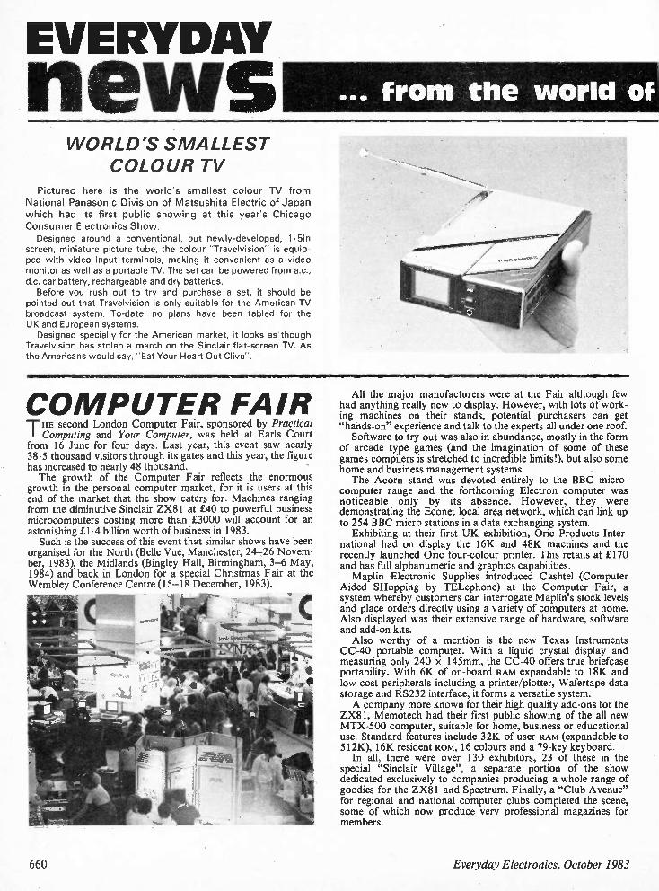
EVERYDAY
news ... from the world of
WORLD'S SMALLEST COLOUR TV
Pictured here is the world's smallest colour TV from National Panasonic Division of Matsushita Electric of Japan which had its first public showing at this year's Chicago Consumer Electronics Show. Designed around a conventional, but newly-developed, 1.5in
screen, miniature picture tube, the colour "Travelvision" is equip-ped with video input terminals, making it convenient as a video monitor as well as a portable TV. The set can be powered from ac., d.c. car battery, rechargeable and dry batteries. Before you rush out to try and purchase a set, it should be
pointed out that Travelvision is only suitable for the American TV broadcast system. To-date, no plans have been tabled for the UK and European systems. Designed specially for the American market, it looks as though
Travelvision has stolen a march on the Sinclair flat-screen TV. As the Americans would say, "Eat Your Heart Out Clive".
CO MPUTER FAIR THE second London Computer Fair, sponsored by Practical Computing and Your Computer, was held at Earls Court
from 16 June for four days. Last year, this event saw nearly 38.5 thousand visitors through its gates and this year, the figure has increased to nearly 48 thousand. The growth of the Computer Fair reflects the enormous
growth in the personal computer market, for it is users at this end of the market that the show caters for. Machines ranging from the diminutive Sinclair ZX81 at £40 to powerful business microcomputers costing more than £3000 will account for an astonishing £1•4 billion worth of business in 1983. Such is the success of this event that similar shows have been
organised for the North (Belle Vue, Manchester, 24-26 Novem-ber, 1983), the Midlands (Bingley Hall, Birmingham, 3-6 May, 1984) and back in London for a special Christmas Fair at the Wembley Conference Centre (15-18 December, 1983).
All the major manufacturers were at the Fair although few had anything really new to display. However, with lots of work-ing machines on their stands, potential purchasers can get "hands-on" experience and talk to the experts all under one roof. Software to try out was also in abundance, mostly in the form
of arcade type games (and the imagination of some of these games compilers is stretched to incredible limits!), but also some home and business management systems. The Acorn stand was devoted entirely to the BBC micro-
computer range and the forthcoming Electron computer was noticeable only by its absence. However, they were demonstrating the Econet local area network, which can link up to 254 BBC micro stations in a data exchanging system. Exhibiting at their first UK exhibition, Oric Products Inter-
national had on display the 16K and 48K machines and the recently launched Oric four-colour printer. This retails at £170 and has full alphanumeric and graphics capabilities. Maplin Electronic Supplies introduced Cashtel (Computer
Aided SHopping by TELephone) at the Computer Fair, a system whereby customers can interrogate Maplin's stock levels and place orders directly using a variety of computers at home. Also displayed was their extensive range of hardware, software and add-on kits. Also worthy of a mention is the new Texas Instruments
CC-40 portable computer. With a liquid crystal display and measuring only 240 x 145mm, the CC-40 offers true briefcase portability. With 6K of on-board RAM expandable to 18K and low cost peripherals including a printer/plotter, Wafertape data storage and R5232 interface, it forms a versatile system. A company more known for their high quality add-ons for the
ZX81, Memotech had their first public showing of the all new MTX-500 computer, suitable for home, business or educational use. Standard features include 32K of user RAM (expandable to 512K), 16K resident ROM, 16 colours and a 79-key keyboard. In all, there were over 130 exhibitors, 23 of these in the
special "Sinclair Village", a separate portion of the show dedicated exclusively to companies producing a whole range of goodies for the ZX81 and Spectrum. Finally, a "Club Avenue" for regional and national computer clubs completed the scene, some of which now produce very professional magazines for members.
660 Everyday Electronics, October 1983

electronics
LIVING WITH ROBOTS The British Engineerium, Off Nevill Road, Hove, East Sussex has
launched a new exhibition called Living With Robots and the official opening took place on 29 July, with Patrick Moore, the television presenter presiding over the ceremony. The display incorporates many of the more famous robots of tele-
vision fame. A replica of K9, the Dr Who robot was on display but it did not seem too impressed with its surroundings and would not work. Star Wars was also represented with replicas of models used in the film on show and last but not least the industrial robots like the 600-Fanuc, a programmable robot welder.
London Earth Station
A satellite earth station in the heart of London's dockland is to be built by British Telecom International. The earth station, London's
first, will be operational early next year. It will transmit television programmes to cable TV systems in the UK and in Europe, and provide the capital's businesses with advanced telecommunica-tions services. The earth station will be
located at Pier Road, North Woolwich, close to the old King George V Dock. Initially two dish aerials, 13m (43ft) in diameter, will be ready for service early in 1984. One will operate through the European Communications Satellite (ECS) and the other through an INTELSAT satellite.
The Western Australian Government is to establish a Technology Directorate as a focal point for its drive to encourage technological development in the area.
EVENTS
SHUTTLE PO WER A contract worth more than
$100,000 has been placed by NASA with Gould Micro Power Products Division to provide zinc-air power packs for use on board the Space Shuttle. The power packs, which each
contain 60 zinc-air power cells, will be used to operate an in-cabin radio system that enables astronauts to communicate with each other and with the ground, while maintaining freedom of movement inside the orbiter.
RADIO TRANSFER
The Radio Regulatory Depart-ment, including the Directorate of Radio Technology, has been transferred from the Home Office to the Department of Trade and Industry. The Broadcasting Department
of the Home Office is not being transferred. Its responsibilities in-clude: constitutional aspects of broadcasting; cable programme services; direct broadcasting by satellite (DBS); BBC and IBA finance; TV licensing; technical planning policy; and local and community radio.
The Great Home Entertainment Spectacular takes place from 17 to 25 September at Olympia, London.
The 10th International Broadcasting Convention —IBC '84, will be held at the Metropole Conference & Exhibition Centre, Brighton from 21 to 25 September. Technical Sessions will be run throughout the show.
Sponsored by Jeffries Hi Fi, the South Coast Hi Fl Show is to be held at the Royal Albion Hotel, Old Steine, Brighton, from 11 to 13 November, 1983.
The international cable and satellite television industry is to have a major exhibition at its European focal point in Basel, Switzerland. "Eurocast 714" will take place in the halls of the Swiss Industries Fair from 5 to 9 May next year.
HRH Prince Philip talking to Mr. & Mrs. Frank Chorley after the award ceremony.
Prince Philip Medal •
The 1983 Prince Philip Medal of the City and Guilds of London Institute was presented to Mr. Frank Chorley by HRH Prince Philip in the Music Room at Buckingham Palace. Mr. Chorley is Deputy Chairman and Manag-ing Director of Plessey Electronic Systems Ltd.
Since 1962, the City and Guilds of London Institute has conferred the Prince Philip Medal, its highest award, on an individual who has received an Institute qualification and sub-sequently shown outstanding achievement in technology or in service to industry. Only one medal is awarded each year and the final choice is made by HRH Prince Philip who is the Institute's President.
British Lead British standards are being used in ninety-eight per cent of viewdata
and teletext sets throughout the world. This is revealed by a survey undertaken for British Telecom, Mullard Ltd. and the Department of Trade and Industry. The survey, which identified more than 2+ million viewdata and
teletext sets in 26 countries, was carried out by the US-based con-sultancy, CSP International Inc.
All amateur radio licences will be issued and renewed by the Post Office headquarters in Chesterfield on behalf of the Secretary of State for Trade and Industry.
The annual salary survey of pay and other benefits in com-puting, conducted by the. National Computing Centre, once again shows that, on straight salary terms, salaries tend to be higher in the public sector than in private industry.
NO FAIR THIS YEAR_ Electronic Hobbies Fair Victim of Recession An announcement in this issue explains the reasons behind
the decision not to proceed with this year's Electronic Hobbies Fair. The news will be a great disappointment to thousands who enjoyed their visit to last year's Fair and had been looking forward to this year's event. Additional special attractions had been lined up to extend the overall interest of the Fair, and a number of national organisations had declared their intention of participating. But in the end the whole exhibition depended upon the retail trade that serves the hobbyist and home constructor.
Trade is still in the doldrums and despite frequent optimistic predictions from economists, the eagerly awaited revival still seems as far off as ever. So, for the present, we can only hope for a general improvement before too long, and for a future Elec-tronic Hobbies Fair that will signal this change in fortunes in an unmistakable manner.
Everyday Electronics, October 1983 661
LETTERS Two-Tone Sir —Seeing Mr. Johns item in the July '83 Circuit Exchange (page 423) about his Two- Way Doorbell reminded me of the modification I made to the Modulated Tone Doorbell from the March '81 issue of EVERYDAY ELECTRONICS This involves inserting a "steering diode"
between the two halves of the circuit. An additional switch, S2, will apply 9V to both halves, giving a frequency modulated tone as normal. The original switch, Si, now only applies the power to IC1b and associated components, giving a single, clear tone.
A. B. Wilson, Bradley,
Yorkshire.
To effect Mr. Wilson's modifications, the diode is placed in the 9V line between IC1a and IC1 b with the cathode (k) towards IC1 b (referring to Fig. 1, page 180, March '81 issue). It is important that the power con-nection to ICI (pin 14) is transferred to the IC1b side of the circuit. Pins 4 and 10 remain as shown. The additional push-button switch (S2) is
connected between the anode (a) of the diode and the positive (+) of the battery, B1 . A 1N4148 diode is a suitable device. Some alteration of stripboard layout is necessary.
Key Question Dear Paul Young —With reference to your piano keyboard question in Counter In-telligence in the August issue of EE. Established musicians will quite naturally
be against typewriter or computer keyboards. I can imagine that after having spent years in becoming proficient on a traditional keyboard, the thought of spending a long period adjusting to an "alien" keyboard, trying to rid yourself of deeply ingrained techniques would come as a deep shock. I think that it is thus quite understandable that musicians will not like the idea of new-type keyboards. On the other hand there is one vast dis-
advantage of computer keyboards. Piano keyboards are essentially "analogue" devices. They produce a sound whose loudness is proportional to their velocity. In other words, hit the keys harder and you get a louder noise. Computer keyboards, on the other hand, are "digital" devices. They are either "on" (pressed) or "off" (not pressed). This lack of expression due to using electronic keyboards is a serious handicap to a musician's creativity. This lack of expression is not such a handicap as one may suppose, as good recording and re-mixing facilities can work wonders. It does, however, mean that "live" playing is severely restricted. The ideal solution is to produce a musical
instrument which can be "pre-program-med" by a computer keyboard or played "live" by a traditional keyboard, with "dynamic expression" (the harder you hit the keys, the louder the sound produced).
The Fairlight computer musical instrument possesses all these (and a great many more) abilities, its only real drawback being its price. At around £14,000 each I don't think I will be giving many as Christmas presents this year. I have noticed that from time to time you
have expressed an interest in the paranor-mal. One method of testing for telepathy is achieved by allowing a computer to secretly choose one of five "Zener cards". The sub-ject under test then has to guess which card the computer chose. This process con-tinues for a set number of guesses after which the computer prints the percentage of correct guesses. You will be asked to submit 100 guesses
by the computer. The arithmetic behind the results is as follows:
In five guesses you may score one by pure chance.
In 100 guesses you may score 20 by pure chance.
Hence any score significantly above, say 25 per cent (a statistically adjusted figure to take into account the small number of guesses) may, if repeatable, indicate precognition. For more information about current
thoughts and research in this field consult the book "Mind Over Matter" by Kit Pedler, published by Thames/Methuen. This book provides a layman's guide to the subject and, perhaps most important of all, is completely non-sensationalistic: a definite antidote for an overdose of the Von-Daniken's! In conclusion, may I say that I have read
and enjoyed your articles in EE since 1974 and have enjoyed them all. Please keep it up, your article is the first thing I read when I receive EE.
Christopher Stone, Hull,
North Humberside.
Soft Apple Sir —As a rule, I do not purchase an elec-tronics magazine unless an initial perusal reveals an interesting article likely to be completed without too much difficulty. Accordingly, the article Real-Time Clock
Apple 11 in EVERYDAY ELECTRONICS (Vol. 12, No, 5, May 1983) caught my attention and was read with interest. However, a closer study prompts me to
believe that the article is incomplete, as generally throughout the article and specifically on page 274, reference is made to enclosed programs for initialisation, testing, setting and reading the clock when installed on the Apple II and these appear to have been omitted from the above edi-tion. Your comments would oblige.
D. Elliott, Brisbane, Australia.
In reply to your comments concerning the omission of the program listings for this article, it is not our normal policy to print the software (unless it is a very short routine —a test program for example) as we are primarily an electronics magazine and therefore more concerned with the hardware. All programs are available from the EE Software Service, either in cassette form or as a listing. The order codes for this project (Apple II version) are T002 and L002 respectively, and the current price is £2.95 inclusive. We regret any confusion arising from the
wording of this article.
Oric Interface? Sir —I read with interest the article Microcomputer Interfacing Techniques by Mr. Adams and Mr. Feather, in your July '83 issue. I am an avid reader of your publication
and found the article most enlightening; however, I noticed you select four specific microcomputers and provide abundant details with relation to those particular machines. However, as the owner of an Oric 1 64K computer, I am at a complete loss to know how to utilise the information contained in the last edition. I would be obliged if it were possible for
you to supply details in order that the cir-cuitry in question can be interfaced with the Oric and look forward to hearing from you at your earliest convenience.
N. R. Fineman, Southgate, London.
Unfortunately your Oric 1 computer does not have the necessary user port to carry out the interfacing techniques described in this series. Although the Oric uses the 6502 microprocessor (as used by the four computers described in the series), it does not have the 6522 Versatile Interface Adaptor integrated circuit on board so an additional user port add-on is required. At present, we do not have a suitable cir-
cuit on file, but you may be able to obtain one from an outside supplier. However, we have noted the need for such a project and a design may well be featured in the not too distant future.
Gen On The Generator Sir —I have followed the Test Gear '83 series with zest, making each project as soon as your magazine comes out. So what has happened to the Frequency Meter? Incidentally, the value of the tantalum
bead capacitor (C15) in the Pulse Generator (July '83 issue) cannot be ob-tained. It is listed as a 1004F, 25V compo-nent, but a 100µF, 10V tantalum capacitor is readily available and works well. The VHF Aerial Pre-Amplifier by Hamid
Reza Tajzadeh (Circuit Exchange, August '83) was found to be of little use as all modern TVs are UHF but it worked well on my car radio. Also, is there more "gen' on the Pulse Generator testing and use?
L. R. B. Turner, North End, Portsmouth.
With regard to Mr. Tajzadeh's VHF Pre--Amp, the TV system in Iran is still VHF (unlike our own, which has recently switched exclusively to UHF) but we felt that this circuit would be useful in other applications, for example, f.m. radio. As far as more information on testing
and using the Pulse Generator, it is our usual policy to only publish the details sup-plied by the author if we deem these to be sufficient. However, if you have any par-ticular problems, we would be happy to answer them or forward your query to the author. Concerning the Frequency Meter, the
final unit in the series, unfortunately due to circumstances beyond our control this in-strument will not now be featured in this magazine. We hope this has not incon-venienced too many readers.
662 Everyday Electronics, October 1983
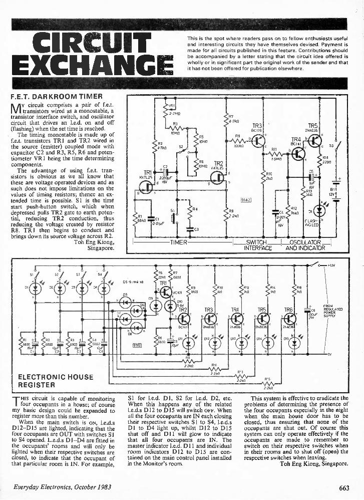
CIRCUIT EXCHANGE F.E.T. DARKROOM TIMER
My circuit comprises a pair of Le.t. transistors wired as a monostable, a
transistor interface switch, and oscillator circuit that drives an I.e.d. on and off (flashing) when the set time is reached. The timing monostable is made up of
Le.t. transistors TR1 and TR2 wired in the source (emitter) coupled mode with capacitor C2 and R3, R5, R6 and poten-tiometer VR1 being the time determining components. The advantage of using Le.t. tran-
sistors is obvious as we all know that these are voltage operated devices and as such does not impose limitations on the values of timing resistors; thence an ex-tended time is possible. Si is the time start push-button switch, which when depressed pulls TR2 gate to earth poten-tial, reducing TR2 conduction, thus reducing the voltage created by resistor R8. TR1 then begins to conduct and brings down its source voltage across R2.
Toh Eng Kiong, Singapore.
TR1 847L25
VRI
2 21.112
R3
101412
R2 4.7k11
C2
1111 -1.
22001.1F d 16V
1-0
52
This is the spot where readers pass on to fellow enthusiasts useful and interesting circuits they have themselves devised. Payment is made for all circuits published in this feature. Contributions should be accompanied by a letter stating that the circuit idea offered is wholly or in significant part the original work of the sender and that it has not been offered for publication elsewhere.
65
101,111
66 TR2 847L25
or,
RI i 68kfl Cl T
0•01pF
Si 84
1 T" TIMER
/ 52 / 53 / S4 /
d a di a dd DO a di
D2 3
•
6 RI +800
70pTC iF22 +
68012 10pF C2
•
iR3 + 68012 =
1057 C3
•
64 + 680.12 =
10pTC4
ELECTRONIC HOUSE REGISTER
D7
•
D5 -9 =104148
D5 0 o Da6
•
a D8
9782
D9
R5 R7
2280 68011
TR1
a 8C109 ek D10
86 68012
5 6V
TR2
BC 141
R9 RIO 1800 140
2'240
TR3
204036
R7
4 7kfl
TR3 BC179
R
100512
9642
R8
2•2kfl
• _ SWITCH _ 1 _OSCILLATOR
INTERFACE AND INDICATOR
RI
1-5Mt2
RIO
2511
TR4 SC 141
C4
0.001 5F 16V
Rt2
74kfl
TR5 2N4036
C5
II-lpF 15V
R13 5612
D1
FLASH-ING LED
S3
R14
22011
B 1
12V I
adi
204036
R1 RIO
2 2417 ' \•At Ar .
R12 R14 816 •411 18/2 18/2
22811
TRSI TR6
204036
T1 HIS circuit is capable of monitoring I four occupants in a house; of course my basic design could be expanded to register more than this number. When the main switch is ON, 1.e.d.s
D12—D15 are lighted, indicating that the four occupants are OUT with switches S I to S4 opened. L.e.d.s DI—D4 are fitted in the occupants' rooms and will only be lighted when their respective switches are closed, to indicate that the occupant of that particular room is IN. For example,
Si for I.e.d. Di, S2 for 1.e.d. D2, etc. When this happens any of the related 1.e.d.s D12 to D15 will switch OFF. When all the four occupants are IN each closing their respective switches Si to S4, I.e.d.s Di to D4 light up, whilst D12 to D15 shut off and D I I will glow to indicate that all four occupants are IN. The master indicator I.e.d. Dll and individual room indicators D 12 to D15 are con-tained on the main control panel installed in the Monitor's room.
RIO
2 2511
204036
et... C. — +12V
C6
loop 254
FROM REGULATED POWER SUPPLY
ov
This system is effective to eradicate the problems of determining the presence of the four occupants especially in the night when the main house door has to be closed, thus ensuring that none of the occupants are shut out. Of course this system can only operate effectively if the occupants are made to remember to switch on their respective switches when in their rooms and to shut off (open) the respective switches when leaving.
Toh Eng Kiong, Singapore.
Everyday Electronics, October 1983 663
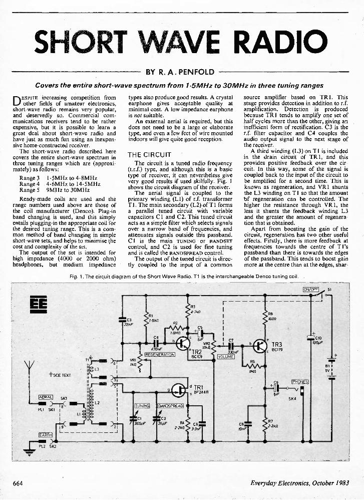
SHORT WAVE RADIO BY R. A. PENFOLD
Covers the entire short- wave spectru m fro m 1.5 MHz to 30 MHz in three tuning ranges
DESPITE increasing competition from other fields of amateur electronics, short-wave radio remains very popular, and deservedly so. Commercial com-munications receivers tend to be rather expensive, but it is possible to learn a great deal about short-wave radio and have just as much fun using an inexpen-sive home-constructed receiver. The short-wave radio described here
covers the entire short-wave spectrum in three tuning ranges which are (approxi-mately) as follows:
Range 3 Range 4 Range 5
1.5MHz to 4.8MHz 4.6MHz to 14.5MHz 9MHz to 30MHz
Ready-made coils are used and the range numbers used above are those of the coil manufacturer (Denco). Plug-in band changing is used, and this simply entails plugging-in the appropriate coil for the desired tuning range. This is a com-mon method of band changing in simple short-wave sets, and helps to minimise the cost and complexity of the set. The output of the set is intended for
high impedance (4000 or 2000 ohm) headphones, but medium impedance
types also produce good results. A crystal earphone gives acceptable quality at minimal cost. A low impedance earphone is not suitable. An external aerial is required, but this
does not need to be a large or elaborate type, and even a Few feet of wire mounted indoors will give quite good reception.
THE CIRCUIT
The circuit is a tuned radio frequency (t.r.f.) type, and although this is a basic type of receiver, it can nevertheless give very good results if used skilfully. Fig. 1 shows the circuit diagram of the receiver. The aerial signal is coupled to the
primary winding (L1) of r.f. transformer Ti. The main secondary (L2) of Ti forms a parallel tuned circuit with variable capacitors Cl and C2. This tuned circuit acts as a simple filter which selects signals over a narrow band of frequencies, and attenuates signals outside this passband. Cl is the main TUNING Or BANDSET control, and C2 is used for fine tuning and is called the BANDSPREAD control. The output of the tuned circuit is direc-
tly coupled to the input of a common
source amplifier based on TR I. This stage provides detection in addition to r.f. amplification. Detection is produced because TR1 tends to amplify one set of half cycles more than the other, giving an inefficient form of rectification. C3 is the r.f. filter capacitor and C4 couples the audio output signal to the next stage of the receiver. A third winding (L3) on Ti is included
in the drain circuit of TR1, and this provides positive feedback over the cir-cuit. In this way, some of the signal is coupled back to the input of the circuit to be amplified for a second time. This is known as regeneration, and VR I shunts the L3 winding on Ti so that the amount of regeneration can be controlled. The higher the resistance through VR1, the less it shunts the feedback winding L3 and the greater the amount of regenera-tion that is obtained. Apart from boosting the gain of the
circuit, regeneration has two other useful effects. Firstly, there is more feedback at frequencies towards the centre of Ti's passband than there is towards the edges of the passband. This tends to boost gain more at the centre than at the edges, shar-
Fig. 1. The circuit diagram of the Short Wave Radio. Ti is the interchangeable Denco tuning coil.
EE
*SEE TEXT
AERIAL
••••••Aiii PL1
II II
SK3
SKI I II ca I
j i I
EARTH
21
PL2 SK2
. C3 22nF
II 470nF
REGENERATION]
'TUNING' IBANDSPREADI
CI . C2 365pF / 25pF
c
VR2 10k11
eTR2 BC109
TR1 BF244B
330nF VOLUME
C8 lOnF
IM0
R6 1000
TR3 BC179
C9 +-
/pF
R7 2.21(0
ON/OFF
'PHONES
SK4
• •
100pF
SI
BI I 9V I
664 Everyday Electronics, October 1983
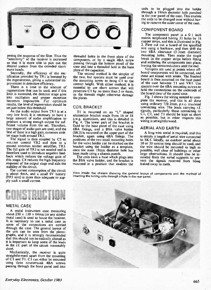
pening the response of the filter. Thus the "selectivity" of the receiver is increased so that it is more able to pick out the desired station from the crowded short-wave bands. Secondly, the efficiency of the rec-
tification provided by TR1 is boosted by the regeneration, giving a substantial im-provement in detection efficiency. There is a limit to the amount of
regeneration that can be used, and if this limit is exceeded, the detector stage goes into oscillation and proper reception becomes impossible. For optimum results, the level of regeneration should be set just below this threshold. As the audio output from TR1 is at a
very low level, it is necessary to have a large amount of audio amplification to produce a strong enough output for suf-ficient volume from the set Therefore, two stages of audio gain are used, and the first of these is a high gain, common emit-ter stage built around TR2. The signal is then coupled by C5 to
VOLUME control VR2 and then to a second common emitter amplifier, TR3. The full gain of TR3 is not needed and is therefore used to introduce negative feed-back which reduces the voltage gain of this stage. C8 reduces the high frequency response of the output stage and aids the stability of the circuit. The current consumption of the circuit
is about 4mA, and a small 9V battery (PP3 size) is more than adequate to sup-ply such a small current.
METAL CASE A metal instrument case measuring
about 230 x 130 x 64mm (or any similar metal case) is used to house the receiver. It is necessary to use a metal case as some of the connections are carried through the case. The general layout of the unit can be seen from the photo-graphs, and it is strongly recommended that this should not be radically altered as it is important to keep some of the leads in the r.f. part of the circuit reasonably short. Mechanically, the receiver is quite
straightforward apart from the mounting of Cl and T 1. Cl can either be mounted using three countersunk 4BA screws passing through the front panel and into
threaded holes in the front plate of the component, or by a single 4BA screw passing through the bottom panel of the case and into a threaded hole in the base plate of the capacitor. The second method is the simpler of
the two, but spacers must be used over the mounting screw to bring Cl to the correct height. With either method, it is essential to use short screws that will penetrate C 1 by no more than 3 or 4mm, as the threads might otherwise damage the plates.
COIL BRACKET Ti is mounted on an "L" shaped
aluminium bracket made from 16 or 18 s.w.g. aluminium, and this is detailed in Fig. 4. The lower part of the bracket is fixed to the base panel of the case using 6BA fixings, and a B9A valve holder (SK3) is mounted on the upper part of the bracket, again using 6BA fixings. The positions of the two small mounting holes for the valve holder can be marked on the bracket using the holder as a template, once the main 19mm diameter hole has been made using a chassis punch. The coils have a base which plugs into
the B9A valve holder, and the bracket is mounted in a position that enables the
coils to be plugged into the holder through a 19mm diameter hole punched in the rear panel of the case. This enables the coils to be changed over without hav-ing to remove the outer cover of the case.
COMPONENT BOARD The component panel is a 0.1 inch
matrix stripboard having 31 holes by 16 copper strips, and this is illustrated in Fig. 2. First cut out a board of the specified size using a hacksaw, and then drill the two 6BA clearance (3.3mm diameter) mounting holes. Then make the single break in the copper strips before fitting and soldering the components into place, leaving the semiconductors until the end. Veropins are used at points where off-
board components will be connected, and these are tinned with solder. The finished board is then mounted on the base panel of the case between Ti and VR1. Use spacers over the 6BA mounting screws to hold the connections on the underside of the board clear of the metal case. Fig. 3 shows the wiring needed to com-
plete the receiver, and this is all done using ordinary 7/0.2mm, p.v.c. insulated connecting wire. The leads carrying r.f. signals, particularly those connecting to Cl, C2, and T1 should be kept as short as possible, but in other respects this wiring is straightforward.
AERIAL AND EARTH A long-wire aerial is required, and this
is simply a length of aerial wire connected to SK 1. Ideally, an outdoor aerial about 10 or 20 metres long should be used, and the wire should be mounted as high as possible, well clear of buildings or other large obstructions. It should also be in-sulated from the aerial supports to pre-vent the signals received from being leaked away to earth.
View inside the chassis showing the general layout of components and the method of inserting the tuning coils through a hole in the rear panel
Everyday Electronics, October 1983 665
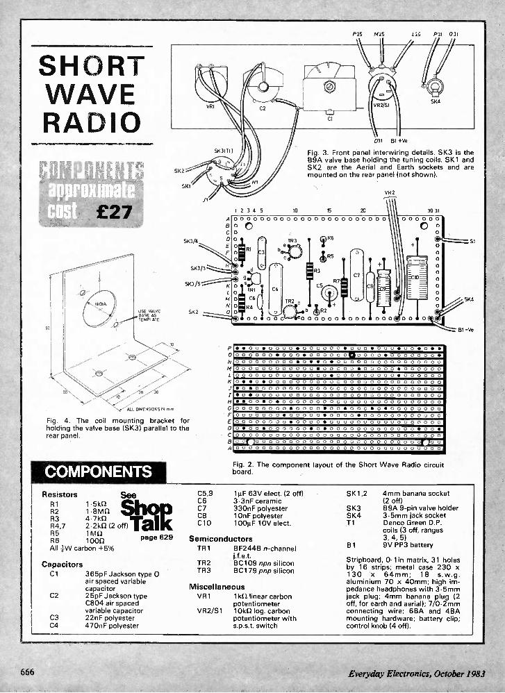
P25 M25 L25 P31 031
SHORT WAVE RADIO
so
2
E27
USE VALVE BASE AS EM P1. ATE
ALL DIMENSIONS IN nn,,,
51(3/4
1 2 3 4 5 10
031 B1 +Ve
Fig. 3. Front panel interwiring details. SK3 is the B9A valve base holding the tuning coils. SK1 and SK2 are the Aerial and Earth sockets and are mounted on the rear panel (not shown).
15 20
VR2
A 0 0 0 0 0 0 0 0 0 0 0 0 0 0 0 0 0 0 0 0 0 0 0
8 0 C o
0 0
E 0 R, F O 0
SK3/3
SK3/5 g 00 T R Si
C
N 0 R4 SK2 0 0
Fig. 4. The coil mounting bracket for holding the valve base (SK3) parallel to the rear panel.
COMPONENTS Resistors
R2 1.8 n Shop R1 1.51(11ni
R4,7 2.21(11 (2 off) Tali( R3 4.71d2
R5 1W/ R6 1000 All 1W carbon +5%
0
A
TR3
TR2
TR6 1125
R3
R7 CS
/ R2
® 4 0 0 0 0 c be0 0 0 0 0 0 è 0 0 0 C 0 0 0 0
131 -ye
30 31
0 0 0 0 0 0
C o 0
5 1
SKIS
• • 0 0 • 0 0 0 0 • 0 0 0 0 0 0 • 0 0 0 • 0 0 0 • 0 0 • 0 • •
00 0 0 0 0 • 0 0 0 • 0 0 0 0 0 o Clo 0 o 0 • 0 0 0 0 0 0 0 • 0 0 0 0 0 0 0 0 0 • 0 • • 0 • 0 0 0 0 0 0 0 0 0 0 0 0 0 0 0 0
0 0 0 0 0 0 0 0 0 0 0 0 • 0 0 0 0 0 • 0 0 0 0 0 • 0 0 0 0 0 0
0 0 0 0 0 0 0 0 0 0 0 0 0 0 • 0 0 0 0 0 0 0 0 0 • 0 0 0 0 0 0
O • • 0 • 0 0 0 0 0 0 0 0 0 0 0 0 0 0 0 0 0 0 0 0 0 0 0 0 0 0
0' 0 • 0 0 0 0 0 0 0 0 0 0 0 0 0 0 0 0 0 0 0 0 0 0 0 0 0 0 0 0
D O • 0 0 0 0 0 0 0 0 0 0 0 0 0 0 0 0 0 0 0 0 0 0 0 0 0 0 0 0
• • 0 0 • 0 • 0 0 0 0 0 0 0 0 0 0 0 0 0 0 0 0 0 0 0 0 0 0 0 0
0 0 0 0 0 0 0 0 • 0 0 0 0 • 0 0 • 0 0 0 • 0 • 0 0 0 0 0 0 0 0
0 0 0 0 0 0 0 • 0 0 0 0 0 • 0 0 0 0 • 0 0 0 0 0 0 0 0 0 0 0 0
0 0 0 0 0 0 0 0 • 0 0 0 0 • 0 0 0 0 0 0 0 0 0 0 0 0 0 0 0 0 0
O • 0 0 • 0 0 0 0 0 0 • O • 0 0 0 0 0 0 0 0 0 0 0 0 0 • 0 0 •
0 0 0 0 0 0 0 0 0 0 0 0 0 0 0 0 0 0 0 0 0 0 0 0 0 0 0 0 0 0 0
a ar j 0 0 0 0 0 0 0 0 0 0 0 0 0 0 0 0 0 0 0 0 0 0 0 0 Or....
0 0 0 0 0 0 0 0 0 0 0 0 0 0 0 0 0 0 0 0 0 0 0 0 0 0 0 0 0 0 0
Fig. 2. The component layout of the Short Wave Radio circuit board.
See
page 629
Capacitors Cl 365pF Jackson type 0
air spaced variable capacitor
C2 25pF Jackson type C804 air spaced variable capacitor
C3 22nF polyester C4 470nF polyester
C5,9 C6 C7 C8 C10
11.tF 63V elect. (2 off) 3.3nF ceramic 330nF polyester 10nF polyester 100µF 10V elect.
Semiconductors TR1
TR2 TR3
BF244B n-channel j.f.e.t. B C109 npn silicon BC179 pnp silicon
Miscellaneous VR1 1k12 linear carbon
potentiometer VR2/S1 10kf/ log. carbon
potentiometer with s.p.s.t. switch
SK1,2
SK3 SK4 Ti
B1
4mm banana socket (2 off) B9A 9-pin valve holder 3.5mm jack socket Denco Green D.P. coils (3 off, ranges 3, 4, 5) 9V PP3 battery
Stripboard, Olin matrix, 31 holes by 16 strips; metal case 230 x 130 x 64mm; 18 s.w.g. aluminium 70 x 40mm; high im-pedance headphones with 3.5mm jack plug; 4mm banana plug (2 off, for earth and aerial); 7/0.2mm connecting wire; 68A and 48A mounting hardware; battery clip; control knob (4 off).
666 Everyday Electronics, October 1983
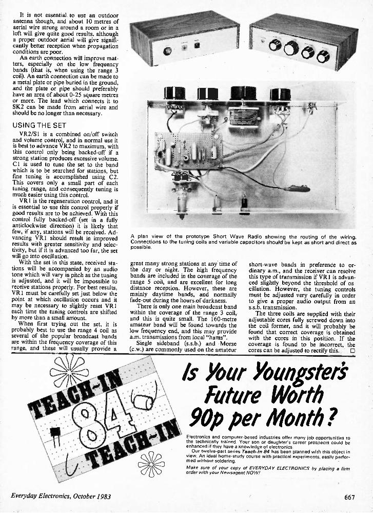
It is not essential to use an outdoor antenna though, and about 10 metres of aerial wire strung around a room or in a loft will give quite good results, although a proper outdoor aerial will give signifi-cantly better reception when propagation conditions are poor. An earth connection will improve mat-
ters, especially on the low frequency bands (that is, when using the range 3 coil). An earth connection can be made to a metal plate or pipe buried in the ground, and the plate or pipe should preferably have an area of about 0.25 square metres or more. The lead which connects it to SK2 can be made from aerial wire and should be no longer than necessary.
USING THE SET VR2/S1 is a combined on/off switch
and volume control, and in normal use it is best to advance VR2 to maximum, with this control only being backed-off if a strong station produces excessive volume. Cl is used to tune the set to the band which is to be searched for stations, but fine tuning is accomplished using C2. This covers only a small part of each tuning range, and consequently tuning is much easier using this control. VR1 is the regeneration control, and it
is essential to use this control properly if good results are to be achieved. With this control fully backed-off (set in a fully anticlockwise direction) it is likely that few, if any, stations will be received. Ad-vancing VR I should result in improved results with greater sensitivity and selec-tivity, but if it is advanced too far, the set will go into oscillation. With the set in this state, received sta-
tions will be accompanied by an audio tone which will vary in pitch as the tuning is adjusted, and it will be impossible to receive stations properly. For best results, VR I must be carefully set just below the point at which oscillation occurs and it may be necessary to slightly reset VR I each time the tuning controls are shifted by more than a small amount. When first trying out the set, it is
probably best to use the range 4 coil as several of the popular broadcast bands are within the frequency coverage of this range, and these will usually provide a
11111 II IR 01111
A plan view of the prototype Short Wave Radio showing the routing of the wiring. Connections to the tuning coils and variable capacitors should be kept as short and direct as possible.
great many strong stations at any time of the day or night. The high frequency bands are included in the coverage of the range 5 coil, and are excellent for long distance reception. However, these are mainly daytime bands, and normally fade-out during the hours of darkness. There is only one main broadcast band
within the coverage of the range 3 coil, and this is quite small. The 160-metre amateur band will be found towards the low frequency end, and this may provide a.m. transmissions from local "hams". Single sideband (s.s.b.) and Morse
(c.w.) are commonly used on the amateur
short-wave bands in preference to or-dinary a.m., and the receiver can resolve this type of transmission if VR1 is advan-ced slightly beyond the threshold of os-cillation. However, the tuning controls must be adjusted very carefully in order to give a proper audio output from an s.s.b. transmission. The three coils are supplied with their
adjustable cores fully screwed down into the coil former, and it will probably be found that correct coverage is obtained with the cores in this position. If the coverage is found to be incorrect, the cores can be adjusted to rectify this. El
Is Your Youngstai Future Worth 90p per Month? Electronics and computer-based industries offer many job opportunities to the technically trained. Your son or daughter's career prospects could be enhanced if they have a knowledge of electronics. Our twelve-part series Teach-In 84 has been planned with this object in
view. An ideal home-study course with practical experiments, easily perfor-med without soldering.
Make sure of your copy of EVERYDAY ELECTRONICS by placing a firm order with your Newsagent NO W!
Everyday Electronics, October 1983 667
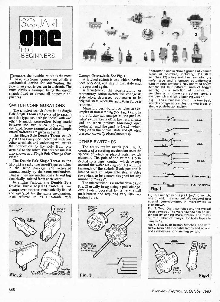
Sa,AR-
one FOR BEGINNERS
PERHAPS the humble switch is the most basic electronic component of all; a mechanical device for interrupting the flow of an electric current in a circuit. The most obvious example being the on/off switch fitted to almost all domestic ap-pliances.
SWITCH CONFIGURATIONS The simplest switch form is the Single
Pole Single Throw (abbreviated to s.p.s.t.) and this type has a single "pole" with one other terminal, connection being made between the two when the switch is operated. Some examples of these simple on/off switches are given in Fig. 2. The Single Pole Double Throw switch
(s.p.d.t.) has only one "pole" but with two other terminals and activating will switch the connection to the pole from one terminal to the other. For this reason it is also known as a Single Pole Change-Over switch. The Double Pole Single Throw switch
(d.p.s.t.) is really two on/off type switches in the same package and activated simultaneously by the same mechanism. That is, they are mechanically linked but electrically isolated from each other. In similar fashion, the Double Pole
Double Throw (d.p.d.t.) switch is two change-over switches mechanically linked and operated by the same mechanism. Also referred to as a Double Pole
MICRO-SWITCH
Fig. 2
SLIDE SWITCH
SWITCH TERMINALS
TOGGLE SWITCH
ON/OFF SWITCH ON
POTENTIOMETER
Change-Over switch. See Fig. I. A latched switch is one which, having
been operated, will stay in that state until it is operated again. Alternatively, the non-latching or
momentary action switch will change its state when depressed but return to its original state when the actuating force is removed. Miniature push-button switches are ex-
amples of non-latching (see Fig. 4) and fit into a further two categories: the push-to-make switch, being off in the natural state and on when pressed (normally open contacts); and the push-to-break switch, being on in the normal state and off when ' pressed (normally closed contacts).
OTHER SWITCHES The rotary wafer switch (see Fig. 3)
consists of a rotating mechanism onto the spindle of which is placed wafer switch elements. The pole of the switch is con-nected to a wiper contact which sweeps around the wafer making contact with the terminals of the switch. Each position is latched and an adjustable stop enables the switch to be custom designed for any number of "ways". The microswitch is a useful device (see
Fig. 2) usually being a single pole change-over switch operated by a very small push-button and requiring very little ac-tuating force.
MIDGET ROTARY SWITCH
EXTENDED SPINDLE FOR
ADDITIONAL WAFERS ......-
Fig. 3
WAFER ROTARY SWITCH
/
d e A 1 44'4
\47,4,0' L ik 1
V * 4
4! V N• WAFER
Photograph above shows groups of various types of switches, including: (1) slide switches; (2) rotary switches, including the wafer tjrpe and a control potentiometer with integral switch; (3) key operated on/off switch; (4) four different sizes of toggle switch; (5) a selection of push-button switches with momentary action types, a microswitch and left, a latching version. Fig. 1. The circuit symbols of the four basic switch configurations plus the two types of simple push-button switch.
S3 b •-• p- - - -
S4b
s.p.s.t.
s.p.d.t.
d p.s.t
d.p.d.t.
55 . ;L. PUSH-TO-MAKE
56
Fig. 1 PUSH-TO-BREAK
Fig. 2. Four types of s.p.s.t. (on/off) switch, one of which is mechanically coupled to a control potentiometer. A microswitch is also shown. Fig. 3. Two rotary switches and the typical circuit symbol. The wafer switch can be ex-tended by adding more wafers. The maxi-mum number of "ways" for both types is usually 12. Fig. 4. Two push-button switches, one with screw terminals (for table lamps and so on), and a miniature non-latching switch.
PUSH BUTTON SWITCH
PUSH BUTTON SWITCH
Fig.4
668 Everyday Electronics, October 1983
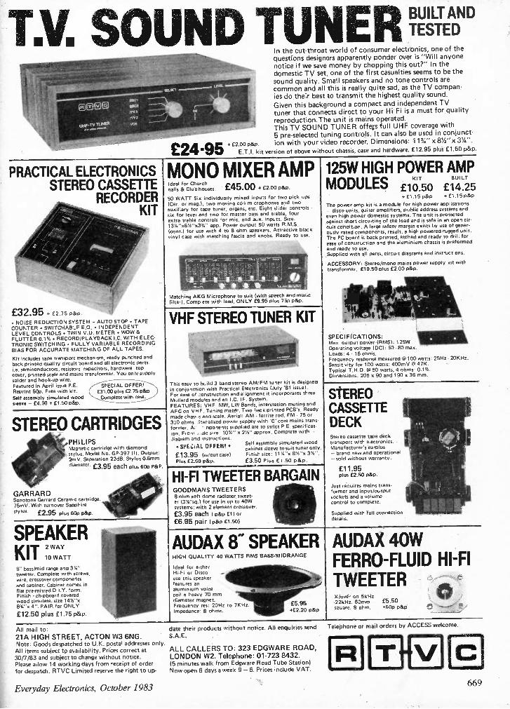
TM. SOUND TUNER In the cut-throat world of consumer electronics, one of the questions designers apparently ponder over is "Will anyone notice if we save money by chopping this out?" In the domestic TV set, one of the first casualties seems to be the sound quality. Small speakers and no tone controls are common and all this is really quite sad, as the TV compan-ies do their best to transmit the highest quality sound. Given this background a compact and independent TV tuner that connects direct to your Hi-Fi is a must for quality reproduction.The unit is mains operated. This TV SOUND TUNER offeis full UHF coverage with 5 pre-selected tuning controls. It can also be used in conjunct-
, £2.00 p&P. ion with your video recorder. Dimensions: 11%" x 81/2"x 314". E.T.I. kit version of above wi hout chassis, case and hardware. £12.95 plus £1.50 p&p £24.95
BUILT AND TESTED
PRACTICAL ELECTRONICS STEREO CASSETTE
RECORDER KIT
£32.95 + £2.75 p&p. • NOISE REDUCTION SYSTEM • AUTO STOP • TAPE COUNTER • SWITCHABLE E.G. • INDEPENDENT LEVEL CONTROLS • TWIN V.U. METER • WOW & FLUTTER 0.1% • RECORD/PLAYBACK I.C. WITH ELEC-TRONIC SWITCHING • FULLY VARIABLE RECORDING BIAS FOR ACCURATE MATCHING OF ALL TAPES.
Kit includes tape transport mechanism, ready punched and back printed quality circuit board and all electronic parts. i.e. semiconductors, resistors capacitors, hardware top cover, printed scale and mains transformer. You only supply solder and hook-up wire. Featured in April issue P.E. Reprint 5Qp. Free with kit. Self assembly simulated wood sleeve - £4.50 + £1.50 p&p.
SPECIAL OFFER! £31.00 plus £2.75 p&p Complete with case.
MONO MIXER AMP Ideal for Church halls & Clubhouses. £45.00 + £2.00 p&p. 50 WATT Six individually mixed inputs for two pick ups (Cer. or meg.), two moving coil microphones and two auxiliary for tape tuner, organs, etc. Eight slider controls - six for level and two for master bass and treble, four extra treble controls for mic. and aux. inputs. Size: 13'4"x6%"x3%" app. Power output 50 watts R.M.S. (cont.) for use with 4 to 8 ohm speakers. Attractive black vinyl case with matching fascia and knobs. Ready to use.
Matching AKG Microphone to suit (with speech and music filter). Complete with lead. ONLY £9.95 plus 75P P&P.
STEREO CARTRIDGES PHILIPS Magnetic cartridge with diamond stylus. Model No. GP-397 III. Output: 2mV. Separation 22dB. Stylus 0.6mm diameter. £3.95 each plus 60p P&P.
GARRARD Sonotone Garrard Ceramic cartridge. 75mV. With turnover Sapphire stylus. s•-•1 rsc u mc.0 plus 60p p&p.
SPEAKER KIT 210W:AIT T
8" bass/mid range and 3%." tweeter. Complete with screws, wire, crossover components and cabinet. Cabinet comes in flat pre-mitred D.I.Y. form. Finish - chipboard covered wood simulate. size 14%"x 8%"x 4". PAIR for ONLY
£12.50 plus £1.75 p&p.
VHF STEREO TUNER KIT
This easy to bu,Id 3 band stereo AM/FM tuner kit is designed in conjunction with Practical Electronics (July '81 issue). For ease of .aanstruction and alignment it incorporates three Mullard modules and an I.C. IF. System. FEATURES: VHF. MW, LW Bands, interstation muting and AFC on VHF. Tuning meter. Two back printed PCB's. Ready made chas,s and scale. Aerial: AM-ferrite rod, FM .75 or 300 ohms. Stabalised power supply with 'C core mains trans-former. Ai' :• nponents supplied are to strict P.E. specificat-ion, From size: 10%" x 2'4" approx. Complete with • iiagram and instructions.
• SPECiAL OFFER!.
£13.95 (W , O W case) Plus £2.50 p&p.
Self assembly simulated wood cabinet sleeve to suit tuner only. Finish size: 11%"x 8%"x 3%".
£3.50 Plus C1.50 p&p
125W HIGH POWER AMP MODULES £10T.50 Clu4L.T25
+ £1.15 p&p + £1.15 P&P
The power amp kit is a module for high power applications disco units, guitar amplifiers, public address systems and
even high power domestic systems. The unit is protected Against short circuiting of the load and is safe in an open cir-cuit cohdition. A large safety margin exists by use of gener-ously rated components, result, a high powered rugged unit. The PC board is back printed, etched and ready to drill for ease of construction and the aluminium chassis is preformed and ready to use. Supplied with all parts, circuit diagrams and instructions.
ACCESSORY: Stereo/mono mains power supply kit with transformer. £10.50 plus £2.00 p&p.
SPECIFICATIONS: Max. output power (RMS): 125W. Operating voltage (DC): 50 - 80 max. Loads: 4- 16 ohms. Frequency response measured 11100 watts: 25Hz - 20K Hz. Sensitivity for 100 watts: 400mV @47K. Typical T.H.D. @50 watts, 4 ohms: 0.1%. Dimensions: 205 x 90 and 190 x 36 mm.
HI-Fl TWEETER BARGAIN GOODMANS TWEETERS 8 ohm soft dome radiator tweet-er (3%''sq.) for use in up to 40W systems; with 2 element crossover.
£3.95 each I p&p £1) or £6.95 pair (p&p £1.50)
StEREO CASSETTE DECK Stereo cassette tape deck transport with electronics. Manufacturer's surplus - brand new and operational - sold without warranty.
£11.95 plus £2.50 p&p.
Just requires mains trans-former and input/output sockets and a volume control to complete.
Supplied with full connection details.
AMAX 8" SPEAKER AUDAX 40W FERRO-FLUID HI-Fl TWEETER 4‘
Its
HIGH QUALITY 40 WATTS RMS BASS/MIDRANGE
Ideal for either Hi-Fi or Disco use this speaker features an aluminium voice coil a heavy 70 mm diameter magnet. Frequency res: 20Hz to 7K1-1z. Impedance: 8 ohms.
£5.95 +C220 p&p
X/over on 5kHz -22kHz. 60mm square. 8 ohm.
£5.50 +60p p&P
All mail to:
21A HIGH STREET, ACTON W3 6NG. Note: Goods despatched to U.K. postal addresses only.
All items subject tp availability. Prices correct at 30/7/83 and subject to change without notice. Please allow 14 working days from receipt of order for despatch. RTVC Limited reserve the right to up-
date their products without notice. All enquiries send Telephone or mail orders by ACCESS welcome.
S.A.E.
ALL CALLERS TO: 323 EDGWARE ROAD, LONDON W2. Telephone: 01-723 8432. (5 minutes walk from Edgware Road Tube Station) Now open 6 days a week 9 -6. Prices include VAT.
Everyday Electronics, October 1983 669
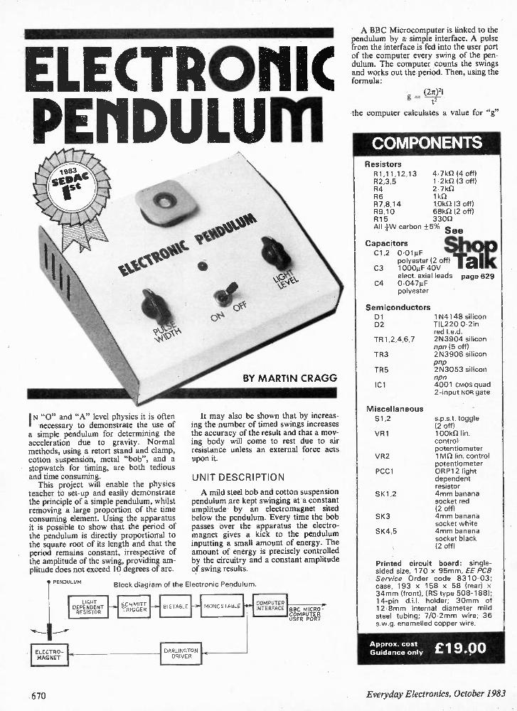
ELECTROMIC PEMDULUM
I N "0" and "A" level physics it is often necessary to demonstrate the use of
a simple pendulum for determining the acceleration due to gravity. Normal methods, using a retort stand and clamp, cotton suspension, metal "bob", and a stopwatch for timing, are both tedious and time consuming. This project will enable the physics
teacher to set-up and easily demonstrate the principle of a simple pendulum, whilst removing a large proportion of the time consuming element. Using the apparatus it is possible to show that the period of the pendulum is directly proportional to the square root of its length and that the period remains constant, irrespective of the amplitude of the swing, providing am-plitude does not exceed 10 degrees of arc.
PENDULUM
ELECTR 0-MAG NET
I LIGHT DEPENDENT RESISTOR
BY MARTIN CRAGG
It may also be shown that by increas-ing the number of timed swings increases the accuracy of the result and that a mov-ing body will come to rest due to air resistance unless an external force acts upon it.
UNIT DESCRIPTION
A mild steel bob and cotton suspension pendulum are kept swinging at a constant amplitude by an electromagnet sited below the pendulum. Every time the bob passes over the apparatus the electro-magnet gives a kick to the pendulum inputting a small amount of energy. The amount of energy is precisely controlled by the circuitry and a constant amplitude of swing results.
Block diagram of the Electronic Pendulum.
SCHMITT TRIGGER
--.I BISTABLE MONOSTABLE
DARLINGTON DRIVER
COMPUTER INTERFACE BBC MICRO-
COMPUTER USER PORT
A BBC Microcomputer is linked to the pendulum by a simple interface. A pulse from the interface is fed into the user port of the computer every swing of the pen-dulum. The computer counts the swings and works out the period. Then, using the formula:
(21021 g = t2
the computer calculates a value for "g"
COMPONENTS Resistors R1,11,12,13 R2,3,5 R4 R6 R7,8,14 R9,10 R15 All 1-W carbon
Capacitors C1,2 0•01µF
polyester (2 off) C3 1000µF 40V
elect. axial leads C4 0•047µF
polyester
Semiconductors D1 D2
TR1,2,4,6,7
TR3
TR5
'Cl
Miscellaneous S1,2
VR1
VR2
PCC1
SK1,2
SK3
SK4,5
4•7k12 (4 off) 1.2k0 (3 off) 2•71d2 1 kn 101(D (3 off) 68k0 (2 off) 330D
15% See
page 629
1N4148 silicon TIL220 0.21n red led. 2N3904 silicon npn (5 off) 2N3906 silicon pnp 2N3053 silicon npn 4001 cmos quad 2-input NOR gate
s.p.s.t. toggle (2 off) 100k0 in. control potentiometer 1 win in, control potentiometer 0RP12 light dependent resistor 4mm banana socket red (2 off) 4mm banana socket white 4mm banana socket black (2 off)
Printed circuit board: single-sided size, 170 x 95mm, EE PCB Service Order code 8310-03; case, 193 x 158 x 58 (rear) x 34mm (front), (RS type 508-188); 14-pin d.i.l. holder; 30mm of 12.8mm internal diameter mild steel tubing; 7/0•2mm wire; 36 s.w.g. enamelled copper wire.
Approx. cost £19 00 Guidance only
670 Everyday Electronics, October 1983
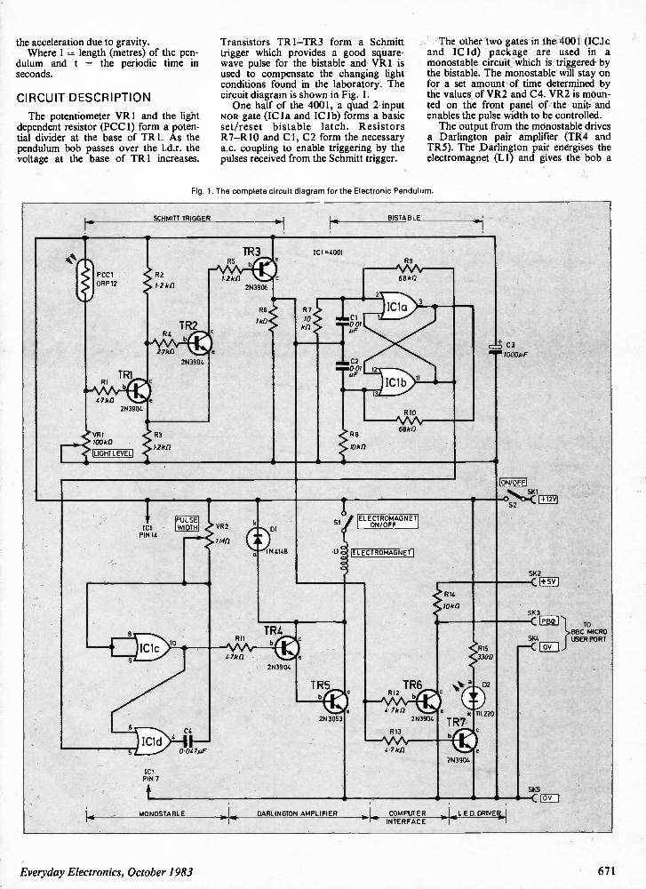
the acceleration due to gravity. Where 1 = length (metres) of the pen-
dulum and t = the periodic time in seconds.
CI R C UI T D E S C RI P TI O N
The potentiometer VR1 and the light dependent resistor (PCC1) form a poten-tial divider at the base of TR1. As the pendulum bob passes over the 1.d.r. the voltage at the base of TR1 increases.
Transistors TR1—TR3 form a Schmitt trigger which provides a good square-wave pulse for the bistable and VR1 is used to compensate the changing light conditions found in the laboratory. The circuit diagram is shown in Fig. 1. One half of the 4001, a quad 2-input
NOR gate (IC la and IC lb) forms a basic set/reset bistable latch. Resistors R7—R10 and Cl, C2 form the necessary a.c. coupling to enable triggering by the pulses received from the Schmitt trigger.
The other two gates in the 4001 (IC lc and IC 1d) package are used in a monostable circuit which is triggered by the bistable. The monostable will stay on for a set amount of time determined by the values of VR2 and C4. VR2 is moun-ted on the front panel of the unit and enables the pulse width to be controlled. The output from the monostable drives
a Darlington pair amplifier (TR4 and TR5). The Darlington pair energises the electromagnet (LI) and gives the bob a
Fig. 1. The complete circuit diagra m for the Electronic Pendulu m,
SCHMITT TRIGGER BISTABLE
TR3 1C1 =40 01
R7
10 kiT
\ RB \
68 kD
2\
IC1 a
CI 0.01 4IF
C2 12
1C 1b
3
R 8
;Oki]
R10
68kf)
-4- C3
ON/OFF
ICI PIN 14
PULSE WIDTH
8
VR2
R11
IC1c 4.7k fl
)1 C1d
> 14
0.0473F
ICI PINT
a
DI
IN 4148
S I ELECTROMAGNET
ON/OFF
ELECTROMAGNET
TR4
b q
2N3904
a
IRS
2N3053
TR6 R12
4. 7 kfl
2N3904
R13
4.7 k n
S2
SKI
SK2
R14
10 kil
a
R15 33011
02
k ITI122O
TR7
MONOSTABLE DARLINGTON AMPLIFIER COMPUTER INTERFACE
2N3904.
•
v.
SK4
+5V
P B0
DV
SKS
• • C 19v
LED. DRIVEtii...
TO BBC MICRO USER PORT
Everyday Electronics, October 1983 671
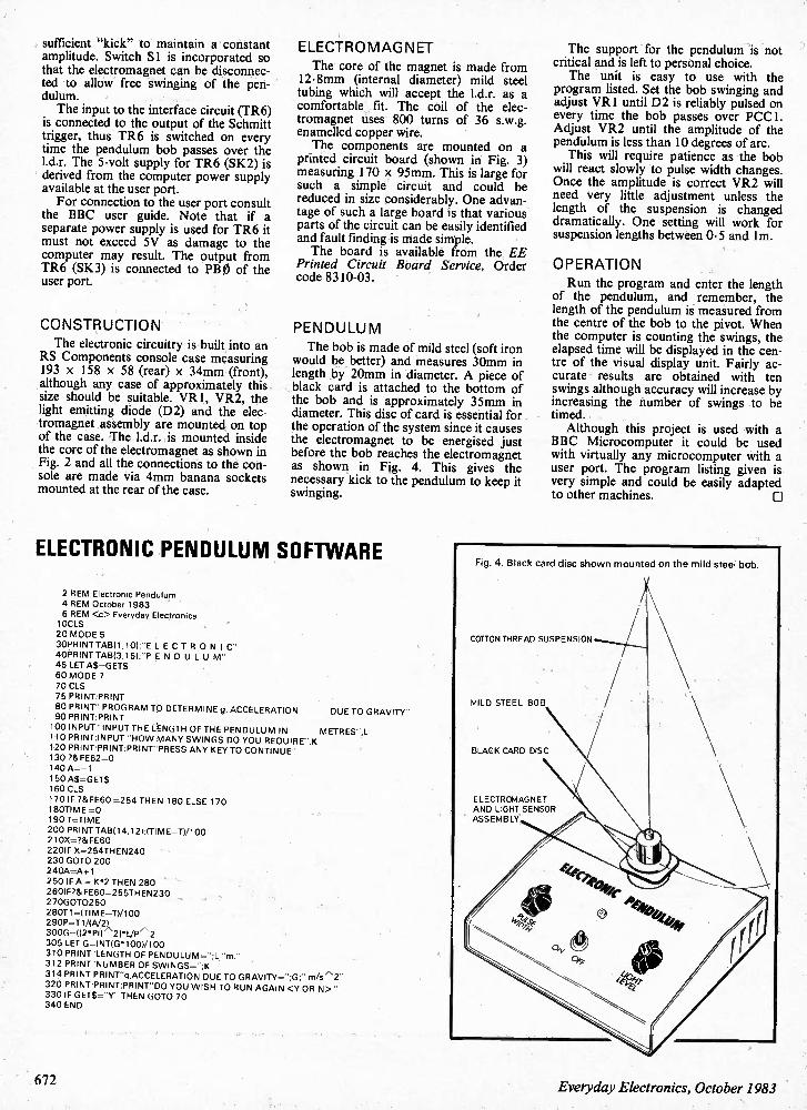
sufficient "kick" to maintain a constant amplitude. Switch Si is incorporated so that the electromagnet can be disconnec-ted to allow free swinging of the pen-dulum. The input to the interface circuit (TR6)
is connected to the output of the Schmitt trigger, thus TR6 is switched on every time the pendulum bob passes over the I.d.r. The 5-volt supply for TR6 (SK2) is derived from the computer power supply available at the user port. For connection to the user port consult
the BBC user guide. Note that if a separate power supply is used for TR6 it must not exceed 5V as damage to the computer may result. The output from TR6 (SK3) is connected to PB 0 of the user port.
CONSTRUCTION
The electronic circuitry is built into an RS Components console case measuring 193 x 158 x 58 (rear) x 34mm (front), although any case of approximately this size should be suitable. VR1, VR2, the light emitting diode (D2) and the elec-tromagnet assembly are mounted on top of the case. The 1.d.r. is mounted inside the core of the electromagnet as shown in Fig. 2 and all the connections to the con-sole are made via 4mm banana sockets mounted at the rear of the case.
ELECTROMAGNET The core of the magnet is made from
12.8mm (internal diameter) mild steel tubing which will accept the 1.d.r. as a comfortable fit. The coil of the elec-tromagnet uses 800 turns of 36 s.w.g. enamelled copper wire. The components are mounted on a
printed circuit board (shown in Fig. 3) measuring 170 x 95mm. This is large for such a simple circuit and could be reduced in size considerably. One advan-tage of such a large board is that various parts of the circuit can be easily identified and fault finding is made simple. The board is available from the EE
Printed Circuit Board Service, Order code 8310-03.
PENDULUM The bob is made of mild steel (soft iron
would be better) and measures 30mm in length by 20mm in diameter. A piece of black card is attached to the bottom of the bob and is approximately 35mm in diameter. This disc of card is essential for the operation of the system since it causes the electromagnet to be energised just before the bob reaches the electromagnet as shown in Fig. 4. This gives the necessary kick to the pendulum to keep it swinging.
ELECTRONIC PENDULUM SOFTWARE
2 REM Electronic Pendulum
4 REM October 1983 6 REM <c> Everyday Electronics 10CLS 20 MODE 5
30PRINT TA1311.10);"E LE CT R O NI C"
40PRINT TAB(3,15);"P EN D U L U M -
45 LET AS=GET$
60 MODE 7 70 CLS 75 PRINT:PRINT
80 PRINT" PROGRAM TO DETERMINE g, ACCELERATION DUE TO GRAVITY" 90 PRINT:PRINT
100 INPUT "INPUT THE LENGTH OF THE PENDULUM IN METRES",L 110 PRINT:INPUT "HO W MANY SWINGS DO YOU REQUIRE",K 120 PRINT:PRINT:PRINT"PRESS ANY KEY TO CONTINUE" 130 ?&FE62=0 140 A=-1
150 AS=GET$ 160 CLS
170 IF ?&FE60 =254 THEN 180 ELSE 170 180TIME =0 190 T=TIME
200 PRINT TAB(14,12);(TIME-71/100 210X= 7&FE60
220IF X=254THEN240 230 GOTO 200 240A=A+1
250 IF A = K•2 THEN 280 26 0IF?&FE60=255THEN230 270G070250 28071=ITIME—TI/100 290P=T1 0/2)
300 G=112 •PV\21•L/P' 2 305 LET G=INTIG •1001/100
310 PRINT"LENGTH OF PENDULUM= 1_ "m. -
312 PRINT"NUMBER OF SWINGS=";K
314 PRINT:PRINT"qACCELERATION DUE TO GRAVITY=";G;" m/s 2"
320 PRINT:PRINT:PRINT"DO YOU WISH TO RUN AGAIN <Y OR N>" 330 IF GET9="Y" THEN GOTO 70 340 END
The support for the pendulum is not critical and is left to personal choice. The unit is easy to use with the
program listed. Set the bob swinging and adjust VR1 until D2 is reliably pulsed on every time the bob passes over PCC1. Adjust VR2 until the amplitude of the pendulum is less than 10 degrees of arc. This will require patience as the bob
will react slowly to pulse width changes. Once the amplitude is correct VR2 will need very little adjustment unless the length of the suspension is changed dramatically. One setting will work for suspension lengths between 0-5 and lm.
OPERATION Run the program and enter the length
of the pendulum, and remember, the length of the pendulum is measured from the centre of the bob to the pivot. When the computer is counting the swings, the elapsed time will be displayed in the cen-tre of the visual display unit. Fairly ac-curate results are obtained with ten swings although accuracy will increase by increasing the number of swings to be timed. Although this project is used with a
BBC Microcomputer it could be used with virtually any microcomputer with a user port. The program listing given is very simple and could be easily adapted to other machines.
Fig. 4. Black card disc shown mounted on the mild steel bob.
COTTON THREAD SUSPENSION
MILD STEEL BOB
BLACK CARD DISC
ELECTROMAGNET AND LIGHT SENSOR ASSEMBLY
672 Everyday Electronics, October 1983
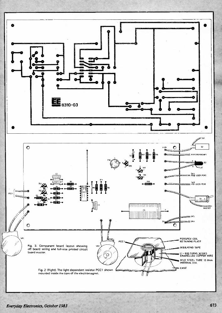
EE 8310-03
Fig. 3. Component board layout showing off-board wiring and full-size printed circuit board master.
Fig. 2 (Right). The light dependent resistor PCC1 shown mounted inside the core of the electromagnet.
Everyday Electronics, October 1983
SKI
52
ELECTROMAGNET
510 PBO USER PORT
51(2 +55 USER PORT
ELECTRO-MAGNET
PERSPEX COIL RETAINING PLATE
INSULATING TAPE
11-800 TURNS 36SW0 ENAMELLED COPPER WIRE
\\..... MILD STEEL TUBE 12.8mm
INTERNAL DIA.
CASF
673
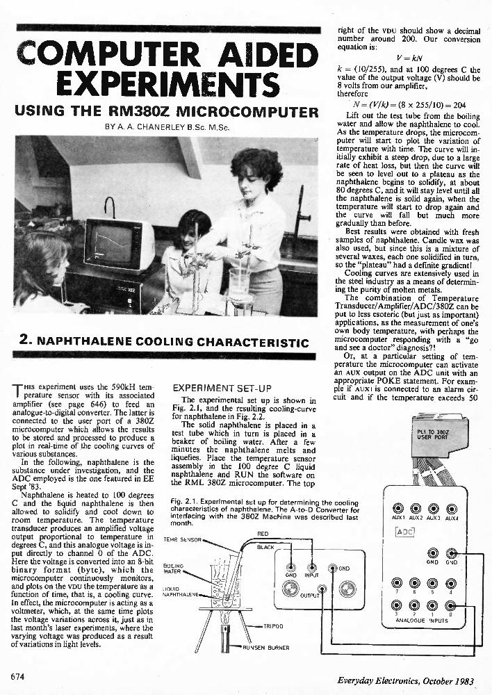
COMPUTER AIDED EXPERIMENTS
USING THE RM380Z MICROCOMPUTER BY A. A. CHANERLEY B.Sc. M.Sc.
2. NAPHTHALENE COOLING CHARACTERISTIC
Txis experiment uses the 590kH tem-perature sensor with its associated amplifier (see page 646) to feed an analogue-to-digital converter. The latter is connected to the user port of a 380Z microcomputer which allows the results to be stored and processed to produce a plot in real-time of the cooling curves of various substances. In the following, naphthalene is the
substance under investigation, and the ADC employed is the one featured in EE Sept '83. Naphthalene is heated to 100 degrees
C and the liquid naphthalene is then allowed to solidify and cool down to room temperature. The temperature transducer produces an amplified voltage output proportional to temperature in degrees C, and this analogue voltage is in-put directly to channel 0 of the ADC. Here the voltage is converted into an 8-bit binary format (byte), which the microcomputer continuously monitors, and plots on the VDU the temperature as a function of time, that is, a cooling curve. In effect, the microcomputer is acting as a voltmeter, which, at the same time plots the voltage variations across it, just as in last month's laser experiments, where the varying voltage was produced as a result of variations in light levels.
EXPERI MENT SET-UP
The experimental set up is shown in Fig. 2.1, and the resulting cooling-curve for naphthalene in Fig. 2.2. The solid naphthalene is placed in a
test tube which in turn is placed in a beaker of boiling water. After a few minutes the naphthalene melts and liquefies. Place the temperature sensor assembly in the 100 degree C liquid naphthalene and RUN the software on the RML 380Z microcomputer. The top
right of the VDU should show a decimal number around 200. Our conversion equation is:
V = kN
k = (10/255), and at 100 degrees C the value of the output voltage (V) should be 8 volts from our amplifier, therefore
N = (VIk)= (8 x 255/10) = 204
Lift out the test tube from the boiling water and allow the naphthalene to cool. As the temperature drops, the microcom-puter will start to plot the variation of temperature with time. The curve will in-itially exhibit a steep drop, due to a large rate of heat loss, but then the curve will be seen to level out to a plateau as the naphthalene begins to solidify, at about 80 degrees C, and it will stay level until all the naphthalene is solid again, when the temperature will start to drop again and the curve will fall but much more gradually than before. Best results were obtained with fresh
samples of naphthalene. Candle wax was also used, but since this is a mixture of several waxes, each one solidified in turn, so the "plateau" had a definite gradient! Cooling curves are extensively used in
the steel industry as a means of determin-ing the purity of molten metals. The combination of Temperature
Transducer/Amplifier/ADC/380Z can be put to less esoteric (but just as important) applications, as the measurement of one's own body temperature, with perhaps the microcomputer responding with a "go and see a doctor" diagnosis?! Or, at a particular setting of tem-
perature the microcomputer can activate an AUX output on the ADC unit with an appropriate POKE statement. For exam-ple if AUXI is connected to an alarm cir-cuit and if the temperature exceeds 50
Fig. 2.1. Experimental set up for determining the cooling characteristics of naphthalene. The A-to-D Converter for interfacing with the 380Z Machine was described last month.
TEMP SENSOR
BOILING WATER
LIQUID NAPHTHALENE
RED
BLACK ,.
GND INPUT
0 OUTPUT
C) GND
TRIPOD
BUNSEN BURNER
PIA TO 380Z USER PORT
AUX 1 AUX 2 AUX 3 AUX 4
ADC
0 e --GND GND
seoe 7 6 5 4
e e 3 2 1 0 ANALOGUE INPUTS j
674 Everyday Electronics, October 1983
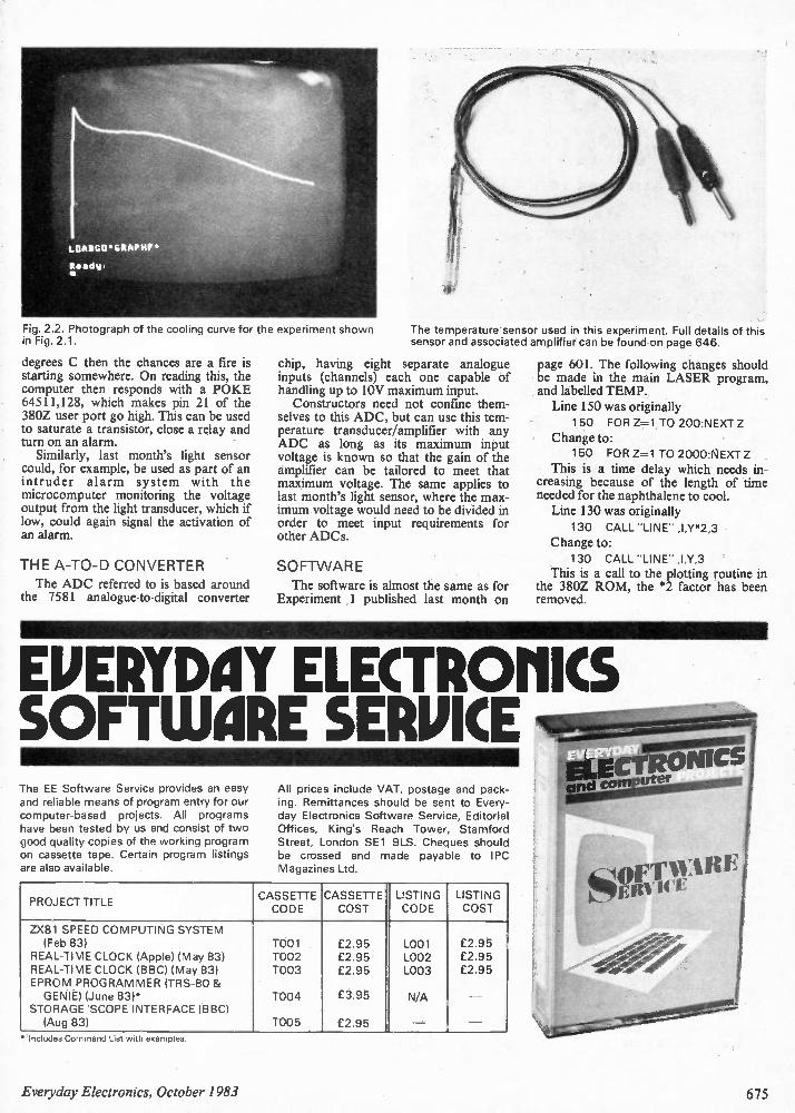
Fig. 2.2. Photograph of the cooling curve for the experiment shown in Fig. 2.1.
degrees C then the chances are a fire is starting somewhere. On reading this, the computer then responds with a POKE 64511,128, which makes pin 21 of the 380Z user port go high. This can be used to saturate a transistor, close a relay and turn on an alarm. Similarly, last month's light sensor
could, for example, be used as part of an intruder alarm system with the microcomputer monitoring the voltage output from the light transducer, which if low, could again signal the activation of an alarm.
THE A-TO-D CONVERTER The ADC referred to is based around
the 7581 analogue-to-digital converter
The temperature sensor used in this experiment. Full details of this sensor and associated amplifier can be found on page 646.
chip, having eight separate analogue inputs (channels) each one capable of handling up to 10V maximum input. Constructors need not confine them-
selves to this ADC, but can use this tem-perature transducer/amplifier with any ADC as long as its maximum input voltage is known so that the gain of the amplifier can be tailored to meet that maximum voltage. The same applies to last month's light sensor, where the max-imum voltage would need to be divided in order to meet input requirements for other ADCs.
SOFTWARE The software is almost the same as for
Experiment 1 published last month on
page 601. The following changes should be made in the main LASER program, and labelled TEMP. Line 150 was originally
150 FOR Z=1 TO 200:NEXT
Change to: 150 FOR Z=1 TO 2000:NEXT Z
This is a time delay which needs in-creasing because of the length of time needed for the naphthalene to cool. Line 130 was originally
130 CALL "LINE" ,I,Y*2,3
Change to: 130 CALL "LINE" ,I,Y,3
This is a call to the plotting routine in the 380Z ROM, the *2 factor has been removed.
EMERYDAY ELECTRONICS SOFTWARE SERPICE The EE Software Service provides an easy and reliable means of program entry for our computer-based projects. All programs have been tested by us and consist of two good quality copies of the working program on cassette tape. Certain program listings are also available.
All prices include VAT, postage and pack-ing. Remittances should be sent to Every-day Electronics Software Service, Editorial Offices, King's Reach Tower, Stamford Street, London SE1 9LS. Cheques should be crossed and made payable to IPC Magazines Ltd.
PROJECT T ITLE CASSETTE CODE
CASSETTE COST
LISTING CODE
LISTING COST
ZX81 SPEED COMPUTING SYSTEM (Feb 83) T001 £2.95 L001 £2.95
REAL-TIME CLOCK (Apple) (May 83) T002 £2.95 L002 £2.95 REAL-TIME CLOCK (BBC) (May 83) T003 £2.95 L003 £2.95 EPROM PROGRAMMER (TRS-80 & GENIE) (June 83)* T004 £3.95 N/A
STORAGE 'SCOPE INTERFACE (BBC) (Aug 83) T005 £2.95 _ — —
• Includes Command List with examples.
Everyday Electronics, October 1983 675
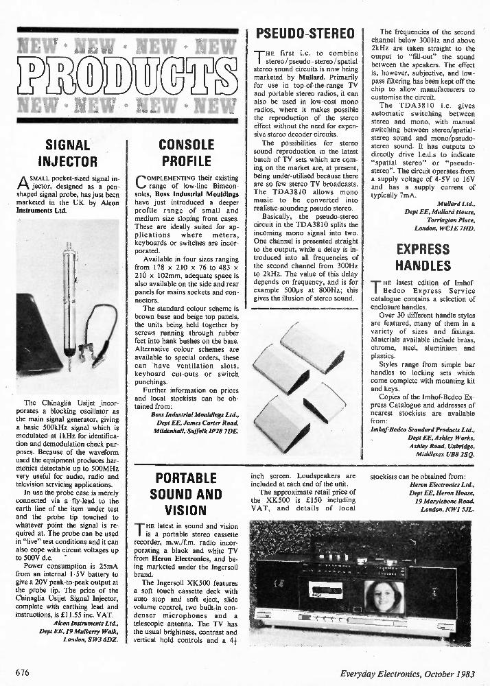
SIGNAL INJECTOR
ASMALL pocket-sized signal in-jector, designed as a pen-
shaped signal probe, has just been marketed in the UK by Alcon Instruments Ltd.
The Chinaglia Usijet _incor-porates a blocking oscillator as the main signal generator, giving a basic 500kHz signal which is modulated at IkHz for identifica-tion and demodulation check pur-poses. Because of the waveform used the equipment produces har-monics detectable up to 500MHz very useful for audio, radio and television servicing applications. In use the probe case is merely
connected via a fly-lead to the earth line of the item under test and the probe tip touched to whatever point the signal is re-quired at. The probe can be used in "live" test conditions and it can also cope with circuit voltages up to 500V d.c. - Power consumption is 25mA
from an internal 1.5V battery to give a 20V peak-to-peak output at the probe tip. The price of the Chinaglia Usijet Signal Injector, complete with earthing lead and instructions, is £11.55 inc. VAT.
Alcon Instruments Ltd., Dept EE, 19 Mulberry Walk,
London, SW3 6DZ.
CONSOLE PROFILE
r•OMPLEMENTING their existing range of low-line Bimcon-
soles, Boss Industrial Mouldings have just introduced a deeper profile range of small and medium size sloping front cases. These are ideally suited for ap-plications where meters, keyboards or switches are incor-porated. Available in four sizes ranging
from 178 x 210 x 76 to 483 x 210 x 102mm, adequate space is also available on the side and rear panels for mains sockets and con-nectors. The standard colour scheme is
brown base and beige top panels, the units being held together by screws running through rubber feet into hank bushes on the base. Alternative colour schemes are available to special orders, these can have ventilation slots, keyboard cut-outs or switch punchings. Further information on prices
and local stockists can be ob-tained from:
Boss Industrial Mouldings Ltd., Dept EE, James Carter Road, Mildenhall, Suffolk IP28 7DE.
PSEUDO-STEREO 1—HE first i.c. to combine stereo/pseudo - stereo/spatial
stereo sound circuits is now being marketed by Mallard. Primarily for use in top-of-the-range TV and portable stereo radios, it can also be used in low-cost mono radios, where it makes possible the reproduction of the stereo effect without the need for expen-sive stereo decoder circuits. The possibilities for stereo
sound reproduction in the latest batch of TV sets which are com-ing on the market are, at present, being under-utilised because there are so few stereo TV broadcasts. The TDA3810 allows mono music to be converted into realistic-sounding pseudo stereo. Basically, the pseudo-stereo
circuit in the TDA3810 splits the incoming mono signal into two. One channel is presented straight to the output, while a delay is in-troduced into all frequencies of the second channel from 300Hz to 2kHz. The value of this delay depends on frequency, and is for example 50011s at 800Hz; this gives the illusion of stereo sound.
The frequencies of the second channel below 300Hz and above 2kHz are taken straight to the output to "fill-out" the sound between the speakers. The effect is, however, subjective, and low-pass filtering has been kept off the chip to allow manufacturers to customise the circuit. The TDA3810 i.c. gives
automatic switching between stereo and mono, with manual switching between stereo/spatial-stereo sound and mono/pseudo-stereo sound. It has outputs to directly drive 1.e.d.s to indicate "spatial stereo" or "pseudo-stereo". The circuit operates from a supply voltage of 4.5V to 16V and has a supply current of typically 7mA.
Mallard Ltd., Dept EE, Mallard House,
Torrington Place, London, WCIE 7HD.
EXPRESS HANDLES
THE latest edition of Imhof-Bedco Express Service
catalogue contains a selection of enclosure handles. Over 30 different handle styles
are featured, many of them in a variety of sizes and fixings. Materials available include brass, chrome, steel, aluminium and plastics. Styles range from simple bar
handles to locking sets which come complete with mounting kit and keys. Copies of the Imhof-Bedco Ex-
press Catalogue and addresses of nearest stockists are available from: Imlutf-Bedco Standard Products Ltd.,
Dept EE, Ashley Works, Ashley Road, Uxbridge, Middlesex UB8 2SQ.
PORTABLE SOUND AND VISION
THE latest in sound and vision is a portable stereo cassette
recorder, m.w./f.m. radio incor-porating a black and white TV from Heron Electronics, and be-ing marketed under the Ingersoll brand. The Ingersoll XK500 features
a soft touch cassette deck with auto stop and soft eject, slide volume control, two built-in con-denser microphones and a telescopic antenna. The TV has the usual brightness, contrast and vertical hold controls and a 41
inch screen. Loudspeakers are included at each end of the unit. The approximate retail price of
the XK500 is £150 including VAT, and details of local
stockists can be obtained from: Heron Electronics Ltd., Dept EE, Heron House, 19 Marylebone Road, London, NW1 5JL.
676 Everyday Electronics, October 1983
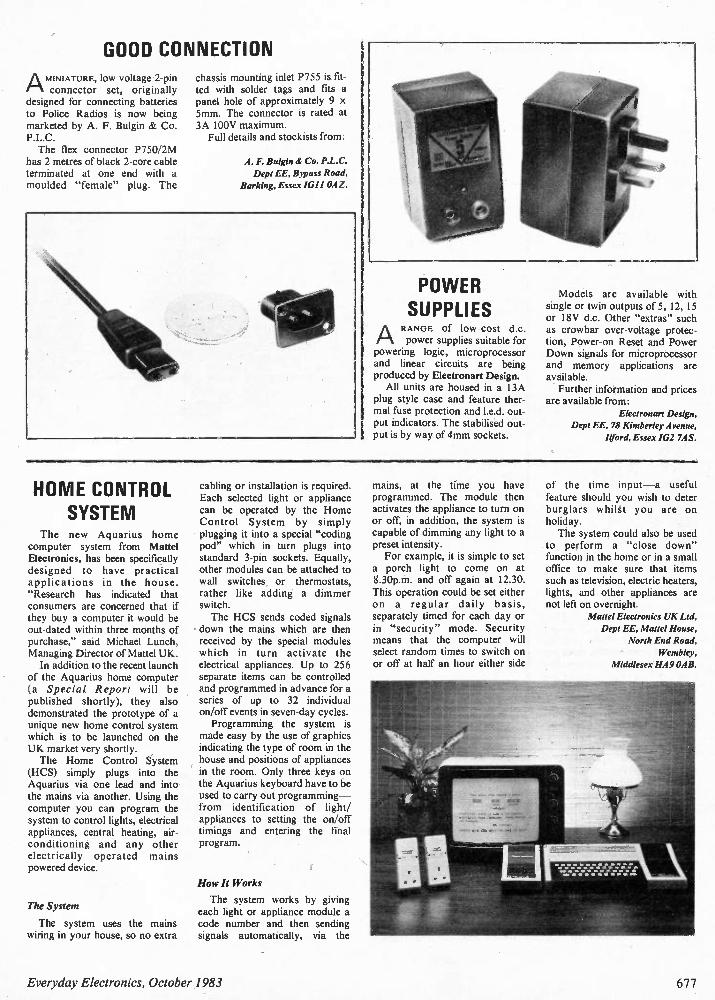
GOOD CONNECTION
AMINIATURE, low voltage 2-pin connector set, originally
designed for connecting batteries to Police Radios is now being marketed by A. F. Bulgin & Co. P.L.C. The flex connector P750/2M
has 2 metres of black 2-core cable terminated at one end with a moulded "female" plug. The
chassis mounting inlet P755 is fit-ted with solder tags and fits a panel hole of approximately 9 x 5mm. The connector is rated at 3A 100V maximum. Full details and stockists from:
A. F. Bulgin & Co. P.L.C. Dept EE, Bypass Road,
Barking, Essex IGI I OAZ.
POWER SUPPLIES RANGE of low-cost d.c. power supplies suitable for
powering logic, microprocessor and linear circuits are being produced by Electronart Design. All units are housed in a 13A
plug style case and feature ther-mal fuse protection and I.e.d. out-put indicators. The stabilised out-put is by way of 4mm sockets.
A
Models are available with single or twin outputs of 5, 12, 15 or 18V d.c. Other "extras" such as crowbar over-voltage protec-tion, Power-on Reset and Power Down signals for microprocessor and memory applications are available. Further information and prices
are available from: Ekaronart Design,
Dept EE, 78 Kimberley Avenue, Irord, Essex IG2 7AS.
HOME CONTROL SYSTEM
The new Aquarius home computer system from Mattel Electronics, has been specifically designed to have practical applications in the house. "Research has indicated that consumers are concerned that if they buy a computer it would be out-dated within three months of purchase," said Michael Lunch, Managing Director of Mattel UK. In addition to the recent launch
of the Aquarius home computer (a Special Report will be published shortly), they also demonstrated the prototype of a unique new home control system which is to be launched on the UK market very shortly. The Home Control System
(HCS) simply plugs into the Aquarius via one lead and into the mains via another. Using the computer you can program the system to control lights, electrical appliances, central heating, air-conditioning and any other electrically operated mains powered device.
The System
The system uses the mains wiring in your house, so no extra
cabling or installation is required. Each selected light or appliance can be operated by the Home Control System by simply plugging it into a special "coding pod" which in turn plugs into standard 3-pin sockets. Equally, other modules can be attached to wall switches or thermostats, rather like adding a dimmer switch. The HCS sends coded signals
down the mains which are then received by the special modules which in turn activate the electrical appliances. Up to 256 separate items can be controlled and programmed in advance for a series of up to 32 individual on/off events in seven-day cycles. Programming the system is
made easy by the use of graphics indicating the type of room in the house and positions of appliances in the room. Only three keys on the Aquarius keyboard have to be used to carry out programming — from identification of light/ appliances to setting the on/off timings and entering the fmal program.
How It Works
The system works by giving each light or appliance module a code number and then sending signals automatically, via the
mains, at the time you have programmed. The module then activates the appliance to turn on or off, in addition, the system is capable of dimming any light to a preset intensity. For example, it is simple to set
a porch light to come on at 8.30p.m. and off again at 12.30. This operation could be set either on a regular daily basis, separately timed for each day or in "security" mode. Security means that the computer will select random times to switch on or off at half an hour either side
of the time input —a useful feature should you wish to deter burglars whilst you are on holiday. The system could also be used
to perform a "close down" function in the home or in a small office to make sure that items such as television, electric heaters, lights, and other appliances are not left on overnight.
Mattel Electronics UK Ltd, Dept EE, Mattel House,
North End Road, Wembley,
Middlesex HA9 OAB.
Everyday Electronics, October 1983 677
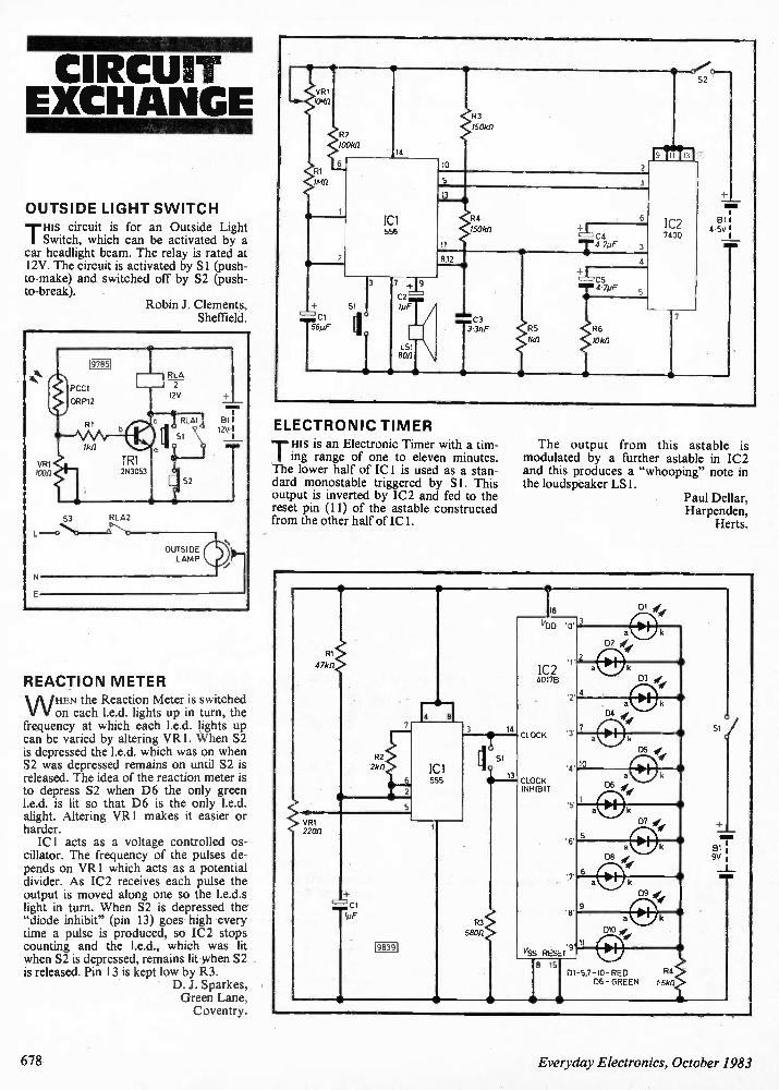
CIRCUIT EXCHANGE
OUTSIDE LIGHT SWITCH
TI His circuit is for an Outside Light Switch, which can be activated by a
car headlight beam. The relay is rated at 12V. The circuit is activated by S I (push-to-make) and switched off by S2 (push-to-break).
Robin J. Clements, Sheffield.
REACTION METER
W HEN the Reaction Meter is switched on each 1.e.d. lights up in turn, the
frequency at which each 1.e.d. lights up can be varied by altering VR1. When S2 is depressed the 1.e.d. which was on when S2 was depressed remains on until S2 is released. The idea of the reaction meter is to depress S2 when D6 the only green 1.e.d. is lit so that D6 is the only 1.e.d. alight. Altering VR1 makes it easier or harder. IC! acts as a voltage controlled os-
cillator. The frequency of the pulses de-pends on VR1 which acts as a potential divider. As IC2 receives each pulse the output is moved along one so the 1.e.d.s light in turn. When S2 is depressed the "diode inhibit" (pin 13) goes high every time a pulse is produced, so IC2 stops counting and the 1.e.d., which was lit when S2 is depressed, remains lit when S2 is released. Pin 13 is kept low by R3.
D. J. Sparkes, Green Lane, Coventry.
VR1 IC6111
RI IMI1
" Cl 1 8pF
R2 100812
6
114
ICI 556
SII
150k12
10 2
9
52
13 I 4
5
13
11
812
R4
150k12
C3
ELECTRONIC TIMER
TIHIS is an Electronic Timer with a tim-ing range of one to eleven minutes. The lower half of ICI is used as a stan-dard monostable triggered by S I. This output is inverted by IC2 and fed to the reset pin (11) of the astable constructed from the other half of ICI.
Cd
T4 7PF tJ CS
I R 6
4 • 7/./F
10kI2
1C2 7400
The output from this astable is modulated by a further astable in IC2 and this produces a "whooping" note in the loudspeaker LS 1.
Paul Dellar, Harpenden,
Herts.
6 7 8 Everyday Electronics, October 1983
ELECTRONIC COMPONENTS * ELECTRONICS
Adaptors Aerosols Ammeters Amplifiers Audio Leads Auto Modulation Meter Batteries Beads — Ferrite Books — Technical Bridge — Rectifiers Bulbs Cable Cable Accessories Cabinet Feet Cage Jacks Capacitors Cases Cassette Mechanisms Caps — Keytops Ceramic Cermet Preset Chassis Punches Chargers —Battery Chokes — Min Fixed Cleaning Blocks Clocks — LCD CMOS ICs Computer Leads Connectors Co-ax Relay Contact Cleaner Aerosol
ambit
*COMMUNICATIONS * COMPUTING * VIDEO * AUDIO
* 3 x 1 DISCOUNT Vouchers as usual Copper Clad PCB Cores Coils Converters Crystals Data Books Die Cast Boxes Displays Diodes Dot Matrix LCD Module Double Balanced Mixer Drafting Aids Drawing Pen Drills Drive Cord Earpieces Enamelled Copper Wire Encoder Rotary EPROM Eraser Equipment Cases Etching Kit Etch Resist Pen Ferric Chloride Ferrite FET Dip Oscillator File Set Filters Fixed Inductors Fluorescent Displays Frequency Counter Function Generators
Generators Helical Filter High Pass Filter ICs IF Transformers Keyboard Switches Keypad Keyswitch Caps LCD Displays LCD Modules Lever Switches Linear ICs Linear Phase Filters Low Pass Filters Mechanical Filters Meters Miniature Loudspeakers Miniature Relays Mixer Diodes Ni-Cad Batteries Noise Measuring Equipment Oscilloscopes Oscilloscope Probes PCB Aids PCB Potentiometers Presets Quartz Crystals Resistors Resonators Rotary Switches
Screwdrivers SCRs Semiconductors Silicon Compound Silicon Diodes Silver Plated Wire Sleeving Stereo Decoders Switches Tape Mechanism Terminal Blocks Thermometer Transformers Transformers Mains Trim Tools Trimmers TV! Filters TV Modulators Variable Inductors Varicap Diodes Video Adaptors Video Leads Voltmeters Voltage Regulators VU Meters Zener Diodes Zero Insert Force Socket Z-8 Development Systems
VISA I II INTERNATIONAL =RN. 0,_40 1 0 1 irn
200 North Service Road, Brentwood, Essex C M14 4SG
Telephone (Consumer Sales/Enquiries) 02 11-230909 — Telephone (Industrial Sales/
Enquiries) 02 11-231616 — Telex 995194 A MBIT G — Data 24 hrs (RS232/300 baud) 02 11-
232628; RE WTEL
* PRICE-ON-THE PAGE
ambit INTERNATIONAL
ex: 995194 Amb4G
entWOOd Essex CM14 4SG
ELECTRON IC ,HOBBIE5,IFAIR,
We are sorry to announce the cancellation of this year's Electronic Hobbies Fair, planned for 27-30 October. In spite of a significant success last year, the con-
tinuing recession is hitting the electronics hobby in-dustry pretty hard. This has meant that many com-panies feel that this year they cannot sensibly allocate the resources of time, money and man-power involved in participation in exhibitions. We feel that any exhibition sponsored by Every-
day Electronics must offer the visitor a full range of
components, equipment, projects and demonstra-tions from a wide selection of companies across the industry. As we cannot be absolutely sure of doing just this, we have decided with regret that we must disappoint our readers now rather than in October. Everyday Electronics would like to thank those
companies who had already given their support to the Electronic Hobbies Fair this year. With our apologies for the disruption of their plans we couple our hopes for a future event in a more buoyant business climate.
Everyday Electronics, October 1983 679
BI-PAK BARGAINS TRIACS - PLASTIC 4 AMP - 400v - T0202 - TAG 1360 1 OFF 10 OFF 50 OFF 100 OFF 40p £3.75 £17.50 £30.00 8 AMP - 400e -'10030 - TAG 425 6Gp £5.75 £27.50 £50.00
MINIATURE FM TRANSMITTER Freq. 95-106MHz. Range: mile Size: 45 x 20mm Add: 9v ball. ONLY Not ficenced in U.K. f5.50 ideal for: 037-M15-FBI-CIA-KGB etc.
PROGRAMMABLE UNIJUNCTION TRANSISTOR PUT case 10106 plastic MEU22 Similar to 2N6027/ 6028 PNPN Silicon Price: 1-9 10-49 50-99 100+ Each 20p 18p 15p 13p Normal Retail Price £0.35 each.
SEMICONDUCTORS FROM AROUND THE WORLD
100 A collection of Transistors, Diodes, Rectifiers & Bndges
Tria cs, IC's & Opto's all of are which current every-day useable
devices.
Guaranteed Value Over f 10 Normal Retail Price.
' Data etc in every pack. Order No. VP56
Our Price £4.00
BI-PAK'S OPTO SPECIAL
A selection of large and small sized LED's
in various shapes, sizes & colours, togeth-
er with 7 Segment Displays both anode &
cathode plus photo transistors emitters
and detectors. Cadmium Cell ORP12 and
Germ, photo transistor OCP71 included. In
all a total of 25 Opto pieces valued over
£12 Normal Price
Order No. VP57 Our Super Value
Price Just £5.00
Pak No. Qty VP1 300 VP2 300
VP3 200 VP4 150 VP5 200 VP6 200 VP7 100 VP8 100 VP9 1(X) VPIO 60 VP11 100 VP12 60 VP13 50 VP14 50 VP15 50
V ALUE PACKS Description Price Assorted Resistors Mend Types £1.00 Carbon Resistors Fi Watt Pre-formed £1.00 Watt MM Carbon Resistors Mixed £1.00 Watt Resistors 100 ohm - 1M Mixed £1.00 Assorted Capacitors All Types £1.00 Ceramic Caps Miniature - Mixed £1.00 Mixed Ceramics Disc. 1pf - 56pf £1.00 Mixed Ceramic Disc. 68pf - .015pf £1.110 Assorted Polyester/Polystyrene Caps £1.00 C280 Type Caps Metal Foil Mixed £1.00 Electrolytics - All Sorts £1.00 Bead Type Polystyrene Min Caps £1.00 Silver Mica Caps Ass. 5.6pf - 150pf £1.00 Silver Mica Caps Ass. 1800 - 4703pf £1.00 High Voltage Disc. Ceramic 750v -8Kv Mixed £1.00
V ALUE PACKS
Pak No. thy description
VP28 VP29
VP30
VP31 VP32
VP33
VP34
VP35
VP36
VP37
VP42
VP43
VP44
VP45
VP46
VP47
Price
10 Rectangular .2" Green LED'S £1.00 30 Ass. Zener Diodes 250mW - 2W
Mixed VIts. Coded £1.00 10 Ass. 10W Zener Diodes Mixed Vits.
Coded £1.00 10 5 Amp SCR's 10-66 50-400v Coded £1.00 20 3 Amp SCR's 10-66 Up To 400v Un-
coded £1.00 200 Sit Diodes Switching Like IN4148 DO-
35 £1.00 200 Sil. Diodes Gen. Purpose Like 0A200/
BAX13/16 £1.00 50 1 Amp IN4000 Series Sil. Diodes Un-
coded All Good £1.00 8 Bridge Re m. 4 x 1 Amp 4 +2 Amp Mixed Vbs. Coded £1.00
8 Black Instrument Type Knobs With Pointer I" Std £1.00
10 Black Heatsinks To Fit TO-3, 10-220 Ready Drilled
4 Power-An Heatsinks 2 x 10⁻³ 2 x TO-66 Size
1 Large Power Heatsink 90 x 80 x 35 mm Drilled For Up To 4 TO-3 Devicesf 1.00
50 BC107/8 Type NPN Transistors Good Gen. Purpose Uncoded £1.00
50 8C177/8 Type PNP Transistors Good Gen. Purpose Uncoded £1.00
10 Silicon Power Trans. Similar 2N3055 Uncoded £1.50
TEACHIN 84 Complete kit of component parts.
Price f21.50
V ALUE PACKS
Pak No. Day Description Price VP16 50 Wirewound Res. 9W (avg)
Ass. 1 ohm - 12K £1.00 VP17 50 Metres PVC Covered
Sedge Strand Wire Mixed Colours f1.00
VP18 30 Metres PVC Covered Multi Strand Wire Mixed Colours£1.00
VP19 40 Metres PVC Single/Multi Strand Hook-Up Wire Mixed £1.00
VP20 6 Rocker Switches 5 Amp 240v £1.00
VP21 20 Pcs. 1 - 2 &4 mm Plugs & Sockets Matching Sizes £1.00
VP22 200 Sq. Inches Total, Copper Clad Board Mixed Sizes £1.00
BI-PAK SOLDER - DESOLDER KIT Kit comprises: ORDER NO. VP80 1 High Quality 25 watt General PurposeLightweightSolderinglron 240v mains incl 3/16" (4.7mm) bit. 1 Quality Desoldering Pump High Suction with automatic ejection Knurled anti-corrosive casing and Teflon nozzle 1.5 metres of De-Soldering braid on plastic dispenser 2 yds (1.83m) Resin Cored Solder on Card 1 Heat Shunt tool tweezer Type Total Retail Value over £12.00 OUR SPECIAL KIT PRICE £9.95 •
VALUE PACKS Pak No. Illy Description Price VP23 20 Assorted Slider Pots,
Mixed Values £1.00 VP24 10 Slider Pots. 40 mm UK 5 x
Log 5 x Lin £1.00 VP25 10 Slider Pots. 40 mm 47K 5 x
Log 5 x Lin f1.00 VF26 20 Small .125" Red LED'S £1.00 VP27 20 Large .2" Red LED'S £1.00
TRANSISTORCLEARANCE All Sorts Transistors, A mixed Bag NPN-PNP Silicon & Germ. Mainly Uncoded You To Sort
100 Pack Includes Instructions For Making Simple Transistor Tester. Super Value. Order No VP60 £1.00
BI-PAK PCB ETCHANT AND DRILL KIT Complete PCB Kit comprises 1 Expo Mini Drill 10, 601RPM 12v DC incl 3 collets & 3 x Twist Bits 1 Sheet PCB Transfers 210mm x 15Ornm 1 Etch Resist Pen 1 lb pack FERRIC CHLORIDE crystals 3 sheets copper dad board 2 sheets Fibreglass copper clad board Full instructions for making your own PCB boards
Retail Value over £15.00 OUR BI-PAX SPECIAL KIT PRICE £9.95
ORDER NO. VP81
vs,
DIGITAL VOLT METER MODULE
3 x 7 segment displays Basic Circuit. 0- * 2v i instructions provided to extend voltage & current ranges Operating voltage 9/12v. Typ. Power Con-sumption 50mA \ 0/No. VP99 Once only price
£9.95
SINGLE SIDED FIBREGLASS BOARD Order NoPieces Size Sq. Ins Price E131 4 9 x 2f" 100 £1.50 FB2 3 11 +3" 100 £1.50 F133 4 13 x• 156 £2.00 DOUBLE SIDED FIBREGLASS BOARD FB4 2 14 x 4" 110 £2.00
SILICON BRIDGE RECTIFIERS Comprising 4 x Amp rectifers
mounted on PCB. VRM - 150 vlts IFM - 1.5 Amps
Size: 1 inch square 10 off £1.00 50 off f4.50 100 off £7.50
ORDER NO: 4R1 B Rect.
rT HYBRID LED COLOUR DISPLAYS
Red, Green, Yellow - .3/.5/.6 inch Mixed types and colours NU MERIC & OVER-
FLO W Co m mon Anode/Cathode.
GaAsP/GaP. Brand New, Full Data incl.
10 pieces lour mix) .. £4.00 Normal Retail Value Over £10.00
Order No. VP5B
IC BARGAINS VP40 30 Assorted 74 Series TTL IC's Gates,
Flip-Flops & M.S.I.'s + Data Book. All New, Normal Retail Value Over £6.00 Our Price
VP41 30 Assorted CMOS 1.0's CD4000 Series Pack Includes 00/09/12/14/18/21/23/ 25/28/30/35/44/68 AY/AE Types Plus Data Sheet Value Over £8.00. Normal retail YOU MAY ORDER any ONE TYPE of the above CMOS at 02.00 per 25 pieces. ORDER AS VP41 + type number re-quired.
£2.50
£2.50
RATCHET SCRE WDRIVER KIT Comprises 2 standard screwdriver blades 5 & 7mm size. 2 cross point size 4 & 6.1 Ratchet handle. 5-in-1 Kit £145 each. 0/No 3298
INTRUSION
ALAR M
The DOOR BIRD DB 2000 alerts you before your door is opened. Just hang on the inside door knob - alarm is activated as soon as the outside door knob is touched.
ONLY
£3.95
OPTO 7-Seg ment Displays Brand new 1st Quality
LITRONIX DL 707R 14-pin
Red 0.3" Common Anode Display 0-9 with right hand decimal point TTL compatible 5v DC Supply. Data supplied
IN PACKS OF
5 pieces £3 10 pieces £5 50 pieces £20 100 pieces £35 1,000 pieces £300
(60p each) (50p each) (40p each) (35p each) 130p each)
THE M ORE YOU BUY - THE LESS YOU PAY
OUR GREAT NEW CATALOGUE
Presented with a Professional Approach and Appeal to ALL who require Quality Electronic Components, Semiconductors and other Accessories ALL at realistic prices. There are no wasted pages of useless information so often included in Catalogues published nowadays. Just solid facts i.e. price, description and individual features of what we have available. But remember, BI-PAK's policy has always been to sell quality components at competitive prices and THAT WE STILL DO.
We hold vast stocks "in stock" for fast immediate delivery, all items in our Catalogue are available ex stock. The Catalogue is designed for use with our 24 hours "ansaphone" service and the Visa/Access credit cards, which we accept over the telephone.
B!'!
•
To receive your NEW 1983 BI-PAK Catalogue, send 75p PLUS 25p p&p to:-
Silicon NPN1' Type Transistors 10-92 Plastic Centre Collector Like BC182L - 183L - 184L VCBO 45 VCEO 30 IC200mA Hfe 100-400 All perfect devices - uncoded. ORDER AS SX183L 50 off 100 off 560o11 1000 off £1.50 £2.50 £10.00 £17.00 Silicon General Purpose NPN Transistors 10-18 Case. Lock fit leads - coded CV7644 similar to BC147 - BC107 - ZT89 ALL NEW VCE 79- IC500mA. ORDER AS CV7644
50 off 103 off 500 off 1000 off PRICE £2.00 £3.80 £17.50 £30.00 Silicon General Purpose PNP Transistors 10-5 Case. Lock fit leads coded CV9507 similar 2N2905A to BFX30 VC60 IC600mA MM HFE 50. ALL NEW. ORDER AS CV9507.
50o11 100th 5C0 off 1000 off PRICE £2.50 £4.00 £19.00 £25.00
Send your orders to Dept. EE10 BI-PAX PO BOX 6, WARE, HERTS. SHOP AT 3 BALDOCK ST., WARE, HERTS. TERMS: CASH WITH ORDER. SAME DAY DESPATCH. ACCESS, BARCLAYCARD ALSO ACCEPTED. TEL I0920) 3182. GIRO 388 7006. ADD 15% VAT AND 75p PER ORDER POSTAGE AND PACKING.
VP38 100 Silicon NPN Transistors - All Perfect. Coded Mixed. Types With Data And Eqvt. Sheet No Rejects Rantas-tic Value • £3.00
VP39 100 Silicon PNP Transistors - All Perfect coded Mixed. Types With Data And Eqvt Sheet No Rejects Real Value £3.00
250055 The best known Power Transistor in the world - 2N3055 NPN 115w. Our Bi-Pak Special Offer Price
10 off . 50 off 100 off £3.50 £16.00 £30.00
B0312 COMPLIMENTARY PNP POWER TRAN-SISTORS TO 2N3055. Equivalent MJ2955,- - -00312-T03. Special price E0.70 10 off E6.50
Use your credit card. Ring as on Ware 3182 NOW and get your order even faster. Goods normally sent 2nd Class Mail. Remember you must add VAT at 15As to your order Total Postage add 75p per Total order
680 Everyday Electronics, October 1983
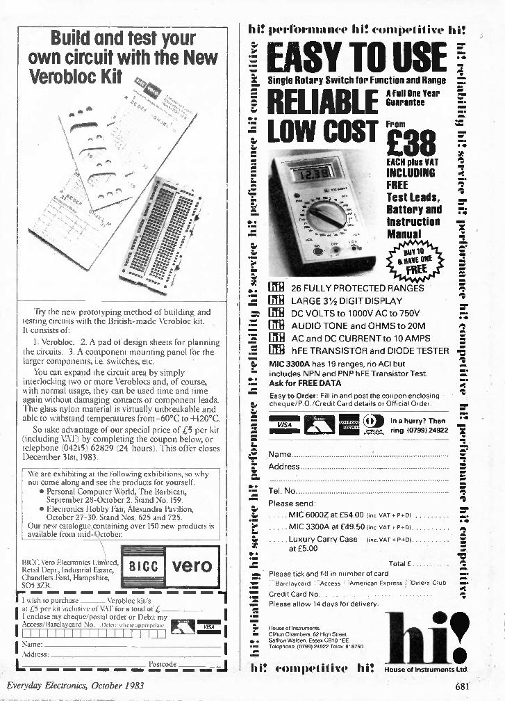
Build and test your own circuit with the New Verobloc Kit
A
Try the new prototyping method of building and testing circuits with the British-made Verobloc kit. It consists of:
1. Verobloc. 2. A pad of design sheets for planning the circuits. 3. A component mounting panel for the larger components, i.e. switches, etc. You can expand the circuit area by simply
interlocking two or more Veroblocs and, of course, with normal usage, they can be used time and time again without damaging contacts or component leads. The glass nylon material is virtually unbreakable and able to withstand temperatures from-60°C to +120°C. So take advantage of our special price of £5 per kit
(including VAT) by completing the coupon below, or telephone (04215) 62829 (24 hours). This offer closes December 31st, 1983.
We are exhibiting at the following exhibitions, so why not come along and see the products for yourself. • Personal Computer World, The Barbican, September 28-October 2. Stand No. 159.
• Electronics Hobby Fair, Alexandra Pavilion, October 27-30. Stand Nos. 625 and 725.
Our new catatogu containing over 150 new products is available from mid-*ctober.
BICC Vero Electronics Limited, Retail Dept., Industrial Estate, Chandlers Ford, Hampshire, SO5 3ZR.
BICC vero
rwish to purchase Verobloc kit/s at £5 per kit inclusive of VA!' for a total of £ I enclose my cheque/postal order or Debit my
• Access/Barclaycard No. Delete where appropriate VISA
I Name: I Address: Postcode
hi! peribrmance hi! competitive hi!
EASY TO USE Single Rotary Switch for Function and Range
RELIABLE A Full One Year Guarantee
LOW COST ba
= Wow.
ot,
1,16•
EACH plus VAT
INCLUDING FREE Test Leads, Battery and Instruction Manual
26 FULLY PROTECTED RANGES
LARGE 31/2 DIGIT DISPLAY
DC VOLTS to 1000V AC to 750V
AUDIO TONE and OHMS to 20M
AC and DC CURRENT to 10 AMPS
hFE TRANSISTOR and DIODE TESTER
MIC 3300A has 19 ranges, no ACI but includes NPN and PNP hFE Transistor Test. Ask for FREE DATA
Easy to Order: Fill in and post the coupon enclosing cheque/P.O./Credit Card details or Official Order.
VISA Eli r. :4 4
MION4104.1
In a hurry? Then ring (0799) 24922
Name
Address
Tel. No.
Please send:
M IC 6000Z at £54.00 (inc. VAT + PA))
M IC 3300A at £49.50 (inc. VAT + P +el
Luxury Carry Case (inc. VAT + P+13) at £5.00
Total £
Please tick and fill in number of card :Barclaycard . :Access :American Express 1Diners Club
Credit Card No. Please allow 14 days for delivery.
House of Instruments. Clifton Chambers. 62 High Street, Saffron Walden. Essex C1310 1 EE. Telephone. (0799) 24922 Telex: 818750
hi! competitive hi!
min ,•••
• 11
a. W WI
a.
,•••fl
1WW IP = W1 W
• •
a.
WO
1=1• •
W WI •11,
= ft
a. WI
a. a. W•0 a. a. WW a.
a. WOW
S.
41W
a. WO
a. WW•
1=1•
•W•
S.
a.
a.
a. a.
W W,
OW.
•
=0 a. a• a. a. a.
= WI a. • -4;
a. a. a. •WW a.
W O.
M t, omk
mi•
1111 House of Instruments Ltd.
Everyday Electronics, October 1983 681
XK113 M W RADIO KIT Based on ZN414 IC, kit includes PCB, wound erial and crystal earpiece and all components o make a sensitive miniature radio. Size: 5.5 K 2.7 in 2c ms. Requires PP3 9V battery. IDEAL
FOR BEGINNERS £5.00
HOME UGH11NG KITS kits contain all necesseiy components and full
mstructrons & are designed to replace • standard well switch and control up to 3000 of lighting
1063006 Remote Control £14.30 Di m mer
MK6 Trans mitter for above £ 4.20 1I3300K Touchdi m mer E 7.00 TS 300K Touchswitch 7.00 TDE/1( Extension kit for 2-way
switching for TD3001( E 2.50
LD300K Rotary Controlled £350 Di m mer
DVM/ULTRA SENSITIVE THERMOMETER KIT
This new design is based on the ICL7126 la lower power version of the ICL7106 chip) and a 31,2 digit liquid crystal display. This kit will form the basis of a digital multi. meter (only a few additional re-
sistors and switches are required-details supplied), or a sensitive digital ther mo meter 1-50 T to+150 T) reading to 0.1 T. The basic kit has a sensitivity ,of 200mV for a full scale reading, auto matic polarity in-dication and an ultra low power require ment-giving a 2 year typical battery life from a standard 9V PP3 when used 8 hours a day, 7 days a week
Price £15.50
NOVV OPEN COMPUTER SHO WROOM
DRAGON 32
COMPONENT PACKS PACK 1 650 Resistors 47 oh m to 10 Mohm
10 per value £4.00
PACK 240 x 16V Electrolytic Capacit Or. 100F to 1000uF - Spar value £3.25
PACK 360 Polyester Capacitors 001 to
1 pF ,250V - 5 per value E5.55 PACK 445 Subminiature Presets 100 ohm to
1 Mohrn - 5 per value £2.90 PACK S 30 Low Profile IC Sockets 8. 14 and 16
- pin'- 10 of each 2,40
PACK 625 Red LEDs 1511101 dia I E 1,25
Hours: Mon-Fri 10am - 6pm
Sat 10am - 4pm
We also stock peripherals and . accessories - disc drives, printers. joy sticks etc. together with a
wide range of books and the latest software for all the above computers including ZX81
SEND S A E FOR LIST TODAY
3-NOTE Era DOOR CHIME
Based on the SAB0600 IC the kit is supplied with all components, including loudspeaker, printed circuit board, a pre-drilled box (95 x 71 o 35mm) and full instructions. Requires only a PP3 9V battery and push-switch to complete. AN IDEAL PROJECT FOR BEGIN NERS. Order as XK 102.
you got our FREE GREEN CATALOGUE ve, NO , Send S A E 6 9'• TODAY.
It's packed with details ot allow KITS plus large range Of SEMICONDUCTORS including CMOS. IS TTL.
microprocessOrs and memories, full range of LEDs, CaPelCilOrs, resistors. hardware, relays. switches etc We also stock VERO and Antex products as well as books 1 rom Texas Instruments. Sabers and Elektor
ALL AT VERY CO MPETITIVE PRICES.
ORDERING IS EVEN EASIER - JUST RING THE NU MBER YOU CAN'T
FORGET FOR PRICES YOU CAN'T RESIST.
5-6-7 8-9-10 and give us your Access or Barclaycard No or write enclosing
cheque or postal order Official Orders accepted from schools. etc
Answering service evngs &weekends
FAST SERVICE -TOP QUALITY LOW LOW PRICES No circuit is complete without a call to
ELECTRONICS 11 - 13 Boston Road London W7 3SJ
£5.00
TEACH-IN 84 Complete kit of top quality components as specified by EE including two EBBO starter packs.
Add 65P postage & packing 1.15% VAT 10101.1 Overseas Customers:
Add £2 501Europel. £3.00 lelsewherel for p&p Send S.A.E for further STOCK DETAILS. Goods by return subject to availability.
OPEN i 3Fr"
TEL
£15.80
ALL PRICES
EXCLUDE VAT 01-567 8910 ORDERS 01-579 9794 ENQUIRIES M I 01-579 2842 TECHNICAL AFTER 3PM
LCD 31/2 DIGIT MULTIMETER 16 ranges including DC voltage 1200 mw-1000 it and AC voltage, DC current 1200 m A-10 Al and resistance 10-2 Ml + NPN & PNP transistor gain and diode check. Input impedance 10M Size 155088031 m m. Requires P M 9v battery.
Test leads included ONLY 09.00
ELECTRONIC LOCK KIT XK101 This KIT contains a purpose designed lock IC, 10-way keyboard, PCBs and all components to construct a Digital Lock, requiring a 4-key sequence to open and providing over 5000 different combinations. The open sequence may be easily changed by means of a pre-wired plug. Size: 7 x 6 x 3 cms. Supply: 5V to 15V d.c. at 40uA. Output: 750mA max. Hundreds of uses for doors and garages, car anti-theft device, electronic equipment, etc. Will drive most relays direct. Full instruc-tions supplied. ONLY £10.50
Electric lock mechanisms for use with latch locks and above kit
£13.50
• DISCO LIGHTING KITS DL 10006
This value-for- money kit
features a bi directional
sequence, speed of sequence and frequency of direction
change, being variable by
means of potentio meters and
incorporates a master di m ming control
£ DLZ100K 14.60 A lower cost version of the above, featuring undirectional channel sequence with speed
variable by means of a pre-set pot. Outputs
switched only at mains zero crossing points
to reduce radio interference to a mini mu m.
Only £8.00 OptiOnel opto input DLA I Allowing audio ("bearl
-light response. 60p
DL3000K
This 3 channel sound to light kit features zero
iioltege switching, auto matic level control &
built in mic. No connections to speaker or amp
required. No knobs to adjust - si mply connect
to mains supply & la mps.
(1KwiChannell Only £11.95
ELECTR MIR
Please Inentio \t his his journal when applying
Access facilities Aerosols Batteries Boxes Breadboards Computers & Eqpmnt Capacitors
Connectors Discounts Electrolytics Ferrites Grommets Hardware 1.CS Knobs
THE E.E ENTHUSIAST'S
AZ BUYING GUIDE Its amazing what you'll find in the pages of our current summer price list be you beginner, expert or professional. The list below gives some idea of the enormous stocks we carry, and our service is just about as good as meticulous care can make it WRITE, PHONE OR CALL FOR OUR SUMMER PRICE UST NOW!
Lamps Meters Opto-electronics Potentiometers Pot Cores Quantity prices Resistors Relays
ITS FREE!
Good Bargains
Good Service
Good Choice
Semi-conductors Switches Solder tools Tools Transformers Vero products Visa facilities Zener diodes
ELECTROVALUE LTD., 28 St. Jude's Road, Englefield Green, Egham, Surrey TW20 OHB. Egham 331501 (London 87; STD 07841 Telex 264475: Northern Shop (Callers only) 680 Burnage Lane M/c M19 1NA. (061-432 49451 EV Computing Shop, 700 Burnage Lane, Manchester (061431 48661.
it you're an electronics man interested in the coverage of T\/ technology, Television is just the magazine for you. Coverage includes the latest developments in circuitry, video and long-distance Television.. .with a special emphasis on servicing. In this months issue
VIDEO TAPE POSITION INDICATOR Most tape counters commonly found on VCRs suffer from two major disadvantages: inaccuracy, and the need to 'zero them. Alan Willcox has come up with an inexpensive, simple to build project which gets over both problems in a rather novel way. It can be fitted to any Grundig machine, the JVC HR7700, Ferguson 3V23, Sony Fl and C9, Sharp 7700 and generally any VCR which has some kind of 'tape remaining' indicator. All the circuitry, including an I.e.d. display, is built on a small printed circuit board.
October issue on sale NOW
TELE111151011 Well worth a closer look Get a copy today.
682 Everyday Electronics, October 1983
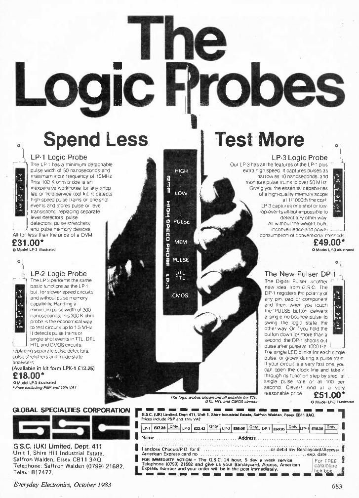
The Logic probes Spend Less
LP-1 Logic Probe The LP-1 has a minimum detachable pulse width of 50 nanoseconds and maximum ,nput frequency of 10MHz This 100 K ohm probe is an inexpensiYe workhorse for any shop. lab or field service tool kit It detects high-speed pulse trains or one-shot events and stores pulse or level transistions. replacing separate ievel detectors, pulse detectors, pulse stretchers and pulse memory devices
All for less than the price of a DVM
£31.00* 0 Model LP-3 illustrated
LP-2 Logic Probe The LP-2 performs the same basic functions as the LP-1 but, for slower-speed circuit , and without pulse memory capability. Handling a minimum pulse width of 300 nanoseconds. this 300 K ohm probe is the economical way to test circuits up to 1.5 MHz It detects pulse trains or single-shot events in TTL. DTL. HTL and CMOS circuits,
replacing separate pulse detectors, pulse stretchers and mode state analysers (Available in kit form LPK-1 £13.25)
£18.00* 0 Model LP-3 illustrated • Price excluding P&P and 15% VAT
GLOBAL SPECIALTIES CORPORATION
G.S.C. (UK) Limited, Dept. 411 Unit 1, Shire Hill Industrial Estate,
Saffron Walden, Essex CB11 3A0.
Telephone: Saffron Walden (0799) 21682. Telex: 817477.
Test More LP-3 Logic Probe
Our LP-3 has all the features ot the LP-1 plus extra high speed It captures pulses as
narrow as 10 nanoseconds. and monitors pulse truins to over 50 MHz Giving you the essential capabilities
of a high-quality memory scope at 1/1000th the cos'
LP-3 captures one shot or low-rep-events all-but-impossible to
detect any other way. All without the weight. bulk. inconvenience and power L
consumption of conventional methods
The logic probes shown are all suitable for TTL, OTC, HTL and CMOS circuits
_1
£49.00* 0 Model LP-3 illustrated
The New Pulser DP-1 I The Digital Pulser another new idea from G.S.C. The DP-1 registers thr:, polarity of any pin, pad or component and then. when you touch the 'PULSE' button, delivers a single no-bounce pulse to swing the logic state the other way ,Or if you hold the button down for more than a second. the DP-1 shoots out pulse after pulse at 1000 Hz The single LED blinks for each single pulse, or glows during a pulse train If your circuit is a very fast one, you can open the clock line and take it through its function step by step, at single pulse rate or at 100 per second Cleveri And at a very
reasonable price £51 00* 0 Model LP-3 illustrated .. rG.S.C.1111K1 Limited, De7st 411, Unit 1, Shire Industrial Estate, Saffron Walden, Essex C811 3A0.
Prices include P&P and 15% VAT 1
LP-1 £31313 Qnty LP 2 L22.42 Qnty
LP-3 0E1.08 Qnty DP-1 £60.95 Only 1,1(4 E16.39 Only
Name Address
II enclose Cheque/P.O. for E or debit my Barclaycard/Access/ I American Express card no exp. date
I FOR IMMEDIATE ACTION — The G.S.C. 24 hour, 5 day a week service 1 For FREE 1 Telephone (07991 21682 and give us your Barclaycard, Access, American catalogue
LExpress number and your order will be in the post immediately, tick box 1 me am INN M O NEI INN M I INN II M M N MIN MIN M N =II
Everyday Electronics, October 1983 683
TEACH-IN 84 G.P.E. SELF-FEED SOLDERING IRON Patented
A new concept in miniature soldering iron design
Once again GREEN WELD will be supplying a complete set of parts for this ever popular series - as we have done for all previous series. Our experience in this field means your kit can be supplied from stock at the best possible price, so order with confidence. Price for complete kit is only 123.95 inc post and VAT.
THE 1984 GREEN WELD CATALOGUE
Now in the course of production, the 1984 GREENWELD catalogue will be published in November. It's Bigger, Brighter, Better, more components than ever before. With each copy there's discount vouchers, Bargain List, Wholesale Discount List, Bulk Buyers List, Order Form and Reply Paid Envelope. All for just £1.00! Order now for early delivery,
MOTORIZED GEARBOX These units are as used in a computerized tank, and offer the experimenter in robotics the opportunity to buy the electro-mechanical parts required in building. remote controlled vehicles. The unit has 2 x 3V motors, linked by a magnetic clutch, thus enabling turning of the vehicle, and a gearbox contained within the black ABS housing, reducing the final drive speed to approx 50rpm. Data is supplied with the unit showing various options on driving the motors etc. Suitable wheels also available; details in next ad. Motorized gearbox price £5.95
PACKS! PACKS! PACKS! 1(517 Transistor Pack. 50 assorted full
spec marked plastic devices PNP NPN RF AF. Type numbers include BC114, 117, 172, 182, 183, 198, 239, 251, 214, 225, 320, BF198, 255, 394, 2N3904 etc etc. Retail cost £7+. Special low price 275p
K523 Resistor Pack. 1000 - yes, 1000 1 and ) watt 5% hi-stab carbon film resistors with pre-formed leads for PCB mounting. Enormous range of preferred values from a few ohms to a several megohms. Only 250p. 5000 £10; 20,000 £36.
1(520 Switch Pack. 20 different assorted switches - rocker, slide, push, rotary, toggle, micro etc. Amazing value at only 200p
1(522 Copper clad board. All pieces too small for our etching kits. Mostly double sided fibreglass. 250g (aPprox 110 sq ins) for 200p
1(541 It's back!! Our most popular pack ever - Vero offcuts. This has been restricted for some time, but we have now built up a reasonable stock and can once again offer 100 sq ins of vero copper clad offcuts, average size 4 x3". Offered at around ) the price of new board 320p
1(530 100 Assorted polyester caps - all new modern components, radial and axial leads. All values from 0.01 to 1uf at voltages from 63 to 1000!! Super value at 395p
1(602 Electrolytics - all long leaded radial type - most values from 10uf to 1000uf, nearly all 10V, few 16V. Bag of 100 assorted £3.50
TREAT YOURSELF TO A NICE NEW DIGITAL MULTIMETER!!
KD55C A DVM for the professional - this 3) digit multitester has overload protection, low battery and over range indication. Full auto-polarity operation. AC Volts: 0.2-700 DC Volts: 0.2-1000 AC Current: 200uA-10A DC Current: 200ua-10A Resistance: 200R-200M Total 28 ranges for just £44.95
COMPUTER GAMES Z901 Can you follow the flashing light/ pulsating tone sequence of this famous game? Supplied as a fully working PCB with speaker (no case) plus full instructions. Only £4.95
2902 Probably the most popular electronic game on the market - based on the old fashioned pencil and paper battleship game, this computerized version has brought it bang up to date! We supply a ready built PCB containing 76477 sound effect chip, TMS1000 micro-processor chip, R's, C's etc. Offered for its component value only (board may be cracked or chipped, it's only £1. 95, Instructions and circuit, 30p.
P.E. LOGIC TUTOR We can supply a complete set of parts for this series starting this month. All parts as specified, including the PCB for £29.95
LIE DETECTOR Not a toy, this precision instrument was originally part of an "Open University" course, used to measure the change in emotional balance, or as a lie detector. Full details of how to use it are given and a circuit diagram. Supplied complete with probes, leads and conductive jelly. Needs 2 4W batts. Overall size 155 x 100 x 100mm. Only £9.95-worth that for the case and meter alone!!
G REE N WELD 443D Millbrook Road Southampton 501 OHX
Tel (0703) 772501 ALL PRICES INCLUDE VAT; JUST ADD 60p P&P
This new development in Soldering Irons combines light weight (80g.) with unique one-handed operation. Solder is housed in the transparent handle and applied directly to the joint by turning the serrated wheel (located in the handle) with the index finger, allowing a clean, bright joint to be made every time. To renew the solder, the spring clip at the end of the handle is released, the cap is removed and a refill is inserted.
ORDERING INFORMATION. (MAIL ORDER ONLY) Soldering Iron 240v,18w. Fitted with 2.3mm Dia. Bit. Complete with 4 metres of solder. Price £14.95. Solder refills (Pack of 4) Price £2.44. Spare Bits. Tip. Dia. 2.3mm, 3mm or 4.7mm.
Price £1.21 each.
All prices include VAT and P & P. S.A.E. for details.
Manufactured and supplied by:
GARDNER PRECISION ENGINEERING North Road, Woking, Surrey GU21 5DS.
Tel. Woking 20722
JEE DISTRIBUTION 43 Strathville Road BS9000 & CECC London SW18 40X Tel: Sales 01-870 0075
LTD. Approved 267 Hanworth Road
Hounslow, Middx. Tel: 01-570 6502
HOBBY KITS £ each 1(2 Babyphone 5.85 K3 Stab. Power Supply 11.50 K4 Stereo Pre-Amp 8.90 K5 Stereo Amp 2 x10W 12.50 K8 Stereo Pre-Amp with tone and vol. controls 11.40
K11 3W FM Transmitter 9.25 K14 Single Channel Receiver 12.50
EAGLE MULTIMETERS KEW 7N Analoge 2,000 opv £5.25 EM10 Analoge 10,000 opv £13.95 MM20 Analoge 20,1:03 opv £21.95
DIGITAL TS 1,000 31 Digit LED £42.00 Logic Probe ELP 200 £19.95 Logic Probe EL 150 01.95
D.I.L. BREADBOARDS (Re-usable) 75 sq. cm. 550 sockets
each £5.70 BIM1 150 sq. cm. 1100 sockets
each £17.86 BIM2 Low cost Blob Boards 0.1" 120 mm centres, 10"x6" type 4V10
each £1.95
MAINS TRANSFORMERS -6.0VA 0-4.5V : 0-4.5V wire-in
each £2.95 0-12V : 0-12V wire-in 0-9V : 0-09V PCB
each £2.95 0-12V : 0-012V PCB
P20C Post. all R. values each 25p Cermet Trimmers each 20p Control Knobs r 0-9 each 45p LED's with Panel Clips 3mm 18p LED's with Panel Clips 5mm 25p Soldering Iron EOW each £16.45
CAPACITORS Electrolyic - Axial - Radial High Stability Polyeste .001 to 47 tiF Solid Tantalum Bead 0.1 to 100 /IF Disc Ceramic Low Voltage
RESISTORS 1 watt Carbon Film 5% i watt Carbon Film 5% I watt Metal Film 1% i watt Metal Film 1%
SEMI CONDUCTORS Diodes, Transistors I/C's Available from stock - FERRANTI, MULLARD, TEXAS, NATIONAL, SYGNETICS.
Visit or phone for a wide range of Electronic Components
684 Everyday Electronics, October 1983
ADDITIONS TO OUR LIST RADIO MOBILE CAR RADIO SPEAKERS 9' s 4" 4 ohm 5 watt - £1.70. 6" 04 W' 3 ohm 4 watt -C1.35, 6"o 4" 4 ohm 4 watt - £1.15. 6" x 4" 16 ohm 5 watt - £1.15: 5" round 8 ohm 10 watt - £2.30. 614" round extra thin for door or back shelf. In fact these are only 1W' thick 16 ohm 5 watt - £1.75; 5" round 16 ohm 5 watt chassis size 51:" square lapprox/. -£1.15; 5" round 4 ohm 5 watt chassis size 5%" square lapprox I. -£1.15; 5" round 4 ohm 6 watt with built in tweeter - £1.15. 9" x 3" 8 ohm E1.15.
IMPORTANT NOTE: The speaker prices above do not include postage but 10 or more speakers are post free - otherwise add £1.50 per order.
STABILISED POWER SUPPLY (Mains Input) By LAMDA (USA) - Ideal for computer add-ons, d.c. output. Regulated for line volts and load current. Voltage regulation .1% with input variations up to 20% - load regulation 1% from no load to full load - or full load to no load. Complete in heavy duty case - Models available: 5v - 6A £17.25. 5v - 9A £23. 1 2v - 1.5A £13.25. 15v- 1.2A £13.25. 24v- 2A £23.
PREPARED APPLIANCE LEADS Buy these, they will save you time and money. Prices are for small quantities but if you are buying £100 lots or more - halve the prices. Twin circular, white .5mm length 54" - 23p; 3 core circular, white 99" - 1.25rnm - 57p; Twin circular black 77", .5mm - 23p; 3 core circular, black 88" .5mm - 35p: 84" .5nvn 46p; Twin circular black 114" 1.25mm - 69p. Twin circular white 200" .75 fitted 2 pin continental plug one end - 57p; 3 core circular white 54" .75mm core sizes fitted continental two pin and earth plug one end and new type 3 flat pin appliance connector at other end - 75p.
MINIATURE TOGGLE SWITCHES As used on TV cameras and other lightweight equipment. American made by the Arrow Company. Arrow ref. TCH3E Single pole changeover, centre off - 469. Arrow ref. TSH3PCL Single pole changeover PCB mounting - 46p. Arrow ref. TC6M Double pole changeover, centre off - 69p.
REED RELAY KIT High inductance coil, moulded to take 4 reeds, operated by three volts DC or 12 ma. Could be used to close 4 circuits, or with the external magnets supplied, you could have two normally open, i.e. two changeovers. An exceptional bargain at 99p for the coil -4 reeds and 2 magnets.
ROCKER SWITCHES Standard size fit 11.5 x 28mm cut out. Single pole on/off - 23p; Single pole changeover 28p; Single Pole changeover with centre off - 30p; Single pole on/off with neon - 469, for double width cut out DpSt 36p, DpDT 46p.
NICAD BATTERY CHARGERS This, although intended to charge button cells, bring leads from the contacts and then it will suit almost any Nicad battery, charge rate approximately 15rnA but easy to vary.
MIXER MOTOR If this had a case around it, it would be a complete mixer as it has a speed control switch giving three changes of main speed and it also has a gear box with two sockets for paddles. Three lower speeds are available from these sockets. £3.45 - post 60p.
LOW VOLTAGE SWITCH Approx 1W diameter, the cover unscrews to enable the switch to be fixed and to keep the contacts covered, contacts look capable of up to 10 amps. 23p.
PILOT BULBS Standard round 1 lmm 6.5v .3a by Philips. Box of 10 price 50P.
12 volt MOTOR BY SMITHS Made for use in cars, etc. these are series
powerful as load increases. Size wound and they become more -
long by 3" dia. They have .. a good length of Y." spindle - Price £3.45. Ditto, but double ended £4.25. Ditto, but permanent magnet £3.75.
EXTRA POWERFUL 12v MOTOR Made to work battery lawnmower, this probably develops up to h.p., so it could be used to power a go-kart or to drive a
compressor, etc. etc. £7.95 • £1.50 post. (This is easily reversible with our reversing switch - Price £1.15).
MAINS MOTORS We have very large stocks of motors from 2 watts to Y. hp. Most at a price well below cost, let us know yoiir requirements. Some new ones just arrived. 67 R.P.M. Motor: 1/10 hp. reversible mains operated split !Awe motor with gear box - shaft fitted with chain sprocket £11.50 plus £2 post. 100 R.P.M. Motor: 1/6 hp. Mains driven reversible motor with gear box, W shaft from gear box - Very powerful £16.50 plus £3 post. BALANCED MOTOR: Disc or tape drive motor 1500 rpm reversible - mains operated. 3" dia 2%" long with good length 3/8" spindle £4.60 plus 80p post.
CROSSOVER NETWORKS 2-way: 4 or 8 ohm impedance - power input up to 25W, crossover frequency 2kHz with wiring dig. 87p each. 3-way: 4 or 8 ohm - power input up to 60W, crossovers at 700kHz and 3500kHz with wiring diagram. E1.15.
- BARGAIN OF THE YEAR -
The AMSTRAD Stereo Tuner. This ready assembled unit is the ideal tuner for a music centre or an amplifier, it can also be quickly made into a personal stereo radio - easy to carry about and which will give you superb reception.
Other uses are as a "get you to sleep radio", you could even take it with you to use in the lounge when the rest of the family want to view programmes in which you are not interested. You can listen to some music instead.
Some of the features are: long wave band 115 - 270 KHz, medium wave bend 525 - 1650KHz, FM band 87 - 108MHz, mono, stereo & AFC switchable, tuning meter to give you spot on stereo tuning, optional LED wave band indicator, fully assembled and fully aligned. Full wiring up data showing you how to connect to amplifier or head-phones and details of suitable FM aerial (note ferrite rod aerial is included for medium and long wave bands. All made up on very compact board.
Offered at a fraction of its cost: only £6.00 + £1.50 post + insurance.
II I A PRESTEL UNIT, complete except for 6 plug-in IC's -• solar as we know the unit would work once the missing IC's are fitted. Price: £19.75 + £2.00 Post.
Contains all the items listed below.
THIS MONTH'S SNIP
VIEWDATA EQUIPMENT ORACLE VB 100 PCB This is the heart of many viewdata systems, including the Prestel Unit which we are currently selling . This board uses 25 IC's, 5 transistors, 2 crystals and very many Other components. It has a TV aerial input and a TV UHF modifier (AZTEC UM 12331. We offer this board, new, unused and complete except for 601 the 25 IC's at £5.75. The plug in holders for the missing IC's are on the board wired ready to receive them.
MINI KEY SERIES KL This is an American made membrane keyboard with silver contacts as used on Prestel to dial into the British Telecom phone system. It is really miniature, only 60mm x 65mm x 5mm thick. It has 16 press buttons, giving standard 0-9 numbers and ABCD facilities. There are two other buttons engraved asterisks. This is an extremely well made board. £4.60.
TELEPHONE LINE TERMINATION UNIT As used with Prestel but undoubtedly suitable for other applications. !moor-tent components are phone line isolation transformer and 3 Clare Reed Relays. All mounted on a pcb with I.C. and other components P.C.B. size approximately 7" x 114" £3.45. . .
VOLTAGE STABILISED POWER SUPPLY As used with Presto' this has a mains input transformer with a 13v • 0' 13v 20 watt mains transformer. Rectifiers and semi-conductors all mounted on P.C.B. size approximately 4%" x 2". The stabilised DC output from this iE -27v - 120 - 0 +0 +120 +27v. Price £4.60.
INSTRUMENT CASE As used with the Prestel unit this comprises an ali chassis and a moulded front plastic cover secured to the chassis by self-tapping screws. Overall size approx 12"x 10" o 216" deep. On the front is fitted the minikeyboard as described above and although originally intended for Prestel, this case should have other uses including telephone answering machine, etc. Price £5.75 + £1.50 post..
X-RAY EQUIPMENT Beautifully made by the American GEC Company. We have a whole range of spares, all unused. X-RAY TROLLEY - This could be motorised, mains or battery driveb with self retractable flex lead, so it could be used for carrying other mains operated equipment which need to be manouvered easily in a relatively confined space. Switching and breaking is done from the handle and there is ample room and capacity for heavy transformers and smaller equipment. The overall size of this trolley is approx. 3' x 2' 0 38" Price £69. X•RAY HEAD This comprises the x-ray tube in a radiation proof housing with plug in lead connectors. The tube enclosed in the housing is a hospital size tube and unused and new. Price £69. EHT TRANSFORMER & RECTIFIER UNIT We estimate that the output voltage of this is probably 30 or 40 Ky. Completely enclos ed in an oil filled container, size 13" x 14" x 15". There are four rectifier sections, each using 20 EHT rectifiers connected in series these plug in for ease of replacement. The unit is powered by a 600 cycle supply. Price £69. 600 CYCLE SUPPLY UNIT Mains operated through a step down transformer, this contains all the electronic components to operate the equipment. Price E57.50
MINI MONO AMP on p.c.b., size 4"x 2" lapp./ P ,tted volume control and a hole for a tone con-trol should you require it. The amplifier has three transistors and we estim-ate the output to be 3W rms. More technical data will be includ-ed with the amp. Brand new, perfect condition, offered at the very low price of £1.15 each, or 10 for £10.00.
50 THINGS YOU CAN MAKE Things you can make include Multi range meter, Low ohms tester, A.C. amps meter. Alarm clock, Soldering iron minder, Two way telephone. Memory logger, Live line tester, Continuity checker, etc, etc., and you will still have hundreds of parts for future projects. Our 10Kg Parcel contains not less than 1,000 items 'panel meters, timers, thermal trips, relays, switches, motors, drills, taps, and dies, tools, thermostats, coils, condensers, resistors, neons, earphone/microphones, nicad charger, power unit, multi•turn pots and notes on the 50 projects.
YOURS FOR ONLY £11.50 plus £3.00 post.
MINI-MULTI TESTER Deluxe pocket size precision mov-ing coil instrument. Jewelled bearings' 2000 o.p.v.mirrored scale. 11 instant range measures: DC volts 10, 50, 250, 1000.
AC volts 10, 50, 250, 1000. DC arhps 0 - 100 rviA.
1 ../....--- --", Continuity and resistance 0' 1 meg ohms in two ranges. Complete with test prods
0. and instruction hook showing how to measure capacity and inductance as well. Unbelievable value at only £6.75 + 60p
i Post and insurance.
t FREE Amps range kit to enable you to read DC current from 0 - 10 amps, directly on the 0-10 scale. It's free if you purchase quickly, but if you already own a Mini-Tester and would like one, send £2.50.
J. BULL (Electrical) Ltd. (Dept. EL), 34 - 36 AMERICA LANE,
HAYWARDS HEATH, SUSSEX RH16 30U. Established 30 YEARS
MAIL ORDER TERMS: Cash, P.O. or cheque with order. Orders under £12 add 60p service charge. Monthly account orders accepted from schools and public companies. Access & Et/card orders accepted day or night. Haywards Heath 104441 454563. Bulk orders: write for quote. Shop open 9.00 - 5.30, Mon to Fri, not Saturday.
EXTRACTOR FANS Mains operated - ex-computer. Woods extractor
5" - £5.75, Post £1.25 6" - £6.95, Post £1.25
5" Plannair extractor £6.50. Post £1.25.
404" Muffin 115v. £4.50. Post 75p.
404" Muffin 230v. £5.75. Post 75p.
9" American made £11.50, post £2.00.
12 volt 6'4" extractor £6.90, post EI S°.
AUTO & ISOLATION TRANSFORMERS 2 KVV ISOLATION TRANSFORMER 230v in 230v out with tapped primary and secondary, facilities any voltage changes that might be needed. This is a very heavy transformer, American made but not encased. The terminals are along the top on insulation board panels. Both primary and secondary are split so this sould also be used as a 2KW isolation step down transformer. £57.50. Carriage at cost depending upon the distance. This is approx half the regular price. 2 KW AUTO TRANSFORMER Similar type of transformer to the above but has only the one winding. £28.50 carriage £3. 1 KW ISOLATED AUTO TRANSFORMER It is not generally realised that many of the American made tools intended for 115v. if used on building sites and similar damp conditions must be isolated from the mains for safety reasons, as in many cases the insulation of this equipment is not good enough for 230v. We have American made isolated auto transformers, completely enclosed in sheet metal case with carrying handle with 230v lead and 110v American type plug. Price £46.00 + £4.50 post. 300 WATT AUTO TRANSFORMER completely encased, lead for the 230v input, American type plug for the 115v output £6.90 + £1.50 post. 100 WATT AUTO TRANSFORMER not enclosed terminals, output primary with tappings for voltage adjustments. Made to rigid specification for the GPO £4.60 + El post. AMERICAN 2 PIN FLAT SOCKETS for use with these auto trans formers - £2.30 each.
3M FACSIMILE EQUIPMENT -send or receive a document in 4 minutes. This equipment is used for sending letters and almost any data through the telephone system - "Mail by Phone". The machines we have are the 3M 600813 with autofeed complete with ansafonettes and connector box. We have three sets of the equipment, it is not old, in fact it was used only for about a year 11980-811, believed to be in good order and certainly in a very good condition - cost new over 00,000. We will accept £500 the lot -- buyer to examine and take away on an "as seen" ba,c,
VENNER TIME SWITCH Mains operated with 20 amp switch, one on and one off per 24 hrs. repeats daily automatically correcting for the lengthen-ing or shortening day. An expensive time switch but you can have it for only £2.95. These are without case but we can supply a plastic case. £1.75. Also available is adaptor kit to convert this into a normal 24 hr. time switch but with the added advantage of UP to 12 on/offs per 24 hrs. This makes an ideal controller for the immersion heater.
Price of adaptor kit is £2.30.
IONISER KIT Refresh your home, office, shop, work room, etc. with a negative ION generator. Makes you feel better and work harder - a complete mains operated kit, case included.
£11.95 plus £2.00 post.
OTHER POPULAR PROJECTS R C Bridge Kit £9.95
3 Channel Sound to Light - with fully prepared Inetal case £14.95
Ditto - made up £2500 Big Ear, listen through walls £950
Robot controller - receiver/transmitter £9 50 Ignition kit - helps starting, saves petrol, improves performance . . . . . . . .. E13.95
Silent sentinel Ultra Sonic Transmitter and receiver £9.50 Car Light 'left on' alarm £3 50
Secret switch - fools friends and enemies alike . 1. 3 - 30v Variable Power Supply £138905
2 Short & Medium wave Crystal Radio £399
3v to 16v Mains Power Supply Kit £ Light Chaser . . . - three modes c171 9 505
Mullard Unilex HiFi stereo amplifier with speakers £16 75
Radio stethoscope - fault finding aid £4 80 Mug stop - emits piercing squark £ Morse Trainer - complete with key E22 5° 99 Drill control kit £395
Drill control kit - made up £695
Interrupted beam kir £2 50
Transmitter surveillance kit £230
Radio Mike £690
FM receiver kit - for surveillance or normal FM £3 50
Seat Belt reminder £300
Car Starter Charger Kit £14
Soil heater for plants and seeds £16
Insulation Tester - electronic megger £7
Battery shaver or fluorescent from 12v £6
Matchbox Radio - receives Medium Wave £29S
Mixer Pre-amp - disco special with case . f16 00
Aerial Rotator - mains operated £29 50
Aerial direction indicator £550
40 watt amp - hifi 20hz - 20kHz £950
Microvolt multiplier - measure very low currents with ordinary multitester £3 95 Pure Sine Wave Generator .. . . . . . . . . E5 75
Linear Power output meter £11 50
115 Watt Amplifier 5Hz •25kHz £13
Power supply for one or two 115 watt amps . . £17
Stereo Bass Booster, most items . . . . . £8.95
00
50
95
90
50
50
Everyday Electronics, October 1983 685

R eceivers & C o mponents
TURN YOUR SURPLUS capacitors, transistors etc., into cash. Contact Coles Harding & Co., 103 South Brink Wisbech, Cambs. 0945-584188. Immediate settlement.
AERIAL BOOSTERS Next to the net fining
1345H/G-UHF TV, gain about 20db5, Tunable over the complete UHF TV band PRICE £8.70. 81I-IlliF/FM RADIO, gain about 14dbs, when on the off position connects the aerial direct to the radio. £1.70. All Boosters we make work off a PP34:106p/6F22 type battery or 8v to 18v DC. P&P 30p PER ORDER. ELECTRONIC MAILORDER LTD, 62 Bridge St. Ramsbottom,
Lancs BLO 946. Tel 1070602) 3036 AccessNisa Cards Welcome SAE Leaflets
ELECTRONIC COMPONENTS MERSEYSIDE, Myca Electronics, 2 Victoria Place, Seacombe Ferry, Wallasey, L44 6NR. 051-638 8647.
NOW OPEN IN NEWCASTLE For the best in Electronic Components, Test Equipment and Accessories.
MARLBOROUGH ELECTRONIC COMPONENTS
15 Waterloo Street, Newcastle NE1 4DE Tel. 618377
Open 9am-6pm Mon-Sat - Easy Parking Stockists of:
Transistors, Resistors, Capacitors, I.C. Diodes, Electronic Books, Etc.
NEW COMPONENTS. Electrolytics 4.7µF 63V 6p, 10µF 22µF47µF 16V 6p, 100µF 25V 9p, 22OµF 16V 10p, 470µF 16V 13p, 470µ.F 25V 19p, 1000µF 25V 30p. Polyester 0.01µF to 0.1µF 6p, 0.15µF0.22µF 8p, 0.331.oF 0.47µF lip. Polystyrene 10pF to 0.01µF 6p. Ceramics 1.8pF to 0.047µF 3p, 1N4148 2p, 1N4001/ 2/3/4 4p, 1N4007 6p, 1N5402 11p, 1N5404 14p. 400mW Zeners 6p. 5mm LEDs Red 8p, yell/green 9p. Clips 2p, 1W resistors 1p. BC109C 10p, 2N3055 40p, 555 16p, 741 15p, 4001B 10p, 4011B 10p, 7400 10p. DIL Sockets 8 pin 7p, 14/16 pin 9p, 18 pin 12p. VAT inclusive. Postage 30p. Lots more. Send for quote: G. Stone, 22 Mailers Lane, Manuden, Bishops Stortford CM23 1DP.
BUMPER BOX OF BITS WOW!!! We've got so many components in stock, we can't possibly list them all!! - So buy a box, in it you'll find resistors, capacitors, displays, switches, panels with transistors, diodes, IC's etc, coils, pots. and so on. All modern parts - guaranteed at least 1000 items, minimum weight 10Ibs. ONLY £8.50 inc. "JUST OUT! 40 page catalogue ONLY 50p."
ELECTRONICS WORLD id Dews Road, Salisbury, Wilts, SP2 7SN
(Prop: Westbrough Ltd)
EVERYDAY
ELECTRONICS and computer PROJECTS Reach effectively and economically to-days enthusiasts anxious to know of your products and services through our semi-display and classified pages. Semi-display spaces may be booked at £780 per single column centimetre (minimum 2.5cm). The prepaid rate for classified advertisements is 33 pence per word (minimum 12 words), box number 60p extra All cheques, postal orders, etc., to be made payable to
Receivers & Components
300 SMALL COMPONENTS, including transistors, diodes £220; 71Ib5 assorted components £6.00; fifty 74 series I.Cs on panel £2.20; post paid. List 25p
refundable. J.W.B. RADIO, 2 Bamfield Crescent, Sale, Cheshire, M33 1NL.
Service Sheets
BELL'S TELEVISION SERVICE for service sheets on Radio, TV etc. £1.25 plus SAE. Service Manuals on Colour TV and Video Recorders, prices on request. SAE with enquiries to: BTS, 190 King's Road, Harrogate, N. Yorkshire. Tel: 0423 55885.
COMPLETE, FULL-SUE SETS ANY PUBLISHED service sheets £2 & !sae, except CTVs/Music Centres from £3 & lsae. Manuals from 1930 to latest. Quota-tions, free 50p magazine, price lists, unique technical publications for lose. Repair data/circs almost any named TV/VCR £8.50 by return. T.I.S.E.E., 76 Church Street, Larkhall, Lanarks, ML9 1HE, Phone (0698) 883334.
C ourses
CONQUER THE CHIP-master modern electronics the practical way by seeing and doing in your own home. Write for your free colour brochure now to BRITISH NATIONAL RADIO & ELECTRON-ICS SCHOOL, Dept C3, Reading, Berks RG1 1BR.
M iscellaneous
THE SCIENTIFIC WIRE COMPANY Ott Forest Road, London E17. Telephone 01331 1568
ENAMELLED COPPER WIRE SWG 1 lb 8 oz 40z 2 oz 8 to 34 3.63 2.09 1.10 0.88 35 to 39 3.82 2.31 . 0.93 40 to 43 6.00 3.20 2.25 1.61 44 to 47 8.67 5.80 3.49 2.75 48 15.96 9.58 6.38 3.69
SILVER PLATED COPPER WIRE 14 to 30 9.09 5.20 2.93 1.97
TINNED COPPER WIRE 14 to 30 3.97 2.41 1.39 0.94 Fluxcore Solder 5.90 3.25 1.82 0.94 Prices include P&P VAT. Orders under £2 add 20p.
SAE for list of copper and resistance wire. Dealer enquiries welcome.
LEARN ELECTRONICS WITHOUT SOLDER Build electronic circuits without solder on a Roden S-Dec. This has built-in contacts and holes into which you plug your components. Suitable for all ages. Can be used time after time. Ideal gift tor students or experimenters. Full instructions and 2 circuit diagrams with each S-Dec. Send cheque or P.O. to:-Wu Products, Sep EE E A 404 High March, Daventry, Northants, 5011 40E •-r • ,u a including p & P
ORDER FORM PLEASE W RI TE IN BL O C K C API TALS
Please insert the advertisement below in the next available issue of Everyday Electronics for Insertions. I enclose Cheque/P.O. for £ (Cheques and Postal Orders should be crossed Lloyds Bank Ltd. and made payable to Everyday Electronics)
NAME
Company registered in England. Registered No. 53626. Registered Office
EVERYDAY ELECTRONICS Classified Advertisement Dept., Room 2612,
ADDRESS King's Reach Tower, Stamford Street, London SE1 9LS Telephone 01-261 5942 Rate:
33p per word, minimum 12 words. Box No. 60p extra. 10/83 King's Reach Tower, Stamford Street, London SE1 9LS.
686 Everyday Electronics, October 1983

AT YOUR SERVICE Everyday Electronics and Computer Projects and crossed "Lloyds Bank Ltd." Treasury notes should always be sent registered post Advertise-ments, together with remittance, should be sent to the Classified Adver-tisement Department Everyday Electronics and Computer Projects, Room 2612, IPC Magazines Limited, King's Reach Tower, Stamford St, London SE1 9LS. (Telephone 01-261 5942).
Security
When replying to Classified Adver-
tisements please ensure:
(A) That you have clearly stated
your requirements.
(B) That you have enclosed the
right remittance.
(C) That your name and address is
written in block capitals, and
(D) That your letter is correctly ad-
dressed to the advertiser.
This will assist advertisers in
processing and despatching orders
with the minimum of delay.
FREE CATALOGUE! OUR GREAT NE W ILLUSTRATED CATALOGUE IS
PACKED WITH INFORMATION ON SUPERB QUALITY,
PROFESSIONAL BURGLAR ALARM EQUIPMENT
AT UNBEATABLE PRICES! SEND SAE OR PHONE NOW FOR YOUR COPY A D ELECTRONICSDEPT EE
217 WARBECK MOOR AINTREE LIVERPOOL 19 OHU/051 523 8440
THIEFCHECK BURGLAR MAIN ALARM 0-1Y SYSTEM rHiffcltcct DISTRIBUTOR
MAIL ORDER ADVERTISING British Code of Advertising Practice Advertisements in this publication are required to conform to the British Code of Advertising Practice. In respect of mail order advertisements where money is paid in advance, the code requires advertisers to fulfil orders within 28 days, unless a longer delivery period is stated. Where goods are returned undamaged within seven days, the purchaser's money must be refunded. Please retain proof of postage/despatch, as this may be needed.
Mail Order Protection Scheme If you order goods from Mail Order advertisements in this magazine and pay by post in advance of delivery, EVERYDAY ELECTRONICS will consider you for compensation if the Advertiser should become insolvent or bankrupt, provided: (1) You have not received the goods or had your money
returned; and (2) You write to the Publisher of EVERYDAY ELECTRONICS
summarising the situation not earlier than 28 days from the day you sent your order and not later than two months from that day.
Please do not wait until the last moment to inform us. When you write, we will tell you how to make your claim and what evidence of payment is required. We guarantee to meet claims from readers made in accordance with the above procedure as soon as possible after the Advertiser has been declared bankrupt or insolvent. This guarantee covers only advance payment sent in direct response to an advertisement in this magazine not, for example payment made in response to catalogues etc, received as a result of answering such advertisements. Classified advertisements are excluded.
FOR ADVERTISING RATES RING
SUE PALMER on
01-261-5942
BURGLAR ALAR M EQUIPMENT. Free cata-logue. C. W.A.S. Ltd (1274-308920, showrooms open 9-5, Mon-Sat.
SECURITY Alar m Syste ms
FREE COMPREHENSIVE CATALOGUE!
• LOWEST DISCOUNT PRICES • HIGHEST QUALITY EQUIPMENT • FREE DIY DESIGN GUIDE • FULLY ILLUSTRATED • MICROCHIP CIRCUITRY •QUICK DESPATCH SERVICE • FULL INSTRUCTIONS
SEND SAE OR PHONE
C-TEC SECURITY, Dept EE, 60 Market St, Wigan WN1 1HX. Telephone (0942) 42444
PBUY NOW WHILE STOCKS LAST! SPECIAL PRICE d c. Voltage: 06, 1.2, 3, 12, 30, 60, 120, 600, 1200;
MULTI-METER U4324 a c. Voltage: 3.6, 15, 60, 150,360, 660,960; including d C. intensity m/a: 0.06, 0.6, 6, 60, 600, 3000;
1E12 VAT, P/P at. intensity m/a: 03, 3, 30, 300, 3C00; d.c. resistance: 02, 5. 50, 560, 5, kOhm;
TRANSFORMERS g e. level dB: —10 to +12. ' British made transformers at very attractive prices.
Primary Secondary Current 1+ 10+ 100+ 240v: 4.5-0-4.5v 400m/a 50p 45p 35p air 240v: 6-0-6v 100m/a 58p 52p 43p 240v: 6-0-6v 500m/a 65p 60p 48p
(Postage & Packing: 45p pertransformer orf1.60 per 10, £4.50 per 100) These very high quaky British made two pin European adaptors are ideal for driving Radios, cassette recorders, TV games, calculators etc. The adaptors fit in the UK shaver socket. (Postage & REF D.C. Voltage Current 1+ 10+ 100+ Packing: 45p
EUROPEAN ADAPTORS
. ----EOB EM3 4.5V 200m/a 50p 45p 32p per adaptor or By 200m/a £1.00 80p 55p f1.60 per la
E09 By 400m/a 0.50 £1.25 85p f4.50 per 100) Send now for our latest catalogue, 35p plus 30p P +P. Over 72 pages packed with complete range of components. Includes Special Offer list, order form and pre-paid envelope. Please add 15% VAT E 131 to the above prices. All orders despatched by return of mail
MARCO TRADING, DEPT. EE10, .10.0141••
iTHE MALTINGS, HIGH STREET, WEM, SHROPSHIRE, SY4 SEN. Tel: (093913276 4
BECOME A RADIO AMATEUR Train now for the Radio Amateur Licence examination. No previous knowledge needed, only a few hours per week of home study for 3 to 6 months. Post coupon now for details or tel. 0734 51515 (24 hr service)
British National Radio & Electronics School Reading, Berks. RG1 1BR
'CAtt" Name
Address
FREE brochure without obligation from: —
British National Radio& Electronics School I READING, BERKS. RG1 1BR
U E/10/846 BLOCK CAPS PLEASE j
Everyday Electronics, October 1983 687

* BAKER * GROUP PA. DISCO AMPLIFIERS post £2
.baker - 1 2 ) 1
0 0 0
150 watt Output, 4 input Mixer pre-amp. Illustrated £99 150 watt Output. Slave 500 inv. Input 3 Speaker Outputs ISO 150+150w Stereo, 300w Mono Slave 500 my. Inputs £123 150w P.A. Vocal, 8 inputs. High/Low Mixer Echo Socket £129 100 watt Valve Model, 4 inputs, 5 Outputs. Heavy duty £125 60 watt Valve Model. 4 inputs. Low imp and 100v line output E69 60 watt Mobile 240s AC + I2v DC. 4-8-16 ohm +100v line _ 189
BAKER LOUDSPEAKERS Post £2 each Make Model Size Watts Ohms Price Baker Hi-Fi Major I2in 30 4/8/16 £16.00 Baker Ht-Fi Superb 121n 30 8/16 £26.00 Baker RA. Group 45 I2in 45 4/8/16 £16.00 Baker Hi-Ft Auditorium 12in 45 8/16 £24.00 Baker Hi-Fi Auditorium 151n 60 .- 8/16 £37.00 Baker RA. 0075 I2in 75 4/8/16 £20.00 Baker P.A. Group 100 121n 100 8/16 £26.00 Baker P.A. Disco 100 I2in 100 8/16 £26.00 Baker PA. Group 100 I5in 100 8/16 £35.00 Baker RA. Disco 100 I5in 100 8/16 £35.00
BAKER DISCO 150 Watts twin tunnables. twat speakers, headphones, microphones, slide controls. Complete £300 + can £30.00.
DRILL SPEED CONTROLLER LIGHT DIMMER KIT. Easy to build kit. Control up to 800 watts AC mains with plastic case 4030 11 in. £51ess case £4.
STEREO PRE-AMP KIT. All parts to build this pre-amp. 3 inputs for high, medium or low gain per channel, with volume control and P.C. Board. Can be ganged to make multi-way stereo mixers. £3.50. Post 65p.
RCS SOUND TO UGHT CONTROL BOX MK II Complete Idl of parts, printed circuit. Cabinet. Mains transfommr. 3 channels. Up to 1,000 watts each. Will operate from 200MV to 100 watts signal. Suitable for home Hi-Fi or Disco. £19. Post £1. OR COMPLETE READY BUILT IN CABINET £27.
200 Watt Rear Reflecting White Light Bulbs. Ideal for Disco Lights. Edison Screw 75p each or 6 for 14 or 12 for 17.50. Post £1.50 per six.
MAINS TRANSFORMERS Primary 240V A.C. Post 250-0-250V 80mA. 6.3V 3.5A IA 16.00 £2 350-0-350V 250A. 6.3V 6 Amp C.T £12.00 £2 220V 25ma. 6V IA £2. 220V 45ma. 6V 2A £4.00 ill 250V 60ma 6.3V 2A £4.75 £1 General purpose tapped outputs voltages available. 2 amps 3,4,5,6,8,9,10,12,15,18,25 and 30V £6.00 £2 I amp 6,8,10,12,16,18,20,24,30,36,40,48,60 £6.00 £2 2 amp 6.8,10.12,16,18,20,24.30,36,40,48,60 £10.50 £2 3 amp 6,8,10,12,16,18,20,24,30,36,40,48,60 £12.50 £2 5 amp 6,8,10,12,16,18,20,24,30,36.40,48,60 £16.00 £2 5-8-10-16V 1a £3.00 £1 12-0-12V 2a £4.50 £1 6V M £2.00 £1 15-0-15V 2a £4.50 f 1 6-0-6V Ha £3.50 £1 20V la £4.00 £1 9V 250ma £1.50 £1 20V 3a £4.50 El 9V 3a £4.00 £1 20-0-20V la £4.50 £1 9-0-9V 50ma £1.50 £1 20-40-60V to £4.50 £2 10-0-10V 2a £4.00 £1 25-0-25V 2a f.4.50 £2 18-38-40 2a £4.50 El 28V la Twice £6.00 £2 I2V 100ma £1.50 £1 30V Ha £4.50 £1 12V 750ma £2.50 ill 30V 5a £5.50 £2 12V 3a £4.50 £1 34-0-34V 6a £12-00 £2 12V 2a £4.00 £1 35V 2a £4.50 £1 TOROIDAL 30-0-30V 4 Amp+20-0-20V 1 Amp £10.00 £2 CHARGER TRANSFORMERS RECTIFIERS 6-12V 3a £4.00 £2 6-I2V 2a £1.00 80p 6-12V 4a 16.50 £2 6-12V 4a £2.00 80p
LOUDSPEAKER BARGAINS. MANY OTHERS 4 ohm. 6 x 4in., 7 x 4in. £2.50. 8 x Sin. 6861. £3. 68in. 20w £7.50. Sin. £4.50. 10in. £5. 12in. 06,00.8 ohm. 21, 21, 21in. £2. 3in., 5 x 3in. £2.50. 8th. 14.50. 1((tn. £3. 16 ohm. 3ein. 6 x 4in. £2.50. 8in. £1.50. 10 x 661. IA. 25 ohm. 31 in. 35 ohm. 3in. £2.50. Many others in stock. Covering Material Samples 32p. Wadding I8in. wide 35p ft.
R.C.S. LOW VOLTAGE STABILIZED POWER PACK KITS 90-100 mA Post 75p r3.95 An pans and instructions with Zener diode printed circuit, rectifiers and double wound mains transformer mput 200-240 ac. Output voltages available 6017 5 or 9 or I2V d.c. up to 100mA. State voltage required. PP BATTERY ELIMINATOR. BRITISH MADE Maim Transformer Rectifier 9 voft 400ma. Post £1 £5 Stabilised, with overload cutout. Plastic case site 5 x 51 x 21. Suitable Radio/Cassettm. Fully Isolated and Smoothed.
THE -INSTANT' BULK TAPE ERASER Suitable for cassettes and all site of tape reels. AC. 200/240V (120V to order). Ideal Computer. Recorder. Post £1 .
0 iriTro D C DEMAGNETISER PROBE £5.00
ALUMINIUM CHASSIS 18 s.w.g. Undrilled, 0 sides, riveted corners: 6 x 4 x 2161. £1.75; 8 x 6 x 21in. £2.20; 10 x 7 x ain. £275; 14 09 x 21in. £3.60; 16 x 6 x 21in. £3; 12 x 3 x aim £1.80; 12 0 8 x 2161. 03.20; 16 x 10 x 21in. £3.80. ALI ANGLE BRACKET 6 x 1 x fin. 30p. ALUMINIUM PANELS 18 s.w.g. 12 x I2in. £1.80; 14 x 91n. £1.75; 6 x 4in. 55p; 12 x 8in. £1.30; 10 x 7in. 96p; 8 x 61n. 90p; 14 x 3M. 72p; 12 x Sin. 90p; 16 x 10in. £2.10; 16 0661. £1.30 up. ALUMINIUM BOXES, MANY OTHER SIZES IN STOCK. 4 x 21 x 2in. MOO; 3 x 2 x lin. 80p; 6 x 40 2in. £1.60; 80603 in. 02.50112 x 5 x 3in. £2.75; 6 04 x 3in. £1.80; 10 x 7 x Sin. £3.
HIGH VOLTAGE ELECTROLYT1CS 32+32/350V 50p 8/450V 45p 8+8/500V .. Up 32+32/500V 02 32/350V .....45p 8+16/450V . 75p 32+32+32/325V 50p 32/500V ... • 95p i 6+16/350V . 75p 16+32+32/500V . • £2
SINGLE PLAY RECORD DECKS. Make Model Cartridge Price BSR PI70 Ceramic £20 BSR P232 Ceramic £24 GARRARD 6200 Ceramic £22 GOLDRING 0102, belt drive. magnetic ., £30 AUTOCHANGERS 200 VOLT Large Turntables BSR Budget Ceramic £16 240 volt AC. BSR Delux Ceramic £18 ,..., BSR C142 Magnetic £26 Post £4
RADIO COMPONENT SPECIALISTS Dept 4, 337, WHITEHORSE ROAD, CROYDON
SURREY, U.K. TEL: 01-684 1665
Post 65p Minimum. Callers Welcome. Closed Wed. Same day despatch.
Lists 32p Access-Barclay-Visa.
PHONE YOUR ORDER
BARCLAYCARD
HOW DARE THEY! If you see an
advertisement in the press, in print, on posters or a cinema commercial which makes you angry write to us at the address below (TV and radio commer-cials are dealt with by the I.B.A.)
The Advertising Standards Authority.
ASA Ltd., Brook House, Torrington Place, London WC1E 7HN.
NO
BATTERIES
NO WIRES ONLY
£39.95 PER PAIR + £8.45 VAT & P & P incl.
The modern way of instant 2-way communications. Just plug into power socket. Ready for use. Crystal clear conununications from MOM to room. Range krnle on the same mains phase. On/off switch. Volume control, with 'buzzer' call and light indicator. Useful as inter-office intercom. Between office and warehouse, in surgery and in homes. Also available F.M. 2-channels model £65.95 incl. VAT & P & P.
NE W AMERICAN TYPE CRADLE TELEPHONE AMPLIFIER
£22.95 + £5.40 VAT 8/P &PincL
Model with recording facility'
Latest transistorised Telephone Amplifier, with detached plug-in speaker. Placing the receiver on to the cradle actwates a switch for immediate two-way conversation without holding the handset. Many people can listen at a time. Increase efficiency in office, shop, workshop. Perfect for "conference" calls: leaves the user's hands free to make notes, consult files. No long waiting, saves time with long-distance calls. On/off switch, volume control.
DOOR ENTRY SYSTEM No house/business/surgery should be without a DOOR ENTRY SYSTEM in this day and age. The modern way to answer the door in safety. Talk two-way to the caller and admit him only if satisfied by pressing a remote control button which will open the door electronically. A boon for the invalid, the aged, and busy housewife. Supplied com-plete di.y. kit with one internal Telephone, outside Speaker panel, electric door lock release (for-Yale type surface latch lock); mains power unit, multicore cable, 50ft and wiring diagram. Price £69.95 including VAT & P & P. Extra phone £10.95. Kit for 2 flats £85.50, 3 flats £99.90, 4 flats £115.50. Cable extra. PLEASE ALLO W 10-15 DAYS FOR DELIVERY
10-day price refund guarantee on all items Access and Barclay Visa Card welcome.
Personal Callers Welcome WEST LONDON DIRECT SUPPLIES (E n)
119 THE VALE, ACTON = LONDON W3 7RQ.TeL 01-740 9760 E ll
INDEX TO ADVERTISERS A.D. Electronics 687 Alcon Instruments 618 Ambit International 679 Audio Electronics 620
Benning Cross 618 Bicc Vero 681 Bi-Pak 680 BK Electronics Cover III B.N.R.E.S. 622,687 Bull J 685
C-Tec Security 687 Cricklewood Electronics 623
Dziubas M. 620
Electronic Mail Order 686 Electronic World 686 Electronize Design .. Cover II Electrovalue 682 Enfield Electronics 618
Gardner Precisions 684 Global Specialties Corporation 683
Greenweld Electronics 684
House of Instruments ... 681
Jee Distribution 684
Magenta Electronics . 620,621 Maplin Electronics . . Cover IV Marco Trading 687 Marlborough Electronic Components 686
Radio Component Specialists 688
Rapid Electronics 619 R & TVC 669 Roden Products 686
Scientific Wire Co. 686 Sparkrite 624
T.K. Electronics 682
West London Direct Supplies 688
Published approximately the third Friday of each month by IPC Magazines Ltd., Kings Reach Tower, Stamford St., London SE I 9LS. Printed in England by Chapel River Press, Andover, Hants. Sole Agents for Australia and New Zealand-Gordon and Gotch (A/Sia) Ltd. South Africa-Central News Agency Ltd. Subscriptions: Inland £12.00, Overseas £13.00 per annum payable to IPC Services, Oakfield House, Perrymount Road, Haywards Heath, Sussex. Everyday Electronics is sold subject to the following conditions namely that it shall not, without the written consent of the Publishers first given, be lent, resold, hired out or otherwise d sposed of by way of Trade at more than the recommended selling price shown on cover, and that it shall not be lent, resold, or hired out or otherwise disposed of in a mutilated condition or in any unauthorised cover by way of Trade, or affixed to or as part of any publication or advertising, literary or pictorial matter whatsoever.
TYPE
TYPE 'O
TYPE E
t I MULLARD SPEAKER KITS Purposefully designed 40 watt R. M.S. and 30 watt R.M.S. 8 ohm speaker systems recently , developed by MULLARD'S specialist team in Belgium. Kits comprise Mullard woofer IV or 51 with foam surround and aluminium voice coil. MuHard 3" high power domed tweeter. B.K.E. built and tested crossover based on Mu!lard circuit, combining low loss components: glass fibre board and recessed loudspeaker terminals. SUPERB SOUNDS AT LOW COST. Kits supplied in polystyrene packs complete with instructions. 8" 40 W system - recommended cabinet size 240 x 216 x 445rnm Price 04.90 each + £2.00 P Fs P. V 30 W system - recommended cabinet size 160 x 175 x 295mm Price £13.90 each + £1.50 P8 P.
Designer approved flat pack cabinet kits, including grill fabric. Can be finished with iron on veneer or self adhesive vinyl etc. 8' system cabinet kit £8.00 each + 0.50 Pe P. 5" system cabinet be £7.00 each + £2. 00 P Er P.
(14) 80 LOUDSPEAKER The very best in quality
and value. Ported tuned cabinet in hard-wearing black vynide with protec-tive cornett and carry handle. Built and tested, employing 10in British driver and Piezo tweeter. Spec: 80 watts RMS; 8 ohms; 45Hz-20KHz; Size: 20in x 15in x 12in; Weight 30 pounds.
Price: £49.00 each £90 per pair
Carriage: £5 each £7 per pair
BK ELECTRONICS Prompt Deliveries VAT inclusive prices
Audio Equipment Test Equipment
by Thandar and Leader
STEREO CASSETTE TAPE DECK MODULE Comprising of a top panel and tape mechanism coupled 03 a record/play back printed board assembly. Supplied as We complete unit for horizontal installation into cabinet or console of own choice. These units are brand new, ready built and tested. Features: Three digit tape counter. Autostop. Six piano type keys, record, rewind, fast forward, play, stop and eject. Automatic record level control. Main inputs plus secondary inputs for stereo microphones. Input Sensitivity: 100rnV to 2V. Input Impedance: 68K. Output level: 400mV to both left and right hand channels. Output Impedance: 10K. Signal to noise ratio: 45dB. Wow and flutter: 0.1 %. Power Supply requirements: 18V DC at 300rnA. Connections: The left and right hand stereo inputs and outputs are via individual screened leads, all terminated with phono plugs tphono sockets provided). Dimensions: Top panel 53in x 11 (in. Clearance required under top panel 2lin. Supplied complete with circuit diagram and connecting diagram. Attractive black and silver finish. Price 028.70 + £2.50 postage and packing. Supplementary parts for 18V D.C. power supply (transformer, bridge rectifier and smoothing capacitor) £3.50.
LOUDSPEAKERS POWER RANGE THREE QUALITY POWER LOUD-SPEAKERS (15", 12" and 8" See 'Photo). Ideal for both Hi-Fl and Disco applica-tions. All units have attractive cast alu-minium (ground finish( fixing escutcheons. Specification and Prices. 15" 100 watt R.M.S. Impedance 8 ohms. 500z. magnet. 2" aluminium voice coil. Res. Freq. 20 Hz. Freq. Resp. to 2.5KHz. Sens. 97dB. Price: £34.00 each + £3.00 P&P 12" 100 watt R.M.S. Impedance 8 ohms. 50 oz. magnet. 2" aluminium voice coil. Res. Freq. 25Hz. Freq Resp. to 4 KHz. Sens. 95dB. Price: £24.50 each + £3.00 P&P 8" 50 watt R.M.S. Impedance 8 ohms. 20 oz. magnet. 11/2" aluminium voice coil. Res. Freq. 40Hz. Freq. Resp to 6 KHz. Sens. 92dB. Black Cone. Price: £9.50 each. Also available with black protective grille Price: £9.99 each. P&P £1.50.
12" 85 watt R.M.S. McKENZIE C1286GP (LEAD GUITAR, KEYBOARD, DISCO) 2" aluminium voice coil, aluminium centre dome, 8 ohm imp., Res. Freq. 45Hz., Freq. Resp. to 6.5KHz.. Sens, 98dB. Price: £23.00 + £3 carriage. 12" 85 watt R.M.S. McKENZIE C12851C (P.A., DISCO) 2" aluminium voice coil. Twin cone. 8 ohm. imp., Res. Freq. 45HZ., Freq. Resp. to 14KHz. Price £23 + £3 carriage. 15" 150 watt R.M.S. McKENZIE C15 (BASS GUITAR, PA.) 3" aluminium voice coil. Die cast chassis. 8 ohm imp., Res. Freq. 40Hz., Freq. Resp. to 4KHz. Price: £47 + £4 carriage.
PIEZO ELECTRIC TWEETERS MOTOROLA Join the Piezo revolution. The low dynamic mass (no voice coil) of a Piezo tweeter produces an improved transient response with a lower distortion level than ordinary dynamic tweeters. As a crossover is not required these units can be added to existing speaker systems of up to 100 watts (more if 2 put in series). FREE EXPLANATORY LEAFLETS SUPPLIED WITH EACH TWEETER.
TYPE 'A' IKSN2036A) 3" round with protective wire mesh, ideal for bookshelf and medium sized Hi-fi speakers. Price £4.29 each.
TYPE '13' (KSN1005A) 3/," super horn. For general purpose speakers, disco and P.A. systems etc. Price £4.99 each.
TYPE 'C' IKSN6016A) 2" v 5" wide dispersion horn. For quality Hi-fi systems and quality discos etc. Price £5.99 each.
TYPE 'D' (KSN1025.6) 2" c 6" wide dispersion horn. Upper frequency response retained extending down to mid range (2K Hz). Suitable for high quality Hi-fi systems and quality discos. Price £7.99 each..
TYPE 'E' IKI3N1038A13%" horn tweeter with attractive silver finish trim. Suitable for Hi.fi monitor systems etc. MUM £4.99 each.
TYPE 'F' IK5N1057A) Cased version of type 'E'. Free standing satellite tweeter. Perfect add on tweeter for conventional loudspeaker systems. Price £10.75 each P&P 20p ea. lor SAE for Plaza leaflets).
TYPE
TYPE '0"
TYPE F'
HOBBY KITS. Proven designs including glass fibre printed circuit board and high quality components complete with instructions.
FM MICROTRANSMITTER (BUG) 90/105MHz with very sensi-tive microphone. Range 100/300 metres. 57 x 46 x 14mm (9 volt) Price: £7.99p DIGITAL THERMOMETER -9.9°C to +99.9°C. LED display. Com-plete with sensor. 70 x 70 mm (9 volt) Price: £27.80p 3 INArr FM TRANSMITTER 3 WATT 85/115MHz varicap con-trolled. professional performance. Range up to 3mi1e5 35 x 84 x 12 mm (12 volt) Price: £12.49p SINGLE CHANNEL RADIO CONTROLLED TRANSMITTER/ RECEIVER 27MHZ Range up to 500 metres. Double coded mod-ulation. Receiver output operates relay with 2amp/240 volt contacts. Ideal for many applications. Receiver 90 x 70 x 22 mm 9/ 12 volt) Price: £16.49 Transmitter 80 x 50 x 15 mm (9/12 volt) Price £10.29 P&P All Kits +50p. S.A.E. for complete list.
BSR P256 TURNTABLE P256 turntable chassis • S shaped tone arm • Belt driven • Aluminium platter • Precision calibrated counter balance • Anti-skate (bias device) • Damped cueing lever • 240 volt AC operation (HzI • Cut-out template supplied • Completely manual arm. This deck has a completely manual arm and is designed primarily for disco and studio us,. where all the advantages of a manual arm or,
required. Price £31.35 each. £2.50 P&P
•
A
3 watt FM Transmitter
PO WER AMPLIFIER MODULE
M O M
NEW OMP100 Mk.II POWER AMPLIFIER MODULE Power Amplifier Module complete with integral heat sink, toroidal transformer power supply and glass fibre p.c.b. assembly. Incorporates drive circuit to power a compatible LED Vu meter. New improved specification makes this amplifier ideal for P.A., Instrumental and Hi-Fi applications. SPECIFICATION Output Power:- 110 watts R.M.S. Loads:- Open and short circuit proof 4/16 ohms. Frequency Response:- 15Hz - 30KHz -3dB. T.H.D.:- 0.01%. S.N.R. (Unweighted):- -118dB ±3.5d13,,
New model. Sensitivity for Max Output:- 500mV @10K. Improved specification Size:- 360x 115 x 72 mm Price:- £31.99 +
£2.00 P&P: Vu Meter Price:- £7.00 + 50p P&P.
OEM's CONTACT BARRY PEARNE Tel. 0702 52752
HOME PROTECTION SYSTEM Better to be 'Alarmed' then terrified. Thandar's famous 'Minder' Burglar Alarm System. Superior microwave principle. Supplied as three units, complete with interconnection cable. FULLY GUARANTEED. Control Unit - Houses microwave radar unit, range up to 15 metres adjustable by sensitivity control Three position, key operated facia switch - off - test - armed. 30 second exit and entry delay. Indoor alarm - Electronic swept freq. siren. 104dB output. Outdoor Alarm - Electronic swept freq. siren. 98dB output. Housed in a tamper-proof heavy duty metal case. Both the control unit and outdoor alarm contain re-chargeable batteries which provide full protection during mains failure. Power requirement 200/260 Volt AC 50/60Hz. Expandable with door sensors, panic buttons etc. Complete with instructions SAVE £128 Usual price 228.85
BKE's PRICE £ 9 9.p&p£4 SAE I or colour brochure
9" 3 9 -
B.K. ELECTRONICS
thscindfat SECUFin-y
ae MIXERS Disco OMP PRO MIX MONO
OMP PROMIX MONO DISCO MIXER
(As illustrated).4 Inputs,-2 bag. Disc. 1 Aux. plus Mic.with override.
Active bass and treble tone cant's. Individual level controls plus master volume. Monitor output(head-phone) for all inputs. Output,275mV Supply 240Vac. Fise.1.9" x 55" x 21".
Privet £49.99 + £2.00 P&P
Egg STEREO DISCO MIXEF( with 7 band graphic. Vu display. All facilities. £99.99 + £2.0011-1,
UNIT 5. COMET WAY, SOUTHEND-ON-SEA, ESSEX. SS2 6TR ;e.-"Al mumm VISA
4710
* SAE for current lists. * Official orders welco me. * All prices include VAT. * Sales Counter. * * All ite ms packed where applicable in special energy absorbing PU foa m. * Please phone 0702 527572 *

Exchange programs with friends, leave or read messages from the various Billboard services, talk to computer bureaux, or place orders and check stock levels on Maplin's Cashtel service. A Maplin Modem will bring a whole new world to your computer and vastly increase its potential. Now you can exchange data with any other computer using a 300 baud European standard (CCITT) modem and because the Maplin Modem uses this standard, you could talk to any one of tens of thousands of existing users. Some computers need an interface and we have kits for the ZX81, VIC20/Commodore 64, Dragon and shortly Spectrum and Atari, whilst the BBC needs only a short program which is listed in Projects Book 8. A Maplin Modem will add a new dimension to your hobby.
Order As LW99H (Modem Kit) excluding case. Price £39.95. YK62S (Modem Case). Price f9.95.
Full construction details in Projects Book 5.
NEW MAPLIN STORE OPENS IN MANCHESTER
Our new Manchester store offer-ing the full range of Maplin's electronic components, compu-ters and software will be opening 16th August, 1983. Part of the new store will be a self-service area where you can browse around and choose the parts you want. Counter service will be available as well. Upstairs you will find our computer demonstration area with displays of hundreds and hundreds of different soft-ware packages for Atari, BBC, Commodore 64, Dragon, Sord M5, Spectrum and VIC20. You will find us at 8, Oxford Road opposite the BBC, between Picca-dilly and the University complex. We're just a few steps from
Manchester's Oxford Road station and about five minutes walk from the city centre. There is excellent parking on meters in the adjacent sideroads and we're about five minutes drive straight in from junction 10 on the M63 at the start of the M56. Call in and see us soon!
Great Projects From E&MM
Our new book "Best of E&MM Projects Vol. 1" brings together 21 fascinating and novel pro-jects from E&MM's first year. Projects include Harmony Gen-
erator, Guitar Tuner, Hexadrum, Syntom, Auto Swell, Partylite, Car Aerial Booster, MOS-FET Amp and other musical, hi-fi and car projects. Order As XH61R. Price £1.
* 1983 * CATALOGUE
Over 390 pages packed with data and pictures and all completely re-vised and includ-ing over 1000 new items. On sale in all branches of W.H. Smith. Price £1.25. Or send £1.50 (including p&p) to our mail-order address.
=pun ELECTRONIC SUPPLIES LTD
See us at the
Maplin's Fantastic Projects 1I5 171111 MAN, ntOre1.45 Nigh %
4.4
Full details in our project books. Price 70p each. In Book 1 (XAO1B) 120W
rms MOSFET Combo-Amplifier • Universal Timer with 18 pro-gram times and 4 outputs • Temperature Gauge • Six Vero Projects. In Book 2 (XAO2C) Home
Security System • Train Con-troller for 14 trains on one circuit • Stopwatch with multiple modes S Miles-per-Gallon Meter. In Book 3 (XAO3D) ZX81
Keyboard with electronics • Stereo 25W MOSFET Ampli-fier • Doppler Radar Intruder Detector • Remote Control for Train Controller. In Book 4 (XAO4E) Tele-
phone Exchange for 16 exten-sions • Frequency Counter 10Hz to 600 MHz • Ultrasonic Intruder Detector • I/O Port for ZX81 • Car Burglar Alarm •
Remote Control for 25W Stereo Amp. In Book 5 (XAO5F) Modem to
European standard • 100W 240V AC Inverter • Sounds Generator for ZX81 • Central Heating Controller • Panic But-ton for Home Security System • Model Train Projects • Timer for External Sounder. In Book 6 (XAO6G) Speech
Synthesiser for ZX81 & VIC20 • Module to Bridge two of our MOSFET amps to make a 350W Amp • ZX81 Sound on your TV • Scratch Filter • Damp Meter • Four Simple Projects. In Book 7 (XAO7H) Modem
(RS232) Interface for ZX81/ VIC20 • Digital Enlarger Timer/ Controller • DXers Audio Pro-cessor • Sweep Oscillator • CMOS Crystal Calibrator. In Book 8* (XA08J) Modem
(RS232) Interface for Dragon • VIC Extendiboard • Synchime • Electronic Lock • Minilab Power Supply • Logic Probe • Door-bell for the Deaf.
*Projects for Book 8 were in an advanced state at the time of writing, but contents may change prior to publication (due 13th August 1983).
LEARN ROBOTICS - with Hero 1; the new robot who sees, hears, speaks and detects move ment! This remarkable microprocessor-con-trolled robot is the perfect robotics training system for industry, home and schools. Hero 1 can see, hear, speak, detect moving and stationary objects and determine their distance, pick up small objects, move in any direction and can learn from your instructions. Hero 1 is a superbly documented Heathkit kit. Order As HK2O W (Robot Kit) Price f1,599.95.
Mail Order: P.O. Box 3, Rayleigh, Essex SS6 8LR. Tel: Southend-on-Sea (0702) 552911. Shops at: 159-161 King Street, Hammersmith, London W6. Tel: 01-748 0926.
284 London Road, Westcliff-on-Sea, Essex. Tel: (0702) 554000. Lynton Square, Perry Barr, Birmingham. Tel: 021-356 7292. 8 Oxford Road, Manchester. Tel: 061-236 0281. (Opens 16th Aug. 19831 All shops closed Mondays.
All prices include VAT & carriage. Please add 50p handling charge if total order value is under £5. , Despatch by return of post where goods available.