Embed Size (px)
Citation preview

i
THE STUDY OF ELECTRIC PROPULSION TECHNOLOGY ON
SPACE CRAFT
THESIS PAPER SUBMITTED IN
SCHOOL OF SCIENCE, TECHNOLOGY, ENGINEERING AND MATH
FOR MASTER’S OF SCIENCE IN SPACE STUDIES
BY
Immanuel Gitamo
January 25, 2015

ii
𝜂𝑒 =𝑝𝑏
𝑝𝑇=
𝐼𝑏𝑣𝑏
𝐼𝑏𝑣𝑏 + 𝑝0
-Unknown, 1956-2003
Abstract

iii
Many spacecraft application are now focusing on using electric propulsion
technology, because, electric propulsion technology has not yet only proven its sound
engineering solution but also has proven how cost effective it can be. In recent years
more experiment have been done on the electric propulsion for example; In Chemical
Propulsion Information System, form 1960 to 1997 it was only 100 spacecraft which had
flown 300 electric propulsion. But since 1998 to 2010 which is a short period of time
compared to the previous, more than 150 spacecraft have used I one way or the other
the electric propulsion devices.
Main focus on this paper will be on the technology used in electric propulsion and
providing preliminary evidence for the endeavor of the technology and how much it can
be worked out to help explore deep space while cutting expenses.
Plasma and Ion thruster will be discussed in detail and how it’s being achieved in
electric propulsion. Through diagram, figures, tables and mathematical, all has been
used in order to give a clear picture that the technology is reliable and efficiency to be
used in spacecraft.
Acknowledgements
iv
I would like to start by saying we did it. I do use ‘we’ because from deep in my
heart I know I could have not done all this on my own. First of all, ill like to thank each
and every one and express my deepest gratitude to all have help me to reach this point
in my life. I say thanks to all my professor especially, Professor, Edward Albin,
Professor, Brian Anderson, Professor Lisa Kearney and all others I can’t remember on
top of my head in the American Military University universe for sage of wisdom,
guidance, constant encouragement, expertise and unwavering support you all gave.
My thanks also go to my fellow students whom all we worked together and come
up to this particular point of time. Ill would like just to say apart from being my fellow
students you guy became my friends in-which your companionship I always enjoyed
Extra special thanks to my parents (Dad, Hezekiah Gitamo and Mom, RoseLeah
Gitamo) for their love, support that is invaluable, affection and support during my whole
life and studies. Ill also like to extend my profound appreciation to my true love Eline
Illah for standing with me all through and believing in me. I love you.
Lastly but not least, I owe my sincere appreciation to my brother Moses Gitamo,
my sister Karen Mose and her beloved husband Evans Mose and entire family for
support and encouraging me over and over the years. I especially want to thank Philip
Ammons for coming into my life and playing big role, with his support, prayers and
encouragement I don’t know how much I can repay, I just want to say thank you and
God Blessing you. Finally, to my friends, Mike N. Kingoina, Cliff Nyachae, Duke Mwebi,
Felix A. Lowole and Jobie Oichoe thanks for continuous encouragement. I owe you
guy’s big time.

v
Table of Content

vi
Abstract …….……………………………………………………………………………………iii
Acknowledgements ……………………………………………………………………………IV
Table of Contents …………………………………………………………………………….…v
List of figures ……………………………………………………………………………….…..ix
List of Tables …………………………………………………………………………….….…..x
List of Abbreviations ……………………………………………………………………………………….xi
1 Introduction …………………………………………………………………….…..……1
1.1 Purpose Statement ………………………….…………………………….……… 2
1.2 Thesis Statement …………………………………………………….……….…... 3
1.3 Theoretical Framework ……………………………………………………….….. 3
1.4 Significance of the Study ……………………………………………………...…. 3
1.5 Research Design and Instrumentation …………………………………….…… 4
1.6 Data Analysis …………………………………………………………………..…. 5
1.7 Research Question ……………………………………………………………….. 5
1.8 Background …………………………………………………………………….…..5
(a) 1906 – 1945 ……………………………………………….………………..5
(b) 1946 – 1956 ………………………………………………..…………….…7
(c) 1957 – 1979 ………………………………………………..……………… 8
(d) 1980 – 1992 ……………………………………………….………………. 8
(e) 1993 – Present …………………………………………….……………….9
1.9 Limitation …………………………………………………………………….…… 9
2 Literature Review ……………………………………………………………….…… 11
vii
2.1 Current Status and Capabilities of Rocket Propulsion ……………………… 11
2.2 Current and Future Plans of Electric Propulsion System …………………… 11
2.3 Guidance Set Forth in Space Policy ………………………………………….. 14
2.4 Summary ……………………………………………………………………….….16
3 Research Methodology ………………………………….……………………….…. 17
3.1 Methodology ……………………………………………………………………... 17
3.2 Plasma Thrust Methodology …………………………………………..……….. 17
3.3 Result …………………………………………………………………………….. 18
3.4 Methodology Analysis ………………………………………………………..…. 20
3.5 Summary ……………………………………………………………………..….. 21
4 Electric Propulsion system …………...………………………………………………22
4.1 Plasma ……………………………………………………………………….…… 22
4.1.1 Plasma Thruster Design ……………………………………………… 29
4.2 Thruster ………………………………………………………………………...… 31
(a) Helicon Hall Thruster ……………………………………………….…… 32
(I) Operational Principles ………………………………….…….….. 33
(ii) Hall Thruster Assembly …………………………………………. 35
(b) Plasma Thruster ………………………………………………….……… 36
4.3 Analysis of Electric Propulsion Cost ……………………………………………37
4.4 Survey Analysis …………………………………………………………………..37
4.5 Summary …………………………………………………………………………..39
5 Conclusion Summary and Recommendation ……………………………………. 41
6 Bibliography …………………………………………………………………..………49

viii
LIST OF FIGURES
4.1 Pulsed Plasma Thruster ……………………………………………………………………. 31

ix
4.2 Power processing Unit …………………………………………………………………..….. 32
4.3 Operating Principles of Ion Thruster ………………………………………………….…… 34
4.4 Operating Principle of Hall Thruster …………………………………………………….…. 36
4.5 Hall Thruster Assembly ………………………………………………………………….….. 39
4.6 Trajectory ……………………………………………………………………………….……. 39
5.1 Ion Thruster ……………………………………………………………….………….………. 42
5.2 Liquid Thruster ……………………………………………………………………….………. 43
LIST OF TABLES

x
3.1 Analysis showing calculated measurement of Faraday ………………………………...…19
4.1 Plasma Thruster Design Summary ……………………………………..…………………. 30
5.1 Comparison between Ion thruster and liquid rocket ……………………………….…..… 47
5.2 Comparison of different propulsion in time to Mars ……………………………………….48
LIST OF ABBREVIATIONS

xi
AFOSR Air Force office of Scientific Research
AC- DBD Dielectric Barrier Discharge
COSPAR Committee of Space Research
EPRB Electric propulsion Research Building
EP Electric Propulsion
FEATHER Flight Demonstration of Electric Aircraft Technology for Harmonized
Ecological Revolution
ICSU International Council on Scientific Union
JAXA Japan Aerospace Exploration Agency
NASA National Aeronautics and Space Administration
UN United Nation
VE Visionary Era
NOMENCLATURE

xii
Constants
ⅇ 2.7183, Base of the natural logarithm [-]
𝐹 96485, Faraday constant [C/mol]
𝜀0 8.8542 𝑥 10−12 , Vacuum Permittivity [F/m]
𝜇0 4𝜋 𝑥 10−7, Vacuum Permeability [H/m]
Variables
�⃗� Magnetic field [T]
𝐵𝑧 Axial magnetic field [T]
𝑐 Capacitance [F]
𝐶𝐷 Drag coefficient [-]
�⃗� Electric field [V/m]
𝑓 Circular frequency [1/s]
𝑚 Particle mass [kg]
�̇� Mass flow rate [kg/s]
𝑀 Vehicle mass [kg]
𝑛𝑑 Density of object [𝑚−3]
𝑝 True pressure [Torr]

xiii
𝑝𝑏 Base Pressure [Torr]
𝑝𝑒𝐿𝑒 Electrical power delivered to Thruster [W]
𝑞 Particle charge [C]
𝑟 Faraday probe distance from thruster [m]
𝑠3 Speed ratio [-]
𝑡 Time [s]
𝑣, 𝑣 Velocity [m/s]
𝑣𝐵 Bohm velocity [m/s]
𝜀, 𝜀 Electron energy [F/m or J]
𝜀0 Permittivity of free space while in charge of density [-]
𝑛 Efficiency [-]
𝜆 Wave length [m]
𝜇 Electric mobility [H/m or 𝑚2/V/s]
𝜙3 Normal mass flux [kg/𝑚2/s]
𝛹𝐵 Beam divergence [-]
𝜔 Frequency of angular [rad/s]
𝜔𝑐 Frequency of cyclotron [1/s]
𝜔𝑝 Frequency of plasma [1/s]

xiv

1
CHAPTER 1
Introduction
Unpiloted or piloted spacecraft do employ the propulsion system that is able to
exert force so as to control and maintain on orbit. They are different kinds of propulsion
system that are being used, for example, the one which need no mass reaction from
external is referred as a rocket. Propellant is the stored mass reaction. The propellant
can be either chemical, liquid or solid.
In this paper, the focus will be on electric propulsion that uses electrical energy
to accelerate the propellant to higher velocity. Electric propulsion (EP) is not just a
portion of satellite or spacecraft, but it is combination of whole different system, such as
the mechanical part, the electric part, the power electronic and the thruster which is the
core in whole system.
The concept of electric propulsion and its technology it’s not new application to
the field of engineering. Since the beginning of the first design of spacecraft and other
meaningful conceptual development and maturity. Electric propulsion system has been
tested in three fundamental types namely; Electrostatic, Electro-thermal and
Electromagnetic. However, having this technology been tested and its advantage been
known like; long duration mission which will benefit more on electric propulsion in either
the attitude precision or even the position control, the deep space mission and the travel
to interplanetary whereby, the satellite or spacecraft will have much higher speed that
will be able to overcome from far away on Earth the relative weak gravitational field, the
2
aircraft with electric propulsion can be operated in very extreme condition, can last
longer compared to other propulsion, the models that’s has already been designed cut
the design cost on future because they can be generated, and last but not lease, the
electric propulsion will have to cut the cost of fuel consumption and trip time in a large
proportion. These importance have not yet been given first priority, due to the more
concentration given on solid and liquid propellant propulsion.
In EP there are some of the primary and essential electric propulsion thruster to
be kept in mind such as; the source of energy like nuclear and solar, how the
conversion of the energy happens into proper electrical voltage, delivering way and
metering just to name a few. Therefore, this paper will also focus on the technology
uniqueness and importance of EP giving them much weight.
1.1 Purpose Statement
Rocket propulsion is a subject of high importance whether in short or long
mission. Subsequently the call for low cost of these missions to space has been the key
priorities from public and interested party. Minimizing the cost of fuel during the mission
has become the major concern for both the government and private entities to finance
long mission. Having that on the hook, the electric propulsion system technology may
have the solution on the matter; since the propulsion system uses electric and magnetic
field rather than chemical energy. Because, ambient gasses that exists in the
atmosphere are able to be used as propellant which, it will cut the cost of fuel in a large
amount. Hence, the electric rocket propulsion will not only cut the fuel cost but also
increase the performance and technology on both short and long missions.
3
1.2 Thesis Statement
Increase of the electric propulsion system will increase technology and greatly
decrease the cost of fuel on mission into the space for example, this has been shown to
be true with the ongoing Dawn mission to Vesta and Cares.
1.3 Theoretical Framework
The theory has to be mathematical correct. That’s why the two cases of the
concentration will be; the technology development of electric propulsion with benefits
that will come along with it proven by mathematical way.
In the first case, this study examines the degradation of the technology used on
the electric spacecraft that makes it unique to use from solid and liquid propellant that
has been used before. In this case, it will show how important the technology is to the
application of deep space exploration both in government and private entity cutting the
cost of fuel. In the second case it will examine shortfall and benefit of electric propulsion
system. In this case it will enlighten its significant particular in this the current time frame
and why it is necessary particular in the performance of long mission.
1.4 Significance of the Study
Many researches have been done to configure the electric propulsion system for
example both NASA Glenn Research Center and Electric Propulsion Research Building
(EPRB). Most of the research done have examined fuel cost, design, lifetime of the
rocket propulsion and some even the current technology. And this one will be difference

4
than the others whereby, the different will be it will be showing most aspect of electric
propulsion and also enforcing on the need to have the electric propulsion system on the
future design in-order to protect space exploration from becoming of the past. More-so,
it will continue to show the technology capabilities that is on hand, that is not being used
due to the current situation of the economy. The need to have something done and
maintain the dignity of space exploration is at hand. Therefore, this research will clearly,
show the effectiveness and importance of the new technology on the rocket propulsion.
1.5 Research Design and Instrumentation
In comparing the cost of need to upgrade from liquid/solid propellant to electric
propulsion, or building the new electric propulsion system. Both the research done from
different entities, engineers, field and mathematical formula will be give high priority to
show how it is cost effective than the chemical or solid propellant. Having attention on
the research already done by other engineers, the concentration will be much focused
on the technology that has been adopted. How safe it is and its advantages. Also, when
doing calculation, it will enlighten the cost, compared with the previous one and its
efficiency.

5
1.6 Data Analysis
Using research already done, and math formula show hoe an electric propulsion
system will be the best compared to the current one that uses liquid or solid fuel. In
addition, using of the electric propulsion system it will much cheaper, higher
performance and long lifetime. Each of the analysis will show how it outweighs the
current one and need of replacing the technology is at hand if the current situation of
bad economy will still continue in future.
1.7 Research Questions
How significance will electric propulsion system technology be in the future
mission to space and impacts to the current one?
1.8 Background
Electric propulsion is a moving science. It has been there for almost a century to
date. This means the identification of the time and history is little bit challenging. Hence
the background information is classified into five categories of period of time with the
intent of giving the framework which can be understood and comprehended deeper on
the peculiar history of the electric propulsion.
(a) 1906-1945.
When tackling the background information of the electric propulsion it doesn’t
really mean that the idea of electric propulsion wasn’t there. The ideas were, but the
discernible nature of electric propulsion wasn’t used until recent years. The visionaries

6
era (between 1906 -1945) as it suggests, people heard vision and limited knowledge of
the electric propulsion and even though most of their work was theoretical, the
accomplishment they made can still be traced down to the current era.
To be precise, between 1957-1935 for example, lived a self-taught Konstantin
Tsiolkovsky. During his life he made some major contribution to the field of aerospace.
His rocket equation,
𝛥𝑣 = 𝑣𝑒𝐼𝑛𝑀𝑜
𝑚1 (1.1)
whereby 𝐼𝑛 is natural logarithm, 𝑀1 is final total mass, 𝑀0 is initial total mass, 𝑣𝑒 is the
effective exhaust velocity and 𝛥𝑣 being maximum change of velocity. These formulas
still remain the most major mathematical and fundamental expression in aerospace and
electric propulsion.
In explaining the visionaries’ era (VE) technology. In 1911 Tsiolkovsky in his
article “Albeit Germinal,” he published the ideas on the electric propulsion in which he
talked of how possible it was to produce the large velocity from the electricity straight
from the particle that are being ejected from the rocket device. Further, on the article he
shows how the atoms of thermal energized and velocity electrostatically particle are
bonded which will clearly show the perspective of the electric propulsion of the rocket.
But, when considering the time frame of the writing, the technology wasn’t that
developed. Hence, it was rejected same to idea of ion where the flux electron were
being thought to be great on the rocket propulsion despite of knowing of their small
momentum flux that was being resulted from having the small mass. During the VE,
7
only the electron was known of capable of attaining high velocity. The idea of positive
charge on the ion was still a nightmare.
On the same VE of Tsiolkovsky; lived a young American educated physicist who
was deeply troubled with the electrostatic acceleration of electron equation despite
having full knowledge of the canal ray. Goddard addressed a research problem of
production of electron in a moving velocity, having, and being knowledgeable on
cathode ray he wasn’t able to answer his own question of what could happen if the
electrons reach the speed of light. The knowledge he heard showed how Walter
Kaufmann’s measurement was highly taken into account giving room for expression of
thrust-to-power ratio.
(b) 1946- 1956
Between the year of 1946 thru 1956. This time it was just a step on previous
continuation era of what the VE pioneers heard done. Just to name a few; the
publication of the EP which contained Tsiolkoky’s equation and other material that was
done in 1954 by Ernst Stulinger who was a physicist. Publication on the paper of electric
propulsion having more benefits. Stuhlinger publication on the paper concerning the
trajectory launch
Even though speculation were there, Ernst Stuhlinger was having great idea on
the scientist standards which he was helped by another physicist Herman Oberth. They
both worked hand in hand even though no experiment were being conducted on that
period due to luck of technology but mostly were documented. Which made this period
more important because a lot of scientific ideas were published.

8
Some challenges and opposition was still there and not all aspect of publication
was accepted because, during that period of time the technology was still young
therefore, most of the things were done not in the aspect of the device but rather on the
feasibility for example the problem of how human being were going to pilot on space
which was not going to be answered unless experiment was done.
(c) 1957-1979.
From 1957 -1979 is a period which is mostly known as diversification period. This
period is where first man walked on the moon. A period which ushered diversification of
Ideas and more experiment were done. During these period completion for space
exploration occurred and it was seen as another era of scientific maturity.
Formation of law, governmental agency and other non-governmental sprung up.
The world was on a race towards the technology. States come together to have
harmonious law to govern use of space in which many treaties were formed and signed
in law. This is a period where EP was tested for the first time and accepted through
engineering.
(d) 1980-1992.
Civil engineer Sylvie from the University of Toulouse and his colleague from
Boeing, Jordan Charles have come openly describing how Einstein’s theory of special
relativity wasn’t accepted before which brought to the earlier ideas felling short. For
example, they heard to compare more than hundred different model of aircraft collecting
their performance and dimensions and after plotting the figures they found common
relationship that was before predicted on the law of physics and constructed law that

9
was for the prediction of aircraft flow system but not for the data mining experiments.
These accounted on geophysics, technology and the design evolution in 1990.
(e) 1993- Present
This is a period of application era, where the technology has been put to work.
The air vehicle together with the land vehicle has evolved becoming more efficient on
transportation of mass to and fro in which the history confirms the trend.
Technology has emerged that has opened windows of what flows especially into
space which was unavailable before. Human being are today moving through morph
design which it is understandable well, the flow of design has changed which is useful
and made huge changes to happen in terms of knowledge. Because the knowledge
always flows through the territory naturally. These is short meant means that less
knowledgeable people are able to accept technology evolution and gain knowledge
through interacting with more knowledgeable people and implementing what works on
the architectural flow technology.
1.9 Limitation
This thesis major limitation is encountered whereby there have not been many
experimental research into the topic on the technology of the electric propulsion in long
mission due to politics, luck of technology at the time and more-so luck of funds. And,
the few experimental research mission conducted especially on the air breathing space
craft on electric propulsion system, different researcher have not agreed in one
conclusion but conflicted and have diversion opinion. Hence, coming up with the

10
conclusion has been, heard task because of rely-lying to the research that has been
done before and luck of fast hand experience.
11
Chapter 2
LITERATURE REVIEW
2.1 Current Status and Capabilities of the Electric Propulsion
Centuries now, EP has being considered as the technology of the future in the
application of space. Being 21st century, its being understandable that the future is at
our hand and the application of the electric propulsion is spread in a wide range of
mission. For instance; the new mission especially the one for deep space probe or to
the interplanetary travel will greatly benefit from the electric propulsion, mission that
require position control or precision attitude are the best candidates for the EP, mission
that may be able to require the increase of vehicle velocity and at the same time
overcoming the weak gravitational from far distance from the earth will be the best
application of the electric propulsion and, lastly but not limited to this, mission of
geosynchronous that rely on the rotational perturbations and overcoming translational.
This application of the electric propulsion is being viewed as so, beneficiary when
compared to the chemical rocket. In a quick illustration, considering any
geosynchronous satellite. Take an example of the communication which has a lifetime
of fifteen years with 5732 pounds mass. In annual basis, the satellite will need an
increase in velocity for about 50 m/s, which means 1,654 pounds, that is much heavier
than a quarter of satellite mass of the chemical propellant that will be needed for its
lifetime. These is contrary with the electric propulsion which is capable of increasing the
specific impulse higher, nine times (2,800 sec) than the chemical propellant. Therefore,

12
the mass in the electric propulsion for satellite has been saved for about 1,213 pounds
which is roughly 18%. This is all contribution from reducing the propellant mass,
deleting the inert mass of chemical system and adding the electric thruster and power
supply. Also, it will be big potential advantages for tax payer money, because it will be a
big saving during the time of launch as delivering 1 kg to space cost $ 10,000.
2.2 Current and Future Plans of Electric Propulsion System.
In mid of 90’s researchers in United States step up to realization when engineers
from Russia published article called Ajax that simply described how plasma, mixture of
free electrons and electrically charged electron can be produced on the vehicle that
could will help to weaken the shock waves that is produced dung the hypersonic flight.
The authors based their technique on the knowledge of how the shock is
weakened due to the effect of heating with the experiments that was done on wind
tunnel earlier and it was deliberately ignored due to luck of science concept behind it.
Team of researchers from Air Force Office of Scientific Research (AFOSR) took the
matter to test whereby, they quickly create the electrodes through controlling plasma
which with other devices and magnet they attached on aircraft fuselage.
The result was positive in which the team was able to examine and see the airfoil
onset, therefore, they used stall which uses hot film sensor that turned automatic
actuator and increase lift. They were joined by the team of international researchers
mostly from Europe who came in for the collaboration. They forwarded to the design

13
engineers and recommended it to be added on the conceptual stage of the aircraft
because it could greatly be helpful in the reduction of aerodynamic stall vulnerability.
In the realization of how plasma could dump shock wave, researcher learned
also during the process the air flow on wings and around the vehicle also could be
impacted. They went ahead and contact universities and aviation companies like
Lockheed and Boeing to do some experiment on subsonic and hypersonic flight having
the plasma device with aim of getting knowledge of safest way of producing plasma on
air flow and how to generate plasma from the wings.
By late 90’s, the experiment done yield positive result that build greater
confidence of alternating current, dielectric barrier discharge (AC-DBD) or plasma
actuators generating more vorticity which will be able to keep the flow of air from
separating with the wing, that could end up causing loss of stall and lift. Even though the
technology is not yet 100%; for instance, the technology on which the currents are
forced through ionized air is capable of producing heat on the combination and
relaxation of molecule which the technology is still being explored, despite that, it stand
at its best and positive feedback from the experiments continue to yield hope on the
growing technology in the right direction.
They are many way of generating plasma and the AC-DBD is one just among.
And they are some of the experiment going on, in generating plasma such as sparks
discharge, radio frequency, high voltage coronas, microwave and electrical arcs. The
main reason of focusing on the plasma actuators is due to the reason that, it’s easy to
use, it has high amplitude, it positively offer possibility of low weight, has rapid response

14
compare to others and wide band width, it’s energy efficiency, scalability, it is durable
and they don’t have moving parts.
The electronic devices flushed with no any moving part has been experimented
and seen offering more rapid response in times of low profiling. Not only experiment
done on controlling shock on transonic shock mitigation and supersonic shows that but
also experiment that were done in the interaction of shock of boundary layer, controlling
of shock, getting rid of any transient phenomena during the off design condition, the
ways reducing drag and boosting lift.
The negative side of the experiment is seen on the re-entry flight. This is
because, during the re-entry, plasma can be manipulated due to the process whereby
plasma that is being generated in aerodynamic heating, can cause heat transfer
mitigation through the magnet on board for the controlling the flight and on generation of
electrical power (Anderson, 2010).
2.3 Guidance Set Forth in the Space Policy.
Before, man entered space, Vladimir Mandl heard already written first law of
monographic on study of space. But it was never published until when Wolf Heinrich in
1953 presented his doctoral thesis that was entitled; Air Law and Space, at university of
Gottingen then in 1958 it was published (Verpaetse, 1960).
Since that time to now, many policy and law concerning space has been passed
and published that is necessary to govern man’s consequential matters and activities in
the outer space. Even though there are different kind of arguments and debates that
have been brought forward to oppose the law of jurisdiction ( Vassile, 1985), Freedom
15
and even sovereignty (Diedericks-Verschoor) concerning space such in Universal
Declaration of Human Right Article 19 about freedom of speech and Antarctic Treaty of
1959 that talk of the disparities of space law. The guidance that was set still rules and
govern the space. This doesn’t mean the sovereignty and jurisdiction argument is
completely irrelevant (Vasilevskaya, 1960).
There is generally four types of law that apply to space, law that apply to
activities that is being performed in the outer space; law that is concerned and apply to
only outer space; law that is apply to the function that is being done on Earth as the
result of activities that will be performed during the outer space exploration and lastly,
the law that apply solely to the environment on the airspace and Earth (John, 2009).
The major point to bear is even though there are arguments and debate from
non-governmental institution like COSPAR (Committee on Space Research) and ICSU
(International Council of Space Law) and intergovernmental organization like UN (united
nation) and many more organization. They both have shown need of exploring the
space. That’s, why until now, article 21 of 1979 is till used and agreement on the
activities that governs states on celestial bodies and moon still applying. Hence,
therefore, the guidance set forth in space policy still apply but recommendation need to
be made so that, the space environment shall be protected from emission. This gives
electric propulsion a better chance of developing its technology.

16
2.4 Summary
Major big step have been made in EP system. Significant advances are
continuing to happen each day, for example the underway test of HK36TTC-ECO
Diamond by the Japan Aerospace Exploration Agency (JAXA) through a project of
Flight Demonstration of Electric Aircraft Technology for Harmonized Ecological
Revolution (FEATHER) through their own build electric powered propulsion system. In
this the JAXA flight test, it was able to bring academia from different institution, NASA,
EP enthusiasts and different industries for a discussion on electric propulsion future and
its advances.
In conclusion, the advancement of electric propulsion technology was given high
priority than negative side of EP moving forward on the technology was constrained
budget. Constrained budget being stumbling block towards testing and advancing the
new technology. Cooperation of companies, organizations and countries was concluded
to be able to conduct research together on same aspect in order to minimize budget
issues (Batishchev, 2009).

17
Chapter 3
RESEARCH METHODOLOGY
3.1 Methodology
Mixed method of methodology has been used in getting to know the efficiency of
technology of the electric propulsion both in the Hall thruster and the Plasma. As seen
from the earlier chapters, both heard shown good performance converting the beams of
ion from the helicon plasma and having the thrust increased rapidly. Therefore, the
methodology that will be described below examines probe to diagnose emanating
plasma from the thruster. Choosing this method was due to it being the most reliable
and active but still under analysis by the researchers from different department of
engineering.
3.2 Plasma Thruster Methodology
The plasma thruster methodology can be divided into three sections: (1) Velocity
of the exhaust ions, (2) divergence effectiveness of the beam and (3) flow rate of ion on
the exhaust. All this will show how efficiency the thruster is when put to work on the long
mission. It’s clearly by now, the knowledge on the reaction of the ion that generates the
thrust (Anderson, 2010). And getting the result on this is through the measuring of
plasma according to the equation 3.1
𝐹𝑖 = �̇�𝑖𝑣𝑖 cos𝑂𝑑𝑖𝑣 = (𝐼𝑏𝑒𝑎𝑚𝑚𝑖
𝑞) (
2𝑞𝑣𝑖
𝑚𝑖) 1
2⁄ (𝐼𝑎𝑥𝑖𝑎𝑙
𝐼𝑏𝑒𝑎𝑚) (3.1)
𝑣𝑖 𝑖𝑠 𝑡ℎⅇ ⅇ𝑓𝑓ⅇ𝑐𝑡𝑖𝑣ⅇ 𝑎𝑐𝑐ⅇ𝑙ⅇ𝑟𝑎𝑡𝑖𝑜𝑛. 𝐼 𝑎𝑥𝑖𝑎𝑙 𝑖𝑠 𝑎𝑥𝑖𝑎𝑙 𝑐𝑜𝑚𝑝𝑜𝑛ⅇ𝑡. 𝐹𝑖 𝑖𝑠 𝑡𝑟𝑢𝑠𝑡 𝑝𝑟𝑜𝑑𝑢𝑐ⅇ𝑑 𝑏𝑦 𝑖𝑜𝑛. �̇�𝑖 𝑖𝑠 𝑓𝑙𝑜𝑤 𝑟𝑎𝑡ⅇ 𝑜𝑓
𝑜𝑓 𝑖𝑜𝑛. 𝐶𝑜𝑠0 𝑑𝑖𝑣 𝑖𝑠 ⅇ𝑓𝑓ⅇ𝑐𝑡𝑖𝑣ⅇ 𝑑𝑖𝑣ⅇ𝑟𝑔ⅇ𝑛𝑐ⅇ

18
Therefore, when getting the thrust efficiency of thruster in total, the total power
that is supplied (electrical) is dived through the kinetic power which is contained on the
ion that is produced on thrust. In addition, the thrust efficiency can be still broken further
on its physical component in which telemetry (Brown, 2009) can be able to determine
according to equation 3.2.
𝑛𝑅𝐹 = 𝜙𝑃𝑛𝐵𝑝𝛹𝐵 = [𝐼𝑏ⅇ𝑎𝑚𝑀𝑖 /𝑞�̇�] [𝐼𝑏𝑒𝑎𝑚𝑣𝑖
𝑝𝑅𝑓] [
𝐼𝑎𝑥𝑖𝑎𝑙
𝐼𝑏𝑒𝑎𝑚] (3.2)
𝜙𝑝 𝑖𝑠 ⅇ𝑓𝑓𝑖𝑐𝑖ⅇ𝑛𝑐𝑦 𝑜𝑓 𝑝𝑟𝑜𝑝ⅇ𝑙𝑙𝑎𝑛𝑡 𝑢𝑡𝑖𝑙𝑖𝑧𝑎𝑡𝑖𝑜𝑛.𝛹𝐵 𝑖𝑠 𝑐𝑜𝑠𝑖𝑛ⅇ 𝑑𝑖𝑣ⅇ𝑟𝑔ⅇ𝑛𝑐ⅇ 𝑎𝑛𝑑 𝜂𝐵𝑝 𝑖𝑠 ⅇ𝑓𝑓𝑖𝑐𝑖ⅇ𝑛𝑐𝑦 𝑜𝑓 𝑝𝑜𝑤ⅇ𝑟
3.3 Results
The electric plasma thruster efficiency was calculated and measure on Faraday
probe which showed the effectiveness (Brown, 2009) of the acceleration voltage in table
3.1 which concur with the equation 3.3
𝑣𝑖 = (𝑒
2𝑚𝑖)(
𝐹𝑅𝐹
𝐼 𝑎𝑥𝑖𝑎𝑙) (3.3)

19
Table 3.1 Analysis showing calculated measurement on Faraday
𝜃 �̇� 𝛹𝐵 𝜙 𝑛𝑅𝐹 𝑝𝑅𝐹 𝑣𝑖 𝑣𝑚𝑝 𝐵𝑧 𝐹𝑅𝐹
deg Mg/s % % % W V V G mN
48 2.4 45 14 0.34 1080 33.7 68.4 550 4.15
49 4.7 42 6.5 0.11 1210 30.9 75.0 470 3.47
46 4.7 48 7.8 0.16 1068 26.2 62.3 550 3.98
48 7.6 44 4.9 0.16 961 40.9 55.5 550 4.86
Table 3.1 has shown the probable measurements which provide kinetic energy
that explain the thrust. Also the result shows the kinetic energy is used to provide the
thrust rather than only to the Vmp (Yano, 2006). But, this is not be the only source of
thrust. Because there is need to increase the performance on the propulsion which will
require the increase of power too.
The two scenario come to play when considering increasing power to the
propulsion. The first scenario is whereby, knowing that the velocity exit of the isentropic
or supersonic can be known only through the constant temperature (Cohen, 2003), it is
assumed, therefore, the specific heat ratio and the area ratio of the nozzle to be same.
This will bring forth the charge exchange which will result on the effective increase of
temperature on the propellant and its effectiveness.
The second scenario is whereby; the gas has strong influence on the
performance of the propulsion. This is more explained later on the next chapter in
equation 4.15, the Maxwellian distribution in which thermalization (Lias, 2005) of the

20
free molecular is used for the acceleration of the neutrals of argon. Therefore, this
scenario closes out other experiment that show pumping of neutral that has been
demonstrated out by other authors on the same.
3.4 Methodology Analysis
From the work done previously with scholars, researchers and engineers on
efficiency methodology of EP thruster. They have put much weight on two probe;
Langmuir probe and Faraday probe. Faraday probe had more advantage in this
experiment over Langmuir because of showing the consistently on the total efficiency
which is always power of electric that is being consumed, 𝑝𝑒𝐿𝑒𝑐 dividing the trust kinetic
power, 𝑝𝐽𝑒𝑡, according to equation 3.4 below.
𝑛𝑡 =𝑝𝐽𝑒𝑡
𝑝𝑒𝐿𝑒𝑐=
1
2�̇�𝑣𝑒𝑥
2
𝑃𝑑+𝑝𝑚𝑎𝑔
(3.4)
𝑝𝑚𝑎𝑔 Is for power supplied while 𝑃𝑑 is power discharged.
Longmier and his colleague wrote in Journal of Propulsion and Power which was
featured in 2011 suggesting how to adapt the scalable technology and low cost in order
to increase the robustness, and in there methodology they used Faraday. Admitting
both can be used but depending on different stages.
21
Therefore, result from the Faraday probe and Langmuir probe has greatly helped
to show how the efficiency of the thruster, determining the ion required for the thrust,
acceleration effectiveness and diagnosing the internal parameter on plasma.
3.5 Summary
Using mixed methodology in this paper. Cross designing, validating and resolving
some discrepancies have been the key. Even though there is a little guideline given
that, emphasis has been put here for the transformative framework in order to get the
accurate result through calculation and observation comparing to the experiments that
has already been done so to eradicate any era in the technology.

22
Chapter 4
ELECTRIC PROPULSION SYSTEMS
4.1 Plasma
Ionized gas that are collectively reacting from the external magnetic and electric
field when applied on them or simply the gas that are electrical charged are known as
plasma. In Lorentz force through the equation 4.1 show that, the electric charge is the
one manifest the interaction (Yano, 2006).
𝑡 𝑖𝑠 𝑡𝑖𝑚ⅇ,𝑚 𝑖𝑠 𝑝𝑎𝑟𝑡𝑖𝑐𝑙ⅇ 𝑚𝑎𝑠𝑠, 𝑞 𝑖𝑠 𝑝𝑎𝑟𝑖𝑐𝑙ⅇ 𝑐ℎ𝑎𝑟𝑔ⅇ, 𝜈 𝑖𝑠 𝑡ℎⅇ 𝑝𝑎𝑟𝑡𝑖𝑐𝑙ⅇ 𝑣ⅇ𝑙𝑜𝑐𝑖𝑡𝑦, 𝜀 𝑖𝑠 𝑡ℎⅇ ⅇ𝑙ⅇ𝑐𝑡𝑖𝑟𝑐 𝑓𝑖ⅇ𝑙𝑑,
and �⃗� 𝑏ⅇ𝑖𝑛𝑔 𝑡ℎⅇ 𝑚𝑎𝑔𝑛ⅇ𝑡𝑖𝑐 𝑓𝑖ⅇ𝑙𝑑.
𝑚𝑑�⃗�
𝑑𝑡= 𝑞(𝜀 + 𝜈 𝑥�⃗� ) (4.1)
The equation 4.1 above just shows how the forces that are acting on the particle
which are charged are functional of the velocity, mass and charge. Also taking a look at
Young Mills equation of buddle curvature can be applied for a better understanding of
both strong and weak forces on the interaction of particles. But, the problem will occur
because it will be therefore forced to put a side and ignore the mass completely which
will be introduced later through Higgs field.
Implementing of plasma technology is so important in successful of electric
propulsion. Just to be caution when plasma becomes time dependent due to variety of
time scales that is associated with frequencies that are different is physics. For

23
instance, where is on the faster time on scale will automatically correspond with the
frequency characteristics. This may end up becoming more complicated. Therefore, by
the definition of plasma, the charge of the whole plasma is approximately zero as both
the negative and positive are nearer to be equals (Brown, 2009). That is being referred
as quasineutrality in which can be expressed by the following equation 4.2
𝑞𝑛𝑖 ≈ ⅇ𝑛𝑒. (4.2)
Even though plasma is being quasineutral, both of the electron and ions create
net charge density due to the capabilities of them to move parallel to each other, in
which it makes it possible to determine the electric field that created on the separation
of the charge. Therefore, in order to determine the electric field Poisson’s equation 4.3
is used:
𝛻 ∖ �⃗� =𝜌𝑞
𝜀𝑜 (4.3)
𝜀0 𝑖𝑠 𝑝ⅇ𝑟𝑚𝑖𝑡𝑡𝑖𝑣𝑖𝑡𝑦 𝑜𝑓 𝑓𝑟ⅇⅇ 𝑠𝑝𝑎𝑐ⅇ 𝑤ℎ𝑖𝑙ⅇ is cherge density.
The force that is being exerted to the charged particles, 𝐹𝑒⃗⃗ ⃗𝐿 , through, the electric
field causes the acceleration that is determined with the equation 4.4

24
𝐹𝑒⃗⃗ ⃗𝐿 = 𝑞�⃗� (4.4)
Therefore, because of electrons is being lighter in weight than ions, the force
from the electric field will on act to change the electrons velocity according to the
equation 4.5
𝑚𝑒𝑑𝑣𝑒⃗⃗⃗⃗
𝑑𝑡 = −ⅇ�⃗� (4.5)
𝑣 𝑒 𝑖𝑠 𝑣ⅇ𝑙𝑜𝑐𝑖𝑡𝑦 𝑜𝑓 ⅇ𝑙ⅇ𝑐𝑡𝑟𝑜𝑛, ⅇ 𝑖𝑠 𝑡ℎⅇ 𝑐ℎ𝑎𝑟𝑔ⅇ 𝑜𝑓 ⅇ𝑙ⅇ𝑚ⅇ𝑛𝑡𝑎𝑟𝑦 𝑎𝑛𝑑 𝑚𝑒 𝑏ⅇ𝑖𝑛𝑔 𝑚𝑎𝑠𝑠 𝑜𝑓 ⅇ𝑙ⅇ𝑐𝑡𝑟𝑜𝑛𝑠
To make it a well understandable and simpler, the analysis of the behavioral of
the plasma can be looked in a one dimension according to the following equations 4.6-
4.8.
𝑑𝐸
𝑑𝑥=
𝜌𝑞
𝜀0 (4.6)
𝑑𝐸
𝑑𝑡=
𝑑𝐸
𝑑𝑥
𝑑𝑥
𝑑𝑡= 𝑣𝑒
𝑒𝑛𝑒
𝜀𝑜 (4.7)
𝑑𝑣𝑒
2
𝑑𝑡2 =𝑒
𝑚𝑒
𝑑𝐸
𝑑𝑡= 𝑣𝑒 (
𝑒𝑛𝑒2
𝑚𝑒𝜀𝑂) (4.8)
𝑛𝑒 𝑖𝑠 𝑡ℎⅇ 𝑛𝑢𝑚𝑏ⅇ𝑟 𝑜𝑓 ⅇ𝑙ⅇ𝑐𝑡𝑟𝑜𝑛 𝑑ⅇ𝑛𝑠𝑖𝑡𝑦 𝑎𝑛𝑑 𝑥 𝑏ⅇ𝑖𝑛𝑔 𝑠𝑝𝑎𝑡𝑖𝑎𝑙 𝑑𝑖𝑚ⅇ𝑛𝑠𝑖𝑜𝑛.

25
In plasma, the oscillatory behavior that is described on the equation will only
mean the sloshing of electrons about the ion, whereby the frequency of electron plasma
characteristics is being described in the following equation 4.9
𝑤𝑝 𝑖𝑠 𝑡ℎⅇ 𝑓𝑟ⅇ𝑞𝑢ⅇ𝑛𝑐𝑦 𝑜𝑓 ⅇ𝑙ⅇ𝑐𝑡𝑟𝑜𝑛 𝑝𝑙𝑎𝑠𝑚𝑎.
𝑤𝑝 = √𝑞2𝑛𝑒
𝑚𝑒𝜀0 (4.9)
There are things which are important to note. In obtaining the plasma
frequency from the analyzing ion, the natural arising of charged particle from the
thermal motion due to the oscillatory behavior of the plasma is one illustration on the
nature of plasma physics time dependent. This is rather different from quasineutral
plasma as the following equation 4.10 implies. The electron plasma frequency is much
heavier than that of the ion plasma frequency.
𝑤𝑃𝑖 𝑖𝑠 𝑖𝑜𝑛 𝑝𝑙𝑎𝑠𝑚𝑎 𝑓𝑟ⅇ𝑞𝑢ⅇ𝑛𝑐𝑦 𝑎𝑛𝑑 𝜔𝑝𝑒
𝑠𝑡𝑎𝑛𝑑𝑠 𝑓𝑜𝑟 ⅇ𝑙ⅇ𝑐𝑡𝑟𝑜𝑛 𝑝𝑙𝑎𝑠𝑚𝑎 𝑓𝑟ⅇ𝑞𝑢ⅇ𝑛𝑐𝑦
𝑤𝑃𝑒𝑤𝑝𝑖
⁄ ≈ √𝑚𝑖 𝑀𝑒⁄ . (4.10)
26
Plasma do shield the bulk population from electric field that comes from external.
These characteristics of plasma enable it to re-arrange charges collectively in a process
called Debye length 𝜆𝐷 as the equation 4.11 shows.
𝜆𝐷 = √𝑘𝐵𝑇𝑒
𝑛𝑒𝑒2 (4.11)
𝑇𝑒 𝑖𝑠 𝑡ⅇ𝑚𝑝ⅇ𝑟𝑎𝑡𝑢𝑟ⅇ 𝑜𝑓 ⅇ𝑙ⅇ𝑐𝑡𝑟𝑜𝑛 𝑎𝑛𝑑 𝑘𝐵𝑖𝑠 𝐵𝑜𝑙𝑡𝑧𝑎𝑚𝑎𝑛𝑛 𝑐𝑜𝑛𝑠𝑡𝑎𝑛𝑡.
On the process of shielding out the electric from external sources for a period of
time especially if it is large plasma, according to Debye lengths, spontaneous electric
field will be developing forming a sheath on the surface which the thickness is few
Debye lengths. Note that the sheath is not quasineutral and the Debye length both
function of the density and the electron temperature. Therefore, in order to get the
characteristics of the plasma speed, whereby the speed here means am bipolar speed,
the multiplication of Debye length and the frequency of ion plasma will be the solution
according to the following equation 4.12.
𝑣𝐵 = √𝑘𝐵𝑇𝑒
𝑚𝑖 (4.12)
𝑚𝑖 𝑖𝑠 𝑖𝑜𝑛 𝑚𝑎𝑠𝑠

27
The ion acoustic speed or the Bohm speed is also known as the am bipolar
speed. The am bipolar speed will only represent the speed of both electron and ion that
propagate on a free surface when the material surface was not bonded with the plasma.
And, the plasma that is mostly used on the propulsion on the space system are mostly
operated in a low pressure.
Plasma are not in a thermodynamic equilibrium because electrostatic propulsion
system are non-thermal and uses plasma with low temperature. This low temperature
plasma gives an advantage on the distribution of ion energy which is lower than room
temperature. These plasma of lower temperature and non- thermal have the weak
ionization characteristics. Therefore, the uncharged gas (neutrals) of the plasma have
strong behavioral properties effects on the plasma. This is because, on plasma, the
neutrals will interact only with other neutrals, ion and electron which means that, they
can’t be either influenced by the magnetic field nor the electric.
Mean free path is the length scale, which is relevant to the neutral behavior that
averages the distance of the gas particles that will travel before colliding into another
particle of the gas. The gas particle will not be likely to collide into each other if the
mean free path is bigger than the unbounded particles of the gas system length scale
until after leaving the system. Equation 4.13 show how the gas particles are molded like
a hard- sphere in a mean of the neutral ideal gas, homogeneous and single species.
𝜆𝑚𝑓𝑝=
1
𝑛𝑔𝑣𝑚 (4.13)

28
𝜎𝑚 𝑖𝑠 𝑐𝑟𝑜𝑠𝑠 − 𝑠ⅇ𝑐𝑡𝑖𝑜𝑛 𝑓𝑜𝑟 𝑚𝑜𝑚ⅇ𝑛𝑡𝑢𝑚 ⅇ𝑥𝑐ℎ𝑎𝑛𝑔ⅇ 𝑐𝑜𝑙𝑙𝑖𝑡𝑖𝑜𝑛
𝑛𝑔 𝑖𝑠 𝑛ⅇ𝑢𝑡𝑟𝑎𝑙 𝑔𝑎𝑠 𝑑ⅇ𝑛𝑠𝑖𝑡𝑦.
Therefore, the characteristics of the time scale of neutral gas are determined
through the time that elapses between neutral gas collisions. And it is being expressed
as collision frequency, 𝑣𝑀. Collision frequency is function to relative velocity the particle
that interact, gas density,𝑛𝑔 and the cross- sectional area of the colliding particles of the
hard-sphere, 𝜎𝑚 as expressed in equation 4.14.
𝑣𝑚 = 𝑣
𝜆𝑚𝑓𝑝= 𝑛𝑔 < 𝜎𝑚𝑉 > (4.14)
According to the equation 4.15, the mean speed of the neutral is being defined on
gas temperature because, the neutral gas in Maxwellian distribution velocity is assumed
to be typically isotropic.
𝑣𝑡ℎ =√8𝑘𝐵𝑇𝑔
𝜋𝑚𝑔 (4.15)
𝑣𝑡ℎ 𝑖𝑠 𝑡ℎⅇ𝑟𝑚𝑎𝑙 𝑣ⅇ𝑙𝑜𝑐𝑖𝑡𝑦, 𝑇𝑔 𝑖𝑠 𝑔𝑎𝑠 𝑡ⅇ𝑚𝑝ⅇ𝑟𝑎𝑡𝑢𝑟ⅇ,𝑚𝑔 𝑖𝑠 𝑝𝑎𝑟𝑡𝑖𝑐𝑙ⅇ 𝑚𝑎𝑠𝑠.
When dealing with the Maxwellian energy distribution, the other thing to note is if
its assumed the gas is in ambient, the ratio of speed will be so critical in the determining

29
the asymptotic solution as shown in both the equation 4.16 and 4.17 which are incident
mass flux on Boltzmann relation respectively to the momentum flux.
𝛷3 =1
4𝑚𝑛(
8𝑘𝐵𝑔𝑇
𝜋𝑚) 1
2⁄ [exp(−𝑠32) + √𝜋𝑠3{ⅇ𝑟𝑓(𝑠3) + 1)] (4.16)
𝑝3 = 𝑛𝑘𝐵𝑇𝑔 [𝑠3
√𝜋ⅇ𝑥𝑝(−𝑠3
2) + (1 2⁄ + 𝑠32)(1 + ⅇ𝑟(𝑆3))] (4.17)
𝑠3 𝑖𝑠 𝑠𝑝ⅇⅇ𝑑 𝑟𝑎𝑡𝑖𝑜, 𝑝3𝑖𝑠 𝑓𝑙𝑎𝑡ⅇ 𝑝𝑙𝑎𝑡ⅇ 𝑤ℎ𝑖𝑙ⅇ 𝛷 𝑖𝑠 𝐵𝑜𝑙𝑡𝑧𝑚𝑎𝑛𝑛 𝑟ⅇ𝑙𝑎𝑡𝑖𝑜𝑛 𝑓𝑜𝑟 𝑖𝑛𝑐𝑖𝑑ⅇ𝑛𝑡4
4.1.1 Plasma Thruster Design
The design of plasma is to show in the experiment how helicon plasma will be of
the advantage in the effectiveness of the thruster to sustain it to live long on the
spacecraft. Using experiment done on a research on a spacecraft which is a square
meter with circular orbit. The laboratory pressure was approximately 1 millitorr because
most pressure in the laboratories operate in that. The equation 4.18 below was used
𝜆𝑧[𝑚] = 0.83 √𝐵𝑧[𝑇] (4.18)
𝐵𝑍 Is axial magnetic field strength while 𝜆𝑧 is helicon wavelength
Due to 10% temperature being higher on the fractional ionization according to the
formula. It is still not accepted according to the measurement of Langmuir probe of
helicon plasma whereby, still the densities of plasma can be achieved on same helicon
wavelength. This is because previous research and studies has shown it may have still
higher coupling efficiency and still works. The result are as in the table 4.1 below

30
Plasma Thruster Design
SummaryProperty Value
Altitude h = 170- 230 km
Mass Flow rate mpr = 1 -7 mg/s
Inlet A inlet = 1 m
Helicon wavelength 26 cm
Operating Pressure 1 m Torr
Table 4.1 Plasma thruster design table.
31
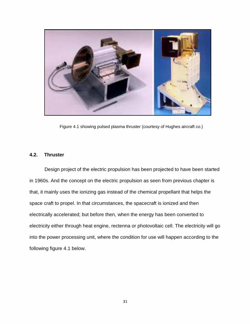
Figure 4.1 showing pulsed plasma thruster (courtesy of Hughes aircraft co.)
4.2. Thruster
Design project of the electric propulsion has been projected to have been started
in 1960s. And the concept on the electric propulsion as seen from previous chapter is
that, it mainly uses the ionizing gas instead of the chemical propellant that helps the
space craft to propel. In that circumstances, the spacecraft is ionized and then
electrically accelerated; but before then, when the energy has been converted to
electricity either through heat engine, rectenna or photovoltaic cell. The electricity will go
into the power processing unit, where the condition for use will happen according to the
following figure 4.1 below.

32
Figure 4.2. (Courtesy of NASA)
The engineering part of the electric propulsion is now used in wide range
whereby, air breathing electric propulsion has been pointed to be the best in mission.
For example a deep space mission and the geosynchronous satellite like METEOSAT.
The main reason for this is the lifelong survival of the propulsion on the space while
having the source of the electricity and also, the high specific impulse that is associated
with it. Rapid growth of technology in design of electric propulsion and its application will
be the main focus. And on this particular place, the concentration will be in two
thrusters, the Helicon Hall which is a two stage thruster and the Plasma Thruster which
is basically using the scaling on the helicon plasma, (Lias, 2005)
(a) Helicon Hall Thruster.
It was on 1970s that hall thrusters were first employed in space but it took more
than 20 years for more major development to occur on it. Primarily, the research has
shown that, major activity that is done in the hall thruster is increasing the lifetime of it
(Batishchev, 2009), because of avoiding using the xenon. Therefore, the current
research shows that current thruster which are versatile in technology and robust its
performance is extendable and there further more increase on the thrust density and
power.
33
The limitation that we know with hall thrusters is of the erosion material which
limits its lifetime. But many research done with the xenon gas has shown that, the hall
thruster can be operated in a way, that, the erosion part is being reduced (Yano, 2006),
hence, increasing its lifetime. The same principles used with hall thruster on the xenon
gas, can be still be applied on other gasses like oxygen or nitrogen making the hall
thruster viable propulsion for spacecraft that’s uses air breathing mechanism.
As mentioned above, the design part of the hall thruster was designed when
using the xenon it has to have high thrust to power in which is synonymous with the
operation of low voltage. For example, when the spacecraft is in lower altitude the
voltage on acceleration will have compensation for drag. Therefore, this makes the
parameter of the electric propulsion Hall thruster design to function and operate well
than the other (Sutton, 2010).
(i) Operational Principles
Characteristics performance of the Hall thruster, which operates with gas has been
well researched due to the stage of ionization that determine the increase of thrust and
power. In addition of being designed a two stage in the utilization of mechanism of
acceleration and ionization sources from helicon plasma (Cohen, 2003). Helicon
thruster has the wave modes that excite the annular helicon from the plasma upstream.
These has come up with more advantages in the controlling of thrust build up ad
controlling the engine start up compared to the other propellant. For instance, research
done on rocket engine showed most engine during stopping especially and starting, the
mixture ratio considerably varied. The variation came from not having same propellant

34
flow of hydraulic resistance which ends up causing instability. The figure 4.3 below
summarizes operating principle of ion thruster.
Figure 4.3 showing operating principles of ion thruster (courtesy of NASA)

35
(ii) Hall Thruster Assembly
The Hall thruster was assembled and designed in the partner of the Aero jet and
Electro-Dynamic Application whereby, it was purposely meant on using the hollow
cathode from external and the electrodes as shown in figure 4.3 show its operating
principle and figure 4.4 after assembly.
Figure 4.3 Operating principle of Hall Thruster (courtesy of Space Exploration)
This operating principle of the hall thruster is a Russian technology. The thruster
can be compared with the one of the ion grid but the only difference is that is much
small physically than the thruster from ion grid.

36
Figure 4.4 showing Hall thruster assembly (courtesy of Space Exploration)
(b) Plasma Thruster
Many researcher have done a lot of work which involves using ionization stages
that include helicon although, the focus of the experiment rely much on the argon so as
so it can accelerate other gasses (Batishchev, 2009) and simply physic analysis on
different acceleration of the research of plasma thruster in the electric propulsion. Most
of the result that came out, show the velocity of exhaust, from the helicon plasma is up
to the standard range that is being desired for the propulsion system that is air-
breathing (Slough, 2009).
Therefore, the preliminary investigation to show if the use helicon on a plasma
thruster will be better idea was conducted in the plasma-dynamic and electric propulsion
library whereby, measurement were taken which were created with argon because most
37
of the experiment done on helicon operates with Argon, which is commonly known by its
appearance of blue core.
4.3 Analysis of electric propulsion cost
Glenn Research center in NASA analyzed the EP cost from the design to the end
of mission in a study done on the exploration and aerial vehicle reconnaissance. They
noted that if the use of the powered core on the engine which was able to extract
hydrogen and helium three and four from the atmosphere will be so advantageous and
will be able to cut the cost of fuel.
The EP weight and size has contributed for the cost of fuel to be low. In addition,
the design of the EP has been able to cut the volume and mass dramatically. And this
has been concurred with NASA who have already put four spacecraft on space and said
the cost has been cut for about 65%.
4.4 Survey Analysis.
They compared with other data and experiment that was done in more than 30
years on the turbulent combustion because is a center that determines operability of the
engine and also, it remains the major process where the energy is being converted in
mostly propulsion engines such like of rockets, engines of the jet and in scramjets.
They took a keenly interest at these engines, because the combustion of oxidizer
and fuel are done there on a high turbulent condition whereby, mechanical energy is

38
converted from chemical energy for propulsion. They still found it’s of more
advantageous approach using the EP from the design, operational and mission wise.
In a different part, the Propulsion Research Laboratory in the State of Utah tested
EP compared with the acrylonitrile butadiene styrene as being new fuel for the hybrid
rocket. The analysis cost was compared from the design of the prototype, building and
testing.
The key note while analyzing the EP will be on the mass and the power in which
power is equal to force multiply by velocity. But in this case of moving aircraft the power
will be termed as power available, 𝑝𝐴 in which it can be represented as for equation
4.19 below.
𝑝𝐴 = 𝑇𝑣∞ (4.19)
T is thrust while 𝑣∞ is velocity.
Simply, the power supply and the energy source input must be in high voltage
than the power output. Hence, for every engine design configuration module the specific
power has to be defined. And when talking of specific power, it mean independent total
mass which will be expelled in the proportion of the power of engine.

39
4.5 Summary
The ion thruster generally can be divided in five part. The ion thruster, power
processing unit, control computer, power source and propellant management system.
This ion thruster has become the most researchable propulsion with the current
engineers as described by Barrett in interviewed on NASA television. Barrett works in
NASA Glenn Research Center. He describes how there is no any other top speed
rocket in the current generation that can move faster and for long distance rather than
the one of ion thruster (Brown, 2009).
Even though it produces low thrust density it is efficiency and cheaper, and also
EP have a characteristic of having trajectories that are spiral because of low thrust and
long thrusting time (Sutton, 2010) as the figure 4.5 shown below, taken from Rocket
Propulsion Elements 8th Edition page 629.
Figure 4.5 Trajectory diagram

40
Lastly, thrusters play a major role in EP. And be in of non-thermal electrical or
electro-thermal the most important aspect is the optimum performance of the flight. And
due to budget constrained not much study has been contacted on its efficiency, specific
power and other most things which is still underway.

41
Chapter 5
Conclusions
In this paper, the EP technology was the major focused and given the priority,
these is because the advantages such as it is much safer, easier to control, easy to
maintain, it can be reused, its environmental friendly, easy to operate, it can last longer,
good geometric constraints and communication attenuation among others.
Therefore as explored, the electric propulsion system on the air-breathing
spacecraft. It’s clearly known how in a wide range on theoretically perspective how it’s
possible for the electric propulsion system to be able to operate (Sutton, 2010). Plasma
and Helicon thruster emerged whereby, the reported measurement concurred with the
requirement of the needed specific impulse for the air breathing spacecraft to
accomplish the mission for long period of time. Figure 5.1.and 5.2 and table 5.1 shows
difference comparison between the ion thruster and liquid.
Electric propulsion technology has three major categories; (a) Electrostatic that
included the microwave, bombardment of ion, colloid ion and many more. (b)
Electromagnetic contained inductive plasma, helicon plasma and other variable specific
impulse plasma just to name a few. (d) Electro-thermal category contains resist-jet and
arc-jet.
In recent years we have seen application of the EP for instance in 1998 the
NSTAR ion engine for deep-space1. In 2003 the Hayabusa spacecraft using ion
propulsion and later on the same year Smart1 having the hall thruster which used the
xenon, and by 2007, the launch of Dawn which was purely using ion propulsion.

42
The principle of electric propulsion general performance can be divided into four
important categories; (a) the thrust which is beam currents which will be proportion to
thrust and acceleration voltage that agrees with the following equation 5.1 and equation
5.2 is the thrust efficiency of the electrical propulsion.
𝑇 =𝑑
𝑑𝑡[𝑚𝑝𝑉𝑒𝑥] =
𝑑𝑚𝑝
𝑑𝑡𝑣𝑒𝑥 = �̇�𝑝𝑣𝑒𝑥
(5.1)
𝑛𝑒 =𝑃𝑏
𝑃𝑇=
𝐼𝑏𝑣𝑏
𝐼𝑏𝑣𝑏+𝑝0 (5.2)
(b) Rocket equation make sense a lot in EP on the utilization of the efficiency of mass
thruster as the equation 5.3 suggest.
𝛥𝑣[𝐼𝑠𝑝𝑔∗ ]𝑙𝑛 [
𝑀𝑑+𝑀𝑝
𝑚𝑑] (5.3)
(c) Force transfer is just simply the one for instance ion to the thruster. And in this case
the electric field will be equal to the net forces on the grid as equation 5.4 explains;

43
𝑑𝐸(𝑥)
𝑑𝑥=
𝑃(𝑥)
𝜀0=
𝑞𝑛𝑖(𝑥)
𝜀0 (5.4)
(d) Specific impulse. There are two important equation in the specific impulse in EP that
need to be put in mind for the thrust mass utilization. Equation 5.5 and 5.6
𝐼𝑠𝑝 =𝑣𝑖
𝑔
�̇�𝑖
�̇�𝑝 (5.5)
𝑛𝑀 =𝑚𝑖
�̇�𝑝=
𝐼𝑏
𝑒
𝑚
�̇�𝑝 (5.6)

44
Figure 5.1 Ion thruster (courtesy of NASA)

45
Figure 5.2 Liquid thruster (courtesy of NASA)
I
Ion
Rocket Liquid Rocket
ue 30,000 m/s 4,500 m/s
Thrust 0.1 N 2,000,000 N
Energy 1,000 GJ 100 GJ
Power 1 kW 300 MW
Isp 3,000 s 450 s
Table 5.1 summarizes comparison between ion thruster
and liquid rocket

46
Recommendation
There are still more research needed to be done in the pursuing of the electric
propulsion; for example the use of fuel cell in spacecraft which is powered by electric
propulsion. There is no measurement of thrust that is published which agrees with each
other, because, of the high energy density on the space craft. Therefore, the physics
student and other interested parties which are responsible on the production of thrust
have to come up with a more guideline on the acceptable way to go with the process
(Sutton, 2010).
Due to some budget constrain and many politics about space exploration. The
need of using available resources at hand is more essential. For instance the idea of
fusion powered electric propulsion. This has been given deaf ear for long and need to
be put in practice and research need to be done on them as more advantages are
known than disadvantage. Therefore, in short electric propulsion need to be
experimented and worked on for the best future space exploration.
Lastly, but not least, more practically on using the thruster for experiment should
be established for knowledge gain. Let them not be in big facility only such as NASA
and big name of schools, accessing it should not be limited and hard to access but open
to space ambition student and easily to access.

47
Summary
EP technology is advancing rapidly, being an active field with different
development stages for instance, from 1906 with Robert Goddard then Konstantin E.
Tsiolkovkiy from the year 1911, then came in 1929 Herman Oberth with his
advancement. After period of time, in 1964 Earnst Stuhlinger came and geared the ion
EP for space flight and up to now the EP is still being tested for different spacecraft
application.
Electric propulsion spacecraft that have already been used have already solved
some problem such the cost of launching, therefore, cutting the cost because of light
mass. They are much safer and environmental friendly especially the one of nuclear.
Using EP on thrust mission will save time compared to the solid or liquid propellant just
to name a few. Therefore, using EP technology is much more dependable and
efficiency. The graph below 5.2 is just an example of comparison of time between
chemical and other electric propulsion to mars.
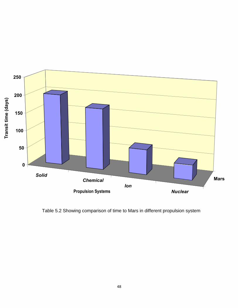
48
Table 5.2 Showing comparison of time to Mars in different propulsion system
Solid Chemical
Ion
Nuclear
Mars
0
50
100
150
200
250
Tra
ns
it t
ime
(d
ays
)
Propulsion Systems

49
BIBLIOGRAPHY
Anderson D John Jr. Fundamental of Aerodynamics; 5th Ed.
Anderson D John, Jr. Aircraft Performance and Design. TATA McGraw-Hill Edition, 2010.
Batishchev, O., “Minihelicon Plasma Thruster,” IEEE Transactions on Plasma Science, Vol. 37, No. 8, August 2009, pp. 1563-1571, doi: 10.1109/TPS.2009.2023990.75
Brown, D. L., Larson, C. W., Beal, B. E., and Gilmore, A. D., “Methodology and Historical Perspective of a Hall Thruster Efficient Analysis, “ Journal of Propulsion and Power, Vol. 25, No. 6, Nov.-Dec. 2009, pp. 1163-1177, doi: 10.2514/1.38092 133, 134, 138
Clement Gilles. Fundamental of Space Medicine.
Cohen, S. A., Siefert, N. S., Boivin, R.F., Scime, E.E., and Leviton, F. M., “Ion acceleration in plasma emerging from a helicon-heated magnetic-mirror device,” Physics of Plasma, Vol. 10, No. 6, 2003, pp. 2593-2598, doi: 10.1063/1.1568342.74
Diedericks-Verschoor, Pro. Dr. I. H and Kopal V Pro. Dr. Kluwer Law International. An Introduction to Space Law; 3rd Ed 2000.
Fujita, K., “Air Intake Performance of Air Breathing Ion Engines,” Journal of the Japan Society for Aeronautics and Space Sciences, Vol. 52, No. 610, 2004, pp. 514-521.12
Hill G Philip and Peterson R Carl. Mechanic and Thermodynamics of Propulsion. 3rd Ed, 1970.
John Lucas. Life in Space. Astrobiology for Everyone. Harvard University Press 2009.
Lias, S. G., “Ionization Energy Evaluation,” NIST Chemistry WebBook, NIST Standard Reference Database Number 69, Eds. P. J. Linstrom and W.G. Mallard, National Institute of Standers Technology, Gaithersburg, MD, 20898
Longmier, B. W., Cassady, L.D., Ballenger, M.G., Carter, M. D., Chang-Daz, F.R., Glover, T. W., Ilin, A. V., McCaskill, G.E., Olsen, C.S., and Squire, J.P., “VX-200 Magnetoplasma Thruster Performance Result,” Journal of Propulsion and Power, Vol. 27, No. 4, Jul.-Aug. 2011, pp.915-923, doi: 10.2514/1.54932. 45, 74, 120, 125, 129.
Slough, J., Kirtley, D., and Weber, T, “Pulsed Plasmoid Propulsion: The ELF Thruster,” 31st International Electric Propulsion Conference, IEPC-2009-265, Ann Arbor, MI, September 2009.74
Sutton P George and Biblarz Oscar. Rocket Propulsion Element 8th Ed. 2010.pg 622-667

50
Vasilevskaya, and Danilenko, G.M., ‘Custom as a Source of International Law of Outer Space, Journal of Space Law, Vol. 13, 1985, pp. 22-35
Verpaetse, J. G., International Law in Vertical Space, 1960
Yano, M. and Walker, M. L. R., “Plasma Ionization by annularly bounded helicon waves,” Physics Plasma, Vol. 13, No. 6, June 2006, pp. 063501-1-5, doi:10.1063/1.2207125.73


