Embed Size (px)
Citation preview

Journal of Industrial and Engineering Chemistry 36 (2016) 229–237
Effect of temperature on foam flow in porous media
L. Kapetas a, S. Vincent Bonnieu b,*, S. Danelis a, W.R. Rossen a, R. Farajzadeh a,b,A.A. Eftekhari a, S.R. Mohd Shafian c, R.Z. Kamarul Bahrim c
a Department of Geoscience and Engineering, Delft University of Technology, Delft, Netherlandsb Shell Global Solutions International BV, Rijswijk, Netherlandsc PETRONAS Research Sdn Bhd, Bandar Baru Bangi, Malaysia
A R T I C L E I N F O
Article history:
Received 4 December 2015
Received in revised form 3 February 2016
Accepted 5 February 2016
Available online 11 February 2016
Keywords:
Foam
EOR
Temperature effect
Viscosity
Modelling
A B S T R A C T
Foam can increase sweep efficiency within a porous medium, which is useful for oil-recovery processes
[1]. The flow of foam in porous media is a complex process that depends on properties like permeability,
porosity and surface chemistry, but also temperature. Although the surface activity of surfactants as a
function of temperature is well described at the liquid/liquid or liquid/gas interface, data on the effect of
temperature on foam stability is limited, especially in porous media.
In this work, we tested a surfactant (AOS) at different temperatures, from 20 8C to 80 8C, in a
sandstone porous medium with co-injection of foam. The pressure gradient, or equivalently the apparent
viscosity, was measured in steady-state experiments. The core-flood experiments showed that the
apparent viscosity of the foam decreased by 50% when the temperature increased to 80 8C. This effect
correlates with the lower surface tension at higher temperatures. These results are compared to bulk
foam experiments, which show that at elevated temperatures foam decays and coalesces faster. This
effect, however, can be attributed to the faster drainage at high temperature, as a response to the
reduction in liquid viscosity, and greater film permeability leading to faster coarsening.
Our results using the STARS foam model show that one cannot fit foam-model parameters to data at
one temperature and apply the model at other temperatures, even if one accounts for the change in fluid
properties (surface tension and liquid viscosity) with temperature. Experiments show an increase in gas
mobility in the low-quality foam regime with increasing temperature that is inversely proportional to
the decrease in gas-water surface tension. In the high-quality regime, results suggest that the water
saturation at which foam collapses fmdry increases and Pc* decreases with increasing temperature.
� 2016 The Korean Society of Industrial and Engineering Chemistry. Published by Elsevier B.V. All rights
reserved.
Contents lists available at ScienceDirect
Journal of Industrial and Engineering Chemistry
jou r n al h o mep ag e: w ww .e lsev ier . co m / loc ate / j iec
Introduction
Foam is a dispersion of gas bubbles in a continuous liquidmedium where bubbles are separated by thin films called lamellae.Foam for Enhanced Oil Recovery (EOR) aims at controlling gasmobility and dealing with phenomena such as gas gravity override,viscous fingering and preferential channeling due to reservoirheterogeneity [2–4]. Despite the fact that active research on foamfor EOR has been on the rise, relatively few field or pilotapplications have been developed. In the field, foam can beinjected by co-injection of gas and surfactant or by surfactant-alternating-gas (SAG) injection. SAG injection with large slugs ofliquid and gas injected at the maximum allowable pressure is the
* Corresponding author. Tel.: +31 704478743.
E-mail address: [email protected] (S. Vincent Bonnieu).
http://dx.doi.org/10.1016/j.jiec.2016.02.001
1226-086X/� 2016 The Korean Society of Industrial and Engineering Chemistry. Publis
preferred approach for field injection to minimize gravity overrideand time of injection [5].
Bulk foam experiments present foam which is not in contactwith the rock, and generally in a tube. Although there is noconsensus on the link between bulk and core-floods tests, bulkfoam experiments can serve to evaluate foam stability with respectto oil and surfactant type and concentration [6,7], gas composition[8] or temperature. Maini et al. [9] showed that the half-life forfoam volume decay in a tube declined dramatically with increasingtemperature; sulfonates were found to be clearly superior, and inparticular the relative performance of long-chain alpha olefinsulfonates improved with increasing temperature. In their study,Sharma et al. [10] found that the surface tension and bubble sizedecreased as the temperature increased. With increasing temper-ature, initial foam volume increased whereas foam half-life(or foam stability) decreased; the difference was more pronouncedin the range 20 to 40 8C than between 40 and 80 8C. The foam film
hed by Elsevier B.V. All rights reserved.
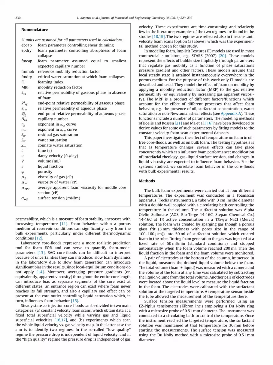
Nomenclature
SI units are assumed for all parameters used in calculations.
epcap foam parameter controlling shear thinning
epdry foam parameter controlling abruptness of foam
collapse
fmcap foam parameter assumed equal to smallest
expected capillary number
fmmob reference mobility reduction factor
fmdty critical water saturation at which foam collapses
FI foaming index
MRF mobility reduction factor
krg relative permeability of gaseous phase in absence
of foam
korg end-point relative permeability of gaseous phase
krw relative permeability of aqueous phase
k0rg end-point relative permeability of aqueous phase
Nca capillary number
ng exponent in krg curve
nw exponent in krw curve
Sgr residual gas saturation
Sw water saturation
Swc connate water saturation
t time (s)
u darcy velocity (ft./day)
V volume (mL)
e liquid fraction
w porosity
mg viscosity of gas (cP)
mw viscosity of water (cP)
mapp average apparent foam viscosity for middle core
section (cP)
swg surface tension (mN/m)
L. Kapetas et al. / Journal of Industrial and Engineering Chemistry 36 (2016) 229–237230
permeability, which is a measure of foam stability, increases withincreasing temperature [11]. Foam behavior within a porousmedium at reservoir conditions can significantly vary from thebulk experiments, particularly under different thermodynamicconditions [12].
Laboratory core-floods represent a more realistic predictiontool for foam EOR and can serve to quantify foam-modelparameters [13]. SAG core-floods can be difficult to interpretbecause of uncertainties they can introduce: slow foam dynamicsin the laboratory due to slow foam generation can introducesignificant bias in the results, since local-equilibrium conditions donot apply [14]. Moreover, averaging pressure gradients (or,equivalently, apparent viscosity) throughout the entire core lengthcan introduce bias as separate segments of the core exist atdifferent states; an entrance region can exist where foam neverreaches its full strength, and also a capillary end effect can bepresent at the core outlet controlling liquid saturation which, inturn, influences foam behavior [15].
Steady state co-injection core-floods can be divided in two maincategories: (a) constant velocity foam scans, which obtain data at afixed total superficial velocity while varying gas and liquidsuperficial velocities [16,17], and (b) experiments which scanthe whole liquid velocity vs. gas velocity map. In the latter case theaim is to identify two regimes. In the so-called ‘‘low quality’’regime the pressure drop is independent of liquid velocity, and inthe ‘‘high quality’’ regime the pressure drop is independent of gas
velocity. These experiments are time-consuming and relativelyfew in the literature; examples of the two regimes are found in thestudies [18,19]. The two regimes are reflected also in the constant-velocity foam scans (option (a) above), which was the experimen-tal method chosen for this study.
In modeling foam, Implicit Texture (IT) models are used in mostcommercial simulators, e.g. STARS (2007) [20]. These modelsrepresent the effects of bubble size implicitly through parametersthat regulate gas mobility as a function of phase saturationspressure gradient and other factors. These models assume thatlocal steady state is attained instantaneously everywhere in theporous medium. For the purpose of this work only IT models aredescribed and used. They model the effect of foam on mobility byapplying a mobility reduction factor (MRF) to the gas relativepermeability (or equivalently by increasing gas apparent viscosi-ty). The MRF is a product of different factors/functions whichaccount for the effect of different processes that affect foambehavior, e.g. the presence of oil, surfactant concentration, watersaturation or non-Newtonian shear effects (see Appendix A). Thesefunctions include a number of parameters. The modeling methodsof Boeije and Rossen [21] and Ma et al. [16] have been developed toderive values for some of such parameters by fitting models to theconstant velocity foam scan experimental datasets.
This paper investigates the effect of temperature on foam in oil-free core-floods, as well as on bulk foam. The testing hypothesis isthat as temperature changes, several effects can take placeconcurrently which can influence foam performance: modificationof interfacial rheology, gas–liquid surface tension, and changes inliquid viscosity are expected to influence foam behavior. For thesystems studied, we correlate foam behavior in the core-floodswith bulk experimental results.
Methods
The bulk foam experiments were carried out at four differenttemperatures. The experiment was conducted in a Foamscanapparatus (Teclis instruments), a tube with 3 cm inside diameterwith a double wall coupled with a circulating bath controlling thetemperature in the column. The surfactant solution was AlphaOlefin Sulfonate (AOS, Bio-Terge 14-16C, Stepan Chemical Co.)14-16C at 1% active concentration in a 1%w/w NaCl (Merck)solution. The foam was created by sparging gas though a porousglass frit (3 mm thickness with pores size in the range of100–160 mm)) into 50 ml of surfactant solution which createdfoam in the tube. During foam generation the gas was injected at afixed rate of 50 ml/min (standard conditions) and stoppedautomatically when the foam volume reached 200 ml. Then theliquid fraction in the foam and the foam volume were monitored.
A pair of electrodes at the bottom of the column, immersed inthe liquid, measures the drained liquid volume below the foam.The total volume (foam + liquid) was measured with a camera andthe volume of the foam at any time was calculated by subtractingthe liquid volume from the total volume. Another pair of electrodeswere located above the liquid level to measure the liquid fractionin the foam. The electrodes were calibrated with the surfactantsolution at the targeted temperature. A temperature sensor insidethe tube allowed the measurement of the temperature there.
Surface tension measurements were performed using anEZ-Piplus tensiometer (Kibron Inc.) employing a Du Nouy ringwith a microsize probe of 0.51 mm diameter. The instrument wasconnected to a circulating bath to control the temperature. Oncethe instrument reached the targeted temperature, the surfactantsolution was maintained at that temperature for 30 min beforestarting the measurements. The surface tension was measuredusing the Du Nouy method with a microsize probe of 0.51 mmdiameter.

Fig. 1. Core-flooding experimental setup: elements include valves, injection points, core in oven, back-pressure regulator, and effluent collection and weighing.
Table 1Relative permeability (Corey) parameters.
Parameter Value
Swc 0.25
Sgr 0.20
nw 2.86
ng 0.70
krw0 0.39
krg0 0.59
L. Kapetas et al. / Journal of Industrial and Engineering Chemistry 36 (2016) 229–237 231
The core-flood experimental setup is schematically shownin Fig. 1. Core-flood experiments were carried out using aBentheimer sandstone core (Kocurek Industries Inc.) of perme-ability K = 1700 mD, and porosity w = 0.24. The core was 17 cmlong with a diameter of 3.8 cm. The procedure is as follows. Aconfining pressure is applied to the core for the duration of theexperiment. Pressure taps allow pressure-drop measurements inthe middle 6.5 cm section of the core. This eliminates entrance-region and capillary end effects. The PEEK core holder is placed inan oven (Memmert) which maintains the temperature constant atthe desired value (�0.1 8C). When temperature is changed betweenexperiments a minimum of approximately 1 h was allowed to let thecore-holder system attain the new temperature. The heat-transfercalculations are described in the report of Danelis [13]. A back-pressure regulator controlled the downstream pressure to a nearlyconstant value of 20 � 0.3 bar.
The protocol before initiating the foam experiments consistedof the following steps: (i) connection and leakage testing under20 bar with Helium, (ii) injection of several pore volumes (PV) ofCO2 to displace the air inside the core, (iii) displacement of CO2
with 6 PV brine at 20 bar back-pressure and (iv) flooding with 5 PVof AOS solution to ensure that adsorption of surfactant on thesandstone was satisfied. Permeability was measured during thelast two steps and the foam flooding was then initiated.
Foam quality was controlled by varying the relative rates ofinjection of N2 gas and AOS solution, at a constant total superficialvelocity. Steady state was considered to be established at a newfoam quality when the recorded pressure drop reached a constantvalue and did not fluctuate (variations less than = �0.2 bar in aperiod of 2 h). A mass balance at the effluent location was used toconfirm stable saturation once steady state was attained. Pressuredrop measurements allow the calculation of the apparent viscosity:this is the value of the pressure gradient normalized with respect tothe permeability and the total flux of surfactant solution and gas [16].Reported apparent viscosity values in this work are calculated basedon the pressure drop in the middle section of the core. Gas velocitywas calculated from its nominal value by applying two corrections: (i)with respect to the injection pressure set on the Mass Flow Controller,(ii) with respect to the compressibility factor due to deviation fromideal-gas behavior. The calculation was performed by applying theJacobsen–Stewart equation of state [22].
Once measurements were completed at a certain temperature,the temperature was raised to the next desired value. A controlexperiment was carried out with a surfactant solution aged at80 8C. No precipitation was observed and the aged solution wasused for a foam scan at 20 8C. Aging did not influence the results;hence the surfactant is deemed stable and non-degradable up to80 8C.
Relative permeability for N2 gas and (surfactant free) brinesolution was measured with the unsteady displacement method
[23] which allowed the estimation of the Corey parameters, watersaturation at residual gas conditions Sgr, and connate watersaturation, Swc. Values are reported in Table 1.
Mobility reduction factor (MRF) is the reduction in gas mobilitycaused by foam, relative to gas mobility at the same watersaturation in the absence of foam. Foam apparent viscosity isrelated to MRF by the following equation:
mappðSwÞ ¼ 1
krwðSwÞ=mw þ krgðSwÞ=MRF�mg
(1)
In the presence of surfactant and absence of oil the STARS foammodel [20] in turn relates MRF (its inverse called FM in STARS) totwo functions of water saturation and capillary number:
MRF ¼ 1 þ fmmob�F2�F5 (2)
where fmmob is the reference mobility factor, F2 is a function ofwater saturation and describes coalescence, and F5 is a shear-thinning function. Appendix A provides a more detailed descrip-tion of the model functions F2 and F5 and the parameters in thosefunctions. The capillary number, Nca, which represents the balanceof viscous forces against surface tension is defined in the followingequation:
Nca ¼mapp�u
swg(3)
where swg is the surface tension between the liquid and the gasand u is the total superficial velocity within the porous medium.The calculation of the capillary number at different temperaturesserves to normalize the value of the apparent viscosity with respectto surface tension and velocity.
Fitting of the experimental foam scan data was carried outusing a constrained non-linear least-squares minimization ap-proach in MATLAB, which simultaneously computes all 5 foamparameters. For this, an initial guess and an allowed range isrequired for each parameter. Equal weights were assigned to allexperimental data during fitting.

L. Kapetas et al. / Journal of Industrial and Engineering Chemistry 36 (2016) 229–237232
Results
Effect of temperature on properties of the surfactant solution
The surface tension and viscosity of the surfactant solutionvaried remarkably with temperature. As expected [24], the surfacetension and viscosity decrease when temperature increases(Fig. 2). It is noted that the surface tension measurements werenot performed at the exact temperature that the core-flood wasconducted. Thus, when used later in this section, the surfacetension values are interpolated and extrapolated from the curvefitted to data in Fig. 2.
Effect of temperature on bulk foam
The foamability, drainage and stability of the foam were testedusing the same surfactant solution and procedure for eachtemperature.
Foamability
The foamability is the ability to create foam. The foam wascreated by injecting gas until it reached a volume Vmax (200 ml)corresponding to a time tmax. The foamability is represented by theFoaming Index (FI), where FI is the ratio of foam volume to injectedgas volume. The injected gas arrived in the experimental tube atroom temperature and was warmed up when it came into contactwith the surfactant solution. The injected gas volume wascorrected with the ideal gas law, accounting for the temperaturedifference. With this correction, the FI was not influenced by thetemperature (Fig. 3a).
Fig. 3. (a) Foaming Index FI as a function of temperature; each point represents one experi
dashed line represents a power law of time, t�2, for comparison.
0
0.2
0.4
0.6
0.8
1
1.2
0 20 40 60 80 100
Visc
osity
[cP]
Temperature [°C]
Fig. 2. Effect of temperature on the viscosity (left) and the surface tension (right) of the su
Foam stability
The foam stability is represented by the foam volume (V)normalized by the maximum volume of the foam column (Vmax)(Fig. 4). The foam volume does not depend on temperature at thebeginning of the experiments, for times smaller than 200 s. After200 s, the foam volume decreases strongly for higher tempera-tures. The two curves at 53 8C are similar at the beginning of theexperiment but differ after some time. In one of the twoexperiments, foam collapses abruptly before the other one. Thecollapse is due to a cascade of bubbles bursting. In general, thefoam volume drops slowly with time at the beginning anddramatically drops at a certain time. The time of the sudden dropfluctuate from one experiment to the other. Despite that foamcollapse is not a smooth process, our experiments shows that foamcollapse increases with increasing temperature (schematicallyshown by the arrow in Fig. 4). Previous works have shown that thefoam stability is influenced by the coupling of coarsening anddrainage [25] and also by surface elasticity [26].
Drainage
The foam becomes dryer faster when drainage rate increases,thus destabilizing the foam more rapidly. The effect of the drainageis illustrated by the normalized foam liquid fraction in Fig. 3b. Itappears that drainage rate hardly depends on temperature at thebeginning of the experiments, for times below 200 s. After 200 s,the foam liquid fraction dries out faster with increasing tempera-ture, indicating that the drainage rate increases with temperature.The liquid fraction e is a power law function of time: e � t
b[27]. The
exponent b usually has a value around (�3) to (�1). tb
with an
ment. (b) Liquid fraction in foam as a function of time for different temperatures. The
y = -0.0 009 x2 - 0.0814 x + 30 .025R² = 0.9981
0
5
10
15
20
25
30
0 20 40 60 80 10 0
Surf
ace
tens
ion
[mN
/m]
Temper ature [°C]
rfactant solution. The size of the markers is larger than the measurement accuracy.

Fig. 5. Measured apparent viscosity against foam quality for constant-velocity foam
scans at different temperatures (data-points). Lines represent models fitted using
the least-squares minimization method (a) by adjusting all foam parameters, (b) by
keeping their values constant and equal to their optimized value for the experiment
at 20 8C, among all temperatures and (c) by treating only fmcap as an adjustable
parameter; all other foam parameters were kept constant and equal to their
optimized value for the experiment at 20 8C (see text for the model
parameterization approach).
Fig. 4. Normalized foam volume as a function of time for different temperatures.
Each series represents an experiment.
L. Kapetas et al. / Journal of Industrial and Engineering Chemistry 36 (2016) 229–237 233
exponent b = �2 is represented in Fig. 3b for comparison with theexperiments. Previous work showed that the drainage rateincreases with decreasing viscosity of the liquid [27]. In our work,Fig. 2a shows that the viscosity of the surfactant decreases withincreasing temperature. The increase of the drainage rate can beexplained by the decrease of viscosity of the surfactant solution.
Coarsening
Coarsening is due to the pressure differences between thebubbles which results in increasing the average bubbles size.Coarsening increases the drainage rate [27]. The coarsening can bequantified by the critical coarsening time tc = L0
2/[2Defff(e0)] whereDeff is the effective film permeability (in our case is 1.67 � 10�5), L0
is the bubble edge length (0.02 cm in our experiments) andf(e0) = (1 � 1.52e0
0.5)2 is the function of the liquid fraction e0
(typically 20%) which is discussed in detail in [28]. The criticalcoarsening time, tc, quantifies the importance of coarsening byrepresenting the time above which the coarsening effect issignificant. The calculated value of tc in our experiment is 118 s.This value of tc suggests that coarsening is limited during thefoaming time because tc is of the same order as the foaming time,about 200 s. Thus, the effect of the coarsening is expected to besignificant after 200 s. This is observed in Figs. 3b and Fig. 4, wherethe effect of temperature is significant after 200 s. Furthermore,coarsening is expected to be accelerated at higher temperaturesbecause the foam films’ permeability to gas, measured by the filmpermeability constant, increases with increasing temperature [11].In others words, temperature increases the films permeabilitywhich in turn increases the coarsening of the foam.
To summarize, the bulk foam tests show that the temperaturerise increases the drainage rate and destabilizes the foam.These effects can be explained as the effects of temperature onthe surfactant viscosity and foam coarsening. The temperatureeffect on the surface rheology has not been investigated.
Effect of temperature on foam in porous media
Fig. 5 shows results for a scan of foam apparent viscosity atconstant nominal superficial velocity at four different tempera-tures (fitted models are discussed later in this section). The foamstrength is represented with the apparent viscosity (in cP) in orderto compare the experiments. For example, pressure drops rangefrom 0.3 to 0.5 MPa for the coreflood of Bentheimer rock at 20 8C. Ingeneral the viscosity increase first with foam quality and thendecrease sharply. This is because, under steady-state conditions,
foam exhibits two flow regimes depending on gas fractional flow(i.e. foam quality) [19]. In the so-called low-quality regime (lowgas fraction), the pressure gradient increases as the gas saturationrises because the foam volume increases. As the quality increases,the capillary pressure increases [29]. Foam collapses at thetransition between regimes (at the maximum of apparent viscosityoccurs because the capillary pressure exceeds the critical capillarypressure Pc*. Transition happens at the critical water saturationSw* (the water saturation corresponding to Pc*). In the high qualityregime (high gas fraction), the capillary pressure exceeds Pc* whichdestabilize the foam, decreasing the apparent viscosity. For thelow-quality regime (portion of data to left of maximum), it is noted

Table 2Mean velocity values at the middle section of the core (for all the different foam
qualities, see Fig. 6), surface tension and liquid viscosity for each temperature used
as measured input parameters to the STARS foam model using the least-squares
minimization method.
Parm/T 20 8C 40 8C 60 8C 80 8C
u (ft./day) 3.92E + 00 4.16E + 00 4.29E + 00 4.58E + 00
mw (mPa�s) 1.08E + 00 7.30E � 01 5.80E � 01 5.70E � 01
s (mNt/m) 2.80E + 01 2.53E + 01 2.19E + 01 1.78E + 01
L. Kapetas et al. / Journal of Industrial and Engineering Chemistry 36 (2016) 229–237234
that as temperature increases from 20 to 80 8C the measuredapparent viscosity of the foam decreases. The size of the decrease,between the experiments carried out at 20 and 80 8C, is of the orderof 50%. It is possible that the lowering of the surface tension(Fig. 2b, Table 2) allows a less-restricted flow of the foam.
The transition foam quality (i.e., quality at the peak in apparentviscosity), fg
*, is approximately the same for all temperatures, i.e.0.93 � 0.03. The decreasing slope of the curves as foam qualityincreases toward fg
* reflects shear thinning behavior of foam in thelow-quality regime. Increasing pressure gradient allows gas to flowmore easily in pores already opened to flow [30] and in additionalpores opened to flow by the higher pressure gradient [31]. Thusapparent mobility is shear-thinning with respect to gas flow rate bothdue to increasing pore pathways available for flow as pressuregradient increases and the shear-thinning rheology along eachpathway [32]. Gas compressibility caused actual gas superficialvelocity to deviate from intended values, especially at the largestpressure drops (largest apparent viscosities), as shown in Fig. 6. Thelargest pressure drops along the core in our experiments as about1.3 MPa, though the pressure rise in the central section in whichpressure-differences were measured was less. The deviations wereless at higher temperatures. Mean velocity values for the middlesection of the core for each temperature are reported in Table 2, with amaximum difference of 17% between experiments at 20 and 80 8C.Viscosity values reported (Fig. 5) where computed based on thevelocity (accounting for gas compression) obtained at each individualfoam quality and temperature. For a shear-thinning foam, a velocity
Fig. 6. Liquid vs. gas velocity for the experimental data of Fig. 5 obtained at different
temperatures. Straight line represents a constant total flow rate of 4.64 ft./day.
Actual superficial velocities deviate somewhat from the nominal values.
decrease can lead to an increase in viscosity. Thus, since a shear-thinning behavior is observed in our experiments we expect that itpartially contributes to the reduction of apparent viscosity in thehigher-temperature experiments.
Increasing temperature induced a reduction in surface tension,which in turn affects the capillary number, Nca, of the displace-ment; Fig. 7a presents the experimental results of Fig. 5 in terms ofNca. Notably, the product of apparent viscosity and Nca collapsesonto a single curve, which suggests that apparent viscosity isproportional to surface tension in our experiments, once results arenormalized for velocity (as by definition done in the capillarynumber calculation). The effect of the surface tension on theapparent viscosity could be explained by the variation of filmelasticity which is related to surface tension as proposed inprevious works [7,33]. The apparent viscosity observed in thecoreflood could also be related to the force required to stretchthe foam film (called surface elasticity). The apparent viscosity inthe coreflood would increase as the elasticity increases. In ourexperiment, the elasticity was not measured but we couldspeculate the elasticity varies like surface tension [4]. Fig. 7bpresents this relationship between apparent viscosity andmeasured surface tension (at the experimental temperaturevalues) for a 60% foam quality: the monotonic relationship is clear.
Modelling
The foam-model equations, as presented in the Methods sectionand Appendix A, are used to provide an interpretation of the effectof temperature on foam mobility. More specifically, we aim toestablish the effect of temperature on foam-model parameters.Three different approaches were followed to fit the experimentaldata:
(1) All foam-model parameters were treated as adjustable. Theiroptimal values are shown in Table 3 and plotted in Fig. 8. Theresults obtained were robust: the initial guess and range valuesprovided did not influence the parameter values, suggesting aglobal optimum solution. The liquid viscosity and the surfacetension were adjusted to their experimentally measured values(Table 2). The former is used in the calculation of the waterrelative permeability and the latter is used in the calculation ofNca within function F5. Fig. 5a presents the model fits. Themodels provide a good fit to all datasets under this fittingapproach. The change of apparent viscosity in the high-qualityregime (to the right of the maximum) can be effectivelyrepresented by a single straight line through (fg = 1, mapp = 0)for all temperatures (cf. [21]). The trend of fitted parameterswith temperature is shown in Fig. 8. Parameter fmdry (thewater saturation around which foam collapses) decreasesslightly (from 0.277 to 0.267), but these values are close toirreducible water saturation (Table 1); therefore this decreaseis enough to make a difference of almost a factor of 4 in waterrelative permeability in the high-quality regime.
The modeling results of Fig. 5a are in close agreement withthe results obtained using the method of Boeije and Rossen [21](see Appendix B). Their method requires a large value of epdry.The least-squares minimization method used here is able to fitdata with smaller values of epdry, allowing a smoothertransition between the low- and high-quality regimes. Likethe method of Boeije and Rossen, the method can accommo-date shear-thinning behavior in the high-quality regime.
(2) To investigate the ability of the model to predict the effect ofsurface tension alone on the apparent viscosity, a second fittingexercise was conducted as follows. All foam model parameterswere kept constant between experiments at different tempera-tures, equal to the values obtained by fitting the model to the

Table 3Optimal values for all foam parameters as calculated by fitting the experimental
data with the least-squares minimization method. Model fits presented in Fig. 5a.
Parm/T 20 8C 40 8C 60 8C 80 8C
fmmob 1.14E + 05 2.01E + 05 1.04E + 05 1.70E + 05
epdry 2.36E + 03 2.42E + 04 9.78E + 04 7.43E + 03
fmdry 2.77E � 01 2.71E � 01 2.67E � 01 2.68E � 01
fmcap 2.53E � 04 1.65E � 04 2.12E � 04 2.05E � 04
epcap 1.33E + 00 1.51E + 00 1.34E + 00 2.04E + 00
Fig. 7. (a) Capillary number vs. foam quality at different temperatures; data are from Fig. 5. (b) Apparent viscosity at fixed foam quality, fg = 0.60, vs. surface tension as affected
by changes in temperature.
L. Kapetas et al. / Journal of Industrial and Engineering Chemistry 36 (2016) 229–237 235
20 8C data in Table 3. Surface tension and liquid viscosity wereadjusted for the effect of temperature using Fig. 2. Fig. 5b showsthat the models at 40, 60 and 80 8C do not provide good fits. Inthe low-quality regime, apparent viscosity is overestimated.Moreover, in the high-quality regime, the model deviates fromthe data; holding fmdry fixed does not account for the nearlyfourfold change in krw in this regime as temperature increases.One cannot fit these foam model parameters at one temperatureand apply them with confidence to other temperatures, even ifone accounts for the effect of temperature on surface tension andliquid viscosity.
Fig. 8. Changes in the five foam parameters with respect
(3) A third modeling approach investigates the effect of tempera-ture on specific parameters. In this case, for the model fitting ofthe experimental data at 40, 60, 80 8C, values for all theparameters were kept constant and equal to the optimizedparameters obtained at 20 8C (Table 3), except for fmcap (theonly fitted parameter). This is equivalent to adjusting fmmob,since only the product of these two parameters fmmob � F5
matters in Eq. (A1). The model fits are shown in Fig. 5c. Therationale for treating fmcap as an adjustable parameter is toidentify if a direct correlation between temperature and a foamparameter exists. In this case fmcap is predicted to decreasewith increasing temperature with values of 2.53 � 10�4,2.44 � 10�4, 2.15 � 10�4, and 1.82 � 10�4 for the 20, 40, 60,80 8C experiments, respectively. The model fits are as good as inFig. 5a in the low-quality regime. Because of the equivalence ofadjusting fmcap and fmmob in this model, in effect, theseresults suggest that fmmob is inversely proportional to gas-water surface tension. In the high-quality regime, they deviatefrom the data because they do not account for the decrease infmdry and water relative permeability.
In the STARS foam model, parameter fmdry is related to thecollapse of foam at the limiting capillary pressure Pc* [29,34]. In the
to temperature changes for Bentheimer sandstone.

Fig. B1. Comparison between the model fits of Boeije and Rossen [21] and least-
squares minimization to the experimental data of the foam scan conducted at 20 8C.
L. Kapetas et al. / Journal of Industrial and Engineering Chemistry 36 (2016) 229–237236
limit of large epdry, fmdry is the water saturation at Pc*. In ourmodel fits, fmdry decreases slightly with increasing temperature,but its value is close to irreducible water saturation. A constantvalue of fmdry, together with the decrease in surface tension(Fig. 2) would imply a reduction in Pc* by about a 25% from 20 8C to80 8C; in other words, foam is less stable at higher temperature.However, we don’t know how sensitive capillary pressure is towater saturation so close to irreducible water saturation, so thetrend of Pc* with temperature cannot be determined from thesedata with confidence. One can conclude that fmdry, the parameterneeded to represent foam flow directly, does decrease withincreasing temperature in these data; the poor fit to the high-quality regimes in Fig. 2b and c make this clear.
Conclusions and implications
This study presents a combination of bulk and core-floodexperimental methods to investigate the effect of temperature onthe foaming ability and mobility of foam for a specific surfactant.The bulk foam experiments show that foam decays faster anddrainage increases as temperature increases. This can be attributedto reduced liquid viscosity leading to faster drainage rates of thesurfactant solution and the increased film permeability leading toan increase of coarsening. The relation between drainage from bulkfoam, over a distance of cm, driven by gravity, to drainage fromfoam films in porous media, over a distance of 100’s mm, driven bycapillary pressure, is not simple, however.
The results in this work indicate that it is critical that laboratorycore-floods be at conditions which approximate the physicalconditions of the reservoir under study. Specifically, the behaviorof foam was shown to be influenced by temperature changes. Inour study the change in foam behavior with temperature could notbe predicted simply from changes in liquid viscosity and surfacetension, holding other foam parameters constant. Although largetemperature differences are not expected within a single reservoir,caution should be taken in extrapolating foam parameters totemperatures different from those studied in the laboratory.Understanding the effect of temperature on foam and incorporat-ing this effect mechanistically in reservoir simulations will requirefurther experimental research.
Acknowledgements
We gratefully acknowledge Shell Global Solutions Internationaland PETRONAS for granting the permission to publish this work.We also thank Sian Jones and Reza Bagheri for their careful readingof the draft of the manuscript and the technical support of MichielSlob at the Laboratory Geoscience & Engineering of TU Delft.
Appendix A
The Local Equilibrium STARS model used in this study is described
by [20,21,34]. The STARS model introduces the MRF function (inverse
of mobility factor FM in STARS) which describes the reduction in gas
mobility by foam (Eq. (1)). The full version of the MRF function is
given by
MRF ¼ 1 þ fmmob F1F2F3F4F5F6 (A1)
The parameter fmmob is the reference gas mobility-reduction
factor for wet foams. This parameter corresponds to the maximum
attainable mobility reduction. The functions F1–F6 are constrained to
values less than or equal to 1, so that each function can only reduce
the gas mobility-reduction factor, i.e. increase gas mobility. The
functions model the effect of surfactant concentration (F1), effect of
water saturation on foam properties (F2), oil saturation (F3), gas
velocity (F4), capillary number (F5) and the critical capillary number
(F6). In the present work F2 and F5 are considered and defined with
Eqs. (A2) and (A3), respectively:
F2 ¼ 0:5 þ arctan epdry Sw�fmdryð Þð Þp
(A2)
F5ðÞepcap (A3)
Thus the foam model we use contains five parameters, namely
fmmob, epdry, fmdry, fmcap and epcap.
� epdry controls the abruptness of the foam collapse as a functionof water saturation. Small values give a gradual transitionbetween the two regimes, while larger values yield a sharper,albeit still continuous, transition.� If the transition between regimes is abrupt, the parameter fmdry
is equal to S�w, the water saturation at the limiting capillarypressure Pc*, i.e. the water saturation at which foam collapses[35].� fmcap represents the lowest capillary number expected in the
simulation and below this value shear thinning behavior is notexpected. Thus fmcap is not considered a foam parameter per se.Parameter epcap controls the significance of shear thinning; thelarger it is, the stronger the shearing thinning behavior becomes.
Appendix B
A comparison between the model fitting results of the least-
squares minimization method and the method of Boeije and Rossen
[21] is provided in more detail in this section. The latter method
assumes an abrupt collapse at the critical capillary pressure
condition. We model the experimental data with both methods
and proceed to a comparison of the parameter values. Fig. B1 shows
that the two model fits are in good agreement with each other and
with the experimental data set. The same conclusion is reached for
the experimental data at the higher temperatures (results not
shown). As fmcap is not a foam parameter per se, its value is fixed
between the two methods (equal to its adjusted value from the least-
squares minimization method, see Table B1). The value of fmdry is
predicted to be the same by the two methods. The values of fmmob
and epcap are in close agreement, which is also suggested by the
model fits; the former mostly controls the magnitude of the model
apparent viscosity in the low-quality regime and the latter the shear

Table B1Comparison between optimized foam parameters obtained with the methods of
Boeije and Rossen [21] and least-squares minimization, fitted to the data of Fig. B1.
Parm Boeije and Rossen Least-squares
fmmob 1.03E + 05 1.14E + 05
epdry high 2.36E + 03
fmdry 2.77E � 01 2.77E � 01
fmcap 2.53E � 04 2.53E � 04
epcap 1.21E + 00 1.33E + 00
L. Kapetas et al. / Journal of Industrial and Engineering Chemistry 36 (2016) 229–237 237
thinning behavior. epdry is not calculated with the model of Boeije
and Rossen [21]; rather it is assumed to be large enough to lead to an
abrupt foam collapse during regime transition as mentioned above.
Its value optimized using the least-squares minimization method
suggests the transition is relatively abrupt.
References
[1] R. Farajzadeh, A. Andrianov, R. Krastev, G.J. Hirasaki, W.R. Rossen, Adv. ColloidInterface Sci. 183–184 (2012) 1, http://dx.doi.org/10.1016/j.cis.2012.07.002.
[2] W.R. Rossen, Foams: Theory: Measurements: Applications, Marcel Dekker, Inc.,New York, NY,Basel, 1995.
[3] L. Laurier, Schramm, Fred Wassmuth, Foams: Fundamentals and Applications inthe Petroleum Industry, vol. 242, American Chemical Society, 1994p. 3.
[4] L.L. Schramm, Surfactants Fundamentals and Applications in the PetroleumIndustry, Cambridge University Press, Calgary, Canada, 2000.
[5] D. Shan, W.R. Rossen, SPE J. 9 (02) (2004) 132, 10.2118/88811-PA.[6] A.K. Vikingstad, A. Skauge, H. Høiland, M. Aarra, Colloids Surf., A: Physicochem. Eng.
Aspects 260 (1–3) (2005) 189, http://dx.doi.org/10.1016/j.colsurfa.2005.02.034.[7] S.A. Jones, G. Laskaris, S. Vincent Bonnieu, R. Farajzadeh, W.R. Rossen, Vol. SPE-
179637-MS, Society of Petroleum Engineers, Tulsa, USA, 2016.[8] R. Farajzadeh, S. Vincent-Bonnieu, N. Bourada Bourada, J. Soft Matter 2014 (2014)
e145352, 10.1155/2014/145352.[9] B.B. Maini, V. Ma, J. Can. Pet. Technol. 25 (06) (1986), http://dx.doi.org/10.2118/
86-06-05.[10] M.K. Sharma, D.O. Shah, W.E. Brigham, AIChE J. 31 (2) (1985) 222, http://
dx.doi.org/10.1002/aic.690310208.[11] R. Farajzadeh, R. Krastev, P.L.J. Zitha, Langmuir 25 (5) (2009) 2881, http://
dx.doi.org/10.1021/la803599z.
[12] M. Chabert, L. Nabzar, V. Beunat, E. Lacombe, A. Cuenca, SPE 169116-MS, SPEImproved Oil Recovery Symposium, 12-16 April, Tulsa, Oklahoma, USA, 2014.
[13] S. Danelis, L. Kapetas, S. Vincent-Bonnieu, W.R. Rossen, Temperature Effect onFoam Coreflood Experiments, TU Delft, Civil Engineering and Geosciences,Geotechnology, 2015.
[14] L. Kapetas, W.A. van El, W.R. Rossen, SPE 169059-MS, SPE Improved Oil RecoverySymposium, 12-16 April, Tulsa, Oklahoma, USA, 2014.
[15] O.G. Apaydin, A.R. Kovscek, Transp. Porous Media 43 (3) (2001) 511, http://dx.doi.org/10.1023/A:1010740811277.
[16] K. Ma, J.L. Lopez-Salinas, M.C. Puerto, C.A. Miller, S.L. Biswal, G.J. Hirasaki, EnergyFuels 27 (5) (2013) 2363, http://dx.doi.org/10.1021/ef302036.
[17] A. Moradi-Araghi, E.L. Johnston, D.R. Zornes, K.J. Harpole, SPE 37218-MS,International Symposium on Oilfield Chemistry, 18-21 February, Houston, Texas,1997.
[18] W.T. Osterloh, M.J. Jante Jr., et al. SPE 24179-MS, SPE/DOE Enhanced Oil RecoverySymposium, 22-24 April, Tulsa, Oklahoma, 1992.
[19] J.M. Alvarez, H.J. Rivas, W.R. Rossen, et al. SPE J. 6 (03) (2001) 325.[20] Computer Modelling Group Ltd., User’s Guide STARS, Computer Modelling Group
Ltd., Calgari, Canada, 2009.[21] C.S. Boeije, W. Rossen, SPE Reserv. Eval. Eng. 18 (02) (2015) 264, http://dx.doi.org/
10.2118/174544-PA.[22] R.T. Jacobsen, R.B. Stewart, J. Phys. Chem. Ref. Data 2 (4) (1973) 757, http://
dx.doi.org/10.1063/1.3253132.[23] E.F. Johnson, D.P. Bossler, V.O.N. Bossler, Calculation of Relative Permeability from
Displacement Experiments, SPE-1023-G, Society of Petroleum Engineers, 1959.[24] J.J. Bikerman, Surface Chemistry, second ed., Academic Press, 1958p. 1.[25] A. Saint-Jalmes, Soft Matter 2 (10) (2006) 836, http://dx.doi.org/10.1039/b606780h.[26] D. Georgieva, A. Cagna, D. Langevin, Soft Matter 5 (10) (2009) 2063, http://
dx.doi.org/10.1039/B822568K.[27] A. Saint-Jalmes, D. Langevin, J. Phys. Condens. Matter 14 (40) (2002) 9397.[28] S. Hilgenfeldt, S. Koehler, H. Stone, Phys. Rev. Lett. 86 (20) (2001) 4704, http://
dx.doi.org/10.1103/PhysRevLett.86.4704.[29] Z.I. Khatib, G.J. Hirasaki, A.H. Falls, et al. SPE Reservoir Eng. 3 (03) (1988) 919.[30] G.J. Hirasaki, J.B. Lawson, Soc. Pet. Eng. J. 25 (02) (1985) 176, http://dx.doi.org/
10.2118/12129-PA.[31] G.-Q. Tang, A.R. Kovscek, Transp. Porous Media 65 (2) (2006) 287, http://
dx.doi.org/10.1007/s11242-005-6093-4.[32] W.R. Rossen, M.W. Wang, SPE J. 4 (02) (1999) 92, http://dx.doi.org/10.2118/
56396-PA.[33] L.L. Schramm, W.H.F. Green, Colloids Surf., A: Physicochem. Eng. Aspests 94 (1)
(1995) 13, http://dx.doi.org/10.1016/0927-7757(94)02997-7.[34] L. Cheng, A.B. Reme, D. Shan, D.A. Coombe, W.R. Rossen, SPE 59287-MS, PE/DOE
Improved Oil Recovery Symposium, 3-5 April, Tulsa, Oklahoma, 2000.[35] Z. Zhou, W.R. Rossen, SPE Adv. Technol. Ser. 3 (01) (1995) 154, http://dx.doi.org/
10.2118/0-PA 2418.


