Embed Size (px)
Citation preview
JOURNAL OF MATERIALS SCIENCE 29 (1994) 3535-3541
Effect of strain rate on the fracture of ceramic fibre reinforced glass matrix composites
R. U. V A I D Y A , K. K. C H A W L A Department of Materials and Metallurgical Engineering, New Mexico Institute of Mining and Technology, Socorro, NM 87801, USA
The effect of strain rate on the fracture behaviour of two ceramic fibre reinforced glass matrix composites was studied. Increasing the strain rate was found to enhance catastrophic failure in both of these composites. This was attributed to the crack deflection and changes in the fibre pullout length as a function of strain rate. Enhanced strain rates were found to decrease the strength, static toughness and fracture energy of the composites. This effect was more pronounced in the case of the coated fibre composites as compared to the uncoated fibre composites. This is because of fibre/matrix isolation, obtained as a result of the coating.
1. I n t r o d u c t i o n Ceramic matrix composites are candidate materials for various structural, high temperature and other specialized applications. The most important reason for the increased interest in these materials is their improved mechanical properties, especially fracture toughness as compared to those of the unreinforced ceramic matrix materials [1-5]. Most of the studies carried out on ceramic matrix composites so far have focussed on the strength and toughness characteriza- tion of such materials. Almost all of the mechanical tests carried out, mostly in bending or compression, few in tension, have employed quasi static loading. However, conditions existing in potential applications warrant the need for characterizing the behaviour of such materials under varying conditions of loading, especially different strain rates.
The need for determining the strain rate sensitivity of ceramic matrix composites arises from the fact that most ceramic materials exhibit subcritical or slow fracture properties which differ significantly from their fast fracture properties. Although it is generally accep- ted that slow crack growth entails some type of envir- onmentally assisted stress corrosion, Maugis [6], whose study was based on an extension of the Griffith criterion, suggested that slow or subcritical crack growth in brittle materials is possible without the presence of stress corrosion. This aspect of failure acquires a new dimension in the case of ceramic matrix composites because of the presence of the rein- forcements. Effects such as fibre/matrix debonding and fibre pullout, primary toughening mechanisms in ceramic matrix composites, can be significantly affec- ted by the strain rate, and in turn can alter the failure characteristics of such composites.
The purpose of this work was to study the effect of strain rate on the fracture behaviour of two ceramic fibre reinforced glass matrix composites. Changes in the fracture behaviour of these composites with strain rate were correlated with the mechanical character-
istics. The failure modes in such composites at ex- tremely low strain rates have been reported in an earlier study [7].
2. Experimental procedure Two ceramic fibre reinforced composites were used: a PRD-166 fibre (A1203 with ZrO2 particles from DuPont) reinforced borosilicate glass matrix (N51A) and a Nextel 480 (mullite fibre from 3M Co.) rein- forced borosilicate glass matrix composite. Two fibre coatings, tin dioxide (on the PRD-166 fibre) and boron nitride (on the Nextel 480 fibre), were employed with a view to modify the interface characteristics in these systems. These coatings were applied on the fibre surfaces by a chemical vapour deposition process. Details of these coating processes can be found elsewhere [7]. A summary of the fibre/coating com- binations used is given in Table I. Details of the mechanical and physical properties, and chemical compositions of the fibres, matrix and coatings are provided in Tables II and III, respectively.
Composites were fabricated by a slurry impregna- tion technique [71. The volume fraction of the fibres was 30 -I- 3% in all of the composite samples. Rectan- gular bar shaped specimens (3.5 • 0.6 • 0.32 cm 3 ) were cut from the hot-pressed material. The surfaces of all the samples were polished with 0.5 ~tm alumina pow- der to minimize the effect of surface flaws. All of the
TABLE I Summary of the various fibre/coating/matrix combina- tions tested
Fibre Coating Matrix
PRD-166 (alumina + 15 w/o zirconia) PRD-166 Tin dioxide Nextel 480 (mullite) - Nextel 480 Boron nitride
N51A borosilicate glass N51A borosilicate glass N51A borosilicate glass N51A borosilicate glass
0022-2461 �9 1994 Chapman & Hall 3535
T A B L E II Properties of N51A glass, PRD-166 and Nextel 480 fibre
Glass PRD-166 Nextel 480
E (GPa) 72 380 221 VHN (GPa) 5.5 - Tensile strength (MPa) 72.6 1375 2043 KI, (MPa m l/z) 0.7-0.8 - - P(g cm- 3) - 3.9 2.77 ~(oc -1) 7 x 1 0 -6 9 x 1 0 -6 4.75x10 -6 Diameter (gin) - 20 Ellipical:
major 11.5 minor 8
Melting point (~ - 2050 1850 Annealing point (~ 570 - - Softening point (~ 785
T A B L E II I Nominal compositions (wt %)
N51A glass" SiO 2 72 B203 12 A1203 7 CaO 1 Na20 6 KzO 2 BaO < 0.1
PRD-166 fibre b A1203 80-85 Zr02 15-20
Nexte1480 c
A1203 70 SiO 2 28 B203 2
Obtained from: "Owens-Illinois Co.; b Du Pont Co.; c 3M Corp.
mechanical property measurements were carried out in three-point bending, at room temperature, in an Instron machine. Three different cross-head speeds of 0.005, 0.05 and 0.5 cmmin-1, which translate into strain rates (apparent) of 0.0008, 0.008 and 0.08 min-1, were used.
Bend strength was measured on unnotched samples in accordance with ASTM standard C-203/85. Frac- ture toughness and fracture energy measurements were made using single edge notched beam (SENB) specimens according to [8]. The notches in the sam- ples were cut using a high speed diamond saw. A span to depth ratio of 10 was used for all the samples. The critical stress intensity factor was calculated using the relationship
K I = Y c r a 1/2 (1)
where K, is the stress intensity factor in mode I, o is the maximum far field stress, a is the crack length (depth of the notch introduced) and Yis a geometrical factor. The expression for Y, according to [-8] is
Y = 1.96 - 2 .75(a /h ) + 13 .66(a /h) 2
- 23 .98 (a /h ) 3 + 25 .22 (a /h ) 4 (2)
where h is the specimen thickness.
3536
The critical stress intensity factor Kxc obtained via Equation 1, corresponds to the maximum load. This critical stress intensity factor has been called the "static fracture toughness", and is valid for compar- ative purposes only, i.e. for tests done on samples of identical dimensions and crack size etc. It should be emphasized that it is not a design parameter.
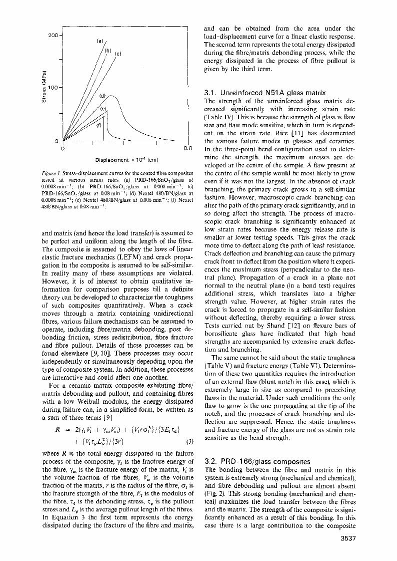
3. Results and discussion The bend strength of the unreinforced glass (N51A), PRD-166/glass, PRD-166/SnO2/glass, Nextel 480/glass and Nextel 480/BN/glass composites as a function of strain rate are given in Table IV. Static fracture tough- ness values are presented in Table V, while the total fracture energy values are presented in Table VI. These results clearly indicate the strong dependence of these properties on the strain rate. The stress-dis- placement curves for the various composites at differ- ent strain rates are presented in Fig. 1.
Characterization of the toughness of fibre rein- forced ceramic matrix composites is a relatively diffi- cult task because of the complexity of microscopic events which lead to macroscopic crack propagation under monotonically increasing loads. Various as- sumptions are incorporated in order to simplify the mathematics involved. The bonding between the fibre
T A B L E IV Variation in bend strength with strain rate
Composite Bending strength (MPa) Strain rate (cm min- 1 ) 0.5 0.05 0.005
N51A glass 48.3 56.1 72.6 PRD-166/glass 173.5 167.6 165.4 PRD- 166/SnO2/glass 148.7 158.5 181.9 Nextel 480/glass 123.4 130.5 138.2 Nextel 480/BN/glass 145.5 168 189.3
T A B L E V Variation in static toughness with strain rate
Composite Static fracture toughness (MPam 1/2)
Strain rate (cm min 1) 0.5 0.05 0.005
N51A glass 0.61 0.55 0.65 PRD-166/glass 1.05 1.13 1.07 PRD- 166/SnO2/glass 1.41 1.49 1.82 Nextel 480/glass 1.28 1.43 1.41 Nextel 480/BN/glass 1.47 1.62 2.52
T A B L E VI Variation in fracture energy with strain rate
Composite Fracture energy (J m -2) Strain rate (cm min- x ) 0.5 0.05 0.005
N51A glass 68 63 67 PRD-166/glass 121 101 123 PRD-166/SnOz/glass 122.7 466.1 569.3 Nextet 480/glass 148.5 168.7 152.4 Nextel 480/BN/glass 286 458.2 675
O.
100
200 - lal/ b) (c)
0 I I I o 0 .8
D i sp l acemen t x 10 .2 (cm)
Figure 1 Stress~tisplacement curves for the coated fibre composites tested at various strain rates. (a) PRD-166/SnO2/glass at 0.0008rain-i; (b) PRD-166/SnO2/glass at 0.008min-~; (c) PRD-166/SnO2/glass at 0.08 min-~; (d) Nextel 480/BN/glass at 0.0008 min-a; (e) Nextel 480/BN/glass at 0.008 min-1; (f) Nextel 480/BN/glass at 0.08 min- 1.
and matrix (and hence the load transfer) is assumed to be perfect and uniform along the length of the fibre. The composite is assumed to obey the laws of linear elastic fracture mechanics (LEFM) and crack propa- gation in the composite is assumed to be self-similar. In reality many of these assumptions are violated. However, it is of interest to obtain qualitative in- formation for comparison purposes till a definite theory can be developed to characterize the toughness of such composites quantitatively. When a crack moves through a matrix containing unidirectional fibres, various failure mechanisms can be assumed to operate, including fibre/matrix debonding, post de- bonding friction, stress redistribution, fibre fracture and fibre pullout. Details of these processes can be found elsewhere [9, 10]. These processes may occur independently or simultaneously depending upon the type of composite system. In addition, these processes are interactive and could affect one another.
For a ceramic matrix composite exhibiting fibre/ matrix debonding and pullout, and containing fibres with a low Weibull modulus, the energy dissipated during failure can, in a simplified form, be written as a sum of three terms [9]
R = 2(yfVf 4- "YmVrn) + {Vfro3}/{3Efrd} + (3)
where R is the total energy dissipated in the failure process of the composite, ~/f is the fracture energy of the fibre, 7m is the fracture energy of the matrix, Vf is the volume fraction of the fibres, Vm is the volume fraction of the matrix, r is the radius of the fibre, of is the fracture strength of the fibre, Ef is the modulus of the fibre, ~d is the debonding stress, ~p is the pullout stress and Lp is the average pullout length of the fibres. In Equation 3 the first term represents the energy dissipated during the fracture of the fibre and matrix,
and can be obtained from the area under the load-displacement curve for a linear elastic response. The second term represents the total energy dissipated during the fibre/matrix debonding process, while the energy dissipated in the process of fibre pullout is given by the third term.
3.1. Unreinforced N51A glass matrix The strength of the unreinforced glass matrix de- creased significantly with increasing strain rate (Table IV). This is because the strength of glass is flaw size and flaw mode sensitive, which in turn is depend- ent on the strain rate. Rice [11] has documented the various failure modes in glasses and ceramics. In the three-point bend configuration used to deter- mine the strength, the maximum stresses are de- veloped at the centre of the sample. A flaw present at the centre of the sample would be most likely to grow even if it was not the largest. In the absence of crack branching, the primary crack grows in a self-similar fashion. However, macroscopic crack branching can alter the path of the primary crack significantly, and in so doing affect the strength. The process of macro- scopic crack branching is significantly enhanced at low strain rates because the energy release rate is smaller at lower testing speeds. This gives the crack more time to deflect along the path of least resistance. Crack deflection and branching can cause the primary crack front to deflect from the position where it experi- ences the maximum stress (perpendicular to the neu- tral plane). Propagation of a crack in a plane not normal to the neutral plane (in a bend test) requires additional stress, which translates into a higher strength value. However, at higher strain rates the crack is forced to propagate in a self-similar fashion without deflecting, thereby requiring a lower stress. Tests carried out by Shand [-12] on flexure bars of borosilicate glass have indicated that high bend strengths are accompanied by extensive crack deflec- tion and branching.
The same cannot be said about the static toughness (Table V) and fracture energy (Table VI). Determina- tion of these two quantities requires the introduction of an external flaw (blunt notch in this case), which is extremely large in size as compared to preexisting flaws in the material. Under such conditions the only flaw to grow is the one propagating at the tip of the notch, and the processes of crack branching and de- flection are suppressed. Hence, the static toughness and fracture energy of the glass are not as strain rate sensitive as the bend strength.
3.2. PRD-166/glass composites The bonding between the fibre and matrix in this system is extremely strong (mechanical and chemical), and fibre debonding and pullout are almost absent (Fig. 2). This strong bonding (mechanical and chem- ical) maximizes the load transfer between the fibres and the matrix. The strength of the composite is signi- ficantly enhanced as a result of this bonding. In this case there is a large contribution to the composite
3537

Figure 2 Scanning micrograph illustrating brittle failure in the PRD-166/glass system even at a low strain rate (0.0008 min-1).
strength by the fibres. Although the crack' is initiated in the matrix (on the tensile surface in three-point bending), once initiated the crack has to propagate through the fibres. The probability that the largest flaw in the matrix (at the centre of the sample in a three-point configuration) coincides with the largest flaws in all the fibres is small (the Weibull modulus of the fibres obtained in a single fibre test was small [-13]). Since the bonding is strong, the crack prop- agates in a more or less self-similar manner, with little or no deflection. Since the major contributors to the composite strength are the fibres, any increase in the strength due to crack deflection in the glass matrix is relatively insignificant. Hence the strength of the com- posite is strain rate insensitive.
The static toughness and fracture energy obtained in the composite are also significantly enhanced as compared to the unreinforced matrix and are strain rate insensitive for the reasons described above. The fracture energy in this case can be described only by the first term in Equation 3, i.e.
R = 2(7f Vff 4- ~/m Vm) (4)
3.3. PRD-166/SnO2/g lass composite The strain rate affected the strength, static toughness and, in particular, the fracture energy of the com- posites containing the tin dioxide interphase. The tin dioxide coating acted as a diffusion barrier between the fibre and matrix and prevented chemical reaction in the system [14]. The magnitude of chemical bond- ing in this composite system was largely mechanical in nature, as can be seen in the series of fractographs shown in Fig. 3. This mechanical interlocking was
3538
Figure 3 Micrographs illustrating the effect of the strain rate on the fracture features in the PRD-166/SnO2/glass system. (a) 0.08 min - 1; (b) 0.008/rain-i; (c) 0.0008 min 1~
enough to ensure that the fibre and matrix system did not behave independently of each other. Extensive crack deflection along the fibre coating interface could be obtained in this system, although fibre pullout was

limited by the relatively rough fibre coating interface which prevented sliding.
The strength and static fracture toughness of these composites varied only slightly with strain rate. Of particular interest, however, is the magnitude of in- crease obtained in the fracture energy with decreasing strain rates. Decreasing the strain rate gave the crack enough time to choose the path of least resistance, thereby deflecting along the weak interfaces (fibre/ coating). This crack deflection can be corroborated by a decrease in the compliance of the composite system, Fig. la. This results in enhanced fracture energies. Increasing the strain rate caused the crack to grow in a self-similar manner. Increase in the bend strength and static toughness over the unreinforced matrix was primarily a result of the incorporation of the fibres into the matrix. These mechanical quantities were not as dependent on the strain rate as the fracture energy. This is because the strength and static toughness were determined by the maximum load criterion, which is more or less dependent on the load transfer in the system, and not on the path chosen by the crack. Although the chemical bonding in this system was significantly reduced, substantial mechanical keying between the fibres and matrix still existed because of the roughness of the fibre surface [15]. This mechan- ical bonding ensured adequate load transfer, and extensive debonding and pullout were minimized. Bending tests done on a smooth SnO2 coated Saphikon fibre (single crystal alumina) reinforced N51A glass matrix composite samples exhibited ex- tensive fibre/matrix debonding and pullout, Fig. 4.
Comparison of the fractographs in Figs 3 and 4 illus- trate the effect of the fibre surface roughness on the fibre pullout obtained in this system.
The fracture energy for this composite can be written as
R = 2[Tf Vff 4- R(~)Tm Vm 4- 'Yc Vc] (5)
where Yc is the fracture energy of the coating, V~ is the volume fraction of the coating and R(~) is an empirical modification factor which depends on the strain rate and accounts for the crack deflection process in the matrix. This is a valid induction in as much as most of the crack deflection occurs in the matrix and not in the fibres or coating.
3.4. Nextel 480/glass composites Failure of the uncoated Nextel 480/glass matrix com- posites showed that they were inherently brittle in nature, Fig. 5, as was also demonstrated earlier [7]. The strength values obtained during the course of that investigation [7] (for the uncoated and BN coated fibre composites) also revealed significantly lower strength values for the composites tested. This obser- vation was consistent with all the samples produced during the course of a single hot-press. The results indicated that the Nextel fibres were not contributing to the overall mechanical strength of the composites. The overall fracture energy of these composites was also low. However, samples cut from a second hot- pressing run (used in this study) were found to exhibit significantly higher values than those from the pre- vious batch. The only explanation for this inconsist- ency is that the fibres were somehow damaged during the earlier hot-pressing run. Differences in mechanical properties resulting from differences in the porosity of
Figure4 Fractograph of a Saphikon fibre/SnO2/glass composite illustrating fibre matrix debonding and pullout.
Figure5 Micrograph illustrating brittle failure of the Nextel 480/glass composite even at a low strain rate (0.0008 rain- 1 ).
3539

samples obtained from the two batches has been over- ruled by measurements done by image analysis. The porosity as determined by image analysis was of the order of 4-5% in samples obtained from both batches.
The bend strength, static toughness and fracture energy of these composites were not significantly affec- ted by the strain rate. Improvements in the strength of the composites were obtained as a result of the incor- poration of the fibres into the brittle matrix. The strong bonding in this system (chemical and mechan- ical) prevented any kind of crack deflection, thereby producing a planar composite fracture. The fracture energy for these composites can also be described by Equation 4.
3.5. Nextel 480/BN/glass composites Unlike the uncoated Nextel/glass composites, the boron nitride coated Nextel 480/glass matrix com- posites exhibited graceful failure characteristics as can be seen from the load-displacement curve, Fig. 1. The changes in the load displacement curve with increas- ing strain rate can also be observed from Fig. 1. The smooth surface of the boron nitride coating (Fig. 6) enhanced fibre/matrix debonding and fibre pullout at low strain rates. However, fibre debonding and pullout beyond the point of maximum load were sig- nificantly reduced at higher strain rates. The absence of fibre pullout at higher strain rates can be seen in the scanning micrographs of the fracture surfaces of these samples, Fig. 7, as can the change in the pullout length of the fibers with strain rate. This dependency of the fracture energy on the strain rate can be attributed to the fact that a high strain rate is conducive to fast fracture, thereby not giving the crack enough time to deflect and cause fibre/matrix debonding [15]. This behaviour is similar to that observed in polycrystalline
Figure 6 Micrograph comparing the surface roughness of the Nextel 480 fibre and boron nitride coating.
3540
Figure 7 Variation in the fracture characteristics of the Nextel 480/BN/glass composite with strain rate. Notice the variation in the pullout length of the fibres.
materials, where the speed of crack propagation af- fects the crack path [17-19]. The fracture energy of these composites is given by Equation 3. Equation 3 can be simplified by introducing constants C1 and C2,

160
,.1~ 20
'E -~80
40
0 0 1(3 20 3}3 4() 5}) 6'0 7'0 8 ; 90 1-00
Lp 2 X 10 2 (/Jm 2)
Figure 8 Plot of the fracture energy with the square of the pullout length.
where C1 is the sum of the first two terms in Equa- tion 3 (fracture energy of the individual components and the debonding energy) and C2 L 2 the pullout contribution. The fracture energy is then given by
R = C 1 ~, CEL~ (6)
A plot of R versus Lp 2 would be a straight line with slope C2 and intercept C1. Such a plot can be obtained experimentally. At very high strain rates the pullout length of the fibres is very close to zero. Hence, the fracture energy of the composite primarily consists of the fracture energy of the individual components and part of the energy dissipated in fibre/matrix debond- ing. The fibre/matrix debonding is evident from the load-displacement curve. The energy dissipated in the debonding process (occurring after the maximum load has been reached) can be obtained from the area under the load-displacement curve.
Assuming that the fracture energy of the individual components of the composite system and the debond- ing energy do not vary much with strain rate (a valid assumption), R as a function of L 2 can be plotted~ Fig. 8. The fracture energy in the case of these com- posites exhibiting fibre pullout was determined by measuring the area under the load-displacement curve upto a cut-off point which was arbitrarily chosen at 50% of the maximum load. A line fitted to the experimental data using the least squares tech- nique is drawn in Fig. 8. The pullout stress, %, as determined from the value of C2 is 3.2 MPa.
Unfortunately the debonding stress cannot be de- termined from the value of C1. This is because the debonding process begins during the loading process at a load below the maximum load of the composite and continues beyond the point of maximum load, Fig. ld. The energy dissipated during the debonding process cannot therefore be isolated from it. A nano- indentation test will be carried out to determine the same.
The strength and static fracture toughness of these composites also decreased with increasing strain rates (Tables IV and V), although not as significantly as the fracture energy.
4. Conclusions The study has demonstrated that the strain is an extremely important parameter in the testing of ce- ramic fibre reinforced glass matrix composites because it affects the bend strength, static toughness and frac- ture energy. The extent to which these quantities are affected depends on the system and the nature of the bonding between the fibre and the matrix. In particu- lar, the fracture energy of the coated fibre composites is significantly affected by changes in the cross-head speed during testing. This is because the major contri- buting processes such as crack deflection (PRD- 166/SnO2/glass system) and fibre/matrix debonding and pullout (Nexte1480/BN/glass system) are sensitive to changes in the testing speed. Such composites might exhibit stable non-catastrophic failure when tested at low speeds, but might fail catastrophically when used in an application subjected to strain rates. Hence, it is important to specify the strain rate when reporting any fracture toughness data.
Acknowledgement This work was supported by the US Office of Naval Research (contract N00014-89-J-1459).
References 1. D.C. PHILLIPS, J. Mater. Sci. 7 (1972) 1175. 2. K .M. PREWO and J. J. BRENNAN, J. Mater. Sci. 17 (1982)
1201. 3. K .M. PREWO, J. Mater. Sci. 21 (1986) 3590. 4. R.L. LEHMAN and C. A. DOUGHAN, Comp. ScL Tech. 37
(1990) 149. 5. T.A. MICHALSKE and J. R. HELLMANN, J. Amer. Ceram.
Soe 71 (1988) 725. 6. D. MAUGIS, in "Fracture mechanics of ceramics", Vol. 8,
edited by R. C. Bradt, A. G. Evans, D. P. H. Hasselman and F. F. Lange (Plenum Press, New York, 1986) p. 255.
7. R . U . VAIDYA, J. A. FERNANDO, K. K. CHAWLA and M. K. FERBER, Mater. Sci. and Eng~ A151 (1992) 163.
8. G .K . BANSAL and W. H. DUCKWORTH, Amer. Soc Test. Mater., Spec. Tech Publ. 678 (1979) 38.
9. J .K. KIM and Y. W. MAI, Comp. Sci. and Tech. 41 (1991) 333. 10. T. MACKE, J. M. QUENISSET, D. NEUILLY, J. P.
ROCHER and R. NASLAIN, Comp. Sci. and Tech. 37 (1990) 267.
11. R .W. RICE, Amer. Soc. Test. Mater. Spec. Tech. Publ. 827 (1984) 5.
12. E.B. SHAND, J. Amer. Ceram. Soc. 42 (1959) 474. 13. S.N. PATANKAR, R. VENKATESH and K. K. CHAWLA,
Scr. Metall. Mater. 25 (1991) 361. 14. A. MAHESHWARI, K. K. CHAWLA and Y. A.
MICAHLSKE, Mater. Sci. and En 9. A107 (1989) 269. 15. R. VENKATESH and K, K. CHAWLA, J. Mater. Sci. Lett. 11
(1992) 650. 16. T.L. JESSEN and DAVID LEWIS III, J. Amer. Ceram. Soc.
72 (1989) 818. 17. K. R. McKINNEY, J. J. MECHOLSKY and S. W. FREI-
MAN, J. Amer, Ceram. Soc. 62 (1979) 336. 18. R . K . GOVILA, K. R. KINSMAN and P. BEARDMORE,
J. Mater. Sci. 14 (1979) 1095. 19. J, J. MECHOLSKY, J. Amer. Ceram. Soc. 64 (1981) 563.
Received 15 December 1992 and accepted 10 December 1993
3541


