Embed Size (px)
Citation preview
Lucie Sestakovaa, Raul Bermejob, Zdenek Chlupc, Robert Danzera,baMaterials Center Leoben Forschung GmbH, Leoben, AustriabMontanuniversität Leoben, Institut für Struktur- und Funktionskeramik, Leoben, AustriacAcademy of Sciences of the Czech Republic, Institute of Physics of Materials, Brno, Czech Republic
Strategies for fracture toughness, strengthand reliability optimisation of ceramic–ceramiclaminatesDedicated to Prof. F. D. Fischer on the occasion of his 70th birthday
Layered ceramics are, compared to conventional mono-lithic ceramics, a good choice for highly loaded structuralapplications having improved fracture toughness, strengthand mechanical reliability. The use of tailored residualcompressive stresses in the layers is the key parameter toadjust these properties. In this work two types of ceramicsare analysed which have external (ECS-laminates) or inter-nal (ICS-laminates) compressive stresses. The most impor-tant factors having influence on the strength and toughnessof these laminates are discussed. Clear recommendationson the proper selection of a suitable mismatch strain, vol-ume ratio of the layer materials and thickness and distribu-tion of individual layers are given, either to achieve a hightoughness and/or a high lower limit (threshold) for strength.
Keywords: Ceramic laminates; Layered ceramics; Residu-al stress; Fracture toughness; Threshold strength
1. Introduction
For many decades nature has inspired research to develophigh performance materials by combining ceramics withother ceramics, metals or polymers [1–3]. Examples of ad-vanced biological structures include the extraordinarily hightoughness and strength of mollusc shells, which are relatedto the fine-scale of their microstructures; a laminate of thincalcium carbonate crystallite layers consisting of 99% cal-cium carbonate (CaCO3) and tough biopolymers, arrangedin an energy-absorbing hierarchical microstructure [4]. Thestrength and toughness of such layered structures are signifi-cantly higher than those of their constituents, for instanceyielding an increase in toughness values of one order of mag-nitude [5, 6]. Nevertheless, the replication of architecturalfeatures found in nature (at the micro and nano scales) intomacro scale structural engineering materials at a reasonablecost is still not possible. But it would be very welcome tobuild these toughness raising architectural features into dur-able materials which possess also additional functional and/or structural properties such as, for example, high tempera-ture stability and specific electric functionality. The conceptsof layered ceramics, functionally graded materials and coat-
ings could allow tailoring of the surface and bulk propertiesof advanced engineering components with the purpose of en-hancing their structural integrity as well as adding multi-functionality, which would translate into higher efficiencyand better performance of these components.
The use of colloidal processing has to some extent en-abled the reduction of the critical size of the flaw causingthe failure of the material, thus yielding relative highstrength ceramics [7]. However in the last decades a “flaw-tolerant” design approach in layered ceramic–ceramic com-posites has also been attempted to improve toughness,strength and mechanical reliability of the ceramic materials[3, 8–14].
Ceramic laminate systems are in general produced viathe powder route, which also involves a high temperaturesintering step. At the sintering temperature significant dif-fusion occurs, and any stress at the micro as well as atmacro scale will be relaxed within a relatively short timespan. But at room temperature significant diffusion in ce-ramic systems does not exist and stresses cannot relax.Therefore the differential thermal shrinking of the constitu-ents during the cooling from sintering to room temperaturecauses significant mismatch strains which translate into re-sidual stresses in the layers [15, 16]. Mismatch strains canalso result from other reasons, e. g. phase transformationsof constituents of the layer materials [17–19].
The residual stress field developed in the layers can beused as key element to improve the fracture behaviour ofthe system. In this regard, various toughening mechanismscan take place in layered ceramic structures. The most im-portant ones, among others, are crack deflection, crack bi-furcation and interface delamination as well as crack shield-ing,which are all triggered by compressive residual stressesand/or elastic mismatch between layers [20–30]. Efforts tocombine both approaches have recently been attempted bysome authors, where, under some particular conditions, in-terface delamination can even be produced in laminateswith strong interfaces, thus taking advantage of varioustoughening mechanisms in a unique design [31, 32].
Crack deflection and interface delamination exist for aspecial group of laminates with “weak interfaces” [2, 33–37], i. e. in this kind of multilayer the interface between theadjacent layers has a very low fracture resistance. An ap-
IJMR_ijmr-110523 – 29.4.11/stm media köthen
L. Sestakova et al.: Strategies for fracture toughness, strength and reliability optimisation of ceramic–ceramic laminates
Int. J. Mat. Res. (formerly Z. Metallkd.) 102 (2011) 6 1
proaching crack deflects into this interface which protectsthe structure against catastrophic failure. Although thestrength of these materials may not in general be signifi-cantly improved, since it is given by the strength of the con-stituent layer, the work of fracture of the system can be en-hanced by about one order of magnitude compared tomonolithic ceramics.
Crack shielding is the dominant mechanism in laminateswith strong interfaces between the layers [3, 8–14, 38]. Itshould be noted that, in nature, crack shielding is in generalrelated to gradients in the elastic properties. In the molluscshells, to give an example, the differences in the elasticmod-uli between the ceramic particles and the biopolymer exceeda factor of several hundred, which causes significant elasticshielding, if the crack propagates from the ceramic to thepolymer [4]. But in the case of ceramic–ceramic compositesdifferences of the elastic constants of the constituents aremuch smaller, i. e. smaller than a factor of two or even muchless, and elastic shielding is much less pronounced. In thiscase significant shielding is caused by compressive residualstresses. Depending on the relative coefficients of thermalexpansion of the layers (and/or of the volume changes ofconstituents) the residual stresses in the external layer canbe compressive or tensile. This has a strong influence on thefracture behaviour. Laminates with externally compressivestressed layers usually have a high strength and excellentwear resistance. Therefore, they can be used, for instance,as cutting tools (see for example [39, 40]). Laminates withexternally tensile stressed layers (internally balanced bycompressive stressed layers) ensures especially high strengthand mechanical reliability [3, 12–14, 41].
Generally, ceramic laminates with residual stresses canhave an arbitrary sequence of layers (architecture), but theyare mostly fabricated as symmetric plates (with respect tothe middle plane) to avoid curving of the laminate. Muchresearch has been conducted on alumina/zirconia lami-nates, because simultaneous sintering of both materials iseasily possible and laminates made of those materials havestrong interfaces. Most of the work considers relativelysimple laminates, which are composed of two types oflayers (A and B). Each layer type has the same thicknessand the layers having a periodic sequence (A, B, A, . . ., A,B, A). Thus, only one parameter, the so-called “layer thick-ness ratio”, has to be optimised in order to find the highestpossible fracture resistance [19, 25, 42]. However, little ef-fort has been devoted to searching for an optimal design ofmultilayer ceramic laminates, which also allows a non-per-iodic sequence of layers.
In this paper we will review concepts and introduce newrecommendations for the optimisation of toughness,strength and mechanical reliability of ceramic laminates de-signed with residual stresses and strong interfaces. At firstwe analyse the residual stresses in the composites. Thenwe analyse the propagation of a surface crack oriented per-pendicular to the layer plane under the influence of the re-sidual stress field. The compressive stresses are consideredto be the driving force for the improvement in the mechani-cal behaviour. The selective location of the compressivestresses is investigated. Both types of laminates, i. e. havingthe external layer under compression or under tension, areconsidered. The concepts are demonstrated for laminateswith a periodic sequence of layers and then extended tosymmetric laminates having a non-periodic layer sequence.
2. Residual stresses in ceramic laminates
We consider laminates where different materials are sealedtogether at high temperatures and which are subsequentlycooled down to room temperature. The layer materials un-dergo differential dimensional changes during cooling(caused for example by differential thermal shrinking,chemical reactions and/or volume changes which originatefrom phase transformations in the layer materials), whichcause a mismatch strain De between adjacent layers. Thisdevelops the residual stress state of the laminate. If the in-terfaces are strong (i. e. the laminate interface does notspontaneously crack) an alternating compressive–tensile re-sidual stress state is generated in the layers.
For ideal elasticmaterials, neglecting the influence of theexternal surfaces (where stresses may relax) and consider-ing the laminate as an infinite plate the stress field havebeen determined analytically and experimentally [16, 43–48]. In the present work the analysis has been made for ther-mal mismatch strains (where the mismatch only resultsfrom different thermal strains of the different layers) butthe results remain valid for mismatch strains between thelayers, which result from any reason. In each layer a homo-geneous and biaxial residual stress state exists. The stressmagnitude rres;i can be defined as:
rres;i ¼Ei
1% mi(% (ið ÞDT ¼ Ei
1% miDei ð1Þ
where Ei, mi and (i are material properties of the ith layer(Young’s modulus, Poisson’s ratio and coefficient of ther-mal expansion;). (% (ið Þ DT ¼ Dei is the mismatch strainof the ith layer. The temperature difference is:DT ¼ T0 % TRef . The reference temperature TRef refers tothe temperature at which the laminate is considered to bestress free. T0 is the room temperature. The coefficient ( isgiven as an averaged expansion coefficient of the laminate:
( ¼
P
N
i¼1
Ei ti (i
1%mi
P
N
i¼1
Ei ti1%mi
ð2Þ
with ti being the thickness of the ith layer and N the number
of layers.Note that the reference temperature TRef is, in practice,
not easy to determine. It is always lower than the sinteringtemperature, since – if temperatures are reduced after sin-tering – the diffusion does not stop abruptly but it becomesslower and slower. In practice a normalisation based onEq. (1) and additional residual stress measurements haveto be performed to determine TRef .
If only two types of layer materials (A and B) are repre-sented in the laminate (this is the case we will consider inthe following), Eq. (2) can be written in the form:
( ¼EA (A1%mA
&P
nA
i¼1
tA;i þ EB (B1%mB
&P
nB
i¼1
tB;i
EA (A1%mA
&P
nA
i¼1
tA;i þ EB1%mB
&P
nB
i¼1
tB;i
ð3Þ
The magnitude of the residual stresses depends on the prop-erties ofA and B and of the ratio between the total thickness
IJMR_ijmr-110523 – 29.4.11/stm media köthen
L. Sestakova et al.: Strategies for fracture toughness, strength and reliability optimisation of ceramic–ceramic laminates
2 Int. J. Mat. Res. (formerly Z. Metallkd.) 102 (2011) 6
of the layers of type A TA ¼P
tA;i% &
and B TB ¼P
tB;i% &
.The ratio of total thickness of the layer materials equals totheir volume ratio: TB=TA ¼ VB=VA. It is interesting to notethat the magnitude of the residual stresses only depends onthis volume ratio and not on the thickness of the individuallayers i:
rres;i ¼ fi
P
nA
j¼1
tA;j
P
nB
j¼1
tB;j
0
B
B
B
@
1
C
C
C
A
¼ fiTB
TA
; <
¼ fiVB
VA
; <
ð4Þ
This is a very important aspect, which has not adequatelybeen addressed in the past. It can provide the designer withmore flexibility in order to tailor the disposition and thick-ness of layers when searching for an optimal design for agiven level of residual stresses. Further consequences willbe exploited below.
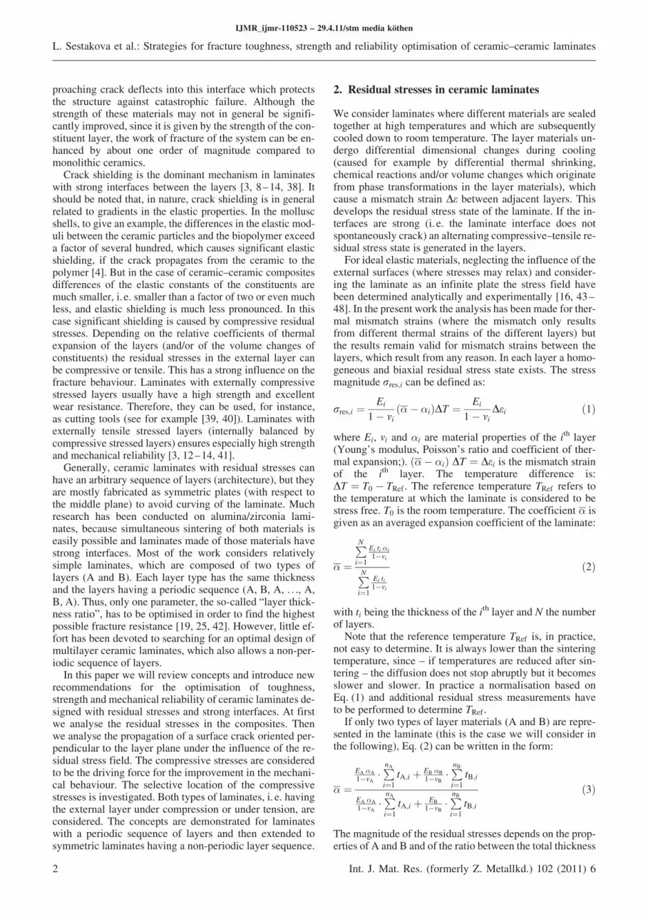
Although residual stresses are the key feature to enhancethe mechanical properties of many layered systems, somenegative effects of high residual stresses should be consid-ered. For instance, while compressive stresses are benefi-cial in acting as a “shielding” mechanism against crack ad-vance, tensile stresses can cause cracking of the layer, if itsstrength is overcome. A typical example of that is “tunnel-ling cracks”, which may appear at the surface of the tensilelayers [24, 49–51] and which can affect the structural in-tegrity of the laminate (see Fig. 1a). They can be avoidedby lowering the tensile stresses in the corresponding layers.
Another important aspect is the free surface of the mate-rial. It is well known that stresses at the free surface oflayered materials are different from those within the bulk.In the region far from the free edges (i. e. in a finite plate),biaxial residual stresses parallel to the layer plane exist,
and the stresses perpendicular to the layer plane are negligi-ble [52]. Near the free edges, however, the residual stressstate is no longer biaxial since the edge surface must betraction-free. As a result, a stress component perpendicularto the layer plane appears at the free edge [52–55]. Thisstress has a sign opposite to that of the biaxial stresses inthe interior. Hence, for a compressive layer sandwiched be-tween two tensile layers, a tensile residual stress perpendi-cular to the layer plane exists near the free surface of thecompressive layer. The maximum tensile residual stress atthe free surface equals the biaxial compressive residualstress in the interior. Although such tensile residual stressdecreases rapidly from the edge surface to become negligi-ble at a distance of the order of the compressive layer thick-ness, defects at the surface may be activated and cracksmayinitiate. An example is the so-called “edge cracks”, initiat-ing from pre-existing flaws, encountered at the free edgesof the compressive layers (see Fig. 1b) [56]. Hence, pre-venting the initiation of edge cracking is important for thestructural integrity of the component and should be consid-ered in the multilayer design, and it will be considered be-low.
3. Approach to describe toughness, strengthand mechanical reliability of ceramic laminates
3.1. Assumptions and simplifications
In order to study the influence of the architecture of multi-layer ceramics on the crack shielding some assumptions re-garding geometry and material properties are beneficial:. The laminate is described as an infinite plate and the in-
fluence of free surfaces is neglected.. We consider laminates made from two materials (A and
B). An extension of the analysis to laminatesmade frommore materials would be straightforward but does notgive new insights.
. The coefficients of thermal expansion of A and B aredifferent. This induces residual stresses in the layers(see Section 2). It is important to emphasise that themagnitude of residual stresses in each layer dependsonly on the volume fraction VB=VA of material A andB as defined in Eq. (3) and Eq. (4).
. In order to avoid some curving of the laminates asso-ciated with the residual stresses in the layers, we alwaysassume in our analysis that the layer architecture is mir-ror symmetrical with respect to the mid plane of the la-minate.
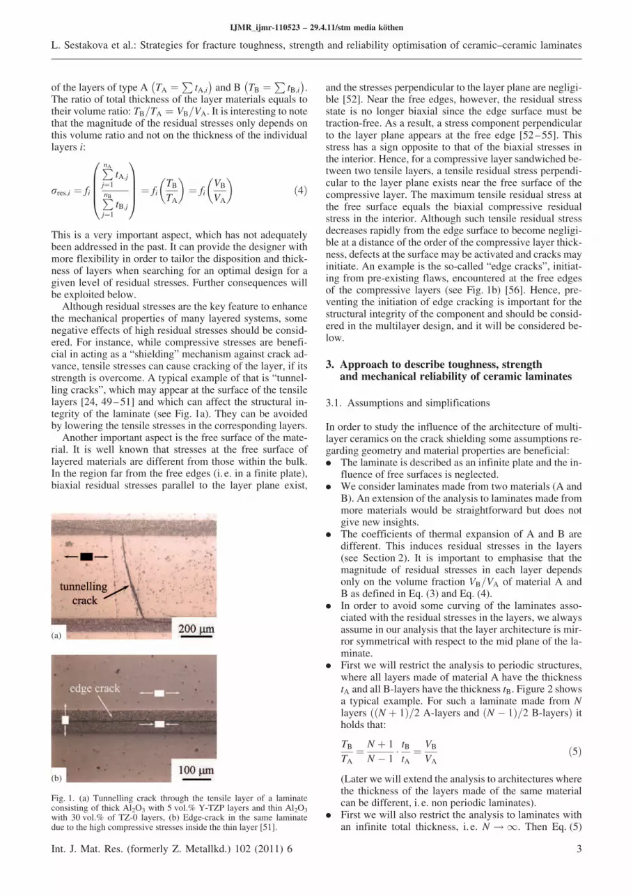
. First we will restrict the analysis to periodic structures,where all layers made of material A have the thicknesstA and all B-layers have the thickness tB. Figure 2 showsa typical example. For such a laminate made from Nlayers ððN þ 1Þ=2 A-layers and ðN % 1Þ=2 B-layersÞ itholds that:
TB
TA¼ N þ 1
N % 1& tBtA
¼ VB
VAð5Þ
(Later wewill extend the analysis to architectures wherethe thickness of the layers made of the same materialcan be different, i. e. non periodic laminates).
. First we will also restrict the analysis to laminates withan infinite total thickness, i. e. N ! 1. Then Eq. (5)
IJMR_ijmr-110523 – 29.4.11/stm media köthen
L. Sestakova et al.: Strategies for fracture toughness, strength and reliability optimisation of ceramic–ceramic laminates
Int. J. Mat. Res. (formerly Z. Metallkd.) 102 (2011) 6 3
Fig. 1. (a) Tunnelling crack through the tensile layer of a laminateconsisting of thick Al2O3 with 5 vol.% Y-TZP layers and thin Al2O3
with 30 vol.% of TZ-0 layers, (b) Edge-crack in the same laminatedue to the high compressive stresses inside the thin layer [51].
(a)
(b)
can be approximated by: tB=tA 9 TB=TA ¼ VB=VA. Forthe stresses this simplification yields:
rA
rB¼ % tB
tAð6Þ
(Later we will extend the analysis to laminates with a fi-nite total thickness).
. For the description of the crack shielding caused by re-sidual stresses the elastic properties of materials A andB are considered to be equal. It should be recognisedthat for most structural ceramics the elastic moduli dif-fer less (ormuch less) than a factor two. Thus,when sig-nificant residual stresses exist in the laminate, the effectof the elastic shielding is much less than the shieldingcaused by residual stresses. Elastic shielding can beneglected and the analysis can be made using the weightfunction method. For details see Appendix A. Note thatunder that assumption it holds EA ¼ EB ¼ E, mA ¼mB ¼ m (also fracture toughness and strength of individ-ual layers was considered equal for convenience, i. e.Kc;A ¼ Kc;B ¼ Kc and rc;A ¼ rc;B ¼ rc) and
rA ¼ r0 &VB
VA þ VBand rB ¼ %r0 &
VA
VA þ VBð7Þ
It follows from Eq. (7) that the difference between thestresses in the A and the B layers (the range of residualstresses) equals to r0:
rA % rB ¼ r0 ð8Þ
Note that this difference only depends on the mismatchstrain De between adjacent layers and not on the layerarchitecture. Changing the architecture therefore onlyshifts the absolute value but not the range of stresses.Hence, if compressive stresses exist in the outer layerthen r0 < 0, and if tensile stresses exist in the outerlayer it then r0 > 0. These observations are not re-stricted to thermal mismatch, but they remain true forany reason of mismatch.
. Fracture of a laminate always starts from the surfacelayer, as observed experimentally under flexural bend-ing. We assume that the fracture initiating flaw can be
described by a straight through-thickness edge crack oflength a (see Fig. 2). Then a 2-D model can be used todescribe the behaviour of the crack.
. For convenience the external stress field is assumed to beuniaxial and homogeneous, having the magnitude rappl.
. The geometric factor of a straight through-thicknessedge crack in a laminate with an infinite thickness in ahomogeneous uniaxial stress field is defined constantas Y ¼ 1:12. If we consider a plate of finite thicknessthe geometric factor becomes dependent on crack lengtha. The same holds for inhomogeneous stress fields. So-lutions can be found in [57].
3.2. Fracture mechanics analysis
The fracture criterion for brittle materials is described bythe well known Griffith/Irwin equation [58]:
KðaÞ 5 Kc ð9Þ
where
KðaÞ ¼ rYffiffiffiffiffi
pap
ð10Þ
is the stress intensity factor, which describes the crack tipfield of a crack of length a under the action of the stress, r.Kc is the fracture toughness of the material and Y the geo-metric factor.
The shielding effect caused by the residual stresses canbe described by treating the residual stresses to be an addi-tional external stress, giving an additional term KresðaÞ tothe stress intensity factor at the crack tip, Ktip, which nowreads:
KtipðaÞ ¼ KapplðaÞ þ KresðaÞ ð11Þ
with KapplðaÞ ¼ Yrapplffiffiffiffiffi
pap
being the stress intensity factorcaused by the applied stress. Thus, solving Eq. (11) forKappl, the Griffith/Irwin criterion (Eq. (9)) becomes:
KapplðaÞ 5 Kc % KresðaÞ ¼ KRðaÞ ð12Þ
For Kres < 0, as it holds for the action of compressive stres-ses, KRðaÞ 5 Kc, what is called an increasing crack growthresistance curve (R-curve). This describes the “shielding”effect associatedwith the compressive stresses. If tensile re-sidual stresses are acting, “anti-shielding” occurs and KR
decreases with increasing crack extension.In the following the crack resistance curves of several ce-
ramic laminates will be determined using the weight func-tion method. The procedure of calculation is described inAppendix A.
4. Results and discussion
4.1. Qualitative behaviour of cracks in ECS-laminates(outer layers under compression)
First, laminates with external compressive stresses (ECS)and having infinite thickness are analysed. For illustrativepurposes material properties are taken for this study basedon typical values for alumina–zirconia based laminates[59]. Hence, elastic properties are chosen as E ¼ 390 GPa,
IJMR_ijmr-110523 – 29.4.11/stm media köthen
L. Sestakova et al.: Strategies for fracture toughness, strength and reliability optimisation of ceramic–ceramic laminates
4 Int. J. Mat. Res. (formerly Z. Metallkd.) 102 (2011) 6
Fig. 2. Periodic multilayer architecture (A, B, A, . . ., A, B, A) consist-ing of alternating layers of materials A and B of thickness tA and tB re-spectively. The laminate is mirror symmetric in respect to its midplane. Also shown is a through-thickness edge crack of length a propa-gating perpendicular to the layers.
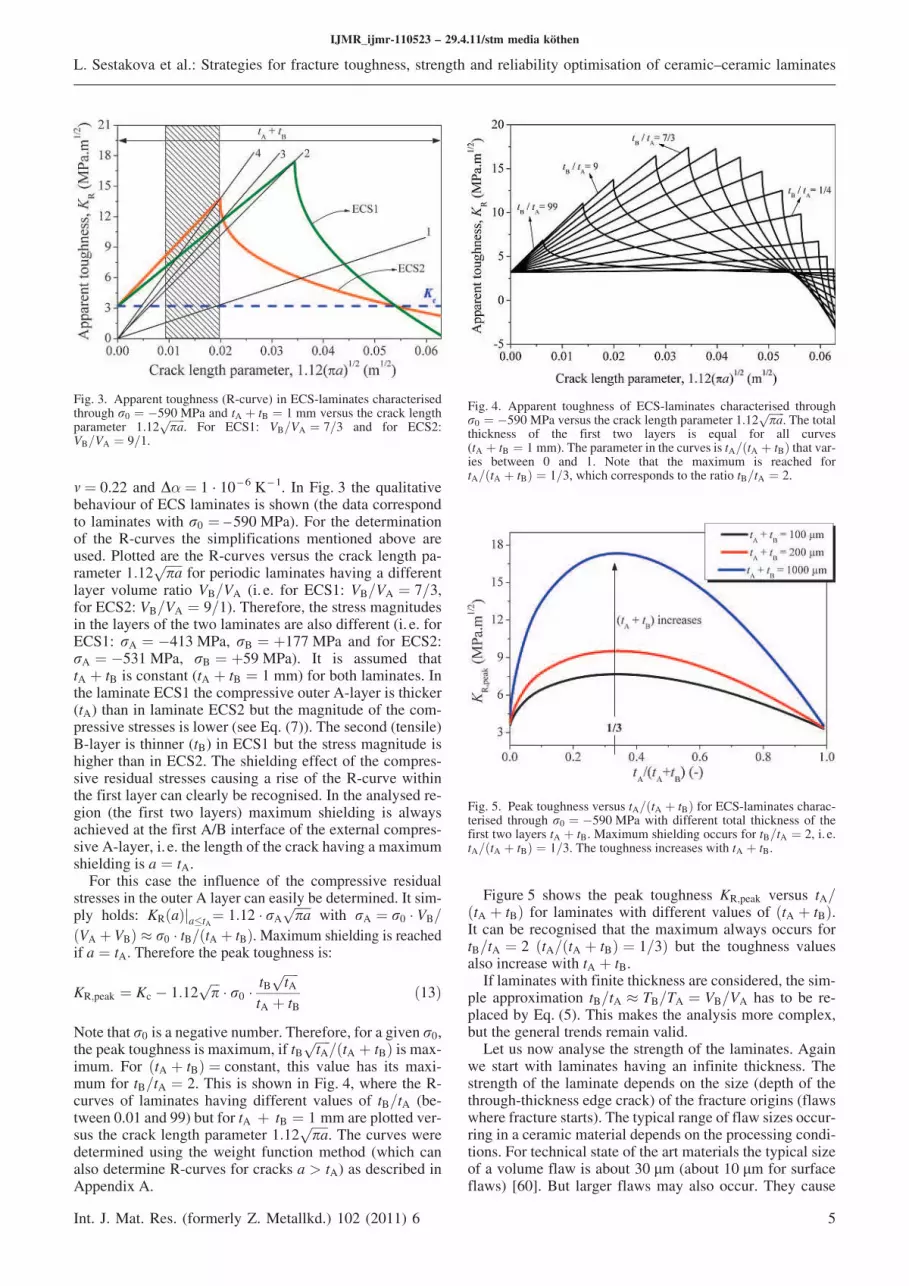
m ¼ 0.22 and D( ¼ 1 · 10 – 6 K – 1. In Fig. 3 the qualitativebehaviour of ECS laminates is shown (the data correspondto laminates with r0 ¼ –590 MPa). For the determinationof the R-curves the simplifications mentioned above areused. Plotted are the R-curves versus the crack length pa-rameter 1:12
ffiffiffiffiffi
pap
for periodic laminates having a differentlayer volume ratio VB=VA (i. e. for ECS1: VB=VA ¼ 7=3,for ECS2: VB=VA ¼ 9=1). Therefore, the stress magnitudesin the layers of the two laminates are also different (i. e. forECS1: rA ¼ %413 MPa, rB ¼ þ177 MPa and for ECS2:rA ¼ %531 MPa, rB ¼ þ59 MPa). It is assumed thattA þ tB is constant (tA þ tB ¼ 1 mm) for both laminates. Inthe laminate ECS1 the compressive outer A-layer is thicker(tA) than in laminate ECS2 but the magnitude of the com-pressive stresses is lower (see Eq. (7)). The second (tensile)B-layer is thinner (tB) in ECS1 but the stress magnitude ishigher than in ECS2. The shielding effect of the compres-sive residual stresses causing a rise of the R-curve withinthe first layer can clearly be recognised. In the analysed re-gion (the first two layers) maximum shielding is alwaysachieved at the first A/B interface of the external compres-sive A-layer, i. e. the length of the crack having amaximumshielding is a ¼ tA.
For this case the influence of the compressive residualstresses in the outer A layer can easily be determined. It sim-ply holds: KRðaÞja4tA
¼ 1:12 & rAffiffiffiffiffi
pap
with rA ¼ r0 & VB=
ðVA þ VBÞ 9 r0 & tB=ðtA þ tBÞ.Maximum shielding is reachedif a ¼ tA. Therefore the peak toughness is:
KR;peak ¼ Kc % 1:12ffiffiffi
pp
& r0 &tB
ffiffiffiffiffi
tAp
tA þ tBð13Þ
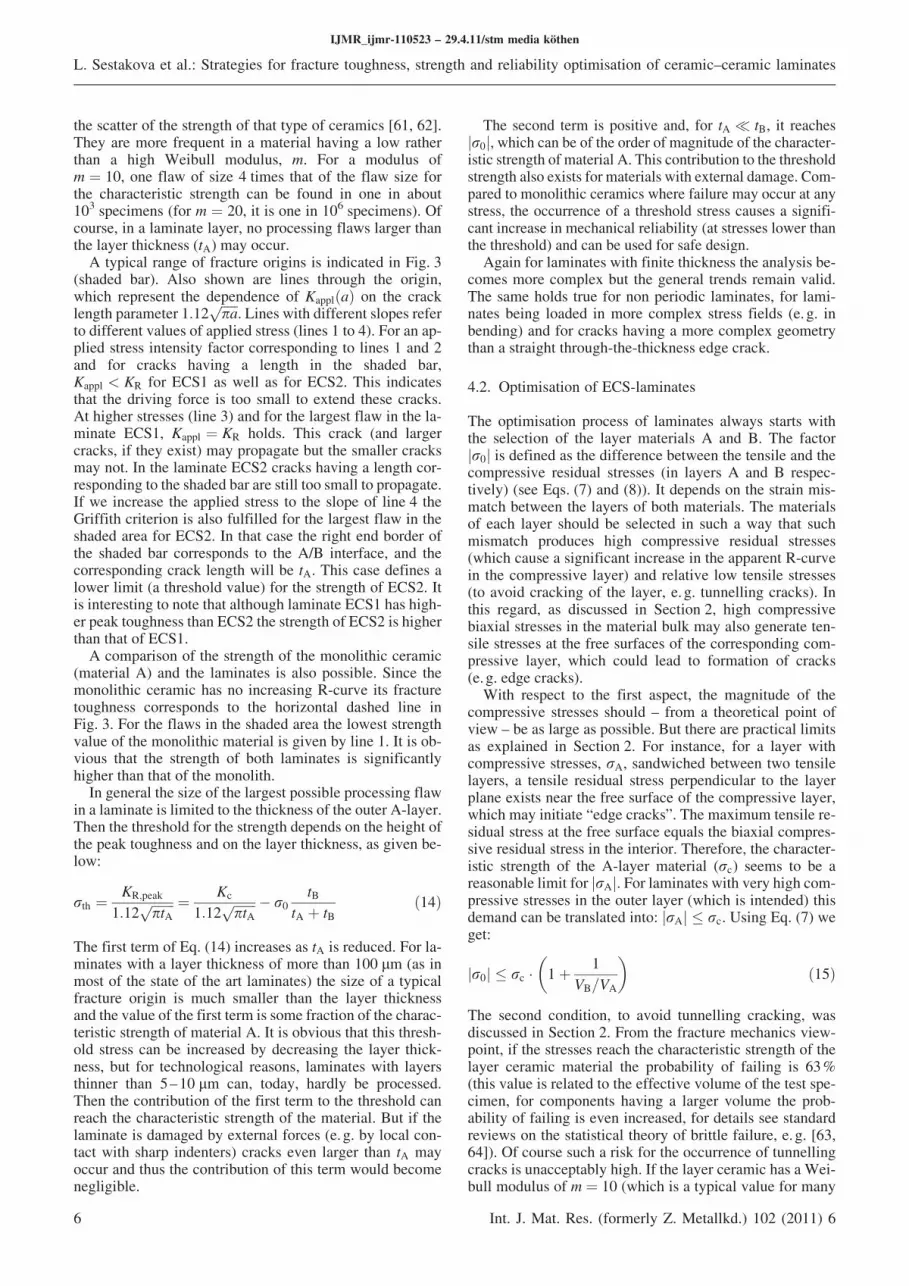
Note that r0 is a negative number. Therefore, for a given r0,the peak toughness ismaximum, if tB
ffiffiffiffiffi
tAp
=ðtA þ tBÞ ismax-imum. For ðtA þ tBÞ ¼ constant, this value has its maxi-mum for tB=tA ¼ 2. This is shown in Fig. 4, where the R-curves of laminates having different values of tB=tA (be-tween 0.01 and 99) but for tA þ tB ¼ 1 mm are plotted ver-sus the crack length parameter 1:12
ffiffiffiffiffi
pap
. The curves weredetermined using the weight function method (which canalso determine R-curves for cracks a > tA) as described inAppendix A.
Figure 5 shows the peak toughness KR;peak versus tA=ðtA þ tBÞ for laminates with different values of ðtA þ tBÞ.It can be recognised that the maximum always occurs fortB=tA ¼ 2 ðtA=ðtA þ tBÞ ¼ 1=3Þ but the toughness valuesalso increase with tA þ tB.
If laminates with finite thickness are considered, the sim-ple approximation tB=tA 9 TB=TA ¼ VB=VA has to be re-placed by Eq. (5). This makes the analysis more complex,but the general trends remain valid.
Let us now analyse the strength of the laminates. Againwe start with laminates having an infinite thickness. Thestrength of the laminate depends on the size (depth of thethrough-thickness edge crack) of the fracture origins (flawswhere fracture starts). The typical range of flaw sizes occur-ring in a ceramic material depends on the processing condi-tions. For technical state of the art materials the typical sizeof a volume flaw is about 30 lm (about 10 lm for surfaceflaws) [60]. But larger flaws may also occur. They cause
IJMR_ijmr-110523 – 29.4.11/stm media köthen
L. Sestakova et al.: Strategies for fracture toughness, strength and reliability optimisation of ceramic–ceramic laminates
Int. J. Mat. Res. (formerly Z. Metallkd.) 102 (2011) 6 5
Fig. 3. Apparent toughness (R-curve) in ECS-laminates characterisedthrough r0 ¼ %590MPa and tA þ tB ¼ 1 mm versus the crack lengthparameter 1:12
ffiffiffiffiffiffi
pap
. For ECS1: VB=VA ¼ 7=3 and for ECS2:VB=VA ¼ 9=1.
Fig. 4. Apparent toughness of ECS-laminates characterised throughr0 ¼ %590MPa versus the crack length parameter 1.12
ffiffiffiffiffiffi
pap
. The totalthickness of the first two layers is equal for all curves(tA þ tB ¼ 1 mm). The parameter in the curves is tA=ðtA þ tBÞ that var-ies between 0 and 1. Note that the maximum is reached fortA=ðtA þ tBÞ ¼ 1=3, which corresponds to the ratio tB=tA ¼ 2.
Fig. 5. Peak toughness versus tA=ðtA þ tBÞ for ECS-laminates charac-terised through r0 ¼ %590MPa with different total thickness of thefirst two layers tA þ tB. Maximum shielding occurs for tB=tA ¼ 2, i. e.tA=ðtA þ tBÞ ¼ 1=3. The toughness increases with tA þ tB.
the scatter of the strength of that type of ceramics [61, 62].They are more frequent in a material having a low ratherthan a high Weibull modulus, m. For a modulus ofm ¼ 10, one flaw of size 4 times that of the flaw size forthe characteristic strength can be found in one in about103 specimens (for m ¼ 20, it is one in 106 specimens). Ofcourse, in a laminate layer, no processing flaws larger thanthe layer thickness (tA) may occur.
A typical range of fracture origins is indicated in Fig. 3(shaded bar). Also shown are lines through the origin,which represent the dependence of KapplðaÞ on the cracklength parameter 1:12
ffiffiffiffiffi
pap
. Lines with different slopes referto different values of applied stress (lines 1 to 4). For an ap-plied stress intensity factor corresponding to lines 1 and 2and for cracks having a length in the shaded bar,Kappl < KR for ECS1 as well as for ECS2. This indicatesthat the driving force is too small to extend these cracks.At higher stresses (line 3) and for the largest flaw in the la-minate ECS1, Kappl ¼ KR holds. This crack (and largercracks, if they exist) may propagate but the smaller cracksmay not. In the laminate ECS2 cracks having a length cor-responding to the shaded bar are still too small to propagate.If we increase the applied stress to the slope of line 4 theGriffith criterion is also fulfilled for the largest flaw in theshaded area for ECS2. In that case the right end border ofthe shaded bar corresponds to the A/B interface, and thecorresponding crack length will be tA. This case defines alower limit (a threshold value) for the strength of ECS2. Itis interesting to note that although laminate ECS1 has high-er peak toughness than ECS2 the strength of ECS2 is higherthan that of ECS1.
A comparison of the strength of the monolithic ceramic(material A) and the laminates is also possible. Since themonolithic ceramic has no increasing R-curve its fracturetoughness corresponds to the horizontal dashed line inFig. 3. For the flaws in the shaded area the lowest strengthvalue of the monolithic material is given by line 1. It is ob-vious that the strength of both laminates is significantlyhigher than that of the monolith.
In general the size of the largest possible processing flawin a laminate is limited to the thickness of the outer A-layer.Then the threshold for the strength depends on the height ofthe peak toughness and on the layer thickness, as given be-low:
rth ¼KR;peak
1:12ffiffiffiffiffiffiffi
ptAp ¼ Kc
1:12ffiffiffiffiffiffiffi
ptAp % r0
tB
tA þ tBð14Þ
The first term of Eq. (14) increases as tA is reduced. For la-minates with a layer thickness of more than 100 lm (as inmost of the state of the art laminates) the size of a typicalfracture origin is much smaller than the layer thicknessand the value of the first term is some fraction of the charac-teristic strength of material A. It is obvious that this thresh-old stress can be increased by decreasing the layer thick-ness, but for technological reasons, laminates with layersthinner than 5–10 lm can, today, hardly be processed.Then the contribution of the first term to the threshold canreach the characteristic strength of the material. But if thelaminate is damaged by external forces (e. g. by local con-tact with sharp indenters) cracks even larger than tA mayoccur and thus the contribution of this term would becomenegligible.
The second term is positive and, for tA < tB, it reachesr0j j, which can be of the order of magnitude of the character-istic strength of materialA. This contribution to the thresholdstrength also exists formaterials with external damage. Com-pared to monolithic ceramics where failure may occur at anystress, the occurrence of a threshold stress causes a signifi-cant increase in mechanical reliability (at stresses lower thanthe threshold) and can be used for safe design.
Again for laminates with finite thickness the analysis be-comes more complex but the general trends remain valid.The same holds true for non periodic laminates, for lami-nates being loaded in more complex stress fields (e. g. inbending) and for cracks having a more complex geometrythan a straight through-the-thickness edge crack.
4.2. Optimisation of ECS-laminates
The optimisation process of laminates always starts withthe selection of the layer materials A and B. The factorr0j j is defined as the difference between the tensile and thecompressive residual stresses (in layers A and B respec-tively) (see Eqs. (7) and (8)). It depends on the strain mis-match between the layers of both materials. The materialsof each layer should be selected in such a way that suchmismatch produces high compressive residual stresses(which cause a significant increase in the apparent R-curvein the compressive layer) and relative low tensile stresses(to avoid cracking of the layer, e. g. tunnelling cracks). Inthis regard, as discussed in Section 2, high compressivebiaxial stresses in the material bulk may also generate ten-sile stresses at the free surfaces of the corresponding com-pressive layer, which could lead to formation of cracks(e. g. edge cracks).
With respect to the first aspect, the magnitude of thecompressive stresses should – from a theoretical point ofview – be as large as possible. But there are practical limitsas explained in Section 2. For instance, for a layer withcompressive stresses, rA, sandwiched between two tensilelayers, a tensile residual stress perpendicular to the layerplane exists near the free surface of the compressive layer,which may initiate “edge cracks”. The maximum tensile re-sidual stress at the free surface equals the biaxial compres-sive residual stress in the interior. Therefore, the character-istic strength of the A-layer material (rc) seems to be areasonable limit for rAj j. For laminates with very high com-pressive stresses in the outer layer (which is intended) thisdemand can be translated into: rAj j 4 rc. Using Eq. (7) weget:
r0j j 4 rc & 1þ 1
VB=VA
; <
ð15Þ
The second condition, to avoid tunnelling cracking, wasdiscussed in Section 2. From the fracture mechanics view-point, if the stresses reach the characteristic strength of thelayer ceramic material the probability of failing is 63%(this value is related to the effective volume of the test spe-cimen, for components having a larger volume the prob-ability of failing is even increased, for details see standardreviews on the statistical theory of brittle failure, e.g. [63,64]). Of course such a risk for the occurrence of tunnellingcracks is unacceptably high. If the layer ceramic has a Wei-bull modulus of m ¼ 10 (which is a typical value for many
IJMR_ijmr-110523 – 29.4.11/stm media köthen
L. Sestakova et al.: Strategies for fracture toughness, strength and reliability optimisation of ceramic–ceramic laminates
6 Int. J. Mat. Res. (formerly Z. Metallkd.) 102 (2011) 6
commercial structural ceramics), the probability of failing(of building a tunnel crack) is about 10 – 3 at a stress whichis half of the characteristic strength, and about 10 – 6 at aquarter of the characteristic strength rc. At a higher modu-lus the corresponding failure probabilities would be lower.TheWeibull modulus is related to the width of the size dis-tribution of the microstructural flaws. It can be expectedthat this distribution will be narrower with increasing pro-cessing quality, which can be expected in the future. Allthese arguments indicate that a residual tensile stress abouthalf of the characteristic strength of the stressed material(causing a risk for the occurrence of tunnel cracks of 10 – 3
or even less) is acceptable, i. e. rB 4 rc=2. Hence, r0j jshould be limited as:
r0j j 4 rc
2& 1þ VB
VA
; <
ð16Þ
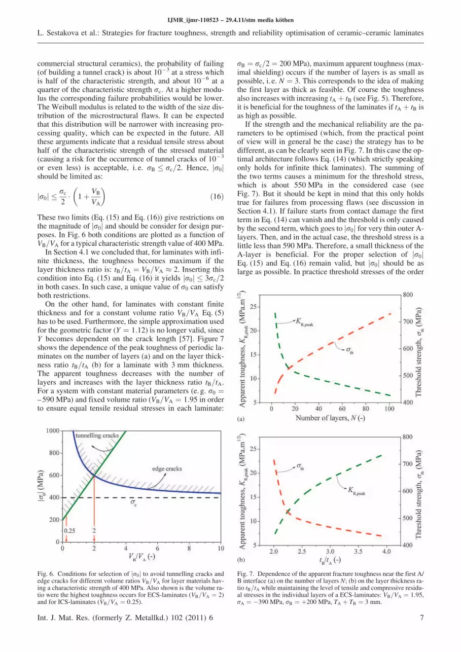
These two limits (Eq. (15) and Eq. (16)) give restrictions onthe magnitude of r0j j and should be consider for design pur-poses. In Fig. 6 both conditions are plotted as a function ofVB=VA for a typical characteristic strength value of 400MPa.
In Section 4.1 we concluded that, for laminates with infi-nite thickness, the toughness becomes maximum if thelayer thickness ratio is: tB=tA ¼ VB=VA 9 2. Inserting thiscondition into Eq. (15) and Eq. (16) it yields r0j j 4 3rc=2in both cases. In such case, a unique value of r0 can satisfyboth restrictions.
On the other hand, for laminates with constant finitethickness and for a constant volume ratio VB=VA Eq. (5)has to be used. Furthermore, the simple approximation usedfor the geometric factor (Y ¼ 1:12) is no longer valid, sinceY becomes dependent on the crack length [57]. Figure 7shows the dependence of the peak toughness of periodic la-minates on the number of layers (a) and on the layer thick-ness ratio tB=tA (b) for a laminate with 3 mm thickness.The apparent toughness decreases with the number oflayers and increases with the layer thickness ratio tB=tA.For a system with constant material parameters (e. g. r0 ¼–590 MPa) and fixed volume ratio (VB=VA ¼ 1:95 in orderto ensure equal tensile residual stresses in each laminate:
rB ¼ rc=2 ¼ 200MPa), maximum apparent toughness (max-imal shielding) occurs if the number of layers is as small aspossible, i. e. N ¼ 3. This corresponds to the idea of makingthe first layer as thick as feasible. Of course the toughnessalso increases with increasing tA þ tB (see Fig. 5). Therefore,it is beneficial for the toughness of the laminates if tA þ tB isas high as possible.
If the strength and the mechanical reliability are the pa-rameters to be optimised (which, from the practical pointof view will in general be the case) the strategy has to bedifferent, as can be clearly seen in Fig. 7. In this case the op-timal architecture follows Eq. (14) (which strictly speakingonly holds for infinite thick laminates). The summing ofthe two terms causes a minimum for the threshold stress,which is about 550 MPa in the considered case (seeFig. 7). But it should be kept in mind that this only holdstrue for failures from processing flaws (see discussion inSection 4.1). If failure starts from contact damage the firstterm in Eq. (14) can vanish and the threshold is only causedby the second term,which goes to r0j j for very thin outerA-layers. Then, and in the actual case, the threshold stress is alittle less than 590 MPa. Therefore, a small thickness of theA-layer is beneficial. For the proper selection of r0j jEq. (15) and Eq. (16) remain valid, but r0j j should be aslarge as possible. In practice threshold stresses of the order
IJMR_ijmr-110523 – 29.4.11/stm media köthen
L. Sestakova et al.: Strategies for fracture toughness, strength and reliability optimisation of ceramic–ceramic laminates
Int. J. Mat. Res. (formerly Z. Metallkd.) 102 (2011) 6 7
Fig. 6. Conditions for selection of r0j j to avoid tunnelling cracks andedge cracks for different volume ratios VB=VA for layer materials hav-ing a characteristic strength of 400MPa. Also shown is the volume ra-tio were the highest toughness occurs for ECS-laminates (VB=VA ¼ 2)and for ICS-laminates (VB=VA ¼ 0:25).
(a)
(b)
Fig. 7. Dependence of the apparent fracture toughness near the first A/B interface (a) on the number of layers N; (b) on the layer thickness ra-tio tB=tA while maintaining the level of tensile and compressive residu-al stresses in the individual layers of a ECS-laminates: VB=VA ¼ 1:95,rA ¼ %390MPa, rB ¼ þ200MPa, TA þ TB ¼ 3 mm.
of magnitude of the characteristic strength of the monolithic(A) material becomes reasonable, which leads to ceramiclaminates with a strength of several hundred MPa and norisk of failure at lower applied tensile stresses. Comparedto monolithic ceramic materials this causes a significant in-crease in strength and mechanical reliability.
Up to now we have been restricted to periodic laminates.The reported trends also remain valid for non-periodic la-minates if tA þ tB are the first two layers of the non-periodiclaminate and if the ratio of VB=VA remains constant.
4.3. Qualitative behaviour of cracks in ICS-laminates(outer layers under tension)
For ICS-laminates (internal compressive stress, the outerlayer is under tension) simple analytical solutions as forECS laminates do not apply and the apparent toughness(the R-curve) has to be determined using approximationmethods such as the weight function method (AppendixA). At first we again restrict the analysis to symmetric andperiodic laminates having infinite thickness.
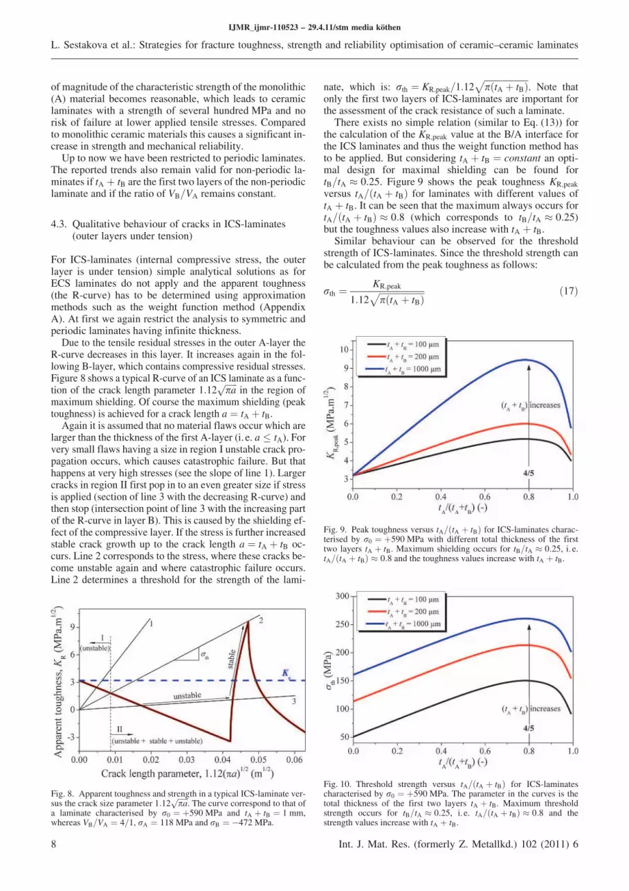
Due to the tensile residual stresses in the outer A-layer theR-curve decreases in this layer. It increases again in the fol-lowing B-layer, which contains compressive residual stresses.Figure 8 shows a typical R-curve of an ICS laminate as a func-tion of the crack length parameter 1:12
ffiffiffiffiffiffi
pap
in the region ofmaximum shielding. Of course the maximum shielding (peaktoughness) is achieved for a crack length a ¼ tA þ tB.
Again it is assumed that no material flaws occur which arelarger than the thickness of the first A-layer (i. e. a 4 tA). Forvery small flaws having a size in region I unstable crack pro-pagation occurs, which causes catastrophic failure. But thathappens at very high stresses (see the slope of line 1). Largercracks in region II first pop in to an even greater size if stressis applied (section of line 3 with the decreasing R-curve) andthen stop (intersection point of line 3 with the increasing partof the R-curve in layer B). This is caused by the shielding ef-fect of the compressive layer. If the stress is further increasedstable crack growth up to the crack length a ¼ tA þ tB oc-curs. Line 2 corresponds to the stress, where these cracks be-come unstable again and where catastrophic failure occurs.Line 2 determines a threshold for the strength of the lami-
nate, which is: rth ¼ KR;peak=1:12ffiffiffiffiffiffiffiffiffiffiffiffiffiffiffiffiffiffiffiffi
pðtA þ tBÞp
. Note thatonly the first two layers of ICS-laminates are important forthe assessment of the crack resistance of such a laminate.
There exists no simple relation (similar to Eq. (13)) forthe calculation of the KR;peak value at the B/A interface forthe ICS laminates and thus the weight function method hasto be applied. But considering tA þ tB ¼ constant an opti-mal design for maximal shielding can be found fortB=tA 9 0:25. Figure 9 shows the peak toughness KR;peak
versus tA=ðtA þ tBÞ for laminates with different values oftA þ tB. It can be seen that the maximum always occurs fortA=ðtA þ tBÞ 9 0:8 (which corresponds to tB=tA 9 0:25)but the toughness values also increase with tA þ tB.
Similar behaviour can be observed for the thresholdstrength of ICS-laminates. Since the threshold strength canbe calculated from the peak toughness as follows:
rth ¼KR;peak
1:12ffiffiffiffiffiffiffiffiffiffiffiffiffiffiffiffiffiffiffiffi
pðtA þ tBÞp ð17Þ
IJMR_ijmr-110523 – 29.4.11/stm media köthen
L. Sestakova et al.: Strategies for fracture toughness, strength and reliability optimisation of ceramic–ceramic laminates
8 Int. J. Mat. Res. (formerly Z. Metallkd.) 102 (2011) 6
Fig. 8. Apparent toughness and strength in a typical ICS-laminate ver-sus the crack size parameter 1:12
ffiffiffiffiffiffi
pap
. The curve correspond to that ofa laminate characterised by r0 ¼ þ590MPa and tA þ tB ¼ 1 mm,whereas VB=VA ¼ 4=1, rA ¼ 118MPa and rB ¼ %472 MPa.
Fig. 9. Peak toughness versus tA=ðtA þ tBÞ for ICS-laminates charac-terised by r0 ¼ þ590MPa with different total thickness of the firsttwo layers tA þ tB. Maximum shielding occurs for tB=tA 9 0:25, i. e.tA=ðtA þ tBÞ 9 0:8 and the toughness values increase with tA þ tB.
Fig. 10. Threshold strength versus tA=ðtA þ tBÞ for ICS-laminatescharacterised by r0 ¼ þ590MPa. The parameter in the curves is thetotal thickness of the first two layers tA þ tB. Maximum thresholdstrength occurs for tB=tA 9 0:25, i. e. tA=ðtA þ tBÞ 9 0:8 and thestrength values increase with tA þ tB.
and the denominator in Eq. (17) is constant, the thresholdstrength reaches its maximum for the ratio tB=tA 9 0.25 ortA=ðtA þ tBÞ 9 4=5. It also increases with tA þ tB, as seenin Fig. 10.
4.4. Optimisation of periodic ICS-laminates
The optimisation process of ICS-laminates must also considerthe restriction of r0 to avoid cracking of the laminate due totunnelling and/or edge cracks. If we consider the optimal de-sign as found in the previous section, i. e. VB=VA ¼ 0.25, themaximum r0 value given by Eq. (16) results in r0j j 4 5rc=8.It can be seen in Fig. 6 that for such small VB=VA ratios, onlyrestrictions of r0 for the formation of tunnelling cracks are re-levant for the design of ICS laminates. For the characteristicstrength of 400MPa (the same as used for the case of ECS-laminates in Section 4.2) this yields r0j j 4 250 MPa. Withthis limit of r0j j and for a infinite thick laminate withtA þ tB ¼ 1 mm the optimal design ðVB=VA ¼ 0:25Þ gives apeak toughness of about 6 MPa m1/2. Although the peaktoughness has been reduced compared to the peak valuepredicted in Fig. 9 for r0j j ¼ 590 MPa, cracking of the la-minate can be avoided.
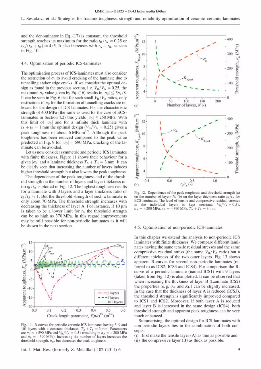
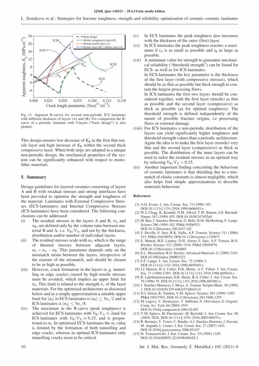
Let us now consider symmetric and periodic ICS laminateswith finite thickness. Figure 11 shows their behaviour for agiven r0j j and a laminate thickness TA þ TB ¼ 3 mm. It canbe clearly seen that increasing the number of layers induceshigher threshold strength but also lowers the peak toughness.
The dependence of the peak toughness and of the thresh-old strength on the number of layers and layer thickness ra-tio tB=tA is plotted in Fig. 12. The highest toughness resultsfor a laminate with 3 layers and a layer thickness ratio oftB=tA 9 1. But the threshold strength of such a laminate isonly about 70 MPa. The threshold strength increases withdecreasing the thickness of layer A. For instance, if 10 lmis taken to be a lower limit for tA the threshold strengthcan be as high as 370 MPa. In this regard improvementsmay be still possible for non-periodic laminates as it willbe shown in the next section. 4.5. Optimisation of non-periodic ICS-laminates
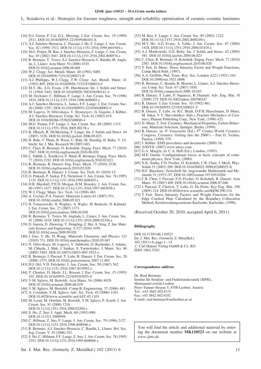
In this chapter we extend the analysis to non-periodic ICSlaminates with finite thickness.We compare different lami-nates having the same tensile residual stresses and the samecompressive residual stress (the same VB=VA ratio) but adifferent thickness of the two outer layers. Fig. 13 showsapparent R-curves for several non-periodic laminates (re-ferred to as ICS2, ICS3 and ICS4). For comparison the R-curve of a periodic laminate (named ICS1) with 9 layers(taken from Fig. 12) is also plotted. It can be observed thatwhen increasing the thickness of layer B (Laminate ICS2)the properties (e. g. rth and KIc) can be slightly increased.In the case that the thickness of layer A is reduced (ICS3),the threshold strength is significantly improved comparedto ICS1 and ICS2. Moreover, if both layer A is reducedand layer B is increased in the same design (ICS4), boththreshold strength and apparent peak toughness can be verymuch enhanced.
Summarising, the optimal design for ICS-laminates withnon-periodic layers lies in the combination of both con-cepts:(i) first make the tensile layer (A) as thin as possible and(ii) the compressive layer (B) as thick as possible.
IJMR_ijmr-110523 – 29.4.11/stm media köthen
L. Sestakova et al.: Strategies for fracture toughness, strength and reliability optimisation of ceramic–ceramic laminates
Int. J. Mat. Res. (formerly Z. Metallkd.) 102 (2011) 6 9
Fig. 11. R-curves for periodic ceramic ICS laminates having 3, 9 and101 layers with a constant thickness, TA þ TB ¼ 3 mm. Parametersare r0 ¼ þ590 MPa and VB=VA ¼ 0:51 (resulting in rA ¼ þ200MPaand rB ¼ %390MPa). Increasing the number of layers increases thethreshold strength, rth, but decreases the peak toughness.
(a)
(b)
Fig. 12. Dependence of the peak toughness and threshold strength (a)on the number of layers N; (b) on the layer thickness ratio tB=tA forECS-laminates. The level of tensile and compressive residual stressesin the individual layers is kept constant: VB=VA ¼ 0:51,rA ¼ þ200MPa, rB ¼ %390MPa, TA þ TB ¼ 3 mm.
This design ensures low decrease of KR in the first thin ten-sile layer and high increase of KR within the second thickcompressive layer.When both steps are adopted in a uniquenon-periodic design, the mechanical properties of the sys-tem can be significantly enhanced with respect to mono-lithic materials.
5. Summary
Design guidelines for layered ceramics consisting of layersA and B with residual stresses and strong interfaces havebeen provided to optimise the strength and toughness ofthe material. Laminates with External Compressive Stres-ses (ECS-laminates) and Internal Compressive Stresses(ICS-laminates) have been considered. The following con-clusions can be addressed:(i) The residual stresses in the layers A and B, rA and
rB, are defined only by the volume ratio between ma-terial B and A, i. e. VB=VA, and not by the thickness,distribution and/or number of individual layers.
(ii) The residual stresses scalewith r0,which is the rangeof thermal stresses between adjacent layers,r0 ¼ rA % rB. This parameter depends only on themismatch strain between the layers, irrespective ofthe reasons of the mismatch, and should be chosento be as high as possible.
(iii) However, crack formation in the layers (e. g. tunnel-ling or edge cracks) caused by high tensile stressesmust be avoided, which implies an upper limit forr0. This limit is related to the strength rc of the layermaterials. For the optimised architecture as discussedbelow and in a simple approximation a suitable upperlimit for r0j j in ECS-laminates is r0j j 4 3rc=2 and inICS-laminates is r0j j 4 5rc=8.
(iv) The maximum in the R-curve (peak toughness) isachieved for ECS-laminates with VB=VA 9 2and forICS-laminates with VB=VA 9 0:25, and is propor-tional to r0. In optimised ECS-laminates the r0 valueis limited by the formation of both tunnelling andedge cracks, whereas in optimal ICS-laminates onlytunnelling cracks seem to be critical.
(v) In ECS laminates the peak toughness also increaseswith the thickness of the outer (first) layer.
(vi) In ICS laminates the peak toughness reaches a maxi-mum if tA is as small as possible and tB as large aspossible.
(vii) Aminimum value for strength to guarantee mechani-cal reliability (“threshold strength”) can be found forECS- as well as for ICS-laminates.In ECS-laminates the key parameter is the thicknessof the first layer (with compressive stresses), whichshould be as thin as possible but thick enough to con-tain the largest processing flaws.In ICS-laminates the first two layers should be con-sidered together, with the first layer (tensile) as thinas possible and the second layer (compressive) asthick as possible (as for optimal toughness). Thethreshold strength is defined independently of thenature of possible fracture origins, i.e processingflaws or external damage.
(viii) For ICS laminates a non-periodic distribution of thelayers can yield significantly higher toughness andthreshold strength values than a periodic architecture.Again the idea is to make the first layer (tensile) verythin and the second layer (compressive) as thick aspossible. The distribution of the inner layers can beused to tailor the residual stresses in an optimal wayby selecting VB=VA ¼ 0.25.
(ix) Another important finding concerning the behaviourof ceramic laminates is that shielding due to a mis-match of elastic constants is almost negligible, whichalso helps find simple approximations to describematerials behaviour.
References
[1] A.G. Evans: J. Am. Ceram. Soc. 73 (1990) 187.DOI:10.1111/j.1151-2916.1990.tb06493.x
[2] W.J. Clegg, K. Kendall, N.M. Alford, T.W. Button, J.D. Birchall:Nature 347 (1990) 455. DOI:10.1038/347455a0
[3] M. Rao, J. Sanchez-Herencia, G. Beltz, R.M.McMeeking, F. Lange:Science 286 (1999) 102. PMid:10506553;DOI:10.1126/science.286.5437.102
[4] S. Deville, E. Saiz, R.K. Nalla, A.P. Tomsia: Science 311 (2006)515. PMid:16439659; DOI:10.1126/science.1120937
[5] E. Munch, M.E. Launey, D.H. Alsem, E. Saiz, A.P. Tomsia, R.O.Ritchie: Science 322 (2008) 1516. PMid:19056979;DOI:10.1126/science.1164865
[6] E.L. Maximilien, R.O. Ritchie: AdvancedMaterials 21 (2009) 2103.DOI:10.1002/adma.200803322
[7] F.F. Lange: J. Am. Ceram. Soc. 72 (1989) 3.DOI:10.1111/j.1151-2916.1989.tb05945.x
[8] J.J. Hansen, R.A. Cutler, D.K. Shetty, A.V. Virkar: J. Am. Ceram.Soc. 71 (1988) C501. DOI:10.1111/j.1151-2916.1988.tb05818.x
[9] R. Lakshminarayanan, D.K. Shetty, R.A. Cutler: J. Am. Ceram. Soc.79 (1996) 79. DOI:10.1111/j.1151-2916.1996.tb07883.x
[10] J. Sanchez-Herencia, J. Moya, A. Tomsia: Scripta Mater. 38 (1998)1. DOI:10.1016/S1359-6462(97)00443-0
[11] D.J. Green, R. Tandon, V.M. Sglavo: Science 283 (1999) 1295.PMid:10037593; DOI:10.1126/science.283.5406.1295
[12] M. Lugovy, V. Slyunyayev, V. Subbotin, N. Orlovskaya, G. Gogotsi:Comp. Sci. Tech. 64 (2004) 1947.DOI:10.1016/j.compscitech.2004.02.007
[13] V.M. Sglavo, M. Paternoster, M. Bertoldi: J. Am. Ceram. Soc. 88(2005) 2826. DOI:10.1111/j.1551-2916.2005.00479.x
[14] R. Bermejo, Y. Torres, C. Baudin, A.J. Sánchez-Herencia, J. Pascual,M. Anglada, L. Llanes: J. Eur. Ceram. Soc. 27 (2007) 1443.DOI:10.1016/j.jeurceramsoc.2006.05.037
[15] H. Tomaszewski: J. Eur. Ceram. Soc. 19 (1999) 1329.DOI:10.1016/S0955-2219(98)00428-2
IJMR_ijmr-110523 – 29.4.11/stm media köthen
L. Sestakova et al.: Strategies for fracture toughness, strength and reliability optimisation of ceramic–ceramic laminates
10 Int. J. Mat. Res. (formerly Z. Metallkd.) 102 (2011) 6
Fig. 13. Apparent R-curves for several non-periodic ICS laminateswith different thickness of layers (A) and (B). For comparison the R-curve of a periodic laminate with 9 layers (“basic design”) is alsoplotted.
[16] D.J. Green, P. Cai, G.L. Messing: J. Eur. Ceram. Soc. 19 (1999)2511. DOI:10.1016/S0955-2219(99)00103-X
[17] A.J. Sanchez-Herencia, C. Pascual, J. He, F. Lange: J. Am. Ceram.Soc. 82 (1999) 1512. DOI:10.1111/j.1151-2916.1999.tb01949.x
[18] M.G. Pontin, M. Rao, J. Sanchez-Herencia, F. Lange: J. Am. Ceram.Soc. 85 (2002) 3041. DOI:10.1111/j.1151-2916.2002.tb00576.x
[19] R. Bermejo, Y. Torres, A.J. Sanchez-Herencia, C. Baudín, M. Angla-da, L. Llanes: Acta Mater. 54 (2006) 4745.DOI:10.1016/j.actamat.2006.06.008
[20] W.J. Clegg: Act. Metall. Mater. 40 (1992) 3085.DOI:10.1016/0956-7151(92)90471-P
[21] A.J. Phillipps, W.J. Clegg, T.W. Clyne: Act. Metall. Mater. 41(1993) 805. DOI:10.1016/0956-7151(93)90014-J
[22] M.Y. He, A.G. Evans, J.W. Hutchinson: Int. J. Solids and Struct.31 (1994) 3443. DOI:10.1016/0020-7683(94)90141-4
[23] M. Oechsner, C. Hillman, F. Lange: J. Am. Ceram. Soc. 79 (1996)1834. DOI:10.1111/j.1151-2916.1996.tb08003.x
[24] A.J. Sanchez-Herencia, L. James, F.F. Lange: J. Eur. Ceram. Soc.20 (2000) 1297. DOI:10.1016/S0955-2219(00)00002-9
[25] M. Lugovy, N. Orlovskaya, V. Slyunyayev, G. Gogotsi, J. Kübler,A.J. Sanchez-Herencia: Comp. Sci. Tech. 62 (2002) 819.DOI:10.1016/S0266-3538(02)00040-4
[26] M.G. Pontin, F.F. Lange: J. Am. Ceram. Soc. 88 (2005) 1315.DOI:10.1111/j.1551-2916.2005.00178.x
[27] K. Hbaieb, R. McMeeking, F. Lange: Int. J. Solids and Struct. 44(2007) 3328. DOI:10.1016/j.ijsolstr.2006.09.023
[28] H. Bahr, V. Pham, H. Weiss, U. Bahr, M. Streubig, H. Balke, V. Ul-bricht: Int. J. Mat. Research 98 (2007) 683.
[29] C. Chen, R. Bermejo, O. Kolednik: Engng. Fract. Mech. 77 (2010)2567. DOI:10.1016/j.engfracmech.2010.06.020
[30] L. Náhlík, L. Šestáková, P. Hutar, R. Bermejo: Engng. Fract.Mech.77 (2010) 2192. DOI:10.1016/j.engfracmech.2010.02.023
[31] R. Bermejo, R. Danzer: Eng. Fract. Mech. 77 (2010) 2126.DOI:10.1016/j.engfracmech.2010.02.020
[32] R. Bermejo, R. Danzer: J. Ceram. Sci. Tech. 01 (2010) 15.[33] O. Prakash, P. Sarkar, P.S. Nicholson: J. Am. Ceram. Soc. 78 (1995)
1125. DOI:10.1111/j.1151-2916.1995.tb08455.x[34] D.B. Marshall, P.E.D.Morgan, R.M. Housley: J. Am. Ceram. Soc.
80 (1997) 1677. DOI:10.1111/j.1151-2916.1997.tb03038.x[35] W.J. Clegg: Mater. Sci. Tech. 14 (1998) 483.[36] A. Ceylan, P.A. Fuierer: Materials Letters 61 (2007) 551.
DOI:10.1016/j.matlet.2006.05.021[37] H. Tomaszewski, H.Weglarz, A.Wajler, M. Boniecki, D. Kalinski:
J. Eur. Ceram. Soc. 27 (2007) 1373.DOI:10.1016/j.jeurceramsoc.2006.04.030
[38] R. Bermejo, Y. Torres, M. Anglada, L. Llanes: J. Am. Ceram. Soc.91 (2008) 1618. DOI:10.1111/j.1551-2916.2008.02336.x
[39] D. Jianxin, D. Zhenxing, Y. Dongling, Z. Hui, A. Xing, Z. Jun: Mate-rials Science and Engineering: A 527 (2010) 1039.DOI:10.1016/j.msea.2009.09.020
[40] J. Gao, Y. He, D.Wang: Materials Chemistry and Physics 123(2010) 731. DOI:10.1016/j.matchemphys.2010.05.047
[41] N. Orlovskaya, M. Lugovy, V. Subbotin, O. Rachenko, J. Adams,M. Chheda, J. Shih, J. Sankar, S. Yarmolenko: J.Mater. Sci. 40(2005) 5483. DOI:10.1007/s10853-005-1923-x
[42] R. Bermejo, J. Pascual, T. Lube, R. Danzer: J. Eur. Ceram. Soc. 28(2008) 1575. DOI:10.1016/j.jeurceramsoc.2007.11.003
[43] H.J. Oël, V.D. Fréchette: J. Am. Ceram. Soc. 50 (1967) 542.DOI:10.1111/j.1151-2916.1967.tb14992.x
[44] T. Chartier, D.Merle, J.L. Besson: J. Eur. Ceram. Soc. 15 (1995)101. DOI:10.1016/0955-2219(95)93055-8
[45] V.M. Sglavo, M. Bertoldi: Acta Mater. 54 (2006) 4929.DOI:10.1016/j.actamat.2006.06.019
[46] V.M. Sglavo, M. Bertoldi: Comp B: Engineering. 37 (2006) 481.[47] A. Costabile, V.M. Sglavo: Adv. Sci. Tech. 45 (2006) 1103.
DOI:10.4028/www.scientific.net/AST.45.1103[48] M. Leoni, M. Ortolani, M. Bertoldi, V.M. Sglavo, P. Scardi: J. Am.
Ceram. Soc. 91 (2008) 1218.DOI:10.1111/j.1551-2916.2008.02260.x
[49] S. Ho, Z. Suo: J. Appl. Mech. 60 (1993) 890.DOI:10.1115/1.2900998
[50] C. Hillman, Z. Suo, F. Lange: J. Am. Ceram. Soc. 79 (1996) 2127.DOI:10.1111/j.1151-2916.1996.tb08946.x
[51] R. Bermejo, A.J. Sanchez-Herencia, C. Baudín, L. Llanes: Bol. Soc.Esp. Ceram. V. 45 (2006) 352.
[52] S. Ho, C. Hillman, F.F. Lange, Z. Suo: J. Am. Ceram. Soc. 78 (1995)2353. DOI:10.1111/j.1151-2916.1995.tb08668.x
[53] M. Rao, F. Lange: J. Am. Ceram. Soc. 85 (2002) 1222.DOI:10.1111/j.1151-2916.2002.tb00249.x
[54] M.Y. He, A.G. Evans, A. Yehle: J. Am. Ceram. Soc. 87 (2004)1418. DOI:10.1111/j.1551-2916.2004.01418.x
[55] A.J. Monkowski, G.E. Beltz: Int. J. Solids and Struct. 42 (2005)581. DOI:10.1016/j.ijsolstr.2004.06.023
[56] C. Chen, R. Bermejo, O. Kolednik: Engng. Fract. Mech. 77 (2010)2567. DOI:10.1016/j.engfracmech.2010.06.020
[57] T. Fett, D.Munz: Stress Intensity Factor and Weight Functions,Comp Mech Publ, (1997).
[58] A.A. Griffith: Phil. Trans. Roy. Soc. London A221 (1921) 163.DOI:10.1098/rsta.1921.0006
[59] R. Bermejo, C. Baudín, R. Moreno, L. Llanes, A.J. Sánchez-Heren-cia: Comp. Sci. Tech. 67 (2007) 1930.DOI:10.1016/j.compscitech.2006.10.010
[60] R. Danzer, T. Lube, P. Supancic, R. Damani: Adv. Eng. Mat. 10(2008) 275. DOI:10.1002/adem.200700347
[61] R. Danzer: J. Eur. Ceram. Soc. 10 (1992) 461.DOI:10.1016/0955-2219(92)90021-5
[62] R. Danzer, T. Lube, in: R.C. Bradt, D.P.H. Hasselmann, D. Munz,M. Sakai, V.Y. Shevchenkov (Eds.), Fracture Mechanics of Cera-mics, Plenum Publishing Corp., New York, (1996) 425.
[63] D. Munz, T. Fett: Ceramics.Mechanical Properties, Failure Behav-iour, Materials Selection, Springer, Berlin, (1999).
[64] R. Danzer, in: P. Vincenzini (Ed.) 9th Cimtec-World CeramicsCongress, Ceramics: Getting into the 2000’s – Part D, Techna,Faenza, (1999) 379.
[65] J. Kübler: ESIS procedures and documents (2000) 16.[66] ANSYS: (2007) www.ansys.com.[67] G.A. Maugin, in: C.A. Hall (Ed.), London, (1993).[68] M.E. Gurtin: Configurational forces as basic concepts of conti-
nuum physics, New York, (2000).[69] N.K. Simha, F.D. Fischer, O. Kolednik, C.R. Chen: J.Mech. Phys.
Solids 51 (2003) 209. DOI:10.1016/S0022-5096(02)00025-X[70] H.F. Bueckner: Zeitschrift für Angewandte Mathematik und Me-
chanik 51 (1971) 97. DOI:10.1002/zamm.19710510204[71] C.R. Chen, J. Pascual, F.D. Fischer, O. Kolednik, R. Danzer: Acta
Mater. 55 (2007) 409. DOI:10.1016/j.actamat.2006.07.046[72] J. Pascual, F. Chalvet, T. Lube, G. De Portu: Key Eng. Mat. 290
(2005) 214. DOI:10.4028/www.scientific.net/KEM.290.214[73] T. Fett: Stress Intensity Factors and Weight Functions for the
Edge Cracked Plate Calculated by the Boundary CollocationMethod, Kernforschungszentrum Karlsruhe, Karlsruhe, (1990).
(Received October 20, 2010; accepted April 6, 2011)
Bibliography
DOI 10.3139/146.110523Int. J.Mat. Res. (formerly Z. Metallkd.)102 (2011) 6; page 1–14# Carl Hanser Verlag GmbH & Co. KGISSN 1862-5282
Correspondence address
Dr. Raul BermejoInstitut für Struktur- und Funktionskeramik (ISFK),Montanuniversität LeobenPeter-Tunner-Strasse 5, 8700 Leoben, AustriaTel.: +43 3842 4024115Fax: +43 3842 4024102E-mail: [email protected]
You will find the article and additional material by enter-ing the document number MK110523 on our website atwww.ijmr.de
IJMR_ijmr-110523 – 29.4.11/stm media köthen
L. Sestakova et al.: Strategies for fracture toughness, strength and reliability optimisation of ceramic–ceramic laminates
Int. J. Mat. Res. (formerly Z. Metallkd.) 102 (2011) 6 11
Appendix A: Determination of the crack driving forces for surface cracks in ceramic laminates
Residual stresses are the key to enhance the resistance tocrack propagation in ceramic laminates. It has been shownin previous works that the crack tip stress intensity factorKtip can be decreased by using the crack shielding effect ofcompressive residual stresses (of course tensile stressescause an “anti-shielding”). This shielding effect can be de-scribed by an apparent increase in the toughness, whichhas been referred to as “apparent R-curve”.
In this appendix we will compare different techniques(FE calculations, configurational force concept and weightfunction (WF) method) to determine this shielding effect.We will show that for ceramic–ceramic layer systems hav-ing a strong layer boundary, the shielding effect caused bythe different elastic properties of the layer materials is verysmall and thatmost of the shielding is caused by the residu-al stresses. In this case the time consuming FE and config-urational force methods give almost the same results as themuch simpler weight function method which will be usedfor following calculations in this paper.
The apparent R-curve (non-constant fracture toughness),KRðaÞ, can be generally estimated as a function of the cracklength, a, from the intrinsic fracture toughness of the corre-sponding layer, Kc, and the stress intensity factor associatedwith the residual stresses, KresðaÞ. It can be expressed as fol-lows:
KRðaÞ ¼ Kc % KresðaÞ ðA1Þ
As can be inferred from Eq. (A1), depending on the sign ofthe residual stresses, i. e. tensile or compressive, KresðaÞwillhave either an “anti-shielding” or a “shielding” effect, re-spectively, on the total KRðaÞ.
The intrinsic fracture toughness, Kc, of each layer can bedetermined experimentally on monolithic specimens, e. g.using the SEVNB method [65]. On the other hand, KresðaÞhas to be determined by theoretical means (e. g. FE calcula-tions, configurational forces concept or weight functionmethod).
A1. FE calculations
One of the very general und universal procedures for the de-termination of KresðaÞ is the finite element (FE) method. A
FEmodel has to be created in order to compute the stress in-tensity factor at the crack tip for every position of the crackwithin the multilayer. Although there is, in general, a singu-larity problem at the interface,methods such as J-integral orCrack Opening Displacement (COD) can approximate thesolution to the problem up to certain distance from the in-terface.
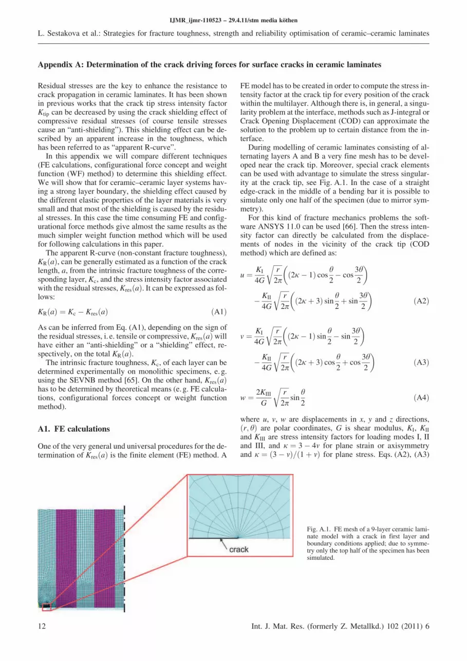
During modelling of ceramic laminates consisting of al-ternating layers A and B a very fine mesh has to be devel-oped near the crack tip. Moreover, special crack elementscan be used with advantage to simulate the stress singular-ity at the crack tip, see Fig. A.1. In the case of a straightedge-crack in the middle of a bending bar it is possible tosimulate only one half of the specimen (due to mirror sym-metry).
For this kind of fracture mechanics problems the soft-ware ANSYS 11.0 can be used [66]. Then the stress inten-sity factor can directly be calculated from the displace-ments of nodes in the vicinity of the crack tip (CODmethod) which are defined as:
u ¼ KI
4G
ffiffiffiffiffi
r
2p
r
2j% 1ð Þ cos h2% cos
3h
2
; <
% KII
4G
ffiffiffiffiffi
r
2p
r
2jþ 3ð Þ sin h2þ sin
3h
2
; <
ðA2Þ
v ¼ KI
4G
ffiffiffiffiffi
r
2p
r
2j% 1ð Þ sin h2% sin
3h
2
; <
% KII
4G
ffiffiffiffiffi
r
2p
r
2jþ 3ð Þ cos h2þ cos
3h
2
; <
ðA3Þ
w ¼ 2KIII
G
ffiffiffiffiffi
r
2p
r
sinh
2ðA4Þ
where u, v, w are displacements in x, y and z directions,ðr; hÞ are polar coordinates, G is shear modulus, KI, KII
and KIII are stress intensity factors for loading modes I, IIand III, and j ¼ 3% 4m for plane strain or axisymmetryand j ¼ ð3% mÞ=ð1þ mÞ for plane stress. Eqs. (A2), (A3)
IJMR_ijmr-110523 – 29.4.11/stm media köthen
L. Sestakova et al.: Strategies for fracture toughness, strength and reliability optimisation of ceramic–ceramic laminates
12 Int. J. Mat. Res. (formerly Z. Metallkd.) 102 (2011) 6
Fig. A.1. FE mesh of a 9-layer ceramic lami-nate model with a crack in first layer andboundary conditions applied; due to symme-try only the top half of the specimen has beensimulated.
and (A4) can be then simplified assuming the displace-ments of nodes at the crack faces (h ¼ 1808) and loadingmode I (see ANSYS for more details [66]). Values of thestress intensity factor determined in this way are in verygood agreement with analytically derived relations for sim-ple specimen geometries and loading conditions.
Although the FE method includes all the effects of thegeometry, material properties, stress relaxation at the crackfaces, shear stresses, etc., it also implies long calculationtimes since every position of the crackwithin the multilayermust be run.
A2. Configurational forces concept
The concept of configurational forces considers a materialinhomogeneity as an additional defect in the material (be-sides the crack) which induces an additional contributionto the crack driving force. This contribution is called thematerial inhomogeneity term Cinh. The thermodynamicforce at the crack tip, denominated as the local, near-tipcrack driving force Jtip, is the sum of the nominally appliedfar-field crack driving force Jfar (classical J-integral of frac-ture mechanics) and the material inhomogeneity term Cinh
[67]:
Jtip ¼ Jfar þ Cinh ðA5Þ
More details and references to the literature with respect tothe configurational forces concept and other related formu-lations can be taken from the literature [68, 69]. The calcu-lation of Cinh also requires an integration over the stressfield perpendicular to the crack front for any position ofthe crack, which is also very time consuming.
Note that an important benefit of thismethod is the possi-bility of quantitative description of the influence of the indi-vidual material interfaces (inhomogeneities) on the crackdriving force.
A3. Weight function method
The term KresðaÞ calculated using the WF method can bederived as follows [57, 70]:
Kres að Þ ¼Z
a
0
h a; xð Þrres xð Þ dx ðA6Þ
where a is the crack length, x is the distance from the sur-face to the point of integration along the crack length,rresðxÞ are the residual stresses varying according to thelayer of the laminate and hða; xÞ is the weight function (de-pending only on the specimen geometry) suggested by FettandMunz for an edge crack and an arbitrary stress distribu-tion acting normal to the crack plane [57]:
h ¼ffiffiffiffiffi
2
pa
r
1ffiffiffiffiffiffiffiffiffiffiffi
1% x
a
r 1þX
2
m¼0
X
4
l¼0
Aml
a
W
9 :l
1% a
W
9 :3=21% x
a
9 :mþ1
2
6
4
3
7
5
ðA7Þ
The corresponding coefficients Alm are listed in Table A.1.W is the total thickness of the specimen.
As can be further inferred from Eq. (A6), the WF methoddoes not take into account the influence of the different elas-tic properties of the individual layers (elastic mismatch).Nevertheless, it will be shown in the following Section thatthe method gives a very good approximation of the R-curvefor laminates made of materials with similar elastic proper-ties (E-moduli ratio less than 2). This condition is satisfiedwithin the most common range of ceramic materials.
A4. Comparison of the methods for K-calculationspresented
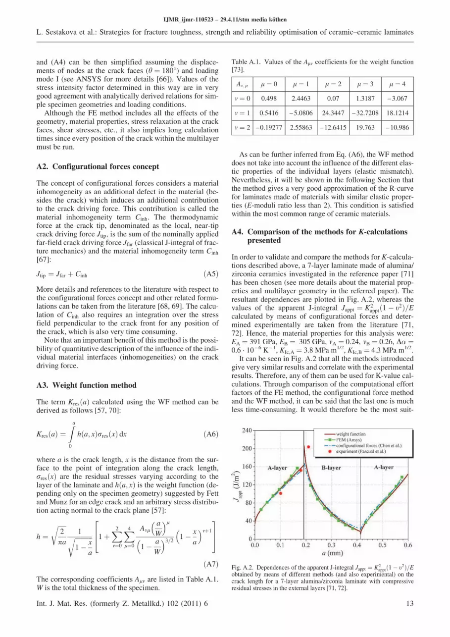
In order to validate and compare the methods for K-calcula-tions described above, a 7-layer laminate made of alumina/zirconia ceramics investigated in the reference paper [71]has been chosen (see more details about the material prop-erties and multilayer geometry in the referred paper). Theresultant dependences are plotted in Fig. A.2, whereas thevalues of the apparent J-integral Jappt ¼ K
2apptð1% t2Þ=E
calculated by means of configurational forces and deter-mined experimentally are taken from the literature [71,72]. Hence, the material properties for this analysis were:EA ¼ 391 GPa, EB ¼ 305 GPa, mA ¼ 0.24, mB ¼ 0.26, D( ¼0.6 · 10 – 6 K – 1, KIc,A ¼ 3.8 MPa m1/2, KIc,B ¼ 4.3 MPa m1/2.
It can be seen in Fig. A.2 that all the methods introducedgive very similar results and correlatewith the experimentalresults. Therefore, any of them can be used for K-value cal-culations. Through comparison of the computational effortfactors of the FE method, the configurational force methodand the WF method, it can be said that the last one is muchless time-consuming. It would therefore be the most suit-
IJMR_ijmr-110523 – 29.4.11/stm media köthen
L. Sestakova et al.: Strategies for fracture toughness, strength and reliability optimisation of ceramic–ceramic laminates
Int. J. Mat. Res. (formerly Z. Metallkd.) 102 (2011) 6 13
Table A.1. Values of the Alm coefficients for the weight function[73].
Am; l l ¼ 0 l ¼ 1 l ¼ 2 l ¼ 3 l ¼ 4
m ¼ 0 0.498 2.4463 0.07 1.3187 –3.067
m ¼ 1 0.5416 –5.0806 24.3447 –32.7208 18.1214
m ¼ 2 –0.19277 2.55863 –12.6415 19.763 –10.986
Fig. A.2. Dependences of the apparent J-integral Jappt ¼ K2apptð1% t2Þ=E
obtained by means of different methods (and also experimental) on thecrack length for a 7-layer alumina/zirconia laminate with compressiveresidual stresses in the external layers [71, 72].
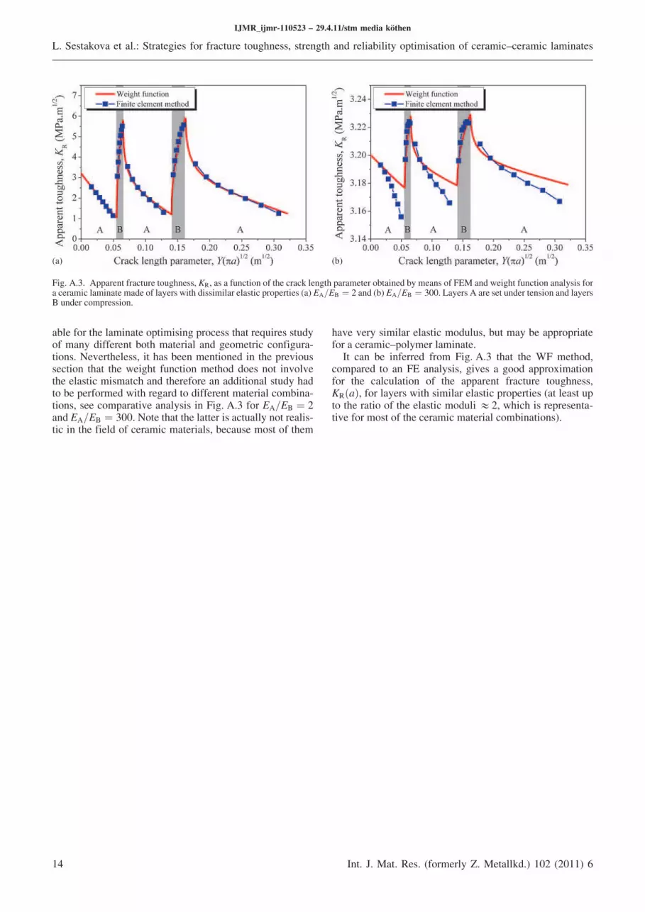
able for the laminate optimising process that requires studyof many different both material and geometric configura-tions. Nevertheless, it has been mentioned in the previoussection that the weight function method does not involvethe elastic mismatch and therefore an additional study hadto be performed with regard to different material combina-tions, see comparative analysis in Fig. A.3 for EA=EB ¼ 2and EA=EB ¼ 300. Note that the latter is actually not realis-tic in the field of ceramic materials, because most of them
have very similar elastic modulus, but may be appropriatefor a ceramic–polymer laminate.
It can be inferred from Fig. A.3 that the WF method,compared to an FE analysis, gives a good approximationfor the calculation of the apparent fracture toughness,KRðaÞ, for layers with similar elastic properties (at least upto the ratio of the elastic moduli &2, which is representa-tive for most of the ceramic material combinations).
IJMR_ijmr-110523 – 29.4.11/stm media köthen
L. Sestakova et al.: Strategies for fracture toughness, strength and reliability optimisation of ceramic–ceramic laminates
14 Int. J. Mat. Res. (formerly Z. Metallkd.) 102 (2011) 6
(a) (b)
Fig. A.3. Apparent fracture toughness, KR, as a function of the crack length parameter obtained bymeans of FEM and weight function analysis fora ceramic laminate made of layers with dissimilar elastic properties (a) EA=EB ¼ 2 and (b) EA=EB ¼ 300. LayersA are set under tension and layersB under compression.


